StarRC User Guide And Command Reference Star RC
StarRC_User_Guide
User Manual:
Open the PDF directly: View PDF ![]() .
.
Page Count: 934 [warning: Documents this large are best viewed by clicking the View PDF Link!]
- Preface
- Part I: StarRC User Guide
- Introduction to StarRC
- Running StarRC
- Process Characterization Interface
- Process Characterization Basics
- The Interconnect Technology Format File
- Creating the ITF File
- Process Effects That Affect Resistance and Capacitance
- Gate-To-Diffusion Capacitance Extraction Based on Capacitance Tables
- Device-Specific Contact Etch
- Device-Dependent Gate-to-Diffusion Capacitance Table
- Defining Additional Extraction Characteristics
- Handling Special Process Effects
- Conformal Dielectrics
- Conductor Cutting Dielectric
- Covertical Conductors
- Drop Factor
- Modeling a Double-Poly Process Using DROP_FACTOR
- Dielectric Air Gaps
- Layer Etch
- Metal Fill (Emulated)
- When An Antenna Diode is in Your Design Database
- 45-Degree Angles
- Diffusion Resistance Extraction
- Spacing- and Width-Dependent Etch
- CAPACITIVE_ONLY and RESISTIVE_ONLY
- Determining WMIN and SMIN Values
- Retaining Coupling Capacitance Between Top and SKIP_CELL Levels
- Handling Overlapping Wells
- Defining Sheet Zones
- Modeling Thickness Variation With StarRC
- Measuring Bottom Conductor Thickness Variation
- Interconnect Parasitics Extraction Based on CMP Simulators
- Microloading Effect
- Damage Modeling
- Translation of Routing DEF Blockage
- Temperature Derating
- Transparent Half-Node Flow
- Generating TLUPlus Models
- Via Merging
- Writing a Mapping File
- Physical Databases
- Introduction to Physical Databases
- Milkyway Database Extraction Flow
- LEF/DEF Database Extraction Flow
- Calibre Connectivity Interface
- Hercules Database Extraction Flow
- IC Validator Extraction Flow
- Cross-Referencing in Transistor Level Flows
- Cross-Referenced Extraction Options
- Parameterized Cells (PCELL)
- Metal Fill
- Shared Database Command Options
- Incremental Extraction
- Incremental Extraction Flow
- Input to StarRC
- Output from Incremental Extraction Runs
- Fixing a Design Using Engineering Change Orders
- Reasons to Perform ECOs
- Identification and Extraction of Nets Affected by ECOs
- Incremental Extraction Using StarRC
- Input Files for Incremental Extraction
- Output Files From Incremental Extraction
- Unsupported Commands During Incremental Extraction
- Running Incremental Extraction
- Incremental Netlist Examples
- Incremental Extraction Flow
- Parasitic Extraction
- Rapid3D Field Solver
- Timing Analysis
- Noise Analysis
- Graphical User Interface
- Variation-Aware Extraction
- Introduction to Variation-Aware Analysis
- Parasitic Extraction to Static Timing Analysis
- The Concept of Sensitivity
- Running StarRC With Sensitivities
- User-Defined Corner and Sensitivity Calculation
- User Interface Modeling Parameters and Their Variation
- Handling Temperature Variation in StarRC
- Defining a Corner (UDC) File
- Sensitivity Netlist With Geometry Information
- SPICE Syntax for Parasitic Sensitivity
- SPEF Extensions
- Variation-Aware Extraction Limitations
- Parasitic Extraction Integration With the Virtuoso Custom Design Platform
- Introduction to Virtuoso Integration
- Packaging, Installation, and Software Compatibility
- Flow Configuration and Related Files
- View Generation
- Temperature Sensitivity
- StarRC Parasitic Generation Cockpit GUI
- Populating the Cockpit Fields Automatically
- Using the Functions in the StarRC Parasitic View Generation Dialog Box
- Run Cockpit Tab
- Device Extraction Tab
- Extract Parasitics Tab
- Output Parasitics Tab
- Load Sharing Facility Job Submission
- File and Path Browsers
- Using Selected Net Parasitics and Selective Netlisting Modes
- Selecting and Customizing the Analysis Options
- StarRC OA View Creation
- Parasitic Probing in the GUI
- Virtuoso Integration Skill Procedures and Related Variables
- General Notes
- Examples
- Transistor-Level Runset Creation
- Advanced Extraction Features
- Hercules GENDEV Device Extraction and Netlist Generation
- Part II: StarRC Command Reference
- StarRC Commands
- ANALOG_SYMMETRIC_NETS
- AUTO_RUNSET
- BLOCK
- BLOCK_BOUNDARY
- BUS_BIT
- CALIBRE_LVS_DEVICE_TYPE_CAP
- CALIBRE_LVS_DEVICE_TYPE_MOS
- CALIBRE_LVS_DEVICE_TYPE_RES
- CALIBRE_OPTIONAL_DEVICE_PIN_FILE
- CALIBRE_PDBA_FILE
- CALIBRE_QUERY_FILE
- CALIBRE_RUNSET
- CASE_SENSITIVE
- CELL_TYPE
- COMPARE_DIRECTORY
- CONLY_NETS
- CONVERT_DIODE_TO_PARASITIC_CAP
- COUPLE_NONCRITICAL_NETS
- COUPLE_NONCRITICAL_NETS_PREFIX
- COUPLE_NONCRITICAL_NETS_SUBNODE_SUFFIX
- COUPLE_TO_GROUND
- COUPLE_TO_PCELL_PINS
- COUPLING_ABS_THRESHOLD
- COUPLING_AVG_THRESHOLD
- COUPLING_MULTIPLIER
- COUPLING_REL_THRESHOLD
- COUPLING_REPORT_FILE
- COUPLING_REPORT_NUMBER
- COUPLING_THRESHOLD_OPERATION
- DENSITY_BASED_THICKNESS
- DENSITY_OUTSIDE_BLOCK
- DETECT_FUSE
- EVACCESS_DIRECTORY
- EXTRA_GEOMETRY_INFO
- EXTRACTION
- EXTRACT_VIA_CAPS
- EXTRACT_RES_BODY_COUPLING
- FS_DP_STRING
- FS_EXTRACT_NETS
- FSCOMPARE_COUPLING_RATIO
- FSCOMPARE_FILE_PREFIX
- FSCOMPARE_OPTIONS
- FSCOMPARE_THRESHOLD
- GDS_FILE
- GDS_LAYER_MAP_FILE
- HIERARCHICAL_SEPARATOR
- HN_NETLIST_MODEL_NAME
- HN_NETLIST_SPICE_TYPE
- ICV_ANNOTATION_FILE
- ICV_RUNSET_REPORT_FILE
- IGNORE_CAPACITANCE
- IGNORE_FIELDPOLY_DIFFUSION_COUPLING
- INCREMENTAL
- INCREMENTAL_FORCE_DP
- INSTANCE_PORT
- INSTANCE_PORT_OPEN_CONDUCTANCE
- INTRANET_CAPS
- KEEP_VIA_NODES
- LEF_FILE
- LEF_USE_OBS
- LPE_DEVICES
- LPE_PARAM
- MACRO
- MACRO_DEF_FILE
- MAGNIFICATION_FACTOR
- MAGNIFY_DEVICE_PARAMS
- MAPPING_FILE
- MARKER_GENERATION
- MERGE_INSTANCE_PORTS
- MERGE_MULTI_CORNER
- MERGE_VIAS_IN_ARRAY
- METAL_FILL_GDS_FILE
- METAL_FILL_GDS_FILE_NET_NAME
- METAL_FILL_GDS_MAG
- METAL_FILL_GDS_OFFSET
- METAL_FILL_OASIS_FILE
- METAL_FILL_OASIS_FILE_NET_NAME
- METAL_FILL_OASIS_MAG
- METAL_FILL_OASIS_OFFSET
- METAL_FILL_POLYGON_HANDLING
- METAL_SHEET_OVER_AREA
- MILKYWAY_ADDITIONAL_VIEWS
- MILKYWAY_CELL_VIEW
- MILKYWAY_DATABASE
- MILKYWAY_EXPAND_HIERARCHICAL_CELLS
- MILKYWAY_EXTRACT_VIEW
- MILKYWAY_REF_LIB_MODE
- MODE
- MODEL_TYPE
- MOS_GATE_CAPACITANCE
- MOS_GATE_DELTA_RESISTANCE
- NET_SEGMENT_CUT_LENGTH
- NET_TYPE
- NETLIST_CAPACITANCE_UNIT
- NETLIST_COMMENTED_PARAMS
- NETLIST_COMMENTS_FILE
- NETLIST_COMPRESS_COMMAND
- NETLIST_CONNECT_OPENS
- NETLIST_CONNECT_SECTION
- NETLIST_CORNER_FILE
- NETLIST_CORNER_NAMES
- NETLIST_COUPLE_UNSELECTED_NETS
- NETLIST_DELIMITER
- NETLIST_DEVICE_LOCATION_ORIENTATION
- NETLIST_FILE
- NETLIST_FORMAT
- NETLIST_GROUND_NODE_NAME
- NETLIST_HIER_PROBE_NODES
- NETLIST_IDEAL_SPICE_FILE
- NETLIST_IDEAL_SPICE_HIER
- NETLIST_IDEAL_SPICE_TYPE
- NETLIST_INCREMENTAL
- NETLIST_INPUT_DRIVERS
- NETLIST_INSTANCE_SECTION
- NETLIST_LOGICAL_TYPE
- NETLIST_MAX_FILE_SIZE
- NETLIST_MAX_LINE
- NETLIST_MERGE_CORNERS
- NETLIST_MERGE_SHORTED_PORTS
- NETLIST_MINCAP_THRESHOLD
- NETLIST_MINRES_HANDLING
- NETLIST_MINRES_THRESHOLD
- NETLIST_MMC_FORMULA
- NETLIST_MMC_FORMULA_NAMES
- NETLIST_NAME_MAP
- NETLIST_NODE_SECTION
- NETLIST_NODENAME_NETNAME
- NETLIST_PARA_VIEW
- NETLIST_PARASITIC_RESISTOR_MODEL
- NETLIST_PASSIVE_PARAMS
- NETLIST_POSTPROCESS_COMMAND
- NETLIST_POWER_FILE
- NETLIST_PRECISION
- NETLIST_PRINT_CC_TWICE
- NETLIST_REMOVE_DANGLING_BRANCHES
- NETLIST_RENAME_PORTS
- NETLIST_RESISTANCE_UNIT
- NETLIST_SELECT_NETS
- NETLIST_SIM_OPTIONS
- NETLIST_SUBCKT
- NETLIST_TAIL_COMMENTS
- NETLIST_TIME_UNIT
- NETLIST_TOTALCAP_THRESHOLD
- NETLIST_TYPE
- NETLIST_UNSCALED_COORDINATES
- NETLIST_USE_M_FACTOR
- NETS
- NETS_FILE
- NONCRITICAL_COUPLING_REPORT_FILE
- NUM_PARTS
- OA_DEVICE_MAPPING_FILE
- OA_LAYER_MAPPING_FILE
- OA_LIB_DEF
- OA_LIB_NAME
- OA_MARKER_SIZE
- OA_PORT_ANNOTATION_VIEW
- OA_PROPERTY_ANNOTATION_VIEW
- OA_READ_FILL_VIEW
- OA_READ_LIB_NAME
- OA_READ_VIEW_NAME
- OA_SKIPCELL_MAPPING_FILE
- OA_VIEW_NAME
- OASIS_FILE
- OASIS_LAYER_MAP_FILE
- OBSERVATION_POINTS
- OPERATING_TEMPERATURE
- PIN_CUT_THRESHOLD
- PIO_FILE
- PLACEMENT_INFO_FILE
- POWER_EXTRACT
- POWER_NETS
- POWER_PORTS
- POWER_REDUCTION
- PRINT_SILICON_INFO
- PROBE_TEXT_FILE
- PROCESS_CORNER
- REDUCTION
- REDUCTION_MAX_DELAY_ERROR
- REMOVE_DANGLING_NETS
- REMOVE_FLOATING_NETS
- REMOVE_NET_PROPERTY
- RETAIN_CAPACITANCE_CAP_MODELS
- RETAIN_GATE_CONTACT_COUPLING
- RING_AROUND_THE_BLOCK
- RING_AROUND_THE_BLOCK_SMIN_MULTIPLIER
- SENSITIVITY
- SHEET_COUPLE_TO_NET
- SHEET_COUPLE_TO_NET_LEVEL
- SHORT_PINS
- SHORT_PINS_IN_CELLS
- SKIP_CELL_AGF_FILE
- SKIP_CELL_PORT_PROP_FILE
- SKIP_CELLS
- SKIP_CELLS_COUPLE_TO_NET
- SKIP_CELLS_COUPLE_TO_NET_LEVEL
- SKIP_CELLS_FILE
- SKIP_INSTANCES
- SKIP_PCELLS
- SKIP_PCELL_LAYERS_FILE
- SLEEP_TIME_AFTER_FINISH
- SPICE_SUBCKT_FILE
- STAR_DIRECTORY
- SUBSTRATE_EXTRACTION
- SUMMARY_FILE
- SYNOPSYS_LIB_FILE
- TARGET_PWRA
- TCAD_GRD_FILE
- TEMPERATURE_SENSITIVITY
- THICKNESS_VARIATION_FILE
- TOP_DEF_FILE
- TRANSLATE_DEF_BLOCKAGE
- TRANSLATE_FLOATING_AS_FILL
- TRANSLATE_RETAIN_BULK_LAYERS
- TVF_ADJUSTMENT_TABLES
- USER_DEFINED_DIFFUSION_RES
- VIA_COVERAGE
- VIA_COVERAGE_OPTION_FILE
- WIDE_DEVICE_TERM_RESISTANCE
- XREF
- XREF_FEEDTHRU_NETS
- XREF_LAYOUT_INST_PREFIX
- XREF_LAYOUT_NET_PREFIX
- XREF_SWAP_MOS_SD_PROPERTY
- XREF_USE_LAYOUT_DEVICE_NAME
- ZONE_COUPLE_TO_NET
- ZONE_COUPLE_TO_NET_LEVEL
- ITF Statements and Options
- AIR_GAP_VS_SPACING
- AREA
- ASSOCIATED_CONDUCTOR
- BACKGROUND_ER
- BOTTOM_DIELECTRIC_ER
- BOTTOM_DIELECTRIC_THICKNESS
- BOTTOM_THICKNESS_VS_SI_WIDTH
- CAPACITIVE_ONLY_ETCH
- CONDUCTOR
- CRT_VS_AREA
- CRT_VS_SI_WIDTH
- CRT1, CRT2, and T0
- DAMAGE_ER
- DAMAGE_THICKNESS
- DENSITY_BOX_WEIGHTING_FACTOR
- DIELECTRIC
- DROP_FACTOR
- DROP_FACTOR_LATERAL_SPACING
- ER
- ETCH
- ETCH_VS_CONTACT_AND_GATE_SPACINGS
- ETCH_VS_WIDTH_AND_LENGTH
- ETCH_VS_WIDTH_AND_SPACING
- FILL_RATIO
- FILL_SPACING
- FILL_TYPE
- FILL_WIDTH
- FROM
- GATE_TO_CONTACT_SMIN
- GATE_TO_DIFFUSION_CAP
- GLOBAL_TEMPERATURE
- HALF_NODE_SCALE_FACTOR
- ILD_VS_WIDTH_AND_SPACING
- IS_CONFORMAL
- IS_PLANAR
- LAYER_TYPE
- MEASURED_FROM
- POLYNOMIAL_BASED_THICKNESS_VARIATION
- RESISTIVE_ONLY_ETCH
- RHO
- RHO_VS_SI_WIDTH_AND_THICKNESS
- RHO_VS_WIDTH_AND_SPACING
- RPSQ
- RPSQ_VS_SI_WIDTH
- RPSQ_VS_WIDTH_AND_SPACING
- RPV
- RPV_VS_AREA
- SIDE_TANGENT
- SMIN
- SW_T
- TECHNOLOGY
- THICKNESS
- THICKNESS_VS_DENSITY
- THICKNESS_VS_WIDTH_AND_SPACING
- TO
- TSV
- TVF_ADJUSTMENT_TABLES
- TW_T
- USE_SI_DENSITY
- VARIATION_PARAMETERS
- VIA
- WMIN
- The grdgenxo Command
- Mapping File Commands
- ITF Examples
- Command Lists
- StarRC Commands

StarRC™
User Guide and Command Reference
Version F-2011.06, June 2011
StarRC User Guide and Command Reference, version F-2011.06 ii
Copyright Notice and Proprietary Information
Copyright © 2011 Synopsys, Inc. All rights reserved. This software and documentation contain confidential and proprietary
information that is the property of Synopsys, Inc. The software and documentation are furnished under a license agreement and
may be used or copied only in accordance with the terms of the license agreement. No part of the software and documentation may
be reproduced, transmitted, or translated, in any form or by any means, electronic, mechanical, manual, optical, or otherwise, without
prior written permission of Synopsys, Inc., or as expressly provided by the license agreement.
Right to Copy Documentation
The license agreement with Synopsys permits licensee to make copies of the documentation for its internal use only.
Each copy shall include all copyrights, trademarks, service marks, and proprietary rights notices, if any. Licensee must
assign sequential numbers to all copies. These copies shall contain the following legend on the cover page:
“This document is duplicated with the permission of Synopsys, Inc., for the exclusive use of
__________________________________________ and its employees. This is copy number __________.”
Destination Control Statement
All technical data contained in this publication is subject to the export control laws of the United States of America.
Disclosure to nationals of other countries contrary to United States law is prohibited. It is the reader’s responsibility to
determine the applicable regulations and to comply with them.
Disclaimer
SYNOPSYS, INC., AND ITS LICENSORS MAKE NO WARRANTY OF ANY KIND, EXPRESS OR IMPLIED, WITH
REGARD TO THIS MATERIAL, INCLUDING, BUT NOT LIMITED TO, THE IMPLIED WARRANTIES OF
MERCHANTABILITY AND FITNESS FOR A PARTICULAR PURPOSE.
Registered Trademarks (®)
Synopsys, AEON, AMPS, ARC, Astro, Behavior Extracting Synthesis Technology, Cadabra, CATS, Certify, Chipidea,
CHIPit, CODE V, CoMET, Confirma, CoWare, Design Compiler, DesignSphere, DesignWare, Eclypse, EMBED-IT!,
Formality, Galaxy Custom Designer, Global Synthesis, HAPS, HapsTrak, HDL Analyst, HSIM, HSPICE, Identify, Leda,
LightTools, MAST, MaVeric, METeor, ModelTools, NanoSim, NOVeA, OpenVera, ORA, PathMill, Physical Compiler,
PrimeTime, SCOPE, SiVL, SNUG, SolvNet, Sonic Focus, STAR Memory System, Syndicated, Synplicity, Synplify,
Synplify Pro, Synthesis Constraints Optimization Environment, TetraMAX, the Synplicity logo, UMRBus, VCS, Vera, and
YIELDExplorer are registered trademarks of Synopsys, Inc.
Trademarks (™)
AFGen, Apollo, ASAP, Astro-Rail, Astro-Xtalk, Aurora, AvanWaves, BEST, Columbia, Columbia-CE, Cosmos, CosmosLE,
CosmosScope, CRITIC, CustomExplorer, CustomSim, DC Expert, DC Professional, DC Ultra, Design Analyzer, Design
Vision, DesignerHDL, DesignPower, DFTMAX, Direct Silicon Access, Discovery, Encore, EPIC, Galaxy, HANEX, HDL
Compiler, Hercules, Hierarchical Optimization Technology, High-performance ASIC Prototyping System, HSIMplus,
i-Virtual Stepper, IICE, in-Sync, iN-Tandem, Intelli, Jupiter, Jupiter-DP, JupiterXT, JupiterXT-ASIC, Liberty, Libra-Passport,
Library Compiler, Macro-PLUS, Magellan, Mars, Mars-Rail, Mars-Xtalk, Milkyway, ModelSource, Module Compiler,
MultiPoint, ORAengineering, Physical Analyst, Planet, Planet-PL, Polaris, Power Compiler, Raphael, RippledMixer,
Saturn, Scirocco, Scirocco-i, SiWare, Star-RCXT, Star-SimXT, StarRC, System Compiler, System Designer, Taurus,
TotalRecall, TSUPREM-4, VCSi, VHDL Compiler, VMC, and Worksheet Buffer are trademarks of Synopsys, Inc.
Service Marks (SM)
MAP-in, SVP Café, and TAP-in are service marks of Synopsys, Inc.
SystemC is a trademark of the Open SystemC Initiative and is used under license.
ARM and AMBA are registered trademarks of ARM Limited.
Saber is a registered trademark of SabreMark Limited Partnership and is used under license.
All other product or company names may be trademarks of their respective owners.

iii
Contents
What’s New in This Release . . . . . . . . . . . . . . . . . . . . . . . . . . . . . . . . . . . . . . . . . . . xxviii
About This User Guide and Command Reference . . . . . . . . . . . . . . . . . . . . . . . . . . xxix
Customer Support. . . . . . . . . . . . . . . . . . . . . . . . . . . . . . . . . . . . . . . . . . . . . . . . . . . xxxi
Part I: StarRC User Guide
1. Introduction to StarRC
Extraction in the Basic Design Flow . . . . . . . . . . . . . . . . . . . . . . . . . . . . . . . . . . . . . 1-2
Extraction Tool Tasks . . . . . . . . . . . . . . . . . . . . . . . . . . . . . . . . . . . . . . . . . . . . . . . . 1-2
Interaction With Other Synopsys Tools . . . . . . . . . . . . . . . . . . . . . . . . . . . . . . . 1-2
Interfacing With External CAD Tools. . . . . . . . . . . . . . . . . . . . . . . . . . . . . . . . . . . . . 1-3
Supported Formats . . . . . . . . . . . . . . . . . . . . . . . . . . . . . . . . . . . . . . . . . . . . . . . . . . 1-3
Physical Tool Requirements . . . . . . . . . . . . . . . . . . . . . . . . . . . . . . . . . . . . . . . . . . . 1-3
Block or Cell Analysis . . . . . . . . . . . . . . . . . . . . . . . . . . . . . . . . . . . . . . . . . . . . . . . . 1-3
User Interfaces . . . . . . . . . . . . . . . . . . . . . . . . . . . . . . . . . . . . . . . . . . . . . . . . . . . . . 1-4
Licensing Requirements . . . . . . . . . . . . . . . . . . . . . . . . . . . . . . . . . . . . . . . . . . . . . . 1-4
2. Running StarRC
StarRC Overview . . . . . . . . . . . . . . . . . . . . . . . . . . . . . . . . . . . . . . . . . . . . . . . . . . . 2-2
Batch Mode Operation . . . . . . . . . . . . . . . . . . . . . . . . . . . . . . . . . . . . . . . . . . . . . . . 2-3
Graphical User Interface . . . . . . . . . . . . . . . . . . . . . . . . . . . . . . . . . . . . . . . . . . . . . . 2-4

Contents iv
StarRC User Guide and Command Reference F-2011.06
StarRC User Guide and Command Reference Version F-2011.06
Selective Job Processing . . . . . . . . . . . . . . . . . . . . . . . . . . . . . . . . . . . . . . . . . . . . . 2-4
Distributed Processing . . . . . . . . . . . . . . . . . . . . . . . . . . . . . . . . . . . . . . . . . . . . . . . 2-6
Manual Submission of Distributed Processing Jobs . . . . . . . . . . . . . . . . . . . . . 2-7
Automatic Submission of Distributed Processing Jobs . . . . . . . . . . . . . . . . . . . 2-7
Summary File . . . . . . . . . . . . . . . . . . . . . . . . . . . . . . . . . . . . . . . . . . . . . . . . . . 2-9
Performance Optimization . . . . . . . . . . . . . . . . . . . . . . . . . . . . . . . . . . . . . . . . . 2-11
Licensing Requirements for Distributed Processing . . . . . . . . . . . . . . . . . . . . . 2-11
StarRC Licensing Features. . . . . . . . . . . . . . . . . . . . . . . . . . . . . . . . . . . . . . . . . . . . 2-11
Tiered Licensing Checkout Policy . . . . . . . . . . . . . . . . . . . . . . . . . . . . . . . . . . . 2-11
License Queuing Not Enabled . . . . . . . . . . . . . . . . . . . . . . . . . . . . . . . . . . 2-12
License Queuing Enabled. . . . . . . . . . . . . . . . . . . . . . . . . . . . . . . . . . . . . . 2-12
StarRC Command File Conventions. . . . . . . . . . . . . . . . . . . . . . . . . . . . . . . . . . . . . 2-14
3. Process Characterization Interface
Process Characterization Basics . . . . . . . . . . . . . . . . . . . . . . . . . . . . . . . . . . . . . . . 3-3
The Interconnect Technology Format File. . . . . . . . . . . . . . . . . . . . . . . . . . . . . . . . . 3-4
Creating the ITF File . . . . . . . . . . . . . . . . . . . . . . . . . . . . . . . . . . . . . . . . . . . . . . . . . 3-4
Process Effects That Affect Resistance and Capacitance . . . . . . . . . . . . . . . . . . . . 3-6
Gate-To-Diffusion Capacitance Extraction Based on Capacitance Tables . . . . . . . . 3-7
Device-Specific Contact Etch . . . . . . . . . . . . . . . . . . . . . . . . . . . . . . . . . . . . . . . . . . 3-8
Device-Dependent Gate-to-Diffusion Capacitance Table . . . . . . . . . . . . . . . . . . . . . 3-9
Defining Additional Extraction Characteristics . . . . . . . . . . . . . . . . . . . . . . . . . . . . . 3-10
Handling Special Process Effects . . . . . . . . . . . . . . . . . . . . . . . . . . . . . . . . . . . 3-10
Conformal Dielectrics. . . . . . . . . . . . . . . . . . . . . . . . . . . . . . . . . . . . . . . . . . . . . 3-11
Conductor Cutting Dielectric . . . . . . . . . . . . . . . . . . . . . . . . . . . . . . . . . . . . . . . 3-12
Covertical Conductors . . . . . . . . . . . . . . . . . . . . . . . . . . . . . . . . . . . . . . . . . . . . 3-13
Drop Factor . . . . . . . . . . . . . . . . . . . . . . . . . . . . . . . . . . . . . . . . . . . . . . . . . . . . 3-14
Modeling a Double-Poly Process Using DROP_FACTOR . . . . . . . . . . . . . . . . . 3-17
Dielectric Air Gaps . . . . . . . . . . . . . . . . . . . . . . . . . . . . . . . . . . . . . . . . . . . . . . . 3-18
Layer Etch . . . . . . . . . . . . . . . . . . . . . . . . . . . . . . . . . . . . . . . . . . . . . . . . . . . . . 3-19
Metal Fill (Emulated) . . . . . . . . . . . . . . . . . . . . . . . . . . . . . . . . . . . . . . . . . . . . . 3-19
When An Antenna Diode is in Your Design Database . . . . . . . . . . . . . . . . . . . . 3-21
45-Degree Angles . . . . . . . . . . . . . . . . . . . . . . . . . . . . . . . . . . . . . . . . . . . . . . . 3-22

Chapter 1: Contents
1-v
Contents v
StarRC User Guide and Command Reference Version F-2011.06
Diffusion Resistance Extraction . . . . . . . . . . . . . . . . . . . . . . . . . . . . . . . . . . . . . 3-22
Spacing- and Width-Dependent Etch . . . . . . . . . . . . . . . . . . . . . . . . . . . . . . . . 3-23
Running grdgenxo . . . . . . . . . . . . . . . . . . . . . . . . . . . . . . . . . . . . . . . . . . . 3-23
CAPACITIVE_ONLY and RESISTIVE_ONLY. . . . . . . . . . . . . . . . . . . . . . . . . . . 3-23
Determining WMIN and SMIN Values . . . . . . . . . . . . . . . . . . . . . . . . . . . . . . . . 3-23
Retaining Coupling Capacitance Between Top and SKIP_CELL Levels . . . . . . 3-24
Handling Overlapping Wells. . . . . . . . . . . . . . . . . . . . . . . . . . . . . . . . . . . . . . . . 3-24
Defining Sheet Zones . . . . . . . . . . . . . . . . . . . . . . . . . . . . . . . . . . . . . . . . . . . . . . . . 3-25
Modeling Thickness Variation With StarRC . . . . . . . . . . . . . . . . . . . . . . . . . . . . . . . 3-28
Measuring Bottom Conductor Thickness Variation. . . . . . . . . . . . . . . . . . . . . . . . . . 3-35
Interconnect Parasitics Extraction Based on CMP Simulators . . . . . . . . . . . . . . . . . 3-37
Microloading Effect . . . . . . . . . . . . . . . . . . . . . . . . . . . . . . . . . . . . . . . . . . . . . . . . . . 3-41
Damage Modeling. . . . . . . . . . . . . . . . . . . . . . . . . . . . . . . . . . . . . . . . . . . . . . . . . . . 3-42
Translation of Routing DEF Blockage . . . . . . . . . . . . . . . . . . . . . . . . . . . . . . . . . . . . 3-44
Temperature Derating . . . . . . . . . . . . . . . . . . . . . . . . . . . . . . . . . . . . . . . . . . . . . . . . 3-44
Transparent Half-Node Flow . . . . . . . . . . . . . . . . . . . . . . . . . . . . . . . . . . . . . . . . . . . 3-45
Generating TLUPlus Models. . . . . . . . . . . . . . . . . . . . . . . . . . . . . . . . . . . . . . . . . . . 3-48
Via Merging. . . . . . . . . . . . . . . . . . . . . . . . . . . . . . . . . . . . . . . . . . . . . . . . . . . . . . . . 3-50
Output Netlist . . . . . . . . . . . . . . . . . . . . . . . . . . . . . . . . . . . . . . . . . . . . . . . . . . . 3-50
Mapping File Syntax . . . . . . . . . . . . . . . . . . . . . . . . . . . . . . . . . . . . . . . . . . . . . 3-51
Examples of Via Merging. . . . . . . . . . . . . . . . . . . . . . . . . . . . . . . . . . . . . . . . . . 3-51
Writing a Mapping File . . . . . . . . . . . . . . . . . . . . . . . . . . . . . . . . . . . . . . . . . . . . . . . 3-58
4. Physical Databases
Introduction to Physical Databases. . . . . . . . . . . . . . . . . . . . . . . . . . . . . . . . . . . . . . 4-2
Milkyway Database Extraction Flow . . . . . . . . . . . . . . . . . . . . . . . . . . . . . . . . . . . . . 4-2
Place-and-Route Flow . . . . . . . . . . . . . . . . . . . . . . . . . . . . . . . . . . . . . . . . . . . . 4-3
Setting the Reference Library Control File. . . . . . . . . . . . . . . . . . . . . . . . . . . . . 4-3
Milkyway Database Command Options. . . . . . . . . . . . . . . . . . . . . . . . . . . . . . . 4-3
LEF/DEF Database Extraction Flow . . . . . . . . . . . . . . . . . . . . . . . . . . . . . . . . . . . . . 4-4
Timing-Driven Design Flow . . . . . . . . . . . . . . . . . . . . . . . . . . . . . . . . . . . . . . . . 4-6
Merging Library GDSII. . . . . . . . . . . . . . . . . . . . . . . . . . . . . . . . . . . . . . . . . . . . 4-6

Contents vi
StarRC User Guide and Command Reference F-2011.06
StarRC User Guide and Command Reference Version F-2011.06
LEF/DEF Database Commands . . . . . . . . . . . . . . . . . . . . . . . . . . . . . . . . . . . . 4-6
Calibre Connectivity Interface . . . . . . . . . . . . . . . . . . . . . . . . . . . . . . . . . . . . . . . . . . 4-7
Hercules Database Extraction Flow . . . . . . . . . . . . . . . . . . . . . . . . . . . . . . . . . . . . . 4-15
GDSII to XTR View Translation . . . . . . . . . . . . . . . . . . . . . . . . . . . . . . . . . . . . . 4-17
Cross-Referenced Extraction in the Hercules Flow . . . . . . . . . . . . . . . . . . . . . . 4-19
Hercules Database Command Options . . . . . . . . . . . . . . . . . . . . . . . . . . . . . . . 4-20
HSIM Reliability Flow Placement Information . . . . . . . . . . . . . . . . . . . . . . . . . . 4-21
IC Validator Extraction Flow . . . . . . . . . . . . . . . . . . . . . . . . . . . . . . . . . . . . . . . . . . . 4-22
Steps in the IC Validator Extraction Flow . . . . . . . . . . . . . . . . . . . . . . . . . . . . . 4-24
Examples of Script Files . . . . . . . . . . . . . . . . . . . . . . . . . . . . . . . . . . . . . . . 4-24
Cross-Referenced Extraction in IC Validator . . . . . . . . . . . . . . . . . . . . . . . . . . . 4-25
Cross-Referencing in Transistor Level Flows . . . . . . . . . . . . . . . . . . . . . . . . . . . . . . 4-26
XREF:NO. . . . . . . . . . . . . . . . . . . . . . . . . . . . . . . . . . . . . . . . . . . . . . . . . . . . . . 4-26
XREF:YES . . . . . . . . . . . . . . . . . . . . . . . . . . . . . . . . . . . . . . . . . . . . . . . . . . . . . 4-26
XREF:COMPLETE . . . . . . . . . . . . . . . . . . . . . . . . . . . . . . . . . . . . . . . . . . . . . . 4-30
Cross-Referenced Extraction Options . . . . . . . . . . . . . . . . . . . . . . . . . . . . . . . . . . . 4-32
Parameterized Cells (PCELL). . . . . . . . . . . . . . . . . . . . . . . . . . . . . . . . . . . . . . . . . . 4-33
How LVS Handles Parameterized Cells. . . . . . . . . . . . . . . . . . . . . . . . . . . . . . . 4-34
Extracting PCELLS Using StarRC . . . . . . . . . . . . . . . . . . . . . . . . . . . . . . . . . . . 4-38
SKIP_PCELLS Extraction Operation . . . . . . . . . . . . . . . . . . . . . . . . . . . . . . . . . 4-39
SKIP_PCELLS Netlist Behavior. . . . . . . . . . . . . . . . . . . . . . . . . . . . . . . . . . . . . 4-40
Metal Fill . . . . . . . . . . . . . . . . . . . . . . . . . . . . . . . . . . . . . . . . . . . . . . . . . . . . . . . . . . 4-41
Emulated Metal Fill . . . . . . . . . . . . . . . . . . . . . . . . . . . . . . . . . . . . . . . . . . . . . . 4-42
Using Emulated Metal Fill in StarRC . . . . . . . . . . . . . . . . . . . . . . . . . . . . . 4-42
Real Metal Fill . . . . . . . . . . . . . . . . . . . . . . . . . . . . . . . . . . . . . . . . . . . . . . . . . . 4-43
Handling Coupling Capacitance on Floating Metal Fills . . . . . . . . . . . . . . . 4-44
Guidelines for Using Metal Fill . . . . . . . . . . . . . . . . . . . . . . . . . . . . . . . . . . 4-45
How StarRC Handles Metal Fill . . . . . . . . . . . . . . . . . . . . . . . . . . . . . . . . . . . . . 4-46
Grounded Metal Fill . . . . . . . . . . . . . . . . . . . . . . . . . . . . . . . . . . . . . . . . . . 4-46
Floating Metal Fill . . . . . . . . . . . . . . . . . . . . . . . . . . . . . . . . . . . . . . . . . . . . 4-46
Floating and Grounded Metal Fill . . . . . . . . . . . . . . . . . . . . . . . . . . . . . . . . 4-46
Accuracy Validation With Metal Fill . . . . . . . . . . . . . . . . . . . . . . . . . . . . . . . . . . 4-47
Shared Database Command Options. . . . . . . . . . . . . . . . . . . . . . . . . . . . . . . . . . . . 4-47

Chapter 1: Contents
1-vii
Contents vii
StarRC User Guide and Command Reference Version F-2011.06
5. Incremental Extraction
Incremental Extraction Flow . . . . . . . . . . . . . . . . . . . . . . . . . . . . . . . . . . . . . . . . . . . 5-2
Input to StarRC . . . . . . . . . . . . . . . . . . . . . . . . . . . . . . . . . . . . . . . . . . . . . . . . . 5-2
Output from Incremental Extraction Runs . . . . . . . . . . . . . . . . . . . . . . . . . . . . . 5-2
Fixing a Design Using Engineering Change Orders . . . . . . . . . . . . . . . . . . . . . 5-3
Reasons to Perform ECOs . . . . . . . . . . . . . . . . . . . . . . . . . . . . . . . . . . . . . . . . 5-3
Identification and Extraction of Nets Affected by ECOs. . . . . . . . . . . . . . . . . . . 5-6
Incremental Extraction Using StarRC . . . . . . . . . . . . . . . . . . . . . . . . . . . . . . . . 5-7
Input Files for Incremental Extraction . . . . . . . . . . . . . . . . . . . . . . . . . . . . . . . . 5-9
Output Files From Incremental Extraction . . . . . . . . . . . . . . . . . . . . . . . . . . . . . 5-9
Unsupported Commands During Incremental Extraction . . . . . . . . . . . . . . . . . 5-10
Running Incremental Extraction . . . . . . . . . . . . . . . . . . . . . . . . . . . . . . . . . . . . . . . . 5-10
Incremental Netlist Examples . . . . . . . . . . . . . . . . . . . . . . . . . . . . . . . . . . . . . . . . . . 5-15
6. Parasitic Extraction
Extraction Overview . . . . . . . . . . . . . . . . . . . . . . . . . . . . . . . . . . . . . . . . . . . . . . . . . 6-2
SingleShot Extraction . . . . . . . . . . . . . . . . . . . . . . . . . . . . . . . . . . . . . . . . . . . . . . . . 6-2
Extraction Commands. . . . . . . . . . . . . . . . . . . . . . . . . . . . . . . . . . . . . . . . . . . . . . . . 6-5
Processing Commands. . . . . . . . . . . . . . . . . . . . . . . . . . . . . . . . . . . . . . . . . . . . . . . 6-6
7. Rapid3D Field Solver
Introduction to Rapid3D Extraction . . . . . . . . . . . . . . . . . . . . . . . . . . . . . . . . . . . . . . 7-2
Running Rapid3D . . . . . . . . . . . . . . . . . . . . . . . . . . . . . . . . . . . . . . . . . . . . . . . . . . . 7-2
Distributed Processing. . . . . . . . . . . . . . . . . . . . . . . . . . . . . . . . . . . . . . . . . . . . 7-3
LSF System . . . . . . . . . . . . . . . . . . . . . . . . . . . . . . . . . . . . . . . . . . . . . . . . 7-4
Gridware System . . . . . . . . . . . . . . . . . . . . . . . . . . . . . . . . . . . . . . . . . . . . 7-4
General Network With a List of Machines. . . . . . . . . . . . . . . . . . . . . . . . . . 7-4
Notes on Distributed Processing . . . . . . . . . . . . . . . . . . . . . . . . . . . . . . . . 7-5
Licensing Requirement for Distributed Processing . . . . . . . . . . . . . . . . . . 7-5
Input and Output Files . . . . . . . . . . . . . . . . . . . . . . . . . . . . . . . . . . . . . . . . . . . . . . . 7-5
Input Files . . . . . . . . . . . . . . . . . . . . . . . . . . . . . . . . . . . . . . . . . . . . . . . . . . . . . 7-5
Technology File. . . . . . . . . . . . . . . . . . . . . . . . . . . . . . . . . . . . . . . . . . . . . . 7-5
Design File . . . . . . . . . . . . . . . . . . . . . . . . . . . . . . . . . . . . . . . . . . . . . . . . . 7-6
Net File . . . . . . . . . . . . . . . . . . . . . . . . . . . . . . . . . . . . . . . . . . . . . . . . . . . . 7-6
Output File . . . . . . . . . . . . . . . . . . . . . . . . . . . . . . . . . . . . . . . . . . . . . . . . . . . . . 7-6

Contents viii
StarRC User Guide and Command Reference F-2011.06
StarRC User Guide and Command Reference Version F-2011.06
Trapezoidal Conductors . . . . . . . . . . . . . . . . . . . . . . . . . . . . . . . . . . . . . . . . . . . . . . 7-7
Conductor Types. . . . . . . . . . . . . . . . . . . . . . . . . . . . . . . . . . . . . . . . . . . . . . . . . . . . 7-7
Nets . . . . . . . . . . . . . . . . . . . . . . . . . . . . . . . . . . . . . . . . . . . . . . . . . . . . . . . . . . 7-8
Net Groups . . . . . . . . . . . . . . . . . . . . . . . . . . . . . . . . . . . . . . . . . . . . . . . . . . . . 7-8
Ground Nets . . . . . . . . . . . . . . . . . . . . . . . . . . . . . . . . . . . . . . . . . . . . . . . . . . . 7-8
Fill Nets . . . . . . . . . . . . . . . . . . . . . . . . . . . . . . . . . . . . . . . . . . . . . . . . . . . . . . . 7-9
Capacitance Types . . . . . . . . . . . . . . . . . . . . . . . . . . . . . . . . . . . . . . . . . . . . . . . . . . 7-9
Boundary Conditions . . . . . . . . . . . . . . . . . . . . . . . . . . . . . . . . . . . . . . . . . . . . . . . . 7-10
Controlling Accuracy and Runtime . . . . . . . . . . . . . . . . . . . . . . . . . . . . . . . . . . . . . . 7-11
Specifying Convergence Goals . . . . . . . . . . . . . . . . . . . . . . . . . . . . . . . . . . . . . 7-11
Specifying the Accuracy Goal . . . . . . . . . . . . . . . . . . . . . . . . . . . . . . . . . . . . . . 7-12
Specifying the Consistency of Results. . . . . . . . . . . . . . . . . . . . . . . . . . . . . . . . 7-13
Specifying the grids_per_meter Parameter . . . . . . . . . . . . . . . . . . . . . . . . . . . . 7-13
Specifying Pattern Matching for Symmetric Nets. . . . . . . . . . . . . . . . . . . . . . . . 7-14
8. Timing Analysis
Timing Analysis Overview. . . . . . . . . . . . . . . . . . . . . . . . . . . . . . . . . . . . . . . . . . . . . 8-2
Net-Specific Modes. . . . . . . . . . . . . . . . . . . . . . . . . . . . . . . . . . . . . . . . . . . . . . . . . . 8-4
Simulation Options in the StarRC Netlist . . . . . . . . . . . . . . . . . . . . . . . . . . . . . . . . . 8-6
Netlist Commands . . . . . . . . . . . . . . . . . . . . . . . . . . . . . . . . . . . . . . . . . . . . . . . . . . 8-7
9. Noise Analysis
Noise Analysis Overview . . . . . . . . . . . . . . . . . . . . . . . . . . . . . . . . . . . . . . . . . . . . . 9-2
Smart Decoupling of Coupling Capacitances . . . . . . . . . . . . . . . . . . . . . . . . . . . . . . 9-3
Noise Analysis Commands. . . . . . . . . . . . . . . . . . . . . . . . . . . . . . . . . . . . . . . . . . . . 9-4
10. Graphical User Interface
Graphical User Interface . . . . . . . . . . . . . . . . . . . . . . . . . . . . . . . . . . . . . . . . . . . . . . 10-2
Files Needed to Run StarRC . . . . . . . . . . . . . . . . . . . . . . . . . . . . . . . . . . . . . . . . . . 10-2
Starting StarRC Using the GUI . . . . . . . . . . . . . . . . . . . . . . . . . . . . . . . . . . . . . . . . . 10-3
Starting a Timing or Noise Job . . . . . . . . . . . . . . . . . . . . . . . . . . . . . . . . . . . . . 10-3
Starting a SingleShot Job . . . . . . . . . . . . . . . . . . . . . . . . . . . . . . . . . . . . . . . . . 10-6

Chapter 1: Contents
1-ix
Contents ix
StarRC User Guide and Command Reference Version F-2011.06
Interface Reference . . . . . . . . . . . . . . . . . . . . . . . . . . . . . . . . . . . . . . . . . . . . . . . . . 10-8
Control Window . . . . . . . . . . . . . . . . . . . . . . . . . . . . . . . . . . . . . . . . . . . . . . . . . 10-8
File Menu . . . . . . . . . . . . . . . . . . . . . . . . . . . . . . . . . . . . . . . . . . . . . . . . . . 10-9
Setup Menu . . . . . . . . . . . . . . . . . . . . . . . . . . . . . . . . . . . . . . . . . . . . . . . . 10-10
Noise Menu. . . . . . . . . . . . . . . . . . . . . . . . . . . . . . . . . . . . . . . . . . . . . . . . . 10-15
Viewer Menu. . . . . . . . . . . . . . . . . . . . . . . . . . . . . . . . . . . . . . . . . . . . . . . . 10-16
Entering Information . . . . . . . . . . . . . . . . . . . . . . . . . . . . . . . . . . . . . . . . . . . . . . . . . 10-17
Entry Fields . . . . . . . . . . . . . . . . . . . . . . . . . . . . . . . . . . . . . . . . . . . . . . . . . . . . 10-17
Analysis Forms . . . . . . . . . . . . . . . . . . . . . . . . . . . . . . . . . . . . . . . . . . . . . . . . . 10-19
List of Nets . . . . . . . . . . . . . . . . . . . . . . . . . . . . . . . . . . . . . . . . . . . . . . . . . 10-20
Creating a Mapping File in the GUI . . . . . . . . . . . . . . . . . . . . . . . . . . . . . . . . . . . . . 10-20
11. Variation-Aware Extraction
Introduction to Variation-Aware Analysis . . . . . . . . . . . . . . . . . . . . . . . . . . . . . . . . . 11-2
Pessimism of Traditional Corner Analysis . . . . . . . . . . . . . . . . . . . . . . . . . . . . . 11-2
Pitfalls of Traditional Corner Analysis . . . . . . . . . . . . . . . . . . . . . . . . . . . . . . . . 11-5
Time-to-Market Challenges With Traditional Corner Analysis . . . . . . . . . . 11-8
Random Versus Systematic Variations . . . . . . . . . . . . . . . . . . . . . . . . . . . . . . . 11-8
Systematic or Intra-Die Process Modeling . . . . . . . . . . . . . . . . . . . . . . . . . 11-9
Random or Inter-Die Process Modeling . . . . . . . . . . . . . . . . . . . . . . . . . . . 11-10
Comparing Random Versus Systematic Variations . . . . . . . . . . . . . . . . . . . . . . 11-11
Parasitic Extraction to Static Timing Analysis . . . . . . . . . . . . . . . . . . . . . . . . . . . . . . 11-12
The Traditional Analysis Flow . . . . . . . . . . . . . . . . . . . . . . . . . . . . . . . . . . . . . . 11-13
Statistical Extraction and Static Timing Analysis . . . . . . . . . . . . . . . . . . . . . . . . 11-14
The Concept of Sensitivity . . . . . . . . . . . . . . . . . . . . . . . . . . . . . . . . . . . . . . . . . . . . 11-17
Calculating Sensitivity Coefficients . . . . . . . . . . . . . . . . . . . . . . . . . . . . . . . . . . 11-18
Characterizing the Effect on Capacitance Values. . . . . . . . . . . . . . . . . . . . 11-18
Computing the Thickness Sensitivity of a Dielectric Layer . . . . . . . . . . . . . 11-18
Defining Capacitance Sensitivity . . . . . . . . . . . . . . . . . . . . . . . . . . . . . . . . 11-18
Defining Resistance Sensitivity. . . . . . . . . . . . . . . . . . . . . . . . . . . . . . . . . . 11-20
Running StarRC With Sensitivities . . . . . . . . . . . . . . . . . . . . . . . . . . . . . . . . . . . . . . 11-20
Example Calculations With Sensitivities . . . . . . . . . . . . . . . . . . . . . . . . . . . . . . 11-21
User-Defined Corner and Sensitivity Calculation . . . . . . . . . . . . . . . . . . . . . . . . . . . 11-23
User Interface Modeling Parameters and Their Variation . . . . . . . . . . . . . . . . . . . . . 11-24
Creating a Variation-Aware ITF . . . . . . . . . . . . . . . . . . . . . . . . . . . . . . . . . . . . . 11-25
Appending Variation Information. . . . . . . . . . . . . . . . . . . . . . . . . . . . . . . . . 11-25

Contents x
StarRC User Guide and Command Reference F-2011.06
StarRC User Guide and Command Reference Version F-2011.06
Single Variation Parameters and Dependent Parameters . . . . . . . . . . . . . 11-25
Specifying Intra-Metal Dielectric Layers . . . . . . . . . . . . . . . . . . . . . . . . . . . 11-26
Variation-Aware ITF Requirements. . . . . . . . . . . . . . . . . . . . . . . . . . . . . . . 11-26
Example of a Variation-Aware ITF . . . . . . . . . . . . . . . . . . . . . . . . . . . . . . . 11-28
Handling Temperature Variation in StarRC . . . . . . . . . . . . . . . . . . . . . . . . . . . . . . . . 11-30
Temperature Variation Flow . . . . . . . . . . . . . . . . . . . . . . . . . . . . . . . . . . . . . . . . 11-30
Defining a Corner (UDC) File . . . . . . . . . . . . . . . . . . . . . . . . . . . . . . . . . . . . . . . . . . 11-31
Sensitivity Command File Options. . . . . . . . . . . . . . . . . . . . . . . . . . . . . . . . . . . 11-32
Formatting the Corner File . . . . . . . . . . . . . . . . . . . . . . . . . . . . . . . . . . . . . 11-32
Example of a User-Defined Corner File (UDC) . . . . . . . . . . . . . . . . . . . . . . . . . 11-33
Sensitivity Netlist With Geometry Information. . . . . . . . . . . . . . . . . . . . . . . . . . . . . . 11-33
SPICE Syntax for Parasitic Sensitivity . . . . . . . . . . . . . . . . . . . . . . . . . . . . . . . . . . . 11-34
Header Section Variation Block . . . . . . . . . . . . . . . . . . . . . . . . . . . . . . . . . . . . . 11-34
Header Section Model Card For Temperature Variation . . . . . . . . . . . . . . . . . . 11-37
Parasitic Section . . . . . . . . . . . . . . . . . . . . . . . . . . . . . . . . . . . . . . . . . . . . . . . . 11-38
SPEF Extensions . . . . . . . . . . . . . . . . . . . . . . . . . . . . . . . . . . . . . . . . . . . . . . . . . . . 11-38
Adding Sensitivity to an SPEF Format Netlist . . . . . . . . . . . . . . . . . . . . . . . . . . 11-39
Extension Details . . . . . . . . . . . . . . . . . . . . . . . . . . . . . . . . . . . . . . . . . . . . 11-40
Parasitic Variation Parameters. . . . . . . . . . . . . . . . . . . . . . . . . . . . . . . . . . . . . . 11-41
Sensitivity Section . . . . . . . . . . . . . . . . . . . . . . . . . . . . . . . . . . . . . . . . . . . . . . . 11-43
Header for SPEF Sensitivity Netlist . . . . . . . . . . . . . . . . . . . . . . . . . . . . . . . . . . 11-46
Variation-Aware Extraction Limitations . . . . . . . . . . . . . . . . . . . . . . . . . . . . . . . . . . . 11-46
Unsupported ITF Options . . . . . . . . . . . . . . . . . . . . . . . . . . . . . . . . . . . . . . . . . 11-47
12. Parasitic Extraction Integration With the Virtuoso Custom Design Platform
Introduction to Virtuoso Integration. . . . . . . . . . . . . . . . . . . . . . . . . . . . . . . . . . . . . . 12-2
Creating Parasitic Views for Netlisting and Simulation . . . . . . . . . . . . . . . . . . . 12-2
Generating Graphical Data From Extracted Polygons and Subnodes. . . . . . . . 12-2
Probing Parasitics From Parasitic and Schematic Views. . . . . . . . . . . . . . . . . . 12-2
Packaging, Installation, and Software Compatibility . . . . . . . . . . . . . . . . . . . . . . . . . 12-3
Installation Files . . . . . . . . . . . . . . . . . . . . . . . . . . . . . . . . . . . . . . . . . . . . . . . . . 12-3
Installation Steps . . . . . . . . . . . . . . . . . . . . . . . . . . . . . . . . . . . . . . . . . . . . . . . . 12-3
Licensing . . . . . . . . . . . . . . . . . . . . . . . . . . . . . . . . . . . . . . . . . . . . . . . . . . . . . . 12-4
Software Compatibility . . . . . . . . . . . . . . . . . . . . . . . . . . . . . . . . . . . . . . . . . . . . 12-4

Chapter 1: Contents
1-xi
Contents xi
StarRC User Guide and Command Reference Version F-2011.06
Flow Configuration and Related Files. . . . . . . . . . . . . . . . . . . . . . . . . . . . . . . . . . . . 12-4
Preparing an Ideal and Parasitic Device DFII Mapping File . . . . . . . . . . . . . . . 12-5
Preparing a Runset-Layer-to-DFII Layer Mapping File . . . . . . . . . . . . . . . . . . . 12-7
Customizing an LVS Device Extraction Job. . . . . . . . . . . . . . . . . . . . . . . . . . . . 12-9
Customizing a StarRC Parasitic Extraction Job. . . . . . . . . . . . . . . . . . . . . . . . . 12-10
View Generation . . . . . . . . . . . . . . . . . . . . . . . . . . . . . . . . . . . . . . . . . . . . . . . . . . . . 12-11
Net and Instance Name Conventions . . . . . . . . . . . . . . . . . . . . . . . . . . . . . . . . 12-11
Port and Terminal Connectivity Characteristics . . . . . . . . . . . . . . . . . . . . . . . . 12-13
Instance Property Annotation from the Schematic View . . . . . . . . . . . . . . . . . . 12-14
The Default Mode of StarRC Instance Property Annotation . . . . . . . . . . . . 12-14
Property Mapping . . . . . . . . . . . . . . . . . . . . . . . . . . . . . . . . . . . . . . . . . . . . 12-16
Instance Name Matching Rule . . . . . . . . . . . . . . . . . . . . . . . . . . . . . . . . . . 12-17
Subnode Marker and Parasitic Device Visualization . . . . . . . . . . . . . . . . . . . . . 12-18
User-Defined Callbacks . . . . . . . . . . . . . . . . . . . . . . . . . . . . . . . . . . . . . . . . . . . 12-20
Pre-Extraction Callback . . . . . . . . . . . . . . . . . . . . . . . . . . . . . . . . . . . . . . . 12-20
View Preprocessing Callback . . . . . . . . . . . . . . . . . . . . . . . . . . . . . . . . . . . 12-21
View Postprocessing Callback . . . . . . . . . . . . . . . . . . . . . . . . . . . . . . . . . . 12-21
Instance Creation Callback. . . . . . . . . . . . . . . . . . . . . . . . . . . . . . . . . . . . . 12-22
Callback Flow Example . . . . . . . . . . . . . . . . . . . . . . . . . . . . . . . . . . . . . . . . . . . 12-23
Temperature Sensitivity. . . . . . . . . . . . . . . . . . . . . . . . . . . . . . . . . . . . . . . . . . . . . . . 12-24
StarRC Parasitic Generation Cockpit GUI . . . . . . . . . . . . . . . . . . . . . . . . . . . . . . . . 12-25
Populating the Cockpit Fields Automatically . . . . . . . . . . . . . . . . . . . . . . . . . . . 12-27
Advanced Save and Load Mode. . . . . . . . . . . . . . . . . . . . . . . . . . . . . . . . . 12-29
Using the Functions in the StarRC Parasitic View Generation Dialog Box . . . . 12-30
Run Cockpit Tab . . . . . . . . . . . . . . . . . . . . . . . . . . . . . . . . . . . . . . . . . . . . . . . . 12-31
Device Extraction Tab . . . . . . . . . . . . . . . . . . . . . . . . . . . . . . . . . . . . . . . . . . . . 12-32
Extract Parasitics Tab . . . . . . . . . . . . . . . . . . . . . . . . . . . . . . . . . . . . . . . . . . . . 12-36
Output Parasitics Tab. . . . . . . . . . . . . . . . . . . . . . . . . . . . . . . . . . . . . . . . . . . . . 12-38
Load Sharing Facility Job Submission . . . . . . . . . . . . . . . . . . . . . . . . . . . . . . . . 12-39
File and Path Browsers . . . . . . . . . . . . . . . . . . . . . . . . . . . . . . . . . . . . . . . . . . . 12-41
Using Selected Net Parasitics and Selective Netlisting Modes . . . . . . . . . . . . . 12-43
Selecting and Customizing the Analysis Options . . . . . . . . . . . . . . . . . . . . . . . 12-43
StarRC OA View Creation. . . . . . . . . . . . . . . . . . . . . . . . . . . . . . . . . . . . . . . . . . . . . 12-45
Open Access . . . . . . . . . . . . . . . . . . . . . . . . . . . . . . . . . . . . . . . . . . . . . . . . . . . 12-45
Environment Setup for Writing Open Access . . . . . . . . . . . . . . . . . . . . . . . 12-46
Linking Open Access Libraries . . . . . . . . . . . . . . . . . . . . . . . . . . . . . . . . . . 12-46

Contents xii
StarRC User Guide and Command Reference F-2011.06
StarRC User Guide and Command Reference Version F-2011.06
Linking StarRC Open Access Libraries . . . . . . . . . . . . . . . . . . . . . . . . . . . 12-46
Setting the Tcl Path . . . . . . . . . . . . . . . . . . . . . . . . . . . . . . . . . . . . . . . . . . 12-46
StarRC Command File Options . . . . . . . . . . . . . . . . . . . . . . . . . . . . . . . . . 12-47
Examples . . . . . . . . . . . . . . . . . . . . . . . . . . . . . . . . . . . . . . . . . . . . . . . . . . 12-47
Parasitic Probing in the GUI . . . . . . . . . . . . . . . . . . . . . . . . . . . . . . . . . . . . . . . . . . . 12-49
StarRC Parasitic Prober. . . . . . . . . . . . . . . . . . . . . . . . . . . . . . . . . . . . . . . . . . . 12-49
StarRC Parasitic Browser . . . . . . . . . . . . . . . . . . . . . . . . . . . . . . . . . . . . . . . . . 12-50
StarRC Parasitic Netlist Browser . . . . . . . . . . . . . . . . . . . . . . . . . . . . . . . . . . . . 12-51
View Selection . . . . . . . . . . . . . . . . . . . . . . . . . . . . . . . . . . . . . . . . . . . . . . 12-52
Flyline Viewing . . . . . . . . . . . . . . . . . . . . . . . . . . . . . . . . . . . . . . . . . . . . . . 12-52
Point-to-Point Resistance Probing . . . . . . . . . . . . . . . . . . . . . . . . . . . . . . . 12-53
Parasitic View Probing . . . . . . . . . . . . . . . . . . . . . . . . . . . . . . . . . . . . . . . . 12-55
Schematic View Probing. . . . . . . . . . . . . . . . . . . . . . . . . . . . . . . . . . . . . . . 12-55
Probed Results Log and Cross-Probing . . . . . . . . . . . . . . . . . . . . . . . . . . . 12-56
Capacitance Probing . . . . . . . . . . . . . . . . . . . . . . . . . . . . . . . . . . . . . . . . . 12-56
Parasitic View Probing . . . . . . . . . . . . . . . . . . . . . . . . . . . . . . . . . . . . . . . . 12-56
Schematic View Probing. . . . . . . . . . . . . . . . . . . . . . . . . . . . . . . . . . . . . . . 12-56
Probe Results Log and Cross-Probing . . . . . . . . . . . . . . . . . . . . . . . . . . . . 12-57
Prober File Input and Output . . . . . . . . . . . . . . . . . . . . . . . . . . . . . . . . . . . 12-57
Schematic Annotation. . . . . . . . . . . . . . . . . . . . . . . . . . . . . . . . . . . . . . . . . 12-57
View Selection . . . . . . . . . . . . . . . . . . . . . . . . . . . . . . . . . . . . . . . . . . . . . . . . . . 12-59
Dynamic Flylines for Probing . . . . . . . . . . . . . . . . . . . . . . . . . . . . . . . . . . . . . . . 12-59
Point-to-Point Resistance Probing . . . . . . . . . . . . . . . . . . . . . . . . . . . . . . . . . . . 12-60
Parasitic View Probing . . . . . . . . . . . . . . . . . . . . . . . . . . . . . . . . . . . . . . . . . . . . 12-60
Schematic View Probing . . . . . . . . . . . . . . . . . . . . . . . . . . . . . . . . . . . . . . . . . . 12-61
Probed Results Log and Cross-Probing . . . . . . . . . . . . . . . . . . . . . . . . . . . . . . 12-61
Prober File Input and Output . . . . . . . . . . . . . . . . . . . . . . . . . . . . . . . . . . . . . . . 12-62
Schematic Annotation . . . . . . . . . . . . . . . . . . . . . . . . . . . . . . . . . . . . . . . . . . . . 12-62
Virtuoso Integration Skill Procedures and Related Variables . . . . . . . . . . . . . . . . . . 12-63
GUI Integration with a Custom Interface . . . . . . . . . . . . . . . . . . . . . . . . . . . . . . 12-64
Batch Mode Procedures . . . . . . . . . . . . . . . . . . . . . . . . . . . . . . . . . . . . . . . . . . 12-64
RCGenParaViewBatch . . . . . . . . . . . . . . . . . . . . . . . . . . . . . . . . . . . . . . . . 12-65
RCGenParaViewBatch2 . . . . . . . . . . . . . . . . . . . . . . . . . . . . . . . . . . . . . . . 12-67
RCCockpitRun . . . . . . . . . . . . . . . . . . . . . . . . . . . . . . . . . . . . . . . . . . . . . . . . . . 12-67
General Notes. . . . . . . . . . . . . . . . . . . . . . . . . . . . . . . . . . . . . . . . . . . . . . . . . . . . . . 12-68
Specifying Relative Paths . . . . . . . . . . . . . . . . . . . . . . . . . . . . . . . . . . . . . . . . . 12-68
Hierarchy Separator for Calibre Connectivity Interface . . . . . . . . . . . . . . . . . . . 12-68

Chapter 1: Contents
1-xiii
Contents xiii
StarRC User Guide and Command Reference Version F-2011.06
13. Examples
Command File Examples . . . . . . . . . . . . . . . . . . . . . . . . . . . . . . . . . . . . . . . . . . . . . 13-2
Netlist Format Examples. . . . . . . . . . . . . . . . . . . . . . . . . . . . . . . . . . . . . . . . . . . . . . 13-2
SPF . . . . . . . . . . . . . . . . . . . . . . . . . . . . . . . . . . . . . . . . . . . . . . . . . . . . . . . . . . 13-3
STAR . . . . . . . . . . . . . . . . . . . . . . . . . . . . . . . . . . . . . . . . . . . . . . . . . . . . . . . . . 13-4
SPEF . . . . . . . . . . . . . . . . . . . . . . . . . . . . . . . . . . . . . . . . . . . . . . . . . . . . . . . . . 13-5
CONLY. . . . . . . . . . . . . . . . . . . . . . . . . . . . . . . . . . . . . . . . . . . . . . . . . . . . . . . . 13-6
NETNAME . . . . . . . . . . . . . . . . . . . . . . . . . . . . . . . . . . . . . . . . . . . . . . . . . . . . . 13-7
NETLIST_IDEAL_SPICE_FILE . . . . . . . . . . . . . . . . . . . . . . . . . . . . . . . . . . . . 13-8
XREF Command SPF Examples . . . . . . . . . . . . . . . . . . . . . . . . . . . . . . . . . . . . . . . 13-10
XREF: NO . . . . . . . . . . . . . . . . . . . . . . . . . . . . . . . . . . . . . . . . . . . . . . . . . . . . . 13-10
XREF: YES . . . . . . . . . . . . . . . . . . . . . . . . . . . . . . . . . . . . . . . . . . . . . . . . . . . . 13-10
XREF: COMPLETE (SPF) . . . . . . . . . . . . . . . . . . . . . . . . . . . . . . . . . . . . . . . . . 13-11
Fast SPICE Integration . . . . . . . . . . . . . . . . . . . . . . . . . . . . . . . . . . . . . . . . . . . . . . . 13-11
14. Transistor-Level Runset Creation
Preparing Hercules Runsets . . . . . . . . . . . . . . . . . . . . . . . . . . . . . . . . . . . . . . . . . . 14-2
Runset Rules . . . . . . . . . . . . . . . . . . . . . . . . . . . . . . . . . . . . . . . . . . . . . . . . . . . 14-2
Required Commands . . . . . . . . . . . . . . . . . . . . . . . . . . . . . . . . . . . . . . . . . 14-5
Sample Runset . . . . . . . . . . . . . . . . . . . . . . . . . . . . . . . . . . . . . . . . . . . . . . 14-7
Marker Generation in Hercules . . . . . . . . . . . . . . . . . . . . . . . . . . . . . . . . . . . . . 14-11
Example of Text-Based Markers. . . . . . . . . . . . . . . . . . . . . . . . . . . . . . . . . 14-11
Example of ID-Layer Markers . . . . . . . . . . . . . . . . . . . . . . . . . . . . . . . . . . . 14-11
Example of Connection-Based Markers . . . . . . . . . . . . . . . . . . . . . . . . . . . 14-12
Preparing IC Validator Runsets . . . . . . . . . . . . . . . . . . . . . . . . . . . . . . . . . . . . . . . . 14-13
Runset Rules . . . . . . . . . . . . . . . . . . . . . . . . . . . . . . . . . . . . . . . . . . . . . . . . . . . 14-13
Required Commands. . . . . . . . . . . . . . . . . . . . . . . . . . . . . . . . . . . . . . . . . . . . . 14-16
Hierarchy Options . . . . . . . . . . . . . . . . . . . . . . . . . . . . . . . . . . . . . . . . . . . . . . . 14-17
Hierarchy Options Syntax . . . . . . . . . . . . . . . . . . . . . . . . . . . . . . . . . . . . . . 14-18
Sample Runset . . . . . . . . . . . . . . . . . . . . . . . . . . . . . . . . . . . . . . . . . . . . . . . . . 14-19
Marker Generation in IC Validator . . . . . . . . . . . . . . . . . . . . . . . . . . . . . . . . . . . 14-21
Text-Based Marker Layers . . . . . . . . . . . . . . . . . . . . . . . . . . . . . . . . . . . . . 14-21
Multifinger Device Support in IC Validator . . . . . . . . . . . . . . . . . . . . . . . . . . . . . 14-23
Preparing Calibre Rule Files. . . . . . . . . . . . . . . . . . . . . . . . . . . . . . . . . . . . . . . . . . . 14-24
Rule File Creation Rules . . . . . . . . . . . . . . . . . . . . . . . . . . . . . . . . . . . . . . . . . . 14-24

Contents xiv
StarRC User Guide and Command Reference F-2011.06
StarRC User Guide and Command Reference Version F-2011.06
Required Commands. . . . . . . . . . . . . . . . . . . . . . . . . . . . . . . . . . . . . . . . . . . . . 14-26
Support for Calibre Preprocessor Directives and Include Statements. . . . . . . . 14-27
Sample Rule File . . . . . . . . . . . . . . . . . . . . . . . . . . . . . . . . . . . . . . . . . . . . . . . . 14-28
Preparing the Mapping File . . . . . . . . . . . . . . . . . . . . . . . . . . . . . . . . . . . . . . . . . . . 14-31
Mapping Rules. . . . . . . . . . . . . . . . . . . . . . . . . . . . . . . . . . . . . . . . . . . . . . . . . . 14-31
Sample Mapping File . . . . . . . . . . . . . . . . . . . . . . . . . . . . . . . . . . . . . . . . . . . . . 14-33
Running the Calibre Query Server for Output to StarRC . . . . . . . . . . . . . . . . . . . . . 14-33
Optional Calibre Query Server Commands . . . . . . . . . . . . . . . . . . . . . . . . . . . . 14-35
Preparing the StarXtract Command File . . . . . . . . . . . . . . . . . . . . . . . . . . . . . . . . . 14-37
Options for Transistor Level in Hercules Flow . . . . . . . . . . . . . . . . . . . . . . . . . . 14-37
Options for Transistor Level in Calibre Connectivity Interface Flow . . . . . . . . . . 14-37
Other Important Options . . . . . . . . . . . . . . . . . . . . . . . . . . . . . . . . . . . . . . . . . . 14-37
Interconnect Technology Format File . . . . . . . . . . . . . . . . . . . . . . . . . . . . . . . . . . . . 14-39
Preparing the ITF File . . . . . . . . . . . . . . . . . . . . . . . . . . . . . . . . . . . . . . . . . . . . 14-39
Limitations . . . . . . . . . . . . . . . . . . . . . . . . . . . . . . . . . . . . . . . . . . . . . . . . . . . . . 14-40
Sample ITF File . . . . . . . . . . . . . . . . . . . . . . . . . . . . . . . . . . . . . . . . . . . . . . . . . 14-40
General Limitations. . . . . . . . . . . . . . . . . . . . . . . . . . . . . . . . . . . . . . . . . . . . . . . . . . 14-41
Limitations in XREF Flows . . . . . . . . . . . . . . . . . . . . . . . . . . . . . . . . . . . . . . . . . . . . 14-41
15. Advanced Extraction Features
Feedthrough Nets . . . . . . . . . . . . . . . . . . . . . . . . . . . . . . . . . . . . . . . . . . . . . . . . . . . 15-2
Feedthrough - First Issue. . . . . . . . . . . . . . . . . . . . . . . . . . . . . . . . . . . . . . . . . . 15-3
Port Renaming . . . . . . . . . . . . . . . . . . . . . . . . . . . . . . . . . . . . . . . . . . . . . . 15-4
Feedthrough - Second Issue . . . . . . . . . . . . . . . . . . . . . . . . . . . . . . . . . . . . . . . 15-4
Runset Requirements. . . . . . . . . . . . . . . . . . . . . . . . . . . . . . . . . . . . . . . . . 15-5
Via Coverage . . . . . . . . . . . . . . . . . . . . . . . . . . . . . . . . . . . . . . . . . . . . . . . . . . . . . . 15-5
Determining the Coverage and Landing Areas
(VIA_COVERAGE_OPTION_FILE) . . . . . . . . . . . . . . . . . . . . . . . . . . . . . . 15-6
Determining the Coverage and Landing Areas (VIA_COVERAGE) . . . . . . . . . 15-8
Positive and Negative Check . . . . . . . . . . . . . . . . . . . . . . . . . . . . . . . . . . . . . . . 15-9
Examples . . . . . . . . . . . . . . . . . . . . . . . . . . . . . . . . . . . . . . . . . . . . . . . . . . 15-10
Via Coverage Examples . . . . . . . . . . . . . . . . . . . . . . . . . . . . . . . . . . . . . . . . . . 15-12
Reading the Output Report . . . . . . . . . . . . . . . . . . . . . . . . . . . . . . . . . . . . . . . . 15-13
Long Ports . . . . . . . . . . . . . . . . . . . . . . . . . . . . . . . . . . . . . . . . . . . . . . . . . . . . . . . . 15-15

Chapter 1: Contents
1-xv
Contents xv
StarRC User Guide and Command Reference Version F-2011.06
User-Defined Diffusion Resistance. . . . . . . . . . . . . . . . . . . . . . . . . . . . . . . . . . . . . . 15-17
Modifying the ITF File . . . . . . . . . . . . . . . . . . . . . . . . . . . . . . . . . . . . . . . . . . . . 15-17
. . . . . . . . . . . . . . . . . . . . . . . . . . . . . . . . . . . . . . . . . . . . . . . . . . . . . . . . . . . . . .
Modifying the Mapping File . . . . . . . . . . . . . . . . . . . . . . . . . . . . . . . . . . . . 15-17
Modifying the StarRC Command File . . . . . . . . . . . . . . . . . . . . . . . . . . . . . . . . 15-18
Postprocessing the Netlist File to Compute Diffusion Resistance . . . . . . . . . . . 15-20
Example of Tcl Script for Netlist Postprocessing . . . . . . . . . . . . . . . . . . . . 15-21
16. Hercules GENDEV Device Extraction and Netlist Generation
Introduction . . . . . . . . . . . . . . . . . . . . . . . . . . . . . . . . . . . . . . . . . . . . . . . . . . . . . . . . 16-2
Device Recognition and Syntax . . . . . . . . . . . . . . . . . . . . . . . . . . . . . . . . . . . . . . . . 16-2
Scheme Extraction Functions . . . . . . . . . . . . . . . . . . . . . . . . . . . . . . . . . . . . . . . . . . 16-4
Hercules LVS With GENDEV Devices . . . . . . . . . . . . . . . . . . . . . . . . . . . . . . . . . . . 16-6
Scheme Property Comparison Functions. . . . . . . . . . . . . . . . . . . . . . . . . . . . . . . . . 16-7
GENDEV Netlist Generation in StarRC . . . . . . . . . . . . . . . . . . . . . . . . . . . . . . . . . . 16-9
Part II: StarRC Command Reference
17. StarRC Commands
ANALOG_SYMMETRIC_NETS . . . . . . . . . . . . . . . . . . . . . . . . . . . . . . . . . . . . . . . . 17-2
AUTO_RUNSET . . . . . . . . . . . . . . . . . . . . . . . . . . . . . . . . . . . . . . . . . . . . . . . . . . . . 17-3
BLOCK . . . . . . . . . . . . . . . . . . . . . . . . . . . . . . . . . . . . . . . . . . . . . . . . . . . . . . . . . . . 17-5
BLOCK_BOUNDARY . . . . . . . . . . . . . . . . . . . . . . . . . . . . . . . . . . . . . . . . . . . . . . . . 17-7
BUS_BIT. . . . . . . . . . . . . . . . . . . . . . . . . . . . . . . . . . . . . . . . . . . . . . . . . . . . . . . . . . 17-9
CALIBRE_LVS_DEVICE_TYPE_CAP . . . . . . . . . . . . . . . . . . . . . . . . . . . . . . . . . . . 17-10
CALIBRE_LVS_DEVICE_TYPE_MOS . . . . . . . . . . . . . . . . . . . . . . . . . . . . . . . . . . . 17-11
CALIBRE_LVS_DEVICE_TYPE_RES . . . . . . . . . . . . . . . . . . . . . . . . . . . . . . . . . . . 17-12
CALIBRE_OPTIONAL_DEVICE_PIN_FILE . . . . . . . . . . . . . . . . . . . . . . . . . . . . . . . 17-13
CALIBRE_PDBA_FILE . . . . . . . . . . . . . . . . . . . . . . . . . . . . . . . . . . . . . . . . . . . . . . . 17-14
CALIBRE_QUERY_FILE . . . . . . . . . . . . . . . . . . . . . . . . . . . . . . . . . . . . . . . . . . . . . 17-15
CALIBRE_RUNSET . . . . . . . . . . . . . . . . . . . . . . . . . . . . . . . . . . . . . . . . . . . . . . . . . 17-17

Contents xvi
StarRC User Guide and Command Reference F-2011.06
StarRC User Guide and Command Reference Version F-2011.06
CASE_SENSITIVE . . . . . . . . . . . . . . . . . . . . . . . . . . . . . . . . . . . . . . . . . . . . . . . . . . 17-18
CELL_TYPE . . . . . . . . . . . . . . . . . . . . . . . . . . . . . . . . . . . . . . . . . . . . . . . . . . . . . . . 17-19
COMPARE_DIRECTORY . . . . . . . . . . . . . . . . . . . . . . . . . . . . . . . . . . . . . . . . . . . . . 17-20
CONLY_NETS . . . . . . . . . . . . . . . . . . . . . . . . . . . . . . . . . . . . . . . . . . . . . . . . . . . . . 17-21
CONVERT_DIODE_TO_PARASITIC_CAP . . . . . . . . . . . . . . . . . . . . . . . . . . . . . . . 17-23
COUPLE_NONCRITICAL_NETS . . . . . . . . . . . . . . . . . . . . . . . . . . . . . . . . . . . . . . . 17-25
COUPLE_NONCRITICAL_NETS_PREFIX . . . . . . . . . . . . . . . . . . . . . . . . . . . . . . . 17-27
COUPLE_NONCRITICAL_NETS_SUBNODE_SUFFIX. . . . . . . . . . . . . . . . . . . . . . 17-28
COUPLE_TO_GROUND . . . . . . . . . . . . . . . . . . . . . . . . . . . . . . . . . . . . . . . . . . . . . 17-29
COUPLE_TO_PCELL_PINS . . . . . . . . . . . . . . . . . . . . . . . . . . . . . . . . . . . . . . . . . . 17-30
COUPLING_ABS_THRESHOLD . . . . . . . . . . . . . . . . . . . . . . . . . . . . . . . . . . . . . . . 17-31
COUPLING_AVG_THRESHOLD . . . . . . . . . . . . . . . . . . . . . . . . . . . . . . . . . . . . . . . 17-32
COUPLING_MULTIPLIER . . . . . . . . . . . . . . . . . . . . . . . . . . . . . . . . . . . . . . . . . . . . 17-33
COUPLING_REL_THRESHOLD . . . . . . . . . . . . . . . . . . . . . . . . . . . . . . . . . . . . . . . 17-34
COUPLING_REPORT_FILE. . . . . . . . . . . . . . . . . . . . . . . . . . . . . . . . . . . . . . . . . . . 17-35
COUPLING_REPORT_NUMBER. . . . . . . . . . . . . . . . . . . . . . . . . . . . . . . . . . . . . . . 17-36
COUPLING_THRESHOLD_OPERATION . . . . . . . . . . . . . . . . . . . . . . . . . . . . . . . . 17-37
DENSITY_BASED_THICKNESS . . . . . . . . . . . . . . . . . . . . . . . . . . . . . . . . . . . . . . . 17-38
DENSITY_OUTSIDE_BLOCK . . . . . . . . . . . . . . . . . . . . . . . . . . . . . . . . . . . . . . . . . 17-39
DETECT_FUSE . . . . . . . . . . . . . . . . . . . . . . . . . . . . . . . . . . . . . . . . . . . . . . . . . . . . 17-40
EVACCESS_DIRECTORY . . . . . . . . . . . . . . . . . . . . . . . . . . . . . . . . . . . . . . . . . . . . 17-42
EXTRA_GEOMETRY_INFO. . . . . . . . . . . . . . . . . . . . . . . . . . . . . . . . . . . . . . . . . . . 17-43
EXTRACTION. . . . . . . . . . . . . . . . . . . . . . . . . . . . . . . . . . . . . . . . . . . . . . . . . . . . . . 17-45
EXTRACT_VIA_CAPS . . . . . . . . . . . . . . . . . . . . . . . . . . . . . . . . . . . . . . . . . . . . . . . 17-46
EXTRACT_RES_BODY_COUPLING . . . . . . . . . . . . . . . . . . . . . . . . . . . . . . . . . . . . 17-48
FS_DP_STRING. . . . . . . . . . . . . . . . . . . . . . . . . . . . . . . . . . . . . . . . . . . . . . . . . . . . 17-49
FS_EXTRACT_NETS . . . . . . . . . . . . . . . . . . . . . . . . . . . . . . . . . . . . . . . . . . . . . . . . 17-51
FSCOMPARE_COUPLING_RATIO . . . . . . . . . . . . . . . . . . . . . . . . . . . . . . . . . . . . . 17-53

Chapter 1: Contents
1-xvii
Contents xvii
StarRC User Guide and Command Reference Version F-2011.06
FSCOMPARE_FILE_PREFIX. . . . . . . . . . . . . . . . . . . . . . . . . . . . . . . . . . . . . . . . . . 17-54
FSCOMPARE_OPTIONS . . . . . . . . . . . . . . . . . . . . . . . . . . . . . . . . . . . . . . . . . . . . . 17-55
FSCOMPARE_THRESHOLD . . . . . . . . . . . . . . . . . . . . . . . . . . . . . . . . . . . . . . . . . . 17-59
GDS_FILE . . . . . . . . . . . . . . . . . . . . . . . . . . . . . . . . . . . . . . . . . . . . . . . . . . . . . . . . 17-60
GDS_LAYER_MAP_FILE . . . . . . . . . . . . . . . . . . . . . . . . . . . . . . . . . . . . . . . . . . . . . 17-61
HIERARCHICAL_SEPARATOR . . . . . . . . . . . . . . . . . . . . . . . . . . . . . . . . . . . . . . . . 17-65
HN_NETLIST_MODEL_NAME. . . . . . . . . . . . . . . . . . . . . . . . . . . . . . . . . . . . . . . . . 17-67
HN_NETLIST_SPICE_TYPE . . . . . . . . . . . . . . . . . . . . . . . . . . . . . . . . . . . . . . . . . . 17-69
ICV_ANNOTATION_FILE . . . . . . . . . . . . . . . . . . . . . . . . . . . . . . . . . . . . . . . . . . . . . 17-71
ICV_RUNSET_REPORT_FILE . . . . . . . . . . . . . . . . . . . . . . . . . . . . . . . . . . . . . . . . 17-73
IGNORE_CAPACITANCE . . . . . . . . . . . . . . . . . . . . . . . . . . . . . . . . . . . . . . . . . . . . . 17-74
IGNORE_FIELDPOLY_DIFFUSION_COUPLING . . . . . . . . . . . . . . . . . . . . . . . . . . 17-77
INCREMENTAL. . . . . . . . . . . . . . . . . . . . . . . . . . . . . . . . . . . . . . . . . . . . . . . . . . . . . 17-79
INCREMENTAL_FORCE_DP . . . . . . . . . . . . . . . . . . . . . . . . . . . . . . . . . . . . . . . . . . 17-81
INSTANCE_PORT . . . . . . . . . . . . . . . . . . . . . . . . . . . . . . . . . . . . . . . . . . . . . . . . . . 17-82
INSTANCE_PORT_OPEN_CONDUCTANCE . . . . . . . . . . . . . . . . . . . . . . . . . . . . . 17-86
INTRANET_CAPS . . . . . . . . . . . . . . . . . . . . . . . . . . . . . . . . . . . . . . . . . . . . . . . . . . 17-87
KEEP_VIA_NODES . . . . . . . . . . . . . . . . . . . . . . . . . . . . . . . . . . . . . . . . . . . . . . . . . 17-88
LEF_FILE . . . . . . . . . . . . . . . . . . . . . . . . . . . . . . . . . . . . . . . . . . . . . . . . . . . . . . . . . 17-89
LEF_USE_OBS . . . . . . . . . . . . . . . . . . . . . . . . . . . . . . . . . . . . . . . . . . . . . . . . . . . . 17-91
LPE_DEVICES . . . . . . . . . . . . . . . . . . . . . . . . . . . . . . . . . . . . . . . . . . . . . . . . . . . . . 17-92
LPE_PARAM. . . . . . . . . . . . . . . . . . . . . . . . . . . . . . . . . . . . . . . . . . . . . . . . . . . . . . . 17-93
MACRO. . . . . . . . . . . . . . . . . . . . . . . . . . . . . . . . . . . . . . . . . . . . . . . . . . . . . . . . . . . 17-95
MACRO_DEF_FILE . . . . . . . . . . . . . . . . . . . . . . . . . . . . . . . . . . . . . . . . . . . . . . . . . 17-96
MAGNIFICATION_FACTOR . . . . . . . . . . . . . . . . . . . . . . . . . . . . . . . . . . . . . . . . . . . 17-97
MAGNIFY_DEVICE_PARAMS . . . . . . . . . . . . . . . . . . . . . . . . . . . . . . . . . . . . . . . . . 17-98
MAPPING_FILE . . . . . . . . . . . . . . . . . . . . . . . . . . . . . . . . . . . . . . . . . . . . . . . . . . . . 17-99
MARKER_GENERATION . . . . . . . . . . . . . . . . . . . . . . . . . . . . . . . . . . . . . . . . . . . . . 17-100

Contents xviii
StarRC User Guide and Command Reference F-2011.06
StarRC User Guide and Command Reference Version F-2011.06
MERGE_INSTANCE_PORTS. . . . . . . . . . . . . . . . . . . . . . . . . . . . . . . . . . . . . . . . . . 17-101
MERGE_MULTI_CORNER. . . . . . . . . . . . . . . . . . . . . . . . . . . . . . . . . . . . . . . . . . . . 17-103
MERGE_VIAS_IN_ARRAY. . . . . . . . . . . . . . . . . . . . . . . . . . . . . . . . . . . . . . . . . . . . 17-106
METAL_FILL_GDS_FILE . . . . . . . . . . . . . . . . . . . . . . . . . . . . . . . . . . . . . . . . . . . . . 17-108
METAL_FILL_GDS_FILE_NET_NAME . . . . . . . . . . . . . . . . . . . . . . . . . . . . . . . . . . 17-109
METAL_FILL_GDS_MAG . . . . . . . . . . . . . . . . . . . . . . . . . . . . . . . . . . . . . . . . . . . . . 17-110
METAL_FILL_GDS_OFFSET . . . . . . . . . . . . . . . . . . . . . . . . . . . . . . . . . . . . . . . . . . 17-111
METAL_FILL_OASIS_FILE. . . . . . . . . . . . . . . . . . . . . . . . . . . . . . . . . . . . . . . . . . . . 17-112
METAL_FILL_OASIS_FILE_NET_NAME . . . . . . . . . . . . . . . . . . . . . . . . . . . . . . . . . 17-113
METAL_FILL_OASIS_MAG . . . . . . . . . . . . . . . . . . . . . . . . . . . . . . . . . . . . . . . . . . . 17-114
METAL_FILL_OASIS_OFFSET . . . . . . . . . . . . . . . . . . . . . . . . . . . . . . . . . . . . . . . . 17-115
METAL_FILL_POLYGON_HANDLING . . . . . . . . . . . . . . . . . . . . . . . . . . . . . . . . . . . 17-116
METAL_SHEET_OVER_AREA . . . . . . . . . . . . . . . . . . . . . . . . . . . . . . . . . . . . . . . . 17-118
MILKYWAY_ADDITIONAL_VIEWS . . . . . . . . . . . . . . . . . . . . . . . . . . . . . . . . . . . . . 17-120
MILKYWAY_CELL_VIEW . . . . . . . . . . . . . . . . . . . . . . . . . . . . . . . . . . . . . . . . . . . . . 17-121
MILKYWAY_DATABASE . . . . . . . . . . . . . . . . . . . . . . . . . . . . . . . . . . . . . . . . . . . . . . 17-122
MILKYWAY_EXPAND_HIERARCHICAL_CELLS. . . . . . . . . . . . . . . . . . . . . . . . . . . 17-123
MILKYWAY_EXTRACT_VIEW . . . . . . . . . . . . . . . . . . . . . . . . . . . . . . . . . . . . . . . . . 17-124
MILKYWAY_REF_LIB_MODE . . . . . . . . . . . . . . . . . . . . . . . . . . . . . . . . . . . . . . . . . 17-125
MODE . . . . . . . . . . . . . . . . . . . . . . . . . . . . . . . . . . . . . . . . . . . . . . . . . . . . . . . . . . . . 17-127
MODEL_TYPE . . . . . . . . . . . . . . . . . . . . . . . . . . . . . . . . . . . . . . . . . . . . . . . . . . . . . 17-128
MOS_GATE_CAPACITANCE . . . . . . . . . . . . . . . . . . . . . . . . . . . . . . . . . . . . . . . . . . 17-130
MOS_GATE_DELTA_RESISTANCE . . . . . . . . . . . . . . . . . . . . . . . . . . . . . . . . . . . . . 17-131
NET_SEGMENT_CUT_LENGTH. . . . . . . . . . . . . . . . . . . . . . . . . . . . . . . . . . . . . . . 17-133
NET_TYPE . . . . . . . . . . . . . . . . . . . . . . . . . . . . . . . . . . . . . . . . . . . . . . . . . . . . . . . . 17-135
NETLIST_CAPACITANCE_UNIT . . . . . . . . . . . . . . . . . . . . . . . . . . . . . . . . . . . . . . . 17-136
NETLIST_COMMENTED_PARAMS. . . . . . . . . . . . . . . . . . . . . . . . . . . . . . . . . . . . . 17-137
NETLIST_COMMENTS_FILE . . . . . . . . . . . . . . . . . . . . . . . . . . . . . . . . . . . . . . . . . 17-138

Chapter 1: Contents
1-xix
Contents xix
StarRC User Guide and Command Reference Version F-2011.06
NETLIST_COMPRESS_COMMAND . . . . . . . . . . . . . . . . . . . . . . . . . . . . . . . . . . . . 17-139
NETLIST_CONNECT_OPENS. . . . . . . . . . . . . . . . . . . . . . . . . . . . . . . . . . . . . . . . . 17-141
NETLIST_CONNECT_SECTION . . . . . . . . . . . . . . . . . . . . . . . . . . . . . . . . . . . . . . . 17-142
NETLIST_CORNER_FILE . . . . . . . . . . . . . . . . . . . . . . . . . . . . . . . . . . . . . . . . . . . . 17-143
NETLIST_CORNER_NAMES. . . . . . . . . . . . . . . . . . . . . . . . . . . . . . . . . . . . . . . . . . 17-145
NETLIST_COUPLE_UNSELECTED_NETS . . . . . . . . . . . . . . . . . . . . . . . . . . . . . . 17-146
NETLIST_DELIMITER . . . . . . . . . . . . . . . . . . . . . . . . . . . . . . . . . . . . . . . . . . . . . . . 17-148
NETLIST_DEVICE_LOCATION_ORIENTATION . . . . . . . . . . . . . . . . . . . . . . . . . . . 17-149
NETLIST_FILE . . . . . . . . . . . . . . . . . . . . . . . . . . . . . . . . . . . . . . . . . . . . . . . . . . . . . 17-151
NETLIST_FORMAT . . . . . . . . . . . . . . . . . . . . . . . . . . . . . . . . . . . . . . . . . . . . . . . . . 17-152
NETLIST_GROUND_NODE_NAME . . . . . . . . . . . . . . . . . . . . . . . . . . . . . . . . . . . . 17-154
NETLIST_HIER_PROBE_NODES . . . . . . . . . . . . . . . . . . . . . . . . . . . . . . . . . . . . . . 17-155
NETLIST_IDEAL_SPICE_FILE . . . . . . . . . . . . . . . . . . . . . . . . . . . . . . . . . . . . . . . . 17-156
NETLIST_IDEAL_SPICE_HIER . . . . . . . . . . . . . . . . . . . . . . . . . . . . . . . . . . . . . . . . 17-157
NETLIST_IDEAL_SPICE_TYPE . . . . . . . . . . . . . . . . . . . . . . . . . . . . . . . . . . . . . . . 17-158
NETLIST_INCREMENTAL . . . . . . . . . . . . . . . . . . . . . . . . . . . . . . . . . . . . . . . . . . . . 17-159
NETLIST_INPUT_DRIVERS . . . . . . . . . . . . . . . . . . . . . . . . . . . . . . . . . . . . . . . . . . 17-161
NETLIST_INSTANCE_SECTION . . . . . . . . . . . . . . . . . . . . . . . . . . . . . . . . . . . . . . . 17-162
NETLIST_LOGICAL_TYPE . . . . . . . . . . . . . . . . . . . . . . . . . . . . . . . . . . . . . . . . . . . 17-164
NETLIST_MAX_FILE_SIZE . . . . . . . . . . . . . . . . . . . . . . . . . . . . . . . . . . . . . . . . . . . 17-165
NETLIST_MAX_LINE . . . . . . . . . . . . . . . . . . . . . . . . . . . . . . . . . . . . . . . . . . . . . . . . 17-167
NETLIST_MERGE_CORNERS . . . . . . . . . . . . . . . . . . . . . . . . . . . . . . . . . . . . . . . . 17-168
NETLIST_MERGE_SHORTED_PORTS . . . . . . . . . . . . . . . . . . . . . . . . . . . . . . . . . 17-169
NETLIST_MINCAP_THRESHOLD. . . . . . . . . . . . . . . . . . . . . . . . . . . . . . . . . . . . . . 17-170
NETLIST_MINRES_HANDLING . . . . . . . . . . . . . . . . . . . . . . . . . . . . . . . . . . . . . . . 17-171
NETLIST_MINRES_THRESHOLD. . . . . . . . . . . . . . . . . . . . . . . . . . . . . . . . . . . . . . 17-172
NETLIST_MMC_FORMULA. . . . . . . . . . . . . . . . . . . . . . . . . . . . . . . . . . . . . . . . . . . 17-173
NETLIST_MMC_FORMULA_NAMES . . . . . . . . . . . . . . . . . . . . . . . . . . . . . . . . . . . 17-174

Contents xx
StarRC User Guide and Command Reference F-2011.06
StarRC User Guide and Command Reference Version F-2011.06
NETLIST_NAME_MAP. . . . . . . . . . . . . . . . . . . . . . . . . . . . . . . . . . . . . . . . . . . . . . . 17-176
NETLIST_NODE_SECTION. . . . . . . . . . . . . . . . . . . . . . . . . . . . . . . . . . . . . . . . . . . 17-177
NETLIST_NODENAME_NETNAME. . . . . . . . . . . . . . . . . . . . . . . . . . . . . . . . . . . . . 17-178
NETLIST_PARA_VIEW. . . . . . . . . . . . . . . . . . . . . . . . . . . . . . . . . . . . . . . . . . . . . . . 17-180
NETLIST_PARASITIC_RESISTOR_MODEL . . . . . . . . . . . . . . . . . . . . . . . . . . . . . . 17-181
NETLIST_PASSIVE_PARAMS . . . . . . . . . . . . . . . . . . . . . . . . . . . . . . . . . . . . . . . . . 17-184
NETLIST_POSTPROCESS_COMMAND. . . . . . . . . . . . . . . . . . . . . . . . . . . . . . . . . 17-186
NETLIST_POWER_FILE . . . . . . . . . . . . . . . . . . . . . . . . . . . . . . . . . . . . . . . . . . . . . 17-187
NETLIST_PRECISION . . . . . . . . . . . . . . . . . . . . . . . . . . . . . . . . . . . . . . . . . . . . . . . 17-188
NETLIST_PRINT_CC_TWICE . . . . . . . . . . . . . . . . . . . . . . . . . . . . . . . . . . . . . . . . . 17-189
NETLIST_REMOVE_DANGLING_BRANCHES . . . . . . . . . . . . . . . . . . . . . . . . . . . . 17-191
NETLIST_RENAME_PORTS . . . . . . . . . . . . . . . . . . . . . . . . . . . . . . . . . . . . . . . . . . 17-192
NETLIST_RESISTANCE_UNIT . . . . . . . . . . . . . . . . . . . . . . . . . . . . . . . . . . . . . . . . 17-193
NETLIST_SELECT_NETS . . . . . . . . . . . . . . . . . . . . . . . . . . . . . . . . . . . . . . . . . . . . 17-194
NETLIST_SIM_OPTIONS . . . . . . . . . . . . . . . . . . . . . . . . . . . . . . . . . . . . . . . . . . . . 17-195
NETLIST_SUBCKT . . . . . . . . . . . . . . . . . . . . . . . . . . . . . . . . . . . . . . . . . . . . . . . . . 17-197
NETLIST_TAIL_COMMENTS. . . . . . . . . . . . . . . . . . . . . . . . . . . . . . . . . . . . . . . . . . 17-198
NETLIST_TIME_UNIT . . . . . . . . . . . . . . . . . . . . . . . . . . . . . . . . . . . . . . . . . . . . . . . 17-200
NETLIST_TOTALCAP_THRESHOLD. . . . . . . . . . . . . . . . . . . . . . . . . . . . . . . . . . . . 17-201
NETLIST_TYPE . . . . . . . . . . . . . . . . . . . . . . . . . . . . . . . . . . . . . . . . . . . . . . . . . . . . 17-202
NETLIST_UNSCALED_COORDINATES . . . . . . . . . . . . . . . . . . . . . . . . . . . . . . . . . 17-204
NETLIST_USE_M_FACTOR . . . . . . . . . . . . . . . . . . . . . . . . . . . . . . . . . . . . . . . . . . 17-205
NETS . . . . . . . . . . . . . . . . . . . . . . . . . . . . . . . . . . . . . . . . . . . . . . . . . . . . . . . . . . . . 17-206
NETS_FILE. . . . . . . . . . . . . . . . . . . . . . . . . . . . . . . . . . . . . . . . . . . . . . . . . . . . . . . . 17-208
NONCRITICAL_COUPLING_REPORT_FILE . . . . . . . . . . . . . . . . . . . . . . . . . . . . . 17-209
NUM_PARTS . . . . . . . . . . . . . . . . . . . . . . . . . . . . . . . . . . . . . . . . . . . . . . . . . . . . . . 17-211
OA_DEVICE_MAPPING_FILE . . . . . . . . . . . . . . . . . . . . . . . . . . . . . . . . . . . . . . . . . 17-212
OA_LAYER_MAPPING_FILE . . . . . . . . . . . . . . . . . . . . . . . . . . . . . . . . . . . . . . . . . . 17-213

Chapter 1: Contents
1-xxi
Contents xxi
StarRC User Guide and Command Reference Version F-2011.06
OA_LIB_DEF . . . . . . . . . . . . . . . . . . . . . . . . . . . . . . . . . . . . . . . . . . . . . . . . . . . . . . 17-214
OA_LIB_NAME. . . . . . . . . . . . . . . . . . . . . . . . . . . . . . . . . . . . . . . . . . . . . . . . . . . . . 17-215
OA_MARKER_SIZE . . . . . . . . . . . . . . . . . . . . . . . . . . . . . . . . . . . . . . . . . . . . . . . . . 17-216
OA_PORT_ANNOTATION_VIEW . . . . . . . . . . . . . . . . . . . . . . . . . . . . . . . . . . . . . . . 17-217
OA_PROPERTY_ANNOTATION_VIEW . . . . . . . . . . . . . . . . . . . . . . . . . . . . . . . . . . 17-218
OA_READ_FILL_VIEW . . . . . . . . . . . . . . . . . . . . . . . . . . . . . . . . . . . . . . . . . . . . . . 17-219
OA_READ_LIB_NAME. . . . . . . . . . . . . . . . . . . . . . . . . . . . . . . . . . . . . . . . . . . . . . . 17-220
OA_READ_VIEW_NAME . . . . . . . . . . . . . . . . . . . . . . . . . . . . . . . . . . . . . . . . . . . . . 17-221
OA_SKIPCELL_MAPPING_FILE . . . . . . . . . . . . . . . . . . . . . . . . . . . . . . . . . . . . . . . 17-222
OA_VIEW_NAME . . . . . . . . . . . . . . . . . . . . . . . . . . . . . . . . . . . . . . . . . . . . . . . . . . . 17-223
OASIS_FILE . . . . . . . . . . . . . . . . . . . . . . . . . . . . . . . . . . . . . . . . . . . . . . . . . . . . . . . 17-224
OASIS_LAYER_MAP_FILE . . . . . . . . . . . . . . . . . . . . . . . . . . . . . . . . . . . . . . . . . . . 17-225
OBSERVATION_POINTS . . . . . . . . . . . . . . . . . . . . . . . . . . . . . . . . . . . . . . . . . . . . . 17-228
OPERATING_TEMPERATURE . . . . . . . . . . . . . . . . . . . . . . . . . . . . . . . . . . . . . . . . 17-230
PIN_CUT_THRESHOLD . . . . . . . . . . . . . . . . . . . . . . . . . . . . . . . . . . . . . . . . . . . . . 17-232
PIO_FILE . . . . . . . . . . . . . . . . . . . . . . . . . . . . . . . . . . . . . . . . . . . . . . . . . . . . . . . . . 17-234
PLACEMENT_INFO_FILE . . . . . . . . . . . . . . . . . . . . . . . . . . . . . . . . . . . . . . . . . . . . 17-235
POWER_EXTRACT . . . . . . . . . . . . . . . . . . . . . . . . . . . . . . . . . . . . . . . . . . . . . . . . . 17-237
POWER_NETS. . . . . . . . . . . . . . . . . . . . . . . . . . . . . . . . . . . . . . . . . . . . . . . . . . . . . 17-240
POWER_PORTS . . . . . . . . . . . . . . . . . . . . . . . . . . . . . . . . . . . . . . . . . . . . . . . . . . . 17-241
POWER_REDUCTION . . . . . . . . . . . . . . . . . . . . . . . . . . . . . . . . . . . . . . . . . . . . . . . 17-242
PRINT_SILICON_INFO . . . . . . . . . . . . . . . . . . . . . . . . . . . . . . . . . . . . . . . . . . . . . . 17-243
PROBE_TEXT_FILE. . . . . . . . . . . . . . . . . . . . . . . . . . . . . . . . . . . . . . . . . . . . . . . . . 17-245
PROCESS_CORNER. . . . . . . . . . . . . . . . . . . . . . . . . . . . . . . . . . . . . . . . . . . . . . . . 17-247
REDUCTION . . . . . . . . . . . . . . . . . . . . . . . . . . . . . . . . . . . . . . . . . . . . . . . . . . . . . . 17-248
REDUCTION_MAX_DELAY_ERROR . . . . . . . . . . . . . . . . . . . . . . . . . . . . . . . . . . . 17-250
REMOVE_DANGLING_NETS . . . . . . . . . . . . . . . . . . . . . . . . . . . . . . . . . . . . . . . . . 17-251
REMOVE_FLOATING_NETS . . . . . . . . . . . . . . . . . . . . . . . . . . . . . . . . . . . . . . . . . . 17-252

Contents xxii
StarRC User Guide and Command Reference F-2011.06
StarRC User Guide and Command Reference Version F-2011.06
REMOVE_NET_PROPERTY . . . . . . . . . . . . . . . . . . . . . . . . . . . . . . . . . . . . . . . . . . 17-253
RETAIN_CAPACITANCE_CAP_MODELS . . . . . . . . . . . . . . . . . . . . . . . . . . . . . . . . 17-254
RETAIN_GATE_CONTACT_COUPLING . . . . . . . . . . . . . . . . . . . . . . . . . . . . . . . . . 17-256
RING_AROUND_THE_BLOCK . . . . . . . . . . . . . . . . . . . . . . . . . . . . . . . . . . . . . . . . 17-258
RING_AROUND_THE_BLOCK_SMIN_MULTIPLIER . . . . . . . . . . . . . . . . . . . . . . . 17-260
SENSITIVITY . . . . . . . . . . . . . . . . . . . . . . . . . . . . . . . . . . . . . . . . . . . . . . . . . . . . . . 17-261
SHEET_COUPLE_TO_NET . . . . . . . . . . . . . . . . . . . . . . . . . . . . . . . . . . . . . . . . . . . 17-263
SHEET_COUPLE_TO_NET_LEVEL . . . . . . . . . . . . . . . . . . . . . . . . . . . . . . . . . . . . 17-264
SHORT_PINS . . . . . . . . . . . . . . . . . . . . . . . . . . . . . . . . . . . . . . . . . . . . . . . . . . . . . . 17-265
SHORT_PINS_IN_CELLS . . . . . . . . . . . . . . . . . . . . . . . . . . . . . . . . . . . . . . . . . . . . 17-269
SKIP_CELL_AGF_FILE . . . . . . . . . . . . . . . . . . . . . . . . . . . . . . . . . . . . . . . . . . . . . . 17-270
SKIP_CELL_PORT_PROP_FILE . . . . . . . . . . . . . . . . . . . . . . . . . . . . . . . . . . . . . . . 17-272
SKIP_CELLS . . . . . . . . . . . . . . . . . . . . . . . . . . . . . . . . . . . . . . . . . . . . . . . . . . . . . . 17-274
SKIP_CELLS_COUPLE_TO_NET . . . . . . . . . . . . . . . . . . . . . . . . . . . . . . . . . . . . . . 17-276
SKIP_CELLS_COUPLE_TO_NET_LEVEL . . . . . . . . . . . . . . . . . . . . . . . . . . . . . . . 17-277
SKIP_CELLS_FILE. . . . . . . . . . . . . . . . . . . . . . . . . . . . . . . . . . . . . . . . . . . . . . . . . . 17-278
SKIP_INSTANCES . . . . . . . . . . . . . . . . . . . . . . . . . . . . . . . . . . . . . . . . . . . . . . . . . . 17-279
SKIP_PCELLS . . . . . . . . . . . . . . . . . . . . . . . . . . . . . . . . . . . . . . . . . . . . . . . . . . . . . 17-280
SKIP_PCELL_LAYERS_FILE. . . . . . . . . . . . . . . . . . . . . . . . . . . . . . . . . . . . . . . . . . 17-282
SLEEP_TIME_AFTER_FINISH . . . . . . . . . . . . . . . . . . . . . . . . . . . . . . . . . . . . . . . . 17-284
SPICE_SUBCKT_FILE. . . . . . . . . . . . . . . . . . . . . . . . . . . . . . . . . . . . . . . . . . . . . . . 17-285
STAR_DIRECTORY . . . . . . . . . . . . . . . . . . . . . . . . . . . . . . . . . . . . . . . . . . . . . . . . . 17-286
SUBSTRATE_EXTRACTION . . . . . . . . . . . . . . . . . . . . . . . . . . . . . . . . . . . . . . . . . . 17-287
SUMMARY_FILE . . . . . . . . . . . . . . . . . . . . . . . . . . . . . . . . . . . . . . . . . . . . . . . . . . . 17-289
SYNOPSYS_LIB_FILE . . . . . . . . . . . . . . . . . . . . . . . . . . . . . . . . . . . . . . . . . . . . . . . 17-290
TARGET_PWRA. . . . . . . . . . . . . . . . . . . . . . . . . . . . . . . . . . . . . . . . . . . . . . . . . . . . 17-291
TCAD_GRD_FILE . . . . . . . . . . . . . . . . . . . . . . . . . . . . . . . . . . . . . . . . . . . . . . . . . . 17-293
TEMPERATURE_SENSITIVITY . . . . . . . . . . . . . . . . . . . . . . . . . . . . . . . . . . . . . . . . 17-294

Chapter 1: Contents
1-xxiii
Contents xxiii
StarRC User Guide and Command Reference Version F-2011.06
THICKNESS_VARIATION_FILE . . . . . . . . . . . . . . . . . . . . . . . . . . . . . . . . . . . . . . . . 17-296
TOP_DEF_FILE . . . . . . . . . . . . . . . . . . . . . . . . . . . . . . . . . . . . . . . . . . . . . . . . . . . . 17-297
TRANSLATE_DEF_BLOCKAGE . . . . . . . . . . . . . . . . . . . . . . . . . . . . . . . . . . . . . . . 17-298
TRANSLATE_FLOATING_AS_FILL . . . . . . . . . . . . . . . . . . . . . . . . . . . . . . . . . . . . . 17-299
TRANSLATE_RETAIN_BULK_LAYERS . . . . . . . . . . . . . . . . . . . . . . . . . . . . . . . . . . 17-300
TVF_ADJUSTMENT_TABLES . . . . . . . . . . . . . . . . . . . . . . . . . . . . . . . . . . . . . . . . . 17-302
USER_DEFINED_DIFFUSION_RES . . . . . . . . . . . . . . . . . . . . . . . . . . . . . . . . . . . . 17-303
VIA_COVERAGE . . . . . . . . . . . . . . . . . . . . . . . . . . . . . . . . . . . . . . . . . . . . . . . . . . . 17-304
VIA_COVERAGE_OPTION_FILE. . . . . . . . . . . . . . . . . . . . . . . . . . . . . . . . . . . . . . . 17-306
WIDE_DEVICE_TERM_RESISTANCE . . . . . . . . . . . . . . . . . . . . . . . . . . . . . . . . . . 17-310
XREF . . . . . . . . . . . . . . . . . . . . . . . . . . . . . . . . . . . . . . . . . . . . . . . . . . . . . . . . . . . . 17-312
XREF_FEEDTHRU_NETS . . . . . . . . . . . . . . . . . . . . . . . . . . . . . . . . . . . . . . . . . . . . 17-314
XREF_LAYOUT_INST_PREFIX . . . . . . . . . . . . . . . . . . . . . . . . . . . . . . . . . . . . . . . . 17-315
XREF_LAYOUT_NET_PREFIX . . . . . . . . . . . . . . . . . . . . . . . . . . . . . . . . . . . . . . . . 17-316
XREF_SWAP_MOS_SD_PROPERTY . . . . . . . . . . . . . . . . . . . . . . . . . . . . . . . . . . . 17-317
XREF_USE_LAYOUT_DEVICE_NAME . . . . . . . . . . . . . . . . . . . . . . . . . . . . . . . . . . 17-318
ZONE_COUPLE_TO_NET . . . . . . . . . . . . . . . . . . . . . . . . . . . . . . . . . . . . . . . . . . . . 17-319
ZONE_COUPLE_TO_NET_LEVEL . . . . . . . . . . . . . . . . . . . . . . . . . . . . . . . . . . . . . 17-320
18. ITF Statements and Options
AIR_GAP_VS_SPACING . . . . . . . . . . . . . . . . . . . . . . . . . . . . . . . . . . . . . . . . . . . . . 18-3
AREA . . . . . . . . . . . . . . . . . . . . . . . . . . . . . . . . . . . . . . . . . . . . . . . . . . . . . . . . . . . . 18-5
ASSOCIATED_CONDUCTOR . . . . . . . . . . . . . . . . . . . . . . . . . . . . . . . . . . . . . . . . . 18-6
BACKGROUND_ER . . . . . . . . . . . . . . . . . . . . . . . . . . . . . . . . . . . . . . . . . . . . . . . . . 18-8
BOTTOM_DIELECTRIC_ER . . . . . . . . . . . . . . . . . . . . . . . . . . . . . . . . . . . . . . . . . . 18-9
BOTTOM_DIELECTRIC_THICKNESS. . . . . . . . . . . . . . . . . . . . . . . . . . . . . . . . . . . 18-10
BOTTOM_THICKNESS_VS_SI_WIDTH . . . . . . . . . . . . . . . . . . . . . . . . . . . . . . . . . 18-13
CAPACITIVE_ONLY_ETCH . . . . . . . . . . . . . . . . . . . . . . . . . . . . . . . . . . . . . . . . . . . 18-16

Contents xxiv
StarRC User Guide and Command Reference F-2011.06
StarRC User Guide and Command Reference Version F-2011.06
CONDUCTOR. . . . . . . . . . . . . . . . . . . . . . . . . . . . . . . . . . . . . . . . . . . . . . . . . . . . . . 18-17
CRT_VS_AREA . . . . . . . . . . . . . . . . . . . . . . . . . . . . . . . . . . . . . . . . . . . . . . . . . . . . 18-21
CRT_VS_SI_WIDTH. . . . . . . . . . . . . . . . . . . . . . . . . . . . . . . . . . . . . . . . . . . . . . . . . 18-23
CRT1, CRT2, and T0 . . . . . . . . . . . . . . . . . . . . . . . . . . . . . . . . . . . . . . . . . . . . . . . . 18-25
DAMAGE_ER . . . . . . . . . . . . . . . . . . . . . . . . . . . . . . . . . . . . . . . . . . . . . . . . . . . . . . 18-27
DAMAGE_THICKNESS . . . . . . . . . . . . . . . . . . . . . . . . . . . . . . . . . . . . . . . . . . . . . . 18-28
DENSITY_BOX_WEIGHTING_FACTOR . . . . . . . . . . . . . . . . . . . . . . . . . . . . . . . . . 18-29
DIELECTRIC . . . . . . . . . . . . . . . . . . . . . . . . . . . . . . . . . . . . . . . . . . . . . . . . . . . . . . 18-30
DROP_FACTOR . . . . . . . . . . . . . . . . . . . . . . . . . . . . . . . . . . . . . . . . . . . . . . . . . . . . 18-31
DROP_FACTOR_LATERAL_SPACING . . . . . . . . . . . . . . . . . . . . . . . . . . . . . . . . . . 18-33
ER. . . . . . . . . . . . . . . . . . . . . . . . . . . . . . . . . . . . . . . . . . . . . . . . . . . . . . . . . . . . . . . 18-34
ETCH . . . . . . . . . . . . . . . . . . . . . . . . . . . . . . . . . . . . . . . . . . . . . . . . . . . . . . . . . . . . 18-35
ETCH_VS_CONTACT_AND_GATE_SPACINGS . . . . . . . . . . . . . . . . . . . . . . . . . . . 18-36
ETCH_VS_WIDTH_AND_LENGTH . . . . . . . . . . . . . . . . . . . . . . . . . . . . . . . . . . . . . 18-41
ETCH_VS_WIDTH_AND_SPACING . . . . . . . . . . . . . . . . . . . . . . . . . . . . . . . . . . . . 18-44
FILL_RATIO . . . . . . . . . . . . . . . . . . . . . . . . . . . . . . . . . . . . . . . . . . . . . . . . . . . . . . . 18-48
FILL_SPACING. . . . . . . . . . . . . . . . . . . . . . . . . . . . . . . . . . . . . . . . . . . . . . . . . . . . . 18-49
FILL_TYPE . . . . . . . . . . . . . . . . . . . . . . . . . . . . . . . . . . . . . . . . . . . . . . . . . . . . . . . . 18-50
FILL_WIDTH. . . . . . . . . . . . . . . . . . . . . . . . . . . . . . . . . . . . . . . . . . . . . . . . . . . . . . . 18-51
FROM . . . . . . . . . . . . . . . . . . . . . . . . . . . . . . . . . . . . . . . . . . . . . . . . . . . . . . . . . . . . 18-52
GATE_TO_CONTACT_SMIN . . . . . . . . . . . . . . . . . . . . . . . . . . . . . . . . . . . . . . . . . . 18-53
GATE_TO_DIFFUSION_CAP. . . . . . . . . . . . . . . . . . . . . . . . . . . . . . . . . . . . . . . . . . 18-55
GLOBAL_TEMPERATURE. . . . . . . . . . . . . . . . . . . . . . . . . . . . . . . . . . . . . . . . . . . . 18-58
HALF_NODE_SCALE_FACTOR . . . . . . . . . . . . . . . . . . . . . . . . . . . . . . . . . . . . . . . 18-59
ILD_VS_WIDTH_AND_SPACING . . . . . . . . . . . . . . . . . . . . . . . . . . . . . . . . . . . . . . 18-62
IS_CONFORMAL . . . . . . . . . . . . . . . . . . . . . . . . . . . . . . . . . . . . . . . . . . . . . . . . . . . 18-65
IS_PLANAR . . . . . . . . . . . . . . . . . . . . . . . . . . . . . . . . . . . . . . . . . . . . . . . . . . . . . . . 18-67
LAYER_TYPE . . . . . . . . . . . . . . . . . . . . . . . . . . . . . . . . . . . . . . . . . . . . . . . . . . . . . . 18-68

Chapter 1: Contents
1-xxv
Contents xxv
StarRC User Guide and Command Reference Version F-2011.06
MEASURED_FROM. . . . . . . . . . . . . . . . . . . . . . . . . . . . . . . . . . . . . . . . . . . . . . . . . 18-70
POLYNOMIAL_BASED_THICKNESS_VARIATION . . . . . . . . . . . . . . . . . . . . . . . . . 18-72
RESISTIVE_ONLY_ETCH . . . . . . . . . . . . . . . . . . . . . . . . . . . . . . . . . . . . . . . . . . . . 18-75
RHO . . . . . . . . . . . . . . . . . . . . . . . . . . . . . . . . . . . . . . . . . . . . . . . . . . . . . . . . . . . . . 18-76
RHO_VS_SI_WIDTH_AND_THICKNESS . . . . . . . . . . . . . . . . . . . . . . . . . . . . . . . . 18-77
RHO_VS_WIDTH_AND_SPACING . . . . . . . . . . . . . . . . . . . . . . . . . . . . . . . . . . . . . 18-80
RPSQ . . . . . . . . . . . . . . . . . . . . . . . . . . . . . . . . . . . . . . . . . . . . . . . . . . . . . . . . . . . . 18-81
RPSQ_VS_SI_WIDTH . . . . . . . . . . . . . . . . . . . . . . . . . . . . . . . . . . . . . . . . . . . . . . . 18-82
RPSQ_VS_WIDTH_AND_SPACING . . . . . . . . . . . . . . . . . . . . . . . . . . . . . . . . . . . . 18-84
RPV . . . . . . . . . . . . . . . . . . . . . . . . . . . . . . . . . . . . . . . . . . . . . . . . . . . . . . . . . . . . . 18-86
RPV_VS_AREA . . . . . . . . . . . . . . . . . . . . . . . . . . . . . . . . . . . . . . . . . . . . . . . . . . . . 18-87
SIDE_TANGENT. . . . . . . . . . . . . . . . . . . . . . . . . . . . . . . . . . . . . . . . . . . . . . . . . . . . 18-89
SMIN. . . . . . . . . . . . . . . . . . . . . . . . . . . . . . . . . . . . . . . . . . . . . . . . . . . . . . . . . . . . . 18-91
SW_T . . . . . . . . . . . . . . . . . . . . . . . . . . . . . . . . . . . . . . . . . . . . . . . . . . . . . . . . . . . . 18-92
TECHNOLOGY. . . . . . . . . . . . . . . . . . . . . . . . . . . . . . . . . . . . . . . . . . . . . . . . . . . . . 18-93
THICKNESS . . . . . . . . . . . . . . . . . . . . . . . . . . . . . . . . . . . . . . . . . . . . . . . . . . . . . . . 18-94
THICKNESS_VS_DENSITY. . . . . . . . . . . . . . . . . . . . . . . . . . . . . . . . . . . . . . . . . . . 18-95
THICKNESS_VS_WIDTH_AND_SPACING . . . . . . . . . . . . . . . . . . . . . . . . . . . . . . . 18-97
TO . . . . . . . . . . . . . . . . . . . . . . . . . . . . . . . . . . . . . . . . . . . . . . . . . . . . . . . . . . . . . . . 18-99
TSV. . . . . . . . . . . . . . . . . . . . . . . . . . . . . . . . . . . . . . . . . . . . . . . . . . . . . . . . . . . . . . 18-100
TVF_ADJUSTMENT_TABLES . . . . . . . . . . . . . . . . . . . . . . . . . . . . . . . . . . . . . . . . . 18-102
TW_T . . . . . . . . . . . . . . . . . . . . . . . . . . . . . . . . . . . . . . . . . . . . . . . . . . . . . . . . . . . . 18-104
USE_SI_DENSITY . . . . . . . . . . . . . . . . . . . . . . . . . . . . . . . . . . . . . . . . . . . . . . . . . . 18-105
VARIATION_PARAMETERS. . . . . . . . . . . . . . . . . . . . . . . . . . . . . . . . . . . . . . . . . . . 18-106
VIA . . . . . . . . . . . . . . . . . . . . . . . . . . . . . . . . . . . . . . . . . . . . . . . . . . . . . . . . . . . . . . 18-107
WMIN . . . . . . . . . . . . . . . . . . . . . . . . . . . . . . . . . . . . . . . . . . . . . . . . . . . . . . . . . . . . 18-109

Contents xxvi
StarRC User Guide and Command Reference F-2011.06
StarRC User Guide and Command Reference Version F-2011.06
19. The grdgenxo Command
Command Details . . . . . . . . . . . . . . . . . . . . . . . . . . . . . . . . . . . . . . . . . . . . . . . . . . . 19-2
Examples . . . . . . . . . . . . . . . . . . . . . . . . . . . . . . . . . . . . . . . . . . . . . . . . . . . . . . . . . 19-3
Incremental grdgenxo . . . . . . . . . . . . . . . . . . . . . . . . . . . . . . . . . . . . . . . . . . . . . . . . 19-6
Reference Indications . . . . . . . . . . . . . . . . . . . . . . . . . . . . . . . . . . . . . . . . . . . . . . . . 19-7
Error and Warning Conditions. . . . . . . . . . . . . . . . . . . . . . . . . . . . . . . . . . . . . . . . . . 19-8
20. Mapping File Commands
conducting_layers . . . . . . . . . . . . . . . . . . . . . . . . . . . . . . . . . . . . . . . . . . . . . . . . . . . 20-2
via_layers . . . . . . . . . . . . . . . . . . . . . . . . . . . . . . . . . . . . . . . . . . . . . . . . . . . . . . . . . 20-5
marker_layers . . . . . . . . . . . . . . . . . . . . . . . . . . . . . . . . . . . . . . . . . . . . . . . . . . . . . . 20-7
remove_layers. . . . . . . . . . . . . . . . . . . . . . . . . . . . . . . . . . . . . . . . . . . . . . . . . . . . . . 20-8
viewonly_layers . . . . . . . . . . . . . . . . . . . . . . . . . . . . . . . . . . . . . . . . . . . . . . . . . . . . 20-9
ignore_cap_layers. . . . . . . . . . . . . . . . . . . . . . . . . . . . . . . . . . . . . . . . . . . . . . . . . . . 20-10
Appendix A. ITF Examples
Fully Planar Process. . . . . . . . . . . . . . . . . . . . . . . . . . . . . . . . . . . . . . . . . . . . . . . . . A-2
Conformal Dielectric Process . . . . . . . . . . . . . . . . . . . . . . . . . . . . . . . . . . . . . . . . . . A-3
Gate Poly Process . . . . . . . . . . . . . . . . . . . . . . . . . . . . . . . . . . . . . . . . . . . . . . . . . . A-4
Local Interconnect Process . . . . . . . . . . . . . . . . . . . . . . . . . . . . . . . . . . . . . . . . . . . A-5
Dielectric Air Gaps Process . . . . . . . . . . . . . . . . . . . . . . . . . . . . . . . . . . . . . . . . . . . A-6
Layer Etch Process. . . . . . . . . . . . . . . . . . . . . . . . . . . . . . . . . . . . . . . . . . . . . . . . . . A-7
Metal Fill Process (Emulated). . . . . . . . . . . . . . . . . . . . . . . . . . . . . . . . . . . . . . . . . . A-8
Transistor-Level Process. . . . . . . . . . . . . . . . . . . . . . . . . . . . . . . . . . . . . . . . . . . . . . A-9
Through-Silicon Via Process . . . . . . . . . . . . . . . . . . . . . . . . . . . . . . . . . . . . . . . . . . A-10
Appendix B. Command Lists
Command List With Task Information . . . . . . . . . . . . . . . . . . . . . . . . . . . . . . . . . . . . B-2
Command List With Flow and License Information. . . . . . . . . . . . . . . . . . . . . . . . . . B-11
Command List With -clean Option Information . . . . . . . . . . . . . . . . . . . . . . . . . . . . . B-20


Preface
What’s New in This Release xxviii
StarRC User Guide and Command Reference F-2011.06
StarRC User Guide and Command Reference Version F-2011.06
What’s New in This Release
Information about new features, enhancements, and changes, along with known problems
and limitations and resolved Synopsys Technical Action Requests (STARs), is available in
the StarRC Release Notes in SolvNet.
To see the StarRC Release Notes,
1. Go to the Download Center on SolvNet located at the following address:
https://solvnet.synopsys.com/DownloadCenter
If prompted, enter your user name and password. If you do not have a Synopsys user
name and password, follow the instructions to register with SolvNet.
2. Select StarRC, and then select a release in the list that appears.

Chapter 1: Preface
About This User Guide and Command Reference 1-xxix
Preface
About This User Guide and Command Reference xxix
StarRC User Guide and Command Reference Version F-2011.06
About This User Guide and Command Reference
The StarRC tool performs layout parasitic extraction of connected databases. This manual
describes StarRC in two parts:
• User Guide – Describes the use of StarRC for parasitic extraction.
• Command Reference – Contains detailed descriptions of commands and statements that
you can use in your StarRC setup files.
Audience
This manual is intended for circuit and layout design engineers working with circuits at the
deep submicron level.
Related Publications
For additional information about StarRC, see the documentation on SolvNet at the following
address:
https://solvnet.synopsys.com/DocsOnWeb
You might also want to see the documentation for the following related Synopsys products:
• PrimeTime Suite
• IC Compiler
• Custom Designer
•IC Validator
•Hercules

Preface
About This User Guide and Command Reference xxx
StarRC User Guide and Command Reference F-2011.06
StarRC User Guide and Command Reference Version F-2011.06
Conventions
The following conventions are used in Synopsys documentation.
Convention Description
Courier Indicates syntax, such as write_file.
Courier italic Indicates a user-defined value in syntax, such as
write_file design_list.
Courier bold Indicates user input—text you type verbatim—in
examples, such as
prompt> write_file top
[ ] Denotes optional arguments in syntax, such as
write_file [-format fmt]
... Indicates that arguments can be repeated as many
times as needed, such as
pin1 pin2 ... pinN
|Indicates a choice among alternatives, such as
low | medium | high
Control-c Indicates a keyboard combination, such as holding
down the Control key and pressing c.
\Indicates a continuation of a command line.
/Indicates levels of directory structure.
Edit > Copy Indicates a path to a menu command, such as
opening the Edit menu and choosing Copy.

Chapter 1: Preface
Customer Support 1-xxxi
Preface
Customer Support xxxi
StarRC User Guide and Command Reference Version F-2011.06
Customer Support
Customer support is available through SolvNet online customer support and through
contacting the Synopsys Technical Support Center.
Accessing SolvNet
SolvNet includes a knowledge base of technical articles and answers to frequently asked
questions about Synopsys tools. SolvNet also gives you access to a wide range of Synopsys
online services including software downloads, documentation, and technical support.
To access SolvNet, go to the following address:
https://solvnet.synopsys.com
If prompted, enter your user name and password. If you do not have a Synopsys user name
and password, follow the instructions to register with SolvNet.
If you need help using SolvNet, click HELP in the top-right menu bar.
Contacting the Synopsys Technical Support Center
If you have problems, questions, or suggestions, you can contact the Synopsys Technical
Support Center in the following ways:
• Open a support case to your local support center online by signing in to SolvNet at
https://solvnet.synopsys.com, clicking Support, and then clicking “Open A Support Case.”
• Send an e-mail message to your local support center.
• E-mail support_center@synopsys.com from within North America.
• Find other local support center e-mail addresses at
http://www.synopsys.com/Support/GlobalSupportCenters/Pages
• Telephone your local support center.
• Call (800) 245-8005 from within North America.
• Find other local support center telephone numbers at
http://www.synopsys.com/Support/GlobalSupportCenters/Pages

Preface
Customer Support xxxii
StarRC User Guide and Command Reference F-2011.06
StarRC User Guide and Command Reference Version F-2011.06

Part I: StarRC User Guide

StarRC User Guide and Command Reference F-2011.06
StarRC User Guide and Command Reference Version F-2011.06

1-1
1
Introduction to StarRC 1
StarRC is a software tool that extracts parasitics—such as resistors, capacitors, and
inductors—from connected databases that represent integrated circuit layout designs.
You can use StarRC to generate netlists to conduct a timing, clock, noise, or power analysis.
This chapter contains the following sections:
•Extraction in the Basic Design Flow
•Extraction Tool Tasks
•Interaction With Other Synopsys Tools
•Interfacing With External CAD Tools
•Supported Formats
•Physical Tool Requirements
•Block or Cell Analysis
•User Interfaces
•Licensing Requirements

Chapter 1: Introduction to StarRC
Extraction in the Basic Design Flow 1-2
StarRC User Guide and Command Reference F-2011.06
StarRC User Guide and Command Reference Version F-2011.06
Extraction in the Basic Design Flow
StarRC is an accurate parasitic extraction solution that has many applications in the design
cycle. StarRC can extract resistance and capacitance information from a fully routed design
block.
Extraction Tool Tasks
StarRC performs these extraction tasks:
• Produces accurate, full-chip parasitics for noise, signal electromigration, voltage (IR)
drop, and timing verification.
• Performs selective extraction and netlisting for critical path analysis.
• Provides a complete, production-proven solution for different design types, such as ASIC,
full custom, microprocessor, memory, and analog designs.
• Offers consistent interconnect modeling for physical design and optimization. Efficient
post-layout analysis enables fast timing convergence and rapid time-to-market.
• Includes advanced process effects such as copper interconnect, local interconnect,
silicon on insulator (SOI), and in-die process variation.
• Creates process characterization files for StarRC, which can also be obtained from major
foundries.
• Integrates into existing design flows.
• Provides hierarchical extraction and distributed processing that can be performed.
Interaction With Other Synopsys Tools
StarRC is integrated with Synopsys timing verification tools (PrimeTime SI), simulation tools
(HSPICE, NanoSim), and the Galaxy platform. It is also integrated with the
layout-versus-schematic verification tools, IC Validator and Hercules.
Post-layout optimization for timing, power, and noise is achieved by integration with the IC
Compiler, PrimeTime, NanoSim, PrimeRail and Astro-Xtalk tools.

Chapter 1: Introduction to StarRC
Interfacing With External CAD Tools 1-3
Chapter 1: Introduction to StarRC
Interfacing With External CAD Tools 1-3
StarRC User Guide and Command Reference Version F-2011.06
Interfacing With External CAD Tools
StarRC integrates into many design flows through standard design data formats like
Milkyway, Library Exchange Format/Design Exchange Format (LEF/DEF), Standard
Parasitic Exchange Format (SPEF), Standard Parasitic Format (SPF), and Calibre®
Connectivity Interface. In fact, widespread use of StarRC in third-party design flows as well
as Synopsys design flows is occurring today. This includes integration with static timing
analysis tools and third-party place-and-route tools directly through the use of LEF/DEF and
the Calibre Connectivity Interface. You can also use GDSII by using Hercules (Milkyway
XTR view) files.
Supported Formats
StarRC supports these industry-standard formats:
Input formats
•LEF/DEF
•GDSII
•Milkyway
Output Netlist Formats
•SPICE
• Synopsys Binary Parasitic Format (SBPF)
• SPEF
• Detailed Standard Parasitic Format (DSPF)
Physical Tool Requirements
StarRC accepts input from GDSII, LEF/DEF, and IC Compiler formats.
Block or Cell Analysis
StarRC extracts billions of capacitors for a typical design. Then it generates the smallest
possible netlist to achieve accurate results by using a proprietary parasitic reduction
algorithm. For increased throughput, StarRC can run in hierarchical and distributed

Chapter 1: Introduction to StarRC
User Interfaces 1-4
StarRC User Guide and Command Reference F-2011.06
StarRC User Guide and Command Reference Version F-2011.06
processing modes. It supports extraction of advanced process technologies such as copper
interconnect, local interconnect, low-κ dielectric, silicon on insulator (SOI), and in-die
process variations.
To facilitate design convergence, StarRC generates accurate process models through the
characterization interface used by the IC Compiler place-and-route tool . StarRC also runs
directly from Synopsys Milkyway database and provides the IC Compiler place-and-route
user a consistent link between extraction and final verification. This flow includes the
following benefits:
• Full-chip extraction at any time during the design cycle—shorted nets, open nets, and
incomplete blocks are handled properly and reported with warning messages
• Accurate parasitic extraction for layouts with physical routing
• Fast selective extraction of nets modified by engineering change orders (ECOs)
• Accurate post-layout optimization for timing, power, and noise through integration with IC
Compiler, PrimeTime, NanoSim, PrimeRail, and Astro-Xtalk optimization tools
User Interfaces
You can use StarRC
• From the StarRC graphical user interface
• From IC Compiler
• In batch mode on the command line
Licensing Requirements
StarRC operates on a three-tier licensing and packaging scheme. The three packages are
as follows:
• StarRC Custom – Performs high-accuracy extraction at the block or transistor level.
• StarRC – Performs full-chip extraction at the gate and transistor level.
• StarRC Ultra – Performs large design extraction and includes advanced features such as
variation-aware extraction.
For information about the availability of specific features in each package, see “Command
List With Flow and License Information” in Appendix B.

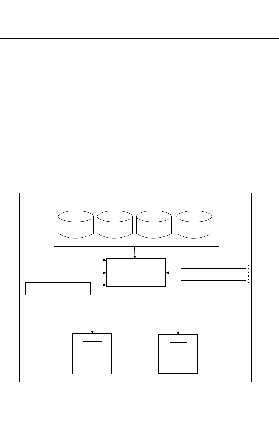
Chapter 2: Running StarRC
StarRC Overview 2-2
StarRC User Guide and Command Reference F-2011.06
StarRC User Guide and Command Reference Version F-2011.06
StarRC Overview
StarRC is a layout parasitic extraction tool that extracts connected databases. StarRC can
be used at any physical design cycle stage to extract accurate parasitics.
• StarRC reads Milkyway place and route, LEF/DEF, Calibre Connectivity Interface, or
Hercules connected databases directly, without external processing.
• Extracted parasitics can be written into the Synopsys centralized Milkyway database for
use by analysis and optimization tools.
Because StarRC gracefully handles designs with layout versus schematic (LVS)
violations, including opens and shorts, timing convergence can be ensured before the
physical verification cycle begins.
• StarRC SingleShot extraction flow produces several netlists for each postextraction
analysis; you only need to rerun netlisting.
Figure 2-1 illustrates the StarRC design flow.
Figure 2-1 StarRC Design Flowchart
Milkyway Milkyway
LEF/DEF
StarRC
SPICE_SUBCKT_FILE
star_cmd
MAPPING_FILE
TCAD_GRD_FILE
TIMING
SPF
SPEF
STAR
Milkyway
NOISE
COUPLING
Connected layout database
XTR
SBPF
AGF
CCI
REPORT
GDS

Chapter 2: Running StarRC
Batch Mode Operation 2-3
Chapter 2: Running StarRC
Batch Mode Operation 2-3
StarRC User Guide and Command Reference Version F-2011.06
Batch Mode Operation
You can run StarRC in batch mode by providing a command file or files on the command
line. The StarXtract command invokes StarRC and uses the following syntax:
StarXtract
[-cleanXREF][-cleanD][-cleanFS][-cleanXFS]
[-cleanTFS][-cleanN]
[-cleanX starrc_command: new_value][-cleanT][-clean]
[-gui]
[-ultra | -custom]
[-cdnlicsvr]
[-tech_out]
[-v]
[-h]
[-iapinetmap]
[-iapixindump]
[-pio]
[-skip]
star_cmd_file [nets_cmd]
Argument Description
-cleanXREF Cleans xref
-cleanD Cleans all processes and minimizes the StarRC run directory size
-cleanFS Cleans field solver process
-cleanXFS Cleans extraction and field solver process
-cleanTFS Cleans translation and field solver process
-cleanN Cleans netlisting process
-cleanX Cleans extraction process
-cleanT Cleans translation process
-clean Cleans all processes
-gui Invokes StarRC GUI
-ultra Uses the STAR-RC2_ULTRA_MANAGER license key only
-custom Uses the STAR-RC2_CUSTOM_MANAGER license key only

Chapter 2: Running StarRC
Graphical User Interface 2-4
StarRC User Guide and Command Reference F-2011.06
StarRC User Guide and Command Reference Version F-2011.06
If you specify duplicate command options, options that can be specified only once are
overwritten (the last takes precedence), whereas options that can be specified more than
once are appended.
Graphical User Interface
StarRC includes an easy-to-use, interactive graphical user interface (GUI) that provides an
intuitive environment for the extraction and analysis of physical designs. Invoke the GUI with
the following command:
% StarXtract -gui
For more information about the StarRC GUI, see Chapter 10, “Graphical User Interface.”
Selective Job Processing
StarRC is designed to run sequentially through a series of independent processing
modules. This means that you can restart a job that was interrupted for some reason,
without revisiting previously completed tasks. It also gives you the ability to selectively
-cdnlicsvr Runs the Virtuoso® Integration License Server
-tech_out Displays a list of StarRC command options and their defaults, if
applicable
-v Displays the version information
-h Displays the command usage report
-iapinetmap Displays the net name/id mapping for IAPI
-iapixindump Displays the ascii xin output for IAPI
-pio Dumps the Star-DC PIO file from Milkyway
-skip Dumps the skip cells from Milkyway models
star_cmd_file Specifies the StarRC command file
nets_cmd Specifies the nets for extraction
Argument Description

Chapter 2: Running StarRC
Selective Job Processing 2-5
Chapter 2: Running StarRC
Selective Job Processing 2-5
StarRC User Guide and Command Reference Version F-2011.06
reconfigure a job without starting from scratch. Guidelines for using selective processing are
detailed in the following section. Selective processing is available both through the GUI and
with batch mode operation.
Note:
You can significantly speed up the runtime by executing StarXtract on a local hard drive.
StarXtract executes tasks in several independent stages and keeps a record after
successful completion of each stage so that results can be reused. With no command-line
options specified, StarXtract attempts to restart the job after the last stage that was
successfully completed (if applicable). If all stages have been previously completed,
StarXtract does not take any action. Command-line options let you control which stages are
executed. Any of the command-line execution options can be specified for a single
StarXtract job.
The valid -clean options for each StarXtract stage are shown in Table 2-1. For a complete list
of specifict commands and their valid -clean options, see Ta bl e B-3 on page B-20.
Table 2-1 Valid -clean Options in the StarXtract Stages
Stage
-clean
-cleanT
-cleanX
-cleanFS
-cleanTFS
-cleanXFS
-cleanN
-cleanXREF
Setup XXXXXXX
HN X
XrefHN X X
Translate X X X
XrefIDX X X
xTract XXX XX
FS X X X X
Netlist XXX(X) (X) (X) X X
(X) means the following: for EXTRACTION:FSCOMPARE
The -cleanFS, -cleanTFS, and -cleanXFS options do not perform netlisting, but
FS_EXTRACT_NETS does the netlisting with these three command-line options.

Chapter 2: Running StarRC
Distributed Processing 2-6
StarRC User Guide and Command Reference F-2011.06
StarRC User Guide and Command Reference Version F-2011.06
You should not use the -cleanXREF option when you are selecting nets by schematic name
for extraction. If the design contains symmetry, the schematic-layout mapping does not
always remain the same from run to run.
Alterations can be made to the command file to reconfigure a partially completed job. This
is especially useful if, for example, you want to extract a new netlist format from a database
that has already been extracted. To accomplish this task, first change the list of nets in the
technology file and then type the following command to produce a netlist containing the new
netlist format (without repeating the previous stages):
StarXtract -cleanN star_cmd
Note:
The rerunning of selective jobs (such as -cleanN) must be done on the same software
version and platform as the original job.
Another use of a -clean option is when you want to change the value of a certain command.
For example, if you change the COUPLE_TO_GROUND: YES command to
COUPLE_TO_GROUND: NO, this affects the extraction in the xTract and netlist stages. In this
case, specify the -cleanX command. StarRC then takes advantage of the results from the
run's previous stages and continues with the -cleanX function in the Xtract stage. The
-cleanX option refreshes the files beginning with the Xtract stage and continues refreshing
the files into the netlist stage.
The -cleanX option uses the following syntax:
StarXtract -cleanX starrc_command: new_value
Distributed Processing
Distributed processing in StarRC partitions the run, based on user input, during translation.
Each partition is spawned off to a separate CPU for extraction. After each CPU has finished
extracting its partition, StarRC integrates the results on a single CPU and generates a
netlist.
To invoke distributed processing, specify the NUM_PARTS command in the star_cmd file:
NUM_PARTS: number_of_partitions
The master CPU executes the StarXtract command, performs the initial translation, and
partitions the run as uniformly as possible among all of the available CPUs. After extraction
is finished on all CPUs, the master CPU compiles the results and generates the final netlist.
The various commands with -clean options can be executed only on the master CPU; they
cannot be issued on a slave CPU. To clean your partition stage (for example, to change the
partitions with the NUM_PARTS command), use the -cleanX command.

Chapter 2: Running StarRC
Distributed Processing 2-7
Chapter 2: Running StarRC
Distributed Processing 2-7
StarRC User Guide and Command Reference Version F-2011.06
If the master CPU fails on a -clean run, the slave CPU that picks up the incomplete job will
not run with -clean.
If one of the processing jobs terminates abnormally or crashes, the incomplete job is placed
in the task queue for completion by an active CPU, even if the failed CPU was the master
CPU. Slave CPUs check the task queue every 90 seconds, so there is a brief delay before
an idle CPU picks up an incomplete job. The extraction results are not merged until all
partitions have been processed.
Manual Submission of Distributed Processing Jobs
Distributed processing for the StarXtract command is similar to distributing processing for
the grdgenxo command; you must begin a job on a single CPU and then use a remote login
to execute jobs on other machines.
LSF System
A Load Sharing Facility (LSF) automatically distributes jobs to multiple CPUs. The
environment setup might differ between LSF clusters, but the usage should be similar to that
of the bsub command to submit jobs.
The following script example distributes a job across three CPUs:
bsub StarXtract star_cmd
bsub StarXtract star_cmd
bsub StarXtract star_cmd
Non-LSF System
If you are not using an LSF system, you must log into multiple remote machines to distribute
the extraction. On each CPU, run StarRC with the following commands:
% xterm
% cd /home/directory
% StarXtract star_cmd
% rlogin remote_machine
% cd /home/directory
% StarXtract star_cmd
You must execute the StarXtract command in the same directory for all machines.
Automatic Submission of Distributed Processing Jobs
StarRC provides automatic distributed processing job submission. You can start a single run
and let StarRC automatically submit multiple jobs according to your specifications.

Chapter 2: Running StarRC
Distributed Processing 2-8
StarRC User Guide and Command Reference F-2011.06
StarRC User Guide and Command Reference Version F-2011.06
To enable automatic job submission, use the following syntax:
STARRC_DP_STRING: job_details
STARRC_DP_STRING can be set as an environment variable or as a command in the
star_cmd file. If it is set in both places, the setting in the star_cmd file takes precedence.
You can use distributed processing in the following computing environments:
•LSF System
•Gridware System
•General Network With a List of Machines
The number of jobs to be submitted is determined by number of partitions specified by the
NUM_PARTS command.
To enable automatic distributed processing job submission, you must run the StarXtract
command with the -clean, -cleanX, -cleanT, -cleanN, -cleanD, or -cleanXREF option.
The license requirement for this feature is the same as that required by manual submission
for the same number of jobs.
When using Gridware system or the list of machines, a _starrcdp.csh shell script is written
to the current working directory and then invoked by a grid command (for a Gridware
system) or the rsh command (for a list of machines).
The executions of the distribution are reported at the beginning of the star_sum file.
LSF System
In an LSF system, you can specify STARRC_DP_STRING as
• An environment variable before launching the tool. Be sure to enclose the LSF command
in single quotes. For example,
% setenv STARRC_DP_STRING 'bsub -a amd64 -R "rusage[mem=5000]"'
• A statement in the star_cmd file. For example,
STARRC_DP_STRING: bsub -a amd64 -R "rusage[mem=5000]"
Gridware System
In a Gridware system, you can specify STARRC_DP_STRING as
• An environment variable before launching the tool. Be sure to enclose the Gridware
command in single quotes. For example,
% setenv STARRC_DP_STRING 'qsub -P bnormal -l "mem_free=1G

Chapter 2: Running StarRC
Distributed Processing 2-9
Chapter 2: Running StarRC
Distributed Processing 2-9
StarRC User Guide and Command Reference Version F-2011.06
mem_avail=1G"'
• A statement in the star_cmd file. For example,
STARRC_DP_STRING: qsub -P bnormal -l "mem_free=1G mem_avail=1G"
General Network With a List of Machines
For a general network with a list of machines, you can specify STARRC_DP_STRING as
• An environment variable before launching the tool. Be sure to enclose the list in single
quotes. For example,
% setenv STARRC_DP_STRING 'list mars jupiter uranus'
• A statement in the star_cmd file. For example,
STARRC_DP_STRING: list mars jupiter uranus
When using a general network with a list of host machines,
• Each machine must be available through a the UNIX rsh command without a password
• The list keyword can only be followed by machine names; it does not support any other
options
• If the specified number of machines does not match NUM_PARTS, the number of jobs to be
dispatched is the minimum of these two numbers
• For multicore machines, you can specify the machine name multiple times
Summary File
In previous releases, distributed processing runs were reported in the star_sum file as a
simple concatenation of summaries from each CPU.
After the distributed processing is complete, StarRC provides a distributed processing report
in the summary file. The report includes the following information:
• Stage summary – Reports run time, memory consumption, CPU or host on which the job
was executed, and job completion timestamp.
• Distributed processing summary for distributed stages – Shows the maximum and
average runtime for each CPU.
• Total runtime – Shows timestamps for the beginning and the end of the run, in addition to
the total runtime.
• Pre-extraction and post extraction times - Reports the runtime information of
pre-extraction and post-extraction stages.

Chapter 2: Running StarRC
Distributed Processing 2-10
StarRC User Guide and Command Reference F-2011.06
StarRC User Guide and Command Reference Version F-2011.06
The following example shows a summary file for a StarXtract -clean run:
Example 2-1 Summary File for a -clean Run
--------------------------------------------------------------------------------------
CPU# | STAGE SUMMARY | END TIME |HOSTNAME
--------------------------------------------------------------------------------------
CPU_01 |*Layers Elp=00:00:01 Cpu=00:00:00 Mem=48.8 | Feb 10 17:45:58 | yak068
CPU_01 |*Models Elp=00:00:00 Cpu=00:00:00 Mem=45.7 | Feb 10 17:46:00 | yak068
CPU_01 |*HN Elp=00:01:05 Cpu=00:00:13 Mem=124.7 | Feb 10 17:47:11 | yak068
CPU_01 |*Cells Elp=00:00:37 Cpu=00:00:02 Mem=121.2 | Feb 10 17:47:50 | yak068
CPU_01 |*Translate Elp=00:01:25 Cpu=00:00:41 Mem=231.2 | Feb 10 17:49:19 | yak068
CPU_01 |*NetlistSetup Elp=00:00:00 Cpu=00:00:00 Mem=45.6 | Feb 10 17:49:23 | yak068
CPU_01 |*Partition Elp=00:00:21 Cpu=00:00:15 Mem=49.1 | Feb 10 17:49:49 | yak068
CPU_01 |*Sort_part1 Elp=00:00:05 Cpu=00:00:04 Mem=104.8 | Feb 10 17:49:59 | yak068
CPU_04 |*Sort_part2 Elp=00:00:04 Cpu=00:00:03 Mem=103.7 | Feb 10 17:50:01 | cow135
CPU_02 |*Sort_part3 Elp=00:00:05 Cpu=00:00:03 Mem=103.3 | Feb 10 17:50:06 | cow118
CPU_03 |*Sort_part4 Elp=00:00:04 Cpu=00:00:03 Mem=106.0 | Feb 10 17:50:08 | cow158
CPU_03 |*xTract_part4 Elp=00:05:21 Cpu=00:05:18 Mem=498.5 | Feb 10 17:55:35 | cow158
CPU_01 |*xTract_part1 Elp=00:05:40 Cpu=00:05:36 Mem=463.6 | Feb 10 17:55:41 | yak068
CPU_04 |*xTract_part2 Elp=00:06:26 Cpu=00:06:22 Mem=486.5 | Feb 10 17:56:27 | cow135
CPU_02 |*xTract_part3 Elp=00:06:19 Cpu=00:06:13 Mem=467.2 | Feb 10 17:56:34 | cow118
CPU_01 |*xTractPP Elp=00:00:29 Cpu=00:00:19 Mem=114.1 | Feb 10 17:57:08 | yak068
CPU_02 |*Netlist_part4 Elp=00:00:16 Cpu=00:00:13 Mem=398.1 | Feb 10 17:57:39 | cow118
CPU_01 |*Netlist_part1 Elp=00:00:43 Cpu=00:00:36 Mem=349.6 | Feb 10 17:57:58 | yak068
CPU_04 |*Netlist_part2 Elp=00:00:45 Cpu=00:00:42 Mem=504.9 | Feb 10 17:58:02 | cow135
CPU_03 |*Netlist_part3 Elp=00:00:42 Cpu=00:00:40 Mem=507.7 | Feb 10 17:58:04 | cow158
CPU_01 |*Netlist_merge Elp=00:00:10 Cpu=00:00:00 Mem=28.3 | Feb 10 17:58:17 | yak068
--------------------------------------------------------------------------------------
Maximum and average run time (Elp) for distributed stages:
Sort max=00:00:05 avg=00:00:04
xTract max=00:06:26 avg=00:05:56
Netlist max=00:00:45 avg=00:00:36
--------------------------------------------------------------------------------------
Start Time: Thu Feb 10 17:45:56 2011
End Time: Thu Feb 10 17:58:28 2011
Total Wall Time: 00:12:32
Time on PreXtraction: 00:04:05
Time on Xtraction: 00:06:35
Time on PostXtraction: 00:01:52
--------------------------------------------------------------------------------------
The following example shows a summary file for a StarXtract –cleanN run:
Example 2-2 Summary File for a -cleanN Run
--------------------------------------------------------------------------------------
CPU# | STAGE SUMMARY | END TIME |HOSTNAME
--------------------------------------------------------------------------------------
CPU_01 |*NetlistSetup Elp=00:00:00 Cpu=00:00:00 Mem=45.6 | Feb 11 14:36:43 | yak048
CPU_01 |*xTractPP Elp=00:00:22 Cpu=00:00:17 Mem=114.1 | Feb 11 14:37:14 | yak048
CPU_04 |*Netlist_part4 Elp=00:00:12 Cpu=00:00:10 Mem=398.1 | Feb 11 14:37:37 | dog124
CPU_01 |*Netlist_part1 Elp=00:00:32 Cpu=00:00:29 Mem=349.6 | Feb 11 14:37:49 | yak048
CPU_03 |*Netlist_part3 Elp=00:00:31 Cpu=00:00:29 Mem=507.7 | Feb 11 14:37:55 | yak726
CPU_02 |*Netlist_part2 Elp=00:00:36 Cpu=00:00:34 Mem=504.9 | Feb 11 14:37:58 | dog131
CPU_01 |*Netlist_merge Elp=00:00:05 Cpu=00:00:00 Mem=28.3 | Feb 11 14:38:06 | yak048
--------------------------------------------------------------------------------------
Maximum and average run time (Elp) for distributed stages:
Netlist max=00:00:36 avg=00:00:27

Chapter 2: Running StarRC
StarRC Licensing Features 2-11
Chapter 2: Running StarRC
StarRC Licensing Features 2-11
StarRC User Guide and Command Reference Version F-2011.06
--------------------------------------------------------------------------------------
Start Time: Fri Feb 11 14:36:40 2011
End Time: Fri Feb 11 14:38:16 2011
Total Wall Time: 00:01:36
Time on PreXtraction: 00:00:08
Time on Xtraction: 00:00:03
Time on PostXtraction: 00:01:25
--------------------------------------------------------------------------------------
Performance Optimization
To optimize performance, ensure that the STAR_DIRECTORY directory is located on the
machine that executes the first StarXtract command. Running the translation across a
network drastically increases the runtime.
You should also keep the number of CPUs equal to the number of partitions, as specified by
theNUM_PARTS command. Failing to do so might result in an inefficient use of computing
resources; if the number of jobs exceeds the number of partitions, the extra jobs would not
run.
Licensing Requirements for Distributed Processing
You must have a StarRC or StarRC Ultra license to run distributed multicore processing; the
StarRC Custom package supports only single-core processing.
StarRC Licensing Features
The StarXtract command has two options related to licensing:
• The -custom option is designed for customers who have only one Custom license in their
license server. This option supports only the StarRC Custom features specified in
Table B-2 on page B-11. With this option, multicore processing and upper-tier commands
are not allowed.
• The -ultra option allows you to check out only an Ultra license key. By specifying this
option, you can indicate a preference to wait until an Ultra license is available, rather than
needing to checking out two StarRC licenses or four Custom licenses.
Tiered Licensing Checkout Policy
When all three types of license keys are available in your license pool, multiple lower-tier
keys can be used to run upper-tier features, as detailed in Figure 2-2. For example, two
StarRC keys or four Custom license keys can run a job with an Ultra feature. Similarly, two
Custom license keys can run one job with a StarRC feature.
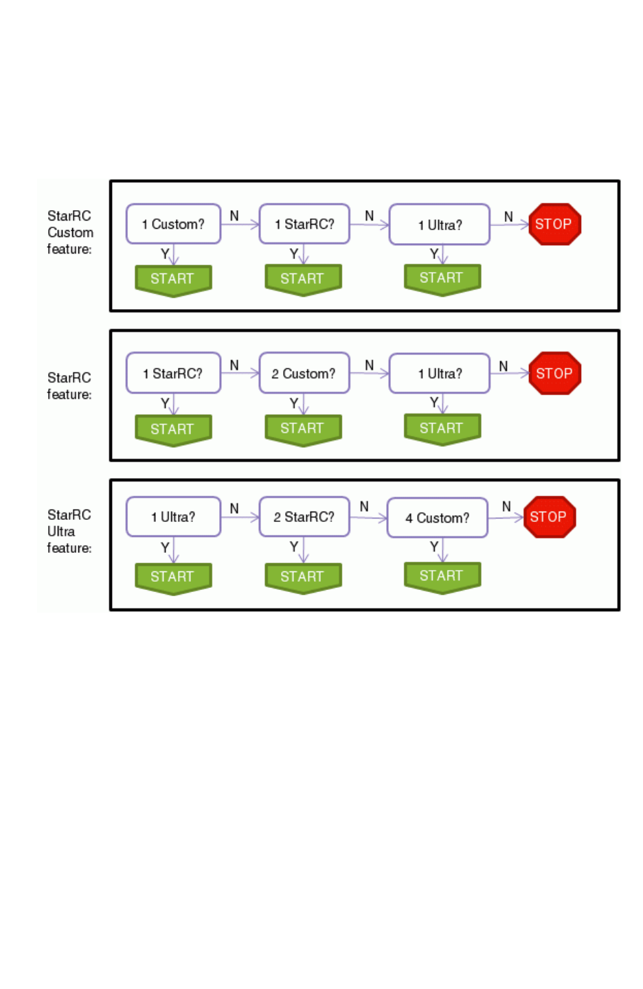
Chapter 2: Running StarRC
StarRC Licensing Features 2-12
StarRC User Guide and Command Reference F-2011.06
StarRC User Guide and Command Reference Version F-2011.06
However, if the -custom option is specified, then StarRC runs only with an available Custom
license. Similarly, if the -ultra option is specified, then StarRC runs only with an available
Ultra license.
Figure 2-2 Tiered Licensing Checkout Policy Without License Queuing
License Queuing Not Enabled
License queuing is not enabled when the UNIX environment variable
STARRC_LICENSE_WAIT is not set to YES. As shown in Figure 2-2, StarRC does not run when
the appropriate licenses are not available and license queuing is disabled.
License Queuing Enabled
To queue a StarRC job when the appropriate licenses are not available, you can enable
license queuing by activating the UNIX environment variable STARRC_LICENSE_WAIT as
follows:
$ setenv STARRC_LICENSE_WAIT yes
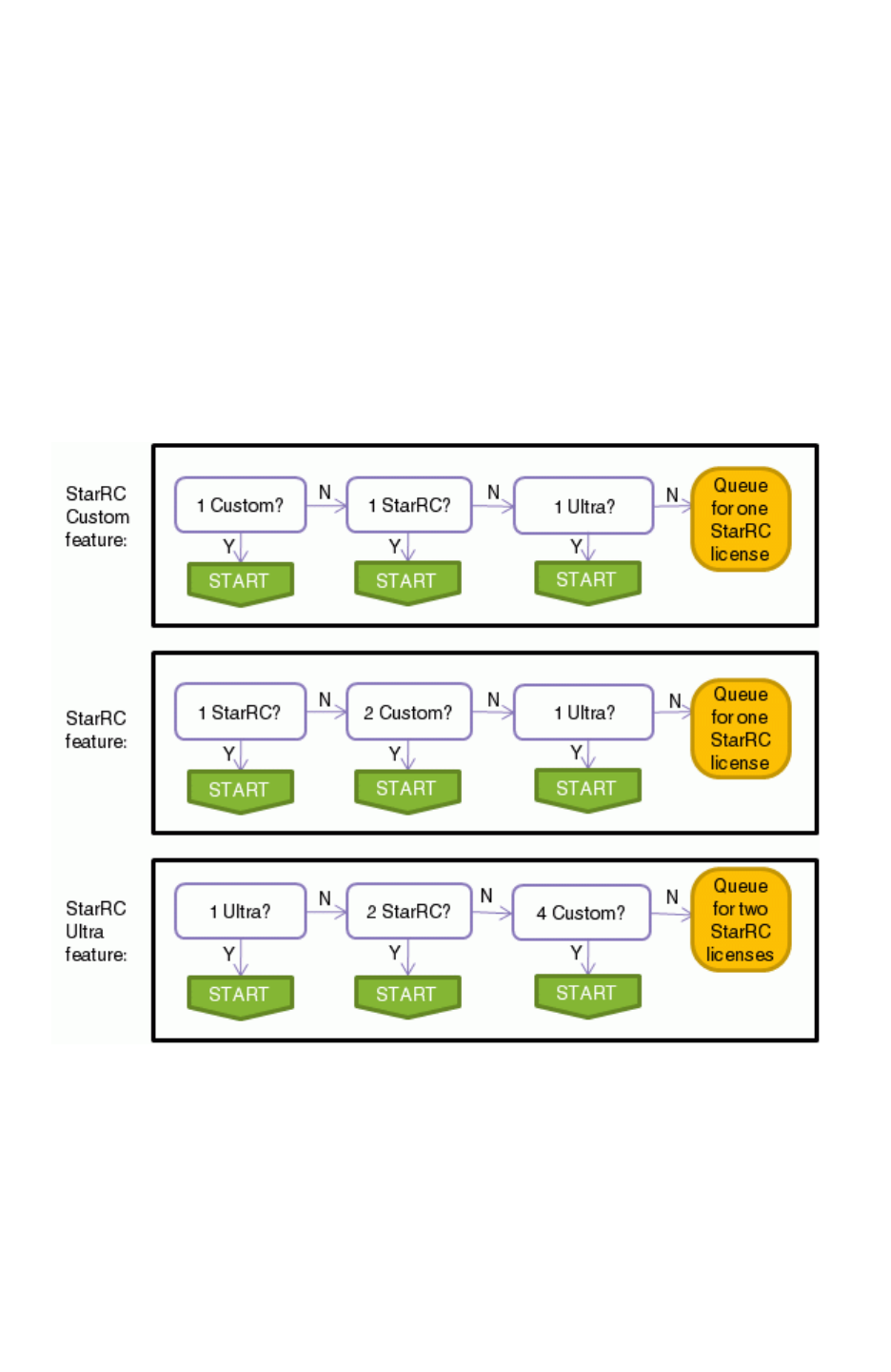
Chapter 2: Running StarRC
StarRC Licensing Features 2-13
Chapter 2: Running StarRC
StarRC Licensing Features 2-13
StarRC User Guide and Command Reference Version F-2011.06
Figure 2-3 shows the tiered licensing checkout procedure with license queuing. When the
appropriate licenses are not available, then StarRC queues the job according to the
StarXtract command options and the features that are used:
• If the -custom option is specified in the command line, then the job queues for one
Custom license.
• If the -ultra option is specified in the command line, then the job queues for one Ultra
license.
• If neither option is specified, but the job uses an Ultra feature, then the job queues for two
StarRC licenses; if no Ultra feature is used, then the job queues for one StarRC license.
Figure 2-3 Tiered Licensing Checkout Policy With License Queuing
License Queuing Daemon
To use StarRC license queuing, specify the license server as
/full/path/to/license/file or port@host. Download and install the 10.9.2 (or higher)
version of the snpslmd combined vendor daemon.

Chapter 2: Running StarRC
StarRC Command File Conventions 2-14
StarRC User Guide and Command Reference F-2011.06
StarRC User Guide and Command Reference Version F-2011.06
StarRC Command File Conventions
All StarRC command options fall into one of nine specification categories. Each category
has a fixed structure that is interpreted consistently by all StarRC modules. Table 2-2 lists
the command types, including a brief description of the input format. Throughout the
remainder of this manual, all command definitions refer to one of these types.
File and directory paths can be specified as either absolute or relative paths in both the GUI
and the batch command file; however, relative paths are always resolved with respect to the
StarRC working directory (not the location of the command file itself). An exception is that
STAR_DIRECTORY cannot be specified with an absolute path.
Use an asterisk (*) at the beginning of a line to indicate a comment.
StarRC command options are not case-sensitive. In batch mode, command options should
be listed in the command file in the following format: command: value
Table 2-2 Command Types
Type Description Multi Format Example
BOOLEAN Simple Boolean flag. NO command: YES | NO CASE_SENSITIVE: YES
DIRECTORY Valid directory name
with full or relative
path. Symbolic links
are acceptable.
NO command:
directory_name
MILKYWAY_DATABASE: design
FILE Valid file name with full
or relative path,
symbolic links are
acceptable.
NO command: file_name NETLIST_FILE: ../star.spf
FILE LIST List of valid file names
with full or relative
paths delimited by
white spaces.
Symbolic links are
acceptable.
YES command: file_name
... file_name
LEF_FILE: tech.lef ../
macroA.lef
FLOAT Floating-point number
can be expressed
exponentially or with
character suffix to
define unit. Must not
contain white space.
NO command:
float[a|f|p|u|n|m|K|
Meg|Gig]
FSCOMPARE_THRESHOLD: 1e-15
CLOCK_SIMULATION_TIME: 200n
INT Integer. NO command: integer NELIST_MAX_LINE: 80

Chapter 2: Running StarRC
StarRC Command File Conventions 2-15
Chapter 2: Running StarRC
StarRC Command File Conventions 2-15
StarRC User Guide and Command Reference Version F-2011.06
LINE String that can contain
white space. Only one
string per line is
allowed.
YES command: sentence
command: sentence
NET_VOLTAGE: vdd 2.5
NET_VOLTAGE: vss 0.0
LIST White space delimited
list of strings.
YES command: string ...
string
NETS: net1 net2 net3
STRING Single word that must
not contain white
space.
NO command: string BLOCK: top
Table 2-2 Command Types (Continued)
Type Description Multi Format Example

Chapter 2: Running StarRC
StarRC Command File Conventions 2-16
StarRC User Guide and Command Reference F-2011.06
StarRC User Guide and Command Reference Version F-2011.06

3-1
3
Process Characterization Interface 3
This chapter describes how you or your foundry defines the foundry process used to
manufacture your design. It involves writing a description of the technology process cross
section in an Interconnect Technology Format (ITF) file.
This chapter contains the following sections:
•Process Characterization Basics
•The Interconnect Technology Format File
•Creating the ITF File
•Process Effects That Affect Resistance and Capacitance
•Defining Additional Extraction Characteristics
•Defining Sheet Zones
•Modeling Thickness Variation With StarRC
•Interconnect Parasitics Extraction Based on CMP Simulators
•Microloading Effect
•Damage Modeling
•Translation of Routing DEF Blockage
•Temperature Derating

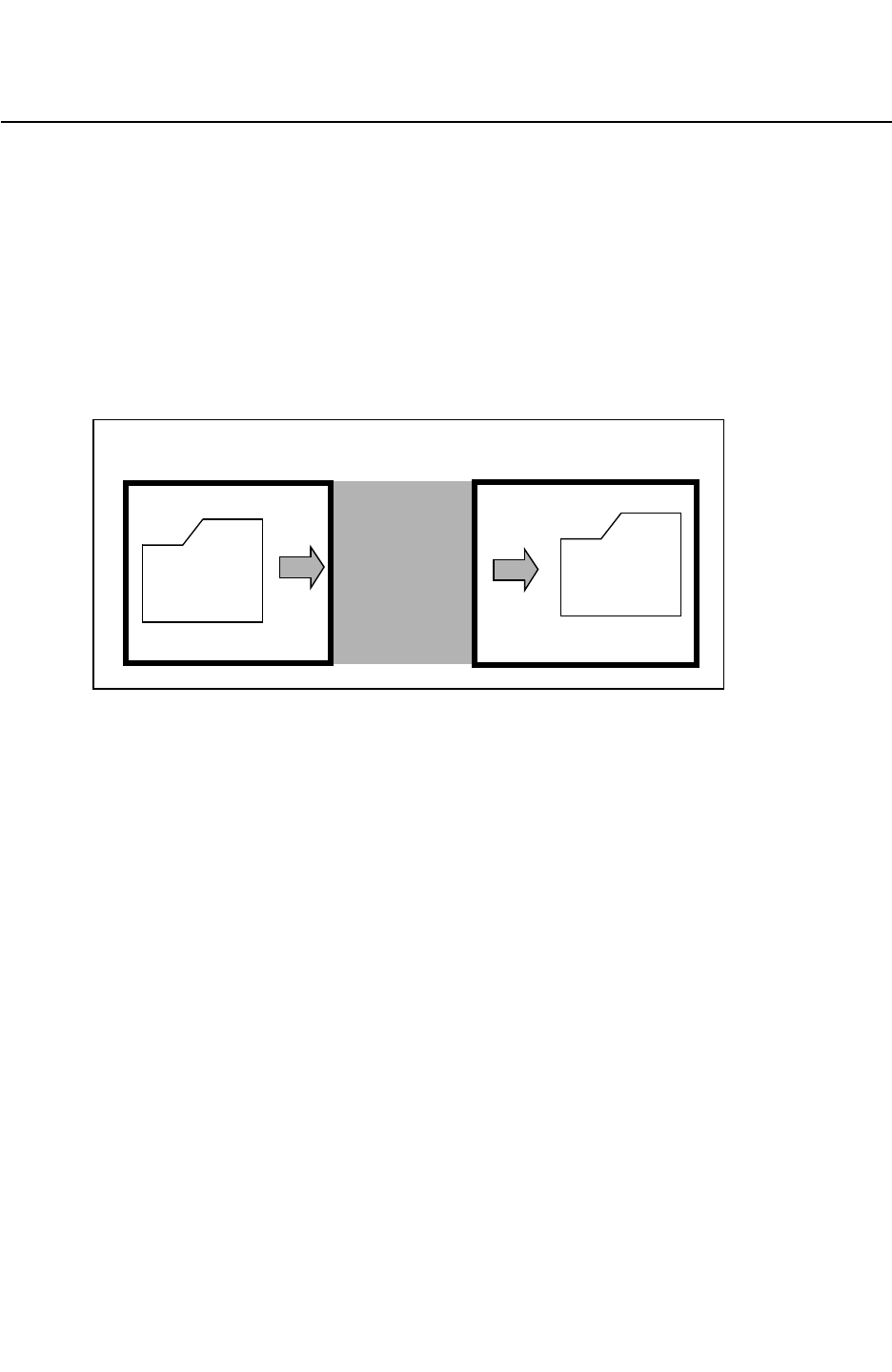
Chapter 3: Process Characterization Interface
Process Characterization Basics 3-3
Chapter 3: Process Characterization Interface
Process Characterization Basics 3-3
StarRC User Guide and Command Reference Version F-2011.06
Process Characterization Basics
Process characterization is composed of those steps you take to define the chip’s physical
layer composition, before you run the grdgenxo command to generate the nxtgrd database.
See Figure 3-1. To begin the process characterization, specify the content of each layer in
an Interconnect Technology Format (ITF) file. Normally, you need to define only one ITF file
for each process technology you plan to extract.
The ITF file consolidates all process information into one source file.
Figure 3-1 ITF File Generation
ITF
FILE
grdgenxo nxtgrd
database
User-created ITF Executable
command output database
Process characterization
The nxtgrd File
The nxtgrd (New Xtraction Generic Regression Database) output file is a database
containing capacitance, resistance, and layer information, which can be encrypted. The ITF
file is also included in the database output file. An internal field solver operating on an
extensive set of primitive structures generates the nxtgrd file. StarRC uses the nxtgrd file to
calculate the parasitics of the actual layout by pattern matching.
You can encrypt the ITF file copy, located at the top of the binary capacitance tables in the
nxtgrd file, by using the -encrypt option of the grdgenxo command:
% grdgenxo -encrypt itf_file
For more information about the grdgenxo command, see Chapter 19, “The grdgenxo
Command.” For details about StarRC compatibility with nxtgrd files generated by earlier
versions of StarRC, see the StarRC Release Notes.

Chapter 3: Process Characterization Interface
The Interconnect Technology Format File 3-4
StarRC User Guide and Command Reference F-2011.06
StarRC User Guide and Command Reference Version F-2011.06
The Interconnect Technology Format File
The ITF file defines a cross section profile of the process. This is an ordered list of conductor
and dielectric layer definition statements. The layers are defined from the topmost dielectric
layer, to the bottommost dielectric layer, excluding substrate. As you read the text of the ITF
file, the layers are defined in the same order in which you would see them in a cross section
view of the process. The ITF cross section layer spatial parameters are specified layer by
layer in a way that is consistent with the physical process.
The lowest layer in the ITF cross section should always be a DIELECTRIC layer. SUBSTRATE
is a reserved keyword and refers to a special conductor whose top plane is at 0 height; it is
assumed to be underneath the lowest defined dielectric. You do not define SUBSTRATE in the
ITF file.
Statements defining via layers follow the process cross section and are defined only relative
to valid conducting layers.
The heights of the conductors and dielectrics are determined exclusively by the order in
which they are specified and by the thicknesses of the lower layers. When you are specifying
a new conductor or dielectric layer, the bottom plane of that layer is exactly the top plane of
the lowest dielectric layer unless a MEASURED_FROM statement is included to explicitly specify
the location of the bottom plane. The lowest dielectric—the lowest physical layer—listed in
the ITF file is automatically measured from the SUBSTRATE layer. A fully planar process, in
which the process cross section does not contain any vertically intersecting conductors at
different heights, is the simplest model. You can find cross section ITF examples in
Appendix A, “ITF Examples.”
Creating the ITF File
To manually create a basic ITF file, follow these steps:
1. Define the TECHNOLOGY statement.
TECHNOLOGY = process_name
The TECHNOLOGY statement is mandatory. You assign process_name as the value
assigned to the TECHNOLOGY statement. The TECHNOLOGY statement should precede all
other statements, but it does not have to be the first line. The output of the grdgenxo
command is stored in the process_name.nxtgrd file.
The TECHNOLOGY statement provides a way of naming a process for tracking and
identification purposes; the statement can be any single word.

Chapter 3: Process Characterization Interface
Creating the ITF File 3-5
Chapter 3: Process Characterization Interface
Creating the ITF File 3-5
StarRC User Guide and Command Reference Version F-2011.06
2. A background dielectric can be specified after the TECHNOLOGY statement, although it is
not required. A background dielectric globally fills the cross section with material of the
given dielectric constant to an infinite height. DIELECTRIC commands specified in the ITF
process cross section locally override the global background dielectric. The default for the
background dielectric is 1.0, or air.
BACKGROUND_ER = float
Note:
This constant background dielectric extends to an infinite height, so it effectively
replaces air as the operating medium for the chip.
3. After defining the TECHNOLOGY statement (or background dielectric definition), define the
following basic layer characteristics and information for all the CONDUCTOR and
DIELECTRIC layers.
ITF layer naming restrictions for CONDUCTOR, DIELECTRIC, and VIA statements are as
follows:
• Layer names must contain only alphanumeric characters and underscores (_).
• Layer names must begin with an alphabetic character.
The following are layer characteristics to be defined:
• Thickness of each CONDUCTOR or DIELECTRIC
• Minimum width and spacing of each CONDUCTOR (design rule spacing)
• Resistivity information of each CONDUCTOR
• Permittivity of each DIELECTRIC
• Resistivity information of each VIA
• Connectivity information of each VIA
4. After you have defined these basic ITF requirements, you can add more definitions to
model other processes.
The following are additional definitions you can use to model other processes:
• Conformal dielectrics
• Vertically overlapping conductors (local interconnect)
• Width-and-spacing-dependent resistance
• Temperature-dependent resistance
• Process-variation-dependent resistance
• Layer-specific or width and spacing etch effects

Chapter 3: Process Characterization Interface
Process Effects That Affect Resistance and Capacitance 3-6
StarRC User Guide and Command Reference F-2011.06
StarRC User Guide and Command Reference Version F-2011.06
• Dielectric air gaps
• Metal fill
• Thickness variation based on local density
5. Add other statements between the TECHNOLOGY statement and the layer definitions.
Other statements might be BACKGROUND_ER or GLOBAL_TEMPERATURE.
The following example shows a basic ITF file:
TECHNOLOGY = SIMPLE
DIELECTRIC TOP { THICKNESS = 3.600 ER = 3.9 }
CONDUCTOR M2 {
THICKNESS = 0.250 WMIN = 0.5
SMIN = 0.5 RPSQ = 0.05 }
DIELECTRIC D3 { THICKNESS = 0.300 ER = 3.9 }
CONDUCTOR M1 {
THICKNESS = 0.212 WMIN = 0.5
SMIN = 0.5 RPSQ = 0.05 }
DIELECTRIC D2 { THICKNESS = 0.200 ER = 4.2 }
CONDUCTOR POLY{
THICKNESS = 0.100 WMIN = 0.3
SMIN = 0.3 RPSQ = 10.0}
DIELECTRIC D1 { THICKNESS = 0.300 ER = 3.9 }
VIA via1 { FROM=M1 TO=M2 RHO=0.263 }
VIA polyCont { FROM=POLY TO=M1 RHO=0.352 }
VIA diffCont { FROM=SUBSTRATE TO=M1 RHO=0.500 }
Process Effects That Affect Resistance and Capacitance
The process effects specified in the ITF that can affect resistance are RPSQ,
RPSQ_VS_SI_WIDTH, and RPSQ_VS_WIDTH_AND_SPACING.
The following options affect resistance or capacitance, depending on whether you specify
the RESISTIVE_ONLY option:
THICHKNESS_VS_DENSITY (affects resistance and capacitance)
THICKNESS_VS_WIDTH_AND_SPACING (affects resistance and capacitance)
ETCH (affects resistance and capacitance)
ETCH_VS_WIDTH_AND_SPACING (affects resistance and capacitance)
The following two options affect both resistance and capacitance:
POLYNOMIAL_BASED_THICKNESS_VARIATION
BOTTOM_THICKNESS_VS_SI_WIDTH
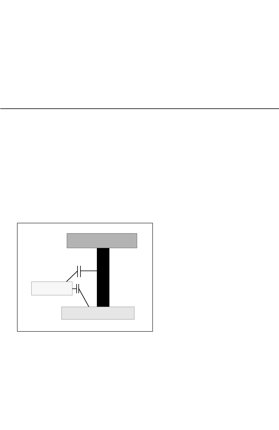
Chapter 3: Process Characterization Interface
Gate-To-Diffusion Capacitance Extraction Based on Capacitance Tables 3-7
Chapter 3: Process Characterization Interface
Gate-To-Diffusion Capacitance Extraction Based on Capacitance Tables 3-7
StarRC User Guide and Command Reference Version F-2011.06
The following two options affect only resistance:
CRT
CRT_VS_SI_WIDTH
Note:
The SIDE_TANGENT option does not change the resistance as the CENTER WIDTH of the
conductor does not change and the resistance depends on that center width.
Gate-To-Diffusion Capacitance Extraction Based on Capacitance
Tables
In UDSM design flows, a seamless interface between parasitic extraction and circuit
simulation tools (for example, StarRC and HSPICE™) is crucial for accurate circuit behavior
predictability in silicon. The pieces from extraction (for example, parasitics) and simulation
(for example, SPICE models) must integrate tightly to avoid double counting or the
elimination of critical layout dependent device parasitics, such as gate-to-contact and
gate-to-diffusion capacitance as shown in Figure 3-2. As process nodes continue to shrink,
it is common practice to remove the constant, spatially independent, device-level parasitics
from SPICE models and expect parasitic tools such as StarRC to extract these critical
components.
Figure 3-2 Layout Dependent Parasitics
M1
DIFF
GATE
This section describes the ability to extract the gate-to-diffusion capacitance component
only when the IGNORE_CAPACITANCE:ALL setting is specified. The gate-to-diffusion intra
device capacitance is of interest for parasitic extraction tools because of the strong layout
dependency of this capacitance component. The gate-to-contact capacitance is extracted
using the EXTRACT_VIA_CAPS:YES command in the StarRC command file.

Chapter 3: Process Characterization Interface
Device-Specific Contact Etch 3-8
StarRC User Guide and Command Reference F-2011.06
StarRC User Guide and Command Reference Version F-2011.06
To retain the gate-to-diffusion (Cf) coupling component when IGNORE_CAPACITANCE: ALL is
specified during a StarRC parasitic extraction, use the following command:
IGNORE_CAPACITANCE:ALL RETAIN_GATE_TO_DIFFUSION_COUPLING
For IGNORE_CAPACITANCE settings other than ALL (DIFF, NONE) in which the
gate-to-diffusion capacitance is retained by default, StarRC extracts this component as
requested.
When you specify this option, StarRC uses the following methods to extract the
gate-to-diffusion component:
• Based on precharacterized models, similar to other capacitances extracted by StarRC
• Based on a 2-D capacitance table look-up dependent on layout parameters
See also GATE_TO_DIFFUSION_CAP and IGNORE_CAPACITANCE.
Device-Specific Contact Etch
StarRC allows you to apply different contact etch values based on the device type. Use the
following syntax to specify multiple contact-bias tables within the VIA statement:
ETCH_VS_CONTACT_AND_GATE_SPACINGS CAPACITIVE_ONLY {
NUMBER_OF_TABLES = num_of_tables
name_of_table1 {
CONTACT_TO_CONTACT_SPACING { c1 c2 c3 ... }
GATE_TO_CONTACT_SPACING { s1 s2 s3 ... }
VALUES { v(c1,s1) v(c2,s1) ...
v(c1,s2) v(c2,s2) ...
...
}
name_of_table2 {
CONTACT_TO_CONTACT_SPACING { c1 c2 c3 ... }
GATE_TO_CONTACT_SPACING { s1 s2 s3 ... }
VALUES { v(c1,s1) v(c2,s1) ...
v(c1,s2) v(c2,s2) ...
...
}
...
}
Note:
You must specify NUMBER_OF_TABLES to define multiple contact etch tables in the ITF.
Specify the values for CONTACT_TO_CONTACT_SPACING, GATE_TO_CONTACT_SPACING,
and VALUES microns.
Example 3-1 shows a VIA statement with multiple contact etch tables.

Chapter 3: Process Characterization Interface
Device-Dependent Gate-to-Diffusion Capacitance Table 3-9
Chapter 3: Process Characterization Interface
Device-Dependent Gate-to-Diffusion Capacitance Table 3-9
StarRC User Guide and Command Reference Version F-2011.06
Example 3-1 VIA Statement With Multiple Contact Etch Tables
VIA diffCont {
FROM=diff TO=metal1
AREA=0.0036 RPV=55
CRT1=9.56e-04 CRT2=-3.68e-07
ETCH_VS_CONTACT_AND_GATE_SPACINGS CAPACITIVE_ONLY {
NUMBER_OF_TABLES=2
NMOS {
CONTACT_TO_CONTACT_SPACINGS {0.08 0.12}
GATE_TO_CONTACT_SPACINGS {0.04 0.08}
VALUES {0.008 0.009
0.003 0.005}
}
PMOS {
CONTACT_TO_CONTACT_SPACINGS {0.08 0.12}
GATE_TO_CONTACT_SPACINGS {0.04}
VALUES {0.004 0.002}
}
}
}
Device-Dependent Gate-to-Diffusion Capacitance Table
You can specify a Cf table based on the device type. The following syntax defines multiple
gate-to-diffusion capacitance tables in the ITF. Note that the number of tables and the table
name must be specified when multiple gate-to-diffusion tables are specified in the ITF.
GATE_TO_DIFFUSION_CAP {
NUMBER_OF_TABLES = num_of_tables
model_name1{
CONTACT_TO_CONTACT_SPACINGS {c1 c2 c3 ...}
GATE_TO_CONTACT_SPACINGS {s1 s2 s3 ...}
CAPS_PER_MICRON { v(c1,s1) v(c2,s1)...
v(c1,s2) v(c2,s2)... }
}
model_name2{
CONTACT_TO_CONTACT_SPACINGS {c1 c2 c3 ...}
GATE_TO_CONTACT_SPACINGS {s1 s2 s3 ...}
CAPS_PER_MICRON { v(c1,s1) v(c2,s1)...
v(c1,s2) v(c2,s2)... }
}
...
}
A contact etch table and a gate-to-diffusion capacitance table for the same type of device
should have the same table names, as shown in Example 3-2.

Chapter 3: Process Characterization Interface
Defining Additional Extraction Characteristics 3-10
StarRC User Guide and Command Reference F-2011.06
StarRC User Guide and Command Reference Version F-2011.06
Example 3-2 Multiple Gate-to-Diffusion Capacitance Tables in a CONDUCTOR Statement
CONDUCTOR gpoly {
THICKNESS= 0.080000 WMIN= 0.040 SMIN= 0.100 RPSQ=12.000
GATE_TO_CONTACT_SMIN=0.040 CRT1=1.924e-03 CRT2=-8.751e-07
GATE_TO_DIFFUSION_CAP {
NUMBER_OF_TABLES=2
NMOS{
CONTACT_TO_CONTACT_SPACINGS {0.08 0.12}
GATE_TO_CONTACT_SPACINGS {0.04 0.08}
CAPS_PER_MICRON {0.062 0.088
0.080 0.096}
}
PMOS{
CONTACT_TO_CONTACT_SPACINGS {0.08 0.12}
GATE_TO_CONTACT_SPACINGS {0.04 0.08}
CAPS_PER_MICRON {0.088 0.120
0.108 0.128}
}
}
}
Defining Additional Extraction Characteristics
To perform more extensive extraction tasks, you can add these characteristics to the ITF:
• Conformal dielectrics
• Vertical overlapping
• Width-dependent conductor resistance
• Layer-specific etch effects
• Dielectric air gaps
• Metal fill
• 45-degree angles
• Diffusion resistance extraction
Handling Special Process Effects
Certain effects require special processing while running StarRC.
•Conformal Dielectrics
•Conductor Cutting Dielectric

Chapter 3: Process Characterization Interface
Defining Additional Extraction Characteristics 3-11
Chapter 3: Process Characterization Interface
Defining Additional Extraction Characteristics 3-11
StarRC User Guide and Command Reference Version F-2011.06
•Covertical Conductors
•Drop Factor
•Dielectric Air Gaps
•Layer Etch
•Metal Fill (Emulated)
•45-Degree Angles
•Diffusion Resistance Extraction
•Spacing- and Width-Dependent Etch
•CAPACITIVE_ONLY and RESISTIVE_ONLY
•Determining WMIN and SMIN Values
•Retaining Coupling Capacitance Between Top and SKIP_CELL Levels
•Handling Overlapping Wells
The ways in which you can handle these are discussed in the following sections.
Conformal Dielectrics
The MEASURED_FROM statement provides the ability to customize the model to account for
such process characteristics as conformal dielectrics, mixed conformal and planar
dielectrics, and covertical conductors. When used with a DIELECTRIC layer definition, the
MEASURED_FROM keyword can refer to a lower dielectric or can have the value TOP_OF_CHIP.
When used with a CONDUCTOR layer definition, the MEASURED_FROM keyword can refer only to
a lower PLANAR dielectric. See specific examples in Appendix A, “ITF Examples.”
The TOP_OF_CHIP keyword value facilitates the creation of conformal dielectrics. It creates
the bottom plane from the layers already present below the new layer and mimics the
topology of the existing base (copies any existing nonplanarities to the new layer, which has
a conformal thickness).
The TOP_OF_CHIP keyword value is required only if you are creating a conformal layer
whose topology is based on the top of the chip. If you want to create a conformal layer that
is on top of an existing conformal dielectric, you can measure either from TOP_OF_CHIP or
the existing conformal layer.
Note:
A MEASURED_FROM statement in CONDUCTOR definitions must always refer to a planar
dielectric.

Chapter 3: Process Characterization Interface
Defining Additional Extraction Characteristics 3-12
StarRC User Guide and Command Reference F-2011.06
StarRC User Guide and Command Reference Version F-2011.06
Note that if you create a layer (defined in a MEASURED_FROM command) referring to a planar
layer, the new layer is also planar, regardless of whether or not you define TW_T and SW_T.
To regain layer planarity after a conformal dielectric has been defined, you need to take the
following steps when defining the new planarized layer:
1. Use the MEASURED_FROM statement to reference a planar dielectric somewhere lower in
the process cross section.
2. Adjust the thickness for the new layer so it is equal to its actual physical thickness plus
the thickness of any layer on top of the MEASURED_FROM layer.
If you place another dielectric layer on top of the conformal layer without using
MEASURED_FROM to regain planarity, use SW_T and TW_T to set the sidewall and top wall
thickness because the new layer is also conformal.
Conductor Cutting Dielectric
If you use the MEASURED_FROM statement with a conductor and that conductor layer is
measured from a dielectric layer that is placed below another dielectric layer, the conductor
might cut through the intermediate dielectric.
Consider the following example:
TECHNOLOGY = SIMPLE
DIELECTRIC TOP { THICKNESS = 3.600 ER = 3.9 }
CONDUCTOR M1 { THICKNESS = 0.600 WMIN = 0.5
SMIN = 0.5 RPSQ = 0.05 }
DIELECTRIC D3 { THICKNESS = 0.300 ER = 3.9 }
CONDUCTOR POLY{ THICKNESS = 0.200 WMIN = 0.3
SMIN = 0.3 RPSQ = 10.0
MEASURED_FROM = D1 }
DIELECTRIC D2 { THICKNESS = 0.100 ER = 4.2 }
DIELECTRIC D1 { THICKNESS = 0.300 ER = 3.9 }
The process cross section is shown in Figure 3-3, where POLY cuts through dielectric D2.
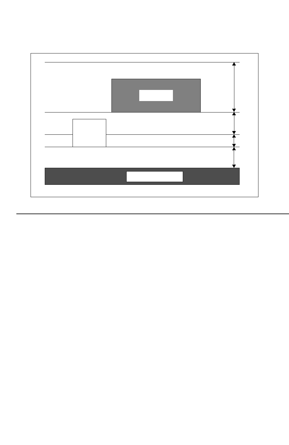
Chapter 3: Process Characterization Interface
Defining Additional Extraction Characteristics 3-13
Chapter 3: Process Characterization Interface
Defining Additional Extraction Characteristics 3-13
StarRC User Guide and Command Reference Version F-2011.06
Figure 3-3 Conductor Cuts an Intermediate Dielectric
POLY
D 1
D 2
D 3 0.2
0.1
0.3
M 1
TOP
3.6
SUBSTRATE
Covertical Conductors
StarRC supports covertical (vertically overlapping) conductors. See example file information
about gate poly and local interconnect processes in Appendix A, “ITF Examples.” The
examples illustrate the ITF handling of covertical conductors that might have unique
thicknesses, as in the case of local poly interconnect.
In this case, the layout database should be modified for the covertical layers, so that those
layers (Gate and Field Poly or Poly and Local Interconnect) do not overlap each other. This
can be done in the Hercules runset by use of BOOLEAN operations:
BOOLEAN POLY NOT LI {} TEMP=POLY
or
BOOLEAN POLY AND LI {} TEMP=LI_OVERLAP
BOOLEAN POLY NOT LI_OVERLAP {} TEMP=POLY
BOOLEAN LI NOT LI_OVERLAP {} TEMP=LI
In the latter case, both LI and LI_OVERLAP are mapped to the Local Interconnect layer in the
nxtgrd file, and the CONNECT sequence in the Hercules runset should be modified
accordingly.
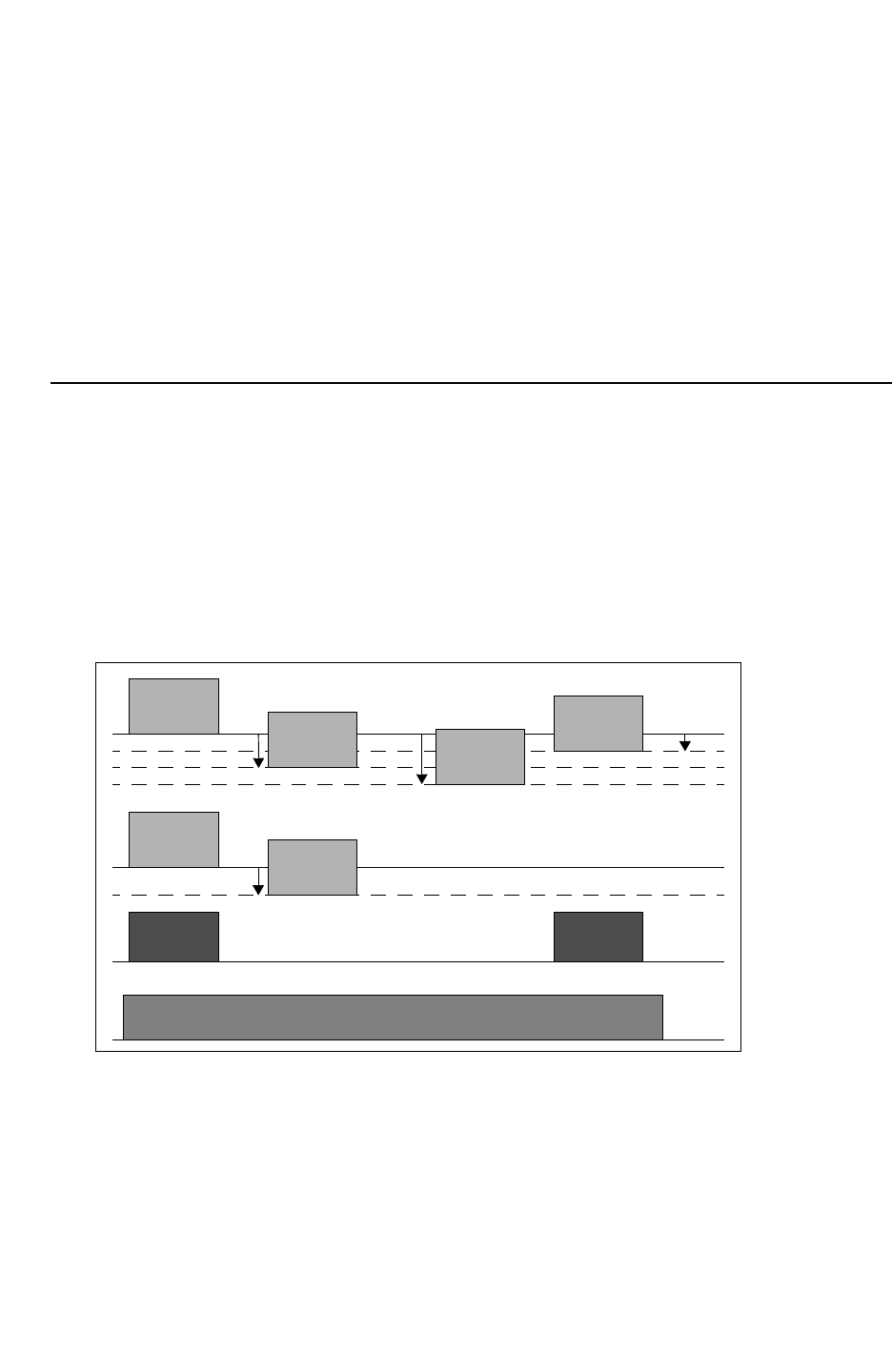
Chapter 3: Process Characterization Interface
Defining Additional Extraction Characteristics 3-14
StarRC User Guide and Command Reference F-2011.06
StarRC User Guide and Command Reference Version F-2011.06
Another potential use for covertical conductors is to handle “metal cheesing” (also known as
wide metal slotting); it creates two metal layers and gives them different sheet resistances,
which can be done in the mapping file without changing anything in the ITF, as follows:
conducting_layers
M5 metal5 RPSQ=10
M5_cheese metal5 RPSQ=100
Note that making separate layers in the ITF for covertical conductors is suitable only for
capacitive modeling; you should not use it for only resistance differences.
Drop Factor
The drop factor feature handles the case in which a conducting layer is at different heights
because of the absence of a lower conducting layer. For example, if Metal2 runs over
Metal1, Metal2 is uniform at a certain height above Metal1. If Metal2 is layered over a
location where there is no Metal1, Metal2 is layered at a lower height. The drop factor feature
considers the differences between the conducting layer heights and calculates the area and
lateral capacitance correctly. An illustration of the process is shown in Figure 3-4.
Figure 3-4 Nonplanar Process Where Conductor Heights Vary As a Function of the Absence of
Lower Conductors
SUBSTRATE
DM1
M1 M1
M2
M2
DM1
M3
M2
DM1+M2 M3
M3
DM2
Nonplanar conductor modeling is typically required for legacy processes at process nodes
above 0.18 micron with smaller numbers of metal conducting layers. The following
observations have been made:
• Such processes typically contain three metals or less.
• Nonplanarities can be introduced by any missing layer in the physical cross section.
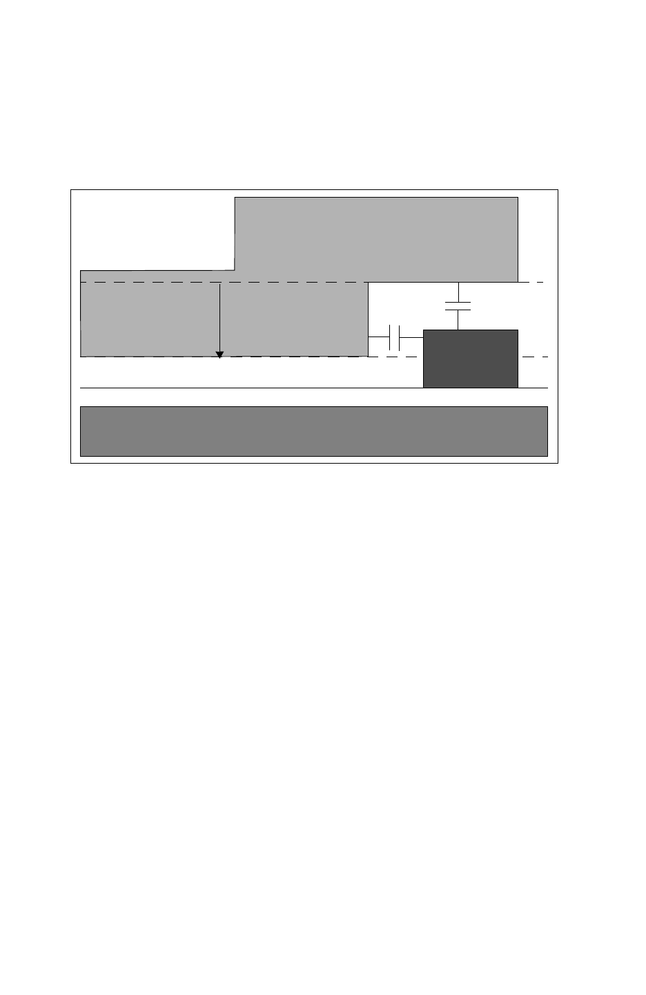
Chapter 3: Process Characterization Interface
Defining Additional Extraction Characteristics 3-15
Chapter 3: Process Characterization Interface
Defining Additional Extraction Characteristics 3-15
StarRC User Guide and Command Reference Version F-2011.06
• Both area and lateral capacitance effects are relevant between two metals that are
consecutive in height. Depending on the degree of drop of an upper conductor, the drop
could introduce a covertical overlap between consecutive conductors that would
introduce a potentially significant lateral capacitance effect. See Figure 3-5.
Figure 3-5 Lateral and Area Capacitance Effects Introduced by Large Drop Factor Values
SUBSTRATE
M1
M2
DM1
Clateral Carea
Drop Factor Error Conditions
The following are error conditions that StarRC might find in your design:
• Specifying the DROP_FACTOR ITF statement option should not cause different horizontally
consecutive levels of the same conductor to become noncovertical with each other. In
other words, if a piece of conductor routing undergoes a different cumulative drop factor
as the number of lower conductors vary along the length of the route, the conductor
should never drop such that it can no longer abut with itself. Horizontally adjacent pieces
of a conductor can cause fail to be covertical because of an excessive cumulative drop
factor. See Figure 3-6.
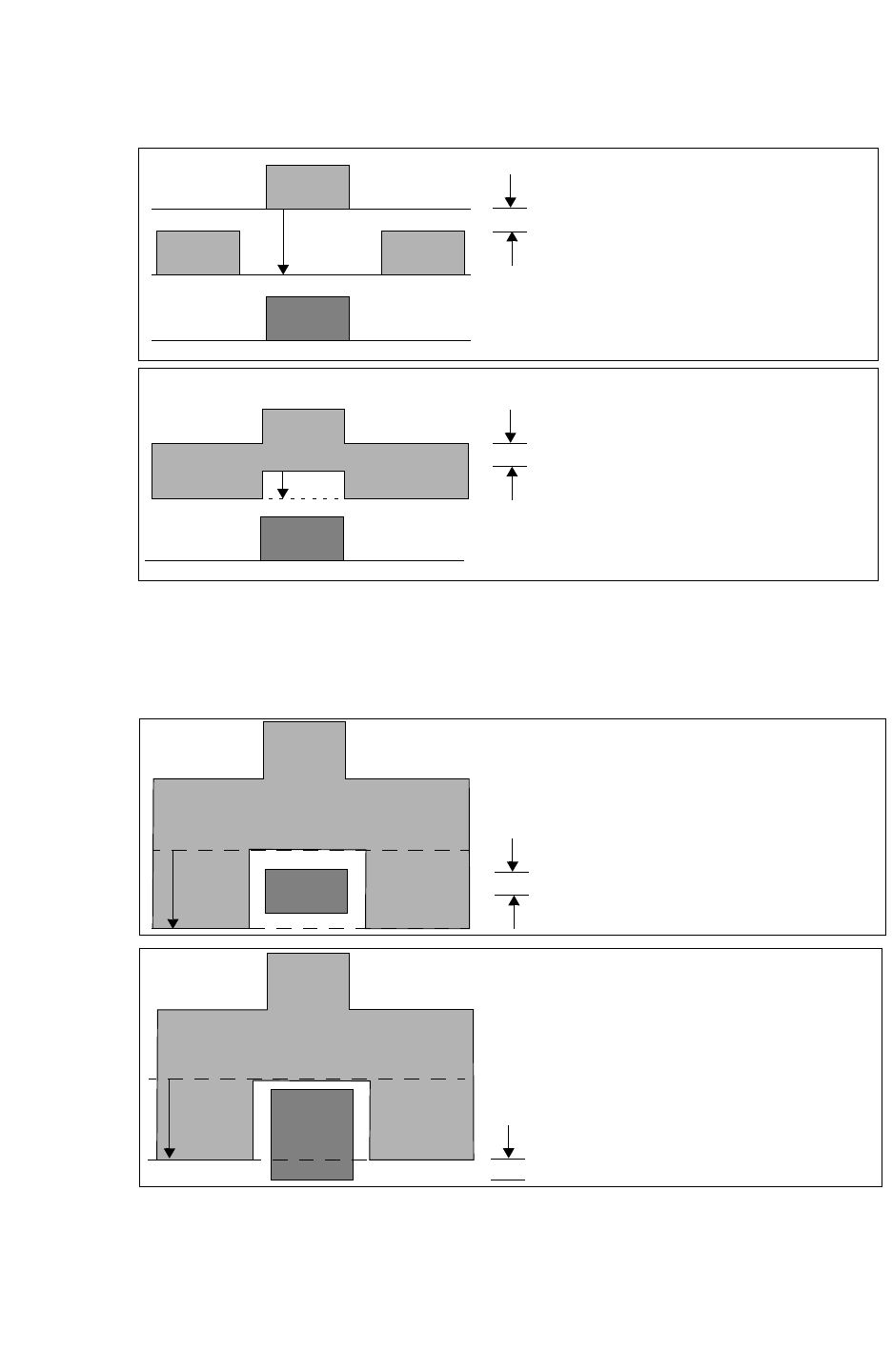
Chapter 3: Process Characterization Interface
Defining Additional Extraction Characteristics 3-16
StarRC User Guide and Command Reference F-2011.06
StarRC User Guide and Command Reference Version F-2011.06
Figure 3-6 Drop Factor Error Condition 1
M1
M2
M2M2 DM1
No covertical area
M1
M2
M2M2 DM1
Covertical area
Horizontally adjacent pieces of a conductor fail to
be coverticle because of excessive cumulative drop
factor.
Satisfactory condition for drop factor, in which
horizontally adjacent pieces of the same conductor
have coverticle overlap over the length of the
conductor.
• No conductor can be modeled at a height below conductors represented at lower levels
in the ITF cross sectional description. If this is the case grdgenxo produces an error. See
Figure 3-7.
Figure 3-7 Drop Factor Error Condition 2
M1
M2
M2
M2
DM1 Error:
M2 falls below M1
Error condition in which an upper conductor (M2)
M1
M2
M2
M2
D
M1
M2 base remains
above M1 base
Satisfactory condition for drop factor in which all
falls below excessive drop factor associated with
the lower conductors.
levels of upper conductors (M2) maintain a base
height above the base height of all levels of lower
conductors.
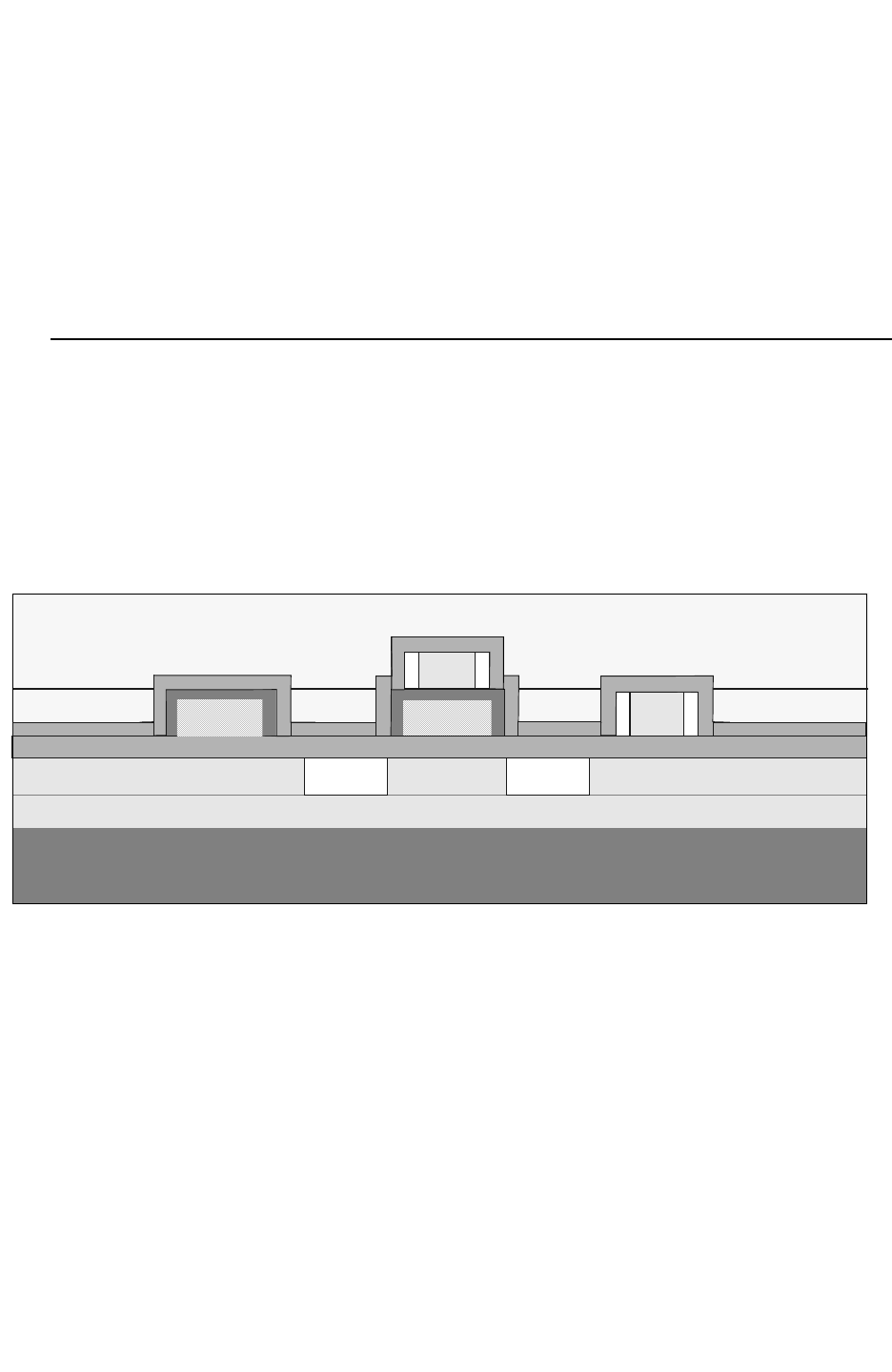
Chapter 3: Process Characterization Interface
Defining Additional Extraction Characteristics 3-17
Chapter 3: Process Characterization Interface
Defining Additional Extraction Characteristics 3-17
StarRC User Guide and Command Reference Version F-2011.06
• Drop factor is not supported with processes that have these features:
• Covertical layers like gate and field polysilicon or polysilicon and local interconnect
• Metal fill emulation using FILL_SPACING, FILL_WIDTH, and FILL_RATIO
• Conformal dielectrics
• Up to four conductors can have the DROP_FACTOR specified.
Modeling a Double-Poly Process Using DROP_FACTOR
To model a double-polysilicon process in StarRC, you can set the IS_CONFORMAL and
ASSOCIATED_CONDUCTOR options in the DIELECTRIC layers of the ITF. The IS_PLANAR
command is necessary in this case to make the metals above the poly layers planar. For
more information, see the IS_PLANAR ITF option.
See an example of this cross section in Figure 3-8.
Figure 3-8 Conformal Dielectric and Poly Layers
Substrate
BSD
LAT_ACT
ACTIVE
ACTIVE
U_P_D
S
S
POLY_A
C_D_PA_A
POLY_B
S
POLY_A
C_D_PA_A
U_P_D
S
ILD_B
ILD_A
C_D_PB
C_D_PB
POLY_B
C_D_PA_B
TD TD TD TD
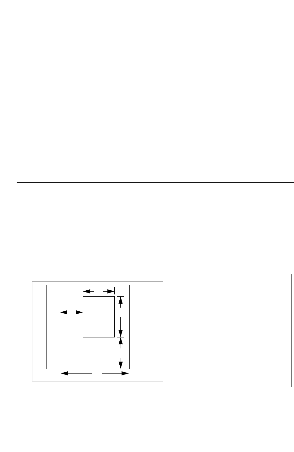
Chapter 3: Process Characterization Interface
Defining Additional Extraction Characteristics 3-18
StarRC User Guide and Command Reference F-2011.06
StarRC User Guide and Command Reference Version F-2011.06
Example 3-3 Modeling a Double-Polysilicon Process in the ITF
DIELECTRIC ILD_B { THICKNESS=0.3 MEASURED_FROM=ILD_A ER=4.2 }
DIELECTRIC C_D_PB { IS_CONFORMAL ER=7 SW_T=0.03 TW_T=0.03
ASSOCIATED_CONDUCTOR=POLY_B}
DIELECTRIC S{IS_CONFORMAL ER=6 SW_T=0.055 TW=0.0
ASSOCIATED_CONDUCTOR=POLY_B}
CONDUCTOR POLY_B { THICKNESS=0.15 WMIN=0.08 SMIN=0.07 RPSQ=10.0 }
DIELECTRIC ILD_A { THICKNESS=0.10 MEASURED_FROM=TD ER=4.2 }
DIELECTRIC TD { ER=7 MEASURED_FROM=U_P_D THICKNESS=0.03 }
DIELECTRIC C_D_PA_B { IS_CONFORMAL ER=7 SW_T=0.03 TW_T=0.03
ASSOCIATED_CONDUCTOR=POLY_A }
DIELECTRIC C_D_PA_A { IS_CONFORMAL ER=3.9 SW_T=0.04 TW_T=0.01
ASSOCIATED_CONDUCTOR=POLY_A }
CONDUCTOR POLY_A { THICKNESS=0.12 WMIN=0.05 SMIN=0.05 RQSP=849
DROP_FACTOR=0.13 }
DIELECTRIC U_P_D { THICKNESS=0.05 ER=3.9 }
DIELECTRIC LAT_ACT { THICKNESS=0.19 ER=4 }
CONDUCTOR ACTIVE { THICKNESS=0.19 WMIN=0.1 SMIN=0.14 RPSQ=0.0001 }
DIELECTRIC BSD { THICKNESS=0.19 ER=4 }
Dielectric Air Gaps
Air gaps in the surrounding dielectric are constructed as part of the CONDUCTOR definition
with the AIR_GAP_VS_SPACING command. The dimensions of the air gap are determined by
these parameters given in this command definition within the CONDUCTOR ITF definition as
shown in the following examples.
In Figure 3-9, all the dimensions of the air gap are determined by the spacing between the
metal lines.
Figure 3-9 Process With Dielectric Air Gaps
M1 AIR M1
T
W
B
S
S = neighboring lines
(SPACINGS)
W =
(AIR_GAP_WIDTH)
T =
gap formed
(AIR_GAP_THICKNESS)
B =
of the airgap from the
bottom of metal
(AIR_GAP_BOTTOM_HEIGHT)
L = metal and air gap ((S-W) /2)
L
spacing between the
height of the bottom
thickness of the air
width of the air gap
spacing between
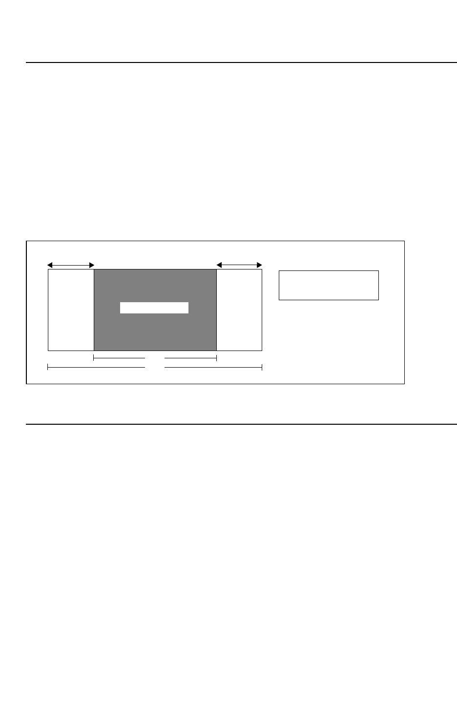
Chapter 3: Process Characterization Interface
Defining Additional Extraction Characteristics 3-19
Chapter 3: Process Characterization Interface
Defining Additional Extraction Characteristics 3-19
StarRC User Guide and Command Reference Version F-2011.06
Layer Etch
You can make an adjustment for layer etch effects that cause the manufactured line width of
a conductor to be different from its drawn width in the ITF process file. The keyword ETCH
can be specified as a part of any CONDUCTOR definition as shown in Figure 3-10.
Both conductor sidewalls retreat or expand by the number specified in the ETCH command,
resulting in a net width difference of twice the ETCH value. A positive ETCH value shrinks the
CONDUCTOR width, and a negative ETCH value increases the CONDUCTOR width.
WMIN and SMIN values are not affected by ETCH, because StarRC does the ETCH adjustments
internally.
Figure 3-10 Process Using Layer Etch Adjustment
CONDUCTOR
ETCH
MW
DW
DW = drawn width
MW = modeled width
MW = DW - 2 *ETCH
ETCH
See Appendix A, “ITF Examples” for an example of a process with layer etch.
Metal Fill (Emulated)
Extracting layout databases containing metal fill objects can make runtime and memory
requirements unacceptable to account for a relatively small effect. You can make an
approximation for the capacitive effects that proximal floating metal objects can have on
routed signals in the design simply and effectively in the ITF. Handling metal fill effects during
grdgenxo is extremely beneficial, because this one-time operation eliminates the need to
extract layout databases containing millions of fill objects.
StarRC ITF metal fill modeling is designed to estimate the capacitive effect of small, floating
fill shapes within the routed core area. This effect is calculated by embedding a fine dust in
the empty areas of the core according to the fill specifications in the ITF. You should not
model ITF metal fill for designs with grounded fill or for regions with large fill plates, which
behave as though they are grounded. Grounded fill is handled by normal extraction.
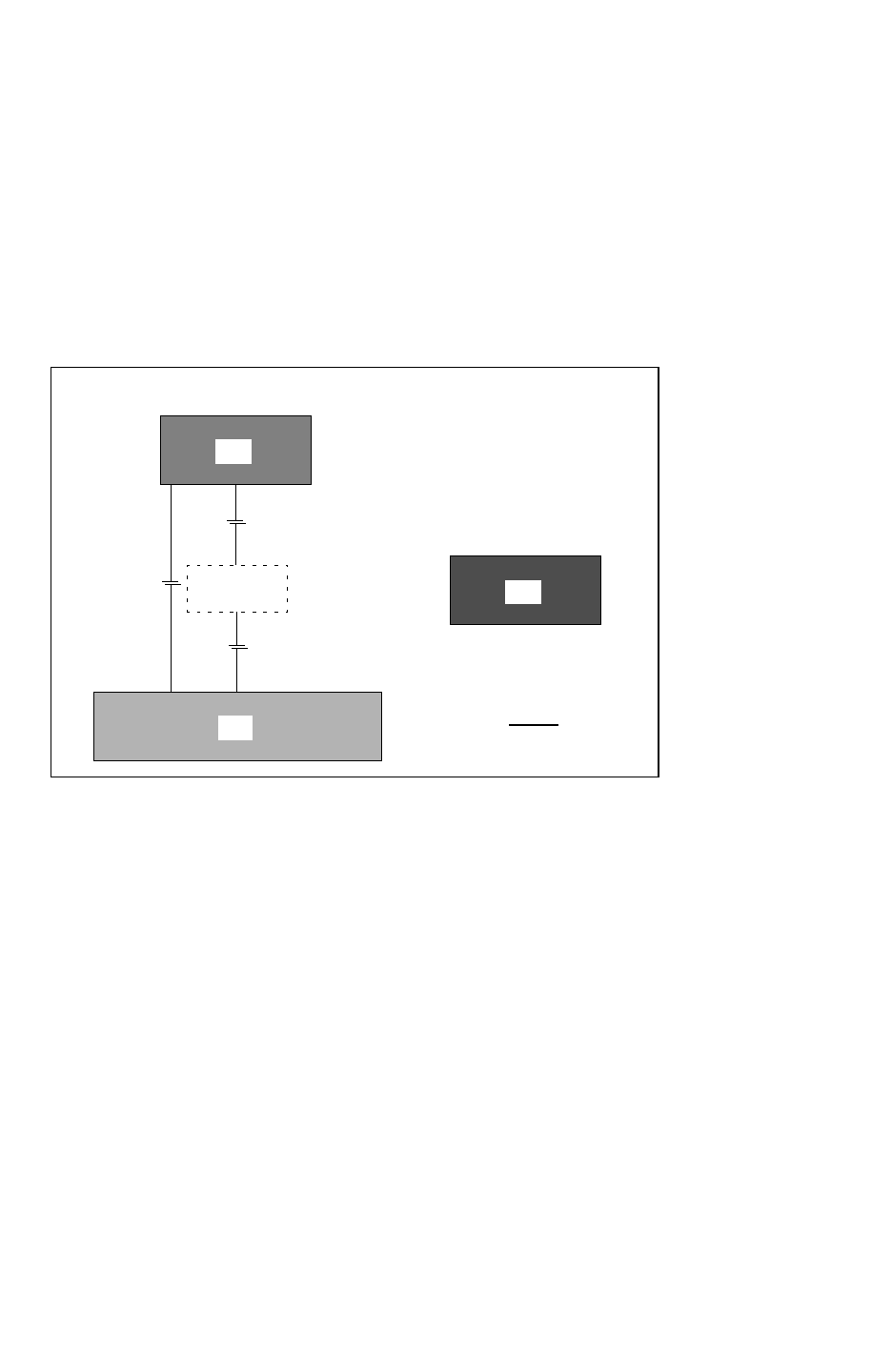
Chapter 3: Process Characterization Interface
Defining Additional Extraction Characteristics 3-20
StarRC User Guide and Command Reference F-2011.06
StarRC User Guide and Command Reference Version F-2011.06
Capacitances are modeled as a function of the global metal density for each extracted
conducting layer. As an optional argument in the CONDUCTOR definition, metal coverage is
specified in the ITF with the FILL_RATIO keyword. When FILL_RATIO is specified for a layer,
any empty space encountered during the extraction is modeled as though it were filled with
floating metal of the same layer. When used by itself, the FILL_RATIO keyword affects only
the vertical capacitance, as shown in Figure 3-11, because fill objects are placed only in
areas where they do not generate any significant lateral capacitance with their neighboring
objects.
Figure 3-11 FILL_RATIO Command
M2
M3
CROSS SECTION
M1
M2FILL
C
1
C
2
C
1
C
2
C
1
+C
2
+ Cc
Cc
C
(M1,M3)
=
For process technologies that allow lateral crowding of signal nets by fill objects, you can
specify the FILL_WIDTH and FILL_SPACING commands in addition to FILL_RATIO.
FILL_TYPE can be specified for treating lateral capacitance of fill as floating or grounded.
FILL_WIDTH and FILL_SPACING are used to define the dimensions of modeled fill objects
within any empty space in the design big enough to accommodate them. FILL_WIDTH is the
width of the fill object. See Figure 3-12. FILL_SPACING is the distance from a signal net to
a fill object.
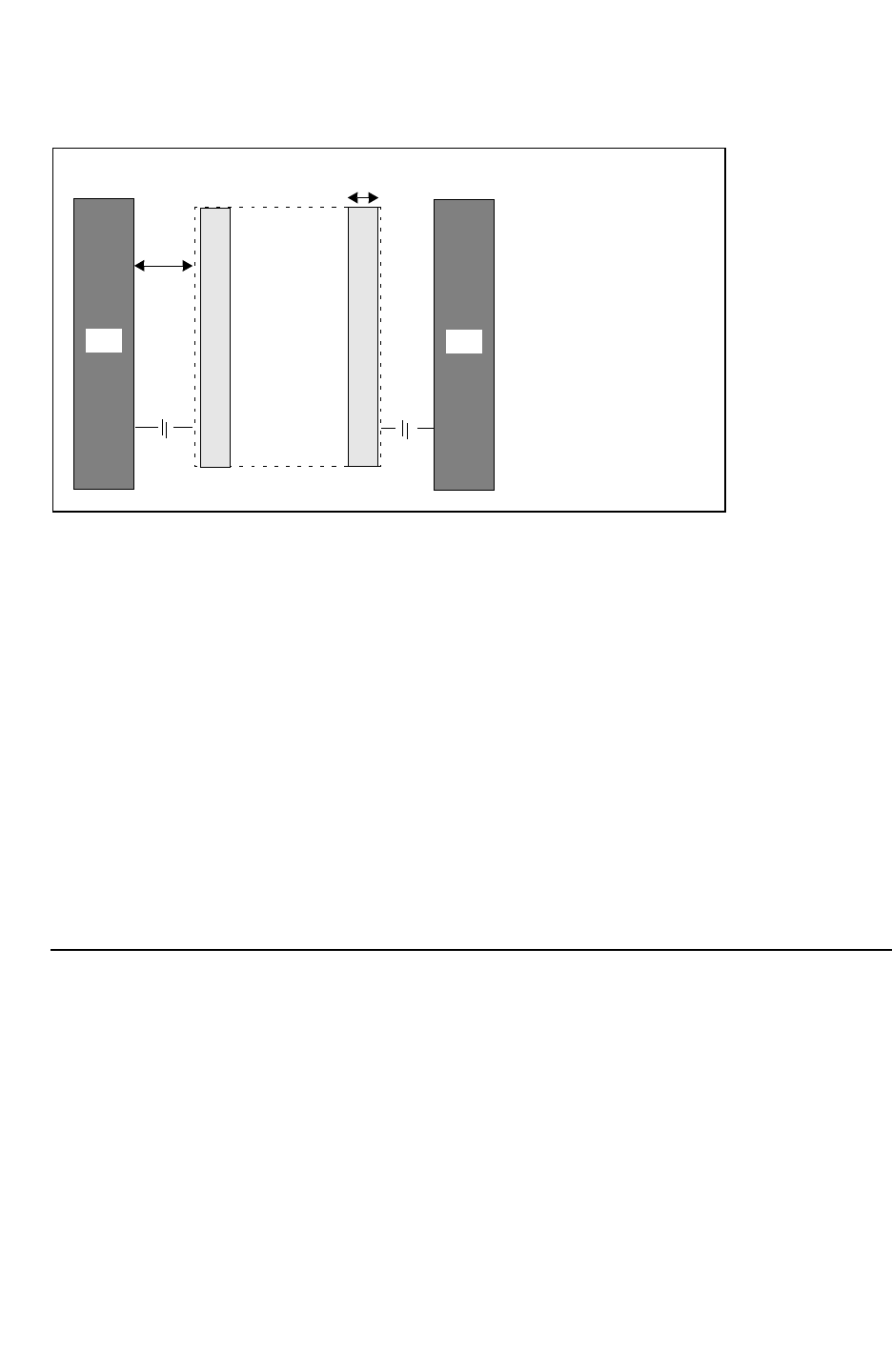
Chapter 3: Process Characterization Interface
Defining Additional Extraction Characteristics 3-21
Chapter 3: Process Characterization Interface
Defining Additional Extraction Characteristics 3-21
StarRC User Guide and Command Reference Version F-2011.06
Figure 3-12 FILL_SPACING and FILL_WIDTH Commands
M 2
TOP VIEW
M2FILL
dd = FILL_SPACING
w = FILL_WIDTH
M 2
C
1
C
2
w
When viewed from a distance, metal fill increases the effective dielectric constant. For lateral
objects close to the filled region, the fill-width and fill-spacing numbers are used to create
grounded “phantom” polygons, which represent the metal fill for objects adjoining the fill
region. No polygons are actually added in the design to represent the metal fill. Instead, the
coefficients in the GRD file are modified to model the impact of metal fill.
In cases that have possible conflicts, such as Poly and Local Interconnect, no fill is placed.
Fill is placed only in areas that can accommodate the fill properly.
Usually, all three fill parameters are determined by the design rules for the process
technology. See Appendix A, “ITF Examples” for an example of a process with metal fill.
There is no way to turn off the emulation fill commands—FILL_RATIO, FILL_WIDTH, and
FILL_SPACING—in the star_cmd file. The emulation fill flow accounts for fill effects, you
should not use it for production purposes. You must regenerate a new nxtgrd without the fill
commands.
When An Antenna Diode is in Your Design Database
In the Milkyway database, when an antenna diode cell is inserted by place and route tools,
the diode cell type is automatically set to a standard filler type. However, some antenna
diode cells might be inserted manually by hand or through Hercules, and the cell type could
be set wrong. This causes StarRC to extract and netlist these incorrect diode cell types.
StarRC can detect standard filler cell types automatically and ignores them during netlisting
in the output parasitic file.
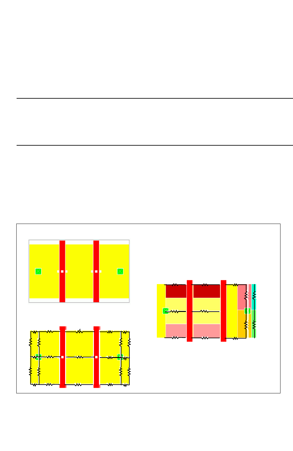
Chapter 3: Process Characterization Interface
Defining Additional Extraction Characteristics 3-22
StarRC User Guide and Command Reference F-2011.06
StarRC User Guide and Command Reference Version F-2011.06
You can query the diode cell instances to confirm the CELL FLAG property, set the antenna
cell type to standard filler, and convert the pin type to DIODE-PIN type.
Diode cells should not be netlisted in the output parasitic file as they are not part of the
original Verilog or SPICE netlist. They create parasitic back-annotation errors/warnings in
PrimeTime.
45-Degree Angles
StarRC has the capability to extract resistance and capacitance for 45-degree routed nets.
This capability is in StarRC by default and no additional commands are required.
Diffusion Resistance Extraction
For ITF definition, diffusion is defined as a CONDUCTOR for a standard shallow trench isolation
process. By default, If diffusion is not defined in the ITF, no resistance is extracted.
Diffusion resistance is extracted as mesh by default. The gate and diffusion overlap is
assumed to be equipotential surface (line node).
Figure 3-13 MOS Device Diffusion Extraction
Ri= RPSQ * li/ wi
l1
w1
R1
R2
l2
l3
w2
w3
R3
l9
w9
R9
l10
w10
R10
l4
w4
R4
R5
l5
l6
w5
w6
R6
l7
w7
R7
l8
w8
R8
MOS Device
Mesh Extraction - Line Node

Chapter 3: Process Characterization Interface
Defining Additional Extraction Characteristics 3-23
Chapter 3: Process Characterization Interface
Defining Additional Extraction Characteristics 3-23
StarRC User Guide and Command Reference Version F-2011.06
Spacing- and Width-Dependent Etch
Spacing- and width-dependent etch can be implemented in the nxtgrd file by use of the
ETCH_VS_WIDTH_AND_SPACING option in the CONDUCTOR statement of the ITF.
With this feature, StarRC can consider the actual fabricated patterns in extracting parasitic
components. This is important, because optical proximity correction (OPC) cannot fix all
proximity effects and the actual patterns might be different from the drawn mask patterns.
Running grdgenxo
If you have added ETCH_VS_WIDTH_AND_SPACING in your existing ITF, you have to rerun
grdgenxo after removing the working directory.
ETCH_VS_WIDTH_AND_SPACING can be used with ETCH, EFFECTIVE_RPSQ_TABLE, or
CLAD_RPSQ. If these are used together, ETCH_VS_WIDTH_AND_SPACING is applied first, ETCH
is added, and then EFFECTIVE_RPSQ_TABLE, RPSQ_VS_SI_WIDTH, or CLAD_RPSQ is
calculated.
CAPACITIVE_ONLY and RESISTIVE_ONLY
ETCH_VS_WIDTH_AND_SPACING affects both capacitance and resistance; if this is
undesirable, you can use ETCH_VS_WIDTH_AND_SPACING CAPACITIVE_ONLY or
ETCH_VS_WIDTH_AND_SPACING RESISTIVE_ONLY, which affect only capacitance or
resistance, respectively. These options use the same ITF syntax as
ETCH_VS_WIDTH_AND_SPACING, with their own tables.
These two options can be used together within a given CONDUCTOR statement but cannot be
used in conjunction with normal ETCH_VS_WIDTH_AND_SPACING. RESISTIVE_ONLY and
CAPACITIVE_ONLY can each be defined only once within any given CONDUCTOR statement.
Determining WMIN and SMIN Values
It is important to have a correct set of WMIN and SMIN values for the CONDUCTOR that has the
ETCH_VS_WIDTH_AND_SPACING statement.
Inappropriate WMIN and SMIN values can cause unwanted opens or shorts of the neighboring
layers by applying the etch values provided in the table. In such a case, a message is printed
during the grdgenxo run. For the entries corresponding to the WMIN in the WIDTHS table, if
positive etch values are greater than or equal to half of the WMIN, an “open” warning is
issued. Similarly, for the entries corresponding to the SMIN in the SPACINGS table, if absolute
values of the negative etch are greater than or equal to half of SMIN, a “short” warning is
issued.

Chapter 3: Process Characterization Interface
Defining Additional Extraction Characteristics 3-24
StarRC User Guide and Command Reference F-2011.06
StarRC User Guide and Command Reference Version F-2011.06
The WMIN and the SMIN of the CONDUCTOR that is described by ETCH_VS_
WIDTH_AND_SPACING can be the same as the smallest value (or the first entry) in the WIDTHS
and SPACINGS tables, respectively.
Retaining Coupling Capacitance Between Top and SKIP_CELL
Levels
You can use the COUPLE_NONCRITICAL_NETS feature to retain coupling capacitance
between top-level parent routing and SKIP_CELL child net routing, where the fully routed
child (DEF or .CEL view) routing netnames are used for coupling node names.
This feature exists for the Milkyway flow using the SPEF netlist format.
To specify which noncritical nets are to be retained with an added prefix, use the
COUPLE_NONCRITICAL_NETS and
COUPLE_NONCRITICAL_NETS_PREFIX commands.
Use the COUPLE_NONCRITICAL_NETS_SUBNODE_SUFFIX command to add a subnode suffix
to the noncritical nets. Use the NONCRITICAL_COUPLING_REPORT_FILE command to specify
an output file containing all the capacitances coupled to the noncritical nets.
Handling Overlapping Wells
StarRC has added a method by which you can deterministically set the vertical profile of
SUBSTRATE. You specify MAPPING_FILE syntax that sets the vertical precedence for
layers mapped to SUBSTRATE.
conducting_layers
db_layer1 SUBSTRATE precedence=pos_integer
db_layer2 SUBSTRATE precedence=pos_integer
...
Any layer mapped to SUBSTRATE, and only layers mapped to SUBSTRATE, accepts an
integer-based precedence value that establishes the layer’s position in the vertical
SUBSTRATE profile. Larger numbers denote higher vertical precedence, while smaller
numbers denote lower vertical precedence. The argument of the precedence keyword is a
positive integer denoting the relative precedence of the layer. It is not necessary for values
to be sequential.
If two layers have the same precedence value, and polygons from those two layers overlap
in layout, StarRC randomly determines the topmost layer for purposes of coupling
capacitance attachment and IGNORE_CAP command functionality. SUBSTRATE-mapped
layers for which precedence is not specified have a precedence value of zero, meaning that
they take precedence below all other layers.
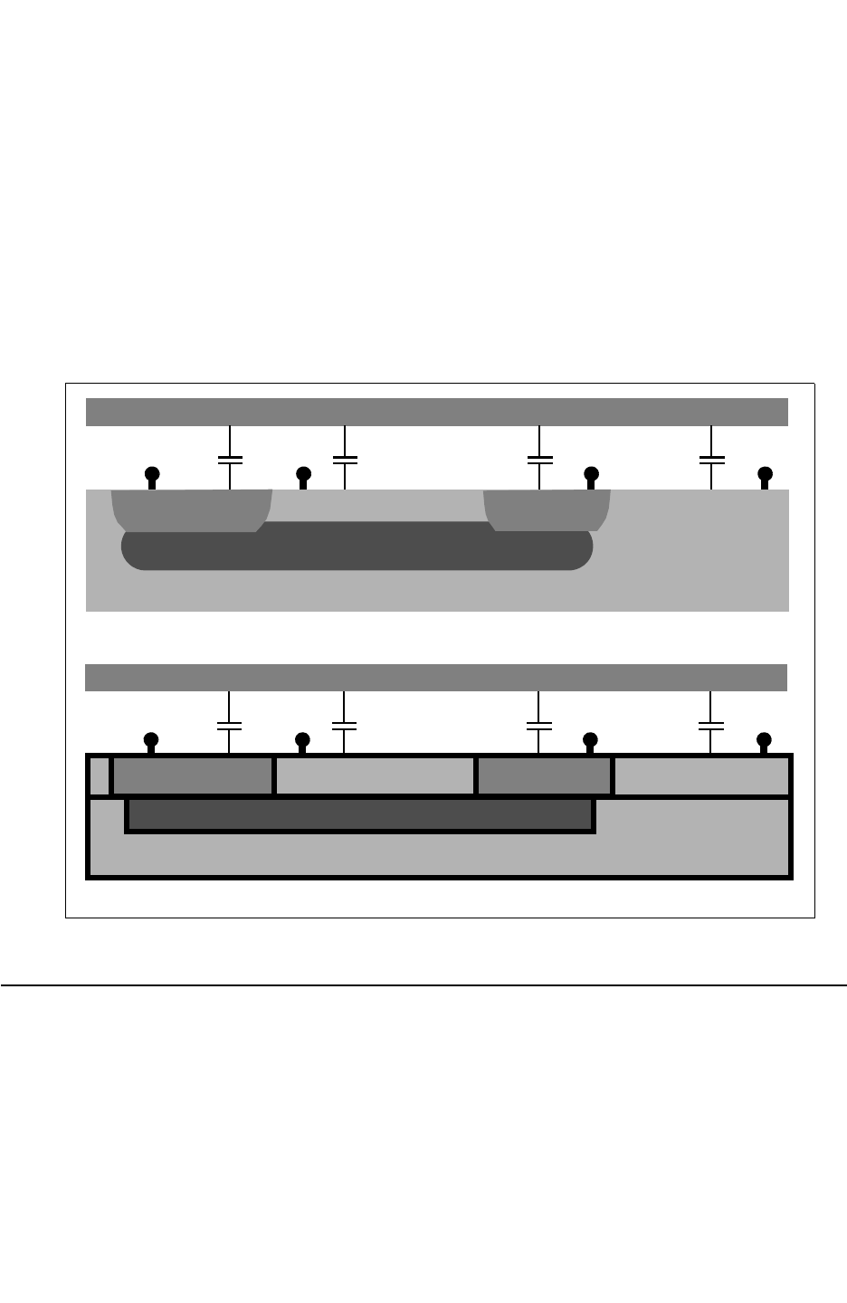
Chapter 3: Process Characterization Interface
Defining Sheet Zones 3-25
Chapter 3: Process Characterization Interface
Defining Sheet Zones 3-25
StarRC User Guide and Command Reference Version F-2011.06
The following is an example of a mapping file used to establish vertical precedence for a
buried well profile. The profile of a physical well for a buried well process and a profile for a
discrete well are shown in Figure 3-14.
conducting_layers
SUBS SUBSTRATE precedence=1
DEEP_NW SUBSTRATE precedence=2
NW SUBSTRATE precedence=3
PSUB2 SUBSTRATE precedence=3
PSUB SUBSTRATE precedence=3
Figure 3-14 Physical Well and Discrete Buried Well Profile
VDD VSS2 VDD VSS
NW NW
PSUB2 PSUB
PSUB
DEEP_NW
Physical well profile for buried well process
VDD VSS2 VDD VSS
PSUB2 PSUB
SUBS
Discrete buried well profile for parasitic extraction
NW NW
DEEP_NW
Defining Sheet Zones
A sheet zone is a location in which you model the insertion of a metal sheet over a specific
area as shown in Figure 3-15. This allows you to measure the coupling capacitance of a
given metal sheet, which has a user-defined net name. You can also provide a suffix to the
netname. By using sheet zone modeling, you can either specify one sheet or many thin
strips of metal with this same command interface.
Chapter 3: Process Characterization Interface
Defining Sheet Zones 3-26
StarRC User Guide and Command Reference F-2011.06
StarRC User Guide and Command Reference Version F-2011.06
You must ensure that any added sheet zone resides in an area that does not cause metal
shorts.
Figure 3-15 Sheet Zone Modeling
Block A
net 1
net 2
Block A
net 1
net 2
Zone Sheet
Anticipate worst-case
coupling as sheet
over an area
output netlist
*D_NET net1 1.5e-15
...
*CAP
1 net1 1.5e-15
...
*D_NET net2 2.0e-15
...
*CAP
1net2 2.0e-15
...
output netlist
*D_NET net1 1.5e-15
...
*CAP
1 net1 1.5e-15
2 net1 zone_sheet 1e-15
*D_NET net2 2.0e-15
...
*CAP
1net2 2.0e-15
...
Specify the METAL_SHEET_OVER_AREA command in your command file followed by the metal
layer name and four coordinates. These coordinates pinpoint the X and Y locations of a
single sheet as shown in Figure 3-16. Then specify the SHEET_COUPLE_TO_NET to designate
a unique net name or name prefix. Optionally, you can specify the SHEET_COUPLE_TO_LEVEL
command. This command enables a layer-level number to be output as the net name suffix
in the output netlist.
Chapter 3: Process Characterization Interface
Defining Sheet Zones 3-27
Chapter 3: Process Characterization Interface
Defining Sheet Zones 3-27
StarRC User Guide and Command Reference Version F-2011.06
Figure 3-16 Specifying a Sheet Zone or Sheet Strips
Block A
net 1
net 2
Zone Sheet Zone Strips
net 2
net 1
Block A
X1
Y1 Y2
X2
X1 X2
Y1 Y2
The following example shows the order in which you specify these commands for a single
zone sheet.
METAL_SHEET_OVER_AREA METAL2 0 0 100 100
METAL_SHEET_OVER_AREA METAL2 200 200 400 400
METAL_SHEET_OVER_AREA METAL4 0 0 100 100
SHEET_COUPLE_TO_NET: zone_sheet
SHEET_COUPLE_TO_NET_LEVEL:YES
The following example shows the order in which you specify these commands for several
sheet strips.
METAL_SHEET_OVER_AREA METAL2 0 5 10 10
METAL_SHEET_OVER_AREA METAL2 8 13 10 10
METAL_SHEET_OVER_AREA METAL2 16 21 10 10
METAL_SHEET_OVER_AREA METAL2 23 28 10 10
METAL_SHEET_OVER_AREA METAL2 31 36 10 10
METAL_SHEET_OVER_AREA METAL2 38 43 10 10
SHEET_COUPLE_TO_NET:zone_strips
SHEET_COUPLE_TO_NET:YES
Limitations
The following limitations accompany the metal sheet capability:
• You must verify that the metal sheet zones you specify do not cause a short.
• The prefix or root net name specified with the SHEET_COUPLE_TO_NET command must be
unique.

Chapter 3: Process Characterization Interface
Modeling Thickness Variation With StarRC 3-28
StarRC User Guide and Command Reference F-2011.06
StarRC User Guide and Command Reference Version F-2011.06
Modeling Thickness Variation With StarRC
The contemporary copper process is affected by a dishing effect on copper lines. This effect
causes a change in cross section that affects the resistance and capacitance of the copper
interconnect. The amount of dishing on a given copper line segment is dependent on its
environment. The environment is specified by the density of a layer, the spacing to its
neighbor, and its own width. Because of these effects, you need an extraction tool to
calculate the variation of thickness and to compute the correct resistance and capacitance.
This enables good correlation with silicon.
StarRC computes the density surrounding a given segment, calculates the thickness
variation, specifies multiple density boxes of varying sizes, and applies weighting factors to
each box to calculate the effective density. You can specify in the StarRC process file at least
one of the following:
• The variation of thickness with density
• The weighting factors for different density boxes
• The variation of thickness with width and spacing of conductors
• The orders of density and width for modeling thickness variation using a polynomial
equation and the coefficients of the polynomial equation
Single-Box Method (Linear Table)
This is a special case of a multiple-box method, where only one box is used for density
calculation. In this method, you choose a single box size and specify the variation of
thickness of the conductor in a table. The box is assumed to be always a square. The
maximum size of the box is 500 microns. This method is simple and does not require an
exhaustive characterization like the multiple box method. If specified alone for a conductor
in the process file, then it does not model local density thickness variation. To do linear table
modeling, you need to specify a multipoint thickness variation versus density table in the
process file.
The THICKNESS_VS_DENSITY statement uses the following syntax:
THICKNESS_VS_DENSITY [ RESISTIVE_ONLY | CAPACITIVE_ONLY ]
{(D1 R1) (D2 R2) (D3 R3) (D4 R4) ... }
D1, D2, D3, D4 represent the various density values; R1, R2, R3, R4 represent the
relative change in thickness; (dT/Tnominal), negative R(dT/T) indicates decrease in
thickness and vice versa; even though R(dT/T) can be any number between -1 and 1, a
number close to 1 or -1 is undesirable. R(dT/T) cannot be –1.
The THICKNESS_VS_DENSITY variation affects both resistance and capacitance. However, if
the coefficients for resistance and capacitance are different, then use the RESISTIVE_ONLY
and CAPACITIVE_ONLY options.

Chapter 3: Process Characterization Interface
Modeling Thickness Variation With StarRC 3-29
Chapter 3: Process Characterization Interface
Modeling Thickness Variation With StarRC 3-29
StarRC User Guide and Command Reference Version F-2011.06
If no DENSITY_BOX_WEIGHING_FACTOR is specified, the default density box size of 50
microns is used with a weighting factor of unity.
Example
CONDUCTOR metal3 {
THICKNESS_VS_DENSITY {
(0.1, -0.1) (0.2 0.1) (0.3 0.2) (0.4 0.3)} THICKNESS=0.5
SMIN=0.2 WMIN=0.22 RPSQ=0.06
}
Multiple-Box Method
In this method you specify multiple-box size and its weighting factor for effective density
calculation. This method requires that you characterize the wafer in greater detail than the
previous method. This method is preferred when the single-box method does not reflect the
process behavior. The density box is assumed to be a square. The maximum size of the
density box is 50 microns and the maximum number of boxes is 5. To use this method you
need to specify the following for a conductor in the process file.
THICKNESS_VS_DENSITY { ( D1 R1) (D2 R2) (D3 R3) (D4 R4) }
DENSITY_BOX_WEIGHTING_FACTOR { (S1 W1) (S2 W2) (S3 W3) (S4
W4) (S5 W5)}
The following explains the previous example:
• S is the size of the density box in microns
• W is the weighting factor
• S1, S2, S3, S4, S5 are integers in microns and are within (0 < S < 500)
S1 < S2 < S3 < S4 < S5; W is a floating-point number and is within this range
(-10 < W < 10)
• If W is set to 0, then the pair (S W) is ignored
R1, R2, R3, R4 are relative to the change in thickness
(dT/Tnominal) negative R(dT/T) indicates decrease in thickness and vice versa.
Calculation of Effective Density
All density calculation is based on drawn width and spacing. When multiple density boxes
are specified, the effective density is calculated as shown in Figure 3-17.
Chapter 3: Process Characterization Interface
Modeling Thickness Variation With StarRC 3-30
StarRC User Guide and Command Reference F-2011.06
StarRC User Guide and Command Reference Version F-2011.06
Figure 3-17 Effective Density Calculation
Deff = Σ D(Xi)*W(Xi)
i=0 to i=5
D(Xi) - Density of box Xi of size Si
W(Xi) - Weighting factor of Xi of Size
Si
X2
X1
X0
Multiple boxes
In Figure 3-17 there are three boxes - X0, X1, and X2. StarRC calculates the density for
each box for a given segment. The effective density is computed as shown in the equation
in Figure 3-17. After computing the effective density, the variation in thickness is computed
based on the THICKNESS_VS_DENSITY table. Both resistance and capacitance for a given
segment are calculated after thickness modification is taken into account.
Make sure to choose a weighting factor in such a way that calculated effective density is less
than unity.
If the computed density exceeds the limit of the density table in the ITF, the closest density
value is picked to calculate the thickness variation.
The following is an ITF example:
CONDUCTOR METAL3 {
THICKNESS = 0.35
WMIN = 0.2
SMIN = 0.21
DENSITY_BOX_WEIGHTING_FACTOR {
(10, 1) (30, 0.23) (20, 0.29)
(40, 0.18) (50, -0.12 ) }
THICKNESS_VS_DENSITY { (0.1, -0.1) (0.2 0.1)}
}

Chapter 3: Process Characterization Interface
Modeling Thickness Variation With StarRC 3-31
Chapter 3: Process Characterization Interface
Modeling Thickness Variation With StarRC 3-31
StarRC User Guide and Command Reference Version F-2011.06
Width and Spacing-Dependent Thickness Variation
In this method, the variation of thickness as a function of the width of a conductor and the
relative spacing to its neighbor is modeled. This thickness variation can be either negative
or positive. As can be noted, this is a very local phenomenon and is independent of the
density box. If specified with either single or multiple boxes, this thickness variation is
computed independently of the density box.
The effective thickness is calculated with the following equation:
T Tnom 1 RTf Deff()RTf W S,()RTf SiW()++ +()×=
where
• Tnom is the nominal thickness specified in the ITF.
• RTf(Deff) is the relative change in thickness based on density.
• RTf(W,S) is the relative change in thickness based on width and spacing.
• RTf(SiW) is the relative change in thickness based on silicon width.
The resistance and capacitance is computed after effective thickness is computed. You can
model this variation in a process file with the THICKNESS_VS_WIDTH_AND_SPACING
statement for a conductor, as shown in the following syntax:
THICKNESS_VS_WIDTH_AND_SPACING [RESISTIVE_ONLY | CAPACITIVE_ONLY] {
SPACINGS { S1 S2 }
WIDTH { W1 W2 }
VALUES {v(S1 W1) v(S2 W1) v(S1 W2) v(S2 W2) }
}
Argument Description
S1, S2 Spacings in microns
W1, W2 Widths of a conductor in microns
V(Sx Wy) Relative change in thickness for a conductor
Note:
V(Sx Wy) can take any value between –1 and +1, but a value close to –1 or +1 might be
unrealistic.
The THICKNESS_VS_WIDTH_AND_SPACING variation affects both resistance and capacitance.
However, if the coefficients for resistance and capacitance are different, use the
RESISTIVE_ONLY and CAPACITIVE_ONLY options.

Chapter 3: Process Characterization Interface
Modeling Thickness Variation With StarRC 3-32
StarRC User Guide and Command Reference F-2011.06
StarRC User Guide and Command Reference Version F-2011.06
Unsupported Flows
The following flows are not supported by the THICKNESS_VS_DENSITY capability:
•THICKNESS_VS_DENSITY table cannot be combined with THICKNESS_VS_DENSITY
[RESISTIVE_ONLY].
•THICKNESS_VS_DENSITY table cannot be combined with THICKNESS_VS_DENSITY
[CAPACITIVE_ONLY].
•DENSITY_BOX_WEIGHING_FACTOR cannot be used without THICKNESS_VS_DENSITY
table.
Error and Warning Messages
The following is a list of error and warning messages associated with the noted commands.
THICKNESS_VS_DENSITY
If an older process file is used, StarRC issues an error message. This is applicable if and
only if THICKNESS_VS_DENSITY is specified.
ERROR: (841) ITF**
ERROR: THICKNESS_VS_DENSITY format changed;
ERROR: THICKNESS_VS_DENSITY { (D1, T1) (D2, T2) ... (Dn, Tn) }
If the DENSITY_BOX_WEIGHTING_FACTOR is not specified for a conductor that has
THICKNESS_VS_DENSITY, the following warning is issued:
WARNING: (924) ITF**
WARNING: DENSITY_BOX_WEIGHTING_FACTOR table is not provided
for
WARNING: DENSITY_BOX_WEIGHTING_FACTOR table is not provided
for
WARNING: layer <layer_name>; Default density box of 50m x
50m with
WARNING: weighting factor of 1 will be used
THICKNESS_VS_DENSITY table should have at least two points.
ERROR: (827) ITF**
ERROR: At least two points must be entered in
THICKNESS_VS_DENSITY
ERROR: table
A warning is issued if relative thickness variation is 1 or –1.
WARNING: (831) ITF**
WARNING: Suspicious value(s) for relative thickness
change(s) in
WARNING: THICKNESS_VS_DENSITY for layer <layer_name>

Chapter 3: Process Characterization Interface
Modeling Thickness Variation With StarRC 3-33
Chapter 3: Process Characterization Interface
Modeling Thickness Variation With StarRC 3-33
StarRC User Guide and Command Reference Version F-2011.06
Density values are reordered when the table is not in ascending order.
WARNING: (832) ITF**
WARNING: Density values in THICKNESS_VS_DENSITY table are
not in
WARNING: ascending order; Reordering the values...
If density values are repeated, the following error message is issued:
ERROR: (850) ITF**
ERROR: THICKNESS_VS_DENSITY table contains repeated
densities
ERROR: <density_value>
If the width values in the THICKNESS_VS_DENSITY table are not sorted, grdgenxo sorts
them.
ERROR: (876) ITF**
ERROR: the width values in the thickness table must be sorted
in
ERROR: ascending order in layer <layer_name>
DENSITY_BOX_WEIGHTING_FACTOR
A maximum of only 5 density boxes is allowed.
ERROR: (842) ITF**
ERROR: Too many entries; Up to 5 density weighting factors
can be
ERROR: defined in DENSITY_BOX_WEIGHTING_FACTOR
DENSITY_BOX_WEIGHTING_FACTOR with no entry leads to the following error:
ERROR: (843) ITF**
ERROR: At least one density box weighting factor must be
defined
ERROR: in DENSITY_BOX_WEIGHTING_FACTOR
A density box with 0 weighting factor is ignored.
WARNING: (796) ITF**
WARNING: Ignoring 0 weighting factor in
DENSITY_BOX_WEIGHTING_FACTOR
If DENSITY_BOX_WEIGHING_FACTOR is specified without THICKNESS_VS_DENSITY for a
conductor, the following error message is issued:
ERROR: (923) ITF**
ERROR: DENSITY_BOX_WEIGHTING_FACTOR table cannot be used
without
ERROR: THICKNESS_VS_DENSITY table for layer

Chapter 3: Process Characterization Interface
Modeling Thickness Variation With StarRC 3-34
StarRC User Guide and Command Reference F-2011.06
StarRC User Guide and Command Reference Version F-2011.06
DENSITY_BOX_WEIGHTING_FACTOR should have at least one point.
ERROR: (827) ITF**
ERROR: At least one point must be entered in
ERROR: DENSITY_BOX_WEIGHTING_FACTOR table
The size of the density box should be positive.
ERROR: (844) ITF**
ERROR: In layer <layer_name>, width of a density box entry
should
ERROR: be a positive value
The maximum size of the density box is 50 microns.
ERROR: (845) ITF**
ERROR: In layer <layer_name>, width of a density box entry
cannot
ERROR: exceed 50.0
If weighting factor is larger than 10 or smaller than –10, a warning is issued.
WARNING: (846) ITF**
WARNING: Suspicious value(s) of weighting factor(s) in
WARNING: DENSITY_BOX_WEIGHTING_FACTOR for layer
<layer_name>
If the width of the DENSITY_BOX_WEIGHTING_FACTOR table is not in ascending order, it is
reordered.
WARNING: (847) ITF**
WARNING: Widths of the density boxes in
DENSITY_BOX_WEIGHTING_FACTOR
WARNING: are not in ascending order; Reordering them...
If the width of the DENSITY_BOX_WEIGHTING_FACTOR is repeated, the following warning is
given:
ERROR: (851) ITF**
ERROR: DENSITY_BOX_WEIGHTING_FACTOR contains repeated width
of
ERROR: <width_value> for layer <layer_name>
THICKNESS_VS_WIDTH_AND_SPACING
Relative thickness change cannot be smaller than –1.
ERROR: (881) ITF**
ERROR: Relative thickness change(s) in
THICKNESS_VS_WIDTH_AND_SPACING
ERROR: for layer <layer_name> cannot be smaller than -1

Chapter 3: Process Characterization Interface
Measuring Bottom Conductor Thickness Variation 3-35
Chapter 3: Process Characterization Interface
Measuring Bottom Conductor Thickness Variation 3-35
StarRC User Guide and Command Reference Version F-2011.06
Relative thickness change cannot be greater than 1.
ERROR: (882) ITF**
ERROR: Suspicious value(s) of relative thickness change(s) in
ERROR: THICKNESS_VS_WIDTH_AND_SPACING for layer
<layer_name>
If THICKNESS_VS_WIDTH_AND_SPACING table is empty, the following message appears:
ERROR: (878) ITF**
ERROR: empty THICKNESS_VS_WIDTH_AND_SPACING table is given
for layer <layer_name>
If the THICKNESS_VS_WIDTH_AND_SPACING table has incorrect values in the value section,
the following message appears:
ERROR: (879) ITF**
ERROR: wrong number of values in
THICKNESS_VS_WIDTH_AND_SPACING table in layer <layer_name>
The spacing values in THICKNESS_VS_WIDTH_AND_SPACING table should be in ascending
order:
ERROR: (877) ITF**
ERROR: the spacing values in the thickness table must be
sorted in
ERROR: ascending order in layer <layer_name>
Measuring Bottom Conductor Thickness Variation
For 45-nm nodes and below, the need to model new process parameters arises for tight
silicon correlation and predictability. Process deficiencies such as conductor trench
thickness become more profound and require parasitic extraction tools to accurately account
for these effects on resistance and capacitance of lines at 45-nm.
The bottom conductor thickness variation, or microloading effect, is caused by the
inaccuracy in the trench depth etching process for thin lines. Microloading effects increase
as wires become thinner and closely spaced. Trench depth variation affects the thickness of
the interconnect and the separation between metal layers, so it affects both resistance and
capacitance.
Modeling of the microloading effect can vary depending on the silicon data available to
foundries.
Chapter 3: Process Characterization Interface
Measuring Bottom Conductor Thickness Variation 3-36
StarRC User Guide and Command Reference F-2011.06
StarRC User Guide and Command Reference Version F-2011.06
Modeling Bottom Conductor Thickness Variation
In StarRC, the BOTTOM_THICKNESS_VS_SI_WIDTH ITF command can be used to model
microloading as a function of silicon width (postetch). The ILD_VS_WIDTH_AND_SPACING
option is different from BOTTOM_THICKNESS_VS_SI_WIDTH in that it enables you to model
intralayer dielectric (ILD) variation (because of microloading) as a function of conductor
width and spacing (drawn). Figure 3-18 shows the ILD4 thickness varying as a result of
microloading on the metal3 conductor:
Figure 3-18 Model Microloading in the Form of ILD
M3
W
S
M3
W
S
M3
W
ILD5
ILD4
ILD3
ILD2
M3
W
S
M3
W
S
M3
W
ILD5
ILD4
ILD3
ILD2
Without ILD Variation of
Microloading Effect
With ILD Variation of
Microloading Effect
Note:
When using BOTTOM_THICKNESS_VS_SI_WIDTH, the thickness of the conductor can
change (increase or decrease). However, for the ILD variation, the conductor thickness
remains constant, but the absolute z-coordinate, or cross section, of the conductor moves
up or down, depending on the direction of ILD variation. This difference might have a
significant impact especially for measuring resistance and coupling capacitance to
neighboring conductors.
For flows where thickness variation information is input through a
THICKNESS_VARIATION_FILE, the ILD variation is automatically turned off, along with all top
thickness variation commands such as PBTV, TVD, and TVWS. It is assumed that the CMP
simulator accounts for the microloading effect while computing the thickness variation.
However, note that the BOTTOM_THICKNESS_VS_SI_WIDTH command is retained in CMP
flows.

Chapter 3: Process Characterization Interface
Interconnect Parasitics Extraction Based on CMP Simulators 3-37
Chapter 3: Process Characterization Interface
Interconnect Parasitics Extraction Based on CMP Simulators 3-37
StarRC User Guide and Command Reference Version F-2011.06
ILD Restrictions
The following restrictions apply to the ILD variation function. Errors are reported to standard
output on the terminal screen if the following occurs:
• The ILD variation is specified for a dielectric layer that does not exist directly below a
conductor, an error is printed.
• The ILD variation specified is greater than 0.2 or less than -0.2, an error is printed.
• The ILD variation table is specified within the same CONDUCTOR statement with a
BOTTOM_THICKNESS_VS_SI_WIDTH table.
Interconnect Parasitics Extraction Based on CMP Simulators
At 90 nm and below, thickness variation of interconnect can change circuit behavior
dramatically. Accurate computation of this variation and its impact on interconnect parasitics
is a must. The extent of the variation depends primarily on the technology node, foundry, and
process control employed for manufacturing.
StarRC produces parasitic netlists with thickness variation effect. It consists of two steps:
• Computes thickness variation for a given interconnect
The computation of thickness variation in StarRC is based on foundry-provided table or
function of how thickness varies as a function of density, width and spacing to next
neighbor. An alternative to this approach is proposed by certain foundries that requires a
CMP simulator to compute thickness variation for interconnects in the design. It’s found
to be more difficult to define rules for thickness variation based on density, width and
spacing.
• Computes resistance and capacitance based on the thickness variation
StarRC computes resistance and capacitance based on changed thickness due to CMP.
This step is independent of whether thickness variation is computed by StarRC or by a
separate CMP simulator.
Single-Layer and MultiLayer Mode
Thickness variation of a given layer can be computed independent of the layers below.
Figure 3-19 describes the single-layer mode for two layers and for two adjacent tiles. The
bottom of the conductor is considered fixed and the top of the conductor can change.
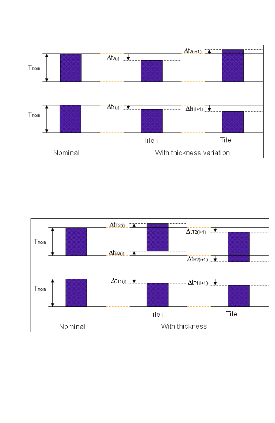
Chapter 3: Process Characterization Interface
Interconnect Parasitics Extraction Based on CMP Simulators 3-38
StarRC User Guide and Command Reference F-2011.06
StarRC User Guide and Command Reference Version F-2011.06
Figure 3-19 Conductor Cross Section for a Single-Layer Mode
This model can be further enhanced to comprehend impact of thickness variation for layers
below on a given layer. This is the multilayer mode. In this mode, bottom of the conductor
can move up or down as shown in Figure 3-20. A CMP simulator computes this by modeling
the dielectric thickness variation and then computing the impact at the bottom of the
conductor.
Figure 3-20 Conductor Movement
Using a Thickness Variation Map File
CMP simulators provide a thickness variation map for each layer in the design. StarRC
reads that thickness variation map, calculates the thickness variation for each interconnect
polygon, and writes the value to the internal database.

Chapter 3: Process Characterization Interface
Interconnect Parasitics Extraction Based on CMP Simulators 3-39
Chapter 3: Process Characterization Interface
Interconnect Parasitics Extraction Based on CMP Simulators 3-39
StarRC User Guide and Command Reference Version F-2011.06
To specify a thickness variation map file in the command file, use the
THICKNESS_VARIATION_MAP command.
The thickness variation map file uses the following syntax:
BLOCK block_name
TILE_SIZE tile_size_in_nm
BEGIN ITF_layer_name
x<numx> y<numy> rel_deltaT_top [rel_deltaT_bot]
x<numx> y<numy> rel_deltaT_top [rel_deltaT_bot]
x<numx> y<numy> rel_deltaT_top [rel_deltaT_bot]
END ITF_layer_name
BEGIN ITF_layer_name
x<numx> y<numy> rel_deltaT_top [rel_deltaT_bot]
x<numx> y<numy> rel_deltaT_top [rel_deltaT_bot]
x<numx> y<numy> rel_deltaT_top [rel_deltaT_bot]
END ITF_layer_name
BEGIN ITF_layer_name
x<numx> y<numy> rel_deltaT_top [rel_deltaT_bot]
x<numx> y<numy> rel_deltaT_top [rel_deltaT_bot]
x<numx> y<numy> rel_deltaT_top [rel_deltaT_bot]
END ITF_layer_name
Table 3-1 Syntax Details
Argument Description
block_name Name of the block
tile_size_in_nm Size of the tile in nanometers
ITF_layer_name ITF layer name
x<numx> X-coordinate location in the chip design
y<numy> Y-coordinate location in the chip design
rel_deltaT_top Relative thickness change for the top of the metal
rel_deltaT_bot Relative thickness change for the bottom of the metal (optional)
• Sort TILES with xy coordinates and relative thickness change.
You sort the tiles by x-coordinates first and then by y-coordinates in ascending order;
x0<x1<<x8 and y0<y1<<y8 as shown in Figure 3-21 on page 3-40 and the example.
• The coordinates you specify are absolute coordinates of the lower-left corner of the TILE.
(x8-x7) or (y8-y7), the last column and rows of tiles, might be smaller than the TILE size.
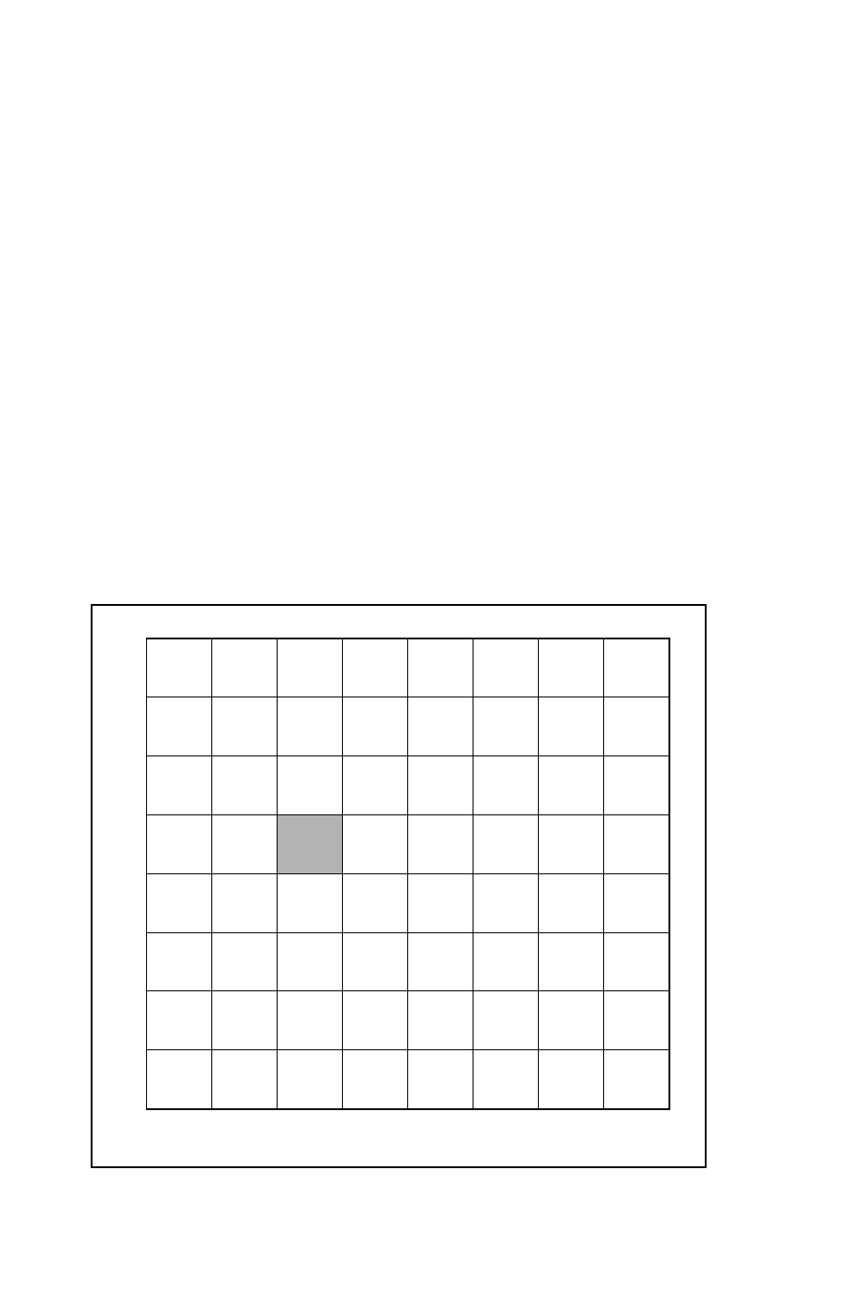
Chapter 3: Process Characterization Interface
Interconnect Parasitics Extraction Based on CMP Simulators 3-40
StarRC User Guide and Command Reference F-2011.06
StarRC User Guide and Command Reference Version F-2011.06
• The xy coordinate of the TILES should match across all layers.
• The TILE description can cover an area larger than the block extent. However, the extent
of the tile description should not be smaller than the extent of the block.
• A relative thickness change is the change from the nominal thickness of the given layer
and is constant for a given tile. If there is no thickness change for a TILE for the layer, it
should be set to 0. The relative thickness change must be in the range from -0.5 to 0.5.
• The file must contain a specified relative thickness change at the top of the conductor
(rel_deltaT_top). If a relative thickness change is provided for the bottom of the conductor
(rel_deltaT_bot), then multilayer mode is invoked automatically.
• Positive relative thickness change implies that the top of the conductor has moved up
(rel_deltaT_top) or the bottom of the conductor has moved down (rel_deltaT_bot). The
sum of the bottom and top thickness change provides the total thickness change and can
be used to calculate the new thickness of the conductor.
• When MAGNIFICATION_FACTOR is used along with THICKNESS_VARIATION_FILE in
StarRC, the coordinates in the TVF file are assumed to be already scaled, or shrunk as
the CMP simulation applies this scaling during simulation.
Figure 3-21 Example of Thickness Variation File Coverage
TILE
x0 x1 x2 x3 x4 x5 x6 x7 x8
x0
x1
x2
x3
x4
x5
x6
x7
x8

Chapter 3: Process Characterization Interface
Microloading Effect 3-41
Chapter 3: Process Characterization Interface
Microloading Effect 3-41
StarRC User Guide and Command Reference Version F-2011.06
Error and Warning Messages
The following error or warning messages might be encountered in certain circumstances:
• If the <block_name> indicated in the thickness variation map file is different from the
block name in the command file, StarRC produces an inconsistent block name error
message and exits.
ERROR: StarXtract
ERROR: Inconsistent block name in the thickness variation
file
ERROR: Block name in command file is xyz
ERROR: Block name in thickness variation file is abc
• If the thickness variation value is out of range [-0.5, 0.5], StarRC gives the error message
that relative thickness change must be within [-0.5, 0.5] and exits.
ERROR: StarXtract
ERROR: Relative thickness change in thickness variation
file is outside [-0.5, 0.5] range
ERROR: 0 0 -0.601909
• If the x- and y-coordinates for tiles do not match across the layers, StarRC issues an error
and exits.
ERROR: StarXtract
ERROR: Tile coordinates in thickness variation file for
layer met2 is different from layer met1
ERROR: Layer met1: 10 70 -0.156
ERROR: Layer met2: 12 75 0.324
• If the TILES do not cover the whole size of the block under analysis, StarRC issues an
error and exits.
ERROR: StarXtract
ERROR: Tile coordinates in thickness variation file
doesn't cover the extent of the design
ERROR: Design extent (in nm): (0,0) to (4799950,
7456200)
ERROR: Thickness variation file extent (in nm): (175,175)
to (4800175, 7460175)
For more information see the THICKNESS_VARIATION_FILE command.
Microloading Effect
Various foundries note that in a low-k dielectric damascene process, one challenge is to etch
accurate depth for metal trenches. Analysis of data indicates that etching accurate depth in
a low-k dielectric process is not only dependent on the materials used, but it is also
dependent on the interconnect dimension and the proximity to the neighboring interconnect.

Chapter 3: Process Characterization Interface
Damage Modeling 3-42
StarRC User Guide and Command Reference F-2011.06
StarRC User Guide and Command Reference Version F-2011.06
The variation in the etch depth for the metal deposition not only affects the thickness of the
interconnect but also affects the vertical distance between metal interconnects. Because of
this, it affects both parasitic resistance and capacitance.
You can model bottom thickness variation with the following command:
BOTTOM_THICKNESS_VS_SI_WIDTH {
(SiW1, DBT1)
(SiW2, DBT2)
...
(SiWN, DBTN)
}
BOTTOM_THICKNESS_VS_SI_WIDTH performs linear interpolation of thickness variation for
wires whose widths fall between entries in the table. StarRC does not extrapolate beyond
the table.
Note:
This feature is available only for conducting layers, because no variations exist for vias or
contacts in standard foundry processes.
Damage Modeling
Changes to process technology continue in an effort to reduce the RC timing delay of
circuits. One of the common process features at this process node is to introduce porosity
into the dielectric film with relative permitivities of 2.5 or less, as a result creating a low-k
dielectric layer. Given the fact that the modulus and hardness of such low-k material is
significantly lower, the porous materials are susceptible to chemical process steps such as
etch and resist strip. The etch and strip processes currently employed cause modifications,
or damage, to the dielectric that nullify the benefit of introducing porosity to features with
dielectric spacers of 70nm or less. The damage on the surface of the metal-low-k dielectric
causes the parasitic capacitance to become significantly larger. At the 45nm process node,
sidewall and bottom wall damage as a consequence of process steps to low-k damage
material can no longer be neglected to accurately predict circuit behavior.
The DAMAGE_THICKNESS ITF option defines the thickness of the damage on the surface of
the conductor and DAMAGE_ER ITF option defines the equivalent permittivity of the damage
layer.
Figure 3-22 shows the various damage modeling cross sections that can be modeled using
the DAMAGE_ER and DAMAGE_THICKNESS options.
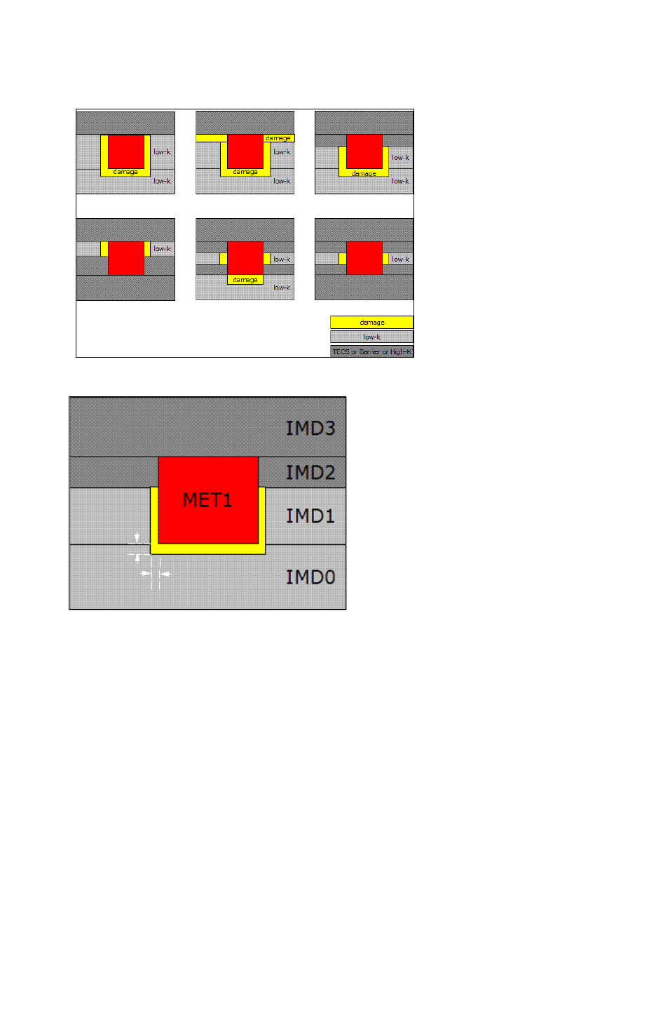
Chapter 3: Process Characterization Interface
Damage Modeling 3-43
Chapter 3: Process Characterization Interface
Damage Modeling 3-43
StarRC User Guide and Command Reference Version F-2011.06
Figure 3-22 Damage Modeling Cross Sections
Figure 3-23 Low-K Damage
0.01
0.02
In Figure 3-23, the damage defined for IMD1 models the side wall damage because IMD1 is
the intrametal dielectric for metal1, whereas IMD0 models the bottom wall damage because
metal1 is on top of the dielectric layer IMD0.
Example
The following is a syntax example for Figure 3-23.
DIELECTRIC IMD3 { THICKNESS=0.09 ER=2.9 }
DIELECTRIC IMD2 { THICKNESS=0.07 ER=4.5 }
DIELECTRIC IMD1 { THICKNESS=0.13 ER=2.9
DAMAGE_THICKNESS=0.01 DAMAGE_ER=5.1 }
CONDUCTOR MET1 { THICKNESS 0.20 SMIN=0.1 WMIN=0.1 }
DIELECTRIC IMD0 { THICKNESS=0.10 ER=2.9
DAMAGE_THICKNESS=0.02 DAMAGE_ER=5.1 }

Chapter 3: Process Characterization Interface
Translation of Routing DEF Blockage 3-44
StarRC User Guide and Command Reference F-2011.06
StarRC User Guide and Command Reference Version F-2011.06
Translation of Routing DEF Blockage
In a design flow, you can divide the chip into platforms or blocks and perform the routing of
the blocks separately. These blocks are then integrated at the top level. While carrying
out the routing at the block level, you can define routing blockages that actually are the
tracks in which the top-level routing is done.
While you are doing the worst corner (pessimistic) extraction at the block/macro level, you
might like to consider the effect of the top-level signal net on the parasitic extraction of the
block-level nets. Because you do not always have the top-level routing information while
doing the block-level extraction, you need to take the blockages defined for the block as an
approximation for the top-level routing. To do this, you need StarRC to consider the effect of
these routing blockages while carrying out extraction. StarRC, by default, does not read or
translate DEF blockage.
StarRC supports the design flow through the TRANSLATE_DEF_BLOCKAGE command:
TRANSLATE_DEF_BLOCKAGE: YES | NO
This option translates the routing DEF BLOCKAGES from TOP_DEF_FILE only. It ignores
DEF BLOCKAGES from the MACRO_DEF_FILE. This is because the routing information
corresponding to these blockages is already present in the TOP_DEF_FILE. Moreover,
placement blockages in the TOP_DEF_FILE are ignored by this option.
The following is an example of the blockage section in a DEF file:
[BLOCKAGES numBlockages ;
[- LAYER layerName
[+ COMPONENT compName | + SLOTS | + FILLS | + PUSHDOWN]
[+ SPACING minSpacing | + DESIGNRULEWIDTH effectiveWidth]
{RECT pt pt | POLYGON pt pt pt ...} ...
;] ...
[- PLACEMENT
[+ COMPONENT compName | + PUSHDOWN]
{RECT pt pt} ...
;] ...
Temperature Derating
StarRC has the capability of modeling temperature-dependent resistance for conducting
layers and VIAs. The resistances are modeled in the same way as they are in SPICE, by
using the equation:

Chapter 3: Process Characterization Interface
Transparent Half-Node Flow 3-45
Chapter 3: Process Characterization Interface
Transparent Half-Node Flow 3-45
StarRC User Guide and Command Reference Version F-2011.06
R= R0*[1+ CRT1* (T-T0) + CRT2* (T-T0) ^2]
R0 is the resistance value at the nominal temperature T0, CRT1 and CRT2 are linear and
quadratic temperature coefficients, and R is the modeled resistance at the operating
temperature T. Note that the modeled resistance R exactly equals the nominal resistance
(R0) if T=T0, or if both CRT1=0 and CRT2=0.
The statement options CRT1, CRT2, and T0 are specified in the ITF on a per-layer basis. If
either CRT1 or CRT2 is nonzero for a layer (VIAs included), then a nominal temperature is
required for that layer.
The defaults for CRT1 and CRT2 are zero. The default nominal temperature for the layers can
be set globally with the GLOBAL_TEMPERATURE command at the top of the ITF. If the
temperature is set both globally and at a layer, the layer nominal temperature overrides the
global setting.
GLOBAL_TEMPERATURE = temp_in_celsius
Transparent Half-Node Flow
StarRC provides you with a way to perform optical scaling on your layout data. This function
allows you to scale the input data uniformly across all layers without affecting the
connectivity of the layout network. Designers gain an added benefit in shrunk or half-node
design flows that increase the device speed or reduce the die area, especially in newer
processes.
The HALF_NODE_SCALE_FACTOR command allows for a transparent optical shrink flow for the
designers. The flow requires downstream tools, such as implementation, simulation, and
reliability, to interpret this option to handle the shrink in a transparent manner. This
transparent flow produces shrunk electrical properties, for example resistance and
capacitance, but retains the original unshrunk design coordinates for the final netlist. The
HALF_NODE_SCALE_FACTOR function does not require scaling options be set in other tools.
The technology files supplied to the designer (from the foundry or CAD design group)
contain the scaling factor for the particular design flow.
How the Function Works
Set the HALF_NODE_SCALE_FACTOR command in the Interconnect Technology Format (ITF)
file as regular syntax as shown in the following example:
TECHNOLOGY = 65nm_sample
GLOBAL_TEMPERATURE = 25
HALF_NODE_SCALE_FACTOR = 0.9
DIELECTRIC PASS2 {THICKNESS=0.800000 ER=6.9}
$DIELECTRIC PASS1 {THICKNESS=0.700000 ER=4.0}

Chapter 3: Process Characterization Interface
Transparent Half-Node Flow 3-46
StarRC User Guide and Command Reference F-2011.06
StarRC User Guide and Command Reference Version F-2011.06
When StarRC finds a scale factor in the nxtgrd file, StarRC automatically sets the
NETLIST_UNSCALE_COORDINATES:YES and the MAGNIFY_DEVICE_PARAMS:NO commands.
Table 3-2 Scale Factor Effect on Commands
Command Function with HALF_NODE_SCALE_FACTOR
NETLIST_UNSCALE_COORDINATES:YES Ensures that all coordinate information in the netlist is
printed at full node. (Automatically set by StarRC.)
MAGNIFY_DEVICE_PARAMS: NO Ensures that the standard device properties ($w, $l,
$area, and so on) are output at full node in
transistor-level flows. (Automatically set by StarRC.)
NETLIST_DEVICE_LOCATION_ORIENTATION For flows requiring device locations, the full node
(original GDSII) coordinates are printed.
MAGNIFY_DEVICE_PARAMS: YES
NETLIST_UNSCALE_COORDINATES: NO
When set in a command file for a run that uses an
nxtgrd file, a warning is issued with the new value for
the options.
How Scaling Affects The Netlist
The following is an example of coordinates that are affected in a SPICE-like netlist at full
node:
*|I (ZN:F12 M1 SRC B 0 0.48 0.64)
*|P (ZN B 0 0.695 1.115)
*|S (ZN:16 0.53 1.545)
The physical properties of parasitic resistors, used for reliability analysis flows
(NETLIST_TAIL_COMMENTS) are netlisted at full node size:
R1 F9 F8 0.588229 $l=9.9 $w=2 $lvl=1
The HALF_NODE_SCALE_FACTOR command does not change the function of the
MAGNIFICATION_FACTOR option. However, you cannot use the MAGNIFICATION_FACTOR
option with the HALF_NODE_SCALE_FACTOR command. It is not allowed.
Embedding a Scale Factor Value in grdgenxo
If you generated the StarRC nxtgrd file without setting the HALF_NODE_SCALE_FACTOR
command, or you set an incorrect value, and you would like to embed a value of 0.9 into the
nxtgrd file, you can run grdgenxo and generate an updated nxtgrd file by using the following
syntax:
grdgenxo -add_sf 0.9 -i noshrink.nxtgrd -o shrink.nxtgrd

Chapter 3: Process Characterization Interface
Transparent Half-Node Flow 3-47
Chapter 3: Process Characterization Interface
Transparent Half-Node Flow 3-47
StarRC User Guide and Command Reference Version F-2011.06
Running StarRC Without Scaling
If you generated a StarRC nxtgrd file with an HALF_NODE_SCALE_FACTOR value and you
would like to run StarRC without the shrink, you can remove the scaling factor from the
nxtgrd file by using the following command syntax:
grdgenxo -add_sf 1 -i noshrink.nxtgrd -o shrink.nxtgrd
You can set the MAGNIFICATION_FACTOR command in the StarRC command file after
removing the value from nxtgrd file as shown in the previous example. You cannot, however,
simply delete the HALF_NODE_SCALE_FACTOR line from the nxtgrd file as this causes the
nxtgrd file to be corrupt.
Updating a Scaling Value
If you want to update the MAGNIFICATION_FACTOR value in the nxtgrd file, use the following
command:
grdgenxo -add_sf <factor> -i input_nxtgrd_file -o output_nxtgrd_file
Interface to CMP Simulation Flows
To run a CMP simulation, you can specify a thickness variation file (TVF file) that contains
the tiled thickness variation data. Coordinates in this file represent the full node (unscaled)
design that conforms to a transparent design flow. The CMP electrical analysis is performed
by StarRC at half node, but the output files are produced with full node geometries.
Interface to Reliability Flows
Reliability tools read the netlist output from the StarRC. Because the netlist from StarRC
represents full node coordinates, the reliability tool’s electromigration rules are supported at
the full node.
StarRC outputs the half node scale factor as a comment in the final netlist for downstream
analysis tools to compute the physical width for estimation. The following is an example of
this comment in the netlist:
//COMMENTS
//TCAD_GRD_FILE /remote/na4apd/starrc/group/xtQaTestCases/option_2/tcad/
grd
//TCAD_TIME_STAMP Sun Feb 18 12:08:22 2007
//TCADGRD_VERSION 56
//HALF_NODE_SCALE_FACTOR 0.9
Device Location and Orientation Flows
For flows that require device locations and use the
NETLIST_DEVICE_LOCATION_AND_ORIENTATION command in StarRC, the full node (original
GDSII) coordinates are printed in the netlist.

Chapter 3: Process Characterization Interface
Generating TLUPlus Models 3-48
StarRC User Guide and Command Reference F-2011.06
StarRC User Guide and Command Reference Version F-2011.06
Generating TLUPlus Models
TLUPlus models describe advanced process effects that can be used by the parasitic
extractors in the Synopsys place-and-route tool for modeling.
TLUPlus models are generated using the grdgenxo command. A description of the process
technology must be provided in the Interconnect Technology Format (ITF) file. This file can
be supplied by the foundry, or you can create this file with the following command:
% grdgenxo -itf2TLUPlus -i ITF_file {-f format_file} -o TLU_file
For more information about ITF creation, see “Creating the ITF File” on page 3-4.
Note:
The grdgenxo command searches for the Galaxy-Common license to generate TLUPlus
models first. If a Galaxy-Common license is not found, grdgenxo looks for an RC2-TCAD
license.
The output TLUPlus model file is in a binary format containing an ASCII header section that
lists the input files used for the binary model. To use TLUPlus in IC Compiler, specify the
TLUPlus files with the set_tlu_plus_files command for extraction.
The grdgenxo -itf2TLUPlus command generates a directory called
technology_name.TLUPlus, which contains the the temporary results. The input ITF and the
format file are saved with the .itf and .format extensions, respectively, in that directory.
Subsequent grdgenxo runs on the same database check the input files for changes from
previous runs and issue an error if there are any differences.
Note:
You can invoke grdgenxo distributed processing with the -itf2TLUPlus option. The
usage of this option is the same as a standard grdgenxo run for nxtgrd file generation.
You can invoke multiple grdgenxo -itf2TLUPlus jobs from the same absolute path of
the directory.
The grdgenxo command assumes the following defaults for TLUPlus models:
• Units of fF, ohm, and micron for the Milkyway technology file
• Nominal operating conditions for CapTable names
• CapTable dimension of 5x16 for width versus spacing
• CapTable grid points are multiples of minimum width and spacing values

Chapter 3: Process Characterization Interface
Generating TLUPlus Models 3-49
Chapter 3: Process Characterization Interface
Generating TLUPlus Models 3-49
StarRC User Guide and Command Reference Version F-2011.06
You need to change the defaults specified in your TLUPlus files if
• You want to create TLUPlus tables for minimum or maximum operating conditions.
• You want to change the dimension of the capacitance table. Larger tables do not
necessarily give you greater accuracy, and smaller tables reduce runtime.
• You want to use nonuniform width and spacing values. This might improve accuracy for
designs by reducing the need for interpolation or extrapolation.
Note:
Dimensions of resistance tables and width points, if applicable, are determined
automatically based on the information in the ITF.
To change the defaults, you can create a format file as an additional parameter to grdgenxo,
as shown in the following file example. You do not have to specify parameters for every layer,
nor do you need to specify the WIDTH and SPACINGS values if you want only to change the
CapTable dimensions, but keep the default width and spacing intervals.
Table 3-3 Example Format File
File content Definition
CAP_UNIT 1e-15 ;CAP_UNIT is capacitance units, in Femtofarads and is fixed.
RES_UNIT l ;RES_UNIT is resistance units in ohms and is fixed.
OPCOND NOM ;OPCOND can be MIN, NOM, or MAX
LAYER poly ;LAYER is the layer name from the ITF (e.g.: ;poly,;metal1, metal2,
etc.)
NUMWIDTH 3 NUMWIDTH is the number of CapTable width points that are
greater than or equal to 2, and less than or equal to 16.
NUMSPACING 3 NUMSPACING is the number of CapTable spacing points that are
greater than or equal to 2, and less than or equal to 16.
WIDTH 0.15 0.3 0.45 ;WIDTH contains the values of the CapTable width points.
SPACING 0.15 0.3 0.45 ;SPACING contains the values of the CapTable spacing ;points.
LAYER metal2
NUMWIDTH 5
NUMSPACING 16

Chapter 3: Process Characterization Interface
Via Merging 3-50
StarRC User Guide and Command Reference F-2011.06
StarRC User Guide and Command Reference Version F-2011.06
itf2TLUPlus Restrictions
The following ITF keywords are not supported for itf2TLUPlus:
• Drop Factor
DROP_FACTOR
DROP_FACTOR_LATERAL_SPACING
•Other
ETCH_VS_CONTACT_AND_GATE_SPACINGS
Format File
The CAP_UNIT and RES_UNIT values in the TLUPlus file are fixed. You are not allowed to
change the units in the TLUPlus files.
Physical Compiler, IC Compiler can accept the hard-coded units in the TLUPlus file and
scale them internally to match the units defined in the technology file. The fixed units are as
follows:
CAP_UNIT 1e-15
RES_UNIT 1
Via Merging
The merging of vias is restricted by the MAX_VIA_ARRAY_LENGTH command. The function
determines how many vias along one side can be merged together. Large via arrays are split
into smaller sets of via arrays for merging, thus reducing the netlist size. Without this option,
a via array with via spacing less than or equal to the MAX_VIA_ARRAY_SPACING value is
reduced to one via and eventually to one resistor.
Output Netlist
The output netlist contains one subnode (*|S) for every resultant via array. The resistors are
listed with an effective resistance value including a summation of area for all individual vias
in the group.
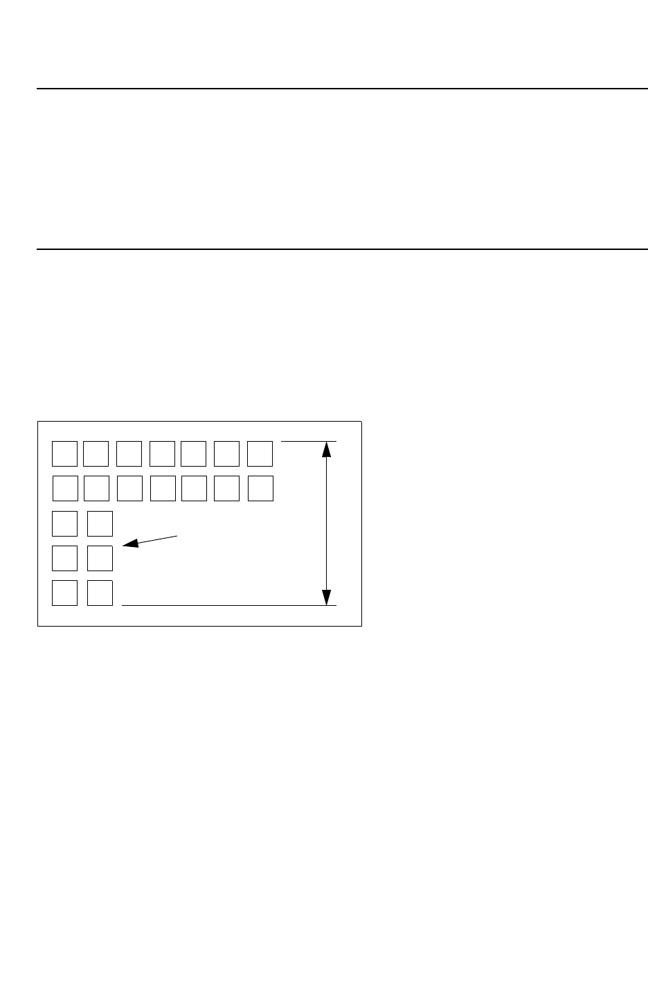
Chapter 3: Process Characterization Interface
Via Merging 3-51
Chapter 3: Process Characterization Interface
Via Merging 3-51
StarRC User Guide and Command Reference Version F-2011.06
Mapping File Syntax
The mapping file syntax for this function is as follows:
VIA GRD_VIA RPV = <value>
Area = <value>
MAX_VIA_ARRAY_SPACING = <value>
MAX_VIA_ARRAY_LENGTH = <value>
Examples of Via Merging
Several cases are explored and suggestions for possible results are included as follows.
Case 1
In an L-shaped via farm, StarRC groups the vias into multiple sets in an arbitrary manner as
shown in Figure 3-24.
Figure 3-24 Case 1 - Before Merge
L1
S1
If you specify MAX_VIA_ARRAY_SPACING: <S1> and MAX_VIA_ARRAY_LENGTH: <L1>, then
the via array can be divided into two groups.
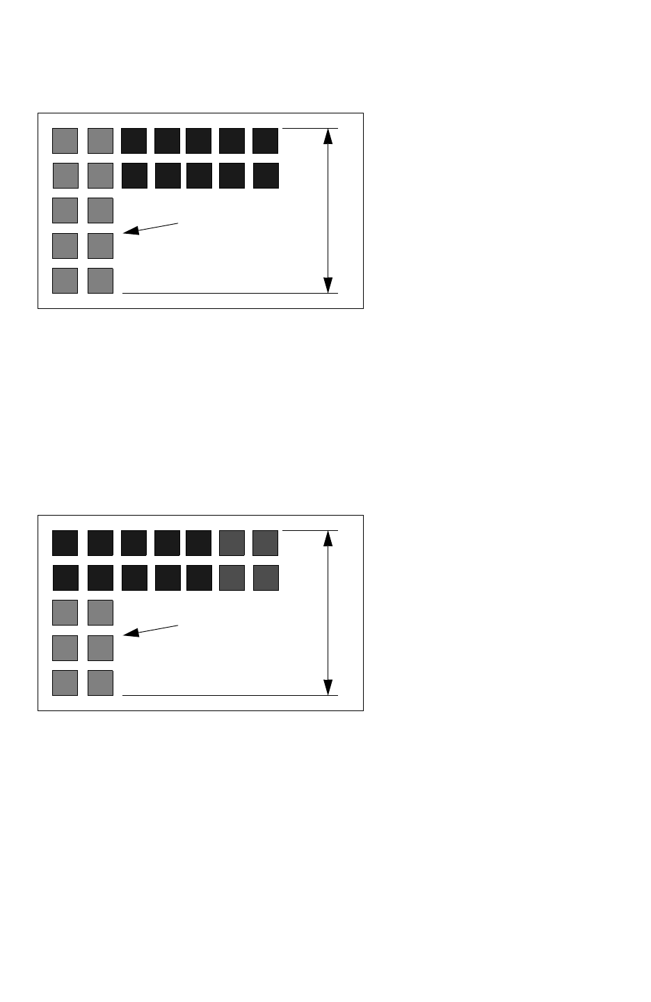
Chapter 3: Process Characterization Interface
Via Merging 3-52
StarRC User Guide and Command Reference F-2011.06
StarRC User Guide and Command Reference Version F-2011.06
Figure 3-25 Case 1 - After Merge
L1
S1
The after merge result is shown in Figure 3-25. The output netlist for this case would be as
follows:
R1 no:1 no:2 (1/10)*<via res> $area=10*<via area> $lvl= <num>
R2 no:3 no:4 (1/10)*<via res> $area=10*<via area> $lvl=<num>
R3 no:2 no:3 <value> $w =<num> $l=<num> $lvl =<num>
Another possibility is that StarRC might divide the vias into three groups as shown in
Figure 3-26.
Figure 3-26 Case 1 - Dividing Into Three Groups
L1
S1
The output netlist for three-groups is as follows:
R1 no:1 no:2 (1/6)*<via res> $area=6*<via area>
R2 no:3 no:4 (1/10)*<via res> $area=10*<via area>
R3 no:5 no:6 (1/4)*<via res> $area=4*<via area>
R4 no:2 no:3 <value> $w =<num> $l=<num> $lvl =<num>
R5 no:4 no:5 <value> $w =<num> $l=<num> $lvl =<num>
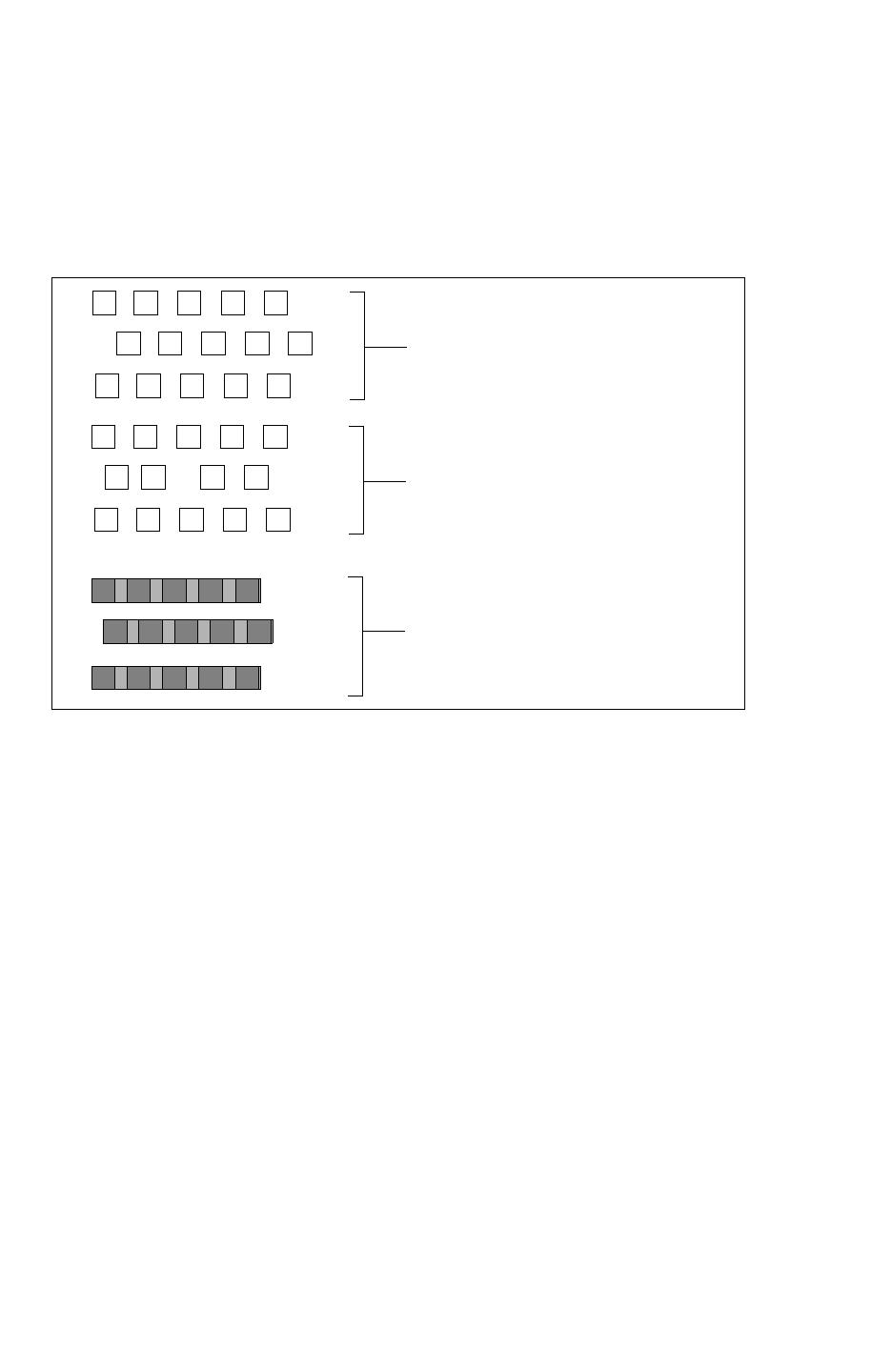
Chapter 3: Process Characterization Interface
Via Merging 3-53
Chapter 3: Process Characterization Interface
Via Merging 3-53
StarRC User Guide and Command Reference Version F-2011.06
Case 2
If the design has asymmetric via arrays with different pitch, then StarRC groups them
arbitrarily based on the specified MAX_VIA_ARRAY_SPACING and MAX_VIA_ARRAY_LENGTH
as shown in Figure 3-27.
Figure 3-27 Case 2 - Irregular Horizontal Spacing
Horizontal spacing same, but not aligned
Horizontal spacing not the same and not aligned
Possible Output from StarRC
In this illustration, the vertical spacing of center
vias is assumed to be greater than the
MAX_VIA_ARRAY_SPACING
.
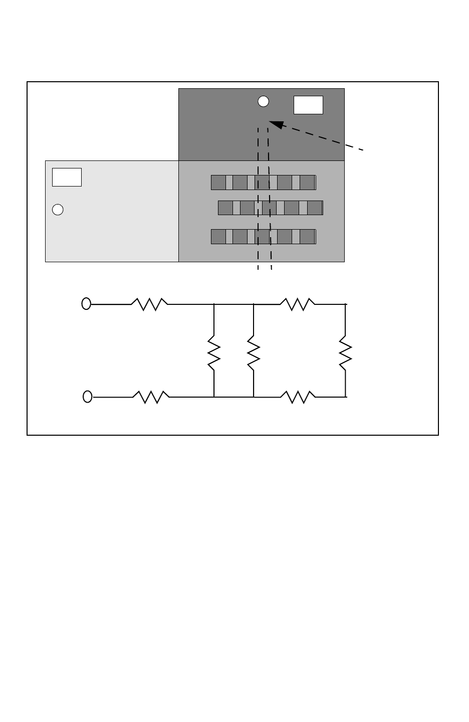
Chapter 3: Process Characterization Interface
Via Merging 3-54
StarRC User Guide and Command Reference F-2011.06
StarRC User Guide and Command Reference Version F-2011.06
Figure 3-28 View from Under the Network
M2
M1
Node location
of via
R3
Rv2 Rv1
R4R2
Rv3
R1
M2 Pin
M1 Pin
In Figure 3-28, you can possibly get below the network. However, if the distance between
two via node locations is small, it can be merged. This means R3 and R4 can be shorted.
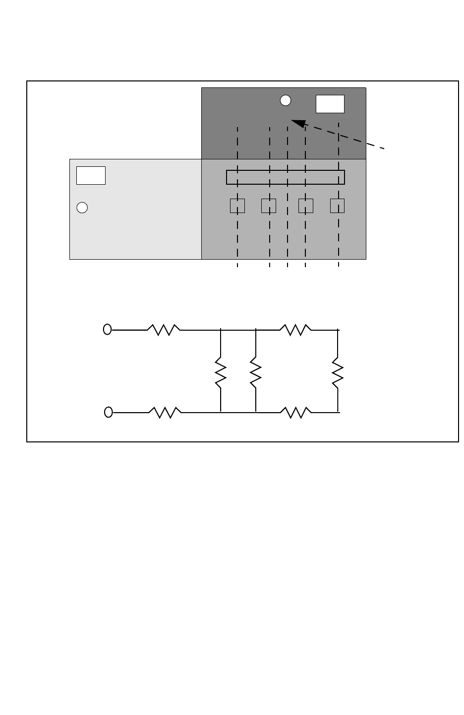
Chapter 3: Process Characterization Interface
Via Merging 3-55
Chapter 3: Process Characterization Interface
Via Merging 3-55
StarRC User Guide and Command Reference Version F-2011.06
Figure 3-29 View from Under the Network - Multiple Nodes
M2
M1
Node location
of via
R3
Rv2 Rv1
R4R2
Rv3
R1
M2 Pin
M1 Pin
ABCDE
Resulting network
In Figure 3-29, StarRC creates multiple nodes for the vias. It chooses the center for the
via-merged polygon (node C as the merged polygons are aligned). Nodes A, B, D, and E are
created for the individual vias. Because the distance between nodes B, C, and D is small,
the metal resistance is shorted out and the resulting network is shown in the lower portion
of the figure.
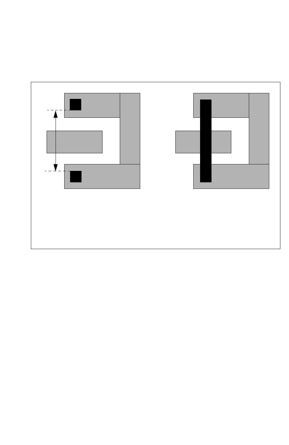
Chapter 3: Process Characterization Interface
Via Merging 3-56
StarRC User Guide and Command Reference F-2011.06
StarRC User Guide and Command Reference Version F-2011.06
Case 3
If you set an arbitrarily large value (much greater than via-to-via spacing), then it can lead to
shorts or loss of metal resistance as shown in Figure 3-30 on page 3-56.
Figure 3-30 Shorts and Loss of Metal Resistance
S1 S1
Original Layout Shorted layout
Setting a large value can lead to
shorts and loss of resistance.
You should use the
VIA to VIA design rule spacing value
for MAX_VIA_ARRAY _SPACING.
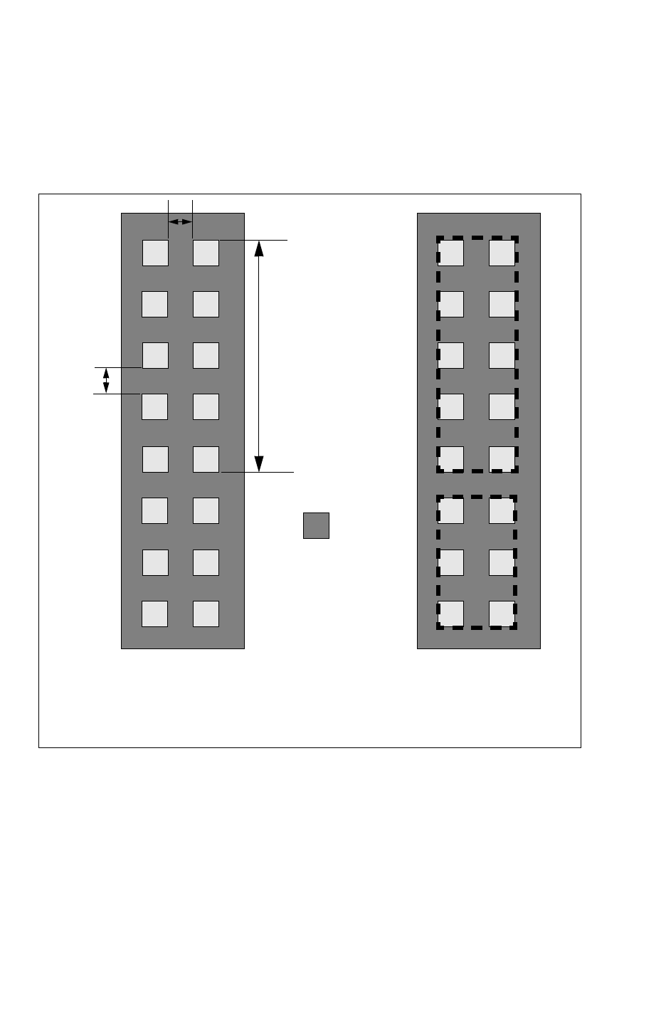
Chapter 3: Process Characterization Interface
Via Merging 3-57
Chapter 3: Process Characterization Interface
Via Merging 3-57
StarRC User Guide and Command Reference Version F-2011.06
Case 4
In a simple rectilinear VIA array, as shown in Figure 3-31, StarRC merges the vias based on
the settings of MAX_VIA_ARRAY_SPACING and MAX_VIA_ARRAY_LENGTH.
Figure 3-31 Simple Rectilinear VIA Array
L
S
INPUT
vi1
OUTPUT
MAX_VIA_ARRAY_SPACING: S
MAX_VIA_ARRAY_LENGTH: L
The output netlist for the arrays shown in Figure 3-31 is as follows:
R1 no:1 no:2 (1/10)*<via res> $area=10*<via area>
R2 no:3 no:4 (1/6)* <via res> $area=6* <via area>
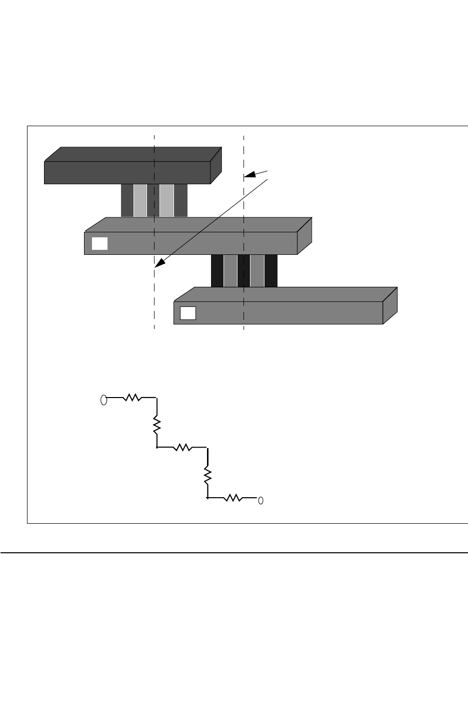
Chapter 3: Process Characterization Interface
Writing a Mapping File 3-58
StarRC User Guide and Command Reference F-2011.06
StarRC User Guide and Command Reference Version F-2011.06
Case 5
in Case 5, the R network for a multilayer net with via merging is shown in Figure 3-32.
Figure 3-32 R Network for a Multilayer Net
M3
M2
M1
Via nodes
The expected R network is as follows:
M1 Pin
R-M1
Rvia1
R-M2
Rvia2 R-M3
M3 Pin
Writing a Mapping File
The mapping file, which maps the database layer to the tcad_grd layer, is needed for every
StarRC run. You can write the mapping file manually or by using the StarRC GUI.

Chapter 3: Process Characterization Interface
Writing a Mapping File 3-59
Chapter 3: Process Characterization Interface
Writing a Mapping File 3-59
StarRC User Guide and Command Reference Version F-2011.06
Mapping multiple database layers to a single process layer is valid, but the reverse is
prohibited. Each logically connected database layer must be mapped in this file, even if the
layer is derived or used only for intermediate connections with no real physical significance.
In LEF/DEF flows, this means that each layer defined in the technology LEF file must be
mapped (including VIAs).
Map the connected database layers with the following mapping file commands, which can
be specified in any order:
•conducting_layers
•via_layers
•marker_layers
•remove_layers
To ignore capacitive interaction between specific layers, use the ignore_cap_layers
command.
Note:
One of the advantages of using the ITF (see “The Interconnect Technology Format File”
on page 3-4) to describe a process technology is that it eliminates the need to maintain,
support, and cross check parameter sets for consistency. If the sheet resistance
parameters for the process must be altered, it is best to regenerate the tcad_grd file (see
“Process Characterization Basics” on page 3-3). Regenerating the tcad_grd with updated
sheet resistances is very fast, because grdgenxo can use the capacitance solution from
the original run.
Example 3-4 shows an example of a mapping file.

Chapter 3: Process Characterization Interface
Writing a Mapping File 3-60
StarRC User Guide and Command Reference F-2011.06
StarRC User Guide and Command Reference Version F-2011.06
Example 3-4 Layer Mapping File
Conducting_layers
fpoly Poly
Bulk Substrate
Poly Poly
Rpoly Poly
Rndiff Od
Ndif Od
Nwell Substrate
apgate Poly
angate Poly
ngate1 Poly
Ngate Poly
Pgate Poly
Nsd Od
Psd Od
Pdif Od
Met4 Metal4
Met3 Metal3
Met2 Metal2
met1 Metal1
Via Layers
Diffcnt Odcont
Plycnt:polycont polyCont
diffcnt:odCont odCont
m3via via3
m2via via2
mvia via1
marker_layers
met1_pin
met2_pin
met3_pin
remove_layers
cont:subCont
diffcnt:subCont
ignore_cap_layers
angate dngate ngate ngate1
pdif psd
ndif rndiff nsd
Ngate Nsd L=0.1
Pgate Psd L=0.1
Nsd BULK L=0.1
Psd BULK L=0.1

4-1
4
Physical Databases 4
This chapter contains the following sections:
•Introduction to Physical Databases
•Milkyway Database Extraction Flow
•LEF/DEF Database Extraction Flow
•Calibre Connectivity Interface
•Hercules Database Extraction Flow
•IC Validator Extraction Flow
•Cross-Referencing in Transistor Level Flows
•Cross-Referenced Extraction Options
•Parameterized Cells (PCELL)
•Metal Fill
•Shared Database Command Options
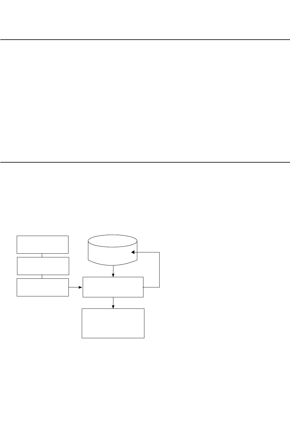
Chapter 4: Physical Databases
Introduction to Physical Databases 4-2
StarRC User Guide and Command Reference F-2011.06
StarRC User Guide and Command Reference Version F-2011.06
Introduction to Physical Databases
StarRC imports a physical description of the layout for calculating parasitic effects from one
of five possible sources: a Milkyway, Hercules, IC Validator, Calibre® Connectivity Interface,
or LEF/DEF database. No preparation of the database is required before you run StarRC.
StarRC can run on Milkyway or LEF/DEF databases with layouts containing opens or shorts.
Special provisions are made to repair the netlist so that delay calculation can be performed
even on the problem nets. Shorted nets are always netlisted independently and contain only
parasitics for the polygons that really belong to them. Open nets can optionally be
connected with the NETLIST_CONNECT_OPENS command in the StarXtract technology file.
Both opens and shorts are reported explicitly in detailed summary files. However, the
StarRC results might be inaccurate in a design with shorts or opens.
Milkyway Database Extraction Flow
The extraction flow shown in Figure 4-1 shows the Milkyway layout database containing all
network annotation information and is read directly by StarRC. The layout does not need to
be LVS-clean for completion of a successful extraction. Warnings are printed by StarRC for
any open or shorted nets it encounters.
Figure 4-1 Milkyway StarRC Extraction Flow
Netlist formats available:
SPF
SPEF
STAR
NETNAME
PARA (view)
mapfile
command file
nxtgrd
StarXtract
Netlist
Milkyway
database

Chapter 4: Physical Databases
Milkyway Database Extraction Flow 4-3
Chapter 4: Physical Databases
Milkyway Database Extraction Flow 4-3
StarRC User Guide and Command Reference Version F-2011.06
Place-and-Route Flow
StarRC offers a seamless integration into the Galaxy place-and-route environment.
StarRC also integrates directly with IC Compiler for sign-off driven design closure. IC
Compiler uses the sign-off quality parasitic extraction of StarRC to perform optimization on
the design.
Setting the Reference Library Control File
In determining the reference library status of a Milkyway database, StarRC uses the
reference library mode stored within the main Milkyway database with the Milkyway function
dbSetLibRefCtrlFileMode. The dbSetLibRefCtrlFileMode command specifies whether
the reference library tree source is from the Internal Reference Mode or the Reference
Control File Mode.
Unlike previous versions of StarRC, there is no longer a session-specific configuration
option, because the reference library status is saved directly as a property of the library. See
the Milkyway documentation for details about the command dbSetLibRefCtrlFileMode.
Milkyway Database Command Options
The commands shown in Figure 4-2 are specific to Milkyway input databases. For details
about these commands, see Chapter 17, “StarRC Commands.”
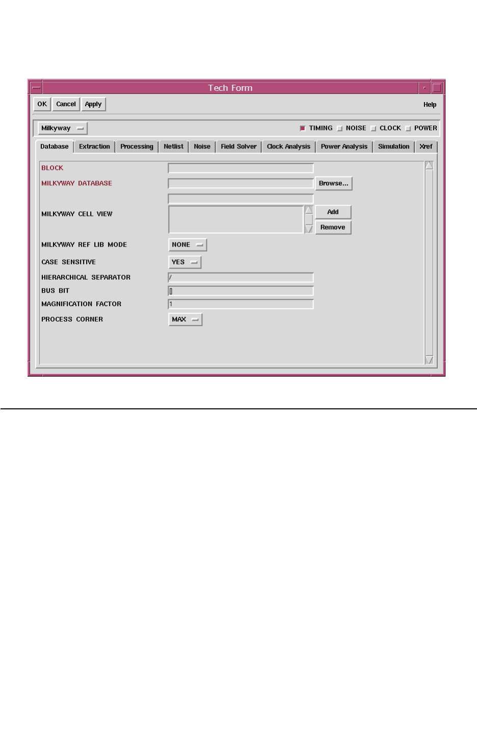
Chapter 4: Physical Databases
LEF/DEF Database Extraction Flow 4-4
StarRC User Guide and Command Reference F-2011.06
StarRC User Guide and Command Reference Version F-2011.06
Figure 4-2 Milkyway Database Tech Form
LEF/DEF Database Extraction Flow
The Library Exchange Format/Design Exchange Format (LEF/DEF) layout description is
read directly by StarRC as shown in Figure 4-3. LEF/DEF file format versions 5.2 through
5.7 are supported.
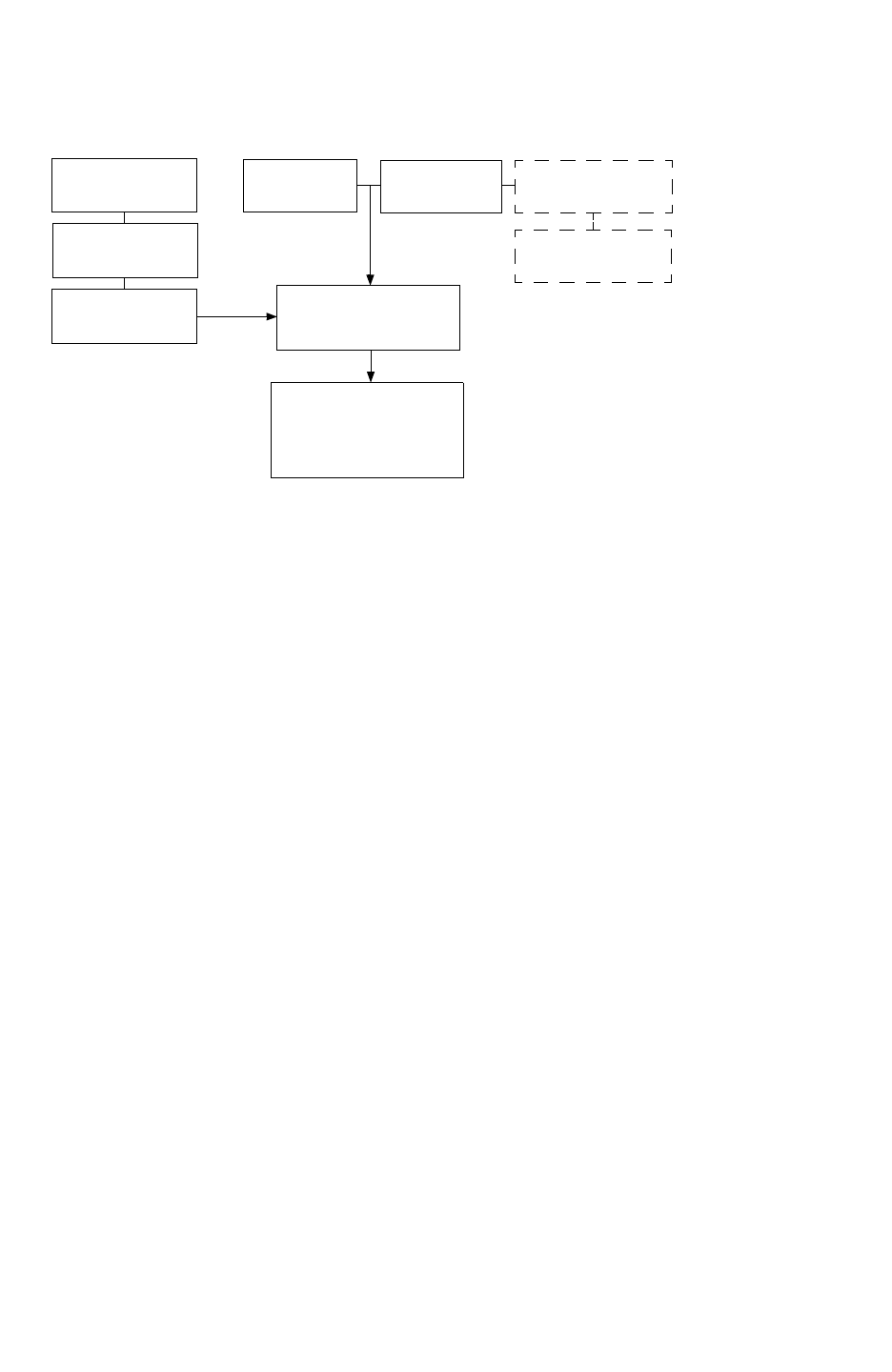
Chapter 4: Physical Databases
LEF/DEF Database Extraction Flow 4-5
Chapter 4: Physical Databases
LEF/DEF Database Extraction Flow 4-5
StarRC User Guide and Command Reference Version F-2011.06
Figure 4-3 LEF/DEF Extraction Flow
mapfile
command file
nxtgrd
StarXtract
SPF/SPEF
SBPF
STAR
LEF DEF MACRO DEF
GDSII
Most information about the design is read directly from the LEF/DEF database. StarRC
automatically identifies the following:
• Power nets
• Primary input/output ports
• Top-level block
•Skip cells
Hierarchical LEF/DEF designs are fully supported. You can specify multiple
MACRO_DEF_FILE commands along with a single TOP_DEF_FILE command, to extract a
hierarchically routed design. If a macro DEF file is specified, all subcells referenced in the
macro DEF must have corresponding MACRO definitions within the library LEF files input to
StarRC.
Starting from StarRC version B-2008.12, you do not need to specify the LEF descriptions for
DEF soft macros
In accordance with the LEF specification, the order in which the LEF files are specified is
important. The technology LEF that contains layer definitions is required before any of the
library LEF files are read. Undefined LEF layers cause an error warning that you must fix
before extraction can be completed. Any parasitic capacitance information contained in the
LEF files is ignored by StarRC. The layer resistance specifications are used only if
resistance information is missing from both the TCAD_GRD_FILE and the MAPPING_FILE.
The LEF file must always contain VIA definitions, even if the VIAs are redefined in the DEF
file. The DEF description takes precedence in the extraction whereas the LEF description is
used for layer mapping and initial connectivity.

Chapter 4: Physical Databases
LEF/DEF Database Extraction Flow 4-6
StarRC User Guide and Command Reference F-2011.06
StarRC User Guide and Command Reference Version F-2011.06
Timing-Driven Design Flow
StarRC also integrates smoothly with LEF/DEF-based place and route flows. You can read
leaf cells in GDSII format directly and they can be merged during translation into the layout
database.
The StarRC commands associated with LEF/DEF place and route are described in “LEF/
DEF Database Commands” on page 4-6.
Merging Library GDSII
GDSII can be directly merged into the LEF description for library cells or macro blocks.
When you use this feature, StarRC uses only the pin shapes from the LEF MACRO cell
definitions and discards the obstructions and other objects. The actual physical layout from
library GDSII is translated and used to represent the contents of SKIP_CELLS during
extraction.
GDSII layers for inclusion must be equated to a LEF database layer with the
GDS_LAYER_MAP_FILE command. For a description of the mapping file format, see the
GDS_LAYER_MAP_FILE command description. If any GDSII layer is not specified in the
GDS_LAYER_MAP_FILE, it is not translated for extraction and does not contribute to the
parasitics.
Indexes Warning in the Netlist Stage
If there is no port geometry for the pins of the cells in a LEF file, a warning is issued. For
example:
MACRO inv
PIN a
DIRECTION INPUT ;
END a
PIN y
DIRECTION OUTPUT ;
END y
END inv
You must make the necessary correction in the LEF file.
LEF/DEF Database Commands
StarRC features several commands for use in a LEF/DEF flow, listed in Table B-2 on
page B-11. You can specify these commands in the tech form for LEF/DEF databases as
shown in Figure 4-4.
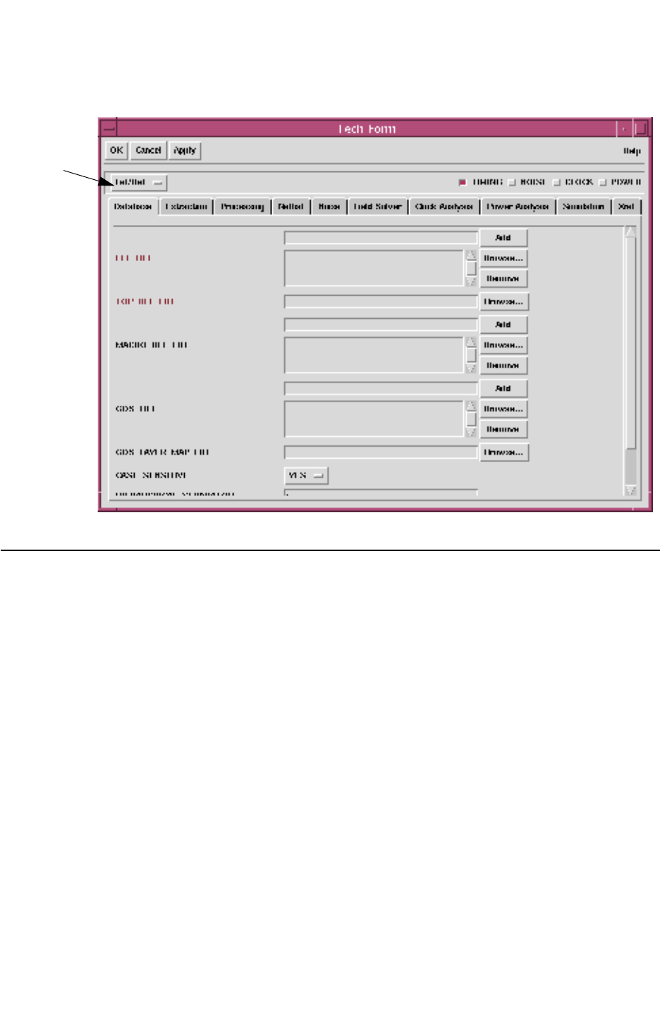
Chapter 4: Physical Databases
Calibre Connectivity Interface 4-7
Chapter 4: Physical Databases
Calibre Connectivity Interface 4-7
StarRC User Guide and Command Reference Version F-2011.06
Figure 4-4 LEF/DEF Database Tech Form
LEF/DEF
Calibre Connectivity Interface
If you use Mentor Graphics® Calibre® as your primary design rule checking (DRC) and
layout versus schematic (LVS) verification tool, StarRC reads Calibre output files and
extracts parasitics for device-level extraction. This is achieved by using the Calibre
Connectivity Interface (CCI). Calibre Connectivity Interface provides the ability to output all
relevant layout, connectivity, port, and cross-referencing information from the Calibre LVS
run in a form that is usable by StarRC. StarRC uses this information to construct a
device-level parasitic netlist in standard DSPF and SPEF formats.
Calibre Connectivity Interface flow extractions output the same Detailed Standard Parasitic
Format (DSPF) and Standard Parasitic Exchange Format (SPEF) netlists available with
other StarRC flows for use with industry simulation and analysis tools.

Chapter 4: Physical Databases
Calibre Connectivity Interface 4-8
StarRC User Guide and Command Reference F-2011.06
StarRC User Guide and Command Reference Version F-2011.06
Calibre generates multiple files with information about polygons, connectivity, text net
names, device tables, and LVS cross-referencing tables. StarRC reads the following Calibre
Connectivity Interface information to construct the parasitic netlist:
• Annotated GDSII (AGF) file containing polygon and connectivity information
• Mapping file describing layer mapping between the AGF file and the Calibre runset
• Ideal layout netlist
• Layout net names file
• Calibre device table describing terminal layers for all possible devices in runset
• Top-level ports file
• LVS net cross-referencing table
• LVS instance cross-referencing table
• Calibre runset to interpret layer connectivity
By reading the layout netlist, layout connectivity, and LVS cross-referencing information,
StarRC provides a means for you to perform schematic back-annotation of the layout
parasitics netlist.
StarRC requires only two command file inputs to read all required Calibre Connectivity
Interface information described previously.
• The query command file with which the Calibre Query Server was run
• The Calibre runset in order to interpret layer connectivity
By reading the Calibre query command file directly, StarRC is able to locate all Calibre
Connectivity Interface generated subordinate files relating to the ideal layout netlist, the
annotated GDSII file, and the cross-referencing information. At the same time, StarRC is
able to do error checking on the Calibre query command file to ensure that the Calibre
Query Server was invoked with the required set and ordering of options for use with StarRC.
See Running the Calibre Query Server for Output to StarRC in Appendix B for information
about the Calibre query command file setup for use with StarRC.

Chapter 4: Physical Databases
Calibre Connectivity Interface 4-9
Chapter 4: Physical Databases
Calibre Connectivity Interface 4-9
StarRC User Guide and Command Reference Version F-2011.06
StarRC Command File Preparation
Calibre Connectivity Interface based extraction requires the following commands in the
StarRC command file:
Command Purpose
CALIBRE_RUNSET: filename LVS command file for the Calibre run. An LVS rule deck
contains data creation commands, device creation
commands, device property calculations, layer connect
sequences, and LVS comparison options. StarRC parses the
layer connect sequence from the Calibre runset, including
derived layer connectivity, to determine ideal netlist
connectivity.
CALIBRE_QUERY_FILE: filename Command file used to invoke Calibre Query Server to output
CCI information from Calibre. This file specifies the location of
all CCI outputs required for parasitic extraction including
annotated GDSII layout and layer mapping information,
top-level port information, ideal layout netlist, ideal netlist net
naming information, cross-referencing tables, top-level cell
extents, and layout device terminal layer information.
CALIBRE_QUERY_FILE also performs error checking of the
command file to ensure conformity with StarRC requirements
for Calibre Query Server invocation.
The following example shows a StarRC command file for the Calibre Connectivity Interface
flow:
BLOCK: sample
TCAD_GRD_FILE: sample.nxtgrd
MAPPING_FILE: sample.map
CALIBRE_RUNSET: calibre.runset
CALIBRE_QUERY_FILE: query_input
To generate an ideal netlist, which extracts specific nets connected to certain devices,
1. Use the UNIX grep command to find the nets that are connected to certain instances or
devices.
2. Extract the design with the selected nets from step 1.
The following set of commands help to reduce the runtime for an ideal SPICE netlist
generation:
REDUCTION: HIGH
EXTRACTION: C
MODE: 100
NETS: !*
NETLIST_IDEAL_SPICE_NETLIST:

Chapter 4: Physical Databases
Calibre Connectivity Interface 4-10
StarRC User Guide and Command Reference F-2011.06
StarRC User Guide and Command Reference Version F-2011.06
StarRC and Calibre Connectivity Interface Flow
Follow the StarRC Calibre Connectivity Interface (CCI) workflow steps as illustrated in
Figure 4-5:
1. Generate an LVS or HLVS clean design.
2. Create a collection of CCI input files with the query command file, query_cmd.
% calibre -query svdb < query_cmd
svdb contains the design data from Calibre.
query_cmd is a user-generated file containing the Calibre options that create the CCI
files.
3. Write a StarRC command file containing the CALIBRE_RUNSET and
CALIBRE_QUERY_FILE commands.
4. Run StarRC with the prepared command file.
The CALIBRE_RUNSET and CALIBRE_QUERY_FILE commands find the necessary Calibre
file information and your desired output file is produced.
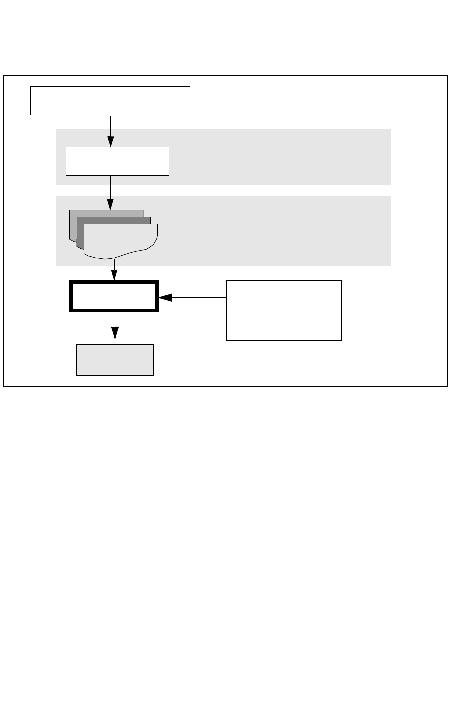
Chapter 4: Physical Databases
Calibre Connectivity Interface 4-11
Chapter 4: Physical Databases
Calibre Connectivity Interface 4-11
StarRC User Guide and Command Reference Version F-2011.06
Figure 4-5 StarRC Calibre Connectivity Interface Flow
LVS or HLVS “clean” Calibre output
Calibre HLVS -svdb
Calibre CCI Files
StarRC StarRC command file
Parasitic
Netlist
% calibre -query svdb < query_cmd
AGF file
AGF layer map
Layout netlist
Net ID map
IXF
NXF
DEVTAB
CELLS_PORTS
requiring only
CALIBRE_RUNSET
and
CALIBRE_QUERY_FILE
Error Messages
StarRC issues error or warning messages whenever the following conditions exist:
• If GDS NETPROP NUMBER, GDS PLACEPROP NUMBER, or GDS DEVPROP
NUMBER are not specified correctly in the Calibre query command file, StarRC issues an
error similar to the following:
ERROR: StarXtract
ERROR: GDS PLACEPROP NUMBER 1 is not supported.
================================
Please set the following Calibre query server commands
in your rule file and rerun calibre -query.
GDS NETPROP NUMBER 5
GDS PLACEPROP NUMBER 6
GDS DEVPROP NUMBER 7
================================
ERROR:StarXtract
ERROR: Input Calibre query command file error.

Chapter 4: Physical Databases
Calibre Connectivity Interface 4-12
StarRC User Guide and Command Reference F-2011.06
StarRC User Guide and Command Reference Version F-2011.06
The GDS NETPROP NUMBER, GDS PLACEPROP NUMBER, and the GDS DEVPROP
NUMBER must be set in accordance with the Calibre Query File requirements listed in
”Running the Calibre Query Server for Output to StarRC” in Appendix B.
• GDS SEED LAYER ORIGINAL, when specified, must come before the GDS MAP
command in the Calibre query command file. If GDS SEED LAYER ORIGINAL is
specified after GDS MAP, the following warning results.
WARNING: GDS SEED PROPERTY ORIGINAL affects CCI AGF layer
mapping;
WARNING: This command should occur before the GDS MAP
command in Calibre query file.
WARNING: GDS MAP file could be invalid.
For the proper ordering and setup of Calibre query file commands for use with StarRC,
see “Running the Calibre Query Server for Output to StarRC” on page 14-33.
•XREF:COMPLETE is not supported in the Calibre Connectivity Interface flow.
•MACRO command is not supported in the Calibre Connectivity Interface flow.
• Duplicate layer mappings in the Calibre AGF layer mapping file produce an error
condition because data in the AGF might be corrupted as a result. For example, if two
AGF layers are mapped to the same layer number, the following error message appears
during the Translate DB stage:
ERROR:StarXtract
ERROR: different gds layers are mapped to the same gds
layer number:<layer1>, <layer2>, <shared layer number>
This condition can result if a partial layer mapping is provided in the Calibre query server
command file. In general, you should not specify layer mappings (using GDS MAP
commands) in the Calibre query server command file. For information about the query
server command, see “Running the Calibre Query Server for Output to StarRC” on
page 14-33.
• Missing pin (x,y) information in the Calibre ideal netlist produces a warning condition
instructing you to include the relevant Calibre Connectivity Interface query commands in
the Calibre Connectivity Interface query command file.
For example, if the Calibre query server command LAYOUT NETLIST PIN LOCATIONS
YES is not used during the query server run, StarRC issues the following warning during
Translate DB:
WARNING: Unable to determine terminal locations for "0"
of device "n". This instance will not be netlisted.

Chapter 4: Physical Databases
Calibre Connectivity Interface 4-13
Chapter 4: Physical Databases
Calibre Connectivity Interface 4-13
StarRC User Guide and Command Reference Version F-2011.06
Schematic/Layout Cross-Referencing
In the Calibre Connectivity Interface flow, StarRC supports layout-based cross-referencing
with the command XREF:YES. In this mode, all nets and devices that occur in the ideal layout
netlist appear in the parasitic netlist, using schematic net and instance/device names
wherever possible. Special naming techniques for handling various merging situations are
described in the general discussion of the command XREF:YES in this user guide.
Schematic and layout cross-referencing in Calibre Connectivity Interface is purely layout
based, meaning that the parasitic RC netlist mirrors the structure, connectivity, and
quantities of nets, instances, and devices present in the actual layout. Calibre Connectivity
Interface cross-referencing tables are used to annotate schematic names onto these nets,
instances, and devices wherever matches are made during LVS.
For cross-referenced ideal devices, the model name specified with Calibre’s NETLIST
MODEL suboption is netlisted with XREF:YES whenever this suboption exists for a particular
DEVICE command in the Calibre LVS rule file. Otherwise, the default Calibre model name is
used. StarRC always uses the default model name with XREF:NO, because the layout netlist
from Calibre uses that convention.
If a net does not exist in the Calibre NXF file, StarRC uses the layout net name with the prefix
specified with the XREF_LAYOUT_NET_PREFIX command (default: ln_). For example, if layout
net A did not match in LVS and does not exist in the Calibre NXF file, StarRC assigns ln_A
in the parasitic netlist. Similarly, if an instance does not exist in the Calibre IXF file, StarRC
uses the layout instance name with the prefix specified in the XREF_LAYOUT_INST_PREFIX
command (default: ld_).
Calibre Support of LVS Black Box Flow
To enable proper StarRC cross-referencing of Calibre LVS BOX cells, one additional
command is required in the Calibre query server command file to output needed information
in the Calibre Connectivity Interface NXF cross-referencing files. No additional StarRC
commands are required.
Note:
This feature is compatible only with enhanced Calibre Connectivity Interface NXF file
output available in Calibre 2003.06 from Mentor Graphics.
Designers commonly perform LVS verification using incomplete subcell information by
having the LVS tool not compare the functional contents of the subcell. In such cases the cell
is called a black box, meaning that the LVS tool treats all instances of the cell as equivalent
between schematic and layout without comparing the contents of the cell. Hercules uses the
BLACK_BOX and BLACK_BOX_FILE commands to specify black-boxed cells, while Calibre
uses the LVS BOX syntax. The only constraint for a black-box cell is that cell ports must have
correspondence between the schematic and layout.

Chapter 4: Physical Databases
Calibre Connectivity Interface 4-14
StarRC User Guide and Command Reference F-2011.06
StarRC User Guide and Command Reference Version F-2011.06
To cross-reference LVS black-box cells, you must add the following Calibre query server
command to the query command file:
NET XREF WRITE <file_name> [BOX]
This command is already required to enable cross-referencing using the XREF command in
StarRC. To enable Calibre LVS BOX capability, the present command in the Calibre query
server command file should be appended with the keyword BOX. Adding the keyword BOX
has two effects on the NXF file:
• Within the NXF file, Calibre lists hcells (or equivalence points) for all LVS BOX cells.
Equivalence point lines begin with the percent character (%) in the IXF and NXF files.
Note that equivalence points for LVS BOX cells are not listed in the NXF file without the
keyword BOX in the Calibre Query Server command file.
• Under the hcell (equivalence point) described in the NXF file, Calibre lists all matched
ports for the cell. This enables StarRC to cross-reference all ports for LVS BOX cells.
An example of output from the Calibre query server command NET XREF WRITE BOX
follows:
% inv1 4 inv1 6 BOX
0 vss 0 vss
0 vdd 0 vdd
0 b 0 b
0 a 0 a
Using this information, StarRC performs the following:
• Netlists cell instances for all LVS BOX cells using schematic instance names, whenever
a match for the instance has occurred in the Calibre IXF file
• Netlists all port connections to LVS BOX instances using schematic port names,
whenever a match for port names occurs in the Calibre NXF file as illustrated previously
Just as with non-LVS BOX cells, Calibre writes interconnect polygon information to the AGF
file for LVS BOX cells. You should specify Calibre BOX cells as SKIP_CELLS in the StarRC
command file. If you do not do this, StarRC issues a warning and adds the BOX cell to the
StarRC SKIP_CELLS list. Because these cells must be specified as SKIP_CELLS for StarRC,
StarRC treats the contents of LVS BOX cells in a gray-box manner by extracting capacitive
interactions from extracted nets to polygons contained in such cells.

Chapter 4: Physical Databases
Hercules Database Extraction Flow 4-15
Chapter 4: Physical Databases
Hercules Database Extraction Flow 4-15
StarRC User Guide and Command Reference Version F-2011.06
Table 4-1 lists concepts, syntax, and file names for the Calibre black box feature.
Table 4-1 Calibre Black Box Feature
LVS BOX Calibre rule-file syntax for listing cells whose contents are not to be
verified during LVS, but are assumed to be LVS equivalent.
hcell
(or equivalence point)
An expression of LVS equivalence between a schematic cell
master and a layout cell master.
IXF file Calibre query server output file listing all instance (device and cell)
matches between schematic and layout verified during LVS; this
file is required by StarRC whenever XREF is activated.
NXF file Calibre query server output file listing all net matches between
schematic and layout verified during LVS; this file is required by
StarRC whenever XREF is activated.
Hercules Database Extraction Flow
To create a parasitic netlist output using the Hercules flow, you must provide a physical
database, schematic netlist, and Hercules runset as shown in Figure 4-6. To connect the
Hercules runset with StarRC, specify the WRITE_EXTRACT_VIEW command. In the Hercules
runset. In StarRC, you must specify the BLOCK, XREF, CELL_TYPE, and
MILKYWAY_EXTRACT_VIEW in the StarRC command file. Also, the path to the nxtgrd and
mapping file must be specified in the StarRC command file. This connects the data. The
connected Hercules database, or Milkyway XTR view, can be generated as a parasitic netlist
or an ideal extraction of the layout from an original GDSII, or place and route Milkyway
database. Note that a net in the database that is not annotated with layout text is assigned
a numerical net identifier by Hercules.
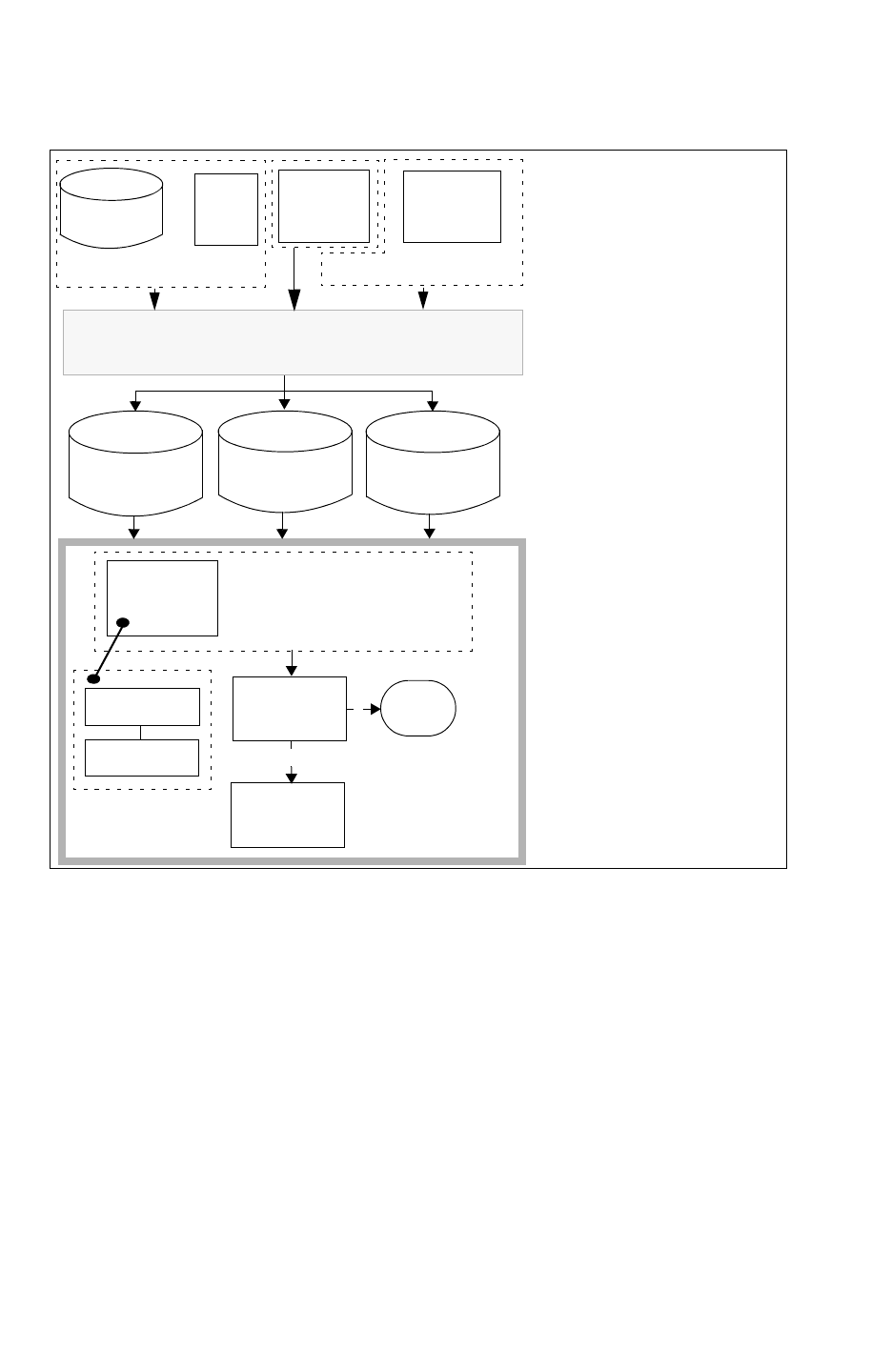
Chapter 4: Physical Databases
Hercules Database Extraction Flow 4-16
StarRC User Guide and Command Reference F-2011.06
StarRC User Guide and Command Reference Version F-2011.06
Figure 4-6 Hercules Extraction Flow
Milkyway
database
GDSII
Hercules
nxtgrdfile
mapfile
StarXtract
Parasitic
runset
Hercules
Output
Milkyway XTR
schematic
netlist
XREF
Information
StarRC
StarRC
Command
File
MILKYWAY_EXTRACT_VIEW
XREF
CELL_TYPE
BLOCK
Schematic
Netlist
WRITE_EXTRACT_VIEW
Physical database
Ideal
Netlist
Netlist
processed
Find information
about the processed
schematic netlist in
the directory:
./run_details/evaccess
Find information
about the XREF
information in the
directory:
./run_details/compare/.db
OR
Specify
WRITE_EXTRACT_VIEW
in your Hercules runset.
Specify a nxtgrd file with
the TCAD_GRD_FILE
command.
Specify a map file with the
MAPPING_FILE command.

Chapter 4: Physical Databases
Hercules Database Extraction Flow 4-17
Chapter 4: Physical Databases
Hercules Database Extraction Flow 4-17
StarRC User Guide and Command Reference Version F-2011.06
GDSII to XTR View Translation
A GDSII file contains no layer connectivity or ideal netlist information. Hercules establishes
layer connectivity and extracts an ideal layout netlist using rules defined in the Hercules
runset. A connected version of the database is then stored in the form of a Milkyway XTR
view database for input to StarRC.
Follow these rules when generating the XTR view:
• The term SUBSTRATE is a reserved keyword in the Hercules runset and cannot be
assigned as a TEMP or PERM layer for any Hercules command.
• In the case of a place-and-route Milkyway database, the Milkyway XTR view generated
by Hercules should be written to a unique library because the technology information is
different from that of the original library.
• Hercules runsets for use with StarRC must be prepared in accordance with StarRC rules
for device terminal and connectivity generation. For more information about Hercules
transistor-level runset creation, see “Preparing Hercules Runsets” on page 14-2.

Chapter 4: Physical Databases
Hercules Database Extraction Flow 4-18
StarRC User Guide and Command Reference F-2011.06
StarRC User Guide and Command Reference Version F-2011.06
The following is a sample Hercules runset containing Hercules commands applicable to a
cell-level GDS flow for use with StarRC:
header{
layout_path = .
inlib = library.gds
format = stream
block = top
}
assign_property {
instance_name (4)
}
assign {
poly (1) text(1;1)
cont (2)
metal1 (3) text(3;1)
via1 (4)
metal2 (5) text(5;1)
via2 (6)
metal3 (7) text(7;1)
}
text_polygon metal3.text {
cell_list = { top }
size = 0.1
text_list = { IN1 IN2 OUT }
} temp = io_pin
connect {
poly metal1 by cont
metal1 metal2 by via1
metal2 metal3 by via2
metal3 by io_pin
}
text {
poly by poly
metal1 by metal1
metal2 by metal2
metal3 by metal3
}
write_extract_view {
library_name = TOP
library_path = .
}
You must include a WRITE_EXTRACT_VIEW command as shown in the previous file sample to
enable Hercules to write out a Milkyway XTR view. It is from this XTR view that StarRC
derives the layout net annotation, layout device annotation, and layout connectivity.

Chapter 4: Physical Databases
Hercules Database Extraction Flow 4-19
Chapter 4: Physical Databases
Hercules Database Extraction Flow 4-19
StarRC User Guide and Command Reference Version F-2011.06
The TECHNOLOGY_OPTIONS command in the Hercules runset can have an impact on StarRC
extraction runtime. A command-line option for Hercules, -rcxt, has been implemented to
set the TECHNOLOGY_OPTIONS for optimal StarRC performance; you should use the -rcxt
option for transistor-level or hierarchical designs.
For more information about
• Marker generation, see “Marker Generation in Hercules” on page 14-11.
• Runset creation, see “Preparing Hercules Runsets” on page 14-2.
Cross-Referenced Extraction in the Hercules Flow
Multi-equivalence points in the layout are supported for cross-referenced extraction.
Multi-equivalence points are points in the layout where one or more layout cells equal to a
single schematic cell. The x-y coordinates of the instance ports and top-level ports are
reported.
If the Hercules IGNORE_CASE=TRUE command is specified in the runset, all schematic names
are uppercase in the StarRC netlist. You must set CASE_SENSITIVE=NO in the command file
if IGNORE_CASE=TRUE in the Hercules runset.
Note:
Check that your Hercules runset does not set CREATE_VIEWS=FALSE in the
EVACCESS_OPTIONS section. Successful XREF requires that this option be either set to
TRUE (the default) or left unspecified.
Certain memory designs might encounter errors in the XrefHN step of an XREF-enabled flow.
For example,
ERROR: StarXtract
ERROR: Found layout instance SRAMblock258x532#448 of equiv
ERROR: SRAMblock258x532#448 which is not a valid equiv point
The SRAMblock blocks are generated by the Hercules LVS engine when
MEMORY_ARRAY_COMPARISON is set to TRUE (this is the default). The SRAMblock blocks do
not exist in the original schematic or layout netlists.
In general, the MEMORY_ARRAY_COMPARE variable does not affect the LVS results in most
memory designs. For nonmemory designs, you do not need to change this option. The
StarRC XREF options do not support the MEMORY_ARRAY_COMPARE variable. You should set
it to FALSE for memory designs that encounter this error when running LVS.
As soon as StarRC finds one instance that is connected to the net “0” in the schematic
netlist, the following error message is issued:

Chapter 4: Physical Databases
Hercules Database Extraction Flow 4-20
StarRC User Guide and Command Reference F-2011.06
StarRC User Guide and Command Reference Version F-2011.06
Build XrefHN
ERROR: StarXtract
ERROR: Schematic instance "MM15/SRC" is connected
to ground "0". To
ERROR: prevent incorrect result, please rename net
"0" to another
ERROR: name.
Warnings: 0 Errors: 1 (See file xrefhn.sum)
In this case, you should change the net name “0” to a different name in the schematic netlist
and rerun Hercules LVS before starting a new StarRC.
All XREF modes support port ordering with the SPICE_SUBCKT_FILE. The port list should
match in the schematic cell definitions and the SPICE_SUBCKT_FILE .SUBCKT definitions.
StarRC generates net names in the <instance>_<port> format for ports present in the
SPICE_SUBCKT_FILE but missing from the schematic or layout, depending on the value of
XREF, so that the port count and order always match the SPICE_SUBCKT_FILE.
When you specify a series merging in Hercules Compare, StarRC reports ln_ for
non-cross-referenced internal nets. If you want to cross-reference these internal nets, you
should run Hercules version Y-2006.12-4 with the following environmental variable before
running StarRC version Z-2007.06 or later:
setenv WRITE_NEW_CDB
Note:
Earlier versions of StarRC do not accept the cross-reference database generated with
the Compatibility option.
Hercules Database Command Options
There are several Hercules database-specific options, as shown in the Tech Form in
Figure 4-7.
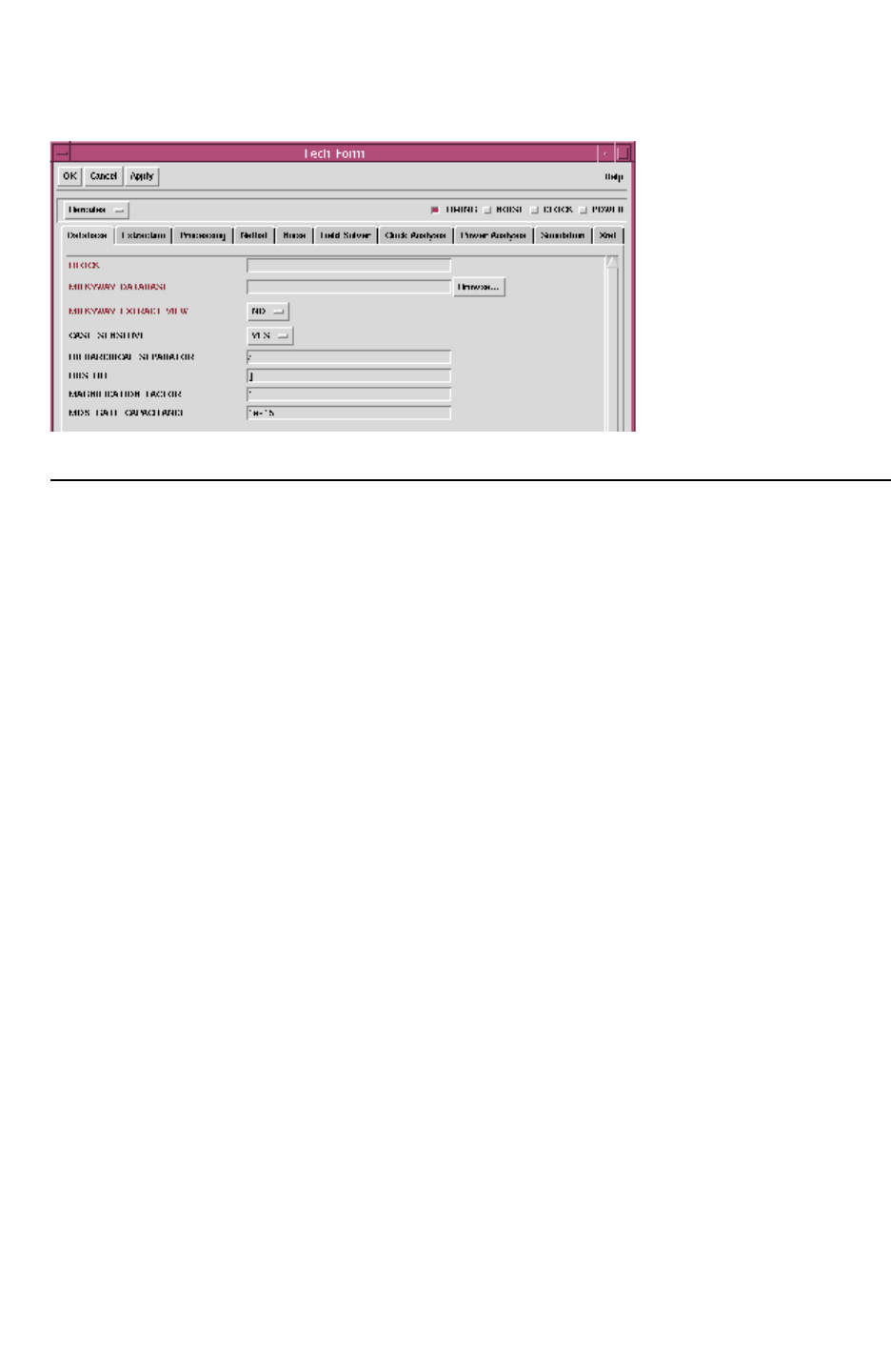
Chapter 4: Physical Databases
Hercules Database Extraction Flow 4-21
Chapter 4: Physical Databases
Hercules Database Extraction Flow 4-21
StarRC User Guide and Command Reference Version F-2011.06
Figure 4-7 Hercules Database Tech Form
HSIM Reliability Flow Placement Information
StarRC interfaces to HSIM through a Detailed Standard Parasitic Format (DSPF) file for both
hierarchical and flat post-layout simulation flows. The Synopsys product HSIM can receive
hierarchical DSPF and flat DSPF to perform hierarchical or flat timing and reliability analysis.
An important output of reliability analysis is a thermal map showing voltage (IR) drop and
electromigration violations provided by HSIM. Because the HSIM product is netlist based,
the reliability analysis thermal map is generated using node information (*|S, *|I, *|P)
provided by StarRC in the DSPF netlist. In a flat extraction, all nodes are shown with respect
to the origin of the top cell and a thermal map can be drawn without ambiguity. However, in
a hierarchical flow, each node in a hierarchical cell’s DSPF is shown with respect to its origin.
In order to map these nodes to the next level of hierarchy, you must know the placement of
the cell in the next level of hierarchy with rotation and flip attributes.
StarRC generates placement information when you specify the following options:
SKIP_CELL_PLACEMENT_INFO_FILE: YES | NO
SKIP_CELL_PLACEMENT_INFO_FILE_NAME: filename
When PLACEMENT_INFO_FILE: is set, StarRC generates the blockname.placement_info file
with the following information:
•Angle
• Reflection
• Cell location
• Cell name
• Cross-referenced instance name

Chapter 4: Physical Databases
IC Validator Extraction Flow 4-22
StarRC User Guide and Command Reference F-2011.06
StarRC User Guide and Command Reference Version F-2011.06
A sample output is as follows:
* PLACEMENT FILE
* VENDOR "Synopsys, Inc."
* PROGRAM "StarRC X-2005.06"
* DATE "Mon Oct 24 17:48:56 2005"
* UNIT " MICRONS"
TOP_CELL = <cell name>
<instance name> <cell name> <X-coord> <Y-coord> <Angle> <reflection>
XSI_0 INV1 49 132 0 NO
XSI_50 XOR2 484 132 180 NO
XSI_61 XOR2 124 312 180 YES
IC Validator Extraction Flow
To create a parasitic netlist with the IC Validator transistor level extraction flow, you must
provide a physical database, schematic netlist, and an IC Validator runset script to generate
an IC Validator database as shown in Figure 4-8. The resulting IC Validator database or the
IC Validator runset report file can be used to generate a parasitic netlist, or an ideal
extraction of the layout from an original GDSII database, or a Milkway place and route
database.
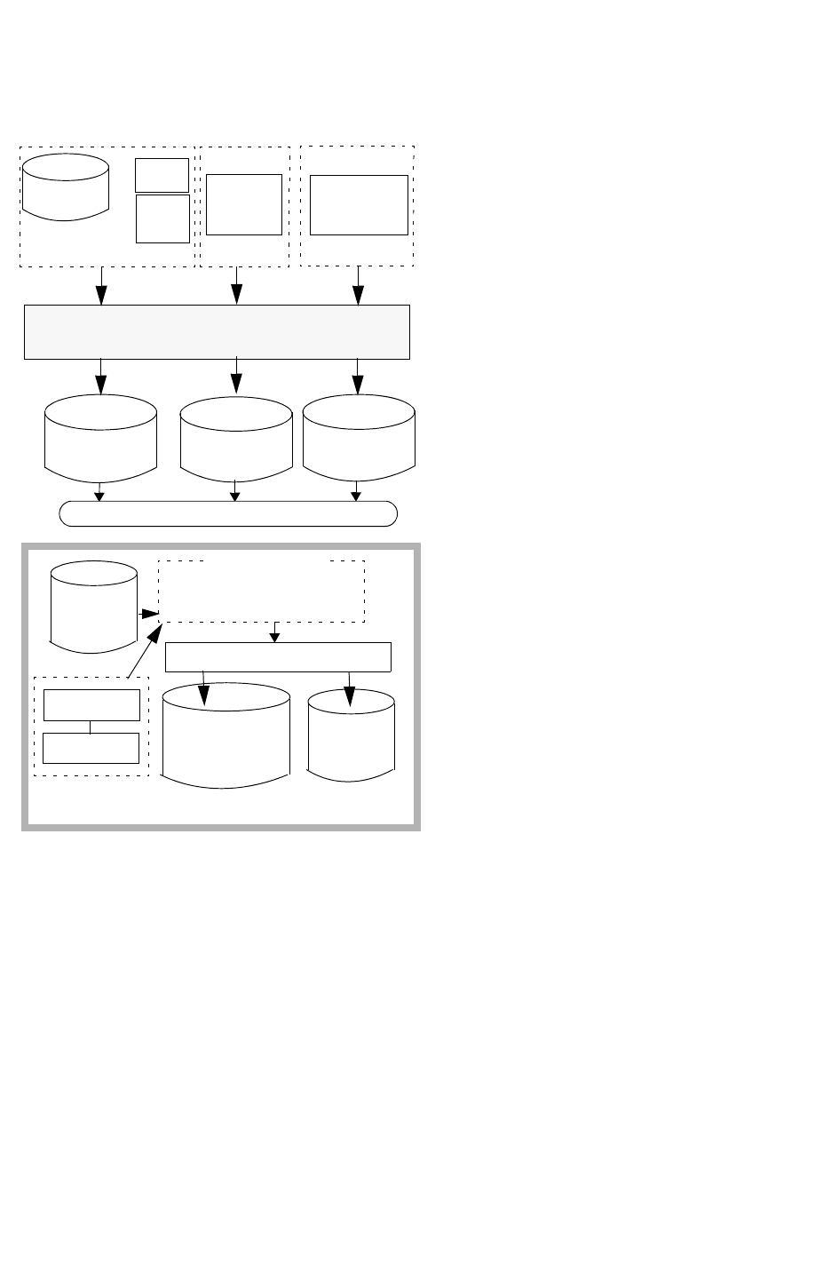
Chapter 4: Physical Databases
IC Validator Extraction Flow 4-23
Chapter 4: Physical Databases
IC Validator Extraction Flow 4-23
StarRC User Guide and Command Reference Version F-2011.06
Figure 4-8 IC Validator Flow
Milkyway
database
GDSII IC Validator
nxtgrd file
mapfile
StarXtract
IC Validator
XREF
Information
StarRC
ICV_RUNSET_REPORT_FILE
XREF
BLOCK
Schematic
Netlist
Physical
Milkyway
OR
Open
Access
run script
schematic
netlist
processed
Extract
View
Database
IC Validator Runset Report File
IC Validator
database
Ideal
(optional)
Netlist
Parasitic Output:
netlist
binary netlist
parasitic view
1. Specify input data for
IC Validator
2. Specify pex_runset_report_file
in your runset script.
All IC Validator results or database
information is recorded in the runset
report file.
in the star_cmd file

Chapter 4: Physical Databases
IC Validator Extraction Flow 4-24
StarRC User Guide and Command Reference F-2011.06
StarRC User Guide and Command Reference Version F-2011.06
Steps in the IC Validator Extraction Flow
To connect the IC Validator database with StarRC, you must specify the following commands
in your scripts:
• In the IC Validator run script, specify the following command:
pex_runset_report_file
• In the StarRC command file, include these commands:
BLOCK, XREF, CELL_TYPE, and ICV_RUNSET_REPORT_FILE
• In the IC Validator run script, specify the runset report filename of your choice in the
pex_report_handle command. By default, the file name is specified as
pex_runset_report in the $ICV_HOME_DIR/includes/rcxt_public.rh file. This step is
optional.
The first two modifications are the required changes to run the IC Validator transistor
extraction flow. The resulting IC Validator database or IC Validator runset report file, can
then be used to generate a parasitic netlist or an ideal extraction of the layout from an
original GDSII database, or Milkyway place and route database.
Examples of Script Files
This section provides examples of the script files necessary for the IC Validator extraction
flow.
IC Validator Runset Script
The following example shows the required commands in an IC Validator runset script with
the default runset report file name.
pex_report_handle = pex_runset_report_file();
pex_generate_results(
pex_matrix = pex_matrix,
device_extraction_matrix = my_devices,
device_db = device_db,
layout_database = mw_handle,
pex_process_map_file = pex_process_handle,
pex_runset_report_file = pex_report_handle
);
To change the runset report file name, modify the pex_report_handle command
specification, which is shown as my_report in the following example, to the filename of your
choice.
pex_report_handle = pex_runset_report_file("my_report");

Chapter 4: Physical Databases
IC Validator Extraction Flow 4-25
Chapter 4: Physical Databases
IC Validator Extraction Flow 4-25
StarRC User Guide and Command Reference Version F-2011.06
Note:
All paths listed in the runset_report_file command are absolute paths.
StarRC Command File
In the StarRC command file, add the following command:
ICV_RUNSET_REPORT_FILE : pex_runset_report
Cross-Referenced Extraction in IC Validator
Multi-equivalence points in the layout are supported for cross-referenced extraction.
Multi-equivalence points are points in the layout where one or more layout cells equal to a
single schematic cell. The x-y coordinates of instance ports and top-level ports are reported.
IC Validator can support a selective case-sensitive operation. The StarRC
CASE_SENSITIVE:YES|NO command might not cover all IC Validator case sensitivity
combinations.
Specify the pex_generate_results function in IC Validator runset script to run the IC
Validator and StarRC flow, as shown in the following example.
pex_generate_results(
pex_matrix = pex_matrix,
device_extraction_matrix = my_devices,
device_db = device_db,
layout_database = mw_handle,
pex_process_map_file = pex_process_handle,
pex_runset_report_file = pex_report_handle
);
Certain memory designs might encounter errors in the XrefHN step of an XREF-enabled flow.
For example,
ERROR: StarXtract
ERROR: Found layout instance SRAMblock258x532#448 of equiv
ERROR: SRAMblock258x532#448 which is not a valid equiv point
The SRAMblock blocks are generated by IC Validator when the memory_array_compare
variable is set to TRUE. This is the default. The SRAMblock blocks do not exist in the original
schematic or layout netlists.
In general, the memory_array_compare variable does not affect the LVS results in most
memory designs. For nonmemory designs, you do not need to change this option. The
StarRC XREF options do not support the memory_array_compare variable. You should set it
to FALSE for memory designs that encounter this error when running LVS.

Chapter 4: Physical Databases
Cross-Referencing in Transistor Level Flows 4-26
StarRC User Guide and Command Reference F-2011.06
StarRC User Guide and Command Reference Version F-2011.06
As soon as StarRC finds one instance that is connected to the net “0” in the schematic
netlist, the following error message is issued:
Build XrefHN
ERROR: StarXtract
ERROR: Schematic instance "MM15/SRC" is connected
to ground "0". To
ERROR: prevent incorrect result, please rename net
"0" to another
ERROR: name.
Warnings: 0 Errors: 1 (See file xrefhn.sum)
In this case, you need to change the net name “0” to a different name in the schematic netlist
and rerun Hercules LVS before starting a new StarRC run.
All XREF modes support port ordering with the the SPICE_SUBCKT_FILE command. The
port count and port order in the schematic cell definitions and the SPICE_SUBCKT_FILE
.SUBCKT definitions should always match. StarRC generates net names in the
<instance>_<port> format for ports present in the SPICE_SUBCKT_FILE section but missing
in the schematic or layout, depending on the value of XREF.
Cross-Referencing in Transistor Level Flows
The StarRC XREF command and its options can be used with the Calibre, Hercules, and IC
Validator flows. Details about the functions of these command options are as follows:
XREF:NO
If this command is set to NO, StarRC reports the layout net names generated by Hercules
during ideal layout extraction. These layout names are either generated or derived from the
application of text. The layout cell instance names can either be the original GDSII instance
name if the ASSIGN_PROPERTY command in Hercules is used or they can be names
generated by Hercules. For an example of XREF:NO .spf, see “XREF:NO SPF” in “XREF
Command SPF Examples” on page 13-10.
XREF:YES
The XREF:YES command does not use name prefixes for merged devices, and it generates
names that correspond to the premerged schematic names, thereby making analysis easier
during simulation, and improving schematic-based simulation accuracy. The following
section describes how the names are modified. The XREF:YES command is layout-based;

Chapter 4: Physical Databases
Cross-Referencing in Transistor Level Flows 4-27
Chapter 4: Physical Databases
Cross-Referencing in Transistor Level Flows 4-27
StarRC User Guide and Command Reference Version F-2011.06
every layout device and net is reported. If LVS successfully matches layout nets and devices
with schematic nets and devices, the parasitic netlist uses the schematic names for the
matched nets and devices.
For an example of XREF:YES .spf, see “XREF: YES” on page 13-10.
The following section describes how the XREF:YES command handles naming. In the
information provided, the syntax used is x:y, where the left side is the number of schematic
devices, and the right side is the number of layout devices. 1 indicates one device, with m
and n being differing values of more than 1. For example, m:m refers to the same number of
schematic and layout devices, whereas m:n refers to different numbers of layout and
schematic devices, and so on.
The XREF:YES command has methodologies for handling both one-to-one correspondences
between schematic and layout net/device entities as established by the LVS tool, and for
handling merged composite device matching generated during LVS.
One-to-One Correspondence
When the LVS tool establishes a one-to-one match between schematic net/device and
layout net/device names, XREF:YES netlists such layout nets and devices using their
matching schematic names.
Composite of Merged Devices
When the LVS tool creates a composite merged device in the schematic side consisting of
N merged devices, and matches it to a composite merged device on the layout side
consisting of M merged devices, the following rules govern the device names in the netlist
generated by the XREF:YES command:
• M individual devices are netlisted in the parasitic netlist, corresponding to the M layout
devices.
• A one-to-one correspondence is established between the first X devices where X is the
smaller of N or M within the schematic composite device and the layout composite device.
The first X devices are netlisted in the parasitic netlist using their corresponding
schematic device names.
• If the number of schematic devices exceeds the number of layout devices (N>M), the
remaining (N-M) schematic devices are not referenced in the schematic netlist, as shown
in Figure 4-9.
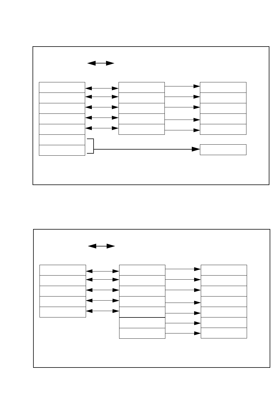
Chapter 4: Physical Databases
Cross-Referencing in Transistor Level Flows 4-28
StarRC User Guide and Command Reference F-2011.06
StarRC User Guide and Command Reference Version F-2011.06
Figure 4-9 Merged Device Handling N>M
S1
Schematic composite
device with N
schematic merged
devices
S2
S3
S4
S5
S6
S7
L1
L2
L3
L4
L5
S1
S2
S3
S4
S5
xrefhn.sum file
Layout composite
device with M layout
merged devices
Devices in the parasitic
netlist with XREF:YES
N>M (# schematic> #layout) merged device handling with XREF:YES. Note the same
convention applies to internal nets within merged devices.
• If the number of layout devices exceeds the number of schematic devices (N<M), the
remaining (M-N) layout devices are mapped back to the top of the schematic device list,
appended by @[number] characters, as shown in Figure 4-10.
Figure 4-10 Merged Device Handling N<M
S1
Schematic composite
device with N
schematic merged
devices
S2
S3
S4
S5
L6
L7
L1
L2
L3
L4
L5
S1
S2
S3
S1@2
S2@2
Layout composite
device with M layout
merged devices
Devices in the parasitic
netlist with XREF:YES
N<M (# schematic <#layout) merged device handling with XREF:YES. Note the same
convention applies to internal nets within merged devices.
S3@2
S1@3

Chapter 4: Physical Databases
Cross-Referencing in Transistor Level Flows 4-29
Chapter 4: Physical Databases
Cross-Referencing in Transistor Level Flows 4-29
StarRC User Guide and Command Reference Version F-2011.06
Table 4-2 shows the device naming conventions for devices participating in composite N:M
merged devices with the XREF:YES setting.
Table 4-2 XREF:YES Device Naming Conventions
Schematic: layout
device merging
Device instance names XREF-info report file
1:1 S1
1:N S1
S1@2
S1@3 ...
S1@N
N:N S1
S2
S3 ...
SN
N:M
(N>M)
S1
S2
S3 ...
SM
alias S(M+1) S1
alias S(M+2) S2 ...
N:M
(N<M)
S1
S2
S3 ...
SN
S1@2
S2@2
S3@2 ...
SN@2 ...
N:1 S1 alias S2 S1
alias S3 S1 ...
alias SN S1
0:M
(filtered schematic
devices)
<XREF_LAYOUT_INST_PREFIX>L1
If a layout net is generated within a merged composite device, that net name in the netlist
contains its layout net name with a prefix of XREF_LAYOUT_NET_PREFIX.

Chapter 4: Physical Databases
Cross-Referencing in Transistor Level Flows 4-30
StarRC User Guide and Command Reference F-2011.06
StarRC User Guide and Command Reference Version F-2011.06
Table 4-3 lists definitions for XREF command-related terms.
Table 4-3 XREF Command-Related Terms
Term Definition
XREF (also back-annotation
or cross-referencing)
Generation of parasitic netlist containing layout parasitics and
schematic-based net and instance names.
Schematic-based XREF Generation of parasitic netlist containing all devices and nets that
occur in a schematic netlist used for LVS. Available in StarRC using
the XREF:COMPLETE command.
Layout-based XREF Generation of parasitic netlist containing all devices and nets that
occur in the extracted layout netlist used for LVS. Available in StarRC
using the XREF:YES command.
Device merging (also called
smashing)
Series or parallel combinations of multiple devices by the LVS tool for
single electrically equivalent devices. Often necessary to
successfully match schematic devices to corresponding layout
devices that were implemented as electrically equivalent series or
parallel combinations of devices.
Composite device Resulting device created by the LVS tool when individual layout or
schematic devices are merged into series or parallel combinations.
When devices are merged, only composite devices participate in the
actual layout-to-schematic LVS matching.
XREF:COMPLETE
The XREF:COMPLETE command reports every SKIP_CELL and device in the schematic.
Parasitics are generated in the netlist only for nets that have been successfully
cross-referenced to schematic nets. Nets that do not cross-reference to a schematic net are
treated as ideal connections by StarRC. Schematic model names are reported for
SKIP_CELL and primitive devices. Currently the XREF:COMPLETE command is supported in
the Hercules flow only.
Internal nets of the SERIES/PATHS merged devices do not have *|NET sections in
XREF:COMPLETE; the netlist result is ideally included in the Instance Section. For an SPF
example of XREF:COMPLETE, see “XREF: COMPLETE (SPF)” on page 13-11.
XREF:COMPLETE Output Reporting
The following section contains information about how XREF:COMPLETE reports device
properties; the syntax used is x:y, where the left side is the number of schematic devices,
and the right side is the number of layout devices. 1 indicates one device, with m and n being
differing values of more than one. For example, m:m is “same number of schematic and

Chapter 4: Physical Databases
Cross-Referencing in Transistor Level Flows 4-31
Chapter 4: Physical Databases
Cross-Referencing in Transistor Level Flows 4-31
StarRC User Guide and Command Reference Version F-2011.06
layout devices more than one” as shown in Table 4-4. The m:n refers to different numbers of
layout and schematic devices, and so on. Width and Length within the set of n MOS devices
in layout can be different for each device. Width and Length within the set of m MOS devices
in the schematic can also be different for each device.
Table 4-4 Device Property Reporting
Type Width Length AD/AS/PD/PS
MERGE_PARALLEL
1:n Summation of all the
width values of the n
MOS devices in the
layout.
Smallest length
values out of n
layout MOS
devices.
Summation of all the AD/
AS/PD/PS values of the
NMOS devices in the
layout.
m:1 Width of the layout
MOS divided by m for
each device.
Same length of the
layout MOS device
for each device.
AD/AS/PD/PS of the
layout MOS device
divided by m for each
device
m:m Corresponding width
value from the layout.
No calculation is
performed.
Corresponding
length value from
the layout.
Corresponding AD/AS/
PD/PS value from the
layout.
m:n Summation of all the
width values of the
nMOS devices in the
layout, divided by m for
each device.
Smallest length
value of all n layout
MOS devices.
Summation of all the AD/
AS/PD/PS values of the n
MOS devices in the
layout, divided by m for
each device.
MERGE_SERIES
m:m Corresponding width
value from layout. No
calculation is
performed.
Corresponding
length value from
layout. No
calculation is
performed.
Corresponding AD/AS/
PD/PS value from layout.
No calculation is
performed.

Chapter 4: Physical Databases
Cross-Referenced Extraction Options 4-32
StarRC User Guide and Command Reference F-2011.06
StarRC User Guide and Command Reference Version F-2011.06
Cross-Referenced Extraction Options
There are several commands you can use for cross-referenced extraction. See “Timing
Extraction/Analysis” on page 13-2.
Cross-referenced extraction options appear in all of the GUI wizards when the Hercules
database is selected; they are otherwise invisible. The XREF Tech Form is shown in
Figure 4-11.
MERGE_SERIES_GATE
1:n Average width of the n
MOS devices in the
layout.
Summation of all
the length values of
the n MOS devices
in the layout.
Summation of all the AD/
AS/PD/PS values of the n
MOS devices in the
layout.
m:1 Same width as the
layout MOS device for
each device.
Length of the layout
MOS divided by m
for each device.
AD/AS/PD/PS of the
layout MOS device
divided by m for each
device.
MERGE_PATHS
MERGE_PATHS is a mixture of the MERGE_PARALLEL, MERGE_SERIES, and
MERGE_SERIES_GATE cases.
If there is a multiple-layout-cell-to-single-schematic-cell equivalency in the LVS, StarRC randomly
chooses only one of the layout cells and uses the layout properties of that cell in when generating the
netlist of all the XREF cells.
Table 4-4 Device Property Reporting (Continued)
Type Width Length AD/AS/PD/PS
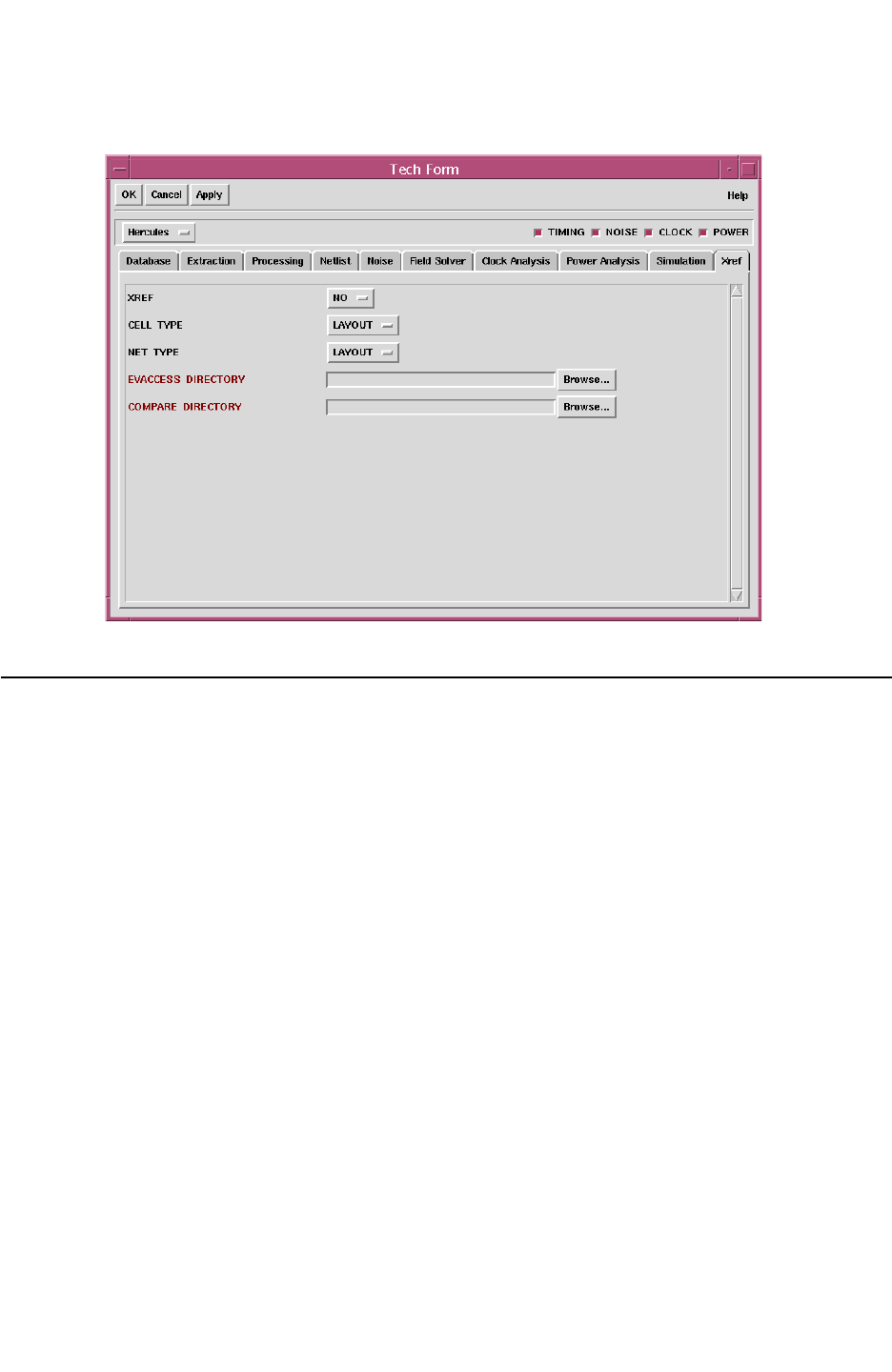
Chapter 4: Physical Databases
Parameterized Cells (PCELL) 4-33
Chapter 4: Physical Databases
Parameterized Cells (PCELL) 4-33
StarRC User Guide and Command Reference Version F-2011.06
Figure 4-11 XREF Tech Form
Parameterized Cells (PCELL)
A parameterized cell (or PCELL) is placed in layout to represent a device. The cell’s contents
are sized during placement according to your parameters to achieve certain geometries and
functionality in the device. For simulation and analysis purposes, the entire contents of the
cell are often characterized and modeled as an encapsulated unit, including all conductor
effects inside the cell boundary.
How StarRC Layer-Based Rules Affect Parameterized Cells
By default, StarRC defines the boundary between interconnect parasitic effects and
intradevice effects through layer-based rules for each standard device type.
Capacitance
For example, these rules allow StarRC to discard all capacitance considered to be inside the
device by ignoring capacitance between certain predetermined device terminal layer
combinations.
Resistance

Chapter 4: Physical Databases
Parameterized Cells (PCELL) 4-34
StarRC User Guide and Command Reference F-2011.06
StarRC User Guide and Command Reference Version F-2011.06
Similarly, StarRC permits the inclusion or exclusion of parasitic resistance on a
layer-by-layer basis. However, because a parameterized cell is typically characterized as a
complete unit, it becomes simpler and more accurate to use the cell boundary and not
layer-based interactions to separate intradevice parasitic effects that are discarded from
interconnect effects, but retained in the netlist.
StarRC uses gray box extraction techniques to handle parameterized cells. See
“SKIP_PCELLS Extraction Operation” on page 4-39. The StarRC container cell method
obviates the need for the scrutiny of intra device layers versus interconnect layers, because
the cell boundary (instead of the device layers) is used to delineate the device boundary.
The preparation of the device extraction rule file for parameterized cell devices becomes
simpler. Also, because the boundary between interconnect and intra device effects is
defined by the parameterized cell boundary for both the device model and the parasitic
extraction tool, the accuracy of the device and interconnect simulation are maximized.
This extraction method allows you to extract PCELL devices without the need for device
layer manipulation in the extraction rule file.
How LVS Handles Parameterized Cells
During ideal device extraction and LVS, you can use standard device extraction commands
to extract one or more logical devices from polygons inside a parameterized cell. The ideal
layout netlist output then contains a hierarchy level representing the PCELL, referred to as
the container cell. Inside this container cell is the extracted device, which represents the
design down to the lowest level of hierarchy or transistor level.
Conversely, the schematic netlist might or might not contain a level of cell hierarchy
corresponding to the container cell. Possible scenarios include:
Layout Schematic
Single device No container cell
Multiple devices No container cell
One or more devices in container cell Container cell
Single Device in Layout Container Cell and
No Container Cell in Schematic
In one design scenario, the schematic netlist might contain only the device instance, not the
container cell instance, because the parameterized cell is a physical (but not logical)
construct. This creates a non uniform hierarchy between the layout and schematic, because
the layout has an extra level of cell hierarchy not present in the schematic as shown in
Figure 4-12. To match the layout and schematic, LVS expands (explodes) the layout
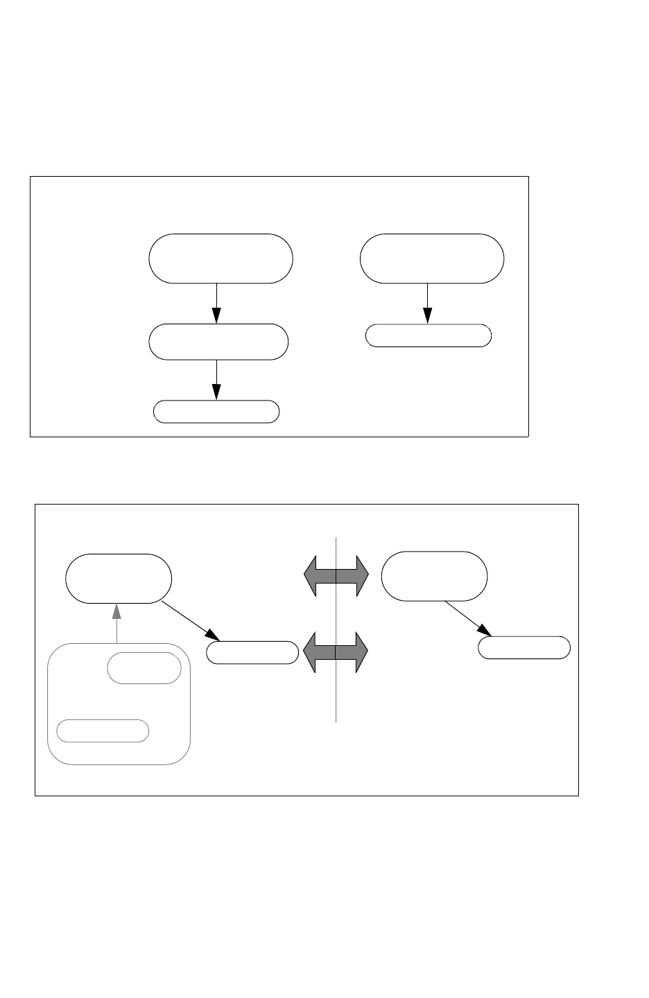
Chapter 4: Physical Databases
Parameterized Cells (PCELL) 4-35
Chapter 4: Physical Databases
Parameterized Cells (PCELL) 4-35
StarRC User Guide and Command Reference Version F-2011.06
container cell in the layout netlist so that the extracted device appears in the layout netlist’s
top block. This results in an equal hierarchy between the layout and schematic for complete
LVS matching as shown in Figure 4-13.
Figure 4-12 PCELL Layout and Schematic Hierarchy; Single Device Inside Container
LEVEL 2
LEVEL 1
LEVEL 0
Layout Hierarchy Schematic Hierarchy
TOP BLOCK
CONTAINER
CELL
DEVICE
TOP BLOCK
DEVICE
Figure 4-13 LVS Matching of PCELL Devices via Layout PCELL Explosion
TOP BLOCK
DEVICE
DEVICE
PCELL
TOP BLOCK
DEVICE
Layout Hierarchy Schematic Hierarchy
LVS Match
Original Hierarchy
Exploded Hierarchy
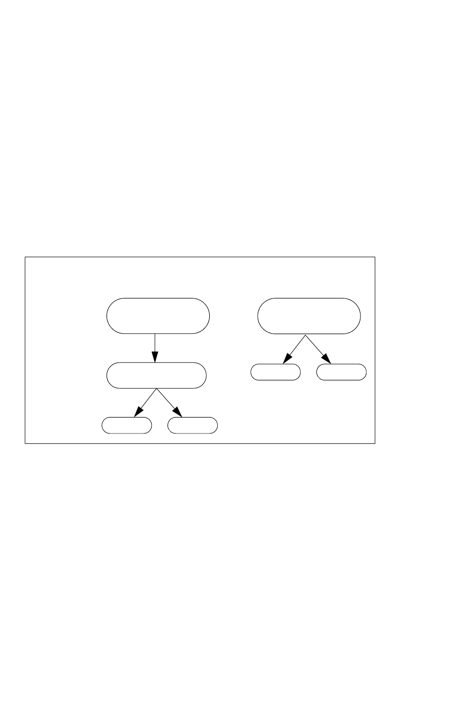
Chapter 4: Physical Databases
Parameterized Cells (PCELL) 4-36
StarRC User Guide and Command Reference F-2011.06
StarRC User Guide and Command Reference Version F-2011.06
Multiple Devices in Layout Container Cell and
No Container Cell in Schematic
In another scenario, the schematic netlist might contain only the device instance, but not the
schematic container cell instance. However, the layout container cell might contain multiple
instances of device primitives, which might or might not be of the same device type. For
example, a parameterized cell representing a MOSFET might have well diodes extracted
inside the layout container cell as well as the MOS primitive itself as shown in Figure 4-14.
In this case, LVS must once again explode the layout container cell, as shown in Figure 4-15,
because no corresponding cell hierarchy exists in the schematic. Then, all primitives
originally inside the layout container cell hierarchy are matched by LVS processing to
primitives in the schematic.
Figure 4-14 PCELL Layout and Schematic Hierarchy; Multiple Devices Inside Layout Container
Cell
LEVEL 2
LEVEL 1
LEVEL 0
Layout Hierarchy Schematic Hierarchy
TOP BLOCK
CONTAINER
CELL
DEVICE
TOP BLOCK
DEVICE
DEVICE DEVICE
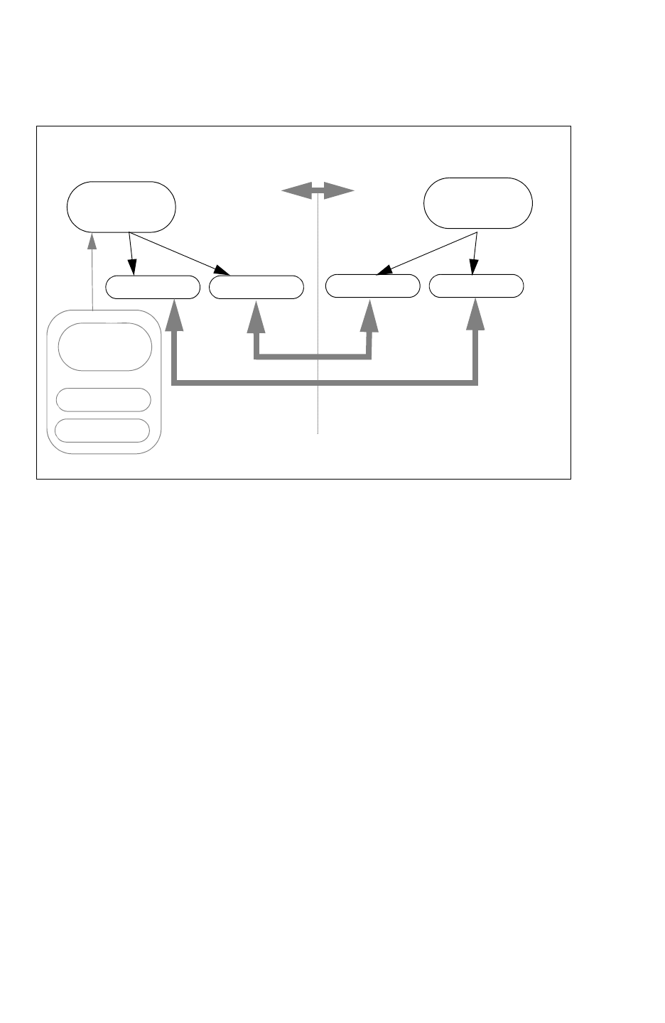
Chapter 4: Physical Databases
Parameterized Cells (PCELL) 4-37
Chapter 4: Physical Databases
Parameterized Cells (PCELL) 4-37
StarRC User Guide and Command Reference Version F-2011.06
Figure 4-15 LVS Matching of PCELL Devices via Layout PCELL Explosion: Multiple Devices
Inside Layout Container Cell
TOP BLOCK
CONTAINER CELL
DEVICE
DEVICE
TOP BLOCK
Layout Hierarchy Schematic Hierarchy
LVS Match
DEVICE DEVICE DEVICE
DEVICE
Original Hierarchy
Exploded Hierarchy
One or More Devices in the Layout Container Cell With
Container Cell in Schematic
In this scenario, the schematic netlist might contain a device instance inside a schematic cell
that has an EQUIV point (Hercules) / HCELL (Calibre) corresponding to the layout container
cell. The layout container cell might contain one or more instances. In this case, LVS
maintains the equivalent schematic and layout hierarchy to match the schematic device to
the layout device as shown in Figure 4-16.
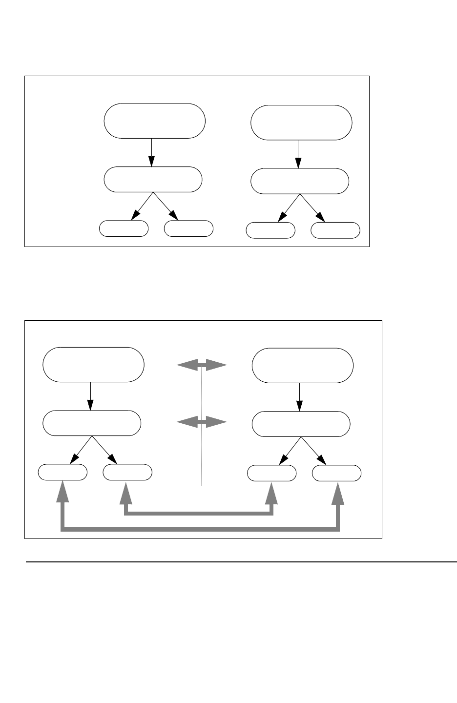
Chapter 4: Physical Databases
Parameterized Cells (PCELL) 4-38
StarRC User Guide and Command Reference F-2011.06
StarRC User Guide and Command Reference Version F-2011.06
Figure 4-16 PCELL Layout and Schematic Hierarchy: Container Cell in Schematic
LEVEL 2
LEVEL 1
LEVEL 0
Layout Hierarchy Schematic Hierarchy
TOP BLOCK
CONTAINER
CELL
DEVICE DEVICE
TOP BLOCK
CONTAINER
CELL
DEVICE DEVICE
In a design that has equivalence between the schematic and layout, no explosion is needed
as shown in Figure 4-17. In this case, LVS maintains the equivalent schematic and layout
hierarchy to match the schematic device to the layout device.
Figure 4-17 LVS Matching of PCELL Layout and Schematic Hierarchy
Layout Hierarchy Schematic Hierarchy
TOP BLOCK
CONTAINER
CELL
DEVICE DEVICE
TOP BLOCK
CONTAINER
CELL
DEVICE DEVICE
LVS Match
Extracting PCELLS Using StarRC
To extract a parameterized cell (PCELL) as a fully characterized gray box cell unit during
parasitic extraction, specify the SKIP_PCELLS command in the StarRC command file.
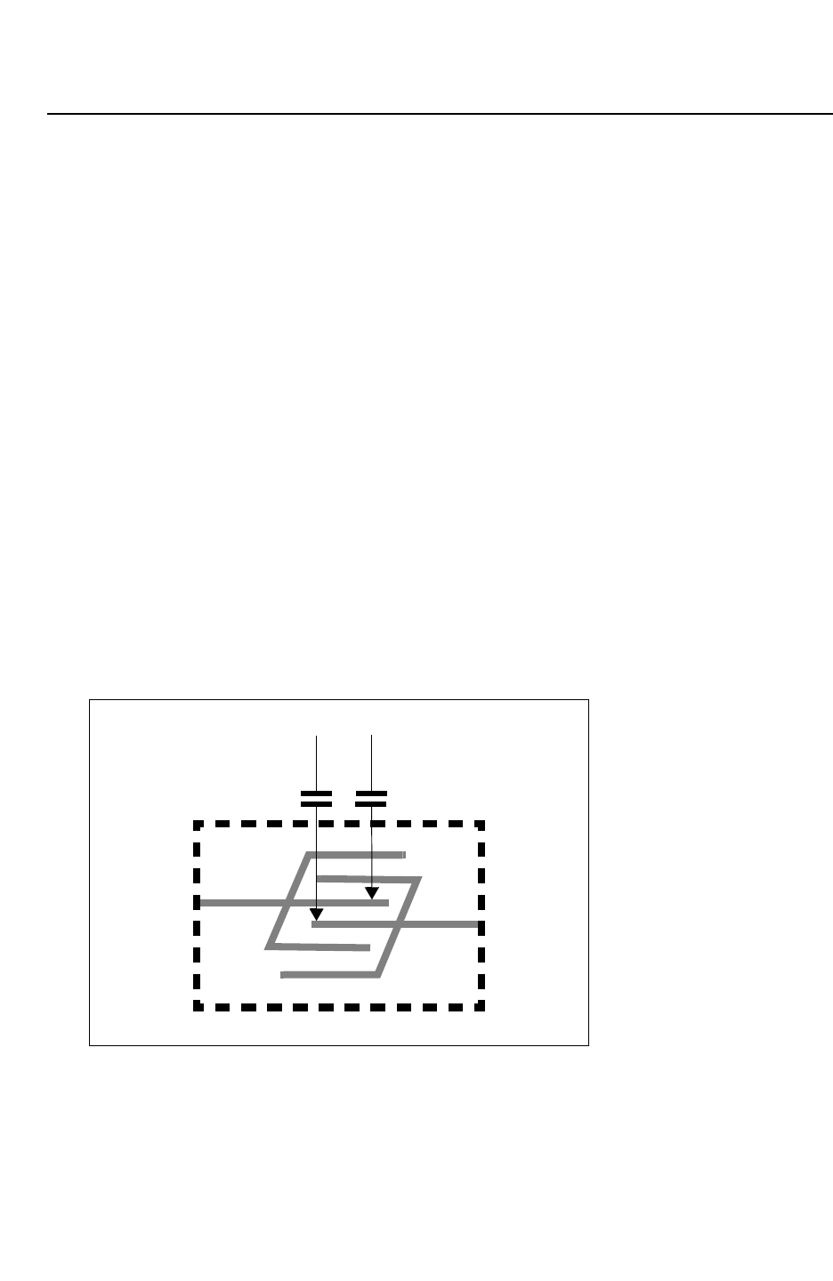
Chapter 4: Physical Databases
Parameterized Cells (PCELL) 4-39
Chapter 4: Physical Databases
Parameterized Cells (PCELL) 4-39
StarRC User Guide and Command Reference Version F-2011.06
SKIP_PCELLS Extraction Operation
During a StarRC SKIP_PCELLS extraction, certain functions are performed differently. The
following functions change when parameterized cells are specified:
Gray Box Handling
Parasitic resistance is extracted up to the instance port (x, y) location for each cell port.
Capacitive interactions between top-level nets and the material inside the cell are extracted
and compiled as ground capacitance in accordance with the StarRC standard gray box
extraction method. Port capacitance is not included in the total capacitance for the net
connecting to the port
IGNORE_CAPACITANCE Command
During extraction, the parameterized cell is treated as a gray-box SKIP_CELL. Functions
related to the IGNORE_CAPACITANCE command are disabled for SKIP_CELL devices (but not
for non-PCELL devices) because layer-based capacitance removal is not required.
Extracting Coupling Capacitances
StarRC reports coupling capacitances for two additional conditions related to PCELL
structures. You can report coupling capacitances between overhead nets to PCELL pins and
coupling capacitances between different PCELL pins reported in the generated netlist. You
can do this by specifying the COUPLE_TO_PCELL_PINS command.
Figure 4-18 Extraction of Overhead Net
pin2
pin1
c1 c2
PCELL Boundary
Overhead Routing
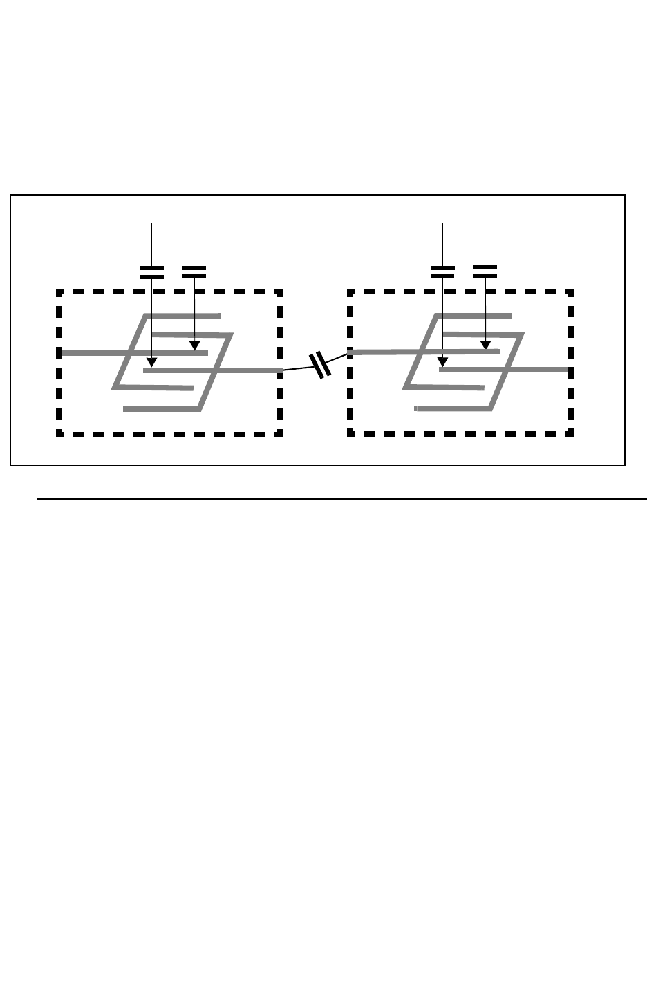
Chapter 4: Physical Databases
Parameterized Cells (PCELL) 4-40
StarRC User Guide and Command Reference F-2011.06
StarRC User Guide and Command Reference Version F-2011.06
With this command, either the coupling capacitances between PCELL pins and overhead
nets are reported or they are grounded, depending on the command syntax. In Figure 4-18
on page 4-39 the extraction of overhead nets to PCELL pins is shown. Figure 4-19 shows
the extraction of overhead nets.
Figure 4-19 Extraction of Overhead Net
pin2
pin1
c1 c2
PCELL Boundary
Overhead Routing Net A
pin2
pin1
cb1 cb2
PCELL Boundary
Overhead Routing Net B
SKIP_PCELLS Netlist Behavior
For compilation purposes, the entire logical content of a PCELL generates a netlist. This
means:
• All devices inside the PCELL container cell are generated in the DSPF instance section.
•All
*|I lines in the DSPF file reflect connections to individual devices inside the container
cell.
The logical content of the DSPF netlist (devices in the instance section,*|I lines) are
identical to a generated netlist if no SKIP_CELLS operation has been performed on the
PCELL container. This allows StarRC to support different LVS configurations of PCELLs.
The netlist result is as follows:
• The devices inside the PCELL container cell are generated with the same device names
used when no SKIP_CELLS operations are performed.
• All geometric device properties belonging to the devices inside the container cell are
generated as normal in the DSPF instance section.
• If the PCELL container cell has a port that is not connected to a device inside the
container cell, that port is ignored during netlist output.
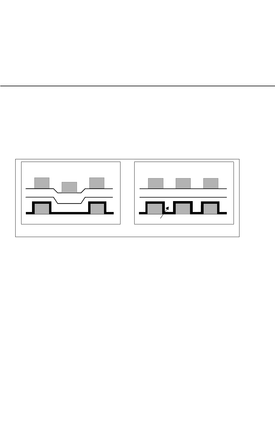
Chapter 4: Physical Databases
Metal Fill 4-41
Chapter 4: Physical Databases
Metal Fill 4-41
StarRC User Guide and Command Reference Version F-2011.06
• Any internal nodes inside the PCELL container cell (for example, nodes that are not
instance ports of the container cell) are output as ideal nets in the DSPF.
• All specified INSTANCE_PORT commands for PCELLS are automatically set to
SUPERCONDUCTIVE.
Metal Fill
In semiconductor manufacturing, each process layer is planarized with chemical mechanical
polishing. This repeated polish causes a conductive layer to settle or “drop down” where
there is no lower-level metal. To avoid conductor layers dropping in to empty spaces
between metals, metal fill is commonly included in the design. This concept is shown in
Figure 4-20.
Figure 4-20 Nonplanar vs. Planar Layers
Dielectric 1
Dielectric 2
Metal1
Metal1
Metal 2
Metal 2
Metal 2
Dielectric 1
Dielectric 2
Metal1
Metal1
Metal 2 Metal 2 Metal 2
Metal
Fill
Nonplanar Layers Planar Layers
Metal fill can exist in a variety of shapes and sizes. Typically there are two types of metal fill
structures in a design: grounded metal fill and floating metal fill. Grounded metal fill is
connected to power or ground by via connections; floating metal fill has no connection to
signal, power, or ground nets. Both types can exist in the same layout design.
When running StarRC extraction, you can specify the metal fill to be emulated or real. These
two approaches yield different results depending on the accuracy you desire. However,
emulation fill is used only during the early stages of the place-and-route flow and should not
be used for correlation with the place-and-route flow.
StarRC can extract designs with metal fill (actual) polygons. These polygons can be read
either directly from the design database (Milkyway or LEF/DEF) or from a separate GDSII
file. The effect of metal fill on signal nets can be extracted by treating them as floating or
grounded. You also can completely ignore the metal fill polygons even though they are
present in the database.

Chapter 4: Physical Databases
Metal Fill 4-42
StarRC User Guide and Command Reference F-2011.06
StarRC User Guide and Command Reference Version F-2011.06
Note:
StarRC reads metal fill information from the GDS file provided. You can determine how
many polygons were read from different layers by reading the metal fill statistics in the
readDB.sum file located in the directory where StarRC deposits intermediate files.
Emulated Metal Fill
A design database containing emulated metal fill does not actually contain any metal fill
shapes or material, but StarRC can emulate the effect of placing metal fill in the design. The
advantages and disadvantages to this approach are shown in Table 4-5.
Table 4-5 Advantages and Disadvantages of Emulated Metal Fill
Advantages Disadvantages
Fast extraction runtimes Less accurate than drawn metal fill
Allows you to change the design function
independent of the design
Only floating metal fill can be run as emulated.
The emulated fill polygons are taken only as
floating in the layout, meaning these virtual
polygons cannot be tied to any power/ground
net.
Works on all database types such as
Milkyway, LEF/DEF, and GDSII
Note:
Use an emulation fill only during the early stages of the place-and-route flow. You should
not use it for correlation with the place-and-route flow.
Using Emulated Metal Fill in StarRC
Three parameters can be specified in an ITF to describe metal fill: FILL_WIDTH and
FILL_SPACING for lateral capacitive effects and FILL_RATIO for vertical capacitive effects.
Figure 4-21 shows a lateral and vertical fill spacing example.
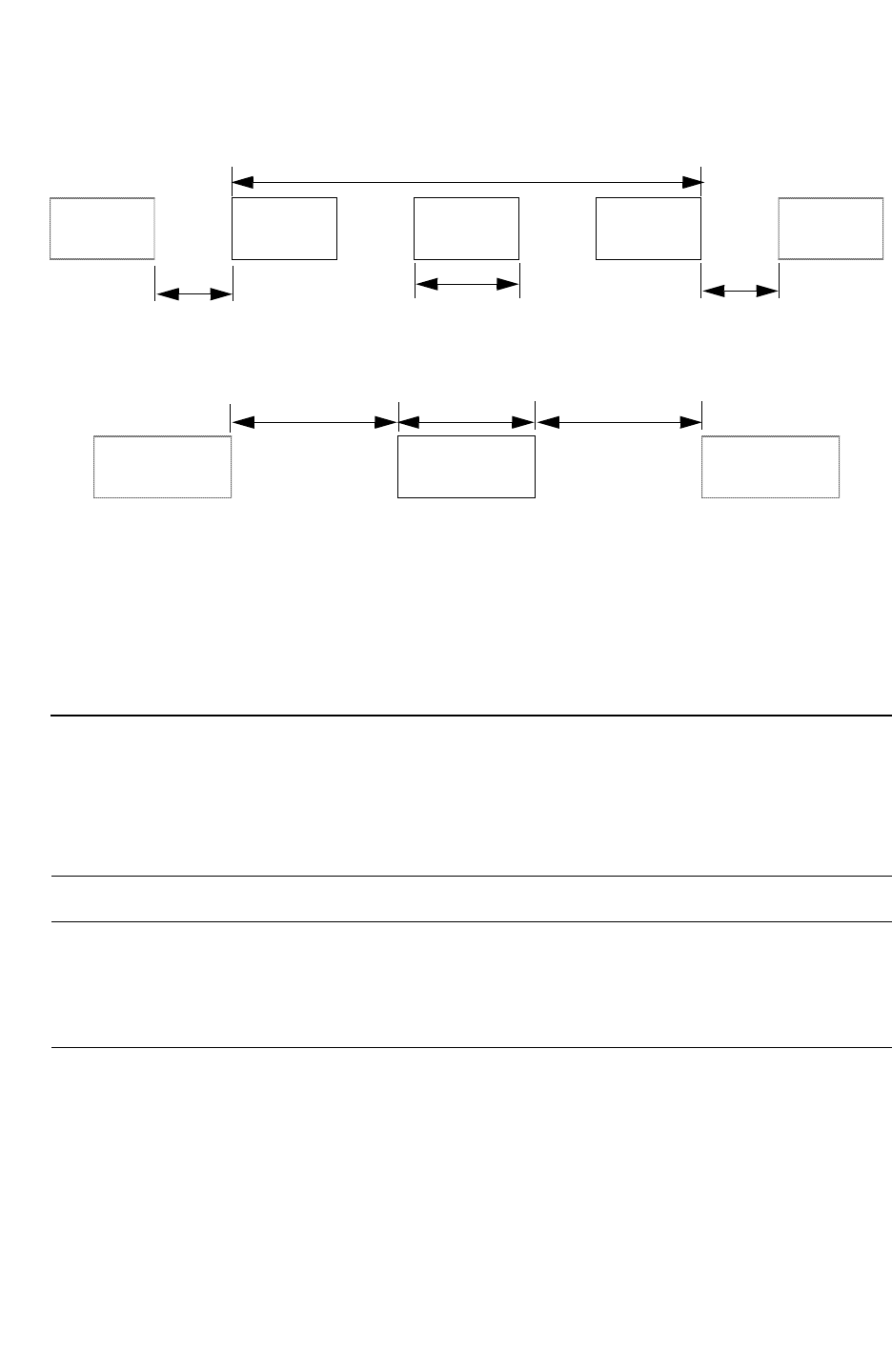
Chapter 4: Physical Databases
Metal Fill 4-43
Chapter 4: Physical Databases
Metal Fill 4-43
StarRC User Guide and Command Reference Version F-2011.06
Figure 4-21 Emulated Fill Example Spacing
Metal 2 Metal 2
Fill
Metal 2
Fill
Metal 2
Fill Metal 2
FILL_SPACINGFILL_SPACING FILL_WIDTH
FILL_RATIO = 50%
Metal 1 Metal 1 Fill Metal 1
FILL_SPACINGFILL_WIDTHFILL_SPACING
Using the nxtgrd File with Emulated Fills
No specific commands are required for the StarRC run regardless of input database
information. Emulated fills are applied according the definitions you provide in the
accompanying nxtgrd file from an ITF. No new data is needed for the design database. The
fill effects are accounted for in the StarRC capacitance modeling function.
Real Metal Fill
Real metal fill can exist in the design database as drawn shapes. The advantages and
disadvantages to this approach are shown in Table 4-6.
Table 4-6 Advantages and Disadvantages of Real Metal Fill
Advantages Disadvantages
• Provides more accurate results • Creates more data
• Requires longer runtimes
• Requires you to regenerate the fill each time a
change is made

Chapter 4: Physical Databases
Metal Fill 4-44
StarRC User Guide and Command Reference F-2011.06
StarRC User Guide and Command Reference Version F-2011.06
StarRC processes metal fills as floating or as grounded depending on their correct
identification in the database. You identify fill in the database by using the
METAL_FILL_POLYGON_HANDLING command and its options. The options identify and treat
metal fill as follows:
•IGNORE
This is the default option. The command does not translate metal fill even if it is in the
database.
•FLOATING
Processes all metal fill as floating even if the fill has been placed as grounded fill.
•GROUNDED
Processes all metal fill as grounded even if the fill has been placed as floating fill.
•AUTOMATIC
Processes LEF/DEF and Milkyway fills based on the section in which they appear. These
can be LEF/DEF or ROUTE_TYPE for Milkyway.
Handling Coupling Capacitance on Floating Metal Fills
The METAL_FILL_POLYGON_HANDLING and REMOVE_FLOATING_NETS commands have some
similarities and differences.
The similar behavior these two commands share is floating polygons are not generated in
the parasitic netlist. If either of these commands are used, any floating net or fill net/polygon
does not have a *D_NET (SPEF format) or *|NET (spf format) section in the netlist, and no
couplings are shown to these floating nets.
The different behavior of these commands becomes evident when you are also using
REMOVE_FLOATING_NETS:YES. StarRC treats floating nets as noncritical material. StarRC
finds the coupling capacitance that exists from the signal nets to this noncritical material,
and then de-couples these capacitors. This coupling capacitance is then added to the total
ground capacitance of the signal net.
If there are floating metals in the design that are designated as fill (either with the
METAL_FILL_GDS_FILE, or as fill material in the Milkyway or LEF/DEF database), then
StarRC uses a different method to handle coupling capacitance to floating fill polygons.
When METAL_FILL_POLYGON_HANDLING:FLOATING is set, StarRC extracts coupling
capacitance to floating fill polygons. However, the goal is to not generate these fill polygons
for the netlist. Instead of grounding the coupling capacitors to fill polygons, StarRC runs
netlist reduction algorithms on the capacitors that connect to nodes on the fill. This allows
StarRC to compute equivalent capacitances, but eliminate the nodes on the floating fill
polygons. By finding equivalent capacitance, the netlist accounts for capacitive effects
created by the fill polygons without generating the nodes in the netlist associated with the fill.

Chapter 4: Physical Databases
Metal Fill 4-45
Chapter 4: Physical Databases
Metal Fill 4-45
StarRC User Guide and Command Reference Version F-2011.06
Because METAL_FILL_POLYGON_HANDLING:FLOATING finds equivalent capacitance of
capacitors coupling to fill, there are a few distinct advantages as explained as follows:
• If nets couple to each other through fill polygons, then the netlist has a coupling capacitor
between these two nets with METAL_FILL_POLYGON_HANDLING:FLOATING. When using
REMOVE_FLOATING_NETS:YES, the coupling capacitance to the floating nets appears as
additional ground capacitance.
• Nets that normally do not couple to each other can couple to each other after fill is added
to the database. When METAL_FILL_POLYGON_HANDLING:FLOATING is specified, this
effect is captured and a coupling capacitor between these nets shows up in the netlist.
This can increase the accuracy of signal integrity analysis because crosstalk effects
induced by metal fill can now be considered.
Guidelines for Using Metal Fill
You can use Milkyway and LEF/DEF 5.4 or higher databases containing real metal fill input
for StarRC. No other flows are supported. Observe the following guidelines for the particular
database:
•Milkyway
StarRC accepts metal fill polygons either in FILL view or CEL/FRAM view for a given
block. This data can be also be created by IC Compiler.
•LEF/DEF
LEF/DEF versions 5.4 and higher support the FILLS section for floating fill and fill wire for
grounded fills only.
LEF/DEF has two different syntaxes for specifying metal fill. Floating metal fill polygons
are specified in the “FILLS” section of the DEF file. If the fill polygons are tied to power
and ground nets, they are specified in the SPECIALNETS section (part of special Wiring
with SHAPE defined as FILLWIRE) for the power and ground nets. For more information
about the syntax, see LEF/DEF Language Reference.
•GDS
StarRC can read metal fill polygons from a separate GDSII file in addition to the design
database. For this flow, the design database can be in Milkyway, LEF/DEF, or GDSII (a
Milkyway XTR view generated in Hercules or an AGF file generated in Calibre) format.
This GDSII file must have metal fill polygons only, because all the polygons from the file
are considered metal fill objects.
The handling mode for metal fill imported through a METAL_FILL_GDS_FILE can be
specified on either a global or layer-specific basis. See the METAL_FILL_GDS_FILE,
METAL_FILL_GDS_FILE_NET_NAME, and GDS_LAYER_MAP_FILE command descriptions.

Chapter 4: Physical Databases
Metal Fill 4-46
StarRC User Guide and Command Reference F-2011.06
StarRC User Guide and Command Reference Version F-2011.06
No floating fills should exist in the XTR view because StarRC cannot automatically
identify these. You can attach (VSS) text to identify grounded fills in the physical layout
and make them a part of the existing grounded network.
StarRC can accept a GDSII stream file containing only fill shapes and add them to the
design. You can specify a flat GDSII file by using the METAL_FILL_GDS_FILE command.
If you would like to attach all fills to a particular net, use the
METAL_FILL_GDS_FILE_NET_NAME command.
To ensure that your fill structures are identified properly in the database, use the
GDS_LAYER_MAP_FILE command.
How StarRC Handles Metal Fill
StarRC reads various design databases and translates metal fill polygons into the internal
format before performing extraction. Translation depends on the setting of the
METAL_FILL_POLYGON_HANDLING command or on the fill handling setting specified in the
GDS_LAYER_MAP_FILE.
Metal fill can be processed in two ways: as grounded metal fill or floating metal fill.
Grounded Metal Fill
During signal net extraction, the fill polygons are treated just like a polygon belonging to a
power and ground net. There is no special handling of these polygons during extraction.
Floating Metal Fill
In this mode, capacitance is calculated between signal and fill polygons and between
different fill polygons. After extraction, fill nodes are reduced “on the fly” and equivalent
capacitance between signal nets and capacitance to ground for signal nets is calculated.
Floating and Grounded Metal Fill
You can process a combination of floating and grounded metal fills in StarRC. The grounded
fills are created as a part of the power network by using text to identify them as part of the
net. You can alternatively use the METAL_FILL_GDS_FILE_NET_NAME command to make the
fill as grounded in the design. The floating fills are created and used in the design either as
FILL view in Milkyway format, FILLS in DEF format or GDS file.
Note:
The combination of emulated fill and real physical fill is not supported in StarRC.

Chapter 4: Physical Databases
Shared Database Command Options 4-47
Chapter 4: Physical Databases
Shared Database Command Options 4-47
StarRC User Guide and Command Reference Version F-2011.06
Accuracy Validation With Metal Fill
The EXTRACTION:FSCOMPARE command for StarRC provides an automated push-button flow
for analysis of test structures or even selected nets from a chip with an industry standard 3-D
field solver.
A 3-D field solver can handle floating metal fill and StarRC automatically prepares the
appropriate 3-D field solver input deck based on the METAL_FILL_POLYGON_HANDLING
command and/or the layer handling specified in the GDS_LAYER_MAP_FILE.
Shared Database Command Options
There are several shared database command options. See “Command List With Task
Information” on page B-2.

Chapter 4: Physical Databases
Shared Database Command Options 4-48
StarRC User Guide and Command Reference F-2011.06
StarRC User Guide and Command Reference Version F-2011.06

5-1
5
Incremental Extraction 5
StarRC incremental extraction provides automatic detection of ECO affected nets to create
an incremental or complete netlist. It is supported in the Milkyway and LEF/DEF extraction
flows.
This chapter includes the following sections:
•Incremental Extraction Flow
•Running Incremental Extraction
•Incremental Netlist Examples
•Schematic Examples and Their Netlists

Chapter 5: Incremental Extraction
Incremental Extraction Flow 5-2
StarRC User Guide and Command Reference F-2011.06
StarRC User Guide and Command Reference Version F-2011.06
Incremental Extraction Flow
This section explains the various incremental extraction flows and describes how to use
incremental extraction with StarRC, IC Compiler, and PrimeTime. The incremental
extraction feature has specific requirements:
• Only run incremental extraction on large designs and blocks. If the design takes several
hours to run, or has more than 250,000 instances. In a normal extraction, consider using
incremental extraction.
• ECO changes must be performed manually, and not generated with automatic features
within the routing tool. Using such automated features can cause changes on a global
scale and make the incremental extraction runtime longer than a normal extraction.
• Small cases should only be used for initial flow testing and debugging. When incremental
extraction is used on a small design, the runtime is expected to be longer than a normal
extraction.
Incremental runs are mainly run on full chip databases. When performing timing closure and
crosstalk analysis, iterative design and analysis runs are necessary to identify timing and
crosstalk issues, perform engineering change orders (ECOs) to correct those problems, and
verify the resolution of those issues. An ECO can include localized gate placement and
sizing changes, net rerouting, and net addition or deletion. StarRC automatically determines
all nets that have been modified, including those nets that are neighbors to
physically-modified nets. The modified nets and neighboring nets are called ECO affected
nets. All ECO affected nets need to be re-extracted by StarRC.
To run an incremental extraction, specify the INCREMENTAL:YES command in the star_cmd
file.
Input to StarRC
Incremental extraction requires that the first complete chip data has been extracted
successfully. The required inputs to StarRC are:
• STAR directory from previous extraction run (full chip or incremental)
• Updated design database with ECO edits
Output from Incremental Extraction Runs
StarRC can output an incremental netlist in either SPEF or SBPF format.

Chapter 5: Incremental Extraction
Incremental Extraction Flow 5-3
Chapter 5: Incremental Extraction
Incremental Extraction Flow 5-3
StarRC User Guide and Command Reference Version F-2011.06
A full-chip netlist contains the parasitic results for the ECO affected nets and previously
extracted parasitic results for non-affected nets/instances. Timing/SI analysis tools without
incremental analysis capability can then use this as input.
An incremental netlist contains only the ECO affected nets, along with couplings to non-ECO
affected nets. These coupling capacitances appear as dangling within the incremental
netlist itself. However, they are not dangling when downstream tools analyze the netlist
incrementally. For incremental analysis, it is essential that nodes on non-ECO affected nets
maintain the same name as the full-chip netlist.
Fixing a Design Using Engineering Change Orders
When performing timing closure and crosstalk analysis, iterative design and analysis runs
are necessary to identify timing and crosstalk issues. Perform engineering change orders
(ECOs) to correct those problems, and verify the resolution of those issues. An ECO can
include localized gate placement and sizing changes, net rerouting, and net addition or
deletion. Verifying the resolution of issues after an ECO requires repeating parasitic
extraction for the affected nets and instances and rerunning timing and/or crosstalk analyses
using the updated parasitic information.
Reasons to Perform ECOs
You should perform an ECO on a design under the following circumstances:
• Pure logical changes in the net names, instance names, or port names
• Pure physical—routing or placement—changes
• A combination of physical and logical changes

Chapter 5: Incremental Extraction
Incremental Extraction Flow 5-4
StarRC User Guide and Command Reference F-2011.06
StarRC User Guide and Command Reference Version F-2011.06
Table 5-1 summarizes the behavior of StarRC under different ECO conditions.
Table 5-1 StarRC Behavior Under Different ECO Conditions
Physical Changes Logical Changes StarRC behavior
No No Terminates with a fatal error and prints an error
message
No Ye s Runs netlist generation only
Ye s No Runs incremental extraction
Ye s Ye s Runs an incremental flow
An efficient analysis, repair, and verification flow for ECOs requires
• An incremental parasitic extraction that re-extracts only those nets and instances affected
by the ECO
• An incremental analysis capability that reads and analyzes only the parasitics that have
changed since the last iteration
If incremental extraction capability is available without an incremental analysis, efficiency is
gained only in the parasitic extraction step, not in the analysis step. Such an incremental
extraction flow is conceptually illustrated in Figure 5-1.
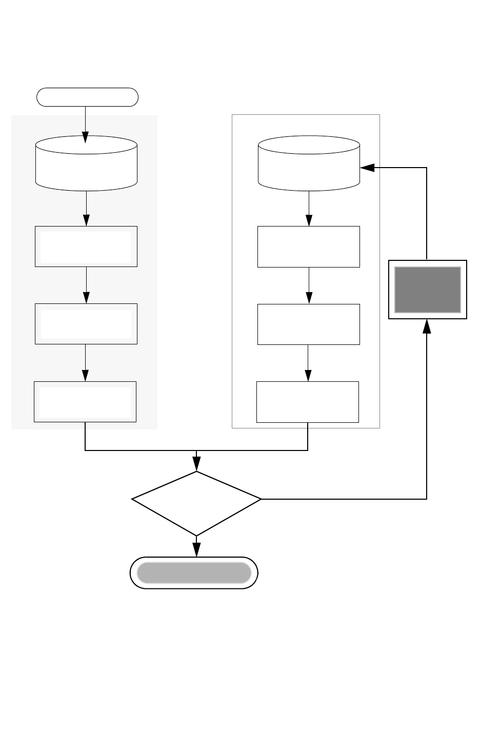
Chapter 5: Incremental Extraction
Incremental Extraction Flow 5-5
Chapter 5: Incremental Extraction
Incremental Extraction Flow 5-5
StarRC User Guide and Command Reference Version F-2011.06
Figure 5-1 Conceptual Flow for Iterative Incremental ECO Extraction Only
Original
Place and Route
Layout Database
Full Chip Flow
Placement/Routing
Full-Chip Timing /
Signal Integrity
Analysis
Full Parasitic Netlist
Full-Chip
StarRC
Extraction
Full-Chip Timing /
Signal Integrity
Analysis
Full Parasitic Netlist
Full-Chip
StarRC
Extraction
ECO-Modified
Place and Route
Database
Timing/Signal Integrity
Violation?
Incremental Extraction Flow
YES
NO
ECO
Router
Design Complete

Chapter 5: Incremental Extraction
Incremental Extraction Flow 5-6
StarRC User Guide and Command Reference F-2011.06
StarRC User Guide and Command Reference Version F-2011.06
Identification and Extraction of Nets Affected by ECOs
A proper incremental extraction methodology must identify and re-extract the parasitic
resistance and capacitance of nets affected by the ECO. This means the extraction tool must
identify and re-extract the parasitic resistance and capacitance.
StarRC automatically identifies all nets in the following six categories. These nets are called
ECO affected nets.
• Nets added by the ECO
• Nets deleted by the ECO
• Nets modified by the ECO
• Any coupling capacitance between neighboring nets and the ECO-added nets (new
neighbors of new nets)
• Any coupling capacitance between neighboring nets to the ECO-modified nets that
changed as a result of the ECO (old and new neighbors of modified nets)
• Any coupling capacitance to nets deleted by the ECO (old neighbors of deleted nets)
Note:
Note that the number of nets changed due to ECO (ECO nets) is a subset of ECO
affected nets from resistance and capacitance extraction. All ECO affected nets need to
be re-extracted by StarRC. Figure 5-2 on page 5-7 illustrates the nets that are
re-extracted during an incremental extraction after a database ECO.
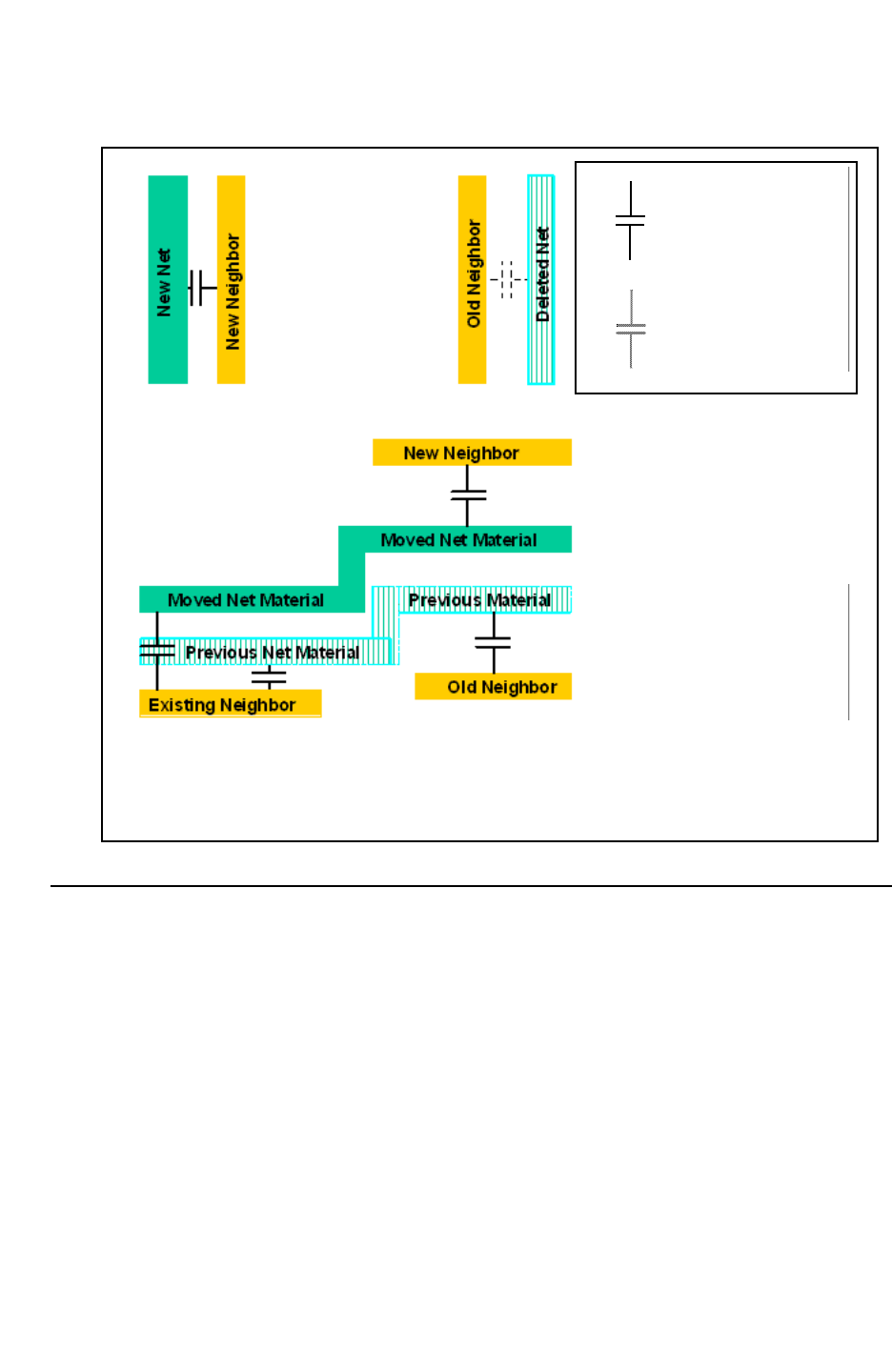
Chapter 5: Incremental Extraction
Incremental Extraction Flow 5-7
Chapter 5: Incremental Extraction
Incremental Extraction Flow 5-7
StarRC User Guide and Command Reference Version F-2011.06
Figure 5-2 Nets and Capacitances Extracted During Incremental Extraction
Nets and capacitances extracted during incremental extraction.
All pre-ECO and post-ECO couplings illustrated are re-extracted during
incremental extraction.
Post-ECO Coupling
Pre-ECO Coupling
Incremental Extraction Using StarRC
Incremental extraction in StarRC requires that the first extraction is a full-chip extraction and
that it completes successfully with a full chip netlist. A full-chip extraction can then be
followed by multiple incremental extractions. StarRC reads the ECO database and
compares it with the data from the previous extraction run, which is stored in the temporary
STAR directory, to determine ECO affected nets.
You must maintain the data integrity of the STAR directory otherwise StarRC reports an
error. If the comparison between databases shows no difference, StarRC does not proceed
to extraction, and stops. You can perform a full-chip extraction after an incremental run as
well, followed by incremental runs.

Chapter 5: Incremental Extraction
Incremental Extraction Flow 5-8
StarRC User Guide and Command Reference F-2011.06
StarRC User Guide and Command Reference Version F-2011.06
Note:
You should complete at least one final full-chip extraction and timing analysis after timing
has been declared clean.
During a full-chip extraction following an incremental extraction, you can change any
command option. A full-chip extraction after an incremental extraction has the effect of
removing all previous incremental extractions.
Between a full-chip and subsequent incremental extraction runs, only certain command
options can be changed. An incremental extraction run reuses translation and extraction
results from previous extractions, so any command or option that affects the integrity of
those results cannot be changed between the full-chip and incremental extractions. In
addition to all the incremental extraction-related options, the following are the only options
that can be changed between full-chip and incremental extraction:
• Options that describe the location and name of the design database:
MILKYWAY_LIBRARY, TOP_DEF_FILE, MACRO_DEF_FILE, BLOCK. Changing these options
allow you to point to a new ECO database.
• All netlist commands, for example, NETLIST_FILE, NETLIST_FORMAT, and so on.
ECO affected nets can be much larger than the actual ECO nets; this depends on the
congestion of the design and the amount of ECO changes implemented. To enable
convergence, the changed database results from incremental extraction and full-chip
extraction should be within a certain tolerance. StarRC targets a tolerance of 5 percent, or
1fF with MODE: 200 (preferable for 90-nm and smaller designs). The key to such
convergence is accurate identification of ECO affected nets during the incremental stage.
When a large number of ECO affected nets exist, it might not be worthwhile to perform
incremental extraction and analysis. If the number of ECO affected nets for re-extraction is
50 percent or more of the total number of nets in the full-chip post-ECO database, StarRC
produces a warning message and continues.
After incremental extraction, StarRC produces a full-chip, or incremental, netlist (if
NETLIST_INCREMENTAL:YES is specified). The incremental netlist can be created only in
SPEF or SBPF formats. StarRC does not provide logical netlist (Verilog) change information.
If the NETLIST_FILE option is same as the last run, StarRC overrides the existing netlist file.
With an incremental netlist, the subsequent analysis stage is sped up dramatically. Any
downstream tool can analyze a full-chip netlist from incremental extraction without any
modification. However, downstream tools need to be enhanced to accurately analyze an
incremental netlist with coupling capacitances.

Chapter 5: Incremental Extraction
Incremental Extraction Flow 5-9
Chapter 5: Incremental Extraction
Incremental Extraction Flow 5-9
StarRC User Guide and Command Reference Version F-2011.06
Input Files for Incremental Extraction
Incremental extraction in StarRC requires that the first extraction is a successful full-chip
extraction followed by multiple runs of incremental or full-chip extraction. StarRC requires
the following inputs:
• The StarRC directory from a previous full-chip or incremental extraction run
• A new design database with ECO edits
Output Files From Incremental Extraction
StarRC can output the following netlists in either SPEF or SBPF formats:
• Full-chip netlist
The full-chip netlist contains the new parasitic results for ECO affected nets and
previously extracted parasitic results for non-affected nets or instances. Timing and
signal-integrity analysis tools without incremental analysis capability can then use the
full-chip netlist as input.
• Incremental netlist
The incremental netlist contains only the ECO affected nets, along with coupling
capacitances to non-ECO affected nets. These coupling capacitances appear as
dangling within the incremental netlist itself. However, they are not dangling when
downstream tools analyze the netlist incrementally. To allow incremental analysis, nodes
on non-ECO affected nets must maintain the same name as the full-chip netlist.

Chapter 5: Incremental Extraction
Running Incremental Extraction 5-10
StarRC User Guide and Command Reference F-2011.06
StarRC User Guide and Command Reference Version F-2011.06
Unsupported Commands During Incremental Extraction
StarRC does not support in-context extraction, power net extraction, or transistor-level
extraction while doing incremental extraction. The commands that are not supported during
incremental extraction are listed in Ta bl e 5-2:
Table 5-2 Unsupported Commands During Incremental Extraction
Command Type Unsupported Commands During Incremental Extraction
In-context
extraction
commands
MACRO, SKIP_CELLS_COUPLE_TO_NET, SKIP_CELLS_COUPLE_TO_NET_LEVEL,
ZONE_COUPLE_TO_NET, ZONE_COUPLE_TO_NET_LEVEL,
COUPLE_NONCRITICAL_NETS, COUPLE_NONCRITICAL_NETS_PREFIX,
RING_AROUND_THE_BLOCK
Power net
extraction
commands
POWER_EXTRACT, POWER_REDUCTION, NETLIST_POWER_FILE
Transistor-level
extraction
commands
MILKYWAY_EXTRACT_VIEW, MAGNIFY_DEVICE_PARAMS,
MOS_GATE_CAPACITANCE, CALIBRE_QUERY_FILE, PROBE_TEXT_FILE,
HN_NETLIST_SPICE_TYPE, TRANSLATE_RETAIN_BULK_LAYERS,
NETLIST_IDEAL_SPICE_FILE, NETLIST_IDEAL_SPICE_TYPE,
NETLIST_IDEAL_SPICE_HIER, NETLIST_USE_M_FACTOR,
NETLIST_PASSIVE_PARAMS, CELL_TYPE, NET_TYPE,
XREF_LAYOUT_NET_PREFIX, XREF_LAYOUT_INST_PREFIX,
XREF_USE_LAYOUT_DEVICE_NAME, XREF_FEEDTHRU_NETS
Other commands SKIP_INSTANCES, EXTRACTION:[R|FSCOMPARE], FS_EXTRACT_NETS,
NETLIST_FORMAT: NONE
Running Incremental Extraction
To perform incremental extraction, a full-chip extraction must be successfully completed and
a netlist produced. Once you have created changes in the database, they can be
re-extracted using the INCREMENTAL:YES command in the StarRC command file to enable
incremental extraction. Several iterations of ECO changes and successive incremental
extractions can be performed as long as
• The changes do not affect more than 50 percent of the nets
• The previous incremental extraction run has completed successfully
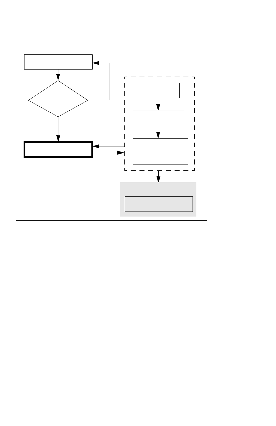
Chapter 5: Incremental Extraction
Running Incremental Extraction 5-11
Chapter 5: Incremental Extraction
Running Incremental Extraction 5-11
StarRC User Guide and Command Reference Version F-2011.06
Figure 5-3 Incremental Extraction Work Flow
Full Chip Extraction
Timing
Check
Clean?
NO
YES
Incremental Extraction
Timing Tools
Layout Change
Updated
Full Chip Extraction
SIGNOFF
DEF or Milkyway
Data
Steps for Running Incremental Extraction
You can proceed with the incremental extraction flow shown in Figure 5-3 by following these
five steps:
1. Collect a complete chip database.
2. Perform a complete extraction.
See “Command File Example for Original Extraction” on page 5-12.
3. Perform a timing analysis.
4. If timing violations are found, make corrections in the database.
See “Command File Example for Incremental Extraction” on page 5-12.
5. Perform the complete extraction with INCREMENTAL:YES specified in the StarRC
command file.

Chapter 5: Incremental Extraction
Running Incremental Extraction 5-12
StarRC User Guide and Command Reference F-2011.06
StarRC User Guide and Command Reference Version F-2011.06
Note:
Only the following commands can be changed between a full and incremental
extraction:
BLOCK MILKYWAY_DATABASE
TOP_DEF_FILE LEF_FILE
MACRO_DEF_FILE DEF_FILE
INCREMENTAL COUPLING_REPORT_FILE
INCREMENTAL_FORCE_DP COUPLING_REPORT_NUMBER
NETLIST_INCREMENTAL YES | NO
In a LEF/DEF flow, you can delete the old DEF file before running incremental extraction.
Command File Example for Original Extraction
The following StarRC command file is an example that can be used for your original
extraction. See Step 2 in “Steps for Running Incremental Extraction” on page 5-11.
BLOCK: original_top_block
MILKYWAY_DATABASE: design_name
TCAD_GRD_FILE: 90nm.ntxgrd
STAR_DIRECTORY:STAR
NETLIST_FILE:original_pre.spef
NETLIST_FORMAT:SPEF
Command File Example for Incremental Extraction
The following StarRC command file is an example that can be used for your incremental
extraction. See Step 4 in “Steps for Running Incremental Extraction” on page 5-11.
BLOCK:post-eco_top_block
MILKYWAY_DATABASE:design_name
TCAD_GRD_FILE:90nm.ntxgrd
STAR_DIRECTORY:STAR
NETLIST_FILE: original_post.spef
NETLIST_FORMAT: SPEF
INCREMENTAL: YES
Using the -clean Options
The StarRC ability to perform certain stages of extraction in parts is also possible when
using the incremental flow, and the behavior is similar to that of normal extraction. The use
of -cleanT, -cleanX, and -cleanN is permitted when performing an incremental
extraction, but this extraction is performed on the current loop of incremental extraction. If
prior stages have not been completed (that is, you specify -cleanX, but the translation
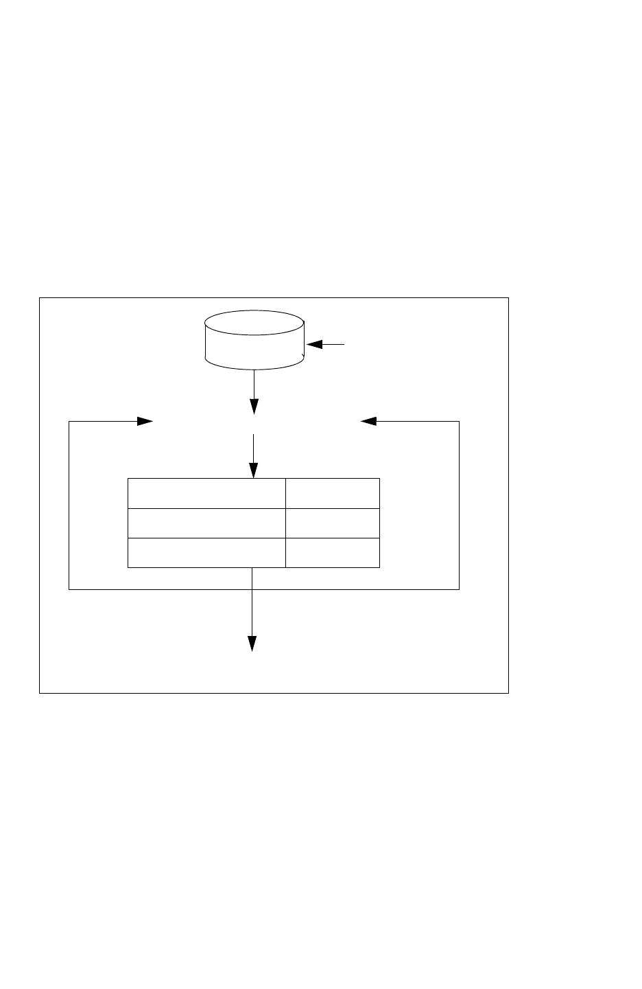
Chapter 5: Incremental Extraction
Running Incremental Extraction 5-13
Chapter 5: Incremental Extraction
Running Incremental Extraction 5-13
StarRC User Guide and Command Reference Version F-2011.06
stage was not performed), those incomplete stages are performed first. See Figure 5-4. For
a complete list of commands and their respective -clean options, see “Command List With
-clean Option Information” on page B-20.
To begin incremental extraction, add INCREMENTAL:YES in the command file and extract
using -clean. The combination of INCREMENTAL:YES and using -clean begins an iteration
of incremental extraction. The command file should point to the correct post-ECO database
and block. STAR_DIRECTORY should also point to the path of the previous extraction run.
Another incremental extraction iteration can begin only after the previous extraction run has
successfully completed.
Figure 5-4 Using -clean Options With Incremental Extraction
Translation -cleanT
Extraction -cleanX
Netlisting -cleanN
EXTRACTION
StarXtract -clean star_cmd
Iteration
loop N
Next incremental
loop, ensure that
INCREMENTAL:YES
is specified in the
star_cmd file.
To perform a normal
extraction, ensure that
INCREMENTAL:NO
is specified in the
star_cmd file.
Perform ECO changes
Database
To perform normal extraction and exit the incremental iteration loop, specify
INCREMENTAL:NO in the star_cmd file and use -clean to overwrite all the current information
in the STAR directory.
Incremental Extraction -undo Option
In some circumstances, certain ECO operations do not yield an improvement in results. In
this case, you might want to go back to the previous extraction result. You can “undo” a
previous extraction result using the following command-line option:

Chapter 5: Incremental Extraction
Running Incremental Extraction 5-14
StarRC User Guide and Command Reference F-2011.06
StarRC User Guide and Command Reference Version F-2011.06
% StarXtract -undo star_cmd
It is not possible to run the -undo command-line option after a non-incremental run because
there is nothing to undo. It is also not possible to run the -undo option twice consecutively
because the star directory is considered the result of a full run. An error message is issued
if you attempt this.
Using Distributed Processing
You can use distributed processing in an incremental extraction flow using the command
INCREMENTAL_FORCE_DP. Here are two typical command file scenarios:
Scenario 1
(better extraction run time)
Scenario 2
Pre ECO commands:
NUM_PARTS:N
Pre ECO commands:
NUM_PARTS:N
Post ECO commands:
NUM_PARTS:N
INCREMENTAL:YES
INCREMENTAL_FORCE_DP:YES
Post ECO commands:
NUM_PARTS:N
INCREMENTAL:YES
INCREMENTAL_FORCE_DP:NO
In scenario 1, the value specified for the
NUM_PARTS command for Pre ECO and Post
ECO must be the same.
Scenario 2 uses a single partition for Post ECO
processing.
Error Conditions and Warnings
There are several messages that can appear while you attempt to perform incremental
extraction.
ERROR:StarXtract
ERROR: Cannot perform undo on the first incremental run.
If StarRC finds no difference between the original block and the post-ECO block, the
following error message appears:
ERROR: StarXtract
ERROR: found zero difference between pre-ECO and post-ECO
layout, no ERROR: need to proceed for extraction.
ERROR: Please ensure that BLOCK: command is set to the correct
block ERROR: or that INCREMENTAL command is set correctly.
ERROR: Please re-run with -clean
Verify that the ECO changes were applied to the post-ECO block, or that the BLOCK
command is the correct post-ECO block name. It is also possible that the INCREMENTAL
setting was not set correctly. After the corrections have been made, use the -clean
command. Not using the -clean command can result in incorrect netlists being produced.

Chapter 5: Incremental Extraction
Incremental Netlist Examples 5-15
Chapter 5: Incremental Extraction
Incremental Netlist Examples 5-15
StarRC User Guide and Command Reference Version F-2011.06
Incremental Netlist Examples
There are two ECO scenarios in which an incremental netlist generated by StarRC can be
applied: when rerouting a net or when performing gate insertion. Examples of these
scenarios are shown in this section.
An incremental netlist satisfies the following two conditions:
• Any cross-couplings between ECO affected networks and non-ECO affected networks
are assumed to be exactly the same in the incremental parasitic file as in the original
parasitic file.
• The node numbers on RC networks of non-ECO affected networks are exactly the same
as before.
To simplify the description, assume that the ECO affected nets consist of ECO nets and their
adjacent neighbors.
The Scenario of Rerouting a Net
A generated incremental netlist consists of the changed net and its neighbors. Figure 5-6 on
page 5-18 illustrates all parasitics that are part of the incremental netlist. Assume one of the
internal nets, net W3, is rerouted. Note that special dangling coupling capacitances are put
into the netlist between re-extracted nets and non-extracted nets. The incremental netlist
looks like a partial full-chip netlist without the non-extracted nets. This scheme allows tools
like PrimeTime SI to annotate coupling capacitors after it restores saved results from a
full-chip analysis run.
The Scenario of Gate Insertion
Assume that a new inverter I34 is inserted on net W3 between I3 and I4. The two new nets
are called W3_a and W3_b. Figure 5-7 on page 5-20 illustrates all parasitics that are part of
the incremental netlist. The incremental netlist consists of the new nets and their neighbors.
Similar to scenario #1, dangling capacitors are generated in the netlist between ECO
affected nets and their neighbors.
Schematic Examples and Their Netlists
Two schematic and netlist examples, one pre-ECO and the other post-ECO, describe the
differences between the two full-chip netlists.
Consider a block of six-inverter chains with consecutive series nets coupled to one another.
The netlist in Figure 5-5 on page 5-16 reflects the pre-ECO full-chip netlist. For this scenario,
only one coupling capacitance between each pair of adjacent nets is shown.
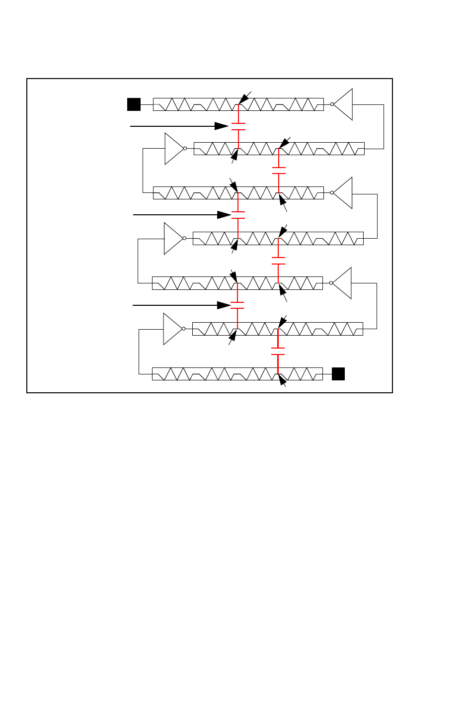
Chapter 5: Incremental Extraction
Incremental Netlist Examples 5-16
StarRC User Guide and Command Reference F-2011.06
StarRC User Guide and Command Reference Version F-2011.06
Figure 5-5 Pre-ECO Six-Inverter Chain Design and Netlist
NET 0 0:3
I6
I5
I4
I3
I2
I1
W5:3
NET W5
W5:2
W4:3
W4:2
W3:3
NET W4
W3:2
W2:3
NET W2
NET W3
NET W1
W1:2
NET I I:2
W2:2
W1:3
Coupling Capacitance
Coupling Capacitance
Coupling Capacitance

Chapter 5: Incremental Extraction
Incremental Netlist Examples 5-17
Chapter 5: Incremental Extraction
Incremental Netlist Examples 5-17
StarRC User Guide and Command Reference Version F-2011.06
Figure 5-5 is an example of a six-inverter chain design. This netlist represents the pre-ECO
full-chip netlist.
*D_NET I 31.5
*CAP
1 I 2.3
2 I:2 2.4
3 I:3 2.5
4 I:4 2.6
5 I1:A 2.7
6 I:2 W1:3 2.8
*RES
1 I I:2 2.9
2 I:2 I:3 3.0
3 I:3 I:4 3.1
4 I:4 I1:A 3.2
*END
*D_NET W1 26.2
*CAP
1 I1:Z 3.3
2 W1:2 3.4
3 W1:3 3.5
4 W1:4 3.6
5 I2:A 3.7
6 W1:3 I:2 2.8
7 W1:2 W2:3 4.7
*RES
1 I1:Z W1:2 3.8
2 W1:2 W1:3 3.9
3 W1:3 W1:4 4.0
4 W1:4 I2:A 4.1
*END
*D_NET W2 64.3
*CAP
1 I2:Z 4.2
2 W2:2 4.3
3 W2:3 4.4
4 W2:4 4.5
5 I3:A 4.6
6 W2:3 W1:2 4.7
7 W2:2 W3:3 4.8
*RES
1 I2:Z W2:2 4.9
2 W2:2 W2:3 5.0
3 W2:3 W2:4 5.1
4 W2:4 I3:A 5.2
*END
*D_NET W3 61.2
*CAP
1 I3:Z 5.2
2 W3:2 5.3
3 W3:3 5.4
4 W3:4 5.5
5 I4:A 5.6
6 W3:3 W2:2 4.8
7 W3:4 I4:A 6.1
*RES
1 I3:Z W3:2 5.8
2 W3:2 W3.3 5.9
3 W3:3 W3:4 6.0
4 W3:4 I4:A 6.1
*END
*D_NET W4 72.1
*CAP
1 I4:Z 6.2
2 W4:2 6.3
3 W4:3 6.4
4 W4:4 6.5
5 I5:A 6.6
6 W4:3 W3.2 5.7
7 W4:2 W5:3 6.7
*RES
1 I4:Z W4:2 6.8
2 W4:2 W4:3 6.9
3 W4:3 W4:4 7.0
4 W4:4 I5:A 7.1
*END
*D_NET W5 12.2
*CAP
1 I5:Z 7.2
2 W5:2 7.3
3 W5:3 7.4
4 W5:4 7.5
5 I6:A 7.6
6 W5:3 W4:2 6.7
7 W5:2 0:3 7.8
*RES
1 I5:Z W5:2 7.9
2 W5:2 W5:3 8.0
3 W5:3 W5:4 8.1
4 W5:4 I6:A 8.2
*END
*D_NET 0 25.2
*CAP
1 I6:Z 8.2
2 0:2 8.3
3 0:3 8.4
4 0:4 8.5
5 0 8.6
6 0:3 W5:2 7.8
*RES
1 I6:Z 0:2 8.9
2 0:2 0:3 9.1
3 0:3 0:4 9.2
4 0:4 0 9.3
*END
Note: The resistance and capacitance numbers are not real.
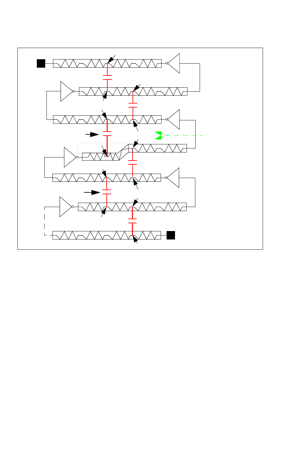
Chapter 5: Incremental Extraction
Incremental Netlist Examples 5-18
StarRC User Guide and Command Reference F-2011.06
StarRC User Guide and Command Reference Version F-2011.06
Figure 5-6 Post-ECO Netlist of Six-Inverter Chain Design (Net Reroute)
NET 0 0:3
I6
I5
I4
I3
I2
I1
W5:3
NET W5
W5:2
W4:3
W4:2
W3:3
NET W4
W3:2
W2:3
NET W2
NET W3
NET W1
W1:2
NET I I:2
W2:2
W1:3
Coupling Capacitance
Coupling Capacitance
COUPLINGS FROM
NEIGHBORING NETS
TO NON-ECO AFFECTED
NETS

Chapter 5: Incremental Extraction
Incremental Netlist Examples 5-19
Chapter 5: Incremental Extraction
Incremental Netlist Examples 5-19
StarRC User Guide and Command Reference Version F-2011.06
Figure 5-6 is an example of a six-inverter chain design after an ECO has been performed on
net W3. The incremental netlist result contains the ECO-modified net reroute, as well as
neighboring nets coupling to the non-ECO modified net. Couplings from neighboring nets to
non-ECO affected nets are generated in the netlist as dangling couplings to be analyzed
incrementally by tools like PrimeTime SI.
*D_NET W2 64.3
*CAP
1 I2:Z 4.2
2 W2:2 4.3
3 W2:3 4.4
4 W2:4 4.5
5 I3:A 4.6
6 W2:3 W1:2 4.7
7 W2:2 W3:3 5.6
*RES
1 I2:Z W2:2 4.9
2 W2:2 W2:3 5.0
3 W2:3 W2:4 5.1
4 W2:4 I3:A 5.2
*END
*D_NET W3 61.2
*CAP
1 I3:Z 4.1
2 W3:2 6.2
3 W3:3 5.1
4 W3:4 3.8
5 I4:A 5.5
6 W3:3 W2:2 5.6
7 W3:2 W4:3 4.8
*RES
1 I3:Z W3:2 5.2
2 W3:2 W3:3 5.1
3 W3:3 W3:4 4.8
4 W3:4 I4:A 6.3
*END
*D_NET W4 72.1
*CAP
1 I4:Z 6.2
2 W4:2 6.3
3 W4:3 6.4
4 W4:4 6.5
5 I5:A 6.6
6 W4:3 W3:2 4.8
7 W4:2 W5:3 6.7
*RES
1 I4:Z W4:2 6.8
2 W4:2 W4:3 6.9
3 W4:3 W4:4 7.0
4 W4:4 I5:A 7.1
*END
Note: The resistance and capacitance numbers are not real.
Figure 5-7 shows a six-inverter chain design, after an ECO has been performed on net W3
with buffer insertion. The incremental netlist result contains the new nets W3_a and W3_b,
as well as all neighboring nets coupling to the ECO nets. Couplings from neighboring nets
to non-ECO affected nets are generated in the netlist as dangling couplings to be analyzed
incrementally by tools like PrimeTime.
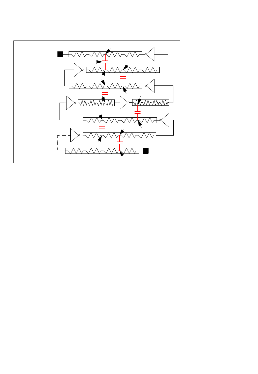
Chapter 5: Incremental Extraction
Incremental Netlist Examples 5-20
StarRC User Guide and Command Reference F-2011.06
StarRC User Guide and Command Reference Version F-2011.06
Figure 5-7 Post-ECO Buffer Insertion and Netlist of Six-Inverter Chain Design (Gate Insertion)
NET 0 0:3
I6
I5
I4
I3
I2
I1
W5:3
NET W5
W5:2
W4:3
W4:2
NET W4
W2:3
NET W2
NET W1
W1:2
NET I I:2
W2:2
W1:3
I34
W3_a:1 W3_b:1
Net W3_b
Coupling Capacitance
*D_NET W2 64.3
*CAP
1 I2:Z 4.2
2 W2:2 4.3
3 W2:3 4.4
4 W2:4 4.5
5 I3:A 4.6
6 W2:3 W1:2 4.7
7 W2:2 W3_b:3 5.6
*RES
1 I2:Z W2:2 4.9
2 W2:2 W2:3 5.0
3 W2:3 W2:4 5.1
4 W2:4 I3:A 5.2
*END
*D_NET W3_a 30.2
*CAP
1 I3:z 4.1
2 W3_a:1 6.2
3 I34:A 2.5
7 W3_a:1 W4:3 4.8
*RES
1 I3:Z W3_a:1 5.2
2 W3_a:1 I34:A 5.1
*END
*D_NET W3_b 30.2
*CAP
1 I34:Z 1.8
2 W3_b:1 3.8
3 I4:A 5.5
6 W3_b:1 W2:2 5.6
*RES
3 I34:Z 1.8
4 W3_b:1 I4:A 6.3
*END
*D_NET W4 72.1
*CAP
1 I4:Z 6.2
2 W4:2 6.3
3 W4:3 6.4
4 W4:4 6.5
5 I5:A 6.6
6 W4:3 W3_a:2 4.8
7 W4:2 W5:3 6.7
*RES
1 I4:Z W4:2 6.8
2 W4:2 W4:3 6.9
3 W4:3 W4:4 7.0
4 W4:4 I5:A 7.1
*END
Note: The resistance and capacitance numbers are not real.


Chapter 6: Parasitic Extraction
Extraction Overview 6-2
StarRC User Guide and Command Reference F-2011.06
StarRC User Guide and Command Reference Version F-2011.06
Extraction Overview
The commands documented in this chapter apply to all StarRC flows and determine how the
layout database of choice is processed and extracted and how the parasitics are reported.
Some of the commands described in this chapter are required to perform an extraction. If
you do not specify any of the optional commands in the command file or in the GUI Setup
notebook, StarRC sets the command option to its default.
SingleShot Extraction
The SingleShot Extraction feature of StarRC executes any combination of extraction/
analysis flows within a single StarRC run. SingleShot extraction takes full advantage of the
overlap between extraction and analysis and shares the extracted parasitics between all of
the flows. The amount of work StarRC must do is minimized. SingleShot extraction also
eases the burden of tracking many runs and consolidates the results into a centralized
location for convenient review. Within the StarRC GUI, the SingleShot Extraction Wizard
manages the commands dynamically, so that only those applicable to the selected flows are
displayed.
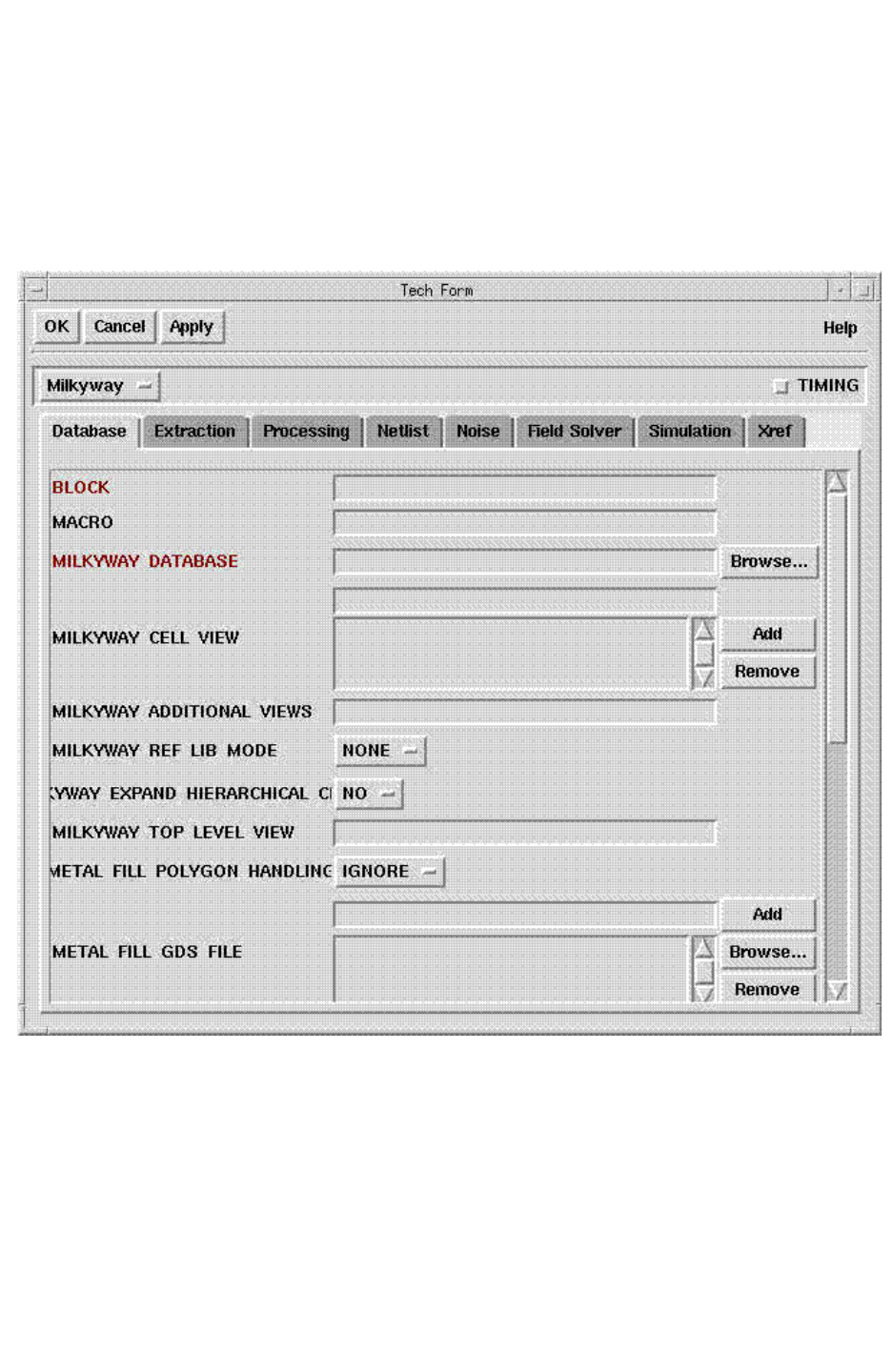
Chapter 6: Parasitic Extraction
SingleShot Extraction 6-3
Chapter 6: Parasitic Extraction
SingleShot Extraction 6-3
StarRC User Guide and Command Reference Version F-2011.06
The SingleShot Extraction form contains all the available commands for the selected flows.
All of the settings in the SingleShot form apply throughout the StarRC GUI, although they
might not be visible in every Setup form. The SingleShot Extraction form is available through
Setup > SingleShot. See Figure 6-1.
Figure 6-1 SingleShot Extraction Form
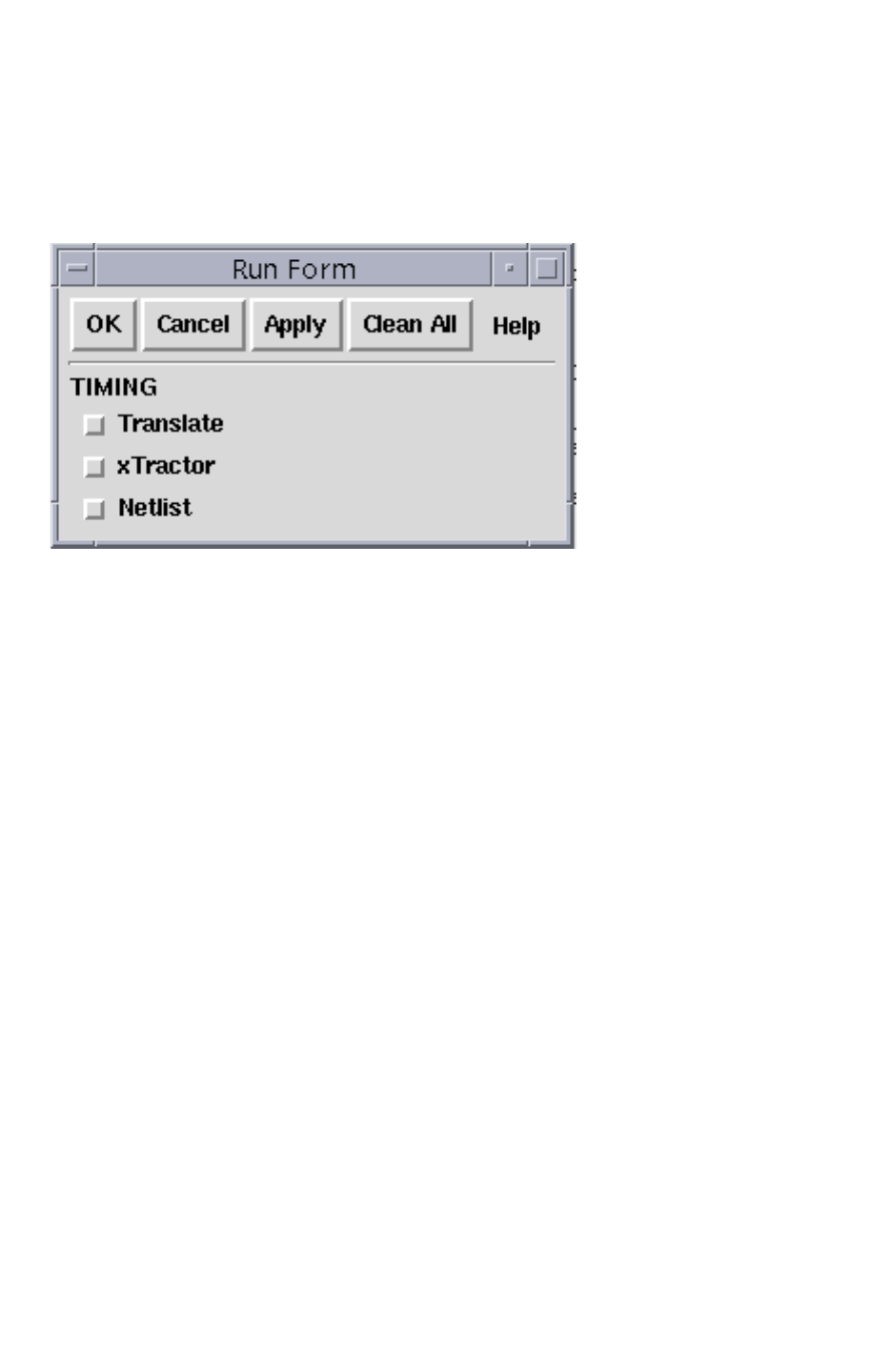
Chapter 6: Parasitic Extraction
SingleShot Extraction 6-4
StarRC User Guide and Command Reference F-2011.06
StarRC User Guide and Command Reference Version F-2011.06
As with the other Extraction Wizard forms, clicking OK or Apply sets the command options
for the StarRC run. A SingleShot extraction can be run using the Tech Form (File > Run).
See Figure 6-2.
Figure 6-2 Run Form
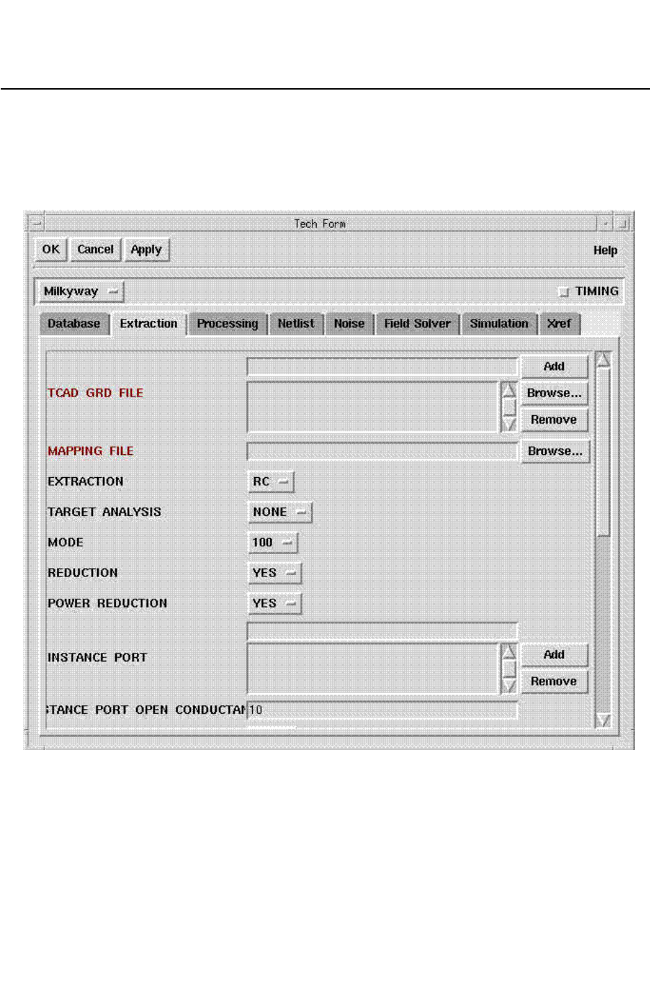
Chapter 6: Parasitic Extraction
Extraction Commands 6-5
Chapter 6: Parasitic Extraction
Extraction Commands 6-5
StarRC User Guide and Command Reference Version F-2011.06
Extraction Commands
There are several extraction commands shown in the Extraction tab in Figure 6-3. For details
about these commands, see Chapter 17, “StarRC Commands.”
Figure 6-3 Extraction Tech Form
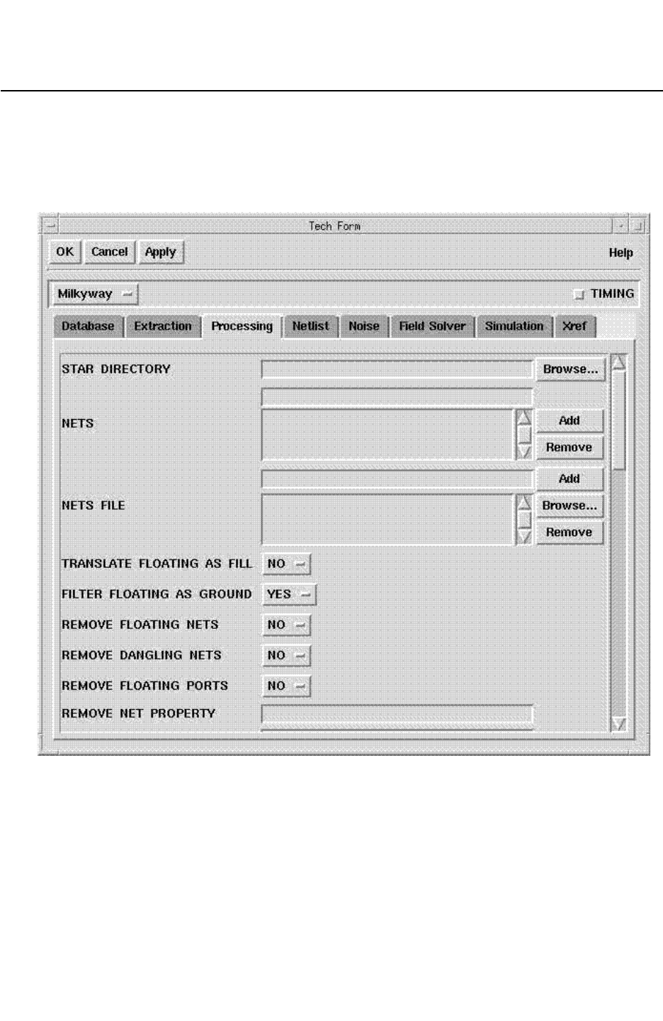
Chapter 6: Parasitic Extraction
Processing Commands 6-6
StarRC User Guide and Command Reference F-2011.06
StarRC User Guide and Command Reference Version F-2011.06
Processing Commands
There are several processing commands in the Processing tab shown in Figure 6-4. For
details about these commands, see Chapter 17, “StarRC Commands.”
Figure 6-4 Tech Fo r m

7-1
7
Rapid3D Field Solver 7
Rapid3D is a 3-D capacitance extraction tool that solves electrostatic equations using
statistical random-walk methods. Rapid3D is used in conjunction with StarRC to verify the
accuracy of StarRC results when very high levels of accuracy are desired.
The following sections describe Rapid3D:
•Introduction to Rapid3D Extraction
•Running Rapid3D
•Input and Output Files
•Trapezoidal Conductors
•Conductor Types
•Capacitance Types
•Controlling Accuracy and Runtime

Chapter 7: Rapid3D Field Solver
Introduction to Rapid3D Extraction 7-2
StarRC User Guide and Command Reference F-2011.06
StarRC User Guide and Command Reference Version F-2011.06
Introduction to Rapid3D Extraction
Rapid3D extracts capacitance by solving the Laplace equations in 3-D. The input structures
are comprised of ideal conductors and dielectrics with fixed dielectric constants. Rapid3D
can handle layouts with millions of conductors and extract thousands of nets without any
restrictions on the number of metal or dielectric layers. The dielectric layers can be planar or
conformal.
Rapid3D considers all 3-D effects and the shielding effects of intervening conductors. It
accounts for the effects of process features such as complex dielectric structures, tapered
conductors and contacts, charge sharing with semiconductor devices, fringing fields, floating
metal (metal fill), density-based thickness variation, etch-vs-width variation, and spacing
variation.
You can control the accuracy and runtime of Rapid3D. In addition, this tool can run on a
single CPU or in distributed processing mode on a Load Sharing Facility (LSF), Gridware, or
a network of machines.
Running Rapid3D
You can invoke Rapid3D seamlessly within StarRC using the FSCOMPARE flow or the
FS_EXTRACT_NETS flow. Ta bl e 7-1 describes the differences between the flows.
Table 7-1 Comparison of Rapid3D Flows
FSCOMPARE flow FS_EXTRACT_NETS flow
Flow description Reports the differences between
the pattern-based extraction results
of StarRC and the random-walk
extraction results of Rapid3D
Extracts critical nets with Rapid3D
Command to invoke flow EXTRACTION: FSCOMPARE FS_EXTRACT_NETS
Default convergence
goal set by the
FSCOMPARE_OPTIONS
-perc_self command
0.5% 1.5%
Output files Generates the .fs_comptot and
.fs_compcoup output files, which
report the differences between the
pattern-based extraction results of
StarRC and the random-walk
extraction results of Rapid3D
Incorporates the extracted
capacitances into the resulting
netlist; does not generate
.fs_comptot and .fs_compcoup
report files

Chapter 7: Rapid3D Field Solver
Running Rapid3D 7-3
Chapter 7: Rapid3D Field Solver
Running Rapid3D 7-3
StarRC User Guide and Command Reference Version F-2011.06
In the .fs_comptot file, shown in Example 7-1, the values in the FS column represent the
capacitances calculated by Rapid3D; the percentages in parentheses represent the
corresponding statistical uncertainty in the Rapid3D results. The values in the xTract column
represent the capacitances calculated by StarRC using its default pattern-based extraction.
Example 7-1 .fs_comptot File
%@100fF %Diff AbsError(fF) FS(fF) xTract(fF) NetName
-0.17 -0.49% 0.0566781 11.5645 (0.5%) 11.5078 D7
0.12 0.55% 0.02676 4.89356 (1.2%) 4.92032 D23
0.08 0.24% 0.0278593 11.551 (0.5%) 11.5789 S7
-0.04 -0.18% 0.011445 6.49725 (1.0%) 6.4858 D22
You can customize Rapid3D extraction by specifying the options listed in Table 17-1 on
page 17-55 in the FSCOMPARE_OPTIONS statement of the star_cmd file.
Distributed Processing
During distributed processing, Rapid3D distributes the nets to be extracted among the
available cores. If the number of specified cores exceeds the number of nets to be extracted,
Rapid3D uses only the same number of cores as nets to be extracted to avoid using
unnecessary cores. Using distributed processing on small jobs that would only take a few
minutes is unlikely to be productive because of the startup time for the machines.
The distributed processing of Rapid3D can also tolerate machine failures. If a Rapid3D job
on one machine is lost during a run, Rapid3D continues to run on the remaining machines.
A Rapid3D process can be split across a combination of machines. For example, you can
split a single job across a mixture of Sun and Linux machines. You can also combine 64-bit
and 32-bit machines. However, if the job is too large for a 32-bit machine, you must use
64-bit machines.
To invoke distributed processing jobs on your compute farm, you must set the
FS_DP_STRING variable, which specifies the distributed processing method and job control
parameters. You can use the following methods to implement distributed processing:
•LSF System
•Gridware System
•General Network With a List of Machines
You must also specify the number of processors with the -np option to the
FSCOMPARE_OPTIONS statement. For example, to use four processors, use the following
statement in your star_cmd file:
FSCOMPARE_OPTIONS: -np 4

Chapter 7: Rapid3D Field Solver
Running Rapid3D 7-4
StarRC User Guide and Command Reference F-2011.06
StarRC User Guide and Command Reference Version F-2011.06
StarRC then invokes Rapid3D with the following command:
rapid3d -f rapid3d.tec -f rapid3d.des -f rapid3d.nets -np 4
LSF System
For an LSF system, you can specify the FS_DP_STRING variable as
• An environment variable before launching the tool. Be sure to enclose the LSF command
in single quotes because it might contain multiple arguments. For example,
% setenv FS_DP_STRING 'bsub -a amd64 -R "rusage[mem=5000]"'
• A statement in the star_cmd file. For example,
FS_DP_STRING: bsub -a amd64 -R "rusage[mem=5000]"
Gridware System
For a Gridware system, you can specify the FS_DP_STRING variable as
• An environment variable before launching the tool. Be sure to enclose the Gridware
command in single quotes because it might contain multiple arguments. For example,
% setenv FS_DP_STRING 'qsub -P bnormal -l "mem_free=1G mem_avail=1G"'
• A statement in the star_cmd file. For example,
FS_DP_STRING: qsub -P bnormal -l "mem_free=1G mem_avail=1G"
General Network With a List of Machines
For a general network with a list of machines, you can specify the FS_DP_STRING variable as
• An environment variable before launching the tool. Be sure to enclose the list in single
quotes because it might contain multiple arguments. For example,
% setenv FS_DP_STRING 'list mars jupiter uranus'
• A statement in the star_cmd file. For example,
FS_DP_STRING: list mars jupiter uranus
Note:
When using a general network with a list of host machines, each machine must be
available through a simple UNIX rsh command without a password.

Chapter 7: Rapid3D Field Solver
Input and Output Files 7-5
Chapter 7: Rapid3D Field Solver
Input and Output Files 7-5
StarRC User Guide and Command Reference Version F-2011.06
Notes on Distributed Processing
When using distributed processing, keep the following points in mind:
• The FS_DP_STRING variable does not specify the number of processors.
• If you specify the FS_DP_STRING variable as both an environment variable and a
star_cmd file statement, then the setting in the star_cmd takes precedence.
• The control parameters are site-specific; refer to your system administrator.
Licensing Requirement for Distributed Processing
You need one StarRC license to run up to four Rapid3D distributed processing jobs.
Input and Output Files
The Rapid3D input and output files are described in the following sections:
•Input Files
•Output File
Input Files
Rapid3D reads the following three input files that share a common syntax:
•Technology File (rapid3d.tec) – Contains the description of metal and dielectric layers,
including their z-coordinates.
•Design File (rapid3d.des) – Contains a description of the layout in the form of boxes, nets,
and net groups.
•Net File (rapid3d.nets) – Contains a list of nets to be extracted.
In the StarRC field solver extraction flow, these files are automatically created before running
Rapid3D. When running Rapid3D from the command line, these files must be specified in
the following order: rapid3d.tec, rapid3d.des, and rapid3d.nets.
Technology File
The technology file contains information about the metal and dielectric layers. You cannot
edit the technology file because it is encrypted in a binary format.
The technology file must be specified on the command line before the design file.

Chapter 7: Rapid3D Field Solver
Input and Output Files 7-6
StarRC User Guide and Command Reference F-2011.06
StarRC User Guide and Command Reference Version F-2011.06
Design File
The design file contains the geometry of the nets in the netlist. It is written in an encrypted
binary format and is created during the StarRC field-solver flow. You cannot edit the design
file.
Net File
The net file contains a list of nets to be extracted. Each net is specified on a single line
preceded by the extract keyword and terminated with the XXend keyword, as shown in the
following syntax:
extract net_name XXend
If the net file does not contain any extract statements, then Rapid3D extracts all the nets.
To execute Rapid3D in distributed processing mode, include a dp_string statement in the
net file. Rapid3D submits the farm jobs using the command followed by the dp_string
keyword.
The following is an example of a net file:
extract net_A XXend
extract net_B XXend
dp_string bsub -q normal -o lsf.log -R "rusage[mem=1000]"
Output File
StarRC reports the following information about Rapid3D in the star_sum file:
• Rapid3D executable path, version, and build date
• Job completion status
•Runtime
• Memory usage
• Warning and error messages
• Distributed processing information
This information can help you to correct setup or design issues. Additional information such
the setting of job control parameters can be found in the rapid3d.log file.
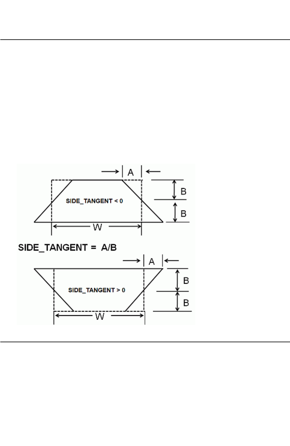
Chapter 7: Rapid3D Field Solver
Trapezoidal Conductors 7-7
Chapter 7: Rapid3D Field Solver
Trapezoidal Conductors 7-7
StarRC User Guide and Command Reference Version F-2011.06
Trapezoidal Conductors
The metal layers with a trapezoidal cross section in the x-z and y-z planes are included in
the layer statements with side_tangent parameter in the technology file. The geometry for
the trapezoidal conductor is shown in Figure 7-1. The side_tangent parameter is a
dimensionless number that is the ratio of horizontal delta divided by one-half of the height of
the conductor. If the side_tangent parameter is positive, the trapezoid is smaller at the
bottom. If the side_tangent parameter is negative, the trapezoid is smaller at the top. The
side_tangent parameter is specified in the rapid3d.tec file.
Rapid3D calculates the capacitance and internally accounts for the trapezoidal shape of the
electrodes, as shown in Figure 7-1. Using trapezoidal electrodes increases the runtime of
Rapid3D.
Figure 7-1 Geometry for Trapezoidal Conductor
Conductor Types
Structures in Rapid3D are composed of conductors and dielectrics. Dielectrics are typically
read through the technology file. Conductors are composed of metal boxes or planar boxes
and are read from the design file. Boxes are specified using the x-, y-, and z-coordinates at

Chapter 7: Rapid3D Field Solver
Conductor Types 7-8
StarRC User Guide and Command Reference F-2011.06
StarRC User Guide and Command Reference Version F-2011.06
two opposite corners. Planar boxes are specified using the x- and y-coordinates at two
opposite corners, and the z-location and thickness come from the layer name specified in
the technology file.
Rapid3D uses the following conductor types:
•Nets
•Net Groups
•Ground Nets
•Fill Nets
Each type of conductor reports capacitance differently. Conductors are composed of
collections of metal boxes. All the metal boxes in a conductor are assumed to be connected
and at the same potential. The following sections describe the five types of conductors and
their reporting rules.
Nets
A net conductor is the most common general type of conductor. Random walks are started
only from nets and net groups. Rapid3D reports capacitances between nets and from nets
to all other types. Nets are created by placing metal boxes or planar boxes between a net
statement and an end statement. Net statements are specified in the encrypted design file
to describe and identify the nets.
Net Groups
A net group is a collection of nets assumed to be electrically connected and, therefore,
having the same potential. Rapid3D extracts the capacitance between nets in different net
groups but not between nets in the same net group. Net groups are specified in the
encrypted design file.
Ground Nets
If Dirichlet boundary conditions are used as the default, then the edges of the bounding box
are electrical ground planes that form a single net called ground. In addition, in the design
file, some nets may be identified as grounded. Rapid3D reports the capacitance from other
nets to ground, but because walks are not started from ground, the total capacitance of
ground is not reported.

Chapter 7: Rapid3D Field Solver
Capacitance Types 7-9
Chapter 7: Rapid3D Field Solver
Capacitance Types 7-9
StarRC User Guide and Command Reference Version F-2011.06
Fill Nets
Fill nets are used to model fill metal polygons in a chip. Fill metal consists of boxes inserted
into a metal layer to improve the planarity of the metal layer. A fill net is assumed to be
electrically floating—not connected to any circuit elements in the netlist.
The electronic potential at fill nets is effectively determined by setting the charge on the fill
net set to zero. Even though fill nets are not electrically connected, they can introduce
capacitive coupling effects between other nets.
The charge on a fill net is calculated as shown in Equation 7-1.
Equation 7-1 Calculation of Charge on a Fill Net
Q1
V1C1C0V1V2
–()C1C2
+
C0C1C2
++
-----------------------------------------------------------------
=
The effective capacitance at net 1 is calculated as shown in Equation 7-2.
Equation 7-2 Calculation of Effective Capacitance Between Fill Nets
Ceff
C1C0C1C2
+
C0C1C2
++
---------------------------------
=
The coupling capacitance between net 1 and net 2 is calculated as shown in Equation 7-3.
Equation 7-3 Calculation of Coupling Capacitance
CcC1C2
C0C1C2
++
--------------------------------
=
Capacitance Types
Rapid3D reports the following capacitances at a node:
• Total capacitance – The capacitance from the net to all other objects in the simulation.
• Coupling capacitance (xcap) – The capacitance between two nets that are not part of the
same net group.
Each capacitance type is reported in a separate section of the Rapid3D capacitance report.

Chapter 7: Rapid3D Field Solver
Boundary Conditions 7-10
StarRC User Guide and Command Reference F-2011.06
StarRC User Guide and Command Reference Version F-2011.06
Boundary Conditions
Boundary conditions are applied at the six edges of the simulation domain. By default,
Rapid3D uses a Dirichlet boundary condition of 0 volts. This is equivalent to placing a
ground plane along each face of the simulation cube. These ground planes are connected
to the Rapid3D global ground net.
Note:
This is different from Raphael RC2 and RC3, which use a Neumann or reflecting
boundary condition at each external edge.
In general, the Dirichlet boundary condition used in Rapid3D causes the reported total
capacitance at a node that is higher than the Neumann boundary condition used in RC2 and
RC3. As the boundary is moved further from the simulated electrodes, the effect becomes
smaller.
You can select Neumann boundary conditions in Rapid3D by adding the -neuman_x and
-neuman_y options to the FSCOMPARE_OPTIONS statement in your star_cmd file.
The following example specifies the use of Neumann boundary conditions in both the x- and
y-directions:
FSCOMPARE_OPTIONS: -neuman_x -neuman_y
StarRC then invokes Rapid3D with the following command:
rapid3d -f rapid3d.tec -f rapid3d.des -f rapid3d.nets -neuman_x -neuman_y
You also can specify periodic boundary conditions on the x- or y-direction with the
-periodic_x and -periodic_y options to the FSCOMPARE_OPTIONS statement in your
star_cmd file. Periodic boundary conditions cause the random walks to wrap around to the
opposite side of the device. For example, a walk that exits the device at the positive x-side
reenters at the negative x-side of the device. Periodic boundary conditions are useful for
devices with repeated cells like RAM or CCD devices.
The following example specifies the use of periodic boundary conditions in both x- and
y-directions:
FSCOMPARE_OPTIONS: -periodic_x -periodic_y
StarRC then invokes Rapid3D with the following command:
rapid3d -f rapid3d.tec -f rapid3d.des -f rapid3d.nets
-periodic_x -periodic_y
You can specify a bounding box when using Neumann or periodic boundaries with the -bb
option to the rapid3d command. For more details, see Ta bl e 17-1 on page 17-55.

Chapter 7: Rapid3D Field Solver
Controlling Accuracy and Runtime 7-11
Chapter 7: Rapid3D Field Solver
Controlling Accuracy and Runtime 7-11
StarRC User Guide and Command Reference Version F-2011.06
Controlling Accuracy and Runtime
In Rapid3D, the runtime has an inverse quadratic dependency on the accuracy. For
example, reducing the accuracy tolerance by a factor of three (such as, from 3 percent to 1
percent) generally results in a ninefold increase in CPU time. The default accuracy tolerance
in Rapid3D is 1 sigma at 0.5 percent for total capacitance. This means that the error
incidence in total capacitance for 68 percent of the nets extracted is less than 0.5 percent.
You can change the default 0.5 percent for total capacitance convergence to a different value
using the -perc_self option in the FSCOMPARE_OPTIONS statement of your star_cmd file.
For example, to specify 1 percent as the requirement for total capacitance convergence, use
the following syntax in your star_cmd file:
FSCOMPARE_OPTIONS: -perc_self 1
In general, the runtime is proportional to the number of nets extracted. The runtime is also
dependent on the overall size of the layout (number of boxes or polygons). Increasing the
number of dielectric layers can also cause the runtime to increase because the number of
hops required for a walk to reach a conductor increases.
Specifying Convergence Goals
A net is considered to be convergent if it satisfies the following relations:
Ec < perc_self x C & for each Cij { Eij < abs_coup + Cij x perc_coup}
In this equation,
• Ec = estimated statistical error on the total net capacitance
• C = total net capacitance
• Cij = coupling capacitance from net i to a neighbor net j
• Eij = estimated statistical error on Cij
• Default of abs_coup = C x coup_cap_thresh
Small coupling capacitors can be very slow to converge. To determine the value of a
coupling capacitor between two electrodes A and B, a walk must start on electrode A and
end on electrode B. The smaller the coupling capacitor, the smaller the probability that this
happens, and a larger number of total walks is needed to obtain accurate statistics on the
coupling capacitor.

Chapter 7: Rapid3D Field Solver
Controlling Accuracy and Runtime 7-12
StarRC User Guide and Command Reference F-2011.06
StarRC User Guide and Command Reference Version F-2011.06
For example, if the total capacitance at a node is 1e-15 farads and a coupling capacitor to
the same node is 1e-18 farads, then 1000 more walks are needed to calculate the coupling
capacitance value. Therefore, extracting the coupling capacitor to the same accuracy as the
net total capacitance takes a 1000 times longer. Usually the largest capacitances are the
most important and converge the fastest in Rapid3D.
By default, Rapid3D does not check the percentage convergence of coupling capacitance.
However, you can force Rapid3D to check the percentage convergence of coupling
capacitance by using the -perc_coup option.
For example, to set the convergence of coupling capacitance to 10 percent, use the following
syntax in your star_cmd file:
FSCOMPARE_OPTIONS: -perc_coup 10
StarRC then invokes Rapid3D with the following command:
rapid3d -f rapid3d.tec -f rapid3d.des -f rapid3d.nets -perc_coup 10
By default, Rapid3D sets the threshold for convergence of coupling capacitance to 1 percent
of the total net capacitance. To change the default, use the -coup_cap_thresh option.
For example, to set the absolute convergence of coupling capacitance to 2 percent of the
total net capacitance, use the following syntax in your star_cmd file:
FSCOMPARE_OPTIONS: -coup_cap_thresh 2
Typically, it is not necessary to set coupling capacitance goals. If you do need to set them,
make sure you fully understand the convergence criteria because incorrectly setting
-perc_coup and -abs_coup can result in unnecessarily long runtimes.
Note:
There is no way to force Rapid3D to evaluate just one particular coupling capacitor of
interest. Coupling capacitors are evaluated in random order, based on where the random
walks start and end.
Specifying the Accuracy Goal
You can specify the accuracy of the extracted total capacitance without having to calculate
the convergence level in terms of the standard deviation. In this case, the tool automatically
chooses the appropriate convergence tolerance.
To specify convergence in this manner, you can set the -perc_accuracy and the
-perc_accuracy_confidence options. The default of the -perc_accuracy_confidence
option is 99.7%. For example, if you set -perc_accuracy to 5% and leave
-perc_accuracy_confidence at its default, the extracted total capacitance value is

Chapter 7: Rapid3D Field Solver
Controlling Accuracy and Runtime 7-13
Chapter 7: Rapid3D Field Solver
Controlling Accuracy and Runtime 7-13
StarRC User Guide and Command Reference Version F-2011.06
accurate to 5% with a confidence level of 99.7%. The 99.7% confidence interval about the
mean of a Gaussian distribution is 3σ. This is equivalent to setting -perc_self 1.67 (that
is, the standard deviation is 5% ÷ 3 = 1.67%).
Specifying the Consistency of Results
In a random walk solver such as Rapid3D, each net has a statistical error associated with
the result. If a design contains 1000 identical nets, then the extracted values vary somewhat
because of this error. The statistical error in Rapid3D follows a normal distribution. The
standard deviation of the distribution sigma (σ) is controlled by the -perc_self option.
For example, because the computed capacitance values follow the normal distribution, 68%
of the nets lie within one sigma of the correct value (μ); that is, they occur between μ–σ and
μ+σ, or within 2σ of each other. Thus, the number of nets consistent to within 2σ is 68%.
As an alternate way of setting the consistency, you can use the -perc_consistency and
-perc_of_nets_consistent options. Use these options to calculate a value for the
-perc_self option.
For example, to specify that 99.7% of the identical nets must have errors less than 1%, you
can use either of the following equivalent commands:
•rapid3d -perc_consistency 1 -perc_of_nets_consistent 99.7
•rapid3d -perc_self 0.167
Specifying the grids_per_meter Parameter
Rapid3D performs all geometric calculations using integers. Therefore, all geometries are
defined as integers in grid units. In the technology file, you can specify how many meters
each grid unit represents. It is important to specify a grid unit small enough to accurately
represent the geometry. Typically, you want to use about 100 grid units to represent the
smallest feature in your process, resulting in approximately one percent accuracy in the
geometry specification. Therefore, if you have a 90-nm process technology, you should
specify grids_per_meter 1e9 in the technology file so that each grid unit represents 1 nm.
The grids_per_meter parameter affects the runtime, with smaller grid units causing a
longer runtime. Therefore, while you could specify grids_per_meter 1e10 for the 90-nm
process for slightly better accuracy, the runtime would be typically twice as long as the
runtime with grids_per_meter 1e9.

Chapter 7: Rapid3D Field Solver
Controlling Accuracy and Runtime 7-14
StarRC User Guide and Command Reference F-2011.06
StarRC User Guide and Command Reference Version F-2011.06
Specifying Pattern Matching for Symmetric Nets
Memory designs often contain thousands of identical or symmetric nets with the same
capacitance characteristics. Rapid3D uses a pattern matching process to identify these
nets, analyze only a single representative net, and copy the capacitance characteristics to
all matching nets. Using pattern matching can speed up the analysis of memory designs as
well as ensure the same capacitance values for identical or symmetric nets.
To enable pattern matching, specify the -match option in the FSCOMPARE_OPTIONS
statement.

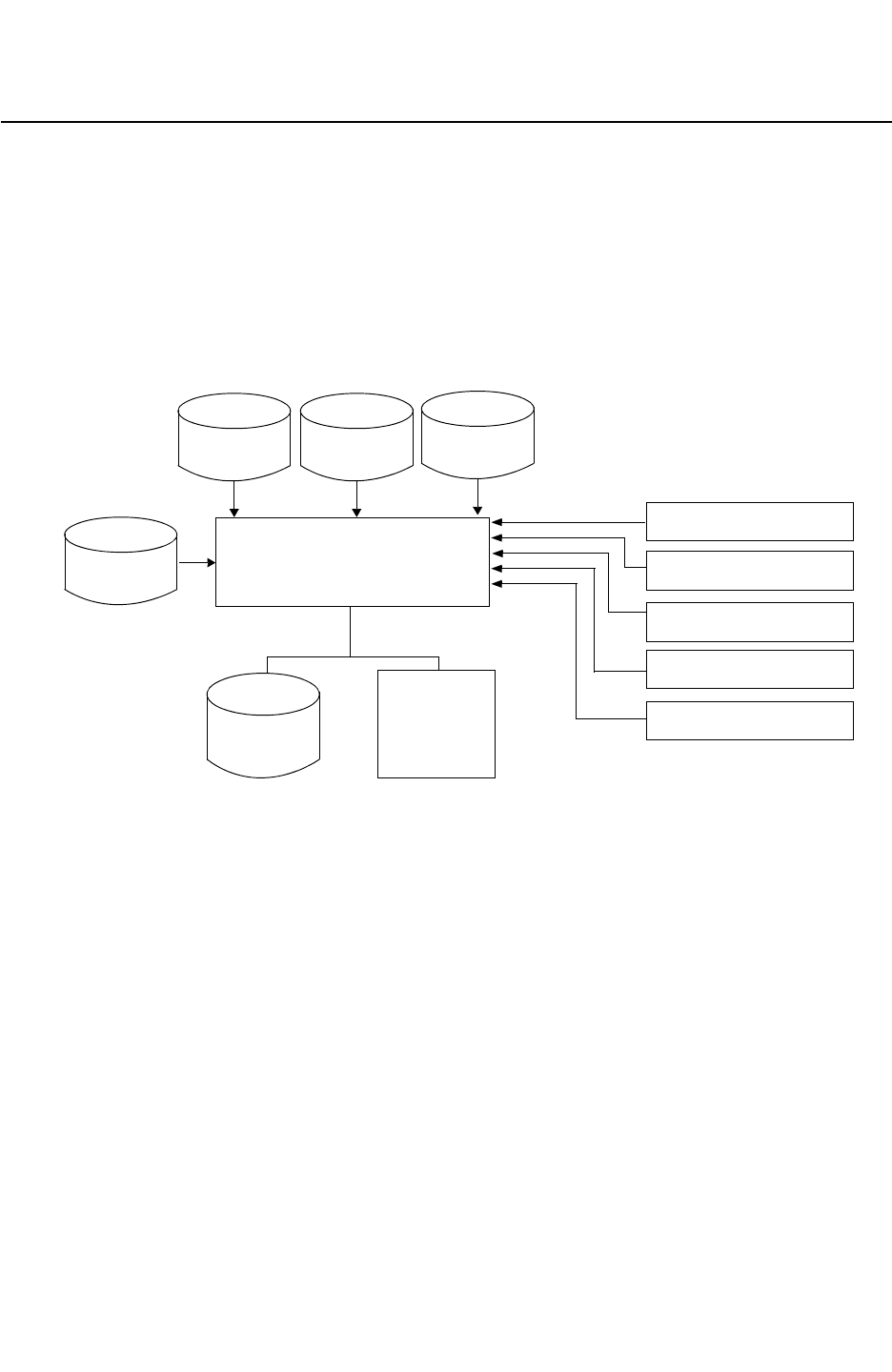
Chapter 8: Timing Analysis
Timing Analysis Overview 8-2
StarRC User Guide and Command Reference F-2011.06
StarRC User Guide and Command Reference Version F-2011.06
Timing Analysis Overview
The StarRC flow is a standard timing extraction intended to prepare raw parasitic output for
either post-layout timing analysis or for timing-driven design. This flow is shown in
Figure 8-1. The results of the extraction are exported into one of the parasitic formats. You
can execute the flow by writing a command file manually and providing it as an argument to
StarXtract or by invoking the GUI and filling in the Timing Wizard (choose Setup > Timing)
form. See Figure 8-2.
Figure 8-1 Timing Analysis
Milkyway
StarRC
LEF/DEF
[GDS]
SPF/SPEF
ANALYSIS: TIMING
GUI
SPICE_SUBCKT_FILE
star_cmd
NETS
SKIP_CELLS
STAR
Milkyway
CEL/FRAM XTR
Milkyway
PARA SBPF
Calibre
[GDS]
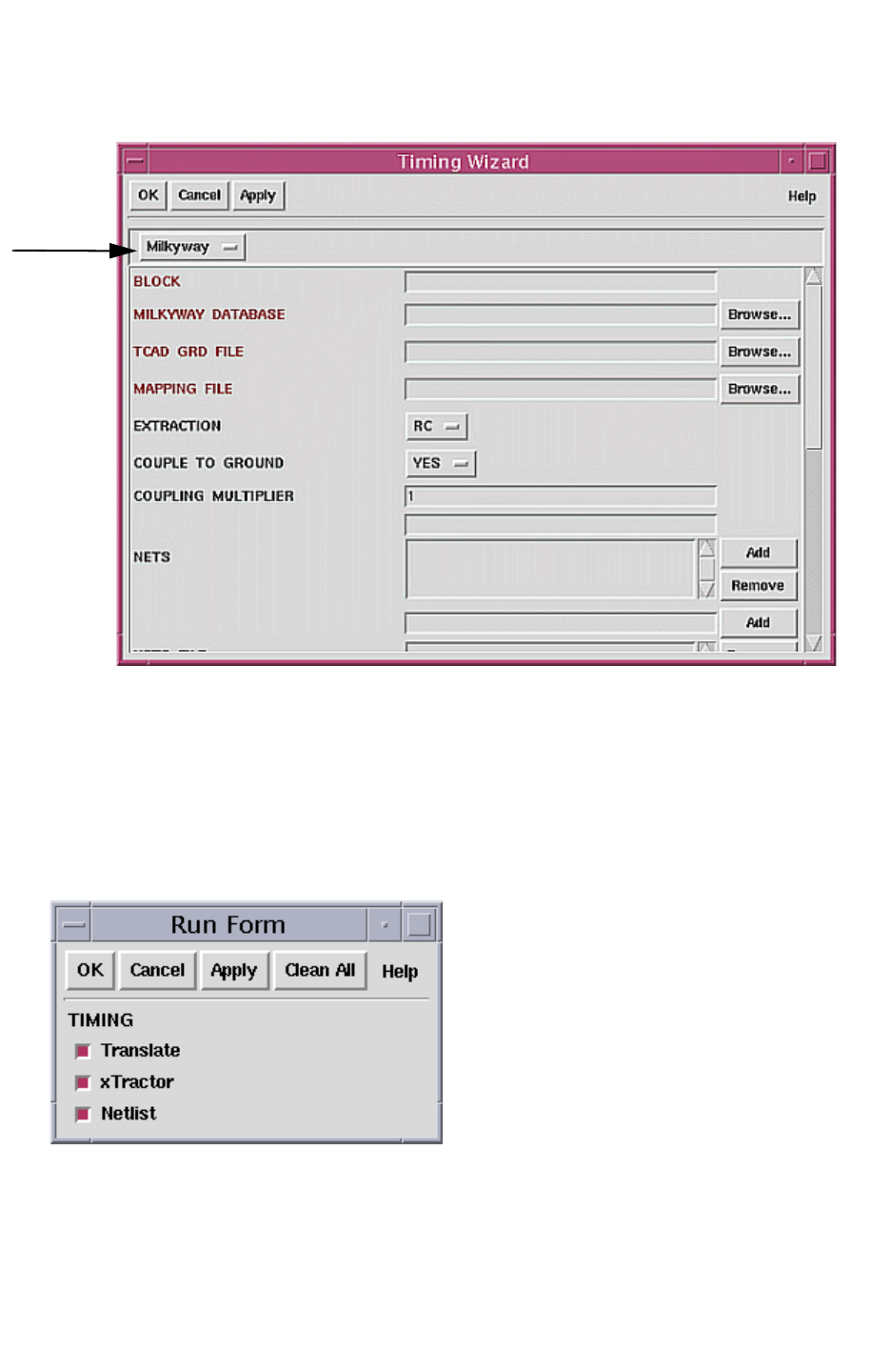
Chapter 8: Timing Analysis
Timing Analysis Overview 8-3
Chapter 8: Timing Analysis
Timing Analysis Overview 8-3
StarRC User Guide and Command Reference Version F-2011.06
Figure 8-2 Timing Wizard Form
database
type
The Timing Wizard shown in Figure 8-2 displays only the required and frequently used
options with the layout database type of choice. The full set of extraction options is available
through the SingleShot Extraction Wizard. Selecting OK or Apply in any of the Setup
notebook forms applies the command options to the extraction job. The current contents of
the Setup notebook can be exported to a file at any time by choosing File > Save. Once you
have specified all of the desired commands, you can execute the extraction by selecting OK
as shown in Figure 8-3.
Figure 8-3 Run Form
Clicking OK or Apply in this form starts the job. You can execute partial jobs by selecting only
the desired actions from the list. See “Selective Job Processing” on page 2-4 for more
information about the StarXtract execution flow.

Chapter 8: Timing Analysis
Net-Specific Modes 8-4
StarRC User Guide and Command Reference F-2011.06
StarRC User Guide and Command Reference Version F-2011.06
Clean All removes all previous results in the STAR_DIRECTORY specified in the Setup
notebook. Selecting any of the options on this form instructs StarRC to clean and redo that
stage and any subsequent stages by deleting any previous results from the specified
STAR_DIRECTORY. Unless you click Clean All, StarRC attempts to use the previous results
for the Build HN stage.
Caution:
Using this clean feature in a directory where an extraction was already run causes all
previous results to be lost. Selecting Translate, xTractor, or Netlist has no effect if there
are no existing results.
When the Translate option is selected, the xTractor and Netlist options are automatically
selected, and every stage that follows the Translate DB stage are executed again. The clean
features have no effect on an empty STAR_DIRECTORY.
An example of commands you can use for a timing flow appears in “Timing Extraction/
Analysis” on page 13-2.
Net-Specific Modes
StarRC lets you specify a specific netlist mode for any net. This means that particular nets
can be generated in the netlist in different ways. Certain nets, such as signal or clock nets,
are required for netlist generation with full resistance and capacitance (RC) coupled
parasitics output for timing and crosstalk analysis during simulation. Other less important
nets might require a lesser degree of parasitic information in the netlist, such as lumped
capacitance only. To minimize netlist size and maximize simulation efficiency, you can
differentiate netlist modes for different types of nets.
Net-specific extraction modes allow for wildcard net selectivity so that you can specify a
group of nets without listing each net. To specify a netlist mode for a specific net, add the
following commands to the StarRC command file:
•NETLIST_SELECT_NETS
•NETLIST_TYPE
You can also specify that all unselected nets coupled to by selected nets be included in the
parasitic netlist, either with full parasitics or ideally. See the
NETLIST_COUPLE_UNSELECTED_NETS command. Unselected nets are all those nets that are
not specified in the NETLIST_SELECT_NETS command. To netlist unselected nets with a
specific mode, add the following command to the StarRC command file:
NETLIST_COUPLE_UNSELECTED_NETS

Chapter 8: Timing Analysis
Net-Specific Modes 8-5
Chapter 8: Timing Analysis
Net-Specific Modes 8-5
StarRC User Guide and Command Reference Version F-2011.06
Examples showing different ways to specify net-specific modes follow. See Chapter 17,
“StarRC Commands” for command details included in the following examples. In all cases,
the original extraction and netlist mode for the affected nets are retained.
Example 1
To netlist net1 as an R-only net and all other nets as RCc nets.
EXTRACTION:RC
NETS: *
COUPLE_TO_GROUND: NO
NETLIST_TYPE:R net1
Example 2
To output net1 and net2 as full RCc nets, and nets that couple to net1 and net2 nets as Cc
nets.
EXTRACTION:RC
NETS: *
COUPLE_TO_GROUND: NO
NETLIST_SELECT_NETS: net1 net2
NETLIST_COUPLE_UNSELECTED_NETS:COMPLETE
NETLIST_TYPE: Cc *
NETLIST_TYPE: RCc net1 net2
Example 3
Outputs to the netlist all nets whose names contain CLK* as RCc nets. Outputs to the netlist
all other nets in the NETLIST_SELECT_NETS command as Cc nets.
EXTRACTION:RC
NETS: *
COUPLE_TO_GROUND: NO
NETLIST_TYPE: Cc *
NETLIST_TYPE:RCc CLK*
Selective Netlist Creation
You can specify different netlist output (R, RCg, and so on) for specific nets in the same
extraction run. To do this, use the NETLIST_TYPE command because of its ability to accept
wildcards. The NETLIST_TYPE command is order-dependent so the last instance overrides
any previous instance.
Suppose the following commands are specified:
EXTRACTION: RC
NETLIST_TYPE: R NET*
NETLIST_TYPE: RCg NETA
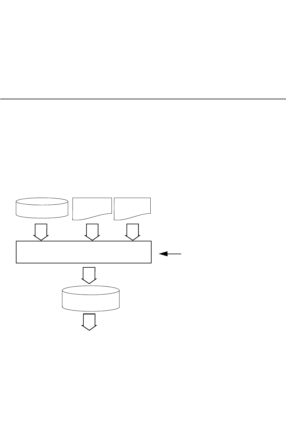
Chapter 8: Timing Analysis
Simulation Options in the StarRC Netlist 8-6
StarRC User Guide and Command Reference F-2011.06
StarRC User Guide and Command Reference Version F-2011.06
With these settings, an RC extraction is performed on the entire design. However, net names
beginning with NET are generated in the netlist with R (resistance) only, except NETA, which
is generated in the netlist as RCg (resistance and capacitance lumped to ground).
Other netlist types include R, Cg, Cc, RCg, and RCc. For more details, see the
NETLIST_TYPE command.
Simulation Options in the StarRC Netlist
Circuit simulation options can be written directly in the StarRC generated netlist. This
eliminates the need for you to set simulation options explicitly depending on the parasitic
extraction tool settings used, and helps eliminate the possibility of double-counting or
omitting some parasitic capacitance and/or resistance. The required simulation options
based on parasitic extraction settings can be specified in a StarRC command file.
To write simulation options into the netlist, use the NETLIST_SIM_OPTIONS command. The
flow for this task is shown in Figure 8-4.
Figure 8-4 Flow Integration for Simulation Option Mapping
Hercules/Calibre
Layer
Mapping File
Process
File
StarRC
with Command File Option Mapping
Parasitic Netlist
SPICE Simulation
ready for simulation
Command file with
NETLIST_SIM_OPTIONS
specified.
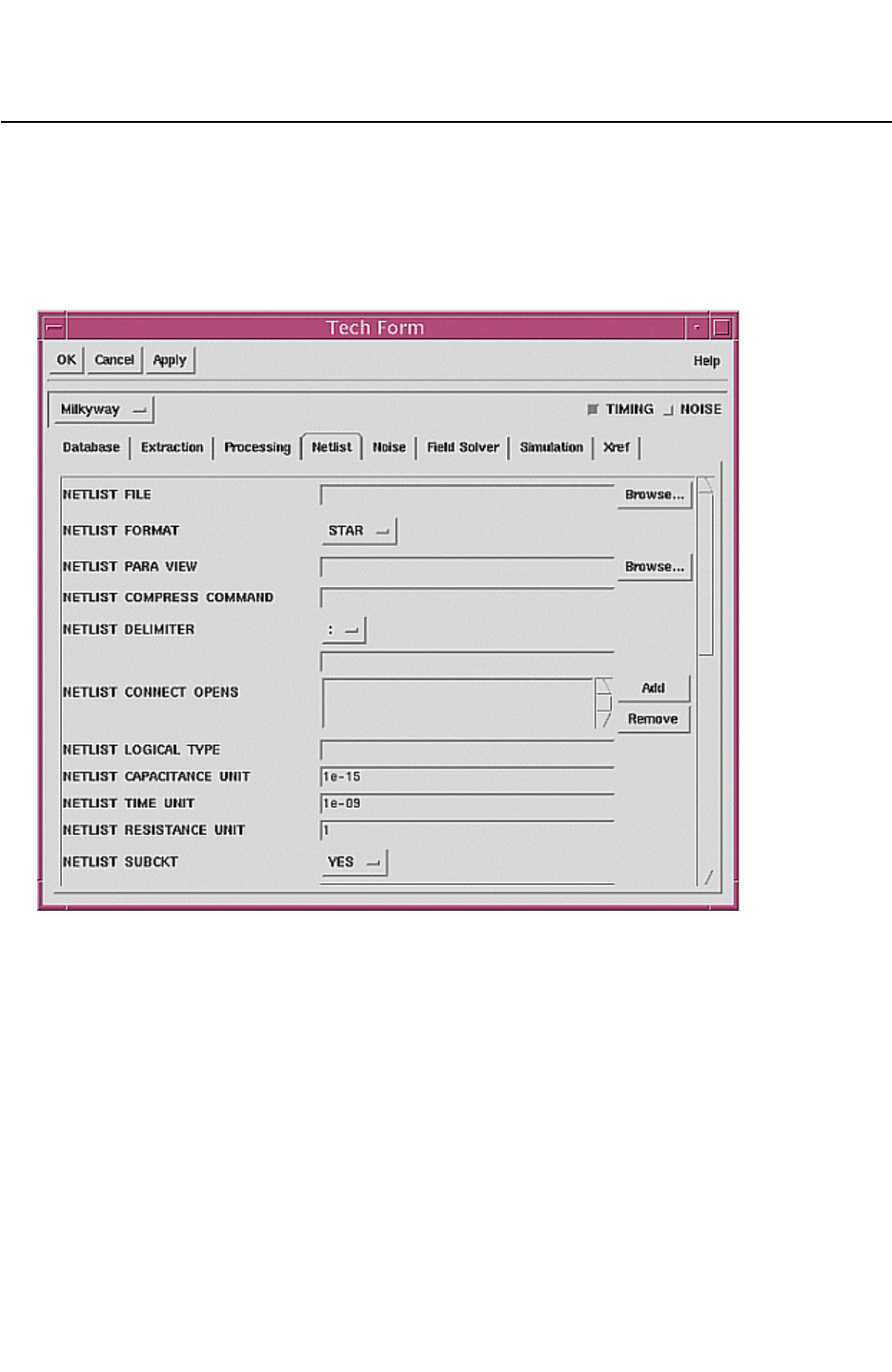
Chapter 8: Timing Analysis
Netlist Commands 8-7
Chapter 8: Timing Analysis
Netlist Commands 8-7
StarRC User Guide and Command Reference Version F-2011.06
Netlist Commands
There are numerous netlist commands. They are found on the Netlist tab of the Tech Form
as shown in Figure 8-5. For a list of commands that affect netlisting, see Ta b l e B-1 on
page B-3.
Figure 8-5 Netlist Tech Form

Chapter 8: Timing Analysis
Netlist Commands 8-8
StarRC User Guide and Command Reference F-2011.06
StarRC User Guide and Command Reference Version F-2011.06

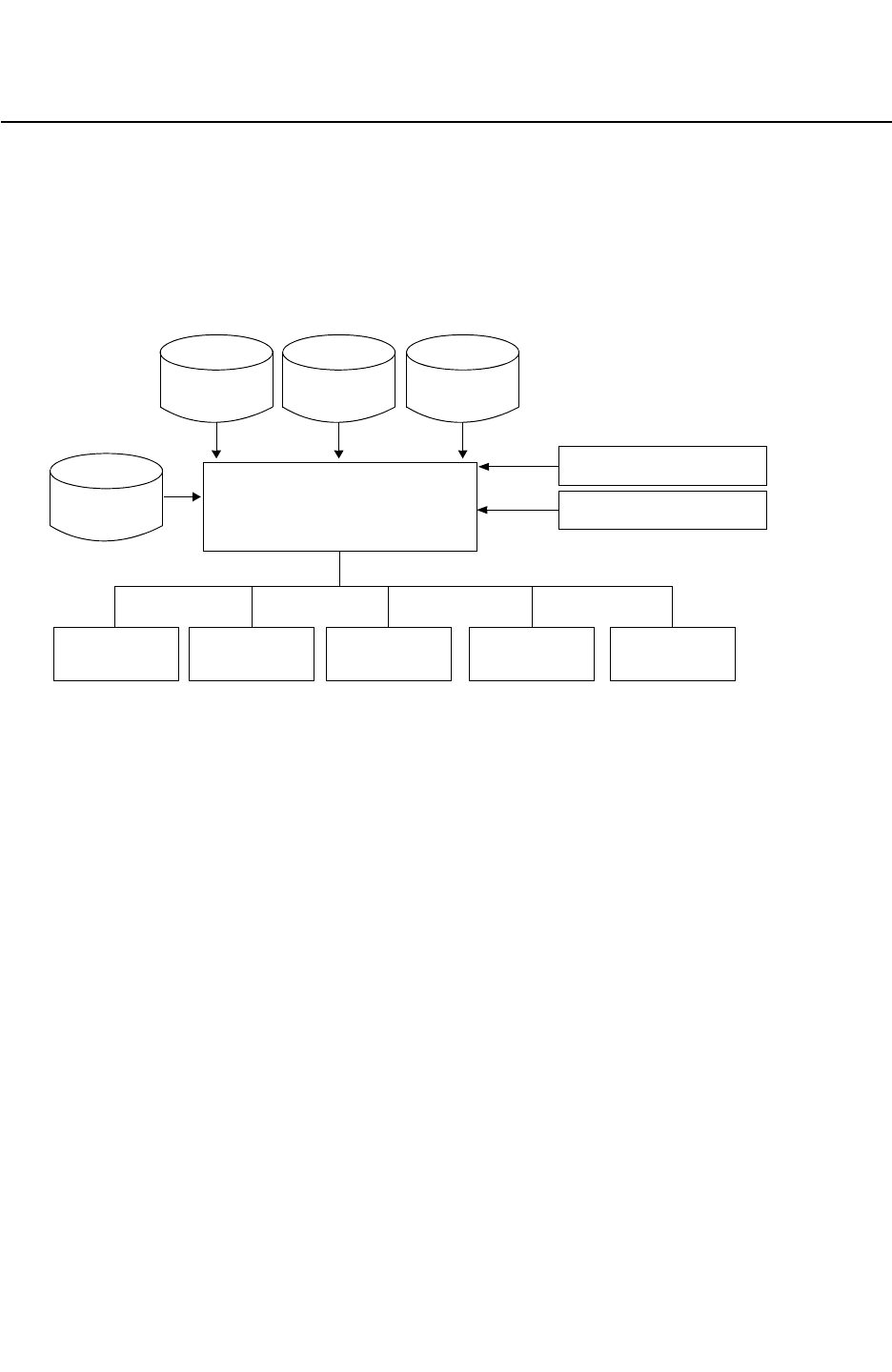
Chapter 9: Noise Analysis
Noise Analysis Overview 9-2
StarRC User Guide and Command Reference F-2011.06
StarRC User Guide and Command Reference Version F-2011.06
Noise Analysis Overview
StarRC provides a fast, low-memory fully coupled chip extraction solution that serves as a
sound basis for detailed critical net noise analysis. This is shown in Figure 9-1. It offers
error-controlled on-the-fly reduction to limit processing resources, plus tools to filter net pairs
that are not susceptible to noise and netlisting features to keep the output manageable.
Figure 9-1 Noise Analysis Flow
Milkyway
StarRC
Milkyway
LEF/DEF
[GDS]
STAR SPEF
COUPLING
ANALYSIS: NOISE
XTR
CEL/FRAM
COUPLE_TO_GROUND: NO
REPORT SBPF
GUI
star_cmd
Calibre
[GDS]
SPF
From the cross-coupled parasitics database, StarRC can generate any of the netlist formats
or generate a coupling report file.
• A specific netlist format is specified using the NETLIST_FORMAT command.
• The COUPLING_REPORT_FILE command can be used to obtain a sorted list of the strongly
coupled nets for quick identification of nets most affected by the switching activity of their
neighbors.
You can change the value of COUPLE_TO_GROUND to YES following a cross-coupled extraction
and produce a decoupled netlist of any format directly from the existing internal parasitics
database. The value of this command can be changed from NO to YES to generate a
second netlist with all coupling capacitors grounded (decoupled). This second netlist is
generated only by executing the netlist stage with the clean option. To do this, you edit the
star_cmd file and run the following:
% StarXtract -cleanN star_cmd
You can alternatively use the GUI to run a noise analysis. See “Starting a Timing or Noise
Job” on page 10-3.

Chapter 9: Noise Analysis
Smart Decoupling of Coupling Capacitances 9-3
Chapter 9: Noise Analysis
Smart Decoupling of Coupling Capacitances 9-3
StarRC User Guide and Command Reference Version F-2011.06
Smart Decoupling of Coupling Capacitances
During extraction coupling capacitances exist on each net. For further work, you must know
which coupling capacitances need to be kept for netlist creation and those that are not
needed. The five conditions listed in Table 9-1 explain how the coupling capacitances are
filtered in subsequent extractions. When you do not use smart decoupling, all capacitances
are kept in the generated netlist.
Table 9-1 Five Conditions for Smart Decoupling
Condition1 Cc(net1_net2) < COUPLING_ABS_THRESHOLD
Condition2 Cc(net1_net2) < COUPLING_REL_THRESHOLD * TCAP_net1
Condition3 Cc(net1_net2) < COUPLING_REL_THRESHOLD * TCAP_net2
Condition4 Cc(net1_net2) < COUPLING_AVG_THRESHOLD * C_avg_net1
Condition5 Cc(net1_net2) < COUPLING_AVG_THRESHOLD * C_avg_net2
In the five conditions for smart decoupling,
• Cc(net1_net2) is the total coupling capacitance between net1 and net2
• TCAP_net1 is the total capacitance of net1
• TCAP_net2 is the total capacitance of net2
•C_avg_net1 is the average coupling capacitance on net1
•C_avg_net2 is the average coupling capacitance on net2
The COUPLING_THRESHOLD_OPERATION command specifies the use of AND filtering or OR
filtering of coupling capacitances.
• When AND filtering is specified by the COUPLING_THRESHOLD_OPERATION: AND
command, then a coupling capacitance is decoupled if the following operation is TRUE:
Condition1 AND (Condition2 AND Condition3) AND (Condition4 AND Condition5)
• When OR filtering is specified by the COUPLING_THRESHOLD_OPERATION: OR command,
then a coupling capacitance is decoupled if the following operation is TRUE:
Condition1 OR (Condition2 AND Condition3) OR (Condition4 AND Condition5)
For threshold checks, the total capacitance of a net includes all attached loading pin
capacitances but does not include intranet capacitance. Intranet capacitance is the
capacitance between one subnode of a net and another subnode of the same net.
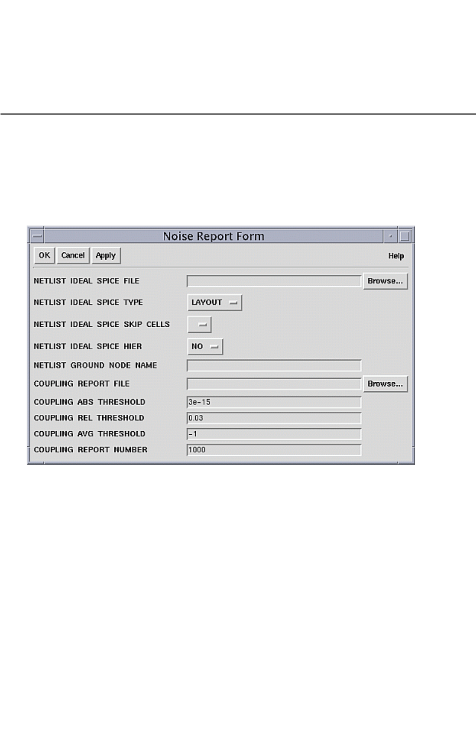
Chapter 9: Noise Analysis
Noise Analysis Commands 9-4
StarRC User Guide and Command Reference F-2011.06
StarRC User Guide and Command Reference Version F-2011.06
For COUPLING_AVG_THRESHOLD checks, no defaults are assured. You need to set a percent
value for these additional checks to take place.
Noise Analysis Commands
There are several noise analysis commands shown in Figure 9-2. For a list of the noise
analysis commands, see the Noise column in Ta bl e B-1 on page B-3.
The Noise Report form lets you set commands specific to a noise analysis.
Figure 9-2 Noise Report Form


Chapter 10: Graphical User Interface
Graphical User Interface 10-2
StarRC User Guide and Command Reference F-2011.06
StarRC User Guide and Command Reference Version F-2011.06
Graphical User Interface
StarRC includes an easy-to-use, interactive graphical user interface (GUI) that provides an
environment for the extraction and analysis of physical designs.
Before starting the GUI, verify that all of the needed files are available. See “Files Needed to
Run StarRC” on page 10-2. To start the GUI, ensure that you are in the StarRC working
directory and enter the following:
% StarXtract -gui
Any StarRC extraction analysis can be configured and executed from the GUI. The GUI
interface also provides command selection for post-layout verification and analysis tools.
Additionally, every copy of StarRC includes a copy of the Milkyway layout viewer.
Files Needed to Run StarRC
Before starting, verify all the necessary files needed to run StarRC. These files are listed in
Table 10-1. Specify the file locations in your star_cmd file. These files must be available at
the specified location for StarXtract access.
Table 10-1 Files Needed to Run StarRC
File Definition
Design database Layout database in one of the following formats: Milkyway, LEF/DEF,
Milkyway XTR, *.AGF (Calibre).
star_cmd ASCII file containing StarRC commands that controls extraction functions.
See Example 10-1.
TCAD_GRD_FILE File containing the modeled layers of a circuit. See the TCAD_GRD_FILE
command.
MAPPING_FILE File containing physical layer mapping information between the input
database and the specified TCAD_GRD_FILE. The file matches every TCAD
process layer to a corresponding layout database layer. See also the
MAPPING_FILE command.

Chapter 10: Graphical User Interface
Starting StarRC Using the GUI 10-3
Chapter 10: Graphical User Interface
Starting StarRC Using the GUI 10-3
StarRC User Guide and Command Reference Version F-2011.06
Example 10-1 shows a star_cmd file. For detailed information about individual commands,
see Chapter 17, “StarRC Commands.”
Example 10-1 A star_cmd File
BLOCK : toprt
MILKYWAY_DATABASE : xtdesign
TCAD_GRD_FILE : example.nxtgrd
MAPPING_FILE : xt.mapping
************ Do NOT change the lines above **************
SKIP_CELLS : !*
NETLIST_FORMAT : SPEF
NETLIST_FILE : toprt.SPEF * default is toprt.spf
STAR_DIRECTORY : ./star * default is star
COUPLE_TO_GROUND: NO * default is YES
The Working Directory
The working directory contains the files needed to run StarRC. StarXtract is invoked at
working directory, the input files, intermediate files and resulting files can be at any location
including the working directory. The location of these files is specified in command file. You
specify the location in the GUI or on the command line. The files listed in the following table
are required.
Starting StarRC Using the GUI
This section explains how to start a timing, a noise, or a combined timing and noise analysis
(SingleShot) in StarRC.
Starting a Timing or Noise Job
Before starting timing or noise analysis, verify that all the necessary files are available. See
“Files Needed to Run StarRC” on page 10-2.
To start a StarRC timing or noise analysis, set up the files and save the collection in a unique
file with the following steps:
1. In your working directory, enter StarXtract -gui.
2. Select the type of analysis you want to run.
• For a timing analysis, choose Setup > Timing.
• For a noise analysis, choose Setup > Noise. The Timing or Noise Wizard appears.
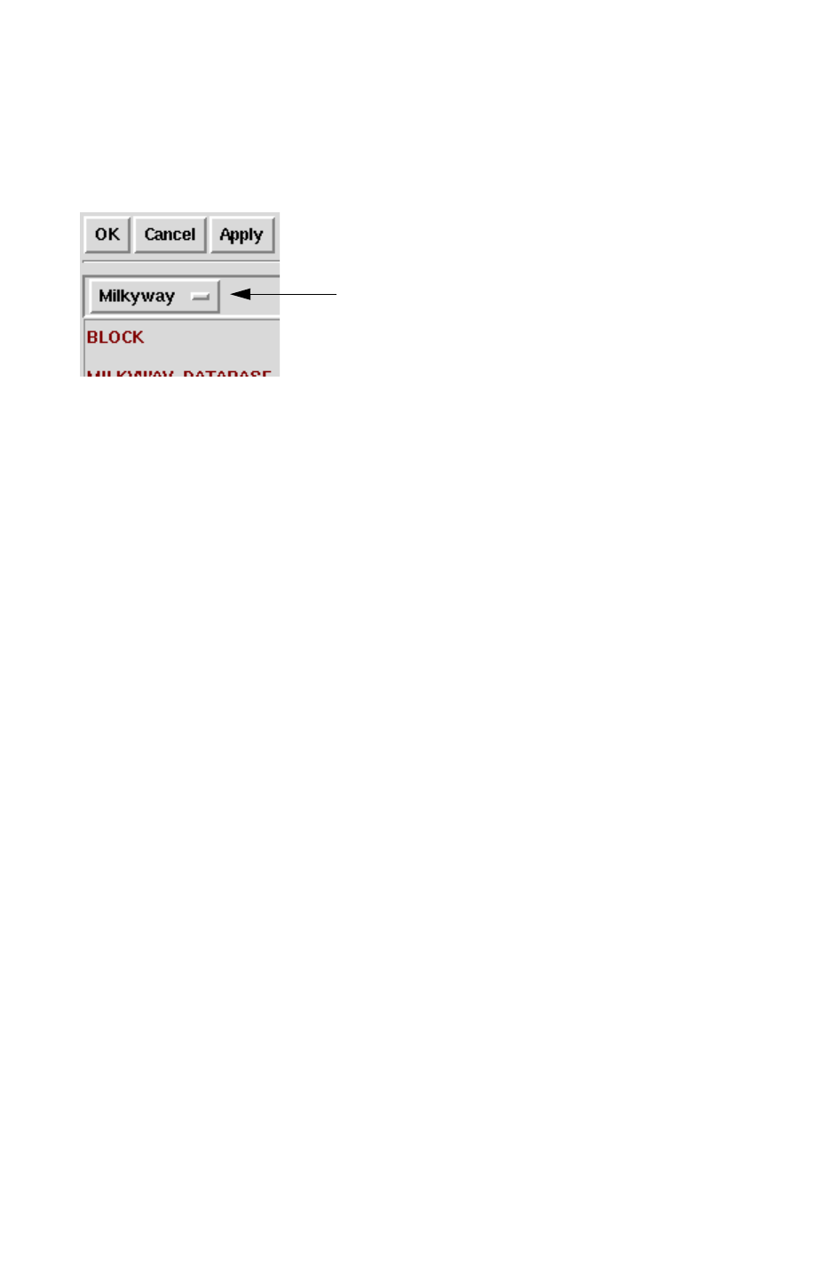
Chapter 10: Graphical User Interface
Starting StarRC Using the GUI 10-4
StarRC User Guide and Command Reference F-2011.06
StarRC User Guide and Command Reference Version F-2011.06
3. Specify the type of input database you are supplying.
Select Milkyway, Lef/Def, Hercules, or Calibre. See Figure 10-1.
Figure 10-1 Select Input Database
Select the type of input database
4. Enter the command information as needed for the analysis.
The commands needed to run a timing or noise analysis are included in the wizard form
in their default setting. You can alter the defaults or accept them at their default. All
commands shown in red in the interface are required.
5. After adding the command information to the Wizard, click OK.
6. Specify the layer mapping file.
Each analysis that you run must contain a layer mapping file. The layer mapping file
should be present in your working directory.
Choose Setup > Layer Mapping.
If you do not have a layer mapping file, see “Creating a Mapping File in the GUI” on
page 10-20.
7. Format the StarRC output file a timing or noise run bu doing one of the following:
• For a timing analysis, choose Timing > Netlist. The Timing Netlist Form appears.
• For a noise analysis, choose Noise > Report. The Noise Report form appears.
8. To save the settings and run the StarRC analysis at a later time, choose File > Save.
The Save Tech File window appears. In the File name field, enter a unique name for the
analysis you have just prepared. Name the file using a unique name. This becomes the
star_cmd file for a subsequent analysis.
9. To run a analysis, choose File > Load.
Enter the unique run tile name in the File name field.
10. Choose File > Run. The Run Form appears.
The default behavior of StarRC is to start with the last unfinished module task. The
Translate, xTractor, and Netlist modules or stages are consecutive. When restarting a
analysis, select the module that follows the last finished module as shown in the log file.
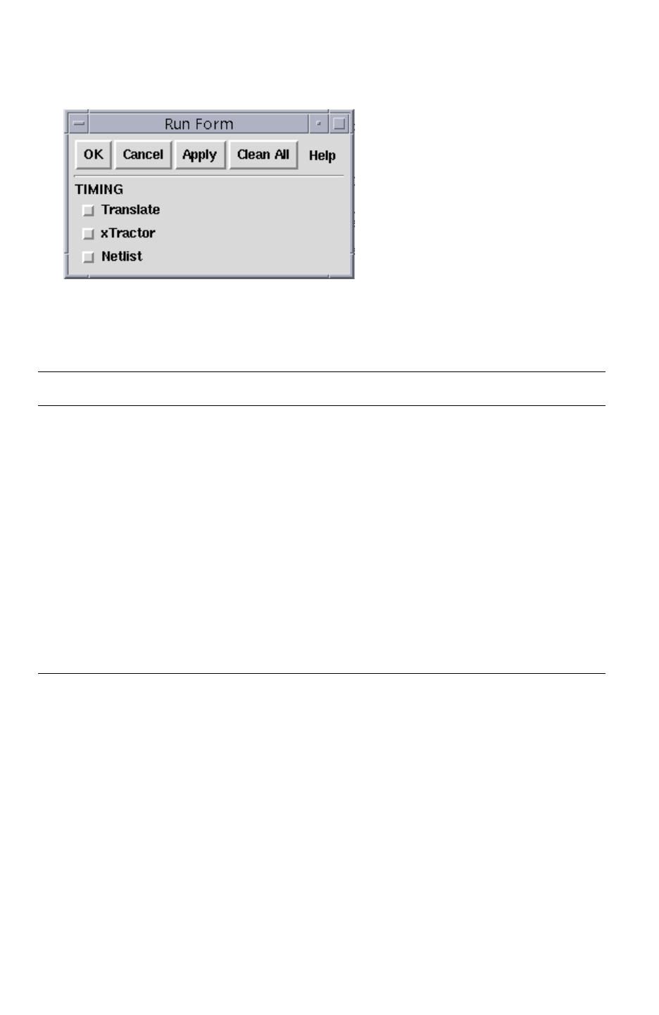
Chapter 10: Graphical User Interface
Starting StarRC Using the GUI 10-5
Chapter 10: Graphical User Interface
Starting StarRC Using the GUI 10-5
StarRC User Guide and Command Reference Version F-2011.06
Figure 10-2 Run Form
11. Name the file using a unique name. This becomes your star_cmd file for your
subsequent analysis.
12. Click OK as shown in the run form in Figure 10-2.
Run Form Selection Description
OK Executes StarRC analysis and closes the Run Form.
Cancel Cancels and closes the Run Form.
Apply Starts the analysis while leaving the Run Form open.
Clean All Removes previously specified file settings and starts
StarRC analysis. (This is the same as specifying -clean
on the command line.)
Translate Starts the StarRC analysis in the Translate module.
xTractor Starts the StarRC analysis in the xTractor module.
Netlist Starts the StarRC analysis in the Netlist module.
When the StarRC analysis is complete, “done” is shown in the run log. To see the complete
contents of the run log, open it in your UNIX working directory.
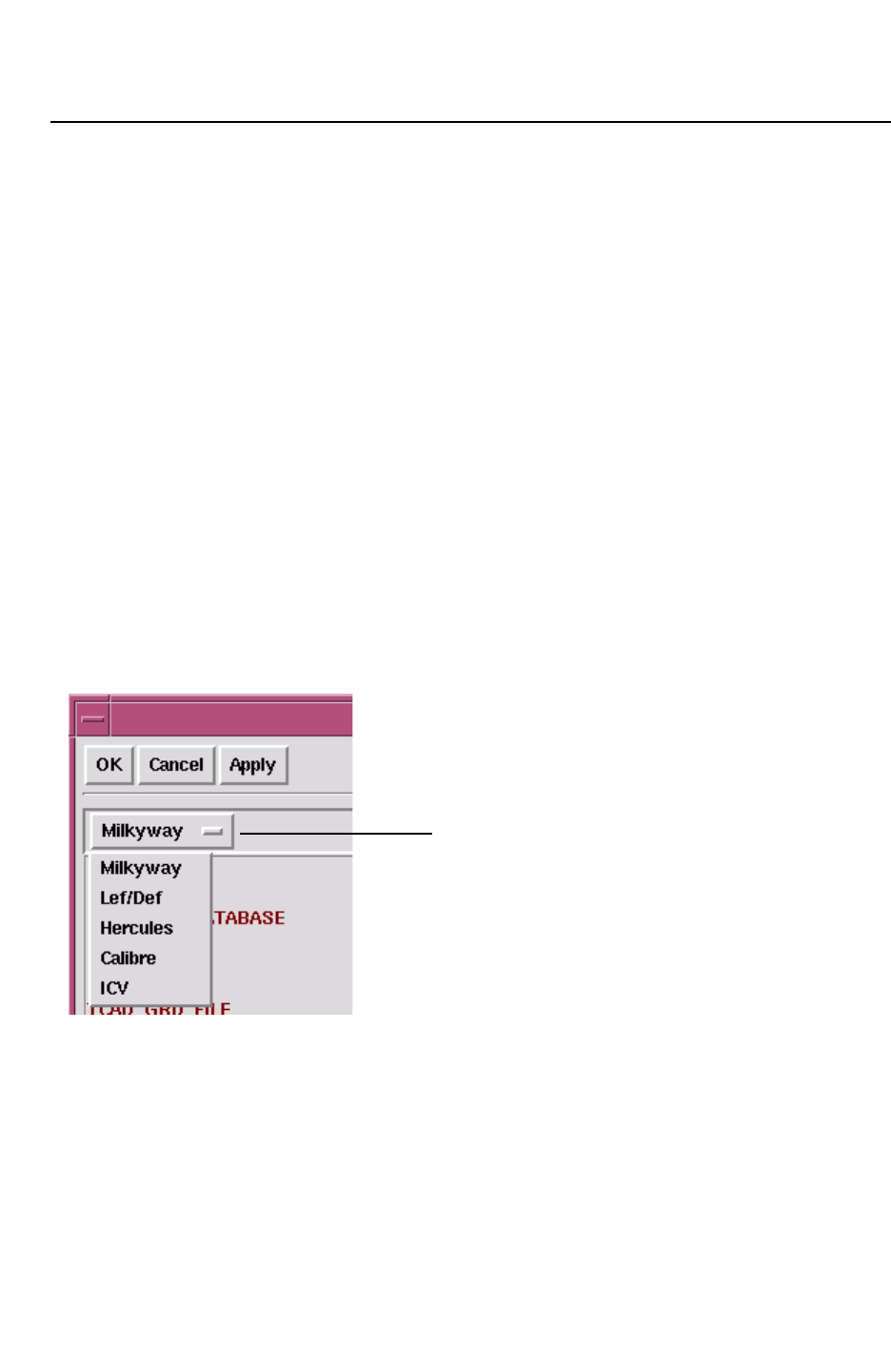
Chapter 10: Graphical User Interface
Starting StarRC Using the GUI 10-6
StarRC User Guide and Command Reference F-2011.06
StarRC User Guide and Command Reference Version F-2011.06
Starting a SingleShot Job
All StarRC command options are global throughout the GUI, so even though not all of the
options are visible on the Wizard forms, they still contain the values shown in the main
window (choose Setup > SingleShot). Command option settings that do not apply to the
currently selected flows are ignored.
• The GUI entry fields display the default upon startup, if applicable.
• Commands in red type are required.
• Command option settings that do not apply to the currently selected flows are ignored.
To start a SingleShot analysis, perform the following steps:
1. In your working directory, enter
$ StarXtract -gui.
2. Choose Setup > SingleShot.
The Tech Form appears.
3. Select the input database type from the Tech Form as shown in Figure 10-3.
Figure 10-3 Select Database Type on Tech Form
Select input database type
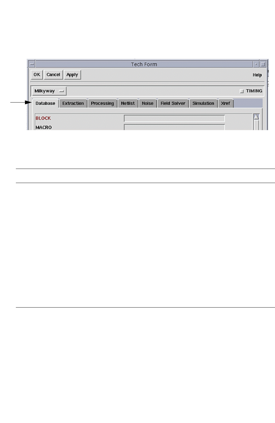
Chapter 10: Graphical User Interface
Starting StarRC Using the GUI 10-7
Chapter 10: Graphical User Interface
Starting StarRC Using the GUI 10-7
StarRC User Guide and Command Reference Version F-2011.06
Each tab on the Tech Form contains lists of options. See Figure 10-4.
Figure 10-4 Tech Fo r m Ta b s
Tech
Form
tabs
4. Select each tab, and specify the appropriate commands for your run. Commands that are
required are listed in Table 10-2.
Table 10-2 Required Commands
Tech Form Tabs Required Commands
Database MILKYWAY BLOCK, MILKYWAY_DATABASE
LEF/DEF LEF_FILE, TOP_DEF_FILE
Hercules BLOCK, MILKYWAY_DATABASE, MILKYWAY_EXTRACT_VIEW
Calibre BLOCK, CALIBRE_RUNSET, CALIBRE_QUERY_FILE,
CALIBRE_DEVTAB, CALIBRE_AGF, CALIBRE_AGF_LAYER_MAP,
CALIBRE_AGF_NETLIST, CALIBRE_AGF_CELL_EXTENTS,
CALIBRE_AGF_NAME_MAP, CALIBRE_CELLS_PORTS,
CALIBRE_IXF_FILE, CALIBRE_NXF_FILE
IC Validator ICV_RUNSET_REPORT_FILE
EXTRACTION TCAD_GRD_FILE, MAPPING_FILE
Xref (Hercules Only) EVACCESS_DIRECTORY, COMPARE_DIRECTORY
Note:
For SingleShot, Timing and Noise are automatically selected.
5. If you would like to save the command settings without running a StarRC analysis,
choose File > Save.
Name the file using a unique name. This becomes your star_cmd file for your subsequent
analysis.
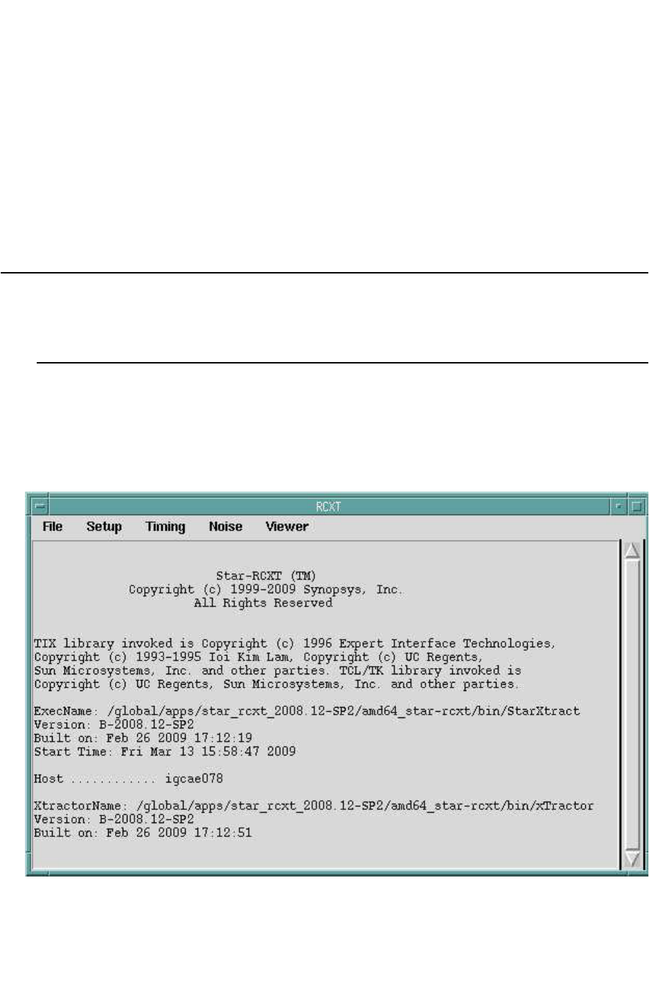
Chapter 10: Graphical User Interface
Interface Reference 10-8
StarRC User Guide and Command Reference F-2011.06
StarRC User Guide and Command Reference Version F-2011.06
6. To start the SingleShot analysis, choose File > Run.
The Run Form appears.
The default behavior of StarRC is to start with the last unfinished module task. The
Translate, xTractor, and Netlist modules (or stages) are consecutive. When restarting an
analysis, select the module that follows the last finished module as shown in the log file.
7. When the StarRC analysis is complete, the run log prints the word “done.” To see the
complete contents of the run log, open it in your UNIX working directory.
Interface Reference
This section shows the various menus and dialog boxes available to you in StarRC.
Control Window
The control window opens when you invoke the GUI executable. It contains the menus you
use to configure and execute your StarRC analysis. The control window is shown in
Figure 10-5.
Figure 10-5 StarRC Control Window
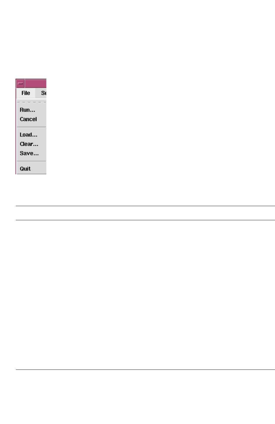
Chapter 10: Graphical User Interface
Interface Reference 10-9
Chapter 10: Graphical User Interface
Interface Reference 10-9
StarRC User Guide and Command Reference Version F-2011.06
File Menu
The File menu shown in Figure 10-6 is on the Control Window. The File menu lists
commands that enable you to load the command file and start your StarRC analysis.
Figure 10-6 File Menu
Table 10-3 explains the file menu options.
Table 10-3 File Menu Options
File menu command Description
Run Runs StarRC analysis using the loaded file.
Cancel Cancels a analysis that is currently running. Intermediate files
remain in the working or “star” directory for your inspection. The
next run can be started after you have used the intermediate files
or specify a run “clean” to begin again with unprocessed files.
Load Opens the Load Tech File window so you can choose files to be
loaded into the StarRC information.
Clear Opens the Clear Technology Options window. This resets every
field to its default. It is helpful to use this command when you are
building a command file with user-specific commands.
Save Opens the Save Technology File window. Specify the technology
files to be saved in the file name field. All the commands you have
entered are contained and stored in the file name. The file is
saved in the working directory.
Quit Exits the StarRC GUI. Any process currently running in the
StarRC GUI is canceled
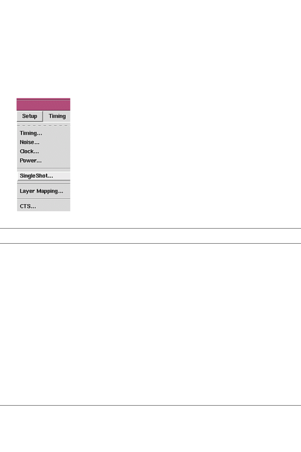
Chapter 10: Graphical User Interface
Interface Reference 10-10
StarRC User Guide and Command Reference F-2011.06
StarRC User Guide and Command Reference Version F-2011.06
Setup Menu
The Setup menu shown in Figure 10-7 is on the Control Window. The Setup menu lists three
different types of StarRC runs (Timing, Noise, and SingleShot) that open forms which enable
you to enter the command options for your desired run. The options listed in the Setup menu
are explained in Table 10-4.
Figure 10-7 Setup Menu
Table 10-4 Setup Menu Options
Setup Menu Command Description
Timing Opens the Timing Wizard window enabling you to prepare to generate a
netlist specifically for a timing analysis. See Figure 10-8. This differs from the
Timing menu. The Timing Menu is shown on page 10-14.
Noise Opens the Noise Wizard window enabling you to generate a netlist for a
crosstalk or noise analysis.
SingleShot Opens the Tech Form window enabling you to generate a netlist specifically
for a combined timing and noise analyses.
Choose the type of database input from Milkyway, LEF/DEF, Hercules, and
Calibre.
Multiple tabs let you set commands and options specific to Database,
Extraction, Processing, Netlist, Noise, Field Solver, Simulation, and Xref
choices. All unused commands remain set to StarRC default settings. For
command details, see Chapter 17, “StarRC Commands.”
Layer Mapping Opens the specified mapping file so that you can alter its contents. A valid
mapping file must have been specified in Timing, Noise, or Single Shot form
before it can be opened with this interface. Alternatively, you can create a
mapping file by specifying a valid TCAD_GRD_FILE in one of the analysis
forms.
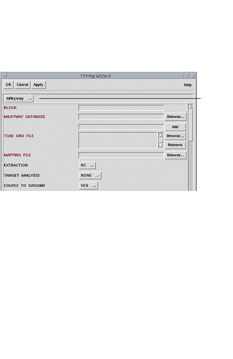
Chapter 10: Graphical User Interface
Interface Reference 10-11
Chapter 10: Graphical User Interface
Interface Reference 10-11
StarRC User Guide and Command Reference Version F-2011.06
Setup > Timing
The Setup > Timing command is on the Control Window. When you choose this menu
option, the Timing menu Wizard appears. As shown in Figure 10-8, the command lets you
specify StarRC commands and options for preparing parasitic netlist for timing analysis.
Figure 10-8 Setup > Timing Wizard (Top Portion)
Choose:
Milkyway
LEF/DEF
Hercules
Calibre
ICV
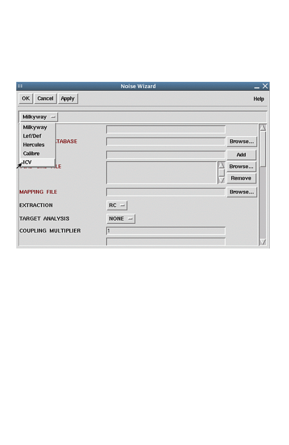
Chapter 10: Graphical User Interface
Interface Reference 10-12
StarRC User Guide and Command Reference F-2011.06
StarRC User Guide and Command Reference Version F-2011.06
Setup > Noise
The following Noise menu is on the Control Window. Setup > Noise, as shown in
Figure 10-9, allows you to prepare a parasitic netlist for noise analysis.
Figure 10-9 Setup > Noise Wizard (Top Portion)
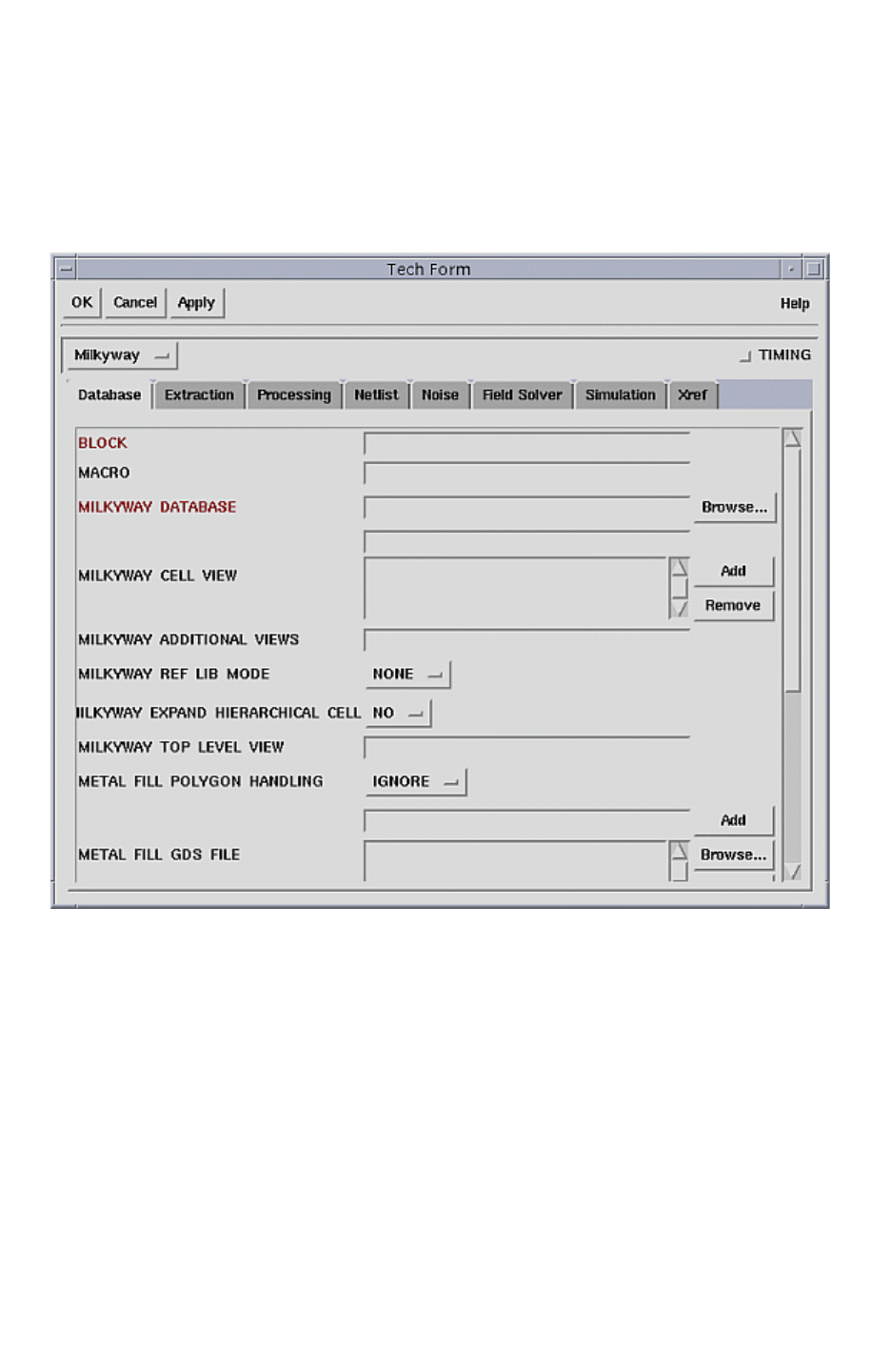
Chapter 10: Graphical User Interface
Interface Reference 10-13
Chapter 10: Graphical User Interface
Interface Reference 10-13
StarRC User Guide and Command Reference Version F-2011.06
Setup > Single Shot
When you choose Setup >Single Shot, a Tech Form appears as shown in Figure 10-10. The
Tech Form window lets you generate a netlist for both timing and noise analyses.
Figure 10-10 Setup > Single Shot Tech Form
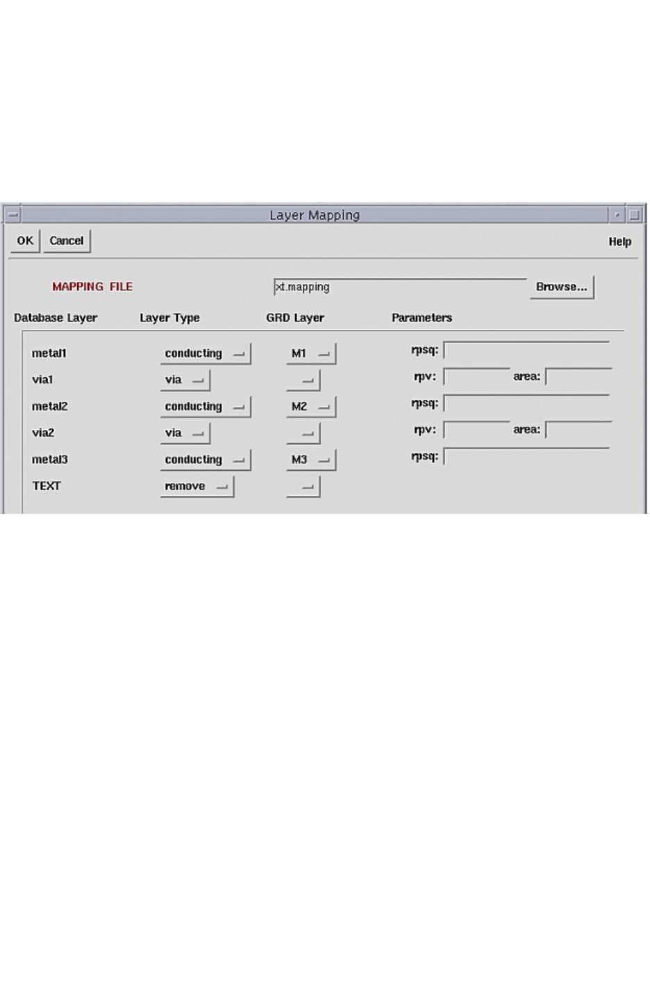
Chapter 10: Graphical User Interface
Interface Reference 10-14
StarRC User Guide and Command Reference F-2011.06
StarRC User Guide and Command Reference Version F-2011.06
Setup > Layer Mapping
The Setup > Layer Mapping menu, as shown in Figure 10-11, is on the Control Window. This
command opens the specified mapping file for modification. To create a mapping file, see
“Creating a Mapping File in the GUI” on page 10-20.
Figure 10-11 Setup > Layer Mapping
Timing Menu
The Timing menu is on the Control window. When you choose Timing > Netlist, the Timing
Netlist form appears.
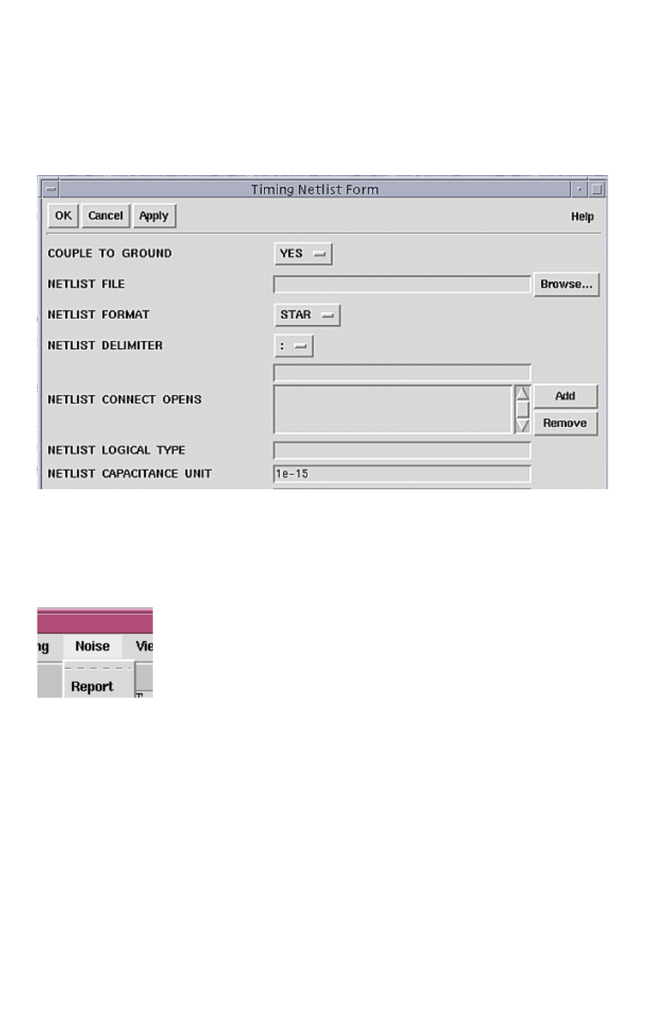
Chapter 10: Graphical User Interface
Interface Reference 10-15
Chapter 10: Graphical User Interface
Interface Reference 10-15
StarRC User Guide and Command Reference Version F-2011.06
The Timing Netlist form is shown in Figure 10-12. This form enables you to generate an
output timing analysis. See “Setup > Timing” on page 10-11. For information about each
command and available options, see Chapter 17, “StarRC Commands.”
Figure 10-12 Top Portion of Timing Netlist Form
Noise Menu
When you choose Noise > Report, from the Noise menu as shown in Figure 10-13, the
Noise Report Form as shown in Figure 10-14 appears.
Figure 10-13 Noise Menu
The Noise report form enables you to enter options to generate output files from the noise
analysis.
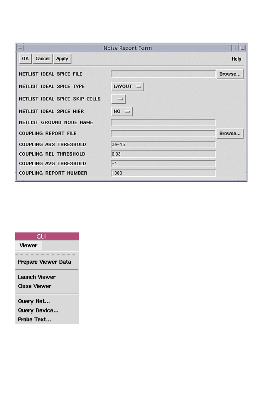
Chapter 10: Graphical User Interface
Interface Reference 10-16
StarRC User Guide and Command Reference F-2011.06
StarRC User Guide and Command Reference Version F-2011.06
Figure 10-14 Noise Report Form
Viewer Menu
The Viewer menu, as shown in Figure 10-15, features commands that let you access the
Milkyway Viewer with StarRC.
Figure 10-15 Viewer Menu

Table 10-5 Commands for Accessing the Milkyway Viewer with StarRC
Menu Command Description
Prepare Viewer Data StarXtract prepares the graphical layout data in the star directory from the
details of the loaded star command file.
Launch Viewer Runs an instance of Milkyway and opens the specified block of layout
design (read-only) from the loaded star_cmd file.
Close Viewer Closes Milkyway viewer.
Query Net Invokes a dialog box for querying nets. The filter provided accepts the
wildcard asterisk (*) and question mark (?).
For each net, the details are shown in the right pane. The top edit box
shows the net detail after the node information has been filtered out.The
net’s node names are listed in the bottom-left list box in the right pane.
The bottom-right list box provides the selected node detail. To show the
node detail, either double-click a node name or select a node name and
click the Show node details button. The viewer zooms to the bounding box
of the node. (You cannot do this from a Milkyway window. It must be done
from the viewer.)
Query Device Invokes a dialog box for querying devices. The filter provided accepts the
wildcard asterisk (*) and question mark (?).
For each device, the details are shown in the right pane. The top edit box
shows the device detail after the node information has been filtered out.
For each device, the details are displayed in the right pane. Among the
device details listed are any port instances (and their net names) to which
this device is connected.
Probe Text Opens Probe Text Window.
Chapter 10: Graphical User Interface
Entering Information 10-17
Chapter 10: Graphical User Interface
Entering Information 10-17
StarRC User Guide and Command Reference Version F-2011.06
Entering Information
This section covers the various types of entries and actions the StarRC GUI enables. See
“StarRC Command File Conventions” on page 2-14. For information about specific
command options found in the forms, see Chapter 17, “StarRC Commands.”
Entry Fields
You can set commands in the StarRC GUI by filling in the entry fields. The StarRC GUI has
several types of entries, as shown in Figure 10-16.
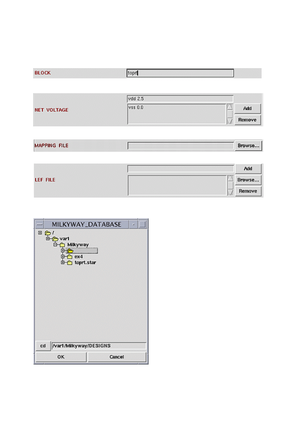
Chapter 10: Graphical User Interface
Entering Information 10-18
StarRC User Guide and Command Reference F-2011.06
StarRC User Guide and Command Reference Version F-2011.06
Figure 10-16 Available Entry Field Types
Single file entry
Multiple entry
Single file entry (with Browse capability)
Multiple file entry
Directory

Chapter 10: Graphical User Interface
Entering Information 10-19
Chapter 10: Graphical User Interface
Entering Information 10-19
StarRC User Guide and Command Reference Version F-2011.06
Table 10-6 explains the use of each type of field.
Table 10-6 Field Types
Entry type Description Additional actions
Single Entry Use this field for command options that
are specified only once. It is used to
specify numbers, white-space delimited
lists, and single words.
Enter text.
Multiple Entries Use this field for command options that
might be specified more than once. It is
used to specify multiple line-type
commands.
Single File Use this field for command options that
can be specified only once and require a
single file path, for input or output files. An
example is a mapping file.
Clicking the Browse button opens a
hierarchical file browser
Multiple Files Use this field for command options that
can be specified more than once and
require a file path, for input files only.
Directory Use this field for command options that
can be specified once and require a
directory path (input or output directories).
The entry field for a directory can be filled
manually, or you can click the Browse
button to the right of the entry field to
display a hierarchical directory browser
Clicking Browse opens a graphical
file browser window. After the file has
been navigated and selected,
clicking OK in the file browser
window automatically enters the file
name in the list. Typing the file name
in the entry field and clicking Add or
pressing Return also enters the file
name in the list. Selecting one of the
files in the list and then clicking
Remove deletes the entry from the
list.
Double-clicking a directory name
collapses or expands the directory
tree. Only directories are shown.
Selecting a directory and then
clicking OK places the directory
name in the command entry field.
Analysis Forms
An analysis form contains lists of nets you have entered.
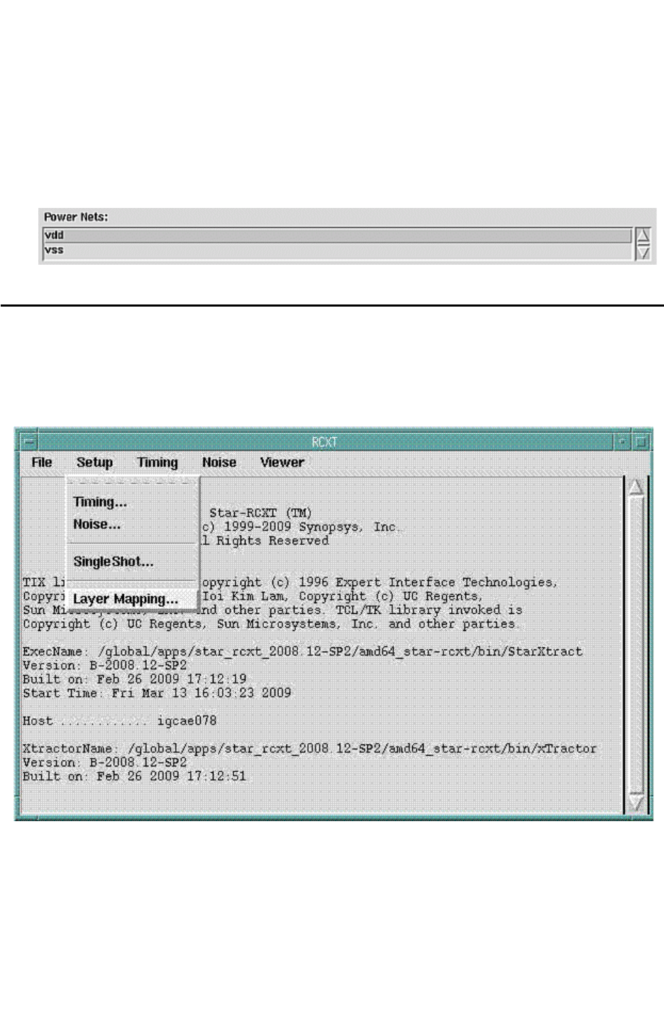
Chapter 10: Graphical User Interface
Creating a Mapping File in the GUI 10-20
StarRC User Guide and Command Reference F-2011.06
StarRC User Guide and Command Reference Version F-2011.06
List of Nets
A list containing the nets that were extracted, solved, and analyzed in the STAR_DIRECTORY
is shown in Figure 10-17. Double-clicking a net name loads the results of the analysis for
that net into the form.
Figure 10-17 List of Nets
Creating a Mapping File in the GUI
Layer mapping can also be done through the StarRC Layer Mapping form shown in
Figure 10-18. (Choose Setup > Layer Mapping.)
Figure 10-18 Layer Mapping Menu
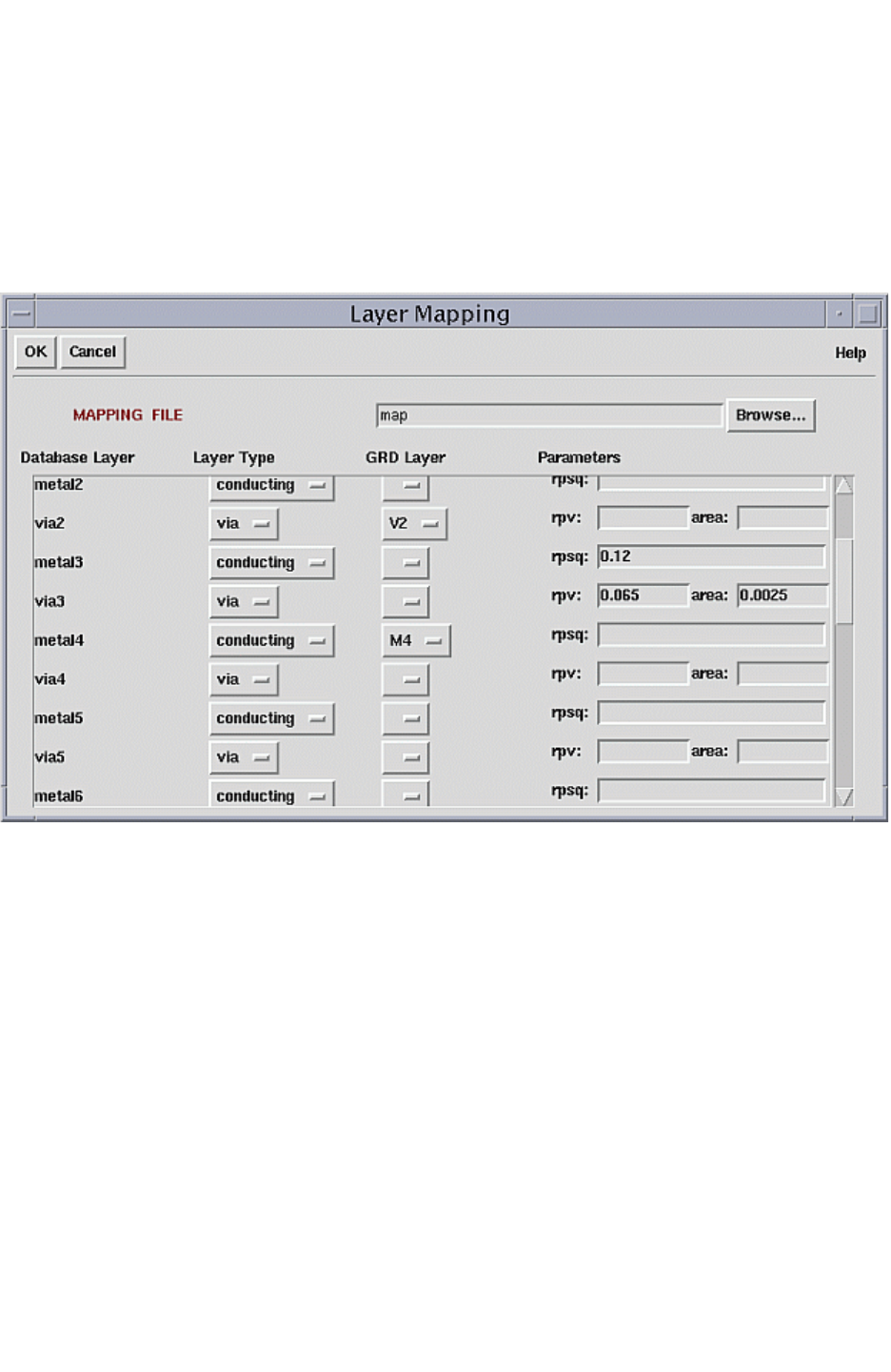
Chapter 10: Graphical User Interface
Creating a Mapping File in the GUI 10-21
Chapter 10: Graphical User Interface
Creating a Mapping File in the GUI 10-21
StarRC User Guide and Command Reference Version F-2011.06
Your input to this form is read into the physical layout database and the TCAD_GRD_FILE,
which you specified in the Setup, and it generates a table, as shown in Figure 10-19. The
form displays each database layer in a vertical list at the left margin. Because the layer
entries are organized by row, any information given in the fields to the right of any of the
database layer entries applies to that layer.
Figure 10-19 Layer Mapping Form
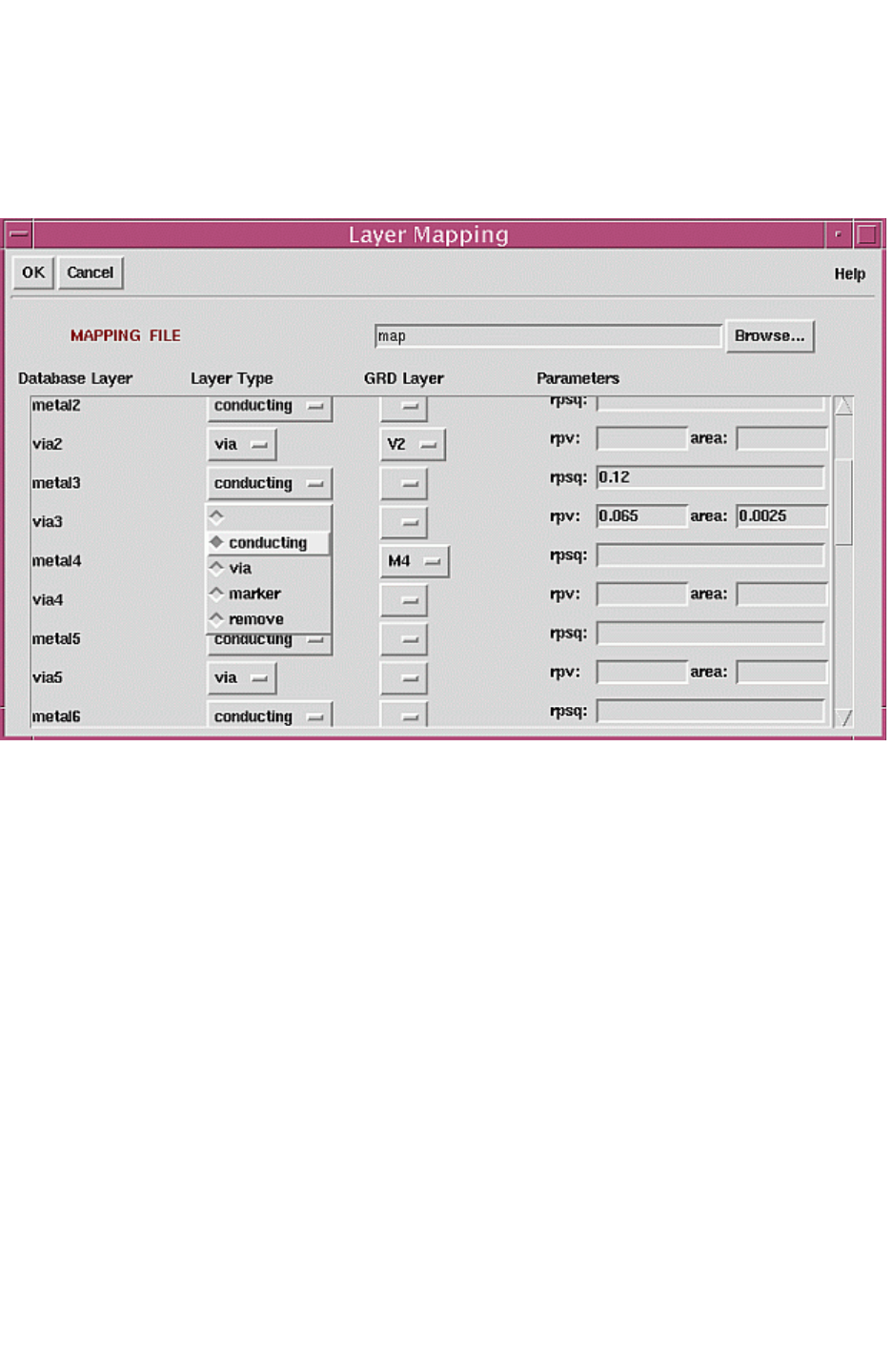
Chapter 10: Graphical User Interface
Creating a Mapping File in the GUI 10-22
StarRC User Guide and Command Reference F-2011.06
StarRC User Guide and Command Reference Version F-2011.06
Each database layer entry is associated with two pull-down menus located to the right. The
first pull-down menu contains the list of layer types, shown in Figure 10-20.
Figure 10-20 Layer Mapping Type
The second pull-down menu contains a list of the available TCAD GRD layers to which the
database layer can be mapped. A selection is not required in this field if the type has been
specified as “remove,” according to the convention described previously. Otherwise, both
pull-down menus associated with a database layer must display a value before the layer
mapping can be applied.
If used, the rightmost entry fields associated with a database layer override the resistance
values that were specified in the TCAD GRD file.
Use the resistance override feature with extreme care. There is no effect on the extraction
itself, but the process of manually specifying process parameters for each extraction is very
susceptible to user error.
The contents of the Setup > Layer Mapping form must be saved to a file before the
extraction. You must specify a mapping file because it is required for all StarRC extraction
flows. Clicking OK exports the information to the file name entered in the MAPPING FILE
box at the top of the form. This file name is automatically applied to the Setup information.

11-1
11
Variation-Aware Extraction 11
This chapter contains the following main sections:
•Introduction to Variation-Aware Analysis
•Parasitic Extraction to Static Timing Analysis
•The Concept of Sensitivity
•Running StarRC With Sensitivities
•User-Defined Corner and Sensitivity Calculation
•User Interface Modeling Parameters and Their Variation
•Handling Temperature Variation in StarRC
•Defining a Corner (UDC) File
•Sensitivity Netlist With Geometry Information
•SPICE Syntax for Parasitic Sensitivity
•SPEF Extensions
•Variation-Aware Extraction Limitations

Chapter 11: Variation-Aware Extraction
Introduction to Variation-Aware Analysis 11-2
StarRC User Guide and Command Reference F-2011.06
StarRC User Guide and Command Reference Version F-2011.06
Introduction to Variation-Aware Analysis
As the number of ultradeep submicron (UDSM) designs increase, yield continues to be the
major concern for companies, with profitability as the primary driving factor. The ability to
predict and analyze various operating conditions has a direct impact on the yield of a
product. In older technologies functional yield loss (or catastrophic loss), or failures due to
dead circuits as a consequence of shorts or opens, was the leading cause of failures.
However, as smaller feature sizes in UDSM designs are more common, parametric yield is
the dominant factor in yield loss. Parametric yield refers to the design’s sensitivity to variation
in the critical device and interconnect process parameters, such as channel length and
conductor thickness, coupled with supply voltage and temperature variations. There are a
number of manufacturing steps that lead to these parametric variations, such as optical
inaccuracies in etch stages and over-polishing in the Chemical Mechanical Polishing (CMP)
stage. One of the major challenges today is to better control these manufacturing steps and
improve parametric yield, in turn reducing cost and increasing profitability.
Computer-aided design (CAD) tools must be able to interpret and analyze parameter
process variations accurately to improve silicon predictability, from device model libraries,
parasitic extraction, and Static Timing Analysis (STA). To analyze and interpret this variation,
the amount of degradation seen during chip timing depends on the magnitude of each
variation type (such as systematic and random), the characterization and modeling
techniques used during parasitic extraction and timing analysis, and the algorithms used by
the static timing analysis tools (such as PrimeTime).
The importance of these tools to analyze and pass process variation information for
accurate analysis in UDSM design is critical.
Variation-aware extraction attempts to mitigate the following in today’s UDSM design flows:
• The traditional corner analysis model has improbable scenarios in silicon (which are
overly pessimistic).
• Corner analysis does not offer full coverage for timing analysis (such as metal mismatch).
• Corner analysis is resource intensive, and adds overhead in meeting today's design
performance and time-to market goals.
Pessimism of Traditional Corner Analysis
In older technologies, predicting circuit behavior at nominal values was sufficient to ensure
high yield, because the variation of these parameters was well understood and controlled.
However, as feature sizes shrink, the parametric variations continue to become more
prominent and critical for accurately predicting circuit behavior in silicon.
Chapter 11: Variation-Aware Extraction
Introduction to Variation-Aware Analysis 11-3
Chapter 11: Variation-Aware Extraction
Introduction to Variation-Aware Analysis 11-3
StarRC User Guide and Command Reference Version F-2011.06
The most common method used to analyze circuit behavior under an atypical process,
voltage, and temperature conditions is referred to as corners simulation. The corners-or
process, voltage, and temperature conditions, are defined by the designer, and the circuit
behavior is analyzed at these corners.
Corners generally represent the worst and best case scenarios of the process variations and
in turn attempt to simulate the worst-case circuit performance, or timing characteristics.
These corners are an attempt to represent the maximum variation that is possible between
any two die due to normal manufacturing tolerances. The process parameter variations
being modeled in these worst-case conditions are generally assumed to be random, and the
corners are generally taken at the +3s and -3s values from nominal (typical corner)
conditions, assuming a normal Gaussian distribution, for each individual varying parameter.
Sigma (s) refers to the standard deviation of a probability distribution function. The
corresponding confidence interval, or interval in which a measurement or trial falls
corresponding to a given probability, for 3 standard deviations is 0.99730 (99.73%).
For example, the worst-case (also referred to as slow) capacitive condition for a one-metal
process with width and thickness varying would occur when the thickness and width are at
the physical maximum (+3s), thus producing the largest capacitance. Conversely, the fast
corner would be represented at the smallest width and thickness of the normal distribution,
or -3s point. Each random parameter, independently varied, exhibits a normal, or Gaussian,
distribution as shown in Figure 11-1. This is in contrast to systematic (or deterministic)
variations, which generally attempt to model intra-die variation and are based on physical
geometries. More discussion of systematic versus random variation follows in “The Concept
of Sensitivity” on page 11-17.
Figure 11-1 Conductor Thickness Across Dies - Normal (Gaussian) Distribution
Conductor Thickness-3σ+3σ
Many argue that corner analysis in today’s design flows is not be feasible to meet the
demands of performance, time to market, and area reduction needed by industry. Therefore,
techniques are required that capture the actual effect of process variations on the circuit and
analyze timing based on statistical predictions of circuit performance, rather than the
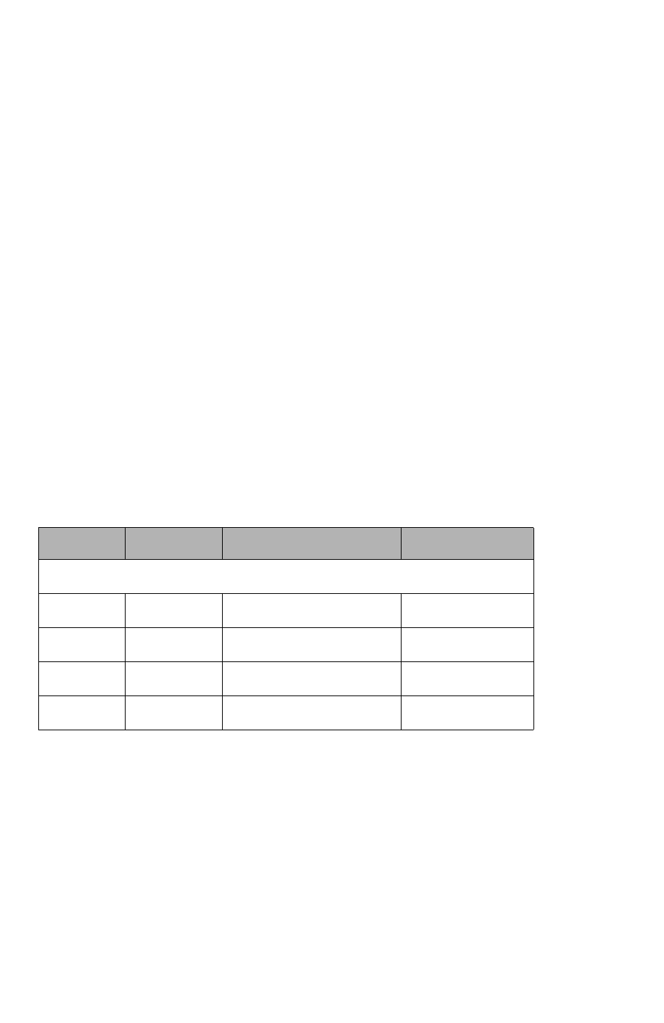
Chapter 11: Variation-Aware Extraction
Introduction to Variation-Aware Analysis 11-4
StarRC User Guide and Command Reference F-2011.06
StarRC User Guide and Command Reference Version F-2011.06
traditional extreme corner cases. As previously stated, corner process files generally model
process parameters at +3s and -3s values for the parameter being varied. Given the
improbability of these situations in real silicon, this type of approach is overly pessimistic and
unrealistic, resulting in tighter timing margins and over-design with respect to area.
It has been explained that each parameter, such as metal1 thickness, is modeled
pessimistically by using the maximum and minimum thickness variations from the +3s and
-3s points of a normal distribution, respectively. In addition, more pessimism is introduced
because the corner files represent all the process variation parameters at the -3s /+3s
values simultaneously, which is an improbable situation in real silicon. Most foundries today
manufacturing and supporting UDSM designs provide support for at least five corner cases:
• Nominal (typical)
• Capacitance (cworst)
• Worst case delay (rcworst)
• Best case capacitance (cbest)
• Best case delay (rcbest)
Table 11-1 is an example of how corners might be defined given three varying parameters
for a particular layer.
Table 11-1 Process Corner Definitions
Corner Width Conductor thickness ILD thickness
Typical Nominal Nominal Nominal
cworst +3σ+3σ-3σ
cbest -3σ-3σ+3σ
rcworst -3σ-3σ-3σ
rcbest +3σ+3σ+3σ
The definition of corners, also referred to as fast and slow in the timing domain, is typically
achieved by varying all the parameters to some statistical limit of uncertainty. Notice that all
the parameters represent either maximum or minimum values for the particular parameter at
each of the corners. Figure 11-2 shows an example of the pessimism for cbest and cworst
corners in a seven-metal process. Each of the metal layers is assumed to be at +3s (cworst)
or -3s (cbest) simultaneously for the respective corner case.
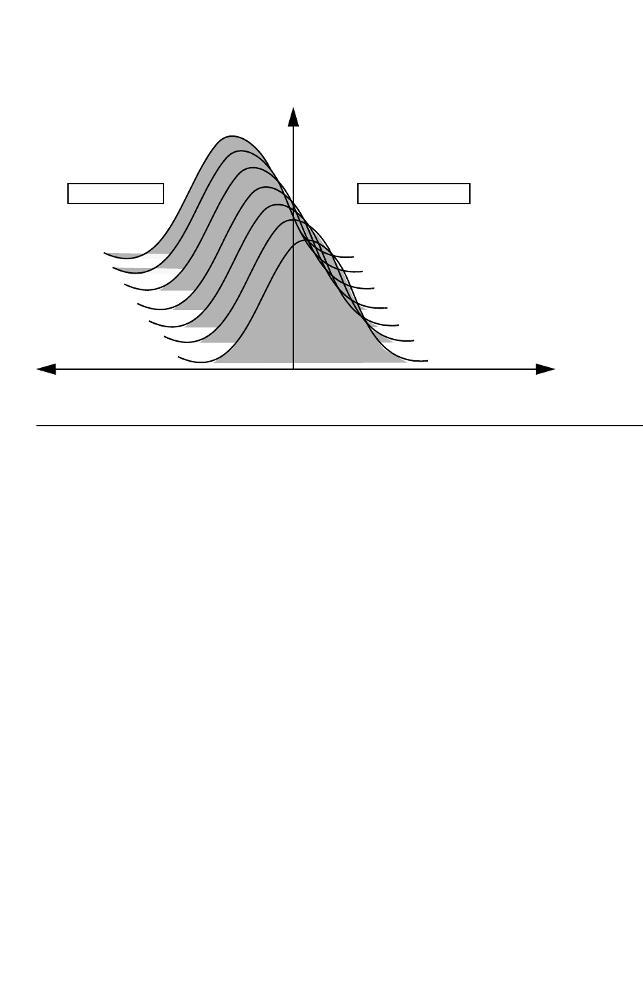
Chapter 11: Variation-Aware Extraction
Introduction to Variation-Aware Analysis 11-5
Chapter 11: Variation-Aware Extraction
Introduction to Variation-Aware Analysis 11-5
StarRC User Guide and Command Reference Version F-2011.06
Figure 11-2 Seven-Metal Process With Corners Definition
+3σ-3σConductor Thickness (7 metals)
metal 2
metal 7
metal 6
metal 5
metal 4
metal 3
metal 1
metal 2
metal 7
metal 6
metal 5
metal 4
metal 3
metal 1
Frequency of Samples
Cbest Corner
Cworst Corner
Pitfalls of Traditional Corner Analysis
In the previous section the widely used process corners referred to as typical, cworst,
rcworst, cbest, and rcbest were described regarding how each one is modeled based on the
+/-3s values of a normal distribution. Currently, the three parameters with variation across
each of these five corners are conductor width, conductor thickness, and dielectric
thickness. Given these three parameter variations, the five corners defined by most
foundries (see Figure 11-2) do not cover all the possible combinations. Given three varying
parameters, the possible number of corners, including the typical corner, are 23 +1.
Figure 11-3 shows the possible corner definitions with three varying parameters. The five
corners defined in Figure 11-2 (marked with circles in Figure 11-3) do not cover all the
possible combinations of +3s/-3s parameter variations.
Chapter 11: Variation-Aware Extraction
Introduction to Variation-Aware Analysis 11-6
StarRC User Guide and Command Reference F-2011.06
StarRC User Guide and Command Reference Version F-2011.06
Figure 11-3 Corners With Three Variation Parameters (Conductor Thickness, Width, and
Dielectric Thickness)
Tc+
rcbest
W +
cworst
Tc-
Td-
rcworst
W - cbest
Td +
Definitions of corner files that represent worst, or best, case situations for all conductors and
dielectrics represent extreme cases of process variation and are therefore improbable. The
main reason for this is the large amount of effort and time required to model, support, and
verify timing for each of these corner files by independent, successive parasitic extraction
and static timing analysis runs.
In addition to the extreme corners shown in Figure 11-3, many companies have corners that
represent specific scenarios which they believe could lead to timing violations. These
specialized corners are usually dependent on design style, circuit behavior, and /or
manufacturing-related data and are in addition to the five standard corners shown in
Figure 11-3. Some foundries today support up to twelve corners for a particular technology.
The number of corners defined is directly related to how well the process parameters are
controlled and modeled using systematic, or deterministic methods. Typically, any process
parameter that cannot be characterized as systematic is lumped into random variation and
is modeled across corner files.
The general assumption is that when you model process variations through extreme
corners, along with voltage power supply and temperature variations, you would model the
maximum variation, and in turn the worst-case timing behavior of a circuit in silicon. The
common misconception is that worst-case process, voltage, and temperature parameter
variation directly results in worst-case timing for a particular block or circuit. However,

Chapter 11: Variation-Aware Extraction
Introduction to Variation-Aware Analysis 11-7
Chapter 11: Variation-Aware Extraction
Introduction to Variation-Aware Analysis 11-7
StarRC User Guide and Command Reference Version F-2011.06
industry data has shown that the relationship between worst-case delay and worst case
process might not be so straightforward, mainly due to the fact that the impact and
magnitude on delay from these variations is not intuitive given the large number of variables.
It is more complicated when SI effects are taken into account, where resistance, ground
capacitance and coupling capacitance along the networks affect both victim and aggressor
behavior. The worst timing behavior in the variation space is no longer guaranteed to be at
one of the traditional corner parasitic corner definitions. As the variables increase, the
number of corners required to predict the delay sensitivities on each path is limited by 2n,
where n is the number of independent variables of interest. However, considering the large
number of variations, the corner analysis approach is becoming intensely time consuming
due to the excessive number of permutations required for parasitic extraction and timing
analysis. The disadvantage to corner analysis is obvious if you are familiar with ASIC design
on nanometer processes.
Given the large number of permutations required in traditional corner analysis to accurately
analyze static timing, it is unlikely that designers can run analysis on all 2N corners, where
n is the number of varying parameters. Therefore, it is essential that CAD tools are aware of
process parameter variation and interpret the variations accurately during static timing
analysis. Academic literature emphasizes the importance of variation-aware analysis in
which a traditional corner analysis is compared to a metal variation-aware timing analysis.
The results from the traditional corner timing analysis show that the chip has met timing
specifications. However, in silicon multiple latches showed hold time failures when hardware
measurements were made.
Consider a circuit as shown in Figure 11-4 on page 11-8. The launch and the capture
portions of a timing path are each dominated by different layers of metal. These two different
layers have opposite process skew; one is at cworst and the other at cbest. This results in
the launch and capture timing being affected such that they have their worst-case effect on
slack. This is an example of “metal mismatch”, where the launch and capture portions of a
timing path are dominated by different metal layers. As described in the last section,
traditional corner files generally do not model all combinations (2N) of the process
parameter variation, such as two metals with one varying at the minimum, or -3s, and the
other at the maximum, or +3s, assuming a normal distribution. Parasitic corners do not
model these metal mismatch issues to be discovered.
Chapter 11: Variation-Aware Extraction
Introduction to Variation-Aware Analysis 11-8
StarRC User Guide and Command Reference F-2011.06
StarRC User Guide and Command Reference Version F-2011.06
Figure 11-4 Metal Mismatching Timing Failure
FAST
QDQ
SLOW
CLK
D
FAIL!
Time-to-Market Challenges With Traditional Corner Analysis
Traditional corner analysis introduces over-design and does not guarantee timing.
Furthermore, accurate corner analysis is a task that requires increased resources, both in
hardware and engineers. Achieving the desired balance of time-to-market and production
yield continues to be a challenge for companies. Not only do smaller process nodes
demonstrate larger process variations, but also the number of parameters varying at these
smaller nodes is increasing quickly. In turn, this leads to more process corner files that are
required to accurately predict silicon behavior and hence improve parametric yield.
Designers struggle to meet design specifications for performance and area in a given time
due to the large number of corners required to analyze and guarantee timing. As the number
of corners a designer must analyze increases, the time required to extract, simulate, and
verify circuit performance at each corner increases proportionally as well. In addition to the
effort involved in creating and analyzing traditional corner situations, design requirements to
meet certain timing specifications at these corners makes it difficult for designers to achieve
the highest performance and smallest area circuits. This in turn has a direct impact on
time-to-market and the yield rate.
Random Versus Systematic Variations
SPICE models and process technology files with various corner cases have traditionally
been the only link between manufacturing and design. The predictability of a circuit, and
hence parametric yield, is directly related to accurately modeling variations, both device and
interconnect. The various sources of variations are introduced by using the concepts of
systematic and random variation. Modeling of critical process parameters such as thickness
variation due to chemical mechanical polishing (CMP) or line width variation because of
optical inaccuracies has, until now, been done in a systematic, or deterministic, method
based on pattern density or layout geometries. These process variations generally model
intra-die, or variations that occur within the same die. Examples of process-induced

Chapter 11: Variation-Aware Extraction
Introduction to Variation-Aware Analysis 11-9
Chapter 11: Variation-Aware Extraction
Introduction to Variation-Aware Analysis 11-9
StarRC User Guide and Command Reference Version F-2011.06
systematic intra-die variation include optical proximity and chemical mechanical polishing
effects. Manufacturing at smaller process nodes also introduces significant variation across
various dies, or inter-die variation. Because of the difficulty of modeling these variations
using deterministic methods, these parameter variations are usually treated as random.
The intra-die variations, or variations within the same chip, are modeled using a
deterministic process and are well controlled. Conversely, inter-die variations, or the process
variation from die to die or wafer to wafer, are assumed to be random, and therefore are
generally modeled using a normal and/or uniform distribution. It is important that the
modeling of the two types of variations, systematic and random, are well understood and
modeled independently, even though the variation parameters (such as conductor thickness
or width) might be the same.
Systematic or Intra-Die Process Modeling
Systematic variations used to model intra-die process parameter variations such as
conductor thickness or line width have been used in chip design methodologies for several
years. Modeling of these variations is controlled and generally exhibits a spatial correlation
with geometry or layout. Unlike random variations, which generally assume a type of
distribution, modeling of systematic variations are based on practical models with various
degrees of complexity, including tables, equations, and simulators. Also, systematic
variations do not have a probability associated with them because they are controlled based
on geometry. StarRC provides various functions that you can use in the ITF to model
intra-die affects, such as width- and spacing-dependent etch
(ETCH_VS_WIDTH_AND_SPACING) and density-based thickness variation
(THICKNESS_VS_DENSITY). The modeling of these variations, such as conductor thickness
as a function of density, is generally taken from silicon data in a deterministic manner. For a
complete list of all StarRC commands, see Chapter 17, “StarRC Commands.”
Thickness variation as a result of chemical mechanical polishing can be modeled as a
function of pattern density (THICKNESS_VS_DENSITY) or width and spacing
(THICKNESS_VS_WIDTH_AND_SPACING) in StarRC. The density-based thickness variation
uses a window to calculate pattern density, whereas the width and spacing thickness
variation is a local effect dependent on neighboring conductors.
Figure 11-5 shows an example of thickness variation dependent on the conductor width and
neighbor spacing. Wider lines with fine spacing exhibit larger thickness variation because of
chemical mechanical polishing.
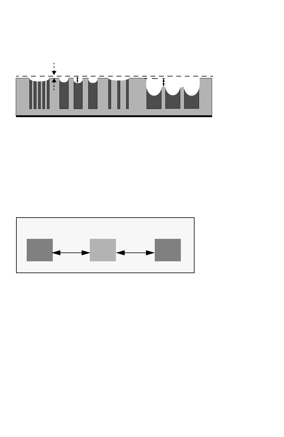
Chapter 11: Variation-Aware Extraction
Introduction to Variation-Aware Analysis 11-10
StarRC User Guide and Command Reference F-2011.06
StarRC User Guide and Command Reference Version F-2011.06
Figure 11-5 Thickness Variation As a Function of Width and Spacing
Oxide
Fine Line
Fine Space Large Line
Large Space Fine Line
Large Space Large Line
Fine Space
Field Oxide
Loss
Dishing Erosion
Another example of a common variation modeled systematically is due to subwavelength
lithography, also referred to as etch, that can be modeled in StarRC as a function of width
and spacing. The command used to model this effect in StarRC is
ETCH_VS_WIDTH_AND_SPACING. In Figure 11-6, if the spacing to the left conductor, s1, is not
equal to the spacing to the right conductor, s2, the etch applied to each side of the conductor
might be different. It is critical that this variation is accounted for correctly to accurately
predict circuit performance, reliability, and even functionality
Figure 11-6 Etch Effect Due to Subwavelength Lithography
S1 S2
W
Random or Inter-Die Process Modeling
Process parameter variations that occur across different dies, or even wafers, are generally
assumed to be random and independent. The minimum and maximum variations for a given
parameter are usually known, along with the type of distribution the parameter exhibits.
Commonly, the random variations are modeled using a normal, Gaussian distribution based
on the Central Limit Theorem. The Central Limit Theorem from introductory probability and
statistics states that if a random distribution is determined by many nearly independent
factors, and none of them plays a dominant role, the resultant distribution is a normal
distribution. The two key points in the theorem that allow designers to use this assumption
are that the parameters are nearly independent and that none of them plays a dominant role.
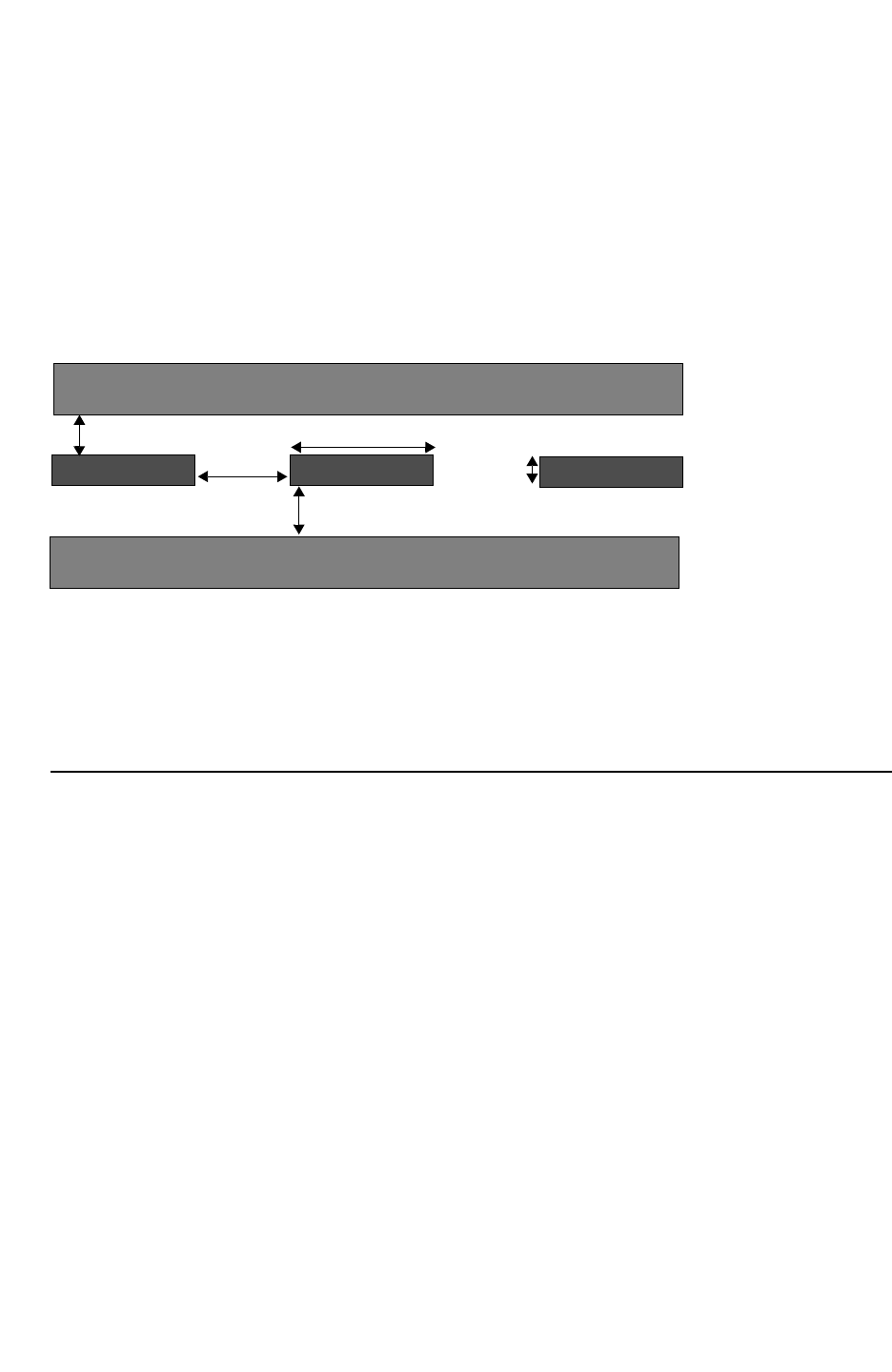
Chapter 11: Variation-Aware Extraction
Introduction to Variation-Aware Analysis 11-11
Chapter 11: Variation-Aware Extraction
Introduction to Variation-Aware Analysis 11-11
StarRC User Guide and Command Reference Version F-2011.06
Random variations are modeled through process corners in traditional methodologies, in
which the maximum and minimum variations are used for conductors and dielectrics. The
corner files generally represent the process variations at +3s and -3s of some type of
distribution, whether normal or uniform. The process parameters in today’s technologies
commonly modeled as random variations are thickness (conductor and dielectric) and
conductor width. These variations can have a significant impact on timing and chip
performance and therefore must be modeled in UDSM designs.
Figure 11-7 Inter-Die Process Parameter Variation (Conductor Thickness/Width, Dielectric
Thickness)
Metal(n+1
Metal(n-
h2Line width
Line spacing
ILD thickness h1
t
metal thickness
s
Figure 11-7 shows the three process parameters modeled as random variations in deep
submicron designs today. In addition to these, some companies also model the variation of
the dielectric constant (ER), sheet resistance (RHO), and via resistance (RPV) as a random
variation. As feature sizes continue to shrink, the number of process parameters modeled as
random variations is expected to increase.
Comparing Random Versus Systematic Variations
The total process variation can be seen as a sum of the systematic, or deterministic, and
random process variation:
Process Variation = Systematic Variation + Random Variation
1. Separate the random and systematic process variations as follows:
Let p denote a set of interconnect parameters,
p = pnom + sys + rand
where
• pnom = nominal value of the parameter
• sys = systematic process variation
• Δrand represents the random process parameter variation.
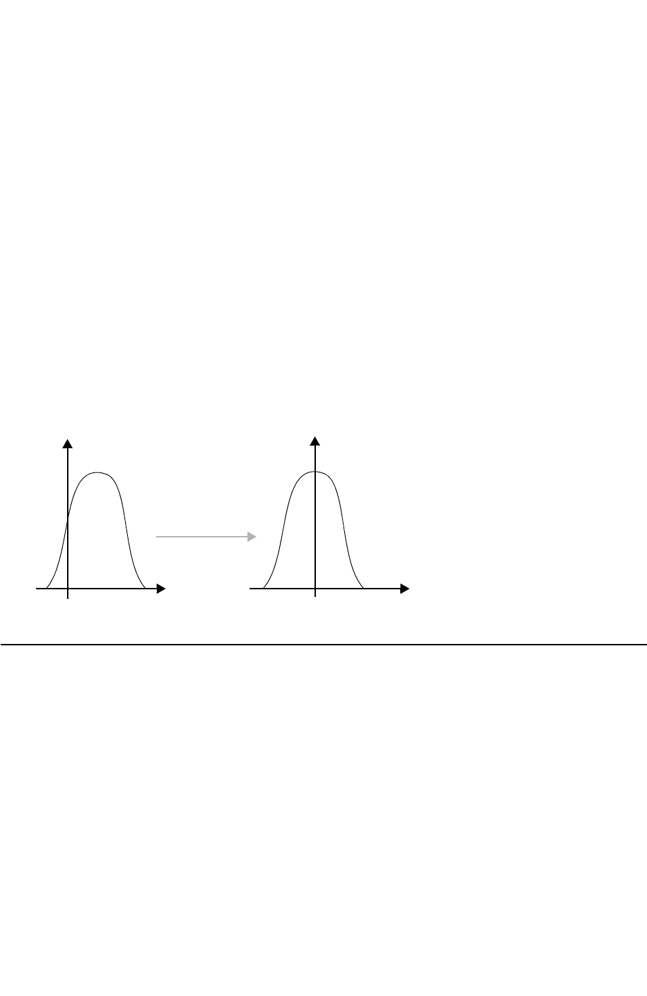
Chapter 11: Variation-Aware Extraction
Parasitic Extraction to Static Timing Analysis 11-12
StarRC User Guide and Command Reference F-2011.06
StarRC User Guide and Command Reference Version F-2011.06
2. Merge the deterministic variation with the nominal variation, and separate the random
variation as follows:
p = po + rand
where po = pnom + Δsys
3. Interconnect parasitic C and R can then be defined as functions of p.
C = f(p) = f(po + Δrand),
R = g(p) = g(po + Δrand)
4. Co and Ro are parasitic C and R incorporating the effects of deterministic process
variation and can be defined as follows:
Co = f(po), Ro = g(po)
Figure 11-8 shows a process parameter, such as conductor thickness, with both systematic
and random variations. In the right side of the figure, it is assumed that the random variation
of this parameter follows a normal, Gaussian type shape.
Figure 11-8 Total Process Variation (Systematic and Random)
Total Random
Without
Systematic
Parasitic Extraction to Static Timing Analysis
With shrinking semiconductor process nodes, environmental and semiconductor process
variations take up a larger portion of the product development time in circuit performance.
Traditional timing analysis flows (using corners) are unable to cope with the large number of
permutations of process, voltage, and temperature corners created by these independent
sources of variation.
The goal of statistical, or variation-aware, analysis is to improve the quality of results by
reducing pessimism, and to improve the time-to-results compared to traditional worst-case
corner analysis. For statistical analysis to be beneficial, it is vital that downstream tools, such

Chapter 11: Variation-Aware Extraction
Parasitic Extraction to Static Timing Analysis 11-13
Chapter 11: Variation-Aware Extraction
Parasitic Extraction to Static Timing Analysis 11-13
StarRC User Guide and Command Reference Version F-2011.06
as PrimeTime and HSPICE, can interpret and analyze the variation effects modeled. In this
section the importance of a seamless flow for statistical extraction and timing analysis is
discussed.
The Traditional Analysis Flow
Circuit performance and manufacturing yield are daily challenges for which ASIC designers
are responsible. Current design methodologies require that designers run circuit simulations
at various design corners to verify circuit behavior, each representing a combination of worst
case process, voltage, and temperature variation. The designer, or process team, must
determine the worst case conditions under which the circuit performs with regard to timing,
and this is typically based on the manufacturing steps, design style, and process rules.
Typically, the corner types used in practice are typical, cworst, rcworst, rcbest, and cbest.
These corners are usually referred to as fast and slow corners in the timing domain. This
requires design teams to maintain multiple process technology files (such as the
Interconnect Technology Format) for extraction and device libraries representing parameters
at each of these corners. To analyze a circuit’s behavior, designers must then run parasitic
extraction and static timing analysis using these multiple corner files.
With the number of process corners growing in deep submicron technologies, designers are
challenged to meet timing specifications for circuits within the project schedule. Figure 11-9
shows the iterations required by designers to run a traditional corner analysis.
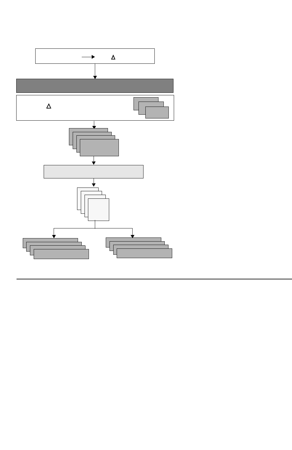
Chapter 11: Variation-Aware Extraction
Parasitic Extraction to Static Timing Analysis 11-14
StarRC User Guide and Command Reference F-2011.06
StarRC User Guide and Command Reference Version F-2011.06
Figure 11-9 Traditional Corner Analysis Design Flow
Foundry (po , rand (%))
Process Characterization
Multiple corner process files
pk=p0+{ p}k
where, k=1..N (N=number of corners) ITF
nxtgrd
StarRC
DSPF
SBPF
SPEF
SPICE
HSPICE
PrimeTime
Statistical Extraction and Static Timing Analysis
Statistical analysis provides a solution to the ever-growing number of process corners and
the pessimism introduced with analyzing and meeting design specifications based on these
worst-case process variations. The parasitic extraction tool must generate a variation-aware
netlist for the static timing tool to interpret and produce timing results based on the
probability distribution of the process and device variations. This is a challenging, not trivial,
task due to the large number of process and device variations, leading to many
permutations.
The goal of statistical extraction is to generate a netlist with variation for each parasitic
element. The variation of each process parameter, such as conductor or dielectric thickness,
is an input to the extraction tool through the ITF and is used to compute sensitivities of
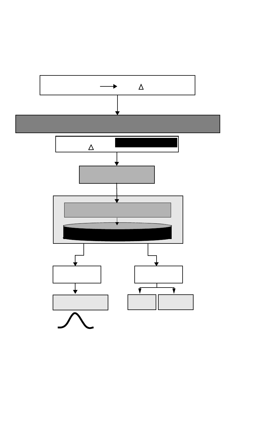
Chapter 11: Variation-Aware Extraction
Parasitic Extraction to Static Timing Analysis 11-15
Chapter 11: Variation-Aware Extraction
Parasitic Extraction to Static Timing Analysis 11-15
StarRC User Guide and Command Reference Version F-2011.06
capacitance or resistance values based on each of these process variations. The process
parameters for which variation can be modeled in StarRC include conductor and dielectric
thickness and conductor width.
Figure 11-10 Sensitivity Extraction Flow
User-Defined
Corner Netlist
Foundry (po , p)
Process Characterization
Single process file
(po
nxtgrd with Sensitivity
pl)
max | Variation-Aware ITF
Extraction
Parasitic Netlist with Sensitivity
StarRC
Variation-Aware
SBPF
PrimeTime PrimeTime
HSPICE
Variation Analysis
Figure 11-10 shows the two different applications for statistical extraction. The left side
shows a netlist produced with variation-aware parasitic elements (R,C) that is interpreted by
a variation-aware simulation tool, such as PrimeTime Variation Analysis, to generate timing
checks based on the statistical distribution. More information about the netlist format are in
the following sections. The flow on the right side of Figure 11-10 allows you to generate a
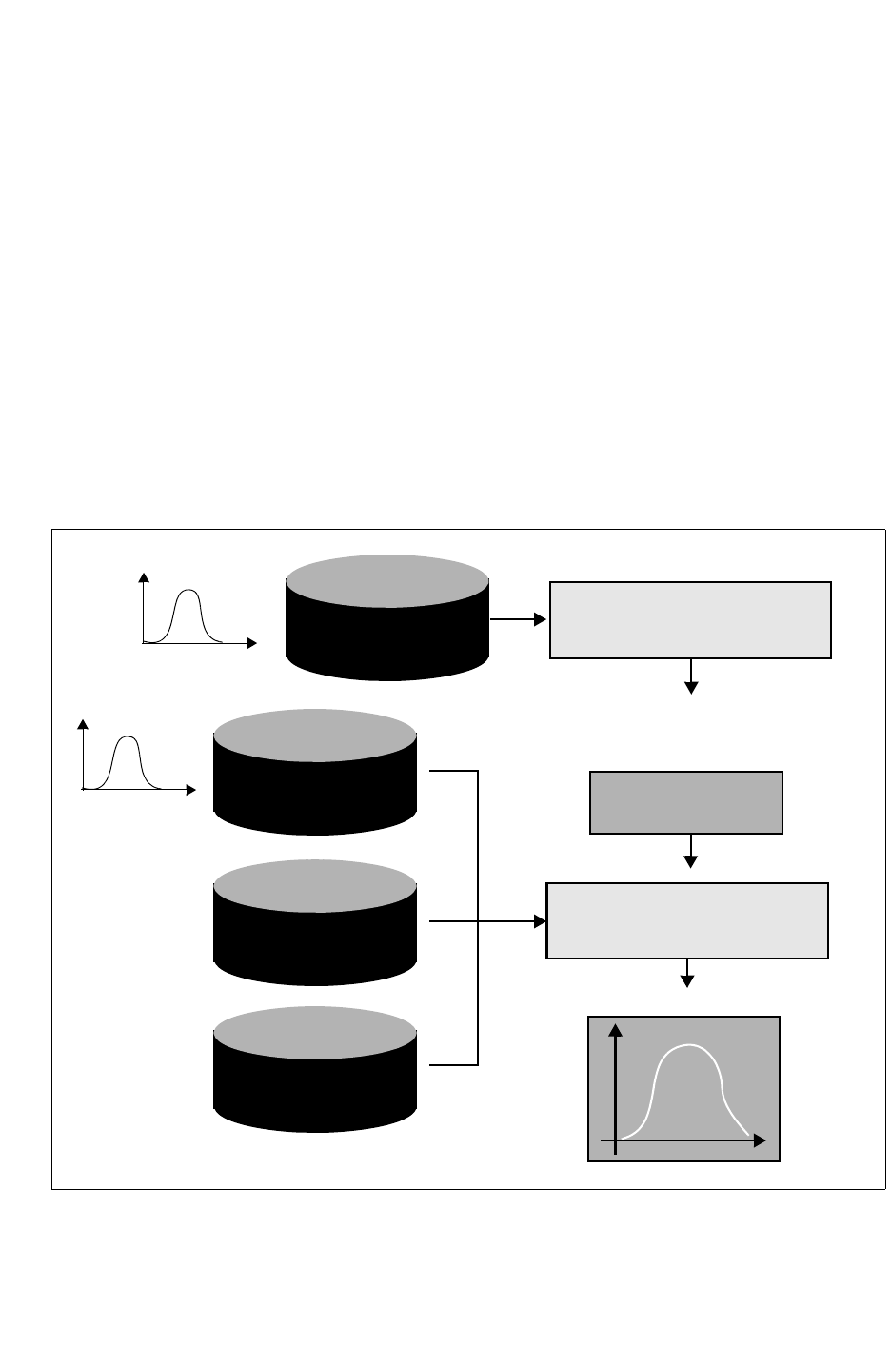
Chapter 11: Variation-Aware Extraction
Parasitic Extraction to Static Timing Analysis 11-16
StarRC User Guide and Command Reference F-2011.06
StarRC User Guide and Command Reference Version F-2011.06
single-corner user-defined netlist. The single-corner netlist is analogous to the corner netlist
produced in traditional timing analysis flows with a corner process file. The variation of
process parameters for the single-corner netlist can be any user-defined variation. This
feature provides you the flexibility to quickly generate any corner netlist given a database
with variation information. Generation of user-defined corner netlists can also be useful in
testing the variation-aware ITF.
The flow diagram in Figure 11-11 shows a parasitic extraction and static timing statistical
analysis-based flow. Simulation tools must interpret and analyze variation-aware netlists in
order to obtain accurate timing, and in turn increase design margin and productivity. The
final timing report produced by a tool such as PrimeTime provides a probability distribution
of occurrence based on the variation and distribution of the device and interconnect
parameters. The distribution of these process and device parameters can be defined in
PrimeTime.
Figure 11-11 The StarRC and PrimeTime Variation-Aware Flow
Device
Variation
Distributions
Variation-aware
Library
Constraints
(SDC)
StarRC
Parasitic Netlist
with Sensitivity
PrimeTime with
Variation
Probability
Interconnect
Variation
Distributions
T, W, H ...
Leff ...
Variation Analysis
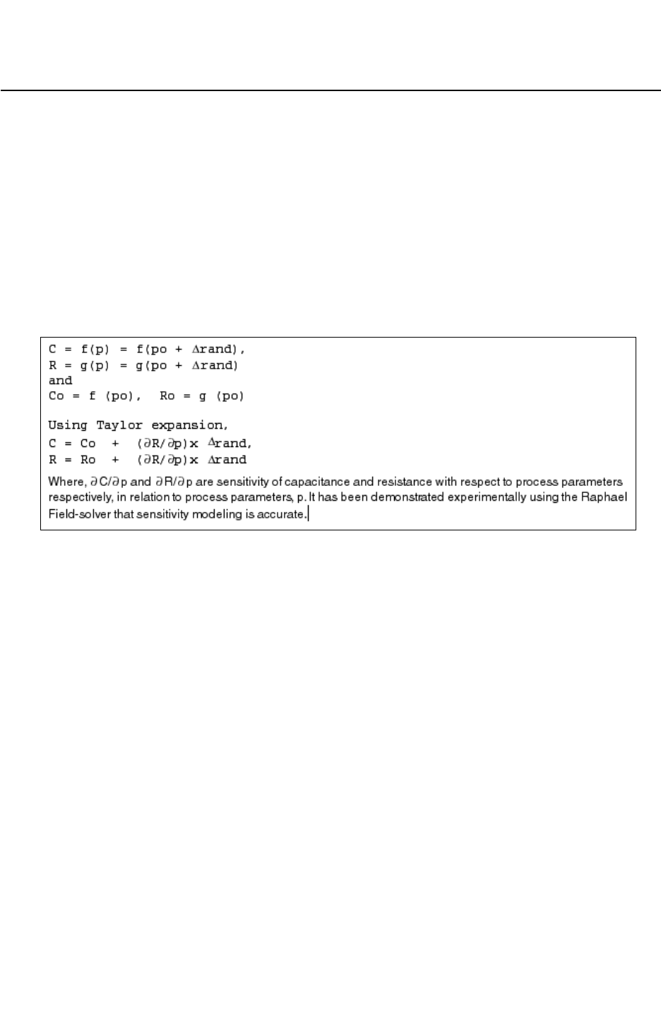
Chapter 11: Variation-Aware Extraction
The Concept of Sensitivity 11-17
Chapter 11: Variation-Aware Extraction
The Concept of Sensitivity 11-17
StarRC User Guide and Command Reference Version F-2011.06
The Concept of Sensitivity
Sensitivity can be defined as the degree of response resulting from a change in an input
source. For the purposes of this explanation, you will assess the sensitivity of capacitance
and resistance as a result of process parameter variations, such as thickness or width. The
concept of sensitivities is the key idea used in StarRC, a model-based extraction tool, to
provide a solution for variation-aware analysis. In this section statistical extraction solutions
using sensitivities are explained.
As defined in the previous section, the random and deterministic process variation can be
decomposed and the variation effect on R and C can be defined as shown in Figure 11-12.
Figure 11-12 Resistance and Capacitance Definition
Given the nominal values and computed sensitivities for a given parameter variation,
parasitics can be computed for any variation value within the range Δrand. Sensitivity
coefficients are basically the gradient of capacitance or resistance values related to specific
parameter changes. The computed sensitivities are necessary key ingredients for
downstream EDA tools, such as PrimeTime or HSPICE, to perform statistical or traditional
timing analysis. Simulation tools such as PrimeTime can use sensitivities along with nominal
values to compute capacitance and resistance for a given random variable, Δrand. StarRC
outputs a netlist with nominal RC values along with independent sensitivities, with respect to
each varying parameter and prints these for every parasitic element. The downstream tools
then apply a distribution using the sensitivities, variation amount, and nominal capacitance/
resistance value. StarRC does not perform any statistical analysis, but rather provides the
effect on parasitics due to a randomly distributed parameter, such as thickness or width.
Sensitivity data is also needed for fast multicorner netlist generation. This is useful for
designers to produce user-defined corner netlists for simulation. Currently, multiple
extraction runs are needed to generate netlists at different corners for circuit verification.
When you perform variation-aware extraction, a database with nominal RC values and
sensitivities is stored and any given corner netlist can be generated from this quickly.

Chapter 11: Variation-Aware Extraction
The Concept of Sensitivity 11-18
StarRC User Guide and Command Reference F-2011.06
StarRC User Guide and Command Reference Version F-2011.06
Calculating Sensitivity Coefficients
Execution of statistical grdgenxo, the program in StarRC to pre-characterize capacitance
models, produces sensitivity coefficients in addition to the usual capacitance values. In the
statistical context, the usual capacitance values are referred to as the nominal capacitance
values.
Characterizing the Effect on Capacitance Values
To compute the sensitivity due to parameter variations, vary each parameter one at a time,
with all other parameters unchanged. This is based on the assumption that each parameter
variation is independent, or noncorrelated, to other parameters varying in a random fashion.
When you compute sensitivities, each thickness or width is varied one at a time, a layer at a
time, whenever it is specified as variant. This is how the effect on capacitance values from
each parameter variation is characterized.
Computing the Thickness Sensitivity of a Dielectric Layer
A thickness change on a metal layer does not affect the thicknesses of other metal or
dielectric layers. The exception to this is the intra-metal dielectric (IMD) which varies by the
same amount as the conductor it is embedded within. This is to prevent a metal cutting
through dielectric layers. Where multiple dielectric layers share the same thickness with a
metal (as in the case with an intrametal dielectric), the thickness changes are proportionally
distributed among the dielectric layers according to their thicknesses.
Furthermore, the locations of the dielectric and metal layers above the changed metal layer
are affected, due to a shift upward or downward related to the thickness change of the metal
layer. The shifted layers do not have a thickness change at all. Their thicknesses remain the
same as before, or nominal. On the other hand, to compute thickness sensitivity of a
dielectric layer, you need only change dielectric thickness and must not change metal
thickness at all.
Defining Capacitance Sensitivity
The following steps explain how to define capacitance sensitivity.
• Define the sensitivity coefficient of capacitance (C) using the following equation:
Sc = (ΔC / Co) / Δ(p / po)
ΔC = C-Co, Co is the nominal capacitance value
Δp = p - po, po is the nominal value of the parameter
(p- po for thickness and Wmin for width)
• To define variation in the parameter with respect to its nominal value, or Wmin in the case
of width, find the coefficient of variation (C.V.).

Chapter 11: Variation-Aware Extraction
The Concept of Sensitivity 11-19
Chapter 11: Variation-Aware Extraction
The Concept of Sensitivity 11-19
StarRC User Guide and Command Reference Version F-2011.06
The ratio of standard deviation, or C.V., is sp to the mean, mp, of a process variation
parameter.
C.V. = Standard Deviation/Mean
C.V. represents the statistical measure of the dispersion of process variation around a
nominal value, assuming the nominal value equals the mean of the variation. By definition,
the C.V. must be a positive number. The C.V. can be specified for conductor thickness,
conductor width, and dielectric thickness. By default, StarRC assumes three standard
deviations between its mean (nominal value) and the maximum variation. Grdgenxo
calculates capacitance sensitivity values at the 3σ point.
The C.V. can be defined in the sensitivity equation as follows:
Δp / po = 3 * C.V.
For example, if the maximum variation for a particular metal is +/-15%, the corresponding
C.V. would be:
Max. Variation = +/-15%
C.V. = 0.15/3 = 0.05
In the case where the maximum and minimum variation is asymmetric with respect to the
mean, the side representing the maximum absolute range should be used for calculating the
C.V. For example, if the variation on a particular metal is +10%/-15%, the C.V. specified
should be taken from the negative side, or C.V. = 0.05. As described in later sections, for the
purposes of generating a corner netlist with such an asymmetric variation, you can specify
any integer multiple (such as a VARIATION_MULTIPLIER in a user-defined corner file) of the
C.V. to generate a specific corner netlist. For more details, see “User-Defined Corner and
Sensitivity Calculation” on page 11-23.”
Therefore, the sensitivity, Sc, can be defined in terms of the C.V.:
Sc = (ΔC / Co) / (3 * C.V.)
The normalization with respect to nominal value Co, To, and Wmin results in ratios for the
sensitivities, either thickness or width. Therefore, you can safely limit the value of sensitivity
(S) to be within a small data range with minimum loss of accuracy.
A sensitivity value of 0.1 means the corresponding capacitance sensitivity is 0.1% of the
variation. In other words, ΔC = Co * 0.1% * 3 * C.V. (coefficient of variation).
During extraction, two capacitances can be summed or subtracted from each other.
Assuming both capacitances are sensitive to certain variation, the sensitivity of the resulting
capacitance is an average weighted sum or subtraction of the sensitivity values of the two
original capacitances.

Chapter 11: Variation-Aware Extraction
Running StarRC With Sensitivities 11-20
StarRC User Guide and Command Reference F-2011.06
StarRC User Guide and Command Reference Version F-2011.06
When you are performing netlist reduction, resistors and capacitors can get merged and
their sensitivities averaged and redistributed accordingly. For instance, when two resistors
sensitive to different variations are reduced to one, the resulting resistor is sensitive to all
variations from the initial two resistors. Thus, after reduction you have fewer RC values, but
each R and C contain more sensitivity values.
Defining Resistance Sensitivity
The definition of the sensitivity coefficient for resistance (R) is similar to the one for
capacitance. StarRC calculates resistor sensitivities in both the conductance and resistance
domain, depending on the type of variation specified. Thickness and width sensitivity
coefficients are calculated, stored, and reported in the conductance (G) domain to minimize
accuracy loss, whereas resistivity variation (rho and rpv) are computed in the resistance (R)
domain.
The conductance sensitivity calculation can be defined as follows:
SRES = (ΔG/ Go) / (p/ po)
Where ΔG = G-Go, Go is the nominal conductance, and where Δp = p-po, po is the nominal
thickness, conductor or dielectric, or Wmin in the case of width variation.
Due to the fact that G is directly proportional to the thickness of the conductor, Sthickness,
sensitivity due to thickness variation is always 1 with no reduction on the network. However,
Swidth, sensitivity due to width variation, is not always 1 because the width variation is a
function of Wmin rather than Wo.
Note:
The coefficient of variation (C.V.) represents 1/3 of the maximum variation and is relative
to thickness. WMIN represents nominal permittivity, or nominal resistance (RHO or RPV),
depending on the type of variation specified.
Running StarRC With Sensitivities
StarRC computes the sensitivity information based on parameter variations specified in the
ITF. The sensitivities are calculated during the capacitance models pre-characterization
stage referred to as grdgenxo. This information is then passed to xTractor to map the
sensitivities to polygons for extraction. The xTractor determines the sensitivities of
conductors to variations on other conductors or dielectrics. Figure 11-13 shows a flow
diagram of StarRC with sensitivities. You can use the sensitivity information to generate a
variation-aware netlist or a corner netlist. In the latter case, StarRC must compute the corner
parasitic value using the nominal value and sensitivities for each resistor and capacitor
element prior to netlist generation.
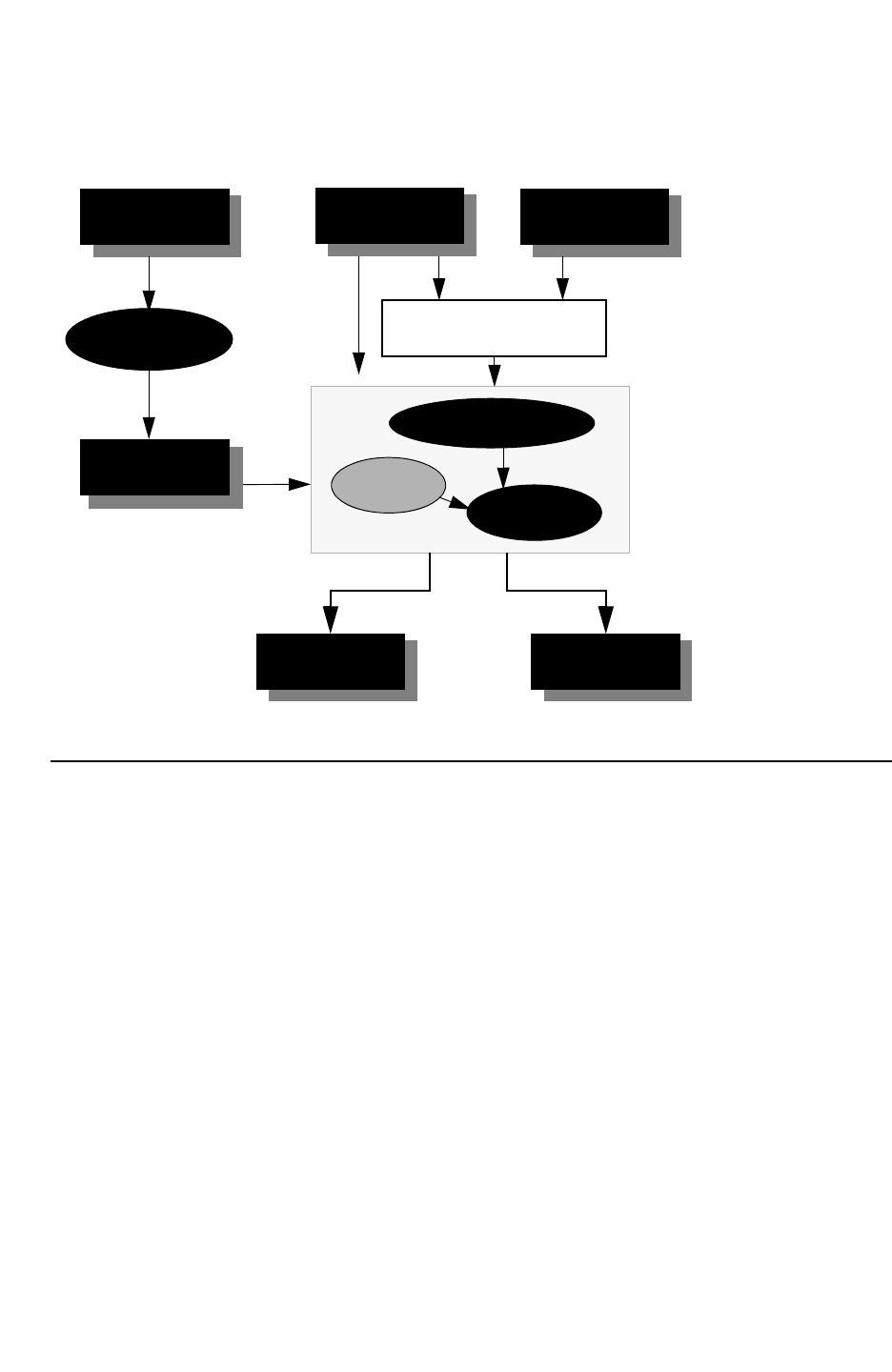
Chapter 11: Variation-Aware Extraction
Running StarRC With Sensitivities 11-21
Chapter 11: Variation-Aware Extraction
Running StarRC With Sensitivities 11-21
StarRC User Guide and Command Reference Version F-2011.06
Figure 11-13 The StarRC Flow With Sensitivities
Process Modeling Cell-Level Transistor-Level
ITF with
Variation
Models with
Sensitivity
grdgenxo
GDSII
Milkyway or
LEF/DEF
Sensitivity
Information
xTractor
StarXtract
Device Extraction
Engine
Netlist with User-defined
variation Netlist
Example Calculations With Sensitivities
In this section, an example and corresponding capacitance computation with sensitivities
are explained. The parameters that are allowed to vary are thickness and width for each
layer. Given the definition of sensitivity computation in the previous section, each parasitic
resistance and capacitance element has a different magnitude of dependency on each of
these parameter variations.
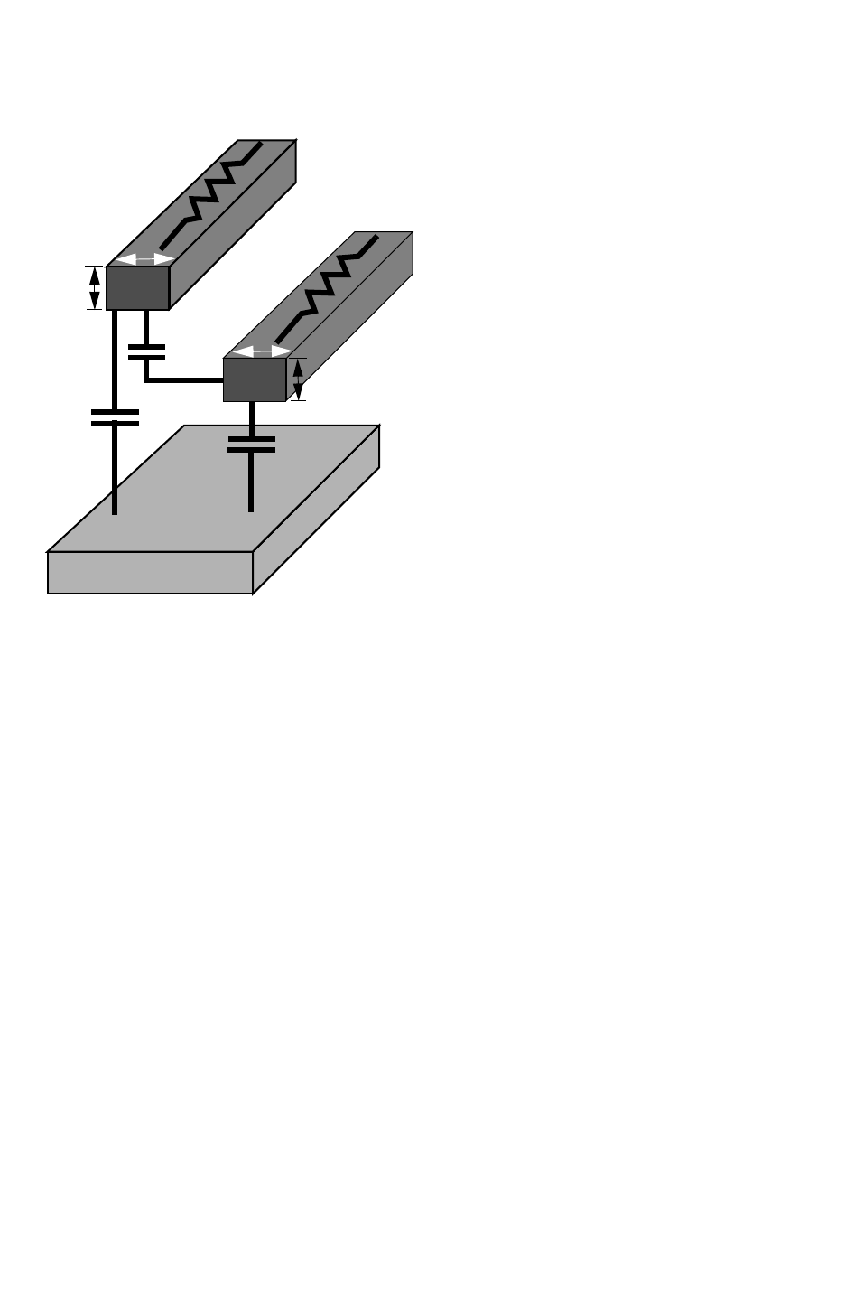
Chapter 11: Variation-Aware Extraction
Running StarRC With Sensitivities 11-22
StarRC User Guide and Command Reference F-2011.06
StarRC User Guide and Command Reference Version F-2011.06
Figure 11-14 RC Calculation With Sensitivities
R4
M4
W4
t4
Substrate
R3
M3
W3
C3
C4
t3
Cc
For the example shown in Figure 11-14, StarRC produces the following capacitance
computations:
C3 = C30*(1+(Sc[t3]*Δt3/t30)+(Sc[w3]*Δw3/w3[min])+(Sc[t4]*Δt4/t40)
+(Sc[w4]*Δw4/w4[min]))
C4 = C40*(1+(Sc[t3]*Δt3/t30)+(Sc[w3]*Δw3/w3[min])+(Sc[t4]*Δt4/t40)
+(Sc[w4]*Δw4/w4[min]))
Cc = Cco*(1+(Scc[t3]*Δt3/t30)+(Scc[w3]*Δw3/w3[min])+(Scc[t4]*Δt4/t40)
+(Scc[w4]+*Δw4/w4[min]))
Given that some of the sensitivity coefficients are very small, the impact on capacitance is
essentially negligible, and therefore some terms may no longer exist in the previous
equation.

Chapter 11: Variation-Aware Extraction
User-Defined Corner and Sensitivity Calculation 11-23
Chapter 11: Variation-Aware Extraction
User-Defined Corner and Sensitivity Calculation 11-23
StarRC User Guide and Command Reference Version F-2011.06
Assume that Sc[w4] for C3, Sc[w3] for C4, Scc[w3] for Cc all are very small and therefore
negligible:
C3 = C30*(1+(Sc[t3]*Δt3/t30)+(Sc[w3]*Δw3/w3[min])
+(Sc[t4]*Δt4/t40)+(Sc[w4]+*Δw4/w4[min]))
C4 = C40*(1+(Sc[t3]*Δt3/t30)+(Sc[w3]*Δw3/w3[min])
+(Sc[t4]*Δt4/t40)+(Sc[w4]+*Δw4/w4[min]))
Cc = Cco*(1+(Scc[t3]*Δt3/t30)+(Scc[w3]*Δw3/w3[min])
+(Scc[t4]*Δt4/t40)+(Scc[w4]+*Δw4/w4[min]))
The following is the resulting equation with respective sensitivities:
C3 = C30*(1+(Sc[t3]*Δt3/t30)+(Sc[w3]*Δw3/w3[min])+(Sc[t4]*Δt4/t40)
C4 = C40*(1+(Sc[t3]*Δt3/t30)+(Sc[t4]*Δt4/t40)+(Sc[w4]*Δw4/w4[min]))
Cc = Cco*(1+(Scc[t3]*Δt3/t30)+(Scc[t4]*Δt4/t40)+(Scc[w4]+*Δw4/w4[min]))
Similarly, the resistance for the example in figure X can be computed as follows:
R3 = R30*(1+(SR[t3]*Δt3/t30)+(SR[w3]*Δw3/w3[min])+(SR[t4]*Δt4/t40)
+(SR[w4]*Δw4/w4[min]))
R4 = R40*(1+(SR[t4]*Δt4/t40)+(SR[w4]*Δw4/w4[min]))
And assuming that SR[t4] and SR[w4] for R3 along with SR[t3] and SR[w3] for R4 are
approximately zero:
R3 = R30*(1+(SR[t3]*Δt3/t30)+(SR[w3]*Δw3/w3[min]))
R4 = R40*(1+(SR[t4]*Δt4/t40)+(SR[w4]*Δw4/w4[min]))
User-Defined Corner and Sensitivity Calculation
Given a corner definition, StarRC provides the capability to generate a netlist. This is
possible as a result of the nominal parasitic database and sensitivity information computed
and stored. Then, given a user-defined corner, a netlist can be generated by applying the
appropriate sensitivities to the nominal capacitance value as follows:
C = Co * (1+ΣSi * ((σpi)/ (mpi))i * VARIATION_MULTIPLIERj)
For i=1...N, and where S is the sensitivity for the parameter with variation, spi/mpi is the
coefficient of variation, and VARIATION_MULTIPLIER defines the ‘n’ of the n-σ point of the
distribution.
As discussed in the previous section, the coefficient of variation (C.V.) is defined as the ratio
of the standard deviation to the mean, or nominal value. By default, StarRC assumes three
standard deviations between its mean and the maximum variation. The maximum variation
is computed by multiplying the C.V. by 3 to obtain the maximum percentage variation in the

Chapter 11: Variation-Aware Extraction
User Interface Modeling Parameters and Their Variation 11-24
StarRC User Guide and Command Reference F-2011.06
StarRC User Guide and Command Reference Version F-2011.06
positive and negative direction from nominal. The VARIATION_MULTIPLIER defined in the
corner file allows you to vary a particular parameter up to the maximum in either the positive
or negative direction by specifying a multiple, or scaler, of the C.V. The capacitance and
resistance is then computed at this multiple of C.V. for the parameters that are stated in the
corner file. The VARIATION_MULTIPLIER value should be between -3 and 3, because the
maximum variation is assumed to be 3 * C.V.
For example, for the rcbest corner defined in the following table, the parameters for
conductor thickness and width would be at the +3σ value, with the dielectric thickness at +3σ.
Corner Width Conductor Thickness ILD Thickness
rcbest +3σ+3σ+3σ
The resulting capacitance computation at this corner would be as follows:
C(rcbest) = Co * (1+ (Sc[t_cond] * (3*σTC / mTC)) + ((Sc[t_diel] *
(3*σt_diel / mt_diel)) + ((Sc[w] * (3*σW/mW))
Where Sc[t_cond], Sc[t_diel], and Sc[w] each represent the sensitivities for capacitance
related to changes in conductor and dielectric thickness, and conductor width, respectively.
Note:
The VARIATION_MULTIPLIER field in the corner definition file represents a multiple of the
C.V., between -3 and 3, that can be set to produce a netlist that represents any corner
definition.
User Interface Modeling Parameters and Their Variation
You must model parameters and their variation in the Interconnect Technology Format (ITF).
The ITF information is used by grdgenxo to produce sensitivity values for the given
parameters with variations. The StarRC xTractor uses the sensitivity data and generates a
netlist with parasitic elements with variation coefficients. The parasitic elements with
variation coefficients are used by the downstream variation-aware STA or other simulation
tools. This section describes how to model the random variation of process parameters with
the Interconnect Technology Format (ITF) used by StarRC and the specific commands as
they relate to statistical extraction.

Chapter 11: Variation-Aware Extraction
User Interface Modeling Parameters and Their Variation 11-25
Chapter 11: Variation-Aware Extraction
User Interface Modeling Parameters and Their Variation 11-25
StarRC User Guide and Command Reference Version F-2011.06
Creating a Variation-Aware ITF
You can define the following parameters and their variations in the ITF format:
• Conductor thickness
• Conductor width
• Dielectric thickness
• Dielectric constant
• Sheet resistance (RHO)
• Via resistance (RPV)
The format you specify in the ITF to represent parameter variations is added to the existing
nonvariation aware ITF format. There is no need for you to modify the process cross-section
or values in the nominal ITF. See also the “Variation-Aware ITF Requirements” on
page 11-26.
Appending Variation Information
You can produce a variation-aware ITF by appending the following:
VARIATION_PARAMETERS {
PARAM1 = {(LAYER, PARAM_TYPE, COEFF_OF_VARIATION)
(LAYER, PARAM_TYPE, COEFF_OF_VARIATION)
(LAYER, PARAM_TYPE, COEFF_OF_VARIATION)}
PARAM2 = {(LAYER, PARAM_TYPE, COEFF_OF_VARIATION)
(LAYER, PARAM_TYPE, COEFF_OF_VARIATION)
(LAYER, PARAM_TYPE, COEFF_OF_VARIATION)}
PARAMn = {(LAYER, PARAM_TYPE, COEFF_OF_VARIATION)
(LAYER, PARAM_TYPE, COEFF_OF_VARIATION)
(LAYER, PARAM_TYPE, COEFF_OF_VARIATION)}
}
Where PARAM[X] is the variation parameter name, LAYER is the layer name,
PARAM_TYPE is the type of parameter with THICKNESS, WIDTH, RHO, and ER
supported, and COEFF_OF_VARIATION is the coefficient of variation.
Single Variation Parameters and Dependent Parameters
Given the syntax to define parameter variations, you can correlate process parameters with
variations into a single variation parameter or introduce a dependency across parameters.
Dependent parameters are assumed to have full correlation and vary the same percentage
of their maximum variation. It is important that dependent variations are mapped together as

Chapter 11: Variation-Aware Extraction
User Interface Modeling Parameters and Their Variation 11-26
StarRC User Guide and Command Reference F-2011.06
StarRC User Guide and Command Reference Version F-2011.06
this directly reduces the number of variation combinations needed for modeling in grdgenxo.
Specifying a dependency between parameters also increases StarRC performance and
reduces the netlist size as the number of sensitivities decreases.
Specifying Intra-Metal Dielectric Layers
For intra-metal dielectric (IMD) layers corresponding to fill of a conductor layer, the
specification of IMD thickness variation must be part of the corresponding metal variation.
Use the following syntax to specify IMD variation:
VARIATION_PARAMETERS {
M1_AND_IMD = {(M1, THICKNESS, CV_M1)
(IMDa, THICKNESS, CV_a)
(IMDb, THICKNESS, CV_b)}
When specifying different variations for each IMD layer, it is essential that the planarity
condition is satisfied, where the sum of thickness variations from the IMD layers must be
equal to the thickness variation of the corresponding conductor layer. This ensures that the
top surface of the upper-most IMD layer is at the same height level as the top surface of the
metal layer, before and after the variations. In the case of nonplanarity, the metal thickness
is used as a reference to adjust the intra-metal dielectric layer if the difference is within a
tolerance of 0.01 microns. An error message appears if the height mismatch is greater than
the tolerance.
Variation-Aware ITF Requirements
The following requirements are expected for variation-aware ITF syntax:
• The coefficient of variation is assumed to be symmetric on the positive and negative
sides.
• Every dependent parameter has to be listed.
• Coefficient of variation cannot be larger than 0.2 (20% for 1 σ), meaning that the
maximum variation modeled as random cannot be larger than 60%, except for RHO,
RPV, and intra-metal dielectrics (IMD).
• Each dependent parameter has layer name, parameter type, and coefficient of variation.
• A unique variation parameter name is given to each set of the dependent variation
parameters.
• Coefficient of variation of the intra-metal (IMD) layers must be specified together with the
corresponding metal layer. The variation for metal and IMD is mapped to the same unique
variation parameter name.
• A different coefficient of variation can be specified for each IMD layer. Specification of
coefficient of variation on select IMD layers is also accommodated. Planarity condition of
the IMD and metal layer must be satisfied.

Chapter 11: Variation-Aware Extraction
User Interface Modeling Parameters and Their Variation 11-27
Chapter 11: Variation-Aware Extraction
User Interface Modeling Parameters and Their Variation 11-27
StarRC User Guide and Command Reference Version F-2011.06
• All dependent variation parameters mapped to the same variation parameter vary the
same percentage of their own maximum variations. These are parameters are fully
correlated. To assign correlation in downstream tools the parameters should be mapped
to different variation parameters.
• If there is no dependency between the process parameters, you can define a one-to-one
mapping.
• RHO and RPV variation parameters cannot be correlated. Resistance variation
parameters can have a coefficient of variation larger than 0.2 (maximum variation +/
-60%).
• For parameters that do not have variation specified, it is assumed that there is no random
variation.
Note:
Coefficient of Variation (C.V.) cannot be larger than 0.2 (20%), except for RHO, RPV, and
intra-metal dielectrics (IMD). A C.V. of 0.2 represents a maximum variation of +/- 60%. In
such cases, you should separate deterministic and random process effects for modeling
purposes.

Chapter 11: Variation-Aware Extraction
User Interface Modeling Parameters and Their Variation 11-28
StarRC User Guide and Command Reference F-2011.06
StarRC User Guide and Command Reference Version F-2011.06
Example of a Variation-Aware ITF
1 TECHNOLOGY=SAMPLE
2 DIELECTRIC PASS3 {THICKNESS=1.850 ER=4.2 }
3 DIELECTRIC PASS2 {THICKNESS=0.400 ER=2.9 }
4 DIELECTRIC PASS1 {THICKNESS=0.05 ER=8.1 }
5 DIELECTRIC IMD9_3 {THICKNESS=0.65 ER=4.2 }
6 DIELECTRIC IMD9_2 {THICKNESS=0.05 ER=8.1 }
7 DIELECTRIC IMD9_1 {THICKNESS=0.05 ER=4.2 }
8 CONDUCTOR metal9 {THICKNESS=0.75 WMIN=3 SMIN=2.0 RPSQ=0.05}
…
9 CONDUCTOR metal3 {THICKNESS=0.2 WMIN=0.10
10 SMIN=0.10 RPSQ=0.08}
11 DIELECTRIC IMD3_1 {THICKNESS=0.1 ER=2.9 }
12 DIELECTRIC IMD2_3 {THICKNESS=0.05 ER=4.5 }
13 DIELECTRIC IMD2_2 {THICKNESS=0.2 ER=2.9 }
14 CONDUCTOR metal2 {THICKNESS=0.2 WMIN=0.10
15 SMIN=0.10 RPSQ=0.08}
16 DIELECTRIC IMD2_1 {THICKNESS=0.1 ER=2.9 }
17 DIELECTRIC IMD1_4 {THICKNESS=0.06 ER=4.5 }
18 DIELECTRIC IMD1_3 {THICKNESS=0.04 ER=5.2 }
19 DIELECTRIC IMD1_2 {THICKNESS=0.06 ER=2.9 }
20 CONDUCTOR metal1 {THICKNESS=0.16 WMIN=0.09
21 SMIN=0.09 RPSQ=0.10}
…
22 VIA VIA1 {AREA = 0.1 RPV=0.5}
23 VARIATION_PARAMETERS {
24 M1_T = {(metal1, THICKNESS, 0.067)
25 (IMD1_2, THICKNESS, 0.067)
26 (IMD1_3, THICKNESS, 0.067)
27 (IMD1_4, THICKNESS, 0.067)}
28 M1_W = {(metal1, WIDTH, 0.0333)}
29 M1_RHO = {(metal1, RHO, 0.50)}
30 IMD2_1_ER = {(IMD2_1, ER, 0.033)}
31 M12_T = {(IMD2_1, THICKNESS, 0.05)}
32 M2_T = {(metal2, THICKNESS, 0.0667)
33 (IMD2_2, THICKNESS, 0.0667)}
34 M2_W = {(metal2, WIDTH, 0.05)}
35 M2_RHO = {(metal2, RHO, 0.1333)}
36 M23_T = {(IMD2_3, THICKNESS, 0.05)
37 (IMD3_1,THICKNESS, 0.02)}
38 M3_T = {(metal3, THICKNESS, 0.0667)
39 (IMD3_2, THICKNESS, 0.0667)}
40 M3_W = {(metal3, WIDTH, 0.05)}
…
41 M9_T = {(metal9, THICKNESS, 0.067)
42 (IMD9_1, THICKNESS, 0.067)
43 (IMD9_2, THICKNESS, 0.067)
44 (IMD9_3, THICKNESS, 0.067)}}
45 M9_W = {(metal9, WIDTH, 0.0333)}
46 PASS = {(PASS1, THICKNESS, 0.0333) (PASS2,
47 THICKNESS, 0.05)}
48 VIA1_RPV = {(via1, RPV, 0.0667)}}

Chapter 11: Variation-Aware Extraction
User Interface Modeling Parameters and Their Variation 11-29
Chapter 11: Variation-Aware Extraction
User Interface Modeling Parameters and Their Variation 11-29
StarRC User Guide and Command Reference Version F-2011.06
The line descriptions in Table 11-2 explain the variations specified in the previous example
for some layers. Line numbers in the previous example file are shown for clarity. Do not
specify line numbers in your ITF.
Table 11-2 Explanation of Variation-Aware ITF Example
Line
Number
Description
17-20, 24 M1_T is the variation parameter for metal1, IMD1b, IMD1c, and IMD1d thickness.
Metal1 and its corresponding intra-metal layers must be listed in the variation parameters.
Metal1 thickness has coefficient of variation of 0.067 and its maximum variation is assumed
to be +/-20%.
The same variation is assumed for IMD1_2, IMD1_3, and IMD1_4 in this case.
When VARIATION_POINT for M1_T is 3.0, metal1 thickness varies by 2% and thickness of
IMD1_2, IMD1_3, and IMD1_4 also varies by 20%.
When VARIATION_POINT for M1_T is -2.0, metal1, IMD1_2, IMD1_3, and IMD1_4 thickness
varies by 13.4%.
16,30 IMD2_1_ER is the variation parameter for the dielectric constant, or permittivity, variation for
layer IMD2_1.
The dielectric constant varies by a maximum +/-10%.
20-21,
22, 29,
48
M1_RHO is the sheet resistance, or rho, variation for layer metal1 and VIA1_RPV is the via
resistance variation for via1.
The maximum sheet resistance variation specified is +/-40%.
The maximum via resistance variation specified is +/-20%.
There is no maximum C.V. limit for these variations.
11-12, 36 M23_T is the variation parameter for IMD3_1 and IMD2_3 thickness.
IMD3_1 thickness has coefficient of variation of 0.0333 and its variation range is assumed
to be +/-10%.
Thickness of IMD2_3 has a coefficient of variation of 0.05, and its variation range is
assumed to be +/-15%.
IMD2_3 and IMD3_1 are specified as dependent parameters.

Chapter 11: Variation-Aware Extraction
Handling Temperature Variation in StarRC 11-30
StarRC User Guide and Command Reference F-2011.06
StarRC User Guide and Command Reference Version F-2011.06
Handling Temperature Variation in StarRC
Today’s corners are generally constructed based on various combinations of process,
voltage, and temperature (PVT) variations. Along with process variations, temperature
variations across a die or wafer can have significant impact on the resistance of a wire and
hence the performance and/or functionality of a circuit.
StarRC can handle temperature as a variation and write temperature derating parameters,
CRT1 and CRT2, into the sensitivity netlist to be handled by downstream tools. The
resistances in the sensitivity netlist produced are at the GLOBAL_TEMPERATURE specified in
the ITF. You can have CRT1 and CRT2 as the only sensitivities, or variation parameters, in
the netlist.
Temperature Variation Flow
Figure 11-15 on page 11-31 shows the temperature variation flow. You can either output
temperature in the netlist as a variation with CRT1/CRT2 in the sensitivity netlist or produce
a User-Defined Corner (UDC) netlist at a specified temperature (see “Defining a Corner
(UDC) File” on page 11-31).
Temperature derating factors, CRT1 and CRT2, can be the only variation specified in the ITF.
Therefore, an existing nonstatistical ITF, without any random process variation information
specified in a VARIATION_PARAMETERS table, can be used for a temperature variation flow.
Note:
Temperature variation is independent of random process variation. Therefore,
temperature derating coefficients, CRT1 and CRT2, can be the only variation parameters
in the ITF. SENSITIVITY:YES must be set with TEMPERATURE_SENSITIVITY:YES
command in the StarRC command file.
When VARIATION_MULTIPLIER for M23_T is 3.0, IMD3a thickness varies by 10% and
IMD_3 thickness varies by 15%.
When VARIATION_POINT for M23_T is 1.5, IMD3_1 thickness varies by 5% and IMD_3
thickness varies by 7.5%.
Table 11-2 Explanation of Variation-Aware ITF Example (Continued)
Line
Number
Description
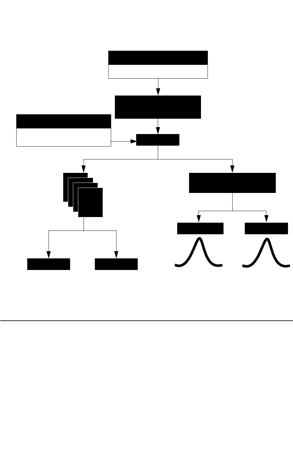
Chapter 11: Variation-Aware Extraction
Defining a Corner (UDC) File 11-31
Chapter 11: Variation-Aware Extraction
Defining a Corner (UDC) File 11-31
StarRC User Guide and Command Reference Version F-2011.06
Figure 11-15 Temperature Variation Flow
Process Characterization (ITF)
CRT1/CRT2/CRT_VS_SI_WIDTH
Extraction with Temperature
Sensitivity (CRT1/CRT2)
Netlister -cleanN
Corner Definition File
CORNER_NAME:HOT
OPERATING_TEMPERATURE:125
- Supports all reduction modes
DSPF
SBPF
SPEF
SPICE
Netlist with CRT1/CRT2
SBPF. SPEF. STAR, NETNAME
PrimeTime HSPICE
PrimeTime-VX HSPICE
Traditional
Static Timing Analysis Simulation
Variation Aware
and
Statistical Simulation
Defining a Corner (UDC) File
You can extract and generate user-defined corners analogous to the traditional corner
netlists. After the sensitivity database is created from a variation-aware extraction, you can
define process parameter variations in a corner file and netlist the corner of your choice. The
corner file is also used to specify the corner operating temperature. This functionality
provides improved throughput time for generating corner netlists compared to traditional
corner extraction. This is because once the sensitivity database is extracted, only a

Chapter 11: Variation-Aware Extraction
Defining a Corner (UDC) File 11-32
StarRC User Guide and Command Reference F-2011.06
StarRC User Guide and Command Reference Version F-2011.06
re-generating (-cleanN) is required to generate the user-defined corner netlist. Therefore
you can add, remove, or modify any process and temperature variation specification on the
user-defined corner (UDC) file and perform only a re-generation of the corner netlist.
Sensitivity Command File Options
The following StarRC command file options are available for sensitivity extraction. For details
about command file options used with variation-aware extraction, see Chapter 17, “StarRC
Commands.”
SENSITIVITY: YES|NO
NETLIST_CORNER_NAMES
NETLIST_CORNER_FILE
NETLIST_FORMAT
Formatting the Corner File
The format of the corner file is as follows:
CORNER_NAME: corner_name
OPERATING_TEMPERATURE: temperature_in_celsius
PARAMETER_NAME VARIATION_TYPE VARIATION_MULTIPLIER
Wherever PARAMETER_NAME is the name of the variation parameter specified in the ITF
VARIATION_PARAMETERS table, and the VARIATION_MULTIPLIER defines the ‘n1 of the n-s
point of the distribution.

Chapter 11: Variation-Aware Extraction
Sensitivity Netlist With Geometry Information 11-33
Chapter 11: Variation-Aware Extraction
Sensitivity Netlist With Geometry Information 11-33
StarRC User Guide and Command Reference Version F-2011.06
Example of a User-Defined Corner File (UDC)
The following is an example of a user-defined corner file.
CORNER_NAME: CMAX
OPERATING_TEMPERATURE:25
# PARAM VARIATION_POINT
M1_T 3.0
M1_W 3.0
M12_T -3.0
M2_T 3.0
M2_W 3.0
M23_T -3.0
CORNER_NAME: RCMAX
OPERATING_TEMPERTURE: 125
M1_T -3.0
M1_W -3.0
M12_T -3.0
M2_T -3.0
M2_W -3.0
M23_T -3.0
CORNER_NAME RCMAX_COLD
OPERATING_TEMPERATURE: -125
CORNER_NAME: M1_CMAX_M2_RCMAX
M1_T 3.0
M1_W 3.0
M12_T -3.0
M2_T -3.0
M2_W -3.0
M23_T -3.0
Sensitivity Netlist With Geometry Information
Certain flows, such as reliability analysis, require that netlists contain geometry information
for parasitic resistor elements in order to verify that a particular polygon or net can carry a
certain amount of required current. To meet these requirements, you can netlist a
sensitivity-based SPEF netlist with the corresponding geometry information in the tail
comments of the resistor element.

Chapter 11: Variation-Aware Extraction
SPICE Syntax for Parasitic Sensitivity 11-34
StarRC User Guide and Command Reference F-2011.06
StarRC User Guide and Command Reference Version F-2011.06
The following syntax shows the geometry information in a sensitivity SPEF netlist when
NETLIST_TAIL_COMMENTS: YES is specified in the StarRC command file.
*RES
1 *13:92 *13:90 0.271859 *SC 33:1.000 34:0.045 // $l=5.00000 $w=2.00000
$lvl=2
*END
SPICE Syntax for Parasitic Sensitivity
For SPICE simulation flows, StarRC supports generating a sensitivity netlist with
NETLIST_FORMAT:NETNAME or STAR. This section explains the STAR and NETNAME parasitic
formats, including the information associated with “Variation Parameters” and “Sensitivity
Coefficients.” The information in the STAR and NETNAME formats is similar to the SPEF
format; however it is presented in a different way to better conform to the need of SPICE
simulators.
These extensions to the STAR and NETNAME formats are required to support sensitivity
information in the Variation block-based DCMatch and Monte Carlo analyses in HSPICE.
Synopsys transistor-level tools use these parasitic formats for sensitivity information. It might
be possible later for SPICE simulators to support extended SPEF formats with sensitivity as
well.
Header Section Variation Block
The purpose of the variation block in the header section is to communicate to downstream
simulation tools the variation information provided by foundries in the ITF as well as
additional variation information that StarRC must communicate to other tools.
The variation information is described in the ITF as follows:
VARIATION_PARAMETERS {
param_name1 = {(layer, param_type, coeff_of_var)}
param_name2 = {(layer, param_type, coeff_of_var)}
….
}
The param_name argument is the variation parameter name, layer is the layer name,
param_type is the type of parameter, and coeff_of_var is the coefficient of variation
defined as s / m.
The ITF variation parameter information is presented in the header section of the STAR and
NETNAME netlist formats as shown in the following example. In addition, it includes
information about the type of the parameter produced during extraction. Variation blocks
have global scope, and the syntax should appear outside any subcircuit definitions.

Chapter 11: Variation-Aware Extraction
SPICE Syntax for Parasitic Sensitivity 11-35
Chapter 11: Variation-Aware Extraction
SPICE Syntax for Parasitic Sensitivity 11-35
StarRC User Guide and Command Reference Version F-2011.06
.Variation
.Interconnect_Variation
.Global_Variation
ID= param_id Name = param_name [R_Sensitivity_Type =
param_type] [C_Sensitivity_Type = param_type]
[L_Sensitivity_Type = param_type] [K_Sensitivity_Type =
param_type] [CV= coeff_of_var]
…
.End_Global_Variation
.End_Interconnect_Variation
.End_Variation
Argument Definition
param_id Specifies a nonnegative integer to identify a unique parameter. In
this way, every parameter is associated with a different integer.
These unique identifiers are used in the parasitic section to
represent the sensitivity information.
param_name Specifies alphanumeric characters without any spaces or meta
characters.
param_type Specifies values N, D, or X. These refer to the form of the
sensitivity expression and indicate if the particular parameter
variation appears in the numerator, the denominator, or does not
influence the element value. If not specified, the default is X.
coeff_of_var This argument is numeric and optional. The default is 1.

Chapter 11: Variation-Aware Extraction
SPICE Syntax for Parasitic Sensitivity 11-36
StarRC User Guide and Command Reference F-2011.06
StarRC User Guide and Command Reference Version F-2011.06
C_Sensitivity_Type, R_Sensitivity_Type, L_Sensitivity_Type, and
K_Sensitivity_Type help to define the form of the sensitivity expression. This is a
generalization of the Taylor series-based variation form.
1+ Σ si Δpi
i I
To the more general Pade’ approximation:
1+ Σ si Δpi
1+ Σ sj Δpj
j J
The index sets I and J are disjoint, for example, a parameter can influence either the
numerator or the denominator, but not both.
Note:
In the StarRC and HSPICE releases, only resistors have the more general Pade
approximation form, capacitors have the Taylor series form, and inductors (normal and
K-Matrix style) have no variation.
HSPICE simulation requires a conversion from the coefficient of variation to a distribution.
The default is a truncated (4sigma) normal distribution. Options are added for HSPICE to
allow you or the foundry to change these defaults as well as to override the coefficient of
variation. Because this is not pertinent to this interface, details are not given in this
document.
Here is an example of an ITF with the following variation parameters information:
VARIATION_PARAMETERS {
ME1_T = {(m1, THICKNESS, 0.06)}
ME1_W = {(m1, WIDTH, 0.04)}
ME1_R = {(m1, RHO, 0.05)}
ME12_T = {(D2_1, THICKNESS, 0.06)}
ME12_ER = {(D2_1, ER, 0.02)}
ME2_T = {(m2, THICKNESS, 0.08)}
ME2_W = {(m2, WIDTH, 0.07)}
ME2_R = {(m2, RHO, 0.04)}
ME23_T = {(D2_3, THICKNESS, 0.04) (D3_1, THICKNESS, 0.06)}
ME23_ER = {(D2_3, ER, 0.02) (D3_1, ER, 0.02)}
ME3_T = {(m3, THICKNESS, 0.08)}
ME3_W = {(m3, WIDTH, 0.07)}
ME3_R = {(m3, RHO, 0.04)}
}

Chapter 11: Variation-Aware Extraction
SPICE Syntax for Parasitic Sensitivity 11-37
Chapter 11: Variation-Aware Extraction
SPICE Syntax for Parasitic Sensitivity 11-37
StarRC User Guide and Command Reference Version F-2011.06
This information is presented in the header section of the STAR and NETNAME netlists as
follows:
.Variation
.Interconnect_Variation
.Global_Variation
ID=0 Name=ME1_T R_Sensitivity_Type=D
C_Sensitvity_Type=N CV=0.06
ID=1 Name=ME1_W R_Sensitivity_Type=D
C_Sensitvity_Type=N CV=0.04
ID=2 Name=ME1_R R_Sensitivity_Type=N
C_Sensitvity_Type=X CV=0.05
ID=3 Name=ME12_T R_Sensitivity_Type=D
C_Sensitvity_Type=N CV=0.06
ID=4 Name=ME12_ER R_Sensitivity_Type=X
C_Sensitvity_Type=N CV=0.02
ID=5 Name=ME2_T R_Sensitivity_Type=D
C_Sensitvity_Type=N CV=0.08
ID=6 Name=ME2_W R_Sensitivity_Type=D
C_Sensitvity_Type=N CV=0.07
ID=7 Name=ME2_R R_Sensitivity_Type=N
C_Sensitvity_Type=X CV=0.04
ID=8 Name=ME23_T R_Sensitivity_Type=D
C_Sensitvity_Type=N CV=0.054
ID=9 Name=ME23_ER R_Sensitivity_Type=X C_Sensitvity_Type=N CV=0.02
ID=10 Name=ME3_T R_Sensitivity_Type=D C_Sensitvity_Type=N CV=0.08
ID=11 Name=ME3_W R_Sensitivity_Type=D C_Sensitvity_Type=N CV=0.07
ID=12 Name=ME3_R R_Sensitivity_Type=N C_Sensitvity_Type=X CV=0.04
.End_Global_Variation
.End_Interconnect_Variation
.End_Variation
Note:
The coeff_of_var of ME23_T is the thickness weighted average of the coeff_of_var
of the dependent layers. In this case D2_3 has a thickness of 50 nm and D3_1 has a
thickness of 130 nm.
Header Section Model Card For Temperature Variation
The purpose of the model card in the header section is to communicate to other tools the
model name used in the parasitic section for the resistors as well as the reference
temperature. The reference temperature is equal to the GLOBAL_TEMPERATURE in ITF with
units in Celsius.
.model model_name R Tref=global_temperature
Example:
.model resStar R Tref=25>

Chapter 11: Variation-Aware Extraction
SPEF Extensions 11-38
StarRC User Guide and Command Reference F-2011.06
StarRC User Guide and Command Reference Version F-2011.06
Parasitic Section
The resistance and capacitance records of STAR and NETNAME formats are enhanced to
contain parasitic sensitivity information.
Cxxx <node1> <node2> Value SENS [param_id, param_id, …] =
[sens_coeff, sens_coeff, …]
Rxxx <node1> <node2> <model_name> R=<value> TC1=<val>
TC2=<val> SENS [param_id, param_id, …] = [sens_coeff,
sens_coeff, …]
The sensitivity style is similar to Matlab and Splus vectors. The SENS key marks the start of
sensitivity information and the two vectors are simply the sparse sensitivity indexes and the
corresponding values. The first vector can contain only ordered nonnegative integers
(param_id) that map to the Interconnect_Variation section whereas the second vector
of sens_coeff contains real numbers that are interpreted as the sensitivity coefficients. The
lengths of the two vectors must match. Note that a space is required between the SENS key
and the left square bracket.
The following is an example of a capacitance record in NETNAME format:
C1 G2[21]:F12 Y2:897 0.699 SENS [0,1,5,6] = [0.009,0.001,0.006,0.010]
The following is an example of a resistance record in NETNAME format:
R1 G2[21]:F12 G2[21]:8 resStar R=0.699 TC1=0.0023 TC2=4-7 SENS [5,6,7] =
[0.51,0.64,0.86]
SPEF Extensions
In order to interface with other static timing analysis tools, such as PrimeTime, the sensitivity
information for each parasitic element must be printed in the netlist. This section describes
extensions required to standardize SPEF in order to represent interconnect parasitic
sensitivity information. StarRC supports SPBF (Standard Parasitic Binary Format) for
interfacing with PrimeTime, along with sensitivities in standard SPEF (Standard Parasitic
Exchange Format) syntax.

Chapter 11: Variation-Aware Extraction
SPEF Extensions 11-39
Chapter 11: Variation-Aware Extraction
SPEF Extensions 11-39
StarRC User Guide and Command Reference Version F-2011.06
Adding Sensitivity to an SPEF Format Netlist
Table 11-3 lists selected syntax definitions for SPEF (Clause 9, IEEE Std.1481-1999
Standard Parasitic Exchange Format) to capture parasitic sensitivity information. It is
assumed that you are familiar with IEEE SPEF syntax and semantics.
Table 11-3 Selected Syntax Definitions for SPEF
Syntax Definitions
SPEF_file ::= header_def [name_map] [power_def] [external_def] [define_def] internal_def
internal_def ::= nets {nets}
nets ::= d_net|r_net|d_pnet|r_pnet
d_net ::= *D_NET net_ref_total_cap [routing_conf] [conn_sec]
[cap_sec][res_sec][induc_sec] *END
cap_sec ::= *CAP cap_elem {cap_elem}
res_sec ::= *RES res_elem {res_elem}
cap_elem ::= cap_id node_name par_value | cap_is node_name node_name2 par_value
res_elem ::= res_id node_name node_name par_value
The proposed solution involves two extensions to the IEEE Std 1481:
• Header section for variation parameter information
• Sensitivity coefficients for all capacitances, resistances, and coupling capacitances in the
*D_NET sections
These two proposed changes are discussed in detail in the following sections. To be
specific, the definitions given in Tabl e 11-3 are modified shown in bold text.
All enhancements in the extended SPEF syntax are optional. Current SPEF formats are
supported providing backward compatibility.

Chapter 11: Variation-Aware Extraction
SPEF Extensions 11-40
StarRC User Guide and Command Reference F-2011.06
StarRC User Guide and Command Reference Version F-2011.06
Extension Details
Table 11-4 explains the extension details.
Table 11-4 Extension Details
Syntax Definition
SPEF_file ::= header_def [name_map] [power_def] [external_def] [define_def]
[variation_def] internal_def
internal_def ::=nets {nets}
nets ::= d_net | r_net | d_pnet | r_pnet
d_net ::= *D_NET net_ref_total_cap [routing_conf] [conn_sec] {cap_sec]
[res_sec] [induc_sec] *END
cap_sec ::= *CAP cap_elem {cap_elem}
res_sec ::= *RES res_elem {res_elem}
induc_sec ::= *INDUC induc_elem {induc_elem}
cap_elem ::= cap_id node_name par_value [sensitivity] |cap_is node_name
node_name2 par_value [sensitivity]
res_elem ::= res_id node_name node_name par_value [sensitivity]
induc_elem ::= induc_id node_name node_name par_value [sensitivity]
The variation_def section defines the variation parameters for interconnect modeling; it
includes process variation parameters and temperature. Process variation parameters
include, but is not limited to thickness, width, resistivity of interconnect layers; thickness and
permittivity of dielectric layers and resistance of via layers. Process variation parameters
affect capacitance, inductance and resistance of an interconnect. Temperature variation
affects resistance of an interconnect. In this section, each variation parameter is uniquely
identified with an id and additional properties are described.
The sensitivity section contains the sensitivity coefficients for each of the variation
parameters. These sensitivity coefficients determine how capacitance, inductance, and
resistance change with variation in process parameters or temperature.

Chapter 11: Variation-Aware Extraction
SPEF Extensions 11-41
Chapter 11: Variation-Aware Extraction
SPEF Extensions 11-41
StarRC User Guide and Command Reference Version F-2011.06
Parasitic Variation Parameters
Table 11-5 lists all the parasitic variation parameters:
Table 11-5 Parasitic Variation Parameters
Parameter Definition
variation_def ::= *VARIATION_PARAMETERS {process_param_def}
[temperature_coeff_def]
process_param_def ::= param_id param_name param_type_for_cap
param_type_for_res param_type_for_induc var_coeff
normalization_factor
param_id ::= integer
param_name ::= qstring
param_type_for_res ::= N | D | X
param_type_for_cap ::= N | D | X
param_type_for_induc ::= N | D | X
var_coeff ::= float
normalization_factor ::= float
temp_coeff_def ::= crt_entry 1 crt_entry 2 global_temperature
crt_entry1 ::= param_id CRT1
crt_entry 2 ::= param_id CRT2
global_temperature ::= float
• The param_id is an integer used to uniquely identify the parameter. Therefore, every
parameter must be associated with a different integer.
• The param_name is a quoted string that specifies the name of the process parameter.
• The param_type specifies the type of the parameter. It can be N (numerator), D
(denominator) or X (not applicable). This is explained further in Figure 11-5 during the
discussion of sensitivity coefficients for resistors.
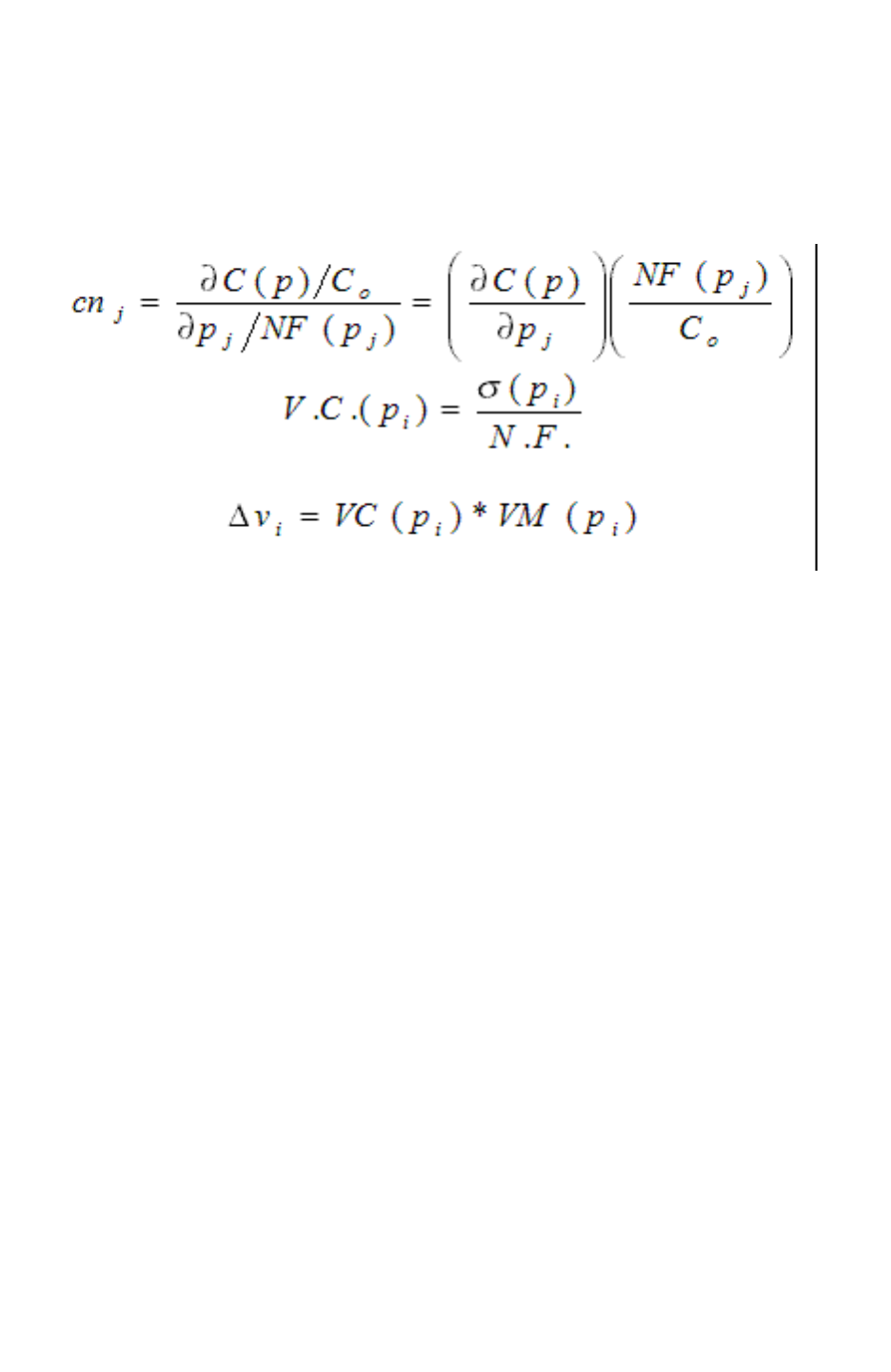
Chapter 11: Variation-Aware Extraction
SPEF Extensions 11-42
StarRC User Guide and Command Reference F-2011.06
StarRC User Guide and Command Reference Version F-2011.06
The nominalization_factor allows normalizing sensitivity coefficients by normalization
factors (NF): (1) mean of variation (2) sigma of variation (3) unity (no normalization). This
is done as follows:
Figure 11-16
where,
VC(pi) is the variation coefficient defined in the header section.
VM(pi) is the variation multiplier, with a conventional value of 3.
• The var_coeff is a floating-point number that specifies the coefficient of variation of the
parameter. Coefficient of variation is the ratio of the standard deviation to the mean of the
variation. Figure 11-5 explains this further.
• Two predefined parameters, CRT1 and CRT2, are used to specify temperature variation
coefficients. This is explained further in Figure 11-5.
• The global_temperature is a floating-point number that specifies the global temperature
for the process. Global temperature is used to calculate the effect of temperature on
interconnect resistance.

Chapter 11: Variation-Aware Extraction
SPEF Extensions 11-43
Chapter 11: Variation-Aware Extraction
SPEF Extensions 11-43
StarRC User Guide and Command Reference Version F-2011.06
Sensitivity Section
The *D_NET section stores the sensitivity coefficients for capacitances and resistances.
Table 11-6 Sensitivity Extension
Syntax Definition
cap_elem ::= cap_id node_name par_value [sensitivity]
res_elem ::= res_id node_name node_name par_value [sensitivity]
induc_elem ::= induc_id node_name node_name par_value [sensitivity]
sensitivity ::= *SC param_id:sensitivity_coeff {param_id:sensitivity_coeff}
param_id ::= integer
sensitivity_coeff ::= float
The sensitivity section specifies the following:
• The param_id is the index of a variation parameter. This is the number associated with
the parameter in the (*VARIATION_PARAMETERS) section.
• The sensitivity_coeff specifies the sensitivity coefficient. Each nonzero sensitivity
coefficient specifies how much the parasitic element is affected by the parameter. The
equations for the capacitances, resistance, and inductances are given in the following
section.
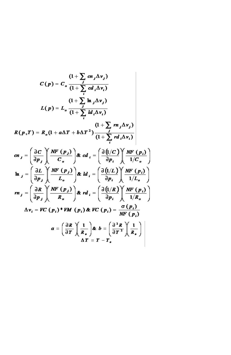
Chapter 11: Variation-Aware Extraction
SPEF Extensions 11-44
StarRC User Guide and Command Reference F-2011.06
StarRC User Guide and Command Reference Version F-2011.06
Capacitance and inductance are functions of process variation. Resistance is a function of
both process and temperature variation. If p denotes a vector of process parameters, pi (i=1
to N), and T is the temperature, then capacitance, inductance and resistance at an arbitrary
value of p and T are given by the following equations in Figure 11-17.
Figure 11-17 Equations for Resistance, Capacitance, and Inductance
The equation definitions are as follows:
• p is a vector of process parameters pi.
• T is the temperature.
• Co, Lo and Ro are capacitance, inductance and resistance at nominal values of p and T
respectively.
• cnj is the sensitivity coefficient for capacitance for N type variation parameter.

Chapter 11: Variation-Aware Extraction
SPEF Extensions 11-45
Chapter 11: Variation-Aware Extraction
SPEF Extensions 11-45
StarRC User Guide and Command Reference Version F-2011.06
• cdi is the sensitivity coefficient for capacitance for D type variation parameter.
• lnj is the sensitivity coefficient for inductance for N type variation parameter.
• ldi is the sensitivity coefficient for inductance for D type variation parameter.
• rnj is the sensitivity coefficient for resistance for N type variation parameter.
• rdi is the sensitivity coefficient for resistance for D type variation parameter.
• NF(pi) is the normalization factor for process parameter pi. It can take three values: mean
of the variation ((pi)), standard deviation of the variation ((pi)) or unity (1).
• VC(pi) is the variation coefficient of the process parameter pi.
• VM(pi) is the variation multiplier of the process parameter pi with a conventional value of
3 for a 3-sigma variation point.
• a is the sensitivity coefficient for resistance for CRT1 parameter.
• b is the sensitivity coefficient for resistance for CRT2 parameter.
• To is the global temperature.

Chapter 11: Variation-Aware Extraction
Variation-Aware Extraction Limitations 11-46
StarRC User Guide and Command Reference F-2011.06
StarRC User Guide and Command Reference Version F-2011.06
Header for SPEF Sensitivity Netlist
The following is an example of the enhanced header section for sensitivity.
*VARIATION_PARAMETERS
0 field_oxide_T X N X 0.080
1 poly_T D N X 0.030
2 poly_W D N X 0.0230
3 Diel1_T X N X 0.0500000
4 metal1_T D N X 0.050
5 metal1_W D N X 0.030
...
30 Diel10_T X N X 0.030
31 metal10_T D N X 0.030
32 metal10_W D N X 0.030
33 Diel11_T X N X 0.030
34 CRT1
35 CRT2 27.0000
The following is an example of a capacitance record with
sensitivity information in SPEF format:
*CAP
1 n1_n2:I 0.00471916 *SC 0:-0.005 1:0.029 3:0.026 4:0.146
5:0.089 6:0.074 7:-0.071 8:-0.015 12:-0.002 13:-0.003 15:
-0.002
The following is an example of a resistance record with
sensitivity information in SPEF format:
*RES
1 p1:A p3:Z 2.50093 *SC 4:0.900 5:0.531 34:0.00321 35:
-0.00021
*END
Variation-Aware Extraction Limitations
The following command file options are not supported with Variation-Aware extraction:
•EXTRACTION: RKC | FSCOMPARE
•FS_EXTRACT_NETS
•VIA_COVERAGE
•MERGE_MULTI_CORNER
•POWER_EXTRACT: RONLY
•INTRANET_CAPS

Chapter 11: Variation-Aware Extraction
Variation-Aware Extraction Limitations 11-47
Chapter 11: Variation-Aware Extraction
Variation-Aware Extraction Limitations 11-47
StarRC User Guide and Command Reference Version F-2011.06
Unsupported ITF Options
The following existing ITF options are not supported with sensitivity extraction:
•FREQUENCY
•FILL_RATIO/FILL_WIDTH/FILL_SPACING
•DROP_FACTOR

Chapter 11: Variation-Aware Extraction
Variation-Aware Extraction Limitations 11-48
StarRC User Guide and Command Reference F-2011.06
StarRC User Guide and Command Reference Version F-2011.06

12-1
12
Parasitic Extraction Integration With the
Virtuoso Custom Design Platform 12
This chapter describes the integration of StarRC with the Cadence® Virtuoso® custom
design platform, particularly the Cockpit GUI, in the following sections:
•Introduction to Virtuoso Integration
•Packaging, Installation, and Software Compatibility
•Flow Configuration and Related Files
•View Generation
•StarRC Parasitic Generation Cockpit GUI
•StarRC OA View Creation
•Parasitic Probing in the GUI
•Virtuoso Integration Skill Procedures and Related Variables
•General Notes

Chapter 12: Parasitic Extraction Integration With the Virtuoso Custom Design Platform
Introduction to Virtuoso Integration 12-2
StarRC User Guide and Command Reference F-2011.06
StarRC User Guide and Command Reference Version F-2011.06
Introduction to Virtuoso Integration
Virtuoso integration (VI) has three primary objectives as described in the following sections:
•Creating Parasitic Views for Netlisting and Simulation
•Generating Graphical Data From Extracted Polygons and Subnodes
•Probing Parasitics From Parasitic and Schematic Views
Creating Parasitic Views for Netlisting and Simulation
Parasitic view creation entails the generation of a Cadence DFII CDBA database (or Open
Access) parasitic view that instantiates all ideal and parasitic devices extracted by the IC
Validator > StarRC, Hercules > StarRC, or Calibre > StarRC flows. This view is compatible
with common netlist generation interfaces used within ADE.
Generating Graphical Data From Extracted Polygons and
Subnodes
Graphical data generation stores graphical data within the parasitic view that reflects
interconnect polygons used during parasitic extraction and parasitic subnode/resistance/
capacitance data output from the parasitic extraction. The following are generated:
• Polygons relevant to the parasitic extraction are stored within the parasitic view and are
annotated with schematic-referenced net names as established by the device extraction/
LVS tool
• Subnode markers representing interconnect discretization performed by StarRC
• Flylines representing parasitic resistors and capacitors link the subnode markers,
allowing you to visualize the relationship between extracted parasitics and physical
polygon locations
Probing Parasitics From Parasitic and Schematic Views
A probing utility is available to probe parasitic resistance and capacitance either within the
parasitic view or within the matching schematic view. This allows you to observe the
following parasitics interactively:
• Point-to-point resistance between subnodes and schematic terminals
• Total capacitance for a net, with or without a list of all constituent couplings

Chapter 12: Parasitic Extraction Integration With the Virtuoso Custom Design Platform
Packaging, Installation, and Software Compatibility 12-3
Chapter 12: Parasitic Extraction Integration With the Virtuoso Custom Design Platform
Packaging, Installation, and Software Compatibility 12-3
StarRC User Guide and Command Reference Version F-2011.06
• Total coupling capacitance between two nets
• Node search
• Parasitic RC search
• Cross probing between schematic view and parasitic view
Built-in highlighting capabilities enable you to highlight parasitic view nodes and polygons for
previously probed resistances or capacitances. The parasitic prober also provides the ability
to output probed parasitics to an ASCII report file and to annotate parasitic view total
capacitance values to an associated schematic view.
Packaging, Installation, and Software Compatibility
The following sections describe the setup of StarRC Virtuoso Integration:
explains the installation files, installation steps, necessary licensing, and software
compatibility.
Installation Files
Two components are necessary to run StarRC Virtuoso Integration:
• The rcskill.cxt Virtuoso binary context file for running StarRC Virtuoso Integration.
• StarRC base executable package
Installation Steps
The following installation steps activate the StarRC Virtuoso Integration functionality:
1. Ensure that StarRC (and Hercules, for Hercules/StarRC based flows) is contained in the
UNIX operating system execution path prior to invoking the Cadence tools.
2. Load the rcskill context file in the Command Interpreter Window (CIW) during Cadence
tool invocation.
loadContext(“rcskill.cxt”)
3. Initialize the context rcskill in the Virtuoso Command Interpreter Window.
callInitProc(“rcskill”)

Chapter 12: Parasitic Extraction Integration With the Virtuoso Custom Design Platform
Flow Configuration and Related Files 12-4
StarRC User Guide and Command Reference F-2011.06
StarRC User Guide and Command Reference Version F-2011.06
Note:
Steps 2 and 3 can be inserted into the .cdsinit file to be run automatically during Virtuoso
startup.
Licensing
The StarRC Virtuoso Integration functionality requires two StarRC license keys:
•STAR-RC2-NETLIST checked out during parasitic view generation in cdba — not
necessary for Open Access flow
•STAR-RC2-PROBER checked out during invocation of parasitic prober
To enable licensing for parasitic view generation or for parasitic prober use, the StarRC base
product must be available in the operating system execution path.
Software Compatibility
This code was developed and tested with Virtuoso icfb version 5.1.41.usr4 (for Open
Access, version 6.1x) of the Cadence Virtuoso Custom Design Platform.
Flow Configuration and Related Files
The Virtuoso Integration (VI) Cockpit is a GUI that lets you run a flow that reads schematic
and layout views to generate parasitic views. There are three main stages in this flow, as
shown in Figure 12-1:
• Layout versus schematic (LVS) — You can use IC Validator, Hercules, or Calibre LVS
tools.
• Parasitic extraction — You can adjust StarRC commands without a star_cmd input file.
• Output — You can select the output format and other options.
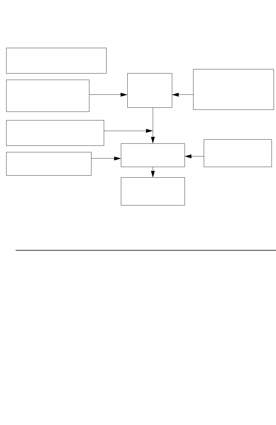
Chapter 12: Parasitic Extraction Integration With the Virtuoso Custom Design Platform
Flow Configuration and Related Files 12-5
Chapter 12: Parasitic Extraction Integration With the Virtuoso Custom Design Platform
Flow Configuration and Related Files 12-5
StarRC User Guide and Command Reference Version F-2011.06
Figure 12-1 Parasitic Extraction Flow in Virtuoso
Input files for the entire flow:
Device mapping file
Layer mapping file
Layout View
Schematic view
Layout GDSII
Schematic netlist
IC Validator (icv_runset_report_file)
Hercules (EXT VIEW)
Calibre (CCI database)
nxtgrd
StarRC mapping file
LVS
(IC Validator,
Hercules,
Calibre)
StarRC
Output files:
parasitic view
netlist
Control files:
Runset
oa_layer_map
GDS_OUT_SETTINGS_FILE
CDL_OUT_SETTINGS_FILE
control files:
additional star_cmd files
skip_cell_list
Note:
The device mapping file, layer mapping file, and skip cell list are special files for Virtuoso
Integration. All other files are standard input files for LVS tools and StarRC.
Preparing an Ideal and Parasitic Device DFII Mapping File
In the StarRC > Virtuoso Integration flow, you must provide a device mapping file that maps
ideal and parasitic devices in the StarRC parasitic output to the corresponding device
symbols in the Virtuoso symbol libraries. This file contains an entry for every ideal and

Chapter 12: Parasitic Extraction Integration With the Virtuoso Custom Design Platform
Flow Configuration and Related Files 12-6
StarRC User Guide and Command Reference F-2011.06
StarRC User Guide and Command Reference Version F-2011.06
parasitic device model that exists in the parasitic output. It also provides the ability to remap
standard StarRC DSPF device property names to user-specified property names. The
following syntax shows the entry format of a single line:
RC_model_name dfii_lib_name dfii_cell_name dfii_view_name
dfii_symbol_pin_1 dfii_symbol_pin_2 [dfii_symbol_pin_3] ...
[CALLBACK = procedureSymbol] [PROPMAP DSPFprop1 = ADEprop1...]
Argument Definition
RC_model_name StarRC output model name; corresponds to the schematic device
model name when XREF is activated. Note that keywords pres and
pcap are used for parasitic resistors and capacitors.
dfii_lib_name Name of Virtuoso library containing the corresponding device symbol.
dfii_cell_name Cell name of Virtuoso device symbol.
dfii_view_name View name of Virtuoso device symbol.
dfii_symbol_pin_N Name of the pin inside Virtuoso device symbol that corresponds to
terminal #N in an analogous DSPF-based StarRC parasitic output.
Note that the ordering of Virtuoso symbol pin names inside the device
mapping file must match the StarRC netlist pin order for the device type
of interest. The keyword nil can be specified for any dfii_symbol_pin
to indicate that the terminal #N in the StarRC parasitic output should be
ignored when connecting the corresponding Virtuoso library symbol.
procedureSymbol Symbol name of an optional user-defined callback procedure that is
executed prior to instantiating a device of type RC_model_name.
DSPFpropN = ADEpropN Optional mapping of standard DSPF property name into a
user-specified property name. Note that keyword PROPMAP is
required before the first property name mapping entry. Setting
DSPFpropN = nil prevents the listed property from being annotated to
the device symbol.
Note:
Two slashes (//) serve as a comment delimiter in the device mapping file.
An example DFII symbol mapping file is illustrated as follows:
MNM devlib nmos4 ivpcell D G S B PROPMAP l=simL w=simW
MPM devlib pmos4 ivpcell D G S B PROPMAP l=simL w=simW
pres Lib presistor auLvs PLUS MINUS CALLBACK=insertPresProp
pcap Lib pcapacitor auLvs PLUS MINUS CALLBACK=insertPcapProp
pind analogLib pinductor symbol PLUS MINUS
pmind analogLib pmind

Chapter 12: Parasitic Extraction Integration With the Virtuoso Custom Design Platform
Flow Configuration and Related Files 12-7
Chapter 12: Parasitic Extraction Integration With the Virtuoso Custom Design Platform
Flow Configuration and Related Files 12-7
StarRC User Guide and Command Reference Version F-2011.06
Note:
Parasitic elements pres, pcap, pind, pmind should use the lib/cell/view from analogLib.
For example,
pres analogLib presistor auLvs PLUS MINUS
pcap analogLib pcapacitor auLvs PLUS MINUS
pind analogLib pinductor symbol PLUS MINUS
pmind analogLib pmind
However, if a parasitic element name conflicts with a user-defined device name, Virtuoso
Integration provides the following parasitic element names:
•pres[starrc]
•pcap[starrc]
•pind[starrc]
•pmind[starrc]
When pres and pres[starrc] both appear in the device mapping file, pres[starrc]
overrides pres as the parasitic element name.
Note:
For information about the CALLBACK keyword, see See “Instance Creation Callback” on
page 12-22.
Preparing a Runset-Layer-to-DFII Layer Mapping File
The StarRC > Virtuoso Integration flow allows you to provide a layer mapping file that maps
StarRC runset layers from the StarRC mapping file to corresponding Virtuoso technology file
layers. This allows polygons, ports, and subnodes from the parasitic extraction to be stored
within the StarRC generated DFII parasitic view.
Each MAPPING_FILE layer that you want to store in the parasitic view should be specified in
the DFII layer mapping file and should be mapped to an existing layer-purpose pair from the
Virtuoso technology library for the library being used. The DFII mapping file also lets you
specify (optionally) DFII layer-purpose pairs for subnode markers generated by StarRC to
represent parasitic top-level ports (*|P), instance ports (*|I), and subnodes (*|S).

Chapter 12: Parasitic Extraction Integration With the Virtuoso Custom Design Platform
Flow Configuration and Related Files 12-8
StarRC User Guide and Command Reference F-2011.06
StarRC User Guide and Command Reference Version F-2011.06
The format of this file is as follows:
RC_MAPPING_FILE_layer
dfii_polygon_layer_name dfii_polygon_purpose_name
[ dfii_port_layer_name dfii_port_purpose_name
[ dfii_subnode_layer_name dfii_subnode_purpose_name]]
RC_MAPPING_FILE_layer
dfii_polygon_layer_name dfii_polygon_purpose_name
[ dfii_port_layer_name dfii_port_purpose_name
[ dfii_subnode_layer_name dfii_subnode_purpose_name]]
. . .
Argument Definition
RC_MAPPING_FILE_layer Database layer name from the CONDUCTING_LAYERS,
VIA_LAYERS, or MARKER_LAYERS sections of the StarRC
MAPPING_FILE.
dfii_polygon_layer_name
dfii_polygon_purpose_name
Layer name and purpose name from the DFII technology
library, which forms the layer-purpose pair to which
RC_MAPPING_FILE_layer polygons should be written. If
either entry is not specified or are specified as nil, polygons
corresponding to the RC_MAPPING_FILE_layer is not
generated within the parasitic view.
dfii_port_layer_name
dfii_port_purpose_name
Layer name and purpose name from the DFII technology
library, which forms the layer-purpose pair to which parasitic
port markers corresponding to RC_MAPPING_FILE_layer
interconnect should be written. Parasitic port markers are
analogous to *|P nodes and .SUBCKT header nodes that
would appear in the DSPF output. If either entry is not
specified or are specified as nil, ports corresponding to the
RC_MAPPING_FILE_layer is not generated within the
parasitic view.
dfii_subnode_layer_name
dfii_subnode_purpose_name
Layer name and purpose name from the DFII technology
library, which forms the layer-purpose pair to which parasitic
subnode markers corresponding to
RC_MAPPING_FILE_layer should be written. Parasitic
subnode markers are analogous to *|l and *|S nodes that
would appear in a DSPF output. If not specified or if
specified as nil, subnodes corresponding to the
RC_MAPPING_FILE_layer is not generated within the
parasitic view.
Note:
Use two slashes (//) to indicate comments in the layer mapping file.

Chapter 12: Parasitic Extraction Integration With the Virtuoso Custom Design Platform
Flow Configuration and Related Files 12-9
Chapter 12: Parasitic Extraction Integration With the Virtuoso Custom Design Platform
Flow Configuration and Related Files 12-9
StarRC User Guide and Command Reference Version F-2011.06
Polygons are written to the parasitic view only if the IC Validator, Hercules, or Calibre
database layer of the polygon is mapped to a valid Virtuoso layer-purpose pair in the DFII
layer mapping file. If a IC Validator, Hercules, or Calibre database layer is not listed in the
mapping file, no polygons corresponding to that layer are stored in the parasitic view. If the
file is not supplied at all, no graphical data is written.
Because all ports and subnodes correspond to specific database layers in standard StarRC
outputs, separate layer-purpose pairs are used in the DFII layer mapping file for the
generation of port and subnode markers relative to the generation of interconnect polygons.
Because port and subnode markers enable point-to-point resistance probing with the
StarRC parasitic probing utility, failure to include layer-purpose pairs for port/subnode
markers prohibits the probing of point-to-point resistance between nodes lacking such
markers.
The following additional restriction also applies to this mapping file: no layer-purpose pair
can be used both as a polygon LPP and a port and subnode LPP. If an LPP used as a
polygon LPP is found in the mapping file, then that same LPP is disregarded if subsequently
listed in the mapping file as a port or subnode LPP. Likewise, if an LPP used as a port or
subnode LPP is found in the mapping file, then that same LPP is disregarded if
subsequently listed in the mapping file as a polygon LPP.
The following example shows a sample DFII layer mapping file:
M1 metal1 net metal1 port metal1 node
fpoly poly net poly port poly node
ngate poly net poly port poly node
pgate poly net poly port poly node
diff_con cc net nil nil cc node
subtie pad drawing nil nil pad node
welltie pad drawing nil nil pad node
nsd nactive net nactive port nactive node
psd pactive net nactive port pactive node
m1_pio_marker nil nil metal1 port nil nil
m2_pio_marker nil nil metal2 port nil nil
m3_pio_marker nil nil metal3 port nil nil
poly_marker nil nil poly port nil nil
Customizing an LVS Device Extraction Job
Virtuoso Integration helps you to execute LVS device extraction jobs for three LVS tools: IC
Validator, Hercules, and Calibre. Choose your LVS tool from the Flow menu. After you
specify an LVS flow, the Device Extraction tab transforms to accept your input.
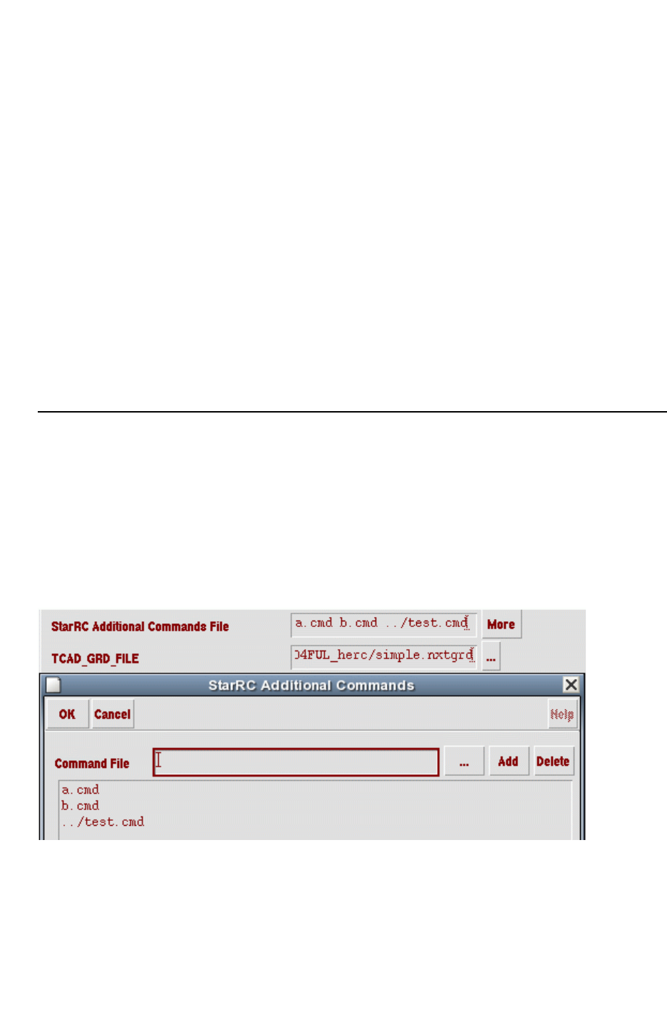
Chapter 12: Parasitic Extraction Integration With the Virtuoso Custom Design Platform
Flow Configuration and Related Files 12-10
StarRC User Guide and Command Reference F-2011.06
StarRC User Guide and Command Reference Version F-2011.06
When you select an LVS tool, you must provide a runset for all LVS tools and a query_cmd
file for the CCI flow. You can customize many items in the Device Extraction tab. Virtuoso
Integration follows a different procedure for different tools:
• IC Validator (ICV) – Regardless of the setting in the user-provided runset, Virtuoso
Integration defaults ICV_RUNSET_REPORT_FILE to pex_runset_report_file unless you
provide a new name in the Cockpit field.
• Hercules – Virtuoso Integration automatically parses the runset for the location of the
extract view.
If multiple WRITE_EXTRACT_VIEW commands exist in the runset, Virtuoso Integration uses
the last one, regardless of the switch setting inside the runset.
• Calibre – Virtuoso Integration automatically parses the runset for the svdb directory.
If multiple MASK SVDB DIRECTORY commands exist in the Calibre runset, Virtuoso
Integration uses only the first one, regardless of the switch setting inside the runset.
Customizing a StarRC Parasitic Extraction Job
You must provide a standard nxtgrd mapping file for Virtuoso Integration for parasitic
extraction. To customize your StarRC job, you can
• Add a user-defined star_cmd file through the StarRC Additional Commands dialog box,
shown in Figure 12-2
• Use the Virtuoso Integration dialog box settings
Figure 12-2 Adding or Deleting Additional StarRC Command Files

Chapter 12: Parasitic Extraction Integration With the Virtuoso Custom Design Platform
View Generation 12-11
Chapter 12: Parasitic Extraction Integration With the Virtuoso Custom Design Platform
View Generation 12-11
StarRC User Guide and Command Reference Version F-2011.06
The priority (from highest to lowest) of StarRC commands follows this order:
1. Required, native Virtuoso Integration commands
2. Additional star_cmd file commands
3. Additional settings in Virtuoso Integration dialog boxes
Note:
Use the view_cmd or oa_cmd commands in your Virtuoso Integration run directory to list
the StarRC commands that Virtuoso Integration has inserted into your job.
View Generation
View generation is described in the following sections:
•Net and Instance Name Conventions
•Port and Terminal Connectivity Characteristics
•Instance Property Annotation from the Schematic View
•Subnode Marker and Parasitic Device Visualization
•User-Defined Callbacks
•Callback Flow Example
Net and Instance Name Conventions
The StarRC parasitic view abides by the following default naming conventions for nets and
instances. These naming conventions are intended to exhibit uniformity with DFII naming
rules and ADE naming conventions for schematic-based parasitic simulation analysis. As
such, these naming conventions are unique to Virtuoso Integration and different from
standard StarRC DSPF netlist conventions:
The pipe character (|) serves as the default hierarchical delimiter for the parasitic view.
During schematic view netlisting for LVS and later StarRC schematic-based
cross-referencing (see StarRC command XREF in the StarRC Reference Manual), the
schematic view netlist generator may append prefixes to instance names according to the
conventions of the netlist generator. These prefixes, commonly called SPICE cards,
propagate into the StarRC parasitic netlist when XREF is activated. However, these extra

Chapter 12: Parasitic Extraction Integration With the Virtuoso Custom Design Platform
View Generation 12-12
StarRC User Guide and Command Reference F-2011.06
StarRC User Guide and Command Reference Version F-2011.06
instance prefixes are not present in the original schematic view and may impede the ability
of ADE to perform full parasitic-view to schematic-view matching during simulation analysis.
As such, StarRC Virtuoso Integration removes these instance name prefixes as follows:
• Always strip initial the SPICE card from ideal (not parasitic) instance names because
StarRC adds this card directly.
• For hierarchical instance names, including those preceding internal net names:
• Decompose the name according to the hierarchical delimiter.
• If a decomposed instance name begins with X anywhere in the decomposed instance
list, then always strip the X.
• If the last name in the decomposed instance (often a primitive) begins with two
occurrences of the same character, strip one of them.
Table 12-1 Examples of Removal of Instance Name Prefixes
StarRC DSPF instance name Parasitic view instance name
XI0/XI5/M1 >I0/I5/1
XI0/XI5/MM1 >I0/I5/1
I0/I5/M1 >I0/I5/M1
I0/I5/MM1 >I0/I5/M1
XI0/X15/net1 >I0/I5/net1
I0/I5/net1 >I0/I5/net1
• If the last name in the decomposed instance (often a primitive) begins with a SPICE card
character, such as X or M that character is always stripped.
• The naming convention assumptions for input data are as follows:
• Your schematic netlist generator always appends an X card to nonprimitive cell
instances. For example, instances in the middle of a flattened hierarchical name.
• No instance name inside the schematic view begins with X.
• No instance name inside the schematic view begins with two occurrences of the same
letter, such as the schematic view instance MM0.

Chapter 12: Parasitic Extraction Integration With the Virtuoso Custom Design Platform
View Generation 12-13
Chapter 12: Parasitic Extraction Integration With the Virtuoso Custom Design Platform
View Generation 12-13
StarRC User Guide and Command Reference Version F-2011.06
Occurrences of bus bits (name<#>) are renamed if the bus bit is embedded within the
middle of a hierarchical instance name. In such cases, the embedded string <#> is replaced
with the embedded string (#). An example where this behavior can occur is an iterated
schematic instance name embedded in a hierarchical name, for example,
[0|I1|I2<3>|net4 becomes I0|I1|I2(3)|net4.
Port and Terminal Connectivity Characteristics
StarRC reads the following information from a pre-existing view of the extracted cell and
populates the same information within the parasitic view:
•netExpression parameters
StarRC parses all terminals and signals in the ports global nets view (default is layout)
and records any netExpression parameters. If a terminal and a signal have the same
name and both have individual netExpressions, then only the netExpression of the
terminal is recorded. The netExpressions are then propagated into the new parasitic view
as follows:
• If a terminal in the parasitic view has a name matching a terminal/signal name for
which a netExpression was read from the existing cell, then the netExpression is
added to that terminal.
• Otherwise, if a signal in the parasitic view has a name matching a cached terminal/
signal name for which a netExpression was read from the existing view, then the
netExpression is added to that signal.
Note:
Terminals in the parasitic view are dictated by the presence of ports in the StarRC
parasitic output which are analogous to *|P nodes or .SUBCKT headers in a DSPF
netlist. If no such nodes exist, then StarRC does not create any terminals in the
parasitic view and no netExpression parameters are transferred.
•Direction parameters for terminals
StarRC parses all terminals in the preexisting view and records any direction parameters
listed on any terminals. If a terminal is found in the parasitic view bearing the same name
as a terminal with a direction parameter in the preexisting view, then StarRC attaches the
same direction parameter string to the matching terminal in the parasitic view.
•isGlobal parameters for signals
StarRC parses all signals in the preexisting view and records any isGlobal parameters
listed on any signals. If a signal is found in the parasitic view bearing the same name as
a signal with an isGlobal parameter in the preexisting view, then StarRC attaches the
same isGlobal parameter string to the matching terminal in the parasitic view. Note that
isGlobal parameters is propagated only for signals to which no terminals bearing
netExpression parameters are attached. The preexisting view from which the previous

Chapter 12: Parasitic Extraction Integration With the Virtuoso Custom Design Platform
View Generation 12-14
StarRC User Guide and Command Reference F-2011.06
StarRC User Guide and Command Reference Version F-2011.06
connectivity and terminal information is read is specified by the corresponding field in the
StarRC parasitic generation cockpit or by the corresponding argument to
RCGenParaViewBatch.
When updating a terminal view, StarRC gathers terminal information from a given
symbolic view and parses all signals in the parasitic view to check for floating nets on
device instance terminals. If a net name matches one terminal name on the symbol view,
StarRC creates the name as the terminal name for the parasitic view.
•Power net name for the ports
StarRC creates the ports of the parasitic view as the input database top-block port
names.
Sometimes, you might want to integrate the parasitic view to another circuit, some
additional power pins are necessary for the parasitic view to connect to upper views. If
additional power port names are necessary for the parasitic view, you can use the option
on the Cockpit: Reading Pin from symbol, to assign an additional (symbol) view for
StarRC to extract the additional power net names from the ports of the given view. Then,
create new ports with the name for the parasitic view.
Instance Property Annotation from the Schematic View
There are properties on the instance inside the parasitic views. The properties can be
grouped mainly into 2 groups. Property names and values come from schematic view and
property names or values come from LVS tool result. There could also have some
user-specified subtle usages such as copy 1 property value to multiple properties names;
delete or make nil for a property; change the property names; create new properties, in
Virtuoso Integration flow. StarRC needs to set the property name and values need to in
parasitic view for simulator to work correctly. Thus, StarRC has developed strategies and
syntax for the instance property annotation flow.
The Default Mode of StarRC Instance Property Annotation
Use the XREF:YES command when you want StarRC to generate a parasitic view
constructed by the layout view and the extracted netlist from the LVS tool, with the schematic
net name/instance name/instance property attached.
The following options control the default behaviors of instance property annotation:
• In the .snps_settings file
CARRY_SCH_PROPERTY : [YES]|NO
• In RCGenParaViewBatch2
carry_sch_property : [t]/nil

Chapter 12: Parasitic Extraction Integration With the Virtuoso Custom Design Platform
View Generation 12-15
Chapter 12: Parasitic Extraction Integration With the Virtuoso Custom Design Platform
View Generation 12-15
StarRC User Guide and Command Reference Version F-2011.06
You may encounter the following issues:
• Some properties only exist in the schematic view.
Because LVS tools do not take schematic views as input, LVS mainly uses the CDL netlist
generated from the schematic view. Some properties might not be netlisted in the CDL
netlist procedure. Also, LVS tools only output the properties that have been defined in the
LVS runset to LVS results database. Therefore, StarRC must carry those properties and
their values from the schematic to the parasitic view.
• Some property names are used in both the schematic view and LVS results.
In this case, the layout view property values override the schematic view property values.
For example, a schematic view contains the following two instances:
I1: p1=s1 p2=s1 p3=s1 p4=s1
I2: p1=s2 p2=s2 p3=s2 p4=s2
The LVS tool extracts the following information:
I1: p3=l1 p4=l1 p5=l1
I2: p3=l2 p4=l2 p5=l2
In the DFII library, the cells I1 and I2 are used in the cell m.
m: p1=0 p2=0 p3=0 p4=0
When CARRY_SCH_PROPERTY:YES is specified, the parasitic view contains the following:
I1: p1=s1 p2=s1 p3=l1 p4=l1 p5=l1
I2: p1=s2 p2=s2 p3=l2 p4=l2 p5=l2
When CARRY_SCH_PROPERTY:NO is specified, the parasitic view contains the following:
I1: p1=0 p2=0 p3=l1 p4=l1 p5=l1
I2: p1=0 p2=0 p3=l2 p4=l2 p5=l2

Chapter 12: Parasitic Extraction Integration With the Virtuoso Custom Design Platform
View Generation 12-16
StarRC User Guide and Command Reference F-2011.06
StarRC User Guide and Command Reference Version F-2011.06
Property Mapping
This section describes syntax that you can use to adjust the property annotation behaviors.
These behaviors are applied to all properties, whether they are in the schematic view or LVS
results.
Syntax Description
dspfProp Property name or value in the StarRC DSPF result, usually from
LVS results
schProp Property name or value In the schematic view
cdfProp CDF defined property name
preProp all property name or value before StarRC parasitic view
generation
paraProp property name or value in the final parasitic view
Property Mapping Behavior
A=B
In the instance of the parasitic view, paraProp B gets its value from preProp A. Also,
paraProp A value comes from preProp A. This is equivalent to A=A and A=B.
A=B and A=C
Similar to A=B, but with multiple usage.
A>B
paraProp B gets its value from preProp A.
Also, paraProp A is removed.
if A is a cdfProp and can't be removed, the value is set to nil such that A=nil and A=B.
A=”constant”
Assigns a constant to paraProp A, no matter what is its original value. If there is no
preProp name A, then StarRC creates a paraProp A with the assigned value.
For example, A="10"
A=nil
Remove paraProp A
If A is a cdfProp and cannot be removed, the value of A is assigned to be nil.

Chapter 12: Parasitic Extraction Integration With the Virtuoso Custom Design Platform
View Generation 12-17
Chapter 12: Parasitic Extraction Integration With the Virtuoso Custom Design Platform
View Generation 12-17
StarRC User Guide and Command Reference Version F-2011.06
PROPMAP Case Sensitivity
In the Cockpit dialog box, as shown in Figure 12-5 on page 12-26: PropMap Case Sensitive
option.
In the .snps_settings file: PROPMAP_CASE_SENSITIVE : YES | NO
In RCGenParaViewBatch2:
?propmap_case_sensitive t|[nil]
This option controls the matching behavior of PROPMAP.
For example,
PROPMAP ABC=abc
When PROPMAP_CASE_SENSITIVE : YES
If there are 2 preProp names as ABC and abc, only ABC is copied to abc.
preProp : ABC=10 abc=100
paraProp: ABC=10 abc=10
When PROPMAP_CASE_SENSITIVE : NO
preProp: Abc=10
StarRC still uses the Abc value as ABC to write to abc.
paraProp: Abc=10 abc=10
Instance Name Matching Rule
StarRC performs instance property annotation by finding the corresponding instance in
schematic view to do the annotation. Because the instance name might be changed by
netlist processing or LVS tool renaming behaviors, it is not easy to find the original schematic
view instance name to determine schProp for annotation. StarRC adopts such a heuristic
way to find instance in schematic view to annotate properties. (See See “Net and Instance
Name Conventions” on page 12-11.) StarRC also performs SPICE card stripping to
schematic view instances according the convention rule, then find the corresponding
instance in schematic view to have its properties for annotation.
Note:
When Virtuoso Integration can't find a certain schematic view instance to annotate
properties to parasitic view instances, StarRC creates the schematic_info_log file to
report failed instances.

Chapter 12: Parasitic Extraction Integration With the Virtuoso Custom Design Platform
View Generation 12-18
StarRC User Guide and Command Reference F-2011.06
StarRC User Guide and Command Reference Version F-2011.06
Subnode Marker and Parasitic Device Visualization
The runset layer to DFII layer mapping file discussed in “Preparing a Runset Layer to DFII
Layer Mapping File” on page 12-7 provides the ability to write extracted polygon data to the
parasitic view. Besides the storage of interconnect polygons, graphical data including
subnode markers, port markers, and pres/pcap flylines are also written to the parasitic view.
A subnode is defined as any *|I or *|S node that would normally occur in a standard StarRC
DSPF parasitic netlist. A port is analogous to any *|P node or any entry in the .SUBCKT
header line of a standard DSPF parasitic netlist. These nodes represent the electrical
connection points for parasitic devices and ideal devices. Every subnode has unique x-y
coordinates as well as an extracted database layer on which the subnode lies. Using this
information, it is possible to represent the subnodes in the parasitic view with small marker
shapes placed at their corresponding x-y coordinates.
The DFII layer-purpose pair to which a port or subnode marker is written is defined in the
DFII layer mapping file described in “Preparing a Runset Layer to a DFII Layer Mapping File”
on page 12-7. Only ports or subnodes whose corresponding database layers are listed in
the DFII layer mapping file has markers written to the parasitic view. The default size of all
subnode markers is 0.1 m x 0.1 m. This default size can be changed by adding an entry to
the cockpit configuration file as follows:
SUBNODE_SIZE: subnode_side_length_in_microns
Likewise, graphical data is also stored for parasitic resistors and coupling capacitors in the
form of flylines between subnodes. Flylines are not stored for grounded capacitors because
such capacitors by definition do not terminate at a finite x-y coordinate on an interconnect
polygon. These flylines are annotated with two properties: the parasitic instance name and
the parasitic value. All flylines for parasitic resistors are written to a single Virtuoso
layer-purpose pair. Likewise, all flylines for parasitic capacitors are written to a separate
Cadence layer-purpose pair. These layer-purpose pairs can be listed in the DFII layer
mapping file as follows, using the special tags *pres and *pcap.
// <*pres or *pcap> dfii_polygon_lyr dfii_polygon_purpose
*pres poly net
*pcap metal1 net
If no *pres and *pcap lines are defined in the DFII layer mapping file, StarRC uses the
following default mapping:
*pres y0 drawing
*pcap y1 drawing
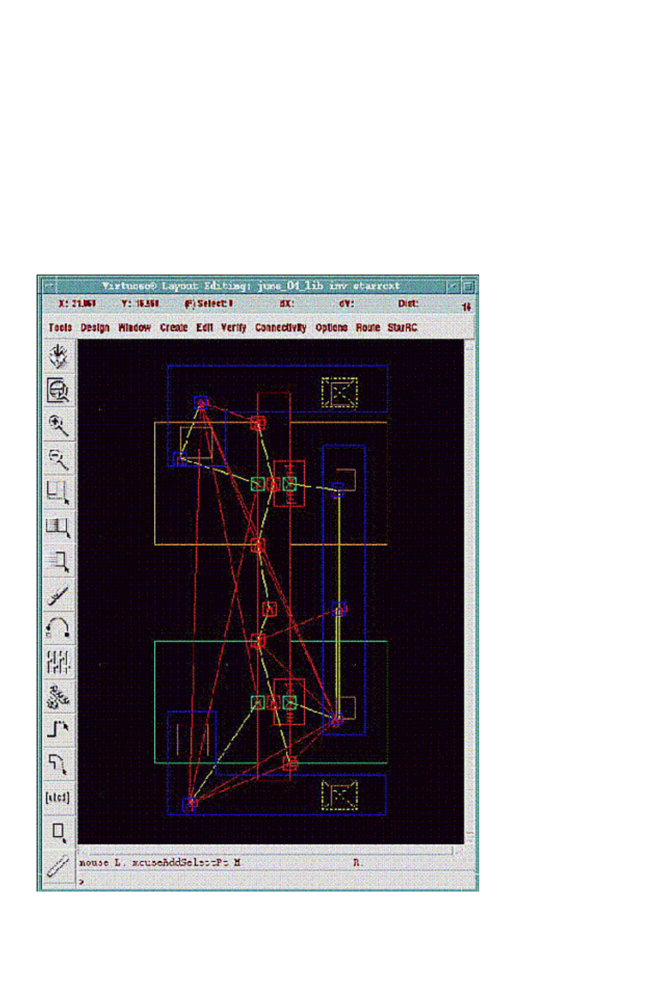
Chapter 12: Parasitic Extraction Integration With the Virtuoso Custom Design Platform
View Generation 12-19
Chapter 12: Parasitic Extraction Integration With the Virtuoso Custom Design Platform
View Generation 12-19
StarRC User Guide and Command Reference Version F-2011.06
Note:
A flyline is stored in the parasitic view only if both of its nodes have markers stored in the
parasitic view. Likewise, port/subnode markers are only stored for runset layers that are
mapped in the DFII layer mapping file. Hence, the number of parasitic resistor and
capacitor flylines present in the parasitic view is a direct function of the runset layer to
DFII layer mappings in the DFII layer mapping file.
An illustration of a StarRC parasitic view containing subnode markers and flylines is shown
in Figure 12-3.
Figure 12-3 StarRC Parasitic View With Port and Subnode Markers and Pres/Pcap Flylines

Chapter 12: Parasitic Extraction Integration With the Virtuoso Custom Design Platform
View Generation 12-20
StarRC User Guide and Command Reference F-2011.06
StarRC User Guide and Command Reference Version F-2011.06
User-Defined Callbacks
You can customize StarRC parasitic view generation through the use of user-defined
callbacks. Four types of callbacks are discussed in the following sections:
•Pre-Extraction Callback
•View Preprocessing Callback
•View Postprocessing Callback
•Instance Creation Callback
Pre-Extraction Callback
The pre-extraction callback is a SKILL expression that is loaded and executed prior to the
beginning of StarRC view generation. This callback interface enables you to customize any
tasks that are on StarRC inputs before StarRC starts extraction. If LVS and StarRC are used
consecutively, then this pre-extraction callback is executed after LVS finishes and before
StarRC starts. The string expression can be directly specified within the appropriate field
inside the StarRC Cockpit and can be automatically loaded from the cockpit configuration
file as follows:
PRE_EXTRACTION_CALLBACK: cmdstring
You can easily configure the pre-extraction callback for existing LVS results by using the
following predefined symbols:
Symbol Definition
lvs_rundir LVS Run Directory
starrc_rundir StarRC Extraction Directory
cci_runset Calibre runset file for LVS
cci_query_file Calibre query file for CCI database
herc_runset Hercules runset for LVS
The following example shows how to specify PREPROCESS_CALLBACK inside the cockpit
configuration file:
PRE_EXTRACTION_CALLBACK: UserPreExtractionCB(lvs_rundir cci_query_file)

Chapter 12: Parasitic Extraction Integration With the Virtuoso Custom Design Platform
View Generation 12-21
Chapter 12: Parasitic Extraction Integration With the Virtuoso Custom Design Platform
View Generation 12-21
StarRC User Guide and Command Reference Version F-2011.06
This example executes a call to your defined procedure UserPreExtractionCB, which uses
the lvs_rundir and cci_query_file symbols as arguments. These symbols are only valid
if the LVS process is already included in the tasks.
View Preprocessing Callback
The view preprocessing callback is a SKILL expression that is loaded and executed after
StarRC extraction and prior to the beginning of parasitic view generation. The string
expression can be directly specified within the appropriate field inside the StarRC Cockpit
and can be automatically loaded from the cockpit configuration file. See “Populating the
Cockpit Fields Automatically” on page 12-27. For example,
PREPROCESS_CALLBACK: cmdstring
The cmdstring parameter can be any type of procedure call or SKILL expression. Three
symbols exist in the scope where cmdstring is evaluated and can be used within
cmdstring as variables or procedure arguments:
Symbol Definition
cellview A dbObject of new empty parasitic cell view before it is populated with parasitics and
physical shapes.
cmdfile String object representing the name of the StarRC command file.
usersym Generic symbol which you can set and then evaluate in downstream callback code.
The following example shows how to specify PREPROCESS_CALLBACK inside the cockpit
configuration file:
PREPROCESS_CALLBACK: UserPreProcCallback( cellview cmdfile )
This example executes a call to your defined procedure UserPreProcCallback which uses
the cellview and cmdfile symbols as arguments.
View Postprocessing Callback
The view postprocessing callback is a SKILL expression that is loaded and executed after
the parasitic cell view is populated with parasitics and shapes but before it is saved and
closed. The string expression can be directly specified within the appropriate field inside the
StarRC Cockpit and can be automatically loaded from the cockpit configuration file as
follows:
POSTPROCESS_CALLBACK: cmdstring
The cmdstring parameter can be any type of procedure call or SKILL expression.

Chapter 12: Parasitic Extraction Integration With the Virtuoso Custom Design Platform
View Generation 12-22
StarRC User Guide and Command Reference F-2011.06
StarRC User Guide and Command Reference Version F-2011.06
Three symbols exist in the scope where cmdstring is evaluated and can be used within
cmdstring as variables or procedure arguments:
Symbol Definition
cellview A dbObject of the parasitic cell view after it is populated with parasitics and physical
shapes.
cmdfile String object representing the name of the StarRC command file.
usersym Generic symbol that is set by you in upstream code and then evaluated inside the
postprocessing callback.
The following example shows how to specify POSTPROCESS_CALLBACK inside the cockpit
configuration file:
POSTPROCESS_CALLBACK: UserPostProcCallback( cellview usersym )
This example executes a call to your defined procedure UserPostProcCallback, which
uses the cellview and usersym symbols as arguments.
Instance Creation Callback
You can use an instance creation callback procedure to manipulate instance parameter lists,
names, coordinate locations, and orientations prior to placing the instance. A procedure
name can be specified on a model-by-model basis in the DFII_DEVICE_MAP file using the
optional parameter CALLBACK=procedureSymbol . (See “Flow Configuration and Related
Files” on page 12-4.) This procedure is invoked prior to creating an instance of the
corresponding model type.
The user-defined procedure identified by procedureSymbol must be defined to accept two
arguments as follows:
Property Definition
argument_1 A defstruct instance that points to a property list of all properties specific to the
instance.
argument_2 A generic symbol that you can manipulate within the view-level preprocessing/
postprocessing procedures and then call within the instance-level procedures;
corresponds to the symbol usersym within the code scope in which the
preprocessing/postprocessing/instance-level procedures are invoked.

Chapter 12: Parasitic Extraction Integration With the Virtuoso Custom Design Platform
View Generation 12-23
Chapter 12: Parasitic Extraction Integration With the Virtuoso Custom Design Platform
View Generation 12-23
StarRC User Guide and Command Reference Version F-2011.06
The defstruct property list for argument_1 is as follows:
argument_1 Property Definition
inst Instance name of device; type = string.
coordlist x-y coordinates of the instance; format is list (xcoord ycoord).
orientation Orientation of instance (for example, R0, R90); type = string.
propList List of parameters that are being annotated to the instance; format is
list(list(t_propname1 t_propType1 g_value1)
list(t_propName2 t_propType2 g_value2) ...)
instNodes Read-only list of terminal node names; type=list. An example is:
list (“M1|DRN” “M1|GATE” “M1|DRN” “M1|BULK”)
Callback Flow Example
Assume that you wish to use user-defined callback procedures to instantiate a new
user-defined property on each device of type MPM, depending on a setting in the StarRC
command file.
The following example shows user-defined callback definitions:
; set via_cap property on disembodied property list if
; EXTRACT_VIA_CAPS was used in the StarRC run
procedure( UserParseCmdFile( cmdfile usersym )
let( ( str stream fields )
stream = infile( cmdfile )
while( gets( str stream )
fields = parseString(str,": \n")
if( nth(0 fields) == "EXTRACT_VIA_CAPS" &&
nth(1 fields) == "YES"
then putprop( usersym t 'via_cap )
)
)
)
)
procedure( UserAddEVCProp( dev usersym )
if( usersym->via_cap
then dev->propList =
cons( list("viacap" "string" "TRUE" ) dev->propList )
)

Chapter 12: Parasitic Extraction Integration With the Virtuoso Custom Design Platform
Temperature Sensitivity 12-24
StarRC User Guide and Command Reference F-2011.06
StarRC User Guide and Command Reference Version F-2011.06
Specify the instance creation callback within DFII_DEVICE_MAP as follows:
MPM devlib pmos4 ivpcell D G S B CALLBACK=UserAddEVCProp
pres analogLib presistor auLvs PLUS MINUS
pcap analogLib pcapacitor auLvs PLUS MINUS
Specify a preprocessing callback procedure call in the cockpit configuration file as follows:
PREPROCESS_CALLBACK: UserParseCmdFile( cmdfile usersym )
The result of this setup is that devices of type MPM has a string property called viacap in the
parasitic view if EXTRACT_VIA_CAPS: YES was set in the StarRC run.
Temperature Sensitivity
In the StarRC ASCII flow, you can generate multiple netlist files for multiple temperature
corners. Using the same settings as the ASCII flow, Virtuoso Integration can also generate
multiple starrc views.
Use the commands in the following example to specify multiple temperature corners:
NETLIST_CORNER_FILE: my_corners
NETLIST_CORNER_NAMES: HOT COLD
In this example, the my_corners file defines the following corners:
CORNER_NAME: HOT
OPERATING_TEMPERATURE: 125
CORNER_NAME: COLD
OPERATING_TEMPERATURE: -40
If you specify starrc as the parasitic view name, Virtuoso Integration generates the
starrc.HOT and starrc.COLD views.
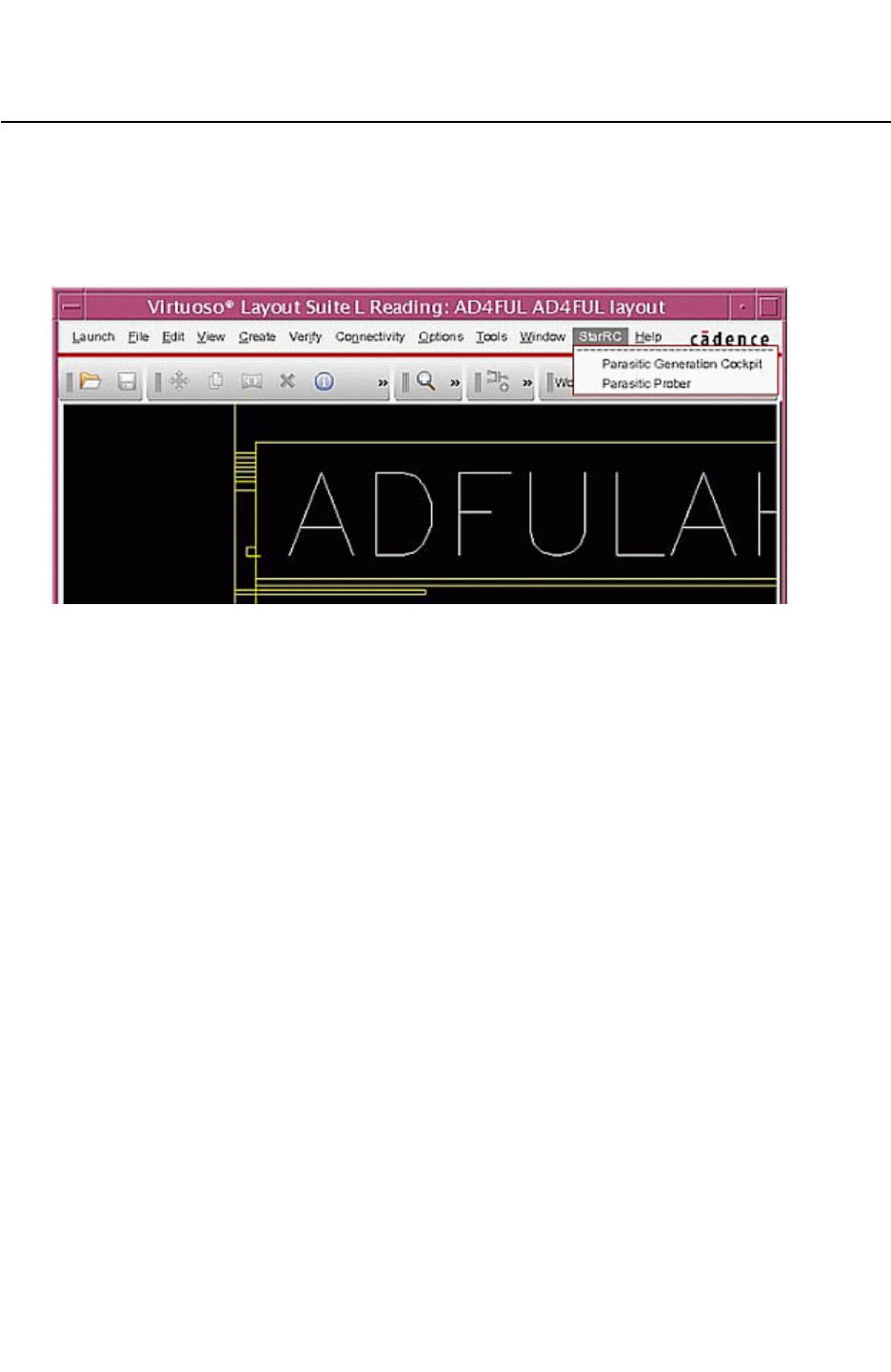
Chapter 12: Parasitic Extraction Integration With the Virtuoso Custom Design Platform
StarRC Parasitic Generation Cockpit GUI 12-25
Chapter 12: Parasitic Extraction Integration With the Virtuoso Custom Design Platform
StarRC Parasitic Generation Cockpit GUI 12-25
StarRC User Guide and Command Reference Version F-2011.06
StarRC Parasitic Generation Cockpit GUI
You can access the StarRC Parasitic Generation Cockpit by choosing StarRC > Parasitic
Generation Cockpit from the Virtuoso menu bar, as shown in Figure 12-4.
Figure 12-4 Starting the StarRC Parasitic Generation Cockpit in Virtuoso
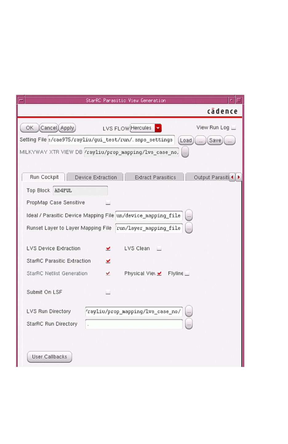
Chapter 12: Parasitic Extraction Integration With the Virtuoso Custom Design Platform
StarRC Parasitic Generation Cockpit GUI 12-26
StarRC User Guide and Command Reference F-2011.06
StarRC User Guide and Command Reference Version F-2011.06
Figure 12-5 shows the StarRC Parasitic View Generation dialog box, also called the Cockpit.
From the Cockpit, you can execute the IC Validator > StarRC, Hercules > StarRC, or Calibre
> StarRC flow either as a complete unit or incrementally in separate stages. You can also
regenerate netlists or parasitic views if an extraction run has already been performed.
Activate each step by selecting the appropriate check box.
Figure 12-5 StarRC Parasitic Generation Cockpit in Virtuoso
Each tab in the Cockpit represents a step in the flow; click on a tab to see the options
relevant to a particular step.
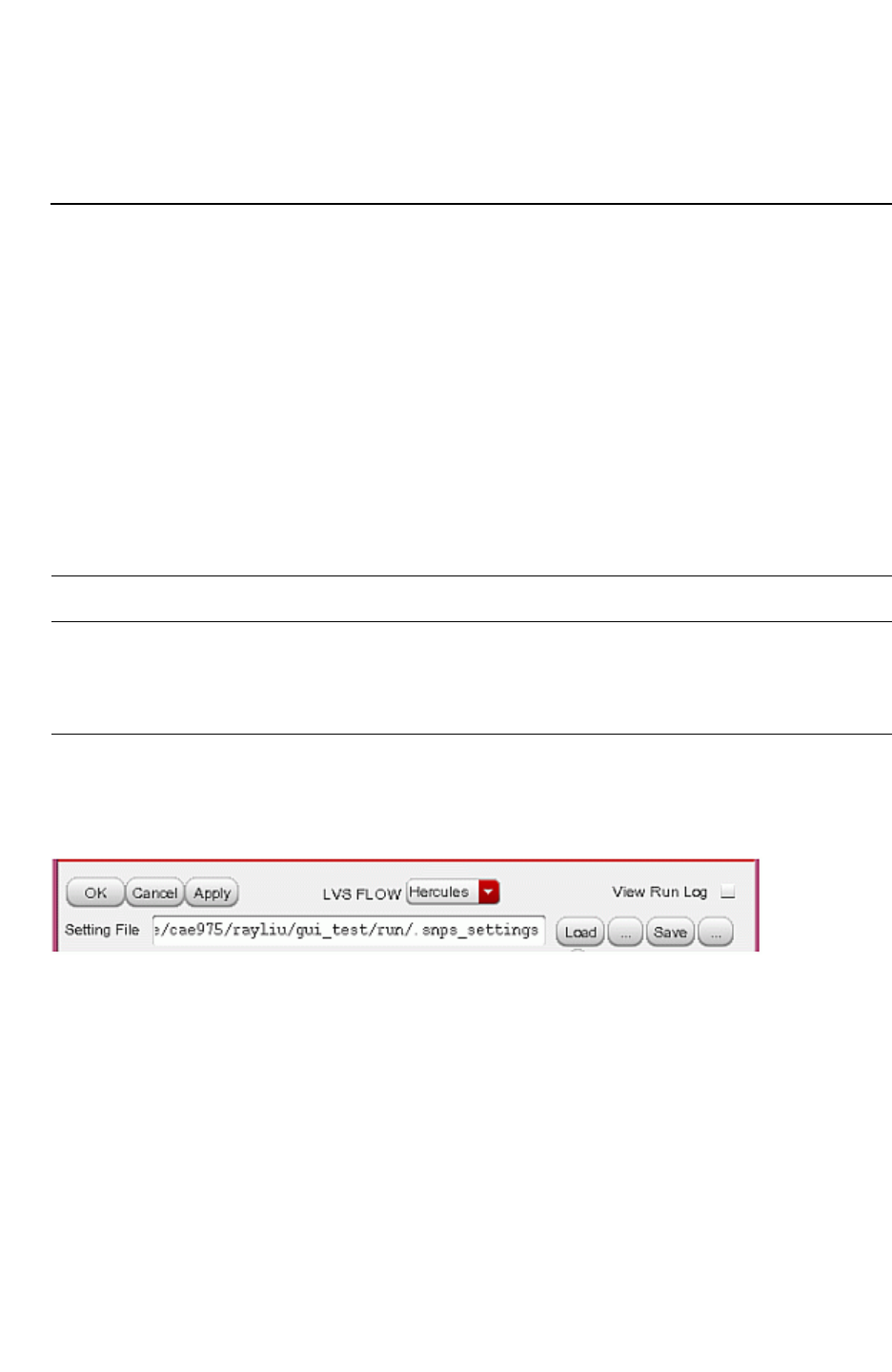
Chapter 12: Parasitic Extraction Integration With the Virtuoso Custom Design Platform
StarRC Parasitic Generation Cockpit GUI 12-27
Chapter 12: Parasitic Extraction Integration With the Virtuoso Custom Design Platform
StarRC Parasitic Generation Cockpit GUI 12-27
StarRC User Guide and Command Reference Version F-2011.06
To see the real-time run results of the LVS tool or StarRC run being executed, select the
View Run Log option.
Populating the Cockpit Fields Automatically
You can use a configuration file to automatically populate certain fields in the Cockpit. The
Cockpit looks for this file in one of two places:
• The environment variable RC_VI_SETTINGS_FILE can be set to point to the desired
configuration file.
• If RC_VI_SETTINGS_FILE is not set, the Cockpit looks for the .snps_settings file in the
directory from which Virtuoso was invoked.
Use the following syntax for each entry in the configuration file:
CONSTANT field_option : field_value
Argument Description
CONSTANT Optional keyword that makes the field option not editable in
the Cockpit dialog box
field_option : field_value Cockpit field and value to be prepopulated
Choose Load or Save to open a file browser and select a target setting file. You can also type
the file name in the Setting File box, as shown in Figure 12-6.
Figure 12-6 Choose Load or Save to Open a File Browser

Chapter 12: Parasitic Extraction Integration With the Virtuoso Custom Design Platform
StarRC Parasitic Generation Cockpit GUI 12-28
StarRC User Guide and Command Reference F-2011.06
StarRC User Guide and Command Reference Version F-2011.06
Table 12-2 describes the Cockpit field options and values that can be automatically
populated:
Table 12-2 Cockpit Fields and Options That Can Be Prepopulated
Tab Name field_option : field_value
Run Cockpit DFII_DEVICE_MAP: filepath
DFII_LAYER_MAP: filepath
FLOW: ICV | HERCULES | CALIBRE
PREPROCESS_CALLBACK: SKILL_expression
POSTPROCESS_CALLBACK: SKILL_expression
Device Extraction
(IC Validator Form)
ICV_RUNSET: filepath
ICV_RUNSET_REPORT_FILE: filepath
Device Extraction
(Hercules Form)
HERCULES_RUNSET: filepath
HERCULES_COMMAND_LINE_OPTIONS: command_string
Extract Parasitics TCAD_GRD_FILE: filepath
MAPPING_FILE: filepath
CALIBRE_QUERY_FILE: filepath (Calibre flow)
CALIBRE_RUNSET: filepath (Calibre flow)
EXTRACTION: R | C | RCCOUPLE_TO_GROUND: YES | NO
NETLIST_GROUND_NODE_NAME: string
Additional Options
Form
Any StarRC command file option listed on the Additional Options form
Miscellaneous SUBNODE_SIZE: subnode_side_length_in_microns
Use a semi-colon (;) to indicate the beginning of a comment inside the .snps_settings file. In
the following example, the second line is ignored:
CONSTANT TCAD_GRD_FILE: simple.nxtgrd
; CONSTANT TCAD_GRD_FILE: simple2.nxtgrd
In the next example, the -hier and -spice options are ignored:
CALIBRE_LVS_CMD_LINE_OPT : -lvs ; -hier –spice
By default, the StarRC commands specified in the Cockpit, such as the Additional Option
dialog box, are saved to the .snps_settings file. The GUI settings are also saved to the
.snps_settings file.
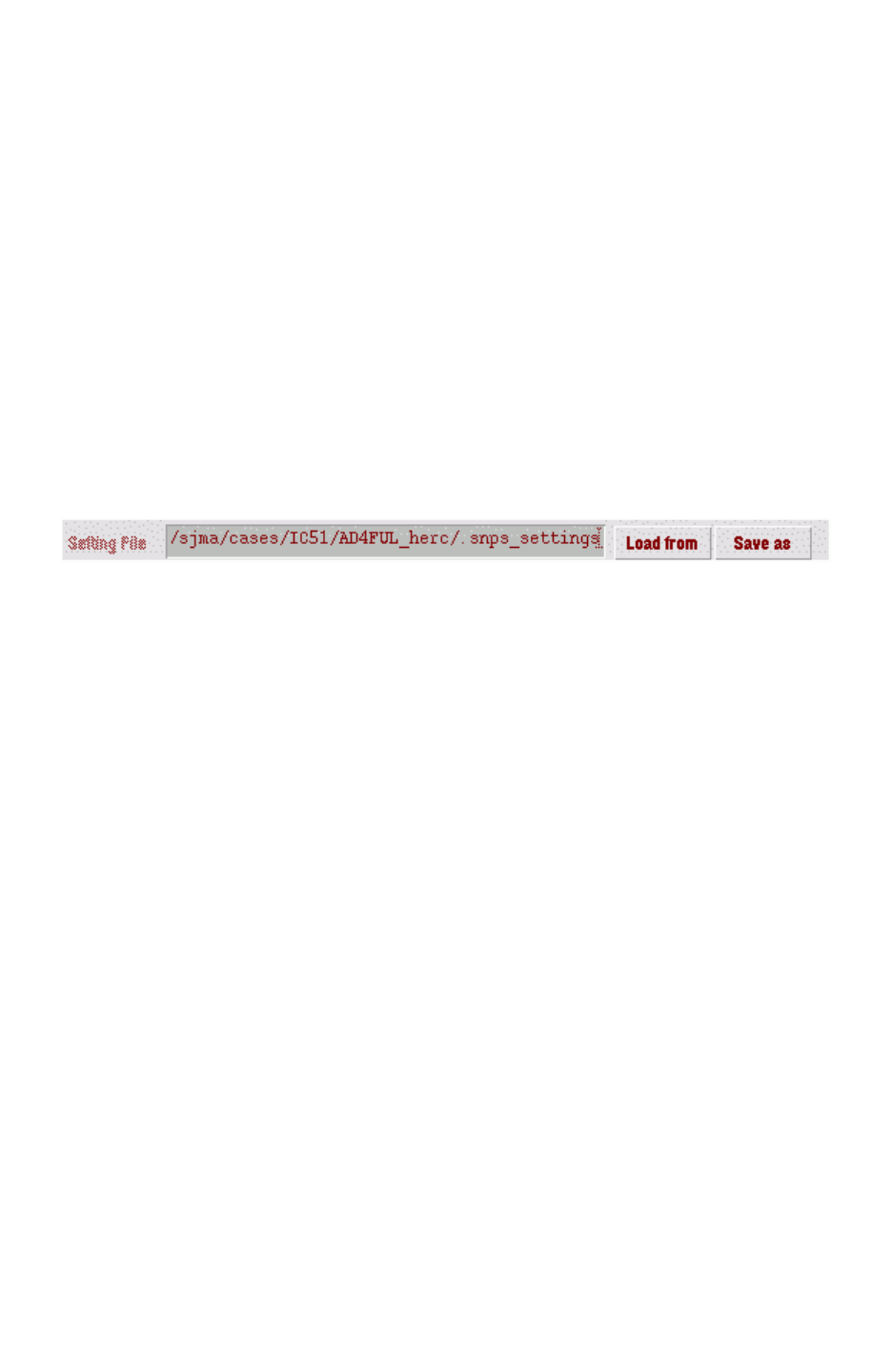
Chapter 12: Parasitic Extraction Integration With the Virtuoso Custom Design Platform
StarRC Parasitic Generation Cockpit GUI 12-29
Chapter 12: Parasitic Extraction Integration With the Virtuoso Custom Design Platform
StarRC Parasitic Generation Cockpit GUI 12-29
StarRC User Guide and Command Reference Version F-2011.06
To create a new .snps_settings file,
1. Open a blank Cockpit dialog box.
2. Edit the fields in the Cockpit.
3. Execute your run.
4. If your run is successful, save your settings to a new .snps_settings file.
The new .snps_settings file contains all required settings to reproduce a run.
Advanced Save and Load Mode
You can select a setting file to save or load by choosing Save As or Load From, as shown in
Figure 12-7, and browsing through the directory structure in the pop-up window.
Figure 12-7 Advanced Save and Load Mode in Virtuoso Integration
To enable this feature, set the ADVANCED_SAVE_LOAD environment variable to YES:
$ setenv ADVANCED_SAVE_LOAD YES

Chapter 12: Parasitic Extraction Integration With the Virtuoso Custom Design Platform
StarRC Parasitic Generation Cockpit GUI 12-30
StarRC User Guide and Command Reference F-2011.06
StarRC User Guide and Command Reference Version F-2011.06
Using the Functions in the StarRC Parasitic View Generation Dialog
Box
Table 12-3 describes the commands and options in the top section of the StarRC Parasitic
View Generation Dialog Box.
Table 12-3 Commands and Options for StarRC Parasitic View Generation
Command or Option Description
OK Starts a Cockpit job and close Cockpit window
Cancel Closes the Cockpit window
Apply Starts Cockpit job and keep the dialog box open
Flow Specifies one of three LVS tools and changes the options in
the Device Extraction Tab accordingly for the specified flow
Setting File Points to a .snps_settings file
Select Opens the file browser to display a setting file
Load Populates the Cockpit fields with values specified by the
setting file
Save Saves the current Cockpit values to the file in the Setting Files
box
Milkyway XTR VIEW DB
ICV RUNSET REPORT FILE
CALIBRE_RUNSET
CALIBRE_QUERY_FILE
Specifies an LVS result database for StarRC to read

Chapter 12: Parasitic Extraction Integration With the Virtuoso Custom Design Platform
StarRC Parasitic Generation Cockpit GUI 12-31
Chapter 12: Parasitic Extraction Integration With the Virtuoso Custom Design Platform
StarRC Parasitic Generation Cockpit GUI 12-31
StarRC User Guide and Command Reference Version F-2011.06
Run Cockpit Tab
Specify the following settings in the Run Cockpit tab, shown in Figure 12-5 on page 12-26.
LVS C Ie an
If you select LVS CIean, Virtuoso Integration Cockpit execution checks if the LVS job is
compared or not. If not, Virtuoso Integration stops the job. StarRC obtains the LVS results
from the following files:
• topblock.LVS_ERRORS (in the IC Validator and Hercules flows)
• svdb database (in the Calibre flow)
Physical View
The parasitic view consists of two parts, the physical view and the logical view. Use the
physical view for browsing and probing; use the logical view for simulation and schematic
view probing.
You can access the Physical View button from the Create button as shown in Figure 12-1.
This button controls the physical view generation. If it is not selected, no physical view is
generated, thus runtime is saved for merging polygons and writing the physical parasitic
view.
Flyline
A flyline is a line that connects nodes on the same net. It helps you to probe point-to-point
resistance. Although generating a flyline and storing it in the parasitic view consumes
runtime and disk space, StarRC provides the option of flyline generation. By default,
flyline generation is disabled.
LVS Run Directory
The directory in which Virtuoso Integration executes an LVS job. All output files are
written to the same directory.
StarRC Run Directory
The directory in which Virtuoso Integration executes a StarRC job.
User Callbacks
Five kinds of callbacks can be specified.
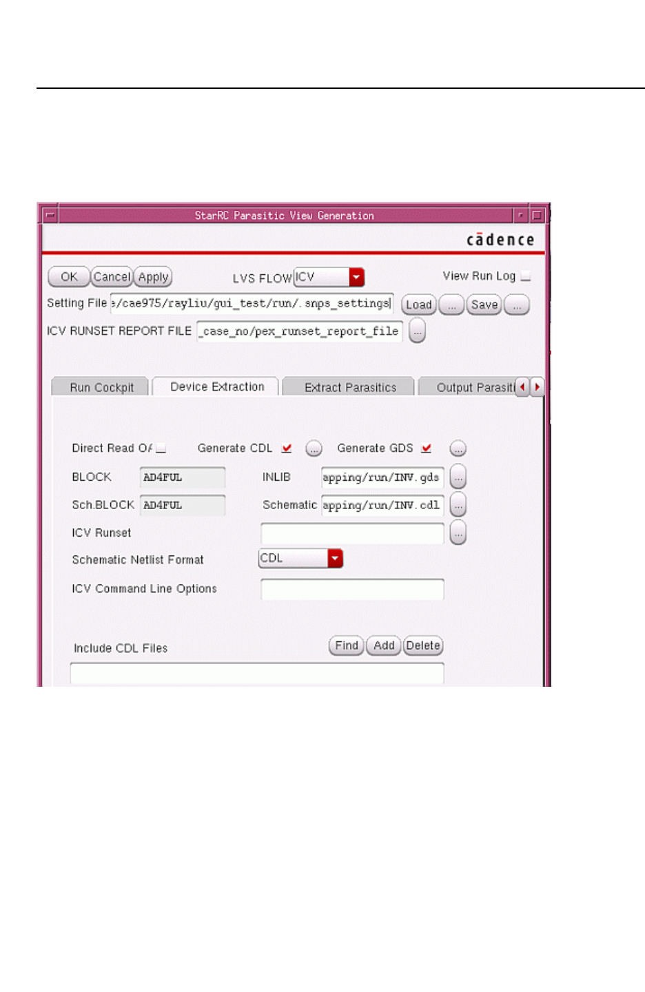
Chapter 12: Parasitic Extraction Integration With the Virtuoso Custom Design Platform
StarRC Parasitic Generation Cockpit GUI 12-32
StarRC User Guide and Command Reference F-2011.06
StarRC User Guide and Command Reference Version F-2011.06
Device Extraction Tab
When you select the IC Validator (ICV) LVS flow, the Device Extraction tab for IC Validator
appears, as shown in Figure 12-8.
Figure 12-8 Device Extraction Tab For IC Validator LVS Flow
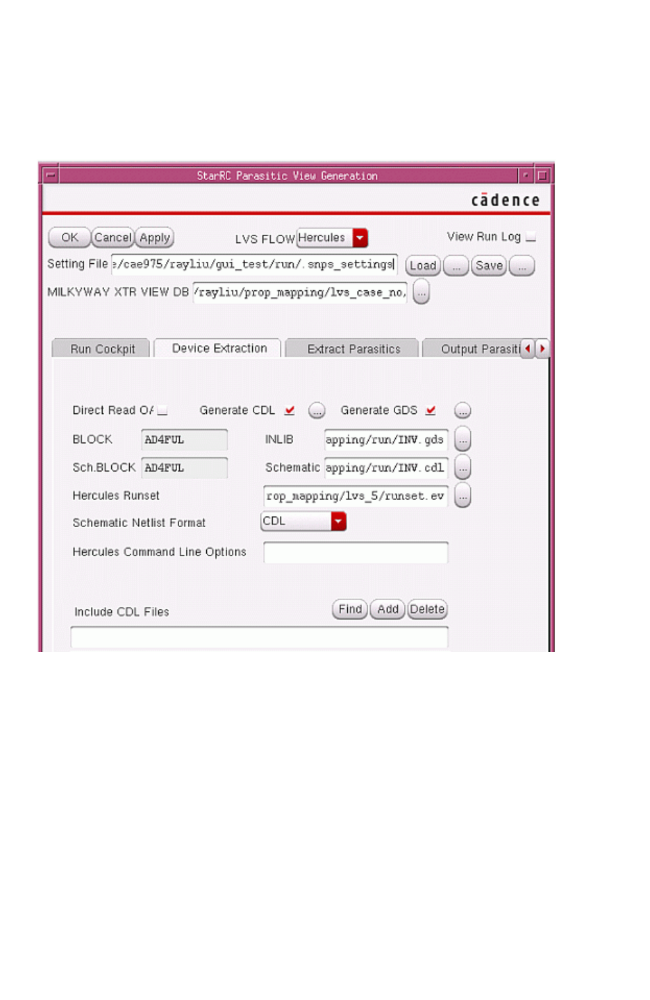
Chapter 12: Parasitic Extraction Integration With the Virtuoso Custom Design Platform
StarRC Parasitic Generation Cockpit GUI 12-33
Chapter 12: Parasitic Extraction Integration With the Virtuoso Custom Design Platform
StarRC Parasitic Generation Cockpit GUI 12-33
StarRC User Guide and Command Reference Version F-2011.06
When you select the Hercules LVS flow, the Device Extraction tab for IC Validator appears,
as shown in Figure 12-9.
Figure 12-9 Device Extraction Tab For Hercules LVS Flow
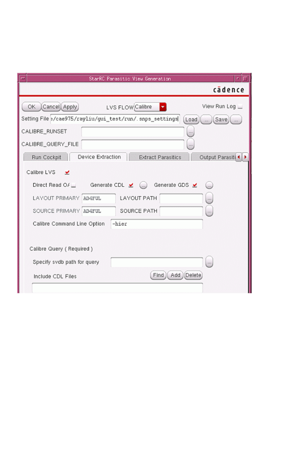
Chapter 12: Parasitic Extraction Integration With the Virtuoso Custom Design Platform
StarRC Parasitic Generation Cockpit GUI 12-34
StarRC User Guide and Command Reference F-2011.06
StarRC User Guide and Command Reference Version F-2011.06
When you select the Calibre LVS flow, the Device Extraction tab for Calibre appears, as
shown in Figure 12-10.
Figure 12-10 Device Extraction Tab For Calibre LVS Flow
Direct OA READ
When you select this option, Virtuoso Integration forces the LVS tool to directly read the
OA layout view. This button is only available in Virtuoso 6.0 and later versions. There are
some more options for you to choose a view other than layout view or to add a
oa_layer_mapping file. For information about the oa_layer_mapping file usage and
syntax, see the manual for your LVS tool.
Generate CDL
When you select this option, Virtuoso Integration writes the netlist to a CDL file that is
passed to the LVS tool, instead of writing to a runset- or Cockpit-specified netlist file.
You can modify the streaming option in the GDSII stream out GUI.

Chapter 12: Parasitic Extraction Integration With the Virtuoso Custom Design Platform
StarRC Parasitic Generation Cockpit GUI 12-35
Chapter 12: Parasitic Extraction Integration With the Virtuoso Custom Design Platform
StarRC Parasitic Generation Cockpit GUI 12-35
StarRC User Guide and Command Reference Version F-2011.06
Generate GDS
When you select this option, Virtuoso Integration streams out the layout view to a GDSII
file that is passed to the LVS tool, instead of streaming the layout to the runset- or
Cockpit-specified GDSII file.
You can modify the streaming option in the GDSII stream out GUI.
Include CDL Files
To use multiple CDL files as input to the Virtuoso Integration LVS tools, specify the CDL
files in the GUI.
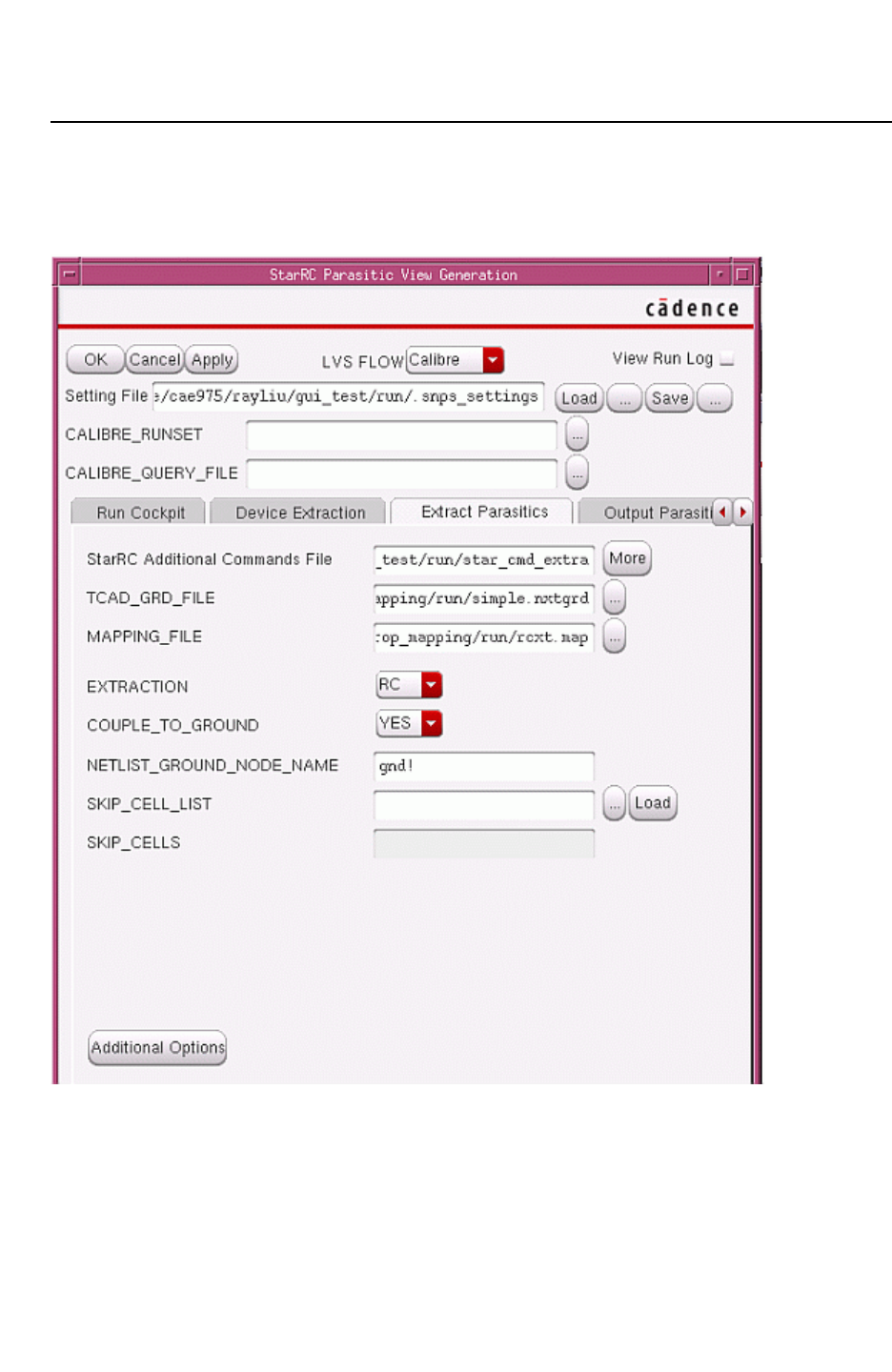
Chapter 12: Parasitic Extraction Integration With the Virtuoso Custom Design Platform
StarRC Parasitic Generation Cockpit GUI 12-36
StarRC User Guide and Command Reference F-2011.06
StarRC User Guide and Command Reference Version F-2011.06
Extract Parasitics Tab
Figure 12-11 shows the Extract Parasitics tab.
Figure 12-11 Extract Parasitics Tab

Chapter 12: Parasitic Extraction Integration With the Virtuoso Custom Design Platform
StarRC Parasitic Generation Cockpit GUI 12-37
Chapter 12: Parasitic Extraction Integration With the Virtuoso Custom Design Platform
StarRC Parasitic Generation Cockpit GUI 12-37
StarRC User Guide and Command Reference Version F-2011.06
SKIP_CELL_LIST
The SKIP_CELL_LIST is used for the Virtuoso Integration skip cell flow. Its file format
follows the device_mapping file, not the StarRC skip_cell file, as shown in the following
example:
skip_cell1 lib1 cell1 view1
skip_cell2 lib2 cell2 view2
...
Additional Command File and Additional Option Form
To assist you in creating the many option combinations needed by Virtuoso Integration for
view creation, you can add a command for the Cockpit and also adjust some options with
the Additional Options Form. To see all the options used by StarRC, view the output file
generated by the StarXtract -tech_out command.
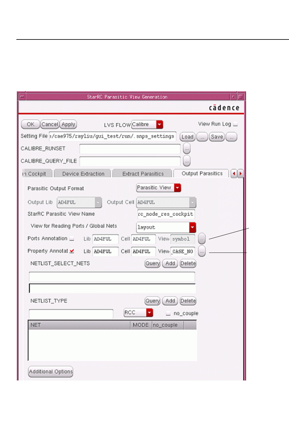
Chapter 12: Parasitic Extraction Integration With the Virtuoso Custom Design Platform
StarRC Parasitic Generation Cockpit GUI 12-38
StarRC User Guide and Command Reference F-2011.06
StarRC User Guide and Command Reference Version F-2011.06
Output Parasitics Tab
Figure 12-12 shows the Output Parasitics tab. You can use Virtuoso Integration as a GUI for
to configure your StarRC run.
Figure 12-12 Output Parasitics Tab
Port
Annotation
View
Property
Annotation
View

Chapter 12: Parasitic Extraction Integration With the Virtuoso Custom Design Platform
StarRC Parasitic Generation Cockpit GUI 12-39
Chapter 12: Parasitic Extraction Integration With the Virtuoso Custom Design Platform
StarRC Parasitic Generation Cockpit GUI 12-39
StarRC User Guide and Command Reference Version F-2011.06
Parasitic Output Format
Use this option to select the file format of the output. Virtuoso Integration can generate
not only a parasitic view but also several netlist file formats.
By default, you cannot change the Output Lib and Output Cell names in the Cockpit. This
default behavior prevents accidentally writing a newly-generated view to a previous cell
from which the .snps_settings file was created.
To override this default behavior and save the Output Lib and Output Cell names to the
.snps_settings file, set the RC_SAVE_ALL environment variable:
$ setenv RC_SAVE_ALL NO
Ports Annotation
Use this option when you are not generating a parasitic view as the top-block view, but
want to integrate the parasitic view into other test bench circuits. Use the Ports
Annotation View option for Virtuoso Integration to annotate correct port and port direction
list to the parasitic view. Then the parasitic view can be connected to the other view to
form a complete circuit for simulation.
Property Annotation
Use this option to specify the view from which to obtain property information for
schematic property annotation. This option defaults to the schematic view in the same lib/
cell window that starts the Virtuoso Integration Cockpit window.
Load Sharing Facility Job Submission
Load Sharing Facility (LSF) support in StarRC Virtuoso Integration gives you the flexibility to
control jobs that are submitted to specified farms. By default, all jobs, including LVS and
StarRC extraction, are performed on the same remote server. However, if you want to run
LVS and StarRC on different farms, use the LSF Form to specify LSF settings for each LVS
and extraction task.
In the LSF Form shown in Figure 12-13, you can specify the StarRC NUM_PARTS option for
distributed processing. The NUM_PARTS value defaults to its corresponding value in the
.snps_settings file. The NUM_PARTS setting in this dialog box overrides all the NUM_PARTS
settings from other sources.
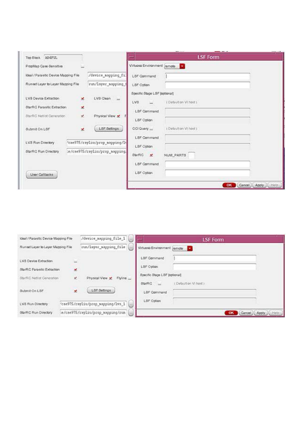
Chapter 12: Parasitic Extraction Integration With the Virtuoso Custom Design Platform
StarRC Parasitic Generation Cockpit GUI 12-40
StarRC User Guide and Command Reference F-2011.06
StarRC User Guide and Command Reference Version F-2011.06
Figure 12-13 LSF Form With LVS Device Extraction Selected
The LSF Form changes based on your flow selection. For example, if LVS Device Extraction
is no selected, then the LSF Form changes as shown in Figure 12-14.
Figure 12-14 LSF Form With LVS Device Extraction Deselected

Chapter 12: Parasitic Extraction Integration With the Virtuoso Custom Design Platform
StarRC Parasitic Generation Cockpit GUI 12-41
Chapter 12: Parasitic Extraction Integration With the Virtuoso Custom Design Platform
StarRC Parasitic Generation Cockpit GUI 12-41
StarRC User Guide and Command Reference Version F-2011.06
If you want to source an environment file before calling StarRC/LVS jobs, such as setup
license and path, you can create a wrapper to source these file first. The following is a simple
example:
#!/bin/csh -fb
foreach arg ( $* )
if( "$arg" == "-source" ) then
set read_source = 1
continue;
endif
if( $read_source == 1 ) then
set source_file = $arg
set read_source = 0
continue;
endif
set args = "$args $last_arg"
set last_arg = $arg
end
cat $source_file > tmp_file
echo $arg >> tmp_file
echo qsub $args tmp_file
$qsub $args $tmp_file
File and Path Browsers
In the StarRC Parasitic View Generation form, some fields require file names or directory
names to be entered. Use the entry point “…” to start the file browser instead of manually
entering the names.
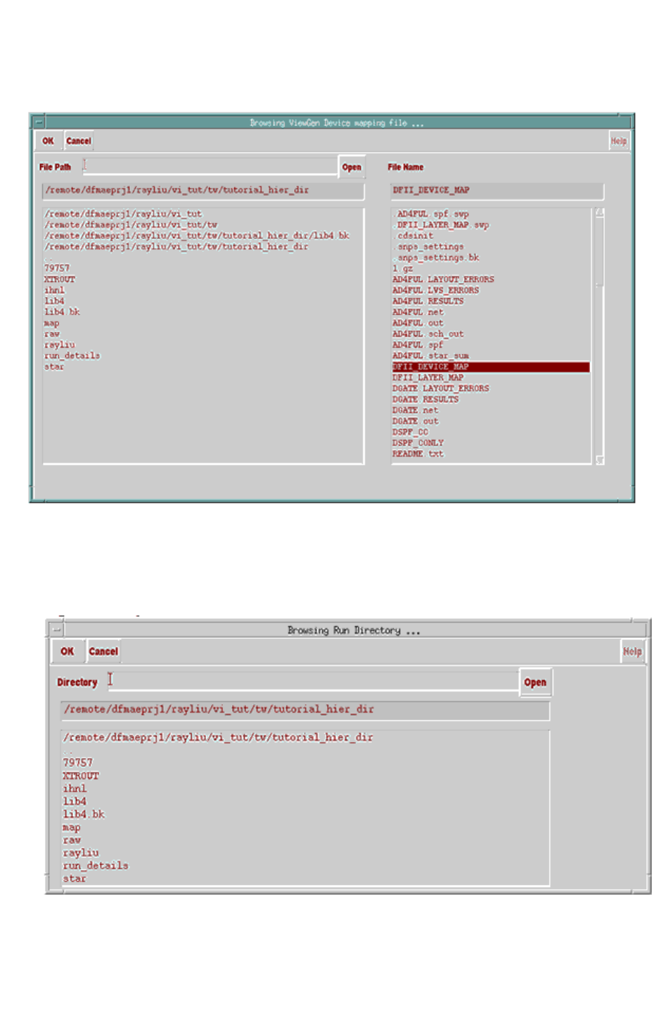
Chapter 12: Parasitic Extraction Integration With the Virtuoso Custom Design Platform
StarRC Parasitic Generation Cockpit GUI 12-42
StarRC User Guide and Command Reference F-2011.06
StarRC User Guide and Command Reference Version F-2011.06
Figure 12-15 File Browser
Figure 12-15 shows an Ideal/Parasitic Device Mapping File is on and with a “…” button
displayed. The “Runset layer to DFII Layer Mapping File” cannot be selected. These
correspond to fields in the .snps_setting file.
Figure 12-16 Browsing a Run Directory
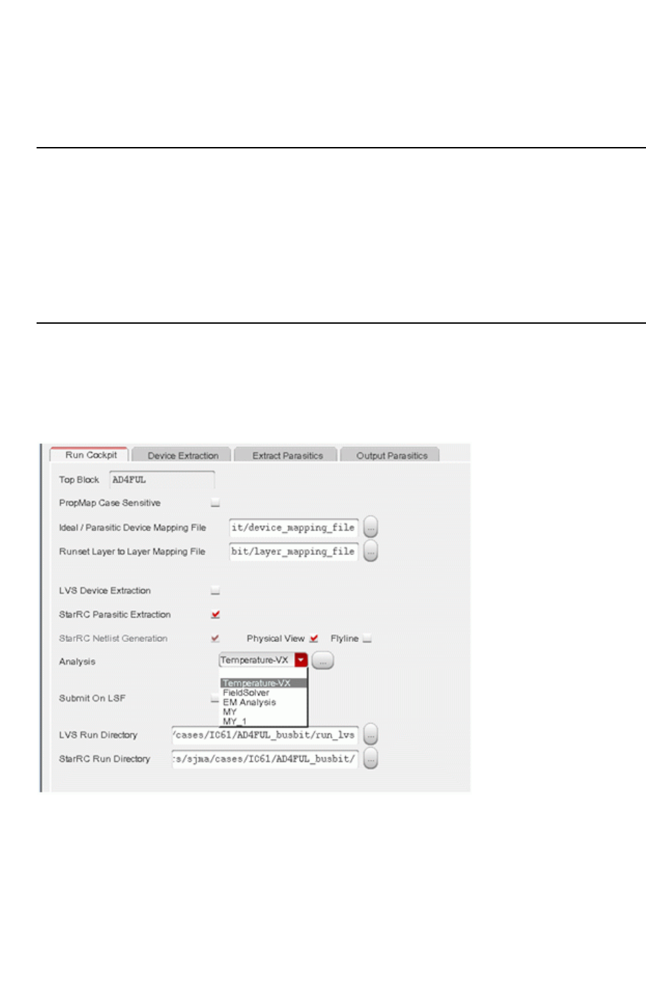
Chapter 12: Parasitic Extraction Integration With the Virtuoso Custom Design Platform
StarRC Parasitic Generation Cockpit GUI 12-43
Chapter 12: Parasitic Extraction Integration With the Virtuoso Custom Design Platform
StarRC Parasitic Generation Cockpit GUI 12-43
StarRC User Guide and Command Reference Version F-2011.06
If you click on “…”, the Browsing Run Directory form is displayed as shown in Figure 12-16.
Click the file desired and is brought back to the Cockpit field.
Using Selected Net Parasitics and Selective Netlisting Modes
By default, StarRC extracts and netlists parasitics for all signal nets in the design, according
to the setting of the EXTRACTION and COUPLE_TO_GROUND options. However, the capability
also exists to netlist only the parasitics belonging to certain nets or to selectively netlist a
subset of parasitics for certain nets. These capabilities use the StarRC options
NETLIST_SELECT_NETS and NETLIST_TYPE, which are activated using the corresponding
fields on the Output Parasitics tab of the parasitic generation cockpit.
Selecting and Customizing the Analysis Options
In the Run Cockpit dialog box, you can select Analysis options such as Temperature-VX,
FieldSolver, EM Analysis, or customized settings, as shown in Figure 12-17.
Figure 12-17 Analysis Options in Run Cockpit Dialog Box
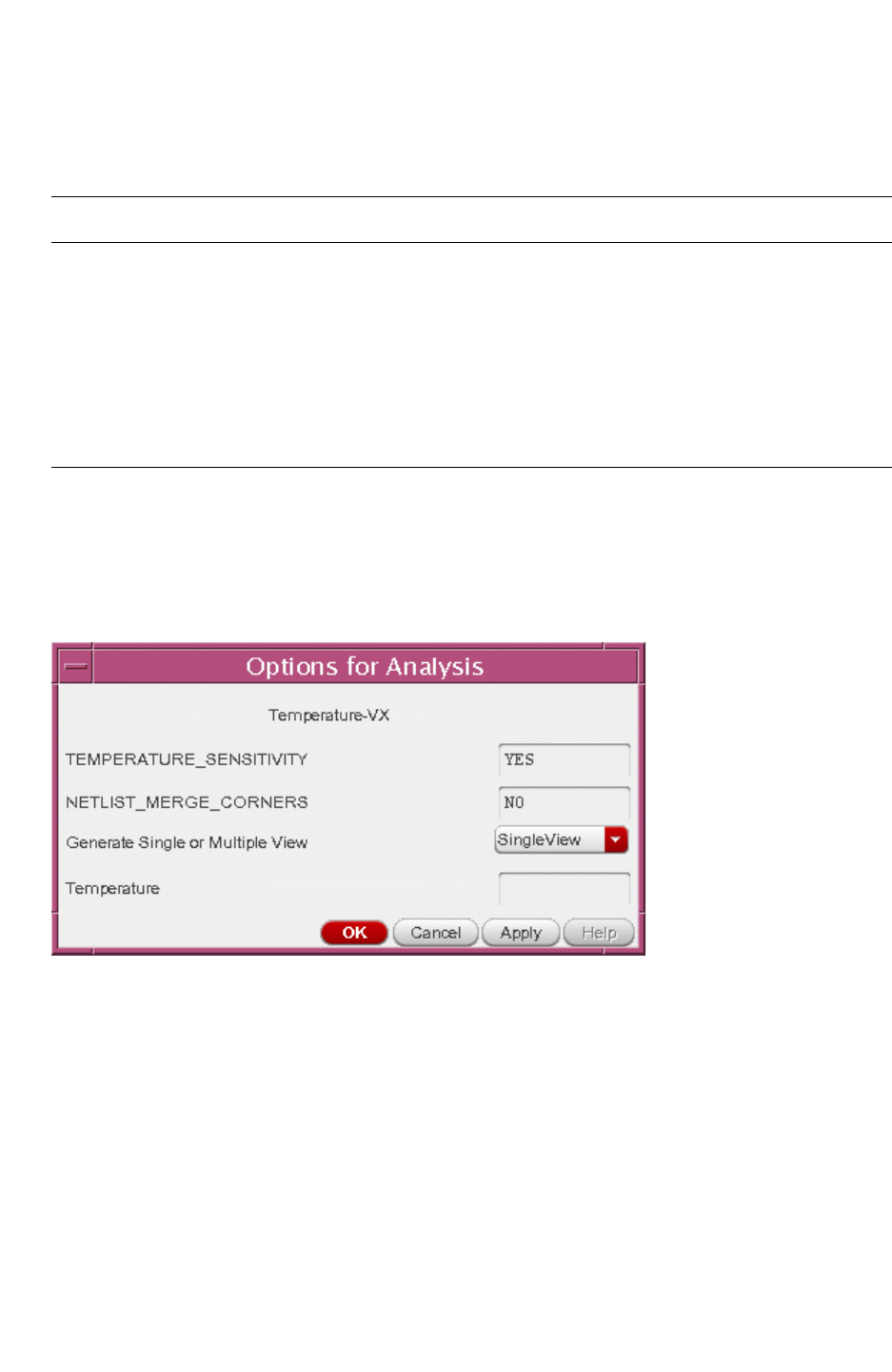
Chapter 12: Parasitic Extraction Integration With the Virtuoso Custom Design Platform
StarRC Parasitic Generation Cockpit GUI 12-44
StarRC User Guide and Command Reference F-2011.06
StarRC User Guide and Command Reference Version F-2011.06
The following table describes the four predefined Analysis options:
Table 12-4 Predefined Analysis Options
Analysis Option Function
(blank) Uses your current settings; this is the default setting
Temperature-VX Allows you to output a single view with a special corner or a multicorner
or merged corner view
FieldSolver Specifies the StarRC FS_EXTRACT_NETS command
EM Analysis Specifies the StarRC REDUCTION: NO, EXTRA_GEOMETRY_INFO: NODE
RES, and POWER_REDUCTION: NO commands
To store or edit the StarRC settings for the extraction run, select the Analysis option in the
Run Cockpit and click the "…" button. The Options for Analysis dialog box appears, as
shown in Figure 12-18. You can view and change the StarRC settings in this dialog box.
Figure 12-18 Options for EM Analysis
To customize the StarRC settings for one or more Analysis options,
1. Specify the ANALYSIS_SETTING statement with the following syntax in the .snps_settings
file:
ANALYSIS_SETTING: analysis_settings_file_name

Chapter 12: Parasitic Extraction Integration With the Virtuoso Custom Design Platform
StarRC OA View Creation 12-45
Chapter 12: Parasitic Extraction Integration With the Virtuoso Custom Design Platform
StarRC OA View Creation 12-45
StarRC User Guide and Command Reference Version F-2011.06
2. In the analysis settings file, specify the ANALYSIS statement for each analysis setting
followed by its corresponding StarRC commands. Use the following syntax:
ANALYSIS: [" "] | Simulation | EM Analysis | FieldSolver |
Temperature-VX | custom_setting_name
StarRC_Command_1
[StarRC_Command_2]
...
To customize the default settings, specify
ANALYSIS: " "
The following example defines custom settings for ANALYSIS_CC and ANALYSIS_CG:
ANALYSIS: ANALYSIS_CC
EXTRACTTION: RC
COUPLE_TO_GROUND: NO
ANALYSIS: ANALYSIS_CG
EXTRACTTION: C
COUPLE_TO_GROUND: YES
StarRC OA View Creation
StarRC can execute Open Access format parasitic view generation outside Virtuoso. StarRC
has many options to control the OA view generation. If using the Virtuoso Integration Cockpit
GUI or the Customer Designer GUI, the GUI is helpful for setting up many options.
Open Access
StarRC provides seamless integration with the Cadence Virtuoso™ Design Environment as
shown Figure 12-19. You can run extraction and generate a parasitic view within Cadence
Design Framework™ for efficient post-layout simulation. The current parasitic view is
generated using the available Skill-based functions in the Cadence Design Environment and
provides you with an accurate representation of parasitics that can be used to optimize
designs.
Accurate layout representation requires netlist connectivity information to instantiate each
extracted parasitic (RC) and device in the design. The parasitic view provides you with an
efficient and detailed analysis tool in the physical domain. The parasitic view must contain
schematic symbols that can be netlisted for simulation as well as used as a graphical tool for
identifying parasitic devices.
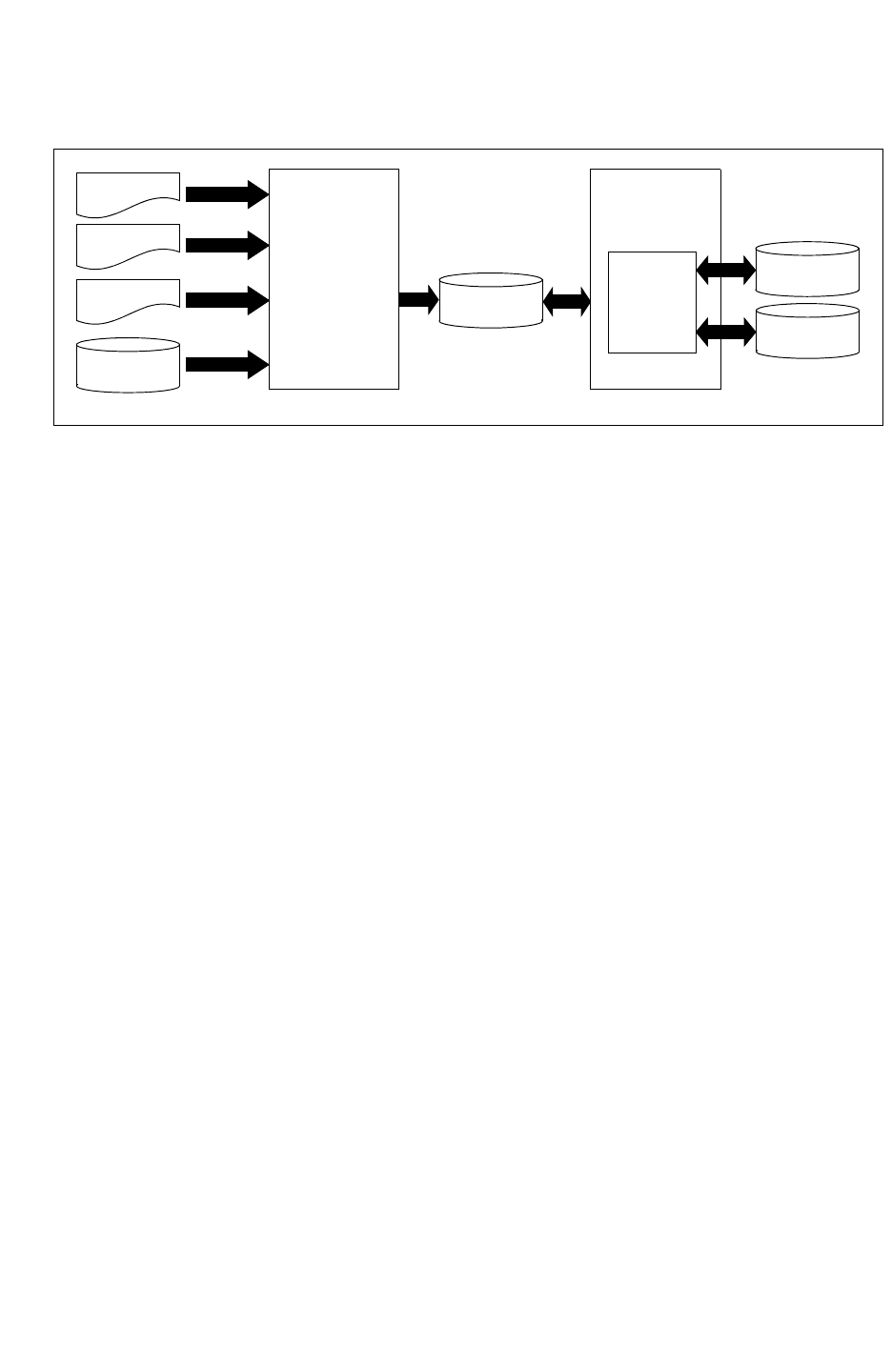
Chapter 12: Parasitic Extraction Integration With the Virtuoso Custom Design Platform
StarRC OA View Creation 12-46
StarRC User Guide and Command Reference F-2011.06
StarRC User Guide and Command Reference Version F-2011.06
Figure 12-19 Open Access Flow
Command File
Layer Map File
Device Map File
Hercules XTR
StarRC
Circuit
Symbols
Connectivity
Parameters
Open Access
Parasitic View
Parasitic
and Ideal
Devices
Parasitic
Analysis
Environment
Open Access
Layout
Open Access
Schema
Design
Environment
Environment Setup for Writing Open Access
StarRC reads the environment variable $LD_LIBRARY_PATH to obtain information about
location of dynamically linked libraries.
StarRC Open Access parasitic view generation capability requires the Qualified System
Configuration (QSC) to be foundation platform compliant.
Linking Open Access Libraries
The Open Access libraries provided by Cadence are dynamic libraries. The path to the
location of these dynamic libraries must be set for $LD_LIBRARY_PATH environment variable.
The standard Open Access libraries are located under the lib/std_oa directory of the
standard StarRC installation. These Open Access libraries can also be downloaded from the
official si2 web page the following address:
http://www.si2.org
Linking StarRC Open Access Libraries
StarRC calls a library called liboaStar-O.so located in the lib/ directory of the standard
StarRC installation. Verify that this path is specified in your $LD_LIBRARY_PATH environment
variable.
Setting the Tcl Path
If the design contains parameterized cells (PCELLS), you need to specify the path for the Tcl
libraries in the environment variable $LD_LIBRARY_PATH. For more details, see the
SKIP_PCELLS command.

Chapter 12: Parasitic Extraction Integration With the Virtuoso Custom Design Platform
StarRC OA View Creation 12-47
Chapter 12: Parasitic Extraction Integration With the Virtuoso Custom Design Platform
StarRC OA View Creation 12-47
StarRC User Guide and Command Reference Version F-2011.06
StarRC Command File Options
The following StarRC commands enable the parasitic view generation to be output in Open
Access format:
Command Type Default Description
NETLIST_FORMAT String NETNAME Set to OA. This command is required.
OA_LIB_DEF String lib.defs Open Access library definition file.
Optional.
OA_LIB_NAME String Open Access library name.
OA_VIEW_NAME String starrc Parasitic view name.
OA_DEVICE_MAPPING_FILE File
name
File containing device mapping.
OA_LAYER_MAPPING_FILE File
name
File containing layer mapping.
OA_MARKER_SIZE Float 0.1 Port or Subnode marker size in
microns. Optional
OA_SKIPCELL_MAPPING_FILE String None Specifies master SKIP_CELL.
OA_PORT_ANNOTATION_VIEW String null string Enables the simulation of a parasitic
view. generated by the Open Access
writer.
OA_PROPERTY_ANNOTATION_VIEW String None Specifies which schematic library, cell,
or view is used to check against ideal
devices for schematic-only properties
and to attach them into the Open
Access parasitic view
Examples
The following sections show examples for the Open Access library definition and the device
mapping file.

Chapter 12: Parasitic Extraction Integration With the Virtuoso Custom Design Platform
StarRC OA View Creation 12-48
StarRC User Guide and Command Reference F-2011.06
StarRC User Guide and Command Reference Version F-2011.06
Open Access Library Definition
The following is an example of the Open Access library definition pointed to in the StarRC
command file OA_LIB_DEF option:
DEFINE w_xxb_fifo1 /remote/cae933/VI/OA/w_xxb_fifo1
DEFINE N90lo /testcases/misc/star_virtuoso/N90lo
DEFINE cdsDefTechLib /global/apps/ic_61/linux/tools/dfII/etc/
cdsDefTechLib
DEFINE analogLib /global/apps/ic_61/linux/tools/dfII/etc/cdslib/artist/
analogLib
DEFINE US_8ths /global/apps/ic_61/linux/tools/dfII/etc/cdslib/sheets/
US_8ths
DEFINE basic /global/apps/ic_61/linux/tools/dfII/etc/cdslib/basic
Open Access Device Mapping File
The following is an example of the Open Access layer mapping file pointed to by the StarRC
command file option OA_LAYER_MAPPING_FILE.
poly PO drawing PO pin PO dummy
metal1 M1 drawing M1 pin M1 dummy
metal2 M2 drawing M2 pin M2 dummy
metal3 M3 drawing M3 pin M3 dummy
metal4 M4 drawing M4 pin M4 dummy
metal5 M5 drawing M5 pin M5 dummy
metal6 M6 drawing M6 pin M6 dummy
metal7 M7 drawing M7 pin M7 dummy
metal8 M8 drawing M8 pin M8 dummy
Cont CO drawing nil nil nil nil
pl3co CO drawing nil nil nil nil
VIA1 VIA1 drawing nil nil nil nil
VIA2 VIA2 drawing nil nil nil nil
VIA3 VIA3 drawing nil nil nil nil
VIA4 VIA4 drawing nil nil nil nil
VIA5 VIA5 drawing nil nil nil nil
VIA6 VIA6 drawing nil nil nil nil
VIA7 VIA7 drawing nil nil nil nil
The following is an example of the Open Access device mapping file pointed to in the StarRC
command file option OA_DEVICE_MAPPING_FILE: command.
pres analogLib presistor auLvs PLUS MINUS
pcap analogLib pcapacitor auLvs PLUS MINUS
nch N90lo nch auLvs G S D B
pch N90lo pch auLvs G S D B
nch_18 N90lo nch_18 auLvs G S D B
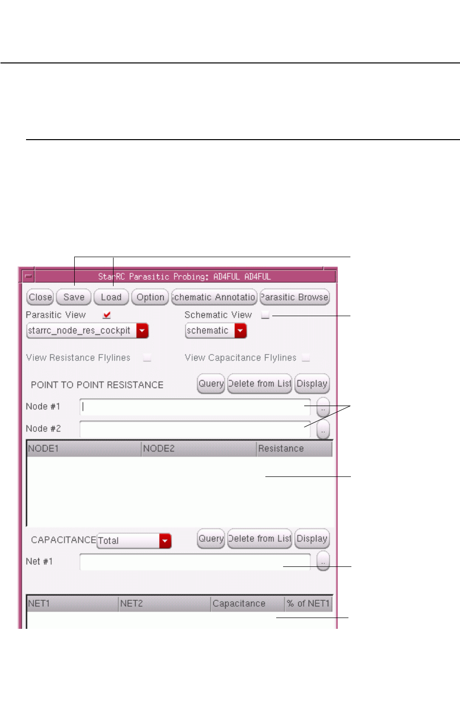
Chapter 12: Parasitic Extraction Integration With the Virtuoso Custom Design Platform
Parasitic Probing in the GUI 12-49
Chapter 12: Parasitic Extraction Integration With the Virtuoso Custom Design Platform
Parasitic Probing in the GUI 12-49
StarRC User Guide and Command Reference Version F-2011.06
Parasitic Probing in the GUI
After the parasitic view is generated, you can probe the parasitic view in the GUI to
understand the StarRC extraction results.
StarRC Parasitic Prober
You can access the StarRC parasitic prober through the Parasitic Prober entry of the StarRC
pulldown menu within any parasitic or schematic view window. Use the StarRC Parasitic
Probing dialog box, shown in Figure 12-20, to probe parasitics within the parasitic view or
the corresponding schematic view.
Figure 12-20 StarRC Parasitic Probing Dialog Box
File input/output
View selection
Capacitance net entry
Capacitance results log
Resistance results log
Resistance node entry

Chapter 12: Parasitic Extraction Integration With the Virtuoso Custom Design Platform
Parasitic Probing in the GUI 12-50
StarRC User Guide and Command Reference F-2011.06
StarRC User Guide and Command Reference Version F-2011.06
Choose one of the following probing modes:
• Parasitic View
• Probes port and subnode markers for point-to- point resistance between any two
same-net points.
• Probes interconnect polygons for total net capacitance, with or without couplings to
constituent nets.
• Probes interconnect polygons for total coupling capacitance between two nets.
• Schematic View
• Probes schematic instance terminals for point- to-point resistance between any two
same-net terminals, at any level of hierarchy contained within the schematic cell
matching the extracted cell.
• Probes schematic nets for total net capacitance, with or without couplings to
constituent nets, at any level of hierarchy contained within the schematic cell matching
the extracted cell.
• Probes schematic nets for total coupling capacitance between two nets, at any level of
hierarchy contained within the schematic cell matching the extracted cell.
The prober also provides the following additional features:
• Highlighting and zooming of parasitic view interconnect polygons corresponding to a
previously probed total capacitance or point-to-point resistance result.
• Annotation of total capacitance results to a corresponding schematic view window
• Sorting of logged resistance and capacitance results based on net name or parasitic
value
• Output of probed parasitic results to an ASCII report file, as well as input of parasitic
results from a previously output ASCII report file
• Activation or deactivation of flylines representing individual parasitic resistors and
capacitors
StarRC Parasitic Browser
From the Parasitic Browser, you can Input, search, or query a net name. All the node
connections and parasitic devices on this net are listed in the form. You can review this
information, select the node, resistor, or capacitor to be deleted or display information about
the StarRC view.
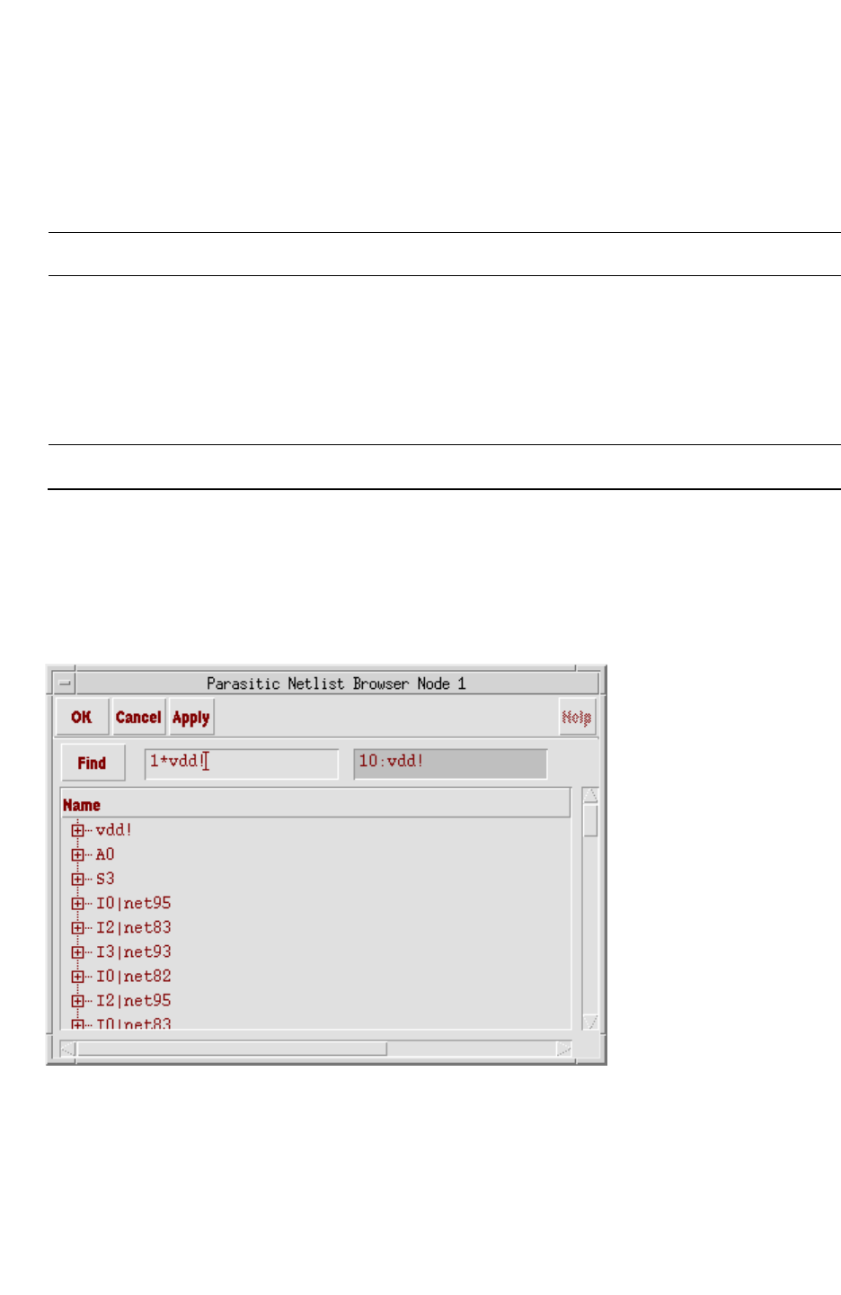
Chapter 12: Parasitic Extraction Integration With the Virtuoso Custom Design Platform
Parasitic Probing in the GUI 12-51
Chapter 12: Parasitic Extraction Integration With the Virtuoso Custom Design Platform
Parasitic Probing in the GUI 12-51
StarRC User Guide and Command Reference Version F-2011.06
Type in a name, then click on Search, and the Parasitic Browser displays all the net names
contained the input pattern. When the desired name is shown, click Done. The Parasitic
Browser parses the net to show all the physical nodes in the Connection field.
Table 12-5 Parasitic Browser Button and Field Functions
Form Button or Field Function
Query Chooses a net and sends it to the Connection field by querying
a name from schematic view or parasitic view
DISPLAY Displays the selected node to be highlighted in the parasitic
view
DELETE Deletes the selected node
StarRC Parasitic Netlist Browser
The Parasitic Netlist Browser, in Figure 12-21, helps you find a particular node. Click on the
plus sign to the left of a net name to expand the net and show the signal group. Click on the
minus sign to collapse the signal group into a net.
Figure 12-21 Parasitic Netlist Browser

Chapter 12: Parasitic Extraction Integration With the Virtuoso Custom Design Platform
Parasitic Probing in the GUI 12-52
StarRC User Guide and Command Reference F-2011.06
StarRC User Guide and Command Reference Version F-2011.06
Use the Parasitic Browser to browse, search, and select a net name to send to the prober.
You can enter a net name containing a wildcard in the Find box. When you click Find, the
matching net name appears. When you click Apply, the pattern is sent to the node or net
field.
Note:
Only one wildcard is allowed in the search string. A string containing more than one
wildcard or the question mark (?) character might not return the expected results.
View Selection
Parasitic view probing is done either within the parasitic view or the schematic view. Click
Parasitic View or Schematic View at the top of the prober dialog box to enable probing for
the selected parasitic or schematic view. You can select only one probing mode at a time,
but the mode can be changed at any time.
The menus beneath the Parasitic View and Schematic View check boxes enable you to
select the specific view names for each mode. The parasitic or schematic view name can be
changed at any time.
Note:
When parasitic view probing is in effect, the selected schematic view is not relevant and
is ignored. However, when schematic view probing is in effect, the selected parasitic view
specifies the view from which resistance and capacitance parasitics is read.
Flyline Viewing
By activating the Flyline button on the StarRC Parasitic View Generation form, you can view
flylines from the parasitic view result.
As described in “Subnode Marker and Parasitic Device Visualization” on page 12-18, flylines
are drawn inside the parasitic view to represent individual parasitic resistors and parasitic
coupling capacitors present inside the view. Each flyline links two port or subnode markers
representing the two parasitic subnodes connected by the parasitic device.
The visibility of resistance and coupling capacitance flylines is controlled through the View
Resistance Flylines and View Capacitance Flylines radio buttons. If the selected parasitic
view contains no resistance (that is, capacitance-only extraction), the View Resistance
Flylines radio button is grayed out because no resistance flylines are present in the view.
Likewise if the selected parasitic view contains no coupling capacitance (that is,
COUPLE_TO_GROUND: YES extraction), the View Capacitance Flylines radio button is
dimmed.
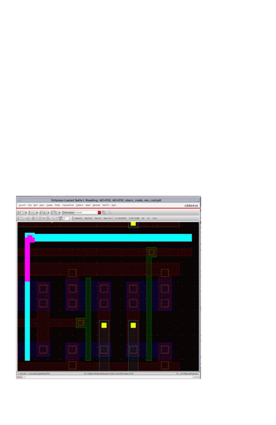
Chapter 12: Parasitic Extraction Integration With the Virtuoso Custom Design Platform
Parasitic Probing in the GUI 12-53
Chapter 12: Parasitic Extraction Integration With the Virtuoso Custom Design Platform
Parasitic Probing in the GUI 12-53
StarRC User Guide and Command Reference Version F-2011.06
Point-to-Point Resistance Probing
Point-to-point (P2P) resistance probing allows you to query two same-net nodes from the
selected view and derive the corresponding parasitic path resistance between these two
nodes. This calculation uses resistance network reduction techniques to reduce the network
down to the two selected nodes and report the equivalent resistance between the two
nodes.
In addition to probing nodes, you can also manually enter the node names into the
corresponding text boxes on the prober form in order to compute equivalent point-to-point
resistance.
Double Highlighting of Point-to-Point Resistance Probe Results
Virtuoso Integration can display double highlighting for the probe results of a point-to-point
resistance network. This feature can help you visualize the parasitic extractions results more
easily.
Figure 12-22 shows an example of double highlighting. The entire net is highlighted in cyan.
The point-to-point resistance probe results are highlighted in magenta.
Figure 12-22 Double Highlighting of a Point-to-Point Resistance Network
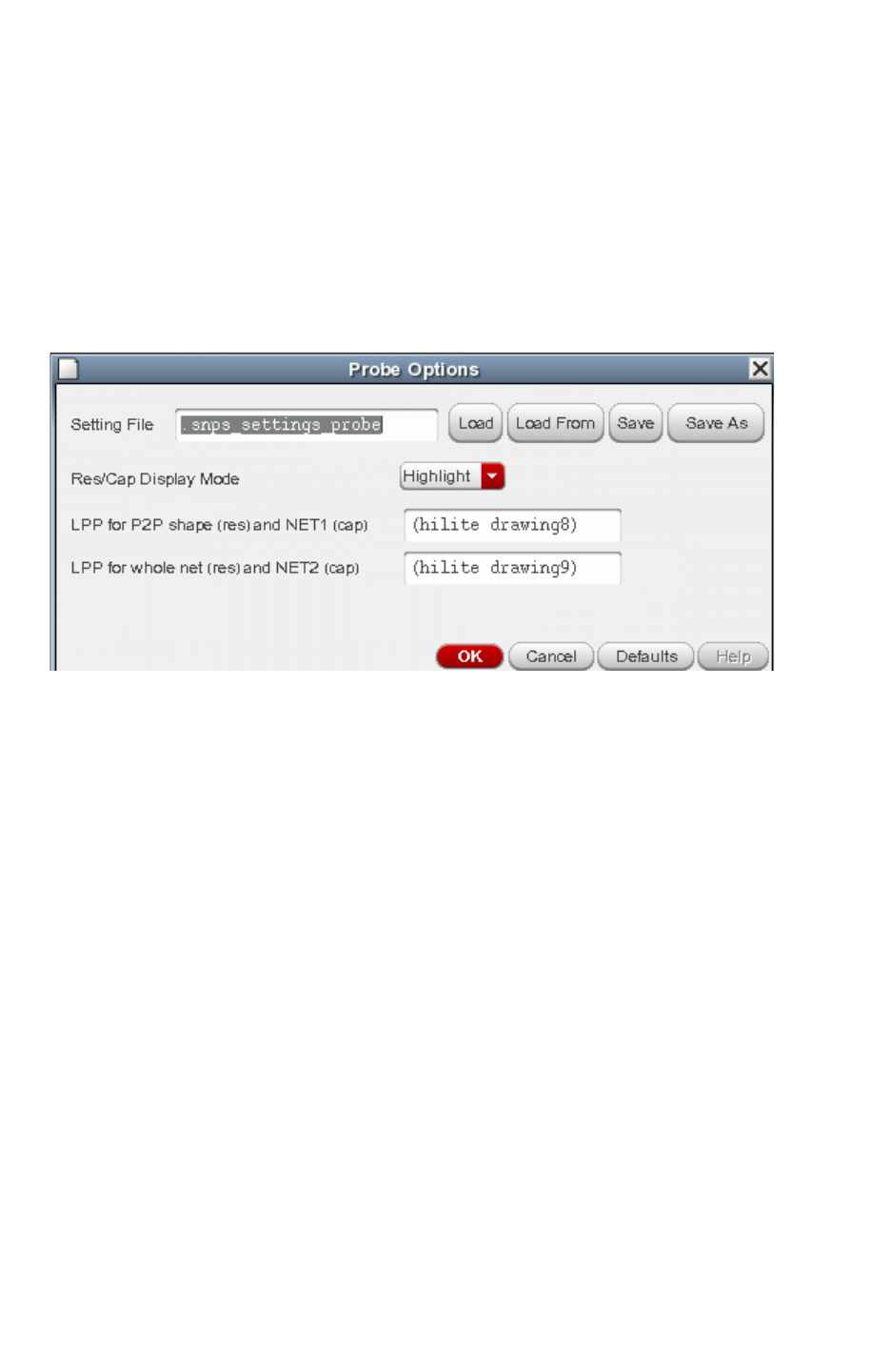
Chapter 12: Parasitic Extraction Integration With the Virtuoso Custom Design Platform
Parasitic Probing in the GUI 12-54
StarRC User Guide and Command Reference F-2011.06
StarRC User Guide and Command Reference Version F-2011.06
To enable double highlighting, add the following commands to your star_cmd file:
REDUCTION : NO
EXTRA_GEOMETRY_INFO: NODE RES
To adjust the highlighting properties, click the Option button. The dialog box shown in
Figure 12-23 appears. You can load or save your settings in the dialog box to the probe
setting file, which defaults to the .snps_settings_probe file.
Figure 12-23 GUI Options Dialog Box
The Res/Cap Display Mode gives you two choices: Highlight and Blinking.
You can specify the color and fill of the highlights in the LPP settings boxes. The color and
fill is picked up from your Virtuoso display resource.
Blinking Probe Results
If you set the Res/Cap Display Mode to Blinking, the Prober displays the probe results as
blinking highlights. Note the following limitations to the blinking highlights:
• Only the highlight for the whole net blinks. The highlight of the P2P partial net does not
blink.
• In blinking mode, the Prober changes the display resource to have blinking LPP. A new
packet—with “B” appended to the original name—is created and used for this LPP.
• The prober tries to add temporary shapes to the view for blinking effects.
If you save the view, Virtuoso Integration asks you to confirm saving the changes made by
the blinking mode. If you do not want to save the changes made by Virtuoso Integration,
choose Cancel.

Chapter 12: Parasitic Extraction Integration With the Virtuoso Custom Design Platform
Parasitic Probing in the GUI 12-55
Chapter 12: Parasitic Extraction Integration With the Virtuoso Custom Design Platform
Parasitic Probing in the GUI 12-55
StarRC User Guide and Command Reference Version F-2011.06
Parasitic View Probing
When you are probing point-to-point resistance inside the parasitic view, it is only possible
to query polygons listed as node (that is, port or subnode) layer-purpose pairs in the Runset
Layer to DFII Layer mapping file. If no node LPPs are specified in that file, point-to-point
parasitic probing is deactivated in the probing utility.
Schematic View Probing
Schematic-based probing of parasitic view resistance is available both when probing the
top-level schematic corresponding to the parasitic view block and when probing
out-of-context by descending the schematic view hierarchy. With this feature, you can probe
instance terminals within the schematic view, and corresponding nodes are located within
the selected parasitic view. It is possible to probe a hierarchical schematic and achieve
resistance results even if the underlying parasitic extraction flattened all hierarchy (that is,
SKIP_CELLS:!*). If you do not specify the OBSERVATION_POINTS command, StarRC adds it
to the Virtuoso Integration run.
The matching of instance terminals from a hierarchical schematic to parasitic subnodes from
a flattened extraction is accomplished as follows:
• The StarRC OBSERVATION_POINTS command generates parasitic subnodes
corresponding to hierarchical interactions of cells that are not SKIP_CELLS. Therefore, it
is possible to probe the terminal of a cell instance in schematic that does not correspond
to a SKIP_CELLS cell and still have the parasitic prober find a directly corresponding node
in the flat parasitic extraction.
• There are several situations where it is not possible to match a probed schematic
instance terminal to a subnode in the parasitic view.
OBSERVATION_POINTS only generates nodes when net material in the parent cell
interacts with port material in the child cell in layout. If, for example, a top-level net in
layout connects through a level-1 instance down to port material inside a level-2 instance,
with no port material existing specifically in the level-1 block, no OBSERVATION_POINTS
node is generated for the level-0 to level-1 interaction.
OBSERVATION_POINTS nodes are only generated for parent-cell/child-cell interactions
when the child cell is listed as a successfully matched EQUIV point (Hercules flow) or
HCELL (Calibre flow) in the LVS output.
When no direct match is found, the parasitic prober searches for all valid parasitic
terminal nodes which (a) connect to the same top-level net as does the probed schematic
instance terminal, and (b) are located inside the specific instance probed in schematic.
All matching parasitic nodes that meet these criteria are used when reporting
point-to-point resistance. Hence, if you probe one schematic terminal that matches M
parasitic terminal nodes, and a second schematic terminal that matches N parasitic
terminal nodes, a total of M * N point-to-point resistance results are reported.

Chapter 12: Parasitic Extraction Integration With the Virtuoso Custom Design Platform
Parasitic Probing in the GUI 12-56
StarRC User Guide and Command Reference F-2011.06
StarRC User Guide and Command Reference Version F-2011.06
Probed Results Log and Cross-Probing
As various point-to-point resistances are probed within either the schematic view or the
parasitic view, results are stored within the results logs, as shown in Figure 12-20. If a
window containing the parasitic view is open, you can select a previously probed resistance
entry in the results log and click Display to highlight or zoom-in to the node shapes between
which the resistance value applies. A flyline also appears between the two node shapes. In
this manner, you can probe point-to-point resistance results in the schematic view and then
select the result in the prober in order to see it highlighted in the parasitic view.
Note that such highlighting and zooming functions only if node markers are contained inside
the parasitic view for the two nodes listed in the selected resistance result. It is possible to
probe the schematic and build resistance results in the results log but be unable to highlight
and zoom in to such results due the fact that node shapes were not generated during
parasitic view generation. For a description of the origin of parasitic view node shapes, see
“Preparing a Runset-Layer-to-DFII Layer Mapping File” on page 12-7.”
Capacitance Probing
The capacitance probing section of the probing utility enables three modes of capacitance
probing via a menu selection list: Total, Net to Net, and All Couplings. Total and All Couplings
both query the total capacitance for a single net. However, the latter gives a list of all
constituent coupling capacitances that make up that total capacitance, while the former
does not. Net to Net allows you to query two separate nets and see the total coupling
capacitance only between those nets. In addition to probing graphical net shapes, you can
also manually enter net names into the corresponding fields in the prober form in order to
compute capacitance.
Parasitic View Probing
When you are probing total capacitance and coupling capacitance, it is only possible to
query polygons listed as polygon layer-purpose pairs in the Runset Layer to DFII Layer
mapping file. When a particular polygon is queried, the total parasitic capacitance for the net
on which that polygon exists is reported.
Schematic View Probing
With schematic-based probing of parasitic capacitance, you are able to query shapes (line
shapes, typically) in any level of schematic hierarchy that correspond to nets. The prober
then reports the total parasitic capacitance for that net from the selected parasitic view. This
functionality is available when probing either the top-level schematic corresponding to the

Chapter 12: Parasitic Extraction Integration With the Virtuoso Custom Design Platform
Parasitic Probing in the GUI 12-57
Chapter 12: Parasitic Extraction Integration With the Virtuoso Custom Design Platform
Parasitic Probing in the GUI 12-57
StarRC User Guide and Command Reference Version F-2011.06
parasitic view block or when probing out-of-context by descending the schematic view
hierarchy. If a net is probed inside a schematic view context that exists below the extracted
top block, then the parasitic prober
• Translates the contextually probed net into its net name relative to the extracted top
schematic block
• Reports the total capacitance for that top-level net name
Hence, if you contextually probe a port net within a level of hierarchy below the top block,
that net name is translated into the name of the net at the highest level of hierarchy at which
the net exists in the schematic.
Probe Results Log and Cross-Probing
As with resistance, it is possible to select capacitance results from the results log in order to
highlight the net corresponding to those results inside the parasitic view. If a window
containing the parasitic view is open, you can select a previously probed capacitance entry
and click Display to highlight the corresponding parasitic view net. As with resistance
cross-probing, such highlighting works only when the parasitic view contains polygons
corresponding to the net selected in the capacitance results log. Also, capacitance results in
the log can be sorted according to net name, capacitance value, or coupling percentage by
clicking the corresponding column header above the capacitance log.
Prober File Input and Output
The toolbar of the parasitic prober contains two buttons used to store and load parasitic
results between the prober form and a text file.
Button Description
Save to File Saves all results contained in the resistance results log and
capacitance results log to a specified text file.
Load From File Loads capacitance and resistance results from a specified text
file into the prober form results logs.
Schematic Annotation
The Parasitic Prober provides the ability to annotate schematic net names with total
capacitance information from the parasitic view specified in the prober form. Select the
Schematic Annotation button on the Parasitic Prober form. This button is shown in
Figure 12-20 on page 12-49. This activates the Schematic Capacitance Annotation form.
The annotations are highlight labels instantiated on layer-purpose pairs:
(“annotate” “drawing8”)
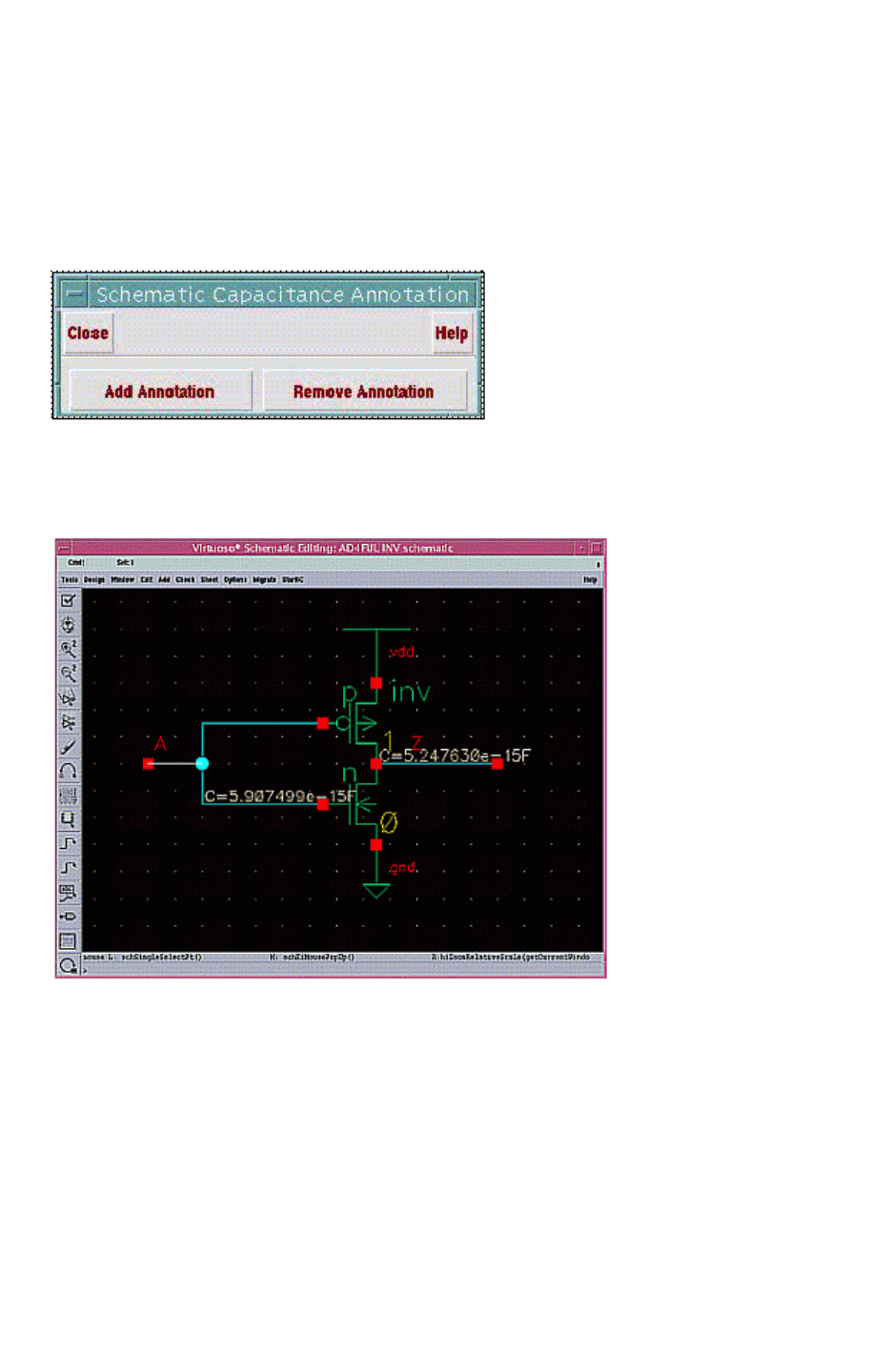
Chapter 12: Parasitic Extraction Integration With the Virtuoso Custom Design Platform
Parasitic Probing in the GUI 12-58
StarRC User Guide and Command Reference F-2011.06
StarRC User Guide and Command Reference Version F-2011.06
When you click either the Add Annotation or Remove Annotation in the Schematic
Capacitance Annotation form, a separate form appears that allows the addition or removal
of parasitic view total capacitance annotations to the specified schematic view. This form is
shown in Figure 12-24.
Figure 12-24 Schematic Annotation Form
An example of a simple inverter schematic annotated with parasitic capacitance is shown in
Figure 12-25.
Figure 12-25 Example of a Schematic With Parasitic Capacitance Annotation
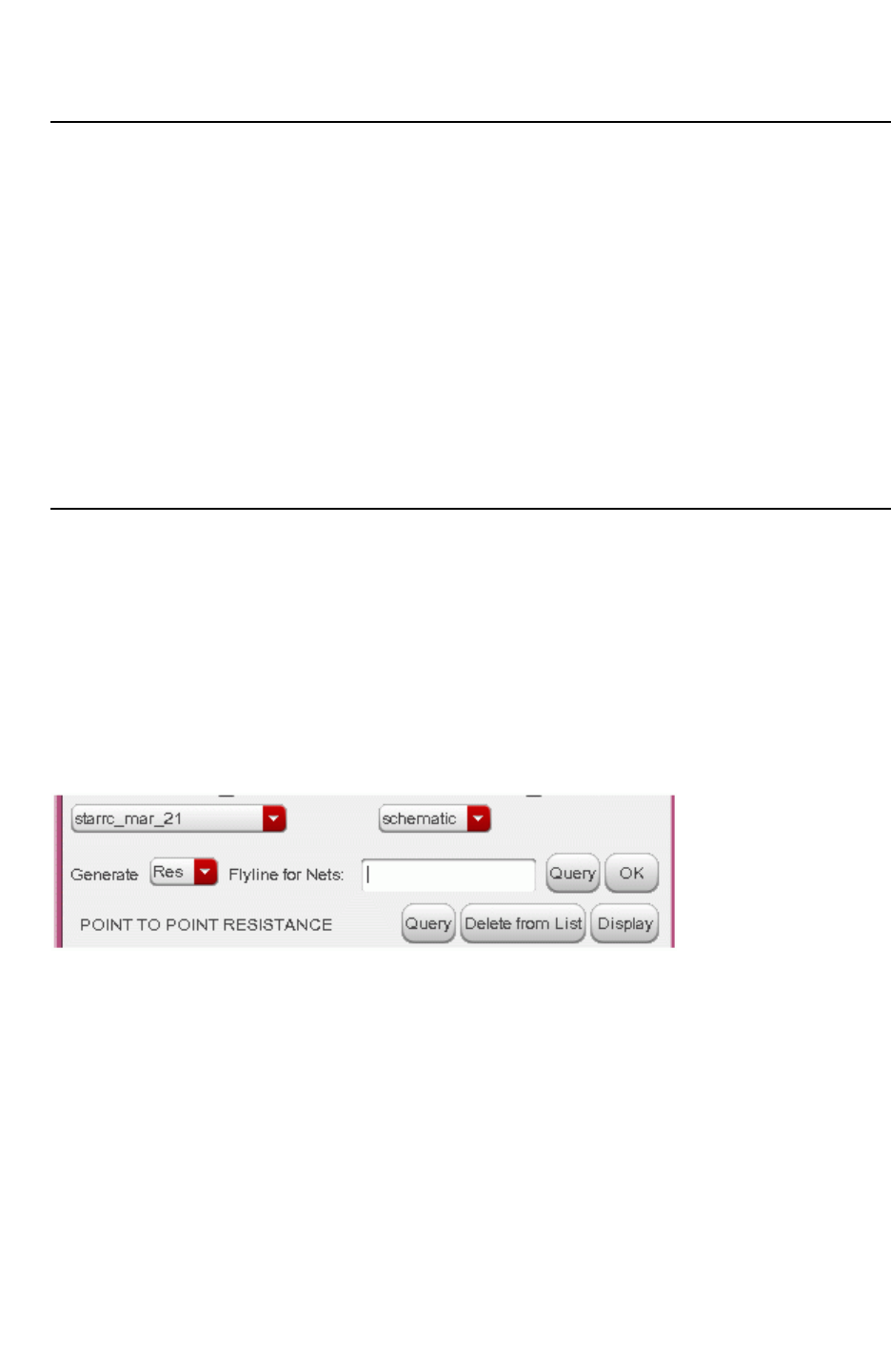
Chapter 12: Parasitic Extraction Integration With the Virtuoso Custom Design Platform
Parasitic Probing in the GUI 12-59
Chapter 12: Parasitic Extraction Integration With the Virtuoso Custom Design Platform
Parasitic Probing in the GUI 12-59
StarRC User Guide and Command Reference Version F-2011.06
View Selection
Parasitic view probing is done either within the parasitic view or the schematic view. The
Parasitic View and Schematic View radio buttons at the top of the prober form enable
probing for either the selected parasitic view or the selected schematic view. Only one
probing mode is selectable at a time, but the mode can be changed at any time using these
radio buttons.
The menus beneath the Parasitic View and Schematic View radio buttons enable you to
select the specific view names to be used for each mode. The parasitic view name or
schematic view name can be changed at any time. Note that when parasitic view probing is
in effect, the selected schematic view is not relevant and is ignored. However, when
schematic view probing is in effect, the selected parasitic view specifies the view from which
resistance and capacitance parasitics is read.
Dynamic Flylines for Probing
When you want to probe point-to-point resistance or capacitance, flylines can help you
select the right node pair. Virtuoso Integration has the capability to generate flylines
dynamically only for certain nets.
In the Flyline for Nets field in the Prober GUI, shown in Figure 12-26, enter the net names or
click Query to start a search. When you click OK, Virtuoso Integration generates the flylines
for the specified nets.
Figure 12-26 Specify Nets to Generate Dynamic Flyline
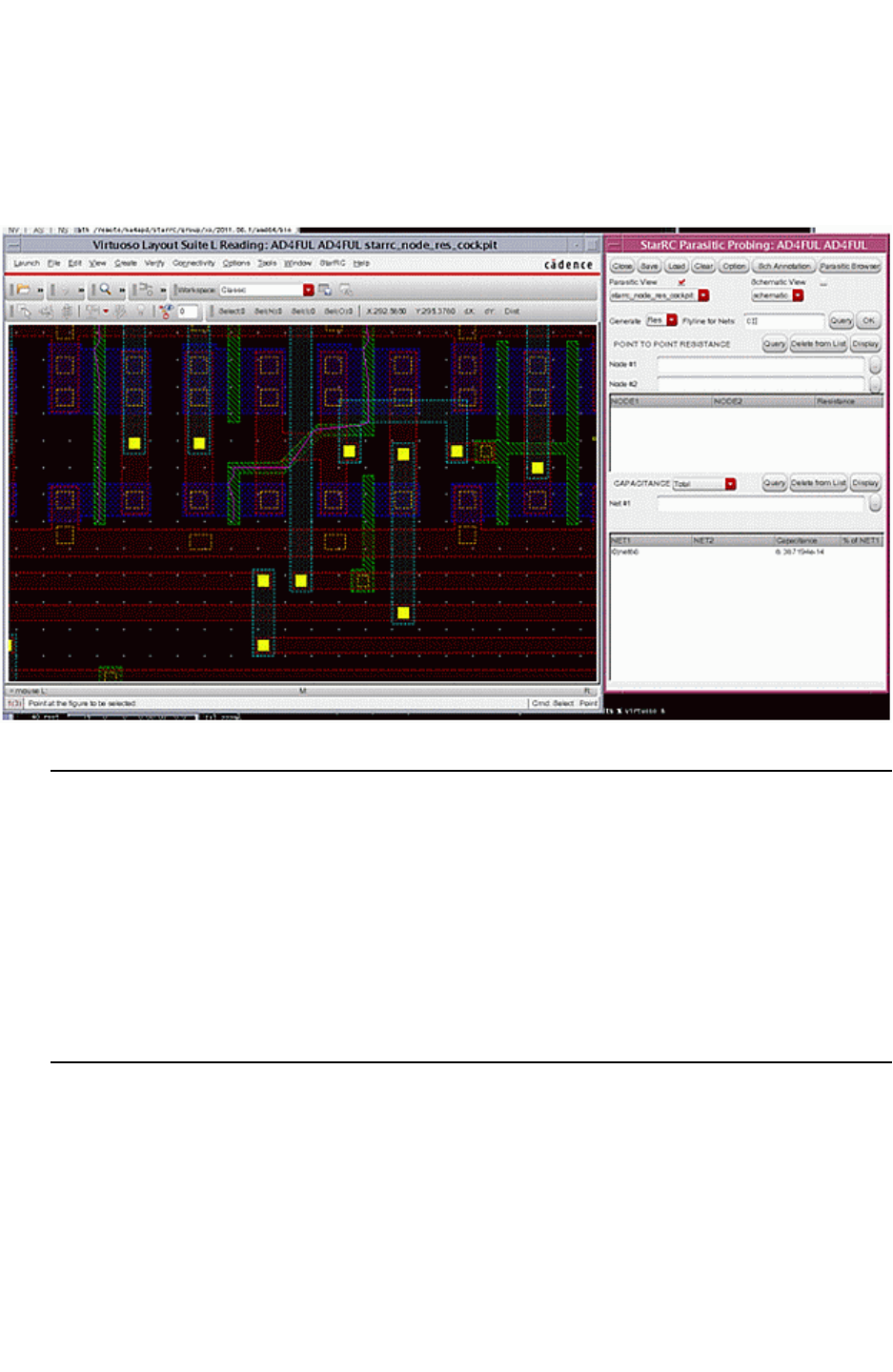
Chapter 12: Parasitic Extraction Integration With the Virtuoso Custom Design Platform
Parasitic Probing in the GUI 12-60
StarRC User Guide and Command Reference F-2011.06
StarRC User Guide and Command Reference Version F-2011.06
The flylines can assist you in point-to-point probing. Figure 12-27 shows the flyline
generated for net CI.
Figure 12-27 Dynamic Flyling Probing
Point-to-Point Resistance Probing
Point-to-point resistance probing allows you to query two same-net nodes from the selected
view and derive the corresponding parasitic path resistance between these two nodes. This
calculation uses resistance network reduction techniques to reduce the network down to the
two selected nodes and report the equivalent resistance between the two nodes. This gives
you the power and flexibility to query the equivalent resistance between any two discrete
nodes on a net. In addition to probing nodes, you can also manually enter node names into
the corresponding fields in the prober form in order to compute equivalent point-to-point
resistance.
Parasitic View Probing
When you are probing point-to-point resistance inside the parasitic view, it is only possible
to query polygons listed as node (that is, port or subnode) layer-purpose pairs in the Runset
Layer to DFII Layer mapping file. If no node LPPs were specified in that file, point-to-point
parasitic probing is deactivated in the probing utility.

Chapter 12: Parasitic Extraction Integration With the Virtuoso Custom Design Platform
Parasitic Probing in the GUI 12-61
Chapter 12: Parasitic Extraction Integration With the Virtuoso Custom Design Platform
Parasitic Probing in the GUI 12-61
StarRC User Guide and Command Reference Version F-2011.06
Schematic View Probing
Schematic-based probing of parasitic view resistance is available both when probing the
top-level schematic corresponding to the parasitic view block and when probing
out-of-context by descending the schematic view hierarchy. With this feature, you can probe
instance terminals within the schematic view, and corresponding nodes are located within
the selected parasitic view. It is possible to probe a hierarchical schematic and achieve
resistance results even if the underlying parasitic extraction flattened all hierarchy (that is,
SKIP_CELLS:!*). If you do not specify the OBSERVATION_POINTS command, StarRC adds it
to the Virtuoso Integration run.
The matching of instance terminals from a hierarchical schematic to parasitic subnodes from
a flattened extraction is accomplished as follows:
• The StarRC OBSERVATION_POINTS command generates parasitic subnodes
corresponding to hierarchical interactions of cells that are not SKIP_CELLS. Thus it is
possible to probe the terminal of a cell instance in schematic that does not correspond to
a SKIP_CELLS cell and still have the parasitic prober find a directly corresponding node in
the flat parasitic extraction.
• There are several situations where it is not possible to match a probed schematic
instance terminal to a subnode in the parasitic view.
OBSERVATION_POINTS only generates nodes when net material in the parent cell
interacts with port material in the child cell in layout. If, for example, a top-level net in
layout connects through a level-1 instance down to port material inside a level-2 instance,
with no port material existing specifically in the level-1 block, no OBSERVATION_POINTS
node is generated for the level-0 to level-1 interaction.
OBSERVATION_POINTS nodes are only generated for parent-cell/child-cell interactions
when the child cell is listed as a successfully matched EQUIV point (Hercules flow) or
HCELL (Calibre flow) in the LVS output.
When no direct match is found, the parasitic prober searches for all valid parasitic
terminal nodes which (a) connect to the same top-level net as does the probed schematic
instance terminal, and (b) are located inside the specific instance probed in schematic.
All matching parasitic nodes that meet these criteria are used when reporting
point-to-point resistance. Hence, if you probe one schematic terminal that matches M
parasitic terminal nodes, and a second schematic terminal that matches N parasitic
terminal nodes, a total of M * N point-to-point resistance results are reported.
Probed Results Log and Cross-Probing
As various point-to-point resistances are probed within either the schematic view or the
parasitic view, results are stored within the results logs (see Figure 12-20 on page 12-49). If
a window containing the parasitic view is open, you can select a previously probed

Chapter 12: Parasitic Extraction Integration With the Virtuoso Custom Design Platform
Parasitic Probing in the GUI 12-62
StarRC User Guide and Command Reference F-2011.06
StarRC User Guide and Command Reference Version F-2011.06
resistance entry in the results log and click Display to highlight or zoom-in to the node
shapes between which the resistance value applies. A flyline also appears between the two
node shapes. In this manner, you can probe point-to-point resistance results in the
schematic view and then select the result in the prober in order to see it highlighted in the
parasitic view.
Note that such highlighting and zooming functions only if node markers are contained inside
the parasitic view for the two nodes listed in the selected resistance result. It is possible to
probe the schematic and build resistance results in the results log but be unable to highlight
and zoom in to such results due the fact that node shapes were not generated during
parasitic view generation. For more information about parasitic view node shapes, see
“Preparing a Runset-Layer-to-DFII Layer Mapping File” on page 12-7.
Prober File Input and Output
The toolbar of the parasitic prober contains two buttons used to store and load parasitic
results between the prober form and a text file.
Button Description
Save to File Saves all results contained in the resistance results log and
capacitance results log to a specified text file.
Load From File Loads capacitance and resistance results from a specified text
file into the prober form results logs.
Schematic Annotation
The Parasitic Prober provides the ability to annotate schematic net names with total
capacitance information from the parasitic view specified in the prober form. Select the
Schematic Annotation button on the Parasitic Prober form. This button is shown in
Figure 12-20 on page 12-49. This activates the Schematic Capacitance Annotation form.
The annotations are highlight labels instantiated on layer-purpose pairs:
(“annotate” “drawing8”)
When you click either the Add Annotation or Remove Annotation in the Schematic
Capacitance Annotation form, a separate form appears that allows the addition or removal
of parasitic view total capacitance annotations to the specified schematic view. This form is
shown in Figure 12-28.
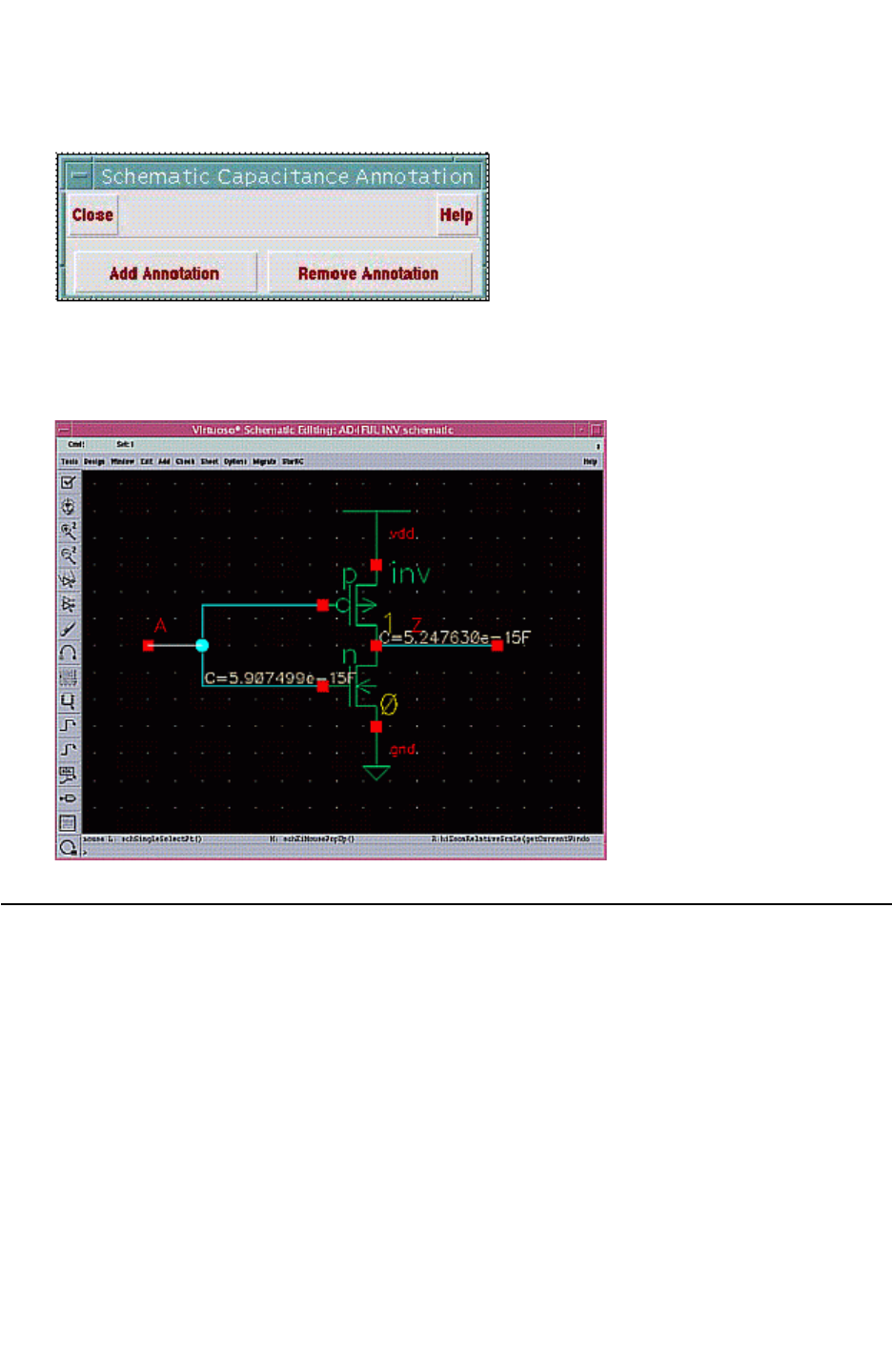
Chapter 12: Parasitic Extraction Integration With the Virtuoso Custom Design Platform
Virtuoso Integration Skill Procedures and Related Variables 12-63
Chapter 12: Parasitic Extraction Integration With the Virtuoso Custom Design Platform
Virtuoso Integration Skill Procedures and Related Variables 12-63
StarRC User Guide and Command Reference Version F-2011.06
Figure 12-28 Schematic Annotation Form
An example of a simple inverter schematic annotated with parasitic capacitance is shown in
Figure 12-29.
Figure 12-29 Example of a Schematic With Parasitic Capacitance Annotation
Virtuoso Integration Skill Procedures and Related Variables
As you load the rcskill.cxt file, you can use two types of SKILL procedures:
•GUI Integration with a Custom Interface
•Batch Mode Procedures

Chapter 12: Parasitic Extraction Integration With the Virtuoso Custom Design Platform
Virtuoso Integration Skill Procedures and Related Variables 12-64
StarRC User Guide and Command Reference F-2011.06
StarRC User Guide and Command Reference Version F-2011.06
GUI Integration with a Custom Interface
You can customize your user interface with the following features:
•RC_ADD_MENU environment variable
The RC_ADD_MENU environment variable controls the StarRC pulldown menu in the layout
and schematic windows.
Variable Definition
RC_ADD_MENU = YES StarRC pulldown menu is shown in the layout and schematic
windows
RC_ADD_MENU = NO StarRC pulldown menu not shown in the layout and schematic
windows
Note:
This variable must be set prior to invoking callInitProc to load the StarRC Virtuoso
Integration feature; this setting remains in effect for the entire Virtuoso session.
•RCProbeFormLaunch SKILL procedure
If you set RC_ADD_MENU=NO to disable the StarRC pulldown menu, you can use the
following SKILL procedure to enable the Parasitic Prober to be launched from your
custom user interface:
RCProbeFormLaunch(hiGetCurrentWindow())
•SetupAllInOneForm SKILL procedure
If you set RC_ADD_MENU=NO to disable the StarRC pulldown menu, you can use the
following SKILL procedure to enable the Cockpit GUI to be launched from your custom
user interface:
SetupAllInOneForm(hiGetCurrentWindow())
Batch Mode Procedures
You can access batch mode parasitic view generation with the following procedures:
•RCGenParaViewBatch
•RCGenParaViewBatch2
•RCCockpitRun

Chapter 12: Parasitic Extraction Integration With the Virtuoso Custom Design Platform
Virtuoso Integration Skill Procedures and Related Variables 12-65
Chapter 12: Parasitic Extraction Integration With the Virtuoso Custom Design Platform
Virtuoso Integration Skill Procedures and Related Variables 12-65
StarRC User Guide and Command Reference Version F-2011.06
RCGenParaViewBatch2 differs from RCGenParaViewBatch by using an evalstring instead
of a loadstring. The location of each value assignment statement is followed by the variable
name.
It is also easier to add features with RCGenParaViewBatch2. For example, the
genPhyPolygon argument controls physical view generation. In RCGenParaViewBatch, the
physical view is always generated, and there is no variable to disable its generation.
RCGenParaViewBatch
RCGenParaViewBatch( LIBNAME CELLNAME VIEWNAME cmdfile
devmapfile lyrmapfile extract [blockMode]
[runDir] [layoutCell] [mkrSize] [preprocCallback]
[postprocCallback] )
Table 12-6 Arguments for RCGenParaViewBatch
Argument Definition Datatype
LIBNAME Library name for output parasitic view string
CELLNAME Cell name for output parasitic view string
VIEWNAME View name for output parasitic view string
cmdfile User-defined StarRC command file string
devmapfile DFII_DEVICE_MAP from user string
lyrmapfile DFII_LAYER_MAP from user string
extract If t, run StarXtract -clean; if nil, run StarXtract -cleanN Boolean
blockMode If t, then RCGenParaViewBatch runs in blocking mode during
the StarXtract run; if nil, procedure runs StarXtract in
nonblocking mode; default is nil
Boolean
runDir Directory where StarRC is run; defaults to current Virtuoso
directory
string
designCell Cell from which pin direction, isGlobal nets, and inherited
connectivity is read; defaults to layout
string
mkrSize Port or subnode marker size; defaults to 0.1 string
preprocCallback Procedural call to a view preprocessing callback string
postprocCallback Procedural call to a view postprocessing callback string

Chapter 12: Parasitic Extraction Integration With the Virtuoso Custom Design Platform
Virtuoso Integration Skill Procedures and Related Variables 12-66
StarRC User Guide and Command Reference F-2011.06
StarRC User Guide and Command Reference Version F-2011.06
The following table lists the return values of the batch mode parasitic view arguments.
Return value Description
tWhen blockMode == nil, inputs are valid and view generation can be launched.
When blockMode == t, view generation was completed successfully.
nil When blockMode == nil, an invalid input is found.
When blockMode == nil, view generation was completed abnormally.

Chapter 12: Parasitic Extraction Integration With the Virtuoso Custom Design Platform
Virtuoso Integration Skill Procedures and Related Variables 12-67
Chapter 12: Parasitic Extraction Integration With the Virtuoso Custom Design Platform
Virtuoso Integration Skill Procedures and Related Variables 12-67
StarRC User Guide and Command Reference Version F-2011.06
RCGenParaViewBatch2
procedure(
RCGenParaViewBatch2(
@key dfiiInputLib dfiiInputCell dfiiOutputView cmdFile
dfiiDeviceMap dfiiLayerMap extract blockMode runDir
(dfiiInputView "layout") (subnodeSize "0.1")
preprocessCallback postprocessCallback
spiceCardStripInstpathCallback spiceCardStripPrimitiveCallback
dfiiOutputLib dfiiOutputCell (genPhyPolygn t) (genFlyline nil)
(skip_cell_list "") (oa_writer t ) (oa_lib_def "") (carry_sch_prop t)
(sch_view_name "schematic") (lsf_command nil)
(propmap_case_sensitive nil)
(port_annotation_view "")
)
Some field values are required; some are optional.
Return Value Meaning
oa_writer (t)/nil select to use StarRC oa_writer or skill writer
oa_lib_def Additional OA library definition
lsf_command LSF configuration file to let Virtuoso Integration know LSF
settings
propmap_case_sensitive t/(nil) propmap behavior that controls case sensitivity
port_annotation_view View for Virtuoso Integration to annotate ports
RCCockpitRun
After each Virtuoso job execution, a cockpit_cmd file is output and saved in the run
directory. You can use this cockpit_cmd file as the input to a RCCockpitRun batch mode
run.
After a successful Virtuoso Integration run several Virtuoso Integration-created files remain
in the run directory. An RCCockpitRun Virtuoso Integration job can be rerun if the
cockpit_cmd, gui_cmd, and view_cmd files are kept.
Keeping these files and specifying the command RCCockpitRun("cockpit_cmd") in the
Cadence CIW window replicates a Virtuoso run. The gui_cmd can be used to replicate the
Virtuoso job.

Chapter 12: Parasitic Extraction Integration With the Virtuoso Custom Design Platform
General Notes 12-68
StarRC User Guide and Command Reference F-2011.06
StarRC User Guide and Command Reference Version F-2011.06
General Notes
This section contains general notes on the usage of Virtuoso Integration.
Specifying Relative Paths
Any relative path that you specify in the Cockpit must be relative to the run directory—the
directory in which you invoke Virtuoso.
Any relative path that you specify in the RCGenParaViewBatch or RCGenParaViewBatch2
SKILL procedures must be relative to the StarRC run directory.
Hierarchy Separator for Calibre Connectivity Interface
If you use the Calibre Connectivity Interface (CCI) with Virtuoso Integration, add the
following command to the Calibre query command file:
HIERARCHY SEPARATOR |
This command forces Calibre to use the pipe character (|) instead of the slash (/) as the
hierarchical separator for compatibility with Virtuoso Integration.


Chapter 13: Examples
Command File Examples 13-2
StarRC User Guide and Command Reference F-2011.06
StarRC User Guide and Command Reference Version F-2011.06
Command File Examples
These examples use the minimum set of command options, to illustrate the simplicity of
StarRC operation.
Timing Extraction/Analysis
The following examples illustrate a Milkyway, LEF/DEF, and Hercules extraction/analysis
sample command file.
Milkyway Database
BLOCK: toprt
MILKYWAY_DATABASE: xtdesign
TCAD_GRD_FILE: example.nxtgrd
MAPPING_FILE: xt.mapping
LEF/DEF Database
LEF_FILE: tech.lef cells.lef
TOP_DEF_FILE: toprt.def
TCAD_GRD_FILE:example.nxtgrd
MAPPING_FILE: xt.mapping
Hercules Database
BLOCK: toprt
MILKYWAY_DATABASE: xtdesign
MILKYWAY_EXTRACT_VIEW: yes
TCAD_GRD_FILE: example.nxtgrd
MAPPING_FILE: xt.mapping
Calibre Database
BLOCK : cl_u1_inv_1x
TCAD_GRD_FILE : ../cln45gs_1p11m+alrdl_4x2y4z_typical.nxtgrd
MAPPING_FILE : ../starrc_mapping_1p11m
CALIBRE_RUNSET : ../../calibre/cal_lvs.ctrl
CALIBRE_QUERY_FILE : ../../query/query.cmd
Netlist Format Examples
This section shows examples of the netlist formats specified by
•SPF
•STAR

Chapter 13: Examples
Netlist Format Examples 13-3
Chapter 13: Examples
Netlist Format Examples 13-3
StarRC User Guide and Command Reference Version F-2011.06
•SPEF
•CONLY
•NETNAME
•NETLIST_IDEAL_SPICE_FILE
SPF
*
*|DSPF 1.0
*|DESIGN top
*|DATE “Wed May 17 13:34:43 2000”
*|VENDOR “Synopsys”
*|PROGRAM “StarRC”
*|VERSION “2003.2.0.0”
*|DIVIDER /
*|DELIMITER :
*
.SUBCKT top net1
*|GROUND_NET 0
*|NET net1 9.60e-04PF
*|P (net1 I 0 3.6 0)
*|I (U1:I U1 I I 4e-15 6.76 8.94)
R1 net1 U1:I 29.8492
Cg1 net1 0 5.8737e-16
Cg2 U1:I 0 3.72441e-16
*|NET insta/net2 5.10e-04PF
*|I (insta/U1:ZN insta/U1 ZN O 0 9.12 21.84)
*|I (insta/U2:I insta/U2 I I 4e-15 6.34 20.94)
R2 insta/U1:ZN insta/U2:I 16.8989
Cg3 insta/U1:ZN 0 2.96927e-16
Cg4 insta/U2:I 0 2.13328e-16
*
* Instance Section
*
Xinsta/U2 insta/U2:I in2 VDD VSS inv
Xinsta/U1 in1 insta/U1:ZN VDD VSS inv
XU1 U1:I net2 VDD VSS inv
.ENDS

Chapter 13: Examples
Netlist Format Examples 13-4
StarRC User Guide and Command Reference F-2011.06
StarRC User Guide and Command Reference Version F-2011.06
STAR
*
*|DSPF 1.3
*|DESIGN top
*|DATE “Wed May 17 13:38:52 2000”
*|VENDOR “Synopsys”
*|PROGRAM “StarRC”
*|VERSION “2003.2.0.0”
*|DIVIDER /
*|DELIMITER :
*
.SUBCKT top net1
*|GROUND_NET 0
*|NET net1 9.60e-04PF
*|P (net1 I 0 3.6 0)
*|I (F5 U1 I I 4e-15 6.76 8.94)
*|S (F6 3.6 0)
Rnet1 net1 F6 0.001
R1 F6 F5 29.8492
Cg1 F6 0 5.8737e-16
Cg2 F5 0 3.72441e-16
*|NET insta/net2 5.10e-04PF
*|I (F2 insta/U1 ZN O 0 9.12 21.84)
*|I (F4 insta/U2 I I 4e-15 6.34 20.94)
R2 F2 F4 16.8989
Cg3 F2 0 2.96927e-16
Cg4 F4 0 2.13328e-16
*
* Instance Section
*
Xinsta/U2 F4 in2 VDD VSS inv
Xinsta/U1 in1 F2 VDD VSS inv
XU1 F5 net2 VDD VSS inv
.ENDS

Chapter 13: Examples
Netlist Format Examples 13-5
Chapter 13: Examples
Netlist Format Examples 13-5
StarRC User Guide and Command Reference Version F-2011.06
SPEF
*SPEF “IEEE 1481-1998”
*DESIGN “top”
*DATE “Wed May 17 19:50:14 2000”
*VENDOR “Synopsys”
*PROGRAM “StarRC”
*VERSION “2003.2.0.0”
*DESIGN_FLOW “PIN_CAP NONE” “NAME_SCOPE LOCAL”
*DIVIDER /
*DELIMITER :
*BUS_DELIMITER []
*T_UNIT 1 NS
*C_UNIT 1 FF
*R_UNIT 1 OHM
*L_UNIT 1 HENRY
*NAME_MAP
*5 net1
*10 insta/net2
*14 U1
*16 insta/U1
*17 insta/U2
*PORTS
*5 I *C 3.6 0
*D_NET *5 1.02e+00
*CONN
*P *5 I *C 3.6 0
*I *14:I I *C 6.76 8.94 *L 4 *D inv
*CAP
1 *5 0.60481
2 *14:I 0.413795
*RES
1 *5 *14:I 29.8492
*END
*D_NET *10 4.58e-01
*CONN
*I *16:ZN O *C 9.12 21.84
*I *17:I I *C 6.34 20.94 *L 4 *D inv
*CAP
1 *16:ZN 0.271701
2 *17:I 0.186

Chapter 13: Examples
Netlist Format Examples 13-6
StarRC User Guide and Command Reference F-2011.06
StarRC User Guide and Command Reference Version F-2011.06
*RES
1 *16:ZN *17:I 16.8989
*END
CONLY
*
*|DSPF 1.3
*|DESIGN toprt
*|DATE "Fri Apr 27 14:55:18 2001"
*|VENDOR "Synopsys"
*|PROGRAM "StarRC"
*|VERSION "2003.2.0.0"
*|DIVIDER /
*|DELIMITER :
**FORMAT CONLY
*
*|GROUND_NET 0
*|NET min_lsb/cnt_blk1/n195 8.62e-03PF
C1 min_lsb/cnt_blk1/n195 sec_msb_led[2] 1.17924e-15
Cg2 min_lsb/cnt_blk1/n195 0 7.43896e-15
*|NET min_msb_led[0] 1.07e-02PF
Cg3 min_msb_led[0] 0 1.06511e-14
*|NET min_msb_led[1] 1.66e-02PF
C4 min_msb_led[1] sec_msb/conv_blk1/n65 8.30274e-16
Cg5 min_msb_led[1] 0 1.57797e-14
*
* Instance Section
*
Xmin_lsb/cnt_blk1/U39 min_lsb/n100 min_lsb/cnt_blk1/n185
VDD VSS INV2
Xmin_msb/cnt_blk1/U44 VDD min_msb/cnt_blk1/n216 VDD VSS INV2
Xmin_lsb/cnt_blk1/U45 min_lsb/n100 min_lsb/cnt_blk1/n195
min_lsb/cnt_blk1/n190 VDD VSS AND2
Xsec_msb/conv_blk1/U33 sec_msb/conv_blk1/n68
sec_msb_led[2] sec_msb/conv_blk1/n67 VDD VSS OR2
Xsec_msb/conv_blk1/U29 sec_msb/conv_blk1/n52 sec_msb/
conv_blk1/n65 sec_msb/bcd[2] VDD VSS OR2
...

Chapter 13: Examples
Netlist Format Examples 13-7
Chapter 13: Examples
Netlist Format Examples 13-7
StarRC User Guide and Command Reference Version F-2011.06
NETNAME
*
*|DSPF 1.3
*|DESIGN toprt
*|DATE "Thu May 10 13:00:11 2001"
*|VENDOR "Synopsys"
*|PROGRAM "StarRC"
*|VERSION "2003.2.0.0"
*|DIVIDER /
*|DELIMITER :
**FORMAT STAR
*
*|GROUND_NET 0
*|NET min_msb_led[0] 1.06e-02PF
*|P (min_msb_led[0] O 0 0 425.8)
*|I (min_msb_led[0]:F485 min_msb/conv_blk1/U4 X O 0 37 394)
Rmin_msb_led[0] min_msb_led[0] min_msb_led[0]:F1558 0.001
Cg1 min_msb_led[0]:F485 0 3.17002e-15
Cg2 min_msb_led[0]:F1558 0 7.44086e-15
R1 min_msb_led[0]:F485 min_msb_led[0]:F1558 12.105
*|NET min_lsb/cnt_blk1/n200 1.00e-02PF
*|I (min_lsb/cnt_blk1/n200:F191 min_lsb/cnt_blk1/U51 X O 0
63.9 49.8)
*|I (min_lsb/cnt_blk1/n200:F141 min_lsb/cnt_blk1/U53 C I 5e-
14 117 53)
Cg3 min_lsb/cnt_blk1/n200:F191 0 5.58775e-15
Cg4 min_lsb/cnt_blk1/n200:F141 0 4.42815e-15
R2 min_lsb/cnt_blk1/n200:F191 min_lsb/cnt_blk1/n200:F141
10.1364
*
* Instance Section
*
Xmin_lsb/cnt_blk1/U39 min_lsb/n100:F162 min_lsb/cnt_blk1/
n185:F164 VDD VSS INV2
Xmin_msb/cnt_blk1/U44 VDD min_msb/cnt_blk1/n216:F521 VDD
VSS INV2
Xmin_lsb/cnt_blk1/U45 min_lsb/n100:F235 min_lsb/cnt_blk1/
n195:F239 min_lsb/cnt_blk1/n190:F237 VDD VSS AND2
Xsec_msb/conv_blk1/U33 sec_msb/conv_blk1/n68:F1471
sec_msb_led[2]:F1475 sec_msb/conv_blk1/n67:F1473 VDD VSS
OR2
Xsec_msb/conv_blk1/U29 sec_msb/conv_blk1/n52:F1476
sec_msb/conv_blk1/n65:F1480 sec_msb/bcd[2]:F1478 VDD VSS
OR2

Chapter 13: Examples
Netlist Format Examples 13-8
StarRC User Guide and Command Reference F-2011.06
StarRC User Guide and Command Reference Version F-2011.06
NETLIST_IDEAL_SPICE_FILE
* SPICE Netlist
* VENDOR "Synopsys, Inc."
* PROGRAM "StarRC"
* DATE "Thu May 16 16:26:00 2002"
**FORMAT SPICE
.SUBCKT AND2 B A OUT
XS1I1 B A S1N3 NAND2
XS1I2 OUT S1N3 INVA
.ENDS AND2
.SUBCKT AND3 C B A OUT
XS1I1 C B A S1N9 NAND3
XS1I2 OUT S1N9 INVA
.ENDS AND3
.SUBCKT CS_ADD1 SUM COUT C B A
XS1I2 B A S1N29 AND2
XS1I3 C S1N9 S1N31 AND2
XS1I4 S1N43 S1N35 S1N39 AND2
XS1I5 S1N29 S1N31 S1N35 NOR2
XS1I6 S1N41 S1N39 S1N37 NOR2
XS1I7 C B A S1N41 AND3
XS1I8 C B A S1N43 OR3
XS1I16 B A S1N9 OR2
XS1I33 COUT S1N35 INVA
XS1I34 SUM S1N37 INVA
.ENDS CS_ADD1
.SUBCKT INVA OUT IN
MS1I1 OUT IN GND GND N ad=39p as=39p l=1u pd=32u ps=32u w=13u
MS1I2 VDD IN OUT VDD P ad=61.5p as=61.5p l=1u pd=47u ps=47u
w=20.5u
.ENDS INVA
*.SUBCKT N D G S VBB
*.ENDS N
.SUBCKT NAND2 B A QN
MS1I1 S1N20 A GND GND N ad=13p as=39p l=1u pd=15u ps=32u w=13u
MS1I3 VDD B QN VDD P ad=61.5p as=46.125p l=1u pd=47u ps=25u
w=20.5u
MS1I4 VDD A QN VDD P ad=61.5p as=46.125p l=1u pd=47u ps=25u
w=20.5u
MS1I25 QN B S1N20 GND N ad=39p as=13p l=1u pd=32u ps=15u w=13u
.ENDS NAND2
.SUBCKT NAND3 C B A QN
MS1I1 S1N11 A GND GND N ad=19.5p as=39p l=1u pd=16u ps=32u

Chapter 13: Examples
Netlist Format Examples 13-9
Chapter 13: Examples
Netlist Format Examples 13-9
StarRC User Guide and Command Reference Version F-2011.06
w=13u
MS1I4 VDD A QN VDD P ad=61.5p as=41p l=1u pd=47u ps=24.5u
w=20.5u
MS1I28 VDD B QN VDD P ad=35.875p as=41p l=1u pd=24u ps=24.5u
w=20.5u
MS1I29 VDD C QN VDD P ad=35.875p as=61.5p l=1u pd=24u ps=47u
w=20.5u
MS1I30 S1N32 B S1N11 GND N ad=19.5p as=19.5p l=1u pd=16u
ps=16u w=13u
MS1I31 QN C S1N32 GND N ad=39p as=19.5p l=1u pd=32u ps=16u
w=13u
.ENDS NAND3
.SUBCKT NOR2 B A QN
MS1I1 QN A GND GND N ad=29.25p as=39p l=1u pd=17.5u ps=32u
w=13u
MS1I2 QN B GND GND N ad=29.25p as=39p l=1u pd=17.5u ps=32u
w=13u
MS1I3 S1N5 B QN VDD P ad=20.5p as=112.75p l=1u pd=22.5u
ps=52u w=20.5u
MS1I4 VDD A S1N5 VDD P ad=61.5p as=20.5p l=1u pd=47u ps=22.5u
w=20.5u
.ENDS NOR2
.SUBCKT NOR3 C B A QN
MS1I1 QN A GND GND N ad=26p as=39p l=1u pd=17u ps=32u w=13u
MS1I2 QN B GND GND N ad=26p as=22.75p l=1u pd=17u ps=16.5u
w=13u
MS1I3 S1N5 B S1N25 VDD P ad=30.75p as=30.75p l=1u pd=23.5u
ps=23.5u w=20.5u
MS1I4 VDD A S1N5 VDD P ad=61.5p as=30.75p l=1u pd=47u ps=23.5u
w=20.5u
MS1I41 S1N25 C QN VDD P ad=30.75p as=82p l=1u pd=23.5u ps=49u
w=20.5u
MS1I42 QN C GND GND N ad=39p as=22.75p l=1u pd=32u ps=16.5u
w=13u
.ENDS NOR3
.SUBCKT OR2 B A OUT
XS1I1 B A S1N3 NOR2
XS1I2 OUT S1N3 INVA
.ENDS OR2
.SUBCKT OR3 C B A OUT
XS1I1 C B A S1N3 NOR3
XS1I2 OUT S1N3 INVA
.ENDS OR3
*.SUBCKT P D G S VBB
*.ENDS P
*.SUBCKT ADD4 S1N9 S1N7 S1N5 SUM3 SUM2 SUM1 SUM0 COUT CIN
B3 B2 B1 B0 A3 A2 A1 A0

Chapter 13: Examples
XREF Command SPF Examples 13-10
StarRC User Guide and Command Reference F-2011.06
StarRC User Guide and Command Reference Version F-2011.06
XS1I1 SUM0 S1N5 CIN B0 A0 CS_ADD1
XS1I2 SUM1 S1N7 S1N5 B1 A1 CS_ADD1
XS1I3 SUM2 S1N9 S1N7 B2 A2 CS_ADD1
XS1I4 SUM3 COUT S1N9 B3 A3 CS_ADD1
*.ENDS ADD4
XREF Command SPF Examples
The following examples are for XREF: SPF.
XREF: NO
*|NET I_0/N_33 1.49e-02PF
*|I (I_0/I_39/M2:SRC I_0/I_39/M2 SRC B 0 -402.5 36.25)
*|I (I_0/I_39/M1:SRC I_0/I_39/M1 SRC B 0 -402.5 11)
*|I (I_0/I_41/M3:GATE I_0/I_41/M3 GATE I 1e-15 -419.5 36.25)
*|I (I_0/I_41/M1:GATE I_0/I_41/M1 GATE I 1e-15 -417 11)
Cg9 I_0/I_39/M2:SRC 0 4.82142e-15
Cg10 I_0/I_39/M1:SRC 0 6.20537e-15
Cg11 I_0/I_41/M3:GATE 0 1.62791e-15
Cg12 I_0/I_41/M1:GATE 0 2.25542e-15
R5 I_0/I_39/M2:SRC I_0/I_41/M3:GATE 141.086
R6 I_0/I_39/M2:SRC I_0/I_39/M1:SRC 1.41411
R7 I_0/I_39/M2:SRC I_0/I_41/M1:GATE 66.6508
R8 I_0/I_39/M1:SRC I_0/I_41/M3:GATE 95.2203
R9 I_0/I_39/M1:SRC I_0/I_41/M1:GATE 44.9831
R10 I_0/I_41/M3:GATE I_0/I_41/M1:GATE 625.714
XREF: YES
*|NET B6 0.0223556PF
*|I (MM18@2:g MM18@2 g I 0.00425085 12.725 143.652)
*|I (MM18:g MM18 g I 0.00425085 11.875 143.652)
*|I (MM17@2:s MM17@2 s B 0 23.565 143.652)
*|I (MM17:s MM17@2 s B 0 23.565 143.652)
Cg30 MM18@2:g 0 2.0949e-15
Cg31 MM18:g 0 2.75462e-15
Cg32 MM17@2:s 0 2.03411e-15
Cg33 MM17:s 0 1.87562e-15
Cg34 B6:79 0 1.57134e-15
Cg35 B6:85 0 7.22334e-15
R7537 MM17:s B6:177 32.2773
R7538 MM17@2:s B6:173 48.3553
R7539 MM18:g B6:85 32.0359
R7540 MM18@2:g B6:79 32.2773
R7541 B6:85 B6:79 32.0359

Chapter 13: Examples
Fast SPICE Integration 13-11
Chapter 13: Examples
Fast SPICE Integration 13-11
StarRC User Guide and Command Reference Version F-2011.06
XREF: COMPLETE (SPF)
*|NET x0/n33 1.49e-02PF
*|I (x0/x39/M2:SRC x0/x39/M2 SRC B 0 -402.5 36.25)
*|I (x0/x39/M1:SRC x0/x39/M1 SRC B 0 -402.5 11)
*|I (x0/x41/M3:GATE x0/x41/M3 GATE I 1e-15 -419.5 36.25)
*|I (x0/x41/M1:GATE x0/x41/M1 GATE I 1e-15 -417 11)
Cg1 x0/x39/M2:SRC 0 4.82142e-15
Cg2 x0/x39/M1:SRC 0 6.20537e-15
Cg3 x0/x41/M3:GATE 0 1.62791e-15
Cg4 x0/x41/M1:GATE 0 2.25542e-15
R1 x0/x39/M2:SRC x0/x41/M3:GATE 141.086
R2 x0/x39/M2:SRC x0/x39/M1:SRC 1.41411
R3 x0/x39/M2:SRC x0/x41/M1:GATE 66.6508
R4 x0/x39/M1:SRC x0/x41/M3:GATE 95.2203
R5 x0/x39/M1:SRC x0/x41/M1:GATE 44.9831
R6 x0/x41/M3:GATE x0/x41/M1:GATE 625.714
Fast SPICE Integration
Because you can set multiple commands in a StarRC command file when extracting a
design for HSIM reliability analysis, often designers specify more design parameters than
are needed. This leads to high memory use as well as the netlist size being larger than
needed. To remedy this, you can use the TARGET_PWRA:YES command to generate a netlist
relevant to the reliability analysis flow. You need only specify the power nets in the command
file.
Creating the Simplified Command File
To create the simplified command file, specify the commands as shown in the following
example:
BLOCK:
MILKYWAY_DATABASE:
MILKYWAY_EXTRACT_VIEW:
TARGET_PWRA:YES
POWER_NETS: list_of_power_nets
TCAD_GRD_FILE:
NETLIST_INSTANCE_SECTION: YES|ALL
MAPPING_FILE:
MODE:200
XREF:YES
SKIP_CELLS:
Note:
If any commands automatically set by the TARGET_PWRA command conflict with your other
settings, then either your settings will be overridden, or a warning will be issued.
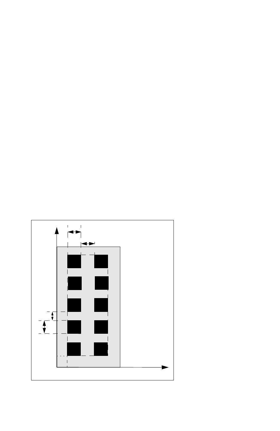
Chapter 13: Examples
Fast SPICE Integration 13-12
StarRC User Guide and Command Reference F-2011.06
StarRC User Guide and Command Reference Version F-2011.06
Using the NETLIST_INSTANCE_SECTION command forces StarRC to netlist devices
connected to an unextracted power net.
Output Netlists
When you set this option in the command file, StarRC extracts two netlists, one unreduced
resistor netlist for power nets and another reduced RC coupled netlist for signal nets. The
signal netlist is useful not only for reliability analysis, but also for signal timing analysis.
Specifying Other Commands
When specifying the TARGET_PWRA command, use only the POWER_REDUCTION: LAYER,
REDUCTION: LAYER, and KEEP_VIA_NODES: NO commands.
SPF Geometry Visualization in HSIM
To perform SPF visualization of the merged vias with MAX_VIA_ARRAY_SPACING or
MAX_VIA_ARRAY_LENGTH in the mapping file, specify the NETLIST_TAIL_COMMENTS: YES,
EXTRA_GEOMETRY_INFO: NODE, and KEEP_VIA_NODES: YES commands in your command
file.
Figure 13-1 shows a 5-by-2 via array. Each via is 0.2-by-0.2-micron, vertical via-to-via
spacing is 0.15 micron, and horizontal via-to-via spacing is 0.2 micron. If you specify
MAX_VIA_ARRAY_ SPACING=0.3, this via array is identified and extracted as one via resistor.
Figure 13-1 Via Array
0.2
0.2
0.2
0.15
(0, 0)
(0,0.2)
(0.2,0) X
Y

Chapter 13: Examples
Fast SPICE Integration 13-13
Chapter 13: Examples
Fast SPICE Integration 13-13
StarRC User Guide and Command Reference Version F-2011.06
If NETLIST_TAIL_COMMENTS is set to YES, the following is printed:
R45 29 32 0.2 $a=0.4 $lvl=5 $n=5x2 $p=4.4
Nodes 29 and 32 reside on the upper and lower layers connected by the via resistor. The via
resistor value is calculated based on the total area of the vias represented by the $a
parameter. The $p parameter represents the perimeter of the bounding box of the via array
and is calculated as follows:
perimeter = (0.2 x 2 + 0.2) x 2 + (0.2 x 5 + 0.15 x 4) * 2 = 4.4

Chapter 13: Examples
Fast SPICE Integration 13-14
StarRC User Guide and Command Reference F-2011.06
StarRC User Guide and Command Reference Version F-2011.06

14-1
14
Transistor-Level Runset Creation 14
This chapter contains information for transistor-level extractions. There is also information
for modifying a Calibre rule file for use in the StarRC Calibre Connectivity Interface (CCI)
flow. Included are rules and examples for developing Hercules, IC Validator, and Calibre
transistor-level ideal layout extraction runsets, StarXtract mapping files, and command files
The chapter contains the following sections:
•Preparing Hercules Runsets
•Preparing IC Validator Runsets
•Preparing Calibre Rule Files
•Preparing the Mapping File
•Running the Calibre Query Server for Output to StarRC
•Preparing the StarXtract Command File
•Interconnect Technology Format File
•General Limitations
•Limitations in XREF Flows

Chapter 14: Transistor-Level Runset Creation
Preparing Hercules Runsets 14-2
StarRC User Guide and Command Reference F-2011.06
StarRC User Guide and Command Reference Version F-2011.06
Preparing Hercules Runsets
The following information explains how to prepare Hercules runsets. Runset rules, required
commands, and a sample runset are included.
Runset Rules
In preparing the Hercules runset, there are certain rules you have to follow in data
manipulation:
Terminology
• Runset layer: Any layer specified in the CONNECT section of the Hercules runset.
• Physical layer: Any layer specified as a CONDUCTOR or VIA in the ITF file.
Rule 1 – A runset layer via may connect only two physical layers.
Wrong:
CONNECT m1 poly BY cont
CONNECT m1 nsd psd BY cont
It is important to separate metal1 to diffusion contacts (dCont) and metal1 to poly contacts
(pCont), because these two contacts connect metal1 to two different physical layers at
different levels in the ITF file. In SOI/STI processes where diffusion and substrate exist on
two different physical levels in the ITF file, it might also be necessary to distinguish metal1
to substrate contacts (sCont). See Figure 14-1. Metal1 to substrate contacts (where
diffusion and substrate exist on separate physical levels in the ITF file) are shown.
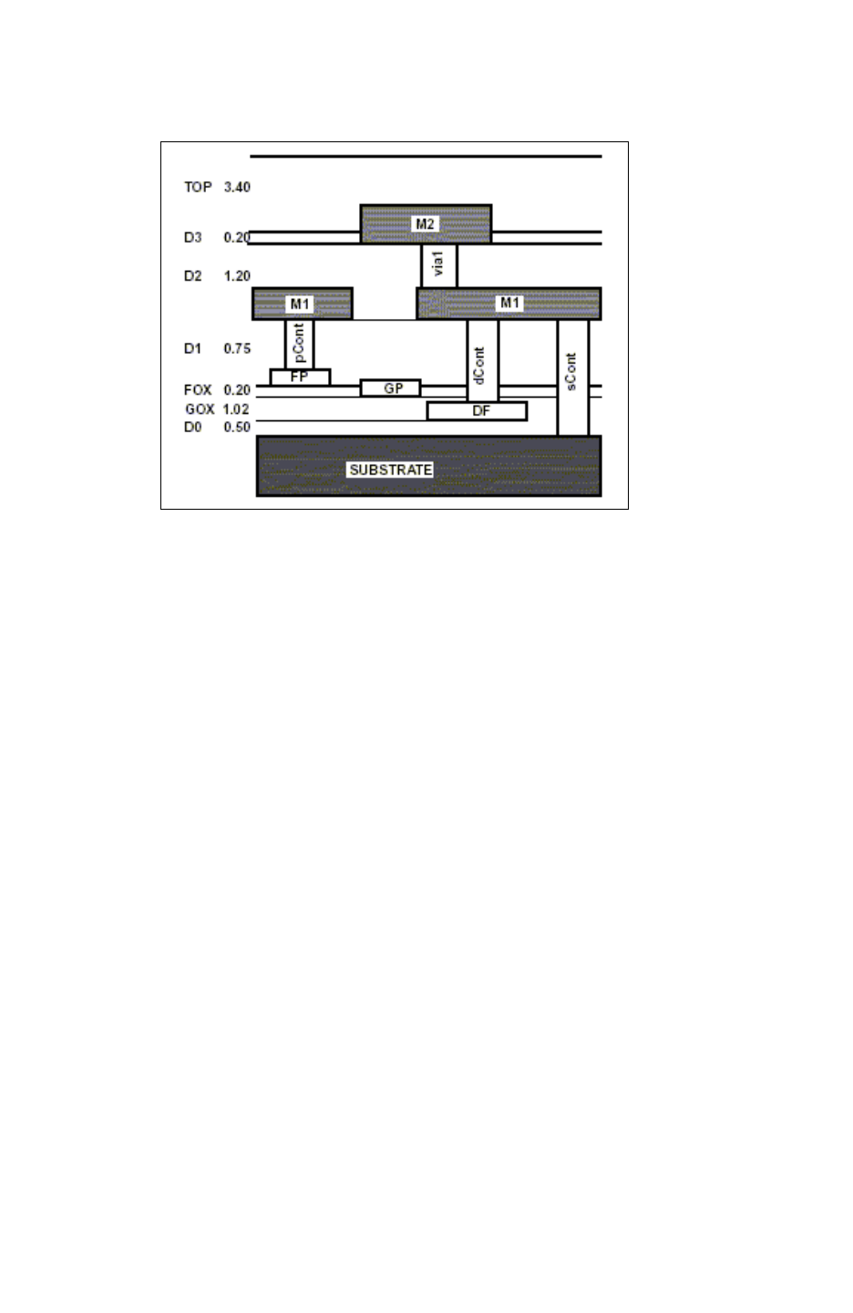
Chapter 14: Transistor-Level Runset Creation
Preparing Hercules Runsets 14-3
Chapter 14: Transistor-Level Runset Creation
Preparing Hercules Runsets 14-3
StarRC User Guide and Command Reference Version F-2011.06
Figure 14-1 Separate Metal1 to Diffusion Contacts
For most runsets, following the correct convention is simple. In general, the runset should
have specific contacts for connecting the following physical layers:
…
metal2 - metal1
metal1 - poly
metal1 - diffusion and/or SUBSTRATE
Correct:
BOOLEAN cont AND poly {} TEMP = polyCont
BOOLEAN cont NOT polyCont {} TEMP = subCont
CONNECT m1 poly BY polyCont
CONNECT m1 nsd psd BY subCont
Rule 2 – All device runset layers should be “NOTed” from the routing runset layers.
Removing portions of routing layers that overlap device layers allows StarRC to correctly
ignore device capacitances. This is a must for MOS gate, source, and drain terminals as well
as for CAP terminals.
Wrong:
BOOLEAN poly AND ndiff {} TEMP = ngate
BOOLEAN ndiff NOT poly {} TEMP = nsd
NMOS n ngate nsd nsd SUSBTRATE {} TEMP = ndev
BOOLEAN m2 AND cap_recog {} TEMP = cap_top
BOOLEAN m1 AND cap_recog {} TEMP = cap_bot
BOOLEAN cap_top AND cap_bot {} TEMP = cap_dev
CAP m1m2cap cap_dev cap_top cap_bot {} TEMP = cdev

Chapter 14: Transistor-Level Runset Creation
Preparing Hercules Runsets 14-4
StarRC User Guide and Command Reference F-2011.06
StarRC User Guide and Command Reference Version F-2011.06
CONNECT poly BY ngate
CONNECT cap_top BY m2
CONNECT cap_bot BY m1
StarRC does not ignore the gate cap correctly, and the designed capacitance is
double-counted in this example. Other devices might not have these issues.
Correct:
BOOLEAN poly AND ndiff {} TEMP = ngate
BOOLEAN ndiff NOT poly {} TEMP = nsd
BOOLEAN poly NOT ngate {} TEMP = poly
NMOS n ngate nsd nsd SUBSTRATE {} TEMP = ndev
BOOLEAN m2 AND cap_recog {} TEMP = cap_top
BOOLEAN m1 AND cap_recog {} TEMP = cap_bot
BOOLEAN cap_top AND cap_bot {} TEMP = cap_dev
BOOLEAN m2 NOT cap_top {} TEMP = m2
BOOLEAN m1 NOT cap_bot {} TEMP = m1
CAP m1m2cap cap_dev cap_top cap_bot {} TEMP = cdev
CONNECT poly BY ngate
CONNECT cap_top BY m2
CONNECT cap_bot BY m1
The Boolean NOT for the gate and field poly is required for planar (where gate poly and field
poly layers are both mapped to a single POLY layer in the nxtgrd file) as well as nonplanar
processes (where gate poly and field poly layers are mapped to separate co-vertical layers
in the nxtgrd file), because IGNORE_CAPACITANCE works in both cases.
Rule 3 – A physical layer cannot directly connect to another physical layer without
using a via, unless the two physical layers are co-vertical.
In Figure 14-1 on page 14-3 metal1 connects to metal2 by via1. However, there is no need
for a contact between physical layers FP and GP because they overlap on the vertical
profile. These two conductors are called covertical.
In the previous runset example, connecting poly and ngate layers is allowed because the
two runset layers map to the covertical physical layers FP and GP. Likewise, connecting
cap_top to m2 is allowed because both are mapped to the same physical layer M2. The
same also applies for cap_bot and m1.
Additional Notes
• EQUATE statements do not have to be included in the original Hercules runset;
Hercules-generated EQUATE statements in lvsflow/lvs_include.ev are sufficient.
• Command-line overrides can be used in the Hercules layout extraction/LVS compare.

Chapter 14: Transistor-Level Runset Creation
Preparing Hercules Runsets 14-5
Chapter 14: Transistor-Level Runset Creation
Preparing Hercules Runsets 14-5
StarRC User Guide and Command Reference Version F-2011.06
Required Commands
Some commands are required in your Hercules runset to make StarXtract run correctly.
They are listed here:
WRITE_EXTRACT_VIEW
WRITE_EXTRACT_VIEW {
LIBRARY_NAME = LIB_NAME
LIBRARY_PATH = .
}
StarXtract uses Milkyway XTR views, instead of the CHECK_POINT for input of the layout
database directory which was used for Star-RC.
After Hercules is finished, the XTR view is written into the LIB_NAME directory, which is
placed in your Hercules working directory. In writing this XTR view, Hercules creates its own
Milkyway technology file called hx2mw.tf.
The hx2mw.tf file has all the layer information of the XTR view, which is different from that in
the ASSIGN section of the runset. This is because the Milkyway XTR view database
contains only derived runset layers that contribute to connectivity or device formation; it does
not contain ASSIGN section layers unless those layers are directly used in CONNECT
statements or device extraction commands.
If the design originates from a Milkyway library, you should not write the XTR view into the
existing library. The technology file of the original Milkyway database is different from the
one made by Hercules. The specified LIBRARY_NAME option should be a unique library name
to which Hercules dumps the XTR view results.
You can open the XTR view from any Milkyway viewer.
TECHNOLOGY_OPTIONS
TECHNOLOGY_OPTIONS {
INCLUDE_TECHNOLOGY_DEFAULTS = FALSE
ALLOW_EXPLODE_WITH_TEXT = TRUE
EXPLODE_AREFS = TRUE /* Default: FALSE */
EXPLODE_1XN_AREFS = TRUE
EXPLODE_AUTO_FLATTEN_LIMIT=100
EXPLODE_CELL_SIZE_PERCENT=70
EXPLODE_CELL_SIZE_PERCENT_OF_TOP=70
EXPLODE_BIG_SPARSE_CELL=TRUE
POST_VCELL_EXPLODE_CELL_SIZE <= 10
VIA_AUTO_EXPLODE=TRUE
SUBLEAF_AUTO_EXPLODE=6
CELL_SIZE_AUTO_EXPLODE <= 10
EXPLODE_DATA_CELL_LIMIT = 1
POST_VCELL_EXPLODE_DATA_CELL_LIMIT = 12
EXPLODE_HOLDING_CELL_LIMIT = 1
EXPLODE_PLACEMENT_LIMIT = 1
VCELL_PASS {
MIN_CELL_OVERLAP = 60

Chapter 14: Transistor-Level Runset Creation
Preparing Hercules Runsets 14-6
StarRC User Guide and Command Reference F-2011.06
StarRC User Guide and Command Reference Version F-2011.06
RATIO=10000.000
MIN_COUNT = 40
MIN_LEAF = 40
STYLE = EXPLODE
}
}
You can use TECHNOLOGY_OPTIONS to optimize the hierarchy in a Hercules run, thereby
speeding up the run and reducing memory usage. In addition to providing these
performance advantages, these options optimize the output hierarchy in the XTR library,
which is used as an input to StarXtract. This enhances the StarRC performance significantly
(more than 50 percent) if the design is very hierarchical.
However, in XREF flows, some of the default options, such as VCELL_PASS {STYLE =
PAIRS} and VCELL_PASS {STYLE = SETS}, can cause unwanted explodes of EQUIV points
and possible mismatches. As a result, you should not use all of the default options for an
LVS-enabled Hercules run. This is because XREF:YES cross-references down to the EQUIV
points and all the EQUIV points should be preserved.
Consequently, you should have the TECHNOLOGY_OPTIONS in your Hercules runset, rather
than using the defaults. To make it easier, use the Hercules command-line option -rcxt to
set the TECHNOLOGY_OPTIONS for you. If you decide to use -rcxt make sure that your runset
does not have any TECHNOLOGY_OPTIONS. Finally, if
INCLUDE_TECHNOLOGY_DEFAULTS=FALSE is set in the Hercules runset, the Hercules -rcxt
option does not work.
NETLIST
NETLIST {}
NETLIST also does not do anything in generating XTR, but it is required for Hercules LVS.
Compare and Evaccess Directories
These are directories generated by Hercules; in XREF runs, StarXtract gets the
cross-reference information from these directories. Do not remove them before the
StarXtract run is over. The locations of these directories are detected automatically if they
have not been moved since the Hercules run was performed. If they have been moved, the
StarXtract command file options COMPARE_DIRECTORY and EVACCESS_DIRECTORY specify
the new paths to these directories.
Commands That Are No Longer Required
The following commands are no longer required in your runset:
•CHECK_POINT – The CHECK_POINT directory is not used any more.
•SAVE_NETLIST_DATABASE – The WRITE_EXTRACT_VIEW command does not get any
information from the SAVE_NETLIST_DATABASE command.

Chapter 14: Transistor-Level Runset Creation
Preparing Hercules Runsets 14-7
Chapter 14: Transistor-Level Runset Creation
Preparing Hercules Runsets 14-7
StarRC User Guide and Command Reference Version F-2011.06
•SPICE – Even in an XREF-enabled run, StarXtract does not look at the block.sp file for
cross-referencing.
•GRAPHICS_NETLIST – Because you have graphical output in XTR format, you do not have
to create another layout database in LTL format.
Sample Runset
The following is a typical Hercules runset for StarXtract transistor-level extraction.
HEADER {
LAYOUT_PATH = .
INLIB = ADD4_CUSTOM.GDS
OUTLIB = EV_OUT
FORMAT = GDSII
BLOCK = add4
SCHEMATIC = ADD4.sch
}
OPTIONS {
SCHEMATIC_GLOBAL = {VDD GND}
SCHEMATIC_GROUND = {GND}
SCHEMATIC_POWER = {VDD}
LAYOUT_GLOBAL = {VDD GND}
LAYOUT_POWER = {VDD}
LAYOUT_GROUND = {GND}
EXPLODE = {VIA *con *tie DEV_*}
NET_PREFIX = N_
EDTEXT = ADD4.text
}
TEXT_OPTIONS {
ATTACH_TEXT = ALL
CONNECT_BY_NAME = MIXED_MODE
}

Chapter 14: Transistor-Level Runset Creation
Preparing Hercules Runsets 14-8
StarRC User Guide and Command Reference F-2011.06
StarRC User Guide and Command Reference Version F-2011.06
ASSIGN {
Ndiff (1)
Pdiff (2)
Nwell (3)
Poly (5)
Cont (6)
Metal1 (8) TEXT (28)
Via1 (9)
Metal2 (10) TEXT (30)
PnAnode (51)
PnCathode (52)
NpCathode (61)
NpAnode (62)
NpnCollector (71)
NpnBase (72)
NpnEmitter (73)
Cap1 (11)
Cap2 (12)
PolyRes (20)
}
TEXT_POLYGON Metal2.text {
SIZE = 0.01
CELL_LIST = {add4}
TEXT_LIST = {* !*VDD* !*VSS* }
} TEMP = Metal2_Mark
/*** NPN BJT ***/
BOOLEAN Cont AND NpnEmitter {} TEMP = NpnEmitterCont
BOOLEAN Cont NOT NpnEmitterCont {} TEMP = Cont
BOOLEAN Cont AND NpnBase {} TEMP = NpnBaseCont
BOOLEAN Cont NOT NpnBaseCont {} TEMP = Cont
BOOLEAN Cont AND NpnCollector {} TEMP = NpnCollectorCont
BOOLEAN Cont NOT NpnCollectorCont {} TEMP = Cont
/*** Without these, all the three terminals of this Npn device will be
shorted and the device will be filtered out. ***/
NPN NpnDev NpnEmitter NpnBase NpnCollector SUBSTRATE {} TEMP = NpnDev
/*** PN DIODE ***/
BOOLEAN PnCathode NOT PnAnode {} TEMP = PnCathodeTerm
BOOLEAN PnAnode AND PnCathode {} TEMP = PnDevice
COPY PnAnode {} TEMP = PnAnodeTerm
DIODE PnDev PnDevice PnAnodeTerm PnCathodeTerm {
DIODE_TYPE = PN
DIODE_RECOGNITION_LAYER_USED = TRUE
} TEMP = PnDev

Chapter 14: Transistor-Level Runset Creation
Preparing Hercules Runsets 14-9
Chapter 14: Transistor-Level Runset Creation
Preparing Hercules Runsets 14-9
StarRC User Guide and Command Reference Version F-2011.06
/*** MOS ***/
BOOLEAN Pdiff AND Nwell {} TEMP = pdev
BOOLEAN Ndiff NOT Nwell {} TEMP = ndev
BOOLEAN Pdiff NOT Nwell {} TEMP = subtie
BOOLEAN Ndiff AND Nwell {} TEMP = welltie
BOOLEAN Poly AND ndev {} TEMP = ngate
BOOLEAN Poly AND pdev {} TEMP = pgate
BOOLEAN ndev NOT ngate {} TEMP = nsd
BOOLEAN pdev NOT pgate {} TEMP = psd
BOOLEAN Poly NOT ngate {} TEMP = Poly
BOOLEAN Poly NOT pgate {} TEMP = Poly
/*** These 2 BOOLEANs are mandatory for StarXtract. ***/
NMOS n ngate nsd nsd SUBSTRATE {} TEMP = ndevice
PMOS p pgate psd psd Nwell {} TEMP = pdevice
/*** Contact separation ***/
BOOLEAN Cont AND Poly {} TEMP = PolyCont
BOOLEAN Cont NOT PolyCont {} TEMP = SubCont
/*** Contact separation is a must for StarXtract. ***/
/*** CAPACITOR ***/
BOOLEAN Cap1 AND Metal1 {} TEMP = Cap1
BOOLEAN Cap2 AND Poly {} TEMP = Cap2
BOOLEAN Metal1 NOT Cap1 {} TEMP = Metal1
BOOLEAN Poly NOT Cap2 {} TEMP = Poly
BOOLEAN Cap1 AND Cap2 {} TEMP = CapRec
CAP CapDev CapRec Cap1 Cap2 {
EV_AREA_CAPVAL = 1.0e-15;
CAP_RECOGNITION_LAYER_USED = TRUE;
} TEMP = CapDev
/*** Poly RESISTOR ***/
BOOLEAN Poly AND PolyRes {} TEMP = pres_body
BOOLEAN Poly NOT pres_body {} TEMP = field_poly
/*** Routing layers can be used as resistor terminals. ***/
RES ResDev pres_body field_poly field_poly {
EV_RESVAL = 3.5;
} TEMP = ResDev

Chapter 14: Transistor-Level Runset Creation
Preparing Hercules Runsets 14-10
StarRC User Guide and Command Reference F-2011.06
StarRC User Guide and Command Reference Version F-2011.06
CONNECT {
Metal2 Metal1 BY Via1
Metal1 BY Cap1
Metal1 field_poly BY PolyCont
field_poly BY Cap2
Metal1 nsd psd welltie subtie BY SubCont
Metal1 PnCathodeTerm BY SubCont
Metal1 PnAnodeTerm BY SubCont
Metal1 NpnCollector BY NpnCollectorCont
Metal1 NpnBase BY NpnBaseCont
Metal1 NpnEmitter BY NpnEmitterCont
ngate pgate BY field_poly
Nwell BY welltie
SUBSTRATE BY subtie
Metal2_Mark BY Metal2
}
TEXT {
Metal1 BY Metal1.text
Metal2 BY Metal2.text
}
NETLIST {}
WRITE_EXTRACT_VIEW {
LIBRARY_NAME = ADDER
LIBRARY_PATH = .
}
COMPARE {}
Power Port Netlist Generation
By default, StarRC netlists only ports that are connected to extracted nets. Nets specified in
the POWER_NETS command are not extracted by default and therefore are not netlisted. There
are two ways to have these power ports netlisted:
• Exclude the power nets from the POWER_NETS command so that these nets are not
identified by StarRC as power nets and extracted.
• Include a SPICE file with the StarRC SPICE_SUBCKT_FILE command. StarRC uses this
SPICE file to duplicate the port list and ordering. This file can be generated from Hercules
by using the SPICE command in the Hercules runset. After the SPICE file is generated
and the power ports are netlisted in this .sp file, it can be specified in the star_cmd file as
the following:
SPICE_SUBCKT_FILE; .sp
The power ports are then netlisted in the parasitic netlist as they are in the .sp file, even
though they might still be included in the POWER_NETS command.

Chapter 14: Transistor-Level Runset Creation
Preparing Hercules Runsets 14-11
Chapter 14: Transistor-Level Runset Creation
Preparing Hercules Runsets 14-11
StarRC User Guide and Command Reference Version F-2011.06
Marker Generation in Hercules
The following sections show how you can generate text or layer markers.
Example of Text-Based Markers
The Hercules TEXT_POLYGON command is used for this flow; it generates a shape
surrounding selected text in the layout. It should be very small, because it is included in the
CONNECT sequence and can create shorts.
In the Hercules runset (runset.ev):
...
ASSIGN metal1 (3;0) text(3;4)
...
TEXT_POLYGON metal1.text {
text_list = { * }
cell_list = { TOP }
size = 0.1
} temp = metal1_pio
TEXT_POLYGON metal1.text {
text_list = { * }
cell_list = { * !TOP }
size = 0.1
} temp = metal1_pin
...
SELECT metal1 INTERACT metal1_pin { CELL_LEVEL } temp =
metal1_tmp
BOOLEAN metal1_tmp OR metal1_pin { } temp = metal1_pin
...
CONNECT metal1 BY metal1_pio
CONNECT metal1 BY metal1_pin
...
TEXT metal1 BY metal1
TEXT metal1_pio BY metal1
TEXT metal1_pin BY metal1
In the StarRC MAPPING_FILE (map):
conducting_layers
metal1
...
marker_layers
metal1_pio
metal1_pin
Example of ID-Layer Markers
The simplest approach to manual marker generation, this technique uses a preexisting input
layer (ASSIGN) to identify marker shapes.

Chapter 14: Transistor-Level Runset Creation
Preparing Hercules Runsets 14-12
StarRC User Guide and Command Reference F-2011.06
StarRC User Guide and Command Reference Version F-2011.06
In the Hercules runset (runset.ev):
...
ASSIGN metal1 (3;0) text (3;4)
ASSIGN metal1_pin (33;0)
ASSIGN PAD (32;0)
...
BOOLEAN metal1 AND PAD { } temp = metal1_pio
BOOLEAN metal1_pio OR metal1_pin = metal1_markers
...
CONNECT metal1 by metal1_markers
TEXT metal1 by metal1
TEXT metal1_markers by metal1
In the StarRC MAPPING_FILE (map):
conducting_layers
metal1
...
marker_layers
metal1_markers
Example of Connection-Based Markers
This approach uses hierarchical geometric interactions to identify exact connection points
into subcells. This is valid only for an all-Hercules flow. This technique uses either BOOLEAN
commands or CONNECTION_POINTS to generate an output layer that represents the
hierarchical interactions of conducting layers. In this example, the REMOVE_OVERLAP
command is used to eliminate redundancy in the layout for “overlay” ports. For more
information about this command, see the Hercules LVS User Guide.
In the Hercules runset (runset.ev):
ASSIGN cont (2;0)
ASSIGN metal1 (3;0) text (3;4)
ASSIGN via1 (4;0)
...
REMOVE_OVERLAP metal1 { } temp = metal1_tmp
CONNECTION_POINTS metal1_tmp metal1_tmp cont via1 {}
temp=metal1_pin
CONNECT metal1 by metal1_pin
TEXT metal1 by metal1
TEXT metal1_pin by metal1
In the StarRC MAPPING_FILE (map):
conducting_layers
metal1
...
marker_layers
metal1_pin

Chapter 14: Transistor-Level Runset Creation
Preparing IC Validator Runsets 14-13
Chapter 14: Transistor-Level Runset Creation
Preparing IC Validator Runsets 14-13
StarRC User Guide and Command Reference Version F-2011.06
Preparing IC Validator Runsets
The following section explains the rules and the required commands in the IC Validator
runsets.
Runset Rules
When creating an IC Validator runset, you must follow certain rules in data manipulation.
The following layer definitions are accepted by IC Validator:
• Runset layer – Any layer specified in the connect section of the IC Validator runset.
• Physical layer – Any layer specified as a CONDUCTOR or VIA in the ITF file.
Rule 1 – A runset layer via may connect only two physical layers.
input_cdb = connect(
connect_items = {
{{M1, poly}, cont},
{{M1, nsd, psd}, cont}
….
};
Separating metal1 to diffusion contacts (dCont) and metal1 to poly contacts (pCont) is
necessary because these two contacts connect metal1 to two different physical layers at
different levels in the ITF file. In SOI or STI processes where diffusion and substrate exist on
two different physical levels in the ITF file, distinguishing the metal1 to substrate contacts
(sCont) might also be necessary. Metal1 to substrate contacts where diffusion and substrate
exist on separate physical levels in the ITF file, are shown in Figure 14-2.
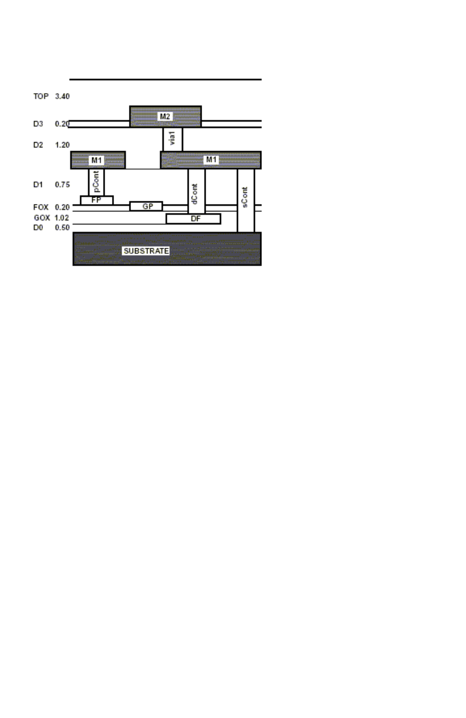
Chapter 14: Transistor-Level Runset Creation
Preparing IC Validator Runsets 14-14
StarRC User Guide and Command Reference F-2011.06
StarRC User Guide and Command Reference Version F-2011.06
Figure 14-2 Separate Metal1 to Diffusion Contacts
For most runsets, following the correct convention is straight forward. In general, the runset
should have specific contacts for connecting the following physical layers:
…
metal2 - metal1
metal1 - poly
metal1 - diffusion and/or
SUBSTRATE
CORRECT:
polyCont = cont and poly;
subCont = cont not polyCont;
input_cdb = connect(
connect_items = {
{{m1, poly}, polyCont},
{{m1, nsd, psd}, subCont}
…
};
Rule 2 – All device runset layers should be negated with the routing runset layers.
Removing portions of routing layers that overlap device layers allows StarRC to ignore
device capacitances correctly, and is necessary for MOS gate, source, and drain terminals
as well as for capacitance terminals.

Chapter 14: Transistor-Level Runset Creation
Preparing IC Validator Runsets 14-15
Chapter 14: Transistor-Level Runset Creation
Preparing IC Validator Runsets 14-15
StarRC User Guide and Command Reference Version F-2011.06
Wrong:
ngate = poly and ndiff;
nsd = ndiff not poly;
….
nmos(my_devices, "n", nsd, ngate, nsd, {{psub}});
….
cap_top = m2 and cap_recog;
cap_bot = m1 not cap_bot;
cap_dev =
cap_top and cap_bot;
….
capacitor(my_devices, "m1m2cap", cap_dev, cap_top, cap_term,
area_capval=1e-15);
……
input_cdb = connect(
connect_items = {
{{poly}, ngate},
{{cap_top}, m2},
{{cap_bot}, m1},
…
};
StarRC does not ignore the gate capacitance correctly and the designed capacitance is
double-counted in this example. Other devices might not have these issues.
Correct:
naget = poly and ndiff;
nsd = ndiff not poly;
poly = poly not ngate;
my_devices = init_device_matrix(netlist_cdb);
nmos(my_devices, "n", nsd, ngate, nsd, {{SUBSTRATE}});
cap_top = m2 and cap_recog;
cap_bot = m1 and cap_recog;
m2 = m2 not cap_top;
m1 = m1 not cap_bot;
capacitor(my_devices, "m1m2cap", cap_dev, cap_top, cap_bot,
area_capval=1e-15);
input_cdb = connect(
connect_items = {
{{poly}, ngate},
{{cap_top}, m2},
{{cap_bo
t}, m1},
…
};

Chapter 14: Transistor-Level Runset Creation
Preparing IC Validator Runsets 14-16
StarRC User Guide and Command Reference F-2011.06
StarRC User Guide and Command Reference Version F-2011.06
The not operation performed on the gate and field poly is required for the planar and
nonplanar processes because the IGNORE_CAPACITANCE capability behaves the same in
both cases. A planar process implies that the gate poly and the field poly layers are both
mapped to a single POLY layer, while a nonplanar process implies that the gate poly and the
field poly are mapped to separate covertical layers in the nxtgrd file.
Rule 3 – A physical layer cannot directly connect to another physical layer without
using a via, unless the two physical layers are covertical.
In Figure 14-1 metal1 connects to metal2 by via1. However, placing a contact between
physical layers FP and GP is not necessary because they overlap on the vertical profile.
These two conductors are called covertical. In the previous runset example, connecting poly
and ngate layers is allowed because the two runset layers map to the covertical physical
layers FP and GP. Likewise, connecting cap_top to m2 is allowed because both are mapped
to the same physical layer M2. The same also applies for cap_bot and m1.
Required Commands
Add the following required commands to your IC Validator runset script to ensure that
StarRC runs correctly:
pex_generate_results(
pex_matrix = pex_matrix,
device_extraction_matrix = my_devices,
device_db = device_db,
layout_database = mw_handle,
pex_process_map_file = pex_process_handle,
pex_runset_report_file = pex_report_handle
);
In addition, the tag command can be used to assign a layer name tag to runset layers.
In Example 14-1 “SUBSTRATE”, “via2” are layer tag names shown in runset report file and
extract view layer name.
Example 14-1 Tag Name Use in IC Validator Run Script
pex_conducting_layer_map(pex_matrix, psub, "SUBSTRATE");
pex_via_layer_map(pex_matrix, V2, "via2");
StarRC uses the IC Validator runset report file to obtain all IC Validator LVS results and
perform parasitic extraction. The key command is pex_runset_report_file in the
pex_generate_result() function. The default for pex_runset_report_file is “./
pex_runset_report” .
After an IC Validator run is completed, the XTR view is written into the LIB_NAME directory
under the default directory path, $working_directory/XTROUT.

Chapter 14: Transistor-Level Runset Creation
Preparing IC Validator Runsets 14-17
Chapter 14: Transistor-Level Runset Creation
Preparing IC Validator Runsets 14-17
StarRC User Guide and Command Reference Version F-2011.06
If you want to change the defaults for variables related to IC Validator, you can check the
following file:
prompt> more $ICV_HOME_DIR/include/rcxt_public.rh
The contents of this file is similar to the following example:
ex_generate_results : published function (
pex_matrix : pex_layer_matrix,
device_extraction_matrix : device_matrix,
device_db : device_database,
layout_database : in_out milkyway_library_handle,
pex_process_map_file : pex_process_map_file_handle,
pex_runset_report_file : pex_runset_report_file_handle,
pex_lpp_map_file : pex_lpp_map_file_handle =
NULL_LPP_MAP_FILE,
pex_tagname_required : boolean = true,
precision : integer = 3
) returning void;
Hierarchy Options
To specify hierarchical options, use the hierarchy_options()function in IC Validator. This
is the same as the technology_options function in Hercules. The hierarchy_options()
option controls the hierarchy optimization and can increase StarRC performance by 50
percent in some well-tuned cases.
Note:
When using the hierarchy_options option, some of the vcell options create new cells
that do not exist in the schematic and hinder the XREF:YES or XREF:COMPLETE flows in
StarRC. In this case, set the iterate_max to 0 in both pairs and sets of stages.

Chapter 14: Transistor-Level Runset Creation
Preparing IC Validator Runsets 14-18
StarRC User Guide and Command Reference F-2011.06
StarRC User Guide and Command Reference Version F-2011.06
Hierarchy Options Syntax
The syntax used to specify hierarchy options is shown in the following example:
hierarchy_options (
pairs = {{pair_cells = {"string", ...},
iterate_max = integer,
explode_into_vcell = ON | OFF | AUTO,
x_pairing = true | false,
y_pairing = true | false},
... }, //optional
sets = {{base_cells = {"string", ...},
programming_cells = {"string", ...},
iterate_max = integer,
explode_into_vcell = ON | OFF | AUTO,
flatten_sets = true | false,
min_cell_overlap = integer,
share_base_cells = true | false},
...}, //optional
);

Chapter 14: Transistor-Level Runset Creation
Preparing IC Validator Runsets 14-19
Chapter 14: Transistor-Level Runset Creation
Preparing IC Validator Runsets 14-19
StarRC User Guide and Command Reference Version F-2011.06
Sample Runset
The following example is a typical IC Validator runset for a StarXtract transistor-level
extraction.
#include "primeyield.rh"
library(
format = GDSII,
cell = "add4",
library_name = "ADD4.GDS"
);
schematic_netlist_db = schematic(
schematic_file = {{"ADD4.sp",SPICE}}
);
#include "equiv.rs"
NDIFF = assign({{1}});
PDIFF = assign({{2}});
NWELL = assign({{3}});
POLY = assign({{5}});
POLY_TEXT = assign_text({{25}});
CONT = assign({{6}});
M1 = assign({{8}});
M1_TEXT = assign_text({{28}});
V1 = assign({{9}});
M2 = assign({{10}});
M2_TEXT = assign_text({{30}});
V2 = assign({{44}});
M3 = assign({{45}});
M3_TEXT = assign_text({{32}});
sub1 = cell_extent(
cell_list = {"*"}
);
psub = sub1 not NWELL;
pactive = PDIFF and NWELL;
nactive = NDIFF not NWELL;
subtie = PDIFF not NWELL;
welltie = NDIFF and NWELL;
pactive = PDIFF not subtie;
nactive = NDIFF not welltie;
ngate = POLY and nactive;
pgate = POLY and pactive;
fpoly = POLY not (ngate or pgate);
nsd = nactive not ngate;
psd = pactive not pgate;

Chapter 14: Transistor-Level Runset Creation
Preparing IC Validator Runsets 14-20
StarRC User Guide and Command Reference F-2011.06
StarRC User Guide and Command Reference Version F-2011.06
input_cdb = connect(
connect_items = {
{{M3, M2}, V2},
{{M2, M1}, V1},
{{M1, fpoly}, poly_con},
{{ngate, pgate}, fpoly},
{{M1, nsd, psd}, diff_con},
{{M1, welltie, subtie}, diff_con},
{{NWELL}, welltie},
{{psub}, subtie}
}
);
netlist_cdb = text_net(
connect_sequence = input_cdb,
text_layer_items = {
{ M3, M3_TEXT },
{ M2, M2_TEXT },
{ M1, M1_TEXT },
{ fpoly, POLY_TEXT }
},
attach_text = ALL
);
my_devices = init_device_matrix(netlist_cdb);
nmos(my_devices, "n", nsd, ngate, nsd, {{psub}});
pmos(my_devices, "p", psd, pgate, psd, {{NWELL}});
device_db = extract_devices(my_devices);
layout_netlist_db = netlist(device_db);
compare_settings = init_compare_matrix();
compare(compare_settings, schematic_netlist_db, layout_netlist_db,
generate_equiv = {FULL_NAME}, write_equiv_netlists=ALL);
pex_matrix = init_pex_layer_matrix(my_devices);
pex_conducting_layer_map(pex_matrix, M3, "metal3");
pex_conducting_layer_map(pex_matrix, M2, "metal2");
pex_conducting_layer_map(pex_matrix, M1, "metal1");
pex_conducting_layer_map(pex_matrix, fpoly, "poly");
pex_conducting_layer_map(pex_matrix, ngate, "poly");
pex_conducting_layer_map(pex_matrix, pgate, "poly");
pex_conducting_layer_map(pex_matrix, nsd, "SUBSTRATE");
pex_conducting_layer_map(pex_matrix, psd, "SUBSTRATE");
pex_conducting_layer_map(pex_matrix, welltie, "SUBSTRATE");
pex_conducting_layer_map(pex_matrix, subtie, "SUBSTRATE");
pex_conducting_layer_map(pex_matrix, NWELL, "SUBSTRATE");
pex_conducting_layer_map(pex_matrix, psub, "SUBSTRATE");
pex_via_layer_map(pex_matrix, V2, "via2");

Chapter 14: Transistor-Level Runset Creation
Preparing IC Validator Runsets 14-21
Chapter 14: Transistor-Level Runset Creation
Preparing IC Validator Runsets 14-21
StarRC User Guide and Command Reference Version F-2011.06
pex_via_layer_map(pex_matrix, V1, "via1");
pex_via_layer_map(pex_matrix, poly_con, "polyCont");
pex_via_layer_map(pex_matrix, diff_con, "diffCont");
pex_process_handle = pex_process_map_file();
pex_report_handle = pex_runset_report_file();
mw_handle = milkyway_library("XTROUT");
pex_generate_results(
pex_matrix = pex_matrix,
device_extraction_matrix = my_devices,
device_db = device_db,
layout_database = mw_handle,
pex_process_map_file = pex_process_handle,
pex_runset_report_file = pex_report_handle
);
Marker Generation in IC Validator
The following sections show how you can generate text or layer markers in IC Validator.
Text-Based Marker Layers
The TEXT_origin()command is used for the IC Validator flow. It generates a shape
surrounding the selected text in the layout. The shape should be very small, because it is
included in the CONNECT sequence and can create shorts.
In the IC Validator runset (runset.rs):
metal1 = assign({{6}});
metal1_text = assign_text({{20}, {30}});
In the previous example, markers = text_origin(metal1_text, shape_size=0.01, cells =
{"XT_DEVICES"}, text = {"*", "VDD", "VSS"});m1_markers = markers interacting metal1;

Chapter 14: Transistor-Level Runset Creation
Preparing IC Validator Runsets 14-22
StarRC User Guide and Command Reference F-2011.06
StarRC User Guide and Command Reference Version F-2011.06
input_cdb = connect(
connect_items = {
…..
{{metal1}, m1_markers},
….
}
);
netlist_cdb = text_net(
connect_sequence = input_cdb,
text_layer_items = {
{ metal1, metal1_text },
….
},
attach_text = ALL
);
...
In the StarRC MAPPING_FILE (map):
conducting_layers
metal1
...
marker_layers
m1_markers
Example of ID-Layer Markers
The simplest approach to manual marker generation, this technique uses a preexisting input
layer (assign()) to identify marker shapes.

Chapter 14: Transistor-Level Runset Creation
Preparing IC Validator Runsets 14-23
Chapter 14: Transistor-Level Runset Creation
Preparing IC Validator Runsets 14-23
StarRC User Guide and Command Reference Version F-2011.06
The following is defined In the IC Validator runset:
metal1 = assign({{6}});
metal1_text = assign_text({{20}, {30}});
...
...
metal1_pio = metal1 and PAD
metal1_markers = metal1_pio or metal1_pi
n
input_cdb = connect(
connect_items = {
...
{{metal1}, m1_markers},
...
}
);
netlist_cdb = text_net(
connect_sequence = input_cdb,
text_layer_items = {
{ metal1, metal1_text },
},
attach_text = ALL
);
In the StarRC MAPPING_FILE (map):
conducting_layers
metal1
...
marker_layers
metal1_markers
Multifinger Device Support in IC Validator
Multifinger devices have multiple gate, source, and drain terminals. However, in the XTR
view of the Milkyway database, a device can only have a single gate, source, and drain
terminal. The XTR view writer in IC Validator stores the extra terminal information inside the
terminal properties, which is parsed by StarRC.
When a device function is declared in IC Validator with the option settings
recognition_layer=true and merge_parallel=true, IC Validator outputs the individual
coordinates of each polygon in terminals with multiple polygons.
StarRC obtains each set of coordinates from the Extract View for correct resistance network
calculation. During the translation stage, StarRC outputs extra text polygons into XIN based
on the extra coordinate information.

Chapter 14: Transistor-Level Runset Creation
Preparing Calibre Rule Files 14-24
StarRC User Guide and Command Reference F-2011.06
StarRC User Guide and Command Reference Version F-2011.06
Preparing Calibre Rule Files
The following sections describe the preparation of a rule file for the Calibre Connectivity
Interface flow:
•Rule File Creation Rules
•Required Commands
•Support for Calibre Preprocessor Directives and Include Statements
•Sample Rule File
Rule File Creation Rules
Apply the following rules when creating a Calibre runset:
• Rule 1 – A runset layer can connect only two physical layers.
Incorrect:
CONNECT m1 poly BY cont
CONNECT m1 nsd psd BY cont
In the Calibre rule file as in the Hercules runset, it is important to separate the metal1 to
diffusion contact from the metal1 to poly contact. LVS conventions typically allow both
contacts to exist on the same rule file layer “cont”. However, physically these are separate
contacts, so it is important for them to be separated for the StarRC extraction engine. See
Figure 14-3. Moreover, these contacts also have different resistivity.
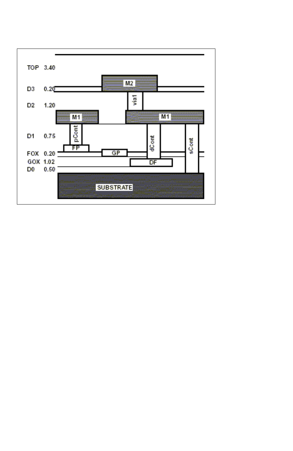
Chapter 14: Transistor-Level Runset Creation
Preparing Calibre Rule Files 14-25
Chapter 14: Transistor-Level Runset Creation
Preparing Calibre Rule Files 14-25
StarRC User Guide and Command Reference Version F-2011.06
Figure 14-3 Separate Calibre Runset Layers
Correct:
polyCont = cont AND poly
subCont = cont NOT poly
CONNECT m1 poly BY polyCont
CONNECT m1 nsd psd BY subCont
• Rule 2 – All device layers should be “NOTed” from routing layers.
Incorrect:
ngate = poly AND ndiff
nsd = ndiff NOT poly
DEVICE MN(n) ngate ngate (G) nsd (S) nsd (D) psub (B)
cap_top = m2 AND cap_recog
cap_bot = m1 AND cap_recog
cap_dev = cap_top AND cap_bot
DEVICE C(m1m2cap) cap_dev cap_top (POS) cap_bot (NEG)
CONNECT poly ngate
CONNECT cap_top m2
CONNECT cap_bot m1
As with the Hercules runset, it is important in the Calibre rule file to remove from routing
layers any overlap that exists with device terminal layers. The StarRC
IGNORE_CAPACITANCE functionality is based on device terminal layers. If there are

Chapter 14: Transistor-Level Runset Creation
Preparing Calibre Rule Files 14-26
StarRC User Guide and Command Reference F-2011.06
StarRC User Guide and Command Reference Version F-2011.06
locations where routing layers overlap terminal layers where the two are mapped to the
same physical layer, then StarRC ignores capacitance to the terminal layer but retains
capacitance to the routing layer. Thus, it is important that any such overlap be removed
from the routing layer to prevent the inadvertent inclusion of MOS device capacitances
when such capacitances are to be ignored, and to prevent the inclusion of parasitic
capacitance between the terminals of a designed capacitor device.
Correct:
ngate = poly AND ndiff
nsd = ndiff NOT poly
poly_route = poly NOT ngate
DEVICE MN(n) ngate ngate (G) nsd (S) nsd (D) psub (B)
cap_top = m2 AND cap_recog
cap_bot = m1 AND cap_recog
cap_dev = cap_top AND cap_bot
m2_route = m2 NOT cap_top
m1_route = m1 NOT cap_bot
DEVICE C(m1m2cap) cap_dev cap_top (POS) cap_bot (NEG)
CONNECT poly_route ngate
CONNECT cap_top m2_route
CONNECT cap_bot m1_route
• Rule 3 – A physical layer cannot connect to another physical layer without using a via,
unless the two physical layers are co-vertical.
This rule applies to both Hercules runsets and Calibre rule files. (see Figure 14-3 on
page 14-25.) In the previous rule file example, poly_route and ngate are allowed to
directly connect without a via because the two runset layers map either to the same
physical layer (if field and gate poly are not separated in the ITF file) or to co-vertical
physical layers (if field and gate poly are separated in the ITF file). Likewise, cap_top is
allowed to directly connect to m2_route because both are mapped to the same physical
layer M2. The same is true for cap_bot and m1_route.
Required Commands
The following commands are required in the Calibre rule file to ensure the Calibre
Connectivity Interface (CCI) query server is able to properly generate StarRC input files:
MASK SVDB DIRECTORY "svdb" CCI
The Calibre Connectivity Interface flag ensures that Calibre writes all required information to
the svdb directory such that the Calibre query server can generate all Calibre Connectivity
Interface outputs required for StarRC.

Chapter 14: Transistor-Level Runset Creation
Preparing Calibre Rule Files 14-27
Chapter 14: Transistor-Level Runset Creation
Preparing Calibre Rule Files 14-27
StarRC User Guide and Command Reference Version F-2011.06
PORT LAYER TEXT
Top-level ports are identified by text layers designated as PORT LAYER TEXT in the Calibre
rule file. This information in turn is used by the Calibre Connectivity Interface query server to
generate the CALIBRE_CELLS_PORTS file, which StarRC uses to netlist top-level ports
(*|P or *P) in the parasitic netlist. Thus, when top-level ports are required in the parasitic
netlist, it is essential that PORT LAYER TEXT be used in the Calibre rule file.
Support for Calibre Preprocessor Directives and Include
Statements
StarRC is able to correctly read the Calibre rule file preprocessor directives #DEFINE,
#UNDEFINE, #IFDEF, #IFNDEF, and #ENDIF. In interpreting #IFDEF and #IFNDEF
statements, StarRC requires that conditional names be defined with #DEFINE directives
directly within the rule file.
StarRC does not support names defined outside the rule file as shell environment variables.
Such names are typically prefixed by a dollar sign ($) within #IFDEF and #IFNDEF
directives. If StarRC encounters a conditional within the rule file that uses a shell variable
prefixed by $, and that $-prefixed variable does not occur previously in the rule file within an
explicit #DEFINE directive, StarRC interprets the variable as undefined and issues the
following warning:
WARNING: StarXtract
WARNING: CALIBRE_RUNSET pre-processor directives which refer
WARNING: to shell or ENV variables are not supported.
WARNING: Conditional expressions which refer to external
WARNING: variables will evaluate as though the variable is
WARNING: undefined.
WARNING: Please see layers.sum for a full list of affected
WARNING: directives.
StarRC also reads Calibre rule file INCLUDE statements that allow one rule file to instantiate
another rule file. In cases where preprocessor directives occur across rule files instantiated
with INCLUDE, StarRC correctly interprets the directives and applies them to all conditionals
across the rule file hierarchy.

Chapter 14: Transistor-Level Runset Creation
Preparing Calibre Rule Files 14-28
StarRC User Guide and Command Reference F-2011.06
StarRC User Guide and Command Reference Version F-2011.06
Sample Rule File
The following is a typical Calibre Connectivity Interface rule file for StarRC transistor-level
extraction.
LAYOUT SYSTEM GDSII
LAYOUT PATH "XT_DEVICES.GDS"
LAYOUT PRIMARY "XT_DEVICES"
LAYOUT ERROR ON INPUT YES
LVS POWER NAME VDD
LVS GROUND NAME VSS
MASK SVDB DIRECTORY "svdb" CCI
TEXT DEPTH PRIMARY
PRECISION 100
// GDSII Input Layer Mapping
LAYER NWELL 1
LAYER ACTIVE 2
LAYER POLY 3
LAYER BORON 4
LAYER CONTACT 5
LAYER METAL1 6
LAYER VIA 7
LAYER METAL2 8
LAYER PWELL 10
LAYER CAP_REG 12
LAYER POLYRES 40
LAYER BJT_REG 13
LAYER DIODE 14
// GDSII Input Text Layer Mapping
TEXT LAYER 20
LAYER MAP 20 TEXTTYPE >= 0 20
TEXT LAYER 30
LAYER MAP 30 TEXTTYPE >= 0 30
// Layer Derivations
psub1 = EXTENT
diode_active = INTERACT ACTIVE DIODE
bjt_active = INTERACT ACTIVE BJT_REG
active1 = (ACTIVE NOT diode_active) NOT bjt_active
bjt_nwell = INTERACT NWELL BJT_REG
nwell1 = NWELL NOT bjt_nwell
psub = psub1 NOT nwell1
poly_cont = POLY AND CONTACT
diff_cont = CONTACT NOT poly_cont
res_poly = INTERACT POLY POLYRES
poly1 = POLY NOT res_poly
res_body = res_poly AND POLYRES
res_term = res_poly NOT res_body

Chapter 14: Transistor-Level Runset Creation
Preparing Calibre Rule Files 14-29
Chapter 14: Transistor-Level Runset Creation
Preparing Calibre Rule Files 14-29
StarRC User Guide and Command Reference Version F-2011.06
pactive = BORON AND active1
nactive = active1 NOT pactive
diff = pactive OR nactive
pgate = poly1 AND pactive
5tngate = INTERACT (poly1 AND nactive) PWELL
ngate = NOT INTERACT (poly1 AND nactive) PWELL
psd1 = pactive NOT pgate
nsd1 = (nactive NOT ngate) NOT 5tngate
subtap = psd1 NOT nwell1
weltap = (nsd1 AND nwell1) NOT PWELL
psd = psd1 NOT subtap
pplus = diode_active AND BORON
nplus = diode_active NOT BORON
emitter = BORON AND bjt_active
bjt_nwell_ntap = active1 AND bjt_nwell
5tnsd = INTERACT nsd1 5tngate
nsd = (nsd1 NOT weltap) NOT 5tnsd
poly_cap_term = (poly1 AND METAL1) AND CAP_REG
fpoly = (poly1 NOT poly_cap_term) NOT diff
metal1_cap_term = (METAL1 AND poly1) AND CAP_REG
m1 = METAL1 NOT metal1_cap_term
dpn_nwell_term = INTERACT NWELL pplus
dnp_psub_term = INTERACT psub nplus
// Text Attachments
ATTACH 20 m1
PORT LAYER TEXT 20
ATTACH 30 METAL2
PORT LAYER TEXT 30
// Layer Connectivity
CONNECT m1 metal1_cap_term
CONNECT METAL2 m1 metal1_cap_term BY VIA
CONNECT m1 psd nsd weltap subtap 5tnsd BY diff_cont
CONNECT m1 nplus pplus emitter bjt_nwell_ntap BY diff_cont
CONNECT metal1_cap_term psd nsd weltap subtap 5tnsd BY
diff_cont
CONNECT metal1_cap_term nplus pplus emitter bjt_nwell_ntap
BY diff_cont
CONNECT m1 fpoly res_term poly_cap_term BY
poly_cont
CONNECT metal1_cap_term fpoly res_term poly_cap_term BY
poly_cont
CONNECT poly_cap_term fpoly
CONNECT pgate ngate 5tngate fpoly
CONNECT NWELL dpn_nwell_term weltap
CONNECT psub dnp_psub_term subtap PWELL
CONNECT bjt_nwell bjt_nwell_ntap
// Device Definitions
DEVICE D(DPN) pplus pplus (POS) dpn_nwell_term (NEG)
DEVICE D(DNP) nplus dnp_psub_term (POS) nplus (NEG)
DEVICE MP(p) pgate pgate (G) psd (S) psd (D) NWELL (B)<diff>

Chapter 14: Transistor-Level Runset Creation
Preparing Calibre Rule Files 14-30
StarRC User Guide and Command Reference F-2011.06
StarRC User Guide and Command Reference Version F-2011.06
[
property L, W, AD, PD, AS, PS
W = ( perimeter_coincide(pgate,psd) / 2)
A = AREA( pgate )
L = A/W
AD = area(D) * W / perimeter_inside(D, diff)
AS = area(S) * W / perimeter_inside(S, diff)
PD = perimeter(D) * W / perimeter_inside(D, diff)
PS = perimeter(S) * W / perimeter_inside(S, diff)
]
DEVICE MN(n) ngate ngate (G) nsd (S) nsd (D) psub (B) <diff>
[
property L, W, AD, PD, AS, PS
W = ( perimeter_coincide(ngate,nsd) / 2)
A = AREA( ngate )
L = A/W
AD = area(D) * W / perimeter_inside(D, diff)
AS = area(S) * W / perimeter_inside(S, diff)
PD = perimeter(D) * W / perimeter_inside(D, diff)
PS = perimeter(S) * W / perimeter_inside(S, diff)
]
DEVICE MN(5tn) 5tngate 5tngate (G) 5tnsd (S) 5tnsd (D)
PWELL (B) NWELL (B2) <diff>
[
property L, W, AD, PD, AS, PS
W = ( perimeter_coincide(5tngate,5tnsd) / 2)
A = AREA( 5tngate )
L = A/W
AD = area(D) * W / perimeter_inside(D, diff)
AS = area(S) * W / perimeter_inside(S, diff)
PD = perimeter(D) * W / perimeter_inside(D, diff)
PS = perimeter(S) * W / perimeter_inside(S, diff)
]
DEVICE R(poly_res) res_body res_term (POS) res_term (NEG)
DEVICE C(poly_cap) CAP_REG poly_cap_term (POS)
metal1_cap_term (NEG)
DEVICE Q(pbjt) psub psub (C) bjt_nwell (B) emitter (E)
// COMPARE section
SOURCE SYSTEM SPICE
SOURCE CASE YES
SOURCE PATH "XT_DEVICES.sp"
SOURCE PRIMARY "XT_DEVICES"
LAYOUT CASE YES
LVS REPORT report.lvs
LVS REPORT OPTION A B C D
LVS REPORT MAXIMUM 100
LVS IGNORE PORTS NO
LVS REDUCE SPLIT GATES YES
LVS RECOGNIZE GATES ALL

Chapter 14: Transistor-Level Runset Creation
Preparing the Mapping File 14-31
Chapter 14: Transistor-Level Runset Creation
Preparing the Mapping File 14-31
StarRC User Guide and Command Reference Version F-2011.06
LVS COMPARE CASE NAMES TYPES
LVS CHECK PORT NAMES NO
LVS REDUCE PARALLEL MOS YES
LVS NL PIN LOCATIONS YES
LVS COMPONENT SUBTYPE PROPERTY mode
Preparing the Mapping File
This information explains the rules for preparing the Hercules and Calibre mapping files. A
sample mapping file is included.
Mapping Rules
The mapping file is used for mapping runset layers in Hercules or Calibre CONNECT
sequences to physical layers in the ITF file.
Rule 1 – No Ideal Layer is Allowed
Every layer in the CONNECT section of the Hercules runset or Calibre rule file needs to be
mapped to a conductor or via in the ITF file. Likewise, every device terminal layer needs to
be mapped to an ITF conductor layer to ensure devices are properly connected to the
parasitic mesh in the parasitic netlist. Nonterminal device recognition layers should not be
mapped, with one exception: RES device body layers should be mapped either as
conducting layers (to include the impact of the RES body on surrounding nets) or
remove_layers (to ignore the impact or the RES body on surrounding nets).
If a runset layer CONNECT or device terminal layer cannot be mapped to any physical layer,
it should be listed under the remove_layers section of the mapping file.
Rule 2 – Bulk Layer Mapping is Optional
A bulk layer is defined as any layer that serves as the bulk terminal connection in any
Hercules or Calibre device extraction command. Bulk layers mapped in the
conducting_layers section of the mapping file are used during parasitic extraction only if the
StarRC command file option TRANSLATE_RETAIN_BULK_LAYERS: YES is specified during
the extraction.
The mapping of bulk layers is generally preferable under the following circumstances:
• Power net extractions where capacitance to well layers should be generated in the netlist
as coupling capacitance
• Extractions containing well devices (for example, well resistors, diodes, BJTs) whose
database terminal layers consist solely of bulk layers

Chapter 14: Transistor-Level Runset Creation
Preparing the Mapping File 14-32
StarRC User Guide and Command Reference F-2011.06
StarRC User Guide and Command Reference Version F-2011.06
• Scenarios in which the bulk terminals of designed devices should be generated in the
netlist as instance port subnodes instead of ideal nodes
In such cases, bulk layers should be mapped as conducting_layers and
TRANSLATE_RETAIN_BULK_LAYERS:YES should be specified during extraction. Otherwise,
mapping of bulk layers is optional.
If there are any other layers in any CONNECT sequences that connect solely to bulk layers,
these layers should be mapped in the same manner as the bulk layers to which they
connect. This is because StarRC only allows a runset layer to be designated as a conducting
layer if the layer has connectivity to other translated runset layers in the design.
Rule 3 – Map Hercules Port Layers as Marker Layers to Obtain Top-Level Ports
Top-level ports in the Hercules flow are identified by the existence of polygons mapped as
marker_layers. In MARKER_GENERATION: AUTOMATIC mode, such layers are generated by
the use of TEXT_POLYGON commands in the Hercules runset.
No such mapping is required in the Calibre Connectivity Interface flow, because top-level
markers are identified by listings in the CALIBRE_CELLS_PORTS file output by the Calibre
Connectivity Interface query server.

Chapter 14: Transistor-Level Runset Creation
Running the Calibre Query Server for Output to StarRC 14-33
Chapter 14: Transistor-Level Runset Creation
Running the Calibre Query Server for Output to StarRC 14-33
StarRC User Guide and Command Reference Version F-2011.06
Sample Mapping File
In the following sample mapping file, the asterisk (*) indicates comments.
conducting_layers
* Routing layers
Metal2 metal2
Metal1 metal2
field_poly poly
Nwell SUBSTRATE
welltie SUBSTRATE
subtie SUBSTRATE
* Device layers connected to routing layers
ngate gate
pgate gate
Cap1 metal1
Cap2 poly
pres_body poly
* Device layers built into the SUBSTRATE
nsd SUBSTRATE
psd SUBSTRATE
PnAnodeTerm SUBSTRATE
PnCathodeTerm SUBSTRATE
NpnEmitter SUBSTRATE
NpnCollector SUBSTRATE
NpnBase SUBSTRATE
via_layers
* Via layers
Via1 via1
PolyCont poly_con
SubCont sub_con
NpnEmitterCont sub_con
NpnCollectorCont sub_con
NpnBaseCont sub_con
marker_layers (only required in Hercules flow)
* Marker layer
Metal2_Mark
remove_layers
Running the Calibre Query Server for Output to StarRC
This section discusses the various Calibre query server commands required to generate
proper Calibre Connectivity Interface files for StarRC. The commands listed in the query
server command file shown in Example 14-2 should be provided to the
calibre -query svdb command.

Chapter 14: Transistor-Level Runset Creation
Running the Calibre Query Server for Output to StarRC 14-34
StarRC User Guide and Command Reference F-2011.06
StarRC User Guide and Command Reference Version F-2011.06
Example 14-2 Sample Calibre Query Command File
LAYOUT NETLIST DEVICE LOCATION CENTER
#Instructs query server to write net ID to seed polygons
GDS SEED PROPERTY ORIGINAL
#Instructs query server to output further information about the
#device recognition layer to the CCI database.
GDS SEED DEVICE PROPERTY ORIGINAL
#Generates the GDS_MAP layer file.
RESPONSE FILE GDS_MAP
GDS MAP
RESPONSE DIRECT
#The following line defines the property numbers for net
#names and instance #names. StarRC expects the NETPROP
#number to be 5, the PLACEPROP number to #be 6, and INSTPROP
#number to be 7 so these cannot be changed.
GDS NETPROP NUMBER 5
GDS PLACEPROP NUMBER 6
GDS DEVPROP NUMBER 7
#Outputs Calibre AGF file for StarRC.
GDS WRITE agf
#These commands ensure pin co-ordinates and proper hierarchy
#in the ideal layout netlist written out by Calibre.
LAYOUT NETLIST TRIVIAL PINS YES
LAYOUT NETLIST EMPTY CELLS YES
LAYOUT NETLIST NAMES NONE
LAYOUT NETLIST PRIMITIVE DEVICE SUBCKTS NO
LAYOUT NETLIST PIN LOCATIONS YES
LAYOUT NETLIST HIERARCHY AGF
LAYOUT NETLIST WRITE nl
#Outputs Calibre ideal layout name map for StarRC.
LAYOUT NAMETABLE WRITE lnn
#Outputs Calibre net cross-referencing table file for StarRC
#This is required to run XREF.
NET XREF WRITE nxf
#Outputs Calibre instance cross-referenceing table for StarRC
#This is required to run XREF.
INSTANCE XREF WRITE ixf
#Outputs Calibre cell extents file for StarRC
CELL EXTENTS WRITE extents.txt
#Outputs Calibre top-level ports file for StarRC.
PORT TABLE CELLS WRITE cells_ports

Chapter 14: Transistor-Level Runset Creation
Running the Calibre Query Server for Output to StarRC 14-35
Chapter 14: Transistor-Level Runset Creation
Running the Calibre Query Server for Output to StarRC 14-35
StarRC User Guide and Command Reference Version F-2011.06
#Outputs Calibre device table report file for StarRC.
RESPONSE FILE devtab
DEVICE TABLE
RESPONSE DIRECT
When creating your query server command file, keep the following points in mind:
• Additional GDS MAP layer mapping commands to specify specific GDS layer numbers
are not required for the query server to output relevant connectivity and device terminal
layers to the AGF file. They simply change the AGF output layer number. Using GDS
MAP commands in such a way can be problematic, because they can cause the query
server to output layers to a layer number that is already internally mapped to another
layer by Calibre. Only the following commands are essential for StarRC:
RESPONSE FILE GDS_MAP
GDS MAP
RESPONSE DIRECT
• The following command directs Calibre to report the device center as the device location
instead the default vertex:
LAYOUT NETLIST DEVICE LOCATION CENTER
Adding this line can help synchronize the Calibre and Hercules flow StarRC behavior.
• If you use Virtuoso Integration with the hierarchical Calibre Connectivity Interface, add
the following command to the query server command file:
HIERARCHY SEPARATOR |
This forces Calibre to use the pipe character (|) as the hierarchical separator for
compatibility with Virtuoso Integration.
Optional Calibre Query Server Commands
Stripping X-Cards in Source Names
The following command directs Calibre to strip X-cards in source names:
XREF XNAME SOURCE OFF
This command strips X-card prefixes at each hierarchical level of source net and instance
names in the NXF and IXF tables. Such functionality is useful in StarRC gate-level
extractions based on hierarchical Calibre LVS runs, in which the StarRC parasitic netlist
must backannotate to an original Verilog netlist that does not contain X-card prefixes in each
level of hierarchy of a hierarchical net or instance name.

Chapter 14: Transistor-Level Runset Creation
Running the Calibre Query Server for Output to StarRC 14-36
StarRC User Guide and Command Reference F-2011.06
StarRC User Guide and Command Reference Version F-2011.06
The effect on the StarRC output parasitic netlist of using this Calibre query server command
is illustrated by the following SPF example:
A StarRC netlist without XREF XNAME SOURCE OFF:
*|NET XA/XB/XC/net0 0.225231PF
*|I (XA/XB/XC/MM1:D XA/XB/XC/MM1 D B 0 13 175)
R1 XA/XB/XC/MM1:D XA/XB/XC/net0:4 1.2335
Cg1 XA/XB/XC/net0:4 1.63099e-16
A StarRC netlist with XREF XNAME SOURCE OFF:
*|NET A/B/C/net0 0.225231PF
*|I (A/B/C/MM1:D A/B/C/MM1 D B 0 13 175)
R1 A/B/C/MM1:D A/B/C/net0:4 1.2335
Cg1 A/B/C/net0:4 1.63099e-16
Note:
This command should be placed in the query server command file before the NET XREF
WRITE and INSTANCE XREF WRITE commands.
The corresponding Calibre query server command XREF XNAME LAYOUT OFF should
not be used with StarRC. This is because the Calibre-generated layout netlist always
contains X-cards regardless of the setting of XREF XNAME LAYOUT, and StarRC
requires consistency between the NXF/ IXF layout names and the Calibre-generated
layout netlist.
This command is not applicable to and produces no differences for StarRC runs based
on Calibre flat LVS runs.
See the Calibre documentation for further details.
Multifinger Device Support in the Calibre Connectivity Interface
The StarRC CCI interface provides multifinger access resistance calculation by creating
pins for each finger. To use this feature, add the following Calibre query command:
GDS SEED DEVICE PROPERTY ORIGINAL
With this command in the query command file, StarRC initiates automatic pin detection to
obtain the pin location for each terminal of the device. When there is more than one polygon
for one terminal, the automatic pin detection code generates a pin location for each terminal
polygon. With this information, StarRC can provide more accurate resistance extraction
results.

Chapter 14: Transistor-Level Runset Creation
Preparing the StarXtract Command File 14-37
Chapter 14: Transistor-Level Runset Creation
Preparing the StarXtract Command File 14-37
StarRC User Guide and Command Reference Version F-2011.06
Preparing the StarXtract Command File
Instructions for preparing a StarXtract command file are found in this section. Options to be
included in this file are explained.
Options for Transistor Level in Hercules Flow
To run StarXtract at the transistor level in the Hercules flow, you must specify the following
options:
MILKYWAY_DATABASE: LIB_NAME
MILKYWAY_EXTRACT_VIEW: YES
BLOCK: BLOCK
SKIP_CELLS: !*
TCAD_GRD_FILE: technology.nxtgrd
MAPPING_FILE: mapping_file_name
MILKYWAY_DATABASE: LIB_NAME is the path to the directory having the XTR view generated
by Hercules. It should be the same as the LIB_NAME in the WRITE_EXTRACT_VIEW command
in the Hercules runset. However, you are allowed to set a new path if you have moved the
directory to another place. Note that the default for SKIP_CELLS is “*” and you must make
sure that you set it as “!*” to extract down to the transistor level.
Options for Transistor Level in Calibre Connectivity Interface Flow
To run StarXtract in the transistor-level Calibre Connectivity Interface (CCI) flow, you must
specify the following options:
BLOCK: block_name
SKIP_CELLS: !*
TCAD_GRD_FILE: technology.nxtgrd
MAPPING_FILE: mapping_file_name
CALIBRE_RUNSET: calibre_rule_file
CALIBRE_QUERY_FILE: calibre_query_command_file
All Calibre options are explained in “Calibre Connectivity Interface” on page 4-7.
Other Important Options
The options listed in the following sections are important to your StarXtract preparation:
NETLIST_FORMAT, IGNORE_CAPACITANCE, XREF, COMPARE_DIRECTORY, and
EVACCESS_DIRECTORY.

Chapter 14: Transistor-Level Runset Creation
Preparing the StarXtract Command File 14-38
StarRC User Guide and Command Reference F-2011.06
StarRC User Guide and Command Reference Version F-2011.06
NETLIST_FORMAT
This command defines the structure and format of the output parasitic netlist:
NETLIST_FORMAT: SPF | STAR | SPEF | MW | CONLY | NETNAME | NONE
For transistor-level extraction, StarXtract supports four kinds of output netlist formats: STAR
(default), SPF, SPEF, and NETNAME formats. You can use the options
NETLIST_CONNECT_SECTION: NO and NETLIST_NODE_SECTION: NO (default) with STAR
format to suppress *|I and *|S sections.
IGNORE_CAPACITANCE
This command disallows certain types of device-level capacitances from being extracted
and netlisted:
IGNORE_CAPACITANCE: ALL | DIFF | NONE
In StarXtract, you can ignore both gate and diffusion capacitance with the
IGNORE_CAPACITANCE command. StarXtract is able to find the gate terminal layers and
automatically performs the IGNORE_CAPACITANCE according to the option setting.
If you set IGNORE_CAPACITANCE: ALL, both overlap and sidewall capacitances between
gate and SUBSTRATE is ignored. All other coupling effects to the gate poly node from other
conducting layers are considered. If you set IGNORE_CAPACITANCE to ALL or DIFF, you can
ignore the junction capacitance between diffusion and SUBSTRATE.
IGNORE_CAPACITANCE is runset-layer-based. This means that each layer in the runset (even
if multiple runset layers are mapped to a single ITF layer) is processed individually. If the
runset defines a PMOS device that uses NWELL as the BULK layer, NWELL must be the
only layer under the device for IGNORE_CAPACITANCE to work.
If the runset contains a connected copy of NWELL that is also present under every PMOS
device, IGNORE_CAPACITANCE appears to have no effect (because the NWELL copy is not
tagged as a MOS BULK layer). In any case, the runset should not contain connected copies
of BULK.
XREF
This command determines which set of names to report for StarRC netlist generation and
analysis flows and which devices and nets to retain if both layout names and
cross-referenced schematic names are present.
XREF: NO | YES | COMPLETE
The XREF command enables cross-referencing of the parasitic netlist for LVS-based
extraction flows with Hercules or Calibre. Nets, devices, and cell instances are output in the
parasitic netlist using schematic names, according to the functionality of the two available
modes YES and COMPLETE.

Chapter 14: Transistor-Level Runset Creation
Interconnect Technology Format File 14-39
Chapter 14: Transistor-Level Runset Creation
Interconnect Technology Format File 14-39
StarRC User Guide and Command Reference Version F-2011.06
Note:
XREF: NO | YES | COMPLETE is available in the Hercules flow, while XREF: NO | YES
is available in the Calibre Connectivity Interface (CCI) flow. For specific details about the
use of XREF in Calibre Connectivity Interface flows, see “Calibre Connectivity Interface”
on page 4-7.
If you set XREF:COMPLETE, all the nets that are not cross-referenced are ignored. Only
successfully matched nets and instances are netlisted in the output file.
If you want to use the SKIP_CELLS command in XREF-enabled flows, be sure that the
SKIP_CELLS are EQUIV points (in the Hercules flow) or hcells (in the Calibre flow) that were
successfully matched during LVS. Those cells that are not matched during LVS cannot be
properly skipped in StarXtract.
Because StarXtract gets cross-reference information from the evaccess and compare
directories, you should not remove them (in the Hercules flow) before your StarXtract run is
over.
COMPARE_DIRECTORY and EVACCESS_DIRECTORY
The COMPARE_DIRECTORY command specifies the location of the Hercules LVS COMPARE
output. The EVACCESS_DIRECTORY command specifies the location of the Hercules LVS
EVACCESS database.
COMPARE_DIRECTORY: PATH_TO_compare_DIRECTORY
EVACCESS_DIRECTORY: PATH_TO_evaccess_DIRECTORY
In XREF:YES or COMPLETE runs, StarXtract gets the cross-reference information and
schematic netlist information from the compare and evaccess directories. If the paths to the
original compare and evaccess directories have changed, you have to set the
COMPARE_DIRECTORY and EVACCESS_DIRECTORY commands with the new paths. These
options can be skipped if they are the same as the Hercules run.
Interconnect Technology Format File
This section explains how to prepare the Interconnect Technology Format (ITF) file. Also see
“Process Characterization Basics” on page 3-3.
Preparing the ITF File
Preparing an ITF file for transistor-level extraction is similar to cell-level extraction; the
difference is that transistor-level ITF files have the connectivity information down to the
diffusion or SUBSTRATE layers. Both planar as well as nonplanar process files can be
created.

Chapter 14: Transistor-Level Runset Creation
Interconnect Technology Format File 14-40
StarRC User Guide and Command Reference F-2011.06
StarRC User Guide and Command Reference Version F-2011.06
The transistor-level ITF file may be either planar, using a single poly layer for both field and
gate poly, or nonplanar, using separate field and gate poly layers. Using a planar process for
StarXtract transistor-level extraction allows for faster nxtgrd file generation time relative to
the nonplanar process, because one less CONDUCTOR layer exists in a planar ITF file.
However, the choice is optional and should be dictated by the parameters of the actual
physical process.
An ITF file contains via layer information and you need to be careful when defining them.
Because a via layer can connect only two conducting layers, you must separate a poly
contact from a SUBSTRATE contact (and diffusion contact, if any).
Limitations
Covertical layers (such as gate and field poly) should be vertically overlapping. Thus if the
bottom of the field poly layer is higher than the top of the gate poly layer (as happens when
the field oxide is too thick or the gate poly is too thin), they are not connected to each other
by mere touch. In this case, you need to modify your runset or rule file, mapping file, and ITF
file to make a dummy via layer connecting the gate and field poly.
Sample ITF File
The following is a sample ITF file that can be used with the two earlier file examples,
“Sample Runset” on page 14-7 and “Interconnect Technology Format File” on page 14-39.
The topology view is shown in Figure 14-4 on page 14-41.
TECHNOLOGY=add4_2m1p
DIELECTRIC sin {THICKNESS=0.70 ER=7.9}
DIELECTRIC imd2 {THICKNESS=1.00 ER=4.2}
CONDUCTOR metal2 {THICKNESS=0.50 WMIN=0.35 SMIN=0.35 RPSQ=0.07}
DIELECTRIC imd1 {THICKNESS=1.05 ER=4.2}
CONDUCTOR metal1 {THICKNESS=0.35 WMIN=0.30 SMIN=0.30 RPSQ=0.08}
DIELECTRIC ild {THICKNESS=0.70 ER=4.1}
CONDUCTOR poly {THICKNESS=0.20 WMIN=0.25 SMIN=0.25 RPSQ=5}
DIELECTRIC fox_b {THICKNESS=0.10 ER=3.9}
CONDUCTOR gate {THICKNESS=0.20 WMIN=0.25 SMIN=0.25 RPSQ=5}
DIELECTRIC fox_a {THICKNESS=0.25 ER=3.9}
VIA via1 {FROM=metal1 TO=metal2 AREA=0.09 RPV=1}
VIA poly_con {FROM=poly TO=metal1 AREA=0.04 RPV=12}
VIA sub_con {FROM=SUBSTRATE TO=metal1 AREA=0.04 RPV=16}
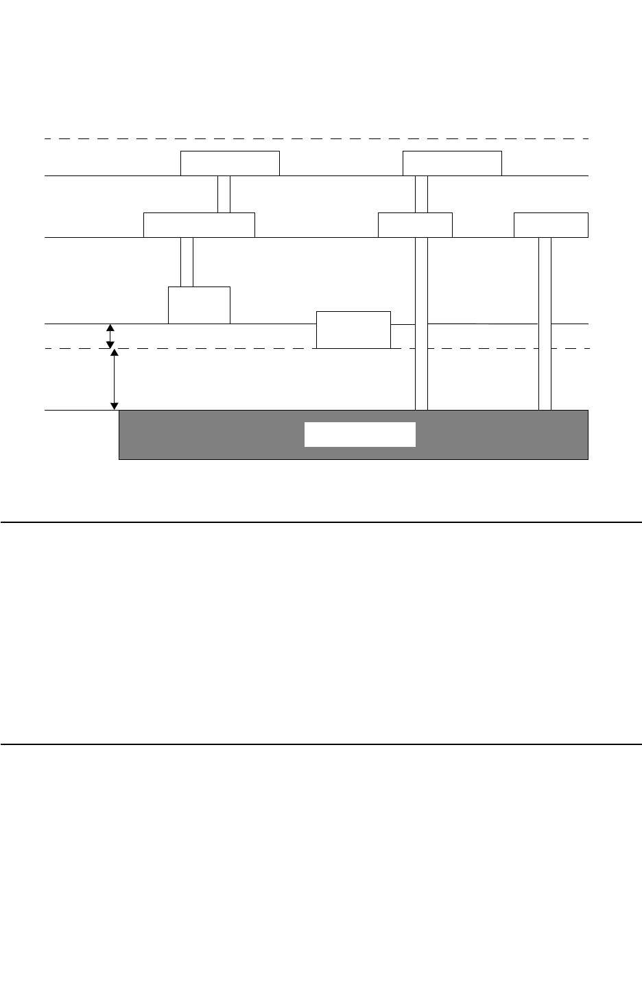
Chapter 14: Transistor-Level Runset Creation
General Limitations 14-41
Chapter 14: Transistor-Level Runset Creation
General Limitations 14-41
StarRC User Guide and Command Reference Version F-2011.06
Figure 14-4 Topology of Sample File
GATE
POLY
metal1 metal1 metal1
metal2 metal2
via1 via1
poly_con sub_con
sub_con
sin
imd2
imd1
ild
fox_b
fox_a
SUBSTRATE
General Limitations
The current release has the following limitations:
• Covertical layers should be overlapping vertically.
•Only
XREF: YES is supported in the Calibre Connectivity Interface (CCI) flow.
• In the Calibre Connectivity Interface (CCI) flow, each device extraction command listed in
the rule file must have a unique model name, to allow StarRC to properly distinguish
devices.
Limitations in XREF Flows
•DETECT_PERMUTABLE_PORTS (Hercules) is supported, but it can degrade performance.
•PUSH_DOWN_DEVICES (Hercules) is not handled correctly.
•PUSH_DOWN_PINS: FALSE (Hercules) should be set when possible to achieve best
results with XREF.

Chapter 14: Transistor-Level Runset Creation
Limitations in XREF Flows 14-42
StarRC User Guide and Command Reference F-2011.06
StarRC User Guide and Command Reference Version F-2011.06
•In XREF:COMPLETE flows in which m(schematic) : n(layout) or m:1 device merging occurs,
StarRC netlists nets connecting to device terminals as ideal nets. This is because no
method exists by which to distribute parasitics from a single layout net across the multiple
schematic nets that are netlisted in the XREF:COMPLETE netlist.
•In XREF:COMPLETE netlists for which multistage m:n merging occurs for designed passive
devices, NETLIST_PASSIVE_PARAMS parameters may not appear in the parasitic netlist.
No method exists by which to annotate layout device properties from N layout devices
onto M schematic devices, because no direct one-to-one correlation can be established
among the layout and schematic devices.

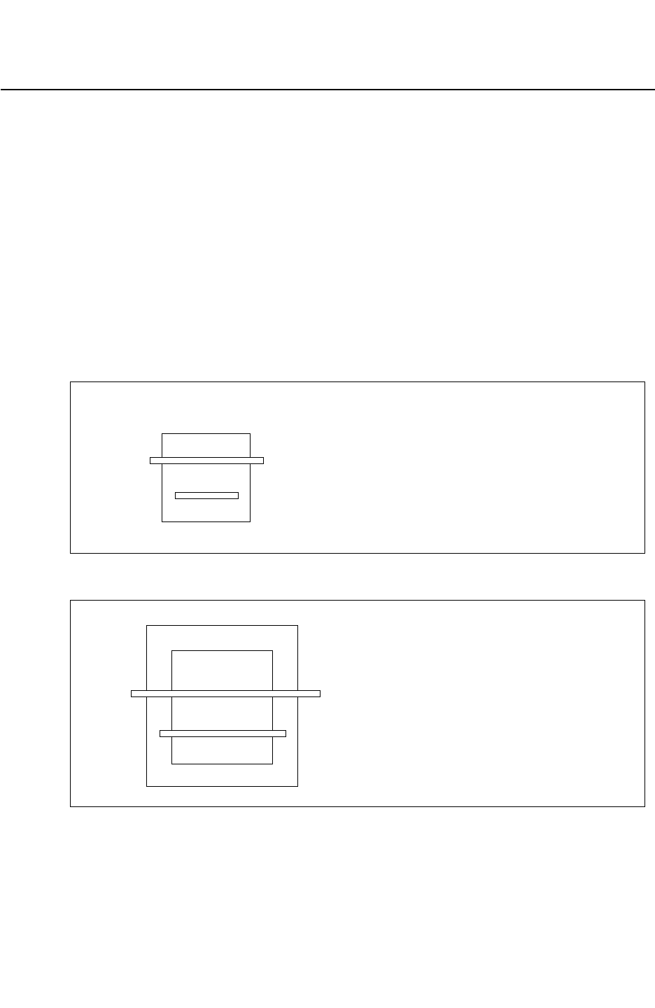
Chapter 15: Advanced Extraction Features
Feedthrough Nets 15-2
StarRC User Guide and Command Reference F-2011.06
StarRC User Guide and Command Reference Version F-2011.06
Feedthrough Nets
A feedthrough net is a net that has one connection to a higher level in the hierarchy.
Feedthroughs do not typically exist in a schematic. There are two feedthrough cases that
StarRC handles:
1. Getting proper *|P when extracting lower-level cells that are later used as SKIP_CELLS, as
shown in Figure 15-1.
2. Ensuring proper *|I for the feedthrough ports of a SKIP_CELLS.See Figure 15-2, when
extracting the TOP block by skipping the cell with feedthrough ports.
Both issues should be taken care of by default in XREF:YES, because it is layout-based and
feedthrough exists in the layout.
Figure 15-1 First Feedthrough Case
top_cell
net1 (with marker_layer at the top)
net2 (no marker_layer)
Figure 15-2 Second Feedthrough Case
net3 (marker_layer at top)
top_cell
sub_cell
net4 (no marker_layer)
To handle these cases with XREF:COMPLETE, there is a new command,
XREF_FEEDTHRU_NETS, for which the default is NO. This command controls feedthrough net
handling for the two previous cases, when XREF: COMPLETE is used.
Chapter 15: Advanced Extraction Features
Feedthrough Nets 15-3
Chapter 15: Advanced Extraction Features
Feedthrough Nets 15-3
StarRC User Guide and Command Reference Version F-2011.06
Note:
Both of these issues can happen for a single cell. For example, if a cell has a SKIP_CELLS
with feedthrough ports and has a feedthrough port for a bigger cell containing the cell
itself, both *|I and *|P is correctly netlisted.
Feedthrough - First Issue
As mentioned previously, the first feedthrough problem is cross-referencing *|P for the
feedthrough ports of a subblock when extracting the subblock. See Figure 15-1 on
page 15-2.
If there are uncompared nets or ports at the top cell of the layout, the netlist of those nets
appears with the “ln_” prefix attached to the texted net names from the layout. This is done
by default for XREF:YES, but for XREF:COMPLETE, the command XREF_FEEDTHRU_NETS must
be set to YES (the default is NO). The prefix itself can be changed with the
XREF_LAYOUT_NET_PREFIX command.
The XREF:COMPLETE flow always prints out the prefix for the feedthrough net name, because
the net name is always based on the layout.
In the Hercules runset, the CREATE_PORTS command must be used for feedthrough ports in
the XREF:COMPLETE flow and included in the netlist.
Figure 15-3 XREF:YES Example
top_cell
A
B
[+]
[+]
[]
- marker
+- CREATE_PORTS is used
The output is:
...
*|NET ln_A
*|P ln_A
...
*|NET ln_B
...
Chapter 15: Advanced Extraction Features
Feedthrough Nets 15-4
StarRC User Guide and Command Reference F-2011.06
StarRC User Guide and Command Reference Version F-2011.06
Port Renaming
To rename feedthrough ports, you can use the SHORT_PINS:NO option. For example, if
SHORT_PINS:NO, the output would be
...
*|NET ln_A
*|P ln_A_1
*|P ln_A_2
...
*|NET ln_B
Figure 15-4 XREF:COMPLETE and XREF_FEEDTHRU_NETS:YES Example
top_cell
[+][+]
[]
[]
+ +
C
D
E
F
[] - marker
+- CREATE_PORTS is used
The output is:
...
*|NET ln_C
*|P ln_C
...
*|NET ln_E
...
Note that nets D and F are not netlisted, because CREATE_PORTS (Hercules) was not used.
Feedthrough - Second Issue
When you are cross-referencing *|I for SKIP_CELLS feedthrough ports (when extracting the
top block with SKIP_CELLS having feedthrough, as in Figure 15-2 on page 15-2), if
XREF_FEEDTHRU_NETS is set to YES,the XREF:COMPLETE command has the same behavior
as XREF:YES, even though the schematic does not have the feedthrough port connection
with the SKIP_CELLS.
When XREF_FEEDTHRU_NETS is NO with XREF:COMPLETE, StarRC ignores the *|I and the
instance section also skips the connection.
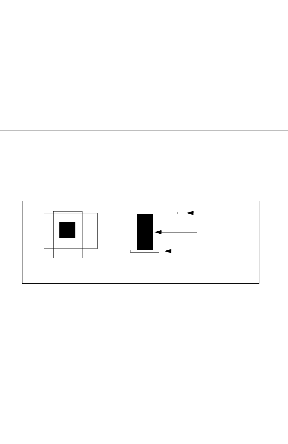
Chapter 15: Advanced Extraction Features
Via Coverage 15-5
Chapter 15: Advanced Extraction Features
Via Coverage 15-5
StarRC User Guide and Command Reference Version F-2011.06
If a SPICE_SUBCKT_FILE is provided for the SKIP_CELLS, then the order and content from
the SPICE_SUBCKT_FILE is maintained in the instance section of the netlist.
Runset Requirements
• Hercules LVS for the SKIP_CELLS having the feedthrough ports must be done with
EQUIV statements. Using the Hercules command BLACK_BOX in the equiv file is not
permitted.
• The Hercules CREATE_PORTS command must be used to properly netlist feedthroughs.
Via Coverage
Verifying the metal coverage of vias (or metal-to-metal connections) helps designers find
and troubleshoot potential layout problems related to via connections for reliability
verification. StarRC provides a way to report via metal coverage by comparing the coverage
metal and landing metal as shown in Figure 15-5.
Figure 15-5 Coverage and Landing Metal Connecting a Via
Top View Side View
Coverage Metal
Landing Metal
Via connection
The VIA_COVERAGE_OPTION_FILE command checks rectangular vias; the VIA_COVERAGE
command checks square vias.
Command Set Up
To report the via coverage from your design, you need only specify one of two commands:
VIA_COVERAGE or VIA_COVERAGE_OPTION_ FILE in the StarRC command file.
Note:
Vias you specify in a VIA_COVERAGE or VIA_COVERAGE_OPTION_FILE command must be
defined in the ITF.
Because the coverage and landing areas of VIAs (see Figure 15-5) are used to classify how
various types of vias are handled in reliability verification, you must specify coverage and
landing values (in nanometers) for each type to be classified.
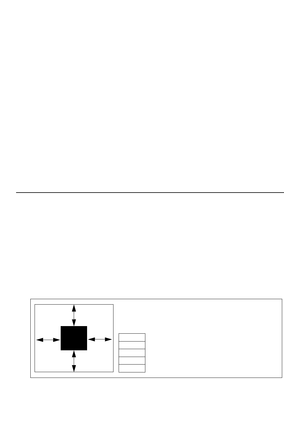
Chapter 15: Advanced Extraction Features
Via Coverage 15-6
StarRC User Guide and Command Reference F-2011.06
StarRC User Guide and Command Reference Version F-2011.06
Those values are
• Full coverage
• Quarter coverage
• Semi-coverage
• Full landing
• Quarter landing
• Semi-landing
The via coverage refers to the metal layer above the via (see Figure 15-5), and the via
landing refers to the metal layer below the via.
Note:
Using syntax previous to release A-2007.12 for VIA_COVERAGE and
VIA_COVERAGE_OPTION_FILE, only full and quarter coverage parameters are specified.
In the A-2007.12 release, semi coverage and landing parameters are optional.
Determining the Coverage and Landing Areas
(VIA_COVERAGE_OPTION_FILE)
The following section explains how the via coverage and landing areas are defined. The via
coverage refers to the metal layer above the via, and the via landing refers to the metal layer
below the via.
The following conditions determine via coverage and landing:
• If all edges are enclosed by the full- coverage parameter, the via is fully covered. See
Figure 15-6.
Figure 15-6 Via Rules for Verifying Full Coverage
6
6
6
6
If all sides have coverage and landing metal
coverage greater than the full (F) enclosure
parameter, the via is fully enclosed.
F = 5
Q2 = 4
Q1 = 1
S2 = 2
S1 = 1
Example via is fully covered because
all enclosures are greater than the
F parameter.
Chapter 15: Advanced Extraction Features
Via Coverage 15-7
Chapter 15: Advanced Extraction Features
Via Coverage 15-7
StarRC User Guide and Command Reference Version F-2011.06
• If the via is not fully covered, it may be quarter covered. If one edge has enclosure greater
than or equal to Q1, and BOTH adjacent edges have enclosure greater than Q2, the via
is quarter covered. The opposite edge must also have an enclosure greater than or equal
to Q1. See Figure 15-7.
Figure 15-7 Via Rules for Verifying Quarter Coverage
3
6
6
6
For quarter coverage, one enclosure must
be greater than or equal to Q1. Must have
both adjacent sides enclosed by more than
Q2.
F = 5
Q2 = 4
Q1 = 1
S2 = 2
S1 = 1
Example via is quarter covered because
one enclosure has greater than
Q1 (3
μ
) and adjacent edges have
an enclosure greater than Q2.
• If the via is not quarter covered, it might be semi-covered. If one edge has enclosure
greater than or equal to S1, and BOTH adjacent edges have enclosure greater than S2,
the via is semi-covered. The opposite edge must also have enclosure greater than or
equal to S1. See Figure 15-8.
Figure 15-8 Via Rules for Verifying Semi Coverage
1
3
3
6
For semi-coverage, one enclosure must be
greater than or equal to S1. Both adjacent
sides must be enclosed by more than S2.
F = 5
Q2 = 4
Q1 = 1
S2 = 2
S1 = 1
Example via is semi-covered because
one edge has an enclosure greater than
or equal to S1 (1
μ
), both adjacent
edges have an enclosure greater than
S2, and adjacent sides are enclosed
by less than Q2.
• If none of the preceding conditions is met, the via is partially covered as shown in
Figure 15-9.
• In instances where a via appears to satisfy both the quarter coverage and semi
-coverage, the via is considered to be quarter covered.
Chapter 15: Advanced Extraction Features
Via Coverage 15-8
StarRC User Guide and Command Reference F-2011.06
StarRC User Guide and Command Reference Version F-2011.06
Figure 15-9 Via Rules for Verifying Partial Coverage
.75
3
1
F = 5
Q2 = 4
Q1 = 1
S2 = 2
S1 = 1
For partial coverage, no enclosure meets the
conditions of full, quarter, or semi-covered.
Example via is partially covered
because no edge meets the
full, quarter, or semi-covered
requirements
1
Determining the Coverage and Landing Areas (VIA_COVERAGE)
The following section explains how the via coverage and landing areas are defined when you
use the VIA_COVERAGE command. The via coverage refers to the metal layer above the via,
and the via landing refers to the metal layer below the via.
Figure 15-10 VIA_COVERAGE Behavior
via
Metal 2
x1
x5
x3
x2
x4
Coverage for the via in Figure 15-10 is determined by the following checks:
1. Is the minimum distance of (x1&x2&x3&x4&x5) greater than or equal to full coverage?
If yes, the via is fully covered (F).
Is the minimum distance (x1&x2&x3&x4&x5) less than Full Coverage and greater than or
equal to Quarter Coverage?
2. If yes, the via is 3/4 covered (Q).
3. Is the minimum distance (x1&x2&x3&x4&x5) less than quarter coverage and greater than
or equal to semi-coverage?
If yes, the via is semi-covered (S).
4. Is the minimum distance (x1&x2&x3&x4&x5 less than semi-coverage?
If yes, the via is partially covered (P).
Chapter 15: Advanced Extraction Features
Via Coverage 15-9
Chapter 15: Advanced Extraction Features
Via Coverage 15-9
StarRC User Guide and Command Reference Version F-2011.06
Positive and Negative Check
Positive and negative checks using VIA_COVERAGE are described in the following section.
This concept is shown in Figure 15-11
• Positive check
Metal edges extend beyond the via edges and metal encloses the via.
• Negative check
Via extends beyond the edges of the metal polygons.
Figure 15-11 Positive and Negative Checks
VIA
METAL
Negative check (enclosure)
Via extends past metal
Positive check (enclosure)
Metal extends past via
Of the two commands supporting via coverage capabilities, VIA_COVERAGE and
VIA_COVERAGE_OPTION_FILE, the negative check is only supported in the
VIA_COVERAGE_OPTION_FILE command.
For the negative check, you specify negative parameters in the
VIA_COVERAGE_OPTION_FILE command. For metal parameters, StarRC performs the
negative check with greater than or equal to values of the negative parameter. If you specify
a negative value in a VIA_COVERAGE command, StarRC issues an error message. The
values of check parameters you specify in the VIA_COVERAGE_OPTION_FILE command can
be zero. Any coverage larger or equal to zero (for example nonnegative) satisfies the zero
coverage and landing check.
Chapter 15: Advanced Extraction Features
Via Coverage 15-10
StarRC User Guide and Command Reference F-2011.06
StarRC User Guide and Command Reference Version F-2011.06
Examples
The examples in this section describe the negative check. Tabl e 15-1 defines the F1, F2,
Q1, Q2, S1, and S2 parameters.
Table 15-1 Negative Check
Parameter Definition
F1 First landing/coverage parameter for a full check
F2 Second landing/coverage parameter for a full check
Q1 First landing/coverage parameter for a quarter check
Q2 Second landing/coverage parameter for a quarter check
S1 First first landing/coverage parameter for a semi check
S2 Second landing/coverage parameter for a semi check
Example 1
• Case 1: Q1=-1 and Q2=1
The geometries do not meet Q1=-1 and Q2 = 1 because via edges extend beyond metal
by 1.5 or more than 1. Via coverage equals -1.5 which is smaller than -1. This is shown
in Figure 15-12.
Figure 15-12
1.5
1.5 VIA
METAL
2
• Case 2: F2= 5, F1= -1; Q2= 3, Q1= -1;S2= 3, S1= -2
Chapter 15: Advanced Extraction Features
Via Coverage 15-11
Chapter 15: Advanced Extraction Features
Via Coverage 15-11
StarRC User Guide and Command Reference Version F-2011.06
The geometries meet Q1=-1 and Q2=1. Because via edges extend beyond the metal
edge by 1, satisfying Q1=-1; and the other adjacent opposite metal edges enclose the via
by distances larger or equal to 2. This is shown in Figure 15-13.
Figure 15-13
1
1VIA
METAL
2
Example 2
The parameters are F2=5, F1=-1;Q2=3, Q1=-1;S2=3, S1=-2. These are shown in
Figure 15-14.
• The geometries do not meet F2=5 and F1=-1 because via extends past metal by more
than 1 and the adjacent enclosures are less than 5.
• The geometries do not meet Q2=3 and Q1-1 because one via edge extension past metal
is -2 which is less than -1 although another opposite enclosure is equal to -1 and the
adjacent enclosures are equal to 3.
• The geometries meet the S2=3 and S1=-2 because the via extension past metal is
greater than or equal to =-2 and the adjacent enclosures are equal to 3.
Figure 15-14
-1
1VIA
METAL
-2
3
3
Example 3
The parameters are F2=5, F1=-1; Q2=3, Q1=-1, S2=1, S1=-1
Chapter 15: Advanced Extraction Features
Via Coverage 15-12
StarRC User Guide and Command Reference F-2011.06
StarRC User Guide and Command Reference Version F-2011.06
• The geometries do not meet F2=5 and F1=-1 because no two opposite enclosures area
greater than or equal to 5.
• The geometries do not meet Q2=3 and Q1=-1 because no two opposite enclosures are
greater than or equal to 3.
• The geometries do not meet S2=1 and S2=-1 because no two opposite enclosures area
greater than or equal to 1.
Figure 15-15
-1
VIA
METAL
-2
3
-1
Output
The via coverage output for a negative check does not have an impact on the output format.
Via Coverage Examples
The following are via coverage and landing practical examples. The VIA_COVERAGE
command supports the checking of square vias and the VIA_COVERAGE_OPTION_FILE
command supports the checking of rectangular vias.
VIA_COVERAGE - Syntax With Semi-Coverage
You can specify the VIA_COVERAGE command with the semi coverage function as follows.
VIA_COVERAGE: <via_layer_name> <Lf> <Lq> [<Ls>] <Cf> <Cq> {<Cs>]
NETLIST_FORMAT: SPEF
NETLIST_TAIL_COMMENTS: YES
VIA_COVERAGE: VIA1 100 80 40 100 80 40
VIA_COVERAGE: VIA2 100 80 40 100 80 40
VIA_COVERAGE - Syntax Without Semi-Coverage
For backward compatibility, you can specify the VIA_COVERAGE command without the semi-
coverage function.

Chapter 15: Advanced Extraction Features
Via Coverage 15-13
Chapter 15: Advanced Extraction Features
Via Coverage 15-13
StarRC User Guide and Command Reference Version F-2011.06
VIA_COVERAGE: <via_layer_name> <Lf> <Lq> <Cf> <Cq>
NETLIST_FORMAT: SPF
NETLIST_TAIL_COMMENTS: YES
VIA_COVERAGE: VIA1 100 80 100 80
VIA_COVERAGE: VIA2 100 80 100 80
VIA_COVERAGE_OPTION_FILE - Syntax With Semi-Coverage
<via_layer_name>
{Xrange=Xmin,Xmax;Yrange=Ymin,Ymax;Landing =
FL,QL1,QL2,[SL1,SL2];Coverage=FC,
QC1,QC2,[SC1,SC2]}
(Xrange=Xmin,Xmax;Yrange=Ymin,Ymax;
Landing=FL,QL1,QL2,[SL1,SL2];Coverage=FC,QC1,QC2,[SC1,SC2]}
VIA_COVERAGE_OPTION_FILE - Syntax Without Semi-Coverage
<via_layer_name>
{Xrange=Xmin,Xmax;Yrange=Ymin,Ymax;Landing =
FL,QL1,QL2;Coverage=FC,QC1,QC2}
(Xrange-Xmin,Xmax;Yrange=Ymin,Ymax;Landing =
FL,QL1,QL2;Coverage=FC,QC1,QC2}
Reading the Output Report
The results from the VIA_COVERAGE functions appear under the heading of
VIA_COVERAGE_CODES in the netlist and as a comment in the resistor element.
Coordinate locations of the reported vias are found in the SPF and SPEF outputs.
Report Appearance Differences
The report generated by StarRC output appears differently depending on which via
coverage commands you specify. Those commands specified with the semi-check output
more results.
When Checking Semi Coverage
You can read the results of the semi-check in the netlist file. Reading the lines horizontally,
find the specific check in the index line. The first letter indicates the via landing and the
second letter indicates the via cover. As shown in Figure 15-16 on page 15-14, the SS
column indicates semi-via landing and semi-via coverage. Similarly, PP indicates partial via
landing and partial via coverage and so on.
Chapter 15: Advanced Extraction Features
Via Coverage 15-14
StarRC User Guide and Command Reference F-2011.06
StarRC User Guide and Command Reference Version F-2011.06
Figure 15-16 Reading Semi Coverage Codes for a Square or Rectangular Check With Semi-
Results
partial coverage
semi landing
semi coverage
partial landing
full landing
semi coverage
line number
The via coverage code shown in Figure 15-16 is for the following example net:
*|NET FF 0PF
*|S (FF:1 0.05 0.05) // $llx=-0.1 $lly=-0.1 $urx=0.2 $ury=0.2 $lvl=1
*|S (FF:2 0.05 0.05) // $llx=-0.1 $lly=-0.1 $urx=0.2 $ury=0.2 $lvl=2
R16 FF:1 FF:2 23.67 $vc=16 $a=0.01 $lvl=3
The coverage code table output when semi is not checked is similar, except the columns
indicating semi via landing or semi via coverage are not included as shown in Figure 15-17
on page 15-15.
Chapter 15: Advanced Extraction Features
Long Ports 15-15
Chapter 15: Advanced Extraction Features
Long Ports 15-15
StarRC User Guide and Command Reference Version F-2011.06
Figure 15-17 Reading Coverage Codes for a Square or Rectangular Via Check Without Semi
Results
The via coverage code shown in Figure 15-17 is for the following example net:
*|NET PP 0PF
*|S (PP:1 1.85 -1.45) // $llx=1.78 $lly=-1.52 $urx=1.92 $ury=-1.38 $lvl=1
*|S (PP:2 1.85 -1.45) // $llx=1.78 $lly=-1.52 $urx=1.92 $ury=-1.38 $lvl=2
R1 PP:1 PP:2 23.67 $vc=1 $a=0.01 $lvl=3
In an SPF file, a parameter is added to the tail comment: $vc. This is an integer that
identifies the coverage code. The key for the codes is located in STAR_DIRECTORY/
via_coverage_codes.
StarRC supports both SPF and SPEF formats.
The X_by_Y column is written for via arrays. In Figure 15-17, the two resistors in the netlist
are the same 2-by-5 via array, with the last one rotated 90 degrees.
Net0 (noncritical) polygons are not used in the VIA_COVERAGE calculation and should not be
considered. All relevant neighbor polygons are considered when the context of the VIA is
being analyzed.
Long Ports
This feature is used to force *|I reported port locations in both top level and cell-level (for
INSTANCE_PORT:NOT_CONDUCTIVE) coordinate systems to the coordinates of the physical
overlap of the top-level route with the instance port shape.
In the simplest case, the x-y coordinate netlisted for the *|I port simply the lower-left corner
of the overlapping region. These regions are called PortUpContacts. See Figure 15-18.
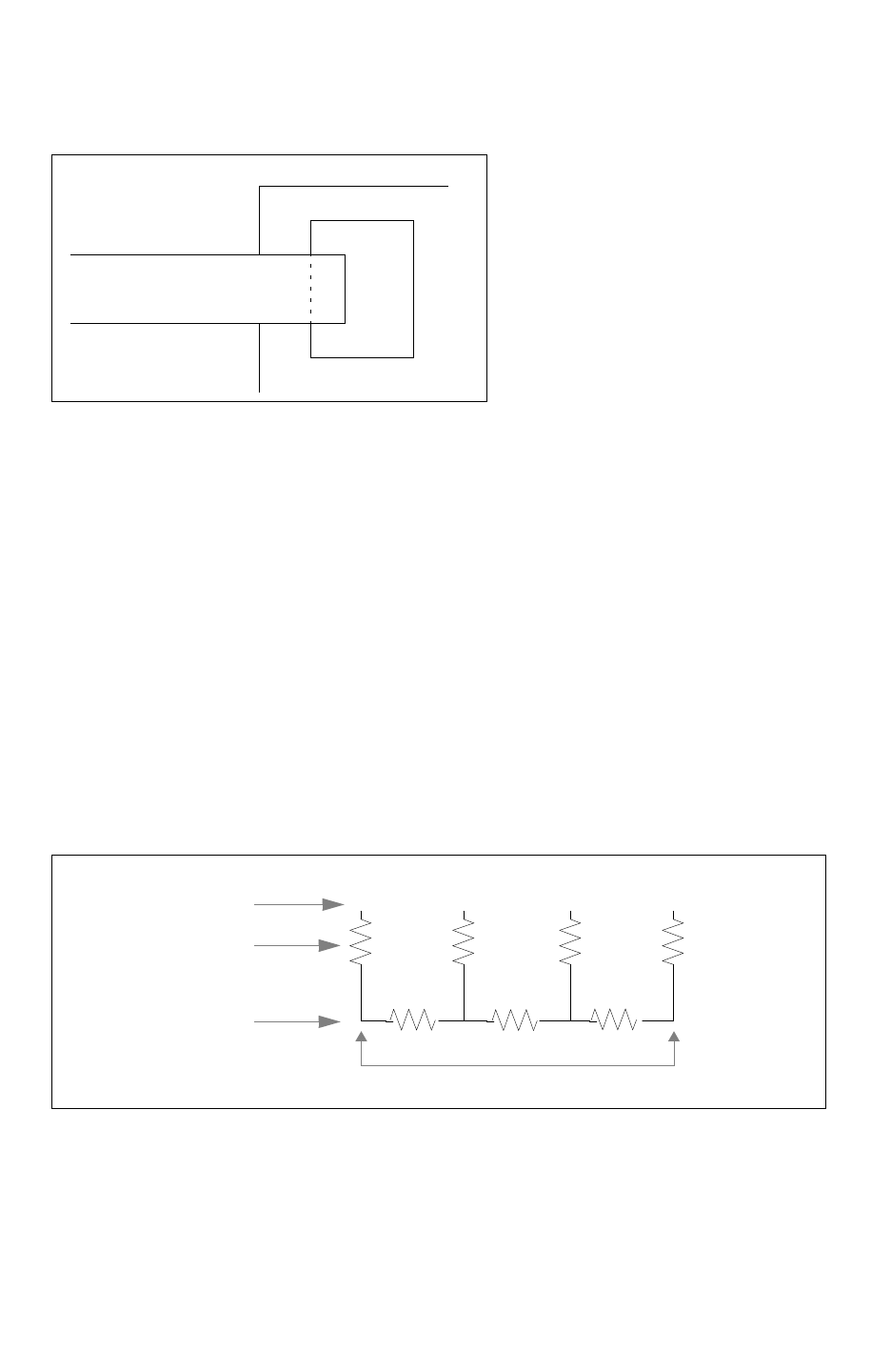
Chapter 15: Advanced Extraction Features
Long Ports 15-16
StarRC User Guide and Command Reference F-2011.06
StarRC User Guide and Command Reference Version F-2011.06
Figure 15-18 PortUpContact Example
NET1
U0
A
X
The x in Figure 15-18 represents the intersection coordinate for the NET1->U0/A
connection. It is called a PortUpContact node.
For longer “overlay”-type connections, multiple PortUpContact nodes are extracted. These
nodes are located in the same way that subnodes on a net are normally extracted.
For multiple separated connections of a single net to a single port (multiple intersection),
multiple PortUpContact nodes are extracted, one for each overlapping area.
When a propagated port is extracted, it is shorted to the lower level by a shorting resistor,
but resistance extraction does not occur at that level. It is assumed that the extraction has
already occurred at the lower level.
In Figure 15-19, the level_2 propagated port is netlisted with multiple *|P, with global
coordinates. The level_1 ports are netlisted with multiple *|I, with local coordinates for the
level_1 instance, and they are shorted to the level_2 with small shorting resistors.
Figure 15-19 Propagated Ports
x
xxx
xx xx
level_2 propagated ports
shorting resistors
level_1 ports,
Rs already extracted
*|P *|P *|P
*|I *|I *|I *|I
*|P

Chapter 15: Advanced Extraction Features
User-Defined Diffusion Resistance 15-17
Chapter 15: Advanced Extraction Features
User-Defined Diffusion Resistance 15-17
StarRC User Guide and Command Reference Version F-2011.06
User-Defined Diffusion Resistance
For advanced processing nodes, diffusion resistance depends on factors such as contact
location, diffusion layout, and so on, because of the channel effect. StarRC can take these
factors into account by applying a user-defined equation model to specific diffusion patterns.
StarRC extracts several layout parameters that are used as variables in the user-defined
equation and outputs these parameters as resistor tail comments for each parasitic resistor
in the netlist. To calculate the final diffusion resistance with the user-defined equations, you
must postprocess the netlist with a script that modifies the diffusion resistors.
To set up StarRC for user-defined diffusion resistance extraction, follow these steps, which
are detailed in the following sections:
•Modifying the ITF File
•Modifying the Mapping File
•Modifying the StarRC Command File
•Postprocessing the Netlist File to Compute Diffusion Resistance
Modifying the ITF File
In your ITF file, include the following parameters within a CONDUCTOR statement that
describes a polysilicon gate layer:
DIFFUSION_RES_GATE_TO_CONT_THRESHOLD = gate_cont_distance
DIFFUSION_RES_BEND_THRESHOLD = gate_diff_bend_distance
These parameters define the equation-based diffusion thresholds. For contacts that do not
meet the specified thresholds, StarRC applies the standard mesh-based diffusion
resistance extraction. For more information about these parameters, see the CONDUCTOR
statement in Chapter 18, “ITF Statements and Options.”
Modifying the Mapping File
In your StarRC mapping file, you can map the device model name to the database gate
layer. Do this by specifying a model name for the equation-based diffusion resistor with the
diffusion_res_model parameter in the conducting_layers statement for the polysilicon
gate layer, as shown in the following example:
conducting_layers
ngate poly diffusion_res_model=n_high
...

Chapter 15: Advanced Extraction Features
User-Defined Diffusion Resistance 15-18
StarRC User Guide and Command Reference F-2011.06
StarRC User Guide and Command Reference Version F-2011.06
The model name parameter is optional in the parasitic netlist. If you do not specify a model
name for the equation-based diffusion resistor, the model name is set to NA.
Modifying the StarRC Command File
To enable user-defined diffusion resistance extraction in StarRC, specify the following option
in your star_cmd file:
USER_DEFINED_DIFFUSION_RES: YES
This command directs StarRC to extract additional information for contacts with layout
parameters that are greater than the thresholds specified in the ITF. These additional
extracted parameters are illustrated in and listed inTabl e 15-2.
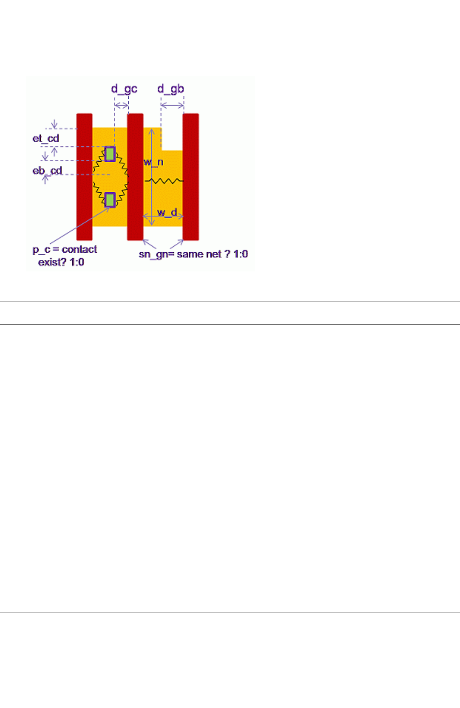
Chapter 15: Advanced Extraction Features
User-Defined Diffusion Resistance 15-19
Chapter 15: Advanced Extraction Features
User-Defined Diffusion Resistance 15-19
StarRC User Guide and Command Reference Version F-2011.06
Figure 15-20 Additional Parameters Extracted for Equation-Based Diffusion Resistance
Table 15-2 Additional Parameters Extracted for Equation-Based Diffusion Resistance
Parameter Description Data Type
p_c Location of the contact in drain or source diffusion area Boolean
sn_gn Presence of shared drain or source between two gates at the
same potential
Boolean
d_gc Gate-to-contact distance Floating-point
number
et_cd Overlap of the contact by drain or source diffusion on the top side
or half of the contact-to-contact spacing on the top side
Floating-point
number
eb_cd Overlap of the contact by drain or source diffusion on the bottom
side or half of the contact-to-contact spacing on the bottom side
Floating-point
number
w_n Width of the neighboring MOS device Floating-point
number
w_d Width of the drain or source diffusion for the contact Floating-point
number
d_gb Distance between the gate and diffusion bend Floating-point
number
model Device model name String

Chapter 15: Advanced Extraction Features
User-Defined Diffusion Resistance 15-20
StarRC User Guide and Command Reference F-2011.06
StarRC User Guide and Command Reference Version F-2011.06
The extracted parameters are printed as tail comments in a 100K-ohm dummy resistor. The
device model name is also printed as a tail comment. The following example shows a
StarRC netlist with the additional parameters and device model name listed in a dummy
resistor:
R22 S_NRVT_W312_1CA_C:11 M0:D 100000 $p_c=1 $sg_ng=0 $d_gc=0.048 $d_gb=0
$et_cd=0.136 $eb_cd=0.136 $w_n=0 $w_d=0.076 $model= n_high
Note:
Reduction is not performed on these equation-based resistors, while the other RC
elements are reduced as usual. An equation-based resistance network is typically
smaller than the default mesh-based resistance network.
The final netlist lists the model name for the corresponding contact and device gate
associated with the contact as netlist tail comments. The tail comments are not affected by
reduction settings.
Next, you need to specify a postprocessing script to process the 100K-ohm dummy resistors
in the initial parasitic netlist:
NETLIST_POSTPROCESS_CMD: script_name
This command reads from the standard output (STDOUT), so that the initial netlist
generated by StarRC is piped into the script and then output as the final netlist. For more
information about the script, see “Postprocessing the Netlist File to Compute Diffusion
Resistance” on page 15-20”
Postprocessing the Netlist File to Compute Diffusion Resistance
When the initial parasitic netlist file is postprocessed by a script, the 100K-ohm dummy
resistors are substituted with real resistors with resistance values calculated by user-defined
equations. The accuracy of the user-defined equation depends on the accuracy of the layout
parameters. You can use a Tcl or Perl script in conjunction with the
NETLIST_POSTPROCESS_CMD command in your star_cmd file. The
NETLIST_POSTPROCESS_CMD command takes the output netlist to be written to STDOUT and
pipes in the netlist for postprocessing. The script must support input through a pipe to
automatically use the NETLIST_POSTPROCESS_CMD command.
The script must perform the following steps:
1. Pipe in the netlist and detect the 100K-ohm dummy resistors.
2. Ensure that the parameters required in the user-defined equation are extracted for the
special resistors.
3. Read the parameters and plug the values into the user-defined equation.

Chapter 15: Advanced Extraction Features
User-Defined Diffusion Resistance 15-21
Chapter 15: Advanced Extraction Features
User-Defined Diffusion Resistance 15-21
StarRC User Guide and Command Reference Version F-2011.06
4. Replace the place holder 100K-ohm dummy resistance with the newly-calculated
resistance value from the script.
The following example shows a portion of an initial DSPF file:
R22 S_CA:11 M0:D 100000 $p_c=1 $sg_ng=0 $d_gc=0.05 $d_gb=0 $et_cd=0.14
$eb_cd=0.14 $w_n=0 $w_d=0.08 $model=n_high
After running through the post-processing script, the final DSPF is as follows:
R22 S_NRVT_W312_1CA_C:11 M0:D 20.46
In this example, the newly-calculated resistance value is 20.46.
Example of Tcl Script for Netlist Postprocessing
Example 15-1 shows ChangeResValue.tcl, a Tcl script that changes the value of a resistor
element in a netlist.
Example 15-1 Tcl Script to Postprocess a Parasitic Netlist
##!/usr/local/bin/tclsh
#Name: ChangeResValue.tcl
#Description: This is a Tcl script to change the value of a resistor
element in the netlist. The input to the script is STDIN for use with the
StarRC command NETLIST_COMPRESS_COMMAND
#Following is a simple example of user-defined equation
set x 1
set y 2
set z 3
#User needs to store resistance calculated in $value
set value [expr $x*$y*$z]
#Read from STDIN
while { [gets stdin line] >= 0 } {
set result [regexp {^R.+0\.001} $line dummy]
if {$result != 0} {
regsub "0.001$" $dummy" $value" newline
puts stdout "$newline"
}
else {
puts stdout "$line"
}
}

Chapter 15: Advanced Extraction Features
User-Defined Diffusion Resistance 15-22
StarRC User Guide and Command Reference F-2011.06
StarRC User Guide and Command Reference Version F-2011.06

16-1
16
Hercules GENDEV Device Extraction and
Netlist Generation 16
This chapter describes how designed nonstandard devices and nonstandard properties of
standard devices can be extracted and netlisted in StarRC by use of the Hercules GENDEV
functionality.
The sections in this appendix include:
•Introduction
•Device Recognition and Syntax
•Scheme Extraction Functions
•Hercules LVS With GENDEV Devices
•Scheme Property Comparison Functions
•GENDEV Netlist Generation in StarRC

Chapter 16: Hercules GENDEV Device Extraction and Netlist Generation
Introduction 16-2
StarRC User Guide and Command Reference F-2011.06
StarRC User Guide and Command Reference Version F-2011.06
Introduction
In a transistor-level Hercules flow, StarRC is capable of creating a netlist for designed
standard devices and standard device properties from the layout, as shown in the following
table:
Device Properties
NMOS/PMOS
(3-, 4-, or 5-terminal)
length (l)
width (w)
source area (as)
drain area (ad)
source perimeter (ps)
drain perimeter (pd)
RESISTOR length (l)
width (w)
resistance (r)
CAPACITOR length (l)
width (w)
capacitance (c)
DIODE area (a)
junction perimeter (pj)
INDUCTOR inductance (l)
NPN/PNP area (a)
If you want to extract from the layout a nonstandard designed device not supported by a
Hercules standard device extraction command, you can use the Hercules GENeric DEVice
command GENDEV. Also, if you want to extract a nonstandard device property for a
standard device, (such as, DIODE length and width), you can use GENDEV instead of the
normal Hercules device extraction command to define and extract this standard device with
nonstandard properties.
Device Recognition and Syntax
Generally speaking, most GENDEV devices can be extracted with GENDEV AUTO mode
operation, wherein a device is recognized whenever exactly one polygon from each
specified terminal layer interacts (through overlap, line touch, or point touch) with the
specified device recognition layer. Syntax for the Hercules GENDEV command is as follows:

Chapter 16: Hercules GENDEV Device Extraction and Netlist Generation
Device Recognition and Syntax 16-3
Chapter 16: Hercules GENDEV Device Extraction and Netlist Generation
Device Recognition and Syntax 16-3
StarRC User Guide and Command Reference Version F-2011.06
GENDEV device_name term_layer1 ... [term_layerN]
{
initialization_func = <init-func>
extraction_func = <extract-func>
recognition_layer = { layer_name }
[processing_layers = { processing_layer1 ...
processing_layerN }]
[gendev_devtype = MOS|RES|CAP|IND|NPDIODE|
PNDIODE|NPNBJT|PNPBJT ]
[gendev_dev_port_name = TRUE|FALSE]
[gendev_hier_proc = TRUE|FALSE]
[ev_netlist_func = <ev-netlist-func> ]
[spice_netlist_func = <spice-netlist-func> ]
} Output [Error_Output]
Parameters relevant to StarRC flows are as follows:
Table 16-1 GENDEV Parameter Definitions
Parameter Definition
term_layer# Layers that define the device’s terminals and touch or overlap the
recognition_layer.
initialization_func Name of the Scheme function wherein properties to be extracted for the
device are listed.
extraction_func Name of the Scheme function wherein property values are calculated for
each property defined in the initialization function.
recognition_layer Layer with which all terminal layers must interact in the layout to define the
device.
processing_layers Layers that are neither terminal nor recognition layers but which are used
for calculating property values in the extraction function.
gendev_devtype Standard device type that the GENDEV device is intended to emulate.
This is used for cases in which GENDEV is employed to extract
nonstandard device properties for standard devices.
gendev_dev_port_name makes extracted device pin names consistent with the standard device
defined by gendev_devtype. This should be set TRUE if gendev_devtype
is specified. If it is set to FALSE, pin names are T1, T2, and so on.
An example of a GENDEV command used to implement a standard designed resistor might
look as follows:

Chapter 16: Hercules GENDEV Device Extraction and Netlist Generation
Scheme Extraction Functions 16-4
StarRC User Guide and Command Reference F-2011.06
StarRC User Guide and Command Reference Version F-2011.06
GENDEV customres resterm resterm {
initialization_func = res-init
extraction_func = res-extract
recognition_layer = { resbody }
gendev_devtype = RES
gendev_dev_port_name = TRUE
} TEMP = res_layer
Hercules extracts a resistor device at any location in the layout where two polygons of layer
resterm interact with one polygon of layer resbody.
The complete set of GENDEV options is discussed in full detail in the Hercules Reference
Manual.
Scheme Extraction Functions
For GENDEV extraction, Scheme functions serve two purposes. The initialization function
specified by initialization_func specifies the names of device properties that are associated
with the generic device. An example of an initialization function that delineates length, width,
area, and perimeter properties for a GENDEV resistor follows:
(define res-init (lambda ()
(ev-dev-property-type-set "l" ’DOUBLE)
(ev-dev-property-type-set "w" ’DOUBLE)
(ev-dev-property-type-set "a" ’DOUBLE)
(ev-dev-property-type-set "p" ’DOUBLE)
(ev-dev-property-scale-factor-set "l" ’U)
(ev-dev-property-scale-factor-set "w" ’U)
(ev-dev-property-scale-factor-set "a" ’P)
(ev-dev-property-scale-factor-set "p" ’U)
))
By default, Hercules calculates one-dimensional geometric properties in units of microns.
However, StarRC netlists these properties in units of meters, according to standard SPICE
conventions. Because of the inherently generic and nonstandard nature of GENDEV device
properties, there is no clear way for either tool to know the appropriate geometric unit for a
newly-defined property, unless you explicitly specify the unit.
The ev-dev-property-scale-factor Scheme function lets you resolve this by specifying an
appropriate scale factor for converting each property value to the appropriate units for
purposes of StarRC netlist generation. The syntax for the function is
(ev-dev-property-scale-factor-set prop_name prop_scale)
• prop_name: -The name of property, enclosed in quotation marks.

Chapter 16: Hercules GENDEV Device Extraction and Netlist Generation
Scheme Extraction Functions 16-5
Chapter 16: Hercules GENDEV Device Extraction and Netlist Generation
Scheme Extraction Functions 16-5
StarRC User Guide and Command Reference Version F-2011.06
• prop_scale
’U (1e-6) for one-dimensional geometric properties (l, w)
’P (1e-12) for two-dimensional geometric properties (area)
A call to ev-dev-property-scale-factor should be specified for every geometric property
defined in the initialization function, and these calls should be placed after the calls to
ev-dev-property-type-set as in the previous example.
For GENDEV AUTO mode, the extraction function specified by extraction_func is used
purely to describe how values are to be calculated for each user-defined property delineated
in the initialization function. Within this function, you calculate property values by utilizing
Hercules-provided ev-measure Scheme routines to measure the geometric properties of the
terminal, recognition, and processing layers. You then attach the calculated values to the
property names defined in the initialization function. An example of an extraction function
that calculates values for resistor length, width, area, and perimeter properties follows:
(define res-init (lambda ()
(let
(
(L 0)
(W 0)
(body-perim)
(body-area)
)
; compute length and width
(set! body-perim (ev-measure1 ‘PERIM resbody))
(set! W (/ (ev-measure2 resbody ‘ABUT_PERIM
resterm) 2))
(set! L (/ (- body-perim (* 2 W)) 2))
(set! body-area (ev-measure1 ‘AREA resbody))
; assign values to the device properties
(ev-dev-property-value-set customres “l” L)
(ev-dev-property-value-set customres “w” W)
(ev-dev-property-value-set customres “a”
body-area)
(ev-dev-property-value-set customres “p”
body-perim)
)
))

Chapter 16: Hercules GENDEV Device Extraction and Netlist Generation
Hercules LVS With GENDEV Devices 16-6
StarRC User Guide and Command Reference F-2011.06
StarRC User Guide and Command Reference Version F-2011.06
Hercules LVS With GENDEV Devices
Hercules GENDEV devices can be equated as standard devices, depending on the setting
of the gendev_devtype option. If gendev_devtype is set to one of the Hercules standard
device types, the EQUATE command for the device can be specified with a corresponding
EQUATE standard device type. In the preceding example, the device would be equated with
the following command:
EQUATE RES customres=customres A B { }
If the GENDEV device of interest is emulating a nonstandard device and no gendev_devtype
is specified, the device should be equated in the EQUATE command as a DEV device. (See
the EQUATE command in the Hercules Reference Manual.)
When a standard device type (CAP, RES, DIODE, NMOS, PMOS, NPN, PNP, IND) is used
in the EQUATE statement for the GENDEV device, Hercules LVS is able to perform device
filtering and merged device property comparisons for standard properties in the normal
manner. However, if device merging is enabled via the MERGE_SERIES,
MERGE_PARALLEL, or MERGE_PATHS options, and if nonstandard properties exist for the
device, then you must provide Scheme routines that dictate how merged nonstandard
properties should be calculated and compared during LVS. You specify which nonstandard
properties are to be compared by using the check_user_properties EQUATE option:
check_user_properties = { nonstandard_property_list }
If device merging is enabled, each nonstandard property to be compared must be
accompanied by a corresponding Scheme routine that dictates how to calculate the merged
property and to perform the property comparison. This is specified inside the EQUATE
command with the comp_prop_func option:
comp_prop_func[non_standard_prop] = scheme_routine
If the GENDEV device is emulating a standard device, you can use the filtering options for
the standard device by configuring the EQUATE command accordingly. However, if the
GENDEV device is not emulating a standard device (in which case EQUATE DEV is used),
no standard filtering functionality is available. Once again, you can provide a Scheme
routine to specify how device filtering should be performed for such an instance. This routine
is specified within the EQUATE command as
filter_func = scheme_routine
Detailed information about writing a Scheme filtering function is available in the Hercules
Reference Manual.
Assume in the GENDEV custom resistor example, that you want to enable series and
parallel device merging during LVS and that you want to compare the merged property a
during LVS. This requires you to supply a Scheme routine to calculate the nonstandard a

Chapter 16: Hercules GENDEV Device Extraction and Netlist Generation
Scheme Property Comparison Functions 16-7
Chapter 16: Hercules GENDEV Device Extraction and Netlist Generation
Scheme Property Comparison Functions 16-7
StarRC User Guide and Command Reference Version F-2011.06
property for the merged device. Because the example emulates a standard RES device, no
Scheme filtering routines are necessary. A complete EQUATE statement for the GENDEV
custom resistor example would look like this:
EQUATE RES customres=customres A B BULK {
merge_series = true
merge_parallel = true
check_properties = {l, w}
check_user_properties = {a}
comp_prop_func[a] = res-area-comp
}
Note that in this example, “l” and “w” are standard Hercules-recognized RES properties
whereas “a” is not. Thus, Scheme routines are necessary to instruct Hercules how to
compare merged property a during LVS. Note also that COMPARE_PROPERTIES = TRUE
must be set in the Hercules COMPARE command for property comparisons to occur at all.
Scheme Property Comparison Functions
When you require nonstandard device properties for devices that are merged during LVS,
you must supply a Scheme routine to perform the merged property comparison. The body
of the routine is used to achieve a single merged value for the schematic merged device and
the layout merged device and to then compare these two values after application of the
specified tolerance bounds. The routine should be coded to return a value of #t when it
considers the property comparison to have passed, and a value of #f when the property
comparison failed. Hercules lsh reads this return value and then reports that the property
comparison either passed or failed.
The following is a Scheme routine that performs the property comparison for the GENDEV
customres device property a follows. More information about writing a Scheme merged
property comparison function is available in the Hercules Reference Manual.

Chapter 16: Hercules GENDEV Device Extraction and Netlist Generation
Scheme Property Comparison Functions 16-8
StarRC User Guide and Command Reference F-2011.06
StarRC User Guide and Command Reference Version F-2011.06
(define res-area-comp (lambda (sch-id lay-id prop)
(let (
(sch-type #f) (lay-type #f)
;; Get values for the specified property
(sch-prop (lvs-inst-prop-get sch-id prop))
(lay-prop (lvs-inst-prop-get lay-id prop))
(sch-name (lvs-inst-name-get sch-id))
(lay-name (lvs-inst-name-get lay-id))
(is-sch-merged (lvs-inst-is-member sch-id))
(is-lay-merged (lvs-inst-is-member lay-id))
(pos-tolerance ( car (lvs-inst-tolerance-get lay-id
prop)))
(neg-tolerance ( cadr (lvs-inst-tolerance-get lay-
id prop)))
(abs-tolerance (lvs-inst-tolerance-is-absolute
lay-id prop))
(sch-merged-area 0)
(lay-merged-area 0)
)
;; Make sure property values exist for this property
;; on both devices
(if (not sch-prop)
(return (format "~s: No schematic property ’~s’
found"
sch-name prop))
)
(if (not lay-prop)
(return (format "~s: No layout property ’~s’
found"
lay-name prop))
)
;; Check whether merging took place in schematic
(if (not is-sch-merged)
(set! sch-merged-area (car sch-prop))
(set! sch-merged-area (sum-list (sch-prop)))
)
;; Check whether merging took place in layout
(if (not is-lay-merged)
(set! lay-merged-area (car lay-prop))
(set! lay-merged-area (sum-list lay-prop))
)
;; Calculate tolerance boundaries
(if (not abs-tolerance)
(set! pos-tolerance (* pos-tolerance sch-
merged-area ))
)

Chapter 16: Hercules GENDEV Device Extraction and Netlist Generation
GENDEV Netlist Generation in StarRC 16-9
Chapter 16: Hercules GENDEV Device Extraction and Netlist Generation
GENDEV Netlist Generation in StarRC 16-9
StarRC User Guide and Command Reference Version F-2011.06
(if (not abs-tolerance)
(set! neg-tolerance (* neg-tolerance sch-
merged-area ))
)
(if (> (- lay-merged-area sch-merged-area ) pos-
tolerance )
(format
"\t~a=~a: Property ~a mismatch. ~s != ~s"
sch-name lay-name prop sch-merged-area lay-
merged-area)
)
(if (<= (- sch-merged-area lay-merged-area ) neg-
tolerance )
#t
(format
"\t~a=~a: Property ~a mismatch. ~s != ~s"
sch-name lay-name prop sch-merged-area lay-
merged-area)
)
)))
GENDEV Netlist Generation in StarRC
StarRC netlists all property names and values defined by the initialization and extraction
functions for GENDEV devices. In SPF/STAR/NETNAME netlist format, these devices are
netlisted in the instance section by use of standard SPICE cards (R for resistor, C for
capacitor, and so on) according to the setting of gendev_devtype in the Hercules netlist. If
no gendev_devtype is specified, the instance is netlisted with an x-card, indicating a call to
a separate .SUBCKT circuit definition.
The instance name is always followed by the device node names, the model name for the
device, and the list of properties defined for the device. For example, if
gendev_devtype=RES is used, the customres resistor occurs in the StarRC SPF netlist as
follows:
RR1 R1:A R1:B customres l=2.5u w=1u a=2.5p p=7u
If gendev_devtype and gendev_dev_port_name are not specified in the Hercules runset, the
device is netlisted by StarRC as follows:
XG1 G1:T1 G1:T2 customres l=2.5u w=1u a=2.5p p=7u
The latter example requires a .SUBCKT customres definition to define the contents of the
device for simulation.

Chapter 16: Hercules GENDEV Device Extraction and Netlist Generation
GENDEV Netlist Generation in StarRC 16-10
StarRC User Guide and Command Reference F-2011.06
StarRC User Guide and Command Reference Version F-2011.06
One limitation is that if XREF:COMPLETE is specified, StarRC only netlists device properties
defined for the device in the schematic netlist, unless the properties are standard properties
by Hercules/StarRC for the emulated standard device.
Note:
Heretofore, GENDEV has been used to obtain designed resistor and capacitor lengths
and widths in the final StarRC output netlist, because these properties were not fully
supported by the Hercules flow in StarRC. Full support for these properties has now been
implemented, eliminating the need for GENDEV to obtain these properties. To ensure
that all such standard properties are netlisted for Hercules standard devices, the following
StarRC option has been implemented:
NETLIST_PASSIVE_PARAMS: <YES | NO> (default = NO)

Part II: StarRC Command Reference

StarRC User Guide and Command Reference F-2011.06
StarRC User Guide and Command Reference Version F-2011.06

17-1
17
StarRC Commands 17
This chapter describes the commands that you can use in the StarRC command file.

Chapter 17: StarRC Commands
ANALOG_SYMMETRIC_NETS 17-2
StarRC User Guide and Command Reference F-2011.06
StarRC User Guide and Command Reference Version F-2011.06
ANALOG_SYMMETRIC_NETS
Enables the analog symmetric nets extraction mode.
Syntax
ANALOG_SYMMETRIC_NETS: NO | YES
Arguments
Argument Description
NO Disables the analog symmetric nets extraction mode.
This is the default.
YES Enables the analog symmetric nets extraction mode.
Description
The ANALOG_SYMMETRIC_NETS command enables a special extraction mode for analog
symmetric nets, such as differential signals. In this extraction mode, StarRC extracts
symmetric total and coupling capacitance values for layout that is independent of design
orientation (rotation and flip). StarRC identifies the width, spacing, and density for each
polygon individually and uses similar capacitance models to ensure that the extraction
results of the symmetric nets are very close to each other.
When you set ANALOG_SYMMETRIC_NETS: YES, StarRC extracts every symmetric net
independently. When compared to using the MODE: 400 command, the analog symmetric
nets extraction mode benefits from improved consistency with no loss of accuracy at the
expense of a longer runtime.
Note:
The analog symmetric nets extraction mode is supported only for transistor-level
extraction, not in the gate-level Milkyway or LEF/DEF flows.
Example
Use the following command when you need consistent total and coupling capacitances for
the symmetric nets in your design :
ANALOG_SYMMETRIC_NETS: YES
See Also
•MODE: 400

Chapter 17: StarRC Commands
AUTO_RUNSET 17-3
Chapter 17: StarRC Commands
AUTO_RUNSET 17-3
StarRC User Guide and Command Reference Version F-2011.06
AUTO_RUNSET
Automatically performs the necessary modifications internally for the separation of device
layers based on device definitions in the LVS rule file.
Syntax
AUTO_RUNSET: NO | YES
Arguments
Argument Description
NO Processes device layers directly from the LVS database without
any detection or modification of layer separation.
This is the default.
YES Enables automatic device layer separation for necessary devices
such as MOS devices and capacitors. Generates the
corresponding statements for such devices by separating layers
based on IGNORE_CAPACITANCE settings.
Description
Normally, StarRC utilizes device extraction data from various LVS flows such as IC Validator,
Hercules, and Calibre for device-level parasitic extraction. To ensure accurate extraction
results, a rule file for StarRC parasitic extraction flows as well as device extraction and LVS
flows must abide by the following conventions:
• MOS device and capacitor terminal layers must be distinct from the routing layers that
form those terminal layers, and no polygon overlap should occur between those layers.
This ensures that StarRC properly excludes all intradevice capacitances that are
represented by device models during simulation.
• All contacts must connect exactly two physical layers to ensure uniformity with the
physical processes as defined in the StarRC ITF file.
To satisfy these conventions required by the StarRC device-level extraction flow, the LVS
rule files must be updated. If you specify the AUTO_RUNSET command, StarRC internally
performs the necessary modifications to your LVS rule file automatically, based on device
definitions in the LVS rule file.

Chapter 17: StarRC Commands
AUTO_RUNSET 17-4
StarRC User Guide and Command Reference F-2011.06
StarRC User Guide and Command Reference Version F-2011.06
Example
The following syntax shows a typical Calibre rule file that uses the polysilicon interconnect
layer directly as the MOS gate terminal layer:
gate = poly AND diff
gatenw = gate NOT nwell
ngate = gatenw AND nplus
DEVICE MN(n) ngate poly (G) ndiff (S) ndiff (D) psub (B)
In this example, the interconnect layer poly itself serves as the gate terminal layer, while
ngate serves as the unconnected recognition (seed) layer. Since the terminal layer
derivations violate StarRC's assumption that the gate terminal layer represents only the gate
area, StarRC erroneously ignores the capacitance for portions of poly that do not serve as
part of the gate, that is, all capacitance between the poly interconnect and the device
diffusions. StarRC then generates the following instructions for the extraction engine to
ignore intradevice capacitance:
IGNORE_CAPACITANCE poly ndiff
IGNORE_CAPACITANCE poly psub
You can solve this problem by using the AUTO_RUNSET command, which performs internal
layer separation operations to differentiate the poly serving as the gate terminal from the
poly remaining as the routing layer.
Note:
The AUTO_RUNSET command can be used only if the recognition layer, which is ngate in
this example, exists in the input physical database.
See Also
•IGNORE_CAPACITANCE

Chapter 17: StarRC Commands
BLOCK 17-5
Chapter 17: StarRC Commands
BLOCK 17-5
StarRC User Guide and Command Reference Version F-2011.06
BLOCK
Defines the layout block name that is to be extracted.
Syntax
BLOCK: block_name
Arguments
Argument Description
block_name The layout name of the block to be extracted.
Default: none
Description
For Milkyway gate-level place and route designs, this option is mandatory. Valid arguments
are top-level blocks or fully placed and routed macro blocks that exist in the
MILKYWAY_DATABASE library.
For LEF/DEF gate-level designs, this option is invalid. The block to be extracted is
determined by the DESIGN keyword in the TOP_DEF_FILE file argument.
For Hercules gate-level or device-level flows, this option is mandatory. Valid arguments for
this flow are dependent on the settings of XREF and CELL_TYPE. With CELL_TYPE:LAYOUT,
which is the default, valid arguments are any cell that exists in the WRITE_EXTRACT_VIEW
library from Hercules. With CELL_TYPE: SCHEMATIC and XREF:YES or XREF:COMPLETE, valid
arguments are any valid equivalence point from Hercules compare.
For Calibre gate-level or device-level flows, this option is mandatory. Valid arguments for this
flow are dependent on the settings of XREF and CELL_TYPE. With CELL_TYPE: LAYOUT,
which is the default, valid arguments are any cell that exists in the annotated GDSII file and
layout netlist file (.nl). With CELL_TYPE:SCHEMATIC and XREF: YES, valid arguments are any
valid HCELL from Calibre compare (.ixf).
Example
This example specifies INT4 as the block to be extracted:
BLOCK: INT4
To override the BLOCK statement for a particular run, you can specify the StarXtract
command line option -b.
% StarXtract -b SMALLARRAY

Chapter 17: StarRC Commands
BLOCK 17-6
StarRC User Guide and Command Reference F-2011.06
StarRC User Guide and Command Reference Version F-2011.06
As shown in the previous example, specifying the -b option causes StarRC to use
SMALLARRAY as the block to extract rather than the block that is defined in the command
file. The command file is not changed, and the override exists for that run only.
See Also
•CELL_TYPE
•MILKYWAY_DATABASE
•MILKYWAY_EXTRACT_VIEW
•TOP_DEF_FILE
•XREF

Chapter 17: StarRC Commands
BLOCK_BOUNDARY 17-7
Chapter 17: StarRC Commands
BLOCK_BOUNDARY 17-7
StarRC User Guide and Command Reference Version F-2011.06
BLOCK_BOUNDARY
Defines a boundary for the block specified by BLOCK.
Syntax
BLOCK_BOUNDARY: x1 y1 x2 y2 [... xn yn]
Arguments
Argument Description
x1 The first x-coordinate in database units
y1 The first y-coordinate in database units
x2 The second x-coordinate in database units
y2 The second y-coordinate in database units
Description
The BLOCK_BOUNDARY command defines a boundary for the block specified by BLOCK when
you use the RING_AROUND_THE_BLOCK command for in-context approximation.
BLOCK_BOUNDARY is required when RING_AROUND_THE_BLOCK is specified for a LEF/DEF
flow. BLOCK_BOUNDARY information is used by StarRC to build the in-context routing
approximation rings for preplacement block noise analysis.
Specify the coordinates in database units, not microns. You can specify an arbitrary number
of boundary points. Two points (x1, y1)(x2, y2) define a rectangular block boundary. If you
specify more than two points, this specifies a rectilinear, or nonrectangular, block boundary.
The points you specify must be in counterclockwise order around the boundary of the block.
You can specify a closing point, but it is not required. This command and coordinates can be
specified only once in the StarRC command file.
It is not necessary to use BLOCK_BOUNDARY when the database is Milkyway, because the
boundary information can be read directly. However, if specified in a Milkyway flow, the
BLOCK_BOUNDARY command overrides the internal database value.
Example
The following example shows how to specify a block boundary with four points:
BLOCK_BOUNDARY: 0 0 269.6 0 269.6 137.6 0 137.6

Chapter 17: StarRC Commands
BLOCK_BOUNDARY 17-8
StarRC User Guide and Command Reference F-2011.06
StarRC User Guide and Command Reference Version F-2011.06
If the following error message appears, you should provide at least four coordinates of the
block boundary irrespective of the shape in counterclockwise direction from the DEF file in
database units to the BLOCK_BOUNDARY command:
ERROR: BLOCK_BOUNDARY must have at least 4 points
See Also
•BLOCK
•RING_AROUND_THE_BLOCK

Chapter 17: StarRC Commands
BUS_BIT 17-9
Chapter 17: StarRC Commands
BUS_BIT 17-9
StarRC User Guide and Command Reference Version F-2011.06
BUS_BIT
Specifies the character or pair of characters that defines the bus bit delimiter during
extraction and netlist creation.
Syntax
BUS_BIT: {} | [] | () | <> | : | .
Arguments
Argument Description
string Specifies the character set that defines the bus bit delimiter
during extraction and netlisting; do not insert spaces between the
characters in the string
Default: Database BUSBIT value
Description
The BUS_BIT command specifies the character or pair of characters that defines the bus bit
delimiter during extraction and netlist creation.
The value of this option affects net selection and the Standard Parasitic Exchange Format
(SPEF) *BUS_DELIMITER header statement that is read by follow-on tools. Any literal
occurrence of these characters in a net or instance name should be escaped during net
selection; attempting to use an illegal delimiter results in an error.
For a LEF/DEF database, the BUS_BIT characters are defined by the LEF/DEF default
specification or database definition of the BUSBITCHARS keyword in the LEF/DEF
database.
This command does not do character substitution in the output netlist; it affects only
selection and escaping.
The BUS_BIT command does not define the bus bit character in the final netlist. To make this
change in the netlist, you must either change the input file or post process the netlist with a
script.
See Also
•NETS

Chapter 17: StarRC Commands
CALIBRE_LVS_DEVICE_TYPE_CAP 17-10
StarRC User Guide and Command Reference F-2011.06
StarRC User Guide and Command Reference Version F-2011.06
CALIBRE_LVS_DEVICE_TYPE_CAP
Identifies user-defined CAP devices.
Syntax
CALIBRE_LVS_DEVICE_TYPE_CAP: list_of_C_devices
Arguments
Argument Description
list_of_C_devices List of user-defined CAP devices
Description
This command identifies user-defined capacitors as CAP devices.
The list_of_C_devices argument follows the case-sensitivity set by the CASE_SENSITIVE
command and must use a layout name. Using schematic names might cause conflicts in
certain situations.
Example
CALIBRE_LVS_DEVICE_TYPE_CAP: cap_ss
See Also
•CALIBRE_LVS_DEVICE_TYPE_MOS
•CALIBRE_LVS_DEVICE_TYPE_RES
•CALIBRE_OPTIONAL_DEVICE_PIN_FILE

Chapter 17: StarRC Commands
CALIBRE_LVS_DEVICE_TYPE_MOS 17-11
Chapter 17: StarRC Commands
CALIBRE_LVS_DEVICE_TYPE_MOS 17-11
StarRC User Guide and Command Reference Version F-2011.06
CALIBRE_LVS_DEVICE_TYPE_MOS
Identifies user-defined MOS devices.
Syntax
CALIBRE_LVS_DEVICE_TYPE_MOS: list_of_M_devices
Arguments
Argument Description
list_of_M_devices List of user-defined MOS devices
Description
This command identifies user-defined MOS devices.
The list_of_M_devices argument follows the case-sensitivity set by the CASE_SENSITIVE
command and must use a layout name. Using schematic names might cause conflicts in
certain situations.
Example
CALIBRE_LVS_DEVICE_TYPE_MOS: nmos_ss
See Also
•CALIBRE_LVS_DEVICE_TYPE_CAP
•CALIBRE_LVS_DEVICE_TYPE_RES
•CALIBRE_OPTIONAL_DEVICE_PIN_FILE

Chapter 17: StarRC Commands
CALIBRE_LVS_DEVICE_TYPE_RES 17-12
StarRC User Guide and Command Reference F-2011.06
StarRC User Guide and Command Reference Version F-2011.06
CALIBRE_LVS_DEVICE_TYPE_RES
Identifies user-defined resistors as RES devices and marks the device terminal layers for
recognition by the WIDE_DEVICE_TERM_RESISTANCE command.
Syntax
CALIBRE_LVS_DEVICE_TYPE_RES: list_of_R_devices
Arguments
Argument Description
list_of_R_devices List of user-defined RES devices
Description
The CALIBRE_LVS_DEVICE_TYPE_RES statement identifies user-defined resistors as RES
devices and marks the device terminal layers for recognition by the
WIDE_DEVICE_TERM_RESISTANCE command.
Example
In the following example, the rp_sio and pwr_rm1 devices defined in the rule file are
identified as resistors:
CALIBRE_LVS_DEVICE_TYPE_RES: rp_sio pwr_rm1
See Also
•CALIBRE_OPTIONAL_DEVICE_PIN_FILE
•WIDE_DEVICE_TERM_RESISTANCE

Chapter 17: StarRC Commands
CALIBRE_OPTIONAL_DEVICE_PIN_FILE 17-13
Chapter 17: StarRC Commands
CALIBRE_OPTIONAL_DEVICE_PIN_FILE 17-13
StarRC User Guide and Command Reference Version F-2011.06
CALIBRE_OPTIONAL_DEVICE_PIN_FILE
Assigns non-standard device terminals by name.
Syntax
CALIBRE_OPTIONAL_DEVICE_PIN_FILE: file_name
Arguments
Argument Description
file_name Name of the device pin file
Description
By default, StarRC assigns non-standard device terminals by position. However, if you
specify the CALIBRE_OPTIONAL_DEVICE_PIN_FILE command, StarRC assigns the device
terminal by the name in the specified file.
Example
In the following example, devpin_file contains the list of device terminal names:
CALIBRE_OPTIONAL_DEVICE_PIN_FILE: devpin_file
The following lines show an example of a device pin file:
M MOS_DEV NDIFSI_D (D) POLY (G) NDIFSI_S (S) NWELL (B)
C CAP_DEV CAP_TOP (PLUS)CAP_BOT (MINUS)
See Also
•CALIBRE_LVS_DEVICE_TYPE_CAP
•CALIBRE_LVS_DEVICE_TYPE_MOS
•CALIBRE_LVS_DEVICE_TYPE_RES

Chapter 17: StarRC Commands
CALIBRE_PDBA_FILE 17-14
StarRC User Guide and Command Reference F-2011.06
StarRC User Guide and Command Reference Version F-2011.06
CALIBRE_PDBA_FILE
Specifies the use of data from a Calibre PDBA file.
Syntax
CALIBRE_PDBA_FILE: file_name
Arguments
Argument Description
file_name File containing devices and device properties
Default: none
Description
The CALIBRE_PDBA_FILE command reads a Calibre PDBA file. This file is generated by
Calibre and lists some devices and device properties. You can use the CALIBRE_PDBA_FILE
command in the StarRC Calibre Connectivity Interface flow to retrieve the separated
properties for a final parasitic netlist with complete device information.
To use the CALIBRE_PDBA_FILE command, you must also include the following commands
in your Calibre runset:
•LVS PUSH DEVICES YES
•LVS PUSH DEVICES SEPARATE PROPERTIES “pdba.data” AGF
Errors
If the file specified by CALIBRE_PDBA_FILE does not exist, StarRC stops and issues a
warning message.
Example
CALIBRE_PDBA_FILE: ./pdba.data
See Also
•SKIP_CELLS
•XREF_SWAP_MOS_SD_PROPERTY

Chapter 17: StarRC Commands
CALIBRE_QUERY_FILE 17-15
Chapter 17: StarRC Commands
CALIBRE_QUERY_FILE 17-15
StarRC User Guide and Command Reference Version F-2011.06
CALIBRE_QUERY_FILE
Specifies the location of all Calibre Connectivity Interface input files.
Syntax
CALIBRE_QUERY_FILE: query_script_file
Arguments
Argument Description
query_script_file The command file used with the Calibre Connectivity Interface
server.
Default: none
Description
To have the Calibre Connectivity Interface (CCI) generate all the files needed for a StarRC
extraction, all the necessary query commands must be in the query command file specified
by CALIBRE_QUERY_FILE.
For details about the Calibre Connectivity Interface, see “Calibre Connectivity Interface” on
page 4-7. For details about Calibre query commands, see “Running the Calibre Query
Server for Output to StarRC” on page 14-33.
Example
CALIBRE_QUERY_FILE: query.cmd
The following is a sample of a Calibre query command file for the Calibre > StarRC flow.

Chapter 17: StarRC Commands
CALIBRE_QUERY_FILE 17-16
StarRC User Guide and Command Reference F-2011.06
StarRC User Guide and Command Reference Version F-2011.06
Example 17-0 Calibre Query Sample File
Sample Query Command File
=========================
# Define property numbers in annotated GDSII
GDS NETPROP NUMBER 5
GDS PLACEPROP NUMBER 6
GDS DEVPROP NUMBER 7
# Output seed polygon with net ID
GDS SEED PROPERTY ORIGINAL
# Output annotated GDSII mapping file for StarRC
RESPONSE FILE GDS_MAP
GDS MAP
RESPONSE DIRECT
# Output annotated GDSII file for StarRC
GDS WRITE agf
# Output device table file containing device layer
descriptions
# for StarRC
RESPONSE FILE devtab
DEVICE TABLE
RESPONSE DIRECT
# Output layout net name/net ID mapping table for StarRC
LAYOUT NETLIST TRIVIAL PINS YES
LAYOUT NETLIST EMPTY CELLS YES
LAYOUT NETLIST NAMES NONE
LAYOUT NAMETABLE WRITE lnn
# Output ideal layout netlist for StarRC
LAYOUT NETLIST PRIMITIVE DEVICE SUBCKTS YES
LAYOUT NETLIST PIN LOCATIONS YES
LAYOUT NETLIST HIERARCHY AGF
LAYOUT NETLIST WRITE nl
# Output net/device instance cross referencing tables for
StarRC
NET XREF WRITE nxf
INSTANCE XREF WRITE ixf
# Output ports file for StarRC
PORT TABLE CELLS WRITE ports_cells
# Output cell extents file for StarRC
CELL EXTENTS WRITE extents.txt
See Also
•CALIBRE_RUNSET

Chapter 17: StarRC Commands
CALIBRE_RUNSET 17-17
Chapter 17: StarRC Commands
CALIBRE_RUNSET 17-17
StarRC User Guide and Command Reference Version F-2011.06
CALIBRE_RUNSET
Specifies the LVS command file used for the Calibre run.
Syntax
CALIBRE_RUNSET: lvs_command_file
Arguments
Argument Description
lvs_command_file The LVS command file used for the Calibre run.
Default: none
Description
The CALIBRE_RUNSET command specifies the LVS command file used for the Calibre run. It
is required for the Calibre > StarRC flow.
An LVS rule deck contains data creation commands, device creation commands, device
property calculations, layer connect sequences, and LVS comparison options. StarRC
parses the layer connect sequence from the Calibre runset, including derived layer
connectivity, to understand the runset layer connectivity.
See Also
•BLOCK
•CALIBRE_QUERY_FILE
•MAPPING_FILE
•TCAD_GRD_FILE

Chapter 17: StarRC Commands
CASE_SENSITIVE 17-18
StarRC User Guide and Command Reference F-2011.06
StarRC User Guide and Command Reference Version F-2011.06
CASE_SENSITIVE
Specifies the case-sensitivity of net and cell names during selection.
Syntax
CASE_SENSITIVE: YES | NO
Arguments
Argument Description
YES Cell and net names are case-sensitive during selection.
This is the default.
NO Cell and net names are not case-sensitive during selection.
Description
The CASE_SENSITIVE command specifies whether net and cell names are case-sensitive
during selection. StarRC always retains the case sensitivity of the input database for netlist
creation. This command does not perform output case casting.
If IGNORE_CASE is set to TRUE in your Hercules runset, then you must specify
CASE_SENSITIVE: NO in your StarRC command file.
Example
The following syntax specifies that all net selection and cell selection are not case-sensitive.
CASE_SENSITIVE: NO
See Also
•CONLY_NETS
•INSTANCE_PORT
•NETLIST_SELECT_NETS
•NETLIST_TYPE
•NETS
•POWER_NETS
•SKIP_CELLS

Chapter 17: StarRC Commands
CELL_TYPE 17-19
Chapter 17: StarRC Commands
CELL_TYPE 17-19
StarRC User Guide and Command Reference Version F-2011.06
CELL_TYPE
Specifies whether layout or schematic cell names are used for data selection.
Syntax
CELL_TYPE: LAYOUT | SCHEMATIC
Arguments
Argument Description
LAYOUT Uses layout cell names from the Milkyway XTR or Calibre layout
databases.
This is the default.
SCHEMATIC Uses schematic cell names matched during LVS.
Description
The CELL_TYPE command specifies whether layout or schematic cell names are used for
BLOCK and SKIP_CELLS during data selection.
This command is ignored if XREF: NO is specified.
Note:
CELL_TYPE identifies only the source of cell names for SKIP_CELLS and BLOCK selection.
It does not affect the cell names reported by StarRC.
Example
CELL_TYPE: LAYOUT
See Also
•BLOCK
•MILKYWAY_EXTRACT_VIEW
•NET_TYPE
•SKIP_CELLS
•XREF

Chapter 17: StarRC Commands
COMPARE_DIRECTORY 17-20
StarRC User Guide and Command Reference F-2011.06
StarRC User Guide and Command Reference Version F-2011.06
COMPARE_DIRECTORY
Specifies the location of the Hercules LVS COMPARE output.
Syntax
COMPARE_DIRECTORY: path
Arguments
Argument Description
path The path to the location of the Hercules LVS COMPARE output
files.
Default: none
Description
The COMPARE_DIRECTORY command specifies the location of the Hercules LVS COMPARE
output. This path is specified in the Hercules runset HEADER section, with the
COMPARE_DIR option. The Hercules default for this option is ./run_details/compare.
This command is optional; however, if this path is not specified and XREF: YES or XREF:
COMPLETE is specified, the tool attempts to read the compare directory location from the XTR
(Milkyway Extract) view.
See Also
•XREF

Chapter 17: StarRC Commands
CONLY_NETS 17-21
Chapter 17: StarRC Commands
CONLY_NETS 17-21
StarRC User Guide and Command Reference Version F-2011.06
CONLY_NETS
Reports cross-capacitance to noncritical net neighbors.
Syntax
CONLY_NETS: list_of_nets
Arguments
Argument Description
list_of_nets List of nets; wildcards can be used.
Default: none
Description
The CONLY_NETS command reports cross-capacitance to noncritical net neighbors of the
NETS selected. The behavior of this command is dependent on the settings of the NETS and
COUPLE_TO_GROUND commands.
Example
In the following example, CONLY_NETS has no effect and all nets are netlisted:
COUPLE_TO_GROUND: NO
NETS: *
In the following example, net_a is extracted and netlisted with coupling to net_b:
COUPLE_TO_GROUND: NO
NETS: net_a
CONLY_NETS: net_b
The previous example results in the following sample output:
*|NET net_a
...
*CAP
1 net_a:23 net_b 1.32
2 net_a:3433 net_b 12.46
With the COUPLE_TO_GROUND: YES command, CONLY_NETS has no effect.


Chapter 17: StarRC Commands
CONVERT_DIODE_TO_PARASITIC_CAP 17-23
Chapter 17: StarRC Commands
CONVERT_DIODE_TO_PARASITIC_CAP 17-23
StarRC User Guide and Command Reference Version F-2011.06
CONVERT_DIODE_TO_PARASITIC_CAP
Specifies the extraction of parasitic properties of antenna diode structures.
Syntax
CONVERT_DIODE_TO_PARASITIC_CAP: model_name area_coeff perimeter_coeff
Arguments
Argument Description
model_name Antenna diode model name
Default: none
area_coeff Area capacitance coefficient
Units: F/m2
Default: none
perimeter_coeff Perimeter capacitance coefficient
Units: F/m
Default: none
Description
Use the CONVERT_DIODE_TO_PARASITIC_CAP command to extract parasitic properties of
antenna diode structures. Antenna diode structures in layout designs are commonly used to
help accommodate high-frequency circuit operations. Their use has increased as devices
have become smaller and their parasitic properties have become included in the extracted
parasitic netlist.
Errors
Error messages are issued when
• The model name is not found
• The capacitance coefficients are not realistic values such as negative numbers
• Device properties are not found in the input data
Example
CONVERT_DIODE_TO_PARASITIC_CAP: NpParaDiode 1e-15 1e-16


Chapter 17: StarRC Commands
COUPLE_NONCRITICAL_NETS 17-25
Chapter 17: StarRC Commands
COUPLE_NONCRITICAL_NETS 17-25
StarRC User Guide and Command Reference Version F-2011.06
COUPLE_NONCRITICAL_NETS
Reports the actual net names when coupling to material outside of the primary extraction
cell.
Syntax
COUPLE_NONCRITICAL_NETS: cell_list
Arguments
Argument Description
cell_list A cell or a list of cells for reporting coupling capacitance outside
the primary extraction cell
Default: !*
Description
Reports the actual net names when coupling to material outside of the primary extraction
cell. This command can affect the children of BLOCK and the parent, siblings, and children of
MACRO.
If you add a child cell to this list (that is, down from the primary cell), primary cell nets can
couple to the real hierarchical net names in the child. The child cells are not included in the
netlist and are floating nodes in the output SPEF. If you add a parent or a sibling cell to this
list, a special naming scheme is used to identify the coupling nodes. Instead of using full
hierarchical names from the MACRO perspective, the noncritical coupling nodes are named
cell_name/local_net_name.
This command overrides ZONE_COUPLE_TO_NET and SKIP_CELLS_COUPLE_TO_NET for the
selected cells.
The wildcards “*”, “?”, and “!” are acceptable. This command can be specified multiple times.
Note:
You should explicitly specify the cells on this list, rather than using the asterisk (*)
wildcard. Using a wildcard slows down runtime unnecessarily.

Chapter 17: StarRC Commands
COUPLE_NONCRITICAL_NETS 17-26
StarRC User Guide and Command Reference F-2011.06
StarRC User Guide and Command Reference Version F-2011.06
Example
Assume that you want to extract an instance, XU0, of cell MacroA in the context of the
BLOCK TopBlock. MacroB is a sibling of MacroA, and SubMacroC is a child of MacroA. The
following example shows how to configure the related options to achieve the following result:
• Parent TopBlock and siblings MacroA and MacroB are coupled with special block/net
names.
• Other siblings of MacroA, such as standard cells, are coupled with the net name ZONE.
• Child SubMacroC is coupled with real hierarchical net names, from the perspective of
MacroA.
• Other children of MacroA are coupled with the net name LUMP.
BLOCK: TopBlock
MACRO: XU0
COUPLE_NONCRITICAL_NETS: TopBlock MacroA MacroB SubMacroC
SKIP_CELLS_COUPLE_TO_NET: LUMP
ZONE_COUPLE_TO_NET: ZONE
The resulting SPEF might have capacitors like this:
*CAP
...
11 net1 TopBlock/clk 1.2e-13
12 net2 MacroA/net1 1e-16 // can couple to
identical // sibling
13 net3 MacroB/net2 1.3e-18
14 net1 instA/net1 8.2e-17 // couple to SubMacroC
cell
...
*END
See Also
•BLOCK
•COUPLE_NONCRITICAL_NETS_PREFIX
•COUPLE_TO_GROUND
•MACRO
•NETLIST_FORMAT
•SKIP_CELLS_COUPLE_TO_NET
•ZONE_COUPLE_TO_NET

Chapter 17: StarRC Commands
COUPLE_NONCRITICAL_NETS_PREFIX 17-27
Chapter 17: StarRC Commands
COUPLE_NONCRITICAL_NETS_PREFIX 17-27
StarRC User Guide and Command Reference Version F-2011.06
COUPLE_NONCRITICAL_NETS_PREFIX
Specifies a prefix for the nets output by the COUPLE_NONCRITICAL_NETS command.
Syntax
COUPLE_NONCRITICAL_NETS_PREFIX: prefix
Arguments
Argument Description
prefix Prefix string
Default: SYNOPSYS_INCONTEXT_
Description
Changes the prefix used by the COUPLE_NONCRITICAL_NETS command flow for nets, which
must be made unique to preserve independent names.
From the specified BLOCK down the hierarchy, this command applies the prefix to
interconnect or port nets of selected COUPLE_NONCRITICAL_NETS and SKIP_CELLS. From a
specified MACRO up the hierarchy, the prefix is applied to all names in the external
environment.
For example, instance/prefixnetname is applied for all noncritical nets.
If you do not specify any value, the default is SYNOPSYS_INCONTEXT_. If you specify NONE
as the value (not case sensitive), an empty prefix is used such that the coupling netname is
instance/netname.
This command is ignored if you do not specify the COUPLE_NONCRITICAL_NETS command.
See Also
•COUPLE_NONCRITICAL_NETS

Chapter 17: StarRC Commands
COUPLE_NONCRITICAL_NETS_SUBNODE_SUFFIX 17-28
StarRC User Guide and Command Reference F-2011.06
StarRC User Guide and Command Reference Version F-2011.06
COUPLE_NONCRITICAL_NETS_SUBNODE_SUFFIX
Specifies a netlist delimiter between the netname and suffix.
Syntax
COUPLE_NONCRITICAL_NETS_SUBNODE_SUFFIX: string
Arguments
Argument Description
string Netlist delimiter to be inserted between the netname and suffix
Default: an empty string
Description
The COUPLE_NONCRITICAL_NETS_SUBNODE_SUFFIX command specifies a netlist delimiter
between the netname and suffix. For example,
instance/prefix netname netlist_delimiter suffix
This command only works for cell-level extraction.
Retaining coupling capacitances between the top-level parent routing and SKIP_CELLS child
net routing exists for the Milkyway flow using the SPEF netlist format.
Example
MY_SUB_GROUP_1/SYNOPSYS_INCONTEXT_n192:1
See Also
•COUPLE_NONCRITICAL_NETS
•NETLIST_FORMAT
•RING_AROUND_THE_BLOCK
•SKIP_CELLS_COUPLE_TO_NET
•ZONE_COUPLE_TO_NET

Chapter 17: StarRC Commands
COUPLE_TO_GROUND 17-29
Chapter 17: StarRC Commands
COUPLE_TO_GROUND 17-29
StarRC User Guide and Command Reference Version F-2011.06
COUPLE_TO_GROUND
Specifies whether or not coupling capacitances are lumped to ground during extraction and
netlist generation.
Syntax
COUPLE_TO_GROUND: YES | NO
Arguments
Argument Description
YES Grounds coupling capacitors to other signal nets.
This is the default.
NO Retains coupling capacitors neighboring signal nets.
Description
The COUPLE_TO_GROUND command specifies whether or not parasitic coupling capacitances
are lumped to ground during extraction and netlist generation. A related command,
COUPLING_MULTIPLIER, defines a scaling factor required to account for crosstalk effects
during decoupling.
Example
COUPLE_TO_GROUND: YES
See Also
•COUPLING_MULTIPLIER
•NETLIST_FORMAT

Chapter 17: StarRC Commands
COUPLE_TO_PCELL_PINS 17-30
StarRC User Guide and Command Reference F-2011.06
StarRC User Guide and Command Reference Version F-2011.06
COUPLE_TO_PCELL_PINS
Specifies the coupling of parameterized cell (PCELL) pins to overhead nets.
Syntax
COUPLE_TO_PCELL_PINS: NO | YES | YES KEEP_CG
Arguments
Argument Description
NO Ignores couplings between adjacent PCELL pins; ignores
couplings between PCELL pins and ground.
This is the default.
YES Extracts couplings between adjacent PCELL pins; ignores
couplings between PCELL pins and ground.
YES KEEP_CG Extracts couplings between adjacent PCELL pins; extracts
couplings between PCELL pins and ground.
Description
The COUPLE_TO_PCELL_PINS command controls whether StarRC extracts PCELL pin
couplings to adjacent PCELL pins and ground.
Example
In the following example, StarRC extracts couplings between adjacent PCELL pins and
couplings between PCELL pins and ground:
COUPLE_TO_PCELL_PINS: YES KEEP_CG
See Also
•SKIP_PCELLS

Chapter 17: StarRC Commands
COUPLING_ABS_THRESHOLD 17-31
Chapter 17: StarRC Commands
COUPLING_ABS_THRESHOLD 17-31
StarRC User Guide and Command Reference Version F-2011.06
COUPLING_ABS_THRESHOLD
Sets an absolute threshold for grounding coupling capacitors.
Syntax
COUPLING_ABS_THRESHOLD: threshold
Arguments
Argument Description
threshold Absolute threshold
Units: farads (F)
Default: 3e-15
Description
Sets an absolute threshold for grounding coupling capacitors. Any coupling capacitor less
than this value that also meets the specified relative threshold criteria is grounded. For more
details, see “Smart Decoupling of Coupling Capacitances” on page 9-3.
See Also
•COUPLING_AVG_THRESHOLD
•COUPLING_REL_THRESHOLD
•COUPLING_THRESHOLD_OPERATION

Chapter 17: StarRC Commands
COUPLING_AVG_THRESHOLD 17-32
StarRC User Guide and Command Reference F-2011.06
StarRC User Guide and Command Reference Version F-2011.06
COUPLING_AVG_THRESHOLD
Syntax
COUPLING_AVG_THRESHOLD: threshold
Arguments
Argument Description
threshold A nonnegative floating-point number
Default: none
Description
Sets the ratio of coupling to the average coupling of a net, which defines a coupling to be
grounded. Two nets are decoupled when the ratio of coupling between two nets to each
average coupling is less than this value (if coupling capacitance meets the specified
absolute threshold and relative threshold). For more details, see “Smart Decoupling of
Coupling Capacitances” on page 9-3.
Note:
The COUPLING_AVG_THRESHOLD command has no default.
Example
In the following example, StarRC retains all coupling capacitors, resulting in a large netlist
size.
COUPLING_AVG_THRESHOLD: 0
See Also
•COUPLING_ABS_THRESHOLD
•COUPLING_REL_THRESHOLD
•COUPLING_THRESHOLD_OPERATION

Chapter 17: StarRC Commands
COUPLING_MULTIPLIER 17-33
Chapter 17: StarRC Commands
COUPLING_MULTIPLIER 17-33
StarRC User Guide and Command Reference Version F-2011.06
COUPLING_MULTIPLIER
Specifies a design- and process-dependent factor to be applied for transferring coupling
capacitances to ground.
Syntax
COUPLING_MULTIPLIER: value
Arguments
Argument Description
value A floating-point number greater than zero
Default: 1.0
Description
Applies a design- and process-dependent factor when you are transferring coupling
capacitances to ground. This command has been implemented primarily to scale parasitic
capacitances for crosstalk effects.
Example
COUPLING_MULTIPLIER: 6
See Also
•COUPLE_TO_GROUND

Chapter 17: StarRC Commands
COUPLING_REL_THRESHOLD 17-34
StarRC User Guide and Command Reference F-2011.06
StarRC User Guide and Command Reference Version F-2011.06
COUPLING_REL_THRESHOLD
Sets the ratio of coupling to total capacitance.
Syntax
COUPLING_REL_THRESHOLD: threshold
Arguments
Argument Description
threshold Floating-point number between 0 and 1
Default: 0.03
Description
Sets the ratio of coupling to total capacitance, which defines nets to be grounded. Two nets
are decoupled when the ratio of coupling capacitance to each total net capacitance is less
than this value, as long as the coupling capacitance meets the specified absolute threshold.
For more details, see “Smart Decoupling of Coupling Capacitances” on page 9-3.
See Also
•COUPLING_ABS_THRESHOLD
•COUPLING_AVG_THRESHOLD
•COUPLING_THRESHOLD_OPERATION

Chapter 17: StarRC Commands
COUPLING_REPORT_FILE 17-35
Chapter 17: StarRC Commands
COUPLING_REPORT_FILE 17-35
StarRC User Guide and Command Reference Version F-2011.06
COUPLING_REPORT_FILE
Generates a report listing the coupling capacitance by net.
Syntax
COUPLING_REPORT_FILE: file
Arguments
Argument Description
file File name for the report containing coupling capacitances by net
Default: none
Description
Generates a report listing the coupling capacitance by net after smart decoupling. The
report is sorted by the percentage of coupling capacitance to total capacitance for the net.
The format is as follows:
< Cc/Ct *100 > < Cc > < victim_net > < aggressor_net
The report contains the number of entries indicated by the COUPLING_REPORT_NUMBER
command.
The total net capacitance used for the coupling percentage calculation is the same as that
used for smart decoupling. It includes loading pin capacitors but not intranet coupling
capacitors (same net coupling).
Example
* 1000 worst couplings in descending order
* ratio(%) coupling victim aggressor
30.00 3e-15 net1 net2
20.00 2e-15 net3 net2
10.00 3e-15 net2 net1
See Also
•COUPLING_REPORT_NUMBER

Chapter 17: StarRC Commands
COUPLING_REPORT_NUMBER 17-36
StarRC User Guide and Command Reference F-2011.06
StarRC User Guide and Command Reference Version F-2011.06
COUPLING_REPORT_NUMBER
Specifies the number of nets reported by COUPLING_REPORT_FILE.
Syntax
COUPLING_REPORT_NUMBER: value
Arguments
Argument Description
value The number of nets for which you want coupling capacitors
reported. This number must be an integer.
Default: 1000
Description
Controls the size of the COUPLING_REPORT_FILE. The top COUPLING_REPORT_NUMBER nets
are exported to the report file.
Example
COUPLING_REPORT_NUMBER: 5
See Also
•COUPLING_REPORT_FILE

Chapter 17: StarRC Commands
COUPLING_THRESHOLD_OPERATION 17-37
Chapter 17: StarRC Commands
COUPLING_THRESHOLD_OPERATION 17-37
StarRC User Guide and Command Reference Version F-2011.06
COUPLING_THRESHOLD_OPERATION
Specifies the use of AND filtering or OR filtering of coupling thresholds.
Syntax
COUPLING_THRESHOLD_OPERATION: AND | OR
Arguments
Argument Description
AND AND filtering
This is the default.
OR OR filtering
Description
The following five conditions are checked to determine whether a coupling capacitance,
Cc(net1-net2) should be decoupled:
Condition1: Cc(net1-net2) < COUPLING_ABS_THRESHOLD
Condition2: Cc(net1-net2) < COUPLING_REL_THRESHOLD * TCAP_net1
Condition3: Cc(net1-net2) < COUPLING_REL_THRESHOLD * TCAP_net2
Condition4: Cc(net1-net2) < COUPLING_AVG_THRESHOLD * C_avg_net1
Condition5: Cc(net1-net2) < COUPLING_AVG_THRESHOLD * C_avg_net2
The COUPLING_THRESHOLD_OPERATION command specifies the use of AND filtering or OR
filtering of coupling capacitances.
• When AND filtering is specified by COUPLING_THRESHOLD_OPERATION: AND, then a
coupling capacitance is decoupled if the following operation is TRUE:
Condition1 AND (Condition2 AND Condition3) AND (Condition4 AND Condition5)
• When OR filtering is specified by COUPLING_THRESHOLD_OPERATION: OR, then a
coupling capacitance is decoupled if the following operation is TRUE:
Condition1 OR (Condition2 AND Condition3) OR (Condition4 AND Condition5)
See Also
•COUPLING_ABS_THRESHOLD
•COUPLING_AVG_THRESHOLD
•COUPLING_REL_THRESHOLD

Chapter 17: StarRC Commands
DENSITY_BASED_THICKNESS 17-38
StarRC User Guide and Command Reference F-2011.06
StarRC User Guide and Command Reference Version F-2011.06
DENSITY_BASED_THICKNESS
Syntax
DENSITY_BASED_THICKNESS:YES | NO
Arguments
Argument Description
YES Considers density-based thickness variation options as specified
in the ITF.
This is the default.
NO Does not consider density-based thickness options.
Description
Enables the calculation of density and thickness variation during extraction. This command
is automatically set to YES if either the THICKNESS_VS_DENSITY or the POLYNOMIAL_BASED_
THICKNESS_VARIATION command is detected in your ITF, or process file.
Note:
No warning is issued when thickness variation commands are not specified in the ITF file.
Example
DENSITY_BASED_THICKNESS: YES
See Also
•NETS
•USE_SI_DENSITY

Chapter 17: StarRC Commands
DENSITY_OUTSIDE_BLOCK 17-39
Chapter 17: StarRC Commands
DENSITY_OUTSIDE_BLOCK 17-39
StarRC User Guide and Command Reference Version F-2011.06
DENSITY_OUTSIDE_BLOCK
Specifies the pattern density outside the block, which affects the thickness variation and
parasitic RC values.
Syntax
DENSITY_OUTSIDE_BLOCK: density_value
Arguments
Argument Description
density_value Pattern cell density, represented by a floating-point number from
0.0 to 1.0
Default: 0.0
Description
The DENSITY_OUTSIDE_BLOCK command defines the pattern density outside the block. The
specified density is applied to all layers on which StarRC performs density calculation. This
command is used by the StarXtract function in StarRC.
By default, StarRC sets the outside density to 0.0. When the tool calculates the density of a
particular polygon, it uses a 50 μm by 50 μm square window that contains the polygon of
interest at the center. If the polygon of interest is located near the edge of the block, a portion
of the 50 μm by 50 μm window might be outside the block. To avoid unexpectedly low density
values for polygons near the block edge, set a nonzero value for DENSITY_OUTSIDE_BLOCK.
Note:
This command is effective only when you specify density-based thickness variation in the
ITF file and specify DENSITY_BASED_THICKNESS: YES in the StarRC command file.
Errors
StarXtract issues an error if the value specified for DENSITY_OUTSIDE_BLOCK is less than 0.0
or greater than 1.0. When the specified value equals 0.0 or 1.0, the error is not issued.
Example
The following example specifies that the pattern density outside the block is 40 percent:
DENSITY_OUTSIDE_BLOCK: 0.40
See Also
•DENSITY_BASED_THICKNESS
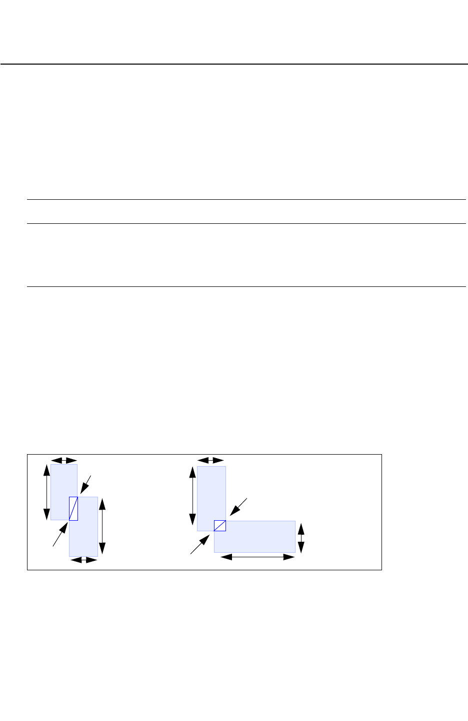
Chapter 17: StarRC Commands
DETECT_FUSE 17-40
StarRC User Guide and Command Reference F-2011.06
StarRC User Guide and Command Reference Version F-2011.06
DETECT_FUSE
Reports the fuse contact width in the netlist.
Syntax
DETECT_FUSE: YES | NO
Arguments
Argument Description
YES Analyze wire contacts to locate fuses.
NO Do not analyze wire contacts to locate fuses.
This is the default.
Description
Fuse contacts can be small regions, for example, where misaligned wire contact as shown
in Figure 17-1, and where local current density might be significantly higher due to the
reduced cross section. As a result, such regions might be susceptible to electromigration
problems. While fuse contacts acting as conductor configurations have a relatively small
effect on the circuit resistance and therefore can be safely ignored in timing or noise
analysis, a more detailed analysis might be needed during reliability verification flow. With
this command, you are able to locate these fuse contacts. For this command to function
properly, the REDUCTION:NO command must be set in your command file.
Figure 17-1 DETECT_FUSE Misaligned Wire Contact
Reports fuse resistors:
- $I=0
- $w=fuse contact width
- Rval =0.01
by
bx
a2
I2
I1
a1
fuse
w
bx
by
fuse
w
a1
I1
I2
Example
DETECT_FUSE: YES


Chapter 17: StarRC Commands
EVACCESS_DIRECTORY 17-42
StarRC User Guide and Command Reference F-2011.06
StarRC User Guide and Command Reference Version F-2011.06
EVACCESS_DIRECTORY
Specifies the location of the Hercules LVS EvAccess database.
Syntax
EVACCESS_DIRECTORY: path
Arguments
Argument Description
path Path to the Hercules LVS EvAccess database
Default: none
Description
Specifies the location of the Hercules LVS EvAccess database. This path can also be
specified in the Hercules runset EVACCESS_OPTIONS section, with the PATH option. The
Hercules default for this option is ./evaccess.
If this path is not specified, and you have specified XREF: YES or XREF: COMPLETE, the tool
attempts to read the directory location from the XTR (Milkyway Extract) view.
The EVACCESS_DIRECTORY command is not used in the IC Validator flow.
See Also
•XREF

Chapter 17: StarRC Commands
EXTRA_GEOMETRY_INFO 17-43
Chapter 17: StarRC Commands
EXTRA_GEOMETRY_INFO 17-43
StarRC User Guide and Command Reference Version F-2011.06
EXTRA_GEOMETRY_INFO
Reports the internal node bounding box information from StarRC resistance extraction.
Syntax
EXTRA_GEOMETRY_INFO: NODE | NONE
Arguments
Argument Description
NODE Reports nodes with geometry information.
NONE Does not report extra geometry information.
This is the default.
Description
Reports the internal node bounding box information from StarRC resistance extraction,
either as a tail comment in the node section of the netlist or as a node property in the
Milkyway parasitic database. This command is supported only for the SPF,STAR,
NETNAME,SPEF,SBPF and MW netlist formats. The dimensions in the bounding box data are
always as drawn and are not affected by the NETLIST_UNSCALED_COORDINATES command.
Example
This example shows the EXTRA_GEOMETRY_INFO:NODE command result:
*D_NET I20|N9 0.0869015
*CONN
*I I20|I44.X O *C 151.19 11.75 *D NAN2 // \
$llx=150.35 $lly=11.75 $urx=151.19 $ury=12.73\
$lvl=1
*I I20|I45.A I *C 149.16 11.75 *L 2 *D NOR2 // \
$llx=149.16 $lly=11.75 $urx=149.16 $ury=12.73\
$lvl=1
*N I20|N9.220 *C 155.04 17.42 // $llx=154.83\
$lly=17.42 $urx=155.04 $ury=17.42 $lvl=1
*N I20|N9.235 *C 154.83 18.68 // $llx=154.83\
$lly=18.68 $urx=155.04 $ury=18.68 $lvl=1
*N I20|N9.234 *C 153.57 18.68 // $llx=153.57\
$lly=18.68 $urx=153.57 $ury=18.68 $lvl=1
*N I20|N9.219 *C 153.57 17.42 // $llx=153.43\
$lly=17.42 $urx=153.57 $ury=17.42 $lvl=

Chapter 17: StarRC Commands
EXTRA_GEOMETRY_INFO 17-44
StarRC User Guide and Command Reference F-2011.06
StarRC User Guide and Command Reference Version F-2011.06
When you run an extraction using EXTRA_GEOMETRY_INFO, the LAYER_MAP section of the
netlist can also contain generated layer names. Extra layers are formed in the case of
device-level extraction when there are database layers at the diffusion level or below that
share a contact. For instance, if the runset contains the line shown in the following example,
then the LAYER_MAP section contains an extra layer called nsd:psd or psd:nsd, which
becomes the lower terminal level of diffCont via resistors.
CONNECT metal1 nsd psd BY diffCon
See Also
•NETLIST_FORMAT
•NETLIST_UNSCALED_COORDINATES

Chapter 17: StarRC Commands
EXTRACTION 17-45
Chapter 17: StarRC Commands
EXTRACTION 17-45
StarRC User Guide and Command Reference Version F-2011.06
EXTRACTION
Specifies the type of extraction and the scope of the generated netlist.
Syntax
EXTRACTION: RC | C | R | FSCOMPARE
Arguments
Argument Description
RC Extracts both parasitic resistor and capacitor devices and merges them into the
original database network to produce a consolidated RC network description of
the layout in the specified format.
This is the default.
CExtracts only parasitic capacitor devices and produces a merged parasitic layout
network description as a SPICE file. The NETLIST_FORMAT command is ignored
for capacitance-only extractions.
RExtracts only parasitic resistor devices and produces a merged parasitic layout
network description in the specified format.
FSCOMPARE Provides a comparison report of a merged layout network description containing
only parasitic capacitors, executes a field solver analysis of the layout, and
produces report files that describe the accuracy in a comparison of the two
results.
When this option and the FS_EXTRACT_NETS command are specified, the
.fscomptot and .fs_compcoup output comparison files
always use the layout net names, regardless of the XREF command setting.
Description
The extraction of parasitic devices is performed only on that portion of the layout network
defined by the NETS command, terminating each net at the boundary of the specified
SKIP_CELLS.
See Also
•FSCOMPARE_OPTIONS
•FS_EXTRACT_NETS
•NETLIST_FORMAT
•REDUCTION

Chapter 17: StarRC Commands
EXTRACT_VIA_CAPS 17-46
StarRC User Guide and Command Reference F-2011.06
StarRC User Guide and Command Reference Version F-2011.06
EXTRACT_VIA_CAPS
Performs a detailed via capacitance extraction.
Syntax
EXTRACT_VIA_CAPS: NO | YES [IGNORE_GATE_CONTACT_COUPLING]
Arguments
Argument Description
NO Do not consider capacitive effect of vias/contacts. In general this
setting uses less runtime and reports fewer capacitances. This is
best used while developing designs and for technology nodes of
130 nm and above.
This is the default.
YES Consider the capacitive effect of vias/contacts. In general, this
setting uses more runtime and reports the accuracy of the total
net capacitance improvement. This is best used for signoff
designs and those with technology nodes of 90 nm and below.
IGNORE_GATE_CONTACT_COUP
LING
Ignore the gate contact coupling if SPICE models include
gate-to-contact capacitance. Use the following command:
EXTRACT_VIA_CAPS: YES
IGNORE_GATE_CONTACT_COUPLING
Description
This command is used in conjunction with the EXTRACTION: RC | C | FSCOMPARE
command.
If EXTRACT_VIA_CAPS is set to YES, StarRC considers the capacitive effects of all kinds of
via/contact layers when it extracts parasitics. You do not need to prepare a new nxtgrd file to
extract via capacitance in general; StarRC takes into account the via capacitance with a
normal nxtgrd file.
The ITF option GATE_TO_CONTACT_SMIN should be used in addition to SMIN inside the ITF
CONDUCTOR definition for polysilicon, for flows in which MOS gate-to-contact capacitance
accuracy is relevant. This allows StarRC to utilize the actual gate-to-contact spacing when
extracting contact capacitance because this spacing is typically smaller than the standard
polysilicon SMIN spacing.


Chapter 17: StarRC Commands
EXTRACT_RES_BODY_COUPLING 17-48
StarRC User Guide and Command Reference F-2011.06
StarRC User Guide and Command Reference Version F-2011.06
EXTRACT_RES_BODY_COUPLING
Specifies the extraction of coupling capacitances between metal interconnects to a resistor
body and resistor body to ground.
Syntax
EXTRACT_RES_BODY_COUPLING: YES | NO
Arguments
Argument Description
YES Enables resistor body capacitor extraction.
NO Disables resistor body capacitor extraction.
This is the default.
Description
Specifies the extraction of coupling capacitances between metal interconnects to a resistor
body and resistor body to ground. The coupling between resistor bodies and interconnect is
distributed between the two terminals of the resistor.
Example
EXTRACT_RES_BODY_COUPLING: YES

Chapter 17: StarRC Commands
FS_DP_STRING 17-49
Chapter 17: StarRC Commands
FS_DP_STRING 17-49
StarRC User Guide and Command Reference Version F-2011.06
FS_DP_STRING
Specifies the distributed processing method and job control parameters for Rapid3D
extraction runs.
Syntax
FS_DP_STRING:
bsub lsf_arguments
| qsub gridware_arguments
| list list_of_machines
Arguments
Argument Description
lsf_arguments Arguments for an LSF system
gridware_arguments Arguments for a Gridware system
list_of_machines List of machines on a general network
Description
For distributed processing, you must specify how to invoke jobs on your compute farm by
setting the FS_DP_STRING command.
There are three methods to implement distributed processing:
• LSF System
• Gridware System
• General Network With a List of Machines
When using distributed processing, keep the following points in mind:
• The FS_DP_STRING command does not specify the number of processors.
• If you specify the FS_DP_STRING variable as both an environment variable and a StarRC
command file statement, then StarRC command file uses the setting in the command file.
• The control parameters are site-specific; ask your system administrator for details.
Example
On an LSF system:
FS_DP_STRING: bsub -a amd64 -R "rusage[mem=5000]"

Chapter 17: StarRC Commands
FS_DP_STRING 17-50
StarRC User Guide and Command Reference F-2011.06
StarRC User Guide and Command Reference Version F-2011.06
On a Gridware system:
FS_DP_STRING: qsub -P bnormal -l "mem_free=1G mem_avail=1G"
On a general network with a list of machines:
FS_DP_STRING: list mars jupiter uranus
See Also
•rapid3d

Chapter 17: StarRC Commands
FS_EXTRACT_NETS 17-51
Chapter 17: StarRC Commands
FS_EXTRACT_NETS 17-51
StarRC User Guide and Command Reference Version F-2011.06
FS_EXTRACT_NETS
Specifies the nets to be extracted by the field solver.
Syntax
FS_EXTRACT_NETS: net_names
Arguments
Argument Description
net_names List of nets the require field solver extraction accuracy.
Wildcards can be used.
Description
The FS_EXTRACT_NETS command specifies a list of nets that need the highest level of
extraction accuracy. In addition to extracting these nets in the regular flow, StarRC also
creates a subset of the design based on these nets to also be extracted by the field solver.
The resulting netlist combines the nets extracted by StarRC and the field solver.
StarRC creates comparison tables for both total and coupling capacitances with the
FS_EXTRACT_NETS command. This enables you to generate an accurate parasitic netlist
along with a validation report. This is available for all flows.
In addition, StarRC supports NET_TYPE: SCHEMATIC when used with the FS_EXTRACT_NETS
command in the Calibre flow.
Example
In the following example, StarRC extracts all nets, but only the three nets specified by the
FS_EXTRACT_NETS command are extracted by the field solver:
NETS: *
FS_EXTRACT_NETS: net1 net2 net3
NET_TYPE: SCHEMATIC
Use the NET_TYPE command to specify whether the net names are layout or schematic net
names.


Chapter 17: StarRC Commands
FSCOMPARE_COUPLING_RATIO 17-53
Chapter 17: StarRC Commands
FSCOMPARE_COUPLING_RATIO 17-53
StarRC User Guide and Command Reference Version F-2011.06
FSCOMPARE_COUPLING_RATIO
Specifies the minimum ratio of the coupling capacitance to the total capacitance required on
a particular net to make it eligible for comparison in an FSCOMPARE extraction.
Syntax
FSCOMPARE_COUPLING_RATIO: value
Arguments
Argument Description
value A floating-point number between zero and one.
Default: 0.10
Description
FSCOMPARE_COUPLING_RATIO specifies the minimum ratio of the coupling capacitance to the
total capacitance required on a particular net to make it eligible for comparison in an
FSCOMPARE extraction. The results are filtered by the field solver results.
The specified value is applied to the capacitance values calculated by the 3-D field solver,
which is Rapid3D by default.
Example
FSCOMPARE_COUPLING_RATIO: 0.2
See Also
•EXTRACTION: FSCOMPARE
•FS_EXTRACT_NETS
•FSCOMPARE_OPTIONS
•FSCOMPARE_THRESHOLD

Chapter 17: StarRC Commands
FSCOMPARE_FILE_PREFIX 17-54
StarRC User Guide and Command Reference F-2011.06
StarRC User Guide and Command Reference Version F-2011.06
FSCOMPARE_FILE_PREFIX
Syntax
FSCOMPARE_FILE_PREFIX: prefix
Arguments
Argument Description
prefix A prefix to be attached to the beginning of file names.
Default: block name specified in the star_cmd file.
Description
Provides a prefix to be attached to files output by the EXTRACTION: FSCOMPARE command.
Example
FSCOMPARE_FILE_PREFIX: myprefix
myprefix.fs-compcoup
See Also
•EXTRACTION

Chapter 17: StarRC Commands
FSCOMPARE_OPTIONS 17-55
Chapter 17: StarRC Commands
FSCOMPARE_OPTIONS 17-55
StarRC User Guide and Command Reference Version F-2011.06
FSCOMPARE_OPTIONS
Specifies field solver options such as convergence goal and multiprocessing.
Syntax
FSCOMPARE_OPTIONS: option_1 [option_2 ...]
Arguments
Argument Description
option_1 [option_2 ...]Field solver options listed in Ta b l e 17-1.
Description
Table 17-1 lists the Rapid3D options that you can specify with FSCOMPARE_OPTIONS to be
passed to the field solver during FSCOMPARE extraction.
Table 17-1 List of Rapid3D Options Set by FSCOMPARE_OPTIONS
Argument Description
-f input_files Specifies the input files. Specify the technology file before the design
file.
-e list_of_nets Specifies a list of nets to extract.
Default: all nonground nets
-v Prints the program version.
-np number_processors During distributed processing, sets the number of processors to use.
Default: 1
-time_out wait_time During distributed processing, sets the maximum time that the
master process waits for the slave machines to start.
Units: minutes
Default: 1440
-mach_term retry_time During distributed processing, sets the time to keep trying to contact
a master or slave machine that has stopped responding. If the
machine does not respond within the specified time, the job
terminates.
Units: minutes
Default: 10

Chapter 17: StarRC Commands
FSCOMPARE_OPTIONS 17-56
StarRC User Guide and Command Reference F-2011.06
StarRC User Guide and Command Reference Version F-2011.06
-min_per_net
minutes_per_net
Sets the maximum extraction time per net.
Units: minutes
Default = 20
-l filename Specifies the name of a file containing a list of client machines. For
each client, specify a row with the following: machine_name arch
If -l is given, then LSF is not used for the clients.
-perc_self
self_cap_conv_goal
Sets the self-capacitance convergence goal at one standard
deviation as a percentage.
Units: percent
Default: 0.5
-perc_coup
coup_cap_conv_goal
Sets the coupling capacitance convergence goal at one standard
deviation as a percentage.
Default: not checking
-abs_coup
abs_cap_conv_goal
Sets the absolute coupling capacitance convergence goal.
The dynamic value of abs_cap_conv_goal is determined by
multiplying the total net capacitance by the percentage set by
-coup_cap_thresh.
Units: farads
Default: dynamic
-coup_cap_thresh number Sets the percentage of total capacitance at which to start checking
coupling.
Units: percent
Default: 1
-perc_consistency max_dev Sets the maximum deviation between identical nets, expressed as a
percentage of the total capacitance.
Units: percent
Default: none
-perc_of_nets_consistent
number
Sets the percentage of identical nets that deviate from each other by
the level specified by -perc_consistency.
Units: percent
Default: 97
Table 17-1 List of Rapid3D Options Set by FSCOMPARE_OPTIONS (Continued)
Argument Description

Chapter 17: StarRC Commands
FSCOMPARE_OPTIONS 17-57
Chapter 17: StarRC Commands
FSCOMPARE_OPTIONS 17-57
StarRC User Guide and Command Reference Version F-2011.06
-perc_accuracy number Sets the accuracy of the extracted capacitance value, expressed as
a percentage of the capacitance value.
Note: if this parameter is specified, -perc_self should not be
specified.
Units: percent
Default: 1.5
-perc_accuracy_confidence
number
Sets the confidence level for the estimated capacitance value,
extracted at the accuracy level set by -perc_accuracy, expressed
as a percentage.
Units: percent
Default: 99.7
-min_cap cap_value Sets the minimum capacitance value to report in the output file.
Units: farads
Default: 1.0e-20
-seed rand_num_seed Sets the random number seed.
Default: 12345
-bb xl yl xh yh Sets the bounding box.
Units: grid units
Default: 100 microns larger than design
-neuman_x Uses Neumann boundary conditions on X boundaries.
Default: false
-neuman_y Uses Neumann boundary conditions on Y boundaries.
Default: false
-periodic_x Uses periodic boundary conditions on X boundaries.
Default: false
-periodic_y Uses periodic boundary conditions on Y boundaries.
Default: false
-match Enables pattern matching and improves runtime and accuracy for
symmetric or identical net extraction in Rapid3D.
Table 17-1 List of Rapid3D Options Set by FSCOMPARE_OPTIONS (Continued)
Argument Description

Chapter 17: StarRC Commands
FSCOMPARE_OPTIONS 17-58
StarRC User Guide and Command Reference F-2011.06
StarRC User Guide and Command Reference Version F-2011.06
To obtain a complete list of Rapid3D options, enter rapid3d -help on the command line.
This assumes that the installation of Rapid3D has been correctly set up.
Example
To run two clients with a one percent self-capacitance goal, use the following command:
FSCOMPARE_OPTIONS: -np 2 -perc_self 1
To run three clients and pass an LSF option to specify a Red Hat Linux 3.0 operating system,
use the following command:
FSCOMPARE_OPTIONS: -np 3 -b "' -R rhel30'"
To run four clients using an AMD64 architecture with a 10 percent coupling capacitance and
one percent self-capacitance goal, use the following command:
FSCOMPARE_OPTIONS: -np 4 -a amd64 -perc_coup 10 -perc_self 1
See Also
•EXTRACTION: FSCOMPARE
•FS_EXTRACT_NETS
•FSCOMPARE_COUPLING_RATIO
•FSCOMPARE_THRESHOLD

Chapter 17: StarRC Commands
FSCOMPARE_THRESHOLD 17-59
Chapter 17: StarRC Commands
FSCOMPARE_THRESHOLD 17-59
StarRC User Guide and Command Reference Version F-2011.06
FSCOMPARE_THRESHOLD
Specifies the minimum total capacitance required on a particular net to make it eligible for
comparison in an FSCOMPARE extraction.
Syntax
FSCOMPARE_THRESHOLD: value
Arguments
Argument Description
value A floating-point number greater than or equal to zero.
Default: 1.0e-14
Description
FSCOMPARE_THRESHOLD specifies the minimum total capacitance required on a particular net
to make it eligible for comparison in an FSCOMPARE extraction. The results are filtered by the
field solver values.
The specified value is applied to the capacitance values calculated by the 3-D field solver,
which is Rapid3D by default.
Example
Setting FSCOMPARE_THRESHOLD to zero ensures that no nets are eliminated based on their
capacitance:
FSCOMPARE_THRESHOLD: 0
See Also
•EXTRACTION: FSCOMPARE
•FS_EXTRACT_NETS
•FSCOMPARE_COUPLING_RATIO
•FSCOMPARE_OPTIONS

Chapter 17: StarRC Commands
GDS_FILE 17-60
StarRC User Guide and Command Reference F-2011.06
StarRC User Guide and Command Reference Version F-2011.06
GDS_FILE
Specifies GDSII format files to represent part of the physical layout.
Syntax
GDS_FILE: file1 [file2] ...
Arguments
Argument Description
file1 [file2] ... Name of GDSII file
Default: none
Description
The GDS_FILE command specifies GDSII format files to represent part of the physical layout.
You can specify gzipped and compressed GDSII files for this command.
With LEF_FILE and TOP_DEF_FILE, this command merges GDSII data into LEF MACRO
definitions for SKIP_CELLS to provide a full physical layout representation. When this
command is specified, only the pin shapes from the LEF MACRO are used for the cells
which are defined both by the LEF MACRO and the GDS_FILE. Any material defined within
the OBS section of the LEF MACRO is overwritten and replaced by material defined within
any GDS_FILE cells of the same name. If no matching cell name is found within the
GDS_FILE for a particular DEF cell placement, then the OBS section of the corresponding
LEF MACRO continues to be used for that cell.
The GDS_FILE command
• Can be specified multiple times
• Must be used with the GDS_LAYER_MAP_FILE command
• Cannot be used with the OASIS_FILE command
See Also
•GDS_LAYER_MAP_FILE
•SKIP_CELLS

Chapter 17: StarRC Commands
GDS_LAYER_MAP_FILE 17-61
Chapter 17: StarRC Commands
GDS_LAYER_MAP_FILE 17-61
StarRC User Guide and Command Reference Version F-2011.06
GDS_LAYER_MAP_FILE
Specifies the mapping between the GDSII layer number and layer name in the design
database.
Syntax
GDS_LAYER_MAP_FILE: file_name
Arguments
Argument Description
file_name GDSII layer map file name
Default: none
Description
The GDS_LAYER_MAP_FILE command specifies the mapping between the GDSII layer
number and layer name in the design database whenever GDS_FILE or
METAL_FILL_GDS_FILE is used to import GDSII data into the design database.
Note:
The GDS_LAYER_MAP_FILE command cannot be used with the OASIS_LAYER_MAP_FILE
command.

Chapter 17: StarRC Commands
GDS_LAYER_MAP_FILE 17-62
StarRC User Guide and Command Reference F-2011.06
StarRC User Guide and Command Reference Version F-2011.06
GDS_LAYER_MAP_FILE Syntax
The GDS_LAYER_MAP_FILE uses the following syntax:
database_layer gdsii_layer_number gdsii_datatype
{FLOATING | GROUNDED | IGNORE}
Argument Description
database_layer Specifies the database layer name that is mapped in the MAPPING_FILE.
gdsii_layer_number Specifies the GDSII layer number.
gdsii_datatype Specifies the GDSII data type. If a gdsii_datatype is not specified, then
all data types on a given layer are read.
FLOATING Optional keyword that specifies whether the corresponding fill layer is to
be treated as floating. If METAL_FILL_POLYGON_HANDLING: AUTOMATIC
is specified in the command file, then the fill handling mode FLOATING is
used for the corresponding layer. If METAL_FILL_POLYGON_HANDLING:
AUTOMATIC is not specified, in the command file, this argument in the
GDS_LAYER_MAP_FILE is ignored.
GROUNDED Optional keyword that specifies whether the corresponding fill layer is to
be treated as grounded. If METAL_FILL_POLYGON_HANDLING:
AUTOMATIC is specified in the command file, then the fill handing mode
GROUNDED is used for the corresponding layer. If
METAL_FILL_POLYGON_HANDLING:AUTOMATIC is not specified in the
command file, this argument in the GDS_LAYER_MAP_FILE is ignored.
IGNORE Optional keyword that specifies whether the corresponding fill layer is to
be treated as ignored. If METAL_FILL_POLYGON_HANDLING:AUTOMATIC is
specified in the command file, then the fill handling mode IGNORE is used
for the corresponding layer. If METAL_FILL_POLYGON_HANDLING:
AUTOMATIC is not specified in the command file, this argument in the
GDS_LAYER_MAP_FILE is ignored.
All GDSII layers for translation must have an entry in this file and must have a definition in
the layout database. The GDS_LAYER_MAP_FILE can be used either to import GDS cell
material into a LEF/DEF database (GDS_FILE) or to import metal fill polygons into a
Milkyway, LEF/DEF, or Calibre Connectivity Interface database (METAL_FILL_GDS_FILE). If
both METAL_FILL_GDS_FILE and GDS_FILE are being used in a single run for a LEF/DEF
database, a single unified layer mapping file should be used for both the GDSII files.
An error occurs if any layer is specified in the file for which a corresponding layer does not
exist in the layout database.

Chapter 17: StarRC Commands
GDS_LAYER_MAP_FILE 17-63
Chapter 17: StarRC Commands
GDS_LAYER_MAP_FILE 17-63
StarRC User Guide and Command Reference Version F-2011.06
The additional specification of a layer-specific fill-handling keyword is available to allow
users to selectively decide how individual metal fill layers are handled during parasitic
extraction. This handling is considered only when METAL_FILL_POLYGON_HANDLING:
AUTOMATIC is set in the StarRC command file. If METAL_FILL_POLYGON_HANDLING:
AUTOMATIC is set in the StarRC command file, but a fill-handling mode is not specified for a
particular layer inside GDS_LAYER_MAP_FILE, StarRC assumes a default of FLOATING for
that layer. If another setting of METAL_FILL_POLYGON_HANDLING (other than AUTOMATIC) is
specified in the StarRC command file, that setting governs the handling of all layers, and any
layer-specific mode specifications inside GDS_LAYER_MAP_FILE are disregarded.
Note that in the given example, handling mode GROUNDED is specified for layer DIFF. If
METAL_FILL_POLYGON_HANDLING: AUTOMATIC is also specified in the StarRC command file,
DIFF is treated as GROUNDED while all other layers are treated as FLOATING. If
METAL_FILL_POLYGON_HANDLING:AUTOMATIC is not specified, the layer-specific mode
specification for DIFF is disregarded, and the global mode set by
METAL_FILL_POLYGON_HANDLING takes precedence.
Example
The following example shows how the DIFF layer is assigned to GDSII layer 2 and GDSII
datatype 0. Note that this example maps layers from a METAL_FILL_GDS_FILE and specifies
layer-specific fill handling for the DIFF layer.
Example 17-1 Layer-Specific Fill Handling
DIFF 2 0 GROUNDED
POLY 7 0
CONT 4 0
METAL1 10 0
METAL1 10 1
METAL1 76 0
VIA1 11 0
METAL2 12 0
In the following example, the METAL_FILL_POLYGON_HANDLING: AUTOMATIC command is
set in the command file.
Example 17-2 Automatic Fill Handling
*layer treated as grounded
DIFF 2 0 GROUNDED
*layer treated as floating
POLY 7 0 FLOATING
*layer governed by default floating mode since mode is unspecified.
METAL1 4 0


Chapter 17: StarRC Commands
HIERARCHICAL_SEPARATOR 17-65
Chapter 17: StarRC Commands
HIERARCHICAL_SEPARATOR 17-65
StarRC User Guide and Command Reference Version F-2011.06
HIERARCHICAL_SEPARATOR
Specifies the character that defines design hierarchy levels during processing and netlist
creation.
Syntax
HIERARCHICAL_SEPARATOR: | | / | . | :
Arguments
Argument Description
|Pipe (|) character separates hierarchy
/Slash (/) character separates hierarchy
This is the default.
.Period (.) separates hierarchy
:Colon (:) character separates hierarchy
Description
Specifies the character that defines design hierarchy levels during processing and netlist
creation. If hierarchical nets are specified with the NETS command, this character must be
used to derive flattened names for selection. Any literal occurrence of this character in a net
or instance name should be avoided for net selection purposes; attempting to use an illegal
separator results in an error.
Changing the Hierarchical Delimiter in the Final Netlist
The StarRC commands HIERARCHICAL_SEPARATOR and BUS_BIT specify to the tool the
hierarchical delimiter and bus bit format used in the input netlist.
These commands are not used to change the hierarchical delimiter and/or bus bit character
in the final netlist. To make these changes in the netlist, you must either change the input file
or post process the netlist with a script.
Example
This example sets the hierarchical separator to the period (.).
HIERARCHICAL_SEPARATOR: .


Chapter 17: StarRC Commands
HN_NETLIST_MODEL_NAME 17-67
Chapter 17: StarRC Commands
HN_NETLIST_MODEL_NAME 17-67
StarRC User Guide and Command Reference Version F-2011.06
HN_NETLIST_MODEL_NAME
Writes a simulation model name instead of the StarRC model name in the parasitic netlist.
Syntax
No wildcards are allowed in the arguments of this command.
HN_NETLIST_MODEL_NAME: ref_model_name SPICE_model_name
Arguments
Argument Description
ref_model_name The model name in the schematic or layout and is denoted by
MODEL_TYPE.
Default: none
SPICE_model_name The internal database is updated with this SPICE model name
Default: none
Description
Writes a simulation model name instead of the StarRC model name in the parasitic netlist.
When you specify this command, StarRC updates the internal database with the model
name provided in the command file. It also controls the model names in devices from an
ideal netlist output by StarRC with the NETLIST_IDEAL_SPICE_FILE command. The
MODEL_TYPE command determines whether StarRC looks for a reference model in the layout
or schematic netlist.
If the specified model is not present, StarRC issues a warning message.
If the same model name is specified more than once, the last one overrides all the other
settings.
You can map multiple reference models to a single simulation model.
If you specify an XREF_USE_LAYOUT_DEVICE_NAME and HN_NETLIST_MODEL_NAME
command in the same command file, then HN_NETLIST_MODEL_NAME overrides the
XREF_USE_LAYOUT_DEVICE_NAME setting.
Example
HN_NETLIST_MODEL_NAME: my_ref_model MY_SPICE_model

Chapter 17: StarRC Commands
HN_NETLIST_MODEL_NAME 17-68
StarRC User Guide and Command Reference F-2011.06
StarRC User Guide and Command Reference Version F-2011.06
If you have multiple device models, specify the command as follows:
HN_NETLIST_MODEL_NAME: p_dev pmos
HN_NETLIST_MODEL_NAME: pdev2 pmos-2
See Also
•MODEL_TYPE
•NETLIST_IDEAL_SPICE_FILE

Chapter 17: StarRC Commands
HN_NETLIST_SPICE_TYPE 17-69
Chapter 17: StarRC Commands
HN_NETLIST_SPICE_TYPE 17-69
StarRC User Guide and Command Reference Version F-2011.06
HN_NETLIST_SPICE_TYPE
Specifies StarRC netlist standard devices as SPICE .SUBCKT calls beginning with “X”.
Syntax
HN_NETLIST_SPICE_TYPE: device_model_name X
Arguments
Argument Description
device_model_name For a flow based on Hercules, any layout model name
specified in a device extraction command, or any
schematic model name specified in an EQUATE
statement.
For a flow based on Calibre, any model name or netlist
model name specified in a DEVICE command.
Default: none
Description
Specifies StarRC netlist standard devices as SPICE .SUBCKT calls beginning with “X”.
When you specify this command for a standard, non-user-defined ideal device, the SPICE
device card is replaced with an X card in the netlist.
For cases in which multiple device extraction commands match a single
device_model_name specified with HN_NETLIST_SPICE_TYPE, X device names are included
in the netlist for devices from all matching commands.
In Hercules flows, the desired SPICE device name can be set directly in the Hercules runset
using the DEVICE_PREFIX option. This setting is automatically propagated into the StarRC
output netlist without your specifying the HN_NETLIST_SPICE_TYPE command. The Hercules
DEVICE_PREFIX option is defined using a string argument. StarRC only includes the first
character of that string argument in the netlist. See the Hercules documentation for more
details about the option DEVICE_PREFIX.
In the Calibre flow, the device_model_name is automatically read from block.devtab for
model name and model card information:
DEVICE {element_name [(model_name)]} device_layer...
[NETLIST MODEL netlist_model_name] [NETLIST ELEMENT
netlist_element_name]
...
[[property_specification]]

Chapter 17: StarRC Commands
HN_NETLIST_SPICE_TYPE 17-70
StarRC User Guide and Command Reference F-2011.06
StarRC User Guide and Command Reference Version F-2011.06
StarRC treats an element or model name as a layout name and a netlist element name as a
schematic name.
Example
HN_NETLIST_SPICE_TYPE: p X
See Also
•MODEL_TYPE

Chapter 17: StarRC Commands
ICV_ANNOTATION_FILE 17-71
Chapter 17: StarRC Commands
ICV_ANNOTATION_FILE 17-71
StarRC User Guide and Command Reference Version F-2011.06
ICV_ANNOTATION_FILE
Specifies the IC Validator annotation file.
Syntax
ICV_ANNOTATION_FILE: file_name
Arguments
Argument Description
file_name Name of the gzip-format IC Validator annotation file
Default: adp.gz
Description
The ICV_ANNOTATION_FILE command specifies the IC Validator annotation file. This
annotation file is produced by IC Validator to extract advanced device properties efficiently
such as the well-proximity effect (WPE) and the length of diffusion (LOD). This command
also triggers the IC Validator Advanced Device Property (ADP) flow. You do not need the
ICV_ANNOTATION_FILE command in your star_cmd file if the annotation_file statement
exists in your IC Validator runset report file.
The IC Validator annotation file must be compressed into the gzip format.
In this annotation file, a line starting with the asterisk (*) character is considered a comment
and ignored. The annotation file contains ADP data in the SPICE format.
Example
ICV_ANNOTATION_FILE: ./my_icv_adp.gz
Example 17-3 Syntax of the IC Validator Annotation File
- Define File
property_annotation_file (
file = "string" //optional
);
- Initiate ADP Flow
init_device_matrix(dual_hierarchy_extraction=true)
- Write Annotation file
write_annotation_file (
device_db = device_database,
output_file = property_annotation_file_handle,
precision = integer //optional
);

Chapter 17: StarRC Commands
ICV_ANNOTATION_FILE 17-72
StarRC User Guide and Command Reference F-2011.06
StarRC User Guide and Command Reference Version F-2011.06
Example 17-4 Example of an IC Validator Annotation File
.SUBCKT mc_co_stld_4x8
M0 sa =0.11u sa1=1.1e-07 sa2=1.1e-07 sa3=1.1e-07 sb=0.29u sb1=2.9e-07
sb2=2.9e-07 sb3=2.9e-07
M1 sa=0.11u sa1=1.1e-07 sa2=1.1e-07 sa3=1.1e-07 sb=0.11u sb1=1.1e-07
sb2=1.1e-07 sb3=1.1e-07
.ENDS
.SUBCKT blkcontrolc
M3 sa=0.29u sa1=2.9e-07 sa2=2.9e-07 sa3=2.9e-07 sb=1.19u sb1=1.19e-06
sb2=1.19e-06 sb3=1.19e-06
M4 sa=1.01u sa1=1.01e-06 sa2=1.01e-06 sa3=1.01e-06 sb=0.47u sb1=4.7e-07
sb2=4.7e-07 sb3=4.7e-07 sca=1.19602 scb=1.91168e-06 scc=2.37977e-12
spa=1.4e-07 spa1=1.4e-07 spa2=1.4e-07 spba=1e-06
X1/M2 sa=1.01u sa1=1.01e-06 sa2=1.01e-06 sa3=1.01e-06 sb=0.47u
sb1=4.7e-07 sb2=4.7e-07 sb3=4.7e-07 sca=1.19602 scb=1.91168e-06
scc=2.37977e-12 spa=1.4e-07 spa1=1.4e-07 spa2=1.4e-07 spba=1e-06
.ENDS
See Also
•ICV_RUNSET_REPORT_FILE

Chapter 17: StarRC Commands
ICV_RUNSET_REPORT_FILE 17-73
Chapter 17: StarRC Commands
ICV_RUNSET_REPORT_FILE 17-73
StarRC User Guide and Command Reference Version F-2011.06
ICV_RUNSET_REPORT_FILE
Specifies the IC Validator runset report file and activates the IC Validator flow.
Syntax
ICV_RUNSET_REPORT_FILE: file_name
Arguments
Argument Description
file_name IC Validator runset report file name
Default: pex_runset_report
Description
The IC Validator runset report file contains information that IC Validator provides to StarRC
for an RC extraction, such as the location of the LVS COMPARE output, the connection
information, the device pin and properties information, and the location of the extract view.
When the ICV_RUNSET_REPORT_FILE command is used, the MILKYWAY_EXTRACT_VIEW
command is set to YES. In addition, the MILKWAY_DATABASE, MAPPING_FILE,
COMPARE_DIRECTORY, and OA_LAYER_MAPPING_FILE commands become optional. If these
optional commands are specified in the StarRC command file, then the values in the StarRC
command file override the values in the IC Validator runset report file.
Example
ICV_RUNSET_REPORT_FILE: my_icv_rrf
See Also
•COMPARE_DIRECTORY
•MAPPING_FILE
•MILKYWAY_DATABASE
•MILKYWAY_EXTRACT_VIEW
•OA_LAYER_MAPPING_FILE

Chapter 17: StarRC Commands
IGNORE_CAPACITANCE 17-74
StarRC User Guide and Command Reference F-2011.06
StarRC User Guide and Command Reference Version F-2011.06
IGNORE_CAPACITANCE
Syntax
IGNORE_CAPACITANCE: ALL [RETAIN_GATE_DIFFUSION_COUPLING] | DIFF | NONE
Arguments
Argument Description
ALL Prohibits the xTractor program from calculating capacitance
between diffusion regions and the substrate, as well as between
the transistor gates and diffusion regions or substrate. Both
overlap and sidewall effects are ignored.
This is the default.
RETAIN_GATE_DIFFUSION_CO
UPLING
Retains gate-to-diffusion coupling capacitance.
DIFF Ignores only the junction capacitance. The gate capacitance is
included.
NONE Includes all parasitic capacitance.
Description
Prevents certain types of device-level capacitances from being extracted and netlisted.
Note:
IGNORE_CAPACITANCE is a device-level command and affects only parasitic output
related to transistor devices.
This command is typically used to identify and separate certain types of parasitic
capacitance from appearing in the transistor-level netlist because the primitive device
models already account for those types.
The IGNORE_CAPACITANCE command applies to capacitive effects internal to each individual
device in the runset. For the highest accuracy, IGNORE_CAPACITANCE: ALL | DIFF does
not exclude capacitive effects between a device and its neighbors because these interdevice
effects are not accounted for in the device model, as shown in Figure 17-2.
The following example contains two MOS devices:
NMOS N ngate nsd nsd SUBSTRATE { } TEMP=ndev_out

Chapter 17: StarRC Commands
IGNORE_CAPACITANCE 17-75
Chapter 17: StarRC Commands
IGNORE_CAPACITANCE 17-75
StarRC User Guide and Command Reference Version F-2011.06
PMOS P pgate psd psd NWELL { } TEMP=pdev_out
Table 17-2 lists the command interactions.
Table 17-2 Command Interactions if IGNORE_CAPACITANCE: ALL
StarRC ignores the following interactions if
IGNORE_CAPACITANCE: ALL
StarRC retains the following interactions if
IGNORE_CAPACITANCE: ALL
ngate-SUBSTRATE
nsd-nsd
ngate-nsd
nsd-SUBSTRATE
pgate-NWELL
psd-psd
pgate-psd
psd-NWELL
ngate-pgate
nsd-psd
ngate-psd
pgate-nsd
ngate-NWELL
nsd-NWELL
This means that interdevice capacitive effects that are not accounted for in the device model
are included in the parasitic netlist. For IGNORE_CAPACITANCE to be most effective and
accurate, it is very important that device layers in the runset be separated from other
connected layers, that is, in the CONNECT sequence of runset, that conflict with them.
For example, if nsd and psd are derived from input layer DIFF, PPLUS and NPLUS, and
DIFF is also a final CONNECT layer, the following Boolean sequence is required:
• BOOLEAN DIFF not nsd { } TEMP=DIFF
• BOOLEAN DIFF not psd { } TEMP=DIFF
This is critical because since the DIFF layer is not used in a device, it is not identifiable as a
diffusion layer. Therefore, its parasitic contribution to both N and P devices cannot be
ignored by StarRC. In other words, DIFF is not an N or P device layer, so it must be assumed
to be part of the unmodeled environment.
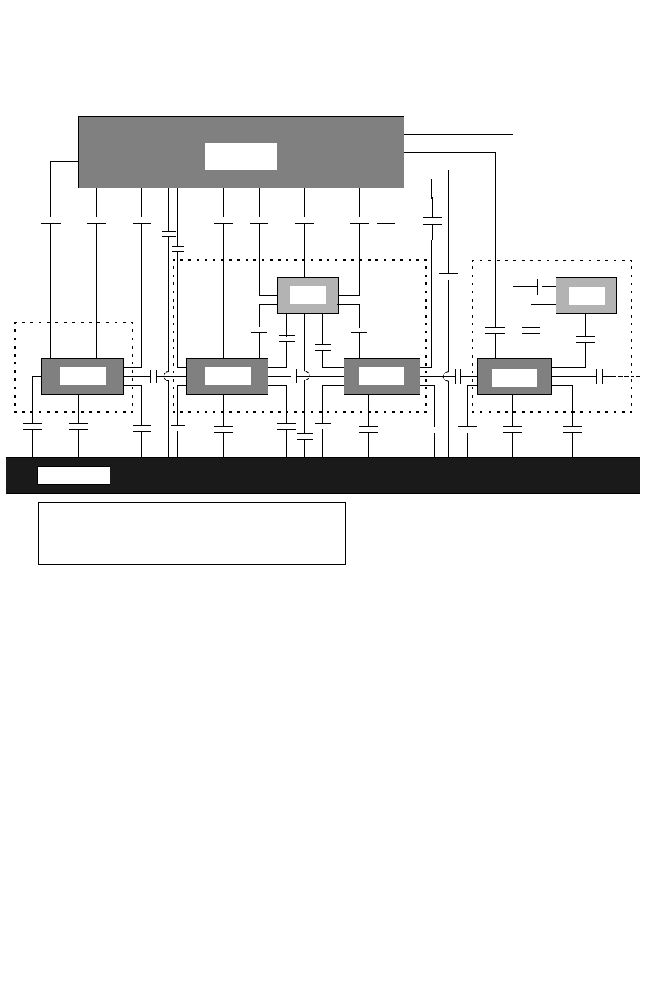
Chapter 17: StarRC Commands
IGNORE_CAPACITANCE 17-76
StarRC User Guide and Command Reference F-2011.06
StarRC User Guide and Command Reference Version F-2011.06
Figure 17-2 IGNORE_CAPACITANCE Command
DIFF DIFF DIFF DIFF
Gate
Metal
Substrate
10 98
13
8
998
7
11 11
12
14
1
2222
1212212
3
44
3
6
5
5
66
5
10
15
DIODE
MOS MOS
Gate
IGNORE_CAPACITANCE:NONE (numbers 1-15 are extracted.)
IGNORE_CAPACITANCE:DIFF (numbers 4-15 are extracted.)
IGNORE_CAPACITANCE:ALL (numbers 4, 8-15 are extracted.)
When the calculation is done for netlist reduction to reduce the nodes with error control,
small coupling capacitors are moved around their individual nodes to attach to one of the
neighboring nodes. In such a situation, some device terminal nodes get coupling
capacitances even if the coupling capacitance is not associated with them irrespective of the
IGNORE_CAPACITANCE setting.
Retaining Gate-to-Diffusion Coupling Capacitance
To retain the gate-to-diffusion (Cf) coupling component when IGNORE_CAPACITANCE:ALL is
specified, use the RETAIN_GATE_DIFFUSION_COUPLING suffix:
IGNORE_CAPACITANCE: ALL RETAIN_GATE_DIFFUSION_COUPLING
When this suffix is specified, StarRC has two methods for extracting the gate-to-diffusion
component:
• Based on precharacterized models, similar to other capacitances extracted by StarRC
• Based on a 2-D capacitance table look-up dependent on layout parameters
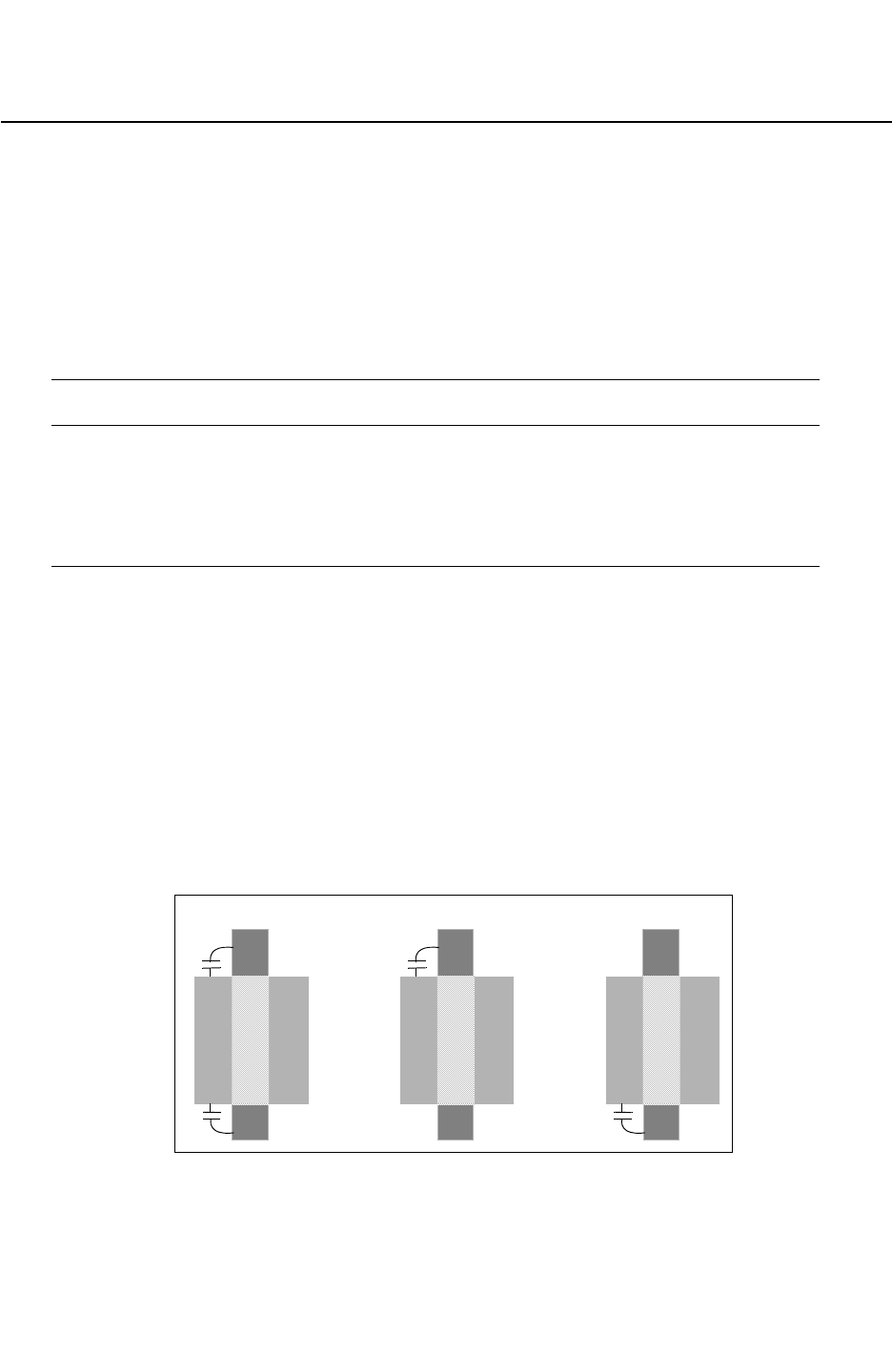
Chapter 17: StarRC Commands
IGNORE_FIELDPOLY_DIFFUSION_COUPLING 17-77
Chapter 17: StarRC Commands
IGNORE_FIELDPOLY_DIFFUSION_COUPLING 17-77
StarRC User Guide and Command Reference Version F-2011.06
IGNORE_FIELDPOLY_DIFFUSION_COUPLING
Syntax
IGNORE_FIELDPOLY_DIFFUSION_COUPLING: YES | [NO]
Arguments
Argument Description
NO Retains field poly to diffusion capacitance.
This is the default.
YES Excludes field poly coupling capacitances during
extraction.
Description
Extracts the field poly to diffusion coupling. Although the capacitance effect may be small
from orthogonal coupling capacitance as shown in Figure 17-3, at lower technology nodes it
might have a capacitance impact. Given the large number of field poly connections in a
design, this can have a large impact on the circuit performance.
This command allows you the flexibility to ignore fieldpoly diffusion coupling when this
coupling effect is already included in the SPICE model.
This command supports all transistor-level flows that are Hercules or Calibre based.
Figure 17-3 Field Poly to Diffusion Ignored by Default
DiffDiff
FP
FP
Gate
Top and Bottom Top Only Bottom Only
DiffDiff
FP
FP
Gate
DiffDiff
FP
FP
Gate


Chapter 17: StarRC Commands
INCREMENTAL 17-79
Chapter 17: StarRC Commands
INCREMENTAL 17-79
StarRC User Guide and Command Reference Version F-2011.06
INCREMENTAL
Syntax
INCREMENTAL: YES | NO
Arguments
Argument Description
YES Enables incremental extraction. This is supported with SPEF and
SBPF formats only. If NETLIST_FORMAT is specified other than
SPEF or SBPF, then StarRC issues an error. A partial coupling
report is generated if the COUPLING_REPORT_FILE is specified.
NO Produces a full-chip parasitic netlist in all formats. This is the
default argument and also controls the content of the coupling
report. A partial coupling report is generated if the
COUPLING_REPORT_FILE command is specified.
This is the default.
Description
Enables use of the previous extraction results in the STAR directory by doing a comparison
with the new, post-ECO block and then producing a netlist that includes the changed
parasitics. To create an incremental netlist that only contains the changed parasitics, the
NETLIST_INCREMENTAL:YES option can be enabled.
Note:
You should perform a final full-chip extraction, using INCREMENTAL:NO and timing
analysis, for the final sign-off timing analysis. If StarRC detects no changes or too many
changes in the post-ECO block, StarRC produces an error message informing you to
perform extraction using INCREMENTAL: NO. If too many changes are applied to a block,
there is very little savings in runtime, and it is better to produce a fully accurate netlist.
For more information about incremental extraction flows and restricted commands, see
Chapter 5, “Incremental Extraction.”

Chapter 17: StarRC Commands
INCREMENTAL 17-80
StarRC User Guide and Command Reference F-2011.06
StarRC User Guide and Command Reference Version F-2011.06
Example
BLOCK: TOP_Post-ECO
MILKYWAY_DATABASE: design
TCAD_GRD_FILE: nxtgrd_file
MAPPING_FILE: map
NETLIST_FORMAT: SPEF
INCREMENTAL: YES
NETLIST_INCREMENTAL: YES
See Also
•INCREMENTAL_FORCE_DP
•NETLIST_INCREMENTAL

Chapter 17: StarRC Commands
INCREMENTAL_FORCE_DP 17-81
Chapter 17: StarRC Commands
INCREMENTAL_FORCE_DP 17-81
StarRC User Guide and Command Reference Version F-2011.06
INCREMENTAL_FORCE_DP
Enables distributed processing with incremental extraction.
Syntax
INCREMENTAL_FORCE_DP: YES | NO
Arguments
Argument Description
YES Enables distributed processing with incremental extraction.
NO Does not enable distributed processing.
This is the default.
Description
Enables distributed processing with incremental extraction in the following ways:
• The pre-ECO full extraction and post-ECO incremental extraction can be run on the same
number of CPUs in parts.
• Pre-ECO full extraction can be run on multiple CPUs and post-ECO incremental can be
run on a single CPU.
If you are using distributed processing, the number of partitions between the pre-ECO and
post-ECO extraction should be the same.
Note:
StarRC supports a LEF file that has been gzipped and compressed.
Example
In the following example, one partition is used for incremental extraction. This is the default.
NUM_PARTS:N
INCREMENTAL:YES
INCREMENTAL_FORCE_DP:NO
See Also
•INCREMENTAL
•NUM_PARTS

Chapter 17: StarRC Commands
INSTANCE_PORT 17-82
StarRC User Guide and Command Reference F-2011.06
StarRC User Guide and Command Reference Version F-2011.06
INSTANCE_PORT
Applies different parasitic resistance extraction modes to different groups of instance ports
in a single extraction run.
Syntax
INSTANCE_PORT: [CONDUCTIVE [SUFFIXED [MULTIPLE] | CAPACITIVE]
| NOT_CONDUCTIVE | SUPERCONDUCTIVE | EXPLODE]
[[CELL wildcard] [INST wildcard]
[PORT wildcard]]
Arguments
Argument Description
CONDUCTIVE Enables resistance extraction for the ports of skip cell instances.
Therefore, feed through resistance of selected instance ports are
preserved.
This is the default.
The supplemental modes available are SUFFIXED or
CAPACITIVE. The SUFFIXED mode can be specified with or
without MULTIPLE.
NOT_CONDUCTIVE Similar to the CONDUCTIVE MULTIPLE SUFFIXED option, with
the exception of the port resistance not being netlisted. If the
top-level material overlaps with the instance port, the
conductance of the overlapping part of the top-level material is
not reported, either. See also “Long Ports” on page 15-15.
SUPERCONDUCTIVE When specified for a SKIP_CELLS port, the port is extracted as
an ideal node with zero resistivity.
EXPLODE Promotes all selected instance port material to the top level, and
marks it as part of the top-level net connecting it. No port nodes
are generated for instance ports selected for EXPLODE
extraction.
CELL Specifies a layout cell name.
INST Specifies a layout instance name.
PORT Specifies a layout port name.

Chapter 17: StarRC Commands
INSTANCE_PORT 17-83
Chapter 17: StarRC Commands
INSTANCE_PORT 17-83
StarRC User Guide and Command Reference Version F-2011.06
Description
Applies different parasitic resistance extraction modes to different groups of instance ports
in a single extraction run.
The INSTANCE_PORT command has four basic modes:
•CONDUCTIVE
•NOT_CONDUCTIVE
•SUPERCONDUCTIVE
•EXPLODE
For the CONDUCTIVE MULTIPLE and NOT_CONDUCTIVE modes, the number of port nodes is
determined by the top-level resistive interaction regions while the CONDUCTIVE mode only
one port node is created.
The INSTANCE_PORT option can be selectively applied to specific cells and/or instances,
and/or ports. Only layout CELL, PORT, and INST names may be specified in these arguments.
The default for all three selections is “*.”
No escape mechanism is provided for the keywords CELL, INST, and PORT in the wildcard
specification.
The INSTANCE_PORT command may be specified multiple times. Each use is cumulative,
and the last definition overrides the previous ones for the INSTANCE_PORT matching the
wildcard.
CONDUCTIVE
By default, one port (*|I) node per instance port is generated and no capacitance is reported
for the port. The location of the node is a point of contact between the port and the top-level
material. This default mode should be sufficient for most applications.
There are three supplemental modes, modifying the default behavior, that can be used
optionally in any combination with INSTANCE_PORT: CONDUCTIVE: SUFFIXED, MULTIPLE,
CAPACITIVE.
•SUFFIXED
If you choose the SUFFIXED option, you modify the port node’s name by having the name
of the instance port attached with a suffix according to the NETLIST_RENAME_PORT
command setting. If the MULTIPLE option is not set, exactly one connection point is
generated, despite the number of interactions between the port and the top-level
material. In the case of no interactions, the location of the node is random within the port.
In the case of the port having multiple connections to the top-level material, only one of

Chapter 17: StarRC Commands
INSTANCE_PORT 17-84
StarRC User Guide and Command Reference F-2011.06
StarRC User Guide and Command Reference Version F-2011.06
them is reported as a port node. If the MULTIPLE option is specified along with the
SUFFIXED option, then all of the connection points are reported as port nodes. In the
case of no interactions, no port nodes is generated. In the case of a large overlap with the
top-level material, multiple connection points are reported.
•MULTIPLE
The MULTIPLE option is meant to be used along with the SUFFIXED option. Use of the
MULTIPLE option without the SUFFIXED option leads to a complicated, indeterminate
behavior that is not supported. For a detailed explanation of MULTIPLE SUFFIXED, see the
SUFFIXED option, earlier.
•CAPACITIVE
The CAPACITIVE option netlists the capacitance of the selected instance ports.
NOT_CONDUCTIVE
If the port resistors are not included in the netlist, there may be disconnected networks.
However, no open warnings is issued, because the net is known to be connected by
feedthrough. Port nodes for a given instance port are generated at every top-level interaction
point. If there is more than one interaction point, multiple port nodes are netlisted. In the
case of no interaction with top-level material, no port nodes is generated.
SUPERCONDUCTIVE
This option instructs StarRC to assume ideal (zero) resistivity when extracting all port
shapes inside the SKIP_CELL. The port shapes effectively act as a short and no resistance
is extracted or netlisted for the port shapes.
EXPLODE
This option instructs StarRC to promote all selected instance port material to the top level
and to mark it as part of the top-level net connecting it. No port nodes are generated for
instance ports selected for EXPLODE extraction.
Note:
No *I or *|I statements are generated for instance ports marked as EXPLODE.
Example
• To select all instance ports as CONDUCTIVE:
INSTANCE_PORT: CONDUCTIVE
• To select all ports in cell ANTENNA for EXPLODE (to the top level) all other instance ports
are still CONDUCTIVE:
INSTANCE_PORT: EXPLODE CELL ANTENNA

Chapter 17: StarRC Commands
INSTANCE_PORT 17-85
Chapter 17: StarRC Commands
INSTANCE_PORT 17-85
StarRC User Guide and Command Reference Version F-2011.06
• To select ports VDD and VSS in all cells to be netlisted with suffixes and multiple times if
you have more than one connection point:
INSTANCE_PORT: CONDUCTIVE MULTIPLE SUFFIXED CELL
* PORT VDD VSS
This causes ports VSS and VDD in ANTENNA to be retained, but all other ports in
ANTENNA are exploded.
• To select all instance ports as CONDUCTIVE SUFFIXED, except for instance ports with
CELL names matching A*, which are NOT_CONDUCTIVE:
INSTANCE_PORT: CONDUCTIVE SUFFIXED
INSTANCE_PORT: NOT_CONDUCTIVE CELL A*
• To select all instance ports matching CELL B* (but not BUF1) PORT VDD* to be
CONDUCTIVE
INSTANCE_PORT: NOT_CONDUCTIVE
INSTANCE_PORT: CONDUCTIVE SUFFIXED CELL A* !AB*
PORT VDD*
Otherwise, instance ports matching CELL A* !AB* PORT VDD* are CONDUCTIVE SUFFIXED
and instance ports matching neither of these conditions is NOT_CONDUCTIVE.
See Also
•NETLIST_RENAME_PORTS
•SKIP_CELLS

Chapter 17: StarRC Commands
INSTANCE_PORT_OPEN_CONDUCTANCE 17-86
StarRC User Guide and Command Reference F-2011.06
StarRC User Guide and Command Reference Version F-2011.06
INSTANCE_PORT_OPEN_CONDUCTANCE
Syntax
INSTANCE_PORT_OPEN_CONDUCTANCE: float
Arguments
Argument Description
float A fixed conductance value for resistors used to connect
members of a port that are not electrically connected inside the
skip cell.
Units: mho
Default: 10
Description
Defines a fixed conductance value for the resistors used to connect members of a port that
are not resistively connected inside of the defined skip cell. This command affects only
CONDUCTIVE instance ports.
This case may happen frequently when the instance port material is not completely ported.
Often, small routing targets at the edges, instead of the entire port, are used as the port
definition. In this case, StarRC inserts resistors with user-defined conductance to prevent
opens in the output netlist. If you are also using the NETLIST_TAIL_COMMENTS command,
the resistor width’s is reported as nine microns to facilitate their identification.

Chapter 17: StarRC Commands
INTRANET_CAPS 17-87
Chapter 17: StarRC Commands
INTRANET_CAPS 17-87
StarRC User Guide and Command Reference Version F-2011.06
INTRANET_CAPS
Syntax
INTRANET_CAPS: YES | NO
Arguments
Argument Description
YES Retains the intranet capacitances during extraction.
NO Eliminates the intranet capacitances during extraction.
This is the default.
Description
Extracts intranet capacitances. These capacitances are defined as coupling capacitances
that have nodes that belong to the same net. Because this command affects extraction, you
must perform a -cleanX run when you change it.
Note:
INTRANET_CAPS is an Xtractor option that eliminates intranet capacitances when
processed. The default is NO, which means that intranet capacitances are eliminated by
default. To have intranet capacitances, you must specify INTRANET_CAPS: YES and do a
-cleanX run.

Chapter 17: StarRC Commands
KEEP_VIA_NODES 17-88
StarRC User Guide and Command Reference F-2011.06
StarRC User Guide and Command Reference Version F-2011.06
KEEP_VIA_NODES
Syntax
KEEP_VIA_NODES: YES | NO
Arguments
Argument Description
YES Preserves original nodes that a via resistor connects.
NO Does not necessarily preserve original nodes.
This is the default.
Description
Defines via nodes as the original nodes that a via resistor connects. The original nodes
might be reduced, or merged with other nodes, depending on the conductor configuration
and reduction used. Turning the mode on preserves such nodes.
See Also
•REDUCTION

Chapter 17: StarRC Commands
LEF_FILE 17-89
Chapter 17: StarRC Commands
LEF_FILE 17-89
StarRC User Guide and Command Reference Version F-2011.06
LEF_FILE
Creates a white-space-delimited list of LEF format files containing complete library cell
descriptions.
Syntax
LEF_FILE: technology_lef library_lef
LEF_FILE: library_lef macro_lef
LEF_FILE: macro_lef custom_lef
Arguments
Argument Description
technology_lef LEF file with the technology information
Default: none
library_lef LEF file with the cell library information
Default: none
macro_lef LEF file with the macro cell information
Default: none
custom_lef LEF file with the custom cell/block information
Default: none
Description
This command, which is mandatory for LEF/DEF flows, can be specified multiple times in a
single command file. The order in which the LEF files are specified is very important.
There are three types of LEF files that can be specified: the technology LEF, the standard
cell LEF, and macro LEF. The technology LEF must be listed first in the command file or in
the graphic user interface. Every layer defined in the technology LEF must be mapped to a
TCAD GRD layer by a MAPPING_FILE entry. Undefined layers that exist in the LEF file cause
StarRC to issue an error and exit. If any of the subsequently specified LEF files contain
additional technology information, it is ignored.
The standard cell LEF and the macro LEF can be listed in any order after the technology
LEF
. A macro LEF description is required for each block defined in a MACRO_DEF_FILE. A
LEF description is required for every member of the SKIP_CELLS list. Gzipped files can be
directly specified in the LEF_FILE command.


Chapter 17: StarRC Commands
LEF_USE_OBS 17-91
Chapter 17: StarRC Commands
LEF_USE_OBS 17-91
StarRC User Guide and Command Reference Version F-2011.06
LEF_USE_OBS
Syntax
LEF_USE_OBS: YES | NO
Arguments
Argument Description
YES Includes the OBS shapes defined in the LEF MACRO and allows
StarRC to extract coupling to these shapes.
This is the default.
NO Uses only the PIN shapes translated from the LEF MACRO
Description
When NO is set, removes all MACRO blockage material from the extraction. LEF_USE_OBS
applies to all SKIP_CELLS commands in your design.
Most LEF MACRO definitions contain groups of shapes under the heading OBS. These are
blockage layers that restrict the top-level router and typically are a close approximation of the
actual cell layout.
This command has no effect on MACRO definitions for which supplemental GDS descriptions
have been provided. A GDS description for LEF MACRO is optional and can be imported
with the GDS_FILE command.
See Also
•GDS_FILE
•SKIP_CELLS

Chapter 17: StarRC Commands
LPE_DEVICES 17-92
StarRC User Guide and Command Reference F-2011.06
StarRC User Guide and Command Reference Version F-2011.06
LPE_DEVICES
Specifies the device model names that follow the LPE_PARAM rules.
Syntax
LPE_DEVICES: param_name device_model_1 [device_model_2 ...]
Arguments
Argument Description
param_name Specifies a user-defined LPE parameter name. The specified
parameter name should match the parameter names specified
by the LPE_PARAM command.
device_model Specifies device models to which the LPE parameter should be
applied.
Description
The LPE_DEVICES specifies the device model names that follow the LPE_PARAM rules. This
command must be used in conjunction with the LPE_PARAM command.
If the list of device models is very long, you can use multiple LPE_DEVICES statements for
the same parameter. The lists of device models are concatenated.
Example
LPE_DEVICES: pre_layout nfet pfet
LPE_DEVICES: nores ncap
See Also
•LPE_PARAM

Chapter 17: StarRC Commands
LPE_PARAM 17-93
Chapter 17: StarRC Commands
LPE_PARAM 17-93
StarRC User Guide and Command Reference Version F-2011.06
LPE_PARAM
Defines a netlist parameter for user-defined instances.
Syntax
LPE_PARAM: param_name mode1 value1 [mode2 value2...] [PINEXCEPT pinIds]
Arguments
Argument Description
param_name The LPE parameter name that you want to use.
mode The extraction mode used to netlist the device.
value Corresponds to flags in the device simulation SPICE model. The
value can be customized based on flows.
PINEXCEPT pinIds Specifies a list of pin indexes to be ignored while checking
extraction mode to compute the value.
Description
The LPE_PARAM command defines a netlist parameter for user-defined instances. The
post-layout parameter is set based on the extraction mode of the nets connected to the
instance of interest. Possible extraction modes include NORC, RC, R, and C.
The command can be used to control, based on a user-defined parameter and value, which
parasitics are taken from simulation SPICE models and which parasitics are extracted by
StarRC.
This command must be used in conjunction with the LPE_DEVICES command.
The PINEXCEPT option causes the list of pin indexes to be ignored while computing the
extraction mode for the device. For example, it could be used to ignore the bulk in a MOS
device (PINEXCEPT 4), so that only the net connected to drain, source and gate would be
taken into account for computing an LPE parameter value.
There can be only one LPE_PARAM definition for each parameter. If multiple LPE_PARAM
definitions exist for a single parameter, then the last definition overrides the previous
definitions.
All extraction modes should be specified in the LPE_PARAM command for completeness.
However, the tool tries to compute the value even if the extraction mode is not specified in
the LPE_PARAM command.

Chapter 17: StarRC Commands
LPE_PARAM 17-94
StarRC User Guide and Command Reference F-2011.06
StarRC User Guide and Command Reference Version F-2011.06
For example, if RC is not described for the nores parameter, then capacitance extraction
has no impact on its value. If capacitance extraction is performed, then tool must use the
NOR value, which is considered the default.
Example
LPE_PARAM: pre_layout_local NORC 1 C 3 R 2 RC 0 PINEXCEPT 4
LPE_PARAM: setres NORC -2 C -2 R 0 RC 0
LPE_PARAM: setcap NORC -1 C 0 R -1 RC 0
See Also
•LPE_DEVICES

Chapter 17: StarRC Commands
MACRO 17-95
Chapter 17: StarRC Commands
MACRO 17-95
StarRC User Guide and Command Reference Version F-2011.06
MACRO
Extracts the specified instance in the context of the specified BLOCK.
Syntax
MACRO: macro_block_instance_name
Arguments
Argument Description
macro_block_instance_name The instance name of the macro block
Description
This extraction mode provides parasitics for nets inside the instance, accounting for the
influence of routes in BLOCK that might run above or adjacent to MACRO nets. The resulting
netlist is a parasitic representation of the MACRO instance as it interacts with the rest of the
chip. All material outside the MACRO instance is grounded.
You must specify BLOCK to use this extraction mode. For the Milkyway and Hercules flows,
the MILKYWAY_DATABASE is the path to the main library that contains BLOCK, not the library
that contains the MACRO definition. In the LEF/DEF flow, the TOP_DEF_FILE and
MACRO_DEF_FILE should be specified just as though BLOCK were going to be extracted. In
general, to execute the MACRO in context extraction, the StarRC job should be configured for
a normal extraction of the BLOCK -then the MACRO instance name can be specified with no
changes to the star_cmd file.
The instance for extraction must have a connected cell description; this means DEF for the
LEF/DEF flow, place and route CEL view for Milkyway flow (not stream-in MACRO blocks), or
any XTR view cell for a Hercules flow.
Note:
Select nets extraction is not supported for MACRO extraction. MACRO instance must have a
connected cell definition.
See Also
•BLOCK

Chapter 17: StarRC Commands
MACRO_DEF_FILE 17-96
StarRC User Guide and Command Reference F-2011.06
StarRC User Guide and Command Reference Version F-2011.06
MACRO_DEF_FILE
Creates a white-space-delimited list of DEF files that define any macros referenced in the
TOP_DEF_FILE.
Syntax
MACRO_DEF_FILE: macro_def_file_name1 macro_def_file_name2 ...
Arguments
Argument Description
macro_def_file_name The file that contains any macro referenced in the
TOP_DEF_FILE
Description
This command can be specified multiple times in a single command file. The ordering of the
list of files is not important, but a LEF_FILE command must be provided for each macro on
this list.
The cells described within a specified MACRO_DEF_FILE may or may not be on the
SKIP_CELLS list. For example, you might go into these macro cells to produce a full-chip flat
netlist, or you might skip them if you are doing hierarchical extraction or analysis. StarRC
does not require any preprocessing to flatten a hierarchical DEF file; the hierarchical DEF is
flattened internally.
Gzipped or compressed DEF files can be directly specified in the MACRO_DEF_FILE
command.
StarRC supports gzipped or compressed DEF files.
See Also
•LEF_FILE
•SKIP_CELLS
•TOP_DEF_FILE

Chapter 17: StarRC Commands
MAGNIFICATION_FACTOR 17-97
Chapter 17: StarRC Commands
MAGNIFICATION_FACTOR 17-97
StarRC User Guide and Command Reference Version F-2011.06
MAGNIFICATION_FACTOR
Performs optical scaling of input data uniformly for all layers.
Syntax
MAGNIFICATION_FACTOR: value
Arguments
Argument Description
value A floating-point number greater than 0.
Default: 1.0
Description
MAGNIFICATION_FACTOR performs optical scaling of input data uniformly for all layers.
Scaling does not affect the connectivity of the layout network.
Specifying a number less than 1 initiates an optical shrink, whereas a number greater than
1 performs an enlargement.
The shrink is done on a database only while reading it.
Your nxtgrd file must contain rules for minimum width, spacing, and tables associated with
the shrunk/increased database.
You cannot use the MAGNIFICATION_FACTOR command together with the
HALF_NODE_SCALE_FACTOR ITF command.
See Also
•HALF_NODE_SCALE_FACTOR
•MAGNIFY_DEVICE_PARAMS

Chapter 17: StarRC Commands
MAGNIFY_DEVICE_PARAMS 17-98
StarRC User Guide and Command Reference F-2011.06
StarRC User Guide and Command Reference Version F-2011.06
MAGNIFY_DEVICE_PARAMS
Controls the behavior of the MAGNIFICATION_FACTOR command.
Syntax
MAGNIFY_DEVICE_PARAMS: YES | NO
Arguments
Argument Description
YES Applies the value specified in the MAGNIFICATION_FACTOR
command to SPICE device parameters.
This is the default.
NO Does not apply the value of the MAGNIFICATION_FACTOR to the
SPICE parameters.
Description
The MAGNIFY_DEVICE_PARAMS command controls the behavior of the
MAGNIFICATION_FACTOR command. When you specify MAGNIFY_DEVICE_PARAMS: YES, all
designed device parameters in the SPICE netlist are multiplied by the factor set by the
MAGNIFICATION_FACTOR command. Table 17-3 lists the designed device parameters that
are affected by the MAGNIFY_DEVICE_PARAMS command.
Table 17-3 Device Parameters Affected By MAGNIFY_DEVICE_PARAMS
Device Type Magnified Parameters
Diode area, pj
Resistor l, w
Capacitor l, w
MOS ad, as, pd, l, w
BJT area
See Also
•MAGNIFICATION_FACTOR

Chapter 17: StarRC Commands
MAPPING_FILE 17-99
Chapter 17: StarRC Commands
MAPPING_FILE 17-99
StarRC User Guide and Command Reference Version F-2011.06
MAPPING_FILE
Specifies the file containing physical layer mapping information between the input database
and the specified TCAD_GRD_FILE.
Syntax
MAPPING_FILE: file_name
Arguments
Argument Description
file_name The mapping file name.
Default: none
Description
This command is mandatory for all flows. Every connected layer must be mapped.
Advanced users can also elect to override sheet resistance values specified in the
TCAD_GRD_FILE by specifying new values in the MAPPING_FILE command.
For more information about mapping files, see Chapter 20, “Mapping File Commands.”
See Also
•TCAD_GRD_FILE

Chapter 17: StarRC Commands
MARKER_GENERATION 17-100
StarRC User Guide and Command Reference F-2011.06
StarRC User Guide and Command Reference Version F-2011.06
MARKER_GENERATION
Indicates how StarXtract should generate PIN shapes for a Hercules database.
Syntax
MARKER_GENERATION: AUTOMATIC | USER
Arguments
Argument Description
AUTOMATIC Specifies that StarRC automatically generates PIN shapes
based on connectivity.
This is the default.
USER Specifies that the user generates the PIN shapes.
Description
Databases generated by Hercules do not generally have a special object to represent a PIN
shape (also referred to as markers). However, StarXtract requires PIN shapes to define the
instance ports.
There are two ways to create PIN shapes in a Hercules database; the first is to identify a
special Hercules output layer that generates the PIN shapes, and the second is to have
StarRC automatically generate PIN shapes, based on connectivity.
For most purposes, using AUTOMATIC is preferable; it’s more robust. Specifying USER allows
more flexibility but requires great care when creating marker shapes and a rigorous
knowledge of the routing methodology to avoid creating opens and shorts in the extraction.
When you are specifying MARKER_GENERATION:USER, there are three techniques for
generating marker (PIN) shapes: text-based markers, ID-layer markers, and
connection-based markers.

Chapter 17: StarRC Commands
MERGE_INSTANCE_PORTS 17-101
Chapter 17: StarRC Commands
MERGE_INSTANCE_PORTS 17-101
StarRC User Guide and Command Reference Version F-2011.06
MERGE_INSTANCE_PORTS
Decreases the effective resistance connecting the schematic port to the rest of the net when
set to YES.
Syntax
MERGE_INSTANCE_PORTS: YES | NO
Arguments
Argument Description
YES Electrically merges together all N ports, which causes the N
branches to be treated as parallel-connected resistive paths
during extraction, netlist reduction, and netlist generation.
NO Matches one of the N layout ports to the single schematic port,
leaving the other N-1 branches as dangling in the parasitic
netlist.
This is the default.
Description
This command is only valid when XREF:COMPLETE is also used. This is shown in Figure 17-4.
For parallel MOS 1 : N (schematic : layout) merging in XREF:COMPLETE flows, this command
electrically merges together all of the N layout instance ports into a single port for netlist
generation on each of the source, drain, and gate nets.
For parallel M : N (schematic : layout) merging in XREF: COMPLETE where N > M,
MERGE_INSTANCE_PORTS electrically merges each of the extra unmatched (N-M) layout ports
with one of the matched M layout ports. The final parasitic netlist contains M ports for each
of the source, drain, and gate nets.
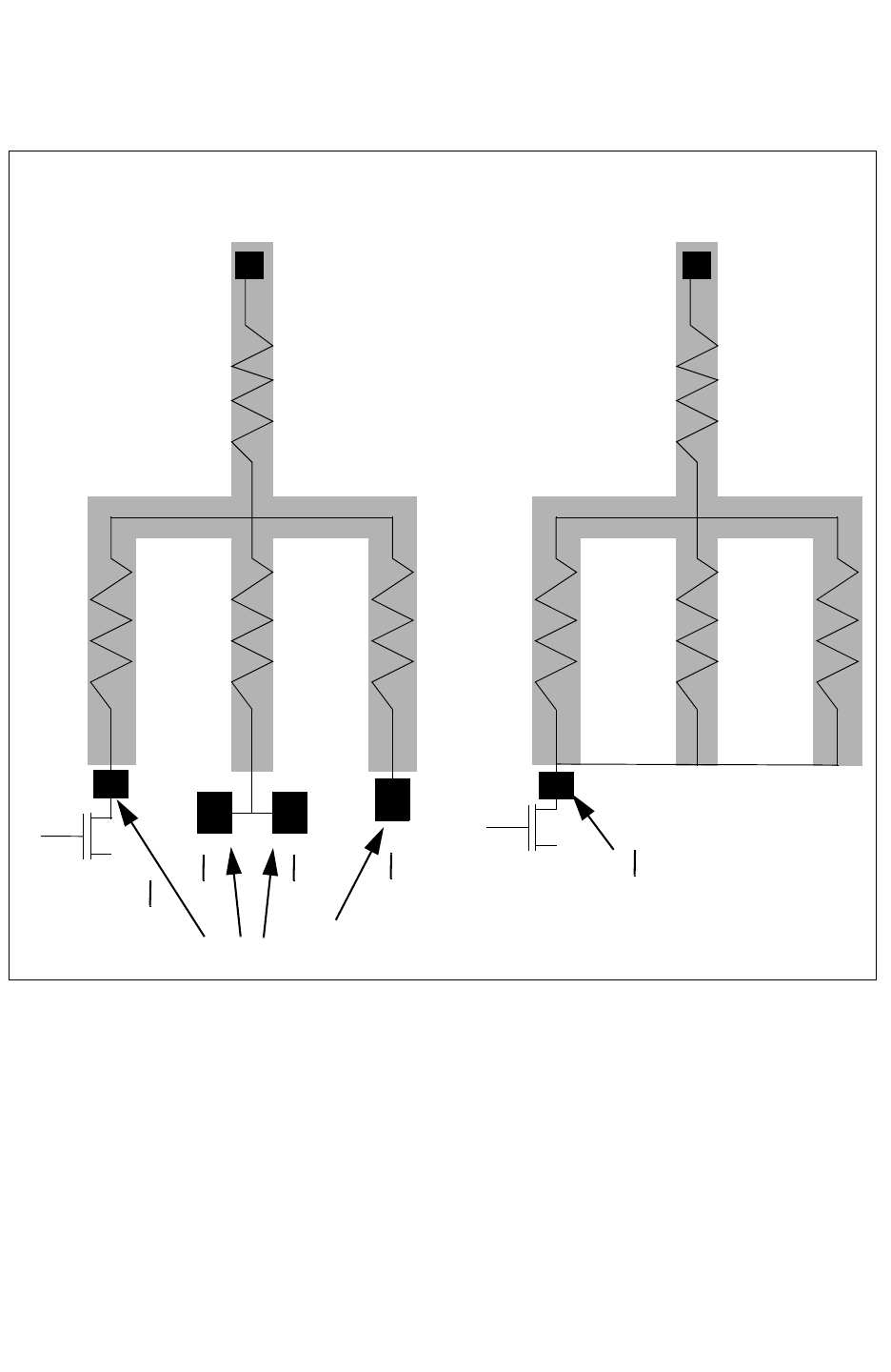
Chapter 17: StarRC Commands
MERGE_INSTANCE_PORTS 17-102
StarRC User Guide and Command Reference F-2011.06
StarRC User Guide and Command Reference Version F-2011.06
Figure 17-4 XREF:COMPLETE Parasitic Netlist With MERGE_INSTANCE_PORTS
4W/L * S * S * S
Port locations for 4 MOS in layout
Rmesh1
Rmesh2Rmesh3Rmesh4
4W/L
Rmesh1
Rmesh2Rmesh3Rmesh4
MERGE_INSTANCE_PORTS:NO
(default)
MERGE_INSTANCE_PORTS:YES
* S
* S
See Also
•XREF:COMPLETE

Chapter 17: StarRC Commands
MERGE_MULTI_CORNER 17-103
Chapter 17: StarRC Commands
MERGE_MULTI_CORNER 17-103
StarRC User Guide and Command Reference Version F-2011.06
MERGE_MULTI_CORNER
Syntax
MERGE_MULTI_CORNER: YES_SPLIT_NETLIST YES | NO
Arguments
Argument Description
YES_SPLIT_NETLIST Generates multiple netlist files similar to the NO option, but
maintains the same topology across corners, which is similar to
the YES option.
YES Produces a single parasitic netlist with multiple-corner data.
NO Produces one netlist for each nxtgrd file specified.
This is the default.
Description
Uses a single translation followed by multiple extraction and single or multiple netlist creation
with multiple corners or multiple netlists with different corners. To do a multiple corner
extraction and create a netlist, specify multiple nxtgrd files using the TCAD_GRD_FILE
command along with the MERGE_MULTI_CORNER command.
Reduction is done to maintain node consistency, but an alternative reduction is used when
you specify multiple nxtgrd files using the TCAD_GRD_FILE command. In this way, a
single-corner extraction result with REDUCTION:YES is not identical to a multiple-corner
extraction supplying multiple netlists for the same corner.
When you specify multiple nxtgrd files using the TCAD_GRD_FILE file command with the
MERGE_MULTI_CORNER:NO command, StarRC produces multiple parasitic netlists with
appended suffixes. An example is yourfile0, where 0 refers to the parasitic netlist file with
parasitics from the first nxtgrd file in the TCAD_GRD_FILE command.
When you specify multiple nxtgrd files using the TCAD_GRD_FILE file command with
MERGE_MULTI_CORNER: YES_SPLIT_NETLIST, StarRC generates multiple netlist files, but
maintains the same circuit topology across multiple corners. As with the YES option, you
must specify the REDUCTION:TOPOLOGY option. Be aware that commands affecting the
resistance and capacitance threshold, such as NETLIST_MINRES_THRESHOLD, cannot take
into account all corners. The output is based on the first corner extraction result.

Chapter 17: StarRC Commands
MERGE_MULTI_CORNER 17-104
StarRC User Guide and Command Reference F-2011.06
StarRC User Guide and Command Reference Version F-2011.06
You can specify corresponding temperatures for each corner by specifying the
OPERATING_TEMPERATURE command.
This command works with all netlist formats except SBPF and PARA View (Milkyway).
Errors
Warning Message for Multicorner Extraction
One of the goals of MERGE_MULTI_CORNER:YES is to ensure the nodes are consistent across
the corners. A dangling net has only one *P or a *I, and it is not possible for StarRC to know
where the net starts or ends. For this reason, the reduction is inconsistent across corners,
and the nodes cannot be guaranteed. Therefore, REMOVE_DANGLING_NETS is turned on
automatically with multiple nxtgrd files in TCAD_GRD_FILE and MERGE_MULTI_CORNER:YES.
The warning appears as follows:
WARNING: StarXtract
WARNING: REMOVE_DANGLING_NETS: NO is not valid when used with
TCAD_GRD_FILE:
WARNING: nx_min.nxtgrd
WARNING: nx_typ.nxtgrd
WARNING: nx_max.nxtgrd
WARNING: Setting REMOVE_DANGLING_NETS: YES...
Example
Example 17-5 shows how you specify three nxtgrd files to produce a single parasitic netlist
with multiple-corner data.
Example 17-5 Three nxtgrd Files Produce a Single Parasitic Netlist With Multiple-Corner Data
BLOCK: TOP_my
MILKYWAY_DATABASE: design
MERGE_MULTI_CORNER: YES
TCAD_GRD_FILE: nxtgrd_file1 nxtgrd_file2 nxtgrd_file3
MAPPING_FILE: map
NETLIST_FORMAT: SPEF
Example 17-6 shows how to specify three nxtgrd files to produce multiple parasitic netlists
while maintaining the same topology.
Example 17-6 Three nxtgrd Files Produce a Multiple Parasitic Netlists
BLOCK: TOP_my
MILKYWAY_DATABASE: design
MERGE_MULTI_CORNER: YES_SPLIT_NETLIST
TCAD_GRD_FILE: nxtgrd_file1 nxtgrd_file2 nxtgrd_file3
MAPPING_FILE: map
NETLIST_FORMAT: SBPF
Example 17-7 is an example of a three corner netlist with MERGE_MULTI_CORNER: YES
specified.

Chapter 17: StarRC Commands
MERGE_MULTI_CORNER 17-105
Chapter 17: StarRC Commands
MERGE_MULTI_CORNER 17-105
StarRC User Guide and Command Reference Version F-2011.06
Example 17-7 Three-Corner Netlist
*D_NET *169 8.18417:8.03749:8.51694
*CONN
*I *623:X O *C 37.0000 251.000 *D OR2
*CAP
1 *623:X 0.00945073:0.0116676:0.0126980
*RES
1 *623:X *169:116 0.0253828:0.0107081:0.038392
See Also
•OPERATING_TEMPERATURE
•TCAD_GRD_FILE
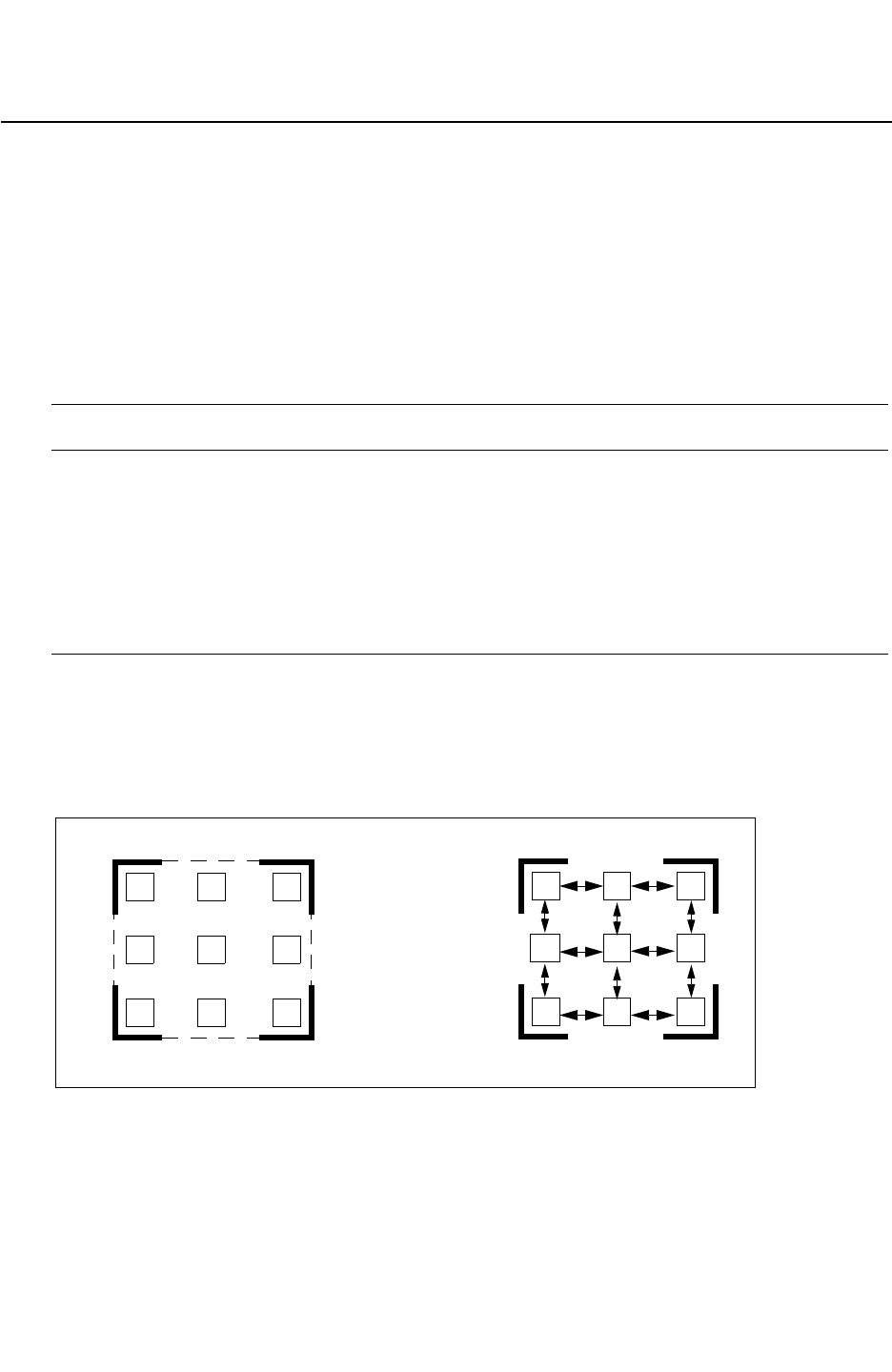
Chapter 17: StarRC Commands
MERGE_VIAS_IN_ARRAY 17-106
StarRC User Guide and Command Reference F-2011.06
StarRC User Guide and Command Reference Version F-2011.06
MERGE_VIAS_IN_ARRAY
Specifies whether or not vias in an array are not netlisted separately for parasitic resistance
output.
Syntax
MERGE_VIAS_IN_ARRAY: YES | NO
Arguments
Argument Description
YES Merges resistance value for a via array and reports one
resistance value for the array in the netlist.
This is the default.
NO Netlists each via in an array structure and reports parasitic
resistors between vias in the netlist output with separate
resistance values. You must also specify the KEEP_VIA_NODES
command.
Description
Resistance values between vias can be netlisted by specifying NO. By default, this command
is set to YES to merge vias into one reported resistance.
MERGE_VIAS_IN_ARRAY: YES
MERGE_VIAS_IN_ARRAY: NO
Report one resistance value for array Report each via resistance value
Example
Example 1
MERGE_VIAS_IN_ARRAY:YES

Chapter 17: StarRC Commands
MERGE_VIAS_IN_ARRAY 17-107
Chapter 17: StarRC Commands
MERGE_VIAS_IN_ARRAY 17-107
StarRC User Guide and Command Reference Version F-2011.06
The result of this example is the following output:
13 min_lsb_led[4]:45min_lsb_led[4]:46 0.72000// $a=2.00000 $lvl=5
Example 2
MERGE_VIAS_IN_ARRAY:NO
VIA_COVERAGE_OPTION_FILE: filename
Content of VIA_COVERAGE_OPTION_FILE:
VIA1 {Xrange=100,100;Yrange=100,100;
Landing=100,80,10,40,10;Coverage=100,80,10,40,10}
The result of this example is the following output:
14 min_lsb_led[4]:45 min_lsb_led[4]:46 1.44000 // $a=1.00000 $lvl=5
15 min_lsb_led[4]:54 min_lsb_led[4]:55 1.44000 // $a=1.00000 $lvl=5
See Also
•KEEP_VIA_NODES
•VIA_COVERAGE_OPTION_FILE

Chapter 17: StarRC Commands
METAL_FILL_GDS_FILE 17-108
StarRC User Guide and Command Reference F-2011.06
StarRC User Guide and Command Reference Version F-2011.06
METAL_FILL_GDS_FILE
Specifies the GDSII file containing metal fill data.
Syntax
METAL_FILL_GDS_FILE: file_name
Arguments
Argument Description
file_name Name of GDSII file containing metal fill data
Default: none
Description
The METAL_FILL_GDS_FILE command supports either hierarchical or flat GDSII files. All
shapes on layers mapped by GDS_LAYER_MAP_FILE within the master definition of BLOCK in
METAL_FILL_GDS_FILE and its children are treated as metal fill objects for extraction. All
other data not referenced by the master definition of BLOCK is ignored.
METAL_FILL_POLYGON_HANDLING applies to all shapes imported through the
METAL_FILL_GDS_FILE interface.
The METAL_FILL_GDS_FILE command
• Must be specified together with the GDS_LAYER_MAP_FILE command
• Cannot be used with the METAL_FILL_OASIS_FILE command
Note:
StarRC does not support a flow with metal fill polygons connected to more than one
power net when metal fill polygons are present in a separate GDSII file from the design
database.
When metal fill is embedded in a Milkyway or LEF/DEF database, StarRC reads the data
when you specify a METAL_FILL_GDS_FILE command.
You can specify gzipped and compressed GDS files for this command.
See Also
•GDS_FILE
•GDS_LAYER_MAP_FILE
•METAL_FILL_GDS_FILE_NET_NAME

Chapter 17: StarRC Commands
METAL_FILL_GDS_FILE_NET_NAME 17-109
Chapter 17: StarRC Commands
METAL_FILL_GDS_FILE_NET_NAME 17-109
StarRC User Guide and Command Reference Version F-2011.06
METAL_FILL_GDS_FILE_NET_NAME
Ties metal fill polygons to a power or ground net.
Syntax
METAL_FILL_GDS_FILE_NET_NAME: net_name
Arguments
Argument Description
net_name The layout net name
Default: none
Description
You can use the METAL_FILL_GDS_FILE_NET_NAME command to tie metal fill polygons to a
power or ground net.
The METAL_FILL_GDS_FILE_NET_NAME command
• Must be specified together with METAL_FILL_GDS_FILE and
METAL_FILL_POLYGON_HANDLING: GROUNDED
• Cannot be used with the METAL_FILL_OASIS_FILE_NET_NAME command
See Also
•GDS_LAYER_MAP_FILE
•METAL_FILL_GDS_FILE
•METAL_FILL_POLYGON_HANDLING

Chapter 17: StarRC Commands
METAL_FILL_GDS_MAG 17-110
StarRC User Guide and Command Reference F-2011.06
StarRC User Guide and Command Reference Version F-2011.06
METAL_FILL_GDS_MAG
Specifies the scaling factor that is applied to the GDSII metal fill data.
Syntax
METAL_FILL_GDS_MAG: float_number
Arguments
Argument Description
float_number Magnification factor
Default: 1.0
Description
The METAL_FILL_GDS_MAG command specifies the scaling factor that is applied to the GDSII
metal fill data.
The metal fill offset, specified by the METAL_FILL_GDS_OFFSET command, is not multiplied by
the scaling factor.
Note:
The METAL_FILL_GDS_MAG command cannot be used with the METAL_FILL_OASIS_MAG
command.
Example
In the following example, the length and width of the GDSII metal fill data are multiplied by a
factor of 0.8:
METAL_FILL_GDS_MAG: 0.8
The total entire area of the design would therefore be scaled by a factor of 0.64.
See Also
•METAL_FILL_GDS_FILE
•METAL_FILL_GDS_OFFSET

Chapter 17: StarRC Commands
METAL_FILL_GDS_OFFSET 17-111
Chapter 17: StarRC Commands
METAL_FILL_GDS_OFFSET 17-111
StarRC User Guide and Command Reference Version F-2011.06
METAL_FILL_GDS_OFFSET
Specifies the origin of the metal fill GDSII file.
Syntax
METAL_FILL_GDS_OFFSET: x_coordinate y_coordinate
Arguments
Argument Description
x_coordinate X-coordinate
Units: microns
Default: 0.0
y_coordinate Y-coordinate
Units: microns
Default: 0.0
Description
The METAL_FILL_GDS_OFFSET command specifies the coordinates of the origin of the metal
fill GDSII file. This command does not affect the magnification factor behavior.
Note:
The METAL_FILL_GDS_OFFSET command cannot be used with the
METAL_FILL_OASIS_OFFSET command.
Example
METAL_FILL_GDS_OFFSET: 10.8 5.3
See Also
•METAL_FILL_GDS_FILE
•METAL_FILL_GDS_FILE_NET_NAME
•METAL_FILL_POLYGON_HANDLING

Chapter 17: StarRC Commands
METAL_FILL_OASIS_FILE 17-112
StarRC User Guide and Command Reference F-2011.06
StarRC User Guide and Command Reference Version F-2011.06
METAL_FILL_OASIS_FILE
Specifies the OASIS file containing metal fill data.
Syntax
METAL_FILL_OASIS_FILE: file_name
Arguments
Argument Description
file_name Name of OASIS file containing metal fill data
Default: none
Description
The METAL_FILL_OASIS_FILE command supports either hierarchical or flat OASIS files. All
shapes on layers mapped by OASIS_LAYER_MAP_FILE within the master definition of BLOCK
in METAL_FILL_OASIS_FILE and its children are treated as metal fill objects for extraction.
All other data not referenced by the master definition of BLOCK is ignored.
METAL_FILL_POLYGON_HANDLING applies to all shapes imported through the
METAL_FILL_OASIS_FILE interface.
The METAL_FILL_OASIS_FILE command
• Must be specified together with the OASIS_LAYER_MAP_FILE command
• Cannot be used with the METAL_FILL_GDS_FILE command
Note:
StarRC does not support a flow with metal fill polygons connected to more than one
power net when metal fill polygons are present in a separate OASIS file from the design
database.
When metal fill is embedded in a Milkyway or LEF/DEF database, StarRC reads the data
when you specify a METAL_FILL_OASIS_FILE command.
You can specify gzipped and compressed OASIS files for this command.
See Also
•METAL_FILL_OASIS_FILE_NET_NAME
•OASIS_FILE
•OASIS_LAYER_MAP_FILE

Chapter 17: StarRC Commands
METAL_FILL_OASIS_FILE_NET_NAME 17-113
Chapter 17: StarRC Commands
METAL_FILL_OASIS_FILE_NET_NAME 17-113
StarRC User Guide and Command Reference Version F-2011.06
METAL_FILL_OASIS_FILE_NET_NAME
Ties metal fill polygons to a power or ground net.
Syntax
METAL_FILL_OASIS_FILE_NET_NAME: net_name
Arguments
Argument Description
net_name The layout net name
Default: none
Description
You can use the METAL_FILL_OASIS_FILE_NET_NAME command to tie metal fill polygons to
a power or ground net.
The METAL_FILL_OASIS_FILE_NET_NAME command
• Must be specified together with METAL_FILL_OASIS_FILE and
METAL_FILL_POLYGON_HANDLING: GROUNDED
• Cannot be used with the METAL_FILL_GDS_FILE_NET_NAME command
See Also
•METAL_FILL_OASIS_FILE
•METAL_FILL_POLYGON_HANDLING
•OASIS_LAYER_MAP_FILE

Chapter 17: StarRC Commands
METAL_FILL_OASIS_MAG 17-114
StarRC User Guide and Command Reference F-2011.06
StarRC User Guide and Command Reference Version F-2011.06
METAL_FILL_OASIS_MAG
Specifies the scaling factor that is applied to the OASIS metal fill data.
Syntax
METAL_FILL_OASIS_MAG: float_number
Arguments
Argument Description
float_number Magnification factor
Default: 1.0
Description
The METAL_FILL_OASIS_MAG command specifies the scaling factor that is applied to the
OASIS metal fill data.
The metal fill offset, specified by the METAL_FILL_GDS_OFFSET command, is not multiplied by
the scaling factor.
Note:
The METAL_FILL_OASIS_MAG command ca not be used with the METAL_FILL_GDS_MAG
command.
Example
In the following example, the length and width of the OASIS metal fill data are multiplied by
a factor of 0.8:
METAL_FILL_OASIS_MAG: 0.8
The total entire area of the design would therefore be scaled by a factor of 0.64.
See Also
•METAL_FILL_OASIS_FILE
•METAL_FILL_OASIS_OFFSET

Chapter 17: StarRC Commands
METAL_FILL_OASIS_OFFSET 17-115
Chapter 17: StarRC Commands
METAL_FILL_OASIS_OFFSET 17-115
StarRC User Guide and Command Reference Version F-2011.06
METAL_FILL_OASIS_OFFSET
Specifies the origin of the metal fill OASIS file.
Syntax
METAL_FILL_OASIS_OFFSET: x_coordinate y_coordinate
Arguments
Argument Description
x_coordinate X-coordinate
Units: microns
Default: 0.0
y_coordinate Y-coordinate
Units: microns
Default: 0.0
Description
The METAL_FILL_OASIS_OFFSET command specifies the coordinates of the origin of the
metal fill OASIS file. This command does not affect the magnification factor behavior.
The METAL_FILL_OASIS_OFFSET command cannot be used with the
METAL_FILL_GDS_OFFSET command.
Example
METAL_FILL_OASIS_OFFSET: 10.8 5.3
See Also
•METAL_FILL_OASIS_FILE
•METAL_FILL_OASIS_FILE_NET_NAME
•METAL_FILL_POLYGON_HANDLING

Chapter 17: StarRC Commands
METAL_FILL_POLYGON_HANDLING 17-116
StarRC User Guide and Command Reference F-2011.06
StarRC User Guide and Command Reference Version F-2011.06
METAL_FILL_POLYGON_HANDLING
Translates metal fill polygons into the internal format before performing extraction.
Syntax
METAL_FILL_POLYGON_HANDLING: IGNORE | GROUNDED | FLOATING | AUTOMATIC
Arguments
Argument Description
IGNORE Performs resistance and capacitance extraction without
considering the effect of metal fill polygons. In Milkyway, metal fill
polygons are ignored only if they have the correct ROUTE_TYPE.
This is the default.
GROUNDED Performs extraction by treating metal fill as grounded. By default,
StarRC treats metal fill polygons as connected to a ground net
(net 0) during extraction, unless the Milkyway or LEF/DEF design
database ties the metal fill polygons to a specific power/ground
net name or the METAL_FILL_GDS_FILE_NET_NAME command
is specified for the METAL_FILL_GDS_FILE.
FLOATING Performs extraction by treating the metal fill as floating. This
argument overrides the type of metal fill polygons provided in the
input database. This means that even though the input database
has grounded fill polygons, METAL_FILL_POLYGON_HANDLING
can extract the capacitance as if the fill polygons were floating. It
can also ignore the existence of fill objects in the database.
AUTOMATIC Performs in LEF/DEF, Milkyway place and route databases
automatic extraction by treating metal fill as floating or grounded.
In LEF/DEF, this argument parses the DEF file and translates fill
polygons based on the section in which they appear in the DEF
file.
Be sure to check LEF/DEF documentation for syntax that
requires fill polygon definitions in specific sections.
With Milkyway, this argument translates fills based on the
ROUTE_TYPE being attached to a net ID or not having a net ID
(floating). Both floating and grounded fills are allowed in the same
design as long as they are identified as such correctly.
To ensure that fills are treated properly using AUTOMATIC, you
should use the insert_metal_filler command in IC
Compiler.

Chapter 17: StarRC Commands
METAL_FILL_POLYGON_HANDLING 17-117
Chapter 17: StarRC Commands
METAL_FILL_POLYGON_HANDLING 17-117
StarRC User Guide and Command Reference Version F-2011.06
Description
The METAL_FILL_POLYGON_HANDLING command translates metal fill polygons into the
internal format before performing extraction. This process depends on the setting of this
command. If metal fill polygons are written into the FILL view in the Milkyway database, you
need to also set the MILKYWAY_ADDITIONAL_VIEWS command in StarRC.
Table 17-4 explains the usage of commands related to the METAL_FILL_POLYGON_HANDLING
command.
Table 17-4 Usage of Commands Related to the METAL_FILL_POLYGON_HANDLING
Command
Related Command Usage of Related Command
METAL_FILL_GDS_FILE_NET_NAME METAL_FILL_GDS_FILE_NET_NAME is required when you want to tie
metal fill polygons to a power or ground net. The net name should
match the layout net name. This command works only when the
METAL_FILL_POLYGON_HANDLING command is set to GROUNDED.
METAL_FILL_GDS_FILE METAL_FILL_GDS_FILE supports either hierarchical or flat GDSII
files. The cell name of the GDS file must be the same as the BLOCK
name, or top cell name of the design. The cell name requirement is
the same for the hierarchical METAL_FILL_GDS_FILE command.
GDS_LAYER_MAP_FILE GDS_LAYER_MAP_FILE is used to specify the mapping between the
GDSII layer number and the layer name in the design database.
GDS_FILE If the GDS_FILE command is specified for a LEF/DEF database, a
single unified layer mapping file should be used for both GDSII
files.
Example
This command treats the metal fill polygons as grounded:
METAL_FILL_POLYGON_HANDLING: GROUNDED
See Also
•GDS_FILE
•GDS_LAYER_MAP_FILE
•METAL_FILL_GDS_FILE
•METAL_FILL_GDS_FILE_NET_NAME
•MILKYWAY_ADDITIONAL_VIEWS

Chapter 17: StarRC Commands
METAL_SHEET_OVER_AREA 17-118
StarRC User Guide and Command Reference F-2011.06
StarRC User Guide and Command Reference Version F-2011.06
METAL_SHEET_OVER_AREA
Specifies an area for sheet metal coupling capacitance measurement.
Syntax
METAL_SHEET_OVER_AREA: layer_name X1 Y1 X2 Y2
Arguments
Argument Description
layer_name Metal layer name
Default: none
X1 Y1 Lower-left coordinates of the area
Default: none
X2 Y2 Upper-right coordinates of the area
Default: none
Description
One or more areas can be designated with repeated use of this command. You can
associate a single or multiple sheets of metal to a user-defined net name and output suffix.
This command is used together with the SHEET_COUPLE_TO_NET command for net naming
capability. You can optionally specify the SHEET_COUPLE_TO_NET_LEVEL command to
enable a net name suffix.
You must verify that the sheet metal areas do not cause metal shorts.
StarRC does not check for areas of metal that overlay each other.
StarRC checks that the layer name specified is a metal layer.
StarRC checks the correctness of the bounding box coordinate values.
Example
METAL_SHEET_OVER_AREA: METAL2 0 0 100 100
METAL_SHEET_OVER_AREA: METAL2 200 200 400 400
METAL_SHEET_OVER_AREA: METAL4 0 0 100 100
SHEET_COUPLE_TO_NET: zone_sheet
SHEET_COUPLE_TO_NET_LEVEL: YES


Chapter 17: StarRC Commands
MILKYWAY_ADDITIONAL_VIEWS 17-120
StarRC User Guide and Command Reference F-2011.06
StarRC User Guide and Command Reference Version F-2011.06
MILKYWAY_ADDITIONAL_VIEWS
Specifies a Milkyway view.
Syntax
MILKYWAY_ADDITIONAL_VIEWS: view_name
Arguments
Argument Description
view_name Name of the additional view
Default: none
Description
Milkyway stores design data in different files called views inside a generated Milkyway
library. Use this command to read views other than CEL, FRAM, TIM, PWR, or LM views. The
previously listed views are automatically read by StarRC. This command causes StarRC to
read an additional view.
See the Milkyway documentation for a complete list of output views.
Example
MILKYWAY_ADDITIONAL_VIEWS: FILL
See Also
•METAL_FILL_POLYGON_HANDLING

Chapter 17: StarRC Commands
MILKYWAY_CELL_VIEW 17-121
Chapter 17: StarRC Commands
MILKYWAY_CELL_VIEW 17-121
StarRC User Guide and Command Reference Version F-2011.06
MILKYWAY_CELL_VIEW
Creates a white-space-delimited list specifying cells that StarRC uses as the layout cell view.
Syntax
MILKYWAY_CELL_VIEW: cell1 cell2 cell3 ... celln
MILKYWAY_CELL_VIEW: cellA !cellB cell? *C ...
MILKYWAY_CELL_VIEW: * !RAM*
Arguments
Argument Description
cell1 cell2 cell3 ... Specifies the cell name for which StarRC uses the layout cell
view during extraction, if available.
Default: none
Description
This command creates a white-space-delimited list specifying cells that StarRC uses as the
layout cell view (Milkyway CEL view) during extraction if it is available. You can specify this
command multiple times in a single command file. The asterisk (*), question mark (?), and
exclamation mark (!) wildcard characters are acceptable.
Note:
This command applies to SKIP_CELLS and their children only; CEL view is always used
for non-SKIP_CELL masters.
For SKIP_CELLS not on this list, the Milkyway FRAM view represents the cell contents during
extraction. The FRAM view typically contains all pin shapes and obstructions.
StarRC attempts to translate the Milkyway cell view for each SKIP_CELLS on this list. The
cell view contains the actual physical layout, including nonroute layers. Specifying a cell in
this list automatically includes all children of the cell. If a cell view cannot be found for a cell
contained in this list, StarRC issues a warning and reverts to the frame view for that cell and
all children of the cell.
See Also
•SKIP_CELLS

Chapter 17: StarRC Commands
MILKYWAY_DATABASE 17-122
StarRC User Guide and Command Reference F-2011.06
StarRC User Guide and Command Reference Version F-2011.06
MILKYWAY_DATABASE
Specifies the location of the input Milkyway layout database.
Syntax
MILKYWAY_DATABASE: layout_library
Arguments
Argument Description
layout_library The name of the layout library from the Milkyway database.
Default: none.
Description
The MILKYWAY_DATABASE command is mandatory for a Milkyway or Hercules extraction flow.
Note:
You must specify the BLOCK for extraction.
See Also
•BLOCK

Chapter 17: StarRC Commands
MILKYWAY_EXPAND_HIERARCHICAL_CELLS 17-123
Chapter 17: StarRC Commands
MILKYWAY_EXPAND_HIERARCHICAL_CELLS 17-123
StarRC User Guide and Command Reference Version F-2011.06
MILKYWAY_EXPAND_HIERARCHICAL_CELLS
Flattens any cell instance that has the cell type or property macro and is routed.
Syntax
MILKYWAY_EXPAND_HIERARCHICAL_CELLS: YES | NO
Arguments
Argument Description
YES StarRC flattens the cell types that are routed in the Milkyway
database and to run extraction.
NO StarRC does not flatten macro or routed cells.
This is the default.
Description
For this command, “routed” means any cell that contains one or more nets or more than one
instance placement. Any other cell type remains a SKIP_CELLS.
This command function is not related to the MACRO StarRC command.
MILKYWAY_EXPAND_HIERARCHICAL_CELLS automatically configures the SKIP_CELLS list and
takes precedence over the SKIP_CELLS command.
See Also
•SKIP_CELLS

Chapter 17: StarRC Commands
MILKYWAY_EXTRACT_VIEW 17-124
StarRC User Guide and Command Reference F-2011.06
StarRC User Guide and Command Reference Version F-2011.06
MILKYWAY_EXTRACT_VIEW
Syntax
MILKYWAY_EXTRACT_VIEW: YES | NO
Arguments
Argument Description
YES StarRC reads the Milkyway XTR view.
NO StarRC does not read the Milkyway XTR view.
This is the default.
Description
Selects the XTR (Milkyway extract view) layout description as the input for your StarRC
extraction. This command is mandatory for a Hercules flow.
Errors
For StarRC to read in data correctly from Hercules output, you must specify
MILKYWAY_EXTRACT_VIEW: YES. If MILKYWAY_EXTRACT_VIEW is not set, StarRC treats the
Milkyway library that was generated by Hercules as if it were a library generated by
Synopsys physical design tools and displays the following message:
WARNING: cannot open milkyway cell top:CEL!
See Also
•BLOCK
•MILKYWAY_DATABASE
•POWER_NETS

Chapter 17: StarRC Commands
MILKYWAY_REF_LIB_MODE 17-125
Chapter 17: StarRC Commands
MILKYWAY_REF_LIB_MODE 17-125
StarRC User Guide and Command Reference Version F-2011.06
MILKYWAY_REF_LIB_MODE
Specifies the order in which libraries are searched for a cell master.
Syntax
MILKYWAY_REF_LIB_MODE: NO | HIER | FILE
Arguments
Argument Description
NO The cell is first searched for in the reference library. The search
order for the reference library is the same as it is in the main
design library.
This is the default.
HIER The child cell is searched for in the same library as its parent
library. If the child cell is not found, the default mode is used.
FILE A reference control file in the main library specifies which
reference library is checked first. The specified order is followed
to find and open the cell.
Description
When extracting Milkyway databases, the MILKYWAY_REF_LIB_MODE command controls the
search preference among libraries and reference libraries for the cell master.
Note:
If you use IC Compiler for place and route, you should specify
MILKYWAY_REF_LIB_MODE: HIER to follow the same search sequence as IC Compiler.
Other tools use different commands or options to specify the library search order. See the
documentation for those tools for more details to ensure that you specify a consistent search
order throughout your entire design flow.
Example
Example 17-8
[ Top/top lib ] --[A1/(instantiated from cell A)]
| - Cell A
|----------[ lib1/ref lib] - cell A
In the library structure shown in Example 17-8, if you specify
MILKYWAY_REF_LIB_MODE: NO, StarRC uses Cell A in ref lib 1. If you specify
MILKYWAY_REF_LIB_MODE: HIER, StarRC uses Cell A in the main library.

Chapter 17: StarRC Commands
MILKYWAY_REF_LIB_MODE 17-126
StarRC User Guide and Command Reference F-2011.06
StarRC User Guide and Command Reference Version F-2011.06
Example 17-9
[ Top/top lib ] --[A1/(instantiated from cell A)]
|----------[ lib1/ref lib] - cell A
|----------[ lib2/ref lib] - cell A
In the library structure shown in Example 17-9, StarRC uses ref lib/lib1 cell A for instance
A1.
Example 17-10
[ Top/top lib ] --[A1/(instantiated from cell A]
|----------[ lib1/ref lib] - cell A
|----------[ lib2/ref lib] - cell A
In the library structure shown in Example 17-10, StarRC uses ref lib/lib 1.
See Also
•MILKYWAY_DATABASE

Chapter 17: StarRC Commands
MODE 17-127
Chapter 17: StarRC Commands
MODE 17-127
StarRC User Guide and Command Reference Version F-2011.06
MODE
Sets the level of extraction accuracy versus speed.
Syntax
MODE: 200 | 400
Arguments
Argument Description
200 Provides the best balance between runtime performance and accuracy
compared to Rapid3D. Use this mode for faster extraction turnaround-time.
This is the default.
400 Provides the best accuracy compared to Rapid3D. Use this mode for higher
extraction accuracy.
Description
The MODE command specifies the level of accuracy versus speed.
Example
The following example sets the mode to 400:
MODE: 400
See Also
•EXTRACTION

Chapter 17: StarRC Commands
MODEL_TYPE 17-128
StarRC User Guide and Command Reference F-2011.06
StarRC User Guide and Command Reference Version F-2011.06
MODEL_TYPE
Syntax
MODEL_TYPE: LAYOUT | SCHEMATIC
Arguments
Argument Description
LAYOUT The reference model has been generated from a layout.
This is the default.
SCHEMATIC The reference model has been generated from a schematic. This
setting is not allowed with the XREF:NO command.
Description
Specifies whether the reference model comes from a layout or schematic in
HN_NETLIST_MODEL_NAME, RETAIN_CAPACITANCE_CAP_MODELS, or
HN_NETLIST_SPICE_TYPE.
If MODEL_TYPE is not specified in the command file, it is assumed to be LAYOUT.
StarRC reports the layout net names generated by Hercules/Calibre during ideal layout
extraction.
XREF Command Setting Behavior
XREF:YES|COMPLETE
(for schematic model name output)
Prints schematic model name in the parasitic netlist.
(default)
XREF:NO Prints the layout model name. (default)
XREF:YES
(for layout model name output)
Set XREF_USE_LAYOUT_DEVICE_NAME:YES in the
command file.
Example
MODEL_TYPE: SCHEMATIC
HN_NETLIST_MODEL_NAME:myrcxtmodel mysim_modelname


Chapter 17: StarRC Commands
MOS_GATE_CAPACITANCE 17-130
StarRC User Guide and Command Reference F-2011.06
StarRC User Guide and Command Reference Version F-2011.06
MOS_GATE_CAPACITANCE
Syntax
MOS_GATE_CAPACITANCE: float
Arguments
Argument Description
float MOS gate capacitance
Units: farads per square micron
Default: 1e-15, but defaults to zero for advanced device property
(ADP) extraction.
Description
Specifies a global loading capacitance per unit area (in square microns) for MOS gate
terminals in the Detailed Standard Parasitic Format (DSPF) and SPEF connectivity sections
(*|I and *I, respectively) of the output parasitic netlist. Only devices generated by the
Hercules commands NMOS and PMOS are assigned this capacitance. In addition, all MOS
gates are netlisted with direction “I”.

Chapter 17: StarRC Commands
MOS_GATE_DELTA_RESISTANCE 17-131
Chapter 17: StarRC Commands
MOS_GATE_DELTA_RESISTANCE 17-131
StarRC User Guide and Command Reference Version F-2011.06
MOS_GATE_DELTA_RESISTANCE
Syntax
MOS_GATE_DELTA_RESISTANCE: YES | NO
Arguments
Argument Description
YES The gate resistance is extracted as delta with one node at the
center of the gate and two nodes (one each) at the edge of the
gate. See Figure 17-5.
NO Does not extract delta resistance.
This is the default.
Description
Extracts the gate resistance of MOS devices as a delta to facilitate the modeling of gate
resistance using a 1/3 (instead of 1/2) scaling factor.
With MOS_GATE_DELTA_RESISTANCE:NO (default), an aggregate gate resistance of 1/2 Rg
appears in the parasitic netlist. An aggregate gate resistance value of 1/3 Rg is achieved by
modeling a delta circuit along the gate polygon length. The nodes of the delta circuit include
the two end nodes of the gate polygon, as well as the center node identified by the ideal
device extraction tool as the gate terminal's physical x, y position. Scaling factors are used
for each of the three legs of the delta circuit to achieve an aggregate resistance of the
following:
• 1/3 Rg for current entering the gate polygon from either end, and entering the MOS
device at the center node.
• 1 Rg for current flowing through the entire length of the gate polygon and not entering the
MOS device.
Note:
A negative resistor appears in the parasitic netlist to represent the delta circuit leg directly
adjoining the two end nodes of the gate polygon in Figure 17-5.
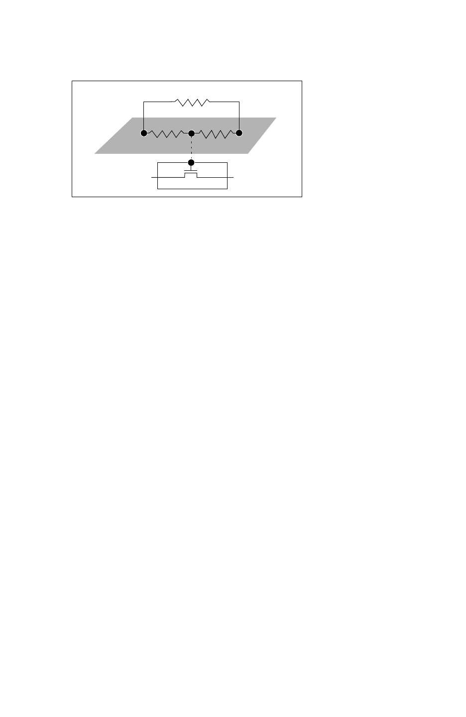
Chapter 17: StarRC Commands
MOS_GATE_DELTA_RESISTANCE 17-132
StarRC User Guide and Command Reference F-2011.06
StarRC User Guide and Command Reference Version F-2011.06
Figure 17-5 Resistance Network Showing MOS_GATE_DELTA_RESISTANCE Command
N1 N1
G
-1/2 Rg
1/6 Rg1/6 Rg

Chapter 17: StarRC Commands
NET_SEGMENT_CUT_LENGTH 17-133
Chapter 17: StarRC Commands
NET_SEGMENT_CUT_LENGTH 17-133
StarRC User Guide and Command Reference Version F-2011.06
NET_SEGMENT_CUT_LENGTH
Specifies the length of a cut segment.
Syntax
NET_SEGMENT_CUT_LENGTH: cut_length
Arguments
Argument Description
cut_length Length of cut segment
Units: microns
Default: 20
Description
StarRC cuts polygons of straight paths along their lengths. You can use the
NET_SEGMENT_CUT_LENGTH command to specify the length of a cut segment. This feature
provides higher extraction accuracy for designs that run at high frequencies.
The length of each resulting segment must be at least twice the width of the path. A cut is
not made if it would result in a segment that is shorter than twice the width of the path.
If you enable netlist reduction with the REDUCTION command, then the additional nodes
created by NET_SEGMENT_CUT_LENGTH are merged based on error control.
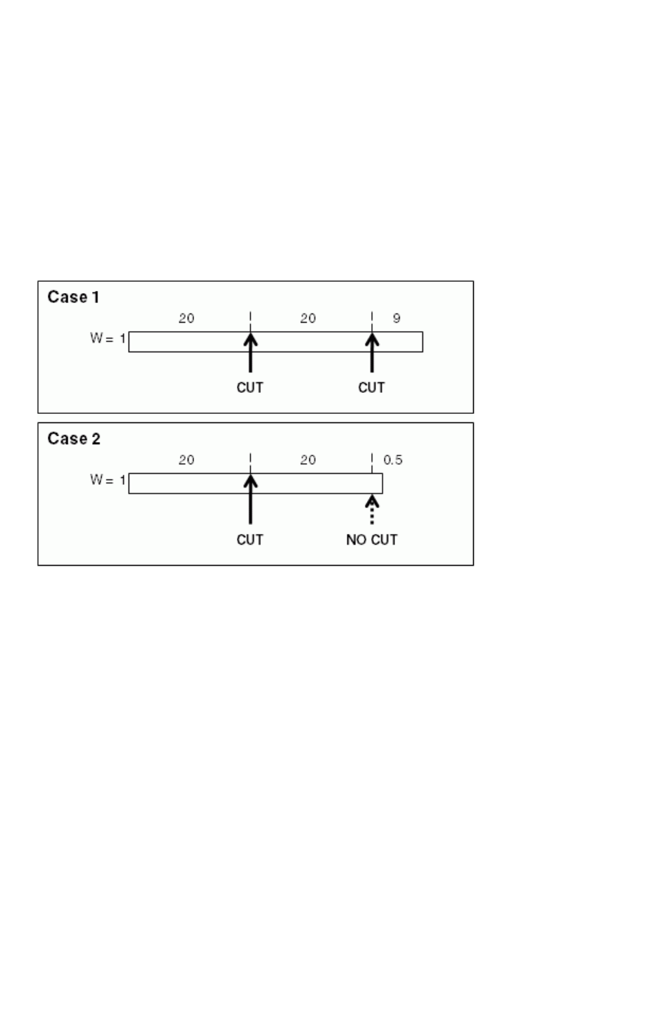
Chapter 17: StarRC Commands
NET_SEGMENT_CUT_LENGTH 17-134
StarRC User Guide and Command Reference F-2011.06
StarRC User Guide and Command Reference Version F-2011.06
Example
NET_SEGMENT_CUT_LENGTH: 20
Figure 17-6 shows one-micron wide paths cut into 20-micron segments, with the exception
of the last segments. In Case 1, the length of the last segment is nine microns, which is more
than twice the width of the path. Since the length of each segment must be at least twice the
width of the path, the second cut is not made in Case 2; therefore, the length of the last
segment is 20.5 microns.
Figure 17-6 Cut Segments for NET_SEGMENT_CUT_LENGTH: 20
See Also
•REDUCTION

Chapter 17: StarRC Commands
NET_TYPE 17-135
Chapter 17: StarRC Commands
NET_TYPE 17-135
StarRC User Guide and Command Reference Version F-2011.06
NET_TYPE
Syntax
NET_TYPE: LAYOUT | SCHEMATIC
Arguments
Argument Description
LAYOUT Specifies that the net names in a NETS: command are
referenced to the layout.
This is the default.
SCHEMATIC Specifies that the net names in a NETS: command are
referenced to the schematic.
Description
Milkyway XTR (extraction) databases contain both layout names and cross-referenced
schematic names. This command determines which set of names to use when looking up
NETS and POWER_NETS during data selection.
This command is ignored if MILKYWAY_EXTRACT_VIEW: NO (Hercules flow) or XREF: NO is
specified.
Note:
NET_TYPE identifies only the source of net names for NETS selection. It does not affect
StarRC reported net names.
See Also
•XREF
•CELL_TYPE
•MILKYWAY_EXTRACT_VIEW
•NETS
•POWER_NETS

Chapter 17: StarRC Commands
NETLIST_CAPACITANCE_UNIT 17-136
StarRC User Guide and Command Reference F-2011.06
StarRC User Guide and Command Reference Version F-2011.06
NETLIST_CAPACITANCE_UNIT
Syntax
NETLIST_CAPACITANCE_UNIT: float
Arguments
Argument Description
float Specifies the unit of capacitance for SPEF format.
Units: farads
Default: 1e-15
Description
Alters the units used for reporting capacitance values in both the header and the body of the
output netlist. Applicable when NETLIST_FORMAT:SPEF.
See Also
•NETLIST_FORMAT

Chapter 17: StarRC Commands
NETLIST_COMMENTED_PARAMS 17-137
Chapter 17: StarRC Commands
NETLIST_COMMENTED_PARAMS 17-137
StarRC User Guide and Command Reference Version F-2011.06
NETLIST_COMMENTED_PARAMS
Syntax
NETLIST_COMMENTED_PARAMS: YES | NO
Arguments
Argument Description
YES Lists instance parameters beginning with a ‘$’ SPICE comment
in the netlist.
NO Does not list instance parameters in the netlist.
This is the default.
Description
Specifies whether to generate instance parameters in the netlist beginning with a ‘$’ SPICE
comment. Extra terminals ($BULK) and $.model are always included in the netlist.

Chapter 17: StarRC Commands
NETLIST_COMMENTS_FILE 17-138
StarRC User Guide and Command Reference F-2011.06
StarRC User Guide and Command Reference Version F-2011.06
NETLIST_COMMENTS_FILE
Syntax
NETLIST_COMMENTS_FILE: file1 file2 ...
Arguments
Argument Description
file Specifies a file name. The content of the file is appended to the
output netlist file.
Default: none.
Description
Inserts the contents of specified files into the parasitic netlist (NETLIST_FILE) as comments.
This section begins after the netlist HEADER is printed. Each line from the file is inserted as
is, prefixed by a comment string (// in SPEF format, ** in all other formats). Empty lines are
not included.
See Also
•NETLIST_FILE
•NETLIST_FORMAT

Chapter 17: StarRC Commands
NETLIST_COMPRESS_COMMAND 17-139
Chapter 17: StarRC Commands
NETLIST_COMPRESS_COMMAND 17-139
StarRC User Guide and Command Reference Version F-2011.06
NETLIST_COMPRESS_COMMAND
Pipes the parasitic netlist through an executable or script for compression or
post-processing.
Syntax
NETLIST_COMPRESS_COMMAND: utility [options]
Arguments
Argument Description
utility The utility name.
Default: none.
options The command-line options for the utility.
Default: none.
Description
Makes the parasitic netlist a specified executable for fast file compression. No suffix is
appended to the output netlist file (in other words, the file name is not changed to *.gz or the
like). If the utility being specified is not in your $PATH, you need to specify the full path to the
executable. This command is relevant only for ASCII-format netlists.
The NETLIST_COMPRESS_COMMAND can also be used for postprocessing a parasitic netlist
through Perl, the UNIX command sed, and so on. When you use the
NETLIST_COMPRESS_COMMAND for postprocessing, StarRC pipes the parasitic netlist through
the script, then outputs the result to the file specified by NETLIST_FILE.
Example
To compress the netlist with gzip, use the following command:
NETLIST_COMPRESS_COMMAND: /usr/local/bin/gzip
The NETLIST_COMPRESS_COMMAND can also be used for postprocessing of the parasitic
netlist. For example, if your downstream tool, such as PrimeRail or NanoTime, does not run
because of backslash (\) characters in the bus bit notation, you can remove the backslash
characters by piping the parasitic netlist through the following sed command:
NETLIST_COMPRESS_COMMAND: sed 's/\\</</g' | sed 's/\\>/>/g'


Chapter 17: StarRC Commands
NETLIST_CONNECT_OPENS 17-141
Chapter 17: StarRC Commands
NETLIST_CONNECT_OPENS 17-141
StarRC User Guide and Command Reference Version F-2011.06
NETLIST_CONNECT_OPENS
Syntax
NETLIST_CONNECT_OPENS: netnames
Arguments
Argument Description
netnames Specifies the net names connected by a small resistor to be
listed (if found open during extraction).
Default: all nets (*)
Description
Creates a white-space-delimited list of nets for StarRC to connect if found open in the input
database. This option may be specified multiple times in a single command file. The
wildcards “*”, “?”, and “!” are acceptable.
A small resistor is inserted wherever a physical open is found on any net belonging to this
list. This function makes it possible for most timing analyzers to calculate delay, even though
the net is not actually connected.
Example
NETLIST_CONNECT_OPENS: * !pwr* !gnd*
NETLIST_CONNECT_OPENS: net1 net2 net3 ... netn
*RES
742 6:425 6:970 0.0100000 // $l=174.000 $w=100.000 $lvl = 0
743 6:970 6:1445 0.0100000 // $l=1.37 $w=100.000 $lvl = 0
This example shows how you can explicitly state that a shorting resistor of a particular value
can be used to connect resistively connected groups (RCGs). In this example, the resistor is
denoted by R=0.01 ohms and width = 100.

Chapter 17: StarRC Commands
NETLIST_CONNECT_SECTION 17-142
StarRC User Guide and Command Reference F-2011.06
StarRC User Guide and Command Reference Version F-2011.06
NETLIST_CONNECT_SECTION
Syntax
NETLIST_CONNECT_SECTION: YES | NO
Arguments
Argument Description
YES Specifies the *I, *P, or *CONN sections to be present in the
output file.
This is the default.
NO Specifies the *I, *P, or *CONN sections to not be present in the
output file.
Description
Applicable for all non-capacitor-only formats, including NETNAME. Setting this command to
NO disables the generation of the information normally contained in the *|I and *|P or
*CONN sections. This can reduce the netlist size significantly, but most delay calculators
and static timing tools require this information.
See Also
•NETLIST_FORMAT

Chapter 17: StarRC Commands
NETLIST_CORNER_FILE 17-143
Chapter 17: StarRC Commands
NETLIST_CORNER_FILE 17-143
StarRC User Guide and Command Reference Version F-2011.06
NETLIST_CORNER_FILE
Specifies the file containing the user-defined corner definitions.
Syntax
NETLIST_CORNER_FILE: corner_file
Arguments
Argument Description
corner_file The relative or absolute path to the file.
Default: none.
Description
The command allows you to define a custom corner file and produce a netlist based on this
corner. You must perform sensitivity extraction to take advantage of user-defined corner
extraction and netlist generation.
Example
NETLIST_CORNER_FILE: /internal/project/mycorner

Chapter 17: StarRC Commands
NETLIST_CORNER_FILE 17-144
StarRC User Guide and Command Reference F-2011.06
StarRC User Guide and Command Reference Version F-2011.06
CORNER_NAME: CMAX
# PARAM VARIATION_POINT
M1_T 3.0
M1_W 3.0
M12_T -3.0
M2_T 3.0
M2_W 3.0
M23_T -3.0
NETLIST_CORNER_NAME: RCMAX
M1_T -3.0
M1_W -3.0
M12_T -3.0
M2_T -3.0
M2_W -3.0
M23_T -3.0
CORNER_NAME: M1_CMAX_M2_RCMAX
M1_T 3.0
M1_W 3.0
M12_T -3.0
M2_T -3.0
M2_W -3.0
M23_T -3.0
CORNER_NAME: RANDOM
M1_T -1.2
M1_W 0.6
M12_T 0.0
M2_T -3.0
M2_W 2.1
M23_T -2.4
See Also
•NETLIST_CORNER_NAMES
•SENSITIVITY

Chapter 17: StarRC Commands
NETLIST_CORNER_NAMES 17-145
Chapter 17: StarRC Commands
NETLIST_CORNER_NAMES 17-145
StarRC User Guide and Command Reference Version F-2011.06
NETLIST_CORNER_NAMES
Syntax
NETLIST_CORNER_NAMES: corner_names
Arguments
Argument Description
corner_names Space delimited list of corner names to extract from the
NETLIST_CORNER_FILE.
Default: none.
Description
This command specifies the user-defined corners to extract from file pointed to in the
NETLIST_CORNER_FILE command.
This command selects the names of the corners from the NETLIST_CORNER_FILE that you
are interested in extracting and netlist generation. The names specified in the command can
be a subset of the corners defined in NETLIST_CORNER_FILE. The corner names specified
are case sensitive.
Sensitivity extraction must be performed to take advantage of user-defined corner extraction
and netlist generation.
Example
NETLIST_CORNER_NAMES:RCMAX RANDOM
See Also
•NETLIST_CORNER_NAMES
•SENSITIVITY

Chapter 17: StarRC Commands
NETLIST_COUPLE_UNSELECTED_NETS 17-146
StarRC User Guide and Command Reference F-2011.06
StarRC User Guide and Command Reference Version F-2011.06
NETLIST_COUPLE_UNSELECTED_NETS
Syntax
NETLIST_COUPLE_UNSELECTED_NETS: IDEAL | COMPLETE | NO
Arguments
Argument Description
IDEAL Coupling capacitances are netlisted from nets specified in a
NETLIST_SELECT_NETS command to other nets, but no *|NET
lines appear for unselected nets (for example, nets not specified
with the NETLIST_SELECT_NETS command.
COMPLETE Coupling capacitances are netlisted from
NETLIST_SELECT_NETS to other nets, and those other nets
have *|NET parasitic sections.
The net type for this option is specified using wildcards with the
NETLIST_TYPE command. Coupling capacitances to
unselected nets are netlisted if the
NETLIST_TYPE:no_couple command is not set for the
unselected nets to which the couplings exist. The
NETLIST_TYPE:no_couple command option overrides the
NETLIST_COUPLE_UNSELECTED_NETS for any unselected
nets described in the NETLIST_TYPE command. If
NETLIST_TYPE: no_couple is set for certain unselected nets
that are coupled to selected nets, neither the unselected nets
nor their couplings to selected nets are netlisted.
NO Couplings to unselected nets are not netlisted.
This is the default.
Description
Specifies that StarRC creates a netlist from any unselected nets (nets not specified by
NETLIST_SELECT_NETS) or that are coupled to by selected nets (specified by
NETLIST_SELECT_NETS).
This is a netlist command. However, for coupled nets to be present in the output, the
extraction must be coupled. To do this, set EXTRACTION: RC, C, and COUPLE_TO_GROUND:
NO.
You can use -cleanN with this command.


Chapter 17: StarRC Commands
NETLIST_DELIMITER 17-148
StarRC User Guide and Command Reference F-2011.06
StarRC User Guide and Command Reference Version F-2011.06
NETLIST_DELIMITER
Specifies the instance pin delimiter.
Syntax
NETLIST_DELIMITER: : | | | . | / | #
Arguments
Argument Description
:Colon (:) character is the instance delimiter.
This is the default.
|Pipe (|) character is the instance delimiter.
/Slash (/) character is the instance delimiter.
.Period (.) character is the instance delimiter.
#Pound sign or hash (#) character is the instance delimiter.
Description
Sets the instance pin delimiter to be printed in the output parasitic netlist.

Chapter 17: StarRC Commands
NETLIST_DEVICE_LOCATION_ORIENTATION 17-149
Chapter 17: StarRC Commands
NETLIST_DEVICE_LOCATION_ORIENTATION 17-149
StarRC User Guide and Command Reference Version F-2011.06
NETLIST_DEVICE_LOCATION_ORIENTATION
Queries each instance of the database for additional parameters including the xy angle.
Syntax
NETLIST_DEVICE_LOCATION_ORIENTATION: YES | NO
Arguments
Argument Description
YES The xy location and orientation angle appears in the instance section of the netlist
file.
NO The xy location and orientation angle does not appear in the instance section of the
netlist file.
This is the default.
COMMENT The dollar sign ($) appears in the instance section of the netlist file preceding the
xy location and orientation angle.
Description
For the output of a particular instance section, the retrieved information is printed in the
netlist.
Currently, this function is implemented for MOSFETS only.
Example
NETLIST_DEVICE_LOCATION_ORIENTATION: YES
The following example shows how the information is entered in the netlist when YES
specified.
MM1 10753:F40289 97802:F40290 10755:F40291 vgnd:F40288 MN ad=5.4p as=9.6p
pd=20.54u ps=40.96u l=0.18u w=20u x=-1873.77 y=1789.68 angle=0
The following example shows how the information is entered in the netlist when NO is
specified.
MM1 10753:F40289 97802:F40290 10755:F40291 vgnd:F40288 MN ad=5.4p as=9.6p
pd=20.54u ps=40.96u l=0.18u w=20u

Chapter 17: StarRC Commands
NETLIST_DEVICE_LOCATION_ORIENTATION 17-150
StarRC User Guide and Command Reference F-2011.06
StarRC User Guide and Command Reference Version F-2011.06
The following example shows how the information is entered in the netlist when COMMENT is
specified.
MM1 10753:F40289 97802:F40290 10755:F40291 vgnd:F40288 MN ad=5.4p as=9.6p
pd=20.54u ps=40.96u l=0.18u w=20u $x=-1873.77 $y=1789.68 $angle=0
See Also
•NETLIST_FORMAT

Chapter 17: StarRC Commands
NETLIST_FILE 17-151
Chapter 17: StarRC Commands
NETLIST_FILE 17-151
StarRC User Guide and Command Reference Version F-2011.06
NETLIST_FILE
Specifies the name of the file to which the output parasitic netlist is written.
Syntax
NETLIST_FILE: file_name
Arguments
Argument Description
file_name The generated output file.
Default: block_name.spf, where block_name is the block specified by the
BLOCK statement
Description
In the case of the SBPF format, you must also specify the .sbpf extension.
Example
NETLIST_FILE: top_block.sbpf
See Also
•NETLIST_FORMAT

Chapter 17: StarRC Commands
NETLIST_FORMAT 17-152
StarRC User Guide and Command Reference F-2011.06
StarRC User Guide and Command Reference Version F-2011.06
NETLIST_FORMAT
Defines the structure and format of the output parasitic netlist.
Syntax
NETLIST_FORMAT: SPF | STAR | SPEF | SBPF | MW | CONLY | NETNAME | NONE
Arguments
Argument Description
SPF DSPF 1.0; supports only EXTRACTION: RC with COUPLE_TO_GROUND: YES | NO.
Supports coupling capacitors from the 2003.03 release.
STAR Uses SPICE-like subnode naming conventions. Compact and allows netlist generation of
EXTRACTION:R and COUPLE_TO_GROUND:NO.
This is the default.
SPEF Flexible and compact. All names are mapped internally, reducing netlist size. Any StarRC
job configuration is supported by this format. SPEF prints the D_NET (detailed parasitics)
net type in the output NETLIST_FILE.
MW For this format, StarRC writes parasitic output into the PARA view of the extracted block in
the source MILKYWAY_DATABASE.
SBPF Specifies Synopsys binary parasitic format. This is an interface format to PrimeTime and
static timing analysis tools.
CAUTION: The following commands should not be specified in the StarRC command file
with the SBPF output format: NETLIST_SELECT_NETS,
NETLIST_COUPLE_UNSELECTED_NETS, CONLY_NETS, ZONE_COUPLE_TO_NET,
COUPLE_NONCRITICAL_NETS, SKIP_CELLS_COUPLE_TO_NET and EXTRACTION:C.
CONLY Outputs only capacitors. This format does not take the pin/port capacitances into account
when preparing the coupling report.
NETNAME Formats internal node names as netname:0, netname:1, and so on. This makes it
easier to determine which nets the parasitics are attached to and makes it easier to probe
an RC network.
NONE Skips the netlist stage.
OA Outputs the parasitic elements and ideal device in Open Access database format. This
allows tools able to read OA to access the parasitic database for analysis and viewing.

Chapter 17: StarRC Commands
NETLIST_FORMAT 17-153
Chapter 17: StarRC Commands
NETLIST_FORMAT 17-153
StarRC User Guide and Command Reference Version F-2011.06
Description
There are five supported formats for parasitics: SPF, STAR, SPEF, MW, SBPF, CONLY, NETNAME,
and NONE.
Example
See “Netlist Format Examples” on page 13-2.
See Also
•COUPLE_TO_GROUND
•EXTRACTION
•MILKYWAY_DATABASE
•NETLIST_FILE

Chapter 17: StarRC Commands
NETLIST_GROUND_NODE_NAME 17-154
StarRC User Guide and Command Reference F-2011.06
StarRC User Guide and Command Reference Version F-2011.06
NETLIST_GROUND_NODE_NAME
Defines the net name used when reporting the capacitance with respect either to noncritical
material or to an ITF defined SUBSTRATE.
Syntax
NETLIST_GROUND_NODE_NAME: string
Arguments
Argument Description
string The name of the net to which the capacitance is to be lumped.
Default: 0
Description
This command is not valid with SPEF format netlists, because the ground node is not output
in SPEF.
If you find a reference to node 0 in your output netlist, it is the location where all noncritical
extracted materials are lumped. This includes coupling to ideal ground, or SUBSTRATE in
StarRC. The entry for node 0 is the SPICE ground.
See Also
•NETLIST_FORMAT

Chapter 17: StarRC Commands
NETLIST_HIER_PROBE_NODES 17-155
Chapter 17: StarRC Commands
NETLIST_HIER_PROBE_NODES 17-155
StarRC User Guide and Command Reference Version F-2011.06
NETLIST_HIER_PROBE_NODES
Syntax
NETLIST_HIER_PROBE_NODES: YES | NO
Arguments
Argument Description
NO Does not report the hierarchy in the output.
This is the default.
YES Reports the hierarchy information cell_inst:text_label in the RC
netlist output.
Description
Specifies whether or not the net hierarchy must be reported in the RC netlist.
Example
**|OI (cell_inst : text_label cell_inst text_label
Z 0 x_coord y_coord
*| NET SUM0 0.0128485PF
**|OI ($1I1:ProbeA1 $1I1 ProbeA1 Z 0 459.5 34.5)
R16 $1I1:ProbeA1 SUM0 1.19335 $l = 38.495 $w = 2 $lvl = 1
The text, $1I1:ProbeA1 is inserted into the output when NETLIST_HIER_PROBE_NODES is
set to YES.

Chapter 17: StarRC Commands
NETLIST_IDEAL_SPICE_FILE 17-156
StarRC User Guide and Command Reference F-2011.06
StarRC User Guide and Command Reference Version F-2011.06
NETLIST_IDEAL_SPICE_FILE
Syntax
NETLIST_IDEAL_SPICE_FILE: file_name
Arguments
Argument Description
file_name The name of the file to be output.
Default: none.
Description
Creates an ideal SPICE-format netlist for use with simulation. Options
NETLIST_PASSIVE_PARAMS and NETLIST_MAX_LINE are in effect for this netlist.
NETLIST_IDEAL_SPICE_TYPE determines whether the ideal netlist should be layout or
schematic based. NETLIST_IDEAL_SPICE_HIER determines whether or not the ideal netlist
is flat or retains the hierarchy of the input data.
The NETLIST_IDEAL_SPICE_FILE stops at SKIP_CELLS boundaries. SKIP_CELLS and
device .SUBCKT statements are included in the netlist as comments to indicate port
ordering. For SKIP_CELLS extractions, the ideal device-level netlists can be provided with
SPICE_SUBCKT_FILE to order the .SUBCKT ports in the NETLIST_IDEAL_SPICE_FILE.
Then the SPICE_SUBCKT_FILE can be provided to a simulation tool in combination with the
NETLIST_IDEAL_SPICE_FILE for a complete device-level ideal SPICE netlist.
See Also
•NETLIST_IDEAL_SPICE_HIER
•NETLIST_IDEAL_SPICE_TYPE
•NETLIST_MAX_LINE
•NETLIST_PASSIVE_PARAMS
•SPICE_SUBCKT_FILE

Chapter 17: StarRC Commands
NETLIST_IDEAL_SPICE_HIER 17-157
Chapter 17: StarRC Commands
NETLIST_IDEAL_SPICE_HIER 17-157
StarRC User Guide and Command Reference Version F-2011.06
NETLIST_IDEAL_SPICE_HIER
Syntax
NETLIST_IDEAL_SPICE_HIER: YES | NO
Arguments
Argument Description
YES The original netlist or layout hierarchy is preserved.
NO The ideal netlist is flattened.
This is the default.
Description
Specifies whether or not to preserve the original hierarchy when you are generating the
NETLIST_IDEAL_SPICE_FILE.
See Also
•NETLIST_IDEAL_SPICE_FILE
•NETLIST_IDEAL_SPICE_TYPE

Chapter 17: StarRC Commands
NETLIST_IDEAL_SPICE_TYPE 17-158
StarRC User Guide and Command Reference F-2011.06
StarRC User Guide and Command Reference Version F-2011.06
NETLIST_IDEAL_SPICE_TYPE
Specifies whether to netlist a layout- or schematic-based NETLIST_IDEAL_SPICE_FILE
command.
Syntax
NETLIST_IDEAL_SPICE_TYPE: SCHEMATIC | LAYOUT
Arguments
Argument Description
SCHEMATIC Specifies the output file has schematic net names.
LAYOUT Specifies the output file has layout net names.
Description
The default for XREF:NO is LAYOUT. The default for all other XREF values is SCHEMATIC.
See Also
•NETLIST_IDEAL_SPICE_FILE

Chapter 17: StarRC Commands
NETLIST_INCREMENTAL 17-159
Chapter 17: StarRC Commands
NETLIST_INCREMENTAL 17-159
StarRC User Guide and Command Reference Version F-2011.06
NETLIST_INCREMENTAL
Specifies whether to output a partial or full netlist for an incremental extraction.
Syntax
NETLIST_INCREMENTAL: YES | NO
Arguments
Argument Description
YES Produces an incremental netlist. This is currently supported by SPEF or SBPF
formats only. If the NETLIST_FORMAT specified is other than SPEF or SBPF,
StarRC issues an error.
NO Produces a full chip parasitic netlist in all formats. This command also controls
the content of the coupling report. With NETLIST_INCREMENTAL: YES, a
partial coupling report is generated.
This is the default.
Description
Specifying NETLIST_INCREMENTAL:YES produces a partial netlist of the post-ECO nets and
the corresponding neighboring nets. Only SPEF and SBPF netlist formats are supported. A
downstream timing analysis tool must accept this partial netlist and properly restitch the
parasitics.
It is also important to note that the timing analysis must have Verilog netlist changes that
match the incremental parasitics. If you fail to match the incremental parasitics, there could
be back-annotation problems.
If you use timing analysis tools that do not support partial netlists, you may benefit by
running incremental extraction using the NETLIST_INCREMENTAL:NO command. A full netlist
is produced that includes parasitics of the post-ECO block.
Note:
The NETLIST_INCREMENTAL command works only when the INCREMENTAL: YES
command is also specified.

Chapter 17: StarRC Commands
NETLIST_INCREMENTAL 17-160
StarRC User Guide and Command Reference F-2011.06
StarRC User Guide and Command Reference Version F-2011.06
Example
BLOCK: TOP_Post-eco
MILKYWAY_DATABASE: design
TCAD_GRD_FILE: nxtgrd_file
MAPPING_FILE: map
NETLIST_FORMAT: SPEF
INCREMENTAL: YES
NETLIST_INCREMENTAL: YES
See Also
•INCREMENTAL

Chapter 17: StarRC Commands
NETLIST_INPUT_DRIVERS 17-161
Chapter 17: StarRC Commands
NETLIST_INPUT_DRIVERS 17-161
StarRC User Guide and Command Reference Version F-2011.06
NETLIST_INPUT_DRIVERS
Identifies the driving cell models in the SPEF netlist format for each instance pin with the
optional *D statement.
Syntax
NETLIST_INPUT_DRIVERS: YES | NO
Arguments
Argument Description
YES Prints the driving cell model name in the netlist.
NO Does not enable the command function.
This is the default.
Description
Many static timing tools do not require this information for the inputs, because the loading
cap for the net is provided. StarRC does not print the *D statements for the inputs by default.
Use this option to print the models for the input instance pins.
This command is ignored unless you specify NETLIST_FORMAT: SPEF.
See Also
•NETLIST_FORMAT

Chapter 17: StarRC Commands
NETLIST_INSTANCE_SECTION 17-162
StarRC User Guide and Command Reference F-2011.06
StarRC User Guide and Command Reference Version F-2011.06
NETLIST_INSTANCE_SECTION
Sets whether or not the SPF instance section is printed in the output netlist.
Syntax
NETLIST_INSTANCE_SECTION: YES | NO | SELECTED
Arguments
Argument Description
YES Prints all instances.
NO Does not print the instance section.
SELECTED Print the instance section connected the nets group that is the
combination of NETS and NETLIST_SELECT_NETS.
This is the default.
Description
This command is valid only when the NETLIST_FORMAT:SPF|STAR|NETNAME command is
set.
Note:
Because .subckt must be consistent with the instance section, the .subckt statement is
printed accordingly.
Example
The following three examples show the expected behavior when combinations of these
commands are specified.
Example 1
NETS selected
XREF:NO|YES|NETS
NETLIST_SELECT_NETS:*
NETLIST_INSTANCE_SECTION:
NO: No instance section is printed.
YES|SELECTED:Only devices attached to extracted nets printed. YES and
SELECTED behave the same.

Chapter 17: StarRC Commands
NETLIST_INSTANCE_SECTION 17-163
Chapter 17: StarRC Commands
NETLIST_INSTANCE_SECTION 17-163
StarRC User Guide and Command Reference Version F-2011.06
Example 2
NETS selected
XREF:COMPLETE
NETLIST_SELECT_NETS:*
NETLIST_INSTANCE_SECTION:
NO: No instance section is printed.
YES|SELECTED: All devices in the schematic devices are printed. Nets not
extracted are ideal. YES and SELECTED behave the same.
Example 3
NETLIST_INSTANCE_SECTION:YES and SELECTED are influenced by the
NETLIST_SELECT_NETS command as explained in the following:
NETS*
XREF:NO|YES|NETS
NETLIST_SELECT_NETS:selected |subset_of_nets_in_NETS
NETLIST_INSTANCE_SECTION:
NO: No instance section is printed.
YES: All devices are generated in the netlist that are present in the IDX
file. .
SELECTED: Only devices attacted to NETLIST_SELECT_NETS are printed.
See Also
•NETLIST_FORMAT
•NETLIST_SELECT_NETS
•NETLIST_COUPLE_UNSELECTED_NETS
•NETS
•POWER_NETS

Chapter 17: StarRC Commands
NETLIST_LOGICAL_TYPE 17-164
StarRC User Guide and Command Reference F-2011.06
StarRC User Guide and Command Reference Version F-2011.06
NETLIST_LOGICAL_TYPE
Sets a value to be printed in the SPEF DESIGN_FLOW NETLIST_TYPE val header card.
Syntax
NETLIST_LOGICAL_TYPE: VERILOG | VHDL87 | VHDL93 | EDIF
Arguments
Argument Description
VERILOG Specifies Verilog as the naming convention used in the SPEF
netlist.
VHDL87 Specifies VHDL87 as the naming convention used in the SPEF
netlist.
VHDL93 Specifies VHDL93 as the naming convention used in the SPEF
netlist.
EDIF Specifies EDIF as the naming convention used in the SPEF
netlist.
Description
This command specifies which naming convention is used in the creation of the SPEF
netlist. It is not required by StarRC but might be necessary for some follow-on tools.
See Also
•NETLIST_FORMAT

Chapter 17: StarRC Commands
NETLIST_MAX_FILE_SIZE 17-165
Chapter 17: StarRC Commands
NETLIST_MAX_FILE_SIZE 17-165
StarRC User Guide and Command Reference Version F-2011.06
NETLIST_MAX_FILE_SIZE
Limits the size of the output netlist file produced by StarRC.
Syntax
NETLIST_MAX_FILE_SIZE: float
Arguments
Argument Description
float Floating-point number that is smaller than the default in defining a
single netlist size.
32-bit default: 1.6 GB
64-bit default: unlimited
Description
It is not necessary to issue this command to adhere to the 32-bit operating system file size
limit; the default for this option is 1.6e9, which is the 32-bit limit. NETLIST_MAX_FILE_SIZE
cannot be set higher than the default, only lower. For a 64-bit platform, this file size limitation
does not exist.
Whenever StarRC reaches a netlist size such that the next complete net exceeds the
specified limit, it begins a new netlist file. If it is impossible to print one complete net within
the specified limit, StarRC will exceed the limit. The minimum file size is not fixed but is
constrained by the requirement that nets may not be split between files.
The netlist header is printed only in the first file.
Note:
NETLIST_MAX_FILE_SIZE is specified in bytes.
Example
Each netlist file uses the root name provided by the NETLIST_FILE command. The first
netlist file does not have a suffix. Subsequent files receive an indexed suffix, as shown in the
following example:
block.spf
block.spf.1
block.spf.2
.....
block.spf.n


Chapter 17: StarRC Commands
NETLIST_MAX_LINE 17-167
Chapter 17: StarRC Commands
NETLIST_MAX_LINE 17-167
StarRC User Guide and Command Reference Version F-2011.06
NETLIST_MAX_LINE
Specifies the maximum number of characters allowed on each netlist line before the line is
discontinued with a carriage return and the text is wrapped with the “+” continuation tag.
Syntax
NETLIST_MAX_LINE: integer
Arguments
Argument Description
integer Maximum number of characters allowed on each netlist line.
Default: no limit.
Description
This command applies to the SPF and STAR netlist formats only. The default is not to limit
the number of characters.
See Also
•NETLIST_FORMAT

Chapter 17: StarRC Commands
NETLIST_MERGE_CORNERS 17-168
StarRC User Guide and Command Reference F-2011.06
StarRC User Guide and Command Reference Version F-2011.06
NETLIST_MERGE_CORNERS
Outputs a single netlist for multiple user-defined corners (UDC).
Syntax
NETLIST_MERGE_CORNERS: YES | NO
Arguments
Argument Description
YES Turns on function to output a single netlist for multiple user-defined
corners.
NO A single netlist for multiple user-defined corners is not generated.
This is the default.
Description
Specify this command with SENSITIVITY:YES to output a single netlist for multiple
user-defined corners (UDC). The resistance and capacitance values are separated by a
colon and are printed in the same order as the corner names specified in the
NETLIST_CORNER_NAMES command.
Note:
This command behaves similarly to MERGE_MULTI_CORNER used for traditional
nonsensitivity-based extraction flows. The command is a netlist generation function and
therefore can be modified for re-creating the netlist (-cleanN).
Example
NETLIST_MERGE_CORNERS:YES
See Also
•NETLIST_CORNER_FILE
•NETLIST_CORNER_NAMES
•SENSITIVITY

Chapter 17: StarRC Commands
NETLIST_MERGE_SHORTED_PORTS 17-169
Chapter 17: StarRC Commands
NETLIST_MERGE_SHORTED_PORTS 17-169
StarRC User Guide and Command Reference Version F-2011.06
NETLIST_MERGE_SHORTED_PORTS
Removes 0.001-ohm node-sharing resistors and merges node names in the netlist to
reduce the file size.
Syntax
NETLIST_MERGE_SHORTED_PORTS: YES | NO
Arguments
Argument Description
YES Instance ports connected by node sharing resistors are replaced by
one node in the group.
NO Instance nodes are unique and might be connected by node sharing
resistors (if there are no physical parasitic resistors).
This is the default.
Description
If NETLIST_MERGE_SHORTED_PORTS is set to YES, whenever multiple port nodes for a net are
connected together by node-sharing shorting resistors, StarRC chooses one node randomly
from the group to represent all nodes. StarRC uses this node to replace every node in the
group for every electrical element in the netlist including parasitic elements, elements in the
instance section, and *|I occurrences in DSPF.
Example
NETLIST_MERGE_SHORTED_PORTS: YES

Chapter 17: StarRC Commands
NETLIST_MINCAP_THRESHOLD 17-170
StarRC User Guide and Command Reference F-2011.06
StarRC User Guide and Command Reference Version F-2011.06
NETLIST_MINCAP_THRESHOLD
Sets the minimum capacitance allowed in the RC section of the netlist.
Syntax
NETLIST_MINCAP_THRESHOLD: capacitance_value
Arguments
Argument Description
capacitance_value The smallest capacitance to be allowed without merging with another
capacitance.
Units: farad (F)
Default: 0.0
Description
Any capacitance below this threshold is merged with another smaller capacitance or larger
capacitance in a given net. This is applicable for both coupling and grounded capacitance.
The capacitance value cannot be less than 0 (zero).
Note:
Capacitance that is below the threshold can remain in the netlist.
When NETLIST_MINCAP_THRESHOLD and COUPLING_ABS_THRESHOLD are both specified,
StarRC performs the function of COUPLING_ABS_THRESHOLD first.
This command is supported only for transistor-level extraction.
Example
This sets the threshold level at 1 fF.
NETLIST_MINCAP_THRESHOLD: 1e-15
See Also
•COUPLING_ABS_THRESHOLD
•NETLIST_TOTALCAP_THRESHOLD

Chapter 17: StarRC Commands
NETLIST_MINRES_HANDLING 17-171
Chapter 17: StarRC Commands
NETLIST_MINRES_HANDLING 17-171
StarRC User Guide and Command Reference Version F-2011.06
NETLIST_MINRES_HANDLING
Syntax
NETLIST_MINRES_HANDLING: SHORT | MERGE
Arguments
Argument Description
SHORT Does not preserve point-to-point resistance.
MERGE Merges the resistor with a neighboring resistor if it is in series and is
smaller than the threshold.
Description
Defines how a resistor is handled if it is less than or equal to the specified threshold in the
NETLIST_MINRES_THRESHOLD command. This command is supported only for
transistor-level extraction.
• If there is only one resistor in the net, it is not merged or shorted.
• If a resistor is attached to a PROBE node (or *P or *I), then that terminal is attached to
“keep nodes” and should not be affected.
•NETLIST_MINRES_HANDLING does not preserve point-to-point resistance.
•NETLIST_MINRES_HANDLING ensures that no resistors exist with their terminals shorted.
• You can specify either SHORT or MERGE in the NETLIST_MINRES_HANDLING command, but
not both. If you specify both, the second one overrides the first one.
•NETLIST_MINRES_HANDLING:MERGE does not work on resistor nodes with more than 3
branches. This means that it does only series merging. However,
NETLIST_MINRES_HANDLING:SHORT works on all resistor nodes and shorts the nodes
appropriately.
• When NETLIST_MINRES_HANDLING:MERGE is specified, the capacitance on the reduced
node is moved to the smaller resistor.
See Also
•NETLIST_MINRES_THRESHOLD

Chapter 17: StarRC Commands
NETLIST_MINRES_THRESHOLD 17-172
StarRC User Guide and Command Reference F-2011.06
StarRC User Guide and Command Reference Version F-2011.06
NETLIST_MINRES_THRESHOLD
Syntax
NETLIST_MINRES_THRESHOLD: threshold_value
Arguments
Argument Description
threshold_value Threshold value at which all resistances are merged or shorted if less
than or equal to this value.
Default: none.
Description
This command merges or shorts all resistances in the netlist less than or equal to the
threshold specified. This command is supported only for transistor-level extraction
• You cannot specify a value less than zero.
• This option is governed by the NETLIST_MINRES_HANDLING: SHORT | MERGE command.
Example
NETLIST_MINRES_THRESHOLD: 0.001
See Also
•NETLIST_MINRES_HANDLING

Chapter 17: StarRC Commands
NETLIST_MMC_FORMULA 17-173
Chapter 17: StarRC Commands
NETLIST_MMC_FORMULA 17-173
StarRC User Guide and Command Reference Version F-2011.06
NETLIST_MMC_FORMULA
Generates the value of resistors and capacitors as a formula in the final merged netlist.
Syntax
NETLIST_MMC_FORMULA: YES | NO
Arguments
Argument Description
YES Generates the value of resistors and capacitors as a formula in
the merged netlist.
NO Does not generate the resistors as a formula in the merged
netlist.
This is the default.
Description
This command activates only when the MERGE_MULTI_CORNER command is set to YES.
Example
The following example shows the command used with related commands.
TCAD_GRD_FILE: nxtgrd1 nxtgrd2 nxtgrd3
MERGE_MULTI_CORNER: YES
NETLIST_PARASITIC_RESISTOR_MODEL:Y ES
NETLIST_MMC_FORMULA: YES
See Also
•MERGE_MULTI_CORNER: YES
•NETLIST_MMC_FORMULA_NAMES
•NETLIST_PARASITIC_RESISTOR_MODEL
•TCAD_GRD_FILE

Chapter 17: StarRC Commands
NETLIST_MMC_FORMULA_NAMES 17-174
StarRC User Guide and Command Reference F-2011.06
StarRC User Guide and Command Reference Version F-2011.06
NETLIST_MMC_FORMULA_NAMES
Specifies the names of fixed corners.
Syntax
NETLIST_MMC_FORMULA_NAMES: corner_name1 corner_name2 ...
Arguments
Argument Description
corner_name Fixed corner name. The number of names specified must be the
same as the number of nxtgrd files.
Default: none
Description
If this command is not specified, the default corner names are used. Other command
requirements are the following:
• If the number of names specified is greater than or lesser than the number of nxtgrd files
specified, then StarRC errors out.
• The order of values in the netlist for a given element does not change. It is always in the
order of the nxtgrd file.
• With the NETLIST_MMC_FORMULA_NAMES command, you must also specify a
NETLIST_MMC_FORMULA:YES
or
MERGE_MULTI_CORNER:YES command.
• You must verify that the order of names corresponds to the named nxtgrd files specified
in the TCAD_GRD_FILE command.
Example
The following example identifies the corners rcworst, rcbest, and cbest in the file syntax:
TCAD_GRD_FILE:nxtgrd1 nxtgrd2 nxtgrd3
MERGE_MULTI_CORNER:YES
NETLIST_PARASITIC_RESISTOR_MODEL:NO
NETLIST_MMC_FORMULA:YES
NETLIST_MMC_FORMULA_NAMES:rcworst rcbest cbest


Chapter 17: StarRC Commands
NETLIST_NAME_MAP 17-176
StarRC User Guide and Command Reference F-2011.06
StarRC User Guide and Command Reference Version F-2011.06
NETLIST_NAME_MAP
Controls name mapping for a SPEF netlist.
Syntax
NETLIST_NAME_MAP: YES | NO
Arguments
Argument Description
YES Enables name mapping in an SPEF netlist only.
This is the default.
NO Disables name mapping in an SPEF netlist only.
Description
The NETLIST_NAME_MAP controls name mapping. This command is only applicable when
you use NETLIST_FORMAT: SPEF.
Note:
Disabling name mapping greatly increases the netlist size. You should not use this
command on a regular basis.
See Also
•NETLIST_FORMAT

Chapter 17: StarRC Commands
NETLIST_NODE_SECTION 17-177
Chapter 17: StarRC Commands
NETLIST_NODE_SECTION 17-177
StarRC User Guide and Command Reference Version F-2011.06
NETLIST_NODE_SECTION
Syntax
NETLIST_NODE_SECTION: YES | NO
Arguments
Argument Description
YES Generates *|S or *N statements in the output netlist.
NO Does not generate *|S or *N statements in the output netlist.
This is the default.
Description
Generates the *|S or *N statements in the output netlist.
Using the default setting, NETLIST_NODE_SECTION:NO greatly reduces the netlist size and is
useful for most post-extraction flows.
Specify this command with netlist formats STAR, SPF, or SPEF.
See Also
•NETLIST_FORMAT

Chapter 17: StarRC Commands
NETLIST_NODENAME_NETNAME 17-178
StarRC User Guide and Command Reference F-2011.06
StarRC User Guide and Command Reference Version F-2011.06
NETLIST_NODENAME_NETNAME
Retains a net name for one of the subnodes of a nonport net.
Syntax
NETLIST_NODENAME_NETNAME: YES | NO
Arguments
Argument Description
YES Retains net names for one of the subnodes of a nonport net. Names
the subnodes with the net name without the pin delimiter and positive
integer
NO Does not retain subnode names.
This is the default.
Description
NETLIST_NODENAME_NETNAME retains a net name for one of the subnodes of a nonport net.
StarRC chooses one subnode from a nonport (internal) net and converts it to a net name.
This command is valid for all settings of the NETLIST_FORMAT command and is particularly
useful for the SPF format. However, parasitic netlist reading tools that adhere strictly to the
SPEF standard might issue errors. To avoid SPEF netlist reading errors, set
NETLIST_NODENAME_NETNAME: NO.
Note:
Do not use a probe name specified in a probe text file that is the same as a net name. In
that case, the two nodes are electrically shorted.
If a net has a top-level port node, for example, *|P (DSPF) or *P (SPEF), then
NETLIST_NODENAME_NETNAME:YES does not rename or generate a node for that net.
When a net has at least one *|S node (DSPF) or *N node (SPEF), one of those *|S or *N is
renamed to match the *|NET or *D_NET net name.

Chapter 17: StarRC Commands
NETLIST_NODENAME_NETNAME 17-179
Chapter 17: StarRC Commands
NETLIST_NODENAME_NETNAME 17-179
StarRC User Guide and Command Reference Version F-2011.06
A node is never a candidate for renaming if it is from one of the following categories:
Node
instance port *|I (DSPF) or *I (SPEF)
top-level port *|P (DSPF) or *P (SPEF)
observation port **|O (DSPF) or **O (SPEF)
probe text **|OP (DSPF) or **OP (SPEF)
If a net contains no *|S or *N subnodes but has at least two *|P and/or *|I nodes, then a new
node is generated whose name matches the net name.
If a net is floating (no *|P or *|I nodes) or dangling (only one *|P or *|I node), then no resistor
is generated and no node is renamed.
Example
NETLIST_NODENAME_NETNAME: NO
*|NET x0.x38.n15 0.000900241PF
*|I (x0.x38.M2|DRN x0.x38.M2 DRN B 0 -492.5 11) //
$llx=-492.5 $lly=4.5 $urx=-489.5 $ury=17.5 $lvl=7
*|I (x0.x38.M1|DRN x0.x38.M1 DRN B 0 -489.5 11)//
$llx=-489.5 $lly=11 $urx=-489.5 $ury=11 $lvl=7
Cg1 x0.x38.M2|DRN 0 2.85306e-16
R1 x0.x38.M2|DRN x0.x38.M1|DRN 0.001 $l=3 $w=10 $lvl=7
Example continues ...
NETLIST_NODENAME_NETNAME: YES
*|NET x0.x38.n15 0.000900241PF
*|I (x0.x38.M2|DRN x0.x38.M2 DRN B 0 -492.5 11) //
$llx=-492.5 $lly=4.5 $urx=-489.5 $ury=17.5 $lvl=7
*|I (x0.x38.M1|DRN x0.x38.M1 DRN B 0 -489.5 11) //
$llx=-489.5 $lly=11 $urx=-489.5 $ury=11 $lvl=7
*|S (x0.x38.n15 -492.5 11//
$llx=-492.5 $lly=4.5 $urx=-489.5 $ury=17.5 $lvl=7)
Cg1 x0.x38.M2|DRN 0 2.85306e-16
R1 x0.x38.n15 x0.x38.M1|DRN 0.001 $l=3 $w=10 $lvl=7
R2 x0.x38.n15 x0.x38.M2|DRN 0.001 $l=3 $w=10 $lvl=7
See Also
•NETLIST_FORMAT

Chapter 17: StarRC Commands
NETLIST_PARA_VIEW 17-180
StarRC User Guide and Command Reference F-2011.06
StarRC User Guide and Command Reference Version F-2011.06
NETLIST_PARA_VIEW
Produces the PARA view output in a single pass.
Syntax
NETLIST_PARA_VIEW: milkyway_library
Arguments
Argument Description
milkyway_library Valid Milkyway library file name
Default: none
Description
The NETLIST_PARA_VIEW command produces the PARA view output in a single pass.
See Also
•NETLIST_FILE
•NETLIST_FORMAT

Chapter 17: StarRC Commands
NETLIST_PARASITIC_RESISTOR_MODEL 17-181
Chapter 17: StarRC Commands
NETLIST_PARASITIC_RESISTOR_MODEL 17-181
StarRC User Guide and Command Reference Version F-2011.06
NETLIST_PARASITIC_RESISTOR_MODEL
Outputs parasitic resistor models directly into the parasitic netlist.
Syntax
NETLIST_PARASITIC_RESISTOR_MODEL: YES |NO
Arguments
Argument Description
YES Prints model information to the parasitic netlist.
NO Does not print layer or model information to the parasitic netlist.
This is the default.
Description
This command outputs parasitic resistor models directly into the parasitic netlist so that
SPICE simulation can be done without additional postprocessing.
The model name printed in the parasitic netlist is based on the database layer from which
the model was extracted. If you need the same model layer for a given GRD layer, then map
the corresponding database layers to the same model in the mapping file.
If a nonphysical resistor is introduced into the netlist, it is not generated in the netlist.
If you have not specified a corresponding resistor MODEL in the database, no model is
printed to the parasitic netlist for that resistor and a warning is issued in the StarRC
summary file.
Example
The mapping file information uses the following syntax:
Conducting Layers
database_layer GRD_layer RPSQ = value MODEL = model_name
database_layer GRD_layer MODEL = model_name
database_layer GRD_layer MODEL = model_name RPSQ = value
Via_layers
database_layer GRD_layer RPV=value AREA=value MODEL=model_name
database_layer GRD_layer MODEL=model_name
database_layer GRD_layer MODEL=model_name RPV=value
AREA=value

Chapter 17: StarRC Commands
NETLIST_PARASITIC_RESISTOR_MODEL 17-182
StarRC User Guide and Command Reference F-2011.06
StarRC User Guide and Command Reference Version F-2011.06
Example 1
TCAD_GRD_FILE: process.nxtgrd
NETLIST_PARASITIC_RESISTOR_MODEL: YES
NETLIST_TAIL_COMMENTS: YES
conducting_layers
metal2 m2 rpsq=0.02 model = M2R
metal1 m1 rpsq=0.02 model = M1R
poly PO1 rpsq=10 model = PR
pgate PO1 rpsq=10 model=PR
ngate PO1 psq=10 model=PR
Example 1 Final Netlist
*|NET IN2 0.0253958PF
*|I (xSD_11/M1:GATE xSD_11/M1 GATE I 2e-14 -5.1 29.8)
*|P (IN2 B 0 -30.8 7)
*|I (xSD_11/M6:GATE xSD_11/M6 GATE I 2e-14 -5.1 -7.2)
*|I (xSD_11/M2:GATE xSD_11/M2 GATE I 2e-14 -12.1 29.8)
*|I (xSD_11/M5:GATE xSD_11/M5 GATE I 2e-14 -12.1 -7.2)
Cg3 xSD_11/M1:GATE 0 1.0243e-15
C4 IN2:1 xSD_11/SN_22:1 6.78185e-17
Cg5 IN2:1 0 6.15523e-15
Cg6 IN2 0 3.06582e-15
C7 xSD_11/M6:GATE xSD_11/SN_22:1 2.54972e-16
Cg8 xSD_11/M6:GATE 0 3.78517e-16
Cg9 xSD_11/M2:GATE 0 8.35609e-16
C10 xSD_11/M5:GATE xSD_11/M6:DRN 2.46994e-16
Cg11 xSD_11/M5:GATE 0 6.85312e-16
Cg12 IN2:3 0 1.05002e-14
R3 xSD_11/M1:GATE IN2:1 PR r=130.419 $l=21.8 $w=1 $lvl=3
R4 IN2:1 IN2:2 M2R r=0.0701772 $l=7 $w=2.56 $lvl=1
R5 IN2:1 xSD_11/M6:GATE M1R r=121.333 $l=15.2 $w=1 $lvl=2
R6 IN2 IN2:2 M2R r=0.102702 $l=15.2 $w=3.6 $lvl=1
R7 IN2:2 IN2:3 VIAR r=0.0237957 $a=2.56 $lvl=10
R8 xSD_11/M2:GATE IN2:3 PR r=130.419 $l=21.8 $w=1 $lvl=3
R9 xSD_11/M5:GATE IN2:3 PR r=121.333 $l=15.2 $w=1 $lvl=3
Example 2
TCAD_GRD_FILE: process1.nxtgrd process2.nxtgrd
NETLIST_PARASITIC_RESISTOR_MODEL: YES
NETLIST_TAIL_COMMENTS: YES
MERGE_MULTI_CORNER: YES

Chapter 17: StarRC Commands
NETLIST_PARASITIC_RESISTOR_MODEL 17-183
Chapter 17: StarRC Commands
NETLIST_PARASITIC_RESISTOR_MODEL 17-183
StarRC User Guide and Command Reference Version F-2011.06
Example 2 Final Netlist
*|NET IN2 0.0253968:0.0253968PF
*|I (xSD_11/M1:GATE xSD_11/M1 GATE I 2e-14 -5.1 29.8)
*|P (IN2 B 0 -30.8 7)
*|I (xSD_11/M6:GATE xSD_11/M6 GATE I 2e-14 -5.1 -7.2)
*|I (xSD_11/M2:GATE xSD_11/M2 GATE I 2e-14 -12.1 29.8)
*|I (xSD_11/M5:GATE xSD_11/M5 GATE I 2e-14 -12.1 -7.2)
C2 IN2:1 xSD_11/SN_22:1 5.80324e-17:5.80324e-17
Cg3 IN2:1 0 1.57527e-15:1.57527e-15
Cg4 IN2:2 0 6.60687e-16:6.60687e-16
Cg5 xSD_11/M1:GATE 0 6.00431e-16:6.00431e-16
Cg6 IN2:3 0 2.08944e-15:2.08944e-15
C7 IN2:4 xSD_11/SN_22:1 9.78612e-18:9.78612e-18
Cg8 IN2:4 0 1.56523e-15:1.56523e-15
Cg9 IN2 0 3.06582e-15:3.06582e-15
Cg10 IN2:9 0 8.40713e-16:8.40713e-16
C11 xSD_11/M6:GATE xSD_11/SN_22:1 2.52126e-16:2.52126e-16
Cg12 xSD_11/M6:GATE 0 2.26279e-16:2.26279e-16
Cg13 IN2:10 0 7.49901e-16:7.49901e-16
Cg14 xSD_11/M2:GATE 0 5.99013e-16:5.99013e-16
Cg15 IN2:11 0 2.14233e-15:2.14233e-15
Cg16 IN2:12 0 3.98535e-15:3.98535e-15
Cg17 IN2:13 0 1.60862e-15:1.60862e-15
Cg18 IN2:14 0 1.56991e-15:1.56991e-15
Cg19 IN2:15 0 8.2874e-16:8.2874e-16
C20 xSD_11/M5:GATE xSD_11/SN_22:1 2.4984e-16:2.4984e-16
Cg21 xSD_11/M5:GATE 0 5.38315e-16:5.38315e-16
R7 IN2:1 IN2:4 poly-contR r=0.0645569:0.0645569 $a=4 $lvl=11
R8 IN2:1 IN2:5 M1R r=0.0210147:0.0210147 $l=3.2 $w=4 $lvl=2
R9 IN2:2 xSD_11/M1:GATE PR r=100:100 $l=10 $w=1 $lvl=4
R10 IN2:2 IN2:3 PR r=30.3125:30.3125 $l=5 $w=1 $lvl=3
R11 IN2:3 IN2:6 poly-contR r=0.0645569:0.0645569 $a=4 $lvl=11
R12 IN2:4 IN2:9 PR r=21.25:21.25 $l=3 $w=1 $lvl=3
R13 IN2:5 IN2:6 M1R r=0.0450315:0.0450315 $l=6.8 $w=4 $lvl=2
R14 IN2:5 IN2:8 VIAR r=0.0237957:0.0237957 $a=2.56 $lvl=10
See Also
•NETLIST_TAIL_COMMENTS
•REDUCTION

Chapter 17: StarRC Commands
NETLIST_PASSIVE_PARAMS 17-184
StarRC User Guide and Command Reference F-2011.06
StarRC User Guide and Command Reference Version F-2011.06
NETLIST_PASSIVE_PARAMS
Syntax
NETLIST_PASSIVE_PARAMS: YES | NO
Arguments
Argument Description
YES Generates the passive device parameters in the netlist.
NO Does not generate the passive device parameters in the netlist.
This is the default.
Description
Selects format to generate the designed R, L, or C devices in the parasitic netlist instance
section (NETLIST_FILE) and the ideal netlist (NETLIST_IDEAL_SPICE_FILE).
The following is an example of the default format for generating an RLC instance netlist. This
format does not require a SPICE model for these devices for simulation:
R11 R11:A R11:B 1000 $.model=Rdev $BULK=VDD
C12 C12:A C12:B 1e-12 $.model=Cdev
L13 L13:A L14:A 10 $.model=Ldev
If NETLIST_PASSIVE_PARAMS:YES is set, the format changes to include any properties you
calculated in the Hercules runset as well as the standard device extraction properties always
calculated by Hercules.
Nonstandard properties, such as capacitor length and width are always generated as
comments in the netlist, because they are not SPICE-model-compatible. For the same
reason, the BULK terminals on ideal RLC devices are always generated as comments in the
netlist.

Chapter 17: StarRC Commands
NETLIST_PASSIVE_PARAMS 17-185
Chapter 17: StarRC Commands
NETLIST_PASSIVE_PARAMS 17-185
StarRC User Guide and Command Reference Version F-2011.06
Example
The following is an example of the NETLIST_PASSIVE_PARAMS: YES format:
R11 R11:A R11:B Rdev r=1000 l=10u w=1000um
$BULK=VDD
C12 C12:A C12:B Cdev c=1e-12 area=100p pj=40u
$l=10u $w=10u
L13 L13:A L13:B Ldev l=10
See Also
•NETLIST_FILE
•NETLIST_INSTANCE_SECTION
•NETLIST_IDEAL_SPICE_FILE

Chapter 17: StarRC Commands
NETLIST_POSTPROCESS_COMMAND 17-186
StarRC User Guide and Command Reference F-2011.06
StarRC User Guide and Command Reference Version F-2011.06
NETLIST_POSTPROCESS_COMMAND
Updates the final netlist prior to simulation.
Syntax
NETLIST_POSTPROCESS_COMMAND: cmd
Arguments
Argument Description
cmd Command to which the StarRC netlist is piped
Description
The NETLIST_POSTPROCESS_COMMAND command gives you the flexibility to update the final
netlist prior to simulation. The StarRC netlist is piped into this command. This command also
works in conjunction with the NETLIST_COMPRESS_COMMAND command. The output of
NETLIST_POSTPROCESS_COMMAND is piped into NETLIST_COMPRESS_COMMAND prior to
writing.
See Also
•NETLIST_COMPRESS_COMMAND

Chapter 17: StarRC Commands
NETLIST_POWER_FILE 17-187
Chapter 17: StarRC Commands
NETLIST_POWER_FILE 17-187
StarRC User Guide and Command Reference Version F-2011.06
NETLIST_POWER_FILE
Controls the file name given to the file created by POWER_EXTRACT:RONLY, which contains
the power rail resistor values.
Syntax
NETLIST_POWER_FILE: file_name
Arguments
Argument Description
file_name The file name of a netlist (for power) with resistors only.
Default: none.
Description
This command should be used only with the POWER_EXTRACT:RONLY command.
See Also
•POWER_EXTRACT

Chapter 17: StarRC Commands
NETLIST_PRECISION 17-188
StarRC User Guide and Command Reference F-2011.06
StarRC User Guide and Command Reference Version F-2011.06
NETLIST_PRECISION
Specifies the default precision of node coordinates in a parasitic netlist.
Syntax
NETLIST_PRECISION: integer
Arguments
Argument Description
integer The precision of node coordinates.
Default: 6
Description
Changes the default precision of node coordinates in a parasitic netlist from 6 digits to the
positive integer specified.
Example
The following line from the netlist shows node coordinates with the default precision of 6
digits:
*|I (MP2:GATE MP2 GATE I 2.88e-16 14765.8 4.2)
The NETLIST_PRECISION: 7 command changes the precision to seven digits, resulting in
the following output:
*|I (MP2:GATE MP2 GATE I 2.88e-16 14765.81 4.2)
See Also
•NETLIST_FORMAT

Chapter 17: StarRC Commands
NETLIST_PRINT_CC_TWICE 17-189
Chapter 17: StarRC Commands
NETLIST_PRINT_CC_TWICE 17-189
StarRC User Guide and Command Reference Version F-2011.06
NETLIST_PRINT_CC_TWICE
Specifies whether or not to generate the reciprocal coupling capacitor twice in the netlist.
Syntax
NETLIST_PRINT_CC_TWICE: YES | NO
Arguments
Argument Description
YES Generates the reciprocal coupling capacitor twice in the netlist.
NO Does not generate the reciprocal coupling capacitor twice in the
netlist.
This is the default.
Description
The second capacitor is reported as a comment so that the netlist remains accurate for
standard simulation and timing analysis. This command is used when the NETLIST_FORMAT
is specified as STAR, or NETNAME.

Chapter 17: StarRC Commands
NETLIST_PRINT_CC_TWICE 17-190
StarRC User Guide and Command Reference F-2011.06
StarRC User Guide and Command Reference Version F-2011.06
Example
NETLIST_PRINT_CC_TWICE: NO
*|NET NETA 0.0010000PF
*|I (NETA:F1 I0 A I 0 485.5 11)
*|I (NETA:F2 I1 Z O 0 483.5 11)
*|I (NETA:F2 I1 Z O 0 483.5 11)
R1 NETA:F1 NETA:F2 12.43
C1 NETA:F1 0 6e-15
C2 NETA:F2 0 3.5e-15
C3 NETA:F1 NETB:F1 5e-16
*|NET NETB 0.007000PF
*|P (NETB B 0 32.5 8.3)
*|I (NETB:F1 I32 B I 0 554.3 12)
RNETB NETB:F1 1032
C4 NETB 0 5e-15
C5 NETB:F1 0 1.5e-15
NETLIST_PRINT_CC_TWICE: YES
*|NET NETA 0.0010000PF
*|I (NETA:F1 I0 A I 0 485.5 11)
*|I (NETA:F2 I1 Z O 0 483.5 11)
R1 NETA:F1 NETA:F2 12.43
C1 NETA:F1 0 6e-15
C2 NETA:F2 0 3.5e-15
C3 NETA:F1 NETB:F1 5e-16
*|NET NETB 0.007000PF
*|P (NETB B 0 32.5 8.3)
*|I (NETB:F1 I32 B I 0 554.3 12)
RNETB NETB:F1 1032
C4 NETB 0 5e-15
C5 NETB:F1 0 1.5e-15
*C6 NETB:F1 NETA:F1 5e-16
See Also
•COUPLE_TO_GROUND
•NETLIST_FORMAT

Chapter 17: StarRC Commands
NETLIST_REMOVE_DANGLING_BRANCHES 17-191
Chapter 17: StarRC Commands
NETLIST_REMOVE_DANGLING_BRANCHES 17-191
StarRC User Guide and Command Reference Version F-2011.06
NETLIST_REMOVE_DANGLING_BRANCHES
Removes dangling RC branches in the netlist.
Syntax
NETLIST_REMOVE_DANGLING_BRANCHES: YES | NO
Arguments
Argument Description
YES Removes dangling branches.
NO Does not remove dangling branches.
This is the default.
Description
This command removes dangling RC branches in the netlist. While doing so, it moves the
capacitors (both Cg and Cc) on dangling branches to an appropriate location in the RC
network.
Note the following:
• The possibility of having a dangling RC branch with REDUCTION: YES | HIGH |
NO_EXTRA_LOOPS is low, because REDUCTION would have eliminated it.
•NETLIST_REMOVE_DANGLING_BRANCHES does not affect point-to-point resistance
between *Ps or *Is, because the removed RC branch would be dangling.
•NETLIST_REMOVE_DANGLING_BRANCHES does not work on open nets that have multiple
RCgs.
See Also
•NETLIST_MINRES_HANDLING
•NETLIST_MINRES_THRESHOLD

Chapter 17: StarRC Commands
NETLIST_RENAME_PORTS 17-192
StarRC User Guide and Command Reference F-2011.06
StarRC User Guide and Command Reference Version F-2011.06
NETLIST_RENAME_PORTS
Syntax
NETLIST_RENAME_PORTS: XY | char
Arguments
Argument Description
XY Specifies the suffix based on the instance port cell location.
char Specifies the suffix for the instance port naming.
Default: none
Description
Globally defines the renaming scheme for ports, when any one of the following is used:
•SHORT_PINS: NO
•INSTANCE_PORT: NOT_CONDUCTIVE
•INSTANCE_PORT: CONDUCTIVE SUFFIXED [MULTIPLE] [CAPACITIVE]
The scheme can be either a single-character delimiter or XY. The XY mode forms a unique
suffix from the cell local coordinates of the instance port interaction point, in nanometers.
Example
NETLIST_RENAME_PORTS: XY
Output in the SPEF Nelist
....
*CONN
*P NET1_x42760y105240 B *C 42.76 105.24
*P NET1_x45000y115500 B *C 45.00 115.50 ...
See Also
•INSTANCE_PORT
•SHORT_PINS

Chapter 17: StarRC Commands
NETLIST_RESISTANCE_UNIT 17-193
Chapter 17: StarRC Commands
NETLIST_RESISTANCE_UNIT 17-193
StarRC User Guide and Command Reference Version F-2011.06
NETLIST_RESISTANCE_UNIT
Syntax
NETLIST_RESISTANCE_UNIT: float
Arguments
Argument Description
float Specifies the resistance unit (ohms) in an SPEF netlist.
Default: 1.0
Description
Alters the units used for reporting resistance values in both the header and the body of the
output netlist. Applicable when NETLIST_FORMAT: SPEF.
See Also
•NETLIST_FORMAT

Chapter 17: StarRC Commands
NETLIST_SELECT_NETS 17-194
StarRC User Guide and Command Reference F-2011.06
StarRC User Guide and Command Reference Version F-2011.06
NETLIST_SELECT_NETS
Syntax
NETLIST_SELECT_NETS: net_names
Arguments
Argument Description
net_names List of nets to be netlisted.
Default: all nets (*).
Description
Selects a subset of the extracted NETS to generate in the selected NETLIST_FORMAT or
NETLIST_TYPE. This command may be specified multiple times and may be used during the
first-pass StarRC execution or at any time following the completion of the xTract stage.
Wildcards “*”, “!”, and “?” are supported. The same selection rules detailed in the NETS
command description also apply to this command.
If a net marked for netlisting with NETLIST_SELECT_NETS was not extracted because it was
not on the original NETS list or because it did not exist, a warning is reported.
The value of this option can be modified following successful completion of the xTract stage,
and the -cleanN command-line option or the Timing > Netlist dialog box in the StarRC GUI
can be used to generate a new netlist containing only the selected nets.
See Also
•NETLIST_TYPE
•NETS

Chapter 17: StarRC Commands
NETLIST_SIM_OPTIONS 17-195
Chapter 17: StarRC Commands
NETLIST_SIM_OPTIONS 17-195
StarRC User Guide and Command Reference Version F-2011.06
NETLIST_SIM_OPTIONS
Enables you to specify simulation commands for downstream tools.
Syntax
NETLIST_SIM_OPTIONS: string
Arguments
Argument Description
string The value you specify is directly written into the StarRC parasitic
netlist for downstream tools to interpret.
Description
This command allows you to explicitly set simulation options dependent on the parasitic
extraction settings specified and to avoid double counting or to omit parasitic capacitance or
resistance.
Note:
For multiple options and/or parameters to be printed in the StarRC netlist, the command
must be specified multiple times.
Example
This example shows how the previous three options are specified for inclusion in the StarRC
generated netlist shown in the following output.
NETLIST_SIM_OPTIONS: .param cflag=0
NETLIST_SIM_OPTIONS: .param rflag=0
NETLIST_SIM_OPTIONS: .option scale=0.9

Chapter 17: StarRC Commands
NETLIST_SIM_OPTIONS 17-196
StarRC User Guide and Command Reference F-2011.06
StarRC User Guide and Command Reference Version F-2011.06
*
*|DSPF 1.3
*|DESIGN Test
*|DATE "Mon Feb 4 17:07:22 2008"
*|VENDOR "Synopsys"
*|PROGRAM "StarRC"
*|VERSION "A-2007.12
*|DIVIDER /
*|DELIMITER :
**FORMAT SPF
*
** COMMENTS
** TCAD_GRD_FILE process.nxtgrd
** TCAD_TIME_STAMP Tue Nov 27 15:29:49 2007
** TCADGRD_VERSION 62
.param cflag=0
.param rflag=0
.option scale=0.9
.option scale=0.9
*|GROUND_NET 0
*|NET BOUNDBUF_N_838 0.0735652PF
*|I (cg/p0849A134:Z cg/p0849A134 Z O 0 -314.774 -248.309)
...
See Also
•NETLIST_FORMAT

Chapter 17: StarRC Commands
NETLIST_SUBCKT 17-197
Chapter 17: StarRC Commands
NETLIST_SUBCKT 17-197
StarRC User Guide and Command Reference Version F-2011.06
NETLIST_SUBCKT
Syntax
NETLIST_SUBCKT: YES | NO
Arguments
Argument Description
YES Specifies that StarRC outputs .SUBCKT and .ENDS statements.
This is the default.
NO Specifies that StarRC does not output .SUBCKT and .ENDS
statements.
Description
Specifies whether or not to print the .SUBCKT and .ENDS lines in the output STAR/SPF
netlist. It is not applicable to any other netlist format.
See Also
•NETLIST_FORMAT

Chapter 17: StarRC Commands
NETLIST_TAIL_COMMENTS 17-198
StarRC User Guide and Command Reference F-2011.06
StarRC User Guide and Command Reference Version F-2011.06
NETLIST_TAIL_COMMENTS
Provides geometric information about parasitic resistor devices as comments in
NETLIST_FILE for the netlist.
Syntax
NETLIST_TAIL_COMMENTS: YES | NO
Arguments
Argument Description
YES Reports resistor geometric information as comments in the netlist.
NO Does not report resistor geometric information.
This is the default.
Description
The NETLIST_TAIL_COMMENTS command outputs geometric information about parasitic
resistor devices as comments in the file specified by the NETLIST_FILE command.
Table 17-5 lists the allowed REDUCTION and POWER_REDUCTION settings for the
NETLIST_TAIL_COMMENTS command.
Table 17-5 Allowed REDUCTION and POWER_REDUCTION Settings for
NETLIST_TAIL_COMMENTS
NETLIST_TAIL_COMMENTS
Setting
Allowed REDUCTION
Settings
Allowed
POWER_REDUCTION
Settings
YES NO
LAYER
LAYER_NO_EXTRA_LOOPS
TOPOLOGICAL
NO
LAYER
LAYER_NO_EXTRA_LOOPS
TOPOLOGICAL
NO HIGH
NO_EXTRA_LOOPS
YES
HIGH
NO_EXTRA_LOOPS
YES

Chapter 17: StarRC Commands
NETLIST_TAIL_COMMENTS 17-199
Chapter 17: StarRC Commands
NETLIST_TAIL_COMMENTS 17-199
StarRC User Guide and Command Reference Version F-2011.06
For device-level extractions with NETLIST_TAIL_COMMENTS, the LAYER_MAP section of the
netlist can also contain generated layer names. Extra layers are formed when there are
database layers at the diffusion level or below that share a contact. For example, if the runset
contains the line shown in the example, then the LAYER_MAP section contains an extra layer
called nsd:psd or psd:nsd, which becomes the lower terminal lvl of diffCont via resistors.
Example
CONNECT metal1 nsd psd BY diffCon
The SPF, NETNAME, and STAR formats geometric information for the netlist as follows:
R3 n1:3 n1:43 132.4 $l=12.3 $w=0.45 $lvl=3
R4 n1:3 n1:4 1.2 $a=0.6332 $lvl=14
The SPEF format generates geometric information for the netlist as follows:
3 n1:3 n1:43 132.4 // $l=12.3 $w=0.45 $lvl=3
4 n1:3 n1:4 1.2 // $a=0.6332 $lvl=14
R3 in the previous example is a CONDUCTOR resistor, whereas R4 is a VIA resistor. The lvl
information is a number that appears in the LAYER_MAP section of the netlist, just after the
HEADER. The number is associated with a retained MAPPING_FILE layer name.
See Also
•NETLIST_FILE
•NETLIST_FORMAT
•POWER_REDUCTION
•REDUCTION

Chapter 17: StarRC Commands
NETLIST_TIME_UNIT 17-200
StarRC User Guide and Command Reference F-2011.06
StarRC User Guide and Command Reference Version F-2011.06
NETLIST_TIME_UNIT
Syntax
NETLIST_TIME_UNIT: float
Arguments
Argument Description
float Specifies the unit for delay in the SPEF netlist.
Units: seconds
Default: 1e-09
Description
Alters the units used for reporting delay values in the header and the body of the netlist.
Applicable when the NETLIST_FORMAT is SPEF.
See Also
•NETLIST_FORMAT

Chapter 17: StarRC Commands
NETLIST_TOTALCAP_THRESHOLD 17-201
Chapter 17: StarRC Commands
NETLIST_TOTALCAP_THRESHOLD 17-201
StarRC User Guide and Command Reference Version F-2011.06
NETLIST_TOTALCAP_THRESHOLD
Syntax
NETLIST_TOTALCAP_THRESHOLD: capacitance_value
Arguments
Argument Description
capacitance_value Threshold at which the net is treated as ideal and there is not
any D_NET or *|NET in the parasitic netlist. The capacitance
value cannot be less than 0.
Units: farad (F)
Default: 0.0
Description
Determines whether a net is generated in the netlist or not. If the total capacitance is below
the specified threshold, then the net is treated as “ideal” and there is no D_NET or *|NET in
the parasitic netlist.
This command is supported only for transistor-level extraction.
Example
The following example sets the ideal threshold at 0.5 fF.
NETLIST_TOTALCAP_THRESHOLD: 0.5e-15

Chapter 17: StarRC Commands
NETLIST_TYPE 17-202
StarRC User Guide and Command Reference F-2011.06
StarRC User Guide and Command Reference Version F-2011.06
NETLIST_TYPE
Specifies the parasitic type to be generated for nets specified in the NETLIST_SELECT_NETS
command.
Syntax
NETLIST_TYPE: [no_couple] [R | Cg | Cc | RCg | RCc] wildcard_net_names
Arguments
Argument Description
no_couple No coupling capacitance is netlisted from other Cc/RCc nets to the listed
wildcard_net_names nets. When unspecified, any extracted coupling
capacitance is netlisted from other Cc/Rcc/RLc nets to the listed
wildcard_net_names nets. This argument is valid only when used
with NETLIST_TYPE: R, Cg, or RCg.
RResistance only.
Cg Lumped capacitance to ground only.
Cc Coupled capacitance.
RCg Resistance plus lumped capacitance to ground.
RCc Resistance plus coupled capacitance.
wildcard_net_names Name or a list of names to which the specified type of netlist is to be
applied. Wildcards are allowed in this list.
Description
This command is order dependent, meaning that the last NETLIST_TYPE specified for a
particular net or net group overrides previous NETLIST_TYPE specifications for the same net.
When NETLIST_TYPE is not specified, nets are generated according to the EXTRACTION and
COUPLE_TO_GROUND settings.
If a net is specified with NETLIST_TYPE Cc, or RCc, then couplings are included in the netlist
between that net and all other selected nets regardless the NETLIST_TYPE of those other
selected nets unless no_couple is specified for those other selected nets.


Chapter 17: StarRC Commands
NETLIST_UNSCALED_COORDINATES 17-204
StarRC User Guide and Command Reference F-2011.06
StarRC User Guide and Command Reference Version F-2011.06
NETLIST_UNSCALED_COORDINATES
Syntax
NETLIST_UNSCALED_COORDINATES: YES | NO
Arguments
Argument Description
YES Outputs unscaled values.
NO Outputs scaled values.
This is the default.
Description
Uses the value specified in the MAGNIFICATION_FACTOR command to de-magnify the layout
coordinates for *|I, *|P, *|S, and INSTANCE_PORT:NOT_CONDUCTIVE port names.
See Also
•INSTANCE_PORT
•MAGNIFICATION_FACTOR

Chapter 17: StarRC Commands
NETLIST_USE_M_FACTOR 17-205
Chapter 17: StarRC Commands
NETLIST_USE_M_FACTOR 17-205
StarRC User Guide and Command Reference Version F-2011.06
NETLIST_USE_M_FACTOR
Syntax
NETLIST_USE_M_FACTOR: YES | NO
Arguments
Argument Description
YES Specifies that device properties calculated with a magnification
factor are output.
This is the default.
NO Specifies that device properties calculated without a
magnification factor are output.
Description
Uses the magnification factor from the schematic netlist to calculate device properties.
Note:
NETLIST_USE_M_FACTOR is relevant only when XREF:COMPLETE is also specified. The
value is ignored for any other setting.
See Also
•XREF

Chapter 17: StarRC Commands
NETS 17-206
StarRC User Guide and Command Reference F-2011.06
StarRC User Guide and Command Reference Version F-2011.06
NETS
Creates a white-space-delimited list of nets for StarRC to extract and generate a netlist.
Syntax
NETS: string
Arguments
Argument Description
string Specifies a list of nets to be extracted.
Default: all nets (*)
Description
This command may be listed multiple times in a single command file. The wildcards “*”, “?”,
and “!” are acceptable.
If the names originate from a hierarchical netlist, they must be fully flattened with the
appropriate hierarchical separator, as defined by the HIERARCHICAL_SEPARATOR command.
Additionally, any reserved character escaping from the input database must be included in
this list to tag the literal use of special characters such as the BUS_BIT delimiter. Names
must be case-sensitive only in accordance with the value of the CASE_SENSITIVE command.
The input database case is always preserved in the output netlist, regardless of the case
used in this list.
StarRC does not alter the net information in the input database except to flatten names as
required. It is important to understand how the place and route tool handles names. If
possible, extract names directly from the input database.
StarRC has the capability to extract resistance and capacitance from 45-degree routed nets.
This is done by default and you need not specify additional commands.
The following example demonstrates the extraction of names from a hierarchical Verilog and
assumes that the place and route tool remembered to handle special characters in the
Verilog identifiers.
The example shows the correct way to specify a list of nets for extraction from a sample
Verilog netlist.

Chapter 17: StarRC Commands
NETS 17-207
Chapter 17: StarRC Commands
NETS 17-207
StarRC User Guide and Command Reference Version F-2011.06
Example
module low ( A , Y ) ;
input A ;
output Y ;
wire n1 ;
INVX1 X0 (.A(A ), .Y(n1 )) ;
INVX1 X1 (.A(n1 ), .Y(Y ));
endmodule
module mid ( IN , OUT ) ;
input IN ;
output OUT ;
wire \instA/din[1] , net2 ;
low U0/instA (.A(IN ), .Y(\instA/din[1] )) ;
INVX1 U1 (.A(\instA/din[1] ), .Y(net2 )) ;
INVX1 U2 (.A(net2 ), .Y(OUT )) ;
endmodule
module top ( SIG, SAME ) ;
input SIG ;
output SAME ;
wire route1 ;
mid U10 (.IN(SIG ), .OUT(route1 ));
mid U11 (.IN(route1 ), .OUT(SAME ));
endmodule
Suppose that HIERARCHICAL_SEPARATOR: / and BUS_BIT: []. To extract instA/din[1]
from instance U10 in block top, specify the following:
NETS: U10/instA\/din\[1\]
To extract n1 from U0/instA of U10 in block top, specify the following:
NETS: U10/U0\/instA/n1
See Also
•BUS_BIT
•CASE_SENSITIVE
•HIERARCHICAL_SEPARATOR
•NET_TYPE
•NETS_FILE

Chapter 17: StarRC Commands
NETS_FILE 17-208
StarRC User Guide and Command Reference F-2011.06
StarRC User Guide and Command Reference Version F-2011.06
NETS_FILE
Syntax
NETS_FILE: file1 [file2... fileN]
Arguments
Argument Description
file1 [file2...
fileN]
Specifies the files containing the NETS command lines.
Default: none
Description
Specifies one or more files containing a series of NETS commands.
Example
Suppose you have a filed named myNets, which contains the following lines:
NETS: neta1 neta2
NETS: netb1 netb2 netb3
NETS: clock1
The following command specifies that myNets file contains your series of NETS commands:
NETS_FILE: myNets
See Also
•BUS_BIT
•CASE_SENSITIVE
•HIERARCHICAL_SEPARATOR
•NETS

Chapter 17: StarRC Commands
NONCRITICAL_COUPLING_REPORT_FILE 17-209
Chapter 17: StarRC Commands
NONCRITICAL_COUPLING_REPORT_FILE 17-209
StarRC User Guide and Command Reference Version F-2011.06
NONCRITICAL_COUPLING_REPORT_FILE
Specifies the file name for the noncritical coupling report.
Syntax
NONCRITICAL_COUPLING_REPORT_FILE: output_file
Arguments
Argument Description
output_file Name StarRC assigns to the noncritical coupling report file.
Default: an empty string.
Description
Report file generation is supported in the Milkyway flow. The format of the file includes the
following:
• A comment at the top of the file refers to the corresponding SPEF filename, prefix
command, and suffix command.
• The report lists all coupling capacitances from noncritical nets to critical nodes, in reverse
order from the .spef output. For example, if the SPEF lists the first line shown in the
following, the report output lists what is shown on the second line.
SPEF:
14 A B/SYNOPSYS_INCONTEXT_b 1.0e-15
Report file:
14 B/SYNOPSYS_INCNTEXT_b A 1.0e-15
• The command works with NETLIST_NAME_MAP:YES | NO for net name mapping of
noncritical net names.
Do not specify the same name for the report file name with either the NETLIST_FILE or
COUPLING_REPORT_FILE commands. Otherwise, StarRC generates an error message and
stops.
Retaining coupling capacitances between the top-level parent routing and skip_cell child
net routing exists for the Milkyway flow using the SPEF netlist format.
Only SPEF format is supported. If the user-specified netlist is not SPEF, StarRC issues a
warning message.

Chapter 17: StarRC Commands
NONCRITICAL_COUPLING_REPORT_FILE 17-210
StarRC User Guide and Command Reference F-2011.06
StarRC User Guide and Command Reference Version F-2011.06
See Also
•NETLIST_FORMAT: SPEF
•COUPLE_NONCRITICAL_NETS
•COUPLE_NONCRITICAL_NETS_PREFIX
•RING_AROUND_THE_BLOCK
•SKIP_CELLS_COUPLE_TO_NET
•ZONE_COUPLE_TO_NET

Chapter 17: StarRC Commands
NUM_PARTS 17-211
Chapter 17: StarRC Commands
NUM_PARTS 17-211
StarRC User Guide and Command Reference Version F-2011.06
NUM_PARTS
Specifies the number of partitions for distributed processing.
Syntax
NUM_PARTS: number_of_partitions
Arguments
Argument Description
number_of_partitions Number of CPUs
Default: 1
Description
The NUM_PARTS command enables distributed processing for extraction (assuming that the
relevant licenses are acquired) and specifies the number of partitions. When set to a value
greater than 1, the design is physically partitioned into that number of parts and distributed
among the participating CPUs.
For additional information, see “Distributed Processing” on page 2-6.

Chapter 17: StarRC Commands
OA_DEVICE_MAPPING_FILE 17-212
StarRC User Guide and Command Reference F-2011.06
StarRC User Guide and Command Reference Version F-2011.06
OA_DEVICE_MAPPING_FILE
Specifies the mapping file to link database and OA device names.
Syntax
OA_DEVICE_MAPPING_FILE: file_path
Arguments
Argument Description
file_path OA device mapping file location.
Default: none
Description
For an example of the mapping file, see “Writing a Mapping File” on page 3-58.
Example
OA_DEVICE_MAPPING_FILE: /path/oa_device_map
See Also
•NETLIST_FORMAT: OA
•OA_LAYER_MAPPING_FILE

Chapter 17: StarRC Commands
OA_LAYER_MAPPING_FILE 17-213
Chapter 17: StarRC Commands
OA_LAYER_MAPPING_FILE 17-213
StarRC User Guide and Command Reference Version F-2011.06
OA_LAYER_MAPPING_FILE
Specifies the mapping file to link database and OA layer names.
Syntax
OA_LAYER_MAPPING_FILE: file_path
Arguments
Argument Description
file_path OA layer mapping file location
Default: none
Description
For an example of the mapping file, see “Writing a Mapping File” on page 3-58.
Example
OA_LAYER_MAPPING_FILE: /path/oa_layer_map
See Also
•NETLIST_FORMAT: OA
•OA_DEVICE_MAPPING_FILE

Chapter 17: StarRC Commands
OA_LIB_DEF 17-214
StarRC User Guide and Command Reference F-2011.06
StarRC User Guide and Command Reference Version F-2011.06
OA_LIB_DEF
Syntax
OA_LIB_DEF: file_path
Arguments
Argument Description
file_path Path to library definition file.
Default: lib.defs
Description
Specifies the path to a file which defines libraries referenced in OA_DEVICE_MAPPING_FILE
and OA_LAYER_MAPPING_FILE.
Example
OA_LIB_DEF: /path/lib.def
See Also
•NETLIST_FORMAT:OA
•OA_DEVICE_MAPPING_FILE
•OA_LAYER_MAPPING_FILE
•OA_LIB_DEF
•OA_READ_FILL_VIEW
•OA_READ_LIB_NAME
•OA_READ_VIEW_NAME

Chapter 17: StarRC Commands
OA_LIB_NAME 17-215
Chapter 17: StarRC Commands
OA_LIB_NAME 17-215
StarRC User Guide and Command Reference Version F-2011.06
OA_LIB_NAME
Specifies the name of the Open Access (OA) library written by StarRC.
Syntax
OA_LIB_NAME: library_name
Arguments
Argument Description
library_name Library name
Default: none
Description
The OA_LIB_NAME command specifies the name of the Open Access (OA) library written by
StarRC. The path to the library can be specified in the OA_LIB_DEF file.
Example
OA_LIB_NAME: PLL
See Also
•NETLIST_FORMAT:OA
•OA_DEVICE_MAPPING_FILE
•OA_LAYER_MAPPING_FILE

Chapter 17: StarRC Commands
OA_MARKER_SIZE 17-216
StarRC User Guide and Command Reference F-2011.06
StarRC User Guide and Command Reference Version F-2011.06
OA_MARKER_SIZE
Specifies the port or subnode marker size.
Syntax
OA_MARKER_SIZE: value
Arguments
Argument Description
value The port or subnode marker size.
Units: microns
Default: 0.1
Description
This command is optional.
Example
OA_MARKER_SIZE: 0.4
See Also
•NETLIST_FORMAT:OA

Chapter 17: StarRC Commands
OA_PORT_ANNOTATION_VIEW 17-217
Chapter 17: StarRC Commands
OA_PORT_ANNOTATION_VIEW 17-217
StarRC User Guide and Command Reference Version F-2011.06
OA_PORT_ANNOTATION_VIEW
Enables the simulation of a parasitic view generated by the Open Access writer.
Syntax
OA_PORT_ANNOTATION_VIEW: lib_name cell_name view_name
Arguments
Argument Description
lib_name Library name containing the top-level port information.
cell_name Cell name containing the top-level port information.
view_name View name containing the top-level port information.
Description
The function accepts a library name, cell name, or view name containing the pins or ports of
interest. The specified library, cell, or view name must correspond to the top-level block. If
the Open Access writer cannot find the named string, a warning is issued and the annotation
view is not generated.
The command functions in the following way:
• For each port in the OA_PORT_ANNOTATION_VIEW, there must be a port on the net in the
parasitic view with the same name. If the net does not have that same port, a port is
created on that net.
• If the port has been created after extraction, there is no annotation for that port.
Example
This example shows how the schematic view from the specified alib and acell arguments is
checked for schematic-only properties. The schematic-only properties are attached from the
Open Access parasitic view.
OA_PORT_ANNOTATION_VIEW: alib acell symbol
See Also
•NETLIST_FORMAT: OA

Chapter 17: StarRC Commands
OA_PROPERTY_ANNOTATION_VIEW 17-218
StarRC User Guide and Command Reference F-2011.06
StarRC User Guide and Command Reference Version F-2011.06
OA_PROPERTY_ANNOTATION_VIEW
Syntax
OA_PROPERTY_ANNOTATION_VIEW: [lib] [cell] view_name
Arguments
Argument Description
lib Checks ideal devices for schematic-only properties in this library.
cell Checks ideal devices for schematic-only properties in this cell.
view_name A view name in the current extraction library. It can be a library name, cell
name, or a view name. A warning is issued
- If the specified lib, cell, or view cannot be found (cannot be opened).
- If you specify more than the allowed names (an invalid value).
Description
Specifies which schematic library, cell, or view is used to check against ideal devices for
schematic-only properties and to attach them into the Open Access parasitic view.
If some ideal instances cannot be correctly cross-referenced, for example I0/I1/ld_M21,
the Open Access writer does not do a schematic annotation for it, while issuing an internal
warning for it as in the following text:“Warning: Instance I0|I1|ld_M21 can’t get
property from schematic view as not-XREF-ed”
Only XREF:YES and XREF:COMPLETE are supported in the schematic view annotation.
Example
This example shows the specified alib and acell arguments that are checked for
schematic-only properties. The Open Access parasitic view is schematic.
OA_PROPERTY_ANNOTATION_VIEW: alib acell schematic
See Also
•XREF: YES
•XREF: COMPLETE
•NETLIST_FORMAT: OA

Chapter 17: StarRC Commands
OA_READ_FILL_VIEW 17-219
Chapter 17: StarRC Commands
OA_READ_FILL_VIEW 17-219
StarRC User Guide and Command Reference Version F-2011.06
OA_READ_FILL_VIEW
Specifies the Open Access (OA) view that is treated as fill during extraction.
Syntax
OA_READ_FILL_VIEW: fill_view_name
Arguments
Argument Description
fill_view_name View name to be treated as fill during extraction
Default: layout
Description
The OA_READ_FILL_VIEW command specifies the OA view that is treated as fill during
extraction. This can accept lib/cell/view format. The current library or cell is the default.
Example
OA_READ_FILL_VIEW: fill
See Also
•OA_LIB_DEF
•OA_READ_LIB_NAME
•OA_READ_VIEW_NAME

Chapter 17: StarRC Commands
OA_READ_LIB_NAME 17-220
StarRC User Guide and Command Reference F-2011.06
StarRC User Guide and Command Reference Version F-2011.06
OA_READ_LIB_NAME
Specifies the name of the Open Access (OA) library read by StarRC.
Syntax
OA_READ_LIB_NAME: library_name
Arguments
Argument Description
library_name Library name
Default: none
Description
The OA_READ_LIB_NAME command specifies the name of the Open Access (OA) library read
by StarRC. The path to the library can be specified in the OA_LIB_DEF file.
Example
OA_READ_LIB_NAME: Top
See Also
•OA_LIB_DEF
•OA_READ_FILL_VIEW
•OA_READ_VIEW_NAME

Chapter 17: StarRC Commands
OA_READ_VIEW_NAME 17-221
Chapter 17: StarRC Commands
OA_READ_VIEW_NAME 17-221
StarRC User Guide and Command Reference Version F-2011.06
OA_READ_VIEW_NAME
Specifies the name of the Open Access (OA) view read by StarRC.
Syntax
OA_READ_VIEW_NAME: view_name
Arguments
Argument Description
view_name View name
Default: layout
Description
The OA_READ_VIEW_NAME command specifies the name of the Open Access (OA) view read
by StarRC.
Example
OA_READ_VIEW_NAME: layout
See Also
•OA_LIB_DEF
•OA_READ_FILL_VIEW
•OA_READ_LIB_NAME

Chapter 17: StarRC Commands
OA_SKIPCELL_MAPPING_FILE 17-222
StarRC User Guide and Command Reference F-2011.06
StarRC User Guide and Command Reference Version F-2011.06
OA_SKIPCELL_MAPPING_FILE
Specifies a file to define SKIP_CELL extraction in an Open Access flow.
Syntax
OA_SKIPCELL_MAPPING_FILE: oa_skip_file
Arguments
Argument Description
oa_skip_file Name of the cell to skip at a particular hierarchical level.
Default: none.
Description
For hierarchical designs, you might only want to extract the top-level design for a parasitic
view, without extracting the lower-level block. One of the benefits of doing this is to greatly
reduce the view generation time without noticeable accuracy degradation. A similar situation
is in normal ASCII DSPF flow, the SKIP_CELLS command is normally set for pre-extracted
blocks. In a DSPF flow, those skipped cells specified in a SKIP_CELLS command are listed
in the *Instance Section* for simulation purposes.
To do this skipping operation in an Open Access writer parasitic view, you must specify
which cell master to use for the SKIP_CELL instantiation in the parasitic view. Each
SKIP_CELL specified has corresponding mapping information for cell instantiation in the
parasitic view.
Example
SKIP_CELLS: INV1 INV2
OA_SKIPCELL_MAPPING_FILE: my_skip_file
The following is the OA_SKIPCELL_MAPPING_FILE, my_skip_file.
INV1 analogLib INV symbol
INV2 analogLib INV symbol
INV3 analogLib INV symbol
Even though there might be an INV3 in the top block, it is not treated as SKIP_CELL since it
is not listed in the SKIP_CELLS command.
See Also
•NETLIST_FORMAT: OA
•SKIP_CELLS

Chapter 17: StarRC Commands
OA_VIEW_NAME 17-223
Chapter 17: StarRC Commands
OA_VIEW_NAME 17-223
StarRC User Guide and Command Reference Version F-2011.06
OA_VIEW_NAME
Specifies the name of the OA parasitic view generated by StarRC.
Syntax
OA_VIEW_NAME: view_name
Arguments
Argument Description
view_name Name of OA parasitic view.
Default: starrc
Description
You can specify the name of the OA parasitic view generated by StarRC. By default, the OA
parasitic view name is starrc. This command is optional.
Example
OA_VIEW_NAME: extract_view
See Also
•NETLIST_FORMAT:OA

Chapter 17: StarRC Commands
OASIS_FILE 17-224
StarRC User Guide and Command Reference F-2011.06
StarRC User Guide and Command Reference Version F-2011.06
OASIS_FILE
Specifies OASIS format files to represent part of the physical layout.
Syntax
OASIS_FILE: file1 [file2] ...
Arguments
Argument Description
file1 [file2] ... Name of OASIS file
Default: none
Description
The OASIS_FILE command specifies OASIS format files to represent part of the physical
layout. You can specify gzipped and compressed OASIS files for this command.
With LEF_FILE and TOP_DEF_FILE, this command merges OASIS data into LEF MACRO
definitions for SKIP_CELLS to provide a full physical layout representation. When this
command is specified, only the pin shapes from the LEF MACRO are used for the cells
which are defined both by the LEF MACRO and the OASIS_FILE. Any material defined
within the OBS section of the LEF MACRO is overwritten and replaced by material defined
within any OASIS_FILE cells of the same name. If no matching cell name is found within the
OASIS_FILE for a particular DEF cell placement, then the OBS section of the corresponding
LEF MACRO continues to be used for that cell.
The OASIS_FILE command
• Can be specified multiple times
• Must be used with the OASIS_LAYER_MAP_FILE command
• Cannot be used with the GDS_FILE command
See Also
•OASIS_LAYER_MAP_FILE
•SKIP_CELLS

Chapter 17: StarRC Commands
OASIS_LAYER_MAP_FILE 17-225
Chapter 17: StarRC Commands
OASIS_LAYER_MAP_FILE 17-225
StarRC User Guide and Command Reference Version F-2011.06
OASIS_LAYER_MAP_FILE
Specifies the mapping between the OASIS layer number and layer name in the design
database.
Syntax
OASIS_LAYER_MAP_FILE: file_name
Arguments
Argument Description
file_name OASIS layer map file name
Default: none
Description
The OASIS_LAYER_MAP_FILE command specifies the mapping between the OASIS layer
number and layer name in the design database whenever OASIS_FILE or
METAL_FILL_OASIS_FILE is used to import OASIS data into the design database.
Note:
The OASIS_LAYER_MAP_FILE command cannot be used with the GDS_LAYER_MAP_FILE
command.
OASIS_LAYER_MAP_FILE Syntax
The OASIS_LAYER_MAP_FILE uses the following syntax:
database_layer oasis_layer_number oasis_datatype
{FLOATING | GROUNDED | IGNORE}
Table 17-6 OASIS File Syntax
Argument Description
database_layer Specifies the database layer name that is mapped in the
MAPPING_FILE.
oasis_layer_number Specifies the OASIS layer number.
oasis_datatype Specifies the OASIS data type. If a oasis_datatype is not specified,
then all data types on a given layer are read.

Chapter 17: StarRC Commands
OASIS_LAYER_MAP_FILE 17-226
StarRC User Guide and Command Reference F-2011.06
StarRC User Guide and Command Reference Version F-2011.06
All OASIS layers for translation must have an entry in this file and must have a definition in
the layout database. The OASIS_LAYER_MAP_FILE can be used either to import OASIS cell
material into a LEF/DEF database (OASIS_FILE) or to import metal fill polygons into a
Milkyway, LEF/DEF, or Calibre Connectivity Interface database (METAL_FILL_OASIS_FILE).
If both METAL_FILL_OASIS_FILE and OASIS_FILE are being used in a single run for a LEF/
DEF database, a single unified layer mapping file should be used for both the OASIS files.
An error occurs if any layer is specified in the file for which a corresponding layer does not
exist in the layout database.
The additional specification of a layer-specific fill-handling keyword is available to allow
users to selectively decide how individual metal fill layers are handled during parasitic
extraction. This handling is considered only when METAL_FILL_POLYGON_HANDLING:
AUTOMATIC is set in the StarRC command file. If METAL_FILL_POLYGON_HANDLING:
AUTOMATIC is set in the StarRC command file, but a fill-handling mode is not specified for a
particular layer inside OASIS_LAYER_MAP_FILE, StarRC assumes a default of FLOATING for
that layer. If another setting of METAL_FILL_POLYGON_HANDLING (other than AUTOMATIC) is
specified in the StarRC command file, that setting governs the handling of all layers, and any
layer-specific mode specifications inside OASIS_LAYER_MAP_FILE are disregarded.
FLOATING Optional keyword that specifies whether the corresponding fill layer is
to be treated as floating. If METAL_FILL_POLYGON_HANDLING:
AUTOMATIC is specified in the command file, then the fill handling
mode FLOATING is used for the corresponding layer. If
METAL_FILL_POLYGON_HANDLING: AUTOMATIC is not specified, in the
command file, this argument in the OASIS_LAYER_MAP_FILE is
ignored.
GROUNDED Optional keyword that specifies whether the corresponding fill layer is
to be treated as grounded. If METAL_FILL_POLYGON_HANDLING:
AUTOMATIC is specified in the command file, then the fill handing
mode GROUNDED is used for the corresponding layer. If
METAL_FILL_POLYGON_HANDLING:AUTOMATIC is not specified in the
command file, this argument in the OASIS_LAYER_MAP_FILE is
ignored.
IGNORE Optional keyword that specifies whether the corresponding fill layer is
to be treated as ignored. If
METAL_FILL_POLYGON_HANDLING:AUTOMATIC is specified in the
command file, then the fill handling mode IGNORE is used for the
corresponding layer. If METAL_FILL_POLYGON_HANDLING:
AUTOMATIC is not specified in the command file, this argument in the
OASIS_LAYER_MAP_FILE is ignored.
Table 17-6 OASIS File Syntax (Continued)
Argument Description

Chapter 17: StarRC Commands
OASIS_LAYER_MAP_FILE 17-227
Chapter 17: StarRC Commands
OASIS_LAYER_MAP_FILE 17-227
StarRC User Guide and Command Reference Version F-2011.06
Note that in the given example, handling mode GROUNDED is specified for layer DIFF. If
METAL_FILL_POLYGON_HANDLING: AUTOMATIC is also specified in the StarRC command file,
DIFF is treated as GROUNDED while all other layers are treated as FLOATING. If
METAL_FILL_POLYGON_HANDLING:AUTOMATIC is not specified, the layer-specific mode
specification for DIFF is disregarded, and the global mode set by
METAL_FILL_POLYGON_HANDLING takes precedence.
Example
The following example shows how the DIFF layer is assigned to OASIS layer 2 and OASIS
datatype 0. Note that this example maps layers from a METAL_FILL_OASIS_FILE and
specifies layer-specific fill handling for the DIFF layer.
Example 17-11 Layer-Specific Fill Handling
DIFF 2 0 GROUNDED
POLY 7 0
CONT 4 0
METAL1 10 0
METAL1 10 1
METAL1 76 0
VIA1 11 0
METAL2 12 0
In the following example, the METAL_FILL_POLYGON_HANDLING: AUTOMATIC command is
set in the command file.
Example 17-12 Automatic Fill Handling
*layer treated as grounded
DIFF 2 0 GROUNDED
*layer treated as floating
POLY 7 0 FLOATING
*layer governed by default floating mode since mode is unspecified.
METAL1 4 0
See Also
•OASIS_FILE
•LEF_FILE
•METAL_FILL_OASIS_FILE

Chapter 17: StarRC Commands
OBSERVATION_POINTS 17-228
StarRC User Guide and Command Reference F-2011.06
StarRC User Guide and Command Reference Version F-2011.06
OBSERVATION_POINTS
Specifies cells that are not skipped for reporting observation nodes in the output netlist.
Syntax
OBSERVATION_POINTS: wildcard_cell_list
Arguments
Argument Description
wildcard_cell_list List of (nonskipped) cell names.
Default: none.
Description
Observation nodes are netlisted as **O statements in the SPEF-format netlist and as **|O
statements in the DSPF-, NETNAME-, and STAR-format netlists. The observation point
statement has formatting identical to the *I and *|I statements.
Note:
This command is not supported for LEF/DEF input.
OBSERVATION_POINTS generates nodes at nonskipped hierarchical interactions.
Observation nodes also exist in the parasitics section of the netlist, allowing these locations
to be probed during simulation.
OBSERVATION_POINTS works with XREF:NO, YES, and COMPLETE. Only EQUIV points can be
selected cells with the OBSERVATION_POINTS command. Schematic names are used with
observation nodes netlisting when XREF is used. The CELL_TYPE option determines which
cell names are applied for selection.
Observation nodes are formed from marker layers. If there are no marker shapes in a
selected level of hierarchy, there are no **O statements.
With the default automatic marker generation, there must be a hierarchical interaction of the
routing layers to get a marker shape for **O at that level of the hierarchy. You can also control
OBSERVATION_POINTS by generating marker shapes with MARKER_GENERATION: USER.
Note:
Remember that the marker shape has nothing to do with either TEXT_POLYGON
commands in Hercules runset or marker_layers in the mapping file when
MARKER_GENERATION: is set to AUTOMATIC.


Chapter 17: StarRC Commands
OPERATING_TEMPERATURE 17-230
StarRC User Guide and Command Reference F-2011.06
StarRC User Guide and Command Reference Version F-2011.06
OPERATING_TEMPERATURE
Sets the temperature to calculate resistance when an R dependency is specified in the
nxtgrd.
Syntax
OPERATING_TEMPERATURE: float
Arguments
Argument Description
float The operating temperature
Units: degrees Celsius.
Default: none.
Description
Also sets the value to print in the SPEF DESIGN_FLOW TEMPERATURE header card.
Units are determined by the tool that reads the information.
OPERATING_TEMPERATURE must be defined in the star_cmd file in order to use the derating
information in the nxtgrd. If the resistance of a layer is changed by the mapping file, the
resistance value is taken for derating and the ITF value is ignored.
Example
OPERATING_TEMPERATURE: -40 25 125
TCAD_GRD_FILE: rcbest.nxtgrd rctyp.nxtgrd rcworst.nxtgrd
This example shows how rcbest.nxtgrd is extracted at -40, rctyp.nxtgrd at 25 degrees
Celsius, and rcworst.nxtgrd is extracted at 125 degrees Celsius.
The OPERATING_TEMPERATURE command accepts multiple values separated by spaces.
StarRC checks that the number of values is equal to the number of corners (or 1) and that
individual values are in the valid range. The new field temperatures can be found in the
netlist under the DESIGN field. This string can contain multiple integers separated by colons
(:).
Supporting Multiple OPERATING_TEMPERATURE for Multicorner Extraction
You can set different OPERATING_TEMPERATURE commands for different corners in a
multicorner extraction flow.

Chapter 17: StarRC Commands
OPERATING_TEMPERATURE 17-231
Chapter 17: StarRC Commands
OPERATING_TEMPERATURE 17-231
StarRC User Guide and Command Reference Version F-2011.06
Specify multiple commands as shown in the following example:
CORNER_NAME: CMAX
OPERATING_TEMPERATURE:-40
M1_T 3.0
M1_W 3.0
M12_T -3.0
M2_T 3.0
M2_W 3.0
M23_T -3.0
CORNER_NAME: RCMAX
OPERATING_TEMPERATURE:125
M1_T -3.0
M1_W -3.0
M12_T -3.0
M2_T -3.0
M2_W -3.0
M23_T -3.0
CORNER_NAME: M1_CMAX_M2_RCMAX
OPERATING_TEMPERATURE:25
M1_T 3.0
M1_W 3.0
M12_T -3.0
M2_T -3.0
M2_W -3.0
M23_T -3.0
See Also
•NETLIST_FORMAT
•TCAD_GRD_FILE
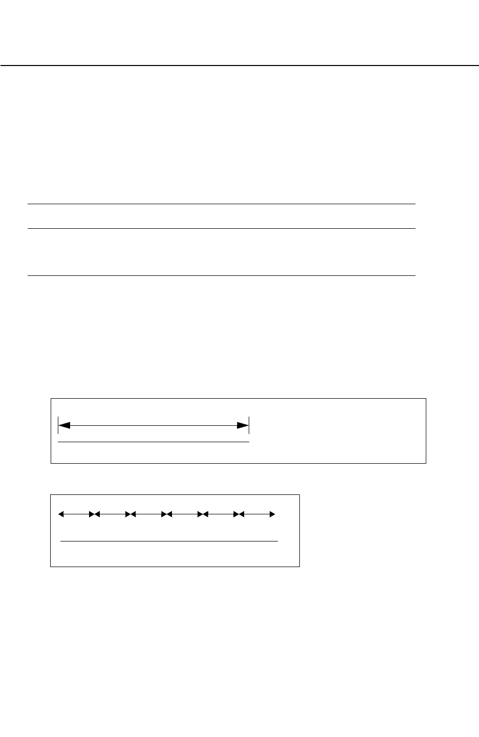
Chapter 17: StarRC Commands
PIN_CUT_THRESHOLD 17-232
StarRC User Guide and Command Reference F-2011.06
StarRC User Guide and Command Reference Version F-2011.06
PIN_CUT_THRESHOLD
Takes a long port and splits it into multiple *|P.
Syntax
PIN_CUT_THRESHOLD distance_in_nm
Arguments
Argument Description
distance_in_nm Distance at which you want the long port to be cut.
Units: nm
Default: none.
Description
This command takes a long port and splits it into multiple *|P. If a port has a continuous
Manhattan length less than the PIN_CUT_THRESHOLD, there is only one *|P for that segment.
In the case of a long port that is not evenly divisible by the PIN_CUT_THRESHOLD value, the
port is broken up symmetrically as shown in Figure 17-7.
Figure 17-7 Symmetric Division
10.2um
XX
long port
With a PIN_CUT_THRESHOLD value of 2,000 nm, this 10.2m long port would be cut as follows:
1.7 u 1.7 u 1.7 u 1.7 u 1.7 u 1.7 u
XXXXXXX
*|P *|P *|P *|P *|P *|P *|P
Note:
LEF/DEF designs and non-Manhattan port shapes are not supported for this option. So,
using INSTANCE_PORT: NOT_CONDUCTIVE and PIN_CUT_THRESHOLD, the output in the
SPEF netlist would be as follows:
Example
PIN_CUT_THRESHOLD 500

Chapter 17: StarRC Commands
PIN_CUT_THRESHOLD 17-233
Chapter 17: StarRC Commands
PIN_CUT_THRESHOLD 17-233
StarRC User Guide and Command Reference Version F-2011.06
...
*CONN
*P NET1_x40000y105000 B *C 40.00 105.00
*P NET1_x45000y115500 B *C 45.00 115.50
*P NET1_x50000y115500 B *C 50.00 115.50
*P NET1_x55000y115500 B *C 55.00 115.50
....
*I Level_1/NET_A:PIN_A_x10000y10000 *C 10.00 10.00
*I Level_1/NET_A:PIN_A_x15000y20500 *C 15.00 20.50
*I Level_1/NET_A:PIN_A_x20000y20500 *C 20.00 20.50
*I Level_1/NET_A:PIN_A_x25000y20500 *C 25.00 20.50
See Also
•INSTANCE_PORT

Chapter 17: StarRC Commands
PIO_FILE 17-234
StarRC User Guide and Command Reference F-2011.06
StarRC User Guide and Command Reference Version F-2011.06
PIO_FILE
Syntax
PIO_FILE: file1 file2 ... fileN
Arguments
Argument Description
file Name of the file containing the pin descriptions.
Default: none.
Description
Specifies a file containing primary input/output pin direction and loading capacitance. Only
applicable for top-level ports. Information contained in PIO_FILE is applied to the output
netlist. Format is white-space-delimited with one entry per line:
pin_name IN | OUT | BIDIR [cap float]
Example
IN1 IN
CLK IN
OUT OUT cap 5pf
IN2 IN
OUT2 OUT cap 1e-12
See Also
•NETLIST_FORMAT

Chapter 17: StarRC Commands
PLACEMENT_INFO_FILE 17-235
Chapter 17: StarRC Commands
PLACEMENT_INFO_FILE 17-235
StarRC User Guide and Command Reference Version F-2011.06
PLACEMENT_INFO_FILE
Specifies the generation of output placement information.
Syntax
PLACEMENT_INFO_FILE: YES | NO
Arguments
Argument Description
YES Output placement information.
NO Do not output placement information.
Description
StarRC interfaces to HSIM through a Detailed Standard Parasitic Format (DSPF) file for both
hierarchical and flat post-layout simulation flows. The Synopsys product HSIM can receive
hierarchical DSPF and flat DSPF to perform hierarchical or flat timing and reliability analysis.
An important output of reliability analysis is a thermal map showing voltage (IR) drop and
electromigration violations provided by HSIM. Because the HSIM product is netlist based,
the reliability analysis thermal map is generated using node information (*|S, *|I, *|P)
provided by StarRC in the DSPF netlist. In a flat extraction, all nodes are shown with respect
to origin of the top cell, and a thermal map can be drawn without ambiguity. However, in a
hierarchical flow, each node in a hierarchical cell’s DSPF is shown with respect to its origin.
In order to map these nodes to the next level of hierarchy, you must know the placement of
the cell in the next level of hierarchy with rotation and flip attributes.
When PLACEMENT_INFO_FILE is set, StarRC outputs a file blockname.placement_info that
has the following information:
•Angle
• Reflection
• Location of the cell
• Cell name
• Cross-referenced instance name

Chapter 17: StarRC Commands
PLACEMENT_INFO_FILE 17-236
StarRC User Guide and Command Reference F-2011.06
StarRC User Guide and Command Reference Version F-2011.06
Example
The following is an example of a transistor-level placement file.
* PLACEMENT FILE
* VENDOR: "Synopsys Inc."
* PROGRAM: "StarRC"
* VERSION: "Y-2006.06-SP1-1
* DATE: "Mon Oct 30 22:42:45 2006"
* UNIT: "MICRONS"
TOP_CELL = STBASE
inst_name cell_name X_Coord Y_Coord Angle reflection
xSD_8/M1 P 8.5 54 0 NO
xSD_8/M2 N 8.5 17 0 NO
xSD_9/M1 P 8.5 54 0 NO
xSD_9/M2 N 8.5 17 0 NO
xSD_10/M1 P 8.5 54 0 NO
xSD_10/M2 N 8.5 17 0 NO
xSD_11/M1 P 15.5 54 0 NO
xSD_11/M2 P 8.5 54 0 NO
xSD_11/M3 P 29.5 54 0 NO
xSD_11/M4 N 29.5 17 0 NO
xSD_11/M5 N 8.5 17 0 NO
xSD_11/M6 N 15.5 17 0 NO
* End of File
This is a sample output from a placement file. An example transistor-level placement file
follows the argument list.
* PLACEMENT FILE
* VENDOR "Synopsys, Inc."
* PROGRAM: "StarRC"
* DATE: "Mon Oct 30 22:39:56 2006"
* UNIT " MICRONS"
TOP_CELL = SMALLARRAY
inst_name cell_name X_Coord Y_Coord Angle reflection
xSD_0 STBASE -1925.8 -379 0 NO
xSD_1 STBASE -1797.2 -379 0 NO
xSD_2 STBASE -1668.6 -379 0 NO
xSD_3 STBASE -1540 -379 0 NO
xSD_4 STBASE -1411.4 -379 0 NO
xSD_5 STBASE -1282.8 -379 0 NO
xSD_6 STBASE -1154.2 -379 0 NO
xSD_7 STBASE -1025.6 -379 0 NO

Chapter 17: StarRC Commands
POWER_EXTRACT 17-237
Chapter 17: StarRC Commands
POWER_EXTRACT 17-237
StarRC User Guide and Command Reference Version F-2011.06
POWER_EXTRACT
Syntax
POWER_EXTRACT: YES | NO | RONLY | DEVICE_LAYERS
Arguments
Argument Description
YES Extracts the power nets.
NO Does not extract the power nets. The power nets are taken into
consideration when the signal nets are extracted. However, they
are not netlisted and the resulting effect on the signal nets is
reported as a grounded capacitance.
This is the default.
RONLY Extracts the power nets for R only and output separately.
Creates an additional resistor-only netlist when the
NETLIST_POWER_FILE and POWER_EXTRACT:YES
commands are used.
DEVICE_LAYERS Extracts the resistance and capacitance for the power nets
whose layers are specified in the mapping file with a device-layer
keyword along with all net extraction. (Hercules and Calibre
only)
Description
Selects the power nets to be extracted. The power nets are identified implicitly in a routed
Milkyway database or a LEF/DEF layout description. The command to specify the power
nets is POWER_NETS.
Using POWER_EXTRACT:RONLY creates an additional resistor-only netlist when the
NETLIST_POWER_FILE and POWER_EXTRACT: YES commands are used.
With the DEVICE_LAYERS command argument, you can extract the resistance from selected
power nets you define in your mapping file with a device_layer keyword.
Note:
The DEVICE_LAYERS command argument and device_layer keyword are very similar.
Use DEVICE_LAYERS in the command file; use device_layer in the mapping file. Verify
that you have specified them correctly or your results might not be accurate.

Chapter 17: StarRC Commands
POWER_EXTRACT 17-238
StarRC User Guide and Command Reference F-2011.06
StarRC User Guide and Command Reference Version F-2011.06
In the netlist, the signal nets have resistance and capacitance parasitics whereas the power
nets have only resistance parasitics included in the netlist. The coupling capacitances
between the signal and power nets are kept and grounded. The coupling capacitances for
power nets are not extracted, and the total capacitance reported for power nets is zero. The
order of the signal and power nets can be output in any order in the netlist. The
device_layer keyword can be specified in any order in the mapping file for the conducting
and via layers when RPSQ, RPV, device model, or via merging options are used. If the
power nets are not specified in the command file, StarRC reads them from the Hercules or
Calibre rule files.
For more information, see Chapter 20, “Mapping File Commands.”
DEVICE_LAYERS Argument Behavior
The following table describes the DEVICE_LAYERS behavior when specified as shown.
Table 17-7 DEVICE_LAYERS Behavior
Commands in File Expected Netlist and Instance Section
Behavior
NETS:*
POWER_NETS:VDD VSS
POWER_EXTRACT:DEVICE_LAYERS
Extracts contact, gate, and diffusion resistance
for VDD and VSS power nets based on the
device_layer keyword in the mapping file along
with all net extraction. The instance section
netlist lists all the devices connected to these
power nets along with the signal nets.
NETS:*
POWER_NETS:VDD VSS
POWER_EXTRACT:NO | YES | RONLY
No effect.
Errors
The following error conditions and restrictions exist when you are using the DEVICE_LAYERS
command argument:
• When NETS:XYZ is specified for a POWER_EXTRACT: DEVICE_LAYERS command. Note
that the NETS command default used with POWER_EXTRACT is all nets so you must specify
a wildcard, not net names.
• Issues an error message when no conducting layer or via layer is defined by a
device_layer keyword in the mapping file when POWER_EXTRACT:DEVICE_LAYERS is in
the command file.
• Issues an error message when the DEVICE_LAYERS argument is specified for a Milkyway
or LEF/DEF work flow.

Chapter 17: StarRC Commands
POWER_EXTRACT 17-239
Chapter 17: StarRC Commands
POWER_EXTRACT 17-239
StarRC User Guide and Command Reference Version F-2011.06
See Also
•AUTO_RUNSET
•NETLIST_MINRES_HANDLING
•NETLIST_MINRES_THRESHOLD
•NETLIST_PARASITIC_RESISTOR_MODEL
•NETLIST_SELECT_NETS
•NETLIST_POWER_FILE
•NETS
•POWER_NETS
•POWER_REDUCTION
•TRANSLATE_RETAIN_BULK_LAYERS

Chapter 17: StarRC Commands
POWER_NETS 17-240
StarRC User Guide and Command Reference F-2011.06
StarRC User Guide and Command Reference Version F-2011.06
POWER_NETS
Identifies power nets for special treatment during extraction.
Syntax
POWER_NETS: netnames
Arguments
Argument Description
netnames List of net names to identify power nets.
Default: none
Description
The power nets are implicitly defined in place and route Milkyway and LEF/DEF databases
and do not need to be specified in the StarRC command file. If this command is not specified
for a Hercules database, StarRC attempts to read the list of power nets from the Hercules
runset. An optional command for a Hercules flow extraction.
The wildcards “*”, “?”, and “!” are acceptable in this white-space- delimited list, and case
sensitivity is determined by the value of the CASE_SENSITIVE command.
See Also
•CASE_SENSITIVE
•POWER_EXTRACT
•NET_TYPE
•XREF

Chapter 17: StarRC Commands
POWER_PORTS 17-241
Chapter 17: StarRC Commands
POWER_PORTS 17-241
StarRC User Guide and Command Reference Version F-2011.06
POWER_PORTS
Defines a list of patterns for identifying POWER/GROUND-type ports for SKIP_CELLS if their
types are not explicitly defined in the database and their names are different from the top
level POWER_NETS.
Syntax
POWER_PORTS: wildcard_list
Arguments
Argument Description
wildcard_list Specifies the list of port names to identify to the power nets.
Default: List specified by the POWER_NETS statement.
Description
In LEF/DEF input, the USE POWER and USE GROUND keywords in LEF MACRO PIN definitions
identify the usage.
In Milkyway place and route input, the port-type tables defined at stream-in and/or during
BLOCKAGE_PIN_VIA_EXTRACTION determine the usage. Querying the PIN shapes in the
FRAM views indicates their usage type. For Hercules XTR view input, none of the ports are
marked.
By default, POWER_PORTS inherits the POWER_NETS list.
See Also
•NETLIST_POWER_FILE
•POWER_NETS

Chapter 17: StarRC Commands
POWER_REDUCTION 17-242
StarRC User Guide and Command Reference F-2011.06
StarRC User Guide and Command Reference Version F-2011.06
POWER_REDUCTION
Determines whether or not reduction of extracted power nets occurs during extraction.
Syntax
POWER_REDUCTION: NO | LAYER | LAYER_NO_EXTRA_LOOPS | YES
Arguments
Argument Description
NO This option is similar to REDUCTION: NO, except that the reduction is
applied to power nets rather than signal nets.
LAYER This option is similar to REDUCTION: LAYER, except that the
reduction is applied to the specified power nets rather than signal nets.
Reduction is not applied across different conductor layers.
LAYER_NO_EXTRA_LOOPS This option is similar to REDUCTION: LAYER_NO_EXTRA_LOOPS,
except that the reduction is applied to the specified power nets rather
than signal nets. Reduction is not applied across different conductor
layers.
YES This option is similar to REDUCTION: YES, except that the reduction is
applied to the specified power nets rather than signal nets.
Description
POWER_REDUCTION does not apply to POWER_EXTRACT:YES. POWER_REDUCTION is in effect
only when POWER_EXTRACT: is set to RONLY. When POWER_EXTRACT:YES is specified, the
power nets are extracted and netlisted, as though they were normal signals, into the
NETLIST_FILE with normal EXTRACTION and REDUCTION settings.
See Also
•REDUCTION

Chapter 17: StarRC Commands
PRINT_SILICON_INFO 17-243
Chapter 17: StarRC Commands
PRINT_SILICON_INFO 17-243
StarRC User Guide and Command Reference Version F-2011.06
PRINT_SILICON_INFO
Prints the silicon width in addition to the drawn width.
Syntax
PRINT_SILICON_INFO: YES | NO
Arguments
Argument Description
YES Specifies that StarRC prints silicon width $si_w for conductor
resistors and nonphysical resistors in addition to the existing
information ($l, $w and $lvl).
NO Specifies that silicon width is not printed to the netlist output.
This is the default.
Description
Technology processes sometimes require the silicon width which is different from the drawn
width for a more accurate analysis result. The silicon width is needed for the analysis, and
the drawn width is needed for display. This command prints the silicon width in addition to
the drawn width.
This command should be used with NETLIST_TAIL_COMMENTS: YES.
When YES is set, StarRC prints silicon width $si_w for conductor resistors and nonphysical
resistors in addition to the existing information ($l, $w and $lvl). For via resistors, silicon area
$si_a is appended after the existing information ($a and $lvl).
The silicon width is the width used in resistance calculation. The value can be smaller or
larger than the drawn width because etch can be positive or negative. The ITF commands
ETCH and ETCH_VS_WIDTH_AND_SPACING (excluding CAPACITIVE_ONLY) are included in the
silicon width computation.
The silicon area $si_a for a via is always the same as the area $a because via etch is not
supported in resistance calculation.
Errors
The silicon width might be inaccurate when ITF commands RPSQ_VS_WIDTH_AND_SPACING
or RHO_VS_WIDTH_AND_SPACING are specified. A warning is issued when
PRINT_SILICON_INFO is used with these two ITF commands. When this occurs, replace
RPSQ_VS_WIDTH_AND_SPACING and RHO_VS_WIDTH_AND_SPACING with RPSQ_VS_SI_WIDTH

Chapter 17: StarRC Commands
PRINT_SILICON_INFO 17-244
StarRC User Guide and Command Reference F-2011.06
StarRC User Guide and Command Reference Version F-2011.06
and ETCH_VS_WIDTH_AND_SPACING. RPSQ_VS_WIDTH_AND_SPACING should not be used to
model a scenario where a conductor has different spacing on the left side compared to the
right side.
Example
R41 M15:SRC Y:15 11.6946 $l=0.105 $w=0.153 $lvl=100 $si_w=0.149
R42 Y:12 Y:54 30 $a=0.0081 $lvl=134 $si_a=0.0081
See Also
•NETLIST_TAIL_COMMENTS:YES

Chapter 17: StarRC Commands
PROBE_TEXT_FILE 17-245
Chapter 17: StarRC Commands
PROBE_TEXT_FILE 17-245
StarRC User Guide and Command Reference Version F-2011.06
PROBE_TEXT_FILE
Specifies a file that contains simulation probe points to appear in the StarRC parasitic netlist.
This is how you can define net locations for particular simulation results.
Syntax
PROBE_TEXT_FILE: file_name
Arguments
Argument Description
file_name The file containing defined (x, y location) probe points
Default: none
Description
A probe point is a specific node point created as a node (in the parasitic node mesh) for a
particular net.
A PROBE_TEXT_FILE entry is translated and netlisted if the following is true:
• The specified cell master name is a valid extracted cell. If XREF is in the command file, the
cell name must correspond to a valid LVS equivalence point. The CELL_TYPE command
regulates whether the schematic or layout name is used.
• A polygon at the specified layer name exists at the specified coordinate location.
• The probe point falls on a net for which parasitics are included in the netlist.
• The probe point falls on a cross-referenced net within a cross-referenced instance in the
XREF: COMPLETE command.
Example
Example 17-13 shows the syntax of the probe text file.

Chapter 17: StarRC Commands
PROBE_TEXT_FILE 17-246
StarRC User Guide and Command Reference F-2011.06
StarRC User Guide and Command Reference Version F-2011.06
Example 17-13 Probe Text File Syntax
CELL cell_name
textstring local_x local_y layername
textstring local_x local_y layername
textstring local_x local_y layername
textstring local_x local_y layername
...
CELL cell_name
...
Parameter Definition
textstring Identifying layout text label for the probe point by which the point is
identified in the parasitic netlist.
local_x X-coordinate for the probe point location. The specified coordinate is
interpreted local to the specified cell.
local_y Y-coordinate for the probe point location. The specified coordinate is
interpreted local to the specified cell.
layername Database layer name to which the probe point corresponds. The name
must correspond to a layer mapped in the conducting_layers section of
the StarRC mapping file.
cell_name Name of the cell master in which the probe point is specified. The
CELL_TYPE command regulates whether a layout cell or schematic cell is
used.
A prepared probe text file is specified as shown in the example. The probe file text syntax is
described following the argument list.
PROBE_TEXT_FILE: myprobetxtfile
Another example:
CELL ADD4_TOP
PROBE1 10 10 M3
CELL INVX$
GATE_1 16.3 14.5 FPOLY
GATE_2 15.3 1.1 FPOLY
See Also
•CELL_TYPE

Chapter 17: StarRC Commands
PROCESS_CORNER 17-247
Chapter 17: StarRC Commands
PROCESS_CORNER 17-247
StarRC User Guide and Command Reference Version F-2011.06
PROCESS_CORNER
Syntax
PROCESS_CORNER: MIN | TYP | MAX
Arguments
Argument Description
MIN Specifies that a minimum value of input loading capacitance is
taken from the input.
TYP Specifies that a typical value of input loading capacitance is
taken from the input.
MAX Specifies that a maximum value of input loading capacitance is
taken from the input.
This is the default.
Description
Milkyway databases can contain three pin capacitance values (or triplets) or input loading
capacitances for SKIP_CELLS. This command allows you to choose one of possibly three
capacitance values for use with (or generate a report) during your StarRC job.

Chapter 17: StarRC Commands
REDUCTION 17-248
StarRC User Guide and Command Reference F-2011.06
StarRC User Guide and Command Reference Version F-2011.06
REDUCTION
Specifies parasitic netlist reduction.
Syntax
REDUCTION: HIGH | LAYER | NO_EXTRA_LOOPS | TOPOLOGICAL | YES | NO
Arguments
Argument Description
HIGH Performs maximum netlist reduction for device-level parasitic
extraction. This setting is intended to decrease excessive
runtimes of SPICE-level simulators, for which simulation runtime
is dominant relative to extraction runtime. Parasitic netlists
produced with REDUCTION:HIGH are of a size equal to or
smaller than netlists produced with REDUCTION:YES, with a
10-20% increase in extraction runtime relative to
REDUCTION:YES. Not enabled for use with LEF/DEF or
Milkyway cell-level extractions, and an error message is
generated when the source database is either LEF/DEF or
Milkyway.
YES Specifies that a reduced parasitic netlist during extraction.
This is the default.
NO Specifies that a unreduced parasitic netlist during extraction.
LAYER Similar to REDUCTION:YES, except that reduction does not
occur across different conductor layers.
NO_EXTRA_LOOPS Performs netlist reduction, but ensures that no resistive loops
are introduced into the parasitic netlist as a result of the
reduction algorithm. This setting enables a lesser degree of
netlist reduction for delay calculators that are unable to interpret
resistive loops. Limiting the algorithm to not produce resistive
loops produces a larger parasitic netlist (10-20 percent) than is
realized with REDUCTION:YES. This option does not prevent
loops in the parasitic netlist that occur as a result of the topology
of the layout being extracted. For example, overlapping metals
connected by two or more parallel vias can produce meshes in
the parasitic netlist even with REDUCTION: NO_EXTRA_LOOPS,
because such meshes directly reflect the physical topology of
the layout.

Chapter 17: StarRC Commands
REDUCTION 17-249
Chapter 17: StarRC Commands
REDUCTION 17-249
StarRC User Guide and Command Reference Version F-2011.06
Description
This command specifies the reduction of extracted parasitic devices during extraction. The
degree of compression is controlled by the REDUCTION_MAX_DELAY_ERROR command. The
reduction algorithm is designed to preserve point-to-point resistance and total net
capacitance.
Setting REDUCTION: YES is highly preferable because of the large amounts of data typically
involved in today’s designs and the level of detail the StarRC extraction engine achieves.
See Also
•REDUCTION_MAX_DELAY_ERROR
TOPOLOGICAL Similar to REDUCTION: LAYER without timing error control. This
option allows StarRC to create a similar topology of the RC
network for different process or temperature corners. Different
process or temperature corners have different R and C values,
and if the reduction error control is based on R and C values (for
example, timing), it’s not possible to maintain the same topology
for different corners.
This reduction mode does not support REDUCTION_MAX_
DELAY_ERROR which is used to specify timing error control
during reduction.
Argument Description

Chapter 17: StarRC Commands
REDUCTION_MAX_DELAY_ERROR 17-250
StarRC User Guide and Command Reference F-2011.06
StarRC User Guide and Command Reference Version F-2011.06
REDUCTION_MAX_DELAY_ERROR
Specifies the acceptable net delay error tolerance when StarRC performs reduction.
Syntax
REDUCTION_MAX_DELAY_ERROR: threshold
Arguments
Argument Description
threshold The absolute error threshold.
Units: seconds.
Default: 1.0 e-12
Description
The absolute error between the original and reduced netlists is not greater than this
threshold.
Note:
This option should not be combined with REDUCTION:TOPOLOGICAL because the
TOPOLOGICAL mode does not have timing error control.
See Also
•REDUCTION

Chapter 17: StarRC Commands
REMOVE_DANGLING_NETS 17-251
Chapter 17: StarRC Commands
REMOVE_DANGLING_NETS 17-251
StarRC User Guide and Command Reference Version F-2011.06
REMOVE_DANGLING_NETS
Directs StarRC to identify dangling nets and reassign them to ground (effectively removing
them).
Syntax
REMOVE_DANGLING_NETS: YES | NO
Arguments
Argument Description
YES Specifies that the netlist is output without dangling nets.
NO Specifies that the netlist is output with dangling nets.
This is the default.
Description
Dangling nets are defined as:
• Unrouted database nets (for Milkyway, LEF/DEF, and CCI)
• Nets that have only one connection (for Milkyway, LEF/DEF, CCI, and Hercules).
Nets that are connected to a pin port (*|P) are not eligible for removal. In Hercules flows,
such as *|P, ports must be generated during Hercules device/connectivity extraction using
the CREATE_PORTS runset command. Otherwise, StarRC does not consider the port
connection and the net is removed. REMOVE_DANGLING_NETS does not remove layout
material; the objects are assigned to ground.
You must run with -clean to change the value of this command.
See Also
•REMOVE_FLOATING_NETS

Chapter 17: StarRC Commands
REMOVE_FLOATING_NETS 17-252
StarRC User Guide and Command Reference F-2011.06
StarRC User Guide and Command Reference Version F-2011.06
REMOVE_FLOATING_NETS
Removes nets that have no connection, by reassigning them to ground (for Milkyway, LEF/
DEF, CCI, and Hercules designs).
Syntax
REMOVE_FLOATING_NETS: YES | NO
Arguments
Argument Description
YES Specifies that the output netlist does not contain floating nets.
NO Specifies that the output netlist does contain floating nets.
This is the default.
Description
No layout material is actually deleted; the objects are reassigned.
You must run with -clean to change the value of this command.
When using REMOVE_FLOATING_NETS, StarRC does not completely disregard polygons on
floating nets. The command’s goal is to eliminate floating nets from the parasitic netlist, but
to account for effects these nets might have on real signal nets in the design.
When REMOVE_FLOATING_NETS:YES is set in the command file, StarRC treats the floating
nets as noncritical material. This means that StarRC finds the coupling capacitance from
signal nets to the noncritical material and then decouples these capacitors. The decoupled
capacitance is then added to the ground capacitance of the signal net. The total capacitance
of the signal nets accounts for the effects of coupling to floating nets. The floating nets are
not shown in the parasitic netlist.
See Also
•REMOVE_DANGLING_NETS

Chapter 17: StarRC Commands
REMOVE_NET_PROPERTY 17-253
Chapter 17: StarRC Commands
REMOVE_NET_PROPERTY 17-253
StarRC User Guide and Command Reference Version F-2011.06
REMOVE_NET_PROPERTY
Specifies a single property name to indicate to the Milkyway layout database which objects
should not be extracted as signal nets (for Milkyway extraction flows).
Syntax
REMOVE_NET_PROPERTY: string
Arguments
Argument Description
string Specifies that nets with this property are not included in the
netlist
Default: none
Description
These objects are treated as ground during the extraction, and the influence of these objects
is considered when you are extracting the capacitance of neighboring signal nets. See the
Milkyway Environment Data Preparation User Guide for information about setting object
properties in the Milkyway database.
See Also
•MILKYWAY_DATABASE

Chapter 17: StarRC Commands
RETAIN_CAPACITANCE_CAP_MODELS 17-254
StarRC User Guide and Command Reference F-2011.06
StarRC User Guide and Command Reference Version F-2011.06
RETAIN_CAPACITANCE_CAP_MODELS
Specifies model-specific plate-to-plate capacitance retention for capacitor devices.
Syntax
RETAIN_CAPACITANCE_CAP_MODELS: model_list
Arguments
Argument Description
model_list List of capacitor devices for which plate-to-plate capacitance is to be retained.
Default is None. Accepted model names in model_list can include either the
schematic or layout names regardless of your XREF command setting.
If a specified model name matches the schematic model name of a capacitor device
in the design, RETAIN_CAPACITANCE_CAP_MODELS functionality is propagated to
all layout capacitor devices matching that schematic model name. If a specified
model name matches the layout model name of a capacitor device in the design,
RETAIN_CAPACITANCE_CAP_MODELS functionality is propagated only to layout
capacitor devices matching that layout model name. All of this occurs independent of
the XREF command in the command file.
Default: none.
Description
In certain applications, it is advantageous to retain parasitic capacitances within the parasitic
netlist for capacitor devices, particularly when you want to simulate devices using parasitic
capacitances instead of device simulation models.
To allow such a simulation flow, you can selectively retain plate-to-plate capacitance
(between plates) for designed capacitor devices. Devices whose capacitances are to be
retained are specified by model name.
You specify a list of model names of capacitor devices for which IGNORE_CAP statements
should not be generated between terminal layers and for which plate-to-plate capacitance
should not be ignored by the StarRC extraction engine.
Note:
If the MODEL_TYPE is not specified in the command file, it is assumed to be LAYOUT.
Errors
A warning is issued when a model name exists in the RETAIN_CAPACITANCE_CAP_MODELS
command for which no corresponding capacitor exists.

Chapter 17: StarRC Commands
RETAIN_CAPACITANCE_CAP_MODELS 17-255
Chapter 17: StarRC Commands
RETAIN_CAPACITANCE_CAP_MODELS 17-255
StarRC User Guide and Command Reference Version F-2011.06
Example
The following command retains capacitance for device cm1m2:
RETAIN_CAPACITANCE_CAP_MODELS: cm1m2
See Also
•MODEL_TYPE

Chapter 17: StarRC Commands
RETAIN_GATE_CONTACT_COUPLING 17-256
StarRC User Guide and Command Reference F-2011.06
StarRC User Guide and Command Reference Version F-2011.06
RETAIN_GATE_CONTACT_COUPLING
Retains gate-to-contact coupling capacitance.
Syntax
RETAIN_GATE_CONTACT_COUPLING: YES | NO
Arguments
Argument Description
YES Retain the gate-to-contact capacitance when COUPLE_TO_GROUND:YES is set
in the StarRC command file.
NO All couplings are retained if COUPLE_TO_GROUND:NO is set in the StarRC
command file.
This is the default.
Description
When this command is set in conjunction with EXTRACT_VIA_CAPS:YES, the gate-to-contact
capacitance is retained with COUPLE_TO_GROUND:YES, even if the coupling capacitances are
below the capacitance threshold value specified for COUPLING_ABS_THRESHOLD,
COUPLING_REL_THRESHOLD, or COUPLING_AVG_THRESHOLD.
When COUPLE_TO_GROUND:YES is set in the StarRC command file, coupling is retained to the
contact. Coupling thresholds are not used for the gate-to-contact coupling. When
COUPLE_TO_GROUND:NO is set in the StarRC command file, the coupling to contact is
retained only if the coupling is above the coupling thresholds specified. For more details, see
“Smart Decoupling of Coupling Capacitances” on page 9-3.
Note:
The RETAIN_GATE_CONTACT_COUPLING command is supported only in the Hercules and
Calibre flows.

Chapter 17: StarRC Commands
RETAIN_GATE_CONTACT_COUPLING 17-257
Chapter 17: StarRC Commands
RETAIN_GATE_CONTACT_COUPLING 17-257
StarRC User Guide and Command Reference Version F-2011.06
Table 17-8 describes the behavior of the RETAIN_GATE_CONTACT_COUPLING command
when specified with other commands.
Table 17-8 RETAIN_GATE_CONTACT_COUPLING Interaction With Commands
Command COUPLE_TO_GROUND:YES COUPLE_TO_GROUND:NO
NETS:*
EXTRACT_VIA_CAPS:YES
RETAIN_GATE_CONTACT_COUPLING:YES
POWER_EXTRACT:NO
Retain the gate-to-contact
capacitance for all signal nets
even if they are less than the
coupling threshold values.
All coupling capacitances for
signal nets including
gate-to-contact are retained and
netlisted. Coupling thresholds
apply to all coupling
capacitances, including gate-to-
contact.
NETS:*
EXTRACT_VIA_CAPS:YES
RETAIN_GATE_CONTACT_COUPLING:YES
POWER_EXTRACT:
DEVICE_LAYERS
Retain the gate-to-contact
capacitance for all signal and
power nets, only if the
appropriate device layers are
set (that is, contacted) for power
nets.
All coupling capacitances for
signal and power nets are
retained, only if the appropriate
device layers are set (that is,
contacted) for power nets.
NETS:*
EXTRACT_VIA_CAPS:YES
RETAIN_GATE_CONTACT_COUPLING:YES
POWER_EXTRACT: YES
Retain the gate-to-contact
capacitance for all signal nets
and power nets.
All coupling capacitances for
signal and power nets are
retained and netlisted.
Errors
The RETAIN_GATE_CONTACT_COUPLING command results in the following error message
when it is used in a LEF/DEF or Milkyway flow:
Error Message: RETAIN_GATE_CONTACT_CAPACITANCE is only supported in the
Hercules/Calibre flow.
See Also
•NETS
•NETS_FILE

Chapter 17: StarRC Commands
RING_AROUND_THE_BLOCK 17-258
StarRC User Guide and Command Reference F-2011.06
StarRC User Guide and Command Reference Version F-2011.06
RING_AROUND_THE_BLOCK
Generates a virtual ring on every routing layer around the block for extraction.
Syntax
RING_AROUND_THE_BLOCK: YES | NO
Arguments
Argument Description
YES Generates a ring around the block.
NO Does not generate a ring around the block.
This is the default.
Description
The RING_AROUND_THE_BLOCK command generates a virtual ring around the block for
extraction. The capacitance between the block material and the imaginary ring is calculated
as though the block is surrounded by solid metal.
Note:
Do not use the RING_AROUND_THE_BLOCK command with the MACRO command.
Specify the block for extraction with the BLOCK command.
Specify the block boundary with the BLOCK_BOUNDARY command and a list of points, which
can be read directly from the Milkyway database. It must be provided for LEF/DEF designs.
BLOCK material that lies outside the specified BLOCK_BOUNDARY does not create shorts with
or attach capacitance from the imaginary rings, even if they overlap. Overlaps should be
avoided, because shielding of nets occurs.
You can specify the spacing between the block boundary and the ring with the
RING_AROUND_THE_BLOCK_SMIN_MULTIPLIER command.
The rings are grounded by default but can be given a special name with the
ZONE_COUPLE_TO_NET command.


Chapter 17: StarRC Commands
RING_AROUND_THE_BLOCK_SMIN_MULTIPLIER 17-260
StarRC User Guide and Command Reference F-2011.06
StarRC User Guide and Command Reference Version F-2011.06
RING_AROUND_THE_BLOCK_SMIN_MULTIPLIER
Specifies the spacing between the block boundary and the ring around the block in
hierarchical analysis.
Syntax
RING_AROUND_THE_BLOCK_SMIN_MULTIPLIER: multiplier
Arguments
Argument Description
multiplier Floating-point number that is greater than or equal to 0.5
Units: none
Default: 0.5
Description
The RING_AROUND_THE_BLOCK_SMIN_MULTIPLIER command specifies the spacing between
the block boundary and the ring around the block. The spacing is equal to the product of the
multiplier and the SMIN value of the GRD layer. The SMIN value might be different from layer
to layer, resulting in different ring spacing.
See Also
•BLOCK
•BLOCK_BOUNDARY
•RING_AROUND_THE_BLOCK

Chapter 17: StarRC Commands
SENSITIVITY 17-261
Chapter 17: StarRC Commands
SENSITIVITY 17-261
StarRC User Guide and Command Reference Version F-2011.06
SENSITIVITY
Enables sensitivity-based extraction for statistical or variation-aware analysis.
Syntax
SENSITIVITY: YES | NO
Arguments
Argument Description
YES Extracts sensitivities for resistance and capacitance.
NO Performs normal nominal extraction.
This is the default.
Description
If SENSITIVITY:YES is specified, the xTractor extracts capacitance and resistance
sensitivities along with the nominal values. The ITF and nxtgrd files supplied for the run must
have a VARIATION_PARAMETERS section, or temperature coefficients (CRT1/CRT2) if
TEMPERATURE_SENSITIVITY:YES is being used.
Sensitivity is supported by the following extraction modes: EXTRACTION: C|R|RC
When RKC extraction is specified, RKC nominal values are computed, whereas only RC
sensitivities are computed.
SENSITIVITY:YES is supported with existing commands used to model systematic
variations, such as THICKNESS_VS_DENSITY or ETCH_VS_WIDTH_AND_SPACING. Support for
this feature also exists with key flow features such as SKIP_CELLS for cell level and
IGNORE_CAPACITANCE for ignoring device capacitances.
Note:
The COUPLING_AVG_THRESHOLD, COUPLING_ABS_THRESHOLD, and
COUPLING_REL_THRESHOLD commands have functionality that can be altered as a result
of sensitivity extraction.
Example
*RES
1 *13:92 *13:90 0.271859 *SC 33:1.000 34:0.045
*END


Chapter 17: StarRC Commands
SHEET_COUPLE_TO_NET 17-263
Chapter 17: StarRC Commands
SHEET_COUPLE_TO_NET 17-263
StarRC User Guide and Command Reference Version F-2011.06
SHEET_COUPLE_TO_NET
Specifies a prefix net name for the sheet zone extraction capability. This user-defined name
appears in the generated output netlist.
Syntax
SHEET_COUPLE_TO_NET: prefix_name
Arguments
Argument Description
prefix_name Net prefix name reported in the output netlist.
Default: none.
Description
If this command is not specified, StarRC automatically sets the prefix name to ZONE_SHEET.
Example
METAL_SHEET_OVER_AREA: METAL2 0 0 100 100
METAL_SHEET_OVER_AREA: METAL2 200 200 400 400
METAL_SHEET_OVER_AREA: METAL4 0 0 100 100
SHEET_COUPLE_TO_NET: zone_sheet
SHEET_COUPLE_TO_NET_LEVEL: YES
See Also
•METAL_SHEET_OVER_AREA
•SHEET_COUPLE_TO_NET_LEVEL

Chapter 17: StarRC Commands
SHEET_COUPLE_TO_NET_LEVEL 17-264
StarRC User Guide and Command Reference F-2011.06
StarRC User Guide and Command Reference Version F-2011.06
SHEET_COUPLE_TO_NET_LEVEL
Enables or disables a net name suffix using the layer-level number for the sheet zone netlist
capability.
Syntax
SHEET_COUPLE_TO_NET_LEVEL: NO | YES
Arguments
Argument Description
NO Disables net name suffix reporting in sheet zone netlist output.
This is the default.
YES Enables net name suffix reporting in sheet zone netlist output.
Description
Enables or disables a net name suffix using the layer-level number for the sheet zone netlist
capability.
Example
METAL_SHEET_OVER_AREA: METAL2 0 0 100 100
METAL_SHEET_OVER_AREA: METAL2 200 200 400 400
METAL_SHEET_OVER_AREA: METAL4 0 0 100 100
SHEET_COUPLE_TO_NET: zone_sheet
SHEET_COUPLE_TO_NET_LEVEL: YES
See Also
•METAL_SHEET_OVER_AREA
•SHEET_COUPLE_TO_NET

Chapter 17: StarRC Commands
SHORT_PINS 17-265
Chapter 17: StarRC Commands
SHORT_PINS 17-265
StarRC User Guide and Command Reference Version F-2011.06
SHORT_PINS
Specifies whether or not to short top-level pin ports that have multiple placements.
Syntax
SHORT_PINS: YES | NO | MIXED
Arguments
Argument Description
YES If it is set to YES, all of the placements of the pin port are reported as
a single node (a single *|P).
This is the default.
NO If it is set to NO, each Hercules marker group, or Milkyway (LEF/DEF
flow) PIN, at the top level is uniquely netlisted with a suffix defined by
NETLIST_RENAME_PORTS.
MIXED Ensures correct back-annotation of a parasitic netlist. This option is
only available in the LEF/DEF flow. In Milkyway, SHORT_PINS:MIXED
behaves as SHORT_PINS:YES. In a Hercules > Calibre flow, the pin
names are the same as net names, so this option does not apply.
Description
A unique pin instance is defined as a physically connected group of objects marked as
interface material: PIN section in DEF, PIN type in Milkyway, MARKER_LAYER in Hercules.
Each separated group of connected objects is a pin instance. When you specify
SHORT_PINS:YES, the name of the *P connected to a net always inherits the name of the
*D_NET in case there are multiple names.
If the layout database has unique names for each pin instance associated with a single port,
that information is used to netlist the *P, instead of the NETLIST_RENAME_PORTS method
being used. The NETLIST_RENAME_PORTS delimiter is used only if no naming information
exists in the input layout database.

Chapter 17: StarRC Commands
SHORT_PINS 17-266
StarRC User Guide and Command Reference F-2011.06
StarRC User Guide and Command Reference Version F-2011.06
Example
Input database contains unique pin names:
PINS 2 ;
- C.1 + NET C + LAYER METAL2 ( 0 0 ) ( 1000 1600 )
+ PLACED ( 263800 136000 ) N ;
- C.2 + NET C + LAYER METAL2 ( 0 0 ) ( 1000 1600 )
+ PLACED ( 264800 136000 ) N ;
END PINS
SHORT_PINS: NO
*|NET C 0.0295887PF
*|P (C.2 B 0 264.8 136)
*|P (C.1 B 0 263.8 136)
SHORT_PINS: YES
*|NET C 0.0295887PF
*|P (C B 0 264.8 136)
Input database does not contain unique pin names:
PINS 2 ;
- C + NET C + LAYER METAL2 ( 0 0 ) ( 1000 1600 )
+ PLACED ( 263800 136000 ) N ;
- C + NET C + LAYER METAL2 ( 0 0 ) ( 1000 1600 )
+ PLACED ( 264800 136000 ) N ;
END PINS
SHORT_PINS: NO, NETLIST_RENAME_PORTS: _
*|NET C 0.0295887PF
*|P (C_2 B 0 264.8 136)
*|P (C_1 B 0 263.8 136)
SHORT_PINS: YES
*|NET C 0.0295887PF
*|P (C B 0 264.8 136)

Chapter 17: StarRC Commands
SHORT_PINS 17-267
Chapter 17: StarRC Commands
SHORT_PINS 17-267
StarRC User Guide and Command Reference Version F-2011.06
Input database contains partial unique naming information:
PINS 3 ;
- C.1 + NET C + LAYER METAL2 ( 0 0 ) ( 1000 700 )
+ PLACED ( 263800 136000 ) N ;
- C.1 + NET C + LAYER METAL2 ( 0 0 ) ( 1000 700 )
+ PLACED ( 263800 137000 ) N ;
- C.2 + NET C + LAYER METAL2 ( 0 0 ) ( 1000 1600 )
+ PLACED ( 264800 136000 ) N ;
END PINS
SHORT_PINS: NO, NETLIST_RENAME_PORTS: _
*|NET C 0.0295974PF
*|P (C.1 B 0 263.8 136)
*|P (C.2 B 0 264.8 136)
*|P (C.1_1 B 0 263.8 137)
SHORT_PINS: YES
*|NET C 0.0295887PF
*|P (C B 0 264.8 136)
Input database contains the mixed pin names shown in the following table:
Net Name Logical Pins Physical Pins SHORT_PINS:MIXED
Net 1 Net 1 Net 1 Net 1
Net 1 net 1 Net 1 (Multiple) Net 1
Net 1 Pin 1 Pin 1 Pin 1
Net 1 Pin 1 Net 1 Pin 1 Net 1 Pin1 Net 1
Net 1 Pin 1 Net 1 Pin 1 Net 1 (Multiple) Pin1 Net 1
Net 1 Pin 1 Net 1 Pin 1 (Multiple)
Net 1 (Multiple)
Pin1 Net 1
Fixing Redundant Ports
Redundant ports that are unnecessary for an HSIM/NanoSim parasitic back-annotation flow
can be removed. The port name postfix “_1” in an extracted file is generated because the
input database contained partial unique naming information, such as:
SUBCKT v_ctl VCI_P0 VCI_P0_1 GND_P0 GND_P0_1 VDD_P0 VDD_P0_1
The redundant ports “VCI_P0_1”, “GND_P0_1” and “VDD_P0_1” can be removed by
changing the StarRC command SHORT_PINS:NO to SHORT_PINS:YES.

Chapter 17: StarRC Commands
SHORT_PINS 17-268
StarRC User Guide and Command Reference F-2011.06
StarRC User Guide and Command Reference Version F-2011.06
The result is as follows:
SUBCKT v_ctl VCI_P0 GND_P0 VDD_P0
The extracted SPF file can then be used for HSIM/NanoSim parasitic back-annotation.
See Also
•NETLIST_RENAME_PORTS

Chapter 17: StarRC Commands
SHORT_PINS_IN_CELLS 17-269
Chapter 17: StarRC Commands
SHORT_PINS_IN_CELLS 17-269
StarRC User Guide and Command Reference Version F-2011.06
SHORT_PINS_IN_CELLS
Syntax
SHORT_PINS_IN_CELLS: list
Arguments
Argument Description
list The list of skip cell names.
Default: *
Description
Place and route Milkyway databases sometimes contain ports of the class EEQ. These
ports are logically equivalent but can have a wide geographic distribution throughout the
design. StarRC merges all EEQ pins into a single port for every SKIP_CELLS on the
SHORT_PINS_IN_CELLS list.
Occasionally, designs with EEQ ports are instantiated as macros. If a macro with EEQ ports
were on the SKIP_CELLS list, StarRC default behavior reports a single connection for the
EEQ port in the netlist, using the first EEQ pin location. Because the EEQ pins can be so
widely distributed in the layout, it can be desirable to treat each of the EEQ pins as a unique
port for simulation. Negating a cell from the SHORT_PINS_IN_CELLS list means that StarRC
treats each EEQ pin as a unique port and uses the original database port suffix to report it.
Wildcards “*”, “?”, and “!” are acceptable. This command can be specified multiple times.
SHORT_PINS always overrides SHORT_PINS_IN_CELLS.
See Also
•CASE_SENSITIVE
•SHORT_PINS
•SKIP_CELLS

Chapter 17: StarRC Commands
SKIP_CELL_AGF_FILE 17-270
StarRC User Guide and Command Reference F-2011.06
StarRC User Guide and Command Reference Version F-2011.06
SKIP_CELL_AGF_FILE
Imports Hercules annotated GDSII (AGF) files as the detail view for SKIP_CELL.
Syntax
SKIP_CELL_AGF_FILE: cell agf_file herc_ideal_netlist
Arguments
Argument Description
cell AGF cell name
agf_file AGF file name
herc_ideal_netlist Hercules ideal netlist name
Description
Use this command in the star_cmd file to import Hercules annotated GDSII (AGF) files as
the detail view for SKIP_CELL. Specify the command once for each SKIP_CELL that has an
AGF description.
•A
SKIP_CELL_AGF_FILE command cannot be specified as a macro.
•All
SKIP_CELL_AGF_FILE commands specified must use the same layer mapping as
defined in the GDS_LAYER_MAP_FILE command.
• Layer mapping file must also be shared with the GDS_FILE (if it is used).
If the list of cells in a COUPLE_NONCRITICAL_NETS command contains a
SKIP_CELL_AGF_FILE cell (or descendant), the layout names are used to its contents. If the
list of cells in a COUPLE_NONCRITICAL_NETS command does not contain a
SKIP_CELL_AGF_FILE cell, its contents are annotated as noncritical (ground potential).
Note:
Child cells of a COUPLE_NONCRITICAL_NETS command are not automatically made into
COUPLE_NONCRITICAL_NETS themselves; they must be specified in the
COUPLE_NONCRITICAL_NETS command as well.
Example
SKIP_CELL_AGF_FILE:INV_BUF buf.agf buf.sp


Chapter 17: StarRC Commands
SKIP_CELL_PORT_PROP_FILE 17-272
StarRC User Guide and Command Reference F-2011.06
StarRC User Guide and Command Reference Version F-2011.06
SKIP_CELL_PORT_PROP_FILE
Specifies files containing pin or port information for skip cell properties.
Syntax
SKIP_CELL_PORT_PROP_FILE: file1 [file2 ... fileN]
Arguments
Argument Description
fileN File name
Default: none
Description
You can also use this command to specify pin information (such as direction or capacitance)
for LEF/DEF and checkpoint databases (or to override values from a Milkyway database) for
netlist purposes.
The description of all port properties of a cell should be in one CELL block and should be
uniquely defined. For example, do not specify multiple descriptions of a cell in the same or
another (reference) library. Otherwise, the result is unpredictable. Ensure that reference
libraries you specify contain unique definitions of cells.

Chapter 17: StarRC Commands
SKIP_CELL_PORT_PROP_FILE 17-273
Chapter 17: StarRC Commands
SKIP_CELL_PORT_PROP_FILE 17-273
StarRC User Guide and Command Reference Version F-2011.06
Create a port property file by specifying the keyword CELL followed by the cell name. Follow
this by specifying the named cell’s pin name, pin direction, and pin capacitance. All three
parameters are required.
Argument Description
CELL Keyword specifying the beginning of the cell definition
cell_name Name of the cell whose pin characteristics are defined
pin_name String of the pin or port name
pin_io Pin/port direction. It could be I, O, or B representing input,
output, and bidirectional, respectively
pin_cap The capacitance value of the corresponding pin/port. It can
include a unit of the capacitance. The valid units are: FF, PF,
NF, uF and mF.
Errors
If the StarRC command file contains the command, SYNOPSYS_LIB_FILE, a warning
message is issued. The SYNOPSYS_LIB_FILE command will be phased out in a future
release.
Note:
If the SKIP_CELL_PORT_PROP_FILE is not specified, StarRC attempts to load the cell
models from the Milkyway LM (CLF) database. If both SYNOPSYS_LIB_FILE and
SKIP_CELL_PORT_PROP_FILE are specified, SKIP_CELL_PORT_PROP_FILE takes
precedence. A message indicating that StarRC is using the SKIP_CELL_
PORT_PROP_FILE command and ignoring the SYNOPSYS_LIB_FILE is issued.
Example
The following example shows the port property file format:
CELL cell1name
pin1name pin1io pin_cap
pin2name pin2io pin_cap
CELL cell2name
pin1name pin1io pin_cap
pin2name pin2io pin_cap
See Also
•SYNOPSYS_LIB_FILE
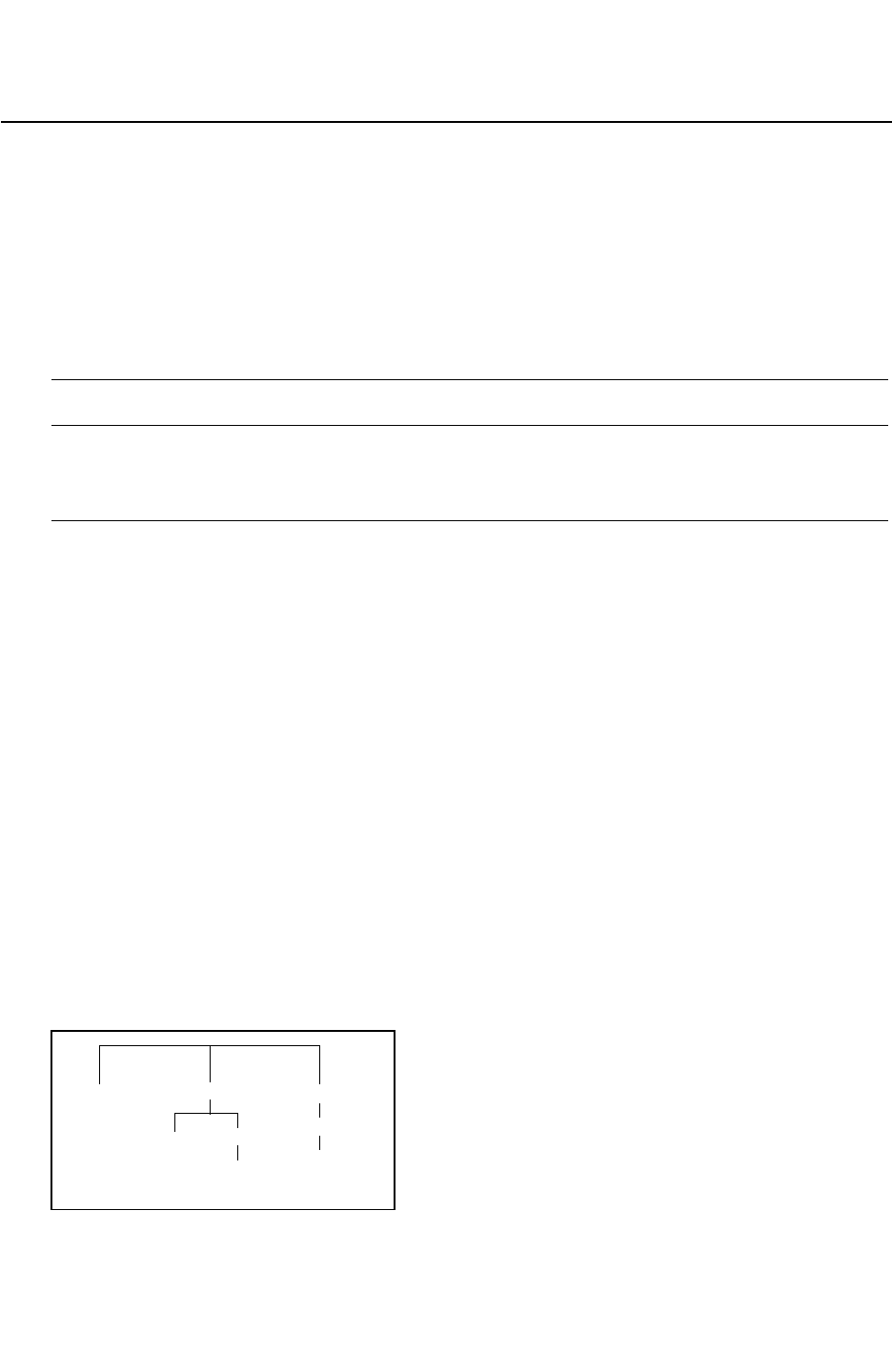
Chapter 17: StarRC Commands
SKIP_CELLS 17-274
StarRC User Guide and Command Reference F-2011.06
StarRC User Guide and Command Reference Version F-2011.06
SKIP_CELLS
Creates a white-space-delimited list of cells for StarRC to skip during extraction.
Syntax
SKIP_CELLS: cell1 cell2 ... cellN
Arguments
Argument Description
cell1 cell2 ... cellN A list of cells to be skipped during extraction. Wildcard characters
are acceptable.
Default: *
Description
The SKIP_CELLS command creates a white-space-delimited list of cells for StarRC to skip
during extraction. This command may be specified multiple times in a single command file.
The asterisk (*), exclamation mark (!), and question mark (?) wildcard characters are
acceptable. Case sensitivity for selection purposes is determined by the value of the
CASE_SENSITIVE command, but the netlist always retains the case of the original input
database.
Skipped cells are typically cells with their own timing models, which can later be applied,
along with the StarRC parasitic netlist, to perform a timing analysis. Skipped cells should
have labeled, or otherwise annotated, pin shapes for proper parasitic netlisting.
The default for all extraction flows is to skip everything in the input database, so any macro
blocks without timing models must be negated from the list.
Example
SKIP_CELLS: cellA !cellB cell? *C ...
SKIP_CELLS: * !macroA !macroB ...
Figure 17-8 Example Using SKIP_CELLS
AmacroB
macroA
B
A
B
A
A

Chapter 17: StarRC Commands
SKIP_CELLS 17-275
Chapter 17: StarRC Commands
SKIP_CELLS 17-275
StarRC User Guide and Command Reference Version F-2011.06
Using the hierarchy showing in Figure 17-8 only cell A is skipped in the following example:
SKIP_CELLS: A
Cell macroA is not skipped. The resulting netlist contains 4 instances of A.
If you use the following command, cells A and B is skipped:
SKIP_CELLS: A B
Cells macroA and macroB are not skipped. The resulting netlist contains 2 instances of A
and 2 instances of B.
In following example, all cells are skipped:
SKIP_CELLS: *
The following example specifies that all cells except macroA and macroB are skipped:
SKIP_CELLS: * !macro?
In following example, no cells are skipped:
SKIP_CELLS: !*
See Also
•CASE_SENSITIVE
•CELL_TYPE

Chapter 17: StarRC Commands
SKIP_CELLS_COUPLE_TO_NET 17-276
StarRC User Guide and Command Reference F-2011.06
StarRC User Guide and Command Reference Version F-2011.06
SKIP_CELLS_COUPLE_TO_NET
Specifies a lump net for all coupling capacitance between top-level routes and noncritical
SKIP_CELLS material.
Syntax
SKIP_CELLS_COUPLE_TO_NET: string
Arguments
Argument Description
string The net name to the noncritical SKIP_CELLS material.
Default: ground net.
Description
The default is to use ground as the noncritical SKIP_CELLS material potential.
You must set NETLIST_FORMAT: SPEF and COUPLE_TO_GROUND: NO to use this option.
Use this option in conjunction with SKIP_CELLS_COUPLE_TO_NET_LEVEL to append the
SKIP_CELLS_COUPLE_TO_NET name to the actual SKIP_CELLS object layer number.
Example
SKIP_CELLS_COUPLE_TO_NET: LUMP
See Also
•COUPLE_TO_GROUND
•NETLIST_FORMAT
•SKIP_CELLS_COUPLE_TO_NET_LEVEL

Chapter 17: StarRC Commands
SKIP_CELLS_COUPLE_TO_NET_LEVEL 17-277
Chapter 17: StarRC Commands
SKIP_CELLS_COUPLE_TO_NET_LEVEL 17-277
StarRC User Guide and Command Reference Version F-2011.06
SKIP_CELLS_COUPLE_TO_NET_LEVEL
Appends the SKIP_CELLS_COUPLE_TO_NET name to the real layer number for the
SKIP_CELLS material.
Syntax
SKIP_CELLS_COUPLE_TO_NET_LEVEL: YES | NO
Arguments
Argument Description
YES Specifies that the layer number of the SKIP_CELLS material is
appended to the assigned net name.
NO Specifies that the layer number of the SKIP_CELLS material is not
appended to the assigned net name.
This is the default.
Description
This command appends the SKIP_CELLS_COUPLE_TO_NET name to the real layer number for
the SKIP_CELLS material.
This command is ignored unless SKIP_CELLS_COUPLE_TO_NET is specified.
Example
If the net name is LUMP and this command is set to YES, the resulting coupling capacitor
between top-level net1 and a metal1 object inside a SKIP_CELLS might be as follows:
*CAP
...
12 net1 LUMP_1 1.2e-15
...
*END
See Also
•SKIP_CELLS_COUPLE_TO_NET

Chapter 17: StarRC Commands
SKIP_CELLS_FILE 17-278
StarRC User Guide and Command Reference F-2011.06
StarRC User Guide and Command Reference Version F-2011.06
SKIP_CELLS_FILE
Syntax
SKIP_CELLS_FILE: file1 file2 ...
Arguments
Argument Description
file Specifies the name of the file containing the defined
SKIP_CELLS.
Default: none
Description
Specifies a file containing SKIP_CELLS commands. See the SKIP_CELLS command for more
details.
Example
SKIP_CELLS: cellA cellB
SKIP_CELLS: cellC
See Also
•CASE_SENSITIVE
•SKIP_CELLS

Chapter 17: StarRC Commands
SKIP_INSTANCES 17-279
Chapter 17: StarRC Commands
SKIP_INSTANCES 17-279
StarRC User Guide and Command Reference Version F-2011.06
SKIP_INSTANCES
Creates a white space delimited list of cell instances that are not skipped in the SKIP_CELLS
command.
Syntax
SKIP_INSTANCES instance_list
Arguments
Argument Description
instance_list The list of instances to skip.
Default: none
Description
Wildcards “*”, “!”, and “?” are accepted, but cannot be used as global arguments (for
example: SKIP_INSTANCES:*).
Instances that you might want to skip are those that already have timing model or parasitic
netlists elsewhere in the library representing the cell master.
The default is not to skip any specific instances so all cell instances are skipped or flattened
depending on the SKIP_CELLS command setting.
Example
In this example, all macroA instances are flattened, except macroA_instance1. All macroB
instances are flattened, except macroB_instance1.
SKIP_CELLS: * !macroA !macroB
SKIP_INSTANCES: macroA_instance1 macroB_instance1
See Also
•SKIP_CELLS

Chapter 17: StarRC Commands
SKIP_PCELLS 17-280
StarRC User Guide and Command Reference F-2011.06
StarRC User Guide and Command Reference Version F-2011.06
SKIP_PCELLS
Extracts a parameterized cell (PCELL) as a fully characterized gray-box cell unit during
parasitic extraction and creates the entity in the DSPF netlist with all layout properties
extracted for the PCELL.
Syntax
SKIP_PCELLS: pcell_name
Arguments
Argument Description
pcell_name Name of parameterized cell. Only the exclamation mark (!) and
asterisk (*) wildcard characters can be used.
Default: none.
Description
The SKIP_PCELLS command extracts a parameterized cell (PCELL) as a fully characterized
gray-box cell unit during parasitic extraction and creates the entity in the DSPF netlist with
all layout properties extracted for the PCELL. StarRC defines a PCELL as a container cell,
within which one or more devices (including hierarchical cells) are extracted by the ideal
device extraction tool. With this command, StarRC treats the container cell as a gray-box for
parasitic extraction purposes but creates an entry in the DSPF Instance section listing all
geometric properties of the ideal device extracted inside the container cell.
In this flow, the PCELL placed in layout is assumed to be a fully characterized unit, for which
the layout’s PCELL container cell boundary defines the perimeter between the intradevice
effects inside the cell and the interconnect effects outside the cell. As such, runset terminal
layer manipulation is not required to isolate intradevice effects because the PCELL cell
boundary serves this role. Using the cell boundary eliminates the need to perform runset
terminal layer manipulation for PCELLs while retaining device properties in the netlist. This
is the functional benefit of this command.
When you specify the SKIP_PCELLS command, StarRC
• Creates the entity in the DSPF instance section as a device with all layout-extracted
device properties; the instantiation name must be consistent with the ideal devices inside
the container cell
• Treats the container cell as a gray-box (analogous to the SKIP_CELLS command
functionality), meaning that parasitic effects are extracted up to the cell boundary

Chapter 17: StarRC Commands
SKIP_PCELLS 17-281
Chapter 17: StarRC Commands
SKIP_PCELLS 17-281
StarRC User Guide and Command Reference Version F-2011.06
StarRC handles exploded shapes in PCELLS by supporting the following scenarios:
• PCELL shapes that are exploded to the upper level
• Flattened designs with some premodeled areas in which the PCELL is not preserved
Both scenarios require you to specify the PCELL or blocking layer, as well as the layers that
are exploded, in a file specified by the SKIP_PCELL_LAYERS_FILE command.
See Also
•SKIP_CELLS
•SKIP_PCELL_LAYERS_FILE

Chapter 17: StarRC Commands
SKIP_PCELL_LAYERS_FILE 17-282
StarRC User Guide and Command Reference F-2011.06
StarRC User Guide and Command Reference Version F-2011.06
SKIP_PCELL_LAYERS_FILE
Specifies a file that lists PCELL layers.
Syntax
SKIP_PCELL_LAYERS_FILE: file_name
Arguments
Argument Description
file_name File name
Default: none
Description
The SKIP_PCELL_LAYERS_FILE specifies a file that lists PCELL layers.
Example
The specified file uses the following syntax:
PCELL_LAYERS
pcell_name1 layer1 layer2 …
pcell_name2 layer3 layer4 …
pcell_* layer5 layer6 …
BLOCKING_LAYERS
blocking_layer1 [SIZE size_value | SCALE scale_factor] layer1 layer2 …
blocking_layer2 [SIZE size_value | SCALE scale_factor] layer3 layer4 …
The PCELL_LAYERS section has the following requirements:
• The first column specifies the PCELL name; the asterisk (*) wildcard is allowed. The
remaining columns specify the list of exploded layers. If the shapes on these layers are
located on the PCELL boundary, they are considered to be PCELL shapes.
• The PCELL hierarchy is preserved in CCI/XTR database, although some shapes are
exploded.
• The PCELLs must be specified in SKIP_PCELLS command.
• The layers must be specified in the StarRC mapping file.

Chapter 17: StarRC Commands
SKIP_PCELL_LAYERS_FILE 17-283
Chapter 17: StarRC Commands
SKIP_PCELL_LAYERS_FILE 17-283
StarRC User Guide and Command Reference Version F-2011.06
Table 17-9 shows an example of PCELL_LAYERS usage.
Table 17-9 Example of PCELL_LAYERS Usage
star_cmd file SKIP_PCELLS: Cell_1 Cell_2
SKIP_PCELL_LAYERS_FILE PCELL_LAYERS
Cell_1 m1 v1 m2
Cell_2 m3 v3 m4
Behavior Cell_1: normal PCELL + m1/v1/m2 shapes handling
Cell_2: normal PCELL
Cell_3: not considered for PCELL_LAYERS approach
The BLOCKING_LAYERS section has a syntax that is similar to the PCELL_LAYERS section.
• The first column specifies the blocking layer name.
• The size_value (in units of microns) expands or shrinks the blocking layer by the
specified amount. A positive value specifies expansion; a negative value indicates
shrinkage.
• The scale_factor expands or shrink the blocking layer by the specified scaling factor.
If you specify the BLOCKING_LAYERS section, you do not need PCELLS in the design; the
design can be completely flattened. When using this approach,
• The blocking layers must be specified in the CCI/XTR database
• Avoid using both blocking layers and PCELLs for the same area
See Also
•SKIP_PCELLS

Chapter 17: StarRC Commands
SLEEP_TIME_AFTER_FINISH 17-284
StarRC User Guide and Command Reference F-2011.06
StarRC User Guide and Command Reference Version F-2011.06
SLEEP_TIME_AFTER_FINISH
Specifies the CPU wait time before processing the next partition.
Syntax
SLEEP_TIME_AFTER_FINISH: number_of_seconds
Arguments
Argument Description
number_of_seconds Specifies the CPU wait time
Units: seconds
Default: 2
Description
When you use the NUM_PARTS command in your star_cmd file to specify a distributed
processing run, there is a chance that more than one CPU could start processing the same
partition. This can happen because of network glitches, thus causing StarRC to terminate
abnormally.
To prevent failures due to network glitches, use the SLEEP_TIME_AFTER_FINISH command
to increase the CPU wait time before processing the next partition:
By default, SLEEP_TIME_AFTER_FINISH is set to 2 seconds. To mask the effect of network
glitches, try increasing SLEEP_TIME_AFTER_FINISH to 100 or 200 seconds.
Note:
Setting a higher value for the SLEEP_TIME_AFTER_FINISH command can impact your
total runtime.
Example
The following command forces the CPUs to wait 100 seconds before starting a new job:
SLEEP_TIME_AFTER_FINISH: 100
See Also
•NUM_PARTS

Chapter 17: StarRC Commands
SPICE_SUBCKT_FILE 17-285
Chapter 17: StarRC Commands
SPICE_SUBCKT_FILE 17-285
StarRC User Guide and Command Reference Version F-2011.06
SPICE_SUBCKT_FILE
Specifies the SPICE file containing .subckt definitions for all of the SKIP_CELLS.
Syntax
SPICE_SUBCKT_FILE: file1 [... fileN]
Arguments
Argument Description
file1 [... fileN]Files containing the .subckt definitions for all SKIP_CELLS in the
design.
Default: none
Description
StarRC reads the SPICE_SUBCKT_FILE files to obtain port ordering information. The
SPICE_SUBCKT_FILE controls the port ordering of the top cell as well. The port order and the
port list members read from the .subckt for a SKIP_CELLS are preserved in the output netlist.
This command does not support the .include statement in the SPICE files.
See Also
•SKIP_CELLS

Chapter 17: StarRC Commands
STAR_DIRECTORY 17-286
StarRC User Guide and Command Reference F-2011.06
StarRC User Guide and Command Reference Version F-2011.06
STAR_DIRECTORY
Sets the working directory for StarRC.
Syntax
STAR_DIRECTORY: directory
Arguments
Argument Description
directory The working directory for StarRC.
Default: star
Description
The STAR_DIRECTORY command sets the working directory for StarRC with the following
restrictions:
• Absolute paths are not permitted. You must specify a relative path.
• A relative path to a directory can only be specified when the directory resides below the
working directory in the path.
% star_dir/working_dir/other_dir (incorrect)
% working_dir/other_dir/star_dir (correct)

Chapter 17: StarRC Commands
SUBSTRATE_EXTRACTION 17-287
Chapter 17: StarRC Commands
SUBSTRATE_EXTRACTION 17-287
StarRC User Guide and Command Reference Version F-2011.06
SUBSTRATE_EXTRACTION
Extracts resistance from layers mapped to substrate in the mapping file.
Syntax
SUBSTRATE_EXTRACTION: YES | NO
Arguments
Argument Description
YES Perform substrate extraction on layers specified in the mapping
file as “substrate” layers.
NO Substrate extraction is not done.
This is the default.
Description
You must specify each substrate layer in your mapping file and include RPSQ values for each
layer. The RPSQ values can be different for each layer as shown in line 2 and line 3 in the
previous example. The word substrate must also be specified in the mapping file (as
shown in the example) for those layers you want to extract. At least one substrate layer must
be specified in the mapping file. The command TRANSLATE_RETAIN_BULK_LAYERS:YES
must be specified in your command file when SUSTRATE_EXTRACTION is specified. You can
also specify substrate layers without RPSQ values. All substrate layers that do not have RPSQ
values are treated as ideal.
Since bulk layers are large and highly resistive, StarRC performs mesh extraction for these
layers, resulting in an increased parasitic netlist size.
It is appropriate to use the SUBSTRATE_EXTRACTION functionality for obtaining substrate
resistance information for three purposes:
• To prevent the shorting together of multiple electrical nodes that exist within a common
substrate well, to enable analyses of power nets having multiple electrical taps to a
common well.
• To prevent the shorting together of multiple electrical nodes that exist within a common
substrate well in parasitic viewing applications, to enable resistive probing between
nodes that share a common well.
• To allow the extraction of resistance between a MOS device's bulk terminal and source/
drain terminal, so that MOS back-biasing effects can be simulated.

Chapter 17: StarRC Commands
SUBSTRATE_EXTRACTION 17-288
StarRC User Guide and Command Reference F-2011.06
StarRC User Guide and Command Reference Version F-2011.06
This feature is generally not intended to facilitate substrate extraction for purposes of
substrate noise modeling.
Example
The following example shows a mapping file:
(with substrate extraction)
conducting_layers
nwell SUBSTRATE RPSQ=1000
psub SUBSTRATE RPSQ=2000
(with substrate extraction)
conducting layers
nwell SUBSTRATE
psub SUBSTRATE
See Also
•RPSQ
•TRANSLATE_RETAIN_BULK_LAYERS

Chapter 17: StarRC Commands
SUMMARY_FILE 17-289
Chapter 17: StarRC Commands
SUMMARY_FILE 17-289
StarRC User Guide and Command Reference Version F-2011.06
SUMMARY_FILE
Specifies the name of the summary file.
Syntax
SUMMARY_FILE: file_name
Arguments
Argument Description
file_name The name of the summary file
Default: block_name.star_sum
Description
The SUMMARY_FILE command specifies the name of the summary file generated by StarRC.
By default, the summary file is located in the run directory and has the name
block_name.star_sum, where block_name is the block specified by the BLOCK command.
You can use the SUMMARY_FILE command to change the name and location of the summary
file. This command accepts a path relative to the run directory. However, an absolute path is
not permitted because of the possibility of a change in the network file system (NFS).
Example
To create a summary file my_summary.log in the results subdirectory, use the following
syntax in your star_cmd file:
SUMMARY_FILE: ./results/my_summary.log
See Also
•BLOCK

Chapter 17: StarRC Commands
SYNOPSYS_LIB_FILE 17-290
StarRC User Guide and Command Reference F-2011.06
StarRC User Guide and Command Reference Version F-2011.06
SYNOPSYS_LIB_FILE
Specifies the path to a Synopsys .lib library timing database.
Syntax
SYNOPSYS_LIB_FILE: file1 [... fileN]
Arguments
Argument Description
file1 [... fileN] The name of the Synopsys binary file.
Default: none
Description
The information in these models can be used in any or all analysis flows. This command can
also be specified to provide pin information (such as capacitance or direction) for LEF/DEF
and Checkpoint databases (or to override the values from the Milkyway database) for
netlisting purposes. If this command is not specified, StarRC attempts to load the cell
models from the Milkyway (CLF) database.
This command affects all analysis flows.
Note:
This command will be phased out in a future release. See the
SKIP_CELL_PORT_PROP_FILE command.
See Also
•MILKYWAY_DATABASE

Chapter 17: StarRC Commands
TA R G E T _ P W R A 17-291
Chapter 17: StarRC Commands
TA R G E T _ P W R A 17-291
StarRC User Guide and Command Reference Version F-2011.06
TARGET_PWRA
Automatically generates all StarRC command file options that are needed in a power
reliability analysis flow.
Syntax
TARGET_PWRA: NO | YES
Arguments
Argument Description
NO Does not set an optimized set of commands for reliability
analysis.
This is the default.
YES Sets an optimized set of commands for a reliability analysis using
a StarRC/HSIM flow. Optimizes StarRC power extraction-related
commands.
Description
The TARGET_PWRA command automatically generates all StarRC command file options that
are needed for RC extraction in a power reliability analysis flow. With this command, you
also use the POWER_NETS command must specify a list of power nets.
The TARGET_PWRA: YES command sets the following options:
POWER_EXTRACT: RONLY
POWER_REDUCTION: LAYER_NO_EXTRA_LOOPS
NETLIST_CONNECT_SECTION: YES
NETLIST_NODE_SECTION: YES
NETLIST_TAIL_COMMENTS: YES
NETLIST_FORMAT: SPF
NETLIST_POWER_FILE: block_name.pwr.spf
SHORT_PINS: NO
Note:
StarRC automatically sets the POWER_EXTRACT option to the appropriate setting.
You do not need to set the EXTRA_GEOMETRY_INFO: NODE command because *|S is the
center of the bounding box node.
Only the reduction option KEEP_VIA_NODES as set by the TARGET_ANALYSIS: PWRA option
can be overridden by user settings. Other options are ignored and a warning is issued.

Chapter 17: StarRC Commands
TA R G E T _ P W R A 17-292
StarRC User Guide and Command Reference F-2011.06
StarRC User Guide and Command Reference Version F-2011.06
Example
BLOCK:
MILKYWAY_DATABASE:
MILKYWAY_EXTRACT_VIEW
TARGET_PWRA:YES
POWER_NETS: list_of_power_nets
TCAD_GRD_FILE:
MAPPING_FILE:
MODE: 200
XREF: YES
SKIP_CELLS: list_of_cells
NETLIST_POWER_FILE: blockname_power_nets.spf
NETLIST_FILE: blockname_signal_nets.spf
See Also
•EXTRA_GEOMETRY_INFO: NODE
•KEEP_VIA_NODES: NO
•NETLIST_CONNECT_SECTION
•NETLIST_FORMAT
•NETLIST_POWER_FILE
•NETLIST_NODE_SECTION
•NETLIST_TAIL_COMMENTS
•POWER_EXTRACT
•POWER_NETS
•POWER_REDUCTION
•REDUCTION
•SHORT_PINS

Chapter 17: StarRC Commands
TCAD_GRD_FILE 17-293
Chapter 17: StarRC Commands
TCAD_GRD_FILE 17-293
StarRC User Guide and Command Reference Version F-2011.06
TCAD_GRD_FILE
Specifies the location of the TCAD GRD file.
Syntax
TCAD_GRD_FILE: file
TCAD_GRD_FILE: nxtgrd_file1 nxtgrd_file2 nxtgrd_file3
Arguments
Argument Description
file TCAD model file for StarRC
Default: none
Description
This command is mandatory for all extraction flows. It specifies the location of the TCAD
GRD file containing conductor sheet resistances and models for 3-D parasitic capacitance
calculation.
The MAPPING_FILE command specifies a file that maps every TCAD process layer to a
corresponding layout database layer. For more information about creating the mapping file,
see “Writing a Mapping File” on page 3-58. For information about creating the TCAD GRD
file, see “Process Characterization Basics” on page 3-3.
See Also
•MAPPING_FILE
•MERGE_MULTI_CORNER

Chapter 17: StarRC Commands
TEMPERATURE_SENSITIVITY 17-294
StarRC User Guide and Command Reference F-2011.06
StarRC User Guide and Command Reference Version F-2011.06
TEMPERATURE_SENSITIVITY
Syntax
TEMPERATURE_SENSITIVITY: YES | NO
Arguments
Argument Description
YES When TEMPERATURE_SENSITIVITY:YES is set in the StarRC
command file, any OPERATING_TEMPERATURE setting in the
command file is ignored. Temperature (CRT1/CRT2/
CRT_VS_SI_WIDTH) can be the only variation specified in the ITF file.
NO TEMPERATURE_SENSITIVITY function is not on.
This is the default.
Description
This command enables the temperature variation flow in StarRC. Temperature derating
parameters, CRT1 and CRT2, can be either printed in the sensitivity netlist or evaluated
during netlist creation based on a user-specified operating temperature.
When TEMPERATURE_SENSITIVITY:YES is set in the StarRC command file, the
OPERATING_TEMPERATURE setting in the command file is ignored. Temperature (CRT1/CRT2/
CRT_VS_SI_WIDTH) can be the only variation specified in the ITF file. You can input a nxtgrd
file without a VARIATION_PARAMETERS table and CRT1/CRT2 is treated as the only variation
parameter.
This command is supported for all reduction modes. For usage guidelines and expected
output, see Table 17-10.
Table 17-10 UDC and Statistical Flow
UDC Flow Statistical Flow
Temperature in UDC CRT1/CRT2 and sensitivities
Temperature from star_cmd
file
Nominal at star_cmd temperature with sensitivities

Chapter 17: StarRC Commands
TEMPERATURE_SENSITIVITY 17-295
Chapter 17: StarRC Commands
TEMPERATURE_SENSITIVITY 17-295
StarRC User Guide and Command Reference Version F-2011.06
Example
TEMPERATURE_SENSITIVITY: YES
SENSITIVITY: YES
See Also
•NETLIST_CORNER_FILE
•NETLIST_CORNER_NAMES
•NETLIST_MERGE_CORNERS
•OPERATING_TEMPERATURE
•SENSITIVITY

Chapter 17: StarRC Commands
THICKNESS_VARIATION_FILE 17-296
StarRC User Guide and Command Reference F-2011.06
StarRC User Guide and Command Reference Version F-2011.06
THICKNESS_VARIATION_FILE
Specifies the thickness variation map for each layer in the design generated by CMP
simulators.
Syntax
THICKNESS_VARIATION_FILE: file_name
Arguments
Argument Description
file_name The thickness variation file.
Default: none.
Description
StarRC reads the thickness variation map, calculates the thickness variation for each
interconnect polygon, and writes the value to the internal database.
Example
When the THICKNESS_VARIATION_FILE command exists in the StarRC command file, the
following commands are automatically disabled from the ITF:
POLYNOMIAL_BASED_THICKNESS_VARIATION
THICKNESS_VS_DENSITY
ILD_VS_WIDTH_AND_SPACING
For information about writing a thickness variation map file, see Chapter 3, “Interconnect
Parasitics Extraction Based on CMP Simulators.”
See Also
•DENSITY_BASED_THICKNESS
•TVF_ADJUSTMENT_TABLES

Chapter 17: StarRC Commands
TOP_DEF_FILE 17-297
Chapter 17: StarRC Commands
TOP_DEF_FILE 17-297
StarRC User Guide and Command Reference Version F-2011.06
TOP_DEF_FILE
Specifies the top-level block design file in DEF format.
Syntax
TOP_DEF_FILE: def_file
Arguments
Argument Description
def_file The top block design file in DEF format.
Default: none.
Description
This command is mandatory for LEF/DEF flows.
Define the top-level block for extraction. This DEF file can reference macros that can be
defined in separate files with the MACRO_DEF_FILE command. The standard cell and routing
layer definitions should be defined in the accompanying LEF_FILE. Macro blocks appearing
in the TOP_DEF_FILE are skipped by default.
Gzipped files can be directly specified in the TOP_DEF_FILE command.
See Also
•LEF_FILE
•MACRO_DEF_FILE

Chapter 17: StarRC Commands
TRANSLATE_DEF_BLOCKAGE 17-298
StarRC User Guide and Command Reference F-2011.06
StarRC User Guide and Command Reference Version F-2011.06
TRANSLATE_DEF_BLOCKAGE
Translates the routing DEF blockages from a TOP_DEF_FILE.
Syntax
TRANSLATE_DEF_BLOCKAGE: YES | NO
Arguments
Argument Description
YES Turns on function to translate the routing DEF BLOCKAGES from a designated
TOP_DEF_FILE.
NO Does not turn on translation of DEF BLOCKAGE.
This is the default.
Description
This command translates the routing DEF blockages from a TOP_DEF_FILE only. It ignores
DEF blockages from the MACRO_DEF_FILE. This is because the routing information
corresponding to these blockages is already present in the TOP_DEF_FILE. Moreover,
placement blockages in the TOP_DEF_FILE are ignored by this option.
Example
[BLOCKAGES numBlockages ;
[- LAYER layerName
[+ COMPONENT compName | + SLOTS | + FILLS | + PUSHDOWN]
[+ SPACING minSpacing | + DESIGNRULEWIDTH effectiveWidth]
{RECT pt pt | POLYGON pt pt pt ...} ...
;] ...
[- PLACEMENT
[+ COMPONENT compName | + PUSHDOWN]
{RECT pt pt} ...
;] ...
See Also
•MACRO_DEF_FILE
•TOP_DEF_FILE

Chapter 17: StarRC Commands
TRANSLATE_FLOATING_AS_FILL 17-299
Chapter 17: StarRC Commands
TRANSLATE_FLOATING_AS_FILL 17-299
StarRC User Guide and Command Reference Version F-2011.06
TRANSLATE_FLOATING_AS_FILL
Syntax
TRANSLATE_FLOATING_AS_FILL: YES | NO
Arguments
Argument Description
YES Treats disconnected floating polygons as fill polygons. Their capacitive
interaction is accounted as metal fill polygons.
NO Treats disconnected floating polygons as simple ideal ground. This is the
default.
Description
StarRC handles floating and grounded metal fill through a separate metal fill GDSII file
interface for transistor-level flows. For these flows, StarRC determines the name of a net
based on pin-marker definitions from physical verification tools such as Hercules or Calibre.
For nets that do not have pin-marker layers or text, verification tools generally assign a
random net ID to these layers. These polygons are considered disconnected or floating.
Since these are present in the input database, StarRC must take the polygons into account
for capacitive interaction. Resistance is not a concern since there are no pins present and
thus no current flowing through these polygons.
The TRANSLATE_FLOATING_AS_FILL command is independent of the
METAL_FILL_POLYGON_HANDLING command.
See Also
•METAL_FILL_GDS_FILE

Chapter 17: StarRC Commands
TRANSLATE_RETAIN_BULK_LAYERS 17-300
StarRC User Guide and Command Reference F-2011.06
StarRC User Guide and Command Reference Version F-2011.06
TRANSLATE_RETAIN_BULK_LAYERS
Syntax
TRANSLATE_RETAIN_BULK_LAYERS: YES | NO
Arguments
Argument Description
YES Specifies that all mapped bulk layers are passed to the StarRC
extraction engine for use during extraction.
When YES is specified, layer precedence should be set in your
mapping file; otherwise accuracy can be affected.
NO Specifies that no bulk layers are passed to the StarRC extraction
engine for use during extraction.
This is the default.
Description
Specifies that StarRC use (YES) or discard (NO) bulk layers during device-level parasitic
extraction, assuming such layers are mapped in a MAPPING_FILE.
A bulk layer is defined as any database layer that is used as the bulk terminal layer for any
of the following Hercules and Calibre device extraction commands: NMOS/PMOS, resistor,
diode, or bipolar junction transistor.
Note:
In Calibre flows, MOS bulk layer recognition is applicable to devices bearing a
device_type equal to MOS in the CALIBRE_DEVTAB file (including MN, MP, MD, and ME
element names) as well as to devices bearing the element name ’M’. This bulk layer
recognition is not applicable to lightly doped drain (LDD) devices. These LDD devices are
MOS transistors with source and drain pins that are not swappable. It is also not
applicable to most devices bearing the USER tag in the device_type field of the
CALIBRE_DEVTAB file, including inductor devices.
When you set the TRANSLATE_RETAIN_BULK_LAYERS:YES, command StarRC has the
capability to output coupling capacitance to well layers that serve as bulk layers. In this
mode, StarRC also outputs an instance port subnode for the bulk terminal of any of the
devices described previously. By contrast when you specify the TRANSLATE_RETAIN_BULK_

Chapter 17: StarRC Commands
TRANSLATE_RETAIN_BULK_LAYERS 17-301
Chapter 17: StarRC Commands
TRANSLATE_RETAIN_BULK_LAYERS 17-301
StarRC User Guide and Command Reference Version F-2011.06
LAYERS:NO command, StarRC includes the capacitance to well layers as a generic ground
capacitance in the netlist. In this way, StarRC also outputs bulk terminals using ideal net
names instead of instance port subnodes.
You should use TRANSLATE_RETAIN_BULK_LAYERS: YES command for the following types
of device-level extraction scenarios:
• Power net extractions where capacitance to well layers should be output as coupling
capacitance
• Extractions containing well devices (for example, well resistors, diodes, bipolar junction
transistors) whose database terminal layers consist solely of bulk layers
• Scenarios in which the bulk terminals of designed devices should be output as instance
port subnodes instead of ideal nodes
Errors
Two warning messages can be issued by StarRC when one of the following conditions
exists:
• When no precedence is set in a mapping file with the TRANSLATE_RETAIN_
BULK_LAYERS:YES command for layers mapped to substrate.
In this situation, accuracy can be affected. Check the order of substrate layer precedence
specified in your mapping file whenever the TRANSLATE_RETAIN_BULK_LAYERS:YES
command is specified.
• When the precedence is not set for all layers mapped to substrate in the mapping file.
For those layers not set with precedence, their precedence is set to zero automatically.
Example
To set precedence in a mapping file, use the following syntax:
conducting_layers
db_layer SUBSTRATE precedence=pos_integer
db_layer SUBSTRATE precedence=pos_integer
...
See Also
•COUPLE_TO_GROUND
•POWER_REDUCTION

Chapter 17: StarRC Commands
TVF_ADJUSTMENT_TABLES 17-302
StarRC User Guide and Command Reference F-2011.06
StarRC User Guide and Command Reference Version F-2011.06
TVF_ADJUSTMENT_TABLES
Specifies a file containing the thickness variation adjustment tables for local or density
effects.
Syntax
TVF_ADJUSTMENT_TABLES: file_name
Arguments
Argument Description
file_name File containing thickness variation adjustment tables
Description
The TVF_ADJUSTMENT_TABLES command specifies a file that contains the thickness
variation adjustment tables. These tables are an extension to the CMP flow interface, which
allows a thickness variation file to specify the bottom conductor thickness information. The
adjustment tables adjust the thickness variation based on the width and spacing of the local
conductor and based on the pattern density of neighboring tiles.
These adjustment tables are optional when THICKNESS_VARIATION_FILE is specified.
When adjustment tables are not provided with thickness variation file, the bottom thickness
variation is taken directly from the thickness variation file, and no adjustment is applied for
local or density effects.
See Also
•THICKNESS_VARIATION_FILE

Chapter 17: StarRC Commands
USER_DEFINED_DIFFUSION_RES 17-303
Chapter 17: StarRC Commands
USER_DEFINED_DIFFUSION_RES 17-303
StarRC User Guide and Command Reference Version F-2011.06
USER_DEFINED_DIFFUSION_RES
Controls the application of equation-based diffusion resistance methodology to contacts that
are below the thresholds specified in the ITF file.
Syntax
USER_DEFINED_DIFFUSION_RES: YES | NO
Arguments
Argument Description
YES Enables equation-based diffusion resistance methodology to
contacts that are below the thresholds specified in the ITF file.
NO Disables equation-based diffusion resistance methodology to
contacts that are below the thresholds specified in the ITF file.
This is the default.
Description
The USER_DEFINED_DIFFUSION_RES command controls the application of equation-based
diffusion resistance methodology to contacts that fall below the following thresholds
specified in the ITF file:
•DIFFUSION_RES_GATE_TO_CONT_THRESHOLD
•DIFFUSION_RES_BEND_THRESHOLD
For contacts with layout parameters that are above the thresholds specified in the ITF file,
StarRC performs the standard mesh-based diffusion resistance extraction.
Setting USER_DEFINED_DIFFUSION_RES: YES affects the capacitance values of nets within
the statistical convergence error limit because of layout polygon fragmentation and changing
nodes.
Example
To enable equation-based diffusion resistance methodology, use the following command:
USER_DEFINED_DIFFUSION_RES: YES
See Also
•NETLIST_POSTPROCESS_COMMAND

Chapter 17: StarRC Commands
VIA_COVERAGE 17-304
StarRC User Guide and Command Reference F-2011.06
StarRC User Guide and Command Reference Version F-2011.06
VIA_COVERAGE
Specifies the six values from the via edge to outer metal edge for coverage and landing
measurement.
Syntax
VIA_COVERAGE: via1 Lf Lq [Ls] Cf Cq [Cs]
Arguments
Argument Description
Lf Maximum number for a Landing full measurement.
Units: nanometers.
Lq Maximum number for a Landing quarter measurement.
Units: nanometers.
Ls Maximum number for a Landing semi- measurement.
Units: nanometers.
Cf Maximum number for a Coverage full measurement.
Units: nanometers.
Cq Maximum number for a Coverage quarter measurement.
Units: nanometers.
Cs Maximum number for a Coverage semi- measurement.
Units: nanometers.
Description
Each number corresponds to a coverage or landing measurement.
The VIA_COVERAGE command checks square vias; the VIA_COVERAGE_OPTION_FILE
command checks rectangular vias.
Note:
The NETLIST_TAIL_COMMENTS:YES command is required; the NETLIST_FORMAT:SPEF
command is no longer required. The VIA_COVERAGE command does not require a text
file.
All netlist formats are accepted by this command.

Chapter 17: StarRC Commands
VIA_COVERAGE 17-305
Chapter 17: StarRC Commands
VIA_COVERAGE 17-305
StarRC User Guide and Command Reference Version F-2011.06
Each VIA_COVERAGE command must have all six entries to include the semi-coverage
capability. (For backward compatibility, you can specify four numbers and get results without
the semi-coverage capability. Both are reported in the netlist under the heading
“VIA_COVERAGE_CODES.”
The full coverage/landing and quarter coverage/landing numbers are in nanometers and
represent “as drawn” dimensions. (These dimensions are before the application of a
MAGNIFICATION_ FACTOR command).
The full-coverage/landing numbers must be greater than the quarter-coverage/landing
numbers. All vias specified for this feature must also be defined in your ITF file.
Example
This example shows how to specify the measurement of via coverage including
“semi-coverage.”
NETLIST_FORMAT: SPF
NETLIST_TAIL_COMMENTS: YES
VIA_COVERAGE: via1 100 80 100 80
VIA_COVERAGE: via2 100 80 100 80
See Also
•MERGE_VIAS_IN_ARRAY
•NETLIST_FORMAT
•NETLIST_TAIL_COMMENTS
•VIA_COVERAGE_OPTION_FILE

Chapter 17: StarRC Commands
VIA_COVERAGE_OPTION_FILE 17-306
StarRC User Guide and Command Reference F-2011.06
StarRC User Guide and Command Reference Version F-2011.06
VIA_COVERAGE_OPTION_FILE
Checks rectangular vias.
Syntax
VIA_COVERAGE_OPTION_FILE: file_name
Arguments
Argument Description
file_name The via coverage option file
Description
This command uses the dimensions (for each side of a via) that you specify to check the
specified area. See Figure 17-9 on page 17-307. This function works as an area checking
rule. You specify a text file containing via check ranges that you name in this command
syntax.
The VIA_COVERAGE_OPTION_FILE command checks rectangular vias; the VIA_COVERAGE
command checks square vias.
The StarRC via coverage report in the netlist contains a table that shows the detail of the via
coverage results. These results are determined by rules inside of StarRC that read and
analyze your via coverage data. The via coverage results are shown as full coverage,
quarter coverage, semi-coverage, and partial coverage.
All netlist formats are accepted for this command.
A via satisfies the area check of a drawn box if the box area in the figure is filled with metal
polygons. This applies to both coverage and landing. For coverage, the metal layer refers to
the metal layer above the via layer (for example, metal2 for via12) and for the landing it refers
to the metal layer below the via layer (for example metal1 for via 12).
All dimensions are given in nanometers and integers.
The output netlist contains the following via classifications:
•FULL means all sides of the via are covered because all enclosures are greater than the
F parameter (as shown in Figure 17-9).
•QUARTER means one enclosure must be greater than or equal to Q1 and must have both
adjacent sides enclosed by greater than Q2.
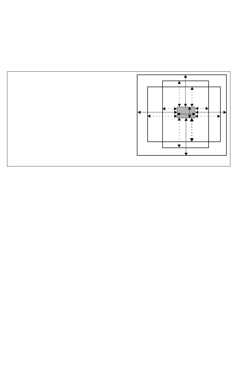
Chapter 17: StarRC Commands
VIA_COVERAGE_OPTION_FILE 17-307
Chapter 17: StarRC Commands
VIA_COVERAGE_OPTION_FILE 17-307
StarRC User Guide and Command Reference Version F-2011.06
•SEMI means one enclosure must be greater than or equal to S1 and both adjacent sides
must be enclosed by more than S2.
•PARTIAL means no enclosures meet the full, quarter, or semi-coverage requirements.
Figure 17-9 Via Coverage
W = the width of the VIA in the horizontal (x direction)
L = the length of the VIA in the vertical (y direction)
F1, F2, Q2, Q1, S2, S1 are the parameters in the VIA_COVERAGE_OPTION_FILE command
F2
F2
Q2/S2
Q1/S1
Q2/S2
Q2/S2
Q1/S1
Q1/S1
Q2/S2
Q1/S1
F1
F1 L
W
For each data set, you specify three numbers for coverage and three numbers for landing
when you are not checking semi-coverage and landing. For each data set, you specify five
numbers for coverage and five numbers for landing when you are checking semi-coverage
and landing.
The VIA_COVERAGE_OPTION_FILE command rules are as follows:
• Non-Manhattan shapes are not supported.
• For via arrays, all inside vias (those not on the perimeter) are considered fully covered.
• The horizontal direction is equal to the direction of the x-axis of coordinates used by the
StarRC extraction.
• The vertical direction is equal to the direction of the y-axis coordinates used by StarRC
extraction.
• Via coverage parameters must meet the following conditions, which apply to both
coverage and landing parameters and are checked in StarRC.
• F must be greater than or equal to Q2.
• F must be greater than or equal to S2.
• Q2 must be greater than S2.
• Q2 must be greater than Q1.

Chapter 17: StarRC Commands
VIA_COVERAGE_OPTION_FILE 17-308
StarRC User Guide and Command Reference F-2011.06
StarRC User Guide and Command Reference Version F-2011.06
• S2 must be greater than or equal to S1.
The following table explains text file syntax entries.
Keyword Description
Xrange Width of the via contact
Xmin Minimum width value of the via contact
Xmax Maximum width value of the via contact
Yrange Length of the via contact
Ymin Minimum length value of the via contact
Ymax Maximum length value of the via contact
FL1Full coverage “y” value for via landing
FL2Full coverage “x” value for via landing
FC1 Full coverage “y” value for via cover
FC2 Full coverage “x” value for via cover
QL1 Quarter coverage value for landing (small enclosure value)
QC1 Quarter coverage value for via cover (small enclosure value)
QL2 Quarter coverage value for via landing (large enclosure value)
QC2 Quarter coverage value for via cover (large enclosure value)
SL1 Semi-coverage value for via landing (small enclosure value)
SC1 Semi-coverage value for via cover (small enclosure value)
SL2 Semi-coverage value for via landing (large enclosure value)
SC2 Semi-coverage value for via cover (large enclosure value)
Example
Text File Syntax Single Parameter
via_layer_name
{Xrange=Xmin,Xmax;Yrange=Ymin,Ymax;Landing = FL,QL1,QL2,[SL1,SL2];
Coverage = FC,QC1,QC2,[SC1,SC2]}

Chapter 17: StarRC Commands
VIA_COVERAGE_OPTION_FILE 17-309
Chapter 17: StarRC Commands
VIA_COVERAGE_OPTION_FILE 17-309
StarRC User Guide and Command Reference Version F-2011.06
(Xrange=Xmin,Xmax;Yrange=Ymin,Ymax;
Landing = FL,QL1,QL2,[SL1,SL2];Coverage = FC,QC1,QC2,[SC1,SC2]}
Text File Syntax With Two Parameters
Without semi-coverage extraction
via_layer_name
{Xrange=Xmin,Xmax;Yrange=Ymin,Ymax;Landing = FL1,FL2,QL1,QL2;
Coverage = FC1,FC12,QC1,QC2}
With semi-coverage extraction
via_layer_name
{Xrange=Xmin,Xmax;Yrange=Ymin,Ymax;
Landing = FL1,FL2,QL1,QL2,[SL1,SL2];Coverage = FC1,FC2,QC1,QC2,[SC1,SC2]}
File Format Example 1 - With Semi-Coverage
VIA1 { Xrange= 100,100; Yrange = 100,100;
Landing = 100,80,10,40,10;Coverage = 100,80,10,40,10}
File Format Example 1 - Without Semi-Coverage
VIA1 { Xrange= 100,100; Yrange = 100,100;
Landing = 100,80,10;Coverage = 100,80,10}
In the example files, Xrange and Yrange represent the as-drawn length in X and Y
dimension of the via (before any scale factor has been applied). The ranges must not be
overlapping, and, each via size should be map-able to exactly one of the data sets in the list.
The range specification for a via landing and via coverage is the same. These requirements
are checked in the tool. No interpolation or extrapolation is needed. If -during a via coverage
mode extraction, a via is found that cannot be mapped to one of the specified ranges, then
StarRC issues a warning and the via has an “invalid” via coverage code, which is 0. There is
no limit to the number of data set ranges.
See Also
•NETLIST_FORMAT
•NETLIST_TAIL_COMMENTS
•REDUCTION
•VIA_COVERAGE

Chapter 17: StarRC Commands
WIDE_DEVICE_TERM_RESISTANCE 17-310
StarRC User Guide and Command Reference F-2011.06
StarRC User Guide and Command Reference Version F-2011.06
WIDE_DEVICE_TERM_RESISTANCE
Syntax
WIDE_DEVICE_TERM_RESISTANCE: RES
Arguments
Argument Description
RES Activates equipotential line node handling for RES devices.
Default: none.
Description
This command activates equipotential line node handling for RES devices -for example,
devices extracted with a RES command in Hercules or devices containing an element_name
= R in Calibre. Specifically, this command forces StarRC to always treat the A and B terminal
nodes as electrical line nodes (as opposed to electrical point nodes), which is the default
behavior. With this treatment, StarRC identifies the terminal or body boundary line and
extracts parasitic resistance orthogonal to that line.
For a resistor device, an electrical point node is a physical approximation that assumes all
current is concentrated at a single point instead of being distributed along the width of the
material. For a device whose width is small relative to its length, this approximation is
appropriate for default extraction flows. However, when the width of the device is large
relative to its length as shown in Figure 17-10, the impact of current distribution along the
entire terminal/body boundary must be considered during the parasitic resistance extraction.
If RES is specified, StarRC first identifies the A and B terminal layers for all the RES devices
extracted by LVS tools. Since LVS tools always put a RES device instance port on the butting
edge of the terminal shape and the RES device body shape, StarRC can determine the
current direction for the terminal shape to be perpendicular to the butting edge when
extracting the resistance of the terminal shapes. It is assumed that the RES terminal
contains one shape with its RES instance port lying on one edge. If the terminal contains
multiple shapes, only the shape touched by the instance port is treated. The other shapes
resume normal processing.
This command does not apply to bulk terminal layers of RES devices.
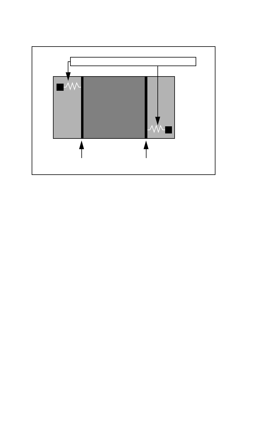
Chapter 17: StarRC Commands
WIDE_DEVICE_TERM_RESISTANCE 17-311
Chapter 17: StarRC Commands
WIDE_DEVICE_TERM_RESISTANCE 17-311
StarRC User Guide and Command Reference Version F-2011.06
Figure 17-10 Line Nodes for Resistor Terminals
terminal resistance to electrical line node
electrical line nodes
for resistor terminals

Chapter 17: StarRC Commands
XREF 17-312
StarRC User Guide and Command Reference F-2011.06
StarRC User Guide and Command Reference Version F-2011.06
XREF
Syntax
XREF: NO | YES | COMPLETE
Arguments
Argument Description
NO Reports the layout net names generated by Hercules or Calibre
during ideal layout extraction. These layout names are either
generated or derived from the application of text. The layout
instance names can either be the original GDSII instance name
(if the ASSIGN_PROPERTY command in Hercules is used), or
names generated by Hercules.
This is the default.
YES Reports all layout nets and devices occurring in the ideal layout
netlist using schematic, net, and instance names wherever
possible. When nets or devices exist that were not successfully
matched during LVS, layout names are used. When a successful
match did occur during LVS, StarRC uses schematic names.
StarRC handles composite device merging by using schematic
instance names with modifiers attached whenever layout devices
outnumber schematic devices within a particular composite
device pairing.

Chapter 17: StarRC Commands
XREF 17-313
Chapter 17: StarRC Commands
XREF 17-313
StarRC User Guide and Command Reference Version F-2011.06
Description
A GDS-based device-level extraction database contains both layout names and
cross-referenced schematic names if a logic versus schematic verification was performed.
The XREF command determines which set of names to provide to StarRC for netlist creation
and analysis flows. It also determines which devices and nets to retain.
This command is only valid when MILKYWAY_EXTRACT_VIEW: YES is specified for Hercules
input databases, or when a CALIBRE_IXF_FILE and CALIBRE_NXF_FILE are specified for
Calibre input databases.
See Also
•MILKYWAY_EXTRACT_VIEW
COMPLETE Reports every SKIP_CELLS/device in the schematic.
XREF:COMPLETE is only valid in the Hercules flow. The netlist
includes all instances. If you do not want this, make sure that any
net selected with the NETS command is also included in
NETLIST_SELECT_NETS.
Parasitics are netlisted only for nets that were successfully
cross-referenced to schematic nets. Nets that do not
cross-reference to a schematic net are treated as ideal
connections by StarRC. Schematic model names are reported for
SKIP_CELLS and primitive devices.
Internal nets of the SERIES/PATHS merged devices do not have
*|NET sections in XREF:COMPLETE; they are netlisted ideally in
the instance section. For an example of XREF:COMPLETE, see
Appendix A, “XREF:COMPLETE (SPF).
XREF:COMPLETE reports device properties in the following way.
The syntax used is x:y, where the left side is the number of
schematic devices and the right side is the number of layout
devices. A1 indicates one device, with m and n being differing
values of more than one. For example, m:m is “same number of
schematic and layout devices, but more than one,” m:n would
refer to different numbers of layout and schematic devices, and so
on.
Layout property merging for XREF:COMPLETE applies only to
standard SPICE properties. Nonstandard properties cannot be
merged for smashed devices in XREF:COMPLETE.
Argument Description

Chapter 17: StarRC Commands
XREF_FEEDTHRU_NETS 17-314
StarRC User Guide and Command Reference F-2011.06
StarRC User Guide and Command Reference Version F-2011.06
XREF_FEEDTHRU_NETS
Syntax
XREF_FEEDTHRU_NETS: YES | NO
Arguments
Argument Description
YES Generates pure layout feed-through nets and ports in the
XREF:COMPLETE netlist.
NO Does not generate feed-through nets and ports.
This is the default.
Description
Specifies whether or not to output pure layout feed-through nets and ports in the XREF:
COMPLETE netlist. These are routes that cross a hierarchical boundary but whose ports were
excluded from LVS, because they have no correspondence in the schematic netlist.
This command has no effect on XREF arguments other than COMPLETE. Pure layout
feed-through nets are always netlisted in the other XREF modes, because the other modes
are layout-based.
Note:
The CREATE_PORTS option must be enabled in the Hercules runset for
XREF_FEEDTHRU_NETS: YES.
See Also
•XREF

Chapter 17: StarRC Commands
XREF_LAYOUT_INST_PREFIX 17-315
Chapter 17: StarRC Commands
XREF_LAYOUT_INST_PREFIX 17-315
StarRC User Guide and Command Reference Version F-2011.06
XREF_LAYOUT_INST_PREFIX
Syntax
XREF_LAYOUT_INST_PREFIX: prefix
Arguments
Argument Description
prefix A prefix to be used in netlist generation
Default: Id_
Description
Sets a prefix for layout device instance names that were not cross-referenced to a schematic
device by the LVS tool. This prefix is applicable only for layout-based XREF mode YES, which
generates a netlist for every layout element whether or not it was cross-referenced. Device
instances that have no LVS comparison information, such as filtered layout instances, are
netlisted with this prefix followed by the layout instance name.
See Also
•XREF_LAYOUT_NET_PREFIX

Chapter 17: StarRC Commands
XREF_LAYOUT_NET_PREFIX 17-316
StarRC User Guide and Command Reference F-2011.06
StarRC User Guide and Command Reference Version F-2011.06
XREF_LAYOUT_NET_PREFIX
Sets a prefix for layout net names that were not cross-referenced to a schematic net by the
LVS tool.
Syntax
XREF_LAYOUT_NET_PREFIX: prefix
Arguments
Argument Description
prefix A prefix to be assigned to net names in netlist generation.
Default: ln_
Description
This prefix is applicable only for the layout based XREF mode YES, which generates a netlist
for every layout element whether or not it was cross-referenced. Nets that have no LVS
comparison information such as dangling and floating nets are output with this prefix
followed by the layout net name.
See Also
•XREF_LAYOUT_INST_PREFIX

Chapter 17: StarRC Commands
XREF_SWAP_MOS_SD_PROPERTY 17-317
Chapter 17: StarRC Commands
XREF_SWAP_MOS_SD_PROPERTY 17-317
StarRC User Guide and Command Reference Version F-2011.06
XREF_SWAP_MOS_SD_PROPERTY
Syntax
XREF_SWAP_MOS_SD_PROPERTY: prop1 prop2 [model_name]
Arguments
Argument Description
prop1 prop2 A pair of properties to be swapped
model_name Specifies that prop1 and prop2 are swapped only for
model_name device models
Description
Specifies a pair of MOS properties to be swapped. The pair of properties has the same
swapping behavior as generic MOS source and drain properties such as, ad, ps, and pd.
The XREF_SWAP_MOS_SD_PROPERTY statement affects SPICE, SPF, and any other netlist
format that has instances with properties. It does not affect SPEF files, which do not include
device parameters.
Example
To swap multiple pairs of properties, use a separate XREF_SWAP_MOS_SD_PROPERTY
statement for each pair of properties. For example,
XREF_SWAP_MOS_SD_PROPERTY: as2 ad2
XREF_SWAP_MOS_SD_PROPERTY: as3 ad3
To restrict the property swapping to a specific device model, specify the model name in the
XREF_SWAP_MOS_SD_PROPERTY statement as shown in the following example:
XREF_SWAP_MOS_SD_PROPERTY: as5 ad5 nch_mac5
See Also
•MODEL_TYPE
•XREF: YES | COMPLETE

Chapter 17: StarRC Commands
XREF_USE_LAYOUT_DEVICE_NAME 17-318
StarRC User Guide and Command Reference F-2011.06
StarRC User Guide and Command Reference Version F-2011.06
XREF_USE_LAYOUT_DEVICE_NAME
Syntax
XREF_USE_LAYOUT_DEVICE_NAME: YES | NO
Arguments
Argument Description
YES Netlist layout model names for all devices with XREF:
YES. A layout model name is a primary device model
name used in a device extraction command in a
Hercules or Calibre rule-file.
NO Netlist schematic model names for all devices with
XREF: YES; continue to use layout model names for
XREF: NO. A schematic model name is a device model
name that occurs in a schematic netlist used for an LVS
(Hercules flow) or that occurs in NETLIST MODEL or
TEXT MODEL commands (Calibre flow). This is default.
This is the default.
Description
Device model names recognized by StarRC can originate from one of two places:
• Schematic model name from a Hercules flow or NETLIST MODEL rule-file command
from a Calibre flow.
• Layout model name specified in device extraction command
See Also
•COUPLE_TO_GROUND
•NETLIST_FORMAT
•XREF
•ZONE_COUPLE_TO_NET_LEVEL

Chapter 17: StarRC Commands
ZONE_COUPLE_TO_NET 17-319
Chapter 17: StarRC Commands
ZONE_COUPLE_TO_NET 17-319
StarRC User Guide and Command Reference Version F-2011.06
ZONE_COUPLE_TO_NET
Syntax
ZONE_COUPLE_TO_NET: net_name
Arguments
Argument Description
net_name The net name to the noncritical material outside the
defined MACRO.
Default: none.
Description
This command is analogous to the SKIP_CELLS_COUPLE_TO_NET command, except that it
applies to overhead or adjacent material when you are doing the in-context extraction of a
MACRO or using the RING_AROUND_THE_BLOCK in-context approximation.
You must specify NETLIST_FORMAT: SPEF and COUPLE_TO_GROUND: NO to use this
command.
Example
ZONE_COUPLE_TO_NET: ZONE
See Also
•ZONE_COUPLE_TO_NET_LEVEL

Chapter 17: StarRC Commands
ZONE_COUPLE_TO_NET_LEVEL 17-320
StarRC User Guide and Command Reference F-2011.06
StarRC User Guide and Command Reference Version F-2011.06
ZONE_COUPLE_TO_NET_LEVEL
Syntax
ZONE_COUPLE_TO_NET_LEVEL: YES | NO
Arguments
Argument Description
YES Appends the layer number of the material outside the
MACRO.
NO Does not append the layer number of the material
outside the MACRO.
This is the default.
Description
Analogous to the SKIP_CELLS_COUPLE_TO_NET_LEVEL command option, except that it
applies to the ZONE_COUPLE_TO_NET.
See Also
•ZONE_COUPLE_TO_NET

18-1
18
ITF Statements and Options 18
The Interconnect Technology Format (ITF) defines a cross-section profile of the process.
The ITF file consists of an ordered list of conductor and dielectric layer definition statements.
The layers are defined from the topmost dielectric layer to the bottommost dielectric layer,
excluding the substrate, in a way that is consistent with the physical manufacturing process.
This chapter describes the ITF statements and their options. Use the ITF statements to
create an ITF file with the following structure:
TECHNOLOGY = process_name
[GLOBAL_TEMPERATURE = temp_value]
[BACKGROUND_ER = value]
[HALF_NODE_SCALE_FACTOR = scale_factor]
[USE_SI_DENSITY = YES | NO ]
[DROP_FACTOR_LATERAL_SPACING = value]
DIELECTRIC top_dielectric_name {...}
CONDUCTOR top_conductor_name {...}
[...]
[DIELECTRIC bottom_dielectric_name{...}]
VIA top_via_name {...}
[...]
VIA bottom_via_name {...}
[VARIATION_PARAMETERS {...}]
Comments in an ITF File
In an ITF file, a dollar sign ($) at the beginning of a line indicates a comment that is not
interpreted by the extraction tool.

Chapter 18: ITF Statements and Options
18-2
StarRC User Guide and Command Reference F-2011.06
StarRC User Guide and Command Reference Version F-2011.06
Restrictions for Layer Names
In the CONDUCTOR, DIELECTRIC, and VIA statements, the case-sensitive layer names
• Must contain only alphanumeric characters and underscores (_) unless otherwise noted
• Must begin with an alphabetic character
• Must not begin with a number or an underscore (_)
• Must not contain periods

Chapter 18: ITF Statements and Options
AIR_GAP_VS_SPACING 18-3
Chapter 18: ITF Statements and Options
AIR_GAP_VS_SPACING 18-3
StarRC User Guide and Command Reference Version F-2011.06
AIR_GAP_VS_SPACING
Defines the parameters of the air gap in your process.
Syntax
AIR_GAP_VS_SPACING {
SPACINGS { s1 s2 .. sn }
AIR_GAP_WIDTHS { w(s1) s(s2) ... s(sn) }
AIR_GAP_THICKNESSES { t(s1) t(s2) ... t(sn) }
AIR_GAP_BOTTOM_HEIGHTS { h(s1) h(s2) h(sn) }
}
Arguments
Argument Description
s1 s2 ... sn Spacings between the two conductors.
Units: microns
w(s1) s(s2) ... s(sn) The widths of the air gap formed at the corresponding spacing
values.
Units: microns
t(s1) t(s2) ... t(sn) The thicknesses of the air gap formed at the corresponding
spacing values.
Units: microns
h(s1) h(s2) ... h(sn) The heights of the bottom of the air gap from the bottom of the
conductor at the corresponding spacing values.
Units: microns
Description
Use AIR_GAP_VS_SPACING within a CONDUCTOR statement to define the parameters of the air
gap in your process. The number of arguments in each row of the table must be equal.
Spacing value s1 must be equal to SMIN in the CONDUCTOR statement.
If the spacing between the polygons is greater than sn, an air gap does not form.

Chapter 18: ITF Statements and Options
AIR_GAP_VS_SPACING 18-4
StarRC User Guide and Command Reference F-2011.06
StarRC User Guide and Command Reference Version F-2011.06
Errors
If StarRC finds an air gap definition from an earlier release format, the following warning
message is issued:
WARNING:(1005) ITF**
WARNING: AIR_GAP_WMAX, AIR_GAP_SMAX, AIR_GAP_HEIGHT are obsolete from
2003.03 release;
WARNING: grdgenxo translates them into the following new syntax for layer
M2:
WARNING: AIR_GAP_VS_SPACING {
WARNING: SPACINGS { 0.28 1 2 }
WARNING: AIR_GAP_WIDTHS { 0.28 1 1 }
WARNING: AIR_GAP_THICKNESSES { 0.4 0.4 0.4 }
WARNING: AIR_GAP_BOTTOM_HEIGHTS { 0.1 0.1 0.1 }
WARNING: }
If you change any values in the air gap definition, you need to regenerate the nxtgrd file. The
previous grdgenxo run directory cannot be used.
Example
AIR_GAP_VS_SPACING {
SPACINGS { 0.3 0.5 0.7 1.0 3.0 }
AIR_GAP_WIDTHS { 0.1 0.09 0.09 0.15 0.20 }
AIR_GAP_THICKNESSES { 0.2 0.23 0.25 0.26 0.28 }
AIR_GAP_BOTTOM_HEIGHTS { 0.1 0.14 0.18 0.20 0.22 }
}
See Also
•CONDUCTOR

Chapter 18: ITF Statements and Options
AREA 18-5
Chapter 18: ITF Statements and Options
AREA 18-5
StarRC User Guide and Command Reference Version F-2011.06
AREA
Specifies the default area of a via.
Syntax
AREA = via_area
Arguments
Argument Description
via_area Area of default via.
Units: square microns
Default: 1.0e -6 / RPV
Description
The resistive properties of the via layer must be specified. The via layers can be specified in
two ways: RHO, or RPV and AREA. However, only one specification method is required.
If RPV is specified, then AREA is required.
You must specify this option within a VIA statement.
Example
VIA via1 { FROM=m1 TO=m2 AREA=4 RPV=0.25 }
See Also
•RPV
•VIA

Chapter 18: ITF Statements and Options
ASSOCIATED_CONDUCTOR 18-6
StarRC User Guide and Command Reference F-2011.06
StarRC User Guide and Command Reference Version F-2011.06
ASSOCIATED_CONDUCTOR
Allows conformal layers to be associated with a specified conductor layer.
Syntax
ASSOCIATED_CONDUCTOR = layer_name
Arguments
Argument Description
layer_name Layer to which the associated conductor is assigned
Description
The ASSOCIATED_CONDUCTOR statement allows conformal layers to be associated with a
specified conductor layer.
• Only one CONDUCTOR is allowed for an ASSOCIATED_CONDUCTOR.
• When an ASSOCIATED_CONDUCTOR material drops with a DROP_FACTOR defined for a
CONDUCTOR below it, IS_CONFORMAL layers also drop.
• If a CONDUCTOR above overlaps with the TW_T of an IS_CONFORMAL layer, the CONDUCTOR
cuts into the IS_CONFORMAL layer.
•An
IS_CONFORMAL layer can be specified without an ASSOCIATED_CONDUCTOR. See also
IS_CONDUCTOR
An ASSOCIATED_CONDUCTOR statement can only be defined for an IS_CONFORMAL layer; it
cannot be used with other conformal layers. When no ASSOCIATED_CONDUCTOR is specified
for an IS_CONFORMAL layer, the default is to measure from the top layer.
Errors
The following error and warning messages can be issued in the noted conditions:
• It the layer defined by ASSOCIATED_CONDUCTOR is not a valid layer, the following error
message appears:
ERROR: ASSOCIATED_CONDUCTOR layer xxx for layer xxx is not a valid
• If the layer defined by ASSOCIATED_CONDUCTOR is not a conductor layer, the following
error message appears:
ERROR: ASSOCIATED_CONDUCTOR must be a conductor for layer xxx.

Chapter 18: ITF Statements and Options
ASSOCIATED_CONDUCTOR 18-7
Chapter 18: ITF Statements and Options
ASSOCIATED_CONDUCTOR 18-7
StarRC User Guide and Command Reference Version F-2011.06
• If ASSOCIATED_CONDUCTOR is defined for a non-IS_CONFORMAL layer, the following
error message appears:
ERROR: Layer xx must be set to be IS_CONFORMAL if it has
ASSOCIATED_CONDUCTOR.
• If the conductor defined for ASSOCIATED_CONDUCTOR is higher than the IS_CONFORMAL
layer, the following message appears:
ERROR: ASSOCIATED_CONFORMAL layer xxx for layer xxx cannot be higher
than the layer itself.
Example
DIELECTRIC D1 {
IS_CONFORMAL
ASSOCIATED_CONDUCTOR=met1
SW_T=0.1 TW_T=0.1 ER=2.5
}

Chapter 18: ITF Statements and Options
BACKGROUND_ER 18-8
StarRC User Guide and Command Reference F-2011.06
StarRC User Guide and Command Reference Version F-2011.06
BACKGROUND_ER
Specifies the relative permittivity, or dielectric constant, of the background dielectric.
Syntax
BACKGROUND_ER = relative_permittivity
Arguments
Argument Description
relative_permittivity Relative permittivity
Default: 1.0
Description
The BACKGROUND_ER statement is an optional statement. If the BACKGROUND_ER statement is
not specified, then the relative permittivity of the background dielectric defaults to 1.0, the
relative permittivity of air.
The background dielectric globally fills the cross section to an infinite height, effectively
replacing air as the operating medium for the chip.
The DIELECTRIC statements specified in the ITF locally override the global background
dielectric.
Example
TECHNOLOGY = Sample_tech
GLOBAL_TEMPERATURE = 31.0
BACKGROUND_ER = 4.1

Chapter 18: ITF Statements and Options
BOTTOM_DIELECTRIC_ER 18-9
Chapter 18: ITF Statements and Options
BOTTOM_DIELECTRIC_ER 18-9
StarRC User Guide and Command Reference Version F-2011.06
BOTTOM_DIELECTRIC_ER
Specifies the relative permittivity of the dielectric region below the conductor.
Syntax
BOTTOM_DIELECTRIC_ER = permittivity
Arguments
Argument Description
permittivity Relative permittivity of the dielectric
Description
Specify the BOTTOM_DIELECTRIC_ER option together with the
BOTTOM_DIELECTRIC_THICKNESS option within a CONDUCTOR statement.
For more information about the BOTTOM_DIELECTRIC_ER option, see the description of the
BOTTOM_DIELECTRIC_THICKNESS option.
Example
BOTTOM_DIELECTRIC_ER = 4.0
See Also
•BOTTOM_DIELECTRIC_THICKNESS
•CONDUCTOR

Chapter 18: ITF Statements and Options
BOTTOM_DIELECTRIC_THICKNESS 18-10
StarRC User Guide and Command Reference F-2011.06
StarRC User Guide and Command Reference Version F-2011.06
BOTTOM_DIELECTRIC_THICKNESS
Specifies the thickness of the dielectric region below the conductor.
Syntax
BOTTOM_DIELECTRIC_THICKNESS = thickness
Arguments
Argument Description
thickness Thickness of the dielectric
Units: microns
Description
Specify the BOTTOM_DIELECTRIC_THICKNESS option together with the
BOTTOM_DIELECTRIC_ER option within a CONDUCTOR statement. If the specified conductor
layer does not appear in a certain model, the bottom dielectric layer does not appear in the
model either.
If a conductor with a bottom dielectric also has conformal dielectrics on the sides of the
conductor, the side conformal dielectric layers extend to the bottom of the bottom conformal
dielectric, as shown in Figure 18-1. When placing a conductor with bottom dielectric in the
dielectric stack, the bottom of the bottom dielectric layer is assumed to be sitting on top of
the planar dielectric layer defined below the conductor. To specify the thickness of the
conductor with the bottom dielectric layer, use the THICKNESS option in the CONDUCTOR
statement. Therefore, the top of the conductor with the bottom dielectric is at a distance
equal to the conductor thickness and the bottom dielectric thickness above the planar
dielectric.
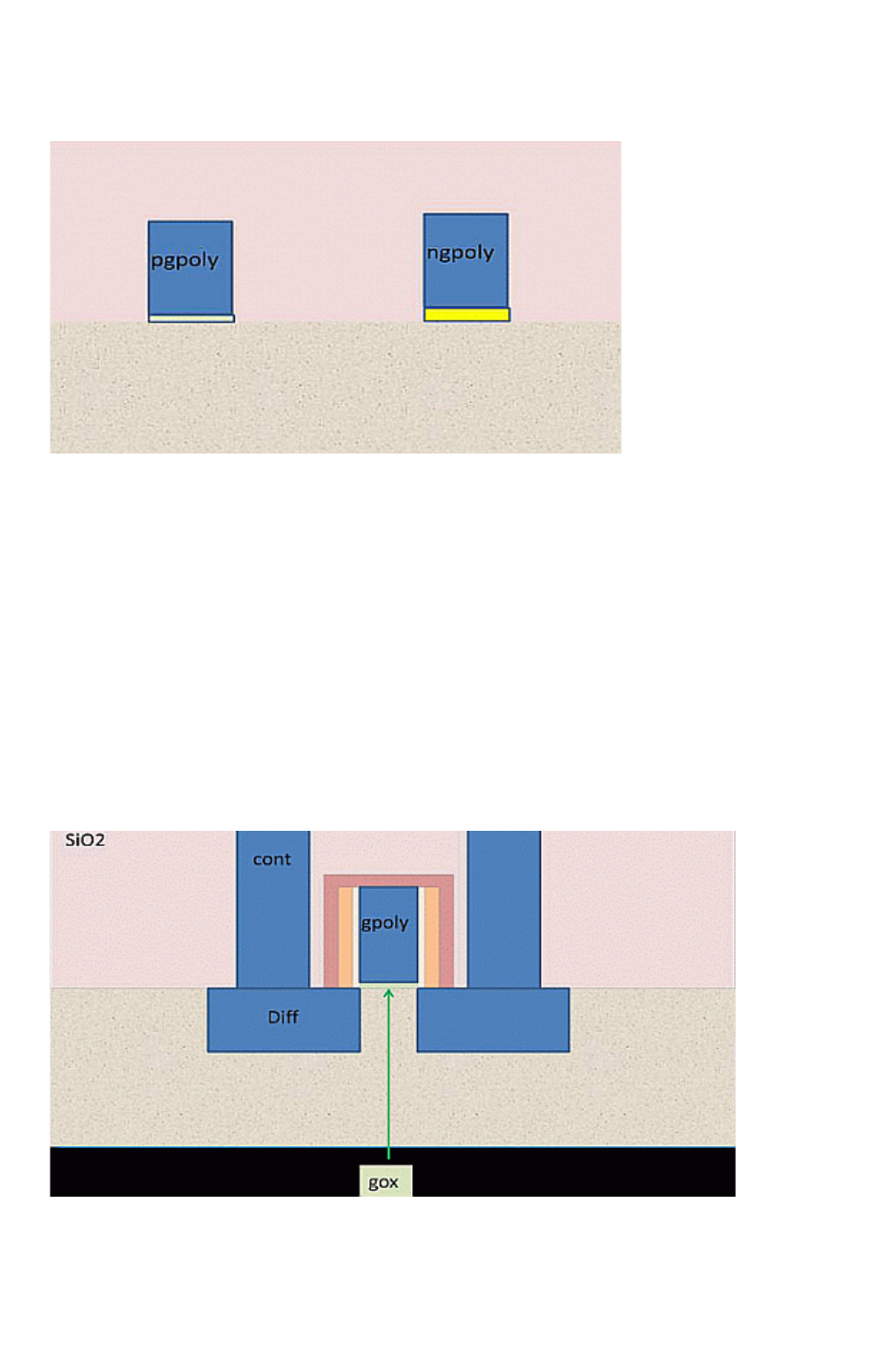
Chapter 18: ITF Statements and Options
BOTTOM_DIELECTRIC_THICKNESS 18-11
Chapter 18: ITF Statements and Options
BOTTOM_DIELECTRIC_THICKNESS 18-11
StarRC User Guide and Command Reference Version F-2011.06
Figure 18-1 Bottom Dielectric Layer with Covertical Layers
Example
High-Permittivity Gate Oxide
The high-permittivity dielectric under the gate shown in Figure 18-2 can be modeled with the
following syntax:
CONDUCTOR gpoly {
THICKNESS = 0.06
WMIN = 0.03
SMIN = 0.03
BOTTOM_DIELECTRIC_THICKNESS = 0.002
BOTTOM_DIELECTRIC_ER = 10.0
}
Figure 18-2 Modeling the High-Permittivity Dielectric Under the Gate

Chapter 18: ITF Statements and Options
BOTTOM_DIELECTRIC_THICKNESS 18-12
StarRC User Guide and Command Reference F-2011.06
StarRC User Guide and Command Reference Version F-2011.06
Independent Bottom Dielectric Regions in Covertical Conducting Layers
You can define independent bottom dielectric regions in covertical conducting layers. For
example, pgpoly and ngpoly conductors with different bottom dielectric regions, as shown in
Figure 18-1 on page 18-11, can be specified in the following manner:
CONDUCTOR pgpoly {
THICKNESS = 0.06 WMIN = 0.03 SMIN = 0.03
BOTTOM_DIELECTRIC_THICKNESS = 0.002
BOTTOM_DIELECTRIC_ER = 10.0
}
CONDUCTOR ngpoly {
THICKNESS = 0.06 WMIN = 0.03 SMIN = 0.03
BOTTOM_DIELECTRIC_THICKNESS = 0.004
BOTTOM_DIELECTRIC_ER = 12.0
}
See Also
•BOTTOM_DIELECTRIC_ER
•CONDUCTOR

Chapter 18: ITF Statements and Options
BOTTOM_THICKNESS_VS_SI_WIDTH 18-13
Chapter 18: ITF Statements and Options
BOTTOM_THICKNESS_VS_SI_WIDTH 18-13
StarRC User Guide and Command Reference Version F-2011.06
BOTTOM_THICKNESS_VS_SI_WIDTH
Specifies the bottom thickness of a conductor layer at different widths.
Syntax
BOTTOM_THICKNESS_VS_SI_WIDTH [RESISTIVE_ONLY | CAPACITIVE_ONLY]
{ (s1, r1) (s2, r2) . . . (sn, rn) }
Arguments
Argument Description
RESISTIVE_ONLY Applies thickness adjustment to resistance only.
CAPACITIVE_ONLY Applies thickness adjustment to capacitance only.
s1 ... sn Silicon widths in ascending order. The first entry should be the
smallest possible silicon width of the layer coming from the drawn
WMIN, but there is no error checking in the grdgenxo process. There
is no extrapolation beyond the range of s1 ... sn.
r1 ... rn Relative changes in bottom thickness. This is the absolute thickness
change from the bottom divided by the nominal thickness of the layer.
A bottom thickness or BTi is positive if the thickness becomes larger in
the nominal value. A bottom thickness BTi is negative if the thickness
becomes smaller than the nominal value.
Description
The BOTTOM_THICKNESS_VS_SI_WIDTH statement models bottom thickness within a
CONDUCTOR statement.
Various foundries note that in a low-k dielectric damascene process, one challenge is to etch
accurate depth for metal trenches. Analysis of data indicates that etching accurate depth in
a low-k dielectric process is not only dependent on the materials used, but it is also
dependent on the interconnect dimension and the proximity to the neighboring interconnect.
The variation in the etch depth for the metal deposition not only affects the thickness of the
interconnect but also affects the vertical distance between metal interconnects. Both
parasitic resistance and capacitance are affected.

Chapter 18: ITF Statements and Options
BOTTOM_THICKNESS_VS_SI_WIDTH 18-14
StarRC User Guide and Command Reference F-2011.06
StarRC User Guide and Command Reference Version F-2011.06
BOTTOM_THICKNESS_VS_SI_WIDTH performs linear interpolation of thickness variation for
wires whose widths fall between entries in the table. StarRC does not extrapolate beyond
the table.
• This feature is available only for conducting layers, because no variations exist for vias or
contacts in standard foundry processes.
•grdgenxo automatically processes trapezoidal conductor cross-sections. This means
that at a given thickness coming from a change at the bottom (and/or top), the specified
ETCH_VS_WIDTH_AND_SPACING, ETCH_FROM_TOP, or SIDE_TANGENT is automatically
applied for the whole cross-section when calculating the sensitivity,
• An error message is issued from grdgenxo if a BOTTOM_THICKNESS_VS_SI_WIDTH table
changes the relative thickness larger than 0.5 or smaller than -0.5. It does not guarantee
the accuracy of the modeling if the thickness changes too much. The same warning
condition is used for the following thickness variation flows in StarRC:
THICKNESS_VS_DENSITY, THICKNESS_VS_WIDTH_AND_SPACING,
POLYNOMIAL_BASED_THICKNESS_VARIATION, THICKNESS_VARIATION_FILE
• You can specify the BOTTOM_THICKNESS_VS_SI_WIDTH option along with the thickness
variation from the top of the conductor by using the following options:
THICKNESS_VS_DENSITY, THICKNESS_VS_WIDTH_AND_SPACING,
POLYNOMIAL_BASED_THICKNESS_VARIATION.
• When the BOTTOM_THICKNESS_VS_SI_WIDTH option is used along with
THICKNESS_VARIATION_FILE, which can already take thickness from the bottom of the
conductor, the resulting bottom thickness variation value is the sum of the two values.
• The BOTTOM_THICKNESS_VS_SI_WIDTH option cannot be used in conjunction with
multiple ETCH_VS_WIDTH_AND_SPACING tables.
• The BOTTOM_THICKNESS_VS_SI_WIDTH option cannot be specified in the same
CONDUCTOR statement as the MEASURED_FROM option.
Effective Thickness Calculation
The effective thickness is calculated with the following equation:
T Tnom 1 RTf Deff()RTf W S,()RTf SiW()++ +()×=
where
• Tnom is the nominal thickness specified in the ITF.
• RTf(Deff) is the relative thickness change due to density.

Chapter 18: ITF Statements and Options
BOTTOM_THICKNESS_VS_SI_WIDTH 18-15
Chapter 18: ITF Statements and Options
BOTTOM_THICKNESS_VS_SI_WIDTH 18-15
StarRC User Guide and Command Reference Version F-2011.06
• RTf(W,S) is the relative change in thickness due to width and spacing.
• RTf(SiW) is the relative change in thickness due to silicon width.
The resistance and capacitance is computed after the effective thickness is computed.
Note:
The grdgenxo process errors out and issues the following message when either a
RESISTIVE_ONLY or CAPACITIVE_ONLY argument is used with another
BOTTOM_THICKNESS_VS_SI_WIDTH table without any qualifiers:
Either a common BOTTOM_THICKNESS_VS_SI_WIDTH table or two separate
BOTTOM_THICKNESS_VS_SI_WIDTH tables with RESISTIVE_ONLY and
CAPACITIVE_ONLY can be used in the ITF.
See Also
•CONDUCTOR

Chapter 18: ITF Statements and Options
CAPACITIVE_ONLY_ETCH 18-16
StarRC User Guide and Command Reference F-2011.06
StarRC User Guide and Command Reference Version F-2011.06
CAPACITIVE_ONLY_ETCH
Specifies the etch value on one edge.
Syntax
CAPACITIVE_ONLY_ETCH = etch_value
Arguments
Argument Description
etch_value Etch value on one edge. A positive value reduces width.
Units: microns
Default: 0.0
Description
This option is specified in the ITF only within a CONDUCTOR statement.
It is identical to the ETCH option, except that only capacitance is affected by etching;
resistance is unaffected. This option is not the same as ETCH_VS_WIDTH_AND_SPACING
CAPACITIVE_ONLY.
Example
CONDUCTOR metal1 {
CAPACITIVE_ONLY_ETCH = 0.05
THICKNESS=0.66 WMIN=0.15 SMIN=0.15 RPSQ=0.078
}

Chapter 18: ITF Statements and Options
CONDUCTOR 18-17
Chapter 18: ITF Statements and Options
CONDUCTOR 18-17
StarRC User Guide and Command Reference Version F-2011.06
CONDUCTOR
Describes the properties of a conductor layer.
Syntax
CONDUCTOR conductor_name {
WMIN = min_width
SMIN = min_spacing
THICKNESS = thick_value
[AIR_GAP_VS_SPACING { ... }]
[BOTTOM_DIELECTRIC_THICKNESS = thickness
BOTTOM_DIELECTRIC_ER = permittivity]
[BOTTOM_THICKNESS_VS_SI_WIDTH ... { ... }]
[T0 = nominal_temp]
[CRT1 = lin_coeff
| CRT2 = quad_coeff
| CRT1 = lin_coeff CRT2 = quad_coeff
| CRT_VS_SI_WIDTH { ... }]
[DENSITY_BOX_WEIGHTING_FACTOR { ... }]
[DROP_FACTOR = value]
[ETCH = value
| CAPACITIVE_ONLY_ETCH = value
| RESISTIVE_ONLY_ETCH = value]
[ETCH_VS_WIDTH_AND_SPACING ... { ... }]
[FILL_RATIO = fill_ratio_value
FILL_WIDTH = fill_width_value
FILL_SPACING = fill_spacing_value
FILL_TYPE = GROUNDED | FLOATING ]
[GATE_TO_CONTACT_SMIN = value]
[GATE_TO_DIFFUSION_CAP { ... }]
[ILD_VS_WIDTH_AND_SPACING { ... }]
[IS_PLANAR]
[LAYER_TYPE = GATE | FIELD_POLY | DIFFUSION | TRENCH_CONTACT]
[MEASURED_FROM = dielectric_name | TOP_OF_CHIP]
[POLYNOMIAL_BASED_THICKNESS_VARIATION { ... }]
[RPSQ = rpsq_value
| RHO = rho_value
| RPSQ_VS_SI_WIDTH { ... }
| RPSQ_VS_WIDTH_AND_SPACING { ... }
| RHO_VS_SI_WIDTH_AND_THICKNESS { ... }
| RHO_VS_WIDTH_AND_SPACING { ... }]
[SIDE_TANGENT = value]
[THICKNESS_VS_DENSITY ... { ... }]
[THICKNESS_VS_WIDTH_AND_SPACING ... { ... }]
[TVF_ADJUSTMENT_TABLES { ... }]
}
Arguments
Argument Description
conductor_name Name of the conductor layer

Chapter 18: ITF Statements and Options
CONDUCTOR 18-18
StarRC User Guide and Command Reference F-2011.06
StarRC User Guide and Command Reference Version F-2011.06
WMIN = min_width Minimum width of a geometry on this layer
Units: microns
SMIN = min_spacing Minimum spacing between two geometries on this layer
Units: microns
THICKNESS = thick_value Thickness of this layer; cannot be less than 0.001 micron
Units: microns
BOTTOM_DIELECTRIC_THICKN
ESS = thickness
Thickness of the dielectric
Units: microns
BOTTOM_DIELECTRIC_ER =
permittivity
Relative permittivity of the dielectric
T0 = nominal_temp Nominal temperature for the layer
Units: degrees Celsius
Default: temperature specified by GLOBAL_TEMPERATURE
CRT1 = lin_coeff Layer-specific linear temperature coefficient
Default: 0
CRT2 = quad_coeff Layer-specific quadratic temperature coefficient
Default: 0
FILL_RATIO =
fill_ratio_value
Ratio of metal fill coverage
FILL_WIDTH =
fill_width_value
Average width of metal fill objects
Units: microns
FILL_SPACING =
fill_spacing_value
Average lateral spacing between signal nets and metal fill objects
Units: microns
ISPLANAR From this conductor and above, the layers do not drop because
DROP_FACTOR is specified for the lower layers
RPSQ = rpsq_value Resistance per square of the conducting layer
Units: ohms/square
Default: 0
Argument Description
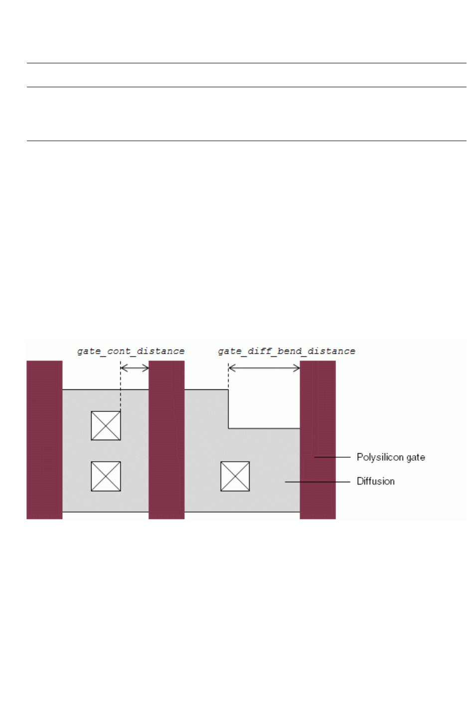
Chapter 18: ITF Statements and Options
CONDUCTOR 18-19
Chapter 18: ITF Statements and Options
CONDUCTOR 18-19
StarRC User Guide and Command Reference Version F-2011.06
Description
The CONDUCTOR statement describes the properties of a conductor layer such as minimum
width, minimum spacing, thickness, resistivity, and process variation.
StarRC allows a maximum of 50 CONDUCTOR statements in the ITF file.
User-Defined Diffusion Resistance
To apply a user-defined, equation-based model for diffusion resistance extraction, set
USER_DEFINED_DIFFUSION_RES: YES in your star_cmd file and specify the
DIFFUSION_RES_GATE_TO_CONT_THRESHOLD and DIFFUSION_RES_BEND_THRESHOLD
arguments within a CONDUCTOR statement for a polysilicon gate layer. Figure 18-3 illustrates
the gate_cont_distance and gate_diff_bend_distance parameters.
Figure 18-3 Parameters for User-Defined Diffusion Resistance Thresholds
When you specify DIFFUSION_RES_GATE_TO_CONT_THRESHOLD, equation-based diffusion
resistance extraction is applied to any contact with a distance from the gate less than
gate_cont_distance. Standard mesh-based extraction is applied to any contact with a
distance from the gate greater than gate_cont_distance.
RHO = rho_value Bulk resistivity of the via or conductor layer.
Units: ohms-micron
Default: RPV x AREA
Argument Description

Chapter 18: ITF Statements and Options
CONDUCTOR 18-20
StarRC User Guide and Command Reference F-2011.06
StarRC User Guide and Command Reference Version F-2011.06
Similarly, when you specify DIFFUSION_RES_BEND_THRESHOLD, equation-based diffusion
resistance extraction is applied to any contact with a distance from a diffusion bend less than
gate_diff_bend_distance. Standard mesh-based extraction is applied to any contact with
a distance from a diffusion bend greater than gate_cont_distance.
Example
The following example shows a simple CONDUCTOR statement for a metal layer.
Example 18-1 CONDUCTOR Statement for a Metal Layer
CONDUCTOR M1 { THICKNESS=0.8 WMIN=0.5 SMIN=0.45 RPSQ=0.041 }
The following example shows a CONDUCTOR statement with thresholds for equation-based
diffusion resistance.
Example 18-2 CONDUCTOR Statement With Thresholds for Equation-Based Diffusion
Resistance
CONDUCTOR POLY_GATE {
CRT1=0.0030 CRT2=0.0000 THICKNESS=0.10
GATE_TO_CONTACT_SMIN=0.04 WMIN=0.03 SMIN=0.04
RPSQ=13.00
DIFFUSION_RES_GATE_TO_CONT_THRESHOLD = 0.6
DIFFUSION_RES_BEND_THRESHOLD = 0.6
}

Chapter 18: ITF Statements and Options
CRT_VS_AREA 18-21
Chapter 18: ITF Statements and Options
CRT_VS_AREA 18-21
StarRC User Guide and Command Reference Version F-2011.06
CRT_VS_AREA
Specifies the temperature coefficients of resistance as a function of via area.
Syntax
CRT_VS_AREA {
(area_1, crt1_1, crt2_2)
(area_2, crt1_1, crt2_2)
...
(area_n, crt1_n, crt2_n)
}
Arguments
Argument Description
area_1 ... area_n Via areas specified in increasing order
Units: square microns
crt1_1 ... crt1_n Linear temperature coefficients for corresponding via sizes
crt2_1 ... crt2_n Quadratic temperature coefficients for corresponding via sizes
Description
Use a CRT_VS_AREA table within a VIA statement to specify the temperature coefficients of
resistance as function of via area. There is no limit to the number of entries you can specify.
You cannot specify CRT_VS_AREA together with CRT1 or CRT2 in the same VIA statement.
When the actual via size does not exactly equal any of the area entries in the CRT_VS_AREA
table, CRT1 and CRT2 are determined by the following methods:
• If the actual via size is less than the smallest area entry in the CRT_VS_AREA table, the
CRT values are set to the corresponding crt1 and crt2 entries of the smallest area
entry; no extrapolation is performed.
• If the actual via size falls between two area entries in the CRT_VS_AREA table, CRT1 and
CRT2 are calculated by linear interpolation.
• If the actual area is greater than the largest area entry in the CRT_VS_AREA table, the CRT
values are set to the corresponding crt1 and crt2 entries of the largest area entry; no
extrapolation is performed.
Note:
CRT and AREA values specified in a mapping file take precedence over the CRT_VS_AREA
values specified in an ITF file.

Chapter 18: ITF Statements and Options
CRT_VS_AREA 18-22
StarRC User Guide and Command Reference F-2011.06
StarRC User Guide and Command Reference Version F-2011.06
Errors
The grdgenxo executable issues a warning message if
•AREA values in the table are not specified in increasing order. The grdgenxo executable
internally re-orders the table entries with increasing AREA values.
• The absolute value of CRT1 specified in the table is greater than 0.02.
• The value of CRT2 specified in the table is less than -0.002.
The grdgenxo executable errors out if
• You specify both the CRT_VS_AREA statement and the CRT statement in the same VIA
definition.
• You specify neither the nominal temperature for the via layer nor the global temperature.
• The CRT_VS_AREA table contains fewer than two rows. This same requirement applies to
the RPV_VS_AREA statement.
• The AREA values in the table are zero or negative.
• The CRT_VS_AREA table contains duplicate AREA values.
• You specify the -res_update option while adding or removing a CRT_VS_AREA table.
Example
CRT_VS_AREA {
(0.002025, 9.04E-04, 4.74E-07)
(0.005265, 1.18E-03, 8.02E-07)
}
See Also
•CRT1, CRT2, and T0
•VIA

Chapter 18: ITF Statements and Options
CRT_VS_SI_WIDTH 18-23
Chapter 18: ITF Statements and Options
CRT_VS_SI_WIDTH 18-23
StarRC User Guide and Command Reference Version F-2011.06
CRT_VS_SI_WIDTH
Specifies the CRT-based temperature derating for different conductor widths.
Syntax
CRT_VS_SI_WIDTH {
(siw_1, crt1_1, crt2_1)
(siw_2, crt1_2, crt2_2)
...
(siw_n, crt1_n, crt2_n)
}
Arguments
Argument Description
siw_1 ... siw_n Post-etch conductor widths
Units: microns
crt1_1 ... crt1_n Linear temperature coefficients for corresponding conductor
widths
crt2_1 ... crt2_n Quadratic temperature coefficients for corresponding conductor
widths
Description
You can use a CRT_VS_SI_WIDTH table within a CONDUCTOR statement to specify the CRT-
based temperature derating for different conductor widths. There is no limit to the number of
entries you can specify.
When the actual conductor width does not exactly equal any of the siw entries in the
CRT_VS_SI_WIDTH table, then CRT1 and CRT2 are determined by the following methods:
• If the actual conductor width is less than the smallest siw entry in the CRT_VS_SI_WIDTH
table, the CRT values are set to the corresponding crt1 and crt2 entries of the smallest
siw entry; no extrapolation is performed.
• If the actual conductor width falls between two siw entries in the CRT_VS_SI_WIDTH table,
CRT1 and CRT2 are calculated by linear interpolation.
• If the actual conductor width is greater than the largest siw entry in the
CRT_VS_SI_WIDTH table, the CRT values are set to the corresponding crt1 and crt2
entries of the largest siw entry; no extrapolation is performed.

Chapter 18: ITF Statements and Options
CRT_VS_SI_WIDTH 18-24
StarRC User Guide and Command Reference F-2011.06
StarRC User Guide and Command Reference Version F-2011.06
You can specify CRT_VS_SI_WIDTH only within CONDUCTOR statements, not VIA or CONTACT
statements.
If CRT_VS_SI_WIDTH is used with RPSQ_VS_SI_WIDTH, then the width index of
CRT_VS_SI_WIDTH should match that of RPSQ_VS_SI_WIDTH.
Example
CONDUCTOR MET1 {
THICKNESS=0.6 WMIN=0.34 SMIN=0.40
CRT_VS_SI_WIDTH {
(0.34, 0.001, 0.000)
(0.40, 0.001, 0.001)
(0.823, 0.002, 0.001)
(2.0, 0.003, 0.001)
}
}
See Also
•CONDUCTOR
•CRT1, CRT2, and T0
•RPSQ_VS_SI_WIDTH

Chapter 18: ITF Statements and Options
CRT1, CRT2, and T0 18-25
Chapter 18: ITF Statements and Options
CRT1, CRT2, and T0 18-25
StarRC User Guide and Command Reference Version F-2011.06
CRT1, CRT2, and T0
Defines parameters for temperature-dependent resistance models for CONDUCTOR and VIA
layers.
Syntax
CRT1 = lin_coeff
CRT2 = quad_coeff
T0 = nominal_temp
Arguments
Argument Description
CRT1 = lin_coeff Linear temperature coefficient for the layer. Specified on a per-
layer basis.
Default: 0
CRT2 = quad_coeff Quadratic temperature coefficient for the layer. Specified on a
per-layer basis.
Default: 0
T0 = nominal_temp Nominal temperature for the layer
Units: degrees Celsius
Default: temperature specified by GLOBAL_TEMPERATURE
Description
CRT1, CRT2, and T0 define temperature-dependent resistance models for conducting layers
and vias. The resistances are modeled similar to the way they are modeled in SPICE, by
using the following equation:
RR0CRT1TT0–()×CRT2 T T0–()
2
×1++[]×=
In this equation,
• R is the modeled resistance at the operating temperature T.
• R0 is the resistance value at the nominal temperature T0.
• CRT1 and CRT2 are the linear and quadratic temperature coefficients.

Chapter 18: ITF Statements and Options
CRT1, CRT2, and T0 18-26
StarRC User Guide and Command Reference F-2011.06
StarRC User Guide and Command Reference Version F-2011.06
Note:
The modeled resistance R exactly equals the nominal resistance (R0) if T=T0, or if both
CRT1=0 and CRT2=0.
If either CRT1 or CRT2 is nonzero for a layer (VIAs included), then a nominal temperature
specification is required for that layer. A value for nominal temperature can be set globally
with the command GLOBAL_TEMPERATURE at the top of the ITF. If the temperature is set by
individual layer and globally, the layer nominal temperature overrides the global setting.
Note:
OPERATING_TEMPERATURE must also be set in the command file to use the derating
information in the nxtgrd. If the resistance of a layer is changed by the mapping file, and
if that layer has temperature derating in the ITF, specifying the OPERATING_TEMPERATURE
command uses the temperature derating coefficients for that layer from the ITF.
OPERATING_TEMPERATURE is an extraction option. You must use the -cleanX option to the
StarXtract command if it is changed. OPERATING_TEMPERATURE replaces the
NETLIST_TEMPERATURE command.
Example
TECHNOLOGY = Sample_tech
GLOBAL_TEMPERATURE = 31.0
DIELECTRIC IMD2 { THICKNESS=2.0 ER=3.9 }
CONDUCTOR metal2 {
CRT1=3.00e-3 CRT2=2.0e-7
THICKNESS = 0.6 SMIN=0.5 WMIN=0.5 RPSQ = 0.06
}
DIELECTRIC IMD1 { THICKNESS=1.9 ER=4.9 }
CONDUCTOR metal1 {
CRT1=3.50e-3 CRT2=2.5e-7
THICKNESS = 0.5 SMIN = 0.4 WMIN=0.4 RPSQ = 0.08
}
DIELECTRIC FOX { THICKNESS=1.0 ER=3.9 }
VIA via1 {
FROM=metal1 TO=metal2 AREA=1 RPV=1
CRT1=2.5e-3 CRT2=1e-6 T0=29
}

Chapter 18: ITF Statements and Options
DAMAGE_ER 18-27
Chapter 18: ITF Statements and Options
DAMAGE_ER 18-27
StarRC User Guide and Command Reference Version F-2011.06
DAMAGE_ER
Defines the equivalent permittivity of a damage layer.
Syntax
DAMAGE_ER = equivalent_permittivity
Arguments
Argument Description
equivalent_permittivity Equivalent permittivity
Description
Use the DAMAGE_ER statement to specify the equivalent permittivity of a damage layer.

Chapter 18: ITF Statements and Options
DAMAGE_THICKNESS 18-28
StarRC User Guide and Command Reference F-2011.06
StarRC User Guide and Command Reference Version F-2011.06
DAMAGE_THICKNESS
Defines the thickness of the damage on the surface of the conductor.
Syntax
DAMAGE_THICKNESS = thickness
Arguments
Argument Description
thickness Thickness of the damage on the surface of the conductor
Units: microns
Description
The DAMAGE_THICKNESS statement defines the thickness of the damage on the surface of
the conductor.

Chapter 18: ITF Statements and Options
DENSITY_BOX_WEIGHTING_FACTOR 18-29
Chapter 18: ITF Statements and Options
DENSITY_BOX_WEIGHTING_FACTOR 18-29
StarRC User Guide and Command Reference Version F-2011.06
DENSITY_BOX_WEIGHTING_FACTOR
Specifies a density box weighting factor.
Syntax
DENSITY_BOX_WEIGHTING_FACTOR {(S1 W1) (S2 W2) (S3 W3) (S4 W4) (S5 W5)}
Arguments
Argument Description
Sn The size of the density box. Up to five entries are allowed.
S1, S2, S3, S4 and S5 are integers that are within (0<S<500) S1
< S2 < S3 < S4 < S5. Density box is SxS.
Units: microns
Wn The weighting factor specified in a floating-point number. Must be
within the range (-10 < W < 10). If W is set to 0, then that pair (Sn
Wn) is ignored.
Description
This option is to be used with the THICKNESS_VS_DENSITY option when specifying a single
or multiple box method for effective density calculation.
If you do not specify a DENSITY_BOX_WEIGHTING_FACTOR option, then the default density
box size of 50 µm is used with the weighting factor of unity. The weighting factor is multiplied
with the density to arrive at the effective density. The default is
DENSITY_BOX_WEIGHTING_FACTOR {(50 1)}.
Example
CONDUCTOR metal3 {
SMIN= 0.35 WMIN=0.42 THICKNESS=0.53 RPSQ=0.061
THICKNESS_VS_DENSITY {(0.1 -0.1)(0.2 0.1)(0.3 0.15)(0.5 0.3)}
DENSITY_BOX_WEIGHTING_FACTOR
{ (10 1)(20 0.23)(30 0.29)(40 0.08)(50 0.12) }
}
See Also
•THICKNESS_VS_DENSITY
•DENSITY_BASED_THICKNESS

Chapter 18: ITF Statements and Options
DIELECTRIC 18-30
StarRC User Guide and Command Reference F-2011.06
StarRC User Guide and Command Reference Version F-2011.06
DIELECTRIC
Describes the properties of a dielectric layer.
Syntax
DIELECTRIC dielectric_name {
ER = value
THICKNESS = value
[MEASURED_FROM = layer_name | TOP_OF_CHIP
[SW_T = value] [TW_T = value]]
[ASSOCIATED_CONDUCTOR = conductor_name [IS_CONFORMAL]]
[DAMAGE_THICKNESS = value DAMAGE_ER = value]
}
Arguments
Argument Description
dielectric_name Name of the dielectric layer
Description
The DIELECTRIC statement describes a dielectric layer above or below a conductor layer.
Errors
The following error messages are issued when limitations for THICKNESS, TW_T, and SW_T
are not observed:
ERROR:(908) ITF**
ERROR: Too thin SW_T value of 0.001 is specified for layer local1;
0 < SW_T < 0.005 is not allowed
ERROR:(910) ITF**
ERROR: Too thin TW_T value of 0.001 is specified for layer local1;
0 < TW_T < 0.005 is not allowed
ERROR:(906) ITF**
Too thin THICKNESS value of 0.0007 is specified for layer thin;
0<THICKNESS<0.001 is not allowed (THICKNESS=0 is allowed for conformal
dielectrics)
Example
The following example describes a dielectric layer with a thickness of 0.3 µm and a relative
permittivity of 3.9.
DIELECTRIC FOX { THICKNESS=0.3 ER=3.9 }
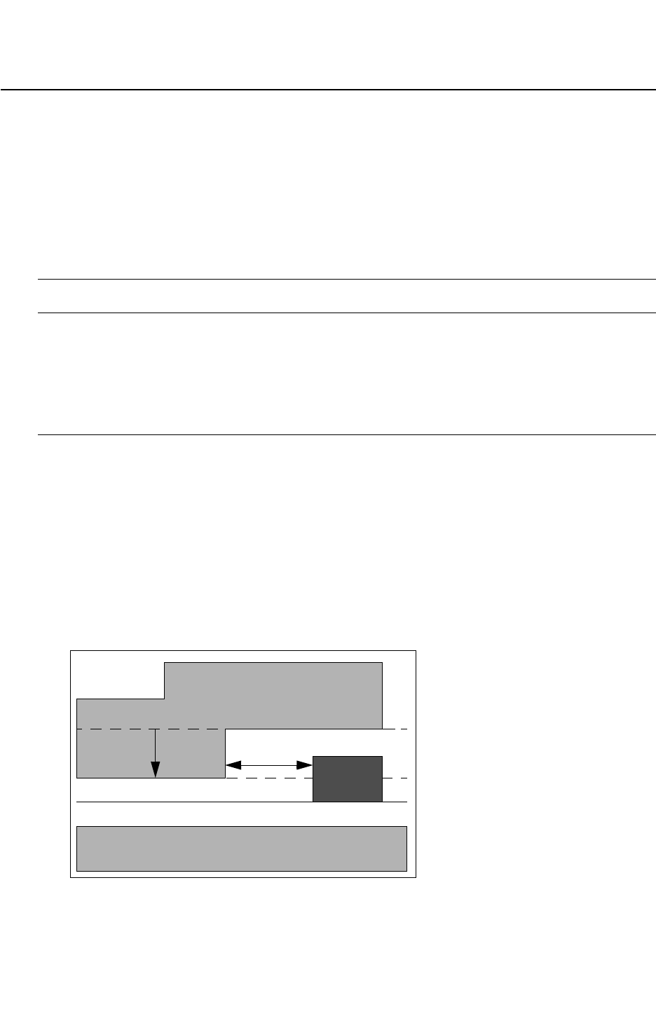
Chapter 18: ITF Statements and Options
DROP_FACTOR 18-31
Chapter 18: ITF Statements and Options
DROP_FACTOR 18-31
StarRC User Guide and Command Reference Version F-2011.06
DROP_FACTOR
Syntax
DROP_FACTOR = value
Arguments
Argument Description
value Absolute height which describes the nonplanarity of conductor
layers by specifying the amount that upper conductors fall in base
height whenever polygons of the specified conductor are not
present in a given layout area.
Units: microns
Default: 0
Description
This ITF CONDUCTOR option represents the decrease in base height of all conductors above,
when the bottom conductor is not present in the given layout area.
When a part of a polygon drops by the DROP_FACTOR specified for the conductor below, there
is a lateral gap between the dropped polygon and the polygon as shown in Figure 18-4. This
lateral gap is fixed at 0.5 micron.
You can specify up to four conductors with a DROP_FACTOR command.
Figure 18-4 DROP_FACTOR
M2
0.5 µm
0.2 µm
SUBSTRATE
M1


Chapter 18: ITF Statements and Options
DROP_FACTOR_LATERAL_SPACING 18-33
Chapter 18: ITF Statements and Options
DROP_FACTOR_LATERAL_SPACING 18-33
StarRC User Guide and Command Reference Version F-2011.06
DROP_FACTOR_LATERAL_SPACING
Specifies a constant lateral spacing value.
Syntax
DROP_FACTOR_LATERAL_SPACING = value
Arguments
Argument Description
value Constant value between 0.5 and 4.0
Units: microns
Default: 0.5
Description
The DROP_FACTOR_LATERAL_SPACING statement specifies a constant lateral spacing value
for all conductors.
It is preferred that you specify the DROP_FACTOR_LATERAL_SPACING statement after the
TECHNOLOGY statement.
Example
This example specifies a lateral spacing of 0.6 µm for all conductors when dropped.
TECHNOLOGY = sample_tech
DROP_FACTOR_LATERAL_SPACING = 0.6

Chapter 18: ITF Statements and Options
ER 18-34
StarRC User Guide and Command Reference F-2011.06
StarRC User Guide and Command Reference Version F-2011.06
ER
Specifies the relative permittivity of a dielectric.
Syntax
ER = permittivity
Arguments
Argument Description
permittivity Relative permittivity of a dielectric layer
Description
The ER statement specifies the relative permittivity, or dielectric constant, of a dielectric
layer.
The ER statement must be specified within the DIELECTRIC statement.
Example
DIELECTRIC D2 {THICKNESS = 1.2 ER = 3.9}
See Also
•DIELECTRIC

Chapter 18: ITF Statements and Options
ETCH 18-35
Chapter 18: ITF Statements and Options
ETCH 18-35
StarRC User Guide and Command Reference Version F-2011.06
ETCH
Specifies the absolute width adjustment for layer etch effects.
Syntax
ETCH = width_adjustment
Arguments
Argument Description
width_adjustment Absolute width adjustment for layer etch effects
Units: microns
Description
ETCH is calculated before resistance is calculated (for example, RPSQ). A positive value
denotes conductor shrink; a negative value denotes conductor growth. The adjusted width
is equal to the drawn width minus twice the etch value.
Specify the ETCH statement within a CONDUCTOR statement. The ETCH value is applied to
each edge of the conductor.
Example
CONDUCTOR M1 {
THICKNESS=0.6 WMIN=0.3 SMIN=0.3 RPSQ=0.05 ETCH=0.05
}
See Also
•CAPACITIVE_ONLY_ETCH
•RESISTIVE_ONLY_ETCH

Chapter 18: ITF Statements and Options
ETCH_VS_CONTACT_AND_GATE_SPACINGS 18-36
StarRC User Guide and Command Reference F-2011.06
StarRC User Guide and Command Reference Version F-2011.06
ETCH_VS_CONTACT_AND_GATE_SPACINGS
Specifies a contact bias as a function of contact width and spacing between the gate and
contact.
Syntax
ETCH_VS_CONTACT_AND_GATE_SPACINGS CAPACITIVE_ONLY {
CONTACT_TO_CONTACT_SPACING { c1 c2 c3 ... }
GATE_TO_CONTACT_SPACING { s1 s2 s3 ... }
VALUES { v(c1,s1) v(c2,s1) ...
v(c1,s2) v(c2,s2) ...
...
}
}
OR
ETCH_VS_CONTACT_AND_GATE_SPACINGS CAPACITIVE_ONLY {
NUMBER_OF_TABLES = num_of_tables
name_of_table1 {
CONTACT_TO_CONTACT_SPACING { c1 c2 c3 ... }
GATE_TO_CONTACT_SPACING { s1 s2 s3 ... }
VALUES { v(c1,s1) v(c2,s1) ...
v(c1,s2) v(c2,s2) ...
...
}
name_of_table2 {
CONTACT_TO_CONTACT_SPACING { c1 c2 c3 ... }
GATE_TO_CONTACT_SPACING { s1 s2 s3 ... }
VALUES { v(c1,s1) v(c2,s1) ...
v(c1,s2) v(c2,s2) ...
...
}
...
}
Description
The actual size of contacts in silicon may be different than the sizes drawn in layout. To
account for this difference during parasitic extraction, the VIA statement allows a contact
bias to be specified as a function of contact width and gate-to-contact spacing.
A positive etch value models a shrinking contact, and a negative etch value indicates that
the contact size is growing.
The resistance is assumed to be measured and therefore post-etch as specified in the RPV
statement for a via definition. Hence, the contact etch only affects the estimated
capacitance.

Chapter 18: ITF Statements and Options
ETCH_VS_CONTACT_AND_GATE_SPACINGS 18-37
Chapter 18: ITF Statements and Options
ETCH_VS_CONTACT_AND_GATE_SPACINGS 18-37
StarRC User Guide and Command Reference Version F-2011.06
All values for CONTACT_TO_CONTACT_SPACING, GATE_TO_CONTACT_SPACING, and VALUES
must be specified in microns.
Errors
The following error and warning messages can occur if the noted condition exists.
•grdgenxo errors and warnings
• If NUMBER_OF_TABLES is not given, only the old format is accepted in grdgenxo. If
there are multiple tables or a table with a table_name, an error occurs.
• If the number of tables are different from the specified NUMBER_OF_TABLES, grdgenxo
stops and issues an error message.
• If the old ITF format (no NUMBER_OF_TABLES, no table name) and a new format exists
at the same time in ITF with each format used for each of contact-etch and Cf tables
grdgenxo process stops and issues an error message.
• StarXtract Layers errors and warnings:
• If the table_name option in a mapping file does not match with any <name_of_table>
option in the ITF, StarXtract issues the following warning:
“Warning: TABLE_NAME table_name is provided for layer_name layer in Mapping file,
but is not found in ITF. TABLE_NAME for this layer will be ignored.”
• If a table_name is given for a non gate level layer in mapping file, StarXtract issues the
following warning:
“Warning: TABLE_NAME table_name is specified for non-gate-level layer layer_name
in the mapping file. TABLE_NAME for this layer will be ignored.”
• If contact-etch and/or gate-diffusion cap tables with the table name in the new format
present in ITF but a gate-level layer in mapping file does not have the TABLE_NAME
option, StarXtract issues the following warning:
“Warning: No TABLE_NAME is given for layer_name layer in the mapping file, while
there exist contact etch and/or gate-diffusion cap tables in ITF.”
Example
The following VIA definition does not have a contact bias:
VIA DiffCont {
FROM=diff TO=metal1 AREA=0.003 RPV=15
CRT1=6.56e-04 CRT2=-5.643e-0
}

Chapter 18: ITF Statements and Options
ETCH_VS_CONTACT_AND_GATE_SPACINGS 18-38
StarRC User Guide and Command Reference F-2011.06
StarRC User Guide and Command Reference Version F-2011.06
The previous VIA definition can be extended to include a contact bias 2-D table, or etch
table, as a function of contact-to-contact and gate-to-contact spacings. For example,
VIA DiffCont {
FROM=diff TO=metal1 AREA=0.003 RPV=15
CRT1=6.56e-04 CRT2=-5.643e-0
ETCH_VS_CONTACT_AND_GATE_SPACINGS CAPACITIVE_ONLY {
CONTACT_TO_CONTACT_SPACINGS {0.1 0.2 0.3}
GATE_TO_CONTACT_SPACINGS {0.05 0.1 0.15}
VALUES {0.005 0.006 0.007
0.004 0.005 0.006
0.003 0.004 0.005}
}
}
You can specify multiple table definitions in the ETCH_VS_CONTACT_AND_GATE_SPACINGS
option. Each table should have a name_of_table, which associates with a gate database
layer through a mapping file. You must use the same name for a contact etch table and a
gate diffusion table for one kind of device. A keyword can, however, associate with only one
contact-etch table or gate-diffusion capacitance table.
The following is an example of an ITF with multiple contact etch tables defined:
VIA diffCont {
FROM=diff TO=metal1 AREA=0.0036 RPV=55
CRT1=9.56e-04 CRT2=-3.68e-07
ETCH_VS_CONTACT_AND_GATE_SPACINGS CAPACITIVE_ONLY {
NUMBER_OF_TABLES=2
NMOS {
CONTACT_TO_CONTACT_SPACINGS {0.08 0.12}
GATE_TO_CONTACT_SPACINGS {0.04 0.08}
VALUES {0.008 0.009 0.003 0.005}
}
PMOS {
CONTACT_TO_CONTACT_SPACINGS {0.08 0.12}
GATE_TO_CONTACT_SPACINGS {0.04}
VALUES {0.004 0.002}
}
}
}
Mapping File Syntax
Use the following syntax for the mapping file:
conducting_layers gate_database_layer gate_grd_layer [table_name=keyword]
If the table_name keyword is defined for a gate, StarRC finds and uses the contact etch
table and gate-diffusion capacitance table of the same name in the ITF.

Chapter 18: ITF Statements and Options
ETCH_VS_CONTACT_AND_GATE_SPACINGS 18-39
Chapter 18: ITF Statements and Options
ETCH_VS_CONTACT_AND_GATE_SPACINGS 18-39
StarRC User Guide and Command Reference Version F-2011.06
By default, if a table_name is not defined for a gate database layer, no contact etch or gate-
diffusion capacitance calculation is applied to the device with the gate of that data layer. For
those devices, the contact etch is zero, and the gate-diffusion capacitance is the extracted
value if the IGNORE_CAP is set to extract gate-diffusion coupling.
Mapping File for Multiple Contact Etch Table Support
When multiple contact etch tables are defined in the ITF, the device gate layer that maps to
the corresponding table name must be specified in the StarRC mapping file. Use the
following mapping file syntax to look up the appropriate gate-to-diffusion table:
conducting_layers
gate_database_layer1 gate_grd_layer1 [table_name=name1]
gate_database_layer2 gate_grd_layer2 [table_name=name2]
...
If table_name is defined for a gate, StarRC finds and uses the corresponding gate-diffusion
capacitance table with same NAME in ITF.
If table_name is not defined for a gate database layer, no gate-diffusion capacitance
calculation is done for the device with the gate of that database layer.
The following example shows a mapping file to lookup the corresponding gate-to-diffusion
capacitance tables based on the tables specified in the previous example:
conducting_layers
ngate gpoly table_name=NMOS
pgate gpoly table_name=PMOS
tngate gpoly
tpgate gpoly
With this mapping file definition, devices with ngate as the gate polysilicon use the NMOS
contact etch table, and devices with pgate as the gate polysilicon use the PMOS table in the
ITF. No gate-to-contact etch is applied to the devices with tngate or tpgate gates.
Backward Compatibility
If an nxtgrd file from a previous version of StarRC is given as an input, StarRC behaves as
it did in the previous version. The older format supports a single table for each contact-etch
and Cf specification and does not have the table_name attribute in the ITF.
StarRC treats the given table as a default table for all gate layers as it did in older versions.
Even when the mapping file has table_name attributes for gate layers,
• StarRC ignores the table_name given in mapping file because there is no match in the
nxtgrd file.
• StarRC uses the table with no name in the nxtgrd file for all cases.


Chapter 18: ITF Statements and Options
ETCH_VS_WIDTH_AND_LENGTH 18-41
Chapter 18: ITF Statements and Options
ETCH_VS_WIDTH_AND_LENGTH 18-41
StarRC User Guide and Command Reference Version F-2011.06
ETCH_VS_WIDTH_AND_LENGTH
Specifies different via etch values for the length and width sides of nonsquare vias.
Syntax
ETCH_VS_WIDTH_AND_LENGTH CAPACITIVE_ONLY {
LENGTHS { l1 l2 ... lm }
WIDTHS { w1 w2 ... wn }
VALUES { (v_l1, v_w1) (v_l2, v_w1) ... (v_lm, v_w1)
(v_l1, v_w2) (v_l2, v_w2) ... (v_lm, v_w2)
...
(v_l1, v_wn) (v_l2, v_wn) ... (v_lm, v_wn)
}
}
Arguments
Argument Description
CAPACITIVE_ONLY Applies etch effect to capacitance only
l1 l2 ... lm Via lengths specified in ascending order
Units: microns
w1 w2 ... wn Via widths specified in ascending order
Units: microns
(v_l1, v_wn)
... (v_lm, v_wn)
Etch values of corresponding via lengths and widths
Units: microns
Description
Specify the ETCH_VS_WIDTH_AND_LENGTH option within a VIA statement to apply different
via etch values to the length and width sides of nonsquare vias.
The specified length and width values are used as indexes for the two-dimensional table of
etch values. Each combination of length lm and width wn has a corresponding pair of etch
values (v_lm, v_wn), where v_lm represents the etch value for the length, and v_wn
represents the etch value for the width.
Note the following restrictions when using an ETCH_VS_WIDTH_AND_LENGTH table:
• When the width is greater than the length, the corresponding etch values are n.
• Do not use the ETCH_VS_WIDTH_AND_LENGTH option to describe nonsquare diffusion
contacts.

Chapter 18: ITF Statements and Options
ETCH_VS_WIDTH_AND_LENGTH 18-42
StarRC User Guide and Command Reference F-2011.06
StarRC User Guide and Command Reference Version F-2011.06
• Do not specify the ETCH_VS_WIDTH_AND_LENGTH option together with the
ETCH_VS_CONTACT_AND_GATE_SPACINGS option in the same VIA statement.
• You can use ETCH_VS_WIDTH_AND_LENGTH together with the contstant etch
CAPACITIVE_ONLY_ETCH option.
Errors
If the ETCH_VS_WIDTH_AND_LENGTH option is specified along with the constant etch
CAPACITIVE_ONLY_ETCH option in a VIA definition, the two etch values are added together
in xTractor to apply the via etch.
The grdgenxo executable issues a warning message if
• A width and length combination results in an aspect ratio greater than one. The grdgenxo
executable then forces their corresponding etch values to be zero.
• A width and length combination results in an aspect ratio equal to one, but their
corresponding etch values are not the same.
The grdgenxo executable errors out if
• The CAPACITIVE_ONLY keyword is not specified.
• The ETCH_VS_WIDTH_AND_LENGTH statement and the
ETCH_VS_CONTACT_AND_GATE_SPACINGS statement both exist in the same VIA definition.
•VL ≥ 0.5 x LENGTH or VW ≥ 0.5 x WIDTH.
Note:
If you specify both ETCH_VS_WIDTH_AND_LENGTH and CAPACITIVE_ONLY_ETCH within
the same VIA definition, then the combined value of the two etches is subject to the
preceding restriction.
Example
In the following example, the etch entry for length=0.045 and width=0.115 is set to
(VL,VW)=(0.000, 0.000) because the parameter combination is invalid when the length is
less than the width.
VIA via1{ FROM=M8 TO=M9 AREA=0.005 RPV=5
ETCH_VS_WIDTH_AND_LENGTH CAPACITIVE_ONLY {
LENGTHS { 0.045 0.115 0.200 }
WIDTHS { 0.045 0.115 }
VALUES { (0.015, 0.015) (0.002, 0.002) (0.003 0.001)
(0.000, 0.000) (0.015, 0.015) (0.005 0.002)
}
}
}


Chapter 18: ITF Statements and Options
ETCH_VS_WIDTH_AND_SPACING 18-44
StarRC User Guide and Command Reference F-2011.06
StarRC User Guide and Command Reference Version F-2011.06
ETCH_VS_WIDTH_AND_SPACING
Specifies different via etch values for different via sizes and spacings.
Syntax
ETCH_VS_WIDTH_AND_SPACING
[RESISTIVE_ONLY | CAPACITIVE_ONLY | ETCH_FROM_TOP] {
SPACINGS { s1 s2 ... sm }
WIDTHS { w1 w1 ... wn }
VALUES { v_s1_w1 v_s2_w1 ... v_sm_w1
v_s1_w2 v_s2_w2 ... v_sm_w2
...
v_s1_wn v_s2_wn ... v_sm_wn
}
}
Arguments
Argument Description
RESISTIVE_ONLY Applies etch effect to resistance only
CAPACITIVE_ONLY Applies etch effect to capacitance only
ETCH_FROM_TOP Specifies a trapezoidal cross section using the spacing and
width-dependent top etch feature of CONDUCTOR
SPACINGS {...} Spacing values specified in ascending order
Units: microns
WIDTHS {...} Width values
Units: microns
VALUES {...} Etch values
Units: microns
Description
This option helps you to consider the actual fabricated patterns in the extraction of parasitic
components. This is important because OPC (Optical Proximity Correction) cannot fix all
proximity effects and the actual patterns might be different from the drawn mask patterns.
You specify this option within a CONDUCTOR statement.

Chapter 18: ITF Statements and Options
ETCH_VS_WIDTH_AND_SPACING 18-45
Chapter 18: ITF Statements and Options
ETCH_VS_WIDTH_AND_SPACING 18-45
StarRC User Guide and Command Reference Version F-2011.06
To more accurately model technologies with multiple etch processes, multiple
ETCH_VS_WIDTH_AND_SPACING tables can be specified in the same order as the
corresponding etch processes. When multiple ETCH_VS_WIDTH_AND_SPACING tables are
present, the RPSQ_VS_WIDTH_AND_SPACING option, RHO_VS_WIDTH_AND_SPACING option,
and BOTTOM_THICKNESS_VS_SI_WIDTH option are not allowed for that layer.
You must specify all three tables in the syntax definition: SPACINGS, WIDTHS, and VALUES.
You can list the tables in any order. All values (sn, wn) must be specified in microns; positive
etch values represent shrink and negative etch values represent an increase in width.
You can apply the ETCH_VS_WIDTH_AND_SPACING statement to both capacitance and
resistance. You can use the RESISTIVE_ONLY and CAPACITIVE_ONLY keywords within the
same conductor syntax, but you cannot use them when using
ETCH_VS_WIDTH_AND_SPACING independently. RESISTIVE_ONLY and CAPACITIVE_ONLY
can each be specified only once within any given CONDUCTOR statement.
The ETCH_FROM_TOP keyword specifies a trapezoidal cross section using the spacing and
width-dependent top etch feature of CONDUCTOR. The amount of etch is edge-based so the
sides of the trapezoidal cross section can have different angles. For example, in Figure 18-5,
the left side of the conductor could have an angular shift of 23 degrees and the right side
could have a shift of 14 degrees. As with the SIDE_TANGENT option, the center width is
unaffected by these adjustments.
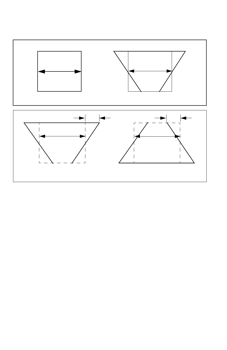
Chapter 18: ITF Statements and Options
ETCH_VS_WIDTH_AND_SPACING 18-46
StarRC User Guide and Command Reference F-2011.06
StarRC User Guide and Command Reference Version F-2011.06
Figure 18-5 Effect of the ETCH_FROM_TOP Keyword
W_center W_center
Before After
ETCH_FROM_TOP = -0.2
W_center
Negative value of ETCH_FROM_TOP
W_center
Positive value of ETCH_FROM_TOP
If you specify both the SIDE_TANGENT statement and the ETCH_FROM_TOP keyword for these
techniques, the top etch value takes precedence.
Example
Example 18-3 Example of a single ETCH_VS_WIDTH_AND_SPACING table
CONDUCTOR metal2 {
THICKNESS=0.65 WMIN=0.65 SMIN=0.50 RPSQ=0.62 ETCH=0.05
ETCH_VS_WIDTH_AND_SPACING RESISTIVE_ONLY {
SPACINGS { 0.5 0.67 0.8 }
WIDTHS { 0.65 0.9 }
VALUES { 0.1 0.05 -0.05
0.15 0.10 -0.10 }
}
}

Chapter 18: ITF Statements and Options
ETCH_VS_WIDTH_AND_SPACING 18-47
Chapter 18: ITF Statements and Options
ETCH_VS_WIDTH_AND_SPACING 18-47
StarRC User Guide and Command Reference Version F-2011.06
Example 18-4 Example using ETCH_FROM_TOP
CONDUCTOR metal5 {
THICKNESS=1.2 WMIN=0.3 SMIN=0.3 RPSQ = 0.62
ETCH_VS_WIDTH_AND_SPACING ETCH_FROM_TOP {
SPACINGS { 0.3 0.85 1.4 }
WIDTHS { 0.3 0.75 1.4 }
VALUES {-0.1 0.0 0.1
-0.1 0.0 0.1
-0.1 0.0 0.1 }
}
}
Example 18-5 Example of multiple ETCH_VS_WIDTH_AND_SPACING tables
CONDUCTOR M2 {
THICKNESS=0.132 WMIN=0.050 SMIN=0.050 SIDE_TANGENT=0.06992
ETCH_VS_WIDTH_AND_SPACING {
*the first EVWS table (round 1, pre-ADI table)
SPACINGS { 0.050 0.100 }
WIDTHS { 0.050 1.0 }
VALUES {-0.0027 0.0034
0.0003 0.0052 }
}
ETCH_VS_WIDTH_AND_SPACING {
*the second EVWS table (round2, API table)
SPACINGS { 0.045 0.150 }
WIDTHS { 0.045 2.0 }
VALUES {-0.002 0.0014
0.004 -0.003 }
}
}
See Also
•CAPACITIVE_ONLY_ETCH
•ETCH
•RESISTIVE_ONLY_ETCH
•RPSQ_VS_SI_WIDTH
•RPSQ_VS_WIDTH_AND_SPACING
•SIDE_TANGENT

Chapter 18: ITF Statements and Options
FILL_RATIO 18-48
StarRC User Guide and Command Reference F-2011.06
StarRC User Guide and Command Reference Version F-2011.06
FILL_RATIO
Specifies the ratio of metal fill coverage for a specified conductor.
Syntax
FILL_RATIO = ratio
Arguments
Argument Description
ratio Ratio of metal fill for a given layer
Description
The FILL_RATIO statement specifies the ratio of metal fill coverage for a specified
conductor. For example, if the density of the fill is 50 percent, specify FILL_RATIO = 0.5.
You must specify FILL_RATIO when you specify the FILL_SPACING and FILL_WIDTH
options.
Example
CONDUCTOR m1 {
THICKNESS=0.6 WMIN=0.3 SMIN=0.3
FILL_RATIO = 0.4 FILL_SPACING = 1.0 FILL_WIDTH = 2.0
}
See Also
•FILL_SPACING
•FILL_TYPE
•FILL_WIDTH

Chapter 18: ITF Statements and Options
FILL_SPACING 18-49
Chapter 18: ITF Statements and Options
FILL_SPACING 18-49
StarRC User Guide and Command Reference Version F-2011.06
FILL_SPACING
Specifies the average lateral space separating signal nets and metal fill objects in microns.
Syntax
FILL_SPACING = float
Arguments
Argument Description
float The average lateral spacing
Units: microns
Description
The FILL_SPACING statement specifies the average lateral space separating signal nets
and metal fill objects in microns. It is required if FILL_RATIO is specified.
Example
CONDUCTOR m1 {
THICKNESS=0.6 WMIN=0.3 SMIN=0.3
FILL_RATIO = 0.4 FILL_SPACING = 1.0 FILL_WIDTH = 2.0
}
See Also
•FILL_RATIO
•FILL_TYPE
•FILL_WIDTH

Chapter 18: ITF Statements and Options
FILL_TYPE 18-50
StarRC User Guide and Command Reference F-2011.06
StarRC User Guide and Command Reference Version F-2011.06
FILL_TYPE
Specifies grounded or floating processing of lateral metal fill emulation.
Syntax
FILL_TYPE = GROUNDED | FLOATING
Arguments
Argument Description
GROUNDED (default) Treats lateral metal fill patterns defined by FILL_WIDTH and
FILL_SPACING as if they are tied to ground net. This is the same
as the existing metal fill emulation in grdgenxo.
FLOATING Treats lateral metal fill patterns defined by FILL_WIDTH and
FILL_SPACING as if they are floating.
Description
FILL_TYPE provides for floating as well as grounded processing of lateral metal fill emulation
as defined by FILL_WIDTH and FILL_SPACING.
In the StarRC tool, real metal fill handling, both floating and grounded metal fill patterns, can
be extracted. However, the grdgenxo metal fill emulation has supported only grounded
handling for the lateral metal fills. The floating and grounded metal fill patterns is required
(especially during the design cycle) because there are no metal fill patterns in the layout until
the place and route has been fully completed. With this ITF command enhancement, you
can specify whether each layer’s metal fill emulation is treated as floating or grounded.
Example
CONDUCTOR m1 {
THICKNESS=0.6 WMIN=0.3 SMIN=0.3 FILL_RATIO = 0.4
FILL_SPACING = 1.0 FILL_WIDTH = 2.0 FILL_TYPE=FLOATING
}
See Also
•FILL_WIDTH

Chapter 18: ITF Statements and Options
FILL_WIDTH 18-51
Chapter 18: ITF Statements and Options
FILL_WIDTH 18-51
StarRC User Guide and Command Reference Version F-2011.06
FILL_WIDTH
Specifies the average size of metal fill objects.
Syntax
FILL_WIDTH = value
Arguments
Argument Description
value Average width of metal fill objects
Units: microns
Description
The FILL_WIDTH statement specifies the average size of metal fill objects, in microns.
FILL_WIDTH is required if FILL_SPACING or FILL_RATIO is specified.
Example
CONDUCTOR m1 {
THICKNESS=0.6 WMIN=0.3 SMIN=0.3
FILL_RATIO = 0.4 FILL_SPACING = 1.0 FILL_WIDTH = 2.0
}
See Also
•FILL_TYPE

Chapter 18: ITF Statements and Options
FROM 18-52
StarRC User Guide and Command Reference F-2011.06
StarRC User Guide and Command Reference Version F-2011.06
FROM
Specifies a conductor layer connected by a via.
Syntax
FROM = layer
Arguments
Argument Description
layer Conductor layer connected by the via
Description
The FROM statement specifies the upper or lower layer (which must be a defined CONDUCTOR
layer) connected by the via. Specify this option within a VIA statement.
Example
VIA sub_tie {
FROM = SUBSTRATE
TO = M1
AREA = 0.25
RPV = 5
}
See Also
•TO
•VIA
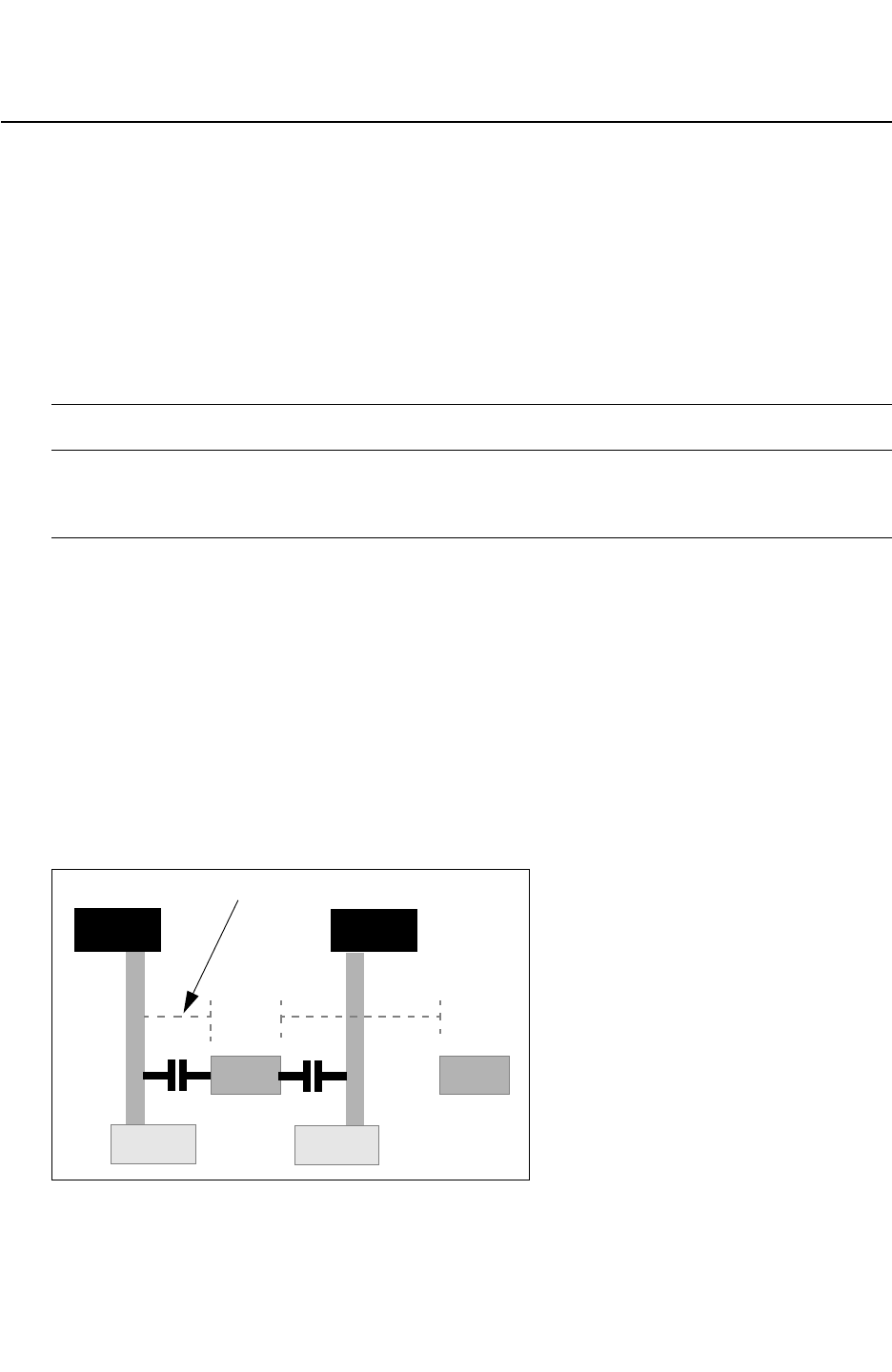
Chapter 18: ITF Statements and Options
GATE_TO_CONTACT_SMIN 18-53
Chapter 18: ITF Statements and Options
GATE_TO_CONTACT_SMIN 18-53
StarRC User Guide and Command Reference Version F-2011.06
GATE_TO_CONTACT_SMIN
Specifies the minimum spacing value between the polysilicon gate and the METAL1-
diffusion contact layer.
Syntax
GATE_TO_CONTACT_SMIN = float
Arguments
Argument Description
float Minimum spacing value between the polysilicon gate layer and
the METAL1 diffusion contact layer. The default is specified by the
SMIN statement.
Description
The GATE_TO_CONTACT_SMIN statement specifies the minimum spacing value between the
polysilicon gate and the METAL1-diffusion contact layer as shown in Figure 18-6. This
parameter is intended for use with ITF used with the StarRC EXTRACT_VIA_CAPS command,
and is specified in addition to SMIN for the polysilicon conductor. Because gate-to-contact
spacing is typically less than the SMIN value for polysilicon, specifying
GATE_TO_CONTACT_SMIN along with SMIN enables grdgenxo to account for both spacings to
maximize accuracy for EXTRACT_VIA_CAPS flows.
GATE_TO_CONTACT_SMIN is specified within a CONDUCTOR statement.
Figure 18-6 Derivation of SMIN and GATE_TO_CONTACT_SMIN
M1
NSD
GATE
NSD
POLY
SMIN
GATE_TO_CONTACT_SMIN
M1

Chapter 18: ITF Statements and Options
GATE_TO_CONTACT_SMIN 18-54
StarRC User Guide and Command Reference F-2011.06
StarRC User Guide and Command Reference Version F-2011.06
Example
CONDUCTOR poly {
THICKNESS=1.00 WMIN=0.13 SMIN=0.15
RPSQ=0.015 GATE_TO_CONTACT_SMIN=0.08
}

Chapter 18: ITF Statements and Options
GATE_TO_DIFFUSION_CAP 18-55
Chapter 18: ITF Statements and Options
GATE_TO_DIFFUSION_CAP 18-55
StarRC User Guide and Command Reference Version F-2011.06
GATE_TO_DIFFUSION_CAP
Models the gate-to-diffusion capacitance within a CONDUCTOR statement.
Syntax
GATE_TO_DIFFUSION_CAP {
NUMBER_OF_TABLES = num_of_tables
model_name1{
CONTACT_TO_CONTACT_SPACINGS {c1 c2 c3 ...}
GATE_TO_CONTACT_SPACINGS {s1 s2 s3 ...}
CAPS_PER_MICRON { v(c1,s1) v(c2,s1)...
v(c1,s2) v(c2,s2)... }
}
model_name2{
CONTACT_TO_CONTACT_SPACINGS {c1 c2 c3 ...}
GATE_TO_CONTACT_SPACINGS {s1 s2 s3 ...}
CAPS_PER_MICRON { v(c1,s1) v(c2,s1)...
v(c1,s2) v(c2,s2)... }
}
...
}
Arguments
Argument Description
num_of_tables Number of tables
model_name Model name
c1 c2 c3 ... Nearest contact-to-contact spacing
Units: microns
s1 s2 s3 ... Gate-to-contact spacings
Units: microns
v(c1,s1) v(c2,s1)... Capacitance per micron
Units: femtofarads per micron
Description
StarRC can extract the gate-to-diffusion capacitance component when the
IGNORE_CAPACITANCE: ALL setting is specified. The gate-to-diffusion intra-device
capacitance is of interest for parasitic extraction tools because of the strong layout
dependency of this capacitance component. The gate-to-contact capacitance is extracted
using the EXTRACT_VIA_CAPS: YES command in the StarRC command file.

Chapter 18: ITF Statements and Options
GATE_TO_DIFFUSION_CAP 18-56
StarRC User Guide and Command Reference F-2011.06
StarRC User Guide and Command Reference Version F-2011.06
To retain the gate-to-diffusion (Cf) coupling component when IGNORE_CAPACITANCE: ALL is
specified during a StarRC parasitic extraction, a command must be specified to include this
capacitance in the netlist.
Foundries responsible for creating a tight link between simulation SPICE models and the
parasitic netlist have requested the ability to provide a direct capacitance table plug-in to
extract gate to diffusion capacitance. Foundries choose to use a direct capacitance table
input rather than having StarRC extract the gate-to-diffusion capacitance based on pre-
characterized models (nxtgrd) to preserve proprietary information regarding complex
process effects around the device gate polysilicon. Another advantage of using the table is
you can use field solvers to characterize this very critical and small capacitance component.
The capacitance table is included as part of the gate polysilicon definition in the ITF file. The
two layout dependent parameters used for the Cf value in the table are:
•CONTACT_TO_CONTACT_SPACINGS
•GATE_TO_CONTACT_SPACINGS
Note:
A contact etch table and gate-diffusion cap table cannot be individually selected for a gate
layer or for a device. They are always selected as a set. If you need another combination
of two tables for a specific type of device, they can be defined in a table set with a new
keyword in ITF and a new database layer for the corresponding gate in the mapping file.
Example
The following example shows a gate-to-diffusion capacitance table specified within the gate-
polysilicon definition:
GATE_TO_DIFFUSION_CAP {
CONTACT_TO_CONTACT_SPACINGS { c1 c2 c3 ... c_m }
GATE_TO_CONTACT_SPACINGS { s1 s2 s3 ... s_n }
CAPS_PER_MICRON {
v(c1,s1) v(c2,s1) ... v(c_m,s1)
v(c1,s2) v(c2,s2) ... v(c_m,s2)
...
v(c1,s_n) v(c2,s_n) ... v(c_m,s_n)
}
}
In the case where contacts do not exist, as for shared source and drain regions, the largest
spacing value is taken from the Cf table that you specified.

Chapter 18: ITF Statements and Options
GATE_TO_DIFFUSION_CAP 18-57
Chapter 18: ITF Statements and Options
GATE_TO_DIFFUSION_CAP 18-57
StarRC User Guide and Command Reference Version F-2011.06
Device Dependent Gate-to-Diffusion Capacitance Table
You can specify a Cf table based on device type. Example 18-6 shows multiple gate-to-
diffusion capacitance tables defined in the ITF, one for an n-type and another for a p-type
device. Note that the number of tables and the table name must be specified when multiple
gate-to-diffusion tables are specified in the ITF.
A contact etch table and a gate-diffusion capacitance table for the same type of device
should have the same table name.
Example 18-6 Device-Dependent Gate-to-Diffusion Capacitance Table
CONDUCTOR gpoly {
THICKNESS= 0.080000 WMIN= 0.040 SMIN= 0.100 RPSQ=12.000
GATE_TO_CONTACT_SMIN=0.040 CRT1=1.924e-03 CRT2=-8.751e-07
GATE_TO_DIFFUSION_CAP {
NUMBER_OF_TABLES=2
NMOS{
CONTACT_TO_CONTACT_SPACINGS {0.08 0.12}
GATE_TO_CONTACT_SPACINGS {0.04 0.08}
CAPS_PER_MICRON {0.062 0.088 0.080 0.096}
}
PMOS {
CONTACT_TO_CONTACT_SPACINGS {0.08 0.12}
GATE_TO_CONTACT_SPACINGS {0.04 0.08}
GAPS_PER_MICRON {0.088 0.1200.108 0.128}
}
}
}
See Also
•CAPACITIVE_ONLY_ETCH
•ETCH_VS_CONTACT_AND_GATE_SPACINGS
•IGNORE_CAP: ALL RETAIN_GATE_TO_DIFFUSION_COUPLING

Chapter 18: ITF Statements and Options
GLOBAL_TEMPERATURE 18-58
StarRC User Guide and Command Reference F-2011.06
StarRC User Guide and Command Reference Version F-2011.06
GLOBAL_TEMPERATURE
Specifies the default nominal global temperature for the layers.
Syntax
GLOBAL_TEMPERATURE = temp_value
Arguments
Argument Description
temp_value Global temperature
Units: degrees Celsius
Default: 25
Description
The GLOBAL_TEMPERATURE statement is optional. If the GLOBAL_TEMPERATURE statement is
not specified, then the nominal global temperature defaults to 25 degrees Celsius.
The nominal layer temperature overrides the global temperature when both are specified.
Example
TECHNOLOGY = Sample_tech
GLOBAL_TEMPERATURE = 31.0
...

Chapter 18: ITF Statements and Options
HALF_NODE_SCALE_FACTOR 18-59
Chapter 18: ITF Statements and Options
HALF_NODE_SCALE_FACTOR 18-59
StarRC User Guide and Command Reference Version F-2011.06
HALF_NODE_SCALE_FACTOR
Shrinks the design database before extraction begins.
Syntax
HALF_NODE_SCALE_FACTOR = scale_factor
Arguments
Argument Description
scale_factor Scale factor
Default:1.0
Description
The HALF_NODE_SCALE_FACTOR statement directs the extraction tool to shrink the design
database by the specified value before extraction begins. This optional statement is useful if
you are using a half-node process technology.
This statement embeds or remove the specified magnification factor from the nxtgrd file
without a grdgenxo models directory.
When the HALF_NODE_SCALE_FACTOR value is detected in the nxtgrd file, StarRC
automatically internally sets the MAGNIFY_DEVICE_PARAMS:NO and
NETLIST_UNSCALED_COORDINATES:YES commands to ensure that the final netlist contains
the full node coordinates.
• The MAGNIFY_DEVICE_PARAMS option ensures that the standard device properties
($w,$l,$area and so on) are generated in the netlist at full node.
• The NETLIST_UNSCALED_COORDINATES option ensures that all of the coordinate
information in the netlist is printed at the full node.
The following list explains possible scenarios and the corresponding StarRC behavior:
• Scenario 1
If the value is set for the MAGNIFICATION_FACTOR in the StarRC command file and a
value is specified for HALF_NODE_SCALE_FACTOR in the nxtgrd file, an error message is
issued.
"ERROR: Both MAGNIFICATION_FACTOR cannot be used in half node flow
where
the scaling factor is specified in the nxtgrd file."

Chapter 18: ITF Statements and Options
HALF_NODE_SCALE_FACTOR 18-60
StarRC User Guide and Command Reference F-2011.06
StarRC User Guide and Command Reference Version F-2011.06
• Scenario 2
If MAGNIFY_DEVICE_PARAMS:YES and/or NETLIST_UNSCALED_COORDINATES:NO is set in
the star_cmd file for a run that uses a nxtgrd file containing the
HALF_NODE_SCALE_FACTOR option, a warning is issued stating the new value for the
options.
"WARNING: HALF_NODE_SCALE_FACTOR detected in nxtgrd file, setting
MAGNIFY_DEVICE_PARAMS:NO for unshrunk device properties.
• Scenario 3
If you generated the StarRC nxtgrd file without setting the HALF_NODE_SCALE_FACTOR, or
you set an incorrect value (not between 0 and 1), and you would like to embed a value of
0.9 into the nxtgrd file, you can run grdgenxo and generate an updated nxtgrd file by
using the following syntax:
grdgenxo -add_sf 0.9 -i noshrink.nxtgrd -o shrink.nxtgrd
If you generated a StarRC nxtgrd file with a HALF_NODE_SCALE_FACTOR value and you would
like to run StarRC without magnification, you can remove the magnification factor from the
nxtgrd file by using the following command syntax:
grdgenxo -add_sf 1 -i noshrink.nxtgrd -o shrink.nxtgrd
Note:
You can set the magnification factor command in the StarRC command file after removing
the value from nxtgrd file as shown in the previous example. You cannot, however, simply
delete the MAGNIFICATION_FACTOR line from the nxtgrd file, because this causes the
nxtgrd file to be corrupt.
Example
This is an example of an ITF header using the HALF_NODE_SCALE_FACTOR statement:
TECHNOLOGY = 65nm_sample
GLOBAL_TEMPERATURE = 25
HALF_NODE_SCALE_FACTOR = 0.9
DIELECTRIC PASS2 {THICKNESS=0.800000 ER=6.9}
DIELECTRIC PASS1 {THICKNESS=0.700000 ER=4.0}
The following is an example of coordinates in a SPICE-like netlist:
*|I (ZN:F12 M1 SRC B 0 0.48 0.64)
*|P (ZN B 0 0.695 1.115)
*|S (ZN:16 0.53 1.545)

Chapter 18: ITF Statements and Options
HALF_NODE_SCALE_FACTOR 18-61
Chapter 18: ITF Statements and Options
HALF_NODE_SCALE_FACTOR 18-61
StarRC User Guide and Command Reference Version F-2011.06
The physical properties of parasitic resistors, used for reliability analysis flows, as a result of
NETLIST_TAIL_COMMENTS:YES option must also be at the full node:
R1 F9 F8 0.588229 $l=9.9 $w=2 $lvl=1
Note:
The HALF_NODE_SCALE_FACTOR command does not change the function of the
MAGNIFICATION_FACTOR option. However, you cannot use the MAGNIFICATION_FACTOR
option with the HALF_NODE_SCALE_FACTOR command. It is not allowed.
If you want to update the magnification factor value during nxtgrd file generation, use the
following command:
grdgenxo -add_sf factor -i input_nxtgrd_file -o output_nxtgrd_file

Chapter 18: ITF Statements and Options
ILD_VS_WIDTH_AND_SPACING 18-62
StarRC User Guide and Command Reference F-2011.06
StarRC User Guide and Command Reference Version F-2011.06
ILD_VS_WIDTH_AND_SPACING
Enables you to measure the micro-loading effect or bottom conductor thickness variation.
Syntax
ILD_VS_WIDTH_AND_SPACING {
DIELECTRIC = ILD_Layer_Name
WIDTHS {w1 w2 w3 ...}
SPACINGS {s1 s2 s3 ...}
THICKNESS_CHANGES {
v(s1,w1) v(s2,w1) ...
v(s1,w2) v(s2,w2) ...
...
}
}
Arguments
Argument Description
ILD_Layer_Name The name of the dielectric layer below the conductor
corresponding to the thickness variation
WIDTHS {...} Width in drawn dimensions
SPACINGS {...} Spacing in drawn dimensions
THICKNESS_CHANGES {...} Absolute thickness variation of the ILD layer specified. A positive
variation indicates an increase of thickness, and a decrease of
thickness is represented by a negative variation. The maximum
value is 0.2. The minimum value is -0.2.
Description
The ILD_VS_WIDTH_AND_SPACING statement in the ITF enables you to measure the micro-
loading effect or bottom conductor thickness variation.
WIDTH and SPACING are both in drawn dimensions and DIELECTRIC is the dielectric layer
below the conductor corresponding to the thickness variation. Each entry of the VALUES
specifies the absolute thickness variation of the ILD layer specified. A positive variation
indicates an increase of thickness, and a decrease of thickness is represented by a negative
variation. The SPACING command can be specified before the WIDTH command; however,
the mapping of the values remains the same regardless of the order of specification of the
two subcommands.
Maximum values specified in the table must not be greater than 0.2 and must not be less
than -0.2.

Chapter 18: ITF Statements and Options
ILD_VS_WIDTH_AND_SPACING 18-63
Chapter 18: ITF Statements and Options
ILD_VS_WIDTH_AND_SPACING 18-63
StarRC User Guide and Command Reference Version F-2011.06
The ILD_VS_WIDTH_AND_SPACING option cannot be used in the same CONDUCTOR statement
as the BOTTOM_THICKNESS_VS_SI _WIDTH option or the MEASURED_FROM option.
Handling ILD Variation in Flows
StarRC today allows multiple definitions of bottom thickness variation:
•BOTTOM_THICKNESS_VS_SI_WIDTH command
•THICKNESS_VARIATION_FILE (TVF) in CMP simulator flow
StarRC does not combine multiple bottom thickness variation sources. As previously
mentioned, you cannot specify BOTTOM_THICKNESS_VS_SI_WIDTH with
ILD_VS_WIDTH_AND_SPACING for a given conductor.
For TVF input to StarRC, the ILD variation from the nxtgrd file is disabled because it is
assumed that the CMP simulation thickness output accounts for the loading effect. The
following thickness variation effects are automatically disabled when TVF input is provided
from a CMP simulation flow:
•POLYNOMIAL_BASED_THICKNESS_VARIATION (PBTV)
•THICKNESS_VS_DENSITY (TVD)
•THICKNESS_VS_WIDTH_AND_SPACING (TVWS)
•ILD_VS_WIDTH_AND_SPACING
Note:
The BOTTOM_THICKNESS_VS_SI_WIDTH is not disabled for TVF input flows because the
CMP simulation in this case is assumed to not model the loading effect.
Restrictions
The following conditions are implemented pertaining to the ILD_VS_WIDTH_AND_SPACING
ITF command:
• If ILD variation is specified for a dielectric layer that does not exist directly below a
conductor, the following error occurs:
“ERROR: ILD_VS_WIDTH_AND_SPACING can only be specified for dielectric layers
directly below the conductor (due to micro-loading)”
• If ILD variation is specified for a conductor layer that does not have
POLYNOMIAL_BASED_THICKNESS_VARIATION, the following error occurs:
“ERROR: ILD_VS_WIDTH_AND_SPACING requires
POLYNOMIAL_BASED_THICKNESS_VARIATION table be specified
ERROR: within the same conductor layer: metal8”

Chapter 18: ITF Statements and Options
ILD_VS_WIDTH_AND_SPACING 18-64
StarRC User Guide and Command Reference F-2011.06
StarRC User Guide and Command Reference Version F-2011.06
• If the ILD variation specified is greater than 0.2 or less than -0.2, the following error
occurs:
“ERROR: Maximum variation of 20% allowed for intra-layer dielectric (ILD) thickness (due
to micro-loading)"
• If ILD variation table is specified within the same CONDUCTOR statement with a
BOTTOM_THICKNESS_VS_SI_WIDTH table, the following error occurs:
“ERROR: ILD_VS_WIDTH_AND_SPACING cannot be specified together with
BOTTOM_THICKNESS_VS_SI_WIDTH within the same CONDUCTOR command"
Example
ILD_VS_WIDTH_AND_SPACING {
DIELECTRIC = ILD3
WIDTHS {0.1 0.2 0.3 0.4}
SPACINGS {0.11 0.22 0.33 0.44}
THICKNESS_CHANGES {0.130 0.134 0.138 0.140
0.135 0.138 0.139 0.142
0.138 0.139 0.139 0.143
0.140 0.142 0.144 0.146
}
}
The DIELECTRIC statement specifies the dielectric layer below which the ILD variation is to
be accounted for. The VALUES specified are absolute ILD variation values.
See Also
•BOTTOM_THICKNESS_VS_SI_WIDTH
•THICKNESS_VARIATION_FILE (CMP simulator)

Chapter 18: ITF Statements and Options
IS_CONFORMAL 18-65
Chapter 18: ITF Statements and Options
IS_CONFORMAL 18-65
StarRC User Guide and Command Reference Version F-2011.06
IS_CONFORMAL
Defines the material the conductor layer is deposited around and allows conformal layers to
be associated with a specified conductor layer.
Syntax
IS_CONFORMAL
Arguments
The IS_CONFORMAL keyword does not have any arguments.
Description
The IS_CONFORMAL keyword is specified with an ASSOCIATED_CONDUCTOR statement. It
defines the material the conductor layer is deposited around and allows conformal layers to
be associated with a specified conductor layer.
•A DIELECTRIC layer specified with an IS_CONFORMAL layer tag is a conformal layer.
•An IS_CONFORMAL layer can have SW_T and/or TW_T around the CONDUCTOR. If TW_T or
SW_T is not specified, 0.0 is assumed.
• When an ASSOCIATED_CONDUCTOR material drops with a DROP_FACTOR defined for a
CONDUCTOR below it, IS_CONFORMAL layers also drop.
• If a CONDUCTOR above overlaps with the TW_T of an IS_CONFORMAL layer, the CONDUCTOR
cuts into the IS_CONFORMAL layer.
•An IS_CONFORMAL layer can be specified without an ASSOCIATED_CONDUCTOR. See also
ASSOCIATED_CONDUCTOR
Errors
The following error and warning messages can be issued in the noted conditions:
• If thickness is defined for an IS_CONFORMAL layer, an error message is issued:
ERROR:LAYER xxx is set to be IS_CONFORMAL; it must have a thickness of
• If ASSOCIATED_CONDUCTOR is defined for a non-IS_CONFORMAL layer:
ERROR: LAYER xxx must be set to IS_CONFORMAL if it has an
ASSOCIATED_CONDUCTOR.
• If the conductor defined for ASSOCIATED_CONDUCTOR is higher than the IS_CONFORMAL
layer, the following message appears:
ERROR: ASSOCIATED_CONFORMAL layer xxx for layer xxx cannot be higher
than
the layer itself.


Chapter 18: ITF Statements and Options
IS_PLANAR 18-67
Chapter 18: ITF Statements and Options
IS_PLANAR 18-67
StarRC User Guide and Command Reference Version F-2011.06
IS_PLANAR
Specifies planar layers.
Syntax
IS_PLANAR
Arguments
The IS_PLANAR keyword does not have any arguments.
Description
Specifies that from this conductor and above, the layers do not drop because the
DROP_FACTOR command is specified for the lower layers.
Example
CONDUCTOR ELEC1 {
THICKNESS = 0.010
WMIN = 0.180
SMIN = 0.100
RPSQ = 0.00001
CAPACITIVE_ONLY_ETCH = 0
IS_PLANAR
}
See Also
•DROP_FACTOR

Chapter 18: ITF Statements and Options
LAYER_TYPE 18-68
StarRC User Guide and Command Reference F-2011.06
StarRC User Guide and Command Reference Version F-2011.06
LAYER_TYPE
Specifies the layer type within a CONDUCTOR statement.
Syntax
LAYER_TYPE = GATE | FIELD_POLY | DIFFUSION | TRENCH_CONTACT
Arguments
Argument Description
GATE Identifies conducting layers that represent the gate of a device. If
separate ITF conducting layers are not specified for gate and field
polysilicon, specify the combined gate-field polysilicon layer as
LAYER_TYPE = GATE.
FIELD_POLY Identifies conducting layers that represent field polysilicon
outside of the device region.
DIFFUSION Identifies conducting layers that represent source or drain
diffusion regions for devices.
TRENCH_CONTACT Identifies conducting layers that represent trench contacts. This
includes both M1-to-diffusion trench contacts and M1-to-
polysilicon trench contacts that can be used both inside and
outside of the device region.
Description
In advanced processes technologies at 28 nm and below, including those with trench
contacts, information in the ITF file about the function of the conducting layers improves
capacitance extraction accuracy in the device region. To identify certain conductor layers,
use the LAYER_TYPE option within the appropriate CONDUCTOR statements.
If a conducting layer does not have a specified layer type, then the layer type is assumed to
be a standard routing layer.
When specifying the layer type, note the following constraints on the relative vertical position
of the conductors in the interconnect stack:
• Conductors with LAYER_TYPE = GATE and LAYER_TYPE = FIELD_POLY must be
covertical.
• Conductors with LAYER_TYPE = TRENCH_CONTACT must be covertical with or above
conductors with LAYER_TYPE = GATE or LAYER_TYPE = FIELD_POLY.

Chapter 18: ITF Statements and Options
LAYER_TYPE 18-69
Chapter 18: ITF Statements and Options
LAYER_TYPE 18-69
StarRC User Guide and Command Reference Version F-2011.06
• Conductors with LAYER_TYPE = DIFFUSION must be below the conductors with
LAYER_TYPE = GATE.
Errors
If the constraints on the layer type are not satisfied, the grdgenxo executable issues an error
message.
Example
The following example uses the LAYER_TYPE option to identify gate and diffusion layers:
CONDUCTOR PS {
THICKNESS = 0.04
WMIN = 0.04
SMIN = 0.04
GATE_TO_CONTACT_SMIN = 0.02
LAYER_TYPE = GATE
...
}
DIELECTRIC DP1 {
THICKNESS = 0.001
...
}
DIELECTRIC D_DIFF {
THICKNESS = 0.04
...
}
CONDUCTOR DIFF {
THICKNESS = 0.04
WMIN=0.04
SMIN=0.04
LAYER_TYPE = DIFFUSION
...
}
See Also
•CONDUCTOR

Chapter 18: ITF Statements and Options
MEASURED_FROM 18-70
StarRC User Guide and Command Reference F-2011.06
StarRC User Guide and Command Reference Version F-2011.06
MEASURED_FROM
Modifies the reference location where thickness is measured.
Syntax
MEASURED_FROM = dielectric_layer | TOP_OF_CHIP
Arguments
Argument Description
dielectric_layer The name of the dielectric layer from which the measurement is
made. This layer name must be defined in the ITF.
The default is the dielectric layer immediately below.
TOP_OF_CHIP Facilitates the creation of conformal dielectrics. It creates the
bottom plane from the layers already present below the new layer
and mimics the topology of the existing base (copies any existing
nonplanarities to the new layer, which has a conformal thickness).
See Example 2 on the previous page.
Description
Modifies the reference location where thickness is measured. The default is the dielectric
layer immediately below it; be careful when using this feature for a conducting layer, as it is
possible to create a conductor that cuts a dielectric, which may not be the desired effect.
The MEASURED_FROM statement provides the ability to customize the model to account for
such process characteristics as conformal dielectrics, mixed conformal and planar
dielectrics, and covertical conductors. When used with a DIELECTRIC layer definition, the
MEASURED_FROM keyword can refer to a lower dielectric or can have the value TOP_OF_CHIP.
When used with a CONDUCTOR layer definition, the MEASURED_FROM keyword can refer only to
a lower PLANAR dielectric.
The heights of the conductors and dielectrics are determined exclusively by the order in
which they are specified and by the thicknesses of the lower layers. When you are specifying
a new conductor or dielectric layer, the bottom plane of that layer is exactly the top plane of
the dielectric layer immediately below it unless a MEASURED_FROM statement is included (to
explicitly specify the location of the bottom plane).
Specify the MEASURED_FROM option within a CONDUCTOR or DIELECTRIC statement.

Chapter 18: ITF Statements and Options
MEASURED_FROM 18-71
Chapter 18: ITF Statements and Options
MEASURED_FROM 18-71
StarRC User Guide and Command Reference Version F-2011.06
Example
In the following example, TOP is planarized by measuring from D2:
DIELECTRIC TOP {
THICKNESS = 3.6
MEASURED_FROM = D2
ER = 3.9
}
In the following example, D3 is a conformal dielectric:
DIELECTRIC D3 {
THICKNESS=0.2
MEASURED_FROM = TOP_OF_CHIP
ER=3.9
}
See Also
•CONDUCTOR
•DIELECTRIC
•SW_T
•TW_T

Chapter 18: ITF Statements and Options
POLYNOMIAL_BASED_THICKNESS_VARIATION 18-72
StarRC User Guide and Command Reference F-2011.06
StarRC User Guide and Command Reference Version F-2011.06
POLYNOMIAL_BASED_THICKNESS_VARIATION
Syntax
POLYNOMIAL_BASED_THICKNESS_VARIATION {
DENSITY_POLYNOMIAL_ORDERS = { o(n), o(n-1), ..., o(0) }
WIDTH_POLYNOMIAL_ORDERS = { o(m), o(m-1), ..., o(0) }
WIDTH_RANGES = { w0, w1 }
POLYNOMIAL_COEFFICIENTS = {
c(n,m), c(n,m-1), ..., c(n ,0)
c(n-1,m), c(n-1,m-1), ..., c(n-1,0)
...
c(0,m), c(0,m-1), ..., c(0,0)
}
POLYNOMIAL_COEFFICIENTS = {
c(n,m), c(n,m-1), ..., c(n ,0)
c(n-1,m), c(n-1,m-1), ..., c(n-1,0)
...
c(0,m), c(0,m-1), ..., c(0,0)
}
POLYNOMIAL_COEFFICIENTS = {
c(n,m), c(n,m-1), ..., c(n ,0)
c(n-1,m), c(n-1,m-1), ..., c(n-1,0)
...
c(0,m), c(0,m-1), ..., c(0,0)
}
}
Arguments
Argument Description
DENSITY_POLYNOMIAL_ORDERS Powers of density used in the polynomial
WIDTH_POLYNOMIAL_ORDERS Powers of width used in the polynomial
WIDTH_RANGES Range of widths for which polynomial coefficients tables are
used
POLYNOMIAL_COEFFICIENTS Coefficient of the yth power of width of the polynomials for xth
power of density coefficient c(x,y)
Description
Use this option to model the effects of thickness variation as a function of density and width
in a polynomial format. This option is to be specified within a CONDUCTOR statement.

Chapter 18: ITF Statements and Options
POLYNOMIAL_BASED_THICKNESS_VARIATION 18-73
Chapter 18: ITF Statements and Options
POLYNOMIAL_BASED_THICKNESS_VARIATION 18-73
StarRC User Guide and Command Reference Version F-2011.06
Only integers are allowed for DENSITY_POLYNOMIAL_ORDERS and
WIDTH_POLYNOMIAL_ORDERS.
The thickness variation is calculated as follows based on the polynomial coefficients along
with width and density:
deltaT/T = fn(w) x Densityn + fn-1(w) x Densityn-1 + ... + f1(w) x Density + f0(w)
In this equation,
fn(w) = c(n,m) x Widthm + c(n,m-1) x Widthm-1 + ... + c(n,1) x Width + c(n,0)
fn-1(w) = c(n-1,m)x Widthm + c(n-1,m-1) x Widthm-1 + ... + c(n-1,1)x Width + c(n-1,0)
...
f1(w) = c(1,m) x Widthm + c(1,m-1) x Widthm-1 + ... + c(1,1) x Width + c(1,0)
f0(w) = c(0,m) x Widthm + c(0,m-1) x Widthm-1 + ... + c(0,1) x Width + c(0,0)
StarRC assumes that the PBTV model is not valid for all density ranges 0-1. To calculate the
range of the density for thickness variation modeling with PBTV, StarRC uses the
ETCH_VS_WIDTH_AND_SPACING (evws) table to obtain the range of widths and spacings. The
minimum and maximum density bounds are calculated as follows:
•Maximum density bound = maximum_width_from_evws/
(maximum_width_from_evws+minimum_sapcing_from_evws)
•Minimum density bound = minimum_width_from_evws/
(minimum_width_from_evws+maximum_sapcing_from_evws)
If the computed polygon density is less than the minimum density bound, the minimum
density is used in the PBTV computation. Similarly, if the density of the polygon is larger than
the maximum density bound, the maximum density is used in the computation.
The following commands or keywords cannot be specified with the
POLYNOMIAL_BASED_THICKNESS_VARIATION command:
• RESISTIVE_ONLY
• CAPACITIVE_ONLY
• THICKNESS_VS_DENSITY
• DENSITY_BOX_WEIGHTING_FACTOR
The following describes how StarRC selects the polynomial coefficients tables.
• The first POLYNOMIAL_COEFFICIENTS table is used for width <= w0.
• The second POLYNOMIAL_COEFFICIENTS table is used for w0 < width <= w1.
• The third POLYNOMIAL_COEFFICIENTS table is used for width > w1.

Chapter 18: ITF Statements and Options
POLYNOMIAL_BASED_THICKNESS_VARIATION 18-74
StarRC User Guide and Command Reference F-2011.06
StarRC User Guide and Command Reference Version F-2011.06
• There can be more than two width values for WIDTH_RANGES, and the number of
POLYNOMIAL_COEFFICIENTS tables should increase accordingly.
• If there is one width value in WIDTH_RANGE, there are two POLYNOMIAL_COEFFICIENTS
tables. The first one is for width <= w0. The second one is for width > w0.
• If the WIDTH_RANGE is not specified, there is only one POLYNOMIAL_COEFFICIENTS table
used for all width values.
Errors
Error and warning messages appear when the following situations exist:
• The thickness variation scaling factor is causing the thickness to vary by more than 50
percent (or less than -50 percent).
•RESISTIVE_ONLY, CAPACITIVE_ONLY, THICKNESS_VS_DENSITY, or
DENSITY_BOX_WEIGHTING_FACTOR is used.
Example
CONDUCTOR M1 { THICKNESS=0.18 SIDE_TANGENT = 0.0556
POLYNOMIAL_BASED_THICKNESS_VARIATION {
DENSITY_POLYNOMIAL_ORDERS = { 3, 2, 1, 0 }
WIDTH_POLYNOMIAL_ORDERS = { 4, 3, 2, 1, 0 }
WIDTH_RANGES = { 0.27 }
$ Coefficients for width <= 0.27
POLYNOMIAL_COEFFICIENTS = {
0, 1.656E+03, -9.488E+02, 1.731E+02, -1.041E+01,
0, -1.212E+03, 6.935E+02, -1.262E+02, 7.666E+00,
0, 2.314E+02, -1.320E+02, 2.400E+01, -1.580E+00,
0, -5.211E+00, 3.417E+00, -6.853E-01, 1.131E-01
}
$ Coefficients for width > 0.27
POLYNOMIAL_COEFFICIENTS = {
1.027E-03, -2.006E-02, 8.996E-02, -5.189E-02, -1.814E-01,
-2.805E-03, 5.795E-02, -3.084E-01, 4.211E-01, 1.152E-01,
2.097E-03, -4.375E-02, 2.394E-01, -3.662E-01, -2.697E-02,
-4.866E-04, 1.001E-02, -5.416E-02, 1.012E-01, 4.308E-02
}
}
}
See Also
•DENSITY_BOX_WEIGHTING_FACTOR
•ETCH_VS_WIDTH_AND_SPACING
•THICKNESS_VS_DENSITY
•DENSITY_BASED_THICKNESS
•PBTV_DENSITY_BOUND

Chapter 18: ITF Statements and Options
RESISTIVE_ONLY_ETCH 18-75
Chapter 18: ITF Statements and Options
RESISTIVE_ONLY_ETCH 18-75
StarRC User Guide and Command Reference Version F-2011.06
RESISTIVE_ONLY_ETCH
Specifies the width adjustment for layer etch effects.
Syntax
RESISTIVE_ONLY_ETCH = etch_value
Arguments
Argument Description
etch_value Etch value
Units: microns
Description
Specify this option within a CONDUCTOR definition. It is identical to the ETCH option, except that
only resistance is affected by etching; capacitance is unaffected. This option is not the same
as ETCH_VS_WIDTH_AND_SPACING RESISTIVE_ONLY.
Note:
This option works only with EXTRACTION:RC. Otherwise resistance extraction does not
have etching effects.
Example
CONDUCTOR metal1 {
RESISTIVE_ONLY_ETCH = 0.05
THICKNESS=0.66
WMIN=0.15 SMIN=0.15 RPSQ=0.078
}
See Also
•CAPACITIVE_ONLY_ETCH
•ETCH
•RPSQ_VS_SI_WIDTH

Chapter 18: ITF Statements and Options
RHO 18-76
StarRC User Guide and Command Reference F-2011.06
StarRC User Guide and Command Reference Version F-2011.06
RHO
Defines the bulk resistivity of a VIA or CONDUCTOR layer.
Syntax
RHO = float
Arguments
Argument Description
float Bulk resistivity of the via or conductor layer
Units: ohms-micron
Default: 0.0 for conductors or RPV x AREA of 1.0e-6 for VIAs.
If not specified for VIA in the ITF, StarRC calculates
RPV x AREA = 1.0e-6.
Description
The resistive properties of the via and conductor layers must be specified.
The via layers can be specified in two ways: RHO, or RPV and AREA, however, only one
specification method is required.
The conductor layer’s resistive properties can be specified in two ways: RHO or RPSQ.
You specify this option within a CONDUCTOR or VIA statement. You cannot specify an
RPV_VS_AREA statement option with an RPV or RHO statement option.
Example
VIA via1 {FROM = M1 TO = M2 RHO = 0.263}
CONDUCTOR M1 {THICKNESS = 0.4 SMIN=0.15 WMIN=0.18 RHO=0.8}
See Also
•RPV

Chapter 18: ITF Statements and Options
RHO_VS_SI_WIDTH_AND_THICKNESS 18-77
Chapter 18: ITF Statements and Options
RHO_VS_SI_WIDTH_AND_THICKNESS 18-77
StarRC User Guide and Command Reference Version F-2011.06
RHO_VS_SI_WIDTH_AND_THICKNESS
Models resistivity as a function of silicon thickness and width.
Syntax
RHO_VS_SI_WIDTH_AND_THICKNESS {
WIDTH {w1 w2 w3 ...}
THICKNESS {t1 t2 t3 ...}
VALUES { v(w1,t1) v(w2,t1) ...
v(w1,t2) v(w2,t2) ...
}
}
Arguments
Argument Description
WIDTH {...} A list of silicon widths of the CONDUCTOR
Units: microns
THICKNESS {...} A list of silicon thickness of the CONDUCTOR
Units: microns
VALUES {...} A list of the RHO values for the corresponding silicon widths and
thicknesses
Description
The RHO_VS_SI_WIDTH_AND_THICKNESS statement models resistivity as a function of silicon
thickness and width.
WIDTH and THICKNESS are both in silicon dimensions. The THICKNESS subcommand can be
specified before the WIDTH subcommand, however the mapping of the values remain the
same regardless of the order of specification of the two subcommands.
Errors
The following restrictions take effect when you are using
RHO_VS_SI_WIDTH_AND_THICKNESS.
• If RHO_VS_SI_WIDTH_AND_THICKNESS is specified but not one of the following commands
are specified in the ITF for the conductor,
•POLYNOMIAL_BASED_THICKNESS_VARIATION
•THICKNESS_VS_DENSITY

Chapter 18: ITF Statements and Options
RHO_VS_SI_WIDTH_AND_THICKNESS 18-78
StarRC User Guide and Command Reference F-2011.06
StarRC User Guide and Command Reference Version F-2011.06
•THICKNESS_VS_WIDTH_AND_SPACING
• If the THICKNESS_VARIATION_FILE is not specified in the StarRC command file, StarRC
issues a warning as follows:
“WARNING: RHO_VS_SI_WIDTH_AND_THICKNESS specified, but
silicon thickness is same as drawn thickness for conductor X”
• If RHO_VS_SI_WIDTH_AND_THICKNESS is specified, but not one of the following
commands are specified in the ITF for the conductor,
•ETCH
•ETCH_VS_WIDTH_AND_SPACING (RESISTIVE_ONLY)
StarRC issues the following warning:
"WARNING: RHO_VS_SI_WIDTH_AND_THICKNESS is specified for
layer X without any ETCH modeling in the ITF. Drawn
width will be used in resistance extraction for this layer."
• If RHO_VS_SI_WIDTH_AND_THICKNESS is specified with the following ITF commands for
the same conductor statement,
•RHO
•RHO_VS_WIDTH_AND_SPACING
•RPSQ
•RPSQ_VS_SI_WIDTH
•RPSQ_VS_WIDTH_AND_SPACING
StarRC issues the following warning:
ERROR: RHO_VS_SI_WIDTH_AND_THICKNESS cannot be specified
for a conductor in conjunction with RHO/
RHO_VS_WIDTH_AND_SPACING, RPSQ/RPSQ_VS_WIDTH_AND_SPACING/
RPSQ_VS_SI_WIDTH.
Example
RHO_VS_SI_WIDTH_AND_THICKNESS {
WIDTH {0.1 0.2 0.3 0.4}
THICKNESS {0.11 0.22 0.33 0.44}
VALUES { 0.304 0.410 0.518 0.640
0.210 0.340 0.438 0.560
0.504 0.530 0.618 0.720
0.604 0.710 0.818 0.940
}
}

Chapter 18: ITF Statements and Options
RHO_VS_SI_WIDTH_AND_THICKNESS 18-79
Chapter 18: ITF Statements and Options
RHO_VS_SI_WIDTH_AND_THICKNESS 18-79
StarRC User Guide and Command Reference Version F-2011.06
See Also
•ETCH
•ETCH_VS_WIDTH_AND_SPACING
•POLYNOMIAL_BASED_THICKNESS_VARIATION
•RESISTIVE_ONLY_ETCH
•RPSQ_VS_SI_WIDTH
•RPSQ_VS_WIDTH_AND_SPACING
•THICKNESS_VS_DENSITY
•THICKNESS_VS_WIDTH_AND_SPACING
•THICKNESS_VARIATION_FILE

Chapter 18: ITF Statements and Options
RHO_VS_WIDTH_AND_SPACING 18-80
StarRC User Guide and Command Reference F-2011.06
StarRC User Guide and Command Reference Version F-2011.06
RHO_VS_WIDTH_AND_SPACING
Models the RHO variation with respect to width and spacing.
Syntax
RHO_VS_WIDTH_AND_SPACING
SPACINGS {s1 s2}
WIDTHS {w1 w2 w3}
VALUES {v(s1 w1) v(s2 w1)
v(s1 w2) v(s2 w2)
v(s1 w3) v(s2 w3)
}
Arguments
Argument Description
SPACINGS {...} A list of spacings to the nearest CONDUCTOR
Units: microns
WIDTHS {...} A list of widths of the nearest CONDUCTOR
Units: microns
VALUES {...} A list of the RHO values for the corresponding width and spacing
Description
Specify this option within a CONDUCTOR statement to model the RHO variation with respect to
width and spacing.
The RHO_VS_WIDTH_AND_SPACING option cannot be used in conjunction with RHO, RPSQ,
RPSQ_VS_WIDTH_AND_SPACING, or multiple ETCH_VS_WIDTH_AND_SPACING tables.
See Also
•ETCH_VS_WIDTH_AND_SPACING
•RHO
•RPSQ_VS_WIDTH_AND_SPACING

Chapter 18: ITF Statements and Options
RPSQ 18-81
Chapter 18: ITF Statements and Options
RPSQ 18-81
StarRC User Guide and Command Reference Version F-2011.06
RPSQ
Specifies the resistance per square of a conductor layer.
Syntax
RPSQ = float
Arguments
Argument Description
float Resistance per square of the conducting layer
Default: 0
Units: ohms/square
Description
RPSQ is the resistance per square of a conductor. You can specify the resistive properties
of CONDUCTOR layers using either the RPSQ or the RHO values, but only one is required.
Example
CONDUCTOR metal1 {
RESISTIVE_ONLY_ETCH=0.05 THICKNESS=0.66
WMIN=0.15 SMIN=0.15 RPSQ=0.078
}
See Also
•RHO
•RPSQ_VS_SI_WIDTH
•RPSQ_VS_WIDTH_AND_SPACING

Chapter 18: ITF Statements and Options
RPSQ_VS_SI_WIDTH 18-82
StarRC User Guide and Command Reference F-2011.06
StarRC User Guide and Command Reference Version F-2011.06
RPSQ_VS_SI_WIDTH
Syntax
RPSQ_VS_SI_WIDTH {(SIW1, R1) (SIW2, R2)... (SIWn, Rn)}
Arguments
Argument Description
SIWn The nth measured width of the conductor
Units: microns
Rn RPSQ of the conductor at silicon width SIWn
Units: ohms/square
Description
Defines the nonlinear relation of resistance per square (RPSQ) of the measured silicon
width. This option replaces the EFFECTIVE_RPSQ_TABLE option. You cannot specify RPSQ for
this conductor in your layer mapping file. This option models the effects of changing RPSQs
because of different widths and includes in its model the different process effects such as
cladding and dishing. The first entry of SIW does not have to be the same as WMIN.
Errors
• This option cannot be used with RPSQ, RHO, or RPSQ_VS_WIDTH_AND_SPACING
• The resistance value of the conductor having RPSQ_VS_SI_WIDTH or
RPSQ_VS_WIDTH_AND_SPACING should not be specified in a mapping file.

Chapter 18: ITF Statements and Options
RPSQ_VS_SI_WIDTH 18-83
Chapter 18: ITF Statements and Options
RPSQ_VS_SI_WIDTH 18-83
StarRC User Guide and Command Reference Version F-2011.06
If this is done, StarXtract issues this error message:
ERROR: StarXtract
ERROR: Invalid to set both RPSQ_VS_SI_WIDTH in the nxtgrd
ERROR: file and RPSQ in the mapping file for
ERROR: layer M2; please remove one of them and run again.
ERROR: StarXtract
ERROR: Invalid to set both RPSQ_VS_WIDTH_AND_SPACING in the
ERROR: nxtgrd file and RPSQ in the mapping file for layer M2;
ERROR: please remove one of them and run again.
ERROR: StarXtract
ERROR: Invalid to set both RPV_VS_AREA in the nxtgrd file
ERROR: and RPV/AREA in the mapping file for layer M2;
ERROR: please remove one of them and run again.
Example
This example specifies a varying RPSQ value with respect to the measured width.
CONDUCTOR MET1 {
THICKNESS=0.6 WMIN=0.34 SMIN=0.40
RPSQ_VS_SI_WIDTH {
(0.34, 0.075) (0.40, 0.062)
(0.823, 0.0817)(2.0, 0.0321)
(6.0,0.0173)
}
}
See Also
•ETCH_VS_WIDTH_AND_SPACING

Chapter 18: ITF Statements and Options
RPSQ_VS_WIDTH_AND_SPACING 18-84
StarRC User Guide and Command Reference F-2011.06
StarRC User Guide and Command Reference Version F-2011.06
RPSQ_VS_WIDTH_AND_SPACING
Syntax
RPSQ_VS_WIDTH_AND_SPACING {
SPACINGS {s1 s2 s3 ... }
WIDTHS {w1 w2 w3 ... }
VALUES {v(s1,w1) v(s2,w1) ...
v(s1,w2) v(s2,w2) ...
}
}
Arguments
Argument Description
SPACINGS {...} A list of spacings to the nearest CONDUCTOR.
Units: microns
WIDTHS {...} A list of widths of the nearest CONDUCTOR
Units: microns
VALUES {...} A list of the RPSQ values for the corresponding width and spacing
Description
Use this option to model the effects of changing RPSQ because of different widths and
spacings. You can use this option to model different process effects such as conductor
cladding or dishing. RPSQ is the resistance per square in ohms per square. The grdgenxo
executable accounts for the RPSQ values for the various widths and spaces and stores them
in the nxtgrd file. If RPSQ has only a dependency on width, SPACINGS can be skipped and
vice versa. This command replaces EFFECTIVE_RPSQ_TABLE. The first entry of SPACINGS
and WIDTHS should be the same as SMIN and WMIN, respectively.
Specify this option within a CONDUCTOR statement. Do not use this option in conjunction with
multiple ETCH_VS_WIDTH_AND_SPACING tables.

Chapter 18: ITF Statements and Options
RPSQ_VS_WIDTH_AND_SPACING 18-85
Chapter 18: ITF Statements and Options
RPSQ_VS_WIDTH_AND_SPACING 18-85
StarRC User Guide and Command Reference Version F-2011.06
Example
CONDUCTOR m1 {
THICKNESS = 0.6 WMIN = 0.25 SMIN = 0.25
RPSQ_VS_WIDTH_AND_SPACING {
SPACINGS {0.25 0.3}
WIDTHS {0.25 0.3}
VALUES {0.1 0.05 0.05 0.01} }
}
}
See Also
•ETCH_VS_WIDTH_AND_SPACING

Chapter 18: ITF Statements and Options
RPV 18-86
StarRC User Guide and Command Reference F-2011.06
StarRC User Guide and Command Reference Version F-2011.06
RPV
Specifies the resistive properties of a via layer.
Syntax
RPV = float
Arguments
Argument Description
float Resistance per default via
Units: ohms
Description
The resistive properties of the via layer must be specified. The via layers can be specified in
three ways: RHO, RPV and AREA, or RPV_VS_AREA. However, only one specification method is
required.
If RPV is specified, then AREA is required.
The default of RPV is such that RPV x AREA = 1-0e-6.
You specify this option within a VIA statement. You cannot specify RPV_VS_AREA together
with RPV or RHO in the same VIA statement.
Example
VIA via1 {
FROM=m1 TO=m2 AREA=0.5 RPV=4
}
See Also
•RHO
•RPV_VS_AREA

Chapter 18: ITF Statements and Options
RPV_VS_AREA 18-87
Chapter 18: ITF Statements and Options
RPV_VS_AREA 18-87
StarRC User Guide and Command Reference Version F-2011.06
RPV_VS_AREA
Specifies the resistance per via (RPV) for different via areas.
Syntax
RPV_VS_AREA {
(area1, rpv1)
(area2, rpv2)
(area3, rpv3)
...
}
Arguments
Argument Description
area Via or contact area
Units: square microns
rpv Resistance per via or contact specified
Units: ohms
Description
You can use a RPV_VS_AREA table in a VIA statement to specify the via resistance for
different via sizes. There is no limit to the number of entries you can specify. You cannot
specify RPV_VS_AREA together with RPV or RHO in the same VIA statement.
• If the actual via area falls between two area entries in the RPV_VS_AREA table, StarRC
performs linear interpolation to calculate the RPV value.
• If the actual via area is less than the smallest area entry in the RPV_VS_AREA table, the
RPV value is set to the corresponding rpv entry of the smallest area entry; no
extrapolation is performed.
• If the actual area is greater than the largest area entry in the RPV_VS_AREA table, the
RPV value is set to the corresponding rpv entry of the largest area entry; no
extrapolation is performed.
Note:
RPV and AREA values specified in a mapping file take precedence over the
RPV_VS_AREA values specified in an ITF.

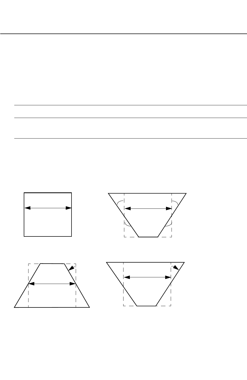
Chapter 18: ITF Statements and Options
SIDE_TANGENT 18-89
Chapter 18: ITF Statements and Options
SIDE_TANGENT 18-89
StarRC User Guide and Command Reference Version F-2011.06
SIDE_TANGENT
Specifies the tangent of an angular shift from vertical of the conductor sides.
Syntax
SIDE_TANGENT = float
Arguments
Argument Description
float Tangent value
Default: 0
Description
The SIDE_TANGENT option specifies the tangent of an angular shift from vertical of the
conductor sides, as shown in Figure 18-7.
Figure 18-7 Effect of the SIDE_TANGENT Option
W_center W_center
Before After
20o
20o
-20o
-20o
Figure 18-8 Positive Versus Negative SIDE_TANGENT Values
W_center
Positive SIDE_TANGENT
W_center
Negative SIDE_TANGENT
-20o
+20o

Chapter 18: ITF Statements and Options
SIDE_TANGENT 18-90
StarRC User Guide and Command Reference F-2011.06
StarRC User Guide and Command Reference Version F-2011.06
If you specify a positive value for SIDE_TANGENT, a trapezoid is produced with a top width
larger than the center width. If W denotes the width of the conductor without any trapezoidal
enhancement, and t is the vertical thickness of the conducting layer, then:
W_top = W + (SIDE_TANGENT * t)
W_bottom = W - (SIDE_TANGENT * t)
W_center = W
t = conductor thickness
The center width (W_center) is not affected by the trapezoidal adjustment. Also note that the
trapezoidal cross section is effectively a capacitive effect because the cross sectional area
does not change as long as top and bottom widths are greater than or equal to zero.
Example
This example shows how you can specify that the conductor has a 20 degree angular shift
(tan 20°=0.364).
CONDUCTOR met4 {
SIDE_TANGENT=0.364 THICKNESS=0.66 WMIN=0.15
SMIN=0.15 RPSQ=0.078
}
See Also
•ETCH_VS_WIDTH_AND_SPACING

Chapter 18: ITF Statements and Options
SMIN 18-91
Chapter 18: ITF Statements and Options
SMIN 18-91
StarRC User Guide and Command Reference Version F-2011.06
SMIN
Minimum spacing between two geometries of this conductor layer.
Syntax
SMIN = float
Arguments
Argument Description
float Minimum spacing value
Units: microns
Description
Minimum spacing between two geometries of this conductor layer.
You must specify this option within a CONDUCTOR statement.
Example
CONDUCTOR m1 {
THICKNESS=1.00 WMIN=0.13 SMIN=0.15 RPSQ=0.015
}
See Also
•WMIN

Chapter 18: ITF Statements and Options
SW_T 18-92
StarRC User Guide and Command Reference F-2011.06
StarRC User Guide and Command Reference Version F-2011.06
SW_T
Defines the sidewall thickness of a conformal layer.
Syntax
SW_T = float
Arguments
Argument Description
float The sidewall thickness
Units: microns
Default: dielectric THICKNESS value
Description
SW_T=0 is allowed for conformal dielectrics. An error message is issued if SW_T is less than
zero or is between zero and 0.005. If not specified, THICKNESS of the dielectric is used as
SW_T.
Example
DIELECTRIC D3 {
THICKNESS = 0.2
MEASURED_FROM = TOP_OF_CHIP
SW_T = 0.15
TW_T = 0.18
ER = 5.9
}
See Also
•MEASURED_FROM
•THICKNESS
•TW_T

Chapter 18: ITF Statements and Options
TECHNOLOGY 18-93
Chapter 18: ITF Statements and Options
TECHNOLOGY 18-93
StarRC User Guide and Command Reference Version F-2011.06
TECHNOLOGY
Specifies the name of the process technology for tracking and identification purposes.
Syntax
TECHNOLOGY = process_name
Arguments
Argument Description
process_name The process name represented by a single word that can contain
alphanumeric characters and underscores
Description
The TECHNOLOGY statement is mandatory and should precede all other statements, but it
does not need to be the first line of the ITF.
The output of the grdgenxo executable is stored in the process_name.nxtgrd file.
Example
In the following example, the process name is sample_tech, and the grdgenxo output is
stored in the sample_tech nxtgrd file:
TECHNOLOGY = sample_tech

Chapter 18: ITF Statements and Options
THICKNESS 18-94
StarRC User Guide and Command Reference F-2011.06
StarRC User Guide and Command Reference Version F-2011.06
THICKNESS
Specifies the thickness of a dielectric or conductor layer.
Syntax
THICKNESS = float
Arguments
Argument Description
float The thickness of the dielectric or conductor
Units: microns
Description
The dielectric or conductor thickness measured from the top of the dielectric layer below it.
The reference point can be changed by setting MEASURED_FROM. Specifying THICKNESS=0 is
allowed for a conformal dielectric layer; for planar layers THICKNESS should not be specified
as 0.
You specify this option within a CONDUCTOR or DIELECTRIC statement.
Errors
An error message is issued if THICKNESS is less than 0.001 micron for a conductor layer or
planar dielectric layer.
Example
CONDUCTOR M2 { THICKNESS=0.60 WMIN=0.55 SMIN=0.50 RPSQ=0.062 }
DIELECTRIC D2 { THICKNESS=1.20 ER=3.9 }
See Also
•MEASURED_FROM
•THICKNESS
•TW_T

Chapter 18: ITF Statements and Options
THICKNESS_VS_DENSITY 18-95
Chapter 18: ITF Statements and Options
THICKNESS_VS_DENSITY 18-95
StarRC User Guide and Command Reference Version F-2011.06
THICKNESS_VS_DENSITY
Syntax
THICKNESS_VS_DENSITY [ RESISTIVE_ONLY | CAPACITIVE_ONLY ]
{(D1 R1) (D2 R2) (D3 R3) (D4 R4) ... }
Arguments
Argument Description
RESISTIVE_ONLY Applies thickness adjustment to resistance only
CAPACITIVE_ONLY Applies thickness adjustment to capacitance only
D1, D2, D3, D4, ... Density values
R1, R2, R3, R4, ... Relative changes in thickness.
(dT/Tnominal) negative R(dT/T) indicates a decrease in thickness
and vice versa. Even though, R(dT/T) can be any number
between -1 and 1, a number close to 1 or -1 is undesirable. R(dT/
T) cannot be -1.
Description
Use THICKNESS_VS_DENSITY to do one of two methods that assist you in thickness
computation: the single box (linear table) method or the multiple box method.
As shown in the example, the values can be separated by either a comma or space.
Single-Box Method
This option enables you to specify one box in a linear table method for density computation.
Choose a single box size and specify the thickness variation of the conductor in a table. The
box is assumed to be square and the default size of the box is 50 microns. This method does
not require the exhaustive characterization of a multiple box method. To specify the box, use
the DENSITY_BOX_WEIGHTING_FACTOR option.
For a linear table model, specify a multi-point thickness variation versus the density table in
the process file.

Chapter 18: ITF Statements and Options
THICKNESS_VS_DENSITY 18-96
StarRC User Guide and Command Reference F-2011.06
StarRC User Guide and Command Reference Version F-2011.06
The THICKNESS_VS_DENSITY variation affects both resistance and capacitance. However, if
the coefficients for resistance and capacitance are different, then use RESISTIVE_ONLY or
CAPACITANCE_ONLY. The values you specify only apply to the conductor’s resistance or
capacitance.
Multiple-Box Method
To specify a multiple box size and its weighting factor for effective density calculation, you
must characterize the wafer in greater detail than you do in the single box method. This
method is preferred when the single box method does not represent the process behavior.
The density box is assumed to be a square. The maximum size of a density box is 500
microns and the maximum number of boxes is 5.
Example
The following example shows the single-box method:
CONDUCTOR metal3 {
THICKNESS=0.5 SMIN=0.25 WMIN=0.25 RPSQ=0.01
THICKNESS_VS_DENSITY RESISTIVE_ONLY
{(0.1,-0.1) (0.2, 0.1)(0.3, 0.2)(0.4, 0.3)}
}
The following example shows the multiple-box method:
CONDUCTOR metal3 {
THICKNESS = 0.5 SMIN = 0.25 WMIN=0.25 RPSQ = 0.01
THICKNESS_VS_DENSITY{(0.1 -0.1)(0.2 0.1)(0.3 0.2)(0.4 0.3)}
DENSITY_BOX_WEIGHTING_FACTOR {
(10 1) (20 0.23) (30 0.29)
(40 0.18) (50 -0.12)
}
}
See Also
•DENSITY_BOX_WEIGHTING_FACTOR
•THICKNESS_VS_WIDTH_AND_SPACING

Chapter 18: ITF Statements and Options
THICKNESS_VS_WIDTH_AND_SPACING 18-97
Chapter 18: ITF Statements and Options
THICKNESS_VS_WIDTH_AND_SPACING 18-97
StarRC User Guide and Command Reference Version F-2011.06
THICKNESS_VS_WIDTH_AND_SPACING
Syntax
THICKNESS_VS_WIDTH_AND_SPACING
[ RESISTIVE_ONLY | CAPACITIVE_ONLY ] {
SPACINGS { S1 S2 }
WIDTHS ( W1 W2 }
VALUES { v(S1,W1) v(S2,W1) v(S1,W2) v(S2,W2) }
}
Arguments
Argument Description
RESISTIVE_ONLY Applies thickness adjustment to resistance only
CAPACITIVE_ONLY Applies thickness adjustment to capacitance only
SPACINGS Spacing values specified in ascending order
Units: microns
WIDTHS Width of a conductor. Values are specified in ascending order
Units: microns
VALUES Values represent the relative change in thickness for a conductor.
Order of the components of the values table is determined by the
indexes in the SPACINGS an WIDTHS table. Entry in the VALUES
table are ordered such that SPACINGS indexes change first for a
given index in the WIDTHS table and then this is repeated for all
indexes in the WIDTHS table.
Description
In this method, the variation of thickness as a function of the width of a conductor and
relative spacing to the neighboring conductor is modeled. The variation is modeled in an ITF
with THICKNESS_VS_WIDTH_AND_SPACING specified as a key word in a CONDUCTOR definition.

Chapter 18: ITF Statements and Options
THICKNESS_VS_WIDTH_AND_SPACING 18-98
StarRC User Guide and Command Reference F-2011.06
StarRC User Guide and Command Reference Version F-2011.06
This thickness variation can be either negative or positive. It is a very local phenomenon and
is independent of the density box. If specified with either single or multiple boxes, then this
thickness variation is computed independently from the density box. The effective thickness
is calculated with the following equation:
T Tnom 1 RTf Deff()RTf W S,()RTf SiW()++ +()×=
In this equation,
• Tnom is the nominal thickness specified in the ITF.
• RTf(Deff) is the relative thickness change due to density.
• RTf(W,S) is the relative change in thickness due to width and spacing.
• RTf(SiW) is the relative change in thickness due to silicon width.
The resistance and capacitance is computed after the effective thickness is computed.
Example
CONDUCTOR m1 {
THICKNESS = 0.60 WMIN 0.25 SMIN = 0.25
THICKNESS_VS_WIDTH_AND_SPACING {
SPACINGS { 0.25 0.30 0.50}
WIDTHS {0.25 0.4 0.50}
VALUES {0.3 0.2 0.1
0 -0.1 -0.20
-0.3 -0.2 -0.1}
}
}
See Also
•DENSITY_BOX_WEIGHTING_FACTOR
•THICKNESS_VS_DENSITY

Chapter 18: ITF Statements and Options
TO 18-99
Chapter 18: ITF Statements and Options
TO 18-99
StarRC User Guide and Command Reference Version F-2011.06
TO
Specifies a conductor layer connected by the via.
Syntax
TO = layer
Arguments
Argument Description
layer The layer connected by the defined via
Description
The TO statement specifies the upper or lower layer connected by the via. A via can connect
only two conductor layers.
You specify this option within a VIA statement.
Example
VIA v1 {
FROM = m2
TO = m3
RPV = 40
AREA = 0.16
}
See Also
•FROM

Chapter 18: ITF Statements and Options
TSV 18-100
StarRC User Guide and Command Reference F-2011.06
StarRC User Guide and Command Reference Version F-2011.06
TSV
Describes a through-silicon via (TSV) layer.
Syntax
TSV tsv_name {
FROM = layer1
TO = layer2
RHO = rho_value
AREA = area_value
THICKNESS = thickness_value
INSULATION_THICKNESS = ins_thickness_value
INSULATION_ER = er_value
[CRT1 = lin_coeff] [CRT2 = quad_coeff] [T0 = nominal_temp]
}
Arguments
Argument Description
FROM = layer1 Conductor layer connected by the TSV
TO = layer2 Conductor layer connected by the TSV
RHO = rho_value Resistivity of the TSV
Units: ohm-microns
AREA = area_value Area of the TSV
Units: square microns
THICKNESS =
thickness_value
Thickness of the TSV
Units: microns
INSULATION_THICKNESS =
ins_thickness_value
Thickness of the insulation layer between the TSV and the
substrate
Units: microns
INSULATION_ER = er_value Relative permittivity of the TSV insulation layer
CRT1 = lin_coeff Layer-specific linear temperature coefficient
Default: 0
CRT2 = quad_coeff Layer-specific quadratic temperature coefficient
Default: 0
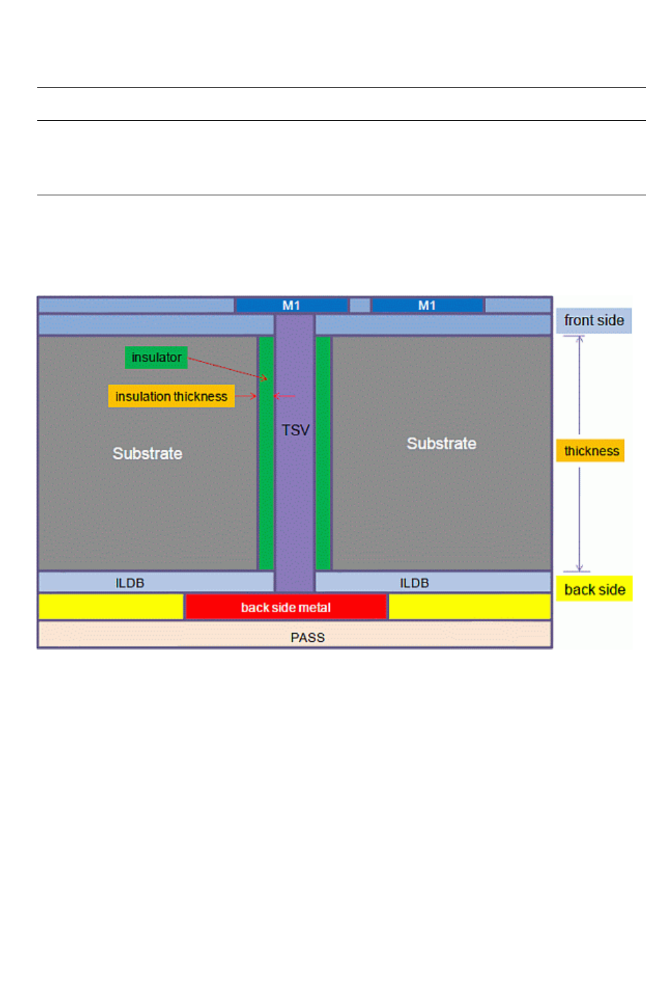
Chapter 18: ITF Statements and Options
TSV 18-101
Chapter 18: ITF Statements and Options
TSV 18-101
StarRC User Guide and Command Reference Version F-2011.06
Description
A through-silicon via (TSV) connects metal conductor layers on the frontside and the
backside of the silicon substrate, as shown in Figure 18-9.
Figure 18-9 Cross Section of Through-Silicon Via
To model a TSV, you must include descriptions of the frontside and backside layers in the
ITF file. The syntax of each ITF stack, either the frontside or the backside, follows the same
ITF syntax. Place the TSV statement after the frontside ITF statements and before the
backside ITF statements. For an example of an ITF file that describes a TSV, see “Through-
Silicon Via Process” in Appendix A.
Example
TSV tsv {
FROM=M1 TO=M1b
RHO=0.05 AREA=49.0 THICKNESS=20.0
INSULATION_THICKNESS=0.4 INSULATION_ER=5.5
CRT1=7.0e-03 CRT2=-3.0e-08 }
T0 = nominal_temp Nominal temperature for the layer
Units: degrees Celsius
Default: temperature specified by GLOBAL_TEMPERATURE
Argument Description

Chapter 18: ITF Statements and Options
TVF_ADJUSTMENT_TABLES 18-102
StarRC User Guide and Command Reference F-2011.06
StarRC User Guide and Command Reference Version F-2011.06
TVF_ADJUSTMENT_TABLES
Specifies tables to adjust the bottom thickness variation.
Syntax
TVF_ADJUSTMENT_TABLES {
[BOTTOM_THICKNESS_VS_WIDTH_AND_SPACING {
SPACINGS { S1 S2 ... }
WIDTHS { W1 W2 ... }
VALUES { V(S1, W1) V(S2, W1) ...
V(S1, W2) V(S2, W2) ...
}
}]
[BOTTOM_THICKNESS_VS_WIDTH_AND_DELTAPD {
DELTAPD { D1 D2 ... }
WIDTHS { W1 W2 ... }
VALUES { V(D1, W1) V(D2, W1) ...
V(D1, W2) V(D2, W2) ...
}
}]
}
Description
The TVF_ADJUSTMENT_TABLES statement specifies tables to adjust the bottom thickness
variation from the THICKNESS_VARIATION_FILE.
The TVF_ADJUSTMENT_TABLES statement allows the specification of one or both the
following tables:
•BOTTOM_THICKNESS_VS_WIDTH_AND_SPACING – Bottom thickness adjustment based on
the conductor width and the nearest spacing.
•BOTTOM_THICKNESS_VS_WIDTH_AND_DELTAPD – Bottom thickness adjustment based on
the conductor width and the neighboring tiles pattern density (PD).
These tables are utilized when you run StarRC with the THICKNESS_VARIATION_FILE option
for interfacing with a CMP simulator.

Chapter 18: ITF Statements and Options
TVF_ADJUSTMENT_TABLES 18-103
Chapter 18: ITF Statements and Options
TVF_ADJUSTMENT_TABLES 18-103
StarRC User Guide and Command Reference Version F-2011.06
Example
For example, for layer M1 in the previous tvf_adj.tab, the input in the ITF file should be:
CONDUCTOR M1 {
...
TVF_ADJUSTMENT_TABLES {
BOTTOM_THICKNESS_VS_WIDTH_AND_SPACING {
SPACINGS { 0.100000 0.200000 0.300000 }
WIDTHS { 0.060000 0.120000 0.240000 }
VALUES { 0.500000 0.150000 0.250000
0.100000 0.250000 0.350000
0.150000 0.350000 0.450000
}
}
BOTTOM_THICKNESS_VS_WIDTH_AND_DELTAPD {
DELTAPD { -0.750000 -0.500000 0.000000 0.500000 0.750000 }
WIDTHS { 0.060000 0.120000 0.240000 }
VALUES { 0.150000 0.500000 0.000000 -0.500000 -0.150000
0.150000 0.500000 0.000000 -0.500000 -0.150000
0.150000 0.500000 0.000000 -0.500000 -0.150000
}
}
}
}
Note that one of the tables inside the TVF_ADJUSTMENT_TABLES could be missing. In this
case, put a "0" for the missing table in the output tvf_adj.tab file.
See Also
•TVF_ADJUSTMENT_TABLES

Chapter 18: ITF Statements and Options
TW_T 18-104
StarRC User Guide and Command Reference F-2011.06
StarRC User Guide and Command Reference Version F-2011.06
TW_T
Syntax
TW_T = float
Arguments
Argument Description
float Topwall thickness
Units: microns
Default: thickness value of the dielectric
Description
Defines the topwall thickness of a conformal layer. TW_T=0 is allowed for conformal
dielectrics. An error message is issued if TW_T is between 0 and 0.005 microns as values
below 0.005 are not allowed. If not specified, the THICKNESS of the dielectric is used as
TW_T.
Example
DIELECTRIC D3 {
THICKNESS=0.2 MEASURE_FROM=TOP_OF_CHIP
SW_T=0.15 TW_T=0.18 ER=5.9
}
See Also
•MEASURED_FROM
•SW_T
•THICKNESS

Chapter 18: ITF Statements and Options
USE_SI_DENSITY 18-105
Chapter 18: ITF Statements and Options
USE_SI_DENSITY 18-105
StarRC User Guide and Command Reference Version F-2011.06
USE_SI_DENSITY
Specifies the density-based thickness variation effect.
Syntax
USE_SI_DENSITY = YES | NO
Arguments
Argument Description
YES Specifies that the thickness variation computation is based on
silicon density.
NO Specifies that the thickness variation computation is based on
drawn (database) density.
This is the default.
Description
Use this optional statement in the ITF when the density-based (THICKNESS_VS_DENSITY or
POLYNOMIAL_BASED_THICKNESS_VARIATION) thickness variation effect applies to silicon
density rather than drawn density.
Example
USE_SI_DENSITY = YES
See Also
•POLYNOMIAL_BASED_THICKNESS_VARIATION
•THICKNESS_VS_DENSITY

Chapter 18: ITF Statements and Options
VARIATION_PARAMETERS 18-106
StarRC User Guide and Command Reference F-2011.06
StarRC User Guide and Command Reference Version F-2011.06
VARIATION_PARAMETERS
Defines variation parameters for a variation-aware ITF file.
Syntax
VARIATION_PARAMETERS {
param1 = {(layer, param_type, coeff_of_variation)
(layer, param_type, coeff_of_variation)
(layer, param_type, coeff_of_variation)
param2 = {(layer, param_type, coeff_of_variation)
(layer, param_type, coeff_of_variation)
(layer, param_type, coeff_of_variation)
...
}
Arguments
Argument Description
param Variation parameter name
layer Layer name
coeff_of_variation Coefficient of variation
param_type Type of parameter. THICKNESS, WIDTH, RHO, and ER are supported.
Description
You can create a variation-aware ITF file by appending variation parameters. The format you
specify in the ITF to represent parameter variations is added to the existing nonvariation-
aware ITF file. There is no need for you to modify the process cross-section or values in the
nominal ITF file.
For more information about the variation-aware ITF format, see Chapter 11, “Variation-
Aware Extraction."
See Also
•SENSITIVITY

Chapter 18: ITF Statements and Options
VIA 18-107
Chapter 18: ITF Statements and Options
VIA 18-107
StarRC User Guide and Command Reference Version F-2011.06
VIA
Describes the properties of a via layer.
Syntax
VIA via_name {
FROM = layer1
TO = layer2
[CRT1 = lin_coeff
| [CRT2 = quad_coeff]
| [CRT_VS_AREA {...}]
| [TO = nominal_temp]]
[RHO = rho_value
| RPV = rpv_value AREA = area_value
| RPV_VS_AREA {...}]
[ETCH_VS_CONTACT_AND_GATE_SPACINGS CAPACITIVE_ONLY {...}
| ETCH_VS_WIDTH_AND_SPACING CAPACITIVE_ONLY {...}
| ETCH_VS_WIDTH_AND_LENGTH CAPACITATIVE_ONLY {...}]
}
Arguments
Argument Description
FROM = layer1 Upper conductor layer connected by the via
TO = layer2 Lower conductor layer connected by the via
CRT1 = lin_coeff Layer-specific linear temperature coefficient
Default: 0
CRT2 = quad_coeff Layer-specific quadratic temperature coefficient
Default: 0
T0 = nominal_temp Nominal temperature for the layer
Units: degrees Celsius
Default: temperature specified by GLOBAL_TEMPERATURE
RHO = rho_value Bulk resistivity of the via or conductor layer.
Units: ohm-microns
Default: RPV x AREA
RPV = rpv_value Resistance per default via
Units: ohms

Chapter 18: ITF Statements and Options
VIA 18-108
StarRC User Guide and Command Reference F-2011.06
StarRC User Guide and Command Reference Version F-2011.06
Description
The VIA statement describes the properties of a via layer such as area, resistance,
nonlinear resistance behavior, and the conductor layers connected by the via.
You can must specify the resistive properties of the via layer with one of the following
methods:
•Specify RHO only
• Specify both RPV and AREA
• Specify an RPV_VS_AREA table
Example
The following example shows a simple VIA statement:
VIA VIA1 { FROM=M1 TO=M2 AREA=0.36 RPV=4 }
The following example shows the syntax for a contact bias 2-D etch table:
ETCH_VS_CONTACT_AND_GATE_SPACINGS {
CONTACT_SPACING {c1 c2 c3}
GATE_SPACING (s1 s2 s3 ... }
VALUES { v(c1, s1) v(c2, s1)
v(c1, s2) v(c2, s2) }
}
See Also
•ETCH_VS_CONTACT_AND_GATE_SPACINGS
•RPV_VS_AREA
AREA = area_value Area of default via
Units: square microns
Default: 1.0e -6 / RPV
Argument Description

Chapter 18: ITF Statements and Options
WMIN 18-109
Chapter 18: ITF Statements and Options
WMIN 18-109
StarRC User Guide and Command Reference Version F-2011.06
WMIN
Specifies the minimum width of a conductor.
Syntax
WMIN = float
Arguments
Argument Description
float The minimum width of the layer
Units: microns
Description
Minimum width of a conductor geometry on a layer. This option must be specified in a
CONDUCTOR statement.
Example
CONDUCTOR metal1 {
THICKNESS=1.00 WMIN=0.13 SMIN=0.15 RPSQ=0.015
}
See Also
•SMIN

Chapter 18: ITF Statements and Options
WMIN 18-110
StarRC User Guide and Command Reference F-2011.06
StarRC User Guide and Command Reference Version F-2011.06

19-1
19
The grdgenxo Command 19
The grdgenxo command is an executable that generates the nxtgrd file. The output file
(*nxtgrd) is a database containing capacitance, resistance, inductance, and layer
information that first undergoes process characterization and is then compiled by the
grdgenxo command function.
This chapter contains the following sections:
•Command Details
•Examples
•Incremental grdgenxo
•Reference Indications
•Error and Warning Conditions

Chapter 19: The grdgenxo Command
Command Details 19-2
StarRC User Guide and Command Reference F-2011.06
StarRC User Guide and Command Reference Version F-2011.06
Command Details
Syntax
grdgenxo
[-encrypt]
[-f format_file]
[-h]
-i itf_file
[-inc]
[-itf2TLUPlus]
[-jpg jpg_filename]
-o TLUPlus_filename
[-parse]
[-res_update]
[-usage]
[-V]
Argument Description
-encrypt Writes an encrypted ITF file into the grdgenxo file.
-f format_file Include format file name.
-h Shows command-line options.
-i itf_file Includes the specified ITF file.
-inc Activates an incremental update of grdgenxo.
-itf2TLUPlus Generates a TLUPlus model from an ITF file. This argument
must be specified first in the syntax. The units are fixed as fF
and ohm.
-o TLUPlus_filename Outputs TLUPlus model file name.
-parse Parses ITF file only to check for syntax errors, without starting
an nxtgrd file generation. Messages are reported when syntax
errors are found. If no errors are found, a confirmation message
is given and grdgenxo terminates.
-res_update Allows the update of resistance parameters (such as RPSQ,
RHO_VS_WIDTH_AND_SPACING) in the nxtgrd file from a new ITF
file without processing through the field solver.
-usage Shows command-line options.
-V Includes the version number in the generated grdgenxo file.

Chapter 19: The grdgenxo Command
Examples 19-3
Chapter 19: The grdgenxo Command
Examples 19-3
StarRC User Guide and Command Reference Version F-2011.06
Description
The grdgenxo command-line executable takes a prepared Interconnect Technology Format
(ITF) file or model as input and generates the nxtgrd database. This nxtgrd file is your data
after StarRC process characterization. For more information about process
characterization, see Chapter 3, “Process Characterization Interface.”
The incremental capability lets you run incremental, or successive, grdgenxo runs in the
original run directory after modifications to the ITF file. With the -inc option, grdgenxo
recognizes the modified layers in the ITF for successive grdgenxo runs and regenerates the
capacitance models (for the changed layers only).
The grdgenxo function generates messages when process characterization errors are
found. These messages are displayed on your screen when the command functions.
Examples
This section explains the details of how to use the grdgenxo syntax to accomplish certain
tasks. See the command argument section for details about required and optional
arguments.
Generating a grdgenxo File
To generate a grdgenxo file, use the following syntax. The grdgenxo command followed by
your specified input ITF file are required. The other arguments are optional.
grdgenxo [-h] [-usage] [-V] itf_file
Reading grdgenxo Output
The grdgenxo capacitance tables in the nxtgrd file are written in binary format by default to
save disk space and to enhance parsing time. StarRC can read nxtgrd files in both binary
format and ASCII for backward compatibility.
The ITF copy (at the top of the nxtgrd file) can be encrypted by using the command-line
option -encrypt with grdgenxo. Note that nxtgrd files created with version V-2004.06 are
not backward compatible with earlier versions of StarRC.
Parsing a File
To parse the ITF file to check only for syntax errors, without starting an nxtgrd file generation,
use the following syntax:
grdgenxo -parse itf_file

Chapter 19: The grdgenxo Command
Examples 19-4
StarRC User Guide and Command Reference F-2011.06
StarRC User Guide and Command Reference Version F-2011.06
Updating an nxtgrd Database Incrementally
To update an nxtgrd database incrementally after being generated by grdgenxo, use the
following syntax:
grdgenxo -inc itf_file
See “Incremental grdgenxo” on page 19-6 for more details.
To run an incremental process characterization, you need to specify the following command
and options where the nxtgrd database directory is located.
grdgenxo -inc new_itf_file
Before an incremental update of the nxtgrd file can be done, StarRC must make a
comparison between the ITF file used to generate the database and its incrementally
modified version. StarRC does this comparison internally.
Updating an nxtgrd Database From a New ITF File
You can update an nxtgrd database from a new ITF file using the -res_update option to
grdgenxo. StarRC modifies an already existing nxtgrd file to a new nxtgrd file based on
information derived from a new ITF file. To do this, specify the following command:
grdgenxo -res_update new_itf_file -i old_nxtgrd_file -o new_nxtgrd_file
This method allows you to update an nxtgrd file while avoiding field solver processing which
saves computing time. The version number and time stamp is not updated; their original
values are kept intact.
StarRC issues an error message and terminates the job if one of the following conditions
occur:
• If an attempt is made to combine the nxtgrd function -which is a stand-alone
command-line procedure- with other command-line options, such as -inc or any others.
• If an attempt is made to update the nxtgrd file when it is encrypted.
• If an attempt is made to update the nxtgrd file introducing new resistance parameters into
it.
• If an attempt is made to update the nxtgrd file, using ITF parameters not listed in the
following since these affect capacitance models:

Chapter 19: The grdgenxo Command
Examples 19-5
Chapter 19: The grdgenxo Command
Examples 19-5
StarRC User Guide and Command Reference Version F-2011.06
AIR_GAP_VS_SPACING, BACKGROUND_ER, CAPACITIVE_ONLY_ETCH, DAMAGE_ER,
DAMAGE_THICKNESS, DROP_FACTOR, DROP_FACTOR_LATERAL_SPACING, ER, ETCH,
ETCH_VS_CONTACT_AND_GATE_SPACING,ETCH_VS_WIDTH_AND_SPACING: CAPACITIVE,
ETCH_VS_WIDTH_AND_SPACING:ETCH_FROM_TOP, FILL_TYPE, FILL_RATIO,
FILL_SPACING, FILL_WIDTH, GATE_TO_CONTACT_SMIN, MEASURED_FROM, NAME (of
dielectric layer),SIDE_TANGENT, SMIN, SW_T, THICKNESS,
THICKNESS_VS_DENSITY: CAPACITIVE, THICKNESS_VS_WIDTH_AND_SPACING:
CAPACITIVE, TW_T,WMIN, number of layers (conductor, dielectric, via)
Deciding When to Regenerate nxtgrd Capacitance Models
When the field solver utility, grdgenxo, generates a nxtgrd file from an ITF process file
description, it generates a directory of intermediate process characterization files. When the
run is complete, these files are compiled into a single capacitance modeling regression
database: the nxtgrd file.
If you would like to make minor, incremental changes to an ITF process description after a
nxtgrd file has been created, rerun grdgenxo using the previous run directory capacitance
table results.
You can run grdgenxo on a previous run directory only when using the same version of
grdgenxo, and only if the changes you have made to the ITF file do not affect the capacitive
tables. If you are unsure which parameters affect capacitive tables, remove the previous run
directory and regenerate all capacitance tables.
When generating nxtgrd files, keep in mind that you can spawn many grdgenxo processes
(there is no licensing limitation) and the speedup is proportional to the number of CPUs.
Commands that would not affect the capacitive tables include RESISTIVE_ONLY_ETCH and
RPSQ.
Commands that would affect capacitive tables include THICKNESS, SMIN, and WMIN
In grdgenxo (release X-2005.06 and later) changes made to CONDUCTOR parameters are
automatically removed and the capacitive tables regenerated. This can improve grdgenxo
runtime significantly. This incremental capability does not pertain to DIELECTRIC thickness
changes because these impact all capacitive models. Use the -inc command-line option for
this capability and verify that the previous grdgenxo run directory still exists.
TLUPlus Model Generation
Generate a TLUPlus model using the following syntax.
grdgenxo -itf2TLUPlus -i itf_file [-f format_file] -o TLUPlus_file
Note:
For an ift2TLUPlus model generation, the units are fF and ohms.

Chapter 19: The grdgenxo Command
Incremental grdgenxo 19-6
StarRC User Guide and Command Reference F-2011.06
StarRC User Guide and Command Reference Version F-2011.06
Distributed Processing
When generating nxtgrd files, you can spawn many grdgenxo processes (there is no
licensing limitation), and the speed increase is proportional to the number of CPUs. This can
be distributed across platforms and machines.
To enable grdgenxo distributed processing,
1. Start an additional process from a different host, or CPU, in the same working directory.
2. Ensure that the grdgenxo versions are the same. To verify this, use the command:
% which grdgenxo
% telnet otherMachine
% cd path/same_working_DIR
% grdgenxo same_ITF_file
You can add additional CPUs at any time. The increased speed is nearly linear with the
number of CPUs. The distributed processing mechanism is fault tolerant. That means, if one
machine dies, the other CPUs continue and complete the remaining characterization tasks.
Incremental grdgenxo
The incremental function of the grdgenxo command lets you update an nxtgrd database
using a modified ITF file. This can save significant development time.
You supply the latest ITF file in the working directory and specify the -inc option when
running grdgenxo. The -inc option distinguishes the run as an incremental generation and
only updates the differences found between the original ITF file information and the new ITF
file you specify.
To run incremental process characterization you need to specify the following command and
options where the nxtgrd database directory is located:
grdgenxo -inc itf_file
Before an incremental update of the nxtgrd file can be done, StarRC must make a
comparison between the ITF file used to generate the database and its incrementally
modified version. StarRC does this comparison internally. Whenever the incremental option
is specified, both of the ITF files should be available for comparison.
In a distributed processing environment, grdgenxo undertakes additional checking to verify
that all processors are using the same ITF file.

Chapter 19: The grdgenxo Command
Reference Indications 19-7
Chapter 19: The grdgenxo Command
Reference Indications 19-7
StarRC User Guide and Command Reference Version F-2011.06
Limitations to Using the Incremental Argument
Data modification using the following conducting layer options has a localized effect on
capacitance values. Therefore, changes can be incrementally updated into an existing
nxtgrd database when desired. The following keyword changes to in the CONDUCTOR
statement are supported:
AIR_GAP_VS_SPACING
CAPACITIVE_ONLY_ETCH
ETCH
ETCH_VS_WIDTH_AND_SPACING
ETCH_VS_WIDTH_AND_SPACING: CAPACITIVE_ONLY
ETCH_VS_WIDTH_AND_SPACING: ETCH_FROM_TOP
MEASURED_FROM
SIDE_TANGENT
SMIN
THICKNESS
WMIN
Modification of the following layer options has more extensive effect on capacitance values
because their effect on the design is global. The following keyword changes to in the
CONDUCTOR statement are not supported:
DROP_FACTOR
FILL_RATIO
FILL_SPACING
FILL_WIDTH
FILL_TYPE
The following ITF file changes are not allowed:
• Any changes to dielectric layers have a wide range of implications on capacitance values.
You should run grdgenxo from the beginning without the incremental option under the
following circumstances.
• Changes that make a difference between total number of conductors or dielectrics.
• Removal of a conductor.
• Modification of resistance and related data on conducting layers is supported.
Reference Indications
The following sections describe suggestions that might assist you when running the
grdgenxo command.

Chapter 19: The grdgenxo Command
Error and Warning Conditions 19-8
StarRC User Guide and Command Reference F-2011.06
StarRC User Guide and Command Reference Version F-2011.06
ITF File Preparation
• If you have added the ETCH_VS_WIDTH_AND_SPACING option to your existing ITF file, you
must rerun grdgenxo after removing the working directory.
• Inappropriate WMIN and SMIN values specified in your ITF file can cause unwanted opens
or shorts of the neighboring layers by applying the etch values provided in the table. In
such a case, a message is printed during the grdgenxo run.
• If the width value in the THICKNESS_VS_DENSITY table is not sorted, grdgenxo sorts it.
Working With Models
• TLUPlus models are generated using grdgenxo from StarRC. A description of the
process must be provided in your ITF file. This can be created by you or supplied by a
CAD design group or foundry. See Chapter 3, “Process Characterization Interface.”
Error and Warning Conditions
This section explains several error and warning conditions specific to the grdgenxo function.
• In a distributed processing (DP) environment, the ITF file name and path specified for
each processor is compared to the ITF specified for the main processor. An error
message is issued, and job execution terminated if the file paths and names are different.
• If the total number of dielectric and/or conducting layers between an updated or
incremental ITF file are not the same as the original saved ITF file, an error message is
issued and execution is terminated. These files cannot be updated using an incremental
update; a completely new grdgenxo generation is necessary.
• Changes you make in an ITF file involving dielectric layers have extensive implications for
capacitance values. In this case, a completely new run of grdgenxo is necessary. An
error message is issued and the job terminates.
• The modification of a conducting layer involving metal fill and drop factor is not supported,
because of their extensive effects on capacitance values. An error message is issued and
the job is terminated. A complete new run of grdgenxo is necessary.
• If grdgenxo is not reading your format file for TLUPlus generation, see “Generating
TLUPlus Models” on page 3-48.

20-1
20
Mapping File Commands 20
Each database imported to StarRC must be accompanied by a mapping file that links each
physical database layer to a TCAD GRD modeled layer. This chapter describes the
commands that you use in a StarRC mapping file.
Although there is no restriction on the order in which these commands are listed in your file,
you should specify them in the following order:
•conducting_layers
•via_layers
•marker_layers
•remove_layers
•viewonly_layers
•ignore_cap_layers

Chapter 20: Mapping File Commands
conducting_layers 20-2
StarRC User Guide and Command Reference F-2011.06
StarRC User Guide and Command Reference Version F-2011.06
conducting_layers
Maps a conducting layer from the layout database to a conductor in the tcad_grd file.
Syntax
conducting_layers
database_layer grd_layer [device_layer] [rpsq=rpsq_value]
MODEL=model_name
[diffusion_res_model=diff_res_model_name]
Arguments
Argument Description
database_layer Conducting layer name in the design database.
grd_layer Conductor name in the technology file (ITF or nxtgrd) file. Can
also be the SUBSTRATE.
rpsq_value Resistance per square for the design database layer.
model_name Model for parasitic netlist output. The value for this argument is a
string. This value is used by StarRC to write out model names for
parasitic resistors in a parasitic netlist. It is required that all
conducting layers be mapped to a model if you specify the
NETLIST_PARASITIC_RESISTOR_MODEL command. If you
have not specified a corresponding resistor MODEL in the
database, no model will be printed to the parasitic netlist for that
resistor. A warning is issued in the StarRC summary file.
device_layer Layer for resistance extraction of power nets. Specify this
keyword in your mapping file when you are using
POWER_EXTRACT: DEVICE_LAYERS in the command file. The
device_layer keyword can be specified in any order in the
mapping file for the conducting layers when RPSQ and device
model options are used.
diff_res_model_name Model name for user-defined diffusion resistance extraction. The
final netlist prints the model name for the corresponding contact
and device gate as netlist tail comments.
Default: NA
Description
Use the conducting_layers command to map a conducting layer from the layout database
(routing layers, device terminal layers, device layers, and so on) to a conductor in the
TCAD_grd file.

Chapter 20: Mapping File Commands
conducting_layers 20-3
Chapter 20: Mapping File Commands
conducting_layers 20-3
StarRC User Guide and Command Reference Version F-2011.06
Note:
For TCAD GRD layers which use RPSQ_VS_SI_WIDTH or RPSQ_VS_WIDTH_AND_SPACING,
RPSQ override is only possible if specifying RPSQ=0 in the conducting_layers section. A
non-zero RPSQ override in the conducting_layers section is not possible for TCAD GRD
layers using these two resistance modeling functions. You can override the sheet
resistance value contained in the TCAD GRD to which the database is being mapped by
specifying the rpsq value (ohms/sq).
The GRD layers appearing in this category can only be TCAD GRD CONDUCTOR layers. You
can map a database layer to the substrate in this category by specifying SUBSTRATE as the
GRD layer.
Example
Example 20-1
conducting_layers
m2 metal2
m1 metal1
nsd SUBSTRATE
psd SUBSTRATE
Example 20-2
conducting_layers
database_layer GRD_layer RPSQ = rpsq_value MODEL = model_name
database_layer GRD_layer MODEL = model_name
database_layer GRD_layer MODEL = model_name RPSQ = rpsq_value
Example 20-3
conducting_layers
M2 metal2
M1 metal1
POLY fpoly
nsd SUBSTRATE device_layer RPSQ=0.5
psd SUBSTRATE device_layer
welltie SUBSTRATE
subtie SUBSTRATE
ngate gpoly device_layer
pgate gpoly
NWELL SUBSTRATE
via_layers
V1 via1
POLY_CONT polyCont device_layer
DIFF_CONT diffCont device_layer RPV=0.5
When you define multiple Cf tables in the ITF file, the device gate layer that maps to the
corresponding table name must be specified in the StarRC mapping file. To look up the
appropriate gate-to-diffusion table, use the mapping file syntax shown in the following
example.

Chapter 20: Mapping File Commands
conducting_layers 20-4
StarRC User Guide and Command Reference F-2011.06
StarRC User Guide and Command Reference Version F-2011.06
Example 20-3 Mapping File for Multiple Tables in the ITF File
conducting_layers
gate database_layer gate grd_layer [table_name=keyword]
If table_name is defined for a gate, StarRC will find and use the corresponding
gate-diffusion capacitance table with same NAME in ITF file.
The following example shows a mapping file that you can use to lookup corresponding
gate-to-diffusion capacitance tables:
conducting_layers
ngate gpoly table_name=NMOS
pgate gpoly table_name=PMOS
tngate gpoly
tpgate gpoly
Given the previous mapping file definition, devices with “ngate” as the gate poly will use the
gate to diffusion capacitance table under NMOS, and devices with “pgate” as the gate poly
will use tables with the PMOS table name in ITF file.
No gate to diffusion capacitance lookup will be applied to the devices with “tngate” and
“tpgate” gates.
Mapping File for User-Defined Diffusion Resistance
The following example shows a mapping file with a model name specified for the
user-defined diffusion resistance extraction flow:
conducting_layers
ngate poly diffusion_res_model=n_high
The final netlist will contain the model name n_high for the contact and its associated device
gate as netlist tail comments. The tail comments are not affected by reduction settings.
See Also
•MAPPING_FILE
•TCAD_GRD_FILE
•POWER_EXTRACT: DEVICE_LAYERS

Chapter 20: Mapping File Commands
via_layers 20-5
Chapter 20: Mapping File Commands
via_layers 20-5
StarRC User Guide and Command Reference Version F-2011.06
via_layers
Maps a via layer in the database to a via layer in the tcad_grd file.
Syntax
via_layers
database_layer grd_layer [device_layer]
[rpv=rpv_value]
[area=via_area]
[MODEL=model_name]
[MAX_VIA_ARRAY_LENGTH = length_in_microns]
[MAX_VIA_ARRAY_SPACING = spacing_in_microns]
Arguments
Argument Description
database_layer Via layer in the design database.
grd_layer Via layer in the in the technology file, ITF, or nxtgrd file.
device_layer Layer for the resistance extraction of power nets. Specify this
keyword in your mapping file when you are using
POWER_EXTRACT:DEVICE_LAYERS in the command file. The
device_layer keyword can be specified in any order in the
mapping file for the via layers when RPV, device model, or via
merging options are used.
rpv = rpv_value Resistance per via.
Units: ohms per via
area = via_area Area of the via.
Units: square microns
MODEL = model_name Specifies a model for parasitic netlist output. The value for this
argument is a string. This value is used by StarRC to write out model
names for parasitic resistors in a parasitic netlist. It is required that
all via layers be mapped to a model if you specify the
NETLIST_PARASITIC_RESISTOR_MODEL command.
If you have not specified a corresponding resistor MODEL in the
database, no model will be printed to the parasitic netlist for that
resistor. A warning is issued in the StarRC summary file.

Chapter 20: Mapping File Commands
via_layers 20-6
StarRC User Guide and Command Reference F-2011.06
StarRC User Guide and Command Reference Version F-2011.06
Description
The via_layers statement maps a via layer in the database to a via layer in the tcad_grd file.
You can override the via resistance value contained in the TCAD GRD to which the database
is being mapped, by specifying the rpv_value value and the via_area. The GRD layers
appearing in this category can be only TCAD GRD via layers.
Example
Example 20-4 via_layers Statement
via_layers
V2 via2
V1 via1
SubCont Cont rpv=10 area=0.04
PolyCont Cont rpv=8 area=0.04
Example 20-5 via_layers Statement With Optional device_layer
via_layers
V1 via1
POLY_CONT polyCont device_layer
DIFF_CONT diffCont device_layer rpv=0.5
See Also
•MAPPING_FILE
•TCAD_GRD_FILE
•RPV_VS_AREA
•POWER_EXTRACT: DEVICE_LAYERS
MAX_VIA_ARRAY_LENGTH
= length_in_microns
Specifies the length of a via array to be reduced to a single via.
If you do not specify this argument, an array with via spacing less
than or equal to MAX_VIA_ARRAY_SPACING is reduced to one via
and eventually to one resistor.
Units: microns
Default: 20
MAX_VIA_ARRAY_SPACING
= spacing_in_microns
Specifies the via-to-via spacing. This argument merges vias that lie
within the specified spacing. The merging of vias is restricted by the
MAX_VIA_ARRAY_LENGTH argument.
Typically, you should set MAX_VIA_ARRAY_LENGTH to the DRC
spacing rule for that via layer.
Units: microns
Default: none
Argument Description

Chapter 20: Mapping File Commands
marker_layers 20-7
Chapter 20: Mapping File Commands
marker_layers 20-7
StarRC User Guide and Command Reference Version F-2011.06
marker_layers
Specifies marker layers.
Syntax
marker_layers
database_layer
Arguments
Argument Description
database_layer Name of marker layer in the design database
Description
This command is applicable only in a Hercules flow. Marker layers are objects optionally
derived from text interactions to identify special nets that will become either primary input or
output ports or SKIP_CELLS ports (instance pins) in the StarRC output parasitic netlist.
Example
marker_layers
metal1_pin
poly_pin
metal7_pio
See Also
•MAPPING_FILE

Chapter 20: Mapping File Commands
remove_layers 20-8
StarRC User Guide and Command Reference F-2011.06
StarRC User Guide and Command Reference Version F-2011.06
remove_layers
Specifies layers to be ignored by the extractor.
Syntax
remove_layers
database_layers
Arguments
Argument Description
database_layer Name of the design database layer
Description
The remove_layers command specifies layers to be ignored by the extractor.
Note:
Removing database layers can affect the connectivity of the output parasitic netlist. An
extraction under typical conditions should not require the use of this mapping category.
Example
remove_layers
ntap
ptap
tndiff
tpdiff
See Also
•MAPPING_FILE

Chapter 20: Mapping File Commands
viewonly_layers 20-9
Chapter 20: Mapping File Commands
viewonly_layers 20-9
StarRC User Guide and Command Reference Version F-2011.06
viewonly_layers
Specifies view-only layers to be written to the StarRC extracted view.
Syntax
viewonly_layers
database_layers
Arguments
Argument Description
database_layer Name of the design database layer
Description
The viewonly_layers command specifies the view-only (nonconnectivity) layers to be
written to the StarRC extracted view. The layers specified in this command are written to the
extracted view in the same way as the connectivity layers.
To make the view-only layers visible in the Open Access (OA) view, you must also map these
layers in the layer purpose pair (LPP) mapping file.
Example
The following example shows a portion of a StarRC layer mapping file:
...
remove_layers
nwdiode25_dio
nwdiode33_dio
viewonly_layers
medvtp
...
The following example shows the corresponding LPP mapping file:
...
M5PIN poly drawing poly net poly subnode
M6PIN poly drawing poly net poly subnode
M7PIN poly drawing poly net poly subnode
M8PIN poly drawing poly net poly subnode
M9PIN poly drawing poly net poly subnode
POLYPIN poly drawing poly net poly subnode
medvtp medvtp drawing nil nil nil nil
...

Chapter 20: Mapping File Commands
ignore_cap_layers 20-10
StarRC User Guide and Command Reference F-2011.06
StarRC User Guide and Command Reference Version F-2011.06
ignore_cap_layers
Specifies that the capacitance between certain design database layer-to-layer interactions
is to be ignored.
Syntax
ignore_cap_layers
layer_name1 layer_name2 [layer_name3 ...]
[layer_name1 layer_name2 [layer_name3 ...]]
Arguments
Argument Description
layer_name
layer_name L=value
Input design database layer names. Values (L=value) can be
added to ignore areas to gate and substrate.
NGATE NSD L=value Specifies the n-diffusion length (L=value) for which you want to
ignore the capacitance to the particular NGATE source/drain.
Can be specified for only MOS transistors. If a layer pair is not
part of a MOS definition, a warning is issued.
PGATE PSD L=value Specify the p-diffusion length (L=value of which you want to
ignore the capacitance to the particular NGATE source/drain.
Can be specified for only MOS transistors. If a layer pair is not
part of a MOS definition, a warning is issued.
nsd SUBSTRATE L=value Specify the n-diffusion to substrate length of which you want to
ignore the capacitance.
psd SUBSTRATE L=value Specify the p-diffusion to substrate length for which you want to
ignore the capacitance.
Description
The ignore_cap_layers command specifies that the capacitance between certain design
database layer-to-layer interactions is to be ignored. In addition, you can specify a length
value (or distance) of diffusion where capacitances are ignored.
To partially ignore capacitances for source/drain transistor areas to gate and substrate, use
L=value. This means StarRC ignores the capacitance up to the amount you specify. The
total capacitance on the net with specified capacitance will increase when an L value is
specified.
• All parallel-plate and fringing capacitance components between a specified layer pair are
omitted from the parasitic netlist.
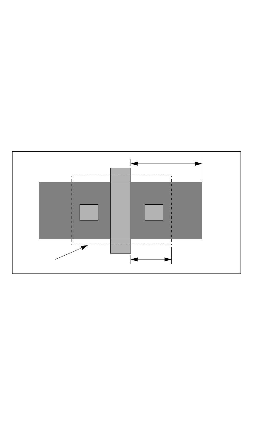
Chapter 20: Mapping File Commands
ignore_cap_layers 20-11
Chapter 20: Mapping File Commands
ignore_cap_layers 20-11
StarRC User Guide and Command Reference Version F-2011.06
• If you specify a design database layer in the ignore_cap_layers section of the mapping
layers file, this function acts independently from the function of the IGNORE_CAPACITANCE
command regardless of the IGNORE_CAPACITANCE setting.
• If more than 2 layers are specified, all the capacitance between every possible
combination is ignored. To ignore the capacitance between the polygons of the same
layer, specify the same layer twice.
The field solver modes FSCOMPARE and FS_EXTRACT_NETS interpret a specified
ignore_cap_layers section when producing field solver results for accuracy validation and/or
netlisting.
Figure 20-1 shows capacitance applied to MOS source and drain.
Figure 20-1 Applying Capacitance to MOS Source/Drain
ngatensd nsd
X
Y
Area modeled in SPICE
Partially Ignoring Gate Capacitance
Normally StarRC ignores all capacitance between a gate to a source or drain terminal of a
metal oxide semiconductor (MOS) transistor. This is acceptable when the complete
capacitance of that MOS transistor is present in the SPICE model. However, in some cases
the drawn devices have larger source or drain areas than the characterized transistors. To
ignore them completely makes the design inaccurate.
The partial ignoring of gate capacitance can now be specified to help you avoid the double
counting of capacitance already modeled in the device. See Figure 20-2 on page 20-12. To
do this, set a length parameter in the ignore cap section of your mapping file for the specified
layer pair using the ignore_cap_layers command.
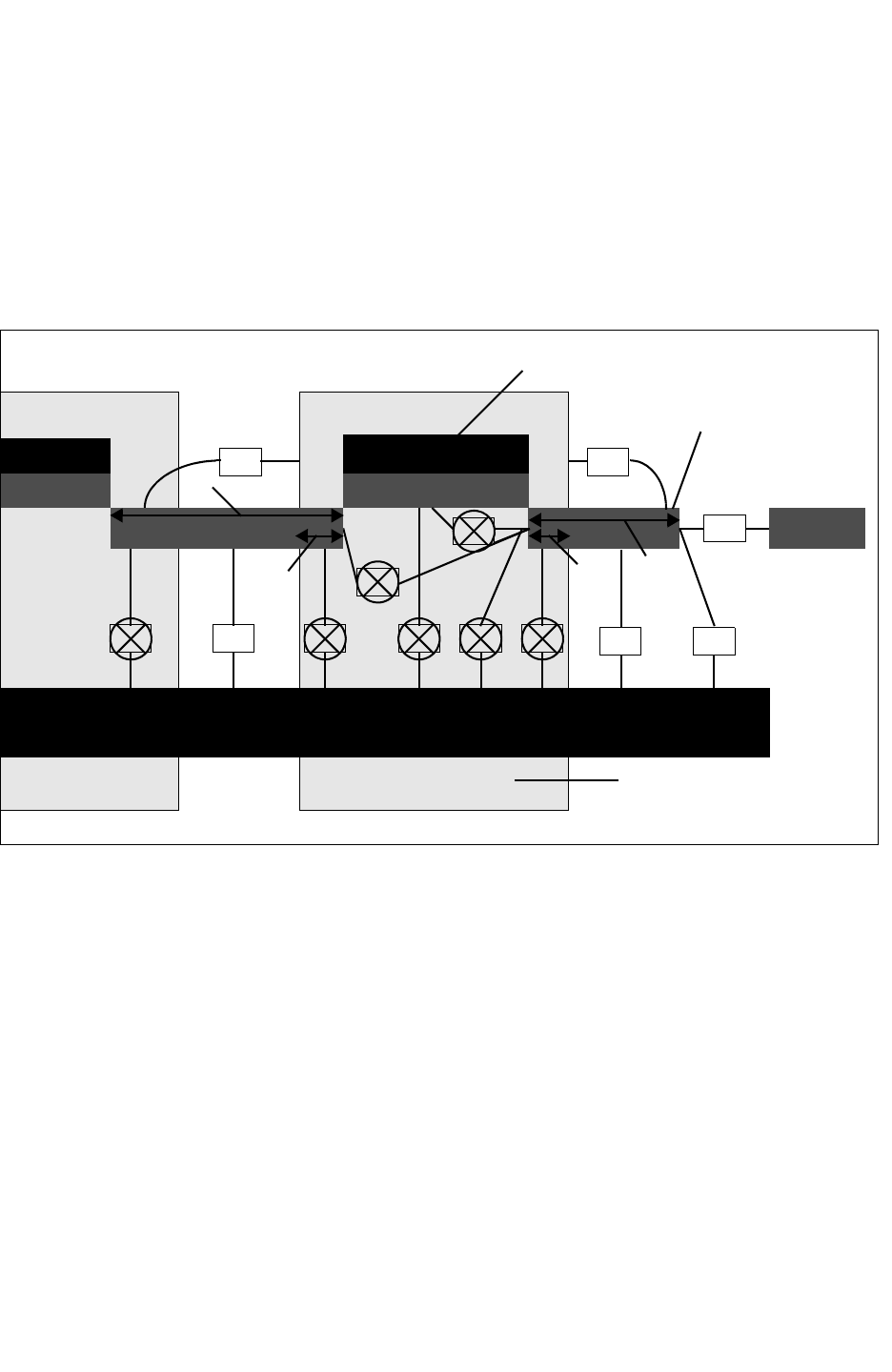
Chapter 20: Mapping File Commands
ignore_cap_layers 20-12
StarRC User Guide and Command Reference F-2011.06
StarRC User Guide and Command Reference Version F-2011.06
The conditions under which the length parameter is supported are as follows:
• Both layer1 and layer2 for the specified layer pair should be part of the MOSFET device.
The layer can be the gate terminal layer or substrate while the other is the source/drain
terminal layer.
• The value of ignore_cap_layer must be positive.
Figure 20-2 Defining a Partial Distance to Ignore
C12 C11 C7 C9
C10 C2 C5 C6
C5
C4 C8
C1 C3
L=
Y
L=
Y1
gate
source/drain
substrate
ignored area
Example
The following shows a simple example:
ignore_cap_layers
tn_diff NSD nnsd
m1_cap_term SUBSTRATE
The following example specifies a length value for source/drain of the MOS transistor to
partially ignore capacitance, which can cause the total capacitance on a net to increase.
ignore_cap_layers
ngate NSD L=0.1
pgate PSD L=0.1
nsd SUBSTRATE L=0.1
psd SUBSTRATE L=0.1

Chapter 20: Mapping File Commands
ignore_cap_layers 20-13
Chapter 20: Mapping File Commands
ignore_cap_layers 20-13
StarRC User Guide and Command Reference Version F-2011.06
See Also
•MAPPING_FILE

Chapter 20: Mapping File Commands
ignore_cap_layers 20-14
StarRC User Guide and Command Reference F-2011.06
StarRC User Guide and Command Reference Version F-2011.06

A-1
A
ITF Examples A
This appendix contains examples of ITF files for several process technologies. Each of the
following sections contains a sample ITF file and a diagram of the process cross section:
•Fully Planar Process
•Conformal Dielectric Process
•Gate Poly Process
•Local Interconnect Process
•Dielectric Air Gaps Process
•Layer Etch Process
•Metal Fill Process (Emulated)
•Transistor-Level Process
•Through-Silicon Via Process
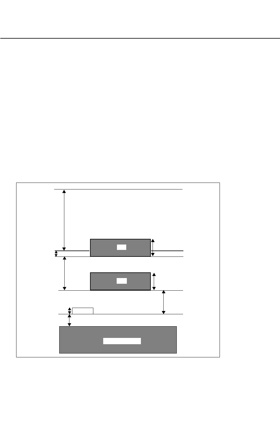
Appendix A: ITF Examples
Fully Planar Process A-2
StarRC User Guide and Command Reference F-2011.06
StarRC User Guide and Command Reference Version F-2011.06
Fully Planar Process
The following example ITF file describes the fully planar process shown in Figure A-1.
TECHNOLOGY = planar
DIELECTRIC TOP { THICKNESS=3.4 ER=3.9 }
DIELECTRIC D3 { THICKNESS=0.2 ER=4.7 }
CONDUCTOR M2 { THICKNESS=0.6 WMIN=0.5 SMIN=0.5 RPSQ=0.05 }
DIELECTRIC D2 { THICKNESS=1.2 ER=3.9 }
CONDUCTOR M1 { THICKNESS=0.6 WMIN=0.3 SMIN=0.3 RPSQ=0.05 }
DIELECTRIC D1 { THICKNESS=0.725 ER=3.9 }
CONDUCTOR POLY{ THICKNESS=0.125 WMIN=0.3 SMIN=0.3 RPSQ=10.0
}
DIELECTRIC D0{ THICKNESS=0.375 ER=3.9 }
VIA sub_tie { FROM=SUBSTRATE TO=M1 AREA=0.25 RPV=5 }
VIA poly_cont { FROM=POLY TO=M1 AREA=0.25 RPV=4 }
VIA via { FROM=M1 TO=M2 AREA=0.36 RPV=4 }
Figure A-1 Fully Planar Process
POLY
0.2
0.725
1.2
0.125
0.375
SUBSTRATE
M1
3.4
M2
0.6
0.6
TOP
D3
D2
D1
D0
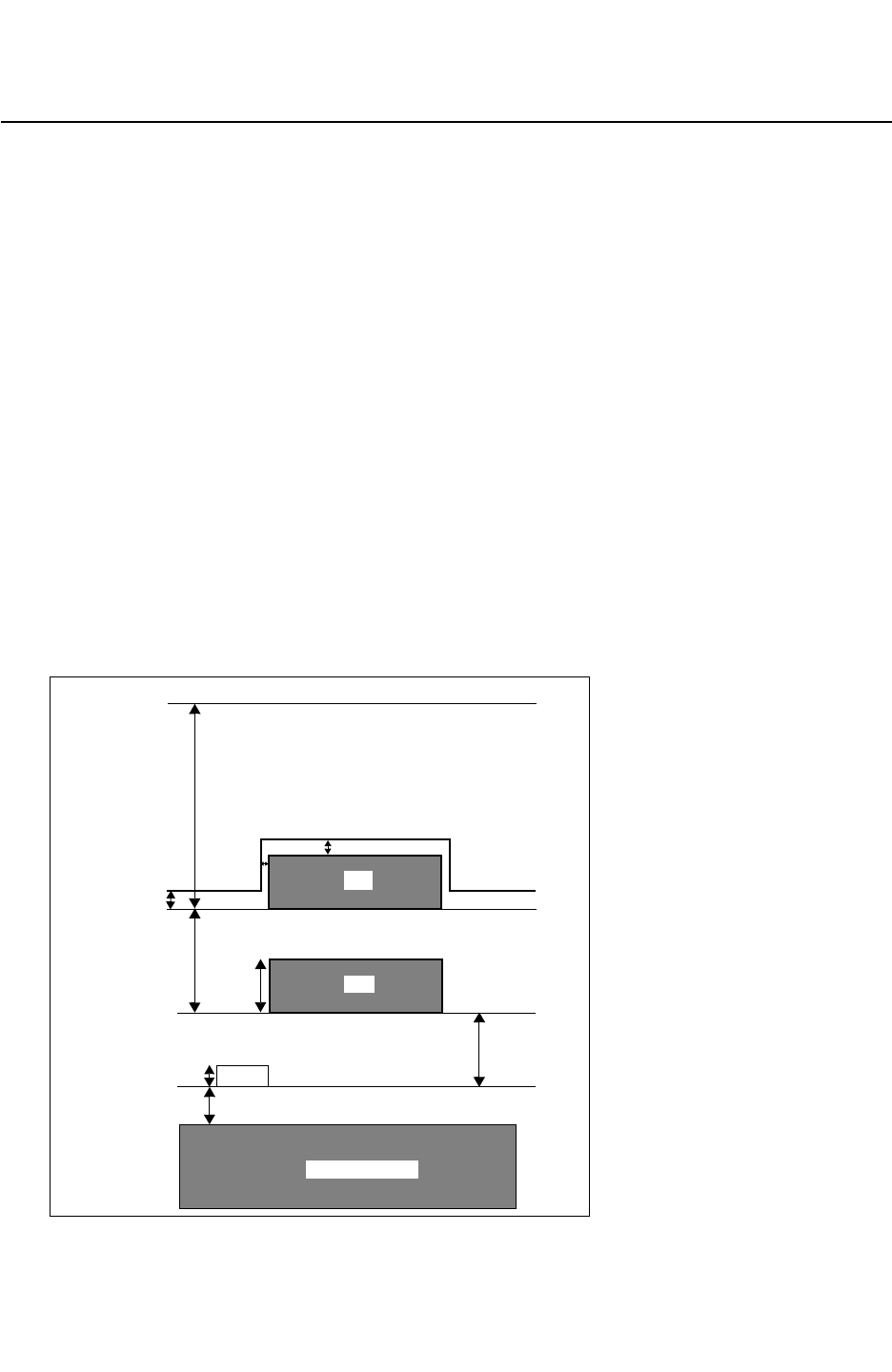
Chapter A: ITF Examples
Conformal Dielectric Process A-3
Appendix A: ITF Examples
Conformal Dielectric Process A-3
StarRC User Guide and Command Reference Version F-2011.06
Conformal Dielectric Process
The following example ITF file describes the conformal dielectric process shown in
Figure A-2.
TECHNOLOGY = conformal
$ TOP is planarized by measuring from D2
DIELECTRIC TOP { THICKNESS=3.6 MEASURED_FROM=D2 ER=3.9 }
$ D3 is a conformal dielectric
DIELECTRIC D3 {
THICKNESS=0.2 MEASURED_FROM=TOP_OF_CHIP
SW_T=0.15 TW_T=0.18 ER=5.9 }
CONDUCTOR M2 { THICKNESS=0.6 WMIN=0.5 SMIN=0.5 RPSQ=0.05 }
DIELECTRIC D2 { THICKNESS=1.2 ER=3.9 }
CONDUCTOR M1 { THICKNESS=0.6 WMIN=0.3 SMIN=0.3 RPSQ=0.05 }
DIELECTRIC D1 { THICKNESS=0.725 ER=3.9 }
CONDUCTOR POLY { THICKNESS=0.125 WMIN=0.3 SMIN=0.3 RPSQ=10.0
}
DIELECTRIC D0 { THICKNESS=0.375 ER=3.9 }
VIA DIFF_CONT { FROM=SUBSTRATE TO=M1 AREA=0.25 RPV=5 }
VIA POLY_CONT { FROM=POLY TO=M1 AREA=0.25 RPV=4 }
VIA V1 { FROM=M1 TO=M2 AREA=0.36 RPV=4 }
Figure A-2 Conformal Dielectric Process
POLY
0.2
0.725
1.2
0.125
0.375
SUBSTRATE
M1
3.6
M2
0.6
0.18
0.15
TOP
D3
D2
D1
D0
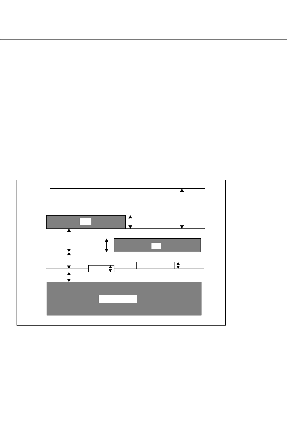
Appendix A: ITF Examples
Gate Poly Process A-4
StarRC User Guide and Command Reference F-2011.06
StarRC User Guide and Command Reference Version F-2011.06
Gate Poly Process
The following example ITF file describes the gate poly process shown in Figure A-3.
TECHNOLOGY = polygate
DIELECTRIC TOP { THICKNESS=1.2 ER=3.9 }
CONDUCTOR M2 { THICKNESS=0.4 WMIN=0.5 SMIN=0.5 RPSQ=0.05
DIELECTRIC D4 { THICKNESS=0.7 ER=3.9}
CONDUCTOR M1 { THICKNESS=0.4 WMIN=0.4 SMIN=0.4 RPSQ=0.05 }
DIELECTRIC D3 { THICKNESS=0.5 ER=3.9 }
CONDUCTOR POLY { THICKNESS=0.2 WMIN=0.3 SMIN=0.3 RPSQ=10.0 }
DIELECTRIC D2 { THICKNESS=0.1 ER=3.9 }
CONDUCTOR GATE { THICKNESS=0.2 WMIN=0.2 SMIN=0.2 RPSQ=8.0 }
DIELECTRIC TOX { THICKNESS=0.2 ER=3.9 }
VIA DIFF_CONT { FROM=SUBSTRATE TO=M1 AREA=0.25 RPV=5 }
VIA POLY_CONT { FROM=POLY TO=M1 AREA=0.25 RPV=4 }
VIA V1 { FROM=M1 TO=M2 AREA=0.36 RPV=4 }
Figure A-3 Gate Poly Process
POLY
GATE 0.1
0.2
0.2
1.2
0.4
0.5
0.7 0.4
SUBSTRATE
M2
M1
TOP
D4
D3
D2
TOX 0.2
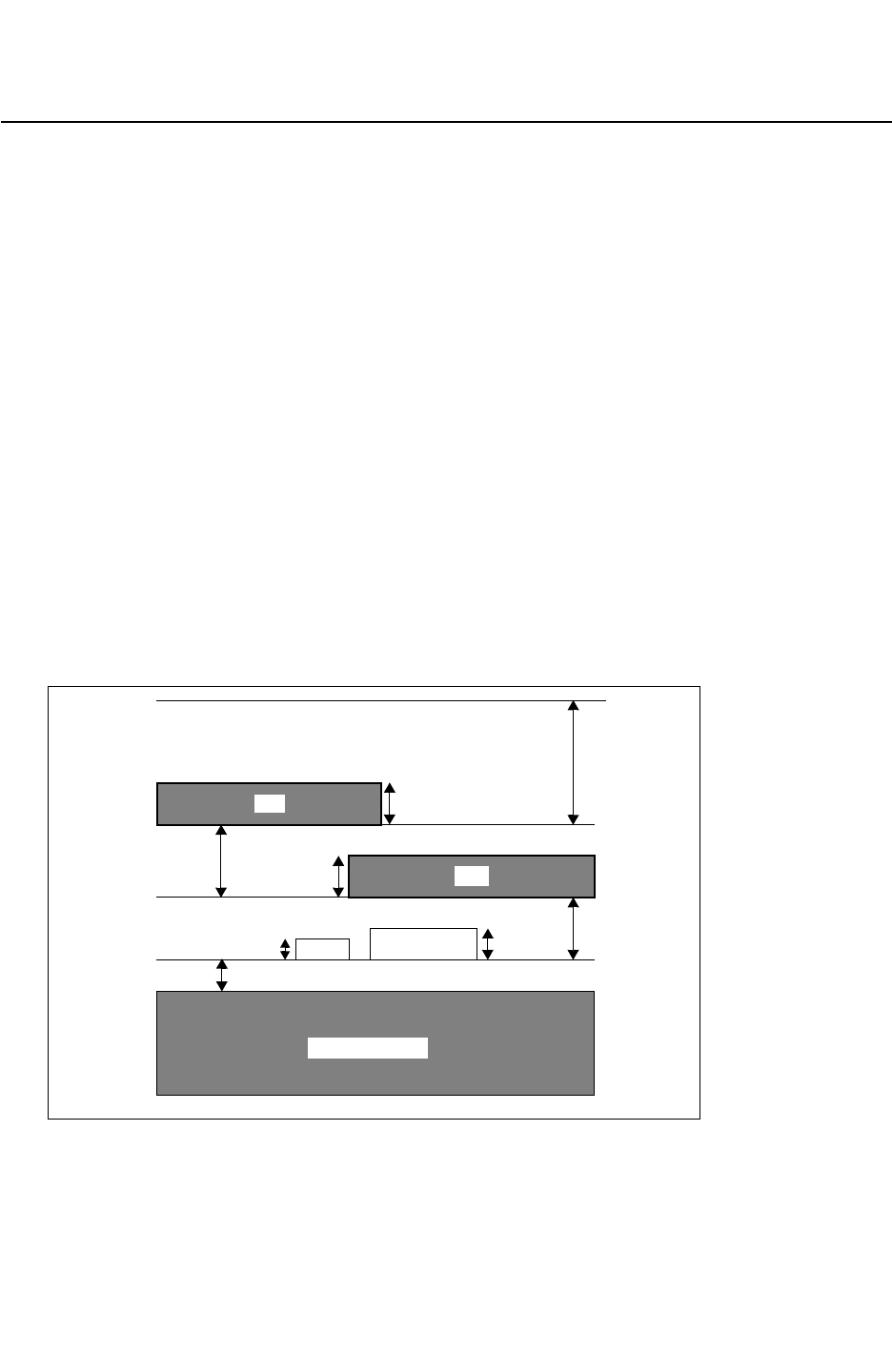
Chapter A: ITF Examples
Local Interconnect Process A-5
Appendix A: ITF Examples
Local Interconnect Process A-5
StarRC User Guide and Command Reference Version F-2011.06
Local Interconnect Process
The following example ITF file describes thelocal interconnect process shown in Figure A-4.
TECHNOLOGY = polyli
DIELECTRIC TOP { THICKNESS=1.2 ER=3.9 }
CONDUCTOR M2 { THICKNESS=0.4 WMIN=0.5 SMIN=0.5 RPSQ=0.05
DIELECTRIC D4 { THICKNESS=0.7 ER=3.9 }
$ D4 thickness measured from D3
CONDUCTOR M1 { THICKNESS=0.4 WMIN=0.4 SMIN=0.4 RPSQ=0.05 }
DIELECTRIC D3 { THICKNESS=0.6 ER=3.9 }
$ D3 thickness measured from D21
CONDUCTOR LI { THICKNESS=0.3 WMIN=0.4 SMIN=0.4 RPSQ=1 }
$ LI thickness measured from top of D21
CONDUCTOR POLY { THICKNESS=0.2 WMIN=0.2 SMIN=0.2 RPSQ=10.0 }
$ POLY thickness measured from top of D21
DIELECTRIC D21 { THICKNESS=0.2 ER=3.9 }
VIA LI_SUB { FROM=SUBSTRATE TO=LI AREA=0.25 RPV = 4 }
VIA CONT { FROM=LI TO=M1 AREA=0.25 RPV=5 }
VIA V1 { FROM=M1 TO=M2 AREA=0.25 RPV=4 }
Figure A-4 Local Interconnect
POLY LI 0.6
1.2
0.4
0.4
0.2 0.3
0.7
SUBSTRATE
M2
M1
TOP
D4
D3
D21 0.2
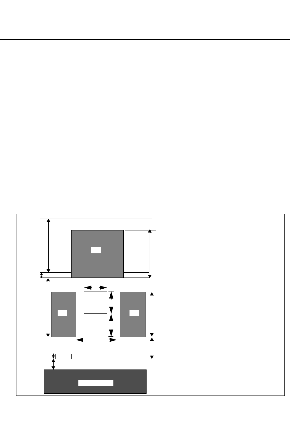
Appendix A: ITF Examples
Dielectric Air Gaps Process A-6
StarRC User Guide and Command Reference F-2011.06
StarRC User Guide and Command Reference Version F-2011.06
Dielectric Air Gaps Process
The following example ITF file describes the dielectric air gaps process shown in Figure A-5.
TECHNOLOGY = airgap
DIELECTRIC TOP { THICKNESS=3.4 ER=3.9 }
DIELECTRIC D3 { THICKNESS=0.2 ER=4.7 }
CONDUCTOR M2 { THICKNESS=0.6 WMIN=0.5 SMIN=0.5 RPSQ=0.05 }
DIELECTRIC D2 { THICKNESS=1.2 ER=3.9 }
CONDUCTOR M1 {THICKNESS=0.5 WMIN=0.3 SMIN=0.3 RPSQ=0.05
AIR_GAP_VS_SPACING {
SPACINGS {0.3 0.5 0.7 1.0 3.0}
AIR_GAP_WIDTHS {0.1 0.09 0.09 0.08 0.07}
AIR_GAP_THICKNESSES {0.2 0.23 0.25 0.26 0.28}
AIR_GAP_BOTTOM_HEIGHTS {0.1 0.14 0.18 0.20 0.22}}
DIELECTRIC D1 { THICKNESS=0.725 ER=3.9 }
CONDUCTOR POLY{ THICKNESS=0.125 WMIN=0.3 SMIN=0.3 RPSQ=10.0
}
DIELECTRIC D0 { THICKNESS=0.375 ER=3.9 }
VIA sub_tie { FROM=SUBSTRATE TO=M1 AREA=0.25 RPV=5 }
VIA poly_cont { FROM=POLY TO=M1 AREA=0.25 RPV=4 }
VIA via { FROM=M1 TO=M2 AREA=0.36 RPV=4 }
Figure A-5 Dielectric Air Gap Process
POLY
0.2
0.725
1.2
0.125
0.375
SUBSTRATE
3.4
M2
0.6
TOP
D3
D2
D1
D0
1.6
LAIR
T
W
B
S
S = spacing between neighboring lines
(SPACINGS)
W= width of the air gap
(AIR_GAP_WIDTH)
T= thickness of the air gap formed
(AIR_GAP_THICKNESS)
B= height of the bottom of the airgap
from the bottom of metal
(AIR_GAP_BOTTOM_HEIGHT)
L= spacing between the metal and air gap.
((S-W) /2)
M1M1
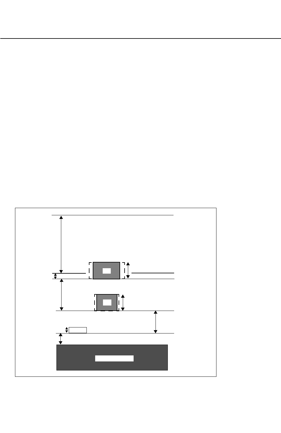
Chapter A: ITF Examples
Layer Etch Process A-7
Appendix A: ITF Examples
Layer Etch Process A-7
StarRC User Guide and Command Reference Version F-2011.06
Layer Etch Process
The following example ITF file describes the layer etch process shown in Figure A-6.
TECHNOLOGY = etch
DIELECTRIC TOP { THICKNESS=3.4 ER=3.9 }
DIELECTRIC D3 { THICKNESS=0.2 ER=3.9 }
CONDUCTOR M2 {
THICKNESS=0.6 WMIN=0.5 SMIN=0.5 RPSQ=0.05
ETCH=0.1 }
DIELECTRIC D2 { THICKNESS=1.2 ER=3.9 }
CONDUCTOR M1 {
THICKNESS=0.6 WMIN=0.3 SMIN=0.3 RPSQ=0.05
ETCH=0.05 }
DIELECTRIC D1 { THICKNESS=0.725 ER=3.9 }
CONDUCTOR POLY{ THICKNESS=0.125 WMIN=0.3 SMIN=0.3 RPSQ=10.0
}
DIELECTRIC D0 { THICKNESS=0.375 ER=3.9 }
VIA sub_tie { FROM=SUBSTRATE TO=M1 AREA=0.25 RPV=5 }
VIA poly_cont { FROM=POLY TO=M1 AREA=0.25 RPV=4 }
VIA via { FROM=M1 TO=M2 AREA=0.36 RPV=4 }
Figure A-6 Layer Etch Process
POLY
0.2
0.725
1.2
0.375
SUBSTRATE
3.4
0.6
0.6
TOP
D3
D2
D1
D0
M2
M1
0.125
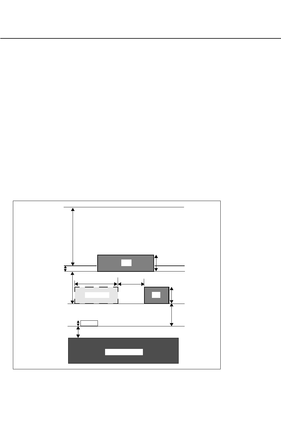
Appendix A: ITF Examples
Metal Fill Process (Emulated) A-8
StarRC User Guide and Command Reference F-2011.06
StarRC User Guide and Command Reference Version F-2011.06
Metal Fill Process (Emulated)
The following example ITF file describes the metal fill process shown in Figure A-7.
TECHNOLOGY = metal_fill
DIELECTRIC TOP { THICKNESS=3.4 ER=3.9 }
DIELECTRIC D3 { THICKNESS=0.2 ER=3.9 }
CONDUCTOR M2 {
THICKNESS=0.6 WMIN=0.5 SMIN=0.5 RPSQ=0.05
DIELECTRIC D2 { THICKNESS=1.2 ER=3.9 }
CONDUCTOR M1 {
THICKNESS=0.6 WMIN=0.3 SMIN=0.3 RPSQ=0.05
FILL_RATIO=0.4 FILL_SPACING=1.0 FILL_WIDTH=2.0 }
DIELECTRIC D1 { THICKNESS=0.725 ER=3.9 }
CONDUCTOR POLY{ THICKNESS=0.125 WMIN=0.3 SMIN=0.3 RPSQ=10.0
}
DIELECTRIC D0 {THICKNESS = 0.375 ER = 5.2}
VIA sub_tie { FROM=SUBSTRATE TO=M1 AREA=0.25 RPV=5 }
VIA poly_cont { FROM=POLY TO=M1 AREA=0.25 RPV=4 }
VIA via { FROM=M1 TO=M2 AREA=0.36 RPV=4 }
Figure A-7 Metal Fill Process (Emulated)
POLY
0.2
0.725
1.2
0.125
0.375
SUBSTRATE
3.4
M2 0.6
TOP
D3
D2
D1
D0
M1
1.0
0.6
M1FILL
2.0
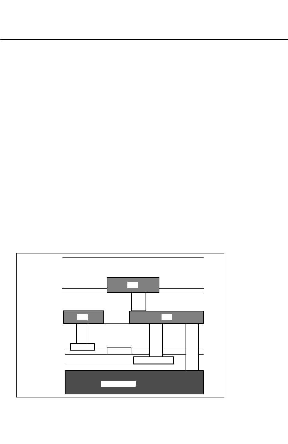
Chapter A: ITF Examples
Transistor-Level Process A-9
Appendix A: ITF Examples
Transistor-Level Process A-9
StarRC User Guide and Command Reference Version F-2011.06
Transistor-Level Process
The following example ITF file describes the transistor-level process shown in Figure A-8.
TECHNOLOGY=xtor
DIELECTRIC TOP { THICKNESS=3.40 ER=4.3 }
DIELECTRIC D3 { THICKNESS=0.20 ER=3.9 }]
CONDUCTOR M2 { THICKNESS=0.60 WMIN=0.55 SMIN=0.50 RPSQ=0.062
}
DIELECTRIC D2 { THICKNESS=1.20 ER=3.9 }
CONDUCTOR M1 { THICKNESS=0.60 WMIN=0.50 SMIN=0.45 RPSQ=0.062
}
DIELECTRIC D1 { THICKNESS=0.75 ER=3.9 }
CONDUCTOR FP{ THICKNESS=0.30 WMIN=0.35 SMIN=0.40 RPSQ=3.200
}
DIELECTRIC FOX { THICKNESS=0.20 ER=3.9 }
CONDUCTOR GP{ THICKNESS=0.30 WMIN=0.35 SMIN=0.40
RPSQ=3.200 }
DIELECTRIC GOX { THICKNESS=1.02 ER=5.0 }
CONDUCTOR DF{ THICKNESS=1.00 WMIN=1.00 SMIN=0.35
RPSQ=10.00 }
DIELECTRIC D0 { THICKNESS=0.50 ER=3.9 }
VIA via1 { FROM=M1 TO=M2 RHO=0.263 }
VIA pCont { FROM=FP TO=M1 RHO=0.352 }
VIA dCont { FROM=DF TO=M1 RHO=0.500 }
VIA sCont { FROM=SUBSTRATE TO=M1 RHO=0.600 }
Figure A-8 Transistor-Level Process
0.20
1.20
0.20
SUBSTRATE
3.40TOP
D3
D2
D1
D0
FP GP
DF
0.75
0.50
1.02GOX
FOX
dCont
via1
pCont
sCont
M2
M1 M1

Appendix A: ITF Examples
Through-Silicon Via Process A-10
StarRC User Guide and Command Reference F-2011.06
StarRC User Guide and Command Reference Version F-2011.06
Through-Silicon Via Process
The following example ITF file describes the through-silicon via process shown in
Figure A-9. The TSV statement must be placed after the frontside ITF statements and before
the backside ITF statements.
TECHNOLOGY = tsv_process
GLOBAL_TEMPERATURE = 25.0
$ Fronside ITF statements
CONDUCTOR M1 {
THICKNESS=0.3 WMIN=0.12 SMIN=0.12 SIDE_TANGENT=0.2
CRT1=7.0e-03 CRT2=-8.0e-07
}
DIELECTRIC ILD_B { ER=5.5 THICKNESS=0.5 }
DIELECTRIC GATE_OXIDE { ER=4.3 THICKNESS=0.03 }
DIELECTRIC FOXIDE_A { ER=5.0 THICKNESS=0.1 }
CONDUCTOR DIFFUSION {
THICKNESS=0.1 WMIN=0.1 SMIN=0.06
CRT1=8.0e-03 CRT2=-1.0e-07 RPSQ=36.0
}
DIELECTRIC FOXIDE { ER=5.0 THICKNESS=0.2 }
VIA via1 { FROM=M1 TO=M2 AREA=0.03 RPV=2.5 CRT1=3.0e-04 CRT2=-6.0e-06 }
$ TSV statement
TSV tsv {
FROM=M1 TO=M1b RHO=0.05 AREA=49.0 THICKNESS=20.0
INSULATION_THICKNESS = 0.4 INSULATION_ER = 5.5
CRT1=7.0e-03 CRT2=-3.0e-08
}
$ Backside ITF statements
DIELECTRIC PASS { ER=9.0 THICKNESS=2.0 }
DIELECTRIC DIELb { ER=5.0 THICKNESS=1.0 }
CONDUCTOR M1b {
THICKNESS=2.0 WMIN=4.0 SMIN=4.0 SIDE_TANGENT=-0.2
CRT1=1.0e-03 CRT2=-7.0e-07
}
DIELECTRIC ILDB{ ER=5.2 THICKNESS=1.0 }
Note:
The locations of the backside dielectric layers ILDB and PASS with respect to the
substrate are shown in Figure A-9.
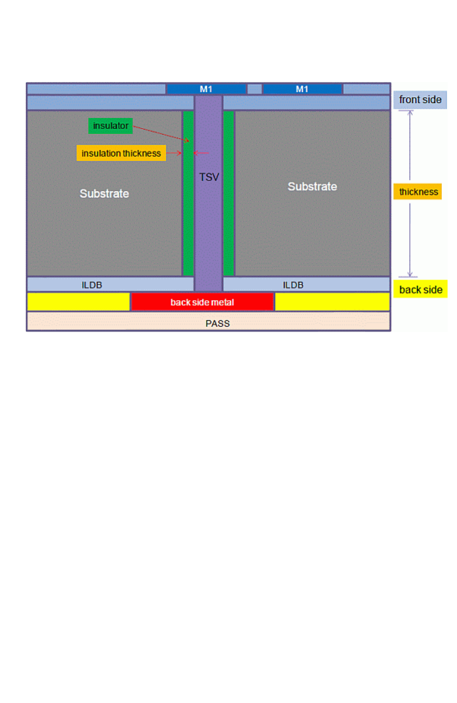
Chapter A: ITF Examples
Through-Silicon Via Process A-11
Appendix A: ITF Examples
Through-Silicon Via Process A-11
StarRC User Guide and Command Reference Version F-2011.06
Figure A-9 Through-Silicon Via Process

Appendix A: ITF Examples
Through-Silicon Via Process A-12
StarRC User Guide and Command Reference F-2011.06
StarRC User Guide and Command Reference Version F-2011.06

B-1
B
Command Lists B
The tables in this appendix alphabetically list the StarRC commands and with specific
information about the task groups, flows and license packages that they belong to. The
-clean option to be used for each command is shown in the last section.
•Command List With Task Information
•Command List With Flow and License Information
•Command List With -clean Option Information

Appendix B: Command Lists
Command List With Task Information B-2
StarRC User Guide and Command Reference F-2011.06
StarRC User Guide and Command Reference Version F-2011.06
Command List With Task Information
Table B-1 lists the StarRC commands with the following task information:
• Processing – Commands used to read input and process information.
• Layer Mapping – Commands used for linking each database layer to a TCAD GRD file
layer.
• Translation – Commands that control the translation of the input design database into
internal optimized data.
• XREF – Commands directing the method of cross-referencing schematic objects into
layout objects.
• Incremental – Commands used for incremental extraction.
• DP – Commands used to specify the option for the distributed processing during the
parasitic component extraction stage.
• Extraction – Commands associated with the setting of options for parasitic extraction.
• Field Solver – Commands for specifying and controlling the process of performing
extraction with a 3-D field solver and comparing with regular extraction results.
• Netlisting – Commands directing the format and contents of the generated parasitic
netlist.
• Noise – Commands associated with producing a parasitic netlist suitable for noise
analysis.
• Open Access (OA) – Commands associated with generating output parasitic data
conforming to the Open Access standard.

Chapter B: Command Lists
Command List With Task Information B-3
Appendix B: Command Lists
Command List With Task Information B-3
StarRC User Guide and Command Reference Version F-2011.06
Ta ble B - 1 List of Commands With Task Information
Command Name
Processing
Layer Mapping
Translation
XREF
Incremental
DP
Extraction
Field Solver
Netlist
Noise
Open Access
ANALOG_SYMMETRIC_NETS X
AUTO_RUNSET X
BLOCK X
BLOCK_BOUNDARY X
BUS_BIT X X X
CALIBRE_LVS_DEVICE_TYPE_CAP X
CALIBRE_LVS_DEVICE_TYPE_MOS X
CALIBRE_LVS_DEVICE_TYPE_RES X
CALIBRE_OPTIONAL_DEVICE_PIN_FILE X
CALIBRE_PDBA_FILE X
CALIBRE_QUERY_FILE X
CALIBRE_RUNSET X
CASE_SENSITIVE X
CELL_TYPE X
COMPARE_DIRECTORY X
CONLY_NETS X
CONVERT_DIODE_TO_PARASITIC_CAP X X X
COUPLE_NONCRITICAL_NETS X
COUPLE_NONCRITICAL_NETS_PREFIX X
COUPLE_NONCRITICAL_NETS_SUBNODE_SUFFIX X
COUPLE_TO_GROUND X
COUPLE_TO_PCELL_PINS X X X X
COUPLING_ABS_THRESHOLD X X X
COUPLING_AVG_THRESHOLD X X X
COUPLING_MULTIPLIER X X
COUPLING_REL_THRESHOLD X X X
COUPLING_REPORT_FILE X X X
COUPLING_REPORT_NUMBER X X X
COUPLING_THRESHOLD_OPERATION X X X
DENSITY_BASED_THICKNESS X

Appendix B: Command Lists
Command List With Task Information B-4
StarRC User Guide and Command Reference F-2011.06
StarRC User Guide and Command Reference Version F-2011.06
DENSITY_OUTSIDE_BLOCK X
DETECT_FUSE X
EVACCESS_DIRECTORY X
EXTRA_GEOMETRY_INFO X
EXTRACT_RES_BODY_COUPLING X X
EXTRACT_VIA_CAPS X X X
EXTRACTION X
FS_DP_STRING X
FS_EXTRACT_NETS X
FSCOMPARE_COUPLING_RATIO X
FSCOMPARE_FILE_PREFIX X
FSCOMPARE_OPTIONS X
FSCOMPARE_THRESHOLD X
GDS_FILE X
GDS_LAYER_MAP_FILE X
HIERARCHICAL_SEPARATOR X
HN_NETLIST_MODEL_NAME X
HN_NETLIST_SPICE_TYPE X
ICV_ANNOTATION_FILE X
ICV_RUNSET_REPORT_FILE X
IGNORE_CAPACITANCE X
IGNORE_FIELDPOLY_DIFFUSION_COUPLING X
INCREMENTAL X
INCREMENTAL_FORCE_DP X
INSTANCE_PORT X
INSTANCE_PORT_OPEN_CONDUCTANCE X
INTRANET_CAPS X X
KEEP_VIA_NODES X
LEF_FILE X
LEF_USE_OBS X
Table B-1 List of Commands With Task Information (Continued)
Command Name
Processing
Layer Mapping
Translation
XREF
Incremental
DP
Extraction
Field Solver
Netlist
Noise
Open Access

Chapter B: Command Lists
Command List With Task Information B-5
Appendix B: Command Lists
Command List With Task Information B-5
StarRC User Guide and Command Reference Version F-2011.06
LPE_DEVICES X
LPE_PARAM X
MACRO X
MACRO_DEF_FILE X
MAGNIFICATION_FACTOR X
MAGNIFY_DEVICE_PARAMS X
MAPPING_FILE X
MARKER_GENERATION X
MERGE_INSTANCE_PORTS X
MERGE_MULTI_CORNER X
MERGE_VIAS_IN_ARRAY X
METAL_FILL_GDS_FILE X
METAL_FILL_GDS_FILE_NET_NAME X
METAL_FILL_GDS_MAG ?
METAL_FILL_GDS_OFFSET ?
METAL_FILL_OASIS_FILE X
METAL_FILL_OASIS_FILE_NET_NAME X
METAL_FILL_OASIS_MAG ?
METAL_FILL_OASIS_OFFSET ?
METAL_FILL_POLYGON_HANDLING X
METAL_SHEET_OVER_AREA X
MILKYWAY_ADDITIONAL_VIEWS X
MILKYWAY_CELL_VIEW X
MILKYWAY_DATABASE X
MILKYWAY_EXPAND_HIERARCHICAL_CELLS X
MILKYWAY_EXTRACT_VIEW X
MILKYWAY_REF_LIB_MODE X
MODE X
MODEL_TYPE X
MOS_GATE_CAPACITANCE X
Table B-1 List of Commands With Task Information (Continued)
Command Name
Processing
Layer Mapping
Translation
XREF
Incremental
DP
Extraction
Field Solver
Netlist
Noise
Open Access

Appendix B: Command Lists
Command List With Task Information B-6
StarRC User Guide and Command Reference F-2011.06
StarRC User Guide and Command Reference Version F-2011.06
MOS_GATE_DELTA_RESISTANCE X
NET_SEGMENT_CUT_LENGTH X
NET_TYPE X
NETLIST_CAPACITANCE_UNIT X
NETLIST_COMMENTED_PARAMS X
NETLIST_COMMENTS_FILE X
NETLIST_COMPRESS_COMMAND X
NETLIST_CONNECT_OPENS X
NETLIST_CONNECT_SECTION X
NETLIST_CORNER_FILE X
NETLIST_CORNER_NAMES X
NETLIST_COUPLE_UNSELECTED_NETS X
NETLIST_DELIMITER X
NETLIST_DEVICE_LOCATION_ORIENTATION X
NETLIST_FILE X
NETLIST_FORMAT X
NETLIST_GROUND_NODE_NAME X
NETLIST_HIER_PROBE_NODES X
NETLIST_IDEAL_SPICE_FILE X
NETLIST_IDEAL_SPICE_HIER X
NETLIST_IDEAL_SPICE_TYPE X
NETLIST_INCREMENTAL X
NETLIST_INPUT_DRIVERS X
NETLIST_INSTANCE_SECTION X
NETLIST_LOGICAL_TYPE X
NETLIST_MAX_FILE_SIZE X
NETLIST_MAX_LINE X
NETLIST_MERGE_CORNERS X
NETLIST_MERGE_SHORTED_PORTS X
NETLIST_MINCAP_THRESHOLD X
Table B-1 List of Commands With Task Information (Continued)
Command Name
Processing
Layer Mapping
Translation
XREF
Incremental
DP
Extraction
Field Solver
Netlist
Noise
Open Access

Chapter B: Command Lists
Command List With Task Information B-7
Appendix B: Command Lists
Command List With Task Information B-7
StarRC User Guide and Command Reference Version F-2011.06
NETLIST_MINRES_HANDLING X
NETLIST_MINRES_THRESHOLD X
NETLIST_MMC_FORMULA X
NETLIST_MMC_FORMULA_NAMES X
NETLIST_NAME_MAP X
NETLIST_NODE_SECTION X
NETLIST_NODENAME_NETNAME X
NETLIST_PARA_VIEW X
NETLIST_PARASITIC_RESISTOR_MODEL X
NETLIST_PASSIVE_PARAMS X
NETLIST_POSTPROCESS_COMMAND ?
NETLIST_POWER_FILE X
NETLIST_PRECISION X
NETLIST_PRINT_CC_TWICE X
NETLIST_REMOVE_DANGLING_BRANCHES X
NETLIST_RENAME_PORTS X
NETLIST_RESISTANCE_UNIT X
NETLIST_SELECT_NETS X
NETLIST_SIM_OPTIONS X
NETLIST_SUBCKT X
NETLIST_TAIL_COMMENTS X
NETLIST_TIME_UNIT X
NETLIST_TOTALCAP_THRESHOLD X
NETLIST_TYPE X
NETLIST_UNSCALED_COORDINATES X
NETLIST_USE_M_FACTOR X
NETS X
NETS_FILE X
NONCRITICAL_COUPLING_REPORT_FILE X
NUM_PARTS X
Table B-1 List of Commands With Task Information (Continued)
Command Name
Processing
Layer Mapping
Translation
XREF
Incremental
DP
Extraction
Field Solver
Netlist
Noise
Open Access

Appendix B: Command Lists
Command List With Task Information B-8
StarRC User Guide and Command Reference F-2011.06
StarRC User Guide and Command Reference Version F-2011.06
OA_DEVICE_MAPPING_FILE X
OA_LAYER_MAPPING_FILE X
OA_LIB_DEF X
OA_LIB_NAME X
OA_MARKER_SIZE X
OA_PORT_ANNOTATION_VIEW X
OA_PROPERTY_ANNOTATION_VIEW X
OA_SKIPCELL_MAPPING_FILE X
OA_VIEW_NAME X
OASIS_FILE X
OASIS_LAYER_MAP_FILE X
OBSERVATION_POINTS X
OPERATING_TEMPERATURE X
PIN_CUT_THRESHOLD X
PIO_FILE X
PLACEMENT_INFO_FILE X
POWER_EXTRACT X
POWER_NETS X
POWER_PORTS X
POWER_REDUCTION X
PRINT_SILICON_INFO X
PROBE_TEXT_FILE X
PROCESS_CORNER X X
REDUCTION X
REDUCTION_MAX_DELAY_ERROR X
REMOVE_DANGLING_NETS X
REMOVE_FLOATING_NETS X
REMOVE_NET_PROPERTY X
RETAIN_CAPACITANCE_CAP_MODELS X
RETAIN_GATE_CONTACT_COUPLING X
Table B-1 List of Commands With Task Information (Continued)
Command Name
Processing
Layer Mapping
Translation
XREF
Incremental
DP
Extraction
Field Solver
Netlist
Noise
Open Access

Chapter B: Command Lists
Command List With Task Information B-9
Appendix B: Command Lists
Command List With Task Information B-9
StarRC User Guide and Command Reference Version F-2011.06
RING_AROUND_THE_BLOCK X
RING_AROUND_THE_BLOCK_SMIN_MULTIPLIER X
SENSITIVITY X
SHEET_COUPLE_TO_NET X
SHEET_COUPLE_TO_NET_LEVEL X
SHORT_PINS X
SHORT_PINS_IN_CELLS X
SKIP_CELL_AGF_FILE X
SKIP_CELL_PORT_PROP_FILE X
SKIP_CELLS X
SKIP_CELLS_COUPLE_TO_NET X
SKIP_CELLS_COUPLE_TO_NET_LEVEL X
SKIP_CELLS_FILE X
SKIP_INSTANCES X
SKIP_PCELLS X
SKIP_PCELL_LAYERS_FILE X
SLEEP_TIME_AFTER_FINISH X
SPICE_SUBCKT_FILE X
STAR_DIRECTORY X
SUBSTRATE_EXTRACTION X
SUMMARY_FILE X
SYNOPSYS_LIB_FILE X
TARGET_PWRA X
TCAD_GRD_FILE X
TEMPERATURE_SENSITIVITY X
THICKNESS_VARIATION_FILE X
TOP_DEF_FILE X
TRANSLATE_DEF_BLOCKAGE X
TRANSLATE_FLOATING_AS_FILL X
TRANSLATE_RETAIN_BULK_LAYERS X
Table B-1 List of Commands With Task Information (Continued)
Command Name
Processing
Layer Mapping
Translation
XREF
Incremental
DP
Extraction
Field Solver
Netlist
Noise
Open Access
Appendix B: Command Lists
Command List With Task Information B-10
StarRC User Guide and Command Reference F-2011.06
StarRC User Guide and Command Reference Version F-2011.06
TVF_ADJUSTMENT_TABLES X
USER_DEFINED_DIFFUSION_RES X
VIA_COVERAGE X
VIA_COVERAGE_OPTION_FILE X
WIDE_DEVICE_TERM_RESISTANCE X
XREF X
XREF_FEEDTHRU_NETS X
XREF_LAYOUT_INST_PREFIX X
XREF_LAYOUT_NET_PREFIX X
XREF_SWAP_MOS_SD_PROPERTY X
XREF_USE_LAYOUT_DEVICE_NAME X
ZONE_COUPLE_TO_NET X
ZONE_COUPLE_TO_NET_LEVEL X
Table B-1 List of Commands With Task Information (Continued)
Command Name
Processing
Layer Mapping
Translation
XREF
Incremental
DP
Extraction
Field Solver
Netlist
Noise
Open Access

Chapter B: Command Lists
Command List With Flow and License Information B-11
Appendix B: Command Lists
Command List With Flow and License Information B-11
StarRC User Guide and Command Reference Version F-2011.06
Command List With Flow and License Information
Table B-2 shows the availability of each command for use with specific flows and license
packages. “IND” indicates that the command requires the inductance license package.
Ta ble B - 2 List of Commands With Flow and License Information
Flow License
Command Name
All Flows
Milkyway
LEF/DEF
IC Validator
Hercules
Calibre
Shared Database
Custom
StarRC
Ultra
ANALOG_SYMMETRIC_NETS XXXXXXXXXX
AUTO_RUNSET X X X X X X
BLOCK X XXXXXXX
BLOCK_BOUNDARY XXXXXXX- XX
BUS_BIT XXXXXXXXXX
CALIBRE_LVS_DEVICE_TYPE_CAP X X X X
CALIBRE_LVS_DEVICE_TYPE_MOS X X X X
CALIBRE_LVS_DEVICE_TYPE_RES X X X X
CALIBRE_OPTIONAL_DEVICE_PIN_FILE X X X X
CALIBRE_PDBA_FILE X - X X
CALIBRE_QUERY_FILE X X X X
CALIBRE_RUNSET X X X X
CASE_SENSITIVE XXXXXXXXXX
CELL_TYPE X X X X X X
COMPARE_DIRECTORY X X X X X X
CONLY_NETS XXXXXXXXXX
CONVERT_DIODE_TO_PARASITIC_CAP XXXXXXXXXX
COUPLE_NONCRITICAL_NETS XXXXXXXXXX
COUPLE_NONCRITICAL_NETS_PREFIX XXXXXXXXXX
COUPLE_NONCRITICAL_NETS_SUBNODE_SUFFIX XXXXXXXXXX
COUPLE_TO_GROUND XXXXXXXXXX
COUPLE_TO_PCELL_PINS XXXXXXX
COUPLING_ABS_THRESHOLD XXXXXXXXXX
COUPLING_AVG_THRESHOLD XXXXXXXXXX

Appendix B: Command Lists
Command List With Flow and License Information B-12
StarRC User Guide and Command Reference F-2011.06
StarRC User Guide and Command Reference Version F-2011.06
COUPLING_MULTIPLIER XXXXXXXXXX
COUPLING_REL_THRESHOLD XXXXXXXXXX
COUPLING_REPORT_FILE XXXXXXXXXX
COUPLING_REPORT_NUMBER XXXXXXXXXX
COUPLING_THRESHOLD_OPERATION XXXXXXXXXX
DENSITY_BASED_THICKNESS XXXXXXXXXX
DENSITY_OUTSIDE_BLOCK XXXXXXXXXX
DETECT_FUSE XXXXXXXXXX
EVACCESS_DIRECTORY X X X X
EXTRA_GEOMETRY_INFO XXXXXXXXXX
EXTRACT_RES_BODY_COUPLING XXXXXXXXXX
EXTRACT_VIA_CAPS XXXXXXXXXX
EXTRACTION XXXXXXXXXX
FS_DP_STRING XXXXXXXXXX
FS_EXTRACT_NETS XXXXXXXXXX
FSCOMPARE_COUPLING_RATIO XXXXXXXXXX
FSCOMPARE_FILE_PREFIX XXXXXXXXXX
FSCOMPARE_OPTIONS XXXXXXXXXX
FSCOMPARE_THRESHOLD XXXXXXXXXX
GDS_FILE XXXXXXX- XX
GDS_LAYER_MAP_FILE XXXXXXX- XX
HIERARCHICAL_SEPARATOR XXXXXXXXXX
HN_NETLIST_MODEL_NAME X X X X X X
HN_NETLIST_SPICE_TYPE X X X X X X
ICV_ANNOTATION_FILE X X X X
ICV_RUNSET_REPORT_FILE X X X X
IGNORE_CAPACITANCE XXXXXXXXXX
IGNORE_FIELDPOLY_DIFFUSION_COUPLING XXXXXXXXXX
Table B-2 List of Commands With Flow and License Information (Continued)
Flow License
Command Name
All Flows
Milkyway
LEF/DEF
IC Validator
Hercules
Calibre
Shared Database
Custom
StarRC
Ultra

Chapter B: Command Lists
Command List With Flow and License Information B-13
Appendix B: Command Lists
Command List With Flow and License Information B-13
StarRC User Guide and Command Reference Version F-2011.06
INCREMENTAL X X - X X
INCREMENTAL_FORCE_DP XXXXXXX- XX
INSTANCE_PORT XXXXXXX- XX
INSTANCE_PORT_OPEN_CONDUCTANCE XXXXXXX- XX
INTRANET_CAPS XXXXXXXXXX
KEEP_VIA_NODES XXXXXXXXXX
LEF_FILE X - X X
LEF_USE_OBS X - X X
LPE_DEVICES XXXXXXXXXX
LPE_PARAM XXXXXXXXXX
MACRO X X - X X
MACRO_DEF_FILE X - X X
MAGNIFICATION_FACTOR XXXXXXXXXX
MAGNIFY_DEVICE_PARAMS X X X X X X
MAPPING_FILE XXXXXXXXXX
MARKER_GENERATION X X X X X
MERGE_INSTANCE_PORTS XXXXXXXXXX
MERGE_MULTI_CORNER XXXXXXXXXX
MERGE_VIAS_IN_ARRAY XXXXXXXXXX
METAL_FILL_GDS_FILE XXXXX XXX
METAL_FILL_GDS_FILE_NET_NAME XXXXX XXX
METAL_FILL_GDS_MAG XXXXXXXXXX
METAL_FILL_GDS_OFFSET XXXXXXXXXX
METAL_FILL_OASIS_FILE X X X X X
METAL_FILL_OASIS_FILE_NET_NAME X X X X X
METAL_FILL_OASIS_MAG XXXXXXXXXX
METAL_FILL_OASIS_OFFSET XXXXXXXXXX
METAL_FILL_POLYGON_HANDLING XXXXXXXXXX
Table B-2 List of Commands With Flow and License Information (Continued)
Flow License
Command Name
All Flows
Milkyway
LEF/DEF
IC Validator
Hercules
Calibre
Shared Database
Custom
StarRC
Ultra

Appendix B: Command Lists
Command List With Flow and License Information B-14
StarRC User Guide and Command Reference F-2011.06
StarRC User Guide and Command Reference Version F-2011.06
METAL_SHEET_OVER_AREA X X X X X
MILKYWAY_ADDITIONAL_VIEWS X - X X
MILKYWAY_CELL_VIEW X - X X
MILKYWAY_DATABASE X X X X
MILKYWAY_EXPAND_HIERARCHICAL_CELLS X - X X
MILKYWAY_EXTRACT_VIEW X X X X X
MILKYWAY_REF_LIB_MODE X X X X
MODE XXXXXXXXXX
MODEL_TYPE X X X X X X
MOS_GATE_CAPACITANCE X X X X X X
MOS_GATE_DELTA_RESISTANCE X X X X X X
NET_SEGMENT_CUT_LENGTH XXXXXXXXXX
NET_TYPE X X X X X X
NETLIST_CAPACITANCE_UNIT XXXXXXXXXX
NETLIST_COMMENTED_PARAMS X X X X X X
NETLIST_COMMENTS_FILE XXXXXXXXXX
NETLIST_COMPRESS_COMMAND XXXXXXXXXX
NETLIST_CONNECT_OPENS XXXXXXXXXX
NETLIST_CONNECT_SECTION XXXXXXXXXX
NETLIST_CORNER_FILE XXXXXXXXXX
NETLIST_CORNER_NAMES XXXXXXXXXX
NETLIST_COUPLE_UNSELECTED_NETS XXXXXXXXXX
NETLIST_DELIMITER XXXXXXXXXX
NETLIST_DEVICE_LOCATION_ORIENTATION X X X X X X
NETLIST_FILE XXXXXXXXXX
NETLIST_FORMAT XXXXXXXXXX
NETLIST_GROUND_NODE_NAME XXXXXXXXXX
NETLIST_HIER_PROBE_NODES XXXXXXX- XX
Table B-2 List of Commands With Flow and License Information (Continued)
Flow License
Command Name
All Flows
Milkyway
LEF/DEF
IC Validator
Hercules
Calibre
Shared Database
Custom
StarRC
Ultra

Chapter B: Command Lists
Command List With Flow and License Information B-15
Appendix B: Command Lists
Command List With Flow and License Information B-15
StarRC User Guide and Command Reference Version F-2011.06
NETLIST_IDEAL_SPICE_FILE X X X X X
NETLIST_IDEAL_SPICE_HIER X X X X X
NETLIST_IDEAL_SPICE_TYPE X X X X X
NETLIST_INCREMENTAL X X - X X
NETLIST_INPUT_DRIVERS XXXXXXXXXX
NETLIST_INSTANCE_SECTION XXXXXXXXXX
NETLIST_LOGICAL_TYPE X X X X
NETLIST_MAX_FILE_SIZE XXXXXXXXXX
NETLIST_MAX_LINE XXXXXXXXXX
NETLIST_MERGE_CORNERS XXXXXXXXXX
NETLIST_MERGE_SHORTED_PORTS XXXXXXXXXX
NETLIST_MINCAP_THRESHOLD XXXXXXXXXX
NETLIST_MINRES_HANDLING XXXXXXXXXX
NETLIST_MINRES_THRESHOLD XXXXXXXXXX
NETLIST_MMC_FORMULA XXXXXXXXXX
NETLIST_MMC_FORMULA_NAMES XXXXXXXXXX
NETLIST_NAME_MAP XXXXXXXXXX
NETLIST_NODE_SECTION XXXXXXXXXX
NETLIST_NODENAME_NETNAME XXXXXXXXXX
NETLIST_PARA_VIEW X - X X
NETLIST_PARASITIC_RESISTOR_MODEL XXXXXXXXXX
NETLIST_PASSIVE_PARAMS X X X X X X
NETLIST_POSTPROCESS_COMMAND XXXXXXXXXX
NETLIST_POWER_FILE XXXXXXXXXX
NETLIST_PRECISION XXXXXXXXXX
NETLIST_PRINT_CC_TWICE XXXXXXXXXX
NETLIST_REMOVE_DANGLING_BRANCHES XXXXXXXXXX
NETLIST_RENAME_PORTS XXXXXXXXXX
Table B-2 List of Commands With Flow and License Information (Continued)
Flow License
Command Name
All Flows
Milkyway
LEF/DEF
IC Validator
Hercules
Calibre
Shared Database
Custom
StarRC
Ultra

Appendix B: Command Lists
Command List With Flow and License Information B-16
StarRC User Guide and Command Reference F-2011.06
StarRC User Guide and Command Reference Version F-2011.06
NETLIST_RESISTANCE_UNIT XXXXXXXXXX
NETLIST_SELECT_NETS XXXXXXXXXX
NETLIST_SIM_OPTIONS X X X X X X
NETLIST_SUBCKT XXXXXXXXXX
NETLIST_TAIL_COMMENTS XXXXXXXXXX
NETLIST_TIME_UNIT XXXXXXXXXX
NETLIST_TOTALCAP_THRESHOLD XXXXXXXXXX
NETLIST_TYPE XXXXXXXXXX
NETLIST_UNSCALED_COORDINATES XXXXXXXXXX
NETLIST_USE_M_FACTOR X X X X X X
NETS XXXXXXX- XX
NETS_FILE XXXXXXX- XX
NONCRITICAL_COUPLING_REPORT_FILE XXXXXXXXXX
NUM_PARTS XXXXXXX- XX
OA_DEVICE_MAPPING_FILE X X X X X
OA_LAYER_MAPPING_FILE X X X X X
OA_LIB_DEF X X X X X
OA_LIB_NAME X X X X X
OA_MARKER_SIZE X X X X X
OA_PORT_ANNOTATION_VIEW X X X X X
OA_PROPERTY_ANNOTATION_VIEW X X X X X
OA_SKIPCELL_MAPPING_FILE X X X X X
OA_VIEW_NAME X X X X X
OASIS_FILE XXXXXXX- XX
OASIS_LAYER_MAP_FILE XXXXXXX- XX
OBSERVATION_POINTS X XXXXXXX
OPERATING_TEMPERATURE XXXXXXXXXX
PIN_CUT_THRESHOLD XXXXXXXXXX
Table B-2 List of Commands With Flow and License Information (Continued)
Flow License
Command Name
All Flows
Milkyway
LEF/DEF
IC Validator
Hercules
Calibre
Shared Database
Custom
StarRC
Ultra

Chapter B: Command Lists
Command List With Flow and License Information B-17
Appendix B: Command Lists
Command List With Flow and License Information B-17
StarRC User Guide and Command Reference Version F-2011.06
PIO_FILE XXXXXXXXXX
PLACEMENT_INFO_FILE XXXXXXXXXX
POWER_EXTRACT XXXXXXXXXX
POWER_NETS XXXXXXXXXX
POWER_PORTS XXXXXXXXXX
POWER_REDUCTION XXXXXXXXXX
PRINT_SILICON_INFO XXXXXXXXXX
PROBE_TEXT_FILE XXXXXXXXXX
PROCESS_CORNER XXXXXXXXXX
REDUCTION XXXXXXXXXX
REDUCTION_MAX_DELAY_ERROR XXXXXXXXXX
REMOVE_DANGLING_NETS XXXXXXXXXX
REMOVE_FLOATING_NETS XXXXXXXXXX
REMOVE_NET_PROPERTY XXXXXXXXXX
RETAIN_CAPACITANCE_CAP_MODELS X X X X X X
RETAIN_GATE_CONTACT_COUPLING X X X X X X
RING_AROUND_THE_BLOCK X X - X X
RING_AROUND_THE_BLOCK_SMIN_MULTIPLIER X X - X X
SENSITIVITY XXXXXXX- - X
SHEET_COUPLE_TO_NET X X X X X
SHEET_COUPLE_TO_NET_LEVEL X X X X X
SHORT_PINS XXXXXXXXXX
SHORT_PINS_IN_CELLS XXXXXXX- XX
SKIP_CELL_AGF_FILE X X - X X
SKIP_CELL_PORT_PROP_FILE XXXXXXX- XX
SKIP_CELLS XXXXXXX- XX
SKIP_CELLS_COUPLE_TO_NET XXXXXXX- XX
SKIP_CELLS_COUPLE_TO_NET_LEVEL XXXXXXX- XX
Table B-2 List of Commands With Flow and License Information (Continued)
Flow License
Command Name
All Flows
Milkyway
LEF/DEF
IC Validator
Hercules
Calibre
Shared Database
Custom
StarRC
Ultra

Appendix B: Command Lists
Command List With Flow and License Information B-18
StarRC User Guide and Command Reference F-2011.06
StarRC User Guide and Command Reference Version F-2011.06
SKIP_CELLS_FILE XXXXXXX- XX
SKIP_INSTANCES XXXXXXX- XX
SKIP_PCELLS XXXXXXXXXX
SKIP_PCELL_LAYERS_FILE XXXXXXXXXX
SLEEP_TIME_AFTER_FINISH XXXXXXXXXX
SPICE_SUBCKT_FILE XXXXXXXXXX
STAR_DIRECTORY XXXXXXXXXX
SUBSTRATE_EXTRACTION X X X X X X
SUMMARY_FILE XXXXXXXXXX
SYNOPSYS_LIB_FILE X X X X X X
TARGET_PWRA X X X X X X
TCAD_GRD_FILE XXXXXXXXXX
TEMPERATURE_SENSITIVITY XXXXXXXXXX
THICKNESS_VARIATION_FILE XXXXXXXXXX
TOP_DEF_FILE X - X X
TRANSLATE_DEF_BLOCKAGE X - X X
TRANSLATE_FLOATING_AS_FILL XXXXXXXXXX
TRANSLATE_RETAIN_BULK_LAYERS X X X X X X
TVF_ADJUSTMENT_TABLES XXXXXXX- - X
USER_DEFINED_DIFFUSION_RES XXXXXXXXXX
VIA_COVERAGE XXXXXXXXXX
VIA_COVERAGE_OPTION_FILE XXXXXXXXXX
WIDE_DEVICE_TERM_RESISTANCE X X X X X X
XREF X X X X X X
XREF_FEEDTHRU_NETS X X X X X X
XREF_LAYOUT_INST_PREFIX X X X X X X
XREF_LAYOUT_NET_PREFIX X X X X X X
XREF_SWAP_MOS_SD_PROPERTY XXXXXXXXXX
Table B-2 List of Commands With Flow and License Information (Continued)
Flow License
Command Name
All Flows
Milkyway
LEF/DEF
IC Validator
Hercules
Calibre
Shared Database
Custom
StarRC
Ultra

Chapter B: Command Lists
Command List With Flow and License Information B-19
Appendix B: Command Lists
Command List With Flow and License Information B-19
StarRC User Guide and Command Reference Version F-2011.06
XREF_USE_LAYOUT_DEVICE_NAME X X X X X X
ZONE_COUPLE_TO_NET XXXXXXX- XX
ZONE_COUPLE_TO_NET_LEVEL XXXXXXX- XX
Table B-2 List of Commands With Flow and License Information (Continued)
Flow License
Command Name
All Flows
Milkyway
LEF/DEF
IC Validator
Hercules
Calibre
Shared Database
Custom
StarRC
Ultra

Appendix B: Command Lists
Command List With -clean Option Information B-20
StarRC User Guide and Command Reference F-2011.06
StarRC User Guide and Command Reference Version F-2011.06
Command List With -clean Option Information
Table B-3 lists the -clean command that must be used if a change is made to the particular
command.
Ta ble B - 3 List of Commands With -clean Option Information
Command Name
-clean
-cleanT
- cleanX
-cleanFS
-cleanTFS
-cleanXFS
-cleanN
-cleanXREF
-cleanD
ANALOG_SYMMETRIC_NETS
AUTO_RUNSET X
BLOCK X
BLOCK_BOUNDARY X
BUS_BIT X
CALIBRE_LVS_DEVICE_TYPE_CAP
CALIBRE_LVS_DEVICE_TYPE_MOS
CALIBRE_LVS_DEVICE_TYPE_RES
CALIBRE_OPTIONAL_DEVICE_PIN_FILE
CALIBRE_PDBA_FILE X
CALIBRE_QUERY_FILE X
CALIBRE_RUNSET X
CASE_SENSITIVE X
CELL_TYPE X
COMPARE_DIRECTORY X
CONLY_NETS X
CONVERT_DIODE_TO_PARASITIC_CAP X
COUPLE_NONCRITICAL_NETS X
COUPLE_NONCRITICAL_NETS_PREFIX X
COUPLE_NONCRITICAL_NETS_SUBNODE_SUFFIX X
COUPLE_TO_GROUND X
COUPLE_TO_PCELL_PINS X
COUPLING_ABS_THRESHOLD X
COUPLING_AVG_THRESHOLD X
COUPLING_MULTIPLIER X
COUPLING_REL_THRESHOLD X
COUPLING_REPORT_FILE X

Chapter B: Command Lists
Command List With -clean Option Information B-21
Appendix B: Command Lists
Command List With -clean Option Information B-21
StarRC User Guide and Command Reference Version F-2011.06
COUPLING_REPORT_NUMBER X
COUPLING_THRESHOLD_OPERATION
DENSITY_BASED_THICKNESS X
DENSITY_OUTSIDE_BLOCK
DETECT_FUSE X
EVACCESS_DIRECTORY X
EXTRA_GEOMETRY_INFO X
EXTRACT_RES_BODY_COUPLING X
EXTRACT_VIA_CAPS X
EXTRACTION X
FS_DP_STRING
FS_EXTRACT_NETS X
FSCOMPARE_COUPLING_RATIO X
FSCOMPARE_FILE_PREFIX X
FSCOMPARE_OPTIONS X
FSCOMPARE_THRESHOLD X
GDS_FILE X
GDS_LAYER_MAP_FILE X
HIERARCHICAL_SEPARATOR X
HN_NETLIST_MODEL_NAME X
HN_NETLIST_SPICE_TYPE X
ICV_ANNOTATION_FILE
ICV_RUNSET_REPORT_FILE
IGNORE_CAPACITANCE X
IGNORE_FIELDPOLY_DIFFUSION_COUPLING X
INCREMENTAL X
INCREMENTAL_FORCE_DP X
INSTANCE_PORT X
INSTANCE_PORT_OPEN_CONDUCTANCE X
INTRANET_CAPS X
KEEP_VIA_NODES X
Table B-3 List of Commands With -clean Option Information (Continued)
Command Name
-clean
-cleanT
- cleanX
-cleanFS
-cleanTFS
-cleanXFS
-cleanN
-cleanXREF
-cleanD

Appendix B: Command Lists
Command List With -clean Option Information B-22
StarRC User Guide and Command Reference F-2011.06
StarRC User Guide and Command Reference Version F-2011.06
LEF_FILE X
LEF_USE_OBS X
LPE_DEVICES
LPE_PARAM
MACRO X
MACRO_DEF_FILE X
MAGNIFICATION_FACTOR X
MAGNIFY_DEVICE_PARAMS X
MAPPING_FILE X
MARKER_GENERATION X
MERGE_INSTANCE_PORTS X
MERGE_MULTI_CORNER X
MERGE_VIAS_IN_ARRAY X
METAL_FILL_GDS_FILE X
METAL_FILL_GDS_FILE_NET_NAME X
METAL_FILL_GDS_MAG
METAL_FILL_GDS_OFFSET
METAL_FILL_OASIS_FILE
METAL_FILL_OASIS_FILE_NET_NAME
METAL_FILL_OASIS_MAG
METAL_FILL_OASIS_OFFSET
METAL_FILL_POLYGON_HANDLING X
METAL_SHEET_OVER_AREA X
MILKYWAY_ADDITIONAL_VIEWS X
MILKYWAY_CELL_VIEW X
MILKYWAY_DATABASE X
MILKYWAY_EXPAND_HIERARCHICAL_CELLS X
MILKYWAY_EXTRACT_VIEW X
MILKYWAY_REF_LIB_MODE X X
MODE X
MODEL_TYPE X
Table B-3 List of Commands With -clean Option Information (Continued)
Command Name
-clean
-cleanT
- cleanX
-cleanFS
-cleanTFS
-cleanXFS
-cleanN
-cleanXREF
-cleanD

Chapter B: Command Lists
Command List With -clean Option Information B-23
Appendix B: Command Lists
Command List With -clean Option Information B-23
StarRC User Guide and Command Reference Version F-2011.06
MOS_GATE_CAPACITANCE X
MOS_GATE_DELTA_RESISTANCE X
NET_SEGMENT_CUT_LENGTH X
NET_TYPE X
NETLIST_CAPACITANCE_UNIT X
NETLIST_COMMENTED_PARAMS X
NETLIST_COMMENTS_FILE X
NETLIST_COMPRESS_COMMAND X
NETLIST_CONNECT_OPENS X
NETLIST_CONNECT_SECTION X
NETLIST_CORNER_FILE X
NETLIST_CORNER_NAMES X
NETLIST_COUPLE_UNSELECTED_NETS X
NETLIST_DELIMITER X
NETLIST_DEVICE_LOCATION_ORIENTATION X
NETLIST_FILE X
NETLIST_FORMAT X
NETLIST_GROUND_NODE_NAME X
NETLIST_HIER_PROBE_NODES X
NETLIST_IDEAL_SPICE_FILE X
NETLIST_IDEAL_SPICE_HIER X
NETLIST_IDEAL_SPICE_TYPE X
NETLIST_INCREMENTAL X
NETLIST_INPUT_DRIVERS X
NETLIST_INSTANCE_SECTION X
NETLIST_LOGICAL_TYPE X
NETLIST_MAX_FILE_SIZE X
NETLIST_MAX_LINE X
NETLIST_MERGE_CORNERS X
NETLIST_MERGE_SHORTED_PORTS X
NETLIST_MINCAP_THRESHOLD X
Table B-3 List of Commands With -clean Option Information (Continued)
Command Name
-clean
-cleanT
- cleanX
-cleanFS
-cleanTFS
-cleanXFS
-cleanN
-cleanXREF
-cleanD

Appendix B: Command Lists
Command List With -clean Option Information B-24
StarRC User Guide and Command Reference F-2011.06
StarRC User Guide and Command Reference Version F-2011.06
NETLIST_MINRES_HANDLING X
NETLIST_MINRES_THRESHOLD X
NETLIST_MMC_FORMULA X
NETLIST_MMC_FORMULA_NAMES X
NETLIST_NAME_MAP X
NETLIST_NODE_SECTION X
NETLIST_NODENAME_NETNAME X
NETLIST_PARA_VIEW X
NETLIST_PARASITIC_RESISTOR_MODEL X
NETLIST_PASSIVE_PARAMS X
NETLIST_POSTPROCESS_COMMAND
NETLIST_POWER_FILE X
NETLIST_PRECISION
NETLIST_PRINT_CC_TWICE X
NETLIST_REMOVE_DANGLING_BRANCHES X
NETLIST_RENAME_PORTS X
NETLIST_RESISTANCE_UNIT X
NETLIST_SELECT_NETS X
NETLIST_SIM_OPTIONS X
NETLIST_SUBCKT X
NETLIST_TAIL_COMMENTS X
NETLIST_TIME_UNIT X
NETLIST_TOTALCAP_THRESHOLD X
NETLIST_TYPE X
NETLIST_UNSCALED_COORDINATES X
NETLIST_USE_M_FACTOR X
NETS X
NETS_FILE X
NONCRITICAL_COUPLING_REPORT_FILE X
NUM_PARTS X
OA_DEVICE_MAPPING_FILE X
Table B-3 List of Commands With -clean Option Information (Continued)
Command Name
-clean
-cleanT
- cleanX
-cleanFS
-cleanTFS
-cleanXFS
-cleanN
-cleanXREF
-cleanD

Chapter B: Command Lists
Command List With -clean Option Information B-25
Appendix B: Command Lists
Command List With -clean Option Information B-25
StarRC User Guide and Command Reference Version F-2011.06
OA_LAYER_MAPPING_FILE X
OA_LIB_DEF X
OA_LIB_NAME X
OA_MARKER_SIZE X
OA_PORT_ANNOTATION_VIEW X
OA_PROPERTY_ANNOTATION_VIEW X
OA_SKIPCELL_MAPPING_FILE X
OA_VIEW_NAME X
OASIS_FILE
OASIS_LAYER_MAP_FILE
OBSERVATION_POINTS X
OPERATING_TEMPERATURE X
PIN_CUT_THRESHOLD X
PIO_FILE X
PLACEMENT_INFO_FILE X
POWER_EXTRACT X
POWER_NETS X
POWER_PORTS X
POWER_REDUCTION X
PRINT_SILICON_INFO X
PROBE_TEXT_FILE X
PROCESS_CORNER X
REDUCTION X
REDUCTION_MAX_DELAY_ERROR X
REMOVE_DANGLING_NETS X
REMOVE_FLOATING_NETS X
REMOVE_NET_PROPERTY X
RETAIN_CAPACITANCE_CAP_MODELS X
RETAIN_GATE_CONTACT_COUPLING X
RING_AROUND_THE_BLOCK X
RING_AROUND_THE_BLOCK_SMIN_MULTIPLIER X
Table B-3 List of Commands With -clean Option Information (Continued)
Command Name
-clean
-cleanT
- cleanX
-cleanFS
-cleanTFS
-cleanXFS
-cleanN
-cleanXREF
-cleanD

Appendix B: Command Lists
Command List With -clean Option Information B-26
StarRC User Guide and Command Reference F-2011.06
StarRC User Guide and Command Reference Version F-2011.06
SENSITIVITY X
SHEET_COUPLE_TO_NET X
SHEET_COUPLE_TO_NET_LEVEL X
SHORT_PINS X
SHORT_PINS_IN_CELLS X
SKIP_CELL_AGF_FILE X
SKIP_CELL_PORT_PROP_FILE X
SKIP_CELLS X
SKIP_CELLS_COUPLE_TO_NET X
SKIP_CELLS_COUPLE_TO_NET_LEVEL X
SKIP_CELLS_FILE X
SKIP_INSTANCES X
SKIP_PCELLS X
SKIP_PCELL_LAYERS_FILE X
SLEEP_TIME_AFTER_FINISH
SPICE_SUBCKT_FILE X
STAR_DIRECTORY X
SUBSTRATE_EXTRACTION X
SUMMARY_FILE
SYNOPSYS_LIB_FILE X
TARGET_PWRA X
TCAD_GRD_FILE X
TEMPERATURE_SENSITIVITY X
THICKNESS_VARIATION_FILE X
TOP_DEF_FILE X
TRANSLATE_DEF_BLOCKAGE X
TRANSLATE_FLOATING_AS_FILL X
TRANSLATE_RETAIN_BULK_LAYERS X
VIA_COVERAGE X
VIA_COVERAGE_OPTION_FILE X
WIDE_DEVICE_TERM_RESISTANCE X
Table B-3 List of Commands With -clean Option Information (Continued)
Command Name
-clean
-cleanT
- cleanX
-cleanFS
-cleanTFS
-cleanXFS
-cleanN
-cleanXREF
-cleanD
Chapter B: Command Lists
Command List With -clean Option Information B-27
Appendix B: Command Lists
Command List With -clean Option Information B-27
StarRC User Guide and Command Reference Version F-2011.06
XREF X
XREF_FEEDTHRU_NETS X
XREF_LAYOUT_INST_PREFIX X
XREF_LAYOUT_NET_PREFIX X
XREF_SWAP_MOS_SD_PROPERTY
XREF_USE_LAYOUT_DEVICE_NAME X
ZONE_COUPLE_TO_NET X
ZONE_COUPLE_TO_NET_LEVEL X
Table B-3 List of Commands With -clean Option Information (Continued)
Command Name
-clean
-cleanT
- cleanX
-cleanFS
-cleanTFS
-cleanXFS
-cleanN
-cleanXREF
-cleanD

Appendix B: Command Lists
Command List With -clean Option Information B-28
StarRC User Guide and Command Reference F-2011.06
StarRC User Guide and Command Reference Version F-2011.06
