Strata AirLink Wireless IG Air Link System Installation Guide
User Manual: Strata AirLink wireless system installation guide www.TelecomUserGuides.com Access User Guides, Manuals and Brochures
Open the PDF directly: View PDF ![]() .
.
Page Count: 117 [warning: Documents this large are best viewed by clicking the View PDF Link!]
- Back to Home Page
- Title Page
- Publication Information
- Contents
- Introduction
- Chapter 1 - The Grand Tour
- Chapter 2 - Pre-installation
- Chapter 3 - BSIA System Installation
- Chapter 4 - RWIU System Installation
- Chapter 5 - Maintenance and Troubleshooting
- Appendix – Specifications
- Glossary
- Index
- Quit Acrobat Reader
May 2000
726+,%$ Telecommunication Systems Division
Wireless Systems
Installation Guide
Digital Business Telephone Systems

Publication Information
Toshiba America Information Systems, Inc., Telecommunication Systems
Division, reserves the right, without prior notice, to revise this information
publication for any reason, including, but not limited to, utilization of new
advances in the state of technical arts or to simply change the design of this
document.
Further, Toshiba America Information Systems, Inc., Telecommunication
Systems Division, also reserves the right, without prior notice, to make such
changes in equipment design or components as engineering or
manufacturing methods may warrant.
D42-IG-WDTEL-VA
4025068
Version A, May 2000
© Copyright 2000
Toshiba America Information Systems, Inc.
Telecommunication Systems Division
All rights reserved. No part of this manual, covered by the copyrights
hereon, may be reproduced in any form or by any means—graphic,
electronic, or mechanical, including recording, taping, photocopying, or
information retrieval systems—without express written permission of the
publisher of this material.
Strata is a registered trademark of Toshiba Corporation. Stratagy is a
registered trademark of Toshiba America Information Systems, Inc. Strata
AirLink is a trademark of Toshiba America Information Systems, Inc.
Trademarks, registered trademarks, and service marks are the property of
their respective owners.

Strata AirLink Installation Guide 5/00 i
Contents
Introduction
Organization............................................................................................................................................ v
Conventions............................................................................................................................................. v
Action/Response Table.................................................................................................................... vi
Related Documents/Media....................................................................................................................vii
General Description........................................................................................................................vii
Installation and Programming ........................................................................................................vii
Feature Description.........................................................................................................................vii
User Guides/Quick Reference Guides for: .....................................................................................vii
CD-ROM ........................................................................................................................................vii
Chapter 1 – The Grand Tour
How Wireless Calls Take Place .............................................................................................................. 1
Receive Calls .................................................................................................................................... 1
Make Calls........................................................................................................................................ 1
Terminate Calls................................................................................................................................. 1
System Configurations............................................................................................................................ 2
Base Station ...................................................................................................................................... 2
Handset ............................................................................................................................................. 2
Wireless Manager Software .................................................................................................................... 3
Strata AirLink BSIA Manager Software .......................................................................................... 3
Strata AirLink RWIU Manager Software......................................................................................... 4
Chapter 2 – Pre-installation
Step 1: Check System Hardware and Software Requirements ............................................................ 6
Step 2: Review System Component Placement ................................................................................... 6
Step 3: Review Possible System Configurations ................................................................................. 8
Single BSIA System with Two Base Stations/Single RWIU System with Four Base Stations....... 8
Multiple BSIA Systems as Single System........................................................................................ 9
Multiple Overlapping Systems ....................................................................................................... 10
Factory with Adjoining Offices...................................................................................................... 11
Manufacturing Plant ....................................................................................................................... 11
Cubicles, Walled Offices, and Conference Rooms ........................................................................ 12
Step 4: Unpack Shipment ................................................................................................................... 12
Step 5: Check Equipment List ........................................................................................................... 12
Step 6: Purchase Additional Equipment ............................................................................................ 13
Step 7: Select Suitable Locations ....................................................................................................... 13
Step 8: Set Up Temporary Installation ............................................................................................... 13
Step 9: Use Stand-alone Base Station Test Stand .............................................................................. 13
Substep A: Before You Begin ...................................................................................................... 13

Contents
Chapter 3 – BSIA System Installation
ii Strata AirLink Installation Guide 5/00
Substep B: Set Up Base Station.................................................................................................... 14
Substep C: Set Up Handsets ......................................................................................................... 14
Substep D: Audio Coverage Test ................................................................................................. 15
Substep E: Perform Handset Bit Error Rate (BER) Test.............................................................. 15
Step 10: Mount Base Stations .............................................................................................................. 16
Chapter 3 –BSIA System Installation
Step 1: Install Analog Line Module (ALM) ...................................................................................... 19
Step 2: Run Cable .............................................................................................................................. 20
Step 3: (Optional) Activate External Critical Alarm ......................................................................... 21
Step 4: Determine Base Station Power Supply .................................................................................. 21
Step 5: Connect Power Supply .......................................................................................................... 23
Step 6: Connect PC ............................................................................................................................ 23
Step 7: Install Strata AirLink Manager Software .............................................................................. 24
Step 8: Copy Upgrade Software ........................................................................................................ 25
Step 9: Configure System ................................................................................................................. 26
Substep A: Activate UTAM ......................................................................................................... 26
Substep B: Set System Time and Date ......................................................................................... 28
Substep C: Enter System Settings ................................................................................................29
Substep D: Configure Handsets ................................................................................................... 31
Substep E: Program Button Sequences ........................................................................................ 32
Substep F: Store IDs in Handset................................................................................................... 37
BSIA Additional Information ............................................................................................................... 38
BSIA (Controller) Specifications ................................................................................................... 38
Adapter and BSIA Pinouts ............................................................................................................. 38
ALM Removal................................................................................................................................ 39
Initial Configuration Change.......................................................................................................... 40
Password Change............................................................................................................................ 40
Base Station Addition..................................................................................................................... 40
Communications Port Change........................................................................................................ 41
Chapter 4 –RWIU System Installation
Step 1: Check DIP Switches and Jumpers on PCB ............................................................................ 43
Step 2: Mount WWIS onto RWIU ..................................................................................................... 45
Step 3: Determine Proper Strata DK Slot Configuration ................................................................... 45
Step 4: Install RWIU/WWIS into Strata DK ..................................................................................... 47
Step 5: Run Cable .............................................................................................................................. 47
Step 6: Determine Base Station Power Supply .................................................................................. 48
Step 7: Connect Power Supply .......................................................................................................... 48
Step 8: Use Proper Power Factor (PF) ............................................................................................... 48
Step 9: Program Strata DK ................................................................................................................ 50
Step 10: Connect PC ............................................................................................................................ 52
Step 11: Initialize RWIU ..................................................................................................................... 52
Step 12: Install RWIU Manager .......................................................................................................... 52
Step 13: Start RWIU Manager ............................................................................................................. 53
Step 14: Set General Settings ............................................................................................................... 53
Step 15: Enter Handset IDs .................................................................................................................. 54
Step 16: Enable UTAM ....................................................................................................................... 55
Step 17: Store IDs in Handset .............................................................................................................. 56

Contents
Chapter 5 –Maintenance and Troubleshooting
Strata AirLink Installation Guide 5/00 iii
RWIU Additional Information.............................................................................................................. 57
RWIU/WWIS Interface Unit.......................................................................................................... 57
Change Initial Configuration.......................................................................................................... 66
Change Communications Ports ...................................................................................................... 66
Check RWIU and Base Station Software Versions........................................................................ 67
View Log Messages........................................................................................................................ 67
Reset Base Stations and RWIU ...................................................................................................... 68
Upgrade RWIU and Base Stations ................................................................................................. 68
Change Base Station Numbers ....................................................................................................... 69
Chapter 5 –Maintenance and Troubleshooting
Maintenance .......................................................................................................................................... 72
Charge Batteries ............................................................................................................................. 72
Discharge Batteries......................................................................................................................... 73
Password Protection ....................................................................................................................... 73
Upgrade Base Stations.................................................................................................................... 76
Troubleshooting .................................................................................................................................... 81
System Power, Polarity, and Continuity......................................................................................... 81
Components .................................................................................................................................... 81
Communications............................................................................................................................. 81
RF Link Termination ...................................................................................................................... 81
Noisy Circuits................................................................................................................................. 81
DC Resistance................................................................................................................................. 81
System Reset................................................................................................................................... 81
Activation Code.............................................................................................................................. 81
Base Station .................................................................................................................................... 82
Replace Defective Base Station...................................................................................................... 83
Handset ........................................................................................................................................... 84
Battery ............................................................................................................................................ 85
Charger Base................................................................................................................................... 86
BSIA System .................................................................................................................................. 86
RWIU System................................................................................................................................. 94
Appendix – Specifications
Base Station Specifications................................................................................................................... 97
Handset Specifications.......................................................................................................................... 98
Grounding Requirements ...................................................................................................................... 99
FCC ....................................................................................................................................................... 99
Part 68............................................................................................................................................. 99
Part 15........................................................................................................................................... 100
UTAM, Inc.......................................................................................................................................... 100
Underwriters Laboratories (UL) ......................................................................................................... 102
Primary and Secondary Protectors ............................................................................................... 102
System Line Circuit Requirements............................................................................................... 102
Glossary ................................................................................................................................................ 103
Index ....................................................................................................................................................... 105

Contents
Chapter 5 –Maintenance and Troubleshooting
iv Strata AirLink Installation Guide 5/00
Strata AirLink Installation Guide 5/00 v
Introduction
This installation guide describes Strata AirLink™ wireless systems. It provides detailed step-by-
step instructions for installing, maintaining and troubleshooting the product line. It is intended for
qualified Service Technicians (Installers).
Organization
This guide contains the following information:
♦Chapter 1 – The Grand Tour covers the Strata AirLink system components.
♦Chapter 2 – Pre-installation gives procedures that must be performed prior to installing the
Strata AirLink system.
♦Chapter 3 – BSIA System Installation contains information on installing the Strata AirLink
External Wireless system.
♦Chapter 4 – RWIU System Installation contains information on installing the Strata AirLink
Integrated Wireless system.
♦Chapter 4 – Maintenance and Troubleshooting provides instructions for basic maintenance
and troubleshooting operations for the Strata AirLink systems.
♦Appendix – Specifications covers Base Station and Handset specifications, grounding
requirements, and FCC, UTAM, Inc. and Underwriters Laboratories (UL) regulations.
♦Glossary/Index
Conventions
This manual uses these conventions:
Conventions Description
Note
Elaborates specific items or references other information. Within
some tables, general notes apply to the entire table and numbered
notes apply to specific items.
Important! Calls attention to important instructions or information.
CAUTION! Advises you that hardware, software applications, or data
could be damaged if the instructions are not followed closely.
WARNING! Alerts you when the given task could cause personal injury or
death.
Courier Shows a computer keyboard entry or screen display.
Introduction
Conventions
vi Strata AirLink Installation Guide 5/00
Action/Response Table
Helvetica Bold represents tokens. For example: M( ).
Italics represent parameter and menu/screen field names, and book titles.
For example: hot_box parameter, Extension field.
“Type”Indicates entry of a string of text.
“Press”Indicates entry of a single key. For example: Type prog then
press Enter.
Plus (+)
Shows a multiple PC keyboard or phone button entry. Entries
without spaces between them show a simultaneous entry.
Example: Esc+Enter. Entries with spaces between them show a
sequential entry. Example: # + 5.
Tilde (~) Means “through.” Example: 350 ~ 640 Hz frequency range.
➤Denotes the step in a one-step procedure.
➤Denotes a procedure.
See Figure 10
Grey words within the printed text denote cross-references. In the
electronic version of this document (Library CD-ROM or FYI
Internet download), cross-references appear in blue hypertext.
1. Actions you perform
appear in this column.
They can consist of either
a single step or a series of
numbered steps.
The immediate response to the action performed appears in
this column. Additional notes and comments are also included.
2. When the action you
perform results in a
screen, menu, etc., the
screen displays to the
right.
Conventions Description
3485

Introduction
Related Documents/Media
Strata AirLink Installation Guide 5/00 vii
Related Documents/Media
Note Some documents listed here may appear in different versions on the CD-ROM, FYI, or in
print. To find the most current version, check the version/date in the Publication
Information on the back of the document’s title page.
General Description
♦Strata DK General Description
Installation and Programming
♦Strata DK Installation & Maintenance Manual
♦Strata DK Programming Manual
Feature Description
♦Strata DK Feature Description Manual
User Guides/Quick Reference Guides for:
♦Strata AirLink External Wireless Handset User Guide
♦Strata AirLink External Wireless Quick Reference Guide
♦Strata AirLink Integrated Wireless Handset User Guide
♦Strata AirLink Integrated Wireless Quick Reference Guide
CD-ROM
♦Strata DK Library CD-ROM
For authorized users, Internet site FYI (http://fyi.tsd.toshiba.com) contains all current Strata DK
documentation and enables you to view, print, and download current publications.

Introduction
Related Documents/Media
viii Strata AirLink Installation Guide 5/00

Strata AirLink Installation Guide 5/00 1
The Grand Tour 1
This chapter tells you how wireless calls take place and gives you the basic system
configurations.There are two available configurations:
♦Strata AirLink External Wireless System – The basis for this system is the Base Station
Interface Adapter (BSIA) system that interfaces to Strata DK systems and many non-Toshiba
systems using the standard telephone ports.
♦Strata AirLink Integrated Wireless System – The basis for the integrated version is the
RWIU system that interfaces to Strata DK16, DK16e, DK40, DK40i, DK280, DK424 and
DK424i using a proprietary RWIU Printed Circuit Board (PCB).
Strata AirLink operates in single building and campus environments in the 1920~1930 MHz band.
This bandwidth is designated by the Federal Communication Commission (FCC) for unlicensed
operation, and an FCC license is not required to install and operate the system.
How Wireless Calls Take Place
Wireless telephone calls are similar to other calls that take place in a telephone system, except that
a Radio Frequency (RF) link is used from a Base Station.
The BSIA/RWIU and handset are assigned unique identification (ID) numbers. The handset must
have a BSIA/RWIU ID before it can communicate with a Base Station. Up to eight system IDs can
be programmed into a handset enabling operation in multiple wireless systems.
Receive Calls
The BSIA/RWIU receives a call for a specific handset and sends the call to all Base Stations. The
handset responds to the Base Station to which it is locked. The Base Station establishes an RF link
to the BSIA/RWIU, and the call proceeds like any other call.
Make Calls
When you make a call, the handset locks onto a channel on the Base Station. The Base Station
transmits the calling information to the BSIA/RWIU, and the call proceeds as any other call.
Terminate Calls
When you end a call, a signal is sent to the BSIA/RWIU freeing a voice channel and changing the
handset to standby. The BSIA/RWIU sends a release message to the Base Station and the RF link
is terminated.
The Grand Tour
System Configurations
2Strata AirLink Installation Guide 5/00
System Configurations
The BSIA system supports up to two Base Stations and one BSIA or controller. The RWIU system
supports up to four Base Stations and interfaces directly to the Strata DK system without using a
controller. Both systems support up to 32 handsets.
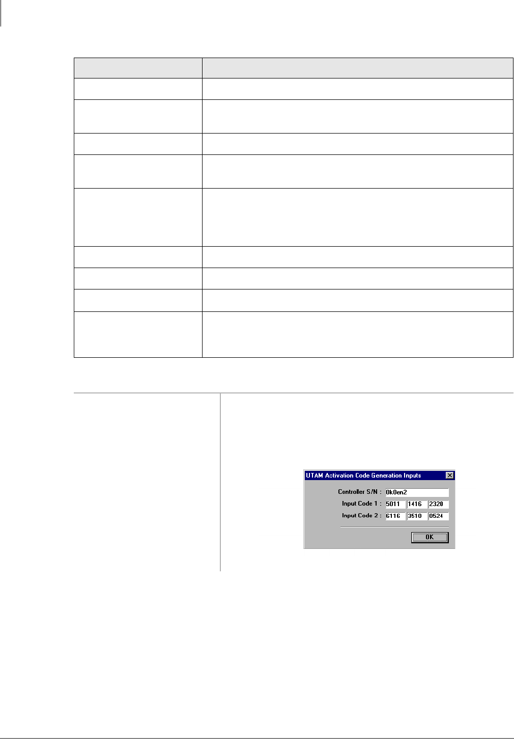
Base Station
Each Base Station (see Figure 1) provides 4
or 8 simultaneous speech paths and up to
320,000 square feet of calling coverage for
either system. Since handsets are not in
continuous conversation, a system can
support more than 8 handsets, up to a
maximum of 32. Multiple systems can be
active simultaneously.
The Base Station has radio transmitters and
receivers that relay calls between the BSIA or
RWIU, handsets, other telephones and trunks.
It has four external antennas that enable the
best choice for receiving and transmitting the
strongest signal.
The Base Stations can be mounted on walls or ceilings up to 2,000 feet from the system, using
twisted-pair continuous cable. They receive power directly or locally. If powered locally, they can
be installed up to 3,300 feet from the system. LEDs provide diagnostic information for System
Administrators or technical personnel (see Table 23 on Page 82).
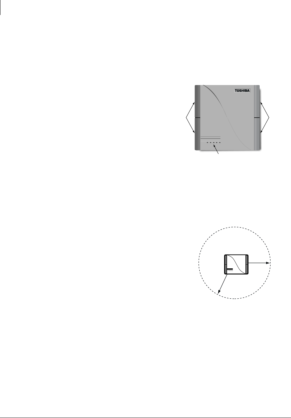
In typical office environments, each Base Station has a
broadcast range (see Figure 2) of up to 300 feet. They
can also be placed one meter apart in the same
coverage area to increase traffic capacity without
interference.
The Base Station software is easily upgraded from the
BSIA or RWIU, simplifying system administration
and eliminating the need to remove the Base Stations
for system upgrades.
Handset
The handset is small, lightweight, and easy to use. Its Liquid Crystal Display (LCD) shows
alphanumeric information and icons that report status. It has many features depending upon the
interfacing telephone system. The handsets used with the RWIU system have many of the same
Strata DK Digital Telephone (DKT) features.
Unique Electronic Serial Numbers (ESNs) are programmed into the handsets at the factory and are
automatically configured the first time a call is made.
3399
Antennas
LEDs
Antennas
Figure 1 Base Station
Base Station
Broadcast Range - 300 Feet
2967
Figure 2 Broadcast Range
The Grand Tour
Wireless Manager Software
Strata AirLink Installation Guide 5/00 3
Wireless Manager Software
There is a version of manager software for each of the wireless systems: Strata AirLink BSIA
Manager Software and RWIU Manager Software. The software enables you to configure the
wireless system from a PC desktop. See Step 7‚“Install Strata AirLink Manager Software” on Page
24 and Step 12‚“Install RWIU Manager” on Page 52 for installation instructions.
Strata AirLink BSIA Manager Software
The Strata AirLink BSIA Manager software is a Windows 95 application that includes:
♦Easy-to-use Desktop Toolbar for navigation
♦Configuration Window for setting system parameters and handset features
♦Status Window to view system alarms
♦Upgrade icon for immediate upgrades to the BSIA and Base Stations
♦Viewable or printable log files
♦Online Help
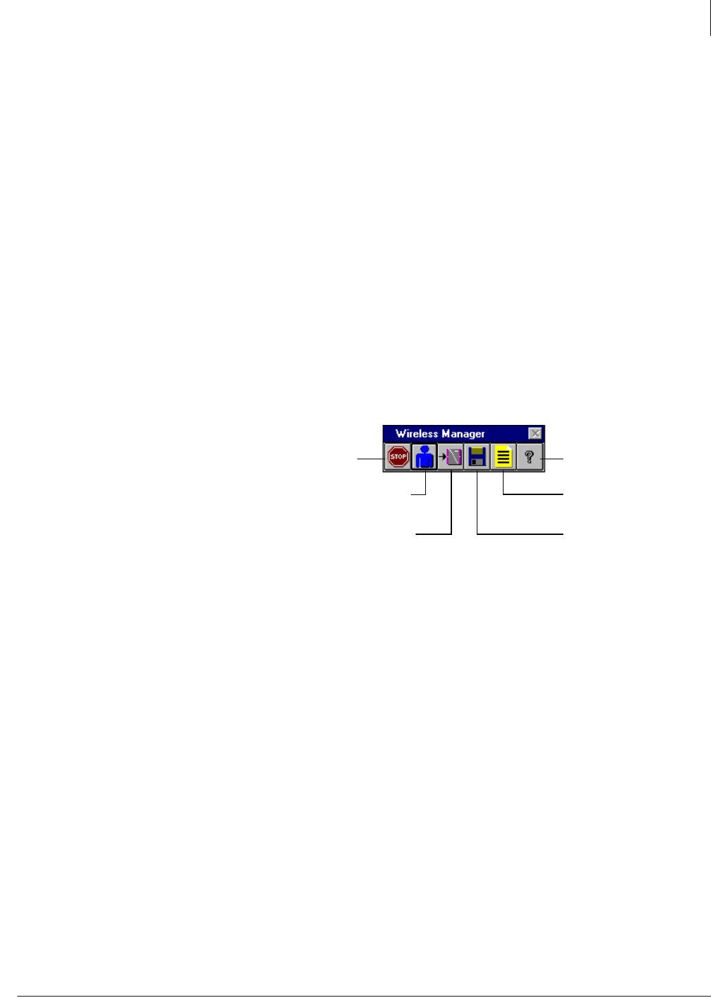
Desktop Toolbar
When you open the Strata AirLink BSIA
Manager software from its Program
Group, the Desktop Toolbar displays
(shown at the right).
Use this toolbar to easily configure the
system, access the Status Window,
upgrade the system, edit and save log
files, access online Help, and exit the
program. The toolbar can be placed anywhere on your desktop.
Configuration Window
The Configuration Window accesses the databases that set system parameters, user settings, and
feature button sequences. The button sequences enable the handsets to use the office telephone
system features.
Status Window
The Status Window, accessed from the Desktop Toolbar, gives you valuable system activity
information. It is an excellent troubleshooting tool. You can check the status of Base Stations,
lines, and calls. You can also clear critical alarms and make a software version inquiry.
Exit Help
Configuration
Window
Log Files
Status Window System Upgrade
3401
The Grand Tour
Wireless Manager Software
4Strata AirLink Installation Guide 5/00
Strata AirLink RWIU Manager Software
The Strata AirLink RWIU Manager software is a Windows 95 application that includes:
♦Easy-to-use Desktop Toolbar for navigation
♦Configuration Window for setting the system ID, handset IDs, time and date, and
communication ports
♦Status Window to view software versions, log messages, reset the Base Stations and/or the
RWIU
♦Software Upgrade Window for immediate upgrades to the RWIU and Base Stations
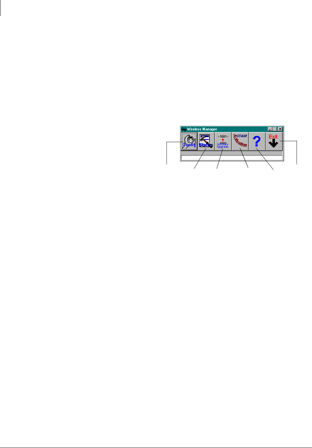
Desktop Toolbar
When you open the Strata AirLink
RWIU Manager software from its
Program Group, the Desktop Toolbar
displays (shown at the right).
Use this toolbar to easily configure
the system, access the Status
Window, upgrade the software,
activate UTAM, and exit the
program. The toolbar can be placed
anywhere on your desktop.
Exit
Help
UTAM
Software
Status
Configuration
Window Window Upgrade Activation

Strata AirLink Installation Guide 5/00 5
Pre-installation 2
This chapter provides common step-by-step pre-installation procedures and several sample
configurations for both Strata AirLink Wireless systems. The configurations range from a single
system with one or two Base Stations to multiple-overlapping systems. The anticipated coverage
of 320,000 square feet per Base Station and a maximum number of 32 users for each system was
used to layout the samples.
It is highly recommended that a site survey and BER test be conducted to assist in the careful
planning of Base Station placement, ensuring the highest possible quality of coverage. The survey
should include:
♦Location of Base Stations
♦Maximum broadcast range required from any Base Station
♦High traffic areas and general coverage areas, such as conference rooms, cafeterias, and
manufacturing floors
♦Obstructions between Base Stations and handsets
♦Office locations and number of handsets within each location
♦Construction materials used in walls, including the insulation, and floors between multistory
buildings
♦Window coatings and coverings
♦Large metal objects, such as equipment, doors, and fluorescent lamp shades
♦Distance of Base Stations from the BSIA or RWIU
There are special installation requirements to meet Underwriters Laboratories (UL) 1459
regulations in the United States that are explained in the “Underwriters Laboratories (UL)” on
Page 102.
Pre-installation
Step 1: Check System Hardware and Software Requirements
6Strata AirLink Installation Guide 5/00
Step 1: Check System Hardware and Software
Requirements
Table 1 lists the minimum hardware and software that your PC must have to use the Strata AirLink
Manager software.
Important! Windows 3.11/3.1 is a 16-bit application and the Manager software is 32-bit. To run
the Manager software, a special 32-bit support expansion is required.
Step 2: Review System Component Placement
A review of component placement before installation will help to reduce or eliminate attenuation.
Attenuation is loss of RF signal strength due to distance, antenna positioning, and/or obstructions.
The loss is measured in decibels (dBs).
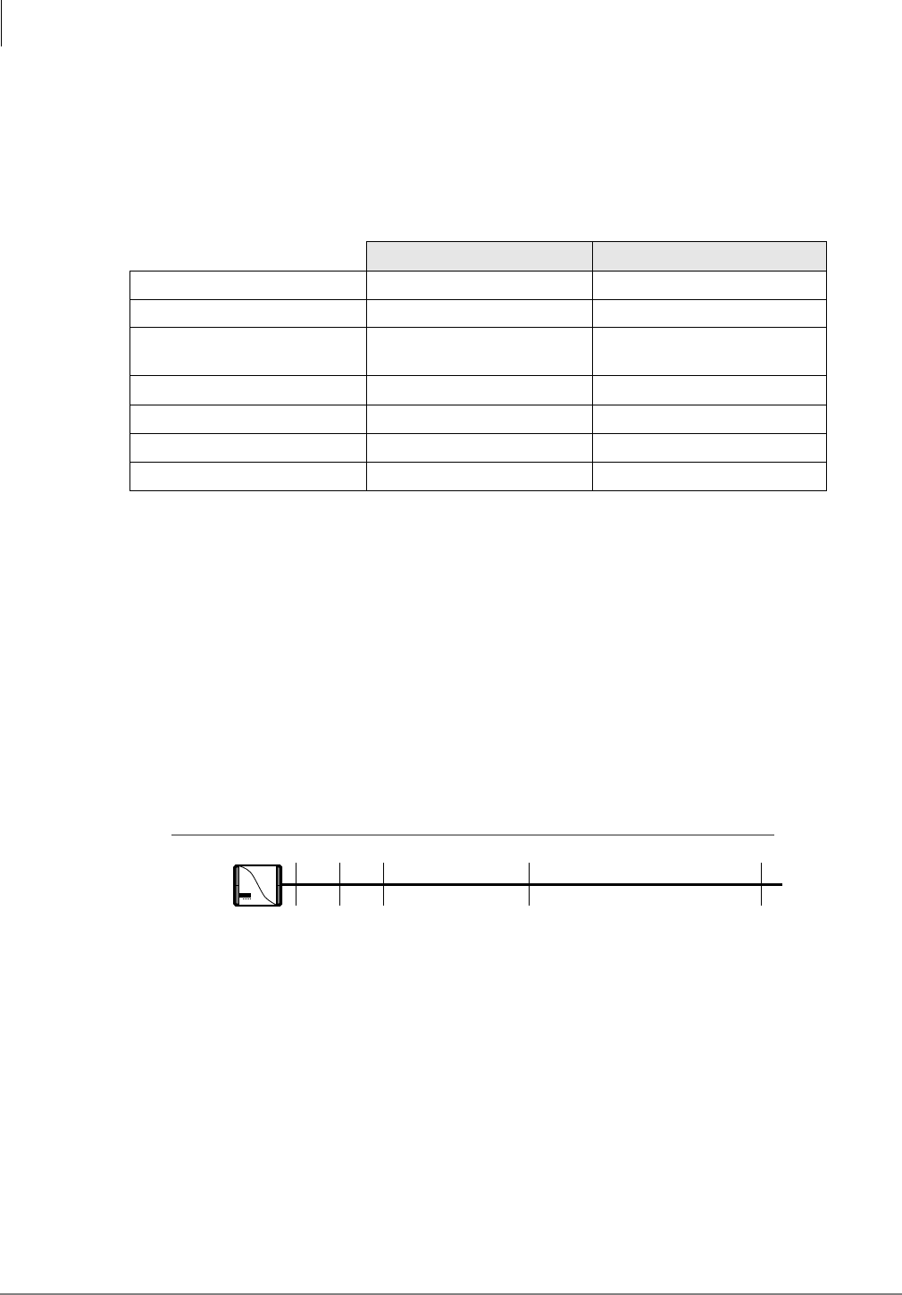
Increases or reductions of three dBs result in doubling or halving signal strength. Try to limit the
total loss to 100 dBs (see Figure 3).
Figure 3 Loss of Signal Strength by Distance (Direct Line of Sight)
Table 1 Hardware and Software Requirements
Minimum Recommended
Hardware 386DX 33 MHz 486DX2 66 MHz
Hard Drive 1.5MB 3MB
Random Access Memory
(RAM) 4MB 8MB
Video VGA SVGA
Mouse Any supported by Windows Same
Floppy Drive 1.44 MB 3.5 inch Same
Software Microsoft Windows 3.11/3.1 Windows 98/95
11020 50 100
-30
40
-50
60
-62
72
-78
88
-90
100
2974
Power:
Loss:
Base
Station
Distance in Meters
dB
Pre-installation
Step 2: Review System Component Placement
Strata AirLink Installation Guide 5/00 7
Table 2 shows attenuation obstruction caused by common materials in a building.
➤To reduce or eliminate attenuation and fading
1. Begin the signal path without obstructions even
though signals can travel through obstacles (see
Figure 4).
2. If obstructions cannot be avoided, do not place
the Base Stations:
♦On or near metallic objects or on walls that
have metallic content such as metal girders
or foil-backed insulation.
♦Near large obstructions; for example, doors
that could temporarily obstruct antennas
when the doors open.
3. Place components in locations that ensure clear
line of sight signaling between the Base Station
and handset.
Note In general, for optimum coverage and reduced signal fading, it is recommended that the
coverage by the Base Station overlap by approximately 25 percent. Base Stations are
designed to automatically use frequencies that are not already in use, so interference
between the Base Stations is not a problem.
4. Plan coverage for each floor separately in multi-story environments. A single Base Station can
support multiple floors. The guidelines for ensuring proper broadcast ranges and maximum
traffic must be followed.
5. Consider the high traffic areas and install the number of Base Stations required to meet the
estimated traffic demand. When multiple Base Stations are needed in the same location, you
can mount Base Stations as close as one meter apart.
Table 2 Signal Attenuation Obstruction
Object Approximate
dB Loss
Concrete 20
Concrete with metal siding 30
Brick 15
Plaster 10
Walls with windows 10
Walls with metal coating 20
Venetian blinds
Open
Closed
10
20
Soft partitioning 3 to 4
2975
Base Station Corridor
Corridor
Figure 4 Maximum Line of Sight
Pre-installation
Step 3: Review Possible System Configurations
8Strata AirLink Installation Guide 5/00
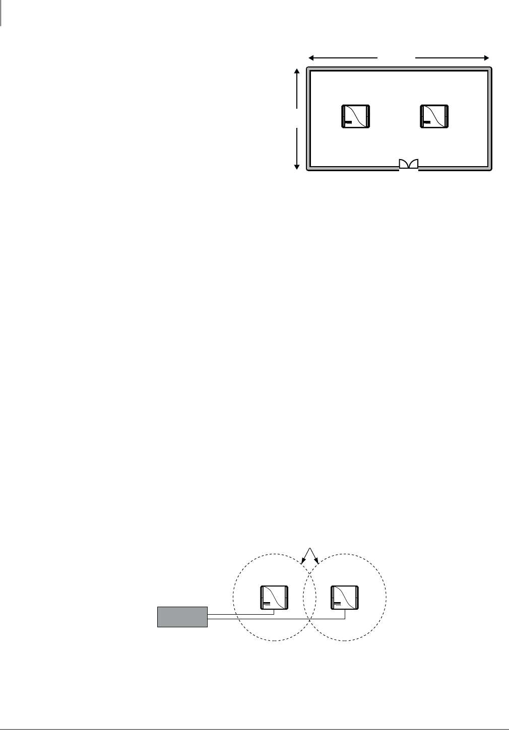
Each Base Station can support eight or
more simultaneous conversations. Figure
5 shows 2 Base Stations supporting 32
handsets in a manufacturing area.
6. Use corridors because they can act as
natural pathways for RF signals. When
trying to cover two types of areas, place
a Base Station near a corridor to
optimize coverage in both areas.
Note Handoff does not operate between
Base Stations connected to different
wireless systems.
Step 3: Review Possible System Configurations
It is highly recommended that you follow the installation guidelines and examples in this step. The
maximum number of Base Stations that the BSIA system supports is two, and the RWIU system,
four.
Some configurations are:
♦Single BSIA system with two Base Stations or single RWIU system with four Base Stations
♦Multiple BSIA systems as a single system
♦Multiple overlapping systems
♦Factory with adjoining offices
♦Manufacturing plant
♦Cubicles, walled offices, and conference rooms
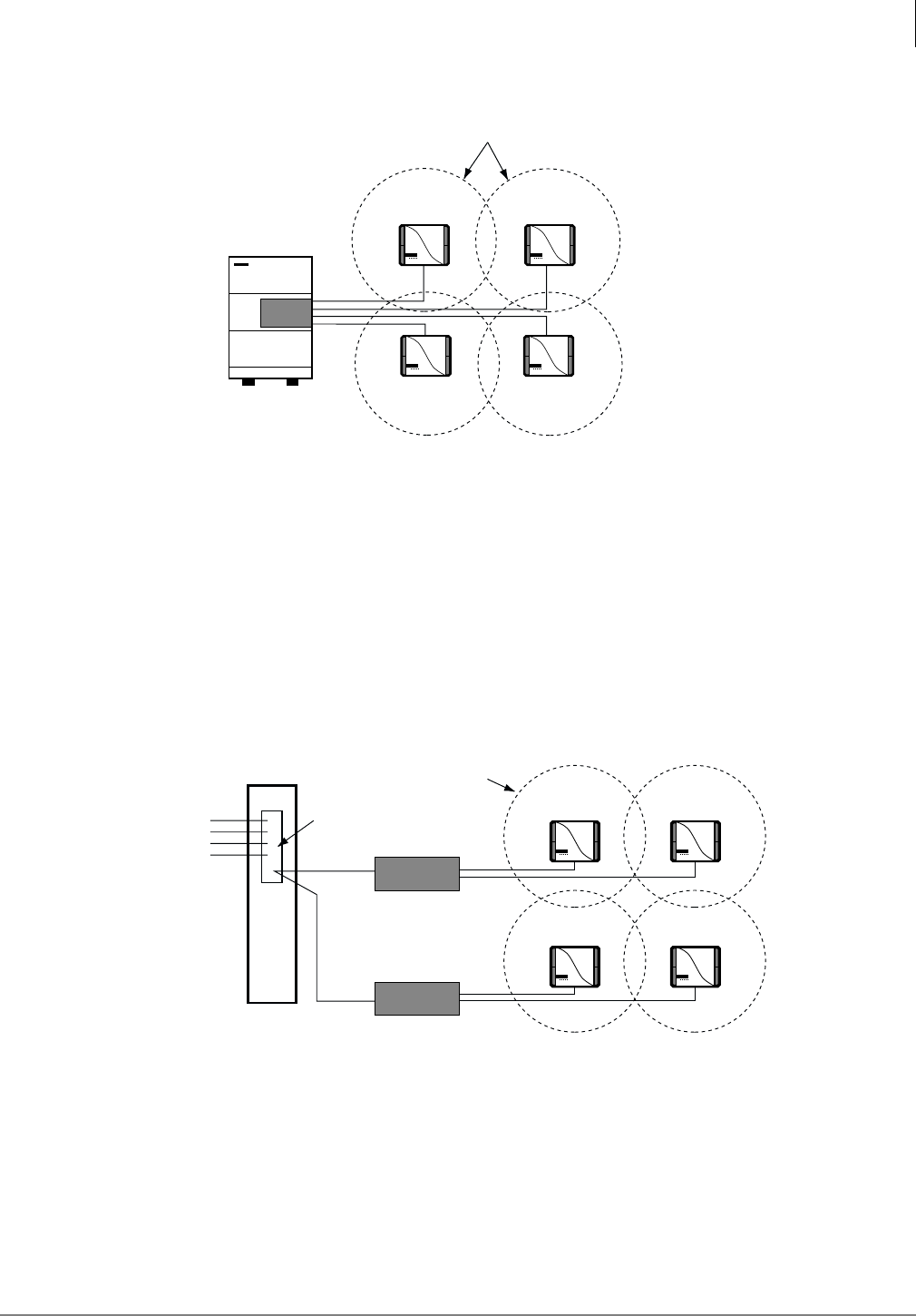
Single BSIA System with Two Base Stations/Single RWIU System with Four
Base Stations
Single BSIA system with two Base Stations (see Figure 6) or single RWIU system with four Base
Stations (see Figure 7). The Base Stations are placed in locations that optimize the requirements of
the system. For example, the Base Stations could be placed in the same general area or on separate
floors, but with overlapping coverage
Figure 6 BSIA System with Two Base Stations
320'
Concrete
Concrete
Manufacturing Floor
(32 handset users)
Base
Station 1
Base
Station 2
2973
168'
Figure 5 Increasing Traffic Capabilities
Base Station 1
Base Station
Broadcast Area
2969
Base Station 2
BSIA
Pre-installation
Step 3: Review Possible System Configurations
Strata AirLink Installation Guide 5/00 9
Figure 7 RWIU System with Four Base Stations
Multiple BSIA Systems as Single System
This configuration (see Figure 8) creates a system with greater coverage area. The handsets must
be programmed with both system IDs. Users can place and receive calls, although handoff does
not automatically operate between Base Stations connected to different BSIAs. Manually invoke
handoff by using )/6+ to hold the call while moving between Base Station 4 and 2, for example.
System Identification numbers (SIDs) for both BSIAs must be programmed in the handset for this
operation.)
Figure 8 Multiple BSIAs in One System
Base Station 1
Base Station
Broadcast Area
3731
Base Station 2
Base Station 3 Base Station 4
Strata DK
RWIU
2971
Base
Station 1
Base Station Broadcast Area
Base
Station 2
BSIA 1
Base
Station 3
Base
Station 4
BSIA 2
Double punch down
to BSIAs 1 and 2
Analog lines (32)
from the office
telephone system
Pre-installation
Step 3: Review Possible System Configurations
10 Strata AirLink Installation Guide 5/00
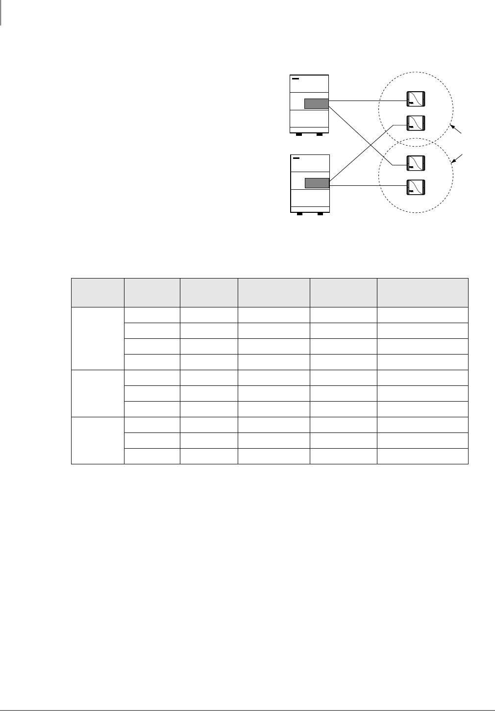
Multiple Overlapping Systems
Multiple overlapping configurations (see Figure
9) create a system with greater user capacity.
This configuration works for the BSIA or RWIU
systems.
Use Table 3 to determine how many Base
Stations are needed to accommodate the
numbers of users at different traffic levels.
Note It is assumed that users have access to
all Base Stations in a high-traffic
environment where only one call is
blocked out of 100 attempts.
Table 3 Base Station Traffic Requirements
Erlangs1
Per User
1. Typical usage assumes .1, .15, and .2 Erlangs (6 minutes, 9 minutes, and 12 minutes, respectively, where 1
Erlang equals 60 minutes of usage) per line during the busiest hour of the day.
Number
of Users
Total
Erlangs
Equivalent
CCS2
2. CCS stands for centi-call seconds, or 100 seconds of telephone conversation.
Required
Channels
Base Stations
Required
.1
10 1 36 5 1
20 2 72 6 1
30 3 108 8 1
32 3.2 115.20 8 1
.15
10 1.5 54 6 1
20 3 108 8 1
323
3. Assumes Base Stations are co-located.
4.8 172 11 2
.2
10 2 72 6 1
16 3.2 115.20 8 1
3236.4 230.4 13 2
3729
Base Station
Broadcast Area
Base Station 1
Base Station 3
Base Station 2
Base Station 4
Strata DK
RWIU
Strata DK
RWIU
Figure 9 Multiple Overlapping Systems
Pre-installation
Step 3: Review Possible System Configurations
Strata AirLink Installation Guide 5/00 11
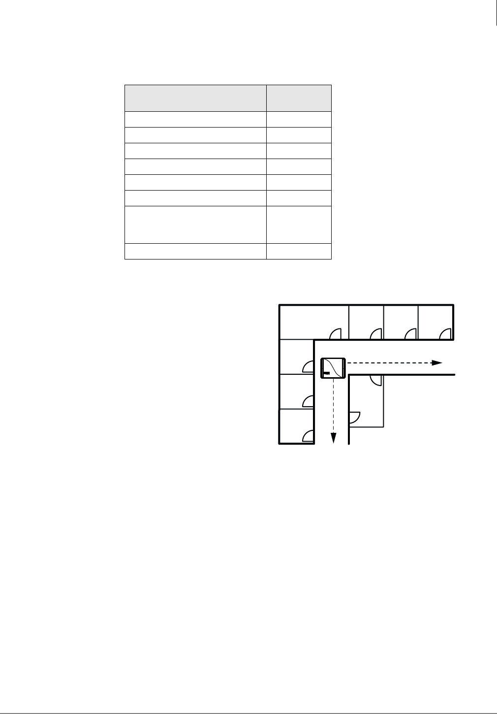
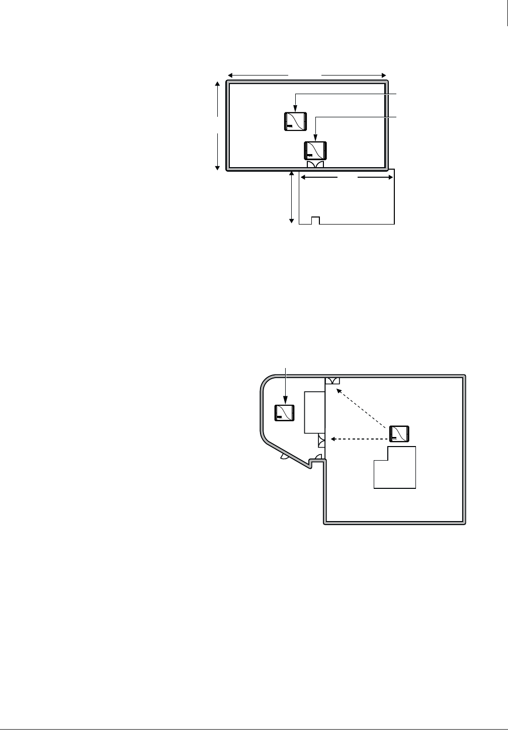
Factory with Adjoining Offices
Both Base Stations are placed in the
factory area (see Figure 10) to
accommodate the greater number of
users in that area.
Place Base Station 2 closer to the
offices, maximizing line of sight
signal through the doorway.
This is especially important if the
wall between the offices and factory
is concrete.
The Base Stations are also mounted
on the ceilings and away from any
potential obstructions to the
antennas.
If a second area was available to the
left of the factory, moving Base
Station 1 to that location would
broaden the coverage to users in that
area also.
Manufacturing Plant
The entrance from the manufacturing area into
the cafeteria is a high-traffic area.
Placing a Base Station (see Figure 11) in the
entry area of the cafeteria blocks the line of
sight to the other areas in the cafeteria.
Locate Base Station 2 centrally in the cafeteria
and Base Station 1 in the manufacturing area.
Align Base Station 2 with the entrance of the
cafeteria to provide coverage into that area.
2976
320'
168'
Concrete
Concrete
Factory Floor
(32 handset users)
Base Station 2
(wall mounted)
Base Station 1
(ceiling mounted)
200'
140'
Offices
Front
Door
Figure 10 System with a Factory and Adjoining Offices
2977
Cafeteria
Offices
Concrete
Manufacturing Area
Base Station 1
Base Station 2
Figure 11 System in a Manufacturing Area
Pre-installation
Step 4: Unpack Shipment
12 Strata AirLink Installation Guide 5/00
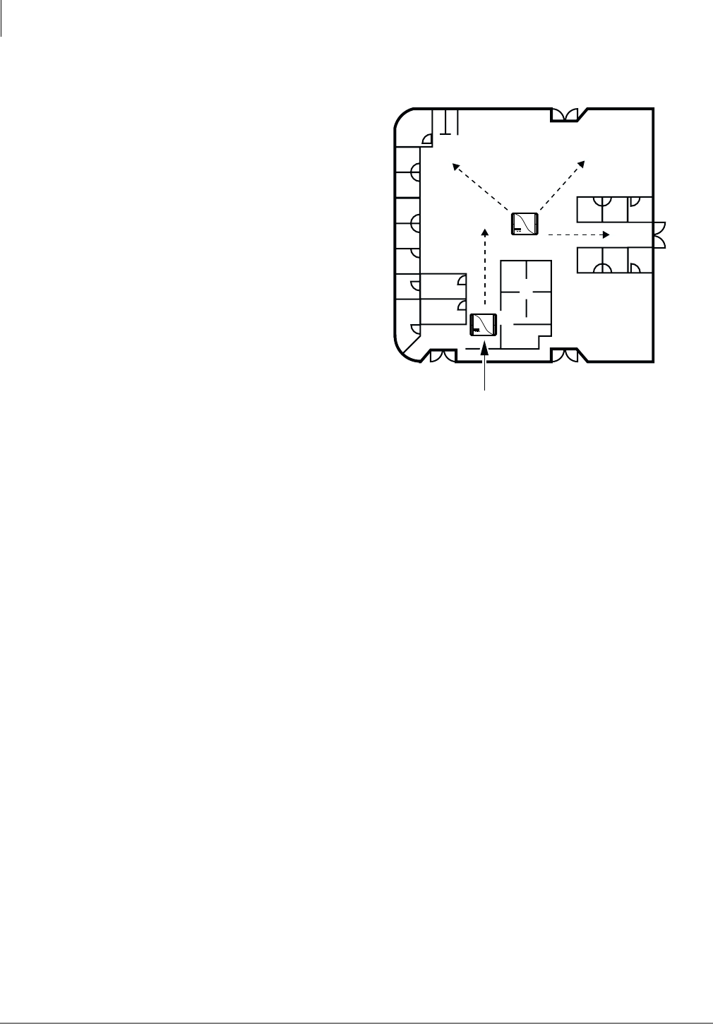
Cubicles, Walled Offices, and Conference Rooms
Although the number of Base Stations in
this environment would depend on the
number of handsets, the Base Stations are
aligned with corridors to maximize the line
of sight (see Figure 12).
Instead of placing both Base Stations close
to each other, place Base Station 1 near the
conference rooms and entrance area to
accommodate greater potential traffic in
these areas.
Step 4: Unpack Shipment
1. Inspect all packages carefully and note any visible damage when the system first arrives. If
any damage is found, do not open the packages. Contact the delivery carrier immediately and
make the proper claims.
2. Unpack all of the packages.
3. Be sure to retain the original packaging materials for re-use when storing or transporting the
system components.
Step 5: Check Equipment List
1. Before installation, check the system components against the packing list and inspect all
equipment for damage. If equipment is missing or damaged, contact the supplier immediately.
2. Ensure that the following Toshiba-supplied equipment was delivered:
♦BSIA or RWIU PCBs
♦PC cable with DB9 or DB25 adapter (BSIA)
♦RWIU Manager interface cable (6-pin connector)
♦Power supplies
♦Optional power supply for locally powered Base Stations
♦Base Stations, handsets, and Charger Bases
♦Strata AirLink Manager and RWIU Manager software (two floppy disks)
2978
Main
Entrance
Cubicle
Area
Cubicle
Area
Conf
Conf
erence
erence
Rooms
Rooms
Conference
Rooms
Walled Offices
Walled Offices
Base Station 1
Base Station 2
Figure 12 Office Area with Cubicles and Walls

Pre-installation
Step 6: Purchase Additional Equipment
Strata AirLink Installation Guide 5/00 13
Step 6: Purchase Additional Equipment
➤Ensure that the following equipment has been purchased:
♦PC (for the Strata AirLink Manager software)
♦BSIA grounding wire (for gauge requirements, see Table 37 on Page 99)
♦BSIA external alarm (see Page 21 for specifications)
♦Cable for the Base Stations (see Page 20 for specifications)
♦ONEAC five-pin analog protector for outside Base Station installation
Step 7: Select Suitable Locations
1. Pick locations for your system components that are dry and clean, well ventilated and
illuminated, and easily accessible.
The indoor/outdoor locations must not be subject to:
♦Extreme heat or cold
♦Corrosive fumes, dust, or other airborne contaminants
♦Excessive vibration
2. Do not place the components next to televisions, radios, or high-frequency equipment.
Step 8: Set Up Temporary Installation
Important! It is recommended that you use the Toshiba Stand-alone Base Station Test Stand
instead of setting up a temporary installation. If the test stand is used, skip this step
and go to Step 2.
Setting up a temporary installation helps to determine proper Base Station placement without
permanently cabling any components. A BER test can be easily conducted to determine the proper
Base Station placement for maximum signaling. The BER test is a password-protected function of
an initialized handset.
One BSIA or RWIU, one Base Station, and one handset is all that is required to conduct the BER
test. To initialize the BSIA system, see Steps 7~9 on Page 24. To initialize the RWIU system, see
Step 2 on Page 52.
Step 9: Use Stand-alone Base Station Test Stand
The Stand-alone Base Station Test Stand verifies the Base Station positioning prior to system
activation or during the site survey. It generates an audible tone for the handset to lock onto,
verifies BER status, and can be moved to validate the best locations for each Base Station.
Substep A: Before You Begin
➤Ensure that the following materials are available:
♦Strata AirLink Stand-alone Base Station Test Stand
♦Base Station power supply with cord
♦One or more handsets with batteries fully charged
♦Floor plan of the facility to survey
Pre-installation
Step 9: Use Stand-alone Base Station Test Stand
14 Strata AirLink Installation Guide 5/00
Substep B: Set Up Base Station
1. Determine the best location for a Base Station. See “Review System Component Placement”
on Page 6 for more information.
2. Temporarily place the Stand-alone Base Station Test Stand as close as possible to the selected
Base Station location with the proper orientation (vertical or horizontal).
Note When testing with a Base Station, be sure to rotate all four antennas to a 90° angle.
3. Plug the Base Station power supply into the +5VDC connector of the test stand (located on the
bottom) and into a 110VAC outlet.
4. Watch the LEDs on the front of the test stand until all red LEDs are out and only the green
LED is lit.
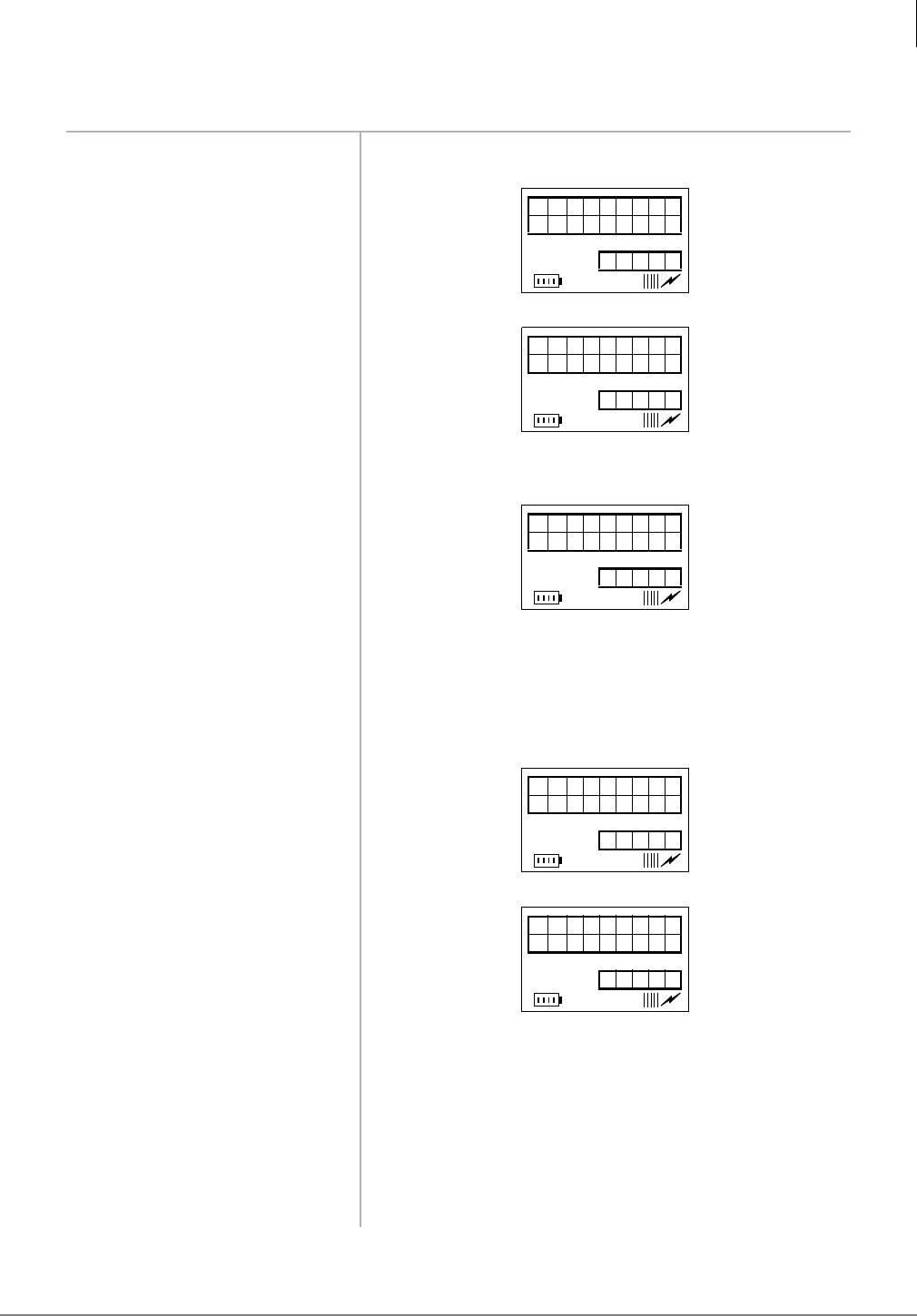
Substep C: Set Up Handsets
1. Make sure that your handsets
are fully charged.
2. Press 3:5 to turn on a
handset.
3. Enter and press )&1 to
access System Configuration.
4. Press )&1 again.
5. Enter .
6. Press ▼ (right of $%&).
7. Enter .
8. Press (1'. The handset returns to idle.
9. Repeat Substeps 1~8 for each
handset, substituting a
different HID number (for
example, 2, 3, 4, 5, etc.) in
Substep 7.
SYSTEM
CONF IG
12: 15
SID#0
12: 15
HID#0
12: 15

Pre-installation
Step 9: Use Stand-alone Base Station Test Stand
Strata AirLink Installation Guide 5/00 15
Substep D: Audio Coverage Test
Important! Strata DK must recognize DTMF signaling, if you have a BSIA. Strata DK requires
a DTMF receiver PCB to support the RSTU ports.
1. Press 3:5 to turn on the handset.
2. Press &$//.
3. Listen for continuous tone while walking around the facility observing coverage area
boundaries.
4. Mark the floor plan where the continuous tone “warbles” (indicating the beginning of a
handoff overlap area) and where the continuous tone “breaks” or stops (indicating the end of
the coverage area).
5. Press (1'. The handset returns to idle.
Substep E: Perform Handset Bit Error Rate (BER) Test
1. Simulate real use rather than
trying to get the best readings
by:
♦Perform tests in all
possible areas that users
may carry their
handsets.
♦Remain in an area long
enough to get an
accurate reading. BER
readings can take a few
seconds to register. It is
recommended that you
stand still for an
accurate reading.
♦Test specific Base
Stations. Handsets do
not perform handoff
during BER tests so that
you can test each Base
Station
2. In idle mode, press .
3. Press $%&, then &$//.
BER
MEASURE
12: 15

Pre-installation
Step 10: Mount Base Stations
16 Strata AirLink Installation Guide 5/00
Step 10: Mount Base Stations
1. Determine a location (see “Set Up Temporary Installation” on Page 13) that provides the best
coverage before mounting the Base Station permanently.
2. Use locations that reduce attenuation and create a clear line of sight.
3. Always mount the Base Stations in a centralized location in open, symmetrical areas.
Note Base Station placement guidelines are provided in “Review Possible System
Configurations” on Page 8.
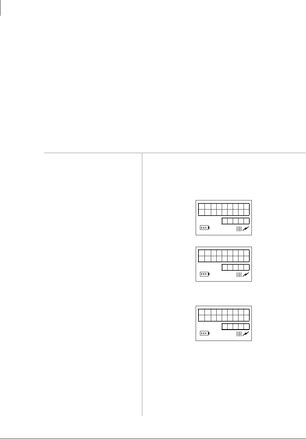
4. Make a 360 degree circle to
check the signal from
different directions.
See Table 4 for BER test readings. In the example above,
02 indicates the Base Station ID, MAX is the handset
receive signal, and GOOD is the Base Station receive
signal.
5. Keep the handset slightly
raised.
Important! Mark the floor plan where the LCD
permanently changes from MAX to GOOD
(indicating the beginning of the handoff
overlap area) and where the LCD
permanently changes from GOOD to POOR
(indicating the end of the coverage area).
6. Walk while performing the
test, but pause occasionally
for the best readings.
7. Press (1'.
Table 4 Explanation of Possible BER Test Results
BER Result Description
Max or Good Values required for clear conversation.
Poor Call setup is not advisable, although calls in progress could survive.
Bad Area is not sufficiently covered to support call traffic. Relocate other Base
Stations or put up another Base Station.
Mismatched values
(e.g., good/bad) Faulty equipment or interference close to the handset or Base Station.
HS MAX
B S 0 2 GOOD
12: 15
Pre-installation
Step 10: Mount Base Stations
Strata AirLink Installation Guide 5/00 17
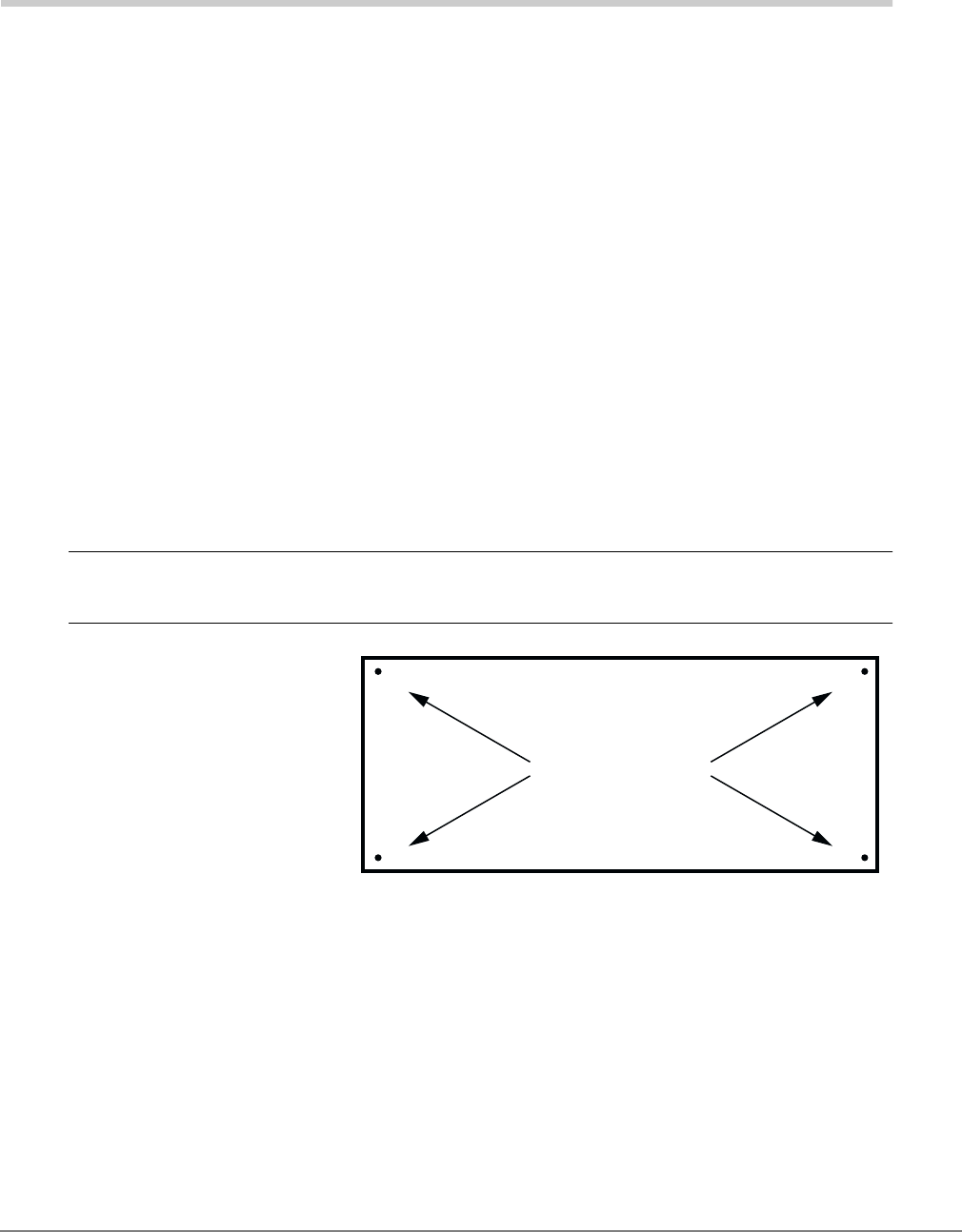
➤To ceiling mount the Base Station
1. Rotate Base Station antennas to
expose the mounting tabs (see
Figure 13).
2. Mark the mounting tab position on
the ceiling by holding the Base
Station in place to use as a guide
for drilling.
3. Drill the four holes in the ceiling.
Important! Do not mount Base Stations on movable surfaces such as acoustic drop ceilings.
Mounting a Base Station above a non-metallic dropped ceiling is acceptable.
4. Insert anchors into the drilled holes.
5. Insert #8 screws in the anchors, leaving a gap between the ceiling and screw head.
6. Mount the Base Station on the screws and tighten the screws.
7. Rotate the antennas so that they are perpendicular to the Base Station (facing down).
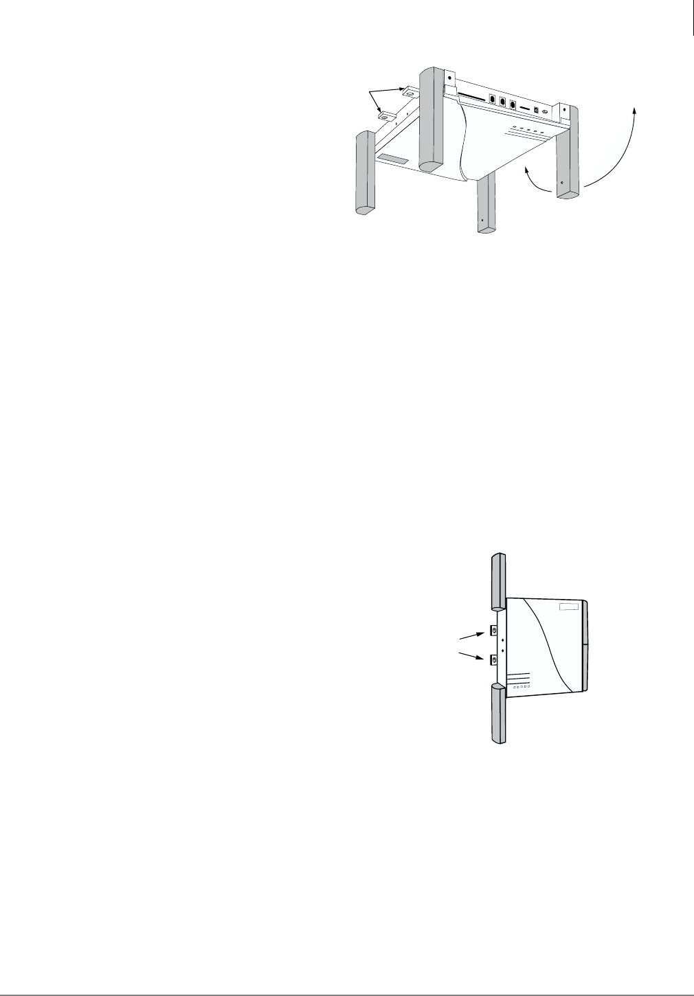
➤To wall mount the Base Station
1. Choose a location that is in a corridor or non-symmetrical area and faces the greatest coverage
area.
2. Mount the Base Station midway between the floor and permanent ceiling, but above any
obstructions such as cubicle walls.
3. Rotate the Base Station antennas to expose
the mounting tabs (see Figure 14).
4. Mark the mounting tab position on the ceiling
by holding the Base Station in place to use as
a guide for drilling.
5. Drill the four holes in the wall.
6. Insert anchors into the drilled holes.
7. Insert #8 screws in the anchors, leaving a gap
between the wall and screw head.
8. Mount the Base Station on the screws and
tighten the screws.
9. Rotate the Base Station antennas so that they
are perpendicular to the wall
For specific installation procedures for the BSIA system, see Chapter 3 – BSIA System
Installation and for the RWIU system, see “Maintenance and Troubleshooting” on Page 71.
3382
Mounting Tabs
Rotated Antenna
Figure 13 Mounting Tabs Location on the Base
Station
3383
Mounting tabs
Figure 14 Location of Mounting Tabs

Pre-installation
Step 10: Mount Base Stations
18 Strata AirLink Installation Guide 5/00
Strata AirLink Installation Guide 5/00 19
BSIA System Installation 3
This chapter describes specific installation steps for the BSIA system. It interfaces to Strata DK16,
DK16e, DK40, DK40i, DK280, and DK424 and many non-Toshiba telephone systems using
standard telephone ports.
Step 1: Install Analog Line Module (ALM)
Note Skip this step and go to Step 2 if ALM PCB was not purchased.
The BSIA motherboard comes configured to support a maximum of 8 handset users (upgradeable
to 16, 24, or 32). Additional groups of eight users can be installed using the ALM PCB.
CAUTION! When installing, removing, or examining PCBs, do not touch the soldered
(back) side or “gold” plate at the edge of the PCB.
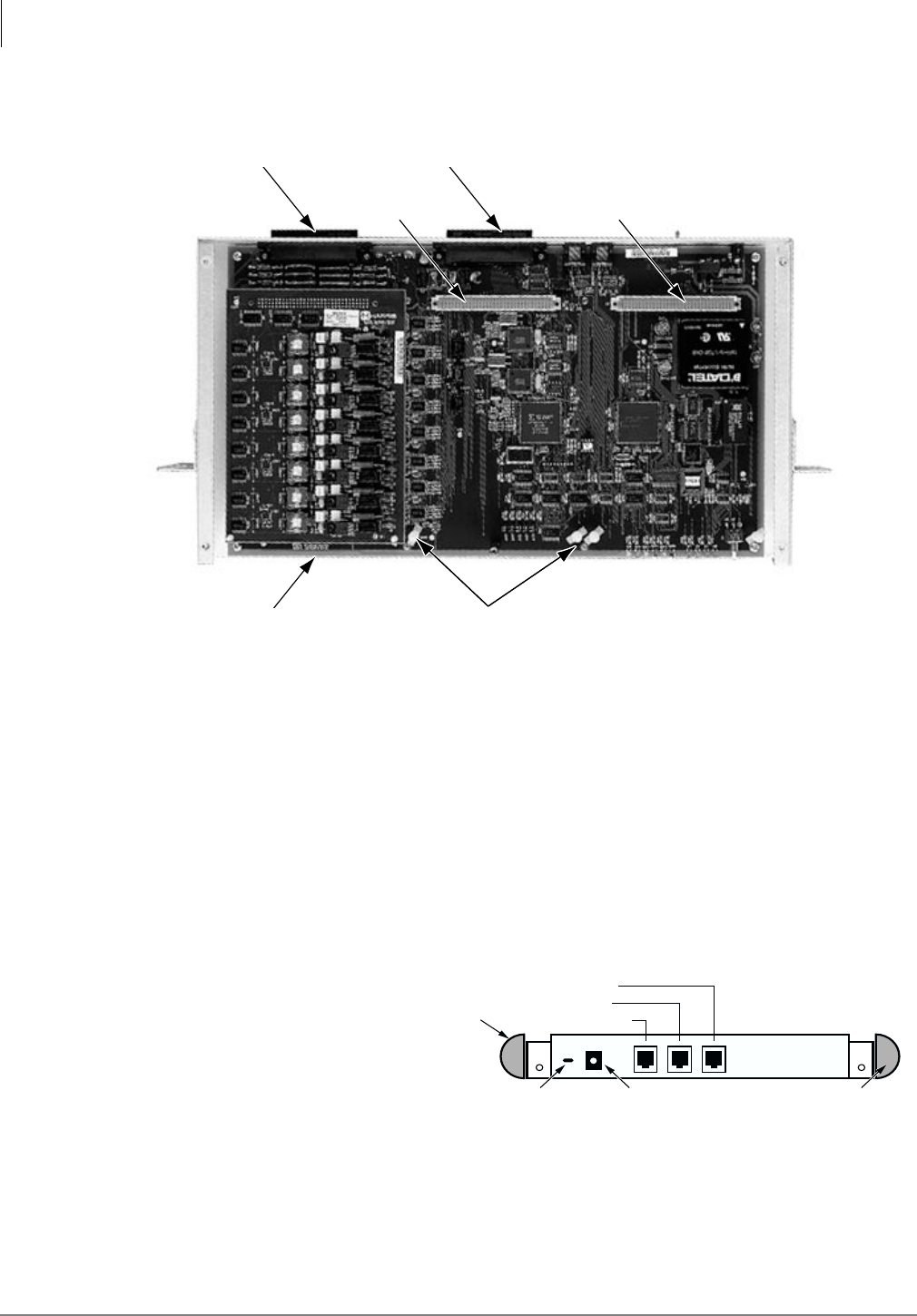
1. Remove the screws securing
the cover of the BSIA (see
Figure 15) and lift the cover
off the BSIA.
2. Align the ALM with DIN
connector J5 (see Figure
16).
3. Gently press the PCB into
the DIN connector.
4. Connect the standoffs.
5. Replace the BSIA cover and
re-install the screws.
Important! Do not power on the BSIA at this point.
2985
Cover Screws
Figure 15 Location of Screws on the BSIA Cover
BSIA System Installation
Step 2: Run Cable
20 Strata AirLink Installation Guide 5/00
Figure 16 ALM Connections on the BSIA
Step 2: Run Cable
1. Run the cable from the Base Stations to the BSIA, using the following maximum cabling
distances:
♦2,000 feet for line power
♦3,300 feet for local power
2. Use Category 5 cable. Using a mix of Categories 2, 3, 4, and 5 is acceptable, but can affect the
total possible cable length. See Figure 19 on Page 22 for the wiring diagram.
3. Connect the transmit cable
(pair 21 or 25) to the receive
side (see Figure 17).
4. Connect the receive cable (pair
20 or 24) to the transmit jack
(see Figure 17).
StandoffsALM Plugged into
DIN Connector J4 (Circuits 9~16)
2964
DIN Connector J5
(Circuits 17~24)
DIN Connector J6
(Circuits 25~32)
Amphenol Connector
(Circuits 1~16)
Amphenol Connector
(Circuits 17~32)
2982
Transmit Jack
Receive Jack
Debug (not used)
Antenna
Antenna
Power Cord
Strain Relief
+5VDC Local Power
Figure 17 Location of Transmit and Receive Jacks

BSIA System Installation
Step 3: (Optional) Activate External Critical Alarm
Strata AirLink Installation Guide 5/00 21
Step 3: (Optional) Activate External Critical Alarm
Note The BSIA system is not equipped with an external critical alarm. If one was not
purchased, skip this Step.
1. Connect pair 22 on connector block P1
to one input on the external alarm device
(see Figure 18).
2. Connect tip (normally closed) or ring
(normally open) of pair 23 on P1 to the
other input of the alarm device.
Step 4: Determine Base Station Power Supply
A Base Station can receive input (line) power from the BSIA or an optional local power supply.
Using a local power supply increases the distance Base Stations can be located from the BSIA.
Toshiba provides an optional universal 110/230VAC, 50/60 Hz power supply with a barrel-jack
connection to the Base Station (see Figure 20 on Page 23).
Customers with 220VAC outlets can:
♦Purchase another power cord to fit the universal connector (three-pronged IEC 320 power
inlet) on the power supply.
♦Replace the 110VAC plug on the cable with an appropriate 220VAC plug.
♦Connect a North American 220VAC adapter to the 110VAC plug.
2981
Lamp or Buzzer Maximum Switched Power 60W
0.5 A, 125VAC Resistive
1.0 A, 48VDC Resistive
Pair 22 - Relay Common
Pair 23, Tip - Normally Closed Contact
Pair 23, Ring - Normally Open Contact
Figure 18 Wiring for External Critical Alarm
BSIA System Installation
Step 4: Determine Base Station Power Supply
22 Strata AirLink Installation Guide 5/00
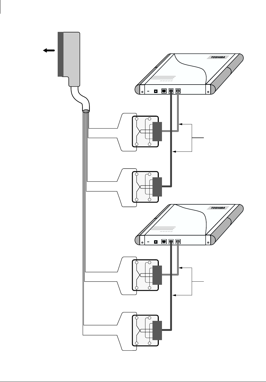
Figure 19 Base Station to BSIA Wiring Diagram
4128
GN
GND RX TX
PWR
R
(Pair 20)
(Pair 21)
GNR
To P1
of BSIA
Yellow/Grey
Grey/Yellow
Violet/Blue
Blue/Violet
RX
TX
Standard Silver
Satin Line Cord
Base Station
GN
GND RX TX
PWR
R
(Pair 24)
(Pair 25)
GNR
Violet/Brown
Brown/Violet
Violet/Slate
Slate/Violet
RX
TX
Standard Silver
Satin Line Cord
Base Station
BSIA System Installation
Step 5: Connect Power Supply
Strata AirLink Installation Guide 5/00 23
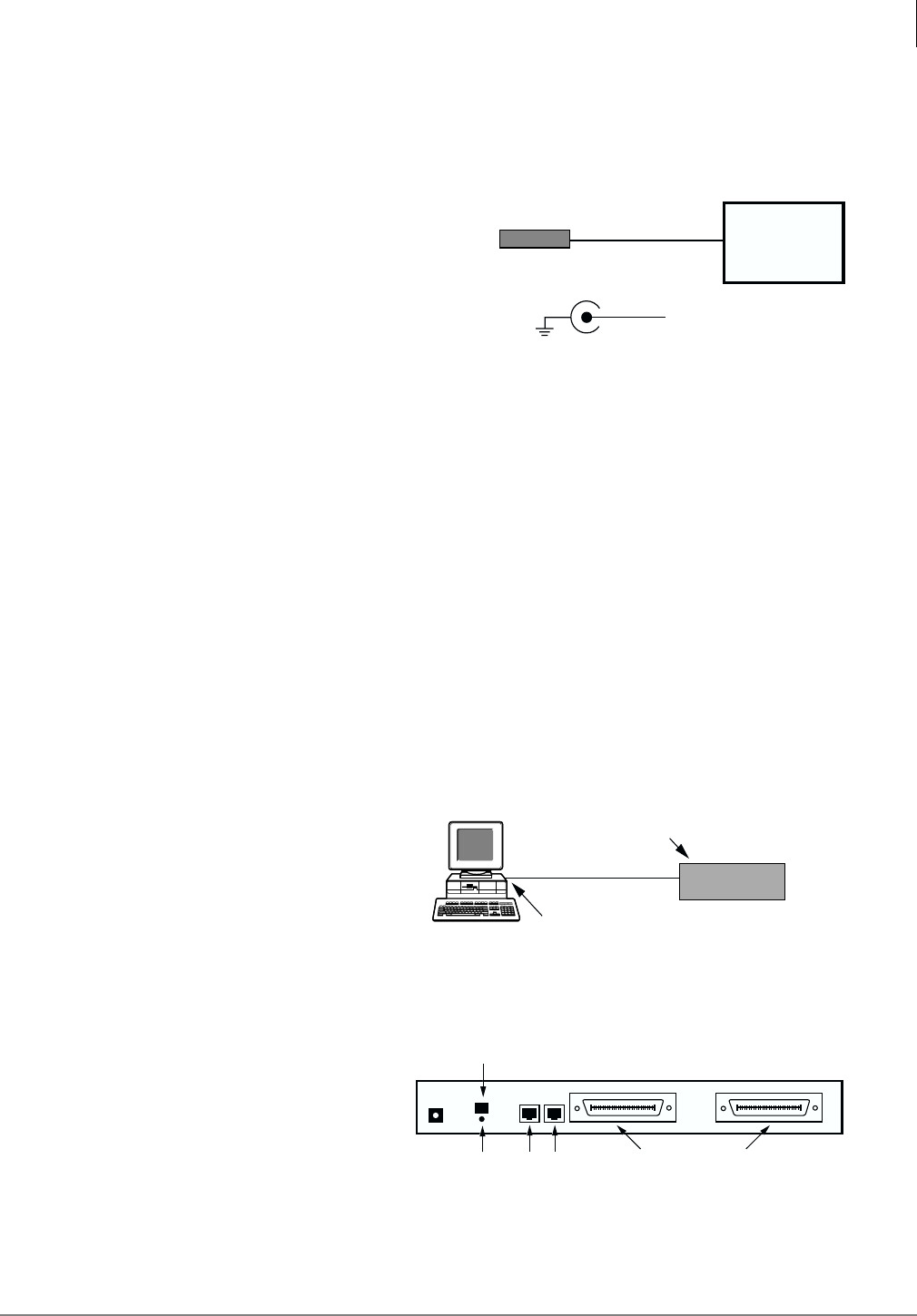
Step 5: Connect Power Supply
➤For AC power, use the power supply that comes with the BSIA system. It has a universal input
(110/220VAC), operates at 50~60 Hz, and provides -48VDC.
Note The power supply includes a cable with a
barrel-jack connection (see Figure 20) to
the BSIA and 110VAC cable.
CAUTION! Connect to power, but do not
power on until the entire system
is cabled.
➤To connect to power when -48VDC is required
1. For DC power, a power cord with the
following is required:
♦18 AWG wire
♦2.1mm ID x 5.5mm barrel jack (Switchcraft, Inc. S765 or equivalent) with minus (–)
potential center lead and positive (+) shield lead
2. Connect the barrel jack to the BSIA at J1 (see Figure 20).
Note Battery source requirements are -44VDC to -56VDC @2 amps. An inline, slow-blow fuse
rated 3 amps @250VAC must be installed as close as possible to the battery source on the
minus potential side.
3. To prevent accidental removal of the power cord connected to J1 on the BSIA, tie wrap the
power cord to the power strain relief above the ground screw on the BSIA (see Figure 22).
Step 6: Connect PC
1. Insert one end of the RS-232-C
cable with a DB9 or DB25 adapter
into the serial port in the back of the
PC (see Figure 21).
2. Insert the RJ-45 connector into the
back of the BSIA (J2) (see Figure
22)
Barrel Jack Power Supply
115/230VAC Input
(50/60 Hz)
GND
+5.3VDC @2.5 Amp Output
2983
Figure 20 Barrel-jack Connection
DB9 or DB25 Connector
(Male DB9 or DB25 Adapter)
RJ-45 Connector (J2 Admin Port)
3730
RS-232-C Cable BSIA
Figure 21 PC to BSIA Connection
3000
Power Cord Strain Relief
Not
Used RJ-45
(Admin Port) 25-pair Female Connectors
(Analog Lines and Base Stations)
-48VDC
Input
(Circuits 17~32) (Circuits 1~16)
P2 P1
J1 J2
J3
GND
Figure 22 BSIA RJ-45 Jack (back side)

BSIA System Installation
Step 7: Install Strata AirLink Manager Software
24 Strata AirLink Installation Guide 5/00
Step 7: Install Strata AirLink Manager Software
1. Check the PC hardware/
software against the required
minimums.
Refer to “Check System Hardware and Software
Requirements” on Page 6.
2. Close any open applications
in Windows.
3. Insert the Strata AirLink
Manager software floppy
disk into the A:\ drive.
4. In Windows 98/95, click Start
and Run
...or in Windows 3.11/3.1,
open Program Manager and
click File and Run.
A dialog box displays requesting the location of the setup
disk.
5. Click File and Run. A dialog box displays requesting the location of the setup
disk.
6. Type A:\Setup and click
OK.
The Windows setup screen appears and warns you to close
other Windows applications.
7. Click Yes A dialog box displays, recommending a destination path
of C:\Wireless.
...or No if you need to close
applications.
8. Click OK C:\Wireless is accepted as the destination directory.
...or change the destination
drive and directory.
9. Click OK. A dialog box displays asking for verification of the
software location (its program directory or the Windows
system directory). It is recommended that the program
directory is used.
10. Select the program directory.
11. Click OK. The files are copied to the hard disk. A program group is
created.
BSIA System Installation
Step 8: Copy Upgrade Software
Strata AirLink Installation Guide 5/00 25
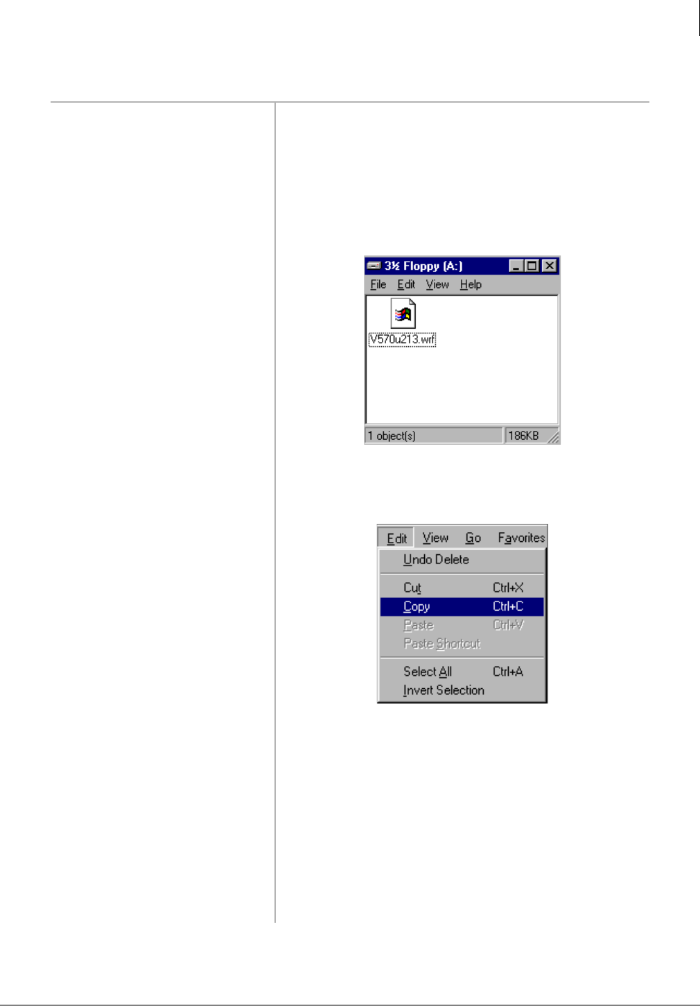
Step 8: Copy Upgrade Software
1. Place the Strata AirLink
floppy disk #2 into drive A:\.
2. In Windows 98/95, double-
click the My Computer icon
...or in Windows 3.11/3.1,
open Program Manager.
3. Navigate to the A:\ drive.
4. From the A:\ drive, highlight
the file to be copied.
5. From the Edit pull-down
menu, double-click Copy.
All of the highlighted files are copied to the clipboard.
6. Navigate to the
C:\Wireless\Software
subdirectory.
7. From the Edit pull-down
menu, double-click Paste.
All of the files on the clipboard are pasted to the
subdirectory.
8. Close all the windows and
return to the Strata Airlink
Manager application.
3332
3505
BSIA System Installation
Step 9: Configure System
26 Strata AirLink Installation Guide 5/00
Step 9: Configure System
Substep A: Activate UTAM
1. Make sure the PC is
connected to a BSIA.
2. Turn on the PC. Windows automatically starts.
3. Double-click the Strata
AirLink Manager Desktop
icon.
This displays only once when the system is initialized.
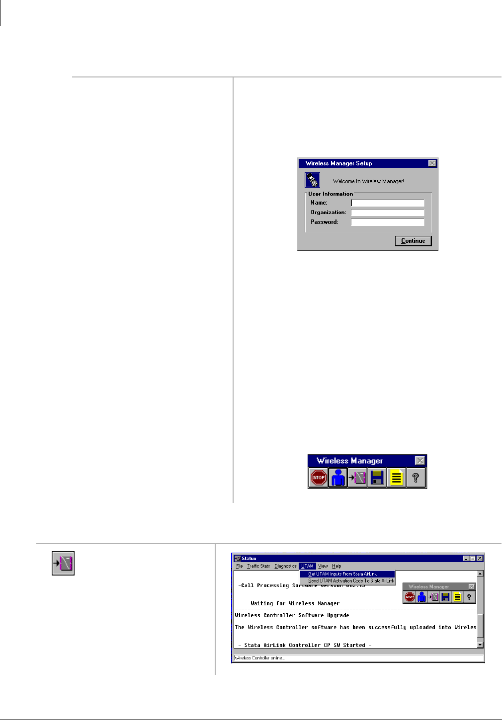
4. Type the name, organization
(company name) and the
password.
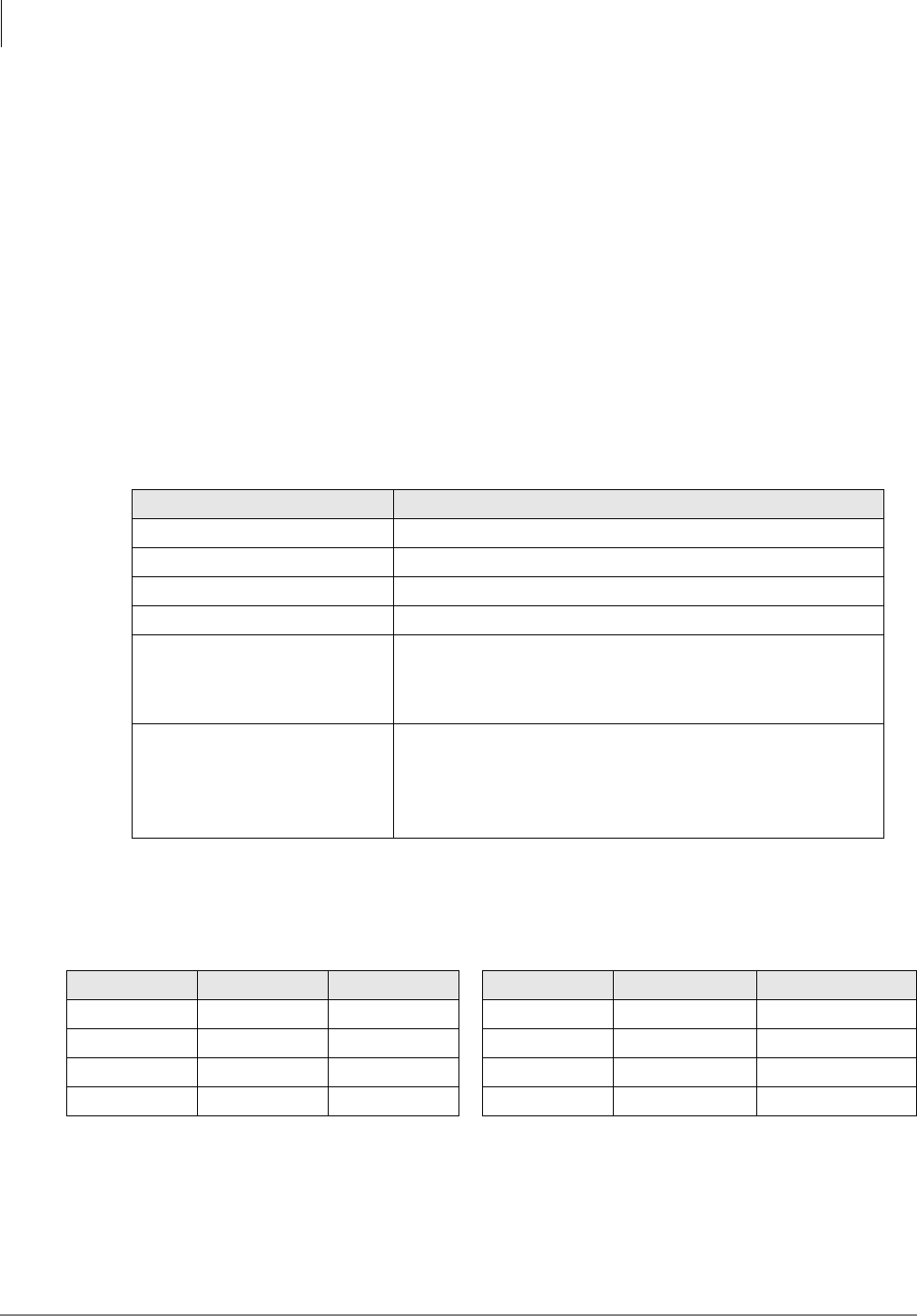
Important! If the password is forgotten, the software must
be reloaded. The password can be changed
after initialization of the system.
5. Click Continue. The Password Verification dialog box appears.
6. Enter the same password and
click OK.
The Setup dialog box displays again.
7. Click Continue. The software starts and requests your password.
Important! If a warning message that the manager
cannot open port 1 or 2 is received, check the
software port configuration against the
hardware configuration.
8. Enter the password and click
OK.
1. From the Desktop
Toolbar, click the
Status icon.
3327
3289
3484
BSIA System Installation
Step 9: Configure System
Strata AirLink Installation Guide 5/00 27
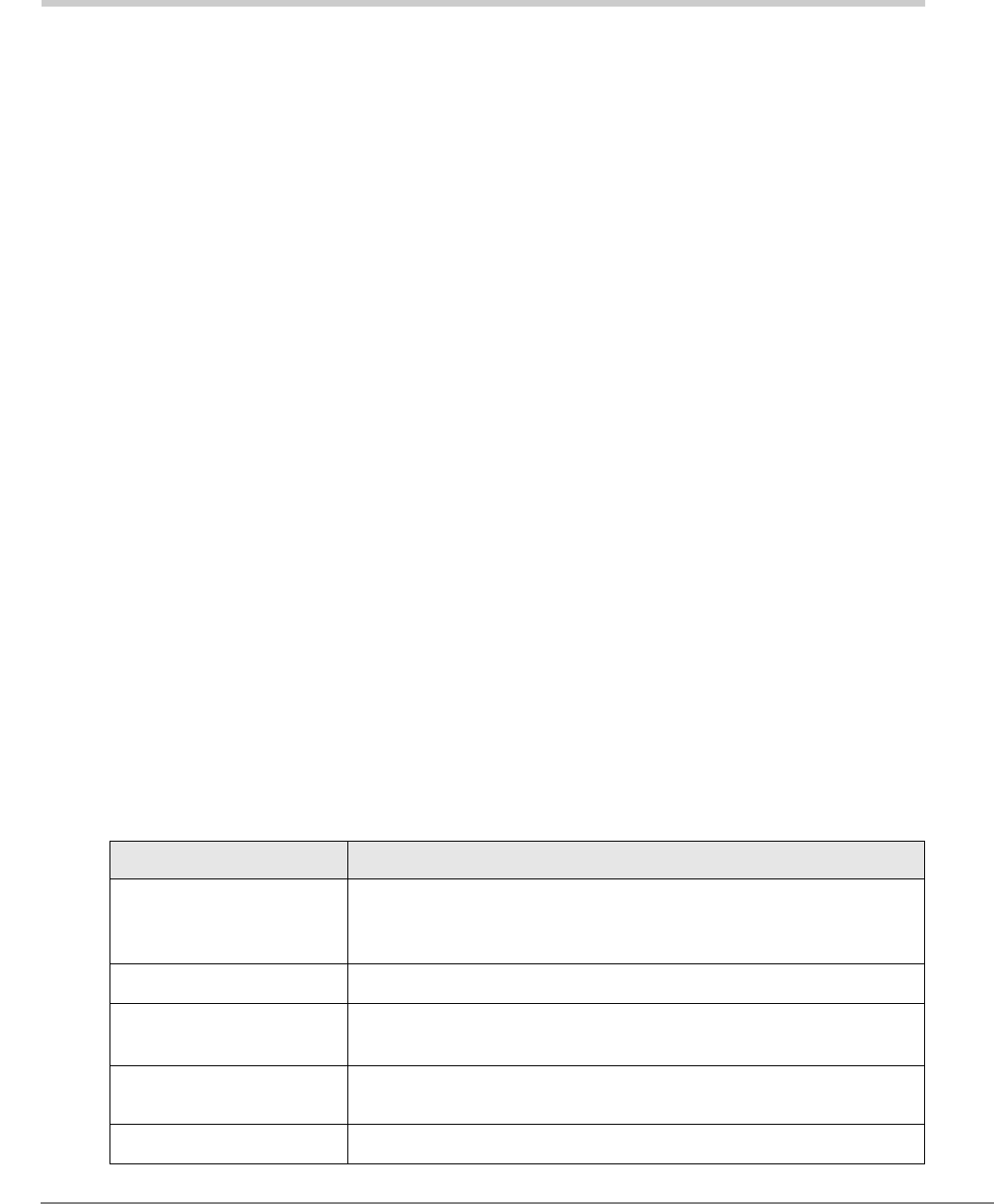
2. Click Get UTAM
Inputs from Strata
Airlink.
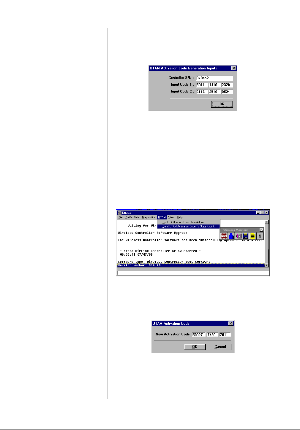
3. Make a note of the
BSIA serial number
and input codes
before calling the
Strata AirLink
Activation Desk
because the staff will
request these
numbers.
4. Call the Strata
AirLink Activation
Desk, (949) 598-
4980 for the
activation code.
Note The hours of operation are: Monday through Friday,
8:00 a.m. to 5:00 p.m., Pacific Standard Time.
After the BSIA serial number and input codes are given to the
activation desk, the technician will give you the UTAM system
activation code.
5. Close the Get UTAM
Inputs From Strata
AirLink window.
The Status window displays.
6. From the Status
window, highlight
UTAM.
7. Select Send UTAM
Activation Code to
Strata AirLink.
8. From the UTAM
Activation Code
dialog box, enter the
UTAM Activation
Code.
9. Click OK. The message “Wireless system has been activated” displays at
the bottom of the Status window.
Important! Install the UTAM code in one hour or a new one
must be obtained.
3485
3486
3487
BSIA System Installation
Step 9: Configure System
28 Strata AirLink Installation Guide 5/00
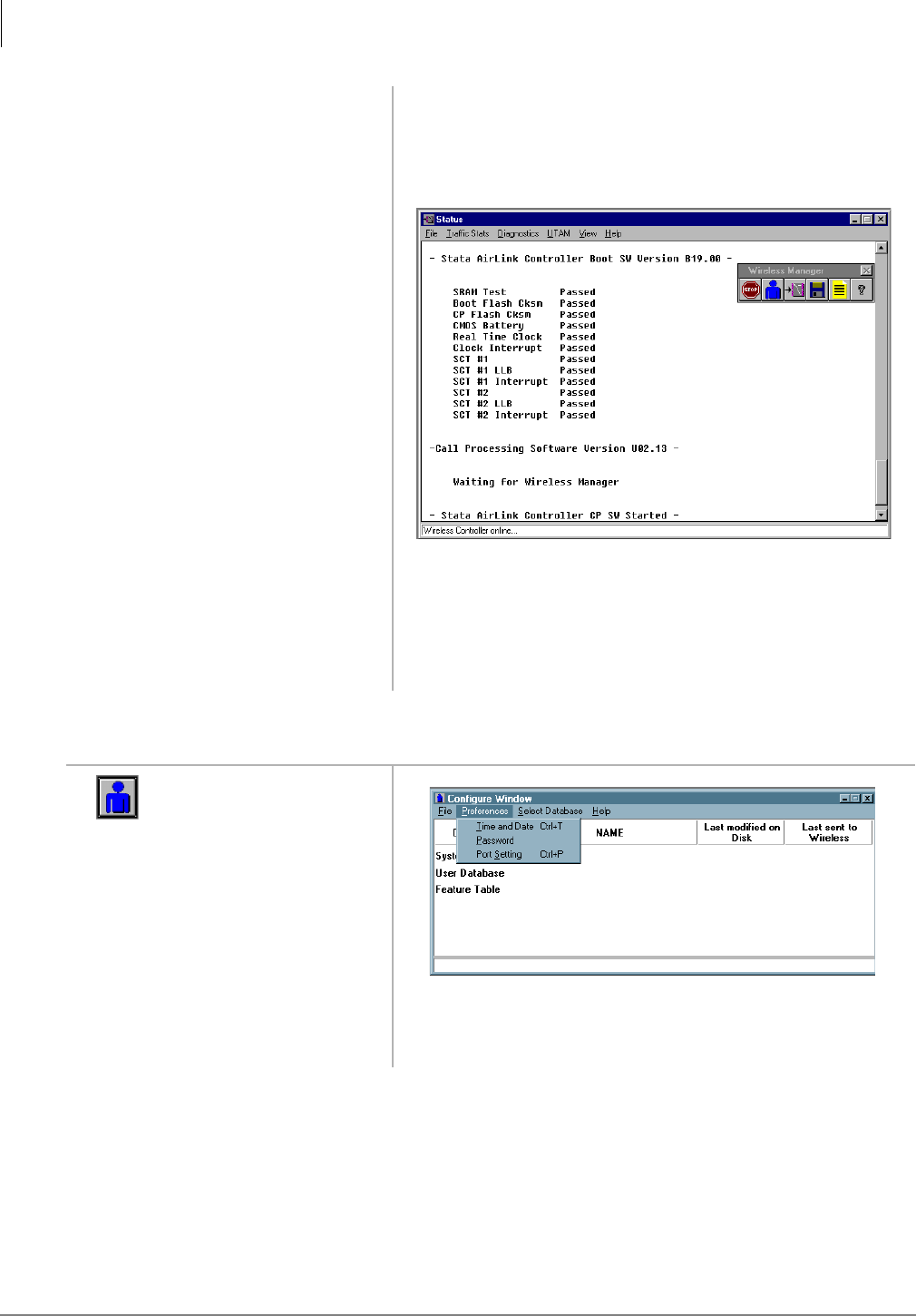
Substep B: Set System Time and Date
Normal LED indications display on the BSIA (PWR and
Master LEDs ON) and Base Stations (PWR LED ON). Several
messages display (below) on the PC screen as Strata AirLink
Manager tests the installation.
Important! If the message “Waiting for Wireless Manager”
does not appear in the Status window before the
progress bar times out, or LED S2 remains lit
after a reboot, the BSIA has not been upgraded.
Repeat Substeps 1~9.
1. Click the
Configuration icon.
2. Highlight
Preferences.
3491
3282
BSIA System Installation
Step 9: Configure System
Strata AirLink Installation Guide 5/00 29
Substep C: Enter System Settings
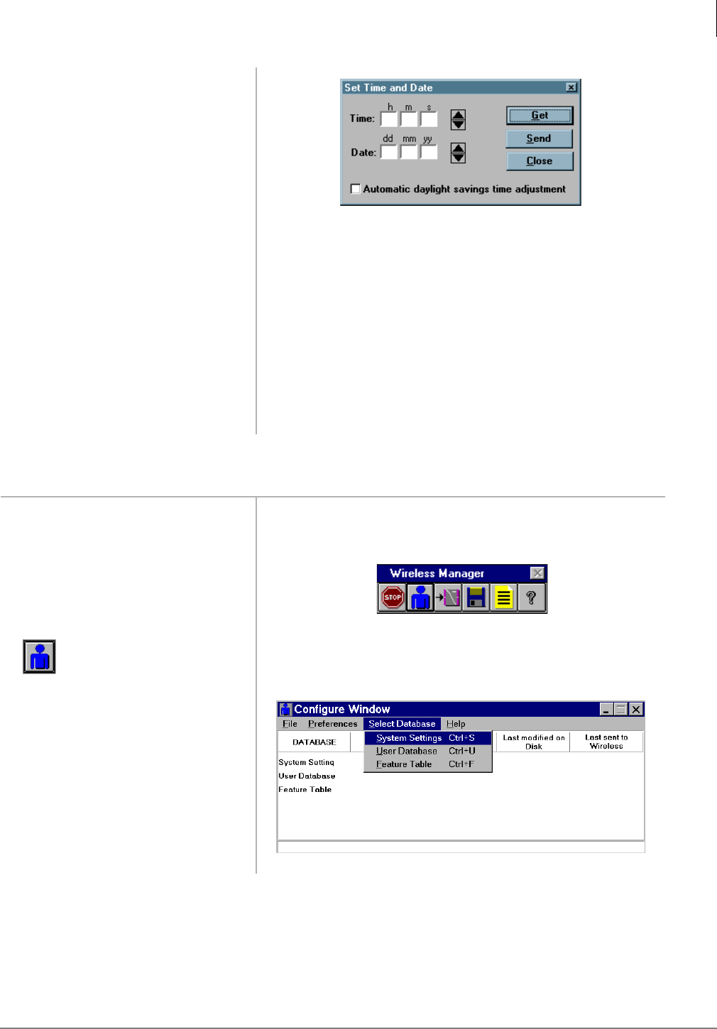
3. Click Time and Date.
4. Enter the time and
date.
5. Click “Automatic
daylight savings time
adjustment,” if
needed.
6. Send the new data to
the configuration file.
7. Click Close.
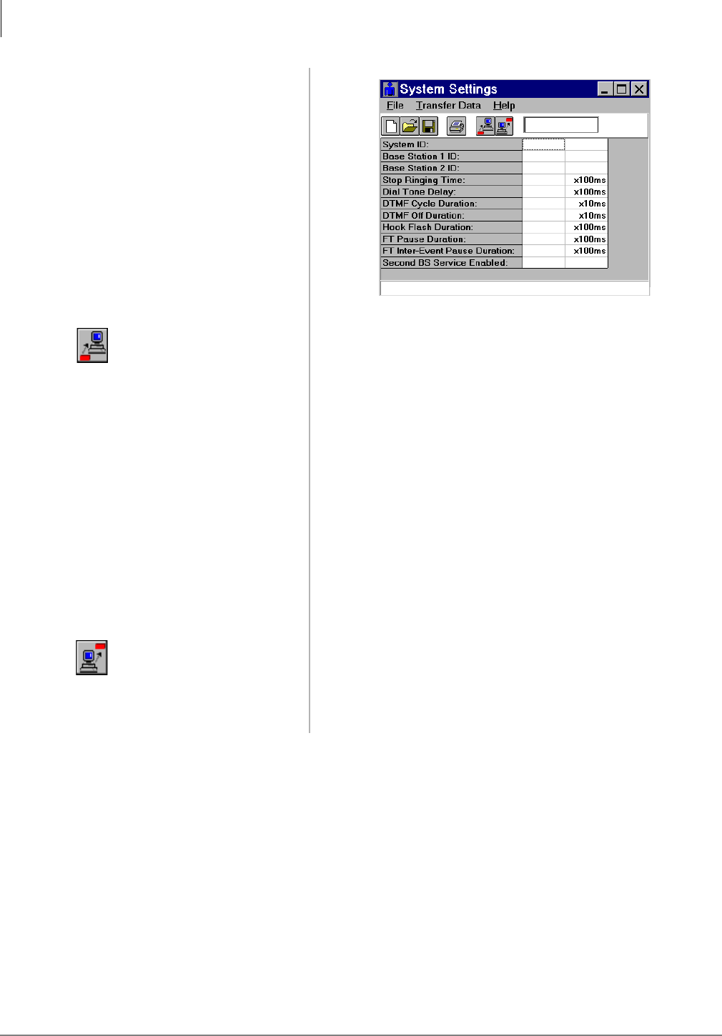
1. Complete the System
Settings form.
See Table 5 on Page 34.
2. Open the Strata
AirLink Manager
program.
3. Click the
Configuration icon.
4. Highlight Select
Database.
3274
3289
3270
BSIA System Installation
Step 9: Configure System
30 Strata AirLink Installation Guide 5/00
5. Click System
Settings
...or double-click
“System Settings” in
the active window.
6. Click the Get icon. The current data from the BSIA displays.
7. Verify previous
settings.
8. Enter the System and
Base Station IDs, and
timing intervals.
The recommended timing intervals are:
♦Stop ringing time – 4500 ms
♦Dial tone delay – 200 ms
♦DTMF cycle duration – 200 ms
♦DTMF off duration – 100 ms
♦Hookflash duration – 500 ms
♦FT pause duration – 1000 ms
♦FT inter-event pause – 100 ms
9. Click the Send icon. The new data is sent to the BSIA.
10. Save the file (file
extension is .sdb).
3271
BSIA System Installation
Step 9: Configure System
Strata AirLink Installation Guide 5/00 31
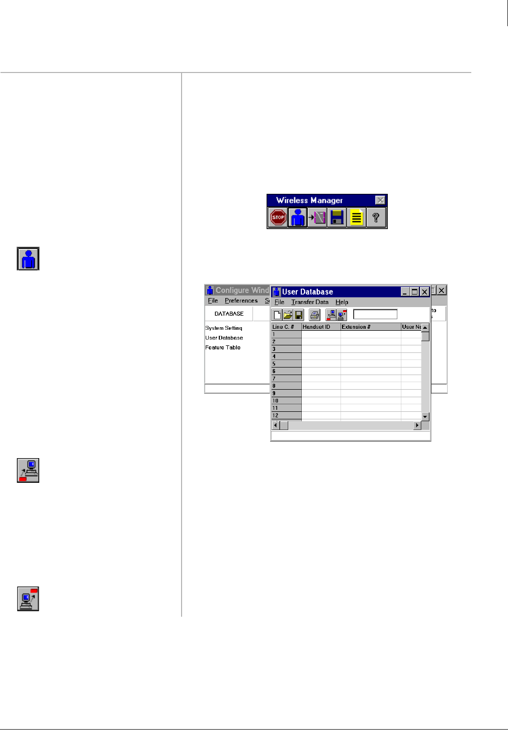
Substep D: Configure Handsets
1. Complete the User
Settings form.
See Table 6 on Page 35.
2. Ensure that each
handset ID
corresponds to the
correct connector
pair.
3. Open the Strata
AirLink Manager
program.
4. Click the
Configuration icon.
5. From the Configure
Window, click Select
Database and User
Database.
6. Click the Get icon. The current data from the BSIA displays.
7. Verify the previous
BSIA settings.
8. Enter the handset ID.
9. Save the file (file
extension is .udb).
10. Click the Send icon. The new data is sent to the BSIA.
3289
3272
BSIA System Installation
Step 9: Configure System
32 Strata AirLink Installation Guide 5/00
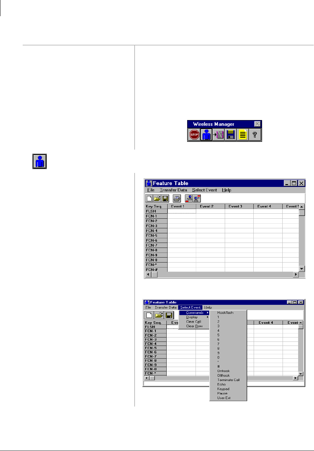
Substep E: Program Button Sequences
1. Complete the
Programming Button
Sequences form.
Consider the order in which commands and text displays
should occur during the execution of a telephone feature. See
Table 7 on Page 36.
2. Enter events 1~20
using the command
codes or text
displays.
3. Open the Strata
AirLink Manager
program.
4. Click the
Configuration icon.
5. From the Configure
Window, click Select
Database and Feature
Table.
6. Click Select Event
and Commands.
3289
3273
3264
BSIA System Installation
Step 9: Configure System
Strata AirLink Installation Guide 5/00 33
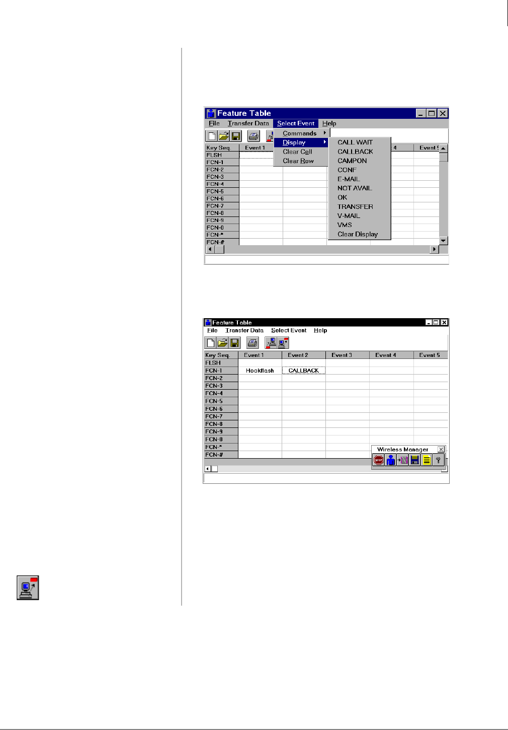
7. Click a command
(Hookflash, 1~0, *,
#, etc.).
The command appears in the designated column (labeled
Event 1~20). The Select Event pull-down menu displays.
8. Highlight Display.
9. Click an LCD
message (CALL
WAIT, CALLBACK,
CAMPON, etc.).
The message appears in the designated column (labeled Event
1~20). A completed Feature Table looks like this:
10. Repeat Substeps 1~5
as necessary.
11. Save the file (file
extension is .fdb).
12. Click the Send icon. The new data is sent to the BSIA.
3265
3258

BSIA System Installation
Step 9: Configure System
34 Strata AirLink Installation Guide 5/00
Programming Sheets
Table 5 System Settings
Parameter Description Units/
Range
Suggested
Setting
Your
Setting
System ID ID for the system (written on the
RWIU label). 1~5
Base Station 1 ID ID of the first Base Station. 0~31
Base Station 2 ID ID of the second Base Station. 0~31
Stop Ringing Time
Length of time the RWIU waits
after last detection of ring voltage
on a line before it stops the ring.
100 ms1
1. For example, a setting of 2 means 2 x 100 ms or 200 ms.
45
Dial Tone Delay2
2. The Dial Tone Delay eliminates the possibility of a user dialing before the office telephone system is ready.
Time delay between pressing
&$// and outpulsing DTMF
tones.
100 ms12
DTMF Cycle Duration
Duration of the full DTMF cycle
(length of tone plus length of
silence between tones) for dialing
and other telephone system
operations.
10 ms3
3. For example, a setting of 2 means 2 x 10 ms or 20 ms.
20
DTMF Off Duration Duration of silence between
DTMF tones. 10 ms310
Hookflash Duration
Duration of the hookflash in
signaling the office telephone
system.
100 ms15
FT Pause Duration Duration of pause events in the
Feature Table. 100 ms110
FT Inter-event Pause Duration of pause between events
in the Feature Table. 100 ms11
Second Base Station
Service Enabled
Enables service for a second
Base Station. TRUE if a second
Base Station is installed. FALSE if
only one Base Station is installed
or out of order.
NA

BSIA System Installation
Step 9: Configure System
Strata AirLink Installation Guide 5/00 35
Table 6 User Settings
Line Amphenol Connector/
Pair
Handset ID
(1 - 1535)
Extension #
(1 - 10 digits)
User Name/Comment
(1 - 12 characters)
1P1, Pair 1
2P1, Pair 2
3P1, Pair 3
4P1, Pair 4
5P1, Pair 5
6P1, Pair 6
7P1, Pair 7
8P1, Pair 8
9P1, Pair 9
10 P1, Pair 10
11 P1, Pair 11
12 P1, Pair 12
13 P1, Pair 13
14 P1, Pair 14
15 P1, Pair 15
16 P1, Pair 16
17 P2, Pair 1
18 P2, Pair 2
19 P2, Pair 3
20 P2, Pair 4
21 P2, Pair 5
22 P2, Pair 6
23 P2, Pair 7
24 P2, Pair 8
25 P2, Pair 9
26 P2, Pair 10
27 P2, Pair 11
28 P2, Pair 12
29 P2, Pair 13
30 P2, Pair 14
31 P2, Pair 15
32 P2, Pair 16

BSIA System Installation
Step 9: Configure System
36 Strata AirLink Installation Guide 5/00
Table 7 Feature Table
Events 1 - 20
(Use the Commands or Text Displays Listed Below)
Button
Sequence
FLSH
FCN 1
FCN 2
FCN 3
FCN 4
FCN 5
FCN 6
FCN 7
FCN 8
FCN 9
FCN 0
FCN *
FCN #
BSIA System Installation
Step 9: Configure System
Strata AirLink Installation Guide 5/00 37
Substep F: Store IDs in Handset
1. Press 3:5. The handset turns on.
2. Press )&1.
3. Press ▼ until SYSTEM
CONFIG. displays
...or + )&1.
4. Press )&1.
5. Enter the proper System ID
(SID).
Note The SID must match the data entered in the system
settings.
6. Press &/5to make
corrections.
7. Press ▼.
8. Enter the handset ID (four
digits) for the system ID
entered in Substep 5.
9. Press ▼ for other systems.
10. Repeat Substeps 1~11 to
enter all the system and
handset IDs required.
A maximum of eight system IDs and associated handset
IDs can be stored in handset memory.
11. Press (1'. The ESN displays momentarily.
12. Press &$//. The handset ESN is stored in the BSIA.
MENU
OPERATION
12 : 15
SYSTEM
CONF IG.
12 : 15
SID#0
12 : 15
HID#0
12 : 15
HID#1
12 : 15
BSIA System Installation
BSIA Additional Information
38 Strata AirLink Installation Guide 5/00
BSIA Additional Information
The following tables have additional information unique to the BSIA system and cover:
♦BSIA (controller) specifications – Table 8
♦Adapter and BSIA pinouts – Tables 9 and 10
♦ALM removal
♦Initial configuration change
♦Password change
♦Base Station additions
♦Communication port change
BSIA (Controller) Specifications
Adapter and BSIA Pinouts
Tables 9 and 10 list the adapter and BSIA pinouts.
Table 8 BSIA Specifications
Name Description
Dimensions 16.84 x 9.29 x 1.75 inches
Weight 4.6 lbs. without ALM
Mount Wall or industry-standard rack mount
Input Power -48VDC or 110/220VAC with optional power supply
Temperatures
Operating: 10°~40°C
Storage: -20°~53°C
Operating Humidity: 20 to 80% non-condensing
Storage Humidity: 5 to 95% non-condensing
Altitude
Operating: 4,920 ft.
Note Systems operating above 4,920 ft. in low humidity areas
could require additional cooling.
Storage: 940 to 9,400 ft.
Table 9 DB9 and DB25 Adapter Pinouts
8-Pin Jack DB9-F DB25-F 8-Pin Jack DB9-F DB25-F
1/BLU Not Used Not Used 5/GRN 3 2
2/ORG 7 4 6/YEL 5 7
3/BLK 8 5 7/BRN Not Used Not Used
4/RED 2 3 8/WHT Not Used Not Used

BSIA System Installation
BSIA Additional Information
Strata AirLink Installation Guide 5/00 39
ALM Removal
1. Power off the BSIA.
2. Remove the screws securing the cover of the BSIA case.
3. Lift the cover off of the BSIA.
4. Unplug connectors J4, J5, or J6.
CAUTION! Do not apply diagonal pressure to the DIN connectors (see Figure 16 on Page
20).
5. Disconnect the ALM from the standoffs on the BSIA PCB.
6. Gently lift the ALM out of the BSIA.
7. Replace the BSIA cover and re-install the screws.
Table 10 BSIA Pinouts
Pair P1 P2
1Tip, ring — station 1 Tip, ring — station 17
2Tip, ring — station 2 Tip, ring — station 18
3Tip, ring — station 3 Tip, ring — station 19
4Tip, ring — station 4 Tip, ring — station 20
5Tip, ring — station 5 Tip, ring — station 21
6Tip, ring — station 6 Tip, ring — station 22
7Tip, ring — station 7 Tip, ring — station 23
8Tip, ring — station 8 Tip, ring — station 24
9Tip, ring — station 9 Tip, ring — station 25
10 Tip, ring — station 10 Tip, ring — station 26
11 Tip, ring — station 11 Tip, ring — station 27
12 Tip, ring — station 12 Tip, ring — station 28
13 Tip, ring — station 13 Tip, ring — station 29
14 Tip, ring — station 14 Tip, ring — station 30
15 Tip, ring — station 15 Tip, ring — station 31
16 Tip, ring — station 16 Tip, ring — station 32
20 Receive from Base Station 1
21 Transmit to Base Station 1
22 Tip, ring — external alarm connection
23 Tip, ring — external alarm connection
24 Receive from Base Station 2
25 Transmit to Base Station 2
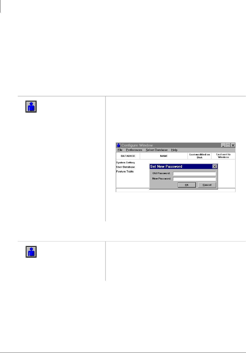
BSIA System Installation
BSIA Additional Information
40 Strata AirLink Installation Guide 5/00
Initial Configuration Change
It is highly recommended that you get the current configuration and save it to a file on the PC as
the working copy. Then, open and edit the working copy – not the original file. Using this method
ensures that the original configuration file is not corrupted while adding or editing existing data.
Once the new information is saved, the BSIA uses the new data immediately.
Important! Sending configuration information to the BSIA overwrites existing information.
Make sure that the sent data contains all of the required configuration information,
not just the few additions or changes that were made.
Password Change
Base Station Addition
1. From the Desktop
Toolbar, click the
Configuration icon.
2. Open the Configure
Window.
3. Select Preferences
from the menu bar
and Password.
4. Enter the old and
new password and
click OK.
1. From the Desktop
Toolbar, click the
Configuration icon.
2. Open the Configure
Window.
3268
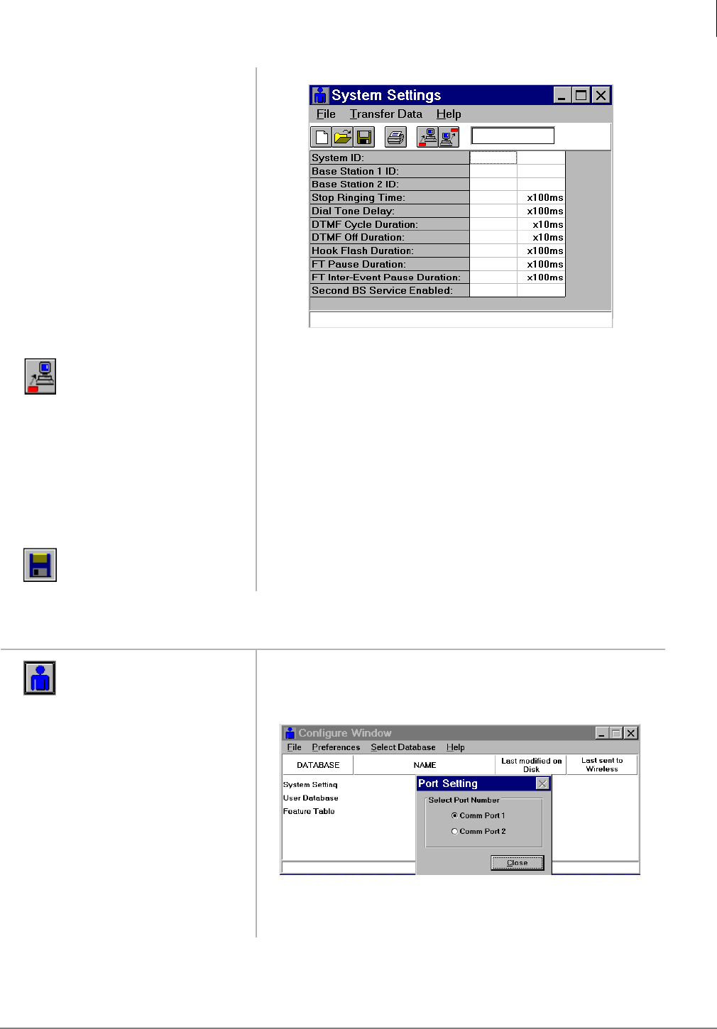
BSIA System Installation
BSIA Additional Information
Strata AirLink Installation Guide 5/00 41
Communications Port Change
3. Click Select
Database and System
Settings.
4. Click the Get icon. The current data from the BSIA displays.
5. Enter TRUE in
Second Base Station
Service Enabled.
Important! Do not perform this step without getting the
current system settings first, or all data is
overwritten.
6. Save the file and
close the Configure
Window.
The Desktop Toolbar displays.
7. Double-click the
Upgrade icon.
The Base Station is upgraded.
1. From the Desktop
Toolbar, click the
Configuration icon.
2. Click Preferences
and Port Setting.
3. Click the new port
and Close.
Important! Click close immediately (before 10 seconds have
elapsed) or the change does not take effect.
3271
3281

BSIA System Installation
BSIA Additional Information
42 Strata AirLink Installation Guide 5/00
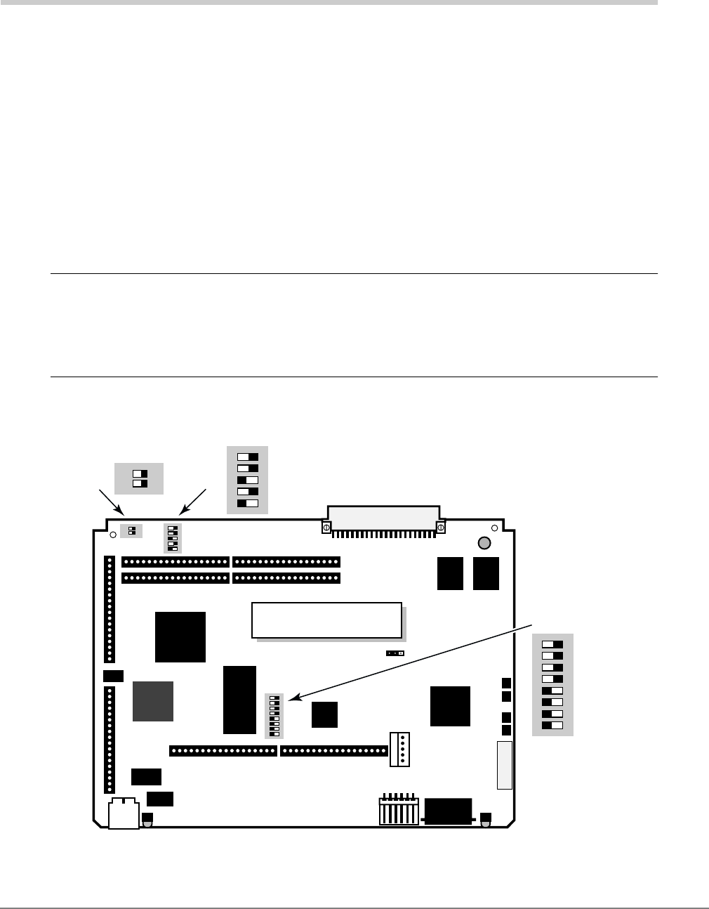
Strata AirLink Installation Guide 5/00 43
RWIU System Installation 4
This chapter describes the specific installation steps for the RWIU PCB.
Step 1: Check DIP Switches and Jumpers on PCB
CAUTION! The RWIU and WWIS come from the factory already assembled. Remove the
WWIS carefully to check the DIP switches on the RWIU, keeping the pins on it
straight. After checking the DIP switches, but before aligning the two PCBs, be
sure that the connectors are not bent. This causes irreparable damage to both
PCBs.
The RWIU has three DIP switches. The location of each is shown in Figure 23. The factory default
positions are given in the following steps.
Figure 23 Location of RWIU DIP Switches S1~S3
3513
RWIU1A
12345678
DIP
ON
12345678
DIP
ON
S1
12345
DIP
ON
12345
DIP
ON
S2
S3
J7
J9J10
J12
J13
J15 J14
J17 J16
J13
LD2 LD1
J8
JTAG
12
ON
12
ON
RWIU (top view)

RWIU System Installation
Step 1: Check DIP Switches and Jumpers on PCB
44 Strata AirLink Installation Guide 5/00
1. Check DIP Switch S1. Table 11 gives the factory settings - defaults are in bold.
Important!
●Switch 8 is used to recover the RWIU in the event of a software load failure. Turn Switch 8
to its off position to force a download of the stored factory default software.
●If any Base Station is not used, put its corresponding S1 switch in the on (inactive)
position. If the switch is in the off position, the WWIS subassembly LED 1 and 2 remain lit
and the RWIU tries to initialize that Base Station every 40 seconds.
2. Check DIP Switch S2. Table 12 gives factory settings - defaults are in bold:
3. Check DIP Switch S3 settings to ensure that the correct number of handsets are enabled (see
Table 13).
4. Verify that the Watch Dog Timer (WDT) is jumpered correctly as shown in Figure 24.
Table 11 S1 Factory Default Positions
S1 DIP Switch Number
Position 1 2 3 4 5 6 7 8
On
Base
Station 1
Inactive
Base
Station 2
Inactive
Base
Station 3
Inactive
Base
Station 3
Inactive
Spare Spare Spare Disable
Download
Off
Base
Station 1
Active
Base
Station 2
Active
Base
Station 3
Active
Base
Station 4
Active
Spare Spare Spare Force
Download
Table 12 S2 Factory Default Positions (RF Signals)
S2 DIP Switch Number
Position 1 2 3 4 5
On Slave1
1. RWIU must be in the master setting to operate.
DECT2 Disabled
2. DECT = Digital European Cordless Telecommunications
PCS3 Disabled
3. PCS = Personal Communication Service
Four Ports Spare
Off Master DECT Enabled PCS Enabled Two Ports Spare
Table 13 S3 Factory Default Positions (Number of Handsets)
S3 DIP Switch Number Number of
Handsets
1 2
On On 8
Off On 16
On Off 24
Off Off 32
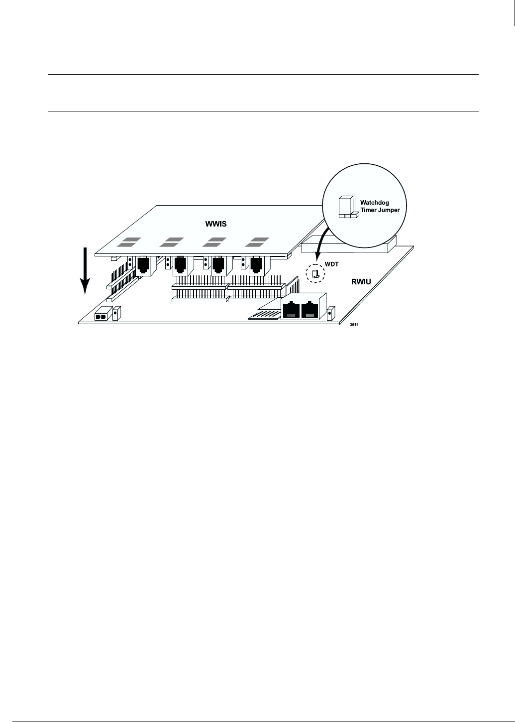
RWIU System Installation
Step 2: Mount WWIS onto RWIU
Strata AirLink Installation Guide 5/00 45
Step 2: Mount WWIS onto RWIU
CAUTION! Before aligning the two PCBs, be sure that the connectors are not bent. This
causes irreparable damage to both PCBs.
1. Carefully align the connectors of the WWIS (P9~P10 and P12~P17) to the terminals on the
RWIU (J9~J10 and J12~J17) (shown in Figure 24).
Figure 24 Alignment of the WWIS onto the RWIU
2. Gently press the WWIS onto the RWIU. Ensure that the connections are solid by gently
pulling the WWIS away from the RWIU. If the connectors are properly seated, a slight
resistance is felt.
Step 3: Determine Proper Strata DK Slot Configuration
➤Use Table 14 to determine the physical slot configuration for the RWIU in Strata DK424i. The
RWIU PCB can provide up to 16 or 32 Strata AirLink Handsets, depending on where it is
placed. The RWIU slot provides eight handsets. Each additional set of eight handsets requires
that an additional cabinet slot adjacent to RWIU be vacant.
RSTU or RDSU: Each RSTU or RDSU PCB connected to BSIA requires one slot. These
PCBs cannot occupy a slot that is left vacant to provide capacity for RDTU, RPTU, or RWIU,
as shown in Table 14. Each RSTU PCB provides circuits for up to eight Strata AirLink
Handsets; each RDSU/RSTS provides circuits for four Strata AirLink Handsets.
RJ45
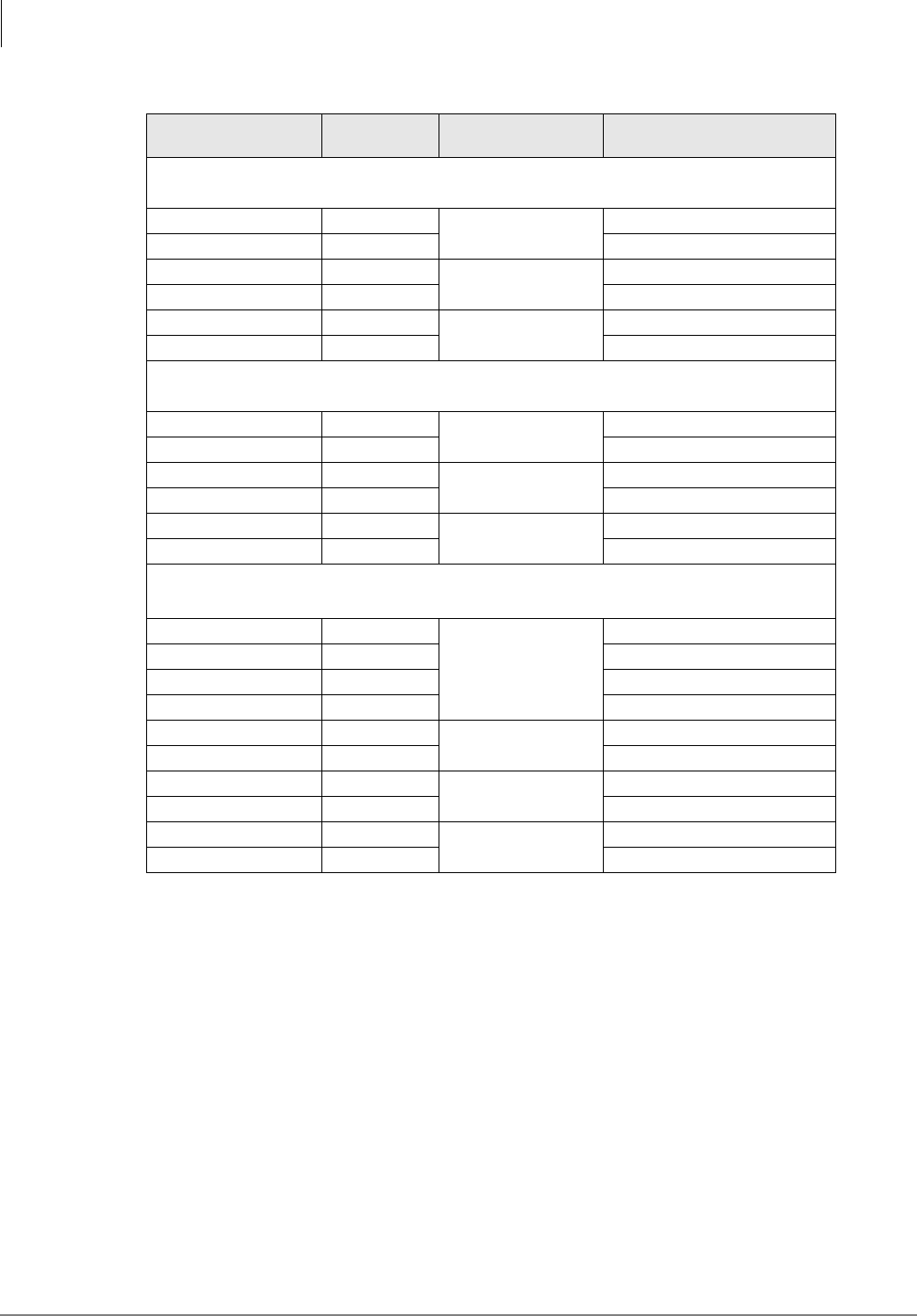
RWIU System Installation
Step 3: Determine Proper Strata DK Slot Configuration
46 Strata AirLink Installation Guide 5/00
Important! For Strata DK40i, if there are eight handsets, the RWIU can be installed in any of
the expansion cabinet slots (15, 16, and 18). If there are 16 handsets, the RWIU
must be installed in slot 15 and Slot 16 must be vacant. This system cannot support
24 or 32 handsets because of a port limitation.
Table 14 Strata AirLink RWIU PCB Cabinet Slot Configuration
Handsets
Needed
Slots
Needed
RWIU PCBs
Needed1RWIU Cabinet Slot Placement
Base Cabinet with any processor
1~8 1 1S103-RWIU1
9~16 2 S104-vacant2
17~24 3 2S105-RWIU2
24~32 4 S106-vacant*
33~40 5 3S107-RWIU3
41~48 6 S108-vacant*
Second cabinet with B2CAU/CBU processor
1~8 1 1S201-RWIU1
9~16 2 S202-vacant2
17~24 3 2S203-RWIU2
24~32 4 S204-vacant2
33~40 5 3S205-RWIU3
41~48 6 S206-vacant2
Second and third cabinet with B3CAU/CBU; or second through fifth cabinet with B5CAU/CBU
1~8 1
1
S_07-RWIU1
9~16 2 S_08-vacant2
17~24 3 S_09-vacant2
24~32 4 S_10-vacant2
33~40 5 2S_01-RWIU2
41~48 6 S_02-vacant2
49~56 7 3S_03-RWIU3
57~64 8 S_04-vacant2
65~72 9 4S_05-RWIU4
73~80 10 S_06-vacant2
1. RWIU PCBs do not have to be installed in the order shown in this table. Example: If only one RWIU is
needed, it can be installed in any RWIU slot shown in the table so long as the slot is supported by the
installed processor.
2. The slot occupied by RWIU supports 8 handsets, for each additional 8 handsets an additional slot
adjacent to RWIU must be vacant.
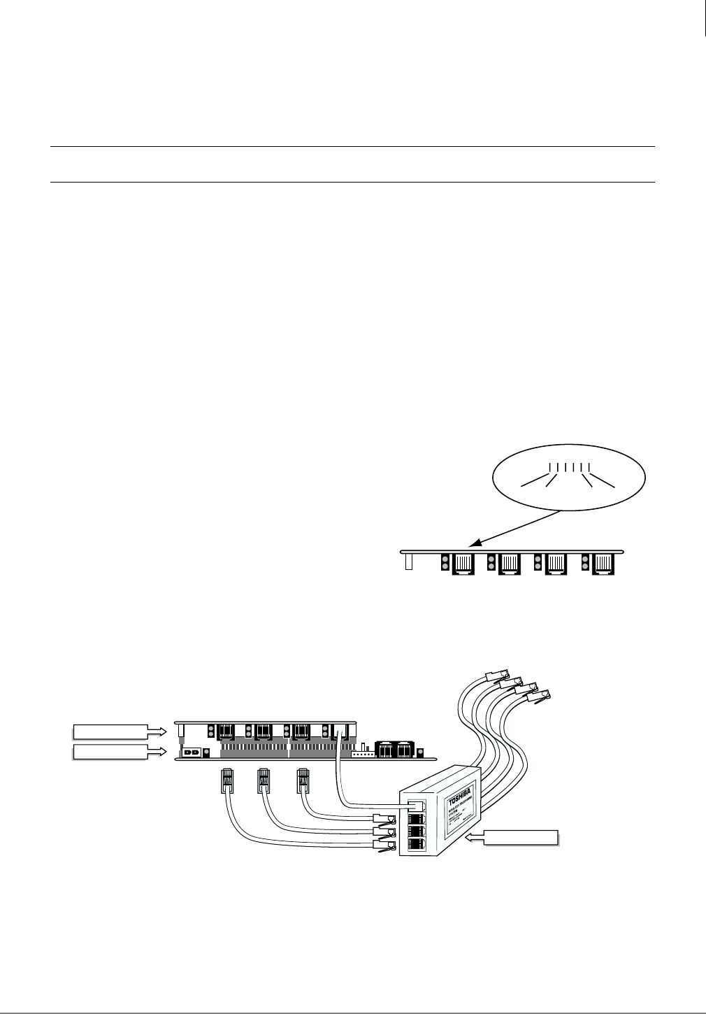
RWIU System Installation
Step 4: Install RWIU/WWIS into Strata DK
Strata AirLink Installation Guide 5/00 47
Step 4: Install RWIU/WWIS into Strata DK
1. Insert the RWIU (WWIS and components facing right) into the appropriate slot of the Strata
DK and apply firm, even pressure to ensure proper mating of connectors.
CAUTION! Strata DK power must be off before inserting the RWIU.
2. After installing the RWIU, gently pull the PCB outward. If the connectors are properly seated,
a slight resistance is felt.
Step 5: Run Cable
1. Do not exceed these cabling distances between the Base Stations and WWIS for Category 5,
24 AWG:
♦2,000 feet for line power
♦3,300 feet for local power
2. Use Category 5 cable. Using a mix of Categories 2, 3, 4, and 5 is acceptable but can effect the
total possible cable length.
3. Connect one end of each cable into the RJ45 jacks
on the RWIU/WWIS (Point B in Figure 26) and
the other end (reversed) into the EMI box (Point
A in Figure 26). The RJ-45 transmit and receive
pins are shown in Figure 25.
4. Connect each end of the other set of cables into
the RJ-45 jacks of the EMI box (Point C - To Base
Stations in Figure 26) and run the opposite end
out to the Base Stations.
Figure 26 EMI Connections to the RWIU/WWIS
RJ45
Transmit Receive
12 6543
3512
RJ45 RJ45 RJ45
Figure 25 RJ-45 Pin Configuration
RWIU1A (side)
WWIS1A (side)
3724
1234
A
B
C - To Base Stations
EMI
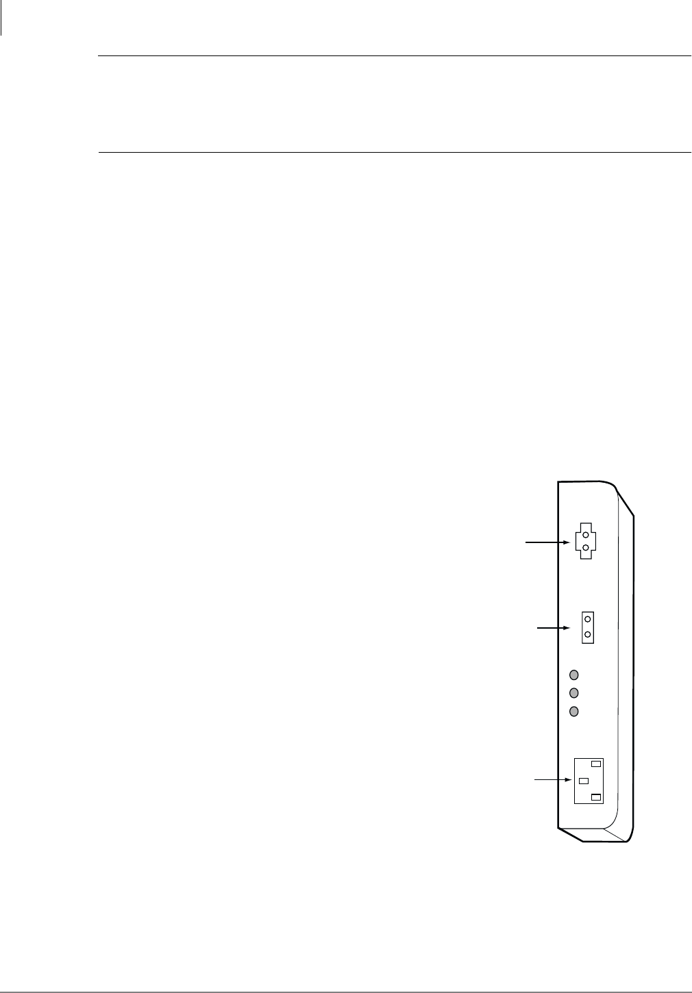
RWIU System Installation
Step 6: Determine Base Station Power Supply
48 Strata AirLink Installation Guide 5/00
CAUTION!
♦Do not use current-limiting (fuse style) primary protectors on the transmit and
receive pairs between the RWIU and Base Stations.
♦Do not connect the RWIU to power at this point.
Step 6: Determine Base Station Power Supply
A Base Station can receive input (line) power from the RWIU or an optional local power supply.
Using a local power supply increases the distance Base Stations can be located from the RWIU.
Customers with 220VAC outlets can:
♦Purchase another power cord to fit the universal connector (three-pronged IEC 320 power
inlet) on the power supply
♦Replace the 110VAC plug on the cable with an appropriate 220VAC plug
♦Connect a North American 220VAC adapter to the 110VAC plug
Step 7: Connect Power Supply
The maximum available PBX power for each RWIU PCB is one amp (+5VDC).
1. Use the external power supply (see Figure 27) to
increase the amps for each Base Station.
The power supply has a -40VDC power connector
for direct connection to the RWIU.
2. Connect to 110VAC power, but do not power on.
Step 8: Use Proper Power Factor
(PF)
➤Check the +5VDC PF using Table 15 as a reference.
Calculation examples are shown in Tables 16 and
17.
Note The maximum voltages for the RPSU280A
Power Supply are 25.0 (+5VDC) and 65.0
(-24VDC).
3923
AC IN
110VAC
Power Cord
DC OUT
40VDC
DC OUT OK
AC/DC OUT
OK
DC/DC OUT
OK
RWIU - 40 VDC
Power Connector
DC IN
24VDC
Backup
Batteries
Figure 27 RWIU Power Supply

RWIU System Installation
Step 8: Use Proper Power Factor (PF)
Strata AirLink Installation Guide 5/00 49
Table 15 Strata DK40i and DK424 PCB and Power Supply PFs
PCB Type +5VDC PF -24VDC PF Notes
IMDU 0.1 0.16
PCOU1, 2 1.9 2.0
PDKU1, 2 0.8 0.3 With 8 DKTs.
PEKU 1.6 0.7 With 8 EKTs.
PEPU 1.1 6.5
PESU 1.5 0.5 With 4 EKTs and 2 SLTs.
PIOU 2.0 6.5
PIOU2 1.1 6.5
PIOUS 0.75 4.0
RSTU/RSTU2 (-24VDC) 1.4 0.5 With 8 SLTs.
R40S 0.0 2.8 Does not use +5VDC.
RATU 1.7 0.3
RBSS 0.6 0.3
RBSS2 0.0 0.3 Does not use +5VDC.
RBSU + RBSS 3.2 0.3
RBSU 2.5 1.0
RBSU2 0.0 1.0 Does not use +5VDC.
RBUS 0.0 0.3 Does not use +5VDC.
RBUU 0.0 1.0 Does not use +5VDC.
RCIS 0.3 0.1
RCIU, RCIU2 0.7 0.2
RCMS 0.6 0.3
RCOS, RCOS2 1.7 2.0
RCOU (4 CO) 2.5 2.0
RCOU + RCOS (8 CO) 3.6 4.0
RCOU, RCOU2 1.9 2.0
RCTUA 2.0 1.0
RCTUB 4.0 1.0
RCTUBA/BB 4.0 1.9
RCTUC/D 4.5 1.9
RCTUE/F 10.0 1.9
RDDU 2.6 7.0
RDSU/RDSS (-24VDC) 1.1 0.3 With 4 DKTs and 4 SLTs.
RDSU + R48S (-48VDC) 1.1 0.5
RDTU 1.8 1.0
REMU2/PEMU 1.0 7.5
RGLU, RGLU2 2.1 2.5
RMCU 0.7 0.3

RWIU System Installation
Step 9: Program Strata DK
50 Strata AirLink Installation Guide 5/00
Step 9: Program Strata DK
Important! Do not use a DKT that has an intercom button for Speed Dial programming.
1. Determine how many handsets, PDKU ports, and available slots are required before
programming the Strata DK. Up to 32 handsets per RWIU are allowed.
2. Use the following programs:
♦Program 03 for Code 61 (slot assignments).
♦Program 32 for Auto Preference.
♦Program 39 for flexible button assignments.
RMDS 0.35 0.16 2400 bps MODEM.
RPTU 2.6 1.0
RRCS-12 1.5 1.0
RRCS-4 0.4 0.3
RRCS-8 1.0 0.5
RSIS 0.35 0.15
RSIU 1.0 0.3
RSSU 0.7 0.3
RSTU + R48S (-48VDC) 1.4 1.0 With 8 SLTs.
RSTU2 4.0 2.3 With 8 MWs.
RWIU 9.2 0.0 With 8, 16, 24, or 32 handsets.
Table 16 Example of Strata DK424 Base Cabinet Configuration with RCTUA4A
PCB Quantity +5VDC PF -24VDC PF
RCTUA4A 1 2.0 1.0
RRCS-4 1 0.4 0.3
PDKU2 2 1.6 0.3
RCOU + RCOS 1 3.6 4.0 (8 COs)
RBSU + RBSS 1 3.2 0.3
RWIU 1 9.0 0.0
Total 7 19.8 5.9
Table 17 Example of Strata DK40i Expansion Cabinet Configuration
PCB Quantity +5VDC PF -24VDC PF
RCOU + RSOU 1 3.6 4.0 (8 COs)
RBSU + RBSS 1 3.2 0.3
RWIU 2 18.0 0.0
Total 4 24.8 4.3
Table 15 Strata DK40i and DK424 PCB and Power Supply PFs (continued)
PCB Type +5VDC PF -24VDC PF Notes

RWIU System Installation
Step 9: Program Strata DK
Strata AirLink Installation Guide 5/00 51
♦Programs 81~89 for line ringing on the handsets.
♦Program 91-9 for automatic PCB recognition.
♦Programs *71~73 for DID ringing on specific handsets.
Refer to Strata DK Programming Manual for specific information and Table 18 for available
Strata DK station features.
Table 18 Available Station Features
Feature Name
Account Code Continuous DTMF Tones
Automatic Call Distribution (ACD) DISA Security Code Revision
Automatic Busy Redial (ABR) Do Not Disturb (DND)
Automatic Call Back (ACB) DND Override (receive)
Automatic Hold Exclusive Hold
Automatic Line Selection Door Phone
Busy Override/Busy Station Transfer/Busy
Station Ringing Headset Interface
Call Forward: Headset Receiver Volume Control
●All Calls Hearing Aid Compatible
●Busy Liquid Crystal Display (LCD)
●No Answer Message Waiting Indication
●Busy/No Answer Multiple Message Waiting
●Fixed Microphone Control (fixed) - Mute Only
●External Microphone Sensitivity Control
Call Park Orbits: Loud Ringing Bell (headset)
●Park/Page Night Lock
Call Pickup: Night Transfer
●Night Bell Off-hook Call Announce (OCA) - Handset Mode
●Tenant Ringing Lines (four groups) Page Access
●Station Groups (20 groups, all call
types) Phantom Message Waiting Indication
●Any Ringing LIne Pooled Line
●Directed Station (all call types) Private CO Lines
●Held CO Lines (selectively) Push-button Dialing
●Parked Call Release and Release/Answer
●External Page Remote Retrieval of Held/Parked Calls
Centrex/PBX Compatible Ringing Line Preference
CO/Centrex Saved Number Redial
Conferencing Timed Reminders
Dial Pulse DTMF Mode Change Toll Restriction Override Code Revision
Direct Station Selection (DSS) User Programmable Feature Buttons
DSS Console Features

RWIU System Installation
Step 10: Connect PC
52 Strata AirLink Installation Guide 5/00
Step 10: Connect PC
➤Run the RS-232-C cable to the back
of the PC (COM port 1) and insert
the 6-pin connector into the RWIU
jack (see Figure 4-1).
Step 11: Initialize RWIU
1. Open the RWIU Manager software.
2. Turn on the Strata DK. The RWIU checks Base Station status and connections.
3. Check the LEDs on the Base Stations. If all the LEDs are OFF, the initialization is complete.
4. Check the handsets for dial tone. If there is dial tone, the initialization is complete.
Step 12: Install RWIU Manager
1. Check the PC hardware/
software against the required
minimums.
Refer to “Check System Hardware and Software
Requirements” on Page 6.
2. Close any open applications
in Windows.
3. Insert the RWIU Manager
floppy disk into the A:\ drive.
4. In Windows 98/95, click Start
and Run
...or in Windows 3.11/3.1,
open Program Manager and
click File and Run.
A dialog box displays requesting the location of the setup
disk.
5. Type A:\Setup and click
OK.
The Windows setup screen warns Windows applications
should be closed.
6. Click Yes A dialog box displays recommending a destination path of
C:\Wireless.
...or No if applications need
to be closed.
7. Click OK C:\Wireless is accepted as the destination directory.
...or change the destination
drive/directory.
3333
RS-232-C 6-pin Jack
RWIU (side view)
Figure 4-1 RWIU 6-pin Jack
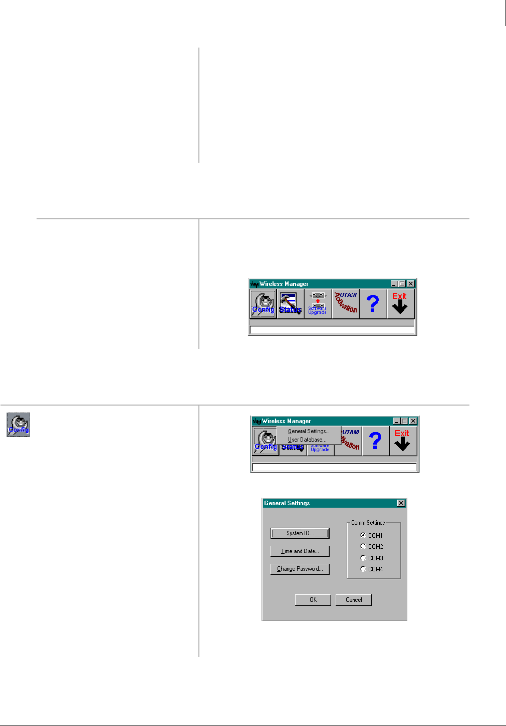
RWIU System Installation
Step 13: Start RWIU Manager
Strata AirLink Installation Guide 5/00 53
Step 13: Start RWIU Manager
Step 14: Set General Settings
8. Click OK. A dialog box displays requesting verification of the
software location (its program directory or the Windows
system directory). Using the program directory is
recommended.
9. Select the program directory.
10. Click OK. The files are copied to the hard disk. A program group is
created.
1. Make sure that the PC is
connected to the RWIU.
2. From the RWIU program
group, double-click on the
Manager icon.
After a few seconds, the Desktop Toolbar displays.
1. From the Desktop Toolbar,
click the Config icon.
2. Click General Settings and
assign COM port 1.
3. Click OK.
3347
3348
3349
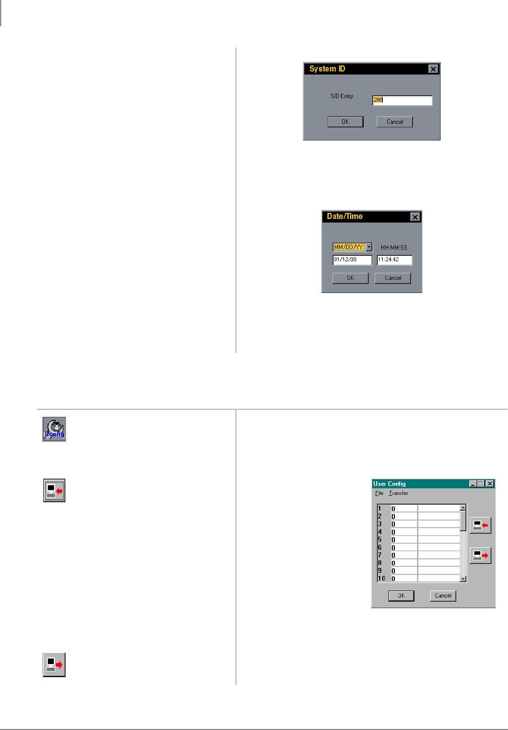
RWIU System Installation
Step 15: Enter Handset IDs
54 Strata AirLink Installation Guide 5/00
Step 15: Enter Handset IDs
4. Click System ID.
5. Enter the System ID.
6. Click OK. General Settings window displays.
7. Click Time and Date.
8. Enter the Date and time.
9. Click OK.
1. From the Desktop Toolbar,
click the Config icon.
2. Click User Database.
3. Download the settings from
the RWIU.
Default IDs display.
Handset IDs do not have
to be in numerical order
and can be changed at any
time.
4. Click OK. The Desktop Toolbar displays.
5. Upload the settings to the
RWIU.
The new IDs are saved.
3351
3354
3746
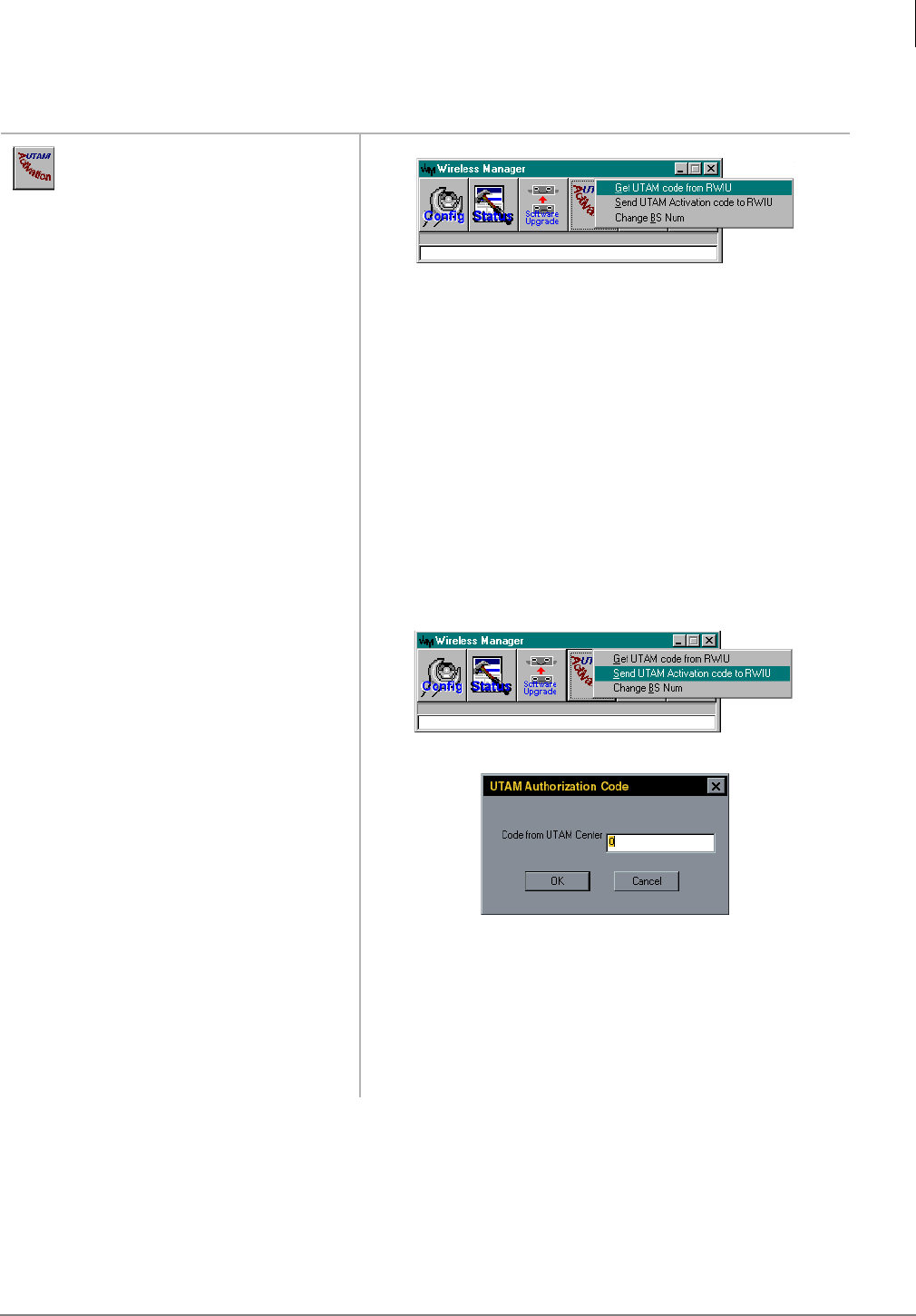
RWIU System Installation
Step 16: Enable UTAM
Strata AirLink Installation Guide 5/00 55
Step 16: Enable UTAM
1. From the Desktop Toolbar,
click the UTAM Activation
icon.
2. Click Get UTAM Code from
RWIU.
3. Enter the password
LABUTAM.
4. Click OK twice. The Desktop Toolbar displays.
5. Click Get UTAM code from
RWIU.
The new 20-digit UTAM activation code displays. Call the
UTAM Activation desk at (949) 598-4980 between the
hours of 8:00 a.m. and 5:00 p.m. (Pacific Standard Time),
Monday through Friday with this number.
6. Click OK. The Desktop Toolbar displays.
7. Click Send UTAM
Activation Code to RWIU.
8. Input the 10-digit code given
to you by the Activation Desk
9. Press Enter. “Permission granted successfully” displays. If an error
message displays, repeat Steps 1~7.
Note If UTAM is required, the Base Stations have one
power LED ON (green), two (center) transmission
LEDs ON (red), and four additional LEDs that are
red.
3356
3357
3358
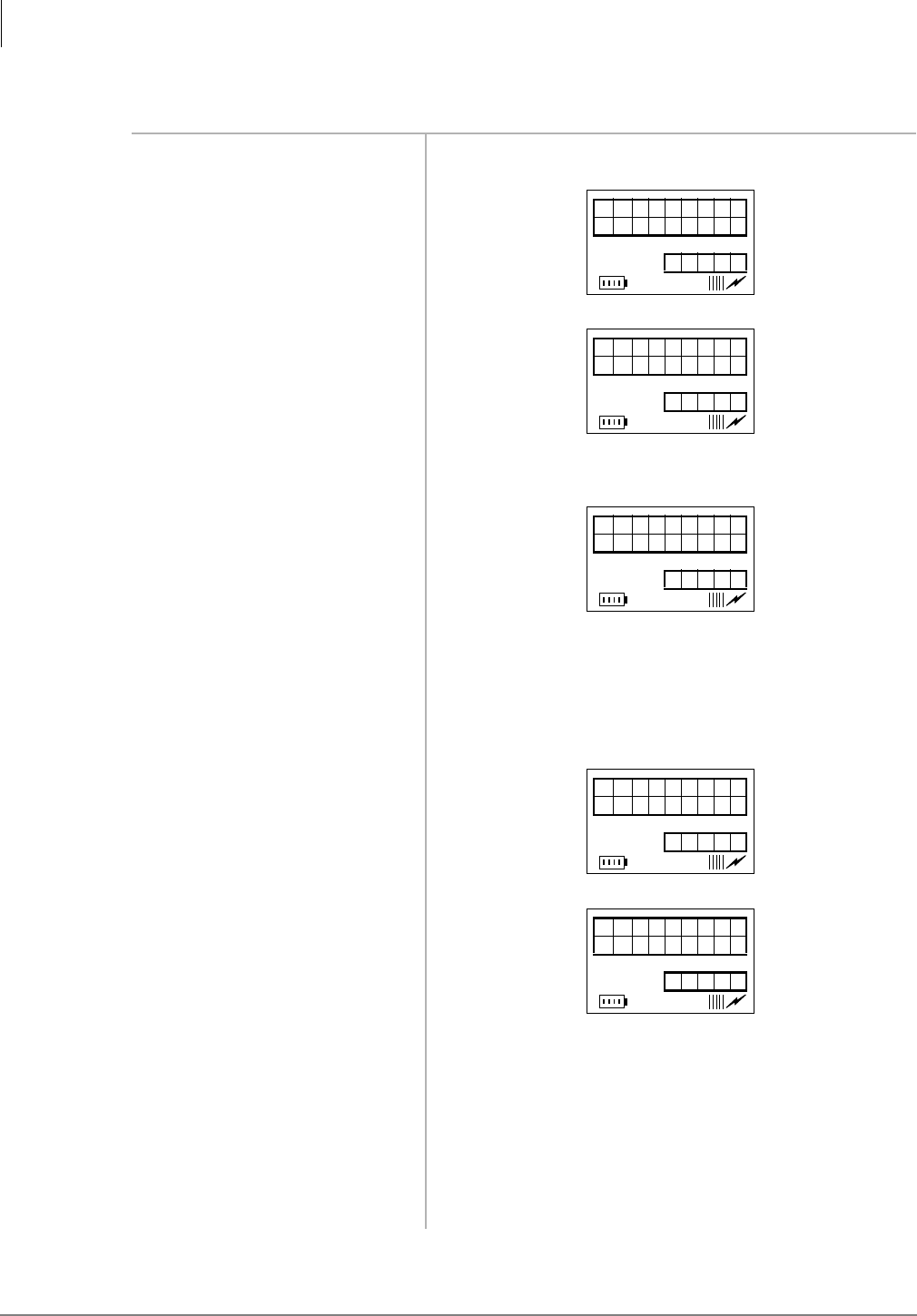
RWIU System Installation
Step 17: Store IDs in Handset
56 Strata AirLink Installation Guide 5/00
Step 17: Store IDs in Handset
1. Press 3:5. The handset turns on.
2. Press )&1.
3. Press ▼ until SYSTEM
CONFIG. displays
...or + )&1.
4. Press )&1.
5. Enter the proper System ID
(SID).
Note The SID must match the data entered in the system
settings.
6. Press &/5to make
corrections.
7. Press ▼.
8. Enter the handset ID (four
digits) for the system ID
entered in Substep 5.
9. Press ▼ for other systems.
10. Repeat Substeps 5~7 to enter
all the system and handset
IDs required.
A maximum of eight system IDs and associated handset
IDs can be stored in handset memory.
11. Press (1'. The ESN displays momentarily.
12. Press &$//. The handset ESN is stored in the BSIA.
MENU
OPERATION
12 : 15
SYSTEM
CONF IG.
12 : 15
SID#0
12 : 15
HID#0
12 : 15
HID#1
12 : 15

RWIU System Installation
RWIU Additional Information
Strata AirLink Installation Guide 5/00 57
RWIU Additional Information
The following paragraphs describe:
♦RWIU/WWIS interface unit
♦Changing the initial configuration
♦Changing the communications port
♦Checking the RWIU and Base Station software versions
♦Viewing log messages
♦Resetting the Base Stations and RWIU
♦Upgrading the RWIU and Base Stations
♦Changing the Base Station number
RWIU/WWIS Interface Unit
The Strata AirLink Wireless System interfaces to Strata DK16, DK16e, DK40, DK40i, DK280,
and DK424 systems with an RWIU Interface Unit. The RWIU PCB (shown in Figure 28) functions
as a protocol converter between the Base Stations on one side and the Strata DK system on the
other. The RWIU is the “master” PCB, generating timing and synchronization signals and the
WWIS PCB is the “slave.”
The PCBs have LEDs that indicate a continuous status of operation for both. They are shown in
Figure 29 on Page 16-59. The switches and jumper are described in Tables 11~13 on Page 44.
The PCB has an Intel® 80C186EC, 25 MHz (provided by a 50 MHz oscillator), 16-bit
Complementary Metal Oxide Semiconductor (CMOS) embedded Central Processing Unit (CPU)
with the following:
♦External 16-bit data bus and 20-bit address bus
♦Four Direct Memory Access (DMA) channels
♦Three programmable timer counters
♦Eight programmable external interrupt controller inputs
♦Two integrated communication channels Universal Asynchronous Receiver/Transmitter
(UARTS)
♦Integrated Watch Dog Timer (WDT)
♦Two flash memories (expandable by two)
♦Two CMOS Static Random Access Memories (SRAMs) (expandable by two)
♦In-circuit test points
The RWIU has the following interfaces:
♦Backplane (P1)
♦Synchronous RS485 bus (J5)
♦Serial line (J7)
♦External power supply (J8)
♦JTAG Mach programming (J11)
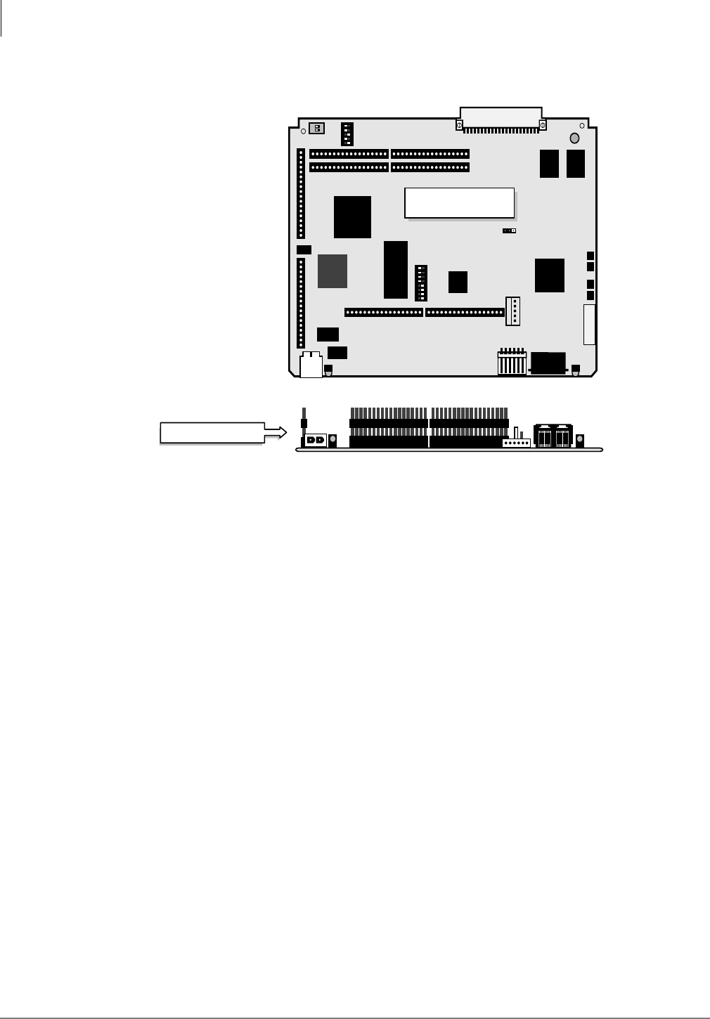
RWIU System Installation
RWIU Additional Information
58 Strata AirLink Installation Guide 5/00
The WWIS has four Base Station interface connectors (J1~J4).
Figure 28 Top and Side View of the RWIU
The CPU addresses come from three octal latches that are also address buffers while the data bus
addresses are buffered by a pair of bidirectional octal transceivers connected to the various
peripheral devices.
There are eight external interrupt signals:
♦INT0 – connects to the data highway receive (RX) and transmit (TX) interrupt output or to the
RX interrupt output of internal serial channel one (optional).
♦INT1 – connects to the TX interrupt output of internal serial channel one.
♦INT2 – connects to interrupt output of the DMA channel N0 (DMA0).
♦INT3 – connects to interrupt output of the DMA channel N1 (DMA1).
♦INT4 – connects to N0~3 interrupt output.
♦INT5 – connects to the RX interrupt output of internal serial channel one or to the data
highway RX and transmit TX interrupt output (optional).
♦INT6 – connects to the general device interrupt output.
♦INT7 – connects to the interrupt output of the optional external UART device.
The CPU has two flash (boot) memories, 128KB each, operating at 55 ns and mounted on 32-pin
sockets. The memory is expandable to two optional flash memories (512KB each, 55 ns). The total
size of program memory is 256KB or 1024KB using two memories.
The Random Access Memory (RAM) consists of two CMOS SRAM chips, 128KB (55 ns), used
as main data memories. It is expandable to 512KB (55 ns) using two additional chips. The total
size of the data memory of the CPU is 512KB.
3721
RWIU1A
12345678
ECE
ON
S1
12345
DIP
ON
S2S3
J7
J9
JP1
J10
J12
J13
J15 J14
J17 J16
J13
LD2 LD1
J8
JTAG
12
ON
RWIU (top view)
RWIU (side view)
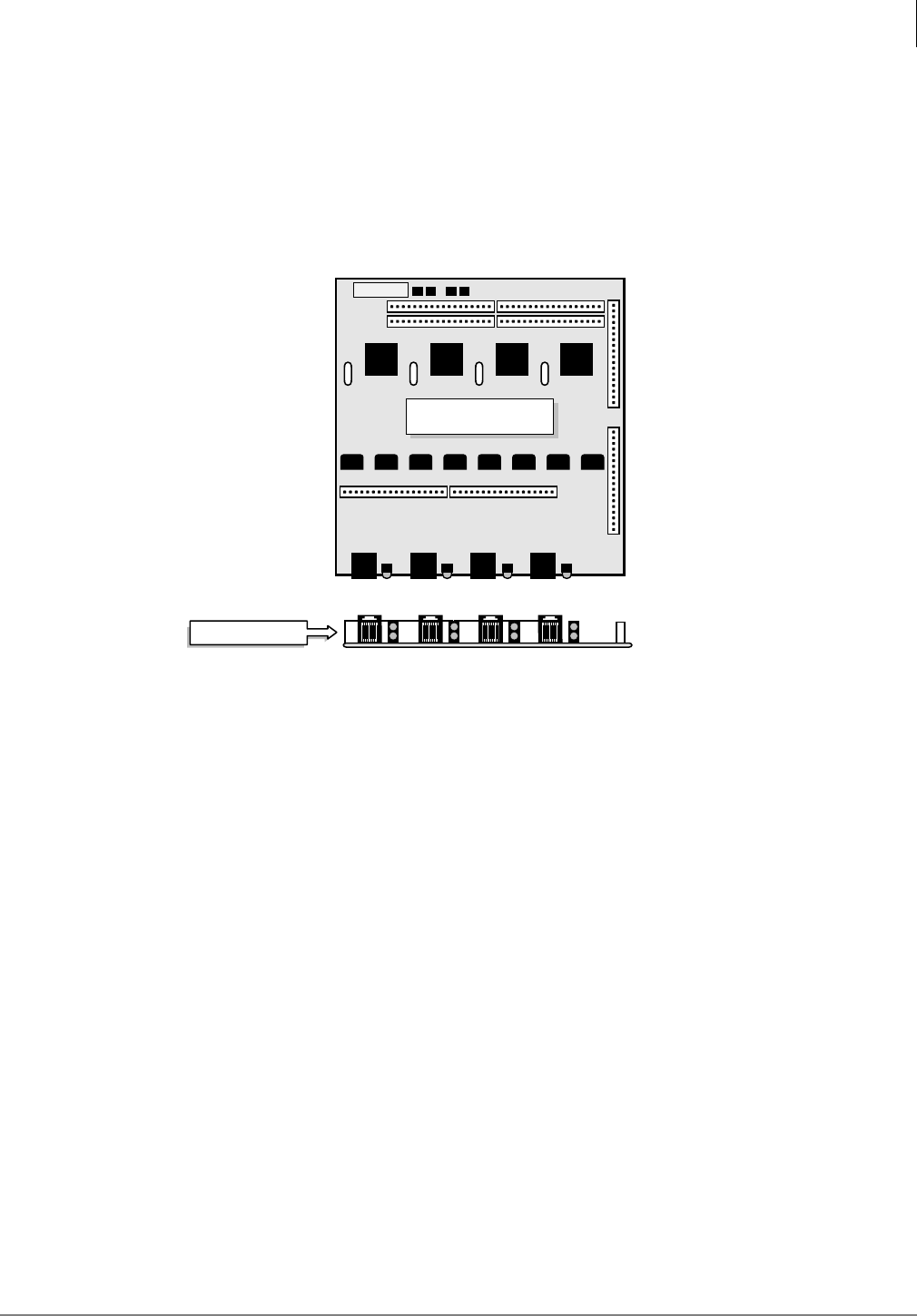
RWIU System Installation
RWIU Additional Information
Strata AirLink Installation Guide 5/00 59
The WWIS PCB (see Figure 29) has the following components:
♦Four E1 transceivers with crystals, line transformers, protectors, and electronic circuit
breakers
♦Two LEDS for each transceiver
♦Eight elastic buffers, two for each E1 interface
♦Surface Mount Technology (SMT) resistors and capacitors
Figure 29 Top and Side View of WWIS
The thickness of the RWIU is 1.6 mm and the maximum distance between the WWIS PCB
(including the height of the mounted components) is 30 mm.
Signaling
A high density Mach decoder generates all the chip select signals and control signals for Erasable
Programmable Read Only Memory (EPROM), flash and RAM memories, peripherals, and Input/
Output (I/O) devices. The Mach device includes a serial interface on connector J7 for on-board
programming.
The digital I/O block has two digital input buffers and four output D flip-flops for the digital
output signals. All input buffers and output flip-flops connect to the CPU lower data bus using a
bidirectional transceiver. All control signals are generated to the I/O devices by the Mach decoder.
A power ON external reset generator is provided by an internal WDT chip. There is also a power-
fail circuit that alerts the CPU when the voltage falls below 4.75V. This feature is necessary
because the CPU stores data in the backup memory of the RTC during a power failure.
An RTC chip mounts on the RWIU PCB only. It has an internal Lithium battery and an internal
backup 2KB of SRAM memory, powered by the same Lithium battery.
The RWIU interfaces to the Strata DK system using a 32 time slot, 2.048 MHz Pulse Code
Modulator (PCM) channel. The PCM channel has the following signals:
♦PHOUT – 32 time slots (receiving data)
♦PHIN – 32 time slots (transmitting data)
♦PHFS – 8 KHz frame synchronization output
3722
J4
LED4LED3LED2LED1
J3J2J1
P16 P17
P14 P15
P13
P12
P9 P10
WWIS1A
TOSHIBA
WWIS (top view)
J4 LED4LED3LED2LED` J3J2J1
WWIS (side view)

RWIU System Installation
RWIU Additional Information
60 Strata AirLink Installation Guide 5/00
♦PHCLK - 2.048 MHz clock input
♦4MCLK - 4.096 MHz clock input
The interface with the voice channel has the following signals:
♦PCM matrix memory time switch device
♦Digital I/O buffers (output enable)
The PHOUT connects to the matrix PCM input signal using a digital input buffer. The PHIN
connects to the output signal using a digital output buffer. It is enabled only during the
transmission phase of the data by the matrix. A time-slot assignment logic enables the output
buffer of the PHIN signal during the right time segment.
There are five hardwired address pins coming from the backplane connector (P1) of the RWIU and
one additional two-position DIP switch (S3). These are connected to seven input pins to control
the time-slot assignment logic for the various configurations. The CPU reads the status of these
hardwired addresses and the state of the two-position DIP switch (S3). An additional five-position
DIP switch (S2) selects various RWIU configurations and synchronizes the clock with the 8 KHz
frame synchronization pulse.
The receive data signal from the main PCM voice channel connects to input N0 (IN0) of the
matrix. The transmit data signal from the main PCM voice channel comes from output N0
(OUT0). The signal connects to a buffer that generates the external buffered transmit data signal
available on the backplane connector P1. Table 19 describes the four internal synchronous 2.048
PCM busses generated by the matrix.
Table 19 Generated Internal Synchronous PCM Signal
PCM Bus
Number E1 Interface Signal
1N1
RD01 internal synchronous PCM channel N1 receive data.
XDI1 internal synchronous PCM channel N1 transmit data
signal, derived from input N1 (IN1) of the matrix while the
output signal is derived from output N1 (OUT1) of the
same matrix.
2N2
RD02 internal synchronous PCM channel N2 receive data.
XDI2 internal synchronous PCM channel N2 transmit data
signal, derived from input N2 (IN2) of the matrix while the
output signal is derived from output N2 (OUT2) of the
same matrix.
3N3
RD03 internal synchronous PCM channel N3 receive data.
XDI3 internal synchronous PCM channel N3 transmit data
signal, derived from input N3 (IN3) of the matrix while the
output signal is derived from output N3 (OUT3) of the
same matrix.
4N4
RD04 internal synchronous PCM channel N4 receive data.
XDI4 internal synchronous PCM channel N4 transmit data
signal, derived from input N4 (IN4) of the matrix while the
output signal is derived from output N4 (OUT4) of the
same matrix.

RWIU System Installation
RWIU Additional Information
Strata AirLink Installation Guide 5/00 61
Timing and Synchronization
To comply with FCC part 15D clock and frame synchronization requirements, the clock and frame
frequency accuracy must be ± 10 parts per million (ppm). To meet this requirement without adding
cost, the system uses the Strata DK system as the primary clock source. The analog, digital, and
Stratum 3 trunks were considered as possible configurations.
To continue using only one single interface between the RWIU and the Base Stations, the clock
signal is sent through the E1 interface using a 320 ms synchronization pulse. The Base Stations
lock onto the RWIU clock signal and the Portable Unit Board (PUB) extracts the clock from the
Base Stations. The RWIU provides a signal to all other PCBs for a simple insertion into the E1
time slot 17.
Backplane Interface Connector
The RWIU has a 44-pin Deutsche Institut fur Normung (DIN) connector (P1) that connects to the
backplane of the Strata DK system. The connector has two rows with 22 pins in each row.
PBX Data Highway Interface
The PBX data highway control channel uses an integrated UART controller running at 312.5 kbs.
The control channel uses the following signals that originate from the backplane connector P1:
♦DHOUT - receive signal (input) and connects to RX
♦DHIN - transmit signal (output) and connect to TX
The UART debug serial channel connects to the integrated serial channel N0, and the
asynchronous multi-drop communication channel connects to serial channel N1. The UART
internal serial channels connect to the debug serial channel and the asynchronous multi-drop
communication channel. The debug serial channel connects to N0, and the asynchronous multi-
drop communication channel connects to the external UART device.
An RS-485 asynchronous multi-drop communication link between the RWIU and the WWIS
occurs because the UART connects to the CPU external bus. The UART is not physically mounted
on the RWIU, but uses the 28-inch PLCC socket on the RWIU.
The UART receives its operating frequency from the output of the internal timer N0 of the CPU.
N0 is programmed to divide the internal 25 MHz operating frequency of the CPU by a factor of 5
to obtain the UART 5 MHz operating frequency. It is possible to use N0 for other software
applications by substituting an optional external 5 MHz crystal.
Base Station Interface Connectors (E1s)
Four identical long-haul E1 (2048 kbs) PCM interfaces connect the RWIU PCB to each Base
Station (N0~N3) using a standard pulse (see Table 20). Each interface has:
♦Primary access transceiver devices
♦Two elastic buffers for each E1 channel
♦RX and TX line transformers with protectors
♦320 ms synchronization signal insertion logic (channel N17)
♦Loop back controls
♦RWIU generated Base Station reset (relays K1~K4)
♦RFI protectors (common mode chokes - optional)
♦Electronic circuit breakers for each E1 channel
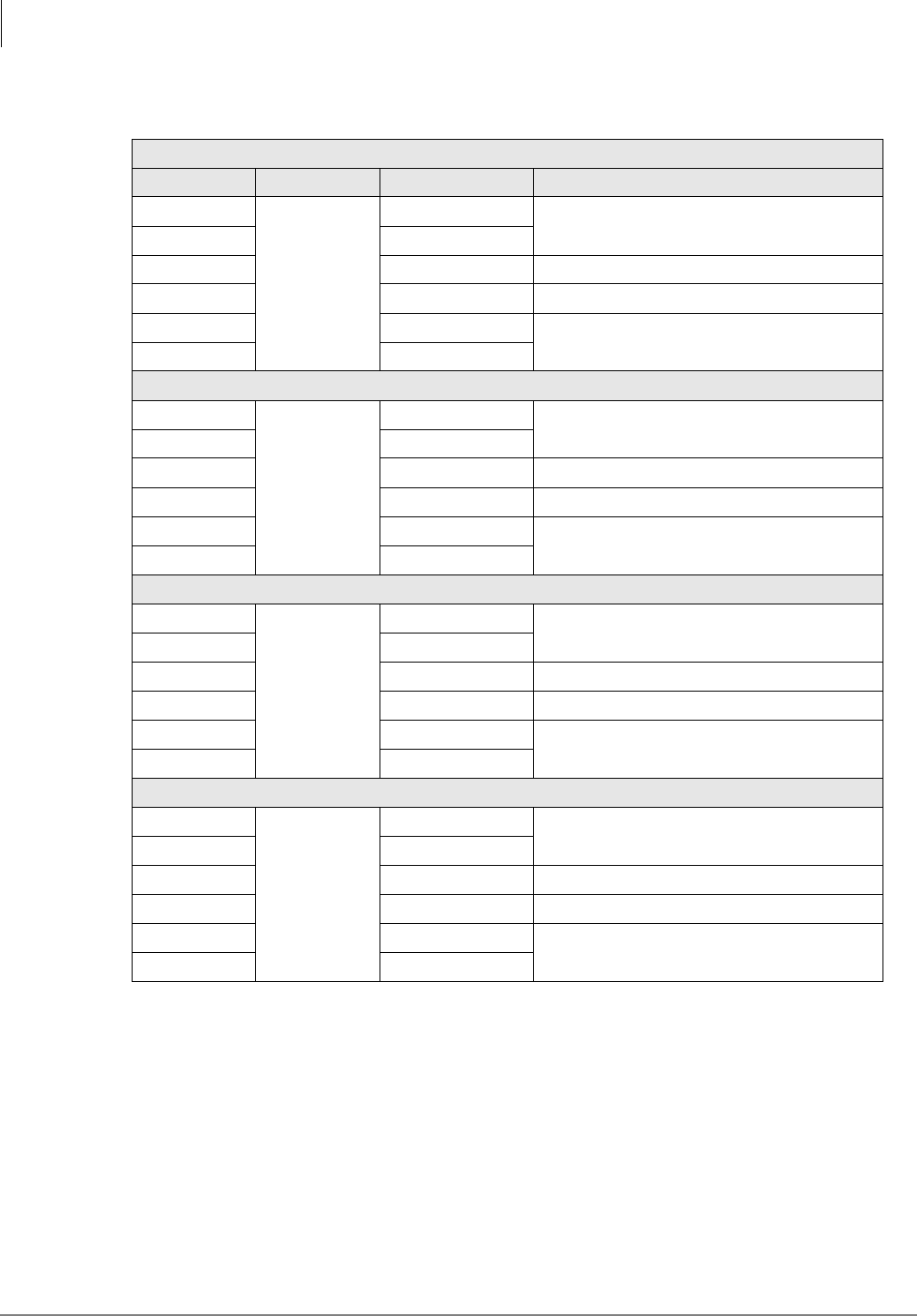
RWIU System Installation
RWIU Additional Information
62 Strata AirLink Installation Guide 5/00
The four primary access transceivers (U7, U13, U25, and U35) use the E1 (31 B + D) interface to
each Base Station. Not all of the 32 time slots of the E1 (32 B + D) frame are used. The format is
called 8 B + D and organized as follows:
♦Time slot N0 – synchronization time slot
♦Time slots N1~N8 – voice channels time slots
♦Time slots N9~N15 – idle (free) time slots
♦Time slot N16 – signaling CCS time slot
♦Time slot N17 – multiframe 320 ms synchronization pulse time slot
♦Time slots N18~N31 – idle (free) time slots
Table 20 Connector J1~J4 Descriptions
J4
Pin No. Base Station Name Description
1
1
TX_TIP_BS1 E1 interface (transmission output from TX line
transformer)
2 TX_TIP_BS1
3 Not used
4 Not used
5 RX_TIP_BS1 E1 interface (transmission output from RX line
transformer)
6 RX_TIP_BS1
J3
1
2
TX_TIP_BS2 E1 interface (transmission output from TX line
transformer)
2 TX_TIP_BS2
3 Not used
4 Not used
5 RX_TIP_BS2 E1 interface (transmission output from RX line
transformer)
6 RX_TIP_BS2
J2
1
3
TX_TIP_BS3 E1 interface (transmission output from TX line
transformer)
2 TX_TIP_BS3
3 Not used
4 Not used
5 RX_TIP_BS3 E1 interface (transmission output from RX line
transformer)
6 RX_TIP_BS3
J1
1
4
TX_TIP_BS4 E1 interface (transmission output from TX line
transformer)
2 TX_TIP_BS4
3 Not used
4 Not used
5 RX_TIP_BS4 E1 interface (transmission output from RX line
transformer)
6 RX_TIP_BS4

RWIU System Installation
RWIU Additional Information
Strata AirLink Installation Guide 5/00 63
The E1 devices receive each processed (but not formatted) 31 B + D frame from the CPU and
transmits it (after formatting) to its Base Station through its TX line transformer. The same is true
from the receiving side. The CPU performs the protocol conversion. Both TX and RX transfers are
actuated in DMA mode by the CPU.
The E1 device connects to the matrix using four internal 2048 kbs synchronous PCM buses with
the following signals:
♦RD01 internal PCM channel n1 received data (U7)
♦XDI1 internal PCM channel n1 transmit data (U7)
♦RD02 internal PCM channel n2 received data (U13)
♦XDI2 internal PCM channel n2 transmit data (U13)
♦RD03 internal PCM channel n3 received data (U25)
♦XDI3 internal PCM channel n3 transmit data (U25)
♦RD04 internal PCM channel n4 received data (U35)
♦XDI4 internal PCM channel n4 transmit data (U35)
The four internal 2048 kbs synchronous PCM busses transfer the data between each E1 device and
the matrix. The matrix places the data on the backplane PCM channels.
Protectors
The RX and TX transformers connect to the E1 line through protector devices. Current-limiting
resistors are used on both sides of the transformers. Tranazorb U45~U47, U53, U57~U58, and
U62~U63 and Gas Tubes G1~G8 devices provide fast protection from lightning by sending
sudden surges to the frame around the RWIU PCB.
Additional protection is provided by the secondary line transformers by dual MMBT7000 diodes.
All the line transformers RX and TX are breakdown-rated at 1500 Vrms. Loop back controls and
Base Station resets are provided for each Base Station by a relay. Each relay is controlled by the
CPU using an output port signal. Transistors drive each relay.
Power (-40VDC) transfers from each Base Station to the associated remote Base Station are
performed using a standard phantom interface on the central taps of the secondary of each TX and
RX transformer of the E1 interface. An electronic circuit breaker with associated power Field
Effect Transistor (FET) is used for each Base Station E1 interface.
Important! In the case of a short circuit on the -40VDC side of one the phantom interfaces, the
electronic breaker turns off its associated power FET. After about five seconds, it
tries to verify that the short is gone by turning on the power FET for a shorter
period (about 200 ms). If the short is gone, the circuit breaker turns on its power
FET permanently. If the short is still present, it continues to retry the circuit.
The same device protects the PCB against a rush current at Base Station power up. Each electronic
circuit breaker block is turned on/off by the CPU using the output port that drives the LED of a
photocoupler. A short circuit indication flag is provided to the CPU for each electronic circuit
breaker. The following are additional protection devices for each E1 interface:
♦Four slow-blow fuses
♦One polyswitch
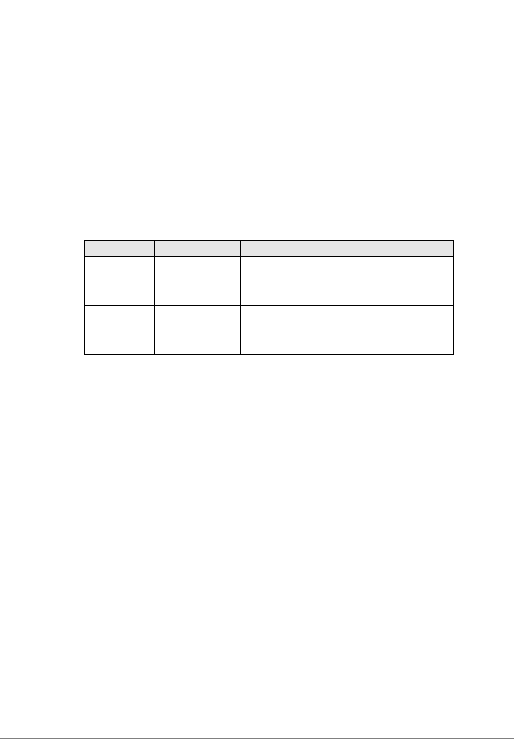
RWIU System Installation
RWIU Additional Information
64 Strata AirLink Installation Guide 5/00
Ring Back Tones Generator
The RWIU PCB incorporates a 32KB EPROM that generates:
♦440 Hz ring back tone, modulated at 480 Hz
♦2400 Hz busy override tone
♦4 tone channels for the U.S.
Each tone generates 800 bytes every 125 ms. The bytes are sent on a specific time slot of the
matrix and to the related time slot of the PHIN output.
Serial Line Interface
There is a six-pin serial line interface (J7) that debugs and sets up the system. It is a RS-232 port
and connects the PC to the RWIU (see Table 21).
Software Architecture
The RWIU software is a real-time embedded software, written in C language designed for the Intel
80186EC processor. Its modules include real-time tasks, service packages, and hardware drivers.
Its functions are:
♦Communication (KSU DHWY and Base Station)
♦Local debugging
♦Monitor communication
♦Call control logic procedures (call origination, delivery and release)
♦Mobility control (handoff)
♦Handset text and icon displays
♦System and Base Station power up controls
♦RWIU cross connects
♦Base Station software download
♦Start-up diagnostics (BIT)
♦Online diagnostics
♦Loop tests
♦System audit and parameter refresh
♦RWIU and Base Station configuration
♦Alarm reports and LEDs
Table 21 Connector J7 Descriptions
Pin No. Name Description
1 TXD RS-232 TX data (from the RWIU)
2 RTS_0 RS-232 RTS data (from the RWIU)
3 RXD RS-232 RX data (to the RWIU)
4 CTS_1 RS-232 CTS data (from the RWIU)
5 Not used
6 GND RS-232 Ground (from the RWIU)

RWIU System Installation
RWIU Additional Information
Strata AirLink Installation Guide 5/00 65
♦System parameters
♦UTAM activation
The software is built in layers, each implementing a different function. Each layer gets input from
the layer below and provides services to the layer above. The hardware drivers layer uses
interrupts and API calls interface with the layers above.
The operating system is totally independent of the hardware configuration and uses API calls to
interface with the other layers. All other layers use API calls and inter-task communication
messages to interface each other.
The operating system main services are:
♦Task definition and initiation, termination, and context switching
♦Inter-task communication (message, semaphores)
♦Message handling (mailbox)
♦Timers
♦Memory management (buffer pools)
All access to the operating system is performed using an Operating System Shell (OSS). The shell
provides a general API to the operating system services. The software supports the following
interrupt-driven protocols:
♦KSU DHWY communication protocol (addressed ASYNC)
♦Base Station communication protocol (E1 D channel)
♦Local debug/monitor communication protocol (RS-232)
The main data structures are:
♦Port information
♦Card status
♦External E1 links state and status
♦External/internal E1 cross connect configuration
♦Base Station configuration
♦System ID
♦UTAM parameter
The communication protocol layer, using the corresponding hardware drivers, handles external
interfaces. Messages from the KSU and the Base Station are converted by the communication
protocol layer to inter-task messages and are sent to the corresponding layer or task. The hardware
drivers consist of:
♦CPU (Intel 80186EC)
♦E1 Transceiver (DALLAS DS2153)
♦Matrix (MITEL MT8985)
♦WDT (CPU)
♦UART (16550 compatible and internal to the CPU)
♦External UART (16550 compatible)
♦PIC (8259 compatible and internal to the CPU)
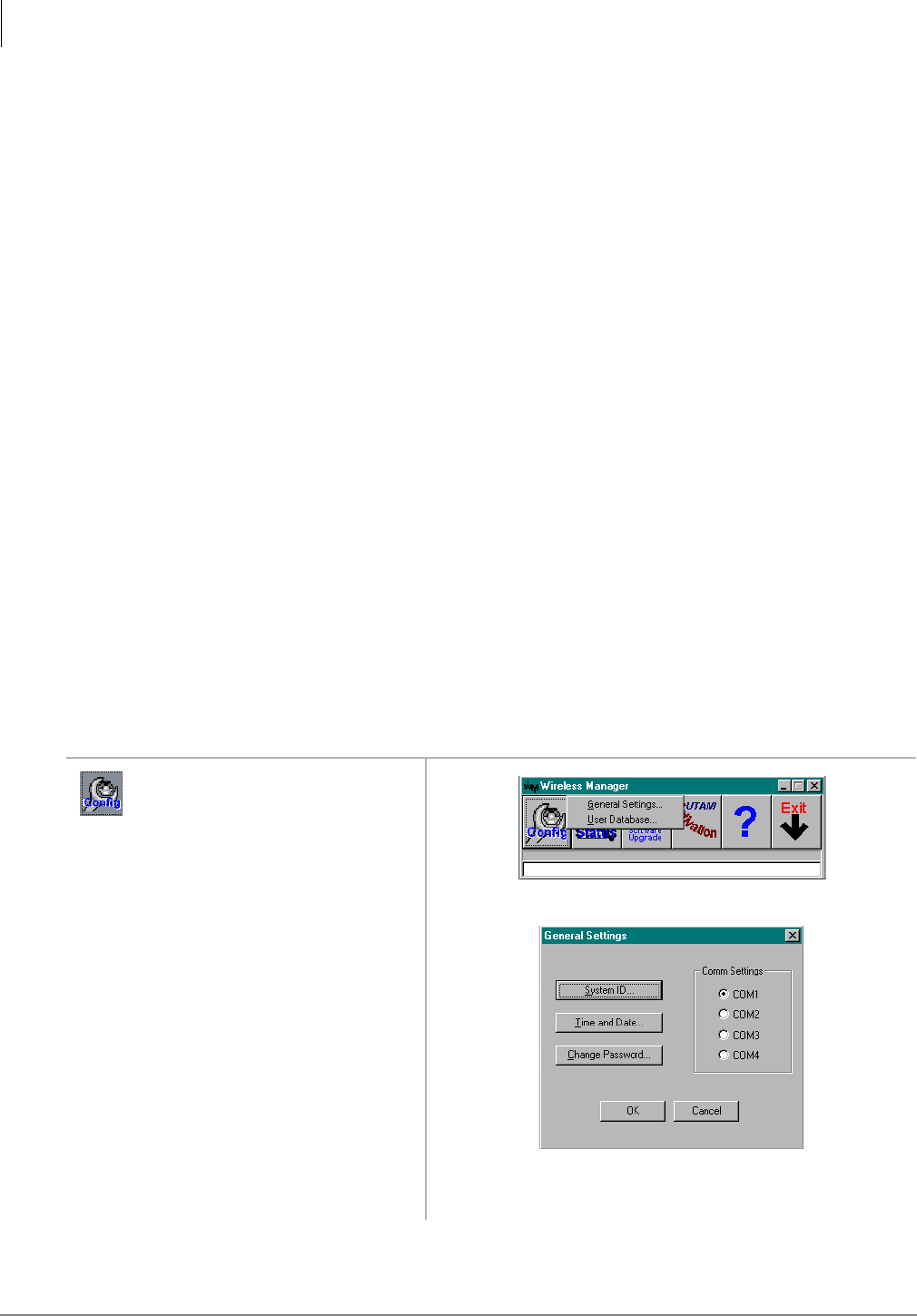
RWIU System Installation
RWIU Additional Information
66 Strata AirLink Installation Guide 5/00
♦DMA (four channels and internal to the CPU)
♦RTC
The communication with hardware drivers is performed using package interface procedures. The
Init task controls the sequence of card initialization and synchronizes it according to the KSU and
Base Station needs.
System management consists of several packages—each a set of functions providing a group of
services. The main features are:
♦Alarm management (send alarm, set alarm severity)
♦Database services (add Base Station, change status)
♦Configuration Interfaces (reset Base Station)
♦Test Control (set loop back, start test, utilities and general services, such as set date and time,
set LED)
♦UTAM procedures
Change Initial Configuration
It is highly recommended that you get the current configuration and save it to a file on the PC as
the working copy. Then, open and edit the working copy – not the original file. Using this method
ensures that the original configuration file is not corrupted while adding or editing existing data.
Once the new information is saved, the RWIU uses the new data immediately.
Important! Sending configuration information to the RWIU overwrites existing information.
Make sure that the sent data contains all of the required configuration information,
not just the few additions or changes that were made.
Change Communications Ports
1. From the Desktop Toolbar,
click the Config icon.
2. Click General Settings.
3. Click the new port and OK. The Desktop Toolbar displays.
3348
3349
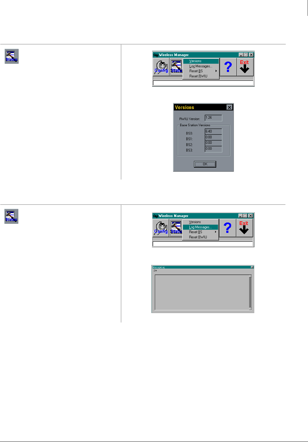
RWIU System Installation
RWIU Additional Information
Strata AirLink Installation Guide 5/00 67
Check RWIU and Base Station Software Versions
View Log Messages
1. From the Desktop Toolbar,
click the Status icon.
2. Click Versions.
1. From the Desktop Toolbar,
click Status.
2. Click Log Messages.
3360
3742
4145
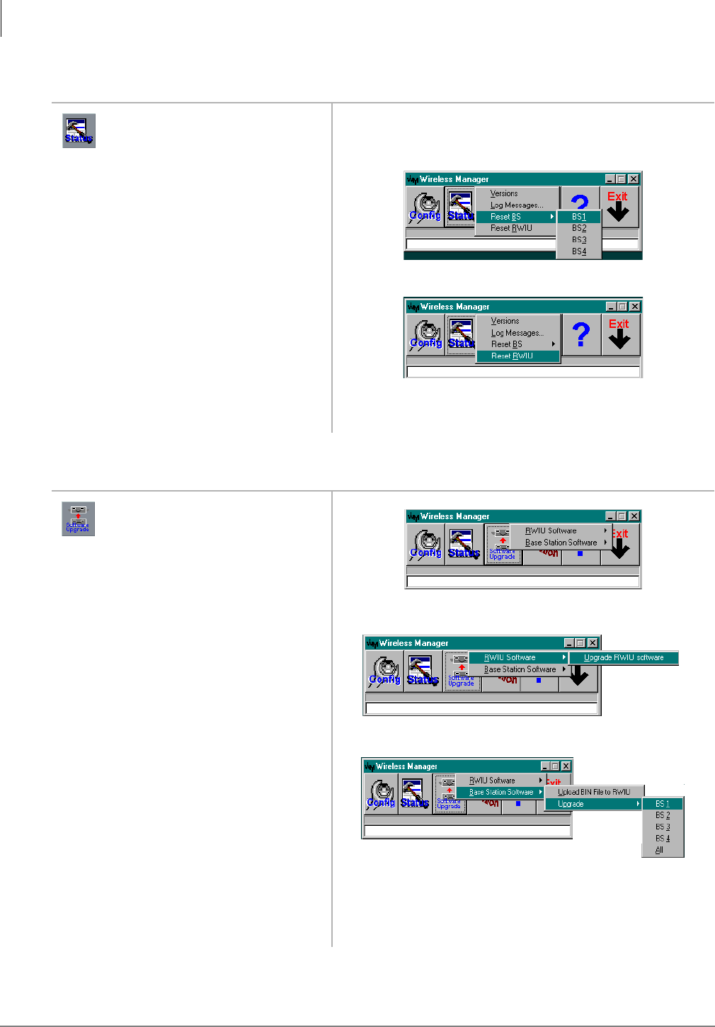
RWIU System Installation
RWIU Additional Information
68 Strata AirLink Installation Guide 5/00
Reset Base Stations and RWIU
Upgrade RWIU and Base Stations
1. From the Desktop Toolbar,
click Status.
2. Click Reset BS
...or Reset RWIU.
The selected Base Station or RWIU is reset automatically.
1. From the Desktop Toolbar,
click the Software Upgrade
icon.
2. Click RWIU Software The software downloads.
...or Base Station Software.
3. Click BS0~BS3
...or Download BIN File to
RWIU.
The software downloads.
4147
4148
3743
3744
3736
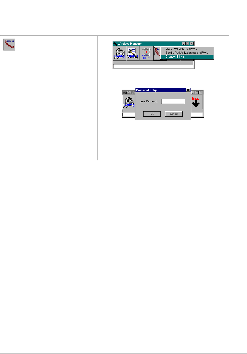
RWIU System Installation
RWIU Additional Information
Strata AirLink Installation Guide 5/00 69
Change Base Station Numbers
1. From the Desktop Toolbar,
click the UTAM Activation
icon.
2. Click Change BS Num. You are prompted for a password.
3. Enter the password and click
OK.
4. Enter the new Base Station
number.
3737
3739

RWIU System Installation
RWIU Additional Information
70 Strata AirLink Installation Guide 5/00

Strata AirLink Installation Guide 5/00 71
Maintenance and Troubleshooting 5
This chapter describes maintenance procedures and troubleshooting tips for the Strata AirLink
Wireless BSIA and RWIU systems. Problems are classified and cleared by replacing the
malfunctioning unit and by performing operational tests in the sequences described in this chapter.
Important! Many wireless system features are assigned, enabled or disabled using software
entries as described in “Install Strata AirLink Manager Software” on Page 24
(BSIA) and RWIU System Installation on Page 43 (RWIU). It is very important to
verify that the programming is correct and functional before troubleshooting the
hardware.
Before beginning diagnostic and troubleshooting tests, check the following:
♦System power, polarity, and continuity
♦BSIA or RWIU LEDs, boot sequence, and alarm relays
♦Base Station LEDs
♦Handset and batteries
♦Strata AirLink and RWIU Manager reports

Maintenance and Troubleshooting
Maintenance
72 Strata AirLink Installation Guide 5/00
Maintenance
This chapter covers the following maintenance procedures: charging batteries, discharging
batteries, password protection, and upgrading base stations.
Charge Batteries
1. Insert the handset with the
battery (power off) into the
Charger Base front pocket.
The front pocket LED changes to amber and then changes
to red to indicate that rapid charging is in progress.
2. Insert the spare battery into
the Charger Base rear pocket.
The rear pocket LED changes to amber while the handset
finishes charging or alternates between green and amber,
indicating in-progress discharge.
FLSH
PWRFCN
STO
CALLENDCLR
123
456
789
ª0
RCL ABC
ABC DEF
MNO
JKL
*
GH I
PQRS TUV
#
WXYZ
3911
Handset LED
3912
Battery LED
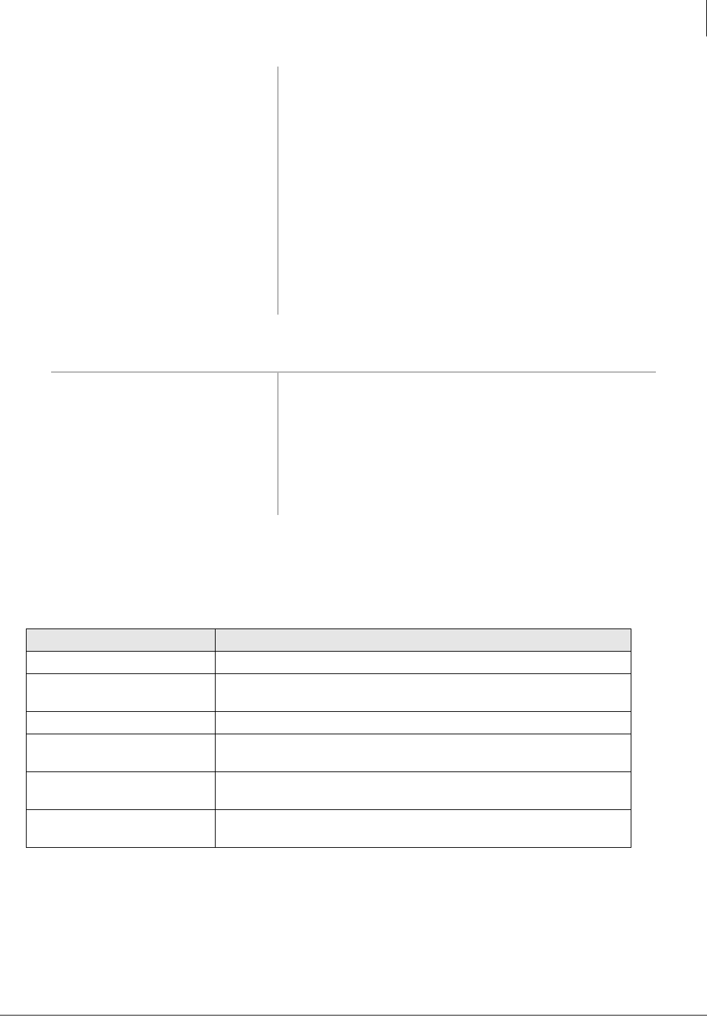
Maintenance and Troubleshooting
Maintenance
Strata AirLink Installation Guide 5/00 73
Discharge Batteries
Password Protection
Table 22 lists functions in the handset that are accessed by password. Some of the functions are for
use by Toshiba technical support only.
3. When LEDs change to green,
charging is complete.
The charger switches to a trickle charge. When the handset
is fully charged, the front pocket LED changes to green
and the rear pocket LED changes to red, indicating an in-
progress charge.
4. Remove the handset or spare
battery.
Important!
♦Do not use an incomplete, charged battery, even if the
battery icon shows full strength. The handset will
have reduced talk/standby time.
♦If a fully charged battery is placed in the charger, it
will detect the charged condition and cancel rapid
charging. The LED changes to amber, red, and then
green.
1. Insert the battery into the
charger base rear pocket.
If the LED alternates between green and amber, leave the
battery in the charger to complete discharging.
After the discharge cycle completes, the LED changes to
red to indicate rapid charging is in progress.
2. Remove the battery, when the
LED changes to green.
Table 22 Handset Password-protected Functions
Function Meaning
Bulker DU Access to functions.
Unique Base Station Locks the handset onto a Base Station with a particular ID. Zero (0)
means normal operation.
Software version Displays handset’s software version.
Beep on Roam Causes an idle handset to beep when the Base Station it is locked onto
changes.
Handoff by Recall Enables 5&/ to initiate handoff to another Base Station in the system
while a call is in progress.
Reset to factory defaults Restores the handset to factory default settings. All changes made via
the handset menu are removed.
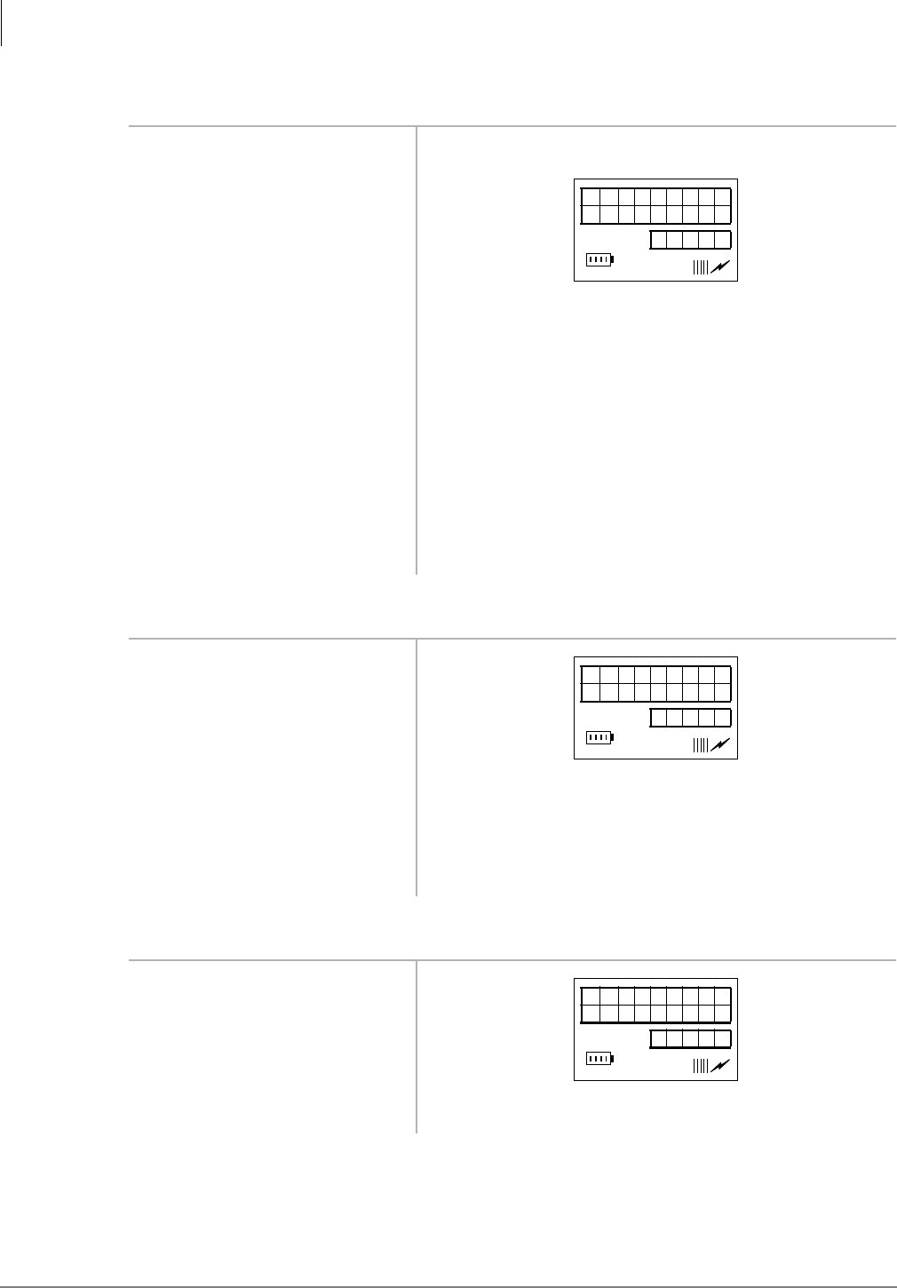
Maintenance and Troubleshooting
Maintenance
74 Strata AirLink Installation Guide 5/00
➤To access password-protected functions
➤To lock a handset to a Base Station
➤To view the software version
1. In idle mode, press .
2. Press $%&, then )&1.
3. Enter the password.
4. Press ▼ to choose UNIQUE
BASE STATION
...or SOFTWARE VERSION
...or BEEP ON ROAM
...or HANDOFF BY RCL
...or FLASH MODE
...or RESET TO FACT DFLT.
1. Press ▼.
2. Enter a Base Station ID (1 or
2)
Note RWIU 1, 2, or 3 cannot lock uniquely to Base
Station 0 (zero).
...or 0 to restore a handset to
normal operation.
1. Press ▼.
2. Press )&1. The software version displays.
BULKER
DU
12: 15
UN IQUE
BS
12: 15
SOFTWARE
VERSION
12: 15
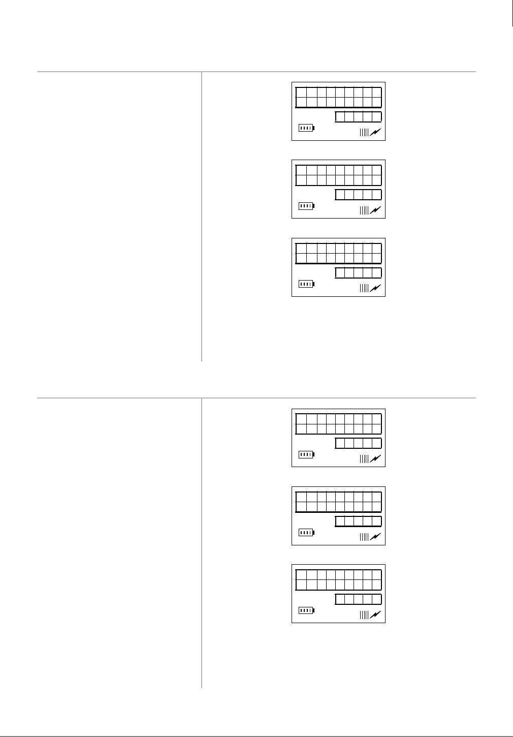
Maintenance and Troubleshooting
Maintenance
Strata AirLink Installation Guide 5/00 75
➤To use the Beep On Roam feature
➤To use the Handoff by Recall feature
1. Press ▼.
2. Press )&1
...or )&1 again.
3. Press (1'
...or ▼ to go the next
password protected function.
1. Press ▼.
2. Press )&1.
...or )&1 again.
3. Press (1'
...or ▼ to go the next
password-protected function.
BEEP ON
ROAM
12: 15
BEEP ON
ROAM ON
12: 15
BEEP ON
ROAM OFF
12: 15
HAND OFF
BY RCL
12: 15
HAND OFF
RCL ON
12: 15
HAND OFF
RCL OFF
12: 15
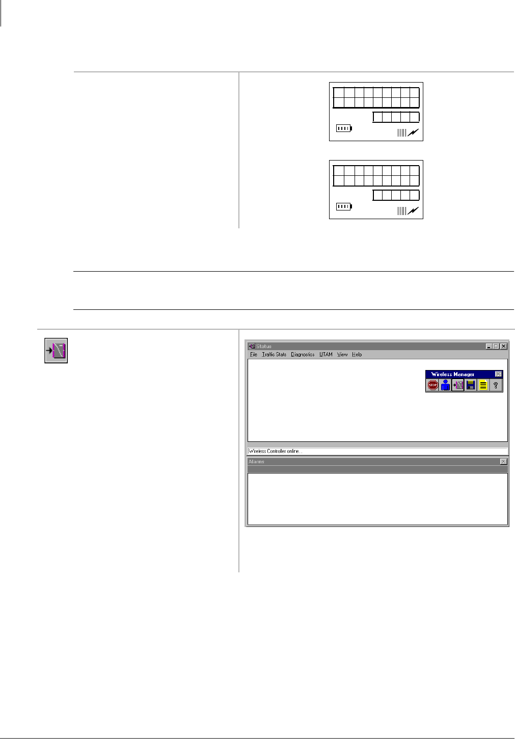
Maintenance and Troubleshooting
Maintenance
76 Strata AirLink Installation Guide 5/00
➤To reset to factory defaults
Upgrade Base Stations
CAUTION! This procedure should only be performed if technical support requires it.
Attempting the procedure without technical support, could destroy the system.
1. Press ▼.
2. Press )&1.
1. From the Desktop Toolbar,
click Status.
Monitor the upgrade by viewing the status messages as the
BSIA powers up.
RESET TO
F ACTDFLT
12: 15
RESET
DONE
12: 15
3496
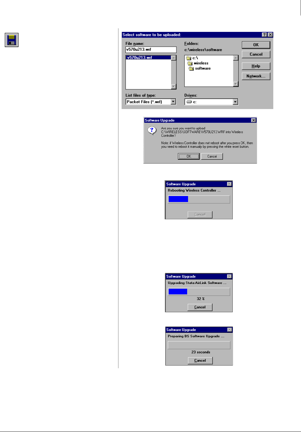
Maintenance and Troubleshooting
Maintenance
Strata AirLink Installation Guide 5/00 77
2. From the Desktop Toolbar,
click Upgrade.
3. From the Select software to
be uploaded: dialog box,
highlight the file and click
OK.
4. From the Software Upgrade
screen, click OK.
The BSIA boots automatically.
Note If the BSIA does not boot automatically within a
few seconds, which occurs sometimes during the
initial upgrade, press the reset button on the BSIA.
A series of screens display:
♦Upgrade of the BSIA software:
♦Upgrade of the Base Station software:
3279
3497
3492
3493
3494
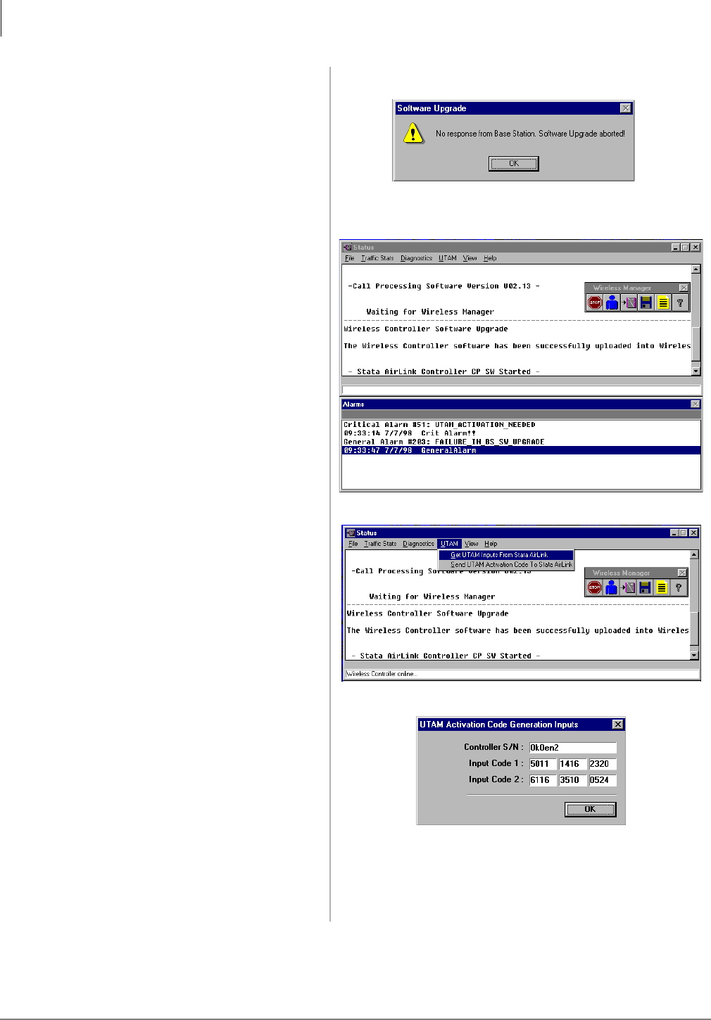
Maintenance and Troubleshooting
Maintenance
78 Strata AirLink Installation Guide 5/00
♦Normal failure of the Base Station upgrade:
Important! At this point in the upgrade process, input the
UTAM system activation code.
5. From the Software Upgrade
screen, click OK.
6. From the Status menu bar,
highlight UTAM and pull
down its menu.
7. From the UTAM pull-down
menu, select Get UTAM
Inputs From Strata AirLink.
Important! Make a note of the BSIA serial number and
input codes before calling the Strata AirLink
Activation Desk because the staff will ask for
these numbers.
3495
3483
3484
3485
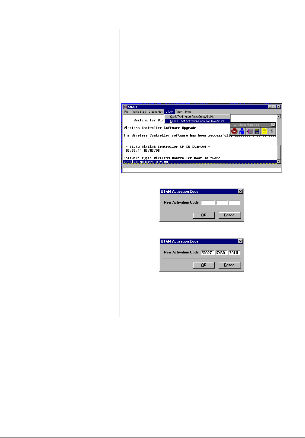
Maintenance and Troubleshooting
Maintenance
Strata AirLink Installation Guide 5/00 79
8. Call the Strata AirLink
Activation Desk, (949) 598-
4980 for the activation code.
Note The hours of operation are: Monday through Friday,
8:00 a.m. to 5:00 p.m., Pacific Standard Time.
After the BSIA serial number and input codes are given to
the activation desk, the technician will give you the UTAM
system activation code.
9. Close the Get UTAM Inputs
From Strata AirLink window.
The Status window displays.
10. From the Status window,
highlight UTAM and pull
down its menu.
11. From the UTAM pull-down
menu, select Send UTAM
Activation Code to Strata
AirLink.
12. In the UTAM Activation
Code dialog box, enter the
UTAM Activation Code and
click OK.
The message “Wireless system has been activated” is
displayed at the bottom of the Status window.
Important! The UTAM code must be installed in one hour
or a new one is required.
3486
3488
3487
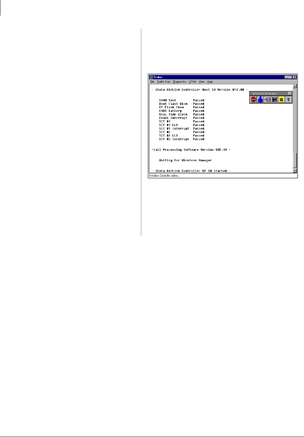
Maintenance and Troubleshooting
Maintenance
80 Strata AirLink Installation Guide 5/00
Normal LED indications display on the BSIA (PWR and
Master LED ON) and Base Stations (PWR LED ON).
Several messages display (shown at the right) on the PC
screen as Strata AirLink Manager tests the installation.
Important! If the message “Waiting for Wireless
Manager” does not appear in the Status
window before the progress bar times out, or
LED S2 remains lit after a reboot, the BSIA
has not been upgraded. Repeat Substeps
1~12.
3491

Maintenance and Troubleshooting
Troubleshooting
Strata AirLink Installation Guide 5/00 81
Troubleshooting
System Power, Polarity, and Continuity
It is important to check all power sources, polarity, and continuity before any other troubleshooting
begins. Quickly check the LEDs. Check the polarity of the system by ensuring that all transmit and
receive pairs are consistently wired throughout the system. Sometimes switching pairs at the Base
Station solves a problem quickly.
Components
If only one system component has a problem, try replacing it with a known good one. For
example, switch Base Stations, RWIUs, BSIAs, ALMs, or handsets to see if problems persist.
Communications
To check for communication errors (for example, serial port failure), perform a software version
query of the Base Station from the software. If the system does not respond to the query, check the
cables.
RF Link Termination
The handset can lose its signal from the Base Station because of reduced power, interference, or
stepping out of range. Verify that the battery is fully charged and the handset is in range of a Base
Station.
Noisy Circuits
If users complain about noisy circuits or problems with dial tone, try switching the user to another
circuit on the office telephone system. If a circuit is not operating at all, use a installer test set to
check continuity throughout a system.
DC Resistance
The distances between the system and its Base Stations (see Table 28), whether using line power or
a local power supply, can be exceeded during an installation. The distances are reflected in the
resistance of the line. For specific BSIA information, see “To measure the DC resistance” on Page
86, and for the RWIU, see “” on Page 95.
System Reset
As a last resort, sometimes resetting the system clears up system problems. Before resetting the
system, collect as much information as possible in the current log file. Get traffic statistics reports,
call status reports, line and Base Station status reports, and alarm reports, if available. Use the Save
As command to save the log file.
Activation Code
If the UTAM activation code has not been uploaded, the Base Stations will not operate (refer to
“Set Up Temporary Installation” on Page 13 for more information). Contact Strata AirLink
Activation Desk at (949) 598-4980 for the code between the hours of 8:00 a.m. and 5:00 p.m.
(Pacific Standard Time), Monday through Friday. Voice mail is available for messages after hours.
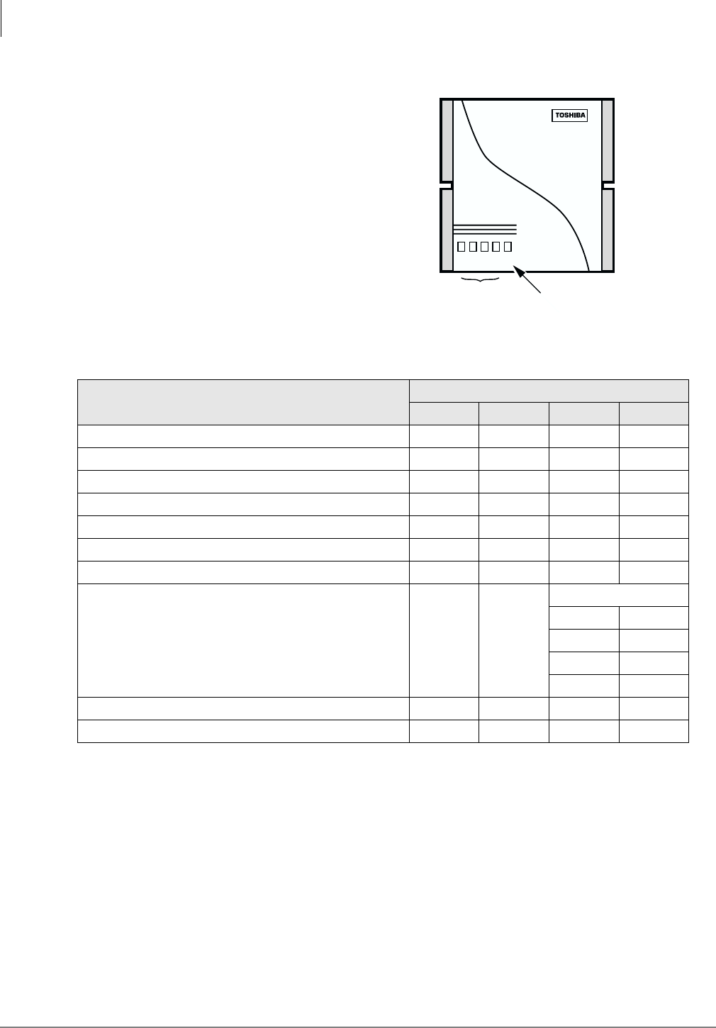
Maintenance and Troubleshooting
Troubleshooting
82 Strata AirLink Installation Guide 5/00
Base Station
The Base Station has five LEDs (see Figure 30).
Four LEDs on the left indicate error conditions
during power on, reset, and during the
diagnostic tests that run during normal
operation. The green LED on the right is the
power indicator.
Power On/Reset
Table 23 explains how to interpret Base Station
LED readings that occur during power on or
reset. The LEDs must be read in combination to
understand their meaning. The footnotes to the
table contain troubleshooting suggestions.
Table 23 Base Station LEDs during Power On/Reset
Failed Test Red LEDs (In Combination)
1234
Memory test 11
1. Indicates a Base Station failure in most cases. Check cable connections or replace transmit/receive cables or local
power supply.
Off Off Off Blinking
Memory test 21Off Off Blinking Off
Memory test 31Off Off Blinking Blinking
Base Station Interface/processor test1Off Blinking Off Off
Base Station Interface external communication test2
2. Check whether the Base Station transmit/receive cables enable another Base Station to initialize.
Off Blinking Off Blinking
ASIC test3
3. Verify power supply.
Off Blinking Blinking Off
Frequency test4
4. Test the Base Station on the another BSIA or RWIU Base Station port and with good transmit/receive cables.
Off Blinking Blinking Blinking
Vocoder Initialization test1Blinking Off
Vocoder # (0–3)
0:Off Off
1:Off On
2:On Off
3:On On
Signaling channel test5
5. Reset the BSIA.
Blinking Blinking Off Off
Memory flash test4Blinking Blinking Off Blinking
12345
Error Condition
LED (red)
3002
Power LED (green)
Figure 30 Base Station LED Location

Maintenance and Troubleshooting
Troubleshooting
Strata AirLink Installation Guide 5/00 83
Normal Operation
Table 24 explains how to interpret Base Station LED readings that occur during self- diagnostic
tests that run during normal operation. The LEDs must be read in combination to understand their
meaning. The footnotes to the table contain troubleshooting suggestions.
Replace Defective Base Station
1. Disconnect the transmit and receive cables and power supply, if applicable.
2. Lift the Base Station off the mounting screws.
3. Mount the new Base Station and connect the cables and power supply, if applicable.
4. If the Base Station does not come online within a minute, perform a software upgrade using
the latest version of software. See “Upgrade Base Stations” on Page 76.
Table 24 Base Station LEDs during Normal Operation
Test Failed Red LEDs (In Combination)
1234
ASIC test1
1. Test the Base Station on another BSIA or RWIU Base Station port and with different transmit and
receive cables.
Off Off Off On
Phase lock loop lock test2
2. Reset the Base Station on the other BSIA or RWIU. Reset a Base Station by plugging/unplugging
its transmit or receive cable. Reset all Base Stations by resetting the BSIA.
On Off On Off
Vocoder test2Off On
Vocoder # (0–3)
0:Off Off
1:Off On
2:On Off
3:On On
Synthesizer unlock test3
3. Test Base Station transmit/receive cables by replacing the Base Station with a functional one.
On Off Off On
Waiting for configuration test4
4. Ensure that the system has been activated or check the BSIA or RWIU configuration. Also try
resetting the BSIA.
Off On On Off
Phase lock loop initialization test2Off On Off Off
Base Station Interface clock test2On On Off Off
Receive loss2Off Off On On
Loss of control channel5
5. Check for RF interference.
On Off Off Off

Maintenance and Troubleshooting
Troubleshooting
84 Strata AirLink Installation Guide 5/00
Handset
Table 25 lists handset symptoms and possible solutions.
Table 25 Handset Troubleshooting
Symptoms Possible Solution
Called party can hear but
cannot be heard.
Conversation broken up.
Handoff clicks occur during
conversation.
The handset signal strength is inadequate. Try moving closer to a Base
Station. If the problem is reported by many users, try moving the Base
Station to a location that provides better coverage.
For best results the signal strength icon should show three to five bars.
The (BER) test should report Good or Max results. See BER testing on
Page 16 for instructions on how to perform this test.
Display does not contain date,
time and signal strength.
The handset is not locked onto a Base Station. Try powering off and on
or moving to another location closer to a Base Station.
Note It may take up to a minute for the full display to appear.
If the problem persists, check system and handset ID configuration.
These symptoms could also occur if the BSIA, RWIU, or Base Station is
being reset.
Off-hook icon ( ) flashes
when &$// is pressed;
Handset operated correctly and
now cannot make calls.
The handset ESN is improperly configured. Fix this problem by:
1. Reprogramming the handset with proper system and handset IDs.
2. Changing the handset ID configured for the handset to any valid ID
not already in use.
3. Changing the handset ID in the User Database to match the ID
programmed in the handset.
4. Making a call on the handset to store its ESN in the BSIA or RWIU.
5. Installing the ALM.
6. Performing a maintenance check (system maintenance busy) and
loop start line status is activated.
Invalid ESN reported for
handset (alarm).
The same handset ID and system ID were programmed into two
telephones and databases, and the handset ESNs were associated with
the wrong analog line when the first telephone call was made. Fix this
problem by:
1. Locating both handsets and correcting the databases.
2. Checking the handset ID configuration in both handsets to make
sure they are correct.
3. Changing the ID in the handset and making another call (corrects
the ESN configuration for that handset).
4. Correcting the configuration for the handset that reported the invalid
ESN. Follow these steps:
●Open the User Database and change the handset ID configured
for the handset to any valid ID not already in use.
●Change the handset ID in the User Database to match the ID
programmed in the handset.
●Make a call on the handset to store its ESN.

Maintenance and Troubleshooting
Troubleshooting
Strata AirLink Installation Guide 5/00 85
Battery
Table 26 lists symptoms of battery problems and possible solutions.
No dial tone.
Make sure the handset is locked and check the volume level. If the
problem remains, the handset is not locked onto a Base Station. Try
powering off and on or moving to another location closer to a Base
Station.
Check the analog line with a installer’s test set to ensure the telephone
system is operating properly. If it is, check the wiring between the BSIA
or RWIU and the telephone system.
Check the BSIA, RWIU, or Base Station for a reset condition because
this will interrupt the dial tone.
Weak or delayed dial tone.
Check the handset volume level. Make sure to align the handset with the
ear rather than mouth and don’t watch the display.
Consider using the predial method to make calls by dialing the number
and pressing &$// (rather than pressing &$// and waiting for dial
tone).
NO SERVICE! message.
The handset is not locked and it is out of range or all eight channels of
the Base Station are being used for other calls. Try powering off and on
or moving to another location closer to a system Base Station.
Check the BSIA, RWIU, or Base Station for a reset condition because
this will cause the NO SERVICE! message.
Reset the handset to the factory defaults.
SYSTEM BUSY message.
The handset is locked onto a Base Station and &$// was pressed, but
the Base Station did not respond. One or more Base Station channels
could be in a maintenance busy state or the handset may not be locked
well enough to complete the request for service.
Unexpected digits in display.
It is easy to inadvertently press keys on the handset when the handset is
not in use. Use the lock feature. To clear digits from the display, use
&/5.
Table 26 Battery Troubleshooting
Symptom Possible Solution
Battery has reduced talk/standby
time.
Try discharging and recharging the battery using the instructions 86.
The handset has been left unpowered for a long period of time and
has drained.
Make sure users are not removing batteries from the charger base
before the green LED appears. The handset battery strength icon
shows full power after a short period of charging.
Complete the full charging cycle before using the batteries. Users
should also use the handset during the day and recharge it at the
end of the day, rather than performing intermittent charging during
the day.
Charger has green flashing LED. Try recharging the battery. If the problem continues, replace the
battery.
Table 25 Handset Troubleshooting (continued)
Symptoms Possible Solution

Maintenance and Troubleshooting
Troubleshooting
86 Strata AirLink Installation Guide 5/00
Charger Base
The Charger Base charges the handset and a spare battery. Do not have to remove the battery from
the handset to charge it. The LEDs indicate the status of the charging process as shown in Table
27.
BSIA System
Reports
Strata AirLink Manager generates reports with troubleshooting information. Some of the reports
are:
♦Alarm conditions
♦Traffic statistics
♦Line, channel, and call status
Analog Line Continuity
To check the analog line continuity throughout the system, use an installer test set at individual
MDF/IDF locations. Check for any bridge taps on the Base Station transmit/receive cables and
remove. Check all punch downs and cable connections.
DC Resistance
The distances between the system and its Base Stations (see Table 28), whether using line power or
a local power supply, can be exceeded during an installation. The distances are reflected in the
resistance of the line.
➤To measure the DC resistance
1. Use a digital multimeter that has resistance measuring capability in ohms and a basic accuracy
of better than one percent.
2. Use an RJ-11 female-to-female line adapter.
3. Ensure that all permanent wiring is done and all primary protectors are installed, if required.
For information on primary protection requirements for UL1459 compliance in the United
States, see “Primary and Secondary Protectors” on Page 102.
Table 27 Charger Base LED Indications
LED State Meaning
Red
Steady Battery is rapid charging.
Flashing Internal battery fault. Charge the battery again. If the problem
persists, replace the battery.
Green
Steady Battery is charged and ready.
Flashing
Battery is charged, but it could have reduced standby/talk time.
Try repeated rapid charging to rejuvenate the battery. Replace
the battery, if this fails to remedy the situation.
Amber
Steady The charger is evaluating the handset or battery state, or waiting
for one battery to complete charging.
Flashing
Short circuit or over-discharged battery is detected. Make sure
contacts are clean and allow the battery to remain in the charger
until rapid charging starts and completes.
Amber/green Alternate flashing Battery is discharging.
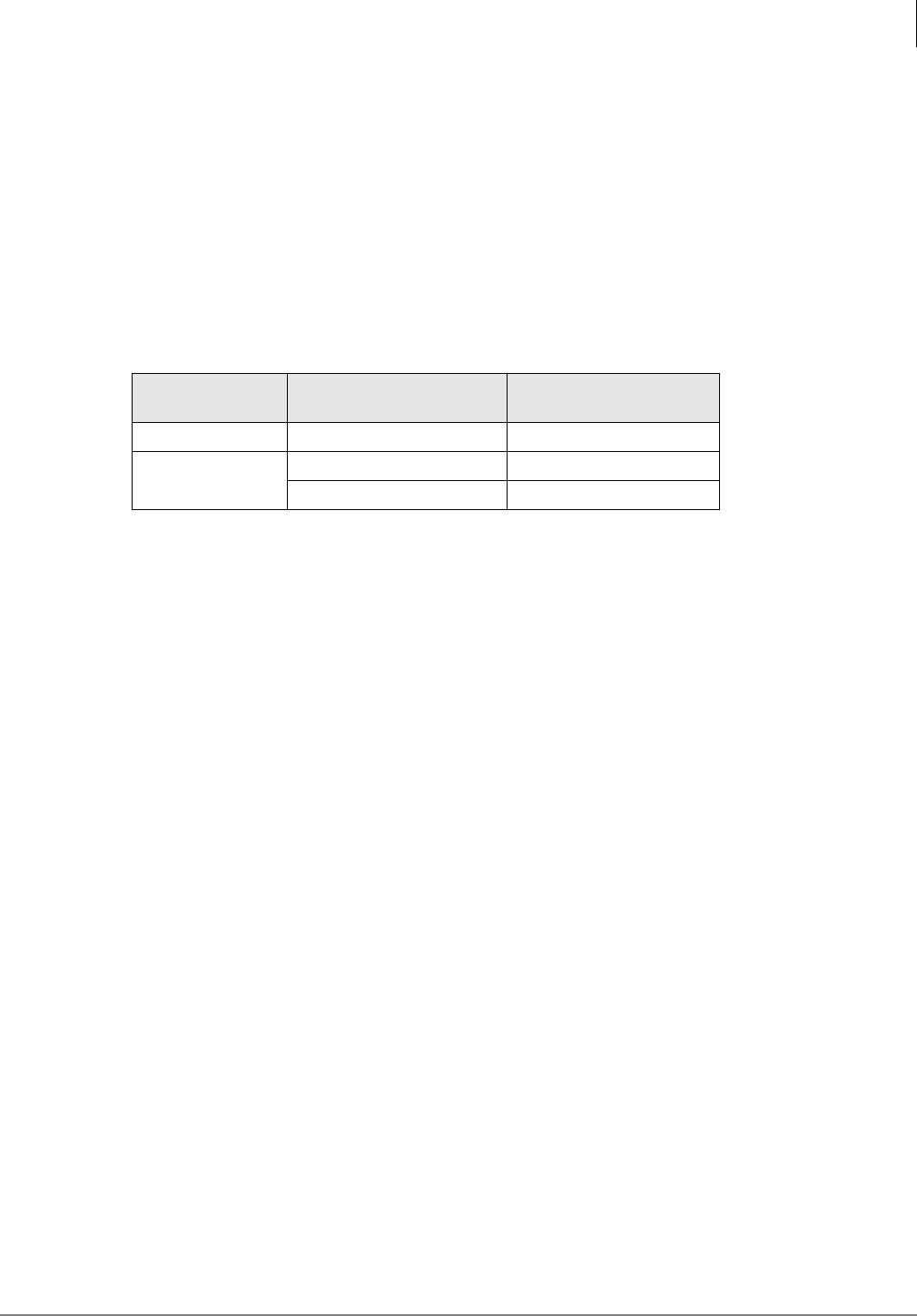
Maintenance and Troubleshooting
Troubleshooting
Strata AirLink Installation Guide 5/00 87
4. Disconnect the BSIA from power.
5. Disconnect the 25-pair cables from P1 and P2 on the BSIA.
6. Disconnect the transmit and receive cables from the Base Station and connect them into each
end of the RJ-11 line adapter.
7. Set the multimeter to the ohms scale.
8. To check the distance to Base Station 1, connect the multimeter probes between pins 20 and 46
of the 25-pair cable that connects to P1 on the BSIA. If no reading or a high resistance is
reported, measure between pins 20 and 21. A reading should register at only one of the pairs
and must be less than the values listed in Table 28.
9. Based on which pins returned a valid reading in Step 8, check readings between the following
pairs:
♦Valid reading pins 20/46 – measure pins 21/45
♦Valid reading pins 20/21 – measure pins 45/46
The readings between the measured sets of pins should be similar.
10. To check the distance to Base Station 2, connect the multimeter probes between pins 24 and
50. If no reading or a high resistance is reported, measure between pins 24 and 25.
Note A reading should register at only one of the pairs and must be less than the values listed in
Table 28.
11. Based on which pins returned a valid reading in Step 10, check readings between the following
pairs:
♦Valid reading pins 24/50 – measure pins 25/49
♦Valid reading pins 24/25 – measure pins 49/50
The readings between the measured sets of pins should be similar.
12. If the multimeter reports no reading or high resistance, check the readings between any of the
other pins specified in Steps 8~11.
If readings after performing Step 9 are correct, the transmit and receive pairs are probably
reversed or shorted somewhere in the installation. If not, there are open connections
somewhere in the installation; check and correct all punch-down connections and repeat Steps
8~11.
Table 28 Cable DC Resistance
Input
Power
Wire
Gauge
Maximum DC Resistance
Allowed for 2,000 feet
Line 22, 24, or mixed 98 ohms
Local 22 66 ohms
24 104 ohms

Maintenance and Troubleshooting
Troubleshooting
88 Strata AirLink Installation Guide 5/00
Status Window
To diagnose problems, there are several reports available that are:
♦Base Station channels status
♦Loop start lines status
♦Call status
♦Critical alarms
A software query can be performed also, or as a last resort, the BSIA can be rebooted from the
Status Window.
Alarms
Table 29 lists possible alarms by its displayed number.
Table 29 Alarm Descriptions by Number
Alarm #
(decimal)
Alarm #
(hex) Description
48 30
NO_MSG_BUFFER_AVAILABLE
The BSIA attempts a system reboot after this alarm occurs. If the system
cannot reset, press the reset button to the right of the LEDs. If the problem
persists, contact Toshiba.
49 31
SMX_OS_ERROR
The BSIA attempts a system reboot after this alarm occurs. If the system
cannot reset itself, press the reset button to the right of the LEDs. If the
problem persists, contact Toshiba.
50 32 UTAM_CHECK_FAIL_SYSTEM_CLOCK
51 33 UTAM_ACTIVATION_NEEDED (UTAM_CHECK_FAIL_NORMAL)
Contact Toshiba for an UTAM activation code.
138 8A
INVALID_HSID_FROM_BS
A handset with invalid handset ID, but valid system ID, tried to make a call.
Compare the handset ID against the user database in the Strata AirLink
Manager and ensure that they match.
153 99
INVALID_INCOMING_BCC
A bad connection exists between the BSIA and Base Station. Check the
cable.
161 A1
INVALID_ESN
A handset with invalid Electronic Serial Number (ESN) tried to make a call.
Check the system settings database in the Strata AirLink Manager software
against the handset ESN. Ensure that they are the same.
186 BA UTAM_ACTIVATION_NOT_NEEDED
The UTAM activation code is not required.
194 C2 NO_BS_SANITY_RESPONSE_RECEIVED
Check the cable connections between the BSIA and Base Station.
203 CB
FAILURE_IN_BS_SW_UPGRADE
The software upgrade process failed. Check the cable connections between
the PC and BSIA and try again.

Maintenance and Troubleshooting
Troubleshooting
Strata AirLink Installation Guide 5/00 89
Critical Alarm Relay
When a critical alarm is detected, a relay on the BSIA is triggered and LED S3 flashes. The relay
activates an external alarm, if one is installed (see installation instructions and specifications in
“Step 3: (Optional) Activate External Critical Alarm” on Page 21).
To reset the alarm relay and determine the cause of the critical alarm, check the critical alarm
report in the Strata AirLink Manager. Checking the critical alarm report also stops the flashing
LED.
LEDs
There are LEDs on the BSIA (controller) that give continuous system status and assist in
diagnosing symptoms. When the BSIA system is powered on, all BSIA LEDs except for PWR,
RLOS1, and RLOS2 go through these changes:
♦LEDs are lit for one second to show that they all work.
♦LEDs turn OFF for a brief moment.
♦LEDs light again.
♦Each LED is turned OFF as the LED passes the test.
♦If an LED remains lit after the boot tests complete, one or more hardware integrity tests have
failed. Call processing software usually starts even if some of the tests fail, although some
failures prevent call processing software from starting.
♦The MASTER LED remains lit during boot up because it does not respond to a boot test.
♦The PWR LED is always lit when the BSIA has power. The RLOS LEDs flicker during boot
tests and are lit when there is a problem with Base Station connections.
204 CC
TIMEOUT_IN_BS_SW_UPGRADE
The software upgrade process failed. Check the cable between the PC and
BSIA and try again.
207 CF
INVALID_MSG_BEFORE_UTAM_ACTIV
The system must be UTAM activated. See “Set Up Temporary Installation” on
Page 13.
208 D0 UTAM_ACTIVITION_CODE_IS_OLD
256 D9
INCOMPATIBLE_BS_SW_VERSION
The software version of one of the Base Stations is not compatible with the
BSIA software. Upgrade the system software.
N/A N/A
UTAM_ACTIVATION_FAILED
A failure occurred during the UTAM activation process. A new UTAM
activation code is needed. Contact Toshiba Activation Desk at (949) 598-
4980.
Table 29 Alarm Descriptions by Number(continued)
Alarm #
(decimal)
Alarm #
(hex) Description
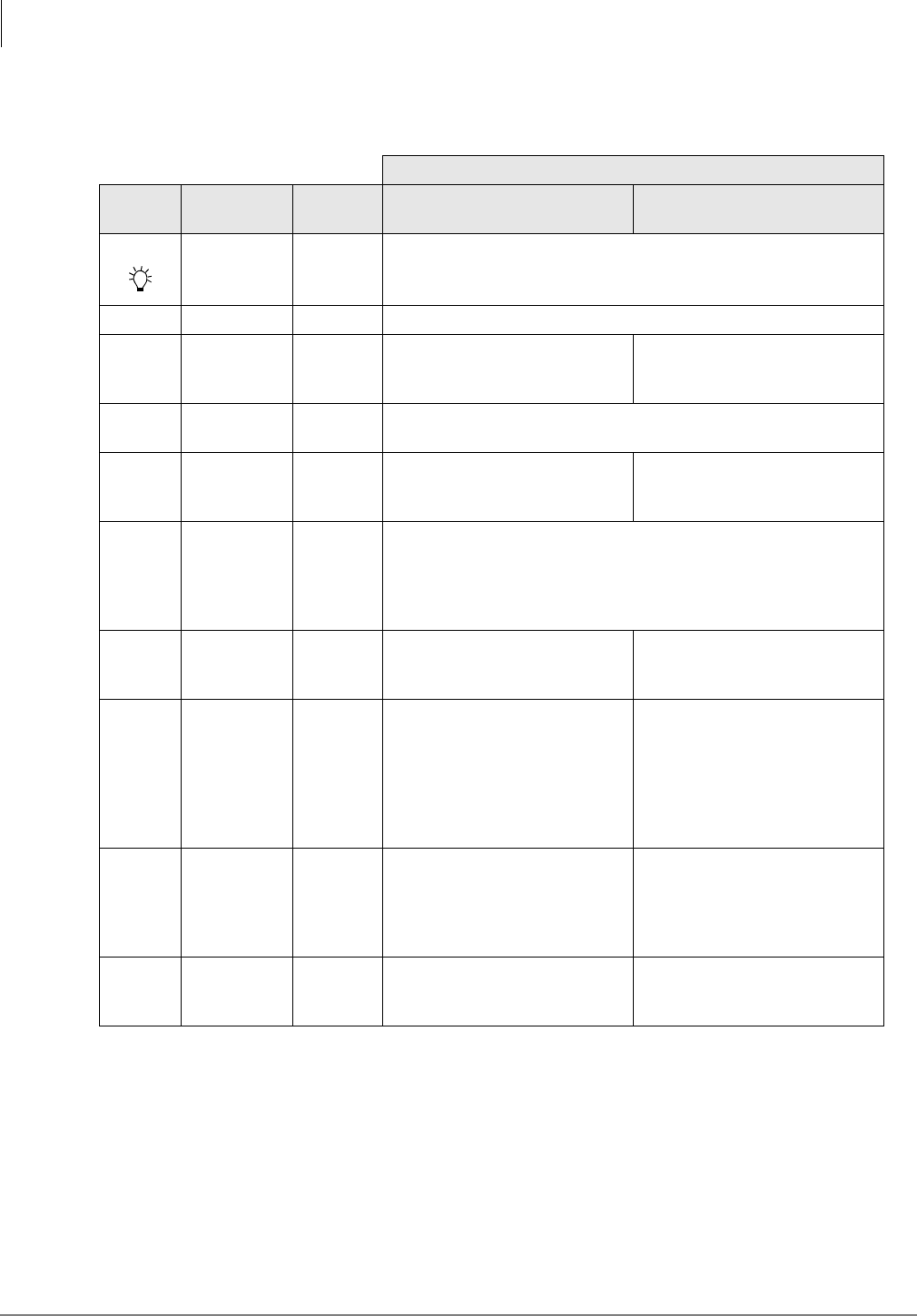
Maintenance and Troubleshooting
Troubleshooting
90 Strata AirLink Installation Guide 5/00
Table 30 explains the meaning of the LED states during boot up and normal operation.
Table 30 BSIA LEDs during Boot Up and Normal Operation
Meaning When Lit
Bottom
Label
Top
Label Color Boot Up Normal Operation
POWER Green The power is on.
9 MASTER Yellow This LED should always be lit.
8BUSY1Green
The test that checks the
integrity of the connection to
Base Station 1 failed.
One or more channels on Base
Station 1 are busy. If flashing, a
software upgrade is in process.
7RLOS1Red
Loss of synchronization occurs on Base Station 1 because of poor
connection, bad cable, Base Station or BSIA failure.
6BUSY2Green
The test that checks the
integrity of the connection to
Base Station 2 failed.
One or more channels on Base
Station 2 are busy.
5RLOS2Red
Loss of synchronization occurs on Base Station 2 because of poor
connection, bad cable, Base Station failure, BSIA failure; or the
Second Base Station Service Enabled parameter is set to TRUE in
the System Settings database when the system has one Base
Station only.
4S3Yellow
The test that checks the
integrity of the real time clock
failed.
If flashing, a critical alarm has
occurred.
3S2Yellow
The test that checks the
integrity of call processing
software stored in non-volatile
memory failed. Try reloading the
software (see “(Optional)
Activate External Critical Alarm”
on Page 21).
2S1Yellow
The test that checks the
integrity of boot software stored
in non-volatile memory failed
because there is a hardware
failure.
1S0Yellow
The test that checks volatile
memory failed because there is
a hardware failure.
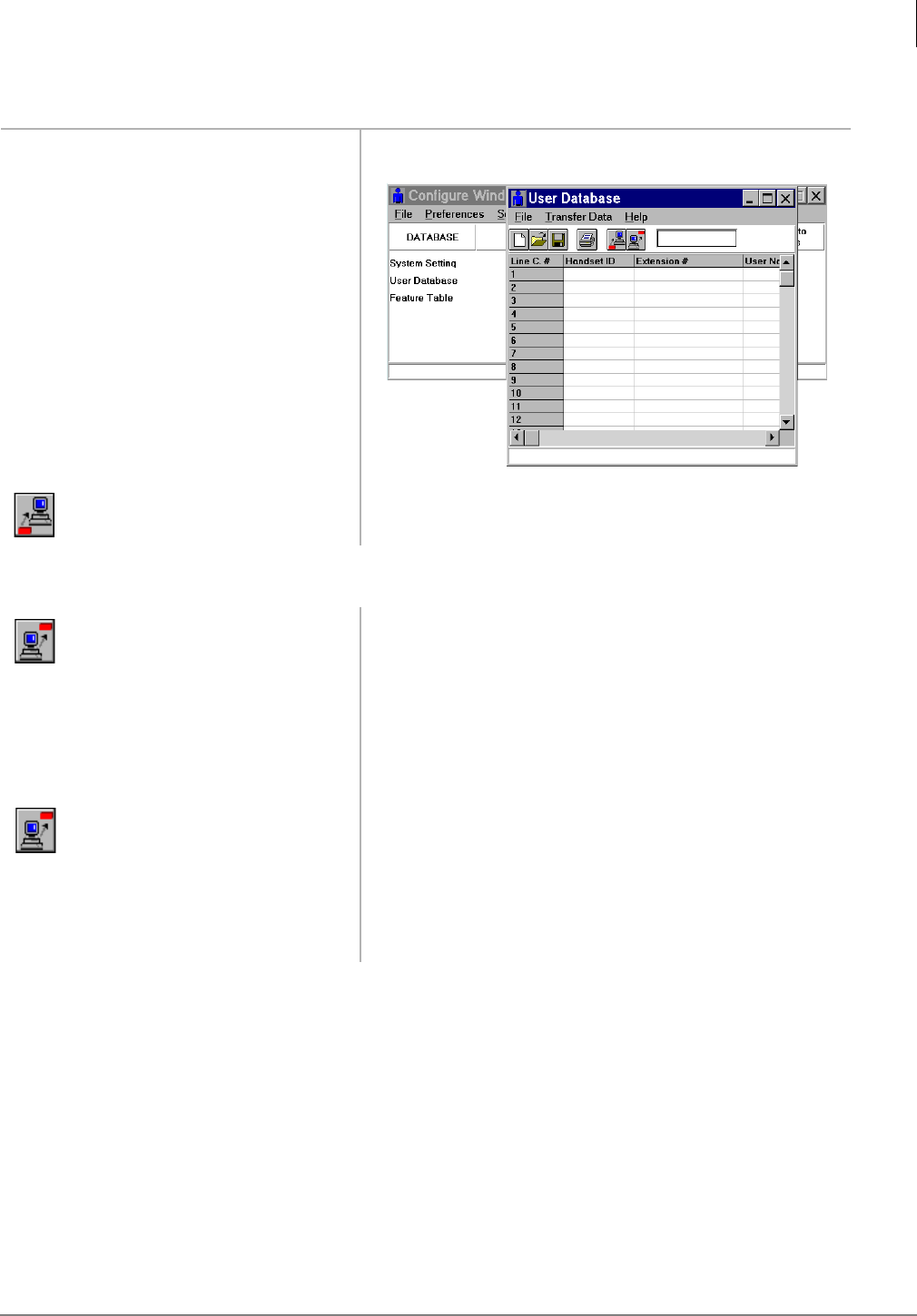
Maintenance and Troubleshooting
Troubleshooting
Strata AirLink Installation Guide 5/00 91
Replace Defective Handsets
Log Files
The Strata AirLink Manager creates log files that open in any text editor for viewing. If the log file
has blank lines when opened, Strata AirLink Manager is running in the background. Close the
software and re-open the log file.
Communication errors (PDQ Comm) occur in the log file when the BSIA is powered on. This has
no effect on performance.
If the log file has information about the boot software instead of the Base Station software after an
upgrade or when querying the software, try querying the BSIA software version before querying
the Base Station software.
1. Go to the Configure Window.
2. Pull down the Select
Database menu and click
User Database.
x
3. From the User Database
toolbar, click Get.
Current information displays.
4. Highlight the handset ID to
be replaced and delete the ID.
5. From the User Database
toolbar, click Send.
Strata AirLink Manager prompts for confirmation.
6. Click OK. The new data is uploaded.
7. Input the original handset ID. Important! Enter the new SID and HID in the handset by
accessing System Configuration ( +
)&1).
8. From the User Database
toolbar, click Send.
Strata AirLink Manager prompts for confirmation.
9. Click OK. The data is uploaded.
10. Go off-hook and press
&$//.
New ESN is locked into the BSIA.
3272
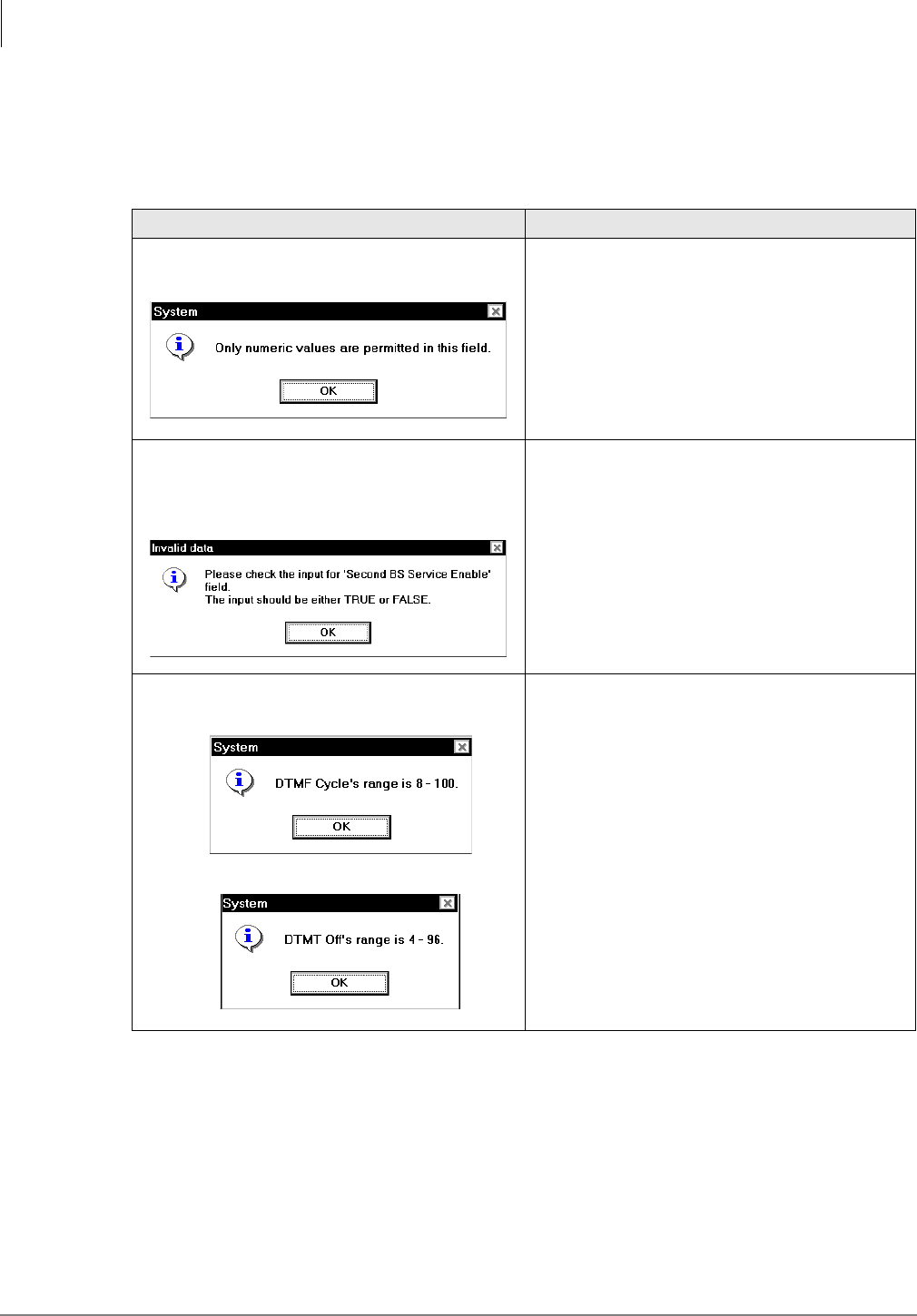
Maintenance and Troubleshooting
Troubleshooting
92 Strata AirLink Installation Guide 5/00
Error Messages
There are several error messages that can occur during the initial configuration process and data
uploads. Most are self-explanatory. A brief description of each is in Tables 31 and 32.
Table 31 System/Base Station ID Troubleshooting
Error Message Possible Solution
When alpha characters are input instead of numeric
characters, this displays:
Click OK and input numeric values.
When adding a Base Station and a word was
entered that Strata AirLink Manager does not
recognize in the Second Base Station Service
Enable field, the following displays:
Click OK and input TRUE or FALSE.
If incorrect DTMF cycle duration ranges have been
input, these display:
Click OK and enter the proper number.
3269
3278
3262
3263
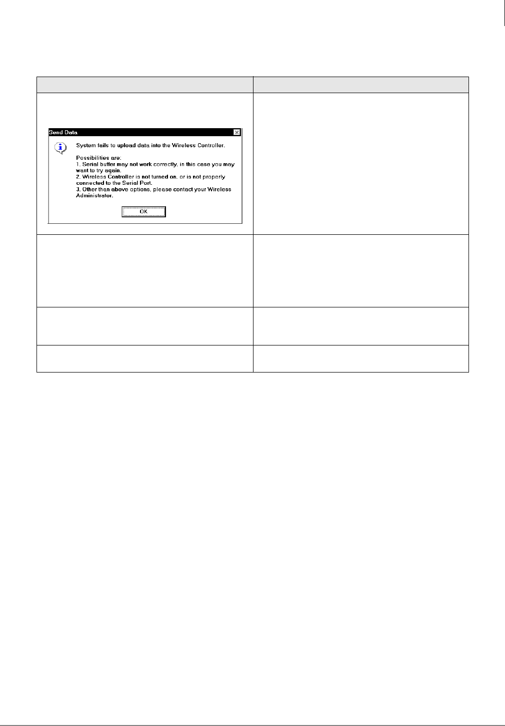
Maintenance and Troubleshooting
Troubleshooting
Strata AirLink Installation Guide 5/00 93
Table 32 BSIA Troubleshooting
Error Message Possible Solution
When uploading data, if this error message
displays:
Check the serial port and try again. If it still fails,
contact the System Administrator.
If these error messages display during UTAM
activation or a software upgrade:
●BSIA off-line
●System did not boot
●Critical alarm #48
Reset the BSIA immediately to clear all errors and
try again.
If this error message: “Corrupt Msg from BSIA. Msg
length = 31. Pls try again” or “ALM #200. Invalid
msg during Base Station sw upgrade” displays
Try the upgrade again.
If the Strata AirLink Manager loses its
communication link with the BSIA Restart the software to re-establish the connection.
3283
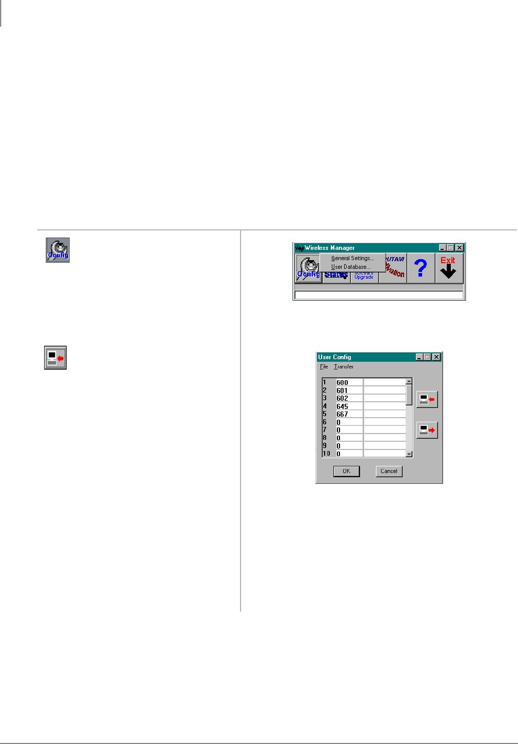
Maintenance and Troubleshooting
Troubleshooting
94 Strata AirLink Installation Guide 5/00
RWIU System
LEDs
There are two LEDs for each Base Station jack on the WWIS, and two on the RWIU for the
external power jack and system. The Base Station LEDs are for the transmit and receive sides of
the Base Stations.
If the LEDs are OFF, they are linked and working. If they are ON, there could be a problem with
the cabling or battery. The power LED should be on and the system LED should be blinking. This
means that the system is properly linked and working.
If any Base Station is not used, its jumper on DIP switch S1 should be off. If S1 is on, the two
LEDs will remain lit and the RWIU will try to initialize that Base Station every 40 seconds.
Replace Defective Handset
1. From the Desktop toolbar,
click the Config icon.
2. Click General Settings.
3. Get current handset IDs.
4. Highlight the defective
handset ID and press Del.
5. Input the new handset ID.
6. Click OK.
7. Go off-hook and press
&$//.
New ESN is locked to the RWIU.
3348
4149
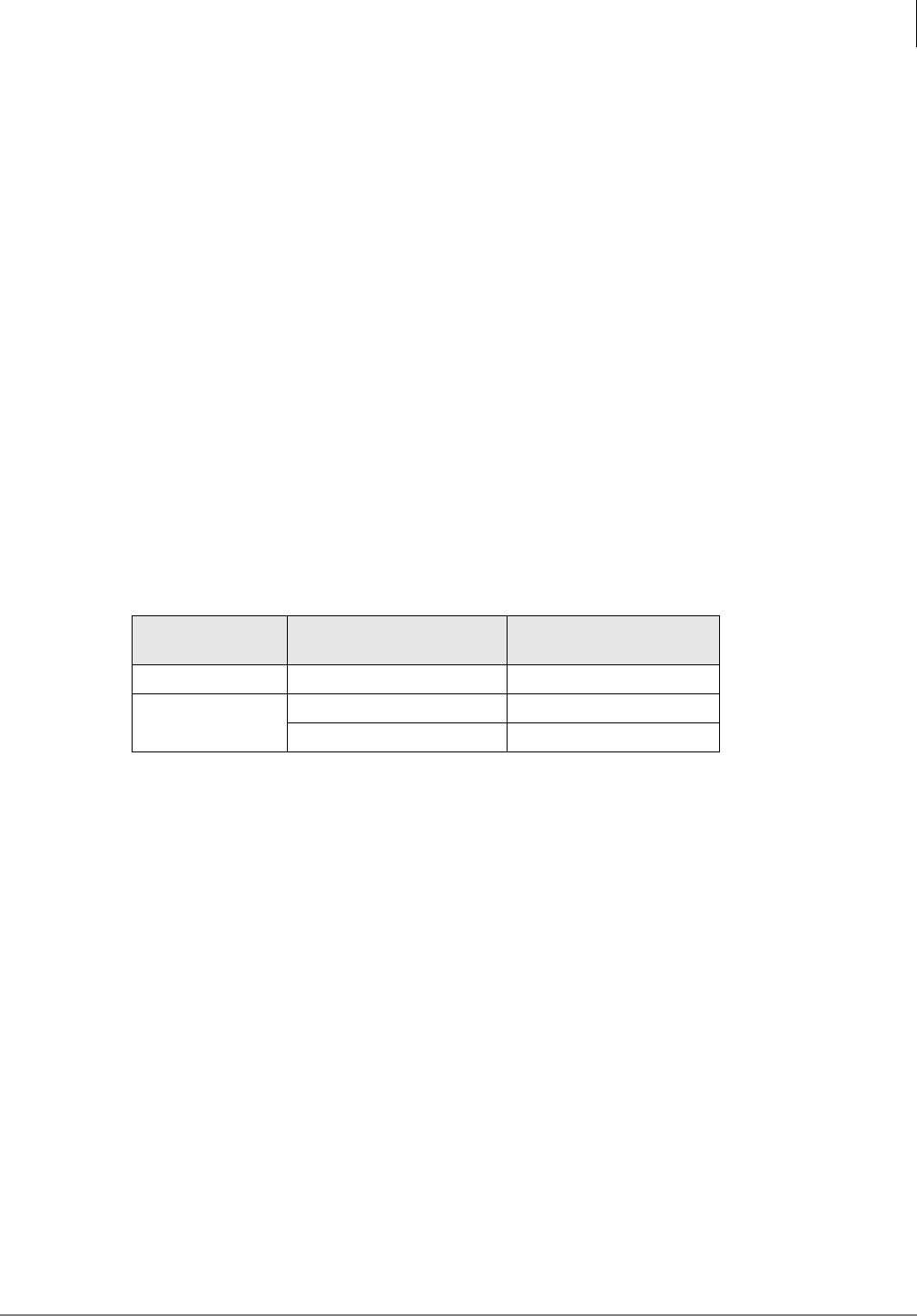
Maintenance and Troubleshooting
Troubleshooting
Strata AirLink Installation Guide 5/00 95
Measure DC Resistance
1. Use a digital multimeter that has resistance measuring capability in ohms and a basic accuracy
of better than one percent.
2. Use an RJ-11 female-to-female line adapter.
3. Ensure that all permanent wiring is done and all primary protectors are installed, if required.
For information on primary protection requirements for UL1459 compliance in the United
States, see “Primary and Secondary Protectors” on Page 102.
4. Disconnect the RWIU from power.
5. Disconnect the cables from Base Station 1, 2, 3, and 4.
6. Disconnect the transmit and receive cables from the Base Station and connect them into each
end of the RJ-11 line adapter, creating a loop.
7. Set the multimeter to the ohms scale.
8. To check the distance to Base Station 1, connect the multimeter probes between pins 1 and 5 or
1 and 6, depending on the cable polarity.
9. Connect the probes between 2 and 5 or 2 and 6.
Note A reading should register at only one of the pairs and must be less than the values listed in
Table 33.
10. Repeat Steps 4~9 to check all the Base Stations.
11. If the multimeter reports no reading or high resistance, check the readings again.
If the readings are correct after performing Step 9, the transmit and receive pairs are probably
reversed or shorted somewhere in the installation. If not, there are open connections
somewhere in the installation; check and correct all punch-down connections and repeat Steps
4~9.
Table 33 Cable DC Resistance
Input
Power
Wire
Gauge
Maximum DC Resistance
Allowed for 2,000 feet
Line 22, 24, or mixed 22/24 98 ohms
Local 22 66 ohms
24 104 ohms

Maintenance and Troubleshooting
Troubleshooting
96 Strata AirLink Installation Guide 5/00

Strata AirLink Installation Guide 5/00 97
Appendix – Specifications
This appendix covers the following:
♦Base station specifications
♦Handset specifications
♦Grounding requirements
♦FCC
♦UTAM, Inc.
♦Underwriters Laboratories (UL)
Base Station Specifications
The following tables list the Base Station and power supply specifications for both wireless
systems.
Table 34 Base Station
Item Description
Dimension 13.25 x 13.25 x 2.5 inches
Weight 4 lbs., 11.5 oz.
Temperatures Operating: 0°~40°C
Storage: -10°~70°C
Channels 8 duplex, 1 control
Antennas 4
Antenna Gain 4 dBi maximum, 3 dBi typical
Mount Ceiling or wall
Wiring Distances from BSIA/RWIU
Line Power:
1,186 ft. (24 AWG)
2,985 ft. (22 AWG)
Local Power:
3,280 ft. (22 and 24 AWG)
Modulation p/4 differential (QPSK)
Gross Bit Rate 384 kbs (QPSK)
Access Method FDMA/TDMA/TDD
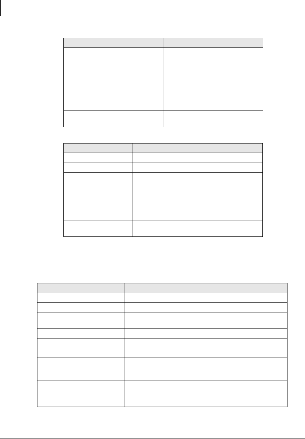
Appendix – Specifications
Handset Specifications
98 Strata AirLink Installation Guide 5/00
Handset Specifications
Power Requirements
Peak Transmission: 80 milliwatts
Average Transmission: 40 milliwatts
From PBX: 6.5~13 watts
For remote power: 13 watts at 2,300
feet
Input: -48VDC line power; +5.2VDC
local power
Consumption: 11.5 watts (-48VDC)
from the PBX
Miscellaneous Line powered, local power option,
voice scrambling.
Table 35 Base Station Power Supply (Local Power Option Only)
Name Description
Dimensions 5 x 3 x 2.25 inches
Weight 15.5 oz. without cable
Mount Desktop
Power
Input:
115/230VAC
0.6/0.3 amps (50/60 Hz)
Output:
5.2V at 2.5 amps (20 watts maximum)
Temperatures Operating: 10°~40°C
Storage: 0°~50°C
Table 36 Handset
Name Description
Dimension 6.125 x 2.25 x 1.125 inches
Weight 6.4 oz. with battery
Transmission Peak: 80 milliwatts
Average: 5 milliwatts
Antenna 1 internal
Antenna Gain 3 dBi maximum, 2 dBi typical
Modulation π/4 (QPSK)
Temperatures
Operating: 0°~40°C
Storage: 0°~50°C (without battery)
-10°~70°C (with battery)
Ringer Types: 8
Volumes: 3, plus mute
LCD 2 lines and 9 characters
Table 34 Base Station(continued)
Item Description
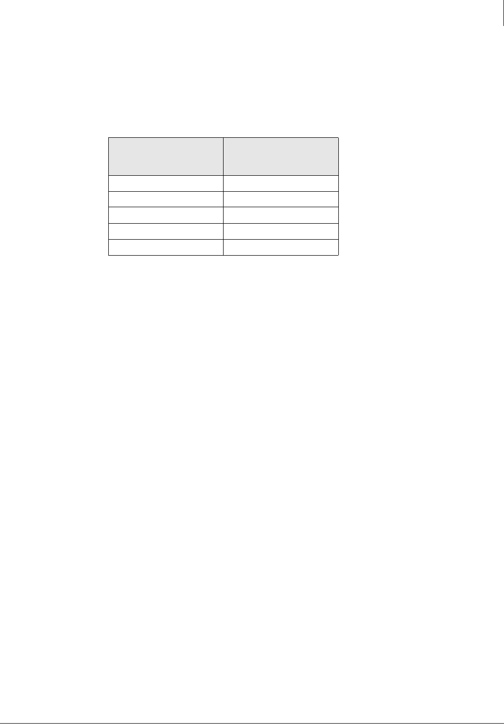
Appendix – Specifications
Grounding Requirements
Strata AirLink Installation Guide 5/00 99
Grounding Requirements
Table 37 provides the recommended gauges for the distances between the system and the master
ground bus of the office telephone system. The proper gauge wire ensures that DC resistance does
not exceed 0.25 ohms.
FCC
The Strata AirLink wireless telephone system operates under the FCC Part 15 rules for Unlicensed
Personal Communications Service (UPCS) equipment in the 1920~1930 MHz band.
Note Part 15 ID numbers for the Base Station (BS) and handset are BS-CJ6DT-WRLS-BS-01
and HS-CJ6DT-WRLS-HS-01, respectively. The system complies with UL1459 for safety,
and the compliance ID is C86-0345.
Part 68
The Strata AirLink Wireless telephone system complies with Part 68 of FCC rules. Product labels
contain, along with other information, the FCC registration number. This information must be
provided to the telephone company if they request it.
Note The FCC Part 68 registration number is 5RYISR-23723-WC-T, and the Ringer
Equivalence Number (REN) is 0.6B.
An FCC-compliant telephone cord with modular plug is provided with the system hardware. This
equipment is designed for telephone networks or premises wiring using a compatible modular jack
that is Part 68 compliant.
If the wireless equipment causes harm to the telephone network, the telephone company will give
advance notification. If advance notice is not practical, the telephone company will give
notification as soon as possible. Along with the notification, the telephone company will advise of
the right to file a complaint with the FCC, if necessary.
To report trouble with the wireless equipment, please contact Toshiba America Information
Systems, Inc., Telecommunications Systems Divisions in Irvine, CA, (949) 583-3700 for repair
and/or warranty information. If the trouble is causing harm to the public telephone network, the
telephone company can request that the wireless equipment be removed from the network until the
problem is resolved.
Important! Repairs must be made by an authorized representative or the warranty is void.
Table 37 Ground Wire Requirements
StrataAirLink:Distance
Between
BSIA/RWIU & Ground
Recommended
Gauge
0~18 feet 16 AWG
0~30 feet 14 AWG
0~46 feet 12 AWG
0~73 feet 10 AWG
0~113 feet 8 AWG

Appendix – Specifications
UTAM, Inc.
100 Strata AirLink Installation Guide 5/00
Do not install the wireless equipment on public coin service provided by the telephone company.
Connection to party line service is subject to state tariffs. Contact the state public utilities
commission for information.
It is recommended that an AC surge arrestor be installed in the AC outlet to which the wireless
system is connected. This prevents damage to the equipment caused by local lightning strikes and
other electrical surges.
The wireless system provides access to interstate providers of operator services through the use of
equal access codes. Modifications by aggregators to alter these capabilities is a violation of the
telephone operator consumer services improvement act of 1990 and Part 68 of the FCC Rules.
Part 15
This equipment has been tested and found to comply with the limits for a Class A digital device,
pursuant to Part 15 of the FCC Rules. These limits provide reasonable protection against harmful
interference when the equipment is operated in a commercial environment.
This equipment generates, uses, and can radiate radio frequency energy. If not installed and used in
accordance with this chapter of the Strata DK Installation and Maintenance Manual, it can cause
harmful interference to radio communications.
Important!
●Changes or modifications not expressly approved by Toshiba America Information
Systems, Inc. can void the authority to operate the equipment.
●The 25-pair cable that connects the BSIA to an MDF must be shielded to meet FCC
emissions limits under Part 15 Class A.
UTAM, Inc.
The Strata AirLink system operates in the 1920~1930MHz band, and microwave services are also
offered in this band. The FCC has designated UTAM, Inc. to coordinate the transition of
microwave services to other frequency bands and the installation of new UPCS equipment, which
includes the wireless system, until all microwave users are cleared from the band.
Each device requesting FCC certification must have an affidavit from UTAM stating that the
device meets the requirements of Rules 15.307(d), (e), and (h), regarding UTAM location
verification and disablement. The basic mandatory requirements are:
♦The handset must not transmit when it is not within the coverage area of any system Base
Station.
♦A Base Station must not begin operation until it is UTAM confirmed and attached to a
permanent structure such as a building so that it cannot be easily relocated.
♦If the system is removed from its original installed location and re-installed at another
location, the system must not begin operation until the new location is UTAM confirmed.
The Frequency Coordination Service Request (sample on Page 101) must be completed and sent to
UTAM before activation of the system. Contact the Strata AirLink Desk at (949) 598-4980 for
more information between the hours of 8:00 a.m. and 5:00 p.m. (Pacific Standard Time), Monday
through Friday. Voice mail is available for messages after hours.
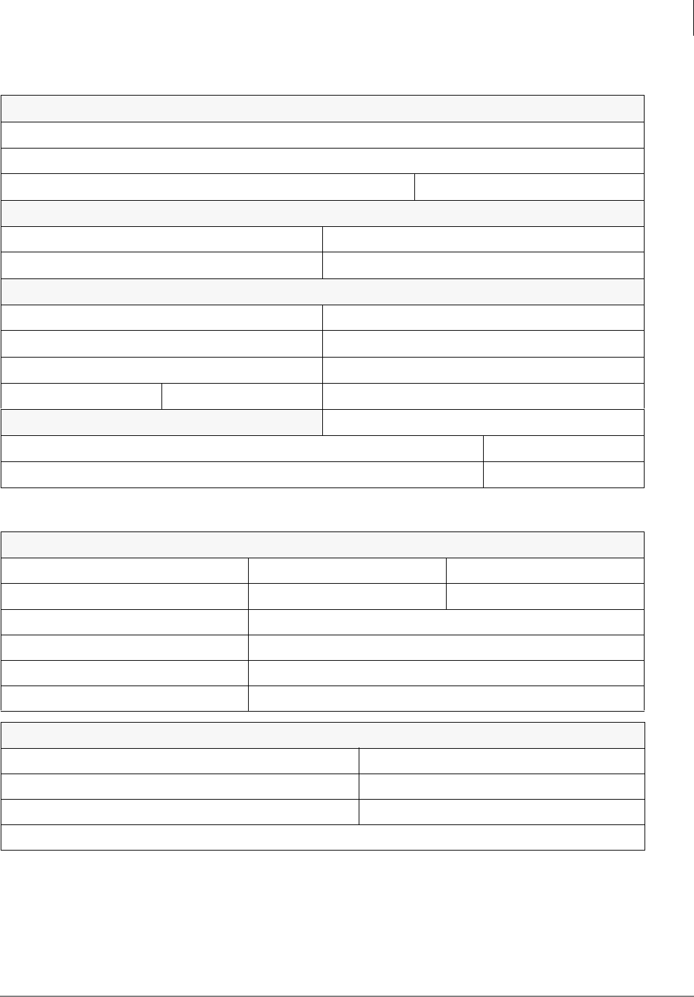
Appendix – Specifications
UTAM, Inc.
Strata AirLink Installation Guide 5/00 101
UTAM FREQUENCY COORDINATION SERVICE REQUEST
DO NOT WRITE BELOW THIS POINT
Part 1 - Installation Status
Type of Request (circle one): New-Permanent/New-Temporary/Reiteration/Removal/Relocation
Installation Date:
If Temporary, Proposed Activation Date: Removal Date:
Part 2 - Dealer Information
Dealer Name: Telephone:
Dealer Contact: Fax:
Part 3 - Site Information
Customer Name: County of Installation:
Street: Customer Contact:
City: Customer Contact Telephone:
State: Zip: Customer Contact Fax:
Part 4 - Equipment Information No. of BSIA Controllers:
No. of Base Stations (antennas) Inside: Outside: No. of Handsets:
Max. Height (inch/feet) and/or Floor of Base Stations Inside: Outside:
Part 5 - System Information
UTAM ID: BSIA CJ6CCLMU00022 Base Station: CJ6DT-WRLS-BS-01 Handset: CJ6DT-WRLS-HS-01
Band: Isochronous Power/Device (mW) - Fixed: 40mW Mobile: 5mW
Building Loss: Unknown Max. Horizontal Distance: 2,000 ft. (default)
Latitude: Longitude:
Zone 1 or Zone 2: FIPS No.:
PFC ID (if not a new site) UTAM Site ID:
Part 6 - Approvals
Jeff Parkin Telephone: (949) 598-4980
Name/Signature of Company Rep./Coordinator: Fax: (949) 583-3097
Title: Primary Frequency Coordinator Date:
UTAM Member Contact (if different from above): Paul Keith
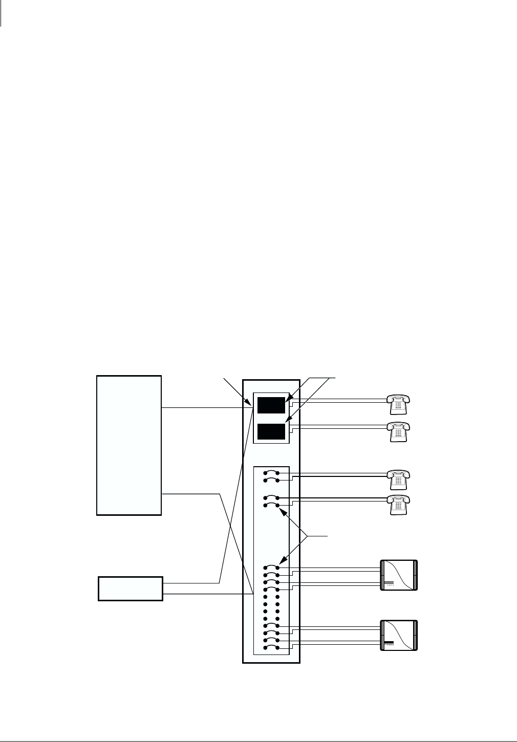
Appendix – Specifications
Underwriters Laboratories (UL)
102 Strata AirLink Installation Guide 5/00
Underwriters Laboratories (UL)
To ensure that installations are fully protected from fire hazards, UL1459 specifies primary and
secondary protectors for circuits that interconnect to the telephone network or cables that exit/enter
buildings.
Primary and Secondary Protectors
Protectors replace bridge clips when installed across two horizontal 66-block terminals. When
using 66-50 connector blocks, it is recommended that protector ITW Linx SCP-9 be used as the
secondary protector and out-of-building primary protector. It provides overvoltage protection of
600VAC or DC, overcurrent protection of 350 mA, and installs in series with the telephone loop.
Line circuits do not require protectors unless the circuit is cross-connected to out-of-building
circuits. In this case, it is recommended that ONEAC 6-AP200 protectors are used. This is a single,
block-mounted protector that provides both primary and secondary protection for out-of-building,
single-line circuits.
System Line Circuit Requirements
Line circuits do not require protectors unless the circuit is cross-connected to out-of-building
circuits. Out-of-building circuits require primary/secondary protectors, and it is recommended that
the ONEAC 6-AP200 be used. This is a single, block-mounted protector that provides both
primary and secondary protection for out-of-building, single-line circuits that are terminated to a
system.
Figure 31 Primary and Secondary Protectors
3004
MDF/IDF
P2
Base Station 1
Pair 20
Pair 21
Base Station 2
Pair 24
Pair 25
WFC/P1
Pair 1
Pair 16
Pair 1
Pair 16
Telephone
System
BSIA
P2
P1
25-pair Cable
25-pair Cable
To ONS Analog
Line Unit
To OPS Analog
Line Unit
Double Punch Down
on System Side
ONS
ONS
OPS
OPS
OPS
OPS
Primary Protection (ONEAC 6-AP-200)
Bridge Clips (Not Protected)
ON-Premise Equipment
ONS =
OFF-Premise EquipmentOPS =

Strata AirLink Installation Guide 5/00 103
Glossary
Term Definition
ALM Analog Line Module - adds groups of 8 handsets to a maximum of 32.
Attenuation The loss of strength of an RF signal due to distance, antenna positioning, and
obstructions.
AWG American Wire Gauge - standard measuring gauge for non-ferrous conductors
(non-iron, non-steel).
Barrel jack A connector that is cylindrical and splices two lengths of thick Ethernet coaxial
cable.
Beep On Roam Causes an idle handset to beep when the Base Station it is locked onto changes.
Breakdown-rated Rated by the amount of voltage that breaks down the insulation between two
conductors.
BSIA Base Station Interface Adapter - The wireless system controller that
accommodates up to two Base Stations in the analog system and four Base
Stations in the digital system.
CCS Centi-Call Seconds - 100 seconds of telephone conversation.
CMOS Complementary Metal Oxide Semiconductor - technology that makes integrated
circuits known for requiring less electricity.
CPU Central Processing Unit - the brain of the computer.
DB9 Standard 9-pin RS-232-C serial port.
DB25 Standard 25-pin connector used for RS-232-C serial data communications.
DC Direct Current - flow of free electrons in one direction within an electrical
conductor.
Dial Tone Delay Time delay between pressing CALL and outpulsing DTMF tones.
DIN Duetsche Institut fur Normung.
DMA Direct Memory Access.
DTMF Dual-Tone Multi-Frequency.
DTMF Cycle Duration Duration of the full DTMF cycle (length of tone plus length of silence between
tones) for dialing and other telephone system operations.
DTMF Off Duration Duration of silence between DTMF tones.
EMI ElectroMagnetic Interference.
EPROM Erasable Programmable Read Only Memory.

Glossary
Erlang ~ WDT
Strata AirLink Installation Guide 5/00 104
Erlang A unit of measurement that equals 60 minutes of usage per line during the
busiest hour of the day.
ESN Electronic Serial Number.
FCC Federal Communication Commission.
FET Field Effect Transistor.
FT Inter-event Pause Duration of pause between events in the Feature Table.
FT Pause Duration Duration of pause events in the Feature Table.
Handoff by Recall A handset feature that enables the user to automatically hand-off between base
stations.
HID Human Input Device - a class of the Universal Serial Bus (USB), such as mouse,
keyboards, gamepads, and joysticks.
Hookflash Duration Duration of the hookflash in signaling the office telephone system.
Hz Hertz - a measurement of frequency in cycles per second. One hertz is one cycle
per second.
I/O Input/Output.
Init task A task that controls the sequence of card initialization and synchronizes it
according to the KSU and Base Station needs.
LED Light Emitting Diode.
Loop back A diagnostic test in which a signal is transmitted across a medium while the
sending device waits for its return.
PCM Pulse Code Modulator.
PUB Portable Unit Board - extracts the clock from the Base Stations.
RAM Random Access Memory.
RFI Radio Frequency Interference.
RJ-11 A six-conductor modular jack also called a plug.
RJ-45 An eight-pin connector used for data transmission over a standard telephone
wire.
RS-232-C A set of standards specifying various electrical and mechanical characteristics for
interfaces between computers, terminals, and modems.
RWIU/WWIS Interface Unit A proprietary digital PCB that interfaces directly to Toshiba Strata DK systems to
enable digital wireless capability.
RX Receive.
SMT Surface Mount Technology.
SRAM Static Random Access Memory.
Stop Ringing Time Length of time the RWIU waits after last detection of ring voltage on a line before
it stops the ring.
TX Transmit.
UART Universal Asynchronous Receiver/Transmitter.
VAC Voltage Alternating Current.
WDT Watch Dog Timer.
Term Definition

Strata AirLink Installation Guide 5/00 105
Index
A
about this guide
conventions,v
organization,v
related,vii
activation code,81
ALM removal,39
analog system line circuits,102
audio coverage test,15
B
base station
cabling distances,39
ceiling mount,17
power on/reset,82
power supply,48
set up,14
wall mount,17
batteries,72-73, 85
troubleshooting,85
beep on roam feature,75
BER test results,16
BSIA
activate UTAM,26
alarms,88
ALM removal,39
analog line continuity,86
base station addition,40
communications port change,41
controller specifications,38
critical alarm relay,89
DC resistance,86
error messages,92
initial configuration change,40
LEDs,89
log files,91
password change,40
program button sequences,32
replace defective handsets,91
reports,86
set system time and date,28
status window,88
system settings,29
wiring diagram,22
BSIA pinouts,38
BSIA system installation
activate external critical alarm,21
base station power supply,21
configure system,26
connect PC,23
connect power supply,23
copy upgrade software,25
install analog line module,19
run cable,20
C
charger base,86
charging batteries,72
communications,81
components,81
continuity,81
D
DC resistance,81
digital interface unit (RWIU/WWIS),57
discharging batteries,73
E
equipment list,12
erlang,10
H
handoff by recall feature,75
handsets
configure,31
lock,74
perform bit error rate (BER) test,15

Index
I ~ S
106 Strata AirLink Installation Guide 5/00
set up,14
store IDs,56
troubleshooting,84
how wireless calls take place,1
I
installation
activate external critical alarm,21
check your equipment list,12
stand-alone base station test stand,13
unpack the shipment,12
M
maintenance,71
manager software
BSIA,3
configuration window,3
desktop toolbar,3
status window,3
install,24
RWIU,4
desktop tool bar,4
mount base stations,16
N
noisy circuits,81
normal operation,83
P
password protection,73
PC port configuration,26
polarity,81
pre-installation,5
primary protectors,102
purchase additional equipment,13
R
replace defective base station,83
reset to factory defaults,76
RF link termination,81
ring back tones generator,64
RWIU
change base station numbers,69
change communication ports,66
change initial configuration,66
check RWIU/base station software
versions,67
LEDs,94
measure DC resistance,95
replace defective handset,94
reset base stations/RWIU,68
RWIU/WWIS interface unit,57
upgrade RWIU/base stations,68
view log messages,67
RWIU AirLink Manager
install,52
start,53
RWIU system installation
base station power supply,48
connect PC,52
connect power supply,48
DIP switches/jumpers on PCB,43
enable UTAM,55
enter handset IDs,54
initialize RWIU,52
install RWIU manager,52
install RWIU/WWIS into Strata DK,47
mount WWIS onto RWIU,45
program Strata DK,50
proper power factor,48
proper Strata DK slot configuration,45
run cable,47
set general settings,53
start RWIU manager,53
store IDs in the handset,55
RWIU/WWIS interface unit
backplane connector,61
protectors,63
S
serial line connector,64
signal attenuation obstruction,7
signal fading,7
software architecture,64
specifications,97
stand-alone base station test stand,13
Strata AirLink Manager
adding base stations,40, 66
changing the configuration,38, 66
installation,24
system,76, 97
suitable locations,13
system
component placement,6
configuration examples,8
configurations
base station,2
cubicles, walled offices, conference
rooms,12

Index
T ~ U
Strata AirLink Installation Guide 5/00 107
factory with adjoining offices,11
handset,2
manufacturing plant,11
multiple BSIA systems,9
multiple overlapping systems,10
single BSIA system,8
hardware/software requirements,6
line circuit requirements,102
password,57
polarity, continuity,81
power,81
reset,81
T
temporary installations,13
troubleshooting,71
activation code,81
base station,76, 83, 97
base station power on/reset,82
communications,81
component problems,81
DC resistance,81
defective base station,83
handset,84-85
handset password,73
noisy circuits,81
RF link termination,81
system,85, 88
reset,81
U
underwriters laboratory (UL),102
unpack shipment,12
upgrading base stations,76
UTAM
activation of codes,100
frequency coordination service request,101
