Surplus_radio_conversion_manual_vol1 Surplus Radio Conversion Manual Vol1
User Manual: Surplus_radio_conversion_manual_vol1
Open the PDF directly: View PDF ![]() .
.
Page Count: 122 [warning: Documents this large are best viewed by clicking the View PDF Link!]

$I]RPTI]$
CONIITB$IOil
BAilI
VOTUME
No. I
Third
Edition
By
R. C. EVENSON
AND O. R. BEACH
. CONf ENÎS
-
BC-22I Frcqucaty llArtrr
BC-342 Rcccivcr
lC.3l2 Rcccivcr
BC.348
Rcceivcr
BC{l 2 Rodqr
Orcillorcopc
BC-ó45
Tro nrmilîcr/Rccclvcr
BC-9,1ó Receivsr
SCR-274
(4534 Serier) Rccrivcn
SCR-274
({57A Scrlar) Tronrmillerc
SC R.522
Tro
nsmitlcr/Rcceivcr
TBY lronscaiver
PE.l03A
Dynomofor
BC-t0ó8A/l tótA Receiver
Eleclronics
Surplus
Index
Cross
Index of A/N Vacuun Tubec

PREFACE
Since the beginning of the "surplus eratr a real need has existed for a
publication devoted entirely to the conversion information necessary to
permit practical use of surplus equipment. The amateur radio operator
has had especiar need for such a pubrication. The authors have endeavored
to fulfil that need in the fo'owing pages by compiling the necessary in-
structions and diagrams for the practical conversion of a number of the
most popular items of surplus equipment.
Theory of circuit operation has not been incruded in this manuar so
that conversion data on the largest number of equipments could be in-
cluded. It has been assumed that those persons interested in a manuar of
this nature are generarly familiar with the operation of erectronic equip_
ment. It should be noted thatthe operation of any radio transmitting equip_
ment, including that described herein, requires the issuance of both an
operator's license and a station license by the Federal communications
Commission.
Th-e
authors regret that time does
not permit them to engage
in
individuar correspondence
regarding these or other surplus items,
and
the publisher has been
requeste-a
not to forward retters.
We have
no information on surplus items other than those in
these several Manuals
$3.50
Cot.
No.
EE-31
I
SURPLUS RADIO
CONVER,SION
MANUAL
VOLUME I
Third Edition
by
R. C. Evenson and O. R. Beach
Published
qnd distributed lo the electronics
irode by
New
Augusto,
Indiono
copyright 1948
by Techno-Graphic
Pubtications. Printed
ln u.s.A.

Subject
BC-22L
BC
-342
BC
-312
BC-348/224
BC-412
BC
-645
BC-9468
BC-453-4-5
scR-274N
ARC-5
BC
-45?-8
-9
BC
-696
SCR-2?4N
ARC-5
BC
-625
BC-624
TBY
PE-103A
BC-1068A
BC-1161A
Electronic Surplus Index
TABLE OF CONTENTS
Frequency
Meter (SCR-211)
Receiver
Receiver
Receiver
Radar Oscilloscope (to TV Receiver and
Test Oscilloscope)
Transmitter/Receiver (420 Mc.)
Receiver (Conversion
to Auto Receiver).
Receivers
(Conversion
to 10
Meters)
Transmitters (Conversion
to VFO)
Transmitters
(scR-
522/
542)
(2
Meters)
Receiver
(SCR-522/b42)
(2 Meters)
.
Transceiver (6 and 10
Meters)
Dynamotor
Receiver
(SCR-268/2?1
Radar)
(2 Meters)
Page
c
L2
22
29
40
53
?3
19
82
104
106
111
122
Index
of A,/N-'\,IT" Tubes vs. Commercial Types

SCR-211
FREQUENCY METER SET
(Bc-221)
The SCR-211 Frequency Meter Set consists of several minor compo-
nents and
the major component, the BC-221 Frequency meter. It is de-
signed to radiate or measure radio frequencies between
125 kc.
and
20,000
kc. This frequency measuring device is a precision instrument and is
capable
of making frequency measurements
to a high degree of accuracy.
It should be noted that no conversion of this unit is required for nor-
mal use unless it is desired to use an a-c power supply in the place of the
required
batteries. If the
a-c power
supply is desired, reference
is made
to fig. 3 which is self-explanatory.
Since
this article is of a descriptive nature,
pertaining to the operation
and use of the BC-22L, the discussion will be made under the following
sections:
General Description
Principles of Operation
General Use of the Instrument
(a) General
Description
There are mÍrny models of the SCR-211 Frequency Meter Set, which
include
the SCR-211-A,
B, C, D, E, F,
L K, L, M, N, O, P, Qr
R, T, AA,
AC,
AE, AF, AG,
AH, AJ, AK, and
AL.
Even though
many of the models are quite similar, there are numerous
minor changes. These changes are too numerous to mention in the scope
of this article; however
the discussion
covers the general operation
and
characteristics
which
pertain to all models.
All models
of the
SCR-211
consist of the
following
components:
1 ea.
Calibration
Boo\ MC-177
1 ea. Crystal Unit,
DC-9
Set of vacuum
tubes, installed
Set of batteries, 6 ea. BA-2 ("8" Batteries)
4 ea. BA-23 ("A"
Batteries)
Headset and Cord (applicable
type)
There are two typesof
cases that enclose
the BC-221,
the woodentype
and
the aluminum alloy type. The dimensions of the aluminum case are
Lz-L/2" high,10"
wide, and
9-tf4" deep;the
wooden
case is slightly larger.
The self-contained battery compartment is designed to hotd 6 BA-2
batteries (22-L/2 volts each) and 4 BA-23 batteries (L-l/z volts each).
This gives the required "B" supply voltage of 135
volts and
6 volts for the
'h" supply. (Note: minimum
voltages
for satisfactory operation are 5.4
volts and
121.5 volts for the "A"
and
"B"
supply respectiveiy.)
Six different control panel designs appear in the BC-221's varying
with the different models and
the different manufacturers. This variation
is not important since the control labeling and
the included unit instruc-
ti.ons
make the operation self-explanatory.
(a)
(b)
(c)
-5-

Each BC-221 unit contains
an individua[y calibrated book,
Mc-1??,
permanently attached to the front panel cover.
(b) Principles of Operation
The
BC-221
is a heterodyne
type
of frequency
meter employing
a 1000
kc. crystal oscillator which
furnishes 1000
kc. check
points for the
vari-
able frequency oscillator. Manual tuning of the variable frequency
oscil-
lator is brought out on the control panet
with its associated
dials.
Two calibration ranges are provided, the 125-250
kc. range and the
2000-4000
kc. range. By use of the 2nd,,
4th, and Bth
harmonics, the low
frequency range covers 250 to 2000 kc. By use of the 2nd,
4th, and bth
harmonics,
the high
frequency
range
covers
4000
to 20,000
kc.
with reference to the block diagram of the Bc-zzl, the output of the
v.f.o. is heterodyned
with the incoming signal from the antenna. After
detection the beat frequency is amplified by the audio amplifier and its
output
connected
to headphones.
when the beat frequency reaches the audible range it is heard in the
headphones
and the final tuning adjustment is made with the v.f.o. to pro-
duce a "zero-beat". This indicates the incoming frequency
and the dial
reading is taken.
The
above description of operation refers to an
incoming
signal such
as checking
a transmitter. since
the Bc-zzl also radiates its v.f.o. sig-
nà\ receiver calibration
and checks
are made
similarly by the "zero-beat"
method
as heard in the receiver output.
From the following factors: mechanical shocks, locking action of
dial, warming up, change
of load at antenna, 10
per cent change in battery
voltage,
error in calibration,
and error in crystal frequency,
the maximum
error should not exceed
.034
per cent at 4000
kc. Normally the errors
tend to ,cancel
each
other so
that the normal error shouid
not
exceed
.02
per cent.
ANTENNA
DETECTOR AUDIO
AMPLI FI
ER
to00
Kc.
XTAL
OSC.
-6-

(c) General Use of the Instrument
Reading the frequency meter dial consists of three individual steps.
The first tùo digits ire read on the hundreds dial (drum dial). From the
large circular dial, labeled "units", th.e
second two digits are read. The
u"""ni"" scale (Iocated on circular dial) provides the fractional digit in the
conventional manper. Thus the following example reading can be obtained:
45 B? . 5. This dial reading is then checked in the calibration book to
obtain the frequency of the signal being measured.
For transmitter frequency measutements, a 2-foot piece of rigid
copper wire is adequate for the frequency meter antenna. The antenna
"n*ta be only in réasonable proximity to the transmitter output. Care
should be exeicised to avoid allowing excess r-f to enter the frequency
meter which can cause permanent damage.
In making frequency checks or dial calibrations with a receiver, the
frequency méter antenna lead should be only loosely coupled to the re-
ceiver input. This can be close proximity or the wrapping of the respec-
tive leads.
At no time should the frequency meter be directly connected for fre-
quency measurement PurPoses.
- In all models of ttre Bc-221, high impedance headphones should be
used for optimum performance. The earlier models specified the P-18
and the n-ig treadphones
while the later models specified the HS-30.
A point wortiiy of mention is that in certain measurements where
visual observation of the "zero-beat" is desired, an output meter with an
appropriateimpedancematchingdevicecanbeusedinplaceofthehead-
phones.
-7-

It
ro ro
lf-
ts
F
'È
s
I
3t
I
(J
è
(9
tt
N
à
@
@
0
n
3
I
l\
II
È
Èt-
lF-
h
f)o
e@*
;
Ì;
I
g(9
=?
@
ct
H.
tto
()
o
o
o
J
ts
à6
F
9s
E:
o
z
,Epg!É
f6o'->
d<7eee
È=UqU
?63Èà5
=f{5 o
:sigx;x;
n
.ó
I
o{r.ì€N6òO
NNdNNNqC'
gg
:sp==rÉÈ
:gòiÉHF3
lìì:.ìa:..
E;;;Eq3!
uor93uuoc
-8-

o
t
a
@
I
N
o
^
z
u
JU
<F
F<f
oc9
35t5
lttl
o-No
3t\
*3
E
;
d
I
c
-
ò
,i
N
\
9x
I;
io
o-
3?
8r
E9
z
F
è
o
z
I
t
'3 J 'ì
a:=:Í
-=t
sÉ6É::
E
{
:A!
---: -óu
:-- ìi3'
-9-

REGULATED POWER SUPPLY FOR THE BC.22T
Figure 3 shows
an easily constructed voltage-regulated power supply
for operation of the BC-221 frequency
meter. The series resistor R
should
be adjusted, with tlre BC-221 serving as a load for the power sup-
ply, until the current from the cathode
terminalof the
VR-150 to ground
is
approximately 15 ma.
40 Bf r50
v.
t!
o
o(J
z>
ed
vR-r5O
b>
9il
2l
Ri
B- s A-;o
F
A+
The existing
"OFF, CRYSTAL,
OPERATE,
CHECK"
switch
is removed
from the "A" (+) battery circuit. The positive "A" heater lead from the
power plug is connected directly to the ungrounded side of the filament
buss.
In earlier models of the BC-221 such as the BC-221C, fig. 1, the
cathode of the amplifier tube may be connected directly to the filament
which
provided its bias. In such
cases it is necessary
to break this con-
nection and
run the cathode
to ground through a proper value cathode re-
sistor. If this is not done excessive hum will result in the frequency
meter output.
On certain models such
as the BC-221Q, fig. 2, the "8" (+)
lead may
be left intact with the original switch. This arrangement in conjunction
with the power "OFF-ON" switch permits warm-up of the unit without
signal radiation.
The switch for the new
power supply (Sw) may be located on the fre-
quency
meter cabinet or chassis
as desired.
toH. l7,sK
il5 V.A.
_10_

I
F'ritta?ù(r lllettr 8C zzt-(il), in nelal cabinet
fre'quenLl ,lldcr BC-221-(6), in uudcn cabinel
-11 -

COI.IVERTING
THE BC-342 RECETVER
Though
the
BC-342
signal corps short-wave
receiverhas not
appeared
tn quantity on the surplus market, the BC-312 has
been widely "ùìr"uró.
Either is considered
an ideal piece of equipment
that can
ue reaaity modi_
fied-
and used-very
nicely as a communications
receiver. Either can
be
made to perform comparably with receivers that sel.l on the current
market for three and four times the price.
The BC-342 is designed
to operate
on l1b volts ac, b0
or 60
cycles.
The direct current version of the Bc-s42 is the ec-irz (12
vons, oó.
Since
the
major part of the
BC-312rs
conversion
is identical
to ttrat
óf tne
Bc-342, only a small part will be devoted
to it under a separate
tiile with
general
reference
directed
to this article.
Among
the most
recent
models of the Bc-glz and BC-312 appearing
on the market are the "1r1"
and "N" models. since the later modelÀ
a"e nol
greatly
different from the earlier models,
the converting
procedure can
apply to all of them without regard to the slight variationl. The most ap_
parent
variation is the
omission of the
crystal Filter on
the
later models
of the
BC-312.
As is immediately
apparent,
these signal corps receivers were built
for service rather than for beauty. Even
thougn iì is not as pretty as the
modern
communications
receiver, the
ham
can
be reasonably
assured
that
this receiver is one
o.f
the_most
rugged,loth mechanicallyand electrically,
that has ever been
built. It has relatively high sensitivity and
good
stabilj
ity. Its frequency
range is 1b00
to 1g000
kc. thereby not cóvering the
broadcast
band or the lO-meter band. converters for ihe high-freqiency
bands
work nicely
with this receiver, since
direct coaxial
coùpling
[o tnó
antenna
input is provided on the front panel of the receiver.
The BC-342 has the following tube line-up with the respective func-
tions:
2 ea 6K?
(VT-86) lst & 2nd
RF amplifiers
6C5
(VT-65)
RF oscillator
6L7 (VT-8?) lst Detector
2 ea 6K7
(VT-86) lst & 2nd
IF amplifiers
6R?
(VT-88)
2nd
Detector,
AVC, lst Audio
amp.
6C5
(VT-65)
CW
Osciilaror
6FO
(VT-66)
Rudio
output
amplifier
5W4
(VT-9?)
Rectifier
The r.f. oscillator stage
has been
well stabilized, making the drift and
dial calibration quite
accurate. The frequency
coverage
of the receiver is
accomplished
in six bands,
with direcily calibrated, fist and slow
vernier
knobs. since
the
military requirements
were not
those
generally
required
for ham
use,
the
following
modifications
and
refinementé
will be covèred:
(a) Modification for the RF Stages
(b) Modifying the Crystat Filter
(c) Backlash
Improvement in the Tuning Mechanism
-12-

I
(d) Reducing the Audio Hum Level
(e) Connection
for the
"send-receive"
Switch
(f ) Improvement for the Audio Section
(S) Additional Circuit Refinements
(h) Optional Refinements
and
Suggestions
(a) Modification for the R.F. Stages
Since the r-f stages are operated with a higher than rated grid bias
and
lower than rated screen voltage, the receivers have a noticably lower
signal to noise ratio than is expected
in good communication receivers.
Increasing the gain of the r-f stages materially improves this condition.
The existing
cathode resistors of the lstand 2nd r-f stages,
R1
and R7,
are 500 ohms. These should be reduced to 250
ohms. The screen re-
sistors, R3 in the lst r-f stage
and Rgin the 2nd
r-f stage,
should
be re-
duced
from the original value of 40,000 ohms to 20,000
ohms. These
changes
give a grid bias of about -3 volts relative to the cathode
and a
screen
voltage of approximately 130
volts. Another recommended
feature
is the removal of the lst r-f stage from the manual r-f gain control
per-
mitting this stage to operate at maximum gain when using the MVC. This
change
provides optimum signal-to-noise ratio when the manually con-
trolled gain is reduced
to the desired listening level.
To make the above alterations it is necessary to remove the shield
plate at the rear of the chassis behind the mixer and the r-f amplifier
tubes. The screen resistors are located underneath the plate on the
mounting strip and are identified from the schematic diagram as R3 and
Rg An easy
way of making the change is to shunt the existing 40,000-ohm
resistors with similar and equal resistors thus giving a value of 20,000
ohms.
The existing cathode resistors are located at the sockets of the tubes
requiring the removal of the tube mounting plate. Substitute 250-ohm,
l/Z-watt resistor for R1, soldered between the cathode
pin and
pin No. 1
(ground). Rq is replaced
with a 250-ohm resistor between the same
points
as
the original resistor.
The increase in gain from the above changes should show
a definite
peak
noise by tuning the trimmer on the lst r-f stage with the antenna
dis-
connected.
(b) Modifying the Crystal Filter
The crystal filter, which is electrically located
just before the 1st i-f
stage,
is a crystal tuned
bridge circuit intended
to give greatly increased
selectivity. Since
the military version seriously reduces the
signal
level,,
its operation is not considered up to the requirements to warrant its use;
however, the following modification will give radical improvement.
As it is, switching the filter in and
out changes
the shunting capaci-
tance across the secondary of the i-f transformer to such an extent that
the stage is considerably
detuned, thus reducing the sensitivity. To avoid
this radical change
in capacitance at the switching point,
which is done
by a
switch on the capacitor shaft, the switching point should
be changed me-
-13-

chanically to close when the phasing capacitor is at minimum capacitance.
The best method of doing this is to force the switch blade around 1g0
degrees on its collar. since all switches are not conducive to this treat-
ment without breaking it may be necessary to solder the blade to the collar
in its new position. After this change is made and functioning properly it
is necessary to readjust the alignment of the i-f transformer secondary in
which the crystal filter operates. This adjustment is made at the top of
the first detector transformer. It is preferable to align it on noise with
the crystal switch out. Now the signal strength should be the same with
the filter out, or peaked on the noise when it is in. The crystal selectivi-
ty is not too great but considered good for ordinary operation.
A refinement frequently made to make the crystal filter tuning less
critical, is to reduce the capacitance of the variable phasing capacitor.
This is done
by removing (breaking) approximatelyhatf of the statoi plates
from the capacitor. since it is not necessary to remove the filter assem-
bly for this operation, it is an easy refinement to add.
(c) Backlash Improvement in the Tuning Mechanism
Generally backlash is not considered as being too bad in these re-
ceivers. However, it is always the general desire to minimize this condi-
tion. The largest part of the backlash occurs between the worm gear and
its mating gear on the capacitor shaft. To tighten the mesh of these two
gears is a major operation generally not recommended since it requires
considerable dismantling of the mechanical tuning assembly. However, in
most cases improvement can be obtained by reducing the amount of end
play on the worm-gear shaft. This is done
by increasing the spring ten-
sion on the worm. To do this, loosen the collar, pressing it lighily against
the spring, and retighten it in its new position.
(d) Reducing the Audio Hum Level
Frequently a relatively high hum level is present in these receivers.
It is generally due
to insufficient power supply filtering and use of the out-
put stage for headphone reception.
If insufficient filtering in the power supply is apparent, it is recom-
mended that midget 8 mfd. filter capacitors be shunted across the existing
filter capacitors C89 and C90 in the power supply section.
Modification of the audio section as discussed under section (f) of this
article will give definite improvement in the hum level for headphone
re-
ception.
(e) Connection for the "send-receive" Switch
The "send-receive" switch does not operate the receiver since it is
connected into the external plug on the front of the receiver. To make it
operate in the normal fashion, it is necessary to remove the leads from
the switch and connect one terminal of the switch to the chassis (ground).
Disconnect the high-voltage center-tap lead from the negative terminal of
the filter capacitor in the power supply and connect this lead to the other
-14-

side of the "send-receive" switch. This lead is brown in color and long
enough
to reach the switch through the grommet in the power supply case,
The "send-receive" switch should be kept in the center tap lead so as to
keep it in the low-potential side of the "8" circuit thus avoiding high voit-
age at the switch and also eliminating switch "pops" that occur when
switching in the high-potential side.
(f ) Improvement for the Audio Section
Since this set is capable of supplying adequate audio volume for head-
phones at the output of the first audio amplifier stage, it is advisable to
shift the lower phone jack connection to the output of the first audio stage.
This stage is the triode section of the 6R?. Hum and noise which may
normally be picked up by the additional audio output stage is reduced con-
siderably.
This change can be accomplished by connecting the lower jack, at the
right side of the front panel and labeled 2nd audio phones, to the grid
(pin No. 5) of the output tube, the 6F6. In some models this modification
will not be necessary since one of the jacks is already connected in the
first audio output and labeled accordingly.
To improve further the above modification, it may be preferred to re-
place the existing jack with an open-circuiting type jack which opens the
grid circuit to the output tube when the headphones plug is inserted. This
is normal practice in most communication receivers since it removes the
speaker output when the headphones are used. If the speaker is not con-
nected, the open-circuiting jack removes the possibility of very high volt-
ages that may be developed at the plate of the output tube with large sig-
nals when the circuit is not loaded. These voltages can easily be high
enough to arc between the electrodes in the output tube or break down the
insulation in the output transformer.
Transformer T1 is an audio interstage transformer that is used in
some models for headphones output from the first audio amplifier. In
other models, the transformer is connected to the external plug on the
front panel and serves no purpose in the normal operation of the set.
Since the output transformet, T2, has an output impedance of approxi-
mately 3000 ohms, it is not considered practical for normal use. It is
generally desired to replace this transformer with a standard output
transformer matching the 6F6 to the desired voice coil impedance. This
works out nicely with a 6 or 8 inch PM speaker. When changing output
transformers, it is possible to select the physical size which can be
squeezed into the original position of T2. The secondary leads can be
brought out as beforeto the speaker jack with thejack labeled accordingly.
If the changing of output transformers is not desired, the existing
output of transformer T2 can be fed directly into another output trans-
former having a primary impedance of 3000 or 4000 ohms when connected
to the speaker voice coil. This method has been used satisfactorily and
will eliminate the work in changing transformers.
Additional refinements considered advisable, especially if more audio
volume is desired, are changing the following circuit components in the
audio section of the receiver.
-15-

Replace
the 6R7
detector first audio
tube with the high mu 6e?. This
is an easy change since the socket connections
are the same and only the
cathode
resistor, R26, must be altered for the proper bias. This is easily
done
by shunting
the existing resistor, R2g, with à 900-ohm, t/2 watt re--
sistor.
The diode filter resistor, R4g, is a relatively high value, being 0.S
megohms. considerable increase in volume can
be obtained by reducing
this value to normal proportions. This can
be convenienily
done by shunt-
ing the
existing resistor with a 100K
1/2-watt resistor.
It will also be noted
that the grid resistor, R33, of the output
stage is
considerably lower than normally used. This resistor should
be increased
from the existing 50K
to 250K.
The above changes
will give much increased audio
volume which will
be more than adequate
for speaker and headphone
operation.
(g) Additional Circuit Refinements
Noise
Limiter:
To bring your receiver up into the top class of communication re-
ceivers, the addition
of the suggested
noise-limiter circuit will be well
worth while. This is a series-type timiter using the 6H6
diode
with an IN-
our switch. The schematic diagram should
be self-explanatory as shown
in fig. 1.
If desired, the entire limiter, tube and
all, can
be encased
in an old
i-f transformer can. This will give a professional appearance
to the in-
stallation, and the assembly may be easily mounted
inside the receiver on
the
chassis.
"S"
Meter:
since many hams do not consider the communication receiver com-
plete without a signal-strength meter, the circuit shown
in fig. 1 is rec-
ommended. This circuit is standard and considered quite satisfactory.
It is generally considered inconvenient to mount even a small meter
on the front panel of the receiver. This is true because of limited space
and tàe thickness of the panel which makes cutting of the hole rather dif-
ficult. In most cases, the meter is mounted
externally on a bracket to the
receiver
case.
Separate
R.F. Gain Control:
An optional feature that is sometimes desired, is separate and indi-
\riduat r-f and a-f gain controls that are not switched
in and out with the
.{VC
switch,
SW-12.
This control, as in the military version, consists of the tandem
po-
tentiometers, R-34 and
R-35. To separate
them it is necessary
to dis-
connect one,
preferably the a-f, R-34, and add an additional 500K
potenti-
ometer to the panel
for the new a-f gain control. After this is done, the
-16-

Ht,'
Y
\
ì\
ìs
t< \
\
('-
'-+.-
6
ct
i
O t':
..1 X
(r É t
!)0
OID+t
oFv.
.r1 +) ..i
oo(D
t1
c
+)+T:
d:
O;,c.
f)o(^
c o+: t t. 0\
F{ tr.d..{ O I
;. c l(ì A11
+) C\ +' fl rí
-U: fi É. rl O; >
l, .i (D , "r'
cr c r_\ +ì o c ,rr
E ..{ .-t li C d)
L! L E'-i c b:
O t O.'{ (r (-.
qr<+)È ai.:
O 0r FlOl:
l+r: O C4-r C)
î O l lDrat'
L-r..{+Cr+r
+-i í-'C C.i l'
f.: Z O.C O'
+r(J CJC:
t$ta;! ..1 O
L- OOO L
+)D--ro c l:F{ C
I( 'c'C Or-1 Oì
:\C-1.<È".:L
o)
J)
....t
()o
{j +)
t-. o
a(ì
\/ o
cìo
ti 0)
-)é
r, -
r1
Oq)
rp
.-1
c. a.
Q\
*_J
*!l\
ìiiìs
iiiìi
llci
ù
$lì
-rì
s
\
\o
...aaa
r-t C\, (f\ -t rr\ \C
,r
I
r/
r
Y
\
*
\
.\
cxÌ
.Y\
\)Q
$
\0
'h
.7 a/-z
rr 0O( L
_17-
Ht'
\
\
I\
fl
3
\
d
\

Ieads
to the two controls should
be reconnected
to by-pass switch, SW-12.
With this change,
the switch in the 2nd and 3rd position only controls the
AVC circuit, being either ON
or OFF.
Tone Control:
Occasionally a tone control is desired for listening ease and can
be
added
to the receiver. This is quite convenient especially if the receiver
does
not have
the crystal phasing
control whichis physically replaced with
the dial light rheostat on the panel. Since
the rheostat is useless in most
cases, it can readily be replaced with any other desired control or in this
case,
the tone control.
A simple type of tone control circuit is shown
in Fig. 1.
(h) Optional Refinements
and Suggestions:
Among the many personal touches that may be added
to the BC-342
and
Be-312 for appearance
and
ease of operation, the following may prove
to be Advantageous
or possibly stimulate new ideas:
The external plug, SO-1, located on the front panel was intended for
use
with other associated
equipment of which the receiver was a compo-
nent
part. Ordinarily there is no particular need
for this plug and
it can
be removed from the panel. The remaining hole can be plugged or used
for added
controls. The leads to plug SO-1 should be removed at conven-
ient points
in the receiver.
ihe small vernier tuning knob (1/4" shaft) can be replaced with a
larger and more attractive knob
which will facilitate fine tuning.
Rubber grommets, inserted in the slide fastener holes
on bottom of the
receiver case, will serve as a partial shock
mount and
wiII eliminate the
possibility of sliding or scratching.
The unused
jacks on the front panel can also be put to use as desired,
such as a phono
or audio input to the audio
amplifier section. There may
be other uses for the jacks that wiil apply the individualrs particular
needs.
As will be apparent to the average
ham, a number of the above sug-
gestions for conversion
of the BC-342 or the BC-312
are optional
and
will
be up to the personal requirements of the individual concerned. With the
abovi conversions this receiver can be made very suitable for ham use
with its performance comparable to the high priced communication re-
ceivers.
- 18
-

zNO R
F
vT-
66
T
oo
t3
llr
SW
I
l-MA rN IUrilNG
+BANO CHANGE
R46
R4i
Rer
PFNq'
VT.65
88
-1i
I
n
a
5
I
tÀ
lur\
I AXI
I ALt(
I
I cro
l9
l"
(corFr cxAssrs
0n aus corntqf lcfisll
Rroro Recnrven
BC-342-Nf
Scnertrrtt;
I)t rcn rrr
-20-

l- --i*CRYSTAL PxasrNG
..jT
52
1
=
+ |
R2ot
lR2l
crgl
I l1 R2
| -n-^
p:ee ìc6,
iG
t-
-L
Rae
-2t-

OOXVERTING THE BC-312 RECEIVER
This conversion directly supplements the conversion of the Bc-g4z
receiver since the Bc-312 is identical to the Bc-842 with the exception
that it is the direct current version designed to operate from baitery
power.
Again it should be noted that the different models of this receiver, as
indicated by the alphabetical letter, have minor differences. The Bc-312A
has a thermostatically controlled heater in the oscillator compartment and
a noise balancing network in the antenna
circuit. The noise balancing net-
work was retained in the "c" model but omitted in later models. tvtoaets
A, C, D, E, F, and
G, all have the crystal filter, but in later models some
were supplied with and some without. This was generally dependent on
the manufacturer that made them. on models made after the "G", some
sets were designed to operate on 24-28 volts and were designated by the
letter 'x" after the alphabetical letter. However, most of thè gc-gti re-
ceivers were designed to operate on 12 volts d.c. at approximately 7
amperes.
If it is desired to operate the set on direct current, connections may
be made directly into the socket on the front panel with the 12 volt con-
nections made ss indicated on the schematic diagram, Fig. 4. For this
operation it is also necessary to ground lug No. g on the terminal strip
located near the front right corner of the chassis.
This article applies to the conversion of the Bc-312 for a+ operation.
Other conversion data for the receiver is covered in the conversion of the
BC-342.
After inspection of the BC-312, it will be apparent that the dynamotor
must be replaced with a conventional power supply and that the series-
parallel wiring of the tube heaters must be revamped if 6-volt heater
operation is desired. An alternate method, which eliminates the difficult
rewiring of the heater circuit, is to leave the wiring as is and operate the
heaters on slightly Iess than 12 volts a.c. This is accomplished by using
the 6x5 rectifier with the 5 and 6 volt windings connected in series thus
supplying approximately 11.3 volts a.c.
The least difficult method of adding the new power supply is to make it
an external unit to the receiver. However, this makes for a more bulky
arrangement with connecting leads between the power supply and the re-
ceiver. with careful selection of parts and a little extra time devoted to
the job, the new power supply can be contained in the dynamotor case and
thereby kept inside the receiver as is done
in the BC-342.
A point worthy of mention is that there have been a few of the BC-342
Dower supplies, the RA-20, on the surplus market. These are a fortunate
frnd for the Bc-312. The RA-20 power supply canbe direcily interchanged
qith tlre dynamotor assembly.
In constructing the new poryer supply unit, a selected g0-ma. power
trarsformer with both the 5 and 6 volt windings can be fitted with a fiiter
choke, a 16-16 mfd. filter capacitor, bleeder resistor, a.nd the rectifier,
5Y3GT, in the old dynamotor case. This will cause a rather crowded con-
drtion but is well worth while if it is desired to have the power supply
rnside
the receiver.
-22-

Both the 6-volt and the l2-volt heater version of the recommended
powgr supply, with parts list and connection
diagram, are shown
in Fig. 3.
It will be noted that the existing oFF-oN switctr, sw-12, and theiuse
on the front panel
are incorporatedin the llLvolt circuit of tire new
power
supply. The dial lights are connected
directly across the heater circuit at
any convenient point in the set. These leads should
be twisted and kept
away from the grid and
plate circuits as much as possible.
For other circuit refinements and modifications, refer to "conversion
of the
BC-342."
-23-

-R.roro
Rnr;nrvnu
Il(l-312-\I
Scrrr:rr.rlrc
I)r rcH
rrr
-24-

I
i
ts'r 0ET
VT.
E7
IST
IF
vT-
OFî
2N0. I
F
VT-86
Rr3
7
PHON€S
ZND AUDIO
Jl
rz
s
{-\ffi
VOLUME
coNTROt-
i,,
{f
Rssfr f
AUOIO
SPE
AXE R
2ND
AUOIO
cotL oF
RLI
swt
J4
,XONE
I
J5 l
XEI
IYPICAL PLUG CONNECIIONS-
D C OPERATPT.I
I FILA,{NÌ +l2r F
E IIC RII'G 6
II SDF TOlf V
" SE|rO.RÉC
RELAY S
At
DiO
!'r.66
lî-
:Ò
.l
,1
2:
!
CONNECTION
SIRIP X |(EY IIP
U IIC IIP
FIG 4 -R,roro
Rr-:r;r:rvr,n
IìC.312.\I
Scrrprr.rlrc Dr.rcH rrr
L3z
cgt
cw osc-
coNTRo*/ c
w. osc
v l-65 i caz
T
czs
IrffiF
czg
* cze
tllT LM.
(gfq)
+Rss
I
IST
D€T zND R F
vl;65 vT;86
RF
OSC.
ISTRE
VT.88
2NqD€r vrÀ66
vr-'65
cw
osc
Rez
v'rÀ85
llrF Y-]l'99
ISTI
-25
-

Pawee supplr Foe
8C-312 PecerveR
8f zto /
B* 250t
PARTS LIST
7î fuuwcr S1/or+rter, 8oo-c7-toou7n,ilA , 63 4 ttl
LF,4tC. Ch?k. /tr/, 90 tulA
Cr-z Condenser, Ft/ler /6- t6 ^,IFD. 45o t/,
RPcstslor, Sqooo t\, t t4A77
5N't Sqaleh, ML/€-AVC tn t€t€etyar
nFuse on r?ccerrer func/, eArrrp.
_26-

COMPONENT PARTS LIST FOR BC312
RECETVER
CAPACITORS
c1 cA-289
c2 cA-291
c3 cA-291
c4 cA-290
c5 cA-290
c6 cA-290
c1 cA-289
c8 cA-291
c9 cA-291
c10 cA-290
cl1 CA-290
c12 CA-290
c13 CA-289
c14 CA-291
c15 CA-291
c16 CA-290
c1? cA-290
c18 CA-290
c19 CA-289
c20 cA-291
c21 CA-291
c22 CA-290
c23 CA-290
c24 CA-290
c25 CA-294
c26 CA-293
c21 CA-284
c28 CA-292
c29
c30 cA-195
c31
c32 CA-284
c33 CA-266
c34 CA-292
c35
c36 CA-195
c3?
c38 CA-294
c39 CA-284
c40 cA-294
c4l cA-278
c42 CA-300
c43 CA-29?
c44 CA-299
c45 CA-266
c46 CA-292
c4? cA-266
c48
c49 CA-195
c50
c51 CA-323
C52 CA-266 100 uuf.
C53 CA-296 400 uuf.
C54 CA-281
.01 uf.
C55 CA-295 50 uuf.
C56 CA-281 .01 uf.
C57 CA-295 50 uf.
C58 CA-281 .01 uf.
C59 .05 ui.
C60 CA-302 .05 uf.
C61 .05 uf.
C62 CA-284 .05 ul.
C63 CA-281 .01 uf.
C64 CA-295 50 uuf.
C65 CA-295 50 uuf.
C66 CA-281
.01 uf.
C61 CA-279 10 uuf.
C68 .05 uf.
C69 CA-301 .05 uJ.
C?0 .05 uf.
C?l CA-218
150 uuf.
C?2 CA-193 500 uuf.
C73 .05 uf.
C?4 CA-301 .05 uf.
C15 .05 uf.
C76 CA-281 .01 uf.
C?7 CA-295 50 uuf.
C?8 0.1 uf.
C79 CA-2?6
0.1 uf.
C80 0.1 uf.
C81 CA-281 .01 uf.
C82 CA-292 13-226 uuf.
C83 CA-z??
0.1 uf.
C84 CA-280
1-10 uuf.
C85 CA-253
4-?5 uuf.
C86 CA-266 100 uuf.
C8? CA-284 .05 uf.
C88 CA-266 100 uuf.
C89 CA-211 .002 uf.
C90 CA-211
.002
uf.
C91 CA-295 50 uul.
C92 CA-295 50 uuf.
C93 CA-295 50 uuf.
C94 CA-298 800 uuf.
C95 CA-298 800 uuf.
C96 CA-286 ?5 uuf.
C9? CA-286 ?5 uuf.
C98 CA-2?5 4 uf.
C99 CA-284 .05 uf.
C100 CA-294 125 uuf.
C101 CA-266 100 uuf.
C102 CA-284 .05 uf.
3-25 uuJ.
6-100 uuf.
6-100 uul.
4-50 uuf.
4-50 uuf.
4-50 uuf.
3-25 uuJ.
6-100 uuf.
6-100 uuf.
4-50 uuf.
4-50 uuJ.
4-50 uuf.
3-25 uuf.
6-100 uuf.
6-100 uuf.
4-50 uuf.
4-50 uuJ.
4-50 uuf.
3-25 uuf.
6-100 uuf.
6-100 uuf.
4-50 uuf.
4-50 uuf.
4-50 uu.f.
125 uuf.
10-210 uuJ.
.05 uf.
13-226
uuj.
.05 uf.
.05 uf.
.05 uf.
.05 uf.
100 uuf.
13-226 uuf.
.05 uî.
.05 uf.
.05 uf.
125 uuf.
.05 uJ.
125 uuf.
5 uuf.
3000 uuf.
1600 uuf.
?50 uuf.
100 uuf.
13-226 uuf.
100 uuf.
.05 uf.
.05 uf.
.05 uf.
4-50 uuf.
-27
-

CX CRYSTAL
DC-6
DM DYNAMOTORDM.l?.A
Fl FUSE
FU-21
F2 FUSE
FU-21
Jl JACK
lK-34 (lst AUDro)
L1
L2
L3 1st
R.F.
COILS
L4
L5
L6
L7
L8
L9 2nd
R.F. COILS
L10
L11
Lt2
L13
LT4
Ll5 lst DET.
COILS
L16
Lt7
l,l ó
J2
j3
I4
l5
JACK
JK-34
(2nd
ALIDTO)
JACK
JK-33
(SPEAKER)
IACK
lK-33 (MTCRoPHONE)
JACK
JK-34
(KEY)
COILS
RESISTORS
L19
L20
L21 Osc. coILS
L22
L23
L26 IGN.
SUPP.
COILS
L27
L2B TRANSFORMER
C-202
L29 TRANSFORMER
C-203
L3O TRANSFORMER
C-204
L31 BEAT
OSC.
L32 FILTER
COIL
LMl NEON
LAMP
LMz LAMP LM-27
LM3 LAMP LM-2?
Rl RS-164
500
ohms
1
watt
R2 RS-169
60,000
ohms
l/2 watt
R3 RS-149
40,000
ohms
t/2 watt
R4 RS-172
100,000
ohms
1/B
watt
R5 RS-16?
1,000
ohms
L/3 walt
R6 RS-173
2
MEG.
t/B watt
R7 RS-164
500
ohms
1
watt
R8 FS-169 60,000
ohms
L/2 watt
R9 RS-149
40,000
ohms
t/2 watt
R10 RS-172
100,000
ohms
1/3 watt
Rl1 RS-167
1,000
ohms
l/S watt
R12 RS-173
2 MEG,
t/3 watt
R13 RS-168
50,000
ohms
t/g watt
R14 RS-166
350
ohms
1
watt
Rl5 RS-140
30,000
ohms
t/Z watt
R16 RS-1?2
100,000
ohms
1/3
watt
R17 RS-125
1,000
ohms
t/Z watt
Rl8 RS-1?2
100,000
ohms
1/3
watt
R19 RS-164
500
ohms
1
watt
R20 RS-163
60,000
ohms
1
watt
R21 RS-149
40,000
ohms
t/2 \Ìatt
R22 RS-125
1,000
ohms
t/2 watt
R23 RS-150
100,000
ohms
1/2 watt
R24 RS-164
500
ohms
1
watt
R25 RS-163
60,000
ohms
I watt
R26 RS-149
40,000
ohms
7/2 watt
R2? RS-125
1,000
ohms
t/2 watt
R28 RS-171
750
ohms
1
wau
R29 RS-162
.25
MEG.
t/2 watt
R30 RS-161
1
MEc. l/3 watt
R31 RS-165
1,000
ohms
1
watt
R32 RS-162
250,000
ohms
l/2 watt
R33 RS-131
50,000
ohms
t/2 watt
R34 POTENTIOMETER 0-500,000
ohms
R35 RS-1?4
0-50,000
ohms
R36 RS-150
100,000
ohms
1/2
watt
R37 RS-150 100,000
ohms l/2 watt
R38 RS-178 12
ohms 15
watts
R39 RS-178 12 ohms 1b
watts
R40 RS-1?8 12
ohms lb watts
R41 RS-139 30,000
ohms I watt
R42 RS-140 30,000
ohms L/2 watt
R43 RS-148 200,000
ohms t/2 watt
R44 RS-127 3,000
ohms l/2 watt
R45 RS-128 5,000
ohms l/Z \ualt
R46 RS-177 7,500
ohms t/2 watt
R47 RS-1?6 60ohms t/2watt
R48 RS-169 60,000
ohms t/2 watt
R49 RS-133 500,000
ohms 1/2 watt
R50 RS-140 30,000
ohms L/2watt
R51 RS-129 10,000
ohms L/2 watt
R52 RS-r?5 10,000
ohms 1/3 watt
R53 RS-173 2 MEG. !/t watt
RLl RELAY BK-13
SOl SOCKET SO-94
swl swtTcH
sw_131
swt
iwi lst R.F.
sw.
swd
Sw; 2nd
R.F. SW.
l$t lst
DEr.
(MD(ER)
sw.
lWB
osc.
sw.
SW1O
CRYSTAL
SW.
swll BEAT
OSC.
SW.
sw12
swrTcH
sw-119
sw13
swITcH
SW_131
T1 TRANSFORMER C-205
"T2 TRANSFOPJ\4ER
C-160
-28-

CONVERTING
THE BC-348 RECEIVER
Introduction:
The BC-348 series of receivers was manufactured for the Armed
Forces and
was
designed
to operate from a 28-volt d-c supply. As these
sets were used
in aircraft, they are extremely compact and
much smaller
than their equivalent
in present commercial cummunications receivers.
The following conversion
data will cover the changes necessary to adapt
the unit to 11S-volt
a-c operation. Various circuit improvements will
also be elaborated
on as applicable to amateur radio use.
Many models of the BC-348 were built but, with the exception of the
BC-348J,
Q and N, they are electrically and mechanically similar. It is
of special note that
the
B minus of the 348Q is not
grounded. The BC-224
series is identical except for the heater circuits.
The receiver covers
the frequency
range
of 1500 to 18,000 kc. and
200
to 500
kc. by means of a directly-calibrated vernier dial. It will be noted
that the 10-meter amateur band as well as the standard broadcast band is
neatly
skipped. Converters will be necessary
if these bands are desired.
The receiver
has
two r-f stages
and three
i-f stages. The intermediate
frequency is 915 kc. A crystal filter is included in the circuit also.
The tube line up is as follows:
lst RF 6K?
2nd RF 6K?
RF Osc. 6C5
1st Det. 6I?
lst IF 6K?
2nd
IF and CW Osc. 6F?
3rd IF and
2nd Det. 688
Audio 4l
It is assumedthat
the reader would not attempt this conversionwithout
enough
technical knowledgeto make unnecessarythe
tedious
"wire by wire"
descriptions generally encountered
and, with the suggestions and conver-
sions given here, satisfactory results should be easily obtained. It is
important to bear in mind that, due to the numerous models, and circuit
differences, common
sense will be required in many of the operations as
exact component symbols and wire movements have been eliminated in
this article.
The following sections of the conversion
procedure will be covered in
detail:
(a) Power supply
(b) Filament circuit
(c) Speaker
matching
(d) Operation
(e) Additional audio stage
(f
) Noise
silencer
(g) General notes
-29
-

(a) Power
Supply:
As the receiver was designed
for operation
from a 2g-volt
d_c
source,
it will be necessary
to build a 11b_vott
a_c supply.
since an external
speaker and
matching
tianirormer wilr be required,
and in order to keep heat
out of the receiver compartment,
it is aànseé
that the power supply be built into the speaker ìabinet arong
with the
speaker matching transformer, and
conneclions be brought outlhrough a
cable
and
plug system.
It should be possibre to obtain, on the surprus market, the plug for
power
connections
that
was
intended
for use
with the receiver. nut ii not.
the present socket can be repraced with a standard octatlìne-s;;#;;
removing the present socket and filing the retaining bracket to take thó
octal tube socket.
The circuit shown
in Fig. 1 will work nicely and, by referring to the
plug connections
given at the end of this article, tne óonnecting
caile can
be
made
up.
(b) Filaments:
For 6.3-voit a-c operation, it witl be necessary
to rewire aII tube
filaments in parallel and to remove the balancing
resistor which was used
in the d-c system. Forturatgly, ail tubes
are of ttre 6.3-vort
type and
no
substitutions
are required. The fixed and
variable dimming
controls
as_
sociated
with the pilot lamp
circuit should
be removed as this feature is
not
essential.
Fig. 2 is self-explanatory for the filament conversion, and careful
examination
will show
the few actuar
wire changes
necessary. The 6.3-
volt lead should
be brought out to pin 3 or pin 4 óf the power plug. (ftréÀe
two
terminals originally were the
2g-volt
input
conneclions.)- "
(c) Speaker
Matching:
The output of the receiver was originally designed for headphone
operation and consisted of two output connections, toi 500
ohms or 4500
ohms, depending
upon the tap used on the output transformer. As most
permanent magnet dynamic speakers are around g ohms, a matching
transformer will be required to match one of the original outputs to the
speaker. This transformer can
be mounted
in the rp"Jt "" cabinet
as dis_
c.ussed
in the
paragraph
dealing
with the
power supply. An alternative
is
the replacement of the original output transformef witt, one designed
to
match
the output
tube to a pM dynamic speaker. However, the former is
to be
preferred as it does
not
necessitate
circuit changes.
(d) Operation:
After completion
of the previous
steps, the receiver wilr function by
merely applying power and connecting together terminals 2 and 6 of thó
output plug. Terminal 2 is the B prus
connection
and
6 is the
screen-grid
lead to the i-f's. These two
terminals provide a very simple method
of
-30-

adding an "S" meter to the set. Examination of Fig. 3 will show that this
circuit can be inserted between terminals 2 and 6 with no other circuit
changes
being required. The meter can be mounted
in the upper right hand
corner of the front panel, providing a very small one is used. The adjust-
able pot should
be of the screwdriver adjusting
type and
also mounted
on
the fiont panel for zero setting the "S"
meter. Calibration of the meter in
"S"
units or in 'bB's" will be necessary. This addition iS not necessary for
operation but will add considerably to the versatility of the receiver for
amateur
use.
(e) Additional Audio Stage:
The audio
gain of the receiver is not quite adequate,
and
an additional
stage
is required for satisfactory results. Fig. 4 is a proven circuit con-
sisting of a 6Jb tube in a simple resistance coupled stage to be inserted
directly ahead of the 41
power amplifier. With this additional stage the
gain
will be sufficient.
It is suggested
that this added
stage be built onto
the small removable
chassis upon
which the dynamotor was originally mounted. The terminal
strip on the chassis can
be used to bring out allnecessary connections
and
will make a neat and comPact unit.
(f) Noise Silencer:
On
the higher frequency
band
of the receiver, and
especially if higher
frequency converters are to be used, the noise problem becomes one
of
impòrtance. A shunt-type noise silencer circuit employing a small 1N34
crystal is shown in Fig. 3A. This circuit can be added easily to the re-
ceiver schematic. Addition of any noise silencer circuit will normally
cause
some distortionin the output
and
therefore should be used only when
ignition noise, fluorescent lighting, etc. gives trouble. If properly con-
nected, the silencer should have very little effect on the receiver gain
when
connected
in the circuit and
no effect when
out of the circuit.
Difficutty may be encountered
in using the added audio stage in con-
junction with the noise silencer due to the common cathode resistor on
ihe second
detector and
third i-f stages. This may be remedied by remov-
ing the wire between
the two cathodes
and
shorting out "R105".
Note: In 348E, M and P this is not possible as the two stages are in
tlte same tube.
(g) General Notes:
If desired, the audio and RF gain controls, which are originally on a
common shaft, may be separated,
especially for CW use. This will neces-
sitate disconnecting one of the controls and running the leads to an added
control of the same value but mounted
elsewhere
on the front panel.
The antenna and grognd connections may be extended to the rear of
the set and terminals added
for convenience.
The AVC-oFF-IVwC switch has several contacts which were original-
Iy used in the 28-volt d-c circuit and which are now useless. These
-31 -

contacts may be used^as
a standby
switch breaking the B minus lead when
the switch is in the oFF position and apprying iI again wnen
in AVC or
MVC positions. carefur circuit tracing wiìi ue n""."""i"v rràre
in order not
to disconnect
the wrong wires on the switcrr. An alterna[ive is the use of a
simple sPST toggle switch mountedon
the frontpanel anJwi"ea in accord_
ance
with Fig. 1.
Connections
to the output plug (original) are as follows:
1- Output
(phones
or speaker)
2- B plus
3- 28
volts plus
4- 28
volts plus
5- Output
6- Screen grid voltage to IF
7- Ground
(B minus, filament common)
-32-

Y o,or
ro-n,
8C-348 Powee Suppty é Frtnnrur CrBcurT
?
. /5r4 AC
slandbv swilcA
(tnsle //'on fronl
Pane/.)
-{;s
1
f,g z
6.t u Ac
2^
SotA
zdrF sdzr Oureur
/SfRF
V:L
zdeF =
Sotid /ines - Origìna/ CrrcurÍ
Dolled /ines- AÚaea Crrcutf (modirtca/ion)
X P/aces lo breok orig/na/ circuTl
NoTe'. Osc. cqn need nol be opened.
/tH - 75 bîA
-33-

AVC
s_METER
CIRCUIT
1Sg 6rid z"d tf
StR/ES TfPf /V0/5t 5/LINCTR
z- tlLI
'jloK r'o/. Con/ro/
tl/o7e : B.+ con
nec f ron {
scieen /ead lo ZFA.np
aze ferrztr4a/s 2 é6
/espec/rze/( on /he po6/er
e/Lq rnele conn et lrons
'
Qrí no-rrt a// 17 slra ppeJ
frr operolroí bul lhe
5-tt| eler can be nserk/
/nsfeod.
For desrred sr.//n0
o/'.ne/rr ad1 us I vqtue bf
Pa. This ra/ue wi // rar'/
w:ln lhe senstlivi/v of '
lhe mefer mo,.emen/ use/,
-=
il
-v4
tq
II
I
,a/ore: r?ernovc /ead {ron't
rear pol (lhe ane lo .(Lb
zF) aind ald /he dorlel
/zne Cosnponen /s in €8r/€5
tvt/A lh)s /ea/ an/ lt e
pl. 6*ttt$ sóaq/d.ée
'/ece/cJ on lan/ Tene ,/
al rCeetttel
Sotr{
-34-

$l
bll
q_l
+
\
I
I
I
I
I
^____J
T___
I
io
lo
l.
\l
al
r..l
\l
dt
-l
ol
\l
al
ìl
\l
\c\
H
\o
\
\o
0o
\
c-)
I
\J
'!
q
c\
ri
r{
,c
(-/ì
aì
À
<T-
!
l!
a
l-)
\
oo
t{ +,
oÉ
Er{
lo
A
t^
-tq
O.O
go o
oo '
E€ +t
qo
É, ,o
r{O
t<é
€ú o
o+t
Eh È
qF{ O
5Fl O (a
o qt Éf,
L É r{}(
ù0 t{
o oh
+r É y{!
o
É+t o€
o à0(D
o Ei 6+'
€ +rst
oo oo
{rl r{
+r ;€
cl oc:
() trl 2al
n
t{
H
o
È
t o9z
-35-

9., vTl7
6t*d VT-17-
(os
x
?ro tt
(t9o) ANr.
(rt
6rú ,cr.2l
lf
(19r)
R.F
a
f':
?"l
;
&!
ll
I
t
R
ét
$ia
3
(
e9- !)
r5000n
(61
a
-(e
ne
cr vT-233
:rOotl ^vC ct
(63R1)
t1
8
DYI.JAÀ,TOTOR
a6l
16'
s
Ìtf
O
í2î
250
vtl
^b;
-:F
; f,:ì
f.J
9
i-
I
(9t.')
?30m4
(9!j
,'î00cn
(?r
?
r00
tl,
a
:
:)
l#l
: {-{Fl '
l{ ;f *,
::
e{_ ,(r_60_
î.)o'. î
l7
ti
l6s
f64
c5rat
I ^ ',
i , vl
?
ll
lr le
tf
SCI{EMATIC
DIAGRAM
and rf1l apply to
rr)r-
u
M
i.
c0\1F01
FoR BC-348J,
N, and Q modolso
8a
8:
Irr
Síó
0
ì0.&r
itl
y, I
-J
-36-

It
l{ot'r' rrr c.tcrrar €ùraa
or tto ira! È oà! .
F pî ao$r.
xt rú?rrrE I nlt.
hlr.c. trt, tltrtttl tt lat
tlal ra larrc ll(.|trlt
l. -t.a.t
(te2) DE'r.
?ro
,
r. gÍÌt 1Ì1.'
vf
^YcI o lI.Y.C
(cfe)5 !r y
vT-lso
-(os
nz)
|lr 0(r ^ro
ot( 093) oec.
.j
v117(o*t),,.,, VT-n7
- losxz)
rtt ff. \ /
Ec wll rc DTAGRAM
FoR BC-548J,
1 apply to Nr and Q mod'els.
tr gt lrjlrE.t! itl[
0..[ cre^crrol a lroll Ylfo
lrt t,3{0 rr t^lAIrtL t|lr
rxt cilrtcî rotr{ cltrarîr.
-37
_

(oxz)
vf-86 ztr'.Í
/O
/ ÍlZ \t
llr
5ct.A
N
t?,t,,,
'À+
t
r?o
I
6n0
I
I
I
I
I
I
I
I
I
I
I
I
I
I
I
I
iF
: l.t
cr'o' ó
q
Ì
v
O'r/'rAr,tOlO R
POUCQ SVPPLY
{
I
{Fa ourpu,
Gr) (6bó)
r Z
otl
ovf-46
|I
t
.!"/1t
ry
lqrf
i+à
o
i
lqo
H)
-1
lr
I
'\,-.1
IÒ.
t,
'r-1
ry
6
1tf lLt )tFOvreur
-/\-\_^./.:
Sr.O lon | |
v#/s I
lo zRr lFr ,;: I
,/\ ' ,^.,\I
to4
Oo Cr
)UJ
t' r ,tfip 4 f". h,1
he. {ì"r".
I
lNa-F.fr. l5 l f:
SCffiMATIC DIAGRAI\{
F0R BC-5488,tI,P,
(and wlIl apply to,
c,KrLrRrH, )
.
î-+
z8v ?ur ?8v
\N
ll.tr.:\,
,Èirl\
."Ìs.lÈò
Orr
ò"rl
,lhF&
irlo'
' t5
t/+
I
X*/*:
Sùitr
Sfl j';i
-" 2zJ ","
* '?ty
ÎN
;r^
" a-
I
I
I
I
I
_)
àf=
t":
vì
f:
-L t"'
'-r -
.tF
^"'
;I
.5
F
ill
ili
.irl
rii
-38-

(ct z)
, I Dtf.
Ít i aze
.r'-=-#*+r\/^?\\^l-
(e cs)
-t
I
V O
LTAGE
R
ÉGULATOR
RCA
991
''--T'T;:"-l I
"'tl
r-1F') |
:..\ll
- orll
tl
tl
lz lt
tt
RELAY
SCruMATIC DIAGRAIú
FoR BC-3488
,1,,1,
P,
(and wlll aPplY to,
c
rKrLrRrH, ).
N01'E: ('apacitors
66-l and 66-2
L lst and second r-f stages
:ìre used
on Radio Receiv-
er. Il('-jì-[8-P
ONLY.
Nof. These Cof{l-àcrJ àre NoRm^lry
? SÈoRTfD FoR RF(tcy€ 6;.c-ef,rioe/.
-i-hqy SHau(D òc op6.r€D Fo& I_RA.tSAtl
g;#rf.1
'lîlî,",ie
I
'i:*--"$4r
ot\- , rl
" t?l to
òa òlF
tt--
rî
L-
fo
l(
I
li
6
$
-39-

CONVERSIONS
FOR THE BC-412 OSCILLOSCOPE
The'
BC-412 radar oscilloscope
was
a component
of the first mass-
produced
ground radar set, the scR-268. This unit is easily recognizable
by its rounded-top case and
its excessive
weight. Its approximate
dimen-
sions
are 13 x 20 x 27 inches.
In addition to the 5-tnch cRT, the Bc-ALz scope consists of 12 tubes
which mahe up its associated video amplifiers, sweep
circuits, and the
high and low voltage power supplies. It operates from 1lb volts a.c.. at
50
or 60
cycles.
The outstanding
feature of this radar scope
unit is its two power sup-
plies, the high-vottage cRT supply and the low-voltage 1b0-ma.
supply.
with these power supplies and the conversions described hereinf -túe
Bc-412 can be made over into a laboratory test oscilloscope or a well
performing television receiver.
This article attempts to briefly ouiline the conversion procedure for
the televisi.on
receiver and
the laboratory oscilloscope with reference to
tàe before and after schematie
diagrams. Itis assumedthat anyone
under-
taking either of these conversions, will have a general working knowledge
of this type equipment.
A woRD oF cAUTION: Always be extremely careful when working
with circuits connected
ìrith the high voltage supplyl operating voltagei
are of several thousand
volts and warrant the use of well insulated
toòts.
1{lways turn off the power and short-circuit the high voltage condensers
(with a well insulated
tool) before attempting work ór adjustments
on this
unit. Remember tàe old phrase, 'beath is so permanent.'ì
TELEVISION RECEryER CONVER,SION
Before any work toward conversion is begun, it is desirable to discard
the heavy
case and base which eventually can
be replaced with a lighter
and more attractive one.
After noting the HV and LV power supplies and their respective com-
ponents, it is necessary to strip the entire chassis of its wiring and com-
ponents
with the exeeption of the two mentioned
power supplies. The high
voltage wiring (ignitioncable)should be savedfor use in the converted
hi[h
voltage circuits. It will be found that a number of the removed
parts can
be used in the new circuits.
In this conversion, it is recommended
that the RF/oscillator section,
the video section, and the Audio sectionbe constructed and used on separ-
ate chassis which are mounted on the main scope
chassis. This method
affords a much easier conversion as well as accessibility for maintenance
or future changes.
(a) Power Supplies
The low voltage
power supply is modified by merely reconnecting
its
components
as shown in fig. 3. It wilt be noted that the filter section
-44-

utilizes both chokes
(44-1 & 44-2) and two of the dual g-mfd. filter capac-
itors (12-3 sz
L2-4), The d-c supply voltage under
loaded
conditions
shbutd
not
exceed
300
volts.
The high-voltage supply is reconnected so that its output
voltage is
positive with respect to ground. Also slight changes
are made
in the filter
section
in order to obtain the
correct voltages
for the 5-inch cRT (bBp4).
For this circuit arrangement
refer to the schematic diagram, fig. 4.
By modifying the high-voltage filter, sufficient voltage may be
obtained
to operate a ?-inch cRT such as the ?Ep4 or ?Jp4. This involves
in-
creasing the value of the firstfilter capacitor and reducing the value of the
series filter resistance.
For this condition
referto the schematic
diagram
in fig. 3.
should a
slightly higher voltage
be desired,
it can
be obtained
by utiliz-
ing the potential voltage of the low voltage supply. This is frequenily done
in commercial sets and is accomplished by connecting the low poiential
side of the lrv transformer secondary
(grounded
side) to the high potential
side of the LV, d-c supply. This arrangement adds the low supply
voltage
to the CRT supply voltage.
(b) CRT Circuits
The cRT circuits include
the vertical oscillator, vertical amplifier,
horizontal oscillator, horizontal amplifier, synchronizing amplifier and the
cRT controls. The five mentioned stages are grouped in the location
shown in fig. 2, and occupy the former tube sockets on the main scope
chassis.
controls for the cRT circuits, which require least adjustment
during
normal operation are brought out on the side of the chassis on a separate
panel. These
controls include
Height, width, vertical position,
Horizontal
Position, and Focus. Due
to the high voltages
involved and
the fact that the
ordinary potentiometers are not designed
to operate in these ranges, the
panel must be of the insulated
type. Bal<elite
or similar material should
be used with insulated couplings
or shafts to the HV controls.
Location and layout of the above controls are shown
in fig. 2.
(c) Rf & Oscillator Section
This section consists
of the mixer (first detector) and the
R-F oscil-
lator with their respective components.
It is necessary to construct this section on a completely
separate
chassis. The layout of parts is critical to the extent of maintaining as
short leads as possible. The control shafts are located to coincide
lith
the panel layout as shown
in fig. 2.
For simplicity and ease of operation, a two-section tuning selector
switch is used
in conjunction
with mica trimrner capacitors to tune
the RF
mixer input and HF oscillator. These capacitors are pretuned to the
desired frequencies and are then switched
in or out of the circuit with the
tuning selector switch. To provide optimum tuning, a fine tuning control
is employed which separately tunes the oscillator in the band-spread
method. This is accomplished with a variable capacitor of approximately
-4L-

3-30 mmfd. which is brought out to the front panel through an insulated
shaft or coupling. During the alignment of the RF/oscillator section, the
fine-tuning variable capacitor should
be set approximately to its mid-
capacitance
position.
The coils for the RF/oscillator section are made in accordance witl
the following data:
L-1, (ant. coil) - 2 turns, No. 18 enamel, 3/4-inch diameter, with
grounded
center-tap; loosely coupled to the mixer
coil.
(mixer coil) - Approximately 3 turns, No. 14 enamel, 3/4-ínch
diameter.
L-2, (osc. coil) - 3 turns, No. 14 enamel, 3/4-inch diameter, with
cathode tap approximately 1 turn from the ground
ed end
of coil.
The above coils are self-supporting, air-wound, and mounted
as close
to their connection
points and as rigidly as possible. Sufficient coupling
between the oscillator and mixer coil is obtained from their close proxi-
mity.
In order to bring the coils to the proper tuning range, they may have
to be compressed or expanded in order to lower or raise their tuning fre-
quency. The normal spacing of turns will be approximately 1/8 inch.
Even
though the RF/oscillator chassis includes the mixer IF trans-
former and the tuned
"sound
trap", essentially tàey are IF components
and
are discussed under section
(d).
For the general layout of components and location of the RF/osciltator
chassis,
refer to fig. 2.
(d) Video IF Section
To avoid the tedious construction work for the video IF coils, effort
should be made to obtain an IF amplifier strip that has the approximate
band pass, frequency, ild amplification. There are a number of such
strips available on
the surplus market which can be tuned within the 12 to
21 Mc, range.
One of the preferable IF amplifier strips consists of 5 stages using
WE-?l?'s with a frequency of 19
Mc. Since
four stages
of this strip offer
sufficient amplification, the 5th stage is replaced with the 2nd detector/
clipper (6H6). The video amplifier stage is also added to the chassis to
complete the video section.
Should a satisfactory IF amplifier strip not be available, other coils,
such
as
the 20-Mc. IF, slug-tuned coils, from the BC-404
Receiver
(com-
ponent
of the SCR-270
& 271) can be used. These coils will function
well
in the stagger-tuned
video amplifier.
The mixer IF transformer consists of two tuned
windings. The pri-
mary is tuned to the approximate midpoint between the audio and video IF
frequencies,
while t}te
secondary is tuned to the audio
IF frequency.
Should coils of the above description not be available, they can be
made
from old IF transformers from the data given below.
-42-

*r
2T
Alignment frequencies for single-tuned coils, as described above, in
order to obtain the
required
video band
pass (3.5
to 4.0
Mc.) are given
in
section
(f).
The contrast control, in the cathode circuit of the second IF stage,
varies the video IF gain. It is physically mounted underneath
the main
chassis directly below the second
IF stage. An extended shaft is used
to
control the rheostat from the front panel
in the position shown
in the panel
layout.
Peaking
coils used
in conjunction with the video amplifier, (La & Lb)
consist of 50
turns of No. 32 wire, wound in approximately l/2 inch length
on 500K.
2-watt resistors.
L-3 L-4 L-8
sEc.2r.25
MC.
to T. No24
PR1.23.75 MC.
t2 T. N.24
ENAM.
r.25 MC. PRI.12 TURNS
NO24
ENAM.
sEc.
12 î.
N"
24
ENAM.,C.T.
BOTH
WINDINGS
2r.25
MC.
1ZT,
N"
24
ENAM.
(-ALL FORM
DTAMETERS 5/}il. \
\ ALL WINDINGS
CLOSEWOUND../
(e) Audio Section
This section consists of an IF amplifier stage,
operating
approximately
4.5 Mc. below the video IF, an FM audio detector, first and
second
audio
amplifier stages, and the associated
speaker.
The signal inputto the audio chassis is taken from the mixer output IF
transformer, L-3. The inter-connecting
leadbetween
the secondary
of L-3
and
the grid of the audio IF amplifier should
be as short as possible.
A conventional discriminator circuit is used for the audio detector
with the double-tuned IF transformer tuned to the audio IF frequency. If
the discriminator IF transformer is not readily available, it can be made
from an old IF transformer from the winding data given above.
A 6-inch PM speaker
is used
with the conventional
plate-to-voice-coil
output transformer, and
is mounted to the audio
chassis as shown in fig. 2.
The speaker grill consistsof symmetrically drilled, 1/4-inch holes, in the
side of the main chassis at the speaker location.
(f) Adjustments for Operation
After the power supply and CRT circuits are completed, they can be
checked for proper operation. These circuits must function properly
before further tests can
t'e made.
-43-

Normal operation of the cRT circuits is indicated when
a rectangular
pattern, formed by the vertical and horizontal sweep, can
be adjust-ed
to
its proper size,
position,
intensity,
ud focus
on
the
cRT screen. Improper
position, size, intensity, and focus indicates improper voltage on
tne ele_
ment concerned
in the CRT.
so as to obtain prop€r alignment, of the video IF amplifier, a signal
generator should
be used. This is essential
to stagger the peakíng
of-the
different stages for the proper video band
pass. rtré uana
pass should
be
between
3.5 and
4.0 Mc. Each stage is pea-ked
to the folowing frequency:
23.75
Mc.
2L.25
ltlc,
2L,25
Mc.
25.?5
Mc.
25.00
Mc.
23.?5
Mc.
21.25
Mc.
It should
be noted
t}rat
other video IF's can be used
in the 12
to 30 Mc.
range, with alignment similar to that given above. occasionally interfer-
ence
problems may be encountered
from other transmitted signals. such
an example can be a strong or local l0-Meter amateur si[nal coming
through an IF amplifier operating in the 2g to S0 Mc. range.
This effect can
be reduced considerably with ttre aaaition of a tuned
RF stage ahead of the first detector, or a tuned
trap circuit to reject the
undesired frequency.
Alignment of the audio section is simply accomplished by peaking
the
discriminator, IF transformer to the audio
IF which
is 4.b
Mc. betow
the
video IF. Final adjustment
may be made
audibly for the best output.
After aligning the video IF section, the RF and oscillator circuits are
tuned to the desired channels by means of the mica trimmers for each
position of the tuning selector switch. In order to utilize the full range of
fine tuning capacitor, it should
be set to its mid-position when
alignirr[ trre
RF & oscillator circuits. The above alignment can be done
by visúally
observing the CRT screen for optimum picture.
A conventional
folded
dipote antenna
with its associated
reflector ele-
ment is recommended and as shown in fig. 1. The antenna
should
be as
high as practical in an unobstructed area. Direction for the antennais
best determined experimentally by rotating it in the horizontal plane for
maximum signal. Frequenily the final position will be a compromise for
the several television stations in the locality.
For additional receiver circuit information, the schematic diagram,
fig. 4, reprinted from the August '4? issue of the Radio News magizine,
has
been included.
LABORATORY TEST OSCILLOSCOPE
After the Bc-412 chassis is stripped of everything except the two
power supplies, the laboratory test oscilloscope can be builf from the
schematic diagram as shown
in fig. b.
L-3 (primary)
(secondary)
L-4 (sound
trap)
L-5, 1st
IF
L-6. 2nd
IF
L-7, 3rd
IF
L-8 (sound
dis.)
-44-

\
r Il
\oH
È
\x
{
a
s
F
È
\J
ì
ù
\
\
\
-{$r
This is a proven circuit which follows the conventional form, and
offers a high sensitivity with a flat response
from 20 to 20,000
cps.
For test scope
use, the 58P1, with which the BC-412's are usually
equipped, is satisfactory.
In order to obtain sufficient over-lap of the coarse frequency adjust-
ment, it may be necessary to select capacitor values for the proper sweep
frequency range.
The bulky and heavy
case is discarded for a lighter and more attrac-
tive one which wiII add
to the appearanceof the completedtest instrument.
l-
a
\J
\l
N
ù
q
*
n
1.1
Àtl
tî
{
o
ù
ì
\J
h
R
ì
Isl
$l
ú
ì
ì
R
l{
ì
t:
ì
t/t
\t
ì
,ì.
N
s
p
^.ì
S\
tr!
ir
èv
\\-..>
S
v
tt
\
L
ì
l{
N
\
a
f
s1
:ì
5.ì
fYìt_
g
sl
ì
òQ
\
r{f
\
\À
R
sr
S
{
\t
q.
\4
S
s
S /^\
\v
*r-''
ì'./ È
ù,'-. È
$' -/tì
:o$
xll
ì\_/
\o
Sal
$\-/ ì
$Cù
*rl
ò.J ì
N /-\
ui )
(.v
a
n
/-\ I /'\
[rs t
/-\ì /^\
Vn L-/
È.\ v
fll t- I
vì aH
,o u(à
b
{
\/
(
-45-
-\

\l
ù. I
r's I
\_l
. *:.r
<\\ r\,r1..
. o-Jl
* \J \
'_i4-H
/l! \r U
ts ! ne
lA,l \rh ,
l. ^' \9
i"' l'\l
i V X.ì ,
-ì
\
\
i
.t,
a
5
l\
a
Ò
\
KI
\
tr{!.
^Q
rÈ
\S
i
\
Ir
I,À
N
h
.\
\_
t\
i\
Lq
, :\l
).\.
tr>
t\
-\
\'
{
l(-
c,i
\'{
c n,
l- \0
ì.:- \
?<
it I
Uì' I
u,!\
.\
i
:l
!\
q
È
\J
\
ì
s
\
o
t{
\I
\l
\
t-.
t.
.
t\J
\
c,
qi
i
l.'
<---\ --------->
\
\.\
\
Yrr
\Q
SI
\1.
cí\
(
l{,
s -46-
S
q
\l
$
u
$
!
ì
a
s
lct
$
{i i
$\
$
lr
!q
JK
XP
(:\
\t
o
v
iù
,qì
8"
!J!
\!l
\!{
\,-\ù
S[:
V)
- \
'\(r
F \,\
'";È
l-
uÈ
*r
uP
l( .\)
^\
\x
ù(
vl
c
I
\'
t.\
q
)
{o
È
I
Ì..
I
e
l
\î
{
,x
:
.\
s
ò
F
q
s

(n
=
fîf
n
()
H
e
f,
o
u
o
o
d
c\
rf
o\
Fl
+,
o
d
à0
c
o
.rla
+t
I
t{
q'l
î5
o
+,
É
Ì{
F.
È
o
É
i i i$ri
i ì:i.i{iq
-ì
-;
iii;:r{;li
Èi,iii;Èi:ìi$$l
i:*€4iiìì:
"ti
È
g"*i
*n"rî
È
ì
ii ;.di:
ii ì ?
J i;.1^!
T
iìJ.,.-rc.i î
; ;b'r i i È :.ÈÉ
:
I r
:e i ;'s
Èsq{((<{E(uu(J9 999
@'ìO
t"cúlll
E6|tCaE
i ,ì i
i ii ii{ ,t'
iE
:.:. . is{ j
i
ii
ll
i; I
'f!i
'ìi
È{iiìiiii::iis:
*i,fililii{lìiÌi,
Fr
<6
UJ
ÚI
tt
oo
F
3.9
.tó
îJ
11tn
t9
Z-
ea
aZ
r<
Cr
*l
il
c,
orlf)
>9
;l
^/
-ln
>@
EI
ol
El
;
É.
ri
zto
OuJ >
NF()
Ez o
?3ì
o
lrJ
Hd
oÉ
.F
EZ
oo
l()
-t
P}
.o
l- trJ F
a.uz
lr.lÀ O
>ut ct
rVlA /
lr
lp
o
a
o
F
É
UJ
>d
:i
\S.-
-47-

Als .lt I
8:
H''{
$
Ss
\, I
Ht,."
n
lr
n\
{8
$5 'qt
C)
-
€
o
o
t
tsr
Fl
Ft
o
trt
-
o
t)
Él
H-
t
o
+t
a
d
F{
C)
I
€
A
Fl
o
;
E
;{
t{
h
o
o
+,
t
c
o
C)
F-1r,
Hl,'
Ht,'
ri
JI
Ht'
\
Hl'
\
$
s
(
ì
a
I\
o
u
\
*
\
q
\t
a
\J
t
\l
ì
ù
n
ì
\|
I
\
ù
R
,\r
tì
lg
è
\a
8r
$
ì
$
\0
\
s
ì
q.
,Ì
q.
IrJ
I
(/)
ù
N
9
-48-
$l
{i
;ìii
TK
È
I
e
(ì
q
è
q
l!
\
ì
ùt
\
-I
I
:l
fl
bl
ul
\l
\
sl
ìl
Or
sl
ùl
tttr
!l
\ll
I
I
I

Auora /.1
2,!2 /.F.
óKl
;:-::: , <t:
ì
:l
Lh
r cl,rC
"Y'p
l)o
1__
/
sJ DET€aroB
atct (ders,
2
315
[.'\
1\
6e4
îít, r
I
5*.^l 05c.
6AC7
--l
411
CENTER
?ZAK
-3'3AMMF
t/AE.
rO ALL HTES.
cH-t cH-z
3
-./
4Kt/.
F hfr
t+ll+-r
t-r-
].
= ,
ili<3 Hre. oFcer
.i.ll-.--.---------*
frgJ ,'/ y.ێ,/
-\
'l/M€6
f
-50-

PM SPI( P
2{" Der. é Ct, eetB
g -J,.
3,'"
cìl
í
:_--]
.5 _p./
.2 !'
.5 -r
6_A_ó
I
(
\r
I
^r
$t
V€,er. AMP. ,..Oj- 2.t/t1
Y
N
6.5_tt7
7y5-q7139rt
z,*1o*' o".:oo,
fr?
-'
-51 -

:9li f;3933 93 :
'?it-
Z=.7g"5
*-'
f
i. .,
t
'^V*N;4VV==y;-
-;
nîX'r-'oró js '- ..i '-
'y&'i !-òÍ;d r9::: 1bíc ;
Ò a!"''.ac n
iÓa*lizz;É;;::t'l
2É7:7#z;aiìÉ;;?Í1,
=;7 .:::?:z z ??a :::o
<<,z 4
_<,ztzj:j--i;i:
-;;.-- .
:
.^
3*3 i; !,'
ooo I- o
-s.- ''3
_a 5''
66q aî îó Ò
éèó èi:t ;i:;
^^8 3.t = *
5Es
e€?€ }ga''i
=z ?
z,Jó -
fÉ'
v)
troÉGv *=Y
:i!I':!==- a *:-
'
<EE5{"ÈÉ-!'-rÍ,
595339:?,Î3-3*
sl-i
:F;:Íiii;ííE=
S=e;.
* - -e - < ::
edC:-C r.aCóFÉJr/e!:l
4ddq
9qq.9
dG dd
OOT3OO
zrY22
-,.,,f
Í2:r2
9994=
37777
<=az4
OOO-OOOOOOO<>
L'U9 JUU 9 9U ('9U
ÈY11
it-zYz2>?Y
x<<<<{<<<<<<<
666 nLaóòó6AÒó
= irt:nl::rt:r
<dcgdc-<€ctEc
I)J))J-J)JJJJ)
u<d<<<<<<<<<d
6ZZZZ2ZZZZZZ;
; cr9
?.J,.q'9gal!.ao
:i:i-l <?k??i-4'<E
-:zz-7ZzZzz22
.,ùotÈG'e€-cÈ<e
E::::*-:3=:::fl
; z?zzzzzzzz2>
I
52

BC-645 CONVERSION
FOR 420-MC. OPERATION
Although
the BC-645 originally was designed
for use by the armed
forces an airborne IFF equipment,
the equipment
may be converted to
form a complete
transmitter and receiver for the 420-Mc.
band. The
unit
originally operated
in the frequency
range between
4?0 and 4gb
Mc. and
transmitted either a pulse signal or a c-w signal modulated
by a 30-kc.
wave. The unit acted
as a transpondor when it emitted pulse signals; that
is to say that the pulse emissions of the transmitter were
triggered by
incoming
pulse
signals
which
had
been detected
by the receiver.
Theoverall
dimensionsof
the
BC44b
ue l}-lf 2"
by l3-lf Z,,by4_L/Z',,
with the weight of the unit being about 25 pounds. power for both the
transmitter and
the receiver were supplied
by a pE-101 dynamotor
which
operated
from either a l2-volt or a 24-voLt d-c source.
This article describes
the BC-645 and its conversion
in the following
sections
with references
to the
included
diagrams:
(a) General Description
and Operation
(b) Transmitter Conversion
(c) Receiver
Conversion
(d) Mechanical
Modifications
(e) Power
Supply
(f
) Operation
of the Converted
Unit
(a) General
Description
and Operation:
The transmitter section includes the following tubes with their re-
spective functions:
WE-316A (VT-15) Self-excited
power
oscillator
6FG (VT-13) Pulse
modulator
6FO (VT-14) 30kc.
oscillator/modulator
7F7 (VT-12) Pulse
amptifier
The wE-316Ais a self-excited
poweroscillator using
a tuned-Iinetank
circuit which determinesits frequency.
Its outputis coupled
to the
antenna
plug through a variabLe pick-up loop and a short section of rigid coaxial
line. T\yo separate
6F6
modulators
are used.
One is used
as a pulse
mod-
ulator which is driven by the ?F7
pulse
amplifiers. The other 6F6 is a
3Okc. oscillator and modulates the power oscillator when
brought into the
circuit by relay No. 6.
The superhet
receiver and its associated output
circuits consist of 11
tubes. Tuned lines are employed in the antema input and
the hf oscillator
circuits. Acorn type,
955
tubes
are used for the
hf oscillator and the first
detector
with the first detector
functioningas
a diode
withan injector grid.
The IF amplifier consists
of three stages
operating
at 40Mc. and
uses
7H7
type tubes in all three stages.
The second detector output, after being amplified by the three video
stages,
is divided, half of which is used to pulse
modulate
the transmitter
-53-

through the pulse amplifiers. The other half operates the sequence
relays
through appropriate timing multivibrator circuits.
Before beginning the circuit conversion of this unit, it is suggested
that
all excess
components
be removed
from the chassis. This is essen-
tial because of the Iimited space in the unitl also, removal of these
parts
wiII result in a neater looking conversion.
The unused components
that should
be removed include the fo[owing:
(1) All relays except
relay #1
(2) AII potentiometers
(3) Two-position switch at front of case
(4) 30-kc. oscillator coil (used
with VT-14)
(5) Resistor/capacitor terminal boards (the
two located
on each side of the center
divider on underside
of chassis)
(b) Transmitter Conversion:
In order to lower the tuning of the self-excited power oscillator to the
420-450
Mc. band, it is necessary electrically to lengthen the tuning line.
This is accomplished by adding a circular type neutralizing capacitor
across the open end of the line. The removal of relay #2 provides space
for the added capacitor. By thls method
of Iowering the tuning to the 420-
450 Mc. band, the increasein equivalent
physicaltength
would approximate
L/2 ínch.
The remainder of the transmitter conversion
consists of revamping
the modulator for voice modulation.
In orderto obtain 100
percent modulationof
the WE-316A,
it is neces-
sary to use both 6F6's (VT-13 & VT-14) operating in parallel. These
stages
are driven from the two-stage
speech
amplifier, ?F?
VT-12, cotF
verted as shown in Fig.2. Sufficient
gain
is provided
by the speech
ampli-
fier for crystal or dynamic,microphone
use.
It wiII be noted
from the converted diagram thatthe two parallel Heis-
ing modulators require a heavier modulating
choke than was used in the
existing circuit.
Relay #1 is used as the send-receive relay and is actuated from the
microphone circuit. This relay operates from 12
volts at approximately
3 ma.
(c) Receiver
Conversion:
Since the antenna
circuit will tune down to the 420-450
Mc. band, no
alteration is required; however, the M oscillator line must be physically
Iengthened
to tune down
to this range. This is accomplished by soldering
a L/2 inch extension to the end of the line (the end
away
from the oscilla-
tor tube.) The shorting bar is then moved to the new end of the tuning
line.
No other changes are required in the RF and oscillator sections of the
receiver.
-54-

I
Even though the IF amplifier section will operate satisfactorily as is
wtthout
bias (other.than
the Avc), better performanc" "* be outairied uy
adding cathode
resistors to ground with their respective by-pass capaci_
tors. This providing of cathode
bias for the IF stages gives a uLtter
signal-to-noise ratio. For the above
alteration, refer-to the circuit dia_
gram in fig. 2.
- The existing audio section requires considerable modification to adapt
it for A2 or A3 reception.
- Beginning at the 9e9ond
detector, the ?86 (vr-6) stage
is changed
to
function as the second
detector, AVC, and
the first audio
implifier in the
conventional
manner. If more audio
gain is desired, the ?E6 may be re-
placed
with a higher mu (triode section) equivalent,
such as the ?E}6. The
only circuit alteration required for this change
is the substitution of the
proper value cathode
resistor.
An AF gain control is added in the grid circuit of the first audio
stage
as shown
in fig. 2.
For the audio output stage a ?cb tube is added
with an appropriate
plate-to-voice-coil output transformer. This stage is RC couptea trom
the first audio stage in the normal manner, and ràplaces the former ?F?
(vr-9) tube. Due
to its height the added ?cb must occupy
the location of
the former relay #3. Required socket connections ana aodeo
components
are shown
in fig. 2.
In adding the ?c5 output
tube, it will be noted that its complementary
series
tube, vr-8, in the 12-volt
heater
circuit is shunted
with a 40-ohm
2-watt resistor to provide
the
proper heater
current for the ?cb.
(d) Mechanical
Modifications:
As previously mentioned,
all excess
circuit components
should
be re-
moved for the ease
of conversion. This becomes
apparent when in some
cases
special long soldering
iron tips have
been
recommended
for working
in these close quarters. It should also be noted
that the IF coits are quité
fragile and extreme care should
be exercised to avoid damaging
them.
To provide an external
oscillator tuning control, the following approach
is quite simple and eliminates a special "hex-nut"
alignment tool:
CUT
OFF -/ INSULATED
coUPLING
a^y*
t
ffi )" { er-r-eN-HEAD
scREw
@-
oscl
LLAToR
TUN
ING
E'I-EMENT
-55-

It is suggested that the existing antenna connectors be replaced with
standard coaxial fittings. This is advisable since the mating plugs for the
present connectors are difficult to obtain and are also quite expensive.
To add the final touch to the converted BC-645, a front panel arrange-
ment should be made to carry the controls, jacks, power plug, and any
other refinements that may be desired.
The panel can be made of 1/16-inch aluminum with the receiver gain
control and speaker jack on the left side and the transmitter mike gain
control and mike jack on the right. The power plug can be mounted in the
center of the panel.
(e) Power Supply:
The power requirements for the converted BC-645 are 400 volts d.c.
at 165 ma., and 12 volts at approximately 2.4 amperes.
The a-c power supply shown in fig. 3 is designed to fill the above re-
quirements and should be self explanatory. It should be noted that the
12 volt d-c source required for relay #1 is obtained from a tap on the
bleeder resistor. This relay may be operated from a 12-volt battery with
a current drain of approximately 3 ma.
Should
the BC-645 be desired for mobile operation, the regular dyna-
motor pE-101 can be used as shown in the plug connections diagram in
fig. 4.
For 6-volt operation, revision of the filament circuit is required. It
should be noted that this is a rather difficult job and may also cause in-
stability in the IF amplifiers.
(f) Operation of the Converted Unit:
The transmitter is simply tuned by the capacitor located at the end of
its tuned-line tank circuit. A 6-volt (blue bead) pilot lamp makes a good
resonance indicator and will burn from l/2 to full brilliance when brought
in contact with the antenna or the center iead of the coax cable.
Before operation the receivertubes should be checked fortheir proper
"8" voltage. The voltage on the acorn tubes (955's) should be 200 to 250
volts with approximately 250volts on the other tubes. The series dropping
resistor in the plate voltage suppiy lead may have to be changed for the
above voltages.
A tuning reaction between the oscillator and antenna circuits wiil be
apparentwhen tuning the receiver. Simultaneous tuning of the two ci.rcuits,
rechecking the antenna tuning after each change in oscillator tuning pro-
vides the best adjustment.
Both receiverandtransmitter are designedfor a 5Gohmload. RG-8/U
coaxial cable which is availableon the surplus market meetsthe above re-
quirements.
-56-

I
ì
,.gl
\
\)
\l
\(!
6:J
.\Q
\ì
-J
l"--lt !r
--l--
-5?-

È.
Èr
t.
I
t.
)o
\o
p
\o
^.a
O"iJ
{ì
>î
!rlJ
\ll.a
,3N.? n
l'.^ S o
\tà
i\:.\
\xà n
d,Y-'oi
'r\
s
9'"X
^s!ld
\;q
\^'J\ rî
ilùN H
I
ts \^.,
Fr A3
Àl r\
r"
ìl
\r
I
, ."ì.1 t-r
\x
*F--
:L
I
o
w)
cY
f't
I
t.J
\J
\t
Oy
tJ-'\
'.1
\o
,l
\J
\
r
a
s
I
O
U
i
\
\
.r5
F-q
\o\
è
)
F
k
ì
\
n\
'oò
NS
tl*
\R
-il-J,
.R
irì;
l-ltr,
Flr'
Hr,,
Ht
;lrr
I-
iit
-58-

o\S
k\ "î
\0
\s
l\ F\ C|\ |
N-:tl
!ù*- s.l
^'5-e .'<'l
N\l \l
Rt:
3\5
!.^r \
.\\
ùci
ì\ì
N\\
i-a È
l.tl
F.f
ol
ll
ì
s.ò
ì'R
R i
l-\\:
:ò à ò
dò
ì- * se b a
f I \ù\ $ar
-l \r: ìì
tQ- *. QQ r- n-
ì; &
ìx
ì ì
€ì ì .ti ì :
\p ; .l' ,ì
ì
!u) È ls :.1
-
q q:4
ì }/.rìV
\* \ ì-- s \
s o-
ù{ \ o
oD
I
U
rD
ì.
a
,n
È.\
A,\
\
<\
Xl'
rrl I
s
I
V)
\
\
!
rl
\
\
h
.s
{
h
.1
P
fo
rK)
5
$
\s
I
\)
.\]
.rl
R
a
.c
\
\
-J
q.
t)
t{.l
\
o
\)
\
\
\$
I
q
-.]
F-
\
$
I
\"t
\)
c
\
rì
\
\
\
rtj
\
h
\
ùj
I
'O\
t.)

return l
tn n{n L
of s o-IlJ,l
Socrar CouuecrroNs
FoR BC-&5 Opeeertott
To pln D of
s0-r76 for (t)
ground noblle
systen. To pln
C of 50-176 for
-) groun
4ob11e
syst
---î---€-j
-6
H, .r/
--i--//"
DYNAUoîoR
RECEPTAgT.E
Dyuauoroe PE-/O/{
24Y, BA.TIERY
SYSîEú
---gv-:rF.îa-pFl
A & B of S0-13I
I
A&Bof50-131
l ^-
'-_lt I
s0-t76
/2 L/OLTS
r2v. amcl
| 2.4A I
--'t--
I
so-tJl
1ì_ To
of p1n C
s0-176
(*) gnd.
coEtlloD
retuln to
p1a L of il
4_ ,€
S0;1J1
-+ ,.:
E
:K
4OOv. to pln
E of 90-131
ALl conaectlons on
S0-176 can be trans-
ferred to unused plns
on S0-lJ1 and elliln-
atlng 50-176.
To pln D of
50-l/6 for
(-) grouna
moblle sys
E/-T-- connon rctunj
E lTo be groundedj
A lat BC-6a5 j
?o p1n D of
s0-176 for (l-)
ground mobLle
systen. To pln
ì |
t of 50-131 for
-Ì------r----> (-) gnd
j noblle systi
-L--
:
To p1a L
50-131 for (-L
;ru^0,M0T0n,
nSCEPTACi,E
-60- fu-t

to
ú
H
FEr
É
o
d
+)
qt
F1
o
a
h
o
(J
o
Fl
E
d
É
+,
É
o
É
Fl
o
m
>r
o
o
+t
t{
5
o
()
61
-

BC-946-B
RECEIVER
- CONVERSION
FOR USE
ON 6 VOLTS D.C. (eUrO RADrO)
Introduction:
The BC-946-B receiver is one designed
for use in Army aircraft and
is of all aluminum construction. It weighs
about 6 pounds and is approxi-
mately 5" x 8" x 12" in size.
The
unit incorporates
a 6-tube
superhet
circuit coveringthe
frequency
range of 520
kc. to 1500 kc. by means
ofa directly calibrated
vernier dial.
The unit is designed
to operate from a 28-volt d-c dynamotor,
but
the in-
structions herein will explain how it can be easiiy adapted for 6-volt bat-
tery operation. The receiver's excellent shielding makes
it a natural for
mobile use.
The conversion data as covered in this article will cover a typical
auto installation in use at present by the author in conjunction with a 10-
meter converter.
Conversion Instructions:
In order that he
may have the general
picture in mind, it is suggested
that the reader briefly scanthis entire article before
commencing
work on
the
receiver.
The following steps
will be covered in detail:
Removal
of present
CW
oscillator stage
Addition
of first a-f stage
in place
of c-w Osc.
Rewiring filaments for 6 volts
Replacing
output transformer
Moving antenna
post
Addition of vibrator power supply or dynamotor
Installation
using FT-220-A rack
Selectivity adj ustments
Noise
limiter circuit
(a) Removal of Present
CW
Oscillator Stage:
Remove
all wiresto terminals 6 and
2
of the 12SR?
tube,
and all wires
to terminal 5 of the 12A6
tube. This operation
makes
the following
compo-
nent
parts useless and they should
be removed to give space: Rl4, C26,
Lrz, Ll3, C27, C28, R15,
C25, Rlg, R19, R20, R16, R1?,
C2g. (It
will be
necessary
to refer to the circuit diagram in order to locate and remove
these
parts.)
(b) Addition of First A-F Stage In Place Of C-W Oscillator:
The triode section
of the 12SR?
tube
is now
free aftertheabovechange,
and a stage of resistance-coupled
amplification can be substituted. The
diagram (Fig. 2) will clearly show
the manner in which this is added. It
(a)
(b)
(c)
(d)
(e)
(f)
(g)
(h)
(r
)
-62-

will be noted that an audio volume control is included in the revision. The
control is physically mounted on the front panel in place of the present
plug. The plug wiring is removed completely and discarded except for the
wire labeled "Gain control line" on the circuit diagram. (Front plug is j1.)
This wire is removed and connected to ground.
This is the RF gain control line. Originally an external control was
used to control the gain. However, in this modification an AF gain control
is used and the RF gain control line is connected to ground, Ieaving the
RF gain wide open as is normal in broadcast receivers.
A dural plate is made to just fit in place of the plug, and the AF gain
control (500,000
ohms) is mounted in the center of the plate.
It will also be noted that a noise silencer circuit is included in the
circuit. This can be built as an individual unit if desired and mounted in a
small can alongside the receiver, or it can be built directly into the set,
depending upon whether the reader desires to use the silencer for other
purposes at some future date.
(c) Rewiring Filament For 6 Volts:
This step might have been accomplished first, but the removal of the
CW osc circuit allows more room for rewiring the filaments.
Rewire all tubes in parallel as in the diagram below. Attention to the
original filament circuit as given will readily show the few wires neees-
sary to be moved.
12SK7 rzKE reSKT t2SK7 t2SR7 12^'6
OR IGINAL
MOD IFICATION
It will be necessary to replace the l2-volt tubes with their 6-volt
equivalents
as follows: replace 12SK?
with 6SK?, 12K8 with 6K8, 12SR?
with 6SR? or 6SQ?, and
replace the 12A6 with either a 6K6,
6V6, or 6F6.
(d) Replacement
of the Output
Transformer:
The present output
transformer should be replaced with a unit which
will match the chosen
output
tube to the voice coil of a PM dynamic
speak-
er. If a very small transformer of the replacement type is obtained it
v6 Y v7 v8
I.F.:DET. À AUDIO
- c.w. osc,
-63-

may be installed in the place of the original transformer. The output
lead
(one
side is grounded)-is run direcily to the rear plug in accordance with
the
general
diagram
of figure 3.
(e) Moving of Antenna
post:
It is advisable to remove the present antenna post and replace it with
a standard
bayonet
receptacle as used on most auto radios. In addition,
it is suggested
that
this receptacle
be
installed
on the side
of the
receiveí
instead
of in front for convenience.
(fl Addition of Vibrator power Supply
or Dynamotor:
Any standard 6-v-olt
vibrator power supplythat will give approximately
160
to 250
volts at 40 ma. can
be used on this receivei. Thè-
supply can
be mounted
on
the space
where the former dynamotor was installed. It can
be a commercial ready-built unit such as a Mallory vibrapack, o" "
standard
circuit buirt and
mounted
on the rear of the chassis.
A very easily obtained power supply for this unit can
be created by
using
a l2-volt dynamotor
such
as is used in the Bc-312 receiver. This
dynamotor will run from 6 volts d.c. and
put out sufficient voltage
with no
conversion.
It will be necessary
to remove the former dynamotor plug ontop of
the
chassis. Remove the plug and all wires except the B plus connection
which should
be re,.^oved
and
connected
to the B plus of the power suppry
used.
(g) Installation Using FT 220
A Rack:
In the author's installation, the FT zz0 Arack was purchased
for less
than $
1 and
one section sawed
off to take the receive". irnu rack is made
for 3 receivers.) The rack is mounted under the daÀh
of the car and
allows the receiver to slip in and out quite easily. The fuse mounted
on
the rear of the rack was used
for the A voltage fuÀe, and
the toggle switch
on front was rewired for a standby switch in ttre É plus lead iJ shown
in
figure 3.
(h) Selectivity
Adjustments:
The selectivity of the
_receiver
is quite
high for broadcast
reception.
If desired, the tuning can be broadened
by incieasing the coupling òt tne
IF transformers. This can be doneby pushing
down,Jtt
tne
way, thl small
fibre rod protruding
from the
IF cans.
(i) Noise
Limiter Circuit:
The noise silencer circuit shown
in figure 2 has proven to be very
effective. The neon-tube peak limiter across the outpit transformer is
then
not
needed.
-64-
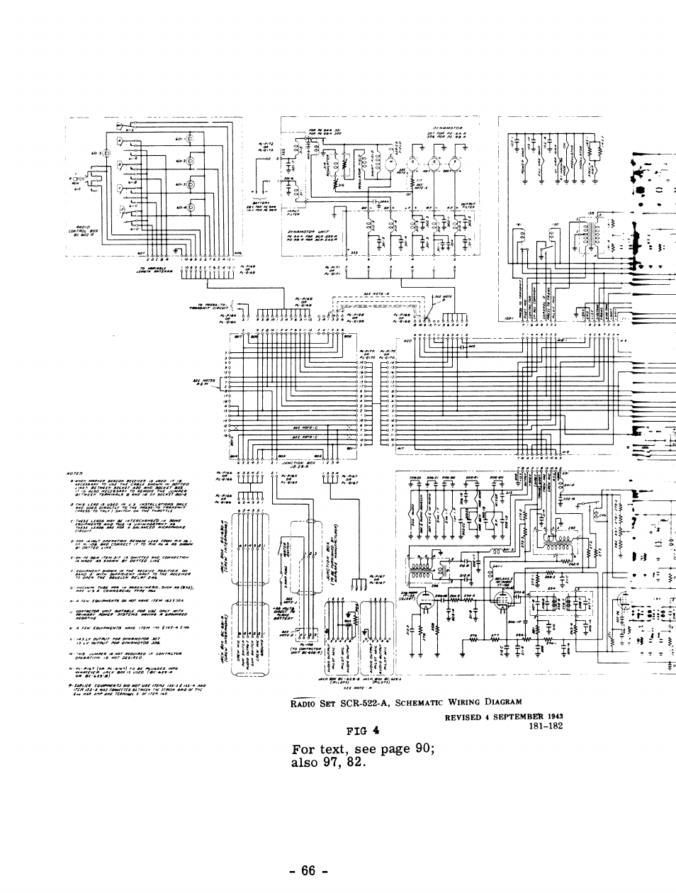
N tr.Xt t2/
- ta 4 ta.. tao
ì
i
r*--
t @rrtEf?l ufrll gf{ar & ug cwa/ t/n
t?rtrol pra, t4rrtgs nrtta a a&rot.o
ueoaT/le
nmro Snr SCR-622-A, ScHsultlc WIRINc DIAcRAM
REVISED
1 SEFTEMBER
1913
FIG 4
For text, see
page
90;
also 91
, 82.
-66r
181-182
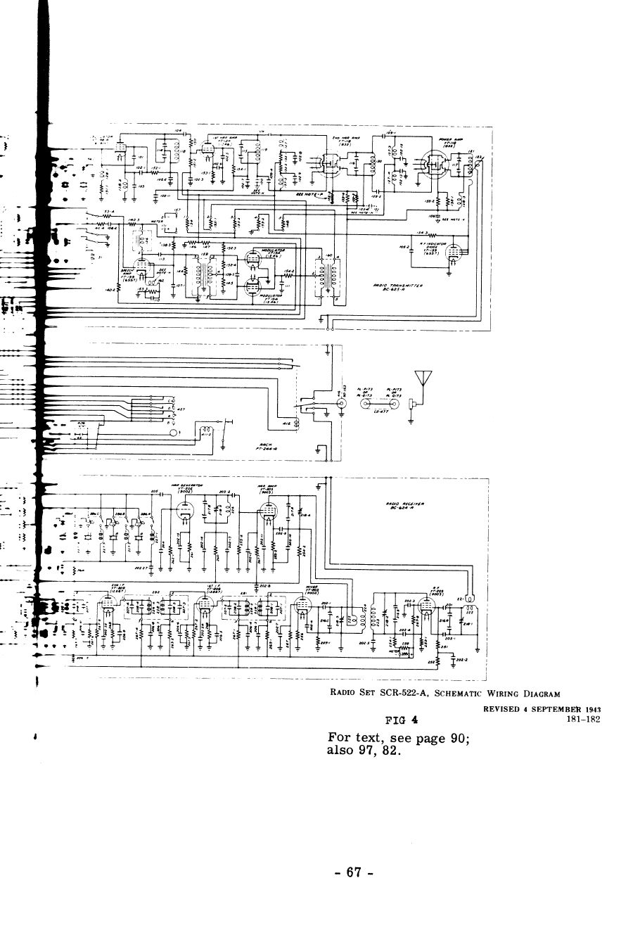
t-:
,
'ut
--
+''::i:: r* :i
3 L--lhl
rT :ii'
T | 9ì ?'
.-!o .(aJ2
)(at, )
toa+
-t, ua 8f c .4
,rÎ
f-pt
(nt)
tuOlO Tfrtsnfrén
tc.625.4
,aoto at4//î,
tc-a2a-e
-_-l
r|r
,.7
J
,r.l I2o2'2
Rloto Spr SCR-522-A, ScHsì{nrlc WlnrNc Dl,c,cnlu
REVTSED
4 SEPTEMBER 1943
FIG 4 t8l_182
For text,_
see
page 90;
also 97
, 82.
-67-

t?5k7 /2 t/é
l,ltxEP lz
s(7
FlPsr / F PtlP
/?5t7 oF wtl/ùo oùtY
?ND. I FRMP I
r-------------------i l-
v.J
?
"1
Ct! o,clLLarce
J-/ Sttur oFF L\NE
Ps y'/.t4,/ED
FPoM
OulstDÍ.
/ P3 \
1rc;T,--"\
\.qeJ%$,
\ ?t -" /-\ ./
/4i\
/,.
=l.rîi] ,lÀ
f fryyr{,é l
\:7
4ì\
/5î
=trylJ .e\
\. . )
\6 //
nrYn,"r,
FFon
ourr:
CIRCUITS
IN R F
COIL
SEI,
IF
COUPLING
UN
I TS.
CW OSCILLAIOR,A
OUÎPUI fR ATISFOFMER
THE
TERMII{AL
NUMEERS ON THESE
UNIIS
AGREEWIIH
THOSE
SHOTVil
AI TAE
CORRESPONDING
LOCAÎIONS
ON
IHE WIRIXG
OIAGRAiI
tF CaùpLtN' UNt73
ffi
twJl
-a><cA
t6ffil
lW- )'c,z 7 I
l.,)Q--Yz I
l-,>Qt(J;l
| / U-'^d1\ I
Itrwfl
IJx(_i/ |
Svnoot z-sc
PF OSC/LLÈrop
SlMaoL Z-58
PF A/.IPL/F/EP
Svnoct z-sa
P F ANTENNq
fiTft I
5/MEoL z-l
lsr lF
( ?J9(C)
SfMaoL
z-2
(2r9K)
SYHaoL
z'3
3PD lF
( 2J9 /(c)
Wiring
0iagram
-68-
fi
Oett Cor'ttpot I rxf
fladio Rectirer BC-940-B
- Schemalic

/? n6
nuoto httP
JYMB
^'r aCZi
5t,ooo
62
0
r50,ooo
300,o
o o
200
200
620
36O,OO
O
I
oo,oo0
?oo
I
oo,ooo
2O,OO0
roo,o
oo
roo,oo0
Sto,ooo
roo,ooo
c26
lrl
c-l
c-2
l"-.
I
c-.1^îoc
i0-5
c-61A,8,C)
i
c-7(A,B,C)
c-8
I
C-9
lc-ro(aB)
c-[
c-12
I
c-r:
fi-l
a-J
a-4
R-3
R-8
R-9
R-to
R-
tl
R-r2
n-B
R-la
F15
R-16
R- r7
R-r8
R-lt
R-20
R-2t
e-22
R-2!
i-28
6?O
2.OOO
p
[!2
lc-r4
c15(A'S,c)
c- t6(ArB,c
I
c-r7
j
o-r3
lc-r9
lc-zoc,c,c.
)
c-21
lc-zz
c-21
ic-24
i
c-25
lc-26
)c-27
I
c-2a
c-29
c-3r
c-16
c-J?
c- 3a
r50o
7000
7000
5r,0oo
qND
[/6ò
tn ConrBot LtNt
J-3 Asúty\/ED FpoM
-óursDE
C
N O5-Sìur-'Orr 11y5
JyMaaL z-4
CW O'f,lLLArap
(?39 t/C)
S/MB)L T-/
1urPur TpeNsroRMEe
@
C
J5
1 TEzMNqL
J 'ro
A*aiep fog @pp
OrU
pltZUZ
czoalT@r
t2s(7
/f,-l\
lJ, /\ ,e\
[.6 !J r"ri
\{J,/
t25P7 t?A6
Qs. ScPtrtt oPto
qJ
(H
Ex).
srpE €N @tq H ÈrcoE
S1ctott
qopxI CoNrpoL
QP\D,
qc SEcrpN.
P, PLarE
P(Htx)
. PLATE,
HEx@€
&cttort
Po
(ry) . PLarE)
o,c.
SECtoN
Q
(tl
tt). Cotreot O
pt
Dt (H
t IoD€ SEc 11 oN
ffadio Beceiver BC-946-B
- Schematic lViring 0iagram
I STANOES
la6 f,MFJ
3 XFD
.o5^/03 x F
o.
o5lov 05 MFD
200MuF
40
uIf
670 ttF foTAL
r80
MUF
t7:ÍF
r80 rxF
olosl05 rFo
z4.zf .22tFo
180
vrF
tTxuF
rgotlF
o5lotl05 úFo
ITMHF
t80
M rF
tEo txF
2oo
fltF
,oor tF0
100 rrF
3!5 Mf,F
J'MMF
.oo6
tFo
r5 rFo
.oot fF0
5 UtO
wrRtrc
caPAc-
rfrncE LEss
fHAn
2 tlF
75O
frlf0
I7 TÍF
ITITF
l7
txt
L-l laNr tnPuf
!-2,L-3 |
RF
AfP
L-.,L-5 I 8F OSC
L-6. L-7 | tN
fr RST
tf
L-8.
L-9 | rr 2t0 | F
L-ro,L-ttl
tN
3RD tF
L-r2,L-r3
I Cw OSC
L-r. I
RF
CHOXE
lr12
MtcRo-
I
HENFTEs
!-r5 I AF CAOXE
Tua€
Socltr TEWNAL,
As Vttt,lED
FpoMSorroM
/4-N /'7-ò\
I' A "\ 1, A,'\
\'Y,,?/ ,k Y,'E
t-L_9r' /{or
U5t
o':{p_}./
lÚEt TeBnruru Cooe
5=
Sterr
H --
HERÌFP
Y =
CATH)DE
S<=5ùppP€sfre.0pD
D7, Frasr Dtoot
Dtert
Dpz'Stcouo D/ooE
PLATE
Q. Coxreot
Qero
-69-

I
ù
!
\.:
*l
5\
r ^ \l
ì ill
P \S:
'ì '-i
-- ò
v .\ v.\
t
\(\
\ \è\\
.ùt\f
>î \
ù q ìÀ
"ì !ù
t$ ì:
ss
ì\
\\ l.\
C\t
.-s
\
Y
vl
\
\<
\
i
\\
I
\t
\
I
krl
sl
N
*l
J
rh
\I
$
o\
I
p
\
\
U
I
L
u
ul
t^-
v)
o
q
\a
\
\
q
s
I
) ')g
l__lt,
- - - - -.lr
4tr6autv lr
- - J L _^la ^^^.
WJF?2 rNoJ
;--j1r,ìv
-70-

coNrEctlotf DIA,GnAI Fon Bc-9468 RECETVEn
I'SIIG IEE N-22OA RACK
(TYPICAL
AI'TO IISÎAI,IATIOX)
'7
A- -: SAT\EPY
TC
SPKE,
-TC ,QF.
É /í ;.
t//8pA-
PA'K
TO
ANT TERM'NA,
ON PF.:EiVEP
/
/
OUTSID€ I//EW OF
BIAR EECEITE PIUG
(.;r rtvT rnc
'biJe T
tkiÈìrrous)
Coptecrep
-oFF-OM 5W.
Pu ),/0L.ccNrea
8C-946
I
Pgcstvep,
L srawo-Bl sw
(on r,eour aF
FT-2?2 ?èa<)
FT-2?CA BACK
(our 5557rC\)
@e
\4,ro
-71
-
t,?
J

BC-9468 RIICEIVER(
Before conve:rslon )
Typlcal of Cormland Set type ReceLvers
-72-

CONVERTING THE SCR-274N
COMMAND
SET RXCEryER,S
(BC-453
Series)
"q-b'er" coNvERsIoN IO-METER CONVERSION
Introduction:
The SCR-2?4N series
of command-set
receivers includes
the BC-4b9,
BC-454,
and
the BC-455. Almost identical
counterparts
to these
three are
available
in the
ARC-5 command-set series.
The 8G453 (andits ARC,-5
equivalent)
is quite effective and
justifiably
popular
as a "sharp-channel"
i-f systemto follow a conventional
communi-
cations receiver. Either the BC-454 or the BC-455 may
be used
intaet as
a communications
receiver, but it will be found
that the receivers are ex-
cessively broad in selectivity due to the high value of intermediate fre-
quency
which is employed. However, due
to this relatively high i.f. either
of the latter types
of receiver may be converted
for image-free operation
on
the lO-meter band by revamping the r-f coil assembly
and the main
tuning capacitor. In addition, several changes
are required in the audio
circuit. These
changes are similar to those
suggested
previously for the
BC-9468 conversion.
(a) GeneralDescription:
The command-set receivers, designedfor
aircraft use,
are light, very
compact, and totally shielded in an aluminum case. Each is a 6-tube
superheterodyne
with one r-f stage, two i-f stages,
mixer, detector,
beat
oscillator and audio. All are designed
to operate from a 28-volt d-c
source, with a dynamotor supplying
the plate voltage.
The units of this series are substantially identical with the exception
of the main tuning
capacitor, and the r-f and i-f coils which are plug-in
units. Frequency coverages
and
intermediate
frequencies
are as
follows:
Unit
BC-453
BC-454
BC-455
Frequency Coverage
190
to 550 kc.
3to6Mc.
6 to 9.1
Mc.
Intermediate
Frequency
85 kc.
1415 kc.
2830
kc.
CoiI Assembly:
(b) Ten-Meter Conversion--Modifying the R-F
This modification involves rewinding of the coils in the plug-in coil
assembly to obtaincoverage
of the 28-Mc.
band. Modification
of the tuning
capacitors to obtain
bandspread operation is discussed
in a later paragraph.
L 1 (Ant. coii) - Remove the existing winding and
rewind with 6 turns of
#18 enameled wire, space
wound
the full length
of the coil form.
L 2 (RF mixer coit) - Remove
the existing
"honey-comb"
coil with the ex-
ception of the last layer. This wil.I leave approximately 9 turns for
L2.
-73-

L 3 (RF mixer coil) - Removethe existingwinding and rewindwith b turns
of #18 enameled wire, spacing the winding evenly the full length of the
coil form.
L 4 (Osc. coil) - No alteration is necessary on this coil.
L 5 (Osc. coil) - Remove the existing winding and rewind with b turns of
#18 enameled wire, close spaced. L 5 should be between l/8 and,3/16
inch from L 4.
(c) Modify ing the Tuning Capacitor:
In order to provide sufficient spreadof the lGmeter band, it is neces-
sary to reducethe capacitance
of each section ofthe tuning capacitor. This
is accomplished by removing all the rotor plates except the two end ones
in each section. Care should be taken so as not to damage the remaining
plates.
rvVith
two rotor plates in each section, the band spreadfor 2? to 30 Mc.
will be approximately 3.5 to 4,7 on the calibrated dial. Using only one
rotor plate per section, the27 to 30Mc. band will cover approximately the
entire dial of the receiver.
To facilitate alignment of the receiver after modification, drill neces-
sary holes (l/4") to expose the trimmer capacitor adjustment screws with
the shields in place. Since the added
cppacitance of the shieids tends to
detune the circuit, it is preferable to align the receiver with the coil
shields in place.
It should be noted that the oscillator frequency must be tuned above
the incoming frequency to obtain tracking over the entire dial.
(d) Changes in the Audio Circuit:
Unless the BFO (V-? stage) is specifically desired, it should be con-
verted to a first audio amplifier. This additional stage gives sufficient
increase in audio gain for satisfactory speaker operation.
Even though some conversions use the existing RF gain control me-
thod (approximately 20K. variable between cathode and ground), it is gen-
erally preferred to have the RF gain remain maximum and use the con-
ventional AF gain control. This is a convenient addition, especially if
stage V-? is changed to the first audio amplifier as mentioned above and
as shown in Fig. 1. When the AF gain control is used, the cathode buss
lead (Iabeled "gain control line") to pin #1 of J-1 is connected directly to
ground.
With reference to Fig. 1 it will be noted that the 12A6 (V-8) is used as
the output stage, R-C coupled to the first audio stage through the AF gain
control. A conventional plate to voice-coil output transformer replaces
the existing output transformer T1. The output transformer used must
match the speaker voice-coil impedance to the required plate load impe-
dance of the 12A6; this is approximately ?500 ohms. The existing output
transformer, T1, is designed for a load impedance of either 300 ohms or
4000 ohms. These outputs were used for headphone reception.
V2 is a neon type, peak-limiting device and should be removed unless
specifically desired.
- l*-

For headphone reception with the above modification of the audio cir-
cuit, and operrcircuiting type jack should be used at the plate output of the
first audio amplifier. This jack is inserted betweenthe coupling capacitor,
C-29, and
the grid of the 12A6.
(e) AVC Circuit:
For optimum signalto noise performance, the RFstage should operate
at maximum gain. This requires removing the AVC voltage from this
stage. To do this, disconnect R2 from the AVC line and ground at some
convenient point. (R2 is V3 grid resistor.)
Due to the high gain of the RF and IF sections of this set, some AVC
action is obtained from the existing circuit. (Diode action of control
grid of second IF amplifier.) If more AVC is desired, it can be obtained
from the unused diode plate of V-? (12SR7)
in the conventional manner.
For this change
refer to Fig. 1.
In using the diode section of V-7 for the AVC, it is necessary to re-
move Rll from the V-6 grid circuit. Refer to Fig. 1 for the added AVC
components to V-7.
(f) Power Supply:
The most convenient AC power supply to use with these receivers is
the one shown in Fig. 2. By using the cathode type rectifier (6Xb), the 5
and 6.3 volt windingsare usedin series which gives approximately 12volts
for filament supply. This permits the use of the existing tubes with just
minor changes in the filament circuit as shown in Fig. 2.
Correct polarity (phasing) of the two filament windings should be ob-
served to obtain the proper additive voltage.
(g) Mechanical Modifications:
To complete the receiver conversion, the following mechanical modi-
fications should be made:
The added controls, OFF-ON switch, volume control, and headphone
jack should be brought out in the front panel. This is accomplished by
removing all of the hardware of the J-1 plug assembly located on the front
panel. An aluminum plate is mounted over the opening left by the J-1 plug
and serves as a panel mount for the controls.
When removing j-1, all connecting leads can be removed from the set
except the one labeled "gain control line" which is connected to pin #1.
This lead is grounded as stated above in section (d).
Witha bit of ingenuity and patience, the power supply can be located on
the receiver chassis in the former dynamotor position. However, if the
power supply is constructed as a separate component, the ]-3 position can
be used as the connecting plug.
AII leads can be removed from f
-2; lead to pin #2 is the filament lead
and is connected to the new filament source.
It is apparent that the several components connected to ]-3 are not
needed
for AC operation and canbe removedto provide more space for the
-75-

modiflcations and additional parts as were the BFo components
of the v-?
stage.
NOTE: For schematic
diagram
refer to Fig. 1 of the
BC 946.
(h) Use of the
BC-453A
as
a
"q-b'er":
The
BC-453A
command
receiver operates
with an i.f. of gb
kc., which
permits
it to have
an unusually
sharp response
characteristic. The
normal
method
of using
this receiver as a "q-b'er" is to convert
the
audio system
and the power supply as just described, and then to couple
a shielded
wire
with a probe on the end into the communications
receivèr in the region of
the last i-f stage. The BC-4b3 wiil operate, without modificatiori, a, "
sharp
i-f channel
for any
receiver having
an intermediate
frequency
from
190
to 550
kc. Greatest selectivity will be obtained
with the fibei rods
which
protrude from the center of the
top of each
of the i-f transformers
pulled out as far as they will go for each
of the three transformers. This
degree
of selectivity, which may be too much for comfortable listening to
a phone
contact, may be reduced
by stagger
tuning the i-f transformèrs
slightly, or by pushing
down
one or more of the fibir rods.
The
BC-453A
may
be
operated
in conjunctionwitha
BG34g as a sharp
channel
either by making modifications
in the r-f coil assembly
of thì
BC-453A or bv using a frequency-converter
stage. It is possible to re-
move
turns from the coils in the r-f assembly until the fiont end of the
receiver wiLl tune to the 915-kc. i.f. of the Bc-349. The alternative
method
of using the
BC-453A in conjunction
with the
BC-34g is to use
an
ou]b9qd mixer stage
between
the output
of the Bc-34B and the input of the
Bc-453A. This mixer stage should accept
the glb kc. signal from the
Bc-348 and convert
it, using
conventional
broadcast
receiver components,
to a frequency
in the
vicinity of 456
kc. for feeding
to the
input of the
nc-
453A. A 6sA?
tube is idealty suited to performing the frequency
conver-
sion
which
is required.
-?6-

Auoro Secrrox FoB CouvrBrro 5C,Q-?71N
(8C-453 A) 5e erts Qect r rzrp
PF CotL SET
SyMaoL Z-J
VOlCE
CO/L
Svuaot Z-SC
RF OSC
Svueot Z-58
PFAMP
Syueot Z-sa
,EFANT
ilofe: : Snaq /d Motse Lirn i f er
Circut/ be. desired refrr lo
conL/er',/on of ac - 9+6 ,
page J/
For orìeinal schetna lìc
diagrarn lefeí /o BC-94ót
/oaEìe J Ò
\ !P,
dD
- al
-

Powee Sueety pap 5CR'274 N
Recetvecs
-_-->
/2/.4a
*-\.--J,--
Sn;cl
/ tt//C 3
-- 'l fzSL v
/24.óa/rA
Ft tnuavr CrpcutT
',/-3 ,'_4 /-5 t/-6 /'/
ì
X
t/-8
=
r\*/ \;, I
l
I
I
:-
=
\-\
5a/ì4 /ìaes- exist'ing circuit'
Y - Open circuit ó/ lhese poinls
oot'fed/ines- added circull'ràr /2r operalion
l,/ofe: 79 6ro/l lqbes ere subs/t-lu/sd {o.
lhe tz ro,/l t'ttbes lhe o/'/'q/rta/ crrcui/
need no/ be aoúrted /or' e ro//
4ea/er 2pera/ron
I
lo
/2
rr'Ac
- 6X5
-?8-

CONVERTING THE BC-45?A TRANSMITTER
SERTES
(SCR-274N)
rOn USE AS VFO
lntroduction:
This series of transmitters was designed for use in Army aircraft
and,
for all practical purposes, the following data will also be applicable to
the Navy version (ARC-5 Series).
Frequency coverage of units:
BC 45?A 4 to 5.3 Mc. (Crystal check
point at 4600
kc.)
" 458A 5.3to7Mc. ( " rr rr " 6200
" )
" 459A 7to9.1 Mc. ( " rr rr " 9000
" )
" 696A 3to4.0Mc. ( " rr rr " 3500
" )
The circuit schematic included as part of this article is for the
BC 4584, but it is typical of all the models including the Navy ARC-5
series.
The output frequency is governed by the directly calibrated tuning dial
and has nothing to do with the crystal in the unit. This crystal is merely
used as a check on dial calibration and can be changed to any frequency
desired, providing the pin connections are observed on the crystal,
The tuning eye (1629) originally obtained part of it's operating bias
from the 24-volt DC source, and, in order to allow this tube to function
normally with AC on the filaments, remove resistors R-?0 and R-7? from
V-53. Replace R-?? with a 2000 or 2500-ohm 1-watt resistor. The tuning
eye will now function nicely. To calibrate the unit, set the dial to fre-
quency of the crystal in the unit and insert a screwdriver in the opening
under the slide in front of the 1629 compartment. Adjust this trimmer
(Osc trimrner) for ma><imum shadow on the 1629 tuaing eye. Clockwise
rotation lowers the frequency.
Connections to the unitwill be greatly simplified if a rack is purchased
which was designed to hold this size unit, and if not used intact, the plug
can be removed and used to make power connections. Otherwise the power
leads will have to be soldered directly to the terminals of the piug on the
rear of the unit.
To Convert For Use As VFO:
]am the bottom relay closed (K53) or short out the associated contacts.
(This relay was used as a keying relay and applied plate voltage to the
Osc while at the same time shorting out R75.)
Solder the top relay (K54) to the antenna
post. This relay originally
grounded out the antenna
when the transmitter was not in use.
Connect 24 volts AC (1 amp), to terminals 1 and 6 of the plug for fila-
ment voltage. (If desired, the filaments may be easily rewired for
12
volts by referring to the schematic.)
1.
2.
3.
-79_

4. connect approximately 300 volts to terminals 1 and ? for the power
Amplifier plate
voltage
(1625's). (Terminat 1 is ground.)
5. connect approximately 200
volts to terminals 1 and 4 for the power
Amplifier Screen
voltage.
6. connect 180 to 200
volts to terminals 1 and
3 for the osc plate
voltage.
(For stable operation
this should
be from a regulated supply.)
7, couple the output of the unit thru a coaxial cable or twisted pair to
your transmitter's v.f.o. input.
8. If trouble is experienced
with oscilLations,
it may
be wise to remove
the antenna tuning coil L52 completely from the unit. If this is done,
the secondary of r54 can
be brought out to the original antenna
post
and to an added one, allowing a balanced (ungrounded) line to your
transmitter.
9. It may also be desirable to add a midget phone
jack in the lower left
hand
corner of the unit and wire in series with the 162b
cathode
cir-
cuit. A milliammeter may then
be plugged into this jack to read plate
current
of the 1625's.
NorE: All terminal designations given
above
are for Bc-4b?A series, the
plug
connections,
of which are shown
immediately
below. For the
ARC-5
series, refer to the alternative
plug-connection
diagram
below.
PLUG
CONNECTIONS
AFTER
MODIFTCATION
FOR V.F.O.
(ECASZN
SERIES)
e4 voLTs Ac
NOT
USED
OSC.
PLATE
VOLTAGE
(rOEO)
PA
SCREEN
VOLTAOE
(reeS)
NOT
USED
24 VOLTS AC
PA HrcH VOLTAGE (reaS,S)
PLUG
CONNECTIONS
AFTER MODIFICATION
FOR V.F.O.
(ENC-S
SERIES)
NOT USED
OSC.
PLATE
VOLTAGE
NOT
USED
24 voLTS
(e
Xo)
24 VOLTS
PA SCREEN VOLTAGE
PA HIOH VOLTAGE
FACING
REAR
OF
TRANSMIÎTER
1.
2_
3.
4,
5.
6,
7,
t.
2.
3.
4,
5.
6.
7,
-80-

ScHEMATIC
0F Bc-458A
(5.3 - 7 Mcs)
\----
58-A
L1.0.-rf-87
(/ó 2ó)
'e 72
C
T<a
v / -/Jb
(tó25)
I
( 5.t Oufs/D€ vtEw
/- 6po
2-
3'Osc.Ptare
4 - Ar,te. ScBteu
5-
6-+24n
ttr
ctBArcSBBrCSSC
- .05 uf
cr9 - .ooo18 uf
C60
- Master Osc. paddlng
C6L
- .006 uf
C62
- Flxed Neutrallzlng
C63 - l{aster Osc. tunlng
C64 - .0O2 uf
C65
- P.A. tunlng
c66 - .01 uf
C67
- P.A. paddlng
C68
- 1.0 uuf
e69 - 50 uuf
Kr3 - Xnttr SeLector Relay
K54 - Iuattr Output Relay
7
- A.\4F.
Ptars
Lrz - Ant. Loadlng Co1l
R67_$7?tR75t
- J1looo oh.ms
R6ErR761
- 20 ohns
Ró9 - I Megohn
n70 - 10@ ohns
n7f - 126 ohns
R73rR74, - lflOOO ohns
R77 - 390 oiuns
R78 - 51 otrns
Rt-50 - Parasltlc Suppressors
T53 - 0scillator Colls
T54 - Arnpllfler Colls
YlO - Crystal Unlt
-81
-
I
I
I
I
\

CONVERTING
THE JCR-522
(Transmitter-Receiver)
A popular
piece of v.h.f. radio equipment
that has been
quite
common
on the surpluÀ market is the SCR-522 (atso SCR-542)
communication
transmitter-receiver. In the military service it was generally known
as
the v.h.f. communication
set used
in the larger aircraft for inter-aircraft
and air-ground communication. The ground
version of the SCR-522
in-
cluded séveral additional components
such as a power unit, antenna, and
antenna
mast.
power
requirementsfor
the
scR-522
are
2gvolts
d.c., at 11.5 amperes
(maximum),
*ith the PE-94A
dynamotor
furnishingthe
required "B" supply.
Identical to the scR-522, the SCR-542
operates
from 14
volts dc., at 23
amperes,
and
uses the
PE-9BA
dynamotor.
This set, consisting
of an automatically-tuned,
four-channel,
crystal-
controlled transmitter-receiver, operates
in the range of 100 to 156 Mc.
The frequency
channels
are determined
by the
four sets of crystals used.
This frequency
range
covers
many ofthe important services
including
air-
port control, police, railroad, air navigation
aids, facsimile, urban
tele-
phone,
and
of course
the 144 to 148 Mc. amateur
band.
The complete
scR-522 Radio
Set
consists
of the
following
components:
Transmitter.... BC-625
Receiver ' BC-624
Dynamotor
Unit . PE-94A
Rack. ..FT-224
case ' ' cs-80
control
Box' ' ' ' Bc-602
]ack
Boxes
(for crew
interphone) BC-629,
BC-630,
and
BC-631
The conversion
of the
SCR-522
for amateur
use involves
the two basic
components,
the
transmitter, Bc-625, and
the receiver, BC-624. These
wiltbe discussed
separately
since
it is generally
preferable to use them
as separate
units for stationary operation. For mobile operation, the units
*"y b" replaced in their original case and
operated
from the
original dy-
namotor,
PE-94A.
Transmitter,
BC-625:
The conversion
and
modification of the BC-625
is discussed
under
the
following section headings:
(a) General
Description
and
Operation
(b) Circuit Changes
(c) Power
SuPPIY
(d) Mechanicai
Modifications
(a) General
Description
and
Operation:
This transmitter with oniy slight modification
makes an
excellent
low-
-82-

power transmitter for either stationary or mobile use. With the recom-
mended power supply, it will deliver 12 to 15 watts to the antenna; or it
may be successfully used to drive a large po'ù/er amptifier on 144 Mc.
where higher power is desired.
The transmitter tube complement consists of seven tubes, three of
which comprise the modulator, and four in the RF section.
Beginning with the RF section, VT-198A (6G6-G) is a modified pierce
crystal oscillator which doubles its frequency in the plate circuit. For
operation in the 144-l4B Mc. range, it is necessary to use a crystal fre-
quency in the range of 8.0 to 8.255 Mc.; the power amplifier output is the
18th
harmonic of the crystal frequency.
The plate output of the crystal oscillator, which is at 16 Mc., is
tripled in the next stage to 48 Mc. This stage is the VT-134 (12A6) and
drives the third stage, VT-118 (832), which also is a tripler. This brings
the frequency uptothe final frequency oî 144
Mc. The output of the second
tripler is coupled into the final with the hair-pin type of tank tuned with a
split-stator butterfly capacitor. The final power amplifier VT-l18 (832)
operates as a straight amplifier and is coupled to the antenna through a
variable swinging link.
It will be noted upon inspection that alL coils are of the silver-plated
type. Another point worthy of mention, is that the antenna loading can be
anything between 20 and 500 ohms. However, it will be most convenient
to
use 52 ohm coaxial cable which matches the receiver input impedance and
which also is the most readily available on the surplus market.
In some models of the SCR-522, a VT-199 (6557) stage is used as an
RF indicator. This stage is connected as a diode and coupled with a pick-
u:: loop into the final tank circui.t.
The modulator section of the transmitter consists of a speech
ampli-
fier, VT-199 (6557), which is driven by a carbon mike through the input
transformer 158. This stage also acts as an audio oscillator when tone
modulation is used. The speech amplifier in turn drives the push-pull
modulators,
VT-134's (12A6's),
which modulate
the plate and screen of
the
final RF amplifier and the screen of the driver stage through the modula-
tion transformer 160.
(b) Circuit Changes:
Voice modulation with the existing modulator is accomplished with a
single or double button carbon mike through input transformer 158. If a
single button mike is used, only half of the transformer primary is used
with the center-tap grounded as shown in fig. 1. If a crystal mike is con-
sidered, it will be necessary to add an additional
pre-amplifiertothemod-
ulator input. This can be a conventional voltage amplifier using a high mu
triode with a 12-volt heater such as the 12F5. An alternative approach is
using the unnecessary RF indicator stage VT-199 (6S5?) rewired in the
conventional manner as the pre-amplifier stage.
The T-1?, which is readily available on the surplus market, will oper-
ate very satisfactorily with the transmitter as a carbon mike.
If modulated c-w operation is desired, in addition to voice, it can be
easily obtained by keying the cathode circuit of the speech amplifier, 655?
-83-

(VT-199), when it operates as an audio oscillator. This is conveniently
done by inserting a normally-closed-circuit keying jack in the cathode
circuit as shown in fig. 1. It is also necessary to install a double-throw
single-pole switch in the grid circuit of the 655?. This switch changes
the
operation of the normal speech amplifier to an audio oscillator, thus
giving
the audio tone necessary for ICW. This switch as shown in fig. 1 merely
replaces the grid circuit contacts that formerly existed on relay No. 131.
Since the mechanical tuning arrangement is removed from the trans-
mitter and discarded as discussedin section (d),
it is necessary to provide
a crystal selector switch in order to utilize the different crystals. This is
accomplished by a four-position single-pole switch as shown in fig. 1. The
switch is physically located onthe front panel as shown inthe panel layout,
fig. 2.
To facilitate tuning and operation, it is necessary to meter the plate
and grid circuits in the conventional manner. This was accomplished by a
switching arrangement and metering leads which were brought outto jacks
for a separate external meter. As shown in fig. 2, a O-l d-c milliammeter
can be mounted on the panel with the metering leads run directly to the
meter. The selector switch shaft is then extended
and controlled from the
panel.
Since metering is practically a necessity for tuning up a transmitter,
the added
meter is a worth-while addition that wiII complete and dress-up
the appearance of the converted transmitter.
After the BC-625 is converted and connected to the power supply,
described in section (c), it can be tuned up on the 144
Mc band in the con-
ventional manner. The following chart gives the resonant conditions of the
different stages, using the O-1 milliammeter in the respective circuit po-
sitions as selected by the metering selector switch:
Sw. Pos. Circuit Normal Meter
Reading Actual Current
(ma) Full Scale
Represents
No. 1
No. 2
No. 3
No. 4
No. 5
No. 6
1st freq.
mult. plate
2nd freq.
mult. plate
PA plate +
Not used *'
PA grid
OFF (open
position)
0.4
0.5
0.6
- 0.?
0.5
- 1.0
40
50
60-?0
1.0
-
2.0
50
100
100
2
posi
* Adjust antenna
loading.
** Used on some
models
in conjunction with RF indicator, full
scale represents 1 ma.
The above data are the approximate values that can
be expected
when
using
a plate supply of 300volts at approximately
260
ma. This represents
approximately 20 watts input to the final which under normal conditions
shoul.d
give about
12 watts to the antenna.
-84-

(c) Power Supply:
The power supply required to operate the BC-62b his to supply 12
volts at 2.4 amperes for the heaters, and to supply a plate toad of ioo -a.
at 300 volts. A fixed negative bias of 1b0
volts is alsò required.
The easiest method for obtaining the bias voltage is irom the bleeder
which is tapped at ground thus giving the required bias voltage below
ground potential. If this method is not convenient,
the bias may bJobtained
from a battery source since the current drain is very low.
A power supply'designed to meet the above réquirements is shown
complete in fig. 3, and should be self-explanatory. It wiil be noted that the
recommended rectifier tube operates very near its upper limit; however
for normal transmitter use, it will operate very satisfaòtorily.
(d) Mechanical Modifications:
The mechanical modifications primarily pertain to the added panel
with its associated controls as shown in fig. 2. In order to add the nàces-
sary tuning controls, it is necessary to disconnect the tuning capacitor
shafts from the ratchet tuning mechanism. It is not necessary to iemove
the ratchet assembly itself since the shaft extensions extend
ihrough this
assenrbly.
The panel used is of standard relay rack dimensions and is mounted
to the transmitter chassis with 3
inch brackets, It carries all of the desis-
nated controls as well as the O-1 milliammeter.
-85-

\l
S. l
\l
x
\'
\v
cr)
a
\
\
qr
t
ll
\
fr)
a
$
c
q
T
I
\
br
\s
\
\
g
i'.J
l-t
f,\
{
s
i<
F\
rf)
N
\o
I
H
_ù
$
I
o
U
ó-
Y
Y
I t?/ |
Lara_Qo-i
-
rrì-qrrt
tAl
tx"l
t.
I
ì
F
è
D t /-9e/ /'/t/
îî ì
\i
I
J
h{
s
R
\\
Vd
'V dvH- o-Nz
'y dvH- -G/
-.-v àHv Y
H 2ttéS
:H
d>
/-l--r
\A) I
YI
ff
ill; I +o*'u
,-2./ :\ I ...
à /-tt/ ,-z€/
-86-

8C -
625 Pnuet / ayour
Par,e/ - *
sheel qfuVtt
7' /9 " sld
rt ,/a y rac k
a / tr)'€ nsiÒn5
1
>-..1
F
L- Meler
5u * x'/a/ syu.
ftql
r----- - ----J
/unincl shqfl
det'óì/
Mla bro'kers
f,'stee/
8-32 lhreqa
-87-

Povtec SueptY FoP BC-62î
/2 /aLTS
PARÎS LIST
f'g
s
+
î
l
+300 t/
I
{
:60 V.
a:
vé
t
tt/o7t - Proper ,
pastnq requ/rcd
'bctvveèn Serres
6rotl rúndtngs
F
Stl
I/5 L/I
AC
îî
rF
Rect.
L
vl
w)
dl
"é
F
Sw
Pone.r
transformer, STANCOR P-63L5r 75Ov
ZlJnaz
Jv, & 6.Jv
Fllanent tiansforroer, 6.3v/2A
523 or 5U4
Fllter Choke,
10 h., ZJO
na.
F11ter Condenser,
8-mfd1
600 v.
l'llter Condenserr
1ó rofdl 600 v.
Reslstor, 351000
ohnsl 1O
watt.
Reslstorr /JO ohms,
f watt.
Fuse, 2 anp.
Swltch, toseLe
-88-

Receiver, BC-624:
As the receiver component of the SCR-522, the BC-624 lends itself
nicely to conversion for the two meter enthusiasts.
From the general description it becomes apparent that there is more
required in converting the BC-624 than its companion component, the
BC-625 transmitter. Even though the conversion appears difficult, it is
generally considered a rather easy and interesting onetothe average ham.
It will also be apparent that some of the described refinements are
optional and not essential for putting the set into operation. However, in
most instancès, these optional features areincorporated as wellas a num-
ber of the personal touches. This is not out of line in doing justice to a
well designed receiver such as the BC-624 which will perform with best
of them.
The following topics of conversion will be discussed in detail with re-
ferences to the schematic diagrams and drawings:
General Description and Operation
The HF Oscillator Circuit
Revamping the Second Detector and Adding the Noise Limiter
The First Audio and Addition of the "S"-Meter
Adding the Second Audio, Power Amplifier Stage
Power Supply
for the BC-624
Tuning Mechanism
Mechanical Modifications and Panel Layout
Performanc e Information
(a) Generai Description and Operation
This receiver is a l0-tube superhet with an intermediate frequency of
12 Mc. In its military form it is a 4-channel receiver which has a preset
tuning arrangement and a crystal-controlled high-frequency oscillator.
The three principal models of the BC-624 are the BC-624A, the BC-
624AM, and the BC-624C. The "A" model is the earlier model with the
"AM" being the modified "A" model. This modification was the miiitary
improvement and consisted of an additional tube (12H6)
installed under the
chassis which functioned as a noise limiter and delayed AVC. The latest
model is the "C", which incorporates several. modifications over the ear -
lier sets. These changes consist of an added
"squelch" circuit andan extra
audio stage.
From the above information, it is apparent that the later models are
the preferable ones since the addition of the noise limiter and AVC is an
important improvement toward the receiver's operation. This modifica-
tion was later made by the Army on almost all of the earlier sets.
The existing tube line-up with their respective functions are as fol-
lows:
9003 (VT-203) First RF Amplifier
9003 (VT-203) Mixer (first detector)
12AH?GT
(VT-207) Crystal Osc.
and
Audio Squelch
(a)
(b)
(c)
(d)
(e)
(f)
(g)
(h)
(i)
-89-

Harmonic Generator
Harmonic
Amplifier
First IF Amplifier
Second IF Amplifier
Third IF Amplifier
Second
Det., AVC, and First Audio
Second Audio Amplifier
(b) The HF Oscillator Circuit:
The existing crystal oscillator operates on four preset crystal fre-
quencies in the range of 8.0 to 8.? Mc. The harmonic generator selects
the desired harmonic, (11th to the 18th) while the harmonic amplifier am-
plifies the relatively weak harmonic frequency to usable strength for the
mixer stage.
To obtain continuous coverage of the band, it is obvious that the oscil-
Iator must be changed from the crystal controlled type to the variable
tuned type. This is accomplished by eliminating the existing crystal os-
cillator stage and converting the harmonic generator to the variable-tuned
HF osciilator. This becomes an easy matter sincethe harmonic generator
tuning capacitor, 21?B now becomes the new oscillator tuning capacitor.
All four crystal circuits and the former oscillator circuit are elimina-
ted in this change and can be removed to provide additional space. The
circuit modification is self-explanatory from the before and after circuit
diagrams in fig. 4+ and fig. 5 respectively.
For the required mechanical tuning arrangement of the oscillator,
refer to section (g).
(c) Revamping the Second Detector and
Adding the Noise Limiter:
As mentioned before, the later models of the BC-624 have the modifi-
cation that incorporates the 12H6 (duo-diode) as the Second
detector and
the noise limiter. This stage is mounted on a bracket under the chassis.
To add this modification to the earlier models, should it be necessary, it
should be noted that the 12HG
reptaces the, original 12CB tube. From the
modified schematic diagram, one half of the 12H6 serves as the detector
and also furnishes AVC voltage in the conventional manner. The other
half of the duo-diode serves as the noise limiterwithits respective circuit
and may be manually switched in or out. This stage should be wired as
per the modified circuit as shown in fig. 5.
(d) The First Audio and Addition of the "S"-Meter:
The former L2CB
tube location is used for the LZAH?, dual triode, one
section of which serves as the first audio amptifier. This stage is coupled
to the second detector output inthe conventional manner through a.5-meg.
volume control.
An optional feature which is frequently added to facilitate tuning andto
estimate signal strength, is the "S"-Meter. The circuit includes a 0-1
milliampere meter which can be attractively added to the panel of the
*For Fig. 4 - see
Pg.
66. _ g0
_
9002
9003
12SG?
12SG?
12SG?
12CB
L2J5
(vr-202
(vT-203
(vr-209
(vr-209
(vr-209
(vr-169
(vr-135

receiver as shown in the panel layout. This "S"-Meter differs from the
more conventional type since it utilizes the AVC voltage for its operation.
The AVC voltage controls the meter bridge circuit through the triode am-
plifier, 12AH? (second
section). For manual adjustment of the meter de-
flection, a 0.25-meg. potentiometer in the 12AH?rs grid circuit is used to
obtain the proper amount of the AVC voltage. A switch is provided in this
circuit for switching the "S"-Meter in or out as desired.
Another version of the above described "S"-Meter circuit incorporates
the tuning-eye instead of the 0-1 millampere meter and the meter bridge
circuit. This is primarily a tuning indicator and involves fewer parts and
less expense if parts have to be purchased.
The 12-volt version of the 6Eb (magic eye
tube) is the 1629
(VT-138)
and is readily obtainable on the surplus market. It can be conveniently
mounted at the rear of the receiver panel projecting through the panel in
the approximate location shown for the meter in fig. 6.
Operation of the tuning-eye is directly controlled by the AVC voltage;
however, due to the relatively low AVC voltage, the circuit shown
below is
recommended Ior optimum operation.
t629 VOLTAGE
DROPPI NG
R ES
I
STOR
TO A.V.C.
BUSS
TO CATHODE
TO B+
OF
2ND DETECTOR I2 V.
HEATER
(e) Adding the Second
Audio, Power Amplifier Stage:
In order to obtain sufficient audio volume for speaker operation, the
power output stage, 12A6, is added with the conventional plate-to-voice-
coil output transformer. In the later models this stage would replace the
existing second audio stage,
(12J5). In the earlier models this stage can be
located in place of the squelch transformer 295. The "squelch" circuit is
generally not considered. practical and is completely removed from the
receiver to make room for added modifications.
The audio power amplifier is coupled to the first audio amplifier
(12AH?)
in the normal R-C manner. Output transformer, 296, intended for
headphone
use (50, 300, and 4000 ohms) is replaced with a conventional
plate-to-voice-coil output transformer. The impedance match for the 12A6
from the PM speaker voice coil should be approximately 7500
ohms.
It may be desired to add a closed circuit jackin the grid circuit ofthe
power amplifier, 12A6, for headphone
operation. Both jacks, first audio
phones and second audio speaker, can be brought out to the panel of the
receiver as shown in the panel layout.
0.5 MEG.
-91
-

(f ) Power Supply for the BC-624:
The power requirements for this receiver are a plate potential of 300
volts at 60 ma., and a 12-volt heater supply at approximately 1.?
amperes.
A power supply for these requirements can be conveniently constructed as
shown in fig. 5. A ?O-ma. power transformer is used with the 5 and 6 volt
windings connected in series, and using the 6X5 (cathode
type) rectifier.
Polarity of the two filament windings must be observed in order to avoid
phase cancellation. This can be determined by experiment so as to obtain
the correct additive voltage. The conventional filter is used with a stand-
by switch placed in the center tap lead for use with the transmitter.
Even thoughit is possible to build the power supplyinside the receiver
with careful layout of parts, it is considered preferable to keep it as a
separate component with a connecting cable and plug to the receiver. If
desired, the power supply OFF-ON switch may be located on the receiver
panel with the leads brought out to the above mentioned power supply con-
necting plug.
(g) Tuning Mechanism:
The manualtuning capacitor controls ofthe converted receiver involve
the two-ganged capacitor which tunes the oscillator and the harmonic am-
plifier, and the three-ganged, RF amplifier grid, the RF amplifier plate,
and Mixer grid tuning capacitor.
The original preset ratchet seleetor and tuning mechanism is not par-
ticularly adaptable for ham operation and should be completely removed
from the receiver chassis. This then makes available both shafts of the
above mentioned tuning capacitors.
Due to the highly compressed 2-Meter band, as appearing on the
capacitor shafts, it is quite necessary to use considerable mechanical re-
duction for manual tuning. This is particularly true for the oscillator
tuning, since the band appears in a very narrow sector of its 90 degree
rotation.
For the three-ganged capacitor, the National velvet vernier dial, such
as found in the surplus BC-3?5 tuning units, is quite satisfactory. This
type of dial is quite compact and easy to use, being well appearing on the
receiver panel.
Due to the very narrow section in the oscillator tuning, it is apparent
that even the National vernier dial is not sufficient reduction to afford
practical tuning or dial calibration. For this problem there has appeared
a variety of tuning arrangements that incLude both the electrical band
spread method as well as the various mechanical methods.
The electrical method is probably the most desirable but does involve
considerable effort for installation. This is generally accomplish.ed by
using a separate two-ganged condenser having onlytwo or three plates per
section, and connecting it in parallel with the existing condenser.
Of the different mechanical reduction arrangements, this one as des-
cribed below, is probably the most straight forward and fool-proof. It
consists of the national, type "A", vernier dial used in conjunction wi.th a
belt (dial cord) driven reduction. The dial cord and pulley arrangement is
-92-

supported between a frame-work consisting of two metal plates. This as-
sembly is mounted directly on the receiver chassis, positioned to couple
the drum to the oscillator capacitor shaft andto locate the tuning knob in a
symmetrical position on the panel. The drawing in fig. 2 shows this as-
sembly in detaii.
The described tuning assembly gives very satisfactory and smooth
tuning reduction. This reduction will be such that the 144-Mc. band will
be approximately 50 divisions on the 100
division vernier dial. parts for
the dial cord and pulley arrangement are easily made
or readily available.
(h) Mechanical Modifications and Panel Layout:
After the removal of the slider-ratchet tuning mechanism from the
front of the receiver, brackets are madeto support thepanel approximately
3 inches from the front of the receiver. The 3-inch space between the
panel and chassis is ample for the tuning reduction assembly and all of the
other controls.
If all the modifications listed herein are contemplated, the front panel
will carry the two National dials, the "S"-Meter or tuning indicator, volume
control, AVC switch, send-receive switch, "S"-Meter" switch (if used)
noise limiter switch, and the power OFF-ON switch.
(i ) Performance Information:
As was originally true in the military version of the BC-624, the con-
verted receiver should have a signal sensitivity of approximately 3
micro-
volts for an audio signal to noise ratio of 10 db.
The receiver input is designed to operate from a 50-ohm antenna cir-
cuit. Should higher impedance lines be used, it will be necessary to in-
crease the number of turns on the antenna
coupling coil. The increase of
turns is small, being approximately Z-lf 2 turns (total) required for a 600-
ohm line.
Should a balanced antenna input be desired, the grounded side of the
coupling coil should be lifted.
It will be found thatthe modified high-frequency oscillator canbe tuned
eitier 12 Mc above or below the incoming signal. After becoming exper-
ienced with the tuning characteristics of the receiver, the operator should
be able to use the preferable frequency (above or beiow) without difficulty.
An interesting note in connection with the exceptional oscillator tuning
range is, that by squeezing the RF and mixer coils slightly, the receiver
will tune down to the 88-108 Mc. FM band. By utilizingthe above andbelow
tuning of the oscillator, as mentioned above, the FM band can be covered
without sacrificing any of the 144-Mc. band, thus a total coveragefromSS
to 148 Mc. Since the IF band pass
is approximately 150kc., it can be made
to operate nicely on FM by incorporating a limiter and discriminator
circuit.
From the above information, the 2-meter enthusiast should be able to
have, at a very nominal cost, a smooth operating and attractive receiver.
The performance of this unit will be found to compare favorably with the
best receivers of this type.
-93-

a1
È
Èì
\)
,\
l\
l\
s
-t
I
.\
{.
\
\
I
s
ù
\o
c
({
F\
a
\
^-
\
\
({
&
dr''
*rl :
ù\ |
È/rl
&T
N
$
è
È\
*
Sr -l
ìì
ò{.
g*d
\ù{
Uì
lq
u\
S
a
\\
a{
$
N
o
-q
t.
\r
U
ì
\
\
rit,,.
ll(
ls
€
l\
ù
(})
r\
\ì
v)
\Ht,'
-94-

Layour roe BC-624
'S L tntefee oB i-uNlNG -
avÈ <r- 7Èv?
LtLtrÉe.È^l
'\
\
/e- \\\
VoL ^/L AVc
Copr S!4. 5W
O/AL CORD EELT/il'
eeurt
fi"Atuu.
ST'D PELAY ,EACI
D/M7ENS/oNS
fis6
-'t'-
Nartopa L
t/€ep/ É2 KNOES
i
\l
tk fùN,lG
Òfn.r/r
Y\J
/\ì\
-95-

9Me-l
lnll lnl:lirl
,
I
6'.F.".E-J
O
( zoo.t
;;;)
,.a o)
F
an
a
F.
F
z
F
z
E
E
(.)
t
o
(0
@
@
@
@N t. ?06-7
o
o?o6-a
269
zo6-9
q
(
@{
rl.
I 267.6
I ?é7-5
. ?O6-tO
z06-zo
v-
i@
rc)
6l
(
gil
Ot
263-3
z06-tl
fzso
2o6.23.
f77î-t
@
€
o
,l
(
@[
-?9rD
:1
-27, I
3*tt
o
€
p
b
ta.9
-96-
TA.5

SECTION
SCREW
FOR
SET
WRENCH
R F SEAIION
MOUNTINA SCREW
1ryD ry PLATE
RES2NATING_
COIL TUNING SCREW
236
CONTROL
STUENT
SCREW
JT-69,DET,
A.IST
AUDIO
,'CONTROL
ÍHENT
SCREW
289
246
248
vT-t35
2 ND
AUDIO
JÍ-207,OgC &
SOUELCH
2t7
EIVER
f
UNING
IIITRO
L
'XHUTS
IVER
237
295
vT-209, 3RO IF
3RO
IF GRIO
RESONATING-
CO,L
TUNINo SCREW
293
2ND IF PLATE
RESONATING
- COIL
rUNINC SCREW
2t2
296
vî-2o9,2ND
rF
zNO
ÎF GRID
RESONATING-COIL
TUNINC SCREW
292
IST TF PLATE
RESONAr
ING- COIL
TUNING SCREW
217
A
vT-209, tsT IF
osc. sEcTtoN
MOUNTING
NUTS
IST TF GRIO
RESONATING
- COIL
TUNING
SCREW
29t
HIXER PLATE
RESONATING.
CO'L
îUNINC SCREW
R F SECTPN
:*
i,i
7_ M)UNING NUT9
2t6
B 2t6C
R.loro
Ret'uvpR
BC-624-A.
ReaR
Vrnw
-97-

CONVERTING THE TBY TRANSCEWER FOR CRYSTAL CONTROLLED
OPERATION ON THE 10 AND 6 METER AMATEUR BANDS
Introduction:
The model TBY transmitter receiver was designed for the US
Navyrs
Ianding operations. It is an ultra-portable unit, weighing less than 50
pounds
complete and
comes equipped
with a canvas
carrying case
that may
be strapped
to the back if desired.
The unit is excellent for mobile or portable operation and
has a nom-
inal power output oÎ t/2 watt,
The frequency range
is from 28 to 80 Mc. and, as originally used,
was
continuously variable over this range. However, the frequency
stability,
along
with the fact that the tuning dials are not calibrated directly in fre-
quency, makes it necessary
to convert the unit to
a crystal-controlled cir-
cuit.The unit was built to operate from either a special battery pack or a
combination vibrator-stoîage battery pack which clips onto the bottom of
the Transmitter/Receiver unit. The special pack of batteries is not avail-
able (at least not with fresh batteries) Ieaving
the vibrator pack for prac-
tical use. This supply
consists of a 4-volt leak proof storage battery and
a vibrator unit supplying
2.35,
3.3,
4.2,8.6, and 158
volts. The storage
battery wilt last about
15
hours and
can
be recharged from any standard 6
volt charger or from a car batterY.
Upon
purchase of the unit, the foltowing accessories should be obtained:
Combination
vibrator -storage battery pack
Whip Antenna (9 ft)
Mike and
Phones
plus cables
The original tube line up is as follows:
1.
2.
3.
(z) gsge's
Transmitter (1) 30
(1) 1E?
(1)
e5e
Receiver (1) 958A
(1) 30
PP self excited oscillator
Tone generator
PP modulators
RF stage
Super Regenerative
Detector .
lst audio (Same
tube acts as tone genera-
tor ln xmtr.)
PP audio (Same
tube acts as modulator in
xmttr.)
(1) 187
Crystal Calibrator (1) 30
Spare tubes usually come with the set, and
a complete set of acces-
sories will come
in handy if available.
Conversion Procedure:
-98-

The actual conversion is quite simple. only one change
need
be made
in the circuit, but two additionat tubes must be added as a crystal con-
trolled oscillator and
buffer. The one change
necessary is thal of lifting
the grid leads of the two push-pull gbSA
tubes in the transmitter circuit
from the turret coil assembly and running these leads out to the added
stages.
The added stage consists of a 1s4
crystal osciliator and a gbgA buffer.
To provide space for these circuits, the tube type 30 (direcily behind the
meter) is removed. This tube originally acted as a crystal calibrator and
will not be needed
now.
The 1S4 crystal stage can be built on a small piece of bakelite and
mounted in the space made available by removing the B0
tube. The gbgA
buffer can be mounted on an insulated plate aiongside the detector shield
can. The smallest components possible should be used, as space is at a
premium, butthe construction can be accomplished by careful planning and
a little ingenuity.
The circuits in Fig. 1 and 2 are self-explanatory, and only the dotted
components need be added. The crystal for the oscillator should be in the
range oî 7125-7425 kc. for the 10-meter phone
band, and in the range g333
-9000 kc. for the 6-meter band.
The complete schematic is also included with this article for informa-
tion.The coil data is as follows (per Fig. 2):
L1 (28 Mc.) 14 turns of #16 enameled b/8" inside
diameter, air wd.
L1 (50
Mc.) 6 turns of #lG enameled
b/8" inside
diameter 1" long
L2
L3, L4
14
turns #16 enameled,
close wound
on 1"
form
-- 8 turns each of #20 DCC and the two wound
side
by side
on 1" form.
Note: C6
need
not
be touched
after initial adjustment
(not
critical).
Operation:
The meter indicates either filament voltage or plate current, depending
upon the switch position. originally, the unit was designed so that boÚr
these readings were normal when the meter read mid-scale. However.
with the additional stages (1s4 and 95BA)
the readings will be higher than
midscale and should read about 3/4 scare on plate current. Adjust the
volume of the receiver to mid position and advance
the regeneration con-
trol until a definite rushing or hissing sound is heard. Adjust the REC
ANT tuning to resonance and when a signal is heard, readjust the REGN
control to a point just above
where the rushing sound
starts. The trans-
mitter is tuned as any conventional
one, and now
that the osc is crystal
controlled,
a pronounced
dipin plate current will indicate
resonance
onthe
meter. This should
occur about 3/4 up the meter scale.
Although the power output is low, this unit will surprise you and is
well worth the cost.
-99-

-100-

it? t
8+ +-r
I
I
.:
ORIOI!ÍAL
ÎRANSXIÎTER
sEcîI0Ir
f,q /
ts4
IODITIED
rBY X 'ITÎR
J
7-
:-
3+
PA8ÎS LISÎ FOR
ADDED
STAGES
R-l - 101OOO
ohnr à r
R-2 - 15010oo ohùl I r
R-3 - 1OO,OO0
ohni rÈ
r
C-l - 25 rlnfd (eaeh sec)
vartablc
C-2 - .@2 nfdl nlca
C-3-2nnfd1n1ca
c-4, c-7 - .001 nldget nlca
C-5 - 1oo nnfd, nldget var.
C-6 - lOO nnfdl trLnner
L-I, L-2r L-3r L-4 See tert
RFC-1r nFC-z - 2.5 tlh. RI' chohes
Crystal - See îert
-r
:
-101-

F
)
u
UN
ulò
U;
ù
ty
9u
:>
IF
o
t
F
9
t-
I
o
ó
)
z
I
u
!J
u)
F
\
0
z
ù
F\
6i
J"
a
J
ì
È
h
o
I
I
Ffr
ii
D
(,
\
is;["@
9 ci t
i-|
tl w
$.
U
F-
\
\*
l{
\
U
9
\z
a9
rl
f-H
'o
É
d
U
ù
&
L ________l
I
I
I
_lr
F';. ll
frr lllll
Illlil llll
aà \ -'. l;i
tr'l
'{J
,i
I ,!
t-a
) t., '3
\../\ ?t
ì,", 1
!,
O ù!
a!
(i' í
lvI
r.,,à
t-
2
9
F
úì
G
I
P
)
.,
)
F
o
ú
-L02-

TBY TRANSCETVER
-103-

PE-103A DYNAMOTOR
The PE-103A
Dynamotor
will deliver 160
ma. at b00
volts from either
a 6 or 12
volt battery.. The battery drain when
used on a 6-volt batterv is
approximatery
22 amps and when
used
on a l}volt batteryis approximate-
ly 11
amps. (This assumes
that
the full load of 160
*a. is bèing
drawn.)
under no-load conditions the battery drain is approximately b arips. lc-
tually the unit will deliver much more than
its rated current.
The lower housing of the unit contains filter components
and circuit
breakers for overload
protection as follows:
Right 40 Amps (Dynamo
primary overload)
Center .22 Amps (High-voltage
overload)
Left ?.5
Amps (Controt
and
filament overload)
A switch located
on top of the housing under a protective cap can
be
set for either 6 or 12
volt operation.
when used on a- 6-volt battery, t}re
green-white wire from the rotary
switch
"3-s-1" should
be removedfo prevent
a small drain when
the
unit ii
not
in operation. (This lead is in a relay circuit for the 12-volt
section.)
The pin connections
are as follows:
1- Not used.
2- Not used.
3- Negative
6 volts through relay.
4- Start
coil.
5- Common,
positive 6 volts and negative
b00volts.
6- Not used.
?- Negative
6 volts.
8- Positive
500
volts.
For typical operation using a 6-volt battery with positive gnd:
Connect terminal 5 to ground.
Turn switch on top to 6-volt position.
Start dynamo
by connecting
terminal 4 to ground.
A minus
will appearat
terminal3 (Aplus is ground).
B plus will appear
at terminal 8 (B minus is ground).
Connections
for 255
volts at 80 ma:
By connecting the armature for 12
volts and
actually rururing it on 6
volts, and running the six-volt field dÍrectly from the battery, thà no-load
current is 3 amps. This will give an output of 2bb
volts at g0
ma., but
under loaded
conditions
the drain is only about
? amps. This provides ex-
cellent
efficiency
andby throwing
the 12v-6v
switch,
power
maybe
stepped
up.
-104-

General Notes On Dynamotors:
Dynamotors intended for 12
volts can be operated at 6 volts by con-
necting the field coils in parallel instead of in series (watch
polarity).
Under these conditions the output voltage
will be cut in half.
Parallel connection for the field coils of 24 volt dynamotors will nor-
mally allow operation from 6 volts but with only a quarter of the normal
output voltage.
,- 5w 35-l
t-*- ì
FEMALE CANNzN
P- 8- 41
keae úew orPtn)
./
/
? n-l
orrvAMOT2R
I
!
-
L
G
il'
I
llI
I
I
L
,?aoro G,vo. FersBeNce FoB ALL'\/2LTA6E,
pE-/ 03
A
DiNAMOTOR
-105-

CONVERTING TI{E 1068A
OR 1161A RECETVER
TO 144-148
MC. (2 METERS)
Introduction:
These receivers were designed originally for the US Army and were
used as IFF recetversin conjunction with tàe
SCR268-2?1 series of Radar
equipment.
The receiver comes complete in an olive-drab steel case which is ap-
proximately 16'o x 16"
x 10" and
weighs about ?5 lbs. It contains
a built in
110-volt AC power
supply and covers the range of 155
to 200
Mc. before
conversion.
The IF transformers are normally stagger tuned with the center on
11 Mc., and
have
a band width of approximately 4 Mc.
The unit contains 14 tubes, used
as follows:
6SH7 lst RF Amp. -no VT No.
6SH7 2nd
RF Amp. -no Vî No.
9006 lst Det. (Mod)
-no VT No.
615 Osc. - VT 94
6AC7 lst IF Amp. -VT 112
6AC7 2ndIF Amp. -VT 112
6AC7 3rdIF Amp.
-VT 112
6A8? 4th IF Amp. -VT 1?6
6A87 5th IF Amp. -VT 176
6HO 2nd Det. -VT 90
6SH7 Video Amp. <ro VT No.
6SN7 Output Amp. -VT 231
6E5G Tuning Indicator -VT 215
5U4G Rectifier -VT 244
Conversion Instructions:
The conversion
will be discussed under the following headings:
(a) Preliminary Steps
(b) nr Modifications
(c) AF Modifications
(d) IF Modifications
(e) General notes
(a) Preliminary Steps:
The first step necessary in converting the unit for 2 meter operation,
is to replace the 3 connectors
(123-124-125)
on the rear of the chassis
with more suitable ones. Connector 123 can be replaced with a female
coaxial chassis plug, 124 with any standard AC connector, such as an
Amphenol 61-M-10, and 125 can be replaced with a standard phone jack
(for the loudspeaker).
_
106
-

The spare-fuse holder and automatic pilot-Iamp switch should be re-
moved from the front panel. The wires from the piiot lamps which were
removed from the automatic pilot-lamp switch are soldered together and
should be connected to the heater circuit. The B plus lead to the tuning
indicator tube which was also removed from the switch is soldered to the
lead coming from the tuning eye tube.
(b) RF Modifications:
The two RF stages and first detector must be changed
to tune the 144-
148
Mc. range. This is done by decreasing the spacing between
turns on
the 3
coils concerned (do not change
the oscillator coil). This wili increase
the inductance and should be sufficient. However, if necessary, small 10-
mmîd. trimmers canbe shunted acrossthe 3 coils. Be careful so as to not
damage the coil windings, and don't allow the turns to touch and short out.
If band-spread tuning is desired on the 2-meter band, a small 2-plate
midget variable capacitor may be mounted beneath the chassis near the
oscillator coil. The shaft for this capacitor is inserted Ín the hole pro-
vided by removal of the automatic pilot-lamp switch.
(c) AF Modifications:
Replace resistor 6?-2 (video amplifier grid resistor) with a 500,000
ohm pot. (arm of pot. goes to grid oI the video amplifier). This will allow
control of the audio gain. This pot. can be mounted in one of the holes in
the front panel. The pot. should be of the type with a switch on the back
which is used as the AC switch in place of the present one, which can now
be used as a standby switch by placing it in series with the center tap of
the HV power transformer winding.
(d) IF Modifications:
A 5000-ohm wire-wound pot. (used as a rheostat) is installed in a.
spare hole and used as an IF gain control. The center arm is grounded
and one side is connected
to the "8" wire on plug 125 (see diagram).
(e) General Notes:
The RF gain can be increased by replacing the RF tubes with the
wE?l? type and also by replacing the loading resistors across the IF
transformer windings (secondary) with 100,000
ohm resistors. This will
narrow the IF band pass and increase the gain.
In addition, an S meter (0-1 ma.) can be connected to the phone jack
marked "IF amp. out" and calibrated in S units.
The receiver is aligned in the usual manner and can be done on a good
local signal.
If ilie audio gain is not adequate, it may be advisable to replace the
6SN? output stage with another consisting of a 65]? and 6V6 or 6K6.
-10?-

Diagram
of audio
modification. The 6sH?
and 6sN?
(vr231) are eliminated
and this circuit inserted
in their place.
VT90
6H0 6K6,6V6
500 K ETC.
500 K
/ll*
-108-

T\l ir-ln7
ó=5
N?à
r F--1
1<o
)--*l
J
o
€
I
\
N>
r^
(n;
(o-
r'lH''
-
tó ,.
-tr
,o'
la{,'- ^^
\ UUI
Hr
to
\Î:
FT
T_E
I
r-lfq i
lt,.tl
li\:+li
-----lP]r
o-
Or5
F-
>.\
I
I
T
U
m
(:
I tJ
Lr-i a J
)u
-o
tJo
HI
tro
*ì
o
É.
o
L!
U
F
trJ o
I:
U
a
s
L-a
I
L
-^ o-
\t/ >
f\<
;;
>?
-ScHE\I{TIC DtA(;RA\r oF IlscetvrR BC-l I
Aì
-4.
l-
(o
o=
\r>
L
f.- <
*ú
Ln
-.
@z
_t__i_rr___
o-
!=
_:
F.,
>-
cÉ
F
tf)Ò
-2.
N;
z.
t-=
>3
791
iaÀ*---lr
T* ì
l---úc.elg!-lr'
L- r )F,
Tn
f-.{,
109

BC-11614 RECEIVER(
Befole conve:rslon)
-110-

ADF
AM-26/zLC
APA-10
APN-1
APN-4
R65/APN-9
APQ-9
RT34/APS-13
APS-15
APT-5
ARB
ARC.4
Navy receiver, 15
to 1750
kc., in 6 bands,
8 tubes
- (3)
6D6,
(2)
76,
(2)
6C6,
(1)
41.
Interphone
Amplifier containing
(2) 1215,
(2)
12A6
tubes,
designed
for use
from 28-volt
DC dynamotor.
Pan-Oscilio
Receiver: is 115vAC
operated
and contains
panoramic
adapter with
IF of 405-50b
kc.. 4.Tb to b.Tb
Mc., and 29 to 31 Mc.
Altimeter: 418-462
Mc. Transmitter and Receiver
which
measures
3 to 4000 feet
altitude, weighs
2b tbs. and is
18"
x 9" x ?". Designed
to operate
from 28
volts DC and
contains
the following
tubes: (4)
12SH7,
(3)
12SJ?,
(2)
12H6,
(1)
VR
150,
(2)
955,
(2)
9004.
Radar Oscilloscope
containing
25
tubes,
18" x g"
x 12",
and weighs 50 lbs.
Loran Indicator
and Receiver
containing
35 tubes
and
B"
scope. 110
volts, 400
cycles.
VHF Radar.
Transmitter and Receiver
containing
following
tubes:
(5)
6J6,
(9)
6AG5,
(1)
VR
150,
(2)
2D2r.
410_420
Mc.
30 Mc. IF Freq.
Radar set,45 tubes, 3 meters,
four 115
volt 400
cycle
supplies,
multivibrators, 5"
and 2" scopes.
Transmitter - 1500
Mc., uses
115VAC
filaments,
no
plate
supply
included.
(2)
6AC?,
(1)
6L6,
(2)
829,
(1)
9gte,
(1)
522,
(1)
6AG?.
Navy
4-band receiver,
195
to g
Mc., uses
(1)
12SA7,
(4)
12SF7,
(1)
12A6,
weighs
28 lbs,,
and
is 6" x ?" x 1b".
Transmitter and Receiver using 4 crystal channels,
in
140
Mc. range f.or
24 or 12
volt DC operation. Trans-
mitter has 7 tubes. Receiver has 13
tubes.
''ELECTRoNIC
SURPLUS
INDEX''
- 111
-

ARC-5 Navy
aircraft equipment:
Receivers: Transmitters Modulator
is
190
to bbo
kc. b00
to 800
kc. MD_T/ARC5
1.5
to 3
Mc. 800
to 1300
kc. 2_162b's
3 to 6
Mc. 1.8
to
2.1 Mc.
6 to 9.1
Mc. 3 to 4
Mc.
4 to 5.3
Mc.
5.3
to ?
Mc.
7
to 9.1
Mc.
100
to 156
Mc.
ARc-429 2
band receiver,
201
to 400
Kcs and
2b00
to 4?00
Kcs
(aircraft).
ARC-429A 2 band
receiver,
201
to 400
Kcs and
41b0
to ?700
Kcs
(aircraft).
R-89/ARN-5A Glide
Path
Receiver
11
tube superhet
on 832 to 33b Mcs
fixed tuning
Glide
path
receiver
(?) 6AG5
(1) 12SRT Crystal frequencies
are:
(2) 12SNT 332.6
Mcs
(1) 28D7 333.8 ',
33 5.0 Ir
weighs
12
lbs.
size 13" x b" x 6"
R-5/ARN-? Radio
Compass
Receiver
- covers 200
to l?b0 Kcs
in 3 bands
with 1T
tubes.
ART-13,
or ATC Coliins
Auto tune
transmitter: 2
to 18.1
Mcs in 11
channels,
weighing T0
lbs.
and is 23" x 13,'x
11"
1b0
watts
voice, cw
or mcw. Uses 913
in final
and
B11rs
in PP modulator. v.f.o. and crystal calibrator.
ASB Radar
equipment,
b15
Mc.
ATD Aircraft transmitter - b40 to 90b0
Kcs CW or phone
requires 380
volts and 1000
votts
DC.
RF osc
- 6L6 6SLT
speech pp 6L6 mod.
RF amp
- 814 6L6 driver Designed
for dyna_
Weight
?5
lbs. size
11"
x I2,, x 2!,, motor
operation
AVT-112A Aircraft transmitter - 2b00 to 6b00
Kcs phone,
operates
from 6, 12,
or 24
volt source. Has 6 tubes
and
weighs
6 lbs.
-1L2-

B-19
BC-191
BC-227
BC-222
BC-223AX
BC-224
BC-306A
BC-312
BC-314
BC-322
BC-342
BC-344
BC-348
Mark II Transmitter and receiver covering 40 to 80
meter bands.
Same
as 375E transmitter except operates on 12
or 14
volts.
Frequency
meter: Up to 125th
harmonic. Basic frequen-
cy is 125
to 250
Kcs and 2000
to 4000
Kcs. Better than
.005Vo
accurate.
Receiver/Transmitter. 28-38
Mcs and 38-b2
Mcs.
Similar to BC-322.
Transmitter, covering
medium
frequencies. Uses 801
Osc, 801 Pa (2)
46
Mod, (1)
46 Sp amp. 10
to 30 watts
output
on tone, voice or CW 4 crystal frequencies
and
master oscillator on switch.
3 coils, TU 1?A
2000
to 3000 Kcs
" 18 3000
to 4500
Kcs
" 25 3boo
to b2bo
Kcs
Black wrinkle case with 2 separate
cases
for spare
coils.
Receiver,
200
to 500 Kcs and
1500
to 18,000
Kcs.
Operates
from 14
volt dynamotor (identical with BC-848
except for input voltage
).
Antenna
tuning unit for BC-3?5 transmitter. Operates
from 150
to 800
Kcs.
Receiver
- 1500 to 18,000
Kcs. Uses 9 tubes with 2
RF
stages.
(4) 6K?,
(1)
6L?,
(2)
6C5,
(1)
6R?,
(l) 6F6.
Same
as BC-312
except covers
150-1500
Kcs.
Receiver/Transmitter 52-65
Mcs.
Same
as BC-312
except will operate
on 115
VAC.
Similar to BC-312 except
covers 150
to 1500
Kcs and is
115
VAC operated.
Receiver
- 1500
to 18,000
Kcs and 200 to 500 Kcs. Auto-
matic noise compensator
(neon). Output
300 or 4000
ohms. Crystal filter, AVC-MVC-BFO.
lst RF 6K7
2nd RF 6K?
RF Osc
6C5
lst Det 6J?
1st IF 6K7
2nd IF & CW Osc 6F?
-113-

3rd IF & 2nd
Det 688
Audio 41
Operates from 28
volts DC
BC-357J Beacon
Receiver
for 75 Mcs.
BC-3?5 Transmitter - 150
watts
output,
200
to 12000
Kcs (Iess
BC),
211 Osc,
211
RF amp, 10
Speech
amp,
(2)
211
pp
modulators, 5 tuning units as follows:
li ii rii[[
tfli
"r"
10I} 10,000
to 12,500
Kcs
BC-403 Radar
oscilloscope,
5"
scope
l1b volt 60
cycles
opera-
tion, component
of SCR-2?0
and 271.
BC-404 Radar receiver
for SCR-270
and 2?1, 102
to 110
Mcs, 12
tubes,
operates
from 115
volts 60
cycles.
BC-406 Receiver
from SCR-268 unit covering
201 to 210 Mcs,
with 15 tubes
and
115
VAC operated.
BC-4L2 Oscilloscope
from SCR-268
radar.
BC-450A Control
box for 453A
type receivers.
BC-453A Army aircraft receiver: This is merely one of a group
in this series. The receivers are of all aluminum
con-
struction weighing about
6 lbs. and
are approximately b"
x 8" x 12". Power required is 2b0
volts at b0 ma and 28.2
volts at .45 A. Receivers
have hi and low impedance
out-
put (300
or 4000
ohms)
and
are for voice, mcw
or cw.
Tubes contained
are (3) 12SK?
(1) 12sR?
(1) 12A6
(1) 12K8
BC-453A
covers
190 to 550
Kcs
454A
covers 3 to 6 Mcs
455A
covers 6 to 9.1
Mcs
The 2?4N
command set
consists of 3 receivers, 2 trans-
mitters, 4 dynamotors, 1 modulator,
2 control boxes,
and
ant coupling and
total of 26 tubes. Receivers cover
190
to 550 Kcs, 3 to 6 Mcs
and
6 to 9.1 Mcs.
Transmitters cover 3-4 Mcs and
4 to 5.3 Mcs.
-tt4-

BC-454A See data on BC-453A.
BC-455A See
data on
BC-453A.
BC-456A Is modulator
unit for BC-45?A
Series transmitters.
BC-45?A Series Transmitters are designed
for use
with BC-453A
Series
receivers in Army aircraft and
are similar in
appearance
but slightly larger. Rated
output is 30-40
watts. Have
directly calibrated vernier dial and
contain
the following tubes:
(2) 1625 PA
(1) 1626
Osc
(1) 1629 Tuning úndicator
All units have crystal for check
on
calibration.
BC-45?A 4 to 5.3 Mcs (Crystal
4600 Kcs)
BC-458A 5.3
to 7
Mcs ( " 6200 Kcs)
BC-459A ? to 9.1
Mcs ( " 8000 Kcs)
BC-696 3to4 Mcs ( " 3500Kcs)
BC-458A See
BC-45?A.
BC-459A See BC-457A.
BC-603 10 channel FM receiver using
push
buttons
or manu:il 20
to 30
Mcs, Superhet, BF0, 12
volt operation. 10
tube.
BC-604 10 channel
FM transmitter push
button
or manual 20
to
30 Mcs using 1625 final with 20
watts output for 12
volt
operation. B tubes.
BC-620A Transmitter and
Receiver covering
20 to 27.9
Mcs
Crystal controlled
FM with 13 tubes.
(4) 1LN5 (4) 12ee
(1) 1LC6 (1) L2e4
(1) 1LH4
(2) 1291 Weighs 38 lbs.
BC-624 Receiver
component
of SCR-522,
10
tube
superhet.
BC-645 Transmitter and
Receiver
(IFF).
435 to 500 Mcs with 15 tubes.
400
volts at 135 ma required
plus I volts at 1.2
Amp AC.
(4) ?F? (2) e55
(4) ?H? (1) 316A
(2) ?E6
(2) 6F6 Weighs
25 lbs.
-115-

BC-653A Transmitter - 100
watts
CW, 22 watts
phone.
2 to 4.5
Mcs
807 buffer
(2) 1613
MO and
Mod
(2) 814 Final
BC-654A Transmitter and Receiver.
3800 to 5800 Kcs
Calibration every 10
Kcs
200
Kcs crystal for check
points
Power output is 12
watts voice or 25 watts CW
?
tube superhet
receiver using
(B)
1NS,
(1) 1AZ,
(2)
3Q5,
(1)
1H5
6 tube transmitter uses (2) 30?A in final
Requires
1.5
volts, 45
volts, 90
volts for receiver
Requires
1.5
volts, 6
volts, 51
volts, 84
volts, and
500
volts for transmitter.
Operates from PE 103A
dynamotor.
BC-659 Transmitter and Receiver.
FM voice only
27
to 38.9 Mcs
Crystal controlled
2 watt output
battery operated
BC-684/683 Transmitter and Receiver.
FM units
Receiver uses 9 tubes in 10 channels
(push
buttons)
Transmitter uses 8 tubes in 10 channels
(" " )
35 watt output
2? to 38.9 Mcs
BC-696 See BC-45?A.
BC-?01 VHF receiver, 1?0
to 180
Mcs. IF freq. is 30.5 Mcs, 11
tubes, seU contained
power supply.
BC-?04A Radar indicator unit, part of SCR-521.
(4) 6AC? (1) 5BP1
(3) 6H6
BC-?28 Push
button receiver.
2-5 Mcs
2 or 6 volts
6 tubes
BC-733D Localizer Receiver.
Blind landing equipment with 6 Crystal frequencies.
108 to 120
Mcs with 10 tubes.
-116-

(3) ?1?A (2) 12sc?
12SQ? 12AH7
12A6 (2) 12SR?
BC-788 Receiver.
420
to 4S0
Mc.
6 IF stages
using
6AGb's
30 Mcs broad band
width
BC-929 Army radar oscilloscope,
110
volts, 400
cycle.
BC-939 Antenna tuning
unit for BC-610
transmitter.
BC-946E} See
BC-453A
receivers
- covers
520
to 1b00
Kcs.
BC-947A UHF transmitter.
3000 Mcs
115
volt AC operation
w-ith
blower
BC-966A IFF, approximately
2 meters, 14
tubes,
3b0
volt dyna_
motor with 12
volt input.
BC-1023A Marker Beacon
Receiver.
75
Mcs
using
650?,
6U6G,
6SC?,
12SH?
L2
or 24
volt DC operation
BC-1068A Receiver
(see
BC-1161A).
BC-1072A Transmitter:
115
volt AC operation
150
to 200
Mcs
11
tubes
BC-1161A Receiver
used
with 10?2A
transmitter.
115
volt AC operation
with 14
tubes
10"x
16"x
1b"
f - 6SN7
Cathode
follower IF Band pass is 4 Mc
1- 6HG
2nd
Det.
2- 6SH?
1st
and 2nd
RF
1- 6SH?
Video
amp
3- 6AC? lst, 2nd
and 3rd
IF
2- 6AH-7 4th, 5th
IF
1- 9006
Mod.
1- 6J5
Osc.
1- 5U4G
Rect.
1- 6Eb
tuning
ind.
Component
of RC 150
IFF
Same
as BC-1068A
-117-

BC-1206C Setchell
Carlson Beacon Receiver:
(2) 25L6,6SK?, 6SF7, 65A?,
6K7
195
or 420 Kcs
Weighs 4 lbs., 4" x 4" x 6-5/8"
BC-1267 Transmitter and
receiver, 154 to 186
Mcs.
1 KW
pulse oscillator
superhet
circuit, 2 RF stages,
and 5 stagger tuned
IF's
BD-??Km Dynamotor, input 14
volts DC, output 1000
volts at 350
ma. Used
with
BC-191.
C-l Auto Pilot Amplifier.
For radio controlled models
etc.
(3) 7F7 Amps.
(3) 7N? Signal
discriminators
(1) 7Y4 Rectifier
CCT-460?7 Transmitter: 2-20 Mcs, 12
Volt input. 30 lbs.
Unit of RBM-2 Equipment.
CRV-46151 Aircraft receiver.
4 bands covering
195
to 9,050 Kcs.
6 tube superhet
DAG-33A Dynamotor, input 18 volts DC, output 450 volts DC at
60 ma.
DM-21 Dynamotor,
input 14 volts DC, output 235 volts at
90 ma.
DM-33A Dynamotor,
input
28 volts DC, output 540
volts DC at
250
ma. (Power
supply for modulator
of SCR-2?4Nseries.)
EE-8 Field telephone.
GF-11 Equipment consists
of:
CW
52063A
Transmitter
CW 52014 Transmitter base
CW
23097 Transmitter control box
CW
2309B Extension
control box
CW
23049 Relay unit
CW 47092 Coil set
C'O-g Transmitter with power
supply, 200 to 18.100
Kcs, 115
volt, 800 cycles. 803
final, v.f.o., 150 watt.
GP-? Navy transmitter, 125 watts, 350 to 9050 Kcs with plug-in
tuning units.
-118-

PC-77 Dynamotor,
input 12
volts DC, output
1?5
volts at 100 ma
and
500
volts at 50
ma.
PE-?3CM Dynamotor, input
28
volts, output 1000
volts at 350
ma,
used with
BC-3?5.
PE-86 Dynamotor,
input
28 volts DC, output 250
volts DC at 60
ma.
PE-101C Dynamotor, input 12
or 24 volts, output 800 voits at 20 ma
and
400
volts at 135
ma, plus 9 volts at L.1
amps. Used
with
BC-645.
PE-103A Dynamotor,
500
volts at 160 ma from either 6 or 12
volts
DC.
PE-104 Dynamotor,
90
volts at 50 ma from 6 or 12
volts DC input.
PE-109 Direct current power plant. Gasoline engine
driven gen-
erator, has 32
volt output at 2000 watts.
PRS-I Mine detector.
RAK-? Navy
Receiver.
9
tubes,
115
volt AC operation
6 bands 15 Kc to 600 Kc
RA-20 115
v. 60 cycle
power
supply for BC-312, BC-342.
RA-38 Rectifier, 15 KVA, output is 15 KV at 500 ma, variable,
weight 2040 lbs., 63" x 54" x 57".
RA-58A Hi voltage
supply.
500 to 15,000
volt continuousìy
variable
at
35 ma for
breakdown
tests, 115
volt AC
operation.
RA-63A Rectifier, input 115
volts at 60
cycles, output
12
volts at
8 amps.
RA-105 Rectifier, 11?
volt, 60
cycles input, output
is 2000
volts,
610
v, 415
v, 300 v, 200 v, all DC
plus
6.3 volts AC.
Weighs
119
lbs.
and
is 10' x 24" x 19".
RAX-I Receiver combination.
#1- 4 bands
from 200
to 1500 Kcs
#2-
4 bands from 1500 to 9000
#3- 5 bands
from ? to 27 Mcs
Operates from 24 volt dynamotor
RC-150 IFF equipment, used
with
SCR-270
and
271.
_119-

RC-188A
RL-9
RT-1248
RU-16/cF-11
scR-195
scR-269F
scR-2?4N
scR-4?4
scR-522
IFF equipment,
157
to 18b
Mcs, Transmitter/Receiver
indicator, 62
tubes,
operates
from 110
volts, 60
cycles.
Interphone
amplifier from 24 volt DC dynamotor.
GE transmitter and receiver.
435
to 500
Mcs
20
watts out
5 tubes
using WE 316A
final
Receiver
uses
10 tubes
gb5
lst Det,
9bb
Osc,
(3)
7H? IFs, 786,7H7
12
volts required
Transmitter - Receiver.
3000
to 4525
and 6000
to g0b0
Kcs Transmitter
195
to 13,575
KC receiver
12 watt voice or CW
100
lbs. and 13"
x 31"
Transceiver Walkie
-Talkie.
52.8
to 65.8
Mcs
27 lbs. with knapsack
25 mile range
handset
and spare parts plus antenna
(telescope)
Radio compass.
17
tube
superhet
receiver
200
to 1750
Kcs in 3 bands
Command
set composed
of 4b3A
series receivers and
457A
transmitters (see
those
listings).
Portable transmitter and receiver, covering 40 and
g0
T9!er bands, 1 volt tubes
in receiver. Has 6V6 v.f.o.,
6V6
power àÍtp., and 6V6 modulator.
Transmitter and Receiver:
100
to 156
Mcs
12
watts output
on voice
4 crystal frequencies
antenna
is AN-104-B L/4wave
Transmitter alone is BC-62b
Receiver
is BC-624
Tubes
used: (2) ASZ
(3) 12A6
(1)
oco
(2)
6ss?
(1) 12J5
(1) t2C8
(1)
e002
(3) e003
(1) 12AH7
(3) 12SG7
-t20-

SCR-536 Wakie Tatkie.
1- 1R5
1- 1T4
1- 1S5
2- 3S4
scR-578 Gibson
girl transmitter. Automatic
sos for sea
rescue.
SCR-625 Mine
detector.
Balanced
inductance
bridge
with 1000
cycle
osc.
?i[":ri?fJfftf":
?Ìî".if.
vo,ts
B
0",,"",
weighs
15
lbs.
SPR-2A Receiver.
Superhet
1000
to 3100
Mcs
2C40
UHF
osc.
1lb VAC operation
lb tubes. Weighs
15
lbs.
and
is g"
x 10,,
x 23,,
T-178 carbon hand
mike, 200
0hms
single
button press to taik.
TA-12 Bendú 100
watt transmitter; v.f.o., par g0?
final.
TBW Transmitter, similar to GO-g.
B_19,100
kc., 1b0
watts.
TBY Transmitter/Receiver 2g_g0
Mcs, Voice
and
MCW
Output
l/2 watt. portable.
TCS-9 Transmitter and
Receiver,
2b
watt output.
1b00
to 12,000
Kcs
11b
Volts AC
Crystals or VFO
TU-58' 68, etc. Tuning
units
for Bc-g?b rransmitter (see
risting
of
BC-375).
I-152AM Radio
altimeter indicator.
3
.each
6AGb,
2X2,
3Dpl, operates
from 110
volts,
400
cycles.
I-722A Signal
gene-rator,
self contained,
115
volts 60
cycle
supp_tl,
with crystal calibrator, g_1b
Mcs and 1b0_
230
Mcs, with harmonics
covers g to 30g
Mcs.
I-233 Range
calibrator.
(2)
6SN?, (2)
6L6,
(2)
6V6,
(1)
6SJ?, (1)
5y3.
602A-41 Amplifier 2 stage
RF amp for UHF.
-t2t_

VT Commercial
Number Number
CROSS INDEX OF ARIVTY
VT NIIMBERS AND COMMERCIAL NUMBERS
Tube Listings bY VT Numbers
VT Commercial
Number Number
VT
Number Commercial
Number
VT-1
vT-2
vT-3
VT.4A
VT-48
VT-4C
vT-5
vr-6
vT-?
vT-8
VT-10
vr-11
vr-12
vr-13
vr-14
vr-16
VT-17
VT-18
vr-19
vr-20
VT-21
vT-22
vr-23
vr-24
vr-25
vr-25A
vr-26
vT-27
VT-28
vr-29
VT-30
vT-31
vr-32
VT-33
VT-34
vr-35
vr-36
vr-37
VT-38
VT-39
VT.39A
vr-40
VT-4I.
vr-42
vr-42A
wE-203A**
wE-2058
ìiÍ
)|+
2Lt
IAN 211
wE-215A
2t2A**
wx-12**
uv-204**
i(,f
**
**
++
*:f
860
*+
861
204A
**
864
10
10
spec
22
30
24,24A
27
01-A
31
*,i
33
207
35/5r
36
3?
38
869
869A
40
851
872
8?2A
spec
vT-43
vT-44
VT-45
vr-46
vT-46A
vr-47
vr-48
vT-49
vr-50
vT-51
vT-52
VT.53
vT-
vr-54
vr-55
vT-56
vr-57
vr-58
VT-60
vr-62
VT-63
VT-64
vr-65
VT-65A
vr-66
vr-66A
vT-67
vr-68
vT-69
vr-70
vî-72
vr-?3
vT-14
vr-75
845
32
45
866
866A
.tt
41
39/44
50
841
45
spec
(vr-42A)
34
865
56
58
850
801,801A
46
800
6C5
6C5G
6F6
6F6G
30
spec
6B7
6D6
6F?
842
843
524
?6
fl
fó
80
B3
84/
624
6K?
6K7G
6K7GT
6L?
6L7G
-r22-
VT-88
vT-88A
VT-888
vr-89
VT-90
vT-90A
VT-91
vT-91A
vT-92
vr-92A*
VT-93
vT-93A
vr-94
VT-94A
vT-94B
vr-94c
VT-94D
vr-95
VT-96
vT-968
vr-9?
VT-98
vT-99
vT-100
VT-1OOA
vr-101
vr-102
vr-103
vr-104
vr-105
vr-106
vT-107
vr-107A
vr-10?B
vr-108
vr-109
vT-111
vT-112
vr-114
vT-115
6R7
6R7G
6R?GT
89
6H6
6H6GT
6I?
6J?GT
6Q?
6Q7G
688
6B8G
615
6J5G
6]5
spec
selec
6J5G
" rl
6J5GT
2A3
6N7
6N7
spec
selec
5W4
6U5/6G5
6F8G
807
807
mod
83?
canceled
6SQ?
12SQ?
6SC7
803
6V6
6V6GT
6V6G
45OTH
2051
5BP4/t802P4
6AC7/t852
5T4
6L6
6L6G
6SI7
6SJ7GT
6SJ?Y
6SK?
VT-?6
vT-77
vT-?8
VT.8O
VT-83
vr-84
vr-86
vr-864
VT-868
vr-87
VT-8?A
vr-115A
vr-116
vT-116A
vr-1168
vr-117

CROSS INDEX OF ARIVTY
Tube
VT Commercial
Number Number
VT NUMBERS AND COMMERCIAL NUMBERS
Listings by VT Numbers
Commercial
Number
VT
Number
VT-1l?A 6SK7GT
VT-118 832
vT-119 2X2/879
vT-120 954
vT-
121 95 5
vr-122 530
VT-123 RCA
A-5586
superceded
by
VT-12
vT-124 lAscT
vT-125 1C5cT
vT-126 6X5
VT.126A 6X5G
VT-1268 6X5GT
VT-127 spec
tube
VT-12?A ÌI II
vT-128
vr-129
vr-130
vT-131
vT-132
vT-133
vr-134
vT-135
VT-135A
vT-136
vT-13?
VT-138
vT-139
vr-140*
vr-141
vT-142
vT-143
vr-t44
vT-145
vr-146
vT-147
vr-148
vT-149
vr-150
VT-150A
vT-151
VT-1518
vT-152
VT-152A
vT-153
1630(A55BB)
304TL
25OTL
12SK?
12KB
spec
12SR?
12A6
12J5GT
7215
1 625
1626
1629
vR-150/30
1
628
531
wE-39DY1
805
813
523
lN5GT
rATGT
lD8GT
3A8GT
6SA7
6SA?GT
6A8G
6ABGT
6K6GT
6K6G
12C8
spec
5Y3cr/c
6G6G
6SS?
vR-105/30
25L6
25L6GT
9002
9003
HK24G
6ST?
5V4G
12AH?GT
7B8
12SG?
154
6SG7
958
AT RA
12H6
6E5
816
811
lOOTH
25OTH
3Q5GT
884
rnau
I
RK-34
30?A
3E P1l
1806P1
7t84
8012
6SL?GT
350A
6SN7GT
E-1148
6SR7
r{Y -
I 148
IrY
-615
ÒJO
UJI
956
1LE3
7 10A
vT-154
vT-155
vT-156
vT-157
VT-158
vT-159
vT-160
vT-161
vT-162
vT-163
vT-164
vT-165
vT-166
VT-16?
vT-16?A
VT-168A'
vT-169
vT-170
vT-1?1
VT-171A
vT-t72
VT-1?3
vT-174
vT-
175
VT-1?6
VT-17?
vT-178
vT-179
vT- 180*
vT-181
VT-182
vT-183
vT-184
vT-185
VT-186
814
spec
tube
iln
r! ll
il|
::l
12SA7
I
2Sl?
6C8G
1619
t624
3 71A
ot\ó
6K8G
6Y6G
12CB
lE5-GP
1R5
1R5(loctal)
144
I la
3S4
1613
6A8_7/1853
1LH4
1LC6
1LN5
3LF4
4ry4
tLa
387
/ t29L
LR4/
1294
vR-ec/30
3D6/ 1299
spec
tube
R?q ^
7E6
7F7
7H7
316A
I A1t
7C7
7J7
1005
6W5G
VT-19?A
VT-198A
vT-199
vT-200
vT-201
VT-201C
vT-202
vT-203
vT -204
vT-205
VT-203A
vT-207
VT-2OB
vT-209
vT-210
\r.r 91 l
vT
-212
VT-213A
Ìf.t ,1À
l/T ol i
vT-216
\/'r D1t
\ L-ZLÓ
vT-219
vT -220
vT
-221
f L -aLz
YT
-223
v't
-224
vT
-225
vT -226
YT
-227
vT -228
vr -229
vT-230
vT-231
YT
-232
vT-233
vT-234
vT-235
vT-236
vT -237
VT-238
vT-239
vT-240
VT.1B?
vT-188
VT-189
vT- 190
vT-191
vT-192
vT-193
vT-194
vT-195
vT-196
VT Commercial
Number Number
-L23-

CROSS INDEX OF ARIVTY
VT NUMBER,S
AND COMMERCIAL NI,'MBER,S
T\rbe Listings by VT Numbers
VT Commercial
Number Number
vT-241 7E.5/1201
vr-243 ZCE/:jzOàt
vT-244 5U4c
vT-245 2050
vT-246 918
vT-247 6Ac?
vT-248 1808P1
vT-249 1006
vT-250 EF50
vT-251 441
vT-252 923
vT-264 304TH
vT-255 ?05A
vT-z56 z,P486
vT-257 K-?
vT-259 829
vT-260 VR-?5/30
vr-264 3Q4
vT-266 1616
vT-26? 5?8
vT-268 1zSC?
vT-269 71?A
vT-277 4L7
vT-279 GY-2
vT-280r c7063
vT-281* IIY-14527
vr-282 2c489
VT_2B3*
eF_206
vT-284 QF-19?
vT-285r QF_200C
vT-286 832A
vT-28? 815
vT-288 12SH?
vT-289 12SL?GT
* Indicates
VT number
canceled.
i* Obsolete.
-L24-

