Optimizing Tekla Structures Performance System Guide 210 Enu
User Manual:
Open the PDF directly: View PDF ![]() .
.
Page Count: 98
- Contents
- 1 Optimizing Tekla Structures performance
- 2 Tekla Open API
- 3 Files and folders
- 3.1 Initialization files
- Typical initialization files and their reading order
- Global default environment settings - env_global_default.ini
- Local environment settings - env_<environment>.ini
- Role settings - role_<role>.ini
- Modifying the user.ini file
- Creating customized initialization files and startup shortcuts
- Initialization files included in customized initialization files
- 3.2 Files storing options and advanced options
- 3.3 Input files
- Customizing user-defined attributes
- The environment database file
- Updating definitions of user-defined attributes in a model
- Objects.inp properties
- User-defined attributes affecting numbering
- Example: Creating and updating a user-defined attribute
- Showing plates as flat bars in drawings and reports
- Defining flat bar sizes with Fltprops.inp
- Defining unfolding parameters
- Unfolding parameter properties
- 3.4 Data files
- 3.5 Message files
- 3.6 Standard files
- 3.7 Properties files
- 3.8 Catalog files
- 3.9 Font files
- 3.10 Symbol files
- 3.11 Files related to templates, reports and drawings
- 3.12 Image files
- 3.13 Log files
- 3.14 Model folder files and file name extensions
- 3.15 Checking and changing Tekla Structures file and folder locations (Directory Browser)
- 3.16 Folder search order
- 3.17 Project and firm folders
- 3.18 Location of environment files
- 3.19 Location of certain files in hidden folders
- 3.20 Macros
- 3.1 Initialization files
- 4 Model dump
- 5 Disclaimer
- Index

Tekla Structures
System Guide
Product version 21.0
March 2015
©2015 Tekla Corporation
Contents
1 Optimizing Tekla Structures performance...................................................... 5
1.1 System memory.........................................................................................................................5
1.2 Graphics card.............................................................................................................................6
1.3 Modeling tips for large models............................................................................................... 6
2 Tekla Open API...................................................................................................8
3 Files and folders.................................................................................................9
3.1 Initialization files....................................................................................................................10
Typical initialization files and their reading order................................................................................................. 10
Global default environment settings - env_global_default.ini.......................................................................... 14
Local environment settings - env_<environment>.ini..........................................................................................14
Role settings - role_<role>.ini.....................................................................................................................................14
Modifying the user.ini file ...........................................................................................................................................15
Creating customized initialization files and startup shortcuts.......................................................................... 16
Initialization files included in customized initialization files.............................................................................18
3.2 Files storing options and advanced options.........................................................................18
Settings in the Options dialog box............................................................................................................................. 19
Settings defined by advanced options.......................................................................................................................32
List of user-specific advanced options...................................................................................................................... 33
Changing advanced option settings .........................................................................................................................38
3.3 Input files................................................................................................................................ 39
Customizing user-defined attributes......................................................................................................................... 39
The environment database file.....................................................................................................................................40
Updating definitions of user-defined attributes in a model............................................................................... 41
Objects.inp properties.....................................................................................................................................................41
User-defined attributes affecting numbering......................................................................................................... 43
Example: Creating and updating a user-defined attribute..................................................................................43
Showing plates as flat bars in drawings and reports............................................................................................ 46
Defining flat bar sizes with Fltprops.inp................................................................................................................... 47
Defining unfolding parameters....................................................................................................................................47
Unfolding parameter properties.................................................................................................................................. 48
3.4 Data files................................................................................................................................. 49
3.5 Message files...........................................................................................................................50
Customizing message files............................................................................................................................................50
Example: Modifying a message file............................................................................................................................51
3.6 Standard files..........................................................................................................................51
List of standard files saved with Save defaults command...................................................................................52
3.7 Properties files........................................................................................................................ 52
3.8 Catalog files............................................................................................................................ 53
3.9 Font files..................................................................................................................................54
2
3.10 Symbol files.............................................................................................................................55
3.11 Files related to templates, reports and drawings................................................................55
3.12 Image files...............................................................................................................................56
3.13 Log files................................................................................................................................... 57
Viewing a log file.............................................................................................................................................................58
Viewing parts listed in a log file..................................................................................................................................59
The numbering.history log file..................................................................................................................................... 59
Numbering series in the numbering.history log file.............................................................................................. 61
3.14 Model folder files and file name extensions....................................................................... 62
3.15 Checking and changing Tekla Structures file and folder locations (Directory
Browser)...................................................................................................................................83
3.16 Folder search order.................................................................................................................84
3.17 Project and firm folders.........................................................................................................86
3.18 Location of environment files...............................................................................................87
3.19 Location of certain files in hidden folders...........................................................................87
3.20 Macros..................................................................................................................................... 89
Recording, editing and running macros.................................................................................................................... 89
Adding a customized toolbar button for a macro..................................................................................................90
4 Model dump.....................................................................................................91
4.1 Exporting a model dump........................................................................................................91
4.2 Importing a model dump........................................................................................................92
5 Disclaimer.........................................................................................................93
3
4
1Optimizing Tekla Structures
performance
To optimize Tekla Structures performance, you should consider the following items especially
when you are handling large and complex models:
• your hardware setup
•Speed and Accuracy settings in the Advanced Options dialog box.
• modeling practices.
For more detailed information on hardware setup, see hardware recommendations in Tekla
User Assistance Support Articles: Hardware recommendations
See also the Hardware and operating system topics on the Tekla Discussion Forum.
System memory on page 5
Graphics card on page 5
Modeling tips for large models on page 6
1.1 System memory
Large models consume more memory. As a 64-bit system is able to utilize more memory than
a 32-bit system, 64-bit Tekla Structures on a 64-bit operating system is recommended.
Optimizing Tekla Structures performance on page 5
See also
See also
Optimizing Tekla Structures performance 5System memory

1.2 Graphics card
Rendering in Tekla Structures uses OpenGL technology, so graphics cards with good hardware
support for OpenGL give the best performance. Up-to-date display drivers are very important
so you should regularly check that you have the latest driver installed.
If you suspect that your graphics card is causing problems with displaying objects, set the
XS_USE_SOFTWARE_RENDERING advanced option to TRUE. This may solve the display
problems but may reduce performance.
You can test your graphics card performance with Steelmark, an application developed by
Tekla. Steelmark tests how fast your computer handles graphical information typically used in
Tekla Structures. You can download Steelmark on the Tekla Extranet.
XS_USE_SOFTWARE_RENDERING
Optimizing Tekla Structures performance on page 5
Tekla Structures graphics hardware test
1.3 Modeling tips for large models
Consider the following modeling tips when you handle large models:
Modeling item Tips
Coordinate system • Do not place the model far away from the origin. More calculations
are required when coordinates are big.
• Mark global coordinates as labels instead of actually using them
during modeling.
• If you need to use building site coordinates, drop the first digits if
they are always the same. For example, instead of coordinate 758
375 6800, use 375 6800.
Work area and visibility • Keep the work area as small as possible.
• Show only the required parts in views.
• Use view filters to control the visibility of parts.
Views • Close unnecessary views.
• Close all views when you save large models.
Round objects • Create holes with the Create bolts command instead of using part
cuts with round beams.
• Use studs to model small straight round objects instead of small
round beams.
• Model lifting hooks and other embeds with reinforcement bars
instead of round polybeams.
Hollow core profiles • Use simple fixed (non-parametric) profiles.
See also
Optimizing Tekla Structures performance 6Modeling tips for large models

Modeling item Tips
• Use chamfers for curved corners.
Custom components • Do not create overly complex custom components. When used in
great numbers they consume a lot of memory.
Numbering • Do not number the whole model in one go. Numbering all objects
in large models may take a considerable amount of time.
Model database • If your model file is getting large, repairing the model database can
help to reduce the file size considerably and therefore help with
memory problems.
Firm and Project
folders
• Save Firm and Project folders locally on the hard drive of your
computer instead of a network drive. This saves time if network
speed is slow.
When working in the multi-user mode, ensure that the folders are
synchronized on all users’ hard drives so that important data is not
lost or changed.
See also
Optimizing Tekla Structures performance 7Modeling tips for large models
2Tekla Open API
Tekla Open API is a specialized Application Programming Interface (API) developed by Tekla
that enables you to develop applications and additional functionality on the Tekla modeling
platform and integrate it into your own environment. Tekla Open API is implemented using
Microsoft .NET technology.
Applications that are developed with Tekla Open API to work in conjunction with Tekla
Structures are called extensions.
With Tekla Open API you can:
• Record and run user interface actions
By recording and running user interface actions you can automate routine tasks, such as
creating daily reports.
• Create automation tools
You can create automation tools for frequently needed objects. With automation tools
you can, for example, create basic structures or add typical details to drawings.
• Integrate Tekla Structures to other software
You can utilize the Tekla Open API and .NET in transferring information between Tekla
Structures and other software, such as Analysis & Design software.
• Create new functionality
With Tekla Open API, you can create tools that add new functionality to Tekla Structures.
For more information on Tekla Open API and extensions, see:
•TeklaOpenAPI_Reference.chm help in the ..\ProgramData\Tekla
Structures\<version>\help\enu folder
• .NET startup package in Tekla Downloads product download service.
• Extensions in Tekla Warehouse.
• Extensions in Tekla User Assistance.
Tekla Open API 8Modeling tips for large models
3Files and folders
This section explains where Tekla Structures stores information. It describes the file types
Tekla Structures contains, where they are located, and how they should be used.
Tekla Structures contains a large amount of files that affect the way the software works. It is
important to know which file controls which functionality, and also which files we do not
recommend that you touch.
The initialization file reading order is also very important. You need to know the order in
which the files are read when you open Tekla Structures, so that you do not do unnecessary
modifications in the files.
Initialization files on page 10
Input files on page 38
Files storing options and advanced options on page 18
Data files on page 49
Message files on page 50
Standard files on page 51
Properties files on page 52
Catalog files on page 53
Font files on page 54
Symbol files on page 55
Files related to templates, reports and drawings on page 55
Image files on page 56
Log files on page 57
Model folder files and file name extensions on page 62
Checking and changing Tekla Structures file and folder locations (Directory Browser) on page
82
Folder search order on page 84
Project and firm folders on page 86
See also
Files and folders 9Modeling tips for large models

Location of environment files on page 87
Location of certain files in hidden folders on page 87
Macros on page 88
3.1 Initialization files
Initialization files are used for defining Tekla Structures start-up parameters and default
settings. They contain advanced options that are used for configuring Tekla Structures for
different standards, and for your or your company’s style of working.
Tekla Structures automatically creates the necessary initialization files during installation.The
number of initialization files it creates depends on how many country-specific environments
you choose to install.
Advanced Options Reference Guide
Typical initialization files and their reading order
Below is a list of all the typical initialization files that are read when Tekla Structures is
started. The numbers indicate their reading order at startup. If there are conflicting settings,
the ones read later override the ones read earlier.
Changing an advanced option value in .ini files located outside the model
folder does not affect the existing models. You can only update advanced options
in the Advanced Options dialog box or in the options.ini file located in
model folder; not from an options.ini file located in folders defined for the
advanced options XS_FIRM or XS_PROJECT. The .ini files are read also
when you open an existing model, but only new advanced options that do not
exist in options_model.db or options_drawings.db are inserted, for
example, such options that are not yet in the Advanced Options dialog box but
have been added in the software.
To check the files that have been read and their reading order, go to Tools -->
Display Log File --> Session History .
See also
Files and folders 10 Initialization files

File and reading order Description
1. fonts_<lang>.ini This file is optional, and it is only needed for languages using
special characters. One example is the fonts_jpn.ini file
for the Japanese language.
This file is read from Tekla Structures\<version>
\nt\bin\ if it is available. It is installed to the ..\nt\bin
folder when Tekla Structures is installed.
NOTE: Do not change these settings.
2.
teklastructures.ini
The file teklastructures.ini starts Tekla Structures. It is
read from ..\Program Files\Tekla Structures
\<version>\nt\bin\.
This file contains basic system settings, such as the location of
software and environment files. This file is installed to the ..
\nt\bin folder when Tekla Structures is installed. It is always
read at Tekla Structures startup.
NOTE: Do not change these settings.
3. lang_<lang>.ini This file contains the language settings. It is read from ..
\Program Files\Tekla Structures\<version>
\nt\bin\.
This file is installed to the ..\nt\bin folder when Tekla
Structures is installed.
Which lang_<lang>.ini files exist in the ..\nt\bin
folder depends on which languages you have selected to install
during the software installation.
The language that is read depends on the language you have
selected in Tools --> Select Language in the previous Tekla
Structures session.
NOTE: Do not change these settings.
4.
env_global_default.i
ni
This file is used as a default for all environments and contains
the global settings. The settings in the
env_global_default.ini provide the basics for all
environment settings globally. The settings in this file can be
localized and specified differently in an environment-specific
initialization file that is read later than this file.
This file is always read at Tekla Structures startup from ..
\ProgramData\Tekla Structures\<version>
\environments\common\ and is installed there from the
common environment installation package.
NOTE: Do not change these settings.
Files and folders 11 Initialization files

File and reading order Description
5.
env_<environment>.in
i
The env_<environment>.ini files contain all the
advanced options that have environment-specific settings. They
are read from ..\ProgramData\Tekla Structures
\<version>\environments\<environment>\.
The env_<environment>.ini files that exist on your
computer depends on which environment packages you have
installed. Which env_<environment>.ini file is read
depends on the environment that you select in the Tekla
Structures the startup dialog box.
For example, this file defines that the US imperial environment
uses imperial units, shows the fractions correctly, and
understands input as imperial. In metric environments metric
units are used.
NOTE: Do not change these settings.
6. role_<role>.ini The role_<role>.ini files contain all the advanced
options that have typical role-specific settings. They are read
from ..\ProgramData\Tekla Structures
\<version>\environments\<environment>\.
The available roles depend on the environments you have
installed.
You can select the role in the Tekla Structures the startup dialog
box.
NOTE: Do not change these settings.
7. All .ini files defined in
shortcut/command line with -
i <name>.ini
Usually none.
8. company.ini The company.ini file is useful especially for big companies
that want to unify certain enterprise-level settings. This file is
read from a folder specified with the advanced option
XS_COMPANY_SETTINGS_DIRECTORY. This file is read
only if the advanced option
XS_COMPANY_SETTINGS_DIRECTORY is set.
This file is created by the system administrator when necessary,
it is not created by the installation.
9. user.ini The user.ini file is where you can save your personal user
settings.
This file is located in the same location as the user-specific
options.bin file, for example, C:\Users\<user>
\AppData\Local\Tekla Structures\<version>
\UserSettings.
Files and folders 12 Initialization files

File and reading order Description
The user.ini is created in the above mentioned location
when you start Tekla Structures for the first time and create and
save a model using the current version. It is read when you start
Tekla Structures.
The changes you make in the advanced options in the Advanced
Options dialog box override the settings in all other initialization
files, if the advanced option exists in both locations.
If user.ini has system options they are read always when
Tekla Structures is opened.
If user.ini has model-specific options they are used when
new model is created.
If user.ini has user-specific options they are used when
Tekla Structures is used for the first time.
10. options.ini in system
folder
The folder is specified with the advanced option XS_SYSTEM.
11. options.ini, firm-
specific, if any exits
12. options.ini, project-
specific, if any exist
The option.ini files containing firm- or project-specific
model settings are saved in and read from user-defined locations
specified with the advanced options XS_FIRM and
XS_PROJECT. They work in the specified way for the firm in
question, or for the specified project if the model has been set
up to read settings from these locations, and if the user has
manually moved the options.ini file to these locations. An
options.ini is created in the firm or project folder when
you copy or move it there.
Updating of model-specific and user-specific advanced options
can only be done from the Advanced Options dialog box or
options.ini located in model folder, not from the firm- or
project-specific options.ini files.
The options.ini in the firm or project folder is read when
you start Tekla Structures or open the model.
13. options.ini, model-
specific
The options.ini in the model folder.
Settings defined by advanced options on page 32
Creating customized initialization files and startup shortcuts on page 16
See also
Files and folders 13 Initialization files
Global default environment settings - env_global_default.ini
Do not modify the env_global_default.ini file. If you need to modify
some environment settings, copy the needed advanced options from this file to
your user.ini file and modify the settings there, or modify the settings in the
Advanced Options dialog box.
This file defines the global defaults for advanced options. Please see the environment settings
file env_<environment name>.ini and the role settings file role_<role
name>.ini files for advanced options that are set according to your local standards. The
local files override the advanced options set in env_global_default.ini.
If the advanced option in the file is preceded by "rem", the software defaults are used and
shown as the value. The outdated advanced options are listed at the end of the file.
Typical initialization files and their reading order on page 10
Local environment settings - env_<environment>.ini
Do not modify the env_<environment>.ini file. If you need to modify
some settings, copy the needed advanced options from this file to your
user.ini file and modify the settings there, or modify the settings in the
Advanced Options dialog box.
This file contains advanced options that are set according to local standards and are different
from the global defaults. The Global default environment settings file
env_global_defaults.ini contains a complete listing of advanced options. The
local files override the advanced options set in env_global_default.ini .
Typical initialization files and their reading order on page 10
Role settings - role_<role>.ini
Do not modify the role_<role>.ini file. If you need to modify some
settings, copy the needed advanced options from this file to your user.ini file
See also
See also
Files and folders 14 Initialization files
and modify the settings there, or modify the settings in the Advanced Options
dialog box.
This file contains advanced options that are set according to typical role requirements in your
local area. These settings are different from your environment settings in
env_<environment>.ini. The global default environment settings file
env_global_defaults.ini contains a complete listing of advanced options. The
advanced option settings in role_<role>.ini override the ones in
env_<environment>.ini
Typical initialization files and their reading order on page 10
Modifying the user.ini file
We recommend that you add in the user.ini file only system-specific
advanced options. You can also add model-specific advanced options, but these
settings only affect new models that you create. Putting user-specific advanced
options in user.ini may not work as desired as options.bin is loaded
after user.ini and may override the value.
To add an advanced option in the user.ini file:
1. Right-click the user.ini file in Windows Explorer and click Open with.... Select a
standard text editor from the list of available programs.
2. On a new line, enter set, then a space, then the name of the advanced option followed
by an equal sign, and then the value in a single line.
Tekla Structures only reads lines in the initialization file that start with set.
3. Save user.ini.
4. Restart Tekla Structures for the changes to take effect.
Possible values Example
TRUE
FALSE
set XS_DISABLE_WELD_PREP_SOLID=TRUE
set
XS_UNDERLINE_AFTER_POSITION_NUMBER_IN_HARDSTA
MP=FALSE
1 set XS_SINGLE_CLOSE_DIMENSIONS=1
0 set XS_SINGLE_USE_WORKING_POINTS=0
string value set
XS_USER_DEFINED_BOLT_SYMBOL_TABLE=bolt_symbol
_table.txt
See also
Files and folders 15 Initialization files
Possible values Example
switches set
XS_ASSEMBLY_FAMILY_POSITION_NUMBER_FORMAT_STR
ING=%%TPL:PROJECT.NUMBER%%
Use two switches.
When you are moving to a new version of Tekla Structures, you can use the
Migration Wizard to automatically copy your user.ini file to the new version.
The Migration Wizard appears once you start Tekla Structures for the first time
after installation. For more information on the Migration Wizard, see the Tekla
Structures installation guide.
Location of certain files in hidden folders on page 87
Typical initialization files and their reading order on page 10
Creating customized initialization files and startup shortcuts
You can use shortcuts for starting teklastructures.exe with initializations that you
have customized, for example, for certain customers or projects. The Tekla Structures
installation automatically creates shortcuts for the selected environments.
We recommend that only administrators create the customizations and the necessary
shortcuts. Otherwise, your settings may differ from the settings defined for your firm, or for
the particular project you are working for.
To create a customized initialization file and a project-specific shortcut:
1. Open the user.ini file using any standard text editor.
2. Save the file with a new name, for example, customer.ini or project.ini.
3. Modify the file by adding the required settings.
4. Save the modified initialization file.
5. Open the Windows Start menu, select All Programs --> Tekla Structures <version>
and right-click Tekla Structures <version>.
6. Select Copy from the pop-up menu.
7. Paste the shortcut to your desktop.
8. Select the shortcut and right-click.
9. Select Properties... from the pop-up menu.
See also
Files and folders 16 Initialization files
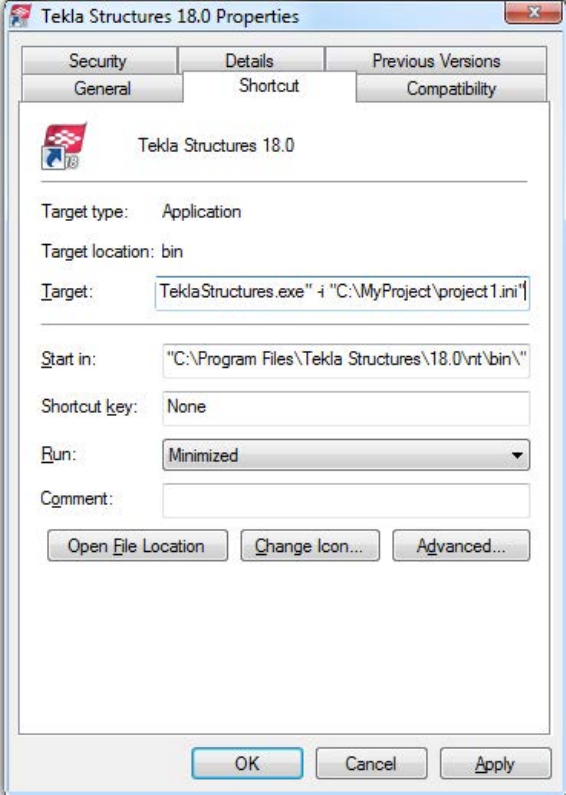
10. Modify the Target of the shortcut by adding the required project initialization
information to it.
First enter the path to the current teklastructures.exe, then the desired
parameters. In the following example, the name of the customized initialization file is
project1.ini.
You can use the following parameters in shortcuts:
•-i <initialization_file>: The initialization file to be read during startup
after the <role>.ini file, for example, -i \\MyServer\MyProject
\Project1.ini. You can repeat this parameter as many times as you need, and
this way enter as many initialization files you need.
•<model_to_be_opened>: Full path to the model to be opened automatically,
for example, "C:\TeklaStructuresModels\New model 1".
Files and folders 17 Initialization files
The settings in user.ini and option.ini files override the settings defined in the
shortcuts using the parameter -i <initialization_file>
The maximum length of a shortcut is 256 characters. If you have problems with the length,
you can call all other necessary initialization files from your customized initialization file
instead of adding them to the shortcut.
Initialization files included in customized initialization files on page 18
Typical initialization files and their reading order on page 10
Initialization files included in customized initialization files
Initialization files can include or call other initialization files. You can use this functionality
to create shortcuts for different purposes, for example, to have customized setup files
depending on the client you are working for in a project such as fabricators.
Below is an example of a customized project initialization file that calls other initialization
files.
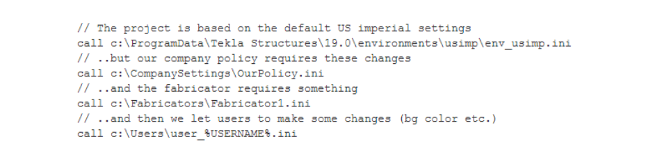
MyProject.ini
The project shortcut for MyProject:
C:\Program
Files\Tekla Structures\19.0\nt\bin\TeklaStructures.exe -i \\MyServer
\MyProject\MyProject.ini \\MyServer\MyProject\MyModel\MyModel.db1
Creating customized initialization files and startup shortcuts on page 16
3.2 Files storing options and advanced options
When a new model is created, Tekla Structures reads model-specific option and advanced
option values from the standard.opt file, and from the .ini files in a certain reading
order, and creates the databases options_model.db and options_drawings.db,
and the options.ini file under the model folder.
When you change a model-specific option or advanced option and press OK or Apply in the
Options or Advanced Options dialog box, the settings are taken into use (otherwise you will
See also
See also
Files and folders 18 Files storing options and advanced options
get a warning message). The updated model-specific option or advanced option settings are
saved in options_model.db and options_drawings.db under model folder when
the model is saved. In addition, there are also some special model-specific advanced options
that can be updated from the options.ini file located in the model folder, for example,
new advanced options that are not yet in the Advanced Options dialog box.
When you change a user-specific option or advanced option, and press OK or Apply in the
Options or Advanced Options dialog box, the settings are saved in options.bin in ..
\Users\<user>\AppData\Local\Tekla Structures\<version>
\UserSettings.
You can change model-specific advanced options only in the Advanced Options dialog box
or in the options.ini file that is located in model folder.
You can change user-specific advanced options only in the Advanced Options dialog box.
You can change model- and_user-specific options only in the Options dialog box manually or
by loading standard.opt file values in the dialog box.
You can save your own settings in the Options dialog by using the Save button. Then the
standard.opt file is saved in the \attributes folder under the model folder.
You can create a complete list of advanced options in a text file by clicking Write
to file in the Advanced Options dialog box. The list shows the name of the
advanced option, current value and type.
Changing an advanced option value in .ini files located outside the model
folder does not affect the existing models. You can only update advanced options
in the Advanced Options dialog box or in the options.ini file located in
model folder; not from an options.ini file located in folders defined for the
advanced options XS_FIRM or XS_PROJECT. The .ini files are read also
when you open an existing model, but only new advanced options that do not
exist in options_model.db or options_drawings.db are inserted, for
example, such options that are not yet in the Advanced Options dialog box but
have been added in the software.
Settings in the Options dialog box on page 19
Settings defined by advanced options on page 32
Settings in the Options dialog box
The Options dialog box (Tools > Options > Options...) contains the current values for a
number of Tekla Structures settings.
Check the settings before you start modeling and change them, if necessary.
See also
Files and folders 19 Files storing options and advanced options
The model-specific settings in this dialog box are saved in the options_model.db and
options_drawings.db databases in the model folder, and the user-specific settings in
options.bin in your local <user> folder.
You can also save your own settings by using the Save button. Then the standard.opt
file is saved in the \attributes folder under model folder. You may want to copy this file
to your firm folder. When you create a model, the standard.opt is read from the firm
folder.
The options in the Options dialog box are described below.
Settings on this page are model-specific.
Option Description
Clash check between bolt and
bolted part Defines whether the model is checked for clashes that occur
between bolts and the related bolted parts.
If you select Yes, Tekla Structures will check the bolts against the
real geometry of the bolted part profiles including roundings, and
using the real bolt dimensions.
Defines the clash check clearance area for bolts.
If you do not enter a value, Tekla Structures uses the default
value 1.00.
If you clear the check boxes, the clearance will be zero.
Defines the minimum clearance or the allowed overlap for
reinforcing bars when they are checked against other reinforcing
bars.
To allow reinforcing bars to overlap, enter a negative value.
If you clear the check box, the clearance will be zero.
Defines the reinforcing bar cover thickness.
Tekla Structures checks the cover thickness against the part that
the reinforcing bar belongs to. Tekla Structures only checks the
distance from bar side to part surface. Tekla Structures does not
check the distance from bar end to part surface. If the bar
penetrates a part surface, a clash is reported, even if the bar is
completely inside a cast unit or pour.
If you clear the check box, Tekla Structures will not check the
cover thickness.
Tekla Structures uses the information on the Components tab when it creates parts using
components.
Component properties defined in component dialog boxes override these settings. Tekla
Structures only uses these settings if the corresponding boxes in the component dialog boxes
are empty.
Clash check page
Components
page
Files and folders 20 Files storing options and advanced options

If you change settings here, Tekla Structures only applies the new settings to components
you subsequently create. Components you created prior to changing the preferences are not
affected.
Settings on this page are model-specific.
Option Description
Profile names Defines parametric profile prefixes for plates. It is important that
profile names are set up correctly so that you can use filters and
wizards effectively.
Profile names must exist in the profile catalog. If you want to
use a parametric profile that does not have a name in the
catalog, first add it to the Profile Catalog, then enter it here.
Tekla Structures uses the Folded plate prefix when you use the
folded plates in components.
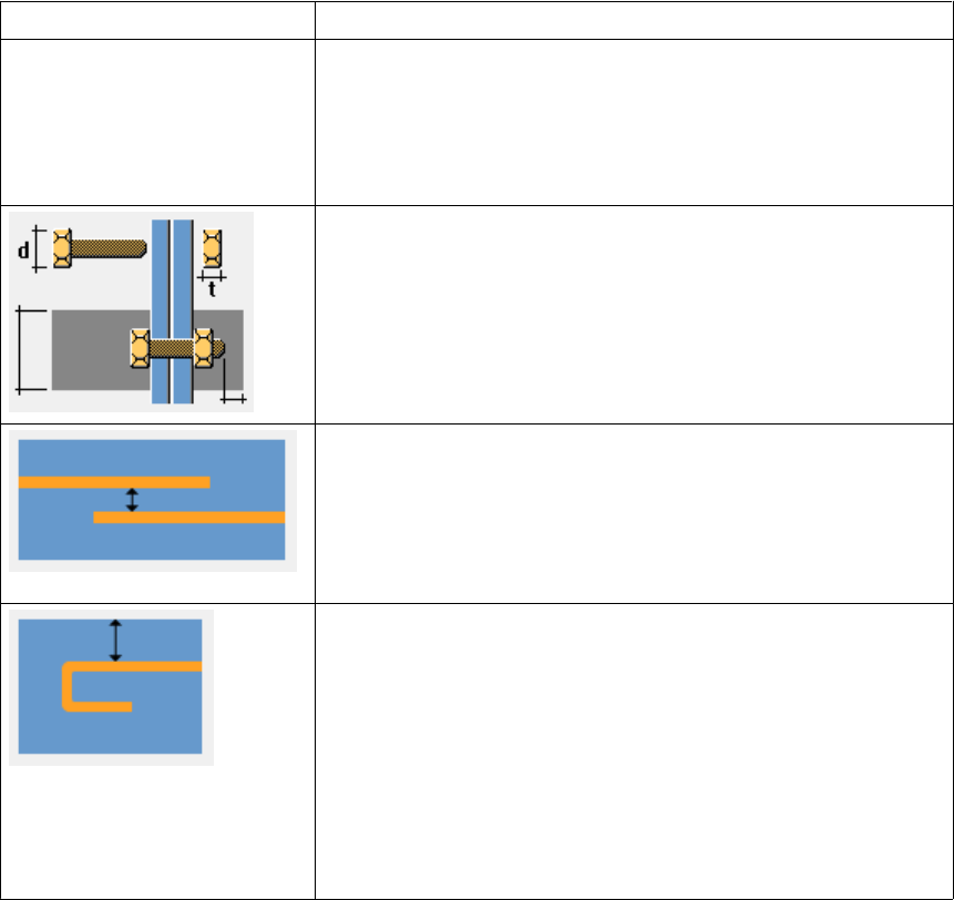
Bolts In components, Tekla Structures uses Factor of bolt edge
distance and Compare edge distance to to check that the bolts
it creates are not too close to the edge of a part, and warns you
if they are. Check that Factor of bolt edge distance is set
according to the standard you are using. The default edge
distance setting depends on your environment.
Compare edge distance defines whether the edge distance
checks are based on bolt or hole diameter.
To define the default bolt properties to use in connections, select
a Bolt standard and Bolt size.
Parts Part material defines the default part material grade.
Part start numbers defines start numbers for parts that are
Welded to primary and Welded to secondary, Loose parts, and
Assembly loose parts.
Cross-check these settings against the numbering series you
define to make sure they do not overlap. If they overlap, Tekla
Structures may create two non-identical parts with the same
part number. This generates an error in the log file
numbering.history.
Settings on this page are model-specific.
Option Description
Exaggeration This setting defines the default values for Exaggeration limit
and Exaggeration scaling.
When you enable the exaggeration of the dimensions, a drawing
dimension that is narrower than the defined limit is expanded.
Exaggeration limit defines the default value for this limit.
Exaggeration scaling defines whether you are using Paper or
Model as the exaggeration scaling method:
Drawing
dimensions page
Files and folders 21 Files storing options and advanced options

Option Description
• If you select Paper, the exaggeration limit is multiplied by
the view scale.
• If you select Model, and the scale is 1:10, all the dimensions
smaller than 10 mm are exaggerated regardless of the
drawing scale.
Absolute dimensions Show zero in absolute dimensions --> Yes shows zero at the
zero points in absolute dimensions.
Draw absolute dimension values parallel to dimension line --
> Yes shows dimensions parallel to dimension lines in absolute
dimensions.
Dimensions in tags Units, Format and Precision define the default unit, format and
precision used in dimension tags.
Show dimension in middle tag of automatic dimension
defines whether you want to create dual dimension tags in
assembly, single-part, cast unit, or general arrangement
drawings.
When Tekla Structures creates the drawing, it adds the lower
dimension tag in the selected unit, format and precision.
Add mark to reinforcement Dimension Marks settings and Tagged Dimension Mark
settings define the predefined property files used for dimension
marks and tagged dimension marks files.
Dimension line Dimension line extension length for line arrow defines the
length of the line extension for dimensions that have line
arrows.
Line extensions are not applied to dimensions that have different
arrows from line arrows, and certain knock-off dimension types.
Settings on this page are model-specific.
Option Description
Edge chamfer Line color defines the default line color of the edge chamfers in
drawings.
Line type defines the default line type of the edge chamfers in
drawings.
These values are overridden by the values set in the Edge
Chamfer Properties dialog box.
On this page, Autosave settings are user-specific. All other settings are model-specific.
Drawing objects
page
General page
Files and folders 22 Files storing options and advanced options

Option Description
Hidden lines No dotted defines that hidden lines are not dotted.
Other parts dotted defines that hidden lines in other parts are
dotted.
All parts dotted defines that hidden lines in all parts are dotted.
Solid bolts defines that the bolts are shown as solid objects.
No solid bolts defines that bolts are not shown as solid objects.
Autosave Autosave interval: Autosave after every xx modeling or
editing commands defines how often Tekla Structures
automatically saves a model and a drawing.
This number represents the number of commands you have
given. For example, if you create many objects without
interrupting (Esc or Edit --> Interrupt) , it counts as one
command.
Autosave after creating every xx drawings defines the number
of drawings after which Tekla Structures automatically saves
your work.
Default adaptivity Off means that adaptivity is not defined.
Relative defines that handles retain their relative distances to
the nearest part faces in relation to the part’s overall size.
Fixed defines that handles retain their absolute distances to the
nearest part faces.
You can also modify the adaptivity settings for each part
separately. These modifications override the default settings in
the Options dialog box.
Use the settings on the tabs of this page to define the building code and safety factors Tekla
Structures uses in load combination.
Settings on this page are model-specific.
Settings on this page are user-specific.
Option Description
Display snap symbols Hides or shows the snap symbols.
Activate snap grid when free
snap is on Activates the snap grid. You can define grid spacing intervals
and offsets for the snap grid origin.
Settings on this page are model-specific.
Option Description
Position number separator Defines the default position number separator. The options are
dot (.), comma (,), slash (/), and hyphen (-).
Load modeling
page
Mouse settings
page
Numbering page
Files and folders 23 Files storing options and advanced options
Option Description
Rebar position number
separator Defines the default reinforcing bar position number separator.
The options are dot (.), comma (,), slash (/), and hyphen (-).
Part number type Defines the default part number type. The options are Part
number and Combined assembly / part number.
Settings on this page are model-specific.
Option Description
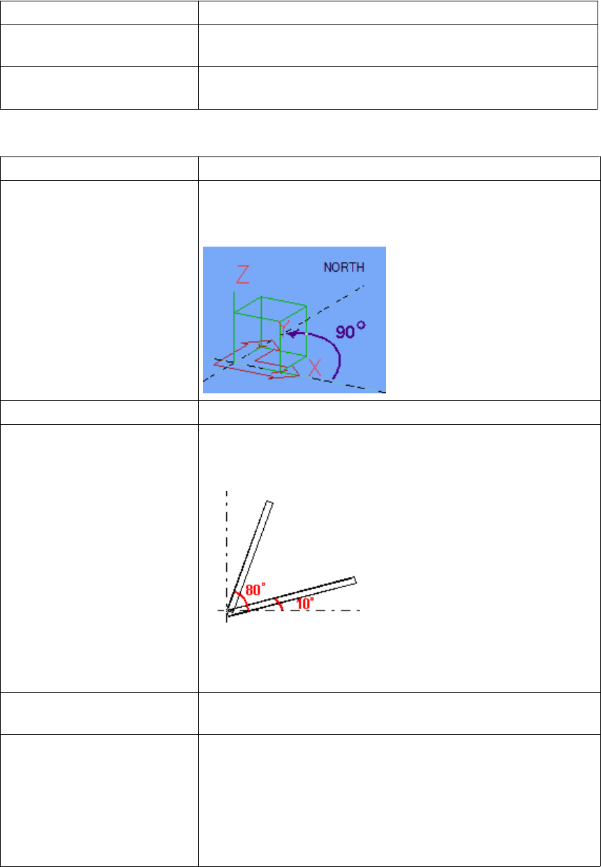
North direction Project north (degrees counter clockwise from global x)
defines which direction is north in the model. Enter the value in
degrees counter-clockwise from the global x axis.
Part viewing direction Defines which direction parts are viewed from in drawings.
Beam skew limit
Column skew limit
Tekla Structures uses limit angles to determine whether a part is
a beam or a column when creating orientation marks. Tekla
Structures treats parts outside these limits as braces.
Parts skewed more than 80° are columns.
Parts skewed less than 10° are beams.
Preferred location for mark Defines the location of part marks in drawings, to the left or
right end of the part.
Mark always to center of
column This setting only affects columns.
Yes places part marks in the center of columns in plan views. To
indicate part orientation, include compass direction (Face
direction) in the part mark instead.
No places part marks on the same flange in general arrangement
and assembly drawings.
Orientation
marks page
Files and folders 24 Files storing options and advanced options
Units and decimals given on the Modeling and Catalogs tabs affect input. The units and
decimals given on the Analysis results tab affect the output data.
The settings on the Modeling tab affect the data that is used when you are modeling, for
example copying, moving, creating grids, creating points, etc. Settings on the Catalogs tab
affect the data stored in the profile and material catalogs.
Settings on the Units and decimals page do not have any effect on drawings or reports, or
on the Inquire and Measure tools.
The number to the left of each option indicates the number of decimals.
The number of decimals affects the input and storage accuracy. Always use a sufficient
number of decimals.
Settings on this page are model-specific.
Option Description
Length mm, cm, m, in (decimal), ft (decimal), ft-in
Angle o, rad
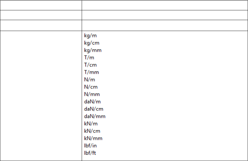
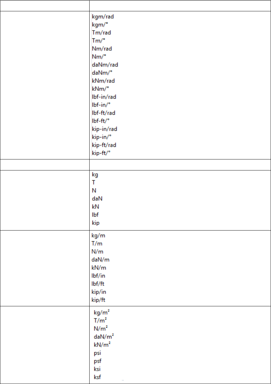
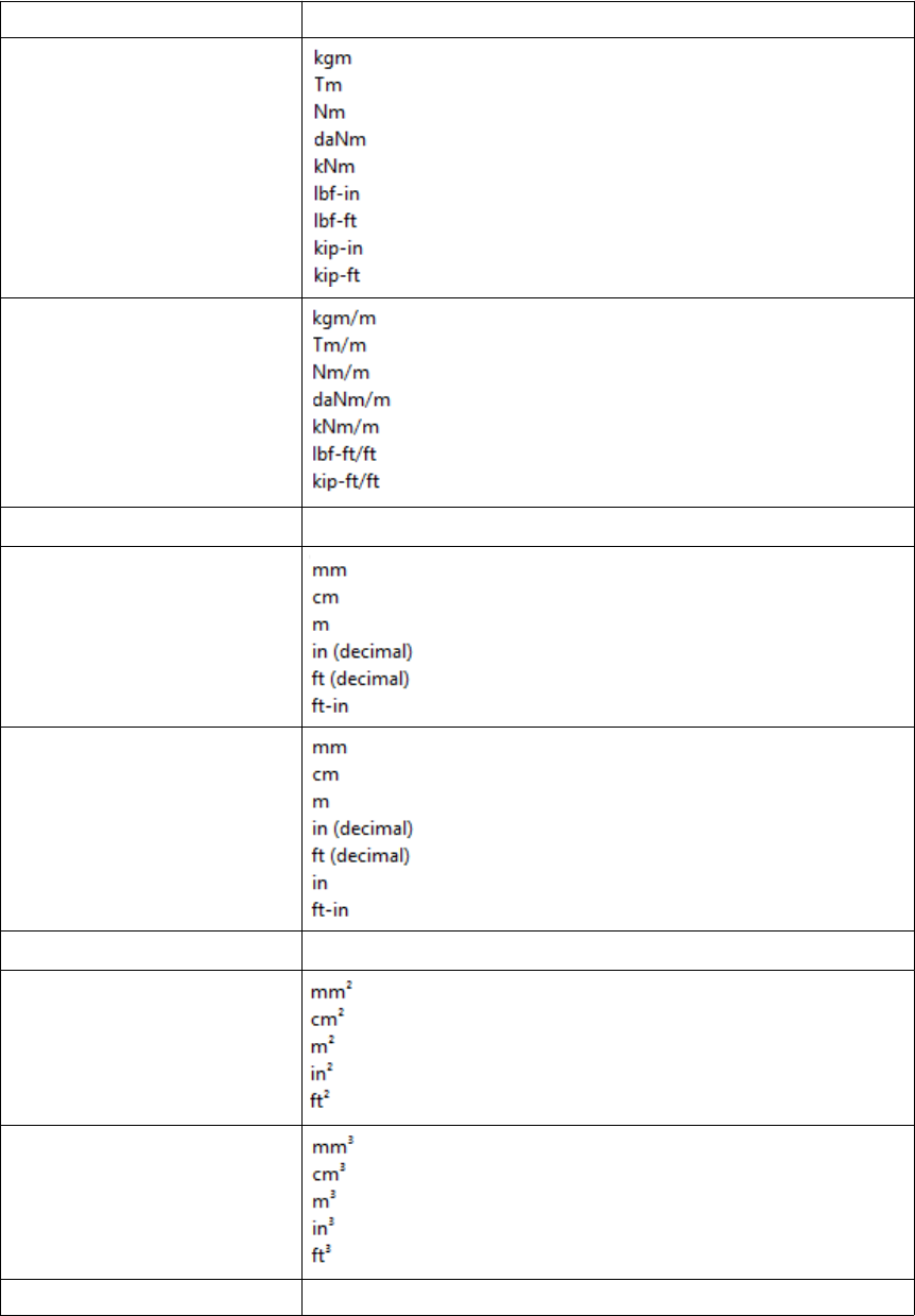
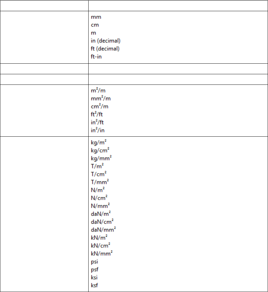
Spring constant
Units and
decimals page
Files and folders 25 Files storing options and advanced options
Option Description
Rot. spring constant
Factor Enter a value using the arrow buttons.
Force
Distributed load
Surface load
Files and folders 26 Files storing options and advanced options
Option Description
Moment
Distributed moment
Temperature oC, oF, K
Deformation
Section dimension
Angle o, rad
Area
Section modulus
Moment of inertia mm4, cm4, in4
Files and folders 27 Files storing options and advanced options
Option Description
Radius of inertia
Torsion constant mm4, cm4, in4
Warping constant mm6, cm6, in6
Cover area
Strength
Files and folders 28 Files storing options and advanced options

Option Description
Modulus
Density
Weight
Strain o/oo, %
Thermal dilat. coeff. 1/oC, 1/oF, 1/K
Ratio o/oo, %
Volume
Length mm, cm, m, in (decimal), ft (decimal), ft-in
Angle o, rad
Files and folders 29 Files storing options and advanced options
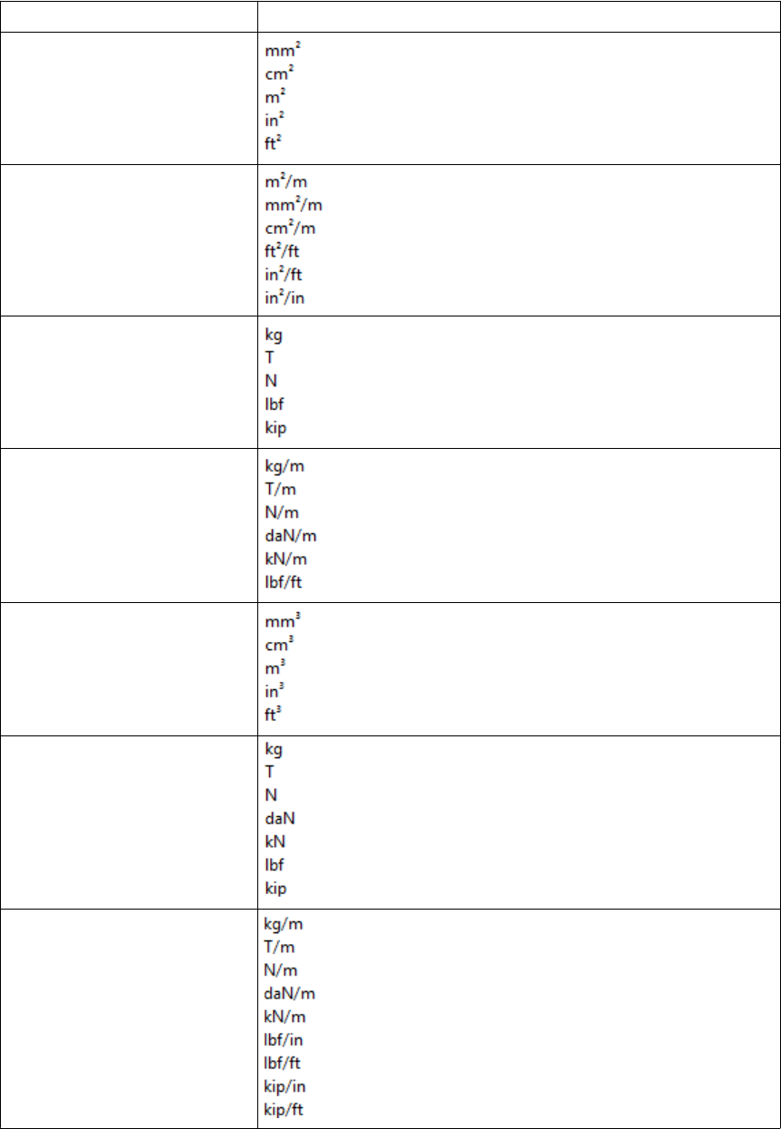
Option Description
Reinforcement area
Transverse reinforc.
Weight
Mass/Length
Volume
Force
Distributed load
Files and folders 30 Files storing options and advanced options
Option Description
Surface load
Moment
Temperature oC, oF, K
Stress
Deformation
Detecting clashesSee also
Files and folders 31 Files storing options and advanced options
Creating exaggerated dimensions
Automatic drawing-level dimensioning
Adding dual dimensions manually
Adding predefined reinforcement dimensions
Edge chamfers in drawings
Saving a model
Autosaving in multi-user mode
Modifying the shape of a reinforcement using adaptivity
Other snap switches
Defining a snap grid
Load combination properties
Displaying orientation marks (north marks)
Displaying compass direction
Mark location
Setting viewing direction for columns in assembly drawings
Setting viewing direction for beams and bracings in assembly drawings...
Files storing options and advanced options on page 18
Settings defined by advanced options
Advanced options can be user-, model-, system or role-specific:
•User-specific advanced options are saved in your local options.bin file, which is by
default located in C:\Users\<user>\AppData\Local\Tekla Structures
\<version>\UserSettings, and work in the specified way in all models that you
have. The folder can be changed using the advanced option
XS_USER_SETTINGS_DIRECTORY. In the Advanced Options dialog box, the type is
USER. Some user-specific advanced options require restarting of Tekla Structures after
changing the value.
•Model-specific advanced options work in the specified way only in the current model.
They are saved to options_model.db and options_drawings.db under
model folder. In the Advanced Options dialog box, the type is MODEL or DRAWING.
Some special model-specific options that are not visible in the Advanced Options dialog
box can be changed from options.ini file under the model folder.
•System-specific advanced options are general to all sessions of Tekla Structures, and
work in the specified way for all users and in all models. In the Advanced Options dialog
box, the type is SYSTEM. A system-specific advanced option can be stored to
options.ini under model folder by clicking SYSTEM next to the option and
changing it to MODEL(SYSTEM). Note that the changed value only works for the current
Files and folders 32 Files storing options and advanced options

model. A MODEL(SYSTEM) advanced option can be changed back to SYSTEM by
changing it to SYSTEM, and in this case it will be removed from the options.ini file
under model folder. Some system-specific advanced options require restarting of Tekla
Structures after changing the value.
The system-specific advanced options are read from environment .ini files:
•Global system settings are read from common env_global_default.ini
in ..\ProgramData\Tekla Structures\<version>\environments
\common\. These settings are used in all environments.
•Environment-specific system settings are read from
env_<environment>.ini in your environment folder. They override any
settings that are defined on a global level in env_global_default.ini.
•Role-specific system settings are read from role_<role>.ini in environment
folder. They override any settings that are defined on a global and environment level
in env_global_default.ini and env_<environment>.ini.
•Company level system-specific system settings override all other system-specific
advanced options. You can save them in the firm or project folders by setting the
folders for the advanced options XS_FIRM and XS_PROJECT.
•SYSTEM(ROLE) options are typically role specific. The settings are read from .ini files
and are not saved to the databases. When changed or if the type is changed, the option
will become model specific and be saved to the databases. MODEL/DRAWING(ROLE)
options are SYSTEM(ROLE) options whose type and/or setting has been changed. The
change would be used when you want the SYSTEM(ROLE) option to be saved with the
model to options_model.db and options_drawings.db under model folder.
These settings can be set back to SYSTEM(ROLE), which will then take into use the
default value.
XS_FIRM
XS_PROJECT
Typical initialization files and their reading order on page 10
List of user-specific advanced options
Tekla Structures saves the settings for the user-specific advanced options in the
options.bin file, located in the folder ..\Users\<user>\AppData\Local
\Tekla Structures\<version>\UserSettings (Windows 7 and Windows
Vista), or in the folder ..\Documents and Settings\<user>\Application
Data\Tekla Structures\<version>\UserSettings (Windows XP). Below is a
list of user-specific options:
RPC_WAIT_TIME
TEXT_X_SIZE
TEXT_Y_SIZE
See also
Files and folders 33 Files storing options and advanced options

XS_ALWAYS_CONFIRM_SAVE_WHEN_CLOSING_DRAWING
XS_ALWAYS_CONFIRM_SAVE_WHEN_EXIT
XS_AUTOMATIC_NEW_MODEL_NAME
XS_AUTOMATIC_USER_FEEDBACK_SENDING_INTERVAL
XS_AUTOSAVE_DIRECTORY
XS_BACKGROUND_COLOR1
XS_BACKGROUND_COLOR2
XS_BACKGROUND_COLOR3
XS_BACKGROUND_COLOR4
XS_BASICVIEW_HEIGHT
XS_BASICVIEW_POSITION_X
XS_BASICVIEW_POSITION_Y
XS_BASICVIEW_WIDTH
XS_BLACK_DRAWING_BACKGROUND
XS_CHAMFER_DISPLAY_LENGTH_FACTOR
XS_CHANGE_DRAGGED_DIMENSIONS_TO_FIXED
XS_CHANGE_DRAGGED_MARKS_TO_FIXED
XS_CHANGE_DRAGGED_NOTES_TO_FIXED
XS_CHANGE_DRAGGED_TEXTS_TO_FIXED
XS_CHANGE_DRAGGED_VIEWS_TO_FIXED
XS_CHECK_BOLT_EDGE_DISTANCE_ALWAYS
XS_CIS_DEP1_EXPRESS_FILE
XS_CLONING_TEMPLATE_DIRECTORY
XS_COMPONENT_CATALOG_COLLECTION_NAME_LENGTH
XS_COMPONENT_CATALOG_THUMBNAIL_SIZE
XS_CREATE_ALSO_BIG_HTML_REPORT_PICTURES
XS_CREATE_DRAWING_PREVIEW_AUTOMATICALLY
XS_DEFAULT_FONT
XS_DEFAULT_FONT_SIZE
XS_DEFAULT_FONT_SIZE_GRID
XS_DISABLE_ANALYSIS_AND_DESIGN
XS_DISABLE_CIS2
XS_DISABLE_CLASSIFIER_FOR_MODIFIED_PARTS
XS_DISABLE_MASTER_DRAWING_CATALOG
XS_DISABLE_PARTIAL_REFRESH
XS_DISABLE_REBAR_MODELING
XS_DISABLE_TEMPLATE_DOUBLE_CLICK
Files and folders 34 Files storing options and advanced options

XS_DISPLAY_DIMENSIONS_WHEN_CREATING_OBJECTS
XS_DISPLAY_DIMENSIONS_WHEN_SELECTING_OBJECTS
XS_DO_NOT_CREATE_ASSEMBLY_DRAWINGS_FOR_CONCRETE_PARTS
XS_DO_NOT_CREATE_ASSEMBLY_DRAWINGS_FOR_LOOSE_PARTS
XS_DO_NOT_CREATE_BOLT_MARKS_IN_ALL_INCLUDED_SINGLE_VIEWS
XS_DO_NOT_CREATE_PART_MARKS_IN_ALL_INCLUDED_SINGLE_VIEWS
XS_DO_NOT_DISPLAY_CHAMFERS
XS_DONT_SHOW_POLYBEAM_MID_EDGES
XS_DRAW_CUT_FACES_WITH_RED_COLOR
XS_DRAWING_ALLOW_SNAPPING_TO_DISTANT_POINTS
XS_DRAWING_CHECK_PARTS_IN_UPDATE
XS_DRAWING_SHEET_HEIGHT
XS_DRAWING_SHEET_POSITION_X
XS_DRAWING_SHEET_POSITION_Y
XS_DRAWING_SHEET_WIDTH
XS_DRAWING_UDAS_MODIFY_ALL_DRAWING_TYPES
XS_DRAWING_VIEW_DIRECTION_MARK_SYMBOL_BACK
XS_DRAWING_VIEW_DIRECTION_MARK_SYMBOL_BOTTOM
XS_DRAWING_VIEW_DIRECTION_MARK_SYMBOL_FRONT
XS_DRAWING_VIEW_DIRECTION_MARK_SYMBOL_TOP
XS_DSTV_DO_NOT_UNFOLD_POLYBEAM_PLATES
XS_DUPLICATE_CHECK_LIMIT_FOR_COPY_AND_MOVE
XS_ENABLE_AUTODRAWINGS_IN_MENU
XS_ENABLE_DOUBLE_BUFFERING_IN_DRAWINGS
XS_ENABLE_POUR_MANAGEMENT
XS_ENABLE_SOLID_ERROR_DIALOG
XS_EXPORT_CODEPAGE
XS_EXPORT_LINE_TYPE_DEFINITION_FILE
XS_EXPORT_TO_MODELSPACE_AND_PAPERSPACE
XS_FAILED_SOLID_COLOR
XS_GRID_COLOR
XS_GRID_COLOR_FOR_WORK_PLANE
XS_GRID_DIMENSION_OVERALL_LENGTH
XS_HANDLE_SCALE
XS_HARD_STAMP_BY_ORIENTATION_MARK
XS_HIDDEN_USE_BOLT_PLANES
XS_HIDE_OTHER_PARTS_IN_ASSEMBLY_AND_CAST_UNIT_VIEWS
Files and folders 35 Files storing options and advanced options

XS_HIDE_WORKAREA
XS_HIGHLIGHT_ASSOCIATIVE_DIMENSION_CHANGES
XS_HIGHLIGHT_MARK_CONTENT_CHANGES
XS_HTML_REPORT_LEAVE_INTERMEDIATE_FILES
XS_IMPERIAL_DATE
XS_IMPERIAL_INPUT
XS_IMPERIAL_TIME
XS_IMPORT_MODEL_LOG
XS_INTELLIGENT_MESSAGES_ALLOWED
XS_KEEP_AUTOSAVE_FILES_ON_EXIT_WHEN_NOT_SAVING
XS_KEYIN_ABSOLUTE_PREFIX
XS_KEYIN_DEFAULT_MODE
XS_KEYIN_RELATIVE_PREFIX
XS_MACRO_LOG
XS_MDIBASICVIEWPARENT
XS_MDIVIEWPARENT
XS_MDIZOOMPARENT
XS_MIS_SEQUENCE
XS_MODEL_TEMPLATE_DIRECTORY
XS_NO_AUTO_DISPLAY_VIEWS
XS_NO_CHAMFERS_IN_EXACT_MODE
XS_OBJECT_SELECTION_CONFIRMATION
XS_OPEN_DRAWINGS_MAXIMIZED
XS_PILOTING_EXTENSIONS
XS_PIXEL_TOLERANCE
XS_PLOT_UNPLOT_BUFFER_SIZE
XS_POP_MARK_EDGE_DISTANCE
XS_PRINT_REPORT_FONT
XS_PROFILE_ANALYSIS_CHECK_ALL
XS_PROFILE_ANALYSIS_VALUE_DIFF_LIMIT
XS_PROFILE_DISPLAY_INCH_MARK_AFTER_FRACTIONS_IN_REPORTS
XS_RECREATE_UNMODIFIED_DRAWINGS
XS_REDRAW_VIEWS_AFTER_SELECTED_NUMBERING
XS_REFERENCE_CACHE
XS_REFERENCE_USE_RENDERED_CLIPPING
XS_RENDERED_CURSOR_LINE_WIDTH
XS_RENDERED_FIELD_OF_VIEW
Files and folders 36 Files storing options and advanced options

XS_RENDERED_FOG_END_VALUE
XS_RENDERED_FOG_START_VALUE
XS_RUN_AT_STARTUP
XS_SDNF_IMPORT_MIRROR_SWAP_OFFSETS
XS_SHOW_PROGRESS_BAR_FOR_PROJECT_STATUS_VISUALIZATION
XS_SHOW_REVISION_MARK_ON_DRAWING_LIST
XS_SHOW_TEMPLATE_LOG_MESSAGES
XS_SMRT_SEPARATE_MEMORY_POOL_FOR_SOLIDS
XS_SMRT_SOLID_POOL_PAGE_SIZE
XS_SNAPSHOT_DIRECTORY
XS_SOLID_BUFFER_SIZE
XS_THUMBNAIL_FONT
XS_USE_COLOR_DRAWINGS
XS_USE_DRAWING_NAME_AS_PLOT_TITLE
XS_USE_MULTI_NUMBERING_WHEN_COPYING_DRAWING_VIEWS
XS_USE_OBJECT_LOCK_PROTO
XS_USE_SMOOTH_LINES
XS_USE_SOFTWARE_RENDERING
XS_VIEW_DIM_LINE_COLOR
XS_VIEW_DIM_TEXT_COLOR
XS_VIEW_FAST_BOLT_COLOR
XS_VIEW_HEIGHT
XS_VIEW_PART_LABEL_COLOR
XS_VIEW_POSITION_X
XS_VIEW_POSITION_Y
XS_VIEW_WIDTH
XS_VISUALIZE_VIEW_NEIGHBOUR_PART_EXTENSION
XS_VISUALIZE_VIEW_IN_ANOTHER_VIEWS
XS_VISUALIZE_VIEW_IN_FATHER_VIEW_ONLY
XS_ZOOM_STEP_RATIO
XS_ZOOM_STEP_RATIO_IN_MOUSEWHEEL_MODE
XS_ZOOM_STEP_RATIO_IN_SCROLL_MODE
Settings defined by advanced options on page 32
Changing advanced option settings on page 37
See also
Files and folders 37 Files storing options and advanced options

Changing advanced option settings
Use advanced options to configure Tekla Structures to suit the way you work, or to comply
with specific project requirements or industry standards.
Change the advanced options only in the Advanced Options dialog box. The settings in the
Advanced Options dialog override the settings in any other initialization file.
To change an advanced option setting:
1. Click Tools --> Options --> Advanced Options... to open the Advanced Options dialog
box.
2. Browse the categories to find the advanced option you want to set.
You can also enter a search term in the Search box. To search the search term in all
categories, select In all categories. You can also use wildcards. For example, to find all
advanced options that have the words anchor and filter and that have any
characters between these two words, enter anchor*filter.
3. Set the advanced option to the desired value by entering the value or by selecting from
the list.
• You can change the type of the role-specific advanced options from SYSTEM (ROLE)
to MODEL (ROLE) or DRAWING(ROLE) and vice versa from the list next to the
option type. When you change the option type to SYSTEM(ROLE), the value
automatically changes to the default value. When you enter a value for a SYSTEM
(ROLE) option, it changes to MODEL (ROLE) or DRAWING(ROLE).
• You can change the type of system-specific advanced options from SYSTEM to
MODEL(SYSTEM), in which case the value is saved in the options.ini file in the
model folder. If you reset the advanced option back to SYSTEM, it will be removed
from the options.ini file.
• You can use switches with some advanced options, for example, to define the
contents of marks: %TPL:PROJECT.NUMBER%.
• If you need to enter a folder path, enter a backslash at the end of the folder path.
4. Click Apply or OK.
To create a complete list of advanced options in a text file, click Write to file. The
list shows the name of the advanced option together with its current value and
type.
Settings defined by advanced options on page 32See also
Files and folders 38 Input files
3.3 Input files
Tekla Structures uses input files to manage dialog boxes and for defining how components
work. All input files have the extension inp.
Input files that you can use for example for customizing Tekla Structures are listed below.
File Description
analysis_design_config.inp Contains settings for analysis and design.
fltprops.inp Includes materials and dimensions of available flat
bars.
objects.inp Used to manage user-defined attributes.
pop_mark_parts.inp Contains settings for pop-marking.
privileges.inp Used to control access rights.
profitab.inp Contains available parametric profiles.
rebar_config.inp Contains settings for reinforcement marks.
rebar_schedule_config.inp Contains internal bending types of reinforcing bars
and their mapping to area specific bending codes.
Rebar Shape Manager is a more versatile way to
define reinforcing bar bending shapes.
Analysis model properties
Reinforcement settings for drawings
Reinforcement in templates
Customizing user-defined attributes
Many dialog boxes contain user-defined attributes for various objects, including beams,
columns, bolts and drawings. Tekla Structures displays these fields when you click the User-
Defined Attributes... button. You can use the values of user-defined attributes in reports
and drawings.
The definitions of a user-defined attribute are unique, which means that a user-defined
attribute cannot have different definitions for different object types, such as beams and
columns.
To define new user-defined attributes, create your own objects.inp file in the model,
project or firm folder.
Do not copy the objects.inp file in the ..\environments\common\inp\
folder. Copying the file creates unnecessary duplicates and later objects.inp updates
made by Tekla can be lost.
See also
Files and folders 39 Input files
Tekla Structures reads the objects.inp files in the following order:
1. model folder
2. project folder
3. firm folder
4. system folder
5. inp folder
The files are merged so that if there are user-defined attributes in any of the files, they are
displayed in the user interface. Tekla Structures merges the files in a way that eliminates
duplicate attributes.
If Tekla Structures encounters the same attribute name in different objects.inp files,
the attribute from the first read objects.inp file will be used.
Updating definitions of user-defined attributes in a model on page 40
The environment database file on page 40
Objects.inp properties on page 41
User-defined attributes affecting numbering on page 43
Example: Creating and updating a user-defined attribute on page 43
The environment database file
To guarantee consistent model behavior when a model is used with different roles, the
environment database file (environment.db) contains the definitions of the user-
defined attributes used in the model.
When you create a new model, Tekla Structures merges the definitions from your
objects.inp files to the environment.db file. Later, when you add new user-
defined attributes in the objects.inp file, the definitions are saved in
environment.db as you open the model.
You can modify your user-defined attributes in an objects.inp file but the changed
definitions do not come into effect automatically. If there are conflicts, the definitions in
environment.db win. You need to run the Diagnose & Change Attribute Definitions
command to see the conflicts between environment.db and objects.inp, and
select the attribute definitions that you want to update.
Customizing user-defined attributes on page 39
Updating definitions of user-defined attributes in a model on page 40
Example: Creating and updating a user-defined attribute on page 43
See also
See also
Files and folders 40 Input files
Updating definitions of user-defined attributes in a model
When you have changed definitions of a user-defined attribute by modifying the
objects.inp file, you need to update the definitions in the model.
To update the definitions of user-defined attributes after you have modified the
objects.inp file:
1. Open the model.
2. Click Tools --> Diagnose & Repair Model --> Diagnose & Change Attribute
Definitions .
The Diagnose & Change Attribute Definitions dialog box opens.
3. Select an attribute from the list on left side to see the comparison of current definitions
and objects.inp definitions.
4. Select the definitions you want to update in the Object classes with Objects.inp
differences compared to current settings list.
5. Click Change current settings to selected Objects.inp settings.
Customizing user-defined attributes on page 39
The environment database file on page 40
Objects.inp properties on page 41
Example: Creating and updating a user-defined attribute on page 43
Objects.inp properties
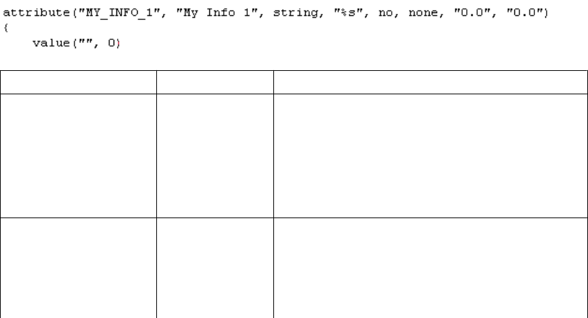
The example below shows the main properties of objects.inp.
Property In the example Description
attribute or
unique_attribute
attribute attribute is a regular attribute, which is
copied with other part properties.
unique_attribute is a non-copyable
attribute. The value of the attribute is never copied
to another part. For example part checking status
attributes usually cannot be copied.
attribute_name MY_INFO_1 Attribute name, used to find the attribute value.
Ensure that Tekla Structures does not already use
the attribute name you use. Consider using a prefix
that ensures the name is unique, for example, your
initials, or an abbreviation of your company name.
See also
Files and folders 41 Input files

Property In the example Description
The attribute name is case-sensitive. Do not use
spaces or reserved characters in attribute names.
The maximum length of the name can be 19
characters.
To include the attribute in a report or template,
add the name of the attribute to your layout in the
Template Editor. When you run a report or create a
drawing, Tekla Structures displays the current
value of the attribute.
label_text My Info 1 Label that Tekla Structures displays in the dialog
box.
Some default attributes have prompts like
j_comment, meaning that the prompt comes
from the joints.ail message file.
value_type string integer or float for numbers
string for text
string_not_modifiable for text whose
modification is prevented. A field with the
string_not_modifiable property is always
displayed as dimmed and it cannot be switched on
or off. The value in the field is not saved when
clicking the Apply button or modified when
clicking the Modify button.
option for lists
date for date with small calendar
date_time_min for date and time [12:00] with
small calendar
date_time_sec for date and time [12:00:00]
with small calendar
field_format %s Definition of the field format in the dialog box
•%s for strings
•%d for numbers
special_flag no no or yes
For parts: consider in numbering
For drawings: display the attribute value in
drawing list
For other elements: no effect
check_switch none none
This option is not used.
Files and folders 42 Input files
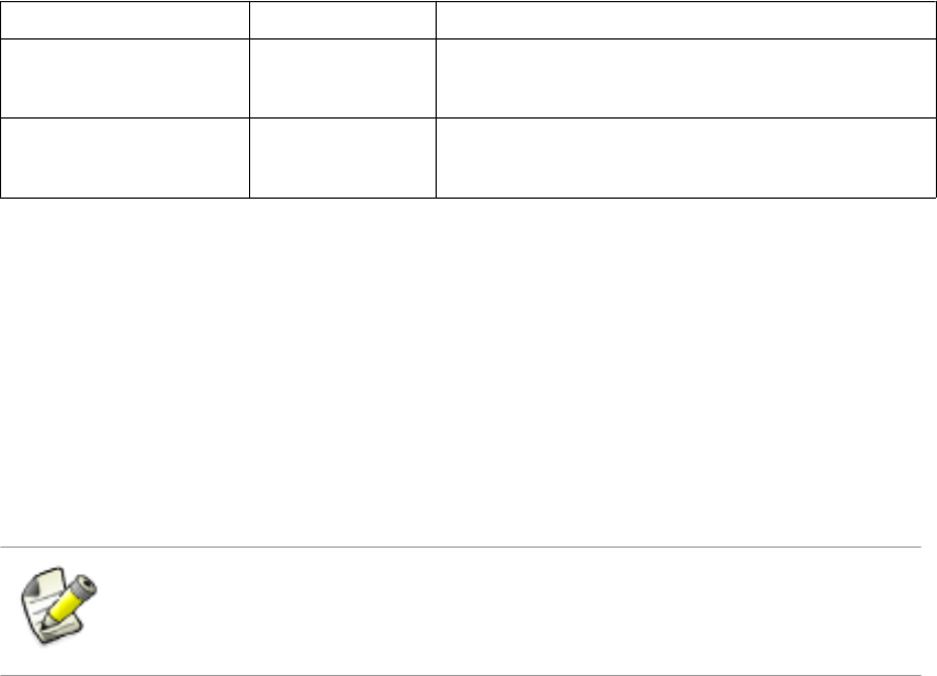
Property In the example Description
attribute_value_max 0.0 0.0
This option is not used.
attribute_value_min 0.0 0.0
This option is not used.
User-defined attributes affecting numbering on page 43
User-defined attributes affecting numbering
You can set whether the user-defined attribute affects numbering or not.
If you want Tekla Structures to consider the user-defined attribute when numbering, set the
special_tag option to yes in the Part attributes section of objects.inp.
Tekla Structures assigns different numbers to parts that are otherwise identical but have
different user-defined attributes.
Only user-defined attributes of parts affect numbering. User-defined attributes of other
objects, such as phases, projects and drawings do not affect numbering.
If you want Tekla Structures to ignore the user-defined attribute when numbering, set the
special_tag option to no in objects.inp.
Objects.inp properties on page 41
Example: Creating and updating a user-defined attribute
This example shows how to create your own user-defined attribute and update the model to
use the changed attribute definition.
To create and update a user-defined attribute:
1. Create a new model and save it.
The user-defined attributes in the model are merged from objects.inp files and
Tekla Structures saves the attribute definitions in the environment.db file in the
model folder.
2. Close the model.
3. Create an input file called objects.inp in the model folder by using a standard text
editor.
4. Enter the following information in objects.inp.
See also
See also
Creating a new
user-defined
attribute
Files and folders 43 Input files
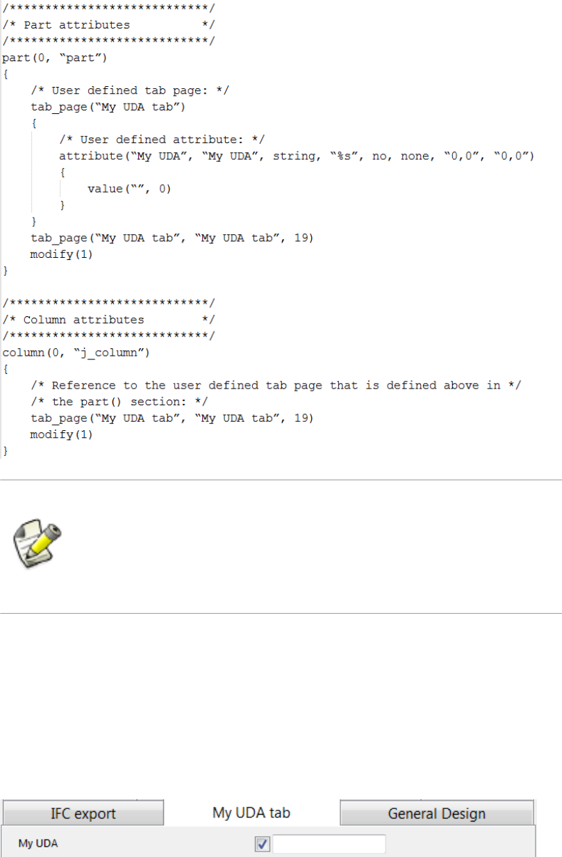
If you want to create a user-defined attribute that also affects numbering, set
the special_flag property of the attribute to yes (it is no in the
example below). Also, just like in the example above, the definition of the
tab_page must be in the part section, and the column (beam, etc.)
section must have only a reference to it.
5. Save objects.inp.
1. Open the model.
2. Create a steel column.
3. Double-click the steel column to open its properties dialog box.
4. Click User-defined attributes.
5. Go to My UDA tab.
6. Enter a value in the My UDA box.
Testing the user-
defined attribute
Files and folders 44 Input files
7. Click Modify.
8. Copy the steel column.
9. Check the My UDA box of the new steel column.
The attribute value was also copied.
10. Close the model.
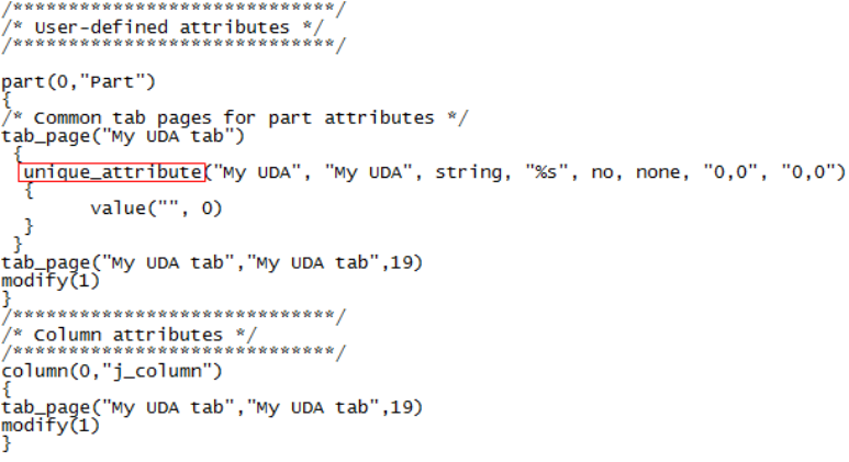
1. Open the objects.inp file in the model folder by using a standard text editor.
2. Enter unique_ before the user-defined attribute.
This makes the user-defined attribute unique, meaning that the value of the user-defined
attribute will not be copied to another part.
3. Save objects.inp.
1. Open the model.
2. Enter a value in the My UDA box for a steel column and click Modify.
3. Copy the steel column.
4. Check the My UDA box of the new column.
5. The value was copied, so the user-defined attribute in the model is not unique. There is a
conflict between the environment.db and objects.inp definitions.
1. Click Tools --> Diagnose & Repair Model --> Diagnose & Change Attribute
Definitions .
The Diagnose & Change Attribute Definitions dialog box opens.
2. Select My UDA in the Attribute area on the left.
You can see that My UDA is not unique in the current setting, but it is set to unique in
objects.inp.
Modifying the
user-defined
attribute
Testing the
unique user-
defined attribute
Updating the
definitions of
user-defined
attributes
Files and folders 45 Input files
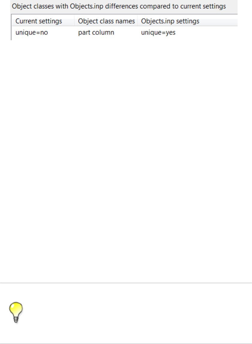
3. Select the definition in the area on the right.
4. Click Change current settings to selected Objects.inp settings.
Now the definition of the user-defined attribute is updated in the model.
If you now copy a steel column that has a value for My UDA, the value is not copied to the
new column.
Updating definitions of user-defined attributes in a model on page 40
Customizing user-defined attributes on page 39
Objects.inp properties on page 41
User-defined attributes affecting numbering on page 43
Showing plates as flat bars in drawings and reports
Tekla Structures can show plates as the equivalent flat bars for manufacturing. Tekla
Structures displays the plates as flat bars in reports and drawings.
To show plates as flat bars:
1. Set the advanced option XS_USE_FLAT_DESIGNATION to TRUE.
2. Indicate the prefix you want to use for flat bars using the advanced option
XS_FLAT_PREFIX.
For example, XS_FLAT_PREFIX=FLAT.
3. Set other platework-related advanced options as required.
4. Define materials, thickness, and width of available flat bars in the Fltprops.inp file.
• To prevent Tekla Structures from displaying the profile in metric units in the
US Imperial version, add the flat bar prefix to the profitab.inp file as a
parametric profile.
• See also page Platework in the Advanced Options dialog box for information
about advanced options related to platework.
Defining flat bar sizes with Fltprops.inp on page 46
See also
See also
Files and folders 46 Input files
Defining flat bar sizes with Fltprops.inp
Use the ..\environments\your_environment\profil\Fltprops.inp file
to define flat bar thickness, width and material.
Copy the Fltprops.inp file to a model, project or firm folder and then modify the file
in the new location as required.
The first row in the file contains flat bar material definitions (enclosed in quotes " ") followed
by plate thicknesses. If you do not define a material, you can use all materials for all flat bars.
The following rows define the widths of available flat bars.
The units are millimeters.
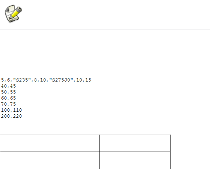
Fltprops.inp contains the following data:
With the above data, Tekla Structures displays the following plates as flat bars:
Plate Material
5x40, 5x45, 6x50, 6x55 All materials
8x60, 8x65, 10x70, 10x75 S235
10x100, 10x110, 15x200, 15x220 S275J0
The flat bars get the prefix that is set in the XS_FLAT_PREFIX advanced option.
Showing plates as flat bars in drawings and reports on page 46
Defining unfolding parameters
The unfolding parameters define the location of the neutral axis when a profile is unfolded.
The neutral axis is a line which runs along the length of a profile where stress and strain are
equal to zero. Tekla Structures uses these parameters to create NC files and to display
unfolded profiles in single-part drawings.
To define unfolding parameters, modify the unfold_corner_ratios.inp file located
in the system folder using a standard text editor. You can copy the
unfold_corner_ratios.inp file to a model, project or firm folder and then modify
the file in the new location as required. Tekla Structures searches for this file in the default
search order.
Example
See also
Files and folders 47 Input files

The settings in unfold_corner_ratios.inp have no effect if the advanced option
XS_USE_OLD_POLYBEAM_LENGTH_CALCULATION is set.
Folder search order on page 84
Unfolding parameter properties on page 48
Unfolding parameter properties
See below for an example of unfolding parameters in unfold_corner_ratios.inp
and the descriptions of the parameters.
1 HE300A S235JR 0 180 2 0 1000 .7
Property In the
example Description
Type 11 is polybeams
2 is plates modeled as polybeams (for example, PLT)
3 is for parts which are not unfolded and follow the
old polybeam calculation (for example, the line 3 L*
* disables unfolding of L profiles)
Profile HE300A You can also use wildcards with profile, for example,
HE300*.
Material S235JR You can also use wildcards with material, for example,
S235*.
Rotation / thickness min 0For polybeams: the minimum angle when the profile is
rotated around its longitudinal axis
For plates: the minimum thickness of plate
Rotation / thickness max 180 For polybeams: the maximum angle when the profile
is rotated around its longitudinal axis
For plates: the maximum thickness of plate
Flag 2This property defines what kind of parts are affected
by the next two properties.
1 is sharp folds. Only polybeams with straight
chamfers are affected.
2 is curved bends. Only polybeams with curved
chamfers are affected.
See also
Files and folders 48 Input files
Property In the
example Description
Angle / radius min 0For sharp folds: the minimum angle
For curved bends: the minimum radius
Angle / radius max 1000 For sharp folds: the maximum angle
For curved bends: the maximum radius
Ratio .7 Defines how much the profile stretches or shrinks
when unfolded.
Ratio = (1 - the relative location of the neutral axis).
If only the inner surface of the profile shrinks, the
ratio is 1. If only the outer surface of the profile
stretches, the ratio is 0. By default, the ratio is 0.5 for
length calculation and 0.0 for bending radius
calculation.
Tekla Structures applies the unfolding ratio if the
profile properties are within the range indicated by
the minimum and maximum values.
To define the rotation angle, set the work plane by the first three points of the
polybeam. Set the rotation angle in the Rotation box in the Beam Properties
dialog box.
Defining unfolding parameters on page 47
3.4 Data files
Data files contain information used by certain components, for example.
These files affect the operation of components. Do not modify the files listed here
unless you are an administrator.
File Description
joints.dat Contains data used in Handrailing (1024) and
Stanchions (S76) components. Used in the
Stanchion connection type option.
railings.dat Contains data used in Handrailing (1024).
Used in the Stanchion connection type option.
See also
Files and folders 49 Data files

File Description
steps.dat Contains the data for Stairs (S82) and Stairs
(S71). Used in the Step profile and Catalogue
step options.
std_flange_plates.dat Contains data for Tapered column (S99). Used
in the options:
•Outer flange profile
•Inner flange profile
•Top plate profile
std_stiffener_plates.dat Contains data used in Tapered column (S99).
Used in the Horizontal stiffener profile box.
marketsize.dat Contains available market sizes for certain
material grade. Can be used with
fMarketSize() function in the custom
component editor.
import_macro_data_types.dat Contains the user-defined attributes that you
can include in an input file in attribute import.
Defining flat bar sizes with Fltprops.inp on page 46
3.5 Message files
Tekla Structures uses the information in the message files to display messages in the user
interface. Message files include, for example, texts used in dialog boxes.
Message files are located in the folder ..\Tekla Structures\<version>
\messages (message files with the .ail extension) and in the folder ..\Tekla
Structures\<version>\messages\DotAppsStrings (message files with
the .xml extension). The files include texts in languages in which the Tekla Structures user
interface is available.
Customizing message files on page 50
Example: Modifying a message file on page 51
Customizing message files
You can customize the messages that Tekla Structures displays in the user interface.
To customize messages:
1. Do one of the following:
See also
See also
Files and folders 50 Message files
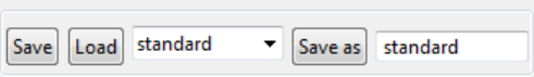
• To modify an .ail message file, go to the ..\Tekla Structures
\<version>\messages folder.
• To modify an .xml message file, go to the ..\Tekla Structures
\<version>\messages\DotAppsStrings folder.
2. Open the message file you want to customize using a standard text editor.
3. Modify the message as required.
4. Save the message file.
Example: Modifying a message file on page 51
Example: Modifying a message file
In this example, you will modify a message that Tekla Structures uses for near side plates in
drawings. You want Tekla Structures to display (NS) instead of (N/S).
To modify the message:
1. Go to the ..\Tekla Structures\<version>\messages folder.
2. Open by_number.ail using a standard text editor.
The by_number.ail file contains both prompts and default texts that Tekla
Structures uses in drawings.
3. Browse to the following section:
string by_number_msg_no_675 {
...
entry = ("enu", "(N/S)");
};
4. Change (N/S) to (NS)in the entry row.
5. Save and close the file.
Message files on page 50
3.6 Standard files
Standard files are property files that Tekla Structures uses by default.
These properties are displayed in the dialog boxes of different objects such as beams,
columns or plates, when you select the standard option in the list next to the Load button,
and click the Load button.
See also
See also
Files and folders 51 Standard files

Standard files are stored in the ..\TeklaStructuresModels\<model_name>
\attributes folder. They are named standard.* where the symbol * is the file name
extension. For example, standard.clm file is used for column properties.
To save a set of standard files in the model folder, click Tools --> Defaults --> Save
Defaults.
Settings in the Options dialog box on page 19
List of standard files saved with Save defaults command
Tekla Structures saves a set of standard files in the attributes folder in the current
model folder when you click Tools --> Defaults --> Save Defaults.
You can copy these standard files to the project or firm folders for future use, to set up Tekla
Structures to suit the way you work.
File Dialog box
standard.cpl Contour Plate Properties
standard.fpl Folded Plate Properties
standard.prt Beam Properties
standard.clm Column Properties
standard.crs Orthogonal Beam Properties
standard.dia Twin Profile Properties
standard.scr Bolt Properties
standard.wld Weld Properties
standard.prf Project properties
standard.ler Layer Properties
standard.fms Plotting Frames
standard.num Numbering Setup
standard.mvi Model View Properties
Project and firm folders on page 86
3.7 Properties files
Tekla Structures stores a number of files, all of which contain object properties, in the current
model folder. Tekla Structures creates these properties files when you click Save or Save as
in dialog boxes.
See also
See also
Files and folders 52 Properties files

You change the standard column properties to create a new type of column you call
custom1. When you click Save as, Tekla Structures creates the file custom1.clm in the
current model folder.
3.8 Catalog files
Tekla Structures uses ASCII and binary files to manage profile, material, reinforcing bar, bolt
and bolt assembly catalogs.
Each environment has its own folder, where the files related to different catalogs are stored.
For example, ..\environments\uk\profil\ contains the files for managing catalog
files used in the United Kingdom.
The following table lists files and file types related to catalogs.
File type File name Used for Located in
.inp profitab.inp Defines the names that
you can use for
parametric profiles.
..\ProgramData\Tekla
Structures\<version>
\environments
\<environment>\profil
rebar_database.
inp
Contains details of the
reinforcement used in
concrete structures.
Includes both the
standard bending radii
and the standard hook
dimensions.
..\ProgramData\Tekla
Structures\<version>
\environments
\<environment>\profil
mesh_database.i
np
Contains details of the
reinforcement meshes
used in concrete
structures.
..\ProgramData\Tekla
Structures\<version>
\environments
\<environment>\profil
.cnv matexp_<softwar
e>.cnv
Contains information
to convert material
names when
transferring model
information using
links. For example,
converts S235JR to
FE360B for DSTV.
..\ProgramData\Tekla
Structures\<version>
\environments
\<environment>\profil
prfexp_<softwar
e>.cnv
Contains information
to convert profile
names when
transferring model
information using
links. For example,
..\ProgramData\Tekla
Structures\<version>
\environments
\<environment>\profil
Example
See also
Files and folders 53 Catalog files
File type File name Used for Located in
converts converts
HEA100 to HE100A for
DSTV.
.clb For example,
RU_CF.clb
Contains the
definitions of
parametric profiles
used in
profitab.inp.
..\ProgramData\Tekla
Structures\<version>
\environments\common
\inp
.lis You can define the file
name while exporting.
Created when you
export bolt, profile and
material catalogs.
You can define the folder where to
export the files.
.db assdb.db The bolt assembly
catalog.
..\ProgramData\Tekla
Structures\<version>
\environments
\<environment>\profil
screwdb.db The bolt catalog. ..\ProgramData\Tekla
Structures\<version>
\environments
\<environment>\profil
.bin profdb.bin The profile catalog. ..\ProgramData\Tekla
Structures\<version>
\environments
\<environment>\profil
matdb.bin The material catalog. ..\ProgramData\Tekla
Structures\<version>
\environments
\<environment>\profil
3.9 Font files
You can define the location of font files with the advanced option DXK_FONTPATH in the
teklastructures.ini or your environment initialization file. For example, you can use
fonts available in the folder ..\ProgramData\Tekla Structures\<version>
\environments\common\fonts. This folder includes the following fonts:
Font Font type
fixfont.fon Tekla Structures graphic font
romco.fon Tekla Structures graphic font
romsim.fon Tekla Structures graphic font
romsim8.fon Tekla Structures graphic font
See also
Files and folders 54 Font files
Font Font type
GOST 2.304-81 type A.ttf True Type font (Cyrillic)
GOST 2.304-81 type B.ttf True Type font (Cyrillic)
Fonts are converted using font conversion files available in the same folder:
File Description
template_fonts.cnv Used to map Tekla Structures fonts to
Windows fonts.
dxf_fonts.cnv Used in exporting drawings.
Initialization files on page 10
3.10 Symbol files
Symbols are used for example in various places in drawings, for example, as separate objects,
and in marks.
You can create symbols with Symbol Editor. In this case, the file name extension is .sym.
You can also use symbols of .dwg format.
Tekla Structures symbol files are by default located in the folder ..\environments
\common\symbols.
3.11 Files related to templates, reports and drawings
Tekla Structures has several files that relate to templates, reports, drawings and printing.
File or file type Description Location
rpt Report templates created with
the Template Editor
...\environments
\<your_environment>
\system\ and its role-
specific sub-folders
tpl Drawing templates created
with the Template Editor
..\environments
\<your_environment>
\template
lay Layout definitions created with
the Drawings & Reports -->
Drawing Settings --> Drawing
Layout... command.
...\environments
\<your_environment>
\system\ and its role-
specific sub-folders
See also
See also
Files and folders 55 Symbol files

File or file type Description Location
plotdev.bin Printer device definitions
created with the File -->
Print... --> Printer Catalog...
command.
..\environments
\<your_environment
\system
xdproc Master Drawing Catalog rule
set
...\environments
\<your_environment>
\system\ and its role-
specific sub-folders
xdproc.master Master Drawing Catalog
master drawing file
...\environments
\<your_environment>
\system\ and its role-
specific sub-folders
xdproc.master.png Master Drawing Catalog
sample (preview) image files
...\environments
\<your_environment>
\system\ and its role-
specific sub-folders
xdproc.png Master Drawing Catalog
thumbnail image files
...\environments
\<your_environment>
\system\ and its role-
specific sub-folders
3.12 Image files
Tekla Structures uses image files in several places:
• In templates in drawings
• In drawing snapshots
• In component dialog boxes and thumbnails
• In drawing line types
• In the surface treatment dialog box
• In the Master Drawing Catalog for thumbnails and sample images
• In profile properties dialog boxes
The following image file formats are supported in Tekla Structures:
• In templates: bmp, gif, grd, jpg, ppm, pgm, rle, tiff and xkrl
• In drawing snapshots, and int thumbnail and sample images for the Master Drawing
Catalog: png
• Other situations: bmp
See also
Files and folders 56 Image files
Adding images in a template
Creating and viewing drawing snapshots
Adding sample and thumbnail images to master drawings
Defining customized line types
3.13 Log files
Tekla Structures writes information to log files when you, for example, number a model or
save a model.
All log files are located in the current model folder.
File Description
analysis.log Tekla Structures stores information in this file when you run
the analysis. The file also contains information on the errors
that occurred during load distribution.
check_database.log Tekla Structures stores information in this file when you run
the Tools --> Diagnose & Repair --> Repair Model
command.
ClashCheck.log Contains clashes found in the most recent clash check.
conflict.log Contains conflicts that have occurred in the multi-user mode
when more than a one user has modified an object.
drawing_cloning.log Contains information on cloned drawings.
drawing_history.log Contains information on drawing history. Use the advanced
option XS_DRAWING_HISTORY_LOG_TYPE to define the
contents of the file.
dstv_nc.log Each time you create NC files, Tekla Structures stores
information in this file about the processed assemblies.
filetranerror.log Used only for cold rolled components, such as Albion, Ayrshire,
and Hispan. If the File Transfer components do not work as
expected, Tekla Structures stores error messages in this file.
numbering.history Contains full details of each numbering session carried out on
the model. Each session is in a different block of the file.
save_history.log Tekla Structures stores information in this file each time you
save a model.
TeklaStructures.log Contains information on the entire Tekla Structures session
from opening the model to closing it. The file contains, for
example, errors and information on which catalogs were used.
See also
Files and folders 57 Log files

File Description
wizard.log Tekla Structures stores information in this file when you run a
drawing rule set (wizard) file. The file contains, for example,
errors and number of drawings created.
Viewing a log file on page 58
XS_DRAWING_HISTORY_LOG_TYPE
XS_CNC_CUT_PLANE_HEIGHT
XS_LOG_FILE_NAME
Viewing a log file
To view a log file:
1. Open the model whose log history you want view.
2. Click Tools --> Display Log File and select a log file you want to examine.
The options are:
• Session history log (TeklaStructures.log)
• Numbering history log (numbering.history)
• Drawing history log (drawing_history.log)
• Saving history log (save_history.log)
• Clash Check history log (ClashCheck.log)
• Analysis history log (analysis.log)
If you want to view the log files in a viewer that has been associated with the file type, for
example, in Microsoft Notepad, select Tools --> Display Log File --> With Associated
Viewer .
Alternatively, if you want to view the log files on a toolbar at the bottom of the Tekla
Structures window, select Tools --> Toolbars --> Message Panel .
Log files on page 57
The numbering.history log file on page 59
See also
See also
Files and folders 58 Log files
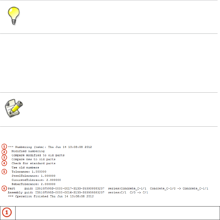
Viewing parts listed in a log file
The parts that are listed in a log file can be viewed in the model.
To view parts listed in a log file:
1. Click Tools --> Display Log File .
2. Select a log file you want to examine.
3. In the log file, select a row which contains a part or an assembly.
Parts and assemblies have the prefix id.
Tekla Structures highlights the part in the model.
If there are several parts or assemblies on a row and you select that row, Tekla Structures
highlights all the parts in the model. You can also select parts on different rows.
You can access a part’s or an assembly’s pop-up menu from the log file by right-clicking a
row that contains a part or an assembly. Tekla Structures displays the same pop-up menu
as when you right-click a part or an assembly in the model.
Log files on page 57
The numbering.history log file
The numbering.history log file contains full details of each numbering session carried
out on the model. Each numbering session is in a different block of the file.
If you remove or delete the numbering.history log file, Tekla Structures generates a
new file with the same name next time when you run numbering. The new file does not
contain a history of previous numbering sessions.
Below is an example of the contents of a numbering.history log file.
User name, date and time of the numbering.
See also
Example
Files and folders 59 Log files

Numbering method.
•Modified numbering is displayed when you run the Number Modified Objects
command.
•Modified numbering for selected series is displayed when you run
the Number Series of Selected Objects command.
•Diagnose & Repair Numbering: All is displayed when you run the
Diagnose & Repair Numbering: All command.
•Diagnose & Repair Numbering: Series of selected objects
is displayed when you run the Diagnose & Repair Numbering: Series of Selected
Objects command.
•Renumber all is displayed when you select the Renumber all option in the
Numbering Setup dialog box.
Some Compare options set in the Numbering Setup dialog box are displayed in the
numbering.history log file only if they are set differently than the default value:
•Compare modified to old parts
•Compare new to old part
•No holes comparing
•No part name comparing
•Beam orientation
•Column orientation
Some Compare options are not displayed at all:
•Reinforcing bars
•Embedded objects
•Surface treatment
Numbering options.
•Use old numbers is displayed only when you have selected the Re-use old
numbers option in the Numbering Setup dialog box.
•Check for standard parts is displayed only when you have selected the
Check for standard parts option in the Numbering Setup dialog box.
Tolerances are set in the Numbering Setup dialog box.
Changes in the position numbers and in the numbering series during one numbering
session.
In addition:
If a numbering series overlaps another, the errors are written to the log file.
Numbering series in the numbering.history log file on page 61See also
Files and folders 60 Log files
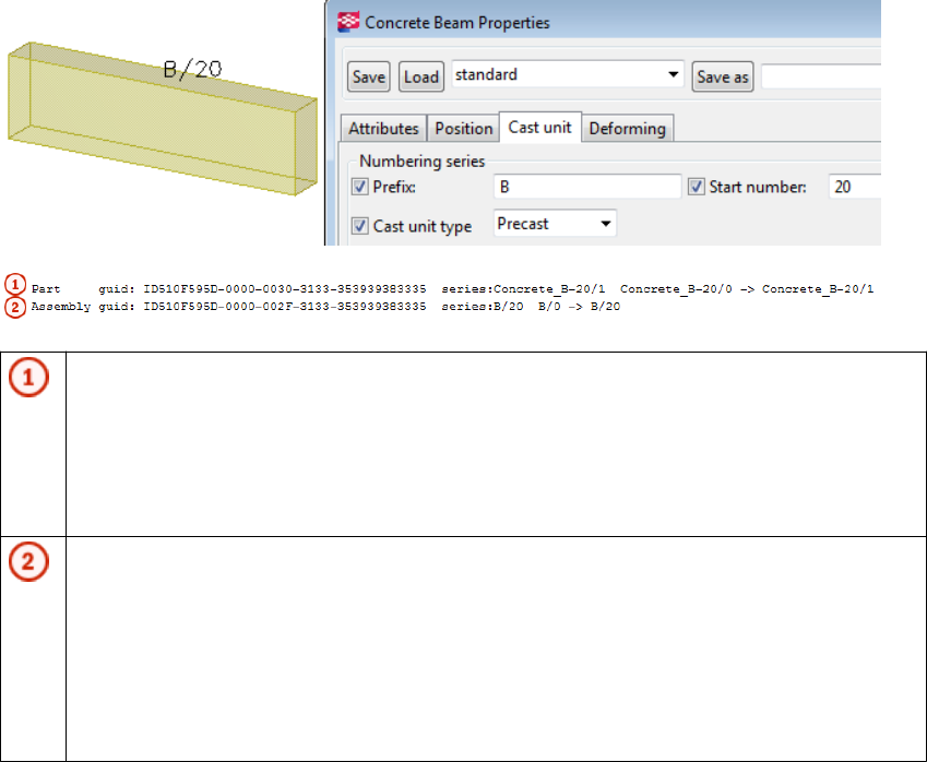
Viewing parts listed in a log file on page 58
Numbering series in the numbering.history log file
Tekla Structures lists information on the numbered parts and assemblies in the
numbering.history log file.
The numbering.history log after one concrete beam B/20 has been created and
numbered:
Part position number.
• The part with the GUID ID510F595D-0000-0030-3133-353939383335 is a
part of the numbering series Concrete_B-20/1.
• The part becomes the first part in the numbering series: Concrete_B-20/0 ->
Concrete_B-20/1.
Assembly position number.
• The assembly ID of the part is
ID510F595D-0000-002F-3133-353939383335.
• The part belongs to the B/20 assembly numbering series, which is also the cast unit
numbering series.
• The part gets the assembly position number: B/20: B/0 -> B/20.
The numbering.history log after another concrete beam B/21 has been created and
numbered:
Example 1
Example 2
Files and folders 61 Log files
Part position number of the new part.
• The part with the ID ID510F595D-0000-0030-3133-353939383335 is
part of the numbering series Concrete_B-20/1.
• The part becomes the second part in the numbering series: Concrete_B-20/0 -
> Concrete_B-20/2.
Assembly position number.
• The assembly ID of the part is
ID510F595D-0000-002F-3133-353939383335.
• The part belongs to the B/20 assembly numbering series, which is also the cast unit
numbering series.
• The part gets the assembly position number: B/20 B/0 -> B/21.
The numbering.history log file on page 59
Viewing parts listed in a log file on page 58
3.14 Model folder files and file name extensions
The following table lists the files and file name extensions in use in Tekla Structures and
located in model folder.
File or file
name
extension
Description For more
information
Files in the Tekla Structures model folder:
*.db1 The model database
*.db2 Numbering database
environmen
t.db
Database for user-defined attribute definitions
See also
Files and folders 62 Model folder files and file name extensions

File or file
name
extension
Description For more
information
xslib.db1 Contains information on user-defined connections and
details, and default component descriptions.
*.idrm Mapping file, which handles IDs. Do not modify.
xslib.db2 Contains numbering information. Numbering the
model
options_mo
del.db and
options_dr
awings.db
Contain values for model-specific options from the
Options dialog box and values for model-specific
advanced options from the Advanced Options dialog
box. When a model is created, Tekla Structures reads
model-specific options and advanced options values
from the standard.opt file and .ini files in the
environment folders and saves them in these two
databases.
Settings in the
Options dialog
box on page 19
xsdb.xs File used for displaying the name of the model in the
Open dialog box.
Opening a model
xs_user.<u
ser name>
Contains interface settings specified by the user.
Each time a model is saved, an
xs_user.<user_name> file is created or updated.
These settings are user specific. If the
xs_user.<user_name> settings are not found in
the model folder when you open the model, Tekla
Structures searches for the xs_user.default file
from the following path: model, model/attributes,
project, firm, system. If this file is not found, Tekla
Structures default settings will be used.
The file contains settings for many of the switches on
the Tools --> Options menu and the settings for the
icons on the Selecting and Snapping toolbars.
save_histo
ry.log
Tekla Structures stores the information in this file each
time the model is saved. The file includes the saving
time, date and information on any conflicts during
saving.
Saving a model
notificati
on_report.
xsr
File used for displaying a notification report of
assignments when you open a model.
XS_SHOW_NOTIF
ICATION_REPORT
TeklaStruc
turesModel
.xml
Contains information on the Tekla Structures session,
for example on opening, closing and what catalogs are
being used.
dotlog.txt A log file that contains information on Tekla Open API
application use.
Tekla Open API
on page 8
Files and folders 63 Model folder files and file name extensions

File or file
name
extension
Description For more
information
*.locked A temporary file that locks the model folder files to
prevent modifications while the model is in use.
*.bak A backup copy of the model database.
assert.txt A log file that contains information on assertion errors.
ClashCheck
.txt
A log file that contains information on clashes found in
the most recent clash check and the date and time of
the clash check.
Detecting clashes
ClashCheck
.history
A file that contains information on all clashes found in
all clash checks and the dates and times of the clash
checks.
wizard.txt Tekla Structures stores information in this file when
you run a drawing rule set (wizard) file. The file
contains, for example, errors, number of drawings
created, and information on which commands were
used.
*.lis Different catalogs can be exported from and imported
to different Tekla Structures models as *.lis files.
These include profile, material and bolt catalogs.
Importing a bolt
catalog
Importing a
material catalog
Importing profile
catalog items
Exporting a bolt
catalog
Exporting a
material catalog
Exporting a
profile catalog
*.tsc Shapes can be exported from and imported to different
Tekla Structures models as *.tsc files.
Importing a
shape
Exporting a
shape
.This_is_m
ultiuser_m
odel
Contains information about the PC running the Tekla
Structures multi-user server.
Do not alter or delete this file in normal circumstances.
If you move a model to a different server, you should
delete this file. Tekla Structures generates a new file
with the same name.
Installing Tekla
Structures multi-
user server as a
service
ComponentC
atalog.txt
Includes the default settings of the search view and
any keywords you save in the component catalog.
Component
Catalog
Files and folders 64 Model folder files and file name extensions

File or file
name
extension
Description For more
information
ModelBasic
sComponent
s.txt
Lists the basic components available. Component
Catalog
Worktypes.
xml
Lists available task types. Created when you start the
Task Manager.
Defining a task
type
WorkTypePr
operties.x
ml
Lists allowed property types and their units.
.tmp A file used to store temporary data.
.cnv A file used to map Tekla Structures profile and material
names with names used in other software.
Conversion files
Files in the analysis model folder:
*.ifc The analysis model exported in IFC format. Analysis model
properties
*.stp The analysis model exported in CIS/2 format.
*.map A file used for debugging analysis models.
analysis_r
esults.db5
Database for analysis load combination results. Saving analysis
results
*.db6 Analysis model database. Analysis model
properties
Files in the \screenshots folder:
*.png Screenshot taken in Tekla Structures. Taking a
screenshot
Files in the \attributes folder:
*.rop Reference object user-defined attribute properties Reference model
objects
*.rop.more Reference object properties
*.m1000001
7
Fabtrol XML import properties Fabtrol XML
*.m1000001
5
Import attribute properties Attribute import
*.ncf NC file properties NC files
*.ExportIF
C.MainDial
og
IFC export properties IFC export
*.m4400000
04
3D DWG/DXF export properties DWG and DXF
*.m4400000
03
3D DGN export properties Exporting to 3D
DGN files
Files and folders 65 Model folder files and file name extensions
File or file
name
extension
Description For more
information
*.m1000004 FEM export properties FEM
*.m1000001
1
CIS analysis model export properties CIS and CIMSteel
*.m1000002
6
CIS manufacturing model export properties CIS and CIMSteel
*.m1000007 CAD export properties Exporting to CAD
*.m1000001
6
Cover sheet export properties
*.SObjGrp Object group selection filter properties Filtering objects
using a selection
filter
*.grd Grid properties Grid properties
*.grd.more Grid user-defined attribute properties
*.grdp Grid line properties Grid line
properties
*.grdp.mor
e
Grid line user-defined attribute properties
*.mvi Model view properties that you have saved for the
model.
Default 3D, part, component, custom component,
assembly, and cast unit view settings files need to be
saved with names used in common environment:
3D view: basic_view
3D part view: part_basic_view
Part front view: part_front_view
Part top view: part_top_view
Part end view: part_end_view
Part perspective view: part_persp_view
3D component view: joint_basic_view
Component front view: joint_front_view
Component top view: joint_top_view
Component end view: joint_end_view
Component perspective view: joint_persp_view
Custom component front view:
custom_object_editor_front_view
Custom component top view:
custom_object_editor_top_view
View properties
Files and folders 66 Model folder files and file name extensions

File or file
name
extension
Description For more
information
Custom component end view:
custom_object_editor_end_view
Custom component perspective view:
custom_object_editor_perspective_view
3D assembly or cast unit view: assembly_basic_view
Assembly or cast unit front view: assembly_front_view
Assembly or cast unit top view: assembly_top_view
Assembly or cast unit end view: assembly_end_view
Assembly or cast unit back view: assembly_back_view
Assembly or cast unit bottom view:
assembly_bottom_view
Assembly or cast unit perspective view:
assebly_persp_view
*.gvi Saved properties for creating views along grid lines Grid view
properties
*.rep Object representation properties Changing the
color and
transparency of
parts
*.clm Steel column properties Steel column
properties
*.clm.more Steel column user-defined attribute properties
*.prt Steel beam properties Steel beam
properties
*.prt.more Steel beam user-defined attribute properties
*.crs Orthogonal beam properties Orthogonal beam
properties
*.crs.more Orthogonal beam user-defined attribute properties
*.dia Twin profile properties Twin profile
properties
*.dia.more Twin profile user-defined attribute properties
*.cpl Contour plate properties Contour plate
properties
*.cpl.more Contour plate user-defined attribute properties
*.ips Item properties Item properties
*.ips.more Item user-defined attribute properties
*.cpf Pad footing properties Pad footing
properties
*.cpf.more Pad footing user-defined attribute properties
*.csf Strip footing properties Strip footing
properties
*.csf.more Strip footing user-defined attribute properties
Files and folders 67 Model folder files and file name extensions

File or file
name
extension
Description For more
information
*.ccl Concrete column properties Concrete column
properties
*.ccl.more Concrete column user-defined attribute properties
.*.cbm Concrete beam or concrete polybeam properties Concrete beam
properties
*.cbm.more Concrete beam or concrete polybeam user-defined
attribute properties
*.csl Concrete slab properties Concrete slab
properties
*.csl.more Concrete slab user-defined attribute properties
*.cpn Concrete panel properties Concrete panel
properties
*.cpn.more Concrete panel user-defined attribute properties
*.ipc Concrete item properties Concrete item
properties
*.ipc.more Concrete item user-defined attribute properties
*.rbr Reinforcing bar properties Creating a
reinforcing bar
*.rbr.more Reinforcing bar user-defined attribute properties
*.rbg Reinforcing bar group properties Creating a
reinforcing bar
group
*.rbg.more Reinforcing bar group user-defined attribute properties
*.rcu Curved reinforcing bar group properties Creating a curved
reinforcing bar
group
*.rci Circular reinforcing bar group properties Creating a
circular
reinforcing bar
group
*.rbm Reinforcement mesh properties Creating a
rectangular
reinforcement
mesh
*.rbm.more Reinforcement mesh user-defined attribute properties
*.rbs Reinforcement strand pattern properties Creating a
reinforcement
strand pattern
*.rbs.more Reinforcement strand pattern user-defined attribute
properties
*.rsp Reinforcement splice properties Creating a
reinforcement
splice
*.rsp.more Reinforcement splice user-defined attribute properties
*.admodel Analysis model properties Analysis model
properties
*.admodel.
more
Analysis model user-defined attribute properties
*.lm1 Point load properties Point load
properties
Files and folders 68 Model folder files and file name extensions

File or file
name
extension
Description For more
information
*.lm2 Line load properties Line load
properties
*.lm3 Area load properties Area load
properties
*.lm4 Uniform load properties Uniform load
properties
*.m1000002
8
Wind load properties Wind load
properties
*.lm6 Temperature load properties Temperature load
properties
*.lco Load combination properties Load
combination
properties
*.adnode Analysis node properties Analysis node
properties
*.adnode.m
ore
Analysis node user-defined attribute properties
*.prt_ad,
*.prt_desi
gn
File types associated with steel beam analysis property
settings. *.prt_ad contains information associated
with the analysis part properties and
*.prt_design contains information associated
with the actual steel beam design.
*.crs_ad,
*.crs_desi
gn
File types associated with orthogonal steel beam
analysis property settings. *.crs_ad contains
information associated with the analysis part
properties and *.crs_design contains information
associated with orthogonal steel beam design.
*.clm_ad,
*.clm_desi
gn
File types associated with steel column analysis
property settings. *.clm_ad contains information
associated with the analysis part properties and
*.clm_design contains information associated
with the actual steel column design.
*.dia_ad,
*.dia_desi
gn
File types associated with steel twin profile analysis
property settings. *.dia_ad contains information
associated with the analysis part properties and
*.dia_design contains information associated
with actual twin profile design.
*.cpl_ad,
*.cpl_desi
gn
File types associated with contour plate analysis
property settings. *.cpl_ad contains information
associated with the analysis part properties and
*.cpl_design contains information associated
with actual contour plate design.
Files and folders 69 Model folder files and file name extensions

File or file
name
extension
Description For more
information
*.cpf_ad,
*.cpf_desi
gn
File types associated with pad footing analysis property
settings. *.cpf_ad contains information associated
with the analysis part properties and
*.cpf_design contains information associated
with the actual pad footing design.
*.csf_ad,
*.csf_desi
gn
File types associated with strip footing analysis
property settings. *.csf_ad contains information
associated with the analysis part properties and
*.csf_design contains information associated
with the actual strip footing design.
*.ccl_ad,
*.ccl_desi
gn
File types associated with concrete column analysis
property settings. *.ccl_ad contains information
associated with the analysis part properties and
*.ccl_design contains information associated
with the actual concrete column design.
*.cbm_ad,
*.cbm_desi
gn
File types associated with concrete beam analysis
property settings. *.cbm_ad contains information
associated with the analysis part properties and
*.cbm_design contains information associated
with the actual concrete beam design.
*.csl_ad,
*.csl_desi
gn
File types associated with concrete slab analysis
property settings. *.csl_ad contains information
associated with the analysis part properties and
*.csl_design contains information associated
with the actual slab design.
*.cpn_ad,
*.cpn_desi
gn
File types associated with concrete panel analysis
property settings. *.cpl_ad contains information
associated with the analysis part properties and
*.cpl_design contains information associated
with the actual concrete panel design.
*.srf Surface treatment properties Adding surface
treatment
*.srf.more User-defined surface treatment attribute properties
*.cha Edge chamfer properties Edge chamfer
properties
*.cha.more User-defined edge chamfer attribute properties
.scr Bolt properties Bolt properties
.scr.more User-defined bolt attribute properties
*.wld Weld properties Weld properties
*.wld.more User-defined weld attribute properties
*.m1000009 Control number properties Control number
settings
Files and folders 70 Model folder files and file name extensions
File or file
name
extension
Description For more
information
*.m1000010 Control number locking properties Locking and
unlocking control
numbers
*.num Numbering setup properties General
numbering
settings
*.rpr Report properties Report settings
*.4d Project status visualization properties Project Status
Visualization
standard.o
pt
Settings are saved in standard.opt in the
\attributes folder only when you save your own
settings in the Options dialog box using Save.
There is a standard.opt file in the environment
folder that gives the initial values to be loaded when a
model is created.
Settings in the
Options dialog
box on page 19
ComponentC
atalogTree
View.txt
Includes the default settings of the folder view in the
component catalog.
Grouping
components in
the Component
Catalog
Files in the \PublicWeb folder:
Model.xml Web Viewer model in XML format Tekla Web Viewer
index.html Index file for the Web Viewer model
Model.zsol Contains information on solid objects in the Web
Viewer model
Files in the css
folder
Contains Cascading Style Sheet (CSS) files for the Web
Viewer Model
Files in the dll
folder
Contains dynamic link libraries (DLL) files for the Web
Viewer model
Files in the
help folder
Contains Web Viewer help and css files.
Files in the
images folder
Contains image files used in Web Viewer
Files in the \drawings folder:
*.dg Drawing files Saving drawings
About drawing
files
*.ldb Drawing export layer properties
Common drawing files:
Files and folders 71 Model folder files and file name extensions

File or file
name
extension
Description For more
information
*.ldr Drawing link properties Adding links to
other drawings
*.cs Section symbol properties Creating a
section view
*.detail Detail symbol properties Creating a detail
view
*.fas Text file properties Adding links to
text files
*.fhl Hyperlink properties Adding hyperlinks
Files related to single-part drawings, drawing level properties, saved in \attributes
folder:
*.wd Single-part drawing properties Drawing
properties
*.wd.copt Single-part drawing detailed object level settings
*.wd.more Single-part drawing user-defined attributes
*.wdf Single-part drawing filter properties Filtering in
drawings
*.wdnf Single-part drawing neighbor part filter properties
*.wdl Single-part drawing layout properties Drawing layout
*.wdl.more Single-part drawing user-defined layout attributes
*.wdv Single-part drawing view properties View properties
in drawings
*.wdv.more Single-part drawing user-defined view attributes
*.wdc Single-part drawing section view properties Section view
properties
*.wdc.more Single-part drawing user-defined section view
attributes
*.wdd Single-part drawing dimension properties Dimension and
dimensioning
properties
*.wdd.more Single-part drawing user-defined dimension attributes
*.wdcd Single-part drawing dimensioning properties
*.wdcd
more
Single-part drawing user-defined dimensioning
attributes
*.wpm Single-part drawing part mark properties Part mark
elements
*.wsm Single-part drawing bolt mark properties Bolt mark
elements
*.wnpm Single-part drawing neighbor part mark properties Part mark
elements
*.wdsurfm Single-part drawing surface treatment mark properties Surface
treatment mark
elements
*.wdsurfm.
more
Single-part drawing user-defined surface treatment
mark attributes
Files and folders 72 Model folder files and file name extensions

File or file
name
extension
Description For more
information
*.wjm Single-part drawing connection mark properties Connection mark
elements
*.wdp Single-part drawing part properties Part and
neighbor part
properties
*.wds Single-part drawing bolt properties Bolt content and
appearance
properties in
drawings
*.wds.more Single-part drawing user-defined bolt attributes
*.wdnp Single-part drawing neighbor part properties Part and
neighbor part
properties
*.wdnp.mor
e
Single-part drawing user-defined neighbor part
attributes
*.wdsrf Single-part drawing surface treatment properties Surface
treatment
visibility and
content
properties in
drawings
*.wdsrf.mo
re
Single-part drawing user-defined surface treatment
attributes
*.wdgr Single-part drawing grid properties Drawing grid
properties
*.wdgr.mor
e
Single-part drawing user-defined grid attributes Drawing grid
properties
*.wdr Single-part drawing protection properties Protecting areas
in drawings
*.wdr.more Single-part drawing user-defined protection attributes Protecting areas
in drawings
Files related to assembly drawings, drawing level properties, saved in \attributes folder:
*.ad Assembly drawing properties Drawing
properties
*.ad.copt Assembly drawing detailed object level settings
*.ad.more Assembly drawing user-defined attributes
*.adf Assembly drawing filter properties Filtering in
drawings
*.adnf Assembly drawing neighbor part filter properties
*.adl Assembly drawing layout properties Drawing layout
*.adl.more Assembly drawing user-defined layout attributes
*.adv Assembly drawing view properties View properties
in drawings
*.adc Assembly drawing section view properties Section view
properties
Files and folders 73 Model folder files and file name extensions

File or file
name
extension
Description For more
information
*.add Assembly drawing dimension properties Dimension and
dimensioning
properties
*.add.more Assembly drawing user-defined dimension attributes
*.adcd Assembly drawing dimensioning properties
*.adcd.mor
e
Assembly drawing user-defined dimensioning
attributes
*.apm Assembly drawing part mark properties Part mark
elements
*.asm Assembly drawing bolt mark properties Bolt mark
elements
*.anpm Assembly drawing neighbor part mark properties Part mark
elements
*.adsurfm Assembly drawing surface treatment mark properties Surface
treatment mark
elements
*.adsurfm.
more
Assembly drawing user-defined surface treatment
mark attributes
*.ajm Assembly drawing connection mark properties Connection mark
elements
*.adp Assembly drawing part properties Part and
neighbor part
properties
*.adp.more Assembly drawing user-defined part attributes
*.ads Assembly drawing bolt properties Bolt content and
appearance
properties in
drawings
*.adnp Assembly drawing neighbor part properties Part and
neighbor part
properties
*.adnp.mor
e
Assembly drawing user-defined neighbor part
attributes
*.adsrf Assembly drawing surface treatment properties Surface
treatment
visibility and
content
properties in
drawings
*.adsrf.mo
re
Assembly drawing user-defined surface treatment
attributes
*.adw Assembly drawing welding properties Model weld mark
visibility and
appearance
properties in
drawings
*.adw.more Assembly drawing user-defined welding attributes
*.adgr Assembly drawing grid properties Drawing grid
properties
Files and folders 74 Model folder files and file name extensions

File or file
name
extension
Description For more
information
*.adgr.mor
e
Assembly drawing user-defined grid attributes Drawing grid
properties
*.adr Assembly drawing protection properties Protecting areas
in drawings
Files related to cast unit drawings, drawing level properties, saved in \attributes folder:
*.cud Cast unit drawing properties Drawing
properties
*.cud.copt Cast unit drawing detailed object level settings
*.cud.more Cast unit drawing user-defined attributes
*.cudl Cast unit drawing layout properties Drawing layout
*.cudl.mor
e
Cast unit drawing user-defined layout attributes
*.cudv Cast unit drawing view properties View properties
in drawings
*.cudv.mor
e
Cast unit drawing user-defined view attributes
*.cudc Cast unit drawing section view properties Section view
properties
*.cudc.mor
e
Cast unit drawing user-defined section view attributes
*.cudd Cast unit drawing dimension properties Dimension and
dimensioning
properties
*.cudd.mor
e
Cast unit drawing user-defined dimension attributes
*.cudcd Cast unit drawing dimensioning properties
*.cudcd.mo
re
Cast unit drawing user-defined dimensioning
properties
*.cupm Cast unit drawing part mark properties Part mark
elements
*.cusm Cast unit drawing bolt mark properties Bolt mark
elements
*.cunpm Cast unit drawing neighbor part mark properties Part mark
elements
*.cudsurfm Cast unit drawing surface treatment mark properties Surface
treatment mark
elements
*.cudsurfm
.more
Cast unit drawing user-defined surface treatment mark
attributes
*.cudrm Cast unit drawing reinforcement mark properties Reinforcement
and neighbor
reinforcement
mark elements
Mark properties
*.cudrm.mo
re
Cast unit drawing user-defined reinforcement mark
attributes
Files and folders 75 Model folder files and file name extensions

File or file
name
extension
Description For more
information
*.cudp Cast unit drawing part properties Part and
neighbor part
properties
*.cudp.mor
e
Cast unit drawing user-defined part attributes
*.cuds Cast unit drawing bolt properties Bolt content and
appearance
properties in
drawings
*.cuds.mor
e
Cast unit drawing user-defined bolt attributes
*.cudnp Cast unit drawing neighbor part properties Part and
neighbor part
properties
*.cudnp.mo
re
Cast unit drawing user-defined neighbor part
attributes
*.cudsrf Cast unit drawing surface treatment properties Surface
treatment
visibility and
content
properties in
drawings
*.cudsrf.m
ore
Cast unit drawing user-defined surface treatment
attributes
*.cudr Cast unit drawing reinforcement properties Reinforcement/
Neighbor
reinforcement
and mesh
properties in
drawings
*.cudr.mor
e
Cast unit drawing user-defined reinforcement
attributes
*.cudw Cast unit drawing welding properties Model weld mark
visibility and
appearance
properties in
drawings
*.cudw.mor
e
Cast unit drawing user-defined welding attributes
*.cudgr Cast unit drawing grid properties Drawing grid
properties
*.cudgr.mo
re
Cast unit drawing user-defined grid attributes Drawing grid
properties
*.cudrp Cast unit drawing protection properties Protecting areas
in drawings
*.cudrp.mo
re
Cast unit drawing user-defined protection attributes Protecting areas
in drawings
*.cuf Cast unit drawing filter properties Filtering in
drawings
*.cunf Cast unit drawing neighbor part filter properties
Files related to multidrawings, drawing level properties, saved in \attributes folder:
*.md Multidrawing properties Drawing
properties
*.md.more Multidrawing user-defined attributes
Files and folders 76 Model folder files and file name extensions

File or file
name
extension
Description For more
information
*.mdl Multidrawing layout properties Drawing layout
*.mdl.more Multidrawing user-defined layout attributes
*.mdr Multidrawing protection properties Protecting areas
in drawings
*.mdr.more Multidrawing user-defined protection attributes Protecting areas
in drawings
Files related to general arrangement drawings, drawing level properties, saved in
\attributes folder:
*.gd General arrangement drawing properties Drawing
properties
*.gd.copt General arrangement drawing detailed object level
settings.
*.gd.more General arrangement drawing user-defined properties
*.gdl General arrangement drawing layout properties Drawing layout
*.gdl.more General arrangement drawing user-defined layout
attributes
*.gdv General arrangement drawing view properties View properties
in drawings
*.gdv.more General arrangement drawing user-defined view
attributes
*.gdd General arrangement drawing dimension properties Dimension and
dimensioning
properties
*.gdd.more General arrangement drawing user-defined dimension
attributes
*.gdcd General arrangement drawing dimensioning properties
*.gdcd.mor
e
General arrangement drawing user-defined
dimensioning attributes
*.gpm General arrangement drawing part mark properties Part mark
elements
*.gsm General arrangement drawing bolt mark properties Bolt mark
elements
*.gnpm General arrangement drawing neighbor part mark
properties
Part mark
elements
*.gdsurfm General arrangement drawing surface treatment mark
properties
Surface
treatment mark
elements
*.gdsurfm.
more
General arrangement drawing user-defined surface
treatment mark attributes
*.gjm General arrangement drawing connection mark
properties
Connection mark
elements
*.gdrm General arrangement drawing reinforcement mark
properties
Reinforcement
and neighbor
Files and folders 77 Model folder files and file name extensions

File or file
name
extension
Description For more
information
*.gdrm.mor
e
reinforcement
mark elements
Mark properties
General arrangement drawing user-defined
reinforcement mark attributes
*.gdp General arrangement drawing part properties Part and
neighbor part
properties
*.gdp.more General arrangement drawing user-defined part
attributes
*.gds General arrangement drawing bolt properties Bolt content and
appearance
properties in
drawings
*.gds.more General arrangement drawing user-defined bolt
attributes
*.gdnp General arrangement drawing neighbor part properties Part and
neighbor part
properties
*.gdnp.mor
e
General arrangement drawing user-defined neighbor
part attributes
*.gdsrf General arrangement drawing surface treatment
properties
Surface
treatment
visibility and
content
properties in
drawings
*.gdw General arrangement drawing welding properties Model weld mark
visibility and
appearance
properties in
drawings
*.gdw.more General arrangement drawing user-defined welding
attributes
*.gdr General arrangement drawing reinforcement properties Reinforcement/
Neighbor
reinforcement
and mesh
properties in
drawings
*.gdr.more General arrangement drawing user-defined
reinforcement attributes
*.gdrmp General arrangement drawing reference object
properties
Setting the
visibility and
appearance of
reference models
in drawings...
*.gdrmp.mo
re
General arrangement drawing user-defined reference
model attributes
Setting the
visibility and
appearance of
reference models
in drawings...
*.gdgr General arrangement drawing grid properties Drawing grid
properties
Files and folders 78 Model folder files and file name extensions

File or file
name
extension
Description For more
information
*.gdgr.mor
e
General arrangement drawing user-defined grid
attributes
Drawing grid
properties
*.gdrp General arrangement drawing protection properties Protecting areas
in drawings
*.gdrp.mor
e
General arrangement drawing user-defined protection
attributes
Protecting areas
in drawings
*.gdf General arrangement drawing filter properties Filtering in
drawings
*.gdnf General arrangement drawing neighbor part filter
properties
View level drawing settings, saved in \attributes folder:
*.vi View level view properties View properties
in drawings
*.vi.copt View level detailed object level settings View properties
in drawings
*.vpm View level part mark properties Part mark
elements
*.vsm View level bolt mark properties Bolt mark
elements
*.vnpm View level neighbor part mark properties Part mark
elements
*.vsurfm View level surface treatment mark properties Surface
treatment mark
elements
*.vjm View level connection mark properties Connection mark
elements
*.vrm View level reinforcement mark properties Reinforcement
and neighbor
reinforcement
mark elements
Mark properties
*.vnrm View level neighbor reinforcement mark properties Reinforcement
and neighbor
reinforcement
mark elements
Mark properties
*.vp View level part properties Part and
neighbor part
properties
*.vs View level bolt properties Bolt content and
appearance
Files and folders 79 Model folder files and file name extensions

File or file
name
extension
Description For more
information
properties in
drawings
*.vnp View level neighbor part properties Part and
neighbor part
properties
*.vsurf View level surface treatment properties Surface
treatment
visibility and
content
properties in
drawings
*.vw View level welding properties Model weld mark
visibility and
appearance
properties in
drawings
*.vr View level reinforcement properties Reinforcement/
Neighbor
reinforcement
and mesh
properties in
drawings
*.vnr View level neighbor reinforcement properties Reinforcement/
Neighbor
reinforcement
and mesh
properties in
drawings
*.vrmp View level reference object properties Setting the
visibility and
appearance of
reference models
in drawings...
*.vg View level grid properties Drawing grid
properties
*.vf View level filter properties Filtering in
drawings
*.vnf View level neighbor part filter properties
Object level settings, saved in \attributes folder:
*.dprt Object level part properties Part and
neighbor part
properties
Files and folders 80 Model folder files and file name extensions

File or file
name
extension
Description For more
information
*.dim Object level dimension properties Dimension and
dimensioning
properties
*.pm Object level part mark properties Mark properties
*.jm Object level connection mark properties
*.sm Object level bolt mark properties
*.rm Object level reinforcement mark properties
*.mrms Object level merged reinforcement mark properties
*.surfm Object level surface treatment mark properties
*.note Object level associative note properties
*.wls Object level weld mark properties Weld mark
properties
*.lev Object level level mark properties Level mark
properties
*.rev Object level revision mark properties Adding revision
marks
*.drmsh Object level reinforcement mesh properties Reinforcement/
Neighbor
reinforcement
and mesh
properties in
drawings
*.drbr Object level reinforcement properties Reinforcement/
Neighbor
reinforcement
and mesh
properties in
drawings
*.sc Object level bolt properties Bolt content and
appearance
properties in
drawings
*.srf Object level surface treatment properties Surface
treatment
visibility and
content
properties in
drawings
*.dgr Object level grid properties Drawing grid
properties
Files and folders 81 Model folder files and file name extensions

File or file
name
extension
Description For more
information
*.sbl Object level symbol properties Symbols in
drawings
*.wls Object level weld mark properties Adding weld
marks
*.drtxt Object level text properties Adding text
*.gln Object level line properties Creating a shape
in a drawing
*.grt Object level rectangle properties
*.gci Object level circle properties
*.gar Object level arc properties
*.gpl Object level polyline properties
*.gpg Object level polygon and cloud properties
Other drawing related files saved in \attributes folder
.dsf Drawing selection filter properties. This file is saved
when you select DrawingSelection filter in the Filter
panel of in the Filter properties dialog box.
Filtering in
drawings
Files in the \Reports folder:
*.xsr Tekla Structures reports Reports
Files in the \ShapeGeometries folder:
*.xml Shape geometry descriptions Importing a
shape
Files in the \Shapes folder:
*.xml Shape descriptions Shapes
Files in the \DSTV_Profiles folder:
*.nc1 NC (numerical control) files NC files
In addition, Tekla Structures generates, for example, the following files depending on what
functionalities you are using:
• Properties files for components available in the Component Catalog, for example
*.j310000063 for 2L Splice (63) component properties. These files are stored in the
attributes folder under the model folder
• Files related to Unitechnik export in the UT_files folder under the model folder.
Files and folders 82 Checking and changing Tekla Structures file and folder
locations (Directory Browser)

3.15 Checking and changing Tekla Structures file and folder locations
(Directory Browser)
Directory Browser is a tool that helps you to find and modify the location of the various
Tekla Structures files and folders, and customize user settings.
Generally, only administrators should change these settings. If you change them
yourself, and you are using the same model with other users, and your settings
differ from those of the project, you will have problems. Also, adding or modifying
files in some of these folders may require administrator rights.
To locate files and folders, and customize your Tekla Structures settings:
1. Select Tools --> Macros... to open the Macros dialog box.
2. Select DirectoryBrowser and click Run.
The Directory Browser dialog box is displayed. Here you can check the most common
folder paths, and customize the settings in your user.ini file, or in the user-specific
or model-specific options.ini file.
3. Check the folder paths and change them if necessary by clicking the buttons on the left
of the Basic tab.
If you click the Project or Firm button and you have not set your firm and project folder,
Tekla Structures will prompt you to do so and add the folder path definition to your
user.ini file.
4. Check the settings in the user.ini and options.ini files and change them if
necessary by clicking the buttons on the right of the Basic tab.
5. Go to the Advanced tab and define the folder paths for additional folders that you may
need to access, such as custom components and macros.
To display the location of your own user settings, click User Settings on the left. If you want
to check or change the content in one of your user settings files, click the User Settings
(user.ini) or the User Specific Settings (options.ini) button to open the file.
Example
Files and folders 83 Checking and changing Tekla Structures file and folder
locations (Directory Browser)
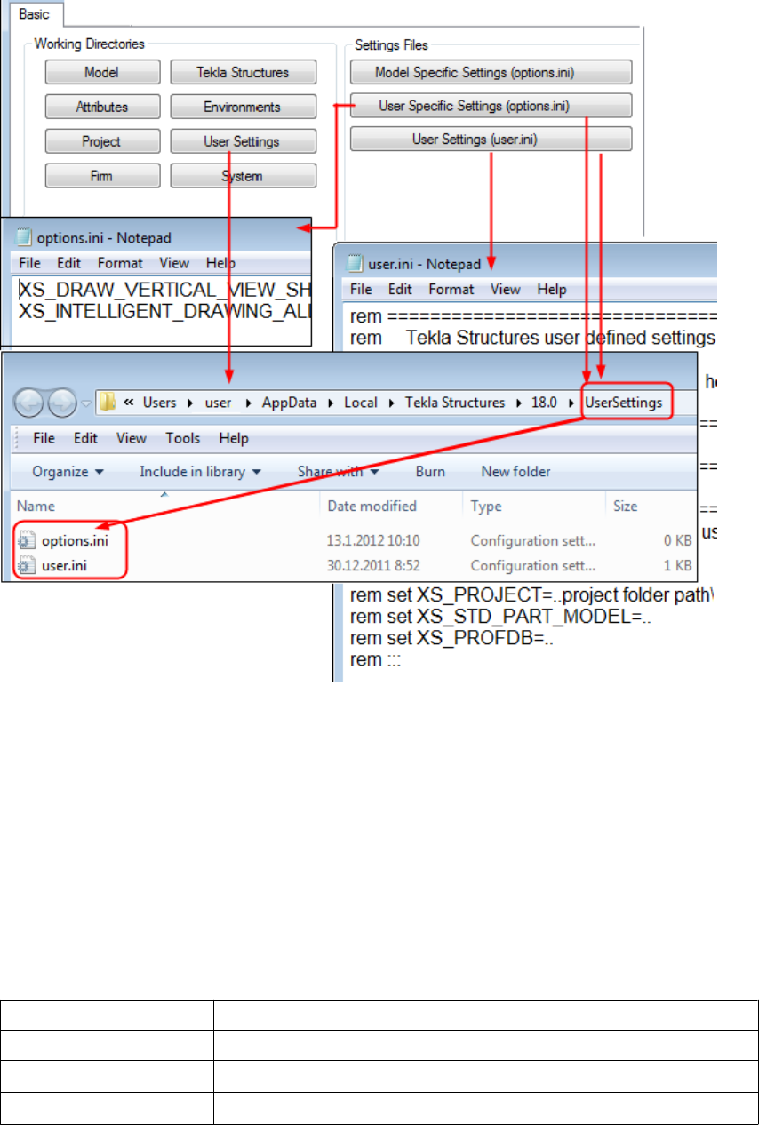
3.16 Folder search order
When you open a model, Tekla Structures searches for the associated files in specific folders
in a set order.
It is important that you keep files in correct folders. Once Tekla Structures finds the
associated files, it stops searching. This means that files that have the same name but are
located lower down the search order are ignored.
The folder search order is:
Folder Defined by
Current model The open model
Project Advanced option XS_PROJECT
Firm Advanced option XS_FIRM
Files and folders 84 Folder search order

Folder Defined by
System Advanced option XS_SYSTEM
Tekla Structures does not search for certain files in exactly this order. The exceptions are
listed below.
The exceptions are:
File (type) Search order
objects.inp • Model folder
• Project folder (XS_PROJECT)
• Firm folder (XS_FIRM)
• System folder (XS_SYSTEM)
• inp folder (XS_INP)
privileges.inp • Model folder
• Project folder (XS_PROJECT)
• Firm folder (XS_FIRM)
• System folder (XS_SYSTEM)
• inp folder (XS_INP)
*.dat files System folder (XS_SYSTEM)
Templates • Folder containing your templates indicated by the advanced
option XS_TEMPLATE_DIRECTORY
• Model folder
• Project folder (XS_PROJECT)
• Firm folder (XS_FIRM)
• Environment-specific system templates indicated by the
advanced option XS_TEMPLATE_DIRECTORY_SYSTEM
• System folder (XS_SYSTEM)
Catalogs Profile, bolt, material and reinforcement catalogs:
• Model folder
• Project folder (XS_PROJECT)
• Firm folder (XS_FIRM)
• Folder indicated by the advanced option XS_PROFDB
Shape catalog:
• Model folder
• Project folder (XS_PROJECT)
• Firm folder (XS_FIRM)
Files and folders 85 Folder search order
File (type) Search order
• System folder (XS_SYSTEM)
• Folder indicated by the advanced option
XS_DEFAULT_BREP_PATH
Printer catalog:
• Model folder
• Project folder (XS_PROJECT)
• Firm folder (XS_FIRM)
• Folder indicated by the advanced option XS_DRIVER
Do not use the system folder to store customized files. That way you will avoid
having problems or doing a lot of unnecessary work when you upgrade to a newer
version of the software.
3.17 Project and firm folders
You can create project and firm folders for customized files. This is a useful technique if you
want to store the files for future use, or want to retain them when you install a new release.
The project folder is where you should store files you customize for a particular project. Use
the firm folder to store files customized for a particular organization or company. Create firm
and project folders manually and make them available in all versions using the advanced
options XS_PROJECT and XS_FIRM in Tools --> Options --> Advanced Options... -->
File Locations .
For example, you regularly work for a company that has specific drawing layout standards it
expects you to use. Customize the drawing templates once for the company and save them in
a sub-folder located under the firm folder. You can then use the customized drawing
templates for all future projects for that company.
Changing an advanced option value in .ini files located outside the model
folder does not affect the existing models. You can only update advanced options
in the Advanced Options dialog box or in the options.ini file located in
model folder; not from an options.ini file located in folders defined for the
advanced options XS_FIRM or XS_PROJECT. The .ini files are read also
when you open an existing model, but only new advanced options that do not
exist in options_model.db or options_drawings.db are inserted, for
Files and folders 86 Project and firm folders
example, such options that are not yet in the Advanced Options dialog box but
have been added in the software.
Folder search order on page 84
Typical initialization files and their reading order on page 10
3.18 Location of environment files
The environment files are by default located in ..\ProgramData\Tekla
Structures\<version>\environments
3.19 Location of certain files in hidden folders
When Tekla Structures is installed in the \Program Files folder the following settings
files are located in hidden folders. You can see hidden folders if you turn them visible in
Windows Folder Options.
You can always check the settings below. If you run into problems with the settings, ask
your administrator or local support for assistance.
File Location
analysis_design_config.inp ..\ProgramData\Tekla
Structures\<version>
\environments\<environment>
\system
contentattributes.lst ..\ProgramData\Tekla
Structures\<version>
\environments\<environment>
\template\settings
contentattributes_global.lst ..\Program Files\Tekla
Structures\<version>\nt\TplEd
\settings
contentattributes_userdefined
.lst
(in USImperial and Metric environments:
contentattributes_customer.ls
t)
..\Program Files\Tekla
Structures\<version>\nt\TplEd
\settings
See also
See also
Files and folders 87 Location of environment files

File Location
dimension_marks.sym ..\ProgramData\Tekla
Structures\<version>
\environments\common\symbols
InquiryTool.config ..\ProgramData\Tekla
Structures\<version>
\environments\common\macros
\modeling
\InquiryToolAttributes
objects.inp ..\ProgramData\Tekla
Structures\<version>
\environments\common\inp
options.bin ..\Users\<user>\AppData\Local
\Tekla Structures\<version>
\UserSettings
privileges.inp ..\ProgramData\Tekla
Structures\<version>
\environments\common\inp
product_finishes.dat ..\ProgramData\Tekla
Structures\<version>
\environments\common\system
rebar_config.inp ..\ProgramData\Tekla
Structures\<version>
\environments\<environment>
\system
TeklaStructures.lin ..\ProgramData\Tekla
Structures\<version>
\environments\common\inp
teklastructures.minitoolbar.x
ml
..\Users\<user>\AppData\Local
\Tekla Structures\<version>
\UserSettings
TilePatternCatalog.dtd ..\ProgramData\Tekla
Structures\<version>
\environments\common\system
TilePatternCatalog.xml ..\ProgramData\Tekla
Structures\<version>
\environments\<environment>
\system
user.ini ..\Users\<username>\AppData
\Local\Tekla Structures
\<version>\UserSettings\
Files and folders 88 Macros
3.20 Macros
In Tekla Structures, you can use the predefined macros available in Tools --> Macros , or you
can record a series of actions from menus, dialog boxes, or shortcuts. You can also create
macro files manually.
Macros are saved as .cs files in the drawings or modeling folder under a folder
defined with the advanced option XS_MACRO_DIRECTORY. By default, this advanced
option is set to ..\ProgramData\Tekla Structures\<version>
\environments\common\macros. In addition to this global folder, you can create a
local folder and save your macros there. You can add your own folder for this advanced
option in addition to the global folder.
Recording, editing and running macros on page 89
Adding a customized toolbar button for a macro on page 90
Checking and changing Tekla Structures file and folder locations (Directory Browser) on page
82
Recording, editing and running macros
To record and edit a macro and then run it:
1. Click Tools --> Macros to open the Macros dialog box.
2. Enter a name for the macro in the Macro name box.
Once you enter the name, the Record button is activated.
3. Click the Global or Local option button depending on whether you want to save the
macro in the global or local macros folder.
The Global and Local option buttons are only available if you have defined a location for
the local macros in your environment using the advanced option
XS_MACRO_DIRECTORY.
4. Click Record.
5. Perform the actions you want to record.
6. Click Stop to stop recording.
The recorded macro is saved under global or local macros in the \drawings or
\modeling folder depending on the mode (drawing or modeling) you were using while
you were recording the macro.
7. To view or edit the macro you created, select the macro and click Edit.
The macro can be opened in any text editor.
8. To run the macro, select it and click Run.
See also
Files and folders 89 Macros

To manually create a macro file, click Create in the Macros dialog box. This creates an
empty macro file, which you can manually edit, for example, by copying commands in it
from other macro files.
Adding a customized toolbar button for a macro on page 90
Macros on page 88
Adding a customized toolbar button for a macro
You can create your own toolbar buttons for macros and have them available on user-
specific toolbars.
To add a customized toolbar button:
1. Create the bitmap you want to use as the toolbar button.
2. Save the bitmap with the same name as the macro in the same folder as the macro.
For example, if you have a macro that is used in modeling, and the name of the macro is
RotatePart.cs, save the bitmap as RotatePart.bmp in the folder ..\Tekla
Structures\<version>\environments\common\macros\modeling.
If you are using large toolbar buttons (24x24 pixels instead of 16x16 pixels), add the
suffix _big to the bitmap name: for example, RotatePart_big.bmp.
3. Click Tools --> Customize to open the Customize dialog box.
4. If you have not created any user-specific toolbars, click New to create one.
5. Enter macro in the Filter box to list the available macros.
6. Select the macro from the list, click the user-specific toolbar in the Toolbars list, and
then click the right arrow.
The macro is added to the user-specific toolbar.
7. Click Close to close the Customize dialog box.
8. Restart Tekla Structures to load the bitmap.
See also
Files and folders 90 Macros

4Model dump
If you have fatal problems with the model, for example, you cannot save the model, using a
model dump is one way of saving your work. Model dump creates an ASCII file. The file
contains your entire model including views and drawings.
The following information is for advanced users.
You can modify a model dump file with a standard text editor. For example, if you
know the ID of a corrupted part, you can search for the ID in the file and delete
the data related to the ID.
Importing a model dump on page 91
Exporting a model dump on page 91
4.1 Exporting a model dump
Exporting a model dump creates an ASCII file of a model. You can import the model dump
into a new model. The model dump file contains the entire model, including views and
drawings.
To export a model into a model dump file, click File --> Export --> Model Dump .
Tekla Structures creates the model.dmp file in the model folder.
Importing a model dump on page 91
See also
See also
Model dump 91 Exporting a model dump

4.2 Importing a model dump
You can only import a model dump into a newly-created model. A model dump can be
imported only once into one model. You can import the same model dump into several new
models.
To import a model dump:
1. Create a new model.
2. Copy the model dump file (.dmp) to the new model’s model folder.
3. Click File --> Import --> Model Dump .
4. Save and close the model.
5. Reopen the model.
Do not import model dumps in multi-user mode.
Exporting a model dump on page 91
See also
Model dump 92 Importing a model dump
5Disclaimer
© 2015 Tekla Corporation and its licensors. All rights reserved.
This Software Manual has been developed for use with the referenced Software. Use of the
Software, and use of this Software Manual are governed by a License Agreement. Among
other provisions, the License Agreement sets certain warranties for the Software and this
Manual, disclaims other warranties, limits recoverable damages, defines permitted uses of the
Software, and determines whether you are an authorized user of the Software. All
information set forth in this manual is provided with the warranty set forth in the License
Agreement. Please refer to the License Agreement for important obligations and applicable
limitations and restrictions on your rights. Tekla does not guarantee that the text is free of
technical inaccuracies or typographical errors. Tekla reserves the right to make changes and
additions to this manual due to changes in the software or otherwise.
In addition, this Software Manual is protected by copyright law and by international treaties.
Unauthorized reproduction, display, modification, or distribution of this Manual, or any
portion of it, may result in severe civil and criminal penalties, and will be prosecuted to the
full extent permitted by law.
Tekla, Tekla Structures, Tekla BIMsight, BIMsight, Tedds, Solve, Fastrak and Orion are either
registered trademarks or trademarks of Tekla Corporation in the European Union, the United
States, and/or other countries. More about Tekla trademarks: http://www.tekla.com/tekla-
trademarks. Trimble is a registered trademark or trademark of Trimble Navigation Limited in
the European Union, in the United States and/or other countries. More about Trimble
trademarks: http://www.trimble.com/trademarks.aspx. Other product and company names
mentioned in this Manual are or may be trademarks of their respective owners. By referring
to a third-party product or brand, Tekla does not intend to suggest an affiliation with or
endorsement by such third party and disclaims any such affiliation or endorsement, except
where otherwise expressly stated.
Portions of this software:
D-Cubed 2D DCM © 2010 Siemens Industry Software Limited. All rights reserved.
EPM toolkit © 1995-2004 EPM Technology a.s., Oslo, Norway. All rights reserved.
Open CASCADE Technology © 2001-2014 Open CASCADE SA. All rights reserved.
FLY SDK - CAD SDK © 2012 VisualIntegrity™. All rights reserved.
Teigha © 2003-2014 Open Design Alliance. All rights reserved.
PolyBoolean C++ Library © 2001-2012 Complex A5 Co. Ltd. All rights reserved.
Disclaimer 93 Importing a model dump
FlexNet Copyright © 2014 Flexera Software LLC. All Rights Reserved.
This product contains proprietary and confidential technology, information and creative
works owned by Flexera Software LLC and its licensors, if any. Any use, copying, publication,
distribution, display, modification, or transmission of such technology in whole or in part in
any form or by any means without the prior express written permission of Flexera Software
LLC is strictly prohibited. Except where expressly provided by Flexera Software LLC in writing,
possession of this technology shall not be construed to confer any license or rights under any
Flexera Software LLC intellectual property rights, whether by estoppel, implication, or
otherwise.
To see the third party licenses, go to Tekla Structures, click Help --> About and click the
Third party licenses button.
The elements of the software described in this Manual are protected by several patents and
possibly pending patent applications in the European Union and/or other countries. For more
information go to page http://www.tekla.com/tekla-patents.
Disclaimer 94 Importing a model dump
Index
A
advanced options..............................................................10
changing...................................................................... 37
storing settings.......................................................... 18
user-specific................................................................33
API............................................................................................8
C
catalog files........................................................................ 53
clash check
settings.........................................................................19
company.ini.........................................................................10
components
settings.........................................................................19
creating
customized initialization files................................16
shortcuts...................................................................... 16
customized initializations...............................................16
customizing
message files...............................................................50
user-defined attributes............................................39
D
data files..............................................................................49
decimals
settings.........................................................................19
defining
flat bar sizes................................................................46
unfolding parameters...............................................47
dimensions
default format............................................................ 19
default precision........................................................19
default unit................................................................. 19
settings.........................................................................19
drawing objects
settings.........................................................................19
E
environment settings
global default ............................................................ 13
local...............................................................................14
environment variables..................................................... 18
see advanced options...............................................37
environment variables, see advanced options..........10
environment.db..................................................................40
environment
database file................................................................40
env_<environment>.ini.......................................10,14,32
env_global_default.ini...............................................10,32
env_global_default.ini ....................................................13
examples
creating user-defined attribute.............................43
flat bar sizes................................................................46
modifying messages..................................................51
updating user-defined attribute........................... 43
exporting
model dump................................................................ 91
extensions..............................................................................8
F
file name extensions........................................................ 62
file types
initialization files.......................................................10
files..........................................................................................9
extensions....................................................................62
in model folder...........................................................62
initialization files.......................................................10
locations.......................................................................82
symbol...........................................................................55
firm folder........................................................................... 86
flat bars
in drawings .................................................................46
in reports......................................................................46
sizes...............................................................................46
fltprops.inp..........................................................................46
folders.....................................................................................9
95
firm................................................................................86
in model folder...........................................................62
locations.......................................................................82
project...........................................................................86
search order................................................................ 84
font files...............................................................................54
fonts......................................................................................54
fonts_<lang>.ini................................................................10
G
global default environment settings........................... 13
graphics card.........................................................................5
I
icons
adding customized toolbar buttons.....................90
image files...........................................................................56
images
file formats..................................................................56
importing
model dump................................................................ 91
ini files............................................................................10,16
env_global_default.ini....................................... 13,14
role_<role>.ini............................................................14
initialization files.............................................................. 10
creating customized................................................. 16
env_<environment>.ini........................................... 14
env_global_default.ini............................................. 13
file types.......................................................................10
including other initialization files .......................18
reading order.............................................................. 10
role_<role>.ini............................................................14
usage.............................................................................10
input files............................................................................ 38
L
lang_<lang>.ini................................................................. 10
load modeling
settings.........................................................................19
local environment settings
env_<environment>.ini........................................... 14
location
of environmental files..............................................87
of hidden files.............................................................87
locations
files................................................................................82
folders...........................................................................82
log files
list of.............................................................................57
numbering.history log........................................ 59,61
viewing......................................................................... 58
viewing parts.............................................................. 58
M
macros..................................................................................88
adding customized toolbar buttons.....................90
editing...........................................................................89
global............................................................................ 89
local...............................................................................89
recording......................................................................89
running.........................................................................89
memory...................................................................................5
message files...................................................................... 50
customizing.................................................................50
messages
modifying.....................................................................51
Migration Wizard..............................................................15
model dump........................................................................91
exporting......................................................................91
importing..................................................................... 91
model folder
file name extensions.................................................62
files................................................................................62
model-specific settings...................................................32
mouse
settings.........................................................................19
N
north marks, see orientation marks.............................19
numbering history.......................................................59,61
numbering
settings.........................................................................19
user-defined attributes............................................43
O
objects.inp...........................................................................41
96
optimizing
Tekla Structures performance.................................. 5
Options dialog box
settings.........................................................................19
options.bin...................................................10,18,32,33,37
options.ini......................................................................10,32
options
storing saving............................................................. 18
options_drawings.db...................................... 18,19,32,37
options_model.db............................................18,19,32,37
orientation marks
settings.........................................................................19
P
performance
modeling tips.................................................................6
optimizing......................................................................5
plates
flat bars........................................................................46
plotdev.bin...........................................................................55
profile files..........................................................................53
project folder......................................................................86
properties files................................................................... 52
properties
objects.inp................................................................... 41
unfolding parameters...............................................48
property files...................................................................... 51
R
reading order
initialization files.......................................................10
recording
macros.......................................................................... 89
report files...........................................................................55
role settings........................................................................14
roles.......................................................................................14
role_<role>.ini....................................................... 10,14,32
running
macros.......................................................................... 89
S
saving
advanced options.......................................................18
options..........................................................................18
search order........................................................................84
settings
clash check..................................................................19
components.................................................................19
decimals....................................................................... 19
dimensions...................................................................19
drawing objects..........................................................19
general..........................................................................19
in the Options dialog box........................................19
load modeling.............................................................19
mouse............................................................................19
north marks, see orientation marks..................... 19
orientation marks...................................................... 19
startup.......................................................................... 19
units...............................................................................19
shortcuts
creating........................................................................ 16
customized initialization files................................18
standard files......................................................................51
creating........................................................................ 52
saving............................................................................52
standard.opt........................................................................19
startup
settings.........................................................................19
symbol files.........................................................................55
system-specific settings..................................................32
T
Tekla Open API......................................................................8
Tekla Structures files.......................................................... 9
Tekla Structures folders.....................................................9
teklastructures.ini............................................................. 10
template files..................................................................... 55
tips
modeling large models............................................... 6
toolbars
adding toolbar buttons for macros...................... 90
U
unfolding parameters
defining........................................................................ 47
properties.....................................................................48
unfold_corner_ratios.inp................................................ 48
units
97
settings.........................................................................19
updating
user-defined attributes in model..........................40
user-defined attributes
customizing.................................................................39
environment.db.......................................................... 40
example........................................................................43
numbering................................................................... 43
objects.inp properties...............................................41
updating in model.....................................................40
user-specific advanced options.................................... 33
user-specific settings.......................................................32
user.ini..................................................................................10
modifying.....................................................................15
V
variables
see advanced options...............................................33
viewing parts
in log files....................................................................58
viewing
log files.........................................................................58
98
