Book T1100MFP
User Manual: T1100MFP
Open the PDF directly: View PDF ![]() .
.
Page Count: 258 [warning: Documents this large are best viewed by clicking the View PDF Link!]
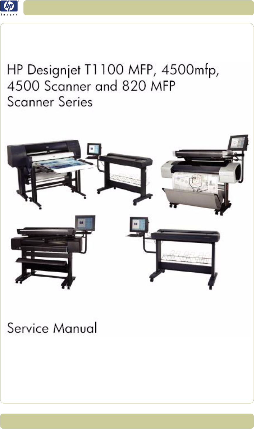
HP Designjet T1100 MFP, 4500mfp,
4500 Scanner and 820 MFP
Scanner Series
Service Manual
For HP Internal Use Only
©Copyright Hewlett-Packard Company
2007
This document contains proprietary
information that is protected by copyright.
All rights are reserved. No part of this
document may be photocopied,
reproduced, or translated to another
language without the prior written consent
of Hewlett-Packard Company.
Fourth Edition, May 2007
Warranty
The information contained in this
document is subject to change without
notice.
Hewlett-Packard makes no
warranty of any kind with regard
to this material, including, but not
limited to, the implied warranties
of merchantability and fitness for
a particular purpose.
Hewlett-Packard shall not be liable for
errors contained herein or for incidental or
consequential damages in connection with
the furnishing, performance, or use of this
material.
WARNING
The procedures described in this manual
are to be performed by HP-qualified
service personnel only.
Electrical Shock Hazard
Serious shock hazard leading to death or
injury may result if you do not take the
following precautions:
- Ensure that the ac power outlet (mains)
has a protective earth (ground) terminal.
- Disconnect the product from the power
source prior to performing any
maintenance.
- Prevent water or any other liquids from
running onto electrical components or
circuits, or through openings in the
enclosure.
Electrostatic Discharge
Refer to the beginning of Chapter 4 of this
manual, for precautions you should take to
prevent damage to the Printer circuits from
electrostatic discharge.
Safety Symbols
General definitions of safety symbols are
given immediately after the table of
contents.
WARNING
The Warning symbol calls attention to a
procedure, practice, or the like, which, if
not correctly performed or adhered to,
could result in personal injury. Do not
proceed beyond a Warning symbol until
the indicated conditions are fully
understood and met.
CAUTION
The Caution symbol calls attention to an
operating procedure, practice, or the like,
which, if not correctly performed or
adhered to, could result in damage to or
destruction of part or all of the product. Do
not proceed beyond a Caution symbol
until the indicated conditions are fully
understood and met.
1
HP Designjet T1100 MFP, 4500mfp, 4500 Scanner, 820 MFP Service Manual

2HP Designjet T1100 MFP, 4500mfp, 4500 Scanner, 820 MFP Service Manual
Using this Manual
Purpose
This Service Manual contains information necessary to troubleshoot and
service:
HP Designjet 4500 Scanner- Model Q1277A
HP Designjet T1100 MFP- Model Q6713A
HP Designjet 820 MFP- Model Q6685
HP Designjet 4500mfp-Model Q1276A
For information about using this product, refer to the corresponding User
and Quick Reference Guides.
This Service Manual is about the Scanner and the integration with the printer
as a multi-functional printer and copier. In order to troubleshoot the printer,
refer to the corresponding Service Manual for the printer.
Readership
The procedures described in this Service Manual are to be performed by HP
Certified service personnel only.
Part Numbers
Part Numbers for service parts are located in Chapter 3.
Conventions
A small arrow ⇒ is used to indicate other parts of the Service Manual where
you can find information related to the topic you are consulting.

3
HP Designjet T1100 MFP, 4500mfp, 4500 Scanner, 820 MFP Service Manual
Table of Contents
1. Troubleshooting
2. System Error Codes
3. Parts and Diagrams
4. Removal and Installation
5. Scanner Adjustments and Calibrations

4HP Designjet T1100 MFP, 4500mfp, 4500 Scanner, 820 MFP Service Manual

1-1
HP Designjet T1100 MFP, 4500mfp, 4500 Scanner, 820 MFP Service Manual
Troubleshooting 1
Troubleshooting Tips 1-2
Is the problem with the printer or with the scanner? 1-2
Image-quality problems 1-2
No Output or Output is not as expected 1-3
Troubleshooting System Error Codes 1-3
Using the SCANtest 6 Diagnostic Software 1-3
Troubleshooting Issues 1-9
Troubleshooting print-quality and copy issues 1-9
Troubleshooting general scanner issues 1-13
Troubleshooting Specific Scanner Issues 1-21
Cleaning the Scanning Area 1-24
Troubleshooting Specific Panel PC Problems 1-27
Power failure. 1-27
Boot up failure. 1-28
LCD/Inverter failure: 1-28
No backlight and no display 1-28
With backlight but no display 1-29
How to check the voltage of the Inverter PCA in the Panel PC. 1-30
DDR DRAM failure: 1-31
DVD-ROM failure: 1-31
The CD/DVD is stuck in the DVD-ROM and cannot be ejected out. 1-31
Touch screen is working but cannot control the cursor. 1-33
Risks of not running the Scanner Maintenance 1-36
1

1-2
Troubleshooting
HP Designjet T1100 MFP, 4500mfp, 4500 Scanner, 820 MFP Service Manual
Guide to Troubleshooting the HP family of MFPs and
Scanners
This chapter guides you through the various procedures for troubleshooting
the HP family of MFPs and scanners.
Troubleshooting Tips
1First record whether the problem is with the Printer, the Scanner, or the Touch
Screen.
2Make sure that the scanning area is completely clean.
3 Test 20: Noise Test can help you find whether or not the scanning area is
dirty.
4The SCAN dump files can help you to understand the light profile of the
affected scanner.
5Remember, in order to cancel when copying, press the Cancel button on the
Touch Screen and the Cancel button on the printer.
Is the problem with the printer or with the scanner?
If you experience one of the following symptoms, the problem could be
related to the scanner:
System Error on the Touch Screen.
LED’s flashing on the Scanner Operator Panel.
WIDEsystem error message.
Vertical lines (either color or black) in the scanned image.
If you experience one of the following symptoms, perform an Image Preview
in the scanner and send a Test Print to the printer:
Image Quality Problems.
No Output.
Output is not as expected.
If the Image Preview fails, this points to a problem with the Scanner. If the
Test Print fails, this points to a problem with the Printer.
Image-quality problems
If you have Image Quality problems in any of your prints, try the following:
1Print out a file already stored or print out the demo plot.
2Once the print is finished, insert it into the Scanner.
3Once scanned, print out the scanned image.
If the original print is the same as the copied print, then the problem is
related to the Printer.
If the original print is NOT the same as the copied print, then the problem
is related to the Scanner.

1-3
Troubleshooting
HP Designjet T1100 MFP, 4500mfp, 4500 Scanner, 820 MFP Service Manual
No Output or Output is not as expected
If the output is not as you expected it to be, try the following:
Check all the settings in the Software: Color Settings and Margins.
Check media settings: Media profile (in software) and media loaded in
the printer (front panel selection) should be the same.
Perform Color Calibration (both Scanner and Printer).
Check the Preview Image.
If there is no output at all, then try the following:
Check the connection between the Printer and the Scanner.
Check the selected settings: List, Collate, Scan to file, etc.
Troubleshooting System Error Codes
Chapter 2 - System Error Codes contains a list of system error codes and
their respective descriptions and recommended corrective actions. Only try
one recommended action at a time and check if the error code has
disappeared.
If you have an error code which is not documented in this Service Manual,
or you have an error which you cannot resolve, report the error to the HP
Response Center or the nearest HP Support Office. When reporting the
error, have the following information ready:
Model and serial number of the MFP or scanner
Software and firmware version for the MFP or scanner. To check the
software and firmware version, press the Setup tab, and then select
Options > General > About).
The complete error number
ScanDump of Light Profiles
Using the SCANtest 6 Diagnostic Software
Here we briefly describe the various tests found in the SCANtest 6
Diagnostic Software, for more detail of some of the Adjustments shown
below refer to Chapter 5 -
The purpose of the SCANtest 6 diagnostic software is to support the
troubleshooting and adjustment of the Scanner.
To access the software you must go to the Setup Tab and to: Options-
>System->Service-> (this part is password protected, the password is
’support’)->Scantest
When the SCANtest 6 diagnostic software has been started, the Scanner is
switched ON in Test Mode, and the Diagnostic LED in the Operator Panel is
Make sure you provide the full error code and the full
software and firmware version. Without this information, the
HP Support personnel cannot help you.

1-4
Troubleshooting
HP Designjet T1100 MFP, 4500mfp, 4500 Scanner, 820 MFP Service Manual
turned ON.
Scanner Test Program Menu
Test 1: Scanner Information
Test 2: LED Test
Test 3: Key Test
Test 4: Original-Sensor Test
Test 5: Lamp Test
Test 6: Motor Test
Test 7: Complete Hardware Test
Test 9: Camera Adjustment
Test 11: Stitching and Vertical Alignment
Test 12: Adjust Y-Axis Scaling
Test 13: Switch Scanner to Test Mode
Test 20: Noise Test
Test 21: Scan Dump
Test 27: Camera Adjustment Wizard
Test 28: Original Guide Sensor Test
Test 30: Calibrate ATAC
Test 31: Driver Board Communication Test
If SCANtest 6 is started when the scanner is in Error Mode, the Error Code
Number and a short description of the error will be displayed on the screen.
Test 1: Scanner Information
This test displays general information regarding the scanner. When
executed, the test displays the following:
Scanner Model:
Firmware Release:
Firmware Release Date:
Firmware Build:
FPGA Revision:
FPGA Release Date:
Boot Code Revision:
Boot Code Release Date:
Scanner ID Switch:
SCSI ID:
To get the complete information of the system error code,
enter the scanner’s Error Mode and launch the ScanTest 6
Diagnostic test. The error code and a short description of the
error is displayed on the Touch Screen.
When possible, always perform a service test on the
component that you are about to replace to ensure that is the
component that has failed. If the test on that component
passes, there is no need to replace it.
1-5
Troubleshooting
HP Designjet T1100 MFP, 4500mfp, 4500 Scanner, 820 MFP Service Manual
Test 2: LED Test
This test checks the functionality of the LED Indicators on the Operator Panel.
When the test is executed, all the LEDs are sequentially switched ON/OFF
until Test 2 is terminated. If any of the LEDs fail, you will NOT get an error
message, instead the LED will NOT switch ON or OFF. If the LED test fails,
replace the Right Cover (which contains the Operator Panel).
Test 3: Key Test
This test checks the functionality of the Keys on the Operator Panel. When
the test is executed, each key on the Operator Panel will turn an LED ON
when pressed.
The only way to know if the test fails is by inspection, there is no error
message that is displayed.
If the Key test fails, replace thse Right Cover (which contains the Operator
Panel).
Test 4: Original-Sensor Test
This test checks the functionality of the Media Sensors.
When the test is executed, the following LEDs turn ON when one of the
Media Sensors is activated.
To test the Media Sensors, load a sheet of media (A4) and the Ready LED
switches ON and when you remove it the Ready LED switches OFF.
If the test fails (if any of the LEDs fail to switch ON), then the problem will be
related to corresponding Sensor.
Test 5: Lamp Test
This test checks the functionality of the Lamp and the associated electronics.
When the test is executed, a message on the Touch Screen will indicate
whether the Lamp is turned ON or OFF (Lamp power is turned ON/OFF)
and whether the Light is ON/OFF (Light is detected or not). The Lamp is
delayed for approximately 2 seconds when switched ON.
Test 6: Motor Test
This test checks the functionality of the Stepper Motor and any associated
Key LED
Forward and Reverse Ready (Green)
Power Wait (Yellow)
Actuator LED
Media Entry Sensor Ready (Green)
Media Exit Sensor Ready (Green)

1-6
Troubleshooting
HP Designjet T1100 MFP, 4500mfp, 4500 Scanner, 820 MFP Service Manual
electronics.
When the test is executed, a menu appears that allows you to select the
motor speed and the motor direction.
If the Stepper Motor or the Driver Board fails to run when the test is
executed, then the Stepper Motor should be replaced.
Test 7: Complete Hardware Test
This test checks the various functions of the Driver and Camera Boards.
Test 9: Camera Adjustment
This test contains a Software Oscilloscope that allows you to check and
adjust the CCD-Cameras. The following functions can be selected from the
Test Program Menu.
Uncorrected or Corrected Light Profiles.
Red, Green, or Blue Color Channels.
Special Detail Views for Light Profile, Scan Width, and Vertical
Positioning.
Forward / Reverse controls for the Camera Motor.
Save screen images.
Print screen images.
The content of the Detail Views is marked on the upper overview window by
red vertical lines. The continuous lines refer to the left Detail View and the
dashed lines to the right Detail View.
Test 11: Stitching and Vertical Alignment
This test is also included in the Scanner Maintenance Software.
This test performs Automatic Vertical Alignment and Horizontal Stitching.
Once the test has been started:
Insert Calibration Sheet.
Select Vertical Alignment to align the cameras.
Select Horizontal Stitching to stitch the cameras.
The screen image can be saved or printed.
This test allows manual setting of the Stitch Values. The Stitch Values are
stored in the Flash Memory on the Driver Board.
The Vertical Alignment may be adjusted manually by controlling the Camera
Motor from the control field ‘<<dddd>>’. The two buttons marked ‘<<’
respectively ‘>>’ are used to start the motor and to determine the direction of
rotation. When started, the motor runs for dddd mili-seconds as entered into
the control field.
Test 12: Adjustment of Y-Axis Scaling
Always use Test 9: Camera adjustment to adjust the
cameras. Do not use Test 27: Camera Adjustment Wizard.

1-7
Troubleshooting
HP Designjet T1100 MFP, 4500mfp, 4500 Scanner, 820 MFP Service Manual
This test allows you to adjust the Y-Axis Scaling.
The scaling (dpi) in the mechanical scan direction (Y-Axis) depends on the
speed of the stepper motor relative to the scanline Exposure Time. The
default motor speed can be changed ± 1%, either from Test 12 or by using
the ‘Scanner Setup/Correction factor …’ option of SW copying. The
correction factor is stored in the Flash Memory on the Driver Board.
Test 13: Switch Scanner to Test Mode
This test allows you to switch the scanner back to Test Mode. Useful if the
scanner gets out of Test Mode, e.g. if it has to be turned OFF/ON during
troubleshooting.
Test 20: Noise Test
The purpose of this test is to detect and locate the possible cause (dust, dirt,
scratches,..) of vertical lines running from top to bottom of the scanned
image.
When the test is executed, it scans the White Calibration Area of the
Calibration Sheet and displays, for each color channel, the graytone values
of each separate pixel averaged over the scanned band.
The displayed image of the Calibration Sheet will be superimposed by low
level noise caused by the CCD chip, and larger spikes most likely caused by
dust, dirt, scratches, or similar defects on the Glass Plate. In rare cases,
larger spikes may be caused by dust, dirt, or pixel faults on the CCD chip.
The positions of larger spikes are shown by the numbers (cm or inch units)
opposite to the spikes. The numbers refer to the Sideload-ruler on the
scanner. Larger spikes going downwards are often caused by dust, dirt,
scratches, or similar defects on the Glass Plate and may be removed by
cleaning the Glass Plate. Downward spikes often show up as darker vertical
lines in the scanned image.
Larger spikes going upwards are often caused by dust or dirt present on the
Glass Plate during the last calibration with Scanner Maintenance. These
defects are memorized by the Light Profiles stored in the Flash Memory and
can only be removed by cleaning of the Glass Plate followed by running
Scanner Maintenance again. Upward spikes show up as very bright vertical
lines in the scanned image.
White vertical lines in the scanned image may be found even if Noise Test
shows a perfectly ‘clean’ scanner. In this case, the cause may be white dust
or particles on the backside of the Glass Plate having the same color as the
white background. In this case, the Light Profiles of SCANtest 6, Test 9 may
show upwards going spikes when a dark original is placed in the scan-area.
Test 21: SCANdump
SCANdump is a tool for remote diagnostic. SCANdump saves the light
profile from the cameras, error codes, and statistics.
When the test is executed, the file SCANdump.con will be placed in the

1-8
Troubleshooting
HP Designjet T1100 MFP, 4500mfp, 4500 Scanner, 820 MFP Service Manual
directory c:\Temp\.
Test 27: Camera Adjustment Wizard
This allows you to adjust the camera using a wizard that guides you through
the complete process. Use this test only if you do not have experience in
adjusting the camera, otherwise you should always use Test 9. See 5-19,
Adjusting the Camera Using the Camera Wizard.
Test 28: Original Guide Sensor Test
This is to test the Guide Plate Sensors which are located under the Guide
Plate. See 5-28, Original Guide Sensor Test
Test 30: Calibrate ATAC (Automatic Thickness Adjustment
Control)
This test sets the current level at which the ATAC will stop if something is
preventing it from moving down. See 5-32, Calibrate ATAC (Automatic
Thickness Adjustment Control)
Test 31: Driver Board Communication Test
This test checks the communication between the Scanner and the Driver
Board. See 5-32, Driver Board Communication Test.
Remember to perform the SCANdump test and provide the
HP Support personnel with the information file stored in the
c:\Temp directory.

1-9
Troubleshooting
HP Designjet T1100 MFP, 4500mfp, 4500 Scanner, 820 MFP Service Manual
Troubleshooting Issues
The following guide will help you to find a solution to some typical problems
that some customers may experience.
The problems (P#) that can be solved remotely through on-phone support
and customer intervention are marked C.
The problems that require on-site intervention performed by a Support
Technician are marked T.
Troubleshooting print-quality and copy issues
Before sending a Support Technician to the customer, identify
whether the problem is related to the scanner or the Panel
PC (PPC).
If the problem is scanner-related, erase the parameter block
and run the scanner maintenance. Then perform the system
recover using the most recent version of the software.
If the problem is PPC-related, perform the system recovery
using the most recent version of the software.
If the problem persists, try the solutions listed in the tables
below.
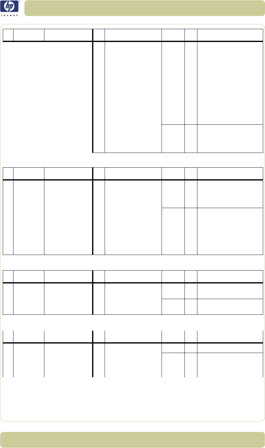
P# Category Problem Q# Question Yes/No C/T Solution
1Copy
problem
The colors on one
side of the copy does
not correspond to the
colors on the other
side of the copy
1 Have you cleaned and
calibrated your scanner
recently?
No C Camera differences - The
scanner needs to be cleaned
and calibrated (refer to P24
and P25)
Yes Refer to Q2
2
Have you upgraded the
system software to the
latest version?
No C Upgrade system software
(use Update System DVD)
Yes T Cameras need adjusting or
the Camera Board replacing
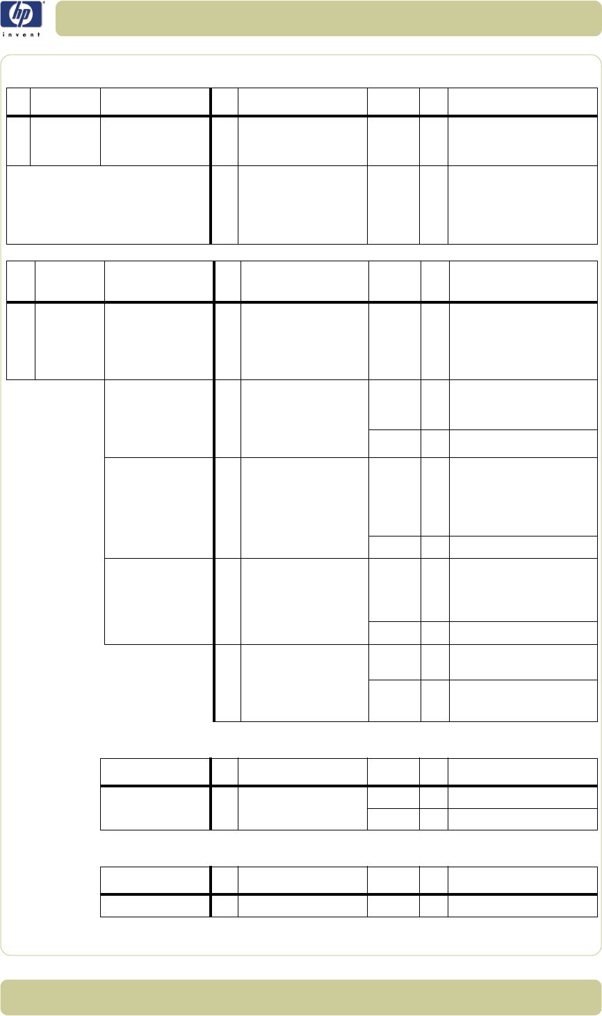
P# Category Problem Q# Question Yes/No C/T Solution
2Copy
problem
I get thin lines of
wrong colors in my
copy
1 Are the lines vertical and
also present in your
preview?
Yes C Erase the parameter block
and run the scanner
maintenance. Then clean and
calibrate the scanner (refer to
P24 and P25)
No Refer to Q2

1-10
Troubleshooting
HP Designjet T1100 MFP, 4500mfp, 4500 Scanner, 820 MFP Service Manual
2
Are the lines horizontal
and equally spaced?
Yes C
Check printheads by starting
printhead test on Printer. By
using the built-in test print
function in the Designjet Scan
Copy application, you can
also get an idea whether the
Printer is performing OK
No Refer to Q3
3
Are the lines horizontal,
but irregular (maybe only
1 line)?
Yes C The lines could be caused by
a data error. Upgrade system
software
No Refer to Q4
4
Do you have a great
number of regular spaced
lines very close to each
other and restricted to one
side (1 camera) only?
Yes T You have a camera error.
Replace Camera Board
P# Category Problem Q# Question Yes/No C/T Solution
P# Category Problem Q# Question Yes/No C/T Solution
3Copy
problem
I get thick lines of
slightly wrong colors
in my copy
1 Are the lines vertical and
also present in your
preview?
Yes C The scanner needs to be
cleaned and calibrated (refer
to P24 and P25)
No Refer to Q2
2
Are the lines horizontal
and equally spaced?
Yes C
Check printheads by starting
printhead test on Printer. By
using the built-in test print
function in the Designjet Scan
Copy application, you can
also get an idea whether the
Printer is performing OK
No Refer to P2
P# Category Problem Q# Question Yes/No C/T Solution
4Copy
problem
Some colors are not
the same when I
compare the master
print with the copy
1 Is the scanner clean and
calibrated?
No C Refer to P1. Clean and
calibrate the scanner (refer to
P24 and P25)
Yes Refer to Q2

1-11
Troubleshooting
HP Designjet T1100 MFP, 4500mfp, 4500 Scanner, 820 MFP Service Manual
2
Do you use the correct
media profile for the
actual media?
No C If you are using e.g. Glossy
Media for this copy, the
media profile selected should
also be for Glossy Media.
Yes Refer to Q3
3
Is the media profile valid?
No C Create a new media profile
(refer to P26)
Yes Refer to Q4
4
Is the option 'Ink Printer
Original' set in
accordance with your
original?
No C If original was printed using
an Inkjet Printer, set this
option (refer to P27)
Yes Refer to Q5
5 Is the media you are
printing on the same type
as the original?
No C e.g. Use Glossy Media to
reproduce a Glossy original
Yes C Create a new media profile
(refer to P26)
P# Category Problem Q# Question Yes/No C/T Solution
P# Category Problem Q# Question Yes/No C/T Solution
5Copy
problem
Only a part of the
master print is being
copied
1 Are you scanning a thick
original?
Yes C Uncheck extended media
handling box in scanner
settings (using extended
media will load the original
between both entry and exit
rollers before scanning - this
means that you will not have
the start of the thick original
scanned. Also the scan speed
will be slower, and no "back -
ups"/reversing is allowed
while scanning)
No Refer to Q2
2
Have you selected 'Auto
size'?
Yes C The scanner needs to be
cleaned (refer to P24)
No Refer to Q3
3
Is the length too short
and the width OK?
Yes C The problem may be with the
Printer (not able to print close
to the edges) or Panel PC
(Hard Disk is full).
No C Check that the margins that
are set are not too big. Also
check Scanner Media Offsets

1-12
Troubleshooting
HP Designjet T1100 MFP, 4500mfp, 4500 Scanner, 820 MFP Service Manual
P# Category Problem Q# Question Yes/No C/T Solution
6Copy
problem
Which setting will
give me the best
result when copying?
-- -C
See section about media
profile (P4). Use copy quality
best. Choose the correct Type
of original ("Map" for maps,
"Photo" for photos, etc).
Eventually go to Original
Setup to fine adjust colors
and sharpening. (See also
online help for more details -
button with "?" symbol)
P# Category Problem Q# Question Yes/No C/T Solution
7Copy
Problem
Nesting feature is not
working
1 Is the correct printer
selected?
No C Select the correct Printer
Yes Refer to Q2
2
Is the Hard Disk close to
being full?
Yes C Free up some space, or try to
run a nesting job with only 2
or 3 small pictures. If that
works refer to P27
No C Make sure that Nesting is set:
Select: |Output|
Layout|Nesting|optimized|
P# Category Problem Q# Question Yes/No C/T Solution
8Copy
problem
The Collate Copy
function does not
work
1 Is your Hard Disk close to
full?
Yes C Free up some space, or try to
run a collate job with a
smaller picture.
No C
Follow the step by step
instructions in the online help
under "Collate Copy".
P# Category Problem Q# Question Yes/No C/T Solution
9Copy
problem
The lines are not
accurate
1 Are the lines wavy and
irregular?
Yes C/T C: The original could be
curled or crumpled. Try to
flattten the original (in case of
very irregular waves there
could be a mechanical
problem with the scanner). T:
check motor and belt drive
tension according to TSM
No Refer to Q2
1-13
Troubleshooting
HP Designjet T1100 MFP, 4500mfp, 4500 Scanner, 820 MFP Service Manual
Troubleshooting general scanner issues
2
Are the lines not sharp?
Yes C/T C: Are you using the correct
copy method? Try
sharpening. If sharpness is
different between Cameras,
you may have a Focus
Problem. T: Check focus of
cameras with Focus
Adjustment Pattern
No Refer to Q3
3
Are the lines broken and
the errors situated in a
vertical column between
2 columns?
Yes C You might have a visible
stitching error (refer to P28)
No C Check the dpi. In the case of
too low resolution, jagged
diagonal lines will appear
P# Category Problem Q# Question Yes/No C/T Solution
P# Category Problem Q# Question Yes/No C/T Solution
10 Copy
Problem
One side of the
preview is black
1 Have you upgraded the
scanner firmware to the
latest version?
No C Upgrade scanner firmware to
latest version. See 5-33.
Yes Refer to Q2
2 Have you upgraded the
system software to the
latest version?
No C Upgrade system software (use
System Recovery DVD)
Yes T Most likely a Camera Error.
Perform the Manual Camera
Adjustment (Test 9). Replace
the Camera Board if
necessary
P# Category Problem Q# Question Yes/No C/T Solution
11 Copy
problem
Only a part of the
master print is being
copied
1 Are you scanning a thick
original?
Yes C Uncheck extended media
handling box in scanner
settings (using extended
media will load the original
between both entry and exit
rollers before scanning - this
means that you will not have
the start of the thick original
scanned. Also the scan speed
will be slower, and no "back -
ups"/reversing is allowed
while scanning)
No Refer to Q2

1-14
Troubleshooting
HP Designjet T1100 MFP, 4500mfp, 4500 Scanner, 820 MFP Service Manual
2
Have you selected 'Auto
size'?
Yes C The scanner needs to be
cleaned (refer to P24)
No Refer to Q3
3
Is the length too short
and the width OK?
Yes C The problem may be with the
Printer (not able to print close
to the edges) or Panel PC
(Hard Disk is full).
No C Check that the margins that
are set are not too big. Also
check Scanner Media Offsets
P# Category Problem Q# Question Yes/No C/T Solution
P# Category Problem Q# Question Yes/No C/T Solution
12 System Error What should I do
when the program
hangs?
1Are you running a copy
job?
Yes C Making a copy takes a lot of
resources according to the
settings. Wait till the copy is
done before performing
another action
No Restart the system. If the
problem is coming back, run
the System recovery (refer to
P17)
P# Category Problem Q# Question Yes/No C/T Solution
13 File problem When I scan to file,
the file is very big
1Are you scanning in
color?
Yes C Scanning large drawings will
generate very big files. An
A0 color drawing scanned at
300 dpi will generate a file
size of approx. 3 Gigabytes
when scanned in an
uncompressed format. In
order to reduce file size,
select TIFF - pack bits as
format. You can reduce size
even more by selecting JPEG
format, but this format will
reduce picture quality
No Refer to Q2
1-15
Troubleshooting
HP Designjet T1100 MFP, 4500mfp, 4500 Scanner, 820 MFP Service Manual
2
Are you scanning in gray
tones?
Yes C Scanning large drawings will
generate big files. An A0
gray tone drawing scanned
at 300 dpi will generate a
file size of approx. 300
Mbytes when scanned in an
uncompressed format. In
order to reduce file size,
select TIFF - pack bits as
format. You can reduce size
even more by selecting JPEG
format, but this format will
reduce picture quality
No In order to reduce file size on
scanned B/W drawings,
select TIFF group 4
compression
P# Category Problem Q# Question Yes/No C/T Solution
P# Category Problem Q# Question Yes/No C/T Solution
14 File problem When I scan to file
my application
cannot read the file
1Did you get an error
message when creating
the file?
Yes C Check that you have enough
disk space and scan to file
again, choosing TIFF
uncompressed as format
No C We only recommend to use
the built-in viewer for file
viewing. Large format
drawing files may not load
correctly in other viewers due
to file size. Try to scan a
smaller original (A4)
P# Category Problem Q# Question Yes/No C/T Solution
15 Network
Problem
I cannot access the
system from the
network
1 Is the PC connected to
the network?
Yes C Do basic network
troubleshooting
No C Connect the PC to the
Network
P# Category Problem Q# Question Yes/No C/T Solution
16 Scan to
network
I cannot access
network drivers
1 With the PPC connected
to the LAN, can you
access the PPC from
another computer on the
network?
Yes C Go to Q2
No C Check the network
performance and connection
to the scanner PPC.

1-16
Troubleshooting
HP Designjet T1100 MFP, 4500mfp, 4500 Scanner, 820 MFP Service Manual
2
Is the folder of the server
you are trying to map
already mapped by
another user in the PPC?
Yes C Windows does not allow the
same server to be mapped
by two different users on one
computer. Use the access
connection previously
mapped or delete the
connection and map a new
access connection.
No C Go to Q3
3Do you have permission
to access and write to the
network folder you are
trying to map?
Yes C Go to Q4
No C You cannot access this
network folder. Select a
network folder for which you
have read and write
permissions.
4 Are you using the correct
user name and
password?
Yes C Try to map the network file
from another computer by
selecting Windows Explorer
> Tools > Map network drive.
If you are able to map the
drive in this manner, you
should also be able to map
through the PPC.
No C Use the correct user name
and password.
P# Category Problem Q# Question Yes/No C/T Solution
P# Category Problem Q# Question Yes/No C/T Solution
17 Recovery How and when is the
Recovery DVD used?
-- -C
The recovery DVD is used if
the system needs to be
reinstalled. Insert the DVD in
to the PC and reboot the
system
P# Category Problem Q# Question Yes/No C/T Solution
18 Scanner
Calibration
Problem
Scanner
Maintenance did not
succeed
1 Did any error occur when
performing the Scanner
Maintenance?
Yes C Refer to Q2
No C Clean the scanner and then
run Scanner Maintenance
again (refer to P24 and P25).
If that does not help, refer to
Q5

1-17
Troubleshooting
HP Designjet T1100 MFP, 4500mfp, 4500 Scanner, 820 MFP Service Manual
2
Error: "Basic calibration
was performed. but failed
to stitch scanner" or
"Could not find horizontal
line" or "Could not read
bar lines" or "Could not
recognize the scanned IT8
picture"
Yes C Clean the scanner and then
run Scanner Maintenance
again (refer to P24 and P25).
If that does not help, refer to
Q5
No Refer to Q3
3
Error: "Sheet not
recognized"
Yes C Reinsert calibration sheet
correctly and run Scanner
Maintenance again. If that
does not help, refer to Q5
No Refer to Q4
4
Error: "No movement in
camera position has been
detected during vertical
camera alignment"
Yes T Check the camera.
No Refer to Q5
5 Have you upgraded the
system software to the
latest version?
No C Upgrade system software (use
Update System DVD). Clean
the scanner and then run
Scanner Maintenance again
(refer to P24 and P25)
Yes T Check the camera.
P# Category Problem Q# Question Yes/No C/T Solution
P# Category Problem Q# Question Yes/No C/T Solution
19 System error I cannot install my
application on the
system
-- -C
The copy system is only meant
to handle the factory installed
software and applications.
P# Category Problem Q# Question Yes/No C/T Solution
20 Updating How do I update the
system?
-- -C
Insert the System Recovery
DVD into the DVD drive and
reboot the PPC.

1-18
Troubleshooting
HP Designjet T1100 MFP, 4500mfp, 4500 Scanner, 820 MFP Service Manual
P# Category Problem Q# Question Yes/No C/T Solution
21 Start-up
Problem
The system does not
power up
1 Is the system dead (no
LEDs are lit, the PPC
screen is black, and no
fan-noise can be heard)?
Yes C 1 - Check that all power
switches on the equipment
are ON.
2 - Check if there is power at
the wall outlet.
3 - Check power cables
between wall outlet and the
individual units.
No Refer to Q2
2
Does PPC start with the
normal initial screen?
Yes C Refer to Q5
No Refer to Q3
3
Does PPC start normally,
but the software does not
work?
Yes C Reinstall system software
No Refer to Q4
4
Is the PPC dead (no fan
noise can be heard and
no screen image
appears)?
Yes T Troubleshoot the PPC
No Refer to Q5
5 Is the Scanner dead (no
fan noise can be heard
and no LEDs are lit)?
No Refer to Q6
Yes T Check, and if necessary
replace:
1 - Power Supply Unit
2 - Driver Board
6 Does the scanner hang-
up with all LEDs lit?
Yes T Try the following:
1 - Erase parameter block
2 - Update the system
software
3 - Replace the Main Board
No Refer to P23
P# Category Problem Q# Question Yes/No C/T Solution
22 Mechanical
Problem
I cannot load the
original
1 Please try to load a new
piece of A4 paper at the
center of the scanner.
Does this paper load?
Yes C You have a problem with
your original. Please check
that paper edges are not bent
or curled in any way
No Refer to Q2
2
Can paper be loaded by
pressing the "Forward"
key?
Yes C Refer to Q3
No T Try replacing the following:
1 - Driver Board
2 - Power Supply Unit
3 - Feed Motor
4 - Main Board
3
Does the Ready LED turn
ON when activating
Original Sensor (insert
paper)?
No T Check, and if necessary
replace:
1 - Original Sensors
2 - Main Board
Yes C Check the settings in the
software for media loading
1-19
Troubleshooting
HP Designjet T1100 MFP, 4500mfp, 4500 Scanner, 820 MFP Service Manual
P# Category Problem Q# Question Yes/No C/T Solution
23 Error Code I get an Error Code,
what do I do?
-- --
Re-power the system, and check
if the error code reappears. If it
does, refer to Q1.
1 Have you upgraded the
system software to the
latest version?
No C
Upgrade the system software
by using the System Recovery
DVD). Check if Error Codes
reappears. If it does, refer to
P23a.
P# Category Problem Q# Question Yes/No C/
T
Solution
23a Error Code I still get an error
code, what do I do?
Does the Diagnostic LED
(and, in some cases also
other LEDs) blink?
Yes C
Lower Guide Plate to Normal
position, start Preview Scan to
obtain an Error Code or check
if WIDEsystem gives an Error
Code
Error Code 100:
3002 to 3013
3019 to 3037
Have you cleaned the
white background and
glass plate, and
performed Scanner
Maintenance?
Yes T Check Camera Adjustment. If
necessary, replace the
Camera Board
No C Refer to P24 and P25
Error Code 100:
3014 to 3018
Have you cleaned the
white background and
glass plate, and
performed Scanner
Maintenance?
Yes T Try the following:
1 - Upgrade the firmware
2 - Check the Stitching Wire
3 - Check Camera Adjustment
4 - Replace Main Board
No C Refer to P23 and P25
Error Code 100:
4003x and 4004x
1 Does the Lamp light up? No T Try replacing the following:
1 - Lamp
2 - Driver Board
3 - Main Board
Yes Refer to Q2
2 Have you cleaned the
white background and
glass plate, and
performed Scanner
Maintenance?
Yes Refer to complete list.
No C Refer to P24 and P25
Problem Q# Question Yes/No C/T Solution
Error Code 100:
500xx
1 Have you performed
Scanner Maintenance?
No C Refer to P24 and P25
Yes T Replace Main Board
Problem Q# Question Yes/No C/T Solution
Error Code 600xx 1 Is it Error Code 600xx Yes T
Replace Interface Board

1-20
Troubleshooting
HP Designjet T1100 MFP, 4500mfp, 4500 Scanner, 820 MFP Service Manual
Problem Q# Question Yes/No C/T Solution
"No scanner found" 1 Does the scanner start
normally?
No C Refer to P23
Yes C Refer to Q2
2
Are the interface cables
(USB, FireWire, or LAN)
properly connected to the
scanner and the PPC?
Yes C Refer to Q3
3Have you run the System
Recovery DVD?
Yes T 1 - Replace Interface Cable
2 - Replace Interface Board
P# Category Problem Q# Question Yes/No C/T Solution
24 Cleaning How do I clean the
scanner?
-- -C
Clean the Glass Plate on both
sides with mild detergent, and
wipe thoroughly with a lint-
free cloth until dry. Check for
scratches. Deep scratches on
the glass plate or background
platen means replacement of
the part
P# Category Problem Q# Question Yes/No C/T Solution
25 Color
Calibration
How do I color
calibrate the
scanner?
1 Do you have the correct
and "as new" scanner
maintenance sheet for
the scanner?
Yes C Clean scanner (refer to P24).
Insert the scanner
maintenance sheet. Start
scanner maintenance. The
process is automatic and will
also include stitching.
No C
Get Correct/New Scanner
Maintenance Sheet
P# Category Problem Q# Question Yes/No C/T Solution
26 Media
Validation
What is media
validation? How do I
validate?
-- -C
If the validate feature is
chosen, a new color patch
sheet is printed and can be
scanned for validation. In this
way it can be determined
whether the produced color
map has passed.
P# Category Problem Q# Question Yes/No C/T Solution
27 Ink Printer
Original
What is Ink Printer
Original?
- - - C When the original has been
printed on an Inkjet printer
this option should be
enabled.

1-21
Troubleshooting
HP Designjet T1100 MFP, 4500mfp, 4500 Scanner, 820 MFP Service Manual
Troubleshooting Specific Scanner Issues
P# Category Problem Q# Question Yes/No C/T Solution
28 Visible
stitching
Errors
What is a visible
stitching error?
-- -C
A visible stitching error
appears typically as a column
of broken lines between 2
cameras. Normally it can be
solved by running Scanner
Maintenance, which will
perform an automatic stitching
adjustment. With some curled
or creased/crumpled originals
it is necessary to straighten out
the original to prevent it from
lifting from the glass plate.
With thick originals it can be
necessary to adjust the
stitching (stitching used for
thick originals only, set this in
scanner setup). A visible
stitching error should not be
confused with the error
message "Error 32 - Could not
stitch Camera A and B"
P# Category Problem Q# Question Yes/No C/T Solution
29 Vertical lines
(possible
dust
problem)
The image has a
vertical, white or
black line, which
could be caused by
dust. To verify that
the line is caused by
dust, preview the
image and inspect
the preview using the
viewing section
buttons.
- - - C Perform Scanner
Maintenance: Cleaning and
Camera Alignment. Using
Test 20 from SCANtest 6 may
help to identify dusty/dirty
areas.
P# Category Problem Q# Question Yes/No C/T Solution
30 Firmware You are receiving
firmware-related
errors.
- - - C Try upgrading the firmware
version. See 5-33.
P# Category Problem Q# Question Yes/No C/T Solution
31 Stepper
Motor
The Stepper Motor
does not work.
-- -CTry the following:
1 - Use Test 6: Motor Test
to check the functionality of
the Stepper Motor.
2 - Replace the Driver Board.
3 - Replace the Stepper Motor.

1-22
Troubleshooting
HP Designjet T1100 MFP, 4500mfp, 4500 Scanner, 820 MFP Service Manual
P# Category Problem Q# Question Yes/No C/T Solution
32 Lamp The lamp does not
work.
-- -CTry the following:
1 - Reseat the lamp cartridge.
2 - Ensure that the Driver
Board is connected tot he
power supply unit.
3 - Ensure that the lamp sensor
and the Driver Board are
functioning correctly.
P# Category Problem Q# Question Yes/No C/T Solution
33 Skewing There is a skewing
problem
-- -CTry the following:
1 - Ensure that the Guide
Plate is closed and latched.
2 - Replace the Guide Plate.
3 - Clean the rollers with
isopropyl alcohol.
4 - Replace the rollers.
P# Category Problem Q# Question Yes/No C/T Solution
34 Media
Loading
The media connot be
loaded or there are
other media loading
problems.
-- -CTry the following:
1 - Check the Original Sensor
(green LED when loading
media), or use Test 4:
Original-Sensor Test to
check the functionality of the
sensor.
2 - Use Test 6: Motor Test
to check the functionality of
the Stepper Motor.
P# Category Problem Q# Question Yes/No C/T Solution
35 Fan The fan is not
working
-- -CTry the following:
1 - Ensure that the fan is
correctly connected.
2 - If the fan is connected and
still doesn’t work, replace the
Driver Board or the fan.
3 - If the fan and driver board
are working correctly, the
problem could be related to
the NTC Sensor.
1-23
Troubleshooting
HP Designjet T1100 MFP, 4500mfp, 4500 Scanner, 820 MFP Service Manual
P# Category Problem Q# Question Yes/No C/T Solution
36 Software You are experiencing
problems with the
software
-- -CTry the following:
1 - Use the System Recovery
DVD to reload the software
2 - After reloading the
software, set-up the system on
the network again (if
necessary).
3 - If the problems persist, run
the System Recovery DVD
again, and delete the user’s
files (press F12)
P# Category Problem Q# Question Yes/No C/T Solution
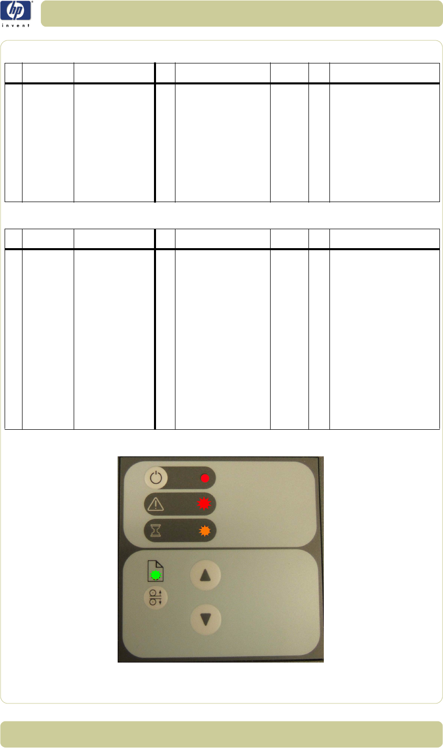
37 Firmware All of the LEDs in the
scanner’s front panel
are flashing when
you turn on the
scanner (as shown in
the image below),
indicating that
printer firmware
needs to be
upgraded.
NOTE: This
describes a different
situation than when
the scanner is turned
on in special boot
mode, in which the
LEDs also flash.
- - - C The most probable reason for
this situation is that the last
firmware upgrade attempt
was not successful. To
remedy this situation,
upgrade the firmware (see 5-
33). NOTE: Before launching
the firmware upgrade utility,
verify that the scanner is
connected directly to the
touchscreen by the Firewire or
USB cable, and then press
the rescan bus button. The
scanner will not detect the
necessary connection without
the use of the Firewire or
USB.

1-24
Troubleshooting
HP Designjet T1100 MFP, 4500mfp, 4500 Scanner, 820 MFP Service Manual
Cleaning the Scanning Area
The following parts must be cleaned using a soft lint-free cloth and a mild,
streak-free, cleaning detergent. Alternatively, the parts may be cleaned
without the use of cleaning detergents by using a damp micro-fibre cleaning
cloth (soak the cloth with water and wring until damp):
Main scanner cover. Clean the main scanner cover to ensure that no dust
is introduced into the scanning area when you scan an original.
White Background Plate on the Guide Plate
The Glass Plate. If you clean both sides, be very careful not to touch the
Stitching Wire (located under the Glass Plate) out of position. Do not use
solvents, as this may dissolve the paint used for the black masks on the
Glass Plate. Do not recommend that customers clean the underside of the
glass plate; it should only be cleaned by an HP support technician.
The Mirrors. It is necessary to remove the Mirror Chassis to get access to
the Mirrors for cleaning. The Camera Adjustment must be checked and if
necessary readjusted after the replacement of the Mirror Chassis.
The Feed Rollers. These may be cleaned with a damp micro-fibre
cleaning cloth.
Once all these procedures have been completed, the scanner will be ready
to work correctly.
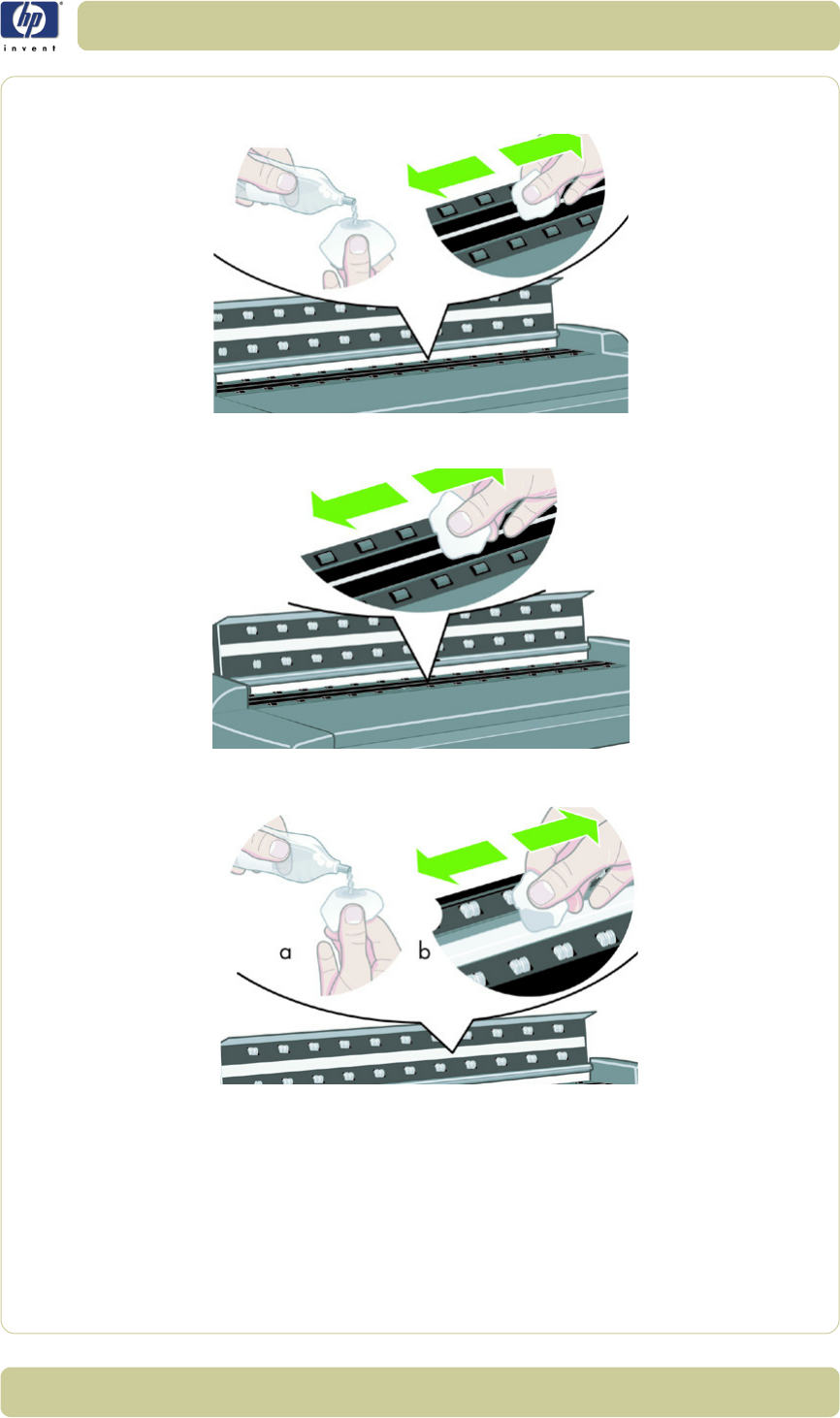
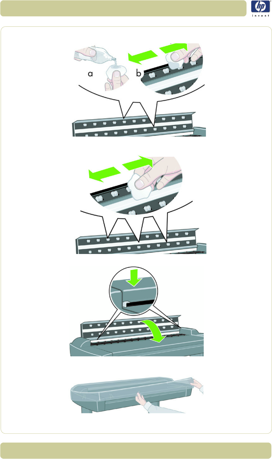
The Cleaning Procedure
When cleaning any part of the scanning area DO NOT use abrasives,
acetone, benzene or fluids that contain these chemicals. Do not spray liquids
directly onto the scanner glass plate or anywhere else in the scanner.
1Turn the scanner power off.
2Disconnect the scanner power cable.
3Open the Guide Plate by pushing down on the left and right locking levers
and flip it upwards to expose the scan area.
The mirrors are normally "Out of Focus", therefore small dust
particles on the mirrors will not deteriorate the scanning
result.
1-25
Troubleshooting
HP Designjet T1100 MFP, 4500mfp, 4500 Scanner, 820 MFP Service Manual
4Gently wipe the Glass Plate. Clean the glass with a lint-free cloth and a mild,
streak-free, glass cleaner.
5Dry the glass completely using a separate clean, dry lint-free cloth like the
one provided with the maintenance kit.
6Clean the white background assembly. Wipe the white metal area with a
lint-free cloth and a mild, streak-free, glass cleaner.
1-26
Troubleshooting
HP Designjet T1100 MFP, 4500mfp, 4500 Scanner, 820 MFP Service Manual
7Clean the platen rollers. Wipe the rollers with a lint-free cloth and a mild,
streak-free, glass cleaner.
8Dry the platen and rollers completely using a separate clean, dry lint-free
cloth.
9Close the Guide Plate.
10 Use the dust sheet to protect the Scanner when not in use.
1-27
Troubleshooting
HP Designjet T1100 MFP, 4500mfp, 4500 Scanner, 820 MFP Service Manual
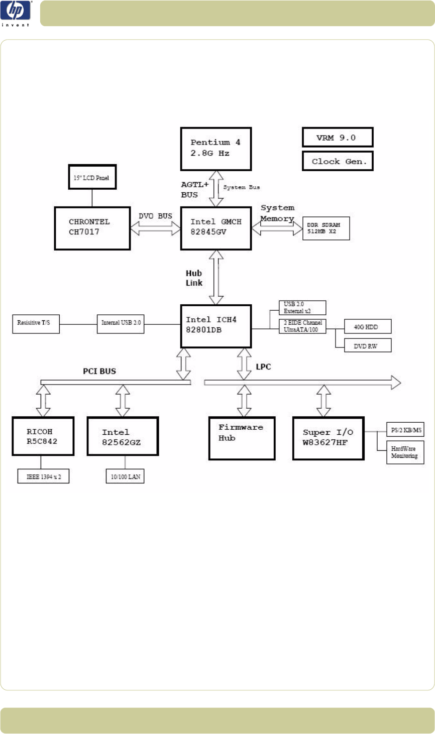
Troubleshooting Specific Panel PC Problems
The following section helps you to troubleshoot problems related to the
scanner’s Panel PC and related components. The diagram below will help
you to identify the Panel PC electronic components, and might be of
assistance in troubleshooting possible system problems.
The sections below helps you to troublehoot Panel PC component failures
and detect which system has failed. Check or replace one component at a
time, and then see if the failure is resolved before investigating further.
Proceding this way will help you to determine which component has failed.
Power failure.
If the power has been turned on, and there is no message on the screen, try
the following:
Make sure the power cord is correctly connected.
Plug the power cord to another power outlet.
The DVD-ROM indicator lights should flash.
The system fan should start up if there is power in the Panel PC, if not
replace the PSU
⇒
Page 4-98.
1-28
Troubleshooting
HP Designjet T1100 MFP, 4500mfp, 4500 Scanner, 820 MFP Service Manual
Boot up failure.
The Panel PC issues a series of beeps which can be used to identify which
part is failing.
One short beep: No error during POST (Power on Self-Test).
One long beep followed by two short beeps: Video initial error.
One long beep followed by nine short beeps: BIOS Bootblock error.
Single long beep repeatedly: DRAM error.
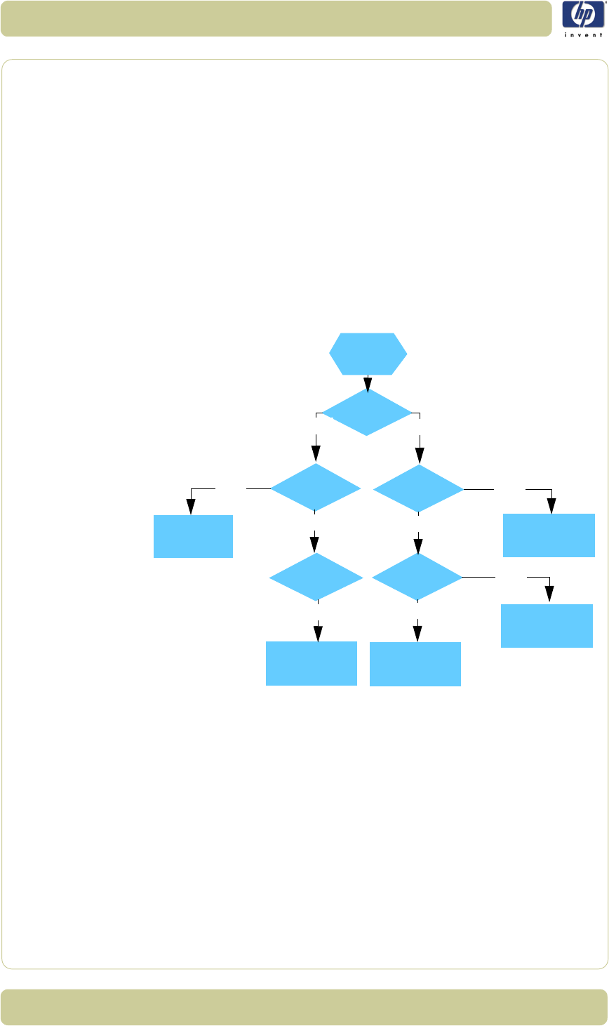
LCD/Inverter failure:
The failure of the LCD display can be divided into two issuses, the Panel PC
has no backlight and no display, or the Panel PC has the backlight but there
is no display. Use the two troubleshooting flow charts to solve the problem:
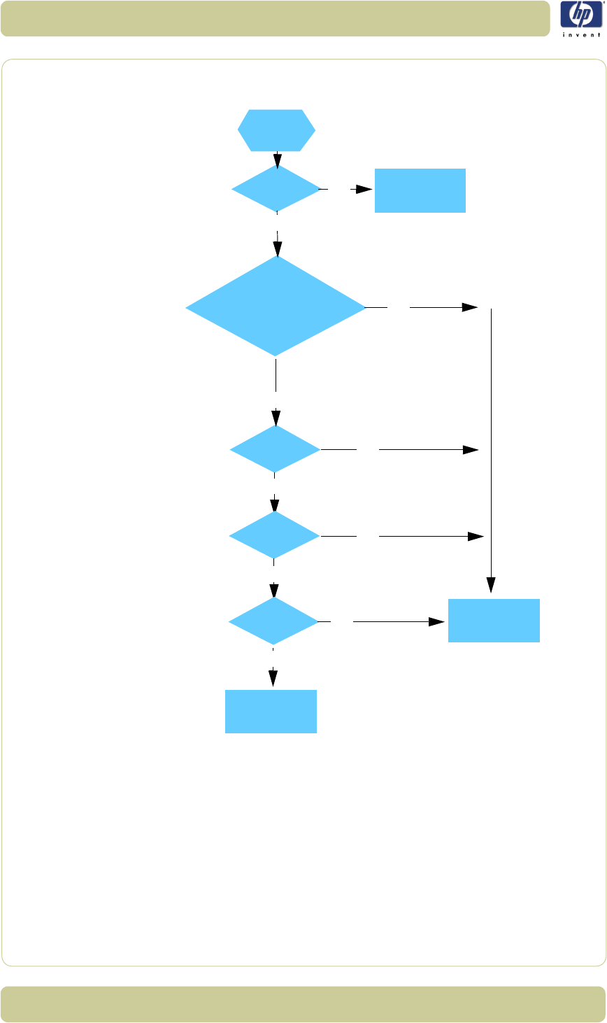
No backlight and no display
No backlight
and no display
Does P.S. have
output voltage?
Does P.S. have
input of AC
110V?
Does inverter
have input
voltage?
voltage?
have output
Does inverter
Change the power
cable of inverter or
DC-DC converter
Change the CON.
of AC SW or
reconnect it
Change fuse Change backlight tube
Change Inverter
N
N
N
N
Y
Y
Y
Y
Does the fuse
of P.S. break?
Y

1-29
Troubleshooting
HP Designjet T1100 MFP, 4500mfp, 4500 Scanner, 820 MFP Service Manual
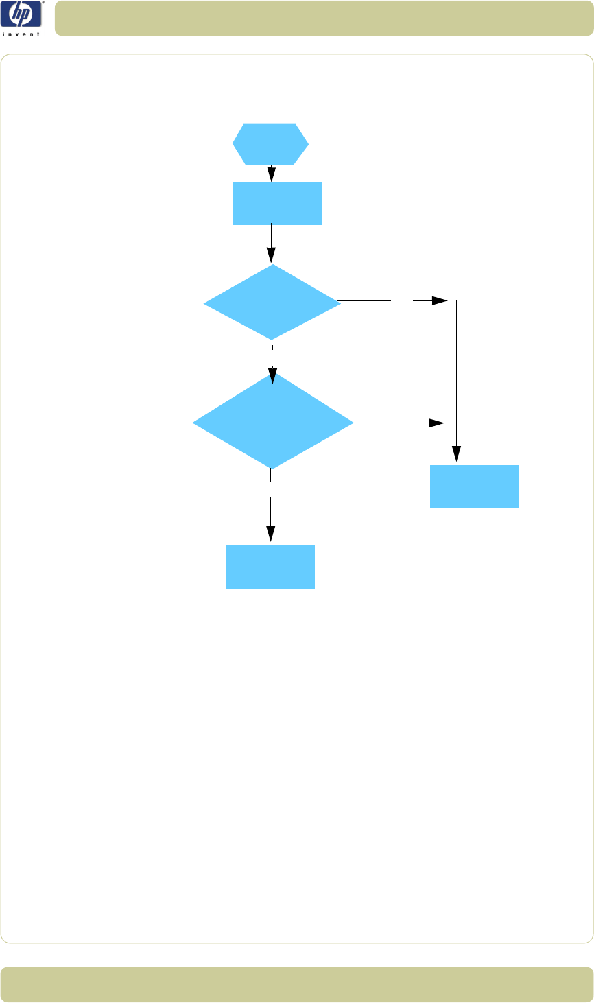
With backlight but no display
With backlight
but no display
Does LCD cable
break or
Does LCD
signal have output?
Change LCD cable
or reconnect it
Change CPU
disconnect?
board
Y
N
N
Change LCD
Y
1-30
Troubleshooting
HP Designjet T1100 MFP, 4500mfp, 4500 Scanner, 820 MFP Service Manual
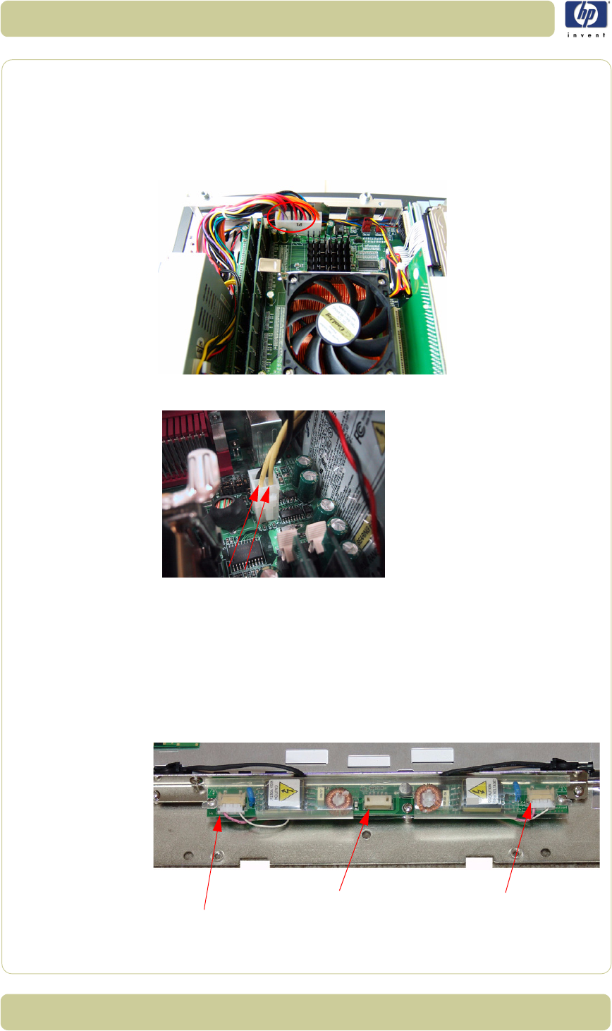
How to check the voltage of the Power Supply Unit in the
Panel PC.
With power on, measure the red pins and the yellow pins of the power
connector.
Output voltage of the red pins should be 5V±5%.
Output voltage of the yellow pins should be 12V±5%.
Output voltage of the yellow pins should be 12V±5%.
How to check the voltage of the Inverter PCA in the Panel PC.
With power on, measure pin 1 of the Inverter PCA input and output
connectors.
Output voltage should be between 600V and 710V (typical value is
640V).
Input voltage should be 12V±10%.
Pin 1
Pin 1 Pin 1
Output connector
Output connector
Input connector

1-31
Troubleshooting
HP Designjet T1100 MFP, 4500mfp, 4500 Scanner, 820 MFP Service Manual
The HDD failure:
The HDD is running, and the system configuration has identified the HDD’s
ID while booting up. Try the following:
Set the type of hard disk to AUTO in STANDARD CMOS SETUP.
Reconnect the cable between HDD and main board.
Change the HDD
⇒
Page 4-91.
The HDD is not running, and the system configuration can not identify the
HDD’s ID while booting up. Try the following:
Reconnect the cable between HDD and main board.
Change the cable between HDD and main board.
Change HDD
⇒
Page 4-91.
DDR DRAM failure:
If the computer repeatedly makes a long beep, and the display is blank
when you power on, this indicates a DDR DRAM error, replace the DDR
DRAM
⇒
Page 4-88.
DVD-ROM failure:
The DVD-ROM indicator light is on when you switch on. Try the following:
Check the possible damage on the cable between DVD-ROM and main
board.
The DVD-ROM indicator light is off when power up and the screen show
no message of any DVD-ROM installed.
Check for DVD-ROM auto detection in the BIOS setup:
Procedure to do this: In the BIOS setup, select standard CMOS features,
set all IDE detections ( ie Primary master, Primary slave ,secondary
master, secondary slave ) to AUTO
Reconnect the cable between DVD-ROM and main board.
Replace the DVD-ROM
⇒
Page 4-89.
The CD/DVD is stuck in the DVD-ROM and cannot be ejected
out.
Push a pin into the hole at the right side of the DVD-ROM eject button.
1-32
Troubleshooting
HP Designjet T1100 MFP, 4500mfp, 4500 Scanner, 820 MFP Service Manual
Image failure:
Follow the steps in the flowchart below to quickly check an image problem.
Power on and
Screen shows
Do you see ’Invalid
See Starting Windows
Turn on
Image bad
Y
boot up
HDD I/O
error
Change HDD or
IDE Cable
system disk or No-system
disk error’ message
when you start the computer
Windows loading
See File error
message
N
Y
Y
N
Y
N
N
N
Y
1-33
Troubleshooting
HP Designjet T1100 MFP, 4500mfp, 4500 Scanner, 820 MFP Service Manual
Touch screen failure:
Follow the steps in the flowchart below to quickly check if the touch screen
fails
Touch screen is working but cannot control the cursor.
Try the following:
Run the calibration program.
Check that the cable between the LCD controller and the LCD is
connected in the correct position
Replace the LCD controller
⇒
Page 4-92.
Replace the LCD
⇒
Page 4-83
.
Touch screen
One part of the
The cursor still has the
Change LCD
N
Change the touch screen
cable or reconnect it
touch screen does not
respond when touched
Change the LCD
N
Y
Y
does not function
big shift key enabled
evern when a calibration
has been run
controller

1-34
Troubleshooting
HP Designjet T1100 MFP, 4500mfp, 4500 Scanner, 820 MFP Service Manual
Erase the Parameter Block in the Scanner
The Scanner has a memory block called the Parameter block. The Parameter
block contains the following:
Stitching values camera transition a/b and b/c
Basic calibration information
Level for uncorrected light profile
Corrected light profile
Camera matching, gray
NTSC color space
sRGB color space
Date of the last calibration
The information that is stored in the Parameter block is gathered during the
calibration of the scanner (Scanner Maintenance).
In rare instances, the stored values will vary too greatly from current read
values, which can cause the scanner to report an error. The easiest way to
solve this problem is to erase the Parameter block.
When to Erase the Parameter Block
It is beneficial to erase the parameter block under the following
circumstances:
If the Scanner Maintenance is unable to recognize the calibrating sheet.
If error messages such as the the following appear:
– "Unable to correct camera x"
– "Unable to stitch camera x/x"
Before changing any hardware, especially before changing the main
board or the camera boards
Before performing any camera adjustments
How to Erase the Parameter Block
All of the information in the Parameter block is restored when the Scanner
Maintenance is run.
To erase the Parameter block and run the Scanner Maintenance, follow
1-35
Troubleshooting
HP Designjet T1100 MFP, 4500mfp, 4500 Scanner, 820 MFP Service Manual
these steps:
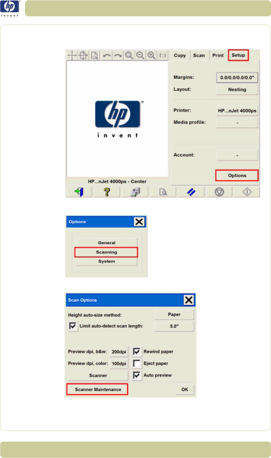
1Press the Setup tab on the Touch Screen, and then select Options.
2In the Options dialog box, select Scanning.
3In the Scan Options dialog box, select Scanner Maintenance.
1-36
Troubleshooting
HP Designjet T1100 MFP, 4500mfp, 4500 Scanner, 820 MFP Service Manual
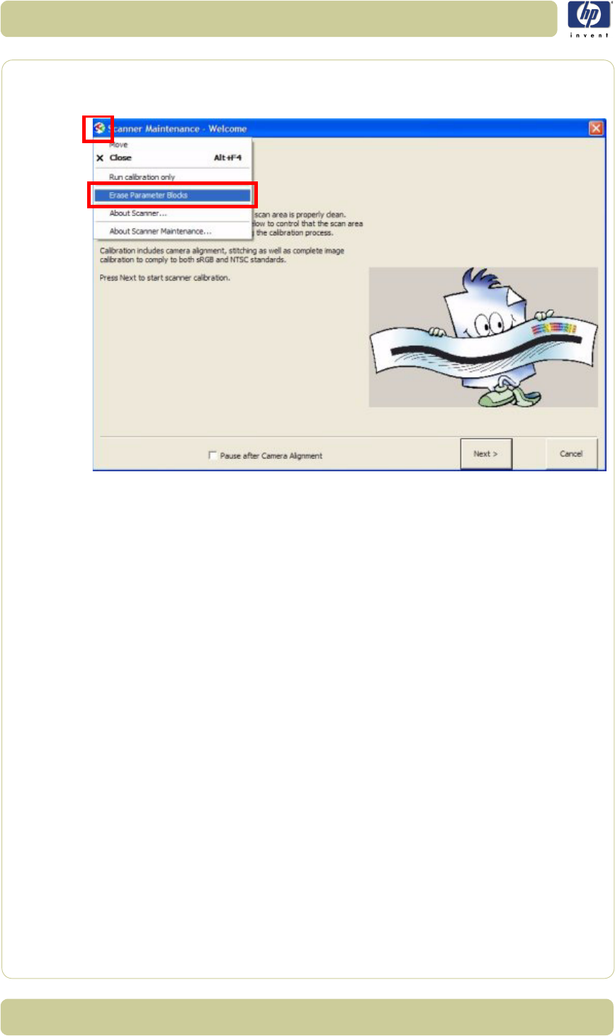
4In the Scanner Maintenance - Welcome window, click on the upper-
left icon, and then select Erase Parameter Block from the drop-down
menu.
Make sure that the scanner and the Scanner Maintenance sheet is clean
and is free of scratches before you run the Scanner Maintenance.
5Clean the scanner and run the Scanner Maintenance.
Risks of not running the Scanner Maintenance
The scanner will not report any errors if the Scanner Maintenance is
neglected, but image quality will detriorate. The following image defects are
likely:
Lightened or darkened scan: basic light lave is not set.
Poor camera-to-camera match: transition is visible, with one lighter or
darker than another.
Insufficient camera height alignment: broken vertical lines in camera
transition area.
Unstitched scanner: overlap or gap between cameras.
Wrong colors and color shifts from one camera to another.

2-1
HP Designjet T1100 MFP, 4500mfp, 4500 Scanner, 820 MFP Service Manual
System Error Codes 2
Introduction 2-2
Error Codes Displayed on the Operator Panel 2-3
Error Codes Reported by the Software 2-4
Error Codes for the JetImage Software RIP 2-32
Error Messages for the Touch Screen 2-40
2

2-2
System Error Codes
HP Designjet T1100 MFP, 4500mfp, 4500 Scanner, 820 MFP Service Manual
Introduction
The following pages contain a list of system error codes and their respective
descriptions and recommended corrective actions. Only try one
recommended action at a time and check if the error code has disappeared.
If you have an error code which is not documented in this Service Manual or
you have an error which you cannot resolve, then report the error to the HP
Response Center or the nearest HP Support Office.
When reporting the error, have the following information
ready:
Model and Serial Number of the scanner.
Which firmware revision the printer and the scanner is
using.
SW version.
The complete error number.
ScanDump of Light Profiles.
2-3
System Error Codes
HP Designjet T1100 MFP, 4500mfp, 4500 Scanner, 820 MFP Service Manual
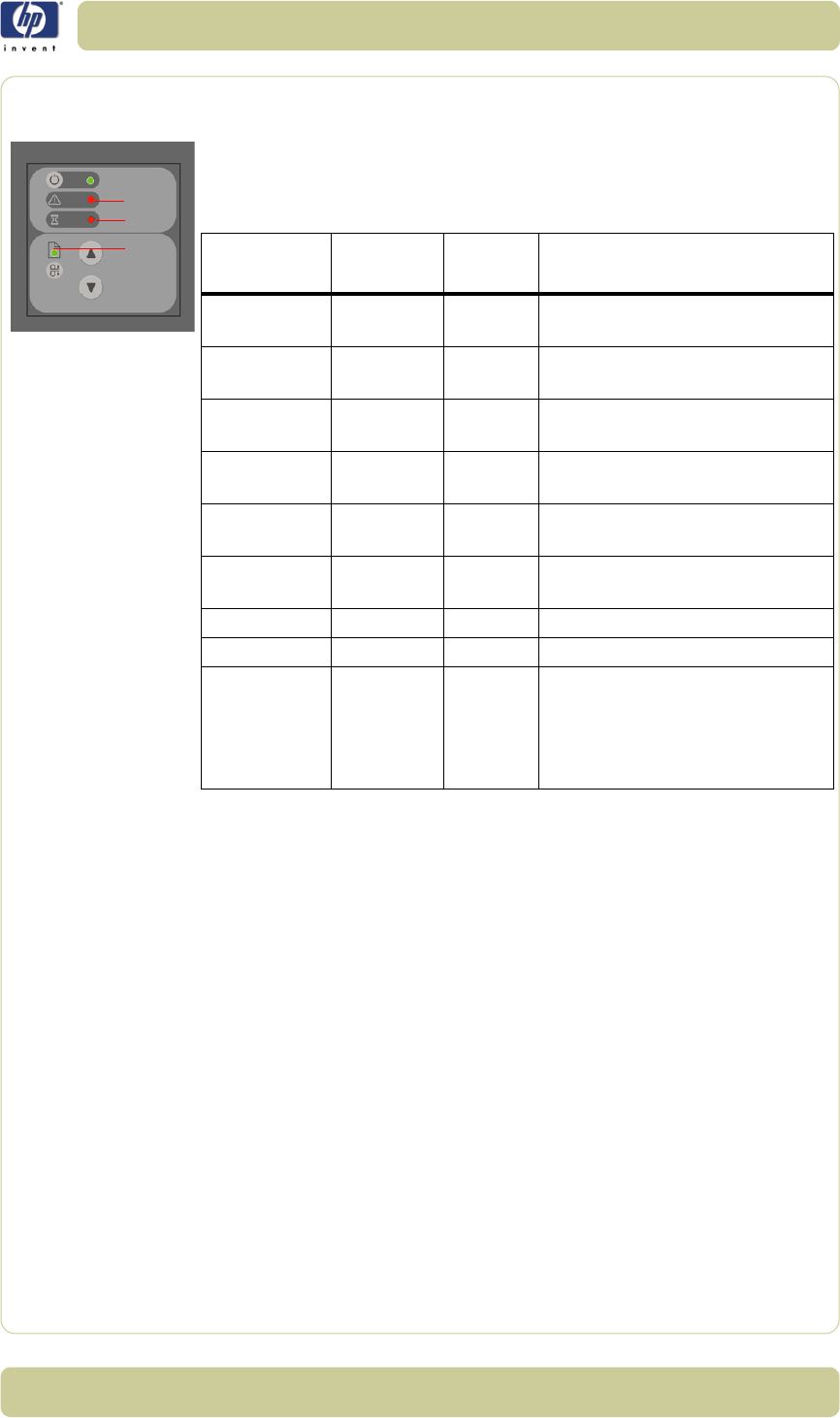
Error Codes Displayed on the Operator Panel
A flashing Diagnostic Indicator indicates an error condition. The error can be
identified by an error code number being displayed on the Touch Screen and/
or by the following combination of flashing indicators on the Operator Panel:
Diagnostic
LED (A)
Wait LED
(B)
Ready
LED (C)
Error Description
Flashing Flashes
Once OFF Correction of camera A failed
Flashing Flashes
Twice OFF Correction of camera B failed
Flashing OFF Flashes
Once
Error on Main PCA
Flashing OFF Flashes
Twice
Error on Camera Board
Flashing OFF Flashes
3 times
Invalid Scanner ID setting
Flashing OFF Flashes
4 times
Error on Interface Board
Flashing Flashing Flashing Scanner is in Boot Mode
Flashing OFF OFF Refer to Error Codes
OFF Flashing Red
Guide plate assembly is not in
the right position, to solve it
press down the guide plate to
move it to the original position
(step 0: 2mm/0.8")
A
B
C

2-4
System Error Codes
HP Designjet T1100 MFP, 4500mfp, 4500 Scanner, 820 MFP Service Manual
Error Codes Reported by the Software
The first set of numbers in the error code refers to a part of the Scanner
software or the Scanner.
System Error: 55-203
Problem
Description:
No movement in camera position has been detected during vertical camera
alignmnet. Check the camera.
Corrective Action: Try the following:
Check that all the cables are connected correctly to the Cameras and the
Camera Boards.
Run SCANtest 6, test 9 or 11 and check each Camera Motor functions
correctly.
System Error: 51-1
Problem
Description:
Incorrect scanner status.
Corrective Action: Try the following:
Check the paper path and reload the media.
Software Modules Comments/Notes
51 - Scanner API Low level scanner control library. All scanner
communication goes though this API.
52 - Image Format Library Printer and file formatting. All printing and file
read/write is formatted/decoded by this library.
53 - Copy Engine The central processing engine in the (JETimage)
software
54 - Closed Loop
Calibration
Color Management math library that calculates
the media profiles
55 - Test Software Scanner Maintenance / SCANtest
56 - Jetimage container All user interface and business logic except for
Scanner Maintenance / SCANtest and
WIDEsystem
57 - WIDEsystem (WS) Scanner surveillance utility
100 - Scanner Mechanical part of the Scanner

2-5
System Error Codes
HP Designjet T1100 MFP, 4500mfp, 4500 Scanner, 820 MFP Service Manual
System Error: 51-12
Problem
Description:
The driver for the scanner cannot be found.
Corrective Action: Try the following:
Perform a system recovery using the System Recovery DVD.
System Error: 51-18
Problem
Description:
No supported scanner was found
Corrective Action: Try the following:
Verify that your scanner is properly connected, and then retry the
operation.
System Error: 51-19
Problem
Description:
The driver for the scanner cannot be found.
Corrective Action: Try the following:
Perform a system recovery using the System Recovery DVD.
System Error: 51-26
Problem
Description:
Internal command error in driver
Corrective Action: Try the following:
Reboot your system.
System Error: 51-27
Problem
Description:
Windows failed to lock STI/WIA device.
Corrective Action: Try the following:
System Error: 51-28
Problem
Description:
Windows failed to unlock STI/WIA device.
Corrective Action: Try the following:
System Error: 51-29
Problem
Description:
The connection to the scanner has been lost.
Corrective Action: Try the following:
Reboot your system.

2-6
System Error Codes
HP Designjet T1100 MFP, 4500mfp, 4500 Scanner, 820 MFP Service Manual
System Error: 51-30
Problem
Description:
Unable to find scanner
Corrective Action: Try the following:
Check the cabling between the scanner and the Touch Screen and reboot
your system.
System Error: 51-31
Problem
Description:
The scanner is currently reserved by another application or user.
Corrective Action: Try the following:
Please wait for the scanner to become available.
System Error: 51-32
Problem
Description:
The operation was aborted due to an internal Windows error.
Corrective Action: Try the following:
Reboot your system.
System Error: 55-101
Problem
Description:
No scanner was found.
Corrective Action: Try the following:
Check that the scanner is properly connected and turned on.
System Error: 55-104
Problem
Description:
The scanner has not been adjusting for more than 1 hour.
Corrective Action: Try the following:
Lower the guide plate and wait 2 minute before retrying the operation.
System Error: 55-108
Problem
Description:
Your scanner firmware must be upgraded to run this program.
Corrective Action: Try the following:
Upgrade the firmware version.
If necessary, perform a system recovery using the System Recovery DVD.

2-7
System Error Codes
HP Designjet T1100 MFP, 4500mfp, 4500 Scanner, 820 MFP Service Manual
System Error: 55-109
Problem
Description:
The scanner firmware does not comply with the Scanner Maintenance
Calibration Sheet.
Corrective Action: Try the following:
Upgrade the firmware version.
System Error: 55-111
Problem
Description:
The scanner returns no picture width.
Corrective Action: Try the following:
Upgrade the firmware version.
System Error: 55-113
Problem
Description:
The scanner firmware does not support this type of calibration sheet.
Corrective Action: Try the following:
Upgrade the firmware version.
Use a new calibration sheet if necessary.
System Error: 55-116
Problem
Description:
Unable to read version information from the registry.
Corrective Action: Try the following:
System Error: 55-117
Problem
Description:
The resource file is missing.
Corrective Action: Try the following:
Perform a system recovery using the System Recovery DVD.
System Error: 55-201
Problem
Description:
Could not find ruler on the calibration sheet.
Corrective Action: Try the following:
Check the calibration sheet for scratches and wear.

2-8
System Error Codes
HP Designjet T1100 MFP, 4500mfp, 4500 Scanner, 820 MFP Service Manual
System Error: 55-203
Problem
Description:
No movement in camera position has been detected during vertical camera
alignmnet. Check the camera.
Corrective Action: Try the following:
Check that all the cables are connected correctly to the Cameras and the
Camera Boards.
Run SCANtest 6, test 9 or 11 and check each Camera Motor functions
correctly.
System Error: 55-205
Problem
Description:
The program has performed an alignment.
Corrective Action: Try the following:
For optimal performance, this should be followed by a scanner
maintenance.
System Error: 55-206
Problem
Description:
Could not recognize the sheet in the scanner as the "Stitching and
Adjustment Chart".
Corrective Action: Try the following:
Load the calibration sheet again.
System Error: 55-210
Problem
Description:
The scanner’s vertical alignment is not good enough to perform the
horizontal stitching.
Corrective Action: Try the following:
Run SCANtest 6, test 11
⇒
Page 1-6.
System Error: 55-211
Problem
Description:
The vertical difference for camera A is too big for automated stitching.
Corrective Action: Try the following:
Run SCANtest 6, test 11
⇒
Page 1-6.
System Error: 55-212
Problem
Description:
The vertical difference for camera B is too big for automated stitching.
Corrective Action: Try the following:
Run SCANtest 6, test 11
⇒
Page 1-6.

2-9
System Error Codes
HP Designjet T1100 MFP, 4500mfp, 4500 Scanner, 820 MFP Service Manual
System Error: 55-213
Problem
Description:
The vertical difference for camera C is too big for automated stitching.
Corrective Action: Try the following:
Run SCANtest 6, test 11
⇒
Page 1-6.
System Error: 55-214
Problem
Description:
The vertical difference for camera D is too big for automated stitching.
Corrective Action: Try the following:
Run SCANtest 6, test 11
⇒
Page 1-6.
System Error: 55-317
Problem
Description:
Could not read bar codes on the calibration sheet.
Corrective Action: Try the following:
To use default calibration parameters during adjustment, press OK. Press
Cancel to end the program.
System Error: 55-318
Problem
Description:
Basic calibration was performed, but failed to stitch the scanner.
Corrective Action: Try the following:
Inspect the calibration sheet for scratches or wear, replace it if the
problem continues, and then run the program again.
System Error: 55-319
Problem
Description:
The calibration sheet was not recognized as the right sheet for this scanner.
Corrective Action: Try the following:
Inspect the calibration sheet for scratches or wear and replace it if the
problem continues.
System Error: 55-401
Problem
Description:
Can’t find stitchlines.
Corrective Action: Try the following:
Inspect the calibration sheet for scratches or wear and replace it if the
problem continues.

2-10
System Error Codes
HP Designjet T1100 MFP, 4500mfp, 4500 Scanner, 820 MFP Service Manual
System Error: 55-402
Problem
Description:
Can’t find gray area.
Corrective Action: Try the following:
Inspect the calibration sheet for scratches or wear and replace it if the
problem continues.
System Error: 55-503
Problem
Description:
Color calibration failed.
Corrective Action: Try the following:
Run the program again.
System Error: 55-506
Problem
Description:
The program cannot find the IT8 reference file.
Corrective Action: Try the following:
If you have received a new calibration sheet, insert the CD.
If the problem persists, perform a system recovery using the System
Recovery DVD.
System Error: 55-508
Problem
Description:
Couldn’t read bar lines.
Corrective Action: Try the following:
Inspect the calibration sheet for scratches or wear and replace it if the
problem continues.
System Error: 55-509
Problem
Description:
IT8 file is not accessible.
Corrective Action: Try the following:
If you have received a new calibration sheet, insert the CD.
If the problem persists, perform a system recovery using the System
Recovery DVD.
System Error: 55-510
Problem
Description:
The IT8 sheet was not recognized.
Corrective Action: Try the following:
Please reinsert the calibration sheet.

2-11
System Error Codes
HP Designjet T1100 MFP, 4500mfp, 4500 Scanner, 820 MFP Service Manual
System Error: 55-511
Problem
Description:
The IT8 sheet was not recognized.
Corrective Action: Try the following:
Inspect the calibration sheet for scratches or wear and replace it if the
problem continues.
System Error: 55-518
Problem
Description:
Aborting Color Calibration Calculation.
Corrective Action: Try the following:
Inspect the calibration sheet for scratches or wear and replace it if the
problem continues.
System Error: 55-520
Problem
Description:
The NTSC calculations failed.
Corrective Action: Try the following:
Inspect the calibration sheet for scratches or wear and replace it if the
problem continues.
System Error: 55-521
Problem
Description:
The sRGB calculations failed.
Corrective Action: Try the following:
Inspect the calibration sheet for scratches or wear and replace it if the
problem continues.
System Error: 55-522
Problem
Description:
The IT8DATA.IT8 reference file could not be found.
Corrective Action: Try the following:
Perform a system recovery using the System Recovery DVD.
System Error: 55-523
Problem
Description:
Sheet not recognized
Corrective Action: Try the following:
Inspect the calibration sheet for scratches or wear and replace it if the
problem continues.

2-12
System Error Codes
HP Designjet T1100 MFP, 4500mfp, 4500 Scanner, 820 MFP Service Manual
System Error: 55-525
Problem
Description:
The IT8 reference file could not be found.
Corrective Action: Try the following:
A standard IT8 reference file will be used instead. Note that optimal color
calibration requires the correct reference file for the current IT8 sheet.
System Error: 55-527
Problem
Description:
Could not recognize the scanned IT8 picture.
Corrective Action: Try the following:
Inspect the calibration sheet for scratches or wear and replace it if the
problem continues.
System Error: 55-530
Problem
Description:
When checking new calibration, the result was not within the limits.
Corrective Action: Try the following:
Inspect the calibration sheet for scratches or wear and replace it if the
problem continues.
System Error: 55-531
Problem
Description:
Calibration stopped
Corrective Action: Try the following:
Maximum time was exceeded. Turn scanner off and then turn it back on.
Wait 15 minutes before running the program.
System Error: 55-601
Problem
Description:
Scanner is initializing
Corrective Action: Try the following:
Turn scanner off and then turn it back on. Wait 15 minutes before
running the program.

2-13
System Error Codes
HP Designjet T1100 MFP, 4500mfp, 4500 Scanner, 820 MFP Service Manual
System Error: 55-602
Problem
Description:
Scanner is warming up
Corrective Action: Try the following:
Turn scanner off and then turn it back on. Wait 15 minutes before
running the program.
System Error: 55-603
Problem
Description:
Scanner is adjusting
Corrective Action: Try the following:
Turn scanner off and then turn it back on. Wait 15 minutes before
running the program.
System Error: 55-604
Problem
Description:
The paper guide is in extended position
Corrective Action: Try the following:
Lower the ATAC system. Click OK to restart the scanner maintenance
wizard.
System Error: 55-605
Problem
Description:
Calibration of the scanner is not possible because the scanner is in
programming mode.
Corrective Action: Try the following:
Turn scanner off and then turn it back on. Wait 15 minutes before
running the program.
System Error: 55-607
Problem
Description:
The scanner is already in calibration mode.
Corrective Action: Try the following:
Turn scanner off and then turn it back on. Wait 15 minutes before
running the program.
System Error: 55-608
Problem
Description:
The camera signals in the scanner is not stitched together.
Corrective Action: Try the following:
Press OK to allow the scanner to perform the calibration, and then press
Cancel to exit the program.

2-14
System Error Codes
HP Designjet T1100 MFP, 4500mfp, 4500 Scanner, 820 MFP Service Manual
System Error: 55-609
Problem
Description:
Unable to position the sheet
Corrective Action: Try the following:
Reinsert the sheet.
System Error: 55-612
Problem
Description:
The calibration failed during camera adjustment.
Corrective Action: Try the following:
Inspect the calibration sheet for scratches or wear, and replace it if the
problem persists.
System Error: 56-6
Problem
Description:
No scanner selected or selected scanner is not present.
Corrective Action: Try the following:
Ensure that the scanner is turned on and ready.
System Error: 56-24
Problem
Description:
Unable to view file.
Corrective Action: Try the following:
Ensure that the file is valid.
System Error: 56-25
Problem
Description:
The file path is not valid.
Corrective Action: Try the following:
A file name cannot contain any of the following characters: \ / : * ? " <
> |
System Error: 56-27
Problem
Description:
Unable to create a temporary ICC profile on the disk.
Corrective Action: Try the following:
Ensure that hard disk space is available.

2-15
System Error Codes
HP Designjet T1100 MFP, 4500mfp, 4500 Scanner, 820 MFP Service Manual
System Error: 56-28
Problem
Description:
Cannot recognize the patch sheet.
Corrective Action: Try the following:
Ensure that the sheet is correctly aligned in the scanner and that it is in
good condition.
System Error: 56-29
Problem
Description:
Cannot recognize the patch sheet.
Corrective Action: Try the following:
Ensure that the sheet is correctly aligned in the scanner and that it is in
good condition.
System Error: 56-30
Problem
Description:
Could not open the file: %s.
Corrective Action: Try the following:
Ensure that the file path is writable and ensure that there is space
available on the hard disk.
System Error: 56-32
Problem
Description:
Could not write to the file: %s.
Corrective Action: Try the following:
Ensure that the file path is writable and ensure that there is space
available on the hard disk.
System Error: 56-33
Problem
Description:
Could not open the ICC profile: %s.
Corrective Action: Try the following:
Ensure that the file exists in the designated location.
System Error: 56-35
Problem
Description:
Could not read from the file: %s.
Corrective Action: Try the following:
Ensure that the file path is readable.

2-16
System Error Codes
HP Designjet T1100 MFP, 4500mfp, 4500 Scanner, 820 MFP Service Manual
System Error: 56-36
Problem
Description:
Could not find the ICC file generated by the Profiler tool (%s).
Corrective Action: Try the following:
Ensure that there is space available on the hard disk.
System Error: 56-37
Problem
Description:
Could not launch the Profiler tool used to prcess the patch sheet: %s.
Corrective Action: Try the following:
Perform a system recovery using the System Recovery DVD.
System Error: 56-41
Problem
Description:
An error occurred while applying network settings.
Corrective Action: Try the following:
Ensure that the entered settings are valid for the network.
System Error: 56-42
Problem
Description:
An error occurred while applying the new computer name.
Corrective Action: Try the following:
Ensure that the name is valid for the network.
System Error: 56-43
Problem
Description:
The CD/DVD drive is not ready.
Corrective Action: Try the following:
Check the CD/DVD media.
System Error: 56-44
Problem
Description:
Unable to write to the CD/DVD.
Corrective Action: Try the following:
Check the CD/DVD media.

2-17
System Error Codes
HP Designjet T1100 MFP, 4500mfp, 4500 Scanner, 820 MFP Service Manual
System Error: 56-45
Problem
Description:
The system was unable to detect the scanner.
Corrective Action: Try the following:
Verify that the cables are secured.
Reboot the system.
System Error: 56-46
Problem
Description:
It is not possible to retrieve the necessary information about the current
printer.
Corrective Action: Try the following:
A likely cause is that the printer is accessed through a print server, as the
operation requires the driver to be installed locally.
System Error: 56-47
Problem
Description:
Unable to add file %s.
Corrective Action: Try the following:
Ensure that the file is valid.
System Error: 56-63
Problem
Description:
Unable to create network mapping.
Corrective Action: Try the following:
Ensure that the entered settings are valid and that the network is working.
System Error: 56-68
Problem
Description:
You do not have access to the network resource.
Corrective Action: Try the following:
Ensure that the entered settings are valid.
System Error: 56-69
Problem
Description:
A folder on the network resource has already been mapped using another
name.
Corrective Action: Try the following:
Disconnect all network folders for the resource.

2-18
System Error Codes
HP Designjet T1100 MFP, 4500mfp, 4500 Scanner, 820 MFP Service Manual
System Error: 56-70
Problem
Description:
Invalid network folder
Corrective Action: Try the following:
Ensure that the entered network folder setting is valid.
System Error: 56-71
Problem
Description:
Logon failure
Corrective Action: Try the following:
Ensure that the entered user name and password are valid.
System Error: 56-72
Problem
Description:
There are too many network connections.
Corrective Action: Try the following:
Remove some network connections.
System Error: 100-118
Problem
Description:
Unable to communicate with the scanner.
Corrective Action: Try the following:
Ensure a secure cable connection between the Panel PC and the scanner.
System Error: 100-128
Problem
Description:
There is a paper jam.
Corrective Action: Try the following:
Reload the media.
System Error: 100-129
Problem
Description:
The scanner does not support this test command in normal mode.
Corrective Action: Try the following:
Turn off the scanner, and then turn it back on.

2-19
System Error Codes
HP Designjet T1100 MFP, 4500mfp, 4500 Scanner, 820 MFP Service Manual
System Error: 100-130
Problem
Description:
The scanner doe snot support this command in test mode.
Corrective Action: Try the following:
Turn off the scanner, and then turn it back on.
System Error: 100-131
Problem
Description:
The scanner is initializing.
Corrective Action: Try the following:
Retry the operation when the scanner has finished initializing.
System Error: 100-132
Problem
Description:
The scanner is warming up.
Corrective Action: Try the following:
Retry the operation when the scanner has finished initializing.
System Error: 100-133
Problem
Description:
The scanner cannot reverse the media while the ATAC system is in the
extended position.
Corrective Action: Try the following:
Manually reload the media.
System Error: 100-134
Problem
Description:
The scanner is calibrating.
Corrective Action: Try the following:
Retry the operation when the scanner has finished calibrating.
System Error: 100-136
Problem
Description:
The scanner is on standby.
Corrective Action: Try the following:
Turn on the scanner and retry the operation when the scanner is ready.

2-20
System Error Codes
HP Designjet T1100 MFP, 4500mfp, 4500 Scanner, 820 MFP Service Manual
System Error: 100-1004
Problem
Description:
The media is currently being loaded by the scanner.
Corrective Action: Try the following:
Retry the operation when the media has been loaded.
System Error: 100-1005
Problem
Description:
The media is currently being positioned by the scanner.
Corrective Action: Try the following:
Retry the operation when the media has been positioned.
System Error: 100-1006
Problem
Description:
There is a paper jam.
Corrective Action: Try the following:
Manually reload the media.
System Error: 100-1007
Problem
Description:
The scanner cannot reverse the media while the ATAC system is in the
extended position.
Corrective Action: Try the following:
Manually reload the media.
System Error: 100-1008
Problem
Description:
The scanner is calibrating.
Corrective Action: Try the following:
Retry the operation when the scanner has finished calibrating.
System Error: 100-2000
Problem
Description:
The scanner is powering up.
Corrective Action: Try the following:
Wait until the scanner is ready, and then retry the operation.

2-21
System Error Codes
HP Designjet T1100 MFP, 4500mfp, 4500 Scanner, 820 MFP Service Manual
System Error: 100-2001
Problem
Description:
Incorrect scanner status
Corrective Action: Try the following:
Check the paper path and reload the media.
System Error: 100-2002
Problem
Description:
The scanner does not support this test command in normal mode.
Corrective Action: Try the following:
Reboot the system.
System Error: 100-2003
Problem
Description:
The scanner does not support this command in test mode.
Corrective Action: Try the following:
Turn off the scanner, and then turn it on again.
System Error: 100-2014
Problem
Description:
The scanner is on standby.
Corrective Action: Try the following:
Turn on the scanner and retry the operation when the scanner is ready.
System Error: 100-2015
Problem
Description:
The scanner did not find any Hollerith data on the aperture card.
Corrective Action: Try the following:
Ensure that the card is valid and correctly inserted.
System Error: 100-2016
Problem
Description:
The scanner cover is open.
Corrective Action: Try the following:
Close the cover before retrying the operation.

2-22
System Error Codes
HP Designjet T1100 MFP, 4500mfp, 4500 Scanner, 820 MFP Service Manual
System Error: 100-3000
Problem
Description:
The firmware was not downloaded properly.
Corrective Action: Try the following:
Perform a system recovery using the System Recovery DVD.
System Error: 100-3002 through 100-3037
Problem
Description:
Unable to adjust camera X, unable to stitch camera X to camera, error
calibrating camera X
Corrective Action: Try the following:
Clean the white background and the glass plate, and then run the
scanner maintenance.
System Error: 100-3051
Problem
Description:
The scanner’s ID switch has been set to an invalid value. Please change
switch setting.
Corrective Action: Try the following:
Check that all the cables are connected correctly to the Main Electronics
Board, Control Panel Board in the Right Cover.
Run SCANtest 6, test 7
⇒
Page 1-6.
Replace the Right Cover
⇒
Page 4-9.
Replace the Main Electronics Board
⇒
Page 4-37.
System Error: 100-3054
Problem
Description:
Unable to write to EEPROM/FLASH
Corrective Action: Try the following:
Check that all the cables are connected correctly to the Main Electronics
Board.
Run SCANtest 6, test 7
⇒
Page 1-6.
Replace the Main Electronics Board
⇒
Page 4-37.
System Error: 100-3056
Problem
Description:
Flash Error: Unable to erase
Corrective Action: Try the following:
Check that all the cables are connected correctly to the Main Electronics
Board.
Run SCANtest 6, test 7
⇒
Page 1-6
Replace the Main Electronics Board
⇒
Page 4-37.

2-23
System Error Codes
HP Designjet T1100 MFP, 4500mfp, 4500 Scanner, 820 MFP Service Manual
System Error: 100-3057
Problem
Description:
Flash Error: Unable to program
Corrective Action: Try the following:
Check that all the cables are connected correctly to the Main Electronics
Board.
Run SCANtest 6, test 7
⇒
Page 1-6
Replace the Main Electronics Board
⇒
Page 4-37.
System Error: 100-3058
Problem
Description:
SCU Board Error
Corrective Action: Try the following:
Check that all the cables are connected correctly to the Main Electronics
Board.
Run SCANtest 6, test 7
⇒
Page 1-6.
Replace the Main Electronics Board
⇒
Page 4-37.
System Error: 100-3059
Problem
Description:
Camera Board, Error
Corrective Action: Try the following:
To find out which board has an error Run SCANtest 6, test 7 and check
the performance of each camera.
Check that all the cables are connected correctly to the
Cameras
Boards.
Run SCANtest 6, test 9 and check the Camera Board.
Replace the Camera Board
⇒
Page 4-29.
Replace the Main Electronics Board
⇒
Page 4-37.
System Error: 100-3061
Problem
Description:
There is a problem with the Interface Board
Corrective Action: Try the following:
Check that the Interface Board is correctly installed.
Run SCANtest 6, test 7
⇒
Page 1-6.
Replace the Interface Board
⇒
Page 4-39.

2-24
System Error Codes
HP Designjet T1100 MFP, 4500mfp, 4500 Scanner, 820 MFP Service Manual
System Error: 100-3062
Problem
Description:
Fan error
Corrective Action: Try the following:
Check that all the cables are connected correctly to the
Fans.
Check that all the cables are connected correctly to the
Driver Board.
Perform the Driver Board Communication Test
⇒
Page 5-32.
Replace the Fan
⇒
Page 4-35
Replace the Driver Board
⇒
Page 4-33
System Error: 100-3063
Problem
Description:
The scanner’s replaceable lamp cartridge is detached.
Corrective Action: Try the following:
Ensure that the lamp cartridge is correctly installed.
System Error: 100-4001
Problem
Description:
No supported scanner could be found.
Corrective Action: Try the following:
Verify that the scanner is turned on and connected to the Touch Screen.
System Error: 100-8220
Problem
Description:
The scanner’s replacable lamp cartridge is detached.
Corrective Action: Try the following:
Ensure that the lamp cartridge is correctly inserted.
System Error: 100-20086
Problem
Description:
Unable to communicate with the ATAC Controller Board.
Corrective Action: Try the following:
Check that all the cables are connected correctly to the
ATAC Board
and
the Main Electronics Board.
Run SCANtest 6, test 7
⇒
Page 1-6.
Replace the ATAC Board
⇒
Page 4-44
Replace the Main Electronics Board
⇒
Page 4-37.

2-25
System Error Codes
HP Designjet T1100 MFP, 4500mfp, 4500 Scanner, 820 MFP Service Manual
System Error: 100-20087
Problem
Description:
Unable to perform paper guide movement (ATAC).
Corrective Action: Try the following:
Check that all the cables are connected correctly to the
ATAC Board
and
the Main Electronics Board.
Run SCANtest 6, test 7
⇒
Page 1-6.
Replace the ATAC Board
⇒
Page 4-44
Replace the Main Electronics Board
⇒
Page 4-37.
System Error: 100-20219
Problem
Description:
There is a problem with one of the Fans.
Corrective Action: Try the following:
Check that all the cables are connected correctly to the
Fans.
Check that all the cables are connected correctly to the
Driver Board.
Perform the Driver Board Communication Test
⇒
Page 5-32.
Replace the Fan
⇒
Page 4-35
Replace the Driver Board
⇒
Page 4-33
System Error: 100-20221
Problem
Description:
There is a problem with the Driver Board.
Corrective Action: Try the following:
Check that all the cables are connected correctly to the
Driver
Board and
the Main Electronics Board.
Perform the Driver Board Communication Test
⇒
Page 5-32.
Run SCANtest 6, test 7
⇒
Page 1-6.
Replace the Driver Board
⇒
Page 4-33.
Replace the Main Electronics Board
⇒
Page 4-37.
System Error: 100-30140
Problem
Description:
Correction of Camera A failed.
Corrective Action: Try the following:
Clean the white background and the glass plate.
Erase the parameter block.
Run the scanner maintenance software.
Replace the camera board.

2-26
System Error Codes
HP Designjet T1100 MFP, 4500mfp, 4500 Scanner, 820 MFP Service Manual
System Error: 100-30141
Problem
Description:
Correction of Camera B failed.
Corrective Action: Try the following:
Clean the white background and the glass plate.
Erase the parameter block.
Run the scanner maintenance software.
Replace the camera board.
System Error: 100-30142
Problem
Description:
Correction of Camera C failed.
Corrective Action: Try the following:
Clean the white background and the glass plate.
Erase the parameter block.
Run the scanner maintenance software.
Replace the camera board.
System Error: 100-30240
Problem
Description:
Correction of Camera A failed.
Corrective Action: Try the following:
Clean the white background and the glass plate.
Erase the parameter block.
Run the scanner maintenance software.
Replace the camera board.
System Error: 100-30241
Problem
Description:
Correction of Camera B failed.
Corrective Action: Try the following:
Clean the white background and the glass plate.
Erase the parameter block.
Run the scanner maintenance software.
Replace the camera board.

2-27
System Error Codes
HP Designjet T1100 MFP, 4500mfp, 4500 Scanner, 820 MFP Service Manual
System Error: 100-30242
Problem
Description:
Correction of Camera C failed.
Corrective Action: Try the following:
Clean the white background and the glass plate.
Erase the parameter block.
Run the scanner maintenance software.
Replace the camera board.
System Error: 100-32144
Problem
Description:
Stitching between Camera A and Camera B failed.
Corrective Action: Try the following:
Clean the white background and the glass plate.
Erase the parameter block.
Run the scanner maintenance software.
Replace the camera board.
System Error: 100-32145
Problem
Description:
Stitching between Camera B and Camera C failed.
Corrective Action: Try the following:
Clean the white background and the glass plate.
Erase the parameter block.
Run the scanner maintenance software.
Replace the camera board.
System Error: 100-32244
Problem
Description:
Stitching between Camera A and Camera B failed.
Corrective Action: Try the following:
Clean the white background and the glass plate.
Erase the parameter block.
Run the scanner maintenance software.
Replace the camera board.
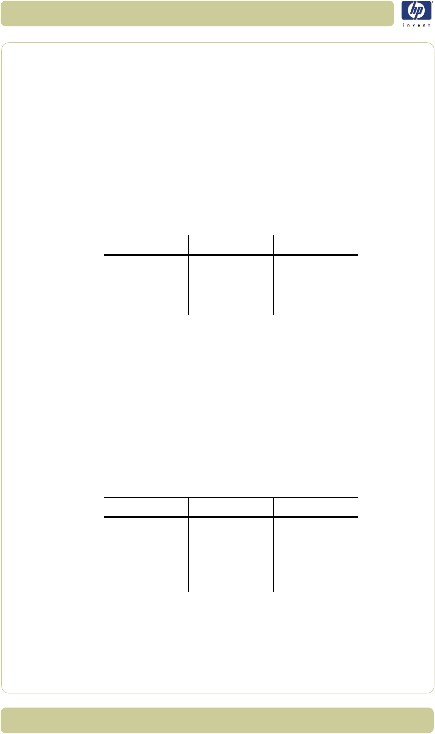
2-28
System Error Codes
HP Designjet T1100 MFP, 4500mfp, 4500 Scanner, 820 MFP Service Manual
System Error: 100-32245
Problem
Description:
Stitching between Camera B and Camera C failed.
Corrective Action: Try the following:
Clean the white background and the glass plate.
Erase the parameter block.
Run the scanner maintenance software.
Replace the camera board.
System Error: 100-4003x/4004x
Problem
Description:
Error on Camera Board. Use the table below to identify the failing Camera
Board.
Corrective Action: Try the following:
Run SCANtest 6, test 7 to verify the error.
Check that all the cables are connected correctly.
Run SCANtest 6, test 9 and check the light profiles
⇒
Page 1-6.
Erase the Parameter Blocks.
Run the Scanner Maintenance
⇒
Page 5-26.
Replace the Camera Board
⇒
Page 4-29
.
System Error: 100-4017x/4018x
Problem
Description:
Unable to calibrate a camera. Use the following table to identify the failing
camera.
Camera (A) Camera (B) Camera (C)
40035 40036 40037
40039 40040 40041
40043 40044 40045
40047 40048 40049
Camera (A) Camera (B) Camera (C)
40170 40171 40172
40174 40175 40176
40178 40179 40180
40182 40183 40184
40186 40187 40188

2-29
System Error Codes
HP Designjet T1100 MFP, 4500mfp, 4500 Scanner, 820 MFP Service Manual
Corrective Action: Try the following:
Erase the parameter block and perform scanner maintenance
⇒
Page 5-
26.
Check that all cables are connected correctly to the Camera Board and
the Main Electronics Board.
Switch Mode Power Supply
Run SCANtest 6, test 9
⇒
Page 1-6.
Replace the Main Electronics Board
⇒
Page 4-37.
Replace the failing Camera Board
⇒
Page 4-29
System Error: 100-40075
Problem
Description:
Camera Board, FPGA CB status error.
Corrective Action: Try the following:
Check that all the cables are connected correctly to the
Cameras
Boards.
Replace the Camera Board
⇒
Page 4-29
Replace the Main Electronics Board
⇒
Page 4-37.
System Error: 100-40076
Problem
Description:
Camera Board, FPGA CB done error.
Corrective Action: Try the following:
Check that all the cables are connected correctly to the
Cameras
Boards.
Run SCANtest 6, test 9
⇒
Page 1-6.
Replace the Camera Board
⇒
Page 4-29.
Run SCANtest 6, test 7
⇒
Page 1-6.
Replace the Main Electronics Board
⇒
Page 4-37.
System Error: 100-40084
Problem
Description:
Camera Board, Camera Cables disconnected.
Corrective Action: Try the following:
Check that all the cables are connected correctly to the
Cameras
Boards.
Run SCANtest 6, test 9
⇒
Page 1-6.
Replace the Camera Board
⇒
Page 4-29.
Run SCANtest 6, test 7
⇒
Page 1-6.
Replace the Main Electronics Board
⇒
Page 4-37.

2-30
System Error Codes
HP Designjet T1100 MFP, 4500mfp, 4500 Scanner, 820 MFP Service Manual
System Error: 100-4013x
Problem
Description:
Unable to calibrate an undefined Camera
Corrective Action: Try the following:
Erase the parameter block and perform scanner maintenance
⇒
Page 5-
26.
Switch Mode Power Supply
Check that all the cables are connected correctly to the
Cameras
Boards.
Run SCANtest 6, test 9
⇒
Page 1-6.
Replace the Camera Board
⇒
Page 4-29.
Run SCANtest 6, test 7
⇒
Page 1-6.
Replace the Main Electronics Board
⇒
Page 4-37.
System Error: 100-501xx
Problem
Description:
Error on the Main Electronics Board.
Corrective Action: Try the following:
Check that all the cables are connected correctly to the
Main Electronics
Board.
Run Scanner Maintenance
⇒
Page 5-26.
Upgrade the Scanner Firmware
.
Run SCANtest 6, test 7
⇒
Page 1-6.
Replace the Main Electronics Board
⇒
Page 4-37.
System Error: 100-50199
Problem
Description:
Incorrect Main Electronics Board and Camera Board. Please validate the
combination for this scanner.
Corrective Action: Try the following:
Check that all the cables are connected correctly to the
Cameras
Boards.
Update the firmware
Run SCANtest 6, test 9
⇒
Page 1-6.
Replace the Camera Board
⇒
Page 4-29.
Run SCANtest 6, test 7
⇒
Page 1-6.
Replace the Main Electronics Board
⇒
Page 4-37.

2-31
System Error Codes
HP Designjet T1100 MFP, 4500mfp, 4500 Scanner, 820 MFP Service Manual
System Error: 100-600xx
Problem
Description:
Communications Interface Error
Corrective Action: Try the following:
Check that all the cables are connected correctly to the
Main Electronics
Board and the Interface Board is correctly installed.
Run SCANtest 6, test 7
⇒
Page 1-6.
Replace the Camera Board
⇒
Page 4-29
Replace the Main Electronics Board
⇒
Page 4-37.

2-32
System Error Codes
HP Designjet T1100 MFP, 4500mfp, 4500 Scanner, 820 MFP Service Manual
Error Codes for the JetImage Software RIP
Introduction
This set of number system error codes refers to the systems related to the
JetImage Software RIP.
System Error: -19
FP Message -19 When combining thick media handling (paper guide in extended
position) with auto size detection, the size detection must be done separately
by running a preview scan before the final copy or scan operation.
Problem
Description:
When combining thick media handling (paper guide in extended position)
with auto size detection, the size detection must be done separately by
running a preview scan before the final copy or scan operation.
Corrective Action: Try the following:
Run a preview scan before the final copy or scan operation
Perform the copy or scan to file instead.
System Error: -16
FP Message -16 error reading the RIP gray balance file.
Problem
Description:
If current media profile specifies to use CSV-file in the RIP gray balance and
the file is not found.
Corrective Action: Either disable the use of gray balance or attempt to create the file again.
System Error: -14
FP Message -14 Unable to reserve the scanner.
Problem
Description:
Unable to reserve the scanner.
Corrective Action: Check and see if any other application is using the scanner.
System Error: -13
FP Message -13 Unable to rename the folder.
Problem
Description:
Unable to rename the folder.
Corrective Action: Occurs during file browsing operations, usually due to a share issue.
System Error: -12
FP Message -12 Unable to delete the folder.
Problem
Description:
Unable to delete the folder (occurs during file browsing operations, typically

2-33
System Error Codes
HP Designjet T1100 MFP, 4500mfp, 4500 Scanner, 820 MFP Service Manual
if a folder is shared).
Corrective Action: Close all the applications and try again.
System Error: -11
FP Message -11 The folder must be empty.
Problem
Description:
The folder must be empty (occurs during file browsing operations).
Corrective Action: Check that the folder is empty before deleting it.
System Error: -9
FP Message -9 The currently selected printer is not installed in the system.
Problem
Description:
The windows printer driver for the currently selected printer is not found.
Corrective Action: Try the following:
Check that the printer driver is installed.
Install the printer driver if not already installed.
System Error: -6
FP Message -6 No scanner selected or selected scanner not present.
Problem
Description:
No scanner selected or selected scanner not present. If the scanner was
turned Off during application start-up.
Corrective Action: Try the following:
Check that the scanner is turned On.
Check that the scanner is selected.
System Error: -2
FP Message -2 No media profile selected for current printer.
Problem
Description:
No media profile selected for current printer.
Corrective Action: Prepare a Media Profile before performing the operation.
System Error: -1
FP Message -1 No printer selected.
Problem
Description:
No printer selected.
Corrective Action: Select a printer. A printer must be configured in the application before trying
to print.

2-34
System Error Codes
HP Designjet T1100 MFP, 4500mfp, 4500 Scanner, 820 MFP Service Manual
System Error: 02
FP Message 02 Invalid scan coordinates. The paper frame was placed fully outside the
scan image.
Problem
Description:
Invalid scan coordinates. The paper frame was placed fully outside the scan
image.
Corrective Action: Try repositioning the paper frame so that it covers some of the scannable
area.
System Error: 06
FP Message 06 Not enough disk space for spool file.
Problem
Description:
Not enough disk space for spool file.
Corrective Action: Make sure that the environment TEMP (or secondary TMP) points to a folder
with plenty of space.
System Error: 08
FP Message 08 The scanner is currently on standby. Please press the soft power button on
the scanner to activate it.
Problem
Description:
The scanner is currently on standby.
Corrective Action: Press the soft power button on the scanner to activate it.
System Error: 00003
FP Message 00003 Scanning invalid size of area requested for scanning.
Problem
Description:
Negative scan-width specified.
Corrective Action: Reselect the scan area and try again.
System Error: 01003
FP Message 01003 Error printing colorsheet.
Problem
Description:
Error printing colorsheet.
Corrective Action: Try the following:
Check the printer to make sure it is switched On and connected to the
scanner.
Try printing a test print to make sure that the printer is working.

2-35
System Error Codes
HP Designjet T1100 MFP, 4500mfp, 4500 Scanner, 820 MFP Service Manual
System Error: 01013
FP Message 01013 Error detecting index-mark.
Problem
Description:
Skew: Error detecting the index mark.
Corrective Action: Try the following:
Try restarting the system.
If the problem persists, view the scandump.tif file for further diagnosis.
System Error: 01014
FP Message 01014 Sheet bad aligned.
Problem
Description:
Sheet badly aligned.
Corrective Action: Try the following:
Reinsert the sheet, making sure that it is straight and at the right position.
If the problem persists, view the scandump.tif file for further diagnosis.
System Error: 01015
FP Message 01015 Error detecting left margin.
Problem
Description:
Error detecting the left margin of the sheet.
Corrective Action: Try the following:
Try reinserting the sheet.
If the problem persists, view the scandump.tif file for further diagnosis.
System Error: 01016
FP Message 01016 Error detecting right margin.
Problem
Description:
Error detecting the right margin of the sheet.
Corrective Action: Try the following:
Try reinserting the sheet.
If the problem persists, view the scandump.tif file for further diagnosis.
System Error: 01017
FP Message 01017 Error reading colorsheet.
Problem
Description:
Error reading the colorsheet. The end of the sheet is reached before
expected.
Corrective Action: Check that the correct colorsheet is being used.

2-36
System Error Codes
HP Designjet T1100 MFP, 4500mfp, 4500 Scanner, 820 MFP Service Manual
System Error: 01018
FP Message 01018 CLC aborted.
Problem
Description:
The Close Loop Calibration (CLC) has been aborted.
Corrective Action: The user has cancelled the color map operation.
System Error: 01019
FP Message 01019 Wrong insert position.
Problem
Description:
The sheet has been inserted in the wrong position.
Corrective Action: Try the following:
Reinsert the sheet, making sure that it is at the right position.
If the problem persists, view the scandump.tif file for further diagnosis.
System Error: 01020
FP Message 01020 Can’t find top of sheet.
Problem
Description:
The top of the sheet couldn’t be found.
Corrective Action: Reinsert the sheet, making sure that it is at the right position.
System Error: 01021
FP Message 01021 Can’t find bottom of sheet.
Problem
Description:
The bottom of the sheet couldn’t be found.
Corrective Action: Reinsert the sheet, making sure that it is at the right position.
System Error: 01022
FP Message 01022 Does not correspond to this version or clc.dll.
Problem
Description:
Incorrect version of the language resource dll.
Corrective Action: Install the correct version of the language resource dll.
System Error: 02004
FP Message 02004 Unable to open device for reading.
Problem
Description:
Unable to open the device for reading.
Corrective Action: Check that the device (file) is available.

2-37
System Error Codes
HP Designjet T1100 MFP, 4500mfp, 4500 Scanner, 820 MFP Service Manual
System Error: 02005
FP Message 02005 Unable to open device for writing.
Problem
Description:
Unable to open the device for writing.
Corrective Action: Check that the device (file or printer) is available.
System Error: 02006
FP Message 02006 Unable to read from device.
Problem
Description:
Unable to read from the device.
Corrective Action: Try the operation again.
System Error: 02007
FP Message 02007 Unable to write to device.
Problem
Description:
Unable to write to the device.
Corrective Action: Try the operation again.
System Error: 02013
FP Message 02013 Destination already exists.
Problem
Description:
Destination already exists.
Corrective Action: Try the operation again with a different file name.
System Error: 03008
FP Message 03008 Device not available.
Problem
Description:
Scanner not found.
Corrective Action: Try the following:
Check that the scanner is turned On.
Check the connection to the scanner.
System Error: 13496
FP Message 13496 The scanner is initializing or warming up
Problem
Description:
The scanner is initializing.
Corrective Action: This happens if you try to scan too quickly after powering On the scanner.
Wait a short while and then try scanning again.

2-38
System Error Codes
HP Designjet T1100 MFP, 4500mfp, 4500 Scanner, 820 MFP Service Manual
System Error: 17977
FP Message 17977 Media is present in scanner, but command was aborted by user.
Problem
Description:
User interfered with the scanner.
Corrective Action: Try the operation again.
System Error: 17980
FP Message 17980 Paper jam.
Problem
Description:
Paper jam.
Corrective Action: Check rollers and mechanical paper detectors for any paper jam. Once
paper jam is cleared, try the operation again.

2-39
System Error Codes
HP Designjet T1100 MFP, 4500mfp, 4500 Scanner, 820 MFP Service Manual
Error Messages for the Touch Screen
Introduction
This set of number system error codes refers to the systems and parts relating
to the Touch Screen.
FP Message: BIOS ROM checksum error - system halted
Problem
Description:
Error during initialization.
Corrective Action: Reboot the system and enter the BIOS setting. Load "Setup Default" and save
the BIOS setting.
FP Message: CMOS battery failed
Problem
Description:
The battery life is approximately 3 years before it requires replacement.
Corrective Action: Replace the CMOS Battery.
FP Message: CMOS checksum error - defaults loaded
Problem
Description:
Error detected in the CMOS.
Corrective Action: Reboot the system and enter the BIOS setting. Load "Setup Default" and save
the BIOS setting.
FP Message: Display switch is set incorrectly
Problem
Description:
Problem found with the Touch Screen.
Corrective Action: Connect the Touch Screen to a CRT Monitor and check the resolution setting
for the display. If the CRT Monitor is working well then it seems there is an
LCD problem. Return the Panel PC to Repair Center for further tests.
FP Message: Hard Disk install failure
Problem
Description:
No Hard Disk detected, error related to Hard Disk Drive.
Corrective Action: Try the following:
In the BIOS setup select Standard CMOS Features and check if the IDE
detection method is set to AUTO (password to access the BIOS is bigcoco)?
– If Yes: In Advanced BIOS features, set HDD to first boot device.
– If No: Choose auto for all IDE detection.
Check if HDD can be detected in the boot-up system configuration table:
– If Yes: check the boot up files in HDD, recover it if necessary.

2-40
System Error Codes
HP Designjet T1100 MFP, 4500mfp, 4500 Scanner, 820 MFP Service Manual
– If No: replace HDD.
FP Message: Primary master hard disk fail
Problem
Description:
No Hard Disk detected, error related to Hard Disk Drive.
Corrective Action: Try the following:
In the BIOS setup select Standard CMOS Features and check if the IDE
detection method is set to AUTO (password to access the BIOS is bigcoco)?
– If Yes: In Advanced BIOS features, set HDD to first boot device.
– If No: Choose auto for all IDE detection.
Check if HDD can be detected in the boot-up system configuration table:
– If Yes: check the boot up files in HDD, recover it if necessary.
– If No: replace HDD.
FP Message: Secondary master hard disk fail
Problem
Description:
No Hard Disk detected, error related to Hard Disk Drive.
Corrective Action: Try the following:
In the BIOS setup select Standard CMOS Features and check if the IDE
detection method is set to AUTO (password to access the BIOS is bigcoco)?
– If Yes: In Advanced BIOS features, set HDD to first boot device.
– If No: Choose auto for all IDE detection.
Check if HDD can be detected in the boot-up system configuration table:
– If Yes: check the boot up files in HDD, recover it if necessary.
– If No: replace HDD.
FP Message: Primary slave hard disk fail
Problem
Description:
No Hard Disk detected, error related to Hard Disk Drive.
Corrective Action: Try the following:
In the BIOS setup select Standard CMOS Features and check if the IDE
detection method is set to AUTO (password to access the BIOS is bigcoco)?
– If Yes: In Advanced BIOS features, set HDD to first boot device.
– If No: Choose auto for all IDE detection.
Check if HDD can be detected in the boot-up system configuration table:
– If Yes: check the boot up files in HDD, recover it if necessary.
– If No: replace HDD.

2-41
System Error Codes
HP Designjet T1100 MFP, 4500mfp, 4500 Scanner, 820 MFP Service Manual
FP Message: Secondary slave hard disk fail
Problem
Description:
No Hard Disk detected, error related to Hard Disk Drive.
Corrective Action: Try the following:
In the BIOS setup select Standard CMOS Features and check if the IDE
detection method is set to AUTO (password to access the BIOS is bigcoco)?
– If Yes: In Advanced BIOS features, set HDD to first boot device.
– If No: Choose auto for all IDE detection.
Check if HDD can be detected in the boot-up system configuration table:
– If Yes: check the boot up files in HDD, recover it if necessary.
– If No: replace HDD.
FP Message: Floppy disk(s) fail
Problem
Description:
No Floppy Disk detected.
Corrective Action: Try the following:
Check if the Floppy Disk Drive cable is connected correctly, reconnect the
cable if necessary.
Replace the Floppy Disk Drive.
FP Message: Floppy disk(s) fail (40)
Problem
Description:
No Floppy Disk detected.
Corrective Action: Try the following:
Check if the Floppy Disk Drive cable is connected correctly, reconnect the
cable if necessary.
Replace the Floppy Disk Drive.
FP Message: Floppy disk(s) fail (80)
Problem
Description:
No Floppy Disk detected.
Corrective Action: Try the following:
Check if the Floppy Disk Drive cable is connected correctly. Reconnect the
cable if necessary.
Replace the Floppy Disk Drive.

2-42
System Error Codes
HP Designjet T1100 MFP, 4500mfp, 4500 Scanner, 820 MFP Service Manual
FP Message: Keyboard error or no keyboard present
Problem
Description:
No keyboard has been detected.
Corrective Action: Try the following:
Check if the Keyboard is connected correctly. Reconnect the cable if
necessary.
Replace the Keyboard.
FP Message: The driver is not ready
Problem
Description:
The system cannot read from the DVD drive.
Corrective Action: Try the following:
Eject the DVD currently in the DVD drive and place it into a different DVD
drive. Can the DVD be read in the other DVD drive?
– If Yes: Replace the DVD drive.
– If No: Replace the DVD; it could be damaged.
FP Message: Memory test fail
Problem
Description:
Memory test has failed.
Corrective Action: Try the following:
Re-install the SDRAM and check if the problem is solved:
– If Yes: There was a poor connection between the Main Board and the
SDRAM Memory Module.
– If No: Replace the SDRAM Memory Module.

3-1
HP Designjet T1100 MFP, 4500mfp, 4500 Scanner, 820 MFP Service Manual
Parts and Diagrams 3
Copier Stand & Touch Screen 3-3
Copier Covers 3-6
Top Assemblies 3-8
Inside Guide Plate 3-10
Drive Assemblies 3-12
Camera Components and Fan 3-14
Electronic Boards 3-16
Touch Screen 3-18
Touch Screen Cabinet Components (Part 1) 3-20
Touch Screen Cabinet Components (Part 2) 3-22
Miscellaneous Items 3-24
3

3-2
Parts and Diagrams
HP Designjet T1100 MFP, 4500mfp, 4500 Scanner, 820 MFP Service Manual

3-3
Parts and Diagrams
HP Designjet T1100 MFP, 4500mfp, 4500 Scanner, 820 MFP Service Manual
Copier Stand & Touch Screen
Copier Stand & Touch Screen
Reference
on
Drawing
HP Part
Number
Quantity Scanner Model Description/
Comments
DJ820 DJ4500 DJT1100
1Q1277-600371 x Top Bar
Q6685-60004 x x Top Bar
2 Q1277-60038 2 x Leg
Q6685-60005 2 x x Leg
3Q1277-600392 x Feet (includes
Castors)
Q6685-60006 2 x x Feet (includes
Castors)
4Q1277-600401 x Rear Bar
Q6685-60007 1 x x Rear Bar
5 Q1277-60041 1 x Arm
Q6685-60008 1 x Arm
Q6713-60006 1 x Arm
6-1xxx
Touch Screen
(refer to Page
3-18 and Page
3-20 for
individual
component
part number)
7Q1277-600421 x x xBracket
8 Q1277-60026 1 x Nameplate
Q6685-60002 1 x Nameplate
Q6713-60005 1 x Nameplate
As of February 2008, the DJ4500 family of scanners will have the same
scanner hardware as the DJT1100 MFP family of scanners (the DJ820 MFP
will retain the components it has at the time of publishing this document,
meaning that all of the hardware components, with the exception of external
aesthetics and accessories such as nameplate, legs, arms, and the like, will
remain the same).
The following graphics belong the the DJ4500 family of scanners. The
external components of the DJT1100 MFP and DJ820 MFP scanners may differ
in shape, dimension, or color.

3-4
Parts and Diagrams
HP Designjet T1100 MFP, 4500mfp, 4500 Scanner, 820 MFP Service Manual
Copier Stand & Touch Screen
Reference
on
Drawing
HP Part
Number
Quantity Scanner Model Description/
Comments
DJ820 DJ4500 DJT1100
9 Q1277-60020 1 x x x Paper Guides
10 Q1277-60044 1 x Keyboard Shelf
Q6685-60010 1 x x Keyboard Shelf
11 Q1277-60045 1 x x x Keyboard
English
Q1277-60046 1 x x x Keyboard
French
Q1277-60047 1 x x x Keyboard
Italian
Q1277-60048 1 x x x Keyboard
German
Q1277-60049 1 x x x Keyboard
Spanish
Q1277-60050 1 x x x Keyboard
Portuguese
Q1277-60051 1 x x x Keyboard
Chinese
Q1277-60052 1 x x x Keyboard
Taiwanese
Q1277-60053 1 x x x Keyboard
Japanese
- Q1277-60036 1 x
Assembly Kit
(Screws and
nuts etc)
-Q6685-600031 x x
Assembly Kit
(Screws and
nuts etc)
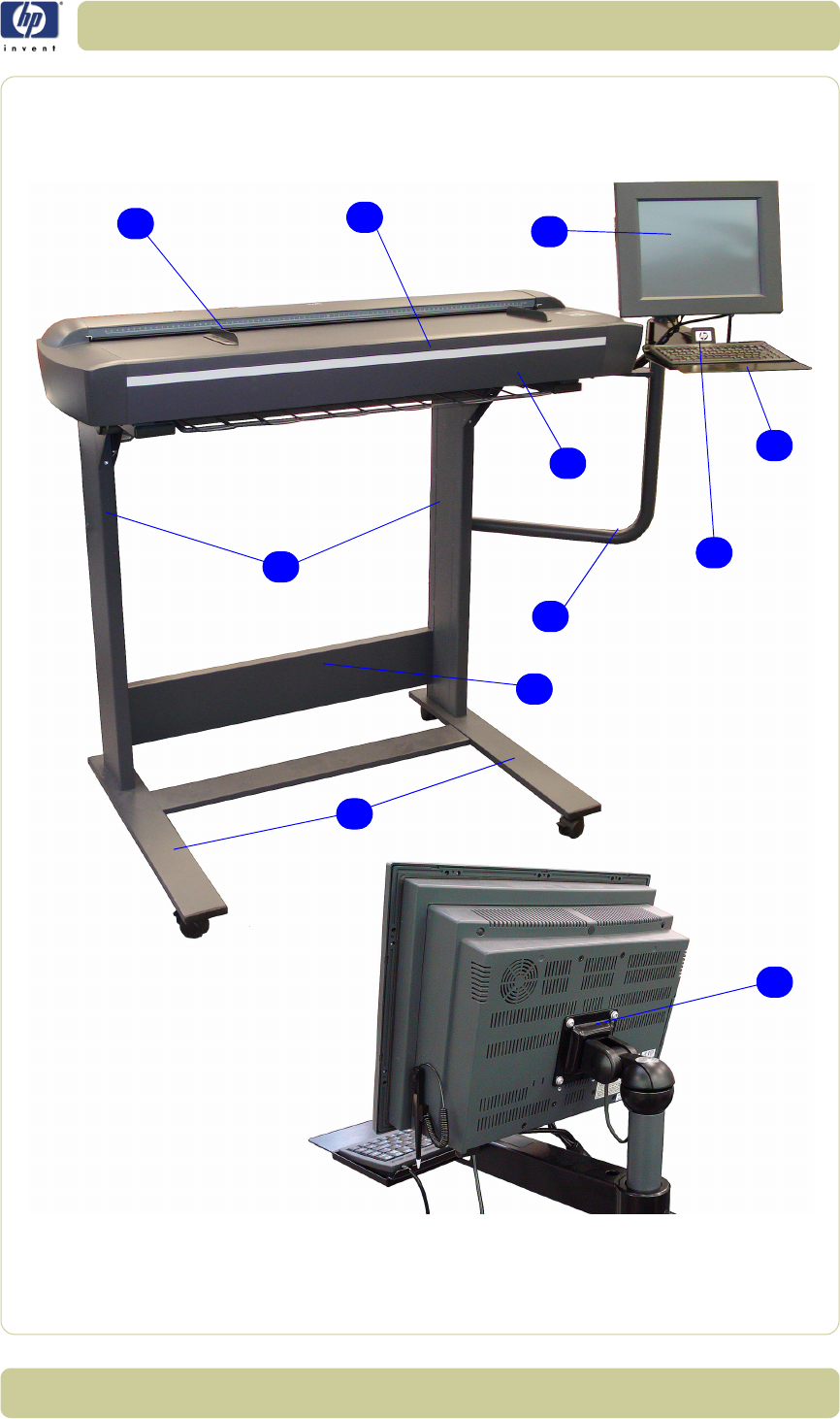
3-5
Parts and Diagrams
HP Designjet T1100 MFP, 4500mfp, 4500 Scanner, 820 MFP Service Manual
Figure 1: Copier Stand & Touch Screen
4
7
9
10
8
1
2
5
11
6
3

3-6
Parts and Diagrams
HP Designjet T1100 MFP, 4500mfp, 4500 Scanner, 820 MFP Service Manual
Copier Covers
Copier Stand & Touch Screen
Reference
on
Drawing
HP Part
Number
Quantity Scanner Model Description/
Comments
DJ820 DJ4500 DJT1100
1Q1277-600231 x x xTop Cover
2 Q1277-60021 1 x x x Left Cover
3Q1277-600221 x
Right Cover
(includes Front
Panel)
Q6685-60012 1 x
Right Cover
(includes Front
Panel)
Q6713-60007 1 x
Right Cover
(includes Front
Panel)
4 Q1277-60024 1 x x Top Profile
Q6713-60003 1 x Top Profile
5 Q1277-60029 1 x x x
Firewire
Connector
Cover
6Q1277-600281 x x x
Fluorescent
Lamp Access
Cover
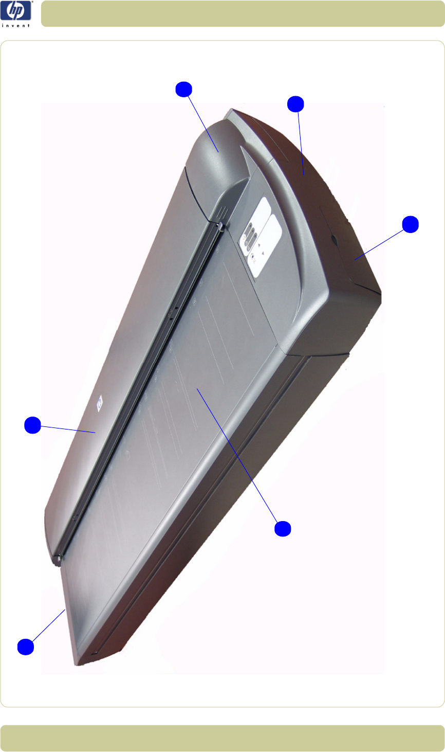
3-7
Parts and Diagrams
HP Designjet T1100 MFP, 4500mfp, 4500 Scanner, 820 MFP Service Manual
Figure 2: Copier Covers
5
1
2
4
3
6

3-8
Parts and Diagrams
HP Designjet T1100 MFP, 4500mfp, 4500 Scanner, 820 MFP Service Manual
Top Assemblies
Copier Stand & Touch Screen
Reference
on
Drawing
HP Part
Number
Quantity Scanner Model Description/
Comments
DJ820 DJ4500 DJT1100
1Q1277-600251 x x Guide Plate
Assembly
Q6713-60004 1 x Guide Plate
Assembly
2 Q1277-60014 1 x x x Glass Plate
3Q1277-600271 x x x
White
Background
Assembly
4 Q1277-60013 1 x x x Fluorescent
Lamp
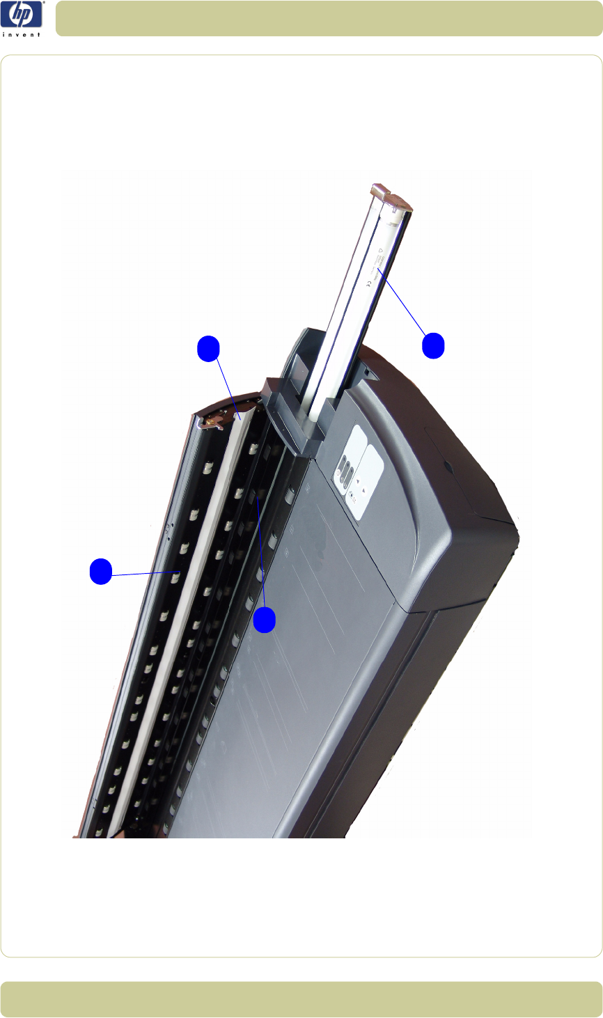
3-9
Parts and Diagrams
HP Designjet T1100 MFP, 4500mfp, 4500 Scanner, 820 MFP Service Manual
Figure 3: Top Assemblies
1
2
3
4

3-10
Parts and Diagrams
HP Designjet T1100 MFP, 4500mfp, 4500 Scanner, 820 MFP Service Manual
Inside Guide Plate
Copier Stand & Touch Screen
Reference
on
Drawing
HP Part
Number
Quantity Scanner Model Description/
Comments
DJ820 DJ4500 DJT1100
1 Q1277-60005 1 x x x MDA Board
2 Q1277-60008 1 x x x
Opto
Interrupter
media sensor
3 Q1277-60011 1 x x Elevation Motor
Q6713-60002 1 x Elevation
Moror
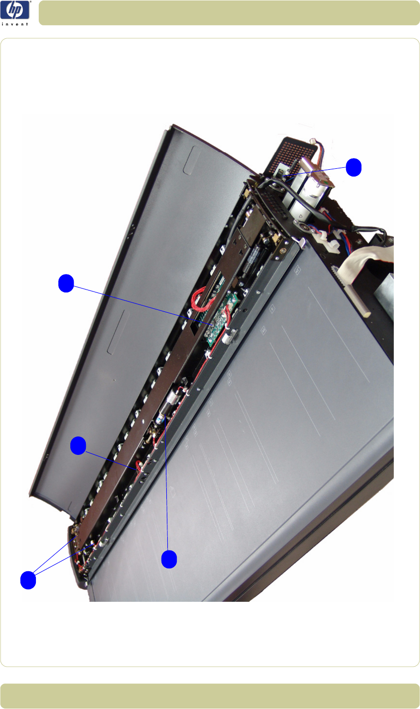
3-11
Parts and Diagrams
HP Designjet T1100 MFP, 4500mfp, 4500 Scanner, 820 MFP Service Manual
Figure 4: Inside Guide Plate
1
3
2
2
2

3-12
Parts and Diagrams
HP Designjet T1100 MFP, 4500mfp, 4500 Scanner, 820 MFP Service Manual
Drive Assemblies
Copier Stand & Touch Screen
Reference
on
Drawing
HP Part
Number
Quantity Scanner Model Description/
Comments
DJ820 DJ4500 DJT1100
1 Q1277-60018 1 x x x Roller Shields
2 Q1277-60015 1 x x x Rollers
3 Q1277-60009 1 x x x Stepper Motor
Assembly
4 Q1277-60016 1 x x x Belt
5 Q1277-60091 1 x x x
Entry Media
Sensor
(included in
Media Sensor
Kit)
6 Q1277-60091 1 x x x
Exit Media
Sensor
(included in
Media Sensor
Kit)
7 Q1261-60008 1 x x x Stitching Wire
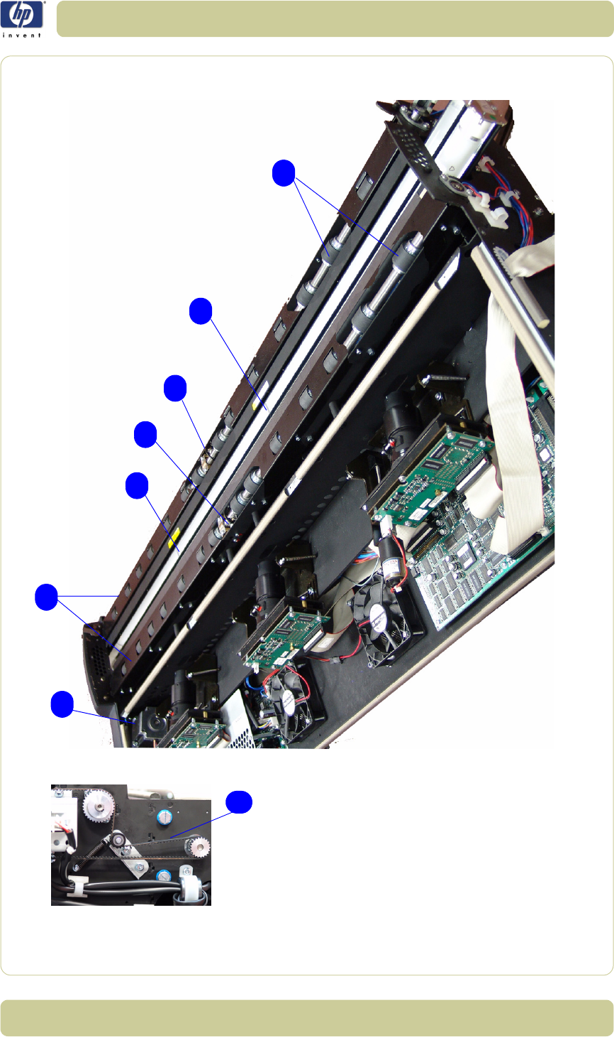
3-13
Parts and Diagrams
HP Designjet T1100 MFP, 4500mfp, 4500 Scanner, 820 MFP Service Manual
Figure 5: Drive Assemblies
1
2
5
4
3
7
7
6

3-14
Parts and Diagrams
HP Designjet T1100 MFP, 4500mfp, 4500 Scanner, 820 MFP Service Manual
Camera Components and Fan
Copier Stand & Touch Screen
Reference
on
Drawing
HP Part
Number
Quantity Scanner Model Description/
Comments
DJ820 DJ4500 DJT1100
1 Q1277-60002 2 x x x Camera Board
2 Q1277-60010 1 x x x Camera Motor
3 Q1277-60012 1 x x x Fan
4Q1277-600331 x x x
Complete
Camera
(without Motor)
5 Q1277-60034 1 x x x
Complete
Camera (with
Motor)
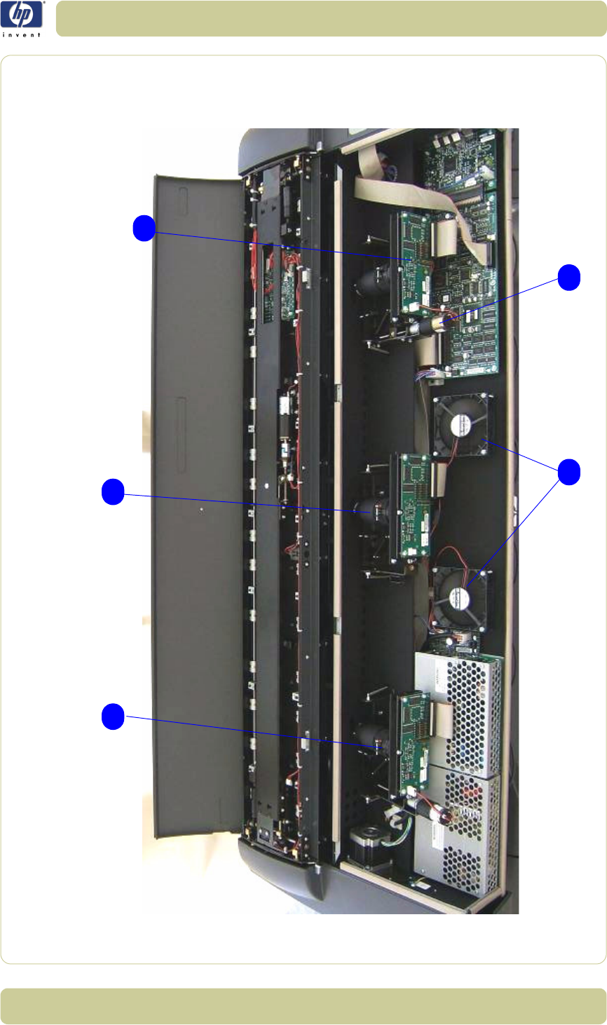
3-15
Parts and Diagrams
HP Designjet T1100 MFP, 4500mfp, 4500 Scanner, 820 MFP Service Manual
Figure 6: Camera Components and Fan
1
4
23
5

3-16
Parts and Diagrams
HP Designjet T1100 MFP, 4500mfp, 4500 Scanner, 820 MFP Service Manual
Electronic Boards
Copier Stand & Touch Screen
Reference
on
Drawing
HP Part
Number
Quantity Scanner Model Description/
Comments
DJ820 DJ4500 DJT1100
1 Q1277-60090 1 x x x Scanner PSU
2 Q1277-60001 1 x x x Driver Board
3 Q1277-60003 1 x x Main Board
Q6713-60001 1 x Main Board
4 Q1277-60004 1 x x x Interface Board
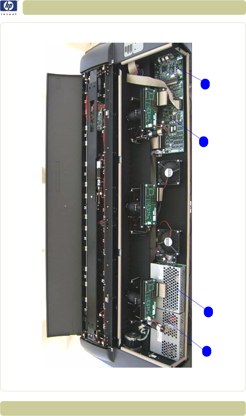
3-17
Parts and Diagrams
HP Designjet T1100 MFP, 4500mfp, 4500 Scanner, 820 MFP Service Manual
Figure 7: Electronic Boards
1234

3-18
Parts and Diagrams
HP Designjet T1100 MFP, 4500mfp, 4500 Scanner, 820 MFP Service Manual
Touch Screen
Copier Stand & Touch Screen
Reference
on
Drawing
HP Part
Number
Quantity Scanner Model Description/
Comments
DJ820 DJ4500 DJT1100
1Q1277-600591 x x x
LCD + Touch
Screen
2 Q1277-60060 1 x x x Touch Screen
Inverter
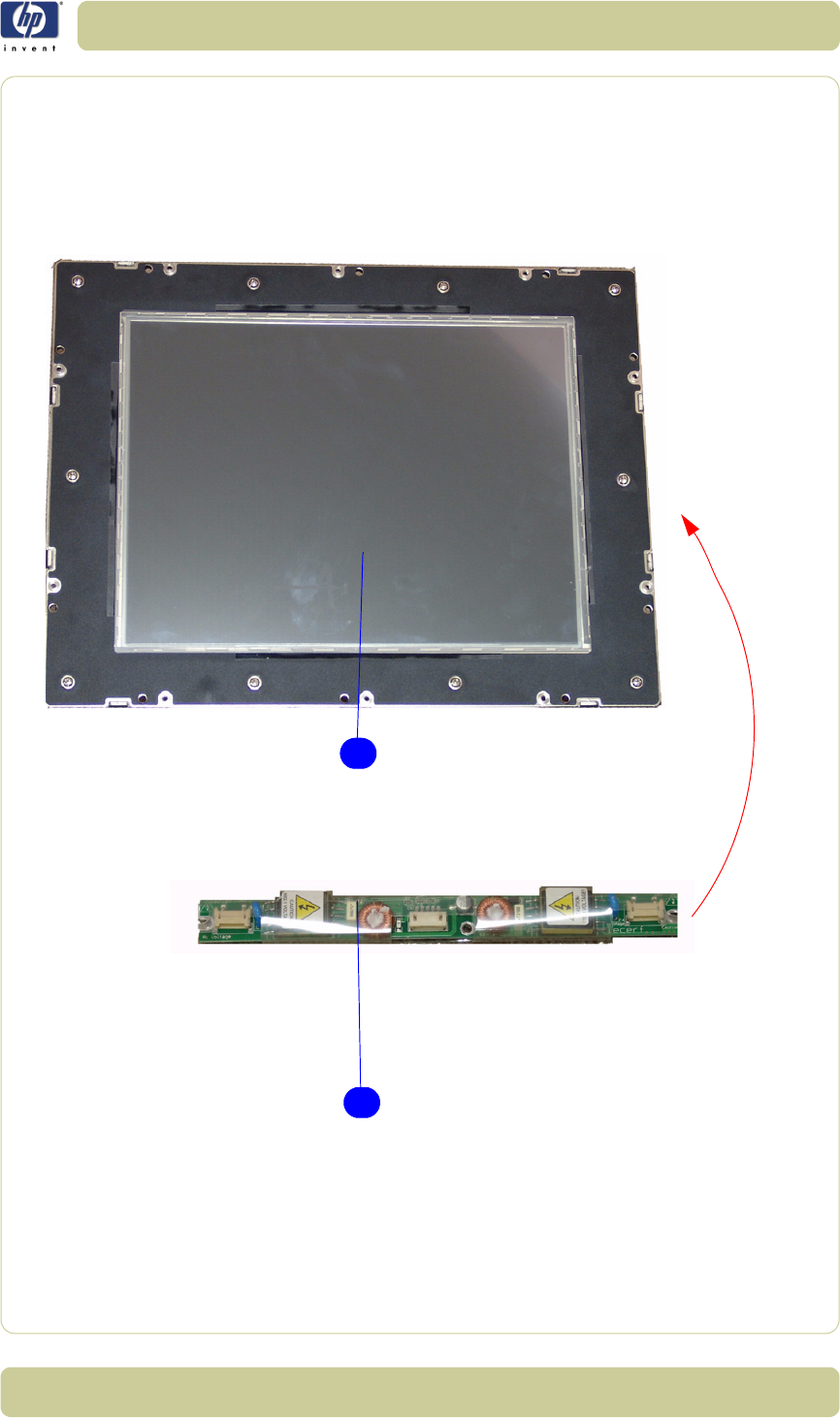
3-19
Parts and Diagrams
HP Designjet T1100 MFP, 4500mfp, 4500 Scanner, 820 MFP Service Manual
Figure 8: Touch Screen
1
2

3-20
Parts and Diagrams
HP Designjet T1100 MFP, 4500mfp, 4500 Scanner, 820 MFP Service Manual
Touch Screen Cabinet Components (Part 1)
Copier Stand & Touch Screen
Reference
on
Drawing
HP Part
Number
Quantity Scanner Model Description/
Comments
DJ820 DJ4500 DJT1100
1 Q1277-60065 1 x x x System Fan
2 Q1277-60057 1 x x x Power Supply
Unit
3 Q1277-60056 1 x x x Hard Disk Drive
4 Q1277-60064 1 x x x LCD Controller
5 Q1277-60061 1 x x x CPU Fan
6 Q1277-60058 1 x x x
SDRAM
Memory
Module
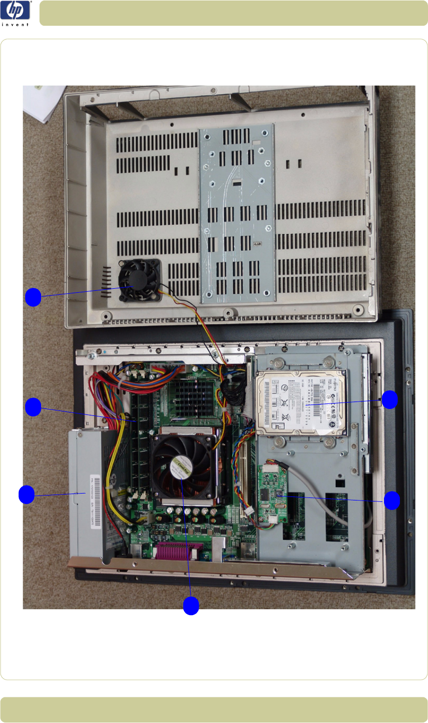
3-21
Parts and Diagrams
HP Designjet T1100 MFP, 4500mfp, 4500 Scanner, 820 MFP Service Manual
Figure 9: Touch Screen Components (Part 2)
1
2
3
4
5
6

3-22
Parts and Diagrams
HP Designjet T1100 MFP, 4500mfp, 4500 Scanner, 820 MFP Service Manual
Touch Screen Cabinet Components (Part 2)
Copier Stand & Touch Screen
Reference
on
Drawing
HP Part
Number
Quantity Scanner Model Description/
Comments
DJ820 DJ4500 DJT1100
1 Q1277-60054 1 x x x Main Board
2 Q1277-60055 1 x x x DVD-ROM
3Q1277-600621 x x xCPU
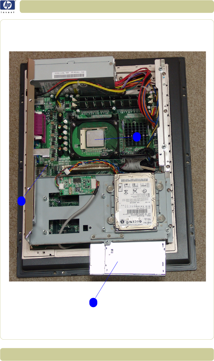
3-23
Parts and Diagrams
HP Designjet T1100 MFP, 4500mfp, 4500 Scanner, 820 MFP Service Manual
Figure 10: Touch Screen Components (Part 2)
3
2
1

3-24
Parts and Diagrams
HP Designjet T1100 MFP, 4500mfp, 4500 Scanner, 820 MFP Service Manual
Miscellaneous Items
Copier Stand & Touch Screen
Reference
on
Drawing
HP Part
Number
Quantity Scanner Model Description/
Comments
DJ820 DJ4500 DJT1100
- Q1277-60030 1 x x x
Service Patterns
(includes the
focus pattern
and the
calibration
sheet)
- Q1277-60031 1 x x x Optical Pattern
- Q1277-60032 1 x x x Calibration
Sheet
- Q1261-60044 1 x x x Stylus
- Q1277-60035 1 x x x Harness
Assembly
- Q1261-60042 1 x x x A2 Scan Cover
- Q1277-60019 1 x x x Dust Cover 40"
-Q1277-600921 x x x
Scanner
Firewire Cable
Q1277-60084 1 x x x
Adjustment
Tools for ATAC
Sensors
Q1277-60093 1 x x x PPC, Cable
harness
Q1277-60094 1 x x x PPC, Power
switch button
Q1276-60003 1 x x x Printer Firewire
Cable

4-1
HP Designjet T1100 MFP, 4500mfp, 4500 Scanner, 820 MFP Service Manual
Removal and
Installation 4
Introduction 4-3
Top Cover 4-5
Left Cover 4-7
Right Cover 4-9
Rear Cover 4-13
Top Profile 4-15
Guide Plate 4-18
Glass Plate 4-23
Entry Roller Shield 4-24
Exit Roller Shield 4-25
Camera Motor 4-26
Camera Lens Assembly 4-27
Camera Board 4-29
Power Supply Board 4-31
Driver Board 4-33
Fan 4-35
Main Electronics Board 4-37
Interface Board 4-39
Stepper Motor 4-41
Fluorescent Lamp 4-43
Elevation Motor Driver Board 4-44
Elevation Motor 4-47
Entry Roller 4-50
Exit Roller 4-56
Exit Roller 4-65
Exit Media Sensor 4-67
Belt 4-68
Bottom Cover 4-70
Mirror Chassis 4-73
Stitching Wire 4-76
White Background Assembly 4-78
Panel PC 4-79
Open Cabinet 4-79
Screen Bezel 4-82
LCD 4-83
Back Plate 4-84
CPU Cooling Fan 4-86
4

4-2
HP Designjet T1100 MFP, 4500mfp, 4500 Scanner, 820 MFP Service Manual
CPU 4-87
DRAM PCA 4-88
The DVD 4-89
The Hard Disk Drive 4-91
LCD Controller PCA 4-92
Inverter PCA 4-93
HDD/DVD Deck 4-94
Main PCA 4-96
Power Supply Unit 4-98
System Fan 4-100

4-3
Removal and Installation
HP Designjet T1100 MFP, 4500mfp, 4500 Scanner, 820 MFP Service Manual
Introduction
This chapter is a step by step guide to the removal and installation of the key components in the
product. You may find it useful to tick off the steps as they are performed. Use the illustration at
each procedure to identify the parts referred to in the text.
The procedures appear in order of removal. So the whole product can be stripped down by
starting at the beginning of this chapter and working through the subsequent procedures.
Safety Precautions
Review WARNING and CAUTION instructions before you service the product. Follow these
warnings and cautions for your protection and to avoid damaging the product.
Serious shock hazard leading to death or injury may result if you do not take
the following precautions:
Ensure that the AC power outlet (mains) has a protective earth (ground)
terminal.
Switch off the printer, the scanner, and the PC, and then disconnect them from
the power source prior to performing any maintenance.
Prevent water or other liquids from running onto electrical components or
circuits, or through openings in the module.

4-4
Removal and Installation
HP Designjet T1100 MFP, 4500mfp, 4500 Scanner, 820 MFP Service Manual
Electrostatic Discharge (ESD) Precautions
To prevent damage to the product circuits from high-voltage electrostatic discharge (ESD):
1. Do not wear clothing that is subject to static build-up.
2. Do not handle integrated circuits (ICs) in carpeted areas.
3. Do not remove an IC or a printed circuit assembly (PCA) from its conductive foam pad or
conductive packaging until you are ready to install it.
4. Ground (earth) your body while disassembling and working on the Scanner. This can be
done by touching any metallic part of the Scanner.
5. After removing a cover from the Scanner, attach an earthing (ground) lead between the PCA
common and earth ground. Touch all tools to earth ground to remove static charges before
using them on the Scanner.
6. After removing any PCA from the Scanner, place it on a conductive foam pad or into its
conductive packaging to prevent ESD damage to any ICs on the PCA.
Required Tools
The following tools are required to disassemble and repair the Scanner:
Screwdriver (0.8 x 5)
1.3 mm Allen Key
1.5 mm Allen Key
5.5 mm Wrench
6 mm Wrench
7 mm Wrench
8 mm Wrench
13 mm Wrench
Torx 5 L shape
Torx 6 L shape
Torx 8 L shape
Torx 9 L shape
Torx 10 L shape
Torx 20 L shape
Philips PH1 Screw driver
Philips PH2 Screwdriver
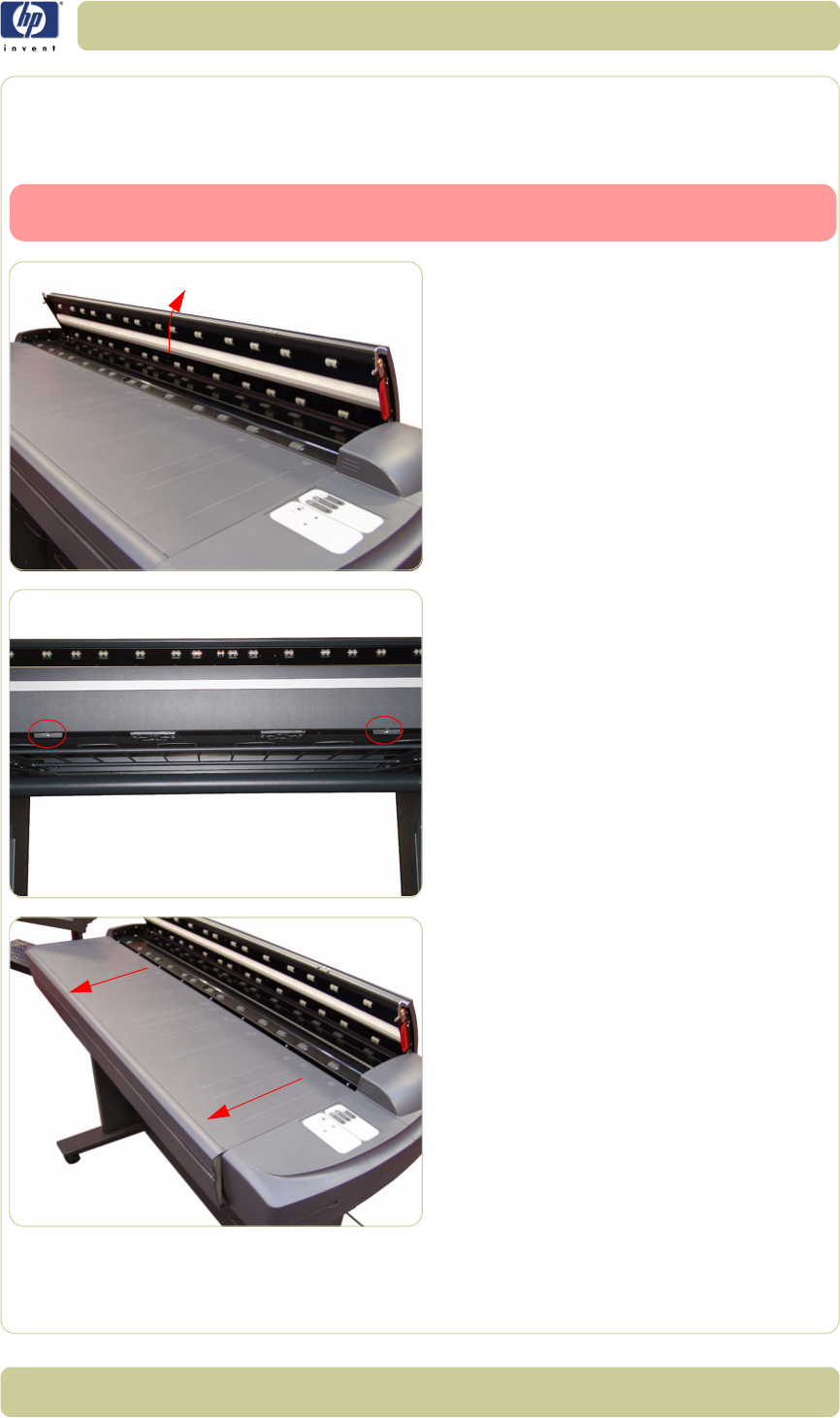
4-5
Removal and Installation
HP Designjet T1100 MFP, 4500mfp, 4500 Scanner, 820 MFP Service Manual
Top Cover
Removal
Switch off the printer, the scanner, and the PC, and then disconnect them from
the power source prior to performing any maintenance.
1. Open the Guide Plate.
2. Remove two T20 screws along the lower
edge of the Top Cover.
3. Pull the front part of the Top Cover away
from the Scanner in order to release the
upper part of the Top Cover.

4-6
Removal and Installation
HP Designjet T1100 MFP, 4500mfp, 4500 Scanner, 820 MFP Service Manual
4. Lift up the Top Cover and remove from the
Scanner.
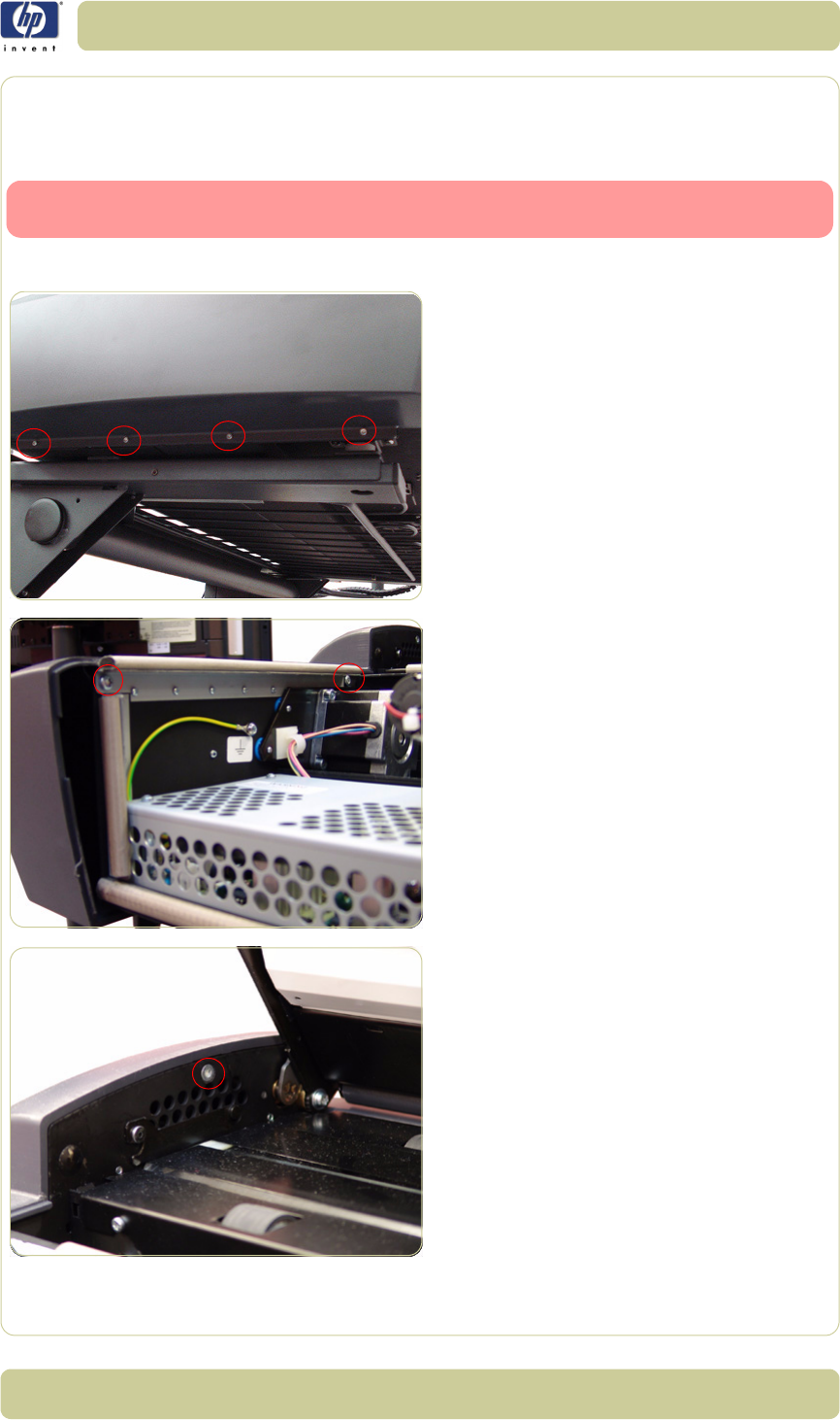
4-7
Removal and Installation
HP Designjet T1100 MFP, 4500mfp, 4500 Scanner, 820 MFP Service Manual
Left Cover
Removal
Switch off the printer, the scanner, and the PC, and then disconnect them from
the power source prior to performing any maintenance.
1. Remove the Top Cover
⇒
Page 4-5
.
2. Remove four T10 screws that secure the Left
Cover from underneath.
3. Remove two T20 screws that secure the Left
Cover from the side.
4. Remove one T20 screw that secures the Left
Cover from the top.

4-8
Removal and Installation
HP Designjet T1100 MFP, 4500mfp, 4500 Scanner, 820 MFP Service Manual
5. Remove the Left Cover from the Scanner.
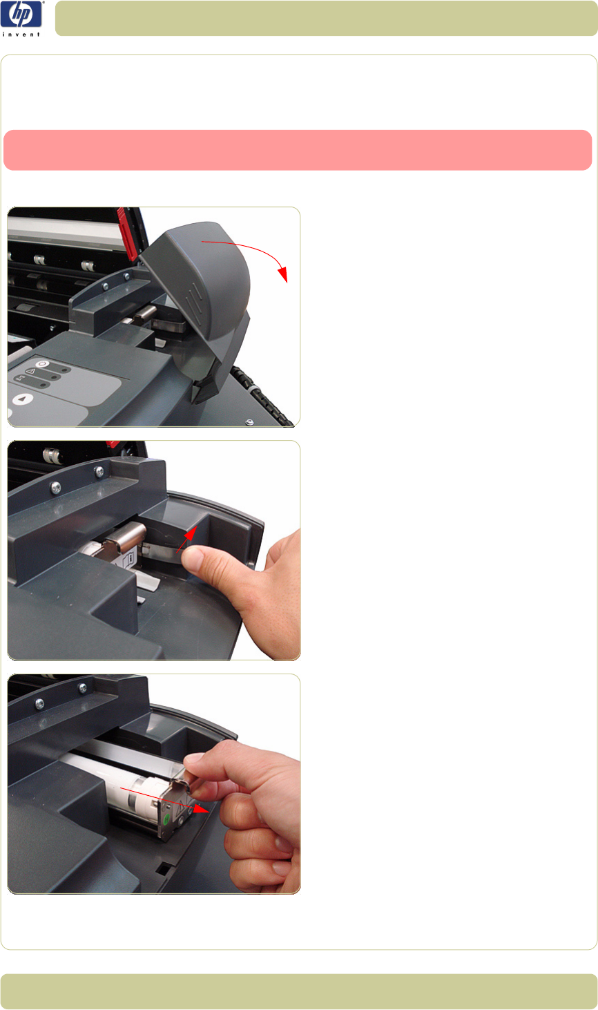
4-9
Removal and Installation
HP Designjet T1100 MFP, 4500mfp, 4500 Scanner, 820 MFP Service Manual
Right Cover
Removal
Switch off the printer, the scanner, and the PC, and then disconnect them from
the power source prior to performing any maintenance.
1. Remove the Top Cover
⇒
Page 4-5
.
2. Remove the Fluorescent Lamp Access
Cover.
3. Press the metal tab to release the
Flourescent Lamp.
4. Slide out the Fluorescent Lamp.
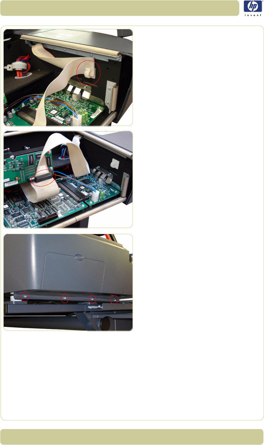
4-10
Removal and Installation
HP Designjet T1100 MFP, 4500mfp, 4500 Scanner, 820 MFP Service Manual
5. Remove the Operator Panel Cable from a
cable clamp.
6. Disconnect the Operator Panel Cable from
the Main Electronics PCA.
7. Remove four T10 screws that secure the
Right Cover from underneath.
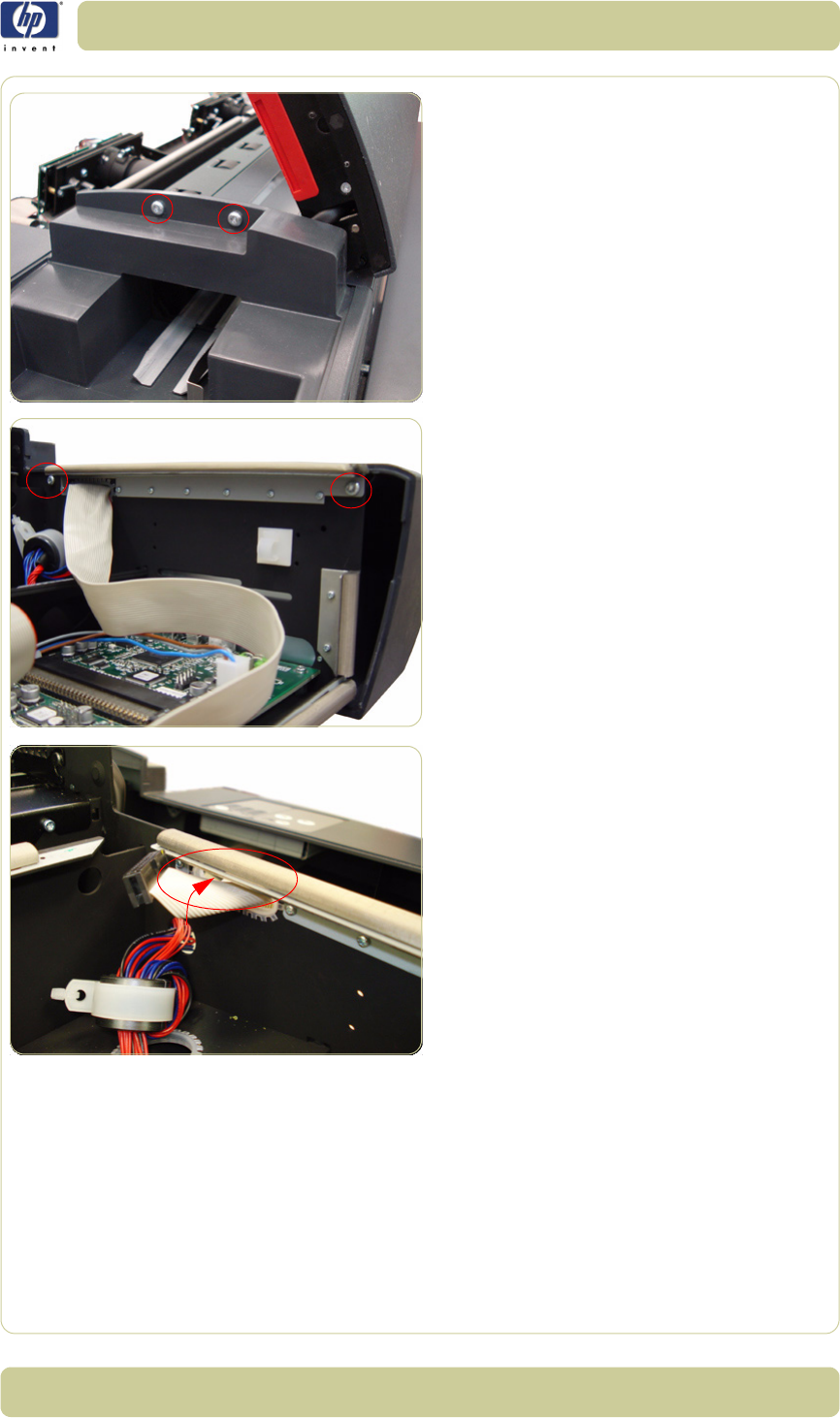
4-11
Removal and Installation
HP Designjet T1100 MFP, 4500mfp, 4500 Scanner, 820 MFP Service Manual
8. Remove two T20 screws that secure the
Right Cover from the top.
9. Remove two T20 screws that secure the
Right Cover from the side.
10. Pass the Operator Panel Cable through an
access hole.
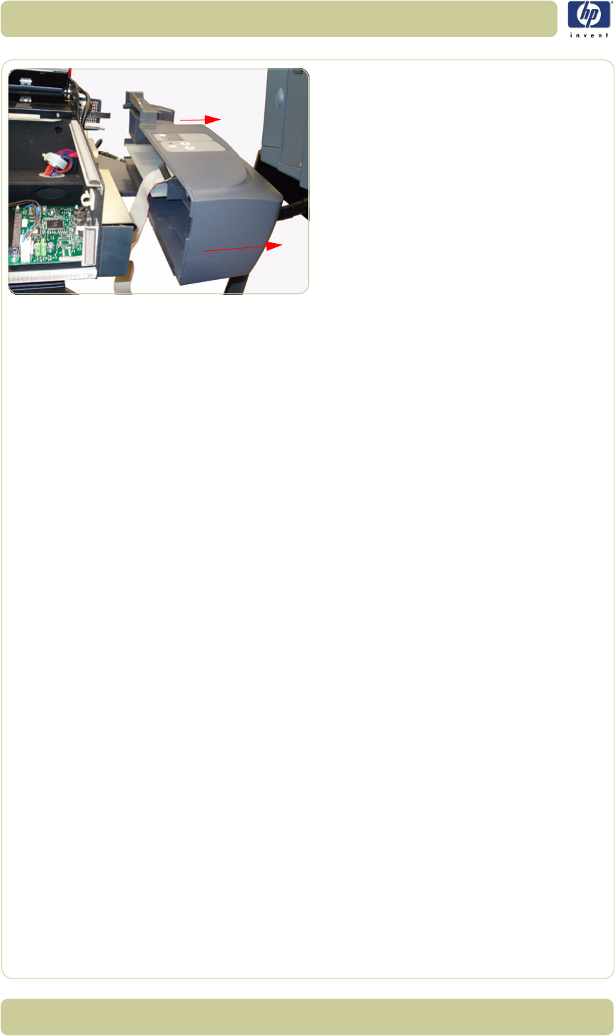
4-12
Removal and Installation
HP Designjet T1100 MFP, 4500mfp, 4500 Scanner, 820 MFP Service Manual
11. Remove the Right Cover from the Scanner.
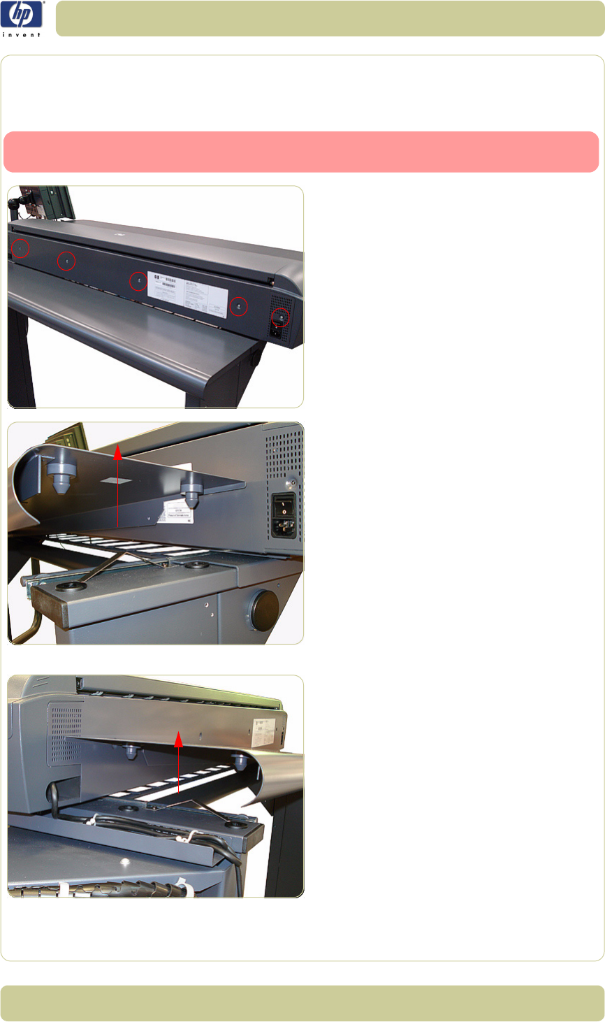
4-13
Removal and Installation
HP Designjet T1100 MFP, 4500mfp, 4500 Scanner, 820 MFP Service Manual
Rear Cover
Removal
Switch off the printer, the scanner, and the PC, and then disconnect them from
the power source prior to performing any maintenance.
1. Remove five T10 screws (and one washer)
that secure the Rear Cover to the rear of
the Scanner.
2. Lift up and release the left side of the metal
shelf.
3. Lift up and release the right side of the
metal shelf.
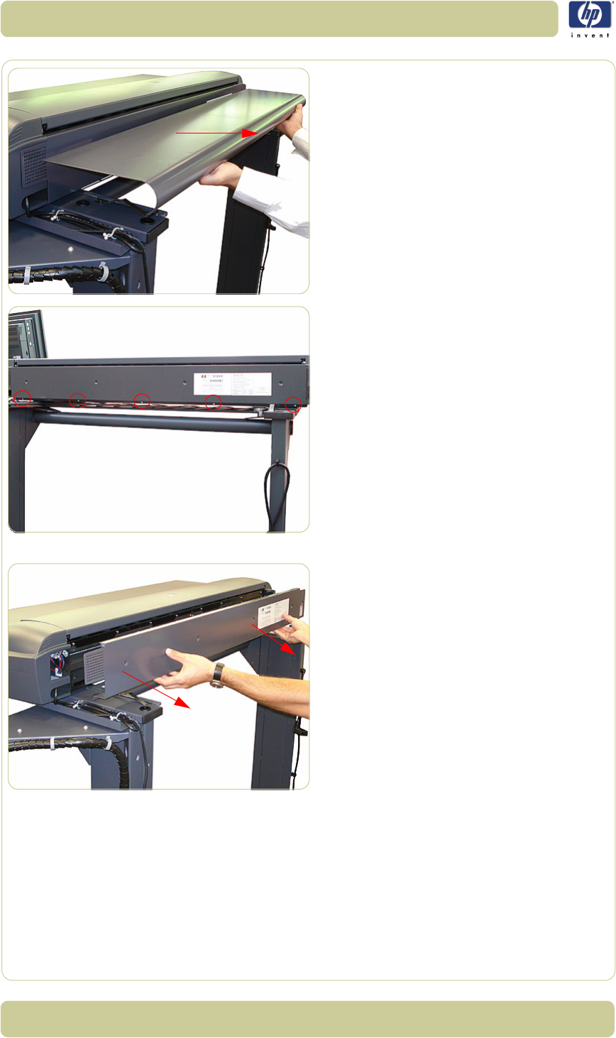
4-14
Removal and Installation
HP Designjet T1100 MFP, 4500mfp, 4500 Scanner, 820 MFP Service Manual
4. Remove the metal shelf.
5. Remove five T10 screws (and one washer)
that secure the Rear Cover to the lower
edge of the Scanner.
6. Remove the Rear Cover from the Scanner.
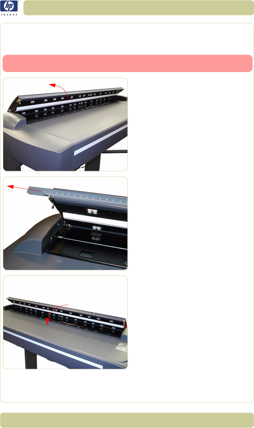
4-15
Removal and Installation
HP Designjet T1100 MFP, 4500mfp, 4500 Scanner, 820 MFP Service Manual
Top Profile
Removal
Switch off the printer, the scanner, and the PC, and then disconnect them from
the power source prior to performing any maintenance.
1. Lift the Top Profile cover so that you can
access the rule.
2. Remove the rule from the front of the Guide
Plate.
3. Close the Top Profile.
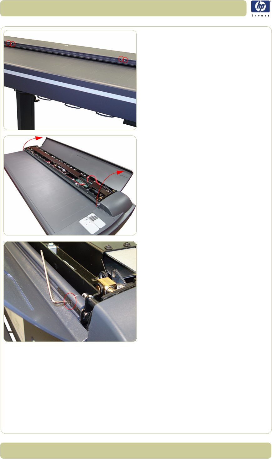
4-16
Removal and Installation
HP Designjet T1100 MFP, 4500mfp, 4500 Scanner, 820 MFP Service Manual
4. Remove four T10 screws that secure the
front of the Top Profile to the Guide Plate.
5. Lift up the Top Profile of the Guide Plate.
6. Use an Allen key (size 1.5) to loosen the
screw at the left side of the scanner.
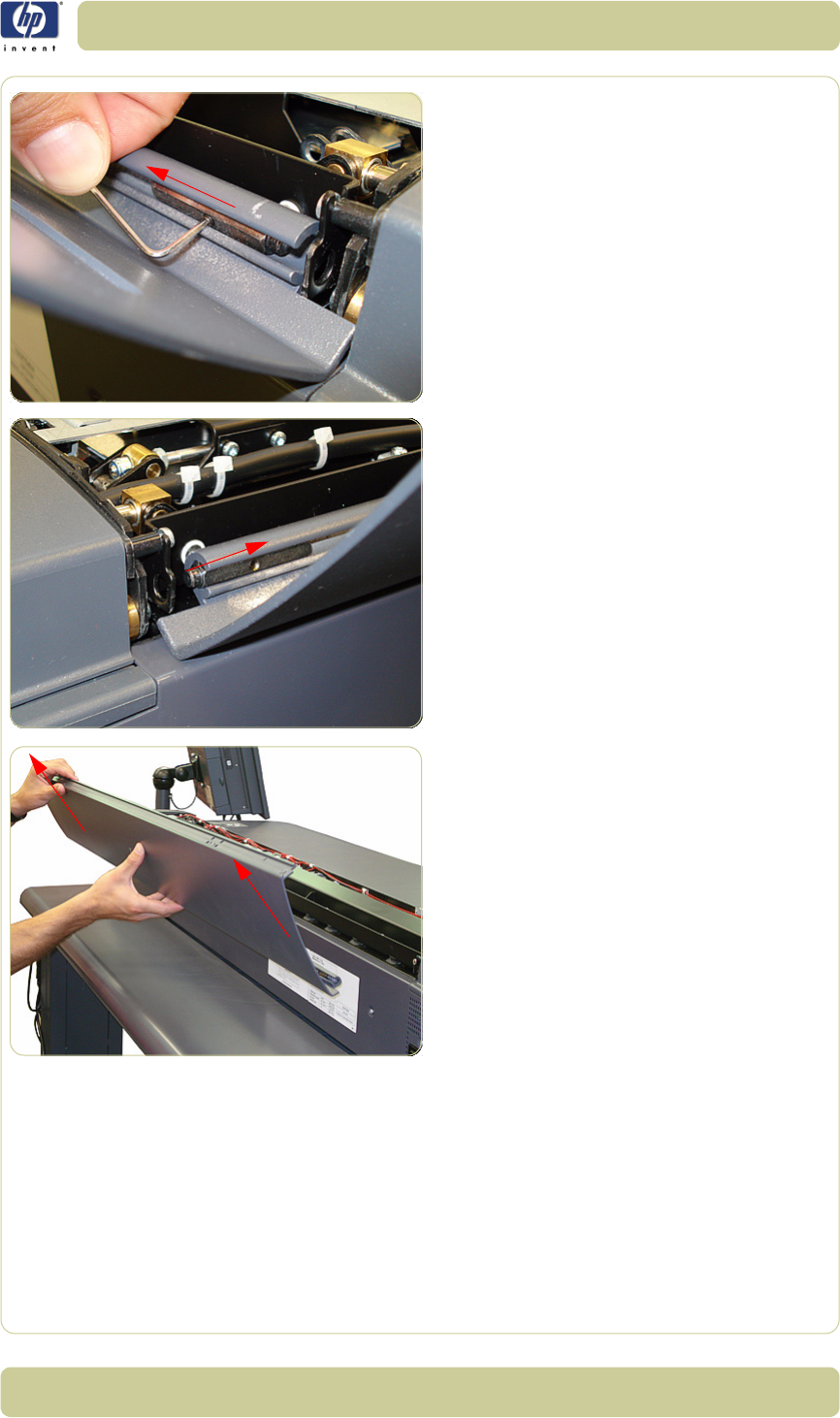
4-17
Removal and Installation
HP Designjet T1100 MFP, 4500mfp, 4500 Scanner, 820 MFP Service Manual
7. Slide the retainer bar from its fitting to
release the left side of the Top Profile.
8. Slide the Top Profile slightly toward the left
to release the right side of the Top Profile.
9. Remove the Top Profile.
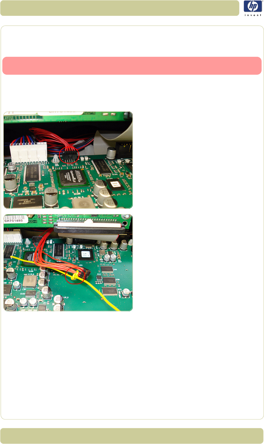
4-18
Removal and Installation
HP Designjet T1100 MFP, 4500mfp, 4500 Scanner, 820 MFP Service Manual
Guide Plate
Removal
Switch off the printer, the scanner, and the PC, and then disconnect them from
the power source prior to performing any maintenance.
1. Remove the Top Cover
⇒
Page 4-5
.
2. Remove the Right Cover
⇒
Page 4-9
.
3. Remove the Top Profile
⇒
Page 4-15.
4. Disconnect the Guide Plate Cable from the
Main Electronics Board (J20) in the Guide
Plate.
5. Tie a cable or a piece of string (the yellow
cable in the photo) to the Guide Plate
Cable to facilitate passing the Guide Plate
Cable through the access hole.
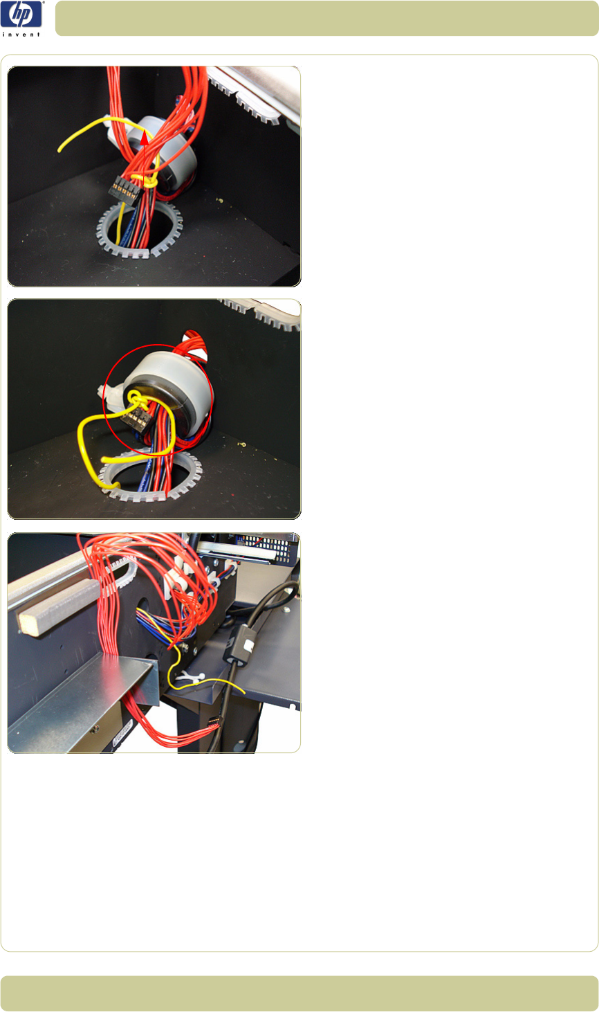
4-19
Removal and Installation
HP Designjet T1100 MFP, 4500mfp, 4500 Scanner, 820 MFP Service Manual
6. Pass the cable through the access hole.
7. Pass the cable through the ferrite core and
through the access hole in the side of the
chassis.
8. After passing the Guide Plate Cable
through the access hole and the ferrite
core, detach the cable you used to assist in
pulling it through.
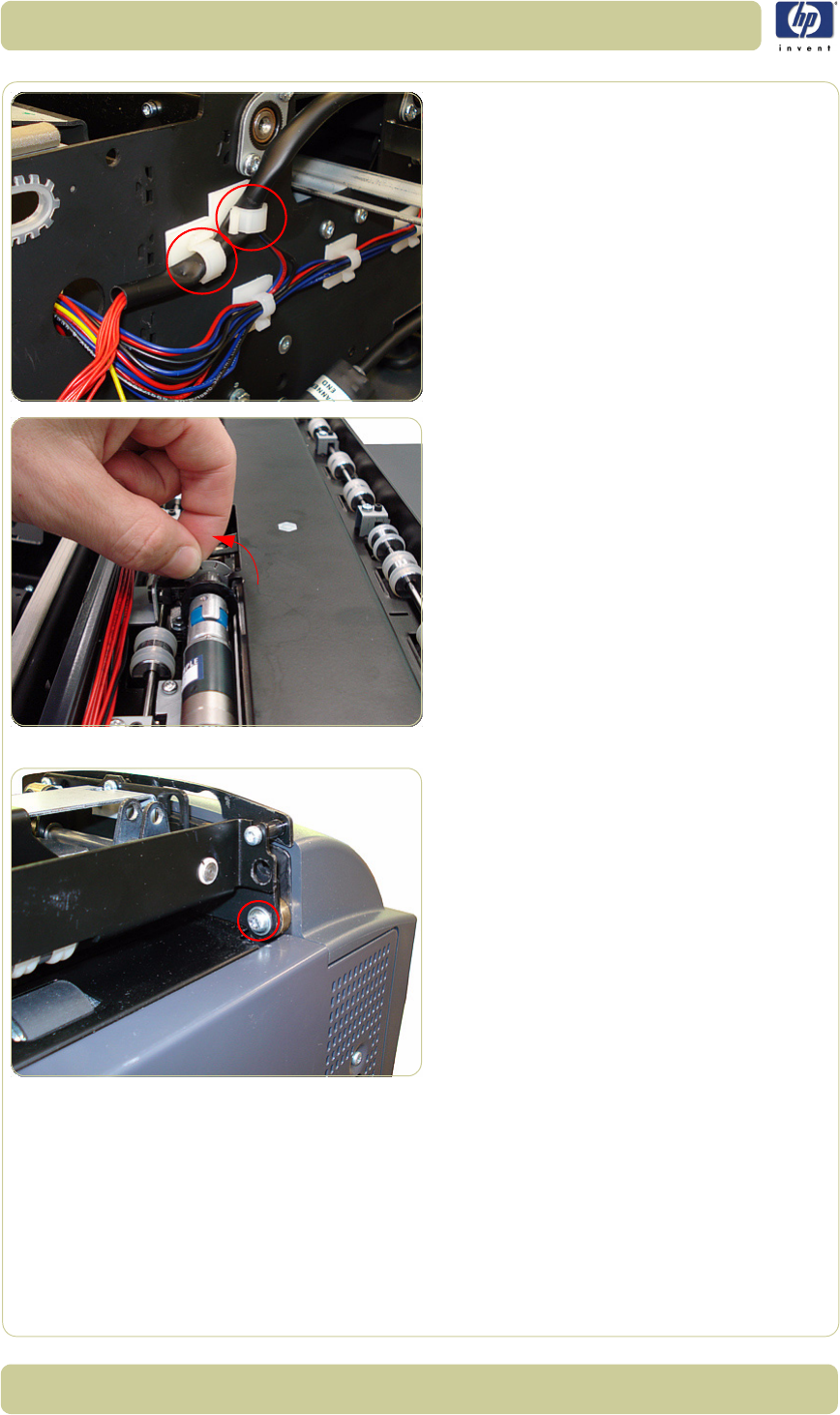
4-20
Removal and Installation
HP Designjet T1100 MFP, 4500mfp, 4500 Scanner, 820 MFP Service Manual
9. Remove the Guide Plate Cable from the
cable clamps.
10. The Guide Plate must be in a raised
position. Manually rotate the motor wheel
toward you (as shown in the photo) until
it no longer turns.
11. Remove one T20 screw that secures the left
side of the Guide Plate.
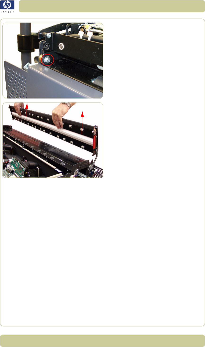
4-21
Removal and Installation
HP Designjet T1100 MFP, 4500mfp, 4500 Scanner, 820 MFP Service Manual
12. Remove one T20 screw that secures the
right side of the Guide Plate.
13. Remove the Guide Plate from the Scanner.
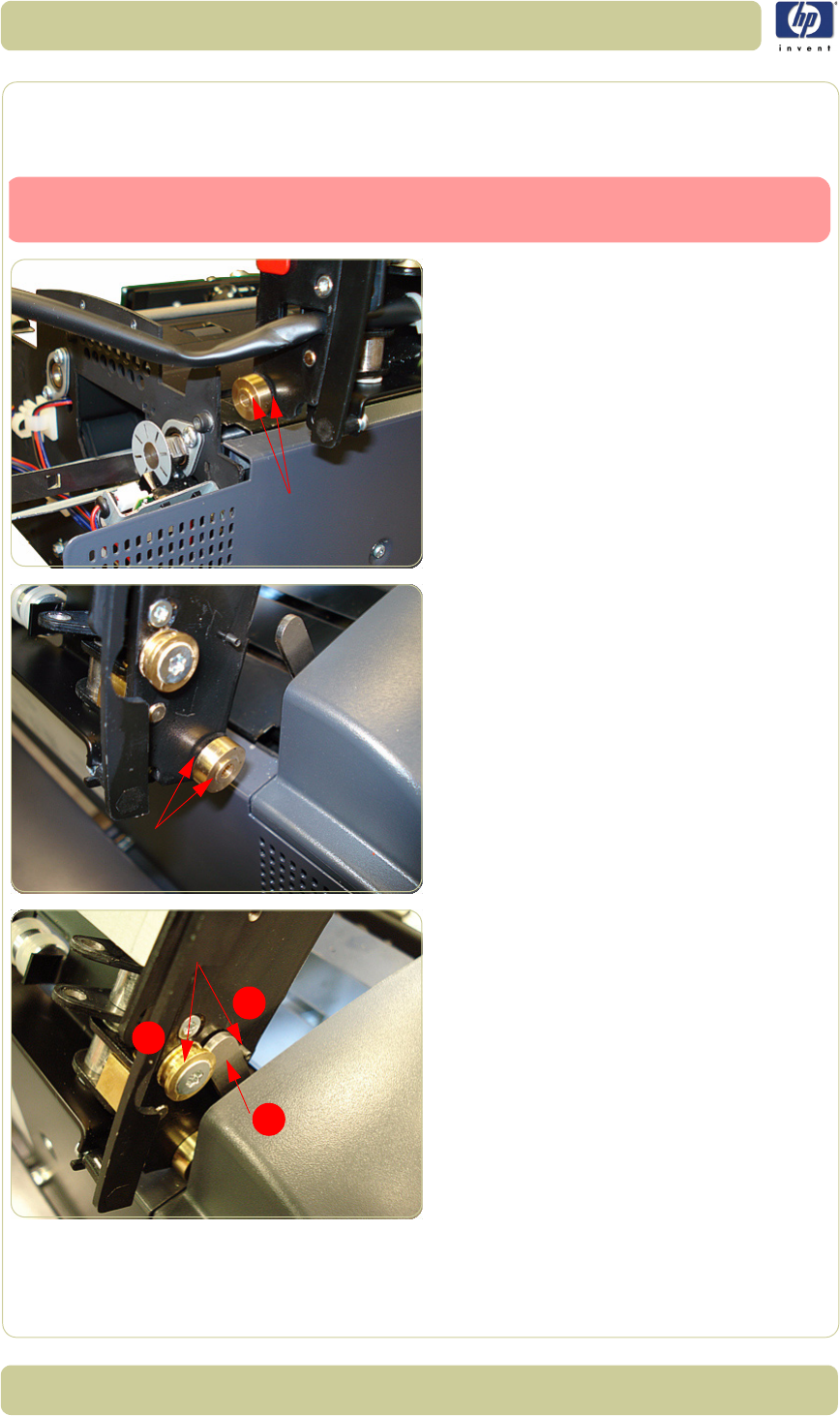
4-22
Removal and Installation
HP Designjet T1100 MFP, 4500mfp, 4500 Scanner, 820 MFP Service Manual
Guide Plate
Installation
1. On the right side of the scanner, position
the brass piece into its fitting as shown in
the photo, and then fit the right side of the
cover into place.
2. On the left side of the scanner, position the
brass piece into its fitting as shown in the
photo, and then fit the left side of the cover
into place.
3. When closing the cover, be sure to place
the gray lever (1) between the pin (2) and
the brass piece (3).
4. To complete the installation of the Guide
Plate, follow steps 1-12 from the Guide
Plate removal procedure in reverse order.
Switch off the printer, the scanner, and the PC, and then disconnect them from
the power source prior to performing any maintenance.
1
2
3
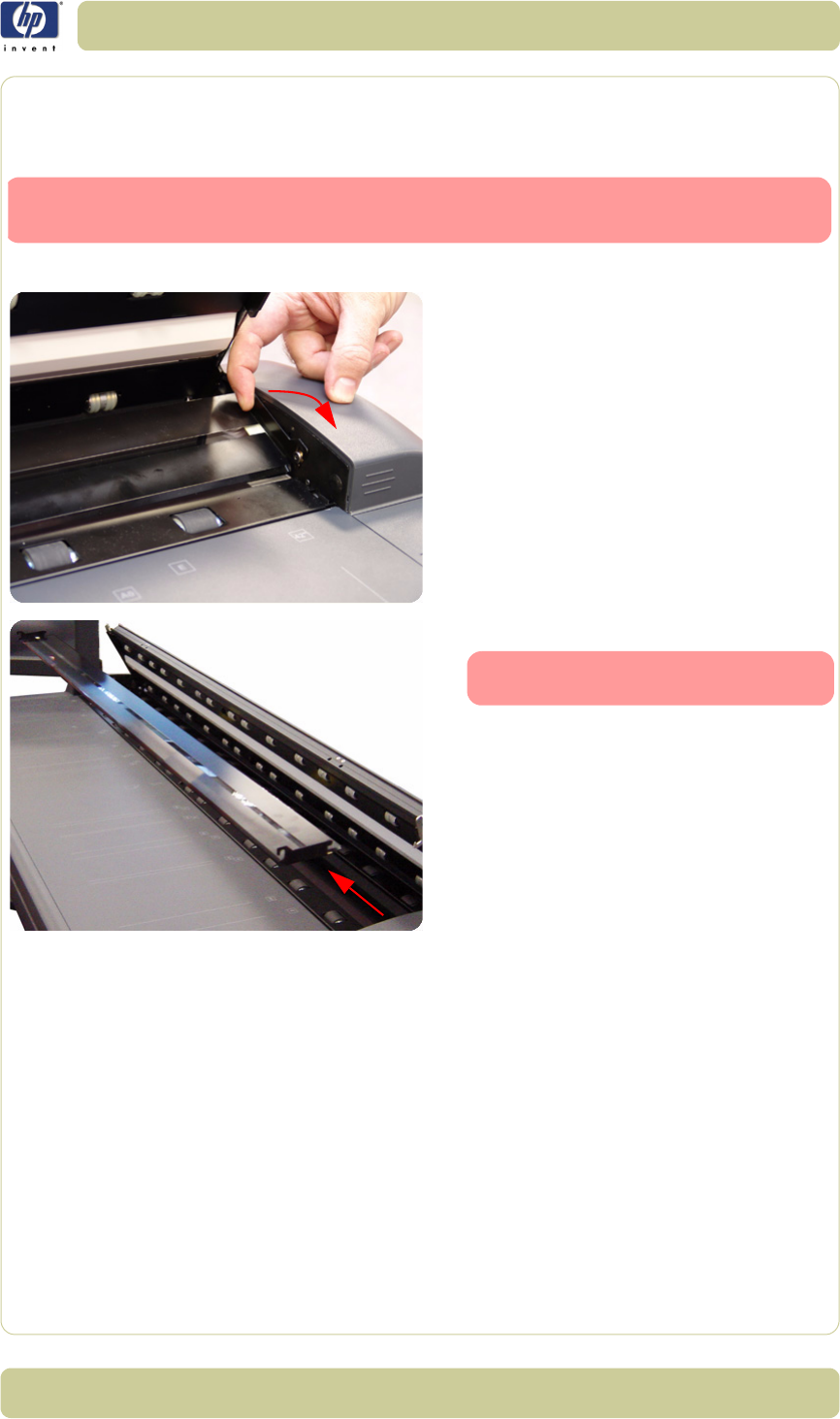
4-23
Removal and Installation
HP Designjet T1100 MFP, 4500mfp, 4500 Scanner, 820 MFP Service Manual
Glass Plate
Removal
1. Open the Guide Plate.
2. Carefully lift up the rear of the Glass Plate
at both ends.
3. Remove the Glass Plate from the Scanner.
Switch off the printer, the scanner, and the PC, and then disconnect them from
the power source prior to performing any maintenance.
Always clean the new glass before
installation.
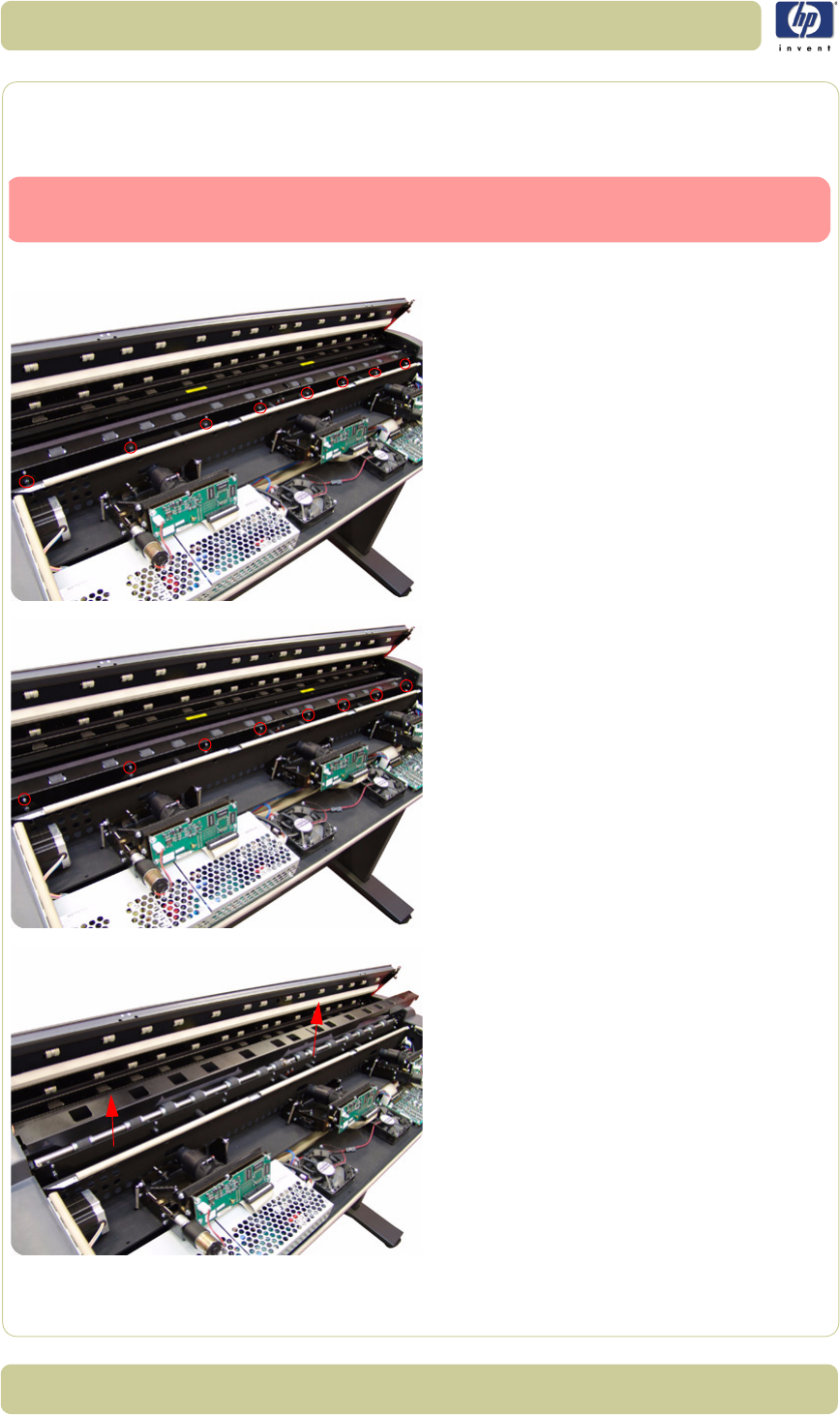
4-24
Removal and Installation
HP Designjet T1100 MFP, 4500mfp, 4500 Scanner, 820 MFP Service Manual
Entry Roller Shield
Removal
1. Remove the Top Cover
⇒
Page 4-5
.
2. Use a size 6 wrench to loosen the eight
guide pins on the front side of the Entry
Roller Shield.
3. Loosen eight screws on the front side of the
Entry Roller Shield.
4. Gently remove the Entry Roller Shield from
the Scanner. Be careful NOT to bend it or
damage it while removing.
Switch off the printer, the scanner, and the PC, and then disconnect them from
the power source prior to performing any maintenance.
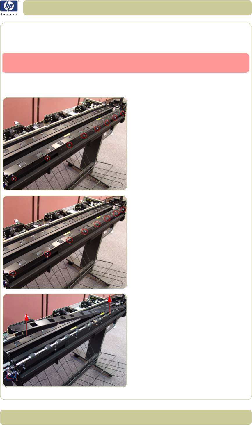
4-25
Removal and Installation
HP Designjet T1100 MFP, 4500mfp, 4500 Scanner, 820 MFP Service Manual
Exit Roller Shield
Removal
1. Remove the Guide Plate
⇒
Page 4-18
.
2. Remove the Rear Cover
⇒
Page 4-13.
3. Use a size 6 wrench to loosen the eight
guide pins on the rear side of the Exit
Roller Shield.
4. Loosen eight T8 screws on the rear side of
the Exit Roller Shield.
5. Gently remove the Exit Roller Shield from
the Scanner. Be careful NOT to bend it or
damage it while removing.
Switch off the printer, the scanner, and the PC, and then disconnect them from
the power source prior to performing any maintenance.
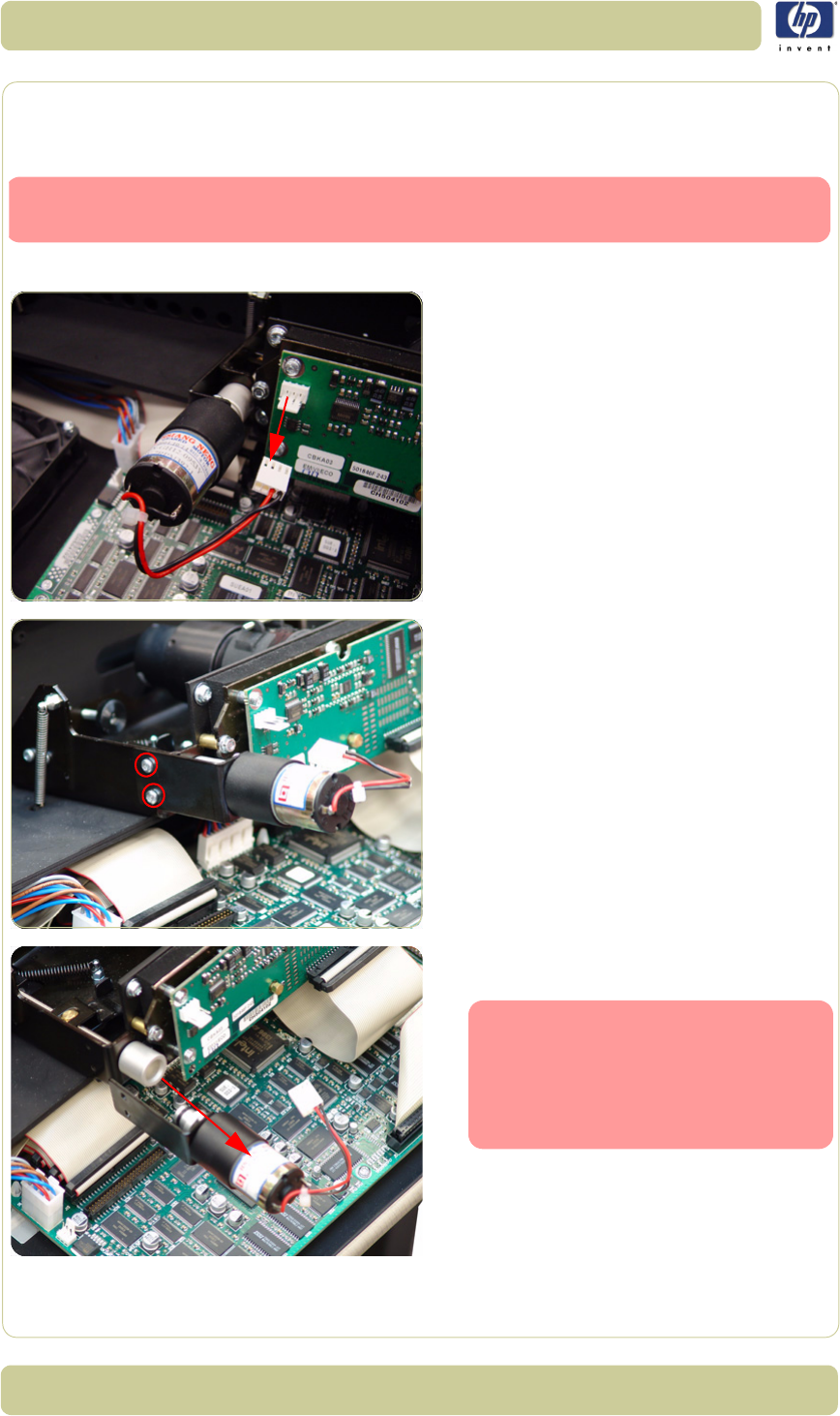
4-26
Removal and Installation
HP Designjet T1100 MFP, 4500mfp, 4500 Scanner, 820 MFP Service Manual
Camera Motor
Removal
1. Remove the Top Cover
⇒
Page 4-5
.
2. Disconnect the Camera Motor cable.
3. Remove the two T10 screws that secure the
Camera Motor.
4. Remove the Camera Motor from the
Scanner.
Switch off the printer, the scanner, and the PC, and then disconnect them from
the power source prior to performing any maintenance.
After reinstalling the Camera Mo-
tor, make sure you run the Scanner
Maintenance
.
The middle Camera does not have
a Motor.
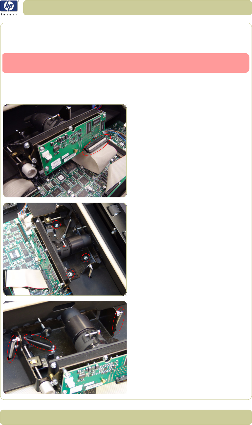
4-27
Removal and Installation
HP Designjet T1100 MFP, 4500mfp, 4500 Scanner, 820 MFP Service Manual
Camera Lens Assembly
Removal
1. Remove the Top Cover
⇒
Page 4-5
.
2. If installed, remove the Camera Motor
⇒
Page 4-26.
3. Disconnect the cable from the Camera
Board.
4. Remove three T20 screws that secure the
Camera Lens to the Chassis.
5. Release three springs that secure the
Camera Lens to the Chassis.
Switch off the printer, the scanner, and the PC, and then disconnect them from
the power source prior to performing any maintenance.

4-28
Removal and Installation
HP Designjet T1100 MFP, 4500mfp, 4500 Scanner, 820 MFP Service Manual
6. Remove the Camera Lens Assembly from
the Scanner.
Make sure you perform the Cam-
era Adjustment procedure after re-
placing the Camera Lens.
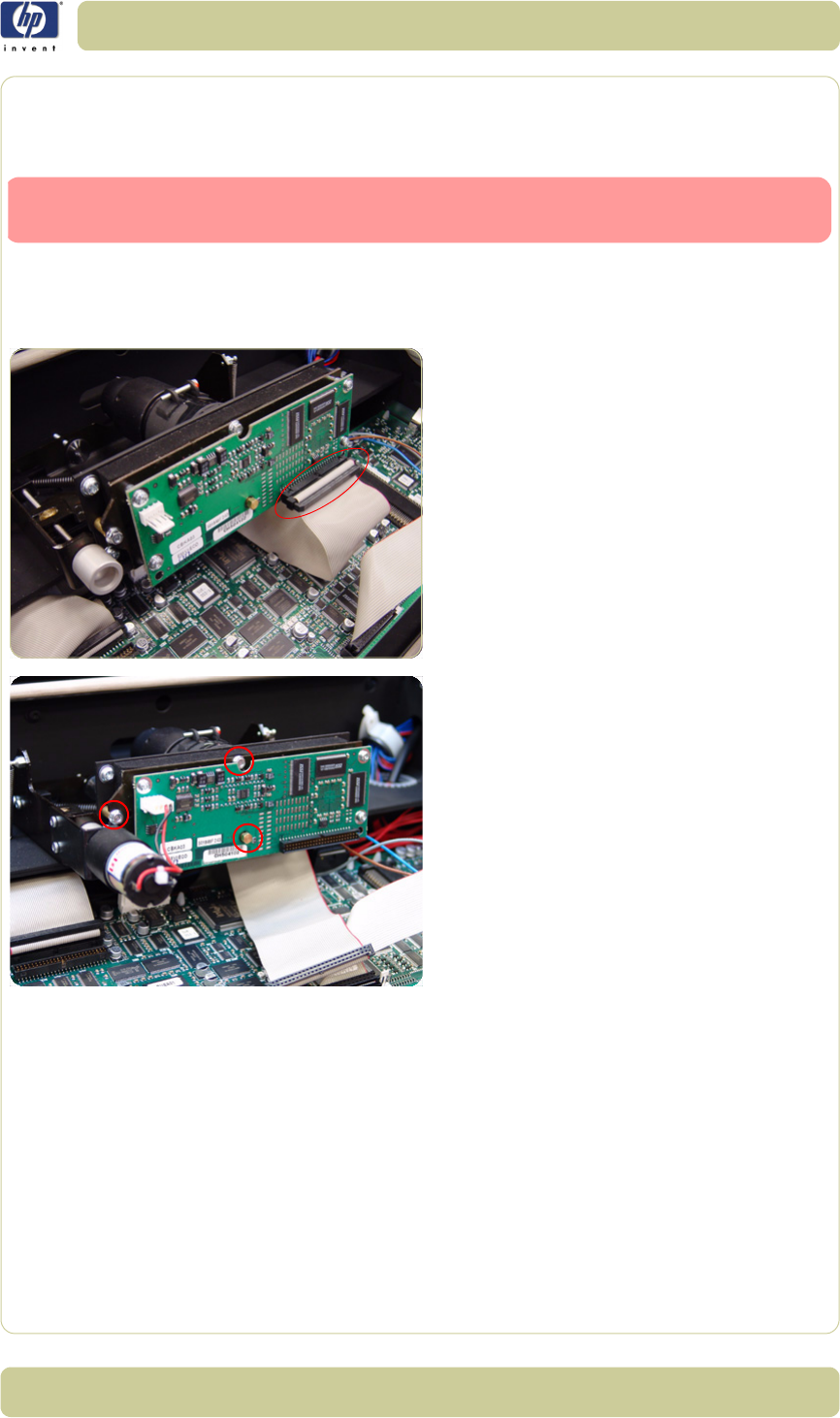
4-29
Removal and Installation
HP Designjet T1100 MFP, 4500mfp, 4500 Scanner, 820 MFP Service Manual
Camera Board
Removal
1. Remove the Top Cover
⇒
Page 4-5
.
2. If installed, remove the Camera Motor
⇒
Page 4-26.
3. Disconnect the cable from the Camera
Board.
4. Using a size 5.5 wrench, remove the three
nuts that secure the Camera Board from the
front.
Switch off the printer, the scanner, and the PC, and then disconnect them from
the power source prior to performing any maintenance.
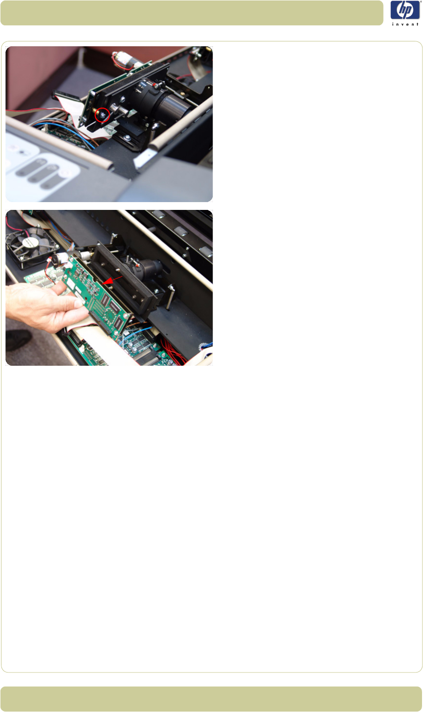
4-30
Removal and Installation
HP Designjet T1100 MFP, 4500mfp, 4500 Scanner, 820 MFP Service Manual
5. Using a size 5.5 wrench, remove one nut
that secures the Camera Board from the
rear.
6. Remove the Camera Board.
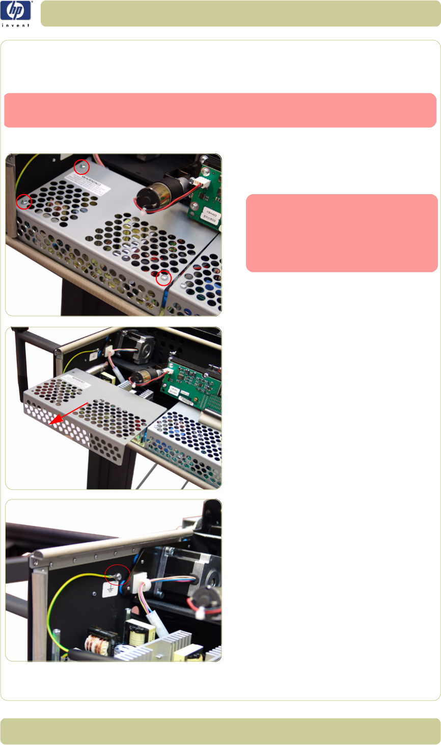
4-31
Removal and Installation
HP Designjet T1100 MFP, 4500mfp, 4500 Scanner, 820 MFP Service Manual
Power Supply Board
Removal
1. Remove the Top Cover
⇒
Page 4-5
.
2. Remove three T10 screws that secure the
Metal Shield that covers the Power Supply
Board.
3. Remove the Metal Shield.
4. Remove the T20 screw that secures the
grounding cable to the chassis and
disconnect ALL the cables from the Power
Supply Board.
Switch off the printer, the scanner, and the PC, and then disconnect them from
the power source prior to performing any maintenance.
The components underneath the
Metal shield represent a risk of
electric shock, once the power has
been disconnected allow three
minutes discharge time before
touching.
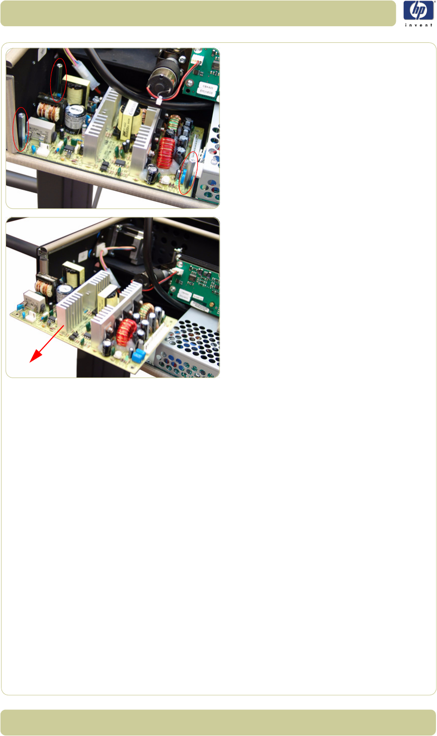
4-32
Removal and Installation
HP Designjet T1100 MFP, 4500mfp, 4500 Scanner, 820 MFP Service Manual
5. Remove the three bolts that secure the
Power Supply Board.
6. Remove the Power Supply Board from the
Scanner.
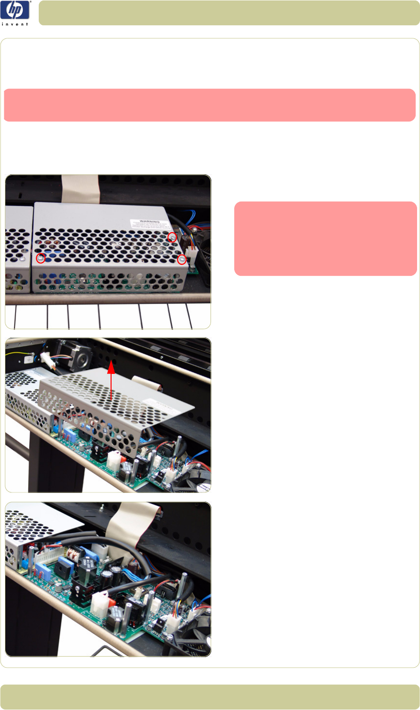
4-33
Removal and Installation
HP Designjet T1100 MFP, 4500mfp, 4500 Scanner, 820 MFP Service Manual
Driver Board
Removal
1. Remove the Top Cover
⇒
Page 4-5
.
2. Remove Left Camera Lens Assembly
⇒
Page 4-27
3. Remove three T10 screws from the Metal
Shield that covers the Driver Board.
4. Remove the Metal Shield.
5. Disconnect ALL the cables from the Driver
Board.
Switch off the printer, the scanner, and the PC, and then disconnect them from
the power source prior to performing any maintenance.
The components underneath the
Metal shield represent a risk of
electric shock, once the power has
been disconnected allow three
minutes discharge time before
touching.
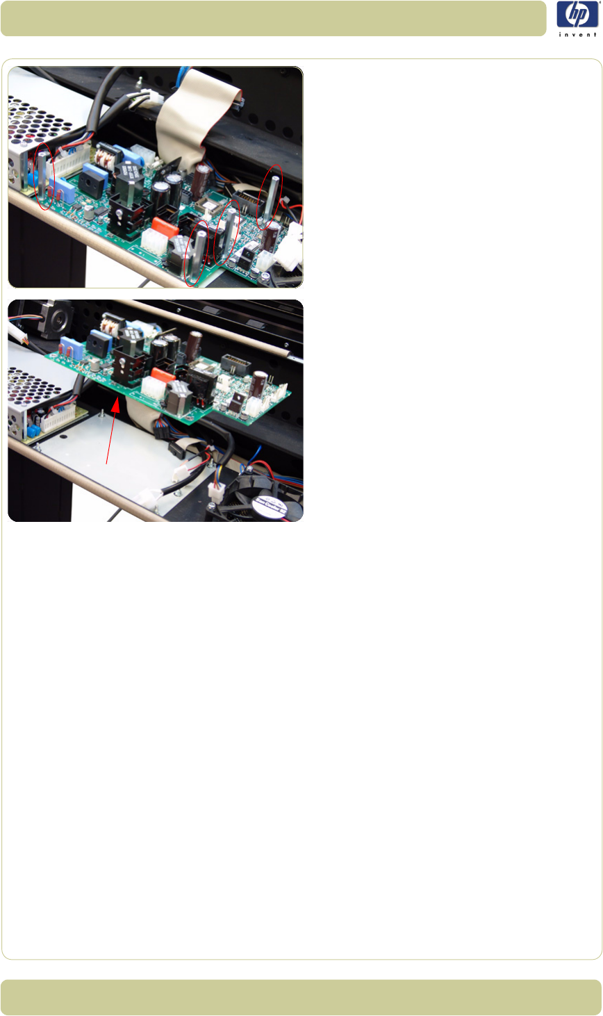
4-34
Removal and Installation
HP Designjet T1100 MFP, 4500mfp, 4500 Scanner, 820 MFP Service Manual
6. Remove four bolts that secure the Driver
Board.
7. Remove the Driver Board from the Scanner.
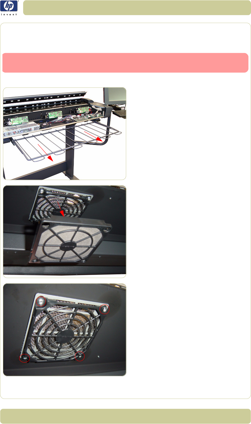
4-35
Removal and Installation
HP Designjet T1100 MFP, 4500mfp, 4500 Scanner, 820 MFP Service Manual
Fan
Removal
1. Remove the Top Cover
⇒
Page 4-5
.
2. Pull out the metal paper bin to gain access
to the Fan Filter.
3. Unclip the Fan Filter from underneath the
Scanner.
4. Gripping the nuts from the top, remove the
four T20 screws from the bottom that
secure the Fan.
Switch off the printer, the scanner, and the PC, and then disconnect them from
the power source prior to performing any maintenance.
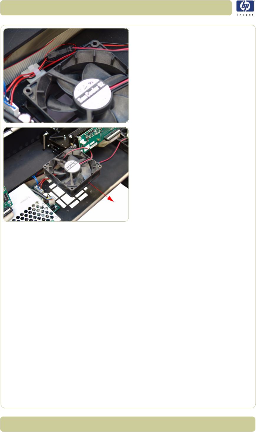
4-36
Removal and Installation
HP Designjet T1100 MFP, 4500mfp, 4500 Scanner, 820 MFP Service Manual
5. Disconnect the Fan Cable.
6. Remove the Fan from the Scanner.
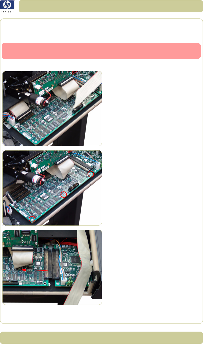
4-37
Removal and Installation
HP Designjet T1100 MFP, 4500mfp, 4500 Scanner, 820 MFP Service Manual
Main Electronics Board
Removal
1. Remove the Top Cover
⇒
Page 4-5
.
2. Disconnect ALL the cables from the Main
Electronics Board.
3. Remove three T10 screws that secure the
Main Electronics Board.
4. Move the Main Electronics Board to the left
to disconnect it from the connector and to
release it from the three plastic locators
(located at the rear of the Board).
Switch off the printer, the scanner, and the PC, and then disconnect them from
the power source prior to performing any maintenance.
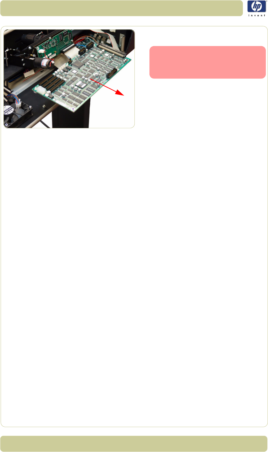
4-38
Removal and Installation
HP Designjet T1100 MFP, 4500mfp, 4500 Scanner, 820 MFP Service Manual
5. Remove the Main Electronics Board from
the Scanner.
After reinstalling the Main Elec-
tronics Board, make sure you run
the Scanner Maintenance and the
ATAC Calibration
⇒
Page 5-32
.
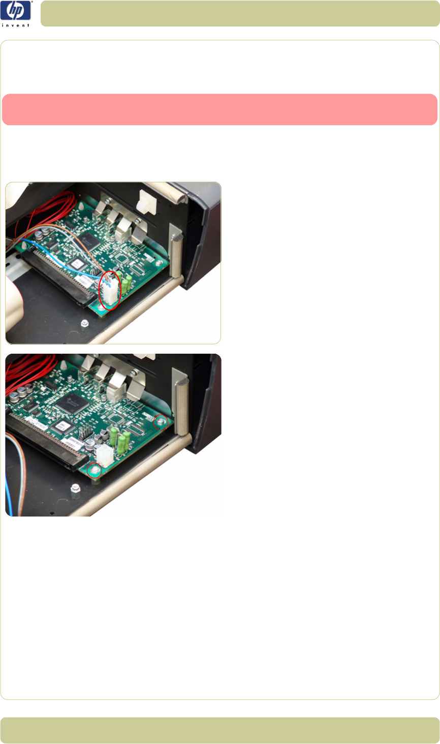
4-39
Removal and Installation
HP Designjet T1100 MFP, 4500mfp, 4500 Scanner, 820 MFP Service Manual
Interface Board
Removal
Switch off the printer, the scanner, and the PC, and then disconnect them from
the power source prior to performing any maintenance.
1. Remove the Top Cover
⇒
Page 4-5
2. Remove the Main Electronics Board
⇒
Page 4-37.
3. Disconnect the cable from the board.
4. Remove two T10 screws that secure the
board.
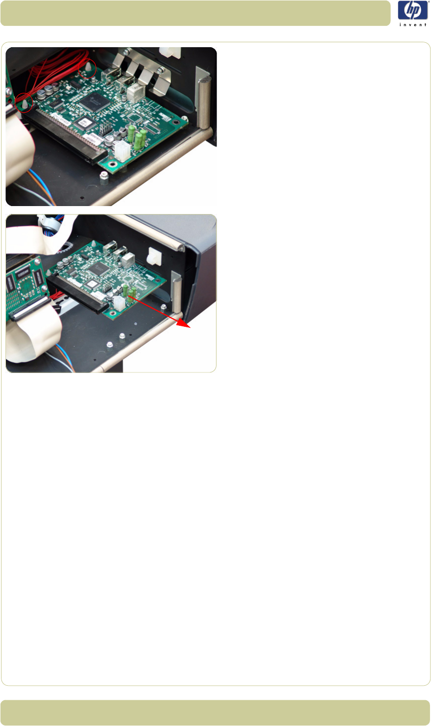
4-40
Removal and Installation
HP Designjet T1100 MFP, 4500mfp, 4500 Scanner, 820 MFP Service Manual
5. Release the board from the two plastic
locators located at the rear.
6. Remove the Interface board from the
Scanner.
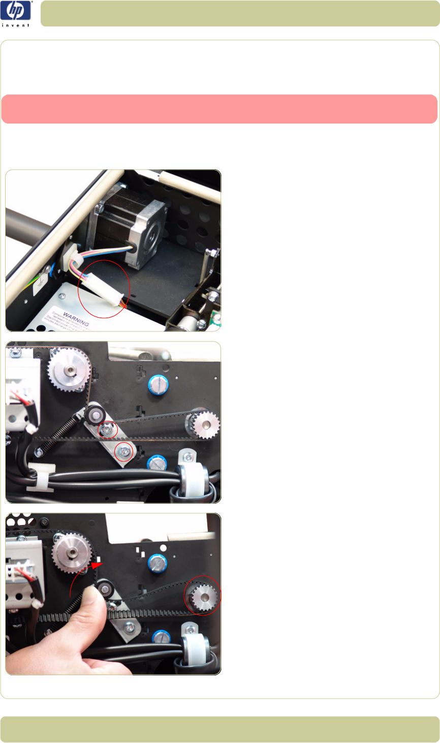
4-41
Removal and Installation
HP Designjet T1100 MFP, 4500mfp, 4500 Scanner, 820 MFP Service Manual
Stepper Motor
Removal
Switch off the printer, the scanner, and the PC, and then disconnect them from
the power source prior to performing any maintenance.
1. Remove the Top Cover
⇒
Page 4-5
.
2. Remove the Left Cover
⇒
Page 4-7.
3. Disconnect the Stepper Motor cable.
4. Loosen two T20 screws on the Belt
Tensioner Bracket.
5. Push the belt tensioner assembly to the
right to release the belt from the Stepper
Motor Pully.
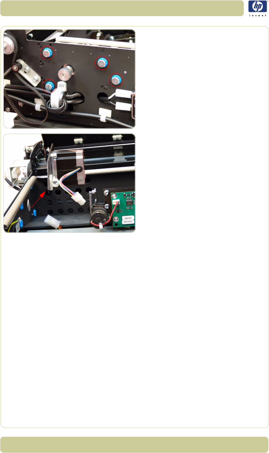
4-42
Removal and Installation
HP Designjet T1100 MFP, 4500mfp, 4500 Scanner, 820 MFP Service Manual
6. Remove four screws that secure the Stepper
Motor to the chassis.
7. Remove the Stepper Motor from the
Scanner.
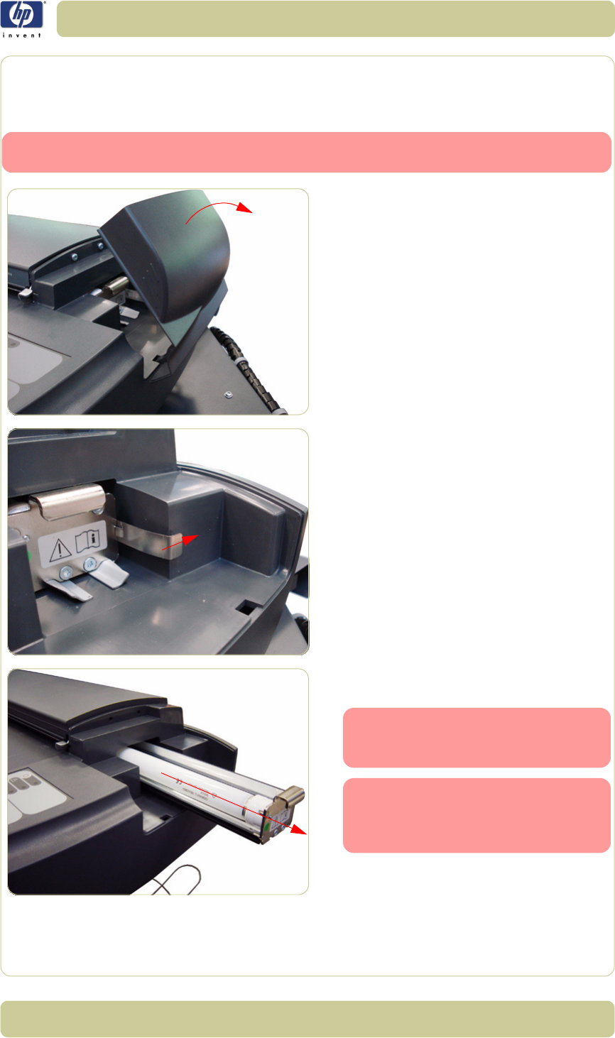
4-43
Removal and Installation
HP Designjet T1100 MFP, 4500mfp, 4500 Scanner, 820 MFP Service Manual
Fluorescent Lamp
Removal
Switch off the printer, the scanner, and the PC, and then disconnect them from
the power source prior to performing any maintenance.
1. Remove the Fluorescent Lamp Access
Cover.
2. Press the metal tab to release the
Flourescent Lamp.
3. Slide out the Fluorescent Lamp from the
Scanner.
Take care not to touch the Stitching
Wire while removing or installing
the Fluorescent Lamp.
After installing a new Fluorescent
Lamp, you must also install the
new Fan Filters which come with
the Lamp
⇒
Page 4-35
.
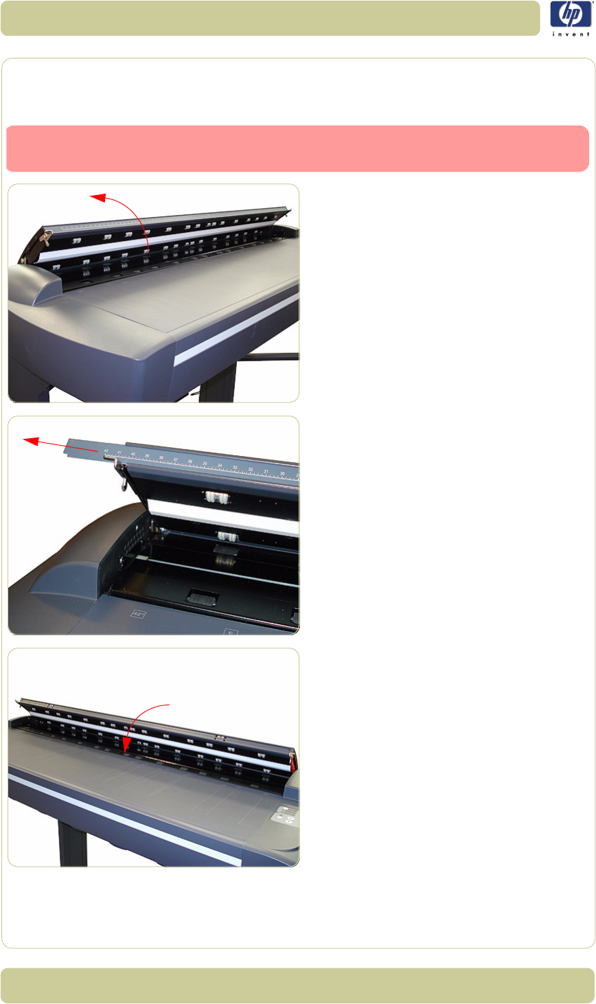
4-44
Removal and Installation
HP Designjet T1100 MFP, 4500mfp, 4500 Scanner, 820 MFP Service Manual
Elevation Motor Driver Board
Removal
1. Open the Top Profile.
2. Remove the rule from the front of the Guide
Plate.
3. Close the Top Profile.
Switch off the printer, the scanner, and the PC, and then disconnect them from
the power source prior to performing any maintenance.
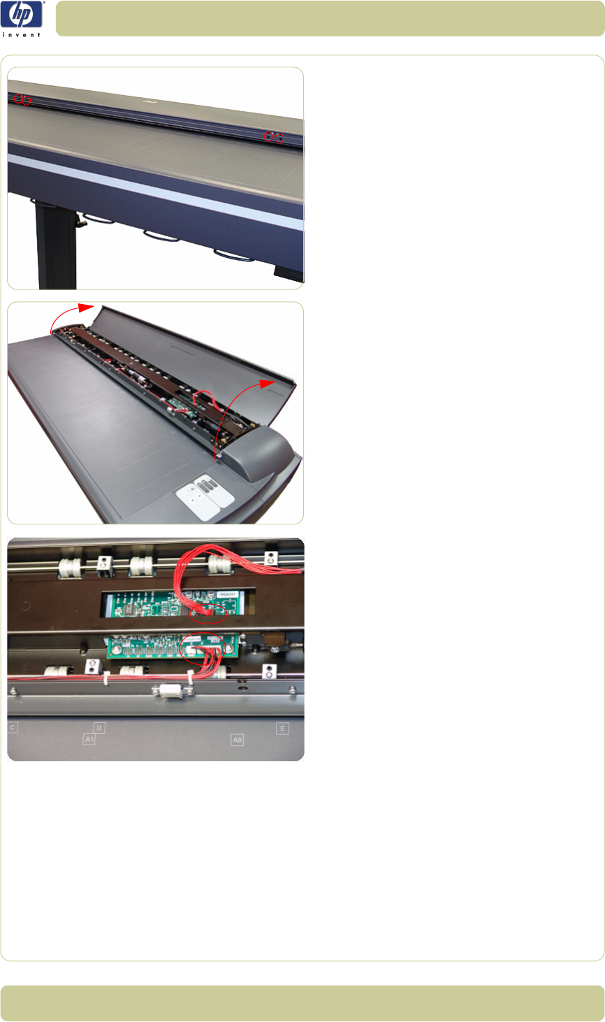
4-45
Removal and Installation
HP Designjet T1100 MFP, 4500mfp, 4500 Scanner, 820 MFP Service Manual
4. Remove the four T10 screws that are used
to secure the front of the Top Profile to the
Guide Plate.
5. Lift up the Top Profile of the Guide Plate.
6. Disconnect all cables from the Elevation
Motor Driver Board.
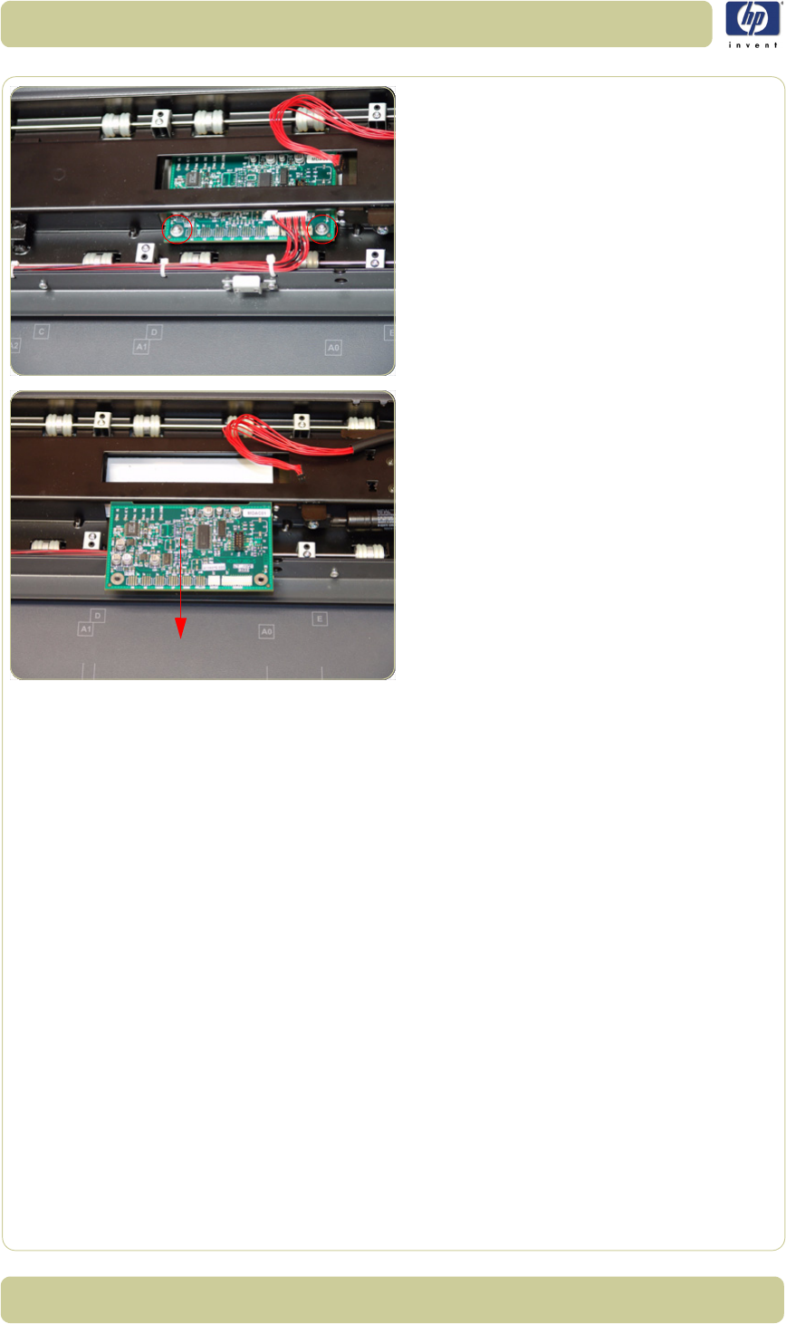
4-46
Removal and Installation
HP Designjet T1100 MFP, 4500mfp, 4500 Scanner, 820 MFP Service Manual
7. Remove two T10 screws that secure the
Elevation Motor Driver Board to the Guide
Plate.
8. Remove the Elevation Motor Driver Board
from the Scanner.
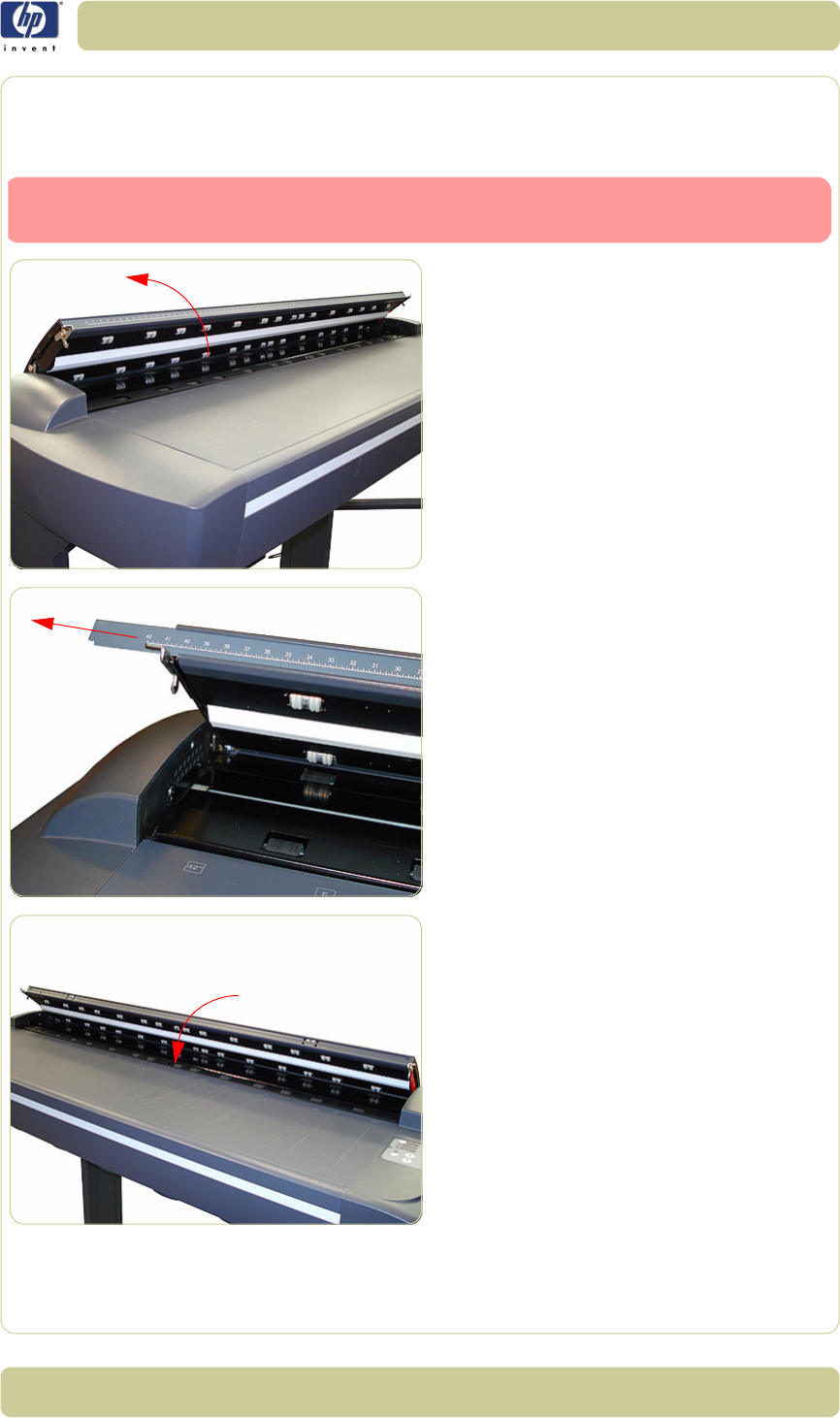
4-47
Removal and Installation
HP Designjet T1100 MFP, 4500mfp, 4500 Scanner, 820 MFP Service Manual
Elevation Motor
Removal
1. Open the Top Profile.
2. Remove the rule from the front of the Guide
Plate.
3. Close the Top Profile.
Switch off the printer, the scanner, and the PC, and then disconnect them from
the power source prior to performing any maintenance.
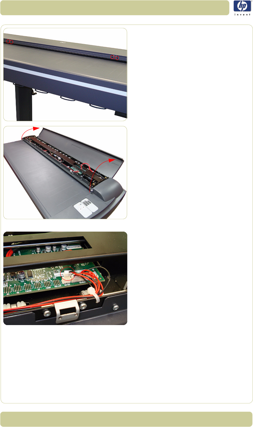
4-48
Removal and Installation
HP Designjet T1100 MFP, 4500mfp, 4500 Scanner, 820 MFP Service Manual
4. Remove the four T10 screws that are used
to secure the front of the Top Profile to the
Guide Plate.
5. Lift up the Top Profile cover of the Guide
Plate.
6. Disconnect the Elevator Motor cable (the
small connector only) from the Elevation
Motor Driver Board.
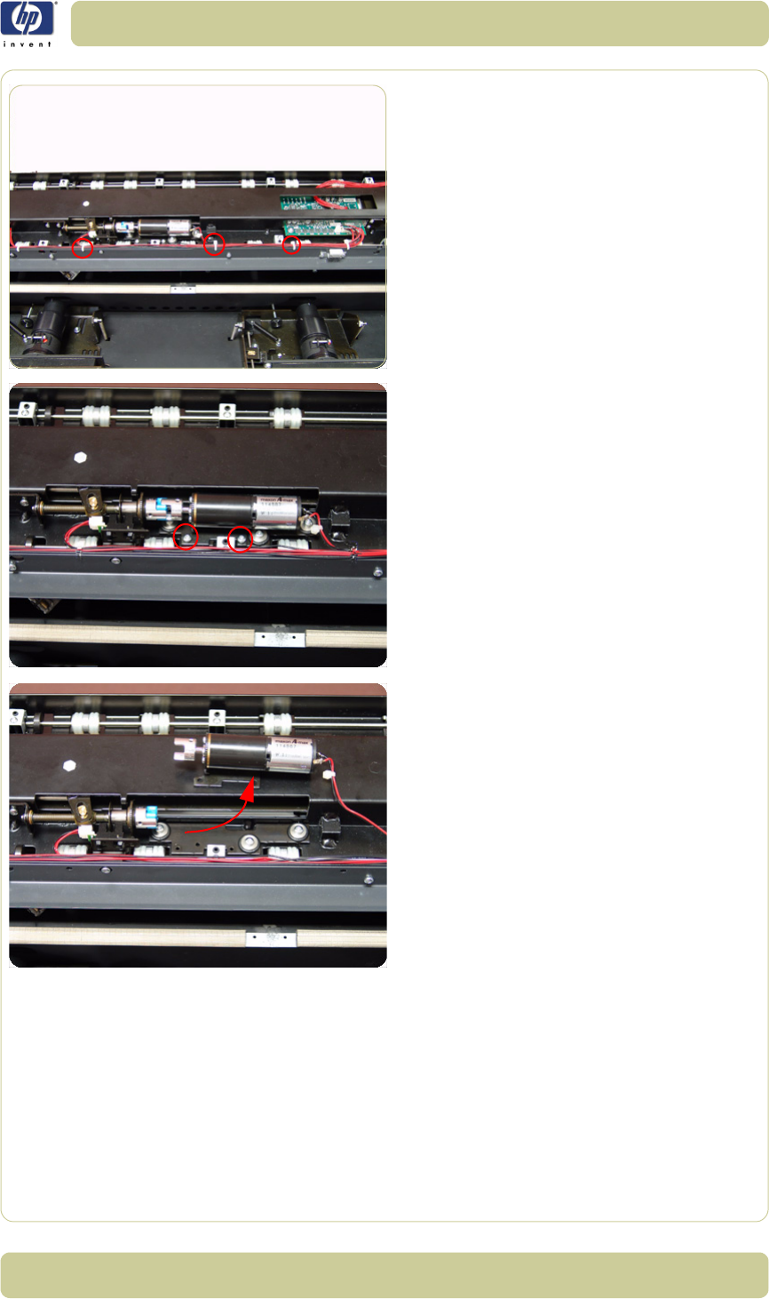
4-49
Removal and Installation
HP Designjet T1100 MFP, 4500mfp, 4500 Scanner, 820 MFP Service Manual
7. Cut the cable clamps holding the cables to
the Guide Plate.
8. Remove two T10 screws that secure the
Elevation Motor to the Guide Plate
Assembly.
9. Remove the Elevation Motor from the
Guide Plate Assembly.
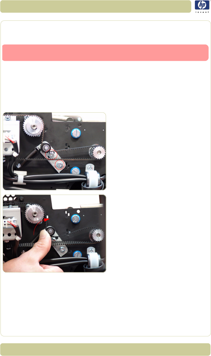
4-50
Removal and Installation
HP Designjet T1100 MFP, 4500mfp, 4500 Scanner, 820 MFP Service Manual
Entry Roller
Removal
1. Remove the Top Cover
⇒
Page 4-5.
2. Remove the Left Cover
⇒
Page 4-7.
3. Remove the Right Cover
⇒
Page 4-9
4. Remove the Glass Plate
⇒
Page 4-23.
5. Remove the Entry Roller Shield
⇒
Page 4-
24.
6. Loosen two screws from the Belt Tensioner
Bracket.
7. Push the Belt Tensioner Bracket to the right
to release the belt.
Switch off the printer, the scanner, and the PC, and then disconnect them from
the power source prior to performing any maintenance.
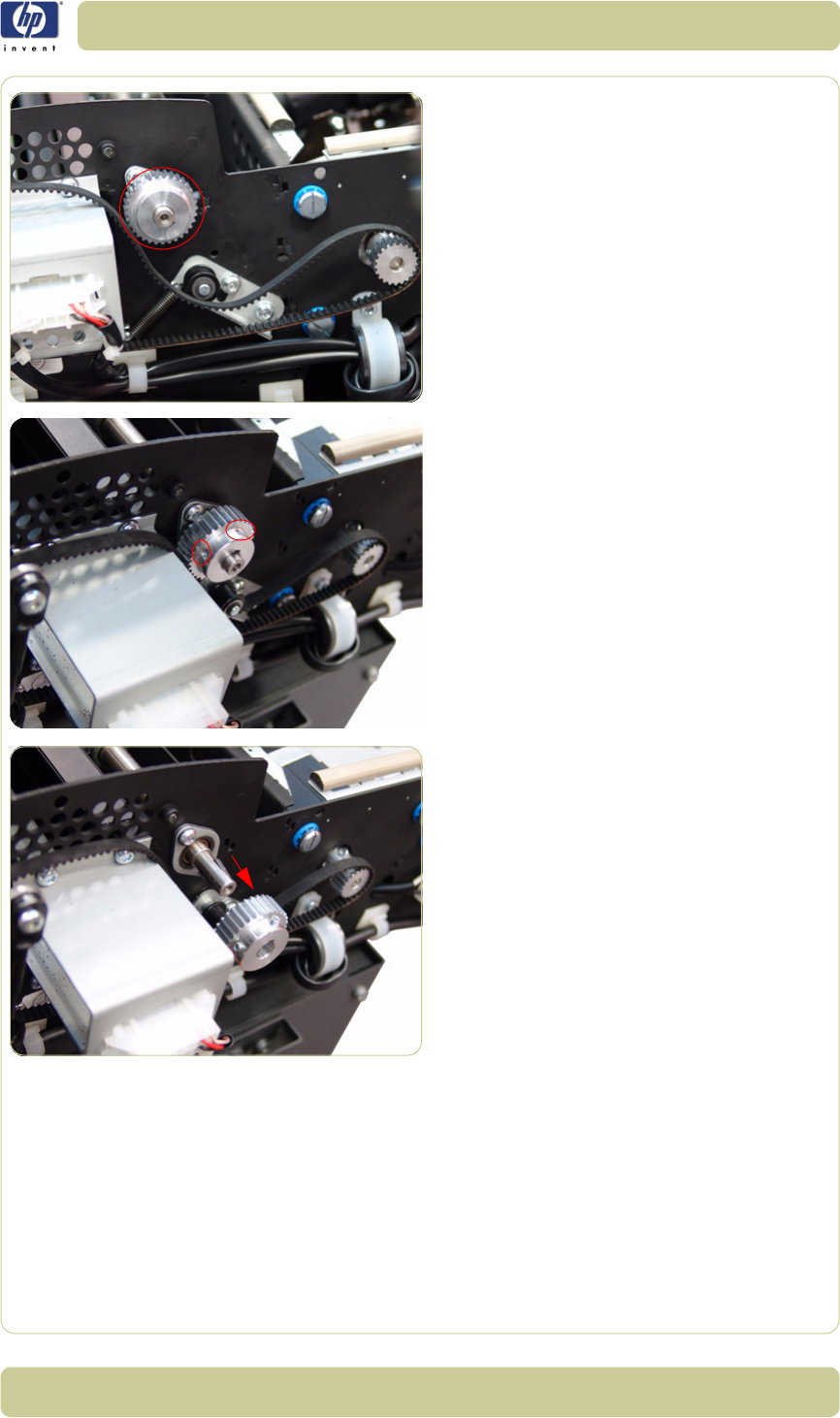
4-51
Removal and Installation
HP Designjet T1100 MFP, 4500mfp, 4500 Scanner, 820 MFP Service Manual
8. Release the Belt from the Entry Roller Gear.
9. Loosen the T8 Allen screws from the Entry
Roller Gear on the left side of the Scanner.
10. Remove the Entry Roller Gear.
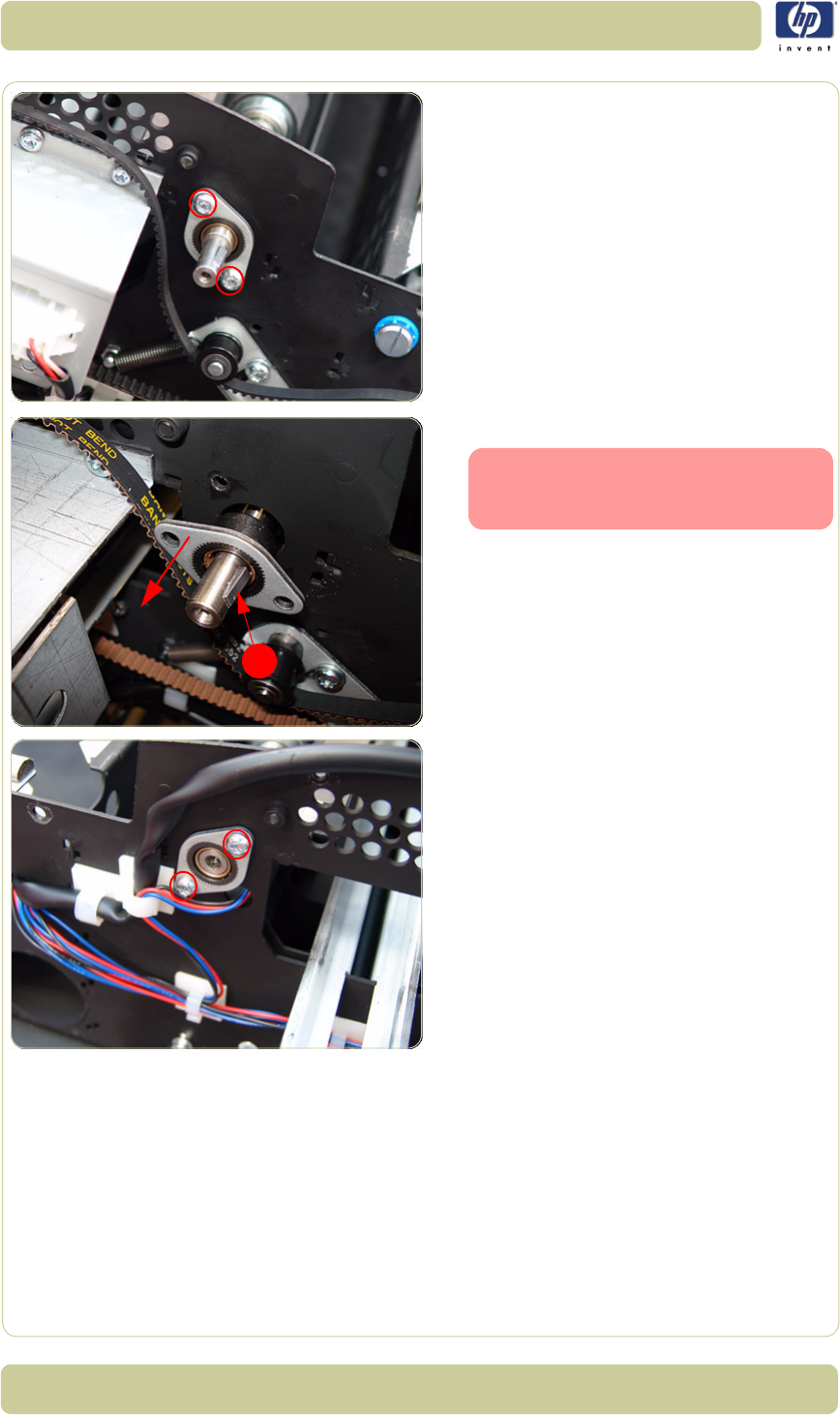
4-52
Removal and Installation
HP Designjet T1100 MFP, 4500mfp, 4500 Scanner, 820 MFP Service Manual
11. Remove two T20 screws that secure the
Entry Roller Mount Bushing from the left
side of the Scanner.
12. Remove the Entry Roller Mount Bushing.
13. Remove two T20 screws that secure the
Entry Roller Mount Bushing from the right
side of the Scanner.
1
Flatten the metal clip (1) with your
finger or a screwdriver, and then
slide off the bushing.
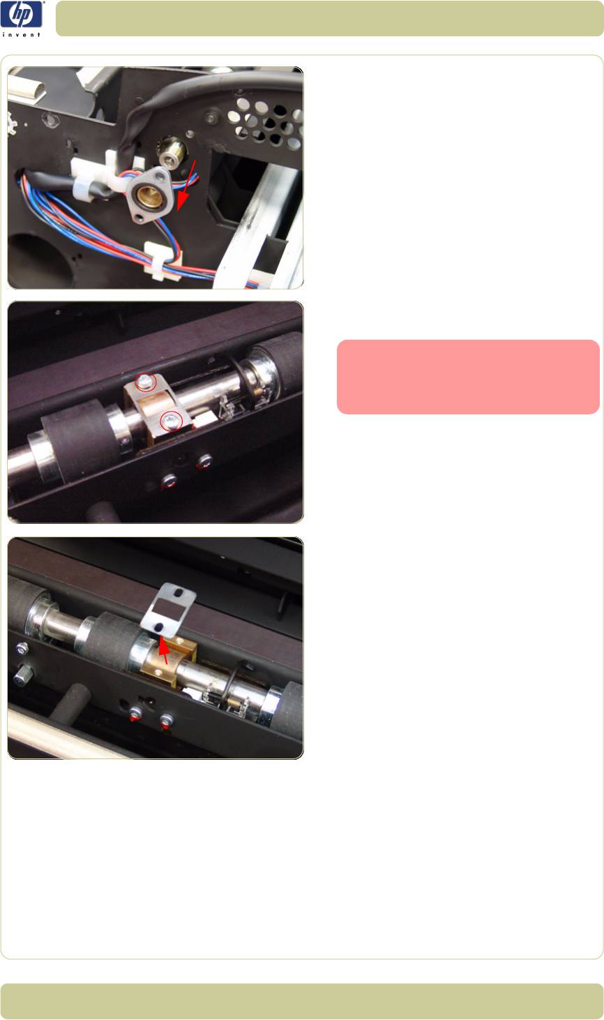
4-53
Removal and Installation
HP Designjet T1100 MFP, 4500mfp, 4500 Scanner, 820 MFP Service Manual
14. Remove the Entry Roller Mount Bushing.
15. Remove the two T10 screws from the Roller
Clamp that secures the Entry Roller.
16. Remove the Roller Clamp.
The Roller Clamps for the Entry
and Exit Rollers must not be inter-
changed, so please mark the Top
Roller Clamp before removing.
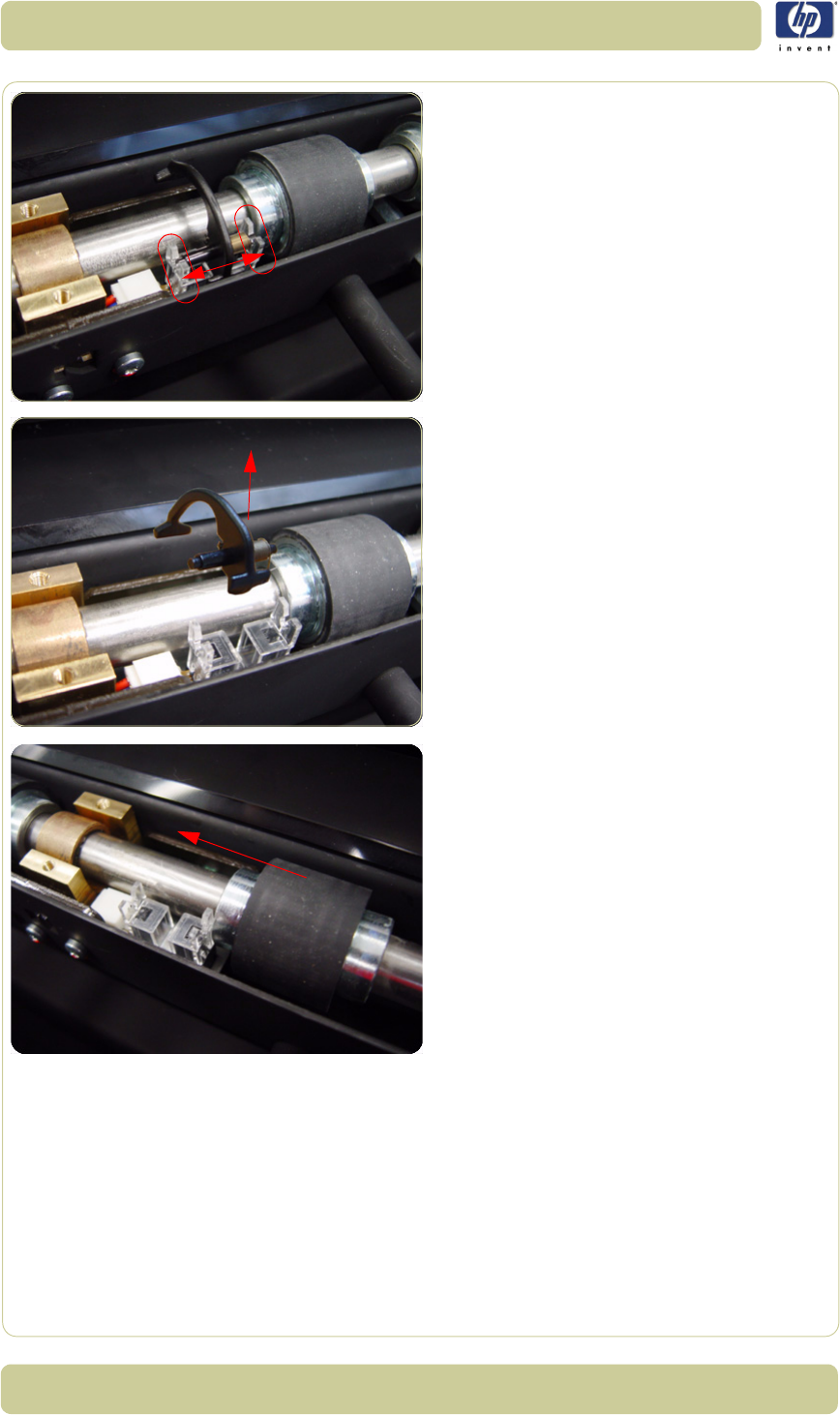
4-54
Removal and Installation
HP Designjet T1100 MFP, 4500mfp, 4500 Scanner, 820 MFP Service Manual
17. Carefully release the Media Entry Switch
from the plastic holder
18. Remove the Media Entry Switch from the
Scanner
19. Slide the Entry Roller towards the pulley
end to remove it out of the bearing at the
opposite end.

4-55
Removal and Installation
HP Designjet T1100 MFP, 4500mfp, 4500 Scanner, 820 MFP Service Manual
20.Remove the Entry Roller from the Scanner.
When removing the Entry Roller
note the number of washers on the
end of the shaft so that they can be
replaced later.
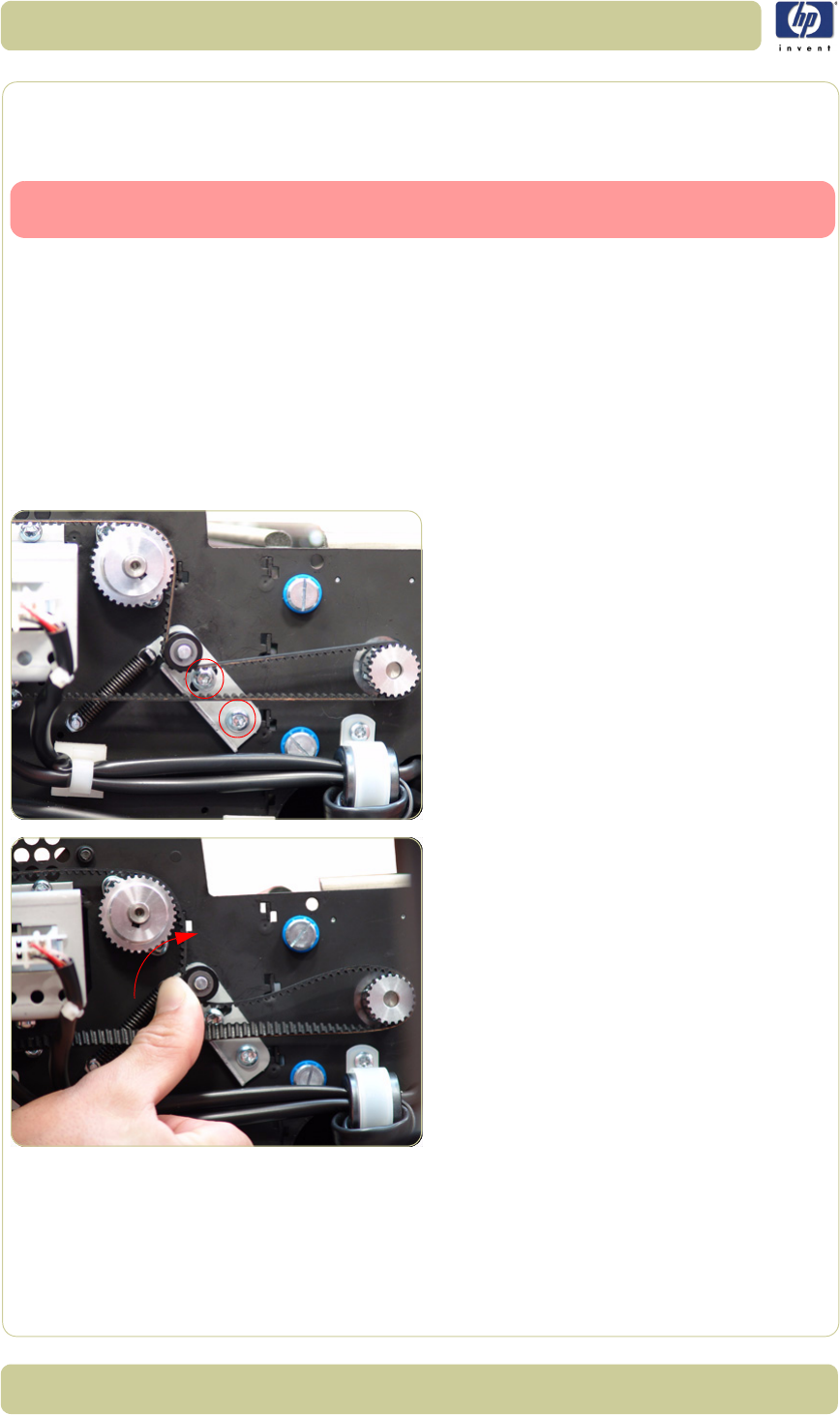
4-56
Removal and Installation
HP Designjet T1100 MFP, 4500mfp, 4500 Scanner, 820 MFP Service Manual
Exit Roller
Removal
Switch off the printer, the scanner, and the PC, and then disconnect them from
the power source prior to performing any maintenance.
1. Remove the Top Cover
⇒
Page 4-5.
2. Remove the Left Cover
⇒
Page 4-7.
3. Remove the Right Cover
⇒
Page 4-9
4. Remove the Rear Cover
⇒
Page 4-13.
5. Remove the Guide Plate
⇒
Page 4-18
6. Remove the Glass Plate
⇒
Page 4-23.
7. Remove the Exit Roller Shield
⇒
Page 4-
25.
8. Loosen the two T20 screws on the Belt
Tension Bracket.
9. Push the Belt Tension Bracket to the right to
release the belt.
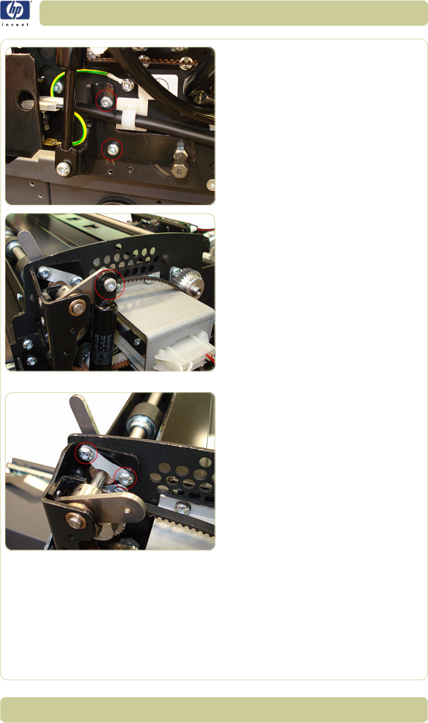
4-57
Removal and Installation
HP Designjet T1100 MFP, 4500mfp, 4500 Scanner, 820 MFP Service Manual
10. Remove the two T20 screws.
11. Remove the one screw and bushing that
secure the piston spring.
12. Remove the two T20 screws used to secure
the small silver plate.
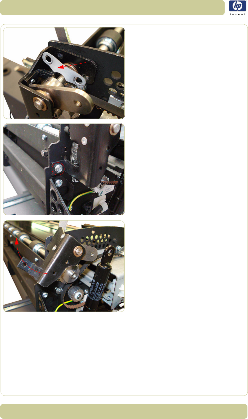
4-58
Removal and Installation
HP Designjet T1100 MFP, 4500mfp, 4500 Scanner, 820 MFP Service Manual
13. Remove the silver plate.
14. Remove one T20 screw.
15. Rotate the black piece upward to gain
access to the Exit Roller Gear.
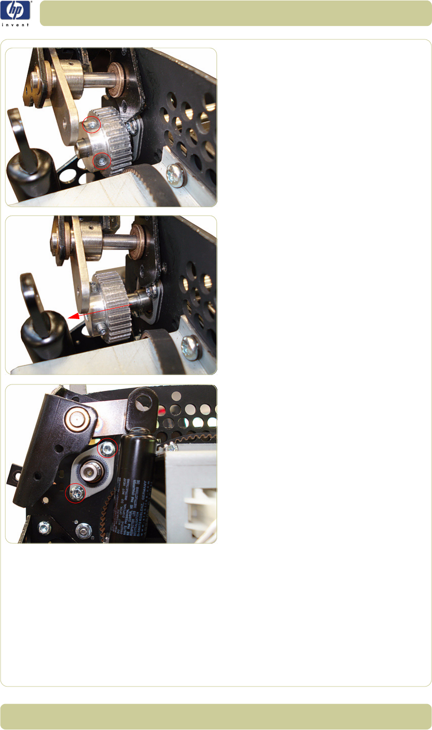
4-59
Removal and Installation
HP Designjet T1100 MFP, 4500mfp, 4500 Scanner, 820 MFP Service Manual
16. Loosen the T8 Allen screws from the Exit
Roller Gear on the left side of the Scanner.
17. Remove the Exit Roller Gear by sliding it off
of the Exit Roller.
18. Remove the two T20 screws that secure the
Exit Roller Mount Bushing from the left side
of the Scanner.
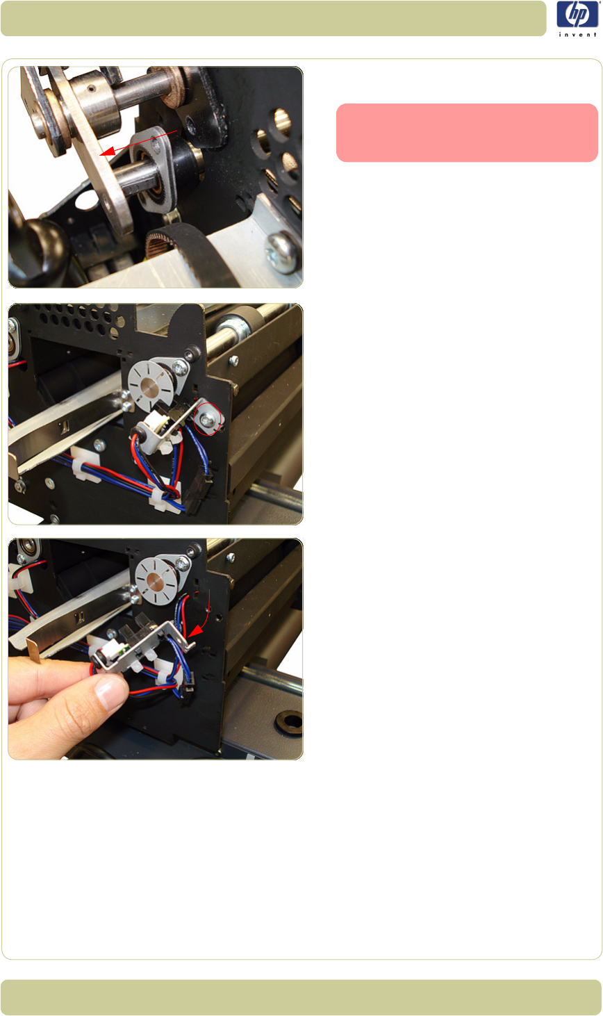
4-60
Removal and Installation
HP Designjet T1100 MFP, 4500mfp, 4500 Scanner, 820 MFP Service Manual
19. Slide the Exit Roller Mount Bushing off of
the Exit Roller.
20.Remove the one T20 screw that secures the
Encoder Sensor Bracket from the right side
of the Scanner.
21. Detach the Encoder Sensor Bracket from
the Scanner.
Flatten the metal clip (1) with your
finger, and then slide off the bush-
ing.
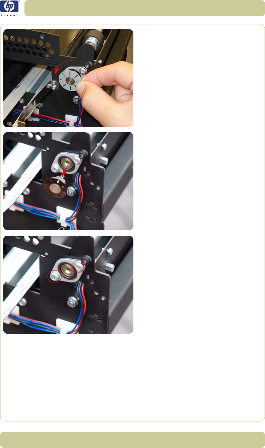
4-61
Removal and Installation
HP Designjet T1100 MFP, 4500mfp, 4500 Scanner, 820 MFP Service Manual
22. Unscrew the Disc Encoder on the right side
of the Scanner by turning clockwise.
23. Remove the Disc Encoder from the right
side of the Scanner.
24. Remove the two T20 screws that secure the
Exit Roller Mount Bushing from the right
side of the Scanner.
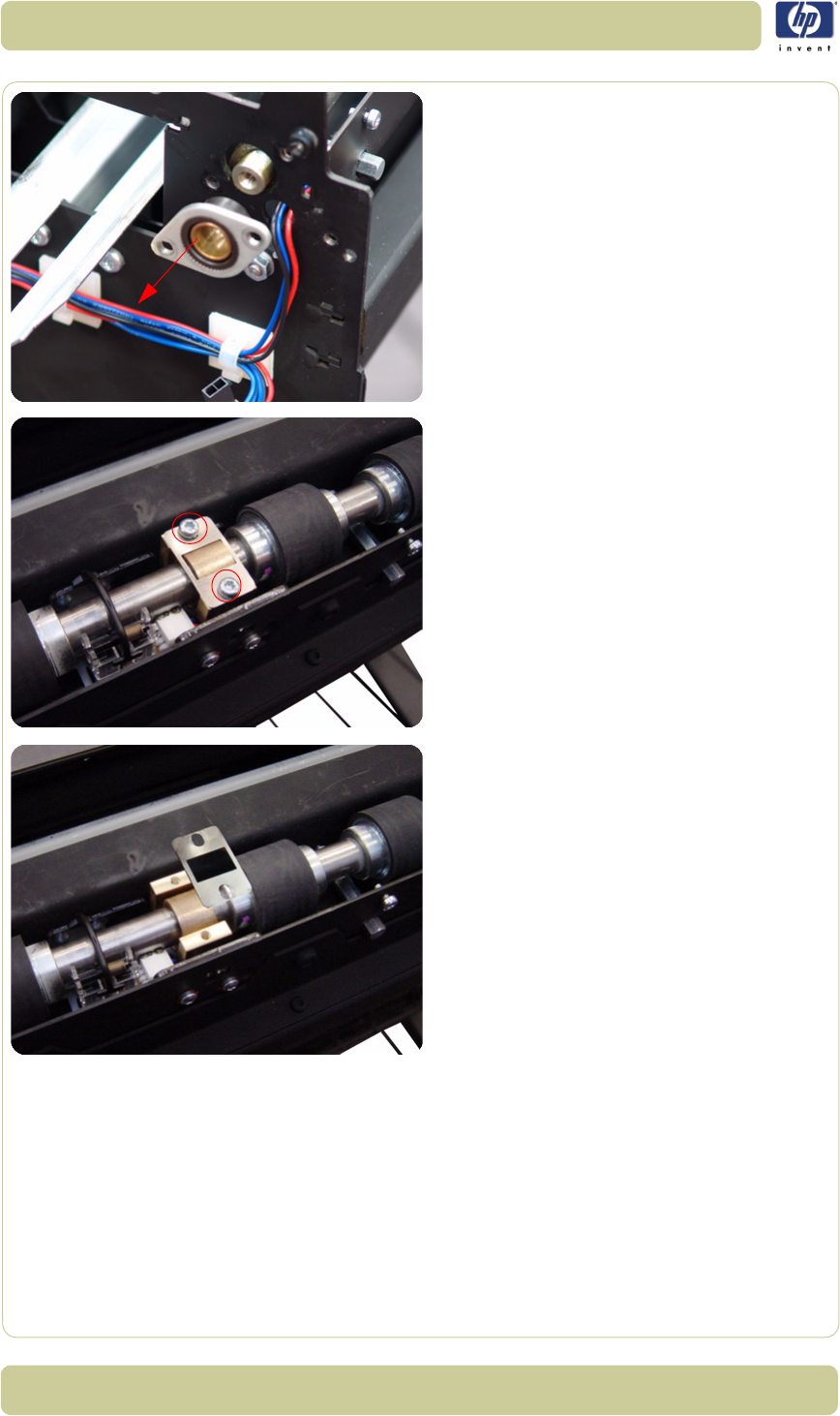
4-62
Removal and Installation
HP Designjet T1100 MFP, 4500mfp, 4500 Scanner, 820 MFP Service Manual
25. Remove the Exit Roller Mount Bushing.
26. Remove the two T10 screws from the Roller
Clamp that secures the Exit Roller.
27. Remove the Roller Clamp.
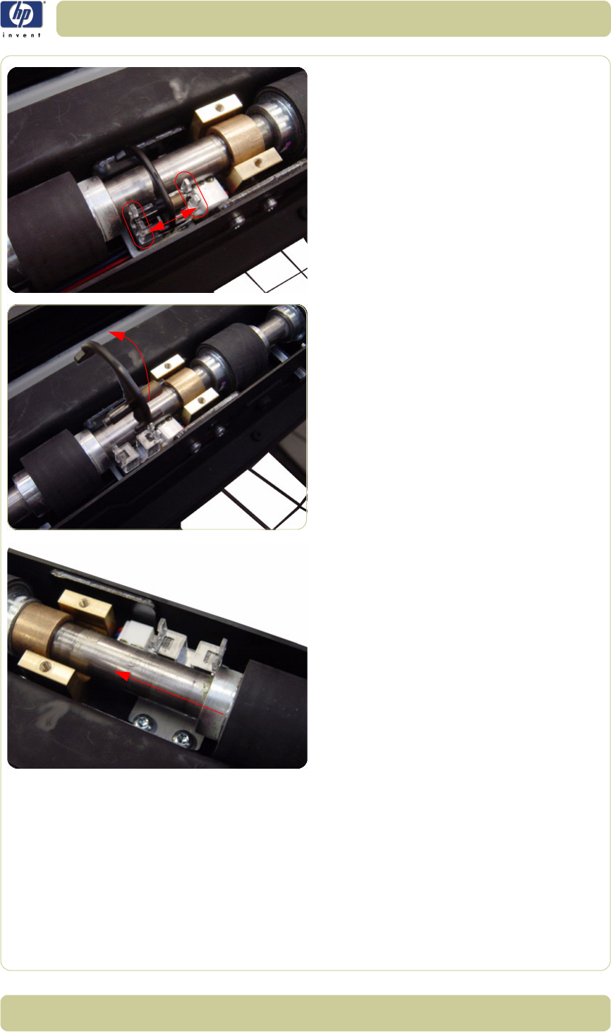
4-63
Removal and Installation
HP Designjet T1100 MFP, 4500mfp, 4500 Scanner, 820 MFP Service Manual
28.Carefully release the Media Entry Rocker
Switch from the plastic holder.
29. Remove the Media Exit Rocker Switch from
the Scanner.
30.Slide the Exit Roller towards the pulley end
to remove it out of the bearing at the
opposite end.

4-64
Removal and Installation
HP Designjet T1100 MFP, 4500mfp, 4500 Scanner, 820 MFP Service Manual
31. Remove the Exit Roller from the Scanner.
As you remove the exit roller from
the Scanner, the Roller Mount
Bushing and Exit Roller Gear will
fall off the left side of the Scanner.
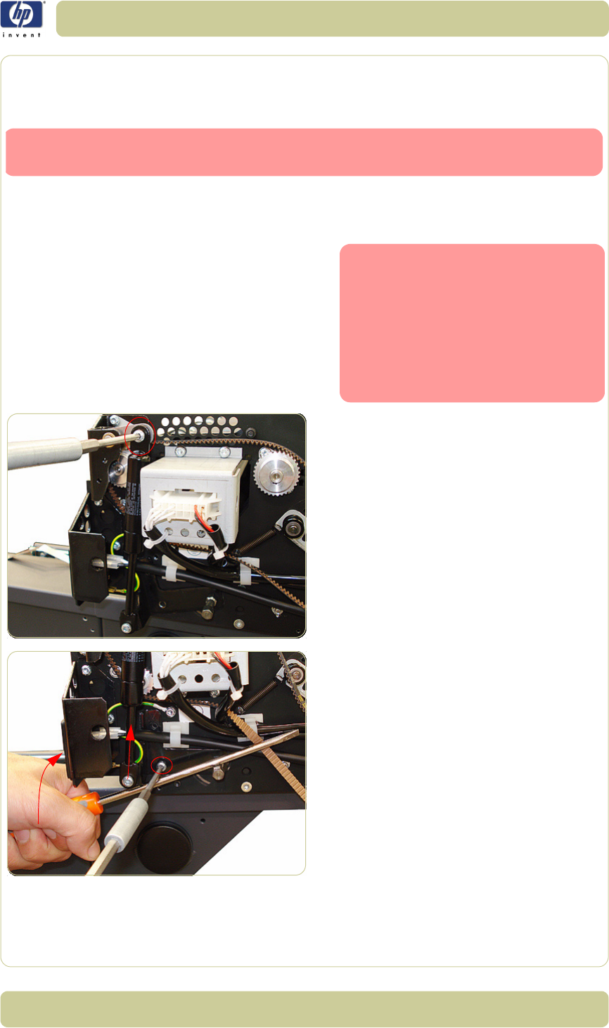
4-65
Removal and Installation
HP Designjet T1100 MFP, 4500mfp, 4500 Scanner, 820 MFP Service Manual
Exit Roller
Installation
1. To install the Exit Roller, follow steps 1-31
from the Exit Roller removal procedure in
reverse order.
2. First, use the screw to attach the uppermost
part of the piston spring.
3. Then use a second screwdriver (or similar
implement) to act as a lever, and pry the
piston spring upward. You will then be
able to affix the screws as shown in the
photo and described in step 10 of the
removal process.
Switch off the printer, the scanner, and the PC, and then disconnect them from
the power source prior to performing any maintenance.
When you are ready to reattach
the piston spring, be sure to follow
steps 10 and 11 from the removal
process in reverse order, as high-
lighted below.
Step 3 (below) guides you in the
handling of the piston spring as
you affix the screws.
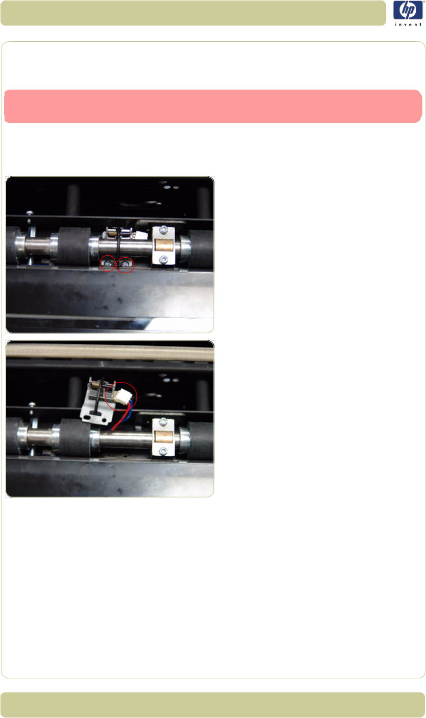
4-66
Removal and Installation
HP Designjet T1100 MFP, 4500mfp, 4500 Scanner, 820 MFP Service Manual
Entry Media Sensor
Removal
1. Remove the Top Cover
⇒
Page 4-5.
2. Remove the Entry Roller Shield
⇒
Page 4-
24.
3. Remove two T10 screws that secure the
Entry Media Sensor.
4. Pull out the Entry Media Sensor from below
the Entry Roller and disconnect the cable to
remove.
Switch off the printer, the scanner, and the PC, and then disconnect them from
the power source prior to performing any maintenance.

4-67
Removal and Installation
HP Designjet T1100 MFP, 4500mfp, 4500 Scanner, 820 MFP Service Manual
Exit Media Sensor
Removal
1. Remove the Top Cover
⇒
Page 4-5.
2. Remove the Right Cover
⇒
Page 4-9
3. Remove the Rear Cover
⇒
Page 4-13.
4. Remove the Guide Plate
⇒
Page 4-18
5. Remove the Exit Roller Shield
⇒
Page 4-
25.
6. Remove the two T10 screws that secure the
Exit Media Sensor.
7. Pull out the Exit Media Sensor from below
the Exit Roller and disconnect the cable to
remove.
Switch off the printer, the scanner, and the PC, and then disconnect them from
the power source prior to performing any maintenance.
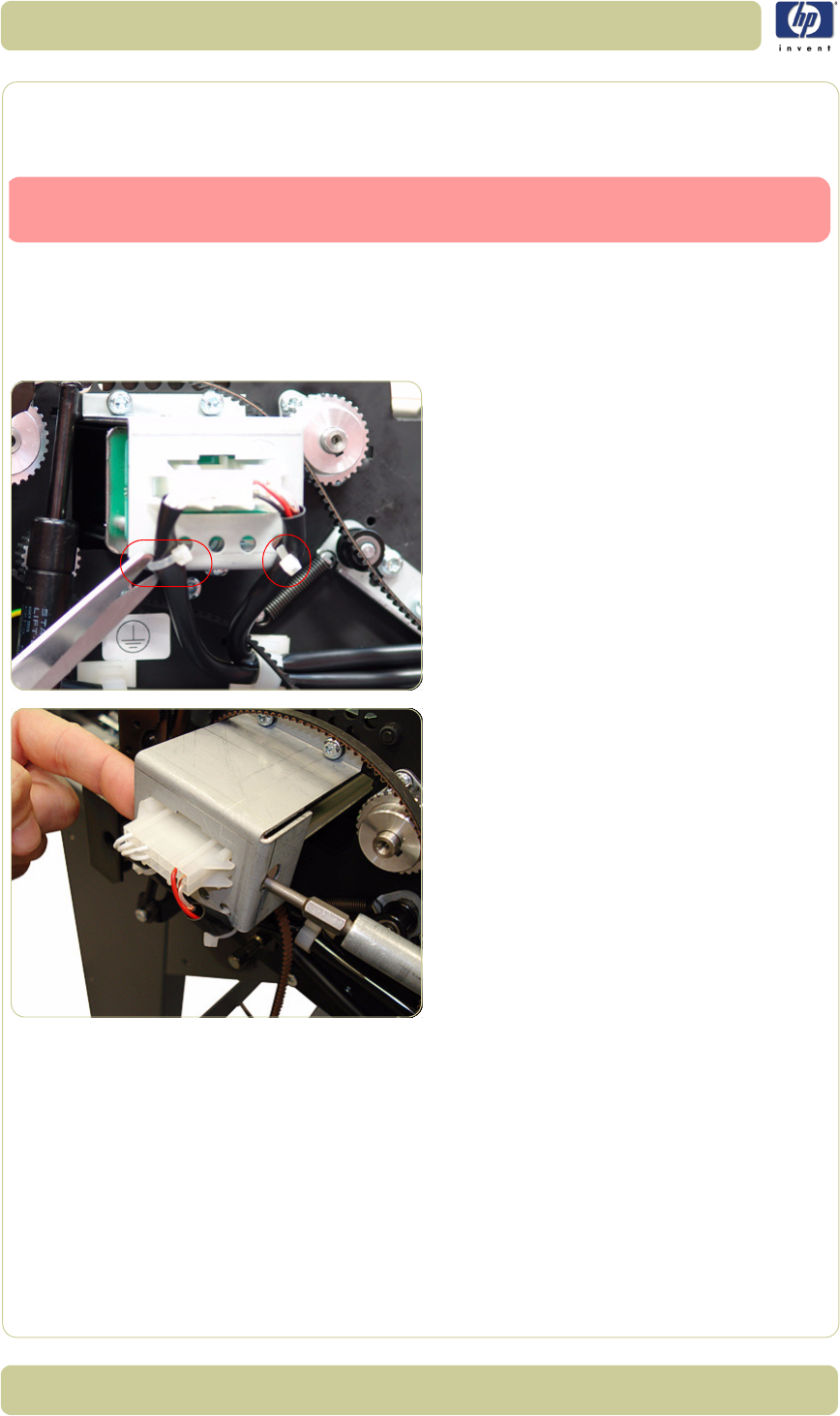
4-68
Removal and Installation
HP Designjet T1100 MFP, 4500mfp, 4500 Scanner, 820 MFP Service Manual
Belt
Removal
1. Remove the Flourescent Lamp
⇒
Page 4-
43.
2. Remove the Top Cover
⇒
Page 4-5.
3. Remove the Left Cover
⇒
Page 4-7.
4. Cut the cable clamps on the Lamp Power
Cable on the left of the Scanner.
5. Using your finger and a screwdriver (or
similar implement), press the clips and
disconnect the Lamp Power cable.
Switch off the printer, the scanner, and the PC, and then disconnect them from
the power source prior to performing any maintenance.
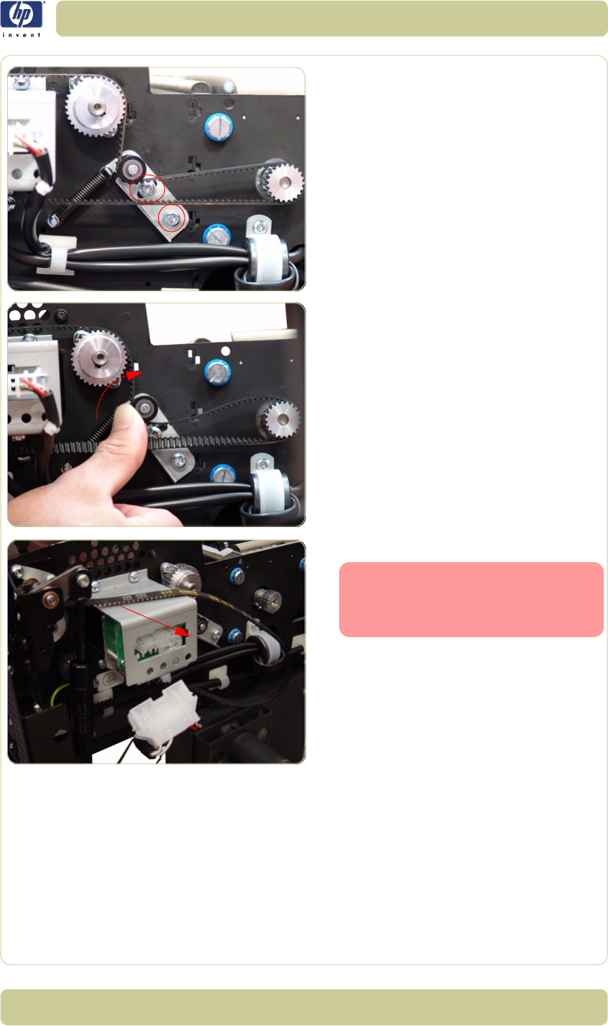
4-69
Removal and Installation
HP Designjet T1100 MFP, 4500mfp, 4500 Scanner, 820 MFP Service Manual
6. Loosen two screws from the Belt Tension
Bracket.
7. Push the Belt Tension Bracket to the right to
release the belt from tension.
8. Remove the belt from the Scanner.
When reinstalling the Belt, make
sure that you adjust the belt ten-
sion when securing the Tension
Bracket.
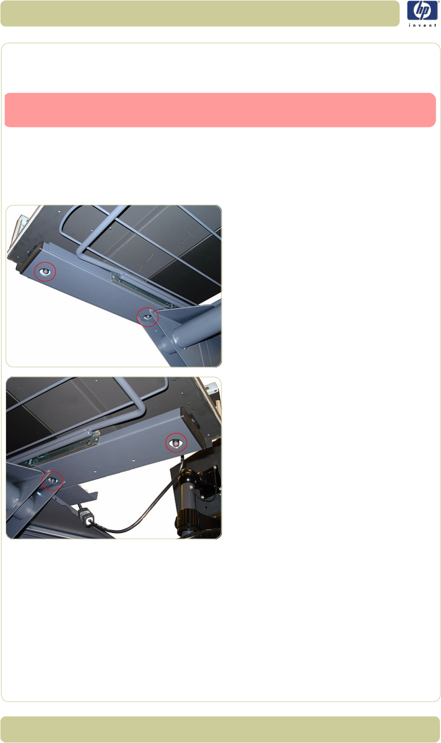
4-70
Removal and Installation
HP Designjet T1100 MFP, 4500mfp, 4500 Scanner, 820 MFP Service Manual
Bottom Cover
Removal
1. Remove the Top Cover
⇒
Page 4-5.
2. Remove the Left Cover
⇒
Page 4-7.
3. Remove the Right Cover
⇒
Page 4-9.
4. Remove the Rear Cover
⇒
Page 4-13.
5. Use a size 2.5 Allen key to remove the two
screws that secure the left side of the
Scanner to the legs.
6. Remove two screws that secure the right
side of the Scanner to the legs.
Switch off the printer, the scanner, and the PC, and then disconnect them from
the power source prior to performing any maintenance.
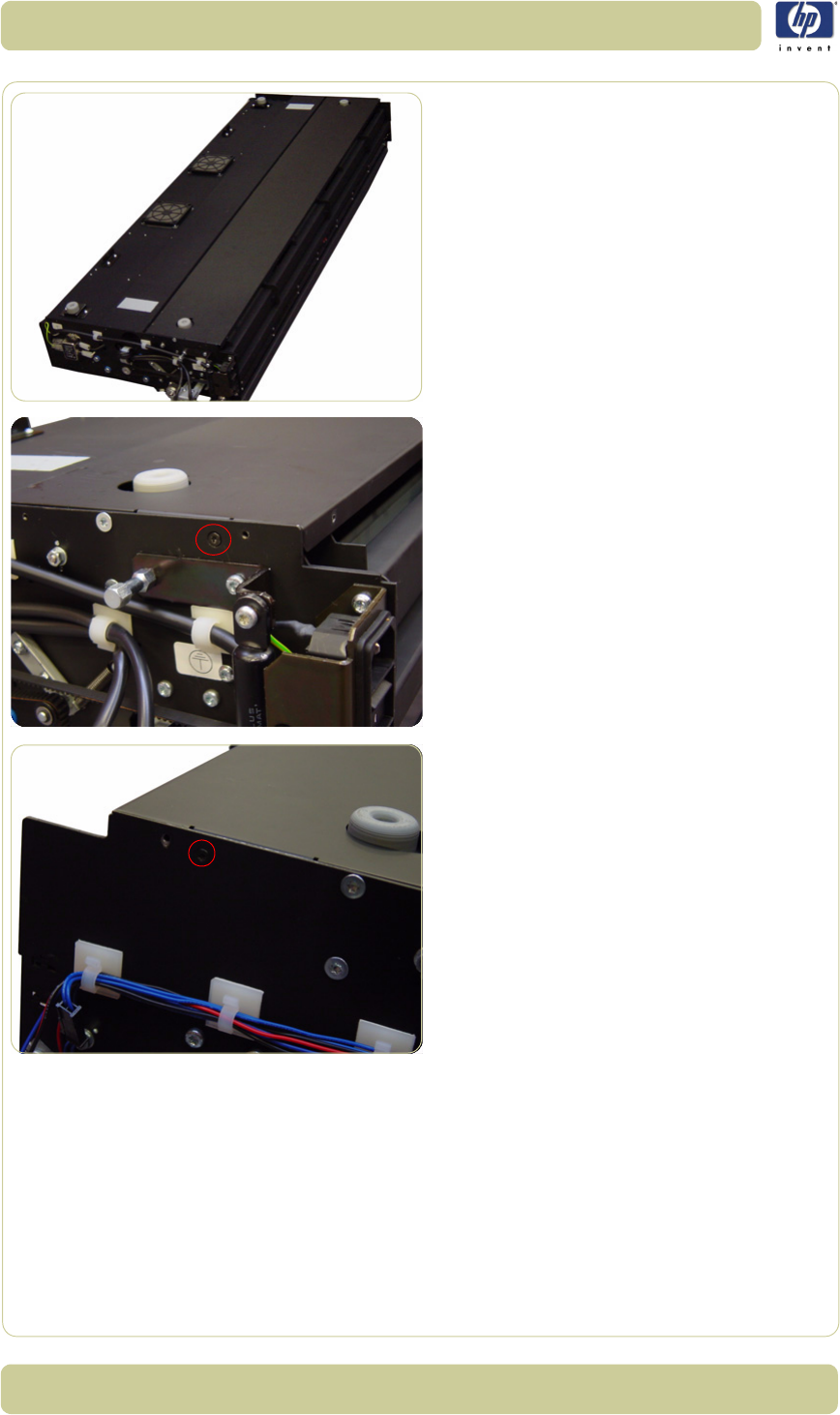
4-71
Removal and Installation
HP Designjet T1100 MFP, 4500mfp, 4500 Scanner, 820 MFP Service Manual
7. Turn the Scanner upside down
.
8. Remove the one T10 screw that secures the
left side of the Bottom Cover.
9. Remove the one T10 screw that secures the
right side of the Bottom Cover.
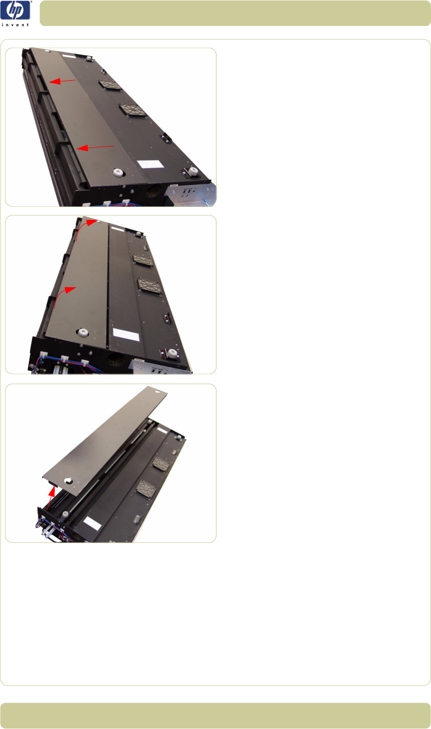
4-72
Removal and Installation
HP Designjet T1100 MFP, 4500mfp, 4500 Scanner, 820 MFP Service Manual
10. Slide the Bottom Cover backwards.
11. Raise the cover slightly from the front.
12. Remove the Bottom Cover from the
Scanner.
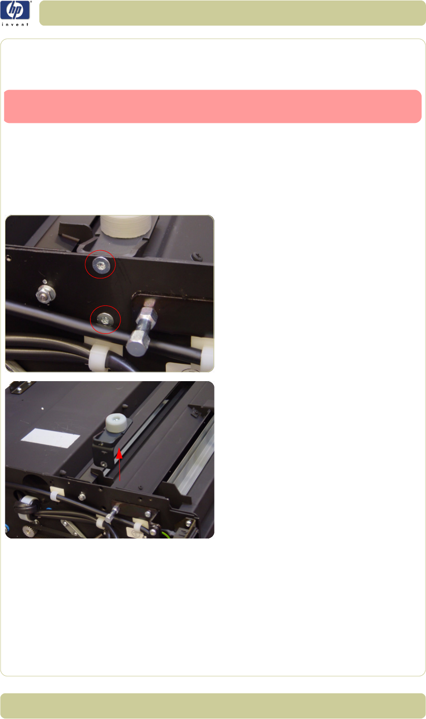
4-73
Removal and Installation
HP Designjet T1100 MFP, 4500mfp, 4500 Scanner, 820 MFP Service Manual
Mirror Chassis
Removal
1. Remove the Top Cover
⇒
Page 4-5.
2. Remove the Left Cover
⇒
Page 4-7.
3. Remove the Right Cover
⇒
Page 4-9.
4. Remove the Rear Cover
⇒
Page 4-13.
5. Remove the Bottom Cover
⇒
Page 4-70.
6. Remove the two T20 screws from each
plastic foot (only the two rear feet).
7. Remove the two rear plastic feet.
Switch off the printer, the scanner, and the PC, and then disconnect them from
the power source prior to performing any maintenance.

4-74
Removal and Installation
HP Designjet T1100 MFP, 4500mfp, 4500 Scanner, 820 MFP Service Manual
8. Remove two nuts that secure the left side of
the Mirror Chassis.
9. Use a size 7 wrench to remove the two nuts
and one washer that secure the right side
of the Mirror Chassis.
10. Remove two locating screws from both
sides of the Mirror Chassis. Upon
installation, ensure that the rubber is not
squeezed. Wiggle the screw to verify that it
is correctly fitted.
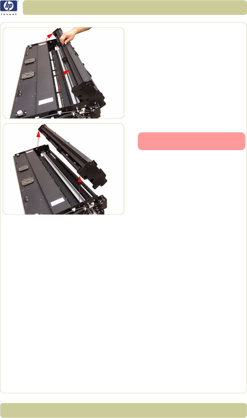
4-75
Removal and Installation
HP Designjet T1100 MFP, 4500mfp, 4500 Scanner, 820 MFP Service Manual
11. Rotate the Mirror Chassis towards you and
lift up.
12. Remove the Mirror Chassis.
Always clean the mirrors before
replacing the Mirror Chassis.
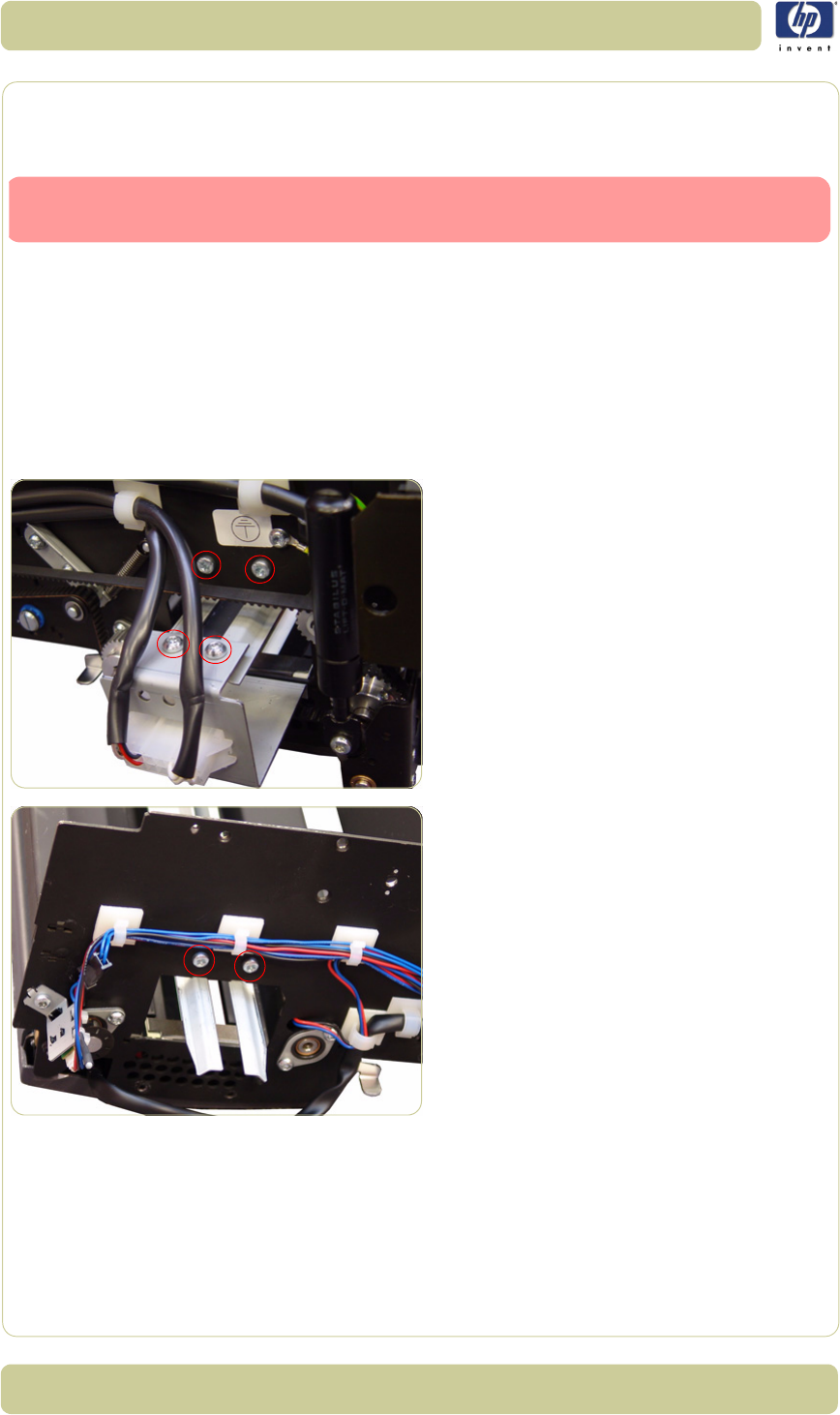
4-76
Removal and Installation
HP Designjet T1100 MFP, 4500mfp, 4500 Scanner, 820 MFP Service Manual
Stitching Wire
Removal
1. Remove the Top Cover
⇒
Page 4-5.
2. Remove the Left Cover
⇒
Page 4-7.
3. Remove the Right Cover
⇒
Page 4-9.
4. Remove the Fluorescent Lamp
⇒
Page 4-
43.
5. Remove the Bottom Cover
⇒
Page 4-70.
6. Remove the Mirror Chassis
⇒
Page 4-73.
7. Remove the four T20 screws that secure the
Fluorescent Lamp Guides to the left side of
the Scanner.
8. Remove the two T20 screws that secure the
Fluorescent Lamp Guides to the right side
of the Scanner.
Switch off the printer, the scanner, and the PC, and then disconnect them from
the power source prior to performing any maintenance.
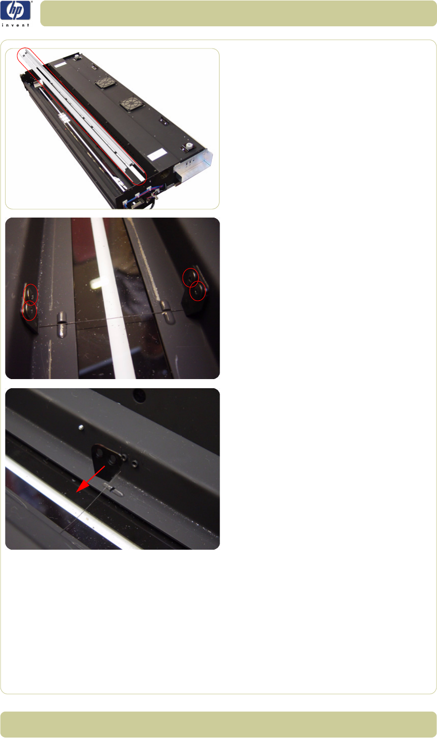
4-77
Removal and Installation
HP Designjet T1100 MFP, 4500mfp, 4500 Scanner, 820 MFP Service Manual
9. Remove the Fluorescent Lamp Guides from
the Scanner.
10. Use a 2.5 size Allen key to remove the four
screws that secure the Leaf Springs.
11. Remove the Leaf Springs and the Stitching
Wire.
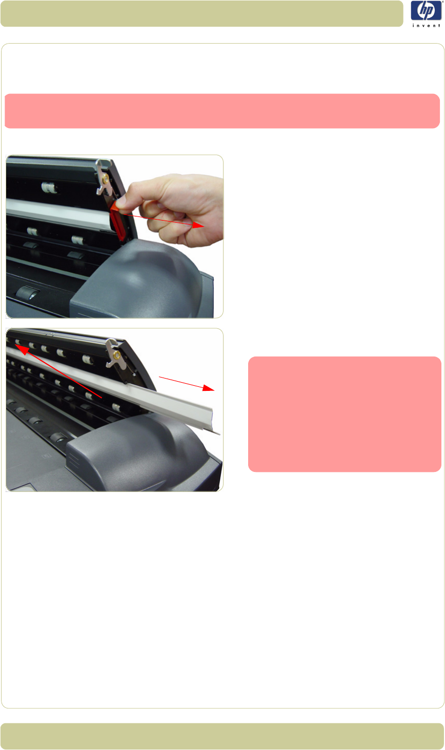
4-78
Removal and Installation
HP Designjet T1100 MFP, 4500mfp, 4500 Scanner, 820 MFP Service Manual
White Background Assembly
Removal
1. Open the Guide Plate.
2. Remove the Red Retaining Cover from the
right of the Guide Plate
.
3. Slide out the White Background Assembly
from the Guide Plate.
Switch off the printer, the scanner, and the PC, and then disconnect them from
the power source prior to performing any maintenance.
You cannot remove and replace
the White Background if the Guide
Plate is in the elevated position.
When replacing the White Back-
ground make sure it is fully insert-
ed and the Red Retaining Cover is
installed before you close the
Guide Plate.
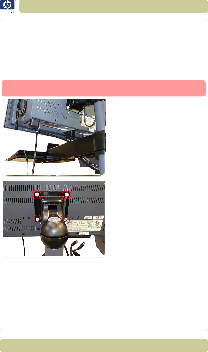
4-79
Removal and Installation
HP Designjet T1100 MFP, 4500mfp, 4500 Scanner, 820 MFP Service Manual
Panel PC
This chapter is a step by step guide to the removal and installation of the key components in the
Panel PC.
Open Cabinet
Removal
1. Disconnect all of the cables from the Panel
PC.
2. Remove the four T20 screws that are used
to secure the Cabinet to the Bracket.
Switch off the printer, the scanner, and the PC, and then disconnect them from
the power source prior to performing any maintenance.
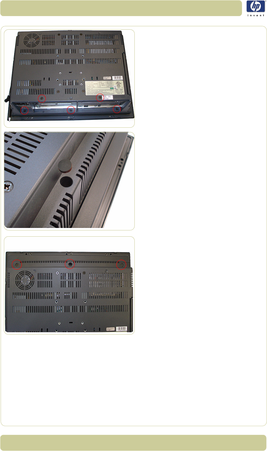
4-80
Removal and Installation
HP Designjet T1100 MFP, 4500mfp, 4500 Scanner, 820 MFP Service Manual
3. Use a Phillips screwdriver to remove the
five screws at the back of the Cabinet.
4. Remove the three rubber covers to gain
access to the screws underneath them.
5. Use a Phillips screwdriver to remove the
three screws at the back of the Cabinet.
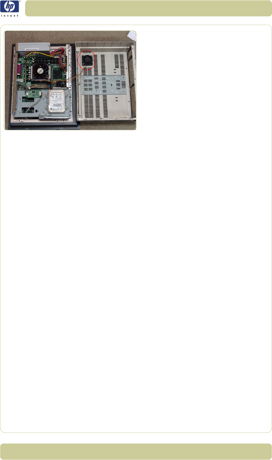
4-81
Removal and Installation
HP Designjet T1100 MFP, 4500mfp, 4500 Scanner, 820 MFP Service Manual
6. As you open the Cabinet, make sure that
you do not damage the cables to the
System Fan.
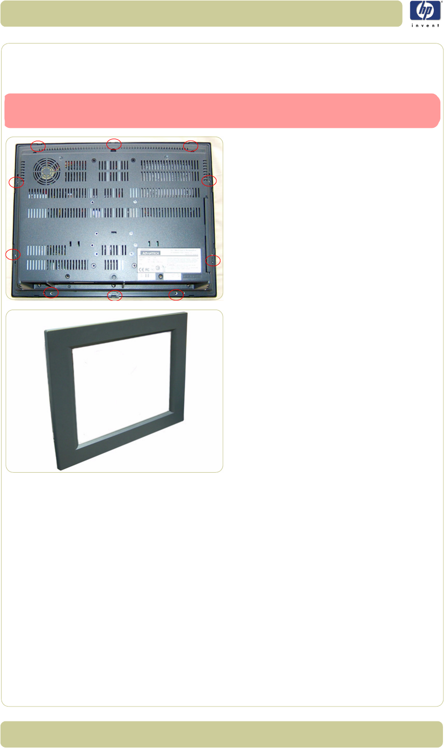
4-82
Removal and Installation
HP Designjet T1100 MFP, 4500mfp, 4500 Scanner, 820 MFP Service Manual
Screen Bezel
Removal
1. Apply pressure with a flat head screw
driver at the rear of the Cabinet at the
places indicaeted.
2. Use a Phillips screwdriver to remove the
Screen Bezel from the Cabinet.
Switch off the printer, the scanner, and the PC, and then disconnect them from
the power source prior to performing any maintenance.
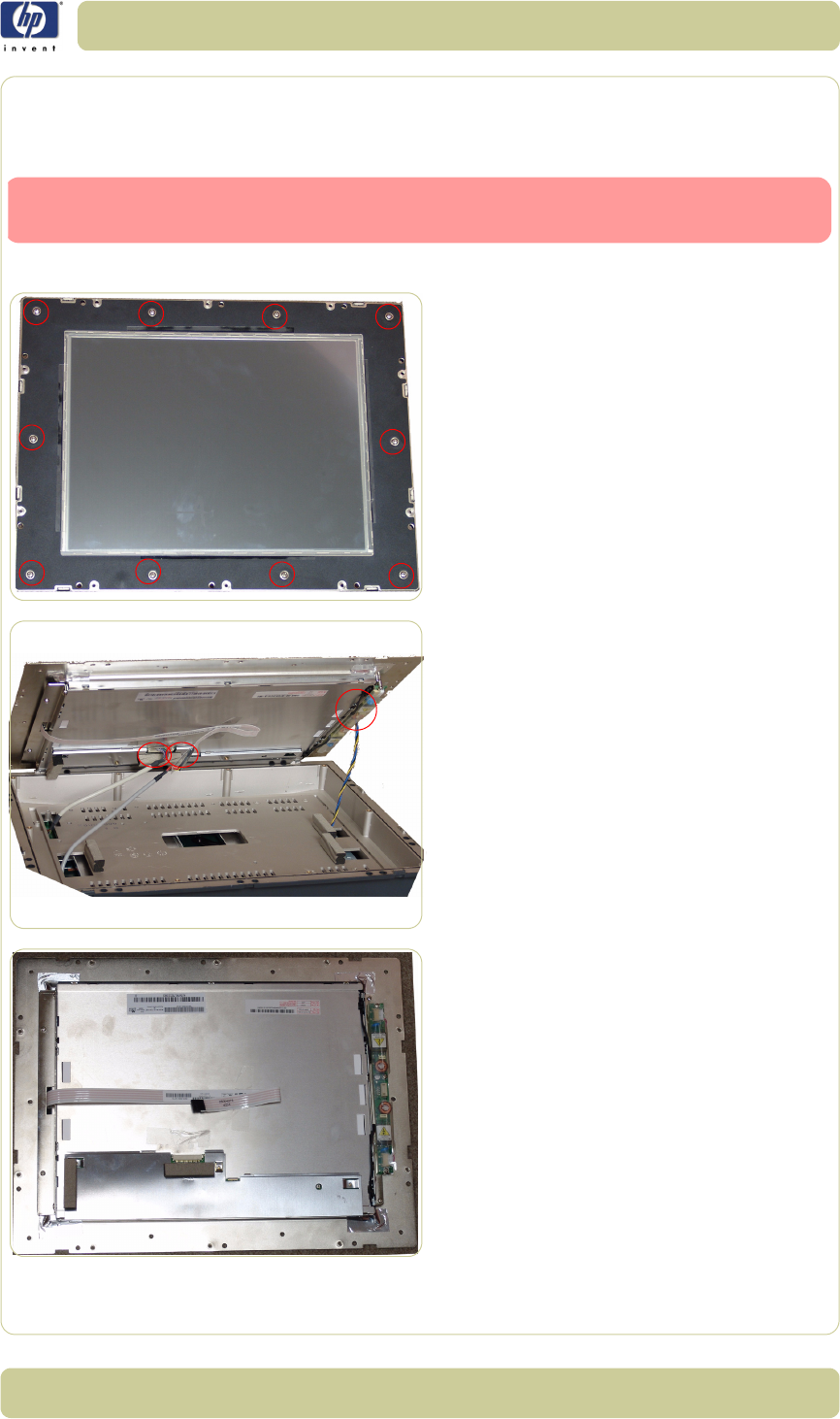
4-83
Removal and Installation
HP Designjet T1100 MFP, 4500mfp, 4500 Scanner, 820 MFP Service Manual
LCD
Removal
1. Remove the Screen Bezel
⇒
Page 4-82.
2. Remove ten screws that secure the LCD to
the PanelPC.
3. Carefully lift up the screen and disconnect
ALL three cables.
4. Remove the LCD.
Switch off the printer, the scanner, and the PC, and then disconnect them from
the power source prior to performing any maintenance.
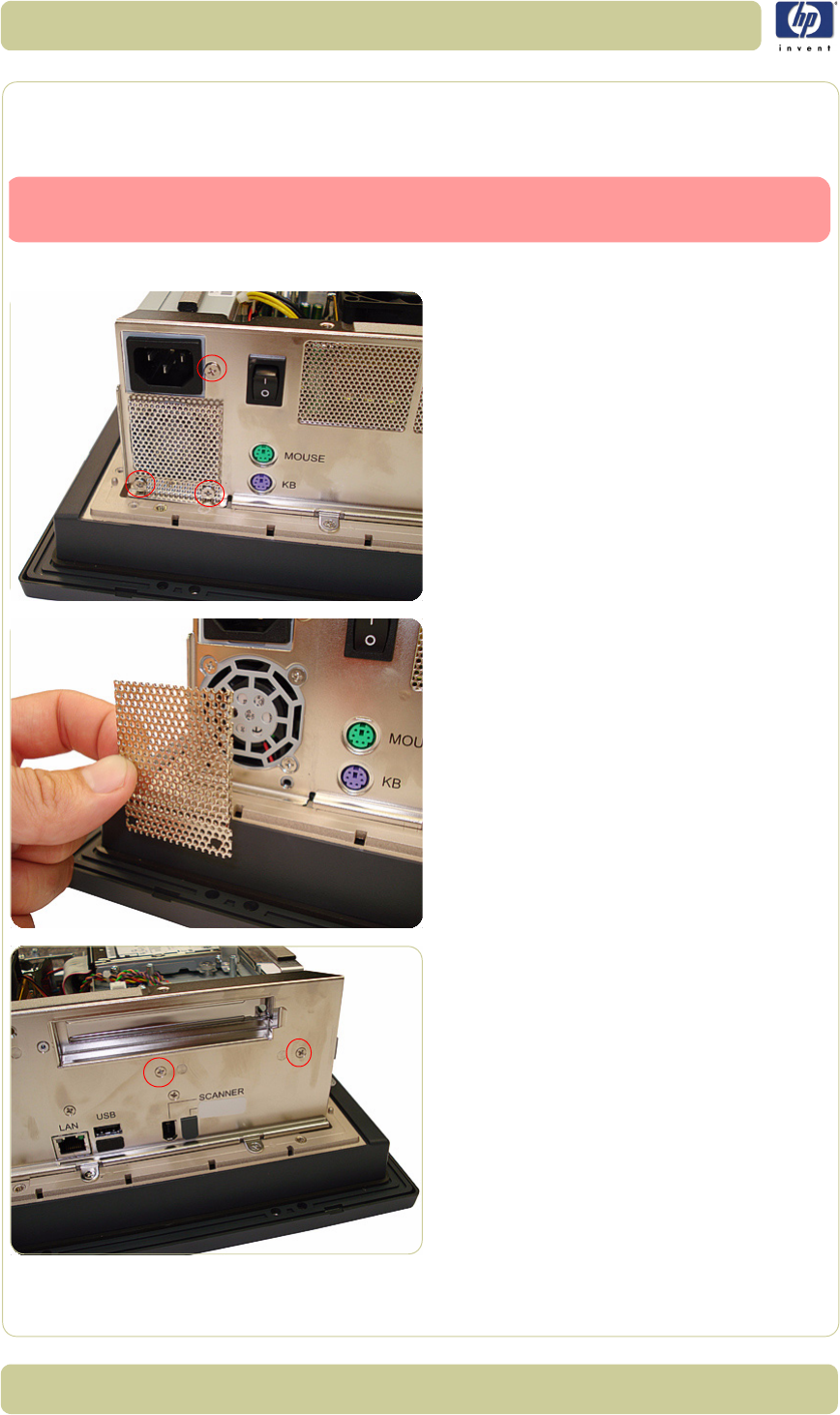
4-84
Removal and Installation
HP Designjet T1100 MFP, 4500mfp, 4500 Scanner, 820 MFP Service Manual
Back Plate
Removal
1. Open Cabinet
⇒
Page 4-79.
2. Use a Phillips screwdriver to remove the
three screws that secure the PSU to the
Back Plate.
3. Remove the metal cover.
4. Use a Phillips screwdriver to remove the
two screws that secure the HDD/DVD deck
to the Back Plate.
Switch off the printer, the scanner, and the PC, and then disconnect them from
the power source prior to performing any maintenance.
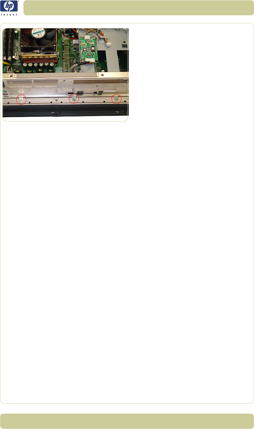
4-85
Removal and Installation
HP Designjet T1100 MFP, 4500mfp, 4500 Scanner, 820 MFP Service Manual
5. Use a Phillips screwdriver to remove the
three screws that secure the Back Plate to
the Cabinet.
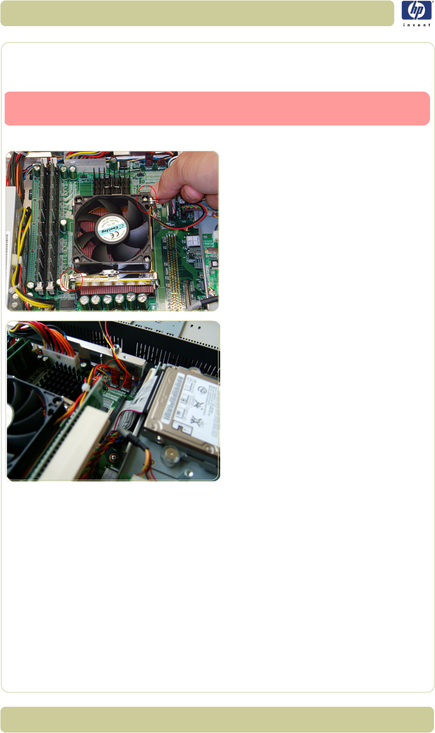
4-86
Removal and Installation
HP Designjet T1100 MFP, 4500mfp, 4500 Scanner, 820 MFP Service Manual
CPU Cooling Fan
Removal
1. Open Cabinet
⇒
Page 4-79.
2. Pull up on the two clips that secure the CPU
Cooling Fan.
3. Disconnect the CPU Cooling Fan Cable
from the Power PCA.
Switch off the printer, the scanner, and the PC, and then disconnect them from
the power source prior to performing any maintenance.
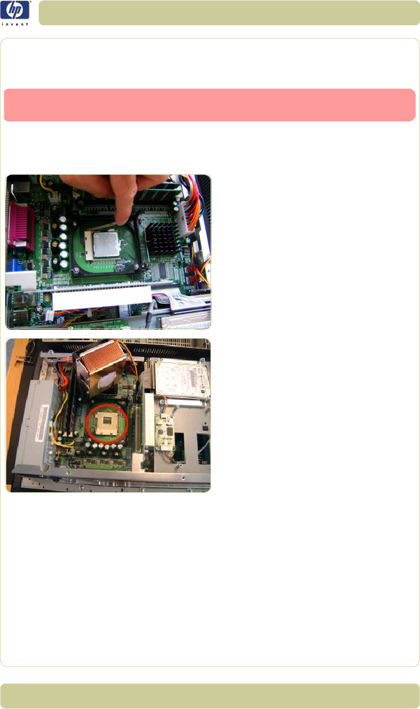
4-87
Removal and Installation
HP Designjet T1100 MFP, 4500mfp, 4500 Scanner, 820 MFP Service Manual
CPU
Removal
1. Open Cabinet
⇒
Page 4-79.
2. Remove the CPU Cooling Fan
⇒
Page 4-
86.
3. Pull aside the clip securing the CPU.
4. Remove the CPU.
Switch off the printer, the scanner, and the PC, and then disconnect them from
the power source prior to performing any maintenance.
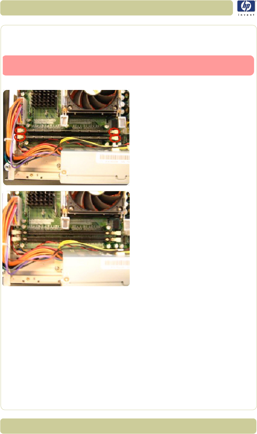
4-88
Removal and Installation
HP Designjet T1100 MFP, 4500mfp, 4500 Scanner, 820 MFP Service Manual
DRAM PCA
Removal
1. Open Cabinet
⇒
Page 4-79.
2. Push the securing clips to the side to
release the DRAM PCA.
3. Remove the DRAM PCA.
Switch off the printer, the scanner, and the PC, and then disconnect them from
the power source prior to performing any maintenance.
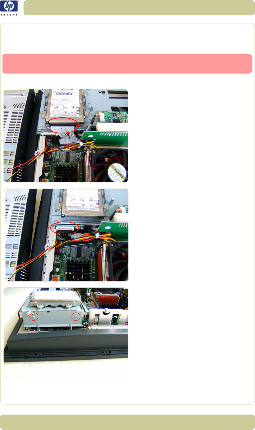
4-89
Removal and Installation
HP Designjet T1100 MFP, 4500mfp, 4500 Scanner, 820 MFP Service Manual
The DVD
Removal
1. Open the Cabinet
⇒
Page 4-79
.
2. Disconnect the cable from the HDD.
3. Disconnect the cable from the DVD.
4. Remove two screws that secure the DVD.
Switch off the printer, the scanner, and the PC, and then disconnect them from
the power source prior to performing any maintenance.

4-90
Removal and Installation
HP Designjet T1100 MFP, 4500mfp, 4500 Scanner, 820 MFP Service Manual
5. Remove the DVD by sliding it out from the
PanelPC.
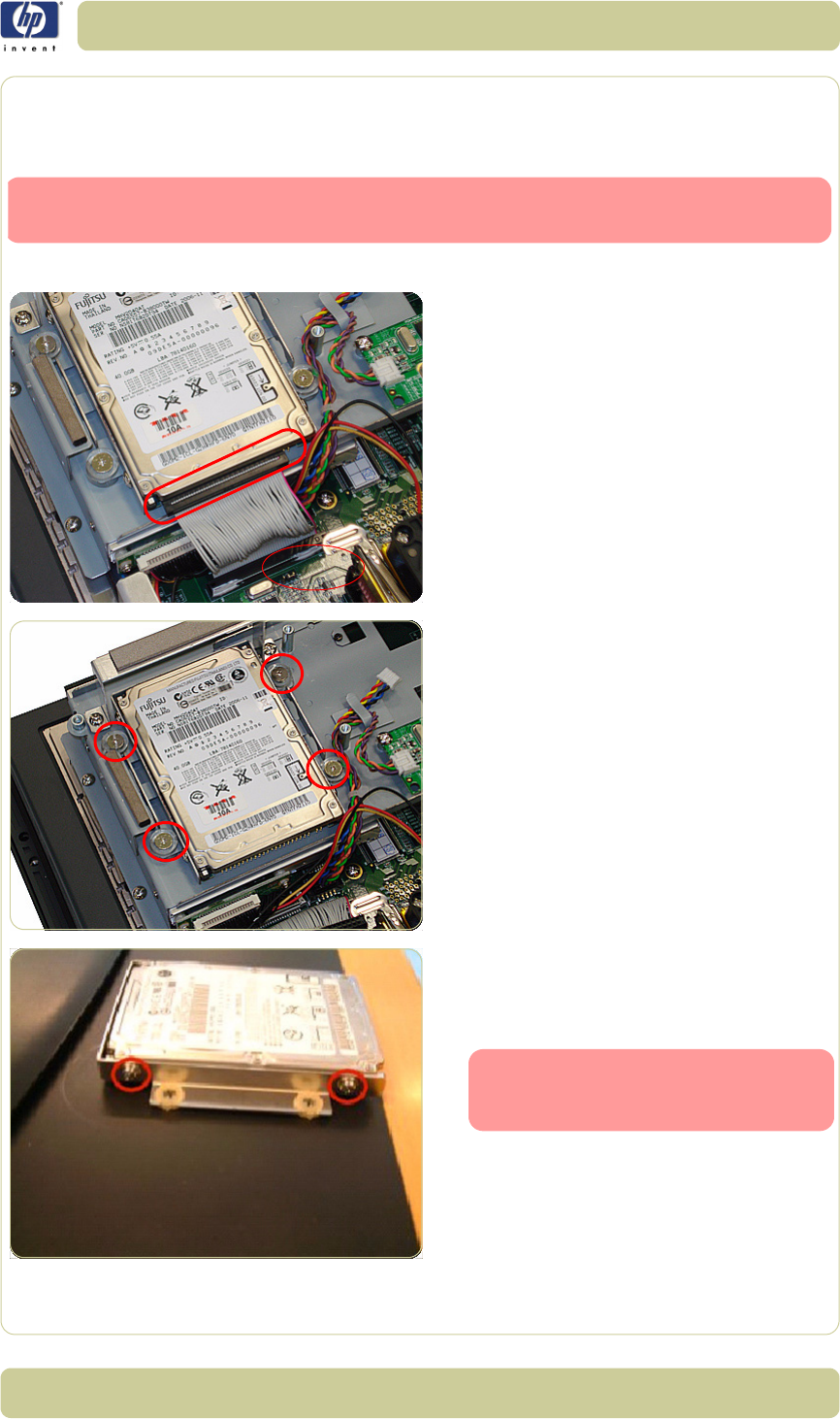
4-91
Removal and Installation
HP Designjet T1100 MFP, 4500mfp, 4500 Scanner, 820 MFP Service Manual
The Hard Disk Drive
Removal
1. Open the Cabinet
⇒
Page 4-79
.
2. Disconnect the cable from the Hard Disk
Drive.
3. Remove four screws that secure the Hard
Disk Drive.
4. Remove the Hard Disk Drive from the
PanelPC and remove four screws (two each
side) from the frame surrounding the Hard
Disk Drive.
Switch off the printer, the scanner, and the PC, and then disconnect them from
the power source prior to performing any maintenance.
After reinstalling the Hard Disk
Drive you will need to reinstall the
system software.
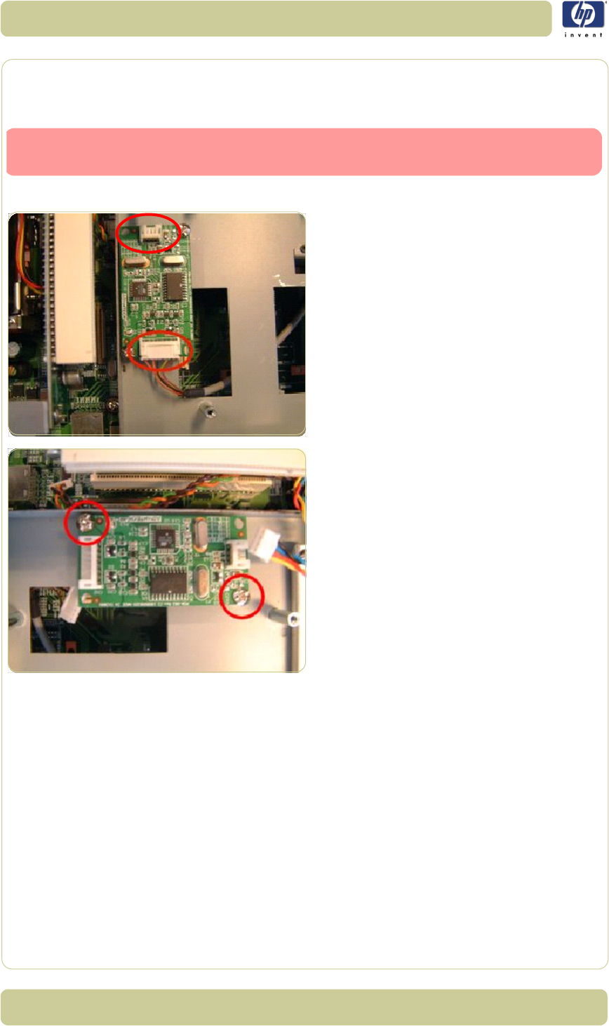
4-92
Removal and Installation
HP Designjet T1100 MFP, 4500mfp, 4500 Scanner, 820 MFP Service Manual
LCD Controller PCA
Removal
1. Open the Cabinet
⇒
Page 4-79
.
2. Disconnect ALL cables connected to the
LCD Controller.
3. Remove two screws that secure the LCD
Controller.
Switch off the printer, the scanner, and the PC, and then disconnect them from
the power source prior to performing any maintenance.
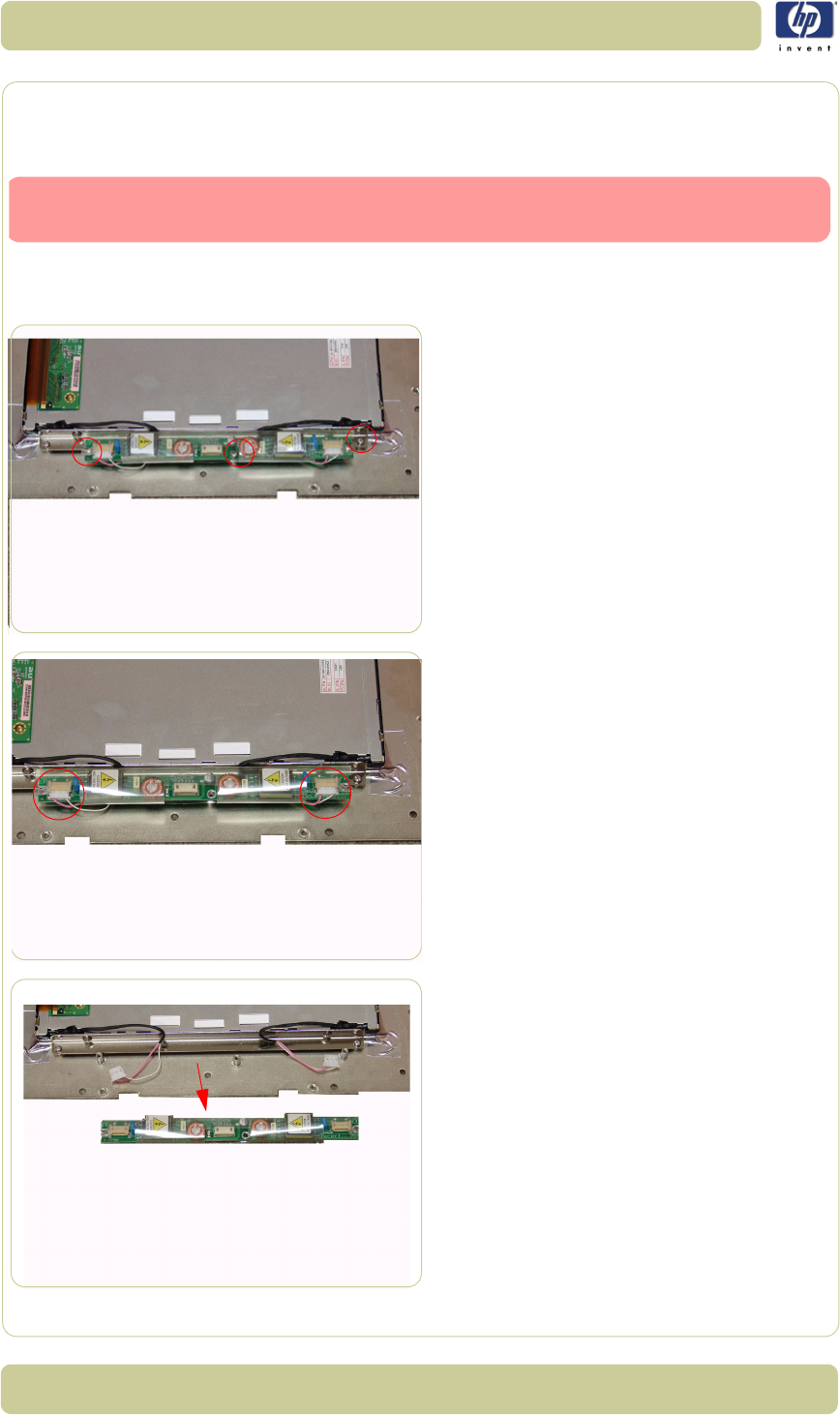
4-93
Removal and Installation
HP Designjet T1100 MFP, 4500mfp, 4500 Scanner, 820 MFP Service Manual
Inverter PCA
Removal
1. Remove the Screen Bezel
⇒
Page 4-82
.
2. Remove the LCD
⇒
Page 4-83
.
3. Use a Phillips screwdriver to remove three
screws that are used to secure the inverter
PCA to the LCD.
4. Disconnect two cables from the inverter
PCA.
5. Remove the inverter PCA.
Switch off the printer, the scanner, and the PC, and then disconnect them from
the power source prior to performing any maintenance.
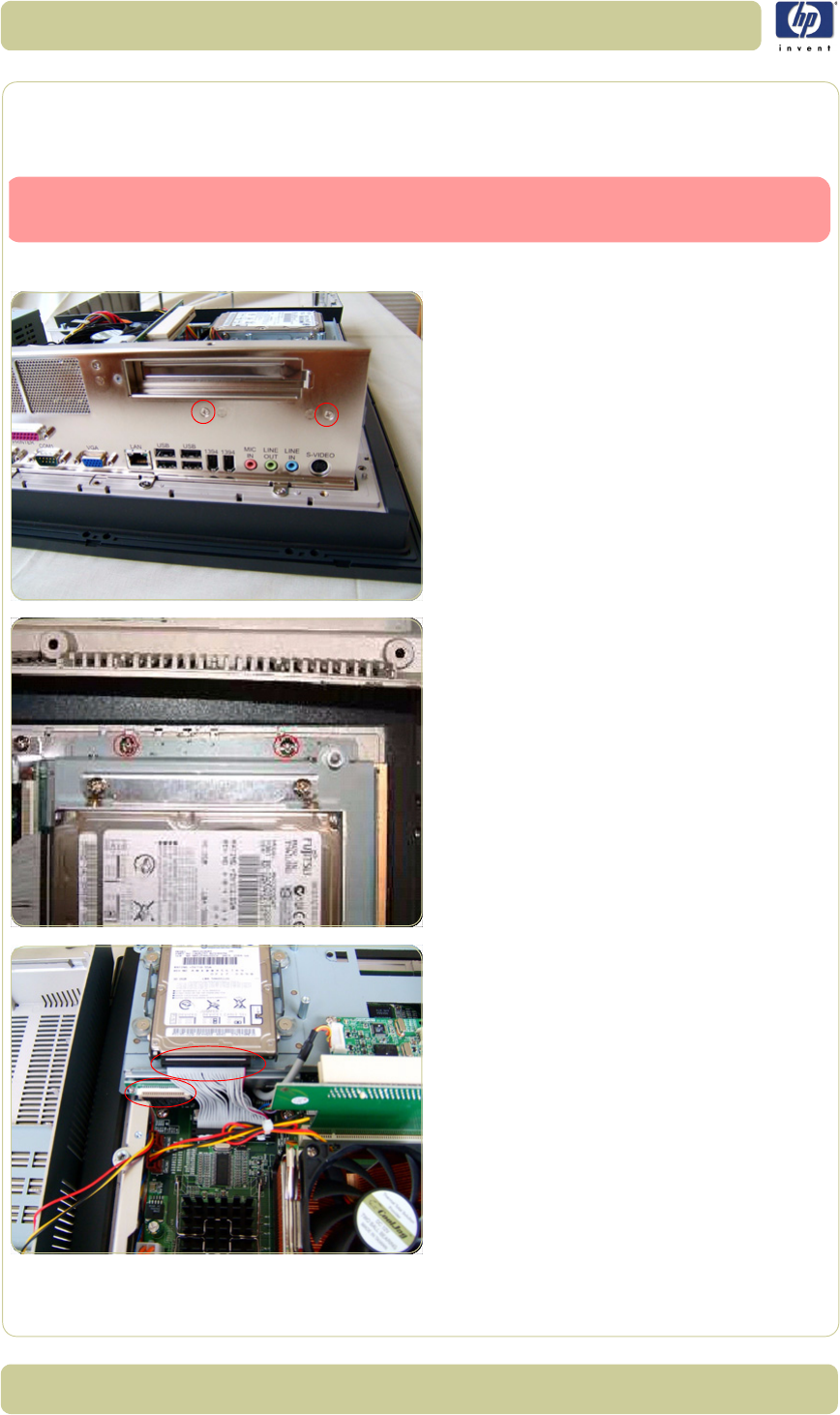
4-94
Removal and Installation
HP Designjet T1100 MFP, 4500mfp, 4500 Scanner, 820 MFP Service Manual
HDD/DVD Deck
Removal
1. Open the Cabinet
⇒
Page 4-79
.
2. Remove two screws that secure the HDD/
DVD Deck to the Back Plate.
3. Remove two screws that secure the HDD/
DVD to the Cabinet.
4. Disconnect two cables from the DVD and
the HDD.
Switch off the printer, the scanner, and the PC, and then disconnect them from
the power source prior to performing any maintenance.
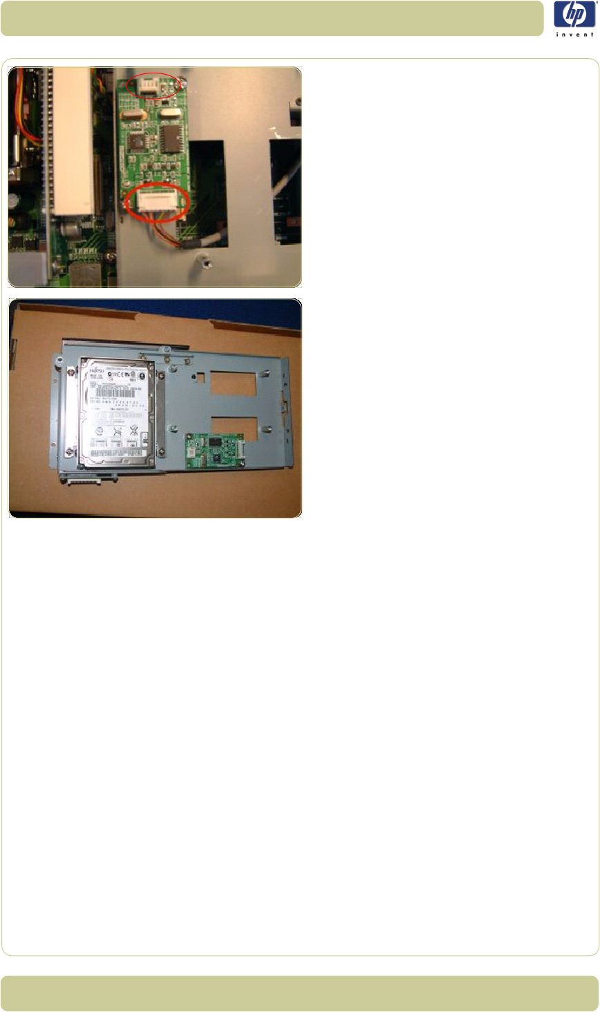
4-95
Removal and Installation
HP Designjet T1100 MFP, 4500mfp, 4500 Scanner, 820 MFP Service Manual
5. Disconnect all cables from the LCD
Controller PCA.
6. Remove the HDD/DVD Deck from the
PanelPCA.
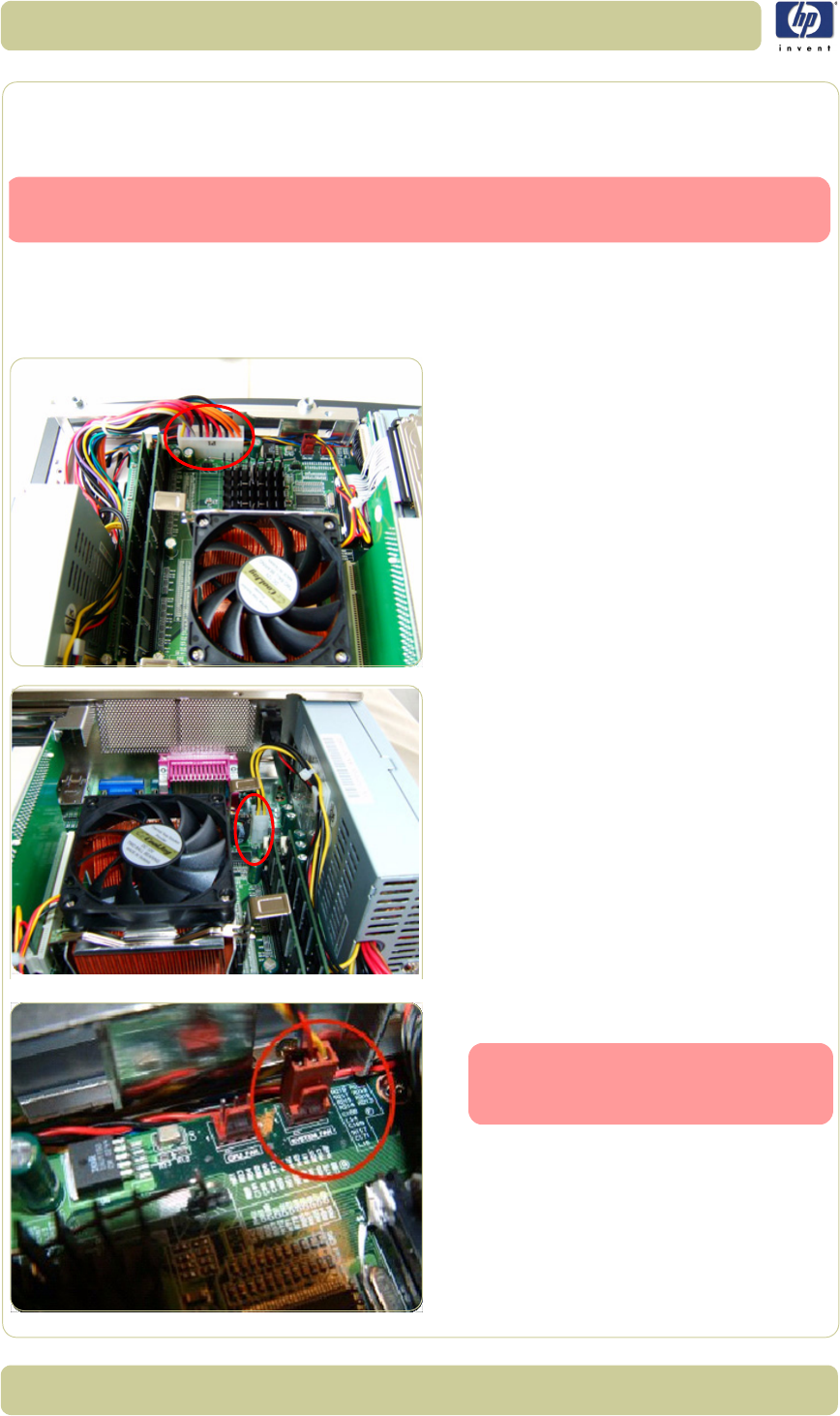
4-96
Removal and Installation
HP Designjet T1100 MFP, 4500mfp, 4500 Scanner, 820 MFP Service Manual
Main PCA
Removal
1. Open Cabinet
⇒
Page 4-79.
2. Remove the Back Plate
⇒
Page 4-84.
3. Remove the HDD/DVD Deck
⇒
Page 4-94.
4. Disconnect the ATX PSU Cable.
5. Disconnect the P4 ATX power cable.
6. Disconnect the System Fan Cable.
Switch off the printer, the scanner, and the PC, and then disconnect them from
the power source prior to performing any maintenance.
For the purpose of installing a new
Main PCA, take note of the cable
routing before you remove.
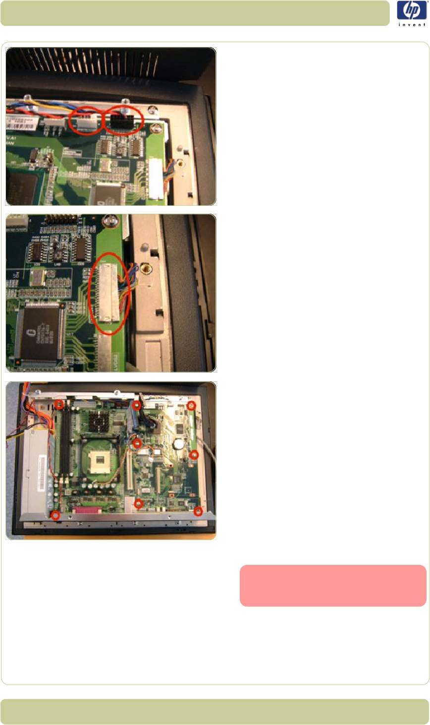
4-97
Removal and Installation
HP Designjet T1100 MFP, 4500mfp, 4500 Scanner, 820 MFP Service Manual
7. Disconnect the Inverter PCA Power Cable
and the Power ON Switch Cable.
8. Disconnect the LVDS1 cable carefully.
9. Remove eight screws that secure the Main
PCA.
10. Remove the Main PCA from the PanelPC.
When installing a new Main PCA,
make sure you install the compo-
nents from the old Main PCA.
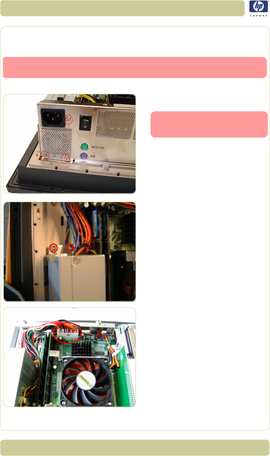
4-98
Removal and Installation
HP Designjet T1100 MFP, 4500mfp, 4500 Scanner, 820 MFP Service Manual
Power Supply Unit
Removal
1. Open the Cabinet
⇒
Page 4-79
.
2. Remove three screws that secure the Power
Supply Unit to the Back Plate.
3. Remove two screws that secure the Power
Supply Unit to the Cabinet.
4. Disconnect the ATX Power Supply Unit
Cable.
Switch off the printer, the scanner, and the PC, and then disconnect them from
the power source prior to performing any maintenance.
These three screws also secure the
System Fan shield to the Back
Plate.
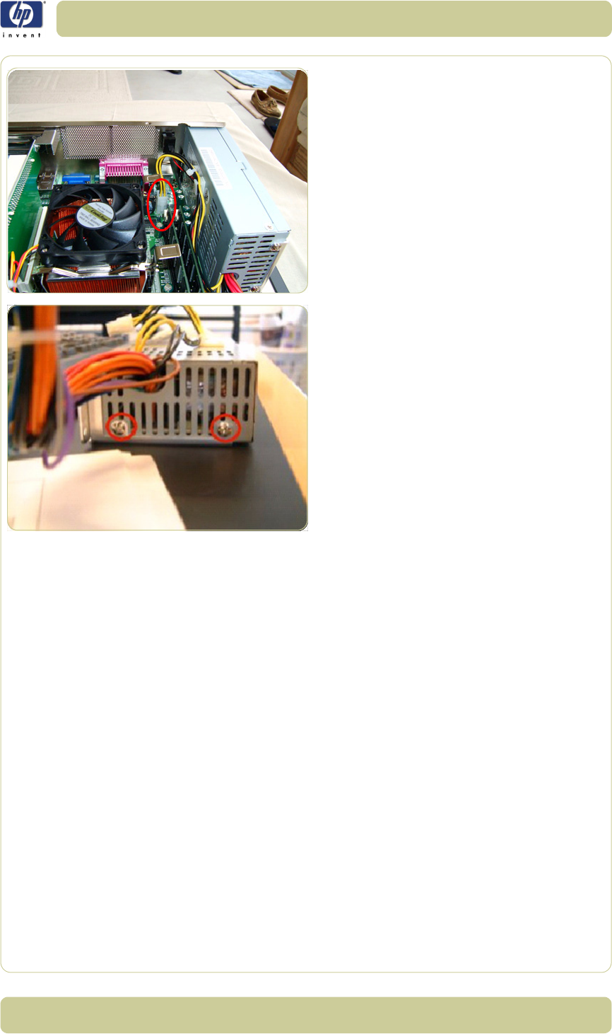
4-99
Removal and Installation
HP Designjet T1100 MFP, 4500mfp, 4500 Scanner, 820 MFP Service Manual
5. Disconnect the P4 ATX Power Cable.
6. Remove two screws that secure the Power
Supply Unit to the metal cover.
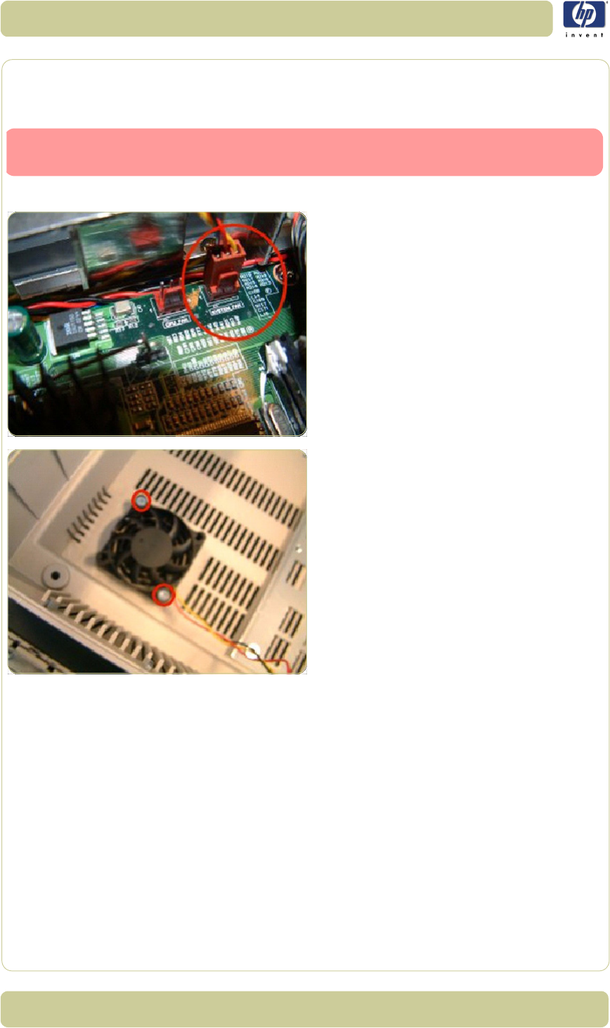
4-100
Removal and Installation
HP Designjet T1100 MFP, 4500mfp, 4500 Scanner, 820 MFP Service Manual
System Fan
Removal
1. Open Cabinet
⇒
Page 4-79.
2. Disconnect the System Fan Cable.
3. Remove two screws that secure the system
fan.
Switch off the printer, the scanner, and the PC, and then disconnect them from
the power source prior to performing any maintenance.

5-1
HP Designjet T1100 MFP, 4500mfp, 4500 Scanner, 820 MFP Service Manual
5Scanner
Adjustments and
Calibrations 1
Introduction 5-2
Tools Required 5-2
Terminology 5-2
Camera Design Overview 5-3
Adjusting the Camera Using Manual Procedure 5-7
Adjusting the Camera Using the Camera Wizard 5-19
Scanner Maintenance 5-26
ATAC Position Sensors check 5-27
Original Guide Sensor Test 5-28
Calibrate ATAC (Automatic Thickness Adjustment Control) 5-32
Upgrade Scanner Firmware 5-33
5

5-2
Scanner Adjustments and Calibrations
HP Designjet T1100 MFP, 4500mfp, 4500 Scanner, 820 MFP Service Manual
Introduction
This chapter explains how to adjust the scanner for optimal scanning-quality.
It describes the adjusting procedures in detail and provides additional
information regarding acceptance criteria.
A general concept when adjusting the scanner is to loosen screws just
slightly. If you loosen the screws too much, you will have difficulties
controlling the adjustments, because of too much play in the adjustment
levers and other adjustment points. Unless this chapter states otherwise,
always loosen screws and nuts only slightly. They should be snug; there
should be no play when you try to wiggle them. When tightening a set of
screws, tighten all of them little by little, rather than fully tightening one, and
then another, and so on.
Tools Required
To perform the Camera Adjustment you will need:
Focus Adjustment Pattern sheet (included in the Service Patterns pn
Q1277-60030).
Optical Adjustment Pattern (pn Q1277-60031).
Torx 10
Torx 20
To perform the Sensor Adjustments you will need:
Adjustment Tools for ATAC Sensors (Q1277-60084).
Torx 10
Terminology
Throughout this chapter a number of visual elements are used to guide you
through the adjustment process.
The exclamation mark is used to point out possible sources of errors. If
something can go wrong when performing a specific action, this visual item
describes it.
Thumps up symbol is used with hints, tips and tricks that make a specific
action easier to complete.
A hand in an illustration means that this particular adjustment does not
require a tool. It can be adjusted with your fingers.
A screwdriver in an illustration means that this particular adjustment requires
a tool. It cannot be adjusted with your fingers alone.
Text in bold describes a mechanical part, an item, or a program button,
which can be located in one of the illustrations.
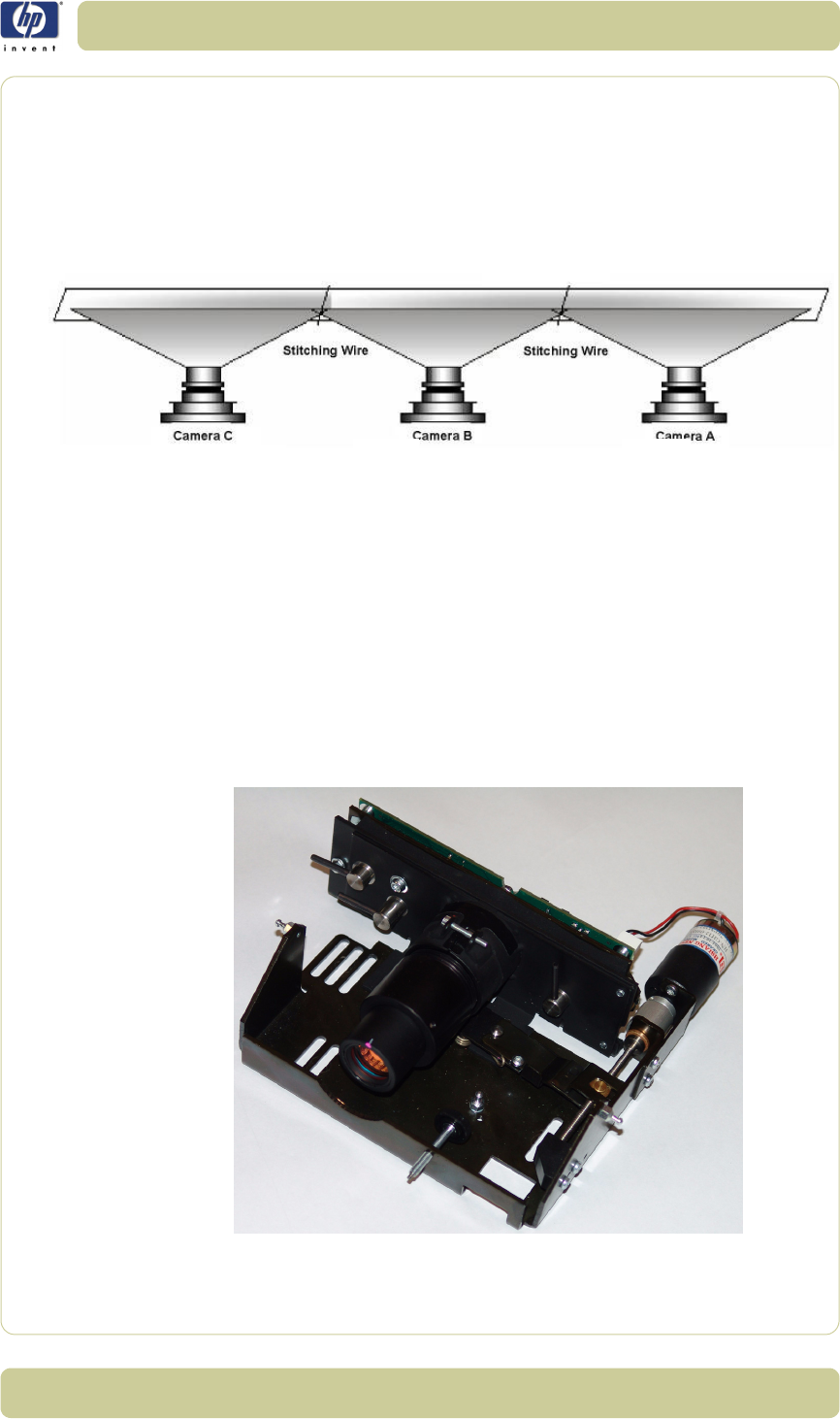
5-3
Scanner Adjustments and Calibrations
HP Designjet T1100 MFP, 4500mfp, 4500 Scanner, 820 MFP Service Manual
Camera Design Overview
Introduction
The HP Designjet scanner uses 3 cameras, where each camera scans its own
part of the image.
The cameras are named A, B and C. Camera A is on the right and Camera
C is furthest to the left. The cameras scan-area overlaps slightly, this is to
ensure that the scanner scans the complete image.
Most of the scanner adjustments are focused on getting the correct Scan-
Width. The adjustment ensures that a camera scans the right amount of
image data so that the basic DPI resolution of the camera is precise. This
fine-tunes the accuracy of the scanner. A metal wire (stitching wire) in the
overlapping area helps the scanner to adjust the cameras electronically.
The following picture shows what the camera actually looks like. Only
Camera A and C have a motor at the rear (Camera B does not have a
motor).
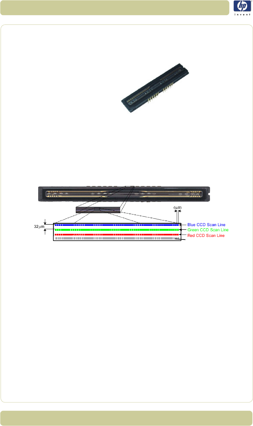
5-4
Scanner Adjustments and Calibrations
HP Designjet T1100 MFP, 4500mfp, 4500 Scanner, 820 MFP Service Manual
The CCD Element
The central component of the Camera is the Sony CCD (Charge Coupled
Device) element, which is responsible for capturing the colors reflected from
the original image.
The CCD is formed as a chip, and is inserted into a standard dual in-line
socket just like a normal chip. The chip has 4 rows each containing 7500
pixels.
The 4 rows each scan a different color. Combined, the 3 rows provide 24 bit
color. The last row is for panchromatic scanning. Each CCD pixel is formed
as a square with a side length of 5 µm. There is 40 µm between the
adjacent lines.
Grey Line
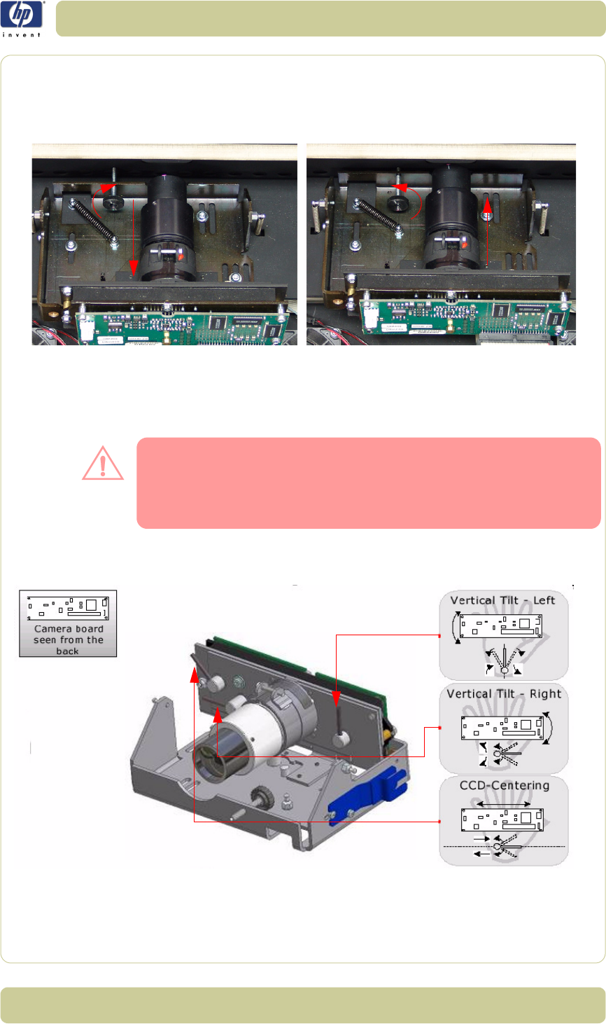
5-5
Scanner Adjustments and Calibrations
HP Designjet T1100 MFP, 4500mfp, 4500 Scanner, 820 MFP Service Manual
Camera Board Adjustments
The Scan-Width Adjustment Screw moves the camera backwards and
forwards, which influences the Scan-Width of the camera.
When the Scan-Width Screw is screwed in, as illustrated on the left side
of the above picture, the camera has a greater possible scan-width. When it
is screwed out (right side of picture), the camera has a smaller possible scan-
width.
The
Scan-Width Screw
is fixed on the camera assembly and not on the
scanner chassis. This means, that when screwing the screw backwards, you
have to loosen two T15 screws and push the camera forward manually to
decrease the scan-width. When screwing forward, the screw will push the
camera backwards on it’s own.
The CBE Camera Board, where the CCD is placed, can be moved relative to
the camera using 3 adjustment levers.
This is an easy and quick way of adjusting the camera, as it does not involve
moving the camera itself, but only the camera board, which can be done
very precisely.
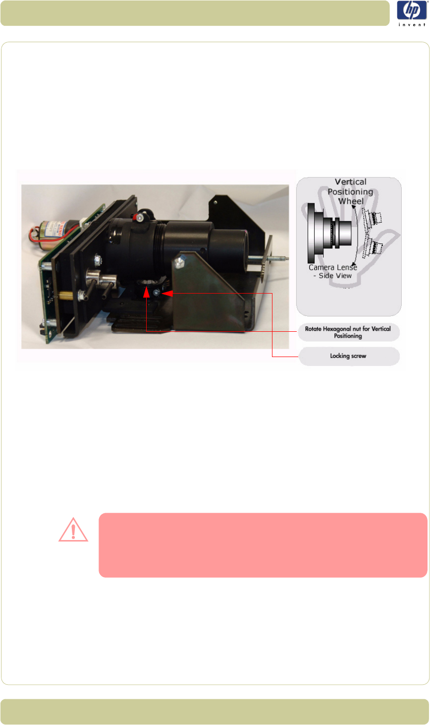
5-6
Scanner Adjustments and Calibrations
HP Designjet T1100 MFP, 4500mfp, 4500 Scanner, 820 MFP Service Manual
Vertical Tilt – Left: moves the left upper edge of the CCD Mounting
Plate and the CBE Camera Board up and down, making the field of
vision tilt in proportion to the horizon.
Vertical Tilt – Right: moves the right upper edge of the CCD Mounting
Plate and the CBE Camera Board up and down, making the field of
vision tilt in proportion to the horizon.
CCD Centering: moves the CCD Mounting Plate and the CBE
Camera Board horizontally left and right and thereby making the field
of vision move horizontally left and right.
The camera itself can be tilted up and down which causes the field of vision
to move up and down. The Vertical Positioning Hexagonal Nut is
used for coarse adjustments and the Tilt Levers are used for finer
adjustments. When you rotate the Vertical Alignment Hexagonal Nut
counter-clockwise you raise the camera and the field of vision and vice
versa.
To rotate the Vertical Positioning Hexagonal Nut use the adjustment
tool which comes with the Camera B, the tool is shown mounted on the side
of the camera in the grapic on the previous page.
When using the
Vertical Positioning Hexagonal Nut
, loosen the
Lock
Screw
first, so that the
Vertical Alignment Arm
doesn’t move
simultaneously. You will normally not adjust directly on the
Vertical
Alignment Screw
, but instead via an extension and through a hole in the
scanner front.
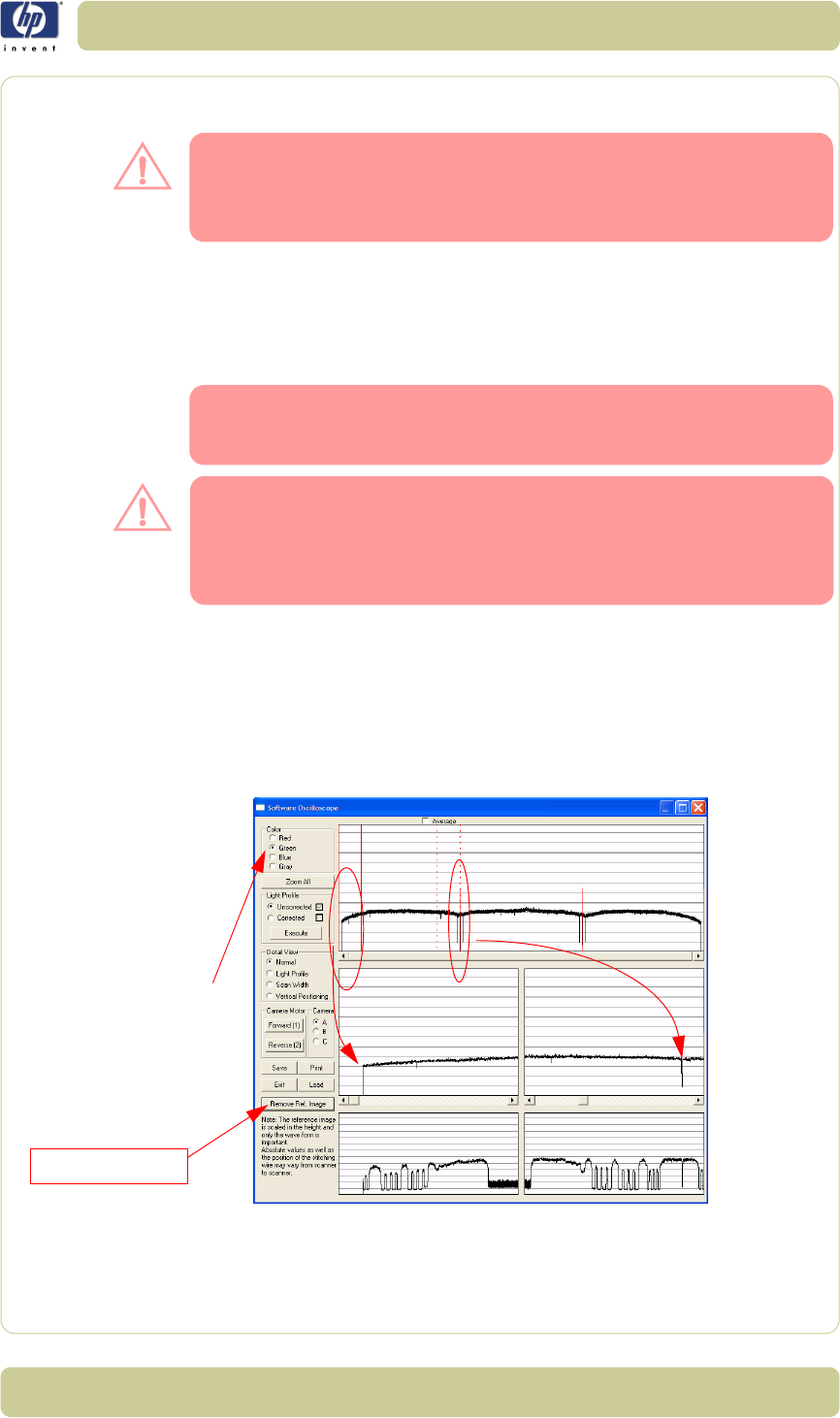
5-7
Scanner Adjustments and Calibrations
HP Designjet T1100 MFP, 4500mfp, 4500 Scanner, 820 MFP Service Manual
Adjusting the Camera Using Manual Procedure
This Chapter explains how to adjust Camera A manually using
oscilloscope sofware which comes with the scanner. In this
procedure we focus on Camera A, but the procedure is exactly
the same for Cameras B and C.
It is important that you use this procedure (Test 9) to manually
adjust the camer and NOT the Camera Adjustment Wizard
(Test 27).
Light Profile
Make sure that the left and right covers are installed and the
top cover is removed. The scanner and the touch screen must
be switched ON.
When you install a camera in the scanner for the first time, the camera is
completely out of adjustment. If you get an Error 30 from SCANtest when
setting the Light Profile to Corrected, start with Uncorrected and follow
steps 3 and 4 as well as you can and then start over with the Corrected
Light Profile again.
The first thing to be done before adjusting the camera that has been
replaced is to ensure that the camera is at least looking in the right direction.
1Make sure that camera is completely installed and all cables are correctly
connected.
2Select button 9. Camera Adjustment in SCANtest 6.
3A software oscilloscope is now activated and looks something like this:
4You see the uncorrected light profile, for Cameras A, B and C that the
scanner receives from the reflection of the White Background on the back of
the Guide Plate. Camera A is on the left, Camera B is in the middle and
Camera C is on the right. You can zoom in with the buttons on the touch
Camera A Camera B
Reference Image
Select the Reference
Image button in order
to view the Reference
Image section
Camera C
When the uncorrected
light profile is
selected, verify that
the Green color
channel is selected.
You adjust the scan
width, tilt, and height
in uncorrected mode.
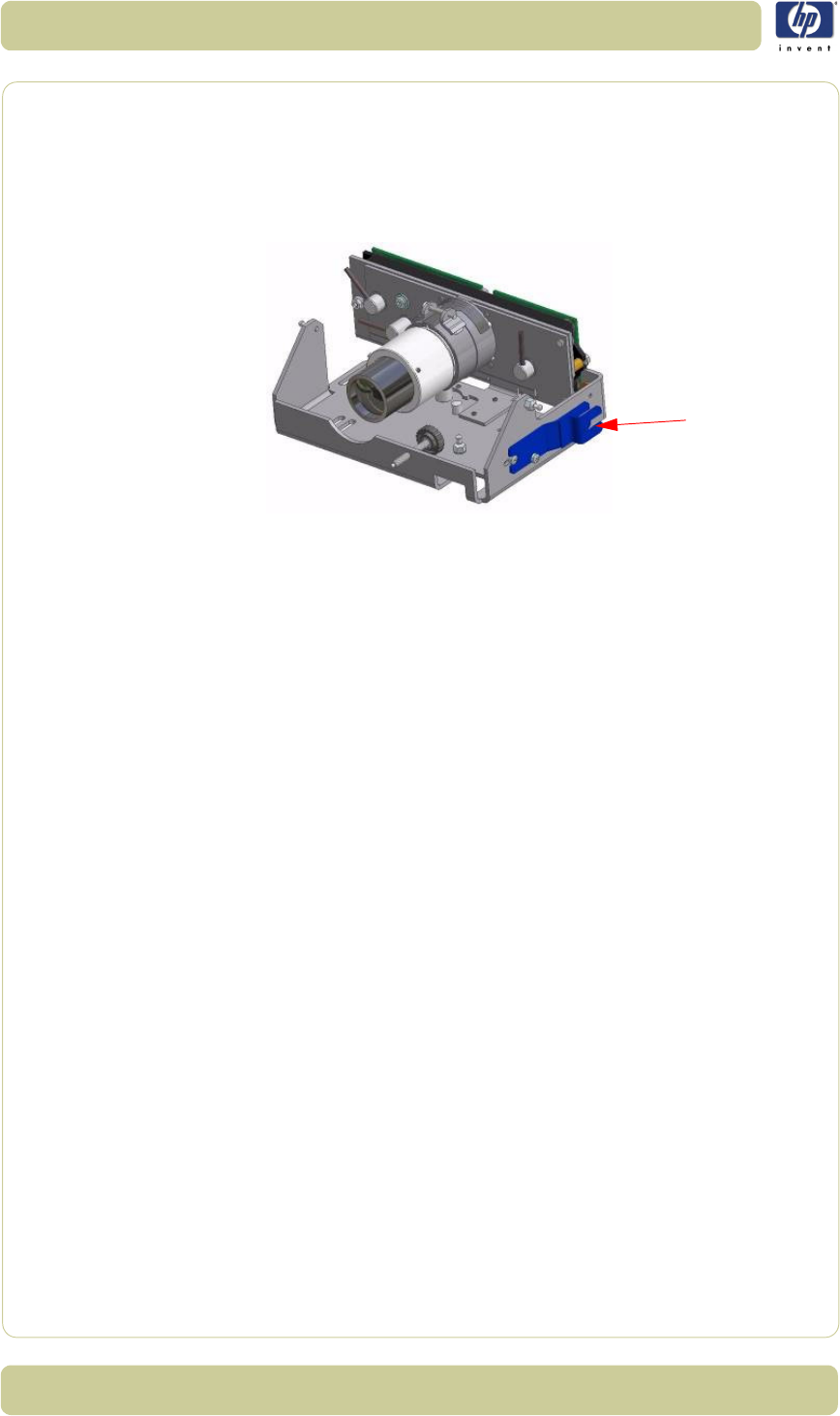
5-8
Scanner Adjustments and Calibrations
HP Designjet T1100 MFP, 4500mfp, 4500 Scanner, 820 MFP Service Manual
screen. You can see that the output is lower at the edges. This is because of
the lens in the camera. If you get a screen that looks distorted in comparison
with the above image, then maybe your camera is looking into the chassis
instead of the mirrors in the copier. To correct this, use the tool to rotate the
Vertical Alignment Screw located underneath the camera, rotate the screw
left or right until you get an oscilloscope image similar to the one shown.
Focus Adjustment
The first adjustment that you need to make is the focus. This adjustment
ensures, that the camera has the right focus, so that the following
adjustments aren’t blurred out. The focus setting is not as sensitive as some of
the other adjustments, which makes it a good example to start with. When
you are finished with all the adjustments, you should check the focus again
just to be sure that it’s still OK.
1Stay in the Software Oscilloscope and select Corrected and then press the
Execute button. Only adjust the focus in the corrected mode. Make sure
that the Blue color channel is selected.
Camera
Adjustment tool
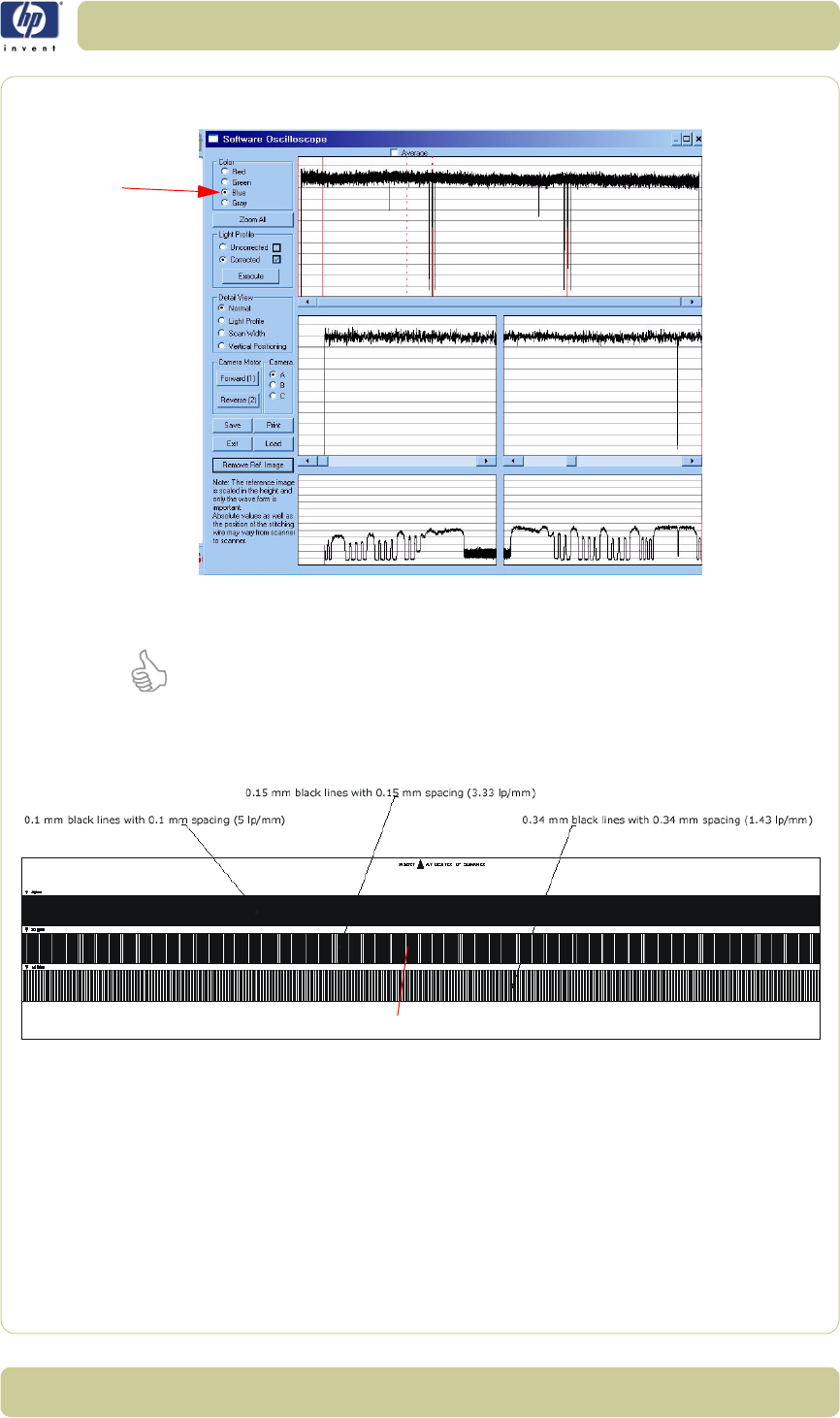
5-9
Scanner Adjustments and Calibrations
HP Designjet T1100 MFP, 4500mfp, 4500 Scanner, 820 MFP Service Manual
2Wait approximately 90 seconds until SCANtest 6 is ready.
3Insert the Focus Pattern in the scanner.
It’s best to insert the sheet from the back of the copier and use the Reverse
Key to position the pattern correctly. This way the sheet won’t cover the
cameras when you adjust them. It requires a little practice but makes the
focus adjustment a lot easier.
Use the operation panel keys to move the sheet so that the cameras see the
Make sure that the
Blue color channel
is selected.
The middle pattern is to be used for adjustment
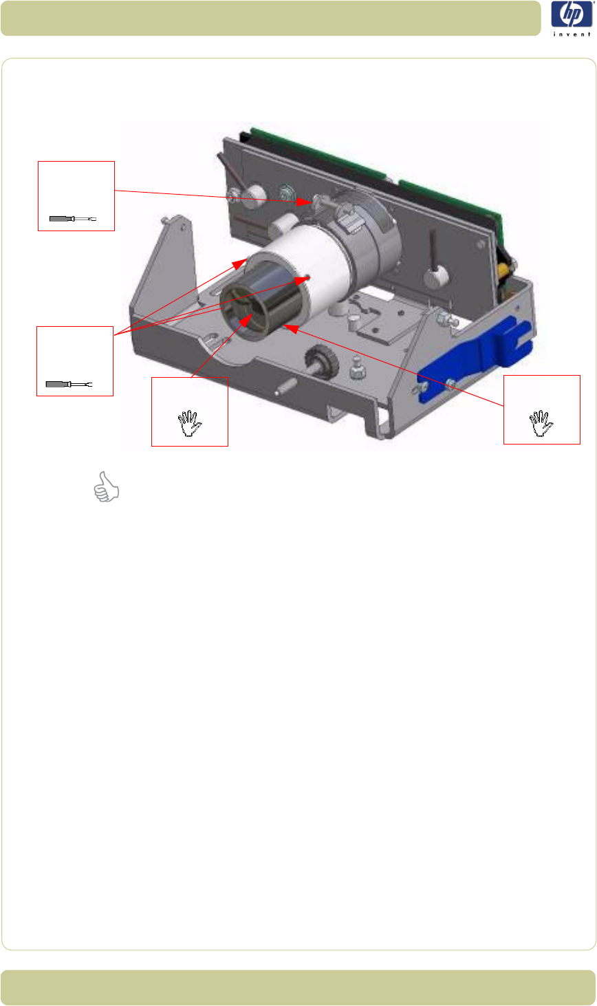
5-10
Scanner Adjustments and Calibrations
HP Designjet T1100 MFP, 4500mfp, 4500 Scanner, 820 MFP Service Manual
3.33 lp/mm pattern.
4
Loosen the
Focus Lock Screw
and turn the
Lens Adapter
to adjust the
focus.
The Focus adjustment greatly influences the Scan-Width. Therefore, the Scan-
Width must be checked and readjusted whenever the Focus adjustment has
been changed.
The Focus adjustment, however, is realatively tolerant to Scan-Width
adjustments. After adjusting the Scan-Width, check the Focus adjustment
again; it will only need further adjusting if the Scan-Width has change
greatly. However, you should check both the Focus and the Scan-Width after
an adjustment to either to ensure that they are both correctly adjusted.
Loosen the Focus Lock Screw and ensure that it is not too loose. Turn the
Lens Adapter until you get this picture on the software oscilloscope
Focus
Lock
Screw
Lens
Adapter
Lens
Fixing
Screws
Lens
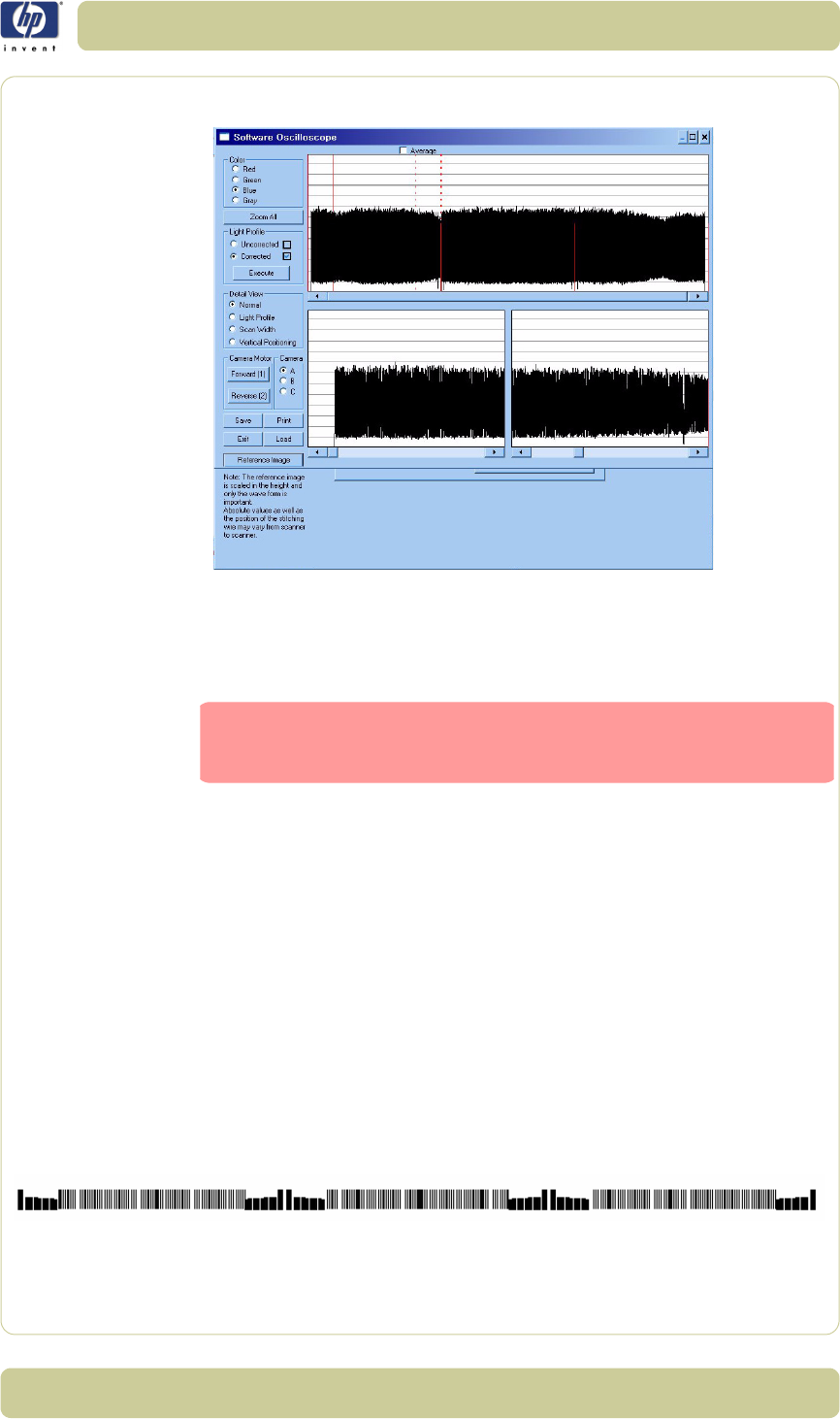
5-11
Scanner Adjustments and Calibrations
HP Designjet T1100 MFP, 4500mfp, 4500 Scanner, 820 MFP Service Manual
(Camera A has been zoomed in):
The signal has to be as even as possible and especially the ends have to be
at their highest possible level.
When the focus is right, tighten the Focus Lock Screw.
There is a mark on every lens, which indicates its “best position”. If you have
completed the focus adjustments and this mark isn’t pointing upwards, mark
the upward position on the Lens Adapter. Turn the Lens Adapter and
loosen the Focus Lock Screw and the three Lens Fixing Screws (with a
1,5 mm Allen key). Then turn the Lens so that the mark is pointing upwards,
tighten the Lens Fixing Screws again. Turn the Lens Adapter back
again and check that the focus it still correct before tightening the Focus
Lock Screw.
Scan-Width Units
When adjusting the Scan-Width, you adjust up against some line on an
Optical Adjustment Pattern.
The Optical Adjustment Pattern is a metal construction with a pattern glued
Keep in mind that if you adjusted the Focus, the Scan-Width
has changed and must be adjusted.
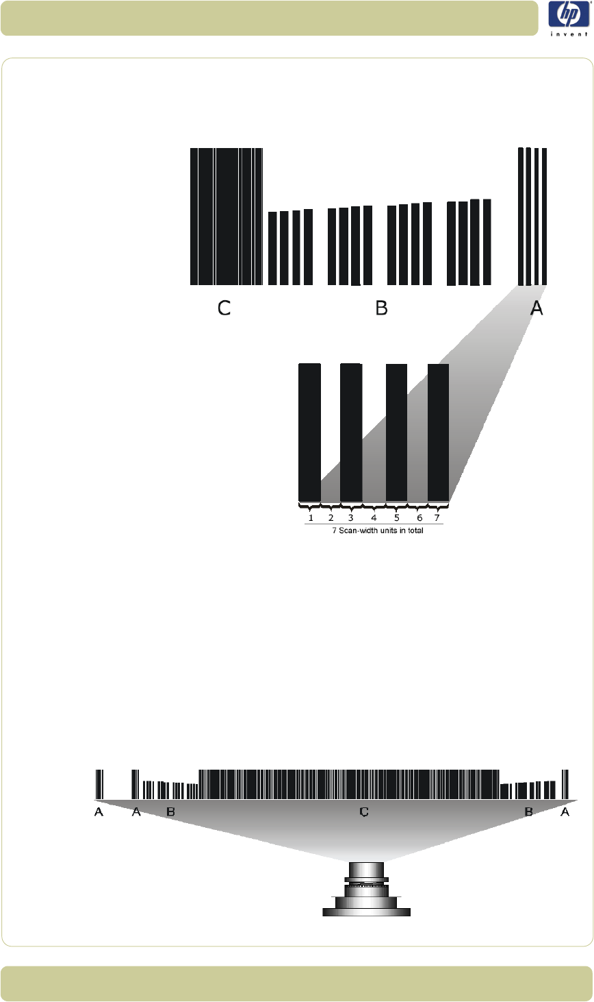
5-12
Scanner Adjustments and Calibrations
HP Designjet T1100 MFP, 4500mfp, 4500 Scanner, 820 MFP Service Manual
on one side. This pattern contains three sub-patterns: A, B and C.
Sub-pattern A contains a pattern used for Scan-Width adjustment.
Sub-pattern B contains a pattern used for Vertical Position adjustment.
Sub-pattern C contains a pattern used for coarse Focus adjustment.
The A part of the pattern consists of scan-width units (SWU).
Each of the black lines represents a scan-width unit (SWU) as does the white
space in between the lines. This makes a total of seven SWU’s.
The black lines and whites spaces work like a marker or indicator that tells
you how wide the camera scan-width is.
The scan-width units help you adjust the cameras, so that they have the
correct scan-width. This ensures that the scanner has the correct optical
resolution. Thereby ensuring that the scaling factor of the scanner is correct.
Camera A has three A patterns in its view:
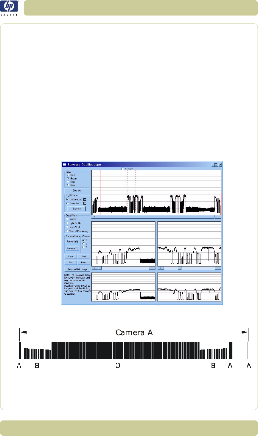
5-13
Scanner Adjustments and Calibrations
HP Designjet T1100 MFP, 4500mfp, 4500 Scanner, 820 MFP Service Manual
To ensure that the camera has the correct optical resolution, you are going to
adjust the camera, so that it covers six scan-width units. This means that the
camera has to see a total of six units at the ends of the view field. This can
be two on the left and four on the right or five on the left or one on the right.
The unit arrangement is not important as long as there are six in total.
Later on you will center the camera, so that there will be three units at each end.
Scan-Width Adjustment
The purpose of Scan-Width adjustment is to position the camera so the field
of vision is correct.
1Open the Guide Plate and place the Optical Pattern on the scanner. Align
the pattern by pressing it to the right towards the operator panel and
backwards toward the back of the scanner.
2If not selected, select button 9 in SCANtest 6. Select Uncorrected Light
Profile and press Execute (make sure that the Green Channel is selected).
3This is what Camera A is going to see, when the scan-width adjustment is
finished:
Camera A scans from right to left, so the image above is a mirrored section
of the total Scan-Width pattern as the copier actually sees it. The
camera only sees a single line of pixels with the green CCD pixel line that
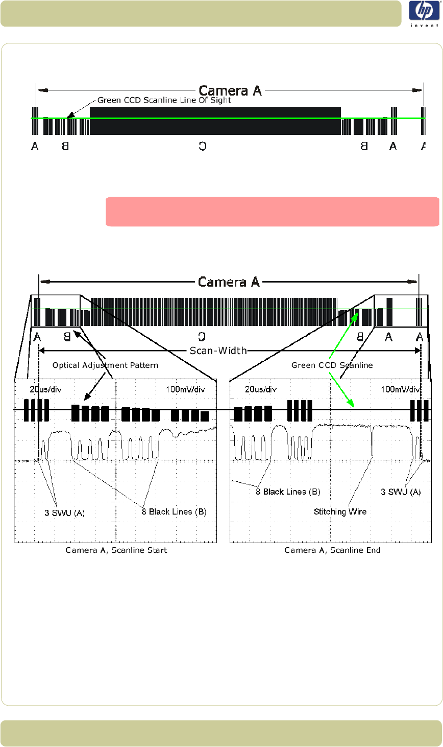
5-14
Scanner Adjustments and Calibrations
HP Designjet T1100 MFP, 4500mfp, 4500 Scanner, 820 MFP Service Manual
we enabled under step 2. The goal is to adjust the camera so that the green
pixel line of the CCD is positioned as the green line below:
When you have succeeded in getting this, most of the adjustments for
Camera A are finished.
But first we start by setting the Scan-Width of Camera A. You use the
software oscilloscope to guide you, and this is what you are going to see:
In the image you see a real oscilloscope image of the left- and the right most
part of the Camera A Scan-Width pattern. Whenever the camera sees
a black line, the output level goes down. It goes up when seeing white.
When the Green CCD Scanline is in the correct position, each end of the
camera output will have the appearance as shown.
4Now press Scan Width under Detail View on the software and the
program automatically zooms in on the left and right part (Scanline Start/
If the scan width changes by more than one scan-width unit
(SWU), you must check the focus.
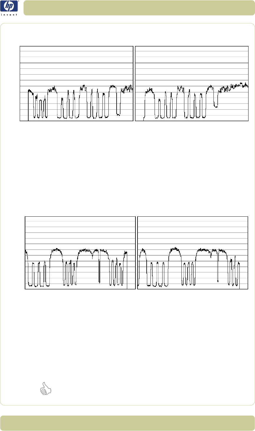
5-15
Scanner Adjustments and Calibrations
HP Designjet T1100 MFP, 4500mfp, 4500 Scanner, 820 MFP Service Manual
End) of the output. On the left side you will get an output like one of these (or
something in between):
The output we are aiming for can be seen below, therefore:
The left output is too much to the left – if you have an output like this, you
need to slide the CCD board to the right by turning the CCD Centering
tab upwards.
The right output is too much to the right – if you have an output like this,
you need to slide the CCD board to the left by turning the CCD
Centering tab downwards.
5When you have one, two or three scan-width units (SWU) on the left side of
the camera, look at the right side of the camera.
6On the right side (Scanline End) you will get output like one of the following:
Remember how many scan-width units you had on the left side and
remember that there has to be six in total.
If you had three SWU’s on the left side of the output you also have to have
three on the right and the output we are aiming at is as shown below.
Therefore:
On the left picture above the Scan-Width is too wide – if you have an
output like this, you need to move the camera forward to decrease the
Scan-Width.
On the right picture above the Scan-Width is too narrow - if you have an
output like this, you need to move the camera backward to increase the
Scan-Width.
Look for the Stitching Wire. There’s only one of these on the right side of
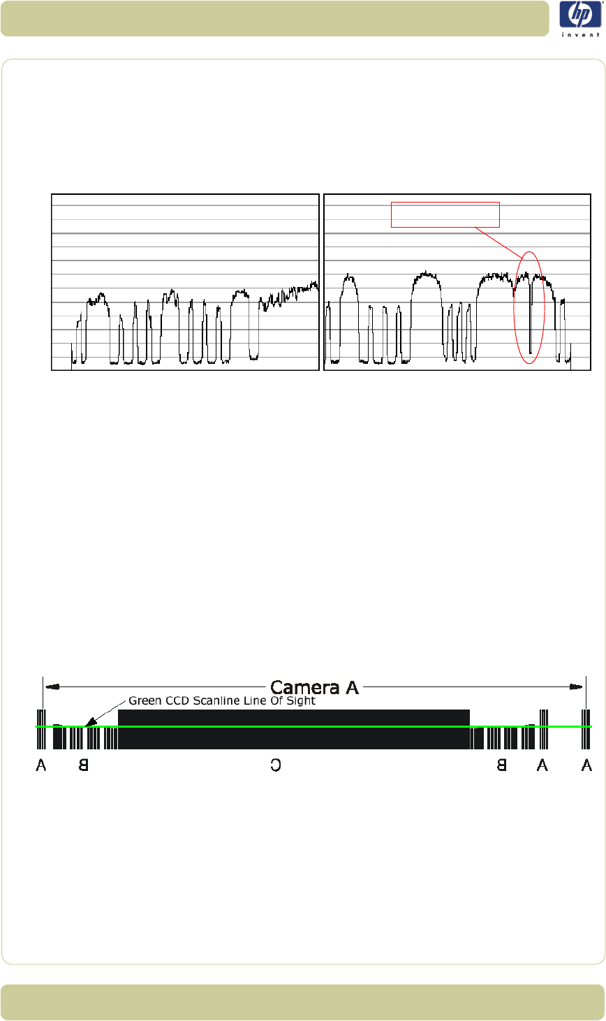
5-16
Scanner Adjustments and Calibrations
HP Designjet T1100 MFP, 4500mfp, 4500 Scanner, 820 MFP Service Manual
the camera. If you don’t see the Stitching Wire, then the camera has to be
pulled back quite a lot because the scan-width is too narrow.
7Repeat steps 4 to 6 until the camera sees a total of six SWU’s.
8When you have six SWU’s in total, use the CCD-Centering lever to adjust
the camera so that there is three SWU’s on each side of the camera as
shown below:
9Check the focus again because large changes to the Scan-Width adjustment
also affects the focus.
10 If the focus needed adjusting, start over with the Scan-Width from step 4,
because a slight change in the focus will affect the Scan-width considerably.
11 When you are finished, and both the focus and the Scan-Width are correct,
tighten the three Camera Fixing Screws without moving the camera.
12 Proceed to the Vertical Positioning section without altering anything about
your set-up.
Vertical Positioning
The purpose of the vertical positioning is to adjust the camera, so the
Green CCD Scanline looks at the correct vertical position on the Optical
Adjustment Pattern as seen on the picture below. Furthermore it ensures
that the Scanline is horizontal.
1SCANtest 6 should still show Uncorrected Light Profile, Green. If not,
change it to those settings.
2Loosen the Camera Back-Plate Fixing Screws if they are not already
loose.
Stitching Wire
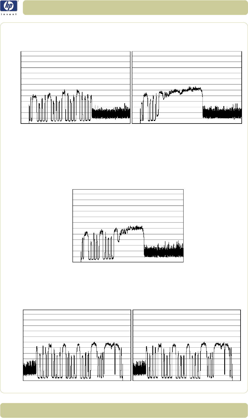
5-17
Scanner Adjustments and Calibrations
HP Designjet T1100 MFP, 4500mfp, 4500 Scanner, 820 MFP Service Manual
3
Select
Vertical Positioning
under Detail View and look at the left part
(Scanline Start) of the camera output. You will get an image similar to one of
these (or even less lines than shown on the right image):
The output we are aiming for can be seen below, therefore:
On the left image the vertical position is too low – if you have an output
like this, you need to lower the left side of camera with the left Vertical
Tilt lever, by turning to the left.
On the right image the vertical position is too high - if you have an output
like this, you need to raise the left side of camera with the left Vertical
Tilt lever, by turning it to the right.
4When you have adjusted the Vertical Tilt so that the output displays 8 black
lines (your output does not have to be identical to the above picture or the
Reference Image, just close) on the left side of the camera, look at the right
side of the camera.
5
On the right side (Scanline End) you will get an output similar to one of these:
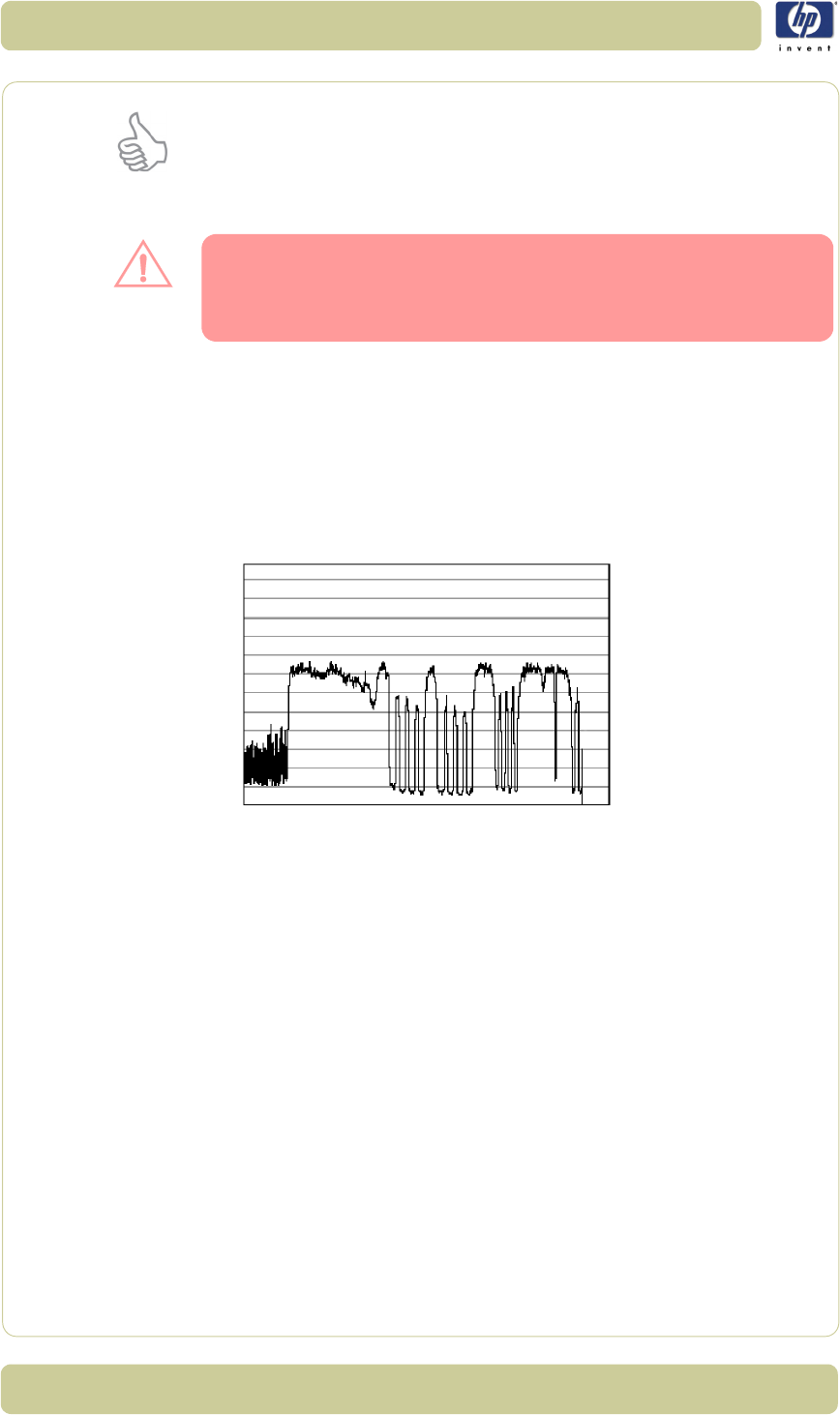
5-18
Scanner Adjustments and Calibrations
HP Designjet T1100 MFP, 4500mfp, 4500 Scanner, 820 MFP Service Manual
The Vertical Tilt lever can’t be moved very far before it loses its grip. If this
happens while you are adjusting the camera, move the Vertical Tilt levers
back to the middle position and use the Vertical Position Pre-Set
Screw to make a coarse adjustment. Then fine tune again with the
Vertical Tilt lever.
The output we are aiming for can be seen below, therefore:
On the left image the vertical position is too low – if you have an output
like this, you need lower the right side of camera with the right Vertical
Tilt lever, by turning downwards.
On the right image the vertical position is too high - if you have an output
like this, you need raise the right side of camera with the right Vertical
Tilt lever, by turning it upwards.
When you have adjusted the Vertical Tilt so that the output displays 8 black
lines and 4 smaller lines (it doesn’t have to be precise, just close to the
above picture) on the right side of the camera, look at the left side again to
check that it’s still okay (it’s probably not). It very likely that you have to go
back and forth between left and right a couple of times until both sides are
adjusted the right way. That is because adjusting one side affects the other
side a little.
6Check that the CCD Centering is OK. That is that you still have 3 SWU’s on
each side of the Camera. If you don’t then adjust it with the CCD
Centering Lever.
7Tighten the Camera Back-Plate Fixing Screws gently to prevent the
camera from moving out of adjustment.
8Once the cameras are adjusted, you will need to adjust the whole scanner to
fine-tune it by performing the Scanner Maintenance (refer to Page 5-26).
When adjusting the Vertical Position, you continuously have to readjust the
CCD Centering (3 scan-width units) with the CCD Centering lever,
because the Vertical Tilt lever moves the camera a little in the horizontal
direction.
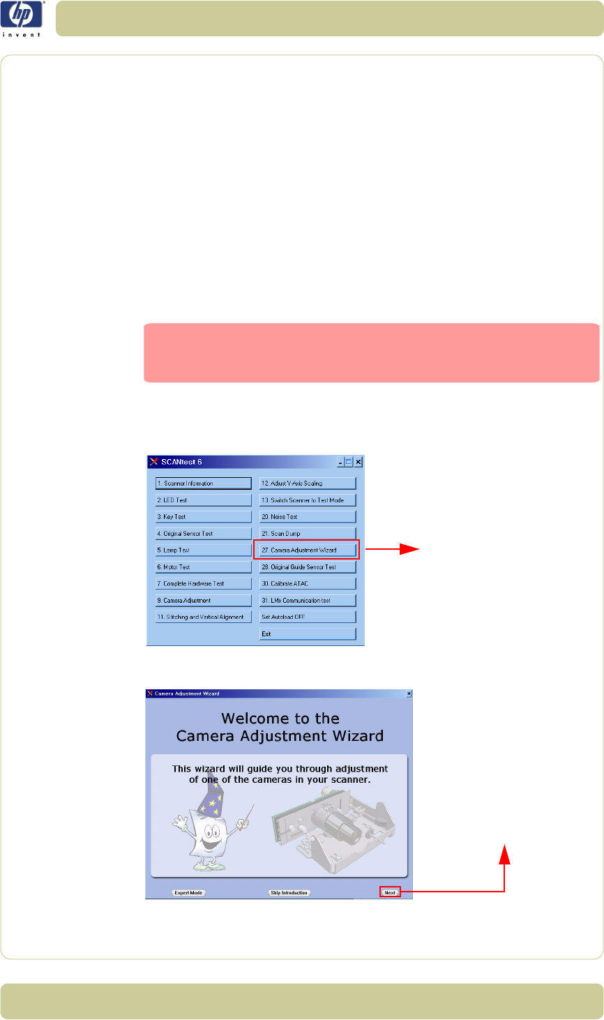
5-19
Scanner Adjustments and Calibrations
HP Designjet T1100 MFP, 4500mfp, 4500 Scanner, 820 MFP Service Manual
Adjusting the Camera Using the Camera Wizard
Preparing the Scanner
Before you start make sure that you have the following items, which are
necessary to complete the Camera Adjustment:
The SCANtest6 is installed in the touch screen (programs - Scanner Test
Program - Scantest 6).
Focus Adjustment Pattern sheet (included in the Service Patterns pn
Q1277-60030).
Optical Adjustment Pattern (pn Q1277-60031).
Make sure that the scanner you are adjusting is fully functional. If the
scanner is not operational, you will not be able to adjust the camera.
1Make sure that the cameras are all installed correctly and all cables are
connected.
2Start SCANtest 6 and select: 27. Camera Adjustment Wizard.
3The Camera Adjustment Wizard will start with the welcome screen. Select
next to contine.
Make sure that the left and right covers are installed and the
top cover is removed. The scanner and the touch screen must
be switched ON.
Select button 27
Select next to continue
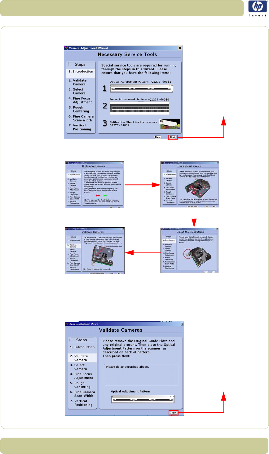
5-20
Scanner Adjustments and Calibrations
HP Designjet T1100 MFP, 4500mfp, 4500 Scanner, 820 MFP Service Manual
4The screen will display the list of Service Tools necessary to complete the
Camera Adjustment correctly. Select next to continue.
5The next 4 screens contain information on how to perform the camera
Adjustment correctly. Select next after reading each screen.
6In order to validate the current state of the cameras you will need to open the
Guide Plate and place the Optical Adjustment Pattern on the Scanner. Align
the pattern by pressing it to the right towards the Operator Panel and
backwards towards the back of the scanner. Once the cameras have been
validated, select next to continue.
Select next to continue
Select next to continue
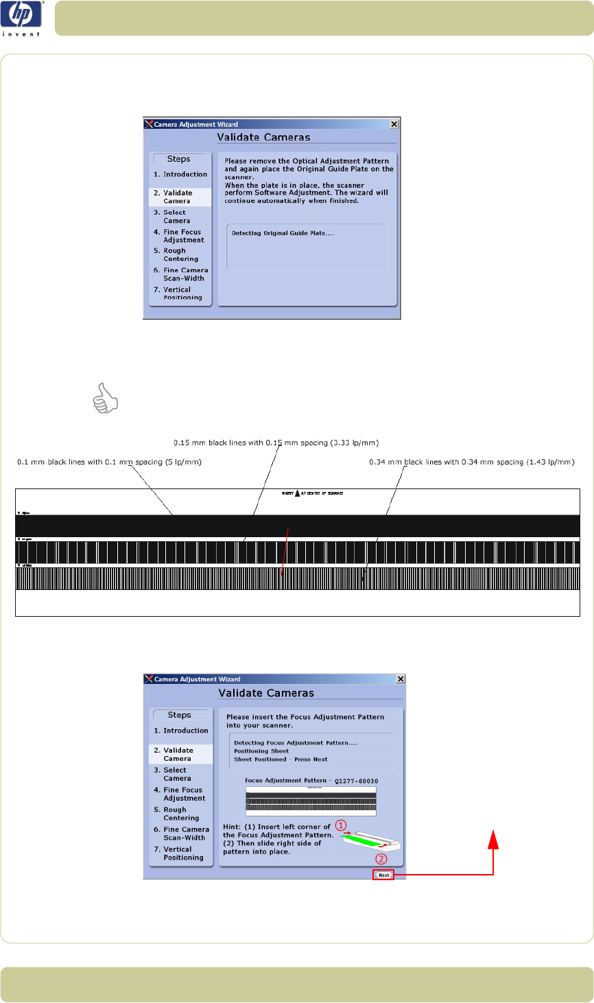
5-21
Scanner Adjustments and Calibrations
HP Designjet T1100 MFP, 4500mfp, 4500 Scanner, 820 MFP Service Manual
7The Scanner will now perform some internal adjustments. In order to do this
you will need to remove the Optical Adjustment Pattern and close the Guide
Plate.
8Once the internal adjustment has been done, you will need to insert the
Focus Adjustment Pattern in the Scanner.
It’s best to insert the left corner of the Focus Adjustment Pattern first and then
slide the right side of the pattern in to place.
9Once the Scanner detects that the Focus Adjustment Pattern is correctly
positioned you will be able to select next to continue.
The middle pattern is to be used for adjustment
Select next to continue
(when it appears)
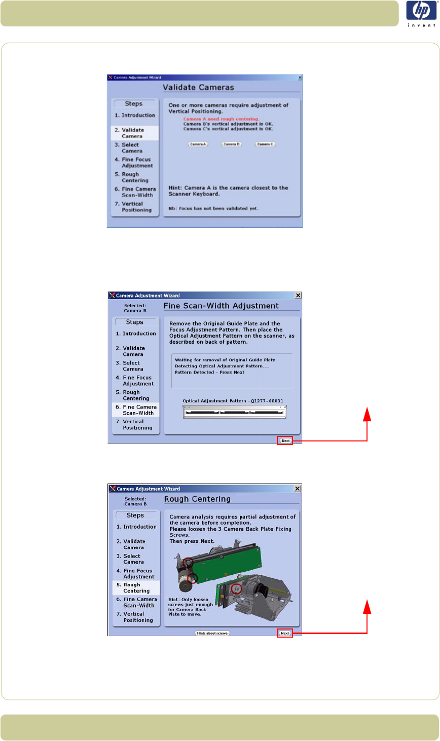
5-22
Scanner Adjustments and Calibrations
HP Designjet T1100 MFP, 4500mfp, 4500 Scanner, 820 MFP Service Manual
10 Select the camera that you need to adjust. Camera A is the one closer to the
front panel.
11
Remove the Focus Adjustment Pattern and place the Optical Adjustment Pattern
on the Scanner. Align the pattern by pressing it to the right and backwards
towards the back of the scanner. Once the pattern has been detected, select
next
to continue.
12 In this example, the camera requires partial adjustment before completion.
Loosen the 3 Camera Back-Plate Fixing Screws and then select next.
Select next to continue
Select next to continue
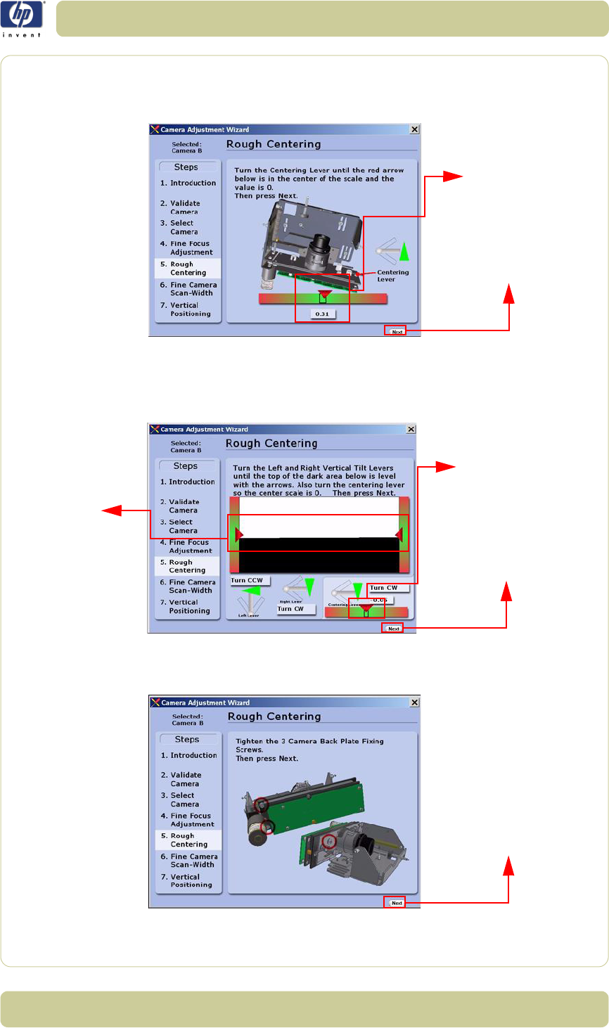
5-23
Scanner Adjustments and Calibrations
HP Designjet T1100 MFP, 4500mfp, 4500 Scanner, 820 MFP Service Manual
13 Turn the Centering Lever until the arrow on the screen is in the center of
the scale and the value is 0 (or as close as possible). Once the value is
within tolerance, you will be able to select next to continue.
14 Turn the Left and Right Vertical Tilt Levers until the horizon is level with
the arrows. Also turn the Centering Lever so the center scale is 0 (or as close
as possible). Once the value is within tolerance and the horizon is level with
the arrows, you will be able to select next to continue.
15 Tighten the 3 Camera Back-Plate Fixing Screws and then select
next.
Select next to continue
(when it appears)
The arrow needs
to be in the center
and the value 0
Select next to continue
(when it appears)
The arrow needs
to be in the center
and the value 0
The horizon
needs to be
in level with
the arrows
Select next to continue
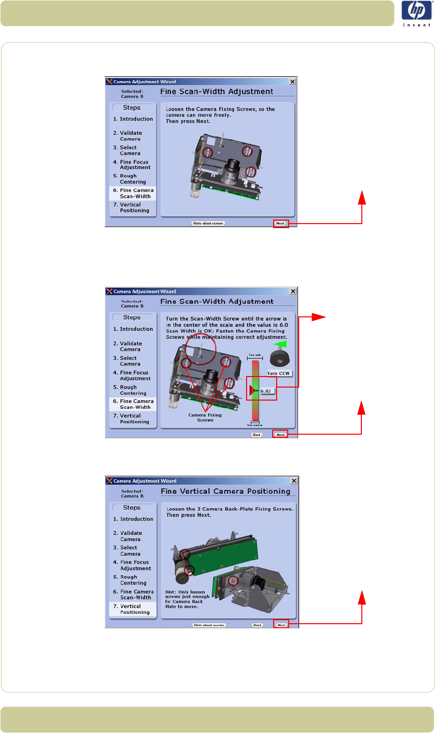
5-24
Scanner Adjustments and Calibrations
HP Designjet T1100 MFP, 4500mfp, 4500 Scanner, 820 MFP Service Manual
16 Loosen the Camera Fixing Screws slightly so that the camera housing
can be moved.
Select
next
to continue.
17
Turn the
Scan-Width Screw
until the arrow on the screen is in the center of
the scale and the value is 6.0.
Once the value is 6.0 (or as close as possible),
tighten the Camera Fixing Screws while maintaining the correct
adjustment. Once the screws are tightened, select next to continue.
18 Loosen the Camera Back-Plate Fixing Screws slightly so that the
camera housing can be moved.
Select
next
to continue.
Select next to continue
Select next to continue
(when it appears)
The arrow needs
to be in the center
and the value 6.0
Select next to continue
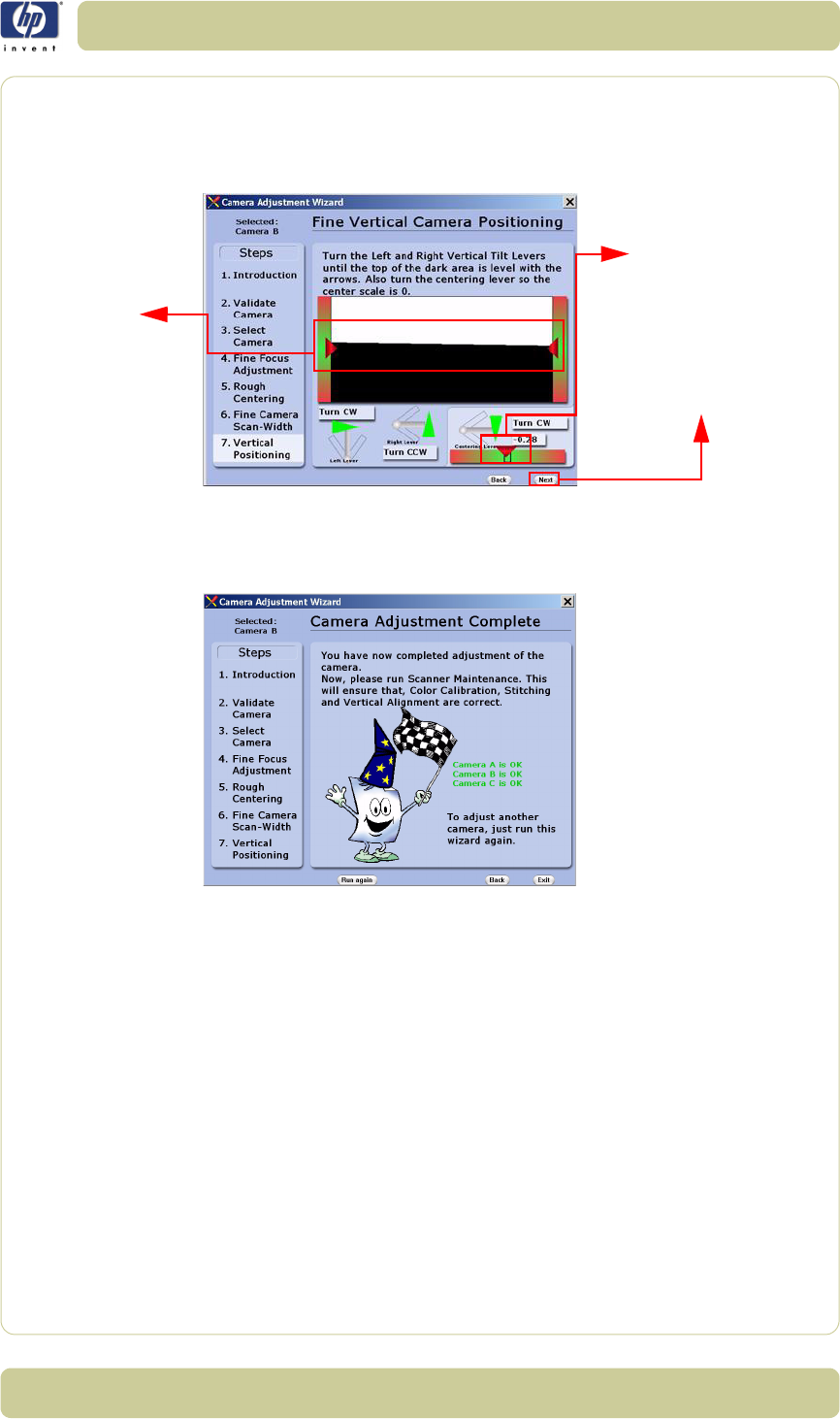
5-25
Scanner Adjustments and Calibrations
HP Designjet T1100 MFP, 4500mfp, 4500 Scanner, 820 MFP Service Manual
19 Turn the Left and Right Vertical Tilt Levers until the horizon is in level
with the arrows. Also turn the Centering Lever so the center scale is 0. Once
the value is 0 (or as close as possible) and the horizon is level with the
arrows, you will be able to select next to continue.
20 Tighten the Camera Back-Plate Fixing Screws gently to prevent the
camera from moving out of adjustment. The Camera Adjustment has now
been completed.
21 Perform the Scanner Maintenance to ensure that Color Calibration, Stitching
and Vertical Alignment are correct.
Select next to continue
(when it appears)
The arrow needs
to be in the center
and the value 0
The horizon
needs to be
in level with
the arrows
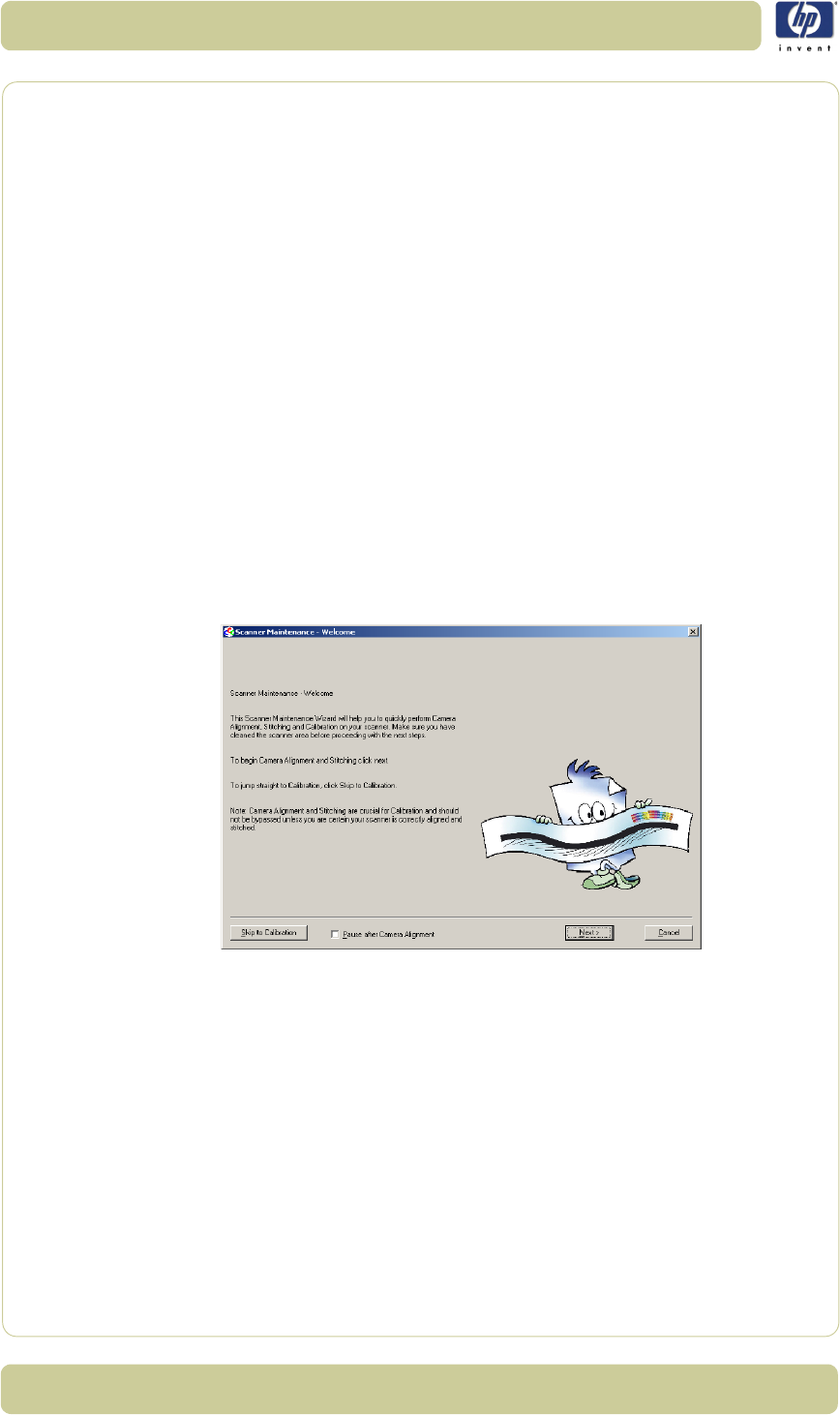
5-26
Scanner Adjustments and Calibrations
HP Designjet T1100 MFP, 4500mfp, 4500 Scanner, 820 MFP Service Manual
Scanner Maintenance
Once the cameras are adjusted, you will need to adjust the whole scanner to
fine-tune it by performing the Scanner Maintenance. Scanner Maintenance
does the following three things automatically:
1Runs Vertical Alignment, which adjusts the vertical position of the Cameras.
2Adjusts the Stitching, which controls the overlap between the Cameras.
3Color Calibrates the Scanner to get optimal colors and gray tones.
Performing Scanner Maintenance
For this part of the adjustments you will need the following item:
Scanner Maintenance Calibration Sheet 42”
(included in the Service
Patterns pn
Q1277-60030
).
1Start by removing the Optical Adjustment Pattern, cleaning the
scanning area, and then closing the Guide Plate.
2Exit the Camera Adjustment Wizard and exit SCANtest 6.
3Wait for the Scanner to reboot and then start Scanner Maintenance when
only the green lamp is lit up on the scanner keyboard.
4Insert the Scanner Maintenance Calibration sheet and press Next two
times.
5Wait for Scanner Maintenance to finish. It takes about 20 minutes.
6Remember to put the calibration sheets back into the original packing, so
that they last longer.
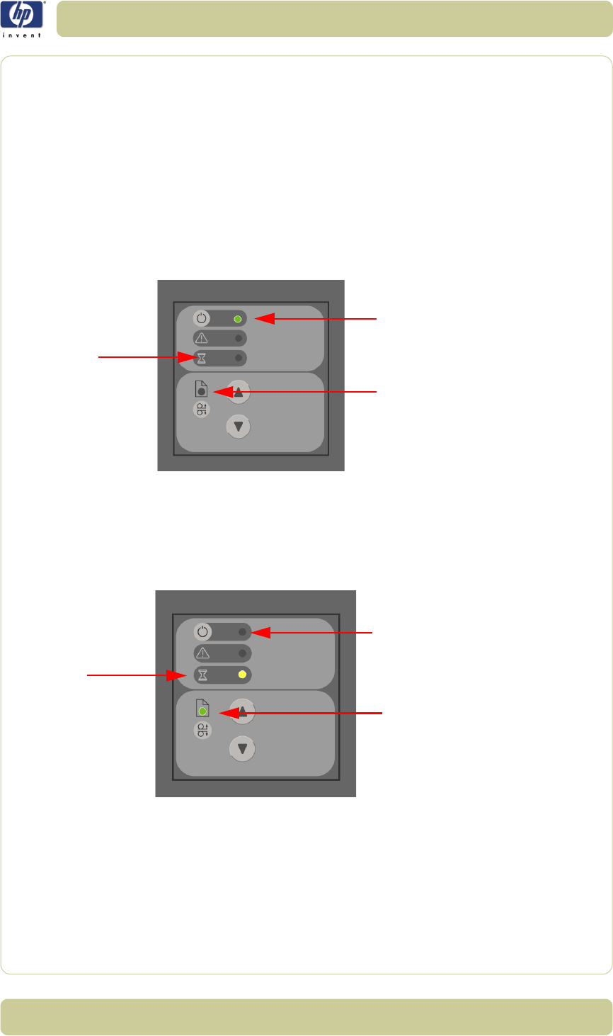
5-27
Scanner Adjustments and Calibrations
HP Designjet T1100 MFP, 4500mfp, 4500 Scanner, 820 MFP Service Manual
ATAC Position Sensors check
This procedure is to check the sensors in the Original Guide come on when
the media sensors are activated.
1Start SCANtest 6 and select Test 28, Original Guide Sensor Test
2If the guide plate is in the lowered position, press the UP Key on the scanner
front panel to move the Guide Plate to the Top Position and observe that:
Ready LED is OFF
Wait LED is OFF
The Power LED turns green (Top Position Sensor activated)
3Move the Guide Plate down by pressing the Down Key on the scanner front
panel and observe the LEDs in following sequence:
Power LED turns OFF
Wait LED turns yellow (Down Position Sensor* activated)
Ready LED turns green (Roller sensor activated)
*The Down Position Sensor cannot be adjusted.
Power LED
Ready LED
Wait LED
Power LED
Ready LED
Wait LED
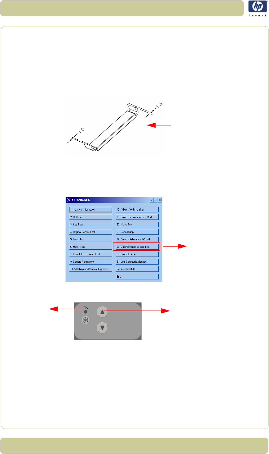
5-28
Scanner Adjustments and Calibrations
HP Designjet T1100 MFP, 4500mfp, 4500 Scanner, 820 MFP Service Manual
Original Guide Sensor Test
This is to test the sensors which are located inside the Guide Plate.
Adjustment of the Roller Sensor
To perform this adjustment you will need the two Roller Sensor Adjustment
tools.
1Perform the following:
Remove ruler from the front of the Guide Plate.
Open the Top Profile on the Guide Plate
⇒
Page 4-15
.
2Start SCANtest 6 and select Test 28. Original Guide Sensor Test
3Press the UP Key on the front panel of the Scanner to move the Guide Plate
up until the Ready LED turns OFF.
Roller Sensor
Adjustment tool
Select button 28
Up key
Ready LED

5-29
Scanner Adjustments and Calibrations
HP Designjet T1100 MFP, 4500mfp, 4500 Scanner, 820 MFP Service Manual
4Loosen the two screws that secure the Roller Sensor.
5Using the 1.5 mm end of each of the two Adjustment Tools, insert them on
both sides of the Roller Sensor under the roller shaft.
6Adjust the position of the Roller Sensor so that the green Ready LED just
about turns ON.
7Using the 1 mm end of each of the two Adjustment Tools, insert them on
both sides of the Roller Sensor under the roller shaft
8Check that the green Ready LED is OFF.
9Tighten the two screws that secure the Roller Sensor.
Adjustment tools
Roller sensor
fixing screws
Ready LED
Adjustment tools
Roller sensor
fixing screws
Ready LED
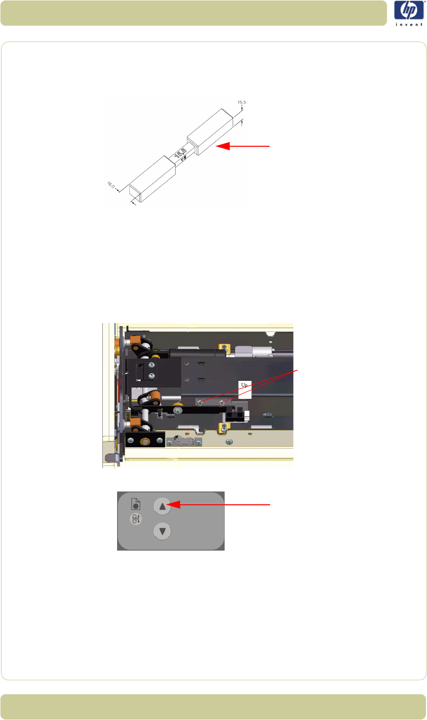
5-30
Scanner Adjustments and Calibrations
HP Designjet T1100 MFP, 4500mfp, 4500 Scanner, 820 MFP Service Manual
Adjustment of Top Position Sensor
To perform this adjustment you will need the adjustment tool for the Top
Position Sensor:
1Perform the following:
Remove the ruler from the front of the Guide Plate.
Open the Top Profile on the Guide Plate
⇒
Page 4-15
.
2Close and lock the Guide Plate.
3Start SCANtest 6 and select Test 28. Original Guide Sensor Test
4Loosen the four screws that secure the sensor bracket, move the sensor to its
uppermost position and tighten the four screws.
5Press the UP Key to move the Guide Plate to the higest position.
6Open the Guide Plate.
7Orientate the two adjustment guides for 16 mm spacing and insert the
guides under the Guide Plate at both ends of the scan area.
8Place the two adjustment guides so that the surface marked “16” is facing
the White Background. To avoid possible damage to the White Background,
place the cut-out centered over the light aperture of the glass plate.
9Close the Guide Plate and make sure that both Release Handles are locked.
Top Position Sensor
Adjustment tool
Top Position Sensor
fixing screws
Up key
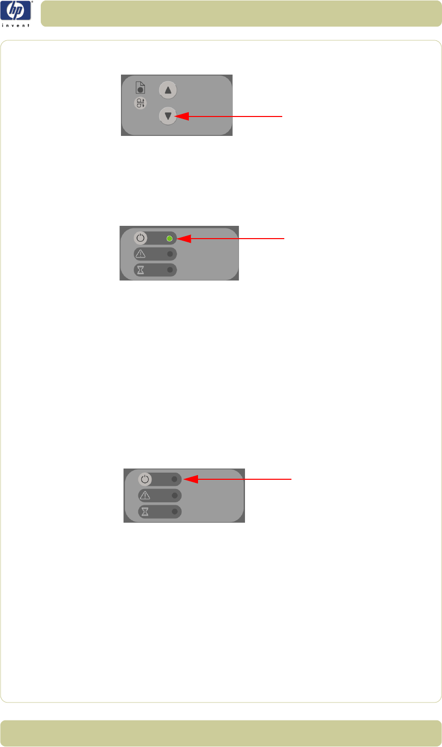
5-31
Scanner Adjustments and Calibrations
HP Designjet T1100 MFP, 4500mfp, 4500 Scanner, 820 MFP Service Manual
10 Press the Down Key to move the Guide Plate down until it automatically stops
against the adjustment guides.
If the Down Key is pressed after the Guide Plate has stopped, the MDA
Board turns OFF and you need to power the scanner ON again.
11 Loosen two screws that secure the Top Position sensor.
12 Adjust the Top Position sensor so that the green Power LED just about turns
ON.
13 Tighten the two screws that secure the Top Position sensor.
14 Open the Guide Plate.
15 Orientate the two adjustment guides for 15.5 mm spacing and insert the
guides under the Guide Plate at both ends of the scan area.
16 Place the two adjustment guides so that the surface marked “15.5” is
facing the White Background. To avoid possible damage to the White
Background, place the cut-out centered over the light aperture of the glass
plate.
17 Close the Guide Plate and make sure that both Release Handles are locked.
18 Press the Down Key on the Scanner front panel to move the Guide Plate
down until it automatically stops against the adjustment guides.
19 Check that the Power LED is OFF.
Down key
Power LED
Power LED
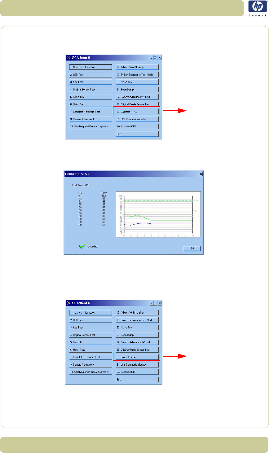
5-32
Scanner Adjustments and Calibrations
HP Designjet T1100 MFP, 4500mfp, 4500 Scanner, 820 MFP Service Manual
Calibrate ATAC (Automatic Thickness Adjustment Control)
To run this test start SCANtest 6 and select: 30. Calibrate ATAC
This test sets the current level at which the ATAC will stop if something is
preventing it from moving. It is a safety measure designed to prevent fingers
from being inadvertently pinched in the guide plate.
Driver Board Communication Test
To run this test start SCANtest 6 and select: 31. LMx Communication
Test.
This tests the communciation between the Driver Board and the Scanner.
When the test is run it will check the:
Lamp
Select button 30
Select button 31

5-33
Scanner Adjustments and Calibrations
HP Designjet T1100 MFP, 4500mfp, 4500 Scanner, 820 MFP Service Manual
The Light levels
The two fans
Upgrade Scanner Firmware
Scanner software version 14 or later
If you have a scanner with software version 14 or later, you can upgrade the
firmware without having to upgrade the entire system. To upgrade the
scanner firmware, follow these steps:
1In the Setup tab, press the Options button.
2Press the System button.
3Press the Service button.
4Press the Upgrade firmware button.
When the upgrade has finished, you are prompted to reboot the system.
Scanner software version 14 or earlier
If you have a scanner with software version 14 or earlier, you are required
to perform a complete system recovery using the most recent software
version in order to upgrade the firmware.

5-34
Scanner Adjustments and Calibrations
HP Designjet T1100 MFP, 4500mfp, 4500 Scanner, 820 MFP Service Manual

6-1
HP Designjet T1100 MFP, 4500mfp, 4500 Scanner, 820 MFP Service Manual
6Preventive
Maintenance 1
Preventive Maintenance 6-2
6

6-2
Preventive Maintenance
HP Designjet T1100 MFP, 4500mfp, 4500 Scanner, 820 MFP Service Manual
Preventive Maintenance
Introduction
This chapter describes the scanner messages that are shown in the Touch
screen, signaling the need for maintenance. It also describes the preventive
maintenance procedures that users must follow to ensure that the scanner
performs optimally.
Over time, several messages will appear in the Scanner Messages window.
Most of them signal the need for maintenance.
Scanner Messages
The following scanner messages appear in the Scanner Messages window
of the Touch Screen. The Scanner Messages window can also be recalled
manually by pressing the progress bar area of JETimage.
User warnings:
Scanner Maintenance has not been run for 30 days.
Maintenance kit #1 required. Please contact HP to order the kit.
The lamp quality is electrically monitored and the warning appears after
approximately 4000 hours of usage (average value). The scanner
maintenance warning appears when scanner maintenance has not been
performed for 30 days. However, the frequency with which scanner
maintenance should be performed depends on the scanner messages.
Preventive Maintenance Kit #1
The Preventive Maintenance Kit #1 is available for the following model:
It is also available for the following scanners once they have been updated
to System Recovery SW 14:
The user can order the Preventive Maintenance Kit #1 through HP Support
(P/N Q1277-600013 PMK#1 Lamp Cartridge, Q1277A).
The message that appears in the Scanner Messages window is shown
Model Part Number
HP Designjet T1100 MFP Model Q6713A
Model Part Number
HP Designjet 4500 Scanner Model Q6713A (from October'07)
HP Designjet 4500mpf Model Q1276A (from October'07)
HP Designjet 820 MFP Model Q6685
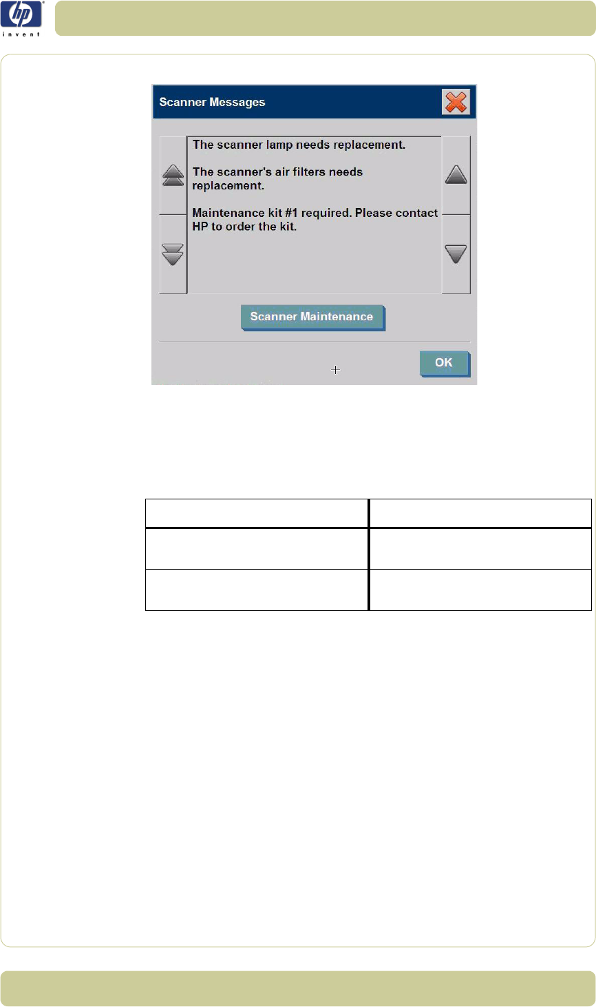
6-3
Preventive Maintenance
HP Designjet T1100 MFP, 4500mfp, 4500 Scanner, 820 MFP Service Manual
below.
User Self Replacement parts
The scanner components that a customer can order through HP Support are
shown below.
Replace the scanner maintenance parts
You can replace key scanner parts that wear down over long-term use.
Changing these parts will renew your scanner and ensure optimal
performance.
Before replacing any parts, you should clean the scan area as described in
the Scanner Maintenance section
⇒
Page 5-26
, to see if any errors or image
defects are alleviated.
Replace the Preventive Maintenance Kit
Replace the Lamp
Lamp effectiveness gradually weakens over time. Replacement of the lamp-
unit (lamp, reflector, power connectors) is recommended after long term use.
Before replacing the lamp, you should clean the scan area as described in
the Scanner Maintenance section
⇒
Page 5-26
, to see if any errors or image
Part Number Description
White Background Assembly, 40/
42"
Q1277-60027
Guide Plate Assembly Q1277-60025, Q1277A, and
Q6685
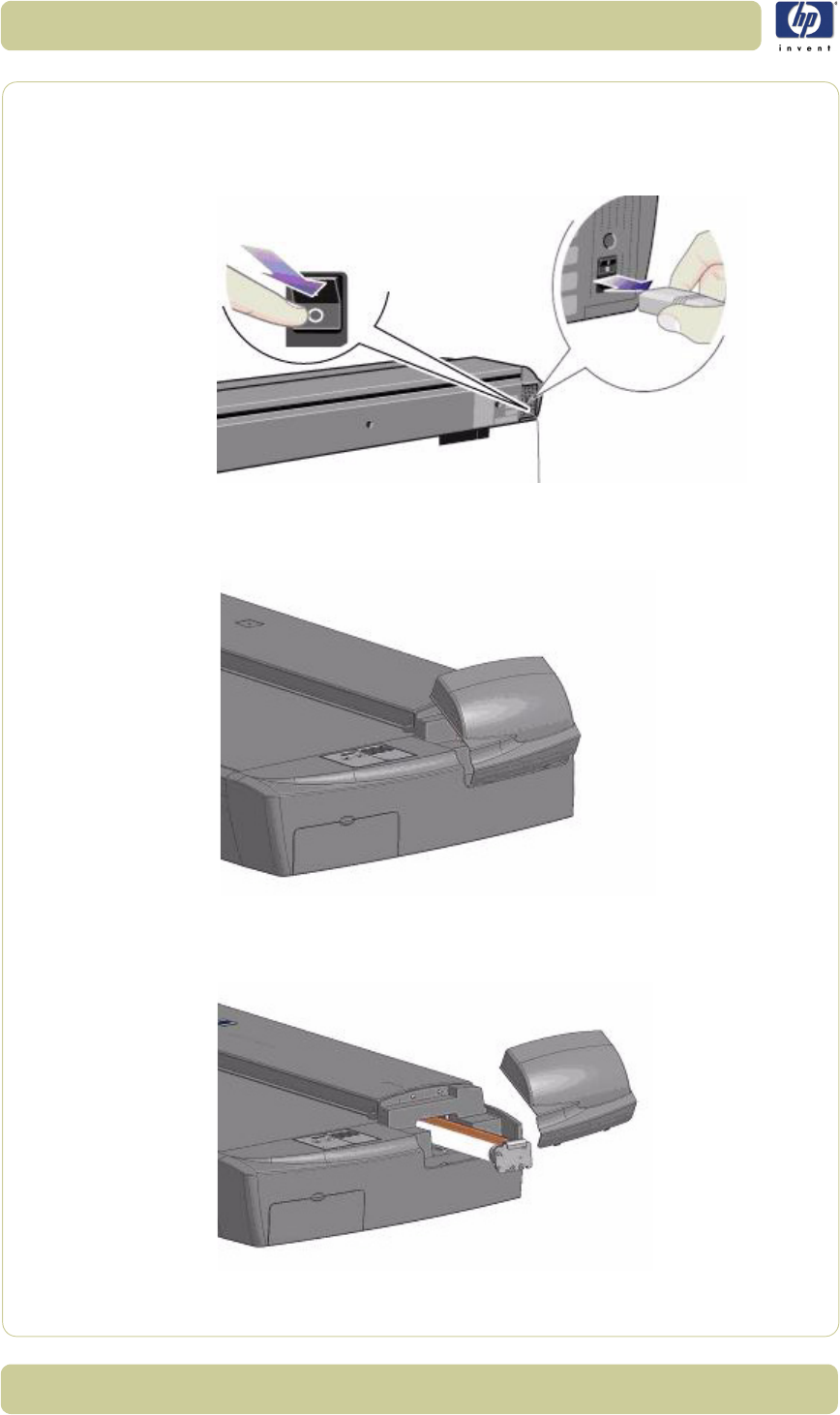
6-4
Preventive Maintenance
HP Designjet T1100 MFP, 4500mfp, 4500 Scanner, 820 MFP Service Manual
defects are alleviated.
To replace the lamp unit follow these steps:
1. Turn off the scanner and disconnect the power plug.
2. The lamp cover is on the top right edge of the scanner. Grasp the cover on
each side with both hands and pull back to detach it. Lift the cover upwards
to free it from the scanner.
3. You must replace the whole lamp-unit. A lamp-unit consists of a lamp
mounted in a reflector brace and fixed power connectors. Grasp the edge of
the lamp-unit and carefully pull it out of the scanner.
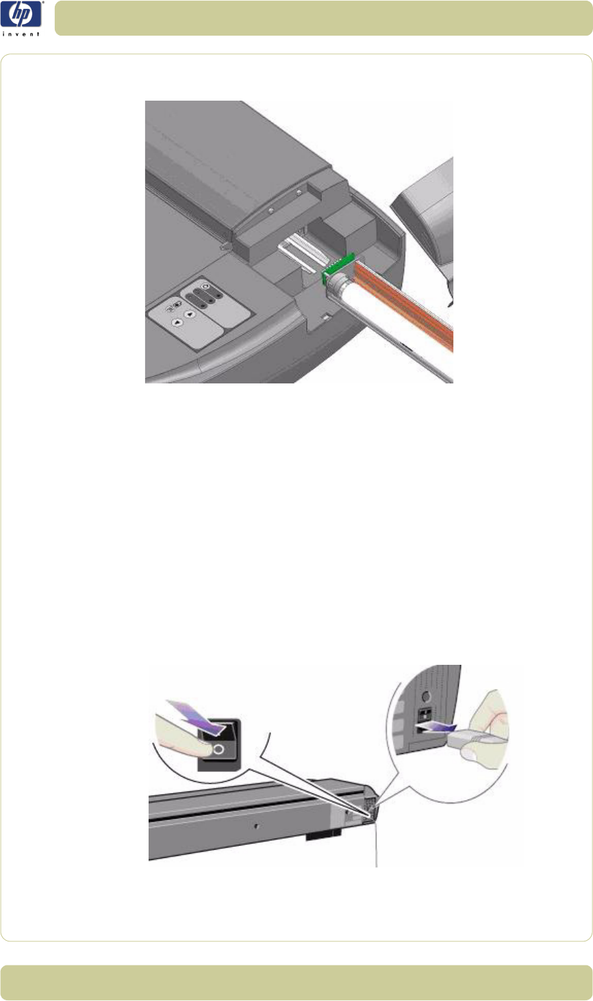
6-5
Preventive Maintenance
HP Designjet T1100 MFP, 4500mfp, 4500 Scanner, 820 MFP Service Manual
4. Reinsert the new lamp-unit by resting the power-connector side on the slider
and carefully slide the lamp-unit into the scanner.
5. Insert the lamp-unit all the way so that the internal power connections
engage with the connections on the lamp-unit.
6. Replace the lamp cover on the scanner. Fit the bottom notches in the holes
and snap the cover shut. The cover must always be closed before turning on
the scanner.
7. Test the lamp by turning on the scanner to see if the lamp illuminates.
Replace the air filters
Fresh air filters can reduce the amount of time spent on cleaning and
calibration. The air filters protect your scanner's air-cooling vents and keep
out dust and unwanted particles.
To replace the air filters:
1. Turn off the scanner and disconnect the power plug.
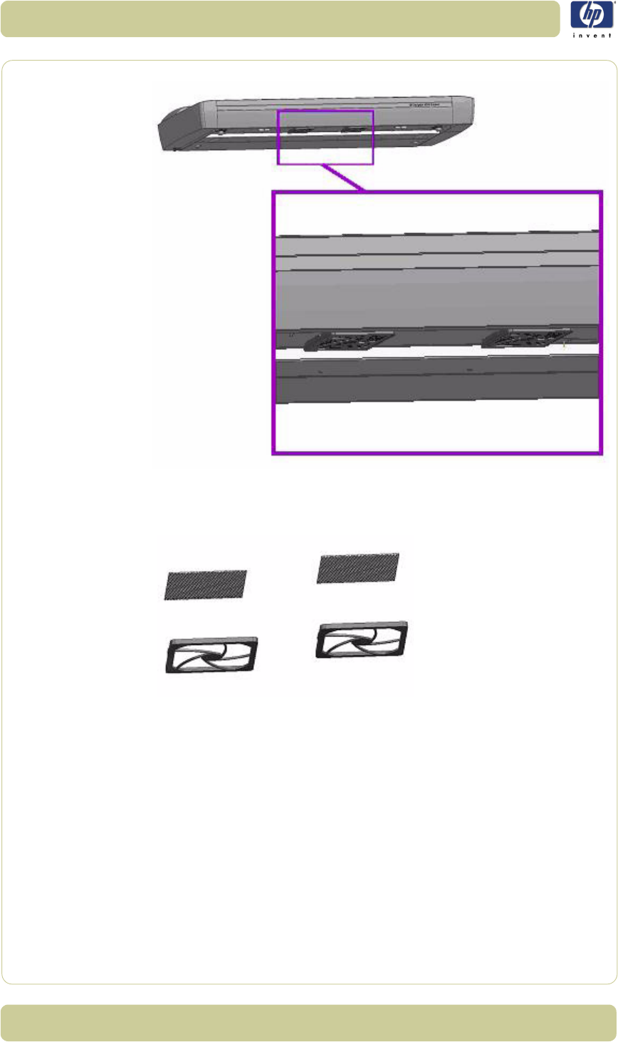
6-6
Preventive Maintenance
HP Designjet T1100 MFP, 4500mfp, 4500 Scanner, 820 MFP Service Manual
2. Locate the 2 square-shaped dust filter bins on the underside of the scanner.
3. Pull down on the edge of a dust filter bin to detach it from its frame.
4. The filter (soft material) is inside the bin. Remove the old filter and replace it
with a fresh one.
5. Reattach (click on) the bin to its frame on the underside of the scanner.
6. Repeat the process with the second filter.
Replace the User Self Replacement parts
Replace the Glass Plate
Small scratches on the glass plate can reduce scanning quality. Replacement
with a new glass plate can be recommended by the program. Before
replacing the white background platen, you should try to clean glass plate to
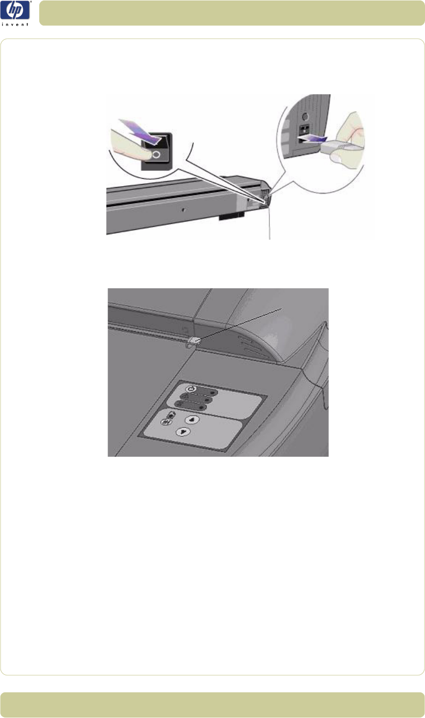
6-7
Preventive Maintenance
HP Designjet T1100 MFP, 4500mfp, 4500 Scanner, 820 MFP Service Manual
see if errors or image defects are alleviated.
To replace the glass plate:
1. Turn off the scanner and disconnect the power plug.
2. Push down on the two lever buttons found near the insertion slot on each
side of the scanning area lid. The scanning area lid locking mechanism
should now be disengaged.
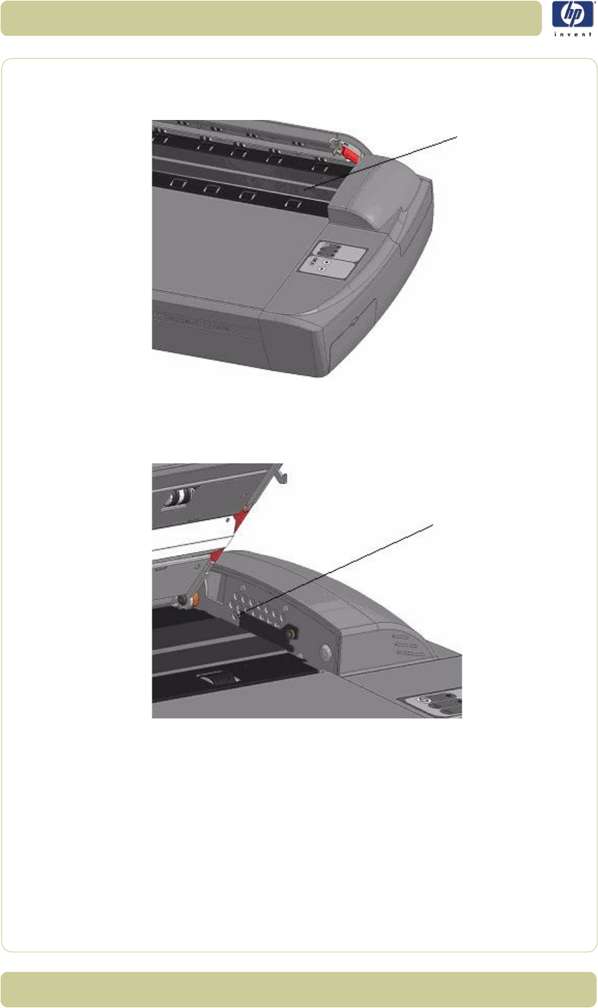
6-8
Preventive Maintenance
HP Designjet T1100 MFP, 4500mfp, 4500 Scanner, 820 MFP Service Manual
3. As you hold both lever buttons down, place your free fingers in the insertion
slot and flip open the scanning area lid. The glass plate will be exposed and
accessible.
4. On each side of the glass plate there is a small lever and round finger-
handle, as shown in the image below. Place your thumbs under both
handles on each side. With both hands, simultaneously pull on the left and
right handles to flip the levers and glass plate towards your body.
5. Each lever is attached to the scanner chassis with a small hook that rests on
a pin. With your thumbs still on the handles, simultaneously lift both levers
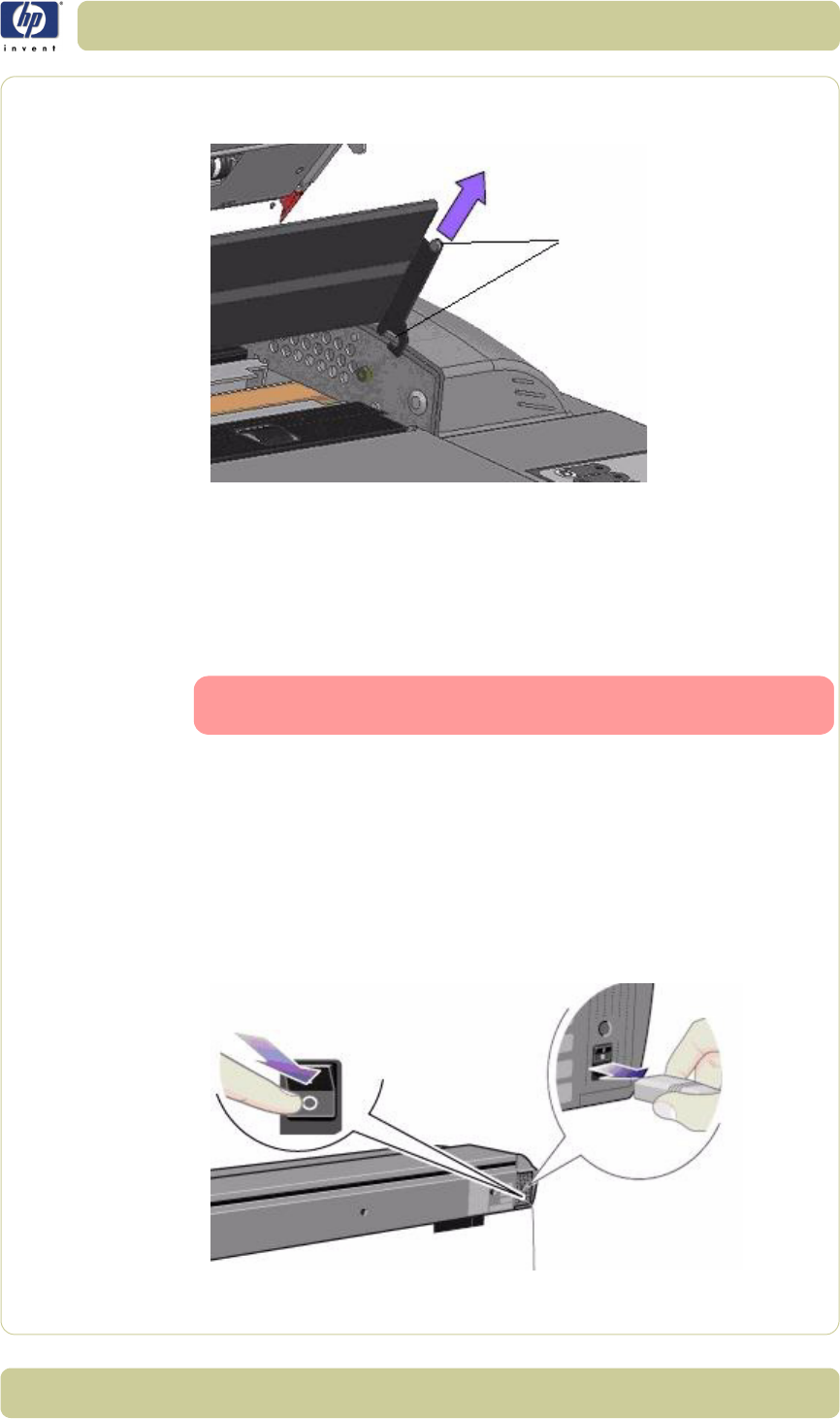
6-9
Preventive Maintenance
HP Designjet T1100 MFP, 4500mfp, 4500 Scanner, 820 MFP Service Manual
upwards to detach their hooks from the pins and free the glass plate from the
scanner.
6. To reinsert a new glass plate. Fit the new glass plate's lever hooks on the
pins on each side of the scanner.
7. While supporting the glass plate with your thumbs on the finger handles,
carefully push the glass plate backwards (away from your body) and ease it
down into place.
8. Close the scanning area lid so that the locking mechanism engages.
Replace the White-Background Platen
A white-background platen can become worn and discolored after long
periods of use. In such cases replacement with a new white-background
platen is recommended. Before replacing the white-background platen,
clean it to see if errors or image defects are alleviated.
To replace the white-background platen:
1. Turn off the scanner and disconnect the power plug.
Make sure you clean a new glass plate before using it with
the scanner.
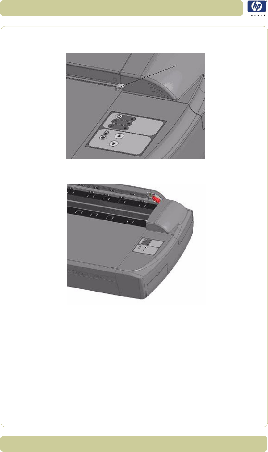
6-10
Preventive Maintenance
HP Designjet T1100 MFP, 4500mfp, 4500 Scanner, 820 MFP Service Manual
2. Push down on the two lever buttons found near the insertion slot on each
side of the scanning area lid. The scanning area lid locking mechanism
should now be disengaged.
3. As you hold both lever buttons down, place your free fingers in the insertion
slot and flip the scanning area lid open.
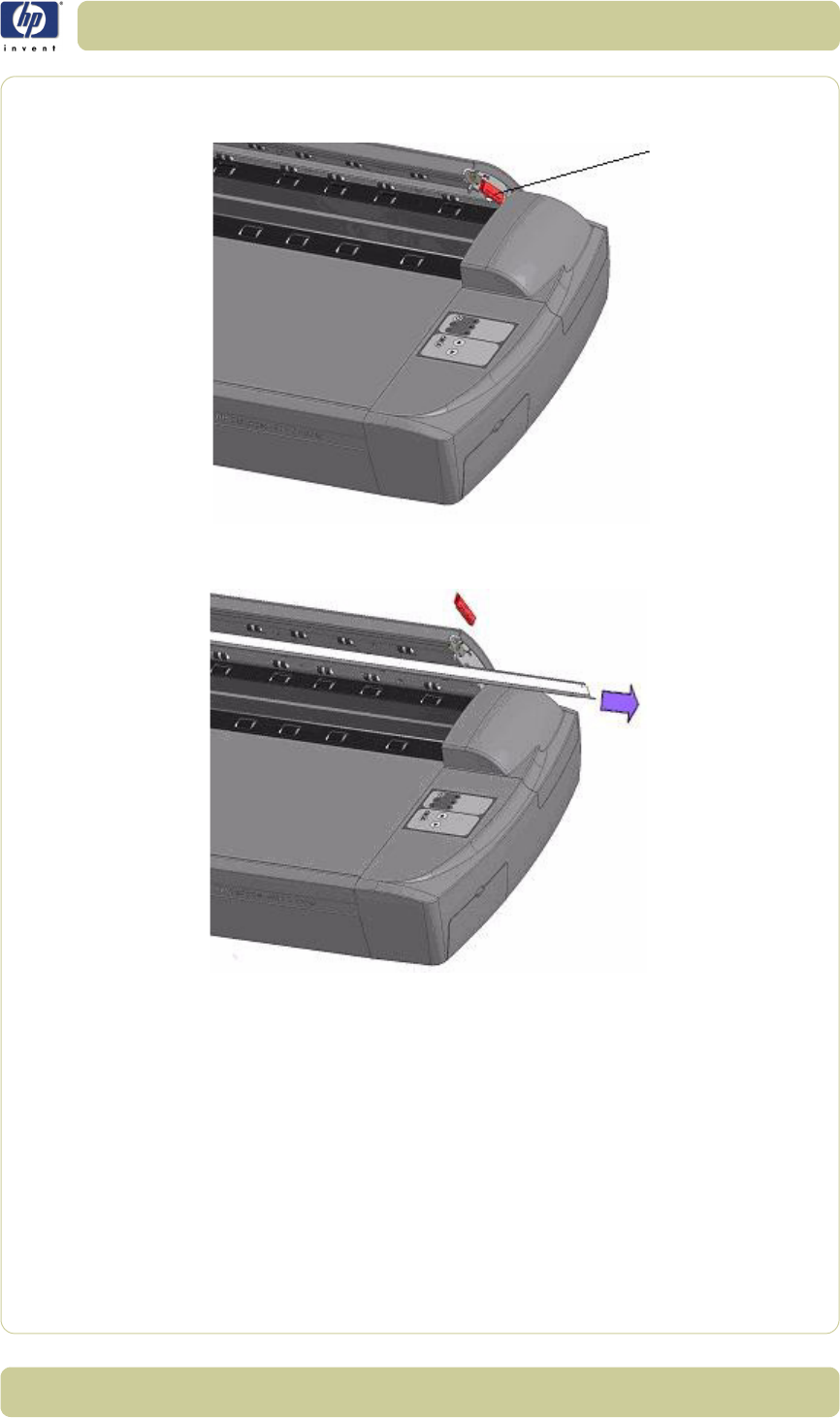
6-11
Preventive Maintenance
HP Designjet T1100 MFP, 4500mfp, 4500 Scanner, 820 MFP Service Manual
4. On the lid's right edge, you will find a red strip. Remove the red strip to
expose the edge of the white-background platen.
5. Grip the edge of the white-background platen with your fingers and pull to
slide it out of the scanner.
6. Slide in the new white-background platen.
7. Reattach the red strip.
8. Close the scanning area lid so the locking mechanism engages.

6-12
Preventive Maintenance
HP Designjet T1100 MFP, 4500mfp, 4500 Scanner, 820 MFP Service Manual
About this Edition
This is the 4th edition of this Service Manual
-2
What’s in this Service Manual
This manual contains information necessary to test, calibrate and service:
- HP Designjet 4500 Scanner - Model Q1277A
- HP Designjet T1100 MFP - Model Q6713A
- HP Designjet 820 MFP - Model Q6685
- HP Designjet 4500mpf - Model Q1276A
For information about using these printers, refer to the corresponding User and
Quick Reference Guides.
The procedures described in this manual are to be performed by HP-qualified
Service Personnel only.

© 2007 Hewlett-Packard Development Company, L.P.
Printed in Germany Imprimé en Allemagne Stampato in Germania
www.hp.com
