T25%201971%20Workshop%20Manual%2099 0945%20x[1]
User Manual: T25%201971%20Workshop%20Manual%2099-0945%20x[1]
Open the PDF directly: View PDF ![]() .
.
Page Count: 141 [warning: Documents this large are best viewed by clicking the View PDF Link!]
www.bsaunitsingles.com
WORKSHOP
}IANUAt
FOR
250c.G. (l
SINGLE
5cu.in.)
CYLINDER
@ Copyright by
TRIUMPH E]{GINEERING CO. LTD.
MERIDEN WORKS . ALLESLEY . COVENTRY
TELEPHONEz 0203-20221
CVs 9AU .ENGLAND
TELEX: ..TRUSTy" 3130S
TELEGRAMS: ..TRUSTy', COVENTRY
Published July 197'l Publication Part No. 99-0945
www.bsaunitsingles.com
IMPORTANT NOTE
Any modifications to anyTriumph motorcycle made by you or to be
made by you in the future shall be held by our company to have been
modified at your own risk and responsibility and without either the
explicit or implied consent of Triumph Engineering Co. Ltd. or
Triumph Motorcycle Corporation. We will assume no liability,
obligation or responsibility for any defective or modified parts or
for the modified motorcycle itself, or for any claims, demands or
legal action for property damage or personal injuries which may
result from the modification of any Triumph motorcycle.
,'€ 'l
._-*_.*J-\
,*:lS'-\
www.bsaunitsingles.com
INTRODUCTION
THIS'manual has been compiled and prepared to provide the necessary service information for workshop,
fitter, technical staff and individual owner, wishing to carry out basic maintenance and repair work on the
TRIUMPH 250 c.c. MODEL T25T and T25SS.
GENERAL DATA for all models within the above range is provided in ready reference form, and a separate
section covering Service Tools is fully illustrated at the end of this manual.
The manual is divided into sections dealing with major assemblies, throughout the machine, each section sub-
divided into sequence order corresponding to normal operations of strip down, examination and rebuilding
p roced u re.
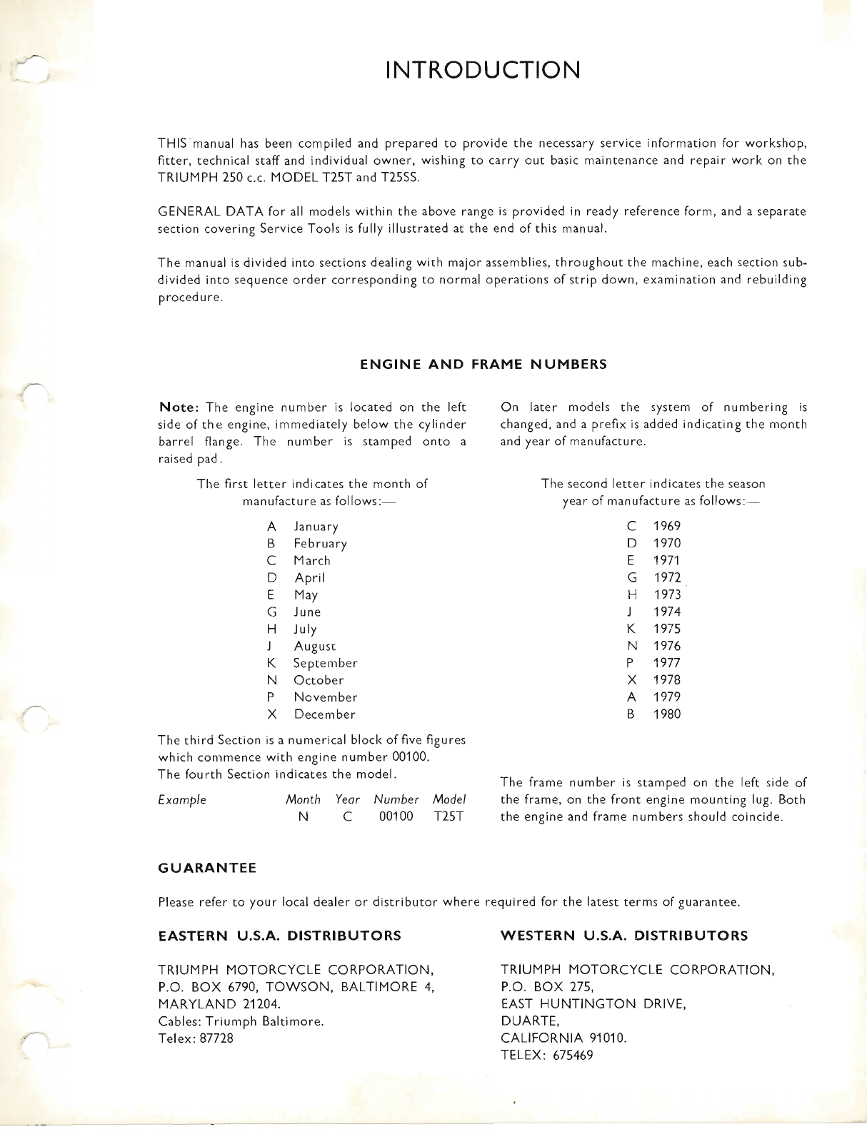
ENGINE AND FRAME NUMBERS
Note: The engine number is located on the left On later models the system of numbering is
side of the engine, immediately below the cylinder changed, and a prefix is added indicating the month
barrel flange. The number is stamped onto a and year of manufacture.
raised pad.
The first letter indicates the month of The second letter indicates the season
manufacture as follows:- year of manufacture as follows:-
A January C 1969
B February D 1970
C March E 1971
D April G 1972
E May H 1973
G June J 1974
H July K 19V5
J Augusr N 1976
K September P 1977
N October X 1978
P November A 1979
X December B 1980
The third Section is a numerical blocl< of five figures
which conrmence with engine number 001 00.
The fourth Section indicates the model' The frame number is stamped on the reft side of
Example Month Yeor Nurnber Model the frame, on the front engine mounting lug. Both
N C 001 00 T25T the engine and frame numbers should coincide.
GUARANTEE
Please refer to your local dealer or distributor where required for the latest terms of guarantee.
EASTERN U.S.A. DISTRIBUTORS WESTERN U.S.A. DISTRIBUTORS
TRIUMPH MOTORCYCLE CORPORATION, TRIUMPH MOTORCYCLE CORPORATION,
p.o. Box 6790, TowsoN, BALTTMORE 4, P.O. BOX 275,
MARYLAND 21704. EAST HUNTINGTON DRIVE,
Cables: Triumph Baltimore. DUARTE,
Telex:87728 CALIFORNIA 91010.
TELEX: 675469
www.bsaunitsingles.com
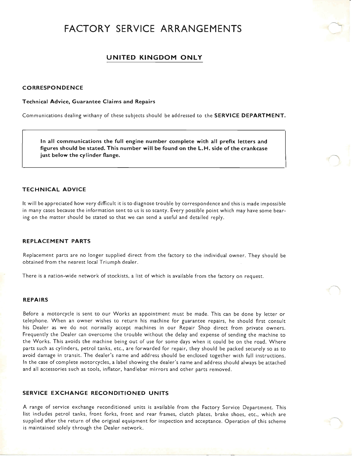
FACTORY SERVICE ARRANGEMENTS
UNITED KINGDOM ONLY
CORRESPONDENCE
Technical Advice, Guarantee Claims and Repairs
Communications dealing withany of these subjects should be addressed to the SERVICE DEPARTMENT.
TECHNICAL ADVICE
It will be appreciated how very difficult it is to diagnosetrouble by correspondence and this is made impossible
in many cases because the information sent to us is so scanty. Every possible point which may have some bear-
ing on the matter should be stated so that we can send a useful and detailed reply.
REPLACEMENT PARTS
Replacement parts are no longer supplied direct from the factory to the individual owner. They should be
obtained from the nearest local Triumph dealer.
There is a nation-wide network of stockists, a list of which is available from the factory on request.
REPAIRS
Before a motorcycle is sent to our Works an appointment must be made. This can be done by letter or
telephone. When an owner wishes to return his machine for guarantee repairs, he should first consult
his Dealer as we do not normally accept machines in our Repair Shop direct from private owners.
Frequently the Dealer can overcome the trouble without the delay and expense of sending the machine to
the Works. This avoids the machine being out of use for some days when it could be on the road. Where
parts such as cylinders, petrol tanks, etc., are forwarded for repair, they should be packed securely so as to
avoid damage in transit. The dealer's name and address should be enclosed together with full instrucrions.
ln the case of complete motorcycles, a label showing the dealer's name and address should always be attached
and all accessories such as tools, inflator, handlebar mirrors and other parts removed.
SERVICE EXCHANGE RECONDITIONED UNITS
A range of service exchange reconditioned units is available from the Factory Service Department. This
list includes petrol tanks, front forks, front and rear frames, clutch plates, brake shoes, etc., which are
supplied after the return of the original equipment for inspection and acceptance. Operation of this scheme
is maintained solely through the Dealer network.
ln all communications the full engine number complete with all prefix letters and
figures should be stated. This number will be found on the L.H. side of the crankcase
just below the cylinder flange.
www.bsaunitsingles.com
CONTENTS
GENERAL DATA
LUBRICATION SYSTEM
ENGIN E
CARBU RETTER
FRAME & ATTACHMENT DETAILS
TELESCOPIC FORK
WHEELS, BRAKES & TYRES
ELECTRICAL SYSTEM
SERVICE TOOLS
CONVERSION TABLES
SECTION
GD
A
B
c
D
E
F
G
J
CT
www.bsaunitsingles.com
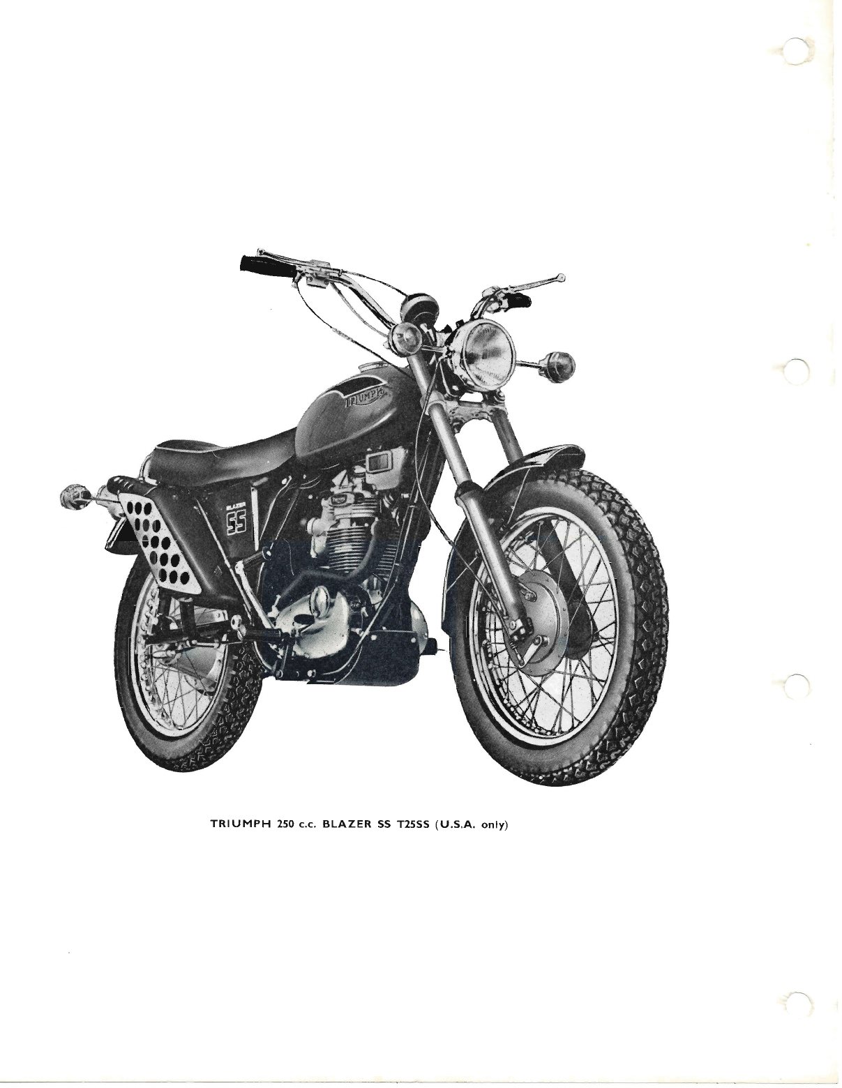
TRIUMPH 250 c.c. BLAZER SS T25SS (U.S.A. only)
www.bsaunitsingles.com
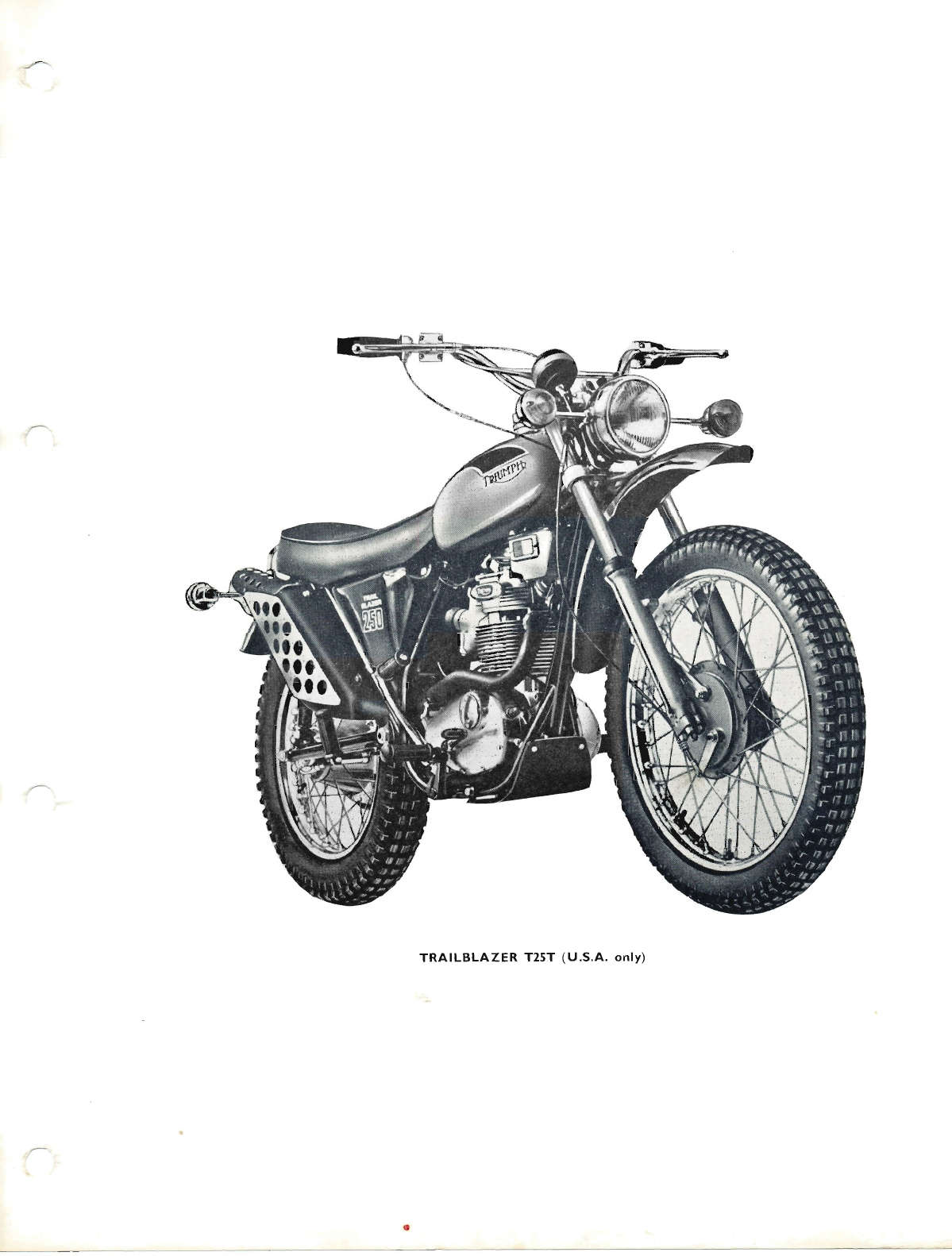
TRAILBLAZER T25T (U.S.A. only)
www.bsaunitsingles.com
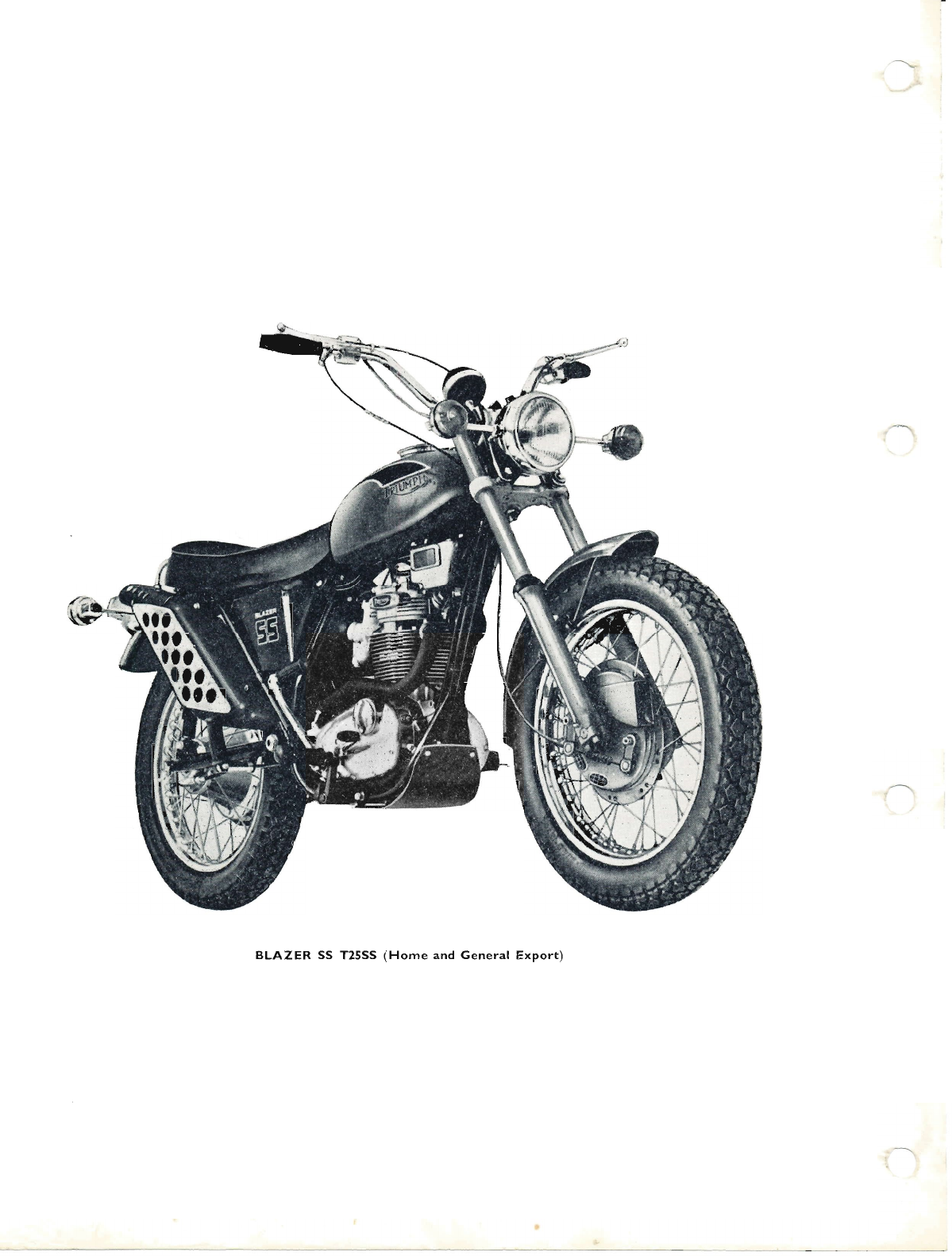
BLAZER SS T25SS (Home and General Export)
www.bsaunitsingles.com
@
o
(o
o
o
o
{'
o
J
s
I
%--
&
eo
d9
;o
9t
?9
9s
w
:l
3,
BI
[*
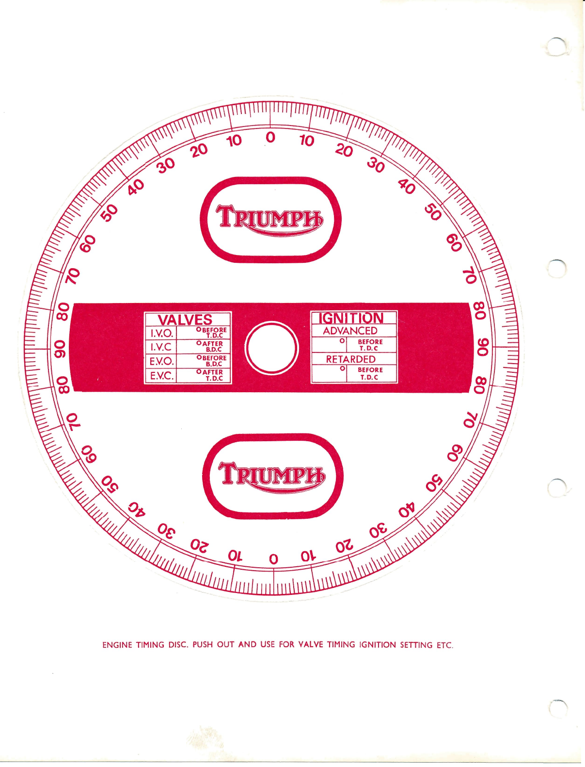
ENGINE TIMING DISC. PUSH OUT AND USE FOR VALVE TIMING IGNITION SETTING ETC,
www.bsaunitsingles.com

\.
BLAZER
GENERAL DATA
BLAZER SS T25SS (USA)
TRAIL BLAZER T25T
SS T25SS (Home and General
250cc. ( 15 cu. ins.)
Export)
GD1
www.bsaunitsingles.com
GD GENERAL DATA
PISTON
Material
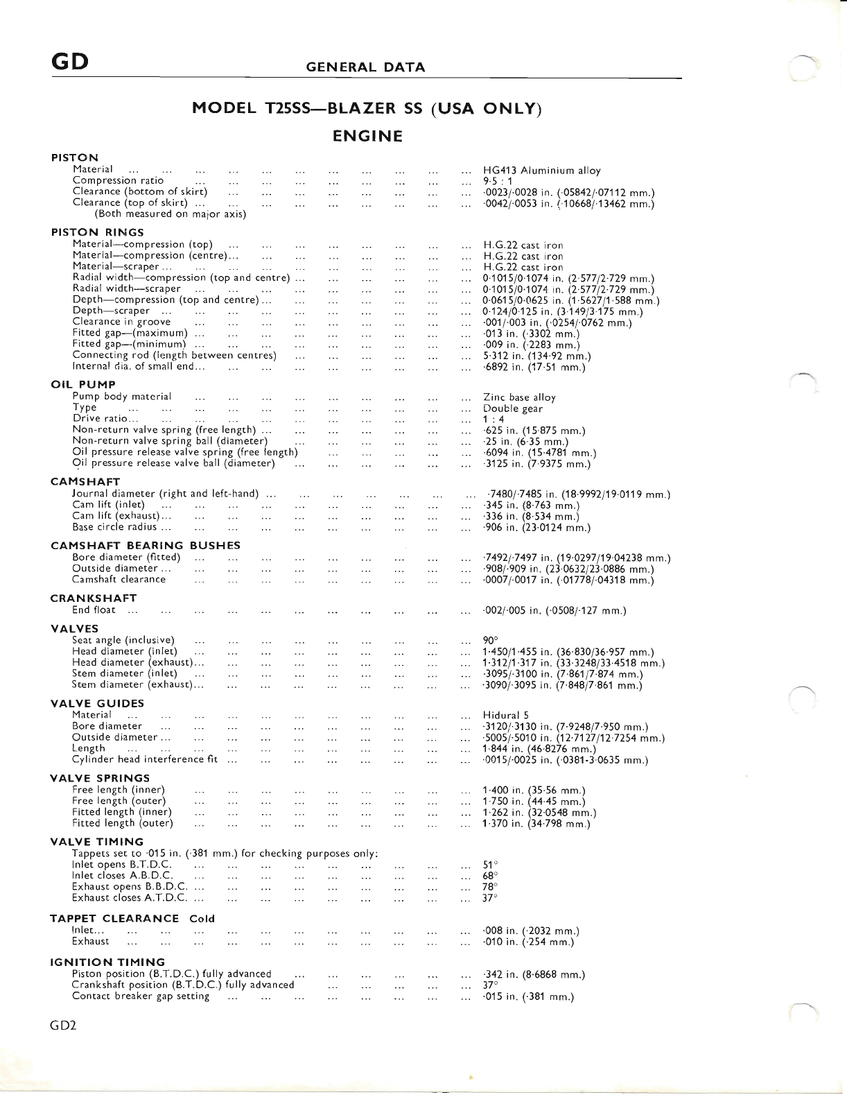
MODEL T25SS-BLAZER SS (USA ONLY)
ENGINE
Compression ratio
Clearance (bottom of skirt)
Clearance (top of skirt) ...
(Both measured on malor axis)
HG413 Aluminium alloy
9.5:1
'0023/'0028 in. (.058421.071'1 2 mm.)
.0042/'0053 in. (..106681.13462 mm.)
PISTON RltlGS
Material-compression (top) H.G.22 cast iron
Material-compression (centre)... H.G.22 cast iron
Material-scraper... H.G.22 cast iron
Radial width-compression (top and centre) ... 0.101510.1074 in. (2.57712.729 mm.)
Radial width-scraper. 0'101510.1074 in. (2.57712.729 mm.)
Depth-compression (top and centre)... 0.0615/0.0625 in. (1 .562711.588 mm.)
Depth-scraper ... 0.12410'125 in. (3.14913.175 mrn.)
Clearance in groove '00t7.993 in. (.0254/.0762 mm.)
Fitted gap-(maximum) ... .01 3 in. (.3302 mm.)
Fitted gap-(minimum) ... .009 in. (.2283 mm.)
Connecting rod (length between centres) 5.312 in.'(134.92 mm.)
lnternal dia. of small end... .6892 in. (j7.51 mm.)
OIL PUMP
Pump body material Zinc base alloy
fYp" Double gear
Driveratio... 1:4
Non-return valve spring (free length) ... '625 in. (15.875 mm.)
Non-return valve spring ball (diameter) .25 in. (6.35 mm.)
Oil pressure release valve spring (free length) .6094 in. (15.4781 mm.)
Oil pressure release valve ball (diameter) '3125 in. (7.9375 mm.)
CAMSHAFT
Journal diameter (right and left-hand) ... .74801.7485 in. (18.9992119.0119 mm.)
Cam lift (inlet) .345 in. (8.763 mm.)
Cam lift (exhaust)... .336 in. (8.534 mm.)
Base circle radius ... .906 in. (23 0124 mm.)
CAMSHAFT BEARING BUSHES
Bore diameter (fitted) .. .74921.7497 in. (19.0297119.04238 mm.)
Outside diameter...
Camshaft clearance
CRANKSHAFT
End float
VALVES
Seat angle (inclusive) 90'
ueaa aiamJter (inteil
Head diameter (exhaust)... 1'3'1211.317 in. (33.3248/33.4518 mm.)
Stem diameter (inlet) '3095i.3100 in. (7'86'117:874 mm.)
Stem diameter (exhaust)... .3090/.3095 in. (7'848/7.861 mm.)
VALVE GUIDES
Material Hidural 5
Bore diameter .31201.3130 in. (7.9248/7.950 mm.)
Outside diameter ... '5005/.5010 in. (12.7127112.7254 mm.)
Length 1'844 in. (46.8276 mm.)
Cylinder head interference fit ... .0015/.0025 in. (.038'l-3.0635 mm.)
VALVE SPRINGS
Free length (inner) 1.400 in. (35.56 mm.)
Free length (outer) 1.750 in. (44.45 mm.)
Fitted length (inner) 1.262 in. (32.0548 mm.)
Fitted length (outer) 1.370 in. (34.798 mm.)
VALVE TIMING
Tappets set to.015 in. (.381 mm.) for checking purposes only:
lnlet opens B.T.D.C. 51"
lnlet closes A.B.D.C. 68"
Exhaust opens B.B.D.C. ... 7S
Exhaust closes A.T.D.C. ... 37'
TAPPET CLEARANCE CoId
lnlet... .008 in. (.2032 mm.)
Exhaust .0'10 in. (.254 mm.)
IGNITION TIMING
Piston position (B.T.D.C.) fully advanced .342 in. (8'6868 mm.)
Crankshaft position (B.T.D.C.) fully advanced 37"
contact breaker gap setting .015 in. (.381 mm.)
7 4921.7497 in. (19.0297 119.04238 m
908 1.909 in. (23'0632123.0886 mm.)
0007 l'0017 in. (.01778
1.0431 8 mm.)
'0007 l'0017 in. (.01778
1.0431 8 mm.)
'002/.00s in. (.0508/.127 mm.)
GD2
www.bsaunitsingles.com
GENERAL DATA GD
Throttle valve
Nominal choke size
Throttle slide return spring (free length)
-th ird
-second
-fi rst
Champion N3
.020/.025 in. (.508/.635 mm.)
14 mm. dia.X.75 in. reach (19.05 mm.)
Aluminium alloy with ausrenitic iron
liner
67 mm.
70 mm.
0'010 and 0.020 in. (0.254 and 0.508 mm.)
Aluminium alloy
1.125 in. (28.575 mm.)
1.25 in. (31'75 mm.)
Amal 928/20 (concentric float chamber)
190
.106 in. (2'69 mm.)
1
3+
28 mm.
2'5 in. (63.5 mm.)
Multi-plate with integral cush drive
4
5
.167 in. (4.242 mm.\
4
1.65685 in. (42.0687 mm.1
9.0 in. (228.6 mm.)
.1875 in. (4.7025 mm.)
1.0
1.24
1.65
2.65
6.89
8.54
11.37
18-26
23 teeth
52 teeth
1 7 teeth
52 teeth
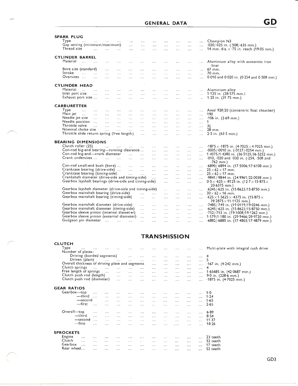
SPARK PLUG
Type
G'.i.etting(minimum/maximumj ..'.' :::
Thread size
CYLINDER BARREL
Material
Bore size (standard)
Stroke
Oversizes ...
CYLINDER HEAD
Material
lnlet port size
Exhaust port size ...
CARBURETTER
TyPe
Main jet
Needle jet size
Needle position ...
BEARING DIMENSIONS
Clutch roller (25) .1875x.1875 in. (4.7A25x4.7025 mm.)
Con-rod big-end bearing-running clearance... .0005/.0010 in. (.0127/.0254 mm.)
Con-rod big-end-crank diameter 1.437511.4380 in. (36.5125/36.5252 mm.)
Crank undersizes ... .0i0, .020 and .030 in. (.254, .508 and
.762 mm.)
Con-rod small-end bush (bore) ... .68901.6894 in. (17.5006/17.6108 mm.)
Crankcase bearing (drive-side) ... 25x62x17 mm.
Crankcase bearing (timing-side) 25x62x17 mm.
Crankshaft dlameter (drive-side and timing-side) ... -984'1 1.9844 in. (24.9961 122'0038 mm.)
Gearbox layshaft bearings (drive-side and timing-side) ... 0.5x.625x.8125 in. (12.7x'15.875x
20.6375 mm.)
Gearbox layshaft diameter (drive-side and timing-side) ... -62451.625 in. (i5.8623/15.8750 mm.)
Gearbox mainshaft bearing (drive-side) 30 x 62 x 16 mrir.
Gearbox mainshaft bearing (timing-side) .625x1.5625x.4375 in. (15.875 x
39.2875x11.1125 mm.)
Gearbox mainshaft diameter (drive-side) .74851.749 in. ('19.0119119.0246 mm.)
Gearbox mainshaft diameter (ti.mjng-side) .62451.625 in. (15.8623/15.8750 mm.)
Gearbox sleeve pinion (internal diameter) .7521:79 in. (19.1008/19.,1262 mm.)'
Gearbox sleeve pinion (external diameter) '1.17911.180 ii. (29-9466129.9720 m;n.)
Gudgeon pin diameter '6882/.6885 in. (17.4803117.4879 mm.)
TRANSMISSION
CLUTCH
TyP"
Number of plates:
Driving (bonded segments)
Driven (plain)
Overall thickness of driving plate and segments
Clutch springs
Free length of springs
Clutch push rod (length)
Clutch push rod (diameter)
GEAR RATIOS
Gearbox-top
-th ird
-second
-first
Overall-top
SPR()CKETS
Engi ne
Clutch
Gearbox
Rear wheel...
GD3
www.bsaunitsingles.com
GD GENERAL DATA
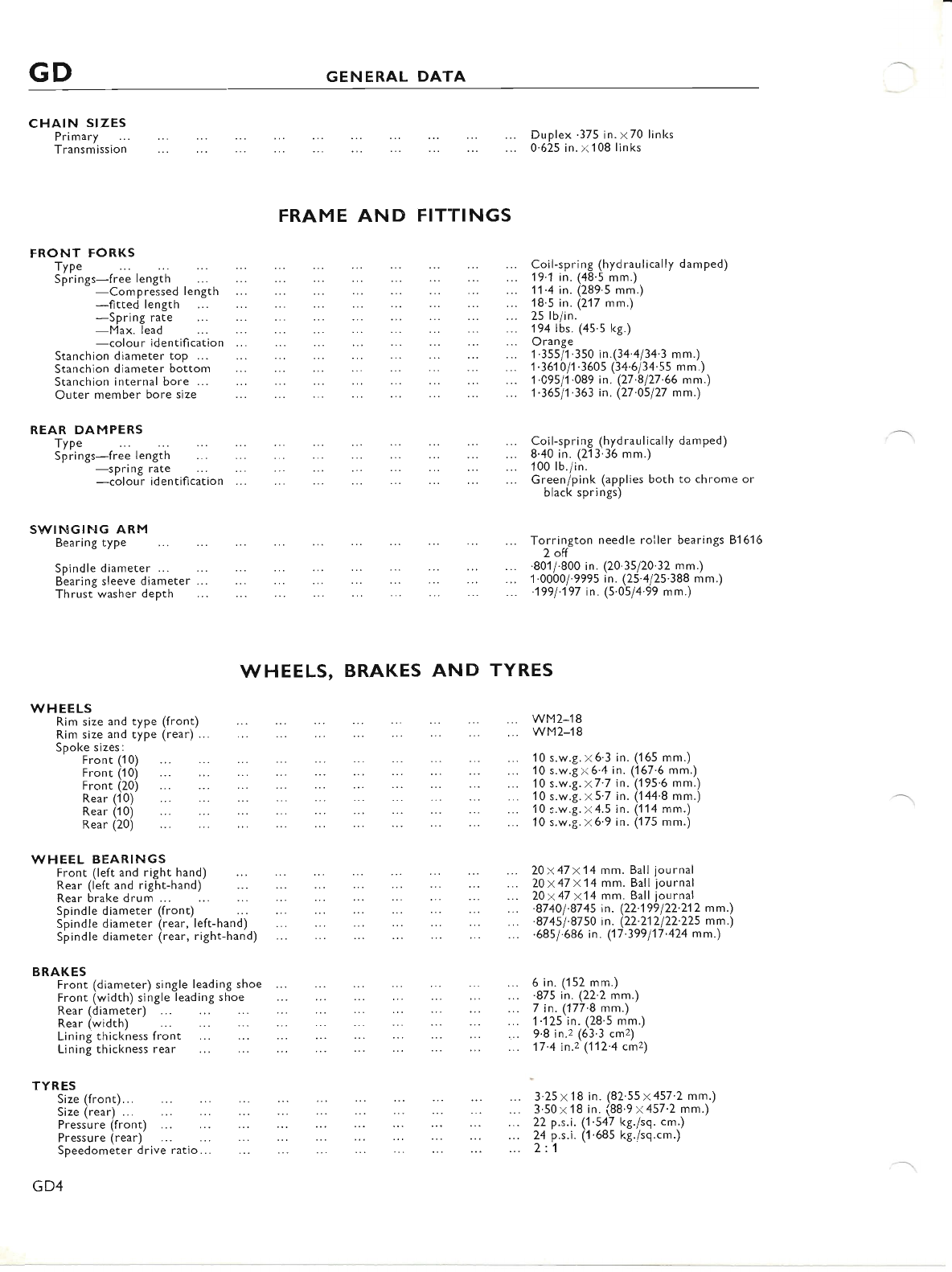
CI.IAIN SIZES
Primary
Transmission
FRAME AND FITTINGS
FRONT FORKS
Type
Siiings-free length ... ... ... ...
-Compressed Iength
-fitted length
-Spring rate
-Max. lead
-colour identification ...
Stanchion diameter top ...
Stanchion diameter bottom
Stanchion internal bore ...
Outer member bore size
REAR DAMPERS
TyP"
Springs-free length
WHEELS, BRAKES AND TYRES
wM2-18
wM2-18
Duplex '375 in. x70 links
0.625 in.x108 links
Coil-spring (hydraulically damped)
19'1 in. (48'5 mm.)
11.4 in. (289.5 mm,)
18.5 in. (217 mm.)
25 lb/in.
194 lbs. (45.5 l<g.)
Orange
1.355/1.350 in.(34 4/34'3 mm.)
1 .3610/1 .360s (34.6/34'ss mm.)
1.09s/1.089 in. (27'8127'66 mm.)
1.36511.363 in. (27'05/27 mm.)
Coil-spring (hydraulically damped)
8.40 in. (213'36 mm.)
100 lb./in.
Green/pink (applies both to chrome or
black springs)
Torrington needle roller bearings 81616
2 off
.801i.800 in. (20'35/20'32 mm.)
1.0000/.999s in. (25'4125'388 mm.)
.1991.197 in. (5'05/4'99 mm.)
20x47 x14 mm. Ball journal
20x47 x14 mm. Ball journal
20x47 x14 mm. Ball iournal
.87 40 l'87 45 in. (22'199 122'21 2 mm.)
.87 45 1.87 50 in. (22.212 122'225 mm.)
.68s/.686 in. (17.399117.424 mm.)
6 in. (152 mm.)
.875 in. (22'2 mm.)
7 in. (177.8 mm.)
1.125 in. (28'5 mm.)
9.8 in.z (63'3 cmz)
17.4 in.z (112'4 cmz\
3.25x18 in. (82'55x457'2 mm.)
3.50x18 in. (88'9x457'2 mm.)
22 p.s.i. (1'547 kg./sq. cm.)
24 p.s.i. ('l'685 kg./sq.cm.)
2:1
-spring rate
-colour identification
S\^/INGING ARM
Bearing type
Spindle diameter ...
Bearing sleeve diameter
Thrust washer depth
\^/HEELS
Rim size and type (front)
Rim size and type (rear) .
Spoke sizes:
Front (1 0)
Front (1 0)
Front (20)
Rear (1 0)
Rear (1 0)
Rear (20)
10 s.w.g. x6'3 in. ('165 mm.)
10 s.w.gx6.4 in. (167.6 mm.)
10 s.w.g. x7'7 in. (195'6 mm.)
10 s.w.g. x 5'7 in. ('144'8 mm.)
10 s.w.g. x4.5 in. (114 mm.)
10 s.w.g.x6'9 in. (175 mm.)
\^,HEEL BEARINGS
BRAKES
Front (left and right hand)
Rear (left and right-hand)
Rear brake drum ...
Spindle diameter (front)
sii" Ji" aii.uter ire".,'left-hanJj
Spindle diameter (rear, right-hand)
Front (diameter) single lead
Front (width) single leading
Rear (diameter) ...
:r) single leading shoe
single leading shoe
Rear (diameter)
Rear (width)
Lining thickness front
Lining thickness rear
TYRES
Size (front)...
Size (rear) ...
Pressu re (front)
Pressure (rear)
Speedometer drive ratio...
GD4
www.bsaunitsingles.com
GENERAL DATA GD
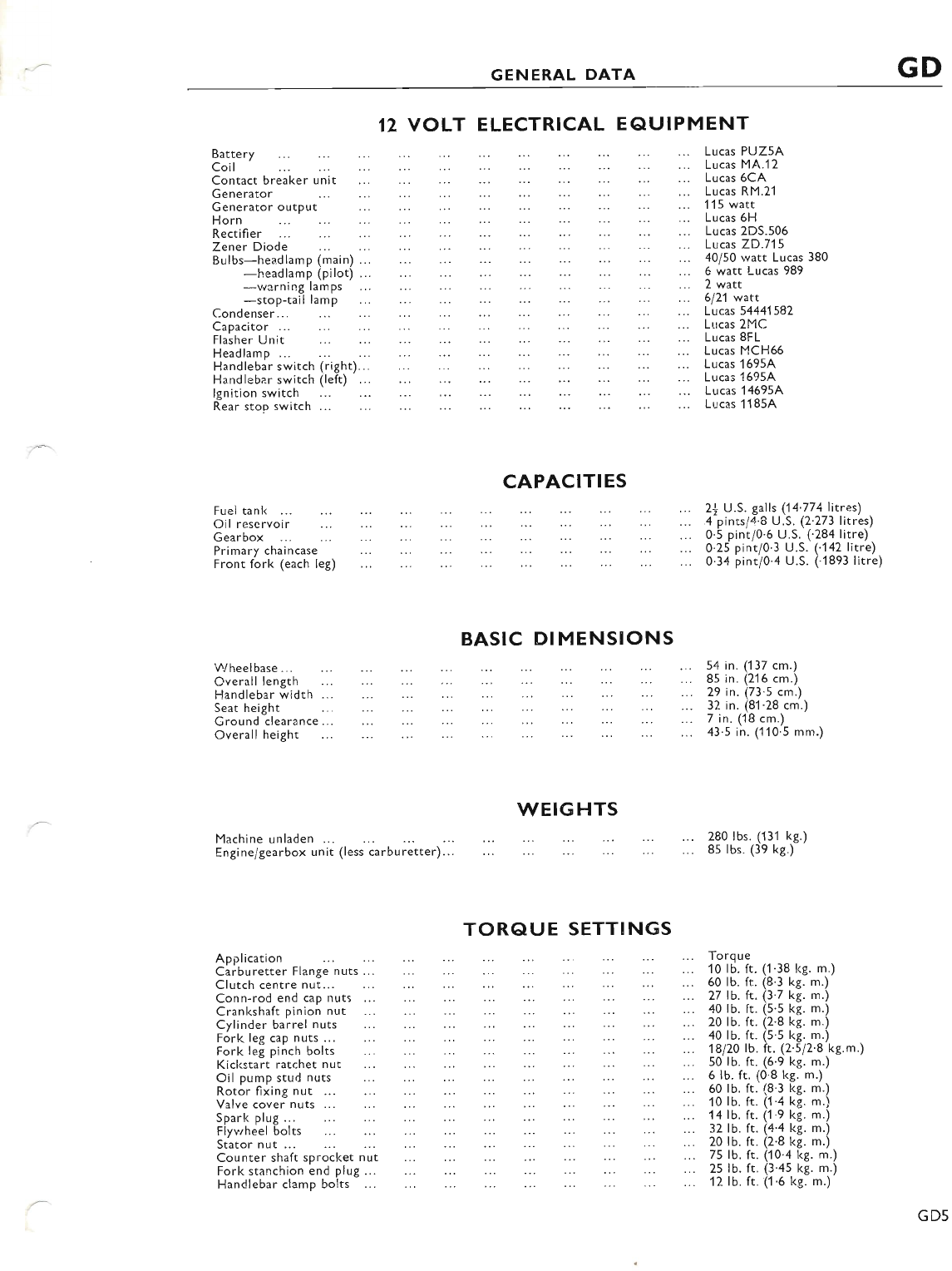
12 VOLT ELECTRICAL EAUIPMENT
Battery
Coil
Contact breaker unit
Generator
Generator output
Horn
Rectifier
Zener Diode
e"it.j"udlu.p (main) ... ...
-headlamp (pilot)...
-warning lamps
-stop-tail lamp
Condenser...
Lucas PUZ5A
Lucas MA.12
Lucas 6CA
Lucas RM.21
1'15 watt
Lucas 6H
Lucas 2DS.506
Lucas 2D.715
40/50 watt Lucas 380
6 watt Lucas 989
2 watt
6121 wart
Lucas 5444'1 582
Lucas 2MC
Lucas 8FL
Lucas MCH66
Lucas 1 695A
Lucas 1 695,4
Lucas 1 4695A
Lucas 1 I 85A
Capacitor ..
Flasher Unit
Headlamp...
Handlebar switch (right)..
Handlebar switch (left) ...
lgnition switch
Rear stop switch ...
Fuel tank ..,
Oil reservoir
Gearbox
CAPACITIES
Primary chaincase
Front fork (each leg)
BASIC DI MENSIONS
\A/heelbase...
Overall length
Handlebar width
Seat height
Ground clearance.
Overall height
WEIGHTS
Machine unladen ...
Engine/gearbox unit (less carburetter)..
TORQUE SETTINGS
A pplication
Carburetter Flange nuts ...
Clutch centre nut...
Conn-rod end cap nuts
Cranl<shaft pinion nut
Cylinder barrel nuts
Fork leg cap nuts ...
Fork leg pinch bolts
Kickstart ratchet nut
Oil pump stud nuts
Rotor fixing nut ...
Valve cover nuts ...
Spark plug...
Flywheel bolts
Stator nut ...
Counter shaft sprocket nut
Fork stanchion end plug ...
Handlebar clamp bolts
2j U.S. galls (14'774litres)
4 pints/4'8 U.S. (2'273 Iitres)
0.5 pint/0.6 U.S. (284 litre)
0.25 pint/0'3 U.S. ("142 Iitre)
0.34 pint/0.4 U.S. (.1893 litre)
54 in. (137 cm.)
85 in. (216 cm.)
29 in. (73.5 cm.)
32 in. (81.28 cm.)
7 in. (18 cm.)
43'5 in. (110'5 mm.)
280 lbs. (131 kg.)
85 lbs. (39 kg.)
Torq ue
10 lb. ft. (1 .38 kg. m.)
60 lb. ft. (8.3 kg. m.)
27 lb. ft. (3.7 kg. m.)
40 lb. ft. (5.s kg. m.)
20 lb. ft. (2.8 kg. m.)
40 lb. ft. (5.5 kg. m.)
1e120 tb. ft. (2.s/2'8 kg.m.)
50 lb. ft. (6.9 kg. m.)
6 lb. ft. (0'8 kg. m.)
60 lb. ft. (8'3 lcg. m.)
10 Ib. ft. (1.a kg. m.)
14 lb. rt. (1.9 kg. m.)
32 lb. ft. (4.4 kg. m.)
20 lb. ft. (2.8 kg. m.)
75lb.ft. (10'4 kg. m.)
2s lb. ft. (3.4s kg. m.)
12 lb. ft. (1.6 kg. m.)
GD5
www.bsaunitsingles.com
GD GENERAL DATA
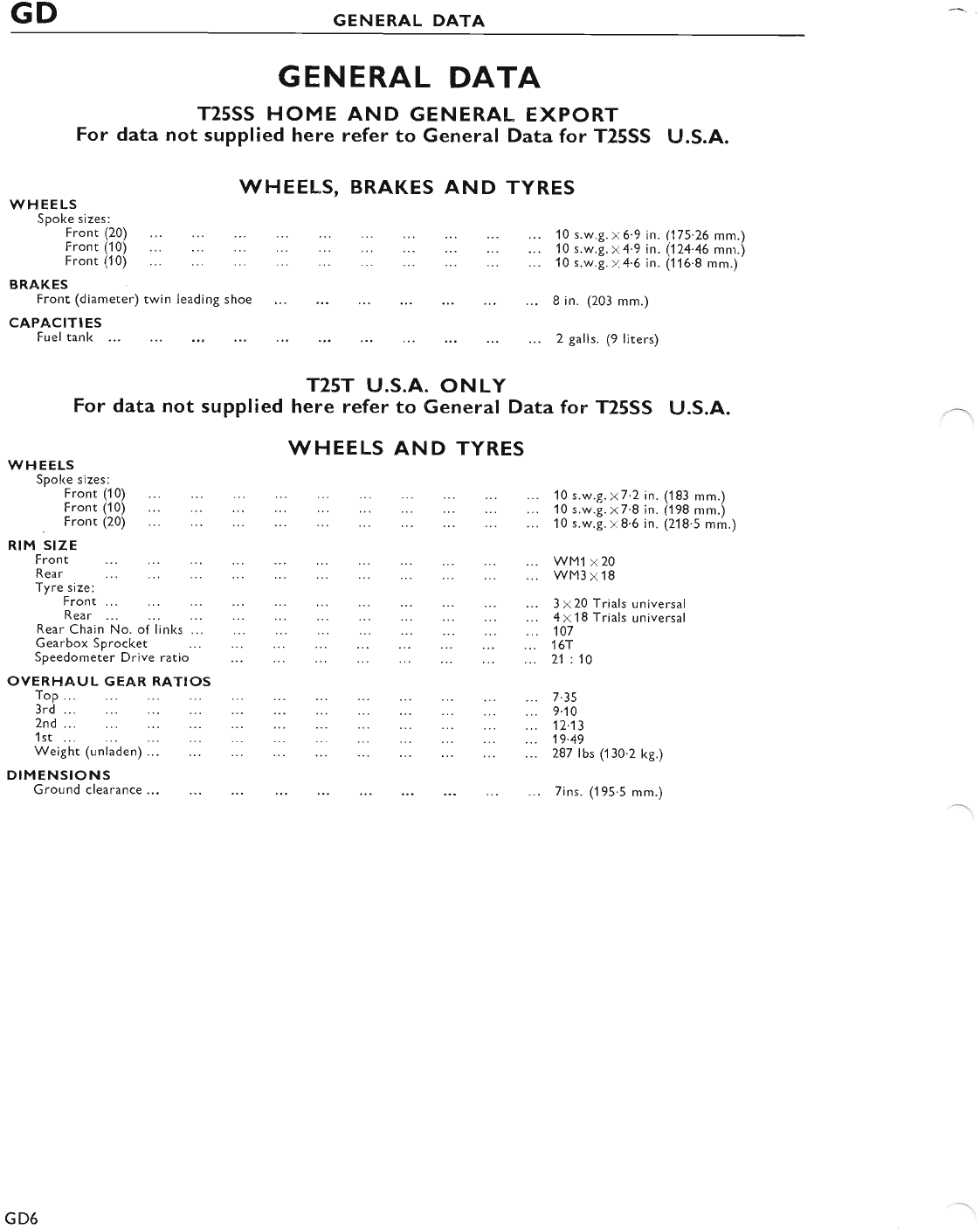
GENERAL DATA
T25SS HOME AND GENERAL EXPORT
For data not supplied here refer to General Data for T25SS U.S.A.
\^/HEELS
Spoke sizes:
Front (20)
t=ront (t oi ..:
Front (1 0)
BRAKES
10 s.w.g. x6.9 in. (175.26 mm.)
10 s.w.g. y 4.9 in. (,124.46 mn.\
10 s.w.g. , 4.6 in. (116.8 mm.)
WHEELS, BRAKES
.....::.:::
AND TYRES
Front (diameter) twin leading shoe 8 in. (203 mm.)
CAPACITIES
Fuel tank 2 galls. (9 liters)
T25T U.S.A. ONLY
For data not supplied here refer to General Data for T25SS U.S.A.
WHEELS AND TYRES
\MHEELS
Spoke sizes:
Front (10)
rront itoj ... ..: ... ::. ...
, Front (20)
RIM SIZE
Front
Rear
Tyre size:
Front ...
Rear ...
Rear Chain No. of links ...
Gearbox Sprocket
Speedometer Drive ratio
OVERHAUL GEAR RATIOS
ToP...
3rd ...
2nd ...
1st ...
Weight (unladen) ...
DIMENSIONS
Ground clearance...
10 s.w.9.x7.2 in. (183 mm.)
10 s.w.g. x7.8 in. (198 mm.)
10 s.w.g.x8.6 in. (218.5 mm.)
WM1 x20
WM3 x 18
3 x 20 Trials universal
4 x 18 Trials universal
107
16r
21 :10
7.35
9.10
12-13
19.49
287 Ibs (130.2 kg.)
7ins. ('195.5 mm.)
GD6
www.bsaunitsingles.com
GENERAL DATA GD
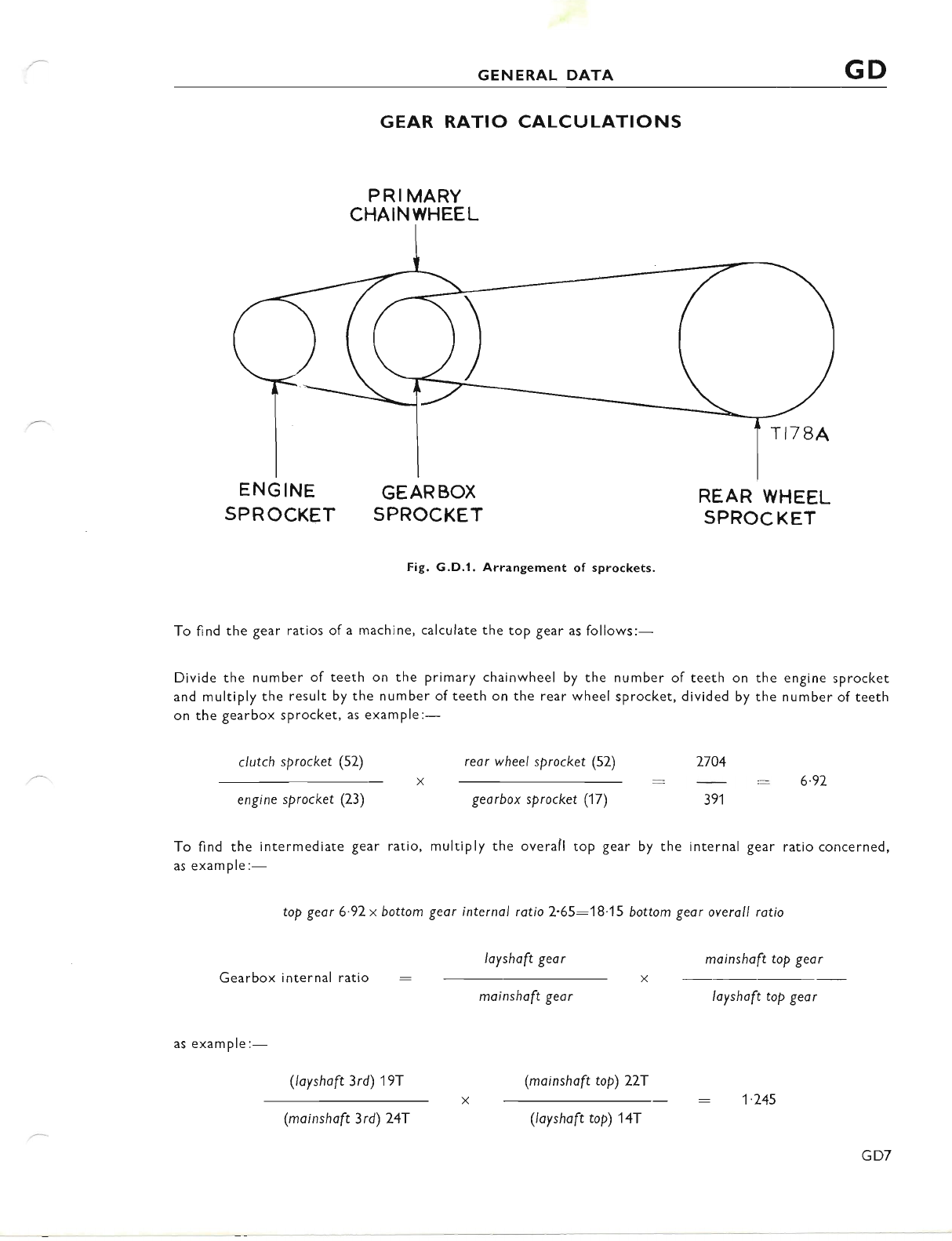
GEAR RATIO CALCULATIONS
PRIMARY
CHAINWHEEL
ENG INE
SP R OCKET GEARBOX
SPROCKET
Fig. G.D.1. Arrangement of sprockets.
REAR WHEEL
SPROC KET
To find the gear ratios of a machine, calculate the top gear as follows:-
Divide the number of teeth on the primary chainwheel by the number of teeth on the engine sprocket
and multiply the result, by the number of teeth on the rear wheel sprocket, divided by the number of teeth
on the gearbox sprocket, as example:-
clutch sprocket (52) rear wheel sprocket (52) 2704
6.92
engine sprocket (23) georbox sprocket (17) 391
To find the intermediate gear ratio, multiply the overall top gear by the internal gear ratio concerned,
as exam ple:-
top gear 6.92x bottom geor internol rotio 2.65:18.15 bottom geor overoll rotio
layshaft gear mainshaft toP geor
Gearbox internal ratio
moinshoft geor loyshoft top geor
(layshoft 3rd) 19f (moinshoft top) 227
TI78A
as example:-
(moinshaft 3rd) 247 (layshoft top) 147
1'245
GD7
www.bsaunitsingles.com
SECTION A
LUBRICATION SYSTEM
INDEX
SECTION
A1 ROUTINE LUBRICATION
A2 RECOMMENDED LUBRICANTS
A3 ENGINE LUBRICATION SYSTEM
A4 CHANGING THE OIL AND CLEANING THE FILTERS
A5 SCAVENGE NON-RETURN VALVE
A5 FEED NON-RETURN VALVE
A7 CRANKCASE OIL PIPE UNION
A8 OIL PRESSURE RELEASE VALVE
A9 LOW OIL PRESSURE
A1O SYPHONING
All DISMANTLING AND RE.ASSEMBLING THE OIL PUMP
412 CONTACT BREAKER
A13 GEARBOX LUBRICATION
A.14 PRIMARY DRIVE
415 REAR CHAIN
l.16 STEERING HEAD
417 TELESCOPIC FORK
4,18 WHEEL BEARINGS
419 LUBRICATING THE CONTROL CABLES
A2O SPEEDOMETER CABLE
A1
www.bsaunitsingles.com
ALUBRICATION
SECTION AI
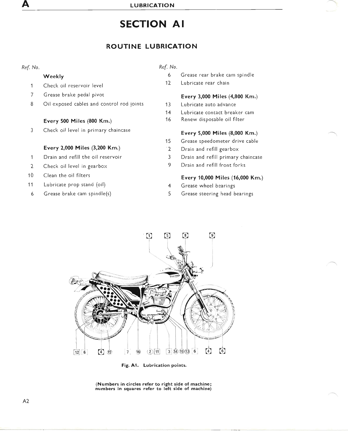
ROUTINE LUBRICATION
Ref. No.
Weekly
1 Check oil reservoir level
7 Grease brake pedal pivot
8 Oil exposed cables and control rod ioints
Every 500 Miles (800 Km.)
3 Check oil level in primary chaincase
Every 2,000 Miles (3,200 Km.)
I Drain and refill the oil reservoir
2 Check oil level in gearbox
10 Clean the oil filters
11 Lubricate prop stand (oil)
6 Grease bral<e cam spindle(s)
Fig. A1. Lubrication points.
(Numbers in circles refer to right side of machine;
numbers in squares refer to left side of machine)
Ref. No.
6 Grease rear brake cam spindle
12 Lubricate rear chain
Every 3,000 Miles (4,800 Km.)
1 3 Lubricate auto advance
14 Lubricate contact breaker cam
16 Renew disposable oil filter
Every 5,000 Miles (8,000 Krn.)
15 Grease speedometer drive cable
2 Drain and refill gearbox
3 Drain and refill primary chaincase
9 Drain and refill front forlcs
Every 10,000 Miles (16,000 Km.)
4 Grease wheel bearings
5 Grease steering head bearings
AZ
www.bsaunitsingles.com
LUBRICATION A
SECTION A2
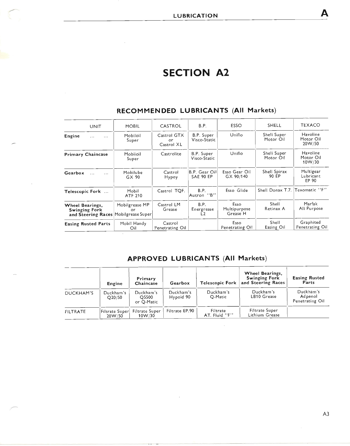
RECOMMENDED LUBRICANTS (All Markets)
Engine
Primary Chaincase
Wheel Bearings,
Swinging Fork
and Steering Races
Easing Rusted Parts
Mobiioil
Super
Mobilgrease MP
or
Mobil Handy
oit
| .orr*or_
I Castrol GTX
1".
I Castrol XL_
Castrolite
Castrol
Penetrati
B.P. Gear Oil
SAE 90 EP
Esso Gear Oil
GX 901140
Shell Super
Motor Oil
Shell Super
Motor Oil
Havoline
Motor Oil
20w/s0
Havol i ne
Motor Oil
10w/30
Sl*il sph-r" l-llut.ig"".
Castrol
HyPoy
Mobilube
GX 90 Lu bricant
EP 90
Wheel Bearings, I
Swinging Fork I
and Steering Races
I
Marfak
All Purpose
G raphited
Penetrati
Easing Rusted
Parts
Duckham's
Adpenol
Penetrating Oil
Duckham's
Q20/s0
I Filtrate super I
I Lirhium Grease I
: Glide I Shell Donax T.7.
t_
Esso I sn"tt
ipurpose I Retinax A
ease H I
gr* f tt*
Penetratine Oil I Easine Oil
Esso
M ulti Pu rPose
Grease H
APPROVED LUBRICANTS (All Markets)
A3
www.bsaunitsingles.com
ALUBRICATION
SECTION A3
ENGINE LUBRICATION SYSTEM
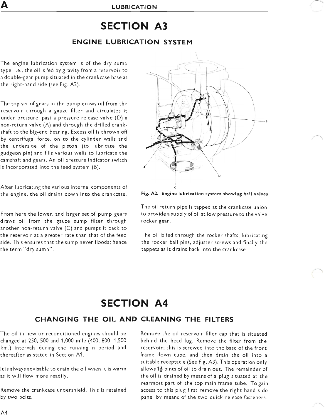
The engine lubrication system is of the dry sump
type, i.e., the oil is fed by gravity from a reservoir to
a double-gear pump situated in the crankcase base at
the right-hand side (see Flg. A2).
The top set of gears in the pump draws oil from the
reservoir through a gauze filter and circulates it
under pressure, past a pressure release valve (D) a
non-return valve (A) and through the drilled crank-
shaft to the big-end bearing. Excess oil is thrown off
by centrifugal force, on to the cylinder walls and
the underside of the piston (to lubricate the
gudgeon pin) and fills various wells to lubricate the
camshaft and gears. An oil pressure indicator switch
is incorporated into the feed system (B).
After lubricating the various internal components of
the engine, the oil drains down into the crankcase.
From here the lower, and larger set of pump gears
draws oil from the gauze sump filter through
another non-return valve (C) and pumps it back to
the reservoir at a greater rate than that of the feed
side. This ensures that the sump never floods; hence
the term "dry sump".
CHANGING THE OIL AND
The oil In new or reconditioned engines should be
changed at 250,500 and 1,000 mile (400,800, 1,500
km.) intervals during the running-in period and
thereafter as stated in Section 41.
It is always advisable to drain the oil when it is warm
as it will flow more readily.
Remove the cranl<case undershield. This is retained
by two bolts.
A4
Fig. A2. Engine lubrication system showing ball valves
The oil return pipe is tapped at the crankcase union
to provide a supply ofoil at low pressure to the valve
rocker gear.
The oil is fed through the rocker shafts, lubricating
the rocker ball pins, adiuster screws and finally the
tappets as it drains back into the cranlccase.
SECTION A4
CLEANING THE FILTERS
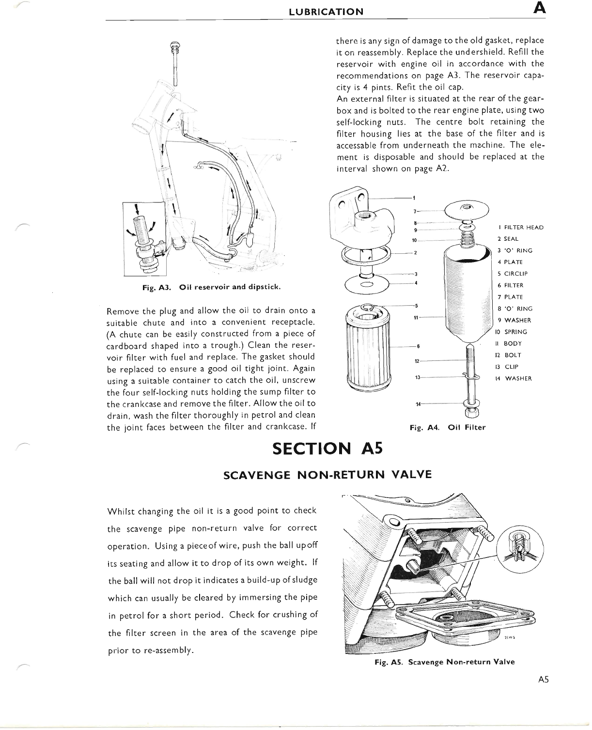
Remove the oil reservclir filler cap that is situated
behind the head lug. Remove the filter from the
reservoir; this is screwed into the base of the front
frame down tube, and then drain the oil inro a
suitable receptacle (See Fig. A3). This operation only
allows 1f; pints of oil to drain out. The remainder of
the oil is drained by means of a plug situated at the
rearmost part of the top main frame tube. To gain
access to this plug first remove the right hand side
panel by means of the two quick release fasteners.
www.bsaunitsingles.com
LUBRICATION
T
,''l
there is any sign of damage to the old gasket, replace
it on reassembly. Replace the undershield. Refill the
reservoir with engine oil in accordance with the
recommendations on page A3. The reservoir caPa-
city is 4 pints. Refit the oil cap.
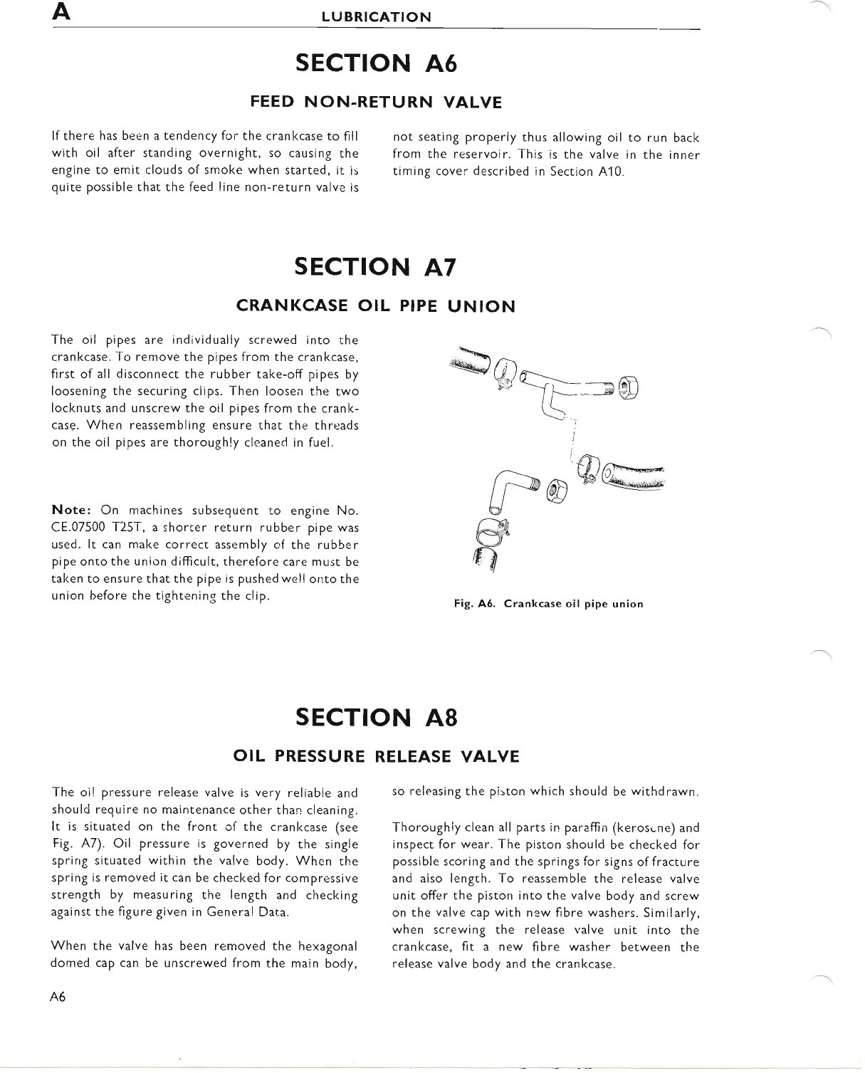
An external filter is situated at the rear ofthe gear-
box and is bolted to the rear engine plate, using two
self-locking nuts. The centre bolt retaining the
filter housing lies at the base of the filter and is
accessable from underneath the ma.chine. The ele-
ment is disposable and should be replaced at the
interval shown on page A2..
Fig. A3. Oil reservoir and dipstick.
Remove the plug and allow the oil to drain onto a
suitable chute and into a convenient receptacle.
(A chute can be easily constructed from a piece of
cardboard shaped into a trough.) Clean the reser-
voir filter with fuel and replace. The gasket should
be replaced to ensure a good oil tight joint. Again
using a suitable container to catch the oil, unscrew
the four self-locking nuts holding the sump filter to
the crankcase and remove the filter. Allow the oilto
drain, wash the filter thoroughly in petrol and clean
the joint faces between the filter and crankcase. lf
-5 ll
--b
12
13
I FILTER HEAD
2 SEAL
3 'O' RING
4 PLATE
5 C|RCLIP
6 FILTER
7 PLATE
8 'O' RING
9 WASHER
IO SPRING
II BODY
12 BOLT
13 cltP
14 WASHER
Fig. A.4. Oil Filter
SECTION A5
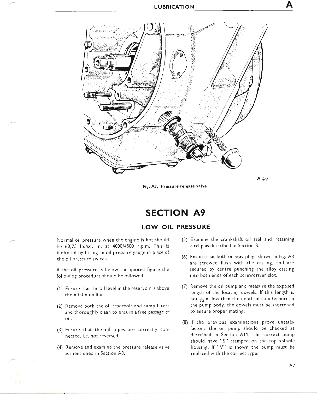
SCAVENGE NON.RETURN VALVE
Whilst changing the oil it is a good Point to check
the scavenge pipe non-return valve for correct
operation. Using a pieceof wire, Push the ball upoff
its seating and allow it to drop of its own weight' lf
the ballwill not drop it indicates a build-up of sludge
which can usually be cleared by immersing the PiPe
in petrol for a short period. Check for crushing of
the filter screen in the area of the scavenge pipe
prior to re-assembly.
Fig. A5. Scavenge Non-return Valve
www.bsaunitsingles.com
LUBRICATION
SECTION A6
FEED NON.RETURN VALVE
lf there has been a tendency for the crankcase to fill
with oil after standing overnight, so causing the
engine to emit clouds of smoke when started, it is
quite possible that the feed line non-return valve is
OIL PRESSURE
The oil pressure release valve is very reliable and
should regu!re no maintenance orher than cleaning.
It is situated on the front of the crankcase (see
Fig. A7). Oil pressure is governed by the single
spring situated within the valve body. When the
sprlng is removed it can be checked for compressive
strength by measuring the Iength and checking
against the figure given in General Data.
When the valve has been removed the hexagonal
domed cap can be unscrewed from the main body,
A6
not seating properly thus
from the reservoir. This
timing cover described in
allowing oil to run back
is the valve in the inner
Section A10.
UNION
*Q?Trr@
SECTION A8
SECTION A7
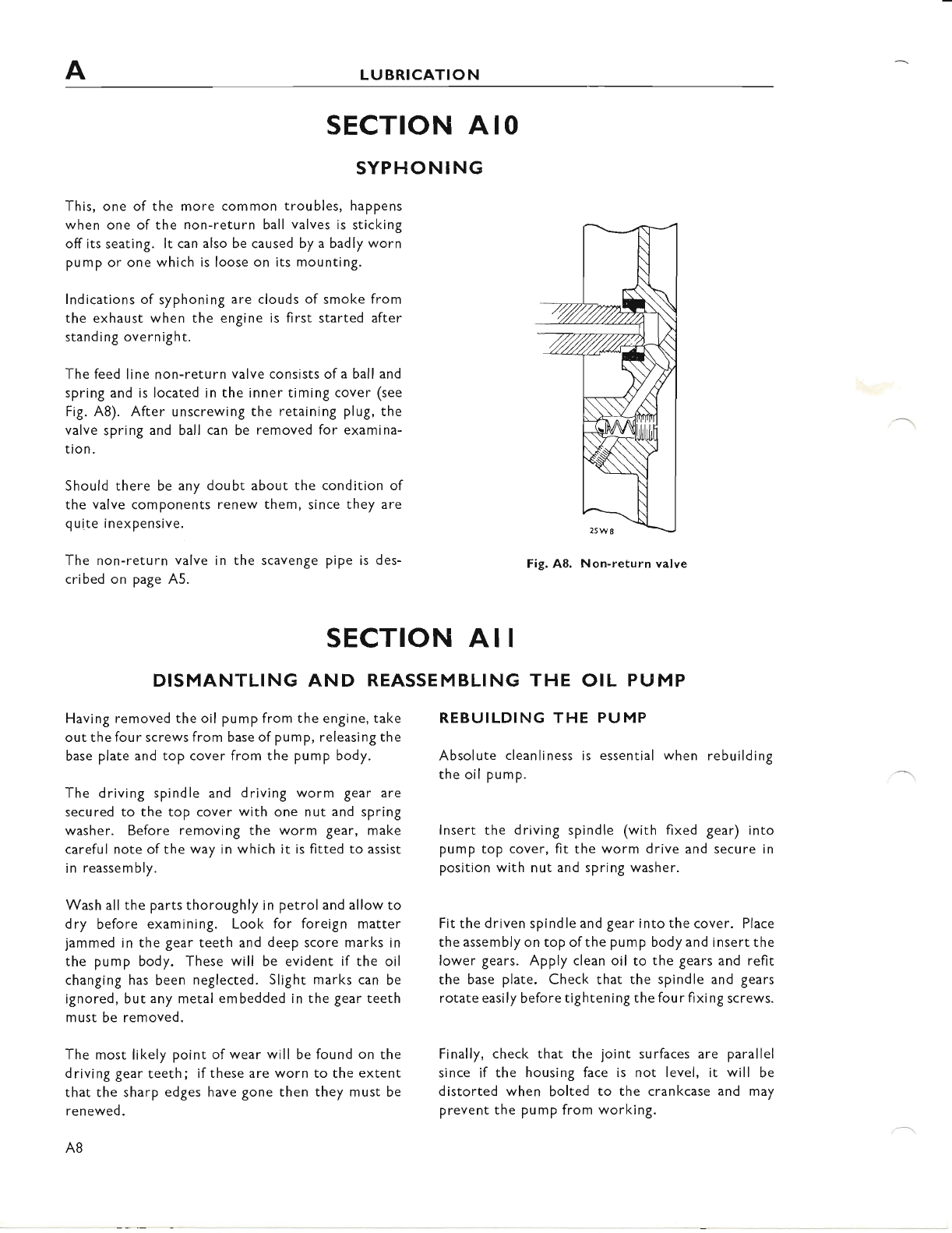
CRANKCASE OIL PIPE
The oil pipes are individually screwed into the
crankcase. To remove the pipes from the crankcase,
first of all disconnect the rubber take-off pipes by
loosening the securing clips. Then loosen the two
locknuts and unscrew the oil pipes from the crank-
case. When reassembling ensure that the threads
on the oil pipes are thorough!y cleaned in fuel.
Note: On machines subsequent to engine No.
CE.07500 T25T, a shorter return rubber pipe was
used. lt can make correct assernbly of the rubber
pipe onto the union difflcult, therefore care must be
taken to ensure that the pipe is pushed well onto the
union before the tightening the clip.
14)r*-
afu6h w(G;
nw
o
Fig. A5. Crankcase oil pipe union
RELEASE VALVE
so releasing the piston which should be withdrawn.
Thoroughly clean all parts !n paraffin (keros.ne) and
inspect for wear. The piston should be checked for
possible scoring and the springs for signs offracture
and also length. To reassemble the release valve
unit offer the piston into the valve body and screw
on the valve cap with new fibre washers. Similarly,
when screwing the release valve unit into the
crankcase, fit a new fibre washer'between the
release valve body and the crankcase.
www.bsaunitsingles.com
LUBRICATION
Fig. .A7. Pressure release valve
(5) Examine the crankshaft oil seal and retainirrg
circlip as described in Section B.
(6) Ensure that both oil way plugs shown in Fig. A8
are screwed flush with the casting, and are
secured by centre punching the alloy casting
into both ends of each screwdriver slot.
(7) Remove the oil pump and measure the exposed
length of the locating dowels. lf this length is
not $in. less than the depth of counterbore in
the pump body, the dowels must be shortened
to ensure ProPer mating.
(8) lf the previous examinations prove un satis-
factory the oil pump should be checked as
described in Section 41 1. l-he correct pump
should have "S" stamped on the top spindle
housing. lf "V" is shown the pump must be
replaced with the correct type.
SECTION A9
LO\tr OIL PRESSURE
Normal oil pressure when the engine is hot should
be 60i75 lb./sq. in. at 4000/4500 r.p.m. This is
indicated by fitting an oil pressure gauge in place of
the oil pressure switch
lf the oil pressure is below the quoted figure the
following procedure should be followed:
(1) Ensure that the oil level in the reservoir is above
the minimum line.
(2) Remcve both the oil reservoir and sump filters
and thoroughly clean to ensure a free passage of
oil.
(3) Ensure that the oil pipes are correctly con-
nected, i.e. not reversed.
(4) Remove and examine the pressure release valve
as mentioned in Section A8.
A7
www.bsaunitsingles.com
LUBRICATION
SECTION AIO
SYPHONING
This, one of the more common troubles, happens
when one of the non-return ball valves is sticking
off its seating. lt can also be caused by a badly worn
pump or one which is loose on its mounting.
lndications of syphoning are clouds of smoke from
the exhaust when the engine is first started after
standing overnight.
The feed Iine non-return valve consists ofa ball and
spring and is located in the inner timing cover (see
Fig. A8). After unscrewing the retaining plug, the
valve spring and ball can be removed for examina-
tion.
Should there be any doubt about the condition of
the valve components renew them, since they are
quite inexpensive.
The non-return valve in the scavenge pipe is des-
cribed on page A5.
Fig. A8, Non.return valve
REBUILDING THE PUMP
Absolute cleanliness is essential when rebuilding
the oil pump.
lnsert the driving spindle (with fixed gear) into
pump top cover, fit the worm drive and secure in
position with nut and spring washer.
Fit the driven spindle and gear into the cover. Place
the assembly on top of the pump body and insert the
lower gears. Apply clean oil to the gears and refit
the base plate. Check that the spindle and gears
rotate easily before tightening the four fixing screws.
Finally, check that the joint surfaces are parallel
since if the housing face is not level, it will be
distorted when bolted to the crankcase and may
prevent the pump from working.
SECTION AII
DISMANTLING AND REASSEMBLING THE OIL PU MP
Having removed the oil pump from the engine, take
out the four screws from base of pump, releasing the
base plate and top cover from the pump body.
The driving spindle and driving worm gear are
secured to the top cover with one nut and spring
washer. Before removing the worm gear, make
careful note of the way in which it is fitted to assist
in reassembly.
Wash all the parts thoroughly in petrol and allow to
dry before examining. Look for foreign matter
jammed in the gear teeth and deep score marks in
the pump body. These will be evident if the oil
changing has been neglected. Slight marks can be
ignored, but any metal embedded in the gear teeth
must be removed.
The most likely point of wear will be found on the
driving gear teeth; if these are worn to the extent
that the sharp edges have gone then they must be
renewed.
A8
www.bsaunitsingles.com
LUBRICATION
@
@
m
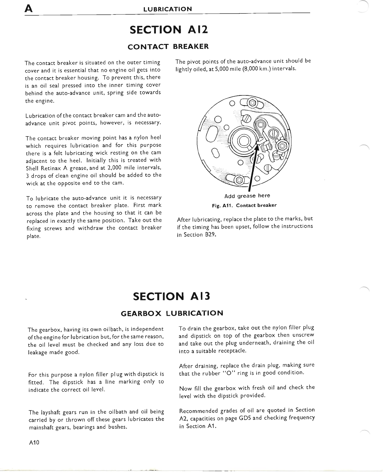
CRANKCASE BREATHER
A short crankcase breather pipe emerges from the
timing case alongside the clutch cable abutment
(See Fig. 410). lt is most important that periodic
checks are made to ensure that this pipe remains
u nobst ructed.
When a machine is used in competition events or
at continued high speeds, it may be necessary to
provide a pressure outlet at the gearbox to prevent
oil leakage. This can be accomplished by drilling
a small hole through the oil filler plug.
Fig. A10. breather
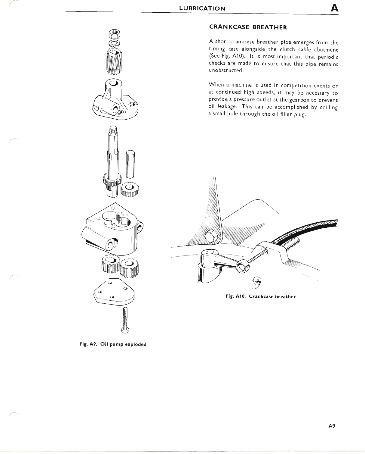
ffis
Fig. A9. Oil pump exploded
I
Crankcase
A9
www.bsaunitsingles.com
ALUBRICATION
SECTION AI2
CONTACT BREAKER
The contact breaker is situated on the outer timing
cover and it is essential that no engine oil gets into
the contact breaker housing. To prevent this, there
is an oil seal pressed into the inner timing cover
behind the auto-advance unit, spring side towards
the engine.
Lubrication ofthe contact breaker cam and the auto-
advance unit pivot points, however, is necessary'
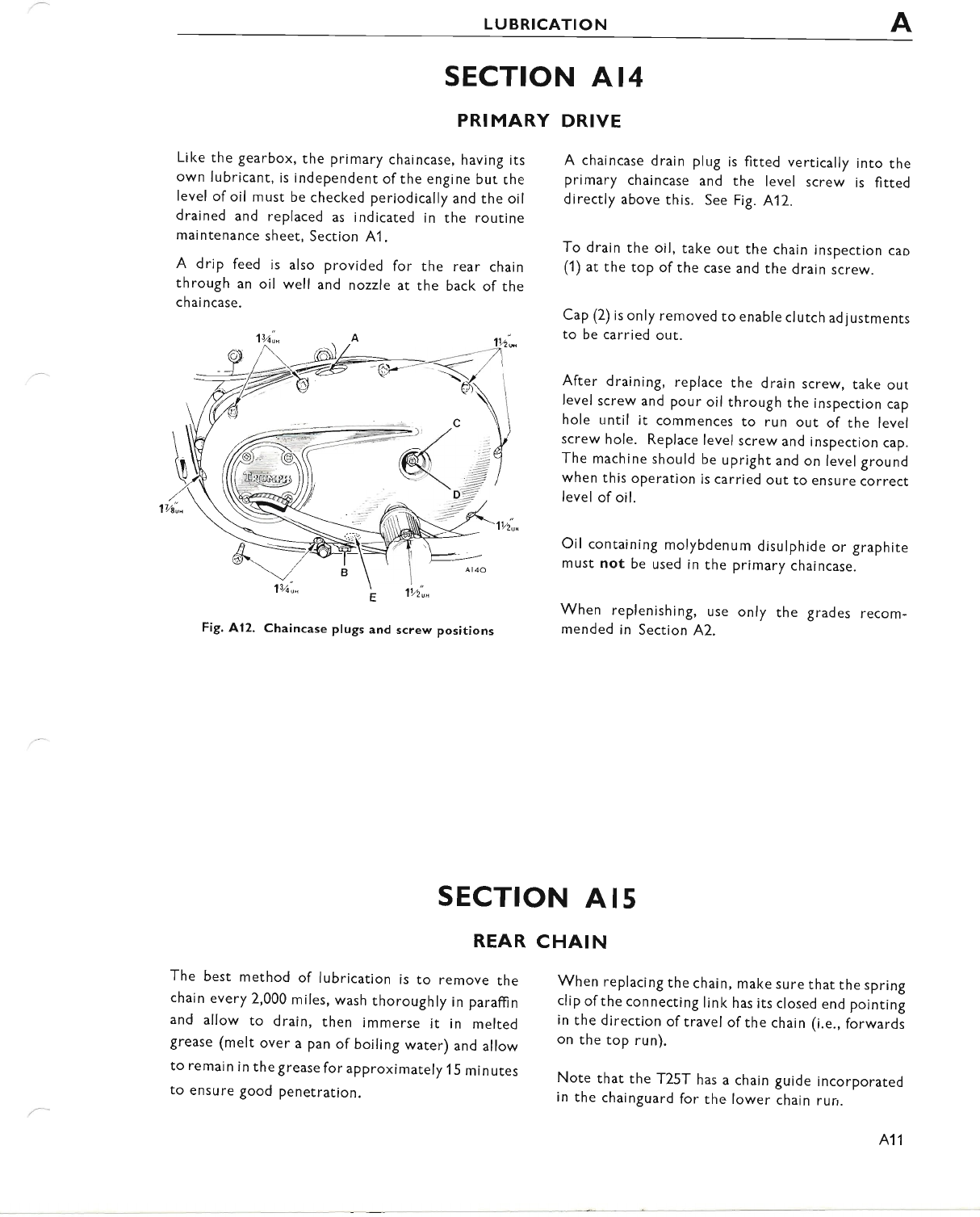
The contact breal<er moving point has a nylon heel
which requires lubrication and for this PurPose
there is a felt lubricating wicl< resting on the cam
adjacent to the heel. lnitially this is treated with
Shell Retinax A grease, and at 2,000 mile intervals,
3 drops of clean engine oil should be added to the
wick at the opposite end to the cam.
To lubricate the auto-advance unit it is necessary
to remove the contact breaker plate. First mark
across the plate and the housing so that it can be
replaced in exactly the same Position. Take out the
fixing screws and withdraw the contact breaker
plate.
The pivot points ofthe auto-advance unit should be
lightly oiled, at 5,000 mile (8,000 km.) intervals'
Fig. Alt. Contact breaker
After lubricating, replace the plate to the marks, but
if the timing has been upset, follow the instructions
in Section 829.
Add grease here
SECTION AI3
GEARBOX LUBRICATION
The gearbox, having its own oilbath, is independent
of the engi ne for I u brication but, for the same reason'
the oil level must be checked and any loss due to
leakage made good.
For this purpose a nylon filler plug with diPstick is
fitted. The dipstick has a line marking only to
indicate the correct oil level.
The layshaft gears run in the oilbatn and oil being
carried by or thrown off these gears lubricates the
mainshaft gears, bearings and bushes.
A10
To drain the gearbox, take out the nylon filler plug
and dipstick on toP of the gearbox then unscrew
and take out the plug underneath, draining the oil
into a suitable recePtacle'
After draining, replace the drain plug, making sure
that the rubber "O" ring is in good condition.
Now fill the gearbox with fresh oil and check the
level with the dipstick Provided.
Recommended grades of oil are quoted in Section
A2, capacities on PaSe GD5 and checking frequency
in Section A1 .
www.bsaunitsingles.com
LUBRICATION
SECTION AI4
PRI MARY DRIVE
Like the gearbox, the primary chaincase, having its
own lubricant, is independent of the engine but rhe
level of oil must be checked periodically and the oil
drained and replaced as indicated in the routine
maintenance sheet, Section 41 .
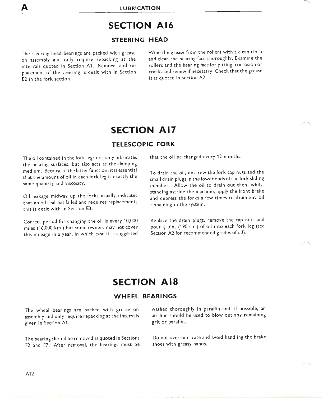
A drip feed is also provided for the rear chain
through an oil well and nozzle at the back of the
chai ncase.
Fig. A12. Chaincase plugs and screw positions
A chaincase drain plug is fitted vertically into the
primary chaincase and the level screw is fitted
directly above this. See Fig. 412.
To drain the oil, take out the chain inspection cao
(1) at the top ofthe case and the drain screw.
Cap (2) is only removed to enable clutch ad justments
to be carried out.
After draining, replace the drain screw, take out
Ievel screw and pour oil through the inspection cap
hole until it commences to run out of the level
screw hole. Replace level screw and inspection cap.
The machine should be upright and on level ground
when this operation is carried out to ensure correct
level of oil.
Oil containing molybdenum disulphide or graphite
must not be used in the primary chaincase.
When replenishing, use only the grades recom-
mended in Section A2.
SECTION AI5
REAR CHAIN
The best method of lubrication is to remove the
chain every 2,000 miles, wash thoroughly in paraffin
and allow to drain, then immerse it in melted
grease (melt over a pan of boiling water) and allow
to remain in the grease for approximately 15 m in utes
to ensure good penetration.
When replacing the chain, make sure that the spring
clip of the connecting link has its closed end pointing
in the direction of travel of the chain (i.e., forwards
on the top run).
Note that the T25T has a chain guide incorporared
in the chainguard for the lower chain run.
A11
www.bsaunitsingles.com
LUBRICATION
SECTION AI6
STEERING HEAD
The steering head bearings are packed with grease
on assembly and only require repacking at the
intervals quoted in Section A1 . Removal and re-
placement of the steering is dealt with in Section
E2 in the fork section.
Wipe the grease from the rollers with a clean cloth
and clean the bearing face thoroughly. Examine the
rollers and the bearing face for Pitting, corrosion or
cracks and renew if necessary. Check that the grease
is as quoted in Section A2.
SECTION A17
TELESCOPIC FORK
The oilcontained in the fork legs not only lubricates
the bearing surfaces, but also acts as the damping
medium. Because of the latter function, it is essential
that the amount of oil in each fork leg is exactly the
same quantity and viscositY.
Oil leakage midway up the forks usually indicates
that an oil seal has failed and requires replacement;
this is dealt with in Section E3.
Correct period for changing the oil is every 10,000
miles (16,000 km.) but some owners may not cover
this mileage in a year, in which case it is suggested
The wheel bearings are packed with grease on
assembly and only require repacking at the intervals
given in Section A1 .
The bearing should be removed as quoted in Sections
F2 and F7. After removal, the bearings must be
that the oil be changed every 12 months.
To drain the oil, unscrew the fork caP nuts and the
small drain plugs in the lower ends of the fork sliding
members. Allow the oil to drain out then, whilst
standing astride the machine, apply the front brake
and depress the forks a few times to drain any oil
remaining in the system.
Replace the drain plugs, remove the caP nuts and
pour { pint (190 c.c.) of oil into each fork leg (see
Section A2 for recommended grades of oil).
washed thoroughly in paraffin and, if possible, an
air line should be used to blow out any remaintng
grit or paraffin.
Do not over-lubricate and avoid handling the brake
shoes with greasy hands.
SECTION AI8
WHEEL BEARINGS
A1Z
www.bsaunitsingles.com
LUBRICATION
SECTION AI9
LUBRICATING THE
The control cables can be periodically lubricated at
the exposed joints with a thin grade of oil (see
Section Al).
A more thorough method of lubrication is that of
feeding oil into one end of the cable by means of a
reservoir. For this, the cable can be either discon-
nected at the handlebar end only, or completely
removed.
The disconnected end of the cable should be
threaded through a thin rubber stoPPer and the
CONTROL CABLES
stopper pressed into a suitable narrow-necked can
with a hole in its base. lf the can is then inverted
and the lubricating oil poured into it through the
hole, the oil will trickle down between the outer
and inner cables. lt is bestto leave the cable in this
position overnight to ensure adequate lubrica-
tion.
Note that the clutch cable has an oil nipple situated
in the outer casing of the clutch cable. A Pressure
oil can should be applied until oil escaPes at either
end of the cable.
SECTION A2O
SPEEDOMETER (AND TACHOMETER CABLE WHERE FITTED)
It is necessary to lubricate the cables to Prevent
premature failure of the inner wires' Care is also
necessary to avoid over-zealous greasing which
may result in the lubricant entering the instru-
ment heads. For lubricating, it is only necessary to
unscrew the cable ferrules and withdraw the inner
wires. The grease should be applied sparingly to
the wires and the top 6 in. must not be greased.
A13
www.bsaunitsingles.com
SECTION B
ENGI NE
INDEX
SECTION
DESCRIPTION
81 DECARBONISING
87 CHECKING VALVE CLEARANCES
83 REMOVING CYLINDER BARREL
84 REMOVING THE PISTON
85 PISTON RINGS
86 RE.FITTING CYLINDER BARREL
87 REMOVING THE ENGINE UNIT
88 TRANSMISSION
89 REMOVING PRIMARY CHAINCASE COVER
B1O CLUTCH DISMANTLING
B11 GENERATOR REMOVAL
B17 INSPECTING THE CLUTCH
B13 CLUTCH SHOCK ABSORBER UNIT
814 GEARBOX SPROCKET
815 CLUTCH OPERATION
816 RE-ASSEMBLING THE PRIMARY DRIVE
817 CoNTACT BREAKER AND AUTOMATIC ADVANCE/RETARD UNIT
B18 TIMING COVERS
B19 REMOVING AND REPLACING OIL PUMP
B2O TIMING GEARS AND TAPPETS
821 SEQUENCE OF GEARCHANGING
8?:2 DISMANTLING THE GEARBOX
B23 SPLITTING THE CRANKCASE HALVES
B24 CRANKSHAFT AND BIG END
B25 FLYWHEEL BALANCING
526 RE.FITTING THE CONNECTING ROD
827 RENEWING THE MAIN BEARINGS
828 RE-ASSEMBLING THE CRANKCASE
829 IGNITION TIMING
B3O FITTING A TACHOMETER
B1
www.bsaunitsingles.com
BENGINE
B2
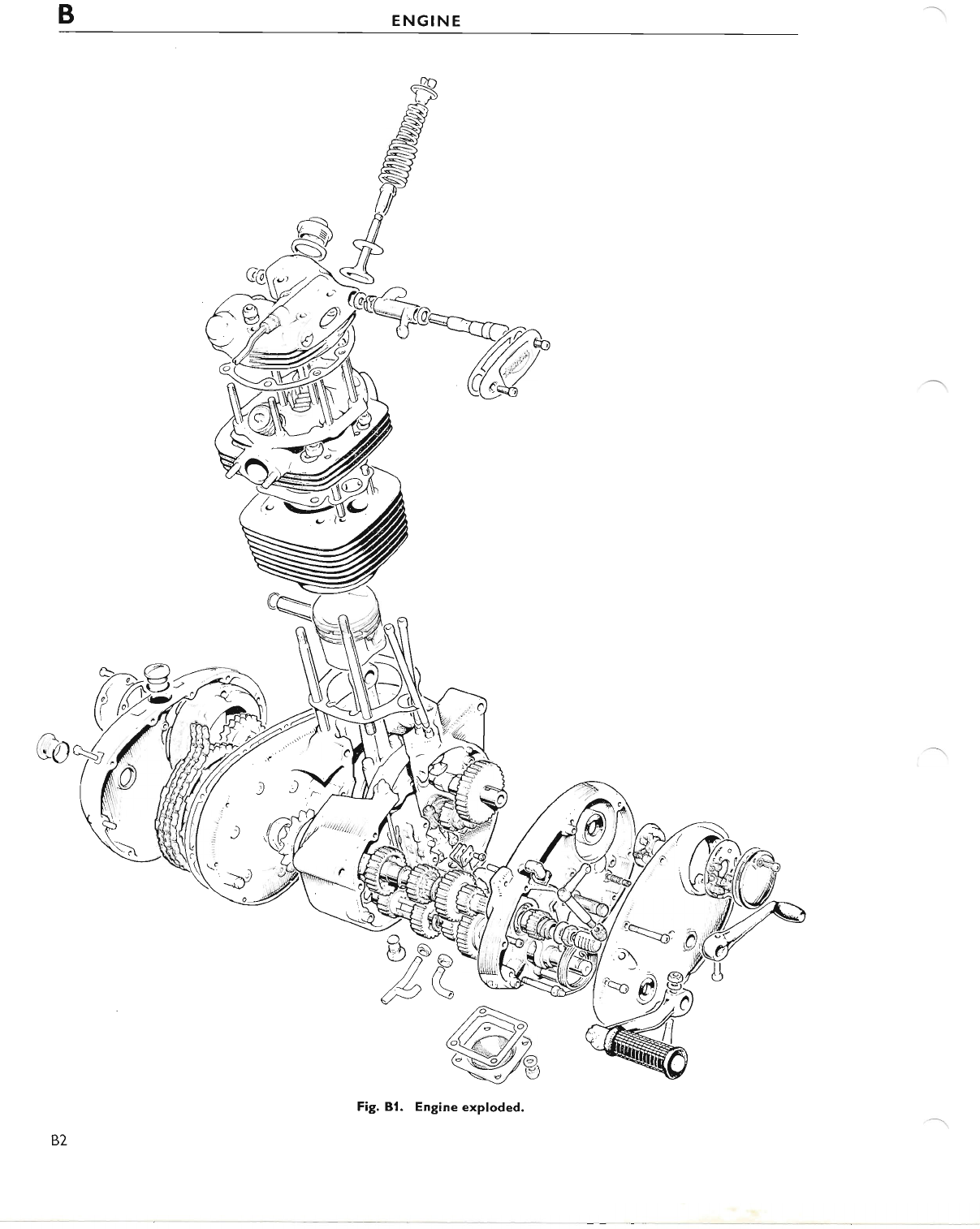
Fig. Bl. Engine exploded.
www.bsaunitsingles.com
ENGINE B
DESCRIPTION
The 250 c.c. overhead valve single cylinder four-
stroke engine is of the unit constructlon type and
incorporates an aluminium alloy cylinder barrel
which has an austenitic iron liner.
The aluminium alloy die-cast piston has one plain
compression ring, one tapered compression ring,
and a scraper ring. The connecting rod is of H-
section Hiduminium alloy.
Four special bolts hold each of the two flywheels to
the one-piece forged cranl<shaft. lncorporated in
the right-hand flywheel is a centrifugal oil sludge
trap, fitted with a screwed plug. The bolt-on con-
necting rod big-end assembly consists of two bear-
ing shell halves, available in three undersizes for use
with reground crankshafts.
The aluminium alloy cylinder head has cast-in, heavy
d uty cast-iron valve seats and removable valve
guides. Housed within the top of the cylinder head
are two valve rocker spindles, carrying the inlet
rocker at the rear and the exhaust rocker at the
front. Each of the valve rocker spindles has an
eccentric cam which provides a means of adjusting
the valve clearances.
The high performance camshaft operates in two
bushes, one of phosphor bronze and the other of
sintered bronze.
Contained within the primary drive case on the left-
hand half of the crankcase are the clutch assembly,
primary chain and the alternator. The alternator
unit consist's. of an encapsulated six-coil stator,
mounted on three studs, and a rotor secured to the
drive-side shaft.
A vertically mounted oil pump of the double gear
type is driven off a wormwheel on the timing side
crankshaft and supplies oil to the big-end assembly,
piston, cylinder walls and the timing gears.
The gearbox, at the rear ofthe right-hand halfofthe
crankcase, and the primary chaincase are indepen-
dent ofthe engine lubrication system and each con-
tain their own lubricant.
Power from the engine is transmitted through the
engine sprocket and duplex primary chain to the
clutch assembly which has a built-in shock absorber.
Here the drive is taken up by the bonded friction
plates and is transmitted through the four-speed
constant-mesh gearbox to the final drive sprocket.
SECTION B I
DECARBONISING
Decarbonising or top overhaul as it is sometimes
called, means the removal of carbon deposits from
the combustion chamber, piston crown, valve heads
and inlet and exhaust ports, and to restore a smooth
finish to these surfaces. Obviously, whilst the upper
portion of the engine is dismantled for this purpose,
opportunity will be taken to examine the valves,
valve seats, springs, guides, etc, for general "wear
and tear", hence the term "top overhaul".
Carbon, produced by combustion taking place in the
engine when running, is not harmful providing it is
not allowed to become excessive and therefore
likely to cause pre-ignition or other symptoms
which may impair performance.
The usual symptoms indicating the need for decar-
bonising, are an increased tendency for the engine
to "pink" (metallic knocking sound when under
load), a general decrease in power and a tendency
for the engine to run hotter than usual. An increase
in petrol consumption may also be apparent.
PREPARING TO DECARBONISE
Perfect cleanliness is essential to ensure success in
any service task, so before starting a job such as this,
make sure that you have a clean bench or working
area on which to operate and room to place parts
as they are removed.
To facilitate removal of the cylinder head for
decarbonising, first take off the petrol tank, as
detailed in Section D.
With the tank removed, the engine torque stay
bracket can be disconnected.
B3
www.bsaunitsingles.com
BENGINE
The right-hand exhaust system is a pr.rsh fit into the
cylinder head. Remove the two fixing bolts situated
at the silencer, loosen the clip securing the silencer
to the exhaust pipe, disconnect the front fixing at
the front engine bolt and then remove the exhaust
pipe from the cylinder head. The pipe may be a tight
fit and may require tapping with a rubber mallet or
sim ilar.
Remove the carburetter from the cylinder head and
tie it bacl< out of the way.
The oil feed pipe to the rocl<er spindles should now
be disconnected and the sparking plug tal<en out.
REMOVING THE CYLINDER HEAD
Set the piston at top dead centre on the compres-
sion strol<e (both valves closed) and take off the six
nuts holding the cylinder head to the barrel.
Leave the rocker box assembly ir position on the
cylinder head, and raise the latter until it clears its
fixing studs. lt will then be necessary to rotate the
cylinder head assembly about the push rods so as to
clear the frame top tube. The rocker box can now
be removed from the cylinder head, thus exposing
the valves and springs.
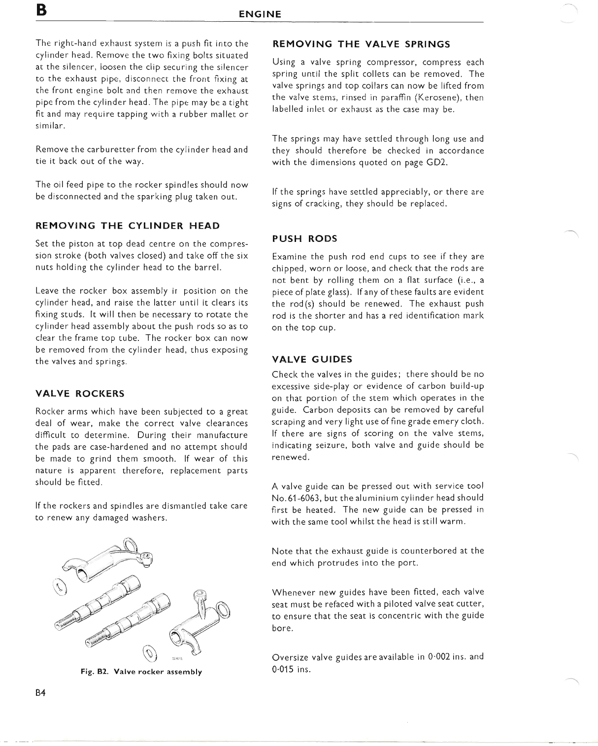
VALVE ROCKERS
Rocker arms which have been subjected to a great
deal of wear, make the correct valve clearances
difficult to determine. During their manufacture
the pads are case-hardened and no attempt should
be made to grind them smooth. lf wear of this
nature is apparent therefore, replacement parts
should be fitted.
lf the rockers and spindles are dismantled tal<e care
to renew any damaged washers.
REMOV|NG THE VALVE SPRINGS
Using a valve spring compressor, compress each
spring until the split collets can be removed. The
valve springs and top collars can now be lifted from
the valve stems, rinsed in paraffin (Kerosene), then
labelled inlet. or exhaust as the case may be.
The springs may have settled through long use and
they should therefore be checked in accordance
with the dimensions quoted on page GD2.
lf the springs have settled appreciably, or there are
signs of cracking, they should be replaced.
PUSH RODS
Examine the push rod end cups to see if they are
chipped, worn or loose, and checl< that the rods are
not bent by rolling them on a flat surface (i.e., a
piece of plate glass). lf any of these faults are evident
the rod(s) should be renewed. The exhaust push
rod is the shorter and has a red identification mark
on the top cup.
VALVE GUIDES
Check the valves in the guides; there should be no
excessive side-play or evidence of carbon build-up
on that portion of the stem which operates in the
guide. Carbon deposits can be removed by careful
scraping and very light use of fine grade emery cloth.
lf there are signs of scoring on the valve stems,
indicating seizure, both valve and guide should be
renewed.
A valve guide can be pressed out with service tool
No.51 -6063, but the aluminium cylinder head should
first be heated. The new guide can be pressed in
with the same tool whilst the head is still warm.
Note that the exhaust guide is counterbored at the
end which protrudes into the port.
Whenever new guides have been fitted, each valve
seat must be refaced with a piloted valve seat cutter,
to ensure that the seat is concentric with the guide
bore.
Oversize valve guides are available in 0'002 ins' and
0.01 5 ins.
,i\
:t
ai\
\J
rocker
B4
Fig, 82. Valve assembly
www.bsaunitsingles.com
ENGINE B
VALVES
Valve heads can be refaced on a valve refacer but if
pitting is deep or the valve head is burnt, then a new
valve must be fitted and ground-in.
The valve seats in the cylinder head are unlikely to
require any attention, but if they are marlced, they
should be refaced. Cutting tools are available under
part nurnber Dl 832, D'l 835 and Dl 863. The seat
angle is 45 degrees.
Sometimes when the engine has been decarbonised
many times, valves become "pocketed". This is
when the valve head and seat are below the surface
of the combustion chamber, so impairing the
efficiency of the valve and affecting the gas flow. The
"pocl<et" should be rernoved with a special blending
cutter Dl 835 beferre re-cutting the seat or grinding-
in the valve.
Fig. 83. Pocketed valve
VALVE GRINEING
lf the valve have been renewed or refaced they must
be ground-in to their seats to ensure a good gas-
seal.
This operation is carried out only after all carbon
deposits have been removed from the combustion
cham ber.
Removal ofcarbon from the head, inlet and exhaust
ports can be carried out with scraPers or rotary
files, but whichever method is used great care must
be tal<en to avoid scoring the valve seats or cylinder
h ead.
A final "polish" can be achieved with the use of fine
emery cloth wetted by paraffn.
Do not attempt to decarbonise the cylinder head by
immersing it in caustic soda solution; the solution
has a harmful effect on aluminium.
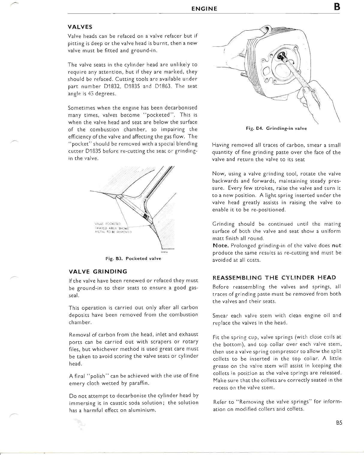
Having removed all traces of carbon, smear a small
quantity of fine grinding paste over the face of the
valve and return the valve to its seat
Now, using a valve grinding tool, rotate the valve
bacl<wards and forwards, maintaining steady pres-
sure. Every few strokes, raise the valve and turn it
to a new position. A light spring inserted under the
valve head greatly assists in raising the valve to
enable it to be re-posltioned.
Grinding should be continued until the mating
surface of both the valve and seat shovv a uniform
matt finish all round.
htote. Prolonged grinding-in of the valve does nert
produce the same results as re-cutting and must be
avoided at all costs.
REASSEMBL!NG THE EYLINDER FIEAD
Before reassembling the valves and springs, all
traces of grinding paste must be removed from bcth
the valves and their seats.
Smear each valve stem with clean engine oil and
replace the valves in the head.
Fit tlre spring cup, valve springs (with close coils at
the bottorn), and top coliar over each valve stem,
then use a valve spring compressor to allow the split
coilets to be inserted in the top coliar. A little
grease on the valye stem will assist in keeping the
collets in position as the valve springs are released.
Make sure that the collets are correctly seatecl in the
recess on the valve stem.
Refer to "Renroving the valve springs" for inform-
ation on modified collers and collets.
Fig, E'4. Grinding-in valve
B5
www.bsaunitsingles.com
BENGINE
CLEANING TI-{E PISTON CROWN
Unless the condition of the engine indicates that the
piston, piston rings or cylinder bore require atten-
tion, the cylinder barrel should not be disturbed.
lf the barrel is not being removed, bring the piston
to the top ofthe bore and, after plugging the push
rod opening with clean rag, proceed to remove the
carbon fronr the piston crown. A stick of tinsmiths
solder, flattened at one end, provides an ideal
scraper tool and will not damage the alloy piston.
lf possi[:le leave a ring of carbon around the edge of
the piston crown and around the top of the cylinder
bore. This will help to provide an additional seal.
After cleaning the piston crown, rotate the engine
to lower the piston and wipe av,tay any loose carbon
frorn the cylinder wall.
The cylinder barrel and head ;oint faces must also be
cleaned, care being taken not to damage the faces by
scoring with the scraper.
Such score marlcs would result in gas l,ea.kage, loss of
compression or even burning of the cylinder head
face.
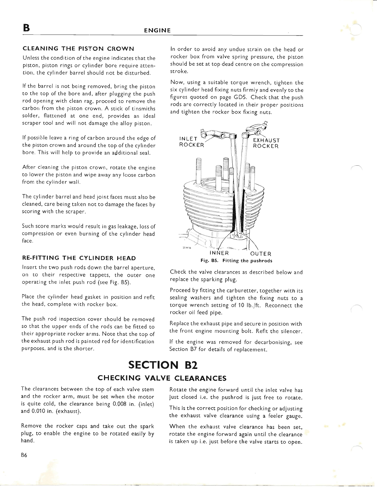
RE.FITTING THE CYLINDER HEAD
lnsert the two push rods down the barrel aperture,
on to their respective tappets, the outer one
operating the inlet push rod (see Fig. 85).
Place the cylinder head gasket in position and refit
the head, complete w'ith rocker box.
The push rod inspection cover should be removed
so that the upper ends of the rods can be fitted to
their appropriate rocker arms. Note that the top of
the exhaust push rod is painted red for identification
purposes, and is the shorter.
ln order to avoid any undue strain on the head or
rocker box from valve spring pressure, the piston
should be set at top dead centre on the compression
stroke.
Now, using a suitable torque wrench, tighten the
six cylinder head fixing nuts firmly and evenly to the
figures quoted on page GD5. Check that the push
rods are correctly located in their proper positions
and tighten the rocker box fixing nuts.
INLET EXH AU ST
ROCKER
ROCKER
OUTER
Fig. 85. Fitting the pushrods
Check the valve clearances as described below and
replace the sparking plug.
Proceed by fitting the carburetter, together with its
sealing washers and tighten the fixing nuts to a
torque wrench setting of 10 lb./ft. Reconnect the
rocker oil feed pipe.
Replace the exhaust pipe and secure in position with
the front engine mounting bolt. Refit the silencer.
lf the engine was removed for decarbonising, see
Section 87 for details of replacement.
'l
SECTION 82
CHECKING VALVE CLEARANCES
The clearances between the top of each valve stem
and the rocker arm, must be set when the motor
is quite cold, the clearance being 0.008 in. (inlet)
and 0.010 in. (exhaust).
Remove the rocker caps and take out the spark
plug, to enable the engine to be rotated easily by
hand.
B6
Rotate the engine forward until the inlet valve has
just closed i.e. the pushrod is just free to rotate.
This is the correct position for checking or adjusting
the exhaust valve clearance using a feeler gauge.
When the exhaust valve clearance has been set,
rotate the engine forward again until the clearance
is taken up i.e. just before the valve starts to open.
f
www.bsaunitsingles.com
ENGINE B
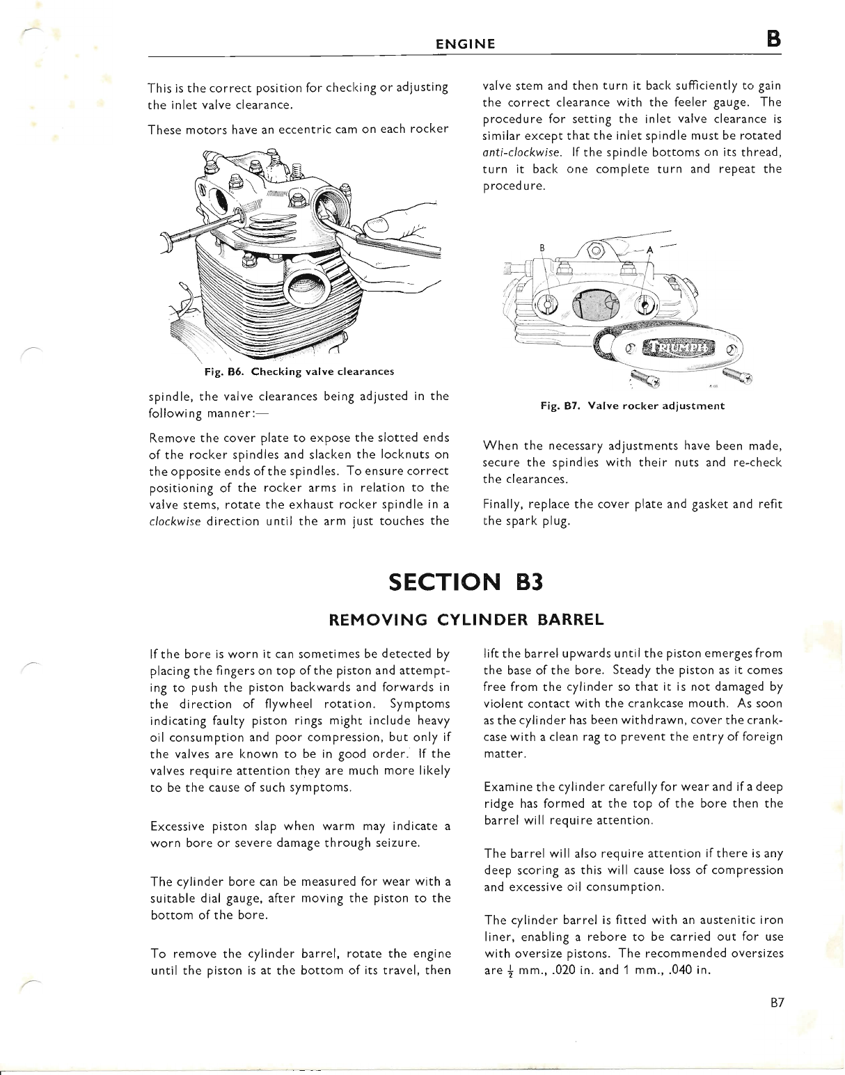
This is the correct position for checl<ing or adjusting
the inlet valve clearance.
These motors have an eccentric cam on each rocker
Fig. 86. Checking valve clearances
spindle, the valve clearances being adjusted in the
following manner:-
Remove the cover plate to expose the slotted ends
of the rocker spindles and slacken the locknuts on
the opposite ends ofthe spindles. To ensure correct
positioning of the rocker arms in relation to the
valve stems, rotate the exhaust rocker spindle in a
clockwise direction until the arm just touches the
valve stem and then turn it bacl< sufficiently to gain
the correct clearance with the feeler gauge. The
procedure for setting the inlet valve clearance is
similar except that the inlet spindle must be rotated
onti-clockwise. lf the spindle bottoms on its thread,
turn it back one complete turn and repeat the
proced u re,
Fig. 87. Valve rocker adiustment
When the necessary adjustments have been made,
secure the spindles with their nuts and re-check
the clearances.
Finally, replace the cover plate and gasket and refit
the spark plug.
SECTION 83
REMOVING CYLINDER BARREL
lf the bore is worn it can sometimes be detected by
placing the fingers on top of the piston and attempt-
ing to push the piston backwards and forwards in
the direction of flywheel rotation. Symptoms
indicating faulty piston rings might include heavy
oil consumption and poor compression, but only if
the valves are known to be in good order. lf the
valves require attention they are much more likely
to be the cause of such symptoms.
Excessive piston slap when warm may indicate a
worn bore or severe damage through seizure.
The cylinder bore can be measured for wear with a
suitable dial gauge, after moving the piston to the
bottom of the bore.
To remove the cylinder barrel, rotate the engine
until the piston is at the bottom of its travel, then
lift the barrel upwards until the piston emerges from
the base of the bore. Steady the piston as it comes
free from the cylinder so that it is not damaged by
violent contact with the crankcase mouth. As soon
as the cylinder has been withdrawn, cover the crank-
case with a clean rag to prevent the entry of foreign
matter.
Examine the cylinder carefully for wear and if a deep
ridge has formed at the top of the bore then the
barrel will require attention.
The barrel will also require attention if there is any
deep scoring as this will cause loss of compression
and excessive oil consumption.
The cylinder barrel is fitted with an austenitic iron
liner, enabling a rebore to be carried out for use
with oversize pistons. The recommended oversizes
are { mm., .020 in. and 1 mm., .040 in.
B7
www.bsaunitsingles.com
BENGINE
SECTION 84
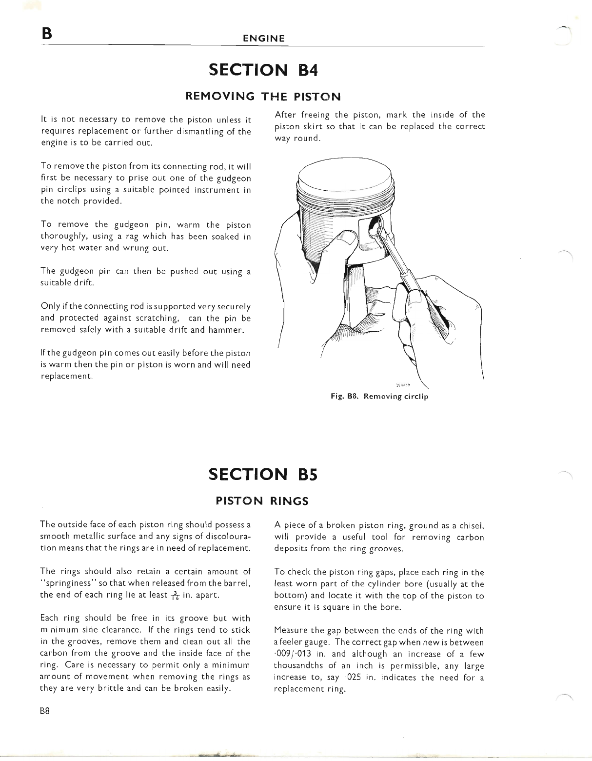
REMOVING
It is not necessary to remove the piston unless it
requires replacement or further dismantling of the
engine is to be carried out.
To remove the piston from its connecting rod, it will
first be necessary to prise out one of the gudgeon
pin circlips using a suitable pointed instrument in
the notch provided.
To remove the gudgeon pin, warm the piston
thoroughly, using a rag which has been soaked in
very hot water and wrung out.
The gudgeon pin can then be pushed out using a
su itable d rift.
Only if the connecting rod is supported very securely
and protected against scratching, can the pin be
removed safely with a suitable drift and hammer.
lf the gudgeon pin comes out easily before the piston
is warm then the pin or piston is worn and will need
replacement.
THE PISTON
After freeing the piston,
piston skirt so that it can
way round.
marl< the inside of the
be replaced the correct
Fig. B8. Removing circlip
SECTION 85
PISTON
The outside face of each piston ring should possess a
smooth metallic surface and any signs of discoloura-
tion means that the rings are in need of replacement.
The rings should also retain a certain amount of
"spri ngi ness" so that when released from the barrel,
the end of each ring lie at least 1| in. apart.
Each ring should be free in its groove but with
minimum side clearance. lf the rings tend to stick
in the grooves, remove them and clean out all the
carbon from the groove and the inside face of the
ring. Care is necessary to permit only a minimum
amount of movement when removing the rings as
they are very brittle and can be broken easily.
B8
RINGS
A piece of a broken piston ring, ground as a chisel,
will provide a useful tool for removing carbon
deposits from the ring grooves.
To checl< the piston ring gaps, place each ring in the
least worn part of the cylinder bore (usually at the
bottom) and locate it with the top of the piston to
ensure it is square in the bore.
Measure the gap between the ends of the ring with
a feeler gauge. The correct gap when new is between
.009/.013 in. and although an increase of a few
thousandths of an inch is permissible, any large
increase to, say.025 in. indicates the need for a
replacement ring.
www.bsaunitsingles.com
ENGINE B
It is advisable to check the gap ofa new ring before
fitting, and ifthe gap is less than 0'009 in. the ends of
the ring must be carefully filed to the correct limit.
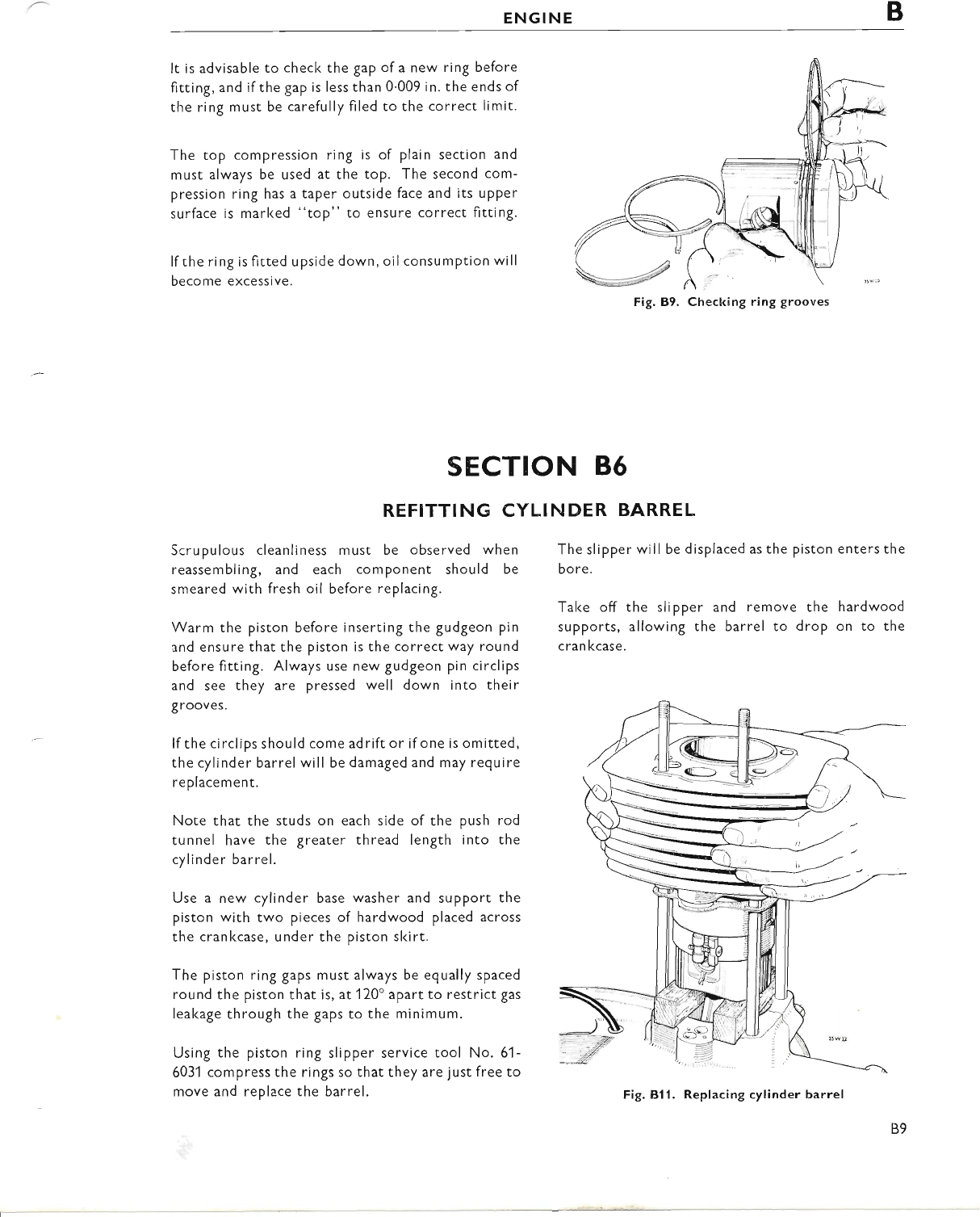
The top compression ring is of plain section and
must always be used at the top. The second com-
pression ring has a taper outside face and its uPPer
surface is marl<ed "top" to ensure correct fitting.
lf the ring is fitted upside down, oilconsumption will
become excessive.
The slipper will be displaced as the piston enters the
bore.
Take off the slipper and remove the hardwood
supports, allowing the barrel to drop on to the
cran kcase.
Fig. 89. Checking ring grooves
SECTION 86
REFITTING CYLINDER BARREL
Scrupulous cleanliness must be observed when
reassembling, and each component should be
smeared with fresh oil before replacing.
Warm the piston before inserting the gudgeon pin
and ensure that the piston is the correct way round
before fitting. Always use new gudgeon pin circlips
and see they are pressed well down into their
grooves.
lf the circlips should come adrift or if one is omitted,
the cylinder barrel will be damaged and may require
replacement.
Note that the studs on each side of the push rod
tunnel have the greater thread length into the
cylinder barrel.
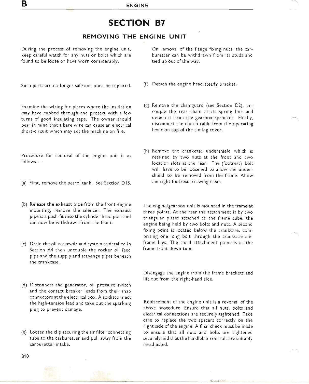
Use a new cylinder base washer and support the
piston with two pieces of hardwood placed across
the crankcase, under the piston skirt.
The piston ring gaps must always be egually spaced
round the piston that is, at 120'apart to restrict gas
leal<age through the gaps to the minimum.
Using the piston ring slipper service tool No. 61 -
6031 compress the rings so that they are just free to
move and replace the barrel. Fig. Bll. Replacing cylinder barrel
B9
www.bsaunitsingles.com
BENGINE
SECTION 87
REMOVING THE
During the process of removing the engine unit,
keep careful watch for any nuts or bolts which are
found to be loose or have worn considerably.
ENGINE UNIT
On removal of the flange fixing nuts, the car-
buretter can be withdrawn from its studs and
tied up out of the way.
Such parts are no longer safe and must be replaced.
Examine the wiring for places where the insulation
may have rubbed through and protect with a few
turns of good insulating tape. The owner should
bear in mind that a bare wire can cause an electrical
short-circuit which may set the machine on fire.
(f) Detach the engine head steady bracket.
(g) Remove the chainguard (see Section D2), un-
couple the rear chain at its spring link and
detach it from the gearbox sprocl<et. Finally,
disconnect the clutch cable from the operating
lever on top of the timing cover.
(h) Remove the crankcase undershield which is
retained by two nuts at the front and two
location slots at the rear. The (footrest) bolt
will have to be loosened to allow the under-
shield to be removed from the frame. Allow
the right footrest to swing clear.
The engine/gearbox unit is mounted in the frame at
three points. At the rear the attachment is by two
triangular plates attached to the frame tube, the
engine being held by two bolts and nuts. A second
fixing point is located below the crankcase, com-
prising one long bolt through the crankcase and
frame lugs. The third attachment point is at the
f rame front down tube.
Procedure for removal of
follows:-
(a) First, remove the petrol
the engine unit is as
tank. See Section D15.
(b) Release the exhaust pipe from the front engine
mounting, remove the silencer. The exhaust
pipe is a push-fit into the cylinder head port and
can now be withdrawn from the front.
(c) Drain the oil reservoir and system as detailed in
Section ,\4 then uncouple the rocker oil feed
pipe and the supply and scavenge pipes beneath
the crankcase.
(d) Disconnect the generator, oil pressure switch
and the contact breaker leads from their snap
connectors at the electrical box. Also disconnect
the high-tension lead and take out the sparking
plug to prevent damage.
(e) Loosen the clip securing the air filter connecting
tube to the carburetter and pull a'way from the
carburetter intake.
810
Disengage the engine from
lift out from the right-hand
the frame brackets and
side.
Replacement of the engine unit is a reversal of the
above procedure. Ensure that all nuts, bolts and
electrical connections are securely tightened. Take
care to replace the two spacers correctly on the
right side of the engine. A final check must be made
to ensure that all nuts and bolts are tightened
securely and that the handlebar controls are suitably
re-adjusted.
www.bsaunitsingles.com
ENGINE B
SECTION B8
TRANSMISSION
DESCRIPTION
Power from the engine is transmitted through the
engine sprocket and primary drive chain to the
clutch chainwheel, then via the clutch driving and
driven plates to the shock absorber unit and gear-
box mainshaft.
The d rive is then transmitted th rough the fou r-speed
gearbox to the final drive sprocket and finally, to
the rear wheel.
The clutch, when operated correctly, enables the
rider to stop and start his machine smoothly
without stalling the engine, and assists in
REMOVING PRIMARY
The primary chaincase cover is held in place by ten
Phillips-head screws. (See Fig. A12 for position of
screws).
The drain plug is fitted vertically into the bottom
of the chaincase. (See Fig. A12).
The oil level plug is located immediately above the
drain plug. (See Fig. 412(E)).
providing a silent and effortless gearchange.
Thus it will be evident that the satisfactory opera-
tion of one part of the transmission system is
dependent on another part. ln other words, if one
part is worn or faulty, it can very often prevent
other parts from working properly.
The dismantling and reassembly of the primary
drive can if necessary, be carried out with the
engine unit in the frame, but will be treated in the
following notes, as though the unit were on a
work bench.
SECTION 89
CHAINCASE COVER
Drain the oil as described in Section A14 and take
out the fixing screws. The screws are of three
different lengths and careful note should be taken of
their respective positions to facilitate refitting. lf
the joint has not already been broken, tap the cover
gently with a hide mallet to release, but have a suit-
able receptacle underneath to catch any remaining
oil.
SECTION B IO
CLUTCH DISMANTLING
Remove the four spring retaining nuts (P) Fig. 81 6,
and withdraw the springs with their cups. The
pressure plate and the remaining clutch plates can
then be taken out. lf these are the only items
requiring attention, the clutch need not be dis-
mantled further.
Before unscrewing the clutch centre nut, it will be
necessary to lock the chainwheel and centre to-
gether with clutch locking tool 61-3774 and to insert
a bar through the connecting rod small-end eye. lf
a service tool is not available, engage top gear and
lock the gearbox sprocket with a length of chain in
a vice. Flatten the tab washer under the clutch
centre nut and unscrew the nut, which has a normal
right-hand thread.
Take offthe nut, tab washer and distance piece. The
clutch push rod may now be withdrawn but do not
attempt to remove thechainwheel at thisstage. The
generator must be removed as in Section 811 before
the chainwheel is disturbed.
Note. Alternatively, the clutch sprocl<et may be
removed by prising out the twenty five roller
bearings and allowing the sprocket to move both
outwards and forwards until it can be unmeshed
from the primary chain. This alternative only
applies if the shock absorber assembly can readily
be detached from the hub to allow access to the
rol I ers.
811
www.bsaunitsingles.com
BENGINE
SECTION BII
GENERATOR REMOVAL
The generator comprises the rotor, fitted to the
engine shaft, and the stator which is mounted on
three studs around the rotor, both being detailed in
Section G1.
Before the clutch chainwheel, chain or engine
sprocket can be removed, the generator must be
taken off.
To remove the stator, take off the three nuts and
pull the generator lead through the rubber grom-
met in the front ofthe chaincase. Take care not to
damage the stator casing, when pulling the stator off
its studs. Note that the stator unit is fitted with the
lead on the inside.
I NSPECTI NG
The four driving plates have segmenrs of special
friction material which are securely bonded to the
metal. These segments should all be complete, un-
broken and not displaced. Even if there is no ap-
parent wear or damage to the plates or segments,
the overall thickness of each segment should be
measured and if the extent of wear is more than
030 in. (75 mm.), the plates should be replaced.
Standard thickness is .167 in. (4.242 mm.).
The tags on the outer edge ofthe plates should be a
reasonable fit in the chainwheel slots and should not
be burred. lf there are burrs on the tags or the seg-
ments are damaged, the plates should be renewed.
The plain driven plates should be free from score
marks and perfectly flat. To check the latter, lay the
plate on a piece of plate glass; if it can be rocked
from side to side, it is buckled and should be re-
placed.
Check the chainwheel for wear; if the slots are
corrugated or the teeth are hooked and thin, the
chainwheel should be replaced.
812
THE CLUTCH
Check the chainwheel roller bearing for up and
down movement. Slight play is permissible but
if excessive, the bearings should be renewed.
Fig. Bl2. Removing clutch
The primary chain tensioner can
but note that the small spacer is
stud.
now be taken off
fitted on the rear
Bend back the tab of the loclcwasher under the
engine shaft nut and unscrew the nut (right-hand
thread). Pull off the rotor and take out the small
Woodruff key from the shaft to avoid losing it.
Using extractor tool 61-3583, the clutch sleeve can
now be freed from the tapered mainshaft, enabling
the clutch chainwheel, chain and engine sprocket to
be withdrawn together.
SECTION BI2
iS,
":{ ,
r ri-:
fu.,. ..di*:;
www.bsaunitsingles.com
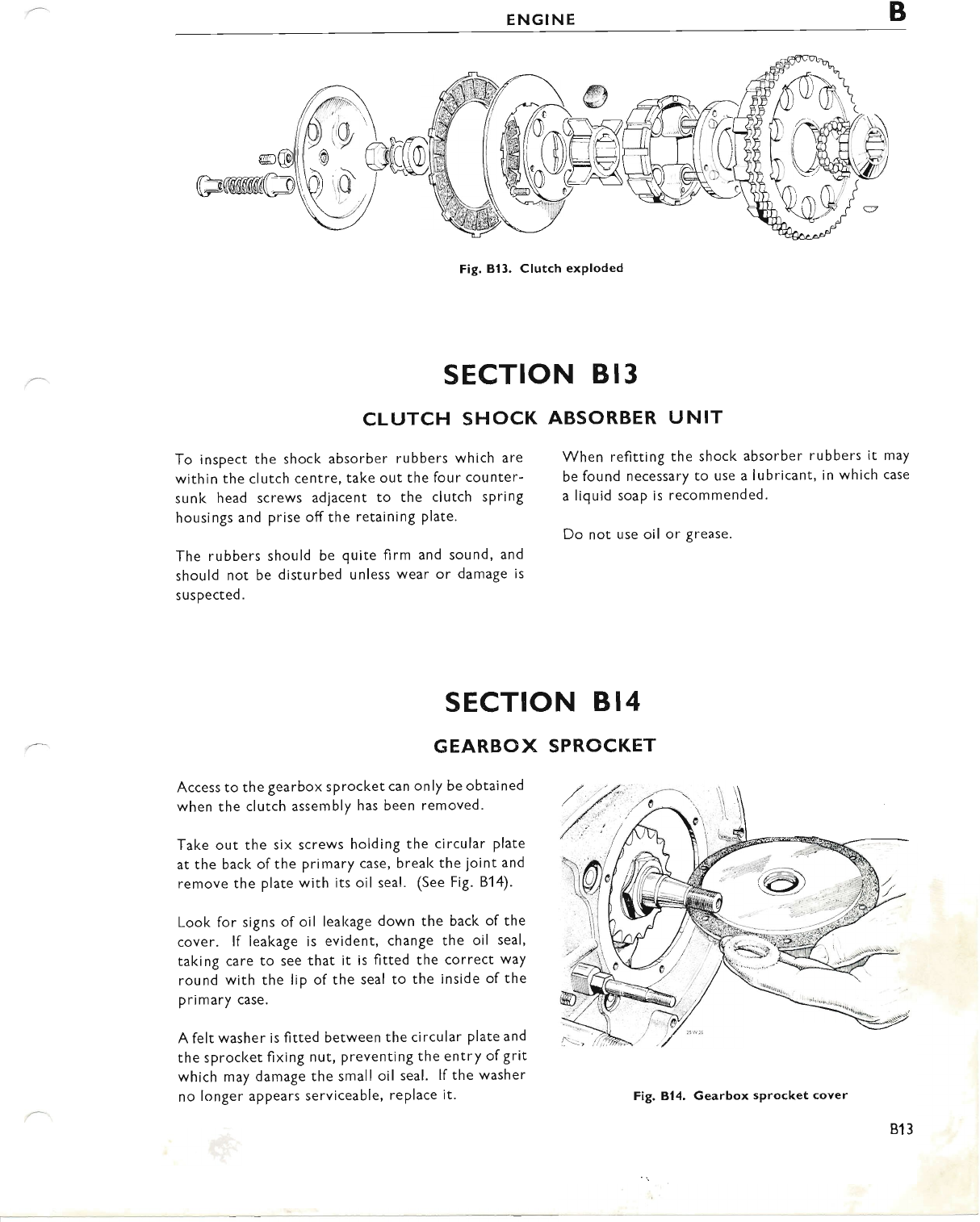
ENGINE B
Fig. Bl3. Clutch exploded
When refitting the shock absorber rubbers it may
be found necessary to use a lubricant, in which case
a liquid soap is recommended.
Do not use oil or Srease.
SECTION B 13
CLUTCH SHOCK ABSORBER UNIT
To inspect the shock absorber rubbers which are
within the clutch centre, take out the four counter-
sunk head screws adjacent to the clutch spring
housings and prise off the retaining Plate.
The rubbers should be quite firm and sound, and
should not be disturbed unless wear or damage is
sus pected.
SECTION B 14
GEARBOX SPROCKET
Access to the gearbox sprocket can only be obtained
when the clutch assembly has been removed'
Take out the six screws holding the circular plate
at the back of the primary case, break the joint and
remove the plate with its oil seal. (See Fig. 814).
Look for signs of oil lealcage down the back of the
cover. lf leakage is evident, change the oil seal,
taking care to see that it is fitted the correct way
round with the lip of the seal to the inside of the
primary case.
A felt washer is fitted between the circular plate and
the sprocket fixing nut, preventing the entry ofgrit
which may damage the small oil seal. lf the washer
no longer appears serviceable, replace it. Fig. 814. Gearbox sprocket cover
813
www.bsaunitsingles.com
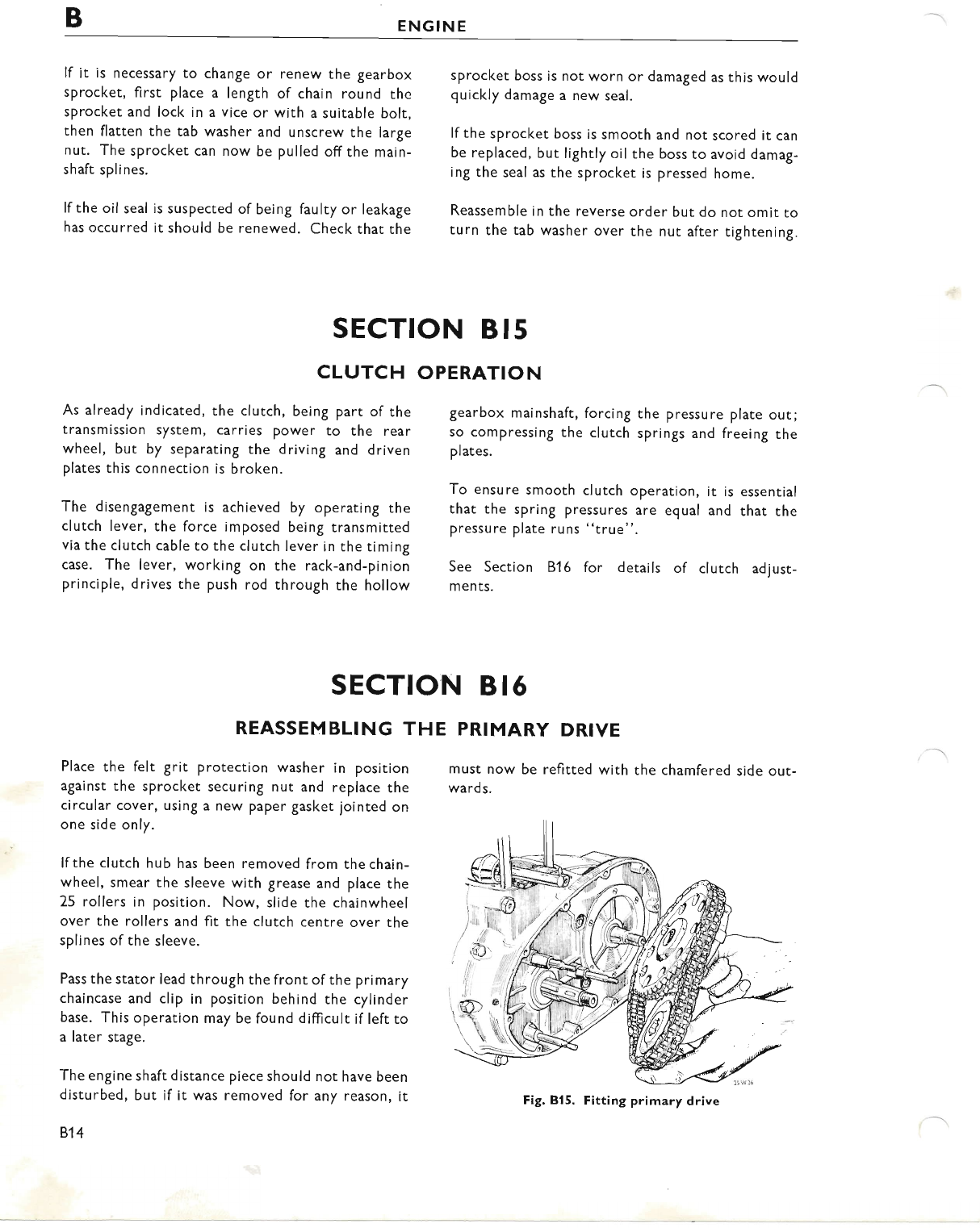
BENGINE
lf it is necessary to change or renew the gearbox
sprocket, first place a length of chain round the
sprocket and lock in a vice or with a suitable bolt,
then flatten the tab washer and unscrew the large
nut. The sprocket can now be pulled offthe main-
shaft splines.
lfthe oil seal is suspected of being faulty or leakage
has occurred it should be renewed. Check that the
sprocket boss is not worn or damaged as this would
quickly damage a new seal.
lf the sprocket boss is smooth and not scored it can
be replaced, but lightly oil the boss to avoid damag-
ing the seal as the sprocket is pressed home.
Reassemble in the reverse order but do not omit to
turn the tab washer over the nut after tightening.
SECTION B 15
CLUTCH OPERATION
As already indicated, the clutch, being part of the
transmission system, carries power to the rear
wheel, but by separating the driving and driven
plates this connection is broken.
The disengagement is achieved by operating the
clutch lever, the force imposed being transmitted
via the clutch cable to the clutch lever in the timing
case. The lever, working on the rack-and-pinion
principle, drives the push rod through the hollow
gearbox mainshaft, forcing the pressure plate out;
so compressing the clutch springs and freeing the
plates.
To ensure smooth clutch operation, it is essential
that the spring pressures are equal and that the
pressure plate runs "true".
See Section 816 for details of clutch adjust-
ments.
SECTION B 16
REASSEMBLING THE PRIMARY DRIVE
Place the felt grit protection washer in position
against the sprocket securing nut and replace the
circular cover, using a new paper gasket jointed on
one side only.
lfthe clutch hub has been removed from thechain-
wheel, smear the sleeve with grease and place the
25 rollers in position. Now, slide the chainwheel
over the rollers and fit the clutch centre over the
splines of the sleeve.
Pass the stator lead th rough the front of the pri mary
chaincase and clip in position behind the cylinder
base. This operation may be found difficult if left to
a later stage.
The engine shaft distance piece should not have been
disturbed, but if it was removed for any reason, it
814
must now be refitted with the chamfered side out-
wards.
Fig. Bl5. Fitting primary drive
www.bsaunitsingles.com
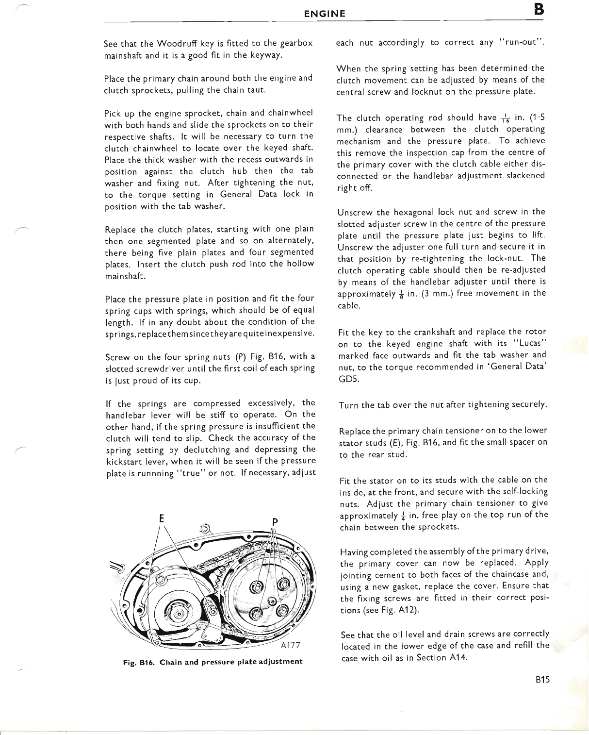
ENGINE B
See that the Woodruff key is fitted to the gearbox
mainshaft and it is a good fit in the keyway.
Place the primary chain around both the engine and
clutch sprockets, pulling the chain taut.
Pick up the engine sprocket, chain and chainwheel
with both hands and slide the sprockets on to their
respective shafts. lt will be necessary to turn the
clutch chainwheel to locate over the keyed shaft.
Place the thick washer with the recess outwards in
position against the clutch hub then the tab
washer and fixing nut. After tightening the nut,
to the torque setting in General Data lock in
position with the tab washer.
Replace the clutch plates, starting with one plain
then one segmented plate and so on alternately,
there being five plain plates and four segmented
plates. lnsert the clutch push rod into the hollow
mainshaft.
Place the pressure plate in position and fit the four
spring cups with springs, which should be of equal
length. lf in any doubt about the condition of the
springs, replace the m since they are q u ite inexpe nsive.
Screw on the four spring nuts (P) Fig. 816, with a
slotted screwdriver until the first coil ofeach spring
is just proud of its cup.
lf the springs are compressed excessively, the
handlebar lever will be stiff to oPerate. On the
other hand, ifthe spring Pressure is insufficient the
clutch will tend to slip. Check the accuracy of the
spring setting by declutching and depressing the
kickstart lever, when it will be seen if the pressure
plate is runnning "true" or not. lf necessary, adiust
each nut accordingly to correct any "run-out".
When the spring setting has been determined the
clutch movement can be adjusted by means of the
central screw and locknut on the pressure plate.
The clutch operating rod should have 1f in. (1 '5
mm.) clearance between the clutch operating
mechanism and the pressure plate. To achieve
this remove the inspection cap from the centre of
the primary cover with the clutch cable either dis-
connected or the handlebar adjustment slackened
right off.
Unscrew the hexagonal lock nut and screw in the
slotted adjuster screw in the centre of the pressure
plate until the pressure plate just begins to lift.
Unscrew the adjuster one full turn and secure it in
that position by re-tightening the lock-nut. The
clutch operating cable should then be re-adjusted
by means of the handlebar adjuster until there is
approximately { in. (3 mm.) free movement in the
cable.
Fit the key to the crankshaft and replace the rotor
on to the keyed engine shaft with its "Lucas"
marked face outwards and fit the tab washer and
nut, to the torque recommended in 'General Data'
GD5.
Turn the tab over the nut after tightening securely.
Replace the primary chain tensioner on to the lower
stator studs (E), Fig. 816, and fit the small sPacer on
to the rear stud.
Fit the stator on to its studs with the cable on the
inside, at the front, and secure with the self-locking
nuts. Adjust the primary chain tensioner to give
approximately f in. free play on the top run of the
chain between the sprockets.
Having completed the assembly of the primary drive,
the primary cover can now be replaced. Apply
jointing cement to both faces of the chaincase and,
using a new gasket, replace the cover. Ensure that
the fixing screws are fitted in their correct posi-
tions (see Fig. A12).
See that the oil level and drain screws are correctly
located in the lower edge of the case and refill the
case with oil as in Section A14.
Fig, 816. Chain and Pressure plate adiustment
815
www.bsaunitsingles.com
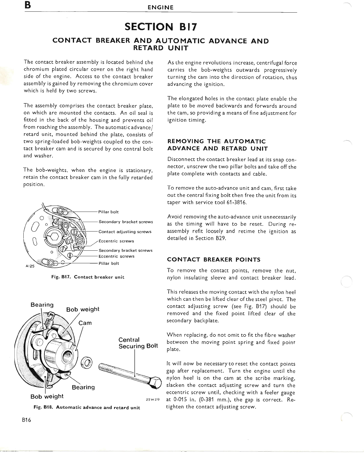
BENGINE
SECTION BI7
CONTACT BREAKER AND AUTOMATIC ADVANCE AND
RETARD UNIT
The contact breaker assembly is located behind the
chromium plated circular cover on the right hand
side of the engine. Access to the contact breaker
assembly is gained by removing the chnomium cover
which is held by two screws.
The assembly comprises the contact breaker plate,
on which are mounted the contacts. An oil seal is
fitted in the back of the housing and prevents oil
from reaching the assembly. The automatic advance/
retard unit, mounted behind the plate, consists of
two spring-loaded bob-weights coupled to the con-
tact breaker cam and is secured by one central bolt
and washer.
The bob-weights, when the engine is stationary,
retain the contact breaker cam in the fully retarded
position.
Pillar bolt
Secondary bracket screws
Contact adiusting screws
Eccentric screws
Secondary bracket screws
Eccentric screws
Pillar bolt
Fig. B17. Contact breaker unit
Central
Securing Bolt
Fig. 818. Automatic advance and retard unit
816
As the engine revolutions increase, centrifugal force
carries the bob-weights outwards progressively
turning the cam into the direction of rotation, thus
advancing the ignition.
The elongated holes in the contact plate enable the
plate to be moved backwards and forwards around
the cam, so providing a means of fine adjustment for
ignition timing.
REMOVING THE AUTOMATIC
ADVANCE AND RETARD UNIT
Disconnect the contact breaker lead at its snap con-
nector, unscrew the two pillar bolts and take offthe
plate complete with contacts and cable.
To remove the auto-advance unit and cam, first take
out the central fixing bolt then free the unit from its
taper with service tool 61 -3816.
Avoid removing the auto-advance unit unnecessarily
as the timing will have to be reset. During re-
assembly refit loosely and retime the ignition as
detailed in Section B29.
CONTACT BREAKER POINTS
To remove the contact points, remove the nut,
nylon insulating sleeve and contact breaker lead.
This releases the moving contact with the nylon heel
which can then be lifted clear of the steel pivot. The
contact adjusting screw (see Fig. 817) should be
removed and the fixed point lifted clear of the
secondary backplate.
When replacing, do not omit to fit the fibre washer
between the moving point spring and fixed point
plate.
It will now be necessaryto reset the contact points
gap after replacement. Turn the engine until the
nylon heel is on the cam at the scribe marking,
slacken the contact adjusting screw and turn the
eccentric screw until, checking with a feeler gauge
at 0.015 in. (0.381 mm.), the gap is correct. Re-
tighten the contact adjusting screw.
25w 29
www.bsaunitsingles.com
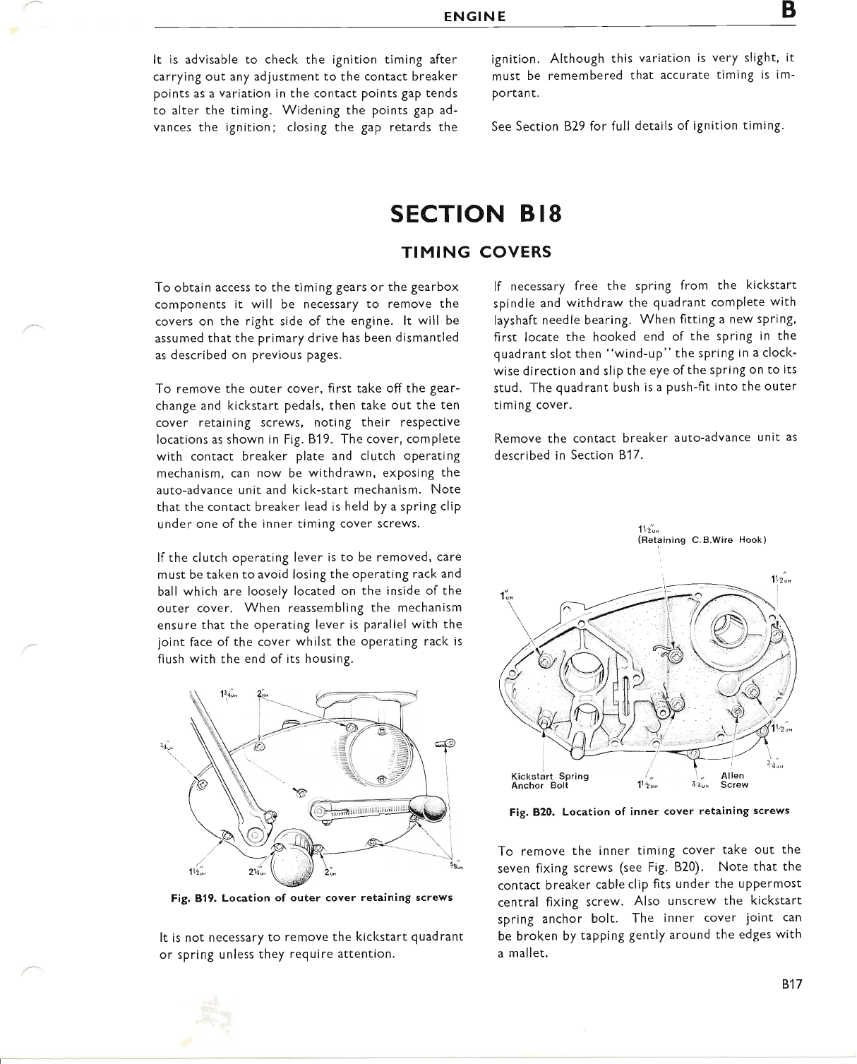
ENGINE B
It is advisable to check the ignition timing after
carrying out any adlustment to the contact breaker
points as a variation in the contact points gap tends
to alter the timing. Widening the points gap ad-
vances the ignition; closing the gap retards the
ignition. Although this variation is very slight, it
must be remembered that accurate timing is im-
po rtant.
See Section B29 for full details of ignition timing.
SECTION B 18
TIMING COVERS
To obtain access to the timing Sears or the gearbox
components it will be necessary to remove the
covers on the right side of the engine. lt will be
assumed that the primary drive has been dismantled
as described on previous pages.
To remove the outer cover, first take off the gear-
change and kickstart pedals, then take out the ten
cover retaining screws, noting their respective
locations as shown in Fig. 819. The cover, complete
with contact breal<er plate and clutch operating
mechanism, can now be withdrawn, exposing the
auto-advance unit and kick-start mechanism. Note
that the contact breaker lead is held by a spring clip
under one of the inner timing cover screws.
lf the clutch operating lever is to be removed, care
must be taken to avoid losing the operating rack and
ball which are loosely located on the inside of the
outer cover. When reassembling the mechanism
ensure that the operating lever is parallel with the
joint face of the cover whilst the operating rack is
flush with the end of its housing.
It is not necessary to remove the kickstart quadrant
or spring unless they reguire attention.
lf necessary free the spring from the kickstart
spindle and withdraw the quadrant comPlete with
layshaft needle bearing. When fitting a new spring,
first locate the hooked end of the spring in the
quadrant slot then "wind-up" the spring in a clock-
wise direction and slip the eye of the spring on to its
stud. The quadrant bush is a push-fit into the outer
timing cover.
Remove the contact breaker auto-advance unit as
described in Section B'l 7.
1ti,"
(Retaining C.B.Wire Hook)
Kickstart Spring
Anchor Bolt
Fig. B20. Location of inner cover retaining screws
To remove the inner timing cover take out the
seven fixing screws (see Fig. B20). Note that the
contact breaker cable clip fits under the uppermost
central fixing screw. Also unscrew the kickstart
spring anchor bolt. The inner cover joint can
be broken by tapping gently around the edges with
a mallet.
Fig.819. Location of outer cover retaining screws
817
www.bsaunitsingles.com
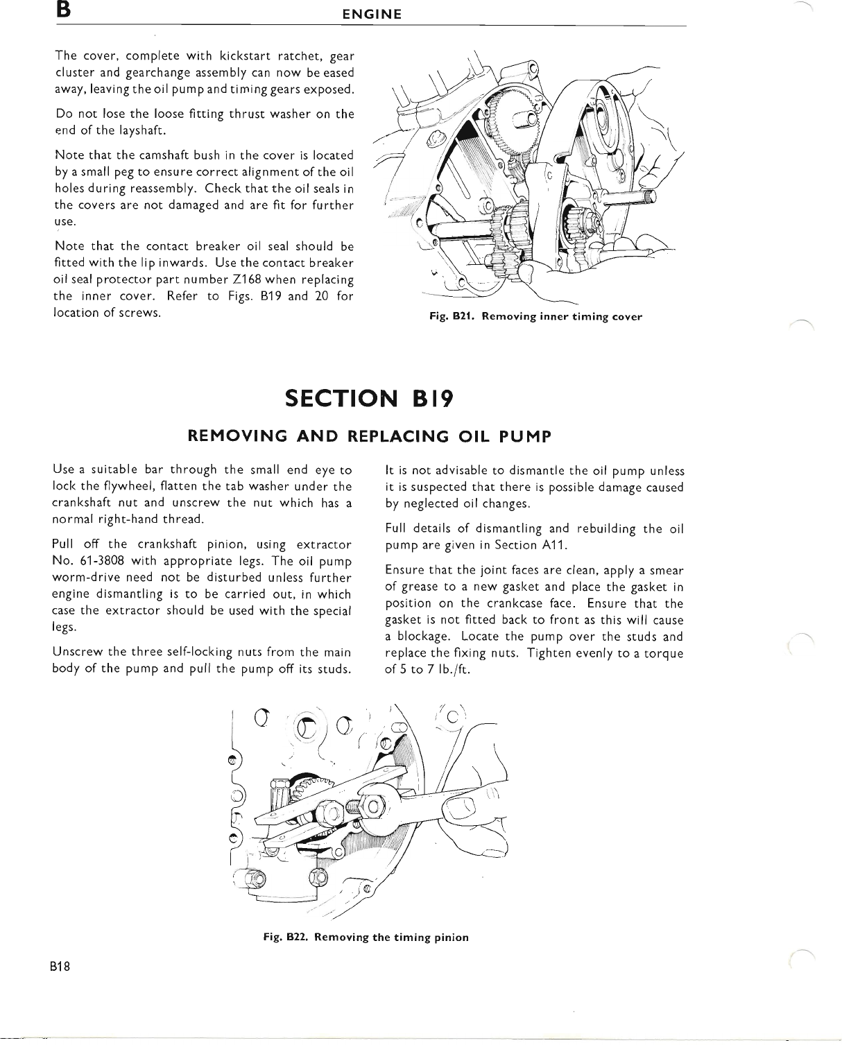
BENGINE
The cover, complete with kickstart ratchet, gear
cluster and gearchange assembly can now be eased
away, leaving the oil pump and timing gears exposed.
Do not lose the loose fitting thrust washer on the
end of the layshaft.
Note that the camshaft bush in the cover is located
by a small peg to ensure correct alignment of the oil
holes during reassembly. Check that the oil seals in
the covers are not damaged and are fit for further
use.
Note that the contact breaker oil seal should be
fitted with the lip inwards. Use the contact breaker
oil seal protector part number 7168 when replacing
the inner cover. Refer to Figs. B19 and 20 for
location of screws.
Use a suitable bar through the small end eye to
lock the flywheel, flatten the tab washer under the
crankshaft nut and unscrew the nut which has a
normal right-hand thread.
Pull off the crankshaft pinion, using extractor
No. 61-3808 with appropriate legs. The oil pump
worm-drive need not be disturbed unless further
engine dismantling is to be carried out, in which
case the extractor should be used with the special
legs.
Unscrew the three self-locking nuts from the main
body of the pump and pull the pump off its studs.
SECTION B 19
b
It is not advisable to dismantle the oil pump unless
it is suspected that there is possible damage caused
by neglected oil changes.
Full details of dismantling and rebuilding the oil
pump are given in Section A1 1.
Ensure that the joint faces are clean, apply a smear
of grease to a new gasket and place the gasket in
position on the crankcase face. Ensure that the
gasket is not fitted back to front as this will cause
a blockage. Locate the pump over the studs and
replace the fixing nuts. Tighten evenly to a torque
of5to7lb.lft.
i/ c''
REMOVING AND REPLACING OIL PUMP
,.9-1',,
o
I
t
I
5
(
cl' )
(
l-
Fig, 821. Removing inner timing cover
818
www.bsaunitsingles.com
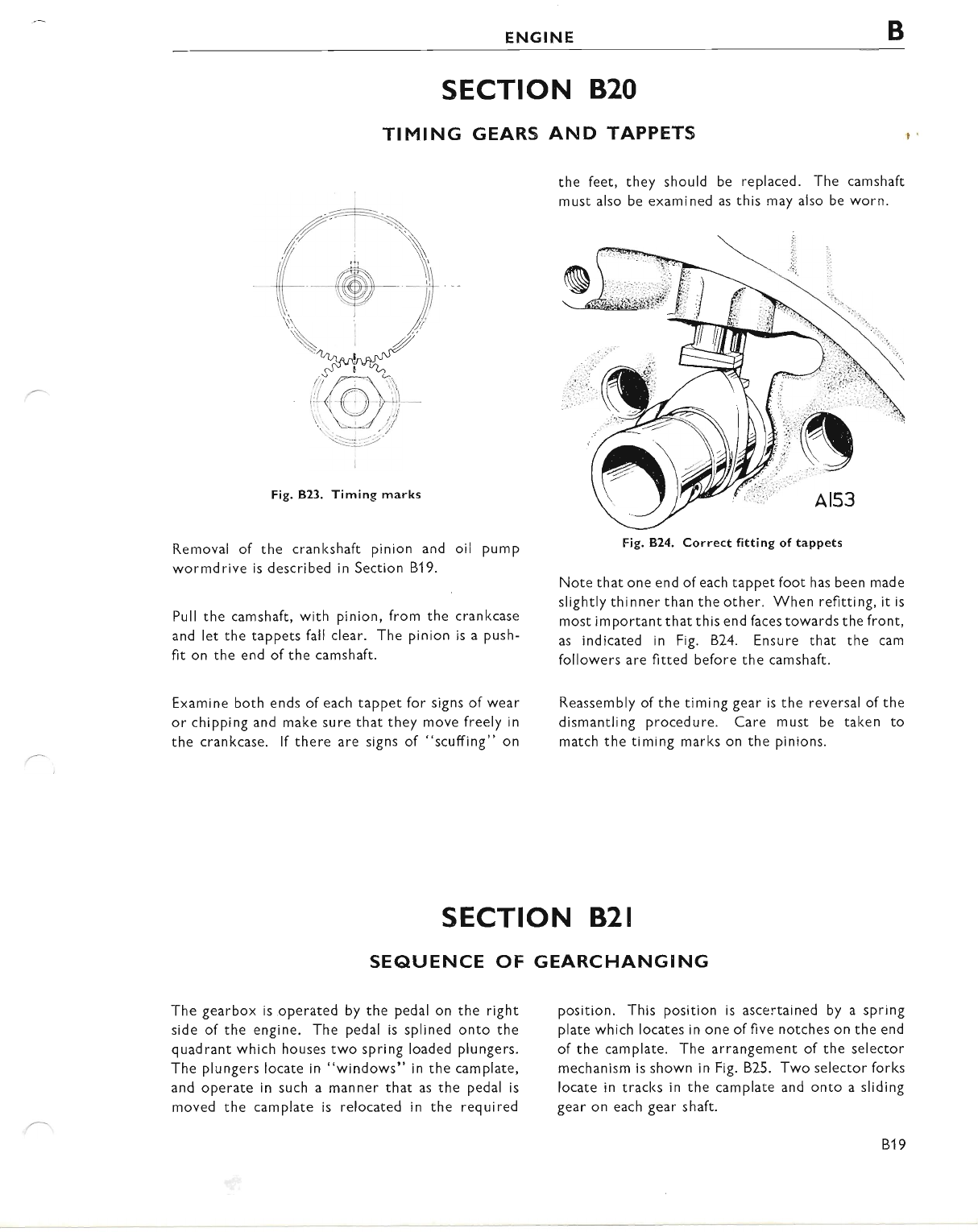
ENGINE B
SECTION B2O
TIMING GEARS AND TAPPETS
the feet, they should
must also be examined
be replaced. The camshaft
as this may also be worn.
Fig. 823. Timing marks
Removal of the crankshaft pinion and
wormdrive is described in Section 81 9.
Pull the camshaft, with pinion, from the
and let the tappets fall clear. The pinion
fit on the end of the camshaft.
Fig.B.24. Correct fitting of tappets
Note that one end ofeach tappet foot has been made
slightly thinner than the other. When refitting, it is
most important that this end faces towards the front,
as indicated in Fig. 824. Ensure that the cam
followers are fitted before the camshaft.
Reassembly of the timing gear is the reversal of the
dismantling procedure. Care must be taken to
match the timing marks on the pinions.
oil pump
cran kcase
is a push-
Examine both ends of each tappet for signs of wear
or chipping and make sure that they move freely in
the crankcase. lf there are signs of "scuffing" on
:1i
SECTION B2I
SEAUENCE OF GEARCHANGING
The gearbox is operated by the pedal on the right
side of the engine. The pedal is splined onto the
quadrant which houses two spring loaded plungers.
The plungers locate in "windows" in the camplate,
and operate in such a manner that as the pedal is
moved the camplate is relocated in the required
position. This position is ascertained by a spring
plate which locates in one of five notches on the end
of the camplate. The arrangement of the selector
mechanism is shown in Fig. B25. Two selector forks
locate in tracks in the camplate and onto a sliding
gear on each gear shaft.
819
www.bsaunitsingles.com
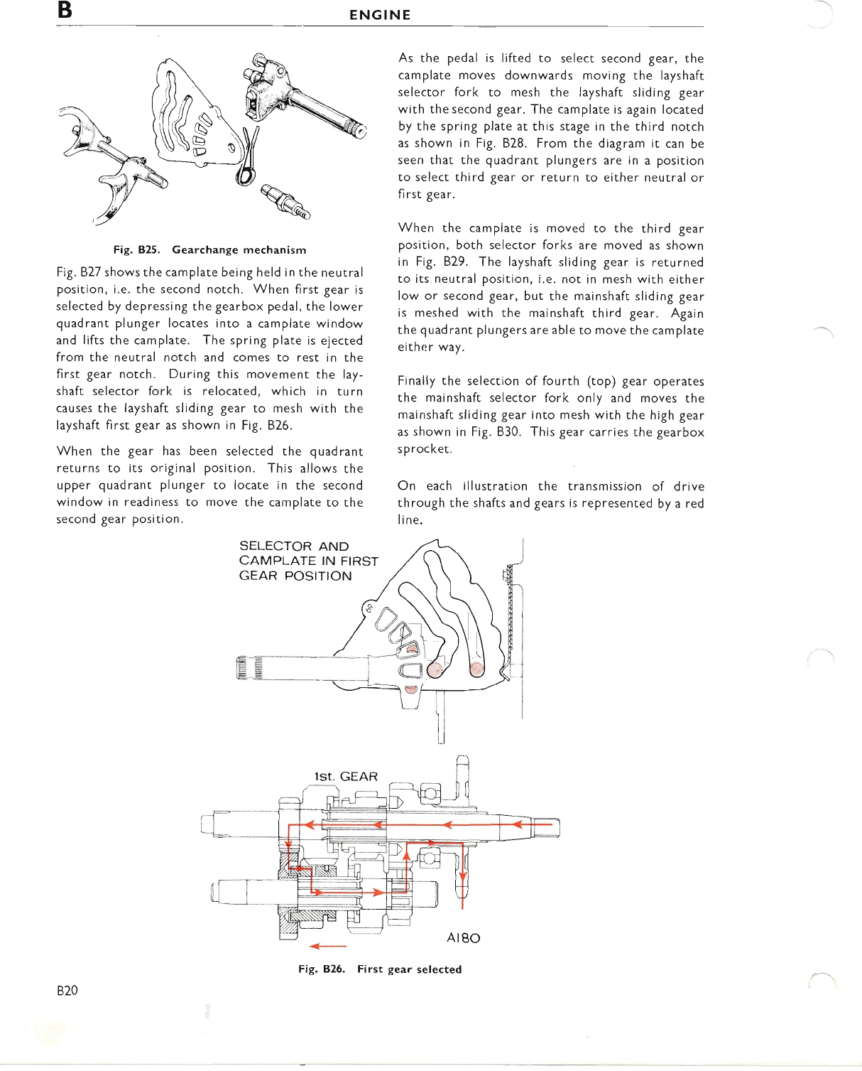
BENGINE
Fig. B25. Gearchange mechanism
Fig. 827 shows the camplate being held in the neutral
position, i.e. the second notch. When first gear is
selected by depressing the gearbox pedal, the lower
quadrant plunger locates into a camplate window
and lifts the camplate. The spring plate is ejected
from the neutral notch and comes to rest in the
first gear notch. During this movement the lay-
shaft selector fork is relocated, which in turn
causes the layshaft sliding gear to mesh with the
layshaft first gear as shown in Fig. 826.
When the gear has been selected the quadrant
returns to its original position. This allows the
upper quadrant plunger to locate in the second
window in readiness to move the camplate to the
second gear position.
As the pedal is lifted to select second gear, the
camplate moves downwards moving the layshaft
selector fork to mesh the layshaft sliding gear
with the second gear. The camplate is again located
by the spring plate at this stage in the third notch
as shown in Fig. B28. From the diagram it can be
seen that the quadrant plungers are in a position
to select third gear or return to either neutral or
fi rst gear.
When the camplate is moved to the third gear
position, both selector forks are moved as shown
in Fig. B29. The layshaft sliding gear is returned
to its neutral position, i.e. not in mesh with either
low or second gear, but the mainshaft sliding gear
is meshed with the mainshaft third gear. Again
the quadrant plungers are able to move the camplate
eithr:r way.
Finally the selection of fourth (top) gear operates
the mainshaft selector fork only and moves the
mainshaft sliding gear into mesh with the high gear
as shown in Fig. 830. This gear carries the gearbox
s p rocket.
On each illustration the transmission of d rive
through the shafts and gears is represented by a red
line.
SELECTOR AND
CAMPLATE IN FIRST
GEAR POSITION
820
www.bsaunitsingles.com
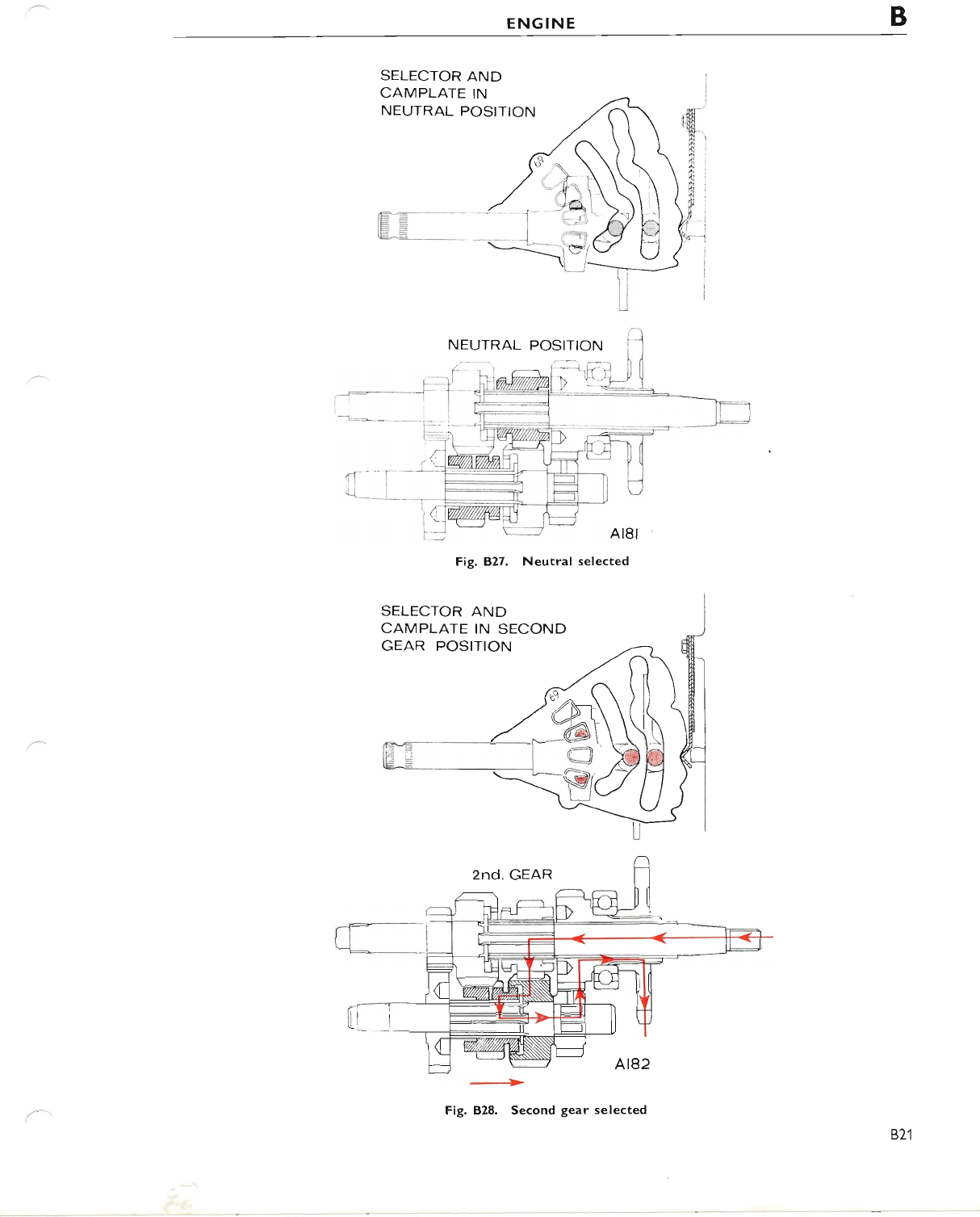
ENGINE B
SELECTOR AND
CAMPLATE IN
NEUTRAL POSITION
Fig. B.27. Neutral selected
SELECTOR AND
CAMPLATE IN SECOND
GEAR POSITION
Fig. B28. Second gear selected
821
www.bsaunitsingles.com
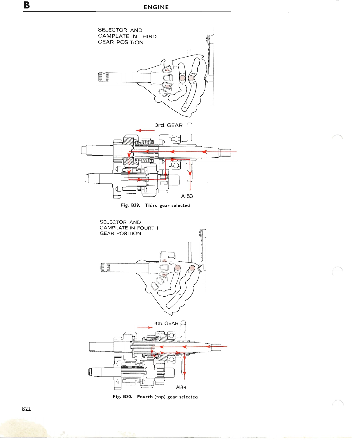
BENGINE
SELECTOR AND
CAMPLATE IN THIRD
GEAR POSITION
Fig.B.29. Third gear selected
SELECTOR .AND
CAMPLATE IN FOURTH
GEAR POSITION
BZ7
Fig. B30. Fourth (top) gear selected
www.bsaunitsingles.com
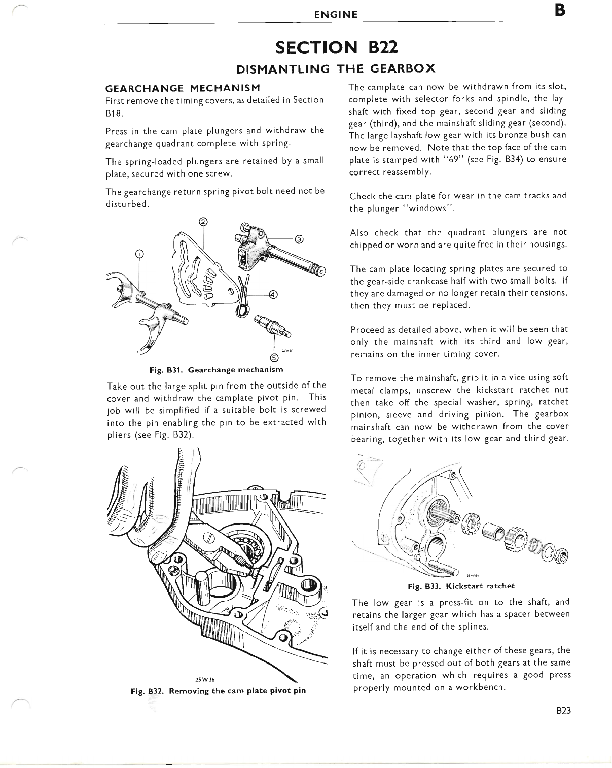
ENGINE B
SECTION B.22
DISMANTLING
GEARCHANGE MECHANISM
First remove the timing covers, as detailed in Section
81 8.
Press in the cam plate plungers and withdraw the
gearchange quadrant complete with spring"
The spring-loaded plungers are retained by a small
plate, secured with one screw,
The gearchange return spring pivot bolt need not be
d istu rbed.
Fig. B3l. Gearchange mechanism
Take out the large split pin from the outside of the
cover and withdraw the camplate Pivot Pin. This
job will be simplified if a suitable bolt is screwed
into the pin enabling the pin to be extracted with
pliers (see Fig. B32).
tr
6"""
THE GEARBOX
The camplate can now be withdrawn from its slot,
complete with selector forks and spindle, the lay-
shaft with fixed top gear, second gear and sliding
gear (third), and the mainshaft sliding gear (second).
The large layshaft low gear with its bronze bush can
now be removed. Note that the toP face ofthe cam
plate is stamped with "69" (see Fig. B34) to ensure
correct reassembly.
Check the cam plate for wear in the cam tracks and
the plunger "windows".
Also check that the quadrant plungers are not
chipped or worn and are quite free in their housings.
The cam plate locating spring plates are secured to
the gear-side crankcase half with two small bolts. lf
they are damaged or no longer retain their tensions,
then they must be replaced.
Proceed as detailed above, when it will be seen that
only the mainshaft with its third and low gear,
remains on the inner timing cover.
To remove the mainshaft, grip it in a vice using soft
metal clamps, unscrew the kickstart ratchet nut
then take off the special washer, spring, ratchet
pinion, sleeve and driving pinion. The gearbox
mainshaft can now be withdrawn from the cover
bearing, together with its low gear and third gear.
@!ss @@a
\.: 25ws
Fig. B33. Kickstart ratchet
The low gear is a press-fit on to the shaft, and
retains the larger gear which has a spacer between
itselfand the end ofthe splines.
lf it is necessary to change either of these gears, the
shaft must be pressed out of both gears at the same
time, an operation which requires a good press
properly mounted on a workbench.
Fig. 832. Removing the cam plate pivot pin
823
www.bsaunitsingles.com
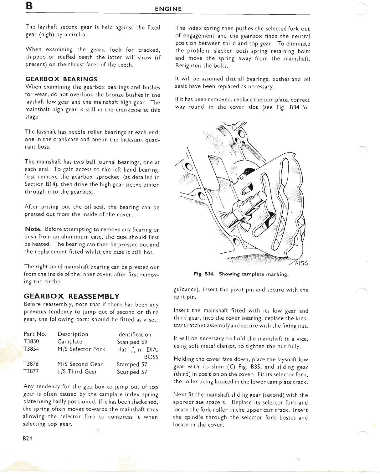
BENGINE
The layshaft second gear is held against the fixed
gear (high) by a circlip.
When examining the gears, look for cracked,
chipped or scuffed teeth rhe latter will show (if
present) on the thrust faces ofthe teeth.
GEARBOX BEARINGS
When examining the gearbox bearings and bushes
for wear, do not overlool< the bronze bushes in the
layshaft low gear and the mainshaft high gear. The
mainshaft high gear is still in the crankcase at this
stage.
The layshaft has needle roller bearings at each end,
one in the crankcase and one in the kickstart quad-
rant boss.
The mainshaft has two ball journal bearings, one at
each end. To gain access to the left-hand bearing,
first remove the gearbox sprocket (as detailed in
Section Bl 4), then drive the high gear sleeve pinion
through into the gearbox.
After prising out the oil seal, the bearing can be
pressed out from the inside ofthe cover.
Note. Before attempting to remove any bearing or
bush from an aluminium case, the case should first
be heated. The bearing can then be pressed out and
the replacement fitted whilst the case is still hot.
The right-hand mainshaft bearing can be pressed out
from the inside ofthe inner cover, after first remov-
ing the circlip.
GEARBOX REASSEMBLY
Before reassembly, note that if there has been any
previous tendency to jump out of second or third
gear, the following parts should be fitted as a set:
Part No. Description
T3850 Cam plate
T3854 M/S Selector Fork
ld entification
Stamped 69
Has ..fin. DlA.
BOSS
The index spring then pushes the selected fork out
of engagement and the gearbox finds the neutral
position between third and top gear. To eliminate
the problem, slacken both spring retaining bolts
and move the spring away from the mainshaft.
Retighten the bolts.
It will be assumed that all bearings, bushes and oil
seals have been replaced as necessary.
If it has been removed, replace the cam plate, correct
way round in the cover slot (see Fig. B34 for
Fig. B34. Showing camplate marking.
guidance), insert the pivot pin and secure with the
split pin.
lnsert the mainshaft fitted with its low gear and
third gear, into the cover bearing, replace the kicl<-
start ratchet assemblyand secure with the fixing nut.
It will be necessary to hold the mainshaft in a vice,
using soft nretal clamps, to righten the nut fully.
Holding the cover face down, place the layshaft low
gear with its shim (C) Fig. B35, and sliding gear
(third) in position on the cover. Fit its selector forl<,
the roller being located in the lower cam plate track.
Next fit the mainshaft sliding gear (second) with the
appropriate spacers. Replace its selector fork and
locate the fork roller in the upper cam track. lnsert
the spindle through the selector fork bosses and
locate in the cover.
T3876
T3877
M/S Second Gear Stamped 57
Li S Third Gear Stamped 57
Any tendency for the gearbox to jump out of top
gear is often caused by the camplate index spring
plate being badly positioned. lf it has been slackened,
the spring often moves towards the mainshaft thus
allowing the selector fork to compress it when
selecting top qear.
874
www.bsaunitsingles.com
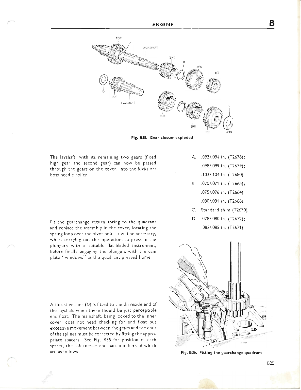
ENGINE B
ew
LAYSHAFT I
@)
dffis
'w
Fig. B35. Gear cluster exploded
The layshaft, with its remaining two gears (fixed
high gear and second gear) can now be passed
through the gears on the cover, into the kickstart
boss needle roller.
Fit the gearchange return spring to the quadrant
and replace the assembly in the cover, locating the
spring loop over the pivot bolt. lt will be necessary,
whilst carrying out this operation, to press in the
plungers with a suitable flat-bladed instrument,
before finally engaging the plungers with the cam
plate "windows" as the quadrant pressed home.
A thrust washer (D) is fitted to the driveside end of
the layshaft when there should be just perceptible
end float" The mainshaft, being locked to the inner
cover, does not need checking for end float but
excessive movement between the gears and the ends
ofthe splines must be corrected by fitting the appro-
priate spacers. See Fig. B35 for position of each
spacer, the thiclcnesses and part numbers of which
are as follows:-
.093 I .094 i n. (T2678) ;
.098/.099 in. (12679);
.103 I .104 in. (T2680).
.0701.071in. (T2665);
.07s 1.076 in. (T2664)
.080/.081 in. (T2666).
Standard shim (T2670).
.078/.080 in. (T2672);
.083/.08s in. ([2671)
A.
B.
c.
D.
Fig. B35. Fitting the gearchange quadrant
B2s
www.bsaunitsingles.com
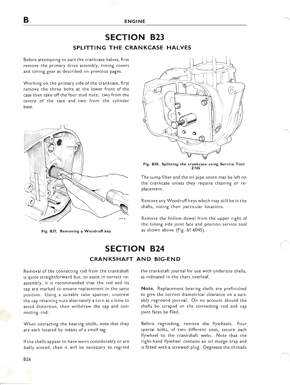
BENGINE
SECTION 823
SPLITTING THE CRANKCASE HALVES
Before attempting to part the crankcase halves, first
remove the primary drive assembly, timing covers
and timing gear as described on previous pages.
Working on the primary side of the crankcase, first
remove the three bolts at the lower front of the
case then take offthe four stud nuts; two from the
centre of the case and two from the cylinder
base.
Fig. 837. Removing a Woodruff key
CRAN KSHAFT
Removal ofthe connecting rod from the crankshaft
is quite straightforward but, to assist in correct re-
assembly, it is recommended that the rod and its
cap are marked to ensure replacement in the same
position. Using a suitable tube spanner, unscrew
the cap retaining nuts alternately a turn at a time to
avoid distortion, then withdraw the cap and con-
necting rod.
When extractinS the bearing shells, note that they
are each located by means of a small tag.
lf the shells appear to have worn considerably or are
badly scored, then it will be necessary to regrind
s26
Fig. 838. Splitting the crankcase using Service Tool
2165
The sump filter and the oil pipe union may be left on
the crankcase unless they require cleaning or re-
placement.
Remove any Woodruff keys which may still be in the
shafts, noting their particular locations.
Remove the hollow dowel from the upper right of
the timing side joint face and position service tool
as shown above (Fig. 61-6045).
SECTION B'24
AND BIG.END
the crankshaft journal for use with undersize shells,
as indicated in the chart overleaf.
Note. Replacement bearing shells are prefinished
to give the correct diametrical clearance on a suit-
ably reground journal. On no account should the
shells be scraped or the connecting rod and cap
joint faces be filed.
Before regrinding, remove the flywheels. Four
special bolts, of two different sizes, secure each
flywheel to the crankshaft webs. Note that the
right-hand flywheel contains an oil sludge trap and
is fitted with a screwed plug. Degrease the threads
www.bsaunitsingles.com
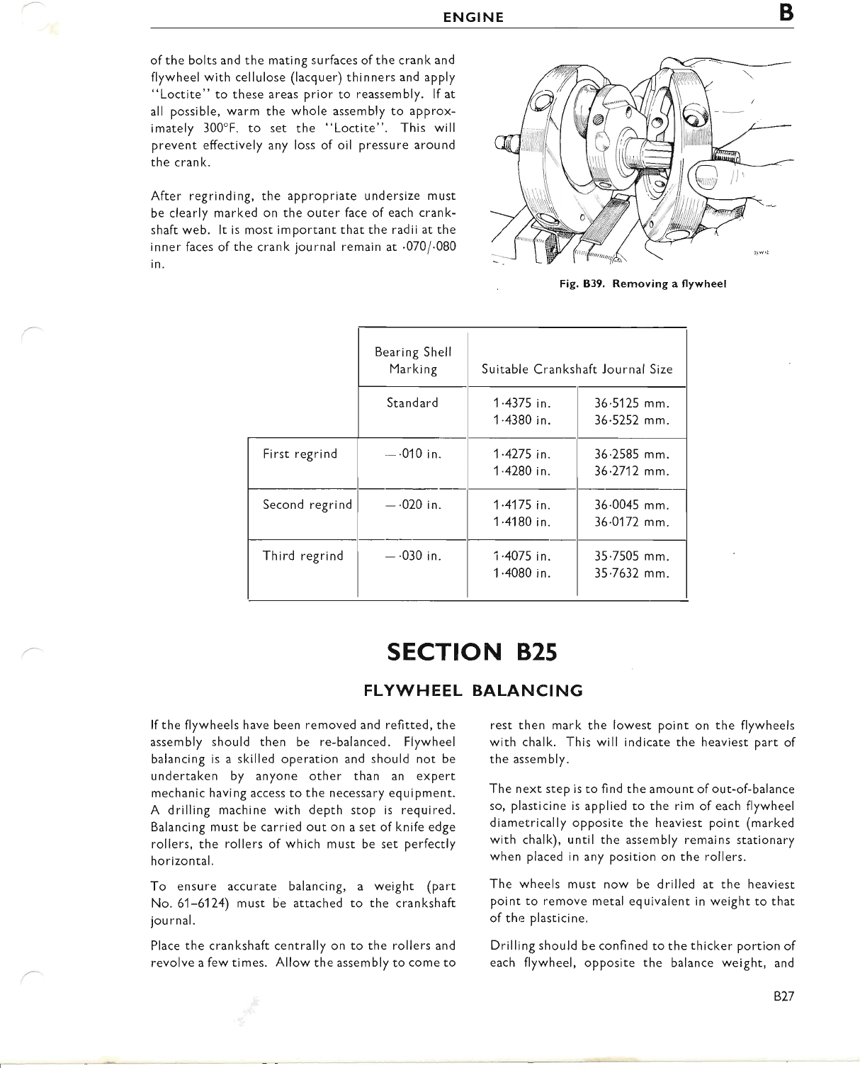
ENGINE B
ofthe bolts and the mating surfaces ofthe cranl< and
flywheel with cellulose (lacquer) thinners and apply
"Loctite" to these areas prior to reassembly. lf at
all possible, warm the whole assembly to approx-
imately 300'F. to set the "Loctite". This will
prevent effectively any loss of oil pressure around
the crank.
After regrinding, the appropriate undersize must
be clearly marked on the outer face of each crank-
shaft web. lt is most important that the radii at the
inner faces of the crank journal remain at .070/.080
in.
Fig. B39. Removing a flywheel
Bearing Shell
Marking Suitable Crankshaft Journal Size
Standard 1-4375 in.
1 .4380 in.
36'5125 mm.
36.5252 mm.
First regrind -.010 in. 1-4275 in.
1'4280 in.
36.2585 mm.
36.7717 mm.
Second regrind -.020 in. 1.4175 in.
1 .4180 in.
36.0045 mm.
36.0172 mm.
Third regrind -.030 in. 1.4075 in.
1.4080 in.
35.7505 mm.
35.7632 mm.
SECTION 825
FLYWHEEL BALANCING
lf the flywheels have been removed and refitted, the
assembly should then be re-balanced. Flywheel
balancing is a skilled operation and should not be
undertaken by anyone other than an expert
mechanic having access to the necessary equipment.
A drilling machine with depth stop is required.
Balancing must be carried out on a set of knife edge
rollers, the rollers of which must be set perfectly
horizontal.
To ensure accurate balancing, a weight (part
No. 61-6124) must be attached to the crankshaft
jou rnal.
Place the crankshaft centrally on to the rollers and
revolve a few times. Allow the assembly to come to
rest then mark the lowest point on the flywheels
with chalk. This will indicate the heaviest part of
the assembly.
The next step is to find the amount of out-of-balance
so, plasticine is applied to the rim of each flywheel
diametrically opposite the heaviest point (marked
with chalk), until the assembly remains stationary
when placed in any position on the rollers.
The wheels must now be drilled at the heaviest
point to remove metal equivalent in weight to that
of thr: plasticine.
Drilling should be confined to the thicker portion of
each flywheel, opposite the balance weight, and
BZ7
www.bsaunitsingles.com
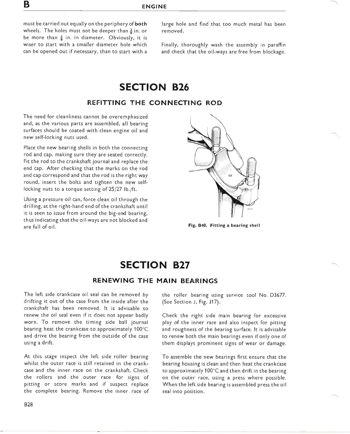
BENGINE
must be carried out equally on the periphery of both
wheels. The holes must not be deeper than $ in. or
be more than $ in. in diameter. Obviously, ir is
wiser to start with a smaller diameter hole which
can be opened out if necessary, than to start with a
large hole and find that too much metal has been
removed.
Finally, thoroughly wash the assembly in paraftin
and check that the oil-ways are free from blockage.
CON NECTING ROD
Fig. 840. Fitting a bearing shell
SECTION B.27
MAIN BEAR.I NGS
the roller bearing using service tool No. D3677.
(See Section J, Fig. J17).
Checl< the right side main bearing for excessive
play of the inner race and also inspect for pitting
and roughness ofthe bearing surface. lt is advisable
to renew both the main bearings even if only one of
them displays prominent signs of wear or damage.
To assemble the new bearings first ensure that the
bearing housing is clean and then heat the crankcase
to approximately 1 00'C and then drift in the bearing
on the outer race, using a press where possible.
When the left side bearing is assembled press the oil
seal into position.
SECTION B.26
REFITTING THE
The need for cleanliness cannot be overemphasized
and, as the various parts are assembled, all bearing
surfaces should be coated with clean engine oil and
new self-locking nuts used.
Place the new bearing shells in both the connecting
rod and cap, making sure they are seated correctly.
Fit the rod to the crankshaft journal and replace the
end cap. After checking that the marks on the rod
and cap correspond and that the rod is the right way
round, insert the bolts and tighten the new self-
locking nuts to a torque setting of 25 177 lb.lft.
Using a pressure oil can, force clean oil through the
drilling, at the right-hand end ofthe crankshaft until
it is seen to issue from around the big-end bearing,
thus indicating that the oil-ways are not blocked and
are full of oil.
RENEWING THE
The left side crankcase oil seal can be removed by
drifting it out of the case from the inside after the
cran kshaft has been removed. lt is advisable to
renew the oil seal even if it does not appear badly
worn. To remove the timing side ball journal
bearing heat the crankcase to approximately'100'C
and drive the bearing from the outside of the case
using a drift.
At this stage inspect the left side roller bearing
whilst the outer race is still retained in the crank-
case and the inner race on the crankshaft. Check
the rollers and the outer race for signs of
pitting or score marks and if suspect replace
the complete bearing. Remove the inner race of
828
www.bsaunitsingles.com
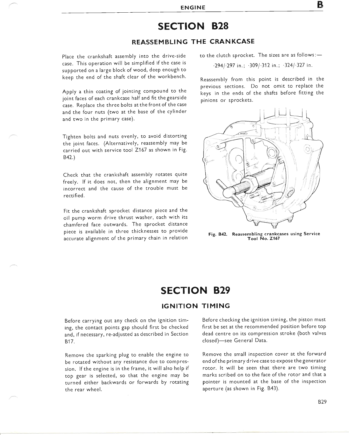
ENGINE B
SECTION B28
REASSEM BLI NG
Place the crankshaft assembly into the drive-side
case. This operation will be simplified if the case is
supported on a large block of wood, deep enough to
keep the end of the shaft clear of the workbench'
Apply a thin coating of jointing compound to the
joint faces of each crankcase half and fit the gearside
case. Replace the three bolts atthefrontofthecase
and the four nuts (two at the base of the cylinder
and two in the primary case).
Tighten bolts and nuts evenly, to avoid distorting
the joint faces. (Alternatively, reassembly may be
carried out with service tool 2167 as shown in Fig.
847.)
Check that the crankshaft assembly rotates quite
freely. lf it does not, then the alignment may be
incorrect and the cause of the trouble must be
rectifi ed.
Fit the crankshaft sprocket distance piece and the
oil pump worm drive thrust washer, each with its
chamfered face outwards. The sprocket distance
piece is available in three thicknesses to provide
accurate alignment of the primary chain in relation
IGNITION
Before carrying out any checl< on the iSnition tim-
ing, the contact points gaP should first be checked
and, ifnecessary, re-adjusted as described in Section
817.
Remove the sparking plug to enable the engine to
be rotated without any resistance due to comPres-
sion. lf the engine is in the frame, it willalso help if
top gear is selected, so that the engine may be
turned either backwards or forwards by rotating
the rear wheel.
THE CRAN KCASE
to the clutch sprocket. The sizes are as follows:-
'2941'297 in.; '309/'312 in.; '3741'377 in.
Reassembly from this Point is descrlbed in
previous sections. Do not omit to replace
keys in the ends of the shafts before fitting
pinions or sprockets.
Fig. B42. Reassernbling crankcases using Service
Tool No' 2167
the
the
the
SECTION B.29
TI MING
Before checking the ignition timing, the Piston must
first be set at the recommended position before toP
dead centre on its compression stroke (both valves
closed)-see General Data.
Remove the small inspection cover at the forward
end of the pri mary d rive case to exPose the generato r
rotor. lt will be seen that there are two timing
marks scribed on to the face ofthe rotor and that a
pointer is mounted at the base of the inspection
aperture (as shown in Fig. 843).
www.bsaunitsingles.com
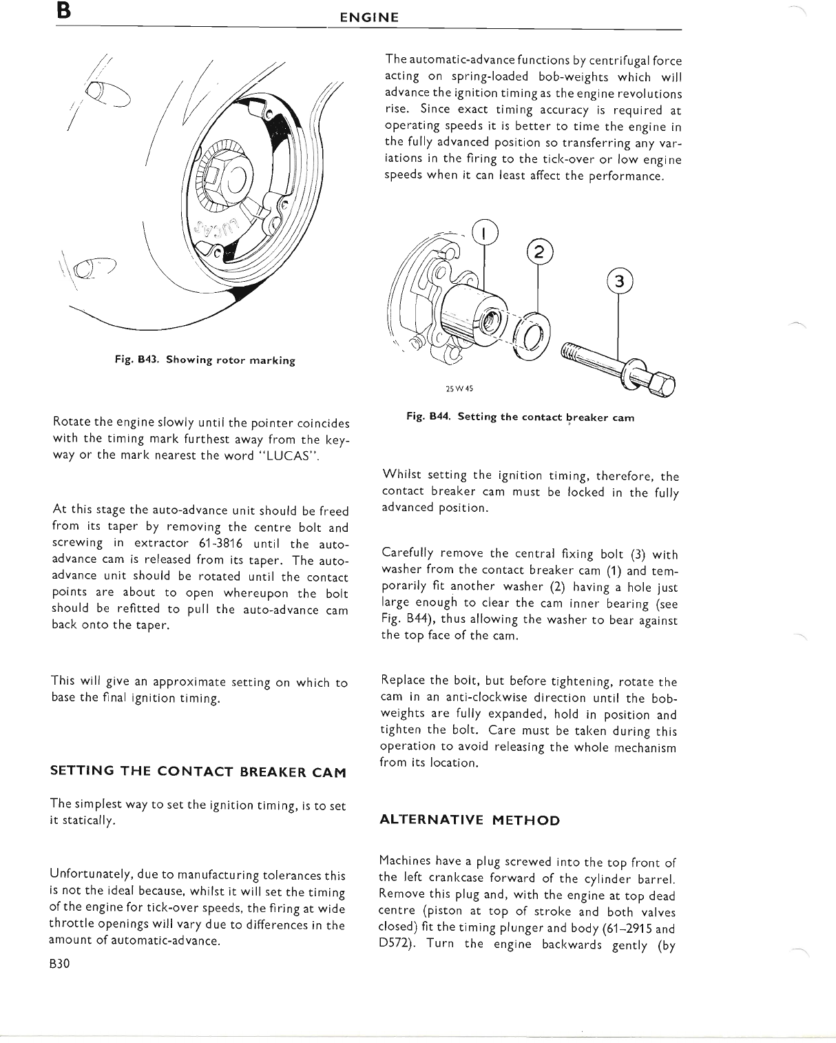
BENGINE
The automatic-advance functions by centrifugal force
acting on spring-loaded bob-weights which will
advance the ignition timing as the engine revolutions
rise. Since exact timing accuracy is required at
operating speeds it is better to time the engine in
the fully advanced position so transferring any var-
iations in the firing to the ticl<-over or low engine
speeds when it can least affect the performance.
Fig. 843, Showing rotor marking
Rotate the engine slowly until the pointer coincides
with the timing mark furthest away from the lcey-
way or the mark nearesr the word "LUCAS".
At this stage the auto-advance unit should be freed
from its taper by removing the centre bolt and
screwing in extractor 61-3816 until the auto-
advance cam is released from its taper. The auto-
advance unit should be rotated until the contact
points are about to open whereupon the bolt
should be refitted to pull the auto-advance cam
back onto the taper.
This will give an approximate
base the final ignition timing. setting on which to
SETTING THE CONTACT BREAKER CAM
The simplest way to set the ignition timing, is to set
it statically.
Unfortunately, due to manufacturing tolerances this
is not the ideal because, whilst it will set the timing
of the engine for tick-over speeds, the firing at wide
throttle openings will vary due to differences in the
amou nt of automatic-advance.
B30
Fig.B,44. Setting the contact breaker cam
Whilst setting the ignition timing, therefore, the
contact breaker cam must be locked in the fully
advanced position.
Carefully remove the central fixing bolt (3) with
washer from the contacr breaker cam (1) and tem-
porarily fit another washer (2) having a hole just
large enough to clear the cam inner bearing (see
Fig. 844), thus allowing the washer to bear againsr
the top face of the cam.
Replace the bolt, but before tightening, rotate rhe
cam in an anti-clockwise direction until the bob-
weights are fully expanded, hold in position and
tighten the bolt. Care must be taken during this
operation to avoid releasing the whole mechanism
from its location.
ALTERNATIVE METHOD
Machines have a plug screwed into the top front of
the left crankcase forward of the cylinder barrel.
Remove this plug and, with the engine at top dead
centre (piston at top of stroke and both valves
closed) fit the timing plunger and body (61-2915 and
D572). Turn the engine backwards gently (by
25W45
www.bsaunitsingles.com
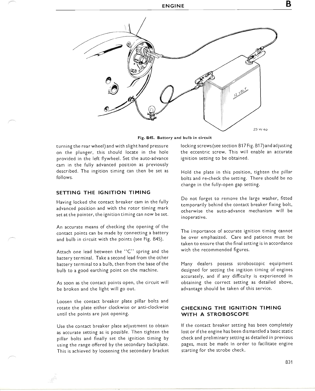
ENGINE B
Fig. B45. Battery and bulb in circuit
turningthe rearwheel) and with slight hand Pressure
on the plunger, this should locate in the hole
provided in the left flywheel. Set the auto-advance
cam in the fully advanced position as previously
described. The ingition timing can then be set as
follows.
SETTING THE IGNITION TIMING
Having locked the contact breaker cam in the fully
advanced position and with the rotor timing mark
set at the pointer, the ignition timing can now be set.
An accurate means of checking the opening of the
contact points can be made by connecting a battery
and bulb in circuit with the points (see Fig. B45).
Attach one lead between the "C" spring and the
battery terminal. Take a second lead from the other
battery terminal to a bulb, then from the base ofthe
bulb to a good earthing point on the machine.
As soon as the contact points oPen, the circuit will
be broken and the light will go out.
Loosen the contact breaker plate pillar bolts and
rotate the plate either clockwise or anti-clockwise
until the points are just oPening.
Use the contact breaker plate adjustment to obtain
as accurate setting as is possible. Then tighten the
pillar bolts and finally set the ignition timing by
using the range offered by the secondary backplate.
This is achieved by loosening the secondary bracket
locki ng screws (see section 817 Fig. 81 7) and ad j usti ng
the eccentric screw. This will enable an accurate
ignition setting to be obtained.
Hold tne plate in this position, tighten the pillar
bolts and re-check the setting. There should be no
change in the fully-open gap setting.
Do not forget to remove the large washer, fitted
remporarily behind the contact breaker fixing bolt,
otherwise the auto-advance mechanism will be
i noperative.
The importance of accurate ignition timing cannot
be over emphasized. Care and patience must be
taken to ensure that the final setting is in accordance
with the recommended figures.
Many dealers possess stroboscopic equipment
designed for setting the ingition timing of engines
accurately, and if any difticulty is experienced in
obtaining the correct setting as detailed above,
advantage should be taken of this service.
CHECKING THE IGNITION TIMING
WITH A STROBOSCOPE
lf the contact breaker setting has been completely
Iost or if the engine has been dismantled a basic static
check and preliminary setting as detailed in previous
pages, must be made in order to facilitate engine
starting for the strobe check.
B3'l
www.bsaunitsingles.com
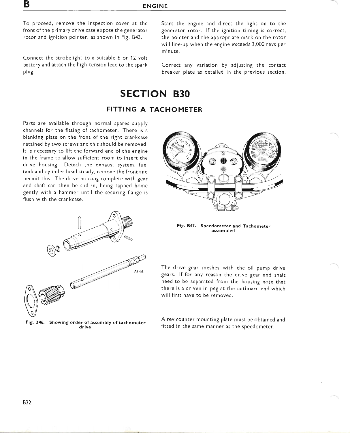
BENGINE
To proceed, remove the inspection cover at the
front ofthe primary drive case expose the generator
rotor and ignition pointer, as shown in Fig. B43.
Connect the strobelight to a suitable 6 or 12 volt
battery and attach the high-tension lead to the spark
Pl ug.
Start the engine and direct the light on to the
generator rotor. lf the ignition timing is correct,
the pointer and the appropriate mark on the rotor
will line-up when the engine exceeds 3,000 revs per
minute.
Correct any variation by adjusting the contact
breaker plate as detailed in the previous section.
SECTION B3O
FITTING A TACHOMETER
Parts are available through normal spares supply
channels for the fitting of tachometer. There is a
blanking plate on the front of the right crankcase
retained by two screws and this should be removed.
It is necessary to lift the forward end of the engine
in the frame to allow sufficient room to insert the
drive housing. Detach the exhaust system, fuel
tank and cylinder head steady, remove the front and
permit this. The drive housing complete with gear
and shaft can then be slid in, being tapped home
gently with a hammer until the securing flange is
flush with the crankcase.
oo
w@
Fig. 846. Showing
Fig. B47. Speedometer and Tachometer
assembled
The drive gear meshes with the oil pump drive
gears. lf for any reason the drive gear and shaft
need to be separated from the housing note that
there is a driven in peg at the outboard end which
will first have to be removed.
A rev counter mounting plate must be obtained and
fitted in the same manner as the speedometer.
order of assembly of tachometer
drive
B32
www.bsaunitsingles.com
sEcTloN c
CARBURETTER
INDEX
SECTION
DESCRIPTION
C1 STRIPPING AND RE-ASSEMBLING THE CARBURETTER
C2 INSPECTING CARBURETTER COMPONENTS
C3 POINTS TO NOTE
C4 TRACING FAULTS
C5 CARBURETTER ADJUSTMENTS
C6 CORRECTING MIXTURE
C7 TUNING THE CARBURETTER
c1
www.bsaunitsingles.com
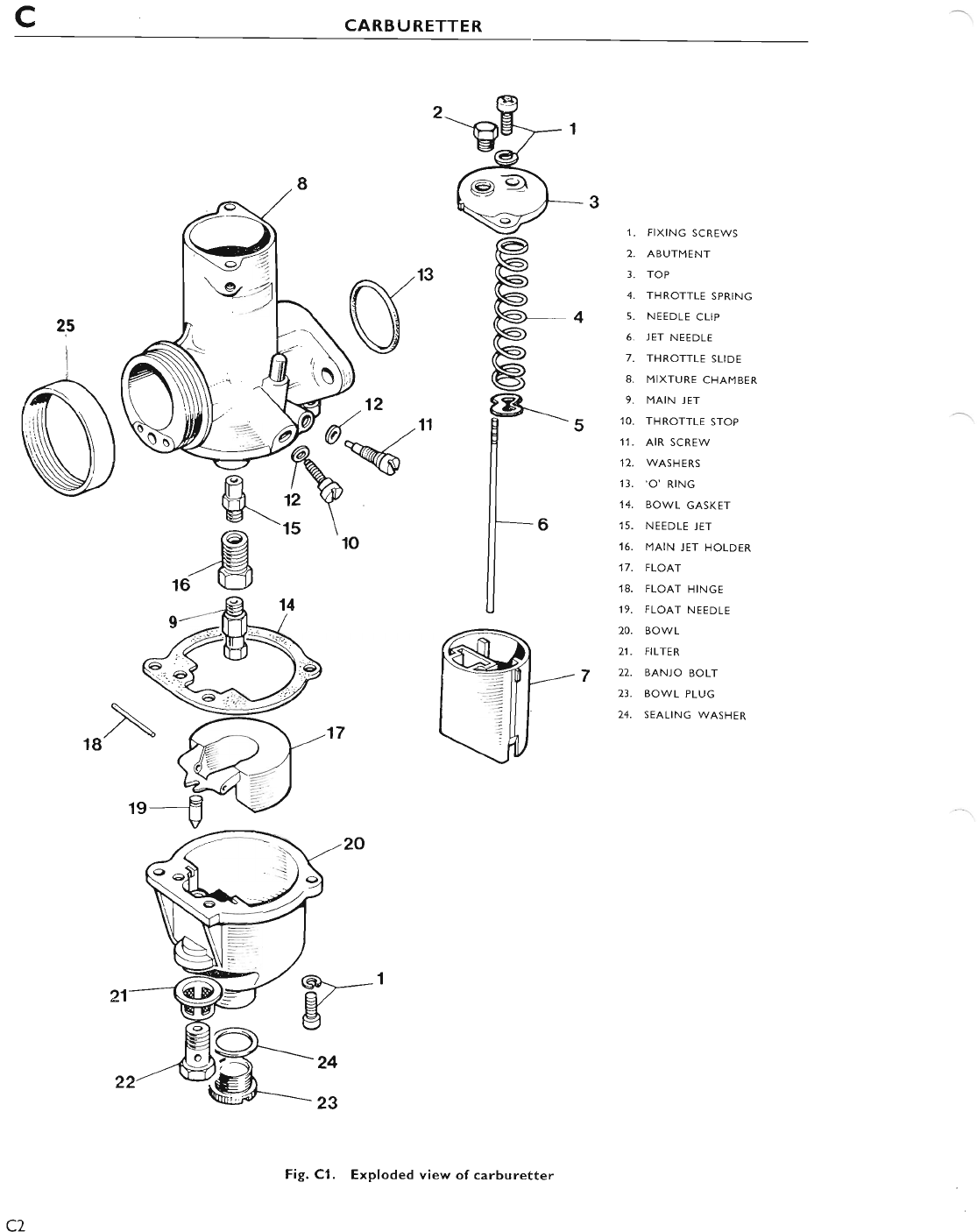
cCARBURETTER
25
i
7
,I. FIXING SCREWS
2. ABUTMENT
3. TOP
4. THROTTLE SPRING
5. NEEDLE CLIP
6. JET NEEDLE
7. THROTTLE SLIDE
8. MIXTURE CHAMBER
9. MAIN JET
10. THROTTLE STOP
'11. AIR SCREW
12. WASHERS
'13, 'o'RtNG
14. BOWL GASKET
15. NEEDLE JET
16. MAIN JET HOLDER
17. FLOAT
18. FLOAT HINGE
19. FLOAT NEEDLE
20. BOWL
21. FILTER
22. BANIO BOLT
23. BOWL PLUG
24. SEALING WASHER
\
18
c2
Fig. Cl. Exploded view of carburetter
www.bsaunitsingles.com
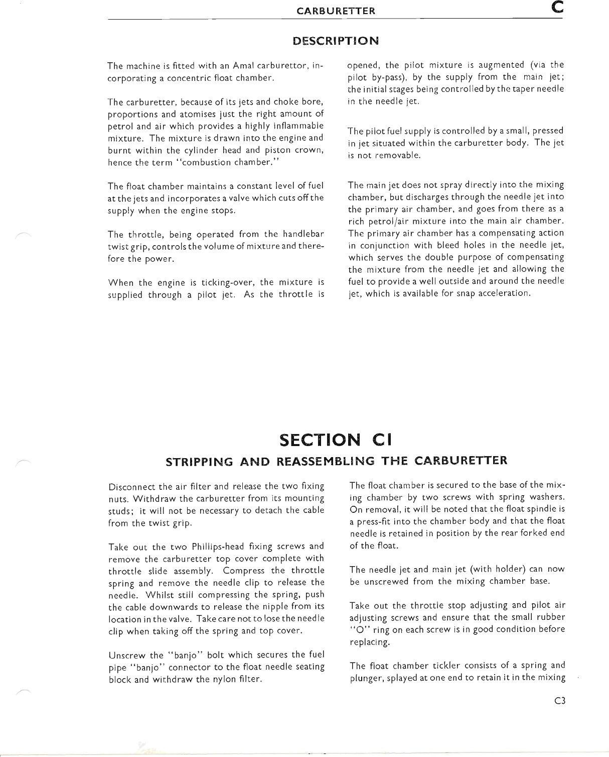
CARBURETTER c
DESCR,IPTION
The machine is fitted with an Amal carburettor, in-
corporating a concentric float chamber.
The carburetter, because of its jets and chol<e bore,
proportions and atomises just the right amount of
petrol and air which provides a highly inflammable
mixture. The mixture is drawn into the engine and
burnt within the cylinder head and piston crown,
hence the term "combustion chamber."
The float chamber maintains a constant level of fuel
at the jets and incorporates a valve which cuts offthe
supply when the engine stops.
The throttle, being operated from the handlebar
twistgrip, controlsthe volume of mixture and there-
fore the power.
When the engine is ticking-over, the mixture is
supplied through a pilot jet. As the throttle is
opened, the pilot mixture is augmented (via the
pilot by-pass), by the supply from the main jet;
the initial stages being controlled bythe taPer needle
in the needle jet.
The pilot fuel supply is controlled by a small, pressed
in jet situated within the carburetter body. The jet
is not removable.
The main jet does not spray directly into the mixing
chamber, but discharges through the needle jet into
the primary air chamber, and goes from there as a
rich petroiiair mixture into the main a!r chamber.
The primary air chamber has a compensating action
in conjunction with bleed holes in the needle jet,
which serves the double purpose of compensating
the mixture from the needle jet and allowing the
fuel to provide a well outside and around the needle
1et, whlch is available for snap acceleration.
The float chamber is secured to the base of the mix-
ing chamber by two screws with spring washers.
On removal, it will be noted that the float spindle is
a press-fit into the chamber body and that the float
needle is retained in position by the rear forked end
of the float.
The needle jet and main jet (with holder) can now
be unscrewed from the mixing chamber base.
Take out the throttle stop adjusting and pilot air
adjusting screws and ensure that the small rubber
"O" ring on each screw is in good condition before
replaci ng.
The float chamber tickler consists of a spring and
plunger, splayed at one end to retain it in the mixing
sEcTloN cl
STRIFPING AND REASSEMBLING TI-IE CARBI.'RETTER
Disconnect the air filter and release the two fixing
nuts. Withdraw the carburetter from its mounting
studs; it will not be necessary to detach the cable
from the twist griP.
Take out the two Phillips-head fixing screws and
remove the carburetter toP cover complete with
throttle slide assembly. Compress the throttle
spring and remove the needle clip to release the
needle. Whilst still compressing the spring, push
the cable downwards to release the nipple from its
location in the valve. Take care not to lose the need le
clip when taking off the spring and top cover.
Unscrew the "banjo" bolt which secures the fuel
pipe "banjo" connector to the float needle seating
block and withdraw the nylon filter.
c3
www.bsaunitsingles.com
cCARBURETTER
chamber. This item should not be subjected to a
great deal of wear and is therefore unlikely to re-
quire replacement.
Having dismantled the carburetter, carefully clean
all parts in petrol (gasolene). Hard deposits on the
carburetter body are best removed with a light
grade wire brush. After washing the parts in clean
petrol (gasoline) allow to dry and ensure that all
holes or small drillings are free from dirt. A hand
pump is ideal for "blowing through" any blockages
in the drillings. lnspect the component parts for
wear and check that the jets are in accordance with
the recommended sizes given in General Data.
Reassembly is simply a reversal of the above in-
structions but remember to replace any gasl<ets or
"O" rings that appear unserviceable. Refer to
Fig. Cl for guidance.
(4) Check the float needle for efficiency by inserting
it into the float needle seating block, pouring a
small amount of petrol (gasolene) into the
aperture surrounding the needle and checl<ing it
it for leakage.
(5) Ensure that the float is nor puncrured by shal<ing
it to see if it contains any fuel. Do not attempt
to repair a damaged float. lf there is any doubt
about its condition, replace it with a new one.
(6) Check the petrol filter that firs over the needle
seating block, for any possible damage to the
mesh. lf the filter has parted from its supporting
structure it will allow the petrol (gasolene) to
pass through unfi ltered.
sEcTtoN c2
I NSPECTING CARBUR,ETTER CO MPONENTS
The parts most liable to show wear after consider-
able mileage are the throttle valve slide and the
mixing chamber.
(1) Inspect the throttle valve slide for excessive
scoring ofthe front area and check the extent of
wear on the rear slide face. lf wear is apparent,
the slide should be renewed; be sure to fit slide
with correct degree of cut-away (see General
Data).
(2) Check the throttle return springs for efficiency.
Check also that it has not lost its compressive
strength by measuring the free length and com-
paring it with the figure given on page GD3.
(3) Examine the needle jet for wear or possible
scoring and check the tapered end ofthe needle
for similar signs.
c4
www.bsaunitsingles.com
CARBURETTER c
sEcrloN c3
HINTS AND TIPS
THROTTLE CABLT
See that there is a minimum of backlash when the
twist grip is turned bacl< and that any movement of
the handlebar does not cause the throttle to oPen.
Use the adjuster on the cable to obtain the correct
setting and ensure that the throttle slide shuts
down freely.
PETROL FEED
Unscrew the float chamber "banjo" bolt, remove
the "banjo", and take off the filter gauze from the
needle seating.
Ensure that the filter gauze is undamaged and free
from all foreign matter. To check fuel flow before
replacing the "banjo", turn on petrol tap momen-
tarily and see that fuel gushes out.
FLOODING
This may be due to a worn needle or a punctured
float, but is more likely due to imPurities (8rit, fluff'
etc.) in the tank. This trouble can sometimes be
cleared by periodically cleaning out the float
chamber. lf however, the trouble persists, the tanl<
must be drained and swilled out.
CARBURETTER AIR LEAKS
Erratic slow-running is often caused by air leaks
between the joints at the carburetter flange and the
cylinder head and can be detected by applying oil
around the joints. Eliminate by fitting new washers
and tightening the flange nuts evenly to the torque
wrench setting given in General Data.
Also check that the rubber sealing ring in the car-
buretter flange is undamaged and located correctly.
On high mileage machines lool< for air leaks caused
by a worn throttle or a worn inlet valve guide.
BANGING, IN EXHAUST
This may be caused by too weak a pilot mixture
when the throttle is closed or nearly closed' lt may
also be caused by too rich a pilot mixture and an air
leak in the exhaust system. The reason in either
case is that the mixture has not fired in the cylinder
but has fired in the hot silencer.
lf the banging occurs when the throttle is fairly wide
open, the trouble will be traced to ignition, not
carbu ration.
EXCESSIVE PETROL CONSUMPTION
lf this cannot be corrected by normal adjustments,
it may be due to flooding caused by impurities from
the petrol tanl< lodging on the float needle seat, so
preventing its valve from closing. The float needle
should also be checked for wear or damage.
High consumption can also be caused by a worn
needle jet and may be remedied or improved by
lowering the needle in the throttle. lf this method
is unsatisfactory, then a new needle and needle iet
will have to be fitted.
There are many other causes of high petrol con-
sumption and it should not be assumed that the
fault lies in the carburetter alone.
AIR FILTERS
lf a carburetter is first set with an air filter and the
engine is then run without, the jet setting may be
affected and care must be taken to avoid overheating
the engine due to too weak a mixture. Testing with
the air supply will indicate if a larger main iet and
higher needle position are required.
EFFECT OF ALTITUDE ON A
CARBURETTER
lncreased altitude tends to produce a rich mixture;
the greater the altitude, the smaller the main jet
required. Carburetters ex-works are suitably set
for use in altitudes of u p to aPProximately 3,000 feet.
Carburetters used constantly in altitudes of between
3,000 to 6,000 feet should have a reduction in main
jetsize of 5/,. A further reduction of 4/" should
be made for every 3,000 feet in excess of 6,000 feet
altitud e.
www.bsaunitsingles.com
cCARBURETTER
sEcTtoN c4
TRACING FAULTS
Faults likely to occur in carburation can be placed in
one of two categories; either richness or weal<ness
of petrol/air mixture.
INDICATIONS OF RICHNESS
Black smoke in exhausr.
Petrol spraying out of carburetter.
Eight-stroking.
Heavy lumpy running.
Sparking plug sooty.
INDIEATIONS OF WEAKNESS
Spitting back in carburetter.
Erratic slow-running.
Overheati ng.
Engine goes better if throttle is almost closed.
Having established whether the mixture is too rich
or too weak, check if caused by:-
(1) Petrol feed-check that jets and passages are
clear, that filter gauze in float chamber "banjo"
connection is not choked with foreign matter,
CARBU RETTER
(A) Throttle Adjusting Screw
Set this screw to hold the throttle open sufficiently
to keep the engine running when the twist grip is
shut off.
(B) Pilot Air Adjusting Screw
This screw regulates the strength of the pilot
mixture for "idling" and for the initial opening
ofthe throttle. The screw controls the depression
on the pilot mixture chamber by metering the
amount of air that mixes with the petrol.
(C) Main Jet
The main jet controls the petrol supply when the
throttle is more than three-quarters open, but at
c6
and that there is arnple flow of fuel. Also ensure
there is no flooding.
(2) Air leaks-usually ar rhe flange joint or due to
worn inlet valve stem and guide.
(3) Defective or worn parts-such as a loose-fitting
throttle valve, worn needle jet, Ioose jets.
(a) Air cleaner cholced-up.
(5) An air cleaner having been removed.
(6) Removal of the silencer-this requires a richer
setti ng.
Having ensured that the fuel feed is correct and that
there is no air leak etc., checl< the ignition, valve
operation and timing. Test to see if the mixture
is rich or weak by partially covering the carburetter
iniet and noting how the engine runs. lfthe engine
runs better, weakness is indicated, but if the engine
runs worse then the mixture is too rich.
For suggested remedies see Section C6.
sEcTroN c5
AD.! USTMENTS
smaller throttle openings although the supply
fuel goes through the main jet, the amount
diminished by the metering effect of the needle
the needle jet.
Each jet is calibrated and numbered so that its
exact discharge is l<nown and two jets of the same
number are alike. Never ream out a jet, get
another of the right size. The bigger the number
the bigger the jet.
To gain aecess to the main jet remove the plug from
the base ofthe float chamber and unscrew the nrain
jet using a small box spanner.
of
is
in
www.bsaunitsingles.com
CARBURETTER c
(D) Needle and Needle Jet
The needle is attached to the throttle valve and
being tapered either allows more or less petrol to
pass through the needle jet as the throttle is
opened or closed throughout the range, excePt
when idling or at nearly full throttle. The taPer
needle position in relation to the throttle opening
can be set according to the mixture required by
fixing it to the throttle valve with the jet needle
clip in a certain groove. thus either raising or
lowering it. Raising the needle richens the mixture
and lowering it weakens the mixture at throttle
openings from quarter to three-quarters oPen.
(E) Throttle Valve Cut-away
The atmospheric side of the throttle is cut away to
influence the depression on the main fuel supply
and thus gives a means of tuning between the pilot
and needle jet range of throttle opening' The
amount of cut-away is recorded by a number
marked on the throttle valve, viz. 900/3{ means
throttle valve type 900 with number 3+ cut-away;
larger cut-aways, say 4 and 5, give weaker mixtures
and2arichermixture.
(F) Tickler or Primer
This is a small spring-loaded plunger, in the car-
buretter body. When pressed down on the float,
the needlevalve isallowed tooPen and so "flooding"
is achieved. Flooding ternporarily enriches the
mixture until the level of the Petrol subsides to
normal.
TO CURE
Position 1.
Position 2.
Position 3.
Position 4.
TO CURE
Position 1.
Position 2.
SEerloN c6
EORRECTING MIXTURE
RICHNESS
Fit smaller main jet.
Screw out pilot air adjusting screw.
Fit a throttle with a larger cut-away
(see paragraph E, Section C5).
Lower needle one or two grooves
(see paragraph D, Section C5).
w'EAKNESS
Fit larger main jet.
Screw pilot air adjusting screw in.
Position 3. Fit a throttle with a smaller cut-away
(see paragraph E, Section C5).
Position 4. Raise needle one or two grooves (see
paragraph D, Section C5).
(Positions 1,2, 3 and 4 refer to Positions of throttle
openings as shown in Fig. C2, Section C7).
Note. lt is incorrect to attemPt to cure a rich mix-
ture at half-throttle by fitting a smaller jet because
the main jet may be correct for power at fu ll th rottle.
The correct method is to lower the throttle needle.
CARBURETTER
With the correct size of main jet, the engine at full
throttle should run evenly and regularly with
maximum Power.
lf testing for speed work, ensure that the main jet
size is sufiicient for the mixture to be rich enough
to maintain a cool engine. To verify this, examine
the sparking plug after taking a fast run, declutching
and stopping the engine quicl<ly. lf the sparking
plug has a cool appearance the mixture is correct;
if sooty, the mixture is rich; if, however, there
are signs of intense heat, the plug being very white
sEcTrol{ c7
TUNING THE
Read the remarks in Section C5 for each tuning
device and get the motor going perfectly on a quiet
road with a slight up-gradient so that on test, the
engine is pulling under load. Set carburation in the
following order:
1st. Main Jet with throttle in position 1 (Fig. C2).
lf at full throttle the engine runs "heavil/", the
main jet is too large. If, at full throttle, the engine
seems to have better Power when the throttle is
eased off or the carburetter intake is slightly
covered, then the main jet is too small.
c7
www.bsaunitsingles.com
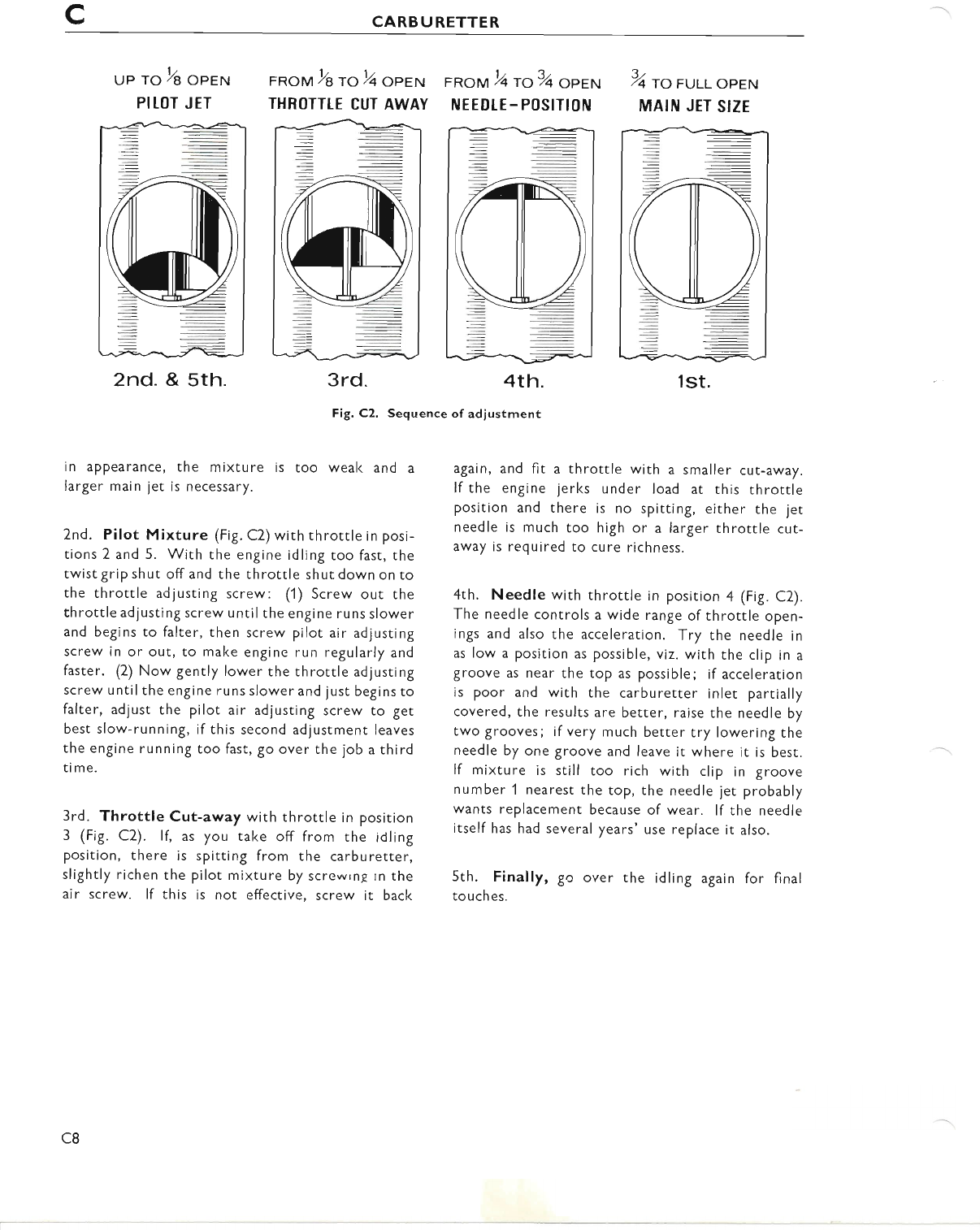
cCARBURETTER
uP To 2e oprNr
PITOT JET
2nd. & sth.
FRoM y'aroy'qoPEN
THBOTTIE CUT AWAY
FRoM 2qto3/qoPEN
IUEEDI-E - POSITION
4th.
%rorut oPEN
MAIN JET SIZE
in appearance, the mixture is too weak and a
larger main jet is necessary.
2nd. Pilot Mixture (Fig. C2)with rhrottle in posi-
tions 2 and 5. With the engine idling too fast, the
twist grip shut off and the throttle shut down on to
the throttle ad justing screw: (1) Screw our rhe
throttle adjusting screw until the engine runs slower
and begins to falter, then screw pilot air adjusting
screw in or out, to make engine run regularly and
faster. (2) Now gently lower the throttle adjusting
screw until the engine runs slower and just begins to
falter, adjust the pilot air adjusting screw to get
best slow-running, if this second adjustment leaves
the engine running too fast, go over the job a third
time.
3rd. Throttle Cut-away with throtrle in position
3 (Fig. C2). lf, as you take off from the idling
position, there is spitting from the carburetter,
slightly richen the pilot mixture by screwrng rn the
air screw. lf this is not effective, screw it back
3rd. 4th,
Fig. C2. Sequence of adjustment
1st.
again, and fit a throttle with a smaller cut-away.
lf the engine jerks under load at this throttle
position and there is no spitting, either the jet
needle is much too high or a larger throttle cut-
away is required to cure richness.
4th. Needle with throttle in position a fig. C2).
The needle controls a wide range of throttle open-
ings and also the acceleration. Try the needle in
as low a position as possible, viz. with the clip in a
groove as near the top as possible; if acceleration
is poor and with the carburetter inlet partially
covered, the results are better, raise the needle by
two grooves; if very much better try lowering the
needle by one groove and leave it where it is best.
lf mixture is still too rich with clip in groove
number 1 nearest the top, the needle jet probably
wants replacement because of wear. lf the needle
itself has had several years' use replace it also.
5th. Finally, go over the idling again for final
tou ches.
c8
www.bsaunitsingles.com
SECTION D
FRAME
INDEX
SECTION
D1 FRAME ALIGNMENT
D7 CHAINGUARD REMOVAL
D3 REAR SUSPENSION UNITS
D4 REMOVING THE SWINGING ARM
D5 SWINGING ARM BEARINGS
D6 CHECKING SWINGING ARM ALIGNMENT
D7 TWINSEAT
D8 PROP STAND
D9 REAR BRAKE PEDAL
D1O MUDGUARDS
D11 AIR CLEANER
D17 ELECTRICAL BOX-DISMANTLING PROCEDURE
D13 BATTERY CARRIER AND TOOLBOX
D14 REMOVAL OF HEADLAMP
D15 PETROL TANK REMOVAL
D16 APPLYING TRANSFERS (DECALS)
D17 CENTRE STAND (WHERE FlrrED)
D18 CONTROL CABLE REPLACEMENT
D1
www.bsaunitsingles.com
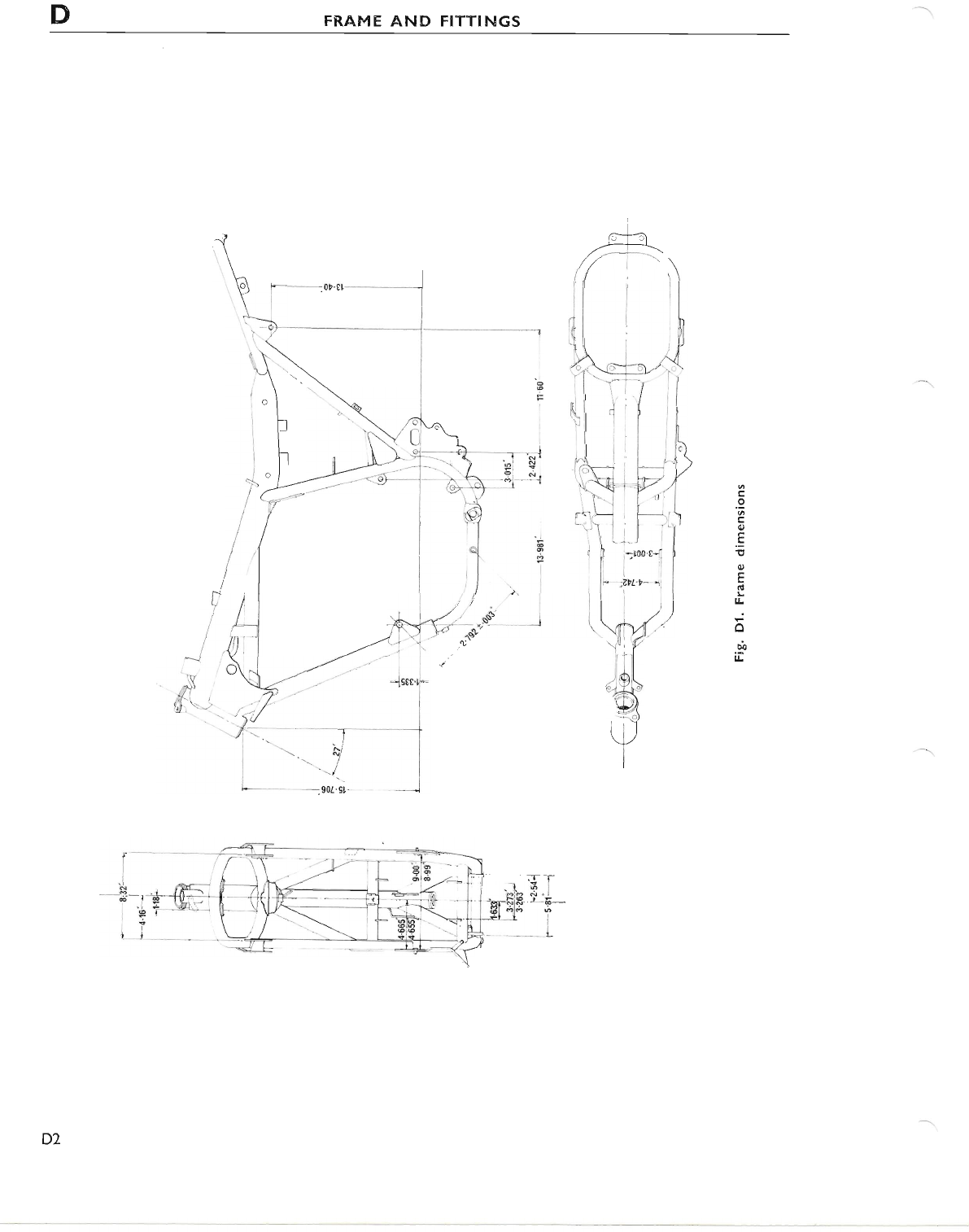
DFRAME AND FITTINGS
D2
www.bsaunitsingles.com
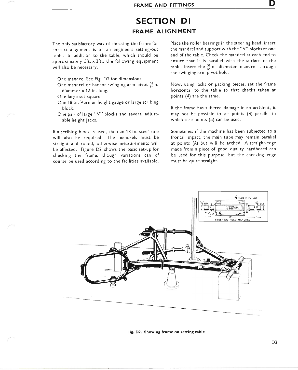
FRAME AND FITTINGS D
SECTION DI
FRAME ALIGN MENT
The only satisfactory way of checking the frame for
correct alignment is on an engineers settinS-out
table. ln addition to the table, which should be
approximately 5ft. x 3ft., the following equiPment
will also be necessary.
One mandrel See Fig. D2 for dimensions.
One mandrel or bar for swinging arm pivot fin.
diameter x 12 in. long.
One large set-square.
One 18 in. Vernier height gauge or large scribing
block.
One pair of large "V" blocks and several adjust-
able height jacks.
lf a scribing block is used, then an 18 in. steel rule
will also be required. The mandrels must be
straight and round, otherwise measurements will
be affected. Figure D2 shows the basic set-up for
checking the frame, though variations can of
course be used according to the facilities available.
Place the roller bearings in the steering head, insert
the mandrel and support with the "V" blocks at one
end ofthe table. Check the mandrel at each end to
ensure that it is parallel with the surface of the
table. lnsert the flin. diameter mandrel through
the swinging arm pivot hole.
Now, using jacks or packing pieces, set the frame
horizontal to the table so that checks taken at
points (A) are the same.
lf the frame {ras-suffered damage in an accident, it
may not be possible to set points (A) parallel in
which case points (B) can be used.
Sometimes if the machine has been subjected to a
frontal impact, the main tube may remain parallel
at points (A) but will be arched. A straight-edge
made from a piece of good quality hardboard can
be used for this purpose, but the checking edge
must be quite straight.
%Dlax 16thd uNF
va DtA
l-
TJ
Fig. D2. Showing frame on setting table
D3
www.bsaunitsingles.com
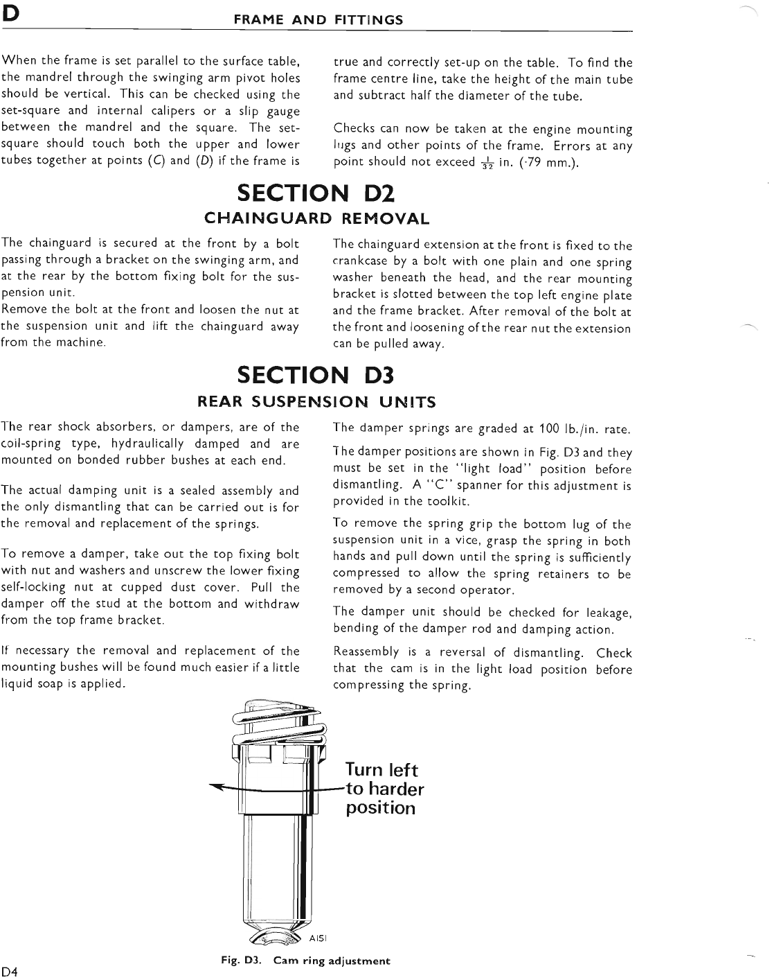
DFRAME AND FITTINGS
When the frame is set parallel to the surface table,
the mandrel through the swinging arm plvot holes
should be vertical. This can be checked using the
set-square and internal calipers or a slip gauge
between the mandrel and the square. The set-
square should touch both the upper and lower
tubes together at points (C) and (D) if the frame is
true and correctly set-up on the table. To find the
frame centre line, take the height of the main tube
and subtract halfthe diameter ofthe tube.
Checks can now be taken at the engine mounting
lugs and other points of the frame. Errors at any
point should not exceed $ in. (.79 mm.).
The chainguard extension at the front is fixed to the
crankcase by a bolt with one plain and one spring
washer beneath the head, and the rear mounting
bracket is slotted between the top left engine plate
and the frame bracl<et. After removal of the bolt at
the front and loosening ofthe rear nut the extension
can be pulled away.
I-he rear shock absorbers, or dampers, are of the
coil-spring type, hydraulically damped and are
mounted on bonded rubber bushes at each end.
The actual damping unit is a sealed assembly and
the only dismantling that can be carried out is for
the removal and replacement ofthe springs.
To remove a damper, take out the top fixing bolt
with nut and washers and unscrew the lower fixing
self-locking nut at cupped dust cover. Pull the
damper off the stud at the bottom and withdraw
from the top frame bracket.
It necessary the removal and replacement of the
mounting bushes will be found much easier if a little
liquid soap is applied.
SECTION D2
CHAINGUARD REMOVAL
The chainguard is secured at the front by a bolt
passing through a bracket on the swinging arm, and
at the rear by the bottom fixing bolt for the sus-
pension unit.
Remove the bolt at the front and loosen the nut ar
the suspension unit and lift the chainguard away
from the machine.
SECTION D3
REAR SUSPENSION UNITS
The damper springs are graded at 100 lb.i in. rate.
The damper positions are shown in Fig. D3 and they
must be set in the "light load" position before
dismantling. A "C" spanner for this adjustment is
provided in the toolkir.
To remove the spring grip the bottom lug of the
suspension unit in a vice, grasp the spring in both
hands and pull down until the spring is sufficiently
compressed to allow the spring retainers to be
removed by a second operator.
The damper unit should be checked for leakage,
bending of the damper rod and damping action.
Reassembly is a reversal of dismantling. Check
that the cam is in the light load position before
compressing the spring.
Turn left
to harder
position
D4 Fig. D3. Cam ring adiustment
www.bsaunitsingles.com
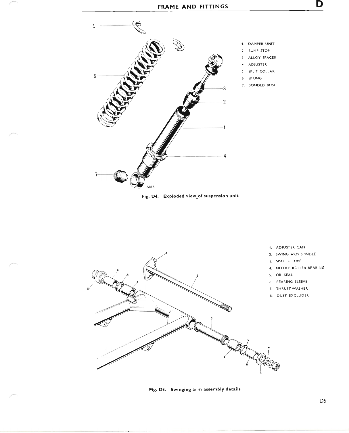
FRAME AND FITTINGS D
r __---(e
\
- A1'!'
l-------1lt)t) ),
wtl
Fig. D4, Exploded view:of suspension unit
1. ADJUSTER CAM
2. SWING ARM SPINDLE
3. SPACER TUBE
4. NEEDLE ROLLER BEARING
5. OIL SEAL
6. BEARING SLEEVE
7. THRUST WASHER
8. DUST EXCLUDER
1. DAMPER UNIT
2. BUMP STOP
3. ALLOY SPACER
4. ADJUSTER
5. SPLIT COLLAR
6. SPRING
7. BONDED BUSH
Fig. D5. Swinging arm assembly details
D5
www.bsaunitsingles.com
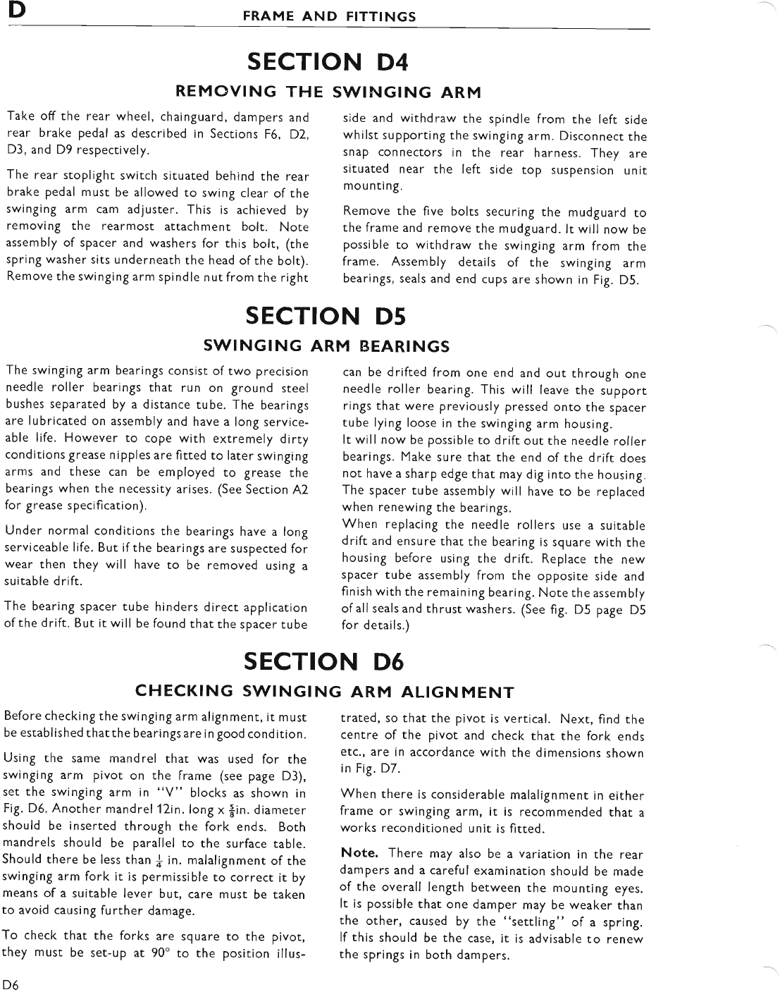
DFRAME AND FITTTNGS
SECTION D4
REMOVING THE
Take off the rear wheel, chainguard, dampers and
rear brake pedal as described in Sections F6, D2,
D3, and D9 respectively.
The rear stoplight switch situared behind the rear
brake pedal must be allowed to swing clear of the
swinging arm cam adjuster. This is achieved by
removing the rearmost attachment bolt. Note
assembly of spacer and washers for this bolt, (the
spring washer sits underneath the head ofthe bolt).
Remove the swinging arm spindle nut from the right
SWINGING ARM
side and withdraw the spindle from the left side
whilst supporting the swinging arm. Disconnect the
snap connectors in the rear harness. They are
situated near the left side top suspension unit
mounting.
Remove the five bolts securing the mudguard to
the frame and remove the mudguard. lt will now be
possible to wirhdraw the swinging arm from the
frame. Assembly details of the swinging arm
bearings, seals and end cups are shown in Fig. D5.
SECTION D5
S\ilINGING ARM BEARINGS
The swinging arm bearings consist of two precision
needle roller bearings that run on ground steel
bushes separated by a distance tube. The bearings
are lubricated on assembly and have a long service-
able life. However to cope with extremely dirty
conditions grease nipples are fitted to later swinging
arms and these can be employed to grease the
bearings when the necessity arises. (See Section A2
for grease specifi cation).
Under normal conditions the bearings have a long
serviceable life. But ifthe bearings are suspected for
wear then they will have to be removed using a
suitable d rift.
The bearing spacer tube hinders direct application
of the drift. But it will be found that the spacer tube
can be drifted from one end and out through one
needle roller bearing. This will leave the support
rings that were previously pressed onto the spacer
tube lying loose in the swinging arm housing.
It will now be possible to drift out the needle roller
bearings. Make sure that the end of the drift does
not have a sharp edge that may dig into the housing.
The spacer tube assembly will have to be replaced
when renewing the bearings.
When replacing the needle rollers use a suitable
drift and ensure thar the bearing is square with the
housing before using the drift. Replace the new
spacer tube assembly from the opposite side and
finish with the remaining bearing. Note the assembly
of all seals and thrust washers. (See fig. D5 page D5
for details.)
SECTION D6
CHECKING SWINGING ARM ALIGNMENT
Before checking the swinging arm alignment, it must
be establ ished that the beari ngs are i n good cond ition.
Using the same mandrel that was used for the
swinging arm pivot on the frame (see page D3),
set the swinging arm in "V" blocks as shown in
Fig. D6. Another mandrel 12in. long x $in. diameter
should be inserted through the fork ends. Both
mandrels should be parallel to the surface table.
Should there be less than f in. malalignment of the
swinging arm fork it is permissible to correct it by
means of a suitable lever but, care must be taken
to avoid causing further damage.
To check that the forks are square ro the pivot,
chey must be set-up at 90' to the position illus-
D6
trated, so that the pivot is vertical. Next, find the
centre of the pivot and check that the fork ends
etc., are in accordance with the dimensions shown
in Fig. D7.
When there is considerable malalignment in either
frame or swinging arm, it is recommended that a
works reconditioned unit is fitted.
Note. There may also be a variation in the rear
dampers and a careful examination should be made
of the overall length between the mounting eyes.
It is possible that one damper may be weaker than
the other, caused by the "settling" of a spring.
lf this should be the case, it is advisable to renew
the springs in both dampers.
www.bsaunitsingles.com
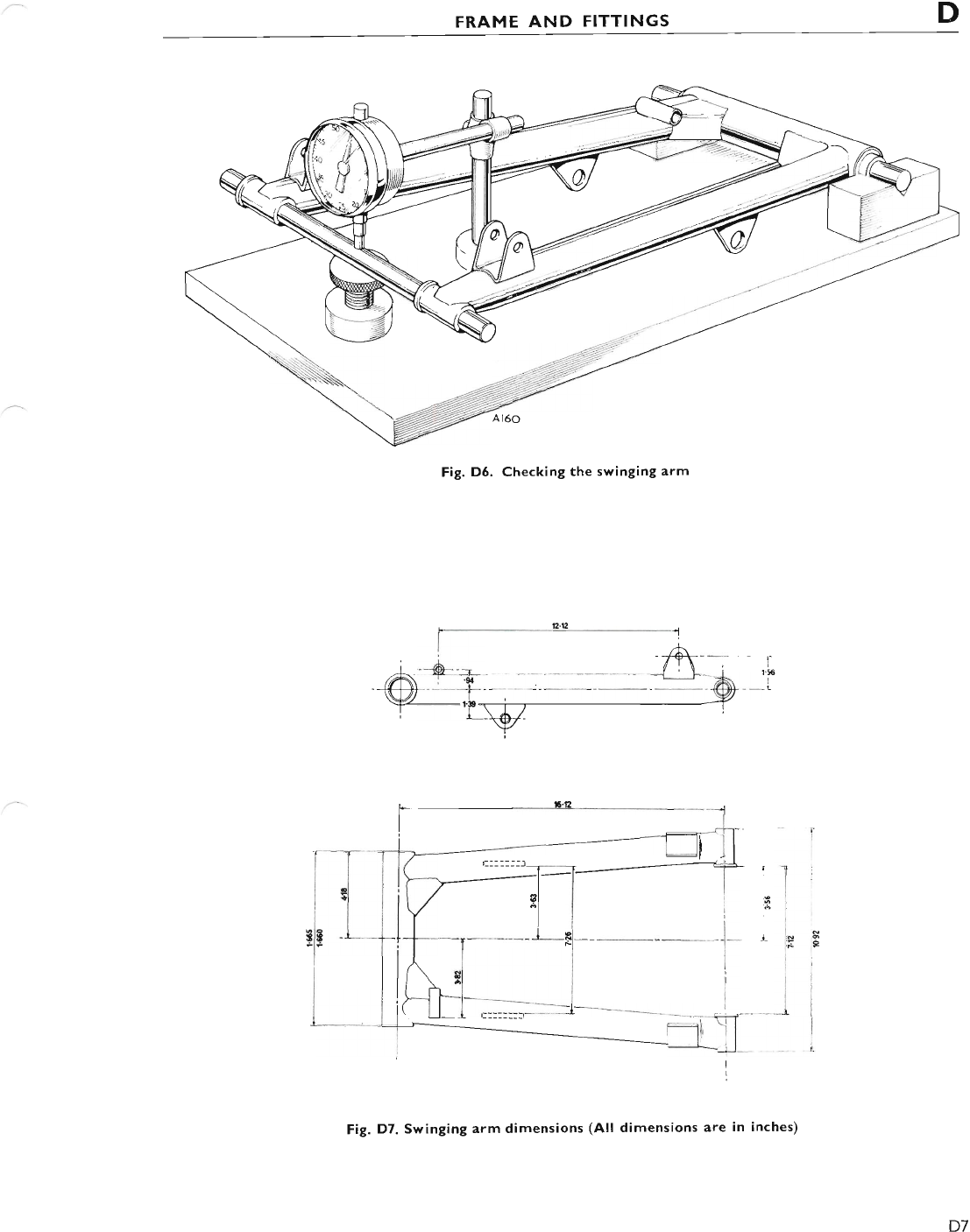
FRAME AND FITTINGS D
Fig, D6. Checking the swinging arm
I
I
Fig. D7. Swinging arm dimensions (All dimensions are in inches)
D7
www.bsaunitsingles.com
t) FRAME AND FITTINGS
SECTION D7
TWIN SEAT
The twin seat is mounted at two points in mid-
position and supported in a slotted bracket at the
front.
To remove the sear unscrew the two bolts from
underneath the seat and slide the seat rearwards
and away from the machine.
Replace in the reverse order, making sure that the
front fixing is engaged correctly in the slot.
SECTION D8
PROP STAND
With the stand in the raised position remove the
"Nyloc" nut from the spindle bolt. Using a screw-
driver remove the slotted head bolt from the inside
of the frame.
Swing the leg into the upright position and by
doing so lever the leg against the stop and remove
from the machine.
Detach the return spring.
Replacement is the reversal of the removal proce-
dure.
SECTION D9
REAR BRAKE PEDAL
Remove the clevis pin that secures the bra(e rod
to the brake pedal and allow the rod to swing
cl ear.
SECTION D IO
M UDG UARDS
T25T: Remove the two attachment bolts at the
bracket suspended by the bottom yolk. Withdraw
blade from between the forks.
T25SS: To detach the mudguard remove the joint
bolts securing the retaining brackets to the fork
legs. Note that the brackets are in two parts sur-
rounding a rubber bush. Hence the mudguard is
completely rubber mounted.
The rear mudguard can be removed complete with
its support rail rear light and number plate. Remove
D8
Remove the spindle by unscrewing the locknut
from inside the frame.
Replacement is the reversal of the above.
the twinseat (see Section D7). Disconnect the rear
harness at the junction snap connectors situated
near the top of the left side suspension unit.
Remove the five bolts and nuts securing the mud-
guard to the frame. Then remove the mudguard
from the rear ofthe machine.
Replace the mudguard in the reverse manner and
checl< that the rear light cables are not damaged at
any point.
www.bsaunitsingles.com
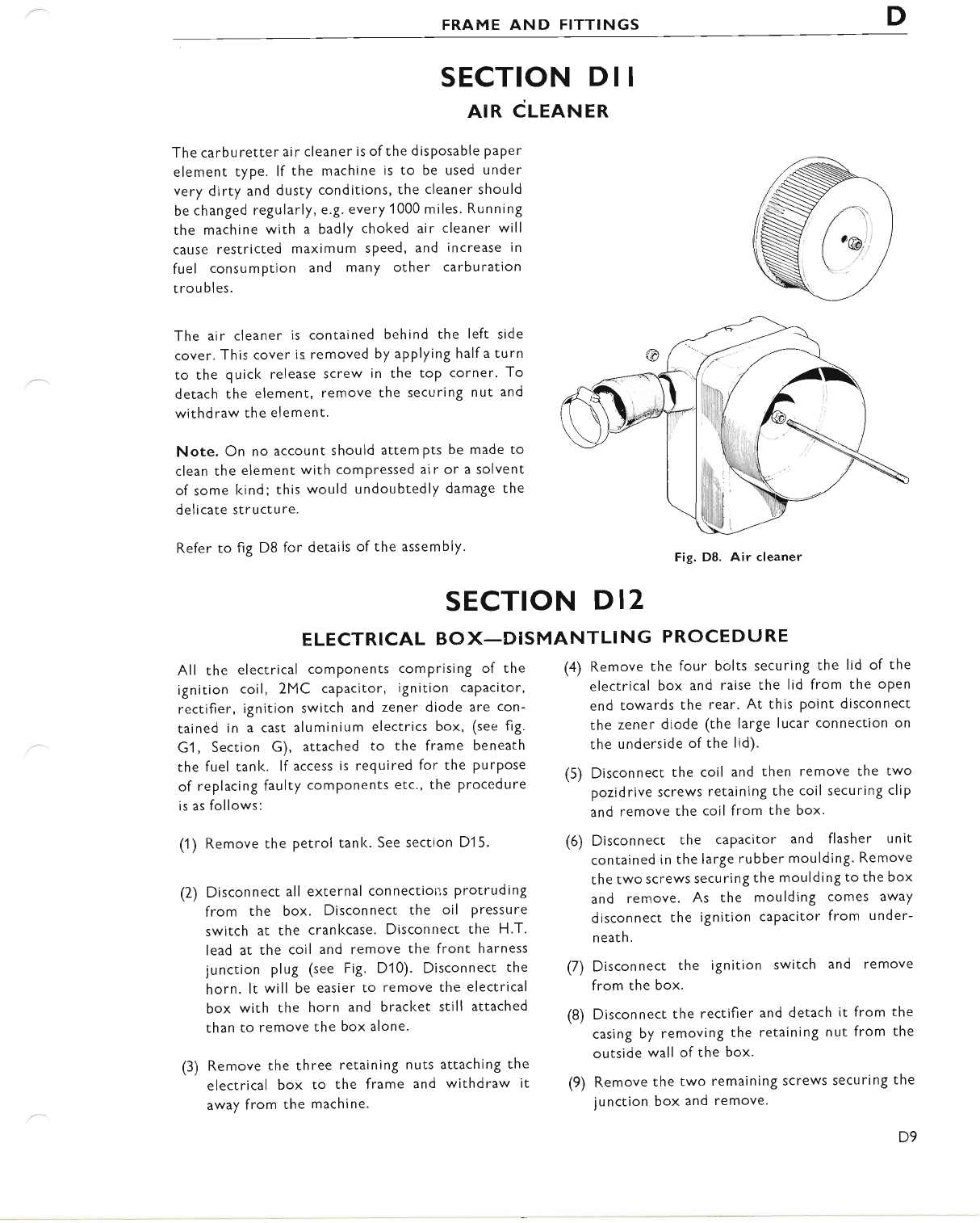
FRAME AND FITTINGS D
SECTION DII
AIR CLEANER
The carburetter air cleaner is ofthe disposable paper
element type. lf the machine is to be used under
very dirty and dusty conditions, the cleaner should
be changed regularly, e.g. every 1000 miles. Running
the machine with a badly choked air cleaner will
cause restricted maximum speed, and increase in
fuel consumption and many other carburation
trou bles.
The ai r cleaner is contained behind the left side
cover. This cover is removed by applying half a turn
to the quicl< release screw in the toP corner- To
detach the element, remove the securing nut and
withdraw the element.
Note. On no account should attem Pts be made to
clean the element with comPressed ai r or a solvent
of some kind; this would undoubtedly damage the
delicate structure.
Refer to fig D8 for details of the assembly'
SECTION D 12
ELECTRICAL BOX_DISMANTLING PROCEDT-'RE
All the electrical comPonents comprising of the
ignition coil, 2MC caPacitor, ignition caPacitor,
rectifier, ignition switch and zener diode are con-
tained in a cast aluminium electrics box, (see fig.
G1, Section G), attached to the frame beneath
the fuel tanl<. lf access is required for the PurPose
of replacing faulty components etc., the procedure
is as follows:
(1 ) Remove the petrol tanl<. See section D1 5'
(2) Disconnect all external connectiotls Protruding
from the box. Disconnect the oil Pressure
switch at the crankcase. Disconnect the H'T.
lead at the coil and remove the front harness
junction plug (see Fig. D10). Disconnect the
horn. lt will be easier to remove the electrical
box with the horn and bracket still attached
than to remove the box alone.
(3) Remove the three retaining nuts attaching the
electrical box to the frame and withdraw it
away from the machine.
Fig. D8. Air cleaner
(4) Remove the four bolts securing the lid of the
electrical box and raise the lid from the open
end towards the rear. At this Point disconnect
the zener diode (the large lucar connection on
the underside of the lid).
(5) Disconnect the coil and then remove the two
pozidrive screws retaining the coil securing clip
and remove the coil from the box.
(6) Disconnect the caPacitor and flasher unit
contained in the large rubber moulding. Remove
the two screws securing the moulding to the box
and remove. As the moulding comes away
disconnect the ignition caPacitor from under-
n eath.
(7) Disconnect the iSnition switch and remove
from the box.
(8) Disconnecl the rectifier and detach it from the
casing by removing the retaining nut from the
outside wall of the box.
(9) Remove the two remaining screws securing the
junction box and remove.
www.bsaunitsingles.com
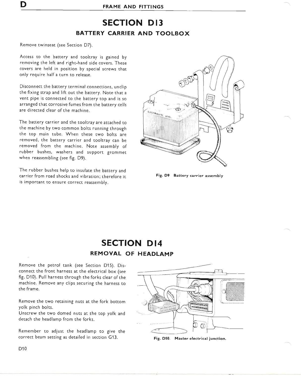
DFRAME AND FITTINGS
SECTION D 13
BATTERY CARRIER AND TOOLBOX
Remove twinseat (see Section D7).
Access to the battery and tooltray is gained by
removing the left and right-hand side covers. These
covers are held in position by special screws that
only require half a turn to release.
Disconnect the battery terminal connections, unclip
the fixing strap and lift out the battery. Note that a
vent pipe is connected to the battery top and is so
arranged that corrosive fumes from the battery cells
are directed clear of the machine.
The battery carrier and the tooltray are attached to
the machine by two common bolts running through
the top main tube. When these two bolts are
removed, the battery carrier and tooltray can be
removed from the machine. Note assembly of
rubber bushes, washers and support grommet
when reassembling (see fig. D9).
The rubber bushes help to insulate the battery and
carrier from road shocks and vibration; therefore it
is important to ensure correct reassembly.
Fig. D9 Battery carrier assembly
SECTION DI4
REMOVAL OF HEADLAMP
Remove the petrol tank (see Section D15). Dis-
connect the front harness at the electrical box (see
fig. D10). Pull harness through the forks clear ofthe
machine. Remove any clips securing the harness to
the frame.
Remove the two retaining nuts at the fork bottom
yolk pinch bolts.
Unscrew the two domed nuts at the top yolk and
detach the headlamp from the forks.
Remember to adjust the headlamp to give the
correct beam setting as detailed in section G13.
D10
Fig. Dl0. Master electrical iunction.
www.bsaunitsingles.com
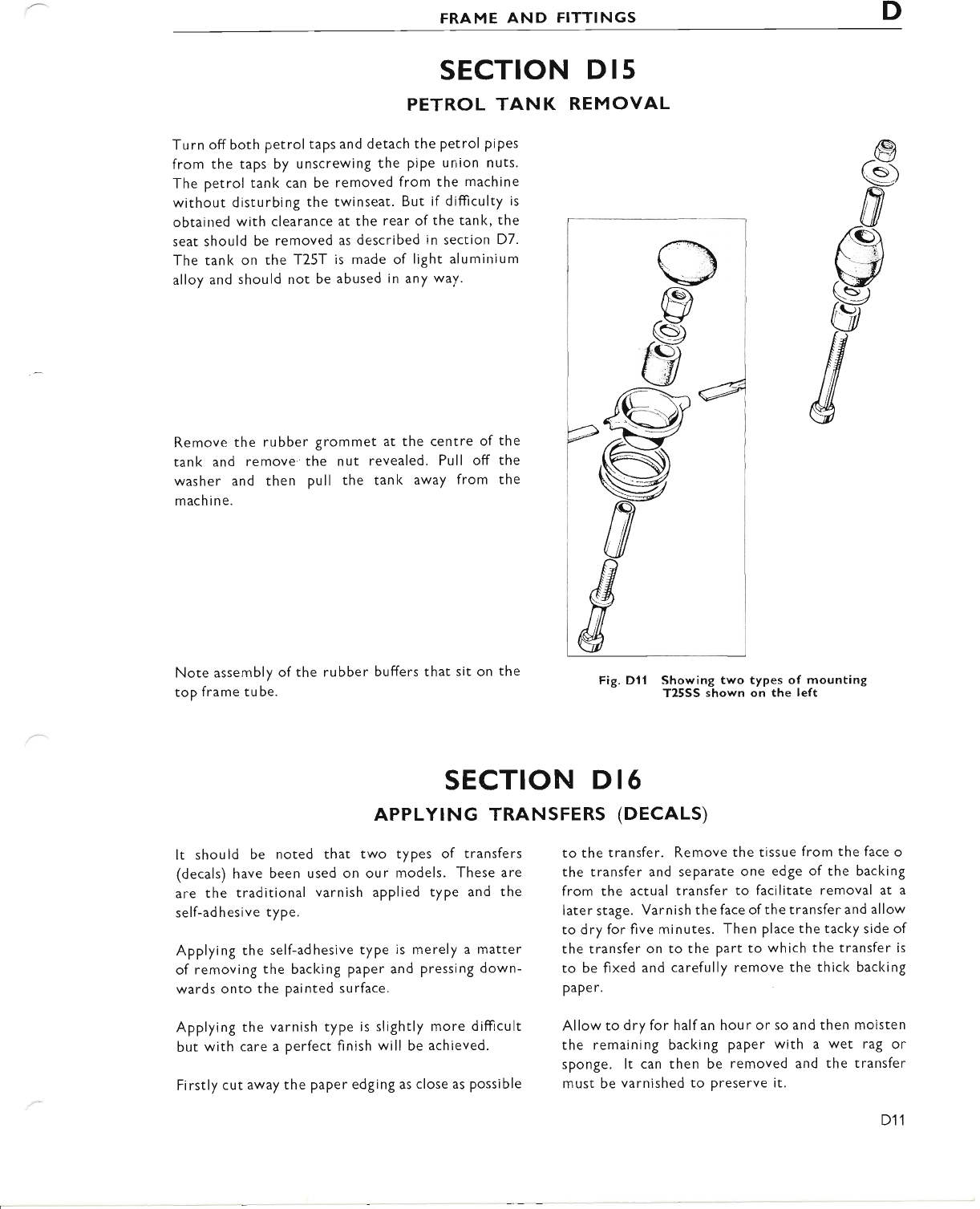
FRAME AND FITTINGS D
Turn off both petrol taps and detach the petrol pipes
from the taps by unscrewing the pipe union nuts.
The petrol tank can be removed from the machine
without disturbing the twinseat. But if difficulty is
obtained with clearance at the rear ofthe tank, the
seat should be removed as described in section D7.
The tank on the T25T is made of light aluminium
alloy and should not be abused in any way.
Remove the rubber grommet at the centre of the
tank and remove'the nut revealed. Pull off the
washer and then pull the tanl< away from the
mach ine.
Note assembly of the
top frame tube. Fig. Dll Showing two types of mounting
T25SS shown on the left
SECTION D 15
PETROL TANK REMOVAL
rubber buffers that sit on the
to the transfer. Remove the tissue from the face o
the transfer and separate one edge of the backing
from the actual transfer to facilitate removal at a
later stage. Varnish the face ofthe transfer and allow
to dry for five minutes. Then place the tacky side of
the transfer on to the part to which the transfer is
to be fixed and carefully remove the thick backing
PaPe r.
Allow to dry for half an hour or so and then moisten
the remaining backing paper with a wet rag or
sponge. lt can then be removed and the transfer
must be varnished to preserve it.
SECTION D 16
APPLYTNG TRANSFERS (DECALS)
It should be noted that two types of transfers
(decals) have been used on our models. These are
are the traditional varnish applied type and the
self-ad hesive type.
Applying the self-adhesive type is merely a matter
of removing the baclcing paper and pressing down-
wards onto the painted surface.
Applying the varnish type is slightly more difticult
but with care a perfect finish will be achieved.
Firstly cut away the paper edging as close as possible
D11
www.bsaunitsingles.com
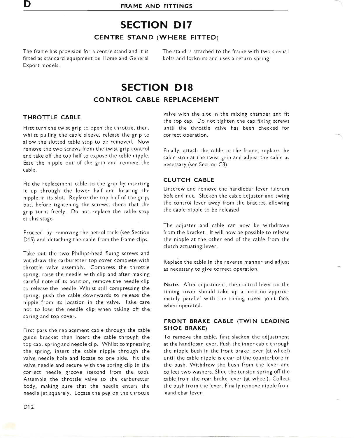
DFRAME AND FITTINGS
SECTION D 17
CENTRE STAND
The frame has provision for a centre stand and it is
fitted as standard equipment on Home and General
Export models.
(wHERE FTTTED)
The stand is attached to the
bolts and locknuts and uses
frame with two special
a return spring.
REPLACE M ENT
valve with the slot in the mixing chamber and fit
the top cap. Do not tighten the cap fixing screws
until the throttle valve has been checked for
correct operation.
Finally, attach the cable to the frame, replace the
cable stop at the twist grip and adjust the cable as
necessary (see Section C3).
CLUTCH CABLE
Unscrew and remove che handlebar lever fulcrum
bolt and nut. Slacken the cable adjuster and swing
the control lever away from the bracket, allowing
the cable nipple to be released.
The adjuster and cabie can now be withdrawn
from the bracket. lt will now be possible to release
the nipple at the other end of the cable from the
clutch actuating lever.
Replace the cable in the reverse manner and adjusc
as necessary to give correct oPeration.
Note. After adjustment, the control lever on the
timing cover should take up a position approxi-
mately parallel with the timing cover joint face,
when operated.
FRONT BRAKE CABLE (TWIN LEADTNG
sHoE BRAKE)
To remove the cable, first slacken the adjustment
at the handlebar lever. Push the inner cable through
the nipple bush in the front brake lever (at wheel)
until the cable nipple is clear of the counterbore in
the bush. Withdraw the bush from the lever and
collect two washers. Slide the tension spring offthe
cable from the rear brake lever (at wheel). Collect
the bush from the lever. Finally remove nipple from
handlebar lever.
SECTION D 18
CONTROL CABLE
THROTTLE CABLE
First turn the twist grip to open the throttle, then,
whilst pulling the cable sleeve, release the grip to
allow the slotted cable stop to be removed. Now
remove the two screws from the twist Srip control
and take offthe top half to expose the cable nipple.
Ease the nipple out of the grip and remove the
cable.
Fit the replacement cable to the grip by inserting
it up through the lower half and locating the
nipple in its slot. Replace the top half of the grip,
but, before tightening the screws, check that the
grip turns freely. Do not replace the cable stop
at this stage.
Proceed by removing the petrol tank (see Section
Dl 5) and detaching the cable from the frame clips.
Take out the two Phillips-head fixing screws and
withdraw the carburetter top cover complete with
throttle valve assembly. Compress the throttle
spring, raise the needle with clip and after making
careful note of its position, remove the needle clip
to release the needle. Whilst still compressing the
spring, push the cable downwards to release the
nipple from its location in the valve. Take care
not to lose the needle clip when taking off the
spring and top cover.
First pass the replacement cable through the cable
guide bracket then insert the cable through the
top cap, spring and needle clip. Whilst compressing
the spring, insert the cable nipple through the
valve needle hole and locate to one side. Fit the
valve needle and secure with the spring clip in the
correct needle groove (second from the top).
Assemble the throttle valve to the carburetter
body, making sure that the needle enters the
needle iet squarely. Locate the peg on the throttle
D12
www.bsaunitsingles.com
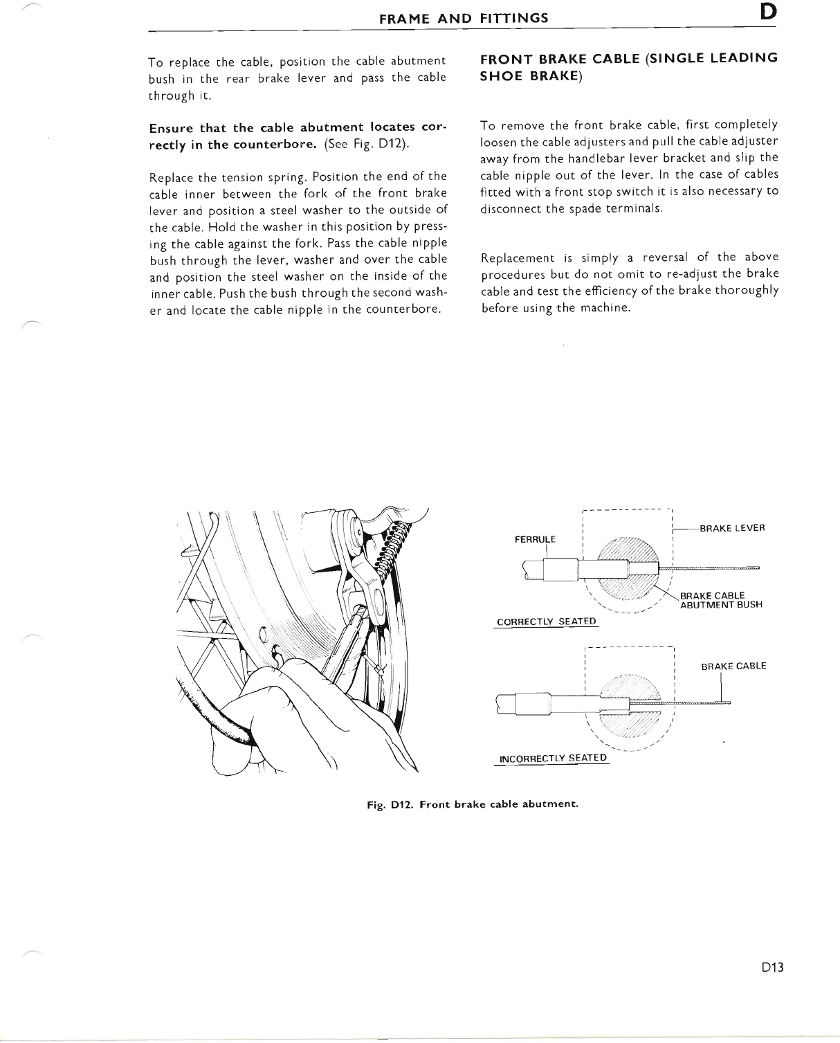
FRAME AND FITTINGS D
To replace the cable, Position the cable abutment
bush in the rear brake lever and pass the cable
th rough it.
Ensure that the cable abutment locates cor-
rectly in the counterbore. (See Fig. D12).
Replace the tension spring. Position the end of the
cable inner between the fork of the front brake
lever and position a steel washer to the outside of
the cable. Hold the washer in this position by press-
ing the cable against the fork. Pass the cable nipple
bush through the lever, washer and over the cable
and position the steel washer on the inside of the
inner cable. Push the bush through the second wash-
er and locate the cable nipple in the counterbore.
FRONT BRAKE CABLE (SINGLE LEADING
sHoE BRAKE)
To remove the front brake cable, first comPletely
loosen the cable adjusters and pull the cable adjuster
away from the handlebar lever bracket and slip the
cable nipple out of the lever. ln the case of cables
fitted with a front stop switch it is also necessary to
disconnect the spade terminals.
Replacement is sim ply a reversal of the above
procedures but do not omit to re-adjust the brake
cable and test the efticiency ofthe brake thoroughly
before using the machine.
I
i-annre LEveR
COBRECTLY SEATED
BRAKE CABLE
Fig. Dl2, Front brake cable abutment'
D13
www.bsaunitsingles.com
SECTION
E1
E7
E3
E4
E5
SECTION E
TELESCOPIC FORKS
INDEX
DESCRIPTION
STEERING HEAD ADJUSTMENT
RENEWING HEAD RACES
STRIPPING AND REASSEMBLING THE FORK LEGS
FORK ALIGNMENT
HYDRAULIC DAMPING
E1
www.bsaunitsingles.com
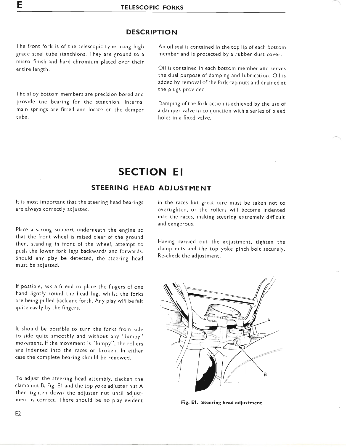
ETELESCOPIC FORKS
DESCRI PTIO N
The front forl< is of the telescopic type using high
grade steel tube stanchions. They are ground to a
micro finish and hard chromium plated over their
entire length.
The alloy bottom members are precision bored and
provide the bearing for the stanchion. lnternal
main springs are fitted and locate on the damper
tu be.
An oil seal is contained in the top lip of each bottom
member and is protected by a rubber dust cover.
Oil is contained in each bottom member and serves
the dual purpose of damping and lubrication. Oil is
added by removal ofthe fork cap nuts and drained at
the plugs provided.
Damping of the fork action is achieved by the use of
a damper valve in conjunction with a series of bleed
holes in a fixed valve.
ADJ USTMENT
in the races but great care must be taken not to
overtighten, or the rollers will become indented
into the races, making steering extremely difficult
and dangerous.
Having carried out the adjustment, tighten the
clamp nuts and the top yol<e pinch bolt securely.
Re-check the adjustment.
SECTION E I
STEERING HEAD
It is most important that the steering head bearings
are always correctly adjusted.
Place a strong support underneath the engine so
that the front wheel is raised clear of the ground
then, standing in front of the wheel, attempt to
push the lower fork legs backwards and forwards.
Should any play be detected, the steering head
must be adjusted.
lf possible, ask a friend to place the fingers of one
hand lightly round the head lug, whilst the forks
are being pulled back and forth. Any play will be felt
quite easily by the fingers.
It should be possible to turn the forks from side
to side quite smoothly and without any "lumpy"
movemenr. lf the movement is "lumpy", the rollers
are indented into the races or broken. ln either
case the complete bearing should be renewed.
To adjust the steering head assembly, slacken the
clamp nut B, Fig. E'l and the top yoke adjuster nut A
then tighten down the adjuster nut unril adlust-
ment is correct. There should be no play evident
E2
Fig. El. Steering head adjustment
www.bsaunitsingles.com
TELESCOPIC FORKS E
SECTION E2
RENEWING
Place a strong support underneath the engine so
that the front wheel is raised clear of the ground.
Remove the front wheel (see Section F1). Remove
the front mudguard (see page D10).
The steering head can be dismantled without strip-
ping the forks. Remove the fuel tank (see page D11).
With reference to page D'l 0 remove the headlamp
complete with mounting brackets. Disconnect the
speedometer drive cable and the illumination light.
Remove the four bolts securing the handlebars to
the top lug and support the handlebars on the frame.
Remove the fork caP nuts and place the speedometer
to one side. Slacken the top yolk pinch bolt (A) and
remove the adjuster nut (B).
HEAD RACES
Then using a raw-hide mallet stril<e the undersides
of the top lug alternately to release it from its taper
fit on the stanchions. Place the yolk to one side and
withdraw the steering stem out of the head lug.
The taper roller bearings can now be removed from
the stem and the top lug for cleaning and inspection.
Check for pitting and fracture of the roller surface.
The bearing must be replaced if any of these faults
are in evidence.
The steering head outer races have a very long
serviceable life and should not need replacement
for a very considerable mileage. lf however their
replacement is deemed necessary the races can be
removed using a suitable drift from inside the head
lug. Replacement ofthe new race is effected by using
service tool 61-6113.
Remove the internal fork springs. Using service
tool 61-6121 placed down into the stanchion; hold
the valve assembly while the retaining allen screw
is being unscrewed at the base of the fork leg.
At this stage it will be possible to remove the fork
leg by sliding it from the stanchion. The stanchions
can remain in position on the machine and will only
require removal if they are to be replaced because
of damage (the stanchions are easily removed by
slackening the pinch bolts on the bottom yolk and
withdrawing the stanchions. When refitting tighten
the pinch bolts to 18/20 lbs./ft.).
The dust cover on the fork leg can easily be prised
off by hand.
The damper valve assembly is retained in the bottom
of the stanchion by an aluminium nut which should
be carefully removed with a ring spanner or similar.
SECTION E3
STRIPPING AND REASSEMBLING THE FORK I.EGS
Before commencing worl< on the forks it is advisable
to have the following service tools and replacements
available:
(a) Oil seal for dust excluder (2)
(b) Oil seal for damper valve (2)
(c) Service tool 61-6121
Remove the front wheel as described in Section F1 .
Unscrew the small drain plugs at the bottom of each
fork leg adjacent to the wheel spindle and drain out
the oil by pumping the forks up and down a few
times. Support the machine on a box with the front
forks clear of the ground. (Remove the front mud-
guard on SS models). Remove the handlebars by
unscrewing the four retaining bolts at the head lug
and lay the handlebars on the petrol tank with a
layer of protective cloth underneath. Remove the
fork cap nuts. Place the speedometer to one side
after first disconnecting the drive cable and the
illuminating light (similar treatment applies to the
tachometer; where fitted).
www.bsaunitsingles.com
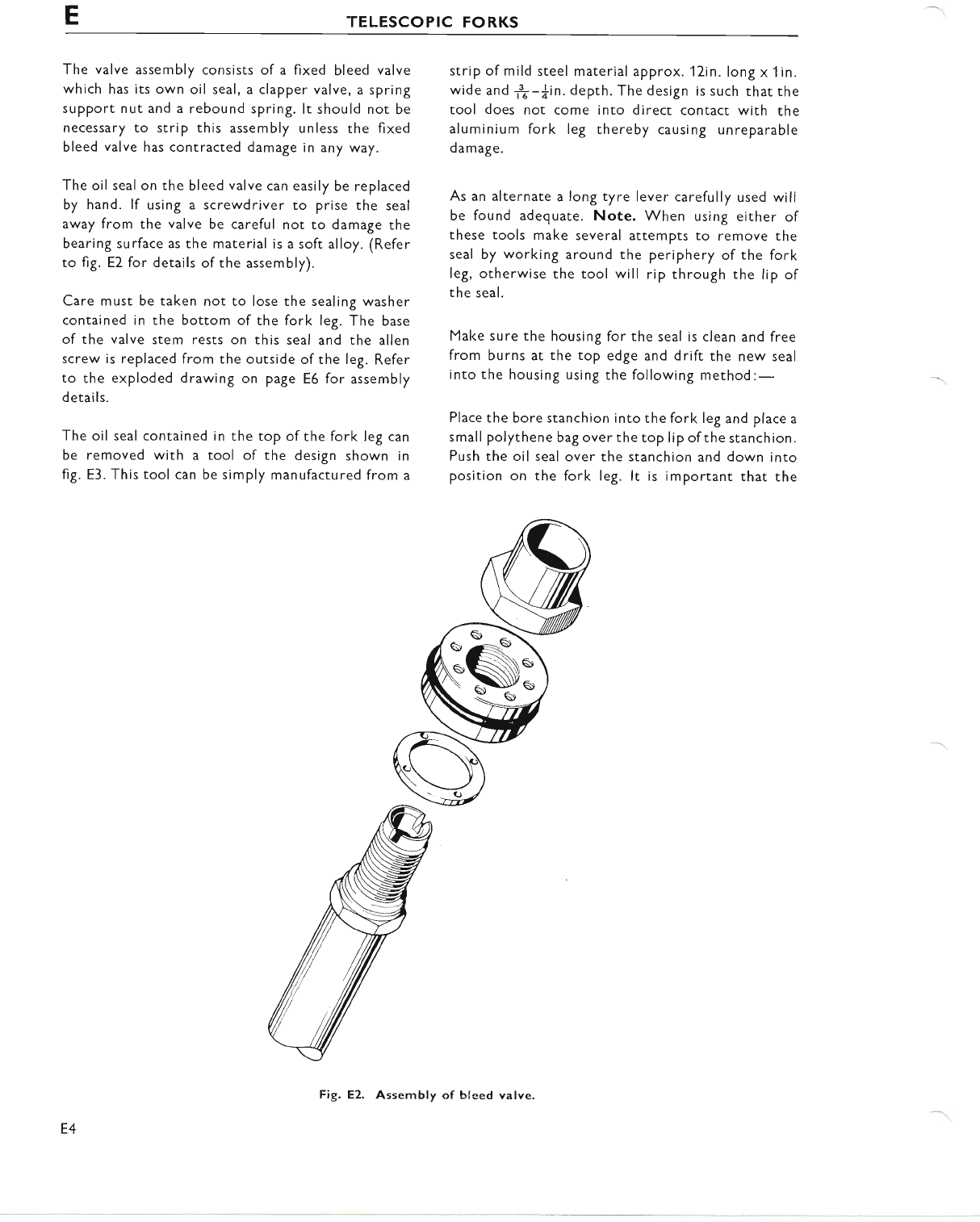
ETELESCOPIC FORKS
The valve assembly consists of a fixed bleed valve
which has its own oil seal, a clapper valve, a spring
support nut and a rebound spring. lt should not be
necessary to strip this assembly unless the fixed
bleed valve has contracted damage in any way.
The oil seal on the bleed valve can easily be replaced
by hand. lf using a screwdriver to prise the seal
away from the valve be careful not to damage the
bearing surface as the material is a soft alloy. (Refer
to fig. E2 for details of the assembly).
Care must be taken not to lose the sealing washer
contained in the bottom of the fork leg. The base
of the valve stem rests on this seal and the allen
screw is replaced from the outside of the leg. Refer
to the exploded drawing on page E6 for assembly
details.
The oil seal contained in the top of the fork leg can
be removed with a tool of the design shown in
fig. E3. This tool can be simply manufactured from a
strip of mild steel material approx. 12in. long x 1in.
wide and *-*in. depth. The design is such that the
tool does not come into direct contact with the
aluminium fork leg thereby causing unreparable
damage.
As an alternate a long tyre lever carefully used will
be found adequate. Note. When using either of
these tools make several attempts to remove the
seal by working around the periphery of the fork
leg, otherwise the tool will rip through the lip of
the seal.
Make sure the housing for the seal is clean and free
from burns at the top edge and drift the new seal
into the housing using the following method:-
Place the bore stanchion into the fork leg and place a
small polythene bag over the top lip of the stanchion.
Push the oil seal over the stanchion and down into
position on the fork leg. lt is important that the
E4
Fig. E2. Assembly of bleed valve.
www.bsaunitsingles.com
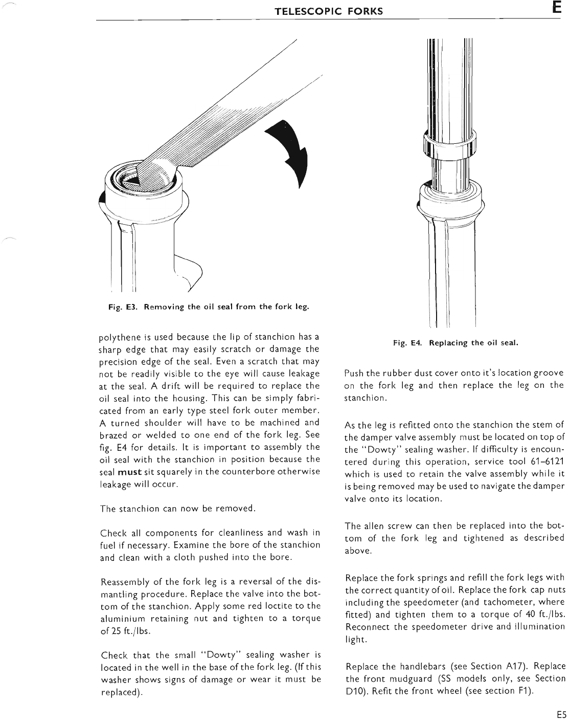
TELESCOPIC FORKS E
Fig. E3. Removing the oil seal from the fork leg.
polythene is used because the lip of stanchion has a
sharp edge that may easily scratch or damage the
precision edge of the seal. Even a scratch that may
not be readlly visible to the eye will cause leakage
at the seal. A drift will be required to replace the
oil seal into the housing. This can be simply fabri-
cated from an early type steel forl< outer member.
A turned shoulder will have to be machined and
brazed or welded to one end of the fork leg. See
fig. E4 for details. lt is important to assembly the
oil seal with the stanchion in position because the
seal must sit squarely in the counterbore otherwise
leakage will occur.
The stanchion can now be removed.
Checl< all components for cleanliness and wash in
fuel if necessary. Examine the bore of the stanchion
and clean with a cloth pushed into the bore.
Reassembly of the forl< leg is a reversal of the dis-
mantling procedure. Replace the valve into the bot-
tom of the stanchion. Apply some red loctite to the
aluminium retaining nut and tighten to a torque
of25 ft./lbs.
Check that the small "Dowty" sealing washer is
located in the well in the base of the fork leg. (lf this
washer shows signs of damage or wear it must be
replaced).
Fig. E4. Replacing the oil seal.
Push the rubber dust cover onto it's location groove
on the forl< leg and then replace the leg on the
stanc h ion.
As the leg is refitted onto the stanchion the stem of
the damper valve assembly must be located on top of
the "Dowty" sealing washer. lf difficulty is encoun-
tered during this operation, service tool 61-6171
which is used to retain the valve assembly while it
is being removed may be used to navigate the damper
valve onto its location.
The allen screw can then be replaced into the bot-
tom of the forl< leg and tightened as described
above.
Replace the fork springs and refill the fork legs with
the correct quantity ofoil. Replace the fork cap nuts
including the speedometer (and tachometer, where
fitted) and tighten them to a torque of 40 ft./lbs.
Reconnect the speedometer drive and illumination
light.
Replace the handlebars (see Section A17). Replace
the front mudguard (SS models only, see Section
D10). Refit the front wheel (see section F1).
E5
www.bsaunitsingles.com
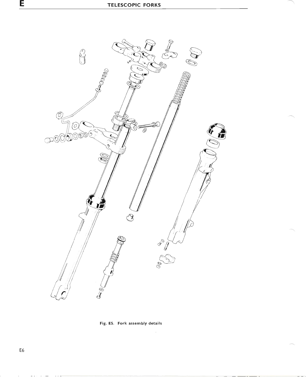
ETELESCOPIC FORKS
a-\
V
s
d,ap
g'
A&
(_ \?
q5-
e
s
/1fl
///
rV
)-\:/t
I\Y
/Y
Q/4
t/-
U
s
d
Fig. E5. Fork assembly details
n
N
E6
www.bsaunitsingles.com
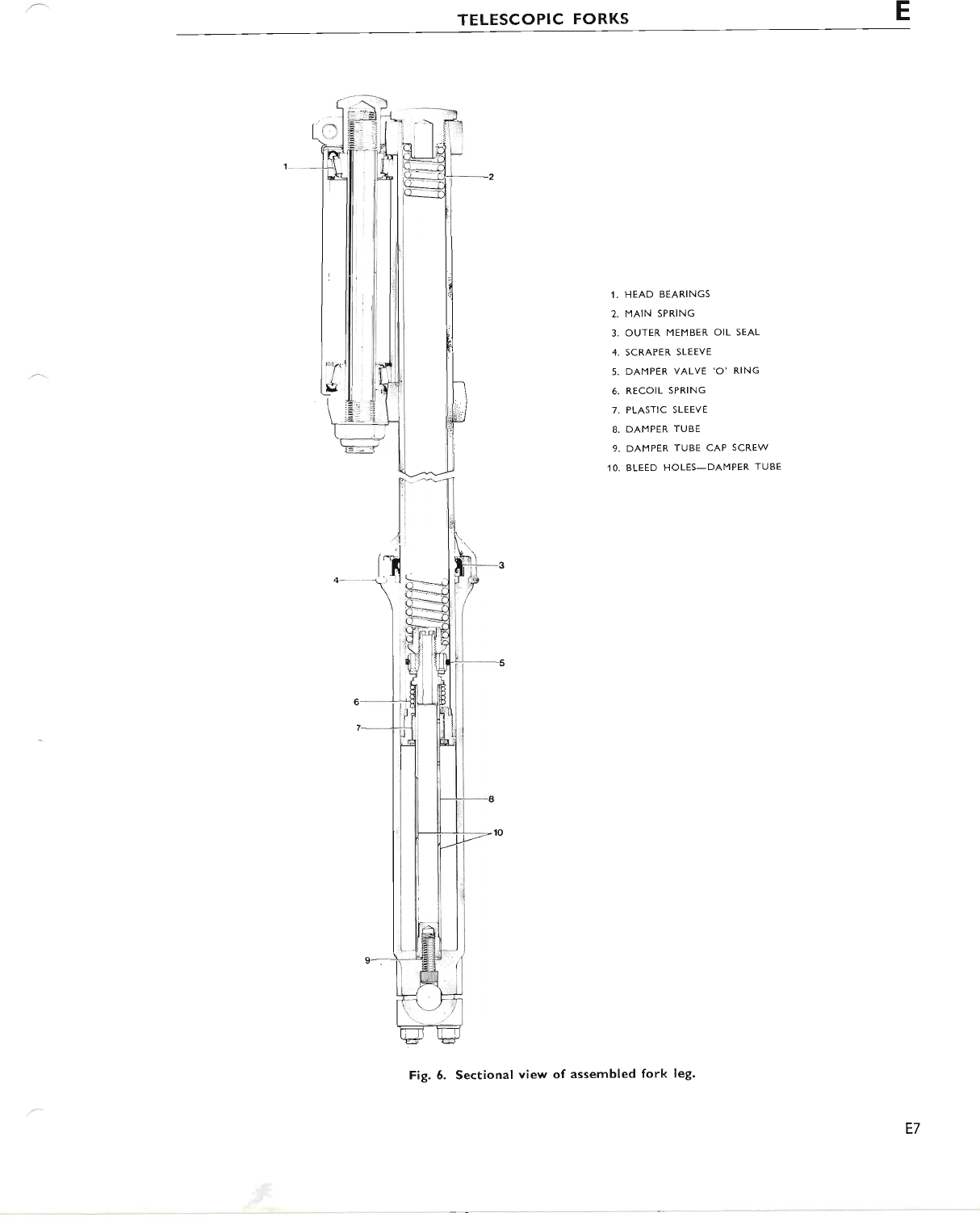
TELESCOPIC FORKS E
1. HEAD BEARINGS
2. MAIN SPRING
3. OUTER MEMBER OIL SEAL
4. SCRAPER,SLEEVE
5. DAMPER VALVE 'O' RING
6. RECOIL SPRING
7. PLASTIC SLEEVE
8. DAMPER TUBE
9. DAMPER TUBE CAP SCREW
.IO. BLEED HOLES_DAMPER TUBE
Fig. 6. Sectional view of assembled fork leg.
E7
www.bsaunitsingles.com
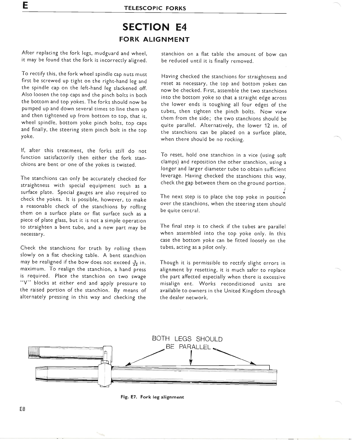
ETELESCOPIC FORKS
SECTION E4
FORK ALIGNMENT
After replacing the fork legs, mudguard and wheel,
it may be found that the fork is incorrectly aligned.
To rectify this, the fork wheel spindle cap nuts must
first be screwed up tight on rhe right-hand leg and
the spindle cap on the left-hand leg slackened off.
Also loosen rhe top caps and the pinch bolts in both
the bottom and top yokes. The forks should now be
pumped up and down several times to line them up
and then tightened up from bottom to top, that is,
wheel spindle, bottom yoke pinch bolts, top caps
and finally, the steering stem pinch bolt in the top
yoke.
lf, after this treatment, the forks still do nor
function satisfactorily then either the fork stan-
chions are bent or one of the yokes is twisted.
The stanchions can only be accurately checked for
straightness with special eguipment such as a
surface plate. Special gauges are also required to
check the yokes. lt is possible, however, to make
a reasonable check of the stanchions by rolling
them on a surface plate or flat surface such as a
piece of plare glass, but it is not a simple operation
to straighten a bent tube, and a new part may be
necessary.
Check the stanchions for truth by rolling them
slowly on a flat checking table. A benr stanchion
may be realigned if the bow does not exceed $ in.
maximum. To realign the stanchion, a hand press
is required. Place the stanchion on two swage
"V" blocks at either end and apply pressure to
the raised portion of the stanchion. By means of
alternately pressing in this way and checking the
stanchion on a flat table the amount of bow can
be reduced until it is finally removed.
Having checked the stanchions for straightness and
reset as necessary, the top and bottom yokes can
now be checked. First, assemble the two stanchions
into the bottom yoke so that a straight edge across
the lower ends is toughing all four edges of the
tubes, then tighten the pinch bolts. Now view
them from the side; the two stanchions should be
quite parallel. Alternatively, the lower 12 in. of
the stanchions can be placed on a surface plate,
when there should be no rocking.
To reset, hold one stanchion in a vice (using soft
clamps) and reposition the other stanchion, using a
longer and larger diameter tube to obtain sufficient
leverage. Having checked the stanchions this way,
check the gap between them on the ground portion-
The next step is to place the top yoke in positioi
over the stanchions, when the steering stem should
be quite central.
The final step is to check if the tubes are parallel
when assembled into the top yoke only. ln this
case the bottom yoke can be fitted loosely on the
tubes, acting as a pilot only.
Though it is permissible to rectify slight errors in
alignment by resetting, it is much safer to replace
the part affected especially when there is excessive
misalign ent. Works reconditioned units are
available to owners in the United Kingdom through
the dealer network.
BOTH LEGS SHOULD
BE PARALLEL
E8
Fig. E7. Fork leg alignment
www.bsaunitsingles.com
TELESCOPIC FORKS E
SECTION E5
HYDRAULIC DAMPING
Note the valve assembly which is retained in the
bottom of the fork leg. Bleed holes are contained
in the valve stem and in a sub-assembly at the toP of
the stem. This particular valve oPerates in conjunc-
tion with a damper valve which acts as a restrictor.
Oil is contained in the bottom member the level
of which is always above the valve assembly. On
compression the oil is forced through bleed holes
in the valve stem. As the travel increases the bleed
holes are progressively sealed off by a plastic sleeve
and the damping increases until finally the stanchion
is trapped on a cushion of oil which acts as the final
bump stop. During this operation a vacuum is
created in the space formed between the bottom of
the stanchion and the damper valve, hence oil is
transferred into this comPartment through the
eight bleed holes in the valve.
On expansion the oil in this newly formed comPart-
ment is compressed, the damper valve closes and the
oil is bled through four small holes in the damper
valve itself and then progressively through the holes
in the valve stem. While this oPeration is being
executed, oil is transferred back into the bottom
member in readiness for the next compression.
E9
www.bsaunitsingles.com
SECTION F
WHEELS, BRAKES AND TYRES
INDEX
SECTION
F1 REMOVING AND RE-FITTING THE FRONT WHEEL
FzREMoVINGANDRE-FITTINGTHEFRoNTWHEELBEARINGS
F3STRIPPINGANDRE-ASSEMBLINGTHEFRoNTBRAKETWIN
LEADING SHOE TYPE (8" BRAKE)
F4 STRIPPING AND RE-ASSEMBLING THE FRONT BRAKE SINGLE
LEADING SHOE TYPE (6' BRAKE)
F5 STRIPPING AND REASSEMBLING REAR BRAKE
F6 REAR WHEEL REMOVAL AND REPLACEMENT
F7 REMOVING AND REPLACING REAR WHEEL BEARINGS
F8 BRAKE ADJUSTMENT
F9 REAR CHAIN ADIUSTMENT
F1O RENEWING BRAKE LININGS
F11 WHEEL BUILDING
F12 WHEEL BALANCING
F13 WHEEL ALIGNMENT
F14 BRAKING PER.FORMANCE DATA
F15 REMOVING AND REFITTING TYRES
F16 SECURITY BOLTS
F17 TYRE MAINTENANCE
F18 TYRE PRESSURES
F1
www.bsaunitsingles.com
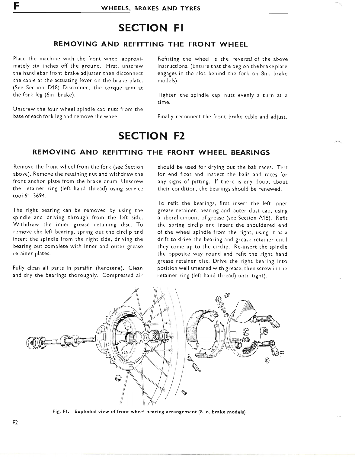
FWHEELS, BRAKES AND TYRES
SECTION FI
REMOVING AND REFITTING THE FRONT WHEEL
Place the machine with the front wheel approxi-
mately six inches off the ground. First, unscrew
the handlebar front brake adjuster then disconnecr
che cable at the actuating lever on the brake plate.
(See Section D18) Disconnect the torque arm at
the fork leg (6in. brake).
Unscrew the four wheel spindle cap nuts from the
base of each fork leg and remove the wheel.
Refitting the wheel is the reversal of the above
instructions. (Ensure that the peg on the brake plate
engages in the slot behind the fork on 8in. brake
models).
Tighten the spindle cap nuts evenly a turn at a
time.
Finally reconnect the front brake cable and adjust.
SECTION F2
REMOVING AND REFITTING
Remove the front wheel from the fork (see Section
above). Remove the retaining nut and withdraw the
front anchor plate from the brake drum. Unscrew
the retainer ring (left hand thread) using service
tool 61-3694.
The right bearing can be removed by using the
spindle and driving through from the left side.
Withdraw the inner grease retaining disc. To
remove the left bearing, spring out the circlip and
insert the spindle from the right side, driving the
bearing out complete with inner and outer grease
retainer plates.
Fully clean all parts in paraffin (kerosene). Clean
and dry the bearings thoroughly. Compressed air
THE FRONT WHEEL BEARINGS
should be used for drying out the ball races. Test
for end float and inspect the balls and races for
any signs of pitting. lf there is any doubt about
their condition, the bearings should be renewed.
To refit the bearings, first insert the left inner
grease retainer, bearing and outer dust cap, using
a liberal amount of grease (see Section A18). Refit
the spring circlip and insert the shouldered end
of the wheel spindle from the right, using it as a
drift to drive the bearing and grease retainer unril
they come up to the circlip. Re-insert the spindle
the opposite way round and refit the right hand
grease retainer disc. Drive the right bearing into
position well smeared with grease, then screw in the
retainer ring (left hand thread) until tight).
F2
Fig. Fl. Exploded view of front wheel bearing arrangement (8 in. brake models)
www.bsaunitsingles.com
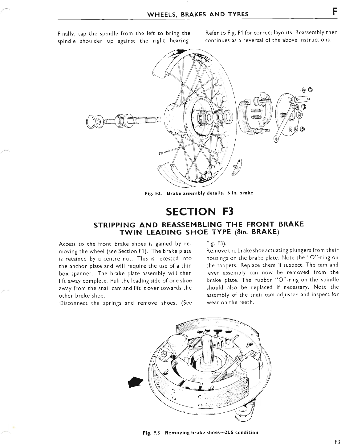
WHEELS, BRAKES AND TYRES
Finally, tap the spindle from
spindle shoulder up against
Access to the front brake shoes is gained by re-
moving the wheel (see Section Fl). The bral<e plate
is retained by a centre nut. This is recessed into
the anchor plate and will require the use of a thin
box spanner. The brake plate assembly will then
lift away complete. Pull the leading side of one shoe
away from the snail cam and lift it over towards the
other brake shoe.
Disconnect the springs and remove shoes. (See
Refer to Fig. F1 for correct layouts. Reassembly then
continues as a reversal of the above instructions.
Fig. F3).
Remove the brake shoe actuati ng pl u ngers from thei r
housings on the bral<e plate. Note the "O"-ring on
the tappets. Replace them if susPect. The cam and
lever assembly can now be removed from the
brake plate. The rubber "O"-ring on the spindle
should also be replaced if necessary. Note the
assembly of the snail cam adjuster and inspect for
wear on the teeth.
the left to bring the
the right bearing.
SECTION F3
STRIPPING AND REASSEMBLING THE FRONT BRAKE
TWIN LEADING SHOE TYPE (8in. BRAKE)
Fig.F2. Brake assembly details. 6 in' brake
Fig. F.3 Removing brake shoes-2LS condition
F3
www.bsaunitsingles.com
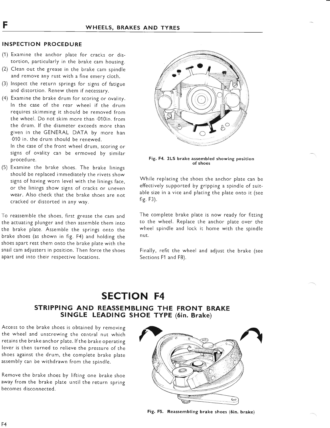
FWHEELS, BRAKES AND TYRES
INSPECTION PR.OCEDURE
(1) Examine the anchor plate for cracks or dis-
tortion, particularly in the brake cam housing.
(2) Clean out the grease in the brake cam spindle
and remove any rust with a fine emery cloth.
(3) lnspect the return springs for signs of fatigue
and distortion. Renew them if necessary.
(4) Examine the brake drum for scoring or ovality.
ln the case of the rear wheel if the drum
requires skimming it sh ould be removed from
the wheel. Do not skim more than .010in. from
the drum. lf the diameter exceeds more than
given in the GENERAL DATA by more han
.01 0 in. the d rum should be renewed.
ln the case of the front wheel drum, scoring or
signs of ovality can be ermoved by sir-nilar
proced u re.
(5) Examine the bral<e shoes. The bralce linings
should be replaced immediately the rivets show
signs of having worn level with the linings face,
or the linings show signs of cracks or uneven
wear. Also check that the bral<e shoes are not
cracked or distorted in any way.
To reassemble the shoes, first grease the cam and
the actuating plunger and then assemble them into
the brake plate. Assemble the springs onto the
brake shoes (as shown in fig. F4) and holding the
shoes apart rest them onto the brake plate with the
snail cam adjusters in position. Then force the shoes
apart and into their respective locations.
Fig. F4. 2LS brake XT:fr:'j. showing position
While replacing the shoes the anchor plate can be
effectively supported by gripping a spindle of suit-
able size in a vice and placing the plate onto it (see
fig. F3).
The complete brake plate is now ready for fitting
to the wheel. Replace the anchor plate over the
wheel spindle and lock it home with the spindle
n ut.
Finally, refit the wheel and adjust the brake (see
Sections Fl and F8).
SECTION F4
STRIPPING AND REASSEMBLING THE FRONT BRAKE
SINGLE LEADING SHOE TYPE (5in. Brake)
Access to the brake shoes is obtained by removing
the wheel and unscrewing the central nut which
retains the brake anchor plate. lfthe brake operating
lever is then turned to relieve the pressure of the
shoes against the drum, the complete brake plate
assembly can be withdrawn from the spindle.
Remove the brake shoes by lifting one brake shoe
away from the brake plate until the return spring
becomes disconnected.
F4
Fig. F5. Reassembling brake shoes (6in. brake)
www.bsaunitsingles.com
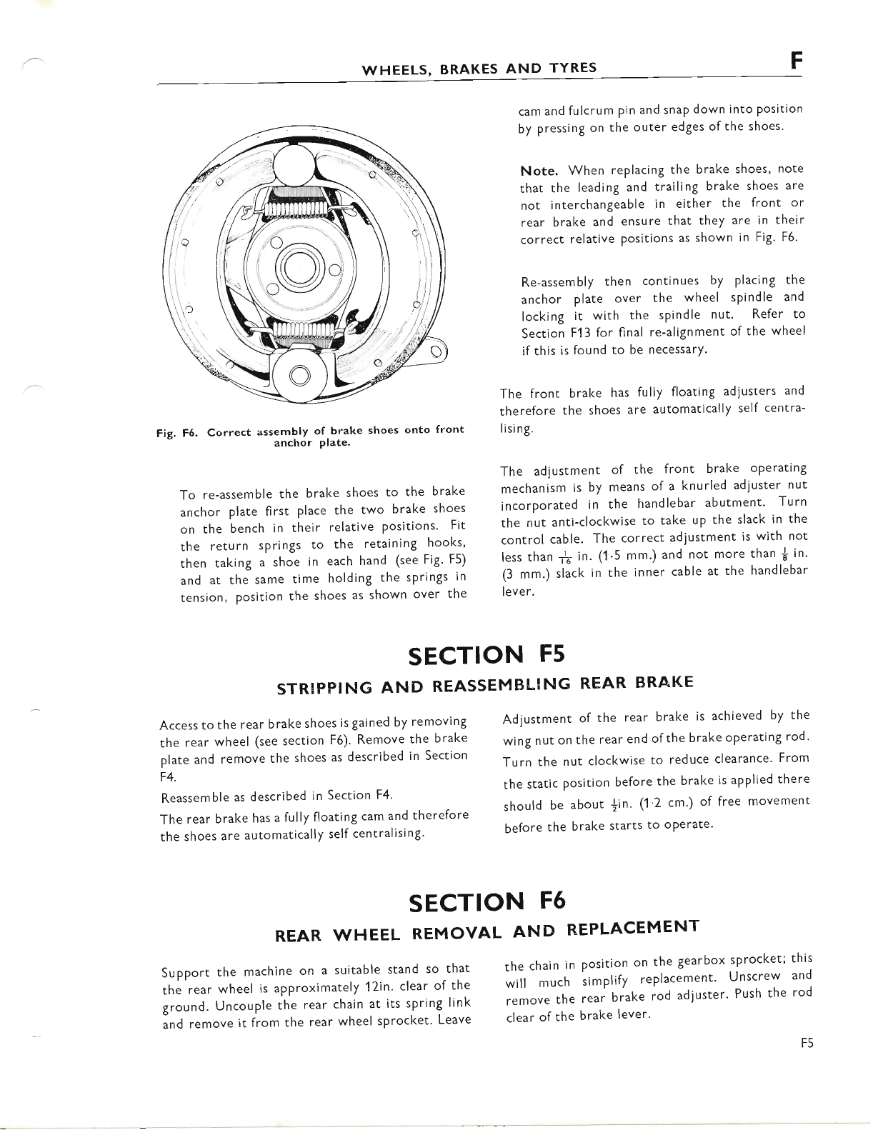
F
WHEELS, BRAKES AND TYRES
Fig. F6. Correct assembly of brake shoes onto front
anchor Plate.
To re-assemble the brake shoes to the brake
anchor plat,e first place the two bralce shoes
on the bench in their relative positions" Fit
the return springs to the retaining hooks,
then taking a shoe in each hand (see Fig' F5)
and at the same time holding the springs in
tension, position the shoes as shown over the
cam and fulcrum pin and snap down into Position
by pressing on the outer edges ofthe shoes.
Note. When replacing the brake shoes, note
that the leading and trailing brake shoes are
not interchangeable in either the front or
rear brake and ensure that they are in their
correct relative Positions as shown in Fig. F6.
Re-assembly then continues by placing the
anchor plate over the wheel spindle and
locking it with the spindle nut. Refer to
Section F1 3 for final re-alignment of the wheel
ifthis is found to be necessarY'
The front brake has fully floating adlusters and
therefore the shoes are automatically self centra-
lising.
The adjustment of the front brake operating
mechanism is by means of a knurled adjuster nut
incorporated in the handlebar abutment' Turn
the nut anti-clockwise to take up the slack in the
control cable. The correct adjustment is with not
less than ft in. (1 '5 mm.) and not more than * in'
(3 mm.) slack in the inner cable at the handlebar
lever.
Adjustment of the rear brake is achieved by the
wing nut on the rear end ofthe brake operating rod'
Turn the nut clockwise to reduce clearance' From
the static Position before the brake is applied there
should be about |in. (1 '2 cm') of free movement
before the brake starts to oPerate'
SECTION F5
STRIPPING AND REASSEMBLING REAR BRAKE
Access to the rear brake shoes is gained by removing
the rear wheel (see section F6). Remove the brake
plate and remove the shoes as described in Section
F4.
Reassemble as described in Section F4'
The rear brake has a fully floating cam and therefore
the shoes are automatically self centralising'
SECTION F6
REAR WHEEL REMOVAL AND REPLACEMENT
Support the machine on a suitable stand so that
the rear wheel is approximately 17in' clear of the
ground. Uncouple the rear chain at its sPring link
"nd remove it from the rear wheel sprocket' Leave
the chain in position on the gearboxsprocket; this
*'if much simplify replacement' Unscrew and
;;;."; the rear biake iod ad;uster' Push the rod
clear of the brake lever'
F5
www.bsaunitsingles.com
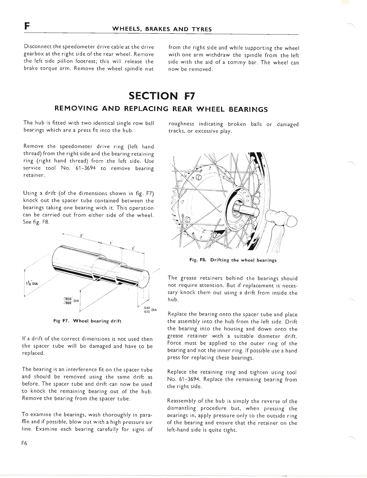
FWHEELS, BRAKES AND TYRES
Disconnect the speedometer drive cable at the drive
gearbox at the right side of the rear wheel. Remove
the left side pillion footrest; this will release the
brake torgue arm. Remove the wheel spindle nut
from the right side and while supporting the wheel
with one arm withdraw the spindle from the left
side with the aid of a tommy bar. The wheel can
now be removed.
SECTION F7
REMOVING AND REPLACING REAR WHEEL BEARINGS
The hub is fitted with two identical single row ball
bearings which are a press fit into the hub.
Remove the speedometer drive ring (left hand
thread) from the right side and the bearing retaining
ring (right hand thread) from the left side. Use
service tool No. 61-3694 to remove bearing
retai n e r.
Using a drift (of the dimensions shown in fig. F7)
knock out the spacer tube contained between the
bearings taking one bearing with it. This operation
can be carried out from either side of the wheel.
See fig. F8.
1--.- 2
('
9
Fig F7. Wheel bearing drift
lf a drift of the correct dimensions is not used then
the spacer tube will be damaged and have to be
replaced.
The bearing is an interference fit on the spacer tube
and should be removed using the same drift as
before. The spacer tube and drift can now be used
to knock the remaining bearing out of the hub.
Remove the bearing from the spacer tube.
To examine the bearings, wash thoroughly in para-
ffin and if possible, blow out with a high pressure air
line. Examine each bearing carefully for signs of
F6
roughness indicating broken balls or damaged
tracks, or excessive play.
Fig. F8. Drifting the wheel bearings
The grease retainers behind the bearings should
not require attention. But if replacement is neces-
sary knocl< them out using a drift from inside the
hub.
Replace the bearing onto the spacer tube and place
the assembly into the hub from the left side. Drift
the bearing into the housing and down onto the
grease retainer with a suitable diameter drift.
Force must be applied to the outer ring of the
bearing and not the inner ring. lf possible use a hand
press for replacing these bearings.
Replace the retaining ring and tighten using tool
No. 61-3694. Replace the remaining bearing from
the right side.
Reassembly of the hub is simply the reverse of the
dismantling procedure but, when pressing the
oearings in, apply pressure only to the outside ring
ofthe bearing and ensure that the retainer on the
left-hand side is quite tight.
oi(J -'
lr.l
| -uoo
lEiS..^>."
www.bsaunitsingles.com
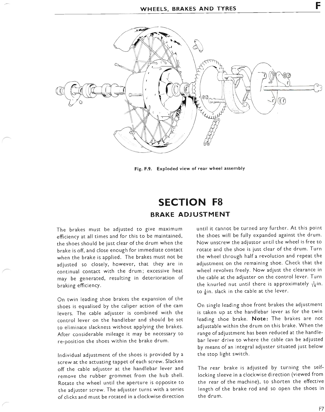
WHEELS, BRAKES AND TYRES F
Fig. F.9. Exploded view of rear wheel assembly
SECTION F8
BRAKE ADJ USTMENT
The brakes must be adjusted to give maximum
efficiency at all times and for this to be maintained,
the shoes should be iust clear ofthe drum when the
brake is off, and close enough for immediate contact
when the brake is applied. The brakes must not be
adjusted so closely, however, that they are in
continual contact with the drum; excessive heat
may be generated, resulting in deterioration of
braking efticiency.
On twin leadlng shoe brakes the expansion of the
shoes is equalised by the caliper action of the cam
levers. The cable adjuster is combined with the
control lever on the handlebar and should be set
to eliminate slackness without applying the brakes.
After considerable mileage it may be necessary to
re-position the shoes within the brake drum.
lndividual adjustment of the shoes is provided by a
screw at the actuating taPPet of each screw. Slacken
off the cable adjuster at the handlebar lever and
remove the rubber Srommet from the hub shell.
Rotate the wheel until the aPerture is opposite to
the adjuster screw. The adluster turns with a series
of clicks and must be rotated in a clocl<wise direction
until it cannot be turned any further. At this point
the shoes will be fully expanded against the drum.
Now unscrew the adjustor until the wheel is free to
rotate and the shoe is just clear of the drum. Turn
the wheel through half a revolution and rePeat the
adjustment on the remaining shoe. Check that the
wheel revolves freely. Now adiust the clearance in
the cable at the adjuster on the control lever. Turn
the knurled nut until there is aPProximately Sin.
to {in. slack in the cable at the lever.
On sJngle leading shoe front brakes the adjustment
is taken up at the handlebar lever as for the twin
leading shoe brake. Note: The brakes are not
adjustable within the drum on this brake. When the
range ofadiustment has been reduced at the handle-
bar lever drive to where the cable can be adjusted
by means of an integral ad.iuster situated ,iust below
the stop light switch.
The rear bralce is adjusted by turning the self-
locking sleeve in a clockwise direction (viewed from
the rear of the machine), to shorten the effective
length of the brake rod and so oPen the shoes in
the drum.
17
www.bsaunitsingles.com
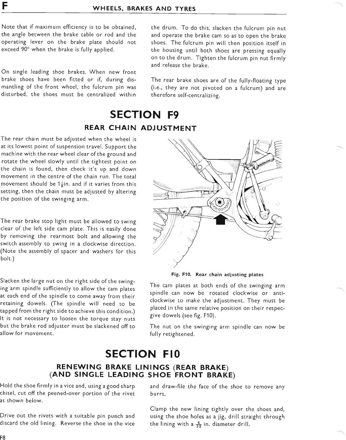
WHEELS, BRAKES AND TYRES
Note that if maximum efficiency is to be obtained,
the angle between the brake cable or rod and the
operating lever on the brake plate should not
exceed 90" when the brake is fully applied.
On single leading shoe brakes. When new front
brake shoes have been fitted or if, during dis-
mantling of the front wheel, the fulcrum pin was
disturbed, the shoes must be centralized within
the drum. To do this, slacl<en the fulcrum pin nut
and operate the brake cam so as to open the brake
shoes. The fulcrum pin will then position itself in
the housing until both shoes are pressing equally
on to the drum. Tighten the fulcrum pin nut firmly
and release the brake.
The rear brake shoes are of the fully-floating type
(i.e., they are not pivoted on a fulcrum) and are
therefore self-central izi ng.
SECTION F9
REAR CHAIh{
The rear chain must be adjusted when the wheel is
at its lowest point of suspension travel. Support the
machine with the rear wheel clear of the ground and
rotate the wheel slowly until the tightest point on
the chain is found, then check it's up and down
movement in the centre ofthe chain run. The total
movement should be 1$in. and if it varies from this
setting, then the chain must be adiusted by altering
the position of the swinging arm.
The rear brake stop light must be allowed to swing
clear of the left side cam plate. This is easily done
by removing the rearmost bolt and allowing the
switch assembly to swing in a clockwise direction.
(Note the assembly of spacer and washers for this
bolt.)
Slacken the large nut on the right side of the swing-
ing arm spindle sufficiently to allow the cam plates
at each end of the spindle to come away from their
retaining dowels. (The spindle will need to be
tapped from the right side to achieve this condition.)
It is not necessary to loosen the torque stay nuts
but the brake rod adjuster must be slackened offto
allow for movement.
ADJ USTMENT
Fig. Fl0. Rear chain adiusting plates
The cam plates at both ends of the swinging arm
spindle can now be rotated clockwise or anti-
clockwise to make the adjustment. They must be
placed in the same relative position on their respec-
give dowels (see fig. F10).
The nut on the swinging arm spindle can now be
fully retightened.
SECTION F IO
RENEWTNG BRAKE LtNtNGS (REAR BRAKE)
(AND STNGLE LEADTNG SHOE FRONT BRAKE)
Hold the shoe firmly in a vice and, using a good sharp
chisel, cut off the peened-over portion of the rivet
as shown below.
Drive out the rivets with a suitable pin punch and
discard the old lining. Reverse the shoe in the vice
F8
and draw-file the face of the shoe to remove any
bu rrs.
Clamp the new lining tightly over the shoes and,
using the shoe holes as a jig, drill straight through
the lining with a $ in. diameter drill.
www.bsaunitsingles.com
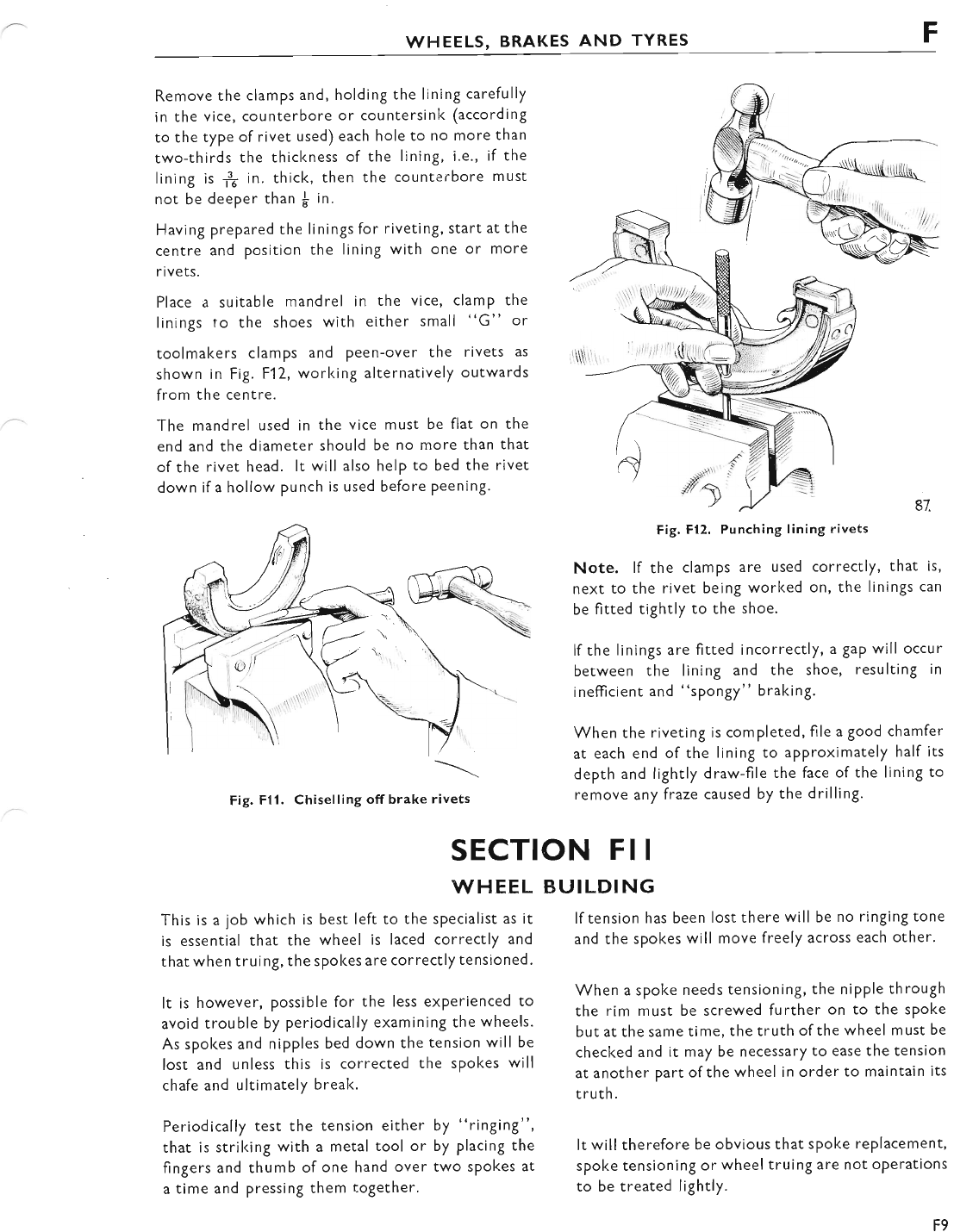
WHEELS, BRAKES AND TYRES F
Remove the clamps and, holding the lining carefully
in the vice, counterbore or countersink (according
to the type of rivet used) each hole to no more than
two-thirds the thickness of the lining, i.e., if the
lining is 1f in. thick, then the counterbore must
not be deeper than I in.
Having prepared the linings for riveting, start at the
centre and position the iining with one or more
rivets.
Place a suitable mandrel in the vice, clamp the
linings ro the shoes with either small "G" or
toolmakers clamps and peen-over the rivets as
shown in Fig. F12, working alternatively outwards
from the centre.
The mandrel used in the vice musc be flat on the
end and the diameter should be no more than that
of the rivet head. lt will also help to bed the rivet
down if a hollow punch is used before peening.
Fig. Fll. Chiselling off brake rivets
Fig, F12. Punching lining rivets
Note. lf the clamps are used correctly, that is,
next to the rivet being worked on, the Iinings can
be fitted tightly to the shoe.
lf the linings are fitted incorrectly, a gap will occur
between the lining and the shoe, resulting in
inefficient and "spongy" braking.
When the riveting is completed, file a good chamfer
at each end of the lining to aPProximately half its
depth and lightly draw-file the face of the Iining to
remove any fraze caused by the drilling.
K
BUILDI NG
lf tension has been lost there will be no ringing tone
and the spokes will move freely across each other'
When a spoke needs tensioning, the nipple through
the rim must be screwed further on to the sPoke
but at the same time, the truth of the wheel must be
checked and it may be necessary to ease the tension
at another part of the wheel in order to maintain its
t ruth.
It will therefore be obvious that spoke replacement,
spoke tensioning or wheel truing are not oPerations
to be treated lightly.
SECTION F I I
\MHEEL
This is a job which is best left to the sPecialist as it
is essential that the wheel is laced correctly and
that when truing, the spokes are correctly tensioned'
It is however, possible for the less experienced to
avoid trouble by periodically examining the wheels.
As spokes and nipples bed down the tension will be
lost and unless this is corrected the spokes will
chafe and ultimately break.
Periodically test the tension either by "ringing",
that is striking with a metal tool or by placing the
fingers and thumb of one hand over two spokes at
a time and pressing them together.
F9
www.bsaunitsingles.com
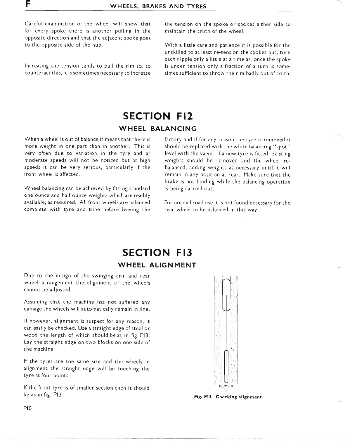
FWHEELS, BRAKES AND TYRES
Careful examination of the wheel will show that
for every spoke there is another pulling in the
opposite direction and that the adjacent spoke goes
to the opposite side of the hub.
Increasing the tension tends to pull the rim so, to
counteract this, it is sometimes necessary to increase
the tension on the spoke or spokes either side to
maintain the truth of the wheel.
With a little care and patience it is possible for the
unskilled to at least re-tension the spokes but, turn
each nipple only a little at a time as, once the spoke
is under tension only a fraction of a turn is some-
times sufticient to throw the rim badly out of truth.
SECTION FIz
\^/HEEL BALANCING
When a wheel is out of balance it means that there is
more weight in one part than in another. This is
very often due to variation in the tyre and at
moderate speeds will not be noticed but at high
speeds it can be very serious, particularly if the
front wheel is affected.
Wheel balancing can be achieved by fitting standard
one ounce and half ounce weights which are readily
available, as required. Allfront wheels are balanced
complete with tyre and tube before leaving the
factory and if for any reason the tyre is removed it
should be replaced with the white balancing "spot"
level with the valve. lf a new tyre is fitred, existing
weights should be removed and the wheel re-
balanced, adding weights as necessary until it will
remain in any position at rear. Make sure that the
brake is not binding while the balancing operation
is being carried out.
For normal road use it is not found necessary for the
rear wheel to be balanced in this way.
SECTION F 13
WHEEL ALIGN MENT
Due to the design of the swinging arm and rear
wheel arrangement the alignment of the wheels
cannot be adjusted.
Assuming that the machine has not suffered any
damage the wheels will automatically remain in line.
lf however, alignment is suspect for any reason, it
can easily be checked. Use a straight edge ofsteel or
wood the length of which should be as in fig. F1 3.
Lay the straight edge on two blocks on one side of
the machine.
lf the tyres are the same size and
alignment the straight edge will be
tyre at four points.
lf the front tyre is of smaller section
be as in fig. F13.
F10
the wheels in
touching the
then it should
www.bsaunitsingles.com
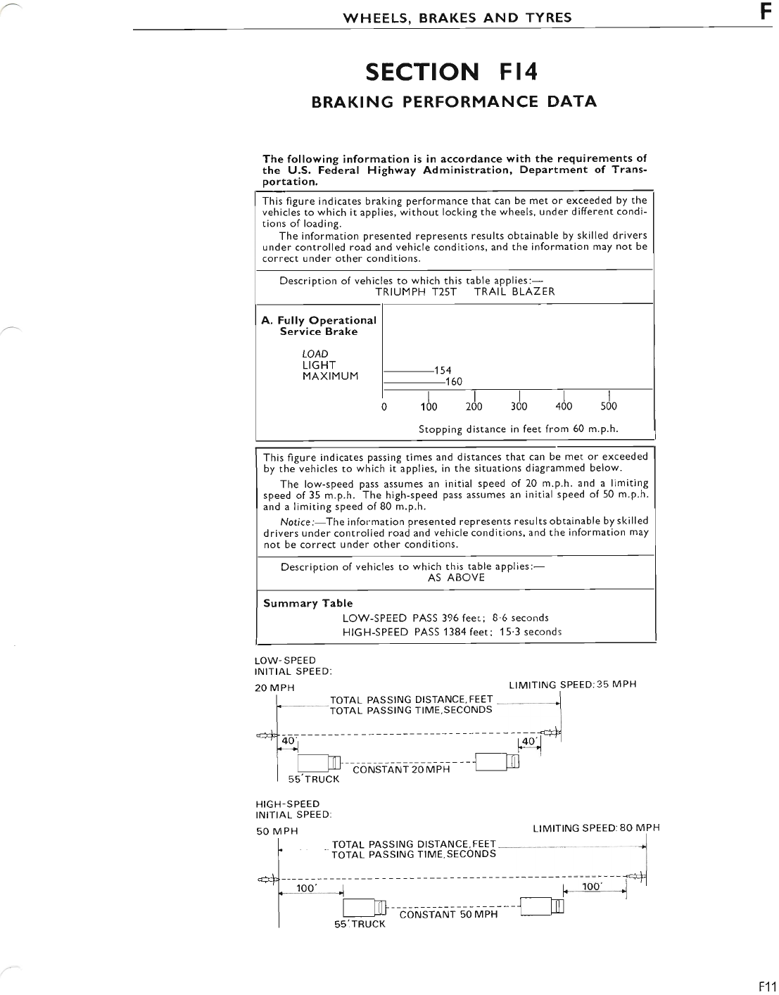
WHEE!-S, BRAKES AND TYRES F
SECTION FI4
BRAKING PERFORMANCE DATA
The following information is in accordance with the requirements of
the U.S. Federal Highway Administration, DePartment of Trans-
portation.
This figure indicates passing times and distances that can be met or exceeded
by the vehicles to which it applies, in the situations diagrammed below.
The low-speed pass assumes an initial speed of 20 m.p.h. and a limiting
speed of 35 m.p.h. The high-speed pass assumes an initial speed of 50 m.p.h.
and a limiting speed of 80 m.p.h.
Notice:-The information presented represents results obtainable by skilled
drivers under controlled road and vehicle conditions, and the information may
not be correct under other conditions.
LOW-SPEED
INITIAL SPEED:
20 MPH LIMITING SPEED:35 MPH
I rorAl PAsstNc DIsTANCE,FEET j
f - TorAL PASSING TlME,sEcoNDS I
tl
. I -, r I
--'7] 4oi I 4o'l 'I
_'--------.-l*l
r [---Jm- -------.] l-a
I I LU coNSTANT 20 MPH
I ss'rRuct<
HIGH-SPEED
INITIAL SPEED
50 MPH LIMITING SPEED:80 MPH
TOTAL PASSING DISTANCE, FEET
TOTAL PASSING TIME.SECONDS
re
55lTRUCK
This figure indicates braking performance that can be met or exceeded by the
vehicles to which it applies, without locking the wheels, under different condi-
tions of loading.
The information presented represents results obtainable by skilled drivers
under controlled road and vehicle conditions, and the information may not be
correct under other conditions.
Description of vehicles to which this table applies:-
TRIUMPH T25T TRAIL BLAZER
A. Fully Operational
Service Brake
LOAD
LIGHT 154
MAXIMUM _1 60
rl,o zJo sJo alo
Stopping distance in feet from 50 m.p.h.
Description of vehicles to whkh .l;Ui?" applies:-
Summary Table
LOW-SPEED PASS 396 feet; 8'6 seconds
HIGH-SPEED PASS 1384 feet: 15'3 seconds
CONSTANT 50 MPH
F11
www.bsaunitsingles.com
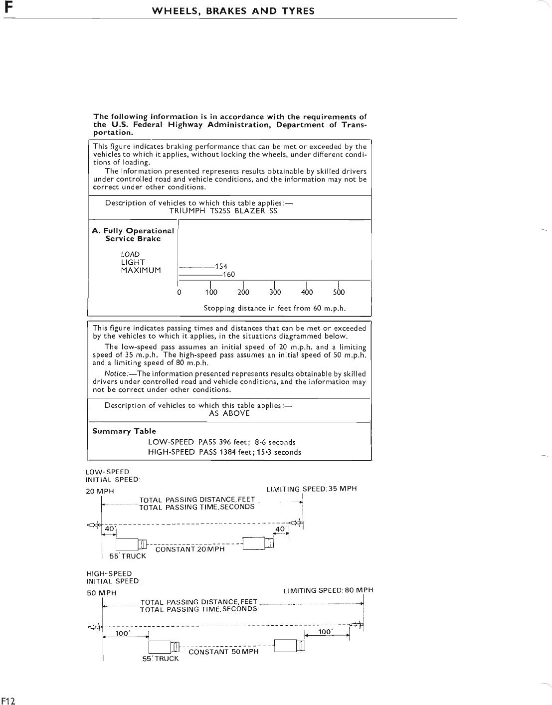
FWHEELS, BRAKES AND TYRES
The following information is in accordance with the requirements of
the U.S. Federal Highway Administration, Department of Trans-
portation.
This figure indicates braking performance that can be met or exceeded by the
vehicles to which it applies, without locking the wheels, under different condi-
tions of loading.
The information presented represents results obtainable by skilled drivers
under controlled road and vehicle conditions, and the information may not be
correct under other conditions.
Description of vehicles to which this table applies:-
TRIUMPH TS25S BLAZER SS
A. Fully Operational
Service Brake
LOAD
LIGHT
--154
MAXIMUM _160
200 300 400
Stopping distance in feet from 60 m.p.h.
This figure indicates passing times and distances that can be met or exceeded
by the vehicles to which it applies, in the situations diagrammed below.
The low-speed pass assumes an initial speed of 20 m.p.h. and a limiting
speed of 35 m.p.h. The high-speed pass assumes an initial speed of 50 m.p.h.
and a limiting speed of 80 m.p.h.
Notice:-The information presented represents results obtainable by skilled
drivers under controlled road and vehicle conditions, and the information may
not be correct under other conditions.
Description of vehicles to which this table applies:-
AS ABOVE
Summary Table
LOW-SPEED PASS 396 feet; 8.6 seconds
HIGH-SPEED PASS 1384 feet;15.3 seconds
LOW-SPEED
INITIAL SPEED:
20 MPH LIMITING SPEED:3s MPH
I TOTAL PASSING DISTANCE,FEET ,
I rornl PASSING TlME,sEcoNDS I
I
*"^t-__----- - -----dl
*-n4oi t4o'l'j
k--t F- - i
I l--tn -----J-l-a
I I Lil CONSTANT 20 MPH I f!
lss'rRrrcK
HIGH-SPEED
INITIAL SPEED:
50 MPH LIMITING SPEED:80 MPH
TOTAL PASSING DISTANCE, FEET
TOTAL PASSING TIME.SECONDS
m
55:TRUCK
F12
CONSTANT 50 MPH
www.bsaunitsingles.com
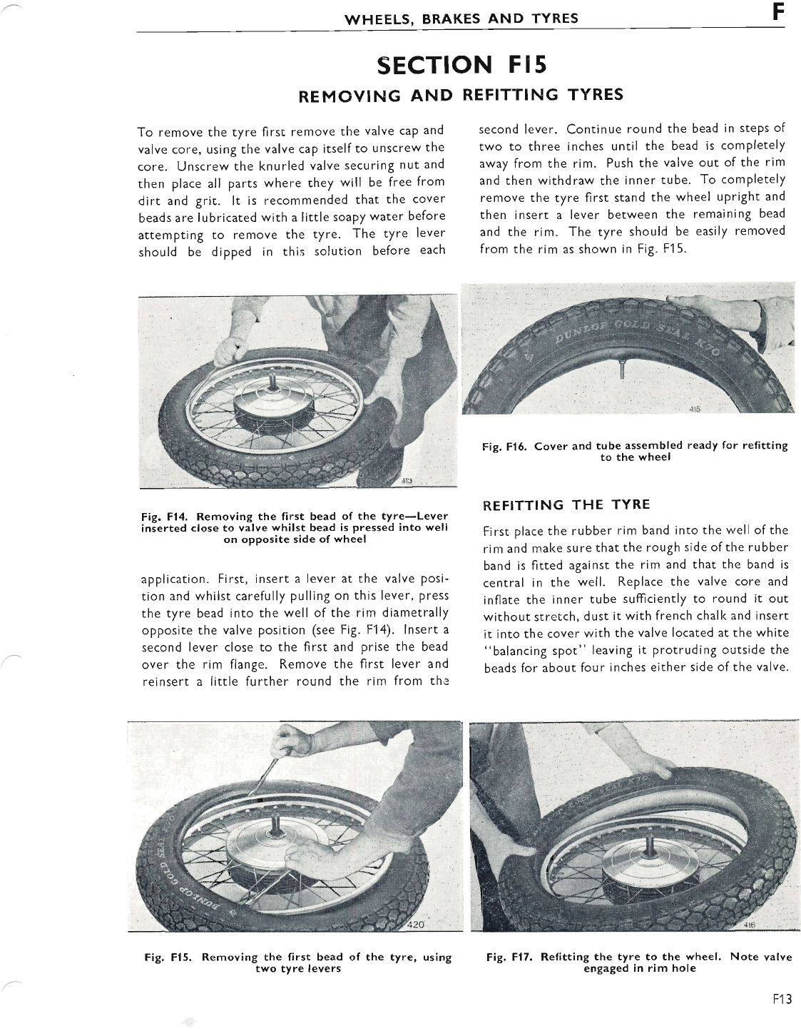
WHEELS, BRAKES AND TYRES F
SECTION F 15
REMOVING AND
To remove the tyre first remove the valve cap and
valve core, using the valve cap itself to unscrew the
core. Unscrew the knurled valve securing nut and
then place all parts where they will be free from
dirt and grit. lt is recommended that the cover
beads are lubricated with a little soaPy water before
attempting to remove the tyre. The tyre lever
should be dipped in this solution before each
REFITTING TYRES
second lever. Continue round the bead in steps of
two to three inches until the bead is completely
away from the rim. Push the valve out of the rim
and then withdraw the inner tube. To completely
remove the tyre first stand the wheel upright and
then insert a lever between the remaining bead
and the rim. The tyre should be easily removed
from the rim as shown in Fig. Fl 5.
Fig. F14. Removing the first bead of the tyre-Lever
inserted close to valve whilst bead is pressed into well
on opposite side of wheel
applicaticn. First, insert a lever at the valve Posi-
tion and whilst carefully pulling on this lever, press
the tyre bead into the well of the rim diametrally
opposite the valve position (see Fig. F14). lnsert a
second lever close to the first and prise the bead
over the rim flange. Remove the first lever and
reinsert a little further round the rim from the
Fig. Fl5, Removing the first bead
two tyre levers
Fig. Fl6. Cover and tube assembled ready for refitting
- to the wheel
REFITTING THE TYRE
First place the rubber rim band into the well of the
rim and mal<e sure that the rough side of the rubber
band is fitted against the rim and that the band is
central in the well. Replace the valve core and
inflate the inner tube sufficiently to round it out
without stretch, dust it with french chall< and insert
it into the cover with the valve located at the white
"balancing spot" leaving it protruding outside the
beads for about four inches either side of the valve.
Fig. F17. Refitting the tyre to the wheel, Note valve
engaged in rim hole
of the tyre, using
F13
www.bsaunitsingles.com
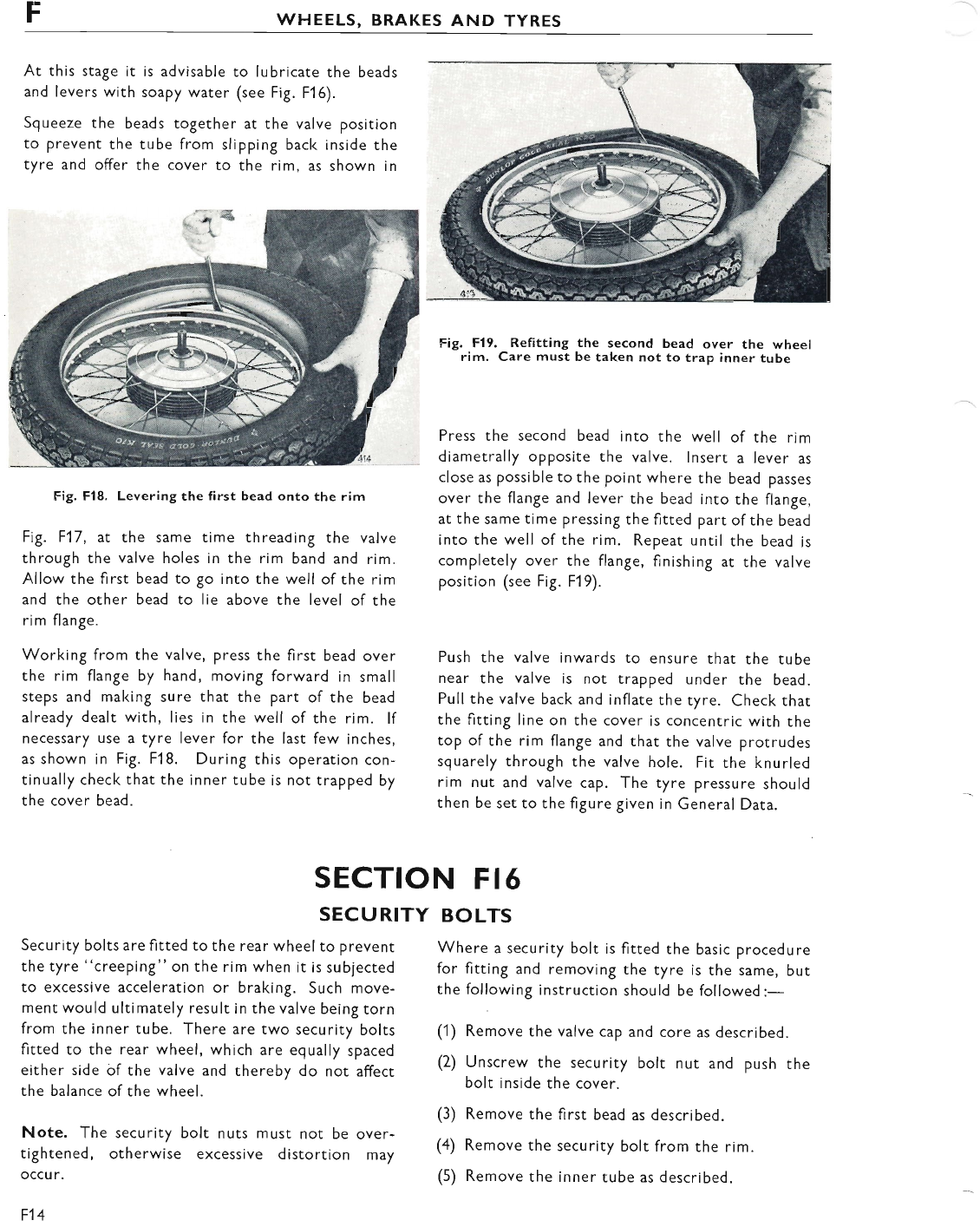
FWHEELS, BRAKES AND TYRES
At this stage it is advisable to lubricate the beads
and levers with soapy water (see Fig. F1 6).
Squeeze the beads together at the valve position
to prevent the tube from slipping bacl< inside the
tyre and offer the cover to the rim, as shown in
Fig. Fl8. Levering the first bead onto the rim
Fig. F17, at the same time threading the valve
through the valve holes in the rim band and rim.
Allow the first bead to go into the well of the rim
and the other bead to lie above the level of the
rim flange.
Working from the valve, press the first bead over
the rim flange by hand, moving forward in small
steps and making sure that the part of the bead
already dealt with, Iies in the well of the rim. lf
necessary use a tyre lever for the last few inches,
as shown in Fig. F18. During this operation con-
tinually check that the inner tube is not trapped by
the cover bead.
Fig. F19. Refitting the second bead over the wheel
rim. Care must be taken not to trap inner tube
Press the second bead into the well of the rim
diametrally opposite the valve. lnsert a lever as
close as possible to the point where the bead passes
over the flange and lever the bead into the flange,
at the same time pressing the fitted part ofthe bead
into the well of the rim. Repeat until the bead is
completely over the flange, finishing ar the valve
position (see Fig. F19).
Push the valve inwards to ensure that the tube
near the valve is not trapped under the bead.
Pull the valve back and inflate the ryre. Check that
the fitting line on the cover is concentric wirh the
top of the rim flange and that the valve prorrudes
squarely through the valve hole. Fit the knurled
rlm nut and valve cap. The tyre pressure should
then be set to the figure given in General Data.
SECTION FI6
SECURITY
Security bolts are fitted to the rear wheel to prevent
the tyre "creeping" on the rim when it is subjected
to excessive acceleration or braking. Such move-
ment would ultimately result in the valve being torn
from the inner tube. There are two security bolts
fitted to the rear wheel, which are equally spaced
either side of the valve and thereby do not affect
the balance of the wheel.
Note. The security bolt nuts must not be over-
tightened, otherwise excessive distortion may
occu r.
tl4
BOLTS
Where a security bolt is fitted the basic procedure
for fitting and removing the tyre is the same, but
the following instruction should be followed:-
(1) Remove the valve cap and core as described.
(2) Unscrew the security bolt nut and push the
bolt inside the cover.
(3) Remove the first bead as described.
(4) Remove the security bolt from rhe rim.
(5) Remove the inner rube as described.
www.bsaunitsingles.com
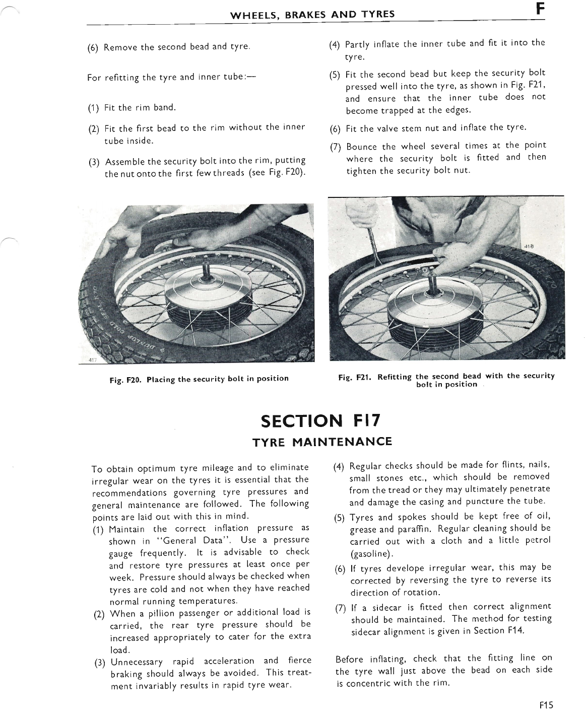
F
wHEELS, BRAKES AND TYRES
(6) Remove the second bead and tYre.
For refitting the tyre and inner tube:-
(1) Fit the rim band.
(2) Fit the first bead to the rim without the inner
tube inside.
(3) Assemble the security bolt into the rim, Putting
the nutontothe first fewthreads (see Fig. F20).
Fig. F20. Placing the security bolt in position
(4) Partly inflate the inner tube and fit it into the
ty re.
(5) Fit the second bead but keep the security bolt
pressed well into the tyre, as shown in Fig. F21 '
and ensure that the inner tube does not
become trapped at the edges'
(6) Fit the valve stem nut and inflate the tyre.
(7) Bounce the wheel several times at the Point
where the secu rity bolt is fitted and then
tighten the security bolt nut.
Fie. F2l. Refitting the second bead with the security
bolt in position
(4) Regular checks should be made for flints, nails,
small stones etc., which should be removed
from the tread or they may ultimately Penetrate
and damage the casing and Puncture the tube.
(5) Tyres and spokes should be kept free of oil,
grease and paraffin. Regular cleaning should be
carried out with a cloth and a little petrol
(gasoline).
(6) lf tyres develope irregular wear, this may be
corrected by reversing the tyre to reverse its
direction of rotation.
(7) lf a sidecar is fitted then correct alignment
should be maintained. The method for testinS
sidecar alignment is given in Section F14.
Before inflating, check that the fitting line on
the tyre wall just above the bead on each side
is concentric with the rim.
SECTION FI7
TYRE MAINTENANCE
To obtain optimum tyre mileage and to eliminate
irregular wear on the tyres it is essential that the
recommendations governing tyre pressures and
general maintenance are followed. The following
points are laid out with this in mind'
(1) Maintain the correct inflation Pressure as
shown in "General Data". Use a Pressure
gauge frequently. lt is advisable to check
and restore tyre Pressures at least once Per
week. Pressure should always be checl<ed when
tyres are cold and not when they have reached
normal running temPeratures.
(2) When a pillion Passenger or additional load is
carried, the rear tyre Pressure should be
increased appropriately to cater for the extra
load.
(3) Unnecessary rapid acceleration and fierce
braking should always be avoided. This treat-
ment invariably results in rapid tyre wear.
F15
www.bsaunitsingles.com
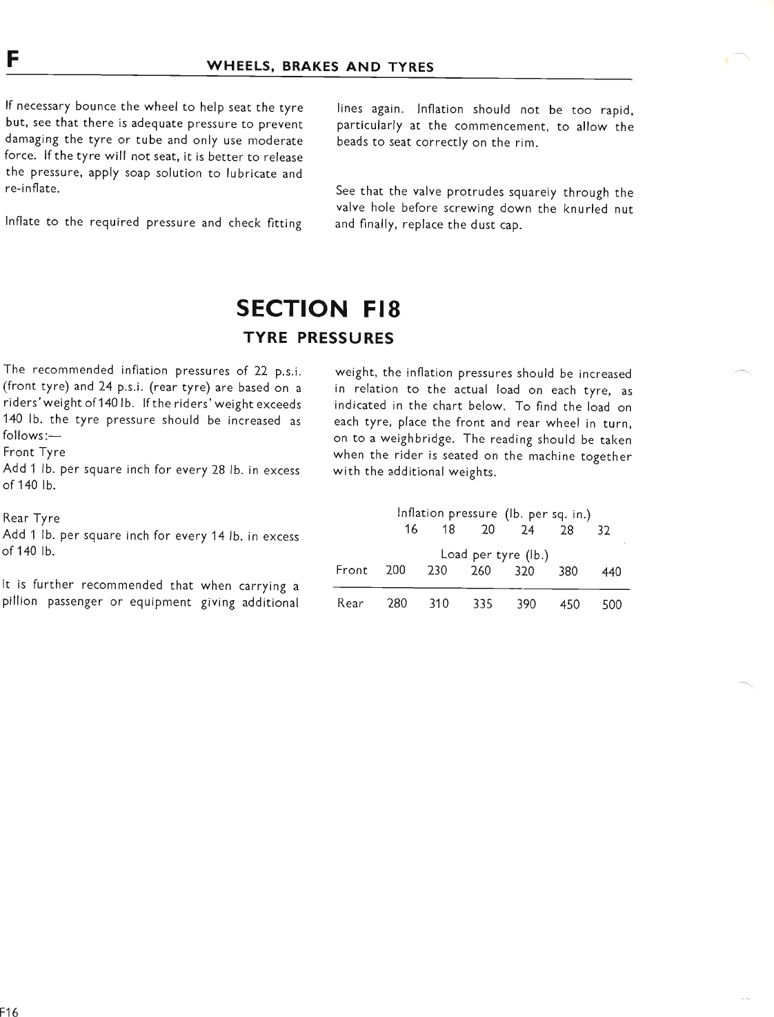
FWHEELS, BRAKES AND TYRES
lf necessary bounce the wheel to help seat the tyre
but, see that there is adeguate pressure to prevent
damaging the tyre or tube and only use moderate
force. lf the tyre will not seat, it is better to release
the pressure, apply soap solution to lubricate and
re-i nflate.
lnflate to the required pressure and check fitting
lines again. lnflation should not be too rapid,
particularly at the commencement, to allow the
beads to seat correctly on the rim.
See that the valve protrudes squarely through the
valve hole before screwing down the knurled nut
and finally, replace the dust cap.
Front
lnflation pressure (lb. per sq. in.)
16 18 20 24 28 32
Load per tyre (lb.)
200 230 260 320 380 440
Rear 280 310 335 390 450 500
SECTION FI8
TYRE PRESSURES
The recommended inflation pressures of 22 p.s.i.
(front tyre) and 24 p.s.i. (rear tyre) are based on a
riders'weightof 1401b. lf the riders'weight exceeds
140 lb. the tyre pressure should be increased as
follows:-
Front Tyre
Add 1 lb. per square inch for every 28 lb. in excess
of140 lb.
Rear Tyre
Add 1 lb. per sguare inch for every 14|b. in excess
of140 lb.
It is further recommended that when carrying a
pillion passenger or eguipmenr giving additional
weight, the inflation pressures should be increased
in relation to the actual load on each tyre, as
indicated in the chart below. To find the load on
each tyre, place the front and rear wheel in turn,
on to a weighbridge. The reading should be taken
when the rider is seated on the machine together
with the additional weights.
F16
www.bsaunitsingles.com
SECTION G
ELECTRICAL
INDEX
SECTION
DESCRIPTION
G1 ALTERNATOR
G2 BATTERY INSPECTION AND MAINTENANCE
G3 COIL IGNITION SYSTEM
G4 SPARKING PLUG
G5 CHARGING SYSTEM
G6 ZENER DIODE CHARGE CONTROL
G7 ELECTRIC HORN
G8 TAIL AND STOP LAMP UNIT
G9 ALTERNATOR_ADDITIONAL INFORMATION
G1O DIRECTION INDICATOR LAMPS
G11 IGNITION SWITCH
G1Z OTHER LIGHT UNITS
G13 HEADLAMP
G1
www.bsaunitsingles.com
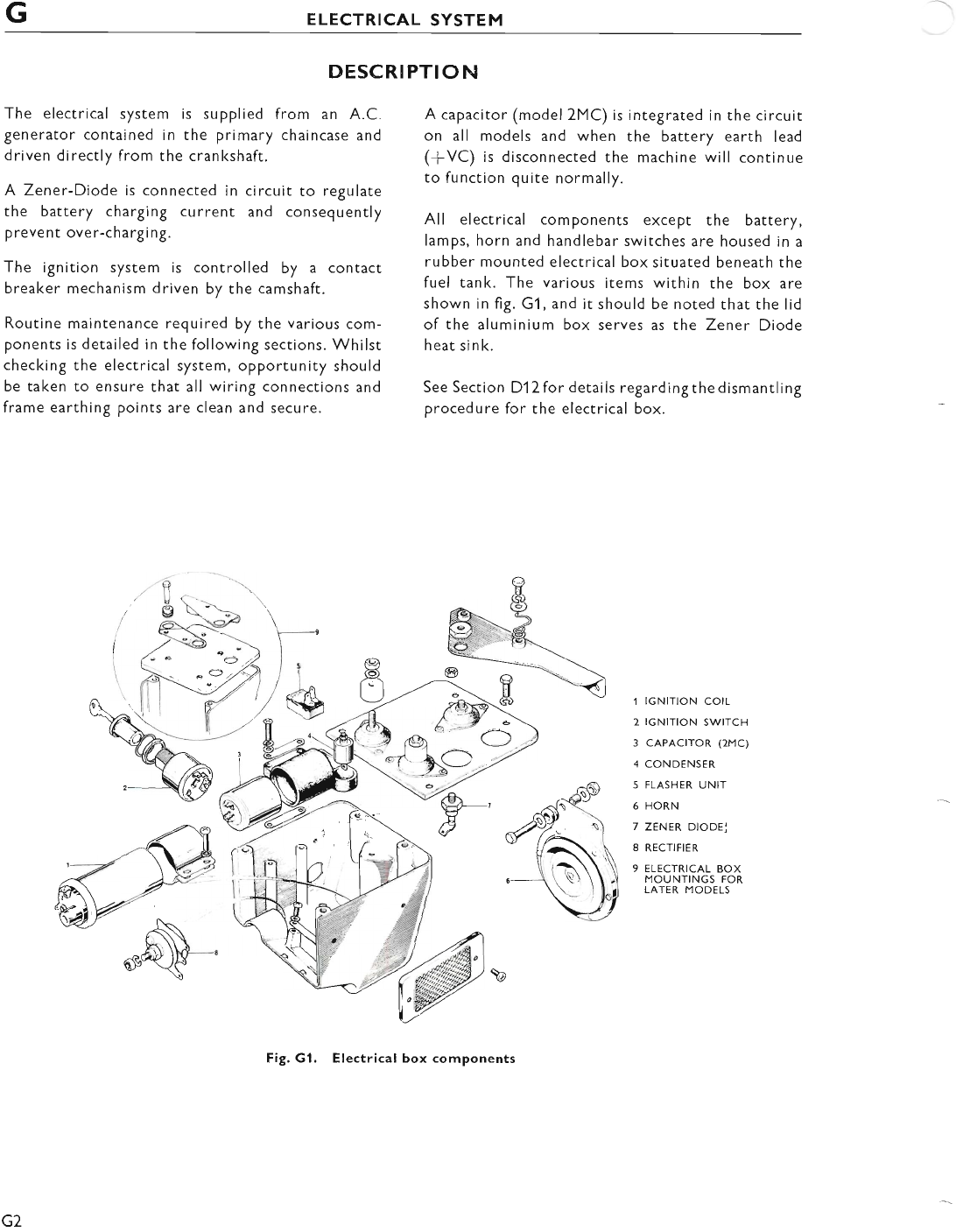
GELECTRICAL SYSTEM
The electrical system is supplied from an A.C.
generator contained in the primary chaincase and
driven directly from the crankshaft.
A Zener-Diode is connected in circuit to regulate
the battery charging current and consequently
prevent over-chargi ng.
The ignition system is controlled by a contact
breaker mechanism driven by the camshaft.
Routine maintenance required by the various com-
ponents is detailed in the following sections. Whilst
checking the electrical system, opportunity should
be taken to ensure that all wiring connections and
frame earthing points are clean and secure.
DESCRIPTION
A capacitor (model 2MC) is integrated in the circuit
on all models and when the battery earth lead
(+VC) is disconnected the machine will continue
to function quite normally.
All electrical components except the battery,
lamps, horn and handlebar switches are housed in a
rubber mounted electrical box situated beneath the
fuel tank. The various items within the box are
shown in fig. G1, and it should be noted that the lid
of the aluminium box serves as the Zener Diode
heat si n k.
See Section D12 for detai ls regard i ng the d ismantl i ng
procedure for the electrical box.
1 IGNITION COtL
2 IGNITION SWITCH
3 CAPACTTOR (2MC)
4 CONDENSER
5 FLASHER UNIT
6 HORN
7 ZENER DIODE,J
8 RECTIFIER
9 ELECTRICAL BOX
MOUNTINGS FOR
LATER MODELS
G2
Fig. Gl. Electrical box components
www.bsaunitsingles.com
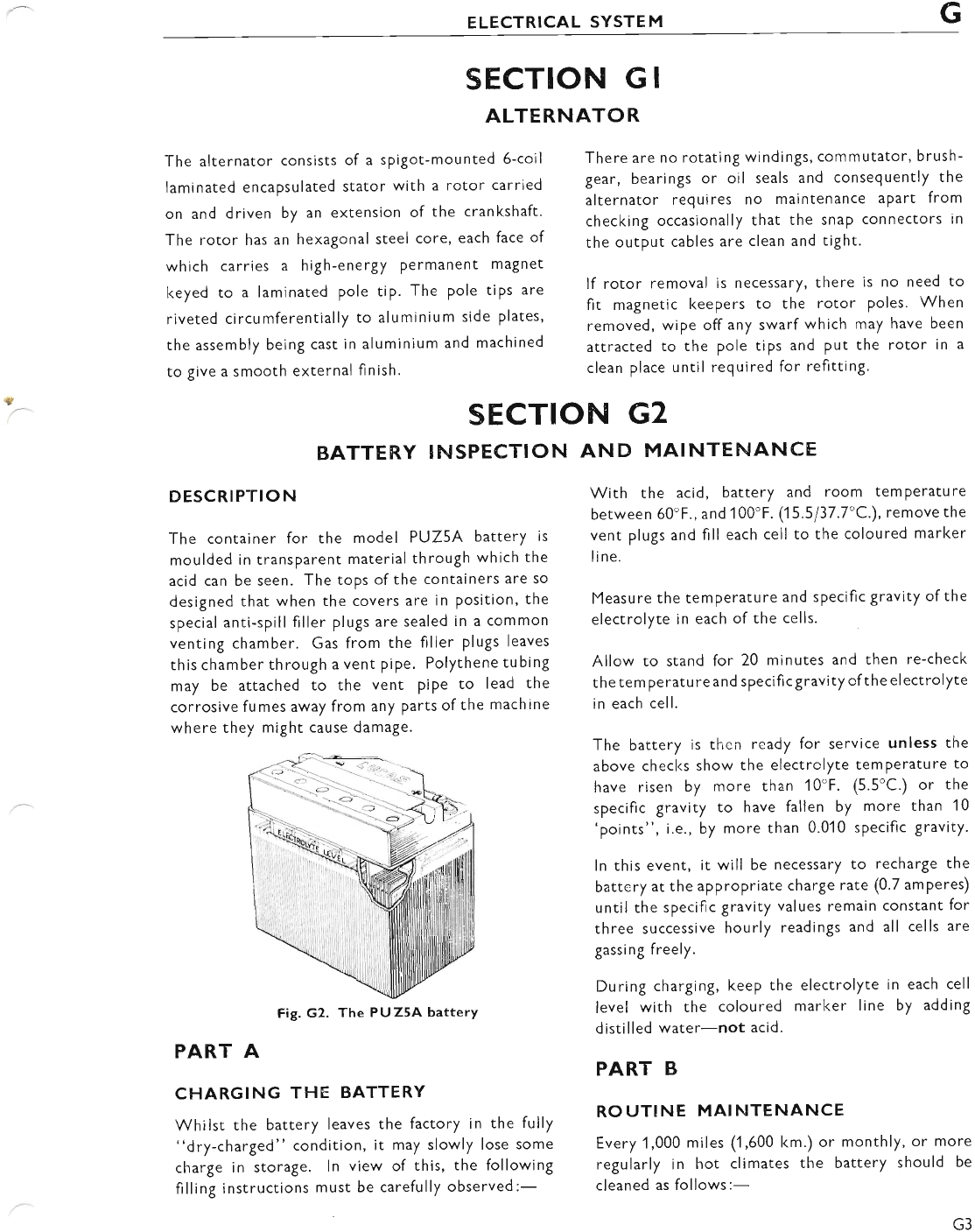
ELECTRICAL SYSTEM G
s
SECTION G I
ALTERNATOR
The alternator consists of a spigot-mounted 6-coil
laminated encapsulated stator with a rotor carried
on and driven by an extension of the crankshaft.
The rotor has an hexagonal steel core, each face of
which carries a high-energy Permanent magnet
keyed to a laminated pole tip. The pole tiPs are
riveted circumferentially to aluminium side plates,
the assembly being cast in aluminium and machined
to give a smooth external finish.
DESCRIPTION
The container for the model PUZ5A battery is
moulded in transparent material through which the
acid can be seen. The tops ofthe containers are so
designed that when the covers are in position, the
special anti-spill filler plugs are sealed in a common
venting chamber. Gas from the filler plugs leaves
this chamber through a vent pipe. Polythene tubing
may be attached to the vent PiPe to lead the
corrosive fumes away from any Parts of the machine
where they might cause damage.
PART A
CHARGING THE BATTERY
Whilst the battery leaves the factory in the fully
"dry-charged" condition, it may slowly lose some
charge in storage. ln view of this, the following
filling instructions must be carefully observed:-
SECTION G2
BATTERY !NSPECTION AND MAINTENANCE
There are no rotating windings, commutator, brush-
gear, bearings or oil seals and consequently the
alternator requires no maintenance aPart from
checking occasionally that the snaP connectors in
the output cables are clean and tight.
lf rotor removal is necessary, there is no need to
fit magnetic keepers to the rotor poles. When
removed, wipe off any swarf which may have been
attracted to the pole tips and put the rotor in a
clean place until required for refitting.
With the acid, battery and room temPerature
between 60'F., and 100'F. (1 5.5/37.7'C.), remove the
vent plugs and fill each cell to the coloured marker
line.
Measure the temperature and specific gravity of the
electrolyte in each of the cells.
Allow to stand for 20 minutes and then re-check
the tem peratu re and specifi c gravity of the electrolyte
in each cell.
The battery is then ready for service unless the
above checl<s show the electrclyte temPerature to
have risen by more than 10'F. (5.5'C.) or the
specific gravity to have fallen by more than 10
'points", i.e., by more than 0.01 0 specific gravity.
ln this event, it will be necessary to recharge the
battery at the appropriate charge rate (0'7 amperes)
until the specific gravity values remain constant for
three successive hourly readings and all cells are
gassing freely.
During charging, keep the electrolyte in each cell
level with the coloured marker line by adding
distilled water-not acid.
PART B
ROUTINE MAINTENANCE
Every 1,000 miles (1 ,600 km.) or monthly, or more
regularly in hot climates the battery should be
cleaned as follows:-
Fig. G2. The PUZ5A batterY
www.bsaunitsingles.com
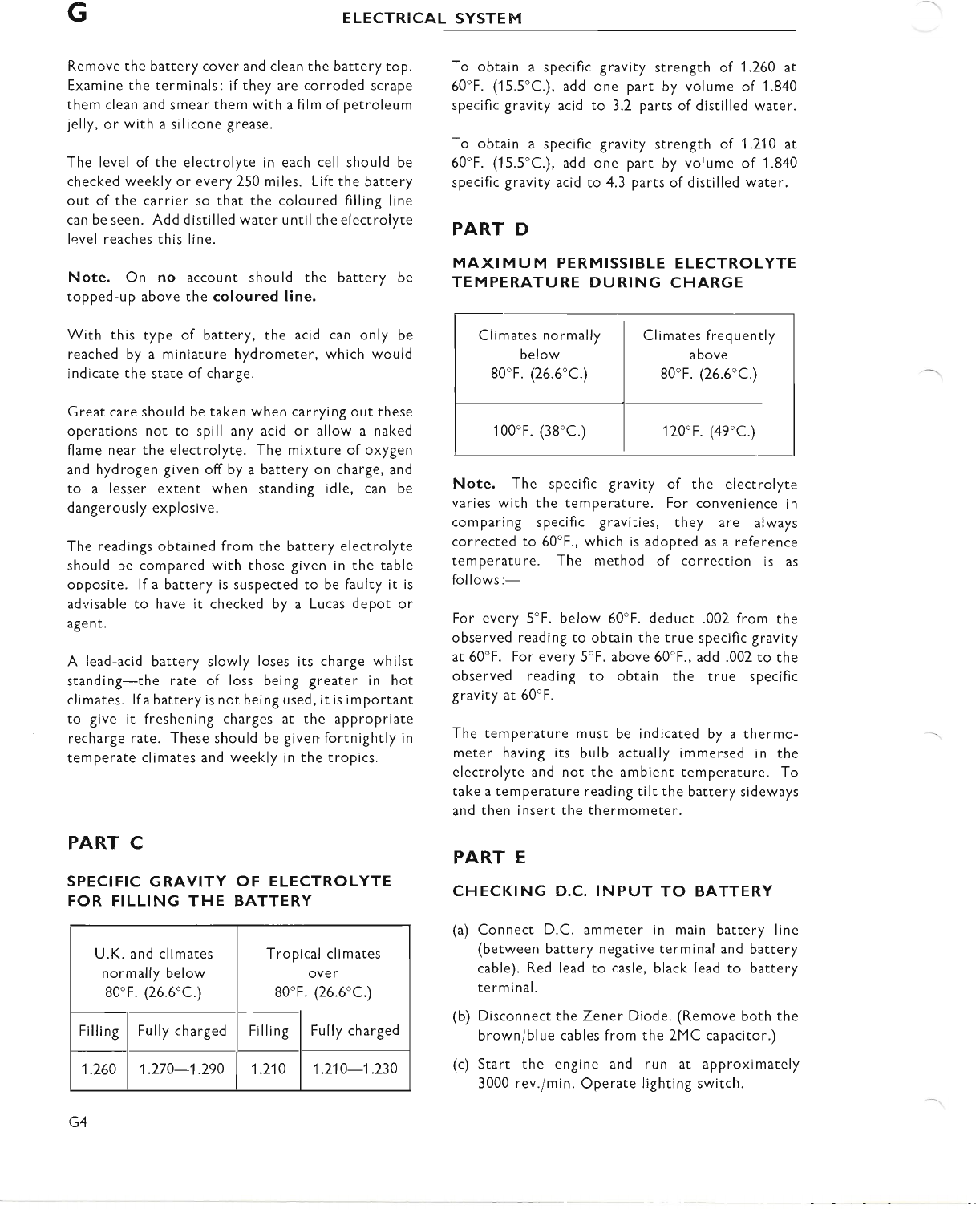
GELECTRICAL SYSTEM
Remove the battery cover and clean the battery top.
Examine the terminals: if they are corroded scrape
them clean and smear them with a film of petroleum
jelly, or with a silicone grease.
The level of the electrolyte in each cell should be
checked weekly or every 250 miles. Lift the battery
out of the carrier so that the coloured filling line
can be seen. Add distilled water untilthe electrolyte
level reaches this line.
Note. On no account should the battery be
topped-up above the coloured line.
With this type of battery, the acid can only be
reached by a miniature hydrometer, which would
indicate the state of charge.
Great care should be taken when carrying out these
operations not to spill any acid or allow a naked
flame near the electrolyte. The mixture of oxygen
and hydrogen given off by a battery on charge, and
to a lesser extent when standing idle, can be
dangerously explosive.
The readings obtained from the battery electrolyte
should be compared with those given in the table
ooposite. lf a battery is suspected to be faulty it is
advisable to have it checked by a Lucas depot or
agent.
A lead-acid battery slowly loses its charge whilst
standing-the rate of loss being greater in hot
climates. lf a battery is not being used, it is important
to give it freshening charges at the appropriate
recharge rate. These should be given fortnightly in
temperate climates and weekly in the tropics.
PART C
SPECIFIC GRAVITY OF ELECTROLYTE
FOR FILLING THE BATTERY
To obtain a specific gravity strength of 1.260 at
60"F. (15.5'C.), add one part by volume of '1.840
specific gravity acid to 3.2 parts of distilled water.
To obtain a specific gravity strength of 1.210 at
60"F. (15.5'C.), add one part by volume of 1.840
specific gravity acid to 4.3 parts of distilled water.
PART D
MAXIMUM PERMISSIBLE ELECTROLYTE
TEMPERATURE DURING CHARGE
Climates normally I Climates frequently
below I above
80'F. (26.6'C ) I 80'F. (25.5'C.)
100"F. (38'C ) I 120"F. (49'C.)
Note. The specific gravity of the electrolyte
varies with the temperature. For convenience in
comparing specific gravities, they are always
corrected to 60'F., which is adopted as a reference
temperature. The method of correction is as
follows:-
For every 5"F. below 50'F. deduct .002 from the
observed reading to obtain the true specific gravity
at 60'F. For every 5'F. above 60"F., add .002 to the
observed reading to obtain the true specific
gravity at 60"F.
The temperature must be indicated by a thermo-
meter having its bulb actually immersed in the
electrolyte and not the ambient temperature. To
take a temperature reading tilt the battery sideways
and then insert the thermometer.
PART E
CHECKING D.C. INPUT TO BATTERY
(a) Connect D.C. ammeter in main battery line
(between battery negative terminal and battery
cable). Red lead to casle, black lead to battery
te rm i nal.
(b) Disconnect the Zener Diode. (Remove both the
brown/blue cables from the 2MC capacitor.)
(c) Start the engine and run at approximately
3000 rev./min. Operate lighting switch.
U.K. and climates
normally below
80'F. (25.6"C.)
Tropical climates
over
80'F. (26.6"C.)
Filling Fully charged Filling Fully charged
1.260 1.270-1.290 1.210 1.210-1.230
G4
www.bsaunitsingles.com
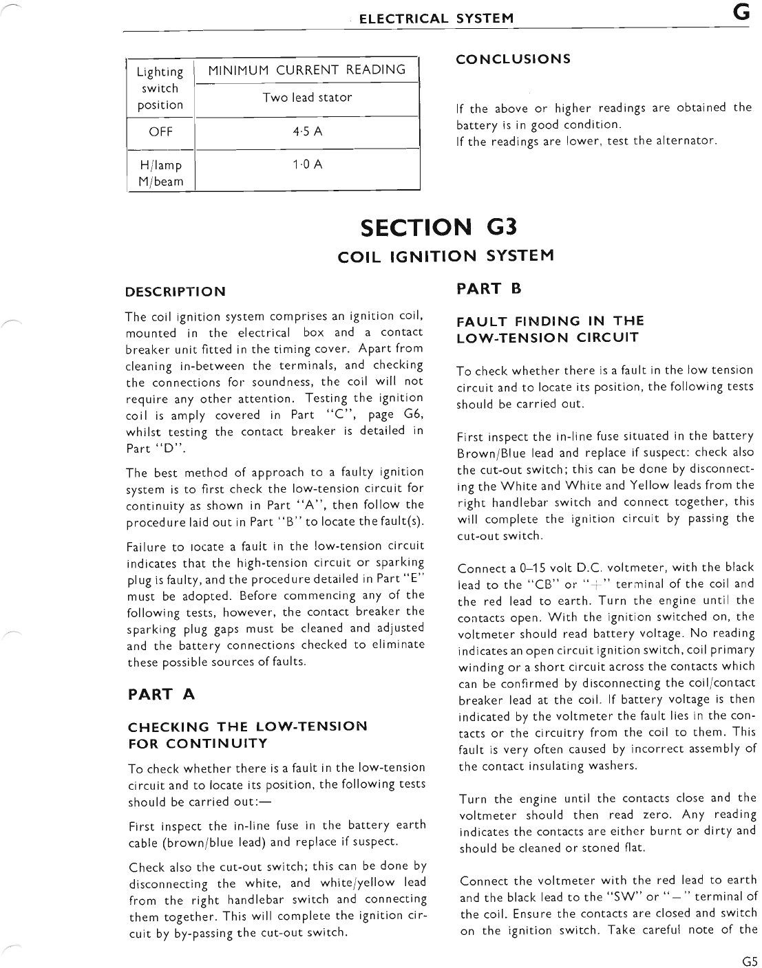
ELECTRICAL SYSTEM G
Lighting
switch
position
MINIMUM CURRENT READING
Two lead stator
OFF 4.5 A
H/lamp
M/beam
1.0 A
coNcLUsloNs
If the above or higher readings are obtained the
battery is in good condition.
lf the readings are lower, test the alternator.
PART B
FAULT F!NDING IN THE
LOW-TENSION CIRCUIT
To checl< whether there is a fault in the low tension
circuit and to locate its Position, the following tests
should be carried out.
First inspect the in-line fuse situated in the battery
Brown/Blue lead and replace if suspect: check also
the cut-out switch; this can be done by disconnect-
ing the White and White and Yellow leads from the
right handlebar switch and connect together, this
will complete the ignition circuit by passing the
cut-out switch.
Connect a 0-1 5 volt D.C. voltmeter, with the black
leaC to the "CB" or "+ " terminal of the coil and
the red lead to earth. Turn the engine until the
contacts open. With the ignition switched on, the
voltmeter should read battery voltage. No reading
indicates an oPen circuit ignition switch, coil primary
winding or a short circuit across the contacts which
can be confirmed by disconnecting the coil/contact
breaker lead at the coil. lf battery voltage is then
indicated by the voltmeter the fault lies in the con-
tacts or the circuitry from the coil to them. This
fault is very often caused by incorrect assembly of
the contact insulating washers.
Turn the engine until the contacts close and the
voltmeter should then read zero. Any reading
indicates the contacts are either burnt or dirty and
should be cleaned or stoned flat.
Connect the voltmeter with the red lead to earth
and the black lead to the "SW" or "-" terminal of
the coil. Ensure the contacts are closed and switch
on the ignition switch. Take careful note of the
SECTION G3
COIL IGNITION SYSTEM
DESCRIPTION
The coil ignition system comprises an ignition coil,
mounted in the electrical box and a contact
breaker unit fitted in the timing cover. Apart from
cleaning in-between the terminals, and checking
the connections for soundness, the coil will not
require any other attention. Testing the ignition
coil is amply covered in Part "C", page G6'
whilst testing the contact breaker is detailed in
Part "D".
The best method of approach to a faulty ignition
system is to first check the low-tension circuit for
continuity as shown in Part "A", then follow the
procedure laid out in Part "B" to locate the fault(s).
Failure to rocate a fault in the low-tension circuit
indicates that the high-tension circuit or sparking
plug is faulty, and the procedure detailed in Part "E"
must be adopted. Before commencing any of the
following tests, however, the contact breaker the
sparking plug gaps must be cleaned and adjusted
and the battery connections checked to eliminate
these possible sources of faults.
PART A
CHECKING THE LOW-TENSION
FOR CONTINUITY
To check whether there is a fault in the low-tension
circuit and to locate its Position, the following tests
should be carried out:-
First inspect the in-line fuse in the battery earth
cable (brown/blue lead) and replace if suspect.
Check also the cut-out switch; this can be done by
disconnecting the white, and white/yellow lead
from the right handlebar switch and connecting
them together. This will complete the ignition cir-
cuit by by-passing the cut-out switch.
www.bsaunitsingles.com
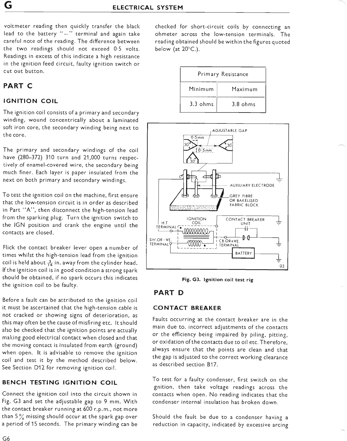
GELECTRICAL SYSTEM
voltmeter reading then quicl<ly transfer the black
lead to the battery "-" terminal and again take
careful note ofthe reading. The difference between
the two readings should not exceed 0.5 volts.
Readings in excess of this indicate a high resistance
in the ignition feed circuit, faulty ignition switch or
cut out button.
PART C
IGNITION COIL
The ignition coil consists of a primary and secondary
winding, wound concentrically about a laminated
soft iron core, the secondary winding being next to
the core.
The primary and secondary windings of the coil
have (280-372) 310 turn and 2'1,000 turns respec-
tively of enamel-covered wire, the secondary being
much finer. Each layer is paper insulated from the
next on both primary and secondary windings.
To test the ignition coil on the machine, first ensure
that the low-tension circuit is in order as described
in Part "A", then disconnect the high-tension lead
from the sparking plug. Turn the ignition switch to
the IGN position and crank the engine until the
contacts are closed.
Flick the contact breaker lever open a number of
times whilst the high-tension lead from the ignition
coil is held about 1f in. away from the cylinder head.
lf the ignition coil is in good condition a strong spark
should be obtained, if no spark occurs this indicates
the ignition coil to be faulty.
Before a fault can be attributed to the ignition coil
it must be ascertained that the high-tension cable is
not cracked or showing signs of deterioration, as
this may often be the cause of misfiring etc. lt should
also be checked that the ignition points are actually
making good electrical contact when closed and that
the moving contact is insulated from earth (ground)
when open. lt is advisable to remove the ignition
coil and test it by the method described below.
See Section D12for removing ignition coil.
BENCH TESTING IGNITION COIL
Connect the ignition coil into the circuit shown in
Fig. G3 and set the adjustable gap to 9 mm. With
the contact breaker running at 600 r.p.m., not more
than 5\ missing should occur at the spark gap over
a period,cf 15 seconds. The primary winding can be
G6
checked for short-circuit coils by connecting an
ohmeter across the low-tension terminals. The
reading obtained should be within the figures quoted
below (at 20'C.).
Primary Resistance
Minimum Maximum
3.3 oh ms 3.8 ohms
Fig. G3. lgnition coil test rig
PART D
CONTACT BREAKER
Faults occurring at the contact breaker are in the
main due to, incorrect adjustments of the contacts
or the efficiency being impaired by piling, pitting,
or oxidation ofthe contacts due to oil etc. Therefore,
always ensure that the points are clean and that
the gap is adjusted to the correct working clearance
as described section 817.
To test for a faulty condenser, first switch on the
gnition, then take voltage readings across the
contacts when open. No reading indicates that the
condenser internal insulation has broken down.
Should the fault be due to a condenser having a
reduction in capacity, indicated by excessive arcing
.GREY FIBRE
OR BAKETISED
FABRIC BLOCK
CONTACT BREAKER
sw.oR -vE.
IERMINAT
www.bsaunitsingles.com
ELECTRICAL SYSTEM G
when in use, and overheating of the contact faces,
a check should be made by substitution'
Particular attention is called to the Periodic lubrica-
tion procedure for the contact breaker which is
given on page A10. When lubricating the parts
ensure that no oil or grease Sets on to the contacts.
lf it is felt that the contacts require surface grinding
then the comPlete contact breal<er unit should be
removed as described on Page 817, and the moving
contact disconnected by unscrewing the securing
nut at the low tension lead, removing the lead and
nylon bush. The spring and contact point can be
removed from the Pivot sPindle. Grinding is best
achieved by using a fine carborundum stone or very
fine emery cloth, afterwards wiping away any trace
of dirt or metal dust with a clean petrol (gasolene)
moistened cloth. The contact faces should be slightly
domed to ensure point contact. There is no need
to remove the pitting from the fixed contact.
When reassembling, the nylon bush is fitted through
the low tension connection tab, and through the
spring location eye. Apply a smear of grease to the
C.B. cam and moving contact Pivot Post. Every
3,000 miles and/or contact replacement, apply two
drops of clean engine oil to the rear of the three
lubricating felt wicks.
PART E
CHECKING THE HIGH.TENSION
CIRCUIT
If ignition failure or misfiring occurs' and the fault is
not in the low-tension circuit, then check the
ignition coil as described in Part "C". lf the coil
proves satisfactory, ensure that the high-tension
cable is not the cause ofthe fault.
lf a good spark is available at the hiSh-tension cable,
then the sparking plug suppressor caP or the
sparking plug itself may be the cause of the fault'
Clean the sparking plug and adjust the electrodes
to the required setting as described on page G.8
and then reset the engine for running performance'
lfthe fault re-occu rsthen it is I i kelythatthe su PPressor
cap is faulty and should be renewed.
2MC ELECTROLYTIC CAPACITOR
The capacitor is an electrolytic polarised unit, which
will be irreparably damaged if incorrectly connected'
TERMI NAL IDENTIFICATION
Looking at the terminal end of the unit, two
Lucar terminals of different sizes will be observed,
the small terminal being the Positive earth
terminal: for identification the rivet has a red
s Pot.
The double Lucar terminal is the negative con-
necti on.
The basic object of using the electrolytic caPacitor
in the system is to enable the motor cycle to be run
without a battery giving the rider the advantage of
using the machine for competition work, and
re-fitting the battery for normal.road use.
lf the battery should be disconnected and the
machine run on caPacitor ensure that the negative
(brown/blue) lead is well insulated.
PERIODIC CHECK
Disconnect the battery, start and run the engine.
Full lighting should be available.
Conclusion.-lf engine will not fire and run, Pro-
ceed to next check.
EFFICIENCY CHECK
(1) Disconnect the caPacitor.
(2) Connect the capacitor direct to a 12 volt
battery for 5 seconds (see polarity note).
(3) Disconnect the battery and let the charged
capacitor stand for 5 min utes'
(4) Connect a D.C. voltmeter across the terminals
(see polarity note) and note the steady reading
after the initial swing, which should not be less
than 9 volts for a serviceable unit.
SERVICE NOTES
Before running the machine with the battery dis-
connected it is essential that the battery negative
lead be insulated to Prevent it from reconnecting
and shorting to earth. This can be done by removing
the fuse from its holder and replacing it with a
length of *in. diameter wooden dowel or other
insulating medium.
A faulty capacitor may not be apparent when used
with a battery system. To prevent any inconvenience
arising, periodically check that the caPacitor is
serviceable by disconnecting the battery to see if
the machine will start easilY.
G7
www.bsaunitsingles.com
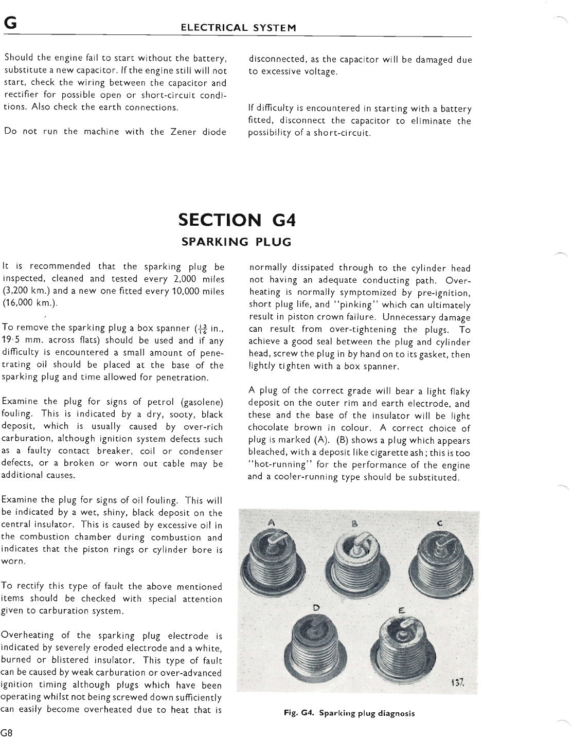
GELECTRICAL SYSTEM
Should the engine fail to start without the battery,
substitute a new capacitor. lf the engine still will not
start, check the wiring between the capacitor and
rectifier for possible open or short-circuit condi-
tions. AIso check the earth connections.
Do not run the machine with the Zener diode
disconnected, as the capacitor wi ll be damaged due
to excessive voltage.
lf difficulty is encountered in starting with a battery
fitted, disconnect the capacitor to eliminate the
possibility of a short-circuit.
normally dissipated through to rhe cylinder head
not having an adequate conducting path. Over-
heating is normally symptomized by pre-ignition,
short plug life, and "pinking" which can ultimarely
result in piston crown failure. Unnecessary damage
can result from over-tightening the plugs. To
achieve a good seal between the plug and cylinder
head, screwthe plug in by hand on to its gasket, then
lightly tighten with a box spanner.
A plug of the correct grade will bear a light flaky
deposit on the outer rim and earth electrode, and
these and the base of the insularor will be light
chocolate brown in colour. A correct choice of
plug is marked (A). (B) shows a plug which appears
bleached, with a deposit like cigarette ash;this is too
"hot-running" for the performance of the engine
and a cooler-running type should be substituted.
g
ffi
"#sMffi&.
ffi
lSW
*|!W
'.1W
b
ffi
SECTION G4
SPARKING PLUG
It is recommended that the sparking plug be
inspected, cleaned and tested every 2,000 miles
(3,200 km.) and a new one fitted every 10,000 miles
(16,000 km.).
To remove the sparking plug a box spanner (j* in.,
19.5 mm. across flats) should be used and if any
diffculty is encountered a small amount of pene-
trating oil should be placed at the base of the
sparking plug and time allowed for penetration.
Examine the plug for signs of petrol (gasolene)
fouling. This is indicated by a dry, sooty, black
deposit, which is usually caused by over-rich
carburation, although ignition system defects such
as a faulty contact breaker, coil or condenser
defects, or a broken or worn out cable may be
additional causes.
Examine the plug for signs of oil fouling. This will
be indicated by a wet, shiny, black deposit on the
central insulator. This is caused by excessive oil in
the combustion chamber during combustion and
indicates that the piston rings or cylinder bore is
worn.
To rectify this type of fault the above menrioned
items should be checked with special attention
given to carburation system.
Overheating of the sparking plug electrode is
indicated by severely eroded electrode and a white,
burned or blistered insulator. This type of fault
can be caused by weak carburation or over-advanced
ignition timing although plugs which have been
operating whilst not being screwed down sufficiently
can easily become overheated due to heat that is
G8
Fig. G4. Sparking plug diagnosis
I gl*
www.bsaunitsingles.com
ELECTRICAL SYSTEM G
A plug which has been running too "cold" and has
not reached its self-cleaning temperature is shown
at (C). This has oil on the base of the insulator and
electrodes, and should be replaced by a plug that
will burn off deposits and remove the possibility of
a short-circuit. The plug marked (D) is heavily
sooted, indicating that the mixture has been too
rich, and a further carburation check should be
made. At illustration (E) is seen a plug which is
completely worn out and in need of replacement.
To clean the plug it is Preferable to make use of a
properly designed proprietary plug cleaner. The
makers instructions for using the cleaner should be
followed carefully.
When the plug has been carefully cleaned, examine
the central insulator for cracking and the centre
electrode for excessive wear. ln such cases the
plug will have completed its useful life and a new
one should be fitted.
Finally, the sparking plug electrode should be
adjusted to the correct gaP setting of.025 in'
(.635 mm.). Before refitting sparking plug the
threads should be cleaned by means of a wire brush
and a minute amount of graphite grease smeared on
to the threads. This will prevent any possibility of
thread seizure occurring.
lf the ignition timing and carburation settings are
correct and the plug has been correctly fitted' but
overheating still occurs, then it is possible that
carburation is being adversely affected by an air leak
between the carburetter and the cylinder head.
This possibility must be checked thoroughly before
taking any further action. When it is certain that
none of the above mentioned faults are the cause of
over-heating then the plug type and grade should
be considered.
Normally the tyPe of plug quoted in General
Data is satisfactory for general use of the machine,
but in special isolated cases, conditions may demand
a plug of a different heat range. Advice is readily
available to solve these problems from the plug
manufacturer who should be consulted.
SECTION G5
CI.{ARGING
DESCRIPTION
The charging current is supplied by the two lead
alternator, but due to the characteristics of alter-
nating current the battery cannot be charged direct
from the alternator. To convert the alternating
current to direct current a full wave bridge silicon
type rectifier is connected into the circuit. The
alternator gives full outPut, all the alternator coils
being permanently connected across the rectifier.
Excessive charge is absorbed by the Zener Diode
which is connected in parallel with the battery.
Always ensure that the ignition switch is in
the OFF position whilst the machine is not in
use, to prevent overheating of the ignition
coils and discharging the battery.
Proceed to test the alternator as described in
Part "A". lf the alternator is satisfactory, the fault
must lie in the charging circuit, hence the rectifier
SYSTEM
must be checked as given in Part "B" and then the
wiring and connections as shown in Part "C".
PART A
CHECKING THE ALTERNATOR
OUTPUT
Disconnect the two alternator outPut cables and
run the engine at 3,000 r.P.m'
Connect an A.C. voltmeter (0-1 5 volts) with 1 ohm
load resistor in parallel with each of the alternator
leads in turn, and observe the voltmeter readings.
A suitable 1 ohm load resistor can be made from a
piece of Nichrome wire as shown in Part "D",
page G12.
The test is conducted by connecting a voltmeter
and the 1 ohrn load resistor between the following
cables and note the readings:-
G9
www.bsaunitsingles.com
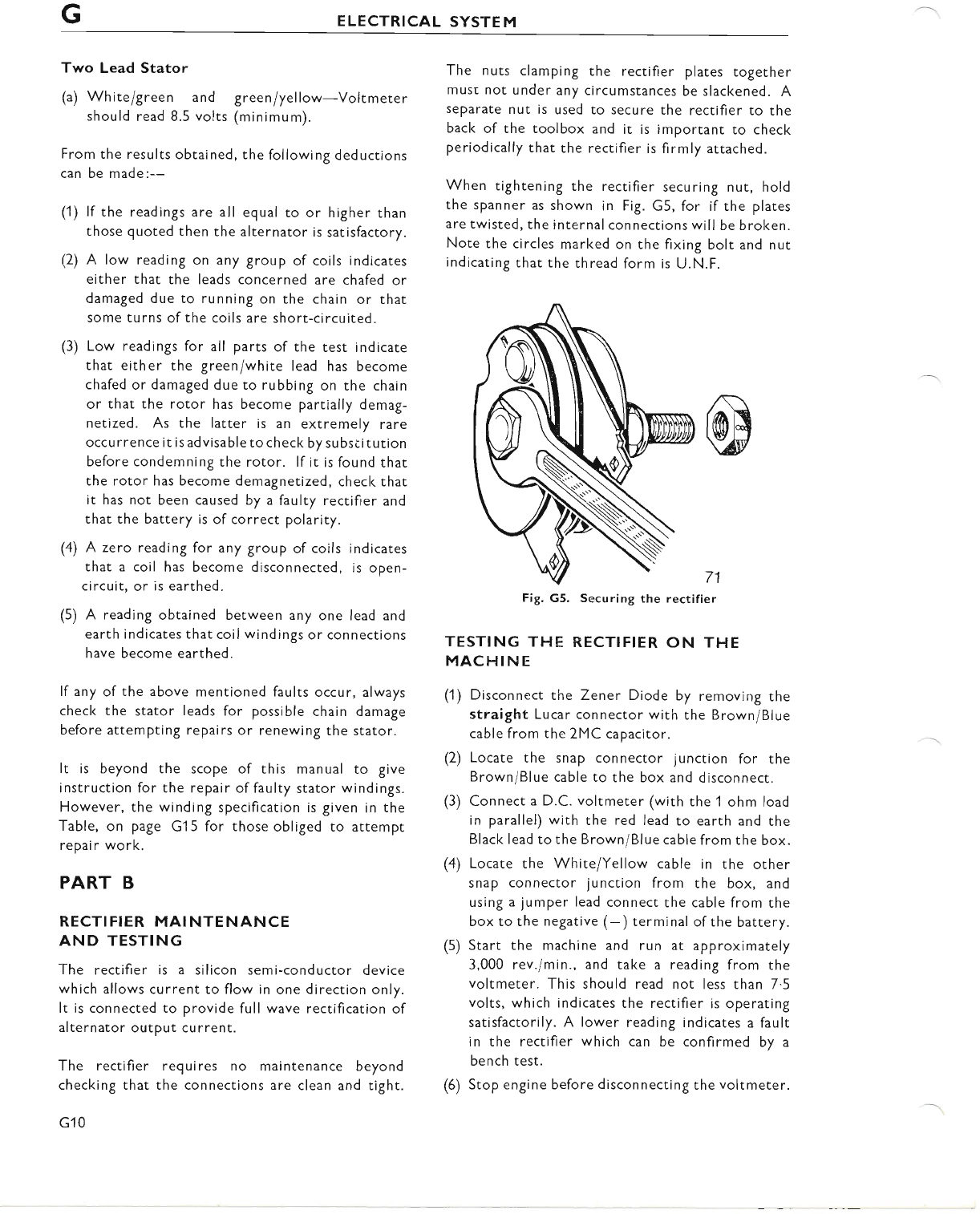
GELECTRICAL SYSTEM
Two Lead Stator
(a) Whiteigreen and greeniyellow-Voltmerer
should read 8.5 volts (minimum).
From the results obtained, the following deductions
can be made:--
(1) lf the readings are all egual to or higher than
those quoted then the alternator is satisfactory.
(2) A low reading on any group of coils indicates
either that the leads concerned are chafed or
damaged due to running on the chain or that
some turns of the coils are short-circuited.
(3) Low readings for all parts of the test indicate
that either the green/white lead has become
chafed or damaged due to rubbing on the chain
or that the rotor has become partially demag-
netized. As the latter is an extremely rare
occu rrence it is advisable to check by su bsi itution
before condemning the rotor. lf it is found that
the rotor has become demagnetized, check that
it has not been caused by a faulty rectifier and
that the battery is of correct polarity.
(4) A zero reading for any group of coils indicates
that a coil has become disconnected, is open-
circuit, or is earthed.
(5) A reading obtained between any one lead and
earth indicates that coil windings or connections
have become earthed.
lf any of the above mentioned faults occur, always
check the stator leads for possible chain damage
before attempting repairs or renewing the stator.
It is beyond the scope of this manual to give
instruction for the repair of faulty stator windings.
However, the winding specification is given in the
Table, on page G15 for those obliged to attempt
rePair work.
PART B
RECTIFIER MAINTENANCE
AND TESTING
The rectifier is a silicon semi-conductor device
which allows current to flow in one direction only.
It is connected to provide full wave rectification of
alternator outPut current.
The rectifier requires no maintenance beyond
checking that the connections are clean and tight.
G10
The nuts clamping the rectifier plates together
must not under any circumstances be slackened. A
separate nut is used to secure the rectifier to the
back of the toolbox and it is important to check
periodically that the rectifier is firmly attached.
When tightening the rectifier securing nut, hold
the spanner as shown in Fig. G5, for if the plates
are twisted, the internal connections will be broken.
Note the circles marked on the fixing bolt and nut
indicating that the thread form is U.N.F.
Fig. G5. Securing the rectifier
TESTING THE RECTIFIER ON THE
MACHINE
(1) Disconnect the Zener Diode by removing the
straight Lucar connector with the Brown/Blue
cable from the 2MC capacitor.
(2) Locate the snap connector junction for the
Brown/Blue cable to the box and disconnect.
(3) Connect a D.C. voltmeter (with the 1 ohm load
in parallel) with the red lead to earth and the
Black lead to the Brown/Blue cable from the box.
(4) Locate the White/Yellow cable in the other
snap connector junction from the box, and
using a jumper lead connect the cable from the
box to the negative (-) terminal of the battery.
(5) Start the machine and run at approximately
3,000 rev./min., and take a reading from the
voltmeter. This should read not less than 7.5
volts, which indicates the rectifier is operating
satisfactorily. A lower reading indicates a fault
in the rectifier which can be confirmed by a
bench test.
(6) Stop engine before disconnecting the voltmeter.
71
www.bsaunitsingles.com
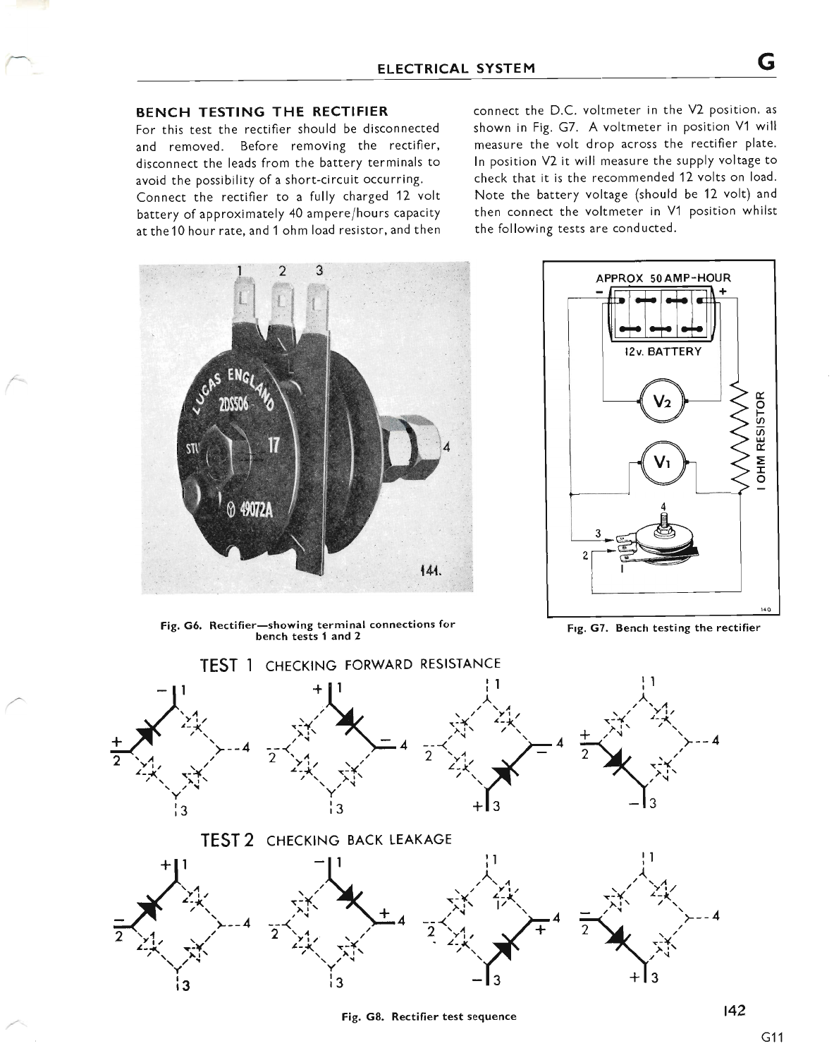
ELECTRICAL SYSTEM G
BENCH TESTING THE RECTIFIER
For this test the rectifier should be disconnected
and removed. Before removing the rectifier,
disconnect the leads from the battery terminals to
avoid the possibility of a short-circuit occurring.
Connect the rectifier to a fully charged 12 vok'
battery of approximately 40 amperei hours caPacity
at the10 hour rate, and 1 ohm load resistor, and then
Fig. G5. Rectifier-showing terminal connections for
bench tests I and 2
I cnrcrtNc FoRwARD REslsrANcE
connect the D.C. voltmeter in the V2 position. as
shown in Fig. G7. A voltmeter in position Vl will
measure the volt drop across the rectifier plate.
ln position V2 it will measure the supply voltage to
check that it is the recommended 12 volts on load.
Note the battery voltage (should be 12 volt) and
then connect the voltmeter in V1 position whilst
the following tests are conducted.
APPROX 50AMP-HOUR
l2v. BATTERY
t
o
F
o
a
UJ
t
=
I
o
Frg. G7. Benclr testing the rectifier
!r
^
->{" >:Y
,^it / -r'>*- 4
TEST
I
'>4, u."
a-1 r-f
--rYr)t--' t.:;k
TEST 2 cHEcKtNG BAcK LEAKAGE
):I:'
>--1 1< -;f.
ll il
A
-:+:' )"1..1 -X' )*
,^{t ,^. , * .rti .>--4
0 """k,,f" 1la/_'
'*, )Y,
ls
ig
I
*
^\r*
l1
, \/l
\ / Yl,
, __,)tl i"'.r-o
?);i.l,{.
)*- -:i'
-tY' ''-r{a
ls
ig
Fig. G8. Rectifier test sequence t42
G11
www.bsaunitsingles.com
ELECTRICAL SYSTEM
ln Fig. G8, the re*ifier terminal marl<ing 1,7 and
3 are as shown physically in Figs. G6 and G7,
while terminal 4 representsthe rectifier center bolt.
1 and 3 are the A.C. input terminals while 2 and 4
are the D.C. output terminals ( -ve and f ve
res pecti vel y)
TEST 1
With the test leads, make the following connections
but keep the testing time as short as possible to
avoid overheating the rectifier cell: (A) 1 and 2,
(B) 1 and 4, (C) 3 and 4, (D) 3 and 2. Each reading
should not be greater than 1.5 volts with the battery
polarity as shown.
TEST 2
Reverse the leads or battery polarity and repeat
Test 1. The reading obtained should be the same as
the battery voltage (V2).
lf the readings obtained are not within the figures
given, then the rectifier internal connections are
faulty and the rectifier should be renewed.
PART C
CHECKING THE CHARGING
CIRCUIT FOR CONTINUITY
This test utilizes the machine's own battery ro test
for continuity or breakdown in the A.C. section of
the charging system.
The battery must be in a good state of charge and
connected correctly into the circuit *ve earth
(ground) and the alternator leads must be dis-
connected at the snap connectors so that there is no
possibility of demagnetizing the rotor.
First, check that there is voltage at the rectifier
centre terminal by connecting a D.C. voltmeter,
DESCRIPTION
The Zener Diode output regulating system which
uses the coils of the alternator connected perman-
ently across the rectifier, provides automatic control
of the charging current. ltwill only operate success-
fully on a 12 volt system where it is connected in
parallel with the battery as shown in the wiring
diagram, Fig. G13.
G12
SECTION G6
ZENER DIODE CHARGE CONTROL
with 1 ohm load resistor in parallel, between the
rectifiercentreterminal and earth, remember (+ ve)
positive earth (ground). The voltmeter should read
dattery volts. lf it does nor, there is a fau lty
connection in the wiring.
PART D
CONISTRI..'CTING A 1 OHM
LOAD RESISTOR
The resistor used in the following tests must be
accurate and constructed so that it will not overheat
otherwise the correct values of current or voltage
will not be obtained.
A suitable resistor can be made from 4 yards (3f
metres) of 18 s.w.g. ('048 in., i.e.,1'2 mm. diameter)
Nichrome wire by bending ir into rwo equal parts
and calibrating it as follows:-
(1) Fix a heavy gauge flexible lead to the folded end
of the wire and connect this lead to the positive
terminal of a 6 volt battery.
(2) Connect a D.C. voltmeter (0-1 0 volts) across
the battery rerminals and an ammeter (0-1 0
amp.) between the battery negative terminal
and the free ends ofthe wire resistance, using a
crocodile clip to make the connection.
(3) Move the clip along the wires, making contact
with both wires until the ammeter reading is
numerically equal to the number of volts shown
in the voltmeter. The resistance is then 1 ohm.
Cut the wire at this point, twist the two ends
together and wind the wire on an asbestos
former approximately 2 in. (5 cm.) diameter so
that each turn does not contact the one next to
it.
Assuming the battery is in a low state of charge its
terminal voltage (the same voltage is across the
Diode) will also be low, therefore the maximum
charging current will flow into the battery from the
alternator. Atfirst noneofthe current is by-passed
by the Diode because of it being non-conducting
due to the low battery terminal volts. However, as
the battery is quickly restored to a full state of
charge, the system voltage rises until at 13.5 volts
www.bsaunitsingles.com
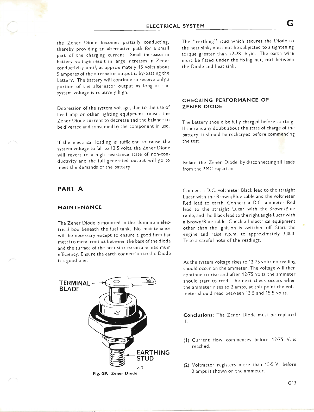
ELECTRICAL SYSTEM G
the Zener Diode becomes partially cond ucting,
thereby providing an alternative Path for a small
part of the charging current. Small increases in
battery voltage result in large increases in Zener
conductivity until, at aPProximately 15 volts about
5 amperes of the alternator outPut is by-passing the
battery. The battery will continue to receive only a
portion of the alternator outPut as long as the
system voltage is relatively high.
Depression of the system voltage, due to the use of
headlamp or other lighting equipment, causes the
Zener Diode current to decrease and the balance to
be diverted and consumed by the comPonent in use.
lf the electrical loading is sufficient to cause the
system voltage to fallto 13'5 volts, the Zener Diode
will revert to a high resistance state of non-con-
ductivity and the full generated outPut will go to
meet the demands of the batterY.
PART A
MAINTENANCE
The Zener Diode is mounted in the aluminium elec-
trical box beneath the fuel tanl<. No maintenance
will be necessary excePt to ensure a good firm flat
metal to metal contact between the base of the diode
and the surface of the heat sink to ensure maximum
efiiciency. Ensure the earth connection to the Diode
is a good one.
TERMINAL
BLADE
The "earthing" stud which secures the Diode to
the heat sink, must not be subjected to a tightening
torque greater than 22-28 lb./in. The earth wire
must be fitted under the fixing nut, not between
the Diode and heat sinl<.
CHECKING PERFORMANCE OF
ZENER DIODE
The battery should be fully charged before starting.
lfthere is any doubt about the state ofcharge ofthe
battery, it should be recharged before commencing
the test.
lsolate the Zener Diode by disconnecting all leads
from the 2MC capacitor.
Connect a D.C. voltmeter Blacl< lead to the straight
Lucar with the Brown/Blue cable and the voltmeter
Red lead to earth. Connect a D.C. ammeter Red
lead to the straight Lucar with the Brown/Blue
cable, and the Black lead to the right angle Lucar with
a Brown/Blue cable. Checl< all electrical equipment
other than the ignition is switched off. Start the
engine and raise r.p.m. to aPProximately 3,000.
Take a careful note cfthe readings.
As the system voltage rises to 12'75 volts no reading
should occur on the ammeter. The voltage will then
continue to rise and after 12'75 volts the ammeter
should start to read. The next check occurs when
the ammeter rises to 2 amps, at this point the volt-
meter should read between 13'5 and 15'5 volts.
Conclusions: The Zener Diode must be replaced
if:-
(1) Current flow commences before 12'75 V. is
reached.
(2) Voltmeter registers more than 15'5 V. before
2 amps is shown on the ammeter'
EARTHING
STUD
Fig, G9. Zener Diode
G13
www.bsaunitsingles.com
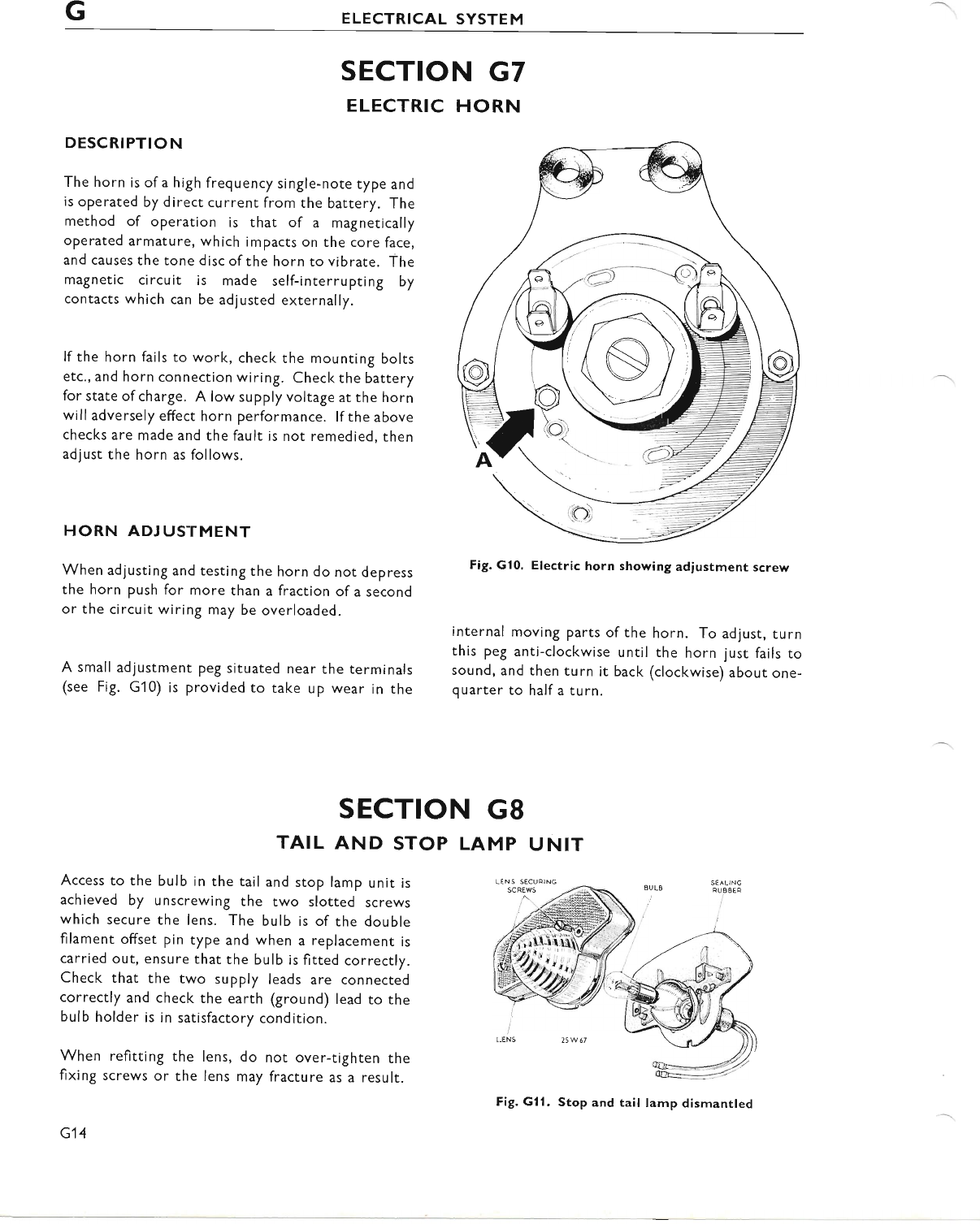
GELECTRICAL SYSTEM
SECTION G7
ELECTRIC HORN
DESCRIPTION
The horn is of a high frequency single-note type and
is operated by direct current from the battery. The
method of operation is that of a magnetically
operated armature, which impacts on the core face,
and causes the tone disc ofthe horn to vibrate. The
magnetic circuit is made self-inrerrupting by
contacts which can be adjusted externally.
lf the horn fails to work, check the mounting bolts
etc., and horn connection wiring. Check the battery
for state ofcharge. A low supply voltage at the horn
will adversely effect horn performance. lf the above
checks are made and the fault is not remedied, then
adlust the horn as follows.
HORN ADJUSTMENT
When adjusting and testing the horn do not depress
the horn push for more than a fraction of a second
or the circuit wiring may be overloaded.
A small adjustment peg situated near the terminals
(see Fig. G10) is provided to take up wear in the
internal moving parts of the
this peg anti-clockwise until
sound, and then turn it back
quarter to half a turn.
Fig. G10. Electric horn showing adiustment screw
Access to the bulb in rhe tail and stop lamp unit is
achieved by unscrewing the two slotted screws
which secure the lens. The bulb is of the double
filament offset pin type and when a replacement is
carried out, ensure that the bulb is fitted correctly.
Check that the two supply leads are connected
correctly and check the earth (ground) lead to the
bulb holder is in satisfactory condition.
When refitting the lens, do nor over-tighten the
fixing screws or the lens may fracture as a result.
G14
SECTION G8
TAIL AND STOP LAMP UNIT
25 W67
SEAL NG
RU B 8EE
horn. To adlust, turn
the horn just fails to
(clockwise) about one-
Fig. Gl1. Stop and tail lamp dismantled
www.bsaunitsingles.com
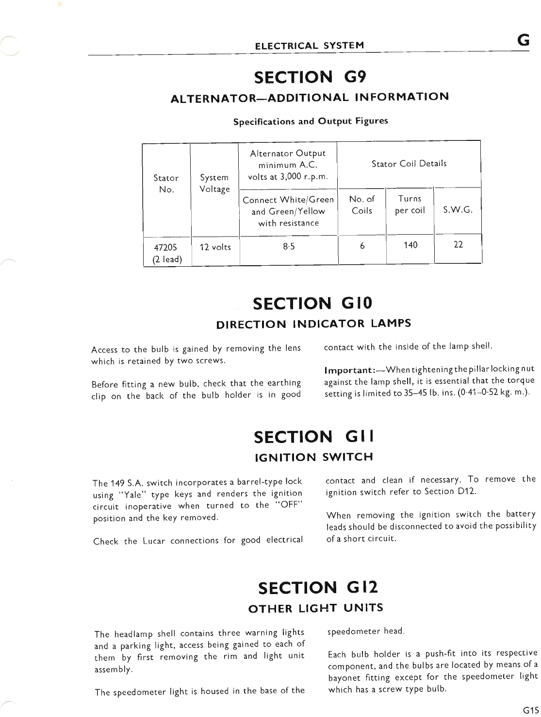
ELECTRICAL SYSTEM
SECTION G9
ALTERNATOR-ADDITI O NAL I N FORMATIO N
Specifications and Output Figures
Stator
No.
System
Voltage
Alternator Output
minimum A.C.
volts at 3,000 r.p.m.
Stator Coil Details
Connect White/Green
and Green/Yellow
with resistance
No. of
Coils
Tu rns
per coil S.W.G.
47705
(2 lead)
12 volts 8.5 6140 72
SECTION G IO
DIRECTION INDICATOR LAMPS
Access to the bulb is gained by removing the lens contact with the inside of the lamp shell'
which is retained by two screws' lmportant:-Whentighteningthe pillarlocking nut
Before fitting a new bulb, check that the earthing against the lamp shell, it is essential that the torgue
clip on the back of the bulb holder is in good settingislimitedto35-45lb.ins.(0'41-0'52kg.t.).
SECTION G I I
IGNITION SWITCH
The 149 S.A. switch incorporates a barrel-type lock contact and clean if necessary. To remove the
using "yale" type keys and renders the ignition ignition switch refer to Section D12.
circuit inoperative when turned to the "OFF"
position and the key removed. when removing the ignition switch the battery
leads should be disconnected to avoid the possibility
Check the Lucar connections for good electrical ofashortcircuit.
SECTION GI2
OTHER LIGFIT UNITS
The headlamp shell contains three warning lights speedometer head'
and a parking light, access being gained to each of
them by first removing the rim and light unit Each bulb holder is a push-fit into its resPective
assembly. component, and the bulbs are located by means of a
bayonet fitting except for the speedometer light
The speedometer light is housed in the base of the which has a screw type bulb.
G15
www.bsaunitsingles.com
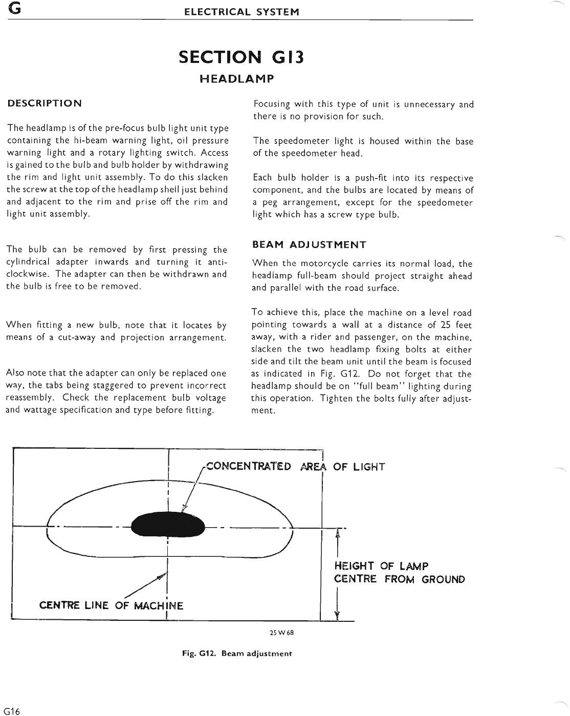
GELECTRICAL SYSTEM
DESCRIPTION
The headlamp is of the pre-focus bulb light unit type
containing the hi-beam warning light, oil pressure
warning light and a rotary lighting switch. Access
is gained to the bulb and bulb holder by withdrawing
the rim and light unit assembly. To do this slacken
the screw at the top ofthe headlamp shell just behind
and adjacent to the rim and prise off the rim and
light unit assembly.
The bulb can be removed by first pressing the
cylindrical adapter inwards and turning it anti-
clockwise. The adapter can then be withdrawn and
the bulb is free to be removed.
When fitting a new bulb, note that it locates by
means of a cut-away and projection arrangement.
Also note that the adapter can only be replaced one
way, the tabs being staggered to prevent incorrect
reassembly. Check the replacement bulb voltage
and wattage specification and type before fitting.
CENTRE LINE OF MACFIINE
SECTION G 13
H EADLA M P
25W68
Fig, G12. Beam adiustment
Focusing with this type of unit is unnecessary and
there is no provision for such.
The speedometer light is housed within the base
of the speedometer head.
Each bulb holder is a push-fit into its respective
component, and the bulbs are located by means of
a peg arrangement, except for the speedometer
light which has a screw type bulb.
BEAM ADJUSTMENT
When the motorcycle carries its normal load, the
headlamp full-beam should project straight ahead
and parallel with the road surface.
To achieve this, place the machine on a level road
pointing towards a wall at a distance of 25 feet
away, with a rider and passenger, on the machine,
slacken the two headlamp fixing bolts at either
side and tilt the beam unit until the beam is focused
as indicated in Fig. Gl 2. Do not forget that the
headlamp should be on "full beam" Iighting during
this operation. Tighten the bolts fully after adjust-
ment.
OF LIG}.IT
FIEIGHT
CENTRE OF LAMP
FROM GROUND
CONCENTRATED ARFA
G16
www.bsaunitsingles.com
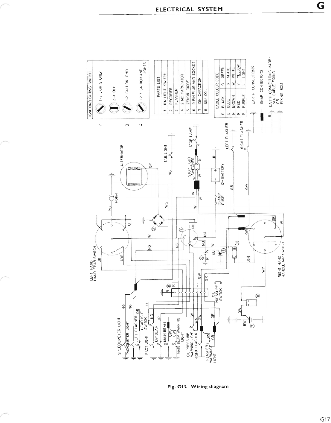
G
ELECTRICAL SYSTEM
u
o
o
O
E
f
o
o
U
E
z
U
U
E
o
o
U
kU
t
T
3
3
3
o
UI
o
=
o
m
T
f
m
f
z
V
m
o
U
E
U
L
E
l
L
c
:
E
s
E
!!
L
F
o
U
E
I
o
=
I
o
)
9
E
u
I
a
v
o
fl
o
U
o
o
o
E
o
z
U
N
U
o
o
z
o
l
L
z
L
E
o
L
L
z
o
o
o
z
o
Ld
o
6>
Z^ a 6,^
YEz=
690=
U O E-
2 Z -u,., Fr
oz=-o
o o:fr m
5<
% = -r;"-?
i o a>oL
u
t "rl
:r
t
U
I
@
I
T
o
&
U
T
L
I
U
v
U
t
m
s
u
l
L
o
z
E
U
I
o
=
a
I
o
@
<@
rU
r9
JI
Or
iA
IU
LO
hi
E'
o
4
z
E
g
U
o
zI
o
-
I
=
o
c
E
U
-
a
J
L
F
I
U
I
o
l
E
U
I
o
T
o
.
E
U
-
L
ur
_EO
oo
uz
cft
J<
o=
6
T
> O.r
Z -J
oa z
zo
OF
l-z
z\2
9_
:i
oo
z
o
T
o
l
@
I
o
=
o
tr
r
o
z
o
2
I
G17
Fig. Gl3. Wiring diagram
www.bsaunitsingles.com
sEcTroN J
SERVICE TOOLS
INTRODUCTION
This section of the Workshop Manual illustrates pictorially the workshop service tools that
are available for carrying out the major dismantling and reassembly operations on the
UNIT CONSTRUCTION-250 c.c. TRIUMPH MOTORCYCLE.
J1
www.bsaunitsingles.com
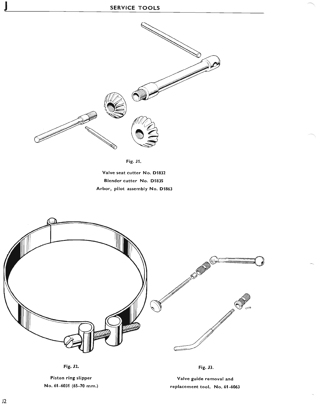
SERVICE TOOLS
Fig. Jl.
Valve seat cutter No. D1832
Blender cutter No. D1835
Arbor, pilot assembly No. D|853
Fig. t2.
Piston ring slipper
No.6l-5031 (65-70 mm.)
Fig. J3.
Valve guide removal and
replacement tool. No, 6l-6063
JZ
www.bsaunitsingles.com
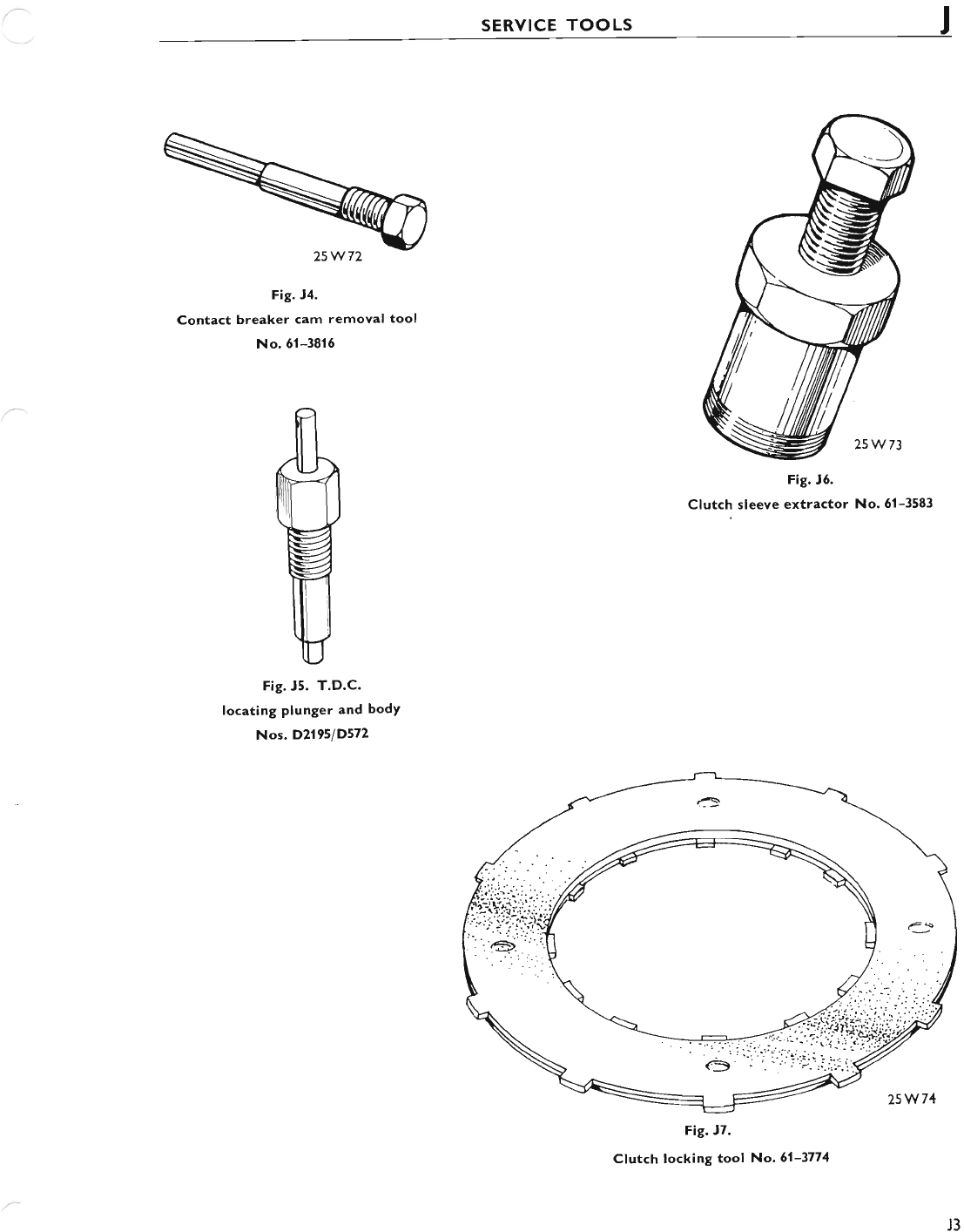
SERVICE TOOLS J
Flg. t4.
Contact breaker cam removal tool
No.6l-3816
Fig. J5. T.D.C.
locating plunger and bodY
Nos. D2195/D572
Fig. J5.
Clutch sleeve extra€tor No. 61-3583
Fig. J7.
Ctutch locking tool No. 6l-3774
J3
www.bsaunitsingles.com
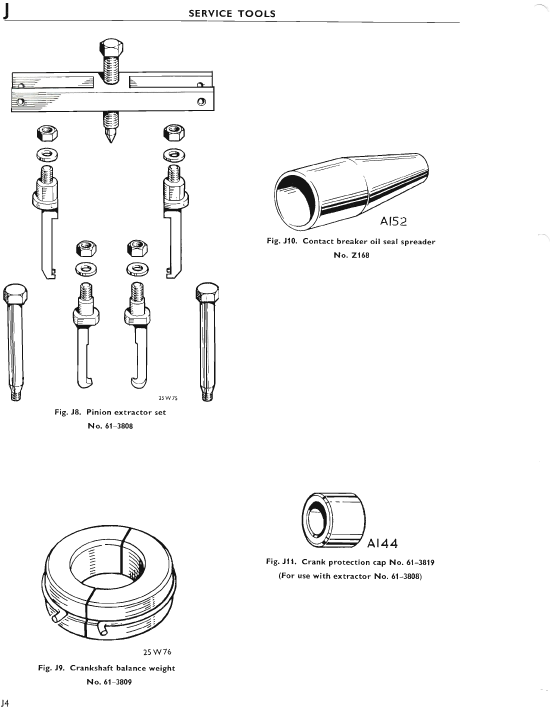
TSERVICE TOOLS
@
@
fl
@
@
tFig. Jl0. Contact breaker oil seal spreader
No. 2168
At44
Fig. Jll. Crank protection cap No.61-3819
(For use with extractor No. 61-3808)
W
@
@
fl
@
@
ff 25W75
Fig. J8. Pinion extractor set
No. 51-3808
25W76
Fig. J9. Crankshaft balance weight
No.61-3809
J4
www.bsaunitsingles.com
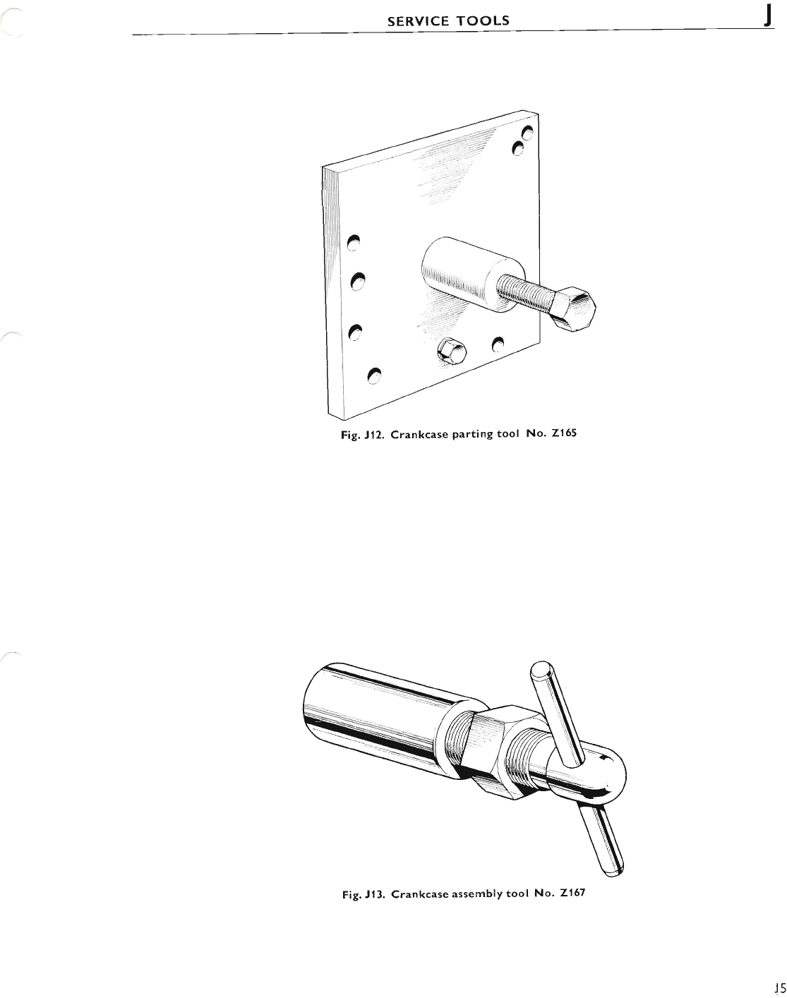
SERVICE TOOLS
Fig. J12. Crankcase Parting tool No. 2155
Fig. J13. Crankcase assembly tool No. Zl57
J5
www.bsaunitsingles.com
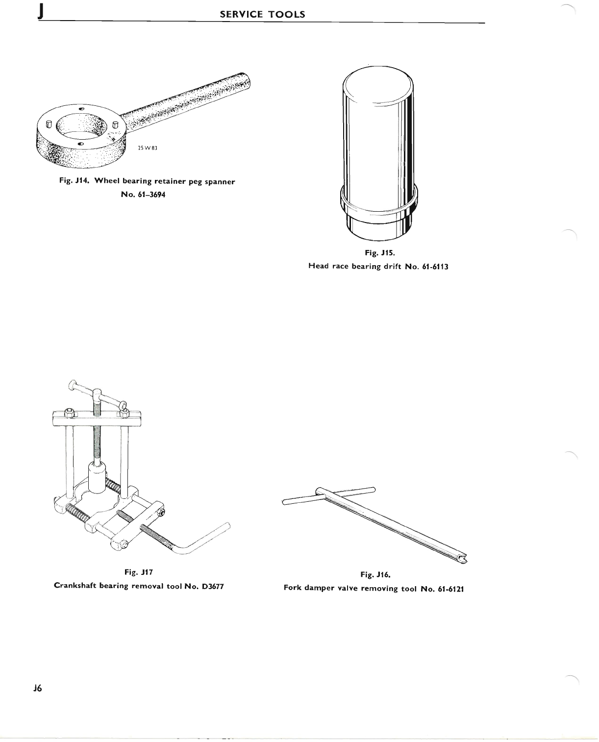
JSERVICE TOOLS
Fig. tl4. Wheel bearing retainer peg spanner
No. 5l-3694
Fig. t17
Crankshaft bearing removal tool No. D3677
Fig. Jl5.
Head race bearing drift No. 6l-5113
Fig. Jl6.
Fork damper valve removing tool No. 61-6121
J6
www.bsaunitsingles.com

CONVERSION
TABLES
cT1
www.bsaunitsingles.com
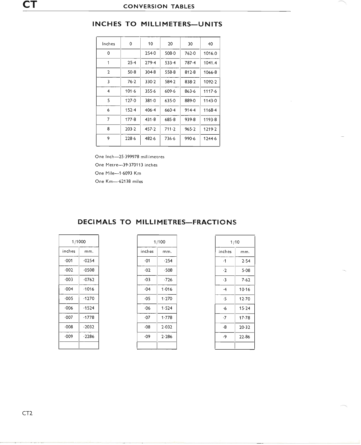
CT CONVERSION TABLES
INCHES TO MILLIMETERS-UNITS
lnches 0 10 20 30 40
0254.0 508.0 762.0 1016.0
125.4 279.4 533.4 787.4 1041.4
250.8 304.8 558.8 812.8 1066.8
376.2 330.2 584.2 838.2 1092.2
4101 .6 355'6 609'6 863.6 1117.6
5127-O 38'1.0 635.0 889.0 1143.0
6152.4 406.4 660.4 914.4 1168.4
7177.8 431.8 685.8 939.8 1193.8
I203.2 457.2 711.2 965-2 1219.2
9228.6 482.6 736.6 990.6 1244.6
One lnch-25.399978 millimetres
One Metre-39.37011 3 inches
One Mile-1.6093 Km
One Km-.62138 miles
DECI MALS TO M I LLI M ETRES-FRACTIO N S
11100
i n ches mm.
.01 .254
.02 .508
.03 .726
.o4 1 .016
.05 1.270
.06 1.524
.07 1.778
'08 2.032
09 2.286
1 /1 000
i nches mm.
.001 .0254
.002 .0508
.003 .0762
.004 -1016
.005 1270
.006 .'t524
.007 .1778
.008 .2032
'009 .2286
1t10
L r-
rnches I mm
.1 2.54
-2 5.08
.3 7.62
.4 14.16
'5 12.70
-6 15.24
.7 17.78
.8 20.32
.9 22.86
CT7
www.bsaunitsingles.com
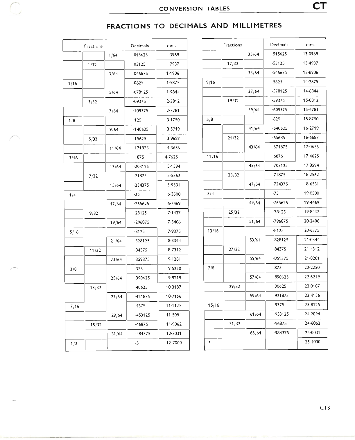
CONVERSION TABLES CT
FRACTIONS TO DECIMALS AND MILLIMETR,ES
F ractions Decimals mm.
1164 .01 5625 -3969
1132 .031 25 -7937
3164 .04687s 1-1906
1116 .0625 1.5875
5t64 .078125 1.9844
3132 '0937s 2.3812
7164 .'t09375 2.7781
1t8 -125 3.'1750
9 t64 444625 3.5719
s l32 -15625 3.9687
11 164 171875 4.3656
3116 .1875 4.7625
13164 .203125 5.1594
7132 .21875 5.5562
15t64 .234375 5.9531
114 .25 6.3500
17 164 265625 6.7469
e 132 28125 7.1437
't9164 296875 7-5406
s116 3125 7.9375
21 164 328125 8.3344
11132 .34375 8.7312
23164 .359375 9.1281
3/8 .375 9.5250
2s 164 390625 9.9219
13132 40625 10'31 87
27164 421875 10.7156
7116 .4375 11.',!125
29164 .453125 11.5094
1s132 .46875 11.9062
31 164 484375 1 2.3031
't 12 .5 12.7000
Fracti ons Decimals mm.
33164 .5'15625 '13.0969
17132 .531 25 13.4937
35t64 .546675 1 3.8906
e 116 .5625 14.287s
37164 -57812s 14.6844
19132 .59375 15.0812
39164 -60937s 15.478'l
s/8 .625 1 5.8750
41 164 -640625 16.2719
21!32 .65685 16.6687
43 t64 .671875 17.06s6
1',t 116 .6875 17.4625
4s164 .703125 17.8594
23132 '71875 18.2562
47 164 .734375 '18'653'l
314 .75 1 9.0500
49164 .765625 19.4469
25132 .7g'.t25 19.8437
sl164 .79687s 20.2406
13116 '8125 24"6375
s3164 .828125 21.0344
27 32 .84375 21.4312
ssl64 .859375 21.8281
718 .875 22.2250
s7 164 .890625 22.6219
29132 .90625 23.O187
s9164 .921875 23.4156
1s116 '9375 23.8125
61 164 .9531 25 24.2094
31132 .96875 24.6062
63164 .984375 25.0031
25.4000
cT3
www.bsaunitsingles.com
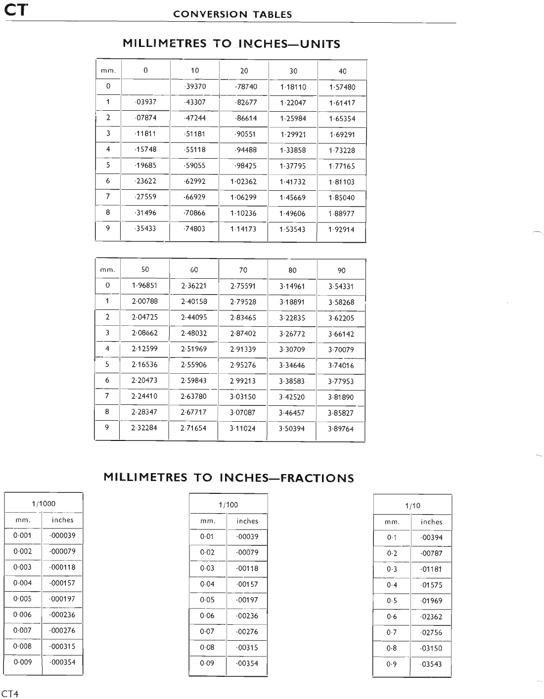
CT CONVERSION TABLES
MILLI MFTRES TO INCI.{ES-UNITS
MILLIMETRES TO INCHES-FRACTIONS
I 1100
mm. i nch es
0.01 .00039
0.02 '00079
0.03 '001 18
0'04 .00't 57
0.0s .00197
0.06 .00236
0.07 .04276
0.08 .00315
0.09 .003s4
mm. 0 10 20 30 40
0.3937C .78740 1.181't0 1.57480
1.03937 .43307 '82677 1-22047 1.61417
2.07874 .47244 .86614 1.25984 1'65354
311811 '511 81 .90551 1.29921, 't-69291
4 15748 '551 1 I.94488 1.33858 1.73228
5'1968s .59055 .98425 1.37795 1-77165
6.23622 .62992 1.02362 1.41732 1 .81103
7.27559 .669?-9 1.06299 1.45669 1'85040
8'31496 .70866 I .10236 1.49606 1.88977
9.35433 .74803 1.14173 1.53543 1.92914
mm. 50 60 70 80 90
01.96851 2.36221 2.75591 3.14961 3.5433'l
12.00788 2.40158 2.79528 3.1 8891 3.58268
22.04725 2.44495 2.83465 3.22835 3.62205
32.08662 2.48032 2.87402 3.26772 3-66142
42.'.t2599 2-51969 2.91339 3'30709 3.70079
52-16s36 2.55906 2.95276 3.34646 3.74A16
62.20473 2.59843 2 99213 3.38s83 3.77953
72.24414 2.63780 3.031 s0 3.42520 3'81 890
I2.28347 2.67717 3.07087 3.46457 3.85827
92.32284 2.71654 3.11024 3'50394 3.89764
1 /1 000
mm. inches
0.001 .000039
0'002 .000079
0.003 .0001 1 8
0.004 .0001 57
0.005 .000197
0.006 '000236
0.007 .000276
0'008 .00031 5
0.009 .000354
1110
mm, i n ches
0.1 00394
0.2 .oo787
0.3 .o1't81
0.4 .01575
0.5 .01969
0.6 -02362
0'7 .02756
0.8 .031 50
0.9 .03543
CT4
www.bsaunitsingles.com
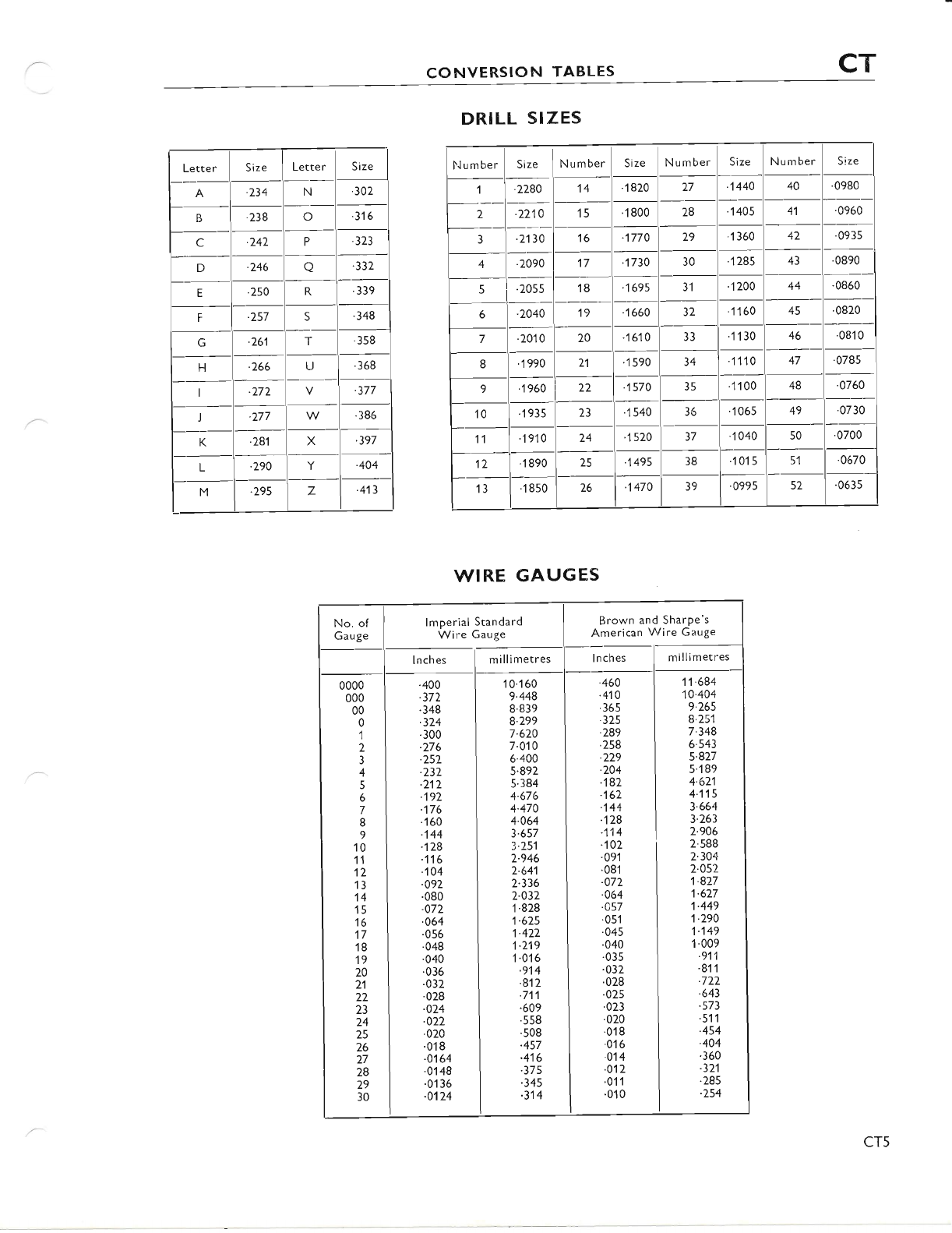
CONVERSION TABLES CT
Lette rSize Letter Size
A.234 N.302
B.238 o.316
c.v42 P.323
D-246 o'332
E.250 R.339
F.257 c.348
G.261 T'358
FI .266 U.368
.277 .377
I'277 .386
K.281 X'397
L.290 Y.404
M295 z.413
DRILL SIZES
WIRE GAUGES
Number Size N u rnber Size Number Size Number Size
1'2280 14 .1820 27 .1440 40 .0980
2.7210 15 .1800 28 .1405 41 '0960
3.2130 16 .1770 29 .1 360 42 .0935
4.2090 17 1730 30 "1 285 43 .0890
5.2055 18 .1695 31 1 200 44 .0860
6.2040 19 .1660 )z 1160 45 0820
7.2010 20 .1610 33 .11 30 46 .081 0
8.1990 21 '1 s90 34 1110 47 .0785
9.1960 22 1570 35 1 100 48 .0760
10 .1935 23 1540 36 'r 06s 49 .0730
11 1910 24 1 520 37 '1040 50 '0700
12 1 890 ?q .1495 38 .101 551 '0670
13 .1850 26 1470 39 '0995 52 .0635
Brow,n and Sharpe's
American Wire Gauge
.460
.410
.365
.325
.289
'258
-229
.204
.187
.162
.144
.128
.114
.102
.091
.081
.072
.064
.457
.051
.045
'040
.035
.032
.028
.025
.023
'020
'018
.0'16
014
.012
'011
.010
11.684
10-404
9.265
8.251
7.348
6-543
5.827
5.189
4.621
4.115
3.664
3.263
2.906
2.588
2.304
2.052
1.827
1.627
1.449
1.290
1.149
1.009
.911
.811
.722
.643
.573
.511
.454
.404
.360
.321
.285
.254
0000
000
00
0
1
2
3
4
5
6
7
8
9
10
11
12
13
14
15
16
17
'18
19
20
21
22
23
24
25
26
27
28
29
30
.400
.372
.348
.324
.300
.276
.252
.232
.212
.'t92
.176
'160
.144
.128
.116
.104
.092
.080
.072
.064
.056
.048
.040
.036
.032
.028
.024
.022
.020
.018
.0164
.0148
.01 36
.0't24
10.160
9.448
8 839
8.299
7.620
7.010
6.400
5.892
5.384
4.676
4.470
4.064
3.657
3.251
2.946
2.641
2.336
2.032
1.828
1.625
't.422
1.219
1.016
.9',t4
.812
.7'11
.609
'558
.508
.457
-416
.375
.345
.314
millimetres
CT5
www.bsaunitsingles.com
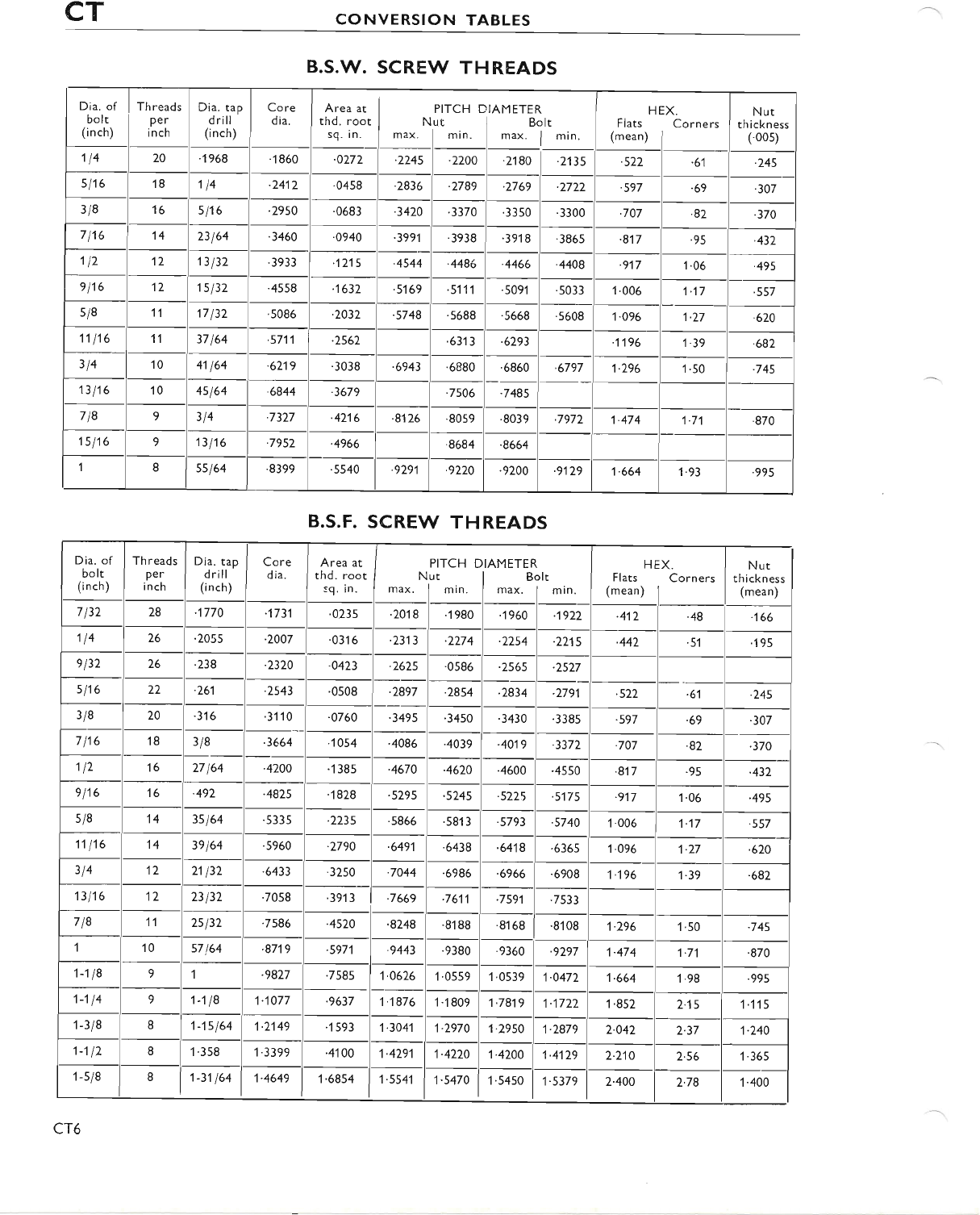
CT CONVERSION TABLES
B.S.W. SCREW THREADS
Dia. of
bolt
(i n ch)
Th reads
Per
in ch
Dia. tap
d rill
(inch)
Core
dia. Area at
thd. root
sq. in.
PITCH
Nut
max. lmin.
AMETER
Bolt
max. lmin.
HEX.
Flats Corners
(mean) |
Nut
th i ckn ess
(.00s)
114 20 .1968 .1860 .0272 .224s I i,oo -522 '6'l -245
s 116 18 114 .2417 .0458 .2836 -2789 .2769 .2722 '597 .69 .307
3/8 16 s116 .2950 .0683 .3420 3370 '3350 3300 -707 .82 .370
7116 't4 23t64 .3460 .0940 .3991 .3938 .39't 8.3865 .817 .95 -432
112 12 13132 3933 .1215 .4544 .4486 .4466 .4408 .917 1.06 .49s
e 116 12 1s 132 .4558 .1632 .5169 .5111 .5091 .5033 1.006 1.'.t7 '557
s/8 11 17132 .5086 .2032 .s748 .5688 .5668 .5608 1.096 't-27 .620
11l't6 11 37 164 .5711 -2562 .631 3-6293 '1196 1.39 .682
314 't0 41164 .6219 .3038 '6943 '6880 '6860 .6797 1.296 1.50 .745
13116 10 4s 164 .6844 .3679 7506 .7485
718 9314 '7327 .4216 .8126 .8059 .8039 .7972 1.474 1.71 .870
'ts l16 913 t16 '7952 .4966 .8684 .8664
1Iss 164 .8399 .s540 .9291 -9220 .9200 .9129 1.664 '1.93 .995
B.S.F. SCREW THREADS
Dia. of
bolt
(inch)
Th reads
Per
i nch
Dia. tap
d rill
(i n ch)
Core
dia. Area at
thd. root
sq. in.
PITCH DIAMETER
Nut I Bolt
max. lmin. Iru*. 1min.
HEX.
Flats Corners
(mean) |
Nut
th i ckness
(mean)
7132 28 .1770 .1731 .0235 .2018 '1980 .1960 .1922 412 .48 166
114 26 .2055 2007 .0316 -2313 .2274 .2254 .2215 -442 .51 195
el32 26 .238 2320 .0423 .2625 .0586 .2565 -2527
s116 22 -261 2543 .0508 .2897 .2854 .2834 .2791 .522 '6',1 -245
3/8 20 316 .31't 00760 .3495 '3450 .3430 .3385 .597 .69 -307
7116 18 3/8 .3664 '1054 .4086 .4039 .4019 .3372 '707 '82 .370
112 16 27 164 .4200 '1385 '4670 '4620 .4600 .4550 .817 .95 .432
e 116 16 .492 -4425 "1 828 .5295 .5245 .5225 .5175 .9'.17 '1.06 .495
s/8 14 3s164 .5335 2235 5866 .s81 3'5793 -5744 1.006 1.17 .557
11116 14 39164 .s960 2790 -6491 .6438 .6418 .6365 1.096 1.27 .620
314 12 21132 .6433 '3250 .7044 .6986 .6966 .6908 1.196 1.39 682
13116 12 23 t32 .70s8 391 3 7669 .7611 .7s91 '7533
718 11 25t32 7586 .4520 .8248 .8188 .8168 .8108 1.296 1.50 .745
10 57 64 .87',t9 .5971 .9443 '9380 .9360 .9297 1.474 1.71 .870
1-118 91.9827 .7585 1.0626 1.0559 1.0539 1.0472 1.664 1.98 .995
1114 91-118 1.1077 .9637 1.'1876 1 .1809 1.7819 1|t722 1.852 2.15 1115
1 -3/8 I1-15164 1-2149 '1593 1.3041 1.2970 1.2950 1.2879 2-042 2.37 1.240
1-112 81'358 1.3399 .4100 1.4291 1.4220 1-4200 1.4129 2.2'10 2.56 1.365
1 -s/8 81-31164 1.4649 1.6854 1.5541 1-5470 1'54s0 1.5379 2-400 2.78 1.400
cT6
www.bsaunitsingles.com
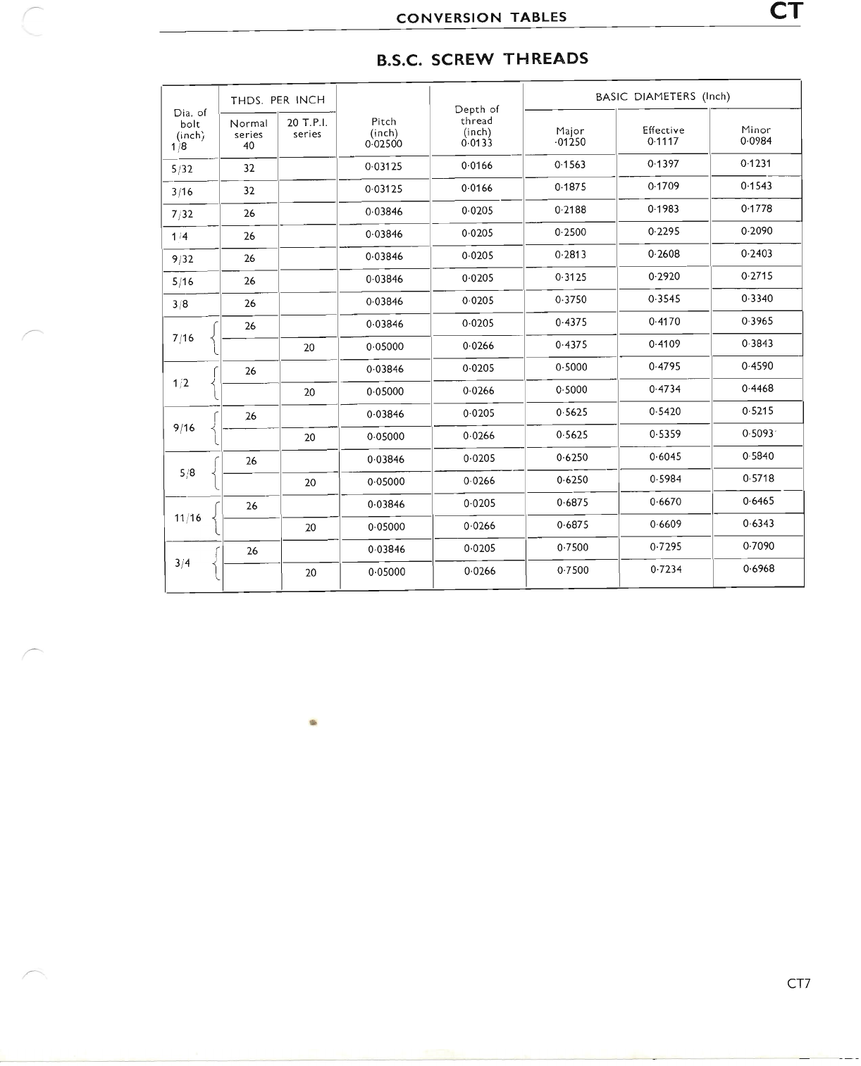
CONVERSION TABLES CT
B.S.C. SCREW THREADS
Dia. of
bolt
(i nch)
1 8
THDS, PER INCH
Pitch
(i n ch)
0.02500
Depth of
th read
(i n ch)
0.0133
BASIC DIAMETERS (lnch)
Normal
series
40
20 T.P.l.
series Major
.01 250 Effective
0.1117 Minor
0'0984
s l32 32 0.03125 0.0166 0.1 563 0.1397 0.1231
3116 32 0.031 2s 0.0166 0.1875 0.1709 0.'t543
7132 26 0.03846 0.0205 0.2'188 0.1983 0.1778
114 26 0.03846 0.0205 0.2500 0.2295 0.2090
e l32 26 0.03846 0.0205 0.2813 0.2608 o.2403
s 116 26 0.03846 0.0205 0'3125 0.2920 0.27't5
3/8 26 0.03846 0.0205 0.3750 0.3s45 0.3340
7t16 j26 0.03846 0.0205 0.4375 o.4't70 0.3965
20 0.05000 0.0266 0.4375 o.4109 0.3843
I
1i2 1
26 0.03846 0.0205 0.5000 o.4795 0.4s90
20 0.05000 0.0266 0.s000 0.4734 0-4468
r
et16 t26 0.03846 0.0205 0.562s 0.5420 0'521 5
20 0.05000 0.0266 0'5625 0's359 0.5093
(
si8 1
26 0.03846 0.020s 0.6250 0.6045 0.5840
20 0.05000 0.0266 0'6250 0.5984 0's718
(
11116 <t
26 0.03846 0.0205 0.6875 0'6670 o.6465
20 0'05000 0'0266 0.6875 0.6609 0.6343
(
314 1
26 0.03846 0.0205 0.7500 0.7295 0.7090
20 0'05000 0.0266 0.7s00 0.7234 0.6968
cT7
www.bsaunitsingles.com
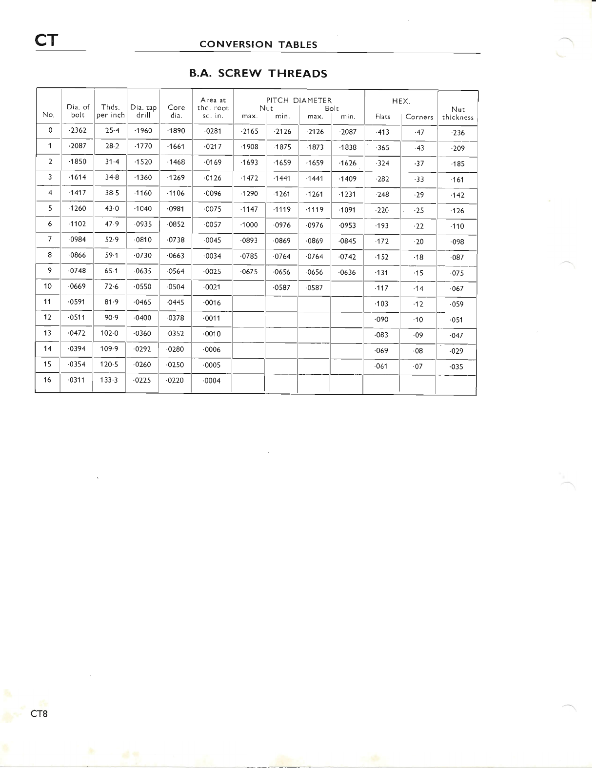
CT CONVERSION TABLES
B.A. SCREW THR,EADS
No. Dia. of
bolt Thds.
per inch Dia. tap
d rill Core
d ia.
Area at
thd. root
sq. in.
PITCH D
Nut
max. I m in.
AMETER
Bolt
max. lmin.
HEX.
Flats lCorners
Nut
thickness
0.2362 25.4 .1960 .1890 .0281 .2165 .2126 2't26 .2087 .413 .47 '236
1.2087 28.2 .1770 .166'l .0217 .'1908 .1875 .1873 1 838 .365 43 .209
2.1850 31.4 1520 1468 .0'169 1693 '1659 .1659 -1626 .324 .37 185
31614 34.8 .'1 360 1269 .0126 1472 1441 1441 .1409 -282 .33 161
4,1417 38.5 1160 fl46 '0096 1290 1261 1261 .'t231 248 .29 -142
5.1260 43.0 1440 .0981 .0075 1147 .1119 11't9 .1091 224 .25 .126
61102 47.9 .0935 '0852 '0057 .1000 '0976 '0976 '0953 19? .22 110
70984 52.9 .0810 '0738 .0045 '0893 .0869 .0869 .0845 '172 .20 .098
8.0866 59.1 .0730 .0663 .0034 '0785 '0764 .0764 -0742 .152 18 .087
9.0748 65.1 .0635 .0564 .0025 .0675 '0656 .0656 .0636 .131 15 '07s
10 .o669 72.6 .0550 .0504 -0021 .0587 .0587 117 14 '067
11 .0591 81.9 .0465 .0445 .00't6 .103 "t2 .059
12 .051'l 90.9 .0400 .0378 .0011 .090 '10 .051
13 .0472 102.0 .0360 .0352 .0010 '083 .09 .o47
14 .0394 109.9 '0292 '0280 .0006 '069 .08 .o29
15 .0354 120.s .0260 .0250 '0005 .061 -07 .035
16 .0311 1 33.3 .0225 .0220 .0004
cT8
www.bsaunitsingles.com
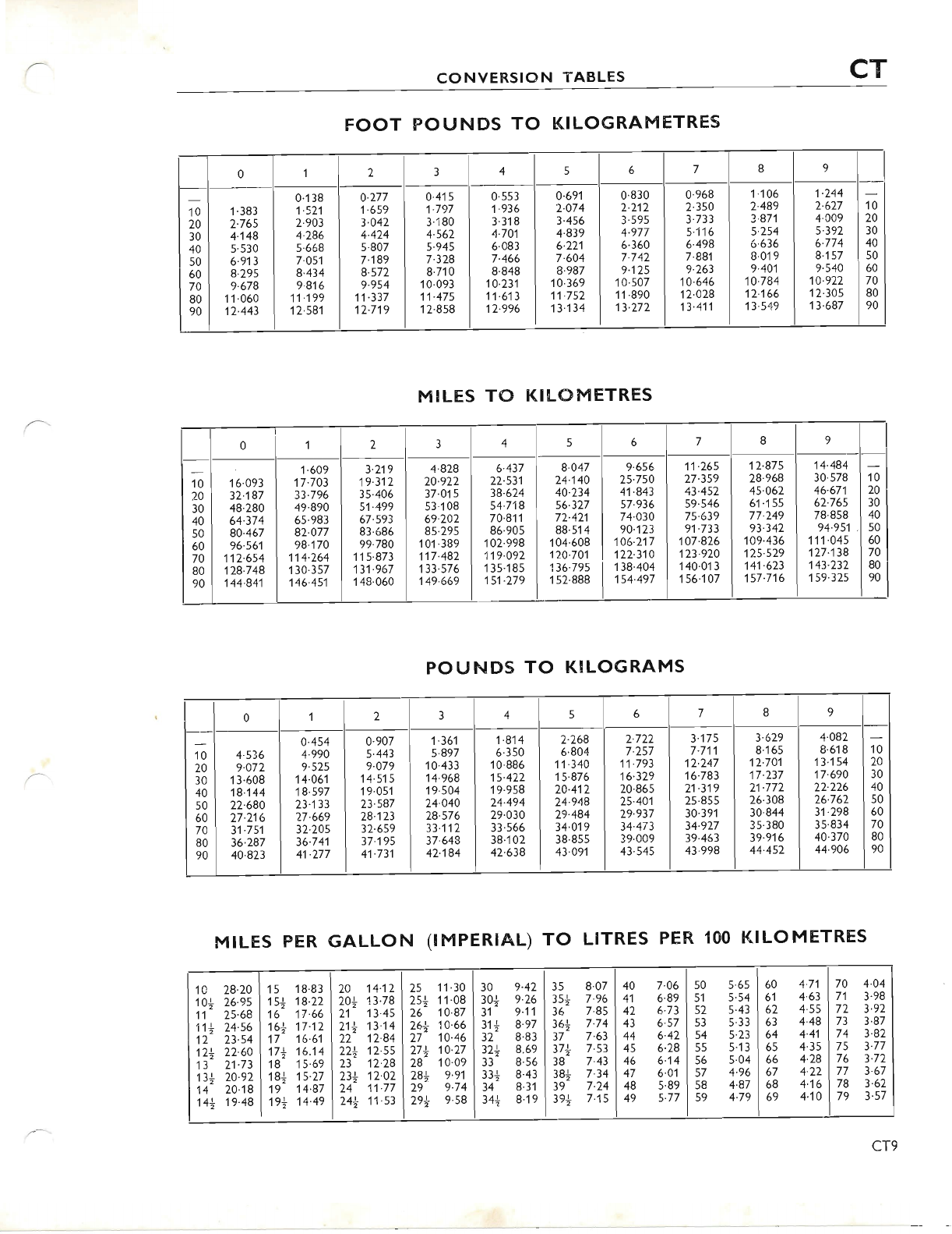
CONVERSION TABLES CT
FOOT POUNDS TO KILOGRAMETRES
M!LES TO KILOMETRES
POUNDS TO KILOGRAMS
01234567I9
10
20
30
40
50
60
70
80
90
1.383
2.765
4.148
5.530
6.913
8'295
9.678
11.060
'12.443
0.'1 38
1-114
2.903
4.286
5.668
7.051
8.434
9'816
11.199
12.581
o.277
1.659
3.042
4.424
5.807
7.189
8.572
9.954
11.337
12.719
0.4'ts
1.797
3.180
4.562
5.945
7.328
8.710
10.093
11.475
12.858
0.553
1.936
3'318
4-701
6.083
7.466
8.848
10.231
11.6'.13
12.996
0.691
2.074
3.456
4.839
6.221
7.604
8.987
1 0.369
11.752
13.134
0.830
2.212
3.595
4.977
6.360
7.742
9.125
1 0.507
'11.890
13.272
0.968
2.350
3'733
s.1't6
6.498
7.881
9.263
10.646
12.028
13.411
1.106
2.489
3'871
5.254
6'636
8.019
9.401
10.784
12.166
1 3.549
1.244
2.627
4.009
5.392
6.774
8.1 57
9.540
10.922
1 2.305
13.687
1o
20
30
40
50
60
70
80
90
0113456789
10
20
30
40
50
60
70
80
90
16.093
32'187
48.280
64.374
80.467
96.561
112.6s4
128.748
'144.841
1'609
17.703
33.796
49.890
65.983
82.077
98.170
114.264
't 30.357
146.451
3.719
't9.312
35.406
51.499
67.593
83.686
99.780
'115.873
131.967
148'060
4.828
20.922
37.01 5
53.108
69.202
85.295
10't .389
117.482
'1 33.576
149.669
6.437
22.531
38-624
54.718
70.811
86.905
102.998
119.092
1 35.185
151.279
8.047
24-140
4A.234
56.327
72.421
88.51 4
1 04.608
110.701
136.79s
1 52'888
9.656
25.750
41.843
57.936
74.030
90.123
106.217
122.310
138.404
154.497
11.265
27.359
43.452
59.546
75.639
91-733
107.826
123'920
140.013
156.107
12.875
28.968
45-462
61.155
77.249
93.342
109.436
125.529
141.623
157.7'16
14'484
30.578
46.671
62.765
78'858
94.951
't11.045
127.138
143.232
159.325
10
20
30
40
50
60
70
80
90
01L3456789
10
20
30
40
50
60
70
80
90
4-536
9.072
'13.608
18.144
22.680
27.216
31.751
36.287
40.823
o.454
4.994
9'525
14.061
18.597
23.133
27.669
32.205
36.741
41.277
0.907
5.443
9.079
14.515
19'051
23.s87
28.123
32.659
37.195
41.731
1.361
5.897
10.433
14'968
19.504
24.040
28.576
33.112
37.648
42'184
1.814
6.350
't 0.886
15.422
'19.958
24.494
29.030
33'566
38'102
42.638
2.268
6.8A4
11.340
15.876
24.412
24.948
29.484
34'019
38.855
43.091
2'722
7.257
1'.t.793
16.329
20.865
25.401
29.937
34.473
39.009
43.545
3.175
7.711
12.247
16.783
21.319
25.8ss
30.391
34.927
39.463
43.998
3.629
8'165
12.741
17.237
21.772
26.308
30.844
35.380
39-916
44.452
4.082
8.618
13.1s4
17-690
22.226
26.762
31.298
35.834
40.370
44-906
1o
20
30
40
50
60
70
80
90
MTLES PER GALLON (!MPERIAI-) TO LITRES PER, 100 KILoMETRES
10 28.20
10+ 26.9s
11 25.68
11+ 24.s6
12 23.54
12+ 22.60
't 3 21.73
13+ 20.92
14 20.18
14+ 19.48
1 5 18.83
1s+ 1e.22
16 17.66
16+ 17.12
17 16.61
17+ 16.14
18 15.69
18+ 1s.27
19 14.87
19+ 14.49
20 14.12
20+ 13.78
2'.t 13.45
21+ 13.14
22 12.84
22+ 12.ss
23 12.28
23+ 12.02
24 11.77
24+ 11.53
25 11 .30
2s+ f.a8
26 10.87
26+ 10.66
27 10.46
27+ 14.27
28 10.09
28+ e.e1
29 9.74
29+ 9.s8
6 89 I sl s.s4
6.73 I s2 s'43
60
61
62
63
64
65
66
67
68
69
40
41
42
43
44
45
46
47
48
49
35
3s+
36
36+
37
37+
38
38+
39
3e+
30
30+
31
31+
32
32+
33
33*
34
34+
o.L)
9.26
9.11
8.97
8.83
8.69
8'56
8.43
8.31
8.19
8.07
7.96
7.85
7.74
7.63
7.53
7.43
7.34
7.24
7-15
7.06 I s0 5.65 4.71 I 70 4.04
4.63 I 71 3.98
4'55 I 72 3.92
6.57 I s3 s.33 4.48 I 73 3.87
6.42 | s4 5'23 4.41 I 74 3.82
6'28 I ss s.13 4.3s I 7s 3.77
6.14 I 56 s.04 4.28 I 76 3'72
6.01 | s7 4.96 4.22 I 77 3.67
s'8e I s8 4.87 4.16 178 362
5.77 I s9 4.79 4'10 I 79 3.57
cT9
www.bsaunitsingles.com
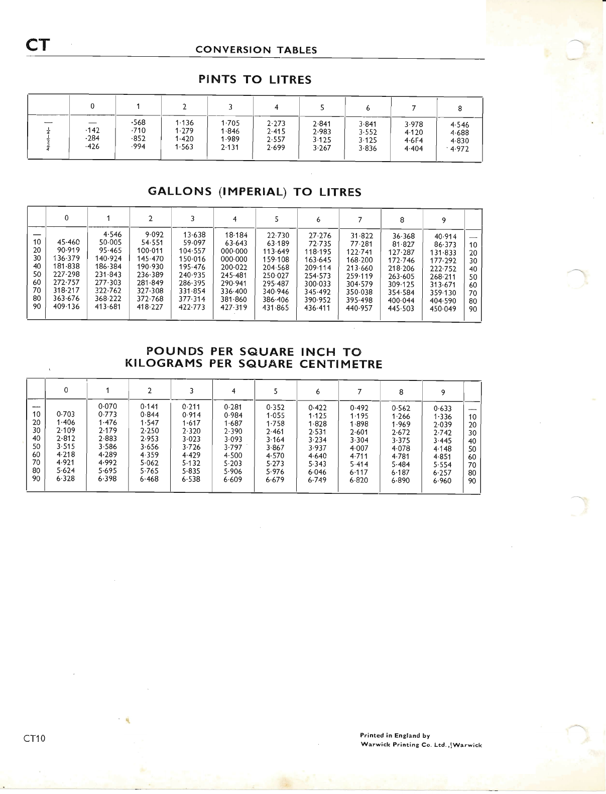
CT CONVERSION TABLES
PINTS TO LITRES
POUNDS PER S@L'ARE INCH TO
KILOGRAMS PER SAUARE CENTIMETRE
012345678
I
..t-
2
3
14'
.284
.426
.568
.710
.8s2
.994
1.'t36
1.279
1.420
1.563
1.705
1.846
1.989
2.131
2.273
2.4't5
2-557
2.699
2.841
2.983
3'125
3.267
3.841
3.552
3.'t2s
3.836
3.978
4.12A
4.6F4
4.404
4.546
4.688
4'830
'4.972
GALLONS (tMPER|AL) TO LTTRES
o1234567I9
10
20
30
40
50
60
70
80
90
45.46A
90-919
136.379
1 81 .838
227.298
272'757
318.217
363.676
409-136
4.546
50'005
9s.465
140.924
186.384
231.843
277.303
322.762
368.222
413.681
9.092
54.551
100.01 1
145.470
1 90.930
236.389
281.849
327.308
372.768
418.227
13.638
59.097
104.557
150.016
195.476
240-935
286.39s
331.854
377.314
422.773
18.'184
63.643
000'000
000.000
200.022
245.481
290'941
336'400
381.860
427.319
22.730
63.1 89
113.649
1 59.108
204.568
250.027
295.487
340.946
386.406
431.86s
27.276
72.73s
118.195
163.645
209-114
254.573
300'033
345.492
390.952
436.411
31.822
77.28'l
122.741
1 68.200
713.660
259.119
304.579
3s0.038
395.498
440.957
36.368
81.827
127.287
172.746
218'206
263.605
309.1 25
354.s84
400.044
44s.503
40.9't4
86.373
13'1 '833
177.292
222-752
268.211
313.671
359.'t 30
404.590
450.049
1o
20
30
40
50
60
70
80
90
0123456 7 89
10
20
30
40
50
60
70
80
90
0.703
1.406
2.109
2.812
3.515
4.218
4.92',1
5.624
6'328
0.070
0-773
1-476
2'179
2.883
3.586
4'289
4.992
5.695
6.398
0-141
0.844
1-547
2.250
2.9s3
3.656
4-359
5.062
5.76s
6.468
c.211
0.914
1-617
2.320
3.023
3.726
4'429
5.132
5.835
6.538
0.28'l
0.984
1.687
2.390
3.093
3.797
4.500
5.203
5.906
6.649
0.352
't.055
'1.7s8
2.46',1
3.164
3.867
4.570
5.273
5-976
6.679
0.422
1.125
1.828
2-531
3-234
3.937
4.640
s.343
6.046
6.749
0.492
1.195
1.898
2.601
3.304
4.007
4.711
5.414
6.117
5.820
0.562
1.266
1.969
2.672
3.375
4.078
4-781
5.484
6.187
6'890
0.633
1.336
2.039
2.742
3.445
4.',t48
4.85'l
5.554
6.257
6.960
10
20
30
40
50
60
70
80
90
Printed in England by
Warwick Printing Co. Ltd.,lWarwick
cT10
www.bsaunitsingles.com
