T2581 2 _95 8 PB Ser# 100 To Current_ Manual 2_95 8_PB_Ser100_to_current_Manual 95 Ser100 Current
User Manual: T2581-2_95-8_PB_Ser100_to_current_Manual
Open the PDF directly: View PDF ![]() .
.
Page Count: 78

Piranha
P.O. Box 457
Hutchinson, Ks 67504
Voice (800) 338-5471
Fax (316) 662-1719
Web Site www.piranhafab.com
No part of this manual may be stored in a retrieval system, transmitted, or, reproduced in any way. Including but not limited to
photocopy, photograph, and magnetic or other record without the prior agreement and written permission of Mega Manufacturing Inc.
PN: T2581-2
95-8 GEN II Manual

Table of Contents
Safety ....................................................................................................................................................3
Warning Labels .....................................................................................................................................4
Tooling Installation Safety ....................................................................................................................6
Safety Standards & Specifications ........................................................................................................7
Introduction ...........................................................................................................................................9
Installation...........................................................................................................................................11
Unpacking............................................................................................................................................11
Placement ............................................................................................................................................11
Initial leveling..................................................................................................................................... 12
Cleaning ..............................................................................................................................................13
Precision Leveling...............................................................................................................................14
Electrical..............................................................................................................................................15
Hydraulic.............................................................................................................................................17
Filling the Pump Case ........................................................................................................................ 18
Motor Rotation ................................................................................................................................... 18
Operator Control..................................................................................................................................19
Pedestal controls..................................................................................................................................21
Key pad functions................................................................................................................................21
Operating Parameters ..........................................................................................................................23
Finishing Speed .................................................................................................................................. 23
Ram Return Modes............................................................................................................................. 24
Steps for Entering Names and Numbers............................................................................................. 24
Machine set-up ................................................................................................................................... 26
Run job after making selection........................................................................................................... 31
Setting Limits for Forming..................................................................................................................32
Programming a Simple Job ................................................................................................................ 32
Edit a Bend ........................................................................................................................................ 32
Recalling a Job ................................................................................................................................... 33
Search For Job Option........................................................................................................................ 33
Scroll For Job Option ......................................................................................................................... 33
Clear Parts Count................................................................................................................................ 33
Steps To Turn Off A CNC Control In Gen II..................................................................................... 33
Steps To Turn On A CNC Control In Gen II ..................................................................................... 34
Change Speed When A 3rd Party CNC Is Running:.......................................................................... 34
Procedure For Setting The Lower Ram Limit For Automec CNC Back Gauges............................... 35
Bed Leveling Adjustment....................................................................................................................36
Tooling Installation .............................................................................................................................37
Press Brake Preparation...................................................................................................................... 37
Die Insertion....................................................................................................................................... 37
Tooling Removal................................................................................................................................ 38
Tool Adjustments ............................................................................................................................... 39
Tonnage Requirements....................................................................................................................... 39
Die Rail Shimming..............................................................................................................................39
Maintenance Procedures......................................................................................................................40
Maintenance Schedule.........................................................................................................................40
Gib Clearance Adjustment ..................................................................................................................41
Gib Adjustment .................................................................................................................................. 41
Side Thrust Gib Adjustment............................................................................................................... 41
Ram Slides .......................................................................................................................................... 41
Hydraulic Power Unit ......................................................................................................................... 42
Hydraulic & Electrical Diagrams........................................................................................................ 43
Electrical Diagrams.............................................................................................................................43
Hydraulic Diagram..............................................................................................................................51
Parts .................................................................................................................................................. 52
Ram Linkage....................................................................................................................................... 52
Hydraulic Assemblies......................................................................................................................... 53
Valve Body Assembly ........................................................................................................................54
Ram Slides .......................................................................................................................................... 58
Oil Filter Assembly.............................................................................................................................59
Wedge Assembly ................................................................................................................................ 60
Die Rail Centering Screw Assembly ..................................................................................................61
Punch Clamp Assembly......................................................................................................................62
Backstop Assembly.............................................................................................................................63
Back Stop Finger Assembly................................................................................................................64
Die Rail .............................................................................................................................................. 65
Glossary .............................................................................................................................................. 66
Index .................................................................................................................................................. 72
Addendums ......................................................................................................................................... 74

Table of Figures
Figure 1: Lifting Lug Location.........................................................................................................11
Figure 2: Leveling Plate /Foot Detail ...............................................................................................12
Figure 3: Precision Leveling Detail..................................................................................................14
Figure 4: Fuse Size Chart .................................................................................................................16
Figure 5: Oil Level & Temperature Sight Gauge.............................................................................17
Figure 6: Hydraulic Pump/Motor Assembly Unit............................................................................18
Figure 7: Main Control Panel..........................................................................................................19
Figure 8: Pedestal Control................................................................................................................20
Figure 9: Bed Tilt Wedge Assembly................................................................................................36
Figure 10: Die Rail Shimming Example ..........................................................................................39
Figure 11: Gib Explanation ..............................................................................................................41
Figure 12: Oil Filter Assembly Exploded View...............................................................................42
Figure 13: Electrical Diagram 1 .......................................................................................................43
Figure 14: Electrical Diagram 2 .......................................................................................................44
Figure 15: Electrical Diagram 3 .......................................................................................................45
Figure 16: Hydraulic Diagram 1.......................................................................................................51
Figure 17: Ram Linkage...................................................................................................................52
Figure 18: Hydraulic Power Unit .....................................................................................................53
Figure 19: Valve Body Assembly Front View .................................................................................54
Figure 20: Valve Body Assembly Rear View ..................................................................................55
Figure 21: Gib Parts..........................................................................................................................58
Figure 22: Oil Filter Assembly Exploded View...............................................................................59
Figure 23: Wedge Assembly ............................................................................................................60
Figure 24: Die Rail Centering Screw Assembly...............................................................................61
Figure 25: Punch Clamp Assembly..................................................................................................62
Figure 26: Back Gauge Assembly....................................................................................................63
Figure 27: Back Stop Finger Assembly............................................................................................64
Figure 28: Die Rail...........................................................................................................................65

Piranha 95 Operator's /Owner's Manual
2

Piranha 95 Operator's /Owner's Manual
3
Safety
Safety must be a primary concern. When operating or performing maintenance procedures,
follow all standard safety guidelines. Do not wear loose fitting clothing or any articles that may
be pulled into any moving parts.
Be sure that when operating the equipment, all safety devices operate properly. Never under
any circumstances disable, remove, or alter the original configuration of the safety system.
Should any component of the safety system become inoperable, immediately discontinue
operation, and notify a supervisor.
! NEVER place fingers, hands, or any other body part in or under the ram area
or other moving mechanisms.
! Proper eye protection must be worn at all times when operating the machine.
! Always insure that the machine is turned OFF before changing the tooling.
Read and understand this manual prior to operating the machine.
The area around the Piranha 95 Press Brake should be well lighted, dry, and free of
obstacles.
The Piranha 95 Press Brake is designed for single person operation only.
Always insure that all tooling is properly secured in position before starting any operation.
When servicing the machine always practice standard lockout/tag-out procedures to avoid
personal injury.
NOTE: The Run/Program keyswitch provides security for choosing initiation means and
operation modes that can be supervised by the user, in accordance with ANSI B11.3 standards.
The Generation II control system also provides a Footswitch Control Module. Removing the
Footswitch Control Module can provide an extra level of lockout security for initiation means,
if your plant safety program deems a level is needed beyond the Run/Program keyswitch.
Without the Footswitch Control Module in place, Foot or Foot/Foot initiation means will not
operate even if chosen using the Run/Program keyswitch.
When installing a Piranha “Plug -n- Play” light curtain assembly, the light curtain connector
will replace the Footswitch Control Module.
Piranha 95 Operator's /Owner's Manual
4
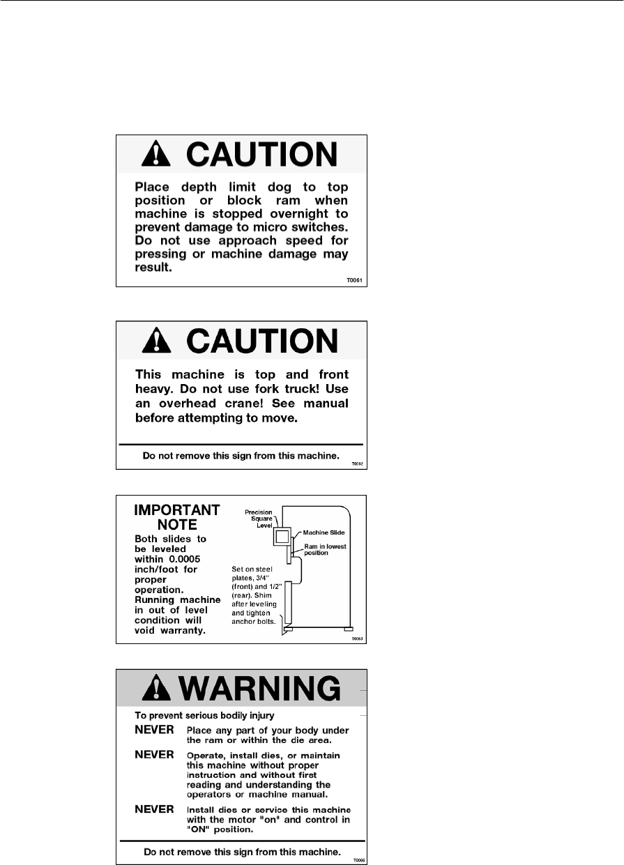
Warning Labels
Located around the Piranha 95 Press Brake are labels warning the operator of various dangers
and precautions to be aware of when operating or servicing the machine.
Place the depth limit dog to the
top position or block the ram in the
up position when the machine is
stopped overnight to prevent
damage to the micro switches. Do
not use approach speed for
pressing or machine damage may
result.
Part – T0061
This machine is top and front
heavy. Do not use a fork truck!
Use an overhead crane! See
manual before attempting to
move.
Part – T0062
Both slides are to be leveled
within 0.0005 inch/foot for proper
operation. Running the machine
out of level will cause damage and
void the warranty.
Part – T0063
To prevent serious bodily injury;
Never place any part of your body
under the ram or within the die
area.
Never Operate, install dies, or
maintain this machine without
proper instruction and without first
reading and understanding the
operators or owners machine
maintenance manual.
Never Install dies or service this
machine with the motor “on” and
control in “on” position.
Piranha 95 Operator's /Owner's Manual
5
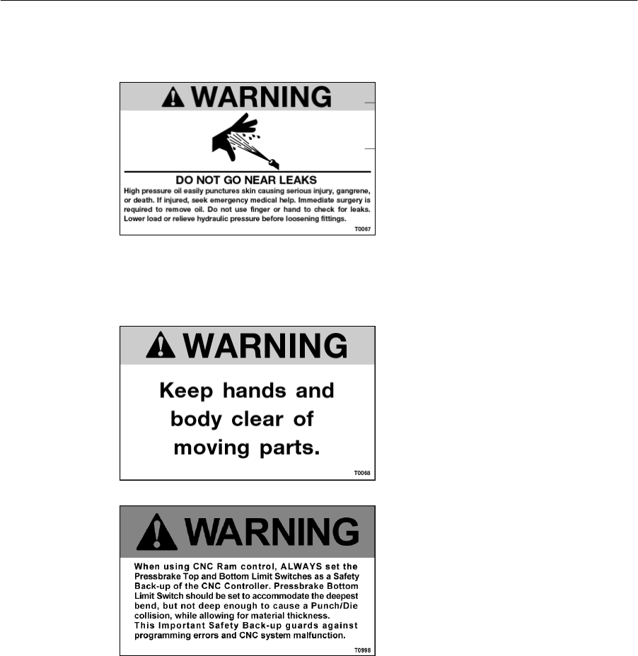
Part – T0066
Do not go near leaks
High-pressure oil easily punctures
skin causing injury, gangrene and
even death. If injured, seek
emergency medical help.
Immediate surgery is required to
remove oil. Do not use finger or
hand to check for leaks. Lower
load or relieve pressure before
loosening fittings.
Part – T0067
Keep hands and body parts clear
of moving parts.
Part – T0068
When using CNC Ram control,
always set the press brake top
and bottom limit switches as a
safety back up of the CNC
controller. Press brake bottom
limit switch should be set to
accommodate the deepest bend,
but not enough to cause a punch
die collision, while allowing for
material thickness.
This important safety back up
guards against programming
errors and CNC system
malfunction.
Part – T0998

Piranha 95 Operator's /Owner's Manual
6
Tooling Installation Safety
Tool setting is a very important job. Safety of the operator, press brake and the tooling is
involved. To properly prepare for the job, the tool setter should have a good working
knowledge of press brakes, tools and materials. The person should also have been
instructed in the use of tool trucks and other handling equipment. The person must also
understand the importance of proper tool adjustment.
Aside from the technical knowledge the setter must develop a sense of personal safety
awareness. It is not only important that tools are correctly installed in the proper size of
equipment; the task must be accomplished in an organized and safe manner to complete
the job.
The following steps offer a precautionary guide in the development for safe tooling
installation procedures.
1. Immediately report any questionable operation, unusual action, unsafe
condition or improper maintenance to the proper personnel.
2. NEVER at any time allow fingers or hands to be between the tools.
3. When working with other people insure that all persons are clear of the press
brake prior to any ram motion (jogging, inching or cycling).
4. Insure that the proper safe material handling equipment (tongs, pliers, vacuum
lifters or other mechanical devices) available to the press brake operator.
5. When changing the settings of press brake controls, insure that the controls are
properly adjusted and test cycle the machine to verify correct operation.
6. Any locking type of controls should be adjusted by authorized personal, and
the key must be removed to a secure location when not being used.
7. Insure that all devices are in proper working order.
8. Anytime that the machine has been left unattended or inoperative for even a
brief time, verify the correct position of all controls and proper press brake
operation.
9. Develop a sense of safety for yourself and any persons around you as well as
your surrounding area.

Piranha 95 Operator's /Owner's Manual
7
Safety Standards & Specifications
Electrical System Design/Manufacture:
The machines manufactured in Hutchinson, KS, are furnished with electrical/electronic
products that are UL (Underwriter’s Laboratory) approved. These components have the
UL numbers printed or stamped on them and can be easily traced to the point of
manufacture.
Hydraulic System Design/Manufacture:
Hydraulic components used in Piranha machines are approved by NFPA (National Fluid
Power Association), and those approval numbers can be traced through the manufacturer’s
part numbers.
ANSI/OSHA Compliance:
Mega Manufacturing meets the current ANSI construction standards for manufacturing of
ironworkers, press brakes, and shears:
ANSI B11.3—Power press brakes, Construction, Care, and Use
The ANSI B11 standards were developed to establish levels of responsibility for
manufacturing safe products, installation, training, and use of these products. The levels of
responsibility are fairly evenly distributed between the manufacturer, the owner/end user of
the equipment, and the operator. Specific guarding requirements are in general assigned to
the owner/end user of the equipment.
Please understand that this ruling places the primary burden of responsibility for
maintenance of guarding on the owner /end user of the equipment. Inherent in this
requirement is the responsibility of the owner/end user of the equipment to develop and
maintain guarding specific to their application for the equipment. These ANSI safety
requirements may be acquired from:
American National Standard Institute
1430 Broadway
New York, New York 10018
Telephone (212) 354-3300
PO Box 457
Hutchinson, KS 67504-0457
Phone: (800) 338-5471
Fax: (620) 669-8964

Piranha 95 Operator's /Owner's Manual
8
This page is intentionally left blank.

Piranha 95 Operator's /Owner's Manual
9
Introduction
The Piranha press brake is a heavy duty, high performance hydraulic powered
machine that provides several important advantages surpassing other press brakes in
today’s market. The Piranha’s single hydraulic cylinder mechanical linkage system
provides full tonnage at any point across the bed.
The machine is shipped fully assembled requiring only hydraulic oil and electric
power to become fully operational. The heavy steel “C” frames, interlocking cross
members, ram and bed provide the integrity and resistance to deflection that is
necessary for accurate performance. State of the art, maintenance free, aerospace
Garfil bushings provide high load capacity and low friction in the form of a thin
walled sleeve. They are completely non-metallic and require no lubrication. Hardened
micro-finished oversize link pins allow the linkage to withstand high load forming
and punching applications.
Other standard features include: emergency stop button, Generation II control system,
bed tilt adjustment, spring open die clamps with hardened clamping bolts. Hardened
& ground ram slides with non-metallic ram gibs, PRS, precision ground die rail
drilled and tapped on both sides with hold down bolts, die rail centering adjustment
bolts and a sturdy 36" micro-adjustable back–gauge for simple, accurate and fast
setting.
The precision model offers ram repeatability of +/- .0004" This machine is equipped
with a Hurco CNC unit as standard. The Hurco CNC must be in use and the Finishing
Speed function must be turned on to achieve +/- .0004” repeatability.
Warranty
Mega Mfg. will replace or repair with like parts, either new or rebuilt, F.O.B. the
factory, or refund the purchase price for any parts on ironworkers, pressbrakes, or
shears, which are defective in materials and workmanship within (12) months of the
date of purchase. Provided the buyer returns the warranty registration within (30
days) of the purchase date, and, at the seller’s option, returns the defective materials
freight and delivery prepaid to the seller, which shall be the buyer’s sole remedy for
the defective materials. A 5 year warranty against defects in materials and
workmanship applies to major structural components on pressbrakes and shears.
Seller shall not be liable to purchaser or any other person for consequential or
incidental damages. Hydraulic and electrical components are subject to their
respective manufacturer’s warranties. This warranty does not apply to machines
and/or components which have been altered in any way, or subjected to abusive or
abnormal use, inadequate maintenance and lubrication, or to use beyond seller
recommended capacities and specifications. Seller shall not be liable under any
circumstances for labor costs expended on such goods or consequential damages.
Seller shall not be liable to purchaser or any other person for loss or damage directly
or indirectly arising from the use of the goods or any other cause. No employee,
agent, officer, or seller is authorized to make oral representations or warranty of
fitness or to waive any of the foregoing terms of sale and none shall be binding on
the seller.

Piranha 95 Operator's /Owner's Manual
10
This page is intentionally left blank.
Piranha 95 Operator's /Owner's Manual
11
Installation
BEFORE INSTALLING THIS PRESS BRAKE, READ AND UNDERSTAND
THE PRESS BRAKE MANUAL WITH PARTICULAR ATTENTION TO
“SAFETY TIPS FOR MAINTENANCE PERSONNEL” THE CURRENT ANSI
B11-3 STANDARD-“SAFETY REQUIREMENTS FOR THE
CONSTRUCTION, CARE AND USE OF POWER PRESS BRAKES.”
Copies can be ordered from: American National Standards Institute,
1430 Broadway, New York, New York 10018
Unpacking
CAUTION: THE PRESS BRAKE IS HEAVY IN FRONT. GUARD
AGAINST TIPPING UNTIL ANCHOR BOLTS ARE SECURED.
This machine was carefully packaged at the factory to avoid damage during
shipment, should any accidental damage occur contact the responsible freight
company immediately and report the damage. Indicate any damage on the Bill of
Lading. All Warranty information included in this packet must be returned to
the factory.
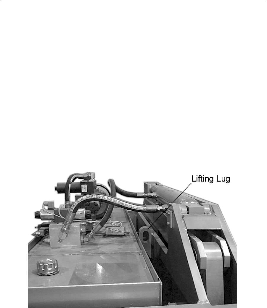
Figure 1: Lifting Lug Location
The Piranha 95 Press Brake must only be lifted using a crane, and the lifting lugs
located in front of the hydraulic oil tank on top of the machine. Do not lift the
machine from the bottom (forklift or jack) as the machine is top and front heavy
and can tip resulting in serious bodily harm or death. Lifting the machine from
the bottom can also result in machine damage.
Placement
Piranha recommends that the machine be placed on a reasonably level concrete
foundation suitable to support the press brake’s total weight and in accordance
Piranha 95 Operator's /Owner's Manual
12
with local building codes. The machine should be placed on a single concrete
pad free of cracks and seams. Prior to anchoring or setting, the press brake
should be leveled and shimmed. A section (0) on leveling is included in this
manual. Anchoring can be accomplished using suitable masonry anchors.
Typically, only the rear feet of the machine need to be anchored. Use the
machine as a template for anchoring hole locations. Placement of the machine
should allow easy access around the machine for the operator and maintenance
personnel. For safe operation placement should allow tooling to be installed onto
the bed from the end of the machine.
It is recommended that a minimum four-foot area around the Piranha 95 Press
Brake be provided.
Initial leveling
CAUTION: THE PRESS BRAKE IS HEAVY IN FRONT. GUARD
AGAINST TIPPING BEFORE AND DURING LEVELING.
Level adjusting screws are only provided on the rear feet. The Piranha
95 Press Brake must be placed on four steel pads: 2 each 6" x 6" x ¾"
for the front feet and 2 each 6" x 6" x ½" for the rear feet. These pads
are provided with the press brake.
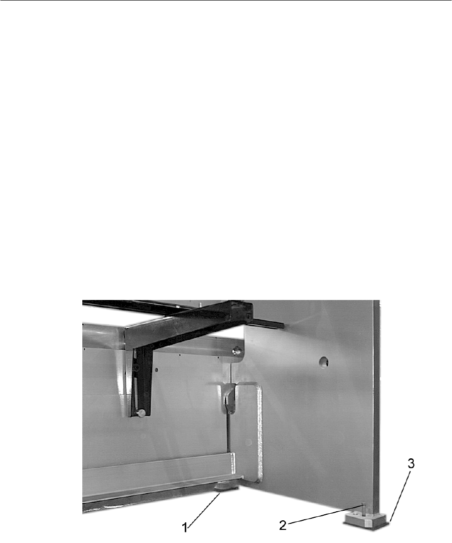
Figure 2: Leveling Plate /Foot Detail
1. Position the 3/4" thick pad under each of the front feet (see
Figure 2 Item 1).
2. Position the 1/2" thick pad under each of the rear feet (see
Figure 2 Item 3).

Piranha 95 Operator's /Owner's Manual
13
3. Before the riggers disconnect the lifting apparatus, check the
press brake for rough level from the left to right plane.
4. Using a machinist square level, shim the front feet until the
machined bottom surface of the Ram is level left to right.
Desired level is within .005”-.015” inch per foot. A jack
angle is located on the inside of the right C-frame to assist in
leveling the machine right to left. Because of bed tilt feature,
the bed cannot easily be used for leveling.
Cleaning
Clean the die rail, bed surface, punch holder pocket and die clamps with a mild
solvent so as not to damage the paint finish on the machine. The main cylinder
rod must also be free contaminants. Any contaminants left on the cylinder rod
may damage the chrome finish and related hydraulic seals. The cylinder rod
must be clean and dry. Wipe down the rest of the press brake with a mild
cleaning solution.
Piranha 95 Operator's /Owner's Manual
14
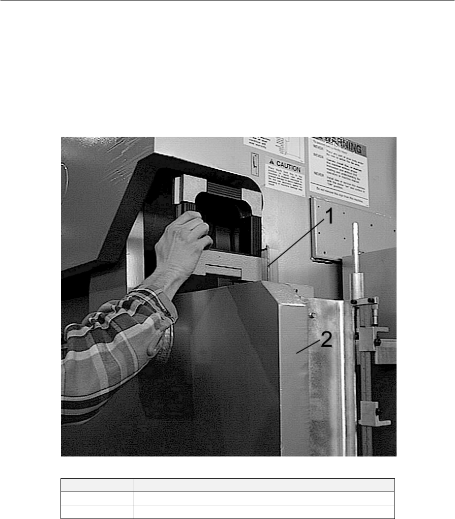
Precision Leveling
The Piranha 95 Press Brake must be leveled precisely prior to operation. The
following steps represent the typical leveling procedure. These instructions must
be followed to avoid damaging the machine.
This procedure will require that the press brake have electrical power connected
and hydraulic fluid installed. The press brake must be functional enough to lower
the ram to the bottom stop position.
Figure 3: Precision Leveling Detail
Item Description
1 Slides
2 Ram
Table 1: Ram Slide Location Explanations
1. Before beginning the leveling procedure, turn on the press brake
and lower the ram to the bottom of stroke position, then turn the
press brake off.
2. It is important to keep in mind that the left and right side need
only to be parallel with each other, rather than perpendicular with
the floor.
3. Using a machinist square level having an accuracy of .0005” inch
per foot graduation, place the level firmly against the front face
of the right vertical ram slide as shown. (See Figure 3 Item1)

Piranha 95 Operator's /Owner's Manual
15
4. Adjust the rear-leveling bolt until the bubble on the level is
centered.
5. Repeat this procedure for the left slide. Adjust leveling bolts as
required.
6. The side frames must be parallel to each other within .0005” per
foot.
7. Once the machine is level, place shims, having a thickness equal
to the gap between the base plate and the bottom of the press
brake foot under the foot.
8. After the shims are in place, lower the adjusting bolts and re-
check the level to ensure that the left and right sides of the
machine have remained parallel to each other. The overall shim
pack height may need to be adjusted in order to maintain side
frame parallelism.
9. The machine may now be anchored to the floor using concrete
anchor lugs.
10. After tightening the floor anchor lugs, re-check the press brake
level to ensure that the machine has not moved.
Electrical
CAUTION: ELECTRICIANS CHECKING DIRECTION OF ROTATION
SHOULD BE CAUTIONED NOT TO OPERATE THE PRESS BRAKE
UNTIL IT HAS BEEN THOROUGHLY CHECKED, CLEANED, LEVELED
AND LUBRICATED. A WIRING DIAGRAM IS FURNISHED IN THIS
MANUAL. THE PRESS BRAKE OPERATING MODE MUST BE IN THE
OFF POSITION WHEN CHECKING MOTOR ROTATION.
BEFORE DRILLING ANY HOLES IN THE ELECTRICAL ENCLOSURE,
BE SURE THAT THE ELECTRONIC CIRCUIT BOARDS/EQUIPMENT
ARE PROTECTED FROM METAL CHIPS CONTACTING THE CIRCUIT
BOARD(S). DO NOT USE COMPRESSED AIR TO BLOW METAL
DEBRIS FROM THE ENCLOSURE. USE A VACUUM TO REMOVE
ANY METAL PARTICLES.
Voltage requirements may be determined by comparing the fuse part number to
the chart located on the inner door panel of the main electrical box. (See Figure 4)

Piranha 95 Operator's /Owner's Manual
16
Figure 4: Fuse Size Chart
Electrical connection of the 3-phase systems requires proper phasing. When
connecting the press to a 3-phase power source, the rotational direction of the
pump drive motor must be correct. . The motor must rotate in the direction of the
arrow on the electrical motor (see Figure 6).
A licensed electrician should perform all electrical connections.
! Warning - The control transformer is for machine operation only. Do not
use the machine transformer to power any secondary devices.
If a CNC back-gauge is installed on the machine, a dedicated 115-VAC, 60Hz,
20-Amp fused service must be provided for the backgauge system. l
Connecting the Pedestal Control
Prior to operation, the pedestal control plug must be attached to the main
control panel. To connect the plug, locate the receptacle on the bottom of
the main electrical control box. Align the plug with the receptacle.
Insert the plug and rotate the outer ring securing the plug to the
receptacle.
Piranha 95 Operator's /Owner's Manual
17
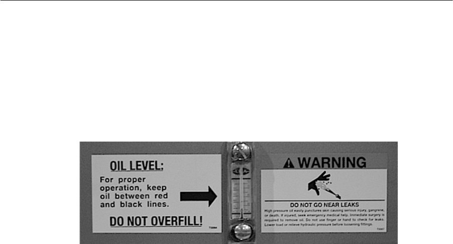
Hydraulic
Before applying power to the Piranha 95 Press Brake, the hydraulic reservoir
must be filled with oil. To fill the reservoir, locate and remove the filler/breather
cap on top of the reservoir. Fill the reservoir with Mobil DTE-13 or ISO32
equivalent, filtered to an ISO 17/15/13-cleanliness level. The proper oil level is
between the red and black lines of the sight gauge found on the rear of the
reservoir (See Figure 5). Do not over fill the reservoir. Replace the filler/breather
cap.
Figure 5: Oil Level & Temperature Sight Gauge
Piranha 95 Operator's /Owner's Manual
18
Filling the Pump Case
Prior to starting the motor for the first time, remove the pump case drain
tube from the hydraulic pump and fill the pump case with hydraulic
fluid. Reconnect the pump case drain tube. If the motor is run in
reversed rotation, this procedure must be repeated. The pump case must
be filled with hydraulic fluid upon start up.
WARNING: Failure to follow this procedure may lead to pump damage
and premature failure.
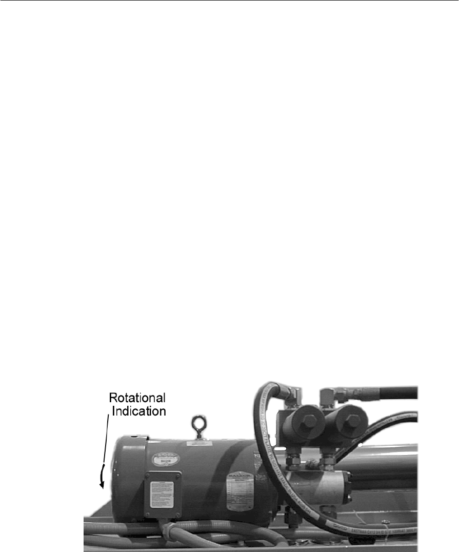
Motor Rotation
Motor rotation can be verified by quickly “Bump Starting” the motor
(starting and stopping quickly) and viewing the fan blade rotation
through he fan blade shroud. The rotation direction of the motor fan
blades must correspond with the direction arrow on the motor.
If the fan blades are obscured, use a flashlight to view the fan blades
from the grease zerk slot on the fan shroud. Shine the light towards the
fan blades and view the fan blade rotation.
Upon initial start-up of the hydraulic unit visually inspect around the
machine for any possible leaks. Do not search for hydraulic oil leaks
using exposed flesh; hydraulic pressure can puncture the skin.
Figure 6: Hydraulic Pump/Motor Assembly Unit
Piranha 95 Operator's /Owner's Manual
19
Operator Control
Operator selectable controls are provided on the Pedestal Control and on the Main Control Panel.
Functionality of both stations is described in the following subsections.
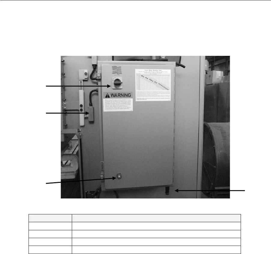
Main Electrical Enclosure
al enclosure is located on the right hand side of the
Figure 7: Main Control Panel
The Ram Safety Switchmust be set to engage within ½” before the speed change point to enable
proper operation of the sequence modes and optional safety devices.
Item Description
1 Safety Disconnect Switch
2 Ram Safety Switch
3 Reset Button
4 Footswitch Control Module
1
2
3
4
Piranha 95 Operator's /Owner's Manual
20
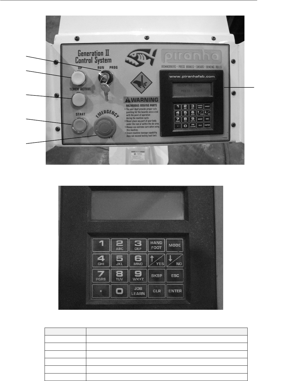
Figure 8: Pedestal Control
Item Description
1 Keyed Program /Run Selector Switch
2 Ram Up Button
3 Teach/Learn Indicator Light
4 Motor Start Button
5 Motor Stop Button
6 LCD/ Keypad Unit
1
2
3
4
5
6

Piranha 95 Operator's /Owner's Manual
21
Pedestal controls
Start button: Depressing the green Start pushbutton will apply power to the electric motor
that drives the Piranha Press Brake hydraulic power unit. Depressing the E-Stop pushbutton
will remove power from the pump unit. Before attempting to start the hydraulic motor insure
that the E-Stop control is in the armed (up) position.
Stop Button: The E-Stop (Emergency Stop) control is a red, two-position maintained push
button. Pressing the E-Stop button will remove electrical power from the hydraulic power
unit drive motor and all base machine control circuits, stopping all machine movement.
Twist the button head clockwise to reset the pushbutton.
Machine movement cannot resume until the E-Stop button has been reset.
Ram up Button: Depressing the Ram Up button will raise the ram from any position to the
up stroke position.
Program/Run keyed switch: The Supervisor key switch limits access to programming
functions, run modes, and initiation means. In the Run position it permits operation of the
press brake. In the program position, programming functions, run mode access, and initiation
means access is permitted.
Dual palm Buttons: Depressing the palm buttons simultaneously will initiate a press cycle.
If either palm button is released before the ram reaches the full down position, the ram will
respond according to the Run mode selector switch setting.
Footswitch: A footswitch is provided for use according to the initiating means. If the
footswitch is released before the ram reaches the full down position the ram will react
according to the Run mode selector switch setting.
Key pad functions
Alpha/numeric keys: Contains numeric and alpha characters used for data entries.
Programs similar to a cell phone format.
Hand/Foot: Permits the operator to toggle between the various initiation means when
Program/Run switch is in the Program position.
Mode: Permits the operator to toggle between the various run modes when Program/Run
switch is in the Program position.
/Yes: Moves the cursor up and answers yes to questions requiring a positive response
/ No: Moves the cursor down and answers no to questions requiring a negative response
Bksp: Moves the cursor backward one position per depression.
Esc: Moves display back to the previous menu
Decimal: Inserts a decimal point.
Job/Learn: Will display a job selection menu, and inputs value during teach mode. When in
the run screen, depressing the job/learn key will display the job selection menu. In the teach
mode, depressing the job/learn key will input the current ram position.
Clr: Clears most recent entry.

Piranha 95 Operator's /Owner's Manual
22
Enter: Confirms data entry.
Cycle counters & Timers
Machine counter: Master cycle counter, tracks total number of ram cycles and is not re-
settable.
Maintenance counter: Cycle counter used for tracking maintenance intervals and may be
reset. An access code is required to gain entry into the counter screen.
Parts counter: Counter used to track the number of completed parts during a production
run. May be reset from the Run Screen (Job/learn key)
Hour meter: Records total “motor run” hours and is not re-settable.
Memory Tag / Job Storage and Back up
The Generation II control system is equipped with a battery backup circuit to prevent
programmed job loss in the event of a power failure or when the machine electrical power is
turned off. The battery has a nominal lifespan of three years after which time the battery
discharges and all stored jobs will be lost if not saved to a memory tag. Stored jobs will also
be lost when the battery is replaced unless jobs are “backed up” on a memory tag.
The backup procedure is detailed here:
1. Turn off main power to electrical enclosure.
2. Open enclosure door.
3. Insert Memory Tag into slot on front face of GII control module (Orientation does
not matter).
4. Close electrical enclosure door.
5. Restore electrical power.
6. Start press brake.
7. After GII initializes, turn “Run/Program” switch to “Program.”
8. Select “Teach/Edit Job” and press Enter.
9. Use “Down Arrow” to select “Memory Tag” and press Enter.
10. Select desired function: “Backup Jobs” or “Restore Jobs” and press Enter.
11. Remove and store memory tag when data transfer is completed.
NOTE: Do Not Remove Memory Stick While “Read/Write” is in progress.
Memory Tag Part Number: T3132

Piranha 95 Operator's /Owner's Manual
23
Operating Parameters (Key required for access)
Initiation means
Hand: When the switch is in the “Hand” position the machine is controlled from the Two-
Hand control. The palm buttons must be engaged simultaneously to initiate a press cycle.
Foot: When the “Foot” mode is selected, the press is controlled by the footswitch alone.
Hand/Foot: This is a sequencing mode of operation that utilizes both Hand and Foot modes.
Ram movement is initialized by Hand mode and then transferred to Foot mode at the speed
change position. Simultaneously depressing and maintaining both of the palm buttons
initiates the sequence. At the speed change position, the ram stops and control is transferred
to the footswitch. Activation of the footswitch will complete the ram cycle.
Foot/Foot: This is a sequencing mode of operation that utilizes a double Footswitch
actuation. Operating the footswitch control initializes Ram movement. The pressbrake ram
travels downward in approach speed to the speed change point, where the ram stops
movement. Reactivation of the footswitch will complete the ram cycle.
Run modes
Off: When the “Off” mode is selected, all Press Brake movement (up or down) is disabled.
Only the hydraulic motor can be started when the Operating Mode switch is in this position.
Inch: When the Inch mode is selected, the Press Brake ram will descend when the palm
buttons are actuated. Releasing the palm buttons will cause the ram to stop. Re-initiating the
palm buttons will restart downward ram movement. At the bottom of stroke position the ram
will stop, and must be raised by depressing the Ram Up button. This mode is useful for
setting or changing tooling, and setting up a job.
Run 1: When the Run 1 mode is selected, the ram will descend when the dual palm buttons
are depressed. When the dual palm buttons are released at any point during the down stroke,
the ram will pause. Downward motion will resume when the dual palm buttons are re-
activated. The ram will automatically return to the top of stroke position when the bottom
stop position is reached.
Run 2: When the Run 2 mode is selected, the ram will descend when the dual palm buttons
are depressed. When the dual palm buttons are released during the down stroke, or when the
bottom stop position is reached, the ram will automatically return to the top of stroke
position.
Run 3: When The Run 3 mode is selected, the ram will descend when the dual palm buttons
are depressed. When the dual palm buttons are released during the down stroke, the ram will
stop. When the ram reaches the bottom stop position, the ram may be “inched” up by
“toggling the dual palm buttons. Run 3 will allow the operator control of the ram with the
dual palm buttons during the return stroke
Finishing Speed
Finishing speed is incorporated into the control configuration to permit the press
brake ram to enter a slower pressing speed, enabling a greater degree of ram
repeatability.

Piranha 95 Operator's /Owner's Manual
24
Ram Return Modes
Low
Low, or “slow” return when selected, is a function where the ram will return slowly
from the bottom of stroke to the top of stroke.
Low / High
Low, or “slow” return when selected, is a function where the ram will return slowly
from the bottom of stroke to the original speed change point. At the speed change
point, the ram will revert to the normal or “high” return speed
High
High-speed return when selected, is a function where the ram will return ito the top of
stroke position in the high speed.
Steps for Entering Names and Numbers
Refer to the letters on the number keys to select the desire characters.
With each press of a numeric key, the displayed character appears in the following order:
Number first, then the corresponding letter on the key (Upper Case only). After a character is
entered, the cursor will automatically advance to the next position
Number of Times Key is Depressed
Keys 1 2 3 4 5
1 1
2ABC 2 A B C
3DEF 3 D E F
4GHI 4 G H I
5JKL 5 J K L
6MNO 6 M N O
7PQRS 7 P Q R S
8TUV 8 T U V
9WXYZ 9 W X Y Z
0 0
If you make a mistake while entering a name
Use BKSP (Backspace) to move the cursor to the incorrect character, enter the correct
character.

Piranha 95 Operator's /Owner's Manual
25
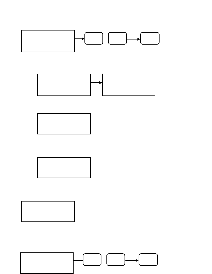
POWER UP
The following screens are displayed upon power up of the control
Depressing the START button on the console will start the main pump motor and initialize
the control for operation or programming.
Piranha:
GENERATION II
VER – 1.**
© 2001 MEGA MFG.
CONTROL READY:
PRESS START
TO RUN
MAIN PUMP MOTOR
INSTALLED OPTIONS
1. “Y” AXIS

Piranha 95 Operator's /Owner's Manual
26
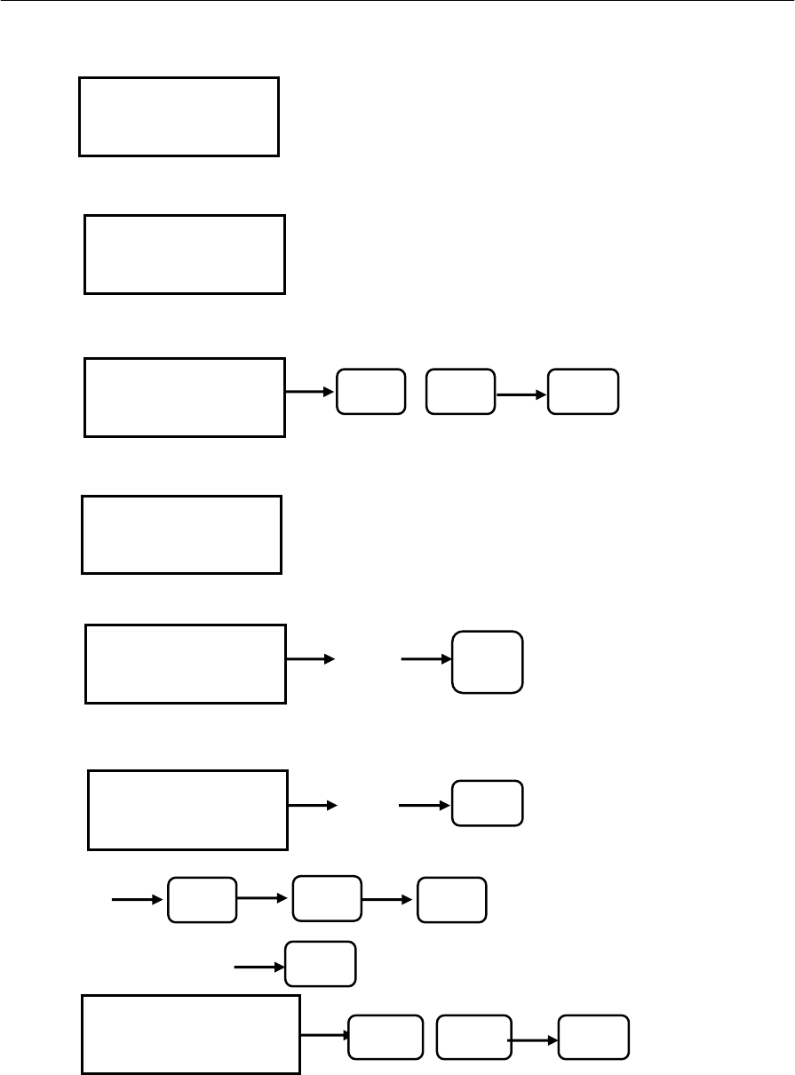
Machine set-up: (Security Code required for access)
Programming menu items are accessed with the RUN/PROGRAM key selector in the Program
mode. Use the UP and DOWN arrow keys to select from the main program screen.
The main program screen displays the HAND/FOOT selection and
the current operation mode.
Tip: Either Use ↑↓ keys to select desired menu item then
Enter, or press number corresponding to desired menu item.
The MACHINE SETUP menu is for machine settings that can be
modified by the user. The security code (9999 or code set by
supervisor) must be entered to gain access to this screen. The
security code field will accept up to six digits.
Tip: Either Use ↑↓ keys to select desired menu item then
Enter, or press number corresponding to desired menu item.
>1 ANTI-TIE-DOWN
NOTE: 500 MS is a default parameter. This value may be
changed for a specific job application if required.
>2 MAINT COUNTER
Cycle counter used for tracking maintenance intervals and
may be reset by depressing the CLR (Clear) button..
>1.ANTI-TIE-DOWN
2.MAINT COUNTER
3.STM TEST
4.SECURITY CODE
5.INCH/MM DISPLAY
6.MACHINE-COUNTER
7.HOUR METER
8.LIGHT CURTAIN
9.TONNAGE READOUT
0.TOS TEST POSN
TOS TIMER
BACKGAUGE
TIMERS:
ANTI-TIE-DOWN
500 MS
HAND SINGLE
1. TEACH/EDIT JOB
2. SET BEND NUMBER
>3. MACHINE SETUP
↑
/YES ↓/NO ENTER
MAINT COUNTER
PRESS CLR TO RESET
123456
PROGRAM
ENTER SECURITY CODE
**** CODE
Piranha 95 Operator's /Owner's Manual
27
>3 STM TEST (Stop Time Measurement)
>STM TEST CYCLE
>HAND SPEED CONST
NOTE: 63 in/sec is a default parameter. This value may
be changed for a specific job application if required.
>LIGHT CURTAIN MOS (Minimum Object Sensitivity)
NOTE: This inch value is the minimum object sensitivity
of the light curtain.
>4 SECURITY CODE
To change the supervisor security code, enter desired code. May
be a combination of Alpha/Numeric symbols up to six digits long.
NOTE: Once this security code is changed, the default security
code (9999) will no longer be active.
>5 INCH/MM DISPLAY
Inch/mm
STM TEST CYCLE
PRESS ENTER TO START
STM TEST READY
PRESS PALM BUTTONS
AND HOLD UNTIL STOP
ESC TO ABORT
STM TEST:
HAND SPEED CONST
63 IN/SEC
STM TEST:
LIGHT CURTAIN MOS
1.00 INCHES
SEC CODE:
TO CHANGE SEC CODE
ENTER SEC CODE
Code
DISPLAY MODE
INCH DISPLAY
↑/ YES ↓/ NO ENTER
>STM TEST CYCLE
HAND SPEED CONST
LIGHT CURTAIN MOS
↑
/ YES ↓/ NO ENTER
Piranha 95 Operator's /Owner's Manual
28
>6 MACHINE COUNTER
Displays ram cycles and is not re-settable
>7 HOUR METER
Displays motor run hours and is not re-settable
>8 LIGHT CURTAIN
OFF/ON
>9 TONNAGE READOUT (Optional)
>0 TOS TEST POSN
>TOS TIMER
>9
>BACKGAGUE
NONE/HURCO/AUTOMEC
BACKGAUGE:
TYPE
NONE
↑
/ YES ↓/ NO ENTE
R
MACHINE COUNTER
12345678
PRESS ESC TO EXIT
HOUR METER
1234567.1
PRESS ESC TO EXIT
LIGHT CURTAIN:
LIGHT CURTAIN
OFF
↑
/ YES ↓/ NO ENTER
TONNAGE READOUT:
POSITION:
TOS TEST POSN
0.XXX
.xxx ENTER
ENTER
.xx
TIMERS:
TOS TIMERS
.XX SEC
ENTER
↓ / NO ↓/ NO ↓/ NO
Piranha 95 Operator's /Owner's Manual
29
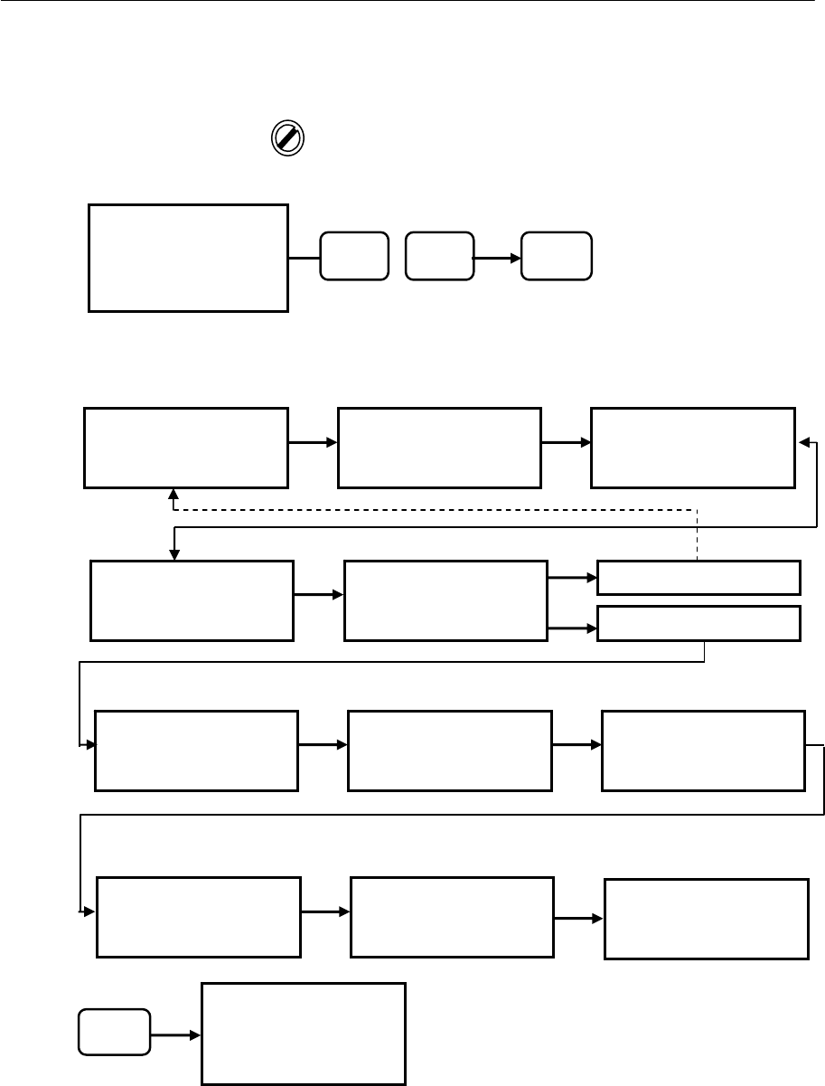
Programming Jobs (Key required for access)
>1 TEACH NEW JOB
TOP POSITION PRESSING POSITION BOTTOM POSITION
RETURN SPEED MODE TON VALVE SETTING
Press #3 to Save Job when complete, and press ESC to exit back to main menu.
>1.TEACH NEW JOB
2.EDIT JOB
3.SAVE CURRENT JOB
4.DEL CURRENT JOB
5.MEMORY TAG
↑/ YES ↓ / NO ENTER
PROGRAM
>1.TEACH NEW JOB
2.EDIT JOB
3.SAVE CURRENT JOB
4.DEL CURRENT JOB
5.MEMORY TAG
ESC
TEACH NEW JOB:
ENTER NEW JOB #
DEFAULT__
TEACH NEW JOB:
PRESSING SPEED #
100_ %
TEACH NEW JOB:
ENTER JOB DESC
DEFAULT__
TEACH NEW JOB:
FINISHING SPEED
100_ % YES
TEACH NEW JOB:
PROCEED TO BENDS?
YES OR NO
NO
JOB#
TOP POSITION
(ACTL POS/LEARN POS)
X.XXXXIN X.XXXXIN
JOB#
BOTTOM POSITION
(ACTL POS/LEARN POS)
X.XXXXIN X.XXXXIN
JOB#
PRESSING POSITION
(ACTL POS/LEARN POS)
X.XXXXIN X.XXXXIN
JOB#
RETURN SPEED MODE
HIGH
JOB#
TON VALVE %
100%
Another Bend?
Yes/No
Piranha 95 Operator's /Owner's Manual
30
>2 EDIT JOB
Tip: Use ↑↓ keys to select desired menu item then Enter.
EDIT JOB
Note: Ability to change
finishing speed is
optional.
EDIT BEND
DELETE BEND
Enter YES or NO to delete a bend displayed for the
current job.
>EDIT JOB
EDIT BEND
DELETE BEND
INSERT BEND
EDIT CURRENT JOB
ENTER JOB DESC
DEFAULT_
EDIT CURRENT JOB
JOB# DEFAULT
BEND #1
JOB#
TOP POSITION
X.XXXXIN
JOB#
BOTTOM POSITION
X.XXXXIN
JOB#
PRESSING POSITION
X.XXXXIN
JOB#
RETURN SPEED MODE
HIGH
JOB#
TON VALVE %
100%
EDIT CURRENT JOB
JOB# DEFAULT
DELETE BEND #1
EDIT CURRENT JOB:
ENTER JOB DESC
DEFAULT
EDIT CURRENT JOB
ENTER NEW JOB #
DEFAULT_
EDIT CURRENT JOB
PRESSING SPEED
100%
EDIT CURRENT JOB
FINISHING SPEED
100%
Piranha 95 Operator's /Owner's Manual
31
INSERT BEND
Enter YES or NO to insert a bend in front of the bend #
displayed for the current Job.
Save job when complete, and press ESC to exit back to main menu.
Run Jobs
1 Choose Program
Choose Menu 1. or 2. to choose job to run.
Tip: Either Use
↑↓
keys to select desired menu item then Enter,
or press number corresponding to desired menu item.
2 Reset Parts Counter
Choose Menu 3. To clear parts counter.
Run job after making selection.
EDIT CURRENT JOB
JOB# DEFAULT
INSERT BEND #1
1.TEACH NEW JOB
2.EDIT JOB
>3.SAVE CURRENT JOB
4.DEL CURRENT JOB
5.MEMORY TAG
#3
>1.SEARCH FOR JOB
2.SCROLL JOB LIST
3.CLEAR PARTS
COUNT
>1.SEARCH FOR JOB
2.SCROLL JOB LIST
3.CLEAR PARTS
COUNT
JOB
LEARN
JOB
LEARN
RUN

Piranha 95 Operator's /Owner's Manual
32
Setting Limits for Forming
WARNING: NEVER GRASP THE MATERIAL WITH FINGERS OR THUMBS ON
TOP OF THE MATERIAL. IF WIDE SHEETS MUST BE HELD DURING
FORMING, SUPPORT THE MATERIAL FROM BELOW WITH THE OPEN PALM,
KEEPING FINGERS AND THUMBS UNDER THE MATERIAL. KEEP ALL PARTS
OF THE BODY CLEAR OF THE UPWARD TRAVEL OF THE MATERIAL
Programming a Simple Job
1. Start Press Brake motor by depressing the green START button.
2. Rotate keyed Programming switch to “PROG” (program) Mode.
3. Press #1 on keypad.
4. On new screen, ensure arrow is on #1 (>1), press ENTER.
5. Key in a job number (11 characters max) and press ENTER.
6. Key in a job description (21 characters max) and press ENTER (To bypass description screen,
press CLR (clear) then ENTER)
7. Key in Pressing Speed to desired value and press ENTER.
8. Key in Finishing Speed to desired value and press ENTER.
9. Press “Yes” button to proceed to bends.
10. Key in desired Top of Stroke position and press ENTER –or-
Move press ram to desired position, then press JOB LEARN button to save position. Press
ENTER.
11. Key in desired Speed Change position and press ENTER –or-
Move press ram to desired position, then press JOB LEARN button to save position. Press
ENTER.
12. Key in desired Bottom of Stroke position and press ENTER –or-
Move press ram to desired position, then press JOB LEARN button to save position. Press
ENTER.
13. Select Return Speed mode by toggling the UP or DOWN arrows and press ENTER.
14. Set Bend Tonnage (if equipped) and press ENTER.
15. To program additional bends, press YES and repeat steps 7-15.
16. If additional bends are not required, press NO.
17. Press #3 to save job.
18. Rotate Keyed Programming switch to “RUN” Mode and cycle press.
Edit a Bend
1. With Press Brake motor running and current job enabled, Rotate keyed Programming switch
to “PROG” (program) Mode.
2. Press #1 on keypad.
3. On new screen, ensure arrow is on “EDIT BEND”(>EDIT BEND), press ENTER.
4. Arrow to EDIT BEND and press ENTER
5. Arrow to desired bend number (or bend function) and press ENTER,
6. If editing ram position, use either arrow key for minute position changes or program new ram
position and press ENTER
7. Rotate keyed Program switch to “RUN”

Piranha 95 Operator's /Owner's Manual
33
Recalling a Job
1. Start Press Brake motor by depressing the green START button.
2. Rotate keyed Programming switch to “RUN” Mode.
3. Press “JOB/LEARN” button on keypad.
4. Select from Three Options:
a. SEARCH FOR JOB
b. SCROLL JOB LIST
c. CLEAR PARTS COUNT
5. Choose the desired option by depressing the corresponding number on the keypad or
by depressing the “↑” or “↓” arrow keys until the desired job has a “>” next to it.
Proceed as follows:
Search For Job Option
1. Enter job name/number or beginning search string identifier and press ENTER on
keypad.
2. Depress the “↑” or “↓” arrow keys until the desired job has a “>” next to it and press
ENTER.
3. Press ESC twice to return to the RUN screen.
4. Job is active and may be “run.”
Scroll For Job Option
1. Displays complete database in alphabetical/numeric order.
2. Depress the “↑” or “↓” arrow keys until the desired job has a “>” next to it and press
ENTER.
3. Press ESC twice to return to the RUN screen.
4. Job is active and may be “run.”
Clear Parts Count
1. Permits the parts counter to be reset.
2. Follow onscreen instructions.
3. After confirming clear, press ESC on keypad until standard RUN screen is displayed.
Steps To Turn Off A CNC Control In Gen II
1. Rotate keyed selector switch to PROGRAM
2. Type “3” for MACHINE SETUP
3. Enter Supervisor Code and press “ENTER”
4. Use ↑ and ↓ until “>” is to the left of BACK GAUGE option and press ENTER
5. Use ↑ and ↓ until NONE is showing and press ENTER
6. Press ESC
NOTE: The press will not cycle until the CNC bypass jumper “Plug” replaces the
CNC interface plug. The bypass plug is located inside the main press brake
electrical enclosure. Unplug the CNC connector and replace with the bypass plug
for Generation II control.

Piranha 95 Operator's /Owner's Manual
34
Steps To Turn On A CNC Control In Gen II
1. Rotate keyed selector switch to PROGRAM
2. Type “3” for MACHINE SETUP
3. Enter Supervisor Code and press ENTER
4. Use ↑ and ↓ until “>” is to the left of BACK GAUGE option and press ENTER
5. Use ↑ and ↓ until AUTOMEC or HURCO is showing and press ENTER
6. Press ESC – Only option 3-MACHINE SETUP should be available now
7. Rotate keyed selector switch to RUN
8. CNC is in control.
Change Speed When A 3rd Party CNC Is Running:
1. Rotate keyed selector switch to PROGRAM
2. Type “3” for MACHINE SETUP
3. Enter Supervisor Code and press “ENTER”
4. Use ↑ and ↓ until “>” is to the left of BACK GAUGE option and press ENTER
5. Use ↑ and ↓ until NONE is showing and press ENTER
6. Press ESC
7. Type “1” for TEACH/EDIT JOB
8. Type “2” for EDIT CURRENT JOB
9. Use ↑ and ↓ until “>” is to the left of EDIT JOB and press ENTER
10. Press ENTER until PRESSING SPEED is displayed
11. Type in desired Pressing Speed % and press ENTER
12. Press ESC three times until Main Program Menu is showing
13. Type “3” for MACHINE SETUP
14. Enter Supervisor Code and press ENTER
15. Use ↑ and ↓ until “>” is to the left of BACK GAUGE option and press ENTER
16. Use ↑ and ↓ until AUTOMEC or HURCO is showing and press ENTER
17. Press ESC – Only option 3-MACHINE SETUP should be available now
18. Rotate keyed selector switch to RUN
19. CNC is in control.
Setting the LOWER RAM LIMIT for AUTOMEC CNC Back Gauges
This software revision/version allows the user of one of our press brakes to set the LOWER
RAM LIMIT as a back-up lower limit when they have an installed 3rd Party CNC Back Gauge,
which is controlling the RAM. When an Automec or Hurco back gauge has been chosen in
the supervisor code protected 3-MACHINE SETUP menu, LOWER RAM LIMIT now shows
as an available parameter in the supervisor code protected 3-MACHINE SETUP menu.

Piranha 95 Operator's /Owner's Manual
35
Procedure for setting the LOWER RAM LIMIT for AUTOMEC CNC Back
Gauges
1. Assuming that AUTOMEC has been chosen as the Back Gauge in the 3-MACHINE
SETUP menu
2. Turn the key switch to PROGRAM
3. Type “3” for the 3-MACHINE SETUP menu
4. Enter the Supervisor Code (factory default is 9999) and hit ENTER
5. Use the ↑ or ↓ buttons until the “>” is next to LOWER RAM LIMIT and hit ENTER
6. Change the LOWER RAM LIMIT to 0”, this moves the Generation II LOWER RAM
LIMIT out of the way and hit ENTER
CAUTION – This overrides the factory set LOWER RAM LIMIT and can allow
the user to bottom out the cylinder!
7. ESC out to the menu which shows 3-MACHINE SETUP
8. Change the run MODE to INCH or RUN 3 – Mode that stops the machine at the
bottom of stroke
9. Turn the key switch to RUN
10. Setup and run job using the AUTOMEC CNC
11. At the bottom of stroke, note the scale reading shown on the dual palm pedestal
12. Complete the stroke
13. Turn the key to PROGRAM
14. Type “3” for 3-MACHINE SETUP menu
15. Enter the Supervisor Code and hit ENTER
16. Use ↓ to get to LOWER RAM LIMIT and hit ENTER
17. Change the LOWER RAM LIMIT to a number that does not interfere with the
AUTOMEC’s control of the bottom of the bend but meets the following AUTOMEC
instructions:
IMPORTANT SAFETY NOTICE TO PRESS BRAKE
OPERATORS AND SET UP PERSONNEL
ALWAYS SET PRESS BRAKE LOWER RAM LIMIT WITH PUNCH AND DIE IN
PLACE BEFORE OPERATING SYSTEM. SET LOWER RAM LIMIT TO ALLOW FOR
THE DEEPEST BEND BUT NOT DEEP ENOUGH TO ALLOW A PUNCH / DIE
COLLISION. BE SURE TO ALLOW FOR MATERIAL THICKNESS.
THIS IMPORTANT SAFETY BACK UP GUARDS AGAINST PROGRAMMING
ERRORS AND SYSTEM MALFUNCTION.
CAUTION – This allows the user to override the factory set LOWER RAM LIMIT!
18. Hit ESC to get out of MACHINE SETUP menu
19. Turn the key to RUN
20. Machine is ready to run
Piranha 95 Operator's /Owner's Manual
36
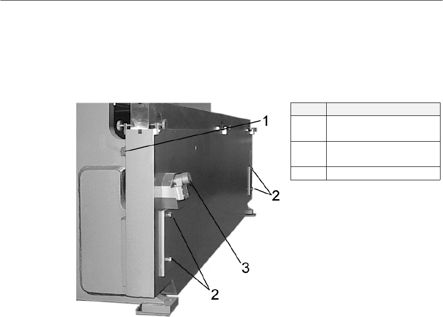
Bed Leveling Adjustment
Located on the left-hand side when facing the front of the machine, is the Bed Leveling
Adjustment Assembly. The Bed Leveling Assembly provides a means of adjusting the Ram
to Bed parallelism; adjustment also permits an out of parallel condition to produce tapered
bends.
Item Description
1 Rear Bed Holding
Bolt
2 Front Bed Holding
Bolt
3 Bed Adjusting Bolt
Figure 9: Bed Tilt Wedge Assembly
The following steps represent the typical bed leveling procedure.
1. To adjust the bed, loosen the six bed holding bolts. Two are located on the rear
side of the bed, one on each end of the press. The other four are located front side
of the bed, two on each end of the bed. (See Figure 9 Items 1 &2).
2. Rotate the adjusting bolt clockwise to lift the bed and counterclockwise to lower.
(See Figure 9 Item 3).
3. Snug the bed holding bolts. The bed holding bolts should only be snug enough to
compress the lock washers, but should not be over tightened. (See Figure 9 Item 1
& 2)
Note: Do not adjust bed tilt with the bed under load.

Piranha 95 Operator's /Owner's Manual
37
Tooling Installation
Before attempting to install, set or remove any tooling from the press brake, the safety section
of this manual must be read and understood.
The exact procedure for installation, setting and removal of dies may vary with the type of die
used. The following steps are a generalized representation and may be tempered to suit the
particular application, though not to the extent of being unsafe.
Always review the instructions provided in this manual and observe the press brake safety
rules!
! NEVER install chipped, cracked, or damaged dies.
Insure that the die is of the correct size and type for the press brake, reducing the risk of
overloading the machine.
Insure that no tools, bolts or other items are in the die area prior to operating the press brake.
Locate any available safety handling tools required.
Keep the floor and surrounding area clean and free of obstruction, debris and oil.
Press Brake Preparation
1. Start the hydraulic power unit.
2. Lower the ram to the bottom position.
3. Remove all power from the press brake.
4. Turn the operating mode to the Off position.
Die Insertion
! NEVER at any time allow fingers or hands to be between the dies.
1. Insure that the Press Brake Preparation procedure has been completed before
continuing with the insertion of dies.
2. Loosen the die rail set screws and punch clamps.
3. Insert the lower die from the end of the press brake, leaving several inches
overhanging the end of the bed
4. Measure the distance between the ram and the lower die to the punch height,
verifying sufficient clearance for insertion of the punch.
5. Adjust the position of the ram as required to allow the punch to rest on the lower
die with the tongue of the die engaged in the punch clamp.
6. Safely transport the punch to the press brake and rest it on the extended portion of
the lower die, aligning the tongue of the punch with the ram groove.

Piranha 95 Operator's /Owner's Manual
38
7. Slide the punch into the punch clamp groove aligning the ends of the punch and
lower dies.
8. Adjust the ram bottom position to make the dies “kiss,” forcing the punch to fully
engage in the punch clamp groove.
9. Tighten the punch clamps and the die rail set screws, securing the dies in the press
brake.
10. Return the ram to the up position.
Tooling Removal
! NEVER at any time allow fingers or hands to be between the dies.
1. Lower the ram until a few thousandths gap exists between the punch and lower
die.
2. Loosen the die rail set screws and punch clamps.
3. Raise the ram position slightly upward and verify that the punch will remain
resting in the lower die. If not, the punch clamps may require further loosening.
4. If additional clearance is required to allow die removal, adjust the ram position to
loosen the die yet keep it well confined.
5. With the punch partially disengaged and guided in the loosened punch clamps,
push both the upper and lower dies several inches out the end of the press brake.
With hands at the end of the dies, push the dies from the end. NEVER place hands
or fingers between the dies.
6. Properly position the die transport device at the end of the press brake to accept
the punch.
7. With hands at the end of the punch, push the punch towards the transport device,
allowing several inches to remain in the punch clamp.
8. Prepare the transport device to completely support the punch, securing the punch
from falling as required.
9. Position the transport device to accept the lower die and slide it from the bed.
Piranha 95 Operator's /Owner's Manual
39
Tool Adjustments
The following steps are a generalized representation and may be tempered to suit the
particular application though not to the extent of being unsafe. It is a good practice to
allow for several sample parts during set up operation, lowering the ram in small
increments until the desired bend is achieved without overloading the machine.
1. Insert a sample piece of material.
2. Adjust the ram limits as required until the desired bend angle is attained. Avoid
over- adjusting the ram.
Note: Shimming may be required to compensate for punch and die wear and any bed
or ram deflection.
Tonnage Requirements
See bending tonnage chart located on side of press brake for approximate bending
requirements.
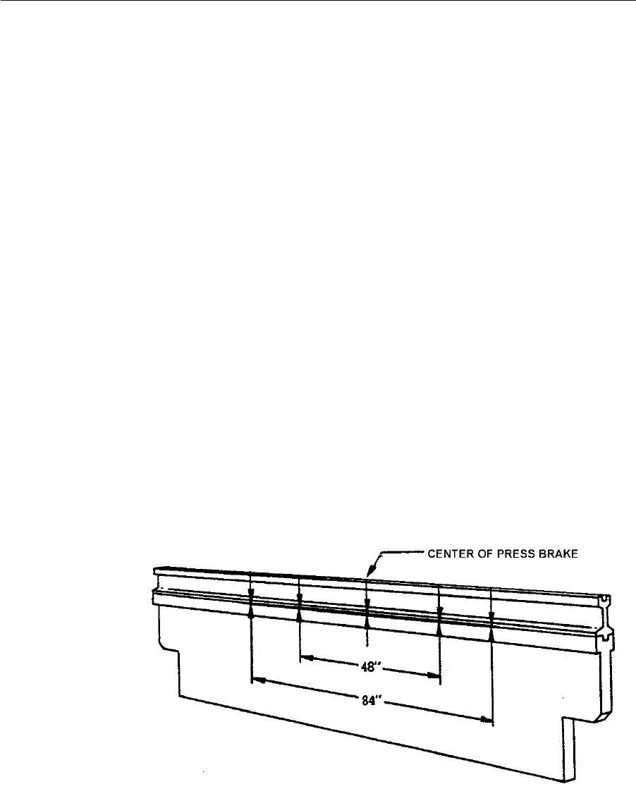
Die Rail Shimming
The Piranha 95 Press Brake is manufactured without a crown in the bed. Occasionally due to
deflection, shimming may be required. If shimming is required under the die rail, shims must
be placed in progressively thicker increments from each end of the bed (see Figure 10).
Typically, shimming is required to compensate for bed deflection and must be performed by
trained personnel. The following diagram is for reference purposes only as each application
will have different requirements.
Figure 10: Die Rail Shimming Example

Piranha 95 Operator's /Owner's Manual
40
Maintenance Procedures
BEFORE MAINTAINING OR REPAIRING THE PRESS BRAKE, READ AND
UNDERSTAND THE CURRENT ANSI B11.3 STANDARD.
This section describes the procedures and requirements for maintaining and repairing the major
components of the Piranha 95 Press Brake.
Maintenance Schedule
This section outlines the suggested points and intervals for regular scheduled
maintenance. The hydraulic power unit is very sensitive to dirt and other contaminants,
but will provide many years of reliable service with a minimum amount of service. The
operating temperature and the cleanliness of the oil directly affect the life of the hydraulic
oil. Regular oil and filter changes will keep the system clean and free of sticking and
clogged valves. Because hydraulic cylinders are lubricated with every stroke, keeping
them clean and free of scratches and dings that may damage the cylinder rod seals is most
important.
The Piranha 95 Press Brake is shipped with an extra hydraulic oil filter. It is important
that after the first forty hours of operation the oil filter be replaced. Upon using the
included extra oil filter it is suggested that a replacement filter be ordered for the next
scheduled filter change.
See parts list for correct filter part number.
1. After First 40 hours:
• Change hydraulic filter
• Check fluid level
• Check gib clearances
• Grease ram slides
• Clean oil cooler by blowing air through radiator portion of the cooler
• Check fittings, bolts, nuts for tightness
2. Every 40 hours (weekly) thereafter:
• Grease ram slides.
• Clean oil cooler by blowing air through radiator portion of the cooler
• Check fittings, bolts, nuts for tightness
3. Every 3 months:
• Change hydraulic filter
It is recommended that the filter element be changed every 3
months depending on workload and environmental conditions. See
repair parts list for re-ordering instructions and the part number.
• Check hydraulic fluid level
• Check gib clearances
4. Every Year:
• Grease electric motor
5. Every Two (2) years:
• Change hydraulic fluid

Piranha 95 Operator's /Owner's Manual
41
Gib Clearance Adjustment
Proper maintenance of the gibs will require periodic adjustment of the gib clearances.
Gib Adjustment
1. Position the press brake ram so the ram slide is in full contact with the gibs.
2. Loosen the Rear Adjustment Screw Jam Nuts on both ends of the press brake.
(See Figure 11 Item 1)
3. Using a torque wrench of the correct torque range, torque the top and bottom
setscrews to 150-in. lbs. (12.5-ft. lbs.).
4. Tighten the remaining setscrews (between the top and bottom setscrews) to the
same torque.
5. Repeat steps 2 & 3.
6. Back off the setscrews 1/8 turn and tighten jam nuts.
7. Repeat this procedure for the other end of the press brake.
Side Thrust Gib Adjustment
1. Position the press brake ram so the ram slide is in full contact with the gibs.
2. Verify that the ram is aligned with the bed (left to right).
3. Loosen the Slide Mounting Bracket Jam Nuts on both ends of the press brake.
(See Figure 11 Item 2)
4. Using a torque wrench of the correct torque range, torque the top and bottom
set screws to 150-in. lbs. (12.5-ft. lbs.).
5. Repeat step 3 on opposite end of the press brake.
6. Tighten the remaining setscrews (between the top and bottom setscrews) to the
same torque.
7. Repeat step 3 on the opposite end of the press brake.
8. Re-torque the setscrews on both ends of the press brake.
9. Back off the setscrews 1/8 turn and the tighten jam nuts on the left side of the
press only.
10. Tighten the jam nuts on the right side of the press brake.
Ram Slides
Figure 11: Gib Explanation
Piranha 95 Operator's /Owner's Manual
42
Hydraulic Power Unit
The hydraulic power unit is a sophisticated and complex system. Only trained personnel
should attempt to perform adjustment procedures on the unit. The power unit generates
very high pressures. Never check for leaks using hands.
Before servicing the hydraulic system, block the ram and turn power off.
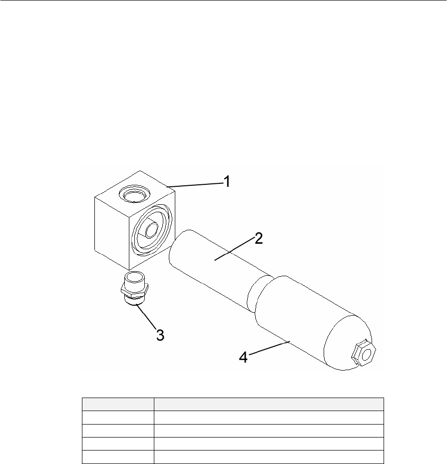
Oil Filter Replacement
Verify the exact element number prior to ordering the replacement element.
Figure 12: Oil Filter Assembly Exploded View
Item Description
1 Filter Body
2 Filter Element
3 Fitting - inlet
4 Filter Bowl
Table 2: Oil Filter Assembly Descriptions
The following steps represent a typical filter element replacement.
1. Insure the main electric power is locked out at the safety
disconnect.
2. Place a small container (½-gallon) under the filter bowl.
3. Remove the filter bowl by turning in a counterclockwise
direction.
4. Remove the filter element by pulling and turning at the same
time.
5. Lubricate the O-ring on the new filter with hydraulic oil and
slide into place.
6. Wipe the inside of the filter element bowl and replace.
Piranha 95 Operator's /Owner's Manual
43
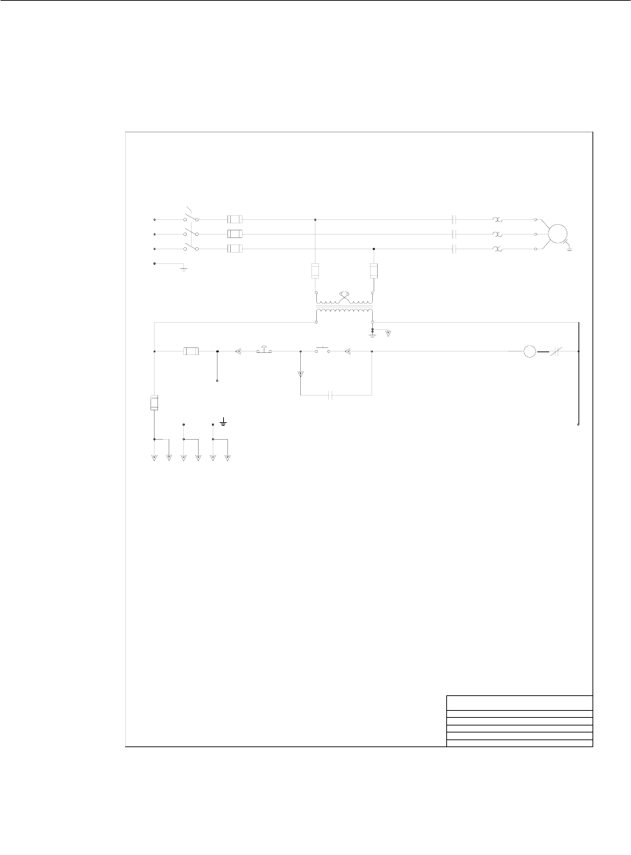
Hydraulic & Electrical Diagrams
Electrical Diagrams
Figure 13: Electrical Diagram 1 of 4
H1 H4
X1 X2
3
2
WHITE
1
M1
HYD
MOTOR
3/0
0/L
M1
F2
F3
EQUIPMENT
GROUND
L1
L2
L3
E STOP START
M1
AUX
F4 F5
PIRANHA
M1
O/L
M1
4
F1
F6
312 5 AMP
1 OF 1
HEATERS
F4 & F5
208 VOLT
230 VOLT
460 VOLT
575 VOLT 15HP
15HP
208 VOLT
230 VOLT
460 VOLT
575 VOLT
750 KVA
208 VOLT
230 VOLT
460 VOLT
575 VOLT
CNC
RECPS
12-5-01
A
W
5
120VA/C
J60
J60
CC30
CC25
B70
B70
B32
B25
CC6.0
CC6.0
CC5.0
CC4.0
F7
3AG/313
5 AMP
TITLE
DRAWING#
DATE
REV#
PAGE#
T2276A-208,230,460,575
15HP PRESS BRAKE
2
1
WGRN
23
1 2 3
3
4
5
1
2
34
4
Piranha 95 Operator's /Owner's Manual
44
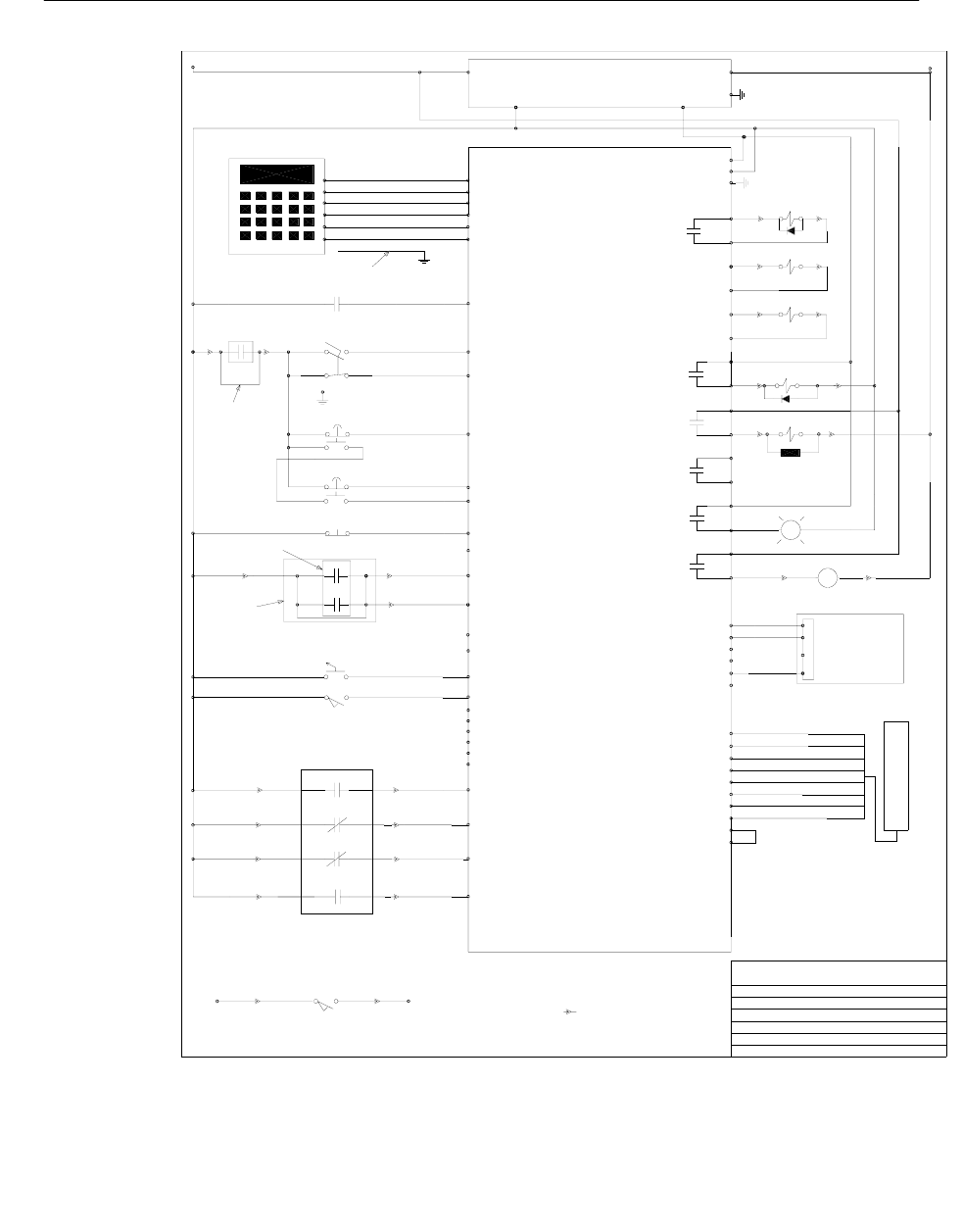
Figure 14: Electrical Diagram 2 of 4
1+ 1-
FOOT
SWITCH
PIRANHA
BOB RILEY
2- 2+
1 OF 3
GRN
REGEN SOL
SUP
24VDC
POWER SUPPLY
M1 AUX MCR
FOOT N/O
FOOT N/C
LEFT DUAL PALM
RIGHT DUAL PALM
LEFT DUAL PALM
RIGHT DUAL PALM
RAM UP
RAM UP
DOWN CHECK
PRESS BRAKE CONTROL
2-18-02
UP SOL
DOWN SOL
TONNAGE SOL
<OPTIONAL>
SPEED SOL
F
WHT
P1-1
P1-2
P1-3
LEFT/RIGHT DUAL PALM
PROGRAM
OX PROGRAM
P6-3
P6-4
P6-2
P6-1
P5-1
P5-2
P5-3
P5-4
P5-5
P5-6
K2
K3
P2-1
P2-2
P2-3
P2-4
P2-5
P2-6
P2-7
P2-12
P3-1
SLOW LIMIT SLOW PRESS
CNC TOP
P4-2
CNC BOTTOM
P4-3
CNC FINISH SPEED
P4-4
K5
Y
2
P6-7
P6-8
K6
P6-9
P6-10
AUTOMEC AUTO ADV.
K4
<SPARE>
P6-5
P6-6
30 31
513
11 12
23 24
86
OPTIONAL
4 3
WIRE PIN AND SOCKET T2270_1F
0
7
8
8
9
10
11
12
13
14
15
18
19
20
21
22
23
24
25
26
27
28
29
#
0
JUMPER USED
WITH OUT HURCO
BLK
RED
BLUE
GRN
BRN
WHT TX+
TX-
RX+
RX-
+15VDC
GRND
P11-1
P11-2
P11-3
P11-4
P11-5
P11-6
DRAIN
SHIELDED CABLE
AUTOMEC
AUTO CAL LIMIT
30 31
12
OPTIONAL
32
33
34
6
JUMPER
P7-1
P7-2
P7-3
P7-4
P7-5
P7-6
P7-7
P7-8
P7-9
P7-10
SENSOR
MICROPULSE
DRAIN
BLUE
WHT
BRN
GRAY
GRN
YEL
2 CHANNEL 12 BIT
A/D PRESSURE
TRANSDUCER
OPTIONAL
+15VDC
-15VDC
GND
GND
GND
+24VDC
INT
INT
INT
INT
CNC SLOW
P4-1
35
P3-2
SPARE
SPARE
P2-8
LC #1 N/O
LC #2 N/O
P2-9
P2-10
36
37
OPTIONAL LIGHT CURTAIN CONTACTS
0
0
1
2
3
4
5
6
K1
P2-11
P3-3
P3-4
P3-5
P3-6
P3-7
P3-8
SLOW
TOP
BOTTOM
FINISH SPEED
OPTIONAL
AUTOMEC AND HURCO
CONTACTS
DOWN SOL
DOWN SOL
TONNAGE SOL
TONNAGE SOL
SPEED SOL
SPEED SOL
UP SOL
UP SOL
REGEN SOL
REGEN SOL
TEACH
TEACH
AUTO ADV
AUTO ADV
TEACH
O
WHT
_+
WHT/BLUE
0
+24 VDC
24 COM
GRND
WHT/BLUE
NEUT
L1
V- V+
6
2
2
2
6
0
OPTIONAL
HURCO
RAM ENABLE
8
P10-1
P10-2
P10-3
P10-4
P10-5
P10-6
IN #1
GRND
IN #2
GRND
WHT
BLK
RED 1
2
3
4
PINK
Y AXIS
TRANSDUCER
2
24VDC
24VDC
6 4
5
811
9 12
10 13
7 4
3 2
0
SPARE
SPARE
SPARE
SPARE
SPARE
SPARE
FOOT SWITCH
MODULE
CONTROL
TITLE
DRAWING
DATE
REV#
DRAWN BY
PAGE#
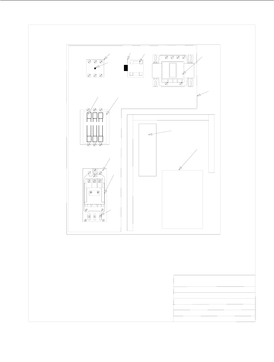
Piranha 95 Operator's /Owner's Manual
45
Figure 15: Electrical Diagram 3 of 4
PIRANHA
TITLE
DRAWING
DATE
REV#
DRAWN BY
PAGE#
PRESS BRAKE CONTROL
T2270_2E
12-6-01
E
BOB RILEY
2 0F 3
VIEW OF BACK PLATE
1
2
34
5
6
7
89
10
11
12
13
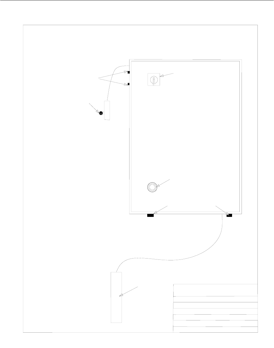
Piranha 95 Operator's /Owner's Manual
46
Figure 16: Electrical Diagram 4 of 4
PIRANHA
TITLE
DRAWING
DATE
REV#
DRAWN BY
PAGE#
PRESS BRAKE CONTROL
T2270_3E
12-6-01
E
BOB RILEY
3 0F 3
VIEW OF ENCLOSURE
R
ON
OFF
14
15
18
16 17
20
21
19

Piranha 95 Operator's /Owner's Manual
47
Electrical Component List
FIG # DESCRIPTION QTY HP/VOLTAGE PIRANHA PT#
1 DISCONNECT 1 15 HP 208/230V 0591602
1 DISCONNECT 1 15 HP 460V 0591605
1 DISCONNECT 1 15 HP 575V 0591605
1 DISCONNECT SHAFT 1 ALL 0591603
4 FUSES, MOTOR SHORT CIRCUIT 3 15 HP 208V T0779
4 FUSES, MOTOR SHORT CIRCUIT 3 15 HP 230V T0779
4 FUSES, MOTOR SHORT CIRCUIT 3 15 HP 460V T0775
4 FUSES, MOTOR SHORT CIRCUIT 3 15 HP 575V T0774
5 STARTER, M1 1 15 HP 208V 0541641
5 STARTER, M1 1 15 HP 230V 0541641
5 STARTER, M1 1 15 HP 460V 0531641
5 STARTER, M1 1 15 HP 575V 0531641
6 STARTER AUX. CONTACT BLOCK 1 ALL T2253
7 HEATERS, OVERLOAD, MOTOR M1 3 15 HP 208V 0541642
7 HEATERS, OVERLOAD, MOTOR M1 3 15 HP 230V 0541642
7 HEATERS, OVERLOAD, MOTOR M1 3 15 HP 460V 0541643
7 HEATERS, OVERLOAD, MOTOR M1 3 15 HP 575V 0521616
8 FUSE HOLDER, TRANSFORMER PRIMARY 1 ALL T1302
9 TRANSFORMER PRIMARY FUSES 2 ALL HP 208/230V T1138
9 TRANSFORMER PRIMARY FUSES 2 ALL HP 460V T1139
9 TRANSFORMER PRIMARY FUSES 2 ALL HP 575V T2279
10 POWER SUPPLY, 24VDC 1 ALL T2560
11 GENERATION II CONTROL MODULE 1 ALL T2267
12 MOTOR POWER SUB BACK PLATE 1 ALL T2323-A
13 TRANSFORMER 1 15 HP 208V T1134
13 TRANSFORMER 1 15 HP 230V T1135
13 TRANSFORMER 1 15 HP 460V T1135
13 TRANSFORMER 1 15 HP 575V T1136
14 DISCONNECT OPERATOR 1 ALL 0531604
15 RESET BUTTON W/ SHAFT 1 ALL 0531686-1
16 RECP.,DUAL PALM 1 ALL T1311
17 RECP FOOT SWITCH CONTROL MODULE 1 ALL T2561
18 MICRO PULSE SCALE 1 ALL T1976
19 LIMIT SWITCH 1 ALL 0531615
20 FUSE HOLDER, CONTROL AND AUTOMEC CNC 2 ALL T0733
21 FUSE, CONTROL AND AUTOMEC CNC 2 ALL T01140
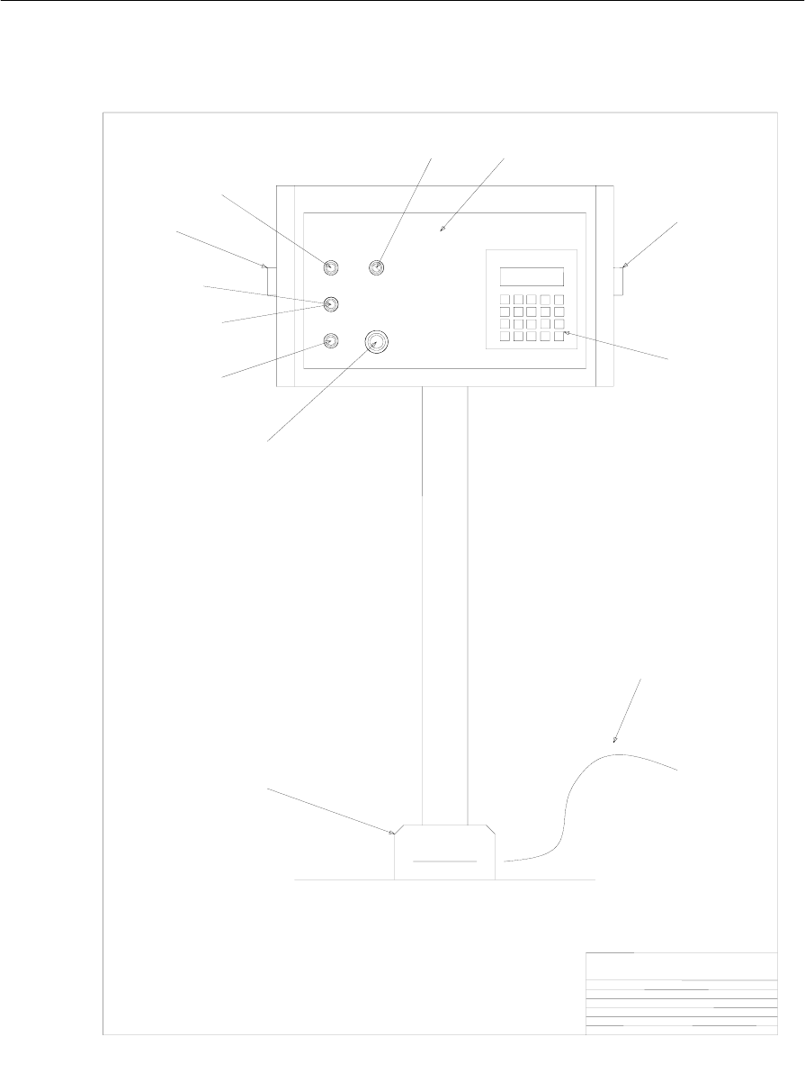
Piranha 95 Operator's /Owner's Manual
48
PIRANHA
TITLE
DRAWING
DATE
REV #
DRAWN BY
PAGE #
PREMIUM PEDESTAL
T1951_1
12-5-01
-
BOB RILEY
1 OF 2
UP
TEACH ACTIVE
START EMEG
STOP
RUN PROG
Generation II
Control System piranha
www.piranhafab.com
123
456
789
.0
1
2
3
4
5
6
8
9
11
77
10
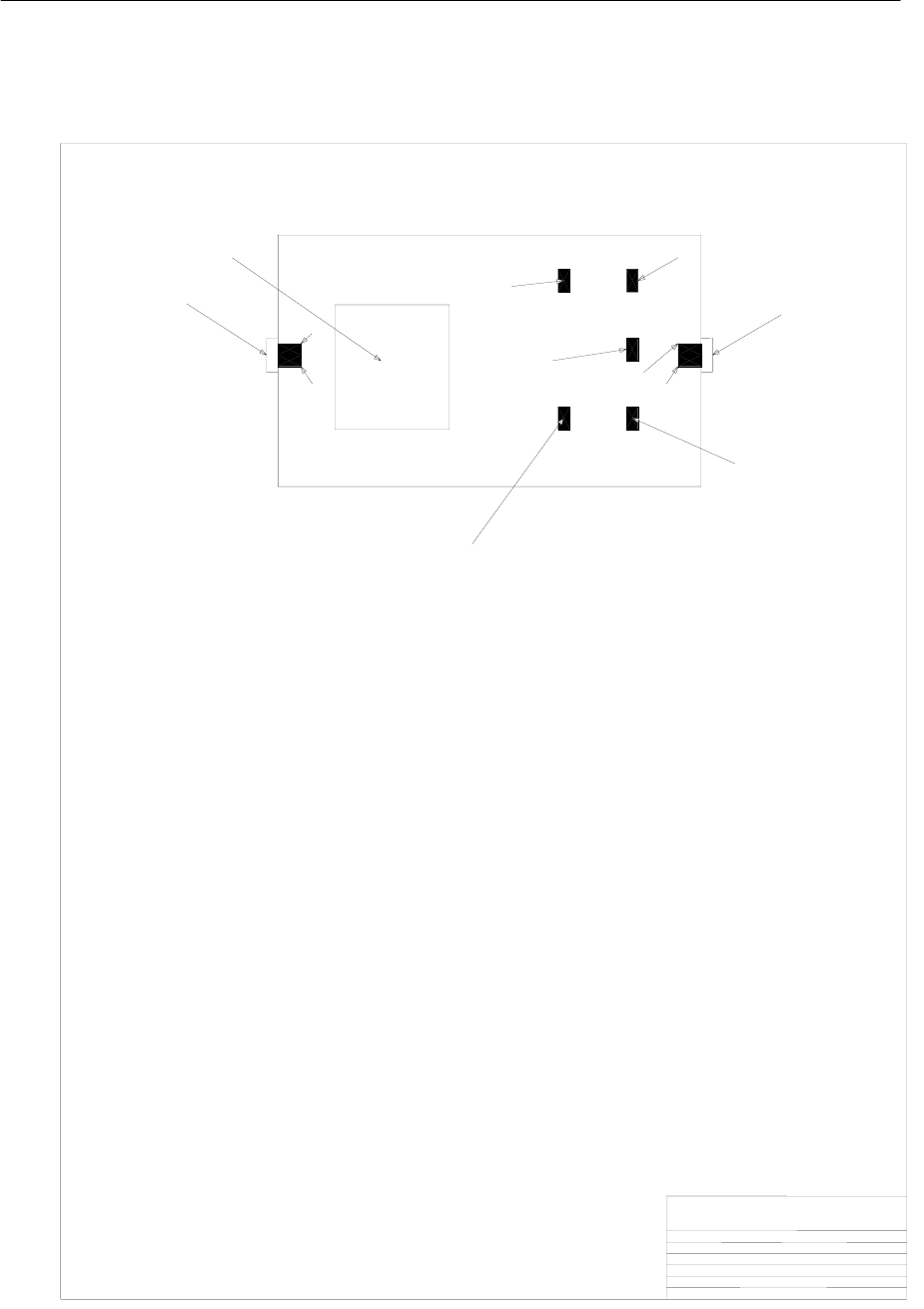
Piranha 95 Operator's /Owner's Manual
49
PIRANHA
TITLE
DRAWING
DATE
REV #
DRAWN BY
PAGE #
PREMIUM PEDESTAL
T1951_2
12-5-01
-
BOB RILEY
2 OF 2
UP
START
EMEG
STOP
INSIDE AND BACK VIEW OF ENCLOSURE
PILOT LIGHT
PROGRAM
SELECTA
DISPLAY
11
77
12
13
5
15
14
17
16
16
17

Piranha 95 Operator's /Owner's Manual
50
PREMIUM PEDESTAL T1951
DESCRIPTION QTY FIG. # PIRANHA PT#
FOOT SWITCH CORD/CONDUIT 1 1 T2595
FOOT SWITCH 1 2 T0746
E STOP OPERATOR 1 3 T0737-1
START OPERATOR 1 4 05316101-1
TEACH ACTIVE PILOT LIGHT, AMBER LED 1 5 T2596
AMBER PILOT LENS 1 6 T2300
DUAL PALM OPERATOR 2 7 T0748-1
UP OPERATOR, EXTD. YELLOW 1 8 T1668-1
PROGRAM SELECTA SWITCH OPERATOR 1 9 0531694-1
DECAL 1 10 T1952
DISPLAY MODULE 1 11 T2268
CONTACT BLOCK W/ BASE, N/C 1 12 05316121-1
CONTACT BLOCK W/ BASE. N/O 1 13 0531696-1
CONTACT BLOCK W/ BASE, N/C 1 14 05316121-1
CONTACT BLOCK W/ BASE, N/O 1 15 0531696-1
CONTACT BLOCK W/ BASE, N/O 2 16 0531696-1
CONTACT BLOCK, N/C 2 17 0591596-1
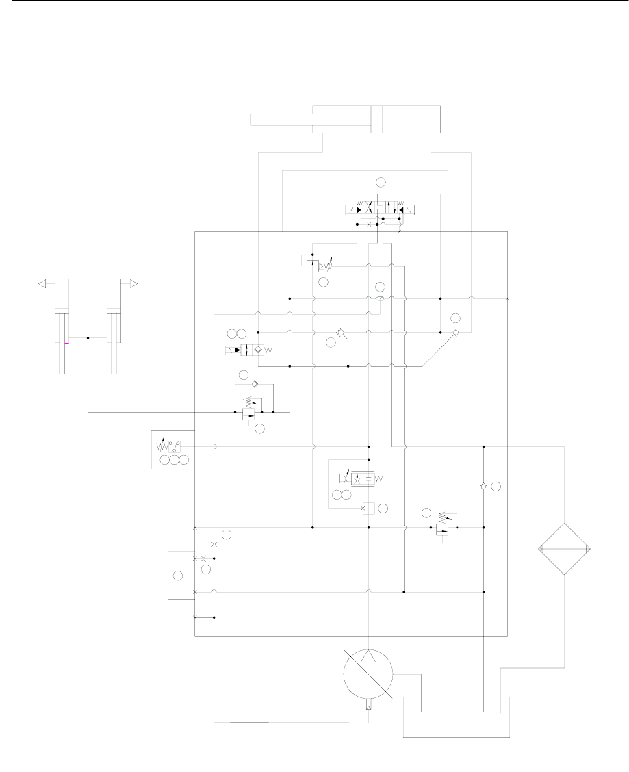
Piranha 95 Operator's /Owner's Manual
51
Hydraulic Diagram
Figure 16: Hydraulic Diagram 1 of 1
TRANS
SP TANK
2500
C5
.031 DIA
G
PRS
PRESS
SW 1
CYLS
PSI
12
1
C3
21
2
C4
3800 PSI
1
3
2
2
1
2
COOLER
1
2
21
3
1
1
2
200
PSI
3
3
21
3
12
SW 2
PRESS
PRELOADED RAM A
PRESS
CYLINDER
C2 TP C1
BA
B
.062 DIA
25
19
15
2
7
4
11 10
8
5
14 13
39
6
16
12
24
T
P
23 22
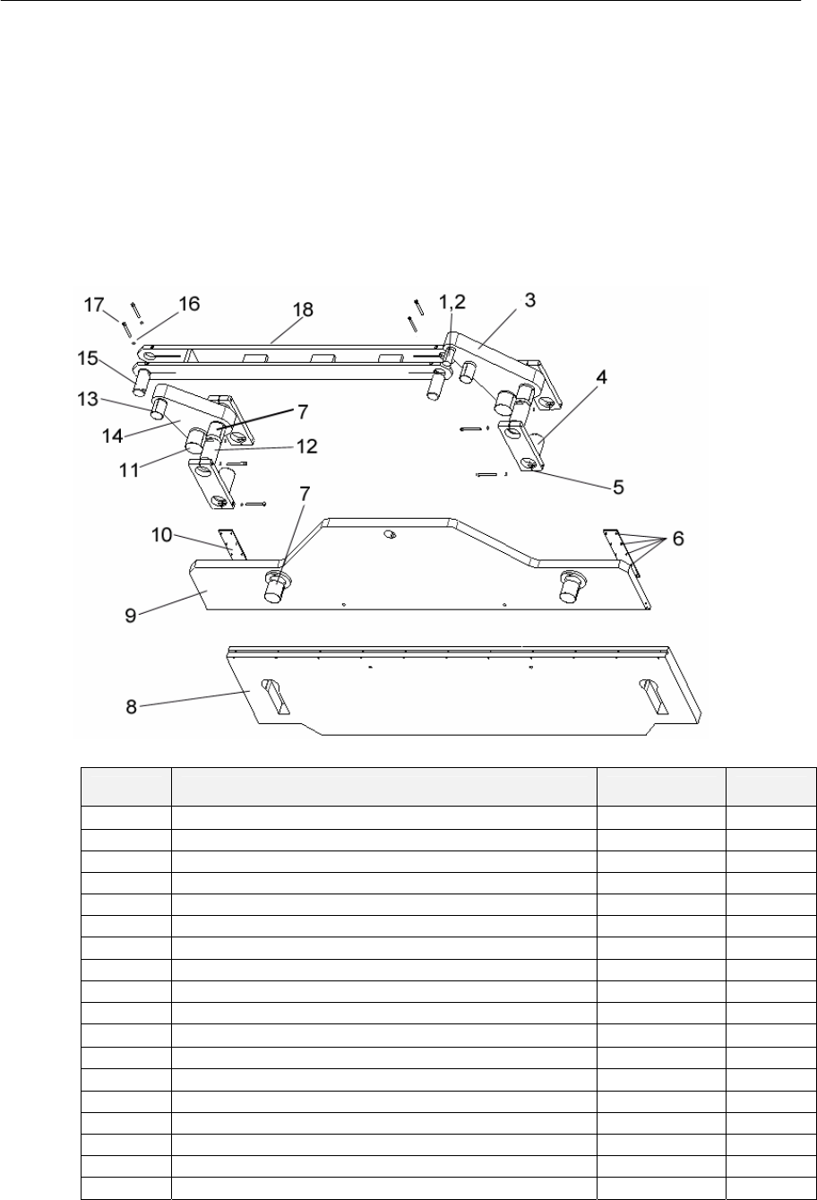
Piranha 95 Operator's /Owner's Manual
52
Parts
Diagrams are provided for the major assemblies of the press brake. The accompanying parts
lists provide item references and descriptions. Part numbers and quantities are provided only
where applicable.
Repair parts are available for the Piranha 95 Press Brake from the manufacturer. Always
provide the model and complete serial number of the press brake along with the part number
description and quantity of the desired parts.
Ram Linkage
Figure 17: Ram Linkage
Item Description Part # Qty.
1 Cylinder Lever Garfil® Bushing T2441 1
2 Cylinder Lever Pin T9301 1
3 Long Lever T2693-1 1
4 Linkage Pin T9304 4
5 Link T8616 4
6 Brass Screws ¼ x ½ T0070 20
7 Link Ram Garfi®l Bushing T2448 4
8 Bed T1716 1
9 Ram T1713 1
10 Ram Phenolic T00963 2
11 Hinge Pin Garfil® Bushing T2453 2
12 Hinge Pin T9303 2
13 C-Rod Garfil® Bushing T2445 2
14 Short Lever T2694-1 1
15 C-Rod Pin T9302 2
16 Lock Washer T0178 12
17 ½ X 5 SHCS 0571055 12
18 C-Rod T1712 1
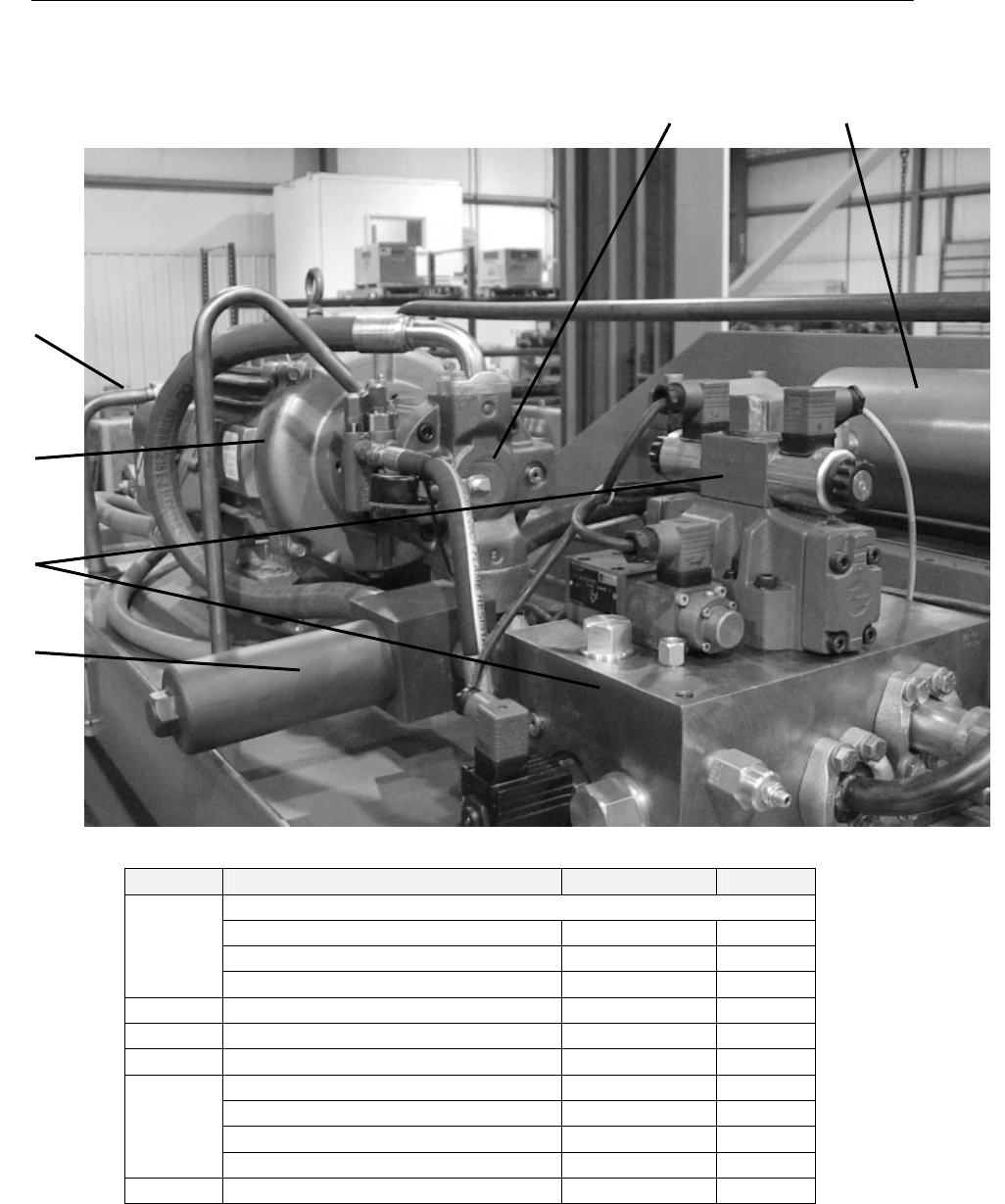
Piranha 95 Operator's /Owner's Manual
53
Hydraulic Assemblies
Figure 18: Hydraulic Power Unit
Item Description Part # Qty.
Pump/Motor Assembly:
15 HP – 200 Volt 0551661-2 1
15 HP – 220/440 Volt 0551660-2 1
1
15 HP – 575 Volt 0551665-2 1
2 Filter Assembly 0591550 2
3 Pump T1051 1
4 Valve Assembly T2271 1
Cylinder Assembly T0553-1 1
Cylinder Garfil Bushing T2440 1
Cylinder Seal Kit T191-1 1
5
Cylinder Pin T9305-3 1
6 Hydraulic Oil Cooler T0837-1 1
Table 3: Hydraulic Power Unit Descriptions
3 5
6
1
4
2
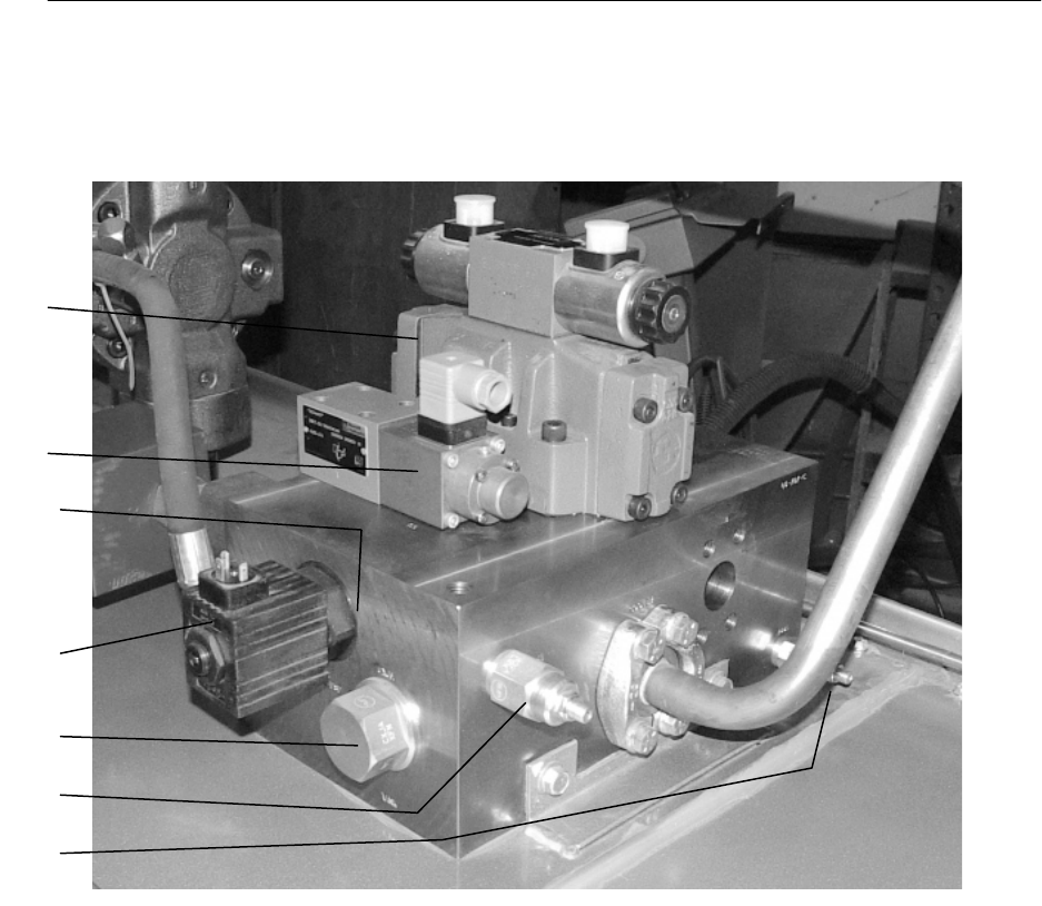
Piranha 95 Operator's /Owner's Manual
54
Valve Body Assembly
Figure 19: Valve Body Assembly Front View–T2271
16
15
13
14
7
2
4

Piranha 95 Operator's /Owner's Manual
55
Figure 20: Valve Body Assembly Rear View T2271
17-18
3
5
6
8
10
11
9

Piranha 95 Operator's /Owner's Manual
56
Hydraulic Valve Body Components
Item # Part Description Valve Function/Location Part # Coil # Seal #
1. Valve Pack body T2424 n/a n/a
2. Relief valve System relief T2425 n/a
3. Pressure reducing valve Pilot reducing valve T1035 n/a T1036
4. Relief valve PRS relief T2426 n/a T1034
5. P. C. Check Regen check T1037 n/a T0869
6. P.O. Check Ram check valve T2427 n/a
7. Check Valve Cooler check valve T2428 n/a T1057
8. Check Valve PRS check valve T1070 n/a T1079
9. Shuttle Valve Load sense T1042 n/a T0870
10. Valve, 2 position, 2 way Regen valve T1044 n/a T1045
11. Valve, normally closed, 2 way Regen valve T0240-1 0591541 T1066
12. Cavity Plug Compensator T2429 n/a T0869
13. Valve, Solenoid, Proportional Speed control w/ coil T2430
14. Coil for above if ordered separately T2603
15. Cover plate w/ hardware & seals Non-tonnage control config.
15. Valve proportional Pressure Tonnage control w/ coil T1060 T1043 T1048
15. Mounting Screws Tonnage control 23149 n/a n/a
16. Directional Control Valve, main Cylinder T2431 T1052 T1053
17. Directional valve mtg. Screws Cylinder T2432 n/a n/a
18. Directional valve mtg. Screws Cylinder T2433 n/a n/a

Piranha 95 Operator's /Owner's Manual
57
Hydraulic Fittings
Location Part Number Size QTY
Suction on pump T0910 4 bolt flange 1-1/2 1
Outlet on pump T1636 #16 Split Flange Kit 1
Inlet on filter 5001024 #16 SAE ORB/#16 37JIC Flare 1
Outlet of filter 5001024 #16 SAE ORB/#16 37JIC Flare 1
P-port valve T0911 1" 4 Bolt Flange Adapter 1
Filter/Valve T1727 #16+SAE ORB/37 JIC Swivel Nut 1
A
-port valve T1636 #16 Split Flange Kit 1
A
-port cyl. T1636 #16 Split Flange Kit 1
B-port valve T1735 #20 Split Flande Kit 1
B-port cyl. T1735 #20 Split Flande Kit 1
Cooler Port Valve T1735 #20 Split Flange Kit 1
Case drain pump T0915 #10 SAE o-ring 1
Load sense pump T0916 #4 SAE o-ring 1
Load sense valve T0917 #6 SAE o-ring 1
Oil Cooler Outlet T0955 #12 ORB/#16OFS 1
Oil Cooler Inlet T2700 #12 ORB/#16OFS 90 Elbow 1
Gauge port valve 0571506 #6 SAE o-ring 1
Guage Ftg. Cap 541531 #6 JIC Cap Nut 1
Guage Adapter 0531514 #6 Jic Swivel/ 1/4 NPT Female 1
Suction tube T0908 1-1/2 pipe 12" long 1
Hose filter-valve T2324 #16 4 BOLT90/SN JIC x 42 LG 1
Return valve T0951 1-1/4 pipe 12" long 1
Return case drain T0894 3/4" hydraulic tube 1
Hose load sense T0949 #6 SN ORFS X 16 LG 1
Valve To Cooler Tube T2623 1" OD Tube Assy 1
Cooler to Tank Tube T0893-1 1" OD Tube Assy 1
Tank outlet 0531516 1/2 Pipe plug 1
Tank outlet T0058 1/2 Pipe ball valve 1
Tank outlet T0128 1/2 Pipe close nipple 1
Suction tube seal T0909 RF-1373 LHA 2 bolt flange 1
Case Drain tube seal T0948 LHA #5767 2 bolt flange 3/4" tube 1
Cooler Tube Seal T0950 1" Tube, 2 Bolt Flange 1
Valve A To Cyl Ret T2325 Hose Assy - Cyl Retract 1
Valve B To Cyl Ext T2326 Hose Assy - Cyl Extend 1
PRS Fittings
Location Part Number Description QTY
Port on Valve T2330 Connector- STR. Swivel Nut 1
Swivel Nut Conn. 531520 Union Tee 2
PRS Cyl. Port T1330 Breather Plug 2
PRS Cyl. Port 531523 90 Deg Elbow 2
Tee @ Swivel Nut Co 541531 Cap 1
PRS Cyl to Tee T2395 Tube Assy - LH 1
PRS Cyl to Tee T2396 Tube Assy - RH 1
PRS Valve to Tee T2348 Tube Assy - Supply/Return 1
Tube Clamp T1764 1
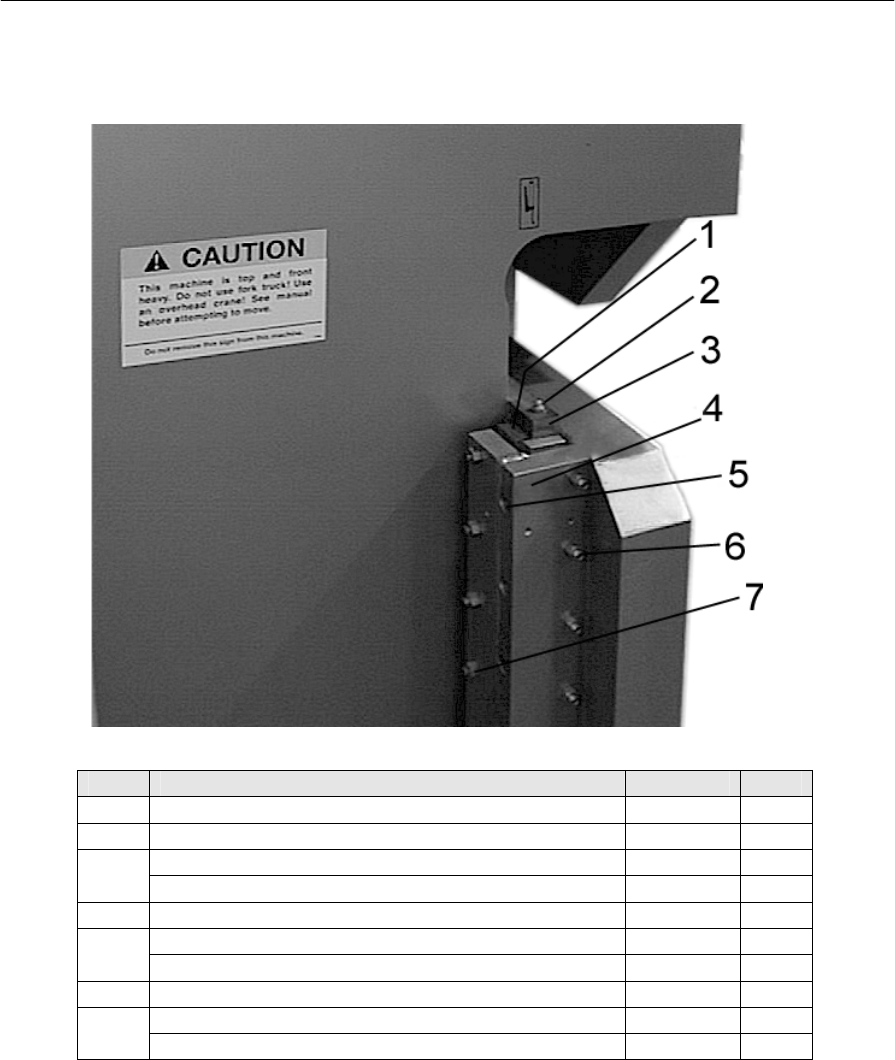
Piranha 95 Operator's /Owner's Manual
58
Ram Slides
Figure 21: Gib Parts
Item Description Part # Qty
29-1 Side/Rear ram slide bearing assembly T0095 4
29-2 Grease zerk 1/8” pipe 0531360 2
Ram slide right (Opposite End) T1564 1
29-3 Ram side left T1565 1
29-4 Slide mounting gib T0018 2
3/8 x 3-½ SHCS T0076 12
29-5 3/8 High collar lock washer T0291 12
29-6 Side adjustment screw 3/8 x 2-¼ SSS T1010 10
Rear /side adjustment nut 0581198 20
29-7 Rear adjustment screw 3/8 x2 SSS T0125 10
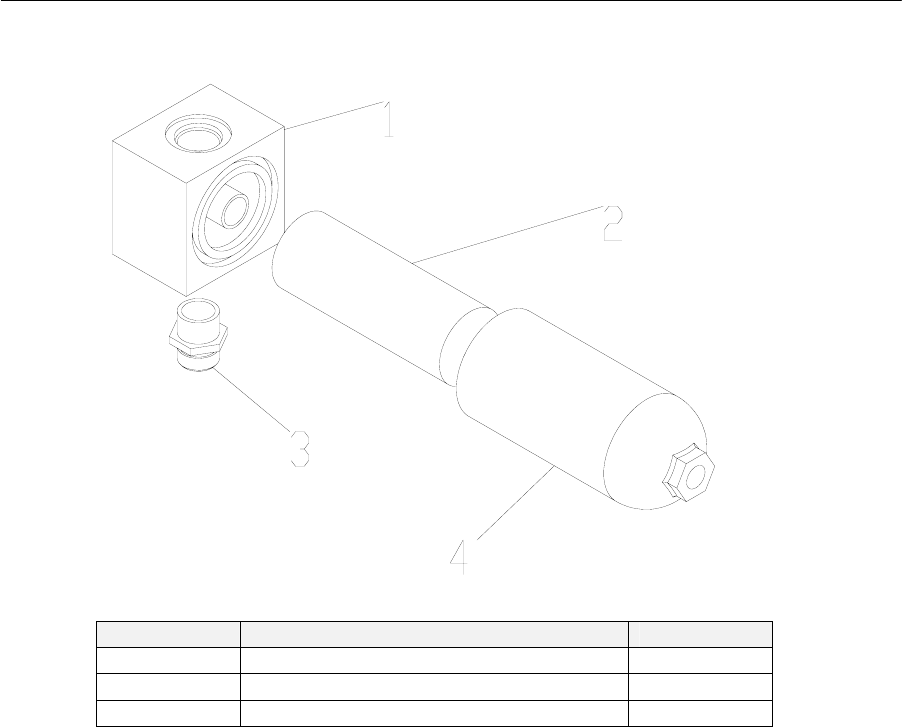
Piranha 95 Operator's /Owner's Manual
59
Oil Filter Assembly
Figure 22: Oil Filter Assembly Exploded View 0591550
Figure-Item Description Part #
31-1&4 Filter body & bowl 0591550
31-2 Filter element 0591551
31-3 Fitting – inlet T0913
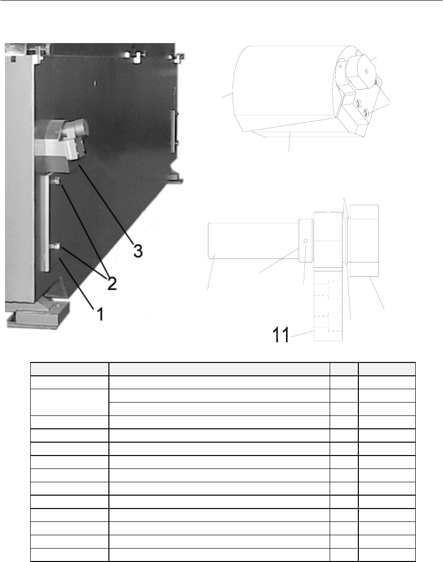
Piranha 95 Operator's /Owner's Manual
60
Wedge Assembly
7
6
5
4
Figure 23: Wedge Assembly
12
10 9
8
13
1
4
Figure-Item Description Qty. Part #
32-1 Key plate 2 T0046
5/8 x 2 SHCS 4 T0080
32-2 5/8 LW 4 0531304
32-4 Wedge adjustment bolt assembly Item 8-12 1 T0049
32-5 SHCS 3/8 – 16 x 1-1/4 3 05131051
32-6 & 3 Wedge bottom half 1 T0047
32-7 Wedge top half 10 T0048
32-8 Wedge thrust washer 2 T460
32-9 Wedge bolt and nut assembly 95 1 T0131
32-10 Wedge thrust bearing 1 T439
32-11 Wedge bottom plate 95 1 T0051
32-12 Roll pin 1/8 x 1-1/2 1 T0069
32-13 Wedge adjust bolt 1 T2750
32-14 Wedge bolt nut 1 T2753
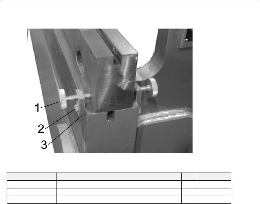
Piranha 95 Operator's /Owner's Manual
61
Die Rail Centering Screw Assembly
Figure 24: Die Rail Centering Screw Assembly*
Item Description Qty. Part #
1 Die Rail Adjusting Hand Screw 6 T0056
2 3/8”-16 x 1-½” HHCS 6 T0186
3 Die Rail Adjusting Block 6 T9200
* If equipped
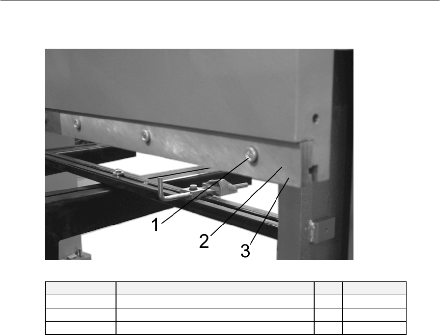
Piranha 95 Operator's /Owner's Manual
62
Punch Clamp Assembly
Figure 25: Punch Clamp Assembly
Figure - Item Description Qty Part #
35-1 ½-13 x 2” Socket Head Cap Screws 6 T1602
35-2 Punch Clamp Spring 8 T0050
35-3 Punch Clamp 12 T2319-1
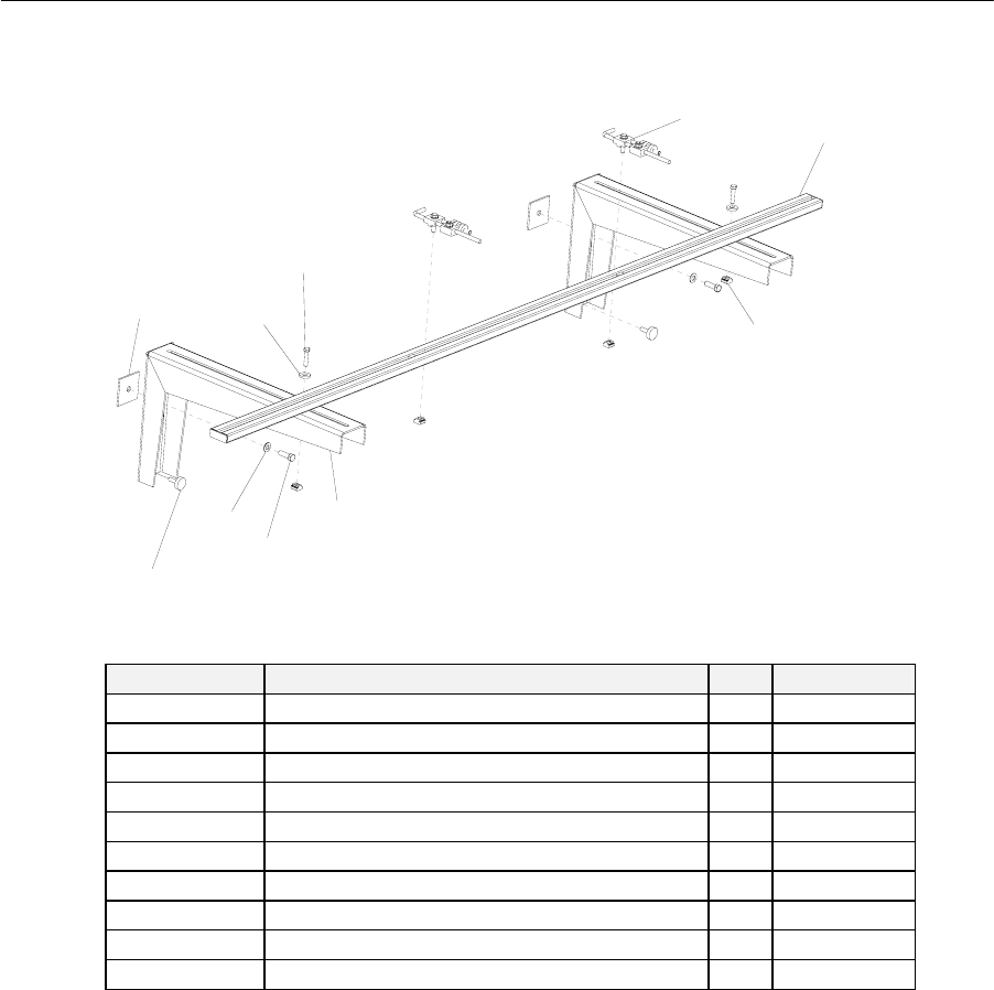
Piranha 95 Operator's /Owner's Manual
63
Backstop Assembly (Optional)
45
6
3
2
1
10
987
Figure 26: Back Gauge Assembly T0227*
Figure - Item Description Qty Part #
36-1 Spacer Plate, Back Gauge 2 T9655
36-2 ½” Flat Washer, ¼” Thick, 1-1/2” OD 2 T0057
36-3 HHCS ½” x 2-¼” 2 0581108
36-4 Back Stop Finger Assembly 2 T14-995
36-5 Back Stop Bar Weldment 1 T02261
36-6 T-Nut 5/8” 2 0531723
36-7 Back Gauge Mount Bracket Weldment 2 T37311
36-8 HHCS 5/8” x 2” 2 T0080
36-9 Washer 5/8” 2 0531311
36-10 Hand Adjusting Screw 2 T0056
* If equipped
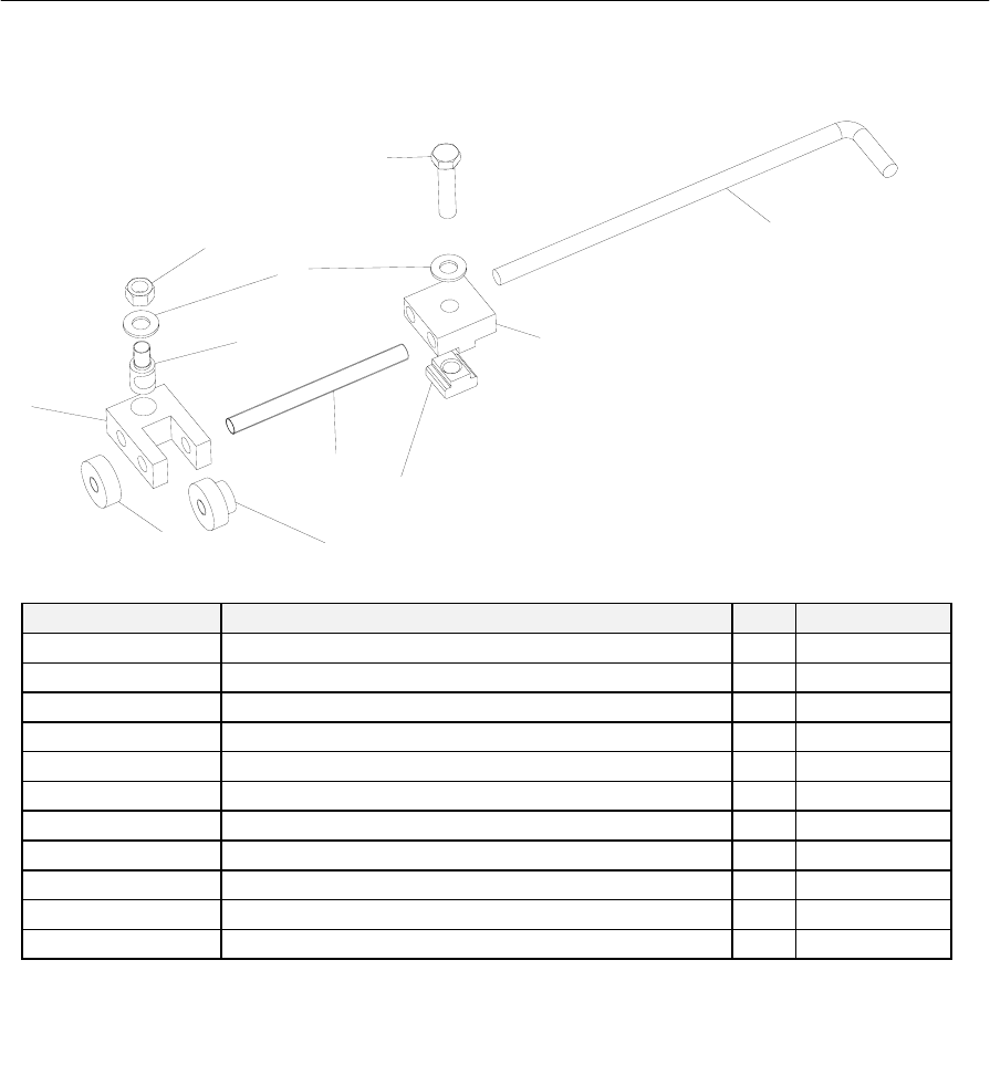
Piranha 95 Operator's /Owner's Manual
64
Back Stop Finger Assembly (Optional)
1
2
3
6
7
9
10
5
48
11
Figure 27: Back Stop Finger Assembly T19-995 *
Figure - Item Description Qty Part #
37-1 Mounting Block Top 1 T9048
37-2 Back Stop Finger Bar 1 T3801
37-3 Adjusting Block 1 T0084
37-4 Adjusting Bar 1 T0086
37-5 Adjusting Nut 1 T0087
37-6 Locking Nut 1 T0088
37-7 Locking Bolt 1 T0085
37-8 T-Nut 5/8 1 0531723
37-9 Flat Washer 1/2” 2 T0057
37-10 Hex Nut 1/2” 1 0581195
37-11 HHCS 1/2 x 2-1/4 1 0581108
* If equipped
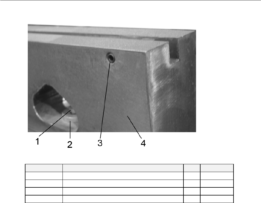
Piranha 95 Operator's /Owner's Manual
65
Die Rail (Optional)
Figure 28: Die Rail *
Figure-Item Description Qty. Part #
38-1 ½” x 2 ¾” HHCS 3 0581105
38-2 ½” Hard Flat Washer 3 T0057
38-3 3/8”-16 x ¾” SSS Cup Point 30 0531056
38-4 Die Rail 95-8 1 T2332
* If equipped

Piranha 95 Operator's /Owner's Manual
66
Glossary
AC Motor An electric motor designed to operate using
AC power.
Accuracy The deviation of a value from its theoretical
value after the device has been correctly
calibrated.
Air Bending The forming of sheet pr plate using a “V” die
where the desired angle is achieved before
the work pieces is compressed between the
upper and lower tools.
Ambient Condition The surrounding atmosphere and
environment.
ANSI American National Standards Institute. A
national, nonprofit organization. Its principle
function is to establish industry-wide
standards that are put in place through a
process of consensus among qualified
participants.
Backlash Mechanical clearances that exists or may
develop through wear between a driven
component and a drive source.
Ball Bushing/Linear Bearing A tubular shaped ball bearing assembly
designed for linear movement on a shaft.
Bed The stationary member of the press brake
that supports the tooling and other
associated equipment.
Bolster (bolster plate) The plate(s) attached to the bed or ram
having means for attaching die components.
Bottom Bending The forming of sheet or plate using “V” die
where e desired angel is completed after the
work piece is compressed between the upper
and lower tools. Typically requires 3-5 times
the tonnage for air bending.
C Frame Vertical side frame of the press brake.
Circuit Breaker A device used with electrical equipment to
provide overload protection.
Closed Height See shut height.

Piranha 95 Operator's /Owner's Manual
67
Coining A method of bottom bending were additional
force is applied during the bend to make the
work piece conform to the shape of the upper
and lower tools. Typically uses “V” dies with
opening of 6 times the material thickness and
requires 5-7 the tonnage for air bending.
Coupling (Shaft) A mechanical device used to join a motor
output shaft to a machine part, typically a
roller.
Cycle A series of events or operations that recur
regularly and usually lead back to the start.
Cylinder A piston-type actuator.
DC Power Supply An electrical device used to convert incoming
AC power to regulated DC power.
Die (s) The tooling used in a press brake for forming
metal.
Die Holder The plate or rail to which the lower portion of
the die member is attached.
Die rail See die holder.
Die Shimming Method to raise for fill a void between two
surfaces. Typically used to compensate for
machine deflection or worn tooling.
Die Space The space between the bed and ram.
Dies, Bending Dies used in press brakes to perform
bending and forming operations on a variety
of work pieces.
Electrical Spike An unpredictable and infrequent momentary
high electrical voltage which can harm
electrical/electronic devices.
Encoder A device typically electromechanical, that
translates motion into electrical pulses. See
also Resolver, Tachometer, or Transducer.
Feedback The return to an input of a part of the output
of a machine or control system, or process.
Fuse Electrical overload protection device.
Fuse Block A holder for a fuse or fuses including wire
termination.

Piranha 95 Operator's /Owner's Manual
68
Gauge A stop against which the material or
workpiece is placed to locate it within the
point of operation.
Gibs The machine members used for guiding the
ram.
Grease zerk Fitting designed to accept grease for
lubricating components.
Hydraulics The branch of mechanics, which uses
controlled hydraulic oil flow, and pressure to
provide force to an actuator.
Inertia A property of matter by which it stays at rest
or in uniform motion in the same straight line
unless acted on by an external force.
Lifting lugs Steel plates with large holes that are
attached to the press brake to assist in lifting
the machine.
Limit Switch Typically, an electrical device that provides
position information to a control system.
Low Voltage A voltage reading that is lower than the
required or expected voltage.
Machinist Square Level Machinists level having four sides. Permits’
measuring vertical surfaces as well as
horizontal surfaces.
Motor Starter A relay capable of withstanding inductive
load generated when starting an electric
motor (AC or DC).
Open Loop A control concept in which feedback is not
used to modify the characteristics of the
output.
Operator Interface Typically, a control or control panel provided
for an operator to modify or monitor system
variables.
Photo Sensor An electronic sensor that uses light
wavelengths to detect the position or
presence of an object.
Point of Operation The location in the press brake where the
material or a workpiece is positioned and
work is performed.

Piranha 95 Operator's /Owner's Manual
69
Pressure Reducer Typically, a hydraulic component that senses
secondary pressure to maintain that output
pressure regardless of the incoming
pressure.
Pressure Relief Typically, a hydraulic component that uses a
spring to hold an orifice closed until system
pressure overcomes the spring and allows
flow to the reservoir.
Proximity Sensor An electrical device capable of detecting the
presence of an object.
PSI Acronym. Available Force expressed in
Pounds per Square Inch
Punch The male part of the tool (die).
Pushbutton A small button or knob actuated by pushing,
provided for operator control, electrical,
pneumatic, or mechanical.
Ram The linear moving press brake member
configured to carry a portion of the tooling.
Relay An electromechanical device for remote or
automatic control that is actuated in variation
of conditions of an electrical circuit and that
operates other devices in an electrical circuit.
Repeatability The closeness of agreement among multiple
measurements of an output, for the same
value of the measured signal under the same
operating conditions, approaching from the
same direction for full range traverses.
Reset To restart or arm a control or safety system.
RPM Acronym. Rotational speed expressed as
Revolutions per Minute.
Safeguarding A method for protection of personnel from
hazards using guards, safety devices, or safe
work procedures.
Selector Switch A small button or knob actuated by turning,
provided for operator control, electrical,
pneumatic, or mechanical.
Service (Safety) Disconnect Typically, a large mechanical switch that is
provided to completely remove incoming
power for the purpose of storage or service
of a machine.

Piranha 95 Operator's /Owner's Manual
70
Setup The process of adjusting the press brake and
the installation and adjustment of work
holding devices or tooling and appropriate
safeguarding to ensure proper and safe
operation of the press brake.
Shield (foil or braided) Typically, a metallic encasement surrounding
wiring or components to avoid interference
from RF signals.
Shut Height The distance from the bed to the ram when
the ram is at the bottom of its stroke (in the
closed position).
Solenoid Valve Typically, a pneumatic or hydraulic valve
actuated by an electromagnetic coil.
Throat An opening or recess in the ram (housing) to
permit the positioning of material or
workpieces.
Tool (Die) The cutting or shaping component used in a
machine.
Transducer A device typically electromechanical, that
translates motion into electrical pulses.
Transformer An electrical device that employs the
principle of mutual induction to convert
variations of current in a primary circuit into
variations of voltage and current in a
secondary circuit.
V-Bending The forming of sheet metal material using a
pair of “V” shaped tools that bend the
workpiece by applying a three-point load.
Valve Any of numerous mechanical devices by
which the flow of liquid, gas, or loose
material in bulk may be started, stopped, or
regulated by a moveable part that opens,
shuts, or partially obstructs one or more ports
or passageways.

Piranha 95 Operator's /Owner's Manual
71
This page is intentionally left blank.

Piranha 95 Operator's /Owner's Manual
72
Index
A
Adjusting screws, 10
Anchoring, 10
Anchoring hole locations, 10
Ansi, 9
B
Bed, 10, 37
Bed adjusting bolt, 34
Bed leveling adjustment, 34
Bed tilt, 11
Bed tilt wedge assembly, 34
C
C Frame, 7
Cleaning, 11
Connecting the pedestal control, 14
Connecting the Pedestal Control, 14
D
Die Insertion, 35
Die Rail Shimming, 37
Die Rail Shimming Example, 37
E
Electrical, 13
F
Filling the pump case, 16
Foundation, 10
Front bed holding bolt, 34
Fuse size chart, 14
G
Gib clearance adjustment, 39
Gib explanation, 40
Gibs, 39
Grease zerk, 57
H
Hydraulic, 15
Hydraulic assemblies, 52
Hydraulic power unit, 41, 52
Hydraulic pump/motor assembly unit, 16
I
Initial leveling, 10
Installation, 9
Introduction, 7
L
Level adjusting screws, 10
Lifting, 9
Lifting Lugs, 9
M
Achinist square level, 11
Main control panel, 17
Maintenance procedures, 38
Masonry anchors., 10
Motor rotation, 16m
O
Oil Filter Assembly Descriptions, 41, 58
Oil Filter Replacement, 41
Oil Level & Temperature Sight Gauge, 15
Operator Control, 17
P
Pads, 10
Parts, 51
Pedestal controls, 19
Placement, 10
Precision leveling, 12
Precision leveling detail, 12
Programming a simple job, 30
R
Ram linkage, 51
Ram safety switch, 17
Ram slide, 12, 57
Ram slides, 57
Rear bed holding bolt, 34
Rear ram slide bearing, 57
Rotational direction, 14; rotation arrow, 14
S
Safety, 1
Setting limits for forming, 30
Shim, 11, 13
Side adjustment screw, 57
Side thrust gib adjustment, 39
Sight gauge, 15
Slide mounting bracket, 57
Speed control fuse, 17
Spring open die clamp, 7
Square level, 11
Steel pads, 10
T
Temperature sight gauge, 15
Test cycle, 4

Piranha 95 Operator's /Owner's Manual
73
Tonnage requirements, 37
Tool adjustments, 37
Tooling installation, 35
Tooling removal, 36
Tooling installation safety, 4
U
Unpacking, 9
V
Valve Body Assembly, 53
W
Warning Labels, 2
Warranty, 7

Piranha 95 Operator's /Owner's Manual
74
Addendums
