69NT40 511 310 T 296PL
User Manual: 69NT40-511-310
Open the PDF directly: View PDF ![]() .
.
Page Count: 84
T-296PL Rev B
Carrier
Transicold
Container
Refrigeration
Service
Parts List
Models
69NT40-511-310,344 & 359

SERVICE PARTS LIST
CONTAINER REFRIGERATION UNIT
MODELS
69NT40-511-310, 344 & 359
Carrier Transicold. A member of the United Technologies Corporation family. Stock symbol UTX.
Carrier Transicold Divsion, Carrier Corporation, P.O. Box 4805, Syracuse, N.Y. 13221 U. S. A.
ã2003 CarrierCorporation DPrintedinU.S.A.9/03
iT-296PL
TABLE OF CONTENTS
INTRODUCTION iii...........................................................................
CONFIGURATION IDENTIFICATION iii.........................................................
OPTION DESCRIPTIONS iii...................................................................
ORDERING INSTRUCTIONS iv................................................................
LETTER DESIGNATIONS iv...................................................................
1 QUICK LIST -- CLAMPS, FILTER-DRIER, FUSE, TY-RAPS, AND WIRE TERMINALS 1.............
2 REFRIGERATION UNIT ASSEMBLY 2....................................................
2.1 REFRIGERATION UNIT -- AREA LOCATOR 2.............................................
2.2 RAIN GUTTERS 4.....................................................................
2.5 CONTROL BOX DOOR 6...............................................................
2.6 CONTROL BOX 8.....................................................................
2.7 CONTROL BOX -- SHIELDS REMOVED,STD ELECTRICAL COMPONENTS,RM & HOURMETER 10.....
2.8 CONTROL BOX -- SHIELDS REMOVED, EVAP FAN CAPABILITY, EBS and EDS, EBS ONLY and CFS 12.
2.9 CONTROL BOX -- CONTROLLER MODULE SECTION AND SOFTWARE CARDS 14...........
2.10 CONTROL BOX -- DISPLAY MODULE AND COMMUNICATIONS INTERFACE MODULE SECTION 16...
2.11 CONDENSER FAN MOTOR AND CONDENSER COIL SECTION 18.........................
2.12 COMPRESSOR TUBING SECTION 20...................................................
2.13 RECEIVER SECTION 22...............................................................
2.14 WATER--COOLED CONDENSER SECTION 24...........................................
2.15 RRS AND RTS SECTION 26............................................................
2.16 USDA SECTION 27...................................................................
2.17 UPPER FRESH AIR MAKE-UP AND ACCESS PANEL SECTION 28.........................
2.18 LOWER FRESH AIR MAKE-UP VENT 30.................................................
2.19 EVAPORATOR FAN ASSEMBLY 32......................................................
2.20 EVAPORATOR COIL SECTION -- REAR PANELS REMOVED 34............................
2.21 BACK PANEL ASSEMBLY -- OPTION 1 -- ALUMINUM BOLTED 36..........................
2.22 BACK PANEL ASSEMBLY -- OPTION 4 -- ALUMINUM HINGED 38..........................
2.23 BACK PANEL ASSEMBLY -- OPTION 8 -- HINGED ALUMINUM W/DRAIN ACCESS DOOR 40..
2.24 PARTLOW TEMPERATURE RECORDER 42..............................................
2.25 SAGINOMIYA TEMPERATURE RECORDER 44...........................................
2.26 OPTION 7 AND OPTION 8 -- ELECTRONIC PARTLOW TEMPERATURE RECORDER 46......
2.27 OPTION 9 -- NO TEMPERATURE RECORDER 46.........................................
2.28 COMPRESSOR MOUNTING, GUARD, CRANKCASE AND DRAIN LINE HEATER COMPONENTS 48
2.29 COMPRESSOR GAUGES AND TRANSDUCERS 50.......................................
2.30 CABLE RESTRAINT COMPONENTS 52..................................................
2.31 VOLTAGE CABLES 54.................................................................
2.32 AUTOTRANSFORMER KIT 56..........................................................
2.33 LABELS AND DECALS 58..............................................................
3 INTERROGATOR AND ACCESSORIES 60...................................................
3.1 DATAREADER 60.......................................................................
3.2 INTERROGATOR RECEPTACLE 62......................................................
4 COMPRESSOR ASSEMBLY 64..............................................................
4.1 GASKET SET 67....................................................................
5 CONTROLLER/DATACORDER CONFIGURATION 68...........................................
6 TOOLS 69..................................................................................
T-296PL ii
INTRODUCTION
1 INTRODUCTION
The Carrier Transicold model 69NT40--511--310 units
are of lightweight aluminum frame construction,
designedtofitinthefrontof acontainerandserveasthe
container front wall.
2 CONFIGURATION IDENTIFICATION
Unit identification information is provided on a plate
located near the compressor. The plate provides the
unit model number, the unit serial number and the unit
parts identification number (PID). The model number
identifies the overall unit configuration while the PID
provides information on specific optional equipment,
factory provision to allow for field installation of optional
equipment and differences in detailed parts.
Configuration identification for the models covered
herein are provided in the Carrier Transicold Container
UnitMatrixmanual,publicationT--300.Printedcopiesof
the T--300 may be obtained from Carrier Transicold.
Also,aweeklyupdatedcopymaybefoundattheCarrier
Web site, www.carrier.refrigeration.com.
3 OPTION DESCRIPTIONS
Various options may be factory or field fitted to the base
unit.Theseoptionsarelistedinthetablesanddescribed
in the following subparagraphs.
3.1 Battery
The refrigeration controller may be fitted with standard
replaceable batteries or rechargeable battery pack.
3.2 Dehumidification
The unit may be fitted with a humidity sensor. This
sensor allows setting of a humidity set point in the
controller. In the dehumidification mode the controller
will operate to reduce internal container moisture level.
3.3 Control Box
The control box may be of aluminum or composite
material andeach type box may be fittedwith a lockable
door.
3.4 Temperature Readout
The unit may be fitted with suction and discharge
temperature sensors. The sensor readings may be
viewed on the controller display.
3.5 Pressure Readout
The unit may be fitted with suction and discharge
pressure gauges or suction and discharge transducers
or no pressure readout. The transducer readings may
be viewed on the controller display.
3.6 USDA
The unit may be supplied with fittings for additional
temperature probes which allow recording of USDA
Cold Treatment data by the integral DataCORDER
function of the Micro--Link refrigeration controller.
3.7 Interrogator
Units that use the DataCORDER function are fittedwith
interrogator receptacles for connection of equipment to
download the recorded data. Two receptacles may be
fitted, one accessible from the front of the container and
the other mounted inside the container (with the USDA
receptacles).
3.8 Remote Monitoring
The unit may be fitted with a remote monitoring
receptacle. This item allows connection of remote
indicators for COOL, DEFROST and IN RANGE.
Unless otherwise indicated, the receptacle is mounted
at the control box location
3.9 Communications.
The unit may be fitted with a communications interface
module. The communications interface module is a
slave module which allows communication with a
master central monitoring station. The module will
respond to communication and return information over
the main power line. Refer to the ship master system
technical manual for further information.
3.10 Compressor
The unit is fitted with a single speed reciprocating
compressor.
3.11 Condenser Coil
The unit may befitted with a 2 row or 4row coilusing
nominal3/8inchtubing, ortheunitmaybefittedwitha
3 row coil using 7mm tubing. The required refrigerant
charge is different for each coil.
3.12 Autotransformer
An autotransformer may be provided to allow operation
on 190/230, 3phase, 50/60 hertz power. The
autotransformer raises the supply voltage to the
nominal 380/460 volt power required by the base unit.
The autotransformer may also be fitted with an
individual circuit breaker for the 230 volt power.
If the unit is fitted with an autotransformer and
communications module, the autotransformer will be
fitted with a transformer bridge unit (TBU) to assist in
communications.
3.13 Temperature Recorder
One of three temperature recording devices may be
fitted to the unit. The devices include a mechanical
recorder manufactured by Partlow Corporation, a
mechanical recorder manufactured by Saginomiya
Corporation, and an electronic recorder manufactured
by Partlow Corporation.
3.14 Gutters
Rain gutters may be fitted over the control box and
recorder section to divert rain away form the controls.
The different gutters include standard length bolted
gutters, extended length gutters and riveted gutters.

T-296PL
iii
3.15 Handles
Theunitmaybefittedwithhandles tofacilitateaccessto
stacked containers. These handles may included fixed
handles(locatedat thesides of theunit)and/orahinged
handle at the center (attached to the condenser coil
cover).
3.16 Thermometer Port
The unit may be fitted with ports in the front of the frame
for insertionof athermometer tomeasuresupply and/or
return air temperature. If fitted, the port(s) will require a
cap and chain.
3.17 Water Cooling
The refrigeration system may be fitted with a water
cooled condenser. The condenser is constructed using
copper--nickel tube for sea water applications. The
water cooled condenser is in series with the air cooled
condenser replaces the standard unit receiver. When
operating on the water cooled condenser, the
condenser fan is deactivated by either a water pressure
switch or condenser fan switch.
3.18 Back Panels
Back panel designs that may be fitted include panels of
aluminum and stainless steel. Panels may be fitted with
access doors and/or hinge mounting.
3.19 460 Volt Cable
Various power cable and plug designs are available for
the main 460 volt supply. The plug options tailor the
cables to each customers requirements.
3.20 230 Volt Cable
Units equipped with an autotransformer require an
additional power cable for connection to the 230 volt
source. Various power cable and plug designs are
available. The plug options tailor the cables to each
customers requirements.
3.21 Cable Restraint
Various designs are available for storage of the power
cables. These options are variations of the compressor
section front cover.
3.22 Upper Air (Fresh Air Make Up)
The unit may be fitted with an upper fresh air makeup
assembly. The openings may also be fitted with
screens.
3.23 Lower Air (Fresh Air Make Up)
The unit may be fitted with a lower fresh air makeup
assembly. These assemblies are supplied in two
designs,thestandarddesignandthemacrodesign.The
openings may also be fitted with screens.
3.24 Arctic Mode
To improve operation in cold ambients, the unit may be
fittedwithacrankcaseheaterand/oracondensatedrain
line heater. The crankcase heater is operated, before
start--up, to warm the compressor oil and boil off any
liquid refrigerant that may be present in the crankcase.
The drain line heater is operated to prevent freezing of
the evaporator condensate drain system.
3.25 Humidification
The unit may be equipped with the Carrier Transicold
NatureFresh humidity management system. The
system includes awatertank, waterpump,waterheater
and atomizer along with various control and monitoring
devices. It is designed to add additional moisture into
the supply air for control of cargo moisture level. A
separately bound manual covering operation and parts
for the CTD NatureFresh System is available, see the
following chart.
Manual
Number Equipment
Covered Type of
Manual
T-297 Humidity Management
System Option Technical
Supplement
3.26 Power Correction
The unit may be fitted with a set of power factor
correction capacitors to assist in correction of
imbalance in current draw by the compressor.
3.27 Evaporator
Evaporator section options include a hermetic thermal
expansion valve and two sizes of heat exchangers.
3.28 Evaporator Fan Operation
The units are fitted with Normal Evaporator Fan
Operation, opening of an evaporator fan internal
protector will shut down the unit.
3.29 Labels
Operating Instruction and Function Code listing labels
will differ depending on the options installed. For
example, additional operating instructions are required
to describe start--up of a unit equipped with an
autotransformer. Where the labels are available with
additional languages, they are listed in the parts list.

T-296PL iv
3.30 Plate Set
Each unit is equipped with a tethered set of wiring
schematic and wiring diagram plates.
The plate sets are ordered using a seven digit base part
number and a two digit dash number. (See Unit Matrix
Manual, T-300)
3.31 Controller
Replacement controllers may be ordered as auniversal
un--configured controller (without configuration
software) or configured.
3.32 Stepper Drive
All the units covered by this manual have suction
modulating valves which act to control system capacity.
Units indicated as being fitted with “stepper drive” have
digital control motors fitted to the suction modulating
valve to open and close the valve in steps as required.
3.33 Condenser Grille
Two styles of condenser grilles are available, direct
bolted grilles and hinged grilles.
3.34 Emergency Bypass
The unit may be equipped with switches to allow
emergencybypass ofthecontroller. TheEMERGENCY
BYPASS switch functions to bypass the controller in the
event of controller failure. The EMERGENCY
DEFROST switch functions to bypass the all controls
and place the unit in the defrost mode.
OPTION LEGEND
General
-- Feature Not Applicable
XFeatures that apply to model
PFactory Installation of Equipment to
Allow Field Installation
Battery Codes
SStandard (throw away) Cells
RRechargeable Cells
Control Box Codes
CComposite Box Without Door Lock
CL Composite Box With Door Lock
Pressure Readout Codes
TFactory Installed Pressure Transducers
GFactory Installed Pressure Gauges
SG Factory Installed Suction Gauge
USDA Codes
DOption D
VOption V
1Option 1
2Option 2
Interrogator Codes
1Left Straight Mount
2Right Mount
3Box Mount
4Left Mount
5Left Angled Mount
6Right Mount
Communications Codes
1Standard
2HighDataRate
3Chipset Modem
4Low Data Rate
Compressor Codes
1R Single Speed Reciprocatingl
Condenser/Receiver Codes
3Three Row Coil
4Four Row Coil
AutoTransformer Codes
1Transformer Fitted
2Transformer With CB2 Fitted
3Transformer With CB2 and Receptical
4Transformer With CB2 and Transformer
Bridging Unit
Temperature Recorder Codes
1Partlow Without Probe
2Partlow With Probe
3Battery Operated Parlow Without Probe
4Battery Operated Parlow With Probe
5Saginomiya Without Probe
6Saginomiya With Probe
7Standard Electronic Partlow
8Special Electronic Parlow
9No Temperature Recorder
10 Electronic Partlow (Both)

T-296PL
v
Gutter Codes
1Standard Length Bolted Gutters
3Extended Length Gutters
4Rivieted Gutters
Handle Codes
1Two Side and One Center
2Two Side
3One Center
4One Right Side and Two Center
Thermometer Port Codes
1Supply Air Port
2Return Air Port
BBoth Ports
Water Cooling Codes
WWater Pressure Switch
FCondenser Fan Switch
Back Panel Codes
1Bolted Panels
4Hinged Panels
7Hinged Panels With Drain Access Door
460 Volt Cable Codes
1Option1
2Option 2
3Option 3
4Option 4
5Option 5
6Option 6
7Option 7
8Option 8
9Option 9
230Volt Cable Codes
1Option 1
2Option 2
3Option 3
4Option 4
5Option 5
6Option 6
7Option 7
8Option 8
9Option 9
10 Option 10
Cable Restraint Codes
1Cable Door
2Left Bungy Cord Only
3J--Hook
4Left and Right Bungy Cord
5Left Bungy Cord With Left Extended Guard
6Left & Right Bungy Cords With Extended
Guards
RDummy Receptical
Upper Air Codes
1No Upper Fresh Air
2Upper Fresh Air Installed
3Upper Fresh Air Installed With Screen
Lower Air Codes
1No Lower Fresh Air
2Lower Fresh Air Installed
3Lower Fresh Air With Screen Installed
Controlled Atmosphere
1TransFresh
2Carrier Transicold Everfresh System
Arctic Mode Codes
CCrankcase Heater
LDrainline Heater
BBoth Crankcase Heater & Drainline Heater
Condenser Grille Codes
BBolted Grille
HHinged Grille
Evaporator Codes
1Original Coil with Semi--Hermetic TXV &
Standard Heat Exchanger
2Coil With Hermetic TXV & Standard Heat
Exchanger (4 Heaters)
3Coil With Hermetic TXV & Large Heat
Exchanger (4 Heaters)
4Helicox Hatched
5Coil With Hermetic TXV & Standard Heat
Exchanger (6 Heaters)
Evaporator Fan Codes
1Normal Evaporator Fan Operation
2Single Evaporator Fan Operation Capability

T-296PL vi
Label Codes
1English
2English / Spanish
3English / French
4English / Korean
5English / Traditional Chinese
6English / Simplifed Chinese
7English / Japanese / Chinese
8English/German
Emergency Bypass Codes
BEmergency Bypass & Emergengy Defrost
EB Emergency Bypass Only
Lower Air Codes
1No Lower Fresh Air
2Lower Fresh Air Installed
3Lower Fresh Air With Screen Installed
Controlled Atmosphere
1TransFresh
2Carrier Transicold Everfresh System
Arctic Mode Codes
CCrankcase Heater
LDrainline Heater
BBoth Crankcase Heater & Drainline Heater
Condenser Grille Codes
BBolted Grille
HHinged Grille
Evaporator Codes
4Helicox Hatched
6Streamline Coil
Evaporator Fan Codes
1Normal Evaporator Fan Operation
Label Codes
1English
2English / Spanish
5English / Traditional Chinese
Emergency Bypass Codes
BEmergency Bypass & Emergengy Defrost
EB Emergency Bypass Only
Ordering Instructions
All orders and inquiries for parts must include: Parts Identification Number (PID), Model Number, Unit SerialNumber,
Part Number, Description of part as shown onlist and Quantity required. Address all correspondence for parts to the
following address: CARRIER TRANSICOLD DIVISION
Replacement Components Group, TR-20
P.O. Box 4805, Syracuse, New York 13221
or FAX to: (315) 432-3778
Letter Designations
The following letter designations are used to classify parts throughout this list:
A/R= As Required
N/A= Not Available
NS = Not shown in illustration
NSS = Not sold separately -- Order next higher assembly or kit
PID = Parts Identification Number -- essential to identify unit configuration.
PL = Purchase Locally
SST = Stainless Steel -- 300 Series unless otherwise specified.
SV = Suffix SV -- added to part number designates service replacement part.

1 T-296PL
1 QUICK LIST -- CLAMPS, FILTER-DRIER, FUSE, TY-RAPS, AND WIRE TERMINALS
PART NO. DESCRIPTION
34-00373-51 Clamp, Tube, 1/4 -- SST
34-00373-53 Clamp, Tube, 3/8 -- SST
34-00373-05 Clamp, Tube, 1/2 -- SST
34-00373-07 Clamp, Tube, 5/8 -- SST
34-00373-59 Clamp, Tube, 3/4 -- SST
34-00373-11 Clamp, Tube, 7/8 -- SST
34-00373-65 Clamp, Tube, 1-1/8 -- SST
34-00373-67 Clamp, Tube, 1-1/4 -- SST
34-00373-69 Clamp, Tube, 1-3/8 -- SST
34-00373-71 Clamp, Tube, 1-1/2 -- SST
22-00066-01 Connector, Butt End, Wire Range -- 22 to 16 AWG
22-00066-02 Connector, Butt End, Wire Range -- 16 to 14 AWG
22-00066-03 Connector, Butt End, Wire Range -- 12 to 10 AWG
22-00041-00 Connector, Closed End, Wire Range -- 22 to 14 AWG
22-00041-02 Connector, Closed End, Wire Range -- 18 to 10 AWG
66U1-7472-1 Filter-Drier
22-02336-02 Fuse, 5 Amp (F1 & F2)
22-02336-04 Fuse, 10 Amp (F3)
22-01140-01 Ring Terminal, #6, Wire Range -- 12 to 10 AWG
22-01140-02 Ring Terminal, #10, Wire Range -- 12 to 10 AWG
22-01140-04 Ring Terminal, 3/8, Wire Range -- 12 to 10 AWG
22-00119-04 Ring Terminal, 1/4, Wire Range -- 12 to 10 AWG
22-00120-04 Ring Terminal, #10, Wire Range -- 16 to 14 AWG
22-00120-07 Ring Terminal, 5/16, Wire Range -- 16 to 14 AWG
22-00121-07 Ring Terminal, #10, Wire Range -- 22 to 16 AWG
22-01139-04 Ring Terminal, 3/8, Wire Range -- 16 to 14 AWG
22-01141-01 Spade Terminal, 1/4 x 5/16, Wire Range -- 16 to 14 AWG
22-00595-01 Spade Terminal, 3/8, Wire Range -- 12 to 10 AWG
22-01106-00 Spiral Wrap, 1/4 Diameter x 25 ft. lg.
22-01107-00 Spiral Wrap, 1/2 Diameter x 25 ft. lg.
66U1-3803 Tube, Heat Shrink, 1/4 ID x 2-1/8 lg.
66U1-3803-1 Tube, Heat Shrink, 1/2 ID x 2-3/4 lg.
44-01043-05 Ty-Raps, 5-1/2 inches lg.
44-01043-07 Ty-Raps, 11.00 inches lg.
22-50007 Series Wire Markers
07-00345-00 Sealant, Pipe (Used to seal fittings on unit with R-134a)
07-00313-00 Cleaner, Coil
76-00397-01 Paint, Compressor Touch-Up, Blue
2T-296PL
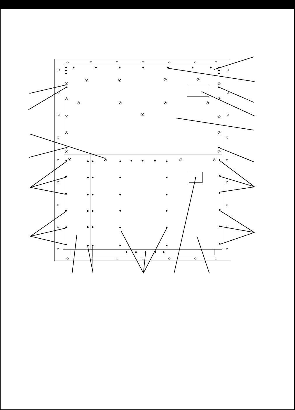
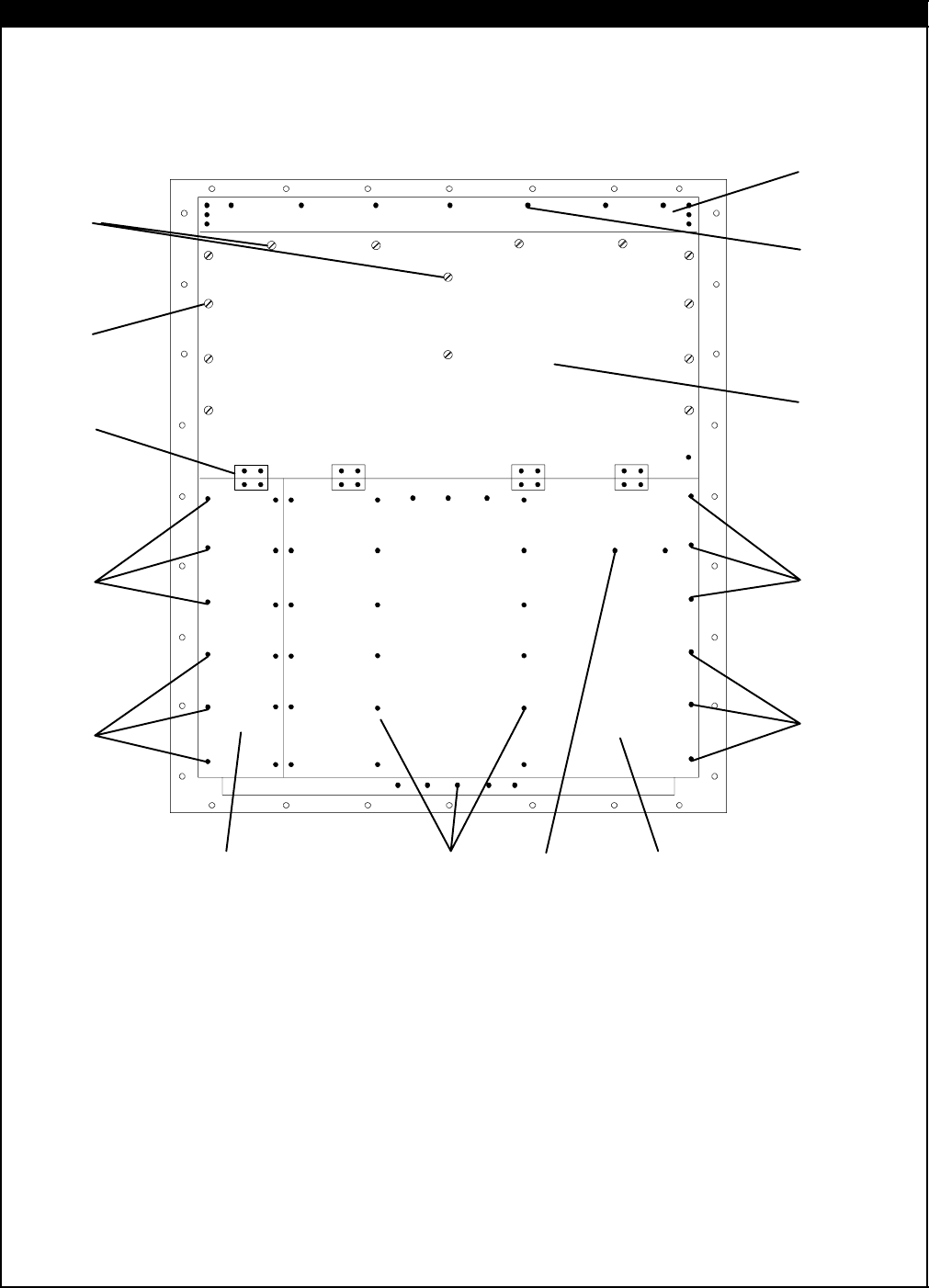
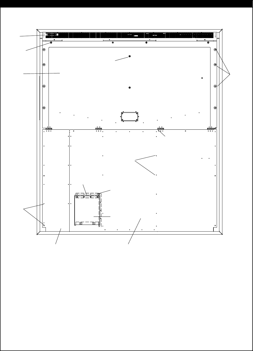
2 REFRIGERATION UNIT ASSEMBLY
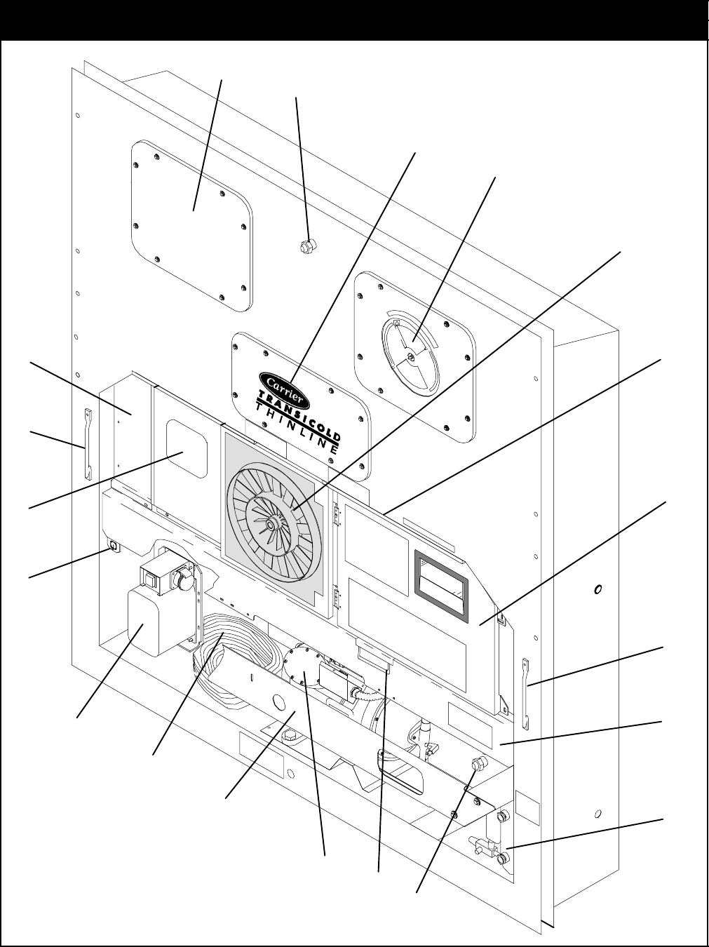
2.1 REFRIGERATION UNIT -- AREA LOCATOR
3
7
9
10
11
13
14
12
16
5
17
15
18
12
6
8
2
8
8
4

3 T-296PL
2.1 REFRIGERATION UNIT -- AREA LOCATOR
Item Section Number Area Description
1Refer to Section 2.19 Evaporator Fan Assembly
2Refer to Section 2.4 Thermometer Port
3Refer to Section 2.33 Labels and Decals
4Refer to Section 2.17 Upper Fresh Air Makeup & Access Panels
5Refer to Section 2.11 Motor, Condenser Fan
6Refer to Section 2.2 Rain Gutters
7Refer to Section 2.5 -- 2.10 Box, Control
8Refer to Section 2.3 Handles
9Refer to Section 2.11 Coil, Condenser
10 Refer to Section 2.13 or 2.14 Receiver or Water-Cooled Condenser
11 Refer to Sections 2.28 or 7 Compressor
12 Refer to Section 2.28 Guard, Compressor
13 Refer to Section 2.31 Cable, Power
14 Refer to Section 2.31 Plug, Power
15 Refer to Section 2.32 Autotransformer
16 Refer to Section 3 Interrogator and Accessories
17 Refer to Section 2.24 -- 2.27 Temperature Recorder
18 Refer to Section 2.18 Lower Fresh Air Makeup
4T-296PL
2.2 RAIN GUTTERS
or
or
or
1
2
3
4
4
Item Part Number Description Qty
OPTION 1 -- STANDARD LENGTH -- BOLTED
169NT35-3987 Gutter, Rain (Bolted, Standard -- Right Side) 1
269NT35-3997-1 Gutter, Rain (Bolted, Standard & Extended Length -- Left Side) 1
OPTION 3 -- EXTENDED LENGTH -- BOLTED
269NT35-3997-1 Gutter, Rain (Bolted, Standard & Extended Length -- Left Side) 1
369NT35-8548 Gutter, Rain (Bolted -- Right Side) 1
OPTION 4 -- RIVETED
468-12417-00 Gutter, Rain (Riveted -- Right and Left Side) 2
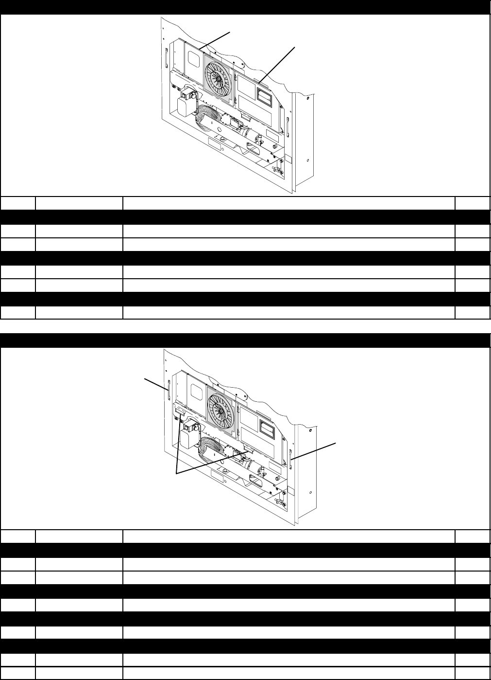
2.3 HANDLES
1
2
1
Item Part Number Description Qty
OPTION 1 -- TWO SIDE, ONE CENTER
169NT35-8113 Handle, Fixed 2
269NT40-657-2 Handle, Hinged 1
OPTION 2 -- TWO SIDE
169NT35-8113 Handle, Fixed 2
OPTION 3 -- ONE CENTER
269NT40-657-2 Handle, Hinged 1
OPTION 4 -- ONE SIDE, TWO CENTER
169NT35-8113 Handle, Fixed 1
269NT40-657-2 Handle, Hinged 2
5 T-296PL
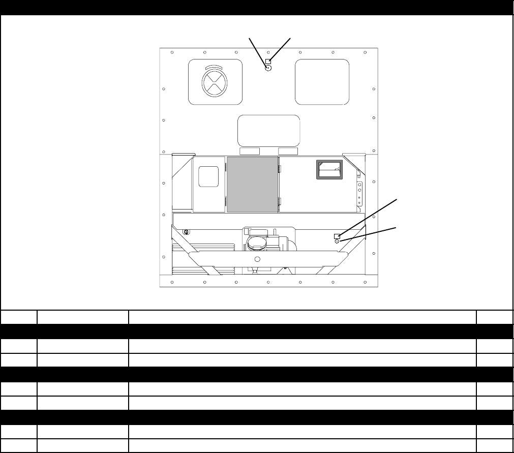
2.4 THERMOMETER PORT
1
3
2
4
Item Part Number Description Qty
OPTION 1 -- SUPPLY AIR PORT
166U1-8662 Cap & Chain Assembly 1
262-10557-00 Label 1
OPTION 2 -- RETURN AIR PORT
366U1-8662 Cap & Chain Assembly 1
462-10557-00 Label 1
OPTION B -- SUPPLY AND RETURN PORTS
1&3 66U1-8662 Cap & Chain Assembly 2
2&4 62-10557-00 Label 2
6T-296PL
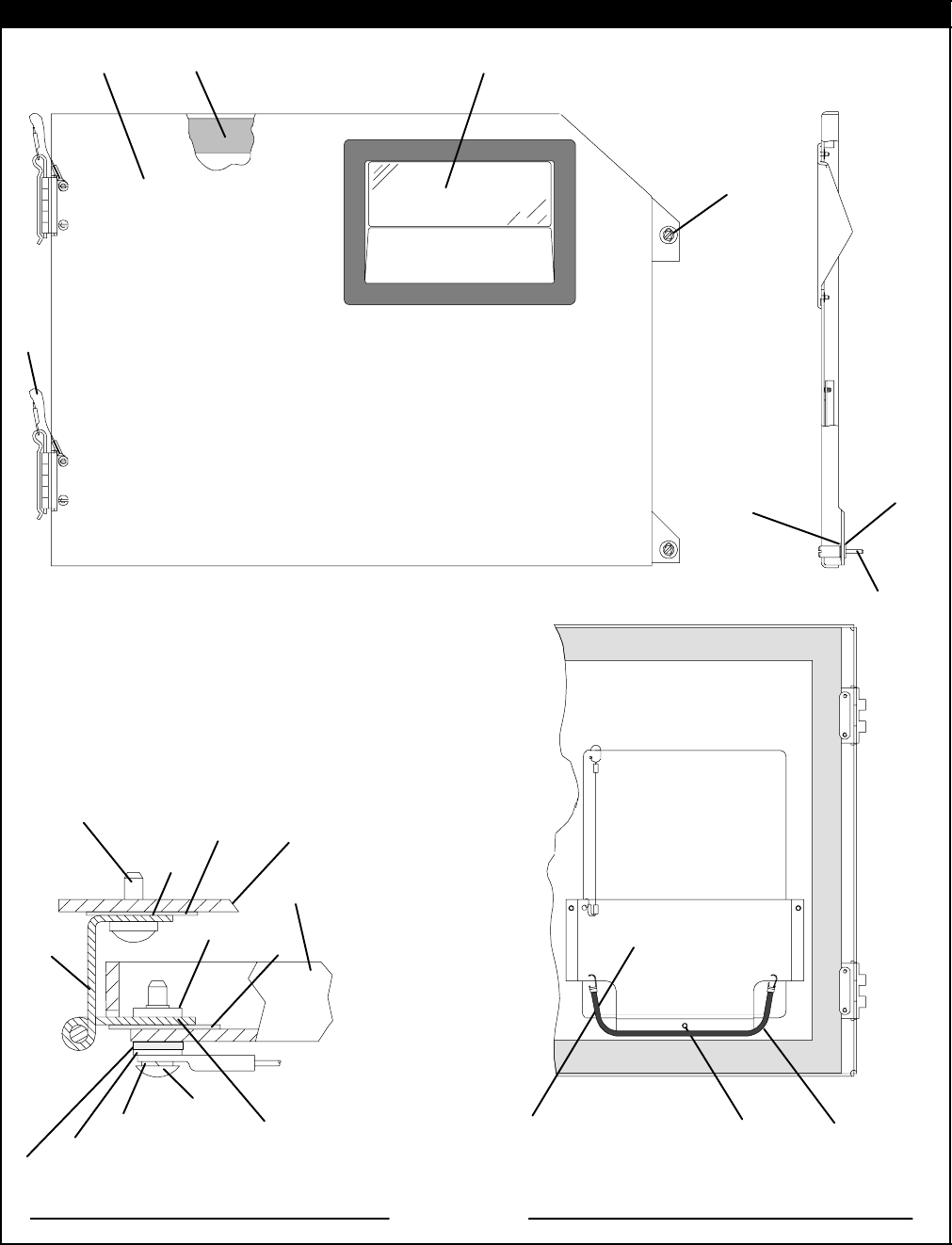
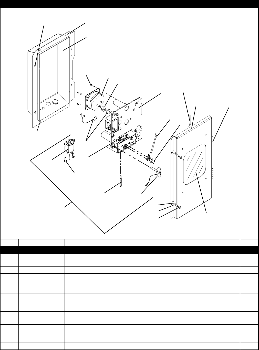
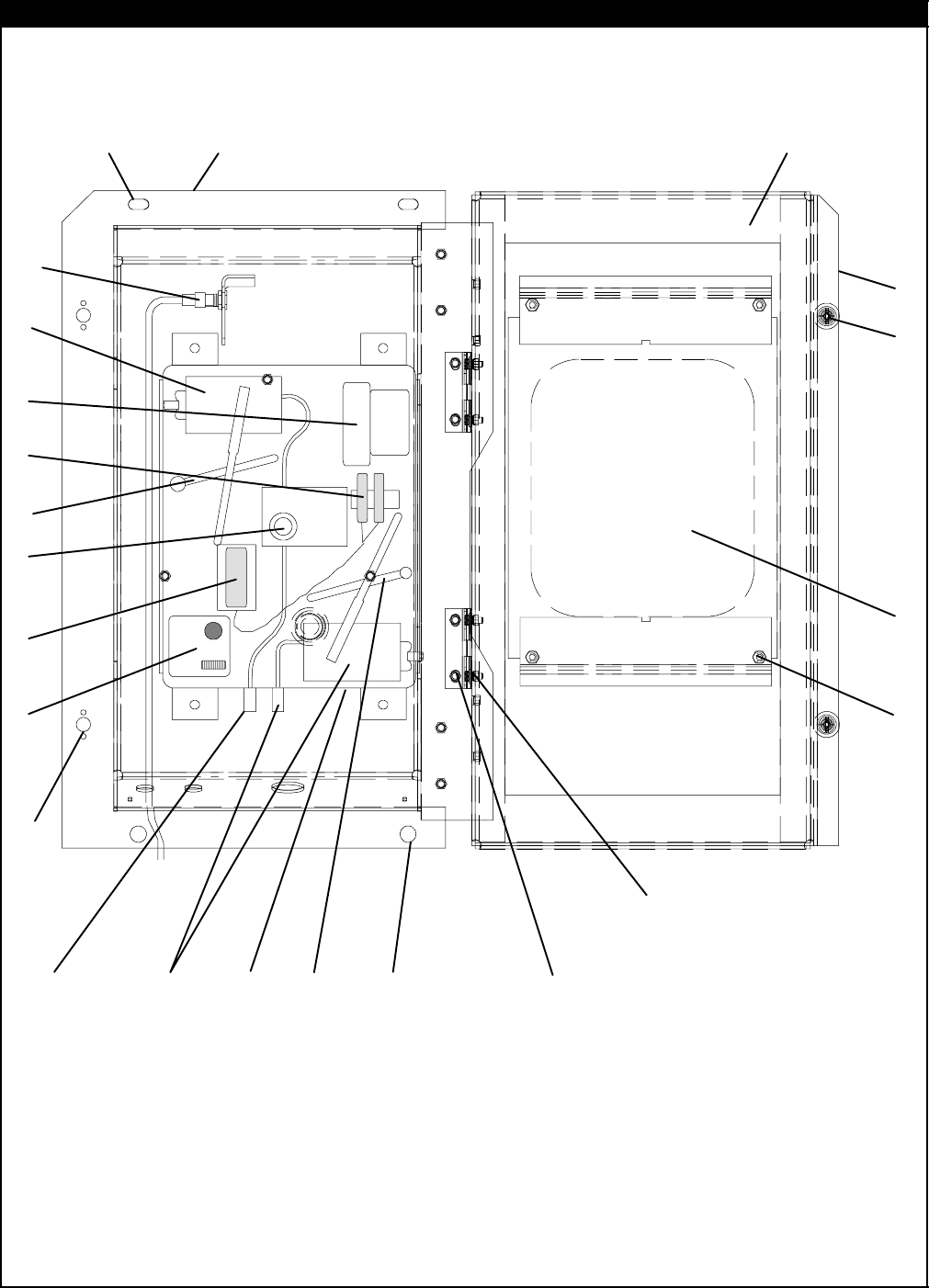
2.5 CONTROL BOX DOOR
Control Box Door
Control Box
HINGE ASSEMBLY -- SECTIONAL VIEW DOOR ASSEMBLY -- PARTIAL BACK VIEW
12 3
4
5
6
7
10
11 12
13
14
15
16
17 18
20
21
22
15
14
4
6
5
19
8
9

7 T-296PL
2.5 CONTROL BOX DOOR
Item Part Number Description Qty
169NT42-688-7 Door Assembly -- Includes: 1
242-00270-02 Gasket, Door 1
358-04366-00SV Window and Gasket Assembly, Control Box Door -- Lexan 1
434-06169-00 Washer, Retaining -- SST 2
566U1-6811-8 Screw, Retaining, Panel, 0.300-0.625 -- SST 2
566U1-6811-15 Screw, Retaining, Wing, 0.300-0.625 -- SST 2
634-06053-00 Washer, Mylar, 0.250 ID x 0.800 OD 4
744-00300-01 Hinge, Half 1
844-00300-02 Hinge, Half 1
944-00300-03 Pin Assembly, with Tether 1
10 58-04101-01 Protector, Mylar (Hinge) (Not Needed with Composite Box) 2
11 34-01167-01 Retainer, Nut 2
12 58-04101-00 Protector, Mylar (Hinge) 2
13 66U1-2403-1 Screw, Truss Head, #10-24 x 3/4 lg. -- SST 4
14 66U1-5331-3 Washer, Lock, #10 -- SST 7
15 66U1-5321-8 Washer, Flat, #10 -- SST 7
16 34-06053-05 Washer, Mylar, 0.205 ID x 0.600 OD 4
17 68-13577-00 Pocket, Placard 1
18 34-00665-09 Locknut, Hex Head, #10-24 -- SST 3
19 34-06107-00 Rivet, Blind, 1/8 Diameter, Grip Range -- 0.188-0.250 3
20 66U1-5371-7 Screw, #10-24 x 1/2 lg. -- SST 4
21 66U1-5321-8 Washer, Flat, #10 -- SST 4
22 58-04346-00 Door Strap Kit 1
8T-296PL
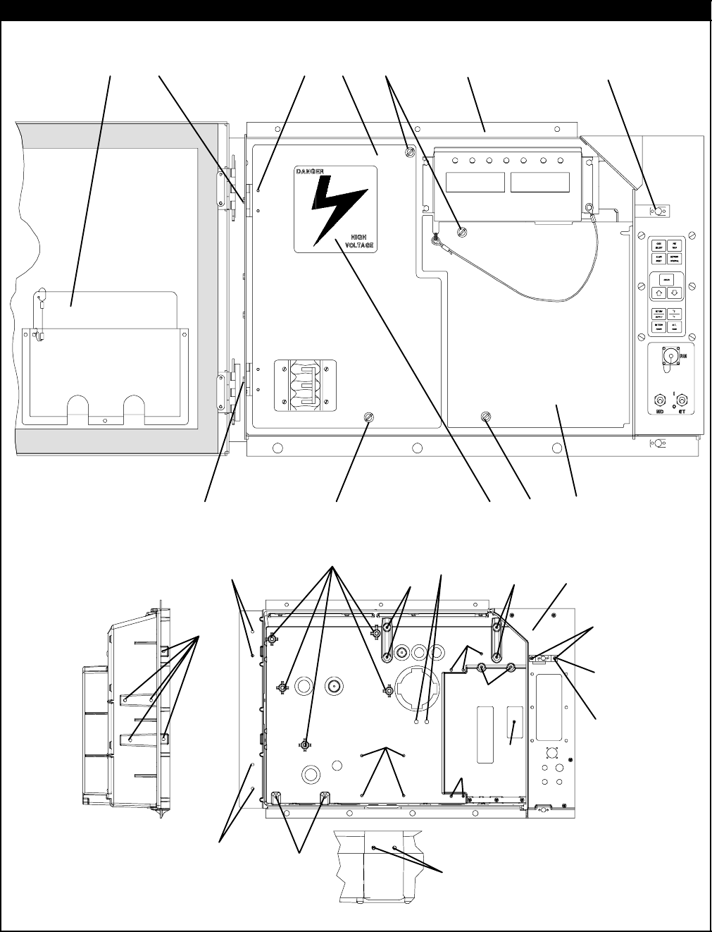
2.6 CONTROL BOX
23
4
56
9
68
2
7
7
14
19
20
21
22
23
24
20
20
20
20
20
21
22
24
6
7
OPTIONC&CL--COMPOSITEBOX
In Box
15
18
17
10
11
12
13
16
1
21

9 T-296PL
2.6 CONTROL BOX
Item Part Number Description Qty
1-- Plate, Schematic & Diagram (Refer to T-300, Container Unit Matrix) 1
266U1-2403 Screw, Truss Head, #10-24 x 1/2 lg. -- SST 2
369NT43-125-1 Shield, High Voltage (Plastic) -- Includes: 1
444-00343-00 Hinge 2
534-00928-02 Rivet, Blind, 1/8 Diameter, Grip Range -- 1/8-3/16 -- SST 4
634-50015-00 Stud & Retainer Package -- Includes: 4
NS NSS Stud, Fastener 1
NS NSS Retainer, Fastener Stud 1
734-06139-03 Receptacle 4
869NT43-124-4SV Shield, Low Voltage (Lexan) -- With Tether 1
962-03957-01 Label, Danger-High Voltage 1
OPTIONA&AL--ALUMINUMCONTROLBOX
10 86-04237-00 Control Box, Standard Aluminum 1
11 68-12791-00 Bracket, Lock (See Note 1) 1
1
2
34-01142-01 Receptacle, Retaining 1
12 34-01152-02 Receptacle, Retaining (See Note 2) 1
1
3
34-00928-01 Rivet, Blind, 1/8 Diameter, Grip Range -- 1/16 - 1/8 2
13 34-00928-03 Rivet, Blind, 1/8 Diameter, Grip Range -- 3/16 - 1/4 (See Note 2) 2
NOTES
1. The bracket is welded to the control box -- order Item #11 for locking plate.
2. When Item #11 is used, 34-01152-02 and rivets, 34-00928-03 are to be used in the upper door location.
OPTIONC&CL--COMPOSITECONTROLBOX
14 58-04367-00 Control Box, Standard Composite 1
1
5
69NT35-6272 Bracket, Non--Locking 1
15 69NT35-2287 Bracket, Locking (See Note 3) 1
16 34-01142-01 Receptacle, Retaining 1
1
7
34-00928-01 Rivet, Blind, 1/8 Diameter, Grip Range -- 1/16 - 1/8 2
17 34-00928-02 Rivet, Blind, 1/8 Diameter, Grip Range -- 1/18 - 3/16 (See Note 4) 2
18 66U1-2403 Screw, Truss Head, #10-24 x 1/2 lg. -- SST 2
NS 76-00724-00SV Crack, Chip and Hole Repair Kit 1
NS 76-50084-00SV Insert Repair Kit -- Includes: 1
19 34-06231-01 Insert -- 17.53 x 9.91 mm (.690 x .390 in) 1/4-20 Threads -- NSS 10
20 34-06231-03 Insert -- 15.88 x 6.35 mm (.625 x .250 in) 10-24 Threads -- NSS 10
21 34-06231-04 Insert -- 25.15 x 7.54 mm (.990 x .297 in) 10-24 Threads -- NSS 10
22 34-06231-05 Insert -- 10.16 x 9.53 mm (.400 x .375 in) 10-24 Threads -- NSS 10
23 34-06231-06 Insert -- 12.70 x 9.91 mm (.500 x .390 in) 1/4-20 Threads -- NSS 10
24 34-06231-07 Insert -- 9.53 x 6.76 mm (.375 x .266 in) 10-24Threads -- NSS 10
NS 02-00082-00 Durabond Epoxy -- NSS 1
NS 07-00390-00 Static Mixing Tube -- NSS 1
NS 07-00391-00 Application Gun -- Required for Insert Repair 1
NOTES
3. The bracket is bolted to the control box -- order 69NT35-2287 for locking bracket.
4. When 69NT35-2287 is used, 34-00928-02, rivet, is to be used in the upper door location.
10T-296PL
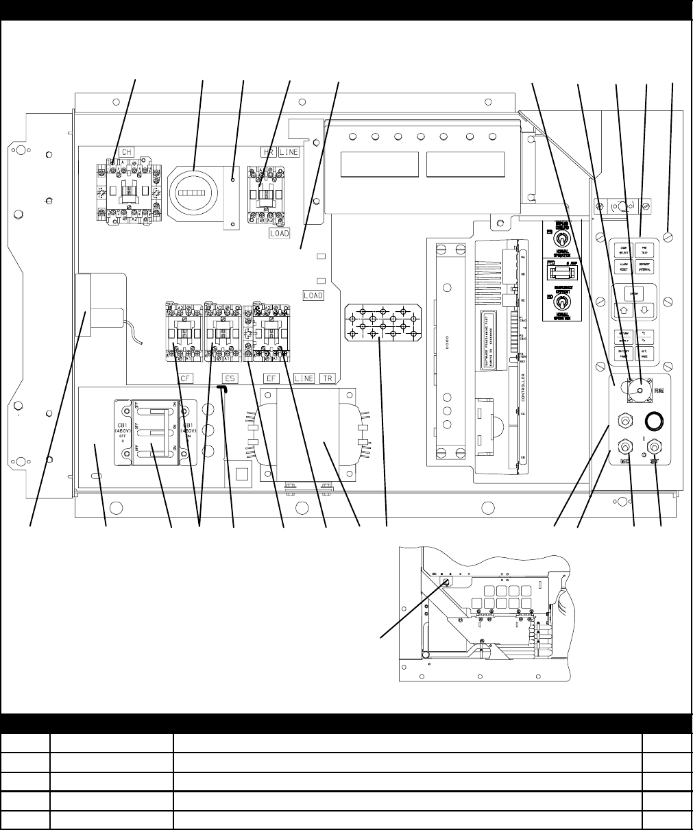
2.7 CONTROL BOX -- SHIELDS REMOVED, STD ELECTRICAL COMPONENTS, RM & HOURMETER
22
23
24
20
26
27
28
1617
18
19
20
66
7
6
7
6
7
8
9
10
13
14
14
15
21
19
20
25
29
36
37
38
39
40
41
42
1
23
443 35
30
31
32
33 34
11
12
REMOTE MONITORING ---
LOWER/EXTERNAL MTG
44
45
5
HOURMETER
Item Part Number Description Qty
166U1-3823 Hourmeter 1
266U1-6651-15 Screw, Pan Head, #4-40 x 3/4 lg. -- SST 3
368-12496-00 Bracket, Hourmeter 1
466U1-5381 Screw, Hex Head, #10-24 x .50 lg. -- SST 2

11 T-296PL
2.7 CONTROL BOX -- SHIELDS REMOVED, STANDARD ELECTRICAL COMPONENTS (Continued)
Item Part Number Description Qty
510-00431--07 Contactor, Compressor (CH) (30 Amp) 1
634--06243--00 Screw, Pan Head, (Thread Cutting) #8-32 x 3/4 lg. -- SST 10
710-00431--06 Contactors, (CF),(HR) &(EF & ES) (12 Amp) 4
868-13427-00SV Panel, Contactor -- Includes: 1
958-00967-00 Spacer (Used with sheet metal control box only) 5
10 34-00655-08 Screw, Hex Head, 1/4-20 x 1.00 lg. -- SST 4
11 34-00928-01 Rivet, Blind, 1/8 Diameter, Grip Range -- 1/16 - 1/8 6
12 34-01142-01 Receptacle 1
13 10-01129-07SV Switch, Toggle (On-Off) 1
14 66U1-9752 Seal, Bushing 1
15 10-01129-10 Switch, Toggle (MDS) 1
16 58-04145-01 Plate, Switch 1
17 69NT41-982-3 Plate, Ground 1
18 10-00332-21SV Transformer, Base Unit 1
19 66U1-5371-7 Screw, Hex Head, #10-24 x 1/2 lg. -- SST A/R
20 66U1-5321-8 Washer, Flat, #10 -- SST A/R
21 10-00431--02 Contact, Auxiliary 1
22 34-00663-07 Washer, Lock, #6 -- SST 4
23 66U1-7842-13 Circuit Breaker -- 460 vac, 25 Amp, (CB1) 1
24 66U1-6651-4 Screw, Pan Head, #6-32 x 3/8 lg. -- SST 4
25 69NT35-6278 Bracket, Circuit Breaker 1
26 10-00366-01SV Transformer, Current Sensing (CS) 1
27 66U1-5371-10 Screw, Hex Head, #10-24 x 1.00 lg. -- SST 2
28 66U1-5321-8 Washer, Flat, #10 -- SST 2
29 66CH1-1172-46 Trim, Flexible (85 Feet Long, Cut to Length) A/R
30 79-01706-03SV Pad, Key -- Includes: 1
31 NSS Gasket (Between Key Pad Plate Assembly and Connector) 1
32 NSS Gasket (Between Key Pad and Key Pad Plate Assembly 1
33 NSS Plate Assembly, Key Pad Mounting 1
3
4
34-06227-00 Screw, Pan Head, #10-24 X 3/4 lg. -- SST (Use with Composite Box) 6
34 66U1-2403 Screw, Pan Head, #10-24 X 3/4 lg. -- SST (Use with Aluminum Box) 6
35 34-06053-05 Washer, Mylar, 0.205 ID x 0.600 OD 6
REMOTE MONITORING (STANDARD LOCATION)
36 22-02341-00 Receptacle, Remote Monitoring (RM) 1
37 22-02368-00 Plug, Remote Monitoring 1
38 22-02341-01 Cap and Tether, Receptacle Assembly 1
39 66U1-6835 Gasket, Remote Monitoring Receptacle 1
40 34-00848-10 Screw, Round Head, #4-40 x 5/8 lg. -- SST 4
41 66U1-5321-6 Washer, Flat, 0.125 ID -- SST 4
42 34-00667-05 Nut, Self Locking, #4-40 -- SST 4
43 58-04145-00 Plate, Switch, with RM 1
REMOTE MONITORING (LOWER LEFT/EXTERNAL LOCATION)
44 22-01889-00 Receptacle, Remote Monitoring (RM) 1
45 69NT40-222 Bracket 1
12T-296PL
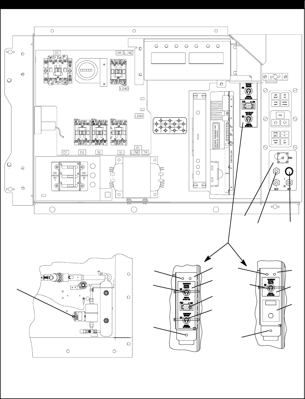
2.8 CONTROL BOX -- SHIELDS REMOVED, EVAP FAN CAPABILITY, EBS and EDS, EBS ONLY and CFS
EBS & EDS EBS Only
Bottom Right Corner of Unit
1
2
3
4
5
6
7
9
10
8
8
8
8
7
6
9
10
11
12
6
9
10
13 17
18
14
15
16
19
20
21

13 T-296PL
2.8 CONTROL BOX -- SHIELDS REMOVED, EVAP FAN CAPABILITY, EBS and EDS, EBS ONLY and CFS
Item Part Number Description Qty
OPTION 1 -- NORMAL EVAPORATOR FAN OPERATION
See Section 2.7 Items 6 and 7 for correct contactor placement
OPTION B -- EMERGENCY BYPASS SWITCH AND EMERGENCY DEFROST SWITCH
110-00416-00 Module, Emergency Bypass 1
266U1-5371-6 Screw, Machine Hex Head, #10-24 x .75 lg. -- SST 2
334-06053-05 Washer, Mylar, 0.205 ID x 0.600 OD 2
466U1-5321-8 Washer, Flat, #10 -- SST 2
5
58-04145-09 Plate, Switch (with light location, no RM) 1
558-04145-07 Plate, Switch (with light location, with RM) 1
610-01129-07 Switch, Toggle 2
768-12544-01 Bracket 1
834-06223-00 Screw, Captive Washer, #10-24 X .56 lg. -- SST 2
910-01129-20 Hex Nut 2
10 66U1-9752 Seal, Bushing 2
11 22-01455-02 Holder Assembly, Fuse 1
12 22-02336-02 Fuse, 5 Amp 1
13 62-02874-01 Label, EB and ED 1
14 22-00518-01 Base,PilotLight 1
15 22-00519-03 Light Assembly, Pilot 1
16 22-00049-01 Lamp, 24VDC 1
OPTION EB -- EMERGENCY BYPASS SWITCH ONLY
110-00416-00 Module, Emergency Bypass 1
266U1-5371-6 Screw, Machine, Hex Head, #10-24 x .75 lg. -- SST 2
334-06053-05 Washer, Mylar, 0.205 ID x 0.600 OD 2
466U1-5321-8 Washer, Flat, #10 -- SST 2
610-01129-07SV Switch, Toggle 1
768-12544-01 Bracket 1
834-06223-00 Screw, Captive Washer, #10-24 X .56 lg. -- SST 2
910-01129-20 Hex Nut 1
10 66U1-9752 Seal, Bushing 1
17 62-02874-00 Label, EB Upper 1
18 62-02874-02 Label, EB Lower 1
OPTION F -- CONDENSER FAN SWITCH
19 10-00298-01 Switch, Toggle (CFS) 1
20 66U1-9752 Seal, Bushing 1
21 58-04145-06 Plate, Switch (with extra switch location) 1
14T-296PL
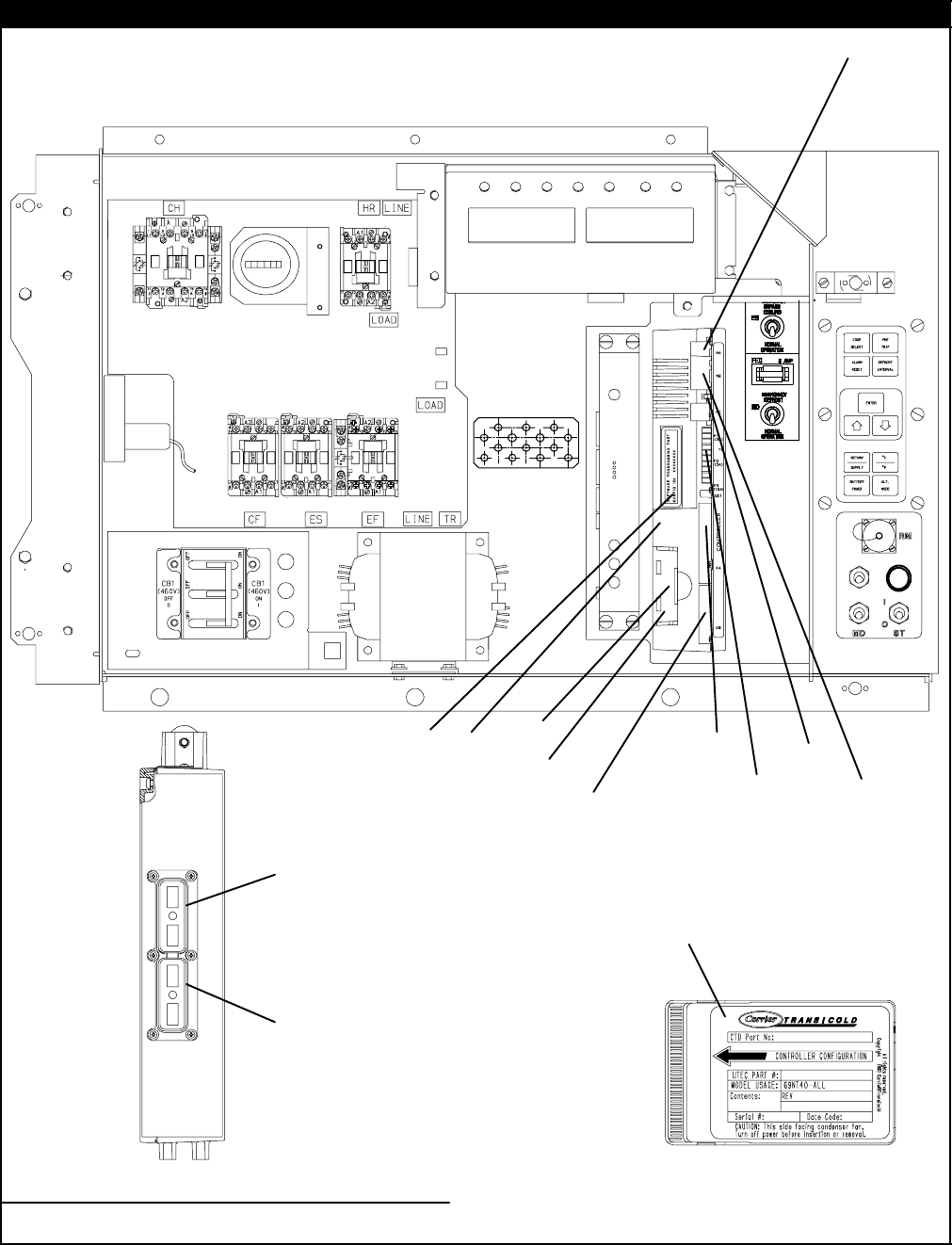
2.9 CONTROL BOX -- CONTROLLER MODULE SECTION AND SOFTWARE CARDS
1
5
6
19
3
4
8
2
View -- Back of Controller/DataCORDER module
9
10
11
12
13
10
12
14
15
16
17
18
720
21

15 T-296PL
2.9 CONTROL BOX -- CONTROLLER MODULE SECTION AND SOFTWARE CARDS
Item Part Number Description Qty
1-- Module, Controller/DataCORDER -- RefertoSection8-- Includes: --
266U1-5371-7 Screw, Hex Head, #10-24 x 1/2 lg. -- SST 1
369NT35-2692 Washer, Fender, 0.063 Thick -- SST 1
458-01184-00 Retainer, Screw, 0.141 ID 1
522-02336-04 Fuse, 10 Amp (F3) 3
622-02336-02 Fuse, 5 Amp (F1 & F2) 1
762-02719-00 Label, Controller/DataCORDER Port 1
812-00397-00/5124 Card, Controller/DataCORDER Operation Software 1
NS 12-00402--xx Card, Configuration Software 1
922-01777-00SV Connector (EC A-K) -- 30 Pin 1
10 22-01777-03 Socket, 20 AWG 35
11 22-50100-00 Socket, 18 AWG 4
12 22-01777-04 Plug, Sealing 21
13 22-01777-01SV Connector (EC L-Y) -- 30 Pin 1
14 22-01556-02 Connector (KA) -- 14 Pin 1
15 22-01556-01 Connector (KB) -- 10 Pin 1
NS 22-01621-23 Connector (KP) -- 9 Pin (Connects to Ribbon Cable) 1
16 22-01622-01 Connector (MA) -- 12 Pin 1
17 22-01622-02 Connector (MB) -- 16 Pin 1
18 22-01622-00 Connector (MC) -- 8 Pin 1
NS 09-00369-00SV Battery, Real Time Clock, (Within the Controller) 1
NS 22-50157-00 Wire Harness, Controller to Current Sensing Transformer) 1
NS 22-01713-06 Wire Harness, Display Module to Controller/DataCORDER Module 1
NS 62-02735-00 Label, Warning, Don’t use 12-00327 ! --(Located on the control box behind
the Controller/DataCORDER module.) 1
NS 62-02738-05 Label, Warning, 5108 Series -- (Located on the bottom panel of the control
box between the transformer and the Communications Interface module.) 1
OPTION R -- RECHARGEABLE BATTERY PACK
19 30-00407-02SV Battery Pack -- Controller/DataCORDER Module 1
OPTION S -- STANDARD CELLS
20 PL Battery (”AA”) 6
21 30-00407-00 Cover, Controller Battery 1
16T-296PL
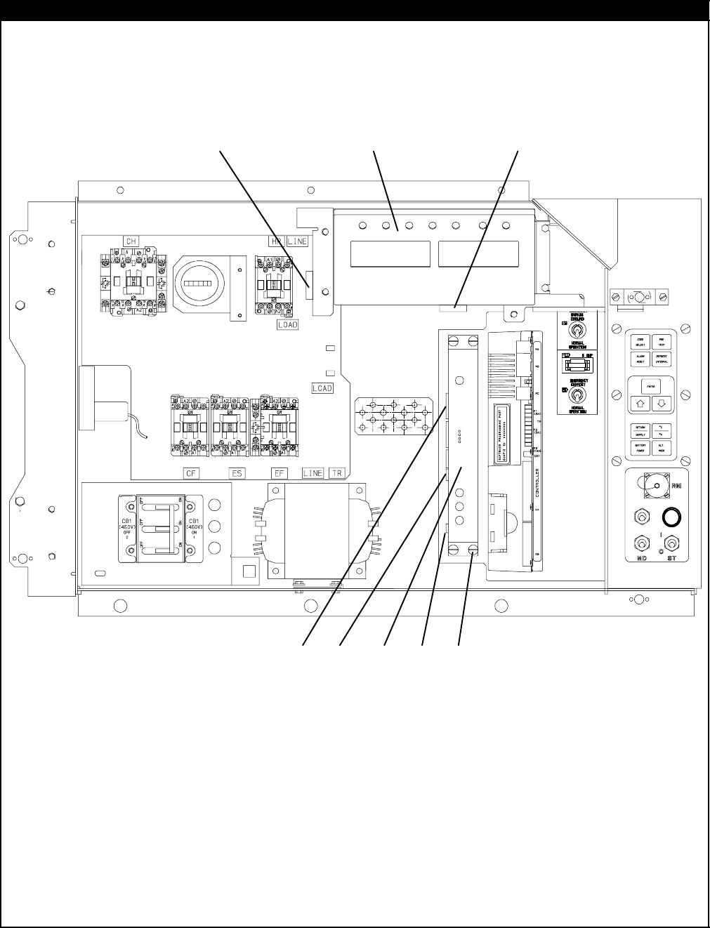
2.10 CONTROL BOX -- DISPLAY MODULE AND COMMUNICATIONS INTERFACE MODULE SECTION
1
2
3
67 8
9
10
11
12
13
45

17 T-296PL
2.10 CONTROL BOX -- DISPLAY MODULE AND COMMUNICATIONS INTERFACE MODULE SECTION
Item Part Number Description Qty
112-00433-00RP Module, Display 1
266U1-5371-7 Screw, Hex Head, #10-24 x 1/2 lg. -- SST 4
369NT35-2692-4 Washer, Fender, 0.063 Thick -- SST 4
422-01621-03 Connector (MK) -- 9 Pin 1
522-01621-02 Connector (MB) -- 16 Pin 1
622-02396-03 Connector (CIC) -- 7 Pin 1
722-02396-02 Connector (CIB) -- 3 Pin 1
822-01556-00 Connector (CIA) -- 7 Pin 1
NS 22-01713-02 Wire Harness, Key Pad to Display Module 1
OPTION 1 -- COMMUNICATIONS INTERFACE MODULE -- STANDARD
912-00573-00SV Module, Communications Interface -- Includes: 1
10 66U1-3442-2 Stud, Fastener, 1/4 turn, 0.705 lg. -- SST 4
11 66U1-9212-1 Retainer, Push-on 4
12 34-06223-00 Screw, Captive Washer #10-24 x 0.56 -- SST 4
13 58-01184-00 Retainer, Screw .75 O.D. 4
OPTION 2 -- COMMUNICATIONS INTERFACE MODULE -- HIGH DATA RATE
912-00275-10SV Module, Communications Interface -- Includes: 1
10 66U1-3442-2 Stud, Fastener, 1/4 turn, 0.705 lg. -- SST 4
11 66U1-9212-1 Retainer, Push-on 4
12 34-06223-00 Screw, Captive Washer #10-24 x 0.56 -- SST 4
13 58-01184-00 Retainer, Screw .75 O.D. 4
OPTION 3 -- COMMUNICATIONS INTERFACE MODULE -- CHIPSET MODEM
912-00573-00SV Module, Communications Interface -- Includes: 1
10 66U1-3442-2 Stud, Fastener, 1/4 turn, 0.705 lg. -- SST 4
11 66U1-9212-1 Retainer, Push-on 4
12 34-06223-00 Screw, Captive Washer #10-24 x 0.56 -- SST 4
13 58-01184-00 Retainer, Screw .75 O.D. 4
OPTION 4 -- COMMUNICATIONS INTERFACE MODULE -- LOW DATA RATE
912-00275-19SV Module, Communications Interface -- Includes: 1
10 66U1-3442-2 Stud, Fastener, 1/4 turn, 0.705 lg. -- SST 4
11 66U1-9212-1 Retainer, Push-on 4
12 34-06223-00 Screw, Captive Washer #10-24 x 0.56 -- SST 4
13 58-01184-00 Retainer, Screw .75 O.D. 4
18T-296PL
2.11 CONDENSER FAN MOTOR AND CONDENSER COIL SECTION
24
25
3
4
6
7
10
11
11
12
13
14
15
5
28
30
31
32
33
34
35
36
37
29
26
27
20
23
16
8
9
21
22
OPTION 3 OR OPTION 4
18
1
2
17
19
OR
38
39
40
41
Item Part Number Description Qty
166U1-5361-25 Capscrew, Hex Head, 1/4-20 x 3/4 lg. -- SST 10
266U1-5321-7 Washer, Flat, 1/4 -- SST 10
334-06053-00 Washer, Mylar, 3/4 OD x 1/4 ID 10
434-06053-03 Washer, Mylar, 1.0 OD x 1/4 ID 2
569NT35-3547 Bracket, Condenser Motor Mount 1
654-00586-20 Motor, Condenser Fan -- Includes: 1
7PL Key, 3/16 Square x 1-3/8 lg. -- SST 1
804-50027-00 Bearing 2
922-50088-02 Capacitor, 15 uF 1
10 66U1-5361 Screw, Hex Head, 5/16-18 x 1-1/4 lg. -- SST 4
11 34-01181-01 Washer, Flat, 5/16 -- SST 8
12 34-06053-02 Washer, Mylar, 1.0 OD x 3/8 ID 4
13 34-00667-12 Locknut, 5/16-18 -- SST 4
14 69NT35-6112 Protector, Condenser Fan Motor Mounting 2
15 38-00503-00 Fan, Condenser (17-1/2 diameter) -- Composite -- Includes: 1
16 PL Set Screw,Square Head, 5/16-24 x 5/8 lg. -- SST 2

19 T-296PL
2.11 CONDENSER FAN MOTOR AND CONDENSER COIL SECTION (Continued)
Item Part Number Description Qty
OPTION 2 -- TWO ROW CONDENSER COIL
Use Option 4 for 2-Row Coil Replacement
OPTION 3 -- THREE ROW (7MM) CONDENSER COIL
1
7
68-13454-02SV Cover, Condenser Coil, Blue Includes: 1
17 68-13454-03SV Cover, Condenser Coil, White Includes: 1
1
8
58-04480-00 Bumper (for use with uncoated center handle) 2
18 58-04481-00 Plug (for use with coated handle or units with no center handle) 2
19 81-01575-00SV Coil, Condenser(Copper) -- 7MM 3 Row -- Includes Mylar Washers 1
20 66CH1-1172-16 Trim, Flexible 2
21 69NT35-8693-7 Protector (Apply between frame and coil & coil cover) 4
22 69NT35-8693-10 Protector (Apply between frame and coil & coil cover) 2
23 58-04026-41 Protector,Mylar (Apply between coil & coil cover, RH &LH sides) 2
OPTION 4 -- FOUR ROW (3/8in.) CONDENSER COIL
2
4
69NT43-148-2 Cover, Condenser Coil, Blue Includes: 1
24 69NT43-148-4 Cover, Condenser Coil, White Includes: 1
1
8
58-04480-00 Bumper (for use with uncoated center handle) 2
18 58-04481-00 Plug (for use with coated handle or units with no center handle) 2
25 69NT43-202-10SV Coil, Condenser(Copper) -- 4 row -- Includes Mylar Washers 1
26 69NT35-8703 Protector (Apply between frame and coil & coil cover) 4
27 58-04026-10 Protector,Mylar (Apply between coil & coil cover, RH &LH sides) 2
OPTION H -- HINGED CONDENSER FAN GRILLE
28 76-00704-01 Grille and Venturi Assembly -- Includes: 1
29 66U1-8912 Label, Rotation 1
30 76-50075-00 Hinge Kit -- Includes: 1
31 44-00374-00 Hinge 2
32 58-04101-07 Protector, Mylar 4
33 34-06179-00 Screw, Hex Head, #10-24 x 7/16 lg. -- SST 8
3
4
66U1-6811-8 Screw, Retaining -- SST 2
34 66U1-6811-12 Screw, Retaining (Phillips Head) -- SST 2
35 34-06169-00 Washer, Retaining -- SST 2
36 34-06053-03 Washer, Mylar, 1/4ID x 1.00OD 2
37 69NT35-2692-1 Washer, Fender 1/4 -- SST 2
OPTION B -- BOLTED CONDENSER FAN GRILLE
28 76-00704-01 Grille and Venturi Assembly -- Includes: 1
29 66U1-8912 Label, Rotation 1
38 69NT35-2692-1 Washer, Fender 1/4 -- SST 4
39 34-06053-03 Washer, Mylar, 1/4ID x 1.00OD 4
40 34-00663-11 Washer, Lock, 1/4 -- SST 4
41 66U1-5361-25 Capscrew, Hex Head, 1/4-20 x 3/4 lg. -- SST 4
20T-296PL
2.12 COMPRESSOR TUBING SECTION
1
6
7
8
9
10
11 12
13
14
15
16
17 18
14
14
15
14
16
17
22
21
2
3
4
519 20

21 T-296PL
2.12 COMPRESSOR TUBING SECTION
Item Part Number Description Qty
114-00263-00 Valve, Stepper Motor -- Includes: 1
214-00263-20 Piston and Motor Assembly -- Includes: 1
322-02392-03 Connector (To Power Pack) 1
NS 22-02393-01 Pin, 18-20 Gauge (Used on 22-02392-03) 4
NS 22-02394-03 Seal (Used on 22-02392-03) 4
414-00263-23 O-Ring 1
514-00263-22 Cap 1
6-- Valve, Service (Discharge) -- See Section NO TAG 1
714-00204-02 Valve, Discharge Pressure Regulator (DPRV) 1
8-- Valve, Service (Suction) -- See Section NO TAG 1
940-00542-00 Elbow, Adapter (R134a) 1
10 40-00520-02 Cap, M8 x 1.0 -- Nylon 1
11 69NT41-702 Bracket Assembly 1
12 66U1-3632-24 Clamp, Cushion, 1.18 Dia. 1
13 34-00373-11 Clamp, Cushion, .88 Dia. 1
14 66U1-5381-1 Screw, Hex Head, #10-24 x .75 lg. -- SST 4
15 34-06053-00 Washer, Mylar, .25 I.D. x .80 O.D. 3
16 66U1-5321-8 Washer, Flat, #10 -- SST 3
17 34-06053-05 Washer, Mylar, .205 I.D. x .60 O.D. 3
18 10-00388-00 Power Pack, Stepper Motor -- Includes: 1
19 22-01585-04 Connector (To Valve) 1
20 22-01836-00 Connector (To Harness) 1
NS 22-01566-01 Socket (Used on 22-01585-04) 4
NS 22-02393-00 Pin (Used on 22-01830-00) 4
NS 22-02394-02 Seal (Used on 22-01835-00, 22-01585-04 and 22-01830-00) A/R
NS 22-01835-00 Connector (On Harness to Drive) 1
NS 22-01566-00 Pin (Used on 22-01835-00) 5
REFRIGERATION TEMPERATURE SENSORS
21 12-01105-02 Sensor, Thermistor (CPDS) 1
22 12-01104-05 Sensor, Thermistor (CPSS) 1
22T-296PL
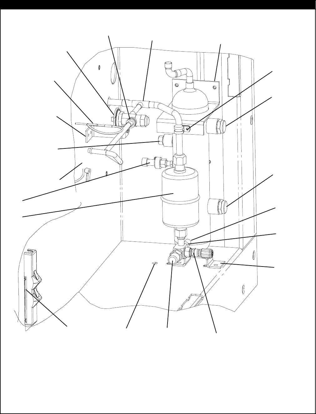
2.13 RECEIVER SECTION
1
2
3
4
5
6
7
8
9
10
11
12
13
15
16
17
18
33
19
20
21
22
24
25
26
27
28
29
23
30
20
21
9
10
11
20
32
31
14
34

23 T-296PL
2.13 RECEIVER SECTION
Item Part Number Description Qty
169NT43-403-2 Receiver, Electro-Coated Modular, Copper -- Includes: 1
214-00220-01 Glass, Sight, w/Red Balls, 1/2-14 npt 1
314-00221-01 Indicator, Moisture-Liquid 1
4
14-01032-14 Plug, Fusible, 3/8 npt -- Brass 1
414-00215-04 Disc, Rupture, 3/8 npt -- Alternate 1
NS 22-02448-00SV Connector, Female (Located on wire harness) 1
512-00352-00 Transducer, Condenser Pressure (CPT) 1
6EC39DM062 Valve, Schrader 1
714-00311-02SV Filter-Drier with O-Rings 1
869NT43-277 Bracket, Liquid Line Valve 1
966U1-5361-25 Screw, Hex Head, 1/4-20 x 3/4 lg. -- SST A/R
10 66U1-5321-7 Washer, Flat, 1/4 -- SST 3
11 34-06053-00 Washer, Mylar, 0.250 ID x 0.800 OD 4
12 40-00520-01 Coupling, M15 -- Brass -- Includes: 1
13 40-00520-03 Cap, Service Port 1
14 14-00222-01 Valve, Liquid Line 1
15 66U1-5361-7 Bolt, Hex Head, 3/8-16 x 1.00 lg. -- SST 1
16 AU11JR241 Washer, Lock, 3/8 -- SST 1
17 66U1-5321-5 Washer, Flat, 3/8 -- SST 1
18 34-06053-02 Washer, Mylar, 0.375 ID x 1.00 OD 1
19 34-00373-05 Clamp, Cushion, 1/2 Diameter 1
20 66U1-5371-6 Screw, Machine, Hex Head, #10-24 x .75 lg. -- SST 3
21 34-06053-05 Washer, Mylar, .205 I.D. x .60 O.D. 4
22 34-00373-07 Clamp, Cushion, 5/8 Diameter 1
23 69NT43-420 Bracket Assembly, Quench Valve 1
24 34-00928-09 Rivet, Blind, 5/32 Diameter, Grip Range -- 1/8-1/4 -- SST 2
25 66U2-1132-1 Connector 1
26 66U1-3803 Heat Shrink 1
27 34-00373-54 Clamp, Cushion, .44 Diameter 1
28 34-06053-03 Washer, Mylar, .25 I.D. x 1.00 O.D. 1
29 14-00212-03SV Valve, Quench, Thermostatic Expansion -- Includes: 1
NS 14-00212-21 Kit, Repair -- Includes: 1
NS NSS Power Head 1
30 58-04026-23 Protector, Mylar 1
31 12-00495-02SV Sensor, Ambient Thermistor (AMBS) 1
32 DE40BA203 Tee, Reducing 1/2 x 1/2 x 3/8 1
33 -- See Section 2.15 for Sensor Assembly and Related Parts --
34 40-00501-50 Cap, Service Valve 1
24T-296PL
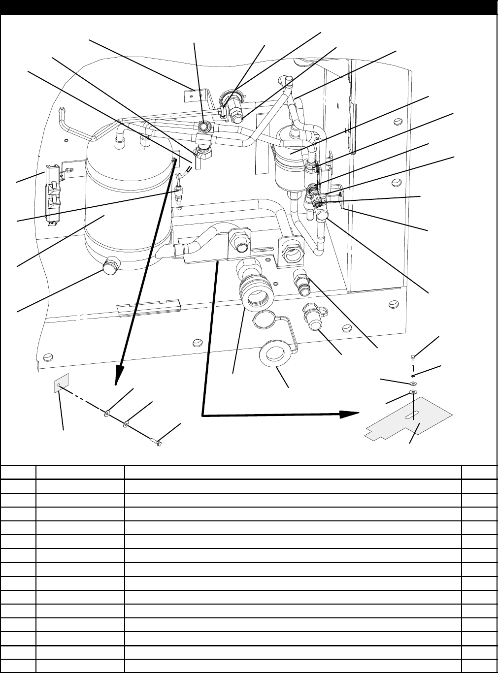
2.14 WATER--COOLED CONDENSER SECTION (See Note 5 )
1
2
34
5
6
7
89
11
12
13
14 15
16
17
18
19
21
22
23
24
25
26
27
28
29
30
31
32
33
34
35
36
37
38 39
40
41
42
43
44
45
43
44
43
44
20 45
Item Part Number Description Qty
-- 69NT42-914 Kit, Condenser/Receiver (For Field Installation) -- See NOTE -- Includes: 1
169NT42-914-1 Condenser/Receiver -- Includes: 1
214-00220-00 Sight Glass, w/red balls, 1/2 npt 1
358-00956-00 Protector, Mylar 2
458-00957-00 Protector, Mylar 1
566U1-2763-5 Coupling (Water-In) 1
666U2-1142 Cap, Dust 1
740-01129-00 Coupling, Self Draining -- Includes: 1
766U1-2763-6 Coupling Assembly, Socket -- Includes: 1
842-50000-00 Seal, O-Ring 1
966U2-1152 Cap, Dust (Use with 40-01129-00) 1
10 79-01757-00 Cap Assembly (Use with 66U1-2763-6) 1
11 12-01071-01SV Switch,Water Pressure OPTION W 1
12 14-00215-05 Disc, Rupture, 3/8 npt 1

25 T-296PL
2.14 WATER--COOLED CONDENSER SECTION (Continued)
Item Part Number Description Qty
13 66U1-5361-7 Bolt, Hex Head, 3/8-16 x 1.00 lg. -- SST 1
14 66U1-5321-5 Washer, Flat, 3/8 -- SST 1
15 AU11JR241 Washer, Lock, 3/8 -- SST 1
16 34-06053-02 Washer, Mylar, 3/8 ID x 1.00 OD 1
17 66U1-5361-25 Capscrew, Hex Head, 1/4-20 x 3/4 lg. -- SST 2
18 66U1-5321-7 Washer, Flat, 1/4 -- SST 2
19 34-06053-00 Washer, Mylar, 1/4 ID x 13/16 OD 2
20 -- See Section 2.15 for Sensor Assembly and Related Parts --
-- 76-00677-00 Accessory Kit, Water-Cooled Condenser Tubing -- Includes: --
21 06DA403-844 Valve, Schrader 1
22 12-00352-00 Transducer, Condenser Pressure (CPT) 1
23 69NT41-477 Tube Assembly -- Includes: 1
24 40-00555-06 Tee, 1/2 x 1/2 x 3/8 npt -- Brass 1
25 14-00311--02SV Filter-Drier with O-Rings 1
26 69NP20-1031 Clamp, Filter-Drier -- Includes: 1
NS 58-50014-00 Gasket (16 ft., Cut to length) 1
-- 69NT41-497 Tube Assembly -- Includes: 1
27 66U1-8552-2 Valve, Liquid Line -- Includes: 1
28 40-00086-04 Cap, Flare -- 1/4 1
29 17-21002-01 Cap, Valve 1
30 40-00520-01 Coupling, M15 -- Brass -- Includes: 1
31 40-00520-03 Cap, Service Port 1
32 68-12368-00 Bracket 1
33 66U1-5371-6 Screw, Hex Head, #10-24 x 3/4 lg. -- SST 2
34 34-06053-05 Washer, Mylar, 0.205 ID x 0.600 OD 2
35 69NT41-487 Tube Assembly -- Includes: 1
36 14-01092-03 Indicator, Liquid Moisture -- Brass 1
37 69NT43-420 Bracket Assembly 1
38 34-00928-09 Rivet, Blind, 5/32 Diameter, Grip Range -- 1/8-1/4 2
39 14-00212-03SV Valve, Quench, Thermostatic Expansion -- Includes: 1
NS 14-00212-21 Kit, Repair -- Includes: 1
NS NSS Power Head 1
40 12-00495-02SV Sensor, Ambient Thermistor (AMBS) 1
41 DE40BA203 Tee, Reducing, 1/2 x 1/2 x 3/8 1
42 34-00373-54 Clamp, Cushion, .44 Diameter 1
43 34-06053-03 Washer, Mylar, .25 I.D. x 1.00 O.D. 3
44 66U1-5371-6 Screw, Machine Hex Head, #10-24 x .75 lg. -- SST 3
45 34-00373-07 Clamp, Cushion, .62 Diameter 2
NOTE
5. Must order tubing accessory kit 76-00677-00 when ordering P/N 69NT42-914 for field installation on units
provisioned for a water-cooled condenser.
26T-296PL
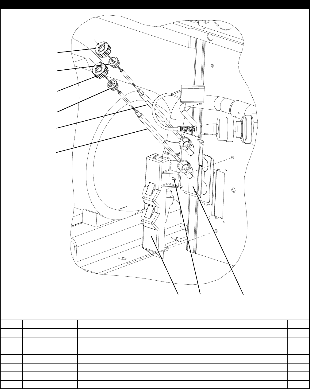
2.15 RRS AND RTS SECTION
1
1
(RRS)
(RTS)
2
3
3
2
45
6
7
Item Part Number Description Qty
112-00395-01SV Sensor Assembly (RRS & RTS) 1
258-04277-00SV Cap, Probe -- Includes: 2
358-04278-00 Grommet NSS 2
458-04279-00 Cover, Probe 1
558-04276-00 Holder, Probe 1
666U1-5321-7 Washer, Flat, 1/4 -- SST 2
766U1-5371-7 Screw, Machine, Hex Head, #10-24 x .50 lg. -- SST 2
27 T-296PL
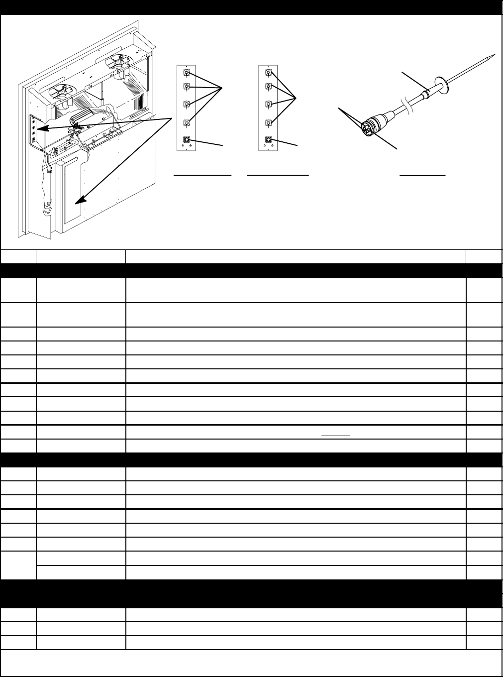
2.16 USDA SECTION (See Note 6 )
OPTION -- D OPTION -- V
7
8
9
1
2
3
4
5
6
6
1
2
4
6
OPTION 1
10
11
12
Item Part Number Description Qty
OPTION D
-- 76-00684-00 Kit, USDA (For field installation, units provisioned for rear-mounted
USDA -- See T-300) -- Includes: --
-- 76-00760-00 Kit, USDA (For field installation, units provisioned for side-mounted
USDA -- See T-300) -- Includes: --
122-01660-08 Plug, Sealing 4
222-01660-00 Receptacle (PR1, PR2, PR3, Cargo Probe 4) (3 Pin) 4
322-01660-03 Receptacle, Interrogator (ICR) (5 Pin)1 1
NS 69NT41-992 Plate Assembly, USDA -- Includes: 1
469NT43-175 Cap, Dust, with Tether (3 Pin) 4
569NT43-176 Cap, Dust, with Chain (5 Pin) 1
622-01613-14 Contact, Pin, #16 (Used with 22-01660-00 & 22-01660-03) 13
NS 69NT40-507-1 Door Assembly (Included and Used with REAR-mount USDA only) 1
NS 22-01660-04 Plug, Interrogator Socket (ICR) (5 Pin) 1
OPTION V
122-01660-08 Plug, Sealing 4
222-01660-00 Receptacle (PR1, PR2, PR3, Cargo Probe 4) (3 Pin) 4
469NT43-175 Cap, Dust, with Tether (3 Pin) 4
622-01613-14 Contact, Pin, #16 (Used with 22-01660-00 & 22-01660-03) 13
722-02412-00 Receptacle, Interrogator (5 Pin) 1
822-02413-00 Cap, Dust, with Tether (5 Pin) 1
9
22-02398-02 Socket, Contact (Silver Plated) A/R
922-02398-03 Socket, Contact (Gold Plated) A/R
USDA PROBE KITS
OPTION 1
10 12-00342-03 Sensor Assembly, 600in. lg. (15M) (USDA Probe) -- Includes: A/R
11 22-50127-00 Plug, Socket (PR1, PR2, PR3, Cargo Probe 4) 1
12 22-01613-15 Contact, Socket, #16 (Used with 22-50127-00 & 22-01660-04) A/R
NOTE
6. Do not mix silver pins with gold pins and sockets.
28T-296PL
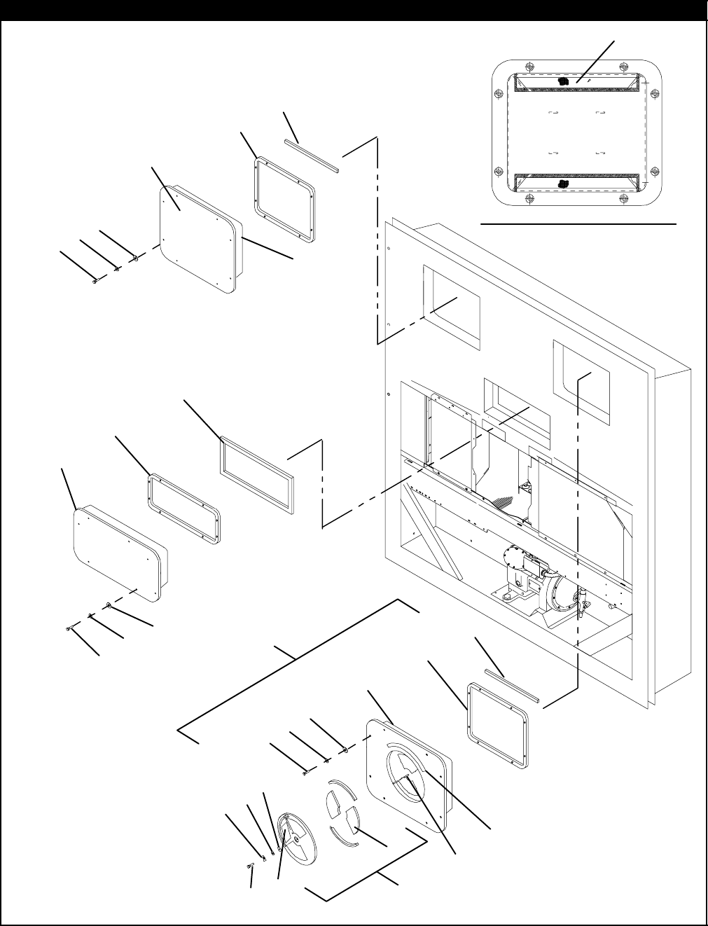
2.17 UPPER FRESH AIR MAKE-UP AND ACCESS PANEL SECTION
1
2
12
13
14
45
45
3
7
6
6
BACK OF FRESH AIR PANEL
11
10
4
21 20
3
22
9
2
5
7
6
18
8
16 17
15
19

29 T-296PL
2.17 UPPER FRESH AIR MAKE-UP AND ACCESS PANEL SECTION
Item Part Number Description Qty
OPTION 1 EVAPORATOR FAN ACCESS PANEL -- PLAIN
179-01697-06SV Panel, Access -- Includes: A/R
242-00296-01 Gasket 1
342-00327-00 Gasket, -- 0.26 x 0.50 Halfmoon 1
434-00662-11 Washer, Flat, 1/4 -- SST 8
534-06053-00 Washer, Mylar, 1/4 ID X 0.80 OD 8
634-06154-00 Screw, Hex Head, 1/4-20 x 1.00 lg. -- TIR 8
766U1-2552-185 Gasket, 0.75 x 1.5 x 16.63 1
OPTION 2 EVAPORATOR FAN ACCESS PANEL -- WITH FRESH AIR MAKEUP
879-01694-00 Panel, Fresh Air Make--up w/Retaining Washers -- Includes: A/R
79-01695-00 Panel with Fresh Air Makeup -- Includes: 1
242-00296-01 Gasket 1
342-00327-00 Gasket, -- 0.26 x 0.50 Halfmoon 1
434-00662-11 Washer, Flat, 1/4 -- SST 8
534-06053-00 Washer, Mylar, 1/4 ID X 0.80 OD 8
634-06154-00 Screw, Hex Head, 1/4-20 x 1.00 lg. -- TIR 8
766U1-2552-185 Gasket, 0.75 x 1.5 x 16.63 1
9-- Label, Fresh Air (See Section 2.33 for Language Selection) 1
10 62-02783-00 Label, Fresh Air 1
OPTION 3 WITH FRESH AIR MAKEUP AND SCREENS -- USE ALL OF OPTION 2 AND ITEM BELOW
11 58-04251-00 Screen, Medfly 2
HEATER ACCESS PANEL
12 79-01697-07SV Panel, Access -- Includes: 1
13 42-00296-00 Gasket 1
14 66U1-8115 Gasket, Access Panel 1
434-00662-11 Washer, Flat, 1/4 -- SST 8
534-06053-00 Washer, Mylar, 1/4 ID X 0.80 OD 8
634-06154-00 Screw, Hex Head, 1/4-20 x 1.00 lg. -- TIR 8
STUD ASSEMBLY KITS (REPLACEMENT)
15 74-00201-02 Kit, Gasket and Stud Assembly (See NOTE 7) -- Includes: 1
16 42-00407-00 Gasket (One Piece) 1
17 74-00201-01 Kit, Disc and Stud Assembly (See NOTE 8) -- Includes: 1
18 NSS Stud Assembly, 5/16-18 1
19 34-06185-01 Screw, Machine Pan Head, #8-32 x 1/2 lg. -- SST 1
20 34-06053-19 Washer, Mylar, 1.00 OD x 0.312 ID 1
21 66U1-5321-13 Washer, Flat, 5/16 -- SST 1
22 66U1-5362-2 Nut, Wing, 5/16-18 -- SST 1
NOTES
7. Disc and stud assembly kit, which will modify stud to 5/16-18, also includes new disc and gasket.
8. Must order 74-00201-01 stud assembly kit, which will modify stud to 5/16-18, and include 42-00407-01 (1
piece) gasket.
30T-296PL
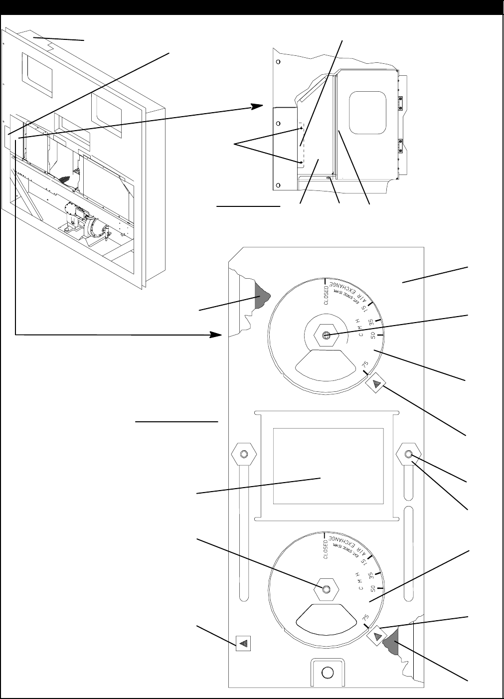
2.18 LOWER FRESH AIR MAKE-UP VENT
12
13
9
10
11
12
13
14
15
17
9
10
11
18
19
21
20
24
24
16
16
16
1
2
3
4
5
22
23
3
4
5
6
OPTION -- 2 & 3
OPTION -- 1
8
7

31 T-296PL
2.18 LOWER FRESH AIR MAKE-UP VENT
Item Part Number Description Qty
OPTION 1 -- LOWER FRESH AIR (NONE)
169NT35-4047 Panel, Blank 1
269NT43-307 Bracket, Panel 1
366U1-5361-25 Screw, Hex Head, 1/4-20 x 3/4 lg. -- SST 3
434-06053-18 Washer, Mylar, 1/4 ID x 1.00 OD 3
566U1-5321-3 Washer, Flat, 1/4, Type A-- SST 3
669NT35-2692-1 Washer, Fender 1/4 -- SST 1
742-00465-00 Gasket 1
OPTION 2 -- INSTALLED
869NT41-852-1 Cover, Fresh Air Makeup -- Includes: 1
969NT40-976-3 Cover Assembly, Air Bleed -- Includes: 2
10 42-00233-01 Gasket, Air Exchange 2
1
1
69NT35-1417 Label, Air Exchange, CMH -- English 2
11 69NT35-9238 Label, Air Exchange, CMF -- English/Spanish 2
1
2
34-06092-00 Nut, Hex, 1/4-20 UNC-2B -- SST 2
12 34-06183-00 Nut, Hex, (with mini handle),1/4-20 UNC-2B -- SST 2
13 34-06053-00 Washer, Mylar, 1/4 ID x 1.00 OD 2
14 42-00295-01 Gasket, Cover 1
15 42-00295-00 Gasket, Cover 1
16 66CH1-1002-33 Label, Arrow 3
17 69NT41-782 Bushing 2
18 69NT35-1287-1 Label, Fresh Air Exchange -- English 1
19 69NT35-7012 Label, Fresh Air 1
20 66U1-5321-7 Washer, Flat, 1/4 -- SST 2
21 34-06092-00 Nut, Hex, 1/4-20 UNC-2B -- SST A/R
22 69NT35-8348 Baffle, Unpainted 1
23 34-00928-09 Rivet, Blind, .156 Diameter, Grip Range -- 3/16-1/4 4
OPTION 3 -- INSTALLED WITH SCREENS -- USE ALL OF OPTION 2 PLUS ITEM BELOW
24 58-04263-01 Screen Assembly, Medfly 2
32T-296PL
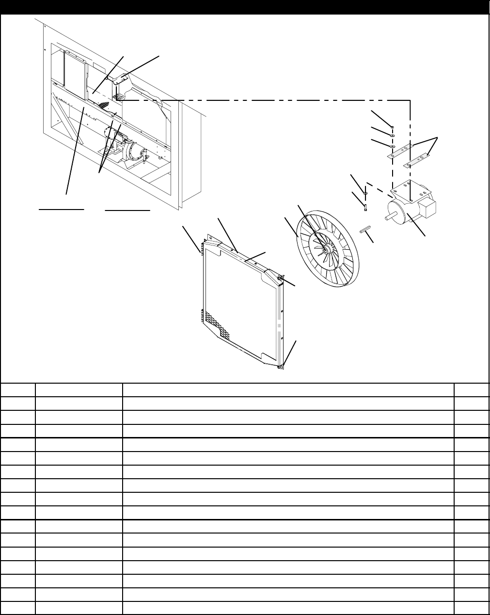
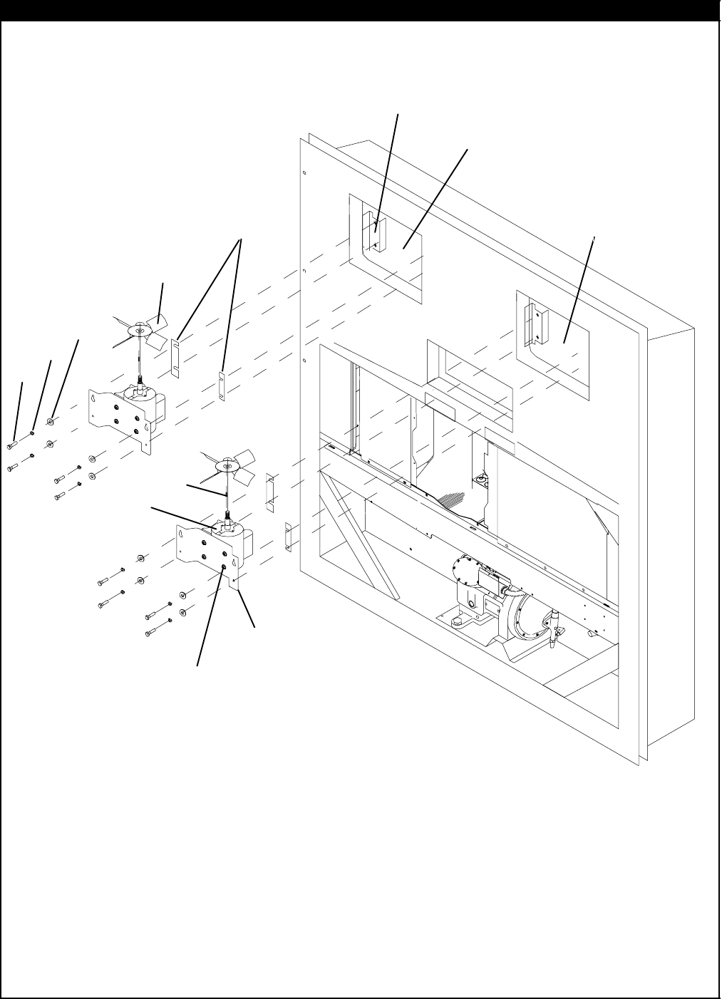
2.19 EVAPORATOR FAN ASSEMBLY
EFM-2 (Location)
EFM-1 (Location)
1
2
3
4
5
6
7
11
8910
12

33 T-296PL
2.19 EVAPORATOR FAN ASSEMBLY
Item Part Number Description Qty
169NT40-476 Bracket, Mounting 4
269NT35-1173 Bracket, Motor Mount 2
334-00792-10 Capscrew, Hex Head, 5/16-18 x 1-1/4 lg --- SST 8
434-01181-01 Washer, Flat, 5/16 --- SST 16
534-00667-12 Locknut, 5/16-18 --- SST 8
654-00513-02 Motor, Evaporator Fan (Two-Speed) --- Includes: 2
7PL Key, 3/16 Square x 1-3/8 lg --- SST 1
NS 54-00122-21 Bearing 2
NS 22-50088---02 Capacitor 1
NS 54-50044-00 Relay, Motor 1
NS 22-50088-00 Capacitor, 20 mF (microfarads) 1
866U1-5361-7 Bolt,HexHead,3/8-16x1.00lg---SST 8
9AU11JR241 Washer, Lock, 3/8 --- SST 8
10 66U1-5321-5 Washer, Flat, 3/8 --- SST 8
11 38-00125-00 Fan, Evaporator (EFM-1) --- Includes: 1
NS PL Setscrews, 5/16-24 x 5/8 lg --- SST 2
11 38-00126-00 Fan, Evaporator (EFM-2) --- Includes: 1
NS 69NT35-1662 Setscrews, 5/16-24 x 5/8 lg --- SST 2
12 69NT35-1662-1 Shim, (If Required) 2
34T-296PL
2.20 EVAPORATOR COIL SECTION -- REAR PANELS REMOVED
19
1
2
3
4
5
4
6
7
8
9
10
12
16
17
18
11
(STS) (SRS)
1
13
14
15
7

35 T-296PL
2.20 EVAPORATOR COIL SECTION -- REAR PANELS REMOVED
Item Part Number Description Qty
112-00395--01SV Sensor Assembly (SRS & STS) 2
2-- Sensor, Thermistor, (Temperature Recorder) -- RefertoSection2.24 --
312-00495-02SV Sensor, Thermistor, Defrost (DTS) 1
434-01178-22 Screw, Hex Head, #8-32 x 1/2 lg. -- SST (For mounting DTS) 3
566U1-6912-16 Thermostat, Heat Termination (HTT) 1
6AA06JA166 Capscrew, Hex Head, 1/4-20 x 1/2 lg. 1
7AU11JR171 Washer, Lock, 1/4 -- SST 10
866U1-5361-25 Capscrew, Hex Head, 1/4-20 x 3/4 lg. -- SST 9
969NT35-2692-1 Washer, Fender, 1/4 -- SST A/R
10 24-00003-00 Heater, Drain Pan 1
11 -- USDA Option -- RefertoSection2.16 --
12 24-00006-02 Heater, Evaporator Coil 4
NS 66U1-3803-1 Tube, Heat Shrink -- 1/2 x 2-3/4 lg. A/R
NS 69NT35-6522 Retainer (For Heaters) 3
NS 69NT35-6532 Clip (For Heaters) 4
OPTION 2 -- COIL WITH HERMETIC TXV and STANDARD HEAT EXCHANGER
13 81-01549-00 Coil, Evaporator -- Hermetic 1
14 14-00273-01 Valve, Thermostatic Expansion, Hermetic 1
15 65-00144-00 Exchanger, Heat 1
OPTION 3 -- COIL WITH HERMETIC TXV and LARGE HEAT EXCHANGER
13 81-01549-00 Coil, Evaporator -- Hermetic 1
14 14-00273-03 Valve, Thermostatic Expansion, Hermetic 1
15 65-00144-01 Exchanger, Heat 1
DEHUMIDIFICATION
-- 76-00675-01 Kit, Humidity Sensor(Field installation, units provisioned for -- See Unit
Matrix, T-300) -- Includes:--
16 10-00413--00 Sensor, Humidity (HS) 1
17 66U1-5371-10 Screw, Hex Head, #10-24 x 1.00 lg. -- SST 4
18 66U1-5321-8 Washer, Flat, #10 -- SST 2
19 68-13181-00 Bracket Assembly, Humidity Sensor 1
36T-296PL
2.21 BACK PANEL ASSEMBLY -- OPTION 1 -- ALUMINUM BOLTED
7
1
2
4
8
9
10
11
6
6
6
7
10
11 3
3
3
3
5
6
612
13

37 T-296PL
2.21 BACK PANEL ASSEMBLY -- OPTION 1 -- ALUMINUM BOLTED
Item Part Number Description Qty
169NT43-464 Grille, Top (Unpainted) 1
234-00928-09 Rivet, Blind, 5/32 Diameter, Grip Range -- 1/8-1/4 21
366U1-7982-2 Rivet, TIR, 3/16 Diameter, Grip Range -- 5/64-11/64 4
469NT41-942-3 Panel Assembly, Upper -- Includes: 1
NS NSS Drain Pan, Side (Location -- Behind upper panel) 2
NS NSS Drain Pan, Center (Location -- Behind upper panel -- Top) 1
542-00334-00 Gasket (Location -- Behind upper panel) 1
NS 66U1-8075 Gasket (25 ft., Cut to length) A/R
634-00928-02 Rivet, Blind, 1/8 Diameter, Grip Range -- 1/8-3/16 46
734-00928-03 Rivet, Blind, 1/8 Diameter, Grip Range -- 3/16-1/4 3
868-13475-00 Panel, Bottom, (Painted) 1
868-13475-08 Panel, Bottom, (Unpainted) 1
968-13475-01 Panel, Bottom (Provision for heat exchanger location), (Painted) 1
968-13475-09 Panel, Bottom (Provision for heat exchanger location), (Unpainted) 1
10 66U1-2403 Screw, Machine, Truss Head, #10-24 x 1/2 lg. -- SST 20
11 69NT35-2692 Washer, Fender, #10 x 1.00 OD -- SST 20
12 69NT35-2257 Duct, Air 1
13 62-02822-01 Label, Carrier Transicold 1
38T-296PL
2.22 BACK PANEL ASSEMBLY -- OPTION 4 -- ALUMINUM HINGED
1
2
3
4
5
6
7
8
9
10
11
12
13
5
5
5
6
2
13
10

39 T-296PL
2.22 BACK PANEL ASSEMBLY -- OPTION 4 -- ALUMINUM HINGED
Item Part Number Description Qty
169NT43-464 Grille, Top 1
234-00928-09 Rivet, Blind, 5/32 Diameter, Grip Range -- 1/8-1/4 37
369NT41-942-4 Panel Assembly, Upper -- Includes: 1
NS NSS Drain Pan, Side 2
NS NSS Drain Pan, Center 1
442-00334-00 Gasket (Location -- Behind upper panel) 1
534-00928-02 Rivet, Blind, 1/8 Diameter, Grip Range -- 1/8-3/16 46
634-00928-03 Rivet, Blind, 1/8 Diameter, Grip Range -- 3/16-1/9 3
7
68-13475-00 Panel, Bottom, (Painted) 1
768-13475-08 Panel, Bottom, (Unpainted) 1
8
68-13475-01 Panel, Bottom (Provision for USDA location), (Painted) 1
868-13475-09 Panel, Bottom (Provision for USDA location), (Unpainted) 1
NS 66U1-8075 Gasket (25 ft., Cut to length) A/R
969NT35-3282 Hinge 4
10 34-01150-30 Washer, Retaining 14
11 34-01150-06 Stud, 1/4 Turn, 1.03 lg. 6
12 34-01150-03 Stud, 1/4 Turn, 0.94 lg. 8
13 34-01150-31 Receptacle, Retaining 14
40T-296PL
2.23 BACK PANEL ASSEMBLY -- OPTION 8 -- HINGED ALUMINUM WITH DRAIN ACCESS DOOR
1
2
3
4
5
6
78
9
10
11
12
13
14
15
16
2
10
11
6

41 T-296PL
2.23 BACK PANEL ASSEMBLY -- OPTION 8 -- HINGED ALUMINUM WITH DRAIN ACCESS DOOR
Item Part Number Description Qty
169NT43-464 Grille, Top 1
234-00928-09 Rivet, Blind, 5/32 Diameter, Grip Range -- 1/8-1/4 37
68--13729--06 Panel Assembly, Upper -- Includes: 1
3NSS Gutter 1
NSS Channel 2
442-00174--34 Gasket (Location -- Behind upper panel) 1
534-00928-02 Rivet, Blind, 1/8 Diameter, Grip Range -- 1/8-3/16 42
634-00928-03 Rivet, Blind, 1/8 Diameter, Grip Range -- 3/16-1/9 2
768--13729--07 Panel, Bottom 1
869NT35--8658 Panel, Bottom (Provision for Drain Access Door location) 1
NS 42--00145--34 Gasket A/R
969NT35-3282 Hinge 4
10 34-01150-30 Washer, Retaining 14
11 34-01150-06 Stud, 1/4 Turn, 1.03 lg. 6
12 34-01150-03 Stud, 1/4 Turn, 0.94 lg. 8
13 34-01150-31 Receptacle, Retaining 14
14 68--13475--05 Drain Access Door 1
15 66U1--2803--10 Hinge 1
16 69NT35--7662 Hinge Spacer 1
42T-296PL
2.24 PARTLOW TEMPERATURE RECORDER
18
20 23
26
27
28
1
3
4
5
67
8
910
15
12
13
14
11
30
31
32
33
31
16
17
29
19
21
22
24
25
2
Item Part Number Description Qty
OPTION 1, OPTION 2, OPTION 3 AND OPTION 4
-- 76-00701-04
OPTION 1 Recorder Kit--Partlow without Simpson Probe -- Includes: Recorder, Box
and Door Assy’s 1
112-00421-02 Temperature Recorder without Simpson Probe--Includes: 1
-- 76-00701-00
OPTION 2 Recorder Kit--Partlow with Simpson Probe -- Includes: Recorder, Box and
Door Assy’s 1
112-00421-00 Temperature Recorder with Simpson Probe--Includes: 1
-- 76-00701-01
OPTION 3 Recorder Kit--Partlow, Battery Operated without Simpson Probe -- Includes:
Recorder, Box and Door Assy’s (For field installation, units provisioned
for -- Refer to Unit Matrix T--300 ) 1
112-00421-01 Temperature Recorder, Battery Operated w/o Simpson Probe
--Includes: 1
-- 76-00701-12
OPTION 4 Recorder Kit--Partlow, Battery Operated without Simpson Probe -- Includes:
Recorder, Box and Door Assy’s(For field installation, units provisioned
for -- Refer to Unit Matrix T--300 ) 1
112-00421-03 Temperature Recorder, Battery Operated w/ Simpson Probe --Includes: 1

43 T-296PL
OPTION 1 - PARTLOW WITHOUT PROBE & OPTION 2 - PARTLOW WITH PROBE (Continued)
Item Part Number Description Qty
209-00104-05 Kit, Stylus -- Includes: 1
3NSS Screw, Round Head, #2-56 x 3/16 lg. 2
409-00296-00 Mechanism and Platen Assembly 1
509-00345-00 Main Lever and Push Rod Assembly (Includes Setscrews) 1
609-00344-00 Rod, Push 1
709-00114-00 Key, Clock Winding 1
809-00119-00 Nut and Chain, Chart (Sonceboz Clock) 1
809-00180-00 Nut and Chain, Chart (Gluck Clock) 1
9PL Screw, Round Head #6-32 x 5/16 7
10 09-00118-00 Flange, Chart Drive (Sonceboz) 1
10 09-00180-01 Flange, Chart Drive (Gluck) 1
11 09-00123-00 Clock, 31 Day, CCW (Counterclockwise) 1
11 09-00302-00 Clock, 31 Day, CCW (Counterclockwise) Battery Operated
Used with P/N 12-00421-01 & 03 1
12 09-00137-00 O-Ring, Element Flange 4
13 09-00209-00 Element, 9 ft. lg. -- Includes: 1
NS 09-00222-00 Sensor, Thermistor (Accessory 344 and Jack) -- 15 ft. lg. 1
13 09-00236-00 Element, 10 ft. lg. Used with P/N 12-00421-01 & -02 1
14 09-00136-00 Screw, Flange 2
15 76-00701-06SV Box Assembly -- Includes: 1
16 34-01142-01 Receptacle -- #12 2
17 34-00928-01 Rivet, Blind, .125 Diameter, Grip Range .063 - .125 -- SST 4
NS 09-00303-00 Battery Cover (Includes Hardware) 1
NS 22-02243-00 Pin (Use with Partlow Thermistor Assembly) 3
NS 09-00128-00 Charts _F -- 31 Day (Box of 50) (--20_Fto+80_F) A/R
NS 09-00128-01 Charts _C -- 31 Day (Box of 50) (--25_Cto+25_C) A/R
18 76-00701-05 Door Assembly -- Includes: 1
19 42-01098-01 Gasket, Door 1
20 66U1-6811-8 Screw, Retaining -- SST 2
21 34-06053-00 Washer, 1/4 I.D. x 1 O.D. -- Mylar 2
22 34-06169-00 Washer, Retaining -- SST 2
23 69NT35-5022-5 Window 1
24 69NT35-5352-1 Gasket 1
25 34-00795-09 Nut, Selflock, 1/4-20 -- SST 4
26 44-00374-00 Hinge -- SST 2
27 58-04101-07 Protector, .010 Thick x .75 x 2.63 -- Mylar 4
28 34-06179-00 Screw, Hex Head, Slotted, #10-24 x 7/16 lg. -- SST 8
29 34-06179-04 Screw, Hex Head, Slotted, #10-24 x 5/16 lg. -- SST 4
30 66U1-5321-7 Washer, Flat, 1/4 -- SST 2
31 66U1-5361-25 Screw, Cap, Hex Head, 1/4-20 x .75 lg. -- SST 4
32 34-06053-13 Washer, Retaining, .19 I.D. x .80 O.D. -- Mylar 2
33 69NT35-2692-1 Washer, Fender, 1/4 I.D. x .993-1.015 O.D. 2
NS PL Battery -- 1.5 volt (D cell size) Alkaline 1
44T-296PL
2.25 SAGINOMIYA TEMPERATURE RECORDER
134
5
6
7
8
9
10
11
1
4
12
13
14 20
19
21
24
25
26
27
16
31
32
17
33 28
29
30
32
27
15
26
22
23
2

45 T-296PL
2.25 SAGINOMIYA TEMPERATURE RECORDER
Item Part Number Description Qty
OPTION 5 -- SAGINOMIYA WITHOUT PROBE AND & OPTION 6 -- SAGINOMIYA WITH PROBE
-- 76-00701-03
OPTION 5 Recording Thermometer Assembly w/Return Sensor -- Includes: Recorder,
Box and Door Assy’s 1
112-01094-00 Recording Thermometer w/Return Sensor -- Includes: 1
-- 76-00701-02
OPTION 6 Recording Thermometer Assembly w/Return & Supply Sensor -- Includes:
Recorder, Box and Door Assy’s 1
112-01094-01 Recording Thermometer w/Return and Supply Sensor -- Includes: 1
209-00365-00 Stylus,LiftArm(See NOTE 9) 1
309-00364-00 Element Assembly 1
409-00367-00 Element Assembly (Used on P/N 12-01094-01) 1
509-00362-00 Indicator, Voltage 1
609-00363-00 Plate, Recorder 1
7PL Battery (Mallory R14P/S 1.5 vdc) 1
809-00326-00 Shaft, Chart 1
909-00329-00 Block, Terminal 1
10 09-00322-00 Timer (31 Day) 1
11 09-00325-00 Nut, Chart (Male) 1
12 69NT40-402-1 Sensor Assembly, Return Temperature (Used on 76-00701-02) --
Includes: 1
NS 12-01095-00 Sensor, Thermistor 1
13 22-02370-00 Jack, Phono (Used on 76-00701-02) 2
14 76-00701-06SV Box Assembly, Recorder -- Includes: 1
15 34-01142-01 Receptacle, Retaining 2
16 34-00928-01 Rivet, Blind, .125 Diameter, Grip Range .063--.125 -- SST 4
17 34-06053-13 Washer, .195 I.D. x .80 O.D. -- Mylar 2
18 34-01142-01 Receptacle, Retaining 2
19 76-00701-05 Door Assembly, Recorder Box -- Includes: 1
20 42-01098-01 Gasket, Door 1
21 66U1-6811-8 Screw, Retaining -- SST 2
22 34-06169-00 Washer, Retaining -- SST 2
23 34-06053-00 Washer, 1/4 I.D. x 1.00 O.D. -- Mylar 4
24 69NT35-5022-5 Window, Lexan 1
25 69NT35-5352-1 Gasket, Window 1
26 44-00374-00 Hinge Assembly -- SST 2
27 58-04101-07 Protector, Mylar (For Hinge) 4
28 34-06179-00 Screw, Hex Head, #10-24 x 7/16 lg. -- SST 4
29 34-06179-04 Screw, Hex Head, #10-24 x 5/16 lg. -- SST 4
30 34-00795-09 Nut, Selflock, #10-32 -- SST 4
31 66U1-5321-7 Washer, Flat, 1/4 -- SST 2
32 66U1-5361-25 Screw, Cap Hex Head, 1/4-20 x .75 lg. -- SST 4
33 69NT35-2692-1 Washer, Fender, 1/4 I.D. x .993-1.015 O.D. 2
NS 09-00128-00 Charts _F -- 31 Day (Box of 50) (--20_Fto+80_F) A/R
NS 09-00128-01 Charts _C -- 31 Day (Box of 50) (--25_Cto+25_C) A/R
9. NOTE: The quantity is two for these charts when using P/N 12-01094-01.
46T-296PL
2.26 OPTION 7 AND OPTION 8 -- ELECTRONIC PARTLOW TEMPERATURE RECORDER
2
4
10
11
15
16
21
7
56
12
13
OPTION -- 7 and 8
1
8
9
14
3
22
24
17
18
19
18
20
23
2.27 OPTION 9 -- NO TEMPERATURE RECORDER
OPTION 9
25
26
27
28
29
30
27

47 T-296PL
2.26 OPTION 7 AND OPTION 8 -- ELECTRONIC PARTLOW TEMPERATURE RECORDER
Item Part Number Description Qty
-- 76-00701-11
OPTION 7 Partlow Recorder Kit, Standard -- Includes: Recorder, Box & Door Assy’s
(For field installation, units provisioned for -- Refer to Manual T-300 ) 1
112-00464-08 Electronic Temperature Recorder 1
-- 76-00701-10
OPTION 8 Partlow Recorder Kit, Special -- Includes: Recorder, Box & Door Assy’s
(For field installation, units provisioned for -- Refer to Manual T-300 ) 1
112-00464-07 Electronic Temperature Recorder 1
276-00701-05 Door Assembly -- Includes: 1
342-01098-01 Seal, Door -- Rubber 1
466U1-6811-8 Screw, Retaining -- .300 -- .625 Panel Thickness -- SST 2
534-06053-00 Washer, .25 I.D. x 1.00 O.D. -- Mylar 4
634-06169-00 Washer, Retaining -- SST 2
769NT35-5022-5 Window 1
869NT35-5352-1 Gasket 1
934-00795-09 Nut, Selflock, 1/4-20 4
10 44-00374-00 Hinge 2
11 58-04101-07 Protector -- Mylar 4
12 34-06179-04 Screw, Hex Head, SEMS, #10-24 x 5/16 lg. 4
13 34-06179-00 Screw, Hex Head, #10-24 x 7/16 lg. -- SST 4
14 76-00701-06SV Box Assembly -- Includes: 1
15 58-00065-67 Grommet, 3/8 ID x 1.25 OD 1
16 58-00065-70 Plug, Hole, .50 DIA 2
17 66U1-5321-7 Washer, Flat, 1/4 -- SST 2
18 66U1-5361-25 Screw, Cap, Hex Head, 1/4-20 x .75 lg. -- SST 4
19 34-06053-13 Washer, Retaining, .19 I.D. x .80 O.D. -- Mylar 2
20 69NT35-2692-1 Washer, Fender, 1/4 I.D. x .993-1.015 O.D. 2
21 34-06053-05 Washer, 1/4 I.D. x 1 O.D. -- Mylar 4
22 34-06053-03 Washer, .25 I.D. x .19 O.D. -- Mylar 2
23 34-06179-00 Screw, Hex Head, SEMS, #10-24 x 7/16 lg. 4
24 09--00371--00 Stylus Arm 1
NS -- Chart -- Owner Supplied A/R
NS 09-00128-00 Charts _F -- 31 Day (Box of 50) (--20_Fto+80_F) A/R
NS 09-00128-01 Charts _C -- 31 Day (Box of 50) (--25_Cto+25_C) A/R
2.27 OPTION 9 -- NO TEMPERATURE RECORDER
Item Part Number Description Qty
25 68-12658-01 Panel 1
26 66U1-5321-7 Washer, Flat, 1/4 -- SST 2
27 66U1-5361-25 Screw, Cap Hex Head, 1/4-20 x .75 lg. -- SST 4
28 69NT35-2692-1 Washer, Fender, 1/4 I.D. x .993-1.015 O.D. 2
29 34-06053-13 Washer, Retaining, .195 I.D. x .80 O.D. -- Mylar 2
30 34-06053-03 Washer, .25 I.D. x 1.00 O.D. -- Mylar 2
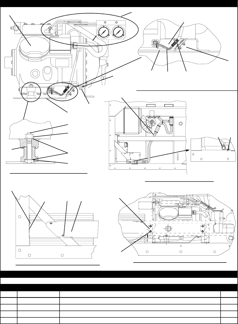
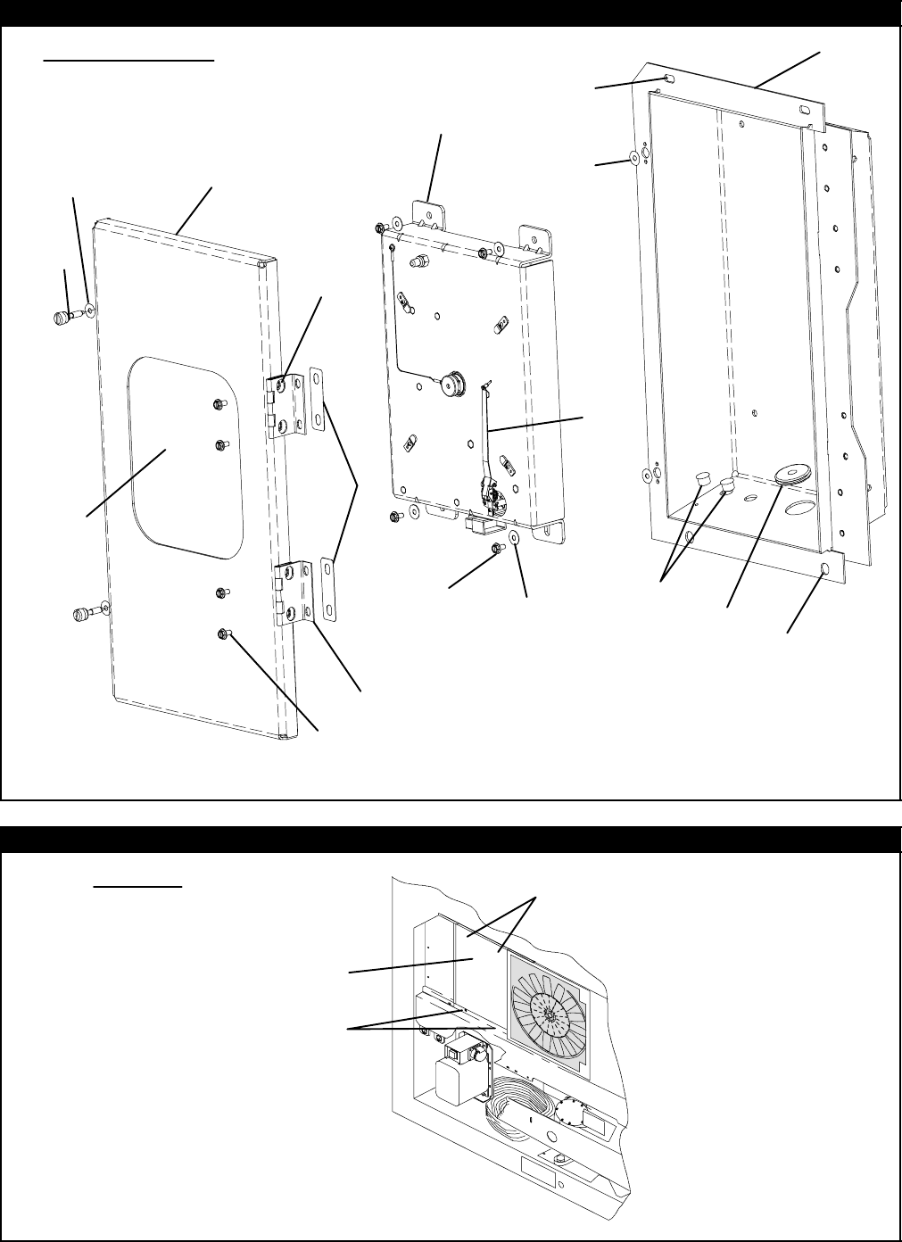
48T-296PL
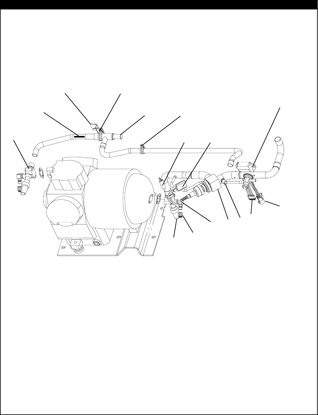
2.28 COMPRESSOR MOUNTING, GUARD, CRANKCASE AND DRAIN LINE HEATER COMPONENTS
Compressor Foot -- Section View
Guards -- Bottom Left Corner of Unit
OPTION C -- Compressor Crankcase Heater
See Section 2.29 for Gauge Components
OPTION L -- Drain Line Heater
7
8
9
10
11
12
13
14
15
16
17
18 19
20
21 22
23 24
20
21
1
2
3
4
5
30
36
37
38
39
31 29
Compressor Guard Support Bracket View
25
26
27
28
6
32
33
34
35
OPTION B -- CRANKCASE HEATER AND DRAIN LINE HEATER
Use Option C and Option L for Both Crankcase Heater and Drain Line Heater
OPTION L -- DRAIN LINE HEATER
122-01877-00 Hose Assembly 1
268-12960-00 Bracket, Drain 1
366U1-5371-6 Screw, Hex Head, #10-24 x 3/4 lg. -- SST 2
434-06053-05 Washer, Mylar, 0.205 ID x 0.600 OD 2
566U1-5321-8 Washer, Flat, 7/16 -- SST 2

49 T-296PL
2.28 COMPRESSOR MOUNTING, GUARD, CRANKCASE AND DRAIN LINE HEATER COMPONENTS
Item Part Number Description Qty
6-- Compressor -- RefertoSection4 --
769NT35-6132 Protector (Compressor to Compressor Base) 1
8AU11JR241 Washer, Lock, 3/8 -- SST 2
9AA06JA232 Capscrew, Hex Head, 3/8-16 x 1-1/4 lg. -- SST 2
10 34-00829-13 Washer, Flat, 3/8 -- SST 2
11 34-06053-02 Washer, Mylar, 0.375 ID x 1.00 OD 2
12 69NT43-469 Base, Compressor 1
NS 66U1-5361-7 Bolt, Hex Head, 3/8-16 x 1.00 lg. -- SST 7
NS 66U1-5321-5 Washer, Flat, 3/8 -- SST 7
NS AU11JR241 Washer, Lock, 3/8 -- SST 7
NS 34-06053-02 Washer, Mylar, 0.375 ID x 1.00 OD 7
13 34-00849-22 Capscrew, 7/16-14 x 2-3/4 lg. -- SST 2
14 34-00667-14 Locknut, 7/16-14 -- SST 2
15 66U1-5321-8 Washer, Flat, 7/16 -- SST 4
16 34-06053-07 Washer, Mylar, 0.438 ID x 0.922 OD 2
17 34-06053-01 Washer, Mylar, 0.438 ID x 1.125 OD 2
1
8
68-12993-00 Panel, Guard 1
18 68-12523-00 Panel, Guard -- Large 1
19 66U1-5361-25 Screw, Hex Head, 1/4-20 x 3/4 lg. -- SST 1
20 66U1-5321-7 Washer, Flat, 1/4 -- SST 9
21 34-06053-00 Washer, Mylar, 1/4 ID x 3/4 OD 9
22 66U1-5361-11 Capscrew, Hex Head, 1/4-20 x 1-1/2 lg. -- SST 4
23 34-00667-11 Locknut, 1/4-20 -- SST 4
2
4
68-13691-00 Guard, Compressor, .125 Thick Alum. (Blue) 1
24 68-12432-03 Guard, Compressor, .125 Thick Alum., For Right Extended Guard (Blue) 1
25 68-13576-00 Bracket 2
26 34-00655-05 Screw, Cap Hex Head 1/4-20 4
27 34-06053-15 Washer, Myler .875-.313 4
28 66U1-5321-7 Washer 1/4 -- SST 4
OPTION C -- CRANKCASE HEATER
-- 76-50094-00 Crackcase Heater Installation Kit -- Includes: 1
29 24-02017-00 Heater, Compressor Crankcase (CCH) NSS 1
30 68-14175-00 Bracket, Heater NSS 1
31 44-00370-03 Clamp, Tube,Cushioned, 1/2 Diameter -- SST 1
32 34-06053-03 Washer, Mylar, 1/4 ID x 1.0 OD 1
33 66U1-5371-6 Screw, Machine Hex Head, #10-24 x .75 lg. -- SST 1
34 58-04316-00 Wire Tie Base 1
35 66U1-3882 Wire Tie 1
NS 66U1-3803 Heat Shrink Tubing 3
NS 22-01292-00 Butt Splice 3
NS 22-00121-27 Terminal, Ring 1
NS 02-00010-01 Thermo Grease 1
36 34-00665-08 Screw, Hex Head, 1/4-20 x 1.00 lg -- SST 2
37 34-06053-00 Washer, Mylar, 0.25 ID x 0.75 OD 4
38 34-00662-11 Washer, Flat, 1/4 x 0.05 Thk. 4
39 34-00667-11 Locknut, 1/4-20 2
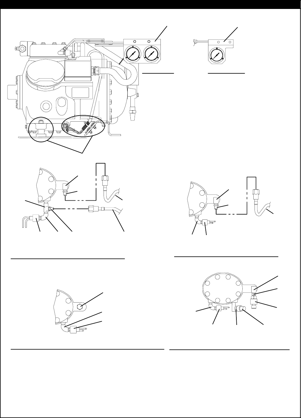
50T-296PL
2.29 COMPRESSOR GAUGES AND TRANSDUCERS
OPTION -- Center Cylinder Head View without Gauges OPTION T -- Center Cylinder Head View
with Pressure Transducers
OPTION G -- Center Cylinder Head View
with Both gauges
See Section 2.28 for Crankcase Heater and Mounting Components
OPTION SG -- Center Cylinder Head
View with Suction Gauge Only
OR
OPTION G OPTION SG
1
219
3
4
5
6
78
9
10
11
12
27
28
29
13
14
15
16
17
18
22
21
23
24
25
26
13
14
20
6

51 T-296PL
2.29 COMPRESSOR GAUGES AND TRANSDUCERS
Item Part Number Description Qty
OPTION G -- PRESSURE GAUGES
169NT41-106-2 Stiffener Assembly 1
NS 66U1-5321-8 Washer, Flat, #10 -- SST 2
NS 66U1-5371-6 Screw, Hex Head, #10-24 x 3/4 lg. -- SST 2
NS 34-06053-05 Washer, Mylar, 0.205 ID x 0.600 OD 2
268-13472-03SV Bracket Assembly, Gauge 1
312-01124-02 Gauge, Suction Pressure 1
412-01125-02 Gauge, Discharge Pressure 1
566U1-6651-19 Screw, Pan Head, #6-32 x 7/16 lg. -- SST 6
606DA403-844 Valve Assembly, Core, Check (Schrader Valve) -- Brass 2
712-00309-03 Switch, High Pressure (HPS) 1
NS 22-02392-00SV Connector, Female, 2 Pin Used w/12-00309-03 (Includes terminals & cable
seal) 1
814-01093-00 Snubber Assembly 2
969NT41-553 Tube Assembly, Low Pressure 1
10 69NT41-543 Tube Assembly, High Pressure 1
11 CA21JA051 Tee, 1/4 npt 1
12 40-00060-02 Elbow, 90 Street, 1/4 FPT x 1/4 MPT -- Brass 1
OPTION T -- PRESSURE TRANSDUCERS
13 12-00352-00 Transducer, Pressure 2
14 06DA403-844 Valve Assembly, Core, Check (Schrader Valve) -- Brass 2
15 12-00309-03 Switch, High Pressure (HPS) 1
NS 22-02392-00SV Connector, Female, 2 Pin Used w/12-00309-03 (Includes terminals & cable
seal) 1
16 14-01093-00 Snubber Assembly 2
17 40-00060-02 Elbow, 90 Street, 1/4 FPT x 1/4 MPT -- Brass 1
OPTION SG -- SUCTION PRESSURE GAUGE ONLY
18 69NT41-106-2 Stiffener Assembly 1
NS 66U1-5321-8 Washer, Flat, #10 -- SST 2
NS 66U1-5371-6 Screw, Hex Head, #10-24 x 3/4 lg. -- SST 2
NS 34-06053-05 Washer, Mylar, 0.205 ID x 0.600 OD 2
19 69NT43-466-4 Bracket Assembly, Gauge 1
20 12-01124-02 Gauge, Suction Pressure 1
21 66U1-6651-19 Screw, Pan Head, #6-32 x 7/16 lg. -- SST 3
22 12-00309-03 Switch, High Pressure (HPS) 1
NS 22-02392-00SV Connector, Female, 2 Pin Used w/12-00309-03 (Includes terminals & cable
seal) 1
23 14-01093-00 Snubber Assembly 2
24 06DA403-844 Valve Assembly, Core, Check (Schrader Valve) -- Brass 2
25 69NT41-553 Tube Assembly, Low Pressure 1
26 40-00060-02 Elbow, 90 Street, 1/4 FPT x 1/4 MPT -- Brass 1
OPTION -- NO GAUGES
27 40-00123-02 Plug, Pipe, 1/4-18 NPTF -- Brass 1
28 14-01093-00 Snubber Assembly 2
29 12-00309-03 Switch, High Pressure (HPS) 1
NS 22-02392-00SV Connector, Female, 2 Pin Used w/12-00309-03 (Includes terminals & cable
seal) 1
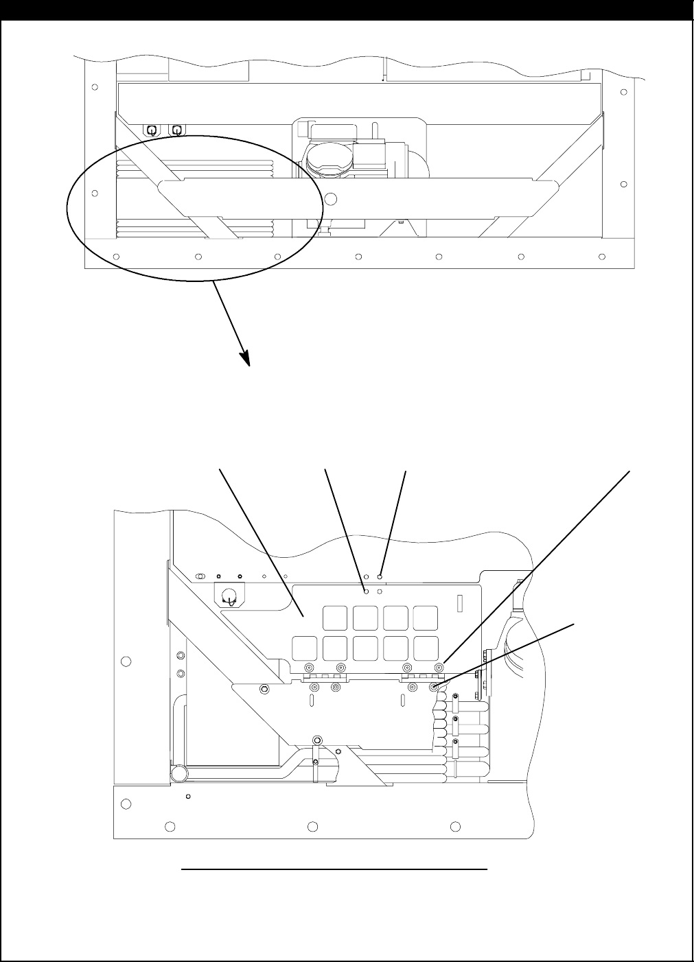
52T-296PL
2.30 CABLE RESTRAINT COMPONENTS
OPTION 1 -- CABLE DOOR
1
2
3
4
5
67
8
9
10
11
12
13
14
15
16
17
18
19
2
3
4
8
9
10

53 T-296PL
2.30 CABLE RESTRAINT COMPONENTS
Item Part Number Description Qty
OPTION 1 -- CABLE DOOR
169NT41-724-4 Cover Assembly w/Latch, Cable Storage -- Includes: 1
234-06126-08 Screw, Hex Head, #4-40 x 1/2 lg. -- SST 2
334-00662-05 Washer, Flat, #4 --SST 4
434-00667-05 Locknut, Hex Head, #4-40 2
534-06053-08 Washer, Mylar, 1/8 ID x 3/8 OD 2
644-00340-03 Latch 1
769NT35-8032 Hinge 2
866U1-2403 Screw, Truss Head, #10-24 x 1/2 lg. -- SST 4
966U1-5321-8 Washer, Flat, #10 4
10 34-00667-09 Locknut, Hex Head, #10-24 -- SST 4
11 34-06053-05 Washer, Mylar, 3/16 ID x 5/8 OD 4
12 58-04001-02 Protector, Mylar 2
13 58-04001-01 Protector, Mylar 1
14 34-06053-05 Washer, Mylar, 3/16 ID x 5/8 OD 2
15 34-01167-01 Retainer, Nut 1
16 66U1-2403 Screw, Truss Head, #10-24 x 1/2 lg. -- SST 2
17 66U1-5321-8 Washer, Flat, #10 -- SST 2
18 66U1-5331-3 Washer, Lock, #10 -- SST 4
19 44-00340-05 Latch, Catch 1
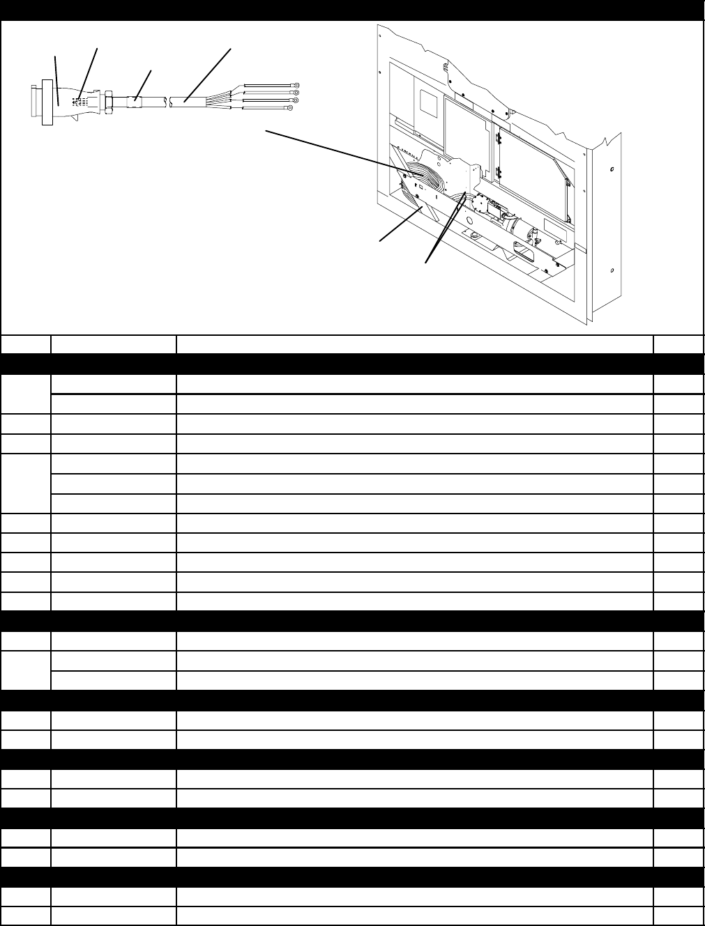
54T-296PL
2.31 VOLTAGE CABLES
1
2
3
4
5
6
7
9
8
10
11 12
13
Item Part Number Description Qty
CLAMPS ON BACK WALL AND CABLE CUTTERS
1
34-00373-56 Clamp, Tube, Cushioned, 9/16 Diameter (Used with Transicord) A/R
134-00373-59 Clamp, Tube, Cushioned, 3/4 Diameter A/R
266U1-5381-1 Screw, Hex Head, #10-24 x 3/4 lg. -- SST A/R
334-06053-03 Washer, Mylar, 1/4 ID x 1.00 OD A/R
69NT35-6412-2 Clamp, Cable Cutter, 8 AWG cable 1
469NT35-6412 Clamp, Cable Cutter, 10 AWG cable 1
69NT35-6412-1 Clamp, Cable Cutter, 11 AWG cable 1
558-04026-07 Protector, Mylar A/R
666U1-5361-11 Screw, Machined Hex Head, 1/4-20 x 1-1/2 lg. -- SST A/R
734-00667-11 Locknut, Hex Head, 1/4-20 -- SST A/R
866U1-5321-7 Washer, Flat, 1/4 -- SST A/R
934-06053-03 Washer, Mylar, 0.25 I.D. x 1.00 O. D. A/R
STANDARD PARTS FOR ALL 460V CABLES
10 66U1-2583 Heat Shrink Tube (Coil Label) -- “460V” 1
1
1
22-02324-01 Bushing (Used with Standard Cable) 4
11 22-02324-05 Bushing (Used with Transicord) 4
OPTION 1 460V CABLES
12 66U1-9782 Cable, Power -- Yellow, 10/4 A/R
13 22-02378-00 Plug, Power 1
OPTION 2 460V CABLES
12 22-01551-00 Cable, Power -- Yellow, 33 amp, 11 AWG A/R
13 22-01891--00 Plug, Power 1
OPTION 3 460V CABLES
12 66U1-9782 Cable, Power -- Yellow, 10/4 A/R
13 22-01891-00 Plug, Power 1
OPTION 4 460V CABLES
12 22-01551-00 Cable, Power -- Yellow, 33 amp, 11 AWG A/R
13 22-01891-01 Plug, Power 1

55 T-296PL
2.31 VOLTAGE CABLES (Continued)
Item Part Number Description Qty
OPTION 5 460V CABLES
12 22-01551-00 Cable, Power -- Yellow, 33 amp, 11 AWG A/R
13 22-01883-00 Plug, Power 1
OPTION 6 460V CABLES
12 22-01551-00 Cable, Power -- Yellow, 33 amp, 11 AWG A/R
13 22-01891-00 Plug, Power 1
OPTION 7 460V CABLES
12 66U1-9782 Cable, Power -- Yellow, 10/4 A/R
13 22-01891-00 Plug, Power 1
OPTION 8 460V CABLES
12 66U1-9782 Cable, Power -- Yellow, 10/4 A/R
13 22-01932-00 Plug, Power 1
OPTION 9 460V CABLES
12 66U1-9782 Cable, Power -- Yellow, 10/4 A/R
13 22-02232-00 Plug, Power 1
STANDARD PARTS FOR ALL 230V CABLES
10 66U1-2583-1 Heat Shrink Tube (Coil Label) -- “230V” 1
11 22-02324-02 Bushing (Used with 8 AWG) 4
12 66U1-9782-1 Cable, Power -- Black, 35 amps, 8 AWG A/R
OPTION 1
13 22-02188-00 Plug, Power 1
OPTION 2
13 22-02375-00 Plug, Power 1
OPTION 3
13 66U1-6782-3 Plug, Power 1
OPTION 4
13 22-01744-00 Plug, Power 1
OPTION 5
13 22-02322-00 Plug, Power 1
OPTION 6
13 22-01884-00 Plug, Power 1
OPTION 7
13 66U1-6782 Plug, Power 1
OPTION 8
13 22-01931-00 Plug, Power 1
OPTION 9
13 22-01906-00 Plug, Power 1
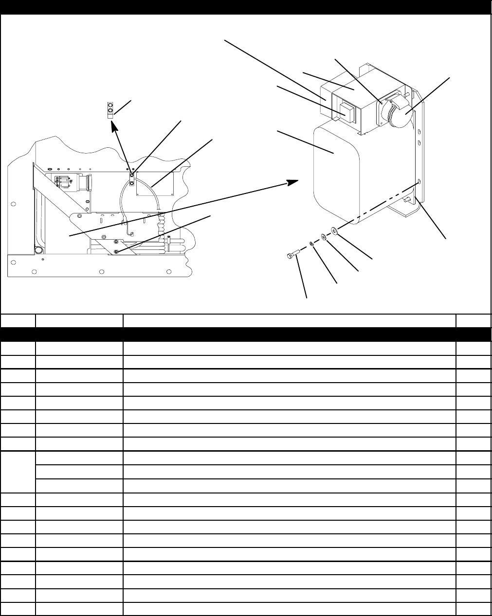
56T-296PL
2.32 AUTOTRANSFORMER KIT
23
16
17
4
5
6
24
19
8
11
25
26
27
28
29
30
31
11
18
1
2
3
7
4
9
10
11
12
20
21
11
14 11
14
13
15
22
Item Part Number Description Qty
STANDARD PARTS INCLUDED IN EVERY 76-00670 SERVICE KIT
-- 76--00670 Standard Parts Include: 1
166U1-5371-7 Screw, Hex Head, #10-24 x 1/2 lg. -- SST 4
266U1-5321-8 Washer, Flat, #10 -- SST 4
334-06053-05 Washer, Mylar, 0.205 ID x 0.600 OD 4
434-06053-00 Washer, Mylar, 0.250 ID x 0.800 OD 5
5AU11JR171 Washer, Lock, 1/4 -- SST 5
6AA06JA170 Screw, Hex Head, 1/4-20 x 1.00 lg. 5
766U1-2603 Strap, Tie Down 1
69NT35-6412-2 Clamp, Cable Cutter, 8 AWG cable 1
869NT35-6412 Clamp, Cable Cutter, 10 AWG cable 1
69NT35-6412-1 Clamp, Cable Cutter, 11 AWG cable 1
958-04026-07 Protector, Mylar 1
10 66U1-5361-11 Screw, Machined Hex Head, 1/4-20 x 1-1/2 lg. -- SST 2
11 66U1-5321-7 Washer, Flat, 1/4 -- SST A/R
12 34-00667-11 Locknut, Hex Head, 1/4-20 -- SST 2
13 69NT35-5992 Clamp, Tie Down Strap 1
14 66U1-5361-25 Bolt, Hex Head, 1/4-20 x 3/4 lg. -- SST A/R
15 34-06053-03 Washer, Mylar, 0.25 ID x 1.00 O.D. 2
16 69NT43-374 Bracket Assembly 1
17 58-04026-17 Protector, Mylar 1

57 T-296PL
2.32 AUTOTRANSFORMER KIT (Continued)
Item Part Number Description Qty
OPTION 1 -- AUTOTRANSFORMER
See Previous Page for Standard Parts Included in the Kit and use with Items Below
-- 76-00670-02 Transformer Kit, Field Installation, without CB2 -- Includes: 1
18 10-01139-04 Transformer, Dual Voltage Modular 1
NS 22-01778-00 Terminal Block -- Used only without CB2 1
19 69NT43-470-1 Box Assembly 1
20 69NT35-8382 Clamp, Tie Down Strap 1
21 58-04026-22 Protector, Mylar 1
OPTION 2 -- AUTOTRANSFORMER WITH CB2 AND RECEPTACLE
See Previous Page for Standard Parts Included in the Kit and use with Items Below
-- 76-00670-01 Transformer Kit, Field Installation, with CB2 -- Includes: 1
18 10-01139-04 Transformer, Dual Voltage Modular 1
19 69NT43-470 Box Assembly -- Used only with CB2 1
2
2
22-01679-00 Receptacle, 32 Amp 1
2
2
22-01679-01 Receptacle, w/ Screw Cap -- 32 Amp, Alternate, SOLD SEPARATELY 1
20 69NT35-8382 Clamp, Tie Down Strap 1
21 58-04026-22 Protector, Mylar 1
-- 76-00667-05 Circuit Breaker Kit, Field Installation -- Includes: 1
23 10-00083-05 Circuit Breaker, 70 amp -- 250 vac, 50/60 hz 1
24 66U2-1531 Boot -- Includes: 1
NS NSS Frame 1
NS NSS Screw, Self Sealing, #6-32 x 3/8 lg. -- SST 6
OPTION 3 -- AUTOTRANSFORMER WITH CB2 AND BRIDGING UNIT
See Previous Page for Standard Parts Included in the Kit and use with Items Below
-- 76-00670-03 Transformer Kit, Field Installation, with CB2 and TBU -- Includes: 1
18 10-01139-04 Transformer, Dual Voltage Modular 1
19 69NT43-470-2 Box Assembly 1
20 69NT35-8382 Clamp, Tie Down Strap 1
21 58-04026-22 Protector, Mylar 1
-- 76-00667-05 Circuit Breaker Kit, Field Installation -- Includes: 1
23 10-00083-05 Circuit Breaker, 70 amp -- 250 vac, 50/60 hz 1
24 66U2-1531 Boot -- Includes: 1
NS NSS Frame 1
NS NSS Screw, Self Sealing, #6-32 x 3/8 lg. -- SST 6
25 12-00474-00 Bridge Unit, Transformer 1
26 42-00470-00 Gasket, Transformer Bridge Unit 1
27 34-06221-00 Screw, Hex Head, #10-24 x 2.50 lg. -- SST 2
28 34-00667-09 Locknut, Hex Head, #10-24 -- SST 2
29 66U1-5321-8 Washer, Flat #10 -- SST 2
30 34-06053-05 Washer, Mylar 0.205 I.D. x 0.600 O.D. 2
31 22-02324-01 Bushing, 0.142 I.D. x 0.472 O.D. 3
OPTION 4 -- AUTOTRANSFORMER WITH CB2 AND RECEPTACLE
See Previous Page for Standard Parts Included in the Kit and use with Items Below
-- 76-00670-04 Transformer Kit, Field Installation, with CB2 -- Includes:
Everything in kit 76-00670-01 except replace Item #22 with below 1
22 22-01734-01 Receptacle, 32 Amp 1
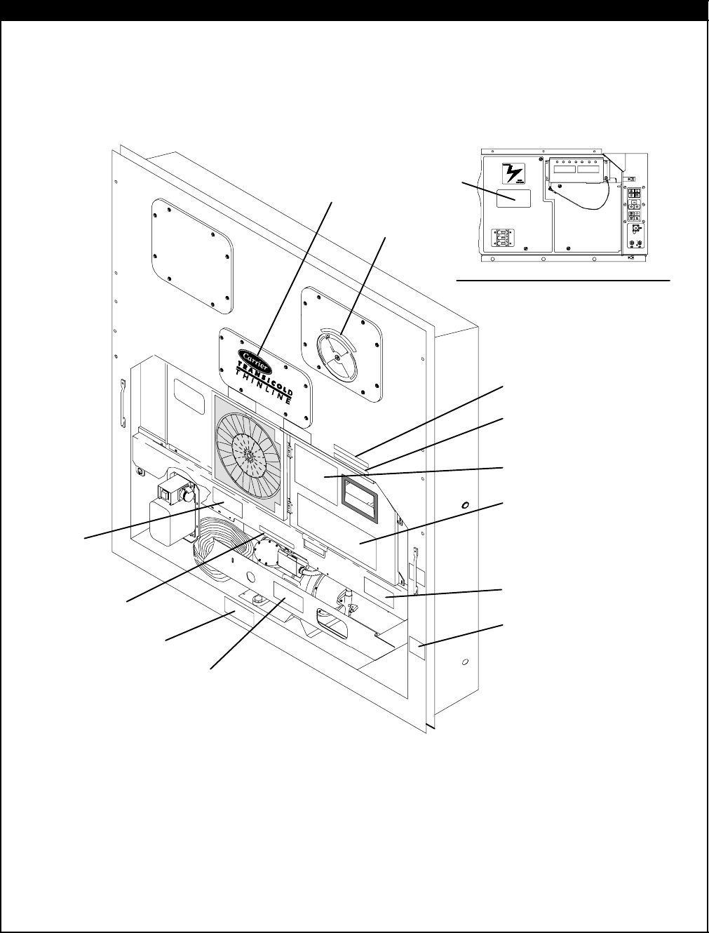
58T-296PL
2.33 LABELS AND DECALS
8
7
6
5
11
4
1
3
2
10
9
12
VIEW -- INSIDE CONTROL BOX
13

59 T-296PL
2.33 LABELS AND DECALS (Not Applicable to All Units)
Item Part Number Description Qty
STANDARD LABELS
162-10769-00 Decal, Carrier Transicold Thinline 1
269NT35-3867 Label, Economy Mode 1
369NT35-3907 Label, Humidity Control Sensor 1
462-02721-00 Label, Function Code -- English 1
5
62-02562-00 Label, Micro-Link 2i with USDA 1
562-02562-01 Label, Micro-Link 2i 1
662-02444-01 Label, Charge with R-134a 1
7
62-02530-00 Label, R-134a -- Ozone Protection -- English 1
762-02530-01 Label, R-134a -- Ozone Protection, Umbrella Only -- English 1
862-02458-00 Label, POE Compressor Oil 1
969NT35-8218 Label, Equipped w/Crankcase Heater (CCH) 1
10 62-02785-00 Label, CE 1
OPTION 1 -- ENGLISH
11 62-02720-00 Label, Operating Instructions (Partlow w/ Return Air) 1
11 62-02743-14 Label, Operating Instructions (Partlow w/ Supply Air) 1
11 62-02743-16 Label, Operating Instructions (Electronic Partlow w/ Supply & Return Air) 1
11 62-02743-12 Label, Operating Instructions (Saginomiya w/ Supply Air) 1
11 62-02743-13 Label, Operating Instructions (Saginomiya w/ Return Air) 1
11 62-02743-18 Label, Operating Instructions (No Recorder) 1
12 62-02723-00 Label, Fresh Air Makeup -- English 1
12 62-02723-03 Label, Fresh Air Makeup (w/ Full CMH) -- English 1
12 62-02723-10 Label, Fresh Air Makeup (w/ Full CMH + CFM) -- English 1
13 62-10532-00 Label, Welding Precautions -- English 1
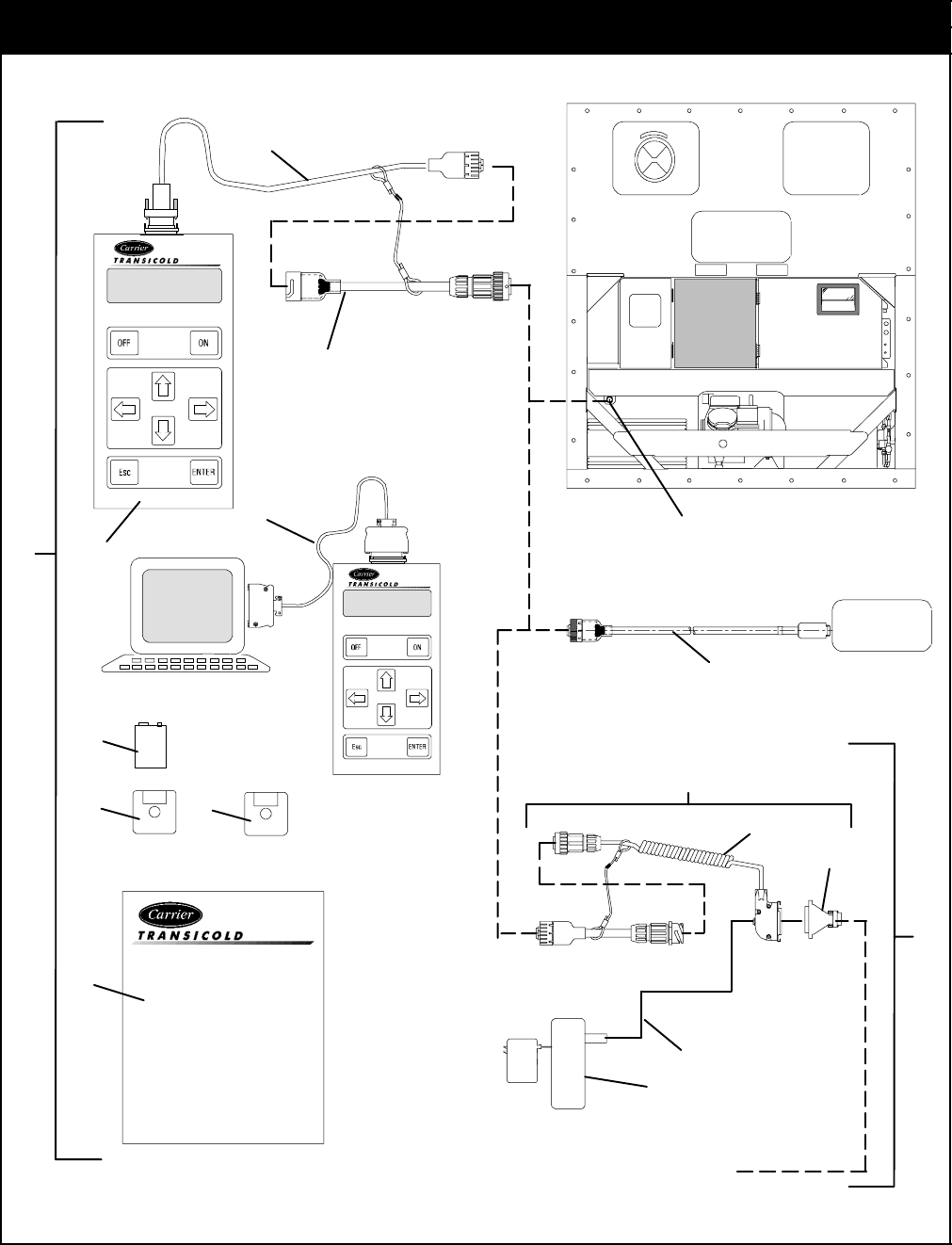
60T-296PL
3 INTERROGATOR AND ACCESSORIES
3.1 DATAREADER
9volt
DataReader
OPERATING
INSTRUCTIONS
DATA RETRIEVAL
FOR
MICRO-LINK AND
MICRO-LINK 2
12
3
4
5
6
7
Personal Computer
DataReader
8
9
10
11
To DataReader or PC
12
H. P.
PALMTOP
15
13
14
16
7

61 T-296PL
3.1 DATAREADER
Item Part Number Description Qty
1-- DataReader -- Includes: 1
212-00377-01/2.5 DataReader NSS 1
322-01737-00 Cable, Download 1
422-01737-01 Cable, Adapter 1
522-01743-00 Cable, Upload 1
6PL Battery, Akaline -- 9 Volt 1
-- 07-00406-00 Disk Kit, DataView (DOS) (3.5 DS/HD Diskettes, Formatted)
(SEE NOTE 10) -- Includes: 1
712-00413-05SV Software, DataView NSS 1
712-00528-00 Software, DataView (Scroll) NSS 1
862-02575-07 Manual, Operating Instructions 1
922-01737-02 Cable, H. P. Palmtop 1
10 76-50058-00 Kit, Battery, with Cable -- Includes: 1
11 NSS Battery, External, with Battery Charger 1
12 22-02401-00 Cable 1
13 76-50059-00 Kit, Cable, with Adapter -- Includes: 1
14 22-02418-02 Cable, Interrogator 1
15 22-02420-00 Adapter 1
16 -- Receptacle -- Refer to section 3.2 --
10. NOTE
Kit includes a 3.5 DS/HD Diskette, Formatted. If a DS/DD
Diskette is required, contact a Customer Service Representative.
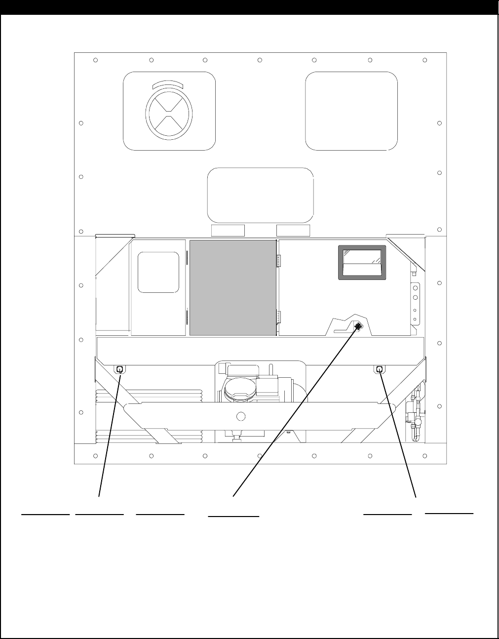
62T-296PL
3.2 INTERROGATOR RECEPTACLE
OPTION 1, OPTION 4 & OPTION 5
4
1
2
3
OPTION 3
8
5
6
7
OPTION 2 & OPTION 6
4
1
2
3
12
9
10
11 12
9
10
11
15
13
14
16

63 T-296PL
3.2 INTERROGATOR RECEPTACLE (see note 11)
Item Part Number Description Qty
OPTION 1 -- LEFT STRAIGHT MOUNT & OPTION 2 -- RIGHT STRAIGHT MOUNT
122-01660-03 Receptacle, Interrogator (ICR) (5 Pin) 1
222-01613-14 Contact, Pin, #16 5
369NT43-176 Cap, Dust, with Tether (5 Pin) 1
469NT41-192 Bracket, Interrogator Connector 1
OPTION 3 -- BOX MOUNT
522-01660-03 Receptacle, Interrogator (ICR) (5 Pin) 1
622-01613-14 Contact, Pin, #16 5
768--12434-02 Bracket, Interrogator Connector 1
842-00174-38 Gasket, Interrogator Connector Bracket 1
OPTION 4 -- LEFT STRAIGHT MOUNT AND OPTION 6 -- RIGHT STRAIGHT MOUNT
922-02412-00 Receptacle, Interrogator (ICR) (5 Pin) 1
10 22-02412-02 Contact, Pin, #16 5
11 22--02413-00 Cap, Dust, with Tether (5 Pin) 1
12 69NT40-222 Bracket, Interrogator Connector 1
OPTION 5 -- LEFT ANGLED MOUNT
13 22-01660-03 Receptacle, Interrogator (ICR) (5 Pin) 1
14 22-01613-14 Contact, Pin, #16 5
15 69NT43-176 Cap, Dust, with Tether (5 Pin) 1
16 68-12553-00 Bracket, Interrogator Connector 1
11. NOTE
Do not mix silver and gold pins and sockets.
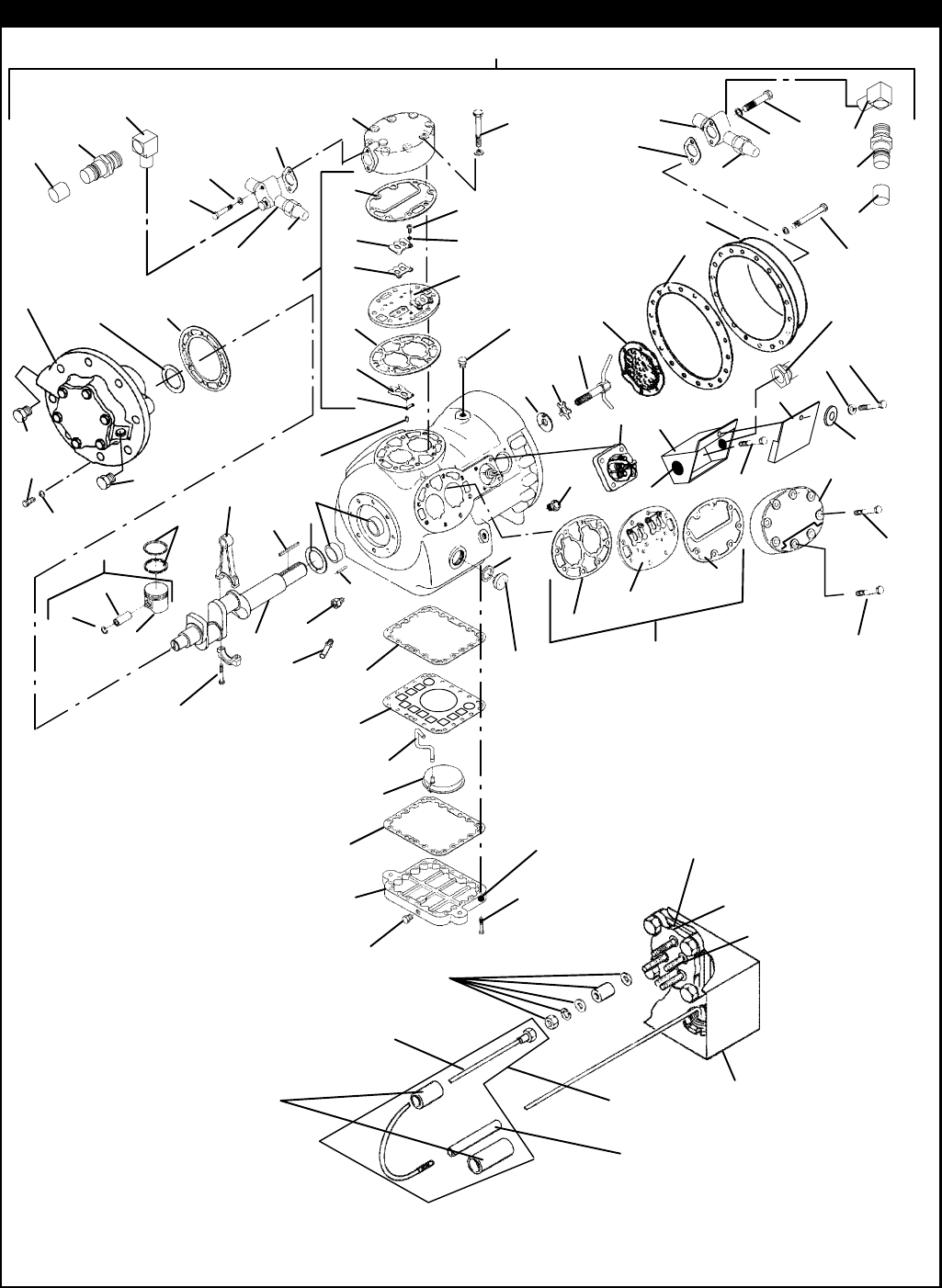
64T-296PL
4 COMPRESSOR ASSEMBLY
76 78
73 74,82
75
29
3
4
7
79 63
65
27
81
47
59
67
23
Existing parts on compressor terminal block
Terminal post
Terminal block
Compressor
junction block
1/4 Inch diameter
heat shrink tubing
Wire assembly
1/2 Inch diameter
heat shrink tubing
1
2
6
8
10
16
17
18
19 20
21
22
28
31
32
35
36 37
38
39
40 41
43
45
46
48
53
54
55
60
61
62
64
66
68
69
70 71
72
73
77
80
82
81
22
23
30
49
13
14
15
24
25
50
57
5
56 12
11
58
58 52
9
Not Available Separately
26
33
42 44
49
43 51
74
82

65 T-296PL
7 COMPRESSOR ASSEMBLY
Item Part Number Description Qty
OPTION 1R -- SERVICE REPLACEMENT COMPRESSOR
118-00055-20SV Compressor, 41 CFM, Single Speed, 460 vac/3 ph/60 hz 1
NS 07-00292-00 SW20 Compressor Oil, Castrol Icematic (Quart) 4
NOTE
Replacement Compressor is sold without terminal box and cover, and without shut-off valves.
Customer should retain the original terminal box and valves for use on replacement compressor.
TERMINAL MOUNTING AND JUNCTION BOX GROUP
266U1-5371-7 Screw, Hex Head, #10-24 x 1/2 lg. (cover to box) -- SST 2
366U1-5321-8 Washer, Flat, #10 (cover to box) -- SST 2
469NT20-513-1SV Box, Junction (Located on Front of Compressor) -- Includes: 1
469NT20-513SV Box, Junction (Located on Back of 230/460v Compressor) -- Includes: 1
569NT20-2083 Cover, Junction Box 1
6AD61JA124 Screw, Pan Head, #10-32 x 3/8 lg. (box to compressor) 4
717-40093-06 Terminal, Compressor (5 Terminals) 1
717-40093-05 Terminal, Compressor (6 Terminals) 1
876-00355-00 Kit, Compressor Terminal Wiring (Single Voltage) 1
NS 76-00384-00 Kit, Compressor Terminal Wiring (Dual Voltage or Single Voltage) 1
9
17-40075-05 Gasket, Terminal Plate -- Fiber 1
917-44128-00 Gasket, Terminal Plate -- Coated Steel 1
10 34-06053-05 Washer, Mylar, 0.205 ID x 0.600 OD 2
11 66U1-5562-7 Plug, 1-1/4 Diameter -- Plastic A/R
12 22-02302-03 Connector, 3/4 Conduit A/R
SERVICE VALVE GROUP
13 40-00523-00 Elbow, M13 x M13 -- Brass 1
14 40-00520-00 Coupling, M13 -- Brass -- Includes: 1
15 40-00520-02 Cap, Service Port 1
16 14-00206-00 Valve, Suction Shut-Off, 1-1/8 ODS 1
17 17-10812-00 Cap, Seal 1
18 17-10811-05 Gasket, Suction Service Valve 1
19 14-00206-01 Valve, Discharge Shut-Off, 7/8 ODS 1
20 17-10812-00 Cap, Seal 1
21 17-10811-05 Gasket, Discharge Service Valve 1
22 66U1-5361-46 Bolt, Hex Head, 5/16-18 x 1-7/8 lg. -- SST 2
23 17-40013-00 Gasket, Bolt, 5/16 2
24 40-00523-01 Elbow, M15 x M15 -- Brass 1
25 40-00520-01 Coupling, M15 -- Brass -- Includes: 1
26 40-00520-03 Cap, Service Port 1
COMPRESSOR -- MOTOR BODY GROUP
NS -- Gasket Set (Refer to Section 7.1)
27 17-21040-00 Head, Cylinder -- Side Bank (Shaved Head) 2
28 17-40016-01 Head, Cylinder -- Center Bank 1
29 17-40018-05 Screw, Hex Head -- Center Head, 3/8-16 x 3.00 lg. -- SAE Grade 5 8
30 17-44124-00 Gasket, Cylinder Head (Side Bank) -- Coated Steel 3
31 17-40034-05 Screw, Hex Head, 3/8-16 x 2.00 lg. -- SAE Grade 5 12
32 17-40037-05 Screw, Hex Head, 3/8-16 x 1.00 lg. -- SAE Grade 5 4
33 17-40020-00 Screen Assembly, Oil Filter 1

66T-296PL
COMPRESSOR -- MOTOR BODY GROUP (Continued)
Item Part Number Description Qty
34 17-40007-00 Gasket, Bolt, 1/2 4
35 17-21062-00 Tube, Oil Suction 1
36 40-00535-00 Orifice, Oil Relief 1
37 17-21201-00SV Sight Glass Package, Oil Level -- Includes: 1
38 17-44021-00 Gasket, Sight Glass -- Coated Steel 1
39 17-20004-00 Cover, Motor End 1
40 17-40029-05 Gasket, Motor End Cover -- Fiber 1
40 17-44136-00 Gasket, Motor End Cover -- Coated Steel 1
41 PL Screw, Hex Head, 7/16-14 x 1-1/4 lg. -- SAE Grade 5 18
42 17-40032-00 Plate, Bottom 1
43 17-40033-05 Gasket, Bottom Plate -- Fiber 2
43 17-44129-00 Gasket, Bottom Plate -- Coated Steel 2
44 17-40034-05 Screw, Hex Head, 3/8-16 x 2.00 lg. -- SAE Grade 5 22
45 17-20005-00 Strainer Assembly, Suction 1
46 PL Plug, Pipe, Oil Fill, 1/4 1
47 17-40042-00 Check Valve Assembly, Oil Return 1
48 17-21063-00 Plate, Screen Hold Down 1
49 PL Pipe Plug (High & Low Pressure Connection and Oil Drain), 1/4-18 NPT 3
50 17-44123-00 Gasket, Cylinder Head (Center Bank) 1
51 -- Heater, Crankcase -- See section 2.28 1
52 17-40025-00 Bushing, Motor End 2
PUMP END GROUP
53 17-40037-05 Screw, Hex Head, Bearing Head, 3/8-16 x 1.00 lg. -- SAE Grade 5 8
54 17-40019-00 Gasket, Capscrew, 3/8 8
55 17-44022-00 Gasket, Cover Plate -- Coated Steel 1
56 17-55009-01 Washer, Thrust 1
57 17-44137-00 Bearing Head & Low Profile Oil Pump Package -- Includes: 1
58 17-44037-00 Plug, Oil Pump (Includes O ring) 2
CRANKSHAFT, ROD AND PISTON GROUP
59 17-40411-00 Crankshaft 1
60 17-40050-00 Washer, Thrust 1
61 17-40048-00 Pin, Spiral, 5/32 Diameter x 5/8 lg. 2
62 34-01110-00 Key, Rotor Drive 1
63 17-21075-00 Washer, Rotor 1
64 17-21076-00 Washer, Star, Rotor, 5/8 1
65 17-21077-00 Tube Assembly, Equalizer 1
66 17-44115-01 Piston & Pin Pkg (Standard) -- Includes: 6
66 17-44115-20 Piston & Pin Pkg (+0.020) -- Includes: A/R
67 NSS Piston 1
68 17-40052-00 Pin, Piston 1
69 17-40053-00 Retainer, Piston Pin 2
70 17-40055-00 Ring, Compression (Standard) 12
70 17-55025-00 Ring, Compression (+0.020) 12
71 17-40056-02 Connecting Rod and Cap Assembly (Standard) -- Includes: 6
71 17-55023-00 Connecting Rod and Cap Assembly (+0.010) -- Includes: 6
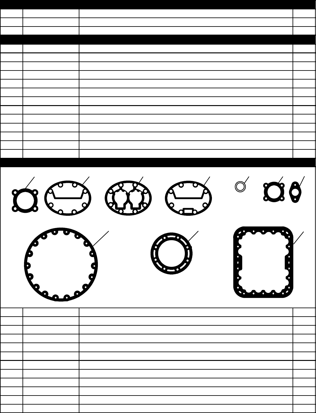
67 T-296PL
CRANKSHAFT, ROD AND PISTON GROUP -- Continued
Item Part Number Description Qty
NS 17-40057-00 Pin, Dowel 2
72 17-55008-00 Capscrew -- Special (Epoxy Coated) 2
VALVE PLATE GROUP
73 17-44109-00 Package, Valve Plate Assembly (All Banks -- Canted) -- Includes: 3
NS NSS Plate Assembly, Valve -- Includes: 1
74 NSS Plate, Valve 1
75 17-40086-00 Valve, Discharge 2
76 17-44160-00 Backer, Discharge Valve Stop 2
77 17-44113-00 Screw, Hex Head, 1/4-28 x 3/8 lg. 4
78 17-10715-00 Washer, Lock, 1/4 4
79 17-40082-00 Valve, Suction 2
80 17-40083-00 Spring, Suction Valve Positioning 2
30 17-44124-00 Gasket, Cylinder Head (Side Bank) -- Coated Steel 1
50 17-44123-00 Gasket, Cylinder Head (Center Bank) -- Coated Steel 1
81 17-55002-00 Gasket, Valve Plate 1
82 17-40057-00 Pin, Dowel (Valve Plate) 12
4.1 GASKET SET
1234567
8
910
Item Part Number Description Qty
-- 17-55020-21 Gasket Set -- Includes: 1
117-40005-05 Gasket, Suction Service Valve (4 Bolt) 1
217-44124-00 Gasket, Cylinder Head -- Side Bank (Standard) 2
317-55002-00 Gasket, Valve Plate 3
417-44123-00 Gasket, Cylinder Head -- Center Bank 1
517-44021-00 Gasket, Sight Glass 2
617-40075-05 Gasket, Oil Pump Cover 2
717-10811-05 Gasket, Service Valve (2 Bolt) 2
817-40033-05 Gasket, Bottom Plate 2
917-44022-00 Gasket, Pump End Bearing Head 1
10 17-40029-05 Gasket, Motor End Cover 1
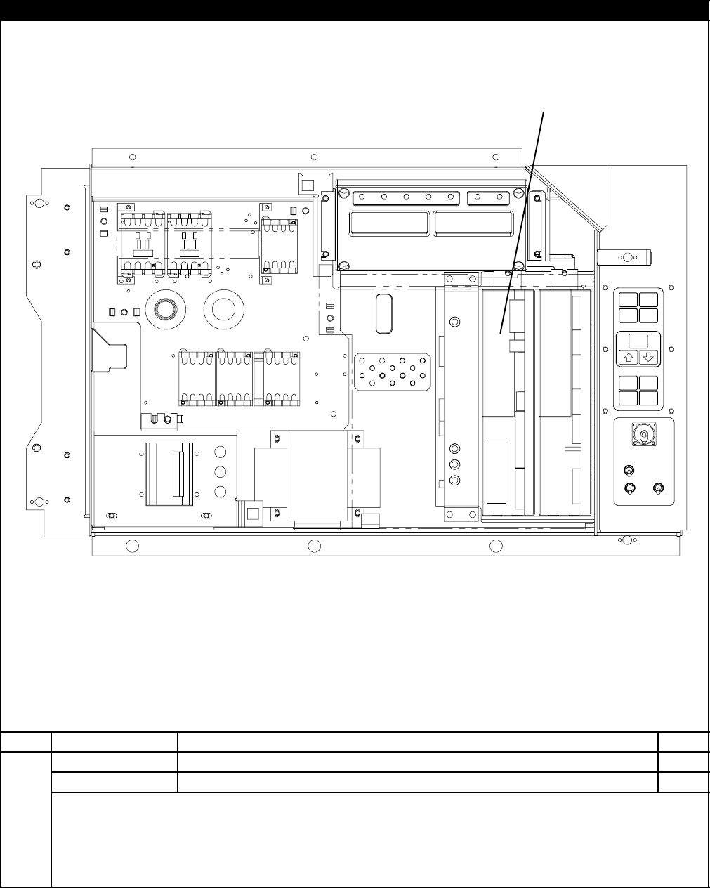
68T-296PL
5 CONTROLLER/DATACORDER CONFIGURATION
1
Item Part Number Description Qty
12--55003 Controller -- Un-Configured (See Note 1) 1
SeeNote2 Controller -- Configured (Refer to Manual T-300, Container Unit Matrix) 1
1NOTES
1. The last four digits of the Part Number is the operation software revision.
2.TheController/DataCORDERmoduleisshippedwiththeoperationalsoftwarealready
loaded, however, when ordering this part number the end user must load the
configuration software at the time of installation.

69 T-296PL
6 TOOLSPART NO. DESCRIPTION
07-00013-00 Temperature Tester (Simpson Meter)
07-00013-01 Temperature Test Lead (15 Foot)
07-00013-02 Temperature Test Lead (50 Foot)
07-00013-03 Adapter, Males (Both Ends) (Use with Temperature Tester)
07-00015-00 Case, Carrying (Used with 07-00013-00)
07-00219-00 Wrench, Compressor Sight Glass
07-00437-00 Inspection Light with Mirror
07-00228-00 Volt-Ohmmeter, Digital
07-00229-00 Amprobe Clamp (Used with 07-00228-00)
07-00238-00 Wrench, Service Valve
07-00243-10 Multimeter, Digital (Fluke)
07-00263-00 Pliers, Crimping (Used for compressor terminal block replacement)
07-00264-00 Grip, Wire Vise (Used for compressor terminal block replacement)
07-00277-00 Kit, Static Dissipative (Used for working on electronic components)
07-00304-00 Ground Strap, Wrist (Used for working on electronic components)
07-00294-00 Gauge Set, Manifold -- Fahrenheit/PSI
07-00294-05 Gauge Set, Manifold -- Centigrade/KPa
07-00295-00 Detector, Leak
07-00397--03 Extractor, Pin (Used on Fan Motor Plugs and Interrogator Plugs)
07-00397--02 Crimper, Pin (Used on Fan Motor Plugs and Interrogator Plugs)
07-00329-00 Extractor, Pin (Used on Controller module connectors)
07-00330-00 Crimper, Pin (Used on Controller module connectors)
07-00370-00 Crimper, Pin (Used on Stepper Valve, HPS)
07-00387--01 Extractor, Pin (Used on Stepper Valve, HPS)
07-00375-00 Tester, Portable, Stepper Motor Drive
07-00391-00 Application Gun (Used with 07-00390-00)
07-00398-00 Software Card Programmer
07-00408-00 Stepper Jumper Assembly
07-00418-00 Torx Driver Bit
Refer to Manual 62-03213
PART NUMBER INDEX
Index-1 T-296PL
PART NO. PAGE NO. PART NO. PAGE NO. PART NO. PAGE NO.
02--00010--01 49
02--00082--00 9
04--50027--00 18
06DA403--844 25, 51
07--00013--00 69
07--00013--01 69
07--00013--02 69
07--00013--03 69
07--00015--00 69
07--00219--00 69
07--00221--00 69
07--00228--00 69
07--00229--00 69
07--00238--00 69
07--00243--10 69
07--00263--00 69
07--00264--00 69
07--00277--00 69
07--00292--00 65
07--00294--00 69
07--00294--05 69
07--00295--00 69
07--00304--00 69
07--00313--00 1
07--00326--00 69
07--00327--00 69
07--00329--00 69
07--00330--00 69
07--00345--00 1
07--00370--00 69
07--00371--00 69
07--00375--00 69
07--00390--00 9
07--00391--00 9, 69
07--00398--00 69
07--00406--00 61
07--00408--00 69
07--00418--00 69
09--00104--05 43
09--00114--00 43
09--00118--00 43
09--00119--00 43
09--00123--00 43
09--00128--00 43, 45, 47
09--00128--01 43, 45, 47
09--00136--00 43
09--00137--00 43
09--00180--00 43
09--00180--01 43
09--00209--00 43
09--00222--00 43
09--00236--00 43
09--00296--00 43
09--00297--00 43
09--00298--00 43
09--00302--00 43
09--00303--00 43
09--00322--00 45
09--00325--00 45
09--00326--00 45
09--00329--00 45
09--00362--00 45
09--00363--00 45
09--00364--00 45
09--00365--00 45
09--00367--00 45
09--00369--00SV 15
10--00083--05 57
10--00318--00 35
10--00332--21SV 11
10--00333--00 11
10--00333--01 11
10--00333--02 11
10--00366--01SV 11
10--00388--00 21
10--00416--00 13
10--01129--07 11, 13
10--01129--10 11
10--01129--11 13
10--01129--20 13
10--01139--04 57
10--0298--01 13
12--00275--04SV 17
12--00275--17SV 17
12--00275--19SV 17
12--00309--03 51
12--00342--03 27
12--00352--00 23, 25, 51
12--00370--00 35
12--00377--01 61
12--00395--01SV 26
12--00397--00/5120 15
12--00402--45 15
12--00413--05 61
12--00421--00 42
12--00421--01 42
12--00421--02 42
12--00421--03 42
12--00433--00RP 17
12--00464--05 47
12--00464--06 47
12--00474--00 57
12--00495--20 23, 25, 35
12--00528--00 61
12--01071--01SV 24
12--01094--00 45
12--01094--01 45
12--01095--00 45
12--01104--05 21
12--01105--02 21
12--01124--01 51
12--01124--02 51
12--01125--02 51
12--55003 68
14--00204--02 21
14--00206--00 65
14--00206--01 65
14--00212--03SV 23, 25
14--00212--21 23, 25
14--00215--03 24
14--00215--04 23
14--00220--00 24
14--00220--01 23
PART NUMBER INDEX
Index-2
T-296PL
PART NO. PAGE NO. PART NO. PAGE NO. PART NO. PAGE NO.
14--00221--01 23
14--00222--01 23
14--00263--00 21
14--00263--20 21
14--00263--22 21
14--00263--23 21
14--00273--01 35
14--00284--02SV 23, 25
14--01032--14 23
14--01092--03 25
14--01093--00 51
17--10715--00 67
17--10811--05 65, 67
17--10812--00 65
17--20004--00 66
17--20005--00 66
17--21002--01 25
17--21040--00 65
17--21062--00 66
17--21063--00 66
17--21075--00 66
17--21076--00 66
17--21077--00 66
17--21201--00SV 66
17--40005--05 67
17--40007--00 66
17--40013--00 65
17--40016--01 65
17--40018--05 65
17--40019--00 66
17--40020--00 65
17--40029--05 66, 67
17--40032--00 66
17--40033--05 66, 67
17--40034--05 65, 66
17--40037--05 65, 66
17--40042--00 66
17--40048--00 66
17--40050--00 66
17--40052--00 66
17--40053--00 66
17--40055--00 66
17--40056--02 66
17--40057--00 67
17--40075--05 65, 67
17--40082--00 67
17--40083--00 67
17--40086--00 67
17--40093--05 65
17--40093--06 65
17--40411--00 66
17--44021--00 66, 67
17--44022--00 66, 67
17--44037--00 66
17--44109--00 67
17--44113--00 67
17--44115--01 66
17--44115--20 66
17--44123--00 66, 67
17--44124--00 65, 67
17--44128--00 65
17--44129--00 66
17--44136--00 66
17--44137--00 66
17--44160--00 67
17--55002--00 67
17--55008--00 67
17--55009--01 66
17--55020--21 67
17--55023--00 66
17--55025--00 66
18--00055--20SV 65
22--00041--00 1
22--00041--02 1
22--00049--01 13
22--00066--01 1
22--00066--02 1
22--00066--03 1
22--00119--04 1
22--00120--04 1
22--00120--07 1
22--00121--07 1
22--00121--27 49
22--00518--01 13
22--00519--03 13
22--00595--01 1
22--01106--00 1
22--01107--00 1
22--01139--04 1
22--01140--01 1
22--01140--02 1
22--01140--04 1
22--01141--01 1
22--01292--00 49
22--01455--02 13
22--01551--00 54, 55
22--01556--00 17
22--01556--01 15
22--01556--02 15
22--01566--00 21
22--01566--01 21
22--01585--04 21
22--01613--14 27, 63
22--01613--15 27
22--01621--02 17
22--01621--03 17
22--01621--23 15
22--01622--00 15
22--01622--01 15
22--01622--02 15
22--01660--00 27
22--01660--03 27, 63
22--01660--04 27
22--01660--08 27
22--01679--00 57
22--01679--01 57
22--01713--02 17
22--01713--06 15
22--01731--00 54
22--01731--01 54
22--01734--01 57
22--01737--00 61
22--01737--01 61
PART NUMBER INDEX
Index-3 T-296PL
PART NO. PAGE NO. PART NO. PAGE NO. PART NO. PAGE NO.
22--01737--02 61
22--01743--00 61
22--01744--00 55
22--01777--00SV 15
22--01777--01SV 15
22--01777--03 15
22--01777--04 15
22--01778--00 57
22--01835--00 21
22--01836--00 21
22--01883--00 55
22--01884--00 55
22--01889--00 11
22--01891--00 55
22--01891--01 55
22--01906--00 55
22--01931--00 55
22--01932--00 55
22--02188--00 55
22--02232--00 55
22--02243--00 43
22--02302--03 65
22--02322--00 55
22--02324--01 54, 57
22--02324--02 55
22--02324--05 54
22--02336--02 1, 13, 15
22--02336--04 1, 15
22--02341--00 11
22--02341--01 11
22--02368--00 11
22--02370--00 45
22--02375--00 55
22--02378--00 54
22--02392--00SV 51
22--02392--03 21
22--02393--00 21
22--02393--01 21
22--02394--02 21
22--02394--03 21
22--02396--02 17
22--02396--03 17
22--02398--02 27
22--02398--03 27
22--02401--00 61
22--02412--00 27, 63
22--02412--02 63
22--02413--00 27, 63
22--02418--02 61
22--02420--00 61
22--02448--00SV 23
22--50007 Series 1
22--50087--00 33
22--50088--00 33
22--50088--02 18
22--50100--00 15
22--50127--00 27
22--50157--00 15
24--00003--00 35
24--00006--02 35
24--02017--00 49
30--00407--02SV 15
34--00373--05 1, 23
34--00373--07 1, 23, 25
34--00373--11 1, 21
34--00373--51 1
34--00373--53 1
34--00373--54 23, 25
34--00373--56 54
34--00373--59 1, 54
34--00373--65 1
34--00373--67 1
34--00373--69 1
34--00373--71 1
34--00655--05 49
34--00655--08 11
34--00662--05 53
34--00662--11 29, 49
34--00663--07 11
34--00663--11 19
34--00665--08 49
34--00665--09 7
34--00667--05 11, 53
34--00667--09 53, 57
34--00667--11 49, 54, 56
34--00667--12 18, 33
34--00667--14 49
34--00792--10 33
34--00795--09 43, 45, 47
34--00829--13 49
34--00848--10 11
34--00849--22 49
34--00928--01 9, 11, 43, 45
34--00928--02 9, 37, 39, 41
34--00928--03 9, 37, 39, 41
34--00928--09 23, 25, 31,
37, 39, 41
34--01110--00 66
34--01142--01 9, 11, 43, 45
34--01150--03 39, 41
34--01150--06 39, 41
34--01150--30 39, 41
34--01150--31 39, 41
34--01152--02 9
34--01167--01 7, 53
34--01178--22 35
34--01181--01, 18
34--06053--00 7, 18, 21
23, 25, 29,
31, 43, 45,
47, 49, 56
34--06053--01 49
34--06053--02 18, 23, 25
49
34--06053--03 18, 19, 23,
25, 47, 49,
54, 56
34--06053--05 7, 11, 13,
21, 23, 25,
47, 51, 53,
56, 57, 65
34--06053--07 49
34--06053--08 53
34--06053--13 43, 45, 47
34--06053--15 49
34--06053--18 31
PART NUMBER INDEX
Index-4
T-296PL
PART NO. PAGE NO. PART NO. PAGE NO. PART NO. PAGE NO.
34--06053--19 29
34--06092--00 31
34--06107--00 7
34--06126--08 53
34--06139--03 9
34--06154--00 29
34--06169--00 7, 19, 43,
45, 47
34--06179--00 19, 43, 45
47
34--06179--04 43, 45, 47
34--06183--00 31
34--06185--01 29
34--06221--00 57
34--06223--00 13, 17
34--06227--00 11
34--06231--01 9
34--06231--03 9
34--06231--05 9
34--06231--06 9
34--06231--07 9
34--50015--00 9
38--00125--00 33
38--00126--00 33
38--00503--00 18
40--00060--02 51
40--00086--04 25
40--00123--02 51
40--00501--50 23
40--00520--00 65
40--00520--01 23, 25, 65
40--00520--02 21, 65
40--00520--03 23, 25
40--00523--00 65
40--00523--01 65
40--00535--00 66
40--00542--00 21
40--00555--06 25
40--01129--00 24
42--00174--38 63
42--00233--01 31
42--00270--00 7
42--00295--00 31
42--00295--01 31
42--00296--00 29
42--00296--01 29
42--00327--00 29
42--00334--00 37, 39, 41
42--00407--00 29
42--00465--00 31
42--00470--00 57
42--01098--01 43, 45, 47
42--50000--00 24
44--00300--01 7
44--00300--02 7
44--00300--03 7
44--00340--03 53
44--00340--05 53
44--00343--00 9
44--00370--03 49
44--00374--00 19, 43, 45,
47
44--01043--05 1
44--01043--07 1
54--00122--21 33
54--00513--02 33
54--00549--00 18
54--50044--00 33
58--00065--67 47
58--00065--70 47
58--00956--00 24
58--00957--00 24
58--00967--00 11
58--01184--00 15, 17
58--04001--01 53
58--04001--02 53
58--04026--07 54, 56
58--04026--10 19
58--04026--17 56
58--04026--22 57
58--04026--23 23
58--04026--41 19
58--04101--00 7
58--04101--01 7
58--04101--07 19, 43, 45,
47
58--04145--00 11
58--04145--01 11
58--04145--06 13
58--04145--07 13
58--04145--09 13
58--04251--00 29
58--04263--01 31
58--04276--00 26
58--04277--00SV 26
58--04278--00 26
58--04279--00 26
58--04316--00 49
58--04346--00 7
58--04366--00SV 7
58--04367--00 9
58--04480--00 19
58--04481--00 19
58--50014--00 25
62--02444--01 59
62--02458--00 59
62--02530--01 59
62--02531--00 59
62--02562--00 59
62--02562--01 59
62--02575--07 61
62--02719--00 15
62--02720--00 59
62--02721--00 59
62--02723--00 59
62--02723--03 59
62--02723--10 59
62--02735--00 15
62--02738--05 15
62--02743--12 59
62--02743--13 59
PART NUMBER INDEX
Index-5 T-296PL
PART NO. PAGE NO. PART NO. PAGE NO. PART NO. PAGE NO.
62--02743--14 59
62--02743--16 59
62--02743--18 59
62--02783--00 29
62--02785--00 59
62--02822--01 37
62--02874--00 13
62--02874--01 13
62--02874--02 13
62--03957--01 9
62--10259--00 59
62--10532--00 59
62--10557--00 5
65--00144--00 35
65--00144--01 35
66CH1--1002--33 31
66CH1--1172--16 19
66CH1--1172--46 11
66U1--2403 9, 11, 37, 53
66U1--2403--1 7
66U1--2552--185 29
66U1--2583 54
66U1--2583--1 55
66U1--2603 56
66U1--2763--5 24
66U1--2763--6 24
66U1--3442--2 17
66U1--3632--24 21
66U1--3803 1, 23, 49
66U1--3803--1 1, 35
66U1--3823 10
66U1--3882 49
66U1--5321--13 29
66U1--5321--3 31
66U1--5321--5 23, 25, 33,
49
66U1--5321--6 11
66U1--5321--7 18, 23, 25,
26, 31, 43,
45, 47, 49,
54, 56
66U1--5321--8 7, 11, 13,
21, 35, 48,
49, 51, 53,
56, 57, 65
66U1--5331--3 7, 53
66U1--5361 18
66U1--5361--11 49, 54, 56
66U1--5361--25 18, 19, 23,
25, 31, 35,
43, 45, 47,
49, 56
66U1--5361--46 65
66U1--5361--7 23, 25, 33,
49
66U1--5362--2 29
66U1--5371--10 11, 35
66U1--5371--6 13, 23, 25,
49, 51
66U1--5371--7 7, 11, 15,
17, 26, 56,
65
66U1--5381 10
66U1--5381--1 21, 54
66U1--5391--3 11
66U1--5562--7 65
66U1--6651--15 10
66U1--6651--19 51
66U1--6651--4 11
66U1--6782 55
66U1--6782--3 55
66U1--6811--12 19
66U1--6811--15 7
66U1--6811--8 7, 19, 43,
45, 47
66U1--6835 11
66U1--6912--16 35
66U1--7472--1 1
66U1--7842--13 11
66U1--7982--2 37
66U1--8075 37, 39, 41
66U1--8115 29
66U1--8552--2 25
66U1--8662 5
66U1--8912 19
66U1--9212--1 17
66U1--9752 11
13
66U1--9782 54, 55
66U1--9782--1 55
66U2--1132--1 23
66U2--1142 24
66U2--1152 24
66U2--1531 57
68--12368--00 25
68--12417--00 4
68--12432--03 49
68--12434--02 63
68--12496--00 10
68--12523--00 49
68--12544--01 13
68--12553--00 63
68--12658--01 47
68--12791--00 9
68--12993--00 49
68--13181--00 35
68--13427--00SV 11
68--13454--02 19
68--13454--03 19
68--13472--03SV 51
68--13475--00 37, 39
68--13475--01 37, 39
68--13475--08 37, 39
68--13475--09 37, 39
68--13576--00 49
68--13577--00 7
68--13691--00 41
68--13729--06 41
68--13729--07 49
68--14175--00 49
69NP20--1031 25
69NT20--2083 65
69NT20--513--1SV 65
69NT20--513SV 65
69NT35--1173 33
PART NUMBER INDEX
Index-6
T-296PL
PART NO. PAGE NO. PART NO. PAGE NO. PART NO. PAGE NO.
69NT35--1287--1 31
69NT35--1417 31
69NT35--1662 33
69NT35--1662--1 33
69NT35--2257 37
69NT35--2287 9
69NT35--2692 15, 37
69NT35--2692--1 19, 31, 35,
43, 45, 47
69NT35--2692--4 17
69NT35--3282 39,41
69NT35--3547 18
69NT35--3867 59
69NT35--3907 59
69NT35--3987 4
69NT35--3997--1 4
69NT35--4047 31
69NT35--5022--5 43, 45, 47
69NT35--5352--1 43, 45, 47
69NT35--5992 56
69NT35--6112 18
69NT35--6132 49
69NT35--6272 9
69NT35--6278 11
69NT35--6412 54, 56
69NT35--6412--1 54, 56
69NT35--6412--2 54, 56
69NT35--6522 35
69NT35--6532 35
69NT35--6598 41
69NT35--6598--1 41
69NT35--7012 31
69NT35--8032 53
69NT35--8113 4
69NT35--8218 59
69NT35--8348 31
69NT35--8382 57
69NT35--8548 4
69NT35--8693--10 19
69NT35--8693--7 19
69NT35--8703 19
69NT35--9238 31
69NT40--222 11, 63
69NT40--402--1 45
69NT40--476 33
69NT40--507--1 27
69NT40--657--2 4
69NT40--976--3 31
69NT41--106--2 51
69NT41--106--2SV 51
69NT41--192 63
69NT41--477 25
69NT41--487 25
69NT41--497 25
69NT41--543 51
69NT41--553 51
69NT41--702 21
69NT41--724--4 53
69NT41--782 31
69NT41--852--1 31
69NT41--942--3 37
69NT41--942--4 39
69NT41--942--5 41
69NT41--982--3 11
69NT41--992 27
69NT42--688--7 7
69NT42--914 24
69NT42--914--1 24
69NT43--124--2 9
69NT43--125--1 9
69NT43--148--2 19
69NT43--148--4 19
69NT43--175 27
69NT43--176 27, 63
69NT43--202--10SV 19
69NT43--277 23
69NT43--307 31
69NT43--374 56
69NT43--403--2 23
69NT43--420 23, 25
69NT43--464--37 39, 41
69NT43--466--4 51
69NT43--469 49
69NT43--470 57
69NT43--470--1 57
69NT43--470--2 57
74--00201--01 29
74--00201--02 29
76--00355--00 65
76--00384--00 65
76--00397--00 1
76--00667--05 57
76--00670--01 57
76--00670--02 57
76--00670--03 57
76--00670--04 57
76--00675--01 35
76--00676--00 27
76--00677--00 25
76--00684--00 27
76--00701--00 42
76--00701--01 42
76--00701--02 45
76--00701--03 45
76--00701--04 42
76--00701--05 43, 45, 47
76--00701--06SV 45, 47
76--00701--10SV 47
76--00701--11SV 47
76--00701--12 42
76--00704--01 19
76--00724--00SV 9
76--50058--00 61
76--50059--00 61
76--50075--00 19
76--50084--00SV 9
76--50094--00 49
79--01694--00 29
79--01695--00 29
79--01697--06SV 29
79--01697--07SV 29
PART NUMBER INDEX
Index-7 T-296PL
PART NO. PAGE NO. PART NO. PAGE NO. PART NO. PAGE NO.
79--01706--03SV 11
79--01757--00 24
81--01549--00 35
81--01575--00SV 19
86--04217--00 43
86--04237--00 9
A
AA06JA166 35
AA06JA170 56
AA06JA232 49
AD61JA124 65
AU11JR171 35, 56
AU11JR241 23, 25, 33
49
C
CA21JA051 51
D
DE40BA203 23, 25
E
EC39DM062 23
