1 T5_Manual T5 Manual
User Manual: T5_Manual
Open the PDF directly: View PDF ![]() .
.
Page Count: 48
© UMS GmbH München
Art.Nr. T5
Version 12/2009
Author: tk, ge, ma
User Manual
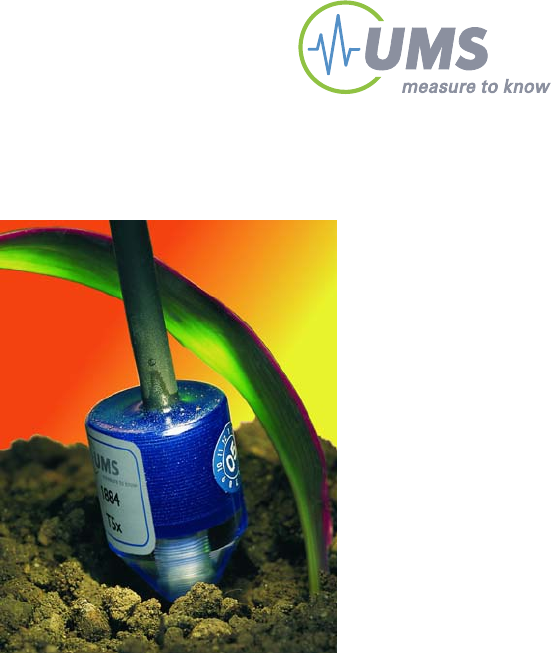
Pressure Transducer Tensiometer
T
T5
5/
/T
T5
5
x
x

Introduction
2/48
Table of content
1 Introduction 4
1.1 Safety instructions and warnings 4
1.2 Content of delivery 5
1.3 Foreword 6
1.4 Guarantee 6
1.5 Durability 6
1.6 Tensiometer T5 and T5x 7
1.6.1 Soils and soil water 7
1.6.2 Intended use 7
1.6.3 Typical applications 8
1.6.4 Extended measuring range of the T5x 8
1.6.5 Specific notes 9
1.7 Quick installation guide 10
2 Sensor description 12
2.1 Design 12
2.1.1 Body and shaft 12
2.1.2 Pressure transducer 12
2.1.3 Reference air pressure 12
2.1.4 The ceramic tip 13
2.2 Analog output signals 13
3 Installation 14
3.1 Scientific measure ideas 14
3.1.1 Selecting the measuring site 14
3.1.2 Number of Tensiometers per level 14
3.1.3 Extension of the site 14
3.1.4 Ideal conditions for installation 15
3.1.5 Documentation 15
3.1.6 Selecting the installation angle 15
3.2 Installation procedure 16
3.3 Offset correction for non horizontal installations 17
3.4 Connecting T5 and T5x 18
3.4.1 Spot readings with the INFIELD7 18
3.4.2 Cables 18
3.4.3 General requirements 18
3.4.4 TV-batt Tensiometer power supply 19
3.4.5 Connection to a data logger 19
3.4.6 Tensiometer loggers DL6-te or GP1-te 19
4 Service and maintenance 20
4.1 Refilling 20
4.1.1 When do Tensiometers need to be refilled? 20
4.1.2 Refilling T5 in lab and field 20
4.2 Testing 32
4.2.1 Calibration 32
4.2.2 Check the Offset 32
4.3 Cleaning 33

Introduction
3/48
4.4 Storage 33
5 Protecting the measuring site 33
5.1 Theft and vandalism 33
5.2 Cable protection 33
5.3 Frost 33
6 Useful notes 34
6.1 Extended measuring range 34
6.1.1 The bubble point of the porous cup 34
6.1.2 The vapour pressure of water 34
6.1.3 Boiling retardation: 35
6.2 Maximum measuring range and data interpretation 36
6.3 Temperature influences during measurements 38
6.4 Vapour pressure influence on pF/WC 38
6.5 Osmotic effect 39
7 Troubleshooting 39
8 Appendix 40
8.1 Technical specifications 40
8.2 Wiring configuration 41
8.3 Accessories 42
8.3.1 Connecting and extension cables 42
8.3.2 Handheld measuring device 43
8.3.3 Tensiometer loggers 43
8.3.4 TV-batt power supply 44
8.3.5 T5 auger kit 44
8.3.6 T5-case 44
8.4 Units for soil water and matrix potentials 45
8.5 Index 46
Your addressee at UMS 48
Introduction
4/48
1 Introduction
1.1 Safety instructions and warnings
Electrical installations must comply with the safety and EMC
requirements of the country in which the system is to be used.
Please note that any damages caused by handling errors are out of
our control and therefore are not covered by guarantee.
Tensiometers are instruments for measuring the soil water tension,
soil water pressure and soil temperature and are designed for this
purpose only.
Please pay attention to the following possible causes of risk:
Lightning: Long cables act as antennas and might conduct surge
voltage in case of lightning stroke – this might damage sensors
and instruments.
Frost: Tensiometers are filled with water and therefore are
sensitive to frost! Protect Tensiometers from frost at any time.
Never leave Tensiometers over night inside a cabin or car when
freezing temperatures might occur!
Tensiometers normally are not damaged when the cup is
installed in a frost free soil horizon (in general below 20 cm).
Excess pressure: The maximum non destructive pressure is
300 kPa = 3 bar = 3000 hPa. Higher pressure, which might occur
for example during insertion in wet clayey soils or during refilling
and reassembling, will destroy the pressure sensor!
Electronic installation: Any electrical installations should only be
executed by qualified personnel.
Ceramic cup: Do not touch the cup with your fingers. Grease,
sweat or soap residues will influence the ceramic's hydrophilic
performance.
Do not twist the T5 shaft against the sensor body!

Introduction
5/48
1.2 Content of delivery
The delivery of a T5 or T5x includes:
Tensiometer, calibrated and filled, with 4-pin plug M12/IP67, with
plug cap
This manual
Rubber protection cap, filled with water to the half, for keeping
the ceramic moist and clean
For available accessories see chapter “Accessories”.
The delivery of a T5-set or T5x-set includes:
Blue plastic transport case
Tensiometer, filled and calibrated, with 4-pin plug M12/IP67,
plug with protective cap
This manual
Rubber protection cap, filled to the half with water to keep
the cup wet and clean
Pack of paper tissues
Polyethylene bottle with 250 ml of water
Filling tube for shafts longer than 10 cm
Evacuation syringe with acrylic adapter for T5 sensor body
Evacuation syringe for T5 shaft
Water reservoir syringe for T5 shaft
Syringe with pipette tip
Spare pipette tip
Gouge auger, diameter 5 mm, length 200 mm
Sensor body auger, diameter 18 mm, length 200 mm
Connecting cable; 1,5 m length

Introduction
6/48
1.3 Foreword
Measuring systems must be reliable and durable and should require
a minimum of maintenance to achieve target-oriented results and
keep the servicing low. Moreover, the success of any technical
system is directly depending on a correct operation.
At the beginning of a measuring task or research project the target,
all effective values and the surrounding conditions must be defined.
This leads to the demands for the scientific and technical project
management which describes all quality related processes and
decides on the used methods, the technical and measurement tools,
the verification of the results and the modelling.
The continuously optimized correlation of all segments and it's
quality assurance are finally decisive for the success of a project.
So please do not hesitate to contact us for further support and
information. We wish you good success with your projects.
Yours,
Georg von Unold
1.4 Guarantee
UMS gives a guarantee of 12 months against defects in manufacture
or materials used. The guarantee does not cover damage through
misuse or inexpert servicing or circumstances beyond our control.
The guarantee includes substitution or repair and package but
excludes shipping expenses. Please contact UMS or our
representative before returning equipment. Place of fulfilment is
Munich, Gmunder Str. 37!
1.5 Durability
The nominal lifespan for outdoor usage is 10 years, but protection
against UV-radiation and frost as well as proper and careful usage
extends the lifespan.

Introduction
7/48
1.6 Tensiometer T5 and T5x
1.6.1 Soils and soil water
All water movements in soils are directly depending on the soil water
tension as water - in soils as well as on the surface - always will
move from a point of higher potential to a point of lower potential.
The majority of soil water flows take place at small water tensions.
Only Tensiometers allow the direct and precise measurement of
these small tensions.
Naturally embedded soils are heterogeneous. Not only precipitation
and evaporation effect the processes, but also texture, particle size
distribution, cracks, compaction, roots and cavities. Due to these
heterogeneities the soil water tension varies. Thus, it is reasonable
to have multiple measuring points at least in soil horizons close to
the surface.
1.6.2 Intended use
The intended use of Tensiometers is the measurement of soil water
tension respectively of matrix potential. These Tensiometers work
from +100 kPa (water pressure/level) to -85 kPa (suction/soil water
tension), the T5x even to a lower tension.
If the soil dries out the Tensiometer runs empty and must be refilled
as soon as the soil is sufficiently moist again.
Soil water and Tensiometer water have contact through the ceramic
which is porous and permeable to water. A wetted porous ceramic
creates an ideal pore/water interface. The soil water tension is
directly conducted to the pressure transducer which offers a
continuous signal.
The atmospheric reference pressure is provided through a
membrane on the cable, a distinctive patented method.
The T5 Miniature Tensiometer is specially designed for punctual
measurements, e. g. in soil columns, pots or laboratory lysimeters, or
when the measurement of a minimal span is desired.
With an active surface of only 0,5 cm2 and a diameter of 5 mm the
ceramic tip has all advantages of small dimensions: little soil
disturbance, punctual pick-up and fast response.

Introduction
8/48
1.6.3 Typical applications
Typical applications of the T5 and T5x:
Punctual measurement of water potential
Miniature soil column studies, e. g. in combination with micro
water samplers and soil temperature probes
Determination of pF/wc and K/Psi in soil columns, soil cores
or soil sampling rings
Determination of leachate and capillary water movements
Controlling irrigation
Pot experiments
Measurements in the upper soil horizons in the field
Monitoring with data loggers
Spot readings with the INFIELD7
For in the field applications it might be recommendable to use T4,
T4e or T8 Tensiometers.
1.6.4 Extended measuring range of the T5x
The special version T5x is tested to reach a measuring range of
-160 kPa when delivered. To achieve this, the T5x requires an
absolutely bubble free filling.
You might notice that your T5x might even go down to -250 kPa
before running empty, sometimes even to -450 kPa, but this is an
exception and cannot be guaranteed.
The T5x is identical with the T5 but has a different ceramic. The
extended measuring range is made possible by the effect called
boiling retardation, the special ceramic with smaller pores and, as a
necessary condition, an absolutely gas free filling.
Do not allow the T5x ceramic to dry out by leaving it unprotected
in air: by drying out the tension might reach the destructive
pressure.
Due to the finer pores of the ceramic the water conductivity is
lower. Therefore the response of a T5x is slower than with a
standard T5.
When the shaft is touched it might warm up. This might cause a
short time change of the pressure.

Introduction
9/48
1.6.5 Specific notes
T5 and T5x are not suitable for dry soils and they are not frost
resistant.
When installed in the field provide sufficient protection.
The less air is inside the cup and the better the soil's conductivity
is, the faster the Tensiometer will respond to tension changes.
It does not make sense to refill a Tensiometer as long as the soil
is dryer than -90 kPa (T5) or - 160 kPa (T5x).
Using a quartz clay slurry is only recommendable in clayey soils
and only if the drilled diameter is larger than the shaft diameter
(5 mm). In coarse sand or gravel soil a fine grained slurry paste
would act as a water reservoir which would lead to a slower
response.
The T5 can be installed in any position and orientation. Bubbles
are easily detectable through the transparent shaft.
Output signals are standardized.

Introduction
10/48
1.7 Quick installation guide
This chapter is only a summary of following chapters. Please read
the complete manual carefully before using the instrument.
T5 are filled and degassed when supplied and are ready for
installation. The procedure is the same for T5 and T5x.
In very soft soils the T5 can be inserted directly without drilling a
hole. As the shaft is fragile, no force should be applied.
For hard soils a special auger kit for is available as an accessory
(art. no. TBT5; included in the T5-set). When the T5 auger is used,
slurrying is unnecessary.
Installation procedure:
1. Drill a hole with the required diameter and depth. Mark the
installation depth on both auger and T5 shaft.
2. Connect the T5 to a readout device, for example a data logger for
continuous measurements or the INFIELD7 handheld device for spot
readings.
During the installation the Tensiometer reading has to be
controlled at any time. Especially in wet, clayey soils a high
pressure might develop while inserting the T5. A pressure of over
3 bar will destroy the pressure transducer. Stop or slow down the
insertion to allow pressure relieve.
3. Carefully remove the water filled rubber cover from the tip and
gently and steadily insert the T5 down to the mark.
Never turn the T5 inside the borehole as this might loosen the
shaft.
Put the protection cup on the plug whenever the plug is not
connected. Dirt will reduce the water tightness of the plug.
Remember to put the protective cap back on the plug after taking
spot readings with the INFIELD7.
Introduction
11/48
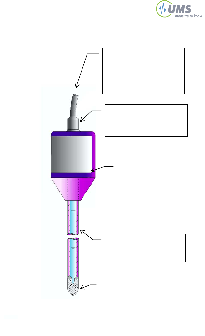
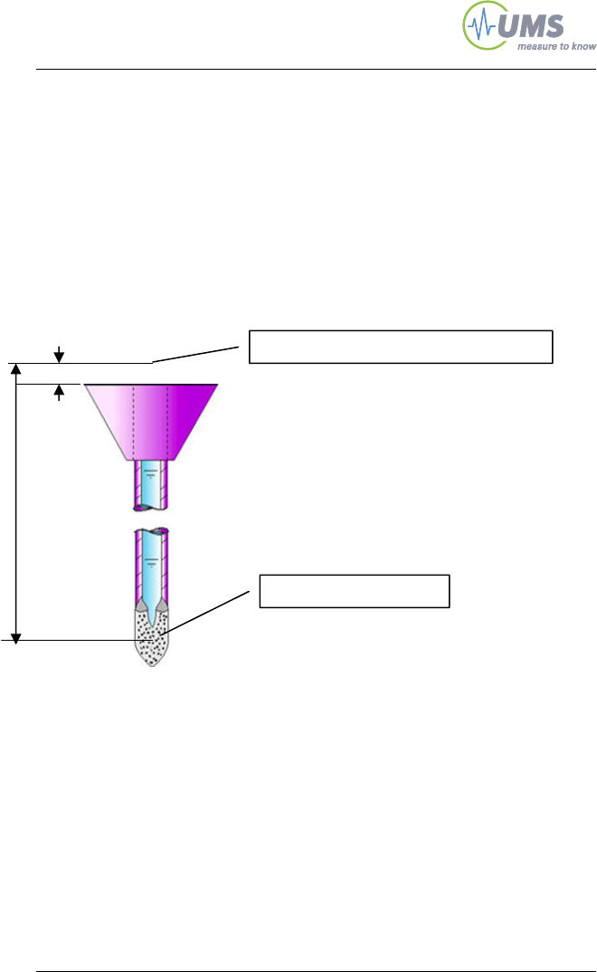
Reference air pressure
The reference atmospheric air
pressure is conducted to the
pressure transducer via the air
permeable (white) Teflon
membrane and through the
cable.
Sealed cable
The T5 can be completely buried
if required. If buried cables
should be protected
Sensor body
The incorporated piezoelectric
pressure sensor measures the
soil water tension against
atmospheric pressure.
Acrylic glass shaft
Shafts are available with
lengths from 2 to 20 cm
High grade porous ceramic cup
Filled with degassed water.

Sensor description
12/48
2 Sensor description
2.1 Design
2.1.1 Body and shaft
The sensor body is made of acrylic glass and incorporates the
pressure transducer and all electronic parts. The corpus is backfilled
with resin to hermetically seal the electronics and make the body
watertight.
2.1.2 Pressure transducer
The piezoelectric pressure sensor measures the soil water tension
against the atmospheric pressure. The atmospheric pressure is
conducted through a watertight diaphragm (the white, 2 cm long tube
on the cable) and through the cable to the reference side of the
pressure sensor.
The non destructive maximum pressure is 3 bar (300 kPa).
Higher pressure will damage the sensor and absolutely must be
avoided! High pressures can appear for example when cup and
sensor are reassembled, when inserted in wet, clayey soils or in
tri-axial vessels.
2.1.3 Reference air pressure
The reference atmospheric air pressure is conducted to the pressure
transducer via the air permeable (white) Teflon membrane and
through the cable. The membrane does not absorb water. Water will
not pass through the membrane into the cable, but moisture inside
the cable will leave the cable through the membrane.
The white membrane on the cable must always have contact to air
during a measurement and should never be submersed into water.
Sensor description
13/48
2.1.4 The ceramic tip
To transfer the soil water tension as a negative pressure into the
Tensiometer, a semi-permeable diaphragm is required. This must
have good mechanical stability and water-permeability, but also have
gas impermeability.
The Tensiometer cup consists of porous ceramic Al2O3 sinter
material. The special manufacturing process guarantees
homogeneous porosity with good water conductivity and very high
firmness. Compared to conventional porous ceramic the cup is much
more durable.
The bubble point of a T5 cup is about 200 kPa, of a T5x about 500
kPa. If the soil gets dryer than this air passes through so the
negative pressure inside the cup decreases and the readings go
down to 0 kPa.
With these characteristics this material has outstanding suitability to
work as the semi permeable diaphragm for Tensiometers.
Ceramic cup: Do not touch the cup with your fingers. Grease,
sweat or soap residues will influence the ceramic's hydrophilic
performance.
Do not allow the T5 ceramic to dry out by leaving it unprotected in
air: By drying out the bubble point might be reached, the reading
will go to 0 kPa and air might enter the cup which requires a
refilling.
2.2 Analog output signals
The pressure transducer offers the soil water tension as a linear
output signal, with 1 mV corresponding to 1 kPa.
As the pressure transducer is a Wheatstone full bridge, it has to be
connected in a certain mode. Please read chapter 3.5.3 and the
manual of your display unit or data-logger before connection.

14/48
3 Installation
3.1 Scientific measure ideas
3.1.1 Selecting the measuring site
The installation spot should be representative for the soil which
should be surveyed. For selection it might be necessary to take soil
samples. If the column is refilled care should be taken to achieve the
best possible homogenous distribution and evenly compaction. Bear
in mind a possible shrinking of backfilled columns when T5 are
installed through the cylinder.
On tillage sites (with plants) root spreading and growth during the
measuring period should be considered. Fine roots might develop
around the ceramic cup as it is a poor but assured water source.
Avoid the root zone if possible or replace the Tensiometer from time
to time.
3.1.2 Number of Tensiometers per level
The lower the level the less the variations of water potentials are. In
sandy or pebbly profundities one Tensiometer per depth is sufficient.
Close to the surface about 3 Tensiometers per level are
recommendable.
Guiding principle: More heterogeneous sites and soil structures
require a higher number of Tensiometers.
3.1.3 Extension of the site
Large distance along with high equidistance between the measuring
spots will reduce the influence of sectional heterogeneity.
To determine the water flow according to Darcy two Tensiometers
per horizon or required, one each in an upper and lower level of this
horizon.
Max. recommendable cable lengths for T5 and T5x are 20 meters:
Accuracy: long cables cause a reduction of the accuracy.
Lightning: cables act as antennas and should always be as short
as possible.

Installation
15/48
3.1.4 Ideal conditions for installation
For the installation of Tensiometers, the ideal conditions are:
Frost-free soil.
Wet coarse clay or loess.
Low skeletal structure (gravel).
3.1.5 Documentation
For every measuring spot you should:
measure the installation spot from 2 reference points (A must for
installations below the ground surface).
Take documenting photos before, during and after installation.
Save a soil sample.
Write down installation depth and angle with each sensor
identification (serial number).
Mark all connecting cables with the corresponding sensor
identification, serial number or logger channel on each end. Clip-
on number rings are available as an accessory.
3.1.6 Selecting the installation angle
An installation position would be ideal if the typical water flow is not
disturbed by the Tensiometer. No preferential water flow along the
shaft should be created.
If the ceramic cup is positioned higher than the sensor body the first
bubble that may appear inside the shaft will block the water
exchange and stop the Tensiometer to measure.

Installation
16/48
3.2 Installation procedure
The following tools are required for installation in the field:
An auger with diameter 5 mm, preferably the UMS
Tensiometer auger kit TBT5
Rule, spirit level, angle gauge, marker pen
Minute book and camera for documentation of site and soil
profile
Perhaps PE-plastic bags for taking soil samples from the site
1. Drill a hole with the required diameter and depth. Mark the
installation depth on both auger and T5 shaft.
2. If the hole’s diameter is larger than 5 mm mix a paste of water
and grinded soil material.
3. Connect the T5 to a readout device, for example a data logger
for continuous measurements or the INFIELD7 handheld device
for spot readings.
During the installation the Tensiometer reading has to be
controlled at any time. Especially in wet, clayey soils a high
pressure might develop while inserting the T5. A pressure of over
2 bar will destroy the pressure transducer. Stop or slow down the
insertion to allow pressure relieve.
4. If you use a slurry paste pour it into the hole.
5. Pull off the water filled rubber cap from the shaft. Do not turn the
cap as this might unscrew the shaft.
6. Gently and steadily insert the T5 down to the mark while
checking the reading.
Never turn the T5 inside the borehole as this might loosen the
shaft.
The less air is inside the cup and the better the soil's conductivity
is, the faster the Tensiometer will respond to tension changes.
7. Put the protection cup on the plug whenever the plug is not
connected. Dirt will reduce the water tightness of the plug.
Remember to put the protective cap back on the plug after taking
spot readings with the INFIELD7.
Installation
17/48
8. Connect the signal cables as described in the chapter
"Connecting the T5 or T5x".
9. Write down the serial number, position, installation angle and
depth.
10. Protect the cables against rodent bites. Lead the cables through
plastic pipes or use the plastic protection tubes which are
available as an accessory.
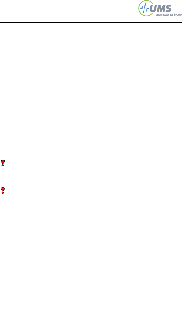
3.3 Offset correction for non horizontal installations
The pressure transducer is calibrated without
a cup. Thus, no compensation is required for
horizontal installations.
If a T5 or T5x is installed in a non horizontal
position, the vertical water column draws on
the pressure sensor and causes an offset
shift.
Compensate the offset:
by calculation,
by entering the installation angle in the Infield7 for spot readings,
in the configuration of a data logger by setting an offset.
The deviation is largest for a vertical water column (at 0o). The water
column drawing on the pressure transducer is equal to the shaft
length, ranging from 2 to 20 cm. The offset is shifted for 0,1 kPa per
cm shaft length.
Example: A 5 cm vertical column of water below the pressure
sensor will create an 0.5 kPa offset. This means that when the soil
water tension is 0 kPa the sensor will indicate -0.5 kPa.
(1 cm water column corresponds to a pressure of -0,983 hPa.)
3 mm Centre of
p
ressure transduce
r
Centre of ceramic
Installation
3.4 Connecting T5 and T5x
3.4.1 Spot readings with the INFIELD7
T5 and T5x are fitted with a 4-pin plug. The plug can be connected
directly to an INFIELD7 handheld measuring device for taking spot
readings of the soil water tension. The INFIELD7 displays and stores
the soil water tension readings. Stored readings can be downloaded
with the USB converters tL-8/USB or tL-8/USB-Mini which are
available as accessory.
Remember to put the protective cap back on the plug after taking
spot readings with the INFIELD7.
3.4.2 Cables
Connecting and extension cables are required for connecting T5 and
T5x to a data logger or other data acquisition device. Find cables in
the chapter “Accessories”.
Cover plugs with the supplied protective cap if not connected.
3.4.3 General requirements
The pressure transducer is a non-amplified bridge circuit which is
calibrated for 10.6 VDC and requires a stabilized power supply.
Other supply voltages are possible, but the output signal range has
to be recalculated.
In a full-bridge the signal must be measured differentially. This
means do not measure only signal plus against common ground, but
measure the voltage drop between signal minus against common
ground and signal plus against common ground.
The supply voltage has to be constant and stabilized.
The supply voltage must not exceed 18 VDC.
If the Tensiometer is not permanently powered the warm-up
before a measurement should be at least 10 seconds. The 99%
value is reached after 1/100 seconds.
If the Tensiometer is supplied with 10.6 VDC the output signal
range is around 5.3 VDC. A data logger must have the capability
18/48

19/48
to measure such a signal level, but many loggers cannot do this.
In this case use a TV-batt power supply.
3.4.4 TV-batt Tensiometer power supply
The TV-batt power supply is specially designed for Tensiometers T3,
T4, T4e and T5. It offers a stabilized 10,6 V power supply, but with
supply minus = -5 V and supply plus = +5,6 V. Therefore the output
signal will have a logger specific signal level. The Tensiometer
signals are in a range of <1 V.
The TV-batt is directly supplied by battery or 12 V mains power.
3.4.5 Connection to a data logger
Some logger types can measure bridge circuits directly, other
loggers require certain measures as the Tensiometer signal minus
and the supply minus do not have the same ground.
3.4.6 Tensiometer loggers DL6-te or GP1-te
T5 and T5x can be connected directly and without further power
supply to the special Tensiometer loggers DL6-te or GP1-te.
The DL6-te is a stand-alone 6-channel logger with six 4-pin sockets.
All Tensiometer with 4-pin plug are connected to the DL6-te with
extension cables EC-4/...
The GP1-te is a stand-alone 2-channel logger with cable glands. All
Tensiometer with 4-pin plug are connected to the GP1-te with
connection cables CC-4/...

Service and maintenance
20/48
4 Service and maintenance
4.1 Refilling
To assure a rapid and reliable measurement of the soil water
tension, the cup must be filled possibly bubble-free with degassed
water. After dry periods or periods with a large number of wet and
drying out successions, Tensiometers must be refilled.
Refilling is the easiest with the refilling tools included in the T5-set or
T5-case. A readout device, for example the INFIELD7, is always
needed to control the signal.
4.1.1 When do Tensiometers need to be refilled?
Tensiometers need to be refilled:
the curve of the readings apparently gets flatter (for example a
rain event has no sharp peak but is round),
the maximum of -85 kPa is not reached anymore.
Refilling is only reasonable if the soil is moister than -90 kPa.
If the soil gets dryer than -85 kPa, the readings will remain constant
at the vapour pressure of water (i. e. for example 92,7 kPa at 20°C
and atmospheric pressure of 95 kPa). By diffusion and slight leakage
the reading will slowly drop within months.
If the soil dries out and reaches the bubble point (-200 kPa for T5;
-500 kPa forT5x), the tension will decrease rapidly as air will enter
the cup.
4.1.2 Refilling T5 in lab and field
This chapter describes the refilling of T5 or T5x using the T5-set.
The procedure has 5 steps:
1. Check the T5 Tensiometer
2. Degas cup and shaft
3. Degas sensor
4. Reassemble
Service and maintenance
21/48
5. Function test
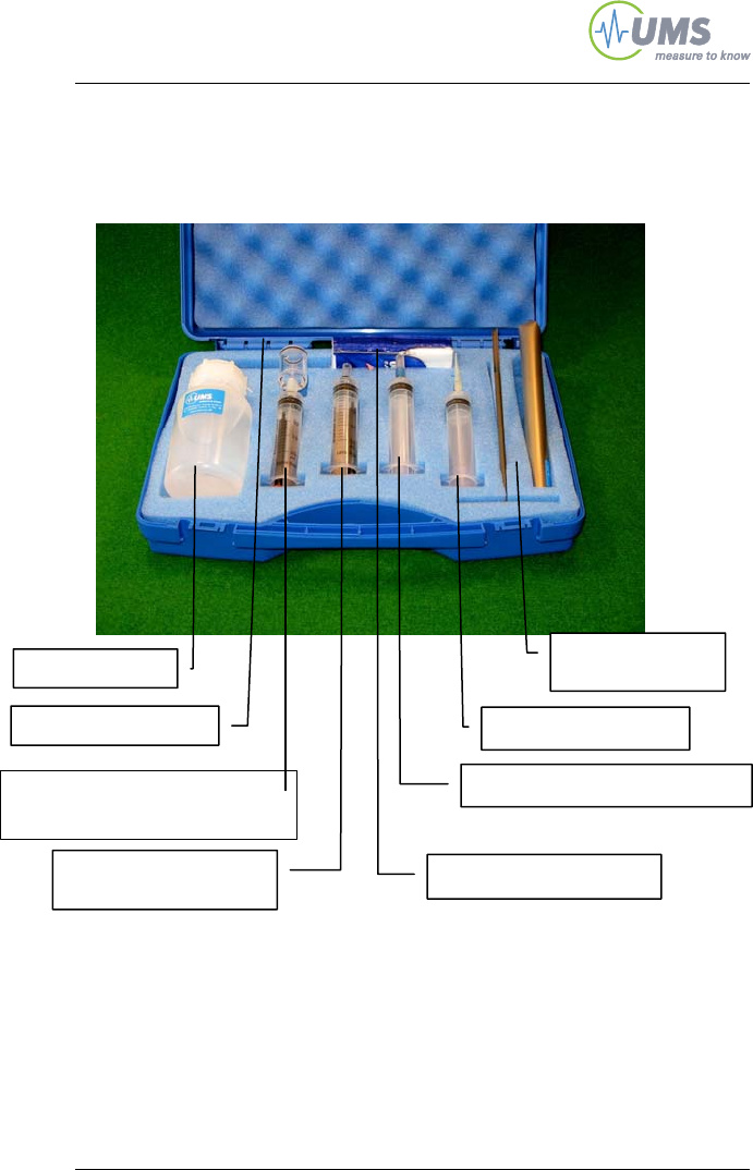
The T5-set includes:
Vacuum syringe with pressure
transducer adapter
Deionised water
Vacuum syringe
for the cup
Filling syringe for the shaft
Drop syringe
Shaft auger &
body auger
Pack of paper tissues
Capillary tube
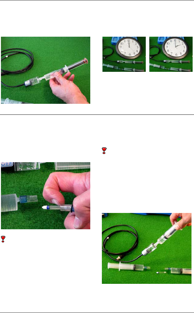
Service and maintenance
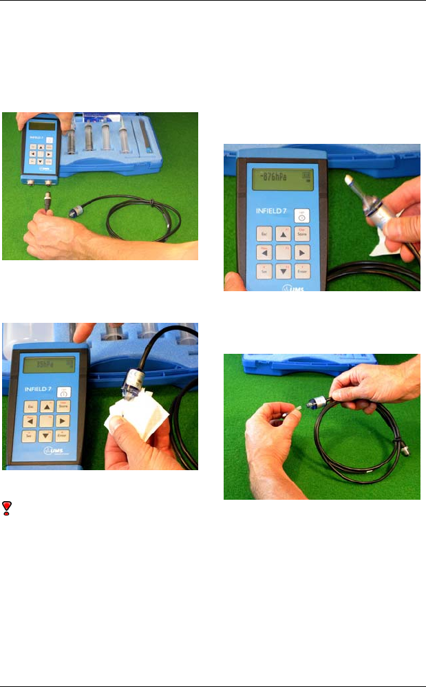
Check the T5
1. First, check if the T5 requires
a refilling: connect it to an
Infield7 or a voltmeter and
power supply.
2. Wrap a dry paper towel
(kitchen roll) around the cup to
dry the ceramic surface.
With short shaft lengths cover
the ceramic with a paper
towel to avoid contamination.
3. Now wave the T5 tip around
in the air. If the reading will rise
to -80 kPa within 10 seconds the
T5 filling is ok.
If this is not the case the T5
needs to be refilled.
4. To disassemble the shaft hold
the sensor body and turn off the
shaft counter-clockwise.
22/48
Service and maintenance
23/48
The pressure sensor diaphragm is inside the small hole on the
pressure sensor body (approx. 2 mm). It is very sensitive and
must never be touched! It can be destroyed even by slightest
contact! No contamination should get on the sealing and gasket.
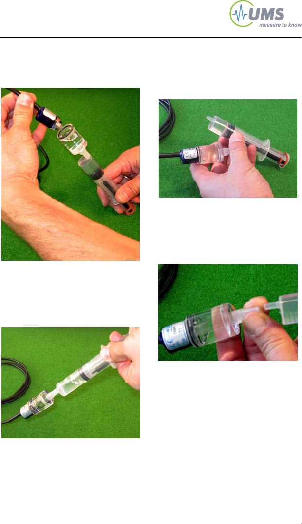
Degas the cup
If the cup is completely dry just put the shaft in a beaker with
deionised or distilled water over night.
Do not fill any water inside the shaft! If water intrudes from inside
and outside bubbles are trapped inside the ceramic pores. But if
the water only intrudes from the outside and soaks into the inside
any air bubbles are pushed out.
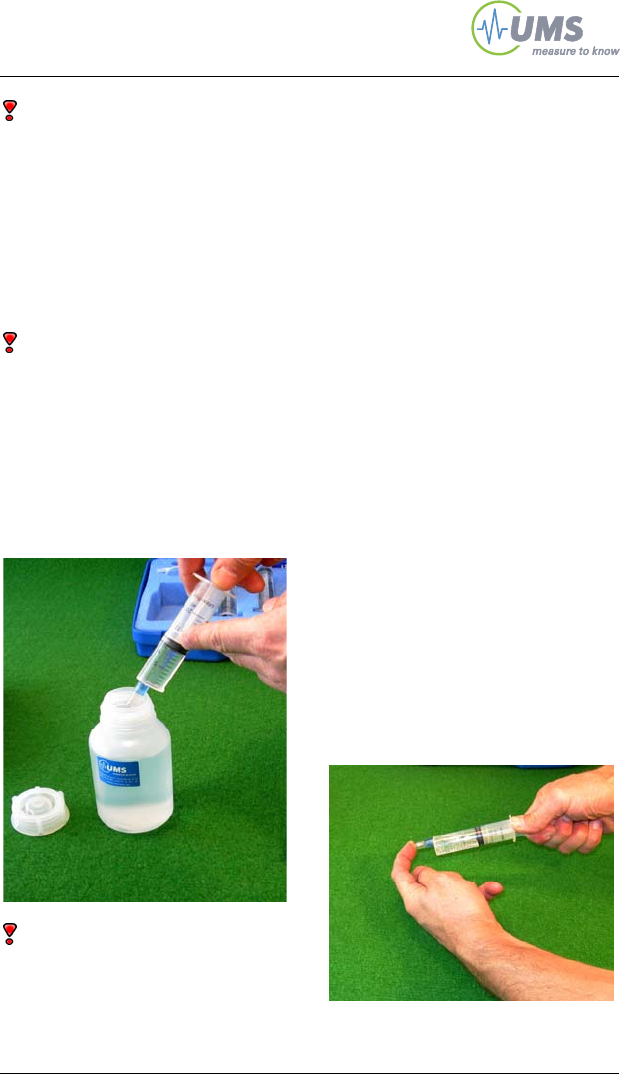
1. Take the syringe with the
short rubber tube.
Pull up 10 ml of deionised or
distilled water.
Take care to avoid bubbles.
2. Remove all air from the
syringe.
Now block the tube with your
finger and pull up the syringe.
This creates vacuum inside the
syringe and dissolved gas is
released. Turn the still
evacuated syringe to collect all
bubbles. Hold the syringe
upright, unblock the tube and
remove all air. Repeat this
procedure until no bubbles
appear anymore.
Service and maintenance
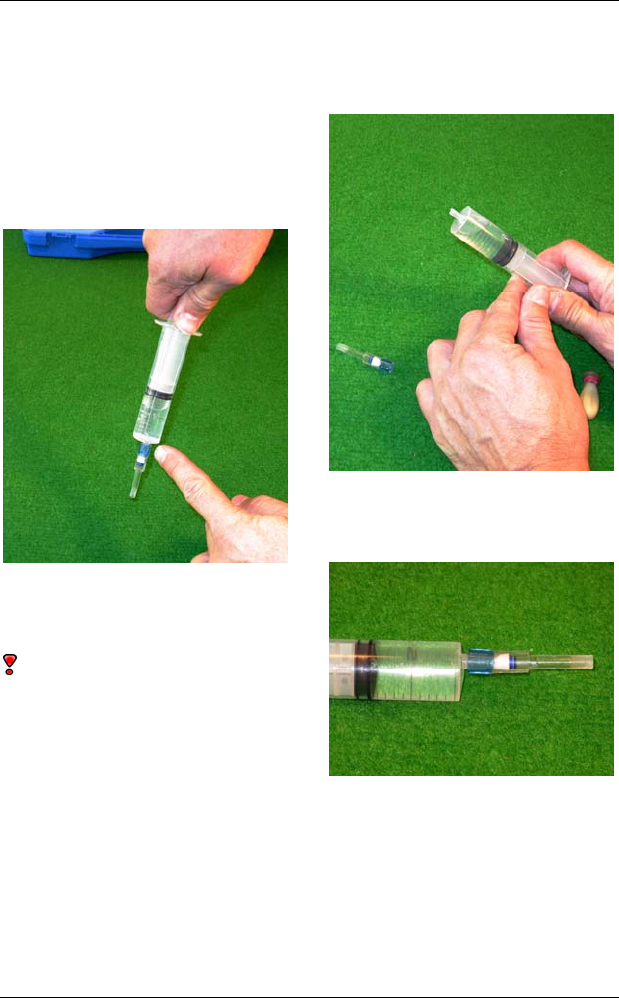
3. Insert the ceramic cup into
the tube as far as possible with
the ceramic pointing inside.
The cup’s tip should be close to
the syringe nozzle.
Pull up the syringe just a little
bit.Hold the syringe down-wards
and tap on it to loosen all
bubbles.
There should be no air inside
the tube around the ceramic. In
case fill in some water with the
syringe.
4. Take off the tube from the
syringe. Leave the shaft inside
the tube.
Remove all air from the syringe
5. Put the tube back on the
syringe.
24/48
Service and maintenance
25/48
6. Now take the vacuum
syringe with the 2 black spacers
and the O-ring on the tube.
Pull up 10 ml water.
7. Degas the water as
described above.
8. Now insert the threaded side
of the T5 shaft completely into
the tube.
Roll up the O-ring so the shaft is
securely fixed: the O-ring should
not be in the range of the thread
but beyond the end of the
thread.
Be careful to keep the parts
clean so there will be no leaking
when vacuum is applied
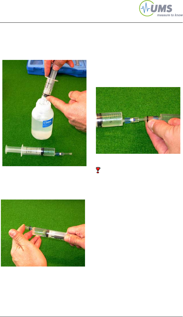
9. Now pull up the syringe until
both spacers snap in.
Turn the syringe to collect all
bubbles, but do not tap on the
syringe!
Release the spacers and allow
water to flow into the shaft.
Carefully remove the tube from
the syringe nozzle and remove
all air from the syringe (see 6).
Service and maintenance
There should be no air inside the
tube before inserting the shaft
again.
In case fill in some drops of
water into the tube with the
syringe.
Reattach the syringe and pull it
up until the spacers snap in.
Leave the syringes on the shaft.
Degas the sensor body
1. Now take the syringe with the
attached sensor body adapter.
Pull up the syringe, but not
further than shortly before the
spacers will snap in.
2. Hold the syringe upwards
and remove all air.
26/48
Service and maintenance
27/48
3. Insert the sensor body. If you
rotate the sensor it will slip in
easier.
4. Pull up the syringe a few
times. Hold the syringe
downwards so bubbles are
collected inside the syringe.
5. Take off the tube and remove
the air from the syringe.
Leave the sensor inside the
adapter.
6. Squeeze the tube to remove
any air inside while reattaching
the syringe.
Service and maintenance
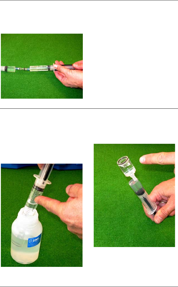
6. Pull up the syringe until the
spacers snap in.
The Tensiometer water now is
degassing.
Leave both syringe assemblies
for at least 2 hours (the longer
the better).
Reassembling
1. Take of the tubes from the
shaft.
Taking off the syringe from the
sensor body needs care to avoid
damage of the pressure
transducer!
The piston must not snap in
as this might damage the
pressure transducer!
2. Hold the syringe and the
syringe piston securely. Bear in
mind there is still vacuum inside.
Press in the spacers and slowly
release the piston.
28/48
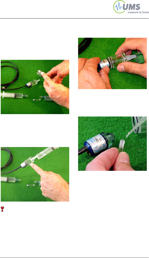
Service and maintenance
29/48
3. Now remove the last
remaining bubbles: draw up the
syringe once more and release
it slowly.
Now take off the syringe and
remove the bubble inside.
3. Reattach the sensor body
and draw up the syringe again.
Tap on the sensor body to
release any bubble.
Let the piston release slowly.
5. Now remove the sensor
body.
6. Add one drop of water onto
the shaft so a bulge of water
overlaps the shaft ...
Service and maintenance
7. … and carefully screw in the
shaft into the senor body.
8. Continuously check the
pressure with the INFIELD7: the
pressure must not exceed 1 bar
You will clearly notice the point
when the shaft hits the o-ring
inside the sensor body.
From this point do only another
quarter turn!
30/48
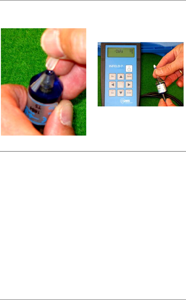
Service and maintenance
31/48
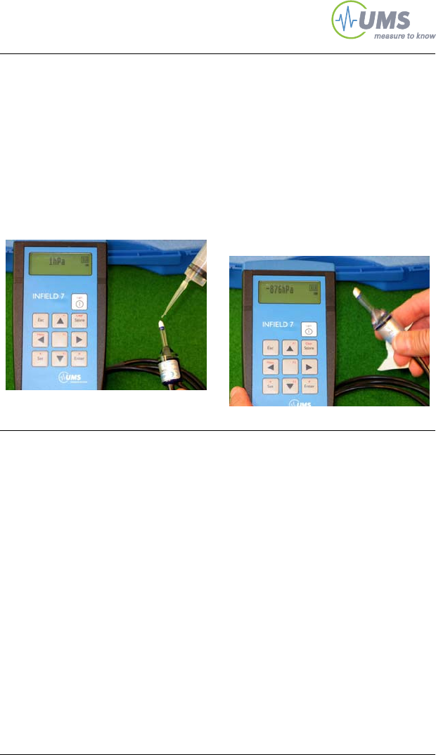
Check the T5
Zero offset:
Place the T5 flat on the table.
Put a drop of water on the cera-
mic cup.
Now the potential is zero and
the reading should be between
- 3 hPa and + 3 hPa (= -0.3 kPa
to +0.3 kPa).
Check the response:
Open the bottle with the water.
Dry the ceramic surface with a
clean tissue.
Then wave the cup in the air.
The reading should rise to -80
kPa within 10 seconds.
If this is the case, the T5 is filled
perfectly.
To find out the maximum measuring range of this T5 hold the
ceramic tip in the headspace of the bottle over the water.
When you move the ceramic away from the water surface the air
gets dryer and the suction rises.
Hold the ceramic as close to the water surface so the tension
reading will rise slowly. Depending on the filling quality the value will
reach -85 to -450 kPa. Then, the value will rapidly drop to the vapour
pressure (around -90 kPa depending on the altitude). Then,
immediately put some water on the ceramic and cover the ceramic
with the protective bulb which should be filled with water to the half. It
will take one day until the Tensiometer will reach its initial value.

Service and maintenance
32/48
4.2 Testing
4.2.1 Calibration
When delivered Tensiometers are calibrated with an offset of 0 kPa
(when in horizontal position) and a linear response. The offset of the
pressure transducer has a minimal drift over the years. Therefore,
we recommend you check sensors once a year and re-calibrate
them every two years.
Return the Tensiometers to UMS for recalibration, or use the
calibration accessories available from UMS.
4.2.2 Check the Offset
If there is no pressure difference between the cup interior and the
surrounding the signal should be 0 kPa.
There are two ways to check the offset.
1. Connect the Tensiometer to a readout device. Place the T5 in a
beaker and fill the beaker with de-ionized water up to the centre of
the sensor body (see 3.4.) Wait until the reading is stable. If there
are bubbles inside the cup this might take a while.
Now the reading is the approximate offset. The value should be
between +0.3 and -0.3 kPa.
2. To check the zero-point more precisely shaft and sensor body
need to be disassembled.
The pressure sensor diaphragm is inside the small hole on the
pressure sensor body. It is very sensitive and must never be
touched! It can be destroyed even by slightest contact! No
contamination should get on the sealing and gasket.
Before reassembling cup and sensor body carry out the degassing
procedure (see chapter "Refilling").
After taking off the shaft shake the pressure sensor to remove water
from the pressure transducer hole. The offset is acceptable when the
reading is between -0.3 and +0.3 kPa.

Protecting the measuring site
33/48
4.3 Cleaning
Clean ceramic and sensor body only with a moist towel. If the
ceramic is clogged it may be flushed it with Rehalon®.
If the pores are clogged with clay particles saturate the ceramic and
then polish the ceramic surface with a wetted, waterproof sandpaper
(grain size 150...240).
4.4 Storage
If the T5/T5x should not be used for a year or more then empty shaft
and sensor body to avoid algae growth. Store both in a dry place.
5 Protecting the measuring site
5.1 Theft and vandalism
The site should be protected against theft and vandalism as well as
against any farming or field work. Therefore, the site should be
fenced and signposts could give information about the purpose of the
site.
5.2 Cable protection
Outdoors cables should be protected against rodents with plastic
protection tubes. UMS offers dividable protection tubes as
accessory.
In the lab the cables should be fixed so they are not accidentally
pulled away and that there is no risk of stumbling.
5.3 Frost
Tensiometers are filled with water and are endangered by frost. T5
and T5x should only be use in frost-free surroundings.
Do not store filled Tensiometer at temperatures below 0°C. Do not
leave filled Tensiometers over night in your car, in a measuring
hut, etc.
Do not fill the Tensiometers with Ethanol, as this is corrosive for
some materials (i. e. PMMA) and will destroy these.

Useful notes
34/48
6 Useful notes
6.1 Extended measuring range
The extent of the measuring range of a Tensiometer is influenced by
3 factors:
1. The bubble point
2. The vapour pressure (boiling point)
3. The boiling retardation
6.1.1 The bubble point of the porous cup
The bubble point of a porous, hydrophilic structure is specified by the
wetting angle and the pore size. The cups used for UMS
Tensiometers have a bubble point far beyond the measuring range
(8.8 bar). Therefore, the bubble point has no limiting influence.
6.1.2 The vapour pressure of water
At a temperature of 20°C the vapour pressure of water is 2.3 kPa
against vacuum. With an atmospheric pressure of 100 kPa and at
20°C the water will start to boil, or vaporize, as soon as the pressure
drops below 2.3 kPa against vacuum, i. e. 97.7 kPa pressure
difference to an atmospheric pressure of 100 kPa - the Tensiometer
drops out.
The measuring range (at 100 kPa/20°C) is limited to -97.7 kPa.
Atmospheric pressures announced by meteorological services are
always related to sea level. Thus, the true pressure in a height of 500
meters over sea level is for example only 94.2 kPa although 100 kPa
are announced. Then, the measuring range at this height (at 20°C) is
even limited to -91.9 kPa.
If the soil gets drier than the maximum possible measuring range the
reading will remain at this value and then drop gradually towards
zero. If the soil gets as dry as the bubble point a spontaneous
equalisation with the atmospheric pressure occurs. Air enters the cup
and the reading will rapidly go to zero.

Useful notes
35/48
True pressure in heights over sea level at an atmospheric
pressure related to sea level as published by meteorological
services
Height over sea
level (meter) Atmospheric
pressure (kPa) Max. measuring
range at 20°C (kPa)
0 101.3 -99.0
500 95.5 -93.2
1000 89.9 - 87.6
1500 84.6 - 82.3
2000 79.5 -77.2
2500 74.5 -72.2
3000 70.1 -67.8
6.1.3 Boiling retardation:
Water needs a nucleation site to boil. As our Tensiometers have
polished surfaces and a gas-free filling the so called boiling
retardation occurs – the Tensiometer keeps on measuring beyond
the boiling point. To achieve this the T5(x) must have an absolutely
bubble free filling.
Some T5x can go down to -250 kPa before they run dry, occasionally
even a range of -450 kPa is achievable. As this is exceptional there
is no guarantee for this measuring range.
Useful notes
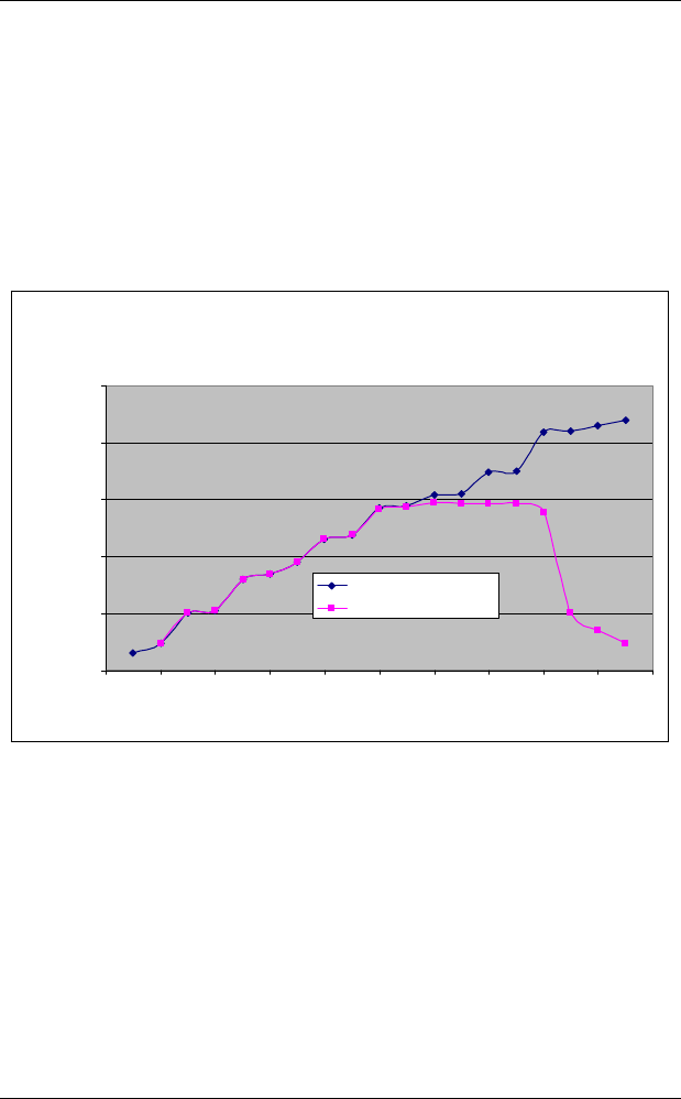
6.2 Maximum measuring range and data
interpretation
The measuring range of Tensiometers is limited by the boiling point
of water. At a temperature of 20°C the boiling point is at 2,3 kPa over
vacuum. So with 20°C and an atmospheric pressure of 95 kPa the
Tensiometer cannot measure a tension below -92,7 kPa, even if the
soils gets drier than that. The readings remain at a constant value
(fig. 7.1, between day 10 and 16).
Interpretation Messwerte bis über 15 bar nahe der
Bodenoberfläche
1
10
100
1000
10000
100000
0246810121416182
Zeit
Wasserspannung
0
Bodenwasserspannung
Tensiometermesswert
Interpretation of readings to -2 bars
Soil water tension
Tensiometer reading
Matrix potential negative (hPa)
Time
Fig. 7.1: Tensiometer readings with tensions to -2 bar
If the soil will get even drier and reaches -2 bar, the ceramic’s bubble
point is reached. The cup water will run out quickly and the reading
of the air filled cup will go to zero (fig. 7.1, day 16-19)
36/48
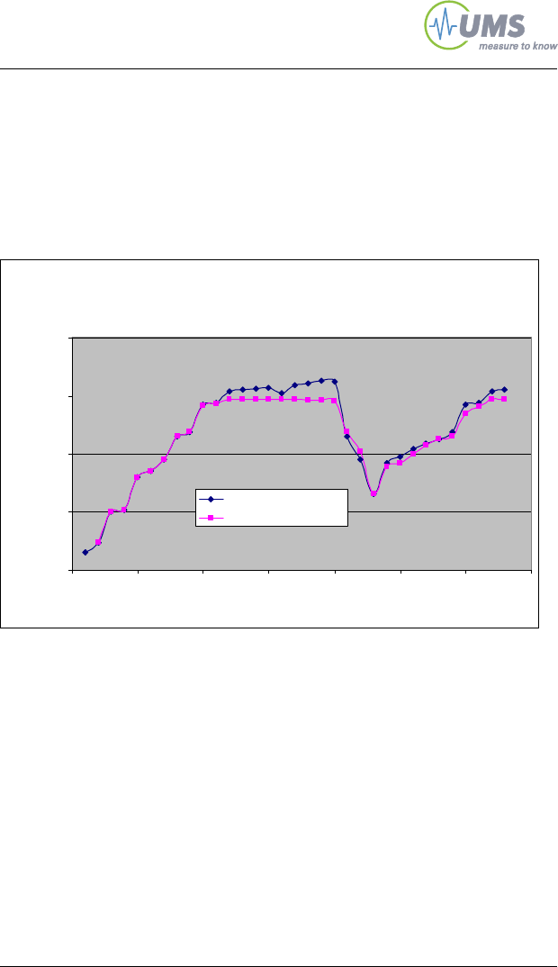
Useful notes
If there will be rain before the soils reaches -2 bars, the Tensiometer
cup will suck up the soil water. However, the soil water includes
dissolved gas which will degas as soon as a dry soil again will
increase the tension. This will result in a poor response, the signal
curve will get flatter and readings will only slowly adapt to the actual
soil water tension. Depending on the size of the developed bubble
readings will get less close to the maximum (fig. 7.2).
37/48
Interpretation Messwerte unter 2 bar
1
10
100
1000
10000
0 5 10 15 20 25 30 35
i
Matrixpotential negativ
Ze t
Bodenwasserspannung
Tensiometermesswert
Interpretation of readings below -2 bars
Matrix potential negative (hPa)
Soil water tension
Tensiometer reading
Time
Fig. 7.2 Tensiometer readings with tensions below -2 bar
Soil water tensions normally change only slowly. Therefore, a signal
curve with lot of jumps could be an indicator for example for loose
contacts, moisture in defective cables or plugs, poor power supply or
data logger malfunctions.

Useful notes
6.3 Temperature influences during measurements
If the sensor is not powered continuously the voltage should be
switched on 10 seconds before a measurement. In this case, the self
heating is negligible.
The correlation of water tension to water content is temperature
dependent. The influence is low at tensions of 0 to 10 kPa 0 …
0,6 kPa/K, but high for tensions over 100 kPa:
oM
TR ln
= Water tension R = Gas constant (8,31J/mol K)
M = Molecular weight p = Vapour pressure
po = Saturation vapour pressure at soil temperature
(from Scheffler/Straub, Grigull)
6.4 Vapour pressure influence on pF/WC
If the temperature of a soil with a constant water content rises from
20°C to 25°C the soil water tension is reduced for about 0,85 kPa
due to the increased vapour pressure which antagonizes the water
tension.
Temperature
in °C 4 10 16 20 25 30 50 70
Pressure
change per
Kelvin in [hPa] 0,6 0,9 1,2 1,5 1,9 2,5 7,2 14
38/48

Troubleshooting
39/48
6.5 Osmotic effect
The ceramic has a pore size of r = 0,3 m and therefore cannot block
ions. Thus, an influence of osmosis on the measurements is
negligible because ion concentration differences are equalized
quickly. If the T5 cup is dipped into a saturated NaCl solution the
reading will be 1 kPa for a short moment, then it will drop to 0 kPa
again.
7 Troubleshooting
Please refer to our webpage where you will find a regularly up-dated
list of FAQs:
http://www.ums-muc.de/en/support/faq/tensiometer.html

Appendix
40/48
8 Appendix
8.1 Technical specifications
Material and dimensions
Ceramic material
Bubble point T5
Bubble point T5x
Ceramic cup
Sensor body
Shaft material
Al2O3 sinter
> 200 kPa
> 500 kPa
Length 6 mm, 5 mm
PMMA, 20 mm
Impact-proof PMMA, 20 mm
Sensor cable
Length
Plug 1.5 m
Male 4-pin, thread M12, IP67
Measuring range
T5
T5x
Water tension
Water level
-85 kPa ... +100 kPa
min. -160 kPa ... +100 kPa
-85 kPa (-160 kPa) … 0 kPa (Tensiometer)
0 kPa … +100 kPa (Piezometer)
Output signal
Pressure 160 mV = -160 kPa (T5x)
85 mV = -85 kPa (T5)
0 mV = 0 kPa
-100 mV = 100 kPa (water level)
Accuracy ±0,5 kPa
Power supply
Supply voltage Vin typ. 10,6 VDC by TV-batt (recommended)
5 ... 15 VDC, stabilized
Current consumption 1,3 mA at 10,6 V (TV-batt)
Substance sustainability
pH range pH 3 ... pH 10
Limited to substances that do not harm silicon, flour silicon, EPDM,
PMMA and polyetherimid.
Appendix
41/48
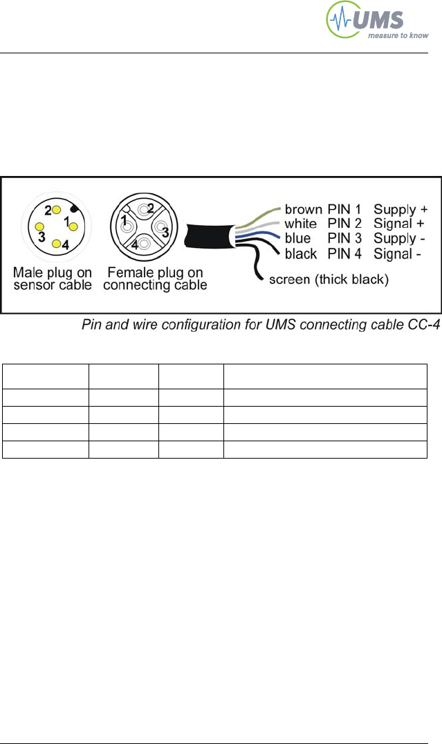
8.2 Wiring configuration
Configuration of T5 and T5x Tensiometer plug and
the 4-wire CC-4 connecting cables:
Signal Wire Pin Function
Vin brown 1 Supply plus
V- blue 3 Supply minus
A-OUT+ white 2 Analog output plus
A-OUT- black 4 Analog output minus
Appendix
42/48
8.3 Accessories
8.3.1 Connecting and extension cables
Cables must be ordered additionally for each Tensiometer.
UMS connecting or extension cables for data logger applications etc.
Connecting cables CC-8/... are fitted with a female plug M12/IP67
and 12 cm wire end sleeves.
Extension cables EC-8/... have one each male and female plug
M12/IP67.
Plugs are supplied with protective caps.
Item Art. no.
4-pin connection cable for T5 and t5x
Length 1,5 m CC-4/1.5
Length 5 m CC-4/5
Length 10 m CC-4/10
Length 20 m CC-4/20
4-pin extension cable for T5 and T5x
Length 5 m EC-4/5
Length 10 m EC-4/10
Length 20 m EC-4/20
Additional items Art. no.
Clip-on cable markers, 30 times numbers 0 ... 9 KMT
Plastic protection tube for cables are available with several diameters, also
dividable slotted tubes for easy re-fitting.
Appendix
43/48
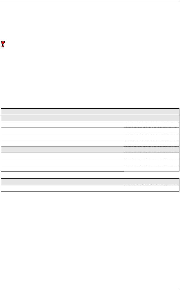
8.3.2 Handheld measuring device
INFIELD7 handheld measuring device for taking and
storing spot readings of soil water tension. Offset
correction of water column and installation angle.
Suitable for all UMS - Tensiometers. The set comes
with refilling tools in small carrying case.
The tL-8/USB-Mini is a USB converter for data
readout of the INFIELD7 via PC or laptop USB port,
incl. Windows PC software tensioVIEW.
Item Art. no.
INFIELD7 set INFIELD7C
USB PC adapter for Infield only tL-8/USB-Mini
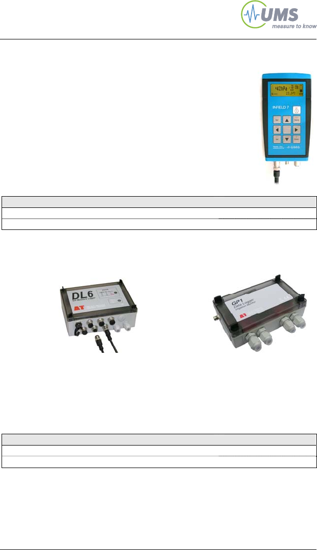
8.3.3 Tensiometer loggers
6-channel logger DL6-te for Tensio-
meters T3, T4, T4e, T5 plus 1x counter,
1x temperature, alarm output, 16.000
readings memory, IP68, 4-pin sockets
for extension cables EC-4
Data logger GP1-te with
channels for 2x Tensio-
meters, 2x temperature, 2
counters, 1 relay output,
IP67
Item Art. no.
6-channel logger, incl. software and data cable DL6-te
2-channel logger, incl. software and data cable GP1-te
Appendix
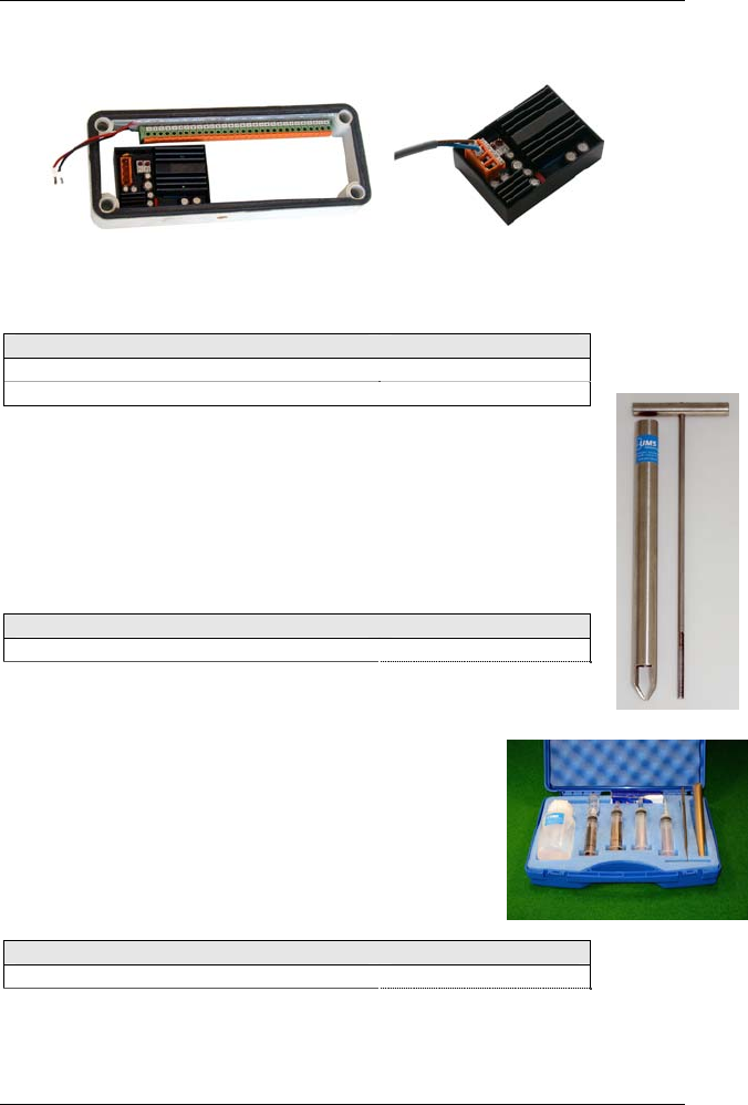
8.3.4 TV-batt power supply
Tensiometer power supply unit for T3, T4, T5, suited in DL2e-logger
extension frame (left), or as an open module (right).
Item Art. no.
TV-batt for DL2e logger TV-Batt/DL2e
TV-batt module only TV-Batt/module
8.3.5 T5 auger kit
Auger kit for T5, with shaft auger, length 250 mm length
and sensor body auger, length 200 mm.
Item Art. no.
T5-auger kit TBT5
8.3.6 T5-case
Service kit for t5 and T5x (without a T5!), incl.
refilling tools (syringes etc.), auger kit,
connecting cable CC-4/1.5, all in blue case 35 x
30 x 8 cm.
Item Art. no.
T5 service kit T5-case
44/48

Appendix
45/48
8.4 Units for soil water and matrix potentials
%rF
99,9993
99,9926
99,9756
99,9261
99,2638
98,8977
92,8772
47,7632
0,0618
psi
-0,1450
-1,4504
-4,9145
-12,345
-14,504
-145,04
-219,52
-1.450,4
-14.504
-145.038
bar
-0,01
-0,1
-0,33
-0,85
-1
-10
-15
-100
-1.000
-10.000
MPa
-0,001
-0,01
-0,033
-0,085
-0,1
-1,0
-1,5
-10
-100
-1.000
kPa = J/kg
-1
-10
-33
-85,1
-100
-1.000
-1.500
-10.000
-100.000
-1.000.000
Cm WS
9,8
98,1
323,6
834,5
980,7
9806,6
14709,9
98.066,5
980.665
9.806.650
hPa
-10
-100
-330
-851
-1.000
-10.000
-15.000
-100.000
-1.000.000
-10.000.000
pF
1
2,01
2,53
2,93
3
4
4,18
5
6
FK field
capacity
Standard
Tensiometer
range
Permanent
wilting point
Air dry, air
humidity
dependant
oven dry

Appendix
46/48
8.5 Index
A
Auger ..................................43
B
Boiling point ........................35
Bubble point..................13, 35
C
Cable protection..................34
Calibration...........................33
Ceramic ..............................13
Compensate the offset........17
Connecting cables ..18, 40, 41
D
Data logger .........................19
Degas the cup.....................23
Degas the sensor body.......27
Destructive pressure.............4
E
Extension cables.................41
F
Frost................................4, 34
G
Gas impermeability.............13
Guarantee.............................6
I
Installation procedure ...10, 16
L
Laboratory lysimeters ...........7
Lightning ...............................4
Long cables ..........................4
M
Maximum pressure .............12
O
Offset ..................................33
Osmosis..............................38
Output signals.....................13
P
Plug.....................................40
Porous ceramic...................13
Pots.......................................7
Pressure sensor..................12

Appendix
47/48
Q
Quartz clay............................9
R
Reassembling.....................29
Reference air pressure .......12
Refilling...............................20
S
Slurry.....................................9
Soil columns .........................7
Spot readings......................18
T
T5-set .................................21
Temperature .......................37
TV-batt ..........................19, 43
Typical applications ..............8
V
Vapour pressure .................37
W
White membrane ................12
Z
Zero offset...........................31

Your addressee at UMS
48/48
Your addressee at UMS
Sales Georg v. Unold Tel:+49-89-126652-15
Email: gvu@ums-muc.de
About this manual Thomas Keller Tel:+49-89-126652-19
Email: tk@ums-muc.de
UMS GmbH
Ph.: +49-89-126652-0
D-81379 München
Gmunderstr. 37 Fax: +49-89-126652-20
email: info@ums-muc.de
Strictly observe rules for disposal of equipment
containing electronics.
Within the EU: disposal through municipal waste
prohibited - return electronic parts back to UMS.
Rücknahme nach Elektro G
WEEE-Reg.-Nr. DE 69093488
