TASP55
User Manual: TASP55
Open the PDF directly: View PDF ![]() .
.
Page Count: 20
1
AEP Model
UK Model
E Model
SPECIFICATIONS
SERVICE MANUAL
MICRO Hi-Fi COMPONENT SYSTEM
TA-SP55
TA-SP55 is the amplifier section
in CMT-SP55MD or CMT-SP55TC.
European model:
DIN power output (Rated): 25 + 25 watts (8 ohms at 1 kHz,
DIN, 230 V)
Continuous RMS power output (Reference):
30 + 30 watts (8 ohms at 1 kHz,
10% THD, 230 V)
Music power output (Reference):
75 + 75 watts
General
Power requirements
European model: 230 V AC, 50/60 Hz
Other models: 110 – 120 V or 220 – 240 V
AC, 50/60 Hz
Power consumption 70 watts
Dimensions (w/h/d)
Mass Approx.
Approx. 202 x 101 x 306 mm
3.9 kg
Design and specifications are subject to change
without notice.
Other models:
DIN power output (Rated): 25 + 25 watts (8 ohms at 1 kHz,
DIN, 240 V)
22 + 22 watts (8 ohms at 1 kHz,
DIN, 220 V)
Continuous RMS power output (Reference):
30 + 30 watts (8 ohms at 1 kHz,
10% THD, 240 V)
28 + 28 watts (8 ohms at 1 kHz,
10% THD, 220 V)
Output
PHONES (stereo phono jack):
accepts headphones of 8 ohms or
more.
2
SAFETY-RELATED COMPONENT WARNING !!
COMPONENTS IDENTIFIED BY MARK 0 OR DOTTED LINE
WITH MARK 0 ON THE SCHEMATIC DIAGRAMS AND IN
THE PARTS LIST ARE CRITICAL TO SAFE OPERATION.
REPLACE THESE COMPONENTS WITH SONY PARTS
WHOSE PART NUMBERS APPEAR AS SHOWN IN THIS
MANUAL OR IN SUPPLEMENTS PUBLISHED BY SONY.
TABLE OF CONTENTS
1. SERVICE NOTE ............................................................... 3
2. GENERAL ......................................................................... 4
3. DISASSEMBLY
3-1. Case ..................................................................................... 5
3-2. Front Panel Assy ................................................................... 5
3-3. HP Board, Panel Board ......................................................... 6
4. DIAGRAMS
4-1. Block Diagram ...................................................................... 9
4-2. Printed Wiring Board – Main Section –.............................. 10
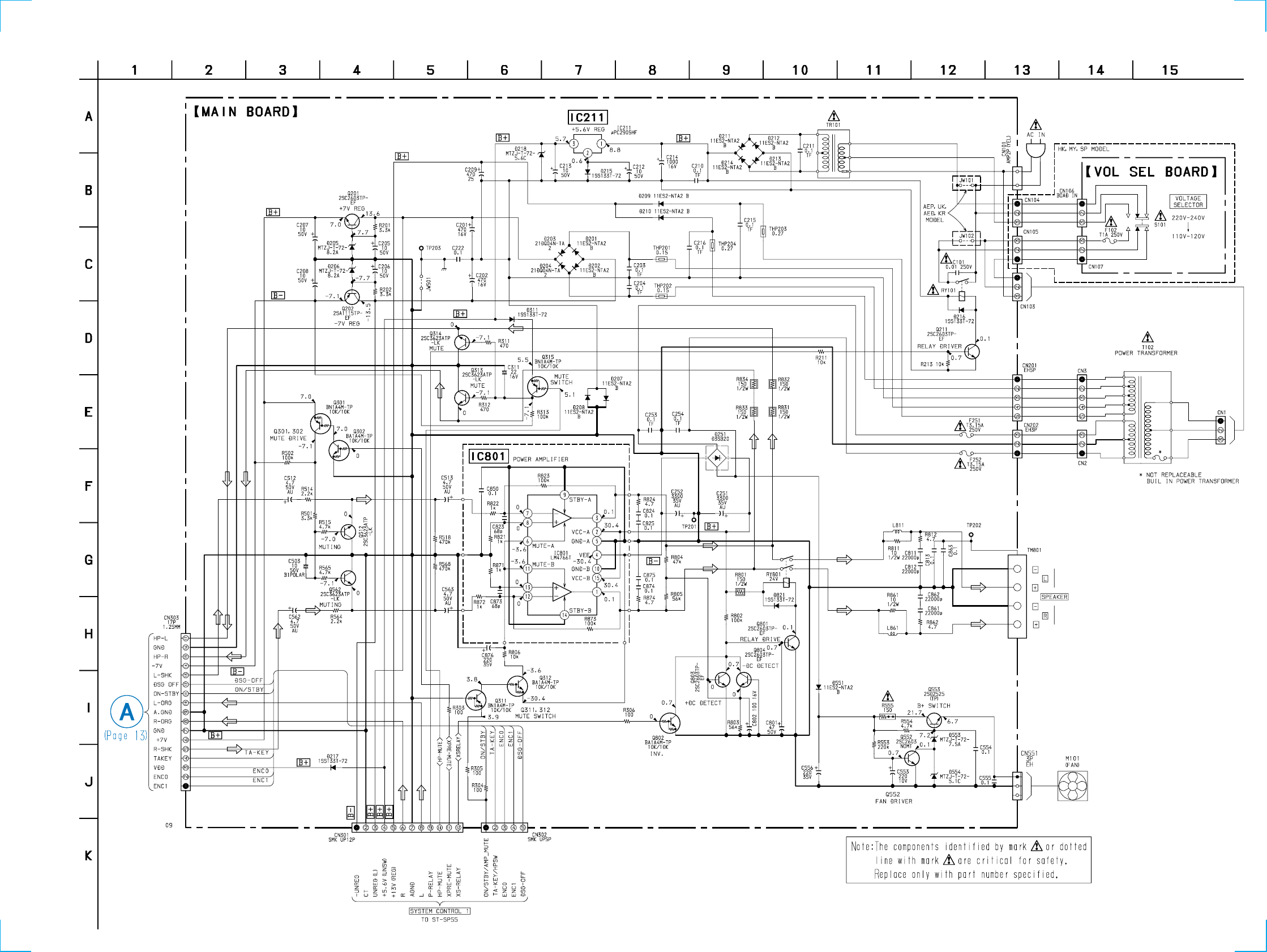
4-3. Schematic Diagram – Main Section –................................ 11
4-4. Printed Wiring Board – Panel Section –............................. 12
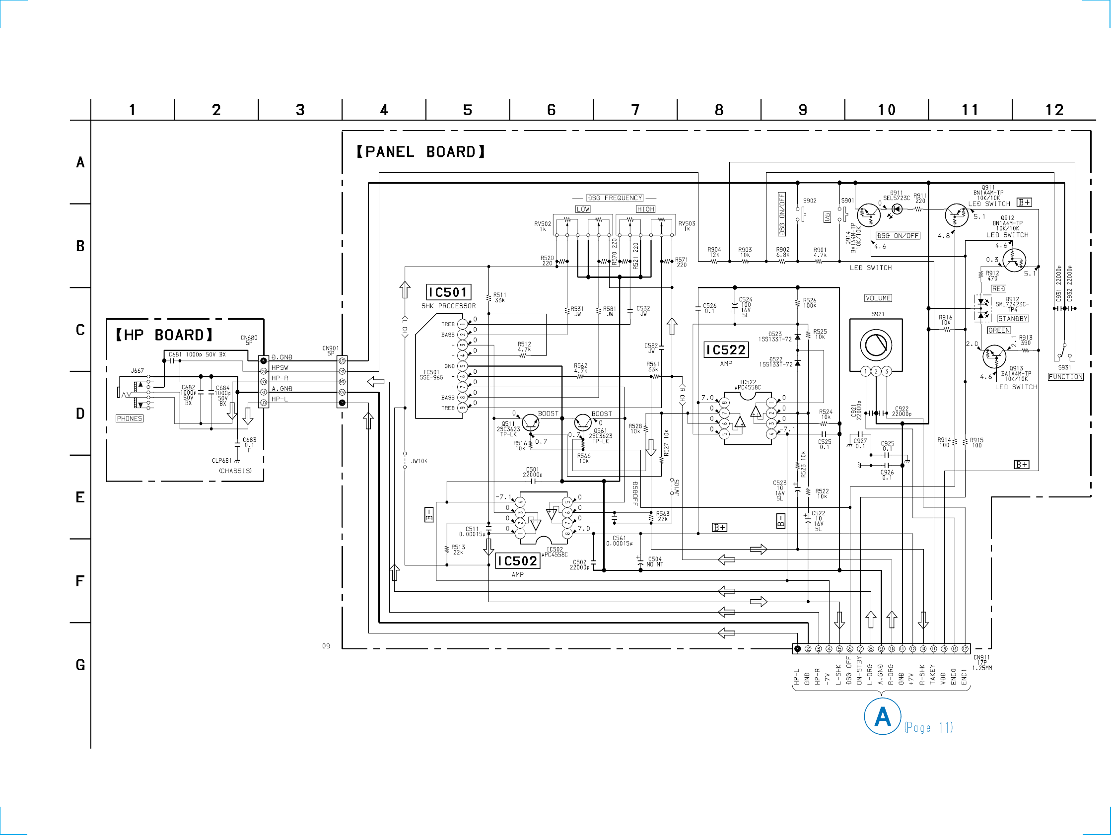
4-5. Schematic Diagram – Panel Section –................................ 13
4-6. Printed Wiring Board – VOLSEL Section –....................... 14
5. EXPLODED VIEWS
5-1. Case and Front Panel .......................................................... 15
6. ELECTRICAL PARTS LIST ........................................ 16
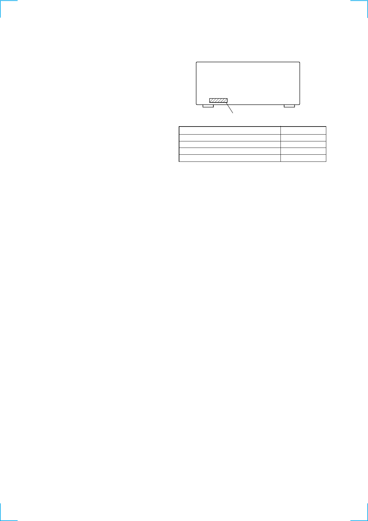
MODEL IDENTIFICATION
MODEL PARTS No.
AEP, AED, UK model 4-229-700-0s
MY, SP model 4-229-700-2s
HK model 4-229-700-3s
KR model 4-229-700-4s
•Abbreviation
AED : North European model
MY : Malaysia model
SP : Singapore model
HK : Hong Kong model
KR : Korea model
Parts No.

3
CD Text Display
• This unit displays CD text.
Text is displayed for the first 50 track only and will not be displayed from the 51st track onwards. Do not suspect a fault in this case.
In some cases, some special characters will not be displayed and may be replaced by other characters. Do not suspect a fault in this case.
Cold Reset
• The cold reset clears all data including preset data stored in the RAM to initial conditions. Execute this mode when returning the set to the
customer.
Procedure :
1. When the power ON, press the ?/1 button (TA) while pressing the TUNING MODE button (ST) and ML buttons (CDP) together.
2. “COLD RESET” is displayed on the fluorescent indicator tube and reset is executed.
Hot Reset
• This mode reset the preset data kept in the memory. The hot reset mode functions same as if the power cord is plugged in and out.
Procedure :
1. When the power ON, press the ?/1 button (TA) while pressing the TUNING MODE button (ST) and lm buttons (CDP) together.
2. Turn off the unit and reset is executed.
GC Test Mode
Procedure :
1. When the power ON, press the ?/1 button (TA) while pressing the TUNING MODE button (ST) and PLAY MODE buttons (CDP)
together.
2. Fluorescent indicator tube are all turned on.
3. Press TUNING MODE button (ST) to enter the model destination indecation mode. “SP55 CE2” appears.
4. Every pressing of TUNING MODE button (ST) changes the display in the following order.
MC Version t CD Version t ST Version t TC Version t TA Version t TM Version t model destination display.
5. Press DISPLAY button (ST) and the date appears as “ 00615a ”
Every pressing of DISPLAY button (ST) changes the display in the Version display and model destination display.
6. Press TUNER/BAND button (ST) to enter the key check mode.
7. In the key check mode, the fluorescent indicator tube displays “Key 0 Vol 0”. Each time a button is pressed, “Key” value increases.
However, once a button is pressed, it is no longer taken into account.
“Vol” Value increases like “1, 2, 3 ...” if rotating VOLUME knob (TA) in the clockwise direction, or decreases like “0, 9, 8 ...” if rotating
in the counterclockwise diretion.
8. To exit from this mode, press three buttons in the same procedure as step 1, or disconnect the power cord.
SECTION 1
SERVICING NOTE
MC Test Mode
Procedure :
1. When the power ON, press the ?/1 button (TA) while pressing TUNING MODE button (ST) and REPEAT button (CDP) together.
2. Frame of the MD mark and the CD mark flash, and “BASS/TRE FLAT” appears for a moment.
3. When the VOLUME knob (TA) is turned clockwise, “VOLUME MAX” appears for a moment.
4. When the VOLUME knob (TA) is turned counterclockwise, “VOLUME MIN” appears for a moment.
5. Select the function “TAPE” using the FUNCTION knob (TA).
Set the test tape AMS-110A or AMS-120.
6. Press DIRECTION button (TC) to enter either “j” (loop) or “h” (two way).
7. Press the CD SYNC REC button (TC) to start the AMS test.
8. Number of AMS signals is counted during the AMS test and the message “EDG#” (# means a number) appears. When the test tape
either AMS-110A or AMS-120 is used, the AMS signal is detected twice before shut off.
9. When the AMS test ends, either “OK” or “NG” appears.
10. To exit the MC test mode, either press the ?/1 button (TA)or perform the cold reset as described above.
(FWD) REW (Shut off)
(FWD) FF AMS
(FWD) REW AMS
END
(Shut off)
(Shut off)
This unit cannot be repaired by itself.
When repairing, connect the whole system except for the speaker.
4
SECTION 2
GENERAL
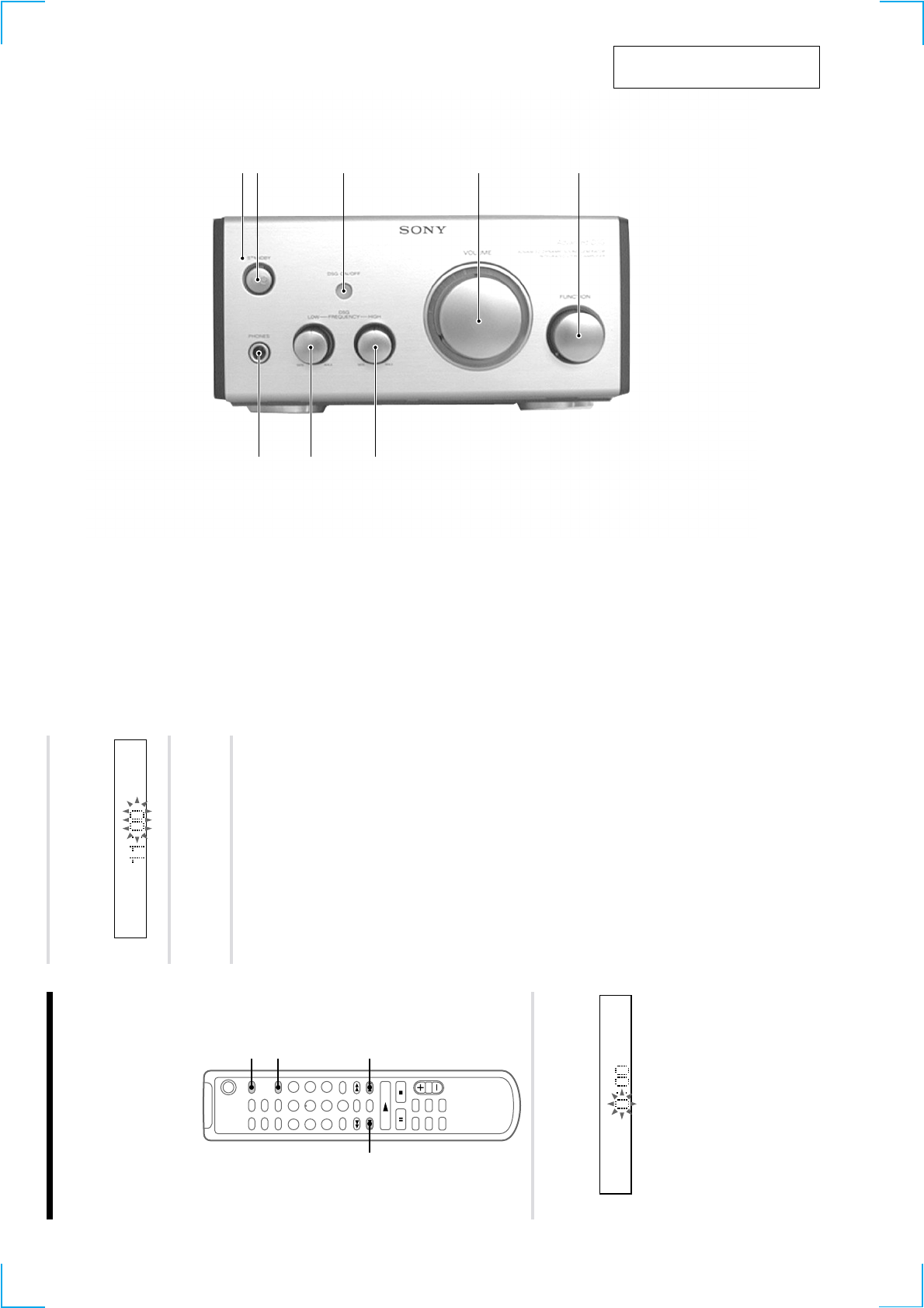
12 3 4 5
87 6
FRONT PANEL
This section is extracted from
instruction manual.
8
Step 2: Setting the time
You must set the time beforehand to use the timer
functions.
The clock is on a 24-hour system for the European
model, and a 12-hour system for other models.
The 24-hour system is used for illustration
purposes.
Set the time before turning on the system.
`/1
1
2,3
2,32,3
1Press CLOCK/TIMER SET while the
system is off.
The hour indication flashes.
2
Press . or > to set the hour, then
press ENTER/YES.
The minute indication flashes.
3
Press . or > to set the minute,
then press ENTER/YES.
The clock starts.
If you made a mistake
Start over from step 1.
To change the preset time
You can change the preset time while the system
is on.
1Press CLOCK/TIMER SET.
2Press . or > repeatedly until “SET
CLOCK” appears, then press ENTER/YES.
3Repeat steps 2 and 3.
Tips
•The built-in clock shows the time in the display
while the system is off. If you press DISPLAY at
this time, the display back light lights up, making
the clock easier to see.
•The upper dot of the colon flashes for the first 30
seconds, and the lower dot flashes for the last 30
seconds of each minute.
1STANDBY indicator
2@/1 button
3DSG ON/OFF button and indicator
4VOLUME knob
5FUNCTION knob
6DSG FREQUENCY HIGH knob
7DSG FREQUENCY LOW knob
8PHONES jack
5
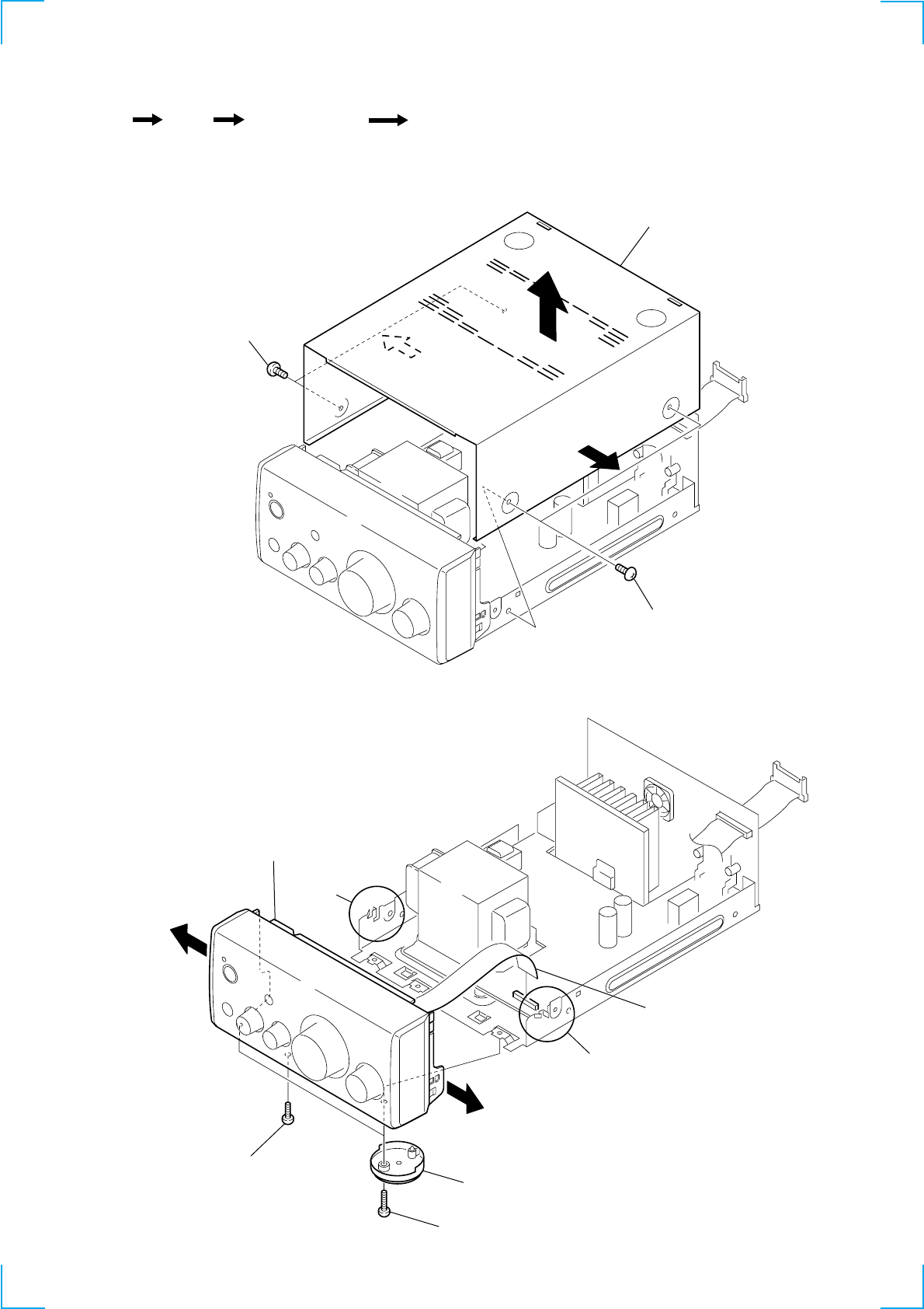
SECTION 3
DISASSEMBLY
3-1. CASE
3-2. FRONT PANEL ASSY
Set Case Front Panel Assy HP Board, Panel Board
1 two screws
(case 3 TP2)
4 case
1 two screws
(case 3 TP2) 2
2
3
1 flat type wire (17 core)
(CN303)
4 screw (BVTP 3x12)
5 front panel assy
2 two screws
(BVTP 3x12)
3 two foot assy's
claws
claws
6
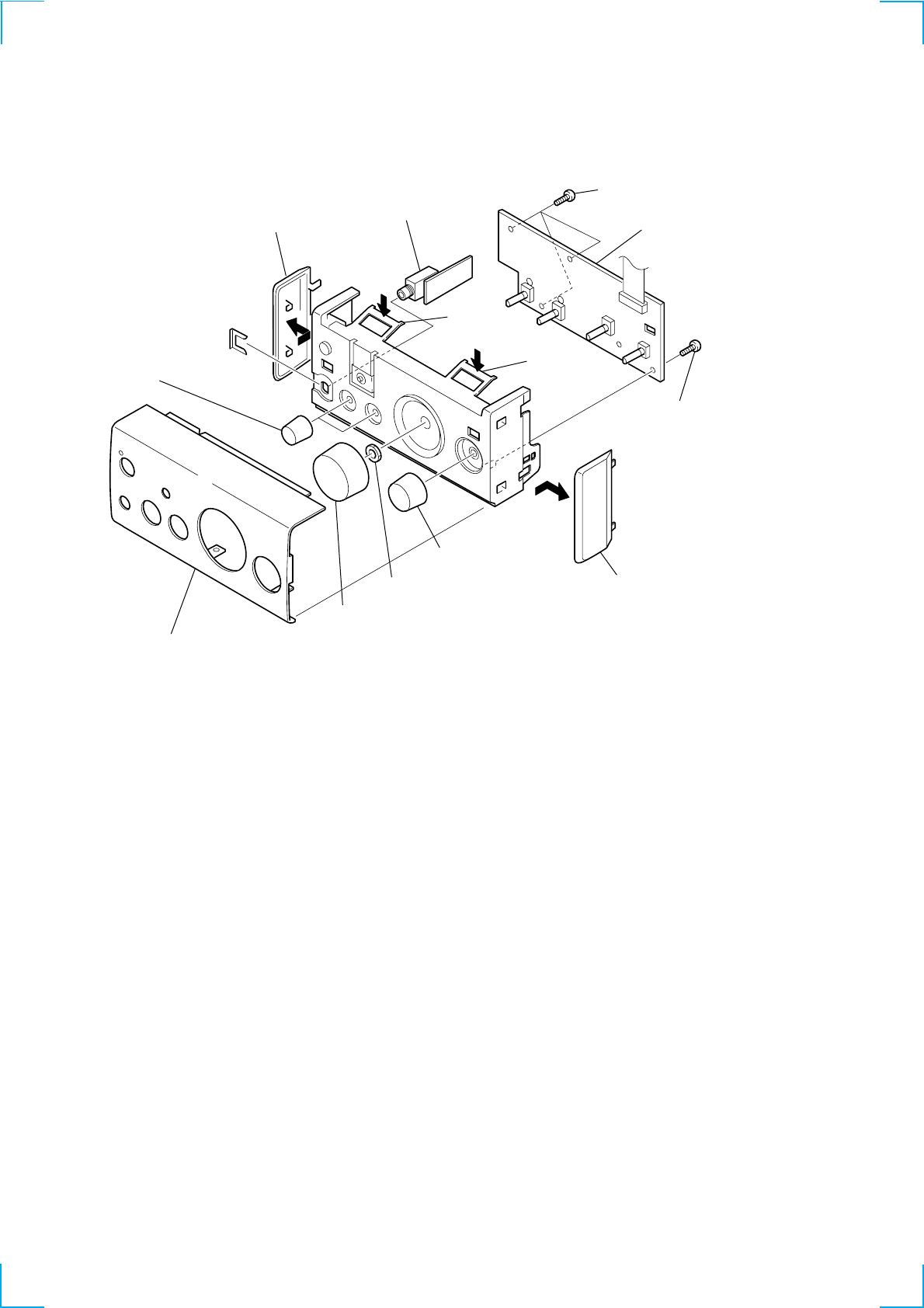
3-3. HP BOARD, PANEL BOARD
0 three screws
(BVTP 2.6x8)
qa panel board
0 screw
(BVTP 2.6x8)
1 panel (L), side 5 HP board
6 two knobs (DSG)
8 nut
7 knobs (VOL)
9 knobs (select)
3 panel (TA), front
4
1 panel (R), side
2 claw
2 claw
7
THIS NOTE IS COMMON FOR PRINTED WIRING
BOARDS AND SCHEMATIC DIAGRAMS.
(In addition to this, the necessary note is printed
in each block.)
For schematic diagrams.
Note:
• All capacitors are in µF unless otherwise noted. pF: µµF
50 WV or less are not indicated except for electrolytics
and tantalums.
• All resistors are in Ω and 1/4 W or less unless otherwise
specified.
•f: internal component.
•2: nonflammable resistor.
•5: fusible resistor.
•C: panel designation.
For printed wiring boards.
Note:
•X: parts extracted from the component side.
•Y: parts extracted from the conductor side.
•a: Through hole.
•b: Pattern from the side which enables seeing.
(The other layers' patterns are not indicated.)
•U: B+ Line.
•V: B– Line.
•H: adjustment for repair.
• Voltages and waveforms are dc with respect to ground
under no-signal (detuned) conditions.
• Voltages are taken with a VOM (Input impedance 10 MΩ).
Voltage variations may be noted due to normal produc-
tion tolerances.
• Waveforms are taken with a oscilloscope.
Voltage variations may be noted due to normal produc-
tion tolerances.
• Signal path.
K: FM
• Abbreviation
AED: North European model
MY: Malasia model
SP: Singapore model
HK: Hong Kong model
KR: Korea model
Caution:
Pattern face side: Parts on the pattern face side seen from the
(Side B) pattern face are indicated.
Parts face side: Parts on the parts face side seen from the
(Side A) parts face are indicated.
• Indication of transistor
B
These are omitted.
CE
B
These are omitted.
CE
Note:
The components identified by mark 0 or
dotted line with mark 0 are critical for
safety.
Replace only with part number specified.
SECTION 4
DIAGRAMS

8
MEMO
TA-SP55
9
9
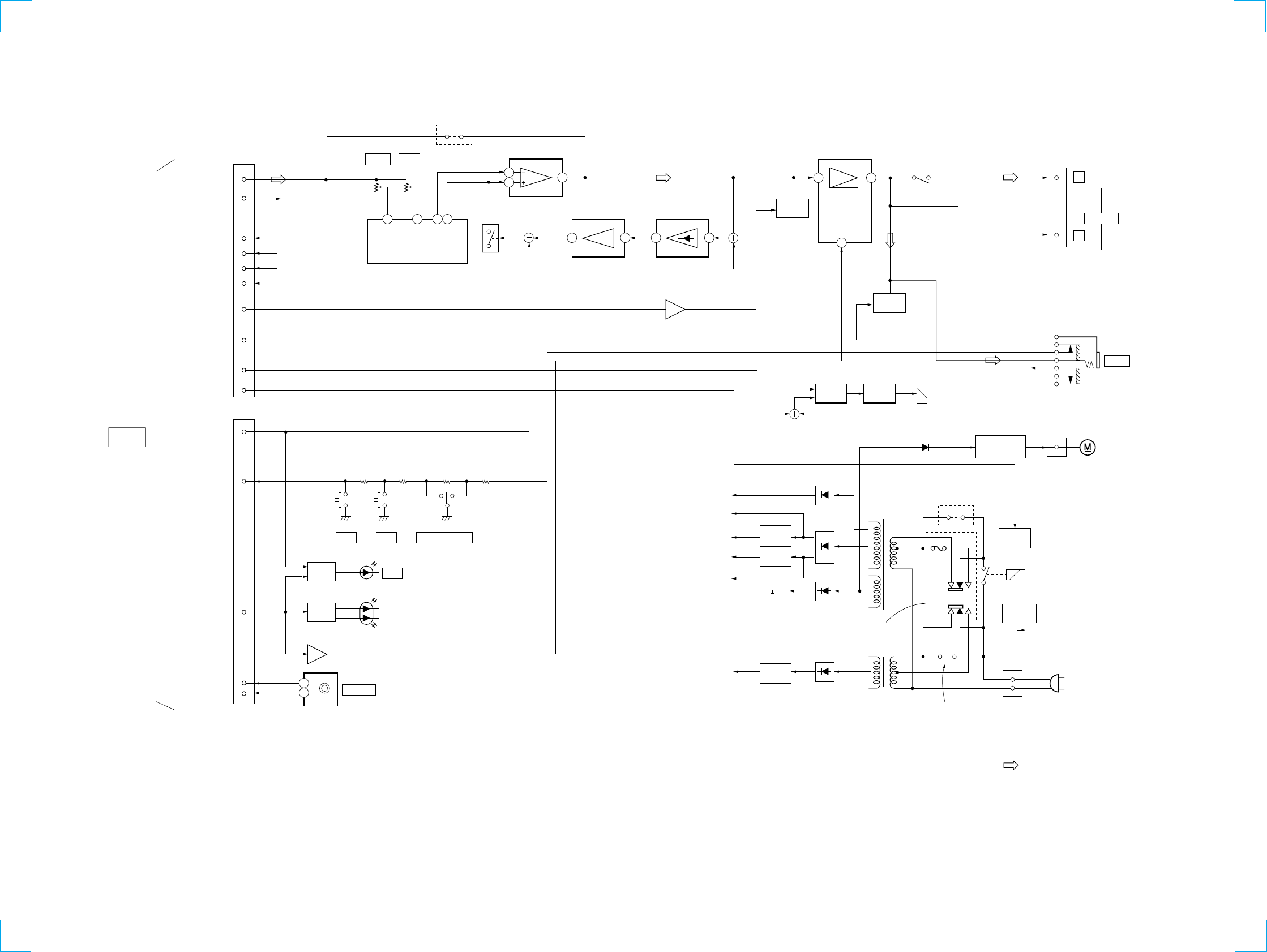
4-1. BLOCK DIAGRAM
1
3
21
2 4 3
57
1
3
21
7
6
3
DSG
DSG
STANDBY
VOLUME
FUNCTION SELECT
LED
DRIVE
LED
DRIVE
Q912,913
Q911,914
Q311,312
D911
D912
S921
MUTE
MUTE
Q552,553
Q802-804 Q801
RY801
CN551
FAN DRIVE
CN101
FAN
DC
DETECT
RELAY
DRIVE
RY101
+7V
REG.
-7V
REG.
+UNREG(H)
(+13V)
+UNREG(L)
-UNREG(L)
+7V
+5.6V
-7V
VCC
Q201
IC211
Q202
D201-204
D209-210
D251
D211-214
T102
D551
TR101
HK, MY, SP
model
(POWER AMP)
+5.6V
REG.
RELAY
DRIVE.
JW102
AEP, AED, UK, KR
model
JW104
IC502
JW101
AEP, AED, UK, KR model
Q211
AC
IN
L
L
SPEAKER
PHONE
TM801
R-CH
R-CH
R-CH
R-CH
IC801
POWER AMP
Q512
Q314
MUTE-A
IC552(2/2)
IC552(1/2)
Q301,302
BUFFER
Q516
IC501
SHK PROCESSOR
TREB
BASS
+
-
L-SHK
TREBLE
RV503 RV502
BASS
L
R
-UNREG(L)
+UNREG(L)
+5.6V(UNSW)
+13V(REG)
XPRE-MUTE
HP-MUTE
XS-RELAY
P-RELAY
DSG-OFF
TA-KEY/HPSW
ON/STBY/
AMP-MUTE
ENC0
ENC1
ENC0
ENC1
R-CH
L-ORG
-UNREG(L)
+UNREG(L)
+5.6V
+UNREG(H)
DSG OFF
TAKEY HPSW
8
6
1
3
4
5
5
2
1
3
4
11
10
12
9
CN301(1/2)
CN302
S901 S902 S931
J667
09
F102
S101 S101
VOLTAGE
SELECT
220V-240V 110V-120V
SYSTEM
CONTROL 1
TO
ST-SP55
"/1
: FM
• Signal Path
• R-ch is omitted due to same as L-ch.
TA-SP55
10
10
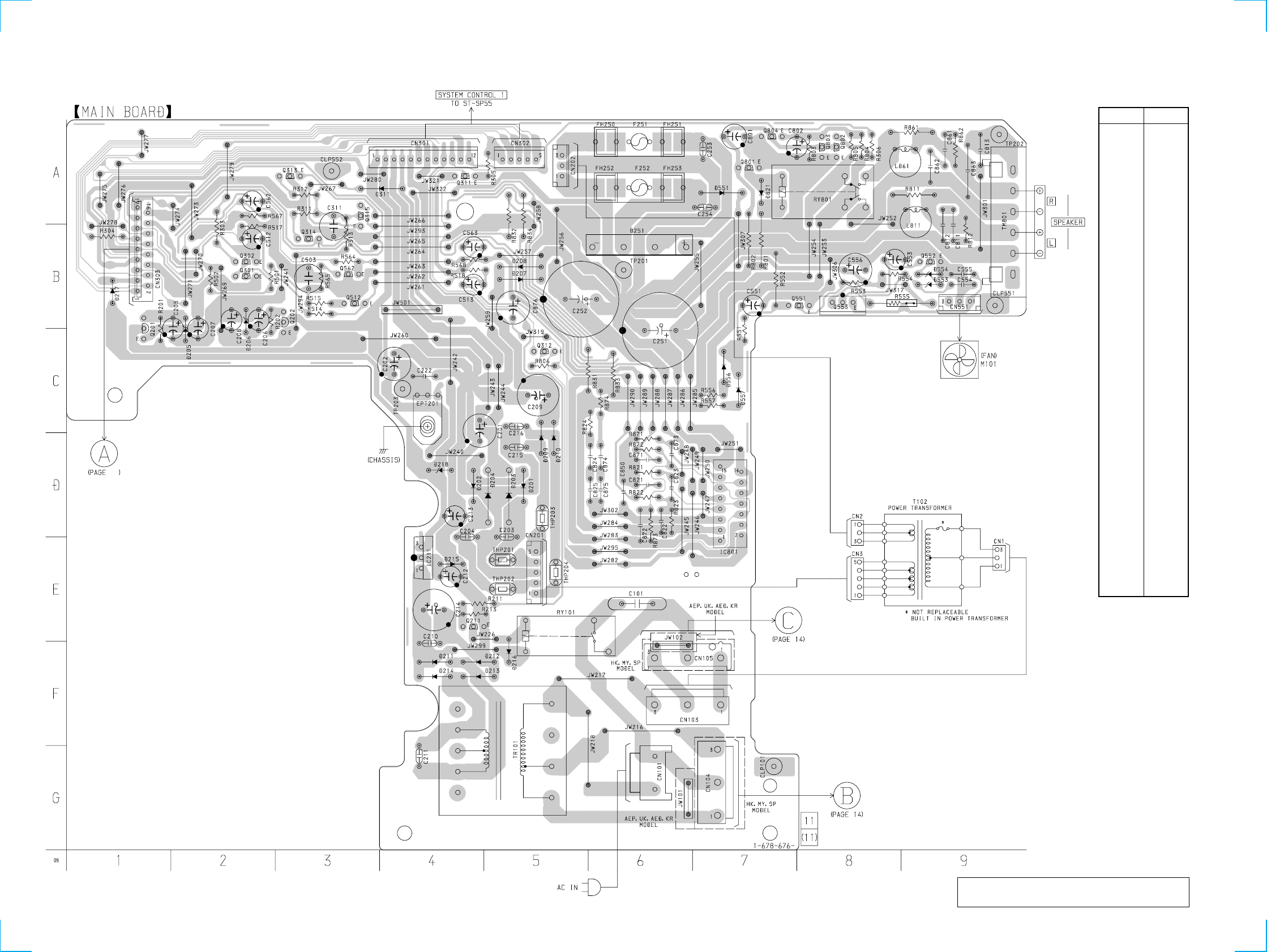
4-2. PRINTED WIRING BOARD – MAIN SECTION –
There are a few cases that the part isn't mounted
in model is printed on diagram.
Ref. No. Location
D201 D-5
D202 D-4
D203 D-5
D204 D-4
D205 C-2
D206 C-2
D207 B-5
D208 B-5
D209 D-5
D210 D-5
D211 F-4
D212 F-4
D213 F-4
D214 F-4
D215 E-4
D216 F-5
D217 B-1
D218 D-4
D251 B-6
D311 A-4
D551 A-7
D553 B-9
D554 B-9
D821 A-7
IC211 E-4
IC801 E-7
Q201 C-1
Q202 B-3
Q211 E-4
Q301 B-2
Q302 B-2
Q311 A-4
Q312 C-5
Q313 A-3
Q314 B-3
Q315 A-3
Q512 B-3
Q552 B-9
Q553 B-8
Q562 B-3
Q801 A-7
Q802 A-8
Q803 A-8
Q804 A-7
• Semiconductor
Location
12
TA-SP55
12
12
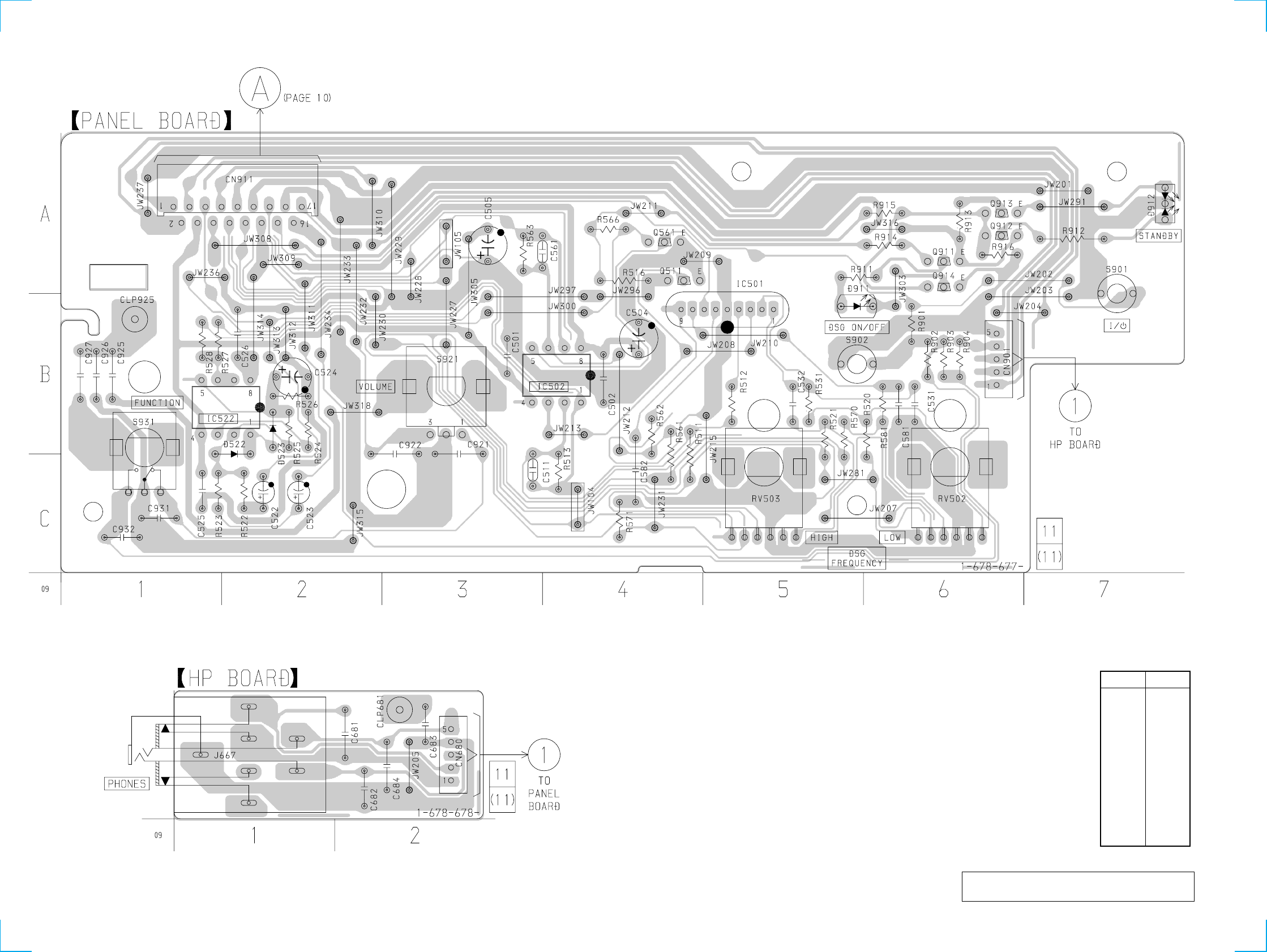
4-4. PRINTED WIRING BOARD – PANEL SECTION –
There are a few cases that the part isn't mounted
in model is printed on diagram.
Ref. No. Location
D522 B-2
D523 B-2
D911 B-5
D912 A-7
IC501 B-5
IC502 B-4
IC522 B-2
Q511 A-4
Q561 A-4
Q911 A-6
Q912 A-6
Q913 A-6
Q914 A-6
• Semiconductor
Location
TA-SP55
14
14
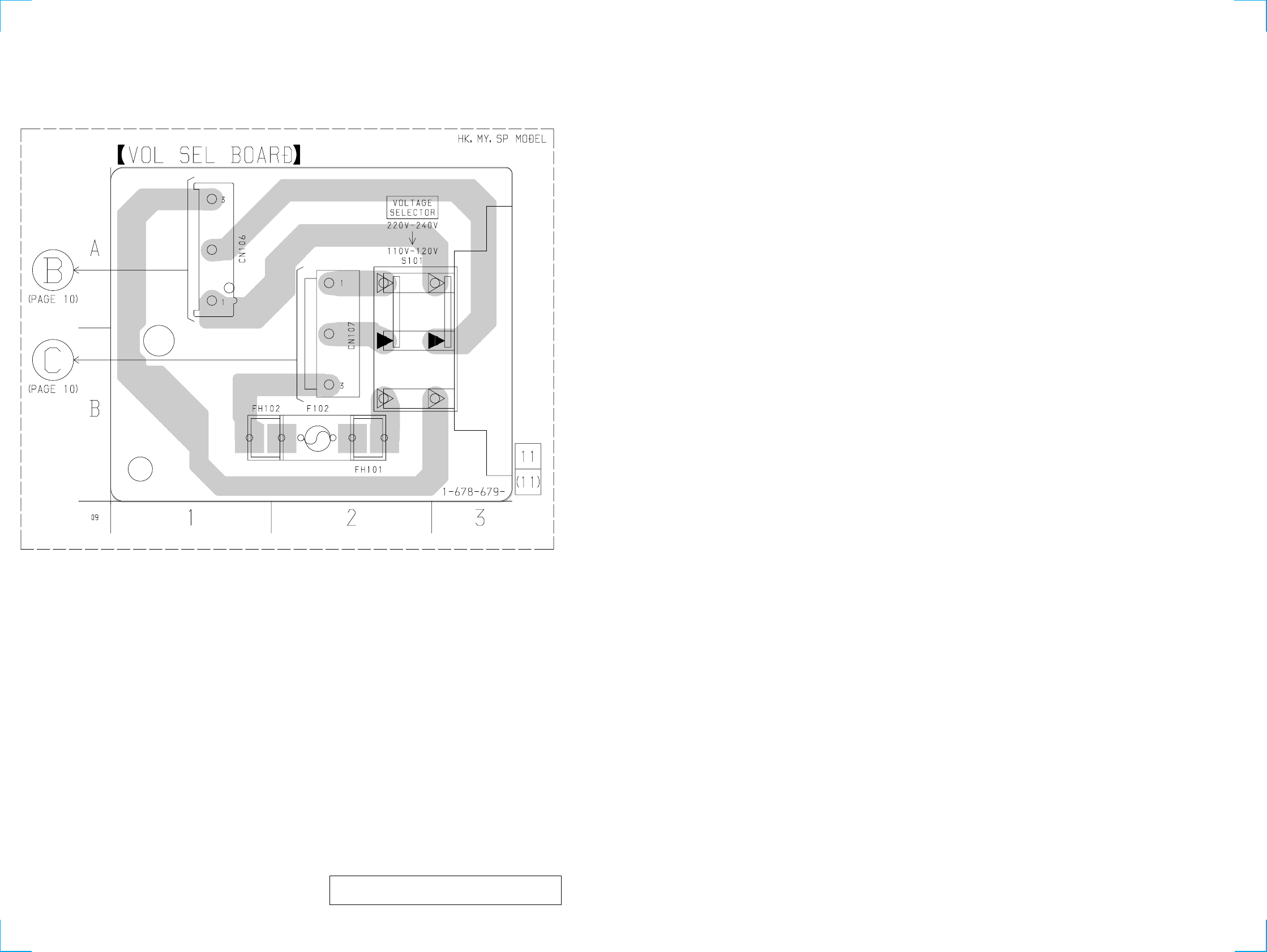
4-6. PRINTED WIRING BOARD – VOLSEL SECTION –
There are a few cases that the part isn't mounted
in model is printed on diagram.
15
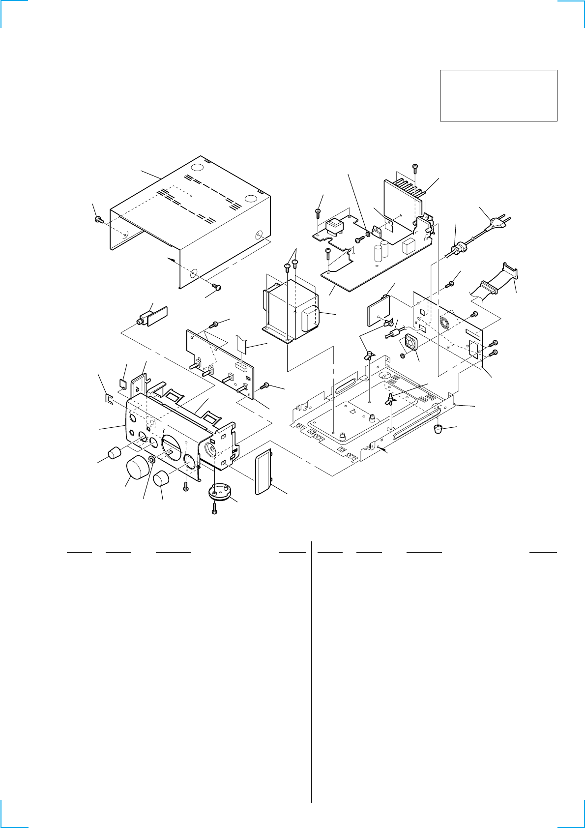
SECTION 5
EXPLODED VIEW
5-1. CASE AND FRONT PANEL
1
2
2
3
4
5
630
30
7
8
9
10 11
12
13
14
15
15
16
17
28
30
31
18
22
27
29 19
20
21
29
29
32
23
25
33
24
26
29
(HK,MY,SP)
not supplied
not supplied
not supplied
T102
Supplied
with J667
Supplied
with S921
M101
A
A
NOTE:
• Items marked “*” are not stocked since they are
seldom required for routine service. Some delay
should be anticipated when ordering these items.
• The mechanical parts with no reference number in
the exploded views are not supplied.
• Hardware (# mark) list and accessories and pack-
ing materials are given in the last of this parts list.
The components identified by
mark 0 or dotted line with mark
0 are critical for safety.
Replace only with part number
specified.
• Abbreviation
AED : North European model
MY : Malasia model
SP : Singapore model
HK : Hong Kong model
KR : Korea model
1 1-773-043-11 WIRE (FLAT TYPE) (17 CORE)
2 4-951-620-01 SCREW (2.6X8), +BVTP
3 1-678-677-11 PANEL BOARD
4 4-229-703-01 PLATE (R), SIDE
5 X-4953-027-1 FOOT ASSY
6 4-229-692-01 KNOB (SELECT)
7 4-229-691-01 KNOB (VOL)
8 4-229-693-01 KNOB (DSG)
9 4-229-690-01 PANEL(TA), FRONT
10 4-229-697-01 INDICATOR (P)
11 4-229-704-01 PLATE (L), SIDE
12 X-4953-023-1 PANEL ASSY (TA), SUB
13 1-678-678-11 HP BOARD
14 4-900-386-01 SCREW
15 3-363-099-51 SCREW (CASE 3 TP2)
16 4-229-701-31 CASE
17 A-4473-728-A MAIN BOARD, COMPLETE (AEP,AED,UK,KR)
17 A-4473-732-A MAIN BOARD, COMPLETE (HK,MY,SP)
18 3-970-608-11 SUMITITE (B3), +BV
019 1-769-079-11 CORD, POWER (KR)
Ref. No. Part No. Description Remarks Ref. No. Part No. Description Remarks
019 1-777-071-61 CORD, POWER (AEP,AED,UK,HK,MY,SP)
*20 3-703-244-00 BUSHING (2104), CORD
21 1-792-922-11 CORD (WITH CONNECTOR)
22 4-857-425-00 BUSHING, 03P INSULATING
23 4-229-700-01 PANEL, BACK (AEP,AED,UK)
23 4-229-700-21 PANEL, BACK (MY,SP)
23 4-229-700-31 PANEL, BACK (HK)
23 4-229-700-41 PANEL, BACK (KR)
24 4-965-822-01 FOOT
25 1-500-386-11 FILTER, CLAMP (FERRITE CORE)
*26 4-954-051-41 HOLDER, PC BOARD
27 1-678-679-11 VOL SEL BOARD (HK,MY,SP)
28 4-230-423-01 SHEET, INSULATING
29 7-685-646-79 SCREW +BVTP 3X8 TYPE2 N-S
30 7-685-648-79 SCREW +BVTP 3X12 TYPE2 N-S
31 7-685-650-79 SCREW +BVTP 3X16 TYPE2 N-S
32 7-682-563-09 SCREW +B 4X12
33 7-684-024-04 N 4, TYPE 2
M101 1-698-997-21 FAN, D.C.
0T102 1-435-600-11 TRANSFORMER, POWER (AEP,AED,UK,KR)
0T102 1-435-601-11 TRANSFORMER, POWER (HK,MY,SP)
16
Ref. No. Part No. Description Remarks Ref. No. Part No. Description Remarks
SECTION 6
ELECTRICAL PARTS LIST
1-678-678-11 HP BOARD
*******
< CAPACITOR >
C681 1-162-294-31 CERAMIC 0.001uF 10% 50V
C682 1-162-294-31 CERAMIC 0.001uF 10% 50V
C683 1-164-159-11 CERAMIC 0.1uF 50V
C684 1-162-294-31 CERAMIC 0.001uF 10% 50V
< JACK >
J667 1-774-933-11 JACK (LARGE TYPE) (PHONES)
**************************************************************
A-4473-728-A MAIN BOARD, COMPLETE (AEP,AED,UK,KR)
***********************************
A-4473-732-A MAIN BOARD, COMPLETE (HK,MY,SP)
******************************
1-533-293-11 FUSE HOLDER
*4-374-846-21 COVER, CAPACITOR, CAP TYPE
< CAPACITOR >
0C101 1-113-925-11 CERAMIC 0.01uF 20% 250V
C201 1-126-935-11 ELECT 470uF 20% 16V
C202 1-126-935-11 ELECT 470uF 20% 16V
C203 1-136-165-00 MYLAR 0.1uF 5% 50V
C204 1-136-165-00 MYLAR 0.1uF 5% 50V
C205 1-126-964-11 ELECT 10uF 20% 50V
C206 1-126-964-11 ELECT 10uF 20% 50V
C207 1-126-964-11 ELECT 10uF 20% 50V
C208 1-126-964-11 ELECT 10uF 20% 50V
C209 1-126-941-11 ELECT 470uF 20% 25V
C210 1-136-165-00 MYLAR 0.1uF 5% 50V
C211 1-136-165-00 MYLAR 0.1uF 5% 50V
C212 1-126-964-11 ELECT 10uF 20% 50V
C213 1-126-964-11 ELECT 10uF 20% 50V
C214 1-126-767-11 ELECT 1000uF 20% 16V
C215 1-136-165-00 MYLAR 0.1uF 5% 50V
C216 1-136-165-00 MYLAR 0.1uF 5% 50V
C222 1-164-159-11 CERAMIC 0.1uF 50V
C251 1-126-042-11 ELECT 3300uF 20% 35V
C252 1-126-042-11 ELECT 3300uF 20% 35V
C253 1-136-165-00 MYLAR 0.1uF 5% 50V
C254 1-136-165-00 MYLAR 0.1uF 5% 50V
C311 1-107-715-11 ELECT 22uF 20% 16V
C503 1-107-714-11 ELECT 10uF 20% 50V
C512 1-126-047-71 ELECT 4.7uF 20% 50V
C513 1-126-047-71 ELECT 4.7uF 20% 50V
C553 1-126-934-11 ELECT 220uF 20% 10V
C554 1-164-159-11 CERAMIC 0.1uF 50V
C555 1-164-159-11 CERAMIC 0.1uF 50V
C556 1-126-949-11 ELECT 220uF 20% 35V
C562 1-126-047-71 ELECT 4.7uF 20% 50V
C563 1-126-047-71 ELECT 4.7uF 20% 50V
C801 1-126-967-11 ELECT 47uF 20% 50V
C802 1-126-933-11 ELECT 100uF 20% 16V
C811 1-161-494-00 CERAMIC 0.022uF 25V
C812 1-161-494-00 CERAMIC 0.022uF 25V
C813 1-164-159-11 CERAMIC 0.1uF 50V
C823 1-162-219-31 CERAMIC 68PF 5% 50V
C824 1-164-159-11 CERAMIC 0.1uF 50V
C825 1-164-159-11 CERAMIC 0.1uF 50V
C850 1-164-159-11 CERAMIC 0.1uF 50V
C861 1-161-494-00 CERAMIC 0.022uF 25V
C862 1-161-494-00 CERAMIC 0.022uF 25V
C863 1-164-159-11 CERAMIC 0.1uF 50V
C873 1-162-219-31 CERAMIC 68PF 5% 50V
C874 1-164-159-11 CERAMIC 0.1uF 50V
C875 1-164-159-11 CERAMIC 0.1uF 50V
C876 1-126-949-11 ELECT 220uF 20% 35V
< CONNECTOR >
*CN101 1-580-230-11 PIN, CONNECTOR (PC BOARD) 2P
CN103 1-564-321-00 PIN, CONNECTOR 2P (AEP,AED,UK,KR)
*CN103 1-564-687-11 PIN, CONNECTOR 3P (HK,MY,SP)
*CN104 1-564-687-11 PIN, CONNECTOR 3P (HK,MY,SP)
*CN201 1-564-508-11 PLUG, CONNECTOR 5P
CN202 1-564-506-11 PLUG, CONNECTOR 3P
CN301 1-794-568-11 PIN, CONNECTOR 12P
CN302 1-794-569-11 PIN, CONNECTOR 5P
CN303 1-784-778-11 CONNECTOR, FFC 17P
CN551 1-564-506-11 PLUG, CONNECTOR 3P
< DIODE >
D201 8-719-024-99 DIODE 11ES2-NTA2B
D202 8-719-024-99 DIODE 11ES2-NTA2B
D203 8-719-975-85 DIODE 21DQ04N-TA2
D204 8-719-975-85 DIODE 21DQ04N-TA2
D205 8-719-947-36 DIODE MTZJ-T-72-8.2A
Ref. No. Part No. Description Remarks Ref. No. Part No. Description Remarks
HP
• SEMICONDUCTORS
In each case, u: µ , for example:
uA...: µ A..., uPA...: µ PA..., uPB...: µ PB...,
uPC...: µ PC..., uPD...: µ PD...
• CAPACITORS
uF : µ F
• COILS
uH : µ H
• Abbreviation
AED : North European model
MY : Malasia model
SP : Songapore model
HK : Hong Kong model
KR : Korea model
• Due to standardization, replacements in the parts
list may be different from the parts specified in the
diagrams or the components used on the set.
• -XX, -X mean standardized parts, so they may
have some difference from the original one.
• Items marked “*” are not stocked since they are
seldom required for routine service. Some delay
should be anticipated when ordering these items.
• RESISTORS
All resistors are in ohms
METAL: Metal-film resistor
METAL OXIDE: Metal Oxide-film resistor
F : nonflammable
Note:
When indicating parts by reference
number, please include the board
name.
The components identified by
mark 0 or dotted line with mark
0 are critical for safety.
Replace only with part number
specified.
MAIN
17
Ref. No. Part No. Description Remarks Ref. No. Part No. Description Remarks
D206 8-719-947-36 DIODE MTZJ-T-72-8.2A
D207 8-719-024-99 DIODE 11ES2-NTA2B
D208 8-719-024-99 DIODE 11ES2-NTA2B
D209 8-719-024-99 DIODE 11ES2-NTA2B
D210 8-719-024-99 DIODE 11ES2-NTA2B
D211 8-719-024-99 DIODE 11ES2-NTA2B
D212 8-719-024-99 DIODE 11ES2-NTA2B
D213 8-719-024-99 DIODE 11ES2-NTA2B
D214 8-719-024-99 DIODE 11ES2-NTA2B
D215 8-719-911-19 DIODE 1SS133T-72
D216 8-719-911-19 DIODE 1SS133T-72
D217 8-719-911-19 DIODE 1SS133T-72
D218 8-719-921-48 DIODE MTZJ-T-72-5.6C
D251 8-719-500-33 DIODE D3SB20
D311 8-719-911-19 DIODE 1SS133T-72
D551 8-719-024-99 DIODE 11ES2-NTA2B
D553 8-719-947-33 DIODE MTZJ-T-72-7.5A
D554 8-719-921-44 DIODE MTZJ-T-72-5.1C
D821 8-719-911-19 DIODE 1SS133T-72
< GROUND TERMINAL >
EPT201 1-537-770-21 TERMINAL BOARD, GROUND
< FUSE >
0F251 1-532-465-31 FUSE T3.15AL/250V
0F252 1-532-465-31 FUSE T3.15AL/250V
< IC >
IC211 8-759-647-11 IC uPC2905HF
IC801 8-759-681-35 IC LM4766T
< COIL >
L811 1-420-872-00 COIL, AIR-CORE
L861 1-420-872-00 COIL, AIR-CORE
< TRANSISTOR >
Q201 8-729-620-05 TRANSISTOR 2SC2603TP-EF
Q202 8-729-119-76 TRANSISTOR 2SA1115TP-EF
Q211 8-729-620-05 TRANSISTOR 2SC2603TP-EF
Q301 8-729-422-57 TRANSISTOR BN1A4M-TP
Q302 8-729-900-80 TRANSISTOR BA1A4M-TP
Q311 8-729-422-57 TRANSISTOR BN1A4M-TP
Q312 8-729-900-80 TRANSISTOR BA1A4M-TP
Q313 8-729-141-30 TRANSISTOR 2SC3623ATP-LK
Q314 8-729-141-30 TRANSISTOR 2SC3623ATP-LK
Q315 8-729-422-57 TRANSISTOR BN1A4M-TP
Q512 8-729-141-30 TRANSISTOR 2SC3623ATP-LK
Q552 8-729-620-05 TRANSISTOR 2SC2603TP-EF
Q553 8-729-026-68 TRANSISTOR 2SD2525(TP)
Q562 8-729-141-30 TRANSISTOR 2SC3623ATP-LK
Q801 8-729-620-05 TRANSISTOR 2SC2603TP-EF
Q802 8-729-900-80 TRANSISTOR BA1A4M-TP
Q803 8-729-620-05 TRANSISTOR 2SC2603TP-EF
Q804 8-729-620-05 TRANSISTOR 2SC2603TP-EF
< RESISTOR >
R201 1-247-843-11 CARBON 3.3K 5% 1/4W
R202 1-247-843-11 CARBON 3.3K 5% 1/4W
R211 1-249-429-11 CARBON 10K 5% 1/4W
R213 1-249-429-11 CARBON 10K 5% 1/4W
R303 1-247-807-31 CARBON 100 5% 1/4W
R304 1-247-807-31 CARBON 100 5% 1/4W
R305 1-247-807-31 CARBON 100 5% 1/4W
R306 1-247-807-31 CARBON 100 5% 1/4W
R311 1-249-413-11 CARBON 470 5% 1/4W F
R312 1-249-413-11 CARBON 470 5% 1/4W F
R313 1-249-441-11 CARBON 100K 5% 1/4W
R501 1-247-843-11 CARBON 3.3K 5% 1/4W
R502 1-249-441-11 CARBON 100K 5% 1/4W
R514 1-249-421-11 CARBON 2.2K 5% 1/4W F
R515 1-249-425-11 CARBON 4.7K 5% 1/4W F
R518 1-247-895-00 CARBON 470K 5% 1/4W
R553 1-247-887-00 CARBON 220K 5% 1/4W
R554 1-249-425-11 CARBON 4.7K 5% 1/4W F
0R555 1-215-887-11 METAL OXIDE 150 5% 2W
R564 1-249-421-11 CARBON 2.2K 5% 1/4W F
R565 1-249-425-11 CARBON 4.7K 5% 1/4W F
R568 1-247-895-00 CARBON 470K 5% 1/4W
R801 1-260-089-11 CARBON 150 5% 1/2W
R802 1-249-441-11 CARBON 100K 5% 1/4W
R803 1-249-438-11 CARBON 56K 5% 1/4W
R804 1-249-437-11 CARBON 47K 5% 1/4W
R805 1-249-438-11 CARBON 56K 5% 1/4W
R806 1-249-429-11 CARBON 10K 5% 1/4W
R811 1-260-076-11 CARBON 10 5% 1/2W
R812 1-249-389-11 CARBON 4.7 5% 1/4W F
R821 1-249-417-11 CARBON 1K 5% 1/4W F
R822 1-249-417-11 CARBON 1K 5% 1/4W F
R823 1-249-441-11 CARBON 100K 5% 1/4W
R824 1-249-389-11 CARBON 4.7 5% 1/4W F
R831 1-260-089-11 CARBON 150 5% 1/2W
R832 1-260-089-11 CARBON 150 5% 1/2W
R833 1-260-089-11 CARBON 150 5% 1/2W
R834 1-260-089-11 CARBON 150 5% 1/2W
R861 1-260-076-11 CARBON 10 5% 1/2W
R862 1-249-389-11 CARBON 4.7 5% 1/4W F
R871 1-249-417-11 CARBON 1K 5% 1/4W F
R872 1-249-417-11 CARBON 1K 5% 1/4W F
R873 1-249-441-11 CARBON 100K 5% 1/4W
R874 1-249-389-11 CARBON 4.7 5% 1/4W F
< RELAY >
RY101 1-755-276-11 RELAY, POWER
RY801 1-515-920-11 RELAY (24V)
< THERMISTOR(POSITIVE) >
THP201 1-804-233-21 THERMISTOR, POSITIVE
THP202 1-804-233-21 THERMISTOR, POSITIVE
THP203 1-804-234-21 THERMISTOR, POSITIVE
THP204 1-804-234-21 THERMISTOR, POSITIVE
< TERMINAL >
TM801 1-694-677-11 TERMINAL BOARD (4P) (SPEAKERS)
MAIN
The components identified by
mark 0 or dotted line with mark
0 are critical for safety.
Replace only with part number
specified.
18
Ref. No. Part No. Description Remarks Ref. No. Part No. Description Remarks
< POWER TRANSFORMER >
0TR101 1-435-624-11 TRANSFORMER, POWER (AEP,AED,UK,KR)
0TR101 1-435-625-11 TRANSFORMER, POWER (HK,MY,SP)
**************************************************************
1-678-677-11 PANEL BOARD
**********
< CAPACITOR >
C501 1-161-494-00 CERAMIC 0.022uF 25V
C502 1-161-494-00 CERAMIC 0.022uF 25V
C511 1-110-337-51 MYLAR 150PF 5% 50V
C522 1-126-157-11 ELECT 10uF 20% 16V
C523 1-126-157-11 ELECT 10uF 20% 16V
C524 1-126-933-11 ELECT 100uF 20% 16V
C525 1-164-159-11 CERAMIC 0.1uF 50V
C526 1-164-159-11 CERAMIC 0.1uF 50V
C561 1-110-337-51 MYLAR 150PF 5% 50V
C921 1-161-494-00 CERAMIC 0.022uF 25V
C922 1-161-494-00 CERAMIC 0.022uF 25V
C925 1-164-159-11 CERAMIC 0.1uF 50V
C926 1-164-159-11 CERAMIC 0.1uF 50V
C927 1-164-159-11 CERAMIC 0.1uF 50V
C931 1-161-494-00 CERAMIC 0.022uF 25V
C932 1-161-494-00 CERAMIC 0.022uF 25V
< LEAD >
*CLP925 1-690-880-31 LEAD (WITH CONNECTOR)
< CONNECTOR >
CN911 1-784-739-11 CONNECTOR, FFC 17P
< DIODE >
D522 8-719-911-19 DIODE 1SS133T-72
D523 8-719-911-19 DIODE 1SS133T-72
D911 8-719-071-42 DIODE SEL5723C-TP15 (DSG ON/OFF)
D912 8-719-056-11 DIODE SML72423C-TP15 (STANDBY)
< IC >
IC501 8-749-015-28 IC SSE-96G
IC502 8-759-705-58 IC NJM4558D-D
IC522 8-759-705-58 IC NJM4558D-D
< TRANSISTOR >
Q511 8-729-141-30 TRANSISTOR 2SC3623ATP-LK
Q561 8-729-141-30 TRANSISTOR 2SC3623ATP-LK
Q911 8-729-422-57 TRANSISTOR BN1A4M-TP
Q912 8-729-422-57 TRANSISTOR BN1A4M-TP
Q913 8-729-900-80 TRANSISTOR BA1A4M-TP
Q914 8-729-900-80 TRANSISTOR BA1A4M-TP
< RESISTOR >
R511 1-249-435-11 CARBON 33K 5% 1/4W
R512 1-249-425-11 CARBON 4.7K 5% 1/4W F
R513 1-249-433-11 CARBON 22K 5% 1/4W
R516 1-249-429-11 CARBON 10K 5% 1/4W
R520 1-249-409-11 CARBON 220 5% 1/4W F
R521 1-249-409-11 CARBON 220 5% 1/4W F
R522 1-249-429-11 CARBON 10K 5% 1/4W
R523 1-249-429-11 CARBON 10K 5% 1/4W
R524 1-249-429-11 CARBON 10K 5% 1/4W
R525 1-249-429-11 CARBON 10K 5% 1/4W
R526 1-249-441-11 CARBON 100K 5% 1/4W
R527 1-249-429-11 CARBON 10K 5% 1/4W
R528 1-249-429-11 CARBON 10K 5% 1/4W
R561 1-249-435-11 CARBON 33K 5% 1/4W
R562 1-249-425-11 CARBON 4.7K 5% 1/4W F
R563 1-249-433-11 CARBON 22K 5% 1/4W
R566 1-249-429-11 CARBON 10K 5% 1/4W
R570 1-249-409-11 CARBON 220 5% 1/4W F
R571 1-249-409-11 CARBON 220 5% 1/4W F
R901 1-249-425-11 CARBON 4.7K 5% 1/4W F
R902 1-249-427-11 CARBON 6.8K 5% 1/4W F
R903 1-249-429-11 CARBON 10K 5% 1/4W
R904 1-249-430-11 CARBON 12K 5% 1/4W
R911 1-249-409-11 CARBON 220 5% 1/4W F
R912 1-249-413-11 CARBON 470 5% 1/4W F
R913 1-249-412-11 CARBON 390 5% 1/4W F
R914 1-247-807-31 CARBON 100 5% 1/4W
R915 1-247-807-31 CARBON 100 5% 1/4W
R916 1-249-429-11 CARBON 10K 5% 1/4W
< VARIABLE RESISTOR >
RV502 1-227-202-11 RES, VAR 1K (DSG FREQ. LOW)
RV503 1-227-202-11 RES, VAR 1K (DSG FREQ. HIGH)
< SWITCH >
S901 1-771-410-21 SWITCH, TACTILE (&/1)
S902 1-771-410-21 SWITCH, TACTILE (DSG ON/OFF)
S921 1-476-087-11 ENCODER, ROTARY (VOLUME)
S931 1-771-963-11 SWITCH (FUNCTION)
**************************************************************
1-678-679-11 VOL SEL BOARD (HK,MY,SP)
*************
1-533-293-11 FUSE HOLDER (HK,MY,SP)
< CONNECTOR >
*CN107 1-564-687-11 PIN, CONNECTOR 3P (HK,MY,SP)
< FUSE >
0F102 1-532-463-31 FUSE 1A/250V (HK,MY,SP) (HK,MY,SP)
< SWITCH >
0S101 1-571-309-11 SWITCH (VOLTAGE SELECTOR) (HK,MY,SP)
**************************************************************
PANEL VOL SEL
The components identified by
mark 0 or dotted line with mark
0 are critical for safety.
Replace only with part number
specified.
MAIN

19
Ref. No. Part No. Description Remarks Ref. No. Part No. Description Remarks
MISCELLANEOUS
*************
1 1-773-043-11 WIRE (FLAT TYPE) (17 CORE)
019 1-769-079-11 CORD, POWER (KR)
019 1-777-071-61 CORD, POWER (AEP,AED,UK,HK,MY,SP)
21 1-792-922-11 CORD (WITH CONNECTOR)
25 1-500-386-11 FILTER, CLAMP (FERRITE CORE)
M101 1-698-997-21 FAN, D.C.
0T102 1-435-600-11 TRANSFORMER, POWER (AEP,AED,UK,KR)
0T102 1-435-601-11 TRANSFORMER, POWER (HK,MY,SP)
**************************************************************
ACCESSORIES & PACKING MATERIALS
*******************************
01-569-008-21 ADAPTOR, CONVERSION 2P (MY,SP)
01-770-019-11 ADAPTOR, CONVERSION PLUG 3P (UK,HK)

20
Ref. No. Part No. Description Remarks Ref. No. Part No. Description Remarks
TA-SP55
Sony Corporation
Audio Entertainment Group
9-929-535-11 2000I097551-1
Printed in Hungary ©2000.9
Published by General Engineering Dept.
