TB6600 User Guide V1.2
TB6600%20User%20Guide%20V1.2
User Manual:
Open the PDF directly: View PDF ![]() .
.
Page Count: 11
www.DFRobot.com
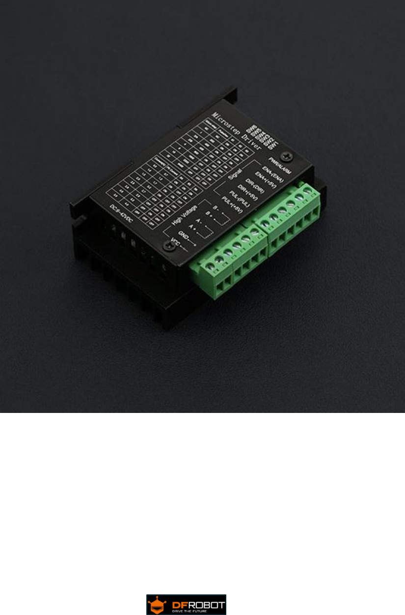
TB6600 Stepper Motor Driver User Guide
Version: V1.2

www.DFRobot.com
Contents
1. Introduction............................................................................................................................... 1
Features:...................................................................................................................................1
Electric Specification:............................................................................................................1
INPUT & OUTPUT:................................................................................................................ 2
2. Stepper Motor Wiring:............................................................................................................ 4
3. Microcontroller Connection Diagram:................................................................................5
4. DIP Switch...................................................................................................................................6
Micro Step Setting................................................................................................................ 6
Current Control Setting.......................................................................................................6
5. Off-line Function (EN Terminal):...........................................................................................7
6. FAQ............................................................................................................................................... 7
7. Dimension (96*56*33)............................................................................................................. 8

www.DFRobot.com
Safety Precautions:
-Before using this product, please read this instruction manual carefully
-Keep this manual in a safe place for future reference
-The appearance of the picture is just for reference, please prevail in kind
This device is driven by DC power supply, make sure the power positive and
negative before you power it.
Please do not electrified plug
Please do not mix conductive foreign matter such as screws or metal
Please keep it dry, and pay attention to moisture-proof
The equipment should be clean and well ventilated.

www.DFRobot.com
www.DFRobot.com.cn
1
1. Introduction
This is a professional two-phase stepper motor driver. It supports speed and direction
control. You can set its micro step and output current with 6 DIP switch. There are 7 kinds
of micro steps (1, 2 / A, 2 / B, 4, 8, 16, 32) and 8 kinds of current control (0.5A, 1A, 1.5A, 2A,
2.5A, 2.8A, 3.0A, 3.5A) in all. And all signal terminals adopt high-speed optocoupler
isolation, enhancing its anti-high-frequency interference ability.
Features:
※Support 8 kinds of current control
※Support 7 kinds of micro steps adjustable
※ The interfaces adopt high-speed optocoupler isolation
※ Automatic semi-flow to reduce heat
※ Large area heat sink
※ Anti-high-frequency interference ability
※ Input anti-reverse protection
※ Overheat, over current and short circuit protection
Electrical Specification:
Input Current
0~5.0A
Output Current
0.5-4.0A
Power (MAX)
160W
Micro Step
1, 2/A, 2/B, 4, 8, 16, 32
Temperature
-10~45℃
Humidity
No Condensation
Weight
0.2 kg
Dimension
96*56*33 mm
www.DFRobot.com
www.DFRobot.com.cn
2
INPUT & OUTPUT:
-Signal Input:
PUL+ Pulse +
PUL- Pulse -
DIR+ Direction +
DIR- Direction -
EN+ Off-line Control Enable +
EN- Off-line Control Enable -
-Motor Machine Winding:
A+ Stepper motor A+
A- Stepper motor A-
B+ Stepper motor B+
B- Stepper motor B-
-Power Supply:
VCC VCC (DC9-42V)
GND GND
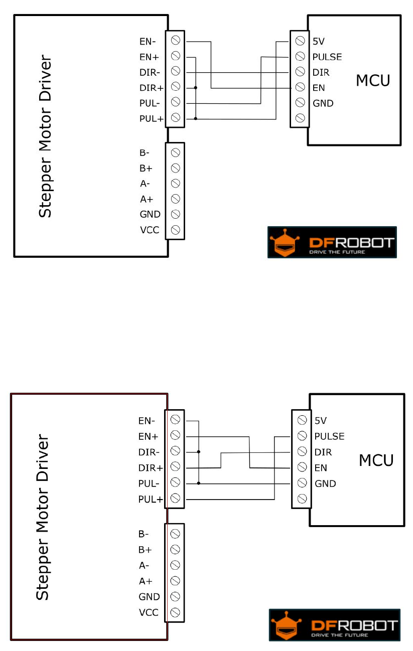
-Wiring instructions
There are three input signals in all: ① Step pulse signal PUL +, PUL-; ② Direction
signal DIR +, DIR-; ③ off-line signal EN +, EN-. The driver supports common-cathode
and common-anode circuit, you can select one according to your demand.
Common-Anode Connection:
Connect PUL +, DIR + and EN + to the power supply of the control system. If the
power supply is + 5V, it can be directly connected. If the power supply is more than +
5V, the current limiting resistor R must be added externally. To ensure that the
controller pin can output 8 ~ 15mA current to drive the internal optocoupler chip.
Pulse signal connects to PUL-; direction signal connects to Dir- ; Enable signal
connects to EN-. As shown below:
www.DFRobot.com
www.DFRobot.com.cn
3
Common-Cathode Connection:
Connect PUL -, DIR - and EN - to the ground terminal of the control system. Pulse
signal connects to PUL-; direction signal connects to Dir- ; Enable signal connects to
EN-. As shown below:
Note: When“EN”is in the valid state, the motor is in a free states (Off-line
mode). In this mode, you can adjust the motor shaft position manually. When“EN”is
in the invalid state, the motor will be in an automatic control mode.
www.DFRobot.com
www.DFRobot.com.cn
4
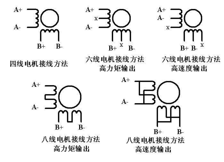
2. Stepper Motor Wiring:
Two-phase 4-wire, 6-wire, 8-wire motor wiring, as shown below:
www.DFRobot.com
www.DFRobot.com.cn
5
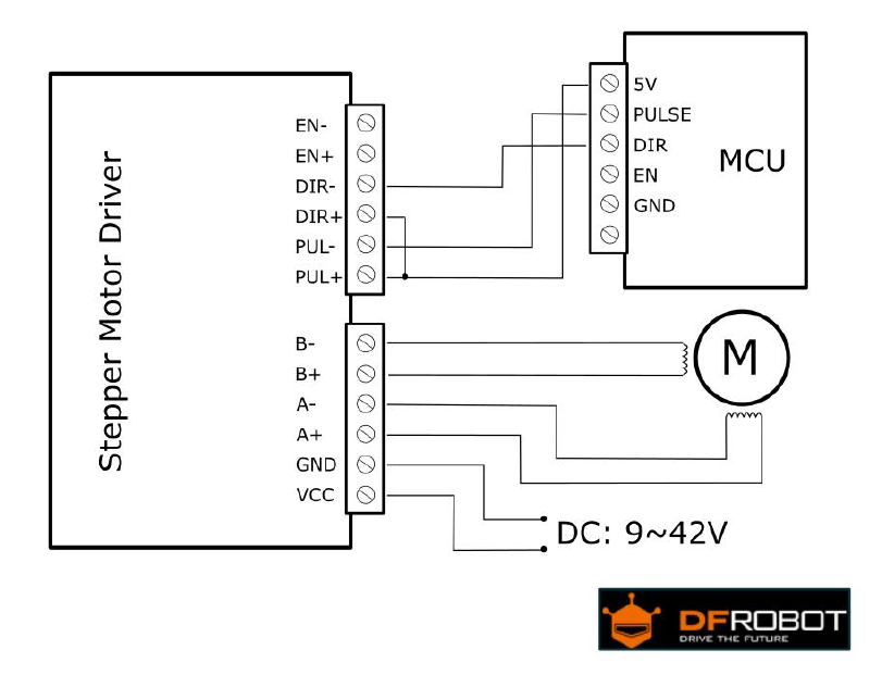
3. Microcontroller Connection Diagram:
This is an example for the common-anode connection. (“EN”not connected )
Note: Please cut off the power when you connect the system, and ensure the
power polar is correct. Or it will damage the controller.
www.DFRobot.com
www.DFRobot.com.cn
6
4. DIP Switch
Micro Step Setting
The follow tablet shows the driver Micro step. You can set the motor micro step
via the first three DIP switch.
Step Angle = Motor Step Angle / Micro Step
E.g. An stepper motor with 1.8° step angle,the finial step angle under “Micro
step 4” will be 1.8°/4=0.45°
Micro Step
Pulse/Rev
S1
S2
S3
NC
NC
ON
ON
ON
1
200
ON
ON
OFF
2/A
400
ON
OFF
ON
2/B
400
OFF
ON
ON
4
800
ON
OFF
OFF
8
1600
OFF
ON
OFF
16
3200
OFF
OFF
ON
32
6400
OFF
OFF
OFF
Current Control Setting
Current (A)
S4
S5
S6
0.5
ON
ON
ON
1.0
ON
OFF
ON
1.5
ON
ON
OFF
2.0
ON
OFF
OFF
2.5
OFF
ON
ON
2.8
OFF
OFF
ON
3.0
OFF
ON
OFF
3.5
OFF
OFF
OFF
www.DFRobot.com
www.DFRobot.com.cn
7
5. Off-line Function (EN Terminal):
If you turn on the Off-line function, the motor will enter a free state. You can adjust
the motor shaft freely, and the pulse signal will be no response. If you turn it off, it will be
back into automatic control mode
Note: Generally, EN terminal is not connected.
6. FAQ
1. Q: If the control signal is higher than 5V, how do I connect?
A: You need add a resistor in series
2. Q: After connected the power, why the motor doesn’t work? The PWR Led has
been ON.
A: Please check the power supply, it must higher than 9V. And make sure the I/O
limited current is higher than 5mA
3. Q: How do we know the right order of the stepper motor?
A: Please check the motor specification, it show you the right order. Or you can
measure it with a multimeter.
www.DFRobot.com
www.DFRobot.com.cn
8
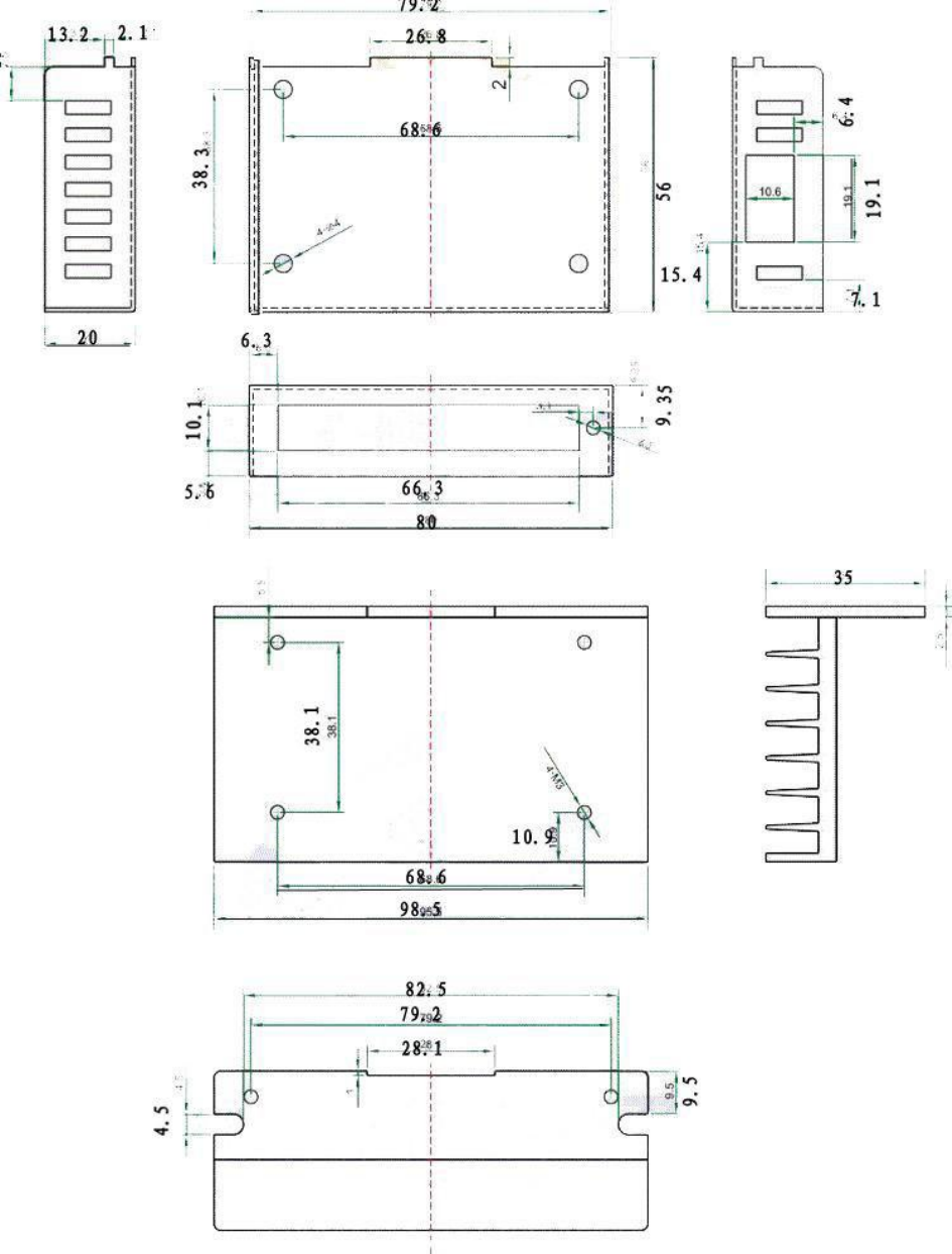
7. Dimension (96*56*33)
