Tower Controller Manual TC 64
User Manual: TC-64-manual
Open the PDF directly: View PDF ![]() .
.
Page Count: 10

RR-CirKits, Inc.
7918 Royal Ct.
Waxhaw, NC USA 28173
http://www.rr-cirkits.com
sales@rr-cirkits.com
704-843-3769
Fax: 704-243-4310
April 5, 2010
TC-64
Tower Controller
64 line I/O to LocoNet® Interface
Firmware Revision 5
User's Guide
LocoNet Certification applied for.
LocoNet® is a trademark of Digitrax Inc. (http://www.digitrax.com/)

Table of Contents
Contact Information.
Overview . . . . . 1
1.0 Features . . . . . 1
2.0 Quick Start . . . . . 1
3.0 Connections and Indicators . . 2
3.1 LocoNet® Connector . . . 2
3.2 Power Connector . . . 2
3.3 Status Indicators. . . . 2
4.0 Boot Loader . . . . 3
5.0 Input/Output Connections . . . 4
5.1 Port Connections . . . 4
5.1.1 Port Electrical . . 4
5.1.2 Connector Pin Identification . 5
5.1.3 Port Configuration . . 5
5.2 Control Bit Definition CV17-22 . . 6
5.3 Control Bit Definition CV1-16 CV23-278 . 7
5.4 Per Line Bit Definition (byte one) . . 8
5.5 Per Line Bit Definition (byte two) . . 9
5.6 Per Line Bit Definition (byte three - four) . 10
6.0 Input/Output Boards . . . . 11
7.0 Trouble Shooting . . . . . 14
7.1 Sanity Test . . . . 14
7.2 Loop Back Test . . . 14
7.3 Factory Reset . . . . 15
8.0 Local Power . . . . 15
9.0 Optical Isolation . . . . 16
10.0 Warranty Information . . . 16
11.0 FCC Information . . . . 16
Contact Information
RR-CirKits, Inc. http://www.rr-cirkits.com
7918 Royal Ct. sales@rr-cirkits.com
Waxhaw, NC USA 28173 service@rr-cirkits.com
1-704-843-3769
Fax: 1-704-243-4310
LocoNet® is a trademark of Digitrax Inc. ( http://www.digitrax.com/ )
WAR N I N G : This product contains a chemical known to the state of
California to cause cancer, birth defects or other reproductive harm.
9.0 Optical Isolation
The Tower Controller provides complete electrical isolation between the layout
and the LocoNet®. This prevents possible ground loop problems between the
LocoNet® and your layout power supplies. For example, many systems are
installed without properly grounding the booster to power ground, but use
grounded power supplies for accessories.
Some devices connect the LocoNet® ground directly to the interface boards.
This provides a ground path from the local power supplies to the LocoNet® and
then to the booster. At best this indirect grounding causes electrical noise. At
worst it could create a fault path via the small gage LocoNet® wiring to ground.
Properly ground your boosters, your power supplies, and your desktop computer
through a 3 wire cable, and isolate them from each other via isolated equipment.
10.0 Warranty Information
We offer a one year warranty on the TC-64. This device contains no user
serviceable parts. If a defect occurs, please contact RR-CirKits at:
service@rr-cirkits.com for a replacement.
11.0 FCC Information
This device complies with part 15 of the FCC Rules. Operation is subject to the
following two conditions:
1. This device may not cause harmful interference, and
2. this device must accept any interference received, including interference
that may cause undesired operation.
Note: This equipment has been tested and found to comply with the limits for
a Class B digital device, pursuant to part 15 of the FCC Rules. These limits
are designed to provide reasonable protection against harmful interference in
a residential installation. This equipment generates, uses and can radiate
radio frequency energy and, if not installed and used in accordance with the
instructions, may cause harmful interference to radio communications.
However, there is no guarantee that interference will not occur in a particular
installation. If this equipment does cause harmful interference to radio or
television reception, which can be determined by turning the equipment off
and on, the user is encouraged to try to correct the interference by one or
more of the following measures:
--Reorient or relocate the receiving antenna.
--Increase the separation between the equipment and receiver.
--Connect the equipment into an outlet on a circuit different from that to
which the receiver is connected.
--Consult the dealer or an experienced radio/TV technician for help.
Any modifications to this device voids the user's authority to operate under and
be in compliance with these regulations. The actual measured radiation from the
Tower Controller is much lower than the maximum that is permitted by the FCC
Rules, so it is unlikely that this device will cause any RFI problems.
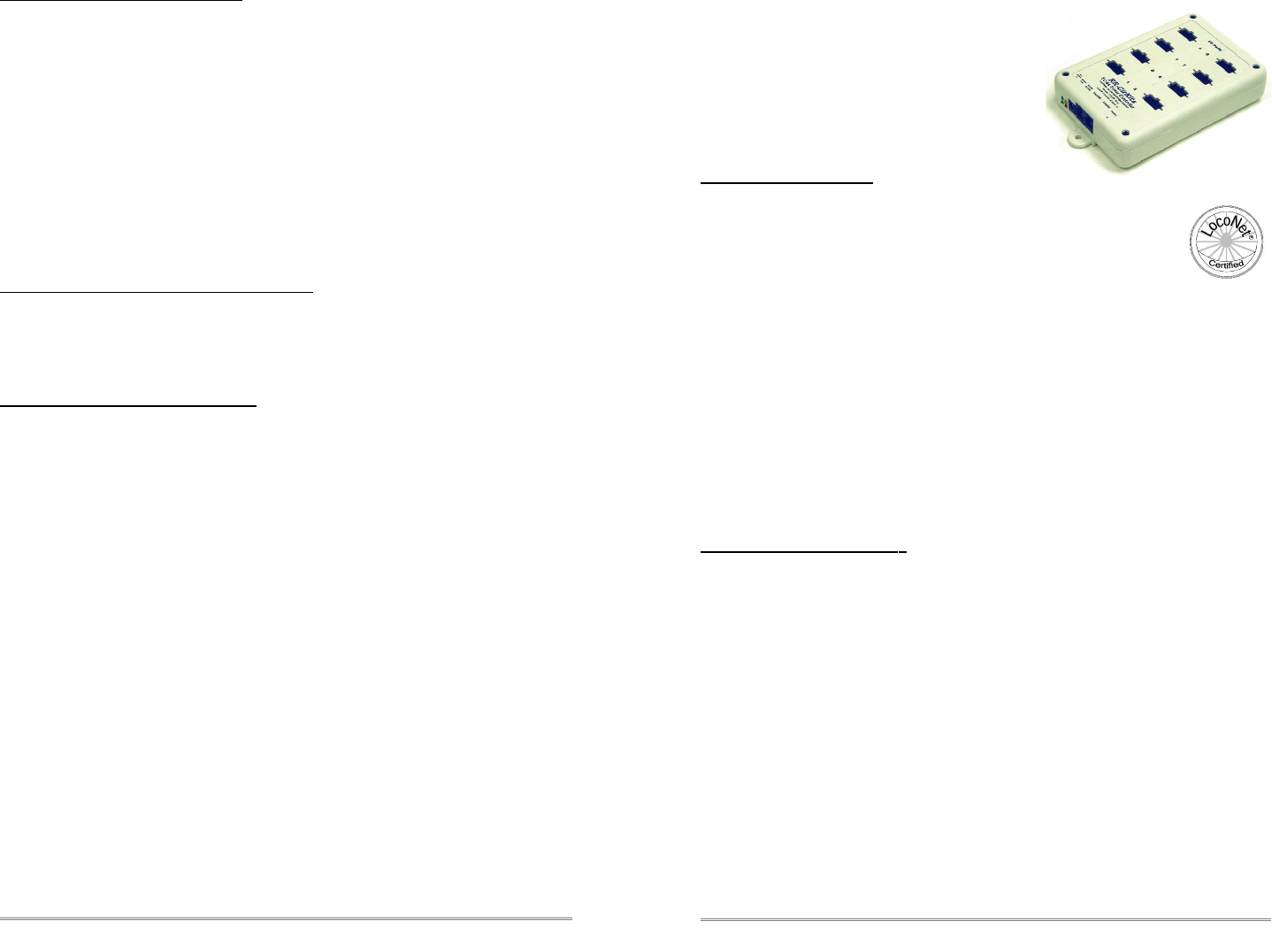
Overview
The TC-64 Tower Controller 64 line
LocoNet®interface provides a simple and
easy way to connect between the Digitrax
LocoNet® bus and the layout. It may be
connected at any convenient point on the
LocoNet®.
1.0 Features
•64 lines of Input/Output arranged in
8 groups of 8 lines each.
•Each group may be configured as an input or output.
•LocoNet® certified (certification applied for)
•CV controlled programming via Software. (e.g. JMRI
DecoderPro 2.0 or later.)
•Both read and write of CV values is supported in OPs mode.
•Each port can be individually addressed, or as part of a group.
•Full optical isolation between LocoNet® and TC-64.
•Automatically saves status during power down. (optionally)
•Boot Loader allows firmware upgrades over LocoNet® connection
•External power input accepts 9V-20V wide range without
overheating. Internal switching regulator provides up to 1 amp
at 5VDC total power to ports for I/O modules..
2.0 Q uick Start
We suggest that you use a computer program such as the JMRI DecoderPro
(2.0 or later) to setup the Tower Controller. The "point and click" interface will
save you much time and frustration while setting the many possible options
that you will need to configure.
•OPS Mode Address: Each Tower Controller has a single address that is
used for OPS mode programming on the layout. Each individual Tower
Controller on your layout must have its own address. Your Tower
Controller comes pre-programmed with an address that is 10xxx where
xxx are the last three numerical digits of the serial number. E.g. device
serial number 015d would have a programming address of 10015.
•This address is only used to configure the Tower Controller. It has
nothing to do with the addresses that each input/output line will use to
communicate information with the LocoNet® system.
•This address must not conflict with that of any Locomotives in use on the
layout, as no distinction is made between mobile and fixed decoders in
OPS mode. This address must be in the range of 0-16383. We suggest
©2006-10 RR-CirKits, Inc. www..rr-cirkits.com 1
16 www..rr-cirkits.com ©2006-10 RR-CirKits, Inc.

that you choose a 5 digit address to avoid potential conflicts.
•Prior to connecting your TC-64 you should make a DecoderPro roster
entry for it. Open the 'Service Mode Programmer ' and select RR-CirKits
TC-64 as the decoder type. Click 'Open Programmer', then go to the
'Basic' tab, check '4 digit addressing' and enter your unit's 5 digit
address in the 'Long Address' box. Go to the 'Roster Entry' tab, enter an
ID (e.g. TC 10030) and then click on the 'Save' button.
•All configuration must be done with the 'Operations Mode Programmer'.
•The lower green status indicator should illuminate as soon as your TC-64
is powered up.
•Connect the unit's LocoNet® jack to any point on your system's
LocoNet®. The upper green status indicator should illuminate, and the red
status indicator should indicate all LocoNet®activity. The yellow command
indicator will light each time the TC-64 initiates or responds to a
LocoNet® command.
•You should now be able to interface to your Railroad from your software.
3.0 Connections and Indicators
The TC-64 Tower Controller has eleven connectors and four status indicators.
3.1 LocoNet® Connector
The LocoNet® connection is made to the TC-64 via the provided LocoNet® cable
connected to either of the two RJ-12 (6 pin) modular jacks. LocoNet® cables are
wired straight through, not reversed like phone cables.
Pin outs for the RJ-12 connector:
Pin Description Color
1 Rail_Sync- white
2 Signal Ground black
3 LocoNet- red
4 LocoNet+ green
5 Signal Ground yellow
6 Rail_Sync+ blue
LocoNet® pins 2 and 5, and pins 3 and 4 are connected together internally.
3.2 Power Connections
The TC-64 requires an external power source of between 9 and 25 volts AC/DC
and should provide 8VA or more. Multiply the output voltage times the rated
current to get VA. For example a 12V 800ma. supply would provide 9.6VA and
be a good choice. A 9V 300ma, supply would only provide 2.7VA and severely
limit the output drive capability of the TC-64.
The LocoNet®receiver and driver circuits receive their power from the Rail_Sync
lines and draw only a few milliamperes. (see section 7.0 for local power options)
Steps:
1. Open the JMRI LocoNet® Monitor window.
1. Using a switch input on the TC-64, send a command.
2. The switch command should appear in the LocoNet® monitor window
and both the TC-64 command (Y) and activity (R) LEDs should blink.
3. Using JMRI send commands (e.g. switch commands) to the TC-64.
4. The commands should appear in the LocoNet® monitor window and the
TC-64 command and activity LEDs should blink.
If there is activity at the interface, but no activity light at the TC-64 when switch
commands are sent, check the LocoNet® wiring. If the command is seen in the
activity light, but not in the command light, be sure that the command you are
sending is addressed to respond on this TC-64. If there is no activity shown in
the LocoNet® monitor window, check that you have the correct interface selected
in the JMRI preferences, and that you have the correct COM port selected.
7.3 Factory Reset
If the TC-64 settings get lost, the unit may be returned to its factory default
settings by sending a value of 170 (hex AA) to CV21 using JMRI DecoderPro in
'Service Mode'. (Note: This is the only TC-64 use of Service Mode) The factory
default Ops address is 10000 with all ports set as input contacts, with ports 1-8
base addresses set to; 0, 8, 16, 24, 32, 40, 48, and 56 respectively.
Steps:
1. Using a paper clip, press the "Program" switch located under the small
hole labeled "Program" for 3 seconds. The yellow "Command" LED
should begin to flash indicating that the TC-64 is in Service Mode.
2. Open DecoderPro (2.0 or later) and select 'Service Mode'. Be sure that
there are no locomotives on your program track. Select RR-CirKits –
TC-64 as the decoder. Click on 'Reset'. The flashing yellow light on the
TC-64 should flicker as the 'reset' command is sent to the unit.
3. Set the proper address for this unit in the “Basic” tab, then switch to the
“CVs” tab and write just CV17 and CV18. (red error is OK)
4. Press the “Program” switch again to return the TC-64 to its normal
operating mode.
8.0 Local Power
This device includes jumper positions to provide
local power to the internal LocoNet® circuits.
This may be useful if the TC-64 is being
used without a Digitrax command station.
The use of an external Rail Sync power
supply such as provided by the various
Digitrax UP panels is a better alternative.
Note: Use of these jumpers bypasses the
built in optical isolation.
To enable the internal power, carefully
open the case and install jumpers at both
positions 1 and 2 of the option connector JP3.
©2006-10 RR-CirKits, Inc. www..rr-cirkits.com 152 www..rr-cirkits.com ©2006-10 RR-CirKits, Inc.

Other Planned TC-64 Input/Output modules include:
●IRD-8 (Infra-Red Detector Board) with 8 inputs. This board includes 8 infra-
red detector inputs, sensitivity controls, and indicators. It may be configured
to use 38KHz IR long range beam block detectors, or else simple retro
reflective and emitter/detector beam break units. Each of the 8 channels are
sequentially accessed to prevent interference between them. Narrow band
pulsed beam technology greatly reduces sensitivity to ambient lighting
conditions and backscatter from other IR sources such as hand held
throttles or remote controls.
●TSB-8 (Terminator Splitter Board) This board is a convenient way to convert
from 10 pin ribbon cable to screw terminals. It may be used for inputs or
outputs, and includes pads for mounting resistors such as required for
connecting LEDs used for direct drive signals or panels.
●RCSB-8 (RC Servo Driver Board) with 8 outputs. This board is designed to
control 4 to 8 RC servos. Uses include semaphores, crossing gates, train
order signals, wig-wags, operating building doors, etc.
7.0 Trouble shooting
7.1 Sanity Test
To perform a very basic TC-64 sanity test perform the following steps:
1. Power up the Tower Controller by plugging it into the computer.
2. The lower green power LED should come on.
3. Plug in the LocoNet® cable. The upper green power LED should light.
4. Unplug the LocoNet® cable. The red activity light should blink briefly as
the cable is removed.
5. Using a paper clip, press the "Program" switch located under the small
hole labeled "Program" for 3 seconds. The yellow "Command" LED
should begin to flash indicating that the TC-64 has entered Service
Mode and is waiting for an address change. Press the switch again
briefly and the LED should extinguish.
If the lower green power LED does not light, be sure that the power supply is
connected and provides at least 9V to the Tower Controller.
If the Rail Sync upper power LED does not light, or if the activity LED does not
blink when you unplug the LocoNet® cable, be sure that your DCC command
station is powered up, then check your LocoNet® wiring.
7.2 Loop Back Test
The Tower Controller's input circuit and code reads directly from the unit's
LocoNet® jack, so if you send a character it should be seen on the input line.
This test uses the free software available from the JMRI project to watch the test
commands. (www.jmri.info)
3.3 Status Indicators
The TC-64 has four status indicators located next to the power connector. The
two green status indicators show the power status. The upper green indicator
shows the power status of the LocoNet® Rail-Sync power input. The lower green
indicator shows the power status of the TC-64 itself. The red status indicator
normally shows all LocoNet® activity, and activity/error status during a boot
loader firmware upgrade. The yellow indicator shows LocoNet® activity
directed to, or coming from, this specific TC-64. It also indicates programming
status. (see section 4.0) LocoNet® commands not acted upon by the TC-64 will
blink the red Activity indicator but not the yellow Command indicator.
4.0 Boot Loader
When an update to your TC-64 firmware is needed, a program such as
"Download Firmware" in JMRI version 2.3.4 or later is required. Do Not use
JMRI version 2.2 – 2.3.2 as they contain a bug related to 'Download Firmware'.
To enter Boot loader mode, make a tool from a bent paper clip to depress the
internal switch located under the small hole in the top of the TC-64 labelled
"Program". Depress the switch for 10 seconds, until the Command light starts to
blink, then lights steadily, and then release it. The yellow led will continue to light
steadily indicating the boot loader is now ready to accept messages from the
JMRI Down loader. Start JMRI and select "LocoNet" then "Download Firmware".
Select the latest TC-64 upgrade and click "Read file" then "Download". The red
activity led will blink each time it receives a data packet from the JMRI down
loader. When programming is successful, the yellow led will extinguish
automatically, and normal operation will resume automatically.
Error codes:
During boot loading, several possible error codes are shown by the red led:
©2006-10 RR-CirKits, Inc. www..rr-cirkits.com 314 www..rr-cirkits.com ©2006-10 RR-CirKits, Inc.
- 1 blink: manufacturer code or product code mismatch;
- 2 blinks: hardware version mismatch;
- 3 blinks: hex file software version equal or lower;
- 4 blinks: unused (no LocoNet® data);
- 5 blinks: internal programming error detected.
Each of the above errors will halt the boot loader process. To recover from the
first three error types, just cycle power to restart the device, correct the error,
and then re-run the JMRI program. Nothing has been overwritten.
To recover from the last error type, it must be assumed that the firmware is in an
undefined state, most probably damaged or incomplete. If the process is
interrupted for any reason you will also end up with corrupted firmware.
To recover from a corrupted upgrade you must first unplug the power to the TC-
64, then, while holding the program switch depressed, plug in the power again.
This will place the unit directly into program mode and allow you to resend the
upgrade. (the yellow command light will light steadily) The boot loader code itself
is protected against being written over.
5.0 Input/Output Connections
The TC-64 Tower Controller Inputs and Outputs are connected via eight internal
10 pin polarized headers, Each header is know as a "Port" and they are
numbered from 1 through 8. Each port is configured individually with its own CV
values. Each port may be configured to be either an input or an output. Each
port has its own individual starting address. The number of addresses used by
each port will be either 4 or 8 depending on its configuration and use. Multiple
ports may be assigned to the same or to different addresses. CV 1-16 are used
to set the address and direction of each port. (see 5.3 for details)
We suggest that the user take advantage of JMRI DecoderPro or a similar
program to set the values, rather than using a hand held controller due to the
large number of items to set. Current versions of DP have the capability of
setting groups of values with one selection.
5.1 Port connections
Each port connector contains 8 I/O data lines and two power connections,
+5VDC and Ground. The +5VDC power available from any single port is limited
to 200ma. (power connections plus lines)
5.1.1 Port Electrical
The maximum current draw by user devices such as LEDs should not exceed
15ma. at 5VDC per output line. The maximum current draw from any individual
port, including data lines and the 5V supply line is 200ma. The total current per
TC-64 is limited to 960ma. The TC-64 includes an internal 1A switching power
supply and internal auto reset fuses to protect against long term overloads that
exceed these values. If you need to drive more voltage and/or current, then you
will need to use an external I/O module powered from its own source.
SMD-8 (Stall Motor Driver – 8 line) The SMD-8
board contains 8 individual, optically isolated, H-
Bridge drivers. This allows the board to be powered
from any supply between 9 Volts and 18 Volts. It is
primarily designed to drive stall motor turnout
machines such as those found in Tortoise® and
Switchcraft® machines . Do not exceed 15VAC or 24VDC at the power
input.
The port cable connector wiring is as follows. This board includes an
adjustable regulator to allow you to control the speed of your switch
machine motors. This regulator will draw 100ma. plus your load current,
and the board normally runs warm even with no load.
DCDB-8 (Direct Current Driver Board - 8 line)
The DCDB-8 driver board contains 8 individual,
optically isolated, H-Bridge drivers. This allows the
board outputs to be powered from any supply
between 8 Volts and 28Volts. It is primarily
designed to drive small DC motors. Do not exceed
24VAC or 36VDC at the power input. This board includes an on-board 5V
switching regulator to allow safe operation at high voltages. The regulator
will draw 50-100ma. plus your load current, and normally runs warm even
with no load.
The DCDB-8 drivers include clamp diodes and may be used to directly
drive inductive loads such as relay or solenoid coils if desired. The
outputs are wired in an "H" bridge configuration but may be used single
ended. Both positive and negative common return points are provided for
single ended operation.
The DCDB-8 outputs are rated at 600ma. per line, not to exceed 1.2A
peak for 100µs non repetitive. The board includes an auto reset fuse that
will prevent extended operation in excess of 1A total continuous output
current per board, but it will NOT protect it from from direct short circuit
currents. Short circuits on any output line may destroy the board, so be
careful of your wiring.
The DCDB-8 input lines are active low so the TC-64 should be
configured as "Driver" for each port that is connected to a DCDB-8. This
inverted input mode matches most types of driver outputs, and the drive
polarity may be easily switched either in the TC-64 setup or by reversing
the DCDB-8 output lines.
©2006-10 RR-CirKits, Inc. www..rr-cirkits.com 13
4 www..rr-cirkits.com ©2006-10 RR-CirKits, Inc.

Revision 5 and later TC-64 firmware now directly supports dual coil
solenoids. In 'Dual Coil' mode the output lines are paired such that the
port requires just 4 addresses. It is no longer required to use secondary
addressing for dual coil operation. Setting the Port 'Direction' to 'Output'
and the Port 'Toggle' bit to 'Alt Action' places the port into paired mode.
Each line of a pair normally responds to either 'Closed' or 'Thrown' with
the output action selected for each line. This action will normally be a 0.1
second pulse when driving solenoids.Dual coil operation should not be
attempted if the switch machine power supply is not of the capacitive discharge
type that will limit the long term current to a low value. Failure to observe this
precaution may result in destruction of equipment and be a fire
hazard!
4ASD-4 (4 Aspect Signal Driver - 4 head) This output
board drives up to 4 four aspect signal heads with 9VDC.
The outputs are multiplexed to allow 4 heads on a single
10 wire flat ribbon cable. LED current dropping resistors
are included on the board allowing the signals to be
directly attached to the cables without purchasing any
extra hardware for each signal. To control the fourth aspect two CV's are
required and "signal" mode must be enabled:
1st, 3rd, 5th and 7th lines: this output byte controls the timing of the flashing aspect;
2nd, 4th, 6th and 8th lines: this output byte selects the two alternating aspect colors.
Normally the 4th aspect will be set to 'dark' and the software will blink the signal if a
flashing mode is required by sending alternate 'dark' and 'color' commands. Select 'SE8c 4
Aspect' as the JMRI signal type for this application. It is also possible to allow the TC-64
to directly flash the signals in the 4th aspect selection. The selection of 'LDT LS-DEC' for
the signal type will make this easy to configure.
SDB-4 (4 Aspect Searchlight Signal Driver - 4 head) This
output board drives up to 4 four aspect searchlight signal
heads using either dual color 3 wire R/G LEDs or bipolar 2
wire R/G LEDs. The bipolar output of this board has color
balance adjustments for each output. The outputs are
wired to allow 4 heads on a single 10 wire flat ribbon
cable. The LED current dropping resistors are included on
the board allowing the signals to be directly attached to the cables without
purchasing any extra hardware for each signal. To control the fourth aspect two
CV's are used and "signal" mode should be enabled:
1st, 3rd, 5th and 7th lines: this output byte controls the timing of the flashing 4th aspect;
2nd, 4th, 6th and 8th lines: this output byte selects the two alternating 4th aspect colors.
Normally the 4th aspect will be set to 'dark' and the JMRI software will blink the signal by
sending alternate 'dark' and 'color' commands if a flashing mode is required. Select 'SE8c
4 Aspect' as the JMRI signal type for this application. It is also possible to allow the TC-64
to directly flash the signals in the 4th aspect selection. The selection of 'LDT LS-DEC' for
the signal type will make this option easy to configure.
5.1.2 Connector Pin Identification
Wire/Pi n num ber I/O line num ber
Brown 1 Tracer Line 8 ( h )
Red 2 Gray Line 7 ( g )
Orange 3 Gray Line 6 ( f )
Yellow 4 Gray Line 5 ( e )
Green 5 Gray Ground
Blue 6 Gray +5VDC
Violet 7 Gray Line 4 ( d )
Gray 8 Gray Line 3 ( c )
White 9 Gray Line 2 ( b )
Black 10 Gray Line 1 ( a )
Note: I/O line 1 is wire 10, I/O line 8 is wire 1. 10 position IDC connector
5.1.3 Port Configuration
Input. To configure a port as inputs using DecoderPro, open the OPs mode
programmer with the OPs mode address of the TC-64 you are configuring. Set
the port as input and then select the type of input message that you want each
line to generate and the desired signal polarity. Input lines can generate general
sensor messages, turnout feedback messages, or switch request commands. To
drive an input you can use either a contact, open collector transistor, or TTL
logic level output. Tie one side of the contact or emitter of an open collector
transistor to ground (port pin 5) and the other side to one of the input lines. (8
per port) The TC-64 includes internal 4.7K pull up resistors to make this simple.
When inputs are configured as General Sensor Messages then each port uses 4
addresses to create 8 inputs. To calculate the first reporting number of a port
multiply the port base address times two and then add 1. For example a port
with the base address of 8 will report as LS17-LS24.
When inputs are configured as Normal Switch Request, then the Address plus
one is the first reporting address, but each port uses two input lines per address,
one thrown, and the next closed, for a total of 4 addresses per port.
When inputs are configured as Alt Button, then the first reporting address is the
port address plus one. (see example below) If the Alt Button is being used to
control switch machines, then the ports should be addressed the same as the
ports controlling the machines.
When inputs are configured as Switch Feedback, then the address plus one is
the first reporting address. Switch feedback ports should be addresses the same
as the driver ports they correspond with.
Output. Each port may also be configured as outputs. Each output line may be
configured to respond to sensor messages or turnout commands.
When output ports are configured as drivers they respond to turnout Commands,
(Switch Request) and the port base address plus one is the first responding
line's address. For example a port with the base address of 8 will respond as
LT9-LT16.
As way of explanation; normally outputs are configured to respond to turnout
messages, and inputs are sensor messages. However, if your outputs were
©2006-10 RR-CirKits, Inc. www..rr-cirkits.com 5
12 www..rr-cirkits.com ©2006-10 RR-CirKits, Inc.
driving panel indicators indicating block occupancy, then you could use the
same port address as your occupancy sensors input port as an output port and
set it to respond to sensor commands so it would respond directly to the sensors
messages.
In like manner, if you wanted to add some buttons that send turnout commands,
then you could change the input message type to be "turnout" commands rather
than sensor messages.
For example to control track switches from local push buttons; set an input port
(for the push buttons) to the same address as an output port (used for the switch
machines). Set the output port to "Driver" and the input port to "Alt Button" using
DecoderPro. This will allow these local push buttons to control the switch
machines even if the computer is not running.
Note, the LocoNet® must be powered up for this example to work, as the
commands are read directly from the LocoNet®.
Duplicate Input port and output port addresses may be located on different
Tower Controllers, (e.g. Control buttons may be located at multiple panel
locations as well as track side). Input and output addresses may also be
duplicated on multiple ports of the same Tower Controller if desired for some
reason.
The following Bit information is for reference only!
Always use JMRI DecoderPro to actually configure your Tower Controller.
6.0 Input/Output Cards
The RR-CirKits Tower Controller I/O cards are designed to either be plugged
directly into the TC-64, or else be clipped into Tyco 3-1/4" Snap-Track® mounted
to the bench work and connected with short ribbon cables. (Snap-Track® is a
plastic channel designed to mount PC cards to a chassis, not something to run
trains on.) Each I/O module card is equipped with two connectors to facilitate
these connection options.
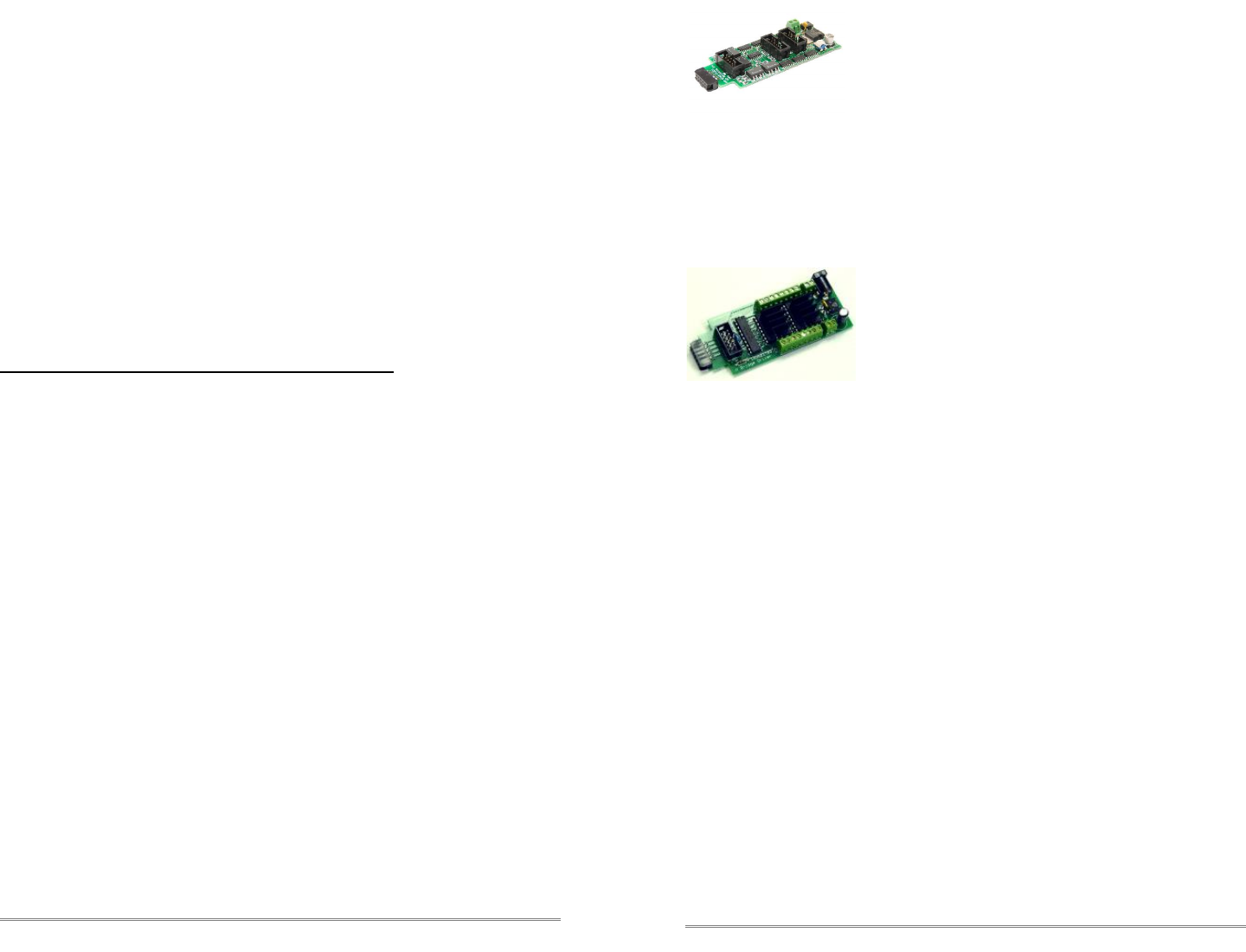
BOD-8 (DCC Block Occupancy Detector - 8 block) The
BOD-8 does not expect you to re-wire your layout to bring
track feeders to the detector cards. The small CT (Current
Transformer) detection coils are placed directly on the track
feeders where they belong. Simple lengths of Cat-5 cable
are the usual way to run the signals back to the detector
boards. Use of CT coils means that there are no track voltage losses associated
with the detectors. Normal detection levels are 1ma. but may be adjusted to
higher levels with on board pots.
During a DCC bus power failure the Power-Lok input on the BOD-8 instantly
locks the current state of each block detector. I.e. the state of the layout does
NOT change during a DCC power outage, neither to all occupied, nor to all
vacant. It just suspends sending any occupancy changes until after power is
restored and things have stabilized again. If you do not want the feature there is
a jumper switch to disable it.
The BOD-8 outputs are low during detection so the TC-64should be configured
as "Detector" for each port that is connected to a BOD-8. This inverts the input
lines to match most types of detector outputs.
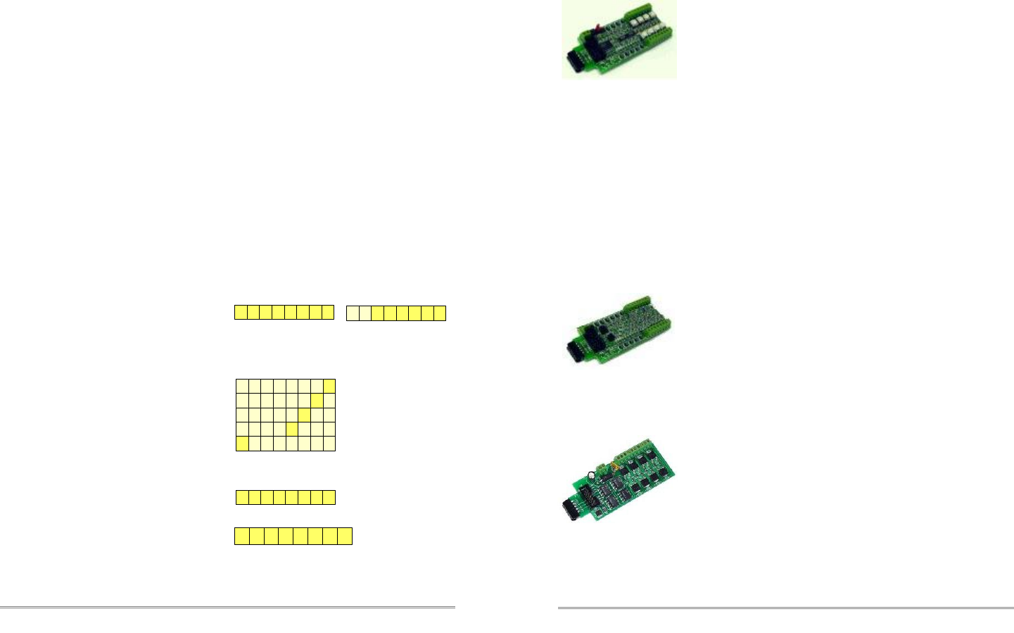
OIB-8 (Opto Isolator Board - 8 input) This 8 input board is
used when a non-isolated source of voltage needs to be
monitored and input to the TC-64. One example would be to
monitor the DCC voltage on a set of points to determine the
position of a turnout without using auxiliary contacts.
This board may be configured to monitor the absence or
presence of an AC or DC signal. It may also be configured to monitor the polarity
of a DC signal. This board requires 10ma. for reliable operation and includes
pads for customer supplied dropping resistors.
SCSD-8 (Single Coil Solenoid Driver) The SCSD-8 Output
Module is designed to drive individual solenoid coils or
other high voltage high power devices. Normally the input
voltage should not exceed 35VDC. The SCSD-8 board is
optically isolated from the driving circuitry to protect the TC-
64 or other control device from the high power outputs.
By using the proper options on the Tower Controller the SCSD-8 may also be
used to control dual coil momentary switch machines. See section 4.0 for
upgrade information.
©2006-10 RR-CirKits, Inc. www..rr-cirkits.com 11
5.2 Control Bit Definition CV 17-22
CV19 Configuration options
hhhh11hh
aaaaaaaa
a = Low Address Bits h = High address Bits
CV17 Ops Mode Address
CV18 Ops Mode Address
0
x
CV 21 Read = Software Version Number
Write = AA to Restore factory defaults
xxxxxxx
CV 22 Manufacturer (87)
1010111
CV17-18 = Ops Mode Address
To program Ops address in service mode, press
and hold program button until command light starts
to blink, then set SV17-18 to desired address.
Press command button again till command light
goes out to exit service mode.
CV19 = Configuration Options
To program configuration options in service mode,
press and hold program button until command light
starts to blink, then set SV19 to desired value.
Press command button again till command light
goes out to exit service mode.
CV20 = Reserved
CV21 = Software Version (read only)
(Send AA to restore Factory defaults)
CV22 = Mfg. ID (87 read only = RR-CirKits)
CV23-278 I/O line control words and Secondary
message control words, configured in groups of 4
bytes per line. (see section 5.1 and 5.3)
mx1 enable port state memory
- - - s g o 1
mx2 enable ops mode program
- - - s g 1 p
mx4 enable gpon interrogate
- - - s o1 p
mx8 enable special interrogate
- - - og1 p
s- - - og1 p 8x enable master mode
6 www..rr-cirkits.com ©2006-10 RR-CirKits, Inc.

10 www..rr-cirkits.com ©2006-10 RR-CirKits, Inc. ©2006-10 RR-CirKits, Inc. www..rr-cirkits.com 7
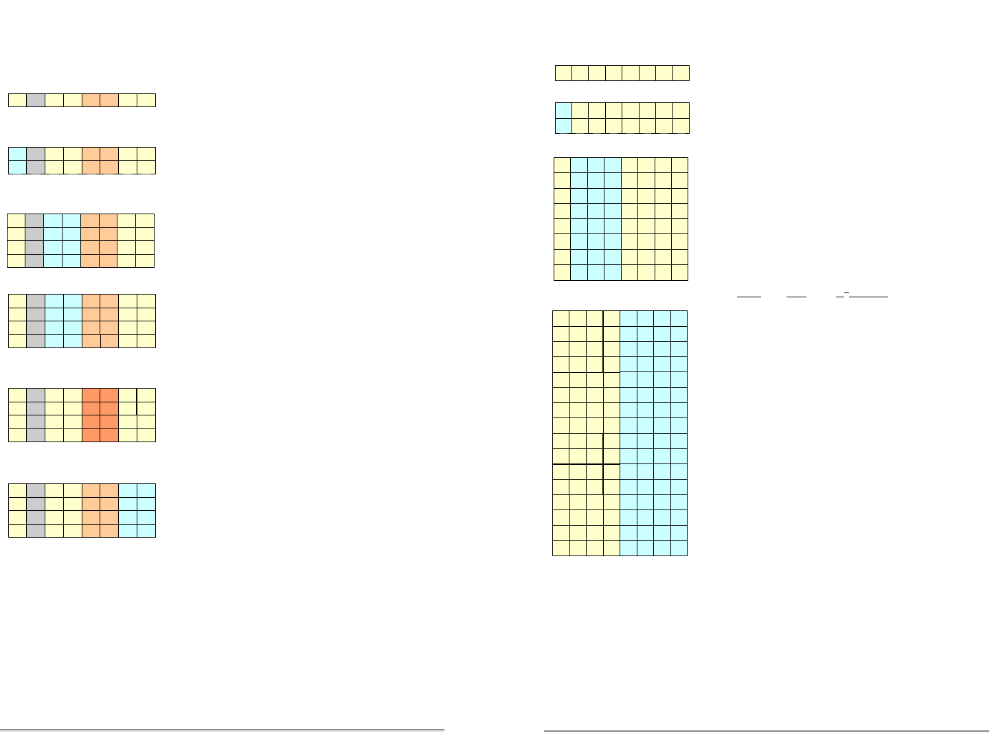
5.3 Control Bit Definition
CV1-16, CV23-278
Range = 0 - 2047
First byte of each pair = low address 0 – 255
Second byte of each pair adds high address bits plus:
- port direction d: 1 = input 0 = output
- switch input t: 1 = toggle (alt action) 0 = normal
- input report t: 1 = precision 0 = normal
- output paired t: 1 = paired lines 0 = normal (Rev5+ only)
- enable signal s: 1 = signal port 0 = normal
CV1-CV16 = Port Starting Addresses and direction.
(sets the first of 8 line addresses for each port)
Factory default values:
cV 1 = 0 SV 2 = 128 ( 1- 8 input)
CV 3 = 8 SV 4 = 128 ( 17- 24 input)
CV 5 = 16 SV 6 = 128 ( 33- 40 input)
CV 7 = 24 SV 8 = 128 ( 49- 56 input)
CV 9 = 32 SV 10 = 128 ( 65- 72 input)
CV 11 = 40 SV 12 = 128 ( 81- 88 input)
CV 13 = 48 SV 14 = 128 ( 97-104 input)
CV 15 = 56 SV 16 = 128 (113-120 input)
CV23-278 I/O line control words and Secondary
message control words, configured in groups of 4
bytes per line.
8x = in 0x = out
Control-Operation Secondary Message
line1=CV87 - 88
line2=CV91 - 92
line3=CV95 - 96
line4=CV99 - 100
line5=CV103-104
line6=CV107-108
line7=CV111-112
line8=CV115-116
CV89 -CV90
CV93 -CV94
CV97 -CV98
CV101-CV102
CV105-CV106
CV109-CV110
CV113-CV114
CV117-CV118
Control-Operation Secondary Message
line1=CV55-56
line2=CV59-60
line3=CV63-64
line4=CV67-68
line5=CV71-72
line6=CV75-76
line7=CV79-80
line8=CV83-84
CV57 - CV58
CV61 - CV62
CV65 - CV66
CV69 - CV70
CV73 - CV74
CV77 - CV78
CV81 - CV82
CV85 - CV86
Control-Operation Secondary Message
line1=CV119-120
line2=CV123-124
line3=CV127-128
line4=CV131-132
line5=CV135-136
line6=CV139-140
line7=CV143-144
line8=CV147-148
CV121-CV122
CV125-CV126
CV129-CV130
CV133-CV134
CV137-CV138
CV141-CV142
CV145-CV146
CV149-CV150
Control-Operation Secondary Message
Port 5
Port 4
Port 2
CV5
Port 3
a a a a a a a a
h h hd t - - CV6
8x = in 0x = out
CV3 a a a a a a a a
h h hd - - CV4
8x = in 0x = out
CV7 a a a a a a a a
h h hd - - CV8
CV9 a a a a a a a a
h h hd - - CV10 8x = in 0x = out
t
t
t
s
s
s
s
line1=CV151-152
line2=CV155-156
line3=CV159-160
line4=CV163-164
line5=CV167-168
line6=CV171-172
line7=CV175-176
line8=CV179-180
CV153-CV154
CV157-CV158
CV161-CV162
CV165-CV166
CV169-CV170
CV173-CV174
CV177-CV178
CV181-CV182
Control-Operation Secondary Message
line1=CV215-216
line2=CV219-220
line3=CV223-224
line4=CV227-228
line5=CV231-232
line6=CV235-236
line7=CV239-240
line8=CV243-244
CV217-CV218
CV221-CV222
CV225-CV226
CV229-CV230
CV233-CV234
CV237-CV238
CV241-CV242
CV245-CV246
Port 7
CV13 a a a a a a a a
h h hd - - CV14 8x = in 0x = out
t s
Control-Operation Secondary Message
Port 6
CV11 a a a a a a a a
h h hd - - CV12 8x = in 0x = out
t s
line1=CV183-184
line2=CV187-188
line3=CV191-192
line4=CV195-196
line5=CV199-200
line6=CV203-204
line7=CV207-208
line8=CV211-212
CV185-CV186
CV189-CV190
CV193-CV194
CV197-CV198
CV201-CV202
CV205-CV206
CV209-CV210
CV213-CV214
Control-Operation Secondary Message
line1=CV247-248
line2=CV251-252
line3=CV255-256
line4=CV259-260
line5=CV263-264
line6=CV267-268
line7=CV271-272
line8=CV275-276
CV249-CV150
CV253-CV254
CV257-CV258
CV261-CV262
CV265-CV266
CV269-CV270
CV273-CV274
CV277-CV278
Port 8
CV15 a a a a a a a a
h h hd - - CV16 8x = in 0x = out
t s
8x = in 0x = out
Control-Operation Secondary Message
line1=CV23-24
line2=CV27-28
line3=CV31-32
line4=CV35-36
line5=CV39-40
line6=CV43-44
line7=CV47-48
line8=CV51-52
CV25 -CV26
CV29 -CV30
CV33 -CV34
CV37 -CV38
CV41 -CV42
CV45 -CV46
CV49 -CV50
CV53 -CV54
CV1
Port 1
a a a a a a a a
h h hd t - - CV2
s
0x xx ↑=close ↓=throw ↑=closed ↓=thrown ↑=hi ↓=low
4x xx ↑=throw ↓=close ↑=thrown ↓=closed ↑=low ↓=hi
Secondary Output Message uses two SVs for each line.
3x xx Reserved
1x xx switch feedback message (closed - thrown)
2x xx general sensor message (high - low)
Secondary message type Control
Secondary Command direction
Byte Four - Secondary Control
1 bit controls polarity for response
2 bits control Secondary message type
4 Bits control Secondary high address bits
Byte Three - Secondary low address bits
5.6 Per Line Bit Definition
Sec. Address
d h h h hp t t
aaaaaaaa
Sec. Control
Bytes Three and Four - SV25-26 etc. Secondary Message Control
0x xx Send Secondary Message
8x xx Receive Secondary Message
0 0
01
1 0
1 1
0x xx switch request (close - throw)
Byte Four Byte Three
Secondary Command polarity
0
1
Byte Four Byte Three
d
d
aaaaaaaa
aaaaaaaa
aaaaaaaa
aaaaaaaa
aaaaaaaa
aaaaaaaa
aaaaaaaa
aaaaaaaa
p h h h ht t
p h h h ht t
0
1
p
p
p
p
d
d
d
d
t t
t t
h h h h
h h h h
h h h h
h h h h
h h h h
h h h h
d = direction
p = polarity
t = type
h = High address Bits
a = Low Address Bits
Secondary messages are optionally sent on the detection of any change of input or output state (or on both changes).
Secondary messages may optionally be received at any address and will trigger the same action as the primary address.
Address Range = 0 – 2047 for turnouts; 0 – 4095 for sensors.
Any type of message may be sent to, or received at, any address (do not send to itself, or a tight loop may occur).
Byte one controls the I/O transition that triggers the message. Bytes three and four control the type of message, if the
message is to be sent or received, and it's address.
The normal use of Secondary Output Messages is to create cascaded commands. One example would be to implement
a yard ladder. Another would be to sequence a traffic signal. Yet another would be to control the lights in a town or a
sound system. Optionally Secondary Receive Messages allow two different commands to trigger the same output. An
example Secondary Receive Message would allow a simulated (or actual) lamp test by programming in a single
Secondary Receive Message address for each panel lamp.
Secondary Messages are in addition to any messages that are normally sent or received, and may be sent to or respond
to any address. They may be sent on the same or a different transition of the input line.
8 www..rr-cirkits.com ©2006-10 RR-CirKits, Inc. ©2006-10 RR-CirKits, Inc. www..rr-cirkits.com 9
5.5 Per Line Bit Definition
Byte Two - CV24 etc. Input / Output Control
8 Bits control Input and Output Messages
x0 . . . . . .Steady ** 10 sec. yy yellow
Input / Output Timing
i = invert t=type T=Timing
8 sec. 10 min. dd dark
6 sec. 8 min. gd blinking green
5 sec. 7 min. rd blinking red
4 sec. 6 min. yd blinking yellow
3 sec. 5 min. dg blinking green
2 sec. 4 min. gg green
1.5 sec. 3 min. rg alt. red / green
1.25 sec. 2 min. yg alt. yellow / green
1 sec. 1.5 min. dr blinking red
0.8 sec. 1 min. gr alt. green / red
0.65 sec. 50 sec. rr red
0.5 sec. 40 sec. yr alt. yellow / red
0.35 sec. 30 sec. dy blinking yellow
0.2 sec. 20 sec. gy alt. green / yellow
0.1 sec. 15 sec. ry alt. red / yellow
ttti
ttti
ttti
ttti
ttti
ttti
t
tti
t
tti
ttti
ttti
ttti
ttti
ttti
ttti
ttti
ttti
7x reserved
6x reserved
111i
011i
TTTT
TTTT
TTTT
TTTT
TTTT
TTTT
TTTT
TTTT
i
i
i
i
i
i
3x output: long blink
110
5x reserved
101
short long 4th aspect *
TTTTttti
Output Invert
Input / Output type
xF . . . . . .
xE . . . . . .
xD . . . . . .
xC . . . . . .
1111
0111
1011
0011
xB . . . . . .
xA . . . . . .
x9 . . . . . .
x8 . . . . . .
1101
0101
1001
0001
x7 . . . . . .
x6 . . . . . .
x5 . . . . . .
x4 . . . . . .
1110
0110
1010
0010
x3 . . . . . .
x2 . . . . . .
x1 . . . . . .
1100
0100
1000
0000
8x invert output
TTTTttt1
0x normal output
TTTTttt0
4x reserved
001
2x output: short blink / input: toggle 'on' time
1x output: long pulse
010
100
000 0x output: short pulse / input: debounce
When no light is connected to the 4th output aspect of a signal head (like in a
three aspect signal), flashing aspects can be used on the respective signal head.
To setup a flashing signal, two CV's are required:
1st, 3rd, 5th and 7th lines: this output byte controls the timing of the flashing aspect;
2nd, 4th, 6th and 8th lines: this output byte selects the two alternating aspect colors
(3rd column). Normally one of these will be “dark” but that is not required.
* The associated port control byte (CV3 <2x> etc.) needs to have “signal” enabled.
** Output: steady; Input: no debounce / 0.1 sec. toggle 'on' time.
5.4 Per Line Bit Definition
Byte One - CV23 etc. Message Type & Input Transition Control
5 Bits control Input/Output (yellow/blue)
2 bits control Secondary message (orange/rust)
Output Responds To
0x switch request (B0)
1x switch feedback (B1)
2x general sensor (B2)
1 1
x0 no input message sent
0 1 x1 send on low to high transition ↑
1x2 send on high to low transition ↓
Input & Secondary Command Direction
0
1
t t
t t
0x ↑=close ↓=throw ↑=closed ↓=thrown ↑=hi ↓=low
8x ↑=throw ↓=close ↑=thrown ↓=closed ↑=low ↓=hi
Input Response Type
0 0
0 1
1 0
0x send switch request
1x send switch feedback message
2x send general sensor message
0 0
x3 send on both transitions ↕
x0 no secondary message sent or received
x4 send/respond on low to high transition ↑
x8 send/respond on high to low transition ↓
xC send/respond on both transitions ↕
1 1
0 1
1 0
0 0
Input Transition Control
m m t t- s sd
0
m m- s s
m m- s s
Input & Secondary Mode only
m m-d
m m-d
m m-d
m m-d
tt
t t
t t
t t
t t- s s
t t- s s
t t- s s
0 0
0 1
1 0
t t- s sd
t t- s sd
t t- s sd
Direction
Output Mode
Secondary Transition Control
Input and Output Modes
m m-d
m m-d
m m-d
m m-d
s s
s s
s s
s s
Input Mode only
1 1 t t- s s 4x Reserved
1 1 t- s sd 4x Reserved
d = direction m = mode s = secondary (transition)
t = transition (input)
d
d
d
d
Input Mode
t
