TDX 5000 DATA SHEET ISA
User Manual: TDX-5000-DATA-SHEET-ISA-
Open the PDF directly: View PDF ![]() .
.
Page Count: 12
• Fully automatic
• Tan Delta, capacitance, dissipation factor
measurements and excitation current test
• Variable output frequency: 1 ÷ 500 Hz
• Output voltage: from 12 V up to 12 kV
• Local control with a large graphic display
• PADS - Power Apparatus Diagnostic Software
for automatic testing, assessment and
report
• Tan Delta test for rotating machines
(generators and motors)
• USB interface and Ethernet interface
for PC connection
• Compact and lightweight
• Patented technology for capacitance and Tan
Delta measurement.
RCTD
COMPENSATING REACTOR
CAP CAL
CALIBRATOR MODULE
STOIL CELL
The following table lists the tests that can be perfor-
med on CTs, VTs and PTs.
10 CT Tan Delta measurements
16 VT Tan Delta measurements
19 PT No-load / excitation current
21 PT Tan Delta measurements
23 CB Tan Delta measurements
28 Capacitor Measurement of the capacitance
Banks
Tests are performed in accordance with the following IEC standards:
IEC61869-2; IEC61869-3; EN 60044-1; EN 60044-2; EN 60044-5; EN
60076-1, and also in accordance with C57,12-90.
LEGENDA:
CURRENT AND VOLTAGE
TRANSFORMER TESTING
POWER TRANSFORMER
TESTING
CIRCUIT BREAKER
TESTING
ELECTRIC MOTOR
TESTING
POWER GENERATOR
TESTING
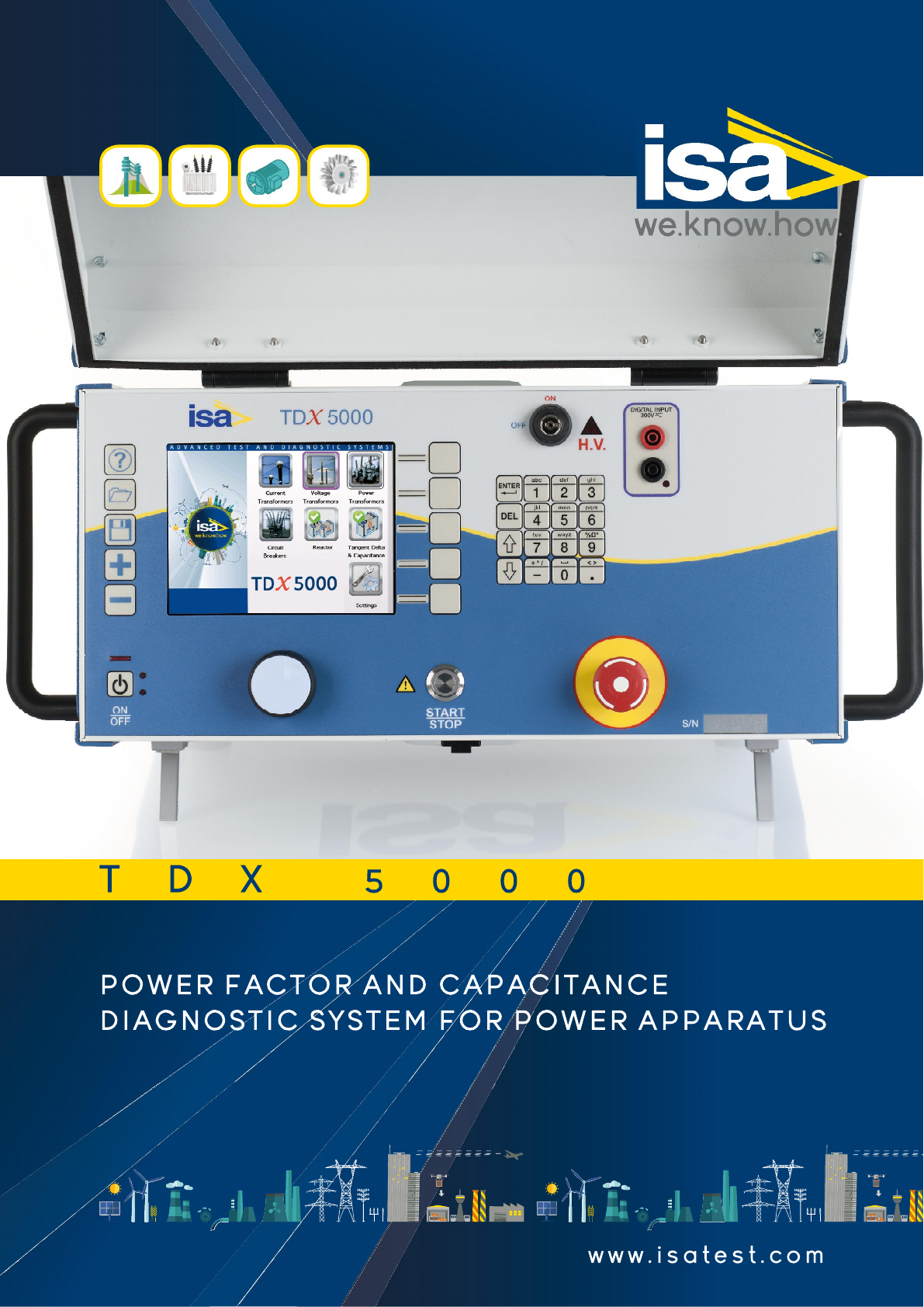
GENERAL CHARACTERISTICS
TDX 5000 equipment performs the measurement of the Tan
Delta, of the dissipation factor and of the capacitance of a
transformer or of any device, at the frequency of the mains or
in a wide frequency range. The measurement is performed by
patented technology.
TDX 5000 measurement circuitry incorporates a reference high
voltage capacitor, rated 200 pF, with a Tan Delta better than
0.005%, and a reference resistor bridge, with accuracy better
than 0.01%, and thermal drift less than 1 ppM/°C. The patented
circuitry and the variable frequency output make test results
immune from external noise.
Available test selections:
. Ungrounded: UST-A; UST-B; UST A+B
. Grounded: GST; GSTg-A; GSTg-B; GSTg-A+B.
TDX 5000 is powered by an internal voltage generator with
electronic control.
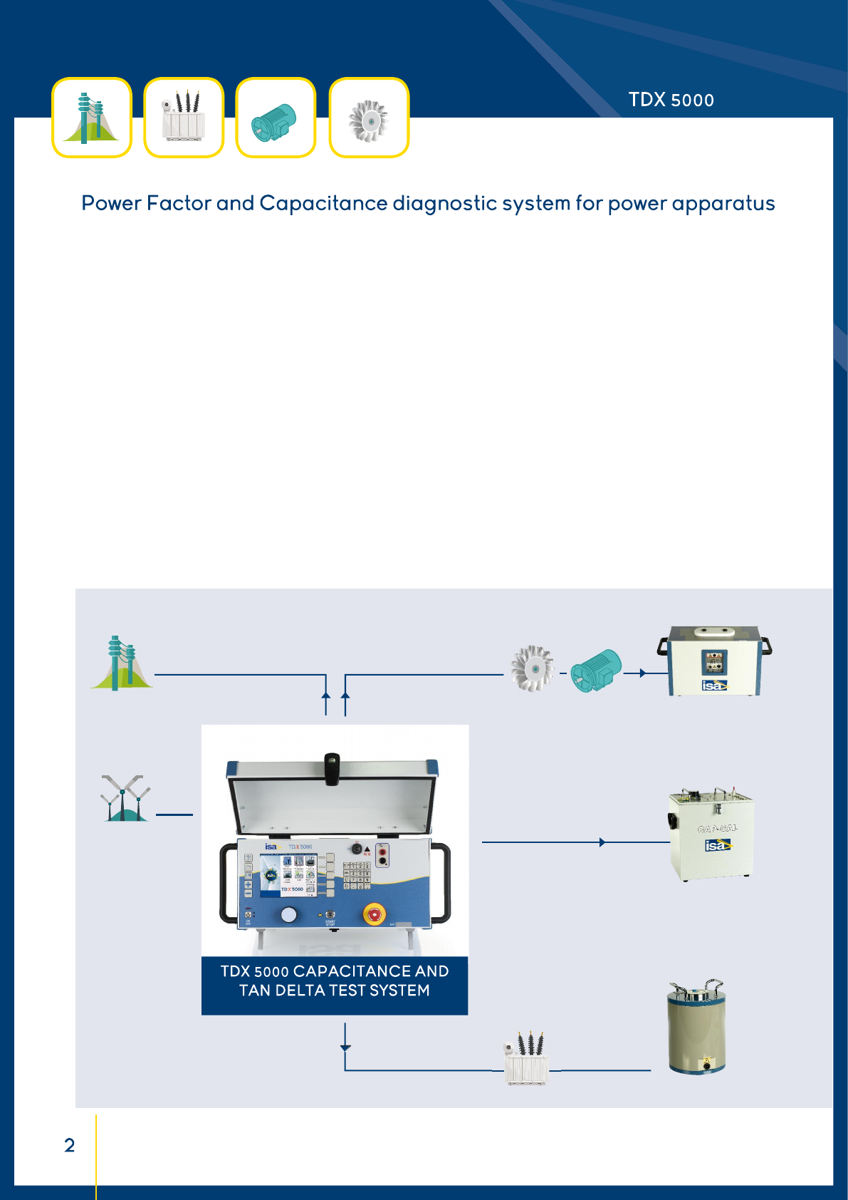
SYSTEM DESCRIPTION
The STS family includes three models : STS 5000, STS 4000
and TDX 5000. TDX 5000 is developed as a compact solution
for high voltage Capacitance and Tan Delta (Dissipation Fac-
tor) measurements. Using the reactor option, TDX 5000 can
also perform tests on rotating machines.
In the local control mode, the selected output is adjustable and
metered on the large, graphic LCD display. With the control knob
and the LCD display, it is possible to enter the MENU mode, that
allows to set many func ons and that make TDX 5000 a very po-
werful tes ng device, with manual and automa c tes ng capa-
bili es and with the possibility to transfer test results to a PC via
ETHERNET or Pen Drive. The TDMS so ware suite, which comes
with the test set, allows to download, display and analyse test
results obtained in local mode. Remote maintenance and dia-
gnos c of the instrument is available via Ethernet. TDMS opera-
tes with all Windows® versions.
The ease of opera on has been the fi rst goal
of TDX 5000 unit. This is why the LCD display is so
large and the dialogue in MENU mode is made easy.
TDX 5000 includes the detec on of the digital signal coming
from the RTCD- Compensa ng Reactor op on.
The instrument is housed in a transportable aluminium box,
which is provided with cover and handles for ease of transporta-
on. A transport trolley can be op onally supplied.
TDMS - Test & Data Management Software
TDMS, Test & Data Management Software, is a powerful
software package providing data management for acceptance
and maintenance testing activities. Electrical apparatus data
and test results are saved in the TDMS database for historical
results analysis.
The TDMS database organizes test data and results for the
majority of electrical apparatus tested with ISA test sets and
related software.
PADS - Power Apparatus Diagnostic Software
PADS - Power Apparatus Diagnostic Software is a power-
ful software application, included in TDMS software, that
optionally allows the remote control of the STS family: STS 5000,
STS 4000, TDX 5000. The software performs various tasks, such as:
. Control STS and TD remotely from PC
. Create test plan
. Download stored test results via Ethernet cable
. Create and customize test reports
. Print test results
This program runs under Windows© environment.
Note: Windows is trademark of Microsoft Corporation.
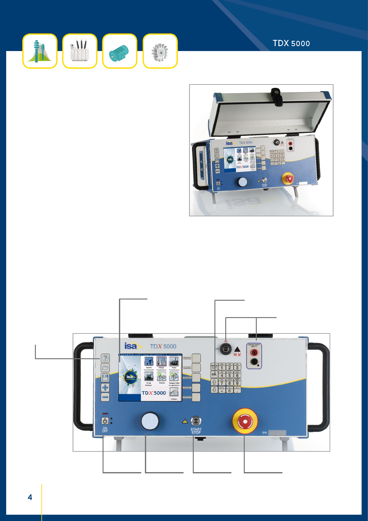
Func on keys
Multifunction
function knob
Digital
input
TDX 5000 - FRONT PANEL
Safety Key
Start/Stop
Power ON/OFF
Keyboard
Emergency
push-bu on
Display
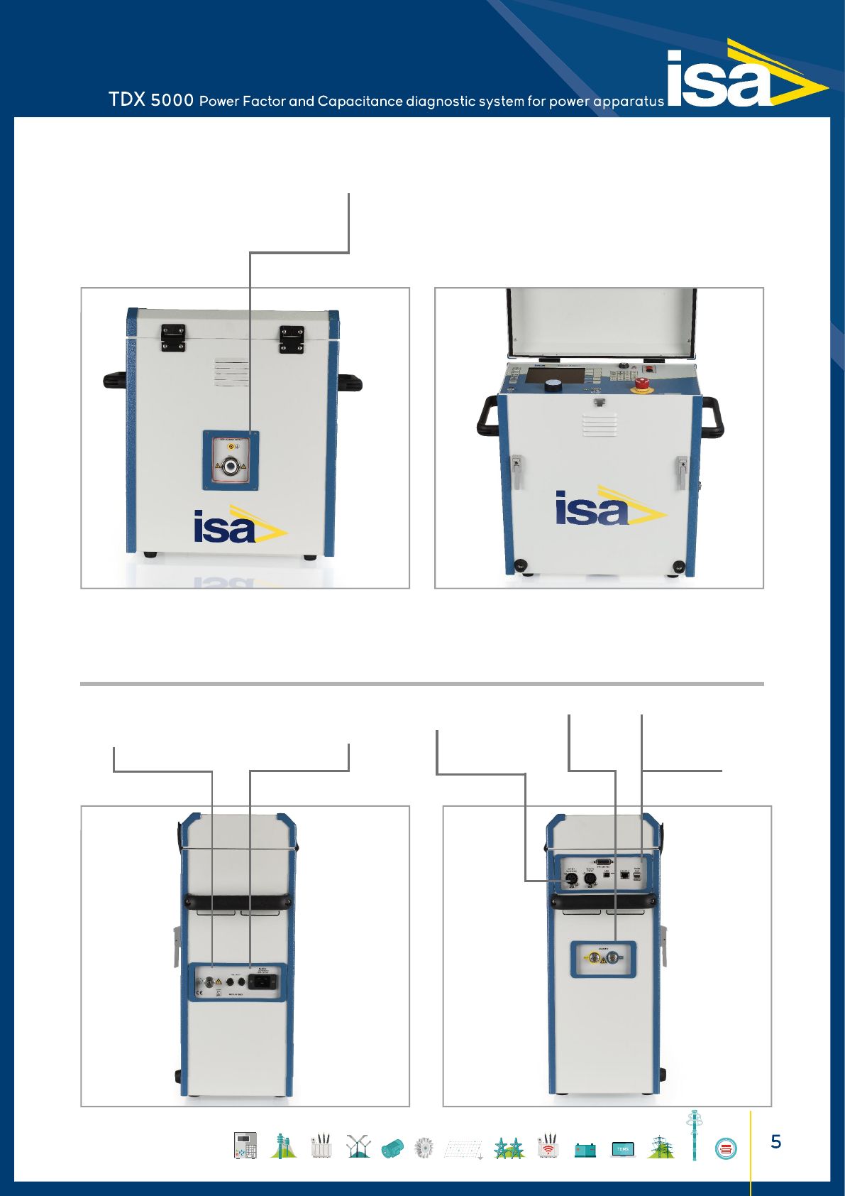
Remote start
External
devices input
Safety warnings Interfaces
TDX 5000 - SIDE PANELS
Power supply
TDX 5000 - SIDE PANELS
High voltage
output
Ground connec on
Measuring
inputs
UST-A
UST-B
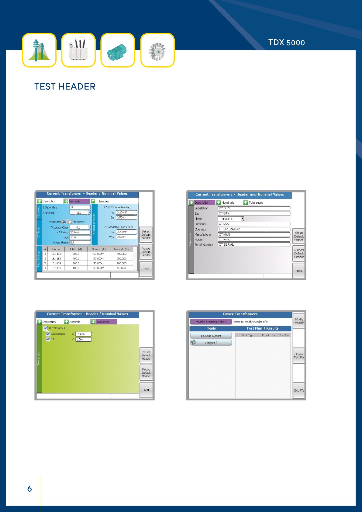
Before star ng a test, all relevant test object data are input into
the header, which is made of four screens. These data are used
by the device for the following test execu on. If, during tests,
some results do not conform and nominal data are to be modifi
ed, the change is made in the Header, so that consistent nominal
data and the corresponding test results are saved together.
If the device is a PT, the Capacitance tests and the no-load current
test can be pre-set together, to form a single Test Plan. The
Test Plan can be saved and recalled; up to 64 diff erent plans can
be stored into memory.
Nominal values window: from these nominal data,
the program computes the nominal saturation knee.
Tests header window: test reference data.
Tolerances window allows se ng the tolerances for
each of the available tests.
Test selection window: it allows selec ng the test to
be performed.
At the end of the programming, star ng the fi rst test will
execute the complete sequence. During the test, test results
are stored in the memory. The test set minimizes the test
dura on, in order to avoid over-hea ng the components. The
same feature is available when controlling the test set via PC
by PADS.
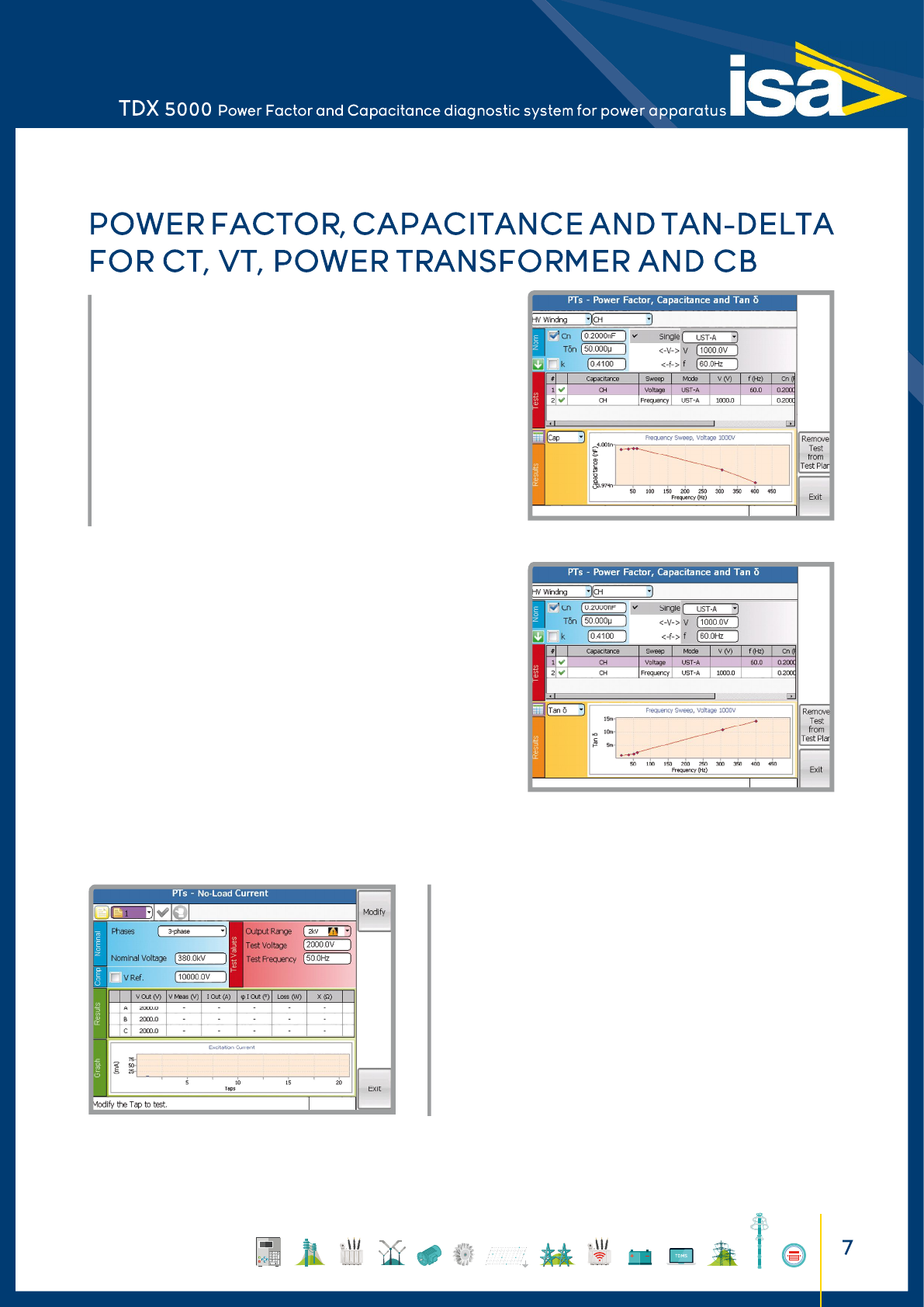
• POWER FACTOR, CAPACITANCE AND TAN DELTA
The test is performed connecting TDX 5000 to the high AC voltage
source to test target.
Input parameters are: Winding, test voltage and frequency, test mode,
and the nominal capacitance, PF, DF.
The display shows the following data:
• Test voltage, current and frequency
• Capacitance, Tan Delta and power factor
• Power data: active, reactive and apparent
• Impedance: module, argument and components.
• NO-LOAD CURRENT
The test is performed connecting TDX 5000 to the high AC voltage
source to the test target.
Input parameters are: the tap number, the type of Tap changer, the test
voltage and the frequency. The test set applies the high voltage and
measures the output current during the test.
The display shows:
• The test voltage
• The current and the phase shift
• The power losses
• The reactance.
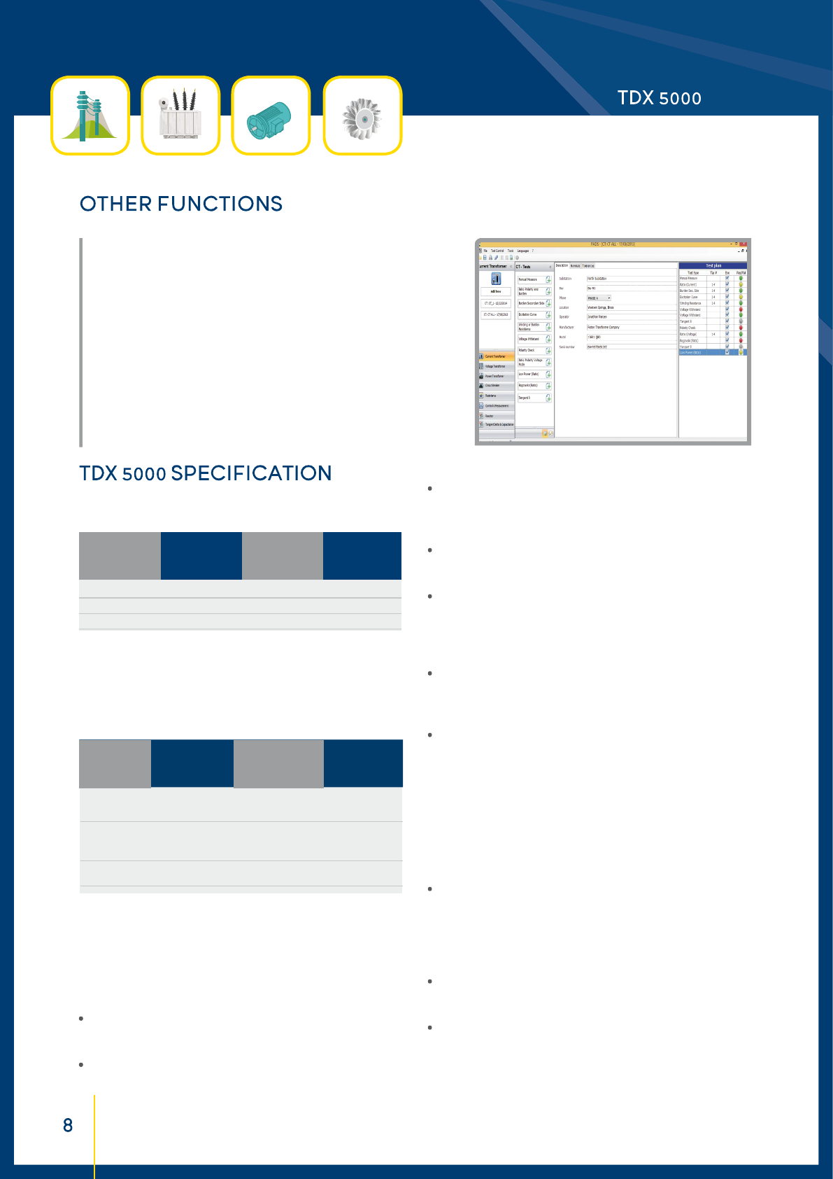
• PADS SOFTWARE
The PADS software is a powerful application, included in the TDMS
software, which provides connectivity to the instruments of the STS
family. The software performs various tasks, such as:
• Edit and upload to the instrument the test headers
• Create and modify plans containing one or more tests
• Optionally remote control of the execution of test plans (start,
interruption, results assessment)
• Download and save results of tests previously performed by the
instrument
• Open and save results on the PC
• Print test results.
GENERATOR CHARACTERISTICS
12000 300 mA 120 s 1 to 500
12000 125 mA > 1 hour 1 to 500
12000 100 mA steady 1 to 500
Note1: the maximum voltage output may decrease for frequency below 50hz
and above 400Hz.
Note2: at 10 kV the output (current value and duration) has the same characteristic.
Voltage and current output metering accuracy and resolution
12000 V AC 1 V ± 0.2% ± 0.5 V < 0.3% + 1 V
5 A AC 1 mA ± 0.2% ± 1 mA < 0.5%
(@ inputs A
or B> 10 mA)
<10 mA AC 0.1 µA ± 0.2% ± 0.1 µA < 0.3% + 0.1 µA
(@ inputs A or B)
INTERNAL RESOLUTION TYPICAL GUARANTEED
MEASURE ACCURACY ACCURACY
± % (rdg) ± % (rg) ± % (rdg) ± % (rg)
. Frequency range: 1 ÷ 500 Hz.
. Connections: by a double shielded HV connector, two Ground
sockets (case and external shield of HV cable), and two measu-
rement sockets (A and B).
TEST MEASUREMENTS
• Capacitance
. Measurement range 1: from 1 pF to 5µF. Resolution: 6 digits.
Accuracy, typical: ± 0.03% of the value ± 0.1 pF; guaranteed:
< 0.1% of the value +1pF (from 45 to 70 Hz).
. Measurement range 2: from 5 µF to 200 µF. Resolution: 6
digits. Accuracy, tipical: ±0.1% of the value ±0.1 nF, guaranteed:
<0.5% of the value ±1 nF.
CURRENT
OUTPUT
A
MAX VOLTAGE
OUTPUT
V
MAX OUTPUT
DURATION
T Max
FREQUENCY
Hz
• Tan Delta or dissipation factor DF
. Measurement range 1: from 0 to 10% (capacitive). Resolution:
5 digits; accuracy, typical: 0.05% of the value ± 0.005 %; guaran-
teed: 0.1% of the value ± 0.005 % (from 45 to 70 Hz, current
< 10 mA).
. Measurement range 2: from 0 to 100%. Resolution: 5 digits;
accuracy, typical: 0.3% of the value ± 0.01 %; guaranteed: 0.5%
of the value ± 0.02 %.
. Measurement range 3: over 100%. Resolution: 5 digits; accu-
racy, typical: 0.5% of the value ± 0.03 %; guaranteed: 0.8% of
the value ± 0.05 %.
• Power factor PF (or cos(φ))
. Measurement range 1: from 0 to 10% (capacitive). Resolution:
5 digits; accuracy, typical: 0.05% of the value ± 0.005 %; guaran-
teed: 0.1% of the value ± 0.005 % (from 45 to 70 Hz, current
< 10 mA).
. Measurement range 2: from 0 to 100%. Resolution: 5 digits;
accuracy, typical: 0.3% of the value ± 0.02 %; guaranteed: 0.5%
of the value ± 0.02 %.
• Impedance
From 1kOhm to 1400 MOhm. Accuracy, typical 0.3% of the
value ± 0.1%, guaranteed <0.5% of the value. Resolution: 6
digits.
• Power
. Measurement ranges: 10 kW, 100 kW, 1 MW. Resolution (5
digits): 0.1 mW; accuracy: <0.5% of the value ± 1 mW.
The same ranges and accuracies are applied to reactive and
apparent power measurements.
• Inductance
. Measurement range 1: from 1 H to 10 kH. Resolution (5 digits):
0.1 mH; accuracy, typical: 0.3% of the value ± 0.5 mH; guaran-
teed: 0.5% of the value.
. Measurement range 2: from 100 H to 1 MH. Resolution (5
digits): 1 H; accuracy, typical: 0.3% of the value; guaranteed:
<0.5% of the value.
• Excitation current
. Range 1: 10 mA. Resolution: 0.1 µA; accuracy, typical: 0.2% of
the value ± 0.1µA; guaranteed: 0.3% of the value ± 0.1µA.
. Range 2: 300 mA. Resolution 1 mA; accuracy, typical: 0.2% of
the value ± 1 mA; guaranteed: 0.5% of the value ± 0.5% of the
range.
Output frequency
. AC output frequency range: 1 to 500 Hz
Max interference condi ons at line
. Electrosta c: 15 mA rms of the interference current into any
lead or cable with no loss of measurement accuracy. Applicable
to a maximum ra o of interference current to specimen current
20:1.
. Electromagne c: 500 µT, at 50 Hz in any direction.
Digital input
Binary input used only for RCTD - Compensating reactor option.
Display
The large graphic display has the following characteristics:
. Pixels: 640 x 480, coloured
. LCD type: TFT
. View area: 132 x 99 mm
. Backlight.
Local test set control
Local test control: by the START / STOP pushbutton. After the
test selection, pressing it, the output is generated, according to
the type of test. During ON, if a manual control test is selected,
the operator adjusts the output at the desired value.
Test saving:
. Automatic save
. After operator confirmation.
OTHER CHARACTERISTICS
Communication interfaces
. Slave USB and ETHERNET for the PC connection
. USB port for the USB key.
Interfaces to external modules:
. Alarms to a flashing light
. Remote start input.
Mains supply
. 100-230 V ± 15%; 50-60 Hz
. Maximum supply current: 16 A.
Dimensions: 450 (W) x 530 (H) x 215 (D) mm.
Weight: 39 kg.
CONNECTION CABLES
. One mains supply cable, 2 m long.
. One grounding cable, 6 m long.
. One ETHERNET interface cable.
. One USB pen drive.
. 1 High voltage connection cable, 20 m long, 25 kV, with earth
screen, for the connection to the device under test, terminated
on the device side with an isolated banana plug and on the TDX
5000 side with two plugs: one for the HV and the other one for
the ground. The cable is mounted on a wheel.
. 1 clamp, 25 mm opening, with a connector which mates with
the HV cable.
. 1 bigger clamp, 40 mm opening, with a connector which mates
with the HV cable.
. 2 shielded connection cables, 20 m long, for the connection to
the metering points. Terminated on the TDX 5000 side with the
metering connector and on the device side with a banana plug.
Cables are mounted on wheels.
. 2 clamps, 25 mm opening, terminated with banana sockets,
which allow connecting to the metering point.
. 2 Kelvin type clamps, 65 mm opening, with banana plugs,
which allow connecting to the metering point.
. 1 hot collar cable, 1m long, with connector.
TRANSPORT CASE
The transport case allows delivering TDX 5000 with no concern
about shocks up to a fall of 1 m. The case is supplied with
handles and wheels.
HEAVY DUTY TRANSPORT CASE
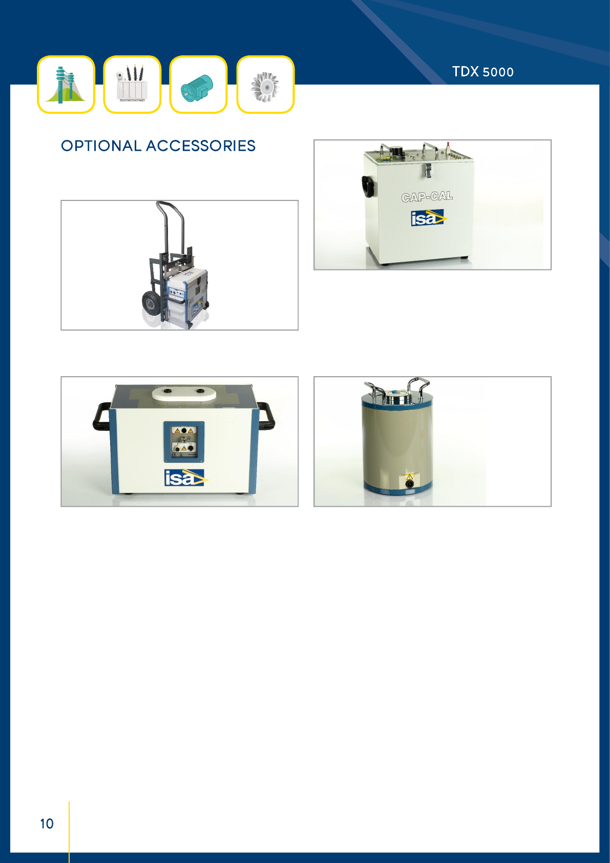
FOLDABLE TROLLEY
The trolley eases the transport of TDX 5000.
RCTD COMPENSATING REACTOR
This module is useful for testing Tan Delta in rotating machines
with TDX 5000 and allows increasing the test current and getting
the maximum test voltage with high capacitive burdens. Each
RCTD is composed by two inductors with a nominal value of 40H
and a steady current of 0.4A. The maximum current on each in-
ductor can be up to 1A for more than 10s. The inductors can be
connected in parallel on the load in order to increase the test fre-
quency. It is possible to connect two RCTD in parallel in order to
have three or four inductors connected together (2 x 80 H total).
CAPCAL CALIBRATOR MODULE
Purpose of the calibrator is to check the correctness of TDX
5000 measurement. The calibrator includes an extremely high
accuracy high voltage capacitor, which comes with a cer fi cate
issued by ISA lab.
RCTD
STOIL CELL FOR THE HV TEST OF THE DIELECTRIC OIL
The option allows testing that the oil characteristics of isolation
are met and that there is no contamination.
The option is made of a suitable glass container with electrodes;
the electrodes are connected to TDX 5000 for the test execu-
tion. The test result, displayed by TDX 5000, is the oil Tan Delta.
Cell characteristics are the followings:
• Maximum test voltage: 12 kV
• Cell volume: about 1l
• Capacitance of the empty cell: 60 pF.
DIGITAL THERMO HYGROMETER
Tan Delta tests are influenced by temperature and humidity.
The option allows measuring these parameters and to input
them into the test settings. Meter characteristics:
. Temperature range: -10÷60°C.
. Temperature measurement accuracy: ± 0.4°C.
. Humidity measurement range: 5÷5% RH.
. Accuracy of humidity measurement: ± 2.5% RH, over the
whole range.
. Dimensions: 141 x 71 x 27 mm. Weight: 150 g.
OIL CELL
CAPCAL
REMOTE SAFETY SWITCH
If it is desired to start the test remotely from the test set, the
op onal switch allows to do it, up to the distance of 20 m, which
is the length of the cable provided.
WARNING STROBE LIGHT
The warning strobe light alerts when the test is completed, or
when there are alarms. The light is self-powered, and turns on
(fl ashes) upon the test set command. A siren is also included.
PADS - Power Apparatus Diagnostic Software
PADS - Power Apparatus Diagnostic Software is a powerful softwa-
re application, included in TDMS software, that allow the remote
control of the STS family: STS 5000, STS 4000, TDX 5000. Please
refer to PADS datasheet for more information.
The test set conforms to the EEC directives regarding
Electromagnetic Compatibility and Low-Voltage instruments.
. Electromagnetic Compatibility: Directive no. 2014/30/UE.
Applicable Standard: EN61326-1:2013.
. Low Voltage Directive: Directive n. 2014/35/UE.
Applicable standards: CEI EN61010-1:2010. In particular:
. Input/output protection: IP 2X - IEC69529; IP 4X for HV
output.
. Operating temperature: -10÷5 °C; storage: -20÷70 °C.
. Relative humidity: 5÷95% without condensing.
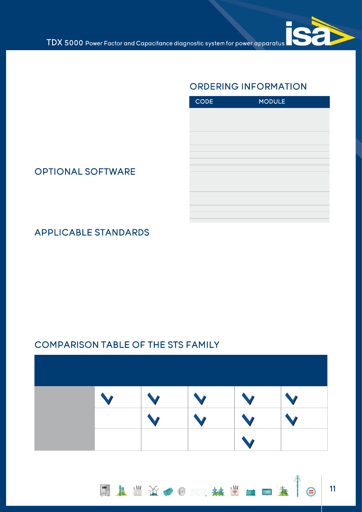
65175 TDX 5000 - with TDMS software*,
standard test cable kit
38175 and heavy duty transport case
10176T PADS software (trasfo)- Power transformer
and Tan Delta test module
40175 CAP-CAL Calibration module
42175 Remote safety switch
44175 Digital thermo hygrometer
43175 Warning strobe light
47175 RCTD - Compensating reactor for TDX 5000
48175 Cable test kit for RCTD
19175 Transport case for RCTD
13175 STOIL Cell for the eletric test of insulating oil
of the transformer
68175 Trolley for TDX 5000
66175 Cable test kit for TDX 5000
*PADS - Power Apparatus Diagnos c So ware is NOT included into
basic unit price. It should be expressly ordered.
STS MODEL HIGH
CURRENT,
AC & DC
HIGH
VOLTAGE
LOW
AC-DC
OUTPUTS
TAN DELTA TESTS OPTIONAL
HIGH AC
CURRENT
WITH BUX 3000
STS 5000 1)
STS 4000 1)
NOT AVAILABLE
TDX 5000
NOT AVAILABLE NOT AVAILABLE NOT AVAILABLE NOT AVAILABLE
with TD 5000
with TD 5000
1) For USA and Germany, only TDX 5000 and STS 3000 light with TD 5000 are available.
The document is subject to change without notice.
Always refer to our technical specification for more detailed
information and as formal contract document.
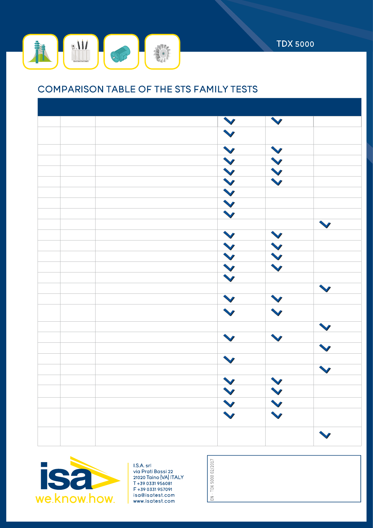
NO. TEST OF TEST DESCRIPTION STS 5000 STS 4000 TDX 5000
1 CT Ra o, Voltage mode NOT AVAILABLE
2 CT Ra o, polarity and burden with high
AC current WITH BUX 3000 NOT AVAILABLE
3 CT Burden; secondary side NOT AVAILABLE
4 CT Excita on curve NOT AVAILABLE
5 CT Winding or burden resistance NOT AVAILABLE
6 CT Voltage withstand NOT AVAILABLE
7 CT Remote polarity check NOT AVAILABLE NOT AVAILABLE
8 CT Rogowski coil transformers WITH BUX 3000 NOT AVAILABLE
9 CT Low power transformers WITH BUX 3000 NOT AVAILABLE
10 CT Tan(δ) measurements WITH TD 5000 WITH TD 5000
11 VT Ra o; polarity NOT AVAILABLE
12 VT Burden, secondary side NOT AVAILABLE
13 VT Ra o, electronic transformers NOT AVAILABLE
14 VT Voltage withstand NOT AVAILABLE
15 VT Remote polarity check NOT AVAILABLE NOT AVAILABLE
16 VT Tan(δ) measurements WITH TD 5000 WITH TD 5000
17 PT Ra o per TAP NOT AVAILABLE
18 PT Sta c and dynamic resistance of Tap
Changer contacts
NOT AVAILABLE
19 PT Excita on current WITH TD 5000 WITH TD 5000
20 PT Short circuit impedance NOT AVAILABLE
21 PT Tan(δ) measurements WITH TD 5000 WITH TD 5000
22 CB High DC current micro-Ohmmeter test NOT AVAILABLE NOT AVAILABLE
23 CB Tan(δ) measurements WITH TD 5000 WITH TD 5000
24 VT CB RELAY Current threshold and ming NOT AVAILABLE
25 R Ground resistance and resis vity NOT AVAILABLE
26 R Step and touch voltages NOT AVAILABLE
27 L Measurement of line impedance and
of the related parameters
NOT AVAILABLE
28 Capacitor
Banks
Measurement of the capacitance WITH TD 5000 WITH TD 5000
