ATCB Form 731 C51 TEW 423PI_FCC 423PI FCC
User Manual: TEW-423PI_FCC .trendnet.com - /Certifications/TEW-423PI/
Open the PDF directly: View PDF ![]() .
.
Page Count: 65

Training Research Co., Ltd.
1F, No. 255, Nan Yang Street, Shijr, Taipei Hsien 221, Taiwan, R.O.C.
TEL: 886-2-26935155 FAX: 886-2-26934440
E-mail: report@trclab.com.tw
TRCSince1985
®
TRENDware
TEW-423PI FCC Test Report

Test Report ------------------------------------------------------------------------------- 1/60
Report No.: C5115391, FCC Part 15
Training Research Co., Ltd., TEL: 886-2-26935155, Fax: 886-2-26934440
MEASUREMENT REPORT
of
Wireless PCI Adapter
Applicant : TRENDware International, Inc.
Product Name : 54Mbps 11g Wireless PCI Adapter
Model Name : TEW-423PI
FCC ID : NHPWLG1200
Report No. : C5115391
Tested by :
Training Research Co., Ltd.
TEL : 886-2-26935155 FAX : 886-2-26934440
No. 255, Nanyang Street, Shijr, Taipei Hsien 221, Taiwan, R.O.C.

Test Report ------------------------------------------------------------------------------- 2/60
Report No.: C5115391, FCC Part 15
Training Research Co., Ltd., TEL: 886-2-26935155, Fax: 886-2-26934440
CERTIFICATION
We here by verify that:
The test data, data evaluation, test procedures and equipment configurations shown in this report
were made mainly in accordance with the procedures given in ANSI C63.4 (1992) as a reference. All test
were conducted by Training Research Co., Ltd., 255 Nanyang Street, Shijr, Taipei Hsien 221, Taiwan,
R.O.C. Also, we attest to the accuracy of each.
We further submit that the energy emitted by the sample EUT tested as described in the report is
in compliance with the technical requirements set forth in the FCC Rules Part 15 Subpart B (Declaration
of Conformity) and C Section 15.247.
Applicant : TRENDware International, Inc.
Applicant address : 3135 Kashiwa Street,Torrance, CA 90505, USA
Product Name : 54Mbps 11g Wireless PCI Adapter
Model Name : TEW-423PI
FCC ID : NHPWLG1200
Report No. : C5115391
Test Date : November 26, 2003
Prepared by: Approved by:
Jack Tsai Frank Tsai
Conditions of issue :
(1) This test report shall not be reproduced except in full, without written approval of
TRC. And the test result contained within this report only relate to the sample
submitted for testing.
(2) This report must not be used by the client to claim product endorsement by NVLAP
or any agency of U.S. Government.
NVLAP LAB CODE: 200174-0

Test Report ------------------------------------------------------------------------------- 3/60
Report No.: C5115391, FCC Part 15
Training Research Co., Ltd., TEL: 886-2-26935155, Fax: 886-2-26934440
Federal Communications Commission
Declaration of Conformity
(DoC)
For the Following Equipment:
Product name : 54Mbps 11g Wireless PCI Adapter
Model name : TEW-423PI
Trade name : TRENDnet
Is herewith confirmed and found to comply with the requirements of CFR 47 part15
Subpart B - Unintentional Radiators regulation. The results of electromagnetic mission
evaluation are shown in the report number: C5115391
This device complies with Part 15 of the FCC Rules. Operation is subject to the
following two conditions:
(1) This device may not cause harmful interference, and
(2) This device must accept any interference received,
including interference that may cause undesired operation
Manufacturer USA local representative
Company name:
TRENDware International Inc.
Company address:
3135 Kashiwa Street
Torrance, CA 90505, USA
ZIP / Postal code
90505
Contact person:
Peggy Huang
Title:
Wireless Comm RD Dept Manager
Internet e-mail address:
Peggy@trendware.com
Tel / Fax:
310-891-1100 / 310-891-1111

Test Report ------------------------------------------------------------------------------- 4/60
Report No.: C5115391, FCC Part 15
Training Research Co., Ltd., TEL: 886-2-26935155, Fax: 886-2-26934440
Tables of Contents
I. GENERAL ...................................................................................................................... 6
1.1 Introduction ............................................................................................................... 6
1.2 Description of EUT .................................................................................................... 6
1.3 Description of Support Equipment .............................................................................. 6
1.4 Test method ............................................................................................................... 9
1.5 Configuration of System Under Test .......................................................................... 10
1.6 Verify the Frequency and Channel ............................................................................. 12
1.7 Test Procedure ......................................................................................................... 12
1.8 Location of the Test Site ............................................................................................ 13
1.9 General Test Condition .............................................................................................. 13
II. Section 15.101(a) : Equipment Authorization of Unintentional Radiators .................... 14
III. Section 15.203 : Antenna Requirement.......................................................................... 15
IV. Section 15.207 : Power Line Conducted Emissions for AC Powered Units ................ 16
4.1 Test Condition & Setup ............................................................................................. 16
4.2 List of Test Instruments ............................................................................................. 16
4.3 Test Result of Conducted Emissions .......................................................................... 17
Un-detachable antenna ................................................................................................ 17
Detachable antenna ..................................................................................................... 20
V. Section 15.247(a) : Technical Description of the EUT .................................................. 24
VI. Section 15.247(a)(2) : Bandwidth for Direct Sequence System .................................. 25
6.1 Test Condition & Setup ............................................................................................. 25
6.2 Test Instruments Configuration ................................................................................... 25
6.3 List of Test Instruments ............................................................................................. 25
6.4 Test Result of Bandwidth ........................................................................................... 25
Channel 01 ................................................................................................................. 26
Channel 06 ................................................................................................................. 27
Channel 11 ................................................................................................................. 28

Test Report ------------------------------------------------------------------------------- 5/60
Report No.: C5115391, FCC Part 15
Training Research Co., Ltd., TEL: 886-2-26935155, Fax: 886-2-26934440
VII. Section 15.247(b) : Power Output ................................................................................. 29
7.1 Test Condition & Setup ............................................................................................. 29
7.2 List of Test Instruments ............................................................................................. 29
7.3 Test Result ................................................................................................................ 29
VIII. Section 15.247(c) : Spurious Emissions (Radiated) ................................................... 30
8.1 Test Condition & Setup ............................................................................................. 30
8.2 List of Test Instruments ............................................................................................. 31
8.3 Test Result of Spurious Radiated Emissions ............................................................... 32
30MHz to 1GHz for Detachable antenna ..................................................................... 32
30MHz to 1GHz for Un-detachable antenna ................................................................ 33
1GHz to 25GHz for Detachable .................................................................................. 34
1GHz to 25GHz for Un-detachable .............................................................................. 40
8.4 Test Result of Bandedge.............................................................................................. 46
Detachable antenna ..................................................................................................... 47
Un-detachable antenna ................................................................................................ 51
IX. Section 15.247(d) : Power Spectral Density .................................................................. 55
9.1 Test Condition & Setup ............................................................................................. 55
9.2 Test Instruments Configuration ................................................................................... 55
9.3 List of Test Instruments ............................................................................................... 55
9.4 Test Result of Power Spectral Density ....................................................................... 56
Channel 01 ................................................................................................................ 57
Channel 06 ................................................................................................................ 58
Channel 11 ................................................................................................................ 59
Appendix A: Brand name and Modem name ..................................................................... 60

Test Report ------------------------------------------------------------------------------- 6/60
Report No.: C5115391, FCC Part 15
Training Research Co., Ltd., TEL: 886-2-26935155, Fax: 886-2-26934440
. GENERAL
1.1 Introduction
The following measurement report is submitted on behalf of applicant in support that the
certification in accordance with Part 2 Subpart J and Part 15 Subpart A, B and C of the
Commission's Rules and Regulations.
1.2 Description of EUT
Product Name : 54Mbps 11g Wireless PCI Adapter
Model Name : TEW-423PI
Granted FCC ID : NHPWLG1200
Frequency Range : 2.412 GHz ~ 2.462GHz
Support Channel : 11 Channels
Modulation Skill : DBPSK, DQPSK, CCK, OFDM
Power Type : Power by Protocol Control Information Interface of PC
Data Cable : None
1.3 Description of Support Equipment
In order to construct the minimum testing, following equipment were used as the support units.
Notebook : IBM Think Pad X20
Model No. : 2662-11T
Serial No. : FX-1192200/09
FCC ID : N/A, DoC Approved (Declaration of Confirmation) Approved
ᛀ : 3892B565
Adaptor : IBM
Model No. : PA2450U
Serial No. : 02K6654
FCC ID : N/A, DoC Approved
Power type : I/P: 100 ~ 240vac, 50 ~ 60 Hz, 0.5A ~ 1.2A; O/P: 16Vdc, 4.5A
Power cord : Non-shielded, 1.80m length, Plastic, with ferrite core

Test Report ------------------------------------------------------------------------------- 7/60
Report No.: C5115391, FCC Part 15
Training Research Co., Ltd., TEL: 886-2-26935155, Fax: 886-2-26934440
PC : IBM 6840; HP Pavilion
Model No. : 6840MJV; P8574A
Serial No. : 96CC 0C1; TW21920435
FCC ID : N/A, DoC
ᛀ : 3892I279; 3902H097
Power type : 100 ~ 127VAC / 4A, 200 ~ 240VAC/2A, 50 ~ 60Hz, 5A, Switching
Power cord : Non-shielded, 2.33m length, Plastic hood, No ferrite core
Printer : HP
Model No. : C6464A, C2642A
Serial No. : TH16LEB5PK, SG69A196GV
FCC ID : None (DoC Approved), B94C2642X
ᛀ : 3892H381, None
Power type : Switching adaptor
Power cord : Non-shielded, 173cm length, No ferrite core (between adaptor and AC source)
Non-shielded, 180cm length, with ferrite core (between printer and adaptor)
Data cable :Shielded, 1.70m length, No ferrite core
Monitor : HP 15’ Color Monitor, HP pavilion mx70
Model No. : D2827A, P1283A
Serial No. : KR91379759, TWTBQ00397
FCC ID : C5F7NFCMC1518X
ᛀ : 3872B039
Power type : 110 ~ 240 VAC / 50 ~ 60 Hz, Switching
Power cord : Shielded, 1.83m length, No ferrite core
Data cable : Shielded, 1.46m length, with two ferrite cores
Modem : ACEEX
Model No. : XDM-56V14
FCC ID : IFAXDM-56V14
Power type : Linear
Power cord : Non-shielded, 1.9m length, No ferrite cord
Data cable : RS232, Shielded, 1.2m length, No ferrite core
RJ11C x 2, 7’ length non-shielded, No ferrite core

Test Report ------------------------------------------------------------------------------- 8/60
Report No.: C5115391, FCC Part 15
Training Research Co., Ltd., TEL: 886-2-26935155, Fax: 886-2-26934440
PS/2 Mouse : HP
Model No. : M-S34
Serial No. : LZB90714106, LZC84446151
FCC ID : DZL211029
ᛀ : 4862A011
Power type : By PC
Power cord : Non-shielded, 1.88m length, No ferrite core
PS/2 Keyboard : HP
Model No. : 5187-0343, SK-2501K
Serial No. : BE21700404, M981216213
FCC ID : DoC Approved, GYUR38SK
ᛀ : 3892C981, 3862A621
Power type : By PC
Data cable : Shielded, 1.73m length, Plastic hood, No ferrite core
USB gamepad : Rockfire
Model No. : QF-337uv
Serial No. : 10600545, KR91379759
FCC ID : None (CE approval)
ᛀ : 3862A574
Power type : By computer
Data Cable : Shielded, 1.81m length, Plastic, with ferrite core
WLAN Card : Gemtek Technology Co., Ltd.
Model No. : C911003
FCC ID : MXF-C911003

Test Report ------------------------------------------------------------------------------- 9/60
Report No.: C5115391, FCC Part 15
Training Research Co., Ltd., TEL: 886-2-26935155, Fax: 886-2-26934440
1.4 Test method
1) The EUT can be equipped with two kinds of antennas, it has an integral (Undetachable)
antenna, and the detachable antenna. During tested, two kinds of antennas were tested.
2) Put the EUT into a personal computer’ s PCI bus and screw it.
3) Using the computer and software provided by the manufacturer to control EUT. The test
is performed under the specific conditions.
4) Set different channels (CH1/CH6/CH11) being tested, and making EUT to as follow
mode:
(a) Radiated for intentional test:
making EUT to the mode of continuous transmission
(b) Conducted and Radiated for unintentional test:
making EUT to the linking (Rx/Tx) mode with far support equipments
Test Report ------------------------------------------------------------------------------ 10/60
Report No.: C5115391, FCC Part 15
Training Research Co., Ltd., TEL: 886-2-26935155, Fax: 886-2-26934440
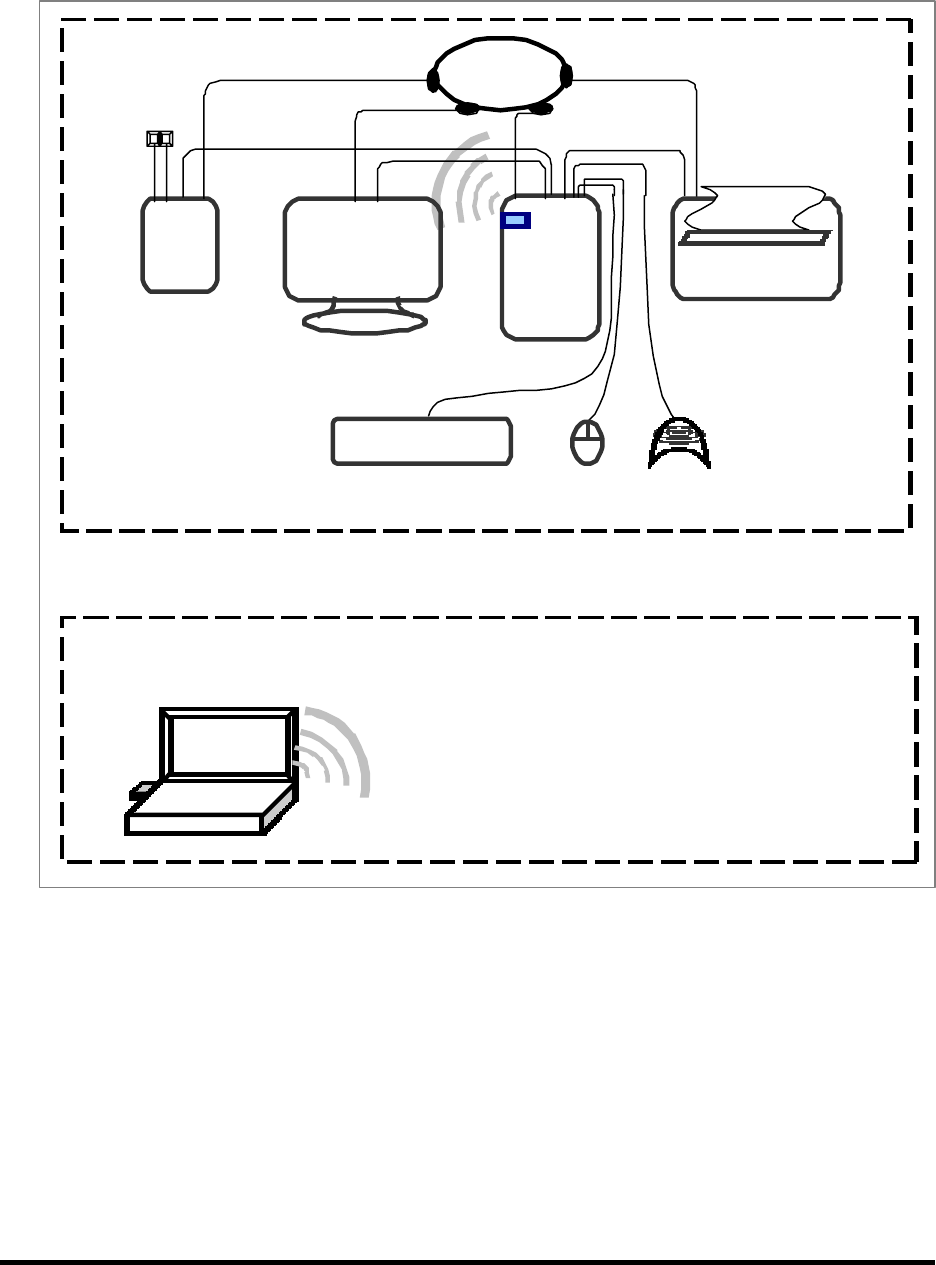
1.5 Configuration of System Under Test
1.5.1 Conducted and Radiated for unintentional
Connections of Computer:
*Parallel Port --- a printer
*Serial Port --- an external modem
*PS/2 Port --- a PS/2 keyboard
*PS/2 Port --- a PS/2 mouse
*USB Port --- a USB gamepad
*PCI Interface --- EUT
Far-end
Notebook
Turntable
EUT
Monitor
Modem
Printer
PC
Power
Source
PS/2
Mouse
USB
Gamepad
PS/2
Keyboard
Test Report ------------------------------------------------------------------------------ 11/60
Report No.: C5115391, FCC Part 15
Training Research Co., Ltd., TEL: 886-2-26935155, Fax: 886-2-26934440
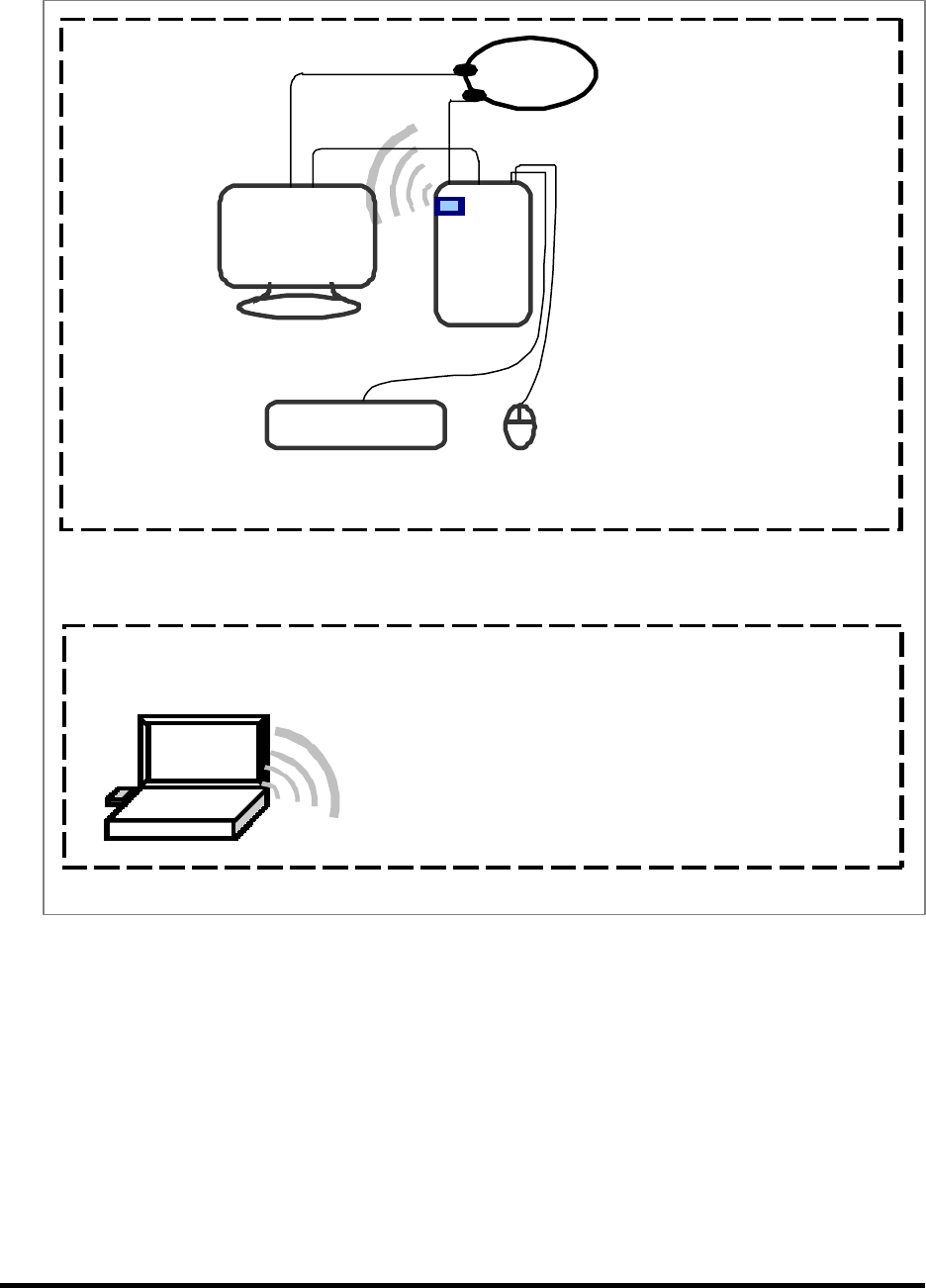
1.5.2 Radiated of intentional
The tests below are carried out the EUT transmitter set at high power in TDD mode. The
EUT is needed to force selection of output power level and channel number.
The setting up procedure was recorded in <1.4 test method>.
Far-end
Notebook
Turntable
EUT
Monitor PC
Power
Source
PS/2
Mouse
PS/2
Keyboard

Test Report ------------------------------------------------------------------------------ 12/60
Report No.: C5115391, FCC Part 15
Training Research Co., Ltd., TEL: 886-2-26935155, Fax: 886-2-26934440
1.6 Verify the Frequency and Channel
CH12345678910
0 2412 2417 2422 2427 2432 2437 2442 2447 2452 2457
1 2462 --- --- --- --- --- --- --- --- ---
Note: 1. This is for confirming that all frequencies are in 2.412GHz to 2.462GHz.
2. Section 15.31(m): Measurements on intentional radiators or receivers shall be performed at
three frequencies for operating frequency range over 10 MHz.
(The locations of these frequencies one near the top, one near the middle and one near the
bottom.)
3. After test, the EUT operating frequencies are in 2.412GHz to 2.462GHz. So all the items
as followed in testing report are need to test these three frequencies:
Top: Channel – 1; Middle: Channel – 6; Bottom: Channel – 11.
1.7 Test Procedure
All measurements contained in this report were performed mainly according to the techniques
described in ANSI C63.4 (1992) and the pre-setup was written on 1.4 test method, the detail setup
was written on each test item.

Test Report ------------------------------------------------------------------------------ 13/60
Report No.: C5115391, FCC Part 15
Training Research Co., Ltd., TEL: 886-2-26935155, Fax: 886-2-26934440
1.8 Location of the Test Site
The radiated emissions measurements required by the rules were performed on the
three-meter,Anechoic Chamber (FCC Registration Number: 93906) maintained by Training
Research Co., Ltd. 1F, No. 255 Nanyang Street, Shijr, Taipei Hsien 221, Taiwan, R.O.C. Complete
description and measurement data have been placed on file with the commission. The conducted
power line emissions tests and other test items were performed in a anechoic chamber also located at
Training Research Co., Ltd.
No. 255 Nanyang Street, Shijr, Taipei Hsien 221, Taiwan, R.O.C. Training Research Co.,
Ltd. is listed by the FCC as a facility available to do measurement work for others on a contract
basis.
1.9 General Test Condition
The conditions under which the EUT operates were varied to determine their effect on the
equipment's emission characteristics. The final configuration of the test system and the mode of
operation used during these tests were chosen as that which produced the highest emission levels.
However, only those conditions, which the EUT was considered likely to encounter in normal use
were investigated.
In test, they were set in high power and continuously transmitting mode that controlled by
computer. The ch01, ch06 and ch11 of EUT were all tested. The setting up procedure is recorded on
1.4 test method.

Test Report ------------------------------------------------------------------------------ 14/60
Report No.: C5115391, FCC Part 15
Training Research Co., Ltd., TEL: 886-2-26935155, Fax: 886-2-26934440
II. Section 15.101(a): Equipment authorization of unintentional radiators
The EUT equipped with a Protocol Control Information interface and should be operated with the
computer. It was categorized to Class B personal computers and peripherals as cannot be operated
stand-alone.The authorization requires Declaration of Conformity (DoC) and the items required such
as Sect.15.107 (Conducted limits) and Sect.15.109 (Radiated emission limits) is same as Sect.15.207 and
15.247(C).

Test Report ------------------------------------------------------------------------------ 15/60
Report No.: C5115391, FCC Part 15
Training Research Co., Ltd., TEL: 886-2-26935155, Fax: 886-2-26934440
III. Section 15.203: Antenna requirement
The EUT can be equipped with two kinds of antennas, it has an integral (Undetachable ) antenna, and
the detachable antenna. The detachable antenna is affixed to the EUT using a unique connector,
which allows for replacement of a broken antenna, but does not use a standard antenna jack or
electrical connector. The antenna requirement stated in Sect.15.203 is inapplicable to this EUT.
The antenna specification of list as follows, (Please Ref. to RF Exposure Calculations, antenna spec.)
(a) Detachable
Manufacturer : WHA YU INDUSTRIAL CO., LTD.
Part No. : 11723B02*317*00
Connector : SMA Plug Reverse
Antenna Type : Dipole Antenna
Antenna Gain : 1.8dBi (Max.)
(b) Undetachable
Manufacturer : WHA YU INDUSTRIAL CO., LTD.
Part No. : C512-510052-A
Antenna Type : Dipole Antenna
Antenna Gain : 1.8dBi (Max.)
Coaxial Cable : Mil-C-17 RG-178

Test Report ------------------------------------------------------------------------------ 16/60
Report No.: C5115391, FCC Part 15
Training Research Co., Ltd., TEL: 886-2-26935155, Fax: 886-2-26934440
IV. Section 15.207: Power Line Conducted Emissions for AC Powered Units
4.1 Test Condition & Setup
The power line conducted emission measurements were performed in an anechoic chamber.
The EUT was assembled on a wooden table, which is 80 centimeters high, was pla ced 40 centimeters
from the backwall and at least 1 meter from the sidewall.
Power was fed to the EUT from the public utility power grid through a line filter and Line
Impedance Stabilization Networks (LISNs). The LISN housing, measuring instrumentation case,
ground plane, etc., were electrically bonded together at the same RF potential. The Spectrum
analyzer (or EMI receiver) was connected to the AC line through an isolation transformer. The
50-ohm output of the LISN was connected to the spectrum analyzer directly. Conducted emission
levels were in the CISPR quasi-peak and average detection mode. The analyzer's 6 dB bandwidth
was set to 9 KHz. No post-detector video filter was used.
The spectrum was scanned from 150 KHz to 30 MHz. The physical arrangement of the test
system and associated cabling was varied (within the scope of arrangements likely to be encountered
in actual use) to determine the effect on the unit's emanations in amplitude and frequency. All
spurious emission frequencies were observed. The highest emission amplitudes relative to the
appropriate limit were measured and have been recorded in paragraph 2.4.
There is a test condition apply in this test item, the test procedure description as <1.4>. Three
channels were tested, one in the top (CH01), one in the middle (CH06) and the other in bottom
(CH11).
4.2 List of Test Instruments
Calibration Date
Instrument Name Model No. Brand Serial No. Last time Next time
EMI Receiver 8546A HP 3520A00242 07/28/03 07/28/04
RF Filter Section 85460A HP 3448A00217 07/28/03 07/28/04
LISN (EUT) LISN-01 TRC 9912-03,04 07/21/03 07/21/04
LISN (Support E.) LISN-01 TRC 9912-05 06/21/03 06/21/04
Auto Switch Box ASB-01 TRC 9904-01 11/20/03 11/20/04
(< 30MHz)
The level of confidence of 95%, the uncertainty of measurement of conducted emission is +2.43dB / -2.53dB.
Test Report ------------------------------------------------------------------------------ 17/60
Report No.: C5115391, FCC Part 15
Training Research Co., Ltd., TEL: 886-2-26935155, Fax: 886-2-26934440
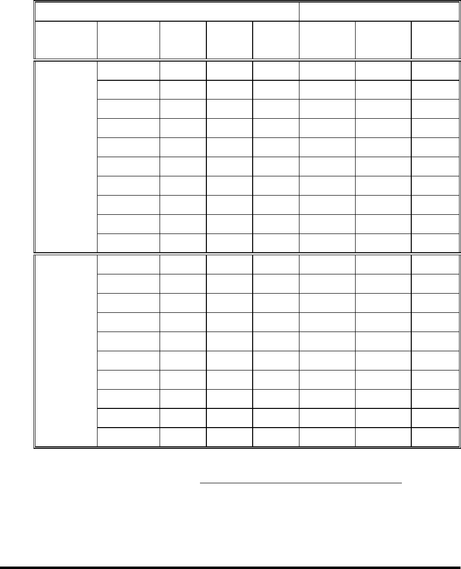
4.3 Test Result of Power Line Conducted Emissions
The following table shows a summary of the highest emissions of power line conducted
emissions on the LIVE and NETURAL conductors of the EUT power cord.
Test Conditions: Temperature : 26.4 °C Humidity : 51.2 % RH
Test mode: Undetachable Antenna,802.11b Channel 1
Power Connected Emissions FCC Class B
Conductor Frequency
(KHz)
Peak
(dB
µ
V)
QP
(dB
µ
V)
Average
(dB
µ
V)
QP-limit
(dB
µ
V)
AVG-limit
(dB
µ
V)
Margin
(dB)
161.00
0
50.33 --- --- 65.69 55.69 -5.3
6
151.75
0
52.94 --- --- 65.00 55.00 -2.0
6
Line 1 240.00
0
38.10 --- --- 63.43 53.43 -15.33
373.00
0
45.87 --- --- 59.63 49.63 -3.7
6
401.00
0
33.02 --- --- 58.83 48.83 -15.81
558.00
0
36.29 --- --- 56.00 46.00 -9.71
3062.00
0
32.89 --- --- 56.00 46.00 -13.11
8150.00
0
32.85 --- --- 60.00 50.00 -17.15
15710.00
0
34.43 --- --- 60.00 50.00 -15.5
7
26540.00
0
32.94 --- --- 60.00 50.00 -17.0
6
161.00
0
48.84 --- --- 65.69 55.69 -6.85
187.23
0
52.17 --- --- 64.94 54.94 -2.7
7
Line 2 240.00
0
38.15 --- --- 63.43 53.43 -15.2
8
370.00
0
43.72 --- --- 59.71 49.71 -5.9
9
558.00
0
38.29 --- --- 56.00 46.00 -7.71
928.00
0
33.69 --- --- 56.00 46.00 -12.31
2329.00
0
29.78 --- --- 56.00 46.00 -16.2
2
3062.00
0
31.02 --- --- 56.00 46.00 -14.9
8
8340.00
0
30.88 --- --- 60.00 50.00 -19.1
2
15040.00
0
33.69 --- --- 60.00 50.00 -16.31
NOTE:
(1)Margin = Peak Amplitude – Limit, The reading amplitudes are all under limit.
(2)A "+" sign in the margin column means the emission is OVER the Class B Limit and
"–" sign of means UNDER the Class B limit

Test Report ------------------------------------------------------------------------------ 18/60
Report No.: C5115391, FCC Part 15
Training Research Co., Ltd., TEL: 886-2-26935155, Fax: 886-2-26934440
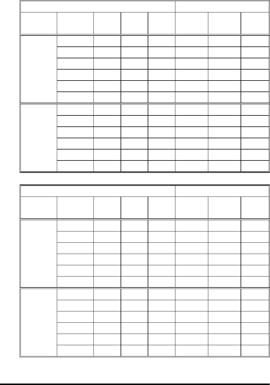
Test mode: Undetachable Antenna,802.11b Channel 6
Power Connected Emissions FCC Class B
Conductor Frequency
(KHz)
Peak
(dB
µ
V)
QP
(dB
µ
V)
Average
(dB
µ
V)
QP-limit
(dB
µ
V)
AVG-limit
(dB
µ
V)
Margin
(dB)
159.00
0
49.40 --- --- 65.74 55.74 -6.3
4
187.51
0
52.64 --- --- 64.94 54.94 -2.3
0
Line 1 370.00
0
45.41 --- --- 59.71 49.71 -4.3
0
558.00
0
36.43 --- --- 56.00 46.00 -9.5
7
928.00
0
34.35 --- --- 56.00 46.00 -11.65
3062.00
0
32.86 --- --- 56.00 46.00 -13.1
4
159.00
0
48.42 --- --- 65.74 55.74 -7.3
2
186.92
0
52.41 --- --- 65.00 55.00 -2.5
9
Line 2 373.00
0
43.86 --- --- 59.63 49.63 -5.7
7
558.00
0
38.62 --- --- 56.00 46.00 -7.3
8
928.00
0
34.56 --- --- 56.00 46.00 -11.4
4
3062.00
0
30.93 --- --- 56.00 46.00 -15.0
7
Test mode: Undetachable Antenna,802.11b Channel 11
Power Connected Emissions FCC Class B
Conductor Frequency
(KHz)
Peak
(dB
µ
V)
QP
(dB
µ
V)
Average
(dB
µ
V)
QP-limit
(dB
µ
V)
AVG-limit
(dB
µ
V)
Margin
(dB)
161.00
0
49.71 --- --- 65.69 55.69 -5.9
8
240.00
0
38.88 --- --- 63.43 53.43 -14.55
Line 1 373.00
0
45.41 --- --- 59.63 49.63 -4.2
2
558.00
0
35.35 --- --- 56.00 46.00 -10.65
928.00
0
34.54 --- --- 56.00 46.00 -11.4
6
3062.00
0
30.29 --- --- 56.00 46.00 -15.71
159.00
0
48.75 --- --- 65.74 55.74 -6.9
9
187.53
0
52.15 --- --- 65.00 55.00 -2.85
Line 2 370.00
0
43.56 --- --- 59.71 49.71 -6.15
558.00
0
38.12 --- --- 56.00 46.00 -7.8
8
745.00
0
33.65 --- --- 56.00 46.00 -12.35
928.00
0
34.52 --- --- 56.00 46.00 -11.4
8

Test Report ------------------------------------------------------------------------------ 19/60
Report No.: C5115391, FCC Part 15
Training Research Co., Ltd., TEL: 886-2-26935155, Fax: 886-2-26934440
Test mode: Undetachable Antenna,802.11g Channel 1
Power Connected Emissions FCC Class B
Conductor Frequency
(KHz)
Peak
(dB
µ
V)
QP
(dB
µ
V)
Average
(dB
µ
V)
QP-limit
(dB
µ
V)
AVG-limit
(dB
µ
V)
Margin
(dB)
158.00
0
49.78 --- --- 65.77 55.77 -5.9
9
130.01
0
52.88 --- --- 65.00 55.00 -2.1
2
Line 1 370.00
0
45.36 --- --- 59.71 49.71 -4.35
558.00
0
36.78 --- --- 56.00 46.00 -9.2
2
928.00
0
32.41 --- --- 56.00 46.00 -13.5
9
3030.00
0
31.07 --- --- 56.00 46.00 -14.93
159.00
0
52.53 --- --- 65.74 55.74 -3.21
187.31
0
53.06 --- --- 65.06 55.06 -2.0
0
Line 2 370.00
0
43.63 --- --- 59.71 49.71 -6.0
8
558.00
0
39.13 --- --- 56.00 46.00 -6.8
7
745.00
0
33.55 --- --- 56.00 46.00 -12.45
3030.00
0
30.81 --- --- 56.00 46.00 -15.1
9
Test mode: Undetachable Antenna, 802.11g Channel 6
Power Connected Emissions FCC Class B
Conductor Frequency
(KHz)
Peak
(dB
µ
V)
QP
(dB
µ
V)
Average
(dB
µ
V)
QP-limit
(dB
µ
V)
AVG-limit
(dB
µ
V)
Margin
(dB)
159.00
0
48.98 --- --- 65.74 55.74 -6.7
6
187.63
0
52.85 --- --- 65.00 55.00 -2.15
Line 1 243.00
0
38.67 --- --- 63.34 53.34 -14.6
7
373.00
0
45.43 --- --- 59.63 49.63 -4.2
0
558.00
0
36.97 --- --- 56.00 46.00 -9.03
928.00
0
33.34 --- --- 56.00 46.00 -12.6
6
161.00
0
48.72 --- --- 65.69 55.69 -6.9
7
185.00
0
51.76 --- --- 65.00 55.00 -3.2
4
Line 2 30.00
0
43.68 --- --- 59.71 49.71 -6.03
558.00
0
38.74 --- --- 56.00 46.00 -7.2
6
745.00
0
34.05 --- --- 56.00 46.00 -11.95
928.00
0
31.78 --- --- 56.00 46.00 -14.2
2

Test Report ------------------------------------------------------------------------------ 20/60
Report No.: C5115391, FCC Part 15
Training Research Co., Ltd., TEL: 886-2-26935155, Fax: 886-2-26934440
Test mode: Undetachable Antenna,802.11g Channel 11
Power Connected Emissions FCC Class B
Conductor Frequency
(KHz)
Peak
(dB
µ
V)
QP
(dB
µ
V)
Average
(dB
µ
V)
QP-limit
(dB
µ
V)
AVG-limit
(dB
µ
V)
Margin
(dB)
159.00
0
49.96 --- --- 65.74 55.74 -5.7
8
191.54
0
52.67 --- --- 65.00 55.00 -2.33
Line 1 370.00
0
45.39 --- --- 59.71 49.71 -4.3
2
558.00
0
36.44 --- --- 56.00 46.00 -9.5
6
928.00
0
33.96 --- --- 56.00 46.00 -12.0
4
3062.00
0
32.32 --- --- 56.00 46.00 -13.6
8
161.00
0
48.68 --- --- 65.69 55.69 -7.01
187.37
0
52.34 --- --- 65.00 55.00 -2.6
6
Line 2 370.00
0
43.63 --- --- 59.71 49.71 -6.0
8
558.00
0
38.81 --- --- 56.00 46.00 -7.1
9
745.00
0
33.98 --- --- 56.00 46.00 -12.0
2
928.00
0
33.12 --- --- 56.00 46.00 -12.8
8
Test mode: Detachable Antenna,802.11b Channel 1
Power Connected Emissions FCC Class B
Conductor Frequency
(KHz)
Peak
(dB
µ
V)
QP
(dB
µ
V)
Average
(dB
µ
V)
QP-limit
(dB
µ
V)
AVG-limit
(dB
µ
V)
Margin
(dB)
159.00
0
48.86 --- --- 65.74 55.74 -6.8
8
188.66
0
52.39 --- --- 64.94 54.94 -2.55
Line 1 238.00
0
39.11 --- --- 63.49 53.49 -14.3
8
373.00
0
45.36 --- --- 59.63 49.63 -4.2
7
563.00
0
35.84 --- --- 56.00 46.00 -10.1
6
937.00
0
33.28 --- --- 56.00 46.00 -12.7
2
159.00
0
49.22 --- --- 65.74 55.74 -6.5
2
189.37
0
52.10 --- --- 64.94 54.94 -2.8
4
Line 2 373.00
0
43.58 --- --- 59.63 49.63 -6.05
563.00
0
39.80 --- --- 56.00 46.00 -6.2
0
745.00
0
34.19 --- --- 56.00 46.00 -11.81
937.00
0
33.71 --- --- 56.00 46.00 -12.2
9

Test Report ------------------------------------------------------------------------------ 21/60
Report No.: C5115391, FCC Part 15
Training Research Co., Ltd., TEL: 886-2-26935155, Fax: 886-2-26934440
Test mode: Detachable Antenna,802.11b Channel 6
Power Connected Emissions FCC Class B
Conductor Frequency
(KHz)
Peak
(dB
µ
V)
QP
(dB
µ
V)
Average
(dB
µ
V)
QP-limit
(dB
µ
V)
AVG-limit
(dB
µ
V)
Margin
(dB)
159.00
0
50.35 --- --- 65.74 55.74 -5.3
9
178.46
0
52.36 --- --- 64.94 54.94 -2.5
8
Line 1 377.00
0
45.12 --- --- 59.51 49.51 -4.3
9
558.00
0
37.17 --- --- 56.00 46.00 -8.83
937.00
0
32.64 --- --- 56.00 46.00 -13.3
6
3030.00
0
31.18 --- --- 56.00 46.00 -14.8
2
161.00
0
49.17 --- --- 65.69 55.69 -6.5
2
169.70
0
52.43 --- --- 64.94 54.94 -2.51
Line 2 243.00
0
43.70 --- --- 63.34 53.34 -9.6
4
373.00
0
43.68 --- --- 59.63 49.63 -5.95
563.00
0
39.75 --- --- 56.00 46.00 -6.25
745.00
0
33.90 --- --- 56.00 46.00 -12.1
0
Test mode: Detachable Antenna,802.11b Channel 11
Power Connected Emissions FCC Class B
Conductor Frequency
(KHz)
Peak
(dB
µ
V)
QP
(dB
µ
V)
Average
(dB
µ
V)
QP-limit
(dB
µ
V)
AVG-limit
(dB
µ
V)
Margin
(dB)
159.00
0
50.58 --- --- 65.74 55.74 -5.1
6
169.00
0
50.19 --- --- 65.46 55.46 -5.2
7
Line 1 190.12
0
52.48 --- --- 64.94 54.94 -2.4
6
373.00
0
45.40 --- --- 59.63 49.63 -4.23
558.00
0
37.01 --- --- 56.00 46.00 -8.9
9
745.00
0
32.39 --- --- 56.00 46.00 -13.61
161.00
0
50.03 --- --- 65.69 55.69 -5.6
6
188.00
0
52.29 --- --- 65.00 55.00 -2.71
Line 2 236.00
0
46.38 --- --- 63.54 53.54 -7.1
6
373.00
0
43.82 --- --- 59.63 49.63 -5.81
558.00
0
39.71 --- --- 56.00 46.00 -6.2
9
745.00
0
33.78 --- --- 56.00 46.00 -12.2
2
Test Report ------------------------------------------------------------------------------ 22/60
Report No.: C5115391, FCC Part 15
Training Research Co., Ltd., TEL: 886-2-26935155, Fax: 886-2-26934440
Test mode: Detachable Antenna,802.11g Channel 1
Power Connected Emissions FCC Class B
Conductor Frequency
(KHz)
Peak
(dB
µ
V)
QP
(dB
µ
V)
Average
(dB
µ
V)
QP-limit
(dB
µ
V)
AVG-limit
(dB
µ
V)
Margin
(dB)
182.00
0
50.03 --- --- 65.09 55.09 -5.0
6
214.00
0
40.57 --- --- 64.17 54.17 -13.6
0
Line 1 291.00
0
38.24 --- --- 61.97 51.97 -13.73
338.00
0
37.33 --- --- 60.63 50.63 -13.3
0
639.00
0
32.70 --- --- 56.00 46.00 -13.3
0
8190.00
0
40.57 --- --- 56.00 46.00 -5.43
182.00
0
50.96 --- --- 65.09 55.09 -4.13
291.00
0
39.66 --- --- 61.97 51.97 -12.31
Line 2 724.00
0
33.76 --- --- 56.00 46.00 -12.2
4
1269.00
0
34.74 --- --- 56.00 46.00 -11.2
6
2741.00
0
34.07 --- --- 56.00 46.00 -11.93
8340.00
0
42.47 --- --- 60.00 50.00 -7.53
Test mode: Detachable Antenna, 802.11g Channel 6
Power Connected Emissions FCC Class B
Conductor Frequency
(KHz)
Peak
(dB
µ
V)
QP
(dB
µ
V)
Average
(dB
µ
V)
QP-limit
(dB
µ
V)
AVG-limit
(dB
µ
V)
Margin
(dB)
161.00
0
49.92 --- --- 65.69 55.69 -5.7
7
196.57
0
52.69 --- --- 64.94 54.94 -2.25
Line 1 240.00
0
38.74 --- --- 63.43 53.43 -14.6
9
373.00
0
45.43 --- --- 59.63 49.63 -4.2
0
558.00
0
36.97 --- --- 56.00 46.00 -9.03
745.00
0
32.34 --- --- 56.00 46.00 -13.6
6
161.00
0
48.49 --- --- 65.69 55.69 -7.2
0
194.34
0
52.29 --- --- 65.00 55.00 -2.71
Line 2 370.00
0
43.47 --- --- 59.71 49.71 -6.2
4
558.00
0
39.60 --- --- 56.00 46.00 -6.4
0
745.00
0
33.88 --- --- 56.00 46.00 -12.1
2
928.00
0
32.27 --- --- 56.00 46.00 -13.73
Test Report ------------------------------------------------------------------------------ 23/60
Report No.: C5115391, FCC Part 15
Training Research Co., Ltd., TEL: 886-2-26935155, Fax: 886-2-26934440
Test mode: Detachable Antenna, 802.11g Channel 11
Power Connected Emissions FCC Class B
Conductor Frequency
(KHz)
Peak
(dB
µ
V)
QP
(dB
µ
V)
Average
(dB
µ
V)
QP-limit
(dB
µ
V)
AVG-limit
(dB
µ
V)
Margin
(dB)
159.00
0
49.96 --- --- 65.74 55.74 -5.7
8
195.91
0
52.43 --- --- 64.94 54.94 -2.51
Line 1 243.00
0
39.11 --- --- 63.34 53.34 -14.23
373.00
0
45.39 --- --- 59.63 49.63 -4.2
4
558.00
0
35.90 --- --- 56.00 46.00 -10.1
0
937.00
0
35.82 --- --- 56.00 46.00 -10.1
8
3062.00
0
30.88 --- --- 56.00 46.00 -15.1
2
8390.00
0
31.82 --- --- 60.00 50.00 -18.1
8
15710.00
0
32.03 --- --- 60.00 50.00 -17.9
7
23710.00
0
33.56 --- --- 60.00 50.00 -16.4
4
163.00
0
49.40 --- --- 65.63 55.63 -6.23
194.19
0
52.17 --- --- 65.00 55.00 -2.83
Line 2 370.00
0
43.47 --- --- 59.71 49.71 -6.2
4
558.00
0
39.82 --- --- 56.00 46.00 -6.1
8
745.00
0
34.03 --- --- 56.00 46.00 -11.9
7
937.00
0
33.30 --- --- 56.00 46.00 -12.7
0
3030.00
0
30.47 --- --- 56.00 46.00 -15.53
8120.00
0
31.96 --- --- 60.00 50.00 -18.0
4
15710.00
0
33.05 --- --- 60.00 50.00 -16.95
23230.00
0
32.93 --- --- 60.00 50.00 -17.0
7

Test Report ------------------------------------------------------------------------------ 24/60
Report No.: C5115391, FCC Part 15
Training Research Co., Ltd., TEL: 886-2-26935155, Fax: 886-2-26934440
V. Section 15.247 (a): Technical description of the EUT
Based on the Section 2.1, Direct Sequence System is a spread spectrum system in which the
carrier has been modulated by a high speed spreading code and an information data stream. The high
speed code sequence dominates the “modulating function” and is the direct cause of the wide spreading of
the transmitted signal. In the operational description demonstrates the operation principles of the Baseband
processor employed by the EUT, shows that which is a complete DSSS baseband processor and meets
the definition of the direct sequence spread spectrum system.
Test Report ------------------------------------------------------------------------------ 25/60
Report No.: C5115391, FCC Part 15
Training Research Co., Ltd., TEL: 886-2-26935155, Fax: 886-2-26934440
VI. Section 15.247(a)(2): Bandwidth for Direct Sequence System.
6.1 Test Condition & Setup
The transmitter bandwidth measurements were performed by the contact manner. The EUT
was set to transmit continuously, also various channels were investigated to find the maximum
occupied bandwidth. The output of the EUT was connected to the spectrum analyzer. The bandwidth
of the fundamental frequency is observed by the spectrum analyzer with 100kHz RBW and 100kHz
VBW.
6.2 Test Instruments Configuration
P.S.: The computer to control the EUT at maximal power output and channel Number
and set antenna kit
6.3 List of Test Instruments
Instrument Name Model No. Brand Serial No. Last time Next time
Spectrum Analyzer MS2665C ANRITSU 6200175476 09/30/03 09/30/04
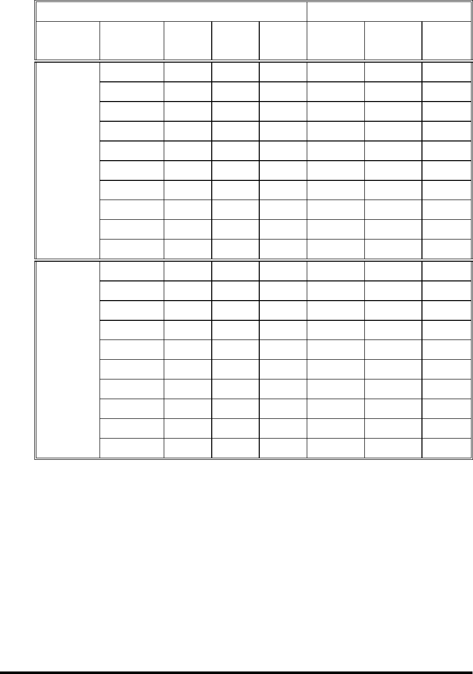
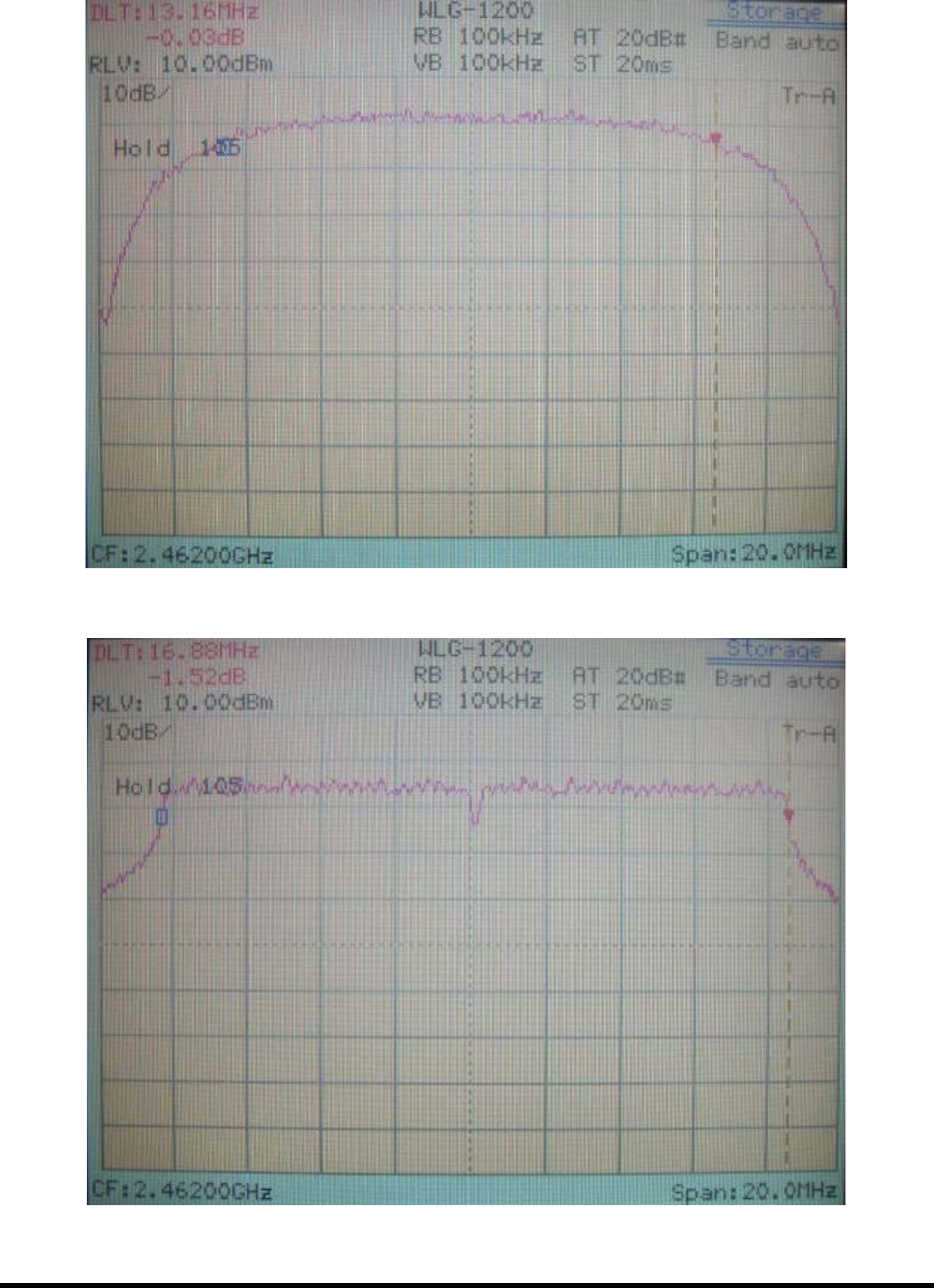
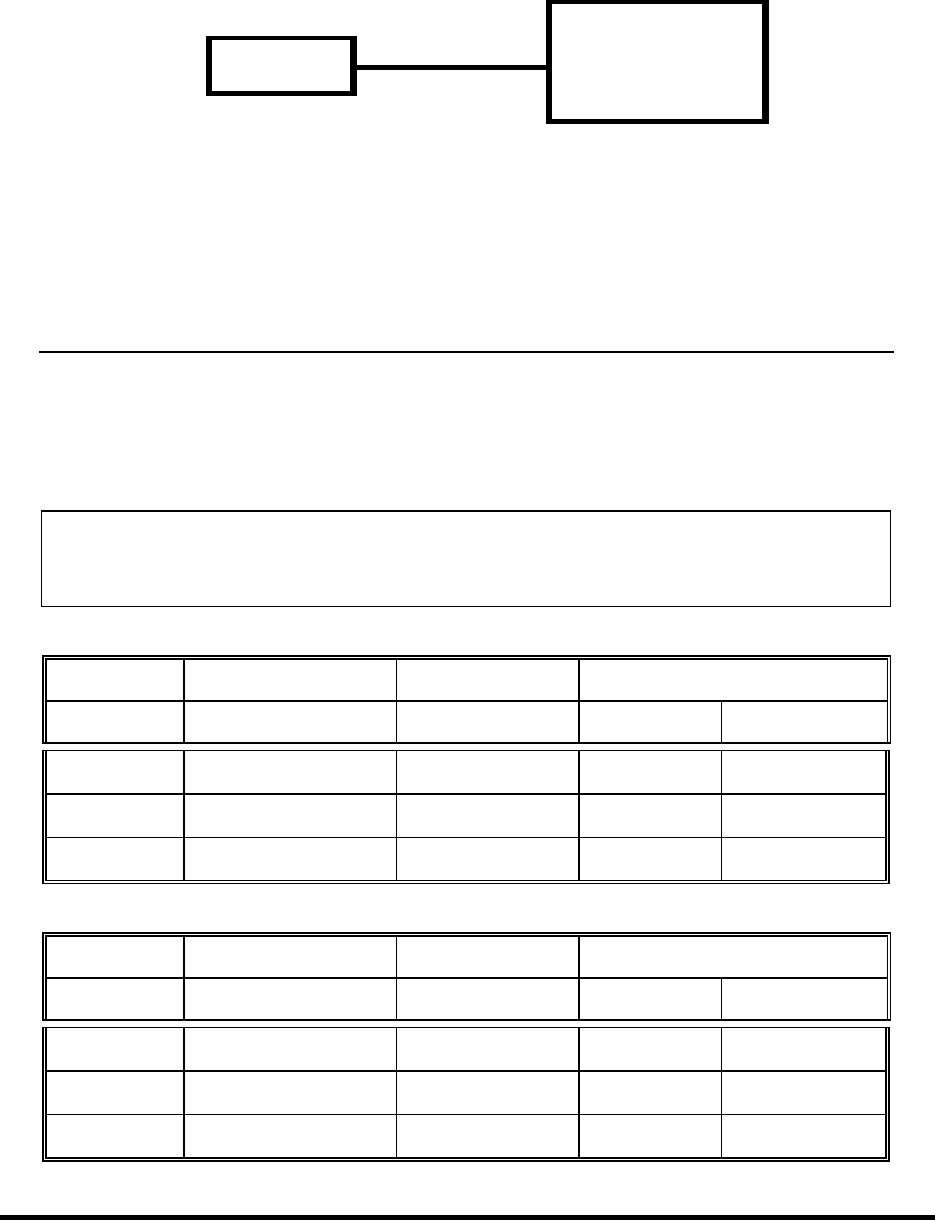
6.4 Test Result of Bandwidth
6dB Bandwidth (MHz)
Channel
802.11b 802.11g
01 12.84 16.80
06 12.84 16.80
11 13.16 16.88
Note: 1. The data in the above table are summarizing the following attachment spectrum analyzer
hard copy. According to the guidance, we’ d made the measurement with the spectrum
analyzer’ s resolution bandwidth (RBW)=100kHz and set the span>>RBW. The results
show the measured 6dB bandwidth comply with the minimum 500kHz requirement.
2. The attachments show these on the following pages.
Spectrum Analyzer
(RBW: 100kHz; VBW: 100kHz)
EUT
Test Report ------------------------------------------------------------------------------ 26/60
Report No.: C5115391, FCC Part 15
Training Research Co., Ltd., TEL: 886-2-26935155, Fax: 886-2-26934440
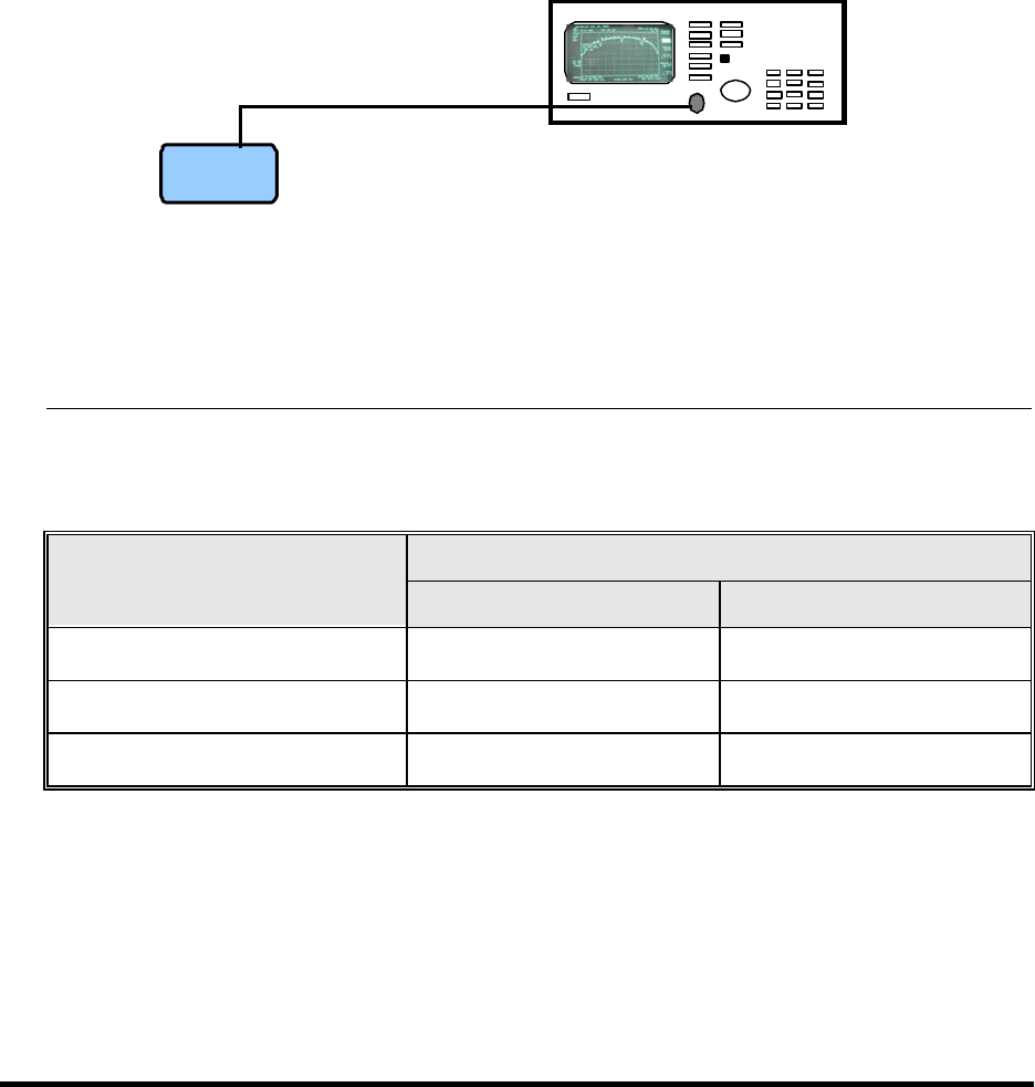
802.11b Channel 1: 12.84MHz (The minimum 6dB BW at least 500kHz)
802.11g Channel 1: 16.80MHz (The minimum 6dB BW at least 500kHz)
Test Report ------------------------------------------------------------------------------ 27/60
Report No.: C5115391, FCC Part 15
Training Research Co., Ltd., TEL: 886-2-26935155, Fax: 886-2-26934440
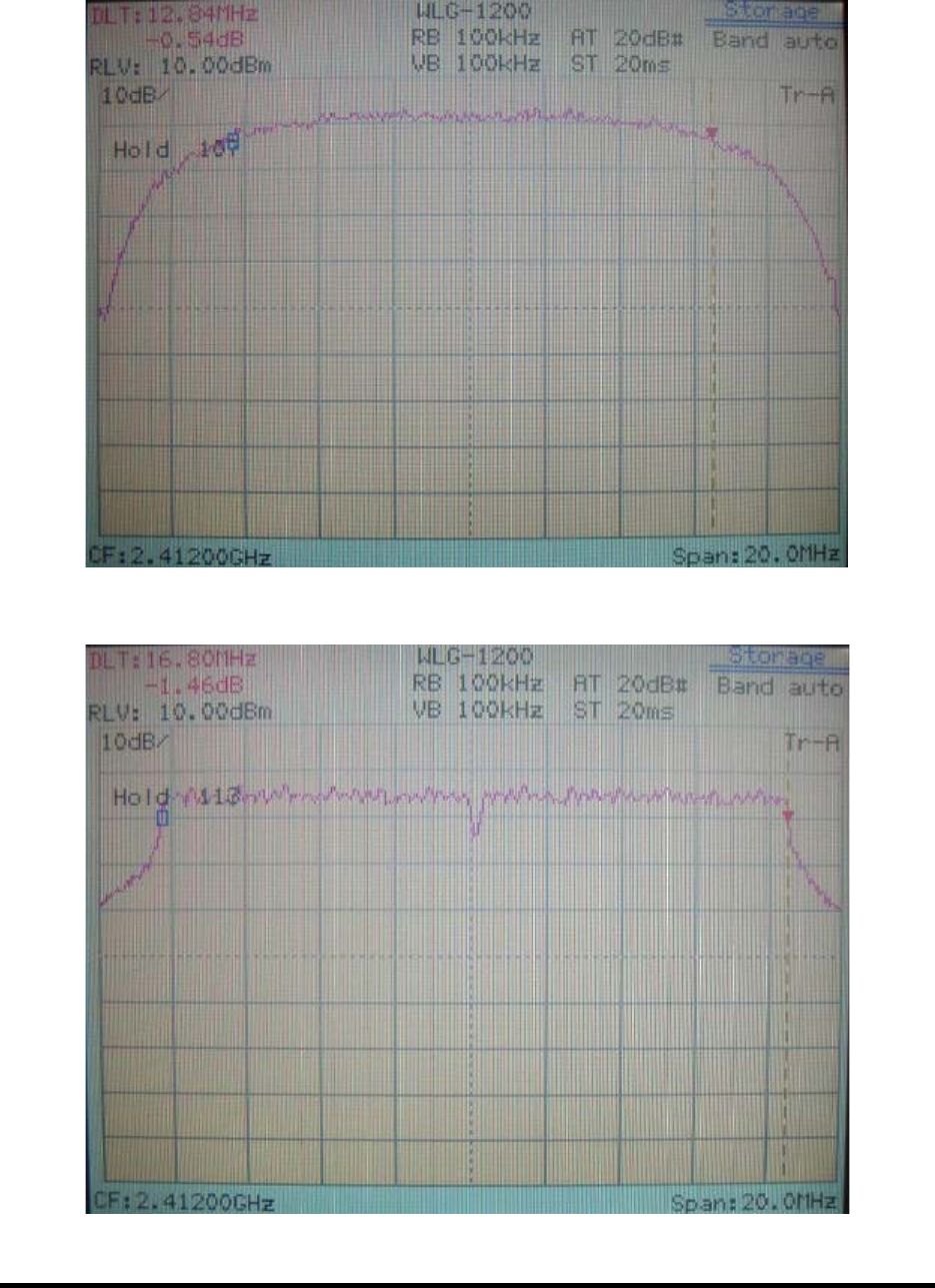
802.11b Channel 6: 12.84MHz (The minimum 6dB BW at least 500kHz)
802.11g Channel 6: 16.80MHz (The minimum 6dB BW at least 500kHz)
Test Report ------------------------------------------------------------------------------ 28/60
Report No.: C5115391, FCC Part 15
Training Research Co., Ltd., TEL: 886-2-26935155, Fax: 886-2-26934440
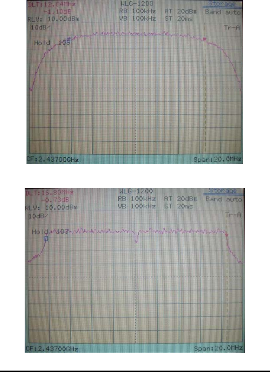
802.11b Channel 11: 13.16MHz (The minimum 6dB BW at least 500kHz)
802.11b Channel 11: 16.88MHz (The minimum 6dB BW at least 500kHz)
Test Report ------------------------------------------------------------------------------ 29/60
Report No.: C5115391, FCC Part 15
Training Research Co., Ltd., TEL: 886-2-26935155, Fax: 886-2-26934440
VII. Section 15.247(b): Power Output
7.1 Test Condition & Setup
1. The output of the transmitter is connected to the BOONTON RF Power Meter.
2. The calibration is performed before every tests. The values of the output power of the EUT will
shown in the dBm directly are the transmitter output peak power. Recording as follows.
7.2 List of Test Instruments
Instrument Name Model No. Brand Serial No. Last time Next time
RF Power Meter 4532 BOONTON 117501 04/12/03 04/12/04
Peak Power Sensor 57340 BOONTON 2698 04/12/03 04/12/04
7.3 Test Result
Formula:
Signal generator + |Cable loss| = Output peak power
IEEE 802.11b
Channel Signal Generator Cable Loss Output Peak Power
dBm dBm dBm mW
CH 1 17.27 0.70 17.97 62.661
CH 6 17.70 0.70 18.40 69.183
CH 11 17.59 0.70 18.29 67.453
IEEE 802.11g
Channel Signal Generator Cable Loss Output Peak Power
dBm dBm dBm mW
CH 1 20.02 0.70 20.72 118.032
CH 6 20.37 0.70 21.07 127.938
CH 11 20.28 0.70 20.98 125.314
EUT
BOONTON
4532
RF Power Meter

Test Report ------------------------------------------------------------------------------ 30/60
Report No.: C5115391, FCC Part 15
Training Research Co., Ltd., TEL: 886-2-26935155, Fax: 886-2-26934440
VIII. Section 15.247 (C): Spurious Emissions (Radiated)
8.1 Test Condition & Setup
We’ d performed the test by the radiated emission skill: The EUT was placed in an anechoic
chamber, and set the EUT transmitting continuously and scanned at 3-meter distance to determine its
emission characteristics. The physical arrangement of the EUT was varied (within the scope of
arrangements likely to be encountered in actual use) to determine the effect on the unit's emanations in
amplitude, directivity, and frequency. The exact system configuration, which produced the highest
emissions were noted so it could be reproduced later during the final tests. For the measurement above
1GHz, according to the guidance we’ d set the spectrum analyzer’ s 6dB bandwidth RBW to 1MHz.
This was done to ensure that the final measurements would demonstrate the worst-case
interference potential of the EUT.
Final radiation measurements were made on a three-meter, anechoic chamber. The EUT
system was placed on a nonconductive turntable, which is 0.8 meters height, top surface 1.0 x 1.5
meter.
The spectrum was examined from 30 MHz to 1000 MHz using an Hewlett Packard 8546A EMI
Receiver, CHASE whole range Bi-log antenna (Model No.: CBL 6141A) is used to measure
frequency from 30 MHz to 1GHz. The final test is used the HP 85460A spectrum and 8564E spectrum
was examined from 1GHz to 25GHz using an Hewlett Packard Spectrum Analyzer, EMCO/CMT
Horn Antenna (Model 3115 / RA42-K-F-4B-C) for 1G - 25GHz.
At each frequency, the EUT was rotated 360 degrees, and the antenna was raised and lowered
from one to four meters to find the maximum emission levels. Measurements were taken using both
horizontal and vertical antenna polarization.
Appropriate preamplifiers were used for improving sensitivity and precautions were taken to
avoid overloading or desensitizing the spectrum analyzer. There are two spectrum analyzers use on this
testing, HP 85460A for frequency 30MHz to 1000MHz, and 8564E for frequency 1GHz to 25GHz. No
post-detector video filters were used in the test. The spectrum analyzer's 6dB bandwidth was set to
120KHz (spectrum was examined from 30 MHz to 1000 MHz), the spectrum analyzer's 6 dB
bandwidth was set to 1 MHz (spectrum was examined from 1GHz to 25GHz) and the analyzer was
operated in the maximum hold mode. There is a test condition applies in this test item, the test
procedure description as the following:
Three channels were tested, one in the top (CH01), one in the middle (CH06) and the other in
bottom (CH11). The setting up procedure is recorded on <1.4 test method >

Test Report ------------------------------------------------------------------------------ 31/60
Report No.: C5115391, FCC Part 15
Training Research Co., Ltd., TEL: 886-2-26935155, Fax: 886-2-26934440
With the transmitter operating from a AC source and using the internal of EUT, radiates
spurious emissions falling within the restricted bands of 15.209 were measured at operating frequencies
corresponding to upper, middle and bottom channels in the 2400 ~ 2483.5 MHz band.
The actual field intensity in decibels referenced to 1 microvolt per meter (dBµV/m) is
determined by algebraically adding the measured reading in dBµV, the antenna factor (dB), and cable
loss (dB) at the appropriate frequency. Since the EUT was set to transmit continuously, no duty cycle
is present.
For frequency between 30MHz to 1000MHz
FIa (dBuV/m) = FIr (dBµV) + Correction Factors
FIa : Actual Field Intensity
FIr : Reading of the Field Intensity
Correction Factors = Antenna Factor + Cable Loss – Amplifier Gain
For frequency between 1GHz to 25GHz
FIa (dBµV/m) = FIr (dBµV) + Correction Factor
FIa : Actual Field Intensity
FIr : Reading of the Field Intensity
Correction Factors = Antenna Factor + Cable Loss – Amplifier Gain
8.2 List of Test Instruments
Instrument Name Model No. Brand Serial No. Last time Next time
EMI Receiver 8546A HP 3520A00242 07/28/03 07/28/04
RF Filter Section 85460A HP 3448A00217 07/28/03 07/28/04
Bi-log Antenna CBL 6141A CHASE 4206 05/27/03 05/27/04
Auto Switch Box ASB-01 TRC 9904-01 11/20/02 11/20/03
(>30MHz)
Spectrum Analyzer 8564E HP 3720A00840 07/23/03 07/23/04
Microwave Preamplifier 84125C HP US36433002 07/30/03 07/30/04
Horn Antenna 3115 EMCO 9104-3668 12/24/02 12/24/03
Horn Antenna RA42-K-F-4B-C CMT 961505-003 02/01/03 02/01/04
Anechoic Chamber (cable calibrated together) 05/20/03 05/20/04
The level of confidence of 95% , the uncertainty of measurement of radiated emission is +3.05dB / -3.84dB.
Test Report ------------------------------------------------------------------------------ 32/60
Report No.: C5115391, FCC Part 15
Training Research Co., Ltd., TEL: 886-2-26935155, Fax: 886-2-26934440
8.3 Test Result of Spurious Radiated Emissions
The highest peak values of radiated emissions form the EUT at various antenna heights, antenna
polarizations, EUT orientation, etc. are recorded on the following.
Test Conditions: Temperature : 25 ° C Humidity : 73 % RH
30MHz to 1GHz for Horizontal [Detachable antenna]
Radiated
Emission
FCC Class B
( 3 m )
Frequency
(MHz)
Amplitude
(dB
µ
V)
Ant. H.
(m)
Table
( )
Correction
Factors
(dB)
Corrected
Amplitude
(dB
µ
V/m)
Limit
(dB
µ
V/m)
Margin
(dB)
78.50 36.49 1.00 302 1.74 38.23 40.00 -1.77
85.78 37.63 1.00 300 1.10 38.73 40.00 -1.27
89.41 37.59 1.00 293 0.72 38.31 43.50 -5.19
250.67 43.09 1.00 263 -2.63 40.46 46.00 -5.54
616.85 27.39 1.00 12 9.26 36.65 46.00 -9.35
768.41 27.61 1.00 73 13.52 41.13 46.00 -4.87
30MHz to 1GHz for Vertical [Detachable antenna]
Radiated
Emission
FCC Class B
( 3 m )
Frequency
(MHz)
Amplitude
(dB
µ
V)
Ant. H.
(m)
Table
()
Correction
Factors
(dB)
Corrected
Amplitude
(dB
µ
V/m)
Limit
(dB
µ
V/m)
Margin
(dB)
33.64 27.57 1.00 314 6.50 34.07 40.00 -5.93
38.49 27.48 1.00 248 5.76 33.24 40.00 -6.76
85.78 35.05 1.00 336 1.10 36.15 40.00 -3.85
103.96 36.69 1.00 315 0.11 36.80 43.50 -6.70
249.46 42.30 1.00 234 -2.62 39.68 46.00 -6.32
883.60 23.56 1.00 343 16.63 40.19 46.00 -5.81
Test Report ------------------------------------------------------------------------------ 33/60
Report No.: C5115391, FCC Part 15
Training Research Co., Ltd., TEL: 886-2-26935155, Fax: 886-2-26934440
30MHz to 1GHz for Horizontal [Undetachable antenna]
Radiated
Emission
FCC Class B
( 3 m )
Frequency
(MHz)
Amplitude
(dB
µ
V)
Ant. H.
(m)
Table
()
Correction
Factors
(dB)
Corrected
Amplitude
(dB
µ
V/m)
Limit
(dB
µ
V/m)
Margin
(dB)
117.30 34.55 1.00 69 -0.94 33.61 43.50 -9.89
207.02 36.46 1.00 197 -2.52 33.94 43.50 -9.56
411.94 33.52 1.00 19 1.06 34.58 46.00 -11.42
616.85 25.57 1.00 244 9.26 34.83 46.00 -11.17
768.41 27.87 1.00 222 13.52 41.39 46.00 -4.61
798.72 26.37 1.00 187 13.71 40.08 46.00 -5.92
30MHz to 1GHz for Vertical [Undetachable antenna]
Radiated
Emission
FCC Class B
( 3 m )
Frequency
(MHz)
Amplitude
(dB
µ
V)
Ant. H.
(m)
Table
()
Correction
Factors
(dB)
Corrected
Amplitude
(dB
µ
V/m)
Limit
(dB
µ
V/m)
Margin
(dB)
114.87 31.53 1.00 336 -0.69 30.84 43.50 -12.66
280.99 36.52 1.00 275 -2.24 34.28 46.00 -11.72
310.09 35.45 1.00 65 -2.12 33.33 46.00 -12.67
433.76 30.77 1.00 174 1.66 32.43 46.00 -13.57
476.20 31.52 1.00 60 3.27 34.79 46.00 -11.21
525.91 29.30 1.00 98 5.64 34.94 46.00 -11.06
Note:
1. Margin = Amplitude – limit, if margin is minus means under limit.
2. Corrected Amplitude = Reading Amplitude + Correction Factors
3. Correction factor = Antenna factor + ( Cable Loss – Amplitude gain)
Test Report ------------------------------------------------------------------------------ 34/60
Report No.: C5115391, FCC Part 15
Training Research Co., Ltd., TEL: 886-2-26935155, Fax: 886-2-26934440
1GHz to 25GHz for Horizontal [Detachable antenna, 802.11b CH 1]
Radiated
Emission
Class B ( 3m )
Corrected
Amplitude
(dBµV/m) Limit (dBµV/m)
Frequency
(MHz)
Ant. H.
(m)
Table
()
Correction
Factors
(dB) Peak Average Peak Ave.
Margin
(dB)
2010.42 1.00 27 1.87 39.87 --- 74.00 53.96 -14.09
3135.42 1.00 116 4.48 43.64 --- 74.00 53.96 -10.32
7239.79 1.00 197 10.11 44.38 --- 74.00 53.96 -9.58
9650.42 1.00 239 11.47 43.58 --- 74.00 53.96 -10.38
1GHz to 25GHz for Vertical [Detachable antenna, 802.11b CH 1]
Radiated
Emission
Class B ( 3m )
Corrected
Amplitude
(dBµV/m) Limit (dBµV/m)
Frequency
(MHz)
Ant. H.
(m)
Table
()
Correction
Factors
(dB) Peak Average Peak Ave.
Margin
(dB)
3135.42 1.00 27 4.48 44.31 --- 74.00 53.96 -9.65
3796.04 1.00 139 0.49 48.76 --- 74.00 53.96 -5.20
7239.79 1.00 117 10.11 44.55 --- 74.00 53.96 -9.41
9650.42 1.00 279 11.47 44.41 --- 74.00 53.96 -9.55
Note:
1. Margin = Corrected - Limit.
2. The EUT utilizes a permanently attached antenna. In addition the spurious RF Radiated
emissions levels do comply with the 20dBc limit both at its bandedges and other spurious
emissions.
3. As stated in Section 15.35(b), for any frequencies above 1000MHz, radiated limits shown are
based upon the use of measurement instrumentation employing an average detector function. As
the results of our test, the peak amplitudes are already below the FCC limit. Thus the average
amplitudes of the rest are omitted.

Test Report ------------------------------------------------------------------------------ 35/60
Report No.: C5115391, FCC Part 15
Training Research Co., Ltd., TEL: 886-2-26935155, Fax: 886-2-26934440
1GHz to 25GHz for Horizontal [Detachable antenna, 802.11b CH 6]
Radiated
Emission
Class B ( 3m )
Corrected
Amplitude
(dBµV/m) Limit (dBµV/m)
Frequency
(MHz)
Ant. H.
(m)
Table
()
Correction
Factors
(dB) Peak Average Peak Ave.
Margin
(dB)
2014.58 1.00 195 1.89 39.72 --- 74.00 53.96 -14.24
3135.42 1.00 10 4.48 43.14 --- 74.00 53.96 -10.82
4877.50 1.00 297 3.97 39.74 --- 74.00 53.96 -14.22
7312.29 1.00 359 10.30 42.74 --- 74.00 53.96 -11.22
9747.08 1.00 149 11.89 43.83 --- 74.00 53.96 -10.13
1GHz to 25GHz for Vertical [Detachable antenna, 802.11b CH 6]
Radiated
Emission
Class B ( 3m )
Corrected
Amplitude
(dBµV/m) Limit (dBµV/m)
Frequency
(MHz)
Ant. H.
(m)
Table
()
Correction
Factors
(dB) Peak Average Peak Ave.
Margin
(dB)
1889.58 1.00 57 2.24 42.24 --- 74.00 53.96 -11.72
2145.83 1.00 219 2.32 41.99 --- 74.00 53.96 -11.97
2616.67 1.00 341 3.65 41.82 --- 74.00 53.96 -12.14
3135.42 1.00 11 4.48 44.31 --- 74.00 53.96 -9.65
7312.29 1.00 183 10.30 43.91 --- 74.00 53.96 -10.05
9747.08 1.00 140 11.89 44.49 --- 74.00 53.96 -9.47

Test Report ------------------------------------------------------------------------------ 36/60
Report No.: C5115391, FCC Part 15
Training Research Co., Ltd., TEL: 886-2-26935155, Fax: 886-2-26934440
1GHz to 25GHz for Horizontal [Detachable antenna, 802.11b CH 11]
Radiated
Emission
Class B ( 3m )
Corrected
Amplitude
(dBµV/m) Limit (dBµV/m)
Frequency
(MHz)
Ant. H.
(m)
Table
()
Correction
Factors
(dB) Peak Average Peak Ave.
Margin
(dB)
2012.50 1.00 247 1.88 39.71 --- 74.00 53.96 -14.25
2308.80 1.00 112 2.87 54.36 47.20 74.00 53.96 -6.76
3135.42 1.00 279 4.48 44.14 --- 74.00 53.96 -9.82
4925.83 1.00 330 4.13 41.07 --- 74.00 53.96 -12.89
7390.83 1.00 109 10.41 42.19 --- 74.00 53.96 -11.77
9849.79 1.00 2 11.93 44.71 --- 74.00 53.96 -9.25
1GHz to 25GHz for Vertical [Detachable antenna, 802.11b CH 11]
Radiated
Emission
Class B ( 3m )
Corrected
Amplitude
(dBµV/m) Limit (dBµV/m)
Frequency
(MHz)
Ant. H.
(m)
Table
()
Correction
Factors
(dB) Peak Average Peak Ave.
Margin
(dB)
1891.67 1.00 154 2.23 42.07 --- 74.00 53.96 -11.89
2143.75 1.00 227 2.32 41.98 --- 74.00 53.96 -11.98
2307.33 1.00 109 2.86 58.19 51.53 74.00 53.96 -2.43
2616.67 1.00 294 3.65 43.82 --- 74.00 53.96 -10.14
3802.08 1.00 66 0.50 45.61 --- 74.00 53.96 -8.35
4925.83 1.00 147 4.13 41.24 --- 74.00 53.96 -12.72
7384.79 1.00 90 10.42 42.36 --- 74.00 53.96 -11.60
9849.79 1.00 167 11.93 45.04 --- 74.00 53.96 -8.92

Test Report ------------------------------------------------------------------------------ 37/60
Report No.: C5115391, FCC Part 15
Training Research Co., Ltd., TEL: 886-2-26935155, Fax: 886-2-26934440
1GHz to 25GHz for Horizontal [Detachable antenna, 802.11g CH 1]
Radiated
Emission
Class B ( 3m )
Corrected
Amplitude
(dBµV/m) Limit (dBµV/m)
Frequency
(MHz)
Ant. H.
(m)
Table
()
Correction
Factors
(dB) Peak Average Peak Ave.
Margin
(dB)
2010.42 1.00 188 1.87 40.37 --- 74.00 53.96 -13.59
3135.42 1.00 246 4.48 44.31 --- 74.00 53.96 -9.65
3802.08 1.00 118 0.50 41.94 --- 74.00 53.96 -12.02
4823.12 1.00 309 3.76 38.20 --- 74.00 53.96 -15.76
7239.79 1.00 54 10.11 43.38 --- 74.00 53.96 -10.58
9650.42 1.00 198 11.47 43.74 --- 74.00 53.96 -10.22
1GHz to 25GHz for Vertical [Detachable antenna, 802.11g CH 1]
Radiated
Emission
Class B ( 3m )
Corrected
Amplitude
(dBµV/m) Limit (dBµV/m)
Frequency
(MHz)
Ant. H.
(m)
Table
()
Correction
Factors
(dB) Peak Average Peak Ave.
Margin
(dB)
1887.50 1.00 96 2.25 42.08 --- 74.00 53.96 -11.88
2145.83 1.00 174 2.32 42.32 --- 74.00 53.96 -11.64
3135.42 1.00 223 4.48 44.98 --- 74.00 53.96 -8.98
3366.67 1.00 205 5.02 44.18 --- 74.00 53.96 -9.78
3796.04 1.00 339 0.49 46.76 --- 74.00 53.96 -7.20
4823.12 1.00 107 3.76 38.36 --- 74.00 53.96 -15.60
7233.75 1.00 192 10.07 44.85 --- 74.00 53.96 -9.11
9650.42 1.00 64 11.47 44.41 --- 74.00 53.96 -9.55

Test Report ------------------------------------------------------------------------------ 38/60
Report No.: C5115391, FCC Part 15
Training Research Co., Ltd., TEL: 886-2-26935155, Fax: 886-2-26934440
1GHz to 25GHz for Horizontal [Detachable antenna, 802.11g CH 6]
Radiated
Emission
Class B ( 3m )
Corrected
Amplitude
(dBµV/m) Limit (dBµV/m)
Frequency
(MHz)
Ant. H.
(m)
Table
()
Correction
Factors
(dB) Peak Average Peak Ave.
Margin
(dB)
2018.75 1.00 97 1.90 39.40 --- 74.00 53.96 -14.56
3135.42 1.00 44 4.48 44.31 --- 74.00 53.96 -9.65
4877.50 1.00 149 3.97 38.91 --- 74.00 53.96 -15.05
7312.29 1.00 228 10.30 43.07 --- 74.00 53.96 -10.89
9747.08 1.00 30 11.89 44.49 --- 74.00 53.96 -9.47
1GHz to 25GHz for Vertical [Detachable antenna, 802.11g CH 6]
Radiated
Emission
Class B ( 3m )
Corrected
Amplitude
(dBµV/m) Limit (dBµV/m)
Frequency
(MHz)
Ant. H.
(m)
Table
()
Correction
Factors
(dB) Peak Average Peak Ave.
Margin
(dB)
1900.00 1.00 204 2.20 41.87 --- 74.00 53.96 -12.09
2062.50 1.00 227 2.05 40.38 --- 74.00 53.96 -13.58
2147.92 1.00 96 2.33 42.16 --- 74.00 53.96 -11.80
3135.42 1.00 47 4.48 45.81 --- 74.00 53.96 -8.15
3802.08 1.00 186 0.50 45.44 --- 74.00 53.96 -8.52
4877.50 1.00 243 3.97 40.24 --- 74.00 53.96 -13.72
7312.29 1.00 63 10.30 43.91 --- 74.00 53.96 -10.05
9747.08 1.00 179 11.89 44.33 --- 74.00 53.96 -9.63

Test Report ------------------------------------------------------------------------------ 39/60
Report No.: C5115391, FCC Part 15
Training Research Co., Ltd., TEL: 886-2-26935155, Fax: 886-2-26934440
1GHz to 25GHz for Horizontal [Detachable antenna, 802.11g CH 11]
Radiated
Emission
Class B ( 3m )
Corrected
Amplitude
(dBµV/m) Limit (dBµV/m)
Frequency
(MHz)
Ant. H.
(m)
Table
()
Correction
Factors
(dB) Peak Average Peak Ave.
Margin
(dB)
2016.67 1.00 47 1.90 39.73 --- 74.00 53.96 -14.23
2310.42 1.00 104 2.87 50.04 --- 74.00 53.96 -3.92
3135.42 1.00 56 4.48 42.48 --- 74.00 53.96 -11.48
4925.83 1.00 107 4.13 41.40 --- 74.00 53.96 -12.56
7390.83 1.00 324 10.41 42.85 --- 74.00 53.96 -11.11
9849.79 1.00 105 11.93 45.21 --- 74.00 53.96 -8.75
1GHz to 25GHz for Vertical [Detachable antenna, 802.11g CH 11]
Radiated
Emission
Class B ( 3m )
Corrected
Amplitude
(dBµV/m) Limit (dBµV/m)
Frequency
(MHz)
Ant. H.
(m)
Table
()
Correction
Factors
(dB) Peak Average Peak Ave.
Margin
(dB)
2145.83 1.00 15 2.32 42.49 --- 74.00 53.96 -11.47
2309.74 1.00 179 2.87 53.86 43.70 74.00 53.96 -10.26
3135.42 1.00 227 4.48 44.64 --- 74.00 53.96 -9.32
3364.58 1.00 208 5.01 43.35 --- 74.00 53.96 -10.61
3802.08 1.00 341 0.50 48.61 --- 74.00 53.96 -5.35
9849.79 1.00 29 11.93 45.04 --- 74.00 53.96 -8.92

Test Report ------------------------------------------------------------------------------ 40/60
Report No.: C5115391, FCC Part 15
Training Research Co., Ltd., TEL: 886-2-26935155, Fax: 886-2-26934440
1GHz to 25GHz for Horizontal [Undetachable antenna, 802.11b CH 1]
Radiated
Emission
Class B ( 3m )
Corrected
Amplitude
(dBµV/m) Limit (dBµV/m)
Frequency
(MHz)
Ant. H.
(m)
Table
()
Correction
Factors
(dB) Peak Average Peak Ave.
Margin
(dB)
1902.08 1.00 81 2.19 42.03 --- 74.00 53.96 -11.93
2008.33 1.00 115 1.87 40.53 --- 74.00 53.96 -13.43
2922.92 1.00 20 4.06 41.39 --- 74.00 53.96 -12.57
4823.12 1.00 223 3.76 40.36 --- 74.00 53.96 -13.60
7233.75 1.00 95 10.07 45.18 --- 74.00 53.96 -8.78
9650.42 1.00 107 11.47 45.41 --- 74.00 53.96 -8.55
1GHz to 25GHz for Vertical [Undetachable antenna, 802.11b CH 1]
Radiated
Emission
Class B ( 3m )
Corrected
Amplitude
(dBµV/m) Limit (dBµV/m)
Frequency
(MHz)
Ant. H.
(m)
Table
()
Correction
Factors
(dB) Peak Average Peak Ave.
Margin
(dB)
1887.50 1.00 216 2.25 42.58 --- 74.00 53.96 -11.38
2152.08 1.00 227 2.34 42.18 --- 74.00 53.96 -11.78
3354.17 1.00 109 4.99 44.99 --- 74.00 53.96 -8.97
4823.12 1.00 176 3.76 40.86 --- 74.00 53.96 -13.10
7233.75 1.00 334 10.07 43.68 --- 74.00 53.96 -10.28
9650.42 1.00 180 11.47 44.91 --- 74.00 53.96 -9.05

Test Report ------------------------------------------------------------------------------ 41/60
Report No.: C5115391, FCC Part 15
Training Research Co., Ltd., TEL: 886-2-26935155, Fax: 886-2-26934440
1GHz to 25GHz for Horizontal [Undetachable antenna, 802.11b CH 6]
Radiated
Emission
Class B ( 3m )
Corrected
Amplitude
(dBµV/m) Limit (dBµV/m)
Frequency
(MHz)
Ant. H.
(m)
Table
()
Correction
Factors
(dB) Peak Average Peak Ave.
Margin
(dB)
1904.17 1.00 51 2.19 41.69 --- 74.00 53.96 -12.27
2022.92 1.00 224 1.92 40.92 --- 74.00 53.96 -13.04
3354.17 1.00 311 4.99 43.82 --- 74.00 53.96 -10.14
4877.50 1.00 107 3.97 40.08 --- 74.00 53.96 -13.88
7312.29 1.00 28 10.30 42.57 --- 74.00 53.96 -11.39
9747.08 1.00 209 11.89 44.99 --- 74.00 53.96 -8.97
1GHz to 25GHz for Vertical [Undetachable antenna, 802.11b CH 6]
Radiated
Emission
Class B ( 3m )
Corrected
Amplitude
(dBµV/m) Limit (dBµV/m)
Frequency
(MHz)
Ant. H.
(m)
Table
()
Correction
Factors
(dB) Peak Average Peak Ave.
Margin
(dB)
1889.58 1.00 17 2.24 42.07 --- 74.00 53.96 -11.89
2145.83 1.00 116 2.32 41.99 --- 74.00 53.96 -11.97
2616.67 1.00 107 3.65 42.65 --- 74.00 53.96 -11.31
3354.17 1.00 48 4.99 43.82 --- 74.00 53.96 -10.14
4877.50 1.00 133 3.97 40.08 --- 74.00 53.96 -13.88
7312.29 1.00 220 10.30 42.74 --- 74.00 53.96 -11.22
9451.04 1.00 50 11.93 44.87 --- 74.00 53.96 -9.09

Test Report ------------------------------------------------------------------------------ 42/60
Report No.: C5115391, FCC Part 15
Training Research Co., Ltd., TEL: 886-2-26935155, Fax: 886-2-26934440
1GHz to 25GHz for Horizontal [Undetachable antenna, 802.11b CH 11]
Radiated
Emission
Class B ( 3m )
Corrected
Amplitude
(dBµV/m) Limit (dBµV/m)
Frequency
(MHz)
Ant. H.
(m)
Table
()
Correction
Factors
(dB) Peak Average Peak Ave.
Margin
(dB)
1904.17 1.00 219 2.19 43.85 --- 74.00 53.96 -10.11
2306.25 1.00 36 2.86 48.52 --- 74.00 53.96 -5.44
3447.92 1.00 228 5.21 45.04 --- 74.00 53.96 -8.92
4925.83 1.00 51 4.13 39.57 --- 74.00 53.96 -14.39
7384.79 1.00 240 10.42 42.20 --- 74.00 53.96 -11.76
9849.79 1.00 347 11.93 43.87 --- 74.00 53.96 -10.09
1GHz to 25GHz for Vertical [Undetachable antenna, 802.11b CH 11]
Radiated
Emission
Class B ( 3m )
Corrected
Amplitude
(dBµV/m) Limit (dBµV/m)
Frequency
(MHz)
Ant. H.
(m)
Table
()
Correction
Factors
(dB) Peak Average Peak Ave.
Margin
(dB)
2307.97 1.00 286 2.86 57.02 49.86 74.00 53.96 -4.10
2618.75 1.00 43 3.66 45.16 --- 74.00 53.96 -8.80
3054.17 1.00 116 4.29 46.62 --- 74.00 53.96 -7.34
4925.83 1.00 73 4.13 38.90 --- 74.00 53.96 -15.06
7384.79 1.00 148 10.42 43.20 --- 74.00 53.96 -10.76
9849.79 1.00 225 11.93 44.04 --- 74.00 53.96 -9.92

Test Report ------------------------------------------------------------------------------ 43/60
Report No.: C5115391, FCC Part 15
Training Research Co., Ltd., TEL: 886-2-26935155, Fax: 886-2-26934440
1GHz to 25GHz for Horizontal [Undetachable antenna, 802.11g CH 1]
Radiated
Emission
Class B ( 3m )
Corrected
Amplitude
(dBµV/m) Limit (dBµV/m)
Frequency
(MHz)
Ant. H.
(m)
Table
()
Correction
Factors
(dB) Peak Average Peak Ave.
Margin
(dB)
1902.08 1.00 51 2.19 39.86 --- 74.00 53.96 -14.10
2016.67 1.00 244 1.90 38.73 --- 74.00 53.96 -15.23
3447.92 1.00 316 5.21 42.21 --- 74.00 53.96 -11.75
4823.12 1.00 11 3.76 42.03 --- 74.00 53.96 -11.93
7233.75 1.00 68 10.07 44.85 --- 74.00 53.96 -9.11
9650.42 1.00 197 11.47 46.24 --- 74.00 53.96 -7.72
1GHz to 25GHz for Vertical [Undetachable antenna, 802.11g CH 1]
Radiated
Emission
Class B ( 3m )
Corrected
Amplitude
(dBµV/m) Limit (dBµV/m)
Frequency
(MHz)
Ant. H.
(m)
Table
()
Correction
Factors
(dB) Peak Average Peak Ave.
Margin
(dB)
2037.50 1.00 167 1.96 40.30 --- 74.00 53.96 -13.66
2154.17 1.00 116 2.35 40.69 --- 74.00 53.96 -13.27
2687.50 1.00 63 3.75 40.58 --- 74.00 53.96 -13.38
3810.14 1.00 241 0.53 49.46 --- 74.00 53.96 -4.50
4823.12 1.00 276 3.76 41.53 --- 74.00 53.96 -12.43
7233.75 1.00 58 10.07 44.01 --- 74.00 53.96 -9.95
9650.42 1.00 266 11.47 45.94 --- 74.00 53.96 -8.02

Test Report ------------------------------------------------------------------------------ 44/60
Report No.: C5115391, FCC Part 15
Training Research Co., Ltd., TEL: 886-2-26935155, Fax: 886-2-26934440
1GHz to 25GHz for Horizontal [Undetachable antenna, 802.11g CH 6]
Radiated
Emission
Class B ( 3m )
Corrected
Amplitude
(dBµV/m) Limit (dBµV/m)
Frequency
(MHz)
Ant. H.
(m)
Table
()
Correction
Factors
(dB) Peak Average Peak Ave.
Margin
(dB)
1904.17 1.00 51 2.19 43.35 --- 74.00 53.96 -10.61
3447.92 1.00 279 5.21 42.37 --- 74.00 53.96 -11.59
4877.50 1.00 334 3.97 40.24 --- 74.00 53.96 -13.72
7312.29 1.00 195 10.30 41.91 --- 74.00 53.96 -12.05
9747.08 1.00 207 11.89 44.99 --- 74.00 53.96 -8.97
1GHz to 25GHz for Vertical [Undetachable antenna, 802.11g CH 6]
Radiated
Emission
Class B ( 3m )
Corrected
Amplitude
(dBµV/m) Limit (dBµV/m)
Frequency
(MHz)
Ant. H.
(m)
Table
()
Correction
Factors
(dB) Peak Average Peak Ave.
Margin
(dB)
2154.17 1.00 14 2.35 39.52 --- 74.00 53.96 -14.44
3447.92 1.00 226 5.21 43.37 --- 74.00 53.96 -10.59
4877.50 1.00 207 3.97 41.41 --- 74.00 53.96 -12.55
7312.29 1.00 63 10.30 43.07 --- 74.00 53.96 -10.89
9747.08 1.00 176 11.89 44.66 --- 74.00 53.96 -9.30
Test Report ------------------------------------------------------------------------------ 45/60
Report No.: C5115391, FCC Part 15
Training Research Co., Ltd., TEL: 886-2-26935155, Fax: 886-2-26934440
1GHz to 25GHz for Horizontal [Undetachable antenna, 802.11g CH 11]
Radiated
Emission
Class B ( 3m )
Corrected
Amplitude
(dBµV/m) Limit (dBµV/m)
Frequency
(MHz)
Ant. H.
(m)
Table
()
Correction
Factors
(dB) Peak Average Peak Ave.
Margin
(dB)
1904.17 1.00 98 2.19 44.02 --- 74.00 53.96 -9.94
2312.50 1.00 162 2.88 44.04 --- 74.00 53.96 -9.92
3447.92 1.00 174 5.21 42.21 --- 74.00 53.96 -11.75
4925.83 1.00 220 4.13 39.57 --- 74.00 53.96 -14.39
7384.79 1.00 209 10.42 42.03 --- 74.00 53.96 -11.93
9849.79 1.00 336 11.93 44.37 --- 74.00 53.96 -9.59
1GHz to 25GHz for Vertical [Undetachable antenna, 802.11g CH 11]
Radiated
Emission
Class B ( 3m )
Corrected
Amplitude
(dBµV/m) Limit (dBµV/m)
Frequency
(MHz)
Ant. H.
(m)
Table
()
Correction
Factors
(dB) Peak Average Peak Ave.
Margin
(dB)
2313.92 1.00 15 2.88 52.70 43.38 74.00 53.96 -10.58
3447.92 1.00 146 5.21 43.21 --- 74.00 53.96 -10.75
4925.83 1.00 110 4.13 40.74 --- 74.00 53.96 -13.22
7384.79 1.00 352 10.42 42.86 --- 74.00 53.96 -11.10
9849.79 1.00 209 11.93 44.04 --- 74.00 53.96 -9.92

Test Report ------------------------------------------------------------------------------ 46/60
Report No.: C5115391, FCC Part 15
Training Research Co., Ltd., TEL: 886-2-26935155, Fax: 886-2-26934440
8.4 Test Result of the Bandedge
If any 100 kHz bandwidth outside these frequency bands, the radio frequency power that is
produced by the modulation products of the spreading sequence, the information sequence and the
carrier frequency shall be either at least 20 dB below that in any 100 kHz bandwidth within the
band that contains the highest level of the desired power or shall not exceed the general levels
specified id
̺
15.209(a),
We perform this section by the conducted manner, the RBW is set to 100kHz and VBW>RBW.
We’ d made the observation up to 10th harmonics and the criterion is all the harmonic/spurious
emissions must be 20dB below the highest emission level measured. If the emissions fall in the
restricted bands stated in the Part15.205(a) must also comply with the radiated emission limits
specified in Part15.209(a). (Peak mode: RBW=VBW=1MHz, Average mode: RBW=1MHz;
VBW=10Hz)
The following pages show our observations referring to the channel 1 and 11 respectively.
Test Condition & Setup: same as < 8.1 >
Test Report ------------------------------------------------------------------------------ 47/60
Report No.: C5115391, FCC Part 15
Training Research Co., Ltd., TEL: 886-2-26935155, Fax: 886-2-26934440
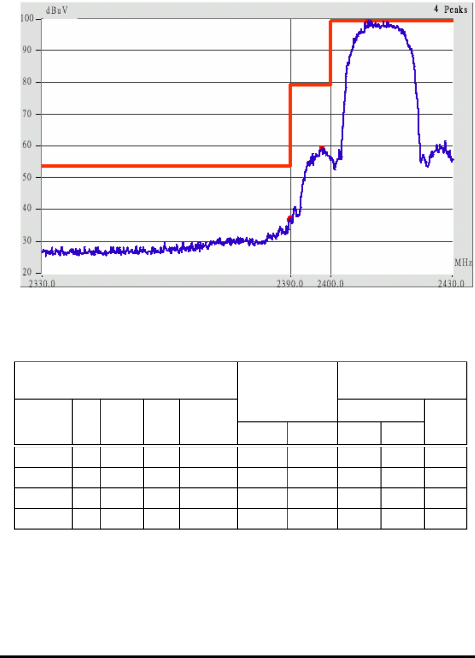
Detachable antenna, 802.11b channel 1 (The lowest one in the frequency bands)
This is the hard copy of our bandedge measurement generated by our bandedge testing program.
The plot shown above is the bandedge of channel 1.
1. The lobe left by the fundamental side is already 20dB below the highest emission level.
2. The emissions recorded in the restricted band is do comply with the Part 15.209(a) – as below.
Radiated
Emission
FCC Class B ( 3m )
Corrected
Amplitude
(dBµV/m) Limit (dBµV/m)
Frequency
(MHz)
Ant.
P.
Ant. H.
(m)
Table
()
Factors
(dB) Peak Average Peak Ave.
Margin
(dB)
2387.74 Hor 1.00 151 3.13 39.96 --- 74.00 53.96 -14.00
2390.07 Hor 1.00 227 3.14 38.97 --- 74.00 53.96 -14.99
2389.64 Ver 1.00 341 3.13 46.30 --- 74.00 53.96 -7.66
2390.02 Ver 1.00 109 3.13 44.97 --- 74.00 53.96 -8.99
Test Report ------------------------------------------------------------------------------ 48/60
Report No.: C5115391, FCC Part 15
Training Research Co., Ltd., TEL: 886-2-26935155, Fax: 886-2-26934440
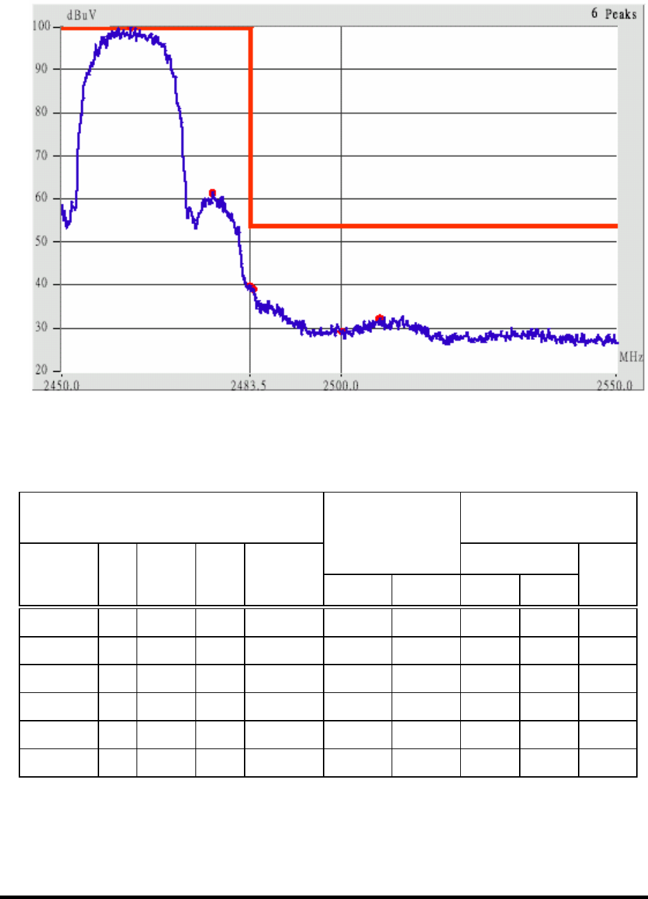
Detachable antenna, 802.11b channel 11 (The Highest one in the frequency bands)
This is the hard copy of our bandedge measurement generated by our bandedge testing program.
The plot shown above is the bandedge of channel 11.
3. The lobe right by the fundamental side is already 20dB below the highest emission level.
4. The emissions recorded in the restricted band is do comply with the Part 15.209(a) – as below
Radiated
Emission
FCC Class B ( 3m )
Corrected
Amplitude
(dBµV/m) Limit (dBµV/m)
Frequency
(MHz)
Ant.
P.
Ant. H.
(m)
Table
()
Factors
(dB) Peak Average Peak Ave.
Margin
(dB)
2483.91 Hor 1.00 174 3.45 40.11 --- 74.00 53.96 -13.85
2506.95 Hor 1.00 296 3.51 39.01 --- 74.00 53.96 -14.95
2483.50 Ver 1.00 142 3.45 47.11 --- 74.00 53.96 -6.85
2484.37 Ver 1.00 209 3.45 46.95 --- 74.00 53.96 -7.01
2500.01 Ver 1.00 27 3.50 39.50 --- 74.00 53.96 -14.46
2502.22 Ver 1.00 116 3.50 42.00 --- 74.00 53.96 -11.96
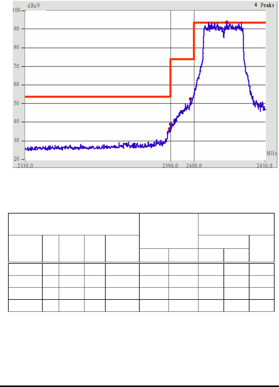
Test Report ------------------------------------------------------------------------------ 49/60
Report No.: C5115391, FCC Part 15
Training Research Co., Ltd., TEL: 886-2-26935155, Fax: 886-2-26934440
Detachable antenna, 802.11g channel 1 (The lowest one in the frequency bands)
This is the hard copy of our bandedge measurement generated by our bandedge testing program.
The plot shown above is the bandedge of channel 1.
5. The lobe left by the fundamental side is already 20dB below the highest emission level.
6. The emissions recorded in the restricted band is do comply with the Part 15.209(a) – as below.
Radiated
Emission
FCC Class B ( 3m )
Corrected
Amplitude
(dBµV/m) Limit (dBµV/m)
Frequency
(MHz)
Ant.
P.
Ant. H.
(m)
Table
()
Factors
(dB) Peak Average Peak Ave.
Margin
(dB)
2389.15 Hor 1.00 54 3.13 41.13 --- 74.00 53.96 -12.83
2390.02 Hor 1.00 127 3.13 39.30 --- 74.00 53.96 -14.66
2389.42 Ver 1.00 334 3.13 45.47 --- 74.00 53.96 -8.49
2390.07 Ver 1.00 10 3.14 45.30 --- 74.00 53.96 -8.66
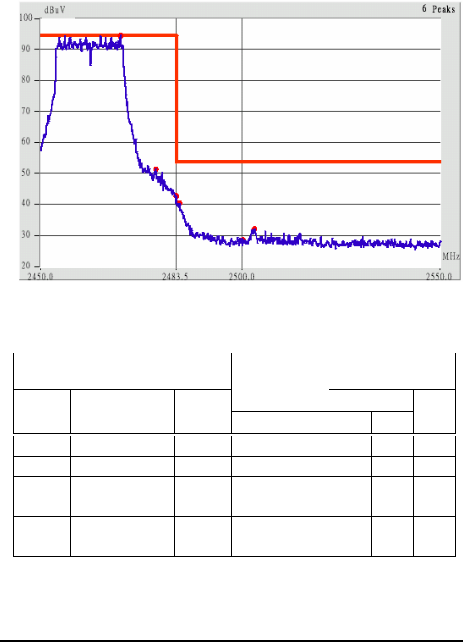
Test Report ------------------------------------------------------------------------------ 50/60
Report No.: C5115391, FCC Part 15
Training Research Co., Ltd., TEL: 886-2-26935155, Fax: 886-2-26934440
Detachable antenna, 802.11g channel 11 (The Highest one in the frequency bands)
This is the hard copy of our bandedge measurement generated by our bandedge testing program.
The plot shown above is the bandedge of channel 11.
7. The lobe right by the fundamental side is already 20dB below the highest emission level.
8. The emissions recorded in the restricted band is do comply with the Part 15.209(a) – as below
Radiated
Emission
FCC Class B ( 3m )
Corrected
Amplitude
(dBµV/m) Limit (dBµV/m)
Frequency
(MHz)
Ant.
P.
Ant. H.
(m)
Table
()
Factors
(dB) Peak Average Peak Ave.
Margin
(dB)
2483.50 Hor 1.00 276 3.45 44.28 --- 74.00 53.96 -9.68
2483.73 Hor 1.00 189 3.45 45.45 --- 74.00 53.96 -8.51
2512.08 Hor 1.00 3 3.52 38.68 --- 74.00 53.96 -15.28
2483.51 Ver 1.00 286 3.45 56.95 38.28 74.00 53.96 -15.68
2500.07 Ver 1.00 291 3.50 39.33 --- 74.00 53.96 -14.63
2513.31 Ver 1.00 33 3.52 41.52 --- 74.00 53.96 -12.44
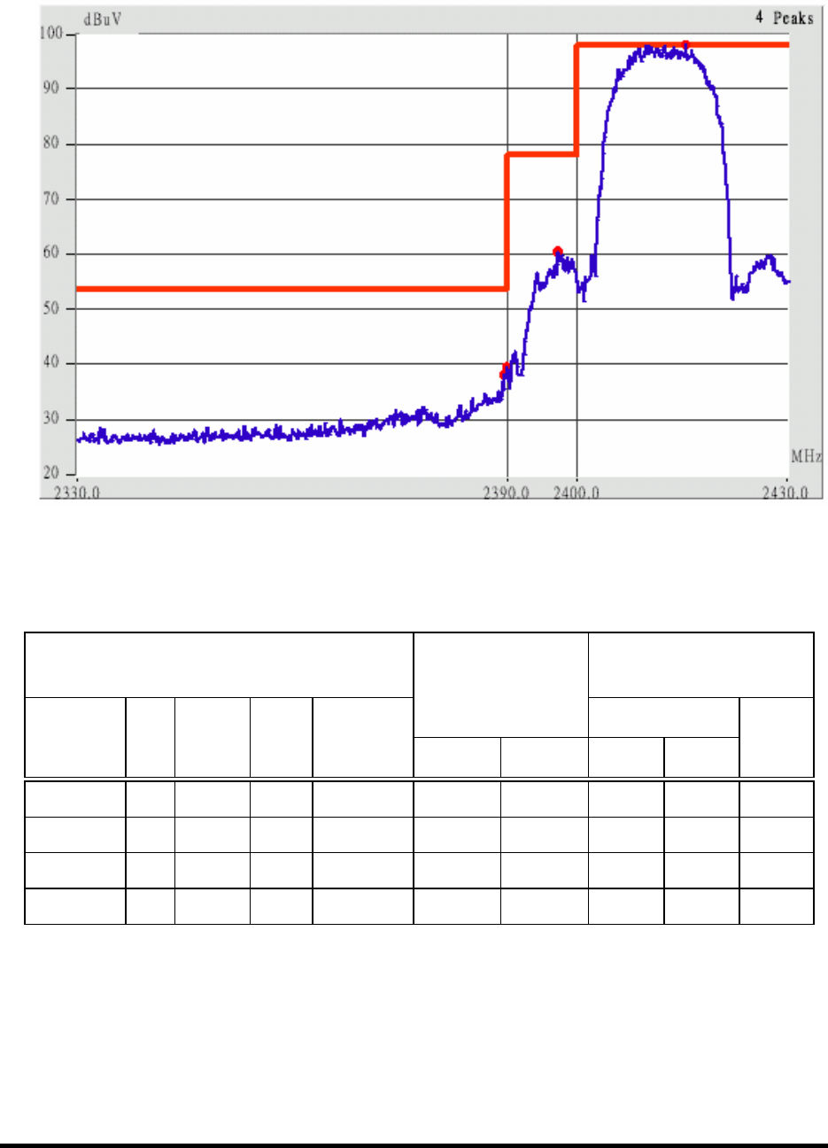
Test Report ------------------------------------------------------------------------------ 51/60
Report No.: C5115391, FCC Part 15
Training Research Co., Ltd., TEL: 886-2-26935155, Fax: 886-2-26934440
Undetachable antenna, 802.11b channel 1 (The lowest one in the frequency bands)
This is the hard copy of our bandedge measurement generated by our bandedge testing program.
The plot shown above is the bandedge of channel 1.
1. The lobe left by the fundamental side is already 20dB below the highest emission level.
2. The emissions recorded in the restricted band is do comply with the Part 15.209(a) – as below.
Radiated
Emission
FCC Class B ( 3m )
Corrected
Amplitude
(dBµV/m) Limit (dBµV/m)
Frequency
(MHz)
Ant.
P.
Ant. H.
(m)
Table
()
Factors
(dB) Peak Average Peak Ave.
Margin
(dB)
2389.42 Hor 1.00 24 3.13 39.63 --- 74.00 53.96 -14.33
2390.07 Hor 1.00 164 3.14 38.64 --- 74.00 53.96 -15.32
2389.47 Ver 1.00 238 3.13 47.13 --- 74.00 53.96 -6.83
2390.02 Ver 1.00 149 3.13 47.97 --- 74.00 53.96 -5.99
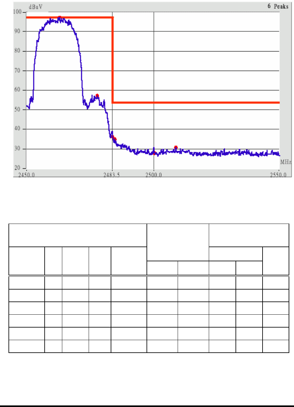
Test Report ------------------------------------------------------------------------------ 52/60
Report No.: C5115391, FCC Part 15
Training Research Co., Ltd., TEL: 886-2-26935155, Fax: 886-2-26934440
Undetachable antenna, 802.11b channel 11 (The Highest one in the frequency bands)
This is the hard copy of our bandedge measurement generated by our bandedge testing program.
The plot shown above is the bandedge of channel 11.
3. The lobe right by the fundamental side is already 20dB below the highest emission level.
4. The emissions recorded in the restricted band is do comply with the Part 15.209(a) – as below
Radiated
Emission
FCC Class B ( 3m )
Corrected
Amplitude
(dBµV/m) Limit (dBµV/m)
Frequency
(MHz)
Ant.
P.
Ant. H.
(m)
Table
()
Factors
(dB) Peak Average Peak Ave.
Margin
(dB)
2489.20 Hor 1.00 154 3.49 38.99 --- 74.00 53.96 -14.97
2534.78 Hor 1.00 207 3.55 39.21 --- 74.00 53.96 -14.75
2483.50 Ver 1.00 309 3.45 46.11 --- 74.00 53.96 -7.85
2483.68 Ver 1.00 40 3.45 45.45 --- 74.00 53.96 -8.51
2500.07 Ver 1.00 298 3.50 39.83 --- 74.00 53.96 -14.13
2531.57 Ver 1.00 173 3.54 40.54 --- 74.00 53.96 -13.42
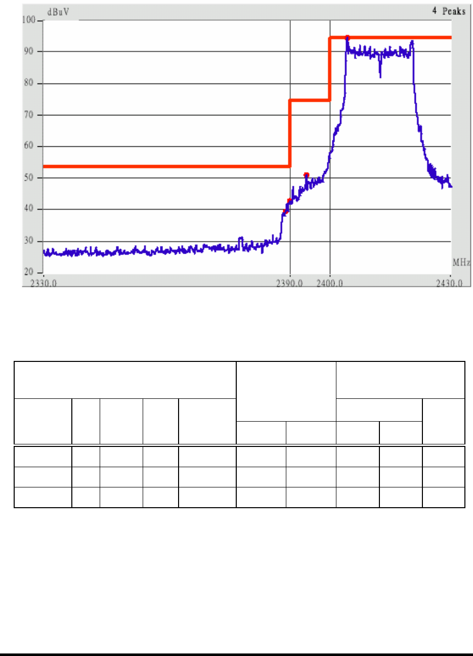
Test Report ------------------------------------------------------------------------------ 53/60
Report No.: C5115391, FCC Part 15
Training Research Co., Ltd., TEL: 886-2-26935155, Fax: 886-2-26934440
Undetachable antenna, 802.11g channel 1 (The lowest one in the frequency bands)
This is the hard copy of our bandedge measurement generated by our bandedge testing program.
The plot shown above is the bandedge of channel 1.
5. The lobe left by the fundamental side is already 20dB below the highest emission level.
6. The emissions recorded in the restricted band is do comply with the Part 15.209(a) – as below.
Radiated
Emission
FCC Class B ( 3m )
Corrected
Amplitude
(dBµV/m) Limit (dBµV/m)
Frequency
(MHz)
Ant.
P.
Ant. H.
(m)
Table
()
Factors
(dB) Peak Average Peak Ave.
Margin
(dB)
2389.26 Hor 1.00 41 3.13 44.97 --- 74.00 53.96 -8.99
2390.02 Hor 1.00 227 3.13 42.97 --- 74.00 53.96 -10.99
2390.49 Ver 1.00 209 3.14 55.97 34.14 74.00 53.96 -19.82
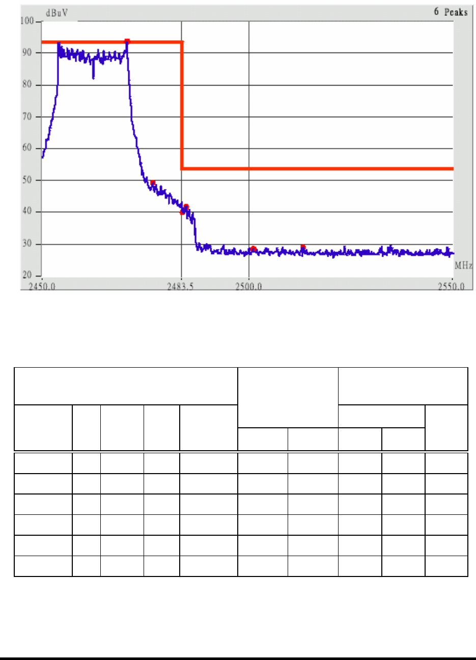
Test Report ------------------------------------------------------------------------------ 54/60
Report No.: C5115391, FCC Part 15
Training Research Co., Ltd., TEL: 886-2-26935155, Fax: 886-2-26934440
Undetachable antenna, 802.11g channel 11 (The Highest one in the frequency bands)
This is the hard copy of our bandedge measurement generated by our bandedge testing program.
The plot shown above is the bandedge of channel 11.
7. The lobe right by the fundamental side is already 20dB below the highest emission level.
8. The emissions recorded in the restricted band is do comply with the Part 15.209(a) – as below
Radiated
Emission
FCC Class B ( 3m )
Corrected
Amplitude
(dBµV/m) Limit (dBµV/m)
Frequency
(MHz)
Ant.
P.
Ant. H.
(m)
Table
()
Factors
(dB) Peak Average Peak Ave.
Margin
(dB)
2483.50 Hor 1.00 46 3.45 44.28 --- 74.00 53.96 -9.68
2484.96 Hor 1.00 191 3.45 43.45 --- 74.00 53.96 -10.51
2503.04 Hor 1.00 227 3.50 39.34 --- 74.00 53.96 -14.62
2483.55 Ver 1.00 19 3.45 54.45 36.45 74.00 53.96 -17.51
2500.07 Ver 1.00 10 3.50 39.33 --- 74.00 53.96 -14.63
2507.47 Ver 1.00 186 3.51 39.84 --- 74.00 53.96 -14.12
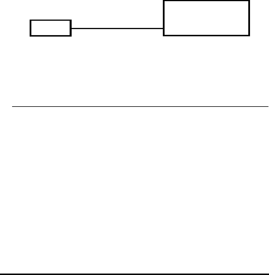
Test Report ------------------------------------------------------------------------------ 55/60
Report No.: C5115391, FCC Part 15
Training Research Co., Ltd., TEL: 886-2-26935155, Fax: 886-2-26934440
IX. Section 15.247(d): Power Spectral Density
9.1 Test Condition & Setup
The tests below are running with the EUT transmitter set at high power in TDD mode. The
EUT is needed to force selection of output power level and channel number. While testing, the EUT
was set to transmit continuously and to be tested by the contact manner with the spectrum analyzer.
9.2 Test Instruments Configuration
P.S.: The computer to control the EUT at maximal power output and channel Number
and set antenna kit
9.3 List of Test Instruments
Instrument Name Model No. Brand Serial No. Last time Next time
Spectrum Analyzer MS2665C ANRITSU 6200175476 09/30/03 09/30/04
EUT
Spectrum Analyzer
RBWΚ3kHzΙ
VBWΚ10kHz

Test Report ------------------------------------------------------------------------------ 56/60
Report No.: C5115391, FCC Part 15
Training Research Co., Ltd., TEL: 886-2-26935155, Fax: 886-2-26934440
9.4 Test Result of Power spectral density
The following table shows a summary of the test results of the Power Spectral Density.
IEEE 802.11b
Channel Frequency
(GHz)
Ppr
(dBm)
Cable Loss
(dB)
Ppq
(dBm)
Limit
(dB)
Margin
(dB)
CH 01 2.412 -12.06 0.70 -11.36 8.00 -19.36
CH 06 2.437 -12.23 0.70 -11.53 8.00 -19.53
CH 11 2.462 -12.37 0.70 -11.67 8.00 -19.67
IEEE 802.11g
Channel Frequency
(GHz)
Ppr
(dBm)
Cable Loss
(dB)
Ppq
(dBm)
Limit
(dB)
Margin
(dB)
CH 01 2.412 -16.87 0.70 -16.17 8.00 -24.17
CH 06 2.437 -15.98 0.70 -15.28 8.00 -23.28
CH 11 2.462 -16.19 0.70 -15.49 8.00 -23.49
Note:
1. The following pages show the results of spectrum reading.
2. Ppr: spectrum read power density (using peak search mode),
Ppq: actual peak power density in the spread spectrum band.
3. Ppq = Ppr + |Cable Loss|
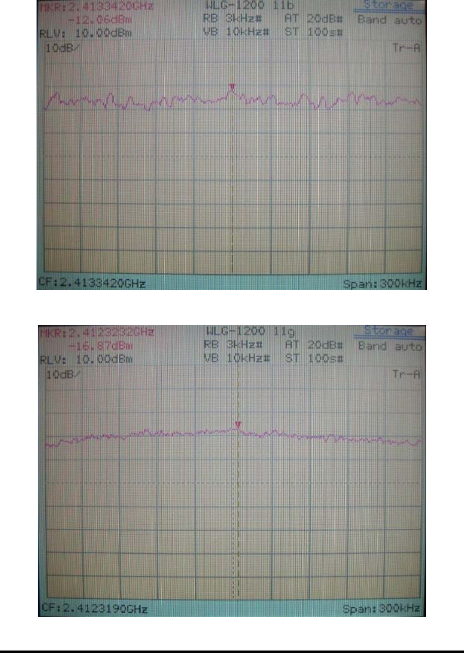
Test Report ------------------------------------------------------------------------------ 57/60
Report No.: C5115391, FCC Part 15
Training Research Co., Ltd., TEL: 886-2-26935155, Fax: 886-2-26934440
802.11b Channel 01
802.11g Channel 01
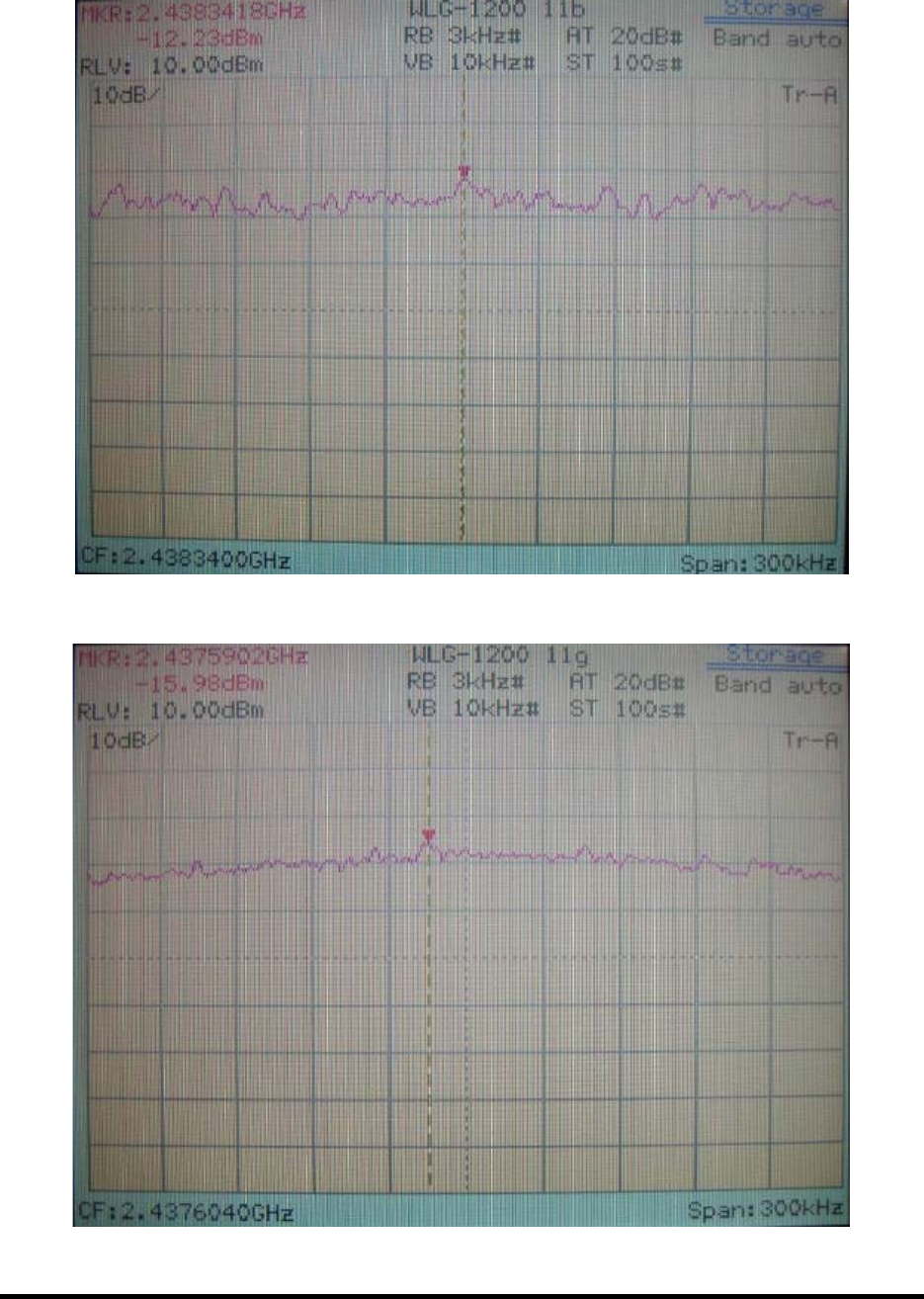
Test Report ------------------------------------------------------------------------------ 58/60
Report No.: C5115391, FCC Part 15
Training Research Co., Ltd., TEL: 886-2-26935155, Fax: 886-2-26934440
802.11b Channel 06
802.11g Channel 06
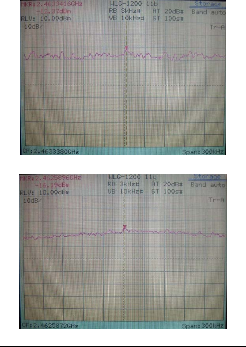
Test Report ------------------------------------------------------------------------------ 59/60
Report No.: C5115391, FCC Part 15
Training Research Co., Ltd., TEL: 886-2-26935155, Fax: 886-2-26934440
802.11b Channel 11
802.11g Channel 11

Test Report ------------------------------------------------------------------------------ 60/60
Report No.: C5115391, FCC Part 15
Training Research Co., Ltd., TEL: 886-2-26935155, Fax: 886-2-26934440
Appendix A
Brand Name and Model Name :
Brand Name Model Name
TRENDnet TEW-423PI

Training Research Co., Ltd.
1F, No. 255, Nan Yang Street, Shijr, Taipei Hsien 221, Taiwan, R.O.C.
TEL: 886-2-26935155 FAX: 886-2-26934440
E-mail: report@trclab.com.tw
TRCSince1985
®
EXHIBIT D
Test Set-up Photos
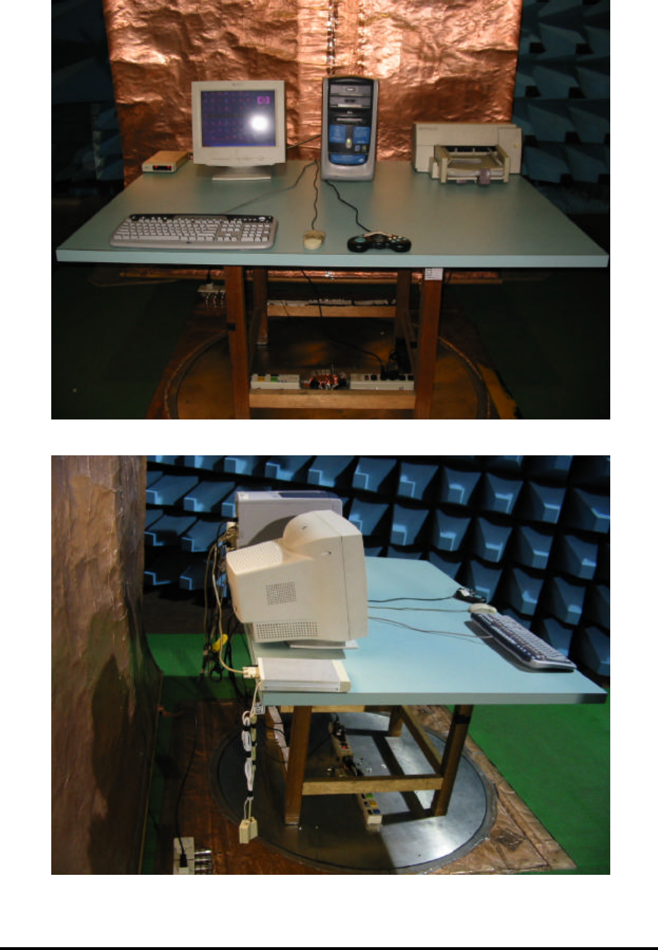
Test Setup Photos ------------------------------------------------------------------------ 1/3
FCC ID: NHPWLG1200
Training Research Co., Ltd., TEL: 886-2-26935155, Fax: 886-2-26934440
Conducted Test Setup Placement:
Front View of the Test Configuration
Side View of the Test Configuration
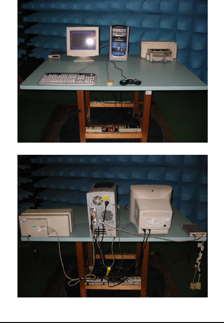
Test Setup Photos ------------------------------------------------------------------------ 2/3
FCC ID: NHPWLG1200
Training Research Co., Ltd., TEL: 886-2-26935155, Fax: 886-2-26934440
Radiated Test Setup Placement:
Front View of Unintentional
Rear View of Unintentional
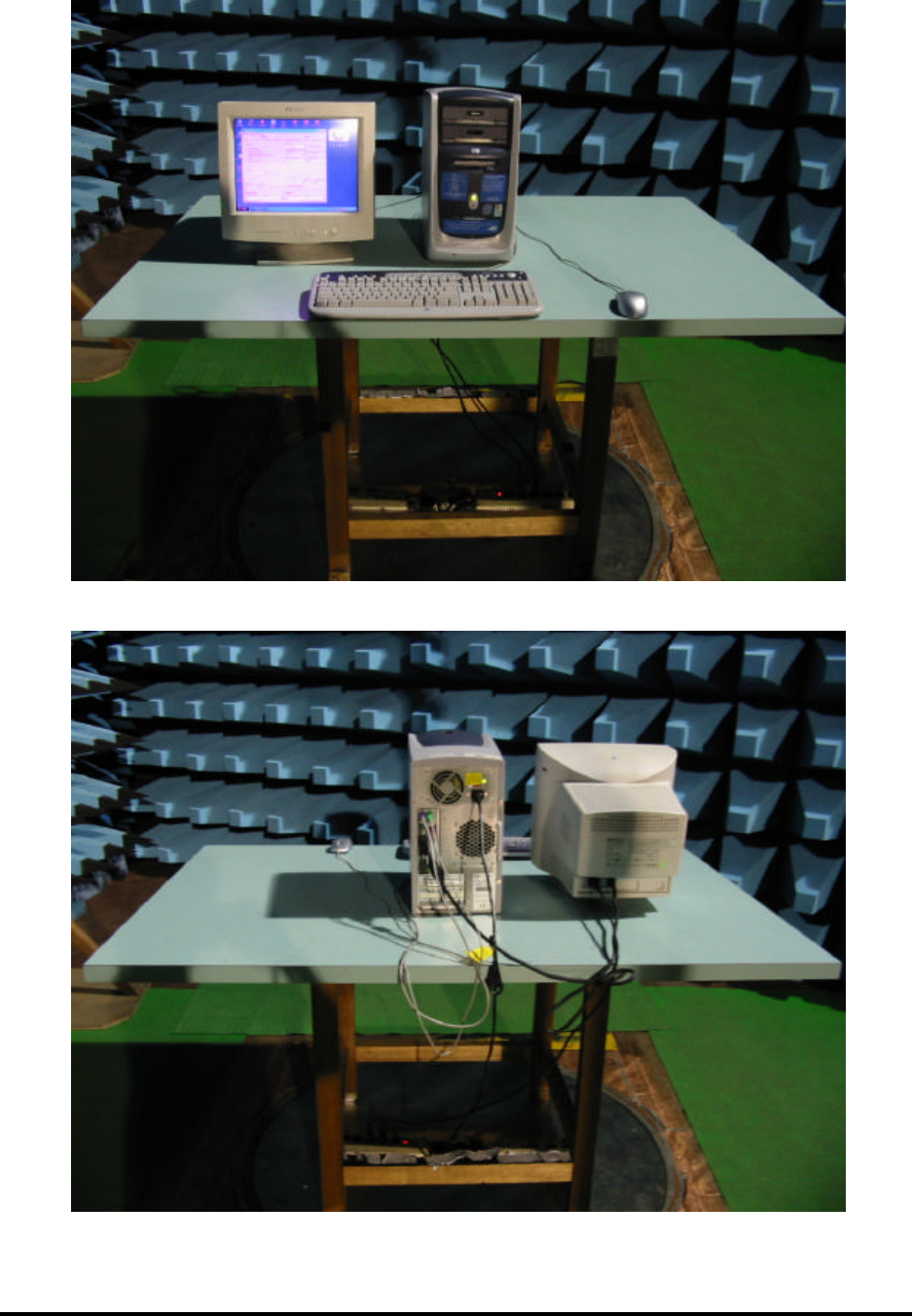
Test Setup Photos ------------------------------------------------------------------------ 3/3
FCC ID: NHPWLG1200
Training Research Co., Ltd., TEL: 886-2-26935155, Fax: 886-2-26934440
Radiated Test Setup Placement:
Front View of Intentional
Rear View of Intentional
