TELGUARD® TG 1 Express Installation Guide Manual
User Manual: TG-1 Express Installation Manual AlarmHow.net Library
Open the PDF directly: View PDF ![]() .
.
Page Count: 43
- Important Note
- Foreword
- Table of Contents
- General Description and Operation
- Visual Tour
- Features
- Getting Ready
- Installation
- Appendix 1 – Connection Guide
- Appendix 2 – Troubleshooting Guide
- ALL OK
- Appendix 3 – Detailed Specifications
- Appendix 4 – Parts List
TG-1
Express
Installation Guide
COMPANY CONFIDENTIAL
For use by TELGUARD® customers only.
Distribution to other parties strictly prohibited.
February 27, 2010

56042501 i © 2010 Telular Corporation
Important Note
The registration form must be completed before leaving for the job
site to install the Telguard product. There are four ways to register a
Telguard unit:
• register online at www.telguardonline.com,
• send the electronic registration form at www.telular.com/telguard,
• email the completed registration form to cellservice@telular.com, or
• fax the completed registration form to 678-945-1651.
Foreword
The Telguard model TG-1 Express cellular alarm communicator (p/n
TG1GX001) is UL Listed for Household Fire systems and Household
Burglary systems. This means that the TG-1 Express may be used in
Household Burglary systems, Household Fire systems or combined
Household Burglary & Fire system as the primary communication path.
Technical Support
Technical support for all Telguard products is available Monday through
Saturday.
Toll Free: 800-229-2326, option 9
Monday -Saturday 8am -8pm EST

56042501 ii © 2010 Telular Corporation
About this Manual
This manual assumes that you have basic security system installation
skills such as measuring voltages, stripping wire, properly connecting
wires together, connecting wires to terminals, and checking phone lines.
It also assumes that you have a familiarity with the proper installation
and programming tasks related to various alarm panels.
The material and instructions covered in this manual have been carefully
checked for accuracy and are presumed to be reliable. However, Telular
assumes no responsibility for inaccuracies and reserves the right to
modify and revise this manual without notice.
It is our goal at Telular to always supply accurate and reliable
documentation. If a discrepancy is found in this documentation, please
mail or fax a photocopy of the corrected material to:
Telular Security Products
Technical Services Department
2727 Paces Ferry Road SE
Suite 1-800
Atlanta, GA USA 30339
Fax: 678-945-1651

56042501 iii © 2010 Telular Corporation
Repair and Warranty
If trouble is experienced with the Telguard
Cellular Alarm Transmission
System please contact Telular Tech Support in the U.S.A. for repair and
(or) warranty information. The customer (user) should not attempt any
repair to the Telguard
Cellular Alarm Transmission System. Repair of
this equipment should be referred to only qualified technical personnel.
Telular will repair or replace (our option) inoperative units for up to two
years from date of manufacture. This excludes damage due to lightning
or installer error. Unauthorized modifications void this warranty. Not
responsible for incidental or consequential damages. Liability is limited
to price of unit. This is the exclusive warranty and no other warranties
will be honored, whether expressed or implied.
An RMA must be assigned by calling Telular Tech Support 800-229-2326
before returning product to:
Telular Corporation
Attention: Repair Depot
294 W Palatine Rd
Wheeling, Il 60090
RMA number must be on outside of box or product will not be
accepted.
Future Testing and Limitations on Use
Telguard is part of an advanced design alarm-communication system.
It does not offer guaranteed protection against burglary and fire. Any
alarm communication system is subject to compromise or failure.
The Telguard will not work without power. Electrically powered devices
will not work if the power supply is off for any reason, however briefly.
The cellular radio network, needed to transmit alarm signals from
protected premises to a central monitoring station, may be inoperable
or temporarily out of service. Cellular radio networks are also subject to
compromise by sophisticated methods of attack.
56042501 iv © 2010 Telular Corporation
This equipment, like any other electrical device, is subject to component
failure. Although this equipment is designed to be long lasting, the
electrical components could fail at any time.
Due to these limitations, we recommend that if the automatic self-test
feature is not enabled, other arrangements be made with the user to
test the system at least once every three months. Moreover,
arrangements should also be made for on-site inspection/test by a
licensed alarm installer at least once each year.

56042501 v © 2010 Telular Corporation
Terms and Conditions for Use of Telular Product
These Terms and Conditions are a legal contract between you and
Telular Corporation for the title to and use of the Product. BY
RETAINING AND USING THE PRODUCT YOU AGREE TO THE TERMS
AND CONDITIONS INCLUDING WARRANTY DISCLAIMERS, LIMITATIONS
OF LIABILITY AND INDEMNIFICATION PROVISIONS BELOW. IF YOU DO
NOT AGREE TO THE TERMS AND CONDITIONS, DO NOT USE THE
PRODUCT AND IMMEDIATELY RETURN THE UNUSED PRODUCT FOR A
COMPLETE REFUND. You agree to accept sole responsibility for any
misuse of the Product by you; and, in addition, any negligent or illegal
act or omission of your or your agents, contractors, servants, employees,
or other users of the Product so long as the Product was obtained from
you, in the use and operation of the Product.
INDEMNIFICATION OF TELULAR CORPORATION (“TELULAR”)
YOU SHALL INDEMNIFY, DEFEND AND HOLD HARMLESS TELULAR FOR
ANY OF THE COST, INCLUDING REASONABLE ATTORNEYS’ FEES, AND
FROM CLAIMS ARISING OUT OF YOU, YOUR CLIENTS’ OR OTHER THIRD
PARTIES’ USE OR OPERATION OF THE PRODUCT: (i) FOR MISUSE OR IN
A MANNER NOT CONTEMPLATED BY YOU AND TELULAR OR
INCONSISTENT WITH THE PROVISIONS OF THIS MANUAL; (ii) IN AN
ILLEGAL MANNER OR AGAINST PUBLIC POLICY; (iii) IN A MANNER
SPECIFICALLY UNAUTHORIZED IN THIS MANUAL; (iv) IN A MANNER
HARMFUL OR DANGEROUS TO THIRD PARTIES; (v) FROM CLAIMS BY
ANYONE RESPECTING PROBLEMS, ERRORS OR MISTAKES OF THE
PRODUCT; OR (vi) COMBINATION OF THE PRODUCT WITH MATERIAL,
MODIFICATION OF THE PRODUCT OR USE OF THE PRODUCT IN AN
ENVIRONMENT NOT PROVIDED, OR PERMITTED, BY TELULAR IN
WRITING. THE PARTIES SHALL GIVE EACH OTHER PROMPT NOTICE OF
ANY SUCH COST OR CLAIMS AND COOPERATE, EACH WITH THE
OTHER, TO EFFECTUATE THIS INDEMNIFICATION, DEFENSE AND HOLD
HARMLESS.

56042501 vi © 2010 Telular Corporation
WARRANTY and LIMITATIONS
TELULAR WILL REPAIR OR REPLACE (OUR OPTION) INOPERATIVE UNITS
FOR UP TO TWO YEARS FROM DATE OF MANUFACTURE. EXCLUDES
DAMAGE DUE TO LIGHTNING OR INSTALLER ERROR AS WELL AS UNITS
THAT INCORPORATE MATERIAL, OR USED IN A MANNER OR
ENVIRONMENT, NOT SPECIFICALLY AUTHORIZED IN THIS MANUAL.
UNAUTHORIZED MODIFICATIONS VOID THIS WARRANTY. NOT
RESPONSIBLE FOR INCIDENTAL OR CONSEQUENTIAL DAMAGES.
LIABILITY LIMITED TO PRICE OF UNIT. THIS IS THE EXCLUSIVE
WARRANTY, IN LIEU OF ALL OTHER WARRANTIES INCLUDING IMPLIED
WARRANTIES OF MERCHANTABILITY, TITLE, DELIVERY, INFRINGEMENT
OR FITNESS FOR A PARTICULAR PURPOSE AND NO OTHER
WARRANTIES WILL BE HONORED, WHETHER EXPRESSED OR IMPLIED.

56042501 vii © 2010 Telular Corporation
Table of Contents
Important Note i
Foreword i
Table of Contents vii
General Description and Operation 1
Visual Tour 2
TG-1 Express – First Look 2
Features 3
Operating Mode 3
Panel-Supplied Power 4
Single Line Interface Cable (SLIC) 4
Multiple Alarm Format Support 4
Complete Supervision of Communication Path 5
Telguard Automatic Self-test Report 6
Telguard Remote Query Capability 7
Programmable Supervisory Trip Output (STC) Relay 7
Diagnostic and Status LEDs 8
UL Listings 8
Getting Ready 9
Dealer Account Establishment 9
56042501 viii © 2010 Telular Corporation
Subscriber Account Registration 9
Pre-Installation Checklist 10
Installation 11
Summary 11
Step 1: Register the Telguard Unit for Service 11
Step 2: Locate Unit and Measure Signal Strength (RSSI) 12
Step 3: Program, Activate & Transmit Alarms 16
Step 4: Connect the Supervisory Trip Output 20
Step 5: Connect and test the trip input (optional) 23
Step 6: Complete the Telguard Installation 24
Appendix 1 – Connection Guide 26
Appendix 2 – Troubleshooting Guide 28
Appendix 3 – Detailed Specifications 32
Dialer to Interface Electronics 32
Power 32
Digital Cellular Radio 32
Appendix 4 – Parts List 34

56042501 1 © 2010 Telular Corporation
General Description and Operation
The Telguard TG-1 Express is a digital cellular radio alarm
transmission device used to provide a primary transmission path
(cellular) for Household alarm panels. When transmitting an alarm
signal, the Telguard unit obtains its data from the alarm panel by way
of a telephone interface. The Telguard will obtain all alarm signal
information including monitoring station phone number, account
number and all zones for every alarm transmission. The Telguard
transmits a Link Request to the Telular Communication Center and,
when a link acknowledgement is received, the Telguard handshakes
with the alarm panel and causes it to transmit the alarm data. Telguard
encodes the alarm data and transmits it to the Telular Communication
Center over the cellular network. The Telular Communication Center
performs a function similar to a central station receiver and issues the
transmission acknowledgement when the last message in the
transmission is received. After decoding and reformatting, the alarm
signal is routed over the telco line (Public Switched Telephone Network
- PSTN) to the appropriate alarm company central station for action.
In a typical alarm installation, Telguard Digital TG-1 Express is installed
in the same area as the host alarm system and is connected directly to
the host alarm panel via the Telguard’s RJ-45 jack in the normal
fashion. One programmable supervisory trip (STC) output is available
for connection to the host control/communicator's trip zone input
terminals in order to provide a Telguard trouble signal to the alarm
panel. Additionally, automatic self-test and status-on-demand report
signals are transmitted exclusively over the cellular network to the
Telular Communication Center. The TG-1 Express receives operating
power form the host alarm panel, and all cellular monitoring and
supervisory functions are built in. No extra modules are required.
The UL Listed equipment at the Telular Communication Center (TCC)
plays a key role in the operation of every Telguard. All Telguard units
are required to use the Communication Center because of the alarm
panel alarm signal format encoding and decoding requirements used
in packet-data transmissions over the digital cellular network. The
56042501 2 © 2010 Telular Corporation
Communication Center also manages the real-time databases for
cellular service and a complete history of every Telguard unit’s
operating conditions. These conditions include programming setup
information, alarm transmission information, supervisory trouble
information, status information, and automatic self-test information.
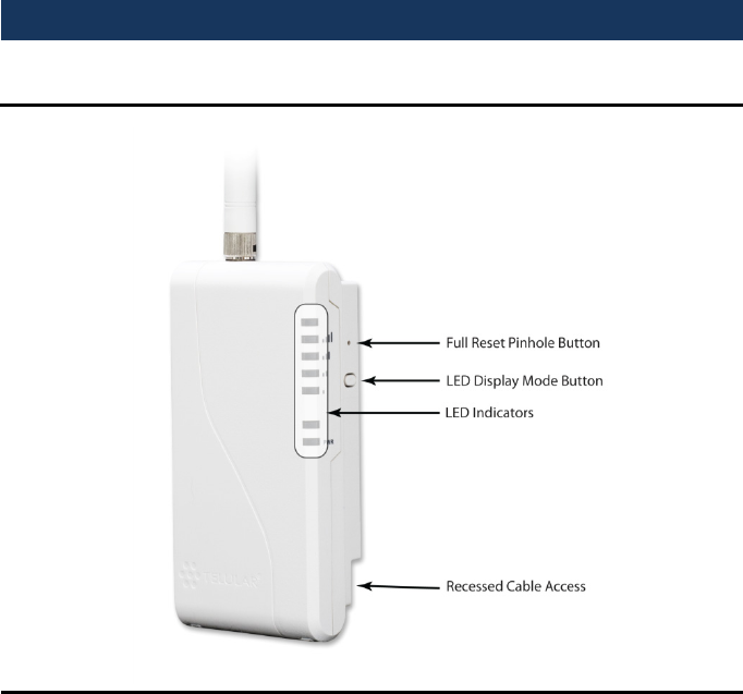
Visual Tour
TG-1 Express – First Look
56042501 3 © 2010 Telular Corporation
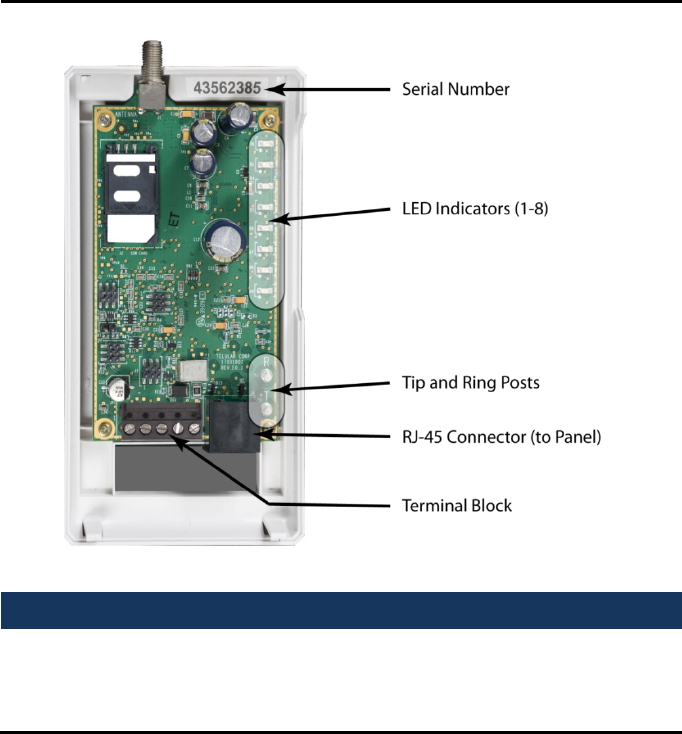
Inside the TG-1 Express
Features
This section summarizes the key features of the Telguard TG-1 Express.
Operating Mode
The Telguard Digital TG-1 Express is a digital cellular transmission
device that is installed at the protected premises to provide primary
alarm transmission integrity for household burglary and fire systems.

56042501 4 © 2010 Telular Corporation
Panel-Supplied Power
The Telguard TG-1 Express has an extremely low power profile, and as
such can usually be powered from the panel to which it is connected.
At 39mA (average), the power required by the TG-1 Express is less than
that used by many keypads.
Using the panel to provide power for the TG-1 Express allows for a
simpler installation, and eliminates the need for additional A/C outlets.
For panels with very limited power capabilities, a Telguard TG-1 or TG-
4 communicator should be used, both of which utilize a battery
backed-up A/C power, separate from the panel.
Single Line Interface Cable (SLIC)
To further simplify installation, the TG-1 Express can be connected to
the panel power using pins 2 and 7 of the RJ-45 connector for Ground
and Power respectively. This allows the installer to connect both the
communication path as well as the power to the alarm panel using a
single cable.
Multiple Alarm Format Support
The default program setting of the Telguard TG-1 Express is for Auto
Detection of the panel alarm format. The Auto Format Detect feature
allows the Telguard to adapt to receive any listed format on every
alarm transmission. If the alarm format is changed for whatever
reason, the Telguard will sense the new format and accept the alarm
signal.
In order for the host alarm panel to be compatible with the Telguard,
the panel must be programmed to transmit alarm messages to the
central station using one of the following non-extended formats:
• Pulse Formats:
o 3+1 pulse; 10pps, Double Round, 1400Hz ack
o 3+1 pulse; 20pps, Double Round, 2300Hz ack

56042501 5 © 2010 Telular Corporation
o 3+1 pulse; 40pps, Double Round, 2300Hz ack
o 4+2 pulse; 10pps, Double Round, 1400Hz ack
o 4+2 pulse; 20pps, Double Round, 2300Hz ack
o 4+2 pulse; 40pps, Double Round, 2300Hz ack
• Ademco Contact ID
• Radionics Modem IIe or IIIa
• SIA2 (SIA-DC-03 level 2 release at 300 baud)
• DMP
Hexadecimal account numbers can be used with 3+1 or 4+2 formats,
as well as Contact ID and Radionics (4 or 10 digits for Contact ID, 4
digits for Radionics).
Complete Supervision of Communication Path
The Telguard TG-1 Express continuously supervises the primary
(cellular) communication path. If the cellular communications path
becomes inoperative, the TG-1 Express generates a relay trip output
that can be connected to a zone input of the host alarm panel and/or
used to activate remote annunciation devices.
No Service Condition (NSC)
The Telguard unit declares a no service condition (NSC) when the
measured “receive” cellular radio signal strength at the protected
premises drops to -114 dBm or less. NSC is programmable to trip the
supervisory relay output (STC relay) after a variable period of time.
When the STC relay trips, the System Trouble Condition LED (STC LED)
will flash 4 times. Restoral of this condition occurs when a measurable
signal strength greater than –114 dBm is maintained for the trip period.
Radio Failure Condition (RFC)
Radio communications failure condition (RFC) is declared when
Telguard is unable to transmit over the cellular network even with
acceptable signal strength. RFC is indicated by the STC LED flashing 5
times. RFC is cleared automatically after 10 minutes.

56042501 6 © 2010 Telular Corporation
Panel Presence Failure Condition (PPFC)
Panel presence failure condition (PPFC) is declared when the Telguard
is unable to detect the presence of the host alarm panel. PPFC is
indicated by the STC LED flashing 7 times. PPFC is restored
immediately after the connection to the panel is restored.
Dial Tone Failure (DTF)
The Telguard continuously monitors the 30V supply circuit that
provides dial tone to the alarm panel. A Dial Tone Failure (DTF) is
declared when the 30V supply drops to 20V or less while the alarm
panel is on-hook. The STC LED will flash 6 times and the STC relay will
trip. Additionally, a TYPE 2 supervisory message is automatically
transmitted to the Telular Communications Center. This condition will
require contacting the Telular Communications Center for resolution.
Catastrophic Failure (CF)
Catastrophic Failure (CF) is any condition that causes the Telguard to
stop functioning at all levels, most commonly because of power failure.
The STC trip output is activated and visible indication is loss of all LED
activity. If power is connected properly to the unit, please contact
Telguard Technical Support for resolution.
Telguard Automatic Self-test Report
The Telguard automatic self-test signal is programmed to daily, weekly
or monthly schedule as prescribed by contract. The central station
receives the automatic self-test report in the same format that the
alarm panel normally uses for communication over the telco line. The
central station provides the Telguard self-test code along with the time
and frequency of transmission when the Telguard is initially activated.
The Communication Center captures all current and historical data
pertaining to the operation of the Telguard when it processes the
automatic self-test signal on to the central station. This data contains
current operational status (C.O.S.) of the Telguard such as "All OK",

56042501 7 © 2010 Telular Corporation
current trip input status, or any combination of the system trouble
conditions, as well as the current signal strength. In addition, the data
also contains historical data for supervisory events that occurred since
the last self-test signal was transmitted. This data includes the number
of occurrences of communications failure conditions and no cellular
service conditions. This additional information is available by
contacting Telular Technical Support or by visiting
www.TelguardOnline.com.
Telguard Remote Query Capability
Although Telguard has the capability for a daily, weekly, or monthly
automatic self-test, a separate feature is provided for determining the
current operational status of every Telguard. This feature is called
Remote Query and is used to provide real-time operational status for
Telguard on-demand. It is useful in resolving STC events that are
reported by the alarm panel to the central station. Authorized
personnel can initiate the Remote Query at any time by calling
Customer Service or by visiting www.TelguardOnline.com. The Remote
Query causes Telguard to upload current operational status data and
historical data, just as the automatic self-test described above, except
that the query signal is controlled by the one who initiates it. The
query signal is held in the Telguard database at the Communication
Center for review and is not forwarded on to the central station.
Programmable Supervisory Trip Output (STC) Relay
The Telguard Digital TG-1 Express has one supervisory relay trip output
(STC) and is energized in a powered-up state when no system troubles
exist. It enables a supervisory trouble code to be transmitted to the
central station when connected to an alarm panel’s 24-hour instant
input zone. The STC relay is programmable, using a standard touch-
tone telephone or butt-set, to meet virtually any installation
requirement.
The following supervisory features or combination of features are
programmable to trip the STC relay in order to meet a variety of
installation requirements:

56042501 8 © 2010 Telular Corporation
• Trips on no service condition (NSC).
• Trips on radio communication failure condition (RFC).
The following system trouble features are embedded in the Telguard
for tripping the STC relay and cannot be changed:
• Tripped when unit is not activated at the Telular
Communications Center (TCC)
• Trips on catastrophic failure (CF) if all power is lost.
• Trips on transmit-disable command from the Communication
Center. This radio command disables only the Telguard
transmitter and would be used, for example, to shut down the
Telguard due to a runaway panel dialer.
Diagnostic and Status LEDs
Seven LEDs are provided as a useful aid during installation and give
installers an immediate visual indication of system status. The LEDs
serve as indicators for activation, system trouble conditions, and
communication indicators. They also can be used to provide a signal
strength indication, similar to the signal strength bars on a cellular
phone. See the installation section for details.
UL Listings
Model TG-1 Express (p/n TG1GX001) meets the requirements for all
Household Burglary, Household Fire, and Combined Household
Burglary/Fire installations. It has a plastic enclosure and dipole antenna.
TG-1 Express is UL Listed for the following:
• UL Household Burglary
• UL Household Fire
• UL Household Burg/Fire Combination

56042501 9 © 2010 Telular Corporation
Getting Ready
The Telguard can only be activated when all the necessary accounting
information has been entered into the customer database located at
the Telular Communication Center. The database includes information
about the customer account, unit location, and system test plan
information.
Dealer Account Establishment
Prior to registration of any Telguard unit, a Dealer Account must be
established. Once the Dealer Account has been established and service
credit line established between the Security Dealer and Telular, a
service registration form may be submitted. Establish your Dealer
Account by completing the Telular Cellular Service Dealer Account
Application that is included with every Telguard and faxing it to Telular
Customer Service at 678-945-1651. Once the application has been
completed you will receive an acknowledgment within 1 business day
or sooner. This is a one-time event; the acknowledgment from the
Telular Technical Service will include a Dealer Account Number that will
be used for all Telguard registrations.
Subscriber Account Registration
A completed Registration Form is required by Telular to register the
Telguard unit prior to leaving for the job site. Service registration of
the Telguard can be accomplished:
• Online – Complete the Registration Form online at
www.telguardonline.com
• By Email – Email the completed Registration form to
cellservice@telular.com.
• By FAX – Fax the completed Service Registration Form that is
shipped with each Telguard unit to Telular Customer Service
at 678-945-1651.

56042501 10 © 2010 Telular Corporation
Service registration occurs within 30 minutes of receipt of the
registration form. The subscriber record is created and the Telguard
device will be ready for activation. Activation occurs automatically
upon transmission of the first alarm signal. Telular Technical Service is
open from 8:00 AM – 8:00 PM EST Monday – Friday, 9:00 AM – 5:00 PM
EST Saturday and closed during major holidays; registration forms
received after hours will be processed by 9:00 AM EST the next
business day.
Pre-Installation Checklist
Before attempting to connect Telguard to the host alarm panel, please
note the following:
Be sure you have all the proper parts before you go to the job site. The
following items are shipped with each Telguard unit:
• Registration Form – The registration form must be
completed and sent before leaving for the job site to
install the Telguard unit.
• Basic TG-1 Express unit, with antenna.
• TG-1 Express Installation Guide.
You must also have certain installation test tools:
• A standard telephone or lineman's butt-set is required at the
job site for use in programming the unit.
• Screws and a screwdriver will be required to attach the unit
and antenna to the wall.
• In order to connect the STC relay output to the alarm panel,
stranded electrical wire will be required. The terminal strips
can accommodate solid or stranded wire sizes from 14 to 22
gauge.
• A standard RJ31X-to-spaded leads cable will be required to
connect the TG-1 Express to the panel. These are usually
supplied with the alarm panel.

56042501 11 © 2010 Telular Corporation
Note: Your unit may be subject to airtime charges for unintended use.
Telular Cellular Service offers several cellular service rate plans. Check
the registration form that was shipped with your unit or call us to
determine what rate plan each unit is operating under.
Installation
Summary
There are six steps in installing Telguard properly. IF YOU DO NOT
PROCEED IN THE ORDER AND MANNER PRESCRIBED, YOU MAY NOT
COMPLETE THE INSTALLATION IN THE TIME ALLOCATED. These six
steps are summarized below and then explained in detail in the
remainder of this manual.
1. Register for Telguard service
2. Locate Unit and measure signal strength
3. Program, activate and transmit alarm panel alarms
4. Connect supervisory trip outputs
5. Connect trip input (optional)
6. Complete installation
This six-step installation approach provides the alarm installer with the
easiest and fastest method of properly installing Telguard. Please
follow the instructions carefully and if you should need assistance or
have any questions, call Telular TECHNICAL SERVICE at 1-800-229-2326
extension 9.
Important: Dealer Account Establishment and service registration form
must be complete prior to Installation (see previous section).
Step 1: Register the Telguard Unit for Service
Installation Tip: Register for service prior to leaving for the job site to
avoid a second trip.

56042501 12 © 2010 Telular Corporation
The registration form must be completed before leaving for the job site
to install the Telguard product. The registration form may be
completed by:
• Fax – 678-945-1651
• Email – cellservice@telular.com
• Online – www.telguardonline.com
Registration requests sent by fax or email are processed Monday-
Friday from 8:00AM to 8:00PM and Saturday 9:00AM to 5:00PM EST
within 30 minutes of receipt of the registration form. Registration
requests made online through www.telguardonline.com are processed
immediately, 24/7.
Activation occurs automatically upon transmission of the first alarm
signal.
Step 2: Locate Unit and Measure Signal Strength (RSSI)
Locate Unit
Pick a spot next to the alarm panel where you think the Telguard will
be mounted and place the unit down temporarily in that spot. Do not
mount it permanently now, since it may need to be moved to receive a
better cellular radio signal or a remote high-gain antenna may be
necessary.
Note that for a UL compliant installation, the Telguard TG-1 Express
must be mounted in the same room as, and not more than 20ft from
the alarm panel.
Connect DC Power
Before connecting the power cables to the alarm panel, make sure that
the panel’s power source and battery are disconnected.
To connect power to the TG-1 Express using terminal block:

56042501 13 © 2010 Telular Corporation
1. Connect the black and red leads to the GND and PWR
terminals of the alarm panel. The specific terminals used on
the panel will depend on the panel make and model.
2. Connect the black and red leads to the GND and PWR
terminals on the TG-1 Express.
3. Reconnect the alarm panel’s power supply, and ensure that
the PWR light (LED 8) on the TG-1 Express is illuminated.
To connect power to the TG-1 Express using the POTS connection:
1. Using a standard RJ-31X to spaded lead cable, connect the
orange and blue leads to the GND and PWR terminals of the
alarm panel.
2. Connect the remaining leads to the Telco terminals in the
alarm panel, per the panel’s instruction.
3. Connect the other end of the cable to the RJ-45 jack on the
TG-1 Express.
Reconnect the alarm panel’s power supply, and ensure that the PWR
indicator (LED 8) on the TG-1 Express is illuminated.
Recommended Wire Size Length Not to Exceed
18 ga 20 ft
16 ga 40 ft
14 ga 60 ft
Connect Antenna and Temporarily Place Unit
The Telguard is supplied with an antenna. In most cases the antenna
may be mounted directly to the Telguard. If a stronger radio signal is
required, the antenna must be moved to a better signal location using
a Telular antenna cable and bracket accessory (sold separately). The
performance of the Telguard antenna may be affected by the wall
material and materials contained within the wall chosen for mounting.
These effects may not be clearly identified by RSSI monitoring alone.
The wall materials may have a more pronounced effect on the
antenna’s transmit band performance.

56042501 14 © 2010 Telular Corporation
When selecting a mounting location, do not mount this unit in an area
where the general public could reasonably be within 20cm (8 inches) of
the antenna.
Note 1: Optimum RF performance can usually be found at the highest
point within a building with the fewest number of walls between the
Telguard’s antenna and the outside of the premises.
Note 2: To avoid interference with other electronic devices operating
in the area, avoid mounting the Telguard’s antenna near other
electronic devices.
Note 3: The Telguard TG-1 Express unit with supplied dipole antenna is
designed for indoor installations ONLY.
These considerations should be coupled with the best RSSI indication
obtainable. Care should be taken to ensure that a large metal object
such as a refrigerator or a metal cabinet is not located on the opposite
side of the wall.
If moving the Telguard to a different location is not practical, then you
may need a cable and remote the antenna in order to receive adequate
radio signal strength. Pick a high, visually secure spot using the
guidelines below.
Tips for Improved Radio Signal Reception
• The higher the antenna the better. So, start in the drop
ceiling above the unit and proceed up from there, to the roof
if necessary.
• Remember, the antenna should be as inconspicuous as
possible for greatest visual security.
• Try to keep the antenna away from sources of RF interference,
including pumps, compressors, ovens, etc., or where metal
objects can shield it or otherwise block the cellular radio RF
signal.

56042501 15 © 2010 Telular Corporation
• Place the antenna perpendicular to the ground, either right
side up or upside down. Do not mount the antenna
horizontally.
• Always use an antenna mounting bracket. Do not mount the
antenna such that it is in contact with another object, as this
may interfere with cellular reception and transmission.
Measure Received Signal Strength (RSSI) for Best Antenna
Placement
Measure the received signal strength by pressing the RSSI button. This
switches the LEDs to signal strength mode. Now, slowly move the unit
or remote antenna to achieve maximum signal strength. Pick the place
where the most LEDs (up to four) are lighted.
RSSI
Value Illuminated LEDs RF dBm
NO
SVC
LED 5 = slow flash, LED 4-2 =
off n/a
1 LED 5 = on, LED 4-2 = off ≤ -111 dBm
1½ LED 5 = on, LED 4 = slow flash
LED 3-2 = off ≥ -110 dBm
2 LED 5-4 = on, LED 3-2 = off ≥ -100 dBm
2½
LED 5-4 = on, LED 3 = slow
flash
LED 2 = off
≥ -90 dBm (Minimum
signal strength required)
3 LED 5-3 = on, LED 2 = off ≥ -80 dBm
3½ LED 5-3 = on, LED 2 = slow
flash ≥ -70 dBm
4 LED 5-2 = on ≥ -60 dBm
LED Function Table – View RSSI Mode (RSSI button)
Note: LED #1 = on, indicates more than one cellular tower.
If you cannot obtain a signal strength reading of 2½ (TWO LEDS ON
SOLID AND THE THIRD LED ON SLOW FLASH), you will probably need

56042501 16 © 2010 Telular Corporation
to move the unit and/or remote antenna higher, or switch to a special
antenna as described below.
Antenna Options
Antenna problems are unlikely unless the premises are located in a
fringe network coverage area, in a building below ground level, or in a
metal structure. If you require a higher gain antenna or a longer cable
assembly please contact your Telular Sales Representative at 800-229-
2326. Telular offers a variety of high quality low loss antenna cables as
well as high gain antennas.
Step 3: Program, Activate & Transmit Alarms
Confirm that the Telguard enables the host alarm panel to transmit
alarm signals over the cellular radio network. The Telguard unit will
confirm registration with the Telular Communication Center if the
registration form was submitted prior to installation. During the
processing of the first alarm signal over the cellular network the
Telguard will transmit all of the parameters from the Telguard along
with the information (central station number and account code) from
the alarm panel. Once this information is received, the TCC will transmit
a message back to the Telguard indicating that the unit is registered.
When this message is received the LED’S on the unit will begin
operating in normal mode; LED #1 will be on solid.
The first alarm is to confirm registration and activate the Telguard unit.
The first alarm will NOT be transmitted to the central station.
Special LED Indications During Activation
If the Telguard fails the activation process, it will be displayed on the
LEDs.
• If LED #1 and LED #4 are flashing, the Telguard serial number
is not in the database at the Telular communication center.
Call Telguard Technical Support to verify correct serial
number.

56042501 17 © 2010 Telular Corporation
• If all of the LEDs are flashing, the activation message was NOT
received at the Telular communication center. Retry
transmitting the activation message. If the TG-1 Express fails a
second time to register, check the signal strength. If the signal
strength is OK, then call Technical Support.
• If no LEDs besides the power LED are lit or flashing, it may
indicate insufficient power supplied from the alarm panel.
Press the LED mode button to change the LEDs to RSSI mode.
If still no LEDs are lit, the check the voltage being supplied to
the Telguard, and ensure that it is above 8V.
Important: On either a registration failed activation or activation error,
the unit must be cleared by pushing the RSSI button twice. THE
ACTIVATION MESSAGE MUST BE RESENT OR THE TELGUARD UNIT WILL
NOT TRANSMIT ANY SIGNALS.
System Status LEDs Activation Indications
ALL LEDS FLASHING Failed Activation – Signal Too
Weak
LED #1 & LED #4 FLASHING Activation Error – Call
Telguard Technical Support
LED #1 ON Activation Successful
System Status LEDs Table
Status LED #2 Indication
1 FLASH STC – Low Input Power
2 FLASH N/A
3 FLASH N/A
4 FLASH NSC – No Service
5 FLASH RFC – Radio Failure
6 FLASH DTF – Dial Tone Failure
7 FLASH PPF – Panel Presence Failure
System Trouble Condition, STC (LED #2) Table

56042501 18 © 2010 Telular Corporation
Connect Alarm Panel to TG-1 Express
If the alarm panel and the TG-1 Express were not already connected in
Step 2, plug the modular jack of the alarm panel to the RJ-45 jack on
the Telguard.
Set Up & Program the Operating Parameters in the
Telguard
When the Telguard is received from the factory and is powered up for
the first time, it is immediately ready for activation, provided the
default settings are what you want. The STC LED #2 will flash to
indicate any failure conditions. If changes are required to the default
settings, the Telguard can be programmed using a line-man’s butt-set
connected to T & R Test Points or a POTS phone connected to the RJ-
45 jack (where the alarm panel is normally connected).
Key Sequence Description
# ##* Enters the programming mode
* Saves and stores changes
Command Key Sequences for POTS Programming Table
To Program the Telguard:
1. Make sure the Telguard unit has finished initialization and is
idle.
2. Connect a POTS phone or lineman’s butt set on the alarm
panel jack.
3. Take the POTS phone off hook or put the butt set in talk
mode. You should hear dial tone.
4. Dial ###*, and you should hear one beep.
5. Dial #*, and you should hear one beep.
6. Dial the POTS command number 8XX; you should hear beep.
7. Enter the command data; you should hear 2 beeps.

56042501 19 © 2010 Telular Corporation
8. After the last POTS command, dial * and you should hear 2
beeps , then hang up to terminate the POTS session;.
The syntax for programming a specific memory location is as follows:
MEMORY LOCATION (3-digits) (Telguard will respond with 1 beep),
then VALUE (Telguard will respond with 2 beeps).
Then press *, you will hear 2 beeps then hang up. This saves the
change and exits the programming mode.
Mem
Loc. Field Setting (default indicated in bold)
851
STC Relay
Output
Reporting
Normally
Closed
Enter the SUM TOTAL of the events
that you wish to trip the STC relay by
ADDING the corresponding values:
00 = STC Relay Output Not Used
08 = NSC
16 = RFC
32 = DTF
57 = ALL
852
STC Trip
Delay for
NSC
1=30 seconds
2=60 seconds
3=3 minutes
4=10 minutes
5=20 minutes
6=30 minutes
7=45 minutes
8=60 minutes
9=24 hours
858 STC History
0 = terminate STC history display mode
1 = start STC history display mode
2 = clear STC history
868 PPF Delay
Timer
0 = disabled, 1 = 10 seconds, 2 = 20
seconds, … 15 = 150 seconds

56042501 20 © 2010 Telular Corporation
Verify Alarm Signal Transmissions over Cellular
Trip several alarms on the alarm panel and verify that the central
station received them by calling the central station operator. Use a
lineman's butt-set in MONITOR MODE and connected to Telguard's
"T" and "R" test pins to "listen" to communications between the alarm
panel and Telguard. After the panel has finished communicating with
the Telguard unit, ACK LED #4 will come on solid while waiting for an
acknowledgement from the Telular message center.
If you are having problems getting reliable alarm signal transmissions,
additional adjustments may be necessary.
• Recheck signal strength. You need RSSI = 2½ (TWO LEDS
ON SOLID AND THE THIRD LED FLASHING) for adequate
signal strength. Also, check antenna connector and make
sure it is seated correctly.
• Call Telular Technical Service, 1-800-229-2326 option 9,
and request the Telular Communication Center operator to
check the Telguard programming configuration for proper
operation and proper communications format.
Step 4: Connect the Supervisory Trip Output
Connect and test the supervisory trip outputs to the alarm panel.
873 Trip Input
Reporting
0 = no report
1 = report trip
874
Trip Input
Restoral
Reporting
0 = no report
1 = report restoral
875
Trip Input
Swinger
Function
0 = swinger function disabled
1 = swinger function enabled
899 Factory
Default Unit
56042501 21 © 2010 Telular Corporation
Activation of a local alarm or strobe light may be desirable when a trip
is declared. The STC trip output can be used directly to activate a local
signaling device, provided that the trip output is not needed to trip the
host control/communicator at the same time. If both a local signal and
a control trip input are required, then external relays are needed to
provide additional uncommitted contacts.
Decide on a STC Trip Output Strategy
The Telguard provides the host alarm panel with one supervisory trip
output for reporting a Telguard system trouble code to the central
station. The supervisory trip outputs are programmable via a touch-
tone telephone or butt-set to suit various installation requirements.
The programming options for these supervisory trip outputs can be
any combination of the following:
• Always Off: Disables all relay supervisory functions.
• NSC: Trips after a variable length of time (default is (60
seconds) on no service condition due to loss of RF signal
strength. Restoral of this condition occurs when a measurable
signal strength greater than –114 dBm is maintained for the
trip period.
• RFC: Trips on radio failure to communicate with the Telular
Communication Center
• DTF: Trips on an internal failure in the dial tone circuitry
within the TG-1 Express
Use the butt-set programming instructions outlined in the previous
step to program the STC trip output strategy.
Reprogram Alarm Panel to Send Proper Code
Reprogram alarm panel, if necessary, to send proper alarm code when
tripped by the Telguard’s supervisory output. Program zone restoral as
desired.
56042501 22 © 2010 Telular Corporation
Check Proper Operation of Telguard Supervisory Output
Check for proper operation of each programmed supervisory output by
causing it to trip the alarm panel and be sure the proper LED
illuminates and that the proper trouble code is reported to the central
station. Skip the testing of any supervisory functions that have not
been enabled. Note that the yellow MODE LED #3 starts to flash when
the alarm panel goes off-hook to report the alarm signal over cellular,
however, an alarm/event will only be transmitted if the STC is being
monitored by an available zone in the panel.
• No Service Condition (NSC): Disconnect the antenna from
the Telguard. Check to see that the STC LED #2 flashes 4
times in the programmed period of time (default is 60
seconds) and the alarm panel transmits the STC trouble code
over the telco line indicating loss of RF signal strength.
Reconnect the antenna and check to see that the STC LED #2
goes off within after a period of time, indicating RF signal
strength restored.
• Note: The Received Signal Strength (RSSI) must be less than -
114 dBm in order to cause a NSC condition. If the Telguard is
located in a high signal strength area (close to a cellular
tower), it is possible for the signal strength to be greater than
-114 dBm even with the antenna disconnected.
Verify the STC History
The POTS command 858 was designed to display STC history for
troubleshooting purposes. This feature increases in-field efficiency by
eliminating the need for installers to call Telular for STC report data.
To access the STC history, enter the POTS programming mode as
described in the previous section. Enter the POTS command 858, and
wait for the confirmation tone (2 beeps). Enter “1” to start the history
display. The STC LED will light for 3 seconds, then each STC in the
history log will be displayed as a series of flashes of the STC LED. At the
end of the history, the STC LED will again light for 3 seconds, denoting

56042501 23 © 2010 Telular Corporation
the end of the history log. After the STC history is displayed, the STC
LED will return to normal operation. To cancel the history playback at
any time, use the POTS command 858 with a parameter value of “0”.
The STC history log can be cleared by using the POTS command 858
with a parameter value of “2”. The STC history log is also cleared when
the Telguard unit is reset.
Step 5: Connect and test the trip input (optional)
In addition to the interface to the alarm panel, a single trip input may
be connected to the terminal block of the TG-1 Express. When the
input is tripped, a supervisory message is sent to the central station via
the Telguard Message Center. This allows an external relay, separate
from the alarm panel, to be connected to the Telguard unit in order to
provide independent sensor input for other functions, such as tamper
detection.
The trip input is connected to the external relay by wiring one side of
the external relay to the TRIP IN terminal, and the other side to either
the GND terminal or to the chassis ground on the TG-1 Express circuit
board.
Note that trip inputs are normally wired such that there is a 2.2kΩ
resistor in parallel with the external relay, so that a tamper condition
(i.e. a cut wire) can be detected.
The functionality of the trip input can be customized at installation
time using an ordinary phone set or a lineman’s butt-set, in a similar
manner to other Telguard programming options. The relevant POTS
programming commands are:
Mem
Loc. Field Default Setting
873 Trip Input
Reporting 0 0 = no report
1 = report trip

56042501 24 © 2010 Telular Corporation
Mem
Loc. Field Default Setting
874
Trip Input
Restoral
Reporting
0 0 = no report
1 = report restoral
875
Trip Input
Swinger
Function
0 0 = swinger function disabled
1 = swinger function enabled
When the trip input functionality is being used, opening the trip
contact will cause the Telguard device to send a message to the
Telguard Message Center, which in turn will cause the TMC to send a
message to the central station. If the Telguard unit is configured to
report restorals, the contact closure will also be reported.
The message that is sent from the TMC to the central station is
configurable in Telguard Online, or by a Telguard Customer Service
Representative. The TG-1 Express unit will automatically be configured
with a unit template that allows configuration of the trip input feature,
including the message that is sent to the central station. There is a
default event configured for each alarm format, so that if the Telguard
unit is configured with the butt-set to send trip input events to the
TMC, a default notification will be sent to the central station.
Swinger Function
The swinger function is designed to reduce the incidence of excessive
messaging and alarms due to faulty equipment or installation. If
enabled, the swinger function will discontinue sending trip input
messages to the TMC once ten trip events are detected within a 10
minute period. The Telguard device will resume sending trip input
messages to the TMC after a ten minute period without trip events.
Step 6: Complete the Telguard Installation
The last step is to permanently mount the Telguard.
56042501 25 © 2010 Telular Corporation
1. Attach earth ground to the grounding screw located on lower
left-hand corner of printed circuit board assembly and
permanently mount the Telguard enclosure.
2. Install the mounting screws (not supplied). The “keyhole”
mounting holes on the back of the TG-1 Express are 2.5”
apart, center-to-center.
3. Slide the enclosure onto these screws.
56042501 26 © 2010 Telular Corporation
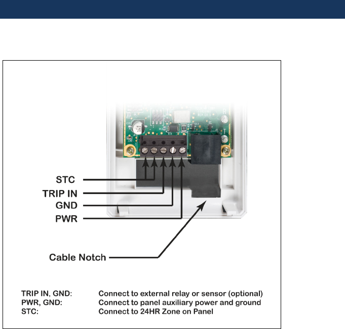
Appendix 1 – Connection Guide
Wiring Diagram
Attaching the RJ-45 Cable
The RJ-45 cable to the panel can be attached to the TG-1 Express either with the
enclosure open or closed. A notch in the rear opening of the enclosure is provided to
allow better cable access. Note that, as with other Telguard products, the RJ-45 cable
to the panel, as well as all other wiring, should be routed through the rear cable
opening, to allow the plastic lid of the TG-1 Express to be closed properly.

56042501 27 © 2010 Telular Corporation
RJ-45 Pin Assignments
Pin Wire Color Assignment
1 Gray R1
2 Orange TG-1 GND (when using SLIC)
4 Red R (Ring)
5 Green T (Tip)
7 Blue TG-1 Power (when using SLIC)
8 Brown T1
Main Terminal Strip Pin Assignments
Terminal Strip Pin Definition Connects To Function
1 STC
2 STC
Supervisory
Relay Trip
output for
programmabl
e trouble
conditions.
Normally
Closed
24-hour trip
zone input on
host alarm
panel.
Enables transmission
of programmed
supervisory trouble
code (see diagram or
installation section)
3 TRIP IN
Trip input External trip
input
Allows an external
relay to trigger an
alarm signal
4 GND
5 PWR
DC power
input
Auxiliary
power and
ground of
alarm panel
Provides primary
power to TG-1 Express
Compatible Alarm Panels
The TG-1 Express is compatible with all popular alarm panels, and many specialized
panels as well. For a complete listing of panels for which the TG-1 Express is UL
cross-listed, please consult the TG-1 Express technical specifications at
www.telguard.com.

56042501 28 © 2010 Telular Corporation
Appendix 2 – Troubleshooting Guide
This section provides a summary of all LED indications and their
meanings, as well as the expected behavior of the TG-1 Express under
various exception conditions.
LED Indicator Guide – Normal Operating Mode
LED Symbol Color Showing Indication
LED #1
Activation Green
Solid On Unit is activated at the message
center and enabled
Off Unit not activated at the message
center (and disabled)
Flashing Unit is activated but disabled
LED #2
STC
(System Trouble
Condition)
Red
Off ALL OK
1 Flash STC – Low Input Power
2, 3 Flashes N/A
4 Flashes STC – No Service
5 Flashes STC – Radio Failure
6 Flashes STC – Dial Tone Failure
7 Flashes STC – Panel Presence Failure
LED #3
MODE
Yellow
Flashing Telguard TG-1 Express
communicating with alarm panel
Off Idle state
LED #4
Acknowledgem
ent
Red Flashing
When flashing with LED #1 unit
has failed activation.0 CALL
TELGUARD TECHNICAL SUPPORT

56042501 29 © 2010 Telular Corporation
Off TG-1 Express initialized
On
TG-1 Express is waiting for
response from Telular
Communication Center
LED #5
Radio Green
Short Flash (1
sec) Radio receiving message
Long Flash (2
sec) Radio sending message
LED #7
Trip Input Green
Solid On Trip input activated
Off Trip input not active or restored
LED #8
Power Red Solid On Power connected to unit
LED Indicator Guide –RSSI Mode
RSSI Value LED’s Lighted RF dBm
NO SVC LED 5 = slow flash, LED 4-2 = off n/a
1 LED 5 = on, LED 4-2 = off ≤ -111 dBm
1½ LED 5 = on, LED 4 = slow flash
LED 3-2 = off ≥ -110 dBm
2 LED 5-4 = on, LED 3-2 = off ≥ -100 dBm
2½ LED 5-4 = on, LED 3 = slow flash
LED 2 = off
≥ -90 dBm
(Minimum signal
strength required)
3 LED 5-3 = on, LED 2 = off ≥ -80 dBm
3½ LED 5-3 = on, LED 2 = slow flash ≥ -70 dBm
4 LED 5-2 = on ≥ -60 dBm
Note: If LED #1 is on, more than one cellular tower is available.
56042501 30 © 2010 Telular Corporation

56042501 31 © 2010 Telular Corporation
Troubleshooting Quick Reference Table
Telguard Event LED
Indication
Relay
Output
Radio
Message Action
STC
Telguard
System
Trouble
Conditions
LIP
STC LED
flashes
1 time.
None None
Check input voltage
on the power
supplied from the
panel.
NSC
STC LED
flashes
4 times.
Optional None
The Telguard will
continue to validate
signal strength, and
remove NSC when
signal returns.
RFC
STC LED
flashes
5 times.
Optional None Wait for RFC restoral.
DTF
STC LED
flashes
6 times.
Yes Yes
Internal 30V supply
circuit failure. Return
unit for repair on
RMA.
PPF
STC LED
flashes
7 times.
No Yes Wait for PPF restoral.
Not Activated Activation
LED #1 off Yes None
Telguard will not
function until unit is
activated.
Telguard Remote
Query activated by
Customer Service.
Radio LED
#5 flashes
during
transmit
None
Yes
(Status
data)
Telguard will send
Status data to
Telguard customer
service for review
Telguard Activation
and Configuration
Upload
Radio LED
#5 flashes
during
transmit
None Setup
data
Telguard sends setup
configuration to the
TCC and switches to
READY state.
Disable TX –
Communication
Center Activated.
Radio LED
#5 flashes
when
transmitting
Yes
Yes
(Status
data)
TX capability is
disabled until further
notice.

56042501 32 © 2010 Telular Corporation
Appendix 3 – Detailed Specifications
Dialer to Interface Electronics
• Line voltage: -30 VDC into standard telephone device when
on-hook.
• Dial tone: Precision 350 + 440Hz +/- 1%. 10 digits dial out
capability.
• Mode: Loop start only. 25mA +/- 10% off-hook.
• Protected by U.S. Patents: 4,658,096; 4,775,997; 4,922,517;
4,737,975; 4,868,519; 5,134,644.
Power
• Nominal DC current draw:
39mA @ 12V (idle)
200mA @ 12V (transmitting)
Digital Cellular Radio
The Telguard TG-1 Express radio supports GSM/GPRS cellular protocol.
It is equipped with an integrated radio transceiver conforming to all
the requirements of the GSM Phase 2+ tests specified in GSM 11.10.
The TG-1 Express transceiver is FCC compliant, meeting all of the
requirements of Part 24 and SAR testing. It is also compliant to the
PTCRB NAPRD03 requirements.
• Frequency range: GSM 850/1900MHz,
824MHz-849MHz
1850MHz-1909MHz
• Antenna Port: SMA connector (female), 50-ohm
• Receiver Sensitivity: -102dBm
• Transmit Power:
EGSM 850MHz: Class 4 (2 watts)
GSM 1900MHz: Class 1 (1 watt)
56042501 33 © 2010 Telular Corporation
• FCC ID: N7NWISMO228
• Supplied Antenna: Dipole
• Physical Size: 5.6"H x 2.9"W x 1.3"D.
• Shipping weight: 1.1 lbs.
• Operating Environment: 0° C to +49° C; 0 - 85% humidity
(non-condensing).

56042501 34 © 2010 Telular Corporation
Appendix 4 – Parts List
Basic Hardware:
Model TG-1 Express
p/n TG1GX001
Model TG-1 Express (p/n TG1GX001) meets the
requirements for Household Burglary, Household
Fire, and Combination Burglary/Fire installations.
It has a plastic enclosure, and dipole antenna. TG-
1 Express is UL Listed for the following:
UL 1023 – Household Burglary
UL 985 – Household Fire
UL Household Burg/Fire Combination
General Accessories:
CTX-12 12 feet SMA/TNC antenna cable and mounting
bracket. The CTX-12 is required for all ACD and
external antenna accessories.
ACD-12 12 feet of antenna cable and mounting bracket
ACD-35 35 feet of low loss high performance antenna
cable and mounting bracket
ACD-50 50 feet of low loss high performance antenna
cable and mounting bracket
ACD-100 100 feet of low loss high performance antenna
cable and mounting bracket
HGD-0 High Gain Directional Antenna
EXD-0 Low profile, dual band antenna with integrated
wire ground plane.
LPD-0 Low profile, dual band antenna with integrated
disc ground plane.
