TJI 110, 210, 230, 360, And 560 Joist Specifier's Guide TJ 4000 Ijoist
User Manual:
Open the PDF directly: View PDF ![]() .
.
Page Count: 24

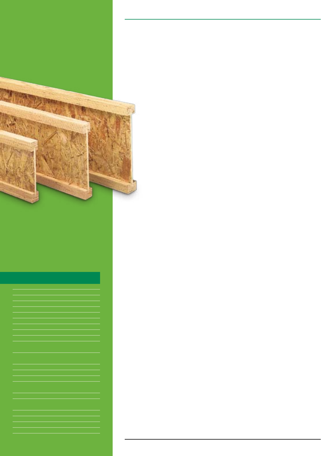
TRUS JOIST®
TJI® 110
■ TJI® 210
TJI® 230 ■ TJI® 360
TJI® 560 JOISTS
Featuring Silent Floor® Joists for
Residential Applications
www.iLevel.com
1.888.iLevel8 (1.888.453.8358)
ROOF SOLUTIONSFLOOR SOLUTIONS
#TJ-4000 SPECIFIER’S GUIDE
■ Uniform and Predictable
■ Lightweight for Fast
Installation
■ Resource Ecient
■ Resists Bowing, Twisting,
and Shrinking
■ Significantly Reduces Callbacks
■ Available in Long Lengths
■ Limited Product Warranty
iLevel Trus Joist® TJI® Joist Specifier’s Guide TJ-4000 February 2008
ALL IN ONE™
2
Design Properties 3
Material Weights 3
Floor Span Tables 4
Floor Load Tables 5
PSF to PLF Conversion Table 5
Floor Performance 6
TJ-Pro™ Rated Floor System 7
Silent Floor® Joist Framing 8
Floor Details 9
Fastener Spacing and
Diaphragm Design 9
Rim Board Selection
and Installation 10
Allowable Holes 11
Cantilevers 12–13
Fire-Safe Construction 14
Understanding and
Preventing Floor Noise 15
Roof Span Table 16–17
Roof Span Notes and
Cut Length Calculation 17
Roof Framing 18
Roof Details 19–20
Roof Load Tables 21
Framing Connectors 22–23
TABLE OF CONTENTS
WELCOME TO iLEVEL
iLevel is an exciting new brand and business within
Weyerhaeuser. iLevel brings the most innovative and
trusted products for residential construction together
under one roof. Within iLevel, you’ll still find all the
reliable, brand-name building products that you’ve been
using—Trus Joist® engineered wood products and
design software, Structurwood® engineered panels,
Performance Tested™ lumber, and more. But with
iLevel, you’ll work with only one service-oriented
supplier to get all of these products and the
support you need to build smarter.
iLevel. A family of brand-name building products…
a source for innovative ideas and solutions…
a supplier that’s simpler to do business with.
TJI® Joists Revolutionized the Way You Build Floors
Trus Joist® developed wooden I-joists nearly 40 years ago, and
since then we’ve continually improved their quality and made them
easier to work with. Engineered to provide strength and consistency,
iLevel® Trus Joist® TJI® joists are a key part of our Silent Floor®
System.
Here’s Why so Many Specifiers and Builders Choose
Silent Floor® Joists:
Silent Floor® joists continue to set the standard for residential floor
and roof joists. Their strength and long lengths give you the freedom
to design the open, spacious floor plans that your customers want.
Engineered for dimensional stability and predictable performance,
Silent Floor® joists resist warping, twisting, and shrinking.
The precision engineering that makes Silent Floor® joists strong also
makes them easier to install. Silent Floor® joists are designed for
easy handling and fast installation. They are lightweight, easy to cut,
and can be installed using standard construction tools. Silent Floor®
joists come with precut knockout holes, and additional holes for
ductwork can be cut at the job site. These same features also make
them a popular choice for roof joists.
iLevel Trus Joist® TJI® Joist Specifier’s Guide TJ-4000 February 2008 3
Floor Panels
Southern Pine
1⁄2" plywood .................................1.7
5⁄8" plywood ..............................2.0 psf
3⁄4" plywood ..............................2.5 psf
11⁄8" plywood .............................3.8 psf
1⁄2" OSB .................................1.8 psf
5⁄8" OSB .................................2.2 psf
3⁄4" OSB .................................2.7 psf
7⁄8" OSB .................................3.1 psf
11⁄8" OSB ................................4.1 psf
Based on: Southern pine – 40 pcf for plywood, 44 pcf for OSB
Roofing
Asphalt shingles . . . . . . . . . . . . . . . . . . . . . . . . . . 2.5 psf
Wood shingles ............................2.0 psf
Clay tile . . . . . . . . . . . . . . . . . . . . . . . . . . . 9.0 to 14.0 psf
Slate (3⁄8" thick) ..........................15.0 psf
Roll or Batt Insulation (1" thick):
Rock wool ................................0.2 psf
Glass wool ...............................0.1 psf
Floor Finishes
Hardwood (nominal 1") . . . . . . . . . . . . . . . . . . . . . 4.0 psf
Sheet vinyl ...............................0.5 psf
Carpet and pad ...........................1.0 psf
3⁄4" ceramic or quarry tile ...................10.0 psf
Concrete:
Regular (1") .............................12.0 psf
Lightweight (1") .....................8.0 to 10.0 psf
Gypsum concrete (3⁄4") ......................6.5 psf
Ceilings
Acoustical fiber tile . . . . . . . . . . . . . . . . . . . . . . . . 1.0 psf
1⁄2" gypsum board . . . . . . . . . . . . . . . . . . . . . . . . . 2.2 psf
5⁄8" gypsum board . . . . . . . . . . . . . . . . . . . . . . . . . 2.8 psf
Plaster (1" thick) . . . . . . . . . . . . . . . . . . . . . . . . . . 8.0 psf
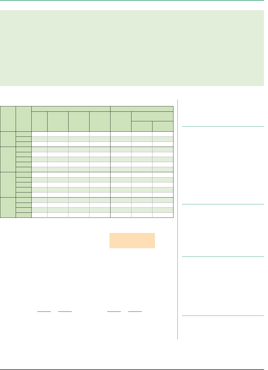
Design Properties (100% Load Duration)
(1) Caution: Do not increase joist moment design properties by a repetitive member use factor.
Depth TJI®
Basic Properties Reaction Properties
Joist
Weight
(lbs/ft)
Maximum
Resistive
Moment(1)
(ft-lbs)
Joist Only
El x 106
(in.2-lbs)
Maximum
Vertical
Shear
(lbs)
13⁄4"
End
Reaction
(lbs)
31⁄2" Intermediate
Reaction (lbs)
No Web
Stiffeners
With Web
Stiffeners
91⁄2"
110 2.3 2,380 140 1,220 885 1,935 N.A.
210 2.6 2,860 167 1,330 980 2,145 N.A.
230 2.7 3,175 183 1,330 1,035 2,410 N.A.
117⁄8"
110 2.5 3,015 238 1,560 885 1,935 2,295
210 2.8 3,620 283 1,655 980 2,145 2,505
230 3.0 4,015 310 1,655 1,035 2,410 2,765
360 3.0 6,180 419 1,705 1,080 2,460 2,815
560 4.0 9,500 636 2,050 1,265 3,000 3,475
14"
110 2.8 3,565 351 1,860 885 1,935 2,295
210 3.1 4,280 415 1,945 980 2,145 2,505
230 3.3 4,755 454 1,945 1,035 2,410 2,765
360 3.3 7,335 612 1,955 1,080 2,460 2,815
560 4.2 11,275 926 2,390 1,265 3,000 3,475
16"
210 3.3 4,895 566 2,190 980 2,145 2,505
230 3.5 5,440 618 2,190 1,035 2,410 2,765
360 3.5 8,405 830 2,190 1,080 2,460 2,815
560 4.5 12,925 1,252 2,710 1,265 3,000 3,475
DESIGN PROPERTIES AND MATERIAL WEIGHTS
ABOUT THIS GUIDE
The applications provided in this guide are readily available through our nationwide network of distributors
and dealers and are intended for use in single-family dwellings only.
For information on using these products in multi-family dwellings, contact your iLevel representative.
For commercial applications such as retail stores, oce buildings, schools, restaurants, hotels,
and nursing homes, please refer to the iLevel Trus Joist® Commercial TJI® L65, L90, H90, HS90 Joists
Specifier’s Guide (Reorder #COM-2000). Commercial products are typically designed,
manufactured, and sold for each specific job.
For more information on any iLevel® product, please call 1-888-453-8358.
General Notes
■ Design reaction includes all loads on the joist. Design shear is com puted at the inside face of supports
and includes all loads on the span(s). Allowable shear may sometimes be increased at interior supports in
accordance with ICC ES ESR-1153, and these increases are reflected in span tables.
■ The following formulas approximate the uniform load deflection of Δ (inches):
w = uniform load in pounds per linear foot
L = span in feet
d = out-to-out depth of the joist in inches
El = value from table above
For
TJI® 110, 210, 230, and 360 Joists
Δ = +
22.5 wL4
El
2.67 wL2
d x 105
For
TJI® 560 Joists
Δ = +
22.5 wL4
El
2.29 wL2
d x 105
Material Weights
(Include TJI® weights in dead load calculations—
see Design Properties table at left for joist weights)
TJI ® joists are intended
for dry-use applications
Code Evaluations: See ICC ES ESR-1153 and ICC ES ESR-1387
iLevel Trus Joist® TJI® Joist Specifier’s Guide TJ-4000 February 2008
4
How to Use These Tables
1. Determine the appropriate live load deflection
criteria.
2. Identify the live and dead load condition.
3. Select on-center spacing.
4. Scan down the column until you meet or
exceed the span of your application.
5. Select TJI® joist and depth.
Depth TJI®40 PSF Live Load / 10 PSF Dead Load 40 PSF Live Load / 20 PSF Dead Load
12" o.c. 16" o.c. 19.2" o.c. 24" o.c. 12" o.c. 16" o.c. 19.2" o.c. 24" o.c.
91⁄2"
110 16'-5" 15'-0" 14'-2" 13'-2" 16'-5" 15'-0" 13'-11" 12'-5"
210 17'-3" 15'-9" 14'-10" 13'-10" 17'-3" 15'-9" 14'-10" 13'-8"
230 17'-8" 16'-2" 15'-3" 14'-2" 17'-8" 16'-2" 15'-3" 14'-2"
117⁄8"
110 19'-6" 17'-10" 16'-10" 15'-5"(1) 19'-6" 17'-3" 15'-8" 14'-0"(1)
210 20'-6" 18'-8" 17'-8" 16'-5" 20'-6" 18'-8" 17'-3" 15'-5"(1)
230 21'-0" 19'-2" 18'-1" 16'-10" 21'-0" 19'-2" 18'-1" 16'-3"(1)
360 22'-11" 20'-11" 19'-8" 18'-4" 22'-11" 20'-11" 19'-8" 17'-10"(1)
560 26'-1" 23'-8" 22'-4" 20'-9" 26'-1" 23'-8" 22'-4" 20'-9"(1)
14"
110 22'-2" 20'-3" 18'-9" 16'-9"(1) 21'-8" 18'-9" 17'-1"(1) 14'-7"(1)
210 23'-3" 21'-3" 20'-0" 18'-4"(1) 23'-3" 20'-7" 18'-9"(1) 16'-2"(1)
230 23'-10" 21'-9" 20'-6" 19'-1" 23'-10" 21'-8" 19'-9" 17'-1"(1)
360 26'-0" 23'-8" 22'-4" 20'-9"(1) 26'-0" 23'-8" 22'-4"(1) 17'-10"(1)
560 29'-6" 26'-10" 25'-4" 23'-6" 29'-6" 26'-10" 25'-4"(1) 20'-11"(1)
16"
210 25'-9" 23'-6" 22'-0"(1) 19'-5"(1) 25'-5" 22'-0"(1) 20'-1"(1) 16'-2"(1)
230 26'-5" 24'-1" 22'-9" 20'-7"(1) 26'-5" 23'-2" 21'-2"(1) 17'-1"(1)
360 28'-9" 26'-3" 24'-8"(1) 21'-5"(1) 28'-9" 26'-3"(1) 22'-4"(1) 17'-10"(1)
560 32'-8" 29'-8" 28'-0" 25'-2"(1) 32'-8" 29'-8" 26'-3"(1) 20'-11"(1)
L/480 Live Load Deflection
Not all products are available in
all markets. Contact your iLevel
representative for information.
TJI® 110 Joists
13⁄4"
3⁄8"91⁄2"
117⁄8"
14"
1¼"–13⁄8"
TJI® 210 Joists
3⁄8"
21⁄16"
91⁄2"
117⁄8"
14"
16"
1¼"–13⁄8"
TJI® 230 Joists
3⁄8"
25⁄16"
91⁄2"
117⁄8"
14"
16"
1¼"–13⁄8"
TJI® 360 Joists
3⁄8"
25⁄16"
117⁄8"
14"
16"
13⁄8"
TJI® 560 Joists
7⁄16"
31⁄2"
117⁄8"
14"
16"
13⁄8"
L/360 Live Load Deflection (Minimum Criteria per Code)
General Notes
■ Tables are based on:
– Uniform loads.
– More restrictive of simple or continuous span.
– Clear distance between supports (13⁄4" minimum end
bearing).
■ Assumed composite action with a single layer of 24" on-center
span-rated, glue-nailed floor panels for deflection only. Spans
shall be reduced 6" when floor panels are nailed only.
■ Spans generated from iLevel® software may exceed the spans
shown in these tables because software reflects actual design
conditions.
■ For loading conditions not shown, refer to software or to the load
table on page 5.
Live load deflection is not the only factor
that affects how a floor will perform.
To more accurately predict floor performance,
use our TJ-Pro™ Ratings.
FLOOR SPAN TABLES
(1) Web stiffeners are required at intermediate supports of continuous-span joists when the intermediate bearing length is less than 51⁄4"
and the span on either side of the intermediate bearing is greater than the following spans:
■ Long-term deflection under dead load, which includes the effect of creep, has not been considered. Bold italic spans reflect initial dead
load deflection exceeding 0.33".
Depth TJI®40 PSF Live Load / 10 PSF Dead Load 40 PSF Live Load / 20 PSF Dead Load
12" o.c. 16" o.c. 19.2" o.c. 24" o.c. 12" o.c. 16" o.c. 19.2" o.c. 24" o.c.
91⁄2"
110 18'-2" 16'-7" 15'-3" 13'-8" 17'-8" 15'-3" 13'-11" 12'-5"
210 19'-1" 17'-5" 16'-6" 15'-0" 19'-1" 16'-9" 15'-4" 13'-8"
230 19'-7" 17'-11" 16'-11" 15'-9" 19'-7" 17'-8" 16'-1" 14'-5"
117⁄8"
110 21'-7" 18'-11" 17'-3" 15'-5"(1) 19'-11" 17'-3" 15'-8" 14'-0"(1)
210 22'-8" 20'-8" 18'-11" 16'-10" 21'-10" 18'-11" 17'-3" 15'-5"(1)
230 23'-3" 21'-3" 19'-11" 17'-9" 23'-0" 19'-11" 18'-2" 16'-3"(1)
360 25'-4" 23'-2" 21'-10" 20'-4"(1) 25'-4" 23'-2" 21'-10"(1) 17'-10"(1)
560 28'-10" 26'-3" 24'-9" 23'-0" 28'-10" 26'-3" 24'-9" 20'-11"(1)
14"
110 23'-9" 20'-6" 18'-9" 16'-9"(1) 21'-8" 18'-9" 17'-1"(1) 14'-7"(1)
210 25'-8" 22'-6" 20'-7" 18'-4"(1) 23'-9" 20'-7" 18'-9"(1) 16'-2"(1)
230 26'-4" 23'-9" 21'-8" 19'-4"(1) 25'-0" 21'-8" 19'-9" 17'-1"(1)
360 28'-9" 26'-3" 24'-9"(1) 21'-5"(1) 28'-9" 26'-3"(1) 22'-4"(1) 17'-10"(1)
560 32'-8" 29'-9" 28'-0" 25'-2"(1) 32'-8" 29'-9" 26'-3" (1) 20'-11"(1)
16"
210 27'-10" 24'-1" 22'-0"(1) 19'-5"(1) 25'-5" 22'-0"(1) 20'-1"(1) 16'-2"(1)
230 29'-2" 25'-5" 23'-2" 20'-7"(1) 26'-9" 23'-2" 21'-2"(1) 17'-1"(1)
360 31'-10" 29'-0" 26'-10"(1) 21'-5"(1) 31'-10" 26'-10" (1) 22'-4"(1) 17'-10"(1)
560 36'-1" 32'-11" 31'-0"(1) 25'-2"(1) 36'-1" 31'-6" (1) 26'-3"(1) 20'-11"(1)
TJI®40 PSF Live Load / 10 PSF Dead Load 40 PSF Live Load / 20 PSF Dead Load
12" o.c. 16" o.c. 19.2" o.c. 24" o.c. 12" o.c. 16" o.c. 19.2" o.c. 24" o.c.
110 N.A. N.A. N.A. 15'-4" N.A. N.A. 16'-0" 12'-9"
210 N.A. N.A. 21'-4" 17'-0" N.A. 21'-4" 17'-9" 14'-2"
230 N.A. N.A. N.A. 19'-2" N.A. N.A. 19'-11" 15'-11"
360 N.A. N.A. 24'-5" 19'-6" N.A. 24'-5" 20'-4" 16'-3"
560 N.A. N.A. 29'-10" 23'-10" N.A. 29'-10" 24'-10" 19'-10"
iLevel Trus Joist® TJI® Joist Specifier’s Guide TJ-4000 February 2008 5
Depth TJI®
Joist Clear Span
8' 10' 12' 14' 16' 18' 20' 22' 24'
Live
Load
L/480
Total
Load
Live
Load
L/480
Total
Load
Live
Load
L/480
Total
Load
Live
Load
L/480
Total
Load
Live
Load
L/480
Total
Load
Live
Load
L/480
Total
Load
Live
Load
L/480
Total
Load
Live
Load
L/480
Total
Load
Live
Load
L/480
Total
Load
91⁄2"
110 *190 127 152 77 127 50 95
210 *210 147 169 90 141 59 114 40 81
230 *236 159 190 98 158 64 126 44 88
117⁄8"
110 *190 *152 *127 83 109 57 92
210 *210 *169 *141 97 121 67 106 48 87
230 *236 *190 *158 105 136 73 119 52 97 39 78
360 *241 *193 *162 136 139 95 121 69 108 51 97 39 78
560 *294 *236 *197 *169 138 148 101 132 76 119 58 108 45 91
14"
110 *190 *152 *127 *109 83 95 59 85
210 *210 *169 *141 *121 96 106 69 94 51 84
230 *236 *190 *158 *136 104 119 75 106 56 93 43 77
360 *241 *193 *162 *139 *121 98 108 73 97 56 88 44 81
560 *294 *236 *197 *169 *148 *132 107 119 83 108 65 99
16"
210 *210 *169 *141 *121 *106 93 94 69 85 53 77
230 *236 *190 *158 *136 *119 100 106 75 95 57 87
360 *241 *193 *162 *139 *121 *108 *97 75 88 59 81
560 *294 *236 *197 *169 *148 *132 *119 *108 86 99
PSF to PLF Conversions
How to Use This Table
1. Calculate actual total and live load in pounds per linear foot (plf).
2. Select appropriate Joist Clear Span.
3. Scan down the column to find a TJI® joist that meets or exceeds actual total and
live loads.
General Notes
■ Table is based on:
– Uniform loads.
– No composite action provided by sheathing.
– More restrictive of simple or continuous span.
■ Total Load limits joist deflection to L/240.
■ Live Load is based on joist deflection of L /480.
■ If a live load deflection limit of L/360 is desired, multiply value in Live Load
column by 1.33. The resulting live load shall not exceed the Total Load shown.
Floor—100% (PLF)
* Indicates that Total Load value controls.
O.C.
Spacing
Load in Pounds Per Square Foot (PSF)
20 25 30 35 40 45 50 55 60
Load in Pounds Per Linear Foot (PLF)
12" 20 25 30 35 40 45 50 55 60
16" 27 34 40 47 54 60 67 74 80
19.2" 32 40 48 56 64 72 80 88 96
24" 40 50 60 70 80 90 100 110 120
FLOOR LOAD TABLE
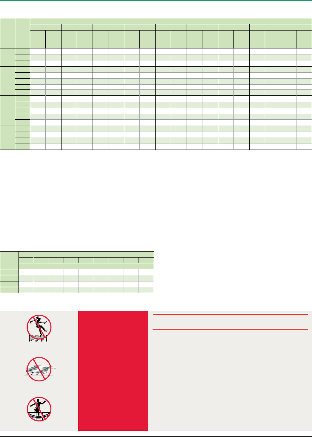
1. All blocking, hangers, rim boards, and rim joists at the end supports of the TJI®
joists must be completely installed and properly nailed.
2. Lateral strength, like a braced end wall or an existing deck, must be established at
the ends of the bay. This can also be accomplished by a temporary or permanent
deck (sheathing) fastened to the first 4 feet of joists at the end of the bay.
3. Safety bracing of 1x4 (minimum) must be nailed to a braced end wall or sheathed
area (as in note 2) and to each joist. Without this bracing, buckling sideways or
rollover is highly probable under light construction loads—such as a worker or one
layer of unnailed sheathing.
4. Sheathing must be completely attached to each TJI® joist before additional loads
can be placed on the system.
5. Ends of cantilevers require safety bracing on both the top and bottom flanges.
6. The flanges must remain straight within a tolerance of 1⁄2" from true alignment.
WARNING NOTES:
WARNING
Joists are
unstable
until braced
laterally
Bracing Includes:
■ Blocking
■ Hangers
■ Rim Board
■ Sheathing
■ Rim Joist
■ Strut Lines
DO NOT walk on joists until braced.
INJURY MAY RESULT.
DO NOT walk on joists that are lying flat.
DO NOT stack building materials on unsheathed
joists. Stack only over beams or walls.
Lack of proper bracing during construction can result
in serious accidents. Observe the following guidelines:
iLevel Trus Joist® TJI® Joist Specifier’s Guide TJ-4000 February 2008
6
Design Smarter—Don’t Over-Specify
The traditional way to specify a floor system is to use live load deflection criteria, but deflection
explains only part of how a floor performs. Depending on factors unique to the structure and its use, the
code minimum of L/360 (or even the more restrictive limits of L /480) may disappoint many customers.
TJ-Pro™ Ratings are a much better predictor of floor performance
because they consider the many factors that affect floor performance,
even taking into account the perceptions of the homeowner. With so
many variables, you can deliver an economical solution tailored to your
customer’s expectations.
Factors That Affect Floor Performance
■ TJI® joist series, depth, and spacing
■ Deck thickness and quality
■ Directly applied ceilings
■ Location of partitions on floor
■ Blocking
■ Bearing conditions for the TJI® joists
TJ-Pro™ Rating Advantages
■ Works as part of iLevel® Trus Joist®
TJ-Beam® and TJ-Xpert® software
■ Provides a new method for accurately
predicting floor performance
■ Takes perceptions of the homeowner
into account
■ Provides cost comparison
Get the Support You Need—
We’re here to help you make the most of TJ-Pro™ Ratings, whether it’s help with
setup, tips and tricks, or selecting the best rating for your project. Call your iLevel
representative today.
FLOOR PERFORMANCE AND TJ-PRO™ RATINGS
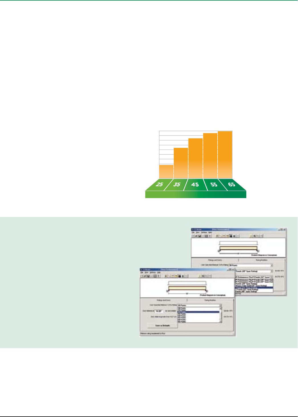
It’s About Choice—
iLevel® Trus Joist® TJ-Pro™ Ratings are generated by a sophisticated computer model
designed to predict floor performance and evaluate the relationship between the
cost and the “feel” of any given floor system. The methodology is based on extensive
laboratory research, more than one million installations, and the combined expertise of
some of the best engineers in the field. TJ-Pro™ Ratings go beyond deflection criteria
to consider job-specific needs and expectations. In many cases, using TJ-Pro™ Ratings
will oer a system that improves performance while actually reducing costs!
Good Better Excellent
Perceived Floor Performance
TJ -Pro™ Rating Points
Customer Satisfaction
28%
63%
84%
96%
99.9%
How do most people
perceive a floor assembly
with a TJ-Pro™ Rating of
45 points? 84% find it
good to excellent and
16% find it marginal to
unacceptable.
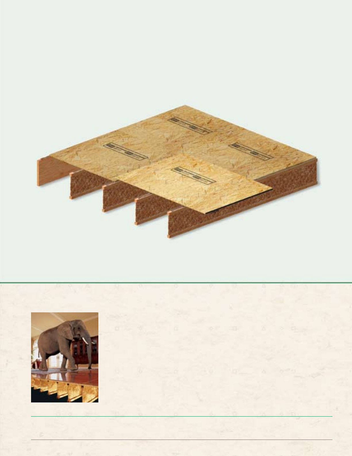
The iLevel® TJ-Pro™ Rated Floor System—
The Premium Floor System From iLevel
Now You Can Build a Strong and Stable Floor—Without Overbuilding.
Design Your Floors to Suit
Each Customer
With TJ-Pro™ Ratings and iLevel’s proprietary
materials, we can accurately predict what it will
take to build a floor that satisfies even your most
demanding customer. And you’ll get the right balance
of cost and performance in every system.
Fewer Callbacks and
More Referrals
Satisfied customers mean more referrals. And the
iLevel® TJ-Pro™ Rated Floor System is the best way to
make sure that there’s less to complain about. It takes
the guesswork out of how to build a floor that
will make your customers happy.
The performance of most commodity building
products is unpredictable. But since we know the
precise strength of every component in the iLevel®
TJ-Pro™ Rated Floor System, we can comfortably
build to your specifications while making sure that
you don’t use more material than you need.
Silent Floor® joists have very specific performance
characteristics. Structurwood Edge Gold® panels
are made with a proprietary formula, meet precise
thickness tolerances, and have a top-quality edge
seal—making them more stable and consistent
than other structural panels. iLevel® Trus Joist®
TimberStrand® LSL rim board; TimberStrand® LSL,
Parallam® PSL, and Microllam® LVL beams and
columns; and our helpful installation guidelines
give you more control, more strength, and more
reliability than you could get with a package
made up of typical framing materials.
So next time you’re building someone’s dream
home, don’t rely on guesswork. Bring your plans
to any iLevel location and we’ll show you how to
make the most of both your framing material and
the labor it takes to turn it into a home.
For projects that demand quality, performance, and customer satisfaction, upgrade to the iLevel® TJ-Pro™ Rated Floor System.
Contact your iLevel representative or call 1-888-453-8358 for more information.
You’ll Like the Way it Builds.
Your Customers Will Love the Way it Feels.
iLevel Trus Joist® TJI® Joist Specifier’s Guide TJ-4000 February 2008
8
Web Stiffener Attachment
Gap:
1⁄8" minimum
23⁄4" maximum
Three 16d (0.135"
x 31⁄2") nails
2x4 web
stiffener(2)
Tight
11⁄2"
11⁄2"
1"
1"
Gap:
1⁄8" minimum
23⁄4" maximum
Three 8d (0.113" x 21⁄2") nails,
clinched
Web stiffener(1) each side
TJI® 110 joists:
5⁄8" x 25⁄16" minimum
TJI® 210 joists:
3⁄4" x 25⁄16" minimum
TJI® 230 and 360 joists:
7⁄8" x 25⁄16" minimum
Tight
TJI® 560 Joists Only
(1) PS1 or PS2 sheathing, face grain vertical
(2) Construction grade or better
Joists must be laterally supported at cantilever
and end bearings by blocking panels, hangers, or
direct attachment to a rim board or rim joist
See Exterior Deck
Attachment on
page 10
See Allowable Holes
on page 11
Structural sheathing
Protect untreated wood
from direct contact
with concrete
Safety bracing (1x4 minimum) placed at
8' on-center (6' on-center for TJI® 110
joists) and extended to a braced end
wall. Fasten at each joist with two
8d (0.113 x 21⁄2") nails minimum.
Silent Floor® joist framing does not require
bridging or mid-span blocking
11⁄2" knockouts
at approximately
12" on-center
11⁄4" TimberStrand® LSL rim board,
iLevel® 11⁄8" rim board, or
TJI® 110 rim joist:
One 10d (0.128" x 3") nail
into each flange
TJI® 210, 230, and 360
rim joist:
One 16d (0.135" x 31⁄2") nail
into each flange
One 10d (0.128" x 3")
nail into each flange
TJI® Joist to Bearing Plate
TJI® Joist Nailing Requirements at Bearing
Rim to TJI® Joist
Squash Blocks to TJI® Joist
(Load bearing wall above)
TJI® 560 rim joist:
Toenail with
10d (0.128" x 3")
nails, one each side
of TJI® joist flange
TJI® 560
floor joist
TJI® 560
rim joist
Top View
13⁄4" minimum
bearing
11⁄4" TimberStrand® LSL or
iLevel® 11⁄8" rim board
One 8d (0.113" x 21⁄2")
nail each side. Drive
nails at an angle at
least 11⁄2" from end.
13⁄4" minimum bearing
at end support; 31⁄2" minimum
at intermediate support
Shear transfer: Connections equivalent to floor panel
nailing schedule
SILENT FLOOR® JOIST FRAMING
Also see detail B2
on page 9
W
Rim board joint between joists
Locate rim board joint between joists
11⁄4" TimberStrand® LSL or
iLevel® 11⁄8" rim board
WARNING
Joists are unstable until
laterally braced.
See Warning Notes on page 5.
iLevel Trus Joist® TJI® Joist Specifier’s Guide TJ-4000 February 2008 9
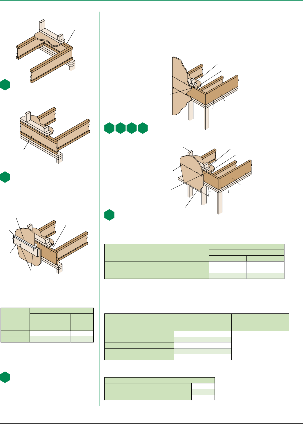
Top flange
hanger
Web stiffeners required if sides of
hanger do not laterally support at least
3⁄8" of TJI® joist top flange
Face mount
hanger
(1) If necessary, increase filler and backer block height for face mount hangers and maintain 1⁄8" gap at top of joist.
See detail W. Filler and backer block dimensions should accommodate required nailing without splitting. The
suggested minimum length is 24" for filler and 12" for backer blocks.
TJI®110 210 230 or 360 560
Depth 91⁄2" or
117⁄8"14" 91⁄2" or
117⁄8"
14" or
16"
91⁄2" or
117⁄8"
14" or
16" 117⁄8"14" or
16"
Filler Block(1)
(Detail H2) 2x6 2x8 2x6 + 3⁄8"
sheathing
2x8 + 3⁄8"
sheathing
2x6 + 1⁄2"
sheathing
2x8 + 1⁄2"
sheathing
Two
2x6
Two
2x8
Cantilever
Filler
(Detail E4)
2x6
4'-0"
long
2x10
6'-0"
long
2x6 + 3⁄8"
sheathing
4'-0" long
2x10 + 3⁄8"
sheathing
6'-0" long
2x6 + 1⁄2"
sheathing
4'-0" long
2x10 + 1⁄2"
sheathing
6'-0" long
Not applicable
Backer Block(1)
(Detail F1
or H2)
5⁄8" or 3⁄4"3⁄4" or 7⁄8" 1" net 2x6 2x8
Filler and Backer Block Sizes
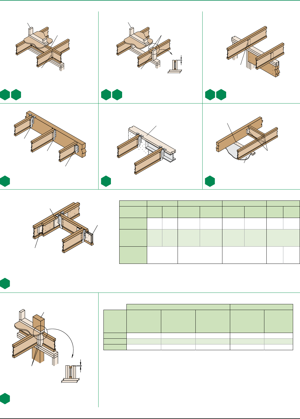
Intermediate Bearing –
No Load Bearing Wall Above
Web stiffeners required
each side at B2W
Load bearing wall above
(must stack over wall below)
Web stiffeners required
each side at B3W
Blocking panels may be required
with shear walls above or below—
see detail B1
Blocking panels may be required
with shear walls above or below—
see detail B1
Filler block: Nail with ten 10d
(0.128" x 3") nails, clinched. Use ten
16d (0.135" x 31⁄2") nails from each
side with TJI® 560 joists.
Also see nailing requirements on page 8
Backer block: Install tight to top
flange (tight to bottom flange with
face mount hangers). Attach
with ten 10d (0.128" x 3")
nails, clinched
when possible.
With top flange hangers, backer block required only
for downward loads exceeding 250 lbs or for uplift
conditions
Use 2x4 minimum squash blocks to transfer
load around TJI® joist
2x4 minimum
squash blocks
Load from above
1⁄16"
Fastener Spacing and Diaphragm Design Information for TJI® Joists
Two 21⁄2" screws for 2x_
strapping connections
Two 8d (0.113" x 21⁄2")
nails or 21⁄2" screws,
typical
When specified on the layout, one of the above
bracing options is required
Backer block
both sides of
web with single
TJI® joist
Apply subfloor
adhesive to all
contact surfaces
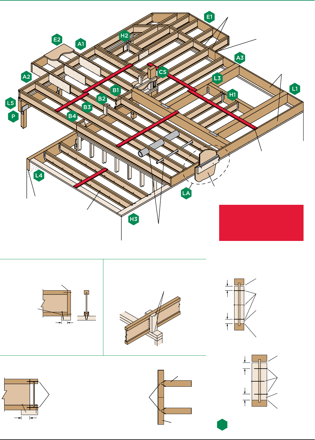
FLOOR DETAILS
2x4 minimum
squash blocks
B2
W
B2
B1
W
B1 B3
W
B3
H1 H3 PB1
H2
CS
1⁄16"
Directly applied ceiling
Closest On-Center Spacing per Row(1) Diaphragm Design Information(2)
TJI®
8d (0.113" x 2½"),
8d (0.131" x 2½"),
10d (0.128" x 3"),
12d (0.128" x 3¼")
10d (0.148" x 3"),
12d (0.148" x 3¼"),
16d (0.135" x 3½")
16d (0.162" x 3½")
Equivalent
Nominal
Framing Width
Maximum
Capacity
(plf)
110 and 210 4" 4"(3) 6" 2" 425
230 4" 4"(3) 6" 3" 480
360 and 560 3" 4"(3) 6" 3" 720
(1) One row of fasteners permitted (two at abutting panel edges) for diaphragms. Stagger nails when using
4" on-center spacing and maintain 3⁄8" joist and panel edge distance. For other applications, multiple rows of fasteners are
permitted if the rows are offset at least ½" and staggered.
(2) To achieve code-tabulated, unblocked diaphragm design values for TJI® 110, 210, and 230 joists, use fasteners in combina-
tion with an ASTM D3498 non-polyurethane sub-floor adhesive. For nailed-only conditions, use 85% of code-tabulated values.
(3) Can be reduced to 3" on-center for light gauge steel straps with 10d (0.148" x 1½") nails.
■ Maximum spacing of nails is 18" on-center.
■ 14 ga. staples may be substituted for 8d (0.113" x 2½") nails if minimum penetration of 1" is achieved.
■ Table also applies to the attachment of TJI® rim joists and blocking panels to the wall plate.
IRC 502.7 requires lateral restraint
(blocking) at all intermediate supports
in Seismic Design Categories D0, D1, and
D2 to strengthen the floor diaphragm
Load bearing or shear wall above
(must stack over wall below)
Blocking
panel
Web stiffeners required
each side at B1W
Flush bearing plate required.
Maximum 1⁄4" overhang
permitted at beam.
iLevel Trus Joist® TJI® Joist Specifier’s Guide TJ-4000 February 2008
10
TJI® rim joist
Blocking
panel
Rim Board Installation
Allowable Uniform Vertical Loads (PLF)
TJI® rim joist or blocking 2,100
11⁄4" TimberStrand® LSL rim board or blocking 4,250
iLevel® 11⁄8" rim board or blocking 4,000
Vertical Load Transfer at Bearing
Exterior Deck Attachment
Fastener
Allowable Load(1) (lbs)
11⁄4"
TimberStrand® LSL
Rim Board
iLevel®
11⁄8"
Rim Board
3⁄8" lag bolt 400 N.A.
1⁄2" lag bolt 475 400
(1) Allowable load determined in accordance with AC 124.
■ Corrosion-resistant fasteners required for wet-service
applications.
Also see nailing requirements on page 8
Rim board is often an important structural link in the ability of a home to resist lateral wind loads. It also transfers
vertical load around the TJI® joists.
Rim board detail A3 (shown below) satisfies conventional construction requirements. But if your project requires a
designed solution, see our iLevel Rim Board Specifier’s Guide for Lateral Wind Loads. This easy-to- use guide for
specifiers and code officials goes beyond conventional construction guidelines—which were based on the smaller,
simpler homes of the past—and provides design information that considers today’s larger, more complex homes.
■ Loads may not be increased for duration of load.
RIM BOARD SELECTION AND INSTALLATION
A1
A2
LA
A3.
4
Plate nail
When sheathing thickness
exceeds 7⁄8", trim sheathing
tongue at rim board
Floor panel nail
Toe
nail
11⁄4" TimberStrand® LSL or
iLevel® 11⁄8" rim board
(see nailing schedule below)
2x_ stud wall at
16" on-center Floor panel nail
Toe nail
12"
min.
Attach panel per nailing
schedule below
Install proper blocking to
support all panel edges
Plate nail
When sheathing thickness
exceeds 7⁄8", trim sheathing
tongue at rim board
11⁄4" TimberStrand® LSL
rim board
A3.
1A3.
2A3.
3
A3
Specifications
A3
Conventional Construction,
Code Minimum
A3.1, A3.2, A3.3, A3.4
Designed
Solution
Rim Board Thickness 11⁄8" or 11⁄4"
See the iLevel
Rim Board Specifier’s Guide
for Lateral Wind Loads
(Reorder #TJ-8000)
Plate Nail—16d (0.135" x 31⁄2") 16" o.c.
Floor Panel Nail—8d (0.131" x 21⁄2") 6" o.c.
Toe Nail—10d (0.128" x 3") 6" o.c.
Wall Sheathing Per code
Nail Size
Closest On-Center Spacing per Row
Rim Board Thickness
11⁄8" 11⁄4"
8d (0.113" or 0.131" x 21⁄2"),
10d (0.128" or 0.148" x 3"), 12d (0.128" or 0.148" x 31⁄4") 6" 4"
16d (0.162" x 31⁄2") 16" 6"(1)
Fastening of Floor Panels to 1
1⁄4" TimberStrand® LSL
or iLevel® 1
1⁄8" Rim Board
(1) Can be reduced to 4" on-center with maximum nail penetration of 13⁄8" into the narrow edge.
■ If more than one row of nails is used, the rows must be offset at least ½" and staggered.
■ 14 ga. staples may be substituted for 8d (0.113" x 2½") nails if minimum penetration of 1" is achieved.
Structural exterior
sheathing
Flashing
Treated
2x_ ledger
See fastener table below.
Maintain 2" distance
(minimum) from edge of
ledger to fastener.
11⁄4" TimberStrand® LSL
or iLevel® 11⁄8"
rim board
Must have 13⁄4" minimum joist bearing at ends
iLevel Trus Joist® TJI® Joist Specifier’s Guide TJ-4000 February 2008 11
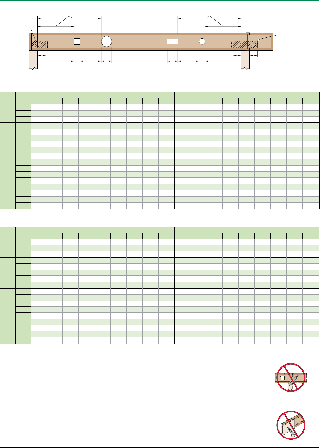
How to Use These Tables
1. Using Table A, Table B, or both if required, determine the hole
shape/size and select the TJI® joist and depth.
2. Scan horizontally until you intersect the correct hole size
column.
3. Measurement shown is minimum distance from edge of hole to
support.
4. Maintain the required minimum distance from the end and the
intermediate or cantilever support.
General Notes
■ Holes may be located vertically anywhere within the web. Leave
1⁄8" of web (minimum) at top and bottom of hole.
■ Knockouts are located in web at approximately 12" on -center;
they do not affect hole placement.
■ For simple span (5' minimum) uniformly loaded joists meeting
the requirements of this guide, one maximum size round hole
may be located at the center of the joist span provided that no
other holes occur in the joist.
■ Distances are based on the maximum uniform loads shown in
this guide. For other load conditions or hole configurations, use
TJ-Beam® software or contact your iLevel representative.
Minimum distance from Table A Minimum distance from Table B
Do not cut holes larger
than 11⁄2" in cantilever
2 x D1
minimum
(applies to all holes
except knockouts)
L1D12 x L2
minimum
L2D2
No field cut holes
in hatched zones 11⁄2" hole may be cut
anywhere in web outside
of hatched zone
6" 6" 6"
6" 6"
Depth TJI®• Round Hole Size ■ Square or Rectangular Hole Size
2" 3" 4" 5" 61⁄2"7" 87⁄8"11" 13" 2" 3" 4" 5" 61⁄2"7" 87⁄8"11" 13"
91⁄2"
110 1'-0" 1'-6" 2'-0" 2'-6" 5'-0" 1'-0" 1'-6" 2'-6" 3'-6" 4'-6"
210 1'-0" 1'-6" 2'-0" 3'-0" 5'-0" 1'-0" 2'-0" 2'-6" 4'-0" 5'-0"
230 1'-0" 2'-0" 2'-6" 3'-6" 5'-6" 1'-0" 2'-0" 3'-0" 4'-6" 5'-0"
117⁄8"
110 1'-0" 1'-0" 1'-0" 1'-0" 2'-6" 2'-6" 5'-0" 1'-0" 1'-0" 1'-6" 2'-6" 4'-6" 4'-6" 6'-0"
210 1'-0" 1'-0" 1'-0" 1'-6" 2'-6" 3'-0" 5'-6" 1'-0" 1'-0" 2'-0" 3'-0" 5'-0" 5'-6" 6'-6"
230 1'-0" 1'-0" 1'-0" 2'-0" 3'-0" 3'-6" 6'-0" 1'-0" 1'-0" 2'-0" 3'-0" 5'-6" 5'-6" 7'-0"
360 1'-0" 1'-0" 1'-6" 2'-6" 4'-6" 5'-0" 7'-0" 1'-0" 1'-0" 2'-6" 4'-0" 6'-6" 6'-6" 7'-6"
560 1'-0" 1'-0" 1'-6" 3'-0" 5'-0" 5'-6" 8'-0" 1'-0" 2'-0" 3'-6" 5'-0" 7'-0" 7'-6" 8'-0"
14"
110 1'-0" 1'-0" 1'-0" 1'-0" 1'-0" 1'-0" 2'-6" 5'-0" 1'-0" 1'-0" 1'-0" 1'-6" 3'-6" 4'-0" 6'-0" 8'-0"
210 1'-0" 1'-0" 1'-0" 1'-0" 1'-0" 1'-6" 3'-0" 6'-0" 1'-0" 1'-0" 1'-0" 2'-0" 4'-0" 4'-6" 6'-6" 8'-6"
230 1'-0" 1'-0" 1'-0" 1'-0" 1'-6" 2'-0" 3'-6" 6'-6" 1'-0" 1'-0" 1'-0" 2'-0" 4'-0" 5'-0" 7'-0" 9'-0"
360 1'-0" 1'-0" 1'-0" 1'-0" 2'-6" 3'-0" 5'-6" 8'-0" 1'-0" 1'-0" 1'-0" 2'-6" 5'-6" 6'-6" 8'-0" 9'-6"
560 1'-0" 1'-0" 1'-0" 1'-0" 2'-6" 3'-0" 6'-0" 9'-0" 1'-0" 1'-0" 1'-6" 3'-6" 6'-6" 7'-0" 9'-0" 10'-0"
16"
210 1'-0" 1'-0" 1'-0" 1'-0" 1'-0" 1'-0" 1'-6" 3'-6" 6'-0" 1'-0" 1'-0" 1'-0" 1'-0" 2'-6" 3'-6" 6'-6" 8'-0" 10'-6"
230 1'-0" 1'-0" 1'-0" 1'-0" 1'-0" 1'-0" 2'-0" 4'-0" 6'-6" 1'-0" 1'-0" 1'-0" 1'-0" 3'-0" 3'-6" 7'-0" 9'-0" 11'-0"
360 1'-0" 1'-0" 1'-0" 1'-0" 1'-0" 1'-0" 3'-0" 6'-0" 9'-0" 1'-0" 1'-0" 1'-0" 1'-0" 4'-0" 5'-0" 9'-0" 10'-0" 11'-6"
560 1'-0" 1'-0" 1'-0" 1'-0" 1'-0" 1'-0" 3'-0" 6'-6" 10'-0" 1'-0" 1'-0" 1'-0" 1'-6" 5'-0" 6'-0" 10'-0" 11'-0" 12'-0"
Depth TJI®• Round Hole Size ■ Square or Rectangular Hole Size
2" 3" 4" 5" 61⁄2"7" 87⁄8"11" 13" 2" 3" 4" 5" 61⁄2"7" 87⁄8"11" 13"
91⁄2"
110 1'-6" 2'-6" 3'-0" 4'-0" 7'-6" 1'-6" 2'-6" 3'-6" 5'-6" 6'-6"
210 2'-0" 2'-6" 3'-6" 4'-6" 7'-6" 2'-0" 3'-0" 4'-0" 6'-0" 7'-0"
230 2'-6" 3'-0" 4'-0" 5'-0" 8'-0" 2'-6" 3'-0" 4'-6" 6'-6" 7'-6"
117⁄8"
110 1'-0" 1'-0" 1'-6" 2'-6" 4'-0" 4'-0" 8'-0" 1'-0" 1'-6" 2'-6" 4'-0" 6'-6" 7'-0" 9'-0"
210 1'-0" 1'-0" 2'-0" 3'-0" 4'-6" 5'-0" 9'-0" 1'-0" 2'-0" 3'-0" 4'-6" 7'-6" 8'-0" 10'-0"
230 1'-0" 2'-0" 2'-6" 3'-6" 5'-0" 5'-6" 9'-6" 1'-0" 2'-6" 3'-6" 5'-0" 8'-0" 8'-6" 10'-0"
360 2'-0" 3'-0" 4'-0" 5'-6" 7'-0" 7'-6" 11'-0" 2'-0" 3'-6" 5'-0" 7'-0" 9'-6" 9'-6" 11'-0"
560 1'-6" 3'-0" 4'-6" 5'-6" 8'-0" 8'-6" 12'-0" 3'-0" 4'-6" 6'-0" 8'-0" 10'-6" 11'-0" 12'-0"
14"
110 1'-0" 1'-0" 1'-0" 1'-0" 2'-0" 2'-6" 4'-6" 8'-0" 1'-0" 1'-0" 1'-0" 2'-6" 5'-0" 6'-0" 9'-0" 12'-0"
210 1'-0" 1'-0" 1'-0" 1'-0" 2'-6" 3'-0" 5'-0" 9'-0" 1'-0" 1'-0" 2'-0" 3'-6" 6'-0" 7'-0" 10'-0" 12'-6"
230 1'-0" 1'-0" 1'-0" 2'-0" 3'-0" 3'-6" 5'-6" 10'-0" 1'-0" 1'-0" 2'-6" 4'-0" 6'-0" 7'-6" 10'-6" 13'-0"
360 1'-0" 1'-0" 2'-0" 3'-6" 5'-6" 6'-0" 8'-6" 12'-6" 1'-0" 2'-0" 4'-0" 5'-6" 9'-0" 10'-0" 12'-0" 14'-0"
560 1'-0" 1'-0" 1'-6" 3'-6" 5'-6" 6'-6" 9'-6" 13'-6" 1'-0" 3'-0" 5'-0" 7'-0" 10'-0" 11'-0" 13'-6" 15'-0"
16"
210 1'-0" 1'-0" 1'-0" 1'-0" 1'-0" 1'-0" 3'-0" 5'-6" 9'-6" 1'-0" 1'-0" 1'-0" 2'-0" 4'-6" 5'-6" 9'-6" 12'-6" 15'-6"
230 1'-0" 1'-0" 1'-0" 1'-0" 1'-6" 2'-0" 4'-0" 6'-6" 10'-6" 1'-0" 1'-0" 1'-0" 2'-6" 5'-0" 6'-0" 10'-6" 13'-0" 16'-0"
360 1'-0" 1'-0" 1'-0" 1'-0" 3'-0" 4'-0" 6'-6" 10'-0" 13'-6" 1'-0" 1'-0" 2'-0" 4'-0" 7'-6" 8'-6" 13'-0" 14'-6" 17'-0"
560 1'-0" 1'-0" 1'-0" 1'-0" 2'-6" 3'-6" 7'-0" 11'-0" 15'-0" 1'-0" 1'-0" 3'-6" 5'-6" 9'-0" 10'-0" 14'-6" 16'-0" 18'-0"
Table A—End Support
Minimum distance from edge of hole to inside face of nearest end support
Table B—Intermediate or Cantilever Support
Minimum distance from edge of hole to inside face of nearest intermediate or cantilever support
■ Rectangular holes based on measurement of longest side.
DO NOT
cut or notch flange.
DO NOT
cut holes in cantilever
reinforcement.
ALLOWABLE HOLES
iLevel Trus Joist® TJI® Joist Specifier’s Guide TJ-4000 February 2008
12
Web stiffeners
required at E1W
Wood
backer
5" to 24"
1
1
⁄
2
times cantilever length
Cantilever length
4'-0" maximum
(uniform loads only)
Less
than 5"
Nail through 2x_cantilever,
wood backer, and TJI®
joist web with two rows
10d (0.148" x 3") nails
at 6" on-center, clinched.
Use 16d (0.135" x 31⁄2")
nails with TJI® 560 joists.
F1 applies to uniformly
loaded joists only.
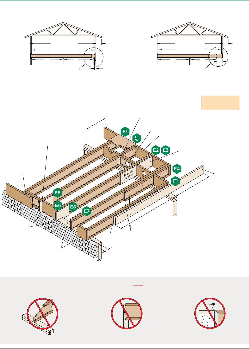
Cantilevers 5" to 24"
See Section B of cantilever table on page 13
Cantilevers Less Than 5" (Brick Ledge)
See Section A of cantilever table on page 13
TJI® joists may be cantilevered 5" to 24" when
supporting roof load, assuming:
■ simple or continuous span
■ L1 ≤ L2
■ minimum backspan = 2x cantilever length
2'-0"
5" to 24"
Roof truss span
40 psf live load
L2L1
2'-0"
Less than 5"
Roof truss span
40 psf live load
TJI® joists may be cantilevered up to 5"
when supporting roof load, assuming:
■ simple or continuous span
■ L1 ≤ L2
■ minimum backspan = 2x cantilever length
L2L1
These Conditions Are NOT Permitted
DO NOT bevel cut joist
beyond inside face of wall.
DO NOT use sawn lumber
for rim board or blocking.
Sawn lumber may shrink after installation.
DO NOT install hanger
overhanging face of plate or beam.
Flush bearing plate with inside face
of wall or beam.
11⁄4" TimberStrand® LSL or
iLevel® 11⁄8" rim board, typical.
Nail with 10d (0.128" x 3")
nails, one each at top and
bottom flange.
CANTILEVERS
8" diameter maximum hole for 117⁄8"–16" deep blocking
panels; 6" diameter maximum for blocking panels 91⁄2"
deep or shorter than 12" long. Do not cut flanges.
Nail with connections
equivalent to floor panel
schedule (E7 and E8)
Blocking panel between each
joist. Full depth vertical
blocking at E5 and E6,
horizontal blocking at E7
and E8.
12" length of 3⁄4" reinforcement on
one side at E5/E7, both sides at
E6/E8. Attach to joist with one 8d
(0.131" x 21⁄2") nail at each corner.
6'-0" length of TJI® joist reinforcement and filler block at E4. Attach to joist
web with three rows 10d (0.148" x 3") nails at 6" on-center, clinched. Use 4'-0"
length with 91⁄2" and 117⁄8" TJI® joists, and attach to joist web with two rows 10d
(0.148" x 3") nails at 6" on-center, clinched. Not for use with TJI® 560 joists.
4'-0" length of 3⁄4" reinforcement on one side
at E2, both sides at E3. Attach to joist with
8d (0.131" x 21⁄2") nails at 6" on-center. When
reinforcing both sides, stagger nails.
TJI® joists are intended
for dry-use applications
1¼" TimberStrand® LSL or
iLevel® 11⁄8" rim board closure, typical
iLevel Trus Joist® TJI® Joist Specifier’s Guide TJ-4000 February 2008 13
How to Use This Table
1. Identify TJI® joist and depth.
2. Locate the Roof Truss Span (horizontal) that meets or exceeds your condition.
3. Identify the cantilever condition (less than 5" or 5" to 24") and locate the Roof
Total Load and On-Center Joist Spacing for your application.
4. Scan down to find the appropriate cantilever detail and refer to drawing
on page 12:
– Blank cells indicate that no reinforcement is required.
– E4 may be used in place of E2 or E3 except when using TJI® 560 joists.
– X indicates that cantilever will not work. Use TJ-Beam® or TJ-Xpert® software,
or reduce spacing of joists and recheck table.
General Notes
■ Table is based on:
– 15 psf roof dead load on a horizontal projection.
– 80 plf exterior wall load with 3'-0" maximum width window or door openings.
For larger openings, or multiple 3'-0" width openings spaced less than 6'-0"
on-center, additional joists beneath the opening’s trimmers may be required.
– More restrictive of simple or continuous span.
– Roof truss with 24" soffits.
■ 3⁄4" reinforcement refers to 3⁄4" Exposure 1 plywood or other 3⁄4" Exposure 1,
48/24-rated sheathing that is cut to match the full depth of the TJI® joist. Install
with face grain horizontal. Reinforcing member must bear fully on the wall plate.
■ Designed for 2x4 and 2x6 plate widths.
■ For conditions beyond the scope of this table, including cantilevers longer than
24", use our TJ-Beam® or TJ-Xpert® software.
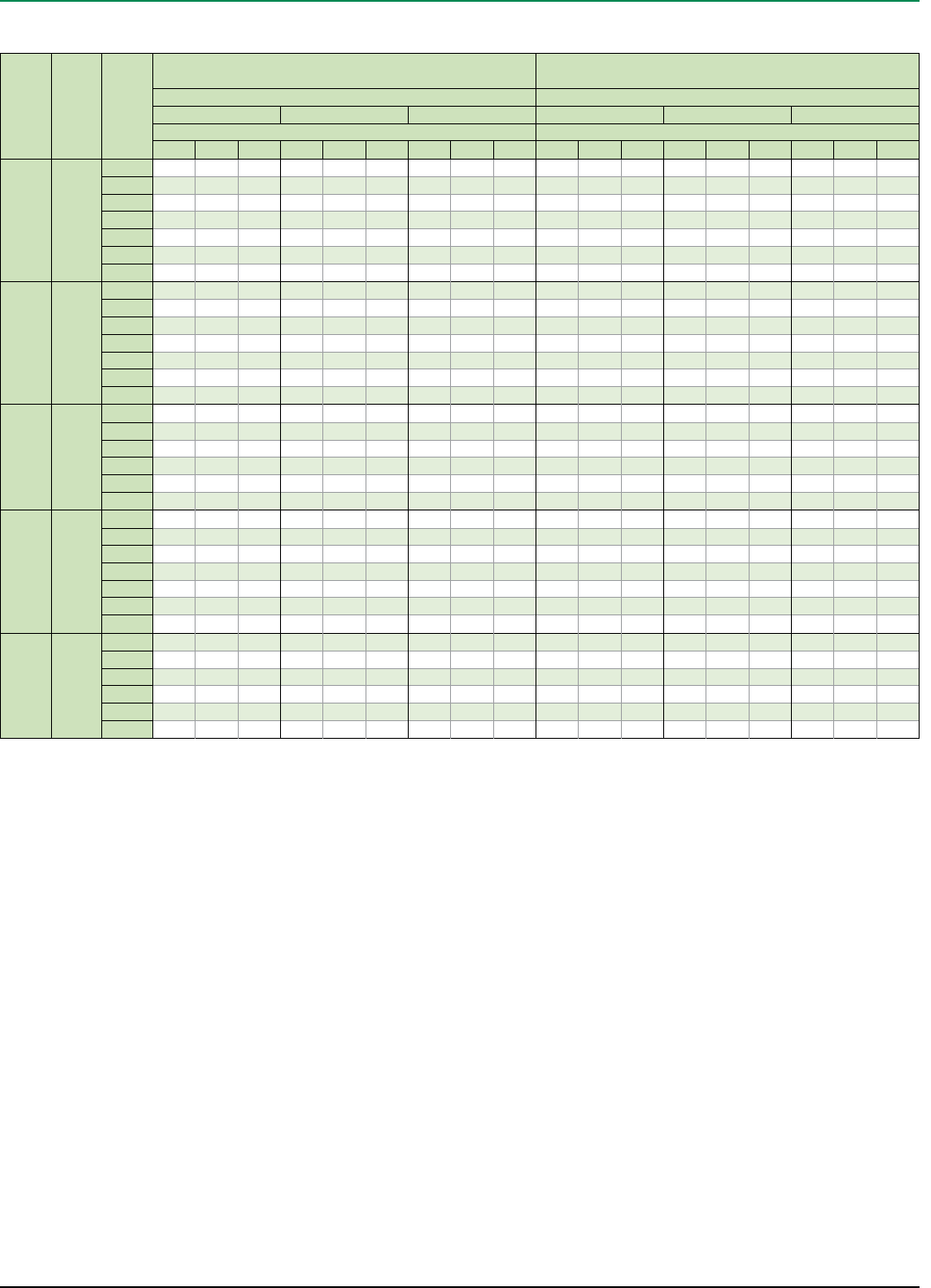
Depth TJI®
Roof
Truss
Span
Section A: Cantilevers less than 5" (Brick Ledge) Section B: Cantilevers 5" to 24"
Roof Total Load Roof Total Load
35 PSF 45 PSF 55 PSF 35 PSF 45 PSF 55 PSF
On-Center Joist Spacing On-Center Joist Spacing
16" 19.2" 24" 16" 19.2" 24" 16" 19.2" 24" 16" 19.2" 24" 16" 19.2" 24" 16" 19.2" 24"
91⁄2"
117⁄8"
14"
110
20' E5 E5 E5 E5 E5 X X
22' E5 E5 E5 E5 E5 E5 X X X
24' E5 E5 E5 E5 E5 E5 E5 E5 X X X
26' E5 E5 E5 E5 E5 E5 E5 E6 XE2 XE2 X X
28' E5 XE5 E5 XE5 E5 XE2 XE2 XXXXX
30' E5 E5 XE5 E5 XE5 E5 XE3 XE3 XXXXX
32' E5 X X E5 X X E5 X X E2 XXXXXXXX
91⁄2"
117⁄8"
14"
16"
210
20' E5 E5 E5 E5 X
22' E5 E5 E5 E5 E5 E2 X
24' E5 E5 E5 E5 E5 E5 E2 X
26' E5 E5 E5 E5 E5 E5 E5 XE2 X
28' E5 E5 E5 E5 E5 E5 E5 E6 E2 E2 XE2 X X
30' E5 E5 E5 E5 E5 E5 E5 E6 E3 E2 E3 XE3 X X
32' E5 E5 XE5 E5 XE5 E5 XE2 XE3 XXXXX
91⁄2"
117⁄8"
14"
16"
230
24' E5 E5 E5 E5 E5 E5 E2 X
26' E5 E5 E5 E5 E5 E5 E5 E2 E2 X
28' E5 E5 E5 E5 E5 E5 E5 E5 E2 E3 E2 E3 X
30' E5 E5 E5 E5 E5 E5 E5 E5 E2 E2 XE2 X X
32' E5 E5 XE5 E5 XE5 E5 XE2 E3 E2 E3 XE3 X X
34' E5 E5 XE5 E5 XE5 E5 XE3 XE3 XXXXX
117⁄8"
14"
16"
360
28' E5 E5 E5 E5 E5 E5 E2
30' E5 E5 E5 E5 E5 E5 E5 E1W E2
32' E5 E5 E5 E5 E5 E5 E5 E5 E2 E2
34' E5 E5 E5 E5 E5 E5 E5 E6 E2 E1W E3
36' E5 E5 E5 E5 E5 E5 E5 E6 E1W E2 E2 E3
38' E5 E5 E5 E5 E5 E5 E5 E5 E6 E1W E2 E2 E3
40' E5 E5 E5 E5 E5 E5 E5 E5 E6 E1W E1W E2 E2 E3
117⁄8"
14"
16"
560
30' E5 E5 E5 E5 E5
32' E5 E5 E5 E5 E5 E5
34' E5 E5 E5 E5 E5 E5 E2
36' E5 E5 E5 E5 E5 E5 E6 E2
38' E5 E5 E5 E5 E5 E5 E5 E6 E2
40' E5 E5 E5 E5 E5 E5 E5 E6 E1W E2
Cantilever Reinforcement
CANTILEVERS
iLevel Trus Joist® TJI® Joist Specifier’s Guide TJ-4000 February 2008
14
FIRE-SAFE CONSTRUCTION
Fire-safe construction and life safety are major concerns for everyone in the building materials and
construction industry. The 2005 US Fire Administration (http://www.usfa.dhs.gov/statistics/national/) statistics
on residential and commercial fires in the U.S. alone include 3,675 fire fatalities and an estimated $10.7 billion
in property damage. These numbers underscore the seriousness of the issue and the need for fire-safe
construction.
Over the past 35 years, prefabricated wood I-joists and other iLevel building products have established a
record of safe and reliable performance in millions of structures. Many of these structures, such as one- or two-
family residential dwellings, do not require specific fire-resistance ratings per the building codes. The following
information is intended to help you specify and install iLevel® Trus Joist® brand products with fire safety in
mind.
For more information on fire assemblies and fire-safe construction,
please refer to the iLevel Fire Facts Guide (Reorder #1500) or
visit www.iLevel.com and www.i-joist.com
Active Fire Suppression
Automatic fire sprinkler systems are commonly required by building codes in schools,
office buildings, factories, and other commercial buildings. Buildings designed with
sprinkler systems are allowed larger heights and areas than buildings designed
without sprinkler systems.
Fire service agencies, such as the US Fire Administration, promote the use of
residential sprinkler systems. These agencies cite benefits such as lowering the total
cost of construction to the homebuilder, ensuring a safer environment, and lowering
insurance rates for the homeowner. Using automatic fire sprinkler systems provides
the following benefits:
■ Early and unsupervised suppression
■ Reduced fire and smoke development
■ Potentially enhanced life safety for the occupant(s)
Smoke Detectors
Smoke detectors are universally recognized as the most cost-effective life-saving
devices. While smoke detectors do not provide protection to the structure or to the
contents in a home, they do alert occupants to potential fire hazards and allow them
time to escape. Similarly, carbon monoxide detectors can also alert occupants to
faulty heating appliances or air contamination in the early stages of a fire.
Passive Fire Protection
Independent tests show that unprotected framing systems, whether combustible
or non-combustible, suffer increased structural degradation when exposed to fire.
All floor framing materials—sawn lumber, wood I-joists, trusses, and light-gauge
steel— succumb quickly to fire if not protected. If a protective membrane such as
gypsum ceiling board is applied to all types of floor framing within the structure, it
will provide additional and uniform protection to the structural framing members.
Passive fire-protection can do the following:
■ Delay fire growth involving structural elements
■ Reduce the potential for significant property damage to structural elements
■ Enhance the market value of the building
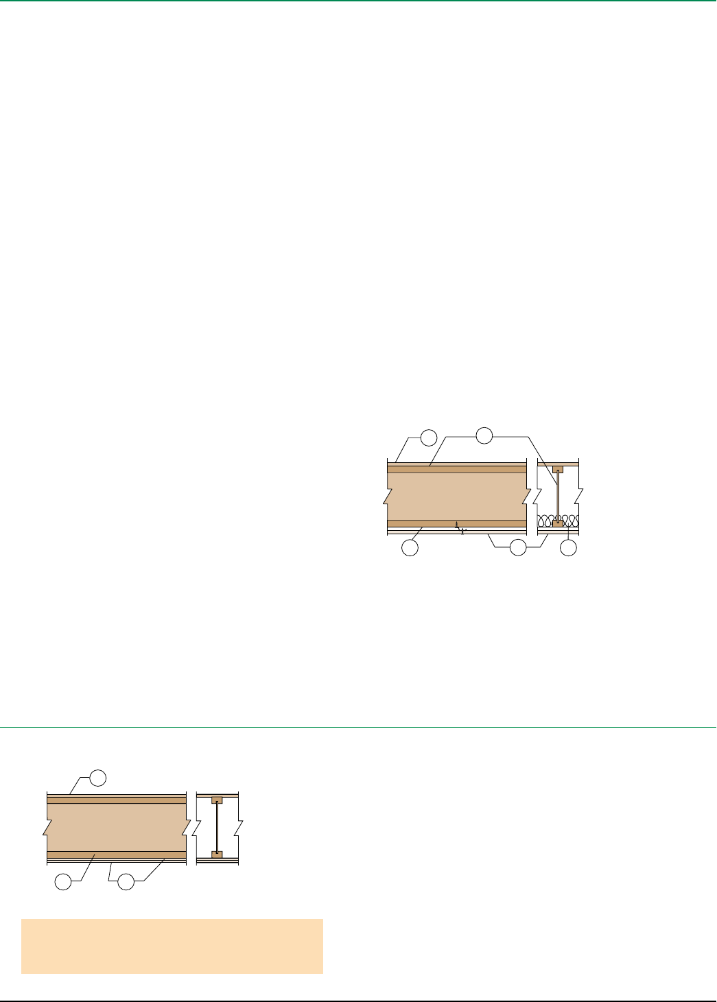
Suggested Minimum Membrane Construction
One-Hour Assembly
1
2 3
1. 48/24 tongue-and-groove, span-rated sheathing (Exposure 1)
2. Two layers
1⁄2" thick Type X gypsum board
3. TJI® joist
Optional when used with resilient channels (not shown): Minimum 31⁄2" thick glass
fiber insulation or non-combustible insulation that is rated R-30 or less
Note
Resilient channels may be installed between the joists and gypsum board if
improved STC and IIC sound ratings are desired.
Reference Assembly B per ICC ES ESR-1153
1. 48/24 tongue-and-groove span-rated sheathing (Exposure 1)
2. TJI® joist
3. Single layer 1⁄2" thick gypsum board
4. Resilient channels at 16" on-center (optional)
5. Optional when used with resilient channels. Minimum 3½" thick glass fiber
insulation or non-combustible insulation that is rated R-30 or less.
1
3
4 5
2
iLevel supports the idea
that all floor/ceiling and
roof/ceiling assemblies
in habitable areas be
protected by a minimum
membrane protection
consisting of 1⁄2" gypsum
board (or equivalent)
iLevel Trus Joist® TJI® Joist Specifier’s Guide TJ-4000 February 2008 15
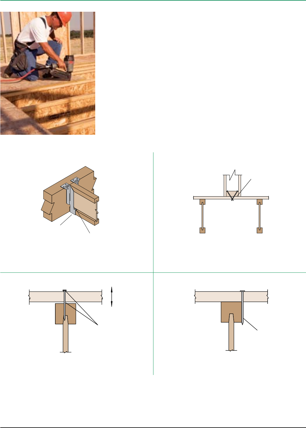
Seat the joist tight to the bottom of the hanger. When using hangers with tabs, bend
the flange tabs over and nail to the TJI® joist bottom flange.
Placing a dab of subfloor adhesive in the seat of the hanger prior to installing the joist
can reduce squeaks.
For more information and tips on how to prevent floor noise, refer to the
iLevel Prevention and Repair of Floor System Squeaks Technical Resource Sheet (Reorder #9009) or contact your iLevel representative.
Properly Seat Each Joist in Hanger Use Adhesive and Special Nailing When Needed
Avoid “Shiners”
Movement
Gaps develop as
sheathing shrinks Shiner
Prevent Shrinkage
Exercise care when nailing. Nails that barely hit the joists (shiners) do not hold the
panel tight to the joist and should be removed. If left in, the nails will rub against the
side of the joist when the panel deflects.
Nail interior partitions to the joists when possible. If the wall can be nailed only to the
floor panel, run a bead of adhesive under the wall and either cross nail, nail through
and clinch tight, or screw tightly into the wall from below.
Keep building materials dry, and properly glue floor panels to the joists. Panels that
become excessively wet during construction shrink as they dry. This shrinkage may
leave gaps that allow the panel to move when stepped on.
UNDERSTANDING AND PREVENTING FLOOR NOISE
Construction
adhesive
Dab subfloor adhesive
in seat of hanger Bend tab
and fasten
Silent Floor® joists are structurally uniform and dimensionally stable,
and they resist shrinking and twisting. This helps prevent gaps from
forming around the nails between the joist and the floor panels—
gaps that can potentially cause squeaks or other floor noise.
Using Silent Floor® joists can help you build a quieter floor, but only
if the entire floor system is installed properly. This is because other
components of the floor system, such as hangers, connectors, and
nails can be a source of floor noise.
To get the best possible performance out of your Silent Floor® joists
and minimize potential squeaks in your floor, we recommend the
following installation tips:
iLevel Trus Joist® TJI® Joist Specifier’s Guide TJ-4000 February 2008
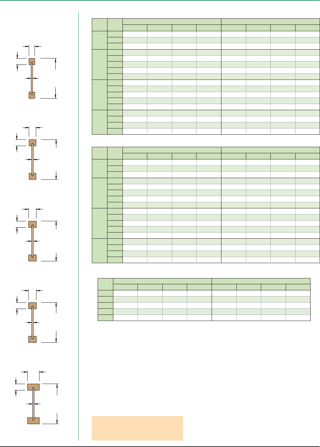
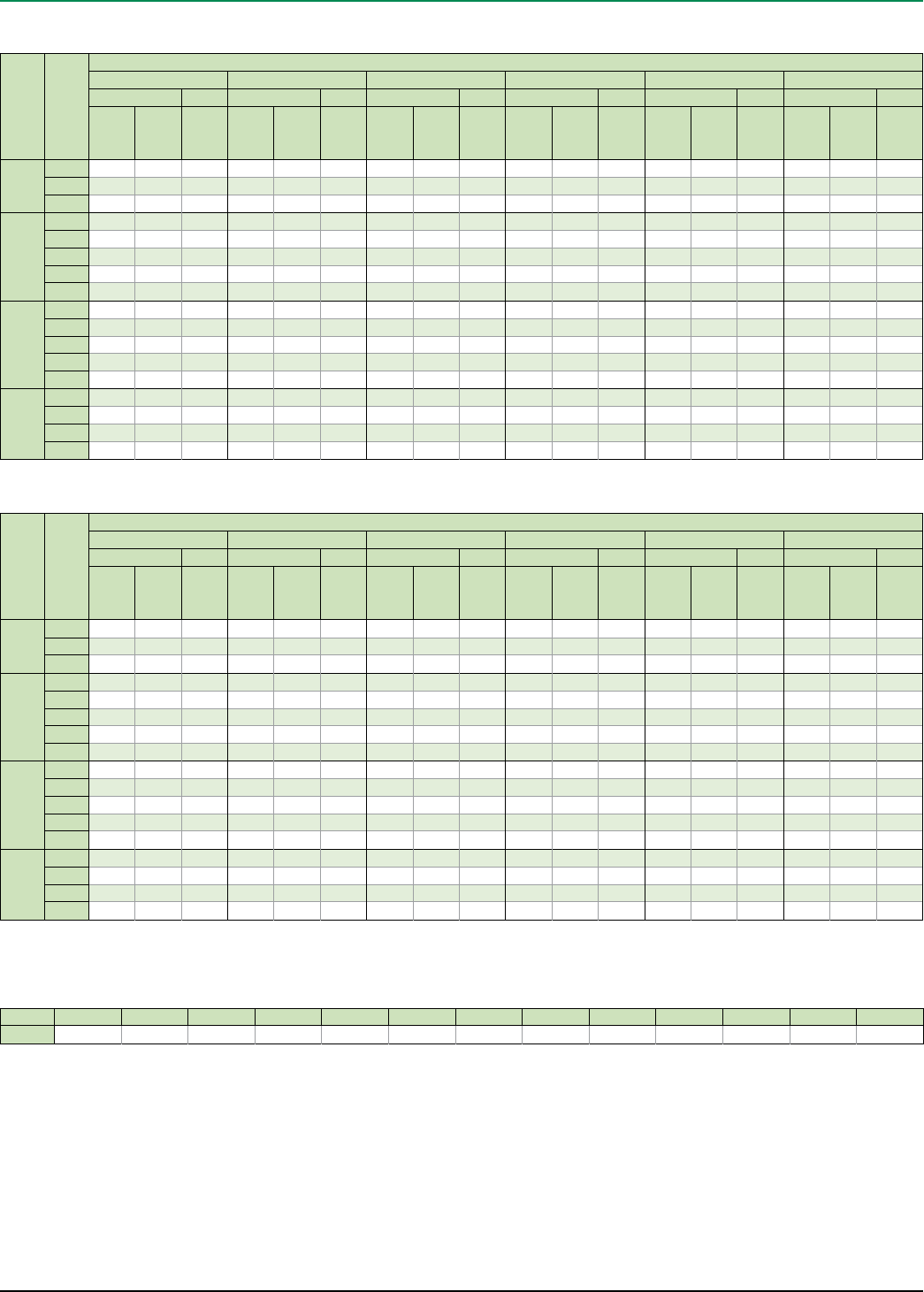
16
O.C.
Spacing Depth TJI®
Design Live Load (LL) and Dead Load (DL) in PSF
Non-Snow (125%) Snow Load Area (115%)
20LL + 15DL 20LL + 20DL 25LL + 15DL 30LL + 15DL 40LL + 15DL 50LL + 15DL
Low High Low High Low High Low High Low High Low High
16"
91⁄2"
110 19'-3" 17'-2" 18'-4" 16'-3" 18'-5" 16'-6" 17'-9" 15'-11" 16'-7" 15'- 0" 15'-6" 14'-3"
210 20'-5" 18'-2" 19'-5" 17'-3" 19'-6" 17'-6" 18'-9" 16'-11" 17'-7" 15'-11" 16'-7" 15'-1"
230 21'-0" 18'-9" 20'-0" 17'-9" 20'-2" 18'-0" 19'-4" 17'-5" 18'-1" 16'-4" 17'-1" 15'-6"
117⁄8"
110 23'-0" 20'-6" 21'-11" 19'-5" 22'-0" 19'-9" 20'-11" 19'-1" 19'- 0" 17'-11" 17'-6" 16'-11"
210 24'-4" 21'-9" 23'-3" 20'-7" 23'-4" 20'-11" 22'-5" 20'-2" 20'-10" 19'- 0" 19'-2" 18'-0"
230 25'-1" 22'-5" 23'-11" 21'-3" 24'-1" 21'-7" 23'-1" 20'-10" 21'-7" 19'-7" 20'-3" 18'-7"
360 27'-9" 24'-9" 26'-5" 23'-5" 26'-7" 23'-10" 25'-6" 23'- 0" 23'-11" 21'-7" 22'-7" 20'-6"
560 31'-11" 28'-6" 30'-5" 27'- 0" 30'-7" 27'-5" 29'-5" 26'-5" 27'-6" 24'-10" 26'- 0" 23'-7"
14"
110 26'-3" 23'-5" 25'- 0" 22'-2" 24'-1" 22'-6" 22'-9" 21'-9" 20'-8" 19'-11" 19'-1" 18'-5"
210 27'-9" 24'-9" 26'-5" 23'-5" 26'-5" 23'-9" 25'- 0" 22'-11" 22'-8" 21'-7" 20'-11" 20'-3"
230 28'-7" 25'-6" 27'-2" 24'-2" 27'-4" 24'-6" 26'-4" 23'-8" 23'-11" 22'-3" 22'-0" 21'-1"
360 31'-6" 28'-2" 30'-0" 26'-8" 30'-2" 27'-1" 29'-0" 26'-1" 27'-2" 24'-7" 25'-8" 23'-4"
560 36'-3" 32'-4" 34'-6" 30'-7" 34'-8" 31'-1" 33'-4" 30'-0" 31'-2" 28'-3" 29'-6" 26'-9"
16"
210 30'-9" 27'-5" 29'-4" 26'- 0" 28'-3" 26'-5" 26'-9" 25'-6" 24'-3" 23'-4" 22'-4" 21'-8"
230 31'-8" 28'-3" 30'-2" 26'-9" 29'-10" 27'-2" 28'-2" 26'-3" 25'-7" 24'-7" 23'-7" 22'-10"
360 34'-11" 31'-2" 33'-3" 29'-6" 33'-5" 30'- 0" 32'-2" 28'-11" 30'-1" 27'-2" 26'- 0" 25'-10"
560 40'-1" 35'-9" 38'-2" 33'-11" 38'-4" 34'-5" 36'-11" 33'-2" 34'-6" 31'-3" 31'-8" 29'-8"
19.2"
91⁄2"
110 18'-1" 16'-1" 17'-3" 15'-3" 17'-4" 15'-6" 16'-8" 15'- 0" 15'-5" 14'-1" 14'-2" 13'-4"
210 19'-2" 17'-1" 18'-3" 16'-2" 18'-4" 16'-5" 17'-8" 15'-10" 16'-6" 14'-11" 15'-7" 14'-2"
230 19'-9" 17'-7" 18'-10" 16'-8" 18'-11" 16'-11" 18'-2" 16'-4" 17'- 0" 15'-4" 16'-1" 14'-7"
117⁄8"
110 21'-7" 19'-3" 20'-7" 18'-3" 20'-3" 18'-6" 19'-1" 17'-11" 17'-4" 16'-8" 16'- 0" 15'-5"
210 22'-11" 20'-5" 21'-10" 19'-4" 21'-11" 19'-8" 20'-11" 18'-11" 19'-0" 17'-10" 17'-6" 16'-11"
230 23'-7" 21'-1" 22'-6" 19'-11" 22'-7" 20'-3" 21'-8" 19'-6" 20'-0" 18'-4" 18'-5" 17'-5"
360 26'-1" 23'-3" 24'-10" 22'-0" 24'-11" 22'-4" 24'- 0" 21'-7" 22'-5" 20'-3" 21'-2" 19'-3"
560 30'- 0" 26'-9" 28'-7" 25'-4" 28'-8" 25'-9" 27'-7" 24'-10" 25'-9" 23'-4" 24'-4" 22'-2"
14"
110 24'-6" 22'- 0" 22'-9" 20'-10" 22'-0" 20'-11" 20'-9" 19'-10" 18'-10" 18'-2" 17'- 0" 16'-10"
210 26'-0" 23'-3" 24'-10" 22'-0" 24'-2" 22'-4" 22'-10" 21'-7" 20'-8" 19'-11" 18'-10" 18'-5"
230 26'-10" 23'-11" 25'-7" 22'-8" 25'-5" 23'-0" 24'-0" 22'-3" 21'-10" 20'-11" 20'-1" 19'-5"
360 29'-7" 26'-5" 28'-2" 25'-0" 28'-4" 25'-5" 27'-3" 24'-6" 25'-6" 23'-1" 21'-7" 21'-8"
560 34'-0" 30'-4" 32'-5" 28'-9" 32'-7" 29'-2" 31'-4" 28'-2" 29'-3" 26'-6" 26'-5" 25'-2"
16"
210 28'-8" 25'-9" 26'-9" 24'-5" 25'-10" 24'-6" 24'-5" 23'-4" 22'-1" 21'-4" 18'-10" 19'-8"
230 29'-9" 26'-7" 28'-2" 25'-2" 27'-3" 25'-6" 25'-9" 24'-7" 23'-4" 22'-6" 21'-2" 20'-9"
360 32'-10" 29'-3" 31'-3" 27'-9" 31'-5" 28'-2" 30'-2" 27'-2" 25'-7" 25'-3" 21'-7" 21'-8"
560 37'-8" 33'-7" 35'-10" 31'-10" 36'-0" 32'-4" 34'-8" 31'-2" 31'-3" 29'-4" 26'-5" 25'-5"
24"
91⁄2"
110 16'-9" 14'-11" 15'-11" 14'-2" 16'-0" 14'-4" 15'-2" 13'-10" 13'-9" 13'-0" 12'-8" 12'-3"
210 17'-9" 15'-10" 16'-11" 15'- 0" 17'- 0" 15'-3" 16'-4" 14'-8" 15'-1" 13'-10" 13'-11" 13'-1"
230 18'-3" 16'-4" 17'-5" 15'-5" 17'-6" 15'-8" 16'-10" 15'-2" 15'-8" 14'-3" 14'-8" 13'-6"
117⁄8"
110 20'-0" 17'-10" 18'-9" 16'-11" 18'-1" 17'-2" 17'-1" 16'-4" 15'-6" 14'-11" 13'-7" 13'-10"
210 21'-2" 18'-11" 20'-2" 17'-11" 19'-10" 18'-2" 18'-9" 17'-7" 17'- 0" 16'-4" 15'-0" 15'-2"
230 21'-10" 19'-6" 20'-10" 18'-5" 20'-11" 18'-9" 19'-9" 18'-1" 17'-11" 17'- 0" 16'-6" 16'- 0"
360 24'-1" 21'-6" 23'- 0" 20'-5" 23'-1" 20'-8" 22'-2" 20'- 0" 20'-5" 18'-9" 17'-3" 17'-4"
560 27'-9" 24'-9" 26'-5" 23'-6" 26'-7" 23'-10" 25'-6" 23'- 0" 23'-10" 21'-7" 21'-1" 20'-3"
14"
110 21'-10" 20'-4" 20'-4" 19'-1" 19'-8" 18'-8" 18'-7" 17'-9" 16'-0" 16'-3" 13'-7" 14'-2"
210 24'- 0" 21'-6" 22'-4" 20'-5" 21'-7" 20'-6" 20'-4" 19'-6" 17'-10" 17'-9" 15'-0" 15'-8"
230 24'-10" 22'-2" 23'-7" 21'- 0" 22'-9" 21'-4" 21'-6" 20'-6" 19'-6" 18'-9" 16'-11" 16'-7"
360 27'-5" 24'-6" 26'-1" 23'-2" 26'-3" 23'-6" 25'-0" 22'-8" 20'-5" 20'-2" 17'-3" 17'-4"
560 31'-6" 28'-1" 30'- 0" 26'-8" 30'-2" 27'-0" 29'- 0" 26'-1" 24'-11" 23'-7" 21'-1" 20'-3"
16"
210 25'-8" 23'-11" 23'-11" 22'-4" 23'-1" 21'-11" 21'-9" 20'-10" 17'-10" 18'-3" 15'-0" 15'-8"
230 27'-1" 24'-7" 25'-2" 23'-3" 24'-4" 23'-1" 23'- 0" 22'- 0" 20'-0" 19'-4" 16'-11" 16'-7"
360 30'-4" 27'-1" 28'-11" 25'-8" 28'-2" 26'-1" 25'-0" 24'-1" 20'-5" 20'-2" 17'-3" 17'-4"
560 34'-10" 31'-2" 33'-2" 29'-6" 33'-4" 29'-11" 30'-6" 28'-3" 24'-11" 23'-7" 21'-1" 20'-3"
Maximum Horizontal Clear Spans—Roof
See page 17 for General Notes and information on how to use this table
ROOF SPAN TABLE
iLevel Trus Joist® TJI® Joist Specifier’s Guide TJ-4000 February 2008 17
ROOF SPAN NOTES AND CUT LENGTH CALCULATION
How to Use Roof Span Table on Page 16
1. Determine appropriate live and dead load, and the load duration factor.
2. If your slope is 6/12 or less, use the Low slope column. If it is between 6/12 and
12/12, use the High column.
3. Scan down the column until you find a span that meets or exceeds the span of
your application.
4. Select TJI® joist and on-center spacing.
General Notes
■ Table is based on:
– Uniform loads.
– More restrictive of simple or continuous span.
– Minimum roof surface slope of 1⁄4" in 12".
– 13⁄4" minimum end bearing and 31⁄2" minimum intermediate bearing.
■ Total load limits joist deflection to L/180.
■ Live load is based on joist deflection of L/240.
■ A support beam or wall at the high end is required. Ridge board applications do
not provide adequate support.
■ Spans shown assume no web stiffeners at intermediate bearings.
Slope 21⁄2 in 12 3 in 12 31⁄2 in 12 4 in 12 41⁄2 in 12 5 in 12 6 in 12 7 in 12 8 in 12 9 in 12 10 in 12 11 in 12 12 in 12
Factor 1.021 1.031 1.042 1.054 1.068 1.083 1.118 1.158 1.202 1.250 1.302 1.357 1.414
Slope Factors
Depth Slope
21⁄2 in 12 3 in 12 31⁄2 in 12 4 in 12 41⁄2 in 12 5 in 12 6 in 12 7 in 12 8 in 12 9 in 12 10 in 12 11 in 12 12 in 12
91⁄2"2" 23⁄8" 27⁄8" 31⁄4" 35⁄8"4" 43⁄4" 55⁄8" 63⁄8" 71⁄8"8" 83⁄4" 91⁄2"
117⁄8"21⁄2"3" 31⁄2"4" 41⁄2"5" 6" 7" 8" 9" 10" 11" 117⁄8"
14" 3" 31⁄2" 41⁄8" 43⁄4" 51⁄4" 57⁄8"7" 81⁄4" 93⁄8"101⁄2"113⁄4"127⁄8"14"
16" 33⁄8"4" 43⁄4" 53⁄8"6" 63⁄4"8" 93⁄8"103⁄4"12" 133⁄8"143⁄4"16"
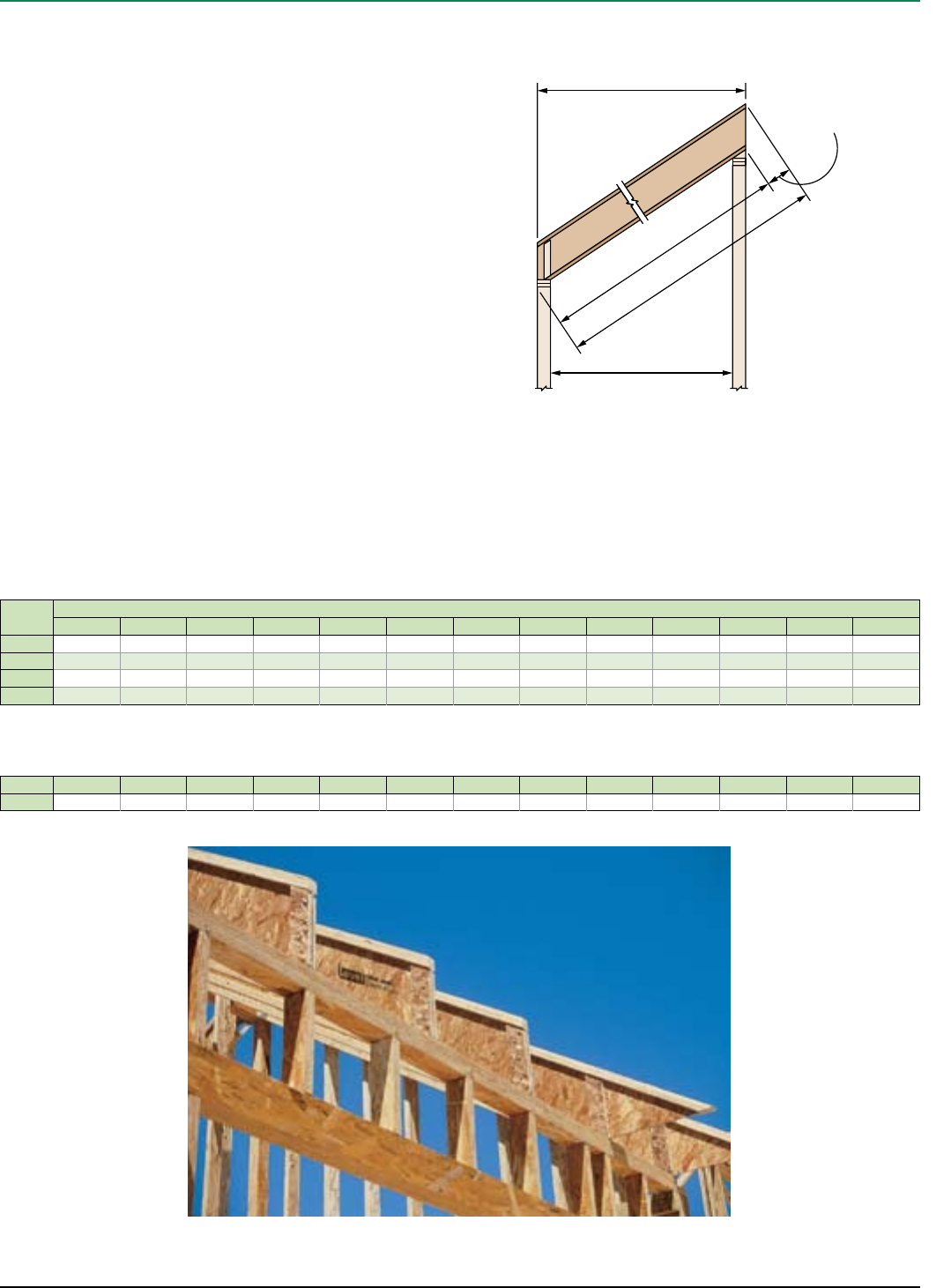
D Factors
Actual cut length can be approximated by multiplying the
horizontal length by the slope factor and adding the D factor.
Horizontal length = L
L x slope factor
Cut length
Add D factor
to obtain proper
cut length
D
Horizontal clear span
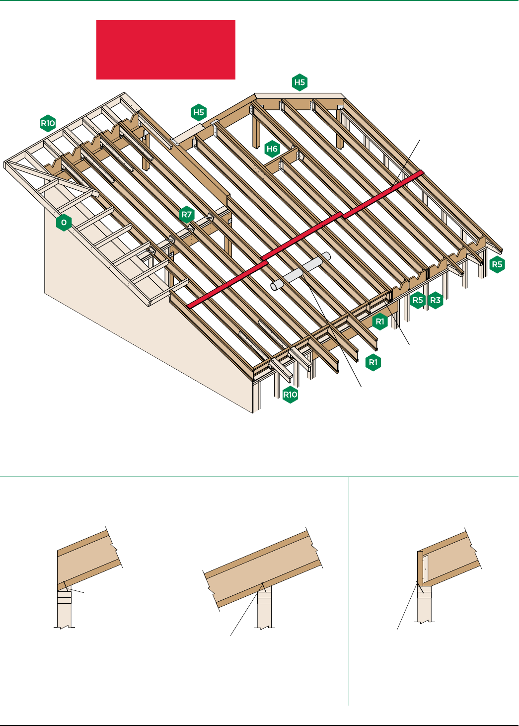
iLevel Trus Joist® TJI® Joist Specifier’s Guide TJ-4000 February 2008
18
Joists must be laterally supported at
cantilever and end bearings by shear
blocking, hangers, or direct attachment
to a rim board or rim joist
See
Allowable Holes
on page 11
General Notes
■ Unless otherwise noted, all details are valid to a maximum slope of 12/12.
■ Web stiffeners are required if the sides of the hanger do not laterally support at
least 3⁄8" of the TJI® joist top flange.
TJI® Joist to Bearing Plate
End Bearing
(13⁄4" minimum bearing required)
TJI® Joist Nailing Requirements at Bearing
Intermediate Bearing
(31⁄2" minimum bearing required)
Blocking to Bearing Plate
8d (0.113" x 21⁄2") nail,
one each side, 11⁄2"
minimum from end
Slopes 3/12 or less:
One 8d (0.113" x 21⁄2") nail each side. See detail R7.
Slopes greater than 3/12:
Two 8d (0.113" x 21⁄2") nails each side, plus a twist strap
and backer block. See detail R7S.
11⁄4" TimberStrand® LSL or iLevel® 11⁄8" rim board:
Toenail with 10d (0.128" x 3") nails at 6" on-center or
16d (0.135" x 31⁄2") nails at 12" on-center
TJI® joist blocking:
10d (0.128" x 3") nails at 6" on-center
Shear transfer nailing:
Use connections equivalent to sheathing nail schedule
When slope exceeds 1⁄4" per foot, a beveled bearing plate, variable slope seat connector, or birdsmouth cut (at low
end of joist only) is required
Safety bracing (1x4 minimum) placed
at 8' on-center (6' on-center for TJI®
110 joists) and extended to a braced
end wall. Fasten at each joist with two
8d (0.113" x 21⁄2") nails minimum.
ROOF FRAMING
WARNING
Joists are unstable until
laterally braced.
See Warning Notes on page 5.
iLevel Trus Joist® TJI® Joist Specifier’s Guide TJ-4000 February 2008 19
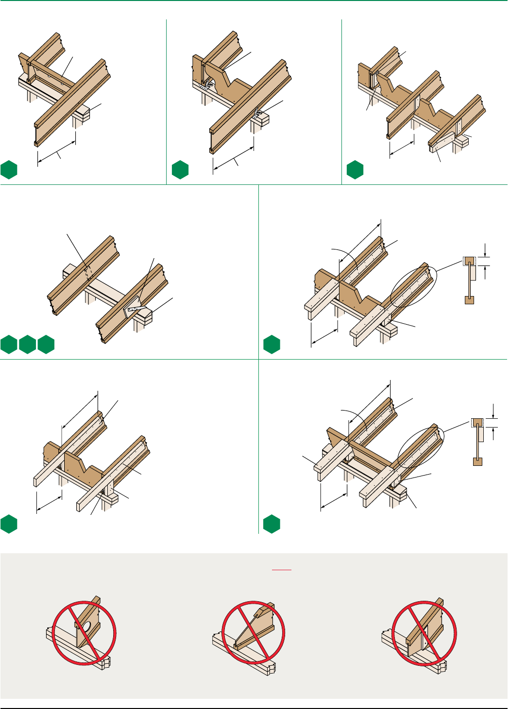
Intermediate Bearing Birdsmouth Cut
Beveled bearing plate
required when slope
exceeds 1⁄4" in 12"
Twist strap and backer block required at
R7S with slopes greater than 3/12. See
nailing requirements on page 18.
Birdsmouth Cut
Allowed at low end of joist only
Variable slope
seat connector
2'-0"
maximum
2'-0"
maximum
4'-0"
minimum
2x4 one side. Use 2x4 both
sides if joist spacing is
greater than 24" on-center.
Two rows 8d
(0.113" x 21⁄2") nails
at 8" on-center
Beveled 2x4 block with
beveled web stiffener on
opposite side of web
1⁄3 adjacent span maximum
1⁄3 adjacent span maximum
Beveled web stiffeners
required on both sides.
Cut to match roof slope.
Birdsmouth Cut
Allowed at low end of joist only
Blocking panels or shear blocking may be specified
for joist stability at intermediate supports
2x4 block for
soffit support
Web stiffeners
required each side
at R7W
Beveled bearing plate
required when slope
exceeds 1⁄4" in 12"
Beveled 2x4 block
2x4 one side. Use 2x6 if joist spacing
is greater than 24" on-center.
2'-0"
maximum
4'-0"
minimum
10d (0.128" x 3") nails
at 8" on-center
Beveled web stiffeners on both sides
2x4 one side. Use 2x4 both
sides if joist spacing is
greater than 24" on-center.
Filler
Two rows 8d
(0.113" x 21⁄2") nails
at 8" on-center
V-cut shear blocking—
11⁄4" TimberStrand® LSL
rim board
Shear blocking—
11⁄4" TimberStrand® LSL
rim board, iLevel® 11⁄8"
rim board, or TJI® joist
4'-0"
minimum
2'-0"
maximum
Allowed at low end of joist only
Beveled
2x4 block
Beveled bearing plate required
when slope exceeds 1⁄4" in 12"
11⁄2"
ROOF DETAILS
These Conditions Are NOT Permitted
DO NOT cut holes
too close to support.
DO NOT bevel cut joist
beyond inside face of wall.
DO NOT overhang birdsmouth cut
from inside face of plate.
TJI® joist flange must bear fully on the plate.
See detail BC on page 20.
Refer to Allowable Holes on page 11
for minimum distance from support.
R1 R3 R5
R7
W
R7 R7
SR8
R10R9
TJI® joist
flange must
bear fully on
plate
Birdsmouth
cut must not
overhang
inside face
of plate
11⁄2"
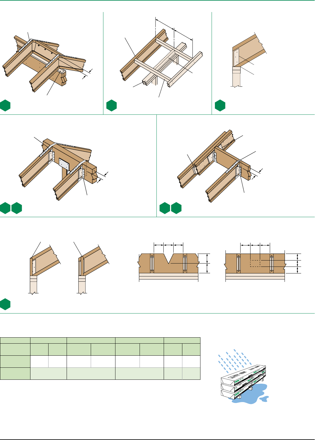
iLevel Trus Joist® TJI® Joist Specifier’s Guide TJ-4000 February 2008
20
Double beveled bearing
plate when slope exceeds
1⁄4" in 12"
For TJI® joists with slopes of 10/12 to 12/12, the vertical depth at bearing will require 11⁄4" TimberStrand® LSL or
iLevel® 11⁄8" rim board (for shear blocking) that is one size deeper than the TJI® joist
TJI® joist flange must bear fully
on plate. Birdsmouth cut must not
overhang inside face of plate.
Filler block: Attach with ten
10d (0.128" x 3") nails,
clinched. Use ten 16d
(0.135" x 31⁄2") nails
from each side with
TJI® 560 joists.
Variable slope joist hanger. See
pages 22 and 23. Beveled web
stiffener required each side.
1⁄31⁄31⁄3
1⁄2
1⁄2
Maximum allowable V-cut Allowed hole zone
1⁄31⁄31⁄3
1⁄3
1⁄3
1⁄3
Birdsmouth Cut
Allowed at low end of joist only
Field trim to match joist depth at outer edge of
wall or locate on wall to match joist depth
Shear Blocking and Ventilation Holes (Roof Only)
LSTA24 (Simpson or USP) strap with twelve
10d (0.148" x 11⁄2") nails required at H5S
with slopes greater than 3/12
LSTA18 strap nails at H6S with
slopes greater than 3/12
Double joist may
be required when L
exceeds joist spacing
2x_ overhang. Notch around
TJI® joist top flange.
LL
Blocking as
required
End wall
Backer block: Install tight to bottom
flange (tight to top flange with top flange
hangers). Attach with ten 10d (0.128" x 3")
nails, clinched when possible.
■ If necessary, increase filler and backer block height for face mount hangers and maintain 1⁄8" gap at top of joist. See
detail W. Filler and backer block dimensions should accommodate required nailing without splitting. The suggested
minimum length is 24" for filler and 12" for backer blocks.
Strap nails: Leave 23⁄8"
minimum end distance
Strap nails: Leave 23⁄8"
minimum end distance, typical
Strap nails:
Leave 23⁄8"
minimum
end distance,
typical
See General Notes and nailing requirements on page 18
Beveled web stiffener each
side of TJI® joist web
TJI®110 210 230 or 360 560
Depth 91⁄2" or
117⁄8"14" 91⁄2" or
117⁄8"
14" or
16"
91⁄2" or
117⁄8"
14" or
16" 117⁄8"14" or
16"
Filler Block
(Detail H6) 2x6 2x8 2x6 + 3⁄8"
sheathing
2x8 + 3⁄8"
sheathing
2x6 + 1⁄2"
sheathing
2x8 + 1⁄2"
sheathing
Two
2x6
Two
2x8
Backer Block
(Detail H6) 5⁄8" or 3⁄4"3⁄4" or 7⁄8" 1" net 2x6 2x8
Additional blocking
may be required for
shear transfer
Additional blocking
may be required for
shear transfer
ROOF DETAILS
R14 O BC
Variable slope joist hanger. See
pages 22 and 23. Beveled web
stiffener required each side.
H5 H5S H6 H6S
SB
Filler and Backer Block Sizes
LSTA18 (Simpson or USP) strap with
twelve 10d (0.148" x 11⁄2") nails
Protect products from sun and water
CAUTION:
Wrap is slippery
when wet or icy
Use support blocks at
10' on-center to keep
products out of mud
and water
Product Storage
iLevel Trus Joist® TJI® Joist Specifier’s Guide TJ-4000 February 2008 21
* Indicates that Total Load value controls.
Depth TJI®
Roof Joist Horizontal Clear Span
6' 8' 10' 12' 14' 16'
Total Load Defl. Total Load Defl. Total Load Defl. Total Load Defl. Total Load Defl. Total Load Defl.
Snow
115%
Non-
Snow
125%
Live
Load
L/240
Snow
115%
Non-
Snow
125%
Live
Load
L/240
Snow
115%
Non-
Snow
125%
Live
Load
L/240
Snow
115%
Non-
Snow
125%
Live
Load
L/240
Snow
115%
Non-
Snow
125%
Live
Load
L/240
Snow
115%
Non-
Snow
125%
Live
Load
L/240
91⁄2"
110 289 314 *218 237 *175 190 *146 159 155 109 118 101 83 91 69
210 321 349 *242 263 *194 211 *162 176 *131 142 118 100 108 81
230 360 392 *272 295 *218 237 *182 198 196 145 158 128 112 118 88
117⁄8"
110 289 314 *218 237 *175 190 *146 159 *125 136 *106 115 *
210 321 349 *242 263 *194 211 *162 176 *139 151 *122 132 *
230 360 392 *272 295 *218 237 *182 198 *156 170 *137 149 146
360 368 400 *277 301 *223 242 *186 202 *159 173 *140 152 *
560 449 488 *338 368 *272 295 *227 246 *195 212 *170 185 *
14"
110 289 314 *218 237 *175 190 *146 159 *125 136 *110 119 *
210 321 349 *242 263 *194 211 *162 176 *139 151 *122 132 *
230 360 392 *272 295 *218 237 *182 198 *156 170 *137 149 *
360 368 400 *277 301 *223 242 *186 202 *159 173 *140 152 *
560 449 488 *338 368 *272 295 *227 246 *195 212 *170 185 *
16"
210 321 349 *242 263 *194 211 *162 176 *139 151 *122 132 *
230 360 392 *272 295 *218 237 *182 198 *156 170 *137 149 *
360 368 400 *277 301 *223 242 *186 202 *159 173 *140 152 *
560 449 488 *338 368 *272 295 *227 246 *195 212 *170 185 *
Depth TJI®
Roof Joist Horizontal Clear Span
18' 20' 22' 24' 26' 28'
Total Load Defl. Total Load Defl. Total Load Defl. Total Load Defl. Total Load Defl. Total Load Defl.
Snow
115%
Non-
Snow
125%
Live
Load
L/240
Snow
115%
Non-
Snow
125%
Live
Load
L/240
Snow
115%
Non-
Snow
125%
Live
Load
L/240
Snow
115%
Non-
Snow
125%
Live
Load
L/240
Snow
115%
Non-
Snow
125%
Live
Load
L/240
Snow
115%
Non-
Snow
125%
Live
Load
L/240
91⁄2"
110
210 77 77 58
230 84 84 63
117⁄8"
110 84 91 82
210 101 109 96 82 89 71
230 112 121 105 91 98 78 75 79 59
360 124 135 *112 122 103 102 105 78 82 82 61
560 152 165 *137 148 *124 135 117 114 122 91 97 97 73 79 79 59
14"
110 98 106 *80 87 *
210 108 118 *97 105 103 80 87 79
230 122 132 *107 117 112 89 96 86 75 81 67
360 124 135 *112 122 *102 111 *93 101 88 86 94 70 76 76 57
560 152 165 *137 148 *124 135 *114 124 *105 114 104 98 106 85
16"
210 108 118 *97 106 *89 96 *77 83 *
230 122 132 *110 119 *100 108 *85 93 90 79 72
360 124 135 *112 122 *102 111 *93 101 *86 94 *80 87 76
560 152 165 *137 148 *124 135 *114 124 *105 114 *98 106 *
Roof—115% and 125% Load Duration (PLF) for 6'–16' Spans
How to Use These Tables
1. Calculate actual total load in pounds per linear foot (plf).
2. Select appropriate Roof Joist Horizontal Clear Span. For slopes greater than 2"
in 12", approximate the increased dead load by multiplying the joist horizontal
clear span by the Slope Factor above.
3. Scan down the column to find a TJI® joist that meets or exceeds actual total load.
Total Load values are limited to deflection of L/180. For stiffer deflection criteria,
use the Live Load L /240 values.
General Notes
■ Tables are based on:
– Uniform loads.
– No composite action provided by sheathing.
– More restrictive of simple or continuous span.
– Minimum roof surface slope of 1⁄4" in 12".
■ Total Load limits joist deflection to L/180.
Slope 21⁄2 in 12 3 in 12 31⁄2 in 12 4 in 12 41⁄2 in 12 5 in 12 6 in 12 7 in 12 8 in 12 9 in 12 10 in 12 11 in 12 12 in 12
Factor 1.021 1.031 1.042 1.054 1.068 1.083 1.118 1.158 1.202 1.250 1.302 1.357 1.414
Slope Factors
ROOF LOAD TABLES
Roof—115% and 125% Load Duration (PLF) for 18'–28' Spans
iLevel Trus Joist® TJI® Joist Specifier’s Guide TJ-4000 February 2008
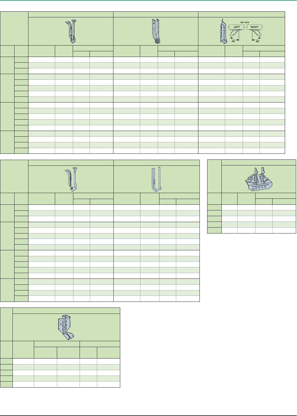
22
Joist
Single Joist—Top Flange Single Joist—Face Mount(1) Face Mount Skewed 45° Joist Hanger(1)
Depth TJI®Hanger Capacity
(lbs)
Nailing Hanger Capacity
(lbs)
Nailing Hanger Capacity
(lbs)
Nailing
Header Joist Header Joist Header Joist
91⁄2"
110 ITS1.81/9.5 1,365 10d N.A. IUS1.81/9.5 935 10d N.A. SU R/L1.81/9 1,595 16d 10d x 11⁄2"
210 ITS2.06/9.5 1,365 10d N.A. IUS2.06/9.5 935 10d N.A. SUR/L2.1/9 1,595 16d 10d x 11⁄2"
230 ITS2.37/9.5 1,365 10d N.A. IUS2.37/9.5 935 10d N.A. SUR/L2.37/9 2,015 16d 10d x 11⁄2"
117⁄8"
110 ITS1.81/11.88 1,365 10d N.A. IUS1.81/11.88 1,170 10d N.A. SUR/L1.81/11 2,130 16d 10d x 11⁄2"
210 ITS2.06/11.88 1,365 10d N.A. IUS2.06/11.88 1,170 10d N.A. SUR/L2.1/11 2,130 16d 10d x 11⁄2"
230 ITS2.37/11.88 1,365 10d N.A. IUS2.37/11.88 1,170 10d N.A. SUR/L2.37/11 2,305 16d 10d x 11⁄2"
360 ITS2.37/11.88 1,365 10d N.A. IUS2.37/11.88 1,170 10d N.A. SUR/L2.37/11 2,305 16d 10d x 11⁄2"
560 ITT411.88 1,300 10d 10d x 11⁄2"IUS3.56/11.88 1,405 10d N.A. SUR/L410 1,860 16d 16d
14"
110 ITS1.81/14 1,365 10d N.A. IUS1.81/14 1,405 10d N.A. SUR/L1.81/14 2,500 16d 10d x 11⁄2"
210 ITS2.06/14 1,365 10d N.A. IUS2.06/14 1,405 10d N.A. SUR/L2.1/11 2,130 16d 10d x 11⁄2"
230 ITS2.37/14 1,365 10d N.A. IUS2.37/14 1,405 10d N.A. SUR/L2.37/14 2,590 16d 10d x 11⁄2"
360 ITS2.37/14 1,365 10d N.A. IUS2.37/14 1,405 10d N.A. SUR/L2.37/14 2,590 16d 10d x 11⁄2"
560 ITT414 1,300 10d 10d x 11⁄2"IUS3.56/14 1,405 10d N.A. SUR/L414 2,395 16d 16d
16"
210 ITT2.1/16 1,300 10d 10d x 11⁄2"IUS2.06/16 1,640 10d N.A. SUR/L2.1/11 2,130 16d 10d x 11⁄2"
230 MIT3516 2,115 16d 10d x 11⁄2"IUS2.37/16 1,640 10d N.A. SUR/L2.37/14 2,590 16d 10d x 11⁄2"
360 MIT3516 2,115 16d 10d x 11⁄2"IUS2.37/16 1,640 10d N.A. SUR/L2.37/14 2,590 16d 10d x 11⁄2"
560 MIT416 2,115 16d 10d x 11⁄2"IUS3.56/16 1,640 10d N.A. SUR/L414 2,395 16d 16d
Joist
Variable Slope Seat Connector(2)
TJI®Hanger Capacity
(lbs)
Nailing
Header Joist
110 VPA25 1,050 10d 10d x 11⁄2"
210 VPA2.1 1,230 10d 10d x 11⁄2"
230 VPA35 1,230 10d 10d x 11⁄2"
360 VPA35 1,230 10d 10d x 11⁄2"
560 VPA4 1,230 10d 10d x 11⁄2"
Joist
Double Joist—Top Flange Double Joist—Face Mount(1)
Depth TJI®Hanger Capacity
(lbs)
Nailing Hanger Capacity
(lbs)
Nailing
Header Joist Header Joist
91⁄2"
110 MIT49.5 2,115 16d 10d x 11⁄2"MIU3.56/9 2,270 16d 10d x 11⁄2"
210 MIT4.28/9.5 2,115 16d 10d x 11⁄2"MIU4.28/9 2,270 16d 10d x 11⁄2"
230 MIT359.5-2 2,115 16d 10d x 11⁄2"MIU4.75/9 2,270 16d 10d x 11⁄2"
117⁄8"
110 MIT411.88 2,115 16d 10d x 11⁄2"MIU3.56/11 2,840 16d 10d x 11⁄2"
210 MIT4.28/11.88 2,115 16d 10d x 11⁄2"MIU4.28/11 2,840 16d 10d x 11⁄2"
230 MIT3511.88-2 2,115 16d 10d x 11⁄2"MIU4.75/11 2,840 16d 10d x 11⁄2"
360 MIT3511.88-2 2,115 16d 10d x 11⁄2"MIU4.75/11 2,840 16d 10d x 11⁄2"
560 B7.12/11.88 3,355 16d 16d HU412-2 2,145 16d 16d
14"
110 MIT414 2,115 16d 10d x 11⁄2"MIU3.56/14 3,125 16d 10d x 11⁄2"
210 MIT4.28/14 2,115 16d 10d x 11⁄2"MIU4.28/14 3,125 16d 10d x 11⁄2"
230 MIT3514-2 2,115 16d 10d x 11⁄2"MIU4.75/14 3,125 16d 10d x 11⁄2"
360 MIT3514-2 2,115 16d 10d x 11⁄2"MIU4.75/14 3,125 16d 10d x 11⁄2"
560 B7.12/14 3,355 16d 16d HU414-2 2,680 16d 16d
16"
210 LBV4.28/16 2,460 16d 10d x 11⁄2"MIU4.28/16 3,410 16d 10d x 11⁄2"
230 LBV4.75/16 2,460 16d 10d x 11⁄2"MIU4.75/16 3,410 16d 10d x 11⁄2"
360 LBV4.75/16 2,460 16d 10d x 11⁄2"MIU4.75/16 3,410 16d 10d x 11⁄2"
560 B7.12/16 3,355 16d 16d HU414-2 2,680 16d 16d
Joist
Variable Slope Seat Joist Hanger(1)(3)
TJI®Hanger
Capacity (lbs) Nailing
Sloped
Only
Sloped and
Skewed Header Joist
110 LSSUI25 1,110 995 10d 10d x 11⁄2"
210 LSSU2.1 1,110 995 10d 10d x 11⁄2"
230 LSSUI35 1,110 995 10d 10d x 11⁄2"
360 LSSUI35 1,110 995 10d 10d x 11⁄2"
560 LSSU410 2,430 1,625 16d 10d x 11⁄2"
General Notes
Bold italic hangers require web stiffeners.
Capacities will vary with different nailing criteria or other support conditions; contact your iLevel
representative for assistance.
■ Hanger capacities shown are either joist bearing capacity or hanger capacity—whichever
is less. Joist end reaction must be checked to ensure it does not exceed the capacity shown
in the tables.
■ All capacities are for downward loads at 100% duration of load.
■ Fill all round, dimple, and positive-angle nail holes.
■ Use sloped seat hangers and beveled web stiffeners when TJI® joist slope exceeds 1⁄4" per foot.
■ Leave 1⁄16" clearance (1⁄8" maximum) between the end of the supported joist and the header or
hanger.
See additional notes on page 23
Hanger information on these two
pages was provided by either
Simpson Strong-Tie® or
USP Structural Connectors®.
For additional information,
please refer to their literature.
FRAMING CONNECTORS (SIMPSON STRONG-TIE®)
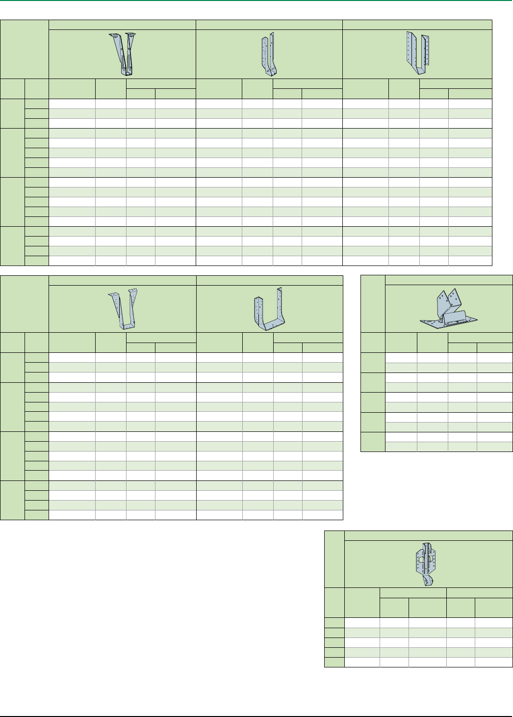
iLevel Trus Joist® TJI® Joist Specifier’s Guide TJ-4000 February 2008 23
Joist
Double Joist—Top Flange Double Joist—Face Mount(1)
Depth TJI®Hanger Capacity
(lbs)
Nailing Hanger Capacity
(lbs)
Nailing
Header Joist Header Joist
91⁄2"
110 THO35950 2,050 10d 10d x 11⁄2"THF35925 1,370 10d 10d x 11⁄2"
210 THO20950-2 2,330 16d 10d THF20925-2 1,390 10d 10d
230 THO23950-2 2,680 16d 10d THF23925-2 1,625 10d 10d
117⁄8"
110 THO35118 2,050 10d 10d x 11⁄2"THF35112 1,825 10d 10d x 11⁄2"
210 THO20118-2 2,330 16d 10d THF20112-2 1,855 10d 10d
230 THO23118-2 2,680 16d 10d THF23118-2 1,855 10d 10d
360 THO23118-2 2,770 16d 10d THF23118-2 1,855 10d 10d
560 BPH71118 3,185 16d 10d HD7120 2,240 16d 10d
14"
110 THO35140 2,100 10d 10d x 11⁄2"THF35140 2,165 10d 10d x 11⁄2"
210 THO20140-2 2,330 16d 10d THF20140-2 2,320 10d 10d
230 THO23140-2 2,680 16d 10d THF23140-2 2,435 10d 10d
360 THO23140-2 2,770 16d 10d THF23140-2 2,500 10d 10d
560 BPH7114 3,185 16d 10d HD7140 2,800 16d 10d
16"
210 THO20160-2 2,330 16d 10d THF20140-2 2,320 10d 10d
230 THO23160-2 2,680 16d 10d THF23160-2 2,435 10d 10d
360 THO23160-2 2,770 16d 10d THF23160-2 2,530 10d 10d
560 BPH7116 3,185 16d 10d HD7160 2,920 16d 10d
Joist
Single Joist—Top Flange Single Joist—Face Mount(1) Face Mount Skewed 45° Joist Hanger(1)(4)
Depth TJI®Hanger Capacity
(lbs)
Nailing Hanger Capacity
(lbs)
Nailing Hanger Capacity
(lbs)
Nailing
Header Joist Header Joist Header Joist
91⁄2"
110 THO17950 950 10d 10d x 11⁄2" THF17925 910 10d 10d x 11⁄2"SKH1720L/R 915 10d 10d x 11⁄2"
210 TFL2095 1,045 10d 10d x 11⁄2"THF20925 910 10d 10d x 11⁄2"SKH2020L/R 1,015 10d 10d x 11⁄2"
230 TFL2395 1,095 10d 10d x 11⁄2"THF23925 1,220 10d 10d x 11⁄2"SKH2320L /R 1,065 10d 10d x 11⁄2"
117⁄8"
110 THO17118 950 10d 10d x 11⁄2"THF17112 910 10d 10d x 11⁄2"SKH1720L /R 915 10d 10d x 11⁄2"
210 TFL20118 1,045 10d 10d x 11⁄2" THF20112 910 10d 10d x 11⁄2"SKH2020L /R 1,015 10d 10d x 11⁄2"
230 TFL23118 1,095 10d 10d x 11⁄2"THF23118 1,220 10d 10d x 11⁄2"SKH2320L /R 1,065 10d 10d x 11⁄2"
360 TFL23118 1,145 10d 10d x 11⁄2"THF23118 1,265 10d 10d x 11⁄2"SKH2320L /R 1,110 10d 10d x 11⁄2"
560 THO35118 1,430 10d 10d x 11⁄2"THF35112 1,460 10d 10d x 11⁄2" SKH410L /R 1,460 16d 16d
14"
110 THO17140 1,215 10d 10d x 11⁄2" THF17140 950 10d 10d x 11⁄2"SKH1720L /R 915 10d 10d x 11⁄2"
210 TFL2014 1,045 10d 10d x 11⁄2" THF20140 1,045 10d 10d x 11⁄2"SKH2020L/R 1,015 10d 10d x 11⁄2"
230 TFL2314 1,095 10d 10d x 11⁄2"THF23140 1,220 10d 10d x 11⁄2"SKH2324L /R 1,065 10d 10d x 11⁄2"
360 TFL2314 1,145 10d 10d x 11⁄2"THF23140 1,265 10d 10d x 11⁄2"SKH2324L /R 1,110 10d 10d x 11⁄2"
560 THO35140 1,430 10d 10d x 11⁄2"THF35140 1,460 10d 10d x 11⁄2" SKH414L /R 1,460 16d 16d
16"
210 TFL2016 1,045 10d 10d x 11⁄2"THF20157 1,400 10d 10d x 11⁄2"SKH2024L/R 1,015 10d 10d x 11⁄2"
230 TFL2316 1,095 10d 10d x 11⁄2"THF23160 1,220 10d 10d x 11⁄2"SKH2324L /R 1,065 10d 10d x 11⁄2"
360 TFL2316 1,145 10d 10d x 11⁄2"THF23160 1,265 10d 10d x 11⁄2"SKH2324L /R 1,110 10d 10d x 11⁄2"
560 THO35160 1,430 10d 10d x 11⁄2"THF35157 1,460 10d 10d x 11⁄2"SKH414L /R 1,460 16d 16d
Joist
Variable Slope Seat Connector(5)
TJI®Hanger Capacity
(lbs)
Nailing
Header Joist
110 TMP175 1,150 10d 10d x 11⁄2"
TMPH175 1,485 10d 10d x 11⁄2"
210 TMP21 1,290 10d 10d x 11⁄2"
TMPH21 1,565 10d 10d x 11⁄2"
230 TMP23 1,460 10d 10d x 11⁄2"
TMPH23 1,580 10d 10d x 11⁄2"
360 TMP23 1,505 10d 10d x 11⁄2"
TMPH23 1,630 10d 10d x 11⁄2"
560 TMP4 1,725 10d 10d x 11⁄2"
TMPH4 1,855 10d 10d x 11⁄2"
Joist
Variable Slope Seat Joist Hanger(1)(3)
TJI®Hanger
Capacity (lbs) Nailing
Sloped
Only
Sloped and
Skewed Header Joist
110 LSSH179 1,140 1,140 10d 10d x 11⁄2"
210 LSSH20 1,140 1,140 10d 10d x 11⁄2"
230 LSSH23 1,140 1,140 10d 10d x 11⁄2"
360 LSSH23 1,140 1,140 10d 10d x 11⁄2"
560 LSSH35 1,590 1,590 16d 10d x 11⁄2"
Support Requirements
■ Support material assumed to be iLevel® engineered lumber or sawn lumber (Douglas fir or southern
pine species).
■ Minimum support width for single- and double-joist top mount hangers is 3" (11⁄2" for ITT hangers).
■ Minimum support width for face mount hangers with 10d and 16d nails is 13⁄4" and 2", respectively.
Footnotes:
(1) Face mount hanger capacities may be increased up to 15% for snow roofs or 25% for non-snow roofs. Maximum
increase for LSSU, LSSUI, and LSSH hangers is 15%.
(2) VPA connectors are allowed on slopes of 3/12 through 12/12 only.
(3) LSSU, LSSUI and LSSH hangers can be field adjusted for slopes and skews of up to 45 degrees. Additional lateral
restraints are required for 16" deep TJI® joists.
(4) Miter cut is required at end of joist.
(5) TMP connectors are allowed on slopes of 1/12 through 6/12 only, and TMPH connectors are allowed on slopes of
6/12 through 12/12 only.
See General Notes on page 22
FRAMING CONNECTORS (USP STRUCTURAL CONNECTORS®)
February 2008
Reorder TJ-4000
FLOOR SOLUTIONSROOF SOLUTIONS
WE CAN HELP YOU BUILD SMARTER.
CONTACT US OUR GUARANTEE
At iLevel, our goal is to help you build solid and durable homes by providing high-quality residential building
products and unparalleled technical and field support.
Floors and Roofs: Start with the best framing components in the industry: our iLevel® Trus Joist® Silent Floor®
joists; TimberStrand® LSL rim board; and TimberStrand® LSL, Microllam® LVL, and Parallam® PSL headers and beams.
Pull them all together with our durable iLevel® Structurwood® roof sheathing and self-gapping Structurwood Edge®
or Structurwood Edge Gold® floor panels.
Walls: Get the best value out of your framing package—use TimberStrand® LSL studs for tall walls, kitchens,
and bathrooms, and our traditional, solid-sawn lumber everywhere else. Cut down installation time by using
TimberStrand® LSL headers for doors and windows, and our Structurwood® wall sheathing with its handy two-way
nail lines.
Software Solutions: If you are a design professional or lumber dealer, iLevel oers a full array of software packages
to help you specify individual framing members, create cut lists, manage inventories—even help you design
whole-house framing solutions. Contact your iLevel representative to find out how to get the software you need.
Technical Support: Need technical help? iLevel has one of the largest networks of engineers and sales
representatives in the business. Call us for help, and a skilled member from our team of experts will contact you
within one business day to evaluate and help solve your structural frame problems—GUARANTEED.
Weyerhaeuser, iLevel®, Microllam®, Parallam®, Silent Floor®, Structurwood®, Structurwood Edge®,
Structurwood Edge Gold®, TimberStrand®, TJ®, TJ-Beam®, TJI®, TJ-Xpert®, and Trus Joist® are registered
trademarks, and All in One™, Performance Tested™, and TJ-Pro™ are trademarks of Weyerhaeuser.
© 2008 Weyerhaeuser Company. All rights reserved. Printed in the USA.
This document supersedes all
previous versions. If this is more
than one year old, contact your
dealer or iLevel rep.
NW
1.888.iLevel8 (1.888.453.8358)
www.iLevel.com
iLevel@weyerhaeuser.com
2910 East Amity Road
Boise, ID 83716
208.364.3600
P.O. Box 8449
Boise, ID 83707-2449
