TM 1146_Augmented_Satellite_Control_Facility_System_Description_Apr63 1146 Augmented Satellite Control Facility System Description Apr63
TM-1146_Augmented_Satellite_Control_Facility_System_Description_Apr63 TM-1146_Augmented_Satellite_Control_Facility_System_Description_Apr63
User Manual: TM-1146_Augmented_Satellite_Control_Facility_System_Description_Apr63
Open the PDF directly: View PDF ![]() .
.
Page Count: 100
UNCLASSIFLED
AD
404
800
DEFENSE
DOCUMENTATION
CENTER
FOR
SCIENTIFIC
AND
IECHNICAL
INFORMATION
CAMERON
STATION.
ALEXANDRIA.
VIRGINIA
UNCLASSIFIED
NOTICE:
When
government
or
other
drawings,
speci-
fications
or
other
data
are
used
for
any
purpose
other
than
in
connection
with
a
definitely
related
government
procurement
operation,
the
U.
S.
Government
thereby incurs
no
responsibility,
nor
any
obligation
whatsoever;
and
the
fact
that
the
Govern-
ment
may
have
formulated,
furnished,
or
in
any
way
supplied
the
said
drawings,
specifications,
or
other
data
is
not
to
be
regarded
by
implication
or
other-
wise
as
in
any
manner
licensing
the
holder
or
any
other
person
or corporation, or
conveying
any
rights
or
permission
to
manufacture,
use
or
sell
any
patented invention
that
may
in
any
way
be
related
thereto.
IC
TM-1146/000
00
Augmented
Satellite
Control
Facility
System
Description
I A 9;!
1q'
TM-11l6/ooo/oo
(TM
Series)
DDCf
AVAILABILITY
NOTICE
Qualified requesters
Tay
obtain
copies
of
this
report
from
DDC.
this
document
was
produced
by
SOC
in
performance
of
contract
AF
19(628)
-16kG8,
Space
Systems
Division
Progrwm,
for
Spaoe
Syýtems
DivLsion,
AFSC.
Augmenited
Satellite
Control
Fneility
SYSTEM
System
Description
DEVELOPMENT
by
CORPORATION
1
April
1963
2500
COLORADO AVE.
Approved
SANTA
MONICA
R.
D.
Knight
CALIFORNIA
The
views,
conciusions
or
recommendations
expressed
in
this
document
do
not
neces-
sarily
reflect
the
official views
or
policies
of
agencies
of
the
United
States
Cuvernment.
Permission
to
quote
from
this
document
orto
reproduce
it,
wholly
or
in
part,
should
be
obtained
in
advance
from
the
System
Development
Corporation.
Although
this
document
contains
no
classified
information
it
has
not
been
cleared
for
open
publication
by
the
Department
of
Defense-
Open
publication,
wholly
or
in
pail,
is
prohibited
without
the
prior
approval
df
the System
Development
Corporation-
1
April
1963
21
nl146/O00/oO
SJMARY
This
description
of
the
Augmented
Satellite
Control
Facility
(SCF)
is
approached
from
two
points
of
view:
first,
the
equipment
subsystems
are
described
in
terms
of
their
capabilities,
functions,
and
primary
usages;
second,
the
principal
activities
performed
by
the
SCF;
i.e.,
telemetry,
tracking,
commanding,
and
scheduling
arŽ•
explained
in
such
a
way
that the
previously
described
equipments
are
tied
together
into
systems,
with
emphasis
on
the
functional
aspects
of
SCF
operations.
The
SCF
is
composed
of
a
central
control
station
called
the
Satellite
Test
Center
(STC)
and
six
remote
tracking
stations,
three
of
which
have
limited
dual
capability.
Mhe
STC
is
equipped
to
support
six
satellites
simultaneously.
Its
data
processing
subsystems
are divided
into
two
main
functional
groupings:
one,
the
"Bird
Buffer
complex,"
is
vehicle
oriented,
and
has
eight
CDC
160A
computers, each
of
which
can
be
individually
assigned
to
an
active
satellite
as
a
buffer;
the
other
grouping
is
the
off-line-computer
complex,
which
uses
four
CDC
1604
computers
to
do
the
main
computational
chores
for
the
system.
To
achieve
flexibility
of
operation
and
rapid
reconfiguration,
computer-
controlled
switching
units
are
used
to
interconnect
the
Bird
Buffers
with
the
off-line
computers
on
one
side,
and
with
the
tracking
stations
on
the
other.
The
three
dual
tracking
stations
are
capable
of
supporting
certain
com-
binations
of
two
satellites
simultaneously.
Each
tracking
station
has
three
main
equipment
groupings:
1.
Antenna
subsystems--these
subsystems
are
in
closest
contact
with
the
orbiting
vehicles
and
provide
the
communication
links
between
the vehicles
and
the
ground.
2.
Data
Processing
subsystem--tnis
subsystem,
which
interfaces
with
the
STC
via
data
link,
is
made
up
of
two
CDC
160A
computers
and
their
peripheral
equipment.
The
two
computers,
one
for
telemetry
and
one
for
tracking
and
commanding,
process
data
sent
to
and from
the
STC.
3.
Telemetry,
Tracking,
and
Command
subsystems--these
subsystems
transform
telemetry,
tracking,
and
commanding
data
from
the
Antenna
subsystems
into
a
form
suitable
for
the
Data
Processing
subsystem,
and
vice versa.
The
above
three
equipment
groupings
are
connected
together
by
manual
patchboards
to
give
tracking
stattons
a
flexibility
and
reconfiguration
capability
ap-
proaching
that
of
the
STC.
The
tracking,
telemetry,
and
commanding
functions
are
initiated
by
a
prepass
message,
which
is
sent
to
the
tracking
station
by
the
STC.
This
message
1
April
1963
2
UM-1I,46/000/00
contains
the
satellite
acquisition
data for
the
antennas,
the
telemetry
mode
configuration,
and
the
command
data
to
be
sent
to
the
satellite.
Upon
acquisition,
tracking
data
are
sent
to
the
STC
for
orbit
determination,
and
selected
telemetry
data
points
are
processed
and
sent
to
the
STC
in
real
time.
Commands
are
initiated
at
the
tracking
station
in
accordance
with
the
instructions
received
from
the
STC,
and
a
record
of
all
commands
sent
to
the
satellite
is
returned
to
the
STC.
Commands
may
be
initiated
from
the
STC
in
real
time
and
telemetry
mode
changes
may
be
made
during
a
pass.
The
functions
of
the
STC
and
the
tracking
stations
are
performed
in
accordance
with
a
master
schedule.
This
schedule,
prepared
by
a
1604
computer
program
called
SCHOPS,
with
inputs
from
the Multi-ops
personnel,
takes
into
account
the
contact
times
of
each
active
vehicle
with
each
station,
the
priorities
of
each
vehicle,
the
system
resources,
and
other
pertinent
information
that.
affects
the
operating
schedule.
These
data
are
processed
to
predict
con-
flicting
demands
on
system
facilities.
The
conflicts
are
resolved
by
preset
priorities
or
by manual
intervention,
and
a
schedule
is
output
detailing
the
usage
of
system
resources.
Also
part
of
the
output
is a
schedule
tape
for
driving the
Switch
Control
Computer
at
the
STC5,
which
causes
switches
to
connect
and
disconnect
the
various
subsystems
at
the
times
dictated
by
the
schedule.
Tracking
station
subsystems
are
connected
and
disconnected
manually
at
the
times
specified
by
the
schedule.
1
April
1963
3
T-lih6/ooo/Oo
FOREWORD
A
need
has
been
recognized
for
a
single-document
source
that
describes
the
end
products
of
the
Augmentation
Program
in
sufficient
detail
to
be
of
interest
to
all
the
diverse
technical
groups
working
on
the
program.
Such
a
treatise
should
be
useful
in
presenting
a
more
complete
picture
to
those
workers
who
are
necessarily
engrossed
in
the minutiae
of
their
daily tasks.
It
should
also
be
of
value
to
those
who
have
a
need
for
a
general
under-
standing
of
the
overall
effort
without
becomming
excessively
involved
in
the
details
of
the
program.
This
document
attempts
to
fill
this
need.
In
preparing
this
document,
the
author
has
borrowed
heavily
from
many
of
the
sources
listed
in
the bibliography.
In
many
cases
whole
sections
were
lifted
intact,
as
were
drawings
and
charts.
The
document
therefore
reflects
the
efforts
of
many
individuals.
The
system
described
herein
is
the
system
that
was
planned
as
of
shortly
before
the
publication
date
of
this
document.
In
a
fast-moving
program
of
this
type,
changes
are
inevitable
and
the
probability
is
high
that
this
document
will
have
already
become
obsolete
in
some
respects
before
reaching
the
hands
of
the reader.
It is
not
planned
to
keep
this
document
current;
rather,
it is
believed
that
its
purpose
will
have
been
achieved
if it
conveys
a
general
understanding
of
the
Augmented
SCF,
its
equipment
functions,
and
its
philosophy
of
operation.

1
Apr1l
1963
4
Tm-
1146/ooo/oo
TABLE OF
CONTENTS
St.umaary-
i
F,,-
............ ,. *...,....c ... eta.,....,oc.....o.,....,..*c..,
1.0
Introduction
....
.......................................... 7
2.0
SCF
Equipment
......................
........................
9
2.1
STC
Equipment
.........................................
.. 9
2.1.1
Bird
Buffer
Subsystems0............
*
*.......... ..... 10
2.1.2
CDC
1604
ComputerSubsystems.........................
18
2.1.3
Communication
Data
Select
&
Cross
Connect
Unit
and
Computer
Select
&
Cross
Connect
Unit
..........
20
2.1.4
CDC
16OA
Switch
ControlComputer.................
21
2.1.5
Master
Data
ControlConsole.......................
22
2.1.6
CDC
1604
Computer
.................. .............
23
2,
2.7
CDC
160A
Computer
.... ............ ..... .........
24
2.1.8
CDC
1615
Magnetic
Tape
Unit.......... ..............
25
2.
1 .
9
CDC
166
Line
Printer
..................
....
.......
26
2.1,10
CDC
3612
Line
Printer
......
....
c cct c
.cc
26
2.1.11
CDC
163
Magnetic
Tape
Unit
........................
26
2.1.12
CDC
169
Awuiliary
Memory
Unit
........................
26
2.1.13
CDC
161
Typewriter
Unit
...........................*cc
27
2.2
Tracking
Station
Equipment
...........................
28
2.2.1
Antenna Subsystems
......
cc.c..sccccccc..
.
.....
ccc.
31
2.2.1.1
Verlort
Radar
..........
c...
c...c......c........
31
2.2.1.
2
Prelort
Radar
......... cc...
cc.c.c..
c......
c.
32
2.2.1.3
Telemetry
and Data
(T&D)
Antenna
........ ...
32
2.2.1.4
TLM-18
TelemetryAntenna..
......... ......
32
2.2.1-5
Diac-On-Rod
(DOR)
Antenna
.......
cc.c.t.acc..
34
2.2.1.6
Tri-Helix
Antenna
..................... *.c..c..cc.
34
2.2.2
Telemetry,
Tracking,
and
Ocananding
Subsystems
..........
35
2.2.2.1
FM/FM
Ground
Station
........
ccoot*cc....o.
35
2.2.2.2
PCM
Ground
Station
.......... .c............a.......cc
36
2.2.2.3
GP-1
Ground
Station
........ . .....c..*c.
37
2.2.2.4
400-me
Receiving/Commanding
Equipment................
39
2.2c3
Data
Processing
Subsystem
...............................
39
2.2.3.1
Tracking
and
Cormand
Computer
Subsystem
(T&C)
........
40
2.2.3.2
Telemetry
Computer
Subsystem
(TIM)
..................
42
2.2.3.3
Input/Output
Buffer
(IOB)
..................
o....c....
43
2.2.3.4
Telemetry
Data
Processor
(TDP)
.......................
44
2.2.3:5
Command
Logic
Equipment
(CLE)
........................
44
2.2.3.6
Station
Operator's
Console
(SOC)
.....................
46
1
April
1963
5
TM-1146/O00/O0
TABLE
OF
CONTENS
(Conttd)
2.3
Communication
Equipment
..................................
60
2.3.1
Computer
Communications
Converter
(CCC)
...............
60
2.3.2
Modulator
and
Demodulator
Terminal
Equipment
(MODEM)..
61
2.3.3
IM-13
Cryptographic
Machine
...........................
62
2.3.4
Automatic
Resynchronizing
Equipment
(Auto-Resync).....
62
3.0
Tracking
Functional
Description
.............................
64
3.
1
General
.................................................
64
3.2
Prepass
Message
..........................................
64
3.3
Acquisition
.............................................
64
3.4
Track
History
...........................................
65
4.0
Telemetry
Functional
Description
............................
66
4.1
iGeneral ..................................................
66
4.2
STA
Telemetry
Processing
Outputs
.........................
66
4.2.1
Preflight
Mode
........................................
66
4.2.2
Prepass
Mode
.........................................
67
h.2.3
Real
Time
Telemetry
Processing
Mode
...................
67
4.3
Telemetry
Modules
at
the
STC
.............................
68
4.4
Data
Flow
at
the
Tracking
Station
........................
68
4.5
Data
Flow
at
the
STC
....................................
71
4.6
Telemetry
Operational
Program
(TLMOP)
....................
71
5.0
Commanding
Functional
Description
..........................
73
5.1
General
....
.......................................... .
73
5.2
Analog
Commanding--Manual
Mode..........................75
5.3
Analog
Commanding--Computer
Automatic
Mode
...............
76
5.4
Digital
Commanding--Manual
Mode
..........................
77
5.5
Digital
Commanding--Computer
Automatic
Mode..............
79
5.6
Stored-Program
Commands
.................................
79
5.7
Real-Time
Commands
........... ......................
83
5.8
Command
History
.........................................
85
6.0
Scheduling
Functional
Description
.........................
87
6.1
General
.................................................
87
6.2
Input
Processing
Module
..................................
88
6.3
Conflict
Prediction
Module
...............................
88
6.4
Conflict
Resolution
Module
..............................
89
6.5
Resources
Allocation
Module
.............................
89
6.6
Launch
Planning
Module
.................................
90
6.7'
Output
Processing
Module
.................................
90
6.8
Simulation
and
Data
Reduction
Module
.....................
91
6.9
Control
Module
........................................... ()
References
.............................................................
93
1
April
1963
6
xm-li46/Ooo/oo
LIST
OF
ILLUSTRATIONS
Figure
Page
1
Locations
of
Augmented
SCF
Tracking
Stations
8
2
STC
Equipment
Block
Diagram
11
3
STC
Control
Area
Layout
13
4
Typical
Augmented
Tracking
Station
Block
Diagram
29
5
Augmented
Tracking
Stations
Equipment
Configurations
33
6
Station
Operator's
Console
(SoC)
47
7 SOC--Antenna
Controller
Section
49
8
SOC--Command
Controller
Section
51
9
SOC--Shift
Supervisor
Section
57
10
Augmented
SCF
Telemetry Data
Flow
69
11
Analog
Pulse
Modulation
Scheme
74
12
Command
Message
Preparation--Inputs
and
Outputs
81
13
Transfer
of
Ctlimand
Message
from
the
1604
to
the
82
Bird
Buffer
14
Transfer
of
Command
Message
frco
Bird
Buffer
to
84
T&C
Computer
at
Tracking
Station
1
April
1963
7
-lJ46/000/00
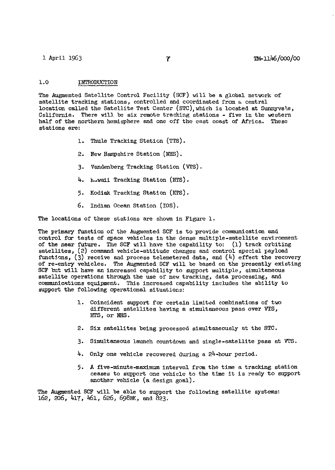
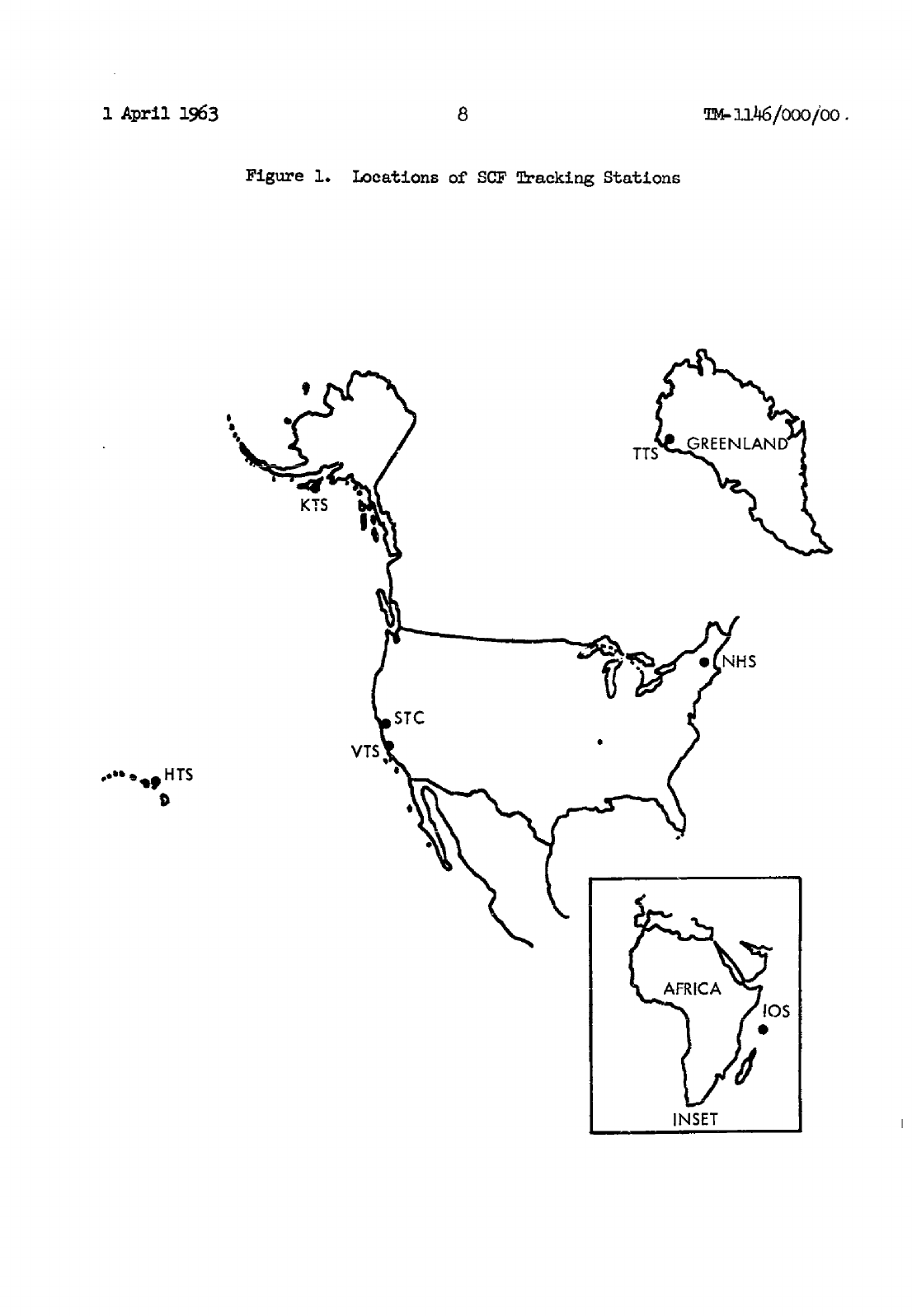
1.0 INTRODUCTION
The
Augmented
Satellite
Control
Facility
(SCF)
will
be
a
global
network
of
satellite
tracking
stations,
controlled
and
coordinated
from
E
central
location called
the
Satellite
Test
Center
(STC),which
is
located
at
Sunnyvale,
California.
There
will
be
six
remote
tracking
stations
-
five
in
the
western
half
of
the
northern
hemisphere
and
one
off
the
east
coast
of
Africa.
These
stations
are:
1.
Thule
Tracking
Station
(TTS).
2.
New
Hampshire
Station
(NHS).
3.
Vandenberg
Tracking
Station
(VTS).
4.
h.waii
Tracking
Station
(HTS).
5.
Kodiak
Tracking
Station
(KTS).
6.
Indian
Ocean
Station
(IOS).
The
locations
of
these
stations
are
shown
in
Figure
1.
The
primary
function
of
the
Augmented
SCF
is
to
provide
communication
and
control
for
tests
of
space
vehicles
in
the
dense
multiple-satellite
environment
of
the
near
future.
The
SCF
will
have
the
capability
to:
(1)
track
orbiting
satellites,
(2)
command
vehicle-attitude
changes
and
control special
payload
functions,
(3)
receive
and
process
telemetered
data,
and
(4)
effect
the
recovery
of
re-entry
vehicles.
The
Augmented
SCF
will
be
based
on
the
presently
existing
SCF
but
will
have
an
increased
capability
to
support
multiple,
simultaneous
satellite
operations
through
the
use
of
new
tracking,
data
processing,
and
communications
equipment.
This
increased
capability
includes
the
ability
to
support
the
following
operational
situations:
1.
Coincident
support
for
certain
limited
combinations
of
two
different
satellites
having
a
simultaneous
pass
over
VTS,
HTS,
or
NBS.
2.
Six
satellites
being
processed
simultaneously
at
the
STCo
3.
Simultaneous launch
countdown and
single-satellite
pass
at
VTS.
4.
Only
one
vehicle
recovered
during
a
24-hour
period.
5.
A
five-minute-maximum
interval
from
the
time
a
tracking
station
ceases
to
support
one
vehicle
to
the
time
it is
ready
to
support
another
vehicle
(a
design
goal).
The
Augmented
SCF
will
be
able
to
support
the
following
satellite
systems:
162,
2o6, 417,
461,
626,
698BK,
and
823.
1
April
1963
8
TM-inh6/ooo/oo.
Figure
1.
Locations
of
SCF
Tracking
Stations
,S
GREENLAND
KTS
..
'
.,K
HTS
AFRICA
INSET
I
Aycil
1963
9
TM-i146/0oo/oo
2M0
SCF
EQUIPMEVT
2.1
STC
EQUIPMENT
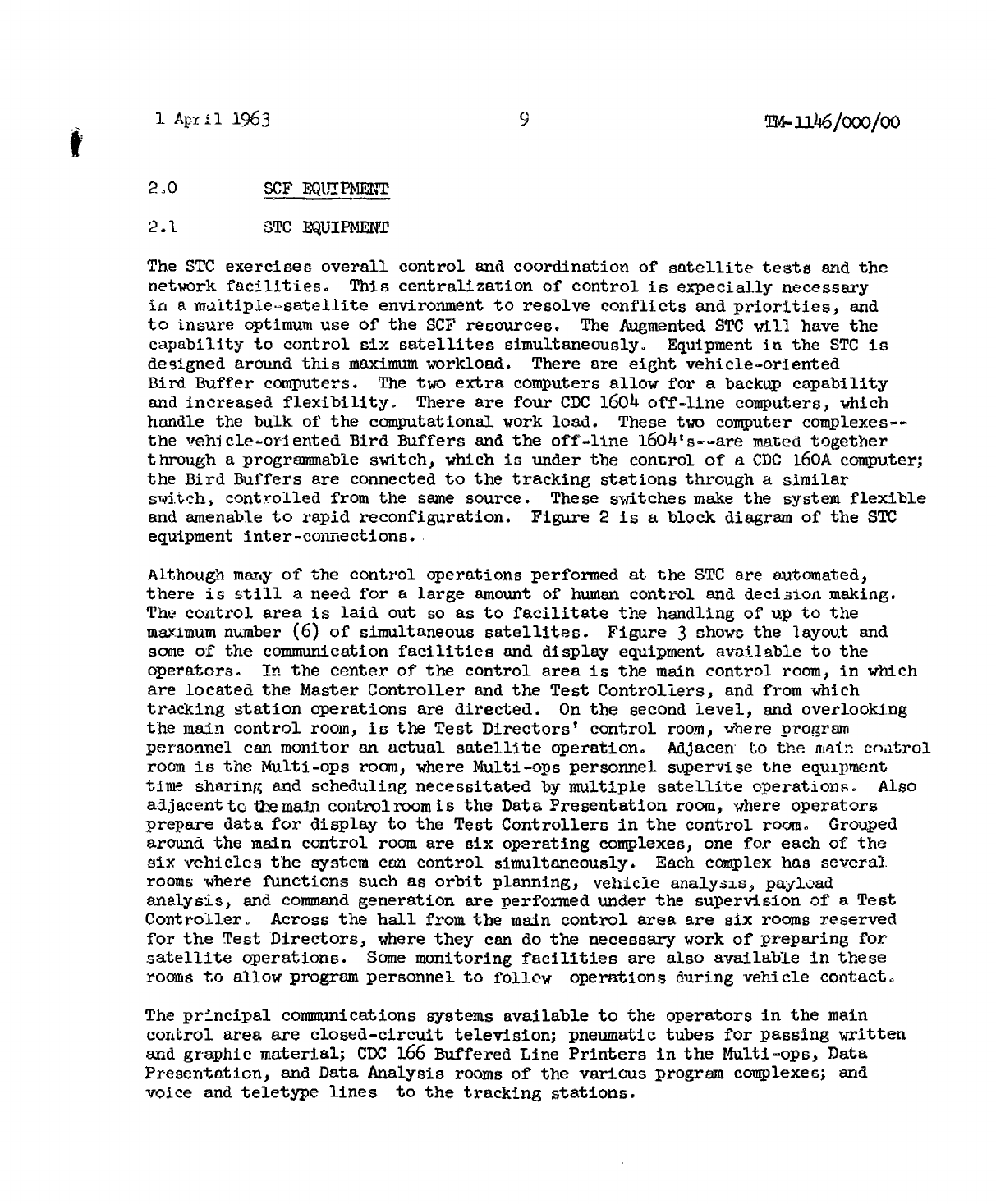
The
STC
exercises
overall
control
and
coordination
of
satellite
tests
and
the
network
facilities.
This
centralization
of
control
is
expecially
necessary
in
a
multiple
-satellite
environment
to
resolve
conflicts
and
priorities,
and
to
insure
optimum
use
of
the
SCF
resources.
The
Augmented
STC
will
have
the
capability
to
control
six
satellites
simultaneously.
Equipment
in
the
STC
is
designed
around
this
maximum
workload.
There
are
eight
vehicle-oriented
Bird
Buffer
computers.
The
two
extra
computers
allow
for
a
backup
capability
and
increased
flexibility.
There
are
four
CDC
1604
off-line
computers,
which
handle
the
bulk
of
the
computational
work
load.
These
two
computer
complexes--
the
vehicle-oriented
Bird
Buffers
and
the
off-line
16
04's--are
mated
together
through
a
programmable
switch,
which
is
under
the control
of
a
CDC
160A
computer;
the
Bird
Buffers
are
connected
to
the
tracking
stations
through
a
similar
s4telh,
controlled
from
the
same
source.
These
switches
make
the
system
flexible
and amenable
to
rapid
reconfiguration.
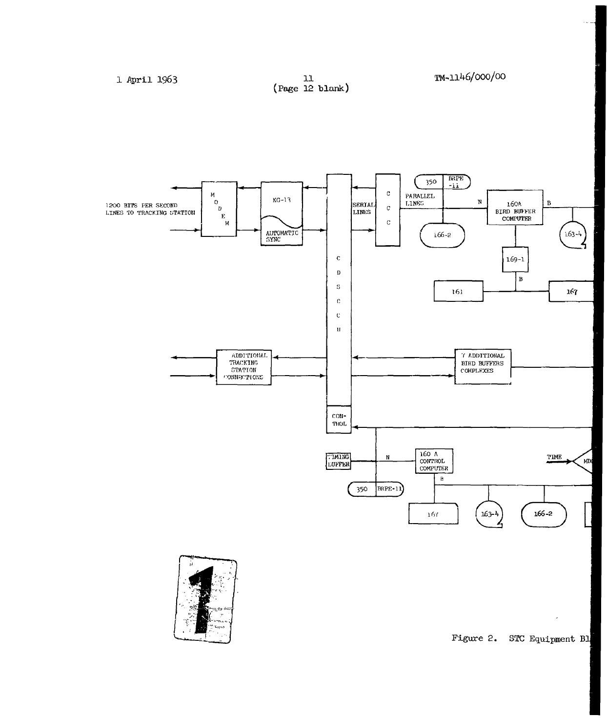
Figure
2
is a
block
diagram
of
the
STC
equipment
inter-connections.
Although
many
of
the
control
operations
performed
at
the
STC
are
automated,
there
is still a
need
for
a
large
amount
of
human
control
and
decision
making.
The
control
area
is
laid
out
so
as
to
facilitate
the
handling of
up
to
the
maximum
number
(6)
of
simultaneous
satellites.
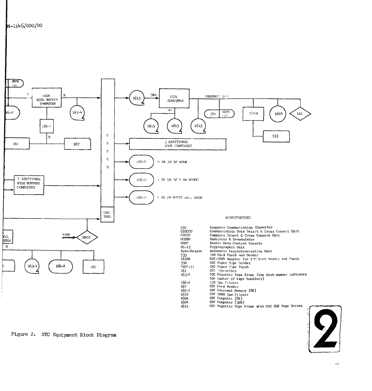
Figure
3
shows
the
layout
and
same
of
the
communication
facilities
and
display
equipment
available
to
the
operators.
In
the center
of
the
control
area
is
the
main
control
room,
in
which
are
located
the
Master
Controller
and
the
Test
Controllers,
and
from
which
tracking
station
operations
are
directed.
On
the
second
level,
and
overlooking
the
main
control
room,
is
the
Test
Directors'
control
room,
ihere
program
personnel
can
monitor
an
actual
satellite
operation.
AdJacen-
to
the
main
control
room
is
the
Multi-ops
room,
where
Multi-ops
personnel supervise
the
equipment
time
sharing
and
scheduling
necessitated
by
multiple
satellite
operations.
Also
adjacentto
tte
main
controlroomis
the
Data
Presentation
room,
where
operators
prepare
data
for
display
to
the
Test
Controllers
in
the
control
room.
Grouped
around
the
main
control
room
are
six
operating
complexes,
one
for
each
of
the
six
vehicles
the
system
can
control
simultaneously.
Each
complex
has
several
rooms
where
functions
such
as
orbit
planning,
vehicle
analysis,
payload
analysis,
and
command
generation
are
performed under
the
supervision
of
a
Test
Controller.
Across
the
hall
from
the
main
control
area
are
six
rooms
reserved
for
the
Test
Directors,
where
they
can
do
the
necessary
work
of
preparing
for
satellite
operations.
Some
monitoring
facilities
are
also
available
in
these
rooms
to
allow
program
personnel
to
follow
operations
during
vehicle
contact.
The
principal
communications
systems
available
to
the
operators
in
the
main
control
area
are
closed-circuit
television;
pneumatic
tubes
for
passing
written
and
graphic
material;
CDC
166
Buffered
Line
Printers
in
the
Multi-ops,
Data
Presentation,
and
Data
Analysis
rooms
of
the
various
program
complexes;
and
voice
and
teletype
lines
to
the
tracking
stations.
1
April
1963
10
TM-1i46/O00/o0
The
principal
equipment
subsystems
at
the
STC
are
discussed
in
more
detail
in
Sections
2.1.1
through
2.1.13
below,
2.1.1
Bird
Buffer
Subsystem.
The
Bird
Buffer
subsystem
acts
as
a
buffer
between
the
tracking
stations
and
the
STC
complex
of
test
personnel
and
the
CDC
1604
off-line
computers.
It
operates
iln
two
modes:
Non-Real-
Time
and
Real-Time.
The
Real-Time
mode
is in
effect
when
the
tracking
station
is in
contact
with
a
vehicle;
at
that
time,
commanaing,
tracking,
and
telemetry
data
are
passed
between
the
Bird
Buffer,
the
tracking
station,
and
the
vehicle
in
real
time.
The
Non-Real-Time
mode
is
entered
when
there
is
no
vehicle
con-
tact;
it is
used
to
send
prepass
data
to
the
tracking
stations
and
to
pass
data
to
and
from
the
1604
computers.
The
Bird
Buffer
program
is
made
up
of
seven
modules,
whose
specific
functions
are
as
follows:*
1.
Executive
Control
Module
(SXCON)--SXCON
determines
the
operating
sequence
of
the
various
programs,
effects
data
transfers,
and
transmits
system
outputs
to
the
proper
equipment.
2.
Command
Module
(SCOMD)--SCOMD
has
three
primary
functions:
a.
Special
verification
of
command
transmission
to
the
tracking
stations
(explained
in
detail
in
Section
5.0).
b.
Processing
and
printout
of
real-time
command
status
reports.
c.
Postpass
printout
of
command
history.
3.
Prepass
Module
(SPREP)--SPREP
has
four
functions:
a. It
maintains
an
updated
prepass
tape
with
TLM
processing
tables,
command
messages,
antenna
pointing data,
scheduling
messages,
and
text.
b.
Upon
request,
it
sends
the
prepass
data
to
the
tracking
station,
verifies
the
messages
sent,
and
keeps
an
account
of
all
data
received
by
the
station.
c.
When
a
change
in
TLM
mode
is
requested,
it
reads
in
the
appropriate
TEEM
proccasing
table
from
the
first
files
of
the
prepass
tape.
d.
Before
the
start
of
a
pass,
it
writes
on
the
recording
tape
the prepass
information
that
the
station
has
received
for
the
coming
pass.
*
For
a
more
detailed
description,
sce
Reference
4.
1
April
1963
11
TM-1146/000/O0
(Page
12
blank)
1200
BITS
FER
SECOND S
RAL
PARLLEL
N B
D SEIL C
LNS
LINES
'10
TRACKING
5)TATTI0UIN
BIRD
BUFFER
C
169-1
D *B
161
167
C
C
II
AtDDITIONAL
-r
7ADDITIONAL
TRA.CKING
BIRD
BUFFERS
TATOO1PEXES
F,
:14
N
160
A
TIME
iCONTRO
LUFgr .SECOMmPUTER
3=50 I)P-1
iiFigure
2.
STO
Equipment
B
-i
•4-ii.46/000/00
I
160A
B
6
W
I604
CIURITf;
i.
BIRD
BUFFER
CO)MPUT1ER 1
61
6-2
3=
1661A 61-P<16
169-i
6511
B
04
CC•4LEXES
C
C 6D 1,
VA
IN
DP
HOW
U
Y ADDITIONAL =6- 1 It! !,!A
1F
(- DA
RO(W4
BIRD
BUIWFRS
COMPLEXES S1~~
IA
S 1-"! .':T
,)p;;.
1l0(.4
CON"-
TROL
Ai-HIEVIATIONM
CCC
Co"'puter
Conmunication
Converter
CDSCCU
Communication
Data
Select
&
Cross
Connect
Unit
CSCCU
Computer
Select
&
Cross
Connect
Unit
I M.r.A .
Modulator
&
Demodulator
IDCC
Master Deta
Control
Console
BG-13
Cryptographic
Unit
Auto-Resync Automatic
henv-nchronlzation
Unit
533
IBM1
Card Punch and
Reader
1610A
CDC-1604
Adaptor
for
1I'l
Crd
Reader
and
Punch
350
CDC
Paper
Tope
neader
66i
1RPF-11
CDS
Paper
Thpe
Punch
161
CD,
'1M•wite
r
163-h
CDC I
apnetlc
Tape
Freme
(the
dash
number
indicates
tie
numler
of
tope
handlers)
166-2
150
Ipw.
Pr
Inter
167
CDC
Card
Reader
169-1
CBC
External
Memory
(8K)
1612
CDC
1000
ipm
Printer
160A
CDC
Computer
(18K)
16oh
CDC
Computer
(32K)
1615
CBIS
TM
agnetic
Tape Frame
w.ith CDC5
606
Tape
Driven
Figure
2.
STO
Equipment
Block
Diagram
1
1
April
1963
13
Tm-iJA6/ooo/oo
LUMvI
t
I
LUHPILA?
I
K t
COW
ANo ORRt O.t. ORV
r ml r ULANIN
[InJ .-
jJ
DAtA i-
GEI
W0 UY
I
L
]aG
[10 001
--L
QP~JII
II....))~
AIEtoo.I
-' SIRCTO
=3
CIO
IOW
lADCOMPLEX
5M
00DIkECION
AALY jJ>I
L
I
Q(ýA(
EDO, SECOND
1Too0
WI001.
LEGEND M1ARCNOEA
O M
-
SL
E -NTAPG
%sYSIT
1.ELE PITAT E J
I
ENE(-,DK TUPE
TItATE
ToECCts
CoN TRat
00o.'
Figure
3.
STO
Control
Area
Layout
1
April
1963
ik
m-iik6/c0oo/oo
4.
Telemetry
Processing
Modujle
(STEPP)...STEPP
accepts
telemetry
data
frcn
the
tracking
station,
performs
the
necessary
con-
versions
to
engineering
units,
perpares
one
set
of
selected
data
for
printout
on
the
Data
Analysis
printer
and
a
different
set
for
printout
on
the
Data
Presentation
printer,
and
prepares,
for
printout,
any
alarms
or
status
messages
generaLed
by
the
TIM
computer
at
che
tracking
station.
5.
Tracking
Module
(STRAK).--STRAK
has
three
functions:
a.
During
a
pass,
it
accepts
track
data
from
a
tracking
station
at
the
rate
of
one
message
per
second,
formats
'the
data
for
printout,
and
sets
flags
so
the
data
will
be
printed
out
on
the
Data
Presentation
and
Data
Analysis
printers.
b.
On
request
from
the
1.604
computer,
it
searches
the
re-
cording
tape
for
the
requested
tracking data,
reads
it
into
core,
and
uses
the
crnunications
subroutine
SIBBTC
to
trans-
fer
it
to
the
1604.
This
operation
is
accomplished
in
the
post-pass
mode.
c.
STRAK
will
print
out
alarm
and
status
messages
which
are
con-
cerned
with
tracking
and
are
received
from
the
remote
site's
T&C
computer.
These
will
consist
of
text
messages
and
will
be
transferred
to
the
Data
Analysis
and
Data
Presentation
printers
as
specified.
6.
Communication
Module
(SIBBTC)-.
SIBIITC
enables
the
Bird
Buffer
to
comr-unicate
with
th
1±60h
computer
on
a
core-to-core
basis,
using
the
direct transfer
mode
of
the
1615
tape
units.
Five
types
of
transfers
are
ef
coted
by
SIBBTC:
a. It
receives
prepass
messages
containing
antenna
pointing,
commands,
scheduling,
and
text
information. All
messages
are
checksumamed
and
the
comnand
messages
are
retransmitted
to
the
1604
computer
for
bit-by-bit
verification.
b.
It
receives
commands
from
the
1604
computers
for
real-time
transmission
to
the
vehicle
via
the
T&C
computer.
Each
message
is
retransmitted
to
the
1604
computer
for
bit-by-bit
verification.
c.
It
transfers
vehicle-time
and
tracking
data
to
the
1604
computer.
These
data
arc
verified
for
correctness
by
the
i6o4,
with
a
response
back
to
the
Birt
Buffer.
d.
A
"last
Operation
Complete"
control
message
is
sent
by
SIBBTC
after
the
last
block
of
tracking
data
has
been
sent.
'lint
function
is
called
for
by
the
user
program
and
is
not
a
decision
of
SIBBTCo

1
April
1963
15
Mrs-11.46/000/00
e.
SCHOPS
data
are
sent
by
the
1604
to
the
Bird Buffer
and
SIBBTC
responds
as
to
the
correctness of
the
data.
7.
Input
Processing
Module
(SPROC)--SPROC
interprets
control
card
inputs
and
causes
the appropriate
actions
to
be
taken
by
the
Bird
Buffer
modules.
The
card-input
requests
and
the
SPROC
response
to
each
request
are
as
follows:
a.
Initialize--The
Bird
Buffer
will
identify
with
the
vehicle
number
contained
on
the
card;
tapes
will
be rewound,
system
flags set
to
zero,
and
system
buffers
initialized.
b.
Transfer
TRK--SPROC
reads
the
requested
tracking
data
from
the
163
tape,
interrupts
the
1604,
and
transfers
the
data
core
to
core.
c.
Transfer
Prepass--SPROC
interrupts
the
1604
and
requests
the
prepass
data.
Each
message
is
checksummed
and
stored
on
the
163
tape.
d.
Command
History--SPROC
searches
the
163
for
the
specified
pass
and
prints
out,
on
the
designated
printers,
all
commands
given
and
operational
report
messages
received
during
this
pass.
e.
Merge
Tape--SPROC
finds
the
telemetry
mode
tables
on
tape,
as
specified
on
this
card,
and
merges
them
onto
the
first
part
of
the
prepass
tape.
f.
Contact
Site--A
"Hello,
STC
to
Site"
message
is
flagged
to
send
to
the
tracking
station.
g.
Send Prepass--SPROC
reads
the
prepass
data
into
core
and
flags
it
for
transmission
to
the
tracking
station.
h.
Transfer
Card
Prepass--SPROC
reads
prepass
data
from
the
cards
and
writes
it
on
a
163
tape
in
the
proper
format
for
transmission
to the
tracking
station.
i.
Transfer
SCHOPS--An
interrupt
and
request
for
a
tracking
station's
scheduling
data
is
sent
to
the
1604
computer.
Transfer
is
core
to
core
and
recording
on
the
163
tape
is
in
the
same
format
in
which
it is
received.
1
April
1963
16
24-fL46/000/00
J.
Restart--This
card,
followed
by
an
initialize
card,
causes
the
Bird
Buffer
to
be
re-initialized.
k.
Change
TRK
Rate--The
new
rate
data
on
the
card
are
assembled,
a
check
sum
is
calculated,
and
a
flag
is
set
for
transmission
to
the
TOC
computer.
1.
Request
Commands--SPROC
interrupts
and
request
commands
from
the
1604.
Commands
sent
are
verified
by
retransmission,
then
flagged
to
be
sent
immediately
to
the
tracking
station.
No
format
change
is
made
and
the
Bird
Buffer
does
not
accept
a
second
64-word
command
message
until
the
first
message
has
been
sent
to
the
tracking
station
and
verified.
m.
Send
Comiand-.SPROC
assembles
the
command
message
from
the
card input,
calculates
a
checksum,
and
flags
the
message
for
transmission
to
the
tracking
station.
n.
Send
Text--SPROC
assembles
the
text
message
from
the
card
input,
computes
a
checksum,
and
flags
it
for
transmission
to
the
tracking
station.
It
also
flags
the
message
for
printout
on
any
of
the
166
printers
designated.
o.
Select
or
Modify
TLM
Mode--SPROC
assembles
the
now
parameters,
computes
a
checksum,
anm
sets
a
flag for
trans-
mission
of
the
message
to
;he
tracking
station.
If
a
new
mode
is
requested,
SPROC
inputs
the
new
mode
tables
from
the
prepass
tape.
p.
Suppress
TRK
Printout--Periodic
printout
of
vehicle
time
and
tracking
data
is
halted
until
a
"Re-initiate
TRK
Printout"
card
is
inserted.
The
data
flow
to the
163
tape
is
not
interrupted.
q.
Re-initiate
TRK
Printout--This
card
restarts
the
printout
of
tracking
data
on
the
166
printers.
r.
END--This
notifies
SPROC
of
the
end
of
an
input
which
is
contained
on
more
than
one
card.
All
cards
following
the
end
card
are
disregarded
until
another
control
card
is
encountered.
0
1
April
1963
17
TM-iI46/ooo/Oo
A
Bird
Buffer
subsystem
consists
of
the
following
equipment
(see
Figure
2).
1.
One
CDC
160A
computer.
2.
One
CDC
169-1
auxiliary
memory,
which
gives
a
total
high-speed
core-memory
capability
of
16,384
twelve-bit
words.
3.
One
160A-P
phantom
resume, which
gives
a
response
to
the
160A
when
an
equipment
selected
by
it is
not
available
0 It is
mounted
on
the
CDC-161
typewriter.
4.
One
160
A-D
amplifier
unit.
This
is a
set
of
line
amplifiers,
which
enable
the
160A
computer
to
drive
equipment
located
up
to
500
feet
away.
5.
One
CDC
161
input/output typewriter
on
the
CDC
169
buffer
channel.
6.
One
350
paper-tape reader
on
the
1.60K
normal
channel.
7.
One
BEPE-11
paper-tape
punch
on
the
160A
normal
channel.
8.
One
CDC
163-4
magnetic-tape
unit
on
the
160A
buffer
channel.
9.
One
CDC
167-2
card
reader
on
the
CDC
169
buffer
channel.
10.
One
CDC
166-2
printer
on
the
160A
normal
channel.
11.
One
CCC
on
the
160A
normal
channel.
It
will
have
two
input
spigots
to
the
Bird
Buffer--one
from
the
TLM
computer
and
the
other
from
the
T&C
computer.
The
Bird
Buffer
system
interfaces
with
the
CDC-1604
off-line
computers
through
CDC-1615
magnetic
tape
units
operating
in
the
satellite
mode.
All
transfers
between
these
two
computers
are
on
a
core-to--core
basis.
The
CSCCU
connects
the
Bird
Buffer
to
a
1604
computer
in
accordance
with
the
SCHOPS
schedule
or
through
manual
intervention
by
the
MDCC
operator. Thirteen
remote
166-2
printers
are
shared
by
all
Bird
Buffers;
un
to
three
of
them
can
be
connected
to
the
160A
buffer
channel
at
one
time.
The
printers
are
connected
to
the
Bird
Buffer
by
the
CSCCU.
1
April
1963
18
r&-1146/O0o/oo
2.1.2
CDC
1604
Computer
Subsystems.
These
subsystems
consist
of
four
computers and
their
peripheral
equipment.
The
four
computers
operate
independently
of
each
other.
In
contrast
to
the
Bird
Buffers,
'which
are
vehicle
oriented,
the
1604's
do
not
usually
support
vehicles
in
real
time;
they
are
normally
operated
off
line
and
on
demand.
(However,
there
are
cases
in
which
real-time
support
of
a
vehicle
may
be
necessary
because
of
urgent
time
con-
siderations.
Some
of
these
cases
are:
(1)
initial
orbit
determination,
(2)
re-entry
impact-point determination
immediately
after
receipt
of
re-entry
tracking
data,
sad
(3)
generation
of
emergency
alternate
command
messages.)
The
1604's
are
time
shared
by
all
satellite-program
users,
with
the
actual
schedule
of
usage
being
prepared
by
SCHOPS
and
Multi-ops
personnel.
Four
main
functions
are
performed
by
the 1604's:
1.
Orbit determination
and
prediction.
2.
Ascent and
re-entry
calculations.
3.
Preparation
of
vehicle
command
messages.
4.
Production
of
SCHOPS
schedules.
A
brief
description
of
these
functions
is
given
below,
with
the
exception
of
the
SCHOPS
function,
which
is
described
in
Section
6.0.*
Orbit
determination
and
prediction
involves
the
collecting
of
tracking
data
from
the
launch
site
and
tracking
stations,
and
the
use
of
these
data
to
generate
ephemerides
for
the
active
satellites
in
the
system.
The
scheduling
of
the
SCF
equipment
and
human
resources
depends
on
these
derived
data.
The
specific
operations
performed
by
the
Orbit
Determination
and
Prediction
programs
are:
1.
Receive
rav
tracking
data
from
the
launch
site
and
tracking
stations
via
the
Bird
Buffer
Subsystem.
2.
Screen
and
process
the
raw
tracking
data
to
obtain
updated
orbital
elements.
3.
Print
out
the
raw
tracking
data
for
visual
analysis.
4.
Use
nominal
or
actual
orbital
elements
to
calculate
vehicle
acquisition
rise
and
set
times
for
SOY
and
SPADATS
tracking
stations.
5.
Use
nominal
or
actual
orbital
elements
to
generate
vehicle
ephemerides
over
designated
time
periods.
*For
more
detailed
descriptions
of
the
functions,
see
References
6
and
10.
I
April
1963
9
-146/000/00
6.
Provide
for
data
fitting
and
tracking
data
prediction
over
an
orbit
adjust
0
7.
Maintain
the
capability
to
select
and
combine
orbital
vectors
to
obtain
updated
orbital
elements.
8.
Generate
data
for
driving
antennas
at tracking
stations.
The
Ascent
and
Re-enlry
programs
support
the
critical
phases
of
a
satellite's
operational
life
by
performing
the
following
operations:
1.
Process
nominal
vehicle
ascent
parameters
to
provide
tracking
station
antenna
pointing
data
for
vehicle
ascent.
2.
Produce
a
nominal
ascent
ephemeris.
3.
Process
data
from
weather
balloons
to
determine
wind
shear
ana
its
effect
upon
booster
performance.
4.
Reduce
ascent
tracking
data
received
from
tracking
stations
and
determine
orbital-injection
parameters.
5.
Provide
the
capability
to
establish
a
nominal
orbit
with
nominal
injection
conditions
0
6.
Predict the
time
to
start
the
re-entry
thrust
stage,
based
upon
desired
impact
location
7.
Determine
nominal
re-entry
impact
location,
based
upon
the
time
of
thrust
start.
8.
Receive,
screenjand process
raw
re-entry
tracking
data
to
determine
the
impact
point
location.
9.
Provide
a
re-entry
ephemeris
and
antenna
pointing
data
for
driving
antennas
and
for
use
by
operations
personnel.
The
vehicle
command
messages
that
are
transmitted
to
the vehicle
by
the
tracking
station
are
assembled
and
formatted
by
the
Vehicle
Command
programs.
(Initiation,
transmissionond
verification
of
commands
are
discussed
in
Section
5.0).
Operations
performed
by
the
Vehicle
Command
programs
are:
1.
Generate
Real
Time
Commands
(RTC)
and
Stored
Program
Commands
(spc).
1
April
1963
20
2&-146/000/O0
2.
Determine
required
Auxiliary
Real
Time
Commands
(ATC)
to
control
the
Fairchild
Timer
operation.
3.
Update
command
tablesbased
upon
commands
being
transmitted
to
and
verified
by
the
vehicle
0
4.
Establish
the
relationship
between
vehicle
and
system
time.
The
1604
computers
interface
with
the
vehicle-oriented
Bird
Buffers
through
the
intermediary
of
the
1615
tape
unit
operating
in
the
satellite
mode.
The
working
time assignments
for
the
1604
are
determined
by
the
SCHOPS
schedule
under
the
direction
of
Multi-ops
personnel
0
Actual
connection
to
a
Bird
Buffer
is
through
the
CSCCU,
under
the
control
of
the
Switch
Control
Computer.
A
1604
sabsystem,
with
its
peripherial
equipment,
consists
of:
1.
One
CDC
1604
Computer.
2.
Four
CDC
1615
Tape
Units.
3-
One
CDC
1612
On-Line
Printer.
4.
One
IBM
088,
8
0o-column
Card
Reader.
5
One
IBM
523,
8-=column
Card
Punch.
0
6.
One
CDC
ERPE-11
Paper
Tape
Punch.
7T
One
CDC
350
Paper
Tape
Reader.
2.1.3
Communication
Data
Select
and
Cross
Connect
Unit
(CDSCCU)
and
Computer
Select
and
Cross
Connect
Unit
(.SCOUJo
The
capability
that
the
Angmented
SCF
has
to
handle
multiple-satellite
operations
is in
large
part
dependent
upon
being
able
to
rapidly
connect
and
disconnect
the
equipment
arrays
at
the
STA
that
are necessary
to
support
the
varied
high load
situation
encountered
in
a
dense
satellite
environment.
The
designs
of
the
CDSCCU
and
CSCCU
are
such
that
great
flexiblity
is
allowed
in
setting
up
and
reconfiguring
the
equipment
complexes
demanded
by
the
rapidly
changing
conditions.
The
CDSCCU
and
CSCCU
are
switching
devices used
to
interconnect
the
communications
and
data-processing
facilities
at
the
STCo
The
CDSCCU
connects
the Bird
Buffers
with
the
terminal
equipment
of
the
1200-bps
communication
lines
which
connect
with
the
tracking
stations.
The
CSCCU
connects
the
Bird
Buffers
to
the
1604
computers
through
the
CDC
1615
magnetic
tape
units
operating
in
the
satellite
mode,
and
to
the
CDC=166
printers
(See
Figure
2). These
switching
units
are
under
the control
of
the
160A
Switch
Control
Computer
(SCC)
and
the
Master
Data
Control
Console
(MDCC).
1
April.
196
21
TM-
1146/ooo/0o
'Thne
CDSCCU,
by
swit...n
a
Bird
Buffer
from
one
track
t
ng-
atin
line
to
another,
enables
the
Bird
Buffer
to
process
all
the
data
from
a
given
sat-
ellite
as
contact
with
it
passes
among
the
various
tracking
stations
in
the
SCF
network.
The
actual
interfaces
of
the
CDSCCU
are
with
the
Computer
Communication
Converter
(CCC)
on
the
Bird
Buffer
side,
and
with
the
KG-13
cryptographic
equipment
on
the
line
side.
The
initial
capacity
of
the switch
is '_
KG-13's
and
8
CCC's.
Each
cross
point
is
a
relay
with
20
break-before-
make
contacts.
Four
of
these
contacts
are
used
for
duplex
serial
input/output
data,
eleven are
for
control
between
the
CCC
and
Autoresync,and
five
are
spares.
The
CSCCU,
by
switching
a
Bird
Buffer
from
among
the
available
1604's,
makes
possible
the
best
use
of
the available
computer
capacity.
The
CSCCU
differs
from
the
CDSCCU
in
that
multiple
connections
may
be
made on
the
1604
side
of
the
switch
so
that
more
than
one
166
printer
may
be
connected
to
a
Bird
Buffer.
Also,
on
the
CSCCU,
there
is
a
Security
mode,
which
can
be
used
to
restrict
certain
printers
from
being
connected
to
certain
Bird
Buffers
by
the
control
computer
or
by
override
from
the
MDCC.
The
initial
capability
of
the
CSCCU
is
eight
Bird
Buffers
on
one
side
by twenty
connections
on
the
other
(four
1615's,
thirteen
166-2's
and
three spares).
It
has
a
growth
potential
to
thirty-two
Bird
Buffers
by
sixty-four
1615's
and
166's.
Each
cross-point
connection
has
forty
break-before-make
contactr,
thirty-six
of
which
are
wired.
Of
the
thirty-six
wired
contacts,
twenty-four are
used
for
duplex
parallel
input/output
data
and
twelve
are
for
control
between
the
tape
storage
units
.nd
the Bird
Buffer.
2.1.h
CDC
160A
Switch
Control
Computer.
The
principal
functions
of
the
Switch
Control
Computer
(SCC)
are
to
control
the
operations
of
the
CDSCCU
and
CSCCU
in
response
to
the
SCHOPS-generated
master
schedule
tape
and
to
monitor
the
switch
actions
controlled
from
the
Mas:ter
Data
Control
Console
(MDCC).
The
SCC
maintains
status
information
on
all
of
the
zross
point
connections
of'
the
two
cross-connect
units.
At
regular
intervals
(one
hour),
and
on
request
from
the
MDCC,
this
status
is
printed
out
on
the
166
printer
located
at
the
MDCC.
There
are
five
modes
of
operation
of
the
SCC:
(1)
Normal,
(2)
Card
Override,
(3)
Cards-only,
(4)
Status,
and
(5)
Interrupt.
The
Normal
mode
operation
processes
a
SCHOPS
tape
input
to
provide
output
commands
that
control
the
CDSCCU
and
CSCCU.
In
the
Card
Override
mode,
card
inputs
can
modify
the
SCHOPS
schedule.
The
Cards-Onlý
mode
puts
all
switch
operations
under
control
of
the
input
cards.
The
Status
mode
allows
checking
of
the
actual
switch
status
with
the
SCHOPS
schedule;
discrepancies
are
noted
and
explained
on
the
printout.
The
Interrupt
mode
allows
interruption
of
the
SCC
by
its
peripheral
equipment
(Figure
2).
As
most
routines
cannot
be
interrupted,
interrupts
are
held
active
so
that
they
can
be
processed
after
the
routine
being
processed
is
completed.
The
SCC
is
supplied
with
system
time
by
the
Computer
Timing
Buffer
Equipment
(CTBE).
Time
is
stored
in
memory,
where
it is
periodically
compared
with
the
switch
times
listed
on
the
SCHOPS-generated
master
schedule.
When
the
schedule time
for
a
cross-point-connection
change
is
reached,
the
SCC
outputs
a
command
to
the
switching
unit
concerned.
The
status
table
is
then
updated
1
Apri-
1963
22
T4-
i146/000/00
for
each
valid
command.
If
the
command
was
not
successful
in
changing
the
cross-point
connection,
the
response
word from
the
switch
unit
is
analyzed
and
an
alarm
is
printed
on
the
MDCC
166
printer.
Invalid
commands,
such
as
commands
for
units
in
a
Maintenance
mode
or
commands
which
set
a
cross-point
connection
to
its
existing
position,
are not
sent
to
the
switching
units.
The
equipment
associated
with
the
160A
Switch
Control
Computer
is
as
follows
(see
Figure
2):
1.
Computer
Timing
Buffer
Equipment
(CTBE).
2.
CDC
167
Card
Reader0
3.
CDC
350
Paper
Tape
Reader.
4.
CDC
BRPE
-
11
Paper
Tape
Punch.
5.
CDC
161
Electric
Typewriter.
6.
CDC
163-4 Magnetic
Tape
Handler.
7.
CDC
166
Printer
0
8.
CDSC~g.
9o
CSCCUo
2.165
Master
Data
Control
Console.
The
Master
Data
Control
Console
(MDCC)
is
the
central
monitor
of
the
data-processing
system
at
the
STC.
It
also
functions
as
a
backup
to
the
160A
Switch
Control
Computer
(SCC)
in
controlling
the
CDSCCU
and
CSCCU.
In
this
capacity,
it
has
three
operating
modes:
(1)
Dual
Control,
(2)
Manual
Lockout,
and
(3)
Manual
Control.
When
operating
in
the
Dual
Control
mode,
the
IDCCC
can
command
the
connect
or
disconnect
of
any
cross-point
connection
in
the
CDSCCU
and
CSCCU.
In
this
mode,
the
SCC
has
the
same
capability
to
control
the
switches
as
the
MDCC.
Thus,
the
CDSCCU
and
the
CSCCU
respond
to
commands
from
either
of
these
sources
and
either
source
can
change
any
cross-point
connection
at
any
time.
In
the
Manual
Lockout
mode,
the
MDCC
has
the
same
control
of
the
switches
as
in
the
previous
mode
but
can
exclude
the control
of
the
SCC
over
any
selected
cross-point
connection.
By
means
of
a
lockout
command,
manually
executed
in
conjunction
with
any
connect
or
disconnect.
the
MDCC
can
prevent
the
SCC
from
changing
that
connection.
This lockout
condition
is
removed
when
a
subsequent
manual
selection,
without
a
lockout
command,
is
made
for
that
cross-point
connection.
I
April
1963
23
T1-
1146/000/00
In
the
Manual
Control
mode,
the
SCC
is
prevented
from
making
cross-point
connects
or
disconnects.
All
switch
changes
are
made
manually
from
the
MDCC.
Changing
from one
mode
of
operation
to
the
other
does
not
in
itself
change
any
existing
cross-point
connections.
The
MDCC
will
have
displays
which
indicate
the
status
of
all
cross-point
connections
in
the
CDSCCU
and
CSCCU,
including
the
"lockout"
condition
of
the
Manual
Lockout
mode.
Timing
displays
available
at
the
MDCC
are:
(i)
universal
time
in
one-second
intervals
up
to
23
hours,
59
minutes,
and
59
seconds;
and
(2)
system
time
in
seconds
up
to
86,399
seconds.
A
communications
panel
is
available
on
the
MDCC
to
allow
the operator
access
to
the
intra-station
and
inter-station
voice-communication
networks.
The
MDCC
is
provided
with
a
CDC-161
input/output
typewriter
for
communication
with
the
SCC.
All
cross-point
connections
made
by
the
MDCC
are
monitored
by
the
SCC
and
a
record
of
these
actions
is
output
on
the
MDCC
166
printer.
2.1.6
CDC
1604
Computer.
The
CDC
1604
is
an
all-transistorized,
stored-
program,
general-purpose
digital
computer.
It
has
a
storage
capacity
of
32,768
forty-eight-bit
words.
Following
axe
some
3f
the
1604
features:
1.
rean&_el
mode
of
operation.
2.
Single-address
logic,
two
instructions
per
48-bit
word:
--
operation
code
-----------
6
bits
--
designator
---------------
3
bits
--
base
execution
address--15
bits
3.
Six
index
registers.
4.
Storage
in
two
independent
16,384
word
banks,
alternately
phased.
--
4.8
microseconds
effective
cycle
time
(overlapping
cycles)
--
6.4
microseconds
total
cycle
time
5.
Input/output
facilities:
--
Three
48-bit
buffer
input
channels
--
Three
48-bit
buffer
output
registers
--
One
high-speed,
48-bit,
input-transfer
channel
(4.8
micro
seconds,
48-bit
parallel
word)
6.
Program
interrupt.
1
April
1963
24
TM-'146/ooo/oo
In
the
i6o0,
input/output
operations
are
carried
out
independently
of
the
main
computer
program
0
When
transmission
of
data
is
required,
the
main
computer
program
is
used only
to
initiate
an
automatic cycle,
which
buffers
data
to
and
from
the
computer
memory
0
The
main
computer
program
then
continues
while
the
actual buffering
of
data
is
carried
out
independently
and
automatically.
The
input/output
section
of
the
1604
contains
facilities
for
several-
modes
of
communication.
For
normal
exchange
of
data
with
peripheral
equipment,
independent
control
is
provided
for
the
transfer
of
data
via three
48-bit
buffer
input
channels
and
three
48-bit
buffer
output
channels.
These
channels
operate
asynchronously
with
the
main
computer
program
0
For
high-speed
communication,
one
48-bit
input-transfer
channel
and
one
48-bit
output-transfer
channel
are
provided
so
that
two
or
more
1604's
can
communicate
with
each
other.
Communication
control
is
performed
by
the
external
function
instruction.
In
addition,
the
interrupt
feature
provides
requests
from
peripheral
equipment
to
the
computer.
See
Section
2.1.8
for
a
description
of
the
1604
Satellite
mode
of
operation
with
a
CDC
160A
computer.
2.1o7
CDC
160A
Computer.
The
CDC
160A
computer
is a
flexible,
multi-
purpose,
stored-program
data
processor
and
converter.
It
employs
high
speed
(:2
megacycle
clock frequency)
transistor
amplifier
circuits,
diode
logic,
and
a
magnetic-core
matrix
memory.
Word
construction
is
12
binary
digits,
parallel
throughout,
programmable
to
multi-precision
and
to
alpha-numeric
end
binary-
coded
decimal.
The
basic
memory
of
the
160A
computer
consists
of
two
units
(banks)
of
magnetic-
core
storage,
each
with
a
capacity of
4096
tvelve-bit
binary
words
and
a
storage
cycle
time
of
6.4
microseconds.
The
internal
program
will
automatically
switch
from
one
storage
bank
to
another,
depending
on
the
addressing
mode.
The
switch
can
also
be
accomplished
by
instructions
which
specifically
assign
and/or
select
the
reference
for
a
particular
bank.
This
basic
memory
may
be
expanded
in
modules
of
8,192
words,
up
to
a
maximum
of
32,768
words.
Instructions
are
executed
in
one
to
four
storage
cycles;
the
time
varies
between
6.4
and
25.6
microseconds.
The
average
program
time
for
executing
the
repertoire
of
130
basic
instructions
is
approximately
15
microseconds
per
instruction.
A
general-purpose
input-channel
and
output-channel
system
is
provided
for
attaching
a
variety
of
input/output
devices.
Input
and
output
transmissions
are
either
a
single
6-bit,
7-bit,
or
8-bit
character,
or
a
12-bit
word.
Standard
input/output
is
by
punched-paper-tape,
high-speed,
read-and-punch
units.
Optionally,
other
input/output
devices,
such
as
on-line
typewriter,
magnetic-tape
handlers,
ounched-card
units,
digital
communication
units,
analog-
to-digital
converters,
or
other
similar
equipment
may
be
added.
A
buffer
input/output
channel
permits
the
computer
to
continue
high-speed
computation
while
communicating
with
external
equipment.
Any
peripheral
unit
connected
to
the
buffer
channel
may
also
be
addressed,
using
the
normal
input/
outpat
channel.
1
April
1963
25
TM-li146/000/C0
Four
interrupt
lines,
including
a
manual
interrupt,
allow
effective
use
of
computer
time
0
Operation
of
the
160A
computer
is
sequenced
by
an
internally
stored
program.
This
program,
as
well
as
the
data
being
processed,
is
contained
in
the
high-
speed,
random-access
storage.
An
instruction
is a
12-bit
word
comprising
a
6-bit
function
code
and
a
6-bit
code
extension
and/or
execution address.
Program
modifications
are
accomplished
and
operands
are
manipulated
by
direct,
relative,
or
indirect
addressing.
The
160A
is
constructed
in
a
standard-size
office
desk.
2.1.8
CDC
1615
Magnetic
Tape
Unit.
The
CDC
1615
is
an
optional
input/
output
and
auxiliary-memory
storage
device
for
the
CDC
1604
computer
0 It is
comprised
of
four
CDC-606
digital
tape
handlers
and
a
synchronizer
control
unit,
all
housed
in a
single
cabinet.
Each
tape
unit
handles
and
processes
plastic-
base
tape
on
which
data
are
stored
as
magnetized
spots.
The
synchronizer
buffers
and
controls
the
flow
of data
between
the
computer
and
the
individual
tape
units.
Transfer
of
data
from
computer
memory
to
magnetic
tapes,
and
vice
versa,
and exchange
of
control
information
is
accomplished
through
coded,
programmed,
external-function
instructions.
Tape
speed
during
reading
and
writing
operations
is
150
inches
per
second;
the
maximum
character
transfer rate
is
83,400
characters
per
second.
A
seven-track,
non-return-to-zero
recording
scheme
is
used.
Six
tracks
are
assigned
to
the
data
(termed
a
character)
and
one
track
contains
a
parity
check
bit
for
the
character.
A
character
and
its
parity
bit
comprise
a
line
of
tape
data.
Data
are
recorded
in
two
formats:
binary
and
binary-coded
decimal
(coded).
The
parity
bit
is
chosen
to
make
the
total
number
of
"I"
bits
in
a
line
odd
in
binary
format
and
even
in
coded
format.
Data
are
recorded
on
the
tape
at
a
selectable
density
of
556
or
200
lines
per
inch
in
records
of
varying
length.
In
the
Satellite
mode
of
operation,
a
1604
computer
communicates
with
a
160A
computer
through
the
1615.
Both
computers
have
access
to
the
tape
units
and
simultaneous
read
and
write
operations
may
take
place.
The
160A
communicates
on
a
12-bit,
two-way
channel
and
the
1604
communicates
on
two
48-bit
channels.
The
160A
may
write
while
the
1604
reads,
or
vice
versa,
but
the read
or
write
control
can
be
used
by
only
one
computer
at
a
time.
An
additional
feature
is
a
6-bit
path
from
the
write-channel
control
to
the
read=channel
control,
which
bypasses
the
tape
completely
and
allows
direct
transfer
of
data
between
computers.
The
rate
of
data
transfer
in
this
mode
is
dependent
only
on
the
transfer
rates
of
the
computers.
For
the
1604,
the
word-transfer
rate
(8
characters)
is
5,000
wps
min
and
50,000
wps maximum.
The
160A
word-transfer
rate
(2
characters)
is
80,000
wps.
1
April
1963
26
r4-
n46/ooo/oo
2.1.9
CDC
166
Line
Printer.
The
CDC
166
Line
Printer
is
a
P88-line-
per-minute
buffered
printer,
with
120
character
positions
per
line.
It
can
be
connected
and
controlled
on
line
from
the
CDC
160A.
That
is,
data
can
be
processed
and
formatted
in
the
computer
and
then
sent
to
the
166
for
printing.
The
166
can
also
be
used
in
an
off-line tape-to-printer
mode.
2.1.10
CDC
]612 Line
Printer.
The
CDC
162
Line
Printer
is a
data-output
device
designed
to
work
in
direct
communication
with
the
CDC
160A
or
160A
computers.
Its
characteristics
are:
1.
Printing
Rate--l000
lpm.
2°
Maximum
Paper
Speed--9000
1pm.
3.
Line
Length-.120
columns.
4.
Line
Spacing--6
lines
per
inch.
5.
Character
Spacing--lO
per
inch
(on
line).
6.
Number
of
Characters--64
including
blanks.
2.1.11
CD)C
163
Magnetic
Tape
Unit,
The
CDC
163
Magnetic
Tape
Unit
is a
high-speed
input/output
device
consisting
of
control
logic
and
several
magnetic-
V
tape
handlers.
The
unit
has
a
maximum
transfer
rate
of
15,000
tvelve-bit
words
per
second,
and
its
data
format
can
be
either-
binary
or
BCD.
2.l.12
CDC
169
Auxii
Memory
Unit.
The
CDC
169
Auxiliary
Memory
Unit
connects
on
line
to
one
or
two
160A
computers.
The
unit
increaseb
the
storage
capacity of
the
160A
in
modules
of
8192 words,
up
to
a
maximum
additional
capacity
of
24,576
words, and
provides the
computers
with
an
additional
input/
output
buffer.
This
buffer,
once
addressed,
operates
independently
of
the
.-
omjumas.
(The
number
following
the
dash,
as
in
GDC
169-1,
indicates
the
number
of
?192-word
modules
that
are
in
the
auxiliary
memory;
thus,
a
CDC
169-1
gives
a
CDC
160A
computer
a
total
memory
capacity
of
16,384
words.)
The
auxiliary
memory
unit
makes
up
to
five
peripheral
equipments
and
six
external
memory
banks
available
to
either
computer.
Since
external buffer
and
memory
circuits
function
independently,
one
computer
can
initiate
an
external
buffer
operation
while
the
other
uses
an
external
memory
module.
As
long
as
the
computers
select
separate
modules,
concurrent
external
memory
references
are
possible.
The
unit
resolves
multiple
requests
for
a
single
module
on
a
word-
by-word,
equal-share
basis.
The
169
cabinet
holds
one,
two,
or
three
external
memory
modules.
Each
module
has
two
4096
twelve-bit
word
banks,
identical
to
those
of
the
160A
internal
memory.
A
basic
twelve-bit
storage
address
designates
a
word
location
in
an
internal
or
external
bank.
Storage
cycle
time
is
6.4
microseconds.
0
I
April
1963
2f
TM-
L:f6/000/O0
The
computer
storage
bank
controls
specify
four
functional
banks:
1.
Relative
(for
instructions)
0
2.
Direct
(for
constants).
3.
Indirect
(foz
operands).
4.
Buffer
(for
internal
buffered
I/O
data).
Programmed
or
manual
bank
selection
by
the
160A
determines
the
physical
bank
to
be
used
(banks
0
and
I in
the
160A,
banks
2
through
T
in
the
169).
A
bank
can
represent
more
than
one
functional
bank.
Several
banks
cannot
operate concurrently
as
one
functional
bank.
For
example,
to
have
banks
2
and
4
represent
the
relative
bank,
the
computer
must
make
two
bank
selections,
negating
the
first
before
selecting
the
second.
Independent
storage
cycles
eliminate
the
need
for
synchronization
between
external
memory
modules.
The
external
buffer
and
computers
share
access
to
each
external-memory
module.
Each
module
contains
a
scanner,
which
continually
monitors
module-access
requests
from
the
computers
or
external
buffer.
When
it
detects
such
a
request,
the
scanner
stops
and
the
module
storage
cycle
starts.
During
the
last
quarter
of
this
cycle,
the
scanning
resumes.
One
device
cannot
monopolize
a
module.
If
the
computers
and
the
external
buffer
try
to
make
concurrent
storage
references
in
a
module,
the
scanner
allows
first
one,
then
another,
and
finally
the
third
device
to
use
the
memory.
In
the
most
unfavorable
case,
the
waiting
period
between
storage
cycles
cannot
exceed
16
microseconds.
In
the
most
favorable
case
(one
device
continuously
interrogating
a
particular
module),
the
scanLner
cycles
back
during
the
fourth
quarter
of
the
cycle
so
that
there
is
no
delay
between
storage
references.
The
external
buffer
is
an
input/output
circuit
that transfers
information
between
the
external
memory
and
peripheral
equipment
at
rates
up
to
125
kc.
Operation
of
the
external
buffer
is
independent
of
the
computer,
once
the
buffer
mode
has
been
initiated.
During
this
time,
the
computer
can
select
another
equipment
or
perform
internal
computation.
The
160A
can
simultaneously
perform
input/output
operations
on
the
interna.•
buffer
channel,
external
buffer
channel
(via
the
169),
and
normal
input/output
channel.
2.1.13
CDC
161
Typewriter
Unit.
The
CDC
161
Typewriter
Unit
is
an
optional
input/output
device
for
the
160A
Computer
System.
The
unit
consists
of
an
IBM
electric
typewriter
modified
by
Soroban
Engineering,
Inc.
,
and
a
control
chassis.
The
typewriter,
which
operates
at
a
rate
of
approximately
lO-to-12
output
characters
per
second,
may
be
used
as
a
keyboard
input
device
or
as
an
output
device
for
producing
printed
copy.
1
April
1963
28
TM-1146/ooo/oo
Control
panel
switches
and
indicators
allow
the
operator
to
monitor
and
manually
control
the
opr-rations.
Information
passes
between
the
typewriter
unit
and
the
computer
via
two
cables,
which
connect
at
the
bottom
wiring
side
of
the
logic
chassis.
Wires
jumper
these
two
cable
connectors
to
allow
other
equipment
to
commnnicate
with
the
computer
on
the
same
communication
paths.
If
more
than
one
typewriter
is
included
in
the
system,
internal
biasing
changes
are
required.
The
typewriter
unit
provides
the
computer
with
a
flexible
input/output
monitoring
device.
Through
this
medium,
data
may
be
entered
manually
into
the
computer,
or,
in
the
output
mode,
monitoring
information
in a
printed
form
may
be
received
from
the
computer.
2.2
TRACKING
STATION
EQUIPMENT
The
six
Augmented
tracking
stations
in
the
SCF
(see
Figure
1)
will
have
major
equipment
additions
and
will
be
connected
to the
STC
with
duplex
1200-bit-per-
second
data
lines.
(IOS,
however,
will
have
100-wpm
telemetry
lines
for
an
indefinite
time.)
The
major subsystems
at
the
six
Augmented
stations
are:
1.
Two
Antenna
subsystems
(one
for
telemetry,
the other
for
tracking
and
commanding).
2.
One
Telemetry Data
Processor
(TDP),
one
FM/FM
Ground
Station,
and
peripheral
equipment.
3.
One
Station
Operator's
Console
(SOC).
4.
One
Input/Output
Buffer
(IOB)
and
Command
Logic
Equipment
(CLE).
5.
One
Data
Processing
subsystem
(two
160A
computers
with
their
peripheral
equipment--one
for
telemetry,
the other
for
tracking
and
commanding).
In
addition
to
the
above
equipments,
three
of
the
Augmented
stations
(VTS,
NHS,
and
HTS)
have
duplicate
data-processing
subsystems
and
various
other
equipments.
These
additional
facilities
give
them
a
limited
capability
to
support
two
satellites
simultaneously.
Certain
combinations
of
satellite
systems
may
be
supported
simultaneously
and
others
may
not,
depending
upon
the
particular
requirements
for
ground
support
equipment
that
each
satellite
has
and
the
capabilities
of
the
various
stations
to
satisfy
these
requirements.
In
addition
to
the
standard
configurations
discussed
above,
some
of
the
Augmented
stations
will
have
satellite-specific
equipment,
such
as
400-mc
receiving/
commanding
equipment,
PCM
telemetry
equipment,
and
GP-l
Ground
Station
equipment.
Reference
11
lists
the
individual
station
equipment
configurations
in
greater
detail.
Figure
4
shows
the
configuration
of
a
typical
augmented
station
and
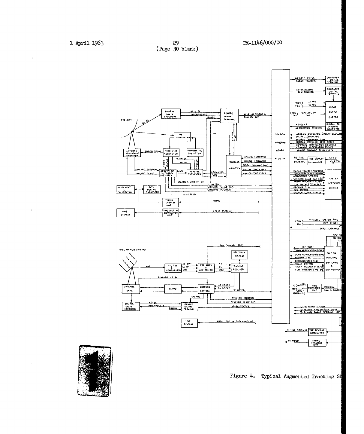
1
April
1963
29
TM-1146/000/00
(Page
30
blank)
RADAR
TRACKER ERG
NFL
RZEL-STRTAS
GPTER
KIM TRACKER FIRILTo
FROM
PRLESS
OTU
B-
.
ITEOVTE FRIM EL-
STRTO
-
TOG TI
E OSY RATf DIGITAL QUALIFY BIT TGBUFFER
RI-EL-I
TEDIGIINALT
RPRRIITIRI
STRTR .ONORO
COIBOR TOE
DIG.A C=O
PROGRAM TIGITALLRRRMOEER
CRECK
RTEM A BBOR SO F
BCEIIR
EJISTIKIBAD EANALOG ZOM R
..
ECNO
CPBC.
1 1 FGTsANALOG (OMARRRS TAGILIT TO TIRE TIKE PISEGR STM
OCOOISITIOAST5.OD
ARO TRACRTOAETE GIIRKIOBS
C- IF
CO",M I,
..
,05_IL E_
_C TILMER T 1ACKO
SIgACTE
TOM.. S005011
TIMTITLNOG
BISRBT 0500
DIS
AlT.
CA
T BCT
ýS
A
ORE RE
DISC RBBON
ARTEB TM/FMTN
COMB UEITR.F O0.05.6.T
RECOMMIATE
BIK
ITLR
LDLCOAIATDD .TIM
COMPARAILL SRM 1100 SUMIR FIRA P E-E TIM ROACEES ROETE 5ITAI8OIT.Q
lIMO
RN.
.
DPIEOT RE.
L(B I)z
REMOTE STROPRO
SLAVE`BO
SAMETL B EDIEIR AAMG
STTS
O10".ACIO
III,.. TR ITO BR-EL ODS T GUU '.M B ISETATSBOA B STELA
DISBTRIBU0TOR
RBS
REDD TIMIBG
Figure
4.
Typical
Augmented
TrackingS
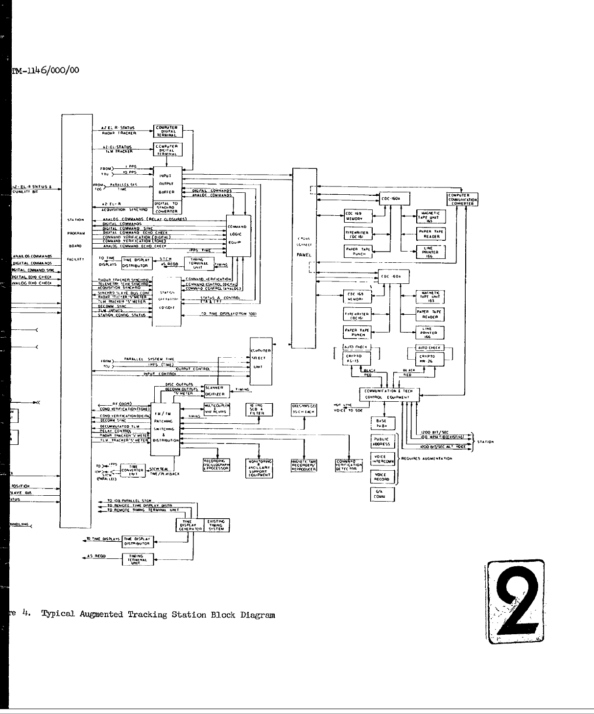
-n6/000/00
MI F -ELSTATUS CC -uIc.
-
'0 IF ANIMALT
F-EL-Ru5STUFus
I FROMFMLEOL S"S TU~J
('O~tFI Air
'
T -WEC ."EE AM CDCL
(Mu..... T.D
CAC-IAL
T COFMLLC.TERm
s
-
CC
RTf AlMA
D.G11A,~F~l FMFF
1.
o-
.
OFAITAL MAIMAN
S.
O
.O. A O (0M
-
1C 0 C 50-[1"
S,1C
SCU
A
BS
C OAT
AMM
-t4'.
'Su.EF V
S F.5I
C'TO
'Lu AFCM A S FEA TITIf
T- PT
1-1N
A (O.FMF 10Pý
C I TQ
L IAF
A F M C O MI
UFIL
TO SotAF
ME TFST SQFl A
CM~M
h£FC
COIFIUOLo
BITMI,
Tu/ FM.
FPuyA
lILI4 FCC-"
FME
...
C TO
SO
LA.
~
~
(MA.DKE
MAICFI
[ 1JCT
F.M
O.CFIIMC
*UMTMIO
AFCFFIF
L.QIOMIM _ C'E CEM- FF1M
A
F~~~o FP
IMFIF
MF MC
MFAAS EG
to
u MOLL iCA6-
e
4.
Typical
Augmented
Tracking
Station
Block
Diagram
I
Apr!Ii)
193
31ft1)246/000/oo
fi!gure
5
lists
the
antenna
systems
that.
wilt
exist
at
the
various
stations.
Tbe
tracking
station
equipment
can
be
grouped
into
three
ma.in
subsystem
c
at
egories;
3.
Antenna
subsystems.
2.
Telemetry,
Tracking
and
Command
subsystems.
3.
Data
Processing
subsystem.
J;,Lexib111ty
of
operation
is
assured
by
intoerconnecting
these
subsystems
through
patchboards.
The
Telemetry,
Tracking,
and
Command
subsystems
are
connected
to
the
Antenna
subsystems
by
the
Station
Patchboard
and
to
the
Data
Processing
subsystem
by
the
Cross
Connect
Panel.
These
tnterronnections
are
determined
at
the
STC
with
the
aid
of
the
SCHOPS
scheduling
program.
A
schedule
is
provided
to
the
station
operators,
which
assures
the
best
use
of
the
available
equipment
to
accomplish
the
multiple
satellite
control
mission.
The
three
main
equipment
subsystems
groupings
are
discussed
in
more
detail
in
Sections
2.2.1
through
2.2.3
below.
2.2.1
Antenna
Subsystems.
The
Antenna
subsystems
are
the
primary
data-
input
devices
of
the
SCF.
They
are
in
direct
contact
with
the
orbiting
vehicles.
The
standard
configuration
at
each
tracking
station
consists
of
two
Antenna
subsy_'ems,
one
foe
telemetry
and
the
other
for
tracking
and
commanding.
M.odifications
to
some
Antenna
subsystems
provide
additional
capabilities.
Scme extra
equipment,
including
antennas,
has
been
installed
at
certain
ztationE
for
use
by
a
specific
satellite
system. For
these
reasons,
the
antenna
configttrations
at
the
various
stations
are
not
identical.
Figure
5
lists
-the
major
Antenna
subsystems
that
will
be
used
at
the
different
stations.
Brief
descriptions
of
the
operating
characteristics
of
the
principal
Antenna
subsystems used
in
the
Augmented
SCF
are
given
in
Sections
2.2.2.1
through
2.2.1.6
below.
2.2.1..1
Verlort
Radar.
The
Verlort
is
an S-Band
radar
operating
in
the
2.7-to&2.9-kmc
frequency
band.
It
transmits
interrogation
pulses
to
a
trans-
ponder
in
the
orbiting
vehicle
and
tracks
the
return
signals.
Tracking
data
are
furnished
in
azimuth,
elevation,
and
range.
The
radar
has
a
10-foot-
diameter, 37-db-gain,
parabolic
reflector.
Verlort
has
an
effective
range
of
500C
miles.
The
feed
assembly
furnishes
a
30-cps
conical
scan,
which
produces
an
error
signal
to
drive
the
antenna
positioning
servos.
The
peak
S "-rir_
1963
32
M-
1146/000/00
power
output
is
325
KW,
the
"main
bang"
pil
se
width
is
0.8
microseconds,
and
the
prf
rates
are
410,
512
584,
and
610.
(More
detailed
system
specifications
are
listed
in
Reference
3.1
The
radar
transmits
a
3-pulse
code
(two
0.25
microseconds
pulses
precede
the
main
bang).
The
first
pulse
position
with
respect
to
the
main
bang
provides
a
code
address
to
identify
a
particular
vehicle
transponder
0
Command
data
are
transmitted
by
means
of
the
middle
pulse
(see
Section
5.0).
The
maximum
automatic
tracking
rates
are
10
degrees
per
second
in
azimuth
and
elevation,
and
10,000
yards
per
second
in
range.
The
angular
and
range
accuracies
are
0.3
degree
and
2500
feet
respectively.
2.2.1.2
Prelort
Radar.
The
Prelort
radar
is
an
S-band
radar
covering
the
seme
frequency
band
and
having
the
same
general
operating
characteristics
as
the
Verlort
radar.
It
represents
a
major
modification
to
the
Verlort
with
improved
resolution
and
accuracy.
It
has
a new
14-foot-diameter
parabolic
reflector
with
an
improved
feed
system,
a
new
precision
pedestal
with
improved
servo
drive
system
and
digital
encoders,
and
low-noise-figure
parametric
pre-amplifiers.
These
improvements
greatly
increase
the
tracking
accuracy
in
azimuth
and
elevation
over
that
of
the
Verlort.
The
range
accuracy
remains
the
same
as
for
the
Verlort.
2.2.1.3
Telemetry
and
Data
(T&)
Antenna.
The
T&D
Antenna
is a
passive
telemetry
receiving
system
originally
designed
to
operate
in
the
2.2-to-2.3-kmc
band.
All
T&D
Antennas
in
use
in
the
SCF
have
been
modified
to
also
receive
telemetry
signals
in
the
225-to-245o-mc
band.
Some
of
these
have
been
further
modified
to
receive
telemetry
signals
in
the
375-to-400
mc
band.
All
have
been
modified
to
have
auto-track
capability
in
either
the
2.2-to-2.3
kmc
band
or
the
375-to-4W0-mc
band.
The
antenna
has
a
60-foot
parabolic
reflector
giving
a
gain
of
from
28
db
to
49
db
and
a beam
width
of
between
3
degrees
and
0.5
degree,
depending
on
the
frequency
band
being
used.
In
addition
to
the
antenna
being
automatically
positioned
in
the
Auto-Track
mode,
it
can
also
be
manually
positioned
or
driven
from
the
slave
data
bus.
Preamplifiers
are
installed
at
the
antenna
for
all
frequency
bands.
Remote
receivers
for
the
2.2-to-2.3-kmc
band
of
frequencies
are
part
of
the
antenna
system.
These
receivers
have
a
maximum
sensitivity
of
about
-134
dbm.
The
amplified
RF
signals
from
the
other
two
frequency
bands
are fed
to
external
telemetry
receivers.
A
doppler
receiver
can
be
used
with
the
antenna
to
extract
dopper
velocity
information
from
the
received
signals
in
the
375-to-400-mc
band
in
those
antennas
where
the
mod-
ification
to
receive
this
frequency
band
exists.
2.2.1.4
TLM-18
Telemetry
Antenna.
The
ThM-18
Antenna
subsystem
passively
tracks
VHF
telemetry signals
in
the
215=to-2
6
0-mc
frequency
band.
Its
principal
function
is
to
receive telemetry
data
from
orbiting
vehicles
but
it
also
supplies
azimuth
and
elevation
angle
information
on
the
vehicle
it is
tracking.
The
antenna
has
a
60-foot-diameter,
28-db-gain,
parabolic
reflector.
The
feed
assembly
furnishes
a
l0-cps-conical-scan
modulation,
which
produces
an
error

I
April
1963
33
Tx-iJ.f
6/ooo/o00
x x
CA
-
-- r
IF0
A w t cm
14 c
I April
1963
34
TM-
1146/ooo/oo
signal
to
drive
the
antenna
positioning
servos.
Pre-amplifiers
at
the
antenna,
with
22-db
gain,
permit
location
of
the
VHF
receivers
at
some
distance from
the
antenna without
appreciable
deterioration
of signal
quality.
The
tracking
accuracy
varies
between
0.12
degree
at
a
1-degree-per-second
rate
and
0.75
degree
at
a
6
-degree-per-second
rate.
The
antenna
can
be
remotely
positioned
by
the
Slave
Data
Bus;
pointing
information
is
derived
from
another
antenna
or
from
acquisition
data
from
the
STC.
Tracking
accuracy
in
the
Slave
mode
of
operation
is
2
degrees.
2.2.1o5
Disc-On-Rod
(DOR)
Antenna.
The
DOR
Antenna
is a
VHF,
passive,
telemetry
receiving
system.
It
consists
of four
slow-wave,
disc-on-rod
structures,
with
a
ground
plane
mounted
on
a
synchro-driven,
gimballed
pedestal.
It
has
a
21-db
gain
over
the
design
frequency
range
of
225
to
260
mc.
It
has
a
beam
width
of
approximately
14
degrees.
It
uses
the
interferometer
method
of
angle
determination
and
has
an
angular
accuracy
of
0.5
degree
in
both
azimuth
and
elevation.
The
antenna
can
be
manually
positioned,
can
automatically
track
VHF
signals,
or
can
be
slaved
to
synchro
data
from
other
antenna
systems
or
aquisition
information
from
the
STC
via
the
slave
data
bus.
Signal
sensitivity
is in
the
range
of
-113
to
-120
dbm.
The
system
has
self-contained
amplifiers
to
develop
the
error signals
used
to
drive
the
azimuth
and
elevation
servos.
The
Telemetry
signal
is
passed
on
undetected
to
external
telemetry
receivers
in
the
FM/FM
Ground
Station.
2.2l.6
Tni-Helix
Antenna.
This
is
a
VHF
passive,
telemetry receiving
system.
It
consists
of
a
three-element
helical
array
on
a
hexagonal
ground
plane,
which
is
mounted
on
a
rotatable
base.
It
has
a
15-db
gain
over
the
design
frequency
range
of
235
to
265
me.
It
has
a
beam
width
of approximately
20
degrees
and
an
angular
accuracy
of
about
10
degrees-
It
can
be
manually
operated
to
assist
in
initial
acquisition
of
satellite
VHF
signals
by
supplying
rough
azimuth
and
elevation
information.
Its
broad
beam
width
does
not
require
highly
accurate
acquisition
data.
It
may
be
driven
by
the
slave
data
bus,
using
acquisition
data
originating
at
the
STC,
or
from
data
developed
by
more
accurate
antenna
systems,
such
as
Verlort
or
TLM-18.
The
pre-amplifiers
used
give
an
additional
gain of
20
db
and
multicouplers
allow
up
to
six
receivers
to
be
connected
to
the
same
pre-amplifier
channel.
1
April
1963
35
•4-l11i6/000/O0
2.2.2
Telemetry,
Tracking,
and
Command
Subsystems.
The
three
subsystems
described
below
have
two
important
functions.
On thh.
one
hand,
they
receive
data
from
the
satellite
in
the
form
of
outputs
from
the
Antenna
subsystems
and
process
it
into
a
format
that
is
usable
to
the
Data
Processing
subsystem.
On
the
o~ier
hand,
acquisition
data
and
commands
from
the
STA
via
the
Data
Processing
subsystem
must
be
acted
upon
and
put
into
a
form
suitable
for
transmission
tc
the
satellite
by
the
Antenna
subsystems.
Flexibility
in
the
use
of
the
station
equipment.
is
made
possible
by
the
use
of
two
manual
patching
terminals--the
Station
Patch
Board
and
the
Cross
Connect
Panel.
The
Station
Patch
Board
(SPB)
interconnects the
Telemetry
Tracking,
and
Command
subsystems
with
the
Antenna
subsystems.
In
addition
to
the
regular
control-circuit
patching
facilities,
the
SPB
has
coaxial
switches
for
connecting
radio-frequency
lines
from
+he
FM/FM
ground
stations
to
the
Antenna
subsystems.
The
Cross
Connect
Panel
(C'P)
interconnects
the
Telemetry,
Tracking,
and
Command
subsystems
to
the
Data
Processing
subsystem.
The
actual
interfaces
for
the
CCP
are
the
TDP
and
LOB
on
one
side,
inter-
connecting
with
the
T&C
and
TLM
data-processing
computers
on
the
other
side.
1+ is
by
means
of
these
two
patching
terminals
that
the configurations
of
the
dual
tracking
stations
are
determined.
The
configuration
is
usually
selected
by
the
STC
and
sent
to
the
tracking
stations
in
the
prepass
message.
Emer-
gency
reconfigurations
and
last
minute
changes
are
readily
accomplished
because
of
the
flexibility
inherent
in
the
patching
terminals.
2.2.2.1
FM/FM
Ground
Station.
The
FM/FM
Ground
Station
processes
and
records
VHF
telemetry
data
from
the
Telemetry
Antenna
Subsystem.
There
are
5
VHF
receivers,
including
one
spare,
which
accept
inputs
in
the
215-to-260-
me
band
or
at
a
5i-mc
predetection
IF
frE
Taneucy
from
an
extc_
iaal
VHF
receiver.
The
composite
video
output
of
the
Leceivers
(100
cps
to
125
kc)
is
recorded
on
magnetic
tape
for
permanent
record
of
all
FM/.7M
telemetry
data
received.
The
subsystem
has
one
18-channel
subcarrier
dtseriminator
(SCD)
group
for
converting
subcarrier
channels
into
corninuous
telemetry
analog
outputs.
In
addition
there
are
two
30-channel,
pulse-amplitude-modulated
(PAM)
de-
commutators
to
demultiplex
a
total
of
60
commutated
points
of
the
NRZ,
GERZ
or
IRIG
standard
types.
Up
to
a
total
of
64
selected
analog
outputs,
con-
tinuous
and decommutated,
are
sent
to
the
telemetry
data
processor
for
conversion
into
digital
form.
The
telemetry
data
flow
is
described
more
fully
in
Section
4.O
and
a
simplified
block
diagram
of
the
FM/FM
Ground
Station
is
shown
in
Figure
10.
Greater
detail
of
the
equipment
and
functions
are given
in
References
3
and
16.
The
major
functional
components
are
listed
below.
1.
Two
VHF
Multicouplers.
2.
Five
VYE
Telemetry
Receivers.
1
April
1963
36
TM-
1146/ooo/oo
3.
Two
Spectrum
Display
Units.
4.
One
3264
Pin
Master
Patch Panel.
5-
One
40-Position
RF
Patch
Panel.
6.
Two
Seven-Channel
Magnetic
Tape
Recorder/Reproducer
Systems.
7.
One
18-Channel
Subcarrier
Discriminator
System.
8.
Two
90-Channel
Decommutator
Systems
with
30
Selectable
Outputs.
9.
Two
36-Channel
Optical Oscillographic
Recorder
Systemz.
10.
One
Band
Switching
Discriminator.
11.
Three
8-Channel
Pen
(heated
stylus)
Oscillographic
Recorders.
12.
Five
18-Channel
Analog/Digital
Line
Driver Amplifiers.
13.
One
Monitoring
Equipment.
14.
One
Operational
Alignment
Equipment.
15.
One
Auxiliary
Support
Equipment.
2.2.2.2
PCM
Ground
Station.
The
PCM
Ground
Station
functions
as
inter-
mediate
processing
equipment
between
the telemetry
receivers
and
the
Telemetry
Data
Processor.
It
converts the
serial,
3-level,
pulse-code-modulated
(PCM)
data
from
the
receiver
frequency-discriminator
output
into
parallel
binary
data
words
that
are
compatible
with
the
Data
Processing
subsystem.
The
detected
signal
from
the
frequency
discriminators
is
passed
through
a
30-kc
filter
to
remove
other
telemetry
data
carried
on
a
70-kc
subcarrier.
The
filter
output
is
then
fed
to
the
input
of
the
PCM
converter.
The
PCM
con-
verter
converts the
3-level signal
into
2-level
form
and
performs
a
noise
rejection
operation.
The
converted
data
are
placed
in
intermediate
storage
to
allow
bi-directional
entry.
This
is
necessary
because,
on
some
programs,
the
PCM
data
are
recorded
on
a
vehicle-borne
magnetic-tape
system,
and
playback
may
be
in
either
forward or
reverse
direction.
The
PCM
data
may
be
received,
therefore,
in
either
a
forward
or
backward
format.
For
off-line
data
processing~the
3-level
PM14
data
is
used
to
modulate
a
voltage-controlled
oscillator
to
provide
a
frequency
modulated
70-kc
carrier
for
recording
on
magnetic
tape.
The
tape
may
then
be
played
back
through
a
70-kc
subcarrier
discriminator
to
recover
the
3-level
PCM
signal
train,
which
may
then
be
sent
through
the
PCM
converter
for
processing.
I
1
April
1963
37
24-1146/O00/00
2.2.2.3
GP-1
Ground
Station.
The
General
Fhxrpose
PAM
Ground
Station
(PAM;-GPl)
has
been
designed
to
receive
a
frequencyý-modulated
PAM
input
signal
from
ground-,based
telemetry-receiving
equipment
and
to
provide
digital
output
data.
In
addition,
demultiplexing
and.
analog
outputs
are
provided
for
various
users,
ThiE
eruipment
can
be
programmed
to
handle
various
PAM
formats
by
a
main
Program Board.
It is
capable
of
recording
all
received
information
on
an
appropriate
wideband
magnetic-tape
recorder,
such
as
the
Ampex
FR
700,
and
of
reproducing
this
recorded
information
for
off-line
processing.
A
digital
tape
recorder,
provided
for
backup
capability,
can
record
received
information
and
reproduce
this
information
for
off-line
processing.
This
recorder
also
makes
it
possible
to
check
the
input/output
transfer
per-
formance
of
the
PAM4GPl.
The
Ground
Station
is
also
capable
of
normalizing
all
PAM
data;
i.e.,
by
making
use
of
the
calibrate
information
in
the
pulse
train,
the
data
information
is
normalized
to
the correct
relative
value,
regardle6s of
amplifier
gain
drift,
r-f
deviation
drift,
or
initial
system
setup
inaccuracieswithin
a
correction
range
of-±30
percent.
This
equipment,
of
modular
construction
for
the
most
part
and
subject
to
programming
is
made
up
of
19
functional
units.
These
units
are
not
necessar-
ily
physia-2l
entities,
but
may
be
composed
of
certain
modules
or
groups
of
m=dules,
the
arrangements
of
vhich
may
change
from
one
program
to
another.
Tbe
PAK.GPl
Ground
Station
is
composed
of
the
following
major
functional
components,
which
are
housed
in
seven
14-inch
relay
racks:
i.
Video
Circuits.
2.
Clock
and
Raw
Sync
Separator.
3.
Multiphase
Clock
Generator.
4.
FYame
Sequencer.
5.
S~ibframe
Sequencer.
6.
Frame
Sync
Logic.
7. Subframe
Svn,
Logic.
8.
Automatic
Gain
Control.
9.
Digitizer.
10.
Output
Buffer.
11.
Digital
Record
Electronics.
12.
Digital
Reproduce
Electronics.
1
April
1963
38
Tm-1146/000/00
13.
Analog
Circuits.
14.
Patch
Panel.
15.
Power
Supplier
and
Interlock.
16.
Digital
Tape
Recorder.
17.
Wideband
Tape
Recorder.
18.
R-F
Detectors
and
Subcarrier Discriminators.
19.
Signal
Simulator.
The
Ground
Station
performs
these
main
functions:
1.
Accepts
input data
in
the
form
of
a
5-mc
frequency-modulated
carrier.
2.
Accepts
input data
in
the
form
of
a
30-mc
frequency-modulated
carrier.
3
Provides
the capability
of
recording,
on
magnetic
tape,
the
input
data
described
in
1
and
2
above.
4.
Allows
for
the
capability
of
detecting
the
frequency modulation
of
the
input
signals
described
in
1
and
2
above.
5.
Allows
for
the
additional
capability
of
detecting
frequency-
modulated
subcarriers
in
systems
utilizing
PAM-FM-FM.
6.
Provides
the
capability
of
supplying
composite
PAM
video,
PAM
clock,
PAM
frame sync,
and
PAM
block
sync
to
display
equipment.
7.
Provides
seven
channels
of
smoothed
(interpolation
filtered)
analog
outputs,
which
may
be
programmed
to
any
desired
channel.
8.
Provides
a
minimum
of
eight
channels
of
sample-and-hold
analog
outputswhich
may
be
programmed
to
any
desired
channel.
9.
Provides
the
capability
of
performing
the
internal
functions
required of
a
General
Purpose
Sync
Separator
and
Digitizer.
The
equipment
accepts
a
serial
PAM
pulse
train
at
a
data-sampling
rate
ranging
from
500
cps
to
40
kc.
It
can
process
a
maximum
of
256
high-frequency
channels.
Four
of
these
high-frequency
channels
may
be
asynchronously
A
1
April
1963
39
U.41146/000/0o
subcommutated
to
a
maximum
of
128
low-frequency
channels;
however,
additional
channels
may
be
subcommutated
provided
they
are
synchronized with
one
or
more
of
the
asynchronous
channels.
Seven
smoothed
analog
outputs
are
provided.
These
signals
are
generated
by
demultiplexing
the
PAM
pulse
train,
passing
the
resulting
PAM
pulses
through
an
interpolation
filter
and
then
through
an
amplifier
for
ampli-
fication.
The
choice
of
the
channels
to
be
demultiplexed
is
performed
on
the
Program
Board.
Eigtt
sample-and-hold
outputs are
also
provided.
The
choice
of
channels
to
be
sampled
and
held
is
performed
on
the
Program
Board.
Each
sample-
and-hold
circuit
samples
the
level
of
a
particular
data
channel
over
a
brief
interval
of
time
and
then,
through
memory,
retains
this
level
until
a
new
sample
is
made
available.
Upon
the
arrival
of
a
keying
pulse
that
initiates
another
sample,
the
output
of
the
sample-and-hold
circuit
changes
to
the
new
data
level
and
remains
at
that
level
until
a
new
sample
is
provided.
2.2.2.4
400-mc
Receiving/Commanding Equipment.
The
1OO-mc
equipment
is
used
with
the
TU4J18
or
T&D
antenna
subsystems
to
enable
them
to
actively
track
vehicles
having
400-mc
transponders.
'The
feed
systems
of
these
antennas
are
modified
to
accomodate
the
new
frequency
band.
The
equipment
can
furnish
error
signals
to
null
the
antenna-positioning
servos
and
provide
auto-track
capability
for
the
antenna
at
400
mc.
The
dopplier
shift
frequency
can
be
extracted
from
the
received
signal
to
obtain
range-rate
information.
The
existing
precision
synchros
and encoder5
geared
to
the
antenna
axes
provide
antenna angle
data.
The
equipment can
&ccept
telemetry
data
from
4
00-mc,
vehicle-borne
transmitters
and can be
us-.d
for
cormanding
with
vehicles
carrying
375-mc
receivers.
The
modifications
to
the
antennas
do
not
affect
their
capability
to
function
at
their
originsl
design
frequency.
2.2.3
Data
Processing
Subsystem.
The
Data
Processing
subsystem
inter-
faces
with
the
Telemetry,
Tracking,
and
Command
subsystems
through
the
Cross
Connect
Panel.
Direct
contact
with
the
SIC
is
maintained
via
the
1200-bps
data
1ines.
The
principal
uncmtions
of
the
Data
Processing
subsystem
are
the
following:
1.
Accepts
predicted
acquisition
and
ephemeris
data
from
the
STC
and
converts
this
information
to
continuous
antennaý
position
data
far
the
tracking-
station
antenna
systems.
2.
Provides
antenna-pointing data
to
the
radar-tracking-subsystem
antenna
drives
and
telemetry-subsystem
antenna
drives,
via
the
appropriate
slaving
busses.
3.
Accepts
tracking
data
from
the
radar-tracking
subsystem
and
provides
tracking
data
for
transmission
to
the
STC.
1
April
1963
4o
IM-1
1
46/0oo/oo
4.
Accepts
digital
antenna
position
data
from
the
telemetry-
antenna
subsystem
and
provides
data
for
transmission
to
the
STC.
5.
Provides
and
accepts
status
and
control
data
to
and
from
the
Station
Operator's
Console
(SOC).
Provides
digital-command
data for
modulating
the
radar,
command
transmitter,
and
telemetry
antennas
commancL-modulation
equipment,
and
provides
analog-
command
data
to
the radar-modulation
equipment.
6.
Processes
telemetry
data
from
the telemetry
subsystems
in
real
time
and
postpass.
7.
Performs
control
and
monitoring
functions
for
the
Checkout
Subsystem.
8.
Provides
for
generating the
ETA
and
ETT
in
time
displakyr
on
the
SOC.
9.
Records
selected
data.
10.
Provides
time
comparison
between
vehicle
and
system
time
and
provides
this
to
the
STC.
Main
components
of
the
Data
Processing
subsystem
are
as
follows:
1.
Tracking
and
Command
(T&C)
Computer
Subsystem.
2.
Telemetry
(TIM)
Computer
Subsystem.
3.
Input/Output
Buffer.
4.
Telemetry
Data
Processor.
5.
Command
Logic
Equipment.
6.
Station
Operator's
Console.
2.2.3.1
Tracking
and
Command
Computer
Subsystem
(T&C).
The
T&C
computer
complex
consists
of
one
each
CDC
160A
Computer,
CDC
169
External
Computer
Memory,
CDC
166
Buffered
Line
Printer,
CDC
163-4
Magnetic
Tape
Unit,
and
CDC
162
Typewriter.
The
computer
has
one
set
of
programs
for
real-time
(RT)
operations
and
one
set
for
non-real-time
(NRT)
operations.
Me
RT
programs
operate
when
the
tracking
station
is
servicing
a
vehicle.
NRT
programs
operate
in
the
period
between
active
servicing
of
vehicles.
I
I
1
April
1963
41
TN-1146/o10/O/
The
following
tracking
and
cosmanding
functions
are
performed
during
RT.
1.
The
RT
Program
uses
standardized
predicted acquisition
data
messages
(in
station
azimuth,
elevation,
and
range
coordi-
nates)
to
provide
slaving data
to
an
acquisition
synch
conver-
ter
for
use
by
the
Antenna
subsystem.
Each
pointing
data
message
contains
header
data
and
data-point
sets
(azimuth,
elevation,
and
range)
spaced
at
a
uniform
At
between
sets.
(At=
2n
seconds,
where
0
:
n
r
6).
The
RT
program
interpolates
the
data
to
20
sps
and
supplies
it
to
the
acquisition
synch
converter
for
use
under
SOC
control.
2.
The
RT
program
provides
and
accepts
command
data
and
status
to
and
from
the
Station
Operator's
Console
(SOC),
commands
and
command
data
from
the
STC,
provides
digital-command
capa-
bility,
records
significant
events
pertaining
to
analog
and
digital
commanding,
and
reports
commanding
operational
status
to
the
STC.
Provisions
will
be
made
to
accept
command
ver-
ification
from
the
FM/FM
Ground
Station
(or
the
Telemetry
Data
Processor)
and
echo
signals
from
the
CLE,
when
available.
3.
The
RT
program
reads
data
on
azimuth,
elevation,
transverse,
range,
range
rate,
control,
and
status
(as
supplied
by
the
antennas
selected)
through
a
digital
data
link,
from
the
antennas
once
each
second
for
history
records,
and
formats
the
selected
information
for
transmission
to
STC
at
a
normal
rate
(or
rate
selected
by
STC
prepass
or
real
time).
4.
The
RT
program
provides
and
accepts
status
and
control
data
to
and
from
STC,
the
Station
Operator's
Console,
and
other
tracking
station
subsystems.
5.
The
RT
program
accepts
system
time
and
vehicle
system
time
word
inputs
and
provides
timing
and
vehicle
identification
display
outputs.
System
time
will
be
accepted
from
the
ground
timing
equipment
and
used
in
timing
displays
or
for
time-tagging
acquisition
messages
and
command
messages.
Vehicle
system
time
and
ground
vehicle
time
offset
shall
be
accepted
from
the
ground
telemetry
subsystem
and
recorded
and
transmitted
to
STC,
as
required.
6.
The
RT
program
provides
the
capability
for
recording
a
history
of
selected
data.
The
history
subprograms
provides
the
capa-
bility
to
record
and
play
back
chronological
records
of
command
actions
(analog
or
digital)
including
initiations,
transmission,
echo-check
data,
and
vehicle
reactions;
tracking
data;
raw
time-tagged
telemetry
;
and
other data,
as
dictated
by
operation
1
April
1963
42
nIM-116/ooo/Oo
requirements
such
as
timing
and
SOC
actions.
This
function
is
also
required
of
the
telemetry
operational
program.
The
following
tracking
and
commanding
functions
are
performed
during
NRT:
1.
The
NRT
program
accepts
new
vehicle
specifications,
commanding
and
pointing
data
from
STC,
and
merges
them
with
operation
tapes
alroeady
on
hand
at
the
tracking
station.
2.
If
required,
the
NRT
program
enters
a Playback
mode,
in
which
history
tapes
are
made
available
to
the
STC
or
for
readout
at
the
station.
3.
The
NRT
program
performs
schedule
printouts,
as
required,
for
station
operation.
4.
In
some
cases,
the
NRT
program
coordinates
those
SOC
functions
involving
system
time,
ETA,
ETT,
etc.
5.
The
NRT
program
coordinates
the
checkout
programs,
including
daily
and
prepass
checkouts.
6.
The
NRT
program
arranges
the
real-time
program
in
the
specific
configuration
determined
by
data
sent
from
the
STC.
7.
The
NRT
program
accomplishes
the
transition
from
non-real-time
to
real-time
operation,
2.2.3.2
Telemetry
Computer
Subsystem
(TLM).
The
TIM
Computer
subsystem
has
the
same
basic
equipment
as
the
T&C
computer
complex;
only
the
programming
is
different.
The
TIM
programs
are
divided
into
an
RT
set
and
an
NRT
set,
as
are
the
T&C
programs.
The
following
telemetry functions are
performed
during
RT:
One
telemetry
data
stream
is
accepted,
time
tagged,
and
recorded.
Some
of
the
data
are
processed
for
local
and
STC
real-time
use
and
postpass
analysis.
The
telemetry
program
formats
and
compresses
the
data
from
selected
channels
in
real
time,
sends
selected
outputs
to
the
STC,
and
locates
command
ver-
ification
data.
Compression
modes
will
be
provided
as
options
in
the
computer
program.
The
telemetry
points selected
and
the
parameters
of
a
processing
algorithm
may
be
changed
without
loss
of
data.
The
telemetry
mode
may
also
be
changed
during
a pass but
some
data
are
lost
during
the
change
over.
During
NRT
,the
following
telemetry
functi
ons
are
performed:
1.
New
modes
are accepted
for
telemetry
compression.
1
April
1963
43
TM-11i46/Oo/O0
direction,
specifying
which
mode
is
to
be
used
on
particular
vehicle
passes,
and
merged
with
data already
on
the
magnetic
operations
tapes
at
the
site.
2.
Scheduled
printouts
are
produced,
as
necessary.
3.
Transition
from
non-real
time
to
real
time
is
performed.
4.
The
capability
exists
to
read
and
process
raw
telemetry
data
from
a
digital
history
tape.
2.2.3.3
In.put/Output
Buffer
(lOB).
The
1OB
provides
for
computer-pro
grammable
input
and
output
of
digital
data,
in
real
time,
to
and
from
a
CDC
160A
computer.
The
computer
Drogram
sets
the
rate
of
input/output
for
each
datum
and
selects
the
input/output
device
and
function
at
the
correct
time
by
the
use
of
function-select
codes.
Computer
interrupts
are
used
to
trigger
input/output
functions of
the
computer
program.
The
IOB
interrupts
the
computer
by
means
of
interrupt
10
for
the
Command
Logic
Equipment
(CLE)
functions,
which
have
the
higheEt
priority
of
any
interrupt
in
the
TMC
160A.
The
1OB
uses
interrupt
40
to
interrupt
the
computer
at
a
20
pps
rate
for
timing
inputs
and
outputs
from
the
other
equipment.
Finally,
the
lOB
uses
interrupt
30
for
digital
data
link
equipment
inputs.
The
1OB
transfers
output
data
to
the
following
equipment
under
computer
control:
1.
CDC-160A
Computer.
2.
Station
Operator
Console.
3.
Acquisition
Servos
for
Slave
Data
Bus.
4.
Command
Logic
Equipment.
5.
Check-out
Subsystem.
It
transfers
input data
from
the
following
equipment
under
computer
control:
1.
CDC-160A
Computer.
2.
Selected
Antenna
Position
Encoders
(Via
Computer
Digital
Terminals
1
and
2).
3.
System
and
Vehicle
Time
Word
and
Offset.
1
April
1963
44
TM-1146/O00/O0
4.
Station
Operator
Console.
5.
Command
Logic
Equipment.
6.
Checkout
Subsystem.
2.2.3.4
Telemetry
Data
Processor
(TDP).
The
TDP
interfaces
between
the
telemetry
subsystems
and
the
telemetry
160A
computer.
It
accepts
vehicle
telemetry data
from
the
GP-l(a),
GP-l(b),
FM/FM,
and
PCM
telemetry
sub-
systems.
The
TDP
can
select
for
input
the
system-time
code
word
(STCW)
and
a
122-bit
input
control
word.
With
certain
telemetry
systems,
the
TDP
can
send
a
12-bit
output
(control)
word
to
the
station
patchboard
for
trans-
mission
to
the
IOB.
This
word
is
used
in
communicating
the
vehicle
command
verification
to
the
commanding
subprogram
in
real
time.
The
GP-l
systems
will
input
one
12-bit
word/telemetry value
to
the
TDP.
The
FM/FM
system
will
input
up
to
64
channels
of
analog
values
to
the
TDP;
a
manually
programwable
plugboard
permits
sampling
of
up
to
64
channels
(at
a
maximum
rate
of
25
kc) and
digitizing
of
sampled
data
for
the
160A.
The
PCM
system
will
provide
one
or
ten
unsynchronized
data
bits/12-bit
word(s)
to
the
160k-
One
pps
is
marked
to
in
all
telemetry data
streams.
A
receiver
phase-loop,
lock-.on
bit
is
provided
in
the
twelfth
bit.
The
160A
can
select
any
one
of
the
TDP
inputs
or outputs
by
programmed
execution
of
the
appropriate function
select
codes.
The
TDP
includes
a
scanner,
a
digitizer,
and
a
computer
select
unit.
The
scanner
will
be
capable
of
sampling
the
input
from
each
subcarrier discriminator
or
de-
commutator
in
the
FM/FM
ground
telemetry
subsystem
(or
a
maximum
of
64
similar
sources)
at
a
minimum
individual
rate
of
5
cps and
a
maximum
combined
rate
of
25
kc.
The
selectable
rates
and
sequence
of
sampling
the
various
sources
will
be
determined
by
a
programmed
patchooard.
2.2.3.5
Command
Logic
Equipment
(CLE).
The
CLE
processes
inputs
from
the
Station
Operator's
Console
(SOC)
and
the
T&C
computer
in
order
to
control
the
transmission
of
analog
and
digital
commands
to
satellites
via
the
command
transmission
facilities
of
the
antenna
subsystems.
The
CIE
has
storage
buffers,
logic
circuitry,
and
function
counters.
It
furnishes
outputs
to
various
external
equipments
in
the
form
of
relay
closures.
It
transforms
parallel
digital
commands
from
the
computer
to
serial
form
for
transmission
to
the
satellite.
For
"analog"
commands,
the
CLE
translates
the
command
number
selected
by
the
SOC
(two
BCI
digits)
into
two
outputs
corresponding
to
one
of
15
commands.
When
the
"Trans,.L."
signal
is
received
from
the
SOC,
these
outputs
are
gated
to
pick
up
two
out
of
six
relays
and
to
hold
them
in
an
operate
condition
for
one
second.
These
relay
closures
are
used
to
tone-modulate
the
radio-
frequency
carrier
that
carries
the
command
information
to
the
satellite.
A
1
April
1963
45
•m-_ll6/ooo/oo
command
counter
is
stepped
once
for
each
"transmit"
and
the
number
of
the
command
transmitted
is
indicated
on
the
SOC.
Approximately
300
milliseconds
after
the
command
relays
close,
a
command
echo
check
is
returned
from
the
transmitter.
This
echo
check
consists
of
two
out
of
six
relay
closures,
held
closed
for
one
second.
The
CLE
compares
the
echo-check
data
with
the
cammand
previously
transmitted.
If
not
in
agreement,
the
Command
Error
indicator
on
the
SOC
is
turned
on,
and
further
commanding
is
inhibited
until
the
Command
Error
indication
has
been
cleared
by
the
"Error
Override"
pushbutton
on
the
SOC.
Also, about
300
milliseconds
after
transmission,
a
command
verification
from
the
satellite
is
returned
to
the
CLE
via
the
FM/FM
ground
station.
This
consists
of
two
out
of
six
relay
closures,
held
closed
for
one
second,
which
are
compared
with
the
transmitted
command
relay
closures.
If
they
agree,
the
verification
indicator
on
the
SOC
is
turned
on
and
a
verification
counter
is
stepped
on
count.
When
the
SOC
goes
into
the Repetitive
Transmit
mode,
the
CLE
retransmits
the
same
command
once
every
two
seconds
until
the
"Stop
Repetitive"
push
button
is
depressed
or
until
the
total
number
of
commands
transmitted
equals
the
repetitive
number
selected
on
the
SOC.
The
CLE
stops
repetitive
transmission
if a
command
echo
check
error
is
received.
When
the
"Error
Override"
push
button
is
depressed
on
the
SOC,
the
CLE
resumes
sending
the
repetitive
commands.
A
count
of
successful
repetitions
made
is
furnished
by
the
CLE
for
display
at
the
SOC.
Digital
command
messages
are
furnished
to
the
CLE
from
the
T&C
computer.
The
command
mode,
command
number,
reject
level,
and
transmit
order
are
transferred
from
the
SOC
to
the
T&C
Computer
via
the
CLE.
The
computer
extracts
from
memory
the
command
word
corresponding
to
the
command
number
and
provides
it
to
the
CLE
via
the
IOB,
serially
bit
by
bit,
on
a
computer-
interrupt
basis.
The
rate
of
command-bit
transfers
from
the
computer
to
the
=LE
is
primarily
determined
by
the
sync
PRF
of
the
command
transmitter
(the
maximum
rate
being
one
kc),
which
also
controls
the
command
bit
transmission
rate
from
the
CLE
to
the
command
transmitter.
Echo
check
data
are
returned
from
the
command
transmitter
to
the
CLE,
serially
bit
by
bit,
at
the
sync
PRF.
These
data
are
sampled
by
the
computer
and
compared
in
the
computer
with
the
original
command
in
memory,
in
real
time.
An
Echo
Check
error
indication
is
made
on
the
SOC.
A
Command
Verification
indication
(accept
or
reject)
is
returned
to
the
CLE
after
completion
of
each
command
word
transmission,
and
is
made
available
to
the
SOC
and
the
T&C
computer
via
the
IOB.
The
computer
also
monitors
the
verification
inputs
for the
occurrence
of
spoofs,
which
also
are
dis-
played
on
the
SOC
and
recorded
by
the
computer.
The
various
modes
of
analog
and
digital
commanding
are
explained
in
detail
in
Section
5.0,which
also
describes
additional
functions
performed
by
CLE.
1
April
1963
46
M-i1146/000/00
2.2-3.6
Station
Operator's
Console.
The
Station
Operator's
Console
(SOC)
is
the
central
control point
at
the
tracking
station.
It is
here
that
the
switches
and
displays
used
to
monitor
and
control
the
tracking,
telemetry,
command,
data
handling,
and
other
functions are
located.
There
are
18
panels,
arranged
in
functional
groupings,
so
that
three
operators
can
work
the
console
with
a
minimum
of
interference
with
each
other
(Figure
6).
These
operators
are
the
Command
Controller,
the
Antenna
Controller,
and
the
Shift
Supervisor.
On
the
left
side
of
the
console
is
a
group
of
panels
involved
with
the
Antenna
subsystem
(Figure
7).
These
are:
1.
Signal Strength
Panel
-
This
panel
has
two
meters,
which
display
the
strength
of
the
tracking
signals
of
the
Radar
Tracker
and
Telemetry
Tracker.
Four
lighted
displays
indicate
the operating
mode
of
each
tracker.
For
the
Radar
Tracker,
these
modes
are
Locked
on,
Slaved,
Search,
and
Manual.
For
the
Telemetry
Tracker
they
are
Auto
Tracking,
Slaved,
Search,
and
Manual.
2.
Range
Panel
-
This
panel
has
a
large,
circular
dial,
which
shows
the
range
in
20
n.m.
increments
out
to
5100
n.m.
The
dial
has
two
cursors:
one
indicates
range
from
the
Radar
Tracker,
and
the
other
the
range
from
the
Computer
Acquisition
program.
3.
Azimuth
Panel
-
This
panel
has
a
large,
circular
3600
dial,
which
is
divided
into
20
increments.
The
dial
has
three
cursors,
which
indicate
azimuth
derived
from:
(1)
the
Radar
Tracker,
(2)
the
Telemetry Tracker,
and
(3)
the
Computer
Acquisition
program.
4.
Elevation
Panel
-
This
panel
has
a
large,
circular
dial,
which
displays elevation
in
20
increments
from
900
at
the top
center
of
the
dial
down
to
-200
on
each
side.
The
dial
is
not
cali-
brated
full
scale.
The
dial
has
three
cursors,
which
display
elevation
as
derived
from
the
same
three
sources
listed
for
the
Azimuth
Panel.
5.
Antanna
Control
Panel
-
This
panel
has
two
sets
of
push
buttons
and
one
set
of
indicator
lamps.
One
set
of
three
push
buttons
is
labeled
"Directing
Source"
and
offers
three
choices
for
selecting
the
source
to
drive
the
system
sync
slave
bus:
(1)
"Computer",
(2)
"Radar
Tracker",
and
(3)
"Telemetry Tracker.
The
other
set
of
four
push
buttons
controls
the
starting
and
stopping
of
the
acquisition
program.
When
the
"Computer
Control"
push
button
is
depressed,
the
acquisition
program
is
under
the
control
of
the
T&C
computer.
When
the
"Manual
Control"
push
button
is,
depressed,
along
with
the
"Manual
Start"
or
"Manual
0
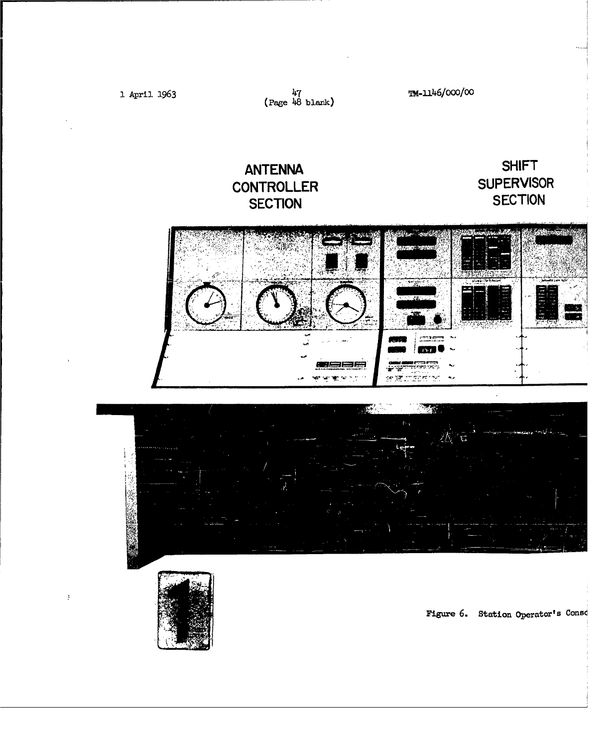
1
April
1963
47 T-116/000/00
(Page
48
blank)
ANTENNASHF
CONTROLLER
SUPERVISOR
SECTION
SECTION
-75
Figure
6.
Station
operator's
Consc
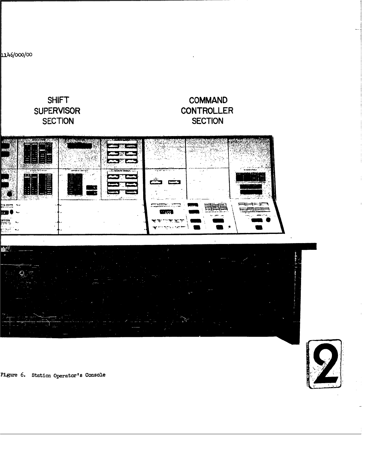
L346/000/00
SHIFT
COMMAND
SUPERVISOR
CONTROLLER
SECTION
SECTION
Figure
6.
Station
Operator's
Console
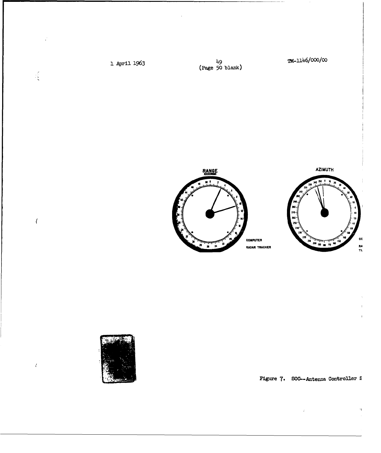
I
April
1963
49
T.P46/000/00
(Page
50
blank)
RA
AZIMUTH
3 M R0 0 20
320 3M3 0
22X0 60
S100
2000
210 90
U
250
noN
~240,125
RADAR
TRACKER
200,
0RA TL
Figure
7.
SOC--Antenna
Controller
E
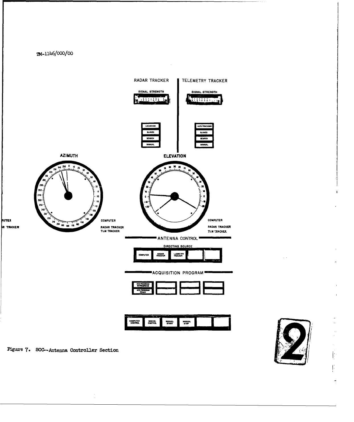
T-_146/ooo/lo
RADAR
TRACKER TELEMETRY TRACKER
SIGNAL STRENGTH SIGNAL STRENGTH
AZIMUTH
ELEVATION
ft R COMPUTER2P
ft TRAANTENANARCTRACOE
1TR
DIRECTING SOURCE
ACQUISITIONPRGA
I2W:
::
0-0 -10
Fitgu~re
7.
SOC--Antenna
Controller
Section
•
1:
w in
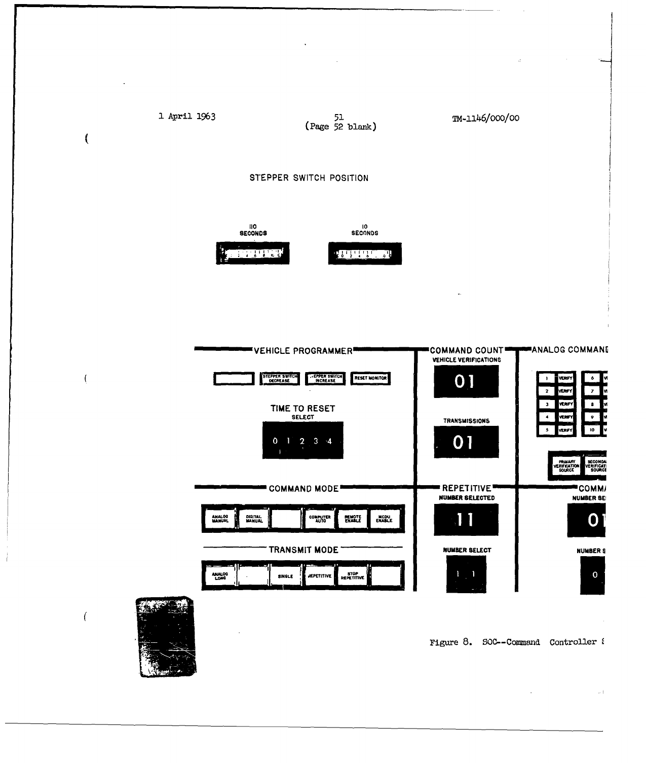
1
April
1963
51
TM-1146/Ooo/Oo
(Page
52
blank)
STEPPER
SWITCH
POSITION
110 I0
SECONDS
SECONDS
VEHICLE
PROGRAMMER
COMMAND
COUNT
ANALOG
COMMANIE
VEHICLE
VERIFICATIONS
_________S-TEPPEOR3SW2TC4
r.E WI-f'T"CN
TIME
TO
RESET
SELECT
TRANSMISSIONS
IA"
'
0
vU
V ERIFC OW
U
VSWIFI CAT
COMMAND
MODE
REPETITIVE
COMMI
NUMBER
SELECTED
NUMBER
SEI
3MANUJAL MANUAL
I
UO
SNRSI..
TRANSMIT
MODE
NUM&ER
SELECT
NUMBER
S
SINOLE 11EPE-T-ITIV
_PE Elr
Figure
8.
SOC--Command
Controller
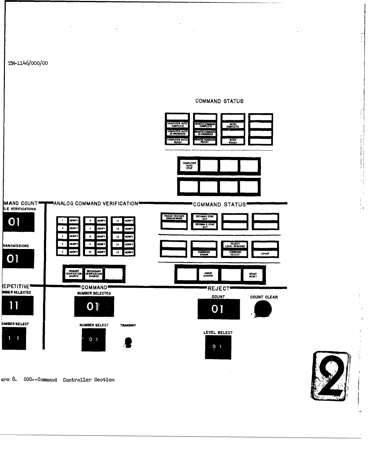
TM-i2l46/ooo/0o
COMMAND
STATUS
CEPMTITTV
COMMAODREJUECT~AEKRO
MPIiC
A"DN B EET COMPLETE
COMPUER
AUT
Ad=______
READY REASY
COMPUTER
ISTOP 7I
MAND
COUNT
ANALOG
COMMAND
VERIFICATION
COMMAND
STATUS
LE
VERIFICATIONS
_WYE E 3OR EESYN
O - a Uon
Sect
3
io WVY
RANSUISSIONS
2EW 9E RW
SEONus I
_______
C
RWIFCATION
VEMICTIiONUE
KEPRCRO
EPETITIVE"""
=COMMAND
-mýREJECTý
MISER
SELECTED
NUMBER
SELECTEDCONCUTCLA
lUMSER
SELECT
NUMBER
SELECT
TRAIUSMrC
LEVEL
SELECT
ure
8.
SOC--Command
Controller
Section
U2
I
i
April
1963
53
M-
1146/000/00
Start"
or
"Manual
Stop"
push
button,
the
acquisition
program
is
under
the
control
of
the
SOC
operator.
Two
lighted
displays
indicate
"Acquisition
Program
Ready"
or
"Acquisition
Program
in
Progress".
On
the
right
side
of
the
SOC
is
a
group
of
panels
involved
with
the
commanding
and
telemetry
functions
(Figure
8).
These
are:
1.
Command
Status
Panel
-
This
is
actually
two
panels,
one
above
the
other,
on
the
far
right
of
the
SOC.
The
upper
panel
has
two
switches
and
three
banks
of
indicator
lights.
The
two
switches
are
"Computer
Auto
Stop,"
which
stops
the
automatic
sending of
the
commands
by
the
computer,
and
"Computer
Command
Advance,"
which
allows
the
command
program
to
proceed
when
a
"Command
Reject"
has
been
received
or
the
reject
level
has
been
reached.
One
bank
of
indicators
shows
whether
the
com-
puter
automatic
commanding
program
is
"ready",
"in
progress",
or
"complete". Another
bank
shows
the
same
three
conditions
for
a
command
sequence
from
remote
console.
The
third
bank
indicates
whether
the
MCDU
console
is
"ready"
to
transmit
a
command
sequence
or
whether
the
command
sequence
is
"complete".
The
lower
panel
has
two
parts:
(1)
a
"Command
Status"
part,
which
has
two
banks
of
indicators
and
a
row
of
push
button
switches;
(2)
a
"Reject"
part,
which
has
a
digital
select
switeh,
a
digital
"Count"
display,
and
a
"Count
Clear"
push
button
switch.
One
bank
has
four
indicators.
There
is
an
"Analog
Command
Coder"
and
a
"Digital
Command
Coder"
to
show
which
type
of
cozmand
the
selected
Radar
Tracker
is
prepared
to
send.
The
other
two
indicators
light
up
if
either
the
number
1
or
number
2
deco-mutator
drops
out
of
synchronism.
The
second
bank
has
seven
indicators,
as
follows:
a.
"Verification
Not
Received"
-
Indicates
that
a
command
has
been
sent but
that
nc
;rify
cr
reject
has
been
received
from
the
vehicle.
b.
"Command
Accept"
-
Indicates
that
the
vehicle
has accepted
the
last
command
and
sent
verification.
c.
"Command
Error"
-
Indicates
that
an
error
was
made
in
the
transmission
of
the
command.
d.
"Reject
Level
Reached"
-
Indicates
that
the
number
of
rejec-
tions
of
a
command
by
the
vehicle
has
reached
the
preset
level.
e.
"Command
Reject"
-
Indicates
that
the
last
command
sent
has
been
rejected
by
the
vehicle.
4:
1
April
1963
54
24-•l146/ooo/oo
f.
"Improper
Command"
-
Indicates
that
the vehicle
has
accepted
an
improper
command.
g.
"Spoof"
-
Indicates
that
a
false verification
was
received
while
the
last
command
was
being
transmitted.
In
the
row
of
push
button
switches
are:
(1) "Manual
Verify,"
which
allows
the
command
program
to
proceed
when
verification
of
the
last
command
was
not
received
from
the
vehicle
and
there
was
no
"Command
Error"
or
"Command
Reject;"
(2)
"Error
Override,"
which
allows
the
command
program
to
proceed
when
a
"Command
Error"
and
a
"Command
Accept"
occur
simultaneously;
and
(3)
"Spoof
Override,
"
which
resets
the
"Spoof"
indicator.
On
the
"Reject"
part
of
this
panel,
the
digital
select
switch,
"Level
Select,"
has
100
positions,
(0
-
99)
which
allows
the
operator
to
select
any
number
up
to
99
for
which a
command
will
be
transmitted
and
rejected
by
the
vehicle.
There
is a
"Count"
display,
which
indicates,
in
decimal
digits,
the
number
of
times
a command
has
been
rejected.
A
"Count
Clear"
push
button
clears
this
indicator.
2.
"Radar
Command
Panel"
-
This
panel
controls
a
number
of
functions
and
is
divided
into
six
groups of
controls;
these are:
0
a.
"Vehicle
Programmer"
group
-
There
are
four
displays
pertinent
to
the
Fairchild
Timer
Operation.
Two
indicators
show
whether
the
stepper
switch
in
the vehicle
is in
the
"Increase"
or "Decrease"
position.
A
third
indicator,
the
"Reset
Monitor,"
indicates
whether
the
vehicle
stepper
switch
may
be
reset.
The
fourth
indicator
is
composed
of
five rotary
drums,
each
of
which
has
ten
digital
positions
(0
-
9);
this
indicator
is
used
to
display
the
system
time
at
which
the
reset
command
must
be
manually
transmitted.
b.
The
next
group
is
made
up
of
two
banks
of
push
buttons:
the
"Command
Mode"
switches
and
the
"Transmit
Mode"
switches.
These
set
up
the
commanding
options
discussed
in
detail
in
Section 5.0.
The
Command
modes
are:
Analog
Manual,
Digital
Manual,
Computer
Auto,
Remote
Enable,
and
MCDU
Enable.
The
Transmit
modes
are:
Analog
Long,
Single,
Repetitive,
and
Stop
Repetitive.
c.
The
"Command
Count"
group
has
two
2-digit
projection
readout
displays.
One,
the
"Vehicle
Verifications"
display,
shows
the
number
of
verifications
received
on
the
last
ccomand
selected.
The
other
display, the
"Transmissions"
readout,
0
1
April
1963
55
TK-)-/O00/00
shows
the
number
of
times
the
last
selected
command
has
been
transmitted.
d.
The
"Repetitive"
group
has
a
"Number
Select"
switch
that
has
100
positions
(0
-
99)
which
allows
the
operator
to
select
the
number
of
times
a
conmmand
will
be
repeated
with
verification
from
the
vehicle.
It
also
has
a
0-99
pro-
jection
readout
display,
which
indicates
the
number
of
repetitions
of
the
comnand
that
have
actually
been
made.
e.
The
"Analog
Command
Verification"
group
has
two
switches
and 15
split-legend
indicators.
The
switches
are:
(1)
I
"Primary
Verification
Source,"
which
selects
the
tcne
analog
output
of
the
subcarrier
discriminator
for
command
verification.
The
15
split-legend
indicators
show,
in
one
half
of
the
split
legend,
which
of
15
possible
analog
commands
have
been
transmitted
and
show,
in
the
other
half,
the
vehicle ver-
ification
of
that
command.
f.
The
"Command"
group
has
a
"Number
Select"
control
con-
sisting
of
two
rotary
drums
with
ten
positions
(0
-
9)
each, which
allows
the
operator
to
select
one
of
99
cosmmands
stored
in
the
T&C
computer.
A
"Number
Selected"
display
shows
the
number
of
the
comand
or block
transmitted.
The
"Transmit"
push
button,
which
initiates
all
command
from
the
SOCis
also
in
this
group.
3.
"Telemetry
Readout"
Panels
-
There
are
two
panels,
each
having
six
meters
with
a
full-scale
calibration
of
0
to
10,
in in-
crements
of
0.2.
Selected
telemetry
points
in
analog
form
can
be
displayed
on
these
meters.
Above
each
meter
is
fastened
a
piece
of
white
formica,
on
which
the
identity
of
the
telemetry
point
selected
may
be
written
in
with
grease
pencil.
4.
"Stepper
Switch
Position"
Panel
-
There
are
two
meters
on
this
panel-,
which
indicate
the
positions
of
the
first
and
second
stepv'ev
switches
in
the
Fairchild
Timer
in
the
vehicle.
The
"10
Seconds"
display
indicates
the
position
of
tne
first
stepper
switch
and
the
"110
Seconds"
display
indicates
the
position
of
the
second
stepper
switch.
Grouped
in
the
center of
the
SOC
are
the
seven
remaining
panels,
which
"ontrol
the
functions
that
would
normally
be
the
responsibility
of
the
Shift
Supervisor
(Figure
9).
Here
are
located
Liuch
functions
ts
vehicle
selection
and
assign-
ment,
equipment
status,
system
configuration,
system
time
and
testing
facilities.
These
seven
panels
are:
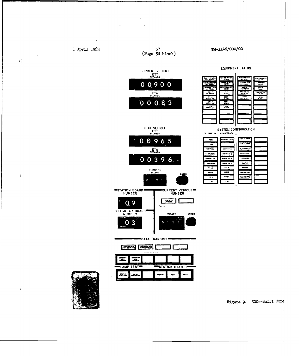
1
April
1963
57
TM-1146/OOO/OO
(Page
58
blank)
EQUIPMENT
STATUS
CURRENT
VEHICLE
ETT
SECONDS 0 *oooc coo
mocr 11.i;
ETA
,..
0NONCN*
CUScc"0
0
WTL00000NOO
I'A
NEXT
VEHICLE
SSE
OFGRTO
ETT SYSTEM
CONFIGURATION
SECONDS TELEMETRY COMD/7RA,•K
ETA
SECONOS
NUMtBE
R
==STATION BOARD
CURRENT VEHICLE==
NUMBER
NUMBER
TELEMETRY
BOARDm
NUMBER
TSELECTr
ENTE*
DATA
TRANSMIT
ELAMP
TESTm
ýSTATION
STATUS•
Figure
9.
SOC-0Shift
SuV0
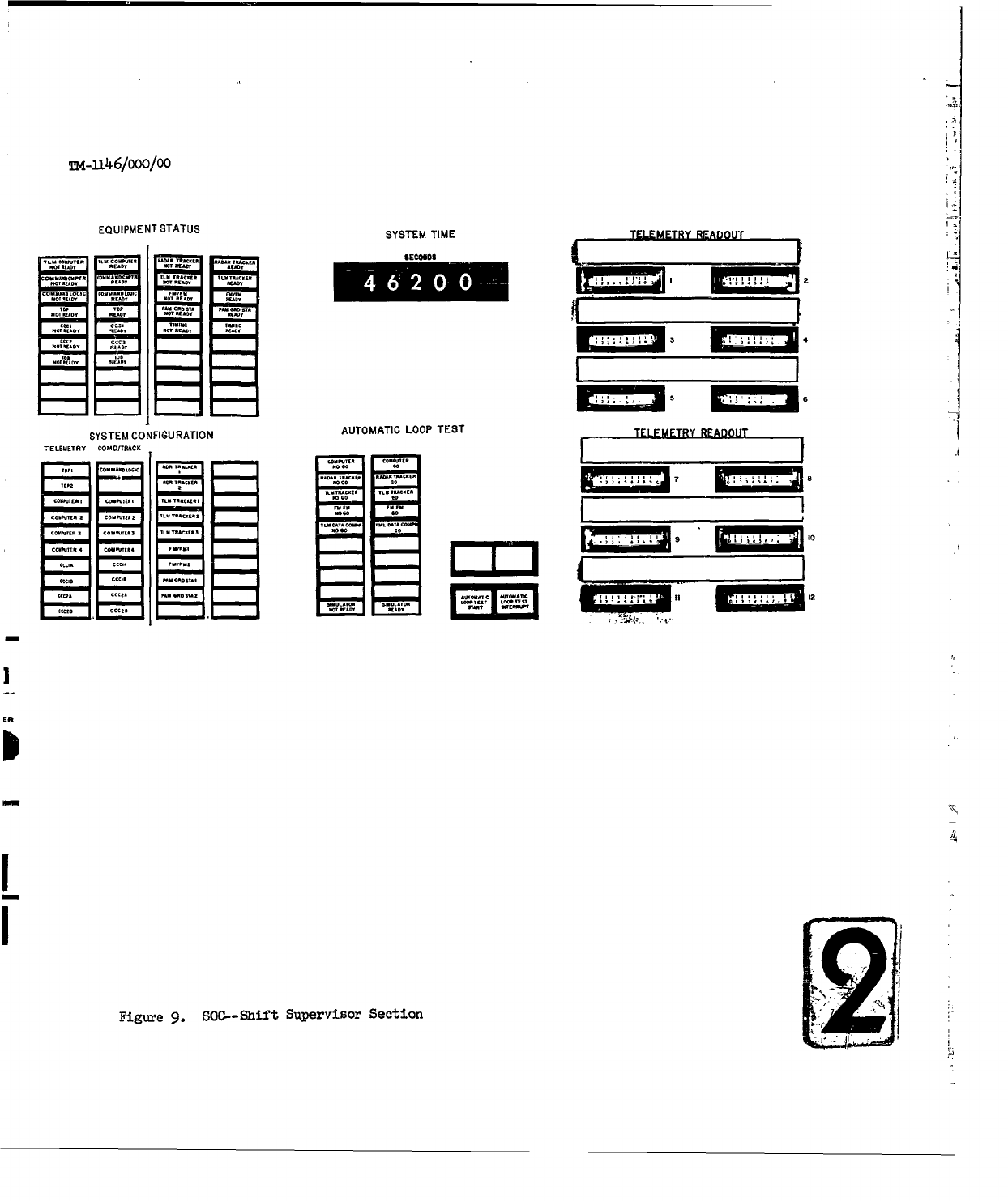
Tm-1146/oOO/0O
EQUIPMENT
STATUS SYSTEM
TIME
TELEMETRY
READOUTJ
•
liTn 01 OIITI
ON
lat 011(0(
SYSTEM
CONFIGURATION
AUTOMATIC
LOOP
TEST
TELEMETRY
READOUT
-ELEUETRY
COMO/0RACK
-E - E40
S .. ... ..... .-- I-
Ail..
TO
.. 0...
' 01 --
I
ITO-+
101
lO
100 00 1000|0
102
SOON
Figure
9.
SOC--Shift
Supervisor
Section
•
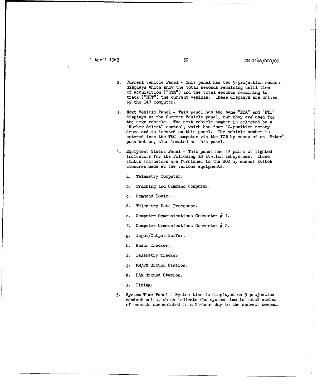
1
April
1963
59
TM-ll46/000/O0
2.
Current
Vehicle
Panel
-
This
panel
has
two
5-projection
readout
displays
which
show
the
total
seconds
remaining
until
time
of
acquisition
("ETA")
and
the
total
seconds
remaining
to
track
("ETT")
the
current
vehicle.
These
displays
are
driven
by
the
T&C
computer.
3.
Next
Vehicle Panel
-
This
panel
has
the
same
"ETA"
and
"ETT1"
displays
as
the
Current Vehicle
panel,
but
they
are
used
for
the
next
vehicle.
The
next
vehicle
number
is
selected
by
a
"Number
Select"
control,
which
has
four
10-position
rotary
drums
and
is
located
on
this
panel.
The
vehicle
number
is
entered
into
the
T&C
computer
via
the
IOB
by
means
of
an
"Enter"
push
button,
also
located
on
this
panel.
4.
Equipment
Status
Panel
-
This
panel
has
12
pairs
of
lighted
indicators
for
the
following
12
station
subsystems.
These
status
indicators
are
furnished
to
the
SOC
by
manual
switch
closures
made
at
the
various
equipments.
a.
Telemetry
Computer.
b.
Tracking
and
Command
Computer.
c.
Command
Logic.
d.
Telemetry
Data
Processor.
e.
Computer
Communications
Converter
# 1.
f.
Computer
Communications
Converter
#
2.
g.
Input/Output
Buffer.
h.
Radar
Tracker.
i.
Telemetry
Tracker.
A.
FM/FM
Ground
Station.
k.
PJAM
Ground
Station.
1.
Timing.
5.
System
Time
Panel
-
System
time
is
displayed
on
5
projection
readout
units,
which
indicate
the
system
time
in
total
number
of
seconds
accumulated
in a
24-hour
day
to the
nearest
second.
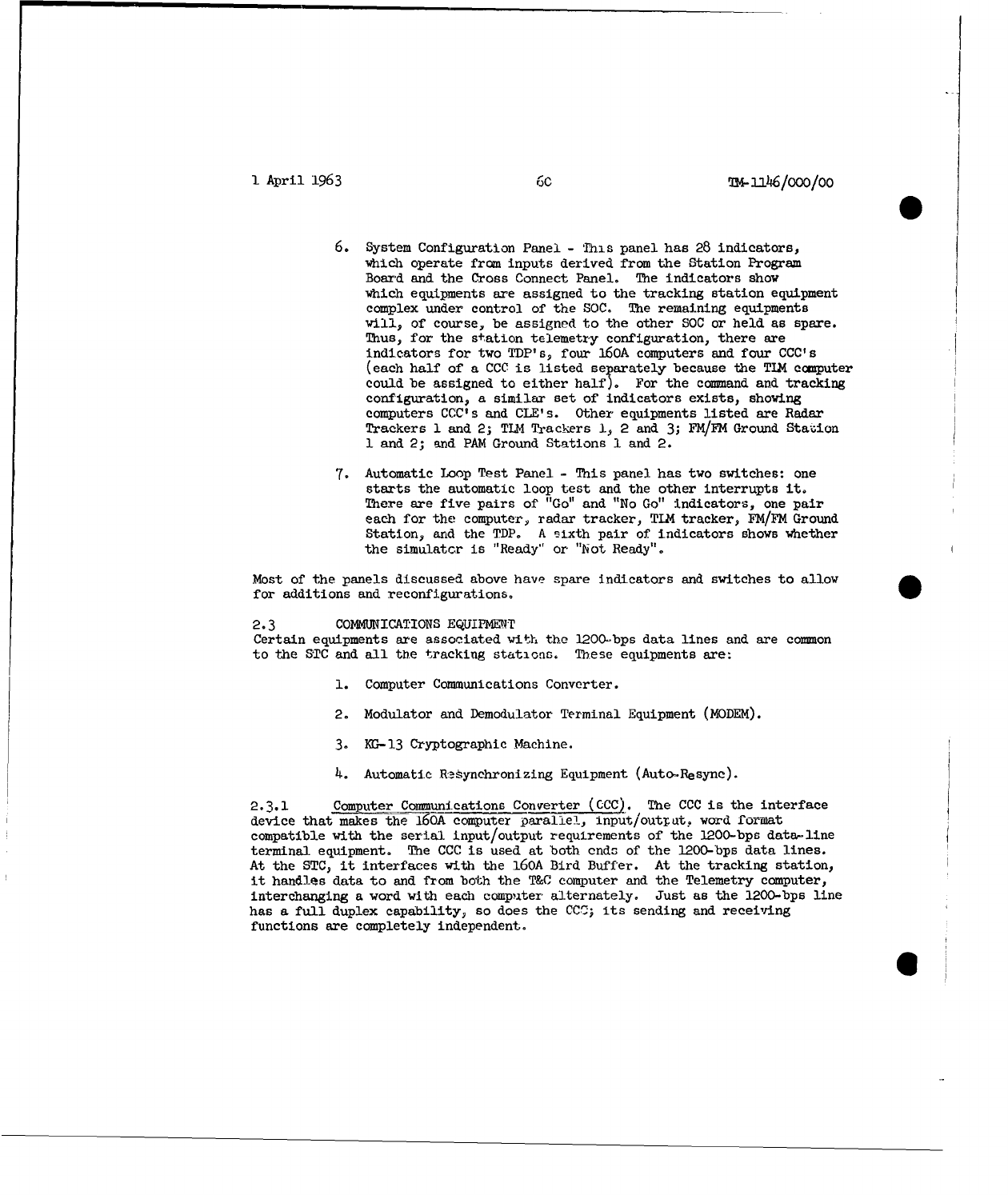
I
April
1963
6c
U&-ifJ6/ooo/oo
6.
System
Configuration
Panel
-
Ihis
panel
has
28
indicators,
which
operate
from
inputs
derived
from
the
Station
Program
Board and
the
Cross
Connect
Panel.
The
indicators
show
which
equipments
are
assigned
to
the
tracking
station
equipment
complex
under
control
of
the
SOC.
The
remaining
equipments
will,
of
course,
be
assigned
to
the other
SOC
or
held
as
spare.
Thus,
for
the
station
telemetry
configuration,
there
are
indicators
for
two
TDP's,
four
160A
computers
and
four
CCC's
(each
half
of
a
CCC
is
listed
separately
because
the
TIM
computer
could
be
assigned
to
either
half).
For
the
command
and
tracking
configuration,
a
similar
set
of
indicators
exists,
showing
computers
CCC's
and CLE's.
Other equipments
listed
are
Radar
Trackers
1
and
2;
TLM
Trackers
1,
2
and
3;
FM/FM
Ground
Stauion
1
and
2;
and
PAM
Ground
Stations
1
and
2.
7.
Automatic
Loop
Test Panel
-
This
panel
has
two
switches:
one
starts
the
automatic
loop
test
and
the
other
interrupts
it.
There
are
five pairs
of
"Go"
and
"No
Go"
indicators,
one
pair
each
for
the
computer,
radar
tracker,
TIM
tracker,
FM/FM
Ground
Station,
and
the
TDP.
A
sixth
pair
of
indicators
shows
whether
the
simulatc
r is
"Ready"
or
"Not
Ready".
Most
of
the
panels discussed
above
have
spare
indicators
and
switches
to allow
for
additions
and
reconfigurations.
0
2.3
COMMUNICATIONS
EQUIPMENT
Certain
equipments
are
associated
with
the
1200-bps
data
lines
and
are
common
to
the
STC
and
all
the
tracking
stations.
These
equipments
are:
1.
Computer
Communications
Converter.
2.
Modulator
and
Demodulator
Terminal
Equipment
(MODEM).
3.
KI-13
Cryptographic
Machine.
4.
Automatic
Resynchronizing
Equipment
(Auto.Resync).
2.3.1
Computer
Communications
Converter
(CCC).
The
CCC
is
the
interface
device
that
makes
the
160A
computer
parallel,
Input/outrat,
word
format
compatible with
the
serial
input/output
requirements
of
the
1200-bps
data-line
terminal
equipment.
The
CCC
is
used
at
both
ends
of
the
1200-bps
data
lines.
At
the
STC,
it
interfaces
with
the
160A
Bird
Buffer.
At
the
tracking
station,
it
handles
data
to
and
from
both
the
T&C
computer
and
the
Telemetry
computer,
interchanging
a
word
with
each
computer
alternately. Just
as
the
1200-bps
line
has
a
full
duplex
capability,
so
does
the
CCC;
its
sending
and
receiving
functions
are
completely
independent.
6@
.
April
1963
61
Tm-146/ooo/oo
The
CCC
has
four
modes
of
operation:
(1)
Sending,
(2)
Receiving,
(3)
No
Data,
and
(4)
Resync. Only
the
Resync
mode
excludes
the
other
modes.
In
the
Sending
mode,
when
a
computer
has
a
word
to
transmit
to
the
other
station,
it
sends
a
transmit request
to
the
CCC,
followed
by
a
12-bit data
word.
The
CCC
also
provides
an
interrupt
to
the
computer
at
the
end
of
each
data
transmission
cycle,
which
may
be
utilized
by
the
computer
to
assure
proper
timing
of
data
transfers
to
or
from
the
CCC.
Four
control
bits
are
added
to
the
word
for
identification
of
the
source
and
destination
of
the
word,
for
parity
check,
and
for
synchronization.
The
resultant
16-bit
word is
then
passed
to
the
1200-bps
line
terminal
equipment.
An
internally
generated
resync
word
is
sent
after
each
128
words.
In
the
Receiving
mode,
the
16-bit
word
is
stripped
of
its
4
control
bits
and
placed
serially
into
the
output
register,
where
it is
ready
for
parallel
transmission
to
the
proper
computer.
The
CCC
furnishes
an
interrupt
to
the
computer
which
will
accept
the
word.
The
No
Data
mode
is
entered
when
there
is
no
word
to
be
transmitted
by
a
computer.
Where
a
CCC
is
interfaced
with
two
computers,
and one
computer
has
no
word
to
transmit,
the
CCC
accepts
alternate
words from
one
computer,
after
sending
an
interrupt to
the
non--transmitting
computer
each
time
its
turn
to
transfer
a
word
comes
up.
When
there
is
no
word
to
be
transferred
from
either
computer,
the
No
Data
mode
is
entered
and
the
CCC
generates
an
internal
word
for
transmission
to
the
CCC
on
the
other
end
of
the
line.
This
self-generated
word
is
used
to
keep
the
system
in
synchronism,
and
is
not
transferred
beyond
the
CCC.
The
Resyn-
mode
is
entered
when
the
system
drops
out
of
synchronism.
In
this
condltion,
sync
data
words
are
exchanged
by
the
two
CCC's
at
each
end
of
the
line.
The
128--word
counters are
reset to
zero
when
synchronism
is
reestablished
and
the
CCC's
enter
one
of
the other
three
modes.
2.3.2
Modulator
and
Demodulator
Terminal
Equipment
(MODEM).
The
inter-
Station
Communication
Modulator
and
Demodulator
(MODEM)
Terminal
Equipment
is
designed
to
interface
the
1200-bit
data
lines
to
the
high-speed
cryptographic
equipment
(KG-13).
Each
duplex
line
that
is
used
to
communicate
with
the
STA
will
require
a
MODEM
at
each
end
of
the
line.
The
MODEM
is
used
at
the
transmitting
terminal
to
transform
the
input
digital
data
into
a
form
suitable
for
transmission
over
voice-communication
circuits.
At
the
receiving
terminal, the
MODEM
restores
the
information
to
its
original
digital
form.
In
addition,
the
MODEM
supplies
a
bit-rate
timing
pulse
to
the
KG-13,
Auto-Resync,
and Computer
Communications
Converter
(CCC)
equipment,
and
is
capable
of
operating
between
0
and
50,000
bits
per
second.
1
April
1963
62
T-1l
4
6/ouo/oo
2.3.3
KG-13
Cryptographic
Machine.
The
KG-13
is a
cryptographic
machine
that
is
used
on
the
1200-bps
line.
The
KW-26
cryptographic
unit
will
be
standard
equipment
for
the
lOO-word-per-minute
teletype
line.
The
KW-26
does
not
require
the
MODEM
to
interface
it
with
the
teletype
transmission
lines.
The
word
length
that
the
KG-13
can
handle
is
limited
to
16
bits.
A
word
length
of
16
bits
has
been
selected
as
a
standard
transmission
word
length
for
the
Augmented
System.
Of
these
16
bits,
only
12
can
be
used
to
transmit
data.
The
other
4
bits
are
used
by
the
Inter-Station
Communication
System
as
control
bits.
2.3.4
Automatic
Resynchronizing
Equipment
(Auto-Resync).
The
Auto-Resync
Equipment
is
part
of
the
Inter-Station
Communication
System.
It is
used
to
check,
sense,
and
perform
the
commands
and
routines
necessary
for
maintaining
the
integrity
of
the
transmitting
and
receiving
cryptographic
equipment.
This
equipment
interfaces
with
the
KG-13
and
the
CCC,
via the
Communication
Data
Select
and
Cross
Connect
Unit
(CDSCCU)
and
MODEM.
Normal
use
of
the
KG-13
requires
manual
intervention
to
place
the
equipment
back
on
the
line
if.,
for
some
reason,
improper
line
response
has
been
detected.
The
amount
of
time
to
manually
resync
a
single
KC-13
would
probably
be
acceptable:
but
if,
for
some
retor,,
a
power
fluctuation
should
occur
and
two
or
more
Ko-13's
lose
sync,
the
resyncing
time
1¢ould
be
intolerable.
It was
for
this
reason
that
the
Auto.Resync
unit
was
designed
to
take
over
the
manual
resynchronization
job.
The
Auto-Resync
Equipment
Is
designed
to
perform
the
following
functions:
1.
Interface
with
the
Inter-Station
Communication
System
equipment
at
operating
Tates of
between
0
and
50,000
bits
per
second.
2.
Originate
a
resynchronization
when
(1)
phase
lock
is
lost
or
(2)
in
response
to
a coimnand
from
the
CCC
or
from
the
remote
Auto
Resync
Unit.
3.
Respond
to
a
request
from
a
remote
Auto-Resync,
the
CCCor
the
KG-
13.
4.
Tally
and
li._o
the
number
of
resync
operations.
This
limit
is
variable
and
is
controlled
by
security.
5.
Verify
the
validity
of
resync
before
releasing
the
circuit
for
data
operation.
6.
Prohibit
the
transmission
of
data
into
or
out
of
the
KG-13
equipment.
7.
Give
an
indication
whenever
a
resync
operation
is in
progress.
1
1
April
1963
63
-m-
,146/uuu/uO
The
Auto-Resync
is
considered
to
be
in
its
Operate
mode
when
it is in a
quiescent
state
(the
ED-13
is in
a
Transmit
mode.)
On
command,
the
Auto-
Resync
will
be
switched
into
a
Resynchronization
mode
or
to
an
Alarm
Check
mode.
After
performing
the
functions
necessary
to
satisfy
the
conditions
that
may
exist,
it
will,
if
possible,
revert
back
to
the
Operate
mode.
Should
it
fail
to
obtain a
resync
condition,
an
alarm
will
be
given,
via
the
CCC,
to
the
cryptographic operator
and
to
the
Bird
Buffer.
1
April
1963
64
TK-
3146/ooo/oo
3°0
TRACKNG
FUNCTIONAL
DESCRIPTION
3o1
GENERAL
Tracking
stations
are
the
sensing
elements
of
the
SCFo
All
satellite
data
enter
the
data
processing
system
at
the
STC
through
the
tracking
stations.
Data
transfer
between
the
STC
and
a
tracking
station
is
effected
by
a
CDC
160A
Bird
Buffer
computer
at
the
STC
and
the
two
CDC
160A
computers
at
the
tracking
station,
via
the
12CO-bps
line.
One
of
the
two
CDC
160A
computers
at
the
tracking
station
processes
all
tracking
data;
it is
called
the
Tracking
and
Command
(T&C)
computer.
The
other
CDC
160A
processes
telemetry
data.
There
are
two
modes
of
operation
by which
the
Bird
Buffer
interacts
with
a
T&C
computer.
One mode,
called
the
Satellite-Contact
mode,
provides
real-time
support
for
a
satellite.
The
other
mode,
the
Non-Satellite-Contact
mode,
effects
such
non-real-time
functions
as
transmitting-antenna-pointing
information,
inter
changing
administrative
messages,
and
forwarding schedule
information.
Both
modes
of
operation
are
used
in
the
tracking
function.
3.2
PREPASS
MESSAGE
A
few
hours
prior
to
an
exoected
station
contact
with
a
particular
satellite,
an
acquisition
message
is
sent
from
the
STC
to
the
T&C
computer
at
the
tracking
station.
This
message
will
have
been
generated
by
a
1604
computer
at
the
STC,
using
all
available
known
and
calculated
orbital
information
on
6
the
particular
vehicle
to
be
tracked.
These
data
are
then passed
to
a
Bird
Baffer
vla
the
1615
tape
unit
and
are sent
to
the
tracking
station
during
operation
in
the
Non-Satellite-Contact
mode. At
the
tracking
station,
the
acquisition
message
is
stored
in
the
magnetic
tape
memory
of
the
T&C
computer.
This
message
specifies
the
tracking
and
telemetry
antennas
to
be
used,
and
the
antenna
driving
information,
which
consists
of
azimuth,
elevation,
and
range
in
local
coordinates
for
successive equal-time
intervals
over
the
duration
of
the
pass.
In
addition
to
the
prepass
acquisition
message,
an
administrative
message
is
sent,
which
specifies
the passes
or
portions
of
passes
during
which
the
station
for
each
pass
is
specified,
including
the
number
of
the
pre-wired
patchboard
that
will
be
used
and
the
manual
switch
actions
that
are
to
be
taken.
3.-3
ACQUISITION
Five
minutes
before
the
scheduled
time
for
the
first
pass,
the
SOC
operator
at
the
tracking
station
will
switch
the
slave-data
message
from
the
tracking
computer
to
the
slave-data
bus.
These
data
position
the tracking
radar
antenna
in
azimuth,
elevation,
and
time
to
the
predicted
acquisition
point
for
the
vehicle.
They
also
stert
the
raster
scan
in
a
search
for
radar-return
signals
from
the
vehicle.
If
acquisition
is
not
made
at
the
acquisition
6!
1
ApIr
1963
64
x-1iJ46/uuu/oo
3°0
TRACKING
FUNCTIONAL
DESCRIPTION
3o1
GENERAL
Tracking
stations
are
the
sensing
elements
of
the
SCF.
All
satellite
data
enter
the
data
processing
system
at
the
STC
through
the
tracking
stations.
Data
transfer
between
the
STC
aud
a
tracking
station
is
effected
by
a
CDC
160A
Bird
Buffer
computer
at
the
STC
and
the
two
CDC
160A
comuters
at
the
tracking
station,
via
the
1200-bps
line.
One
of
the
two
CDC
160A
computers
at
the
tracking
station
processes
all
tracking
data;
it is
called
the
Tracking
and
Command
(T&C)
computer.
The
other
CDC
160A
processes
telemetry
data.
There
are
two
modes
of
operation
by
which
the
Bird
Buffer
interacts
with
a
T&C
computer.
One mode,
called
the
Satellite-Contact
mode,
provides
real-time
support
for
a
satellite,
The
other
mode,
the
Non-Satellite-Contact
mode,
effects
such
non-real-time
functions
as
transmitting-antenna-pointing
information,
inter
changing
administrative
messages,
and
forwarding
schedule
information.
Both
modes
of
operation
are
used
in
the
tracking
function.
3.2
PREPASS
MESSAGE
A
few
hours
prior
to
an
expected
station
contact
with
a
particular
satellite,
an
acqujisition
message
is
sent
from
the
STC
to
the
T&C
computer
at
the
tracking
station.
This
message
will
have
been
generated
by
a
1604
computer
at
the
STO,
using
all
available
kniown
and
calculated
orbital
information
on
0
the
particular
vehicle
to
be
tracked.
These
data
are
then
passed
to
a
Bird
Buffer
via
the
1615
tape
unit
and
are sent
to
the
tracking
station
during
operation
in
the
Non-Satellite-Contact
mode.
At
the
tracking
station,
the
acquisition
message
is
stored
in
the
magnetic
tape
memory
of
the
T&C
computer.
This
message
specifies
the
tracking
and
telemetry
antennas
to
be
used,
and
the
antenna
driving
information,
which
consists
of
azimuth,
elevation,
and
range
in
:Local
coordinates
for
successive
equal-time
intervals
over
the
duration
of
the
pass.
In
addition
to
the
prepass
acquisition
message,
an
administrative
message
is
sent,
which
specifies
the
passes
or
portions
of
passes
during
which
the
station for
each
pass
is
specified,
including
the
number
of
the
pre-wired
patchboard
that
will
be
used
and
the
manual
switch
actions
that
are
to
be
taken.
3.o3
ACQUISITION
Five
minutes
before
the
scheduled time
for
the
first
pass,
the
SOC
operator
at
the tracking
station will
switch
the
slave-data
message
from
the
tracking
computer
to
the
slave-data
bus.
These
data
position
the
tracking
radar
antenna
in
azimath,
elevation,
and
time
to
the
predicted
acquisition
point
for
the
vehicle,
They
also
start
the
raster
scan
in a
search
for
radar-return
signals
from
the
vehicle.
If
acquisition
is
not
made
at
the
acquisition
6
1
April
1963
65
TM.1146/O00/00
point
at
the
predicted
time,
the
tracking
radar
follows
the predicted
orbit,
and
continues the
raster
scan
about
the
predicted point,
until
the
vehicle
is
acquired.
During
acquisition,
the
error
developed
by
the
raster
scan
is
driven
to
zero
by
the
servo loop of
the
tracking
radar,
which
signifies
that
the
antenna
is
pointed
at
the
vehicle.
When
this
stage
is
reached,
the
track-
radar
"locks-on"
to
the
vehicle,
the predicted
acquisition
data
are
removed
from
the
slave-data
bus,
and
the
tracking
radar
begins
to
supply
the
antenna
driving
information
for
the
slave-data
bus.
For
a
period
of
five
minutes
after
acquisisti.on,
the
tracking data
will
be
compared
with
the
predicted
data
from
the
acquisition
message
by
the
tracking
computer.
The
results
of
this
comparison
are
available
only
at
the
tracking
station
and
enable
the
operator
to
determine
whether
the
actual
tracking
data
and
the
predicted
data
are
in
agreement..
If
they
are
not,
he
must
determine
whether
the
fault
is
local
with
the
tracking
radar
or
whether
inaccurate
acquisition
data
were
furnished
by
the
STC.
In
the
former case,
local
correction
is
made;
in
the
latter
case,
the
STC
is
notified
of
the
error
by
means
of
an
administrative
communication
channel
(telephone or
teletype).
3.
h
TRACK
HISTORY
Digitally
coded
tracking
data,
taken
from
the
tracking
radar
and
one
telemetry
tracker,
are
stored
in
the
tracking
computer.
There,
the
data
are
compressed
and
sent
to
the
STC
in
close-to-real
time.
These
data
are
not
printed
out
at
the
Bird
Buffer
but
are
passed
to
the
1615
tape
units
for
storage,
where
they
are
available
for the
1604
orbit
determination
program.
This
program
fits
tracking
data
from
various
tracking
stations
together
to
find
and
update
the
vehicle
ephemeris
for
the
preparation
of
acquisition
messages.
i
April
1963
66
0M41U46/000/00
4.O
TELE4ETRY
FUNCTIONAL
DESCRIPTION
4.1
G(MERAL
It is
of
vital
importance
to
the
satellite
research
and
development programs
serviced
by
the
Augmented
SCF
that
adequate
and
reliable
telemetry processing
facilities
be
available.
The
Augmented
SCF
is
designed
to
provide
these
facilities
with
a
degree
of
flexibility
and
automation
not
hitherto
obtainable.
A
unique
feature
of
the
Augmentation
program
is
that
selected
telemetry
data
received
from
the
satellite
vehicle
are
processed
in
real
time
and
displayed
in
the
proper
engineering
units
to
the
Test
Controllers,
at
the
same
time
that
the
reported
events
in
the vehicle
are
actually
taking
place.
This
is a
decided
advantage
to
the
technical
personnel
directing
the
various
programs.
The
capability
exists
to
change
the
parameters of
a
processing
algorithm
or
to
zhange
the
whole
telemetry
mode
during
a
pass;
however,
the
latter
change
occasions
the
loss
of
some
data
during
the
time
the
new
program
is
being
read
into
the
processing
computer.
Telemetry
operations
are
under
the
control
of
the
Test
Controllers
at
the
STC
and
the
need
for
the
relaying
of
informa-
tion
by
telephone
from
the
tracking
stations
to
the
STC
is
reserved
for
emergency
equipment
failures
or
unusual.
situations.
4.2
TEI2MERY
PROCESSING
OUrPUTS
The
STC
provides
telemetry
processing
instructions
to
the
TIM
160A
computer
at
the
tracking
station
and
provides
printout
format
instructions
with
conversion
units
to
the
Bird Buffer.
The
tracking
station
receives
telemetry
processing
inputs
from
the
prepass
module,
SPREP,
at
the
STC
in
the
form
of
instructions
on
which
telemetry
points
are
to
be
processed,
what
algorithms
are
to
be
used
with
each
telemetry
point,
and
other
telemetry
processing
information.
'Me
Bird Buffer
receives telemetry
data
inputs
from
the
tracking
ý+-tion
and
receives
processing
instructions
from
the
1604
pertaining
to
the
printer
formats
and
conversion
routines
to
be
used.
Outputs
to
the
tracking
station
and
the
remote
printers
are
provided
by
the
STC
during
the
following
operational
modes:
1.
Preflight
mode.
2.
Prepass
mode.
3.
Real
Time
Telemetry
Processing
mode.
4.21.
Preflight
Mode.
During
the
Preflight
mode,
the
1604
(or
an
off-
line
computer)
generates,
from
punched-card
input,
a
library
tape
containing
files
of
mode-specific
information.
A
mode
is
defined
as
a
specification
to
the
tracking
station
of
the
following
telemetry
information:
1
April
1963
67
2l4-1146/OOO/OO
1.
Selection
of
the
ground
station
patchboard.
2.
Number
of
TIM
link.
3.
Processing
priority.
4.
Format
for
transmission
on
the
1200-bps
line.
5.
Algorithms
to
be
used.
6.
Scanner
&
Digitizer
patchboard
parameters.
During
the
Preflight
mode.
the
conversion
routines
and
remote
printer
formats
are
specified
to
the
TIM
Processing
mcdule.
Each
flight
may
have
several
modes
because
the
telemetry
parameters,
algorithms,
and
sampling
rates
may
change
from
pass
to
pass.
Telemetry
information
con-
taining
the
mode-specific
information
generated during
preflight
by
the
1604
program
would
be:
1.
Preflight
TIM
messages
for
each
station.
Information
for
all
modes
of
the
satellite.
2.
Scanner
&
Digitizer
wiring
instructions
for
all
modes.
3.
Conversion
and
printer
tables
for
the
TIM
Processing
module
at
the
STC.
Upon
request, the
Bird
Buffer
transmits
the
telemetry
processing
information,
previously
stored
on
the
Prepass
Tape
by
SPREP,
to
the
tracking
station
TIM
160A.
The
tracking
station
then
performs
the
necessary
functions,
as
instruct-
ed
by
the
preflight
telemetry
processing
information.
The
T1M
160A
has
available
the
necessary
information
for
processing
the
telemetry
data
for
all
modes
of
the
flight.
Conversion
instructions
and
printer
formats
for
each
mode
are
available
to
the
Bird
Buffer.
4.2.2
Prepass
Mode.
A
card input
to
the Bird
Buffer
specifies
to
the
tracking
station
what
mode
to
use
before
each
pass
and
generates
a
mode
selection
message.
Upon
confirmation
from
the
TIM
16OA
at
the
tracking
station
that
it is
prepared
to
operate
in
the
correct
mode,
the
STC
Prepass
module
reads
into
core
the
appropriate
mode-specific
data
for
the
remote
printer
format
and
conversion
units.
4.2.3
Real
Time
Telemetry
Processing
Mode.
During
a
pgss,
the
TIM
160A
transmits
to
the
Bird
Buffer
three
types
of
FM/FM
telemetry:
(1)
"Fixed
Format"
Telemetry
Parameters,
(2)
"Event"
Telemetry
Parameters,
and
(3)
Status
and
Alarm
Messages.
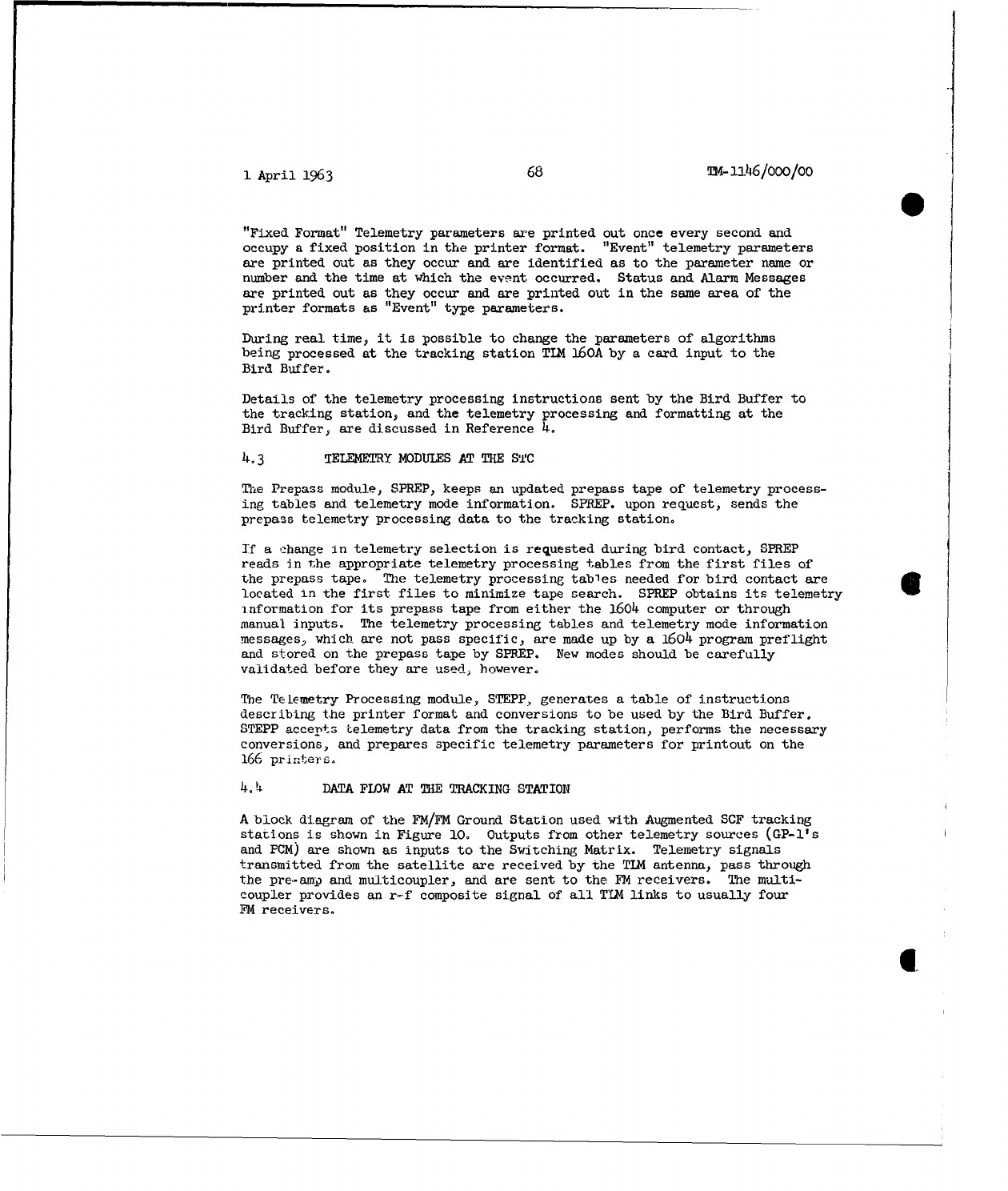
1
April
1963
68
TM-1146/000/00
"Fixed
Format"
Telemetry
parameters
are
printed
out
once
every
second
and
occupy
a
fixed
position
in
the
printer
format.
"Event"
telemetry
parameters
are
printed
out
as
they
occur
and
are
identified
as
to
the
parameter
name
or
number
and
the
time
at
which
the
event occurred.
Status
and
Alarm
Messages
are
printed
out
as
they
occur
and
are
printed
out
in
the
same
area
of
the
printer
formats
as
"Event"
type parameters.
During
real
time,
it is
possible
to
change
the
parameters
of
algorithms
being
processed
at
the
tracking
station
TIM
160A
by
a
card
input
to the
Bird
Buffer.
Details
of
the
telemetry
processing
instructions
sent
by
the
Bird
Buffer
to
the
tracking
station,
and
the
telemetry
processing
and
formatting
at
the
Bird Buffer,
are
discussed
in
Reference
4.
4.3
TELEMETRY
MODULES AT
THE
STC
The
Prepass
module,
SPREP,
keeps
an
updated
prepass
tape of
telemetry
process-
ing
tables
and
telemetry
mode
information.
SPREP.
upon
request,
sends
the
prepass
telemetry processing
data
to
the
tracking
station.
If a
change
In
telemetry
selection
is
requested
during
bird
contact,
SPREP
reads
in
the
appropriate
telemetry
processing
tables
from
the
first
files
of
the prepass
tape.
The
telemetry
processing
tables
needed
for
bird
contact
are
located
in
the
first
files
to
minimize
tape
search.
SPREP
obtains
its
telemetry
information
for
its
prepass
tape
from
either
the
1604
computer
or
through
manual
inputs.
The
telemetry
processing
tables
and
telemetry
mode
information
messages,
which
are
not pass
specific,
are
made
up by
a
1604
program
preflight
and
stored
on
the prepass
tape
by
SPREP.
New
modes
should
be
carefully
validated
before they
are
used,
however,
The
Telemetry
Processing
module,
STEPP,
generates
a
table
of
instructions
describing the
printer
format
and
conversions
to
be
used
by
the
Bird
Buffer.
STEPP
accepts
Lelemetry
data
from
the
tracking
station,
performs
the
necessary
conversions,
and
prepares
specific
telemetry
parameters
for printout
on
the
166
printers.
4.
4
DATA
FLOW
AT
THE
TRACKING
STATION
A
block
diagram
of
the
FM/FM
Ground
Station
used
with
Augmented
SCF
tracking
stations
is
shown
in
Figure
10.
Outputs
from
other
telemetry
sources
(GP-l's
and
PCM)
are
shown
as
inputs
to
the
Switching
Matrix.
Telemetry
signals
transmitted
from
the
satellite
are
received
by
the
TIM
antenna,
pass
through
the
pre-amp
and
multicoupler,
and
are
sent
to
the
FM
receivers.
The
multi-
coupler
provides
an
r-f
composite
signal
of
all
TIM
links
to
usually
four
FM
receivers.
II
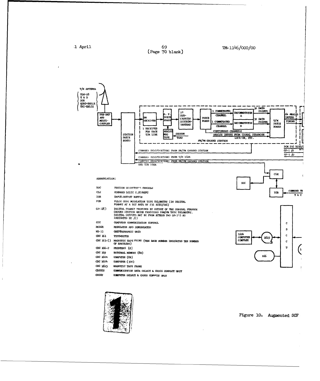
•1
April
69
TM-
146/0O00/O0
(Page
70
blank)
Dl(RM
BADICESWP0ANN
3
CHA ANTENNA
~~I/OI^ DII
VDR FIANDT10CCS !ATMrF
/FM GROUNDR
•
AAIOH
ANHA/M NOA
TTIO18 F AAT TE
IN
LINK ROANAI6X
I0NF/
AND/FD
CTARDST•I
PROBSSA•C
CC*CCORS DE(PTO•
M--lFIlGO _ND
TT NcH
OI NECI~_K,
IIAIN FHANNE R'l
FBOAUNRDATO
BOARD
MGONSODA
TOR AND SI)U
CDC 11 TYEWRIT C -
ICC4MI
W11ATIOION
OBlifl
M/ GRUN SATONT
_
CLI~~RO LDI'/AN GROUN STATION3FIO
ABBRVIA FON. OD';IIAINfF T~I.IY
I
IIA
C DPULECOIDTA
PE
ODFULOA N NE F ROM
(I
N DIGITAL
40313
ATCRI•N
BIC
NATE
OF
2
SrOSS0C
I
GP-
I#()
DAGITL
TELET
FRM
(IFl
BOU
• P NUT
OF.IR
GNA L SH E
C
I
CATED FiBuY 0Ame)
CCC
36A
COMPUTER
(8K)
AIO
CNRO
CDC 163
fEWIE
604
'uC(a CCC~~CCFUF 1a5 N6ICTPEFR5
CDC
13-()
9U4MIC
TAP
VN E
DATAHELC&
(DSS
CNUME
NDICATE MENMR411LE
CDCW10 COMPIUTER
(E8K)
155(4EO
I
Figure
10.
Augmented
SCF
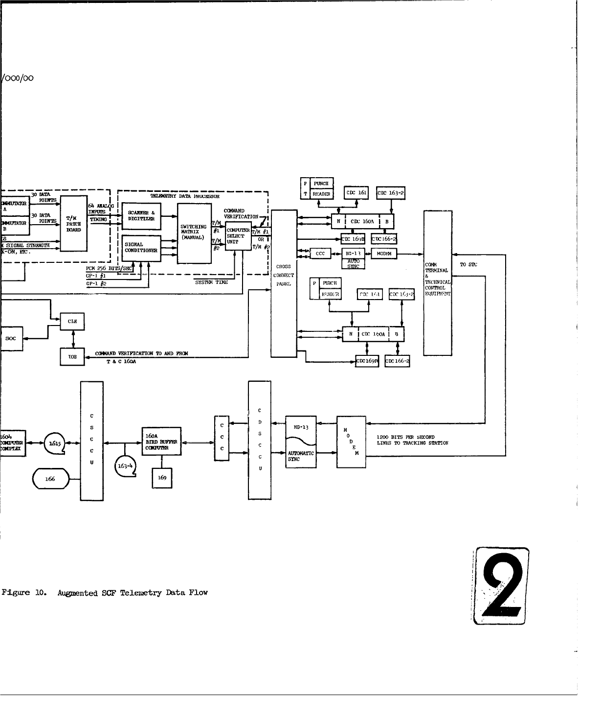
000/00
P
PUINCH[
30NA~
DAA
MMao - - T
REDE
CDCI 161 CDXC
163-2
A
30
DAETA.
INUT
ISANNER
&COMN
ThW1
DIGITIZER VERIFICATION
*4TTR PO M PATC~H TNIcc1o,
SIGSWITCHINGGT
BOAR MARXG1CRPTR M#
7- -(ANUAL) SELEC
SIGA
TMoSGALAcT
UI
RI c1,
c16
M.
CNDITONE
#2
OM
6ol MR
Figur 20. BITSnt SEP CROSetr COWa
Flo
2T
1
April
1963
71
TM-1146/000/00
The
outputs
of
the
FM
receivers
are
then
routed
simultaneously
to
the
7-track
analog
tape
recorders
and
the
18
subcarrier
discriminators
(SCD's).
Four
tracks
of
the
analog
tape
recorder
are
used
for
recording
the
outputs
of
the
FM
receivers
(one
to
each
track),
while
the
other
three tracks
are
used
for
system
time,
reference
signals,
receiver
signal
strengths,
and
voice.
The
outputs
of
the
SCD's
are
fed
to
a
patchboard,
where
two
commutated
channels
selec•ted
from
the
SCD's
are
routed
to
two
decommutators.
Each
decommutator
has
the
capability
of
decommutating
30
data
points
from
each
commutated
channel.
A
total
of
64
data
pointb
are
fed
into
the
Scanner
&
Digitizer
through
the
TIM
patchboard.
The
64
data
noints
consist
of
outputs
from
the
rwc
decommutators,
the
continuous channels
the
-eceiver
signal
strength
lock-
on
indicators,
and
other
analog
function
The
64
analog
inputs
can
be
sampled
at
a maximum
rate
of
25
kc
and
a
minimum
rate
of
5
cps.
The
digitized
outputs
cf
the
Scanner
&
Digitizer
(8-bit
words)
can
be
fed
into
the
Switching
Matrix
together
with
three
digitized
inputs
from
the
two
GP-l's
and
PCM
equipment.
The
Switching
Matrix
manual
patchboard
outputs
two
of
the four
inputs
to
the
Computer
Select
Unit
(CSU).
The
TI24
160A.
which
controls the
CSU,
selects
one
of
the
two
telemetry
inputs
to
the
CSU
for
processing.
The
telemetry
data
are processed,
compressed,
and
formatted
by
the
tracking
station
general-
purpose
telemetry
program,
TIMOP.
Information
concerning
the
data
points
to
be
processed. the
specific
algorithms
associated
with
each
data
point,
the
sampiing
rates
to
be
used,
and
other telemetry
processing
is
sent,
duriLI6
the
preflight,
prepass,
and
real-time
telemetry-processing
modes,
from
the
STC
Bird
Buffer
by
the
Prepass
module,
SPREP.
The
outputs
of
the
TIM
160A
computer
(and
the
T&C
16CA)
are
controlled
by
the
Computer
Communication
Converter
(CCC).
Outputs of
the
CCC
are
passed
through
the
KG-.13,
MODEM,
and
then
to
the
STC
over
the
1200-bits/sec
communicatl
on
lines.
4,
5
DATA
FLOW
AT
THE
STC
At
the
STC.
data
from
the
tracking
station
pass
through
the
MODEM
and
the
&(1,-13:,
and
are
received
by
the
CCC
and
transferred
to
tho
Bird
Buffer.
At
the
Bird
Buffer,
the
Telemetry
Processing
module,
STEPP,
converts
the
telemetry
data
to
the
desired
engineering
units
and
outputs
preselected
data
points
on
the
various
remote
printers.
4.
6
TELEME'RY
OPERATIONAL
PROGRAM
(Ti-IOP)
TLMOP
is a
general-purpose
operational
program
for
processing, formatting,
and
controlling
the
transmission
of
telemetry
data
at
the
tracking
staticns.
TI40P
is, in
general,
non
satellite-specific
and
can
process
each
type
of
data
processed
by
the
Telemetry
Data
Processor
(TDP).
1
April
1963
72 TM-1146/Ooo/Oo
TIMOP
operates
in
prepass,
pass,
and
postpass
functions.
The
prepass
function
is
used
to
receive
and
process prepass
instructions
from
the
STC
during
the
Bird
Buffer's
p
reflight
and
prepass
modes.
The
instructions
contain
informa-
tion
concerning
telemetry
processing,
as
specified
by
the
STC
Prepass
module,
SPREP.
The
tracking
station
prepass
program
stores
and
prints
out,
upon
direction,
prepass
messages
for
each
vehicle.
This
printout
could
include
a
schedule
of
all
vehicles
and
ETA's
contained
in
the
prepass
message.
During
the
pass
function,
which
corresponds
to the
Bird
Buffer's
real-time
telemetry
mode,
TIMOP
accepts
digital
telemetry
data
from
any
one
of
four
sources
(TDP,
two
GP-l's,
or
PCM)
and
processes
these
data
in
accordance
with
instructions
from
the
STC. TIMOP,
during
the
pass
function,
supplies
a
system-time
code
word
(STCW)
and
the
compressed
telemetry
data to
the
STC.
The
following
functions
are
accomplished
in
the telemetry
processing
by
TIMOP:
1.
Reasonableness
checks
of
telemetry
data.
2.
Smoothing
calibration
points
and
normalization
of
data,
if
required.
3.
Compression
of
acceptable
data
and
reporting
of
step
function
levels,
periodic
time
tagged
data-point
values,
time-tagged
data-point
minimum/maximum
values,
time
of
event,
and
other
functions
as
required.
The
STC
can
request
TIMOP
to
process
different
telemetry
points
and
to
use
different
algorithms
during
a
pass.
TU4OP
can
detect
a command
verification
in
the
digital
telemetry
input
to
the
TIM
160A.
TIMOP
transmits
this
infor-
mation
to
the
STC
and
prints
it
on
a
166
printer
at
the
tracking
-tation.
Command
verification
information
may
also
be
transmitted
to
the
T&C
160A,
if
required.
The
data
for
the
postpass
program
are obtained
from
either
digital
or
analog
tapes
recorded
during
the
pass
function
and
are
transmitted
to
the
STC
during
the
Bird
Buffer's
Real-Time
mode.
The
STCW
on
the
tape
corresponds
to
the
system time
when
the
data
were
recorded.
The
tracking
station
con-
figuration
and
telemetry
processing information
during
postpass
is
the
same
as
that
specified
during
the
pass
function.
If
desired,
telemetry
data
can
be
displayed
on
a
166
printer
without
transmission
to
the
STC.
1
April
1963
73
Tm-li46/ooo/oo
5.0
COMMANDING
FUNCTIONAL
DESCRIPTION
5o1
GEERAL
The
ability
to
control
the
functions
of
a
satellite
vehicle
and
its
payload
is
just
as
important
as
the
ability
to
acquire
and
track
it.
Control
of
a
satellite
depends
upon
the
ability
to
establish
two-way
communication
with
it
while
it is in
orbit.
T.o-way
communication
is
necessary
to
allow
the
Test
uontruotev
Vo
oend
h.16
.....
=d:.
to
the
sIatlite
and
to verify
that
they
have
been
received
and
executed.
The
requirements
for
cammanding
a
satellite
vary
with
the
type of
satellite
and
its
mission.
The
means
of
accomplishing
the
command
function
vary
accordingly.
In
general,
commands
are
transmitted
to
satellite
systems
to
perform
the
following
types
of
functions:
1.
Set
or
reset
a
Fairchild
timer
and
shorten
or
lengthen
timer
periods.
(The
Fairchild
timer
turns
equipment
in
the
satellite
on
or
off
at
predetermined
times.)
2.
Send
Stored
Program
Commands
(SPC's)
to
turn
equipment
on
or
off
at
the
proper
time.
3.
Turn
beacons,
payload,
or
telemetry
systems
on
or
off
with
Real
Time
Commands
(RTC's).
4.
Adjust
or
calibrate
internal
systems;
initiate
special
events
such
as
engine
ignition,
separation,
or
recovery.
Different
techniques are
used
to
modulate
the
various
transmitters
used
for
commanding
in
order
to
effect
the transmission
of
commands
to
the
satellites.
These
are
explained
in
detail
in
Reference
3.
There
are
two
main
types
of
command
systems
that
are
of
interest:
analog
systems
and
digital
systems.
The
analog
systems
utilize
a
three-pulse-group
transmission,
with
command
information
carried
by
time
modulation
of
the
center
pulse.
(See
Figure
11.)
The
digital
systems
use
various
forms
of
modulation,
such
as
tone
or
pulse
spacing,
to
send
a
"one"
or
"zero"
each
time
a
pulse-code
group
is
transmitted.
A
succession of
these
binary
bits
form
digital-command
words, which
the
logic
in
the
satellite
command
package
translates
into
relay
closures
at
specific
times.
Two
different
equipments
are
used
for
communicating
coands
from
tracking
stations
to
satellites.
One is
S-band
(2.7-2.9
Kmc)
command
equipment
used
with
the
Verlort
and
Prelort
radar
antenna
systems.
The
other
is
the
UHF
(375-400
mc)
equipment
used
with
the
TIM-18
telemetry
antenna
system
and
the
Telemetry
and
Data
(T&D)
antenna
system.
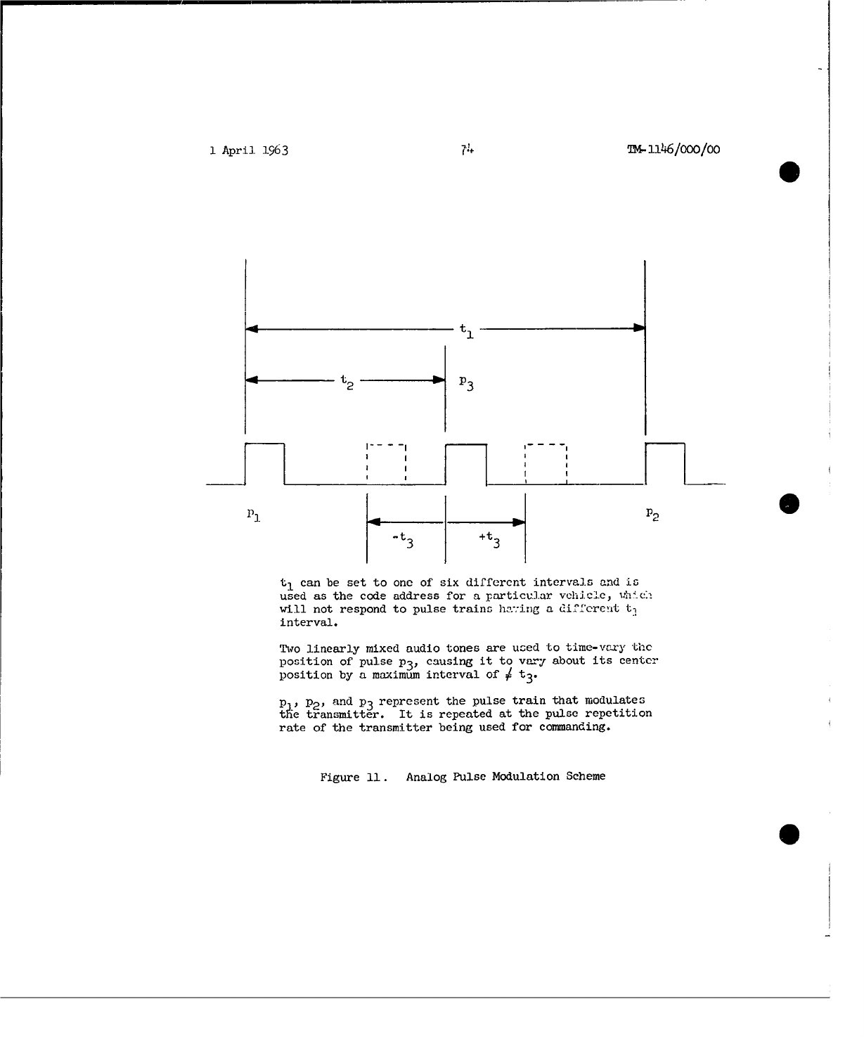
1
April
1963
n-I146/ooo/oo
0t
UJ
t2 p3
I I
I
I
I I I iI
I I I I
-.t 3+t
t,
can
be
set
to
one
of
six
different intervals
and
is
used
as
the
code
address
for
a
particular
vehicle,
-h C.
will
not
respond
to
pulse
trains
ha-:ing
a
different
t,
interval.
Two
linearly
mixed
audio
tones
are
used
to
time-vary
the
position
of
pulse
P31
causing
it
to
vary
about
its
center
position
by
a
maximum
interval
of
ý t3.
p P2,
and
P3
represent
the
pulse
train
that
modulates
tU~e
transmitter.
It is
repeated
at
the
pulse
repetition
rate
of
the
transmitter
being
used
for
commanding.
Figure
11.
Analog
Pulse
Modulation
Scheme
0
1
April
1963
75
TM-U
2
46/000/00
There
are
two
different
modes
of
operation
for
both
Analog
and
Digital
commanding:
the
Manual
mode
and
the
Computer
Automatic
mode.
In
the
MAnual mode,
commands
are
initiated
by
operations
personnel
at
the
tracking
station
by
means
of
switch
actions
at
the
System
Operators
Console
(SOC).
In
the
Computer
Automatic
mode,
commands
are
automatically
provided
and
executed
by
the
•Thacking
and
Cm•'--u-nand
(T&C)
computer.
5°2
ANALOG
COMMAINDING--MANUAL
MODE
Four
submode
options
are
available
in
the
Manual
mode
of
the
Analog
Commanding
Syfstem:
Single,
Lcn.g,
Repetitive,and
Remote.
In
the
Single
submode,
the
operator
at
the
SOC
sets
a
rotary
switch
to
a
number
representing
one
out
of
a
total
of
fifteen
possible
commandso
He
then
closes
the
"Transmit"
switch.
The
Command
Logic
Equipment
(LUE)
translates
this
into
the
closure
of
two
relays
out
of
bank
of
six.
Each
relay
determines
a
different
audio tone
for
time-modulating
the
output
},ulses
of
the
transmitter
being
used
for
commanding
(Figure
11).
The
command
package
in
the
satellite
has
logic
circuitry
which
translates
the
two
tones
into
one
of
fifteen
different
commands.
Verification
that
the
proper
command
was
sent
from
the
tronsmitter
is
made
in
the
form
of
an
echo
check,
-This
echo check
is
derived
by
sampling
the
transmitted
radio
frequency
signal,
demodulating
it
to
recover
the
two
tone
modulating
signals,
and
ceverting
them
to
a
pair
of
relay
closures,
which
are
compared
with
the
original
re]
ay
closures
by
the
CLE.
If
the
original
command
stored
in
the
CLE
and
the
command
returned
from
the
radio
frequency
monitor
on
the
command
transmitter
are
in
agreement,
the
CLE
sends
an
"Echo
Check"
indicator
to
the
SOC
and
the
T&C
computer.
If
they
do
not
check,
a
"Command
Error"
indicator
will
be
sent
to
the
SOC
and
T&C
computer.
Further
commanding
through
the
CLE
will
be
prevented
until
the
"Error
Override"
switch
on
the
SOC
has
been
actuated.
Verification
that
the
satellite
has
received
the
correct
command is
made
in
the
following
way:
relays
in
the
satellite
that
are
actuated
by
the
command
signals
from
the
command
trans-
mitter
have
contacts
whi-ah
are
used
to
modulate
channels
in
the
space-
to-ground
telemetry
link;
these
channels
are
received
by
the
ground
equipment
and
demodulated
by
the
FM/FM
ground
station,
which
sends
two
relay
closures
to
the
CLE
for
verification;
the
CLE
compares
the
relay
closures
with
the
original
command-relay
closures
and
sends
an
indicator
to
the
SOC
and
the
T&C
computer
as
to
whether
the
command
was
received
correctly
or
was
in
error;
and
ditfplay
lamps
on
the
SOC,
which
are
similar
to
the
"Echo
Check"
displays,
indicate
the
status
of
the
command.
Additional
SOC
displays
derived
from
the
CLE
and
displayed
in
decimal
digit
format,
are:
(1)
Comm&.d
Number
Selected,
(2)
Command
Transmission
Count
(number
of
times
that
the
command
was
transmitted),
and
(3)
Vehicle
Verification
Count
(number
of
times
that
the
command
was
verified).
1
April
1963
76
24-
Ll6/ooo/oo
The
Long submode
of
the
manual
mode
permits
the
operator
of
the
SOC
to
continue
to
transmit
a command
as
long
as
he keeps
the
Transmit
push
button
depressed.
Otherwise,
the
functions
and
displays
are
similar
to
the
Single
submode.
Operation
in
the
Repetitive
Transmit
submode
allows
the
SOC
operator
to
select,
by
switch
action,
the
number
of
repetitions
with
verification
of
a
command
which
the
CLE
is
to
automatically
make.
The
CLE
will
repeat
the
whole
procedure
described
for
the
Single
submode
at
the
rate
of
one
command
repetition
for
each
two-second
interval
of
time.
When
the
command
repetition
number
is
reached,
the
command
transmission
will
stop.
The
SOC
operator
may
stop
the
repetitive
action
by
pressing
the
"Stop
Repetitive"
push
button.
If a
"Command
Error"
occurs
on
any
of
the
repetitions,
further
transmission
will
be
inhibited.
Transmission
of
the
remaining
command
repetitions
will
resume
when
the "Error
Override"
push
button
is
actuated.
All
other
functions
and
displays
are
the
same
as
for
the
Single
submode.
The
Remote
submode
is
identical
to
the
Single
and
Long
submodes,
except
that
command
control
will
be
executed
from
a
remote
console.
One
satellite
systemwhich
uses
a
special
console
and
special
logic
equipment
in
the
satellite,
is
able
to
handle
more
than
the
maximum
number
of
15
analog
commands.
This
is
accomplished
by
sending
a
sequence
of
three
tone-pair
combinations,
which
the
satellite
equipment
translates
into
a
single
command.
5.3
ANALOG
COMMANDING--COMPUTER
AUTOMATIC
MODE
In
the
Computer
Automatic
mode,
blocks
of
commands
are
stored
in
the
core
memory
of
the
T&C
computer.
These
blocks
are
made
up
of
RTC's
arranged
in
the
proper
order
for
transmission
to
the
satellite.
(See
Section
5.6
for
the description
of
how
these
commands
are
made
up
at
the
STC
and
transmitted
to
the
tracking
station
as
part
of
the
prepass
acquisition
message.)
The
SOC
operator,
by
pressing
the
"Computer
Auto
Command
Mode"
push
button,
places the
system
in
the
Computer
Automatic
mode.
A
switch
action
at
the
SOC
designates the
number
of
the
block
of
commands
to
be
sent
to
the
satellite
Actuation
of
the
"Transmit"
push
button
on
the
SOC
initiates
the
sending
of
the
entire
block of
commands
under
the
control
of
the
T&C
computer.
The
identification
of
each
co~mnd
sent,
plus
indications
of
echo
checks
completed
and
verifications
received
from
the
satellite,
will
be
displayed
at
the
SOC
in
the
same
manner
as
for
the
Manual
mode.
Also,
the
T&C
computer
will
make
the
usual
records
of
command
status.
Automatic
transmission
of
commands
will
be
inhibited
if
either
an
echo
check
or
vehicle
verification
check
fails,
and
an
alarm
display
will
be
activated
on
the
SOC.
Error
overrid
controls
are
available
on
the
SOC
to
permit
the
operator
to
restart
the
auto-
matic
command
sequence.
The
computer
command
program
may
be
stopped
by
nressing
the
"Computer
Auto
Stop" push
button
at
the
SOC.
It
can
be
restarted
by
pressing
the
"Transmit"
push
button.
Displays
on
the
SOC
indicate:
(1)
whe
the
appropriate
computer
command
program
has been
loaded
in
the
computer
and
i
1
April
1963
77
Ti-ll'i6/ooo/oo
ready
for
transmission;
(2)
when
the
computer
command
program
is in
progress,
transmitting
cosinands
to
the
satellite;
and
(3)
when
the
program
has
been
completed.
5.4
DIGITAL
COMMANDING
--
MANUAL
MODE
Digital
command
requires
more
extensive
use
of
the
T&C
computer
than
does
Analog
commanding. The
T&C
computer
maintains,
in its
memory
files,
a
repertoire
of
RTC' a
which
will
be
used
in
the
Digital
Manual
mode
of
commanding.
The
repertoire
of
commands
is
sent
to
the
T&C
computer,
initially,
as
part
of
the
command
portion
of
the
initial
prepass
message.
Subsequently,
the
reLoertoire
is
maintained
in
a
current
status
through
the
addition
or
deletion
of
commands
by
later
prepass
messages.
The
SOC
operator
can
call
up
a command
from
the
repertoire
by
setting
the
"Number
Select"
control
on
the
SOC
to
the
number
of
the
command
desired
and
pressing
the
"Transmit"
push
button.
The
T&C
computer,
in
response
to
the
switch
action,
provides
the
corresponding
digital-
command
word
to
the
CLE,
via
the
Input-Output
Buffer
(lOB),
serially
bit-by-bit,
on a
computer-interrupt
basis.
The
CLE
will
output
the
command,
serially
bit-by-bit,
to
the
modulating
equipment
of
the
command
transmitter.
The
transmitted signals
are
subject
to
an
echo
check,
made
by
the
computer,
which compares
the
echo
returns
from
the
command
transmitter,
bit-by-bit,
with
the
original
command
word
stored
in
computer
memory.
Echo
check
errors
will
be
displayed
on
the
SOC
and
recorded
by
the
T&C
computer.
In
the
satellite
command
package,
the received
command
word
will
be
checked
for
parity
and
checksum.
If
the
word
passes
this
combined
check,
the
command is
accepted
and
the
"accept"
channel
of
the
telemetry
package
is
used
to
send
a
"word
accept"
verification to
the
ground.
If
the
word
check
fails,
a
"word
reject"
notification
is
sent
to
the
ground
via
the
"reject"
channel
of
the
telemetry
package.
This
acceptance
or
rejection
of
the
command
by
the
satellite
will
be
displayed
on
the
SOC
and
will
be
available
to
the
computer
for
recording.
Additional
controls
and
displays
that
are
available
to
the
operator
of
the
SOC
are:
1.
Reject
Level
Select
Control--sets
the
number
of
times
a
command
will
be
automatically
repeated
when
not
verified.
2.
Reject
Level
Display--inlicates
the
level
selected
by
the
Reject
Level
Select
control.
3.
Reject
Count
Display--indicates
the
number
of
times
a
command
has
been
rejected.
4.
Command
Reject
Display--indicates
the
number
of
the
command
that
was
last
rejected
by
the
vehicle.
5.
Command
Verify
Display--indicates
the
number
of
the
command
that
was
last
accepted
by
the
vehicle.
6.
Spoof
Display--indicates
that
a
false
accept
or
reject
signal
1
April
1963 78
Tm-l146/ooo/oo
was
received
from
the
satellite
while
a
command
word
was
in
the
process
of
transmission.
7.
Repetitive
Number
Select
Control--
sets
the
number
of
times
a
command
will
be
transmitted
and
verified.
8.
Reject
Count
Clear
Control--sets
the
Reject
Level
Display
to
zero
and
allows
the
computer
to
resume
the
command
transmissions
that
were
inhibited
when
the
reject
level
was
reached.
Four
submode
options
are
available
in
the
Manual
mode
of
the
digital
commanding
system:
Single,
Repetitive,
Manual
Control
and
Display
Unit
(MCDU),
and
Remote.
In
the
Single
submode
of
operation,
a
command
will
be
transmitted
and
verified
only
once each
time
the
"Transmit"
switch
is
actuated
from
the
SOC.
If a
transmission
is
not
verified,
the
T&C
computer
will
retransmit
the
command
until
it is
accepted
by
the
satellite,
or
until
the
reject
level
set
by
the
Reject
Level
Select
Control
is
reached. Operation
of
the
Reject
Count
Clear
Control
on
the
SOC
will
allow
the
computer
to
resume
command
transmission
after
the
reject
level
has
been
reached.
In
the
Repetitive
submode
of
operation, the
SOC
operator
sets
the
Repetitive
Number
Select
Control
Switch
to
the
number
of
times
he
wants
a command to
be
repeated
and
verified
by
the
vehicle.
The
computer
will
continue
re-
transmitting
the
command
until
this
number
is
reached.
Other
controls
and
displays
are
the
same
as
for
the
Single
submode.
The
Remote
submode
enables
a
remote
console
to
assume
command
control.
Only
the
Single
submode
type of
operation
previously described
is
allowed
from
the
remote
console.
These
controls
and
displays,
identical
to
those
on
the
SOC,
will
be
provided
to
the
remote
console:
Command
Number
Select
Switches,
Transmit
Switch,
Error
Override
Switch,
Reject
Override
Switch,
Command
Verification
Display,
Command
Echo
Check
Error
Display~and
Command
Reject
Display.
The
status
of
the
remote
console
will
be
indicated
on
the
SOC
by
three
displays:
the
Remote
Command
Ready,
the
Remote
Command
in
Progress,
and
the
Remote
Command
Complete.
The
MCDU
submode
makes
provision
for
transferring
command
control
to
the
MCDU
console
(G.E.
702).
A
digital
command,
selected
from
one
of
six
command
switches
on
the
MCDU
console,
will
be
transferred
to
an
encryptor
keyboard,
a
security
classified
device
in
the
CLE.
The
keyboard
will
trans-
late
the
switch
closure
to
a
7-bit
command,
which
will
be
provided
in
parallel
to
the
computer
via
the
IOB.
The
computer
will
store
the
Command
in
core
memory
and
then
proceed
to
output
the
command
to
the
CLE,
serially
bit-by-bitat
the
synch
PRF
rate
of
the
command
transmitter.
Echo
check
on
the
transmitted
command
words
will
be
handled
in
the usual
manner.
The
1
April
1963
T9
TM-IIa6/Ooo/OO
command
selection
made
by
the
MIDU
operator
will
be
made
available to
the
T&C
computer
for
recording.
Two
displays
on
the
SOC
will
notify
the
SOC
operator
of
the
status
of
the
MCDU
console;
the
MCDU
Ready
and
MCDU
Complete.
.5.5
DIGITAL
COMMAN
DING--
COMPUTER
AUTOMATIC
MODE
In
the
C-mputer
Automatic
mode,
command
control
is
transferred
from
the
SOC
to
the
T&C
co.mputer
for the
transmission
of
a
block
of
commands. The
block
of
commands
may
consist
of
RTC's
and
SPC's
(see
Section
5.6).
Once
the
SOC
operator
has
set
the
"Command
Block
Number"
switch
to
the
proper
command
block
number,
and
pushed
the
"Transmit"
push
button,
the
T&C
comnuter
proceeds
to
send
the
entire
block
of
commands
to
the
CLE
Y
n
proper
sequence
for
transmission
to
the
satellite.
Echo
check
and
verifics~io"
-re
wie
same
as
for
the
Manual
mode.
Automatic
transmission
wil]
cease
if
verification
in
not
obtained
prior
to
reaching
the
present
reject
level.
The
SOC
has
override
controls
available
for
both
echo
check
errors
and
vehicle
word
rejects.
Manual
override
controls
permit
the
computer
to
retransmit
or
proceed
to
the
next
command
word
w4hen
the
computer
command
sequence
has stopped
because
of
an
echo
check
error
and
verification,
or
when
a
word
reject
is
received,
or
if
the
word
reject
I
vel
has
been
attained.
5.6
STORED
PROGRAM
C41MM.NDS
A
satellite-specific
command
program
for
each
satellite
system
is
available
in
the
computer
library
to
enable
a
1604
computer
to
prepare
command
messages
for
transmittal
to
the
tracking
stations.
The
programs
format
real
time
commands
(RTC's'
and
stored
program
commands
(SPC's)
in
response
to
command
requests
Initiated
by
operations
personnel
via
the
088
nard
reader,
the
350
paper
tape
reader,
or
magnetic
tape
input.
They
determine
auxiliary
real-
time
commands
(ATC)
to
conurol
the
?Kirchild
timer
operationas
required
by
some
satelitte
systems.
They
also
establish
the
relationship
between
vehicle
and
system
time,
and
determine
delay
line
assignments
for
storage
of
SPC's
in
the
satellite
memory.
Some
time
prior
to
the
predicted
time
of
a
particular
pass,
the
Test
Con-
troller,
in
preparation
for the
impending
satellite
operation,
makes
up
his
command
requirements
on
data
cards,
wnich
are
read
into
a
1604
computer
via
the
IBM
088
;ard reader.
The
1604
then
makes
the
necessary
computations
to
compile
a
command
list
that
satisfies
the
Test
Controller's
requirements.
A
printout
of
the
command
listwith
execution times
and
other
pertinent
data,is
furnished
to
the
Test
Controller
by means
of
the
1612
printer.
The
Test
Controller
checks
this
command
list
and
inserts
such
corrections
as
are
necessary
via
the
088
ward
reader.
The
1604
then
makes
up
a
command
message
in
the
proper
format
for
transmission
to
the
tracking
station.
This
message
is
stored
in a
1615
tape
unit
with
the
rest
of
the
prepass
acquisition
message,
which
consists
of
commands,
schedules,
telemetry
mode
processing
parameters,
and
antenna
pointing
data.
Figure
12 is a
simplified
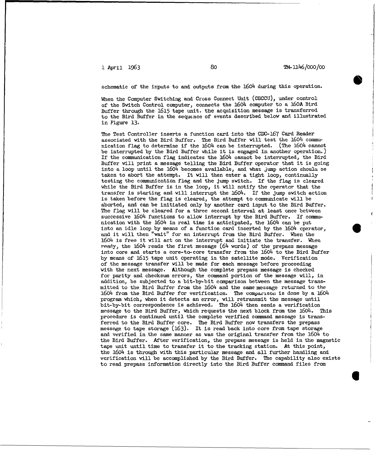
1
April
1963
80
TM-
116/0
0
0/oo
schematic
of
the
inputs
to
and
outputs
from
the
1604
during
this
operation.
When
the
Computer
Switching
and
Cross
Connect
Unit
(CSCCU),
under
control
of
the
Switch
Control
computer,
connects
the
1604
computer
to
a
160A
Bird
Buffer
through
the
1615
tape
unit.
the
acquisition
message
is
transferred
to
the
Bird
Buffer
in
the
sequence
of
events
described
below
and
illustrated
in
Figure
13.
The
Test
Controller
inserts
a
function
card
into
the
CDC-167
Card
Reader
associated
with
the
Bird
Buffer.
The
Bird Buffer
will
test
the
1604
commu-
nication
flag
to
determine
if
the
1604
can be
interrupted.
(The
1604
cannot
be
interrupted
by
the
Bird
Buffer
while
it is
engaged
in
another
operation.)
If
the
communication
flag
indicates
the
1604
cannot
be
interrupted,
the
Bird
Buffer
will
print
a
message
telling
the
Bird
Buffer
operator
that
it is
going
into
a
loop
until
the
1604
becomes
available,
and
what
jump
action
shoula
be
taken
to
abort
the
attempt.
It
will
then
enter
a
tight
loop,
continually
testing
the
communication
flag
and
the
jump
switch.
If
the
flag
is
cleared
while
the
Bird
Buffer
is in
the
loop,
it
will
notify the
operator
that
the
transfer
is
starting
and
will
interrupt
the
1604.
If
the
jump
switch
action
is
taken
before the
flag
is
cleared,
the
attempt
to
communicate
will
be
aborted,
and can
be
initiated
only
by
another
card
input
to
the
Bird
Buffer.
The
flag
will
be
cleared
for
a
three
second
interval
at
least
once
between
successive
1604
functions
to
allow
interrupt
by
the
Bird
Buffer.
If
commu-
nication
with the
1604
in
real
time
is
anticipated,
the
1604
can
be
put
into
an
idle
loop
by
means
of
a
function
card
inserted
by
the
1604
operator,
and
it
will
then
"wait"
for
an
interrupt
from
the
Bird
Buffer.
When
the
.1604
is
free
it
will
act
on
the
interrupt
and
initiate
the
transfer.
When
ready;
the
1604
reads the
first
message
(64
words)
of
the
prepass
message
into
core
and
starts
a
core-to-core
transfer
from
the
1604
to
the
Bird
Buffer
by
means
of
1615
tape
unit
operating
in
the
satellite
mode.
Verification
of
the
message
transfer will
be
made
for
each
message
before
proceeding
with
the
next
message.
Although
the
complete
prepass
message
is
checked
for
parity
and
checksum
errors,
the
command
portion
of
the
message
will,
in
addition,
be
subjected
to
a
bit-by-bit
comparison
between
the
message
trans-
mitted
to
the
Bird
Buffer
from
the
1604 and
the
same
message
returned
to
the
1604
from
the
Bird
Buffer
for
verification.
The
comparison
is
done
by
a
1604
program which,
when
it
detects
an
error,
will
retransmit
the
message
until
bit-by-bit
correspondence
is
achieved.
The
1604
then
sends
a
verification
message
to
the
Bird
Buffer,
which
requests the
next
block
from
the
1604.
This
procedure
is
continued
until
the
complete
verified
command
message
is
trans-
ferred
to
the
Bird
Buffer
core.
The
Bird
Buffer
now
transfers
the
prepass
message
to
tape
storage
(163).
It is
read
back
into
core
from
tape
storage
and
verified
in
the
same
manner
as
was
the
original
transfer
from
the
1604
to
the
Bird
Buffer.
After
verification,
the
prepass
message
is
held
in
the
magnetic
tape
unit
until
time
to
transfer
it
to
the
tracking
station.
At
this
point,
the
1604
is
through
with
this
particular
message
and
all
further
handling
and
verification
will
be
accomplished
by
the
Bird Buffer.
The
capability
also
exists
to
read
prepass information
directly
into
the
Bird
Buffer
command
files
from
6I
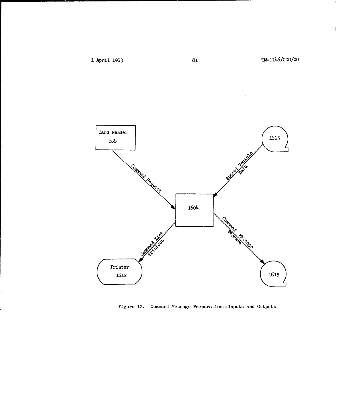
1
April
1963
81
m-]3.16/ooo/Oo
Card
Reader
088
1615
A~o4
F
Preneter
16a
Figure
12.
Command
Message
Preparation--Inputs
and
Outputs
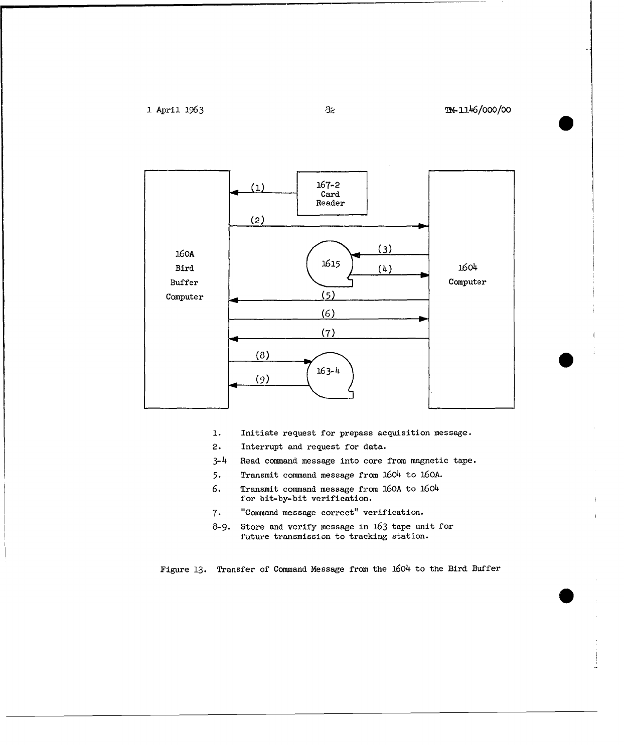
1
April
1a63
32
u4-
6/o0o/0o
'(i)
.167-2
Card
Reader
(2)
_
i60A
(3)
Bird
(4)
1604
Buffer
Computer
Computer
_ _(_5_)
(6)
(7)
(8)
E163-
4
S(9)
1.
Initiate
request
for
prepass
acquisition
message.
2.
Interrupt
and
request
for
data.
3-4
Read
command
message
into
core
from
magnetic
tape.
5.
Transmit
command
message from
1604
to
160A.
6.
Transmit
command
message
from
160A
to
1604
for
bit-by-bit
verification.
7.
"Command
message
correct"
verification.
8-9.
Store
and
verify
message
in
163
tape
unit
for
future
transmission
to
tracking
station.
Figure
13.
Transfer
of
Command
Message
from
the
1604
to
the Bird
Buffer
1
April
1963
83
TM-l
1
6/1000/00
cards.
Certain "vehicle
specific"
commands,
which
need
to
be
available
at
the
tracking
station
for
every pass
over
the
station, will
be
sent
only
once
to
the
station,
and
will
not
be
included
in
the
prepass
message
for
each
pass.
A
short
time
before
a
tracking
station
is
scheduled
to
contact
a
satellite,
the
switch
control
computer
at
the
STC
will
connect
the
Bird
Buffer
to
the
computer
at
the
tracking
station
by
means
of
the
Communication
Data
Select
and
Cross
Connect
Unit
(CDSCCU).
The
operation
of
transmitting
thc prepass
acquisition
message
is
initiated
manually
by
operations personnel
at
the
tracking
station
by
causing
the
two
160A
computers
at
the
tracking
station
to
send
a
"Real
Time
Near"
message
to
the
Bird
Buffer.
This
is
done
about
ten
minutes
before
the
expected
acquisition
time
of
a
satellite
pass.
Trans-
mission
of
the
prepass
message
may
also
be
initiated
at
the
Bird
Buffer
by
means
of
a
function
card.
Additional
data
may
be manually
appended
to the
command
message
at
this
time.
Transmission
and
verification
of
the
command
part
of
the
prepass
message
from
the
Bird
Buffer
to
the
T&C
computer
at
the
tracking
station
is
handled
in a
manner
similar
to
its
transmission
and
verification
from
Lhe
1604
to
the
Bird
Buffer.
The
Bird
Buffer
will
read
the
message
into
core
from
tape
storage
and
initiate
a
core-to-core
transfer
to
the
T&C
computer.
The
T&C
computer
will
check
parity
and
checksum
for
errors
and,
if
none
are
found,
will
retransmit
the
command
message,
a
block
at
a
time,
to
the
Bird
Buffer.
A
Bird
Buffer
program
will
make
a
bit-by-bit
comparison
for
each
message
before
sending
a
verification
for
that
message.
When
the
complete
prepass
message
has
been
verified
in
core
memory
at
the
tracking
station,
it
will
then
be
transferred
to
magnetic
tape,
using
the
same
verification
schemc
employed
by
the
Bird
Buffer.
When
the
complete
message
has
been
verified
and
successfully stored
in
the
163
tape
units,
a
text
message
to
that
effect
will
be
sent
to
the
Bird
Buffer.
The
Bird
Buffer
will
do
the
necessary
bookkeeping
on
its
files
to
keep
track
of
the
prepass
data
that
has
been
sent
to
a
tracking
station
so
that
only
new
information
will
be
sent
in
the
pre-
pass
message;
old
data
referred to
previous
revolutions
will
be
deleted
from
the
prepass
data
stored
in
the
163
tape
units.
Figure
14
shows
the
data
flow
involved
in
this
transfer.
Part
of
the
prepass
message
is a
text
message
which
has
the
schedule
for
the
nominal
times
to
transmit
the
various
commands
in
the
repertoire
of
RTC's.
This
text
message
also
contains
command-specific
instructions
to
the
SOC
operator.
5.7
RFAL-
TIME
COWANDS
Real-time
commands
may
be
initiated
in a
number
of
different
ways.
They
may
be
generated
in a
1604
computer
in
response
to
card
inputs
from
the
Test
Con-
troller.
Command
messages
may
be
input
directly
uo
the
Bird
Buffer
by
card,
in
which
case
they
must
be
made
up
in
the
proper
command
message
format.
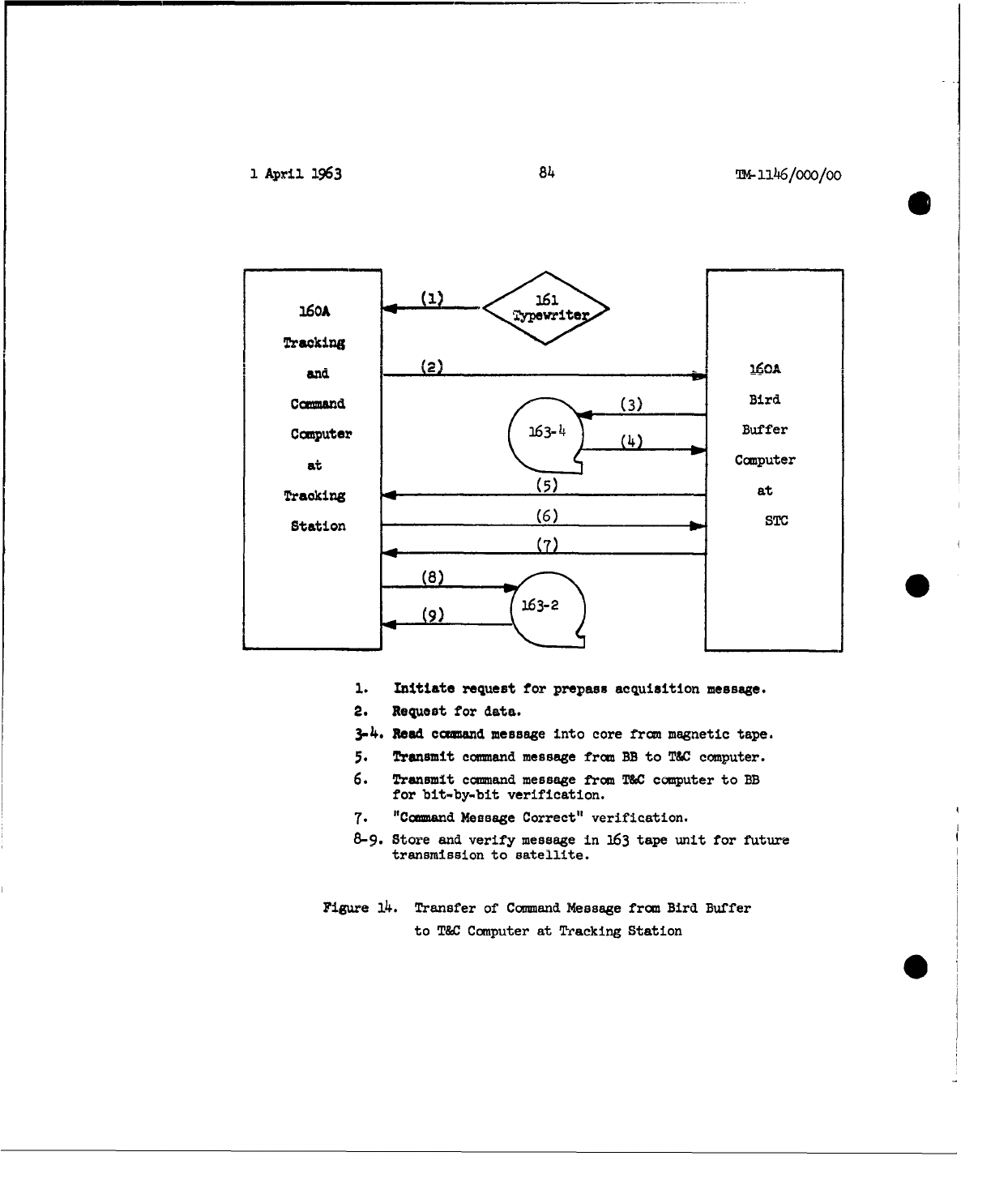
1
April
1963
84
-i146/ooo/oo
160A
3
.61
yp
rite
Trackin;
Cand
Ccimputer
134
()Buffer
at
"
Computer
Tracking_(5) at
Station
(6)
f
STC
(7)
(8)
163-2
.. (9) :I
1.
Initiate
request
for
prepass
acquisition
message.
2.
Request
for
data.
3-4.
Rad
command
message
into
core
from
magnetic
tape.
5.
Transmit
command
message
from
BB
to
TWC
computer.
6.
Transmit
command
message
from
T&C
computer
to
BB
for
bit-by-bit
verification.
7.
"Command
Message
Correct"
verification.
8-9.
Store
and
verify
message
in
163
tape
unit
for future
transmission
to
satellite.
Figure
14.
Transfer
of
Command
Message
from
Bird
Buffer
to
T&C
Computer
at
Tracking
Station
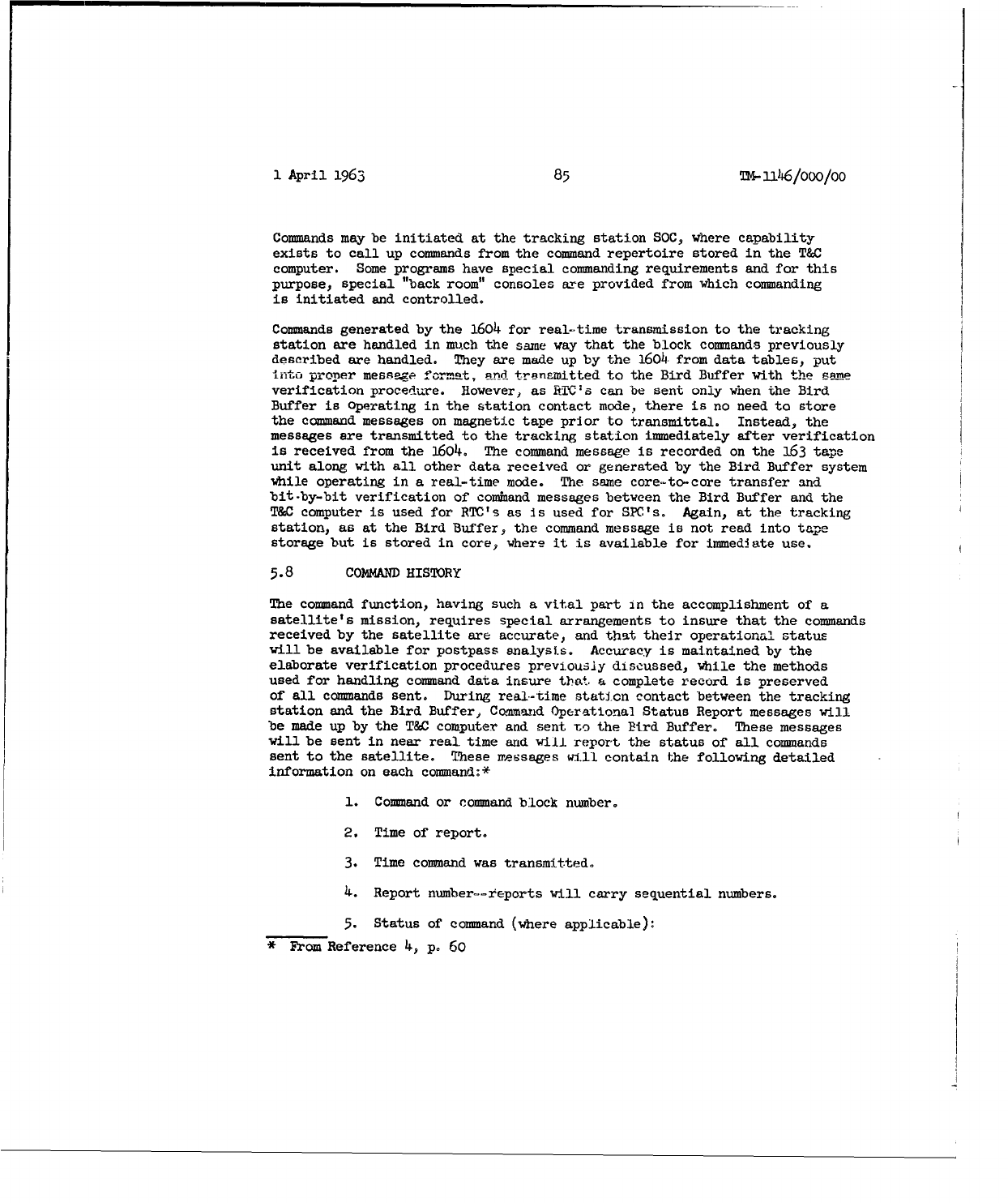
1
April
1963
85
Tn-1146/000/00
Commands
may
be
initiated
at
the
tracking
station
SOC,
where
capability
exists
to
call
up
commands
from
the
command
repertoire
stored
in
the
T&C
computer.
Some
programs
have
special
commanding
requirements
and
for
this
purpose,
special
"back
room"
consoles
are
provided
from
which
commanding
is
initiated
and
controlled.
Commands
generated
by
the
1604
for
real-time
transmission
to
the
tracking
station
are
handled
in
much
the
same
way
that
the
block
commands
previously
described are
handled.
They
are
made
up
by
the
1604
from
data
tables,
put
into
proper
messea
format,
nud
trenrmitted
to
the
Bird Buffer
with
the
smm
verification
procedure.
However,
as
RYTVa
can
be
sent
only
when
the
Bird
Buffer
is
Operating
in
the
station
contact
mode,
there
is
no
need
to
store
the
command
messages
on
magnetic
tape
prior
to
transmittal.
Instead,
the
messages
are
transmitted
to
the
tracking
station
immediately
after
verification
is
received
from
the
1604. The
command
message
is
recorded
on
the
163
tape
unit
along
with
all
other
data
received
or
generated
by
the
Bird
Buffer
system
while
operating
in
a
real-time
mode.
The same
core.-to-core
transfer
and
bit-by-bit
verification
of
command
messages
between
the
Bird Buffer
and
the
T&C
computer
is
used
for
RTC's
as
is
used
for
SPC's.
Again,
at
the
tracking
station,
as
at
the
Bird Buffer,
the
command
message
is
not read
into
tape
storage
but
is
stored
in
core,
where
it is
available
for
immediate
use.
5.8
COMMAND
HISTORY
The
command
function,
having
such
a
vital
part
in
the
accomplishment
of
a
satellite's
mission,
requires
special
arrangements
to
insure
that
the
commands
received
by
the
satellite
are
accurate,
and
that
their
operational
status
will
be
available
for
postpass
analysis.
Accuracy
is
maintained
by
the
elaborate
verification
procedures
previously
discussed,
while
the
methods
used
for
handling
command
data
insure
th1at
a
complete
record
is
preserved
of
all
commands
sent.
During
real-time
station
contact
between
the
tracking
station
and
the
Bird
Buffer,
Command
Operational
Status
Report
messages
will
be
made
up
by
the
T&C
computer
and
sent
to
the
Bird
Buffer.
These
messages
will
be
sent
in
near
real
time
and
will
report
the
status
of
all
commands
sent
to
the
satellite.
These
messages
w1.11
contain
the
following
detailed
information
on
each
command:*
1.
Command
or
command
block
number.
2.
Time
of
report.
3.
Time
command
was
transmitted.
4.
Report
number-=zreports
will
carry
sequential
numbers.
5.
Status
of
command
(where
applicable):
*
From
Reference
4,
p.
60
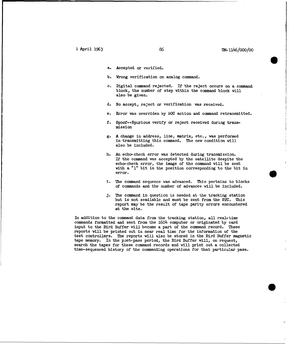
1
April
1963
86
TM-uI46/O00/OO
a.
Accepted
or
verified.
b.
Wrong
verification
on
analog
command.
c.
Digital
command
rejected.
If
the
reject
occurs
on
a
command
block,
the
number
of
step
within
the
command
block
will
also
be
given.
d.
No
accept,
reject
or
verification
was
received.
e.
Error
was
overriden
by
S0C
action
and
command
retransmitted.
f.
Spoof--Spurious
verify
or
reject
received
during
trans-
mission
g.
A
change
in
address,
line,
matrix,
etc.,
was
performed
in
transmitting
this
command.
The
new
condition
will
also
be
included.
h.
An
echo-check
error
was
detected
during
transmission.
If
the
command
was
accepted
by
the
satellite
despite
the
echo-check
error,
the
image
of
the
command
will
be
sent
with
a 'l"
bit
in
the
position
corresponding
to
the
bit
in
error.
i..
The
command
sequence
was
advanced.
This
pertains
to
blocks
of
commands
and
the
number
of
advances
will
be
included.
J.
The
command in
question
is
needed
at
the
tracking
station
but
is
not
available
and
must
be
sent
from
the
STC.
This
report
may
be
the
result
of
tape
parity
errors
encountered
at
the
site.
In
addition
to
the
command
data
from
the tracking
station,
all
real-time
commands
formatted
and
sent
from
the
1604
computer
or
originated
by
card
input
to
the
Bird
Buffer
will
become
a
part
of
the
command
record.
These
reports
will
be
printed
out
in
near
real
time
for
the
information
of
the
test
controllers.
The
reports
will
also
be
stored
in
the
Bird
Buffer
magnetic
tape
memory.
In
the
post-pass
period,
the
Bird Buffer
will,
on
request,
search
the tapes
for
these
command
records
and
will
print
out
a
collected
time-sequenced
history
of
the
commanding
operations
for
that
particular
pass.
0
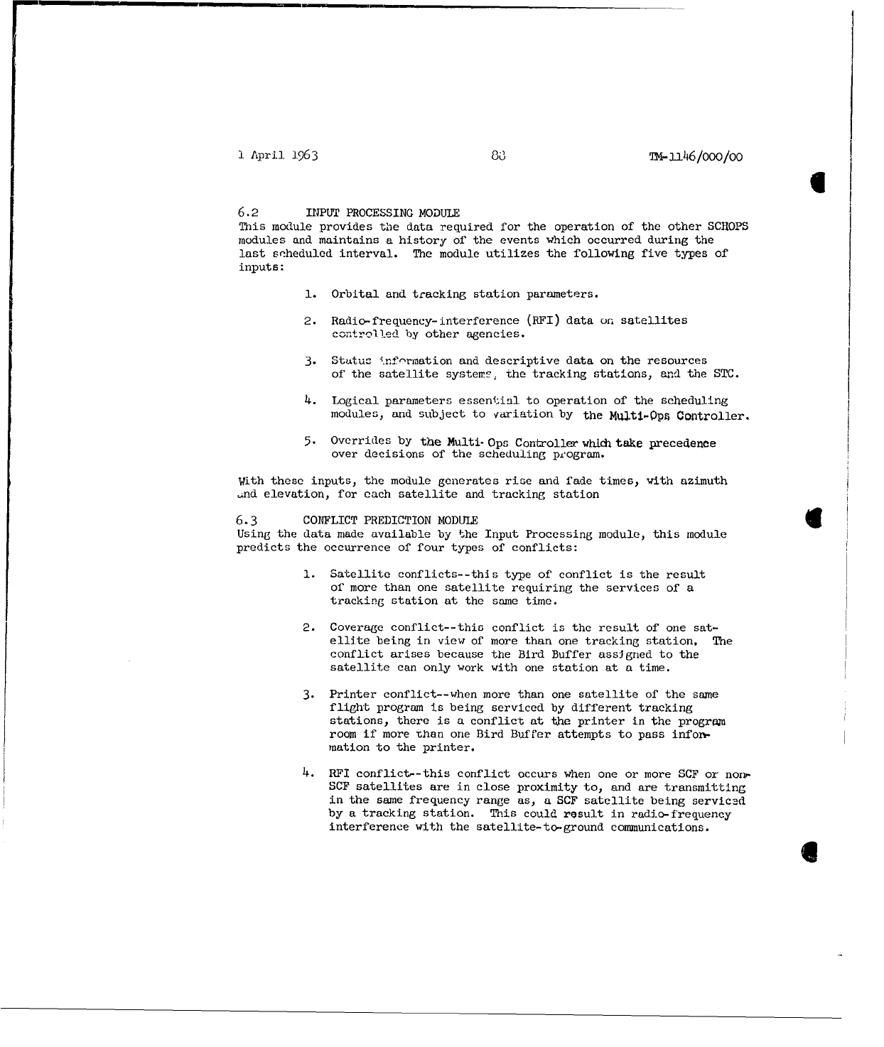
1
April
1963
8T3
•4-i46/ooo/oo
6.2
INPUT
PROCESSING
MODULE
This
module
provides
the
data
required
for
the
operation
of
the
other
SCHOPS
modules
and
maintains
a
history
of
the
events
which
occurred
during
the
last
scheduled
interval.
The
module
utilizes
the
following
five
types
of
inputs:
1.
Orbital
and
tracking
station
parameters.
2.
Radio-frequency-interference
(RFI)
data
on.
satellites
controlled
by
other
agencies.
3.
Status
.nf-rmation
and
descriptive
data
on
the
resources
of
the
satellite
systems.
the
tracking
stations,
and
the
STC.
4.
Logical
parameters
essential
to
operation
of
the
scheduling
modules,
and
subject
to
variation
by
the
Mqlti-Opf
Controller.
5.
Overrides
by
the
Multi-
Ops
Controller
which
take
precedence
over
decisions
of
the
scheduling
p'ogram.
With
these
inputs,
the
module
generates
rise
and
fade
times,
with
azimuth
,.nd
elevation,
for
each
satellite
and
tracking
station
6.3
CONFLICT
PREDICTION
MODULE
4
Using
the
data
made
available
by
the
Input
Processing
module,
this
module
predicts
the
occurrence
of
four
types
of
conflicts:
1.
Satellite
conflicts--this
type
of
conflict
is
the
result
of
more
than
one
satellite
requiring
the
services
of
a
tracking
station
at
the
same
time.
2.
Coverage
conflict--this
conflict
is
the
result
of
one
sat-
ellite
being
in
view
of
more
than
one
tracking
station.
The
conflict arises
because
the
Bird
Buffer
assJgned
to the
satellite
can
only
work
with
one
station at
a
time.
3.
Printer
conflict--when
more
than
one
satellite
of
the
same
flight
program
is
being
serviced
by
different
tracking
stations,
there
is a
conflict
at
the
printer
in
the
program
room
if
more
than
one
Bird Buffer
attempts
to
pass
infor-
mation
to
the
printer.
4.
RFI
conflict--this
conflict
occurs
when
one
or
more
SCF
or
non-
SCF
satellites
are
in
close
proximity
to,
and
are
transmitting
in
the
same
frequency
range
as,
a
SCF
satellite
being
serviced
by
a
tracking
station.
This
could
result
in
radio-frequency
interference
with
the
satellite-to-ground
communications.
I
I
April
1963
T39
TM-1i46/oo0/O0
The
results
of
these
conflict
predictions
are
made
available
to
the
Conflict
Resolution
and
Output
Processing
modules
for
preparation
of
printouts.
6.4
CONFLICT
RESOLUTION
MODULE
This
module
resolves the
satellite
and
coverage
conflict
situations
described
above, and
generates
a
listing
of
the
resolved
vehicle/station
contacts.
Conflict
resolution
is
done
in
three
phases
(I, II,
and
III)
and
is
res-
ponsive
to input
priorities
and
to
the
value
judgements
of
operations
personnel.
Phase
I
selection
is
based
on
mandatory
pass
coverage,
as
designated
by
the
Multi-
ops
Controller.
Phase
II
selection
is
based
on
computations
to
derive
priorities
for
each
vehicle.
These
priorities
include:
(1)
gain
to
the
system
resulting
from
required
frequency
of
contacts;
(2)
gain
due
to
contact
time;
(3)
gain
for
specific
contacts,
independent
of
time;
and
(4)
initial
priority at
the
start
of
a
resolution
period.
The
algorithm
for
resolving
conflicts
in
phase
II
optimizes
the
priority
function
over
the
space
of
possible
pass
combinations
for
each
resolution
period.
The
results
produce
a
sharing
of
time
between
satellites
at
single
sT.ations
and
between
stations
for
a
single
satellite,
depending
on
the
type
of
conflict
being
resolved.
Phase
III
selection
assigns the
inactive
vehicles
to
the
remaining
possible
service
time,
using
vehicle-specific,
constant
priorities
to
resolve
conflicts.
6.5
RESOURCE
ALLOC'ATION
MODULE
This
module
has
three
submodules:
(1)
Transmission,
(2)
1604
Scheduling,
and
(3)
Switch
Scheduling..
1The
Transmission
submodule
allocates
time
for
communications
between
the
B-rd
Buffers
and
the
tracking
stations
for
the
Non-Real-Time
node.
IJ
-)ptimizF.ss
t.he
assignment of non-pass
time,
using
message
requests,
prlnrities,
and
other
message
related
parameters
as
inputs.
The
1604
Scheduling
suboodole
assigns
tasks
to
the
four
160 4
's.
These
tasks
consist
of:
(1)
flight
support
operations
(2)
general
support
operations
such
as
scheduling
and
(3)
non-support
operations
such
as
program
validation
and
acceptance.
The
Inpui
:
are
requests,
priorities,
pass-time,
and
other
parameter
values.
There
are
two
modes
of
operation
in
the
1604
Scheduling
submodule.
One
is
the
Look-Ahead
mode,
which
covers
a
long
period
of
time.
The
schedule
which
is
generated
in
this
mode is
used
as
a
planning
toolo
The
other
mode
is
the
Short-Term
mode;
the
schedule
generated
is
the
final
working
allocation
of
1604
time.
The
Switch
Scheduling
submodule
allocates
the
SCF
equipment
to
be
used
to
perform
multi-vehicle
support
by
generating
a
switching
schedule
for
the
CDCCU
and
CDSCCU.
An
interim
switching
schedule
is
made
up
by
merging
a
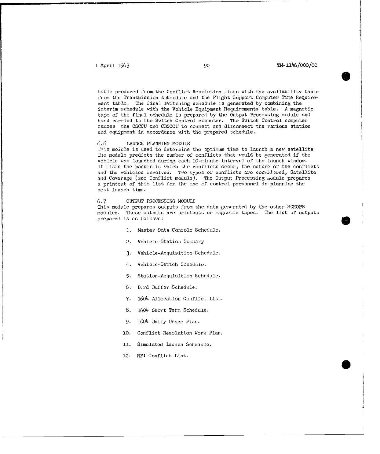
1
•Aril
1963
90
Tm-il6/OOO/Oo
0
table
produced
from
the
Conflict
Resolution
lists
with
the
availability table
from
the
Transmission
submodule
and
the
Flight
Support
Computer
Time
Require-
ment
table.
The
final
switching
schedule
is
generated
by
combining
the
interim
schedule with
the
Vehicle
Equipment
Requirements
table.
A
magnetic
tape
of
the
final
schedule
is
prepared
by
the
Output
Processing
module
and
hand
carried
to
the
Switch
Control
computer.
The
Switch
Control
computer
causes
the
CSCCU
and
CDSCCU
to
connect
and
disconnect
the
various
station
and
equipment
in
accordance
with
the
prepared
schedule.
(.6
LAUIICH
PLANNING
MODULE
J-is
module
is
used
to
determine
the
optimum
time
to
launch
a
new
satellite
Yhe
module
predicts
the
number
of
conflicts
that
would
be
generated
if
the
vehicle
was
launched
during
each
10-minute
interval
of
the
launch
window.
It
lists
the
passes
in
which
the
conflicts
occur,
the
nature
of
the
conflicts
and
the
vehicles
involved.
Two
types
of
conflicts
are
corsid-•red,
Satellite
and
Coverage (see
Conflict
module).
The
Output
Processing
,udule
prepares
a
printout
of
this
list
for
the
use
of
control
personnel
in
planning
the
best
launch
time.
6.7
OUTPUT
PROCESSING
MODULE
This
module
prepares outputs
from
the
data
generated
by
the
other
SCHOPS
modules.
These
outputs
are
printouts
or magnetic
tapes.
The list
of
outputs
prepared
is
as follows:
1.
Master
Data
Console Schedule.
2.
Vehicle-Station
Summary
3.
Vehicle-Acquisition
Schedule.
4.
Vehicle-Switch
Scheduie.
5.
Station-Acquisition
Schedule.
6.
Bird
Buffer
Schedule.
7.
1604
Allocation
Conflict
List.
8.
1604
Short
Term
Schedule.
9.
1604
Daily
Usage
Plan.
10.
Conflict
Resolution
Work
Plan.
11.
Simulated
Launch
Schedule.
12.
RFI
Conflict
List.
S
1
April
1963
91
T-1146/ooo/Oo
6.8
SIMULATION
AND DATA
REDUCTION
MODULE
This
module
faciii,.ates
program
checkout
and
permits
study
of
special
sit-
uations
better
specifi-d
by
non-standard
inputs.
It
can
furnish
non-standard
outputs,
such
as
the
contents of
internal
tables,
for
purposes
of
checkout
and
research
and
development
data.
It
can
generate
distributions,
compute
means
and
standard
devwationi-
cztablish correlations,
and
perform
analysis
of
variance.
Its
purpose
is
to
complement
analysis
of
data
obtained
by
simulation
and
data
cntained
from
external
sources.
6.9
CONTROL
MODULE
This
module
maintains
control
over
the
other
SCHOPS
modules
and
directs
the
sequence
of
operation
of
these
modules.
I
Apri
1
!963
92
TM-i146/000/00
(last•;V•''
REFERENCES
1.
"Implementation Plan
Augmentation
Computer
Programs",
System
Development
Corporation,
TM-751/000/00,
September
4,
1962.
2.
"Augmentation
of
the
USAF
Satellite
Control
Facility"
(U),
Aerospace
Corporation,
TOR-930
(2110)-l, April,
1962.
(SECRET)
3.
"Satellite
Control
Facilities
Capabilities
Manual"
(U),
6594th
Aerospace
Test
Wing,
AFSC,
Sunnyvade
California.
TWRDE-61-26,
(CONFIDENTIAL)
4.
"Bird
Duffer
Combined
Milestone
3-4,"
System
Development
Corporation,
Th4-834/000/0A,
Yebruary
11,
1963.
5.
"Command
System",
Aerospace
Corporation,
AS-62-0000-07768.
(SECRET)
6.
"New
and
Modiled
160h
Computer
Programs
in
Support of
Augmentation--
Milestone
3",
System
Development
Corporation,
TM-810,
November
20,
1962.
7.
"Data
Handling
Subsystem
Specification",
Philco
Corporation,
WDL-98-2046B-09,
N1ovember
5,
1962.
8T
"Control
and
Display
Subsystem
Specification",
Philco
Corporation,
WDL,-98-204A-09,
Au,-usL
10,
1962.
9.
"Data
Subsyctem
Diagnostic
and
Maintenance
Computer
Programs
Multiple
Satellite
Augmentation
Program",
Philco
Corporation
WDL-
TR1950,
November
26,
1962.
10.
"Scheduling
Operations
(SCHOPS)
XMliiestone
4",
System
Development
Corporation,
TM-(L)-795/000/02,
February
7,
1963.
11.
"Augmented
SCF
Tracking
Station
Equipment
Configurations
Description"
(U),
System
Dcvelopment
Corporation,
TMQ(L)-.80/0C0/01, March
1,
1963
(SECRET).
12.
"Milestone
3
for
Contcol
160A
Computer
at
STA",
Lockheed
Aircraft
Corporation,
LMSC-656884,
November
9,
1962.
13.
"Master
Data
Control
Console
Desiqn
Specification",
Lockheed
Aircraft
Corporation,
LaMD
Spec.
1415194,
September
6,
1962.
14.
"Communication
Data
Select
and
Cross
Connect
Unit",
Lockheed
Aircraft
Corporation,
LMSC
-Spec 1415185,
September
5,
1962.
15.
"Computer
Select
and
Cross
Connect
Unit", Iockheed
Aircraft
Corporation
UISC
Spec
1415190,
September
5,
1962.
1
April
1963
93
TM-1146/O00/00
(last
page)
16.
"FM/FM
Telemetry
Ground
Station
Subsystem
Specification",
Philco
Corporation,
WDI,98-2045C-09,
August
16,
1962.
17.
"Telemetry Data
Flow
for
the
Augmented
SCF",
System
Development
Corporation,
TM(L)-949/000/00,
January
14, 1963
18.
"Multiple
Satellite
Augmentation
Program
Tracking
Station
Computer
Operational
Programs
(Milestone
2
&
3)",
Philco
Corporation
WDL-TR]931,
November
15,
1962.
1;.
"CharuteriE5i.c
f
uDhe
Model
1W
4
Cc-•mnpter",
c÷)
....
ta
Corporation,
Publication
No.
01
8
c,
May
1,
1961.
20.
"Milestone
h
-
MSAP
Tracking
Station
Operational
Computer
Program
Design
Specification",
Philco
Corporation,
WDL-TRI957,
February
4,
1963.
1
April
1963
TM-
ll6/000/O0
EXTERNAL
DISTRIBUTION
LIST
Space
Systems
Division
Pnl-E4
(GE-Box
8555)
(Contracting
Agency)
J.
S.
Brainard
Maj.
C.
R.
Bond
(SSOCD)
R. J.
Katucki
Maj.
N.
D.
LaVally
(SAFSP-206)
J.
D.
Selby
6594th
Aerospace
Test
Wing
PIR-E4
(GE-3198
Chestnut)
(Contracting
Agency)
J.
F.
Butler
Col.
A. W.
Dill
(TWRD)
(10)
C. A.
Cummings
Lt.
Col.
M. S.
McDowell
(TWRU'
H. D.
Gilman
TWACS
(20)
PIR-
E4
(GE-
Bethesda)
PIRWE1
(
Lockheed
)
W.
L.
Massey
J.
A.
Boysen
N. N.
Epstein
PIR-E4
(GE-Box
8661)
W.
E.
Moorman
G.
F.
Vader
Fý
T.
Clark
P
.
Eo
.:l±•.
J.
D.
Roger
G. F.
Taylor
Wo
R.
Wcinrieh
PIR-F2
(Philco)
PTIR-.E5
i(Aerospace)
J.
A.
Bean
F.
M.
Adair
J. A.
Isaaes
A.
Bakst
R.
Morrison
J.i W.
Bengston
S.
M.
Stanley
Ro.
V.
Bigelow
P.
0.
Brandsberg
PIR-E3
(LFE)
L.
H.
Garcia
G.
J.
Hansen
(3)
D.
F.
Criley
L, .J.
Kreisberg
K. B.
Williams
M.
L.
Luther
T. R.
Parkin
PIR-E4
(GE-Santa
Clara)
E.
E.
Retzlaff
H. M.
Reynolds
D.
Alexander
D.
Saadeh
R. G.
Stephenson
PIR-Eh
(GF-Sunnyvale)
D. D.
Stevenson
V.
White
J.
Farrentine
N.
Kirby
PIR-E7
(STL)
A. J.
Carlson
(3)
PIR-E8
(Mellonics)
F.
Drudirg
I
1
Apil
1963
TM-1146/000/00
WINSOR,
Me
E.
22156
WONG.
J.
P. SUNNYVALE
WINTER,
J, E,
24117
ZUBRIS.
C. Js
24075
WISE#
Re
C.
22085
40
UNCLASSIFIED
System Development
Corporation,
Santa
Monica,
California
AUGMENTED
SATELLITE
CONTROL
FACILITY
SYSTEM
DESCRIPTION.
Scientific
rept.,
TM-1146,
by
S.
Weems.
1
April
1963,
93p.,
20
refs.
11
figs.
(Contract
AF
19(628)-1648,
Space
Systems
Division
Program,
for
Space
Systems
Division,
AFSC)
Unclassified
report
DESCRIPTORS:
Satellite
Networks.
Programming (Computers).
UNCLASSIFIED
Describes
the
Augmented
Satellite
UNCLASSIFIED
Control
Facility
(SCF)
from
two
points
of
view:
first,
the
equipment
subsystems
are
described
in
terms
of
their
capabilities,
functions
and
primary
usages;
second,
the
principal
activities
performed
by
the
SCF;
i.e.,
telemetry,
tracking,
commanding,
and
scheduling
are
explained
in
such
a way
that
the
previously
described
equipments
are
tied
together into
systems,
with
emphasis
on
the
functional
aspects
of
SCF
operations.
UNCLASSIFIED
UNCLASS]IFIED
UNCLASSI[FED
