TM11_Manual TM11 Manual
TM11_Manual manual pdf -FilePursuit
TM11_Manual TM11_Manual
User Manual: TM11_Manual
Open the PDF directly: View PDF ![]() .
.
Page Count: 90
- 001
- 002
- 003
- 004
- 005
- 006
- 007
- 1-1
- 1-2
- 1-3
- 1-4
- 1-5
- 1-6
- 1-7
- 1-8
- 1-9
- 2-1
- 2-2
- 3-01
- 3-02
- 3-03
- 3-04
- 3-05
- 3-06
- 3-07
- 3-08
- 3-09
- 3-10
- 3-11
- 3-12
- 4-01
- 4-02
- 4-03
- 4-04
- 4-05
- 4-06
- 4-07
- 4-08
- 4-09
- 4-10
- 4-11
- 4-12
- 4-13
- 4-14
- 4-15
- 4-16
- 4-17
- 4-18
- 5-01
- 5-02
- 5-03
- 5-04
- 5-05
- 5-06
- 5-07
- 5-08
- 5-09
- 5-10
- 5-11
- 5-12
- 5-13
- 5-14
- 5-15
- 5-16
- 5-17
- 5-18
- 5-19
- 5-20
- 5-21
- 5-22
- 5-23
- 5-24
- 5-25
- 5-26
- 5-27
- 5-28
- 5-29
- 5-30
- 5-31
- 5-32
- 5-33
- 5-34
- 5-35
- 5-36
- 5-37
- 6-1
- 6-2
- a-1
- a-2
- x
DEC-I1-HTMAA-D-D
TM11
DECmagtape
system
.,
digital
equipment corporation · maynard, massachusetts
1 st Edition, August 1971
2nd Printing, March 1972
3rd Printing, May 1972
4th
Printing, October 1972
5th Printing, February 1973
6th
Printing (Rev), June 1973
7th Printing, July 1974
8th
Printing (Rev), August 1974
Copyright © 1971,
1972,1973,1974
by Digital Equipment Corporation
The material in this manual is for infonna-
tiona! purposes and
is
subject to change
without notice.
Print~d
in U.S.A.
The following are trademarks
of
Digital Equipment
Corporation, Maynard, Massachusetts:
DEC
FLIP CHIP
DIGITAL
UNIBUS
PDP
FOCAL
COMPUTER
LAB

CONTENTS Page
CHAPTER 1 INTRODUCTION
1.1
Introduction
1-1
1.2 Scope I-I
1.3 General Description
1-4
1.3.1
TUI0
DECmagtape Transport
1-4
1.3.2
TM
11
Controller
1-5
1.3.3 Magnetic Tape
1-6
1.4 Specifications
1-6
1.5
Engineering Drawings
1-6
1.6 Maintenance
1-9
CHAPTER 2 INSTALLATION
2.1
Scope
2-1
2.2 Configura tion
2-1
2.3 Unpacking
2-1
2.4 Inspection
2-1
2.5 Space Requirements 2-2
2.6 Power and Cable Requirements
2-2
2.7 Installation
2-2
2.8 Final Checkout 2-2
CHAPTER 3 OPERATION
3.1
Introduction
3-1
3.2 Controls and Indicators
3-1
3.2.1 TUIO DEC magtape Control Panel
3-1
3.2.2
TM
11
Controller Maintenance Panel 3-6
3.3 Operating Procedure
3-7
3.3.1 Mounting Tape
3-8
3.3.2 Off-Line Operation
3-9
3.3.3 On-Line Operation 3-10
3.3.4 Restart After Power Failure 3-10
3.3.5 Restart After Fail-Safe
3-11
3.3.6 Removing Tape
3-11
CHAPTER 4 PROGRAMMING INFORMATION
4.1
Scope
4-1
4.2 Device Registers
4-1
4.2.1 Status Register (MTS)
4-2
4.2.2 Command Register (MTC) 4-6
4.2.3 Byte Record Counter (MTBRC)
4-8
4.2.4 Current Memory Address Register (MTCMA) 4-9
4.2.5 Data Buffer Register (MTD) 4-9
iii
CONTENTS (Cont)
Page
4.2.6 TUIO Read Lines (MTRD) 4-11
4.3 Interrupts 4-12
4.3.1 NPR Requests 4-12
4.3.2 BR Requests 4-12
4.4 Programming Notes 4-12
4.4.1 Rewind Operation 4-13
4.4.2 New Drive Selection 4-15
4.4.3 Error Handling 4-15
4.4.3.1 Write Operations 4-15
4.4.3.2 Read Operations 4-16
4.4.3.3 Write End
of
File Operation 4-17
4.4.3.4 Spacing Operations 4-17
4.4.3.5 Write With Extended IRG Operation 4-17
4.4.3.6 Rewind Operation 4-17
4.5 Program Example 4-17
CHAPTER 5 THEORY
OF
OPERATION
5.1
Introduction
5-1
5.2 Tape
Format
5-2
5.3 Functional Description
5-3
5.3.1 Parity 5-6
5.3.2 Gap Shutdown 5-7
5.3.3 Function Commands
5-7
5.4 System Relationship 5-8
5.5 Address Selection 5-8
5.5.1 Address Selector Module 5-9
5.5.2 Register Select Logic 5-10
5.6 Bus Control 5-12
5.6.1 NPR Transfers 5-12
5.6.2
Interrupt
Request 5-14
5.6.3 Slave Response 5-15
5.7 Bus Drivers and Receivers 5-15
5.8 Registers 5-15
5.8.1 Initialize Logic 5-16
5.8.2 Command Register (MTC) 5-17
5.8.2.1 Error Bit (15) 5-17
5.8.2.2 Density Bits
(14
and 13) 5-18
5.8.2.3 Power Clear Bit (12) 5-19
5.8.2.4 Parity Bit
(11)
5-19
5.8.2.5 Unit Select Bits (10, 09, 08) 5-20
5.8.2.6 Control Unit Ready Bit (07) 5-20
5.8.2.7 Interrupt Enable Bit (06) 5-20
5.8.2.8 Extended Bus Address Bits
(OS
and 04) 5-21
5.8.2.9 Function Bits (03, 02, 01)
5-21
iv
CONTENTS (Cont)
5.8.2.10 Go Bit (00)
5-21
5.8.3 Status Register (MTS) 5-22
5.8.3.1 Illegal Command (15) 5-23
5.8.3.2 End-of-File Bit (14) 5-23
5.8.3.3 Cyclic Redundancy Error Bit (13) 5-23
5.8.3.4 Parity Error Bit (12) 5-24
5.8.3.5
Bus
Grant Late Error Bit (11) 5-24
5.8.3.6 End-of-Tape Bit (10) 5-24
5.8.3.7 Record Length Error Bit (09) 5-25
5.8.3.8
Bad
Tape Error Bit (08) 5-25
5.8.3.9 Non-Existent Memory Bit (07) 5-26
5.8.3.10 Select Remote Bit (06) 5-26
5.8.3.11 Beginning-of-Tape Bit (05) 5-26
5.8.3.12 7-Channel Bit (04) 5-26
5.8.3.13 Settle Down Bit (03) 5-26
5.8.3.14 Write Lock Bit (02) 5-26
5.8.3.15 Rewind Status Bit (01)
5:"27
5.8.3.16 Tape Unit Ready Bit (00) 5-27
5.8.4 Byte Record Counter (MTBRC) 5-27
5.8.5 Current Memory Address Register (MTCMA) 5-28
5.8.6 Data Buffer Register (MTD) 5-28
5.8.7 TUIO Read Lines (MTRD) 5-29
5.9 Tape Control 5-30
5.9.1 Unit Select 5-30
5.9.2 Function Control 5-30
5.9.3 Ready and Start Control
5-31
5.9.4 Tape Unit Motion Control
5-31
5.10 Timing Diagrams 5-32
CHAPTER 6 MODULE DESCRIPTION
6.1
Introduction
6-1
6.2
DEC
Logic
6-1
6.3 Measurement Definitions
6-1
6.4 Loading
6-1
APPENDIX A MASTER TAPE TRANSPORT SIGNALS
A.I Signals from Master to
TMII
Controller A-I
A.2 Signals from
TM
11
Controller
to
Master
A-2
v
Figure No.
1-1
3-1
3-2
3-3
3-4
3-5
3-6
4-1
4-2
4-3
4-4
4-5
4-6
4-7
4-8
5-1
5-2
5-3
5-4
5-5
5-6
5-7
5-8
5-9
5-10
5-11
5-12
5-13
5-14
ILLUSTRATIONS
TM
11
DEC magtape System
TUI0
Control
Panel
Title
TM
II
Controller Maintenance Panel
Using
TMII
Maintenance Panel
Write-Enable Ring
Tape Threading
Tape
Loop
Limits
Status Register (MTS) Bit Assignments
Command Register (MTC) Bit Assignments
Byte Record
Counter
(MTBRC) Bit Assignments
Current Memory Address Register (MTCMA) Bit Assignments
Data Buffer Register (MTD) Bit Assignments
Relationship Between Tape Characters and Memory Byte Characters
TUI0
Read Line (MTRD) Bit Assignments
New Drive Selection Flowchart
7-Channel Tape
Format
9-Channel Tape
Format
EOF
Record
TM
II
System -Simplified Block Diagram
M 1
05 Address Decoding
Derivatives
of
GO Signal
Start
of
Tape Operation
Spacing Forward Three Records
Spacing Reverse Three Records
Page
1-2
3-1
3-6
3-6
3-9
3-10
3-11
4-2
4-6
4-8
4-9
4-9
4-10
4-11
4-15
5-2
5-3
5-8
5-9
5-10
5-22
5-32
5-32
5-33
Spacing
Forward
Three Records, Bad Tape
Error
Appearing in First Record 5-33
Reading Record
of
Three Data Characters 5-34
Reading Record
of
Two Tape Characters in Core
Dump
Mode
Writing Record
of
Three
Data
Characters
Writing Record
of
Two
Tape Characters
in
Core Dump Mode
vi
5-35
5-36
5-37
TABLES
Table No. Title Page
1-1
TM
11
System Manuals
1-3
1-2
Applicable Documents
1-3
1-3
TUIO Models
1-5
1-4
TM
II
DECmagtape System Specifications
1-8
2-1
Interconnecting Cables
2-2
3-1
TUIO DEC magtape Transport Controls
3-2
3-2
TUI0
DEC magtape Transport Indicators 3-4
3-3
Maintenance Panel Indicators
3-7
4-1
Standard Device Register Assignments 4-2
5-1
Controller Functions 5-4
5-2 M797 Decoder Selection
5-11
5-3
Gating and Select Line Signals
5-11
5-4 Bus Control Functions 5-12
5-5
Device Register Functions 5-16
5-6 Core Dump Mode 5-19
6-1
Module Utilization
6-2
vii
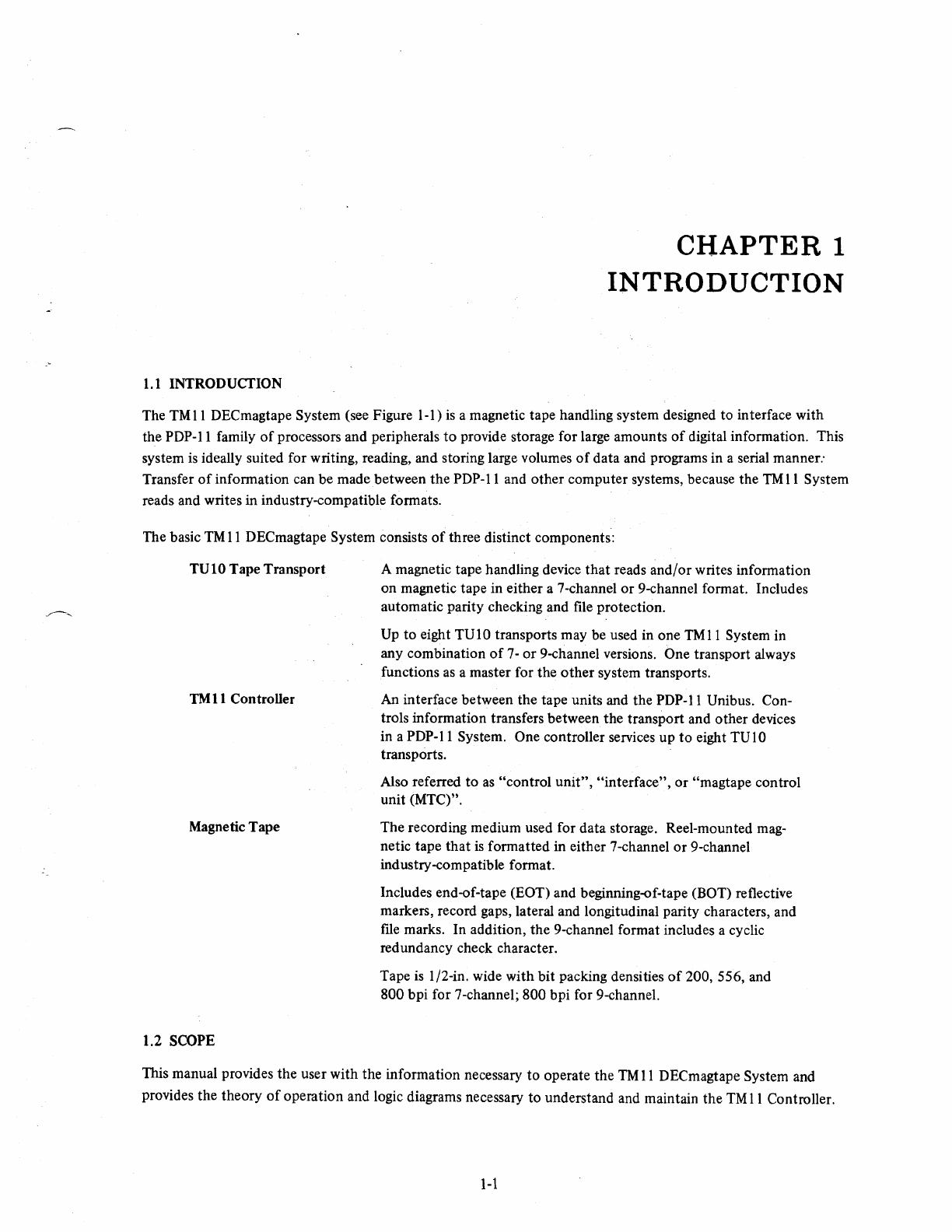
1.1
INTRODUCTION
CHAPTER
1
INTRODUCTION
The
TMll
DEC
magtape System (see Figure 1-1)
is
a magnetic tape handling system designed to interface with
the PDP-II family
of
processors and peripherals
to
provide storage for large amounts
of
digital information. This
system
is
ideally suited for writing, reading, and storing large volumes
of
data and programs in a serial manner:
Transfer
of
information can be made between the PDP-II and other computer systems, because the TM
11
System
reads and writes in industry-compatible formats.
The basic
TM
11
DECmagtape System consists
of
three distinct components:
TUI0
Tape Transport
TM
11
Controller
Magnetic Tape
1.2 SCOPE
A magnetic tape handling device
that
reads and/or writes information
on magnetic tape in either a 7-channel or 9-channel format. Includes
automatic parity checking and file protection.
Up
to eight TU10 transports may be used in one
TMII
System in
any combination
of
7-
or
9-channel versions. One transport always
functions
as
a master for the
other
system transports.
An
interface between the tape units and the PDP-II Unibus. Con-
trols information transfers between the transport and other devices
in a PDP-II System. One controller services up
to
eight TU
10
transports.
Also referred
to
as
"control unit", "interface", or "magtape control
unit (MTC)".
The recording medium used for data storage. Reel-mounted
mag-
netic tape that
is
formatted in either 7-channel or 9-channel
industry-compatible format.
Includes end-of-tape (EOT) and beginning-of-tape (BOT) reflective
markers, record gaps, lateral and longitudinal parity characters, and
file
marks. In addition, the 9-channel format includes a cyclic
red undancy check character.
Tape
is
I/2-in. wide with bit packing densities
of
200, 556, and
800 bpi for 7-channel; 800 bpi for 9-channel.
This manual provides the user with the information necessary
to
operate the
TM
11
DECmagtape System and
provides the theory
of
operation and logic diagrams necessary to understand and maintain the
TM
11
Controller.
1-1
Figure
1-1
TM
11
DECmagtape System
This manual and the TUlO DECmagtape Manual
(DEC-OO-TVIO-DA)
must be used together for a complete
understanding
of
the entire
TM
II
System. The prime subject matter
of
this manual
is
the
TM
11
Controller; the
prime subject matter
of
the
TV
1 0 manual
is
the tape transport and the magnetic tape. In addition, this manual
serves as an overall system operating guide.
Table
1-1
indicates the coverage in the two manuals, and Table
1-2
lists related PDP-II documents
that
are
applicable
to
the
TM
11
DECmagtape System.
1-2

Title
TMll
DECmagtape
System Manual
TU 10 DECmagtape
Transport Manual
TU10 DECmagtape
Master System
Manual
Title
TU10 DECmagtape
PDP-ll Processor and
Systems Manuals
PDP-ll
Processor
Handbook
PDP-ll
Peripherals
Handbook
Table
1-1
TMII
System Manuals
Number
DEC-II-HTMA-D
DEC-oO-TUIO-DA
DEC-oO-TUI0M-D
Coverage
Overall System -description, installation, operation,
programming.
TMII
Controller -detailed
theory
of
operation sup-
ported
by
logic diagrams in a second volume.
Tape Transport -description and installation; de-
tailed theory
of
operation; logic diagrams; mainten-
ance.
Magnetic Tape -detailed description
of
tape format.
Master
Tape
Transport -description, interface and
control, and
theory
of
operation.
Table 1-2
Applicable Documents
Number
DEC-OO-TU
I
O-DA
*
**
112-00973-2908
Coverage
Provides detailed theory, operation, maintenance,
and logic diagrams
for
the tape transport.
A series
of
maintenance and theory manuals
that
provide a detailed description
of
the basic
PDP-II
System.
A general
handbook
that
discusses system architec-
ture, addressing modes,
the
instruction set, pro-
gramming techniques, and software.
A
handbook
devoted
to
a discussion
of
the various
peripherals used with
PDP-II
systems.
It
also provides
detailed theory, flow, and logic descriptions
of
the
Unibus and external device logic;
methods
of
interface
construction; and examples
of
typical interfaces.
* Applicable manuals are furnished with the system at time
of
installation. The document number depends upon the specific
PDP-II family processor.
**Use the processor handbook unique to the actual
CPU.
1-3

Table 1-2 (Cont)
Applicable Documents
Title Number
Logic
Handbook
DEC, 1971
Paper-Tape Software DEC-II-GGPB-D
Programming
Handbook
1.3 GENERAL DESCRIPTION
Coverage
Presents functions and specifications
of
the M-Series
logic modules, accessories, and connectors used in
the
TM
11
Controller and the TU 1 0 Tape Transport.
Includes other types
of
logic produced by
DEC
but
not used with PDP-II devices.
Provides a detailed discussion
of
the PDP-II software
system used to load, dump, edit, assemble, and debug
PDP-II programs; input/output programming; and
the floating-point and math package.
The
TM
11
DECmagtape System
is
a magnetic tape storage facility consisting
of
a
TM
11
Controller and up
to
eight
TUIO
DEC
magtape transports. The system reads
or
records digital data, in parallel,
on
magnetic tape in either a
7-
or 9-channel industry-compatible format. Transfer rates
as
high
as
36,000 characters per second can be achieved.
One tape transport is referred to
as
the master and contains
all
of
the magnetic tape electronics. Additional trans-
ports are referred to
as
slaves and share the electronics in the master. This
is
possible because only one transport
can communicate with the processor at any
given
time. Any combination
of
7-
and 9-channel transports (up to a
total
of
eight) may be used with one
TM
11
Controller.
The
TM
11
DECmagtape System has a number
of
features that improve its reliability and make it exceptionally
useful as a storage device. A read-after-write head automatically checks parity character-by-character; a longitUdi-
nal parity check (LPC)
is
automatically performed on
all
units; and a cyclic redundancy check (CRC)
is
automati-
cally performed on 9-channel units.
Compatibility with industry standards provides efficient transfer
of
data between the PDP-II and other computer
systems. The tape format for
both
7-
and 9-channel transports
is
compatible with all industry standards.
The three major functional components
of
a
TM
II
DECmagtape System are: the TUI 0 DECmagtape Transport,
the
TMll
Controller, and the magnetic tape. Each
of
these functional components
is
briefly described in sub-
sequent paragraphs.
1.3.1
TUI0
DECmagtape Transport
The
TUI0
DECmagtape Transport is a solid-state, magnetic tape handling device
that
controls tape motion and
reads or records digital information on magnetic tape in industry-compatible formats.
14
The TU lOuses vacuum columns and a servo-controlled single capstan
to
control tape motion. The only contact
with the oxide surface
is
the magnetic head and a rolling contact
on
one low-friction, low-inertja bearing. Dancer
arms and pinch rollers, which shorten tape life and can cause errors, are
not
used in the TUlO.
Tape transport commands can be issued manually from the TUI 0 control panel or remotely from the processor
by means
of
the
TMII
Controller. Indicators on
both
the transport and the controller indicate transport status.
Each tape transport (master or slave) consists
of
the TV 10 cabinet, reel and reel
motor
control, capstan drive, and
read/write components. In addition to these components, the master transport contains logic circuits that: start
and stop any tape unit, generate the read and write pulses, generate the required gaps, generate parity, and check
parity. These logic circuits are shared by all transports under control
of
the master and the
TM
II
Controller.
In addition
to
the parity checking features
of
the TUIO, the transport contains deskewing electronics to eliminate
static skew, and write-protect ring sensing.
There are 16 different
TUI0
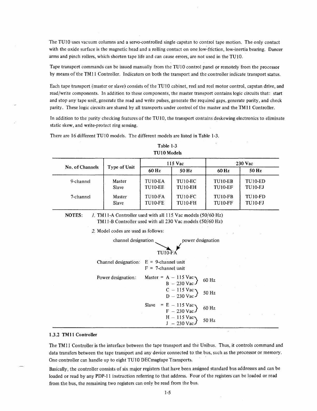
models. The different models are listed in Table 1-3.
Table
1-3
TUlOModels
115 Vac
No. 0 f Channels Type
of
Unit
60Hz
9-channel
7-channel
NOTES:
50Hz
60Hz
Master TUIO-EA TUIO-EC TUIO-EB
Slave TUIO-EE TUIO-EH TUIO-EF
Master TUIO-FA TUIO-FC TUIO-FB
Slave TUIO-FE TUIO-FH
TUI0-FF
1.
TMll-A
Controller used with all 115 Vac models (50/60 Hz)
TM
II-B Controller used with all 230 Vac models (50/60 Hz)
2.
Model codes are used
as
follows:
channel designation power designation
~I
Channel designation: E = 9-channel unit
F = 7 -channel unit
Power designation: Master =
A-lIS
Vac)
60 Hz
B - 230 Vac
Slave
C -115
Vac)
50 Hz
D - 230 Vac
E - 115
Vac)
60 Hz
F - 230 Vac
H - 115
Vac)
50
Hz
J - 230 Vac
1.3.2
TMII
Controller
230 Vac
50Hz
TUIO-ED
TUIO-EJ
TUIO-FD
TUIO-FJ
The
TM
11
Controller
is
the interface between the tape transport and the Unibus. Thus, it controls command and
data transfers between the tape trans'port and any device connected to the bus, such
as
the processor or memory.
One controller can handle up
to
eight TU 1 0 DECmagtape Transports.
Basically, the controller consists
of
six major registers
that
have been assigned standard bus addresses and can be
loaded
or
read by any PDP-II instruction referring to
that
address.
Four
of
the
registers can be loaded or read
from
the
bus, the remaining two registers can only be read from the bus.
1-5
The controller has three main functions: handling
data
transfers, issuing control commands, and monitoring
operation
of
the system.
During data transfer functions,
the
controller assembles the data word from
the
magnetic tape and places
it
on
the
bus (read operation),
or
assembles it from the bus and loads it
into
the
tape transport read/write heads (write
operation) for recording
on
magnetic tape. The commands necessary
to
perform
the
specified operation are gene-
rated
by
the
controller under program control.
Nonnal data word transfers are perfonned by direct memory access transactions
at
the NPR level.
If
the control-
ler
is
ready
to
begin a new function
or
if
an error condition exists, it issues an interrupt request
so
that
it
can be
serviced
by
the program.
In addition
to
the commands required for
data
transfers, the controller may issue
other
commands governing
tape unit selection, direction
of
tape
travel, rewind, space forward, space reverse, write end-of-file mark, etc.
The
controller also monitors various functions and provides an indication
of
error conditions.
The
status
of
the
monitored functions
is
stored in
one
of
the
controller registers.
A controller maintenance panel permits clearing
of
the
TM
11
System and includes 28 indicator lights
to
represent
error conditions and
the
status
of
selected functions.
1.3.3 Magnetic
Tape
The magnetic tape
is
the
recording medium used with the
TM
II
DECmagtape System.
The
tape is 1/2-in. oxide-
coated Mylar 8 . The tape includes reflective end-of-tape (EOT) and beginning-of-tape (BOT) markers and
is
stored
on
2400-ft reels.
Data
is
recorded in an industry-standard format.
The
7-channel format consists
of
six data channels
(I,
2, 4, 8, A,
and B) and a parity channel (C). Each
PDP-II
word
is
divided into
two
6-bit characters. Data
is
stored in variable-
length records separated
by
interrecord gaps
of
3/4
in. A longitudinally parity check (LPC) character
is
written at
the end
of
each record. Standard
fonnat
marks
(tape
mark, group mark, segment mark, etc.) may also be written
in a record along with
the
data. The 7-channel
fonnat
may be written in densities
of
200,556,
or
800
bpi.
The 9-channel format consists
of
eight data channels in
the
following order:
9,8,7,6,5,4,3,
2, and
1.
Channel
4 is used for parity.
In
addition, a cyclic redundancy check (CRC) character
is
written before
the
LPC character.
Data
is
stored in variable length records separated by interrecord gaps
of
one-half inch. Each
PDP-II
word con-
sists
of
two 8-bit characters. The 9-channel format always has a
bit
packing density
of
800
bpi.
Both formats are written
by
means
of
the
non-return-to-zero (NRZI) recording method. Although
the
tape has
two basic states
of
magnetization,
the
state does
not
determine
the
value
of
the
bit. A logical 1
is
represented
by
a change
of
magnetization in
either
direction. A logical 0
is
represented
by
a constant state
of
magnetization.
1.4 SPECIFICATIONS
Operating and physical specifications for the
TMII
Controller,
the
TUIO DECmagtape Transport, and
the
mag-
netic
tape
are given in Table 1-4.
1.5 ENGINEERING DRAWINGS
A complete set
of
reduced engineering drawings and module circuit schematics are provided in a companion
volume
to
this manual, which is entitled, TM11 DECmagtape System, Engineering Drawings. A list
of
individual
modules
is
included in Chapter 6
of
this manual. The general logic symbols used
on
these drawings are described
in
the
DEC Logic Handbook, 1971.
9 Mylar
is
a trademark
of
DuPont Corporation.
1-6
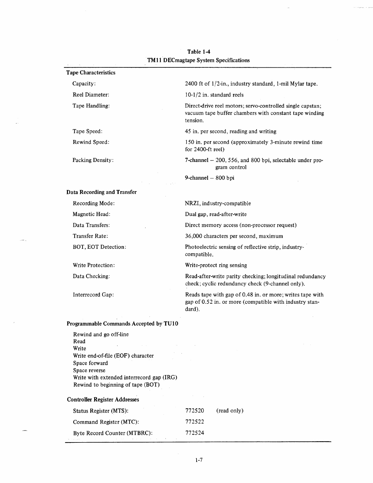
Table 1-4
TMtlDECmagtape
System Specifications
Tape Characteristics
Capacity:
Reel Diameter:
Tape Handling:
Tape Speed:
Rewind Speed:
Packing Density:
Data Recording and Transfer
Recording Mode:
Magnetic Head:
Data Transfers:
Transfer Rate:
BOT,
EaT
Detection:
Write Protection:
Data Checking:
Interrecord Gap:
Programmable Commands Accepted by
TUt
0
Rewind and
go
off-line
Read
Write
Write end-of-file (EOF) character
Space forward
Space reverse
Write with extended interrecord gap (IRG)
Rewind to beginning
of
tape (BOT)
Controller Register Addresses
Status Register (MTS):
Command Register (MTC):
Byte Record Counter (MTBRC):
2400 ft
of
I/2-in., industry standard, I-mil Mylar tape.
10-1/2 in. standard reels
Direct-drive reel motors; servo-controlled single capstan;
vacuum tape buffer chambers with constant tape winding
tension.
45
in. per second, reading and writing
150 in. per second (approximately 3-minute rewind time
for 2400-ft reel)
7-channel -200, 556, and 800 bpi, selectable under pro-
gram control
9-channel -800 bpi
NRZI, industry-compatible
Dual gap, read-after-write
Direct memory access (non-processor request)
36,000 characters per second, maximum
Photoelectric sensing
of
reflective strip, industry-
compatible.
Write-protect ring sensing
Read-after-write parity checking; longitudinal redundancy
check; cyclic redundancy check (9-channel only).
Reads tape with gap
of
0.48 in.
or
more; writes tape with
gap
of
0.52 in. or more (compatible with industry stan-
dard).
772520
772522
772524
1-7
(read only)
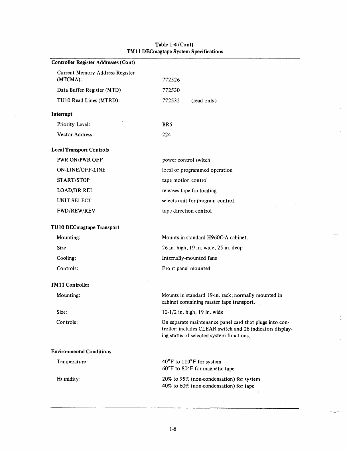
Table 1-4 (Cont)
TM
11
DECmagtape System Specifications
Controller Register Addresses (Cont)
Current Memory Address Register
(MTCMA):
Data Buffer Register (MTD) :
TUIO Read Lines (MTRD):
Interrupt
Priority Level:
Vector Address:
Local Transport Controls
PWR
ON/PWR
OFF
ON-LINE/OFF-LINE
START/STOP
LOAD/BR REL
UNIT SELECT
FWD/REW /REV
TUI0
DECmagtape Transport
Mounting:
Size:
Cooling:
Controls:
TM
11
Controller
Mounting:
Size:
Controls:
Environmental Conditions
Temperature:
Humidity:
772526
772530
772532
BR5
224
(read only)
power control switch
local or programmed operation
tape motion control
releases tape for loading
selects unit for program control
tape direction control
Mounts in standard H960C-A cabinet.
26 in. high,
19
in. wide, 25 in. deep
Internally-mounted fans
Front panel mounted
Mounts in standard 19-in. rack; normally mounted in
cabinet containing master tape transport.
10-1/2 in. high,
19
in. wide
On separate maintenance panel card that plugs into con-
troller; includes CLEAR switch and 28 indicators display-
ing status
of
selected system functions.
40°F
to 110°F for system
60°F to 80°F for magnetic tape
20%
to
95% (non-condensation) for system
40%
to
60% (non-condensation) for tape
1-8

Power
Input
Requirements
Controller:
TU I
O-EA,
EE, FA,
FE
TU 1 O-Ee,
EH,
FC, FH
TUIO-EB, EF, FB,
FF
TUIO-ED, EJ, FD,
FJ
Power and Cabling
TMII
Power:
TUIO Power:
Cabling:
1.6 MAINTENANCE
Table 1-4 (Cont)
TM11 DECmagtape System Specifications
either
lIS
Vac,
50/60
Hz at 6.25A (A model)
or 230 Vac, 50/60 Hz
at
6.25A
(B
model)
lIS
Vac, 60 Hz
115 Vac, 50 Hz
230 Vac, 60 Hz
230 Vac, 50 Hz
System power supplied by one H720 Power Supply
mounted at back
of
master cabinet. Provides +5V
at
16A and -15V at lOA for use
by
TMl1 and up
to
eight
TUI0s.
Tape transport power (reel motors and fans) provided by
internal power supply in each transport.
BC
ll-A
cable
to
connect controller
to
Unibus and
to
con-
nect command signals between controller and master
TUI
O.
M908 ribbon connector
to
connect master TU 10 to slave
TUIOs.
The basic maintenance philosophy
of
the
TM
II
DECmagtape System
is
to present the user with the information
necessary
to
understand normal operation
of
the
system. The user can utilize this information when analyzing
trouble symptoms to determine necessary corrective action.
It
is
beyond 'the scope
of
this manual
to
present de-
tailed troubleshooting information.
Detailed maintenance and troubleshooting information
of
the TUIO DECmagtape Transport
is
given in the TUIO
DECmagtape Manual, DEC-OO-TUIO-DA.
1-9
2.1
SCOPE
CHAPTER
2
INSTALLATION
This
chapter
covers general
infonnation
on
installation
of
the
TM
11
DECmagtape System. Detailed
information
on
installation
of
the
TVI
0 Tape Transport
is
presented in
the
TV]
0 DECmagtape Transport Manual,
DEC-OO-TVIO-DA.
Infonnation
on
various mounting cabinets
is
presented
in
the H720 Power Supply and
Mounting
Box
Manual, DEC-II-HRSB-D.
2.2 CONFIGURATION
Installation procedilres vary greatly, depending
on
the
system configuration.
For
example,
if
the
user has ordered
a complete
PDP-II
System,
the
TMII
DECmagtape System
is
shipped already installed in its appropriate rack
together with
the
required cables.
If
the
complete system
is
shipped,
the
interconnecting cables are already in-
stalled.
However,
if
only a part
of
the
system is shipped because the user already has a basic
PDP-II
System,
then
the
TM
11
DECmagtape System
is
shipped separately together with
the
appropriate cables. Installation procedures
may vary, depending on
whether
the unit
is
mounted
in a DEC-
or
customer-supplied cabinet,
the
number
of
tape
transports in the system, and
other
variable factors.
2.3 UNPACKING
The
equipment
should
be
unpacked
as
follows:
Step
2
3
2.4 INSPECTION
Procedure
Place
the
equipment package within the installation site
near
its final location.
Cut
the
shipping straps and carefully remove all packing material.
Remove
the
machine screws
that
hold
the
cabinet
to
the
shipping pallet. Slide
the
cabinet
off
the
pallet and move
it
to
its final location.
Remove any tape holding
the
modules in place within
the
mounting
panels and
any tape holding
the
power
and interconnecting cables to
the
floor
of
the
cabinet.
Inspect all
of
the
equipment
before installing
it,
checking each piece against
the
parts list.
Any
damage must
be
reported immediately
to
the
shipper and
to
the DEC representative.
2-1
2.5 SPACEREQUIREMENfS
No
special site preparation is required for installation
of
the
TM
11
DECmagtape System. However, when installing
the system, make certain
that
the front and rear
of
the cabinets are accessible
to
maintenance personnel.
If
the
cabinets are separated
by
long distances, consideration should be given
to
overhead trenching ducts
or
floor ducts
for
the
cabling.
2.6 POWER AND CABLE REQUIREMENTS
The
TM
11
Controller and associated
TUI0
transports operate from a line voltage
of
either 115 Vac
or
230 Vac
at
a frequency
of
either 50
or
60
Hz, depending
on
the model ordered
by
the customer. The maximum current
required
is
6.25A for the controller. The
TMII
Controller contains its own power supply, and each
TUI0
trans-
port has its own power supply. Power supply specifications are listed in Table 1-4. The interconnecting cables
are listed in Table 2-1.
Cable
BC
II-A
Cable
M908 Ribbon Connector*
Table
2-1
Interconnecting Cables
Function
Connects
TMII
Controller
to
PDP-II Unibus and
to
TUIO
master transport.
Connects command and analog signals between master trans-
port
and slave transports.
*Number
of
cables supplied dependent on number
of
transports
in
system.
2.7 INSTALLATION
If
the
TM
II
DECmagtape System
is
shipped separately, there are only three components
that
must be installed:
the TMl1 Controller, the TUIO DECmagtape Transport (or transports), and the H720 Power Supply.
The
TMll
Controller
is
19
in. wide and 10-1/2 in. high; therefore, it can be mounted in any standard 19-in. rack
or
cabinet.
Installation
of
the power supply and tape transport are covered in the appropriate manuals referenced in Para-
graph 2.1.
2.8 FINAL CHECKOUT
After the system
is
installed and all cables connected, a final checkout should be performed. The fIrst step is
to
apply power and check all manual controls
of
the transports, power clear operation, etc. The second step is to run
the diagnostics supplied with
the
system.
2-2
3.1 INTRODUCTION
CHAPTER
3
OPERATION
This chapter provides the information necessary to operate the
TM
11
DECmagtape System. The description
is
divided into two major parts: controls and indicators, and operating procedures.
The description
of
the controls and indicators (refer to Paragraph 3.2)
is
in tabular form and provides the user
with the type and function
of
each operating switch and indicator on the
TVI
0 DECmagtape Transport and the
TM
11
Controller maintenance panel.
Step-by-step operating procedures for
both
on-line and off-line system operation are given in Paragraph 3.3.
Complete maintenance-type procedures and adjustments for the TVIO are beyond the scope
of
this manual and
are covered in the
TV
10 DECmagtape Manual.
3.2 CONTROLS AND INDICATORS
The controls and indicators used
to
operate the
TM
11
DECmagtape System are detailed in the following para-
graphs. These paragraphs describe the
TV
1 0 DECmagtape Transport control panel and the
TM
11
Controller
maintenance panel.
3.2.1 TVIO DECmagtape Control Panel
The
TM
11
DECmagtape System is controlled
by
switches mounted
on the control panel
of
the
TV
10 transport. These switches can be
used for off-line (manual
or
local) operation
of
the transport
or
can
be
used to enable the
TM
11
Controller for on-line (or remote) opera-
tion under program con trol.
The
TV
1 0 tape transport control panel (see Figure 3-1)
is
the small
control panel located at
the
lower left
of
the
TV
1 0 front panel.
Table
3-1
lists all tape transport controls and includes the type and
function
of
each. Table 3-2 lists the tape transport indicators.
The controls shown in Figure
3-1
are those used during normal sys-
tem operation. Additional controls, such as
the
adjustments
to
vary
tape speed, control capstan acceleration and deceleration times, and
reduce mechanical and electrical skew, are tape transport mainten-
ance adjustments and are beyond
the
scope
of
this manual.
3-1
I
PWR
IILOADII
ROY
liLDll
END
WI
LEI
~
PT
PROT
I~I~EIEJIWRTII
FWDIIREV IIREWI
PWR
ON
ON·
LINE
START
PWR
OFF
OFF'LINE
STOP
LOAD
FWD
0
REW
UNIT
BR
REL
SELECT
REV
CP-0093
Figure
3-1
TVIO
Control Panel
Table
3-1
TU 10 DECmagtape Transport Controls
Control Type
PWR
ONjPWR
OFF
2-position
switch butterfly switch
ON-LINE/
OFF-LINE switch
START/STOP
switch
2-position
butterfly switch
2-position
butterfly switch
Function
Applies primary power to the TUIO tape transport.
Primary power must be turned on at each individual tape trans-
port;
not
remotely controlled from the system.
PWR
ON position -applies ac power to primary power supply
transformer T 1 and illuminates
PWR
indicator light.
PWR
OFF
position -deactivates
ac
power, thereby removing all
power from the transport.
Controls local (off-line) and remote (on-line) operation
of
the
tape transport.
ON-LINE position -allows on-line system operation under pro-
gram control.
Read/write heads are
not
connected to the
TM
II
Controller
until the program selects the tape transport.
Tape transport
is
not completely on-line until the transport has
been selected by the program (SEL bits in command register).
Unit
is
completely on-line when SEL and RDY indicators are lit.
OFF
-LINE position -disconnects the transport from the
TM
11
Controller to allow manual off-line operation.
Tape motion
is
controlled
by
the FWD/REW/REV and START/
STOP switches when in off-line mode.
Tape unit cannot be remotely selected when switch
is
in OFF-
LINE position.
Controls starting and stopping
of
tape.
START position -
if
transport
is
off-line, initiates tape motion
in the direction determined
by
setting
of
the FWD/REW fREY
switch.
This position has no effect on tape motion
if
transport
is
in on-
line (remote) mode.
STOP position -stops
all
tape motion in off-line mode except
rewind.
Does not stop transport during rewind mode
of
operation.
3-2
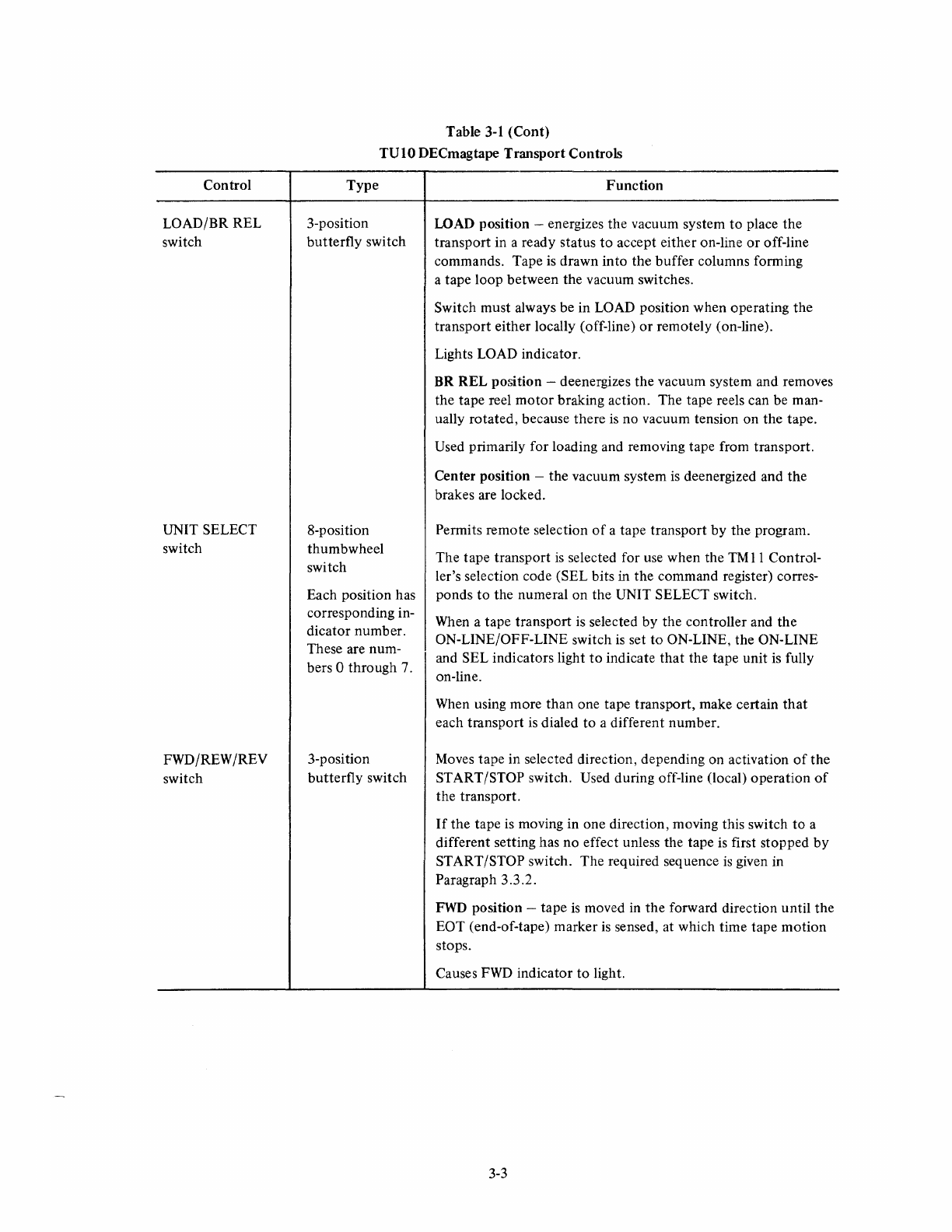
Control
LOAD/BR REL
switch
UNIT SELECT
switch
FWDjREW /REV
switch
Table
3-1
(Cont)
TUIO DECmagtape Transport Controls
Type
3-position
butterfly
switch
8-position
thumbwheel
switch
Each position has
corresponding in-
dicator number.
These are num-
bers 0 through 7.
3-position
butterfly switch
Function
LOAD position -energizes the vacuum system
to
place the
transport in a ready status
to
accept either on-line
or
off-line
commands. Tape is drawn into the
buffer
columns fonning
a tape loop between the vacuum switches.
Switch must always be in LOAD position when operating the
transport either locally (off-line)
or
remotely (on-line).
Lights LOAD indicator.
BR
REL
position -deenergizes the vacuum system and removes
the tape reel
motor
braking action. The tape reels can be man-
ually rotated, because there
is
no vacuum tension on the tape.
Used primarily for loading and removing tape from transport.
Center position -the vacuum system
is
deenergized and
the
brakes are locked.
Pennits remote selection
of
a tape transport
by
the program.
The tape transport
is
selected for use when the
TM
11
Control-
ler's selection code (SEL bits
in
the command register) corres-
ponds
to
the numeral on the UNIT SELECT switch.
When a tape transport is selected by the con troller and the
ON-LINE/OFF-LINE switch
is
set
to
ON-LINE, the ON-LINE
and SEL indicators light
to
indicate
that
the tape unit
is
fully
on-line.
When using more than one tape transport, make certain
that
each transport is dialed to a different number.
Moves tape in selected direction, depending on activation
of
the
START/STOP switch. Used during off-line (local) operation
of
the transport.
If
the tape
is
moving in one direction, moving this switch to a
different setting has
no
effect unless the tape is first stopped
by
START/STOP switch.
The
required sequence
is
given in
Paragraph 3.3.2.
FWD
position -tape
is
moved in the forward direction until the
EOT (end-of-tape) marker
is
sensed, at which time tape
motion
stops.
Causes
FWD
indicator
to
light.
3-3
Control
FWD/REW /REV
switch (cont)
Indicator
PWR
indicator
LOAD
indicator
RDY indicator
LD
PT (load point)
indicator
Table
3-1
(Cont)
TUI0
DECmagtape Transport Controls
Type Function
REW
position -tape
is
moved in the reverse direction, rewind-
ing it onto the feed reel until the BOT (beginning-of-tape) mark-
er
is
sensed, at which time tape motion stops.
After the BOT marker has been reached, depressing the switch
again causes the tape to continue to rewind until it
is
completely
rewound
onto
the feed reel
or
until the switch
is
deactivated.
Causes
REW
indicator to light. During this mode, tape moves
at a much faster speed than during the REV mode.
Tape rewinds to a point well beyond the BOT marker, then
stops, moves forward until the
BOT
marker
is
again sensed,
then comes to a complete stop.
REV position -tape
is
moved
in
the reverse direction until the
BOT
marker
is
sensed, at which time tape motion stops.
Causes REV indicator to light.
Table 3-2
TUI0
DECmagtape Transport Indicators
Type
single light
single light
single light
single light
Function
When
lit, indicates that primary power has been applied
to
the
TUIO transport.
Controlled by
PWR
ON/pWR
OFF
switch.
When
lit, indicates that the vacuum system has been enabled,
tape has been drawn into the buffer columns forming the re-
quired tape loop, and the transport
is
ready
to
accept either on-
line or off-line commands.
Controlled by LOAD/BR REL switch.
When
lit, indicates that
all
read/write circuits and
input/output
lines are enabled; thus, the transport can accept processor com-
mands provided the SEL indicator
is
also lit.
When
lit, indicates that the beginning-of-tape (BOT) marker has
been sensed, and the transport
is
ready for operation.
Tape motion stops when the BOT marker has been sensed.
When
LD
PT
is
lit, the transport does not accept a rewind
(REW) command
but
does accept forward (FWD) and reverse
(REV) commands.
34
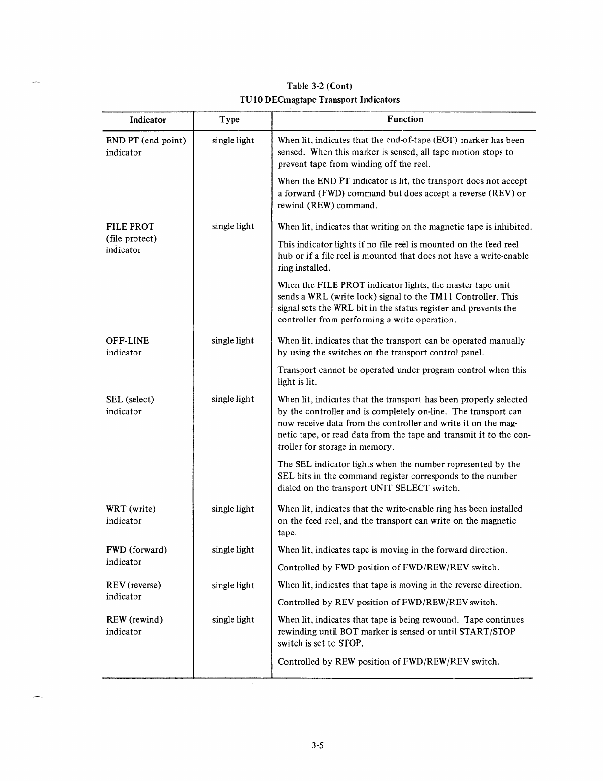
Indicator
END PT (end point)
indicator
FILE PROT
(file protect)
indicator
OFF-LINE
indicator
SEL (select)
indicator
WRT (write)
indicator
FWD
(forward)
indicator
REV (reverse)
indicator
REW (rewind)
indicator
Table 3-2 (Cont)
TUIO
DECmagtape Transport Indicators
Type
single light
single light
single light
single ligh t
single light
single light
single light
single light
Function
When lit, indicates
that
the end-of-tape (EOT) marker has been
sensed. When this marker
is
sensed,
all
tape motion stops to
prevent tape from winding
off
the reel.
When the END PT indicator is lit, the transport does
not
accept
a forward (FWD) command
but
does accept a reverse (REV)
or
rewind (REW) command.
When lit, indicates
that
writing on the magnetic tape is inhibited.
This indicator lights
if
no file reel
is
mounted on the feed reel
hub
or
if
a file reel
is
mounted that does
not
have a write-enable
ring installed.
When the FILE PROT indicator lights, the master tape unit
sends a WRL (write lock) signal
to
the
TM
11
Controller. This
signal sets the WRL bit in
the
status register and prevents
the
controller from performing a write operation.
When lit, indicates
that
the transport can be operated manually
by
using the switches on the transport control panel.
Transport cannot be operated under program control when this
ligh t is
Ii
t.
When lit, indicates
that
the transport has been properly selected
by
the controller and
is
completely on-line. The transport can
now receive data from the controller and write
it
on the mag-
netic tape,
or
read data from
the
tape and transmit
it
to
the
con-
troller for storage in memory.
The SEL indicator lights when the
number
represented
by
the
SEL bits in the command register corresponds
to
the number
dialed on the transport UNIT SELECT switch.
When lit, indicates
that
the write-enable ring has been installed
on the feed reel, and the transport can write on the magnetic
tape.
When lit, indicates tape
is
moving in the forward direction.
Controlled
by
FWD
position
of
FWD/REW/REV switch.
When lit, indicates
that
tape
is
moving in the reverse direction.
Controlled
by
REV position
of
FWD/REW /REV switch.
When lit, indicates
that
tape
is
being rewound. Tape continues
rewinding until BOT marker is sensed
or
until START/STOP
switch
is
set
to
STOP.
Controlled by
REW
position
of
FWD/REW /REV switch.
3-5
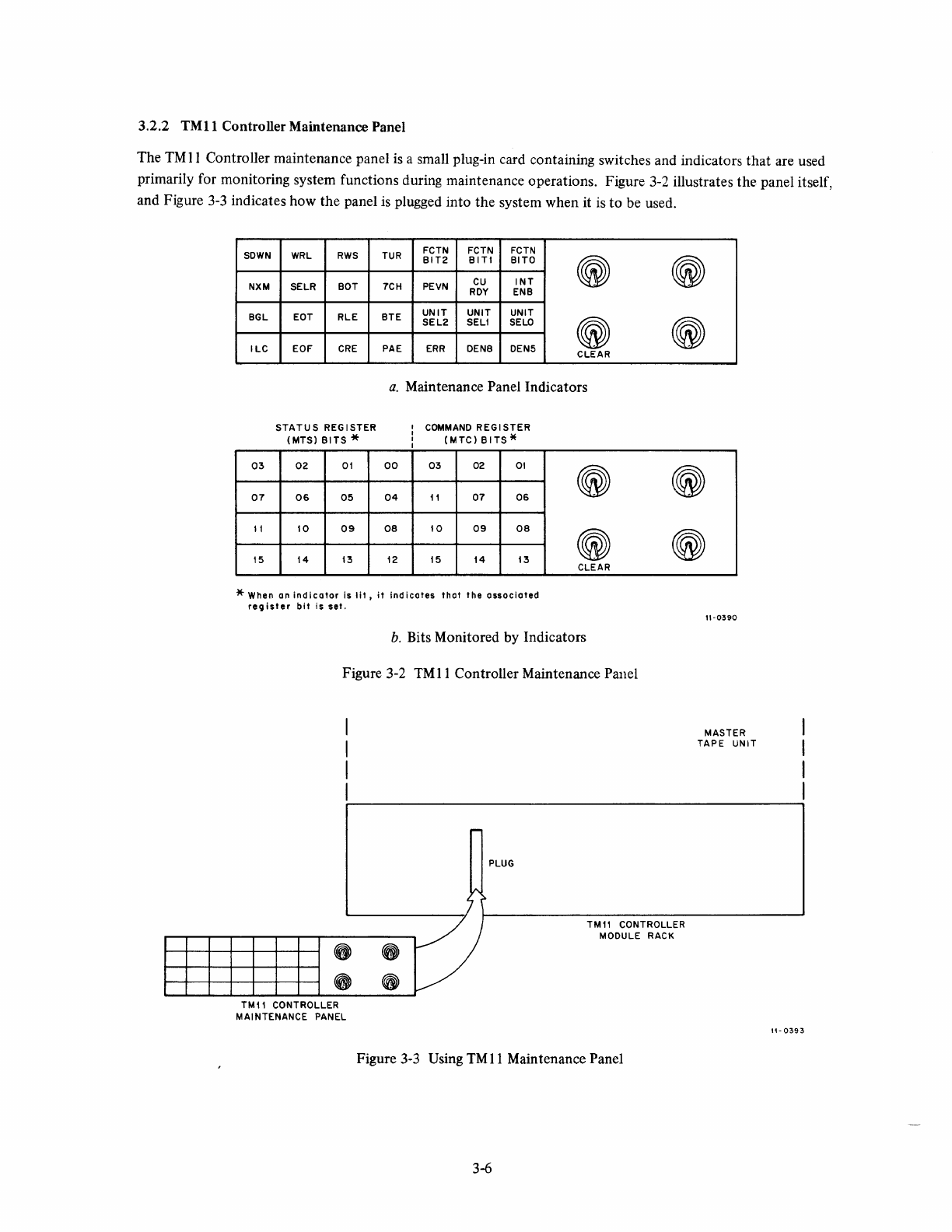
3.2.2
TMll
Controller Maintenance Panel
The
TM
11
Controller maintenance panel
is
a small plug-in card containing switches and indicators that are used
primarily for monitoring system functions during maintenance operations. Figure 3-2 illustrates the panel itself,
and Figure
3-3
indicates how the panel
is
plugged into the system when it
is
to be used.
SOWN
NXM
BGL
ILC
03
07
II
15
WRL
RWS
SELR BOT
EOT
RLE
EOF
CRE
STATUS
REGISTER
(MTS)
BITS
*
02
01
06
05
10
09
14
13
TUR FCTN FCTN
FCTN
BIT2
BITI
BITO
~
7CH PEVN
CU
INT
ROY
ENB
BTE
UNIT
UNIT UNIT
~
SEL2
SEll
SELO
PAE
ERR
DEN8 DEN5 CLEAR
a.
Maintenance Panel Indicators
00
04
08
12
COMMAND
REGI
STER
(MTC)
BITS*
03
02
01
11
07
06
10
09
08
15
14
13
~
~
CLEAR
* When an
indicator
is
lit.
it
indicates
that
the
associated
register
bit
is
set.
b.
Bits Monitored by Indicators
Figure 3-2
TM
11
Controller Maintenance Panel
I"'"
PLUG
II'-
,
J
~
~
~
~
11-0390
MASTER
TAPE UNIT
r/
TMI1
CONTROLLER
~
~
TMll
CONTROLLER
MAINTENANCE PANEL
MODULE RACK
~
~
Figure 3-3 Using
TM
11
Maintenance Panel
3-6
\1-0393
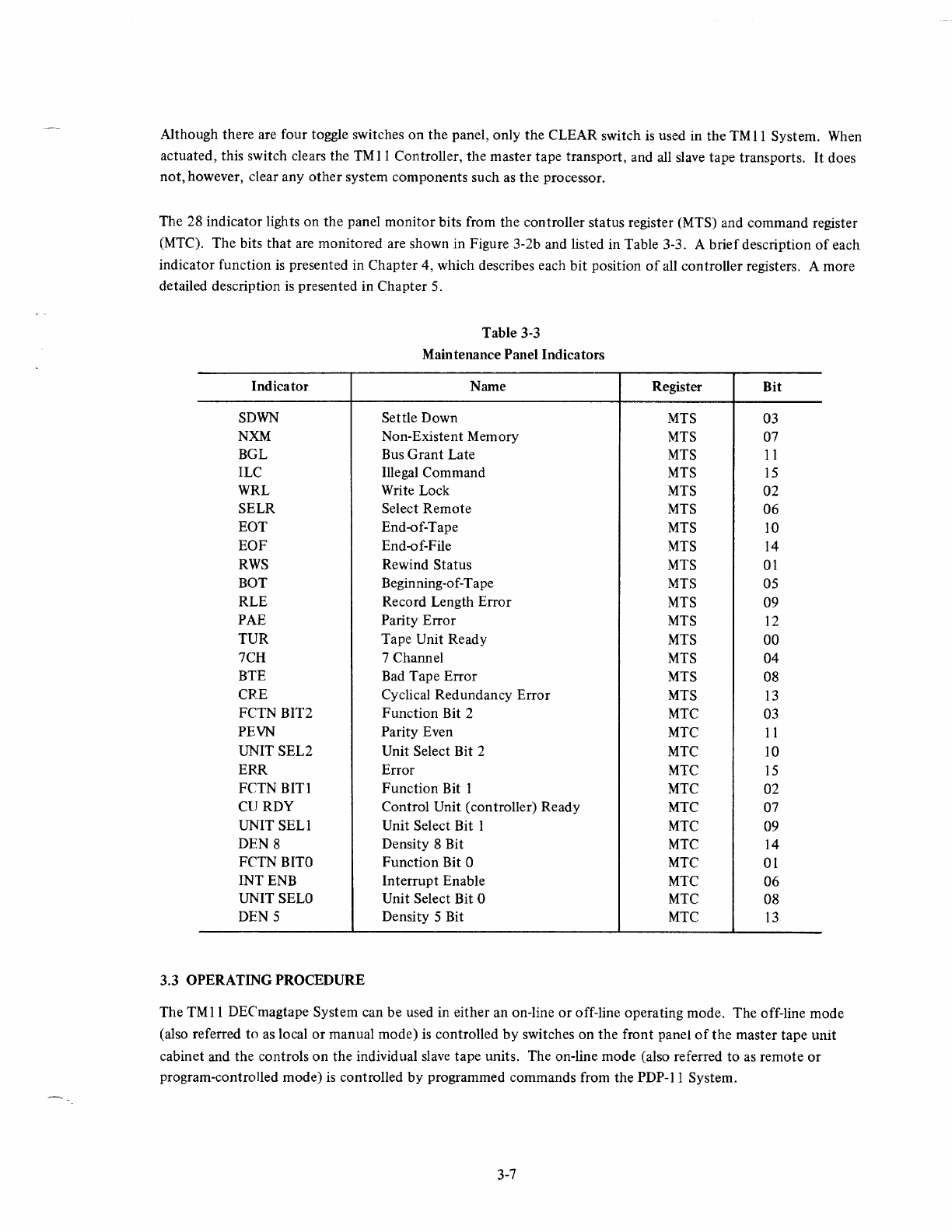
Although there are four toggle switches
on
the
panel, only
the
CLEAR switch
is
used in
the
TM
11
System. When
actuated, this switch clears
the
TM
II
Controller,
the
master tape transport, and all slave tape transports.
It
does
not,
however, clear any
other
system
components
such as
the
processor.
The 28 indicator lights on
the
panel
monitor
bits from
the
controller status register (MTS) and
command
register
(MTC).
The
bits
that
are monitored are shown in Figure 3-2b and listed in Table 3-3. A
brief
description
of
each
indicator function
is
presented in
Chapter
4, which describes each
bit
position
of
all controller registers. A more
detailed description
is
presented in
Chapter
5.
Indicator
SDWN
NXM
BGL
ILC
WRL
SELR
EDT
EOF
RWS
BOT
RLE
PAE
TUR
7CH
BTE
CRE
FCTN BIT2
PEVN
UNIT SEL2
ERR
FCTN
BITl
CURDY
UNIT
SELl
DEN 8
FCTN
BITO
INT ENB
UNIT SELO
DEN 5
3.3 OPERATING PROCEDURE
Table 3-3
Maintenance Panel Indicators
Name
Settle Down
Non-Existent Memory
Bus
Grant
Late
Illegal Command
Write Lock
Select
Remote
End-of-Tape
End-of-File
Rewind Status
Beginning-of-Tape
Record Length
Error
Parity
Error
Tape Unit Ready
7 Channel
Bad
Tape
Error
Cyclical Redundancy
Error
Function
Bit 2
Parity Even
Unit Select Bit 2
Error
Function
Bit 1
Control Unit (controller) Ready
Unit Select Bit 1
Density 8 Bit
Function
Bit 0
Interrupt
Enable
Unit Select Bit 0
Density 5 Bit
Register
Bit
MTS 03
MTS 07
MTS
11
MTS
15
MTS
02
MTS
06
MTS 10
MTS 14
MTS
01
MTS 05
MTS
09
MTS
12
MTS
00
MTS
04
MTS
08
MTS
13
MTC 03
MTC
II
MTC 10
MTC
15
MTC
02
MTC 07
MTC 09
MTC
14
MTC 01
MTC
06
MTC
08
MTC
13
The
TMII
DEC magtape System can be used in either an on-line
or
off-line operating mode.
The
off-line
mode
(also referred
to
as local
or
manual
mode)
is
controlled
by
switches
on
the
front panel
of
the
master tape unit
cabinet and the controls
on
the
individual slave
tape
units. The on-line mode (also referred
to
as
remote
or
program-controlled mode)
is
controlled
by
programmed commands from the
PDP-II
System.
3-7
The following paragraphs present procedures for operating
the
TM
11
DECmagtape System. Both on-line and off-
line procedures are discussed. Although procedures are included for setting up on-line operation,
it
is beyond the
scope
of
this chapter
to
present any detailed programming information. Programming infonnation, along with
references
to
other
programming aids, is included in Chapter 4.
Whenever handling magnetic tapes and reels, it
is
important
to
observe certain precautions
to
prevent loss
of
data
and/or damage
to
tape handling equipment. These precautions are:
a.
Always handle a tape reel by the hub hole; squeezing the reel flanges can cause damage
to
the
tape edges when winding
or
unwinding tape.
b.
Never
touch
the portion
of
tape between the BOT and EOT markers. Oils from fingers
attract
dust and dirt. Do
not
allow the end
of
the tape
to
drag
on
the floor.
c.
Never use a contaminated reel
of
tape; this spreads dirt
to
clean tape reels and can affect tape
transport operation.
d.
Always store tape reels inside their containers. Keep empty containers closed so dust and
dirt
cannot get inside.
e.
Inspect tapes, reels, and containers for dust and dirt. Replace take-up reels
that
are old
or
damaged.
f Do
not
smoke near the transport
or
tape storage area. Tobacco smoke and ash are especially
damaging
to
tape.
g.
Do
not
place the DECmagtape transport near a line printer
or
other
device
that
produces paper
dust.
h.
Clean
the
tape path frequently.
3.3.1 Mounting Tape
Before using the
TMII
DECmagtape System in either mode,
it
is
necessary
to
make certain
that
magnetic tape
is
properly loaded and threaded
in
the TUIO Tape Transport. The following procedure
is
used for mounting tape:
Step
2
3
4
5
6
7
8
Procedure
Apply power
to
the transport
by
depressing the
PWR
ON switch.
Ensure
that
the LOAD/BR REL switch
is
in the center position (this applies
the
brakes).
Place a write-enable ring (see Figure 3-4)
in
the groove
on
the
file reel
if
data
is
to
be written
on
the tape.
If
writing
or
erasing is
not
required, make certain there is no ring in the groove.
Mount the file reel
onto
the lower
hub
with the groove facing towards the back.
Ensure
that
the reel is firmly seated against the flange
of
the hub.
Install the take-up
(top)
reel in the same manner
as
described in Step 4 above.
Place LOAD/BR REL switch to
the
BR REL position.
Unwind tape from the file reel and thread the tape over the tape guides and head
assembly
as
shown in Figure 3-5.
Wind
about
five
turns
of
tape
onto
the
take-up reel.
3-8

Step
9
10
Procedure
Set the LOAD/BR REL switch
to
the LOAD position to draw tape
into
the
vacuum columns.
Select
FWD
and depress the START switch
to
advance the tape
to
the load point.
When
the BOT marker is sensed, tape motion stops, the
FWD
indicator goes
out,
and the LOAD
PT
indicator comes on.
NOTE
If
tape
motion continues for more than 10 seconds,
depress STOP, select REV (reverse), and then depress
START. The
tape
should advance
to
the BOT marker
(load point) before stopping.
Figure 3-4 Write-Enable Ring
3.3.2 Oft-Line Operation
Off-line operation
of
the TU I 0 Tape Transport
is
used primarily for loading and unloading magnetic tape, for
positioning magnetic tape prior
to
on-line operation, and for controlling tape motion during maintenance. During
off-line operation, tape motion
is
controlled
by
the switches on the TUIO control panel.
Althouah there are no specific operating procedures for off-line operation (other than that the ON-LINE/OFF-
UNE
switch must be in OFF-LINE), the following switch restrictions should be noted:
3-9
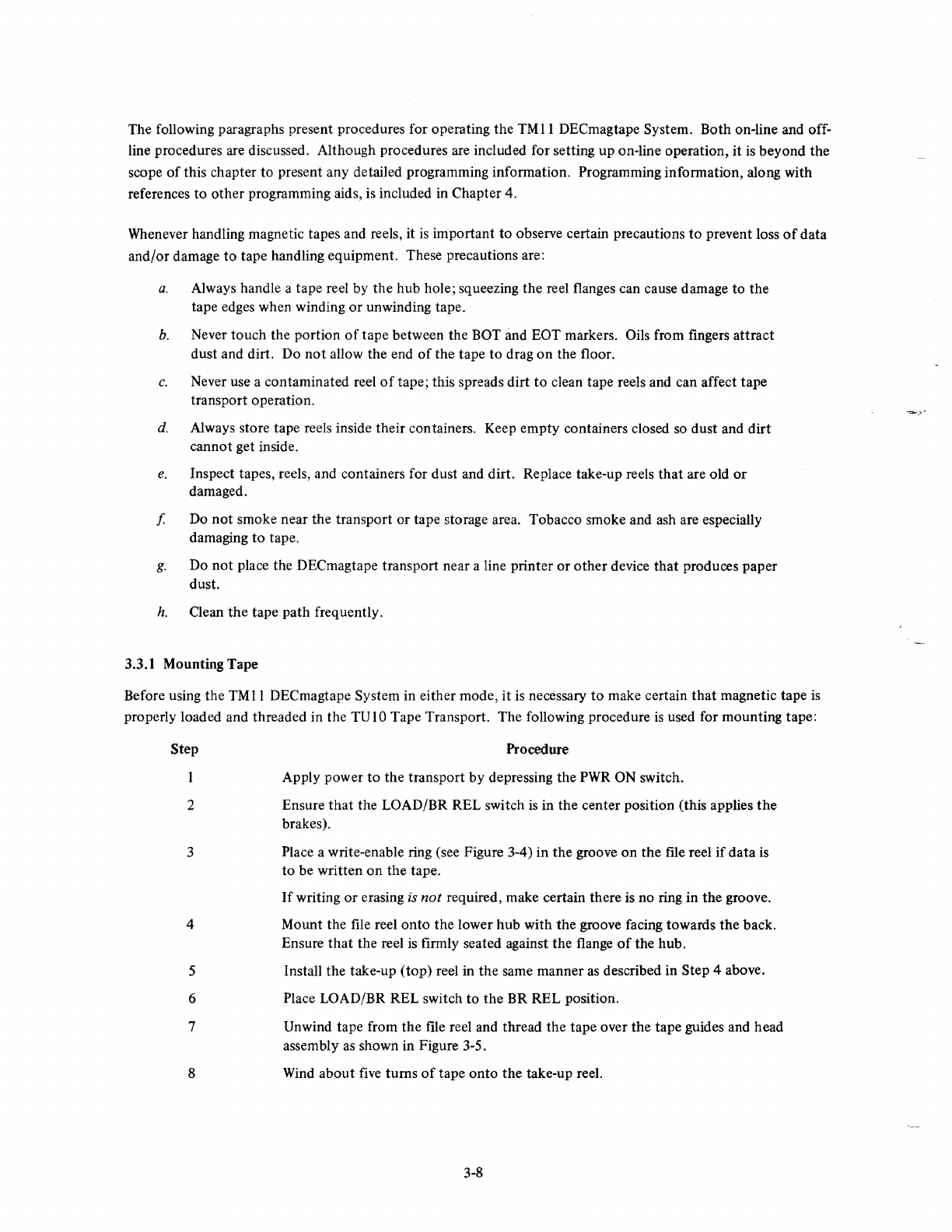
TAPE
GUIDE~.~_
..============7'
POSITIVE
TAPE
TENSION
...----HOLDS
TAPE
AGAINST
"
CAPSTAN
TRANSPORT
WILL I '
AUTOMATICALLY 1
(FAIL-
SAF~H~JNg~r6~)
TR\I'
___
/
I
II'
-'8
RIW
ERASE
HEAD
ASSEMBLY
TAPE
WIL~;i:Hil~~~~O~~)+
[I"
\
__
,-' NOTE'TAPE
IS
AUTOMATICALLY
I "
.'
DRAWN
INTO
VACUUM
COLUMNS
--.J
~
WHEN
LOADI
BR
REL
SWITCH
/
H(--'~S
T:~:
:~,~:AD
POSITION
I:
/'::1
LEFT
VACUUM
COLUMN
"-8-'
1\
FILE REEL
i
~
'I
TURNED
ON
TAPE
WILL
BE
EXTRACTED : "
',
__
/1
II
FROM
COLUMNTh'
I
,.
(TAKE'UP REEL
TURNED
ON)
I \
~
I
'II
TRANSPORT WILL : ,
,/,
1"
AUT~~~i'bAcf~~
- - - : \ \
RIGHT
VACUUM
(FAIL-SAFE
CONDITION)
I '\\",; I
K\COLUMN
L? i,.': I
Ii
\~~":I'",
7-
~'-J':
VACUUM CHAMBER PORT
II:
(TO
VACUUM
MOTOR)
~
\-8-'
I~'
Figure
3-5
Tape Threading
a.
When
the tape
is
traveling in any direction, resetting the FWD/REW/REV switch
to
any other
position has no effect
on
tape travel. The START/STOP switch must first be set to STOP, the
FWD/REW/REV switch reset, and then the START/STOP switch set to START.
b.
When
the tape load point (BOT marker) is reached, the transport does not accept a rewind
(REW) command.
c.
When
the tape end point (EOT marker) is reached, the transport does
not
accept a forward
(FWD) command.
3.3.3 On-Line Operation
On-line operation
of
the TUIO Tape Transport
is
used when the tape transport
is
under program control. Setting
the ON-LINE/OFF-LINE switch
to
ON-LINE allows the transport
to
accept commands from the controller when
the transport
is
selected
by
the program. Thus, the transport
is
not fully on-line until the transport RDY and SEL
indicators are lit.
3.3.4 Restart After Power Failure
In the event
of
a power failure, the DECmagtape transport automatically shuts down, and tape motion stops with-
out damage
to
the tape. Return
of
power
is
indicated when the
PWR
indicator lights. At this time, the transport
can be restarted
as
follows:
3-10

Step
2
3
4
Procedure
Set LOAD/BR REL switch
to
BR
REL position
to
release the brakes.
Manually wind the reels
to
take up any tape slack.
Set the LOAD/BR REL switch to LOAD position
to
draw tape into the vacuum
columns.
Set ON-LINE/OFF-LINE switch
to
desired position and resume desired operation.
3.3.5 Restart After Fail-Safe
If
the tape loop in either buffer column exceeds the limits shown in Figure 3-6, the vacuum system automatically
shuts down, and tape motion stops without damage to the tape.
When
this fail-safe condition occurs, the tape
transport does not respond
to
either on-line or off-line commands. To restart the transport after fail-safe, perform
the same procedures
as
for restarting after power failure (refer to Paragraph 3.3.4).
3.3.6 Removing Tape
o
VACUUM I
SWITCHES
10
I
I I
NORMAL \
~./
OPERATING
,,_
....
LIMITS
NORMAL
OPERATING
LIMITS
SHORT
LOOP
(TRANSPORT
WILL SHUTDOWN)
BUFFER
COLUMN
LONG LOOP
~io"'"---(TRANSPORT
WILL SHUTDOWN
CP-0088
Figure 3-6 Tape Loop Limits
The following procedure describes the method for removing tape from the TUIO Tape Transport.
Step
2
3
4
Procedure
Make certain that ON-LINE/OFF-LINE switch
is
set
to
the OFF-LINE position.
Set START/STOP switch
to
STOP position.
Set FWD/REW /REV switch
to
REW
position.
Set START/STOP switch
to
START position. The tape should rewind until the
BOT marker
is
reached.
3-11
Step
5
6
7
Procedure
Set LOAD/BR REL switch
to
BR REL position
to
release the brakes.
Gently hand wind the file reel in a counterclockwise direction until all
of
the
tape
is
wound
onto
the reel.
CAUTION
When hand winding the tape,
do
not
jerk the reel. This may
stretch
or
compress
the
tape, which can cause irreparable
damage.
Remove the me reel from the hub assembly.
3-12
4.1 SCOPE
CHAPTER
4
PROGRAMMING
INFORMATION
This
chapter
presents general programming information for software control
of
the
TM
11
DECmagtape System.
Although a typical program example
is
included in this chapter, it is beyond the scope
of
this manual
to
provide
detailed programs.
For
more detailed information
on
programming in general, refer
to
the Paper-Tape Software
Programming Handbook, DEC-II-GGPB-D.
This
chapter
of
the
manual
is
divided
into
four major portions: device registers, interrupts, programming
note,
and program example.
4.2 DEVICE REGISTERS
All software control
of
the
TM
11
DECmagtape System
is
performed
by
means
of
six device registers within the
controller. These registers have been assigned bus addresses and can be read
or
loaded using any
PDP-II
instruc-
tion
that
refers to their address.
The
six device registers and associated addresses are listed in Table 4-1. Note
that
these addresses can be changed
by
altering
the
jumpers
on
the
M 1
05
Address Selector Module. However,
any DEC programs
that
refer
to
these addresses
must
also be modified accordingly
if
the jumpers are changed.
Figures
4-1
through 4-6 show
the
bit assignments within the six device registers. Except
in
the case
of
the
data
buffer register,
the
"unused"
and "load
only"
bits are always read
as
Os.
Loading
"unused"
or
"read
only"
bits
has no effect on
the
bit position.
The mnemonic INIT refers
to
the
initialization signal issued
by
the processor. Initialization
is
caused
by
one
of
the
following: issuing a programmed RESET instruction; depressing
the
START switch on
the
processor console;
or
occurrence
of
a power-up
or
power-down condition
of
either the processor power supply
or
the
controller
power supply.
The INIT signal clears
the
entire system; however,
the
INIT signal produced
by
a RESET instruction does
not
clear
the
processor. Clearing only
the
TMII
Controller and the TUIO tape units can
be
accomplished
by
either
using
the
CLEAR switch
on
the
TMll
Maintenance Panel
or
by
loading a 1
into
bit
12
(POWER CLEAR)
of
the
command.register (MTC).
NOTE
INIT
and
POWER CLEAR deselect
the
current tape
unit
and
select tape
unit
O.
Also, a rewind operation
in progress continues
to
the
load point.
4-1
Table
4-1
Standard Device Register Assignments
Register
Status Register
Command Register
Byte Record Counter
Current Memory Address Register
Data Buffer Register
TV
10 Read Lines
Mnemonic*
MTS
MTC
MTBRC
MTCMA
MTD
MTRD
Address
772520
772522
772524
772526
772530
772532
*First two letters
of
mnemonic (MT) refer
to
magnetic tape control; the remaining letters repre-
sent the mnemonic
of
a specific register.
4.2.1 Status Register (MTS)
Bit
15
1/-0'130
Figure
4-1
Status Register (MTS) Bit Assignments
Meaning and Operation
ILC -illegal command bit. Indicates an illegal command. This bit
is
set when-
ever one
of
the following illegal commands occur:
a.
Any DATO
or
DATOB transfer
to
the command register (MTC)
during tape operation (CU RDY bit clear). The register cannot
accept a new command while in the process
of
executing another
command.
b.
A write, write end-of-file,
or
write with extended interrecord gap
(command register functions
2,
3, and 6, respectively), when the
WRL
(write lock) bit
is
set. Writing
is
inhibited with WRL set,
and write commands are illegal.
c.
Any command
to
a tape unit that has its SELR bit clear is illegal,
because SELR clear indicates
that
the unit
is
not on-line.
d.
Any time the SELR bit becomes 0 during any operation except
off-line,
it
sets the ILC bit, because no command can be issued
to
a unit that is not on-line.
If
any
of
the illegal commands listed in
a.
through
c.
above occur, the command
IS
loaded into the command register.
In all
of
the above cases, the ILC bit and the ERR bit (bit
15
in the command
register) are set simultaneously.
Cleared
by
IN
IT or by the
GO
pulse
to
the tape unit.
4-2
Bit
14
13
12
11
Meaning and Operation
EOF -end-of-file bit, used
to
indicate
that
the tape has reached the end
of
the
file. An end-of-file (EOF) character
is
detected during a read, space forward,
or
space reverse operation. During the read or space forward operation, the
EOF bit
is
set when the
LPC
character following the EOF character is read.
During a space reverse operation, the EOF bit
is
set when the EOF character
following its
LPC
character
is
read. The
ERR
bit (bit
15
in the command
register)
is
set when the
LPC
character following the EOF character
is
. detected. It is also set by a WRITE EOF command.
The EOF bit
is
set only by the TUIO logic; it
is
cleared
by
INIT
or
by the
GO
pulse
to
the tape unit.
The EOF character
is
loaded into memory during read operations.
eRE
-cyclic redundancy error bit. A cyclic redundancy error can be detected
during either a read or write operation. This check compares the CRC character,
written on a 9-channel tape during a write
or
a write-with-extended-IRG op-
eration, with the CRC character generated during a read operatis>n.
If the two CRC characters are
not
the same, the
CReE
from the tape unit
be~
comes a
I,
forcing the CRE bit
to
a
1.
The ERR bit in the command register,
however,
is
not
set until the LPC character
is
detected.
Cleared by INIT
or
by
the GO pulse to the tape unit.
PAE -parity error bit. When set, this bit indicates that a parity error exists.
The PAE bit
is
the logical
OR
of
both
lateral and longitudinal parity errors.
A lateral parity error
is
indicated on any character in a record; a longitudinal
parity error occurs only after the
LPC
is
detected.
.'
A lateral parity error does not affect the transfer
of
data.
In
other words, the
entire record
is
transferred
to
the tape during a
wri~e
operation or transferred
into memory during a read operation.
Both lateral and longitudinal parity errors are detected during read, write, and
write-with-extended-IRG operations. The entire record is checked, including
the CRC and
LPC
characters.
Longitudinal parity occurs when an odd number
of
I s
is
detected on any chan-
nel in the record. Lateral parity error occurs when an even number
of
I s is
detected
on
any character, provided the PEVN bit (bit
11
in the command
register)
is
clear,
or
if
an odd number
of
1 s is detected when the PEVN bit
is
set.
When a parity error occurs, PAE is set, and the
ERR
bit (bit
15
in the command
register) is set after the
LPC
character has been detected.
Cleared by INIT
or
by
the GO pulse
to
the
tape unit.
BGL -bus grant late bit.
If
the controller issues a request for the bus and does
not
receive a bus grant before it must issue another bus request for the following
tape character, a bus grant late error occurs.
This error condition
is
tested only for NPRs (non-processor requests). The BGL
bit
is
set if an NPR bus request
is
not
honored before the controller receives a
WRS
pulse for a write operation
or
an RDS pulse for a read operation.
4-3
Bit
11
(cont)
10
09
08
Meaning and Operation
The BGL bit and the ERR bit (bit
15
in the MTC) are set simultaneously, halting
the operation.
If
the BGL error occurred during a write or write-with-extended-IRG operation,
the controller does not send the WDR signal to the master tape unit
to
allow the
master tape unit
to
write the CRC and
LPC
characters on the tape.
Cleared by INIT
or
by the GO pulse to the tape unit.
EDT -end-of-tape bit. The
EaT
bit
is
set
as
soon
as
the
EaT
marker
is
detected,
when the tape
is
moving in the forward direction.
It
is
cleared as soon
as
the
EaT
marker
is
detected, when the tape
is
moving in the reverse direction.
The
EaT
is
an error condition
if
the tape
is
moving forward. Therefore, when
EaT
is
set,
ERR
bit
is
also set when the LPC character
is
read.
Cleared by tape transport
he"ad
passing over
EaT
marker when tape
is
moving
in
the reverse direction.
RLE -record length error bit. The record length error
is
tested only during read
operations. An error
is
indicated
as
soon
as
the
byte
record counter (MTBRC)
attempts to increment beyond
O.
When a record length error occurs, the RLE bit
is
set, incrementation
of
the
MTBRC and the current memory address register (MTCMA) ceases, and the
ERR
bit
is
set when the
LPC
character is read.
The
CU
RDY (bit
07
of
the command register) remains cleared until the
LPC
character
is
read at which time CU RDY
is
set.
Cleared
by
INIT
or
by the GO pulse to the tape unit.
If
the exact record length
is
desired following the occurrence
of
a record length
error, it can be found by setting the MTBRC to a value so large
as
not
to generate
an RLE and re-reading the record. Record length can be derived by subtracting
the current value
of
the MTBRC from its initial setting.
BTE -bad tape error bit. A bad tape error occurs when a character
is
detected
(RDS pulse) during the gap shutdown or settle down period for any tape
function except rewind.
During write, write EOF, or write-with-extended-IRG operations, a bad tape
error sets
both
the BTE and
ERR
bits immediately on detecting
the
error.
During
both
read and space forward or space reverse operations,
the
BTE bit
is
set immediately
on
detection
of
bad tape.
During a read operation, the MTBRC increments continuously, and words are
read into memory until
the
MTBRC overflows. During a space operation, the
MTBRC stops incrementing
as
soon
as
BTE occurs. When BTE
is
discovered,
the tape unit stops, regardless
of
the state
of
the MTBRC.
Because it it
not
possible to artificially generate bad tape, bad tape may be in-
dicated by setting the CU RDY
bit
prematurely, thereby producing the gap
shutdown period while the data
is
still being read. The CU RDY bit
is
set
by
loading a I into bit
13
of
the MTRD.
If
bit 13
of
the MTRD
is
set during a
record for either a read
or
write operation, a bad tape error indication occurs.
Cleared by INIT
or
GO.
4-4
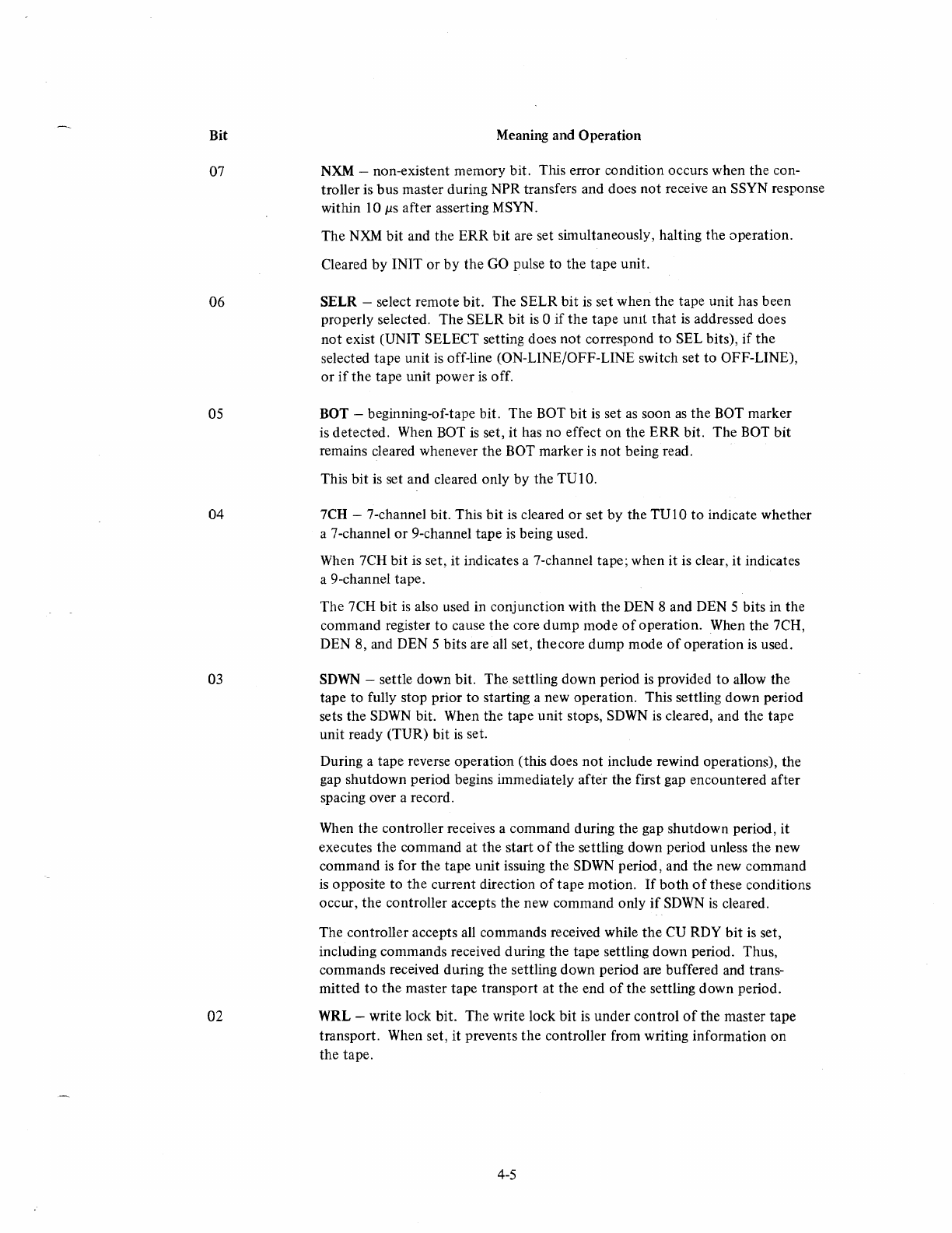
Bit
07
06
05
04
03
02
Meaning and Operation
NXM -non-existent memory bit. This error condition occurs when
the
con-
troller is
bus
master during NPR transfers and does
not
receive an SSYN response
within lOllS after asserting MSYN.
The
NXM
bit
and the
ERR
bit
are set simultaneously, halting the operation.
Cleared
by
IN IT
or
by the GO pulse to
the
tape unit.
SELR -select remote bit. The SELR
bit
is
set
when
the tape unit has been
properly selected.
The
SELR bit
is
0
if
the
tape umt
that
is
addressed does
not
exist (UNIT SELECT setting does
not
correspond
to
SEL bits),
if
the
selected tape unit is off-line (ON-LINE/OFF-LINE switch set
to
OFF-LINE),
or
if
the
tape unit power
is
off.
BOT -beginning-of-tape bit. The BOT
bit
is
set
as
soon
as
the
BOT marker
is detected. When BOT
is
set, it has no effect
on
the
ERR
bit.
The
BOT
bit
remains cleared whenever
the
BOT marker is
not
being read.
This
bit
is
set and cleared only
by
the
TU
I
O.
7CH -7-channel bit. This
bit
is cleared
or
set
by
the TUIO
to
indicate whether
a 7-channel
or
9-channel tape
is
being used.
When 7CH
bit
is set, it indicates a 7-channel tape; when it is clear,
it
indicates
a 9-channel tape.
The 7CH
bit
is
also used in conjunction
with
the DEN 8 and DEN 5 bits in the
command register
to
cause
the
core
dump
mode
of
operation. When the 7CH,
DEN 8, and DEN 5 bits are all set,
thecore
dump
mode
of
operation is used.
SDWN
-settle down bit.
The
settling down period is provided
to
allow the
tape to fully stop prior
to
starting a new operation. This settling down period
sets
the
SDWN
bit. When the tape unit stops, SDWN
is
cleared, and the tape
unit ready (TUR) bit
is
set.
During a tape reverse operation (this does
not
include rewind operations), the
gap shutdown period begins immediately after the first gap encountered after
spacing over a record.
When
the
controller receives a command during the gap shutdown period, it
executes
the
command at the start
of
the
settling down period unless the new
command is for
the
tape unit issuing
the
SDWN
period, and
the
new command
is
opposite to
the
current direction
of
tape
motion.
If
both
of
these conditions
occur,
the
controller accepts the new command only
if
SDWN
is
cleared.
The controller accepts all commands received while
the
CU RDY
bit
is set,
including commands received during the tape settling
down
period. Thus,
commands received during the settling
down
period are buffered and trans-
mitted
to
the
master tape transport at
the
end
of
the
settling
down
period.
WRL -write lock bit. The write lock
bit
is
under
control
of
the master tape
transport. When set, it prevents
the
controller from writing information
on
the tape.
4-5
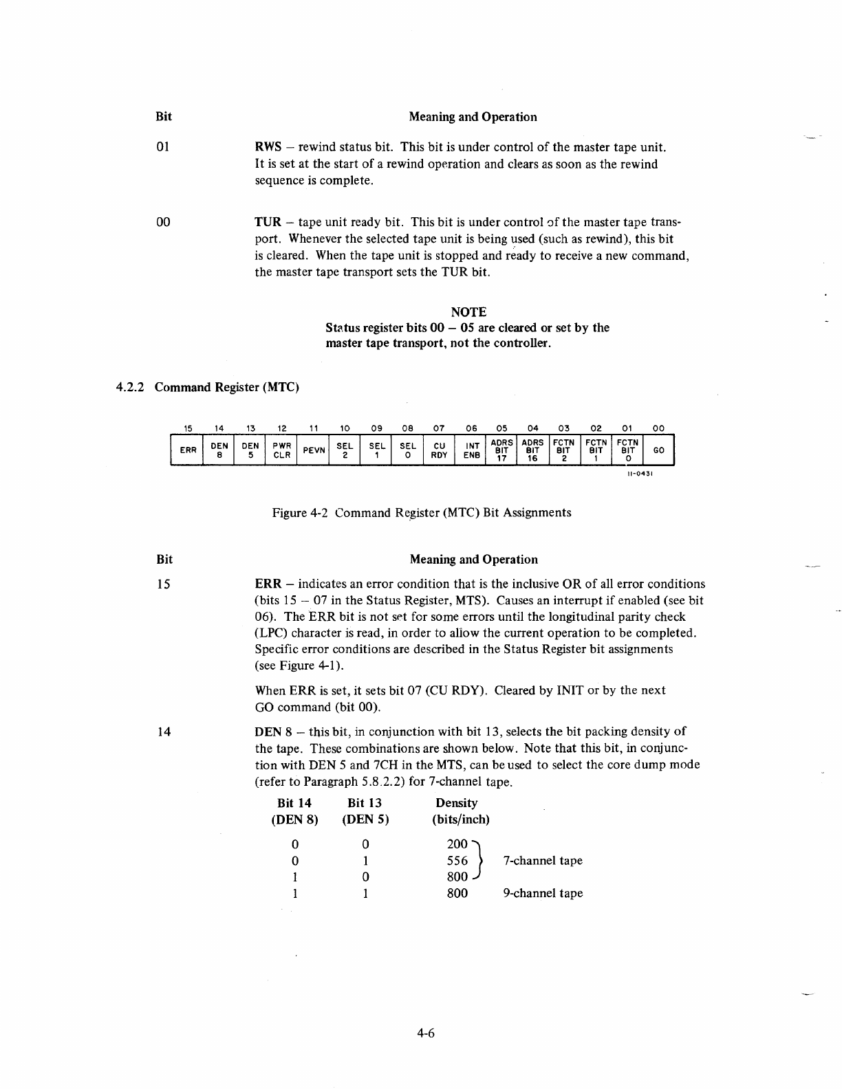
Bit
01
00
Meaning and Operation
RWS
-rewind status bit. This bit is under control
of
the master tape unit.
I t
is
set at the start
of
a rewind operation and clears as soon
as
the rewind
sequence is complete.
TUR
-tape unit ready bit. This
bit
is under control
~f
the master tape trans-
port. Whenever the selected tape unit is being
,:!sed
(such
as
rewind), this
bit
is cleared. When the tape unit is stopped and ready
to
receive a new command,
the master tape transport sets the TUR bit.
NOTE
St~tus
register
bits
00
-05 are cleared or set
by
the
master tape transport,
not
the controller.
4.2.2 Command Register (MTC)
Bit
15
14
11-0431
Figure 4-2 Command Register (MTC) Bit Assignments
Meaning and Operation
ERR
-indicates an error condition
that
is the inclusive OR
of
all error conditions
(bits
15
-07 in the Status Register, MTS). Causes an interrupt
if
enabled (see bit
06). The
ERR
bit is
not
set for some errors until the longitudinal parity check
(LPC) character
is
read, in order to allow the current operation
to
be completed.
Specific error conditions are described in the Status Register bit assignments
(see Figure 4-1).
When
ERR
is
set, it sets bit 07 (CU RDY). Cleared
by
INIT
or
by
the
next
GO command (bit 00).
DEN 8 - this bit, in conjunction with bit 13, selects the bit packing density
of
the tape. These combinations are shown below. Note
that
this bit, in conjunc-
tion
with DEN 5 and 7CH in the MTS, can be used
to
select the core dump mode
(refer
to
Paragraph 5.8.2.2) for 7-channel tape.
Bit 14 Bit 13 Density
(DEN
8)
(DEN
5)
(bits/inch)
o
o
1
a
1
a
200}
556
800
7-channel tape
800
9-channel tape
4-6
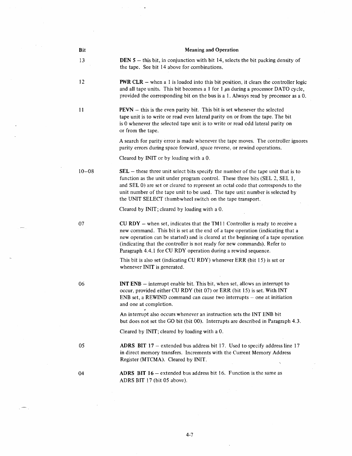
Bit
13
12
11
10-08
07
06
05
04
Meaning and Operation
DEN 5 - this bit, in conjunction with bit 14, selects the bit packing density
of
the
tape. See bit 14 above for combinations.
PWR
CLR -when a 1
is
loaded into this
bit
position, it clears the controller logic
and all tape units. This bit becomes a I for I
J.LS
during a processor DATO cycle,
provided the corresponding bit on
the
bus
is
a
1.
Always read
by
processor
as
a
o.
PEVN -this
is
the even parity bit. This bit
is
set whenever the selected
tape unit
is
to
write
or
read even lateral parity on
or
from the tape. The bit
is
0 whenever the selected tape unit
is
to
write
or
read
odd
lateral parity on
or from the tape.
A search for parity
error
is
made whenever the tape moves. The controller ignores
parity errors during space forward, space reverse,
or
rewind operations.
Cleared by INIT
or
by
loading with a
O.
SEL -these three unit select bits specify the number
of
the tape unit
that
is to
function
as
the
unit under program control. These three bits (SEL 2, SEL
I,
and SEL
0)
are set
or
cleared
to
represent an octal code
that
corresponds
to
the
unit number
of
the tape unit
to
be used. The tape unit number
is
selected by
the UNIT SELECT thumb wheel switch on the tape transport.
Cleared
by
IN IT ; cleared by loading with a
O.
CU
ROY -when set, indicates that the
TMII
Controller
is
ready
to
receive a
new command. This
bit
is
set at the end
of
a tape operation (indicating
that
a
new operation can be started) and
is
cleared at the beginning
of
a tape operation
(indicating
that
the controller
is
not
ready for new commands). Refer
to
Paragraph 4.4.1 for
CU
RDY operation during a rewind sequence.
This bit
is
also set (indicating
CU
RDY) whenever
ERR
(bit 15)
is
set
or
whenever INIT
is
generated.
INT ENB -interrupt enable bit. This bit, when set, allows an interrupt
to
occur, provided either CU RDY
(bit
07)
or
ERR
(bit 15)
is
set. With INT
ENB set, a REWIND command can cause two interrupts -one
at
initiation
and one at completion.
An interrupt also occurs whenever an instruction sets the INT ENB bit
but
does
not
set the
GO
bit (bit 00). Interrupts are described in Paragraph 4.3.
Cleared by INIT; cleared by loading with a
O.
ADRS BIT 17 -extended bus address bit 17. Used
to
specify address line
17
in direct memory transfers. Increments with the Current Memory Address
Register (MTCMA). Cleared
by
INIT.
AORS
BIT
16
-extended bus address
bit
16. Function
is
the same as
ADRS BIT
17
(bit 05 above).
4-7
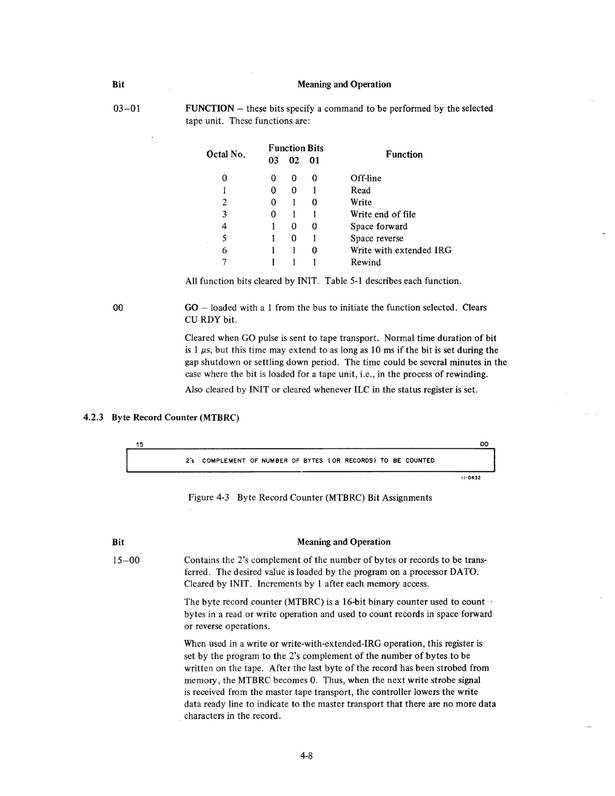
Bit
03-01
00
Meaning and Operation
FUNCTION -these bits specify a command to be performed by the selected
tape unit. These functions are:
Octal No.
0
2
3
4
5
6
7
Function Bits
03 02
01
0 0 0
0 0
0 0
0 1
0 0
0 I
0
Off-line
Read
Write
Function
Write end
of
file
Space forward
Space reverse
Write with extended IRG
Rewind
All function bits cleared by INIT. Table
5-1
describes each function.
GO
-loaded with a 1 from the bus to initiate the function selected. Clears
CU
RDY bit.
Cleared when GO pulse
is
sent to tape transport. Normal time duration
of
bit
is
1
p,s,
but this time may extend to
as
long
as
10
ms
if
the bit
is
set during
the
gap shutdown or settling down period. The time could be several minutes in
the
case where the bit
is
loaded for a tape unit, i.e., in the process
of
rewinding.
Also cleared by INIT or cleared whenever ILC in the status register
is
set.
4.2.3 Byte Record Counter (MTBRC)
15
Bit
15-00
00
2's
COMPLEMENT
OF NUMBER OF BYTES
(OR
RECORDS)
TO
BE COUNTED
11-0432
Figure 4-3 Byte Record Counter (MTBRC) Bit Assignments
Meaning and Operation
Contains the 2's complement
of
the number
of
bytes
or
records
to
be trans-
ferred. The desired value
is
loaded by
the
program on a processor
DATa.
Cleared
by
INIT. Increments by I after each memory access.
The
byte
record counter (MTBRC)
is
a 16-bit binary counter used to count
bytes in a read or write operation and used
to
count records in space forward
or reverse operations.
When
used in a write
or
write-with-extended-IRG operation, this register
is
set by the program
to
the
2's complement
of
the number
of
bytes
to
be
written on the tape. After the last byte
of
the record has been strobed from
memory, the MTBRC becomes
O.
Thus, when the
next
write strobe signal
is
received from the master tape transport, the controller lowers the write
data ready line
to
indicate to the master transport
that
there are no more data
characters in the record.
4-8
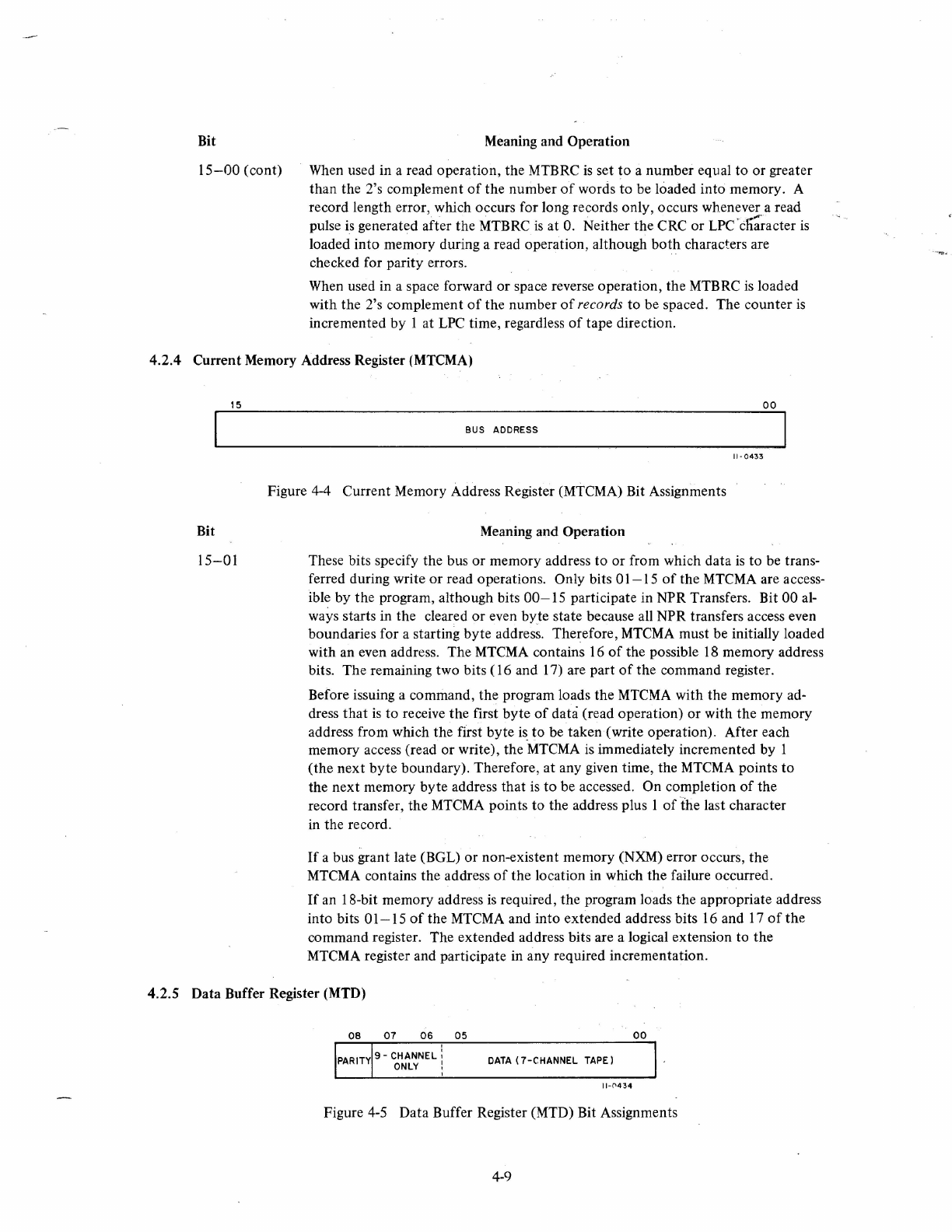
Bit
15-00
(cont)
Meaning and Operation
When used in a read operation, the MTBRC
is
set
to
a number equal
to
or
greater
than
the 2's complement
of
the
number
of
words
to
be loaded
into
memory. A
record length error, which occurs for long records only, occurs
whenevera
read
pulse is generated after
the
MTBRC
is
at
O.
Neither the CRC
or
LPC
'ctra~acter
is
loaded
into
memory during a read operation, although
both
characters are
checked for parity errors.
When used in a space forward
or
space reverse operation,
the
MTBRC
is
loaded
with the 2's complement
of
the
number
of
records
to
be spaced. The
counter
is
incremented
by
I at LPC time, regardless
of
tape direction.
4.2.4 Current Memory Address Register (MTCMA)
15
Bit
15-01
00
BUS ADDRESS
11-
0433
Figure 4-4 Current Memory Address Register (MTCMA) Bit Assignments
Meaning and Operation
These bits specify the bus
or
memory address
to
or from which data
is
to
be trans-
ferred during write
or
read operations. Only bits
01-15
of
the MTCMA are access-
ible by the program, although bits
00-15
participate in NPR Transfers. Bit 00 al-
ways starts in the cleared
or
even
byte
state because all NPR transfers access even
boundaries for a starting
byte
address. Therefore, MTCMA must be initially loaded
with an even address. The MTCMA contains 16
of
the possible
18
memory address
bits. The remaining two bits ( 16 and 17) are part
of
the command register.
Before issuing a command,
the
program loads the MTCMA with the memory ad-
dress
that
is
to
receive
the
first
byte
of
data (read operation) or with the memory
address from which
the
first
byte
is.
to
be taken (write operation). After each
memory access (read
or
write), the MTCMA is immediately incremented by 1
(the
next
byte
boundary), Therefore,
at
any given time, the MTCMA points
to
the
next
memory
byte
address that
is
to
be accessed.
On
completion
of
the
record transfer, the MTCMA points
to
the address plus 1
of
the
last character
in the record.
If
a bus grant late (BGL)
or
non-existent memory (NXM) error occurs,
the
MTCMA contains the address
of
the
location in which the failure occurred.
If
an 18-bit memory address
is
required,
the
program loads
the
appropriate address
into bits
01-15
of
the MTCMA and into extended address bits 16 and
17
of
the
command register. The extended address bits are a logical extension to
the
MTCMA register and participate in any required incrementation.
4.2.5 Data Buffer Register (MTD)
00
DATA
(7-CHANNEL
TAPE)
11-('434
Figure 4-5 Data Buffer Register (MTD) Bit Assignments
4-9
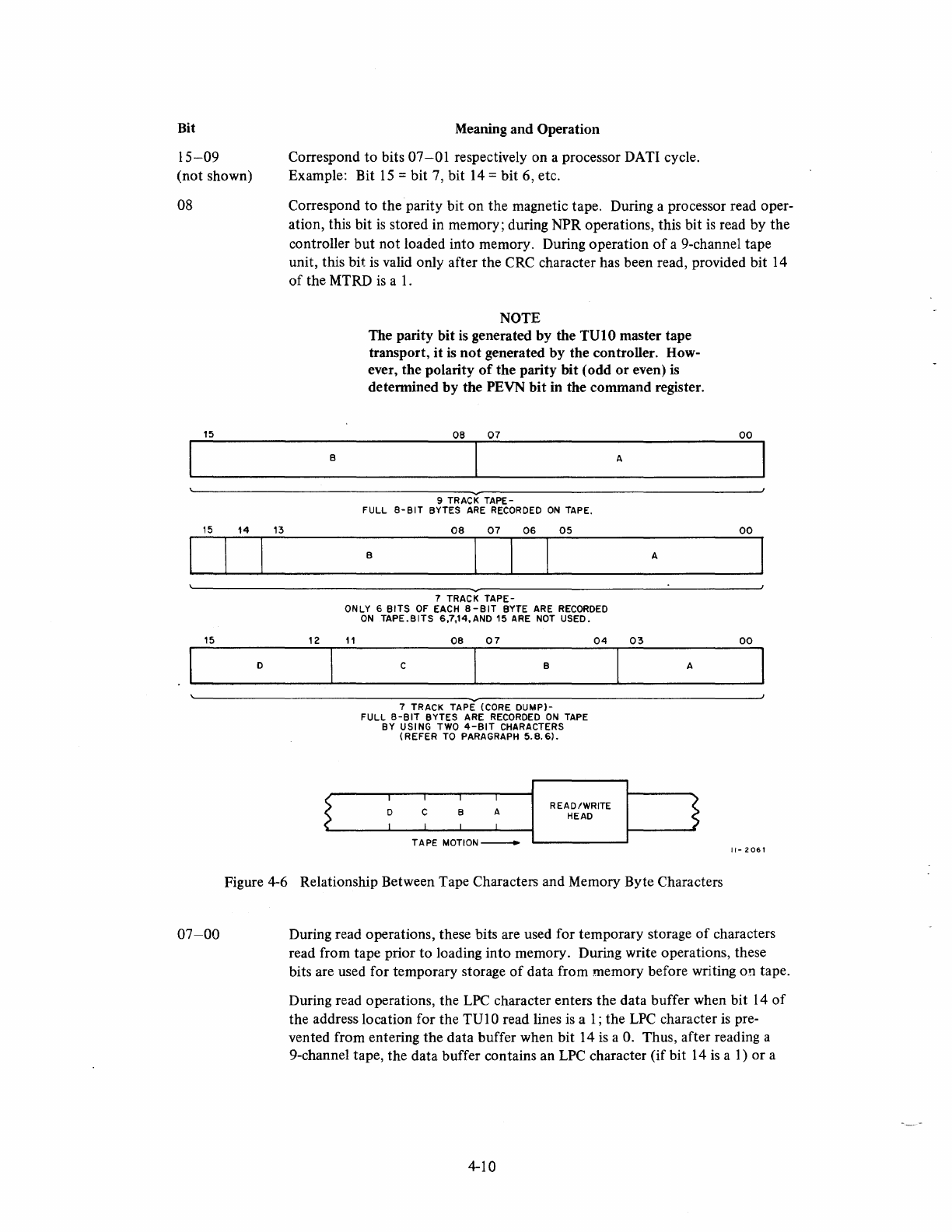
Bit
15-09
(not shown)
08
15
15
14
13
15
D
Meaning and Operation
Correspond
to
bits
07-01
respectively on a processor DATI cycle.
Example: Bit
15
= bit 7, bit
14
= bit 6, etc.
Correspond to the parity bit on the magnetic tape. During a processor read oper-
ation, this bit
is
stored in memory; during NPR operations, this bit
is
read by the
controller but
not
loaded into memory. During operation
of
a 9-channel tape
unit, this bit is valid only after the CRC character has been read, provided bit 14
of
the MTRD
is
a
1.
B
12
NOTE
The parity bit
is
generated
by
the
TVtO
master tape
transport, it
is
not
generated by the controller. How-
ever, the polarity
of
the parity bit (odd
or
even)
is
detennined
by
the PEVN
bit
in the command register.
08
07
A
9 TRACK
TAPE-
FULL
8-81T
BYTES
ARE
RECORDED
ON
TAPE.
08
07
06
05
B A
7 TRACK
TAPE-
ONLY 6
BITS
OF
EACH
8-BIT
BYTE ARE
RECORDED
ON
TAPE.BITS
6,7,14,
AND
15 ARE
NOT
USED.
11
08
07
C B
7 TRACK
TAPE
(CORE
DUMP)-
FULL
8-BIT
BYTES ARE
RECORDED
ON
TAPE
BY USING TWO
4-BIT
CHARACTERS
(REFER
TO PARAGRAPH
5.8.6).
04
03
READ/WRITE
HEAD
A
00
00
00
11-
2061
Figure 4-6 Relationship Between Tape Characters and Memory Byte Characters
07-00
During read operations, these bits are used for temporary storage
of
characters
read from tape prior to loading into memory. During write operations, these
bits are used for temporary storage
of
data from memory before writing on tape.
During read operations, the
LPC
character enters the data buffer when bit
14
of
the address location for the
TVI
0 read lines
is
a
1;
the
LPC
character
is
pre-
vented from entering the data buffer when bit 14
is
a
O.
Thus, after reading a
9-channel tape, the data buffer contains an
LPC
character (if bit 14
is
a
1)
or a
4-10
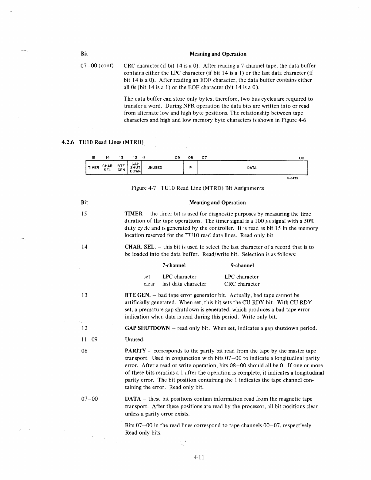
Bit
07-00
(cont)
Meaning and Operation
CRC character
(if
bit
14 is a 0). After reading a 7-channel tape, the data buffer
contains either the
LPC
character (if bit 14
is
a
1)
or
the last data character
(if
bit 14
is
a 0). After reading an EOF character, the data buffer contains either
all
Os
(bit 14
is
a
1)
or
the EOF character (bit 14
is
a 0).
The
data buffer can store only bytes; therefore, two bus cycles are required
to
transfer a word. During NPR operation the data bits are written into
or
read
from alternate low and high byte positions. The relationship between tape
characters and high and low memory
byte
characters
is
shown in Figure 4-6.
4.2.6 TUIO Read Lines (MTRD)
Bit
15
14
13
12
11-09
08
07-00
09
08
07
00
UNUSED
DATA
11-0435
Figure 4-7 TVIO Read Line (MTRD) Bit Assignments
Meaning and Operation
TIMER -the timer bit
is
used for diagnostic purposes by measuring the time
duration
of
the tape operations. The timer signal
is
a 100 ps signal with a
50%
duty
cycle and
is
generated by the controller.
It
is
read
as
bit
15
in the memory
location reserved for the
TV
10
read data lines. Read only bit.
CHAR. SEL. -this bit
is
used to select the last character
of
a record
that
is
to
be loaded into the data buffer. Read/write bit. Selection
is
as
follows:
7-channel
set
LPC
character
clear last data character
9-channel
LPC
character
CRC character
BTE GEN. -bad tape error generator bit. Actually, bad tape cannot be
artificially generated. When set, this
bit
sets the CU RDY bit. With
CV
RDY
set, a premature gap shutdown
is
generated, which produces a bad tape error
indication when data
is
read during this period. Write only bit.
GAP SHUTDOWN -read only bit. When set, indicates a gap shutdown period.
Unused.
PARITY -corresponds
to
the parity bit read from the tape by the master tape
transport. Used in conjunction with bits 07
-00
to indicate a longitudinal parity
error. After a read
or
write operation, bits
08-00
should all be
O.
If
one
or
more
of
these bits remains a 1 after the operation is complete, it indicates a longitudinal
parity error. The bit position containing the 1 indicates the tape channel con-
taining the error. Read only bit.
DATA -these bit positions contain information read from the magnetic tape
transport. After these positions are read
by
the processor, all bit positions clear
unless a parity error exists.
Bits
07-00
in the read lines correspond
to
tape channels
00-07,
respectively.
Read only bits.
4-11
4.3 INTERR UPTS
The
TM
11
Controller uses NPR or BR interrupts
to
gain control
of
the bus in order to perform data transfers
or
to cause a vectored interrupt, thereby causing a branch
to
a handling routine. The NPR requests are used for
direct memory access, whenever it
is
desired to transfer data between memory and the data buffer register with-
out
processor intervention. The BR requests are made when processor servicing
is
required for completed
operations or error conditions.
4.3.1 NPR Requests
The
TM
II
Controller issues an NPR request whenever it
is
necessary to transfer data between memory and the
data buffer register. During a read operation, the direction
of
transfer
is
from the data buffer
to
the core mem-
ory. The RDS pulse (read strobe, from master tape transport
to
controller), which
is
used to strobe data from
the tape transport into the data buffer register, generates the NPR request. When the request
is
granted, the
TMII
Controller performs a DATOB bus cycle and transfers information from the data buffer into memory.
During a write (or write-with-extended-IRG) operation, the NPR request
is
generated by the write strobe (WRS)
pulse from the processor.
When
the request
is
granted, the controller performs a DATI bus cycle and transfers a
byte from core memory into the data buffer register.
During
both
read and write operations, the address in memory that data
is
read from
or
loaded into
is
determined
by the value in the current memory address register (MTCMA).
4.3.2 BR Requests
A
BR
interrupt can occur only
if
the interrupt enable (INT ENB) bit in the command register
is
set. With INT
ENB
set, setting either the
CU
RDY or ERR bit in the command register, or completing a rewind operation
initiates an interrupt request.
When
CU
RDY
is
set, it indicates that the controller
is
ready
to
perform another command.
When
ERR
is
set, it indicates that some type
of
error condition exists. In this case, an interrupt
is
used
to
cause
the program
to
branch
to
an error handling routine.
If
a function command
is
issued with the GO bit cleared and INT
ENB
set,
an
interrupt
is
initiated.
If
the selected tape unit (as indicated by the SEL bits in the command register) completes the rewind operation
before a new command to that unit
is
received and INT
ENB
is
set, an interrupt
is
initiated.
If
the interrupt
is
enabled (INT
ENB
set) and selection
of
the tape unit
is
not changed (as indicated by the SEL
bits), then a rewind command causes two interrupts: an interrupt when the rewind function begins, and an
interrupt when the tape unit completes the rewind function. If, however, the tape unit
is
already at the BOT
marker when rewind
is
issued, only one interrupt occurs.
The interrupt priority level
is
BRS, and the interrupt vector address
is
224. Note
that
the priority level can be
changed by the priority chip on the G736 Module, and the vector address can be changed by jumpers
on
the
M7821 Interrupt Control. However, any
DEC
programs
or
other software referring to the standard level
or
ad-
dress must also be changed
if
the jumpers are changed.
4.4 PROGRAMMING NOTES
In normal programming practice no attempt should be made
to
modify one record in the middle
of
a file. This
practice could result in overwriting the boundary
of
the record and destroying part
of
the next record. Also, a
read operation should never directly follow a write operation without at least one intervening tape move opera-
tion. This prevents running
off
the reel
if
the previous operation involved the last record on the tape.
If
it
is
4-12
desired
to
read a record that was
just
written, a space reverse command should be issued before the read command.
New commands are issued only when CU RDY
is
set, which
is
true
after interrupts.
Because
of
a
TM
11
logic restriction, all software READ/WRITE buffer areas used
by
TM
11
NPR transfers must
start
on
even
byte
boundaries.
Attempting to write an all zero character with even parity on a 7-track
or
9-track tape unit causes the zero char-
acter
to
be converted
to
a tape character
of
twenty (20). When reading this character from tape a twenty (20)
is
read instead
of
a zero.
When changing unit numbers in multi-transport software, the status bits (such
as
WRITE LOCK) are
not
switched
from the old transport to the newly selected one
at
the time the command
is
loaded. The status bits are those
of
the old transport until the interrecord gap
of
the previous
comma~d
has
bee~
written. Therefore, valid status
bits from the new transport are
not
present until
SDWN
is
a 1 (asserted). Because
SDWN
does
not
cause an
inteuupt,
the software must wait in a loop for approximately two milliseconds
or
exit the routine and re-enter
as
a function
of
a time clock.
The standard reel capacity for industry compatible magtape units
is
2400 feet, marker
to
marker. However,
less tape may be used, such
as
in the mini-magtape reels. ASCII standards provide for a
25
foot trailer following
the end-of-tape marker. This allows approximately 10 feet
of
writing space after passing
EaT.
Care should be
taken when attempting
to
write past the
EaT
marker if the operator
is
not
familiar with the tape
that
he
is
working with, because after a tape has been used, the reflective markers are often changed,
pOSSIbly
decreasing
the length
of
the standard
25
foot trailer.
Because the physical displacement
of
the heads differ between 7-channel and 9-channel drives, records written
on one cannot be read by the other. However, a tape
that
is
recorded on one can be re-recorded
by
the other,
providing
you
begin at the load point.
TUIO's and TU16's can be used
on
the same system; however, due to the fact
that
the
TUI0
is
a Unibus device
and the TU
16
is
a Massbus device, they may
not
be used on the same controller.
If
two drives are sharing one controller, care should be taken
not
to allow
both
drives
to
have the same unit
number selected on the thumbwheels.
If
they are
both
set
to
the same number and a command
is
issued, they
will
both
attempt
to respond and data transfers will become totally confused.
The industry standard packing density for 9-channel drives
is
800
bpi, however, 9-channel drives may be
recorded at 200, 556
or
800 bpi, providing the data
is
read back at the same rate.
A backspace
or
REWIND command issued while the tape is at the load
point
will cause
an
immediate interrupt.
4.4.1 Rewind Operation
Assume drive 0
is
to be rewound. The command
to
rewind drive 0
is
issued
to
the controller.
At
this time the
master tape unit asserts bit 1 (RWS) in the status register.
If
bit 6 (INT ENB) in the command register was set
at the start
of
the rewind operation, an interrupt occurs from the
TM
11
controller
as
soon
as
bit 7 (CU RDY)
of
the command register has been set by
RWS.
This informs the program
that
the controller
is
ready
to
accept
a new command.
By
testing bit 1 (RWS) in the status register, the program can determine
if
this
interrupt
was
issued
as
a result
of
drive a completing its rewind operation or
just
beginning it.
When the reflective marker, signifying BOT,
is
sensed, bit 5 (BOT) is asserted in the status register only for the
duration
of
time
that
the reflective marker
is
being read. Tape motion does
not
stop at this time.
4-13
Drive 0, still moving
in
the reverse direction, passes over the reflective marker, reverses its direction, and pro-
ceeds in the forward direction back to the load point. Upon sensing the reflective marker while proceeding in
the forward direction, drive 0 halts tape motion, asserts bit 3
(SDWN)
allowing the tape to fully deskew, and
then sets bit 0 (TUR) in the status register.
An
interrupt
is
issued coincident with bit 0 (TUR) being asserted in the status register, providing the following
conditions have been met.
1.
Bit 6 (INT ENB) in the command register
is
set,
2.
The drive has
not
been deselected by changing the status
of
bits
10-8
in
the command register since
issuing the REWIND command, and
3.
No new commands are stored in the controller awaiting execution.
If
a new command
is
being stored,
the next interrupt will be after
that
command's completion and no rewind complete interrupt will
occur.
If
multiple transports are used, it
is
not
necessary to wait for a REWIND command to be completed on one
transport before switching
to
another. After a REWIND
is
issued, another transport can be switched
to
as
soon
as
RWS
is
set.
When operations on the second transport have been completed, a switch to the rewinding transport can be made
as
soon
as
SDWN
or
TUR
is
true on the second transport (so the status bits will be from the rewinding unit).
Only the unit select bits in the command register have to be changed to the unit that
is
rewinding to get its
status.
If
the rewind
is
complete when the unit
is
selected, TUR
is
set in the status register.
If
the
RWS
bit
is
still set, the software can either work
on
another transport or load the next command to be executed in
bits
1-3
of
the command register where it
is
buffered until the rewind
is
completed.
If
INT
ENB
is
set at this
time, the completion
of
the buffered command causes
an
interrupt to occur. A REWIND command may take
from 3
to
5 minutes to complete.
4-14
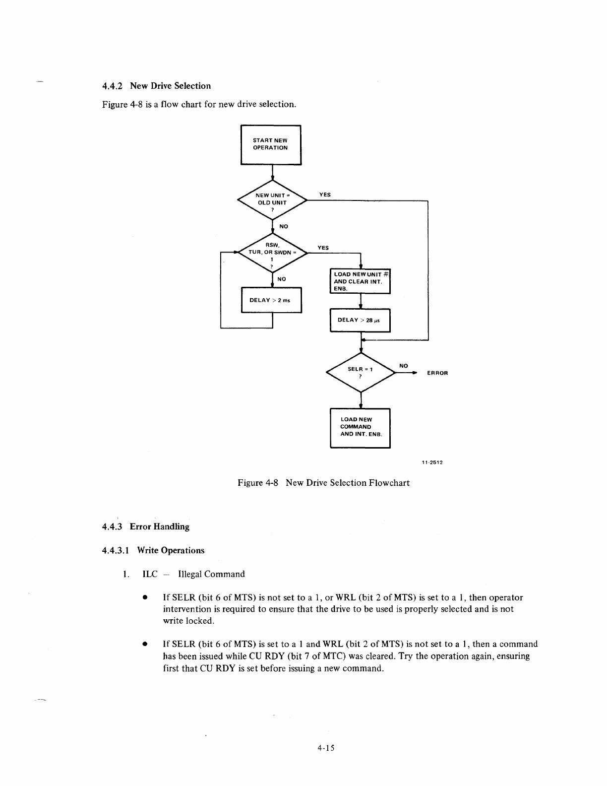
4.4.2 New Drive Selection
Figure 4-8
is
a flow chart for new drive selection.
START
NEW
OPERATION
YES
YES
LOAD
NEW
COMMAND
AND
INT.
ENB.
Figure 4-8 New Drive Selection Flowchart
4.4.3 Error Handling
4.4.3.1 Write Operations
I. ILC -Illegal Command
ERROR
11·:;!51:;!
•
If
SELR (bit 6
of
MTS)
is
not
set
to
a I, or WRL (bit 2
of
MTS)
is
set to
aI,
then operator
intervention
is
required to ensure
that
the drive
to
be used
is
properly selected and
is
not
write locked.
•
If
SELR (bit 6
of
MTS)
is
set
to
a I and WRL (bit 2
of
MTS)
is
not
set to
aI,
then a command
has been issued while CU RDY (bit 7
of
MTC) was cleared. Try the operation again, ensuring
first
that
CU
RDY
is
set before issuing a new command.
4-15
2.
EOF
-
End
of
File
N/
A
3. CRE -Cyclic Redundancy error
Backspace and
try
operation
again
with
extended
IRG.
4. PAE -Parity error
Backspace and
try
operation
again
with
extended
IRG.
5. BGL -Bus grant late
Backspace and
try
operation
N times.
6. EOT -
End
of
tape
The reflective
marker
signifying
the
end
of
tape
has been passed. Operations
past
this
point
are
not
illegal, however,
they
are
not
recommended
unless
the
programmer
is
familiar
with
the
tape being used and is knowledgable
about
the
length
of
tape existing past
the
EOT
marker. Conducting
any
write operations past
the
EOT marker leaves
the
programmer
open
to
the
possibility
of
running
the
tape
off
of
the
reel.
7. RLE -Record length error N/A
8. BTE -Bad tape error
Regain a
known
tape position and
try
the
operation again with
extended
IRG.
NOTE
A
known
tape
position refers
to
BOT, header records,
or
EOF
marks.
9.
NXM-
Non-existent
memory
Resolve
the
memory
discrepancy and try
the
operation
again.
4.4.3.2
Read Operations
1.
ILC -Illegal
Command
2.
3.
4.
5.
•
If
SELR
(bit
6 of. MTS)
is
not
set,
then
operator
intervention
is
required
to
ensure
that
the
drive
to
be used is properly selected.
•
If
SELR
(bit
6
of
MTS)
is
set,
then
a
command
has been issued while CU RDY
(bit
7
of
MTC)
was cleared.
Try
the
operation again
en~uring
that
CU RDY is set
prior
to
issuing
the
new
command.
EOF-
End
of
file
The
characters signifying
the
end
of
a file have
been
read.
CRE-
Cyclic Redundancy error
Backspace and
try
the
operation
N times.
PAE-
Parity error
Backspace and
try
the
operation
N times.
BGL-
Bus grant late
Backspace and
try
the
operation
N times.
4-16
6.
EOT -End
of
tape
The reflective marker signifying the end
of
tape has been passed. Continue only
if
it
is
certain
that
an EOF mark exists after the EOT marker, or the tape will run
off
of
the reel.
7.
RLE -Record length error
Reset the MTBRC
to
a value
that
is
equal to
or
greater than the number
of
bytes in the
record, backspace, and try the operation again.
8.
BTE -Bad tape error
Regain a known tape position and try the operation again.
If,
after doing so, the condition
still persists, the data from the failing point
to
the next known tape position
is
lost.
9.
NXM-
Non-existent memory
Resolve the memory location discrepancy and try the operation again.
4.4.3.3 Write End
of
File Operation
All Errors
This operation should have a software timer because it either performs its function correctly
or
it
enters
a run-away condition and runs the tape
off
the reel.
If
this condition
is
sensed after a few seconds,
recovery
is
as
follows:
• Issue a POWER CLEAR to stop tape motion.
• Regain a known tape position and try the operation again.
4.4.3.4 Spacing Operations
1.
ILC -Illegal command
Same
as
read operation.
2.
EOF -End
of
file
The characters signifying the end
of
a file have been read. Detection
of
the EOF marks stops
a spacing operation even if the MTBRC
is
not
equal
to
zero'.
3. EOT -End
of
tape
Same
as
read operation.
4.
BTE -Bad tape error
Regain a known tape position and try N times.
4.4.3.5 Write With Extended IRG Operation
Same
as
write operation.
4.4.3.6 Rewind Operation
Once a rewind operation
is
started, it continues until complete, regardless
of
errors
or
unit deselection.
4.5 PROGRAM EXAMPLE
The following program example
is
used to write a 1
ODD-byte
record,· backspace, read the record, and compare
data.
4-17
172520
172522
172524
172526
~"1"00
~01~f2I0
0~5"67
171516
001004
lk'5767
171512
f2J0"0U.'l
10~315
"01.,,12
"'06061
1'1'11'2
001016
123315
"01020
e!12767 0.01150
17151?Jk?
0.01026
:"112767
176"~0
17147[0
0011"34
r12767
~6"i2l05
171460
0.010~2
105761
111454
fiH'l1~~6
1210315
"lZll~50
"'12767
177777
1'144~
0.010~6
71
12167
~~0013
11143~
001~64
105767
171432
~
0.0U170
100315
-
00
0"1072
~12767
~flJ3120
171426
00j,1
f2J
.0
"12767
1162130 17141Q
001106
("12761
(1JbIZl0r!l3
1114"'~
0211114
1.05767
1714~~
0"1120
100375
flJ01122
2127e'0
00115Z
001126
(;',127~1
003120
flJ01132
e22021
0211134
1!014~1
00'-136
CHHHH'10
0011~0
~2~027
003120
001,1~4
~02712
0011~6
~0a0~0
0.011 50
N3t'10Q!0
("0312.0
01213120
~000~0
?,000~1
MTS=172520
MTC=172522
MT8RC:;17~524
MTCM.,;172526
.=1~0fZ!
JWRITE
RECORD
r.CR
MTC
T~T9
"1TC
8P~
.-4
R(JR
"'1TS
ecc
,-4
MOV
#WBUF,MTCHA
~OV
*~1~~0,,~T~RC
MOV
#6~~05,MTC
TST8
M'T'C
8PL,
,_4
,RECORD
WRITTEN,
NOW
8ACKS~ACE
MOV
#-l,MTBRC
MOV
#6~013,MTC
TSTB
MTC
8Pl.
1",4
JNOW
READ
RECORD
MOV
#RBU~,MTCMA
MOV
j~1~~0!,MTBRC
MOV
#6~~03,MTC
T5T8
MTC
~pC
,.4
,STATUS
REGISTER
IC~MMAND
REGISTER
,8VTr
~ECORD
C~UNTER
,CURPENT
MEMORY
ADORESS
~EGlST[R
JCLEAR
COMMA~D
REGISTER,
ALSO
SELECTS
UNIT
#~
JIS
CONTROL.
UNIT
READY?
JNC.
WAIT
lIS
TAPE
UNIT
READY?
IN~.
WAIT
Jl~ITlALI~E
MTCMA
WITH
BurrER
AREA
TC
BE
WRITTEN
'INITIALI~~
eYTE
COU~T
ISELECT
UNIT
#~,
8~~
BPI.
WRITE,
ISSUE
GO
lIS
rO~TRO~
UNrT
R~AOY,
INDICATING
COMPL~T10N
OF
W~ITE?
J~~,
WAIT
IINITIAL,lt~
BYTE
COUNT
T~
BACKSPACE
1
RECORD
,ISSUE
BACKSPAeE
COMMAND
115
CONTROL.
UNIT
R~ADY,
tN~IeATING
COMPL,ETION
OF
8AC~SPACE?
JNO.
WAIT
IINITIAL,llE
MTCM.
WITH
8UrrE~
AREA
TO
RE
REA~
!NTO
,lNITIALIlE
RYTE
COUNT
,sr~rcT
UNIT
#~,
a~~
BPI,
READ.
ISSUE
GO
115
CONTRO~
UNIT
READY,
iNDICATING
COMPLElrON
OF
REAO?
JN~.
WAIT
ICOMPARE
DATA
~EAD
WITH
DATA
WRITTrN
ell
W8Ul="
I
RBUFI
MOV
jWBUF,%0
MOV
*R8UF,~1
eMP
(~)+,(l)+
8E.Q
,+4-
HA~T
CMP
8~!
HA~T
C'I
~~,#W8~F+l~0~~
Cl
1 :
1oI
8UF+UH}I1l,
!21
,END
JU~E
RrGIST[RS
0,1
AS
Bu~rrR
P~lNTERS
FOR
COMPARISON
iIS
DA'A
WRITTEN
=
DATA
~EAD?
Ives
INO.
H~VE
DATA
ERROR
IrtNIs~ED
COMPARISON
or
~urFER'
I~O
Jvrs,
rXAMP~E
COMPLETED
,WRITE
BurrER
BEGINS
HERE
IRrAn
~UrFER
BEGINS
~ERE
5.1
INTRODUCTION
CHAPTER
5
THEORY
OF
OPERATION
This chapter provides a detailed description
of
the
TM
11
Controller and consists
of
three major parts: functional
description
of
overall controller operation, block diagram description
of
major components, and detailed descrip-
tion covering controller logic circuits. The discussions
in
this chapter are supported
by
a complete set
of
engineer-
ing drawings located
in
a companion volume entitled,
TM
11
DECmagtape System, Engineering Drawings.
The TMl1 Controller may be divided into seven functional areas: selection logic, bus control logic, register logic,
tape control logic, read/write logic, error logic, and control panel logic. Parity logic
is
part
of
the Master Tape
Transport and is, therefore, only covered
in
general in subsequent discussions. The purpose
of
each
of
the con-
troller functional units is
as
follows:
Selection Logic
Bus Control Logic
Register Logic
Tape Control Logic
Read/Write Logic
Error Logic
Control Panel Logic
Determines
if
the controller has been selected
as
a bus
slave
device, and
what type
of
operation (read or write) has been selected. Permits selec-
tion
of
one
of
six internal registers for use and determines
if
the register
is
to perform an input
or
output
operation.
Permits the controller
to
gain bus control either
by
means
of
an NPR
for transferring data
or
by means
of
a programmed interrupt to req uest
service
by
the program because an error condition exists, because
the
controller is ready to perfonn a new operation,
or
because the control-
ler
is
ready
to
make a direct memory access transfer (NPR transfer).
Six internal registers, addressable by the program, provide data transfer
functions, command and control functions, and status monitoring func-
tions for the
TM
11
Controller.
Controls selection
of
tape unit, direction
of
tape travel (forward,
reverse), and function
to
be perfonned such
as
rewind, write, read,
space forward, and space reverse.
Controls assembly, disassembly, and transfer
of
data between the mag-
netic tape and the Unibus. Counts number
of
words
in
transfer and
keeps track
of
current bus address.
Monitors controller operation and provides an indication
of
any error
condition that arises. Stops the operation and issues an interrupt re-
quest for most error conditions.
Provides signals that light indicators on the controller maintenance
panel; controls operation
of
the CLEAR switch.
5-1
5.2 TAPE FORMAT
The tape format used in the
TMll
DEC magtape System
is
identical
to
industry standard
7-
and 9-channel tape
formats.
It
is
assumed
that
the reader
is
familiar with standard magnetic tape formats.
If
not, a more thorough
explanation
is
presented in Chapter 1
of
the TU10 DECmagtape Manual,
DEC-OO-TUIOM-D.
Each character frame in a 7-channel tape (see Figure 5-1) consists
of
six character bits (B, A, 8, 4, 2,
1)
in descend-
ing order
of
significance. The parity bit,
or
check bit (C),
is
the
seventh bit and
is
set or cleared
by
the transport
write head. One byte
of
a PDP-II word corresponds to one tape character. However, because one byte contains
eight bits and a tape character contains only six data bits, two bits within each byte are not used. During a read
operation, the extra bits are forced
to
0; during a write operation, the bits remained unchanged. During the core
dump mode
of
operation, one PDP-II byte corresponds
to
two tape characters. Thus, all bits within the
byte
are
used; however, the two most significant bits on the tape are not used.
~
FORWARD
TAPE
MOTION
r TAPE CHANNELS
o
o
o
,
1
1
CHARACTER
1 1 1
'-----------------------------------------------------------------------------------------~
LARSE~JRAtiA
-"r-f-----
EXTENDED
IRG
----
...
r41--
EOF
-+-IRG
-+
B~~IN:~~G
IN
BLOCK
RECORD
DATA
BLOCK
:3
BLANK
CHARACTER
PERIODS
b.
EOF RECORD
11-0391
Figure
5-1
7-Channel Tape Format
The magnetic tape
is
divided into data records, each record separated by an interrecord gap (lRG). A record may
be any length from a minimum
of
16
characters
to
a maximum
of
4008 characters. In a block format, a number
of
records are written together with an IRG before the first record and after the last record. In either case, the
IRG
is
an unused portion
of
tape preceding and following the record
or
the block.
The longitudinal parity check (LPC) character
is
written after the data and
is
separated from the data
by
three
character spaces. Each bit in the
LPC
is
such that the total number
of
bits
in
any specific channel
is
even.
5-2
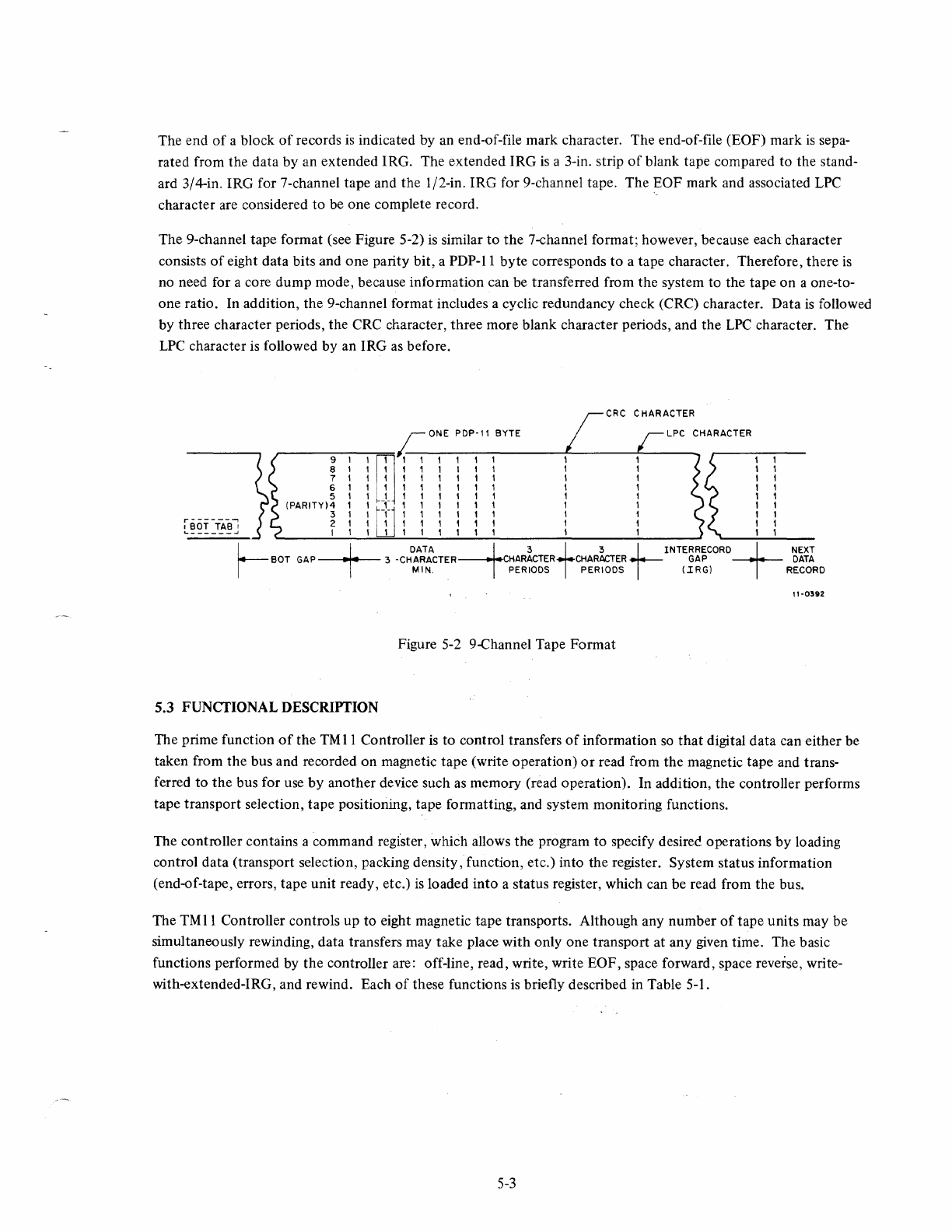
The end
of
a block
of
records
is
indicated by an end-of-file mark character. The end-of-file (EOF) mark
is
sepa-
rated from the data by an extended IRG. The extended IRG
is
a 3-in. strip
of
blank tape compared to the stand-
ard 3/4-in. IRG for 7-channel tape and the 1/2-in. IRG for 9-channel tape. The EOF mark and associated
LPC
character are considered to be one complete record.
The 9-channel tape format (see Figure 5-2)
is
similar to
the
7-channel format; however, because each character
consists
of
eight data bits and one parity bit, a PDP-II byte corresponds to a tape character. Therefore, there
is
no need for a core dump mode, because information can be transferred from the system to the tape
on
a one-to-
one ratio. In addition, the 9-channel format includes a cyclic redundancy check (CRC) character. Data
is
followed
by three character periods, the CRC character, three more blank character periods, and the
LPC
character. The
LPC
character
is
followed by an IRG
as
before.
CHARACTER
,--
_____
-==~
ONE
PDp·l'
BYTE
CHA,-R_A_CT_E_R
___
_
9
'm
1 1 , ,
11
8
l'
1 1 1 1 1 1
7 1 1 1 1 1 , 1 1
6 , 1 1 1 1 1 1 1
5 1 1 1 1 1 1 1 1
(PARITY)4
1 -,- 1 1 1 1 1 1
3 1
[-j-1
1 1 , 1 1 1
[~~i~~~J
~
1 1 W 1 1
~ ~
1 1 1 1 1
L BOT
GAP
-t-
3
-CHDAA~:cTER-+CHAR~CTER+CHARhER
t-INTE~~~CORD+
~i~r
I
MIN,
PERIODS PERIODS
(IRGl
RECORD
11-0392
Figure 5-2 9-Channel Tape Format
5.3 FUNCTIONAL DESCRIPTION
The prime function
of
the
TM
11
Controller
is
to control transfers
of
information
so
that
digital data can either be
taken from the bus and recorded
on
magnetic tape (write operation)
or
read from the magnetic tape and trans-
ferred to
the
bus for use by another device such
as
memory (read operation). In addition, the controller performs
tape transport selection, tape positioning, tape formatting, and system monitoring functions.
The controller contains a command regi'ster, which allows the program to specify desirec operations
by
loading
control data (transport selection, packing density, function, etc.) into the register. System status information
(end-of-tape, errors, tape unit ready, etc.)
is
loaded into a status register, which can be read from the bus.
The
TMII
Controller controls
up
to eight magnetic tape transports. Although any number
of
tape units may be
simultaneously rewinding, data transfers may take place with only one transport at any given time. The basic
functions performed by the controller are: off-line, read, write, write EOF, space forward, space reverse, write-
with-extended-IRG, and rewind. Each
of
these functions
is
briefly described in Table 5-1.
5-3
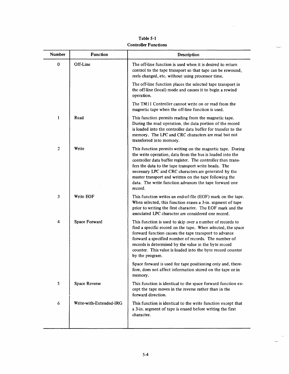
Number Function
o Off-Line
Read
2 Write
3 Write EOF
4 Space Forward
5 Space Reverse
6 Write-with-Extended-IRG
Table
5-1
Controller Functions
Description
The off-line function is used when
it
is
desired to return
control to the tape transport
so
that
tape can be rewound,
reels changed, etc. without using processor time.
The off-line function places the selected tape transport in
the off-line (local) mode and causes
it
to begin a rewind
operation.
The
TM
11
Controller cannot write on
or
read from the
magnetic tape when the off-line function
is
used.
This function permits reading from the magnetic tape.
During the read operation, the data portion
of
the
record
is
loaded into the controller data buffer for transfer
to
the
memory. The
LPC
and CRC characters are read
but
not
transferred in to memory.
This function permits writing on the magnetic tape. During
the write operation, data from the bus
is
loaded into
the
controller data buffer register. The controller then trans-
fers the data
to
the tape transport write heads. The
necessary
LPC
and
CRe
characters are generated by the
master transport and written
on
the tape following the
data. The write function advances
the
tape forward one
record.
This function writes an end-of-ftle (EOF) mark on the tape.
When selected, this function erases a 3-in. segment
of
tape
prior
to
writing the first character. The EOF mark and the
associated
LPC
character are considered one record.
This function
is
used
to
skip over a number
of
records to
find a specific record on the tape. When selected,
the
space
forward function causes the tape transport
to
advance
forward a specified number
of
records. The number
of
records
is
determined
by
the value in
the
byte record
counter. This value
is
loaded into the byte record counter
by the program.
Space forward
is
used for tape positioning only and, there-
fore, does
not
affect information stored
on
the tape
or
in
memory.
This function
is
identical
to
the space forward function ex-
cept the tape moves in the reverse rather than in the
forward direction.
This function
is
identical
to
the write function except that
a 3-in. segment
of
tape
is
erased before writing
the
first
character.
5-4
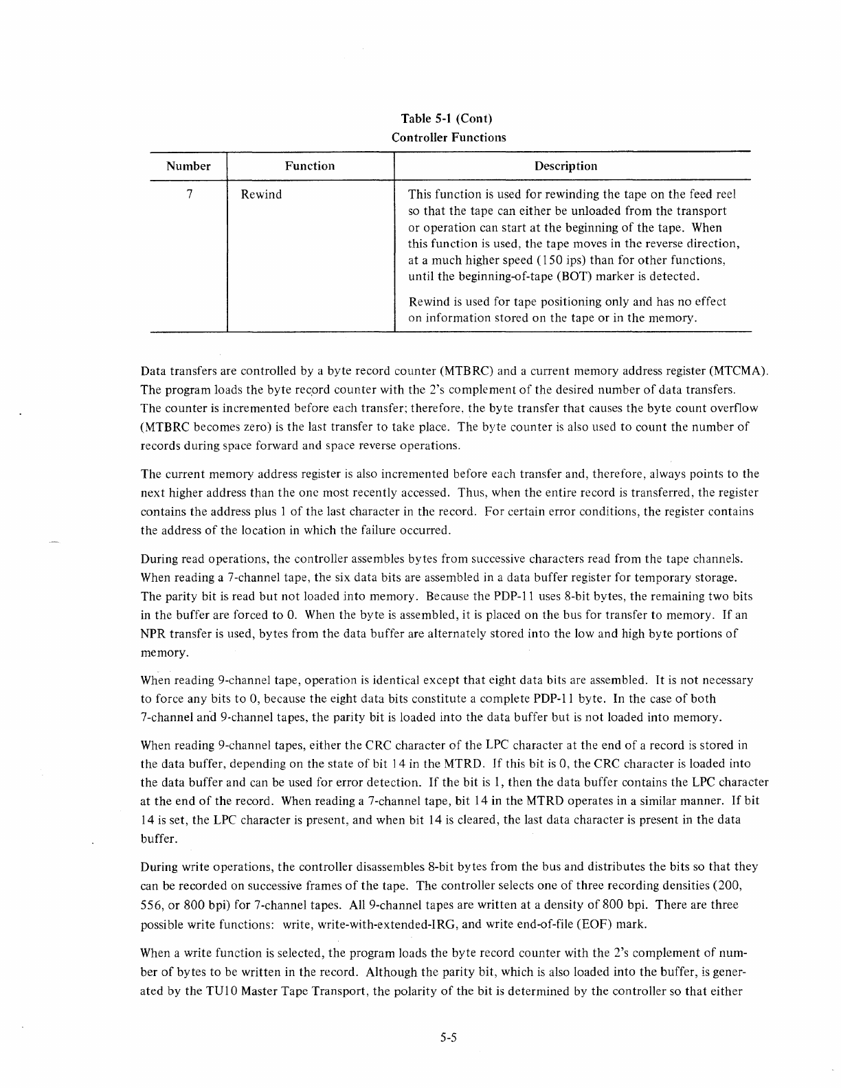
Number
Function
7 Rewind
Table
5-1
(Cont)
Controller Functions
Description
This function
is
used for rewinding the tape
on
the feed reel
so
that
the tape can either be unloaded from the transport
or operation can start
at
the beginning
of
the tape. When
this function
is
used, the tape moves in the reverse direction,
at a much higher speed (150 ips) than for
other
functions,
until the beginning-of-tape (BOT) marker
is
detected.
Rewind
is
used for tape positioning only and has no effect
on information stored on the tape or in the memory.
Data transfers are controlled by a byte record counter (MTBRC) and a current memory address register (MTCMA).
The program loads the byte rec.ord
counter
with the 2's complement
of
the desired number
of
data transfers.
The
counter
is
incremented before each transfer; therefore. the byte transfer
that
causes the
byte
count overflow
(MTBRC becomes zero)
is
the last transfer
to
take place. The byte counter
is
also used
to
count
the number
of
records during space forward and space reverse operations.
The current memory address register
is
also incremented before each transfer and, therefore, always points to the
next higher address than the one most recently accessed. Thus, when the entire record
is
transferred, the register
contains the address plus 1
of
the
last character in the record.
For
certain error conditions, the register contains
the address
of
the location in which the failure occurred.
During read operations, the controller assembles bytes from successive characters read from the tape channels.
When reading a 7-channel tape, the six data bits are assembled in a data buffer register for temporary storage.
The parity bit
is
read
but
not
loaded into memory. Because the
PDP-ll
uses 8-bit bytes, the remaining two bits
in the buffer are forced
to
O.
When the
byte
is
assembled, it
is
placed on the bus for transfer to memory.
If
an
NPR transfer
is
used, bytes from the data buffer are alternately stored into the low and high
byte
portions
of
memory.
When reading 9-channel tape, operation
is
identical except
that
eight data bits are assembled.
It
is
not
necessary
to force any bits
to
0, because the eight data bits constitute a complete PDP-II byte. In the case
of
both
7-channel
an-d
9-channel tapes, the parity bit
is
loaded into the data buffer
but
is
not
loaded into memory.
When reading 9-channel tapes, either the CRC character
of
the LPC character at the end
of
a record
is
stored in
the data buffer, depending on the state
of
bit 14 in the MTRD.
If
this bit
is
0, the CRC character
is
loaded into
the data buffer and can be used for error detection.
If
the bit
is
I,
then the data buffer contains the LPC character
at the end
of
the record. When reading a 7-channel tape, bit 14 in the MTRD operates in a similar manner.
If
bit
14
is
set, the LPC character
is
present, and when
bit
14
is
cleared, the last data character
is
present
in
the data
buffer.
During write operations,
the
controller disassembles 8-bit bytes from the bus and distributes the bits so
that
they
can be recorded on successive frames
of
the tape. The controller selects
one
of
three recording densities (200,
556, or
800
bpi) for 7-channel tapes. All 9-channel tapes are written at a density
of
800 bpi. There are three
possible write functions: write, write-with-extended-IRG, and write end-of-file (EOF) mark.
When a write function
is
selected, the program loads the byte record counter with the 2's complement
of
num-
ber
of
bytes to be written in the record. Although the parity bit, which
is
also loaded into the buffer,
is
gener-
ated by the TUI 0 Master Tape Transport,
the
polarity
of
the bit
is
determined by the controller so
that
either
5-5
odd
binary
or
even
BCD
parity can be selected. When parity
is
generated and the buffer
is
loaded, the controller
transmits the byte
to
the master tape transport, which places the
byte
on the read/write heads
of
the selected
slave transport so
that
data can be written on the magnetic tape.
The write-with-extended-IRG function
is
identical
to
the write function except
that
a 3-in. gap,
rather
than
the
normal gap
is
used between records. When this function
is
selected, a 3-in. segment
of
tape
is
erased before
writing begins.
The write end-of-file (EOF) function
is
used to indicate
that
a block
of
records
is
complete. When this function
is
selected, a special EOF character
is
written on the tape followed by an
LPC
character. These two characters
constitute a complete record. This command causes a 3-in. gap
to
be placed before the EOF mark. The XIRG
command must be absent to have this gap written.
System monitoring functions are performed by the controller status register. The 16 bits in this register retain
error and tape status information. Some status data
is
combined, such as lateral and longitudinal parity errors,
or
has a combined meaning, such
as
illegal command, for
optimum
use
of
the available bits. The status register only
monitors the tape transport selected by the command register; therefore,
other
units
that
may be rewinding,
do
not
interrupt the system when ready for data.
The following paragraphs discuss parity, gap shutdown, and function commands.
5.3.1
Parity
All parity characters are generated and read by the logic in the master tape transport rather than the controller.
However, a brief description
of
parity
is
included in this chapter, because an understanding
of
the parity function
is
necessary for proper understanding
of
controller operation.
Whenever any command
is
issued
that
moves the tape forward, the master tape transport transmits an LPC strobe
(LPCS) pulse at the end
of
each record
of
a 7-channel tape or a CRC strobe (CRCS) pulse and LPCS at the end
of
each record
of
a 9-channel tape.
During any write operation, the controller sends a write data ready (WDR) level to the master tape unit for each
character in the record to indicate
that
the controller
is
ready
to
transmit data
to
the transport. The master tape
transport then issues a write strobe (WRS) pulse
that
strobes the character from the controller data buffer register
into the tape
unit
for writing on the tape.
When the last
WRS
pulse causes the BYTE RECORD COUNTER register
to
overflow, the controller lowers the
WDR level and the master tape transport writes the CRC character (9-channel only) and then the LRC character
on the tape.
Whenever a slave tape transport
is
handling the magnetic tape being read
or
written, the control signals are still
generated
by
the master tape transport, and the necessary characters transferred from the master
to
the slave
at
the appropriate time.
The parity bit tape character in 7-channel format and in 9-channel format can be written in even
or
odd parity.
If
the master tape transport
is
writing even parity,
then
the parity bit is set
or
cleared so
that
the total number
of
ones in the character
is
even.
If
odd parity
is
used, then the parity bit
is
set or cleared so
that
the
total number
of
ones in a character
is
odd. The type
of
parity
to
be used (odd
or
even) is determined
by
the PEVN
bit
in the con-
troller command register.
A longitudinal parity check (LPC)
is
also performed on
both
tape formats. The master tape transport writes an
LPC
character at
the
end
of
each data record. The bits in this character may be either 1 s
or
Os.
The character is
written in such a manner
that
the total number
of
bits in a channel (including the
LPC
character)
is
even.
5-6
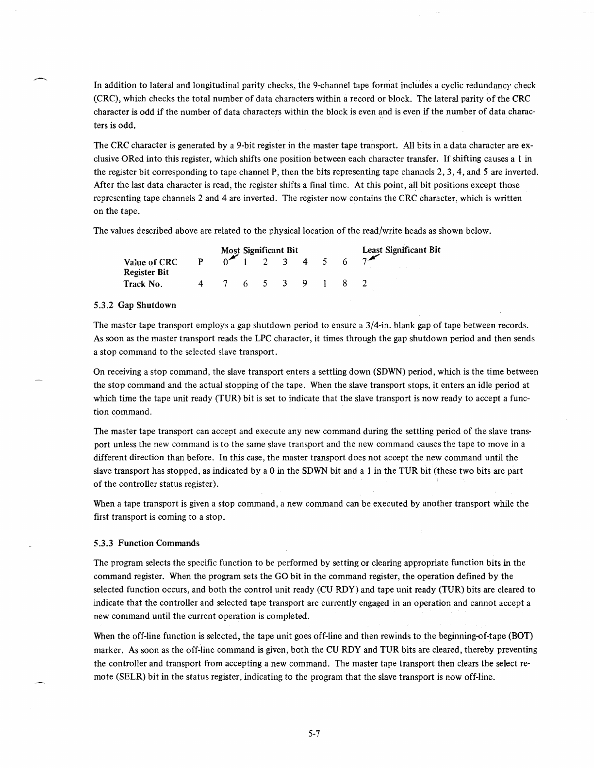
In addition
to
lateral
and
longitudinal parity checks,
the
9-channel tape format includes a cyclic redundancy check
(CRC), which checks
the
total
number
of
data
characters within a record
or
block. The lateral parity
of
the
CRC
character is
odd
if
the
number
of
data
characters within
the
block
is
even and
is
even
if
the
number
of
data
charac-
ters
is
odd.
The CRC character
is
generated
by
a 9-bit register in
the
master
tape
transport. All bits
in
a
data
character are ex-
clusive
ORed
into
this register, which shifts
one
position between each character transfer.
If
shifting causes a I in
the
register
bit
corresponding
to
tape
channel P,
then
the
bits representing tape channels
2,
3,4,
and 5 are inverted.
After
the
last data character is read,
the
register shifts a final time. At this
point,
al,1
bit positions except those
representing tape channels 2 and 4 are inverted. The register
now
contains
the
CRe
character, which
is
written
on
the
tape.
The
values described above are related
to
the
physical location
of
the
read/write heads as shown below.
Value
ofCRC
Register Bit
Track No.
5.3.2
Gap
Shutdown
P
4
Most Significant Bit
O.¥
I 2 3
7 6 5 3
4 5
9
6
8
Least Significant Bit
7~
2
The master
tape
transport
employs a gap shutdown period
to
ensure a 3/4-in. blank gap
of
tape between records.
As
soon
as
the
master
transport
reads
the
LPC character, it times through
the
gap
shutdown
period and
then
sends
a
stop
command
to
the
selected slave
transport.
On receiving a
stop
command,
the
slave
transport
enters a settling
down
(SDWN) period, which
is
the
time between
the
stop
command
and
the
actual stopping
of
the
tape. When
the
slave
transport
stops,
it
enters an idle period at
which
time
the
tape
unit ready
(TUR)
bit
is set
to
indicate
that
the
slave
transport
is
now
ready
to
accept a func-
tion command.
The master
tape
transport
can accept and execute any new command during the settling period
of
the
slave trans-
port
unless
the
new command is
to
the
same slave
transport
and
the
new command causes
the
tape
to
move in a
different direction
than
before.
In
this case,
the
master
transport
does
not
accept
the
new command until
the
slave transport has stopped, as indicated
by
a 0 in
the
SDWN
bit
and a 1
in
the
TUR
bit
(these
two
bits are
part
of
the
controller'status register).
When a tape
transport
is given a
stop
command, a new command can
be
executed
by
another
transport
while
the
first
transport
is coming
to
a stop.
5.3.3
Function
Commands
The program selects
the
specific function
to
be performed
by
setting
or
clearing appropriate function
bits
in
the
command register. When
the
program sets
the
GO
bit
in
the
command register,
the
operation
defined
by
the
selected function occurs, and
both
the
control
unit
ready (CU RDY) and
tape
unit
ready (TUR) bits are cleared
to
indicate
that
the
controller and selected tape
transport
are currently engaged in an operation and cannot accept a
new
command
until
the
current
operation
is completed.
When
the
off-line function is selected,
the
tape
unit
goes off-line and
then
rewinds
to
the
beginning-of-tape (BOT)
marker. As
soon
as
the
off-line command
is
given,
both
the
CU RDY and
TUR
bits are cleared,
thereby
preventing
the controller and
transport
from accepting a new command. The master tape
transport
then
clears
the
select re-
mote (SELR)
bit
in
the
status
register, indicating
to
the
program
that
the
slave
transport
is
now
off-line.
5-7
When
a tape reverse operation (not rewind)
is
selected, the master tape transport enters the gap shutdown period
immediately after reading the first data character.
During a write function (write, write EOF, and write-with--extended-IRG), the
CU
RDY
bit
is set when the first
LPC
character
is
read from
the
tape.
For
write EOF and write-with--extended-IRG functions, a 3-in. gap is erased
prior
to
writing the required data characters.
A write end-of-file (EOF) function causes a character
to
be written on the tape
that
indicates a block
of
data
is
complete. This function writes an EOF character followed by
an
LPC
character. These two characters constitute
one record. In an EOF record (see Figure 5-3), the EOF character and the
LPC
character are identical. Octal
17
is
the EOF character for 7-channel tapes; octal 23
is
the EOF character for 9-channel tapes.
CHANNELS
C
MOST SIGNIFICANT B
A
8
4
2
LEAST
SIGNIFICANT 1
OCTAL LPC
17
(OCTAL
17)
P P
0 0
0 0
1 1
1 1
1 1
1 1
o.7-CHANNEL
FORMAT
7
CHANNELS
MOST SIGNIFICANT 9
8
7
6
5
(PARITY)
4
LEAST SIGNIFICANT
3
2
Figure
5-3
EOF Record
5.4 SYSTEM RELATIONSHIP
OCTAL
LPC
23
(OCTAL
23)
0 0
0 0
0 0
1 1
0 0
0 0
0 0
1 1
1 1
b.9-CHANNEL
FORMAT
1/-0427
Figure 5-4
is
a simplified block diagram
of
the
TM
11
DECmagtape System, showing the relationship
of
the
TM
11
Controller to
the
TUIO DECmagtape Transports and
to
PDP-II System components. Note
that
all communica-
tion between
the
controller and
the
transports
is
handled
by
the master tape transport. Communication between
the controller and
other
PDP-II devices is by means
of
the Unibus.
5.5 ADDRESS SELECTION
The
TM
II
Controller selection logic decodes the address on the bus lines
to
determine
if
the controller has been
selected for use. Unique addresses are assigned to each
of
the six registers in the controller and manipulation
of
these registers determines whether information
is
to
be written on or read from the tape,
or
if
some
other
control
function
is
to be performed.
The
TMII
Controller consists basically
of
six registers (or bus addresses). In addition to decoding the incoming
address, the selection logic controls the information flow between the Unibus and the controller registers. The
logic produces SELECT line and gating IN
or
OUT signals, which determine
the
register to be used and whether
it
is
to
perform an input
or
output
function.
The selection logic consists
of
an MI05 Address Selector Module and register select logic (M797 Module).
5-8
TO
OTHER
DEVICES
ON
BUS
TO
OTHER
DEVICES
ON
BUS
MEMORY
COMMAND
TU10
TM11
DATA
MASTER
CONTROLLER
TAPE
STATUS
TRANSPORT
TU10
DATA
SLAVE
TAPE
TRANSPORT
TU10
DATA
SLAVE
TAPE
TRANSPORT
Figure 5-4
TM
11
System -Simplified Block Diagram
5.5
.1
Address Selector Module
UP
TO
FIVE
ADDITIONAL
SLAVE
TRANSPORTS
11-0428
The M 105 Address Selector Module (Drawing
TM
11-0-21) decodes the address information from the bus
to
pro-
vide the gating and select line signals
that
activate appropriate
TM
II
Controller logic circuits for the selected
register. The M
I 05 Module jumpers are arranged
so
that
the module responds only
to
the standard device register
addresses 772520 through 772532. Although these addresses have been selected by DEC
as
the standard assign-
ments for the
TMII
Controller, the user may change the jumpers to any address desired. However, any MainDEC
program
(or
other
software)
that
references the
TM
11
standard address assignments must be modified
if
other
than the standard assignments are used.
A standard M
105 Module provides only four select line signals and, therefore, can reference only four registers.
Because the
TM
11
Controller contains six registers, the M 105
is
used in conjunction with register select logic
(M797 Module) to provide the six required select lines. This necessitates wiring the M 105 in a somewhat different
than normal manner.
Rather than decode the entire incoming address,
as
is
the normal method, the M 105 in the
TMll
Controller de-
codes all
but
the four least significant bits, These bits are then decoded by the register select module (M797
Module), provided the
other
bits are part
of
a valid address.
Address line
AOO,
which
is
the least significant
bit
of
the address,
is
decoded
by
the M 105
to
determine if a byte
or
word operation
is
required. Address lines
AO
1,
A02, and A03 are grounded and are the only address bits
that
cannot be decoded by the M 105. Thus, the M I 05 decodes all
but
the four least significant bits
of
the incoming
5-9

address
as
shown in Figure 5-5.
If
the
first
portion
of
the
address
is
valid
(77252
or
77253),
then
the address
selector generates an ADRS DEC MSYN L (address decoded, master sync valid) signal
that
clears the decoders in
the register select logic (refer
to
Paragraph 5.5.2).
7
DECODED BY
THE
MIOS.
BIT CONFIGURATION
SHOWN IS ONLY VALID
COMBINATION
7 2 5
010
0 0
I
I DECODED BY REGISTER
I SELECT LOGIC. MAY BE
I ANY COMBINATION
OF
I
Is
AND
Os
I
Xl
I Y
IIX
YYY
Y
I
I
I
I
Indicates value
of
final
digit. May be
any
value
(O-7).
(Indicates
whether
next
to
last digit is 2
or
3.
Figure 5-5 M 105 Address Decoding
The MI 05 Address Selector also decodes
the
bus
CO
I and
COO
mode
control signals
to
generate
the
IN, OUT
LOW,
and
OUT
HIGH signals
that
determine
whether
the selected register
is
reading
or
writing (performing an
input
or
output
function).
It
is
beyond
the scope
of
this discussion
to
cover
operation
of
the
M I
as
Address Selector, detailed descriptions
of
this module are covered in
the
1971
DEC
Logic
Handbook
and in
the
Unibus Interface Manual,
Second
Edition
(DEC-II-HIAB-D).
There are
only
two
prime differences between normal use
of
the
M I 05 and the use in
the
TM
II
Controller. Pin
L2 is normally a test
point,
but
in
the
TM
11
it
is
used
to
provide
the
ADRS DEC MSYN L signal for
the
register
select. Address lines
AD
I,
A02, and A03 are normally decoded by the M I 05,
but
in the
TM
II
they
are decoded
by
the
register select logic (M797 Module).
5.5.2 Register Select Logic
The gating signal lines from
the
M 105 Address Selector and address lines
AO
I,
A02, and
AD3
from
the
bus are
connected
to
the
M797 Register Select Module (Drawing
TM
11-0-22). This module decodes the address lines and
provides
the
pulses
that
select the appropriate register and determine whether
the
register
is
to
be read
or
loaded.
The ADRS DEC MSYN L signal from
the
M 105 Module
is
applied
to
the
register select module when valid ad-
dresses
up
to
the least significant octal digit have been decoded. The ADRS DEC MSYN L signal gates the appro-
priate gating signal (IN, OUT
La,
OUT HI)
to
enable one
of
three
decoders.
If
the M 1 05 has provided an IN
gating signal,
then
the
first
decoder
(E2)
is
enabled, and
one
of
the
six
outputs
is
selected by address lines
AD
1,
AD2,
and
AD3.
The IN gate indicates
that
data
is
beIng transferred
into
the
bus master device, and
the
decoder
output
selects
the
register from which
the
data
is
to
be taken.
Note
that
the
decoder
is
actually enabled
by
the
absence
of
the
two
OUT
signals
rather
than
the
presence
of
the
IN signal (refer
to
Table 5-2).
5-10
Table 5-2
M797 Decoder Selection
Input Signal Function Selected Decoder Enabled
Output
Signals Remarks
IN(-OUTLO)
Load E2 6 One for each register.
-OUT
HI
OUTLO
Load even byte E6
:J
Only four
of
the six regis-
OUT
HI
Load odd byte E9 ters can be loaded.
If
the OUT
La
signal
is
supplied by the M I
OS,
the second decoder (E6)
in
the M797 Module
is
enabled, and the
address lines select one
of
five
decoder outputs. The OUT signal indicates a load operation (data from bus
to
master device). The first four outputs are used for the four registers that can be loaded from the bus. Note that
OUT
LO
loads only the low-order (even) byte in these registers. The fifth
output
is
used
to
load bits
13
and
14
in the TUI 0 read lines.
If the OUT
HI
signal
is
received from the MI05, the third decoder (E9)
is
enabled, and the address lines select
one
of
four decoder outputs
to
load the high-order (odd}
byte
of
the selected register.
Table 5-3 indicates the functions selected by the various select line and gating signal combinations.
Table 5-3
Gating and Select Line Signals
Select Line Gating Signal Function Register Bus Cycle
Status
IN
Status to bus
MTS
DATI
or
DATIP
I
IN
Command to bus
MTC
DATI
or
DATIP
2
IN
Byte record count to bus
MTBRC
DATI
or
DATIP
•
3
IN
Current memory address
to
bus
MTCMA
DATI
or
DATIP
4
IN
Data buffer to bus
MTD
DATI
or
DATIP
5
IN
TUI0
read lines to bus MTRD DATI
or
DATIP
1 OUT
Bus
to
command register
MTC
DATa
or
DATOB
2 OUT
Bus
to
byte record counter MTBRC DATO
or
DATOB
3 OUT
Bus
to
current memory address register
MTCMA
DATa
or
DA
TaB
4 OUT
Bus
to
data buffer register
MTD
DATO or DATOB
5 OUT
Bus
to
bits
13
and
14
of
TU
10
read lines MTRD DATO
or
DATOB
NOTES:
1.
IN
and OUT refer to information transfer with relation to the bus master device.
2.
Status register and TUI 0 read lines can be read by the processor
but
cannot be loaded
by
the processor except for bit
14
of
the TU I 0 read lines, which
is
the CRC/LPC character
selector bit, and bit
13
which
is
the BTE generator bit.
3. The OUT gating signal actually can be OUT
LO
or
OUT HI. OUT
LO
loads the low-
order (even) byte; OUT
HI
loads the high-order (odd) byte.
4.
The
IN
gating signal is actually
(-OUT
LO·""'OUT HI).
5-11
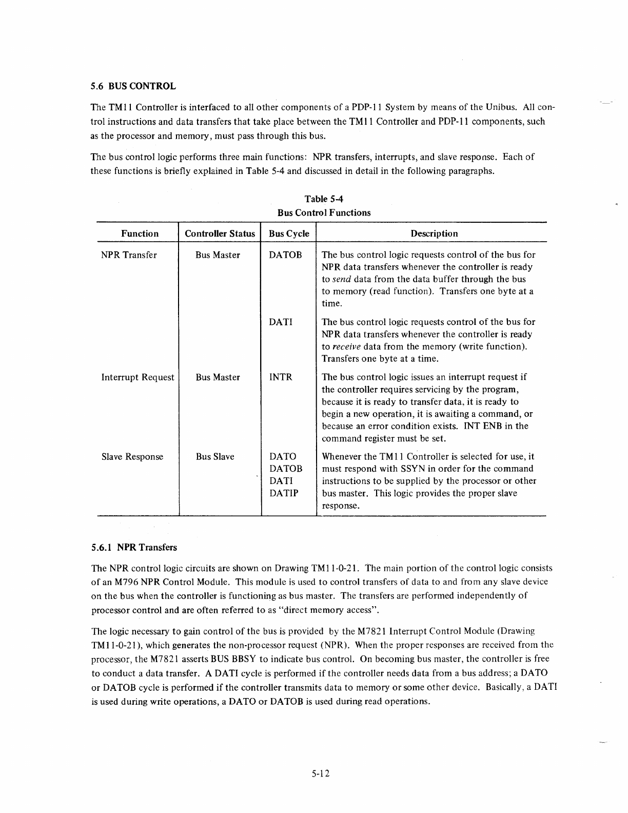
5.6 BUS CONTROL
The
TMll
Controller
is
interfaced to all
other
components
of
a PDP-II System by means
of
the Unibus. All con-
trol instructions and data transfers
that
take place between
the
TM
11
Controller and
PDP-II
components, such
as
the
processor and memory, must pass through this bus.
The bus control logic performs three main functions: NPR transfers, interrupts, and slave response. Each
of
these functions
is
briefly explained in Table 5-4 and discussed in detail in
the
following paragraphs.
Function
NPR Transfer
Interrupt Request
Slave Response
5.6.1 NPR Transfers
Table 5-4
Bus Control
Functions
Controller
Status
Bus Cycle Description
Bus Master DATOB The bus control logic requests control
of
the bus for
NPR data transfers whenever
the
controller
is
ready
to
send
data from
the
data buffer through the bus
to
memory (read function). Transfers one
byte
at
a
time.
Bus Master
Bus Slave
DATI
INTR
DATa
DATOB
DATI
DATIP
The bus control logic requests control
of
the
bus
for
NPR
data
transfers whenever
the
controller
is
ready
to receive data from the memory (write function).
Transfers
one
byte
at a time.
The bus control logic issues an
interrupt
request
if
the controller requires servicing
by
the
program,
because it
is
ready
to
transfer data,
it
is ready
to
begin a new operation,
it
is awaiting a command,
or
because an error condition exists. INT ENB in
the
command register must be set.
Whenever the
TM
11
Controller
is
selected for use, it
must respond with SSYN in
order
for the command
instructions
to
be supplied by the processor
or
other
bus master. This logic provides the proper slave
response.
The NPR con
trollogic
circuits are shown on Drawing
TM
11-0-21. The main portion
of
the
control logic consists
of
an M796 NPR Control Module. This module is used
to
control transfers
of
data to and from any slave device
on
the bus when
the
controller
is
functioning as bus master. The transfers are performed independently
of
processor control and are often referred
to
as
"direct
memory access".
The logic necessary
to
gain control
of
the
bus
is
provided by
the
M7821
Interrupt
Control Module (Drawing
TMII-0-21), which generates the non-processor request (NPR). When the
proper
responses are received from
the
processor, the M7821 asserts BUS BBSY
to
indicate bus control. On becoming bus master, the controller
is
free
to
conduct a data transfer. A DATI cycle
is
performed
if
the
controller needs data from a bus address; a
DATa
or
DATOB cycle is performed
if
the
controller transmits data to memory
or
some
other
device. Basically, a DATI
is
used during write operations, a
DATa
or
DATOB is used during read operations.
5-12
The
bit
that
controls selection
of
a DATI
or
DATO
is
function
bit
02
(Drawing
TM
11-0-09). This
bit
is
always
clear for a read operation (octal
number
01)
and
is
always set for write operations (octal numbers 02,
03,
and 06).
Therefore,
by
using this
bit
for
bus
cycle selection,
the
proper
cycle
is
used for
the
selected function (read=DATO,
write=DATI). The resultant read and write signals are applied
to
the
NPR
input
logic (Drawing
TM
11-0-13).
Whenever a read strobe (RDS)
or
write strobe (WRS) pulse from
the
master tape
transport
is
sent
to
the controller
or
whenever
the
WRITE DATA ENB and GO STROBE pulses are present in
the
controller, a series
of
gates
is
qualified
to
produce a signal
that
sets the NPR enable flip-flop, provided there is
no
non-existent memory, bus
grant late, overflow error condition present,
or
no
CRCS
or
LPCS strobe pulse present. This flip-flop produces
the NPR ENB H level, which initiates the NPR sequence.
The NPR ENB H level activates
the
Master Control A
portion
of
the
M7821
Interrupt
Control Module (Drawing
TM
11-0-21), which generates a request
on
the
BUS NPR line. When
the
processor has completed its current bus
cycle and all higher priority device requests have been satisfied,
the
processor issues a grant
on
BUS NPG IN. The
M7821 Module responds with BUS SACK and, when BUS SSYN, BUS BBSY, and BUS NPG are negated (indicat-
ing that
the
bus
is
free),
the
M7821 claims bus control by asserting BUS BBSY.
At this time,
the
M7821
Interrupt
Control Module produces an NPR MASTER signal, which activates
the
M796
NPR Control Module (Drawing
TM
11-0-21). This NPR MASTER signal produces an internal start signal in
the
M796. Detailed descriptions
of
both
the
M7821
Interrupt
Control and
the
M796 NPR Control Modules are pro-
vided in
the
Unibus Interface Manual,
Second
Edition, DEC-II-HIAB-D. Note, however,
that
in
the
Interface
Manual,
the
M796
is
referred
to
as
the
Unibus Master Control Module.
Regardless
of
the
bus cycle selected, a bus address
must
be used to indicate where
the
controller is
to
send
or
receive data. The M796 Module produces
the
ADRS
-+
BUS L signal, which enables
the
address line drivers
in
the
current memory address register (MTCMA) so
that
the
data transfer
is
made with
the
location specified
by
the
MTCMA.
When a read
operation
is
performed,
the
controller receives
data
read from
the
tape
by
the transport, assembles
the data in
the
data
buffer
register (MTC) and, when
the
data
is
properly assembled, sends the data
to
the
bus.
This
is
a DATOB operation, because only
one
character
is
read from the tape at a time and
the
character corres-
ponds
to
a PDP-II
byte.
When a DATOB bus cycle
is
selected
by
the
M796 Module,
the
module produces the DATA
-+
BUS signal which,
together with a flip-flop and AND gates, produces
al
ternate HI DATA BYTE
Land
LO DATA BYTE L signals
(Drawing
TM
11-0-17)
that
enable
data
buffer
output
gating logic (Drawing
TM
11-0-16); thus,
the
information
stored in the data
buffer
register
is
gated
onto
the bus for storage in alternate memory
byte
locations. After
the
necessary Unibus time delays, BUS MSYN
is
asserted and, thus, a slave device
is
selected. When the slave device
responds with SSYN, MSYN
is
dropped,
and
the
bus cycle
is
complete.
When a write
operation
is
to be performed,
the
controller receives the
data
from
the
Unibus, holds it temporarily
in
the
data
buffer, and
then
transmits
it
through
the
read/write lines
to
the
master tape transport electronics for
writing
on
the
magnetic tape.
When a DATI
is
selected
by
the M796 Module, the module first produces the ADRS -+ BUS signal as usual
but,
rather than produce a DATA
-+
BUS signal, the M796 waits for the slave to respond and then produces
two
sequential pulses: DATA STB 1 and DATA STB
2.
The
DATA STB 1 pulse allows time for
the
data
on
the
Unibus
to
deskew and settle. The pulse
is
also used internally (Drawing
TM
11-0-22)
to
produce DATA
BFR
STB
1
and DATA
BFR
STB 2, which clear
the
data
buffer
register (MTD).
5-13
The
trailing edge
of
DATA
STB 2 is
tied
back
into
the
M796
Module
to
produce
an
internal
signal, indicating
that
the
data
has
been
accepted.
As a result
of
this signal, MSYN
is
dropped,
and
the
bus
cycle
is
complete.
On
completion
of
either
a DATI
or
DATOB
bus
cycle,
the
NPR
CLR
BBSY signal is
generated.
This signal is used
to
increment
the
current
memory
address register (MTCMA).
The
NPR
CLR
BBSY signal also
produces
the
CLK 2 pulse (Drawing TM 11-0-07), which
increments
the
byte
record
counter
(MTBRC).
The
trailing edge
of
NPR
CLR
BBSY
direct
clears
the
request bus flip-flop (Drawing
TMII-O-13),
which
drops
at
the
input
to
the
M7821
Interrupt
Control
which,
in
turn,
drops
BUS BBSY.
A
time-out
flip-flop, referred
to
as NXM
(non-existent
memory),
in
the
M796 Module is set
if
a SSYN response
from
the
slave device does
not
occur
within
10
j1S
after
BUS MSYN
is
asserted
by
the
controller. When this flip-
flop is set,
the
bus
cycle
is
not
performed,
and
the
NXM
error
bit
in
the
status
register is
set
by
the
error
logic cir-
cuits. In this case,
the
current
memory
address register
is
not
incremented
and,
therefore,
the
register
contains
the
address
of
the
erroneous
location.
5.6.2
Interrupt
Request
An
interrupt
request
is
generated
when
the
controller
is
ready
to
send
or
receive
data
to
or
from
the
bus,
or
when-.
ever
an
error
condition
exists.
Interrupt
requests are
controlled
by
the
BR
(bus
request)
input
logic (Drawing
TMII-O-13)
and
by
the
M7821
Interrupt
Control
Module.
The
BR
interrupt
flip-flop
is
used
to
generate
the
BR
INT
pulse, which activates
the
M7821
Interrupt
Control.
Note
that
this flip-flop can be
set
only
if
the
INT ENB
bit
is
set.
When
the
ERR
bit
is
set,
it
indicates
that
some
type
of
error
condition
exists. In this case,
the
ERR
pulse pro-
duces
the
SET
CUR
L pulse (Drawing
TM
11-0-08),
which
sets
the
BR
flip-flop.
When
both
the
controller
and
tape
transport
are
ready
to
perform
a
data
transfer, an
interrupt
service
routine
is
used
to
perform
the
required
bus
cycle. In
this
case,
the
CU RDY signal
and
the
TUR
signal
qualify
an AND
gate
that
produces
an
output,
which
sets
the
BR
flip-flop.
If
a
function
command
is
issued
but
the
GO
bit
remains cleared, INT ENB is set,
and
an
interrupt
initiated.
If
the
selected
tape
transport
(as
indicated
by
the
SEL
bits
in
the
command
register)
completes
the
rewind
operation
before
a
new
command
to
that
unit
is
received,
then
an
interrupt
is
initiated. This logic
is
covered in
Paragraph
5.9.
The
M7821
Module
provides
the
logic necessary
to
make
bus
requests
and
gain
control
of
the
bus
(become
bus
master).
The
module
also includes
the
circuits necessary
for
generating
an
interrupt.
The
module
contains
two
completely
independent
request
and
grant
acknowledge circuits (channels A
and
B)
for
establishing
bus
control.
The
following paragraphs provide a
brief
description
of
both
channels. A detailed
description
of
the
M7821
Module, including circuit schematics,
is
contained
in
the
Unibus Interface Manual,
Second
Edition,
DEC-II-HIAB-D.
Channel A
(master
control
A)
is
used
only
for
NPR
requests
and
is
activated
when
the
bus
request
flip-flop
is
set,
as
described in
Paragraph
5.6.1.
The
BR
MASTER
L signal
from
channel
A activates
the
NPR
control
logic so
that
an
NPR
DATI
or
DATOB bus cycle can be
performed.
No
vector
address is used
with
this
channel.
Channel B
(master
control
B)
is
used
to
generate
interrupts
(Drawing
TM
11-0-24). This
channel
is activated
by
the
BR
INT
pulse described previously.
5-14
The jumpers on the M7821 Module are wired for a standard vector address
of
224 and a bus request level
of
BR5.
Note
that
the priority level can be changed by the priority chip on the G736 Module, and the vector address can
be changed by jumpers
on
the
M7821 Interrupt Control. However, any programs referring
to
that
level
or
vector
address must also be changed
if
the jumpers are changed.
All
DEC software references the above standard jumpers.
5.6.3 Slave Response
When
the
TM
11
Controller is
to
participate in a data transfer
as
a bus slave device, the slave response logic provides
the necessary acknowledgement signals required by the bus master. This slave response logic
is
part
of
the M I 05
Address Selector and the M797 Register Select Modules.
For a DATO, the master device places the address
of
the
TM
II
Controller
on
the hus A lines, data
to
be transferred
on the bus D lines, and signals
on
the bus C lines to select the appropriate register and function to be performed.
The master device waits 150
ns
(75 ns
to
allow for worst case signal skew and 75 ns for address decoding) and then
asserts
BUS
MSYN, provided the bus is clear (SSYN
is
clear).
When
the controller decodes the address, it produces the ADRS DEC MSYN L signal at the time MSYN
is
received. The
BUS
MSYN L signal
is
gated through
the
MI05
to
produce the
BUS
SSYN response. There
is
a
300-ns time delay between MSYN and generation
of
SSYN.
The master device receives SSYN, clears MSYN (which clears ADRS DEC MSYN
L),
Clearing ADRS DEC MSYN L
negates
BUS
SSYN
to
signify the end
of
the bus transaction.
5.7 BUS DRIVERS AND RECEIVERS
The bus drivers and receivers provide the signal levels required for compatibility with the Unibus. The M798
Transmitter Module contains bus drivers for interfacing controller
outputs
to the bus. The M784 Receiver
Module contains inverting circuits
that
provide buffered bus signal outputs, which are used
as
inputs to the con-
troller. The M785 Transceiver Module contains
both
drivers and receivers
that
are used for bidirectional inter-
facing
to
the bus.
The bus receivers are used primarily on the input lines to
the
various controller registers; the bus transmitters are
used on the
output
lines. The transceivers are used on
the
current memory address register lines for bits 0 I, 02,
03, 16, and 17.
The M784, M785, and M798 Modules are described in the Unibus Interface Manual, Second Edition,
DEC-II-HIAB-D.
5.8 REGISTERS
All
software control
of
the
TM
11
Controller is performed
by
means
of
six device registers. These registers are
assigned Unibus addresses and can be read
or
loaded with any PDP-II instruction
that
refers to their address.
Note, however,
that
the status register and the TUIO read lines (with the exception
of
bits
13
and 14 in the read
lines) can be read
but
cannot be loaded from the bus. Bits
13
and 14
of
the read lines can be loaded from
the
bus.
In addition, bit
13
is
always read
as
a
O.
Table
5-5
lists the six registers and the function
of
each.
The register select logic provides the pulses
that
activate a specific register for use. This selection
is
described in
Paragraph 5.S.2.
Paragraph 5.8.1 describes the initialize (lNIT) logic, which
is
common to all registers. Subsequent paragraphs dis-
cuss each
of
the registers from a hardware standpoint. A discussion
of
the registers from a programming stand-
point
is
presented in Chapter 4.
5-15
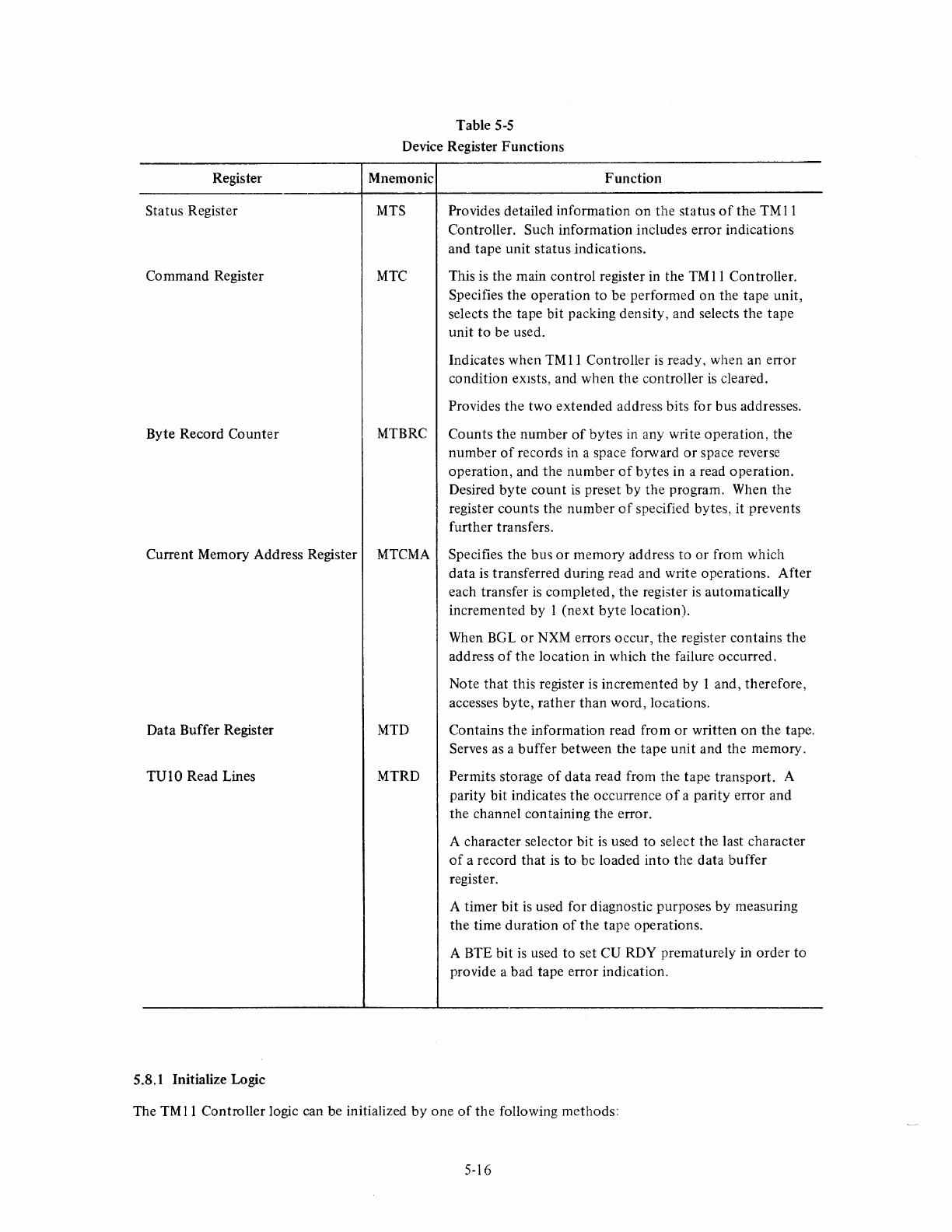
Register
Status Register
Command Register
Byte Record Counter
Table 5-5
Device Register
Functions
Mnemonic
Function
MTS Provides detailed information
on
the
status
of
the TM
11
Controller. Such information includes error indications
and tape unit status indications.
MTC
This is the main control register in the
TM
11
Con troller.
Specifies the operation to be performed on the tape unit,
selects the tape bit packing density, and selects the tape
unit
to
be used.
Indicates when
TM
11
Controller
is
ready, when an error
condition eXIsts, and when the controller
is
cleared.
Provides the two extended address bits for bus addresses.
MTBRC Counts the number
of
bytes
in
any write operation, the
number
of
records in a space forward
or
space reverse
operation, and the number
of
bytes in a read operation.
Desired byte
count
is
preset by the program. When the
register counts the number
of
specified bytes, it prevents
further transfers.
Current Memory Address Register MTCMA Specifies the bus
or
memory address to
or
from which
data
is
transferred during read and write operations. After
each transfer
is
completed, the register
is
automatically
incremented by I (next
byte
location).
Data Buffer Register MTD
TUIO Read Lines MTRD
5.8.1 Initialize Logic
When BGL
or
NXM
errors occur, the register contains
the
address
of
the location in which the failure occurred.
Note that this register
is
incremented
by
1 and, therefore,
accesses byte,
rather
than word, locations.
Contains the information read from or written
on
the
tape.
Serves
as
a buffer between the tape unit and the memory.
Permits storage
of
data read from the tape transport. A
parity bit indicates the occurrence
of
a parity error and
the channel containing the error.
A character selector bit
is
used to select the last character
of
a record that
is
to be loaded into the data buffer
register.
A timer
bit
is
used for diagnostic purposes by measuring
the time duration
of
the tape operations.
A BTE bit
is
used to set CU RDY prematurely
in
order
to
provide a bad tape error indication.
The
TM
11
Controller logic can be initialized
by
one
of
the
following methods:
5-16

a.
Depressing the CLEAR switch on the maintenance panel.
b.
Loading a 1 into bit 12 (POWER CLEAR)
of
the
command register.
c.
Issuing a programmed RESET Instruction.
d.
Depressing the START switch
on
the
PDP-II
processor console.
e.
Occurrence
of
a power fail by either the processor power supply
or
the controller power supply.
The controller initialization logic
is
shown
on
Drawing
TM
11-0-19. When the maintenance panel CLEAR switch
is
activated, it produces the MAN CLR L pulse, which passes through a series
of
gates
to
produce the INIT
Hand
INIT L signals which clear all logic in the controller and in the master tape transport.
When a 1
is
loaded into bit 12
of
the command register, an AND gate
is
qualified by D
12
Hand
SEL 1 OUT HIGH
H.
When
the
AND gate
is
qualified, the INIT
Hand
INIT L signals are produced
as
before.
The remaining three methods
of
initialization (programmed RESET, processor START, power fail) all use external
logic to provide a
BUS
INIT signal input
to
the controller. This signal becomes INIT REC H and produces the
INIT
Hand
INIT L signals
as
before.
5.8.2 Command Register (MTC)
The command register
is
the main control register in the system and specifies the operation
to
be performed.
Each
of
the bits
is
discussed separately below, beginning with the most significant bit.
5.8.2.1 Error Bit
(15)
-The
ERROR
bit (bit 15) in the command register
is
the inclusive OR
of
all error con-
ditions in
the
status register. Thus,
if
any error bit in the status register
is
set, it sets the
ERROR
bit in the com-
mand register. When any error condition occurs, it sets the appropriate flip-flop in the status register. The ap-
propriate level from the flip-flop passes through a series
of
OR
gates (Drawing
TM
11-0-20) and sets the command
register error flip-flop, which produces the
ERR
H signal. The
ERR
H signal
is
then applied through a series
of
AND gates (Drawing
TM
11-0-15) so
that
the bit can be read from the bus.
Because
of
the gating shown on Drawing
TM
11-0-20, the
ERR
flip-flop
mayor
Ill.ty
not
be set simultaneously
with the detection
of
an error condition. In the case
of
BGL (bus grant late),
NXM
(non-existent memory), ILC
(illegal command), and BTE (bad tape error) errors, the resultant error signal passes through
OR
gates and sets the
error flip-flop simultaneously with detection
of
the error.
If
RLE (record length error), CRE (cyclical redundancy error), PAE (parity error), or EOF (end-of-file) occurs,
the appropriate status register flip-flop
is
set, and the resultant error signal
is
ANDed with the LRCSD signal,
which occurs only when the
LPC
character
is
detected. Thus, the command register error flip-flop
is
not set
until the
LPC
character has been read, in order to
give
the controller time to complete the current operation.
When the EOT (end-of-tape) marker
is
detected, it represents an error condition only
if
the tape
is
moving in the
forward direction. The EOT signal
is
ANDed with SPACE REV L, REWIND
L,
and LRSCD. This AND gate,
therefore,
is
qualified only if: the end-of-tape marker has been detected (EOT), the tape
is
not
moving in the
reverse direction (SPACE REV L), the tape
is
not
being rewound (REWIND L), and the
LPC
character has been
detected (LRCSD).
If
these conditions are met, the gate
is
qualified, and the resultant
output
sets the error
flip-flop in the command register.
5~17
When the
ERROR
bit
is
set, it sets the CU RDY
bit
(bit
07),
as
shown
on
Drawing
TM
11-0-08.
The
ERR
L
signal from
the
error
flip-flop passes
through
2 pulses
and
two
OR gates
to
produce
the
SET
CUR
L signal
that
direct sets
the
control
unit
ready (CU RDY) flip-flop.
The
output
of
the
interrupt
flip-flop (BR INT
H)
is
applied
to
the
MASTER
CONTROL
B section
of
the
M782l
Interrupt
Control
Module,
and
the
TM
11
Controller
initiates an
interrupt
routine. Thus, an
error
condition
causes an
interrupt,
provided
the
INT ENB bit
is
set.
A selection
error
is
an illegal
command
and, therefore, also causes an
error
condition.
The
error
conditions can be cleared by INIT (refer
to
Paragraph 5.8.1)
or
by
the
next
GO
command.
5.8.2.2
Density Bits
(14
and
13) -
The
DEN 8 and DEN 5 bits are used
together
to
determine
the
bit packing
density
of
the
tape. Densities
of
200,556,
and
800
bpi
may
be selected for
the
7-channel tape,
but
only
800
bpi
can be used for the 9-channel tape. The program selects
the
density
by
loading
the
appropriate
value
into
these
bit positions, according
to
the
following table:
DEN 8
(Bit 14)
o
o
DEN 5
(Bit 13)
o
I
a
Selected bpi
200}
556
800
800
7-channel
tape
9-channel
These values are applied
to
the
master
tape
transport
by
the
controller.
The
master
tape
transport
contains
the
actual density selection logic
for
the
tape.
The
controller logic
is
used primarily
to
feed
appropriate
bits
to
the
master
tape
transport
and
to
select the core
dump
mode
of
operation.
Controller
logic
is
shown
on
Drawing
TMII-O-I0.
When a I
is
loaded
into
bit 13 (DEN 5), it
is
applied
to
the D-input
of
a flip-flop.
The
clock
input
is
the
SEL I
OUT HI H signal
that
indicates
the
bus
is
loading the
command
register. These
two
inputs
set
the
flip-flop.
The
low side
of
the
flip-flop qualifies an AND gate, provided the core
dump
mode
is
not
being used.
The
output
of
the AND gate
is
the
DEN 5 signal (representing binary I)
that
is
applied
through
the
BC
1 1 A
interconnecting
cable
to
master
tape
transport.
If
a 0
is
loaded
into
this bit position,
the
flip-flop
is
not
set,
the
AND gate
is
disqualified, and
the
AND gate
out-
put
is
a low level representing binary
O.
The
DEN 8
(bit
14) signal
is
produced
in an identical
manner
to
the DEN 5 signal.
The
core
dump
mode
is
used with 7-channel tapes when it
is
desired to use all bits within a
memory
byte.
Nor-
mally,
the
two
most significant bits in a
byte
are
not
used. During core
dump
mode,
all bits are used,
but
the
two
most
significant channels
on
the
tape are
not
used.
In
effect,
two
tape characters are used
to
represent
one
byte
as
shown
in Table 5-6.
The
core
dump
mode
is
enabled whenever
the
program sets
both
DEN 5
and
DEN 8
to
a I while
the
7-channel
(7CH) signal
from
the
master tape
transport
is
a
I,
indicating
that
a 7-channel tape
is
being used. When
both
the
DEN 5
and
DEN 8 flip-flops are set, the DEN 5 H
and
DEN 8 H signals are applied
to
an AND gate
that
is
quali-
fied by
the
7CH H signal from
the
master
transport.
A signal
produced
from this AND gate
is
CORE
DUMP H,
which disqualifies
the
AND gate from the low side
of
the
DEN 5 flip-flop so
that
the
DEN 5 signal
to
the
master
5-18
transport is a
O.
This
is
necessary because
both
DEN signals had been 1 s in order
to
select the core
dump
mode,
but a 10 code must
be
applied
to
the master transport in order for the actual transfer
to
take place at
800
bpi.
The core dump mode
is
used for reading and writing on tape.
It
is
important
to
note that the TU 1 0 tape channels
are numbered in the reverse order
of
the data buffer bits. Thus, for example, data buffer bits 0,
1,
2, and 3 cor-
respond to tape channels
7,6,5,
and 4, respectively.
After the core dump mode has been properly selected, the resultant CORE
DUMP
Land
7CH L pulses disqualify
the four AND gates connected
to
tape channels 3, 2,
I,
and 0 (Drawing
TM
11-0-11). Channels 1 and 0 are dis-
qualified
by
7CH, because they are used only during 9-channel operation; tape channels 3 and 2 are disqualified
by CORE DUMP L, because they are
not
used during the core
dump
mode
of
operation.
When transferring data from the data buffer register to the master tape transport during the core dump mode, one
8-bit PDP-II byte
is
written
as
two 4-bit tape characters. This
is
accomplished by the gating shown on Drawing
TM
11-0-11 and
is
in the form shown in Table 5-6.
First Tape Character
a
2
3
Table S-6
Core Dump Mode
Second Tape Character
4
5
6
7
Corresponding TU 10 Write Lines
WD7
WD6
WD5
WD4
NOTE: These two characters represent one
byte
with
0-7
bits.
5.8.2.3 Power Clear Bit
(12)
-When the program loads a 1 into this bit position, an initialize signal
is
provided
to clear the
TMll
Controller, the master tape transport, and the slave transports. This initialize signal does
not
clear the processor
or
any
other
device
on
the bus. The initialize signal
is
generated by the controller logic
as
described in Paragraph 5.8.1. The INIT signal passes through a gate and becomes the CINIT signal, which
is
applied
to
the master tape transport logic to clear all transports.
5.8.2.4
Parity Bit (11) -The parity bit (bit 11) specifies whether odd
or
even lateral parity
is
to be read from
or
written on the magnetic tape. Although parity is generated by the master tape transport, the parity bit in the con-
troller command register
is
used
to
select the polarity. The parity bit
is
referred to
as
the PEVN (parity even) bit,
because it denotes even parity when set.
The parity flip-flop
is
shown on Drawing
TM
11-0-1
O.
The flip-flop
is
set by SEL
lOUT
HI H (indicating that the
command register has been selected for loading from the bus) and by D
11
H (indicating
that
a 1 has been loaded
into bit
11
of
the command register). With the flip-flop set, the low side passes through a gate and becomes the
PEVN signal, which is applied
to
the master tape unit to indicate that even parity is to be used.
The parity flip-flop is cleared by loading a 0 into bit
11
(the D
11
H input becomes low)
or
by an INIT signal,
which direct clears the flip-flop. When the flip-flop
is
clear, the resultant PEVN signal
is
low, indicating to the
master tape transport
that
odd parity
is
to be used.
5-19
5.8.2.5 Unit Select Bits (10,
09,
08) -The three unit select bits (bits 10 through 08) specify the tape transport
that
is
to be used for a particular operation. The states
of
these three bits represent an octal code corresponding
to the
number
of
the transport,
as
set
by
the
UNIT SELECT switch
on
the
individual transport.
The three unit select bits are shown on Drawing
TM
11-0-12. These three bits (UNIT SEL BIT 2, UNIT SEL BIT
1,
and UNIT SEL BIT 0) are set
or
cleared
by
loading Is
or
Os
from bus lines
10,09,
and 08, respectively. The
UNIT SEL BIT signals are applied
to
one side
of
a flip-flop. The
other
side
of
the flip-flop receives
the
CLK UNIT SEL L signal. Therefore, these flip-flops are set
or
cleared, depending
on
the UNIT SEL BIT signal.
This results in SEL 2, SEL 1, and
SEl
0 signals (representing the appropriate octal code loaded from the bus),
which are applied
to
the
master tape transport logic. The
ClK
UNIT
SEl
1 signal
is
produced, provided
the
following conditions exist: the command register is being loadtrl from the bus
(SEllOUT
l),
the master tape
transport
is
off-line (SEL R),
is
rewinding,
or
is
not
in
either
the
tape operation time (CU RDY
is
0)
or
gap shut-
down time.
The three SEL signals are applied to a binary-to-octal decoder within the master tape transport. Depending
on
which signals are high,
one
of
the eight tape units
is
selected for use.
It
is
possible
that
the desired tape unit may
not
be properly selected.
For
example, there may be no tape trans-
port UNIT SELECT switch
that
is
set
to
the number loaded
by
the program. Another instance
of
improper
selection would be selecting a tape transport
that
is
off-line. In either case, improper selection is an illegal com-
mand (lLC) error, which, in turn, causes
an
ERR
indication.
The unit select logic also produces UNIT SEL BIT
TM
Hand
1 signals, which are used
by
the tape motion control
logic described in Paragraph 5.9.
5.8.2.6 Control Unit Ready Bit
(07)
-The control unit ready bit (bit 07) indicates
that
the controller
is
ready to
receive a new command.
It
is set (indicating ready) whenever the previous command operation
is
completed, an
initialize" signal
is
given,
or
an error condition exists.
It
is
cleared at the beginning
of
a tape operation when the
GO command (bit 00)
is
issued.
The
control
unit ready flip-flop
is
shown on Drawing
TM
11-0-08. A series
of
gates
is
connected to
the
direct-set
input
of
the flip-flop.
If
the INIT signal goes high (indicating initialize)
or
the
ERR
signal
is
presen t (indicating
some type
of
error condition exists), the
output
of
the
OR
gate goes low and direct sets
the
control unit ready
flip-flop, producing CU RDY
H.
The
gating also direct sets
the
CU RDY bit when: the byte record counter overflows with space forward
or
space
reverse operations; when
the
first
LPC
character
is
read in a tape forward command which
is
not
a SPACE
FORWARD; when a rewind operation has started; when the unit goes off-line during an operation; and when the
BOT
is
sensed during a rewind
or
SPACE REV operation.
The control unit ready flip-flop
is
cleared by the
GO
BIT H signal, which occurs whenever the GO bit
is
loaded
from
the
bus.
5.8.2.7
Interrupt
Enable Bit
(06)
-The interrupt enable
(lNT
ENB) bit, when set, allows an interrupt to occur
provided either CU RDY (bit 07) or
ERR
(bit
15) becomes set.
It
also permits an
interrupt
whenever a tape unit
in
the rewind mode reaches the BOT marker at the time CU RDY
is
a I,
or
whenever an instruction sets the
INT ENB
bit
but
does
not
set the GO bit (Bit 00).
5-20
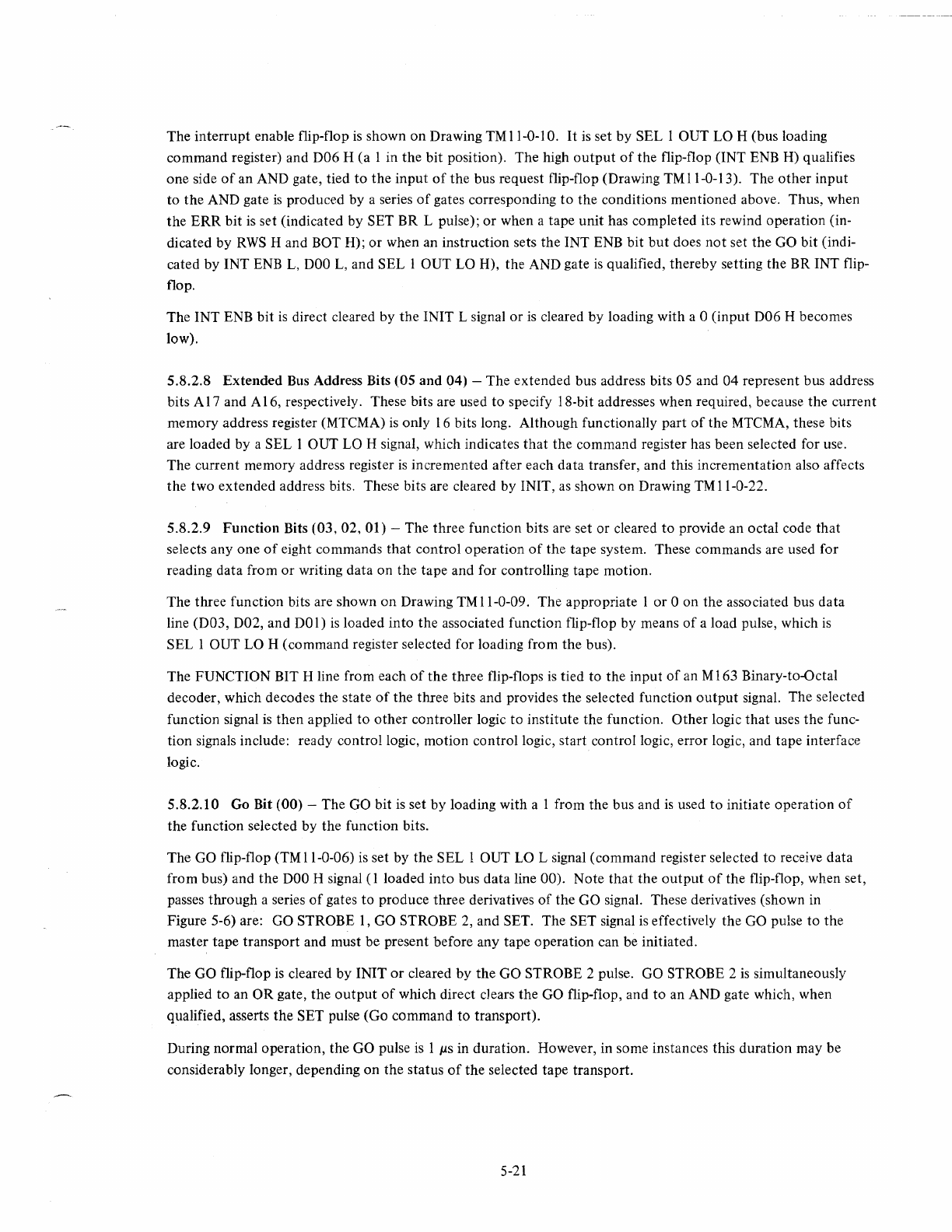
The
interrupt
enable flip-flop
is
shown
on
Drawing
TM
11-0-1
O.
It
is
set
by
SEL
lOUT
LO H (bus loading
command register) and D06 H
(a
1 in the bit position). The high
output
of
the flip-flop (lNT ENB
H)
qualifies
one side
of
an AND gate, tied
to
the
input
of
the
bus request flip-flop (Drawing
TM
11-0-13). The
other
input
to
the
AND gate
is
produced by a series
of
gates corresponding
to
the conditions mentioned above. Thus, when
the
ERR
bit
is
set (indicated by SET BR L pulse);
or
when a tape unit has completed its rewind operation (in-
dicated by
RWS
H and BOT
H);
or
when an instruction sets the INT ENB bit
but
does
not
set the GO bit (indi-
cated by INT
ENB
L,
DOO
L,
and SEL
lOUT
LO H), the AND gate
is
qualified, thereby setting the BR INT flip-
flop.
The INT ENB
bit
is
direct cleared by the INIT L signal
or
is
cleared by loading with a 0 (input D06 H becomes
low).
5.8.2.8
Extended
Bus Address Bits
(OS
and
04) -The extended bus address bits 05 and
04
represent bus address
bits A
17
and A 16, respectively. These bits are used to specify I8-bit addresses when required, because the current
memory address register (MTCMA)
is
only 16 bits long. Although functionally part
of
the MTCMA, these bits
are loaded by a SEL 1 OUT LO H signal, which indicates
that
the command register has been selected for use.
The current memory address register
is
incremented after each data transfer, and this incrementation also affects
the two extended address bits. These bits are cleared by INIT,
as
shown
on
Drawing
TM
11-0-22.
5.8.2.9
Function
Bits (03,
02,
01) -The three function bits are set or cleared
to
provide an octal code that
selects
anyone
of
eight commands that control operation
of
the tape system. These commands are used for
reading data from
or
writing data on the tape and for controlling tape motion.
The three function bits are shown
on
Drawing TMII-0-09. The appropriate 1
or
0
on
the associated bus data
line (D03, D02, and
DO
1)
is
loaded into
the
associated function flip-flop by means
of
a load pulse, which
is
SEL
lOUT
LO H (command register selected for loading from the bus).
The FUNCTION BIT H line from each
of
the three flip-flops
is
tied to the input
of
an M 163 Binary-to-Octal
decoder, which decodes the state
of
the three bits and provides the selected function
output
signal. The selected
function signal
is
then applied
to
other
controller logic to institute the function.
Other
logic
that
uses the func-
tion signals include: ready control logic, motion control logic, start control logic, error logic, and tape interface
logic.
5.8.2.10 Go Bit (00) -The GO bit
is
set
by
loading with a 1 from the bus and
is
used
to
initiate operation
of
the function selected by the function bits.
The GO flip-flop (TM 11-0-06) is set by the SEL 1 OUT LO L signal (command register selected to receive data
from bus) and the
DOO
H signal
(1
loaded
into
bus
data
line 00). Note
that
the
output
of
the flip-flop, when set,
passes through a series
of
gates
to
produce three derivatives
of
the GO signal. These derivatives (shown in
Figure 5-6) are: GO STROBE
1,
GO STROBE 2, and SET. The SET signal is effectively the GO pulse
to
the
master tape transport and must be present before any tape operation can be initiated.
The GO flip-flop
is
cleared by INIT
or
cleared
by
the GO STROBE 2 pulse. GO STROBE 2
is
simultaneously
applied
to
an
OR
gate,
the
output
of
which direct cJears the GO flip-flop, and
to
an AND gate which, when
qualified, asserts
the
SET pulse (Go command
to
transport).
During normal operation, the GO pulse is 1
J..LS
in duration. However, in some instances this duration may be
considerably longer, depending
on
the status
of
the selected tape transport.
5-21
GO
GO
STROBE
1
GO
STROBE 2
SET
NOTES:
1.
All
signals
are
lps
in
duration
2.
Go
signal
is
normally
1ps but
may
be
10ms
or
longer
depending on what
time
the
bit
is
set (see
text)
//-0429
Figure 5-6 Derivatives
of
GO Signal
As
mentioned previously, the GO pulse cannot go low until the GO STROBE 2 pulse
is
generated. Before
GO STROBE 2 can be generated, a 4-input AND gate must be qualified. The four conditions needed
to
qualify
this AND gate are: GO BIT H (GO flip-flop
is
set), GSD L (Transport
not
in gap shutdown period), unit has
completed a rewind instruction, and the logic has determined
that
a GO can be sent to the transport during the
SDWN time.
If
anyone
of
these four conditions
is
not
true, the GO pulse remains high until the required condi-
tion becomes true.
If
the
transport
is
in
a gap shutdown or settling down period, the GO bit duration could be
as
long
as
10 ms, de-
pending
on
what point in the period the GO bit was set.
If
the selected tape
unit
is
not
ready
(note
that
this
condition also exists during rewind, because
RWS
direct sets the flip-flop, providing one
of
the AND gate inputs),
the GO bit duration could be
as
long
as
several minutes
as
would be the case when the selected tape unit
is
in
the
process
of
rewinding.
The GO BIT H signal
is
also applied
to
the control unit ready (CO RDY) flip-flop (Drawing TMII-O-08)
to
clear
the CU RDY bit. This
is
necessary because whenever the GO bit
is
present, it indicates the controller
is
perform-
ing an operation and
is
not
ready to accept a new command.
5.8.3 Status Register (MTS)
The status register
is
used primarily to provide indications
of
error conditions.
It
also indicates
the
status
of
cer-
tain system functions such
as
write lock, settling down period, tape unit ready, and beginning
of
tape.
The status register error logic is shown
on
Drawing TMII-O-20. Whenever one
of
the specific error signals
is
present,
it
passes through an
OR
gate, which
is
the inclusive OR
of
all error conditions. The resultant flip-flop
output
signal
(ERR
L) passes through a pulser and two
OR
gates in the ready control logic (Drawing TMII-O-08)
and direct sets the control unit ready (CU ROY) flip-flop. This allows the controller to issue an
interrupt
re-
quest whenever an error exists (refer
to
Paragraph 5.6.2).
All error bits (15 through 06)
in
the status register are read-only bits.
They
can be read (tested) by the program
to determine
if
a specific error exists or not,
but
they
cannot
be loaded by the program. All error bits are cleared
by INIT
or
by
the
GO (GO STROBE
1)
pulse
to
the
tape unit.
5-22
The remaining bits (05
through
00) indicate system
status
and are set
or
cleared
by
the master
tape
transport.
These bits can also be read by
the
program.
Each individual bit in
the
status register
is
discussed separately in
the
following paragraphs.
5.8.3.1 Illegal
Command
(15) -
The
illegal
command
(ILC)
error
is
bit
15
of
the
st~tus
register
and
indicates a
conflict in commands.
The
ILC
error
logic (Drawing
TM
11-0-19) consists
of
a series
of
gates and a flip-flop.
The first series
of
gates is used
to
direct set
the
ILC flip-flop.
Any
time
that
a DATO
or
DATOB transfer is made
to
the
command
register (SEL
lOUT
LO H
or
SEL
lOUT
HI H) during a
current
tape
operation
(CUR
DEL
L),
gating is qualified
to
set
the
ILC flip-flop, because
the
command register
cannot
accept a new
command
while in
the
process
of
executing
another
command.
When
the
SELR
bit becomes 0
(SELR
H) during any operation (CUR DEL L)
except
an
off
line
command,
gating
is
qualified
to
direct set
the
ILC flip-flop, because
no
command
can be issued
to
a
tape
transport
that
is
not
on-
line.
The remaining gates in
the
ILC
error
logic are used
to
produce
SET ILC H, which sets
the
ILC flip-flop when
the
GO pulse is present (GO STROBE 2 L). There are
two
illegal commands
that
can
produce
SET ILC H.
The first
command
is
any
command
to
a tape
transport
that
has its
SELR
bit
clear
(SELR
H), because when
SELR
is
clear it indicates
the
transport
is
off-line.
The second illegal
command
is
any write, write end-of-file,
or
write-with-extended-IRG
command
(WRITE ENB H)
that
is issued when
the
write lock
bit
is
set (WRL H), Writing
is
inhibited with WRL set, and all write commands
are, therefore, illegal.
When an illegal
command
produces
the
ILC H pulse,
the
pulse is applied
to
the
gating logic for
the
error
flip-flop
in
the
command
register (Drawing
TM
11-0-20); thus,
the
command
register
ERR
bit
is
set simultaneously with
the
status register ILC bit.
The ILC error
bit
is
cleared
by
INIT
or
by occurrence
of
the
GO pulse. When
the
GO pulse occurs,
the
GO
STROBE I pulse occurs immediately preceding
the
GO STROBE 2 pulse and
is
used
to
direct clear
the
ILC flip-
flop.
5.8.3.2 End-of-File Bit (14) -Bit
14
in
the
status
register is
the
end-of-file
(EOF)
bit
that
is
used
to
indicate
that
the
tape has reached
the
end
of
the
file. The
EOF
flip-flop (Drawing
TM
11-0-20) is set by the master tape
transport
and cleared by INIT
or
GO pulse. The
input
to
the
flip-flop
is
the FMK (file mark) signal from
the
master
tape
transport. This signal, when present, indicates
that
the
transport
has
detected
the
end-of-file mark
on
the tape.
The
signal sets
the
EOF
flip-flop
to
produce
the
EOFF
H signal.
It
is
beyond
the
scope
of
this manual
to
describe
the
logic used by
the
master
tape
transport
to
detect
the
end-of-
file mark.
The
transport
logic
is
covered in
the
TV
10
DECmagtape Manual. A
brief
description
of
the
EOF
bit
is
presented
in
Figure
4-1
of
this manual.
5.8.3.3 Cyclic
Redundancy
Error
Bit (13) -The cyclic
redundancy
error
(eRE)
bit
in the
status
register indi-
cates
that
the
cyclic
redundancy
check for a 9-channel tape has detected a parity error. This check compares
the
CRC character written during a write
or
write-with-extended-IRG
operation
with
the
CRC character generated
during a read operation.
The comparison
of
the
two
CRC characters
is
performed by logic within
the
master tape transport.
If
the
two
characters are
not
identical,
then
the
CRCE from
the
tape
unit
becomes a 1 and
is
applied
to
gating logic in
the
controller error circuits (Drawing
TMII-0-20).
The
gating logic sets the
CRE
flip-flop
to
produce
CRE
H.
5-23
The CRE
output
of
the flip-flop
is
applied
to
gating logic associated with the command register
ERR
flip-flop.
Note, however,
that
the AND gate
is
not
qualified until
both
CRE and LRCSD H are present. The latter signal
indicates that the LPC character has been detected. Thus, when a CRC error
is
detected, the CRE bit in the
status register
is
set immediately,
but
the
ERR
bit in the command register
is
not
set until
the
LPC
is
detected.
This gives the controller time
to
complete the current operation before branching
to
an error routine by means
of
the interrupt.
5.8.3.4 Parity Error Bit (12) -The parity error (PAE) bit in the status register indicates that a parity error exis(s
in
the
data. The error may be in either lateral (vertical)
or
longitudinal parity. A lateral parity error
is
indicated
for any character in a record; a longitudinal parity error indicates an error in a specific channel.
The parity error circuits are shown on Drawing TMII-0-20. An AND gate
output
is
used
to
set the PAE flip-flop;
this AND gate
is
qualified by three inputs. The first
input
is
RDS H from the master tape transport, which
is
used
to
sample parity. The second
input
is
either WRITE ENB
or
READ, because parity
is
checked during
both
read
and write operations. The third
input
is
either the VPE (vertical parity error)
or
LRCE (longitudinal parity error)
signal from the transport. Thus,
both
lateral (vertical) and longitudinally parity errors are detected during read,
write, write EOF, and write-with-extended-IRG operations. The entire record
is
checked, including the CRC and
LPC characters.
Note
that
longitudinal parity occurs when an odd
number
of
I s
is
present in any channel in the record; lateral
parity errors may be even
or
odd, depending
on
the setting
of
the PEVN bit in the command register.
The PAE
output
of
the parity error flip-flop
is
applied to command register gating logic in the same manner
as
the
CRE
output,
as
explained previously. In the case
of
P AE, the PAE bit in the status register
is
set immediately,
but
the command register
ERR
flip-flop
is
not
set until detection
of
the LPC character.
5.8.3.5 Bus
Grant
Late Error Bit (11) -The bus grant late (BGL) error flip-flop
is
bit
II
of
the status register.
During normal operation, the controller makes an NPR request
to
gain control
of
the bus and initiate a data
transfer (either a read or a write).
If
the controller
is
still engaged in the NPR transfer when
another
NPR request
is
initiated, a BGL error condition occurs.
The BGL flip-flop
is
shown on Drawing
TM
11-0-20.
It
is
set (indicating an error) when
both
the NPR ENB and
NPR SET inputs are high. These inputs are received from the NPR
input
logic (Drawing TMII-O-13).
If
the controller receives either a
WRS
or
RDS pulse from
the
master tape transport, the NPR logic circuits pro-
duce the NPR SET H pulse. This pulse
is
gated through an AND gate and sets the NPR request flip-flop on its
trailing edge.
If, however, the NPR transfer
is
still occurring when the next NPR SET H pulse occurs, the BGL flip-flop
is
set
to
indicate an error. The NPR request flip-flop
is
cleared
at
the end
of
an NPR transaction by the
NPR CLEAR BBSY H signal.
The
BGL error signal disqualifies
the
AND gate on the input
of
the NPR request flip-flop, thereby preventing any
further NPR requests until the error condition
is
corrected. In addition, the BGL signal
is
applied through gates
in the error logic (Drawing TMI 1-0-20) to set the
ERR
flip-flop in the command register.
5.8.3.6 End-of-Tape Bit (10) -
The
end-of-tape (EOT) bit
is
bit 10 in the status register. This bit
is
set when
the EOT marker
is
detected when the tape
is
moving in the forward direction; it
is
cleared by the trailing edge
of
the EOT marker when the tape
is
moving in the reverse direction. Note
that
the EOT bit
is
an error condition
only when the tape
is
moving forward.
5-24
The EOT
bit
is
controlled by the master tape transport.
The
transport logic detects the EOT and sends
the
appropriate signal
to
the status register to set
or
clear
the
bit. When
the
EOT marker
is
detected by the transport,
the EOT H signal
is
applied to error logic in the controller (Drawing
TMll-0-20).
An AND gate
is
qualified
if
EOT
is
high, and
both
SPACE REV L and REWIND L are
true
(indicating the tape
is
not
moving in the reverse
direction). The
output
of
the AND gate
is
ANDed with the LRCSD H signal (indicating
that
the LPC character
has been detected) and used
to
set
the
ERR
flip-flop in the command register.
Thus, the EOT bit in
the
status register
is
set
or
cleared as soon
as
the EOT marker
is
detected,
but
the
ERR
bit
in
the
command register
is
not
set until the LPC character has been read in order to allow completion
of
the cur-
rent operation prior
to
initiating an interrupt.
5.8.3.7 Record Length Error Bit (09) -During read operations, the record length error (RLE)
bit
is
set
if
the
master tape transport
attempts
to load
another
character into the controller after the number
of
bytes specified
by the
byte
record
counter
has already been transferred
to
memory. This error bit
is
used for long records only
and is set
as
soon
as
the
byte
record counter increments beyond
O.
The
byte
record counter (MTBRC)
is
used
to
keep track
of
the
number
of
data
bytes loaded into memory from a
tape record. Initially,
the
MTBRC
is
loaded with the 2's complement
of
the
number
of
bytes to be loaded. Each
time
the
master tape transport reads a character,
it
loads it
into
the data buffer register. After a
byte
is
transferred
to memory, the MTBRC
is
incremented by
1.
When the last
byte
is
transferred
to
memory, incrementing
the
MTBRC by I sets
it
to
O.
As
soon
as
the
byte record counter goes
to
0,
it produces a CARRY OUT 2 L signal, which sets the OVERFLOW
flip-flop (Drawing
TM
11-0-20). This flip-flop had been reset because
of
the INIT
o~
GO L signal. Therefore, it
is
now set and produces an OVERFLOW H pulse.
This overflow pulse is applied
to
one leg
of
a 3-input AND gate. Because the RLE error can only occur during a
read operation, the AND gate
is
not
qualified unless a read operation
is
being performed
as
indicated by a read
strobe signal (READ STB H) and
the
absence
of
a CRCS or LRCS pulse (CRCS L
or
LRCS L). When the AND
gate
is
qualified, its
output
changes
the
state
of
the
RLE flip-flop, thereby setting
it
to
provide an indication
of
record length error in status register bit position 09.
When the RLE flip-flop
is
set, the RLE L
output
qualifies an
OR
gate in the error logic circuits. The signal from
the
OR
gate qualifies an AND gate when the
LPC
character
is
read (LRCSD H), thereby setting the
ERR
flip-flop.
Thus, when a record length error occurs, the RLE bit
is
immediately set, and the
ERR
bit in
the
command regis-
ter
is
set after the current operation
is
completed.
5.8.3.8 Bad Tape Error Bit (08) - A bad tape error occurs when a character
is
detected (RDS pulse) during the
gap shutdown or settling down period for all tape functions except rewind and
off
line.
The bad tape error flip-flop (Drawing
TM
11-0-19)
is
normally in the clear state.
It
is
set by
the
output
of
a
4-input NAND gate. One input
of
this NAND gate
is
the RDS H pulse, which indicates
that
a character has been
detected. The second
input
to
the NAND gate comes from a series
of
gates that are qualified
if
the tape unit
is
in
either
the
gap shutdown (GSD L)
or
settling down (SDWN L) period. The third
input
is
in the INH BTE signal
(BGL, NXM, or ILC
is
true). Issuing a new GO command
or
an INIT pulse causes the bad tape error flip-flop
to
clear so
that
it
can be ready for
another
bad tape error.
When
the
bad tape error flip-flop
is
set, it also qualifies
one
leg
of
an
OR
gate shown
on
Drawing
TMII-0-20.
The
output
of
this gate sets the
ERR
flip-flop as soon
as
the error occurs.
5-25
5.8.3.9 Non-Existent Memory Bit (07) -The non-existent memory (NXM) error flip-flop
is
bit 07
of
the status
register. When set, this bit indicates that the controller was bus master during NPR operations
but
did
not
receive
a SSYN response from the slave device within
10
I1S
after the controller issued the MSYN signal. The
ERR
bit
is
set simultaneously with the
NXM
bit, thus terminating all operation.
If
the
NXM
error occurs during a write
or
write-with-extended-IRG operation, the controller does
not
send the
WDR
signal
to
the master tape transport;
however, the master transport writes the
eRe
character
(if
required) and the
LPe
character
onto
the tape.
The
NXM
error flip-flop
is
part
of
the NPR control circuits on the M796 Module and
is
described in Paragraph
5.6.1.
5.8.3.10 Select Remote Bit (06) -The select remote (SELR) bit
is
bit 06
of
the status register and, when set,
indicates
that
the selected transport has been selected and is on-line. When this bit
is
0,
it
indicates
that
the tape
transport addressed does not exist (no transport UNIT SELECT switch set
to
the number specified
by
the pro-
gram),
is
off-line (transport ON-LINEjOFF-LINE switch set to OFF-LINE),
or
that
the selected transport has its
power turned off.
The select remote logic
is
within the master tape transport, which supplies the appropriate signal to
the
status
register for monitoring.
5.8.3.11 Beginning-of-Tape Bit (05) -The beginning-of-tape (BOT) bit in the status register indicates when the
BOT marker on the magnetic tape
is
read.
As
long
as
this bit remains 0, it indicates
that
the
BOT marker has
not
been sensed. When the bit
is
aI,
it indicates
that
the marker has been sensed, and the beginning
of
the tape has
been reached. The
ERR
bit
is
not
set when the BOT bit
is
sensed, because sensing
of
the BOT marker does
not
indicate an error condition.
The beginr:ing-of-tape logic is within the master tape transport, which supplies the appropriate signal
to
the
status
register
to
set
or
clear the BOT bit.
5.8.3.12
7~hannel
Bit (04) -This bit
is
set
or
cleared by the master tape transport
to
indicate whether a
7-channel
or
9-channel tape is being used. When the bit
is
set, it indicates a 7-channel tape; when it is clear,
it
indicates a 9-channel tape.
The 7-channel bit
is
also used in conjunction with the DEN 8 and DEN 5 bits in the command register
to
cause
the core dump mode
of
operation. When these three bits are
all
set, the core dump mode
is
used, and all bits
within each
byte
in
a memory location are transferred
to
the tape. A detailed discussion
of
the core
dump
mode
is
presented in Paragraph 5.8.2.2.
5.8.3.13 Settle Down Bit (03) - A settling down period
is
provided
to
allow the tape to fully deskew prior to
stopping
or
starting a new operation. This settling down period sets the
SDWN
bit
in
the status register. When the
tape unit stops,
SDWN
is cleared, and the tape unit ready bit
is
set.
The settle down logic
is
within the master tape transport, which supplies the appropriate signal
to
set
or
clear the
SDWN
bit in the status register. A description
of
the
SDWN
bit
is
contained in Paragraph 4-2
of
this manual.
5.8.3.14 Write Lock Bit (02) -The write lock (WRL) bit
is
under control
of
the
master tape transport. When
set,
it
prevents the controller from writing information on the magnetic tape.
If
the write lock signal
is
supplied
from the master tape transport (WRL H) and the controller attempts to write on the tape (WRITE ENB H), then
an AND gate
is
qualified (Drawing
TM
11-0-19) that sets the illegal command
(ILe)
flip-flop, thereby setting the
ERR
flip-flop and preventing the write operation from being executed.
5-26
5.8.3.15 Rewind Status Bit (01) -The rewind status (RWS) bit
is
under
control
of
the
master tape transport,
which supplies
the
signal to set
or
clear
the
RWS
bit in the status register.
The
RWS
bit
is
set
at
the
start
of
a re-
wind operation, and becomes a 0
as
soon as the BOT marker
is
detected while
the
tape is moving in the forward
direction. Thus, when the bit is set, it indicates the tape
is
rewinding; when it is clear, it indicates the rewind
operation
is
complete. The
RWS
signal from the master tape transport is also used in the
tape
control ready logic
described in Paragraph 5.9.3.
5.8.3.16
Tape
Unit Ready Bit (00) -
The
tape unit ready (TUR)
bit
is
under
control
of
the master tape unit,
which supplies
the
signal
to
set
or
clear
the
TUR
bit in the status register. Whenever
the
selected tape unit
is
being
used (such
as
rewind), this
bit
is
cleared. When
the
tape unit
is
stopped and ready
to
receive a new command, this
bit
is
set.
The
TUR
signal from
the
master tape transport
is
used in the tape start control logic described
in
Paragraph 5.9.4.
5.8.4
Byte
Record
Counter
(MTBRC)
The
byte
record
counter
(MTBRC) is a 16-bit binary
counter
used
to
count
bytes in a read
or
write operation and
used
to
count records in space forward and space reverse operations. This register and the current memory ad-
dress register constitute the M795 Module shown
on
Drawing
TM
11-0-21. A detailed schematic and associated
description
of
this module
is
presented in the Unibus Interface Manual,
Second
Edition, DEC-l1-HIAB-D.
When used in a write
or
write-with-extended-IRG operation,
the
register is set by the program to the 2's comple-
ment
of
the number
of
bytes
to
be written
on
the tape. Each time a write operation
is
performed, the register in-
crements by
1.
After the last
byte
has been strobed from memory,
the
register increments
to
0 and produces a
CARRY OUT 2 signal. This signal sets the OVERFLOW flip-flop (Drawing TMI1-0-20), which produces the
OVERFLOW signal. When
the
next
write strobe (WRS) signal occurs, the OVERFLOW signal clears the write
data ready (WDR) line (Drawing
TMII-0-09);
thus, the controller lowers the write data ready line
to
indicate
to the master tape transport
that
there are no more data characters in the record.
When used in a read operation,
the
byte
record
counter
is
set to a
number
equal
to
or
greater than the 2's comple-
ment
of
the
number
of
tape characters to be loaded into memory. A record length
error
(RLE), which occurs for
long records only, occurs whenever a read pulse
is
generated after the MTBRC
is
at
O.
The
RLE error is shown on
Drawing TMl1-0-20. The RLE flip-flop
is
set
by
the
output
of
an AND gate
that
is
qualified
if
the MTBRC has
incremented
to
0 (OVERFLOW H), a read pulse
is
generated (READ STB H), and there
is
no
CRCS
or
LRCS
pulse (""CRCS + LRCS).
When the MTBRC
is
used in a space forward
or
space reverse operation, it
is
set to the 2's complement
of
the
number
of
records
to
be spaced. The
counter
is
incremented
by
I
at
LPC time, regardless
of
direction
of
tape
motion. A new GO pulse
is
sent
to
the tape unit during
the
SDWN
time
if
the MTBRC
is
not
yet
at
O.
This logic
is
shown
on
Drawing TMII-O-06. Either direction (SPACE FWD
or
SPACE REV) qualifies an
OR
gate to produce
SPACE H, which
is
one
leg
of
an AND gate. The
other
leg
of
the gate
is
qualified
if
the MTBRC
is
not
at 0
(OVERFLOW L), and there
is
no end-of-file mark (EOF F L). The
output
of
this AND gate qualifies
another
AND gate, provided settle down
is
present (SDWN H). When this gate
is
qualified, it triggers the logic
that
pro-
duces the GO pulse.
When the last record
is
reached,
the
byte
record
counter
increments
to
0 and produces the
CARRY
OUT
2 pulse.
This pulse is ANDed with SPACE H (Drawing TMII-O-08), passes through two
OR
gates, and direct sets
the
CU
RDY flip-flop. When this flip-flop is set, it indicates that the controller
is
ready to receive a new command,
because
the
space operation
is
now complete.
5-27
5.8.5 Current Memory Address Register (MTCMA)
The current memory address register specifies the bus
or
memory address
to
or
from which data is to
be
transfer-
red during write or read operations. The current memory address register (MTCMA) and the byte record counter
(MTBRC) constitute the M795 Module shown on Drawing
TM
11-0-21. A detailed schematic and associated
description
of
this module
is
presented in the Unibus Interface Manual, Second Edition, DEC-II-HIAB-D.
Before issuing a command, the program loads the MTCMA with the memory address
that
is
to
receive the first
byte
of
data (read operation)
or
the memory address from which
the
first byte
is
to
be taken (write operation).
After each memory access (read
or
write), the
MTCMA
is
immediately incremented
by
1.
This incrementation
is
caused by the NPR CLR
BBSY
signal, which indicates the bus transfer
is
completed.
The logic shown
on
Drawing TMII-O-22
is
used
to
carry the bus address register incrementation
to
extended ad-
dress bits 16 and 17 in the status register. When
increment~tion
of
the
MTCMA
causes the register
to
contain all
Is, the next clock pulse sets the current memory address register to all
Os
and produces a CARRY OUT 3 pulse,
which sets extended address bit 16. The
MTCMA
then
continues incrementing until another CARRY OUT 3
pulse
is
produced, which sets extended address
bit
17.
The logic shown
on
Drawing TM11-0-17
is
used
to
select the low-
or
high-order byte
of
the data register. This
is
necessary because the MTCMA increments
by
1 (byte addresses). Each time a
byte
transfer
is
completed,
the
flip-flop
is
clocked
by
the NPR CLEAR
BBSY
signal. Initially, this flip-flop
is
cleared and produces the
La
DATA BYTE
output.
After the first transaction, it
is
clocked and becomes set, thereby producing the
HI
DATA BYTE
output.
The
next
transaction clocks it
to
the clear state. This process continues
so
that
the
flip-flop produces alternate
LO
DATA BYTE and
HI
DATA BYTE
sig~als
to
the data register until the desired
data transfer function is complete. When the function
is
complete, the controller CU RDY bit indicates
that
the
controller
is
ready to accept a new command. The
CU
RDY L signal direct clears the flip-flop; thus, any future
data transfers begin
on
even byte addresses.
5.8.6 Data Buffer Register (MTD)
The data buffer register
is
used
as
a temporary storage device during read and write operations. During read
operations, it stores characters from the tape prior
to
loading them into memory; during write operations, it stores
data prior to writing
on
the magnetic tape. A functional description
of
the data buffer register
is
given in
Paragraph 4.2.
The inputs to the
data
buffer are shown on Drawing
TM
11-0-18. If a read operation
is
being performed, data is
loaded into
the
buffer from the tape transport data channels. Each channel
is
connected to one leg
of
an AND/
OR gate. The
other
leg to the gate
is
controlled by a flip-flop. The read operation (indicated by READ
STB
L)
sets this flip-flop. The high
(1)
side
of
the flip-flop qualifies four
of
the AND/OR gates
to
produce the
DATA BFR IN BIT H signals for bits a through 3. The low (0) side
of
the flip-flop produces the signals for bits
4 through 7. Thus, during a read operation, the data from the tape channels
is
gated through
to
the input
of
the
buffer register
and
strobed into the register by the DATA BFR
STB
signals.
As
shown
on
the data buffer drawing
(TMII-0-22), the first four bits are strobed in
by
the
DATA BFR STB 1 signal; the second four bits are strobed
in
by
the DATA BFR STB 2 H signal.
During write operations,
data
from the bus
is
strobed into the data buffer register. The low byte
is
applied
to
one
series
of
gates, the high byte
to
another series
of
gates (Drawing
TM
11-0-18). Each bus line
is
applied
to
one input
of
a 2-input AND/OR gate. The
other
leg
is
qualified only
if
the appropriate byte has been selected. This selection
is
determined by two AND gates. One
is
qualified
if
the current memory address is even
(CMA
00 L), which indi-
cates a low byte. The
other
is
qualified
if
the current memory address
is
odd
(CMA
00 H), which indicates a high
byte. The data from the bus lines
is
then
strobed into the register in the same manner
as
before.
5-28
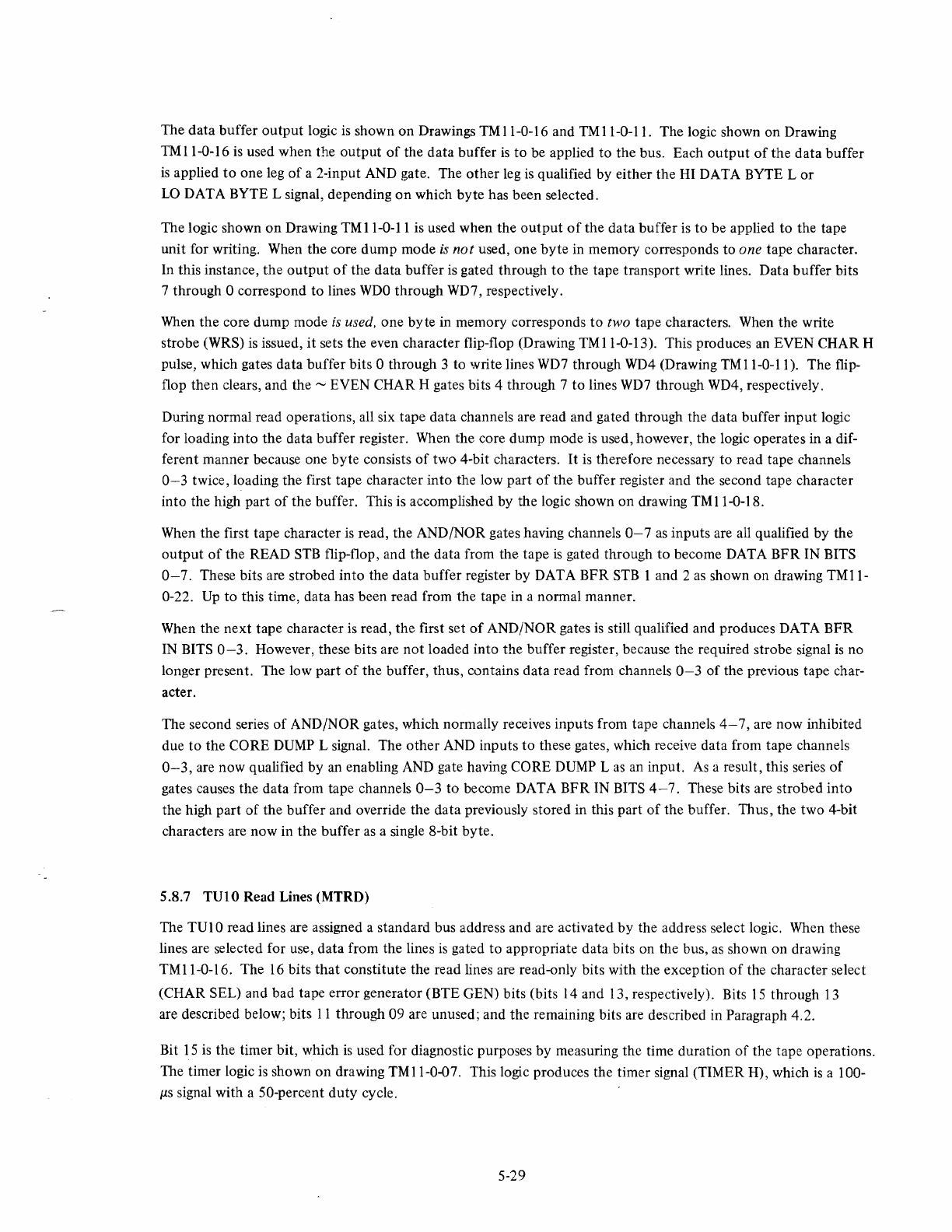
The data buffer
output
logic
is
shown on Drawings
TM
11-0-16 and
TM
11-0-11. The logic shown on Drawing
TM
11-0-16
is
used when the
output
of
the data buffer
is
to be applied
to
the bus. Each
output
of
the data buffer
is
applied
to
one leg
of
a 2-input AND gate. The
other
leg
is
qualified by either the HI DATA BYTE L
or
LO
DATA BYTE L signal, depending
on
which byte has been selected.
The logic shown
on
Drawing TMII-0-11 is used when the
output
of
the data buffer is
to
be applied
to
the tape
unit for writing. When the core dump mode
is
not
used, one
byte
in memory corresponds to one tape character.
In this instance,
the
output
of
the data buffer is gated through
to
the tape transport write lines. Data buffer bits
7 through 0 correspond
to
lines
WDO
through WD7, respectively.
When the core dump mode
is
used, one byte in memory corresponds
to
two tape characters. When the write
strobe (WRS) is issued, it sets the even character flip-flop (Drawing
TM
11-0-13). This produces
an
EVEN CHAR H
pulse, which gates data buffer bits 0 through 3 to write lines
WD7
through
WD4
(Drawing
TM
11-0-11). The flip-
flop then clears, and the""" EVEN CHAR H gates bits 4 through 7
to
lines
WD7
through WD4, respectively.
During normal read operations, all six tape data channels are read and gated through the data buffer
input
logic
for loading into the data buffer register. When the core dump mode
is
used, however, the logic operates in a dif-
ferent manner because one byte consists
of
two 4-bit characters.
It
is
therefore necessary to read tape channels
0-3
twice, loading the first tape character into the low part
of
the buffer register and the second tape character
into the high part
of
the buffer. This is accomplished by the logic shown on drawing
TM
11-0-18.
When the first tape character
is
read, the AND/NOR gates having channels
0-7
as
inputs are
all
qualified by the
output
of
the READ
STB
flip-flop, and the data from the tape
is
gated through
to
become DATA BFR IN BITS
0-7.
These bits are strobed
into
the data buffer register by DATA BFR
STB
1 and 2
as
shown on drawing
TMll-
0-22.
Up
to
this time, data has been read from the tape in a normal manner.
When the
next
tape character is read, the first set
of
AND/NOR gates
is
still qualified and produces DATA
BFR
IN
BITS
0-3.
However, these bits are
not
loaded into the buffer register, because the required strobe signal
is
no
longer present. The low part
of
the buffer, thus, contains data read from channels
0-3
of
the previous tape char-
acter.
The second series
of
AND/NOR gates, which normally receives inputs from tape channels
4-7,
are now inhibited
due
to
the CORE DUMP L signal. The
other
AND inputs
to
these gates, which receive data from tape channels
0-3,
are now qualified by an enabling AND gate having CORE DUMP L
as
an
input.
As
a result, this series
of
gates causes the data from tape channels
0-3
to
become DATA BFR IN BITS
4-7.
These bits are strobed into
the high part
of
the buffer and override the data previously stored in this part
of
the buffer. Thus, the two 4-bit
characters are now in the buffer as a single 8-bit byte.
5.8.7
TUI0
Read Lines (MTRD)
The TUI 0 read lines are assigned a standard bus address and are activated
by
the address select logic. When these
lines are selected for use, data from the lines
is
gated to appropriate data bits on the bus,
as
shown on drawing
TM
11-0-16. The
16
bits
that
constitute the read lines are read-only bits with the exception
of
the character select
(CHAR SEL) and bad tape error generator (BTE GEN) bits (bits 14 and 13, respectively). Bits
15
through
13
are described below; bits
11
through 09 are unused; and the remaining bits are described in Paragraph 4.2.
Bit
15
is
the timer bit, which
is
used for diagnostic purposes by measuring the time duration
of
the tape operations.
The timer logic
is
shown
on
drawing TM11-0-07. This logic produces the timer signal (TIMER H), which
is
a 100-
j1S
signal with a 50-percent
duty
cycle.
5-29

Bit 14
is
the character select bit, which is used
to
select the last character
of
a record
that
is
to
be loaded
into
the
data
buffer. When this
bit
is
loaded with
ai,
the last character loaded
into
the buffer is the LPC character for
both
7-channel and 9-channel tapes. When this
bit
is
loaded with a 0, the last character loaded in the
buffer
is
the
last
data
character for 7-channel tapes
or
the
CRC character for 9-channel tapes.
Bit 13
is
the
bad tape error generator, which
is
used
to
check the bad tape error logic. When loaded with
aI,
this
bit
sets the
CV
READY flip-flop, thereby causing a premature gap
shutdown
period. When this
portion
of
the
tape
is
then
read,
it
produces a bad tape
error
indication.
Bit 12
is
the
gap
shutdown
bit. It is a read-only
bit
and indicates a gap
shutdown
period when
it
is
a
1.
Data on
the
TV
1 0 read lines
is
gated
to
the
bus
by
the logic shown on drawing
TM
11-0-16. When the read lines
are selected for use (SEL 5 IN L), an inverter
output
qualifies
one
leg
of
a series
of
gates. The
other
leg
of
each
gate
is
connected
to
one
of
the
channels in the tape transport. The
output
of
these gates are
then
fed
through
drivers
to
the bus.
5.9
TAPE CONTROL
The TM
11
Controller provides various tape control functions. These functions are:
unit
selection, function con-
trol, ready control, start control, and tape
motion
control. Each
of
these functions
is
described in detail in subse-
quent
paragraphs.
5.9.1 Unit Select
The unit select logic determines the tape unit
to
be used
for
the selected function. Up to eight individual tape
units may be used with a single
TM
11
Controller; however, only
one
tape
unit
may
be selected for program con-
trol
at
any given time.
The
number
of
the tape unit (0 through 7)
to
be selected
is
represented
by
a 3-bit number, generated
by
three
flip-flops (bits 10 through
08)
in
the
command register as shown on drawing TMII-O-12.
The
number
of
the
desired tape unit is loaded
into
the command register from bus
data
lines DIO, D09, and D08.
If
the
command
register has been selected for use (SEL 1 OUT HI),
then
the three unit flip-flops are set
or
cleared,
dependent on
the
bus
input
data. The flip-flop
outputs
are
then
applied
to
a decoder in the master
tape
transport
and
to
the
register read lines.
The
outputs
of
the three flip-flops are also applied 10 three additional flip-flops
that
provide signals for
the
motion
controllogic
(refer
to
Paragraph 5.9.5).
5.9.2
Function
Control
The function control logic specifies the command
to
be performed by the selected tape unit.
Anyone
of
eight
functions can be selected for a given tape unit. A detailed description
of
each
of
these functions is given in Table
5-1.
The
number
of
the function (0 through 7)
to
be selected
is
represented by a 3-bit
number,
generated
by
three
flip-flops (bits 03 through 0
I)
in the command register as shown
on
drawing
TM
11-0-09.
The
number
of
the
desired function
is
loaded
into
the
command register from bus data lines D03, D02, and DOL
If
the
command register has been selected for use (SEL 1 OUT LO),
then
the
three function flip-flops are set
or
cleared, dependent
on
the bus
input
data. The
outputs
of
these flip-flops are applied
to
a binary-to-octal decoder
to
provide
the
necessary function signal.
5-30
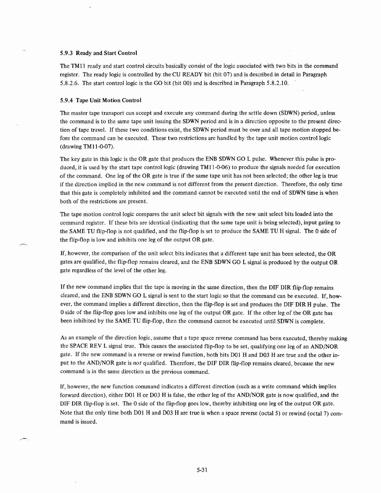
5.9.3 Ready and Start Control
The
TM
11
ready and start control circuits basically consist
of
the logic associated with two bits in the command
register. The ready logic
is
controlled by the
CU
READY bit (bit 07) and
is
described in detail in Paragraph
5.8.2.6. The start control logic
is
the
GO
bit
(bit 00) and is described in Paragraph 5.8.2.10.
5.9.4 Tape Unit Motion Control
The master tape transport can accept and execute any command during the settle down (SDWN) period, unless
the command
is
to the same tape unit issuing the
SDWN
period and
is
in a direction opposite to the present direc-
tion
of
tape travel.
If
these two conditions exist, the
SDWN
period must be over and all tape motion stopped be-
fore the command can be executed. These two restrictions are handled by the tape unit motion control logic
(drawing TMII-0-07).
The key gate in this logic
is
the
OR
gate
that
produces the
ENB
SDWN
GO
L pulse. Whenever this pulse
is
pro-
duced, it
is
used by the start tape control logic (drawing TMI1-0-06) to produce the signals needed for execution
of
the command. One
leg
of
the OR gate
is
true
if
the same tape unit has
not
been selected; the other leg
is
true
if
the direction implied in the new command
is
not different from the present direction. Therefore, the only time
that
this gate
is
completely inhibited and the command cannot be executed until the end
of
SOWN
time
is
when
both
of
the restrictions are present.
The tape motion control logic compares the unit select bit signals with the new unit select bits loaded into the
command register.
If
these bits are identical (indicating that the same tape unit
is
being selected), input gating to
the SAME TU flip-flop
is
not
qualified, and the flip-flop
is
set to produce the SAME TU H signal. The 0 side
of
the flip-flop
is
low and inhibits one
leg
of
the
output
OR gate.
If, however, the comparison
of
the unit select bits indicates
that
a different tape unit has been selected, the OR
gates are qualified, the flip-flop remains cleared, and the
ENB
SOWN
GO L signal is produced by the
output
OR
gate regardless
of
the level
of
the other leg.
If
the new command implies that the tape
is
moving in the same direction, then the DIF DIR flip-flop remains
cleared, and the
ENB
SDWN
GO L signal
is
sent to the start logic
so
that the command can be executed. If, how-
ever, the command implies a different direction, then the flip-flop is set and produces the OIF OIR H pulse. The
o side
of
the flip-flop goes low and inhibits one
leg
of
the
output
OR gate.
If
the other
leg
of
the OR gate has
been inhibited
by
the
SAME
TV
flip-flop, then the command cannot be executed until
SOWN
is
complete.
As
an example
of
the direction logic, assume
that
a tape space reverse command has been executed, thereby making
the SPACE REV L signal true. This causes the associated flip-flop to be set, qualifying one leg
of
an ANO/NOR
gate.
If
the new command is a reverse
or
rewind function,
both
bits
DOl
Hand
D03 H are true and the other in-
put to the AND/NOR gate
is
not qualified. Therefore, the DIF DIR flip-flop remains cleared, because the new
command
is
in the same direction
as
the previous command.
If, however, the new function command indicates a different direction (such
as
a write command which implies
forward direction), either
DOl
H or D03 H
is
false, the other leg
of
the AND/NOR gate
is
now qualified, and the
DIF DIR flip-flop
is
set. The 0 side
of
the flip-flop goes low, there by inhibiting one leg
of
the
output
OR
gate.
Note
that
the only time
both
DOl
Hand
D03 H
aretrue
is
when a space reverse (octal 5) or rewind (octal 7) com-
mand
is
issued.
5-31
5.10 TIMING DIAGRAMS
Timing diagrams
of
various tape operations are shown in Figures 5-7 through 5-14. These diagrams portray spe-
cific tape operations such
as
reading a record
of
three data characters, reading a record
of
two tape characters in
the core dump mode, etc. The purpose
of
these diagrams
is
to illustrate overall
TM
11
operation as described in
previous paragraphs.
SEL
2
OUT
LO
H
000
H
GO
BIT
H
GO
STROBE
1 H
GO
STROBE
2 H
-+
______
-+
......
SET
+-
_______
---'
SELR L
+-
_____
..
_
..
....;
..
~
____
_+~------------
r-
--
-----
-
--------
ILC H
__
~
__________
~
__
~
__________
___
CU
READY
H
CUR
DEL
H
________________
--.;~
11-0382
Figure 5-7
Start
of
Tape Operation
CU
READY H I
~
LPC H
________
-1'
J~--__I,.I_I
___
..."n
....
___
__I
...
I-
d
___
-'~L..
________
_
SOW
N H
--------II_--++"
'--_---JI--
____
..... n
....
__
-"u/
_________
-'nL...-
__
_
GO~I---_+--'L..---II--------'n
....
--~ind/~------------
MTBRC
____
~7~7~7~77~5~-~~--~7~7~7~77~6~---L--~7~7~7~7~77~-
__
~
___
~OO~O~O~O~O
__
"-0385
Figure 5-8 Spacing Forward Three Records
5-32
CU
READY
H
LPS
H
SOWN
H
GO
H
MTBRC
~
~
Figure
5-9
Spacing Reverse Three Records
CU
READY H
LPC H
------f
SOWN H
GO
H
BTE
MTBRC
ERR H
----..,;'~----+-'
-----~/~-~~-------
Figure 5-10 Spacing Forward Three Records, Bad Tape Error
Appearing in First Record
5-33
11-0387
11-0386
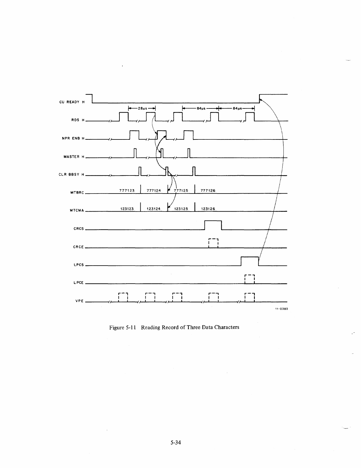
CU
READY
H
1--28JJS--j
RDS
H-----I/~
NPR
ENB
H
____
-I,~
MASTER
H
____
-Ij~
C
l.
R
BB
S Y H
_______
;()'/~
____
_
MTBRC
__________
7_7_7
__
12_3
__
~
_____
_L_~---~--7-7-7-1-2-6------------
______
-+
__
MTCMA
_______
~1~23~12~3
__
~_~~
__
_L_~~~~_'~2~3~1~2~6
____________
~~
__
_
CRCS
_____________________________________
~
,...-,
I I
CRCE
_____________________________________
~
__
~
______________
~--------
LPCS
_________________________________________
~
r-"
I I
LPCE
_______________________________________________________
~,
__
~I
__________
__
r-,
r-,
r--,
r--,
,.-,
I I I I I I I I I I
;'/
I I
//
I I
//
I
VPE
______
-I~-~~~~~~~--~{~~~~---~I,i~'-I~~I---_{')I~_~I
_______
__
1'-0383
Figure
5-11
Reading Record
of
Three Data Characters
5-34
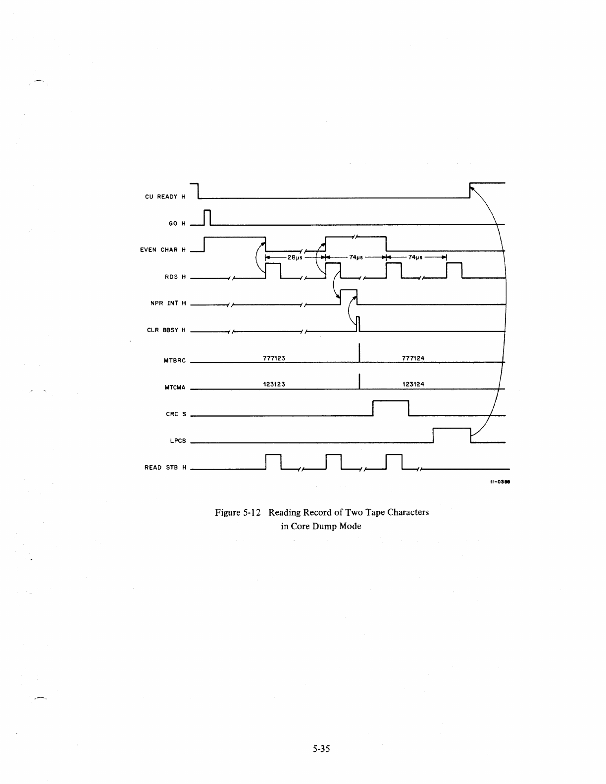
CU
READY
H
GO
H
EVEN
CHAR
H
RDS
H
-----1//
NPR
INT
H
-----1/
,I_'
______
--I~--.....J
CLR
BBSY
H
-----I/,I-'--------Ir-----~I---------------~
MTBRC
777123 777124
MTCMA
_________
1_2_3_12_3
________
~_~--1-2~3-12-4---------+_
CRe
S
_________________________
~
LPCS
__________________________
-------------------~
READ
STB
H
------------~~JLI_/-----------
Figure 5-12 Reading Record
of
Two Tape Characters
in Core Dump Mode
5-35
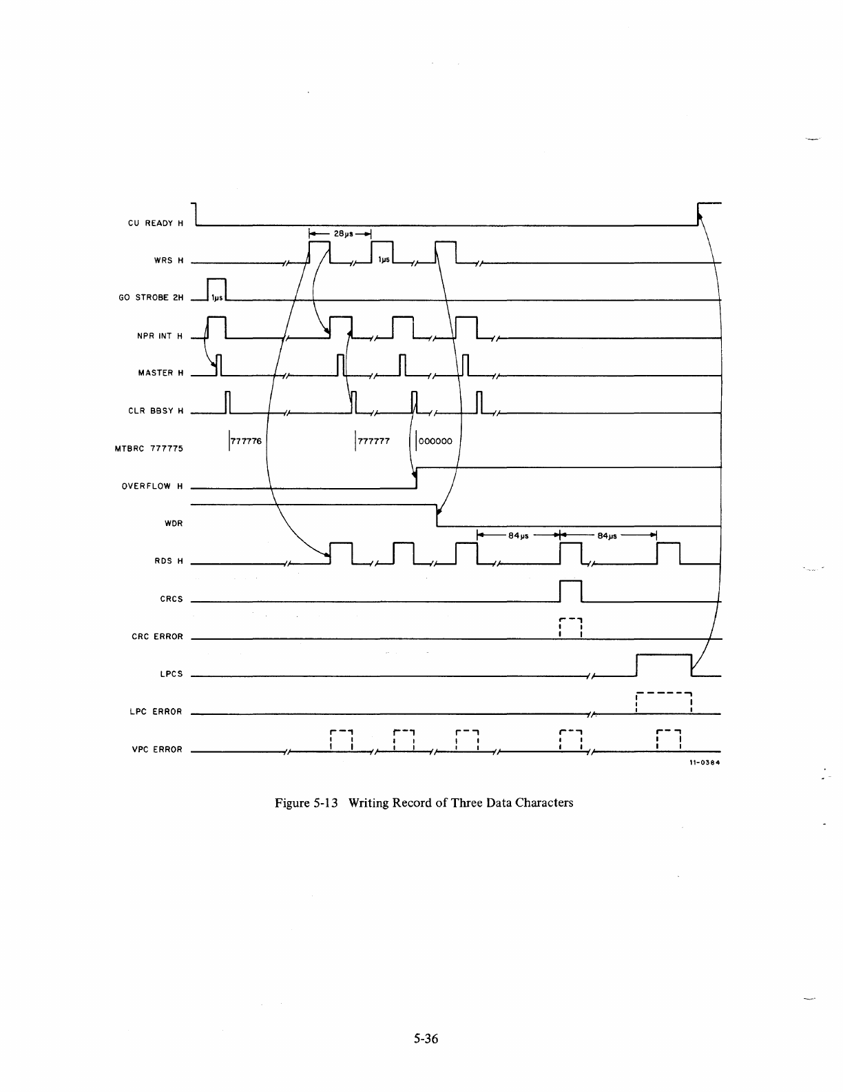
CU
READY H
WRS H
GO
STROBE
2H
NPR INT H
MASTER
H
CLR
BBSY
H
MTBRC
777775
OVERFLOW
H
WDR
RDS
H
CRCS
CRC
ERROR
LPCS
LPC
ERROR
VPC
ERROR
,--.,
,-,
I I
,/
I I
//
//
r-,
, I
I I
/;
r-
-,
I I
I I
,-..,
I
)J.
I
1/
Figure 5-13 Writing Record
of
Three Data Characters
5-36
-----...,
: I
I I
,--
..,
I I
I I
11-0384
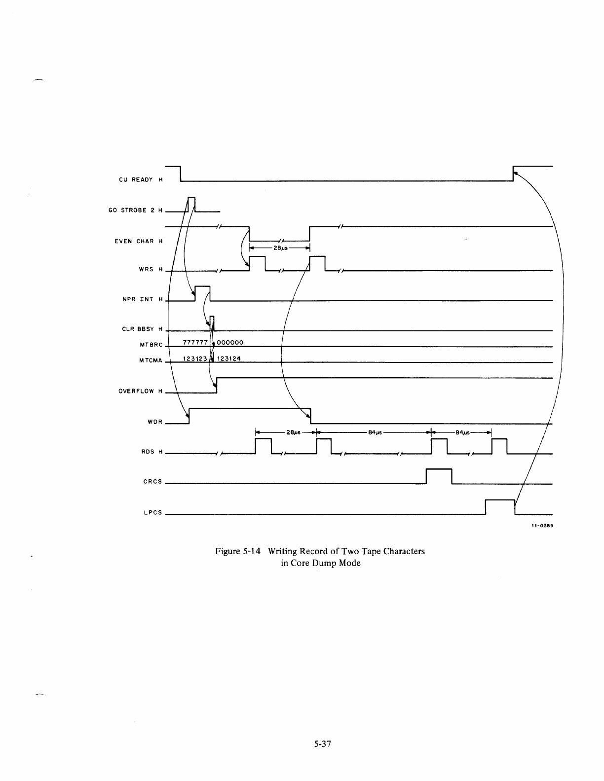
CU
READY
H
GO
STROBE
2 H
EVEN
CHAR
H
1-----28
••
------l
.
~
~'
WRS
H-+
__
~----~
~~(~--------------------------------------------
NPR
INT
H
+-
__ ---'
CLR
BBSY
H+-
______
~I~~------------~----------------------------------------------------------
MTBRC~
__
~~~~~~~
______
-+
________________________________________________________
__
MTCMA~
__
~~~~1~23~1~2~4~
______
~
________________________________________________________
__
OVERFLOW
H
_~
___
-'
WDR
I----
2BlJs-
........
f·--------
64
j.1s
-----
......
I·....--84IJ
s
---l
RDSH------fl~~/
/~
CRCS
_______________________________
~
LPCS
________________________________________________
~
Figure 5-14 Writing
Record
of
Two
Tape Characters
in Core
Dump
Mode
5-37
"-0389
6.1 INTRODUCfION
CHAPTER
6
MODULE
DESCRIPTION
This chapter provides infonnation on the logic modules used in the
TM
1 I DECmagtape Controller. The position
of
the modules within the mounting
box
is shown on Drawing TMll-O-02.
A list
of
all
TMll
Controller modules is presented in Table 6-1. This table lists the modules in numerical order,
the
quantity
of
each type used in the system, and the name
of
the module. The last column indicates the DEC
document containing the detailed description
of
that
particular module.
Note
that
it
is beyond the scope
of
this manual
to
provide information
on
any
of
the modules used in
the
Master
Tape Transport logic.
6.2 DEC LOGIC
Except for cable and
jumper
modules,
all
of
the modules used in the
TM
11
Controller are M-Series logic modules.
The M-Series are high-speed, monolithic integrated circuit modules, employing TTL logic (transistor-transistor
logic). These circuits provide high speed, high fanout, large capacitance drive capability, and excellent noise
margins.
A general description
of
DEC logic and detailed circuit descriptions
of
TTL logic gates is provided in the 1971
DEC Logic Handbook. The symbology used with all PDP-II logic drawings is shown and explained in the PDP-11
Conventions Manual, DEC-ll-HR6B-D.
6.3 MEASUREMENT DEFINITIONS
Timing
is
measured with the input driven by a gated pulse amplifier
of
the series under test and with
the
output
loaded with gates
of
the same series. Percentages are assigned
as
follows: 0 percent is the initial steady-state level,
100 percent
is
the final steady-state level, regardless
of
the
direction
of
change.
Input/output
delay is the time difference between
input
change and
output
change, measured from 50 percent
input change
to
50 percent
output
change. Rise and fall delays for the same module are usually specified sepa-
rately. Rise time and fall time
is
measured from
10
percent to
90
percent
of
waveform change, rising
or
falling.
6.4 LOADING
Input loading and
output
driving are specified in unit loads, where one unit load
is
1.6 rnA
by
definition. The
inputs to low-speed gates usually draw one unit load. High-speed gates draw 1-1/4 unit loads,
or
2 rnA.
6-1
Module Number Quantity Used
MIOS
I
MIll
6
MIl2
3
MII3
6
MllS
2
MII7
I
MI21 2
MI27 3
MI49
4
MI63 I
M203 I
M20S 2
M216 S
M239 I
M304 2
M307 1
M627 3
G736 1
M7821 I
M784 1
M78S 1
M79S 2
M796 1
M797 1
M798 1
REFERENCES
Table
6-1
Module Utilization
Address Selector
Inverter
NOR Gate
Title
Ten 2-input NAND Gates
Eight 3-input NAND Gates
Six 4-input NAND Gates
AND/NOR Gate
2-2-2-3 AND/NOR Gate
9x2 NAND Wired
OR
Matrix
Dual Binary-to-Octal Decoder
Eight Reset/Set Flip-Flops
Five
"D"
Flip-Flops
Six Flip-Flops
Three 4-bit Counter Registers
Four
One-Shot Delays
Integrating One-Shot
NAND Power Amplifier
Jumper Module
Interrupt Control
Unibus Receiver
Unibus Transceiver
Word Count and Bus Address Register
Unibus Master Control
Register Selection
Unibus Drivers
1.
Chapter 3
of
Unibus Interface Manual, Second Edition, DEC-II-HIAB-D.
2.
DEC Logic Handbook, 1971 Edition.
6-2
Reference
1
2
2
2
2
2
2
-
-
-
2
-
-
-
-
-
2
1
1
1
1
1
1
1
1
APPENDIX
A
MASTER
TAPE
TRANSPORT
SIGNALS
A.l
SIGNALS FROM MASTER TO
TMll
CONTROLLER
Mnemonic
RDO
-RD7
RDP
SDWN
TUR
SELR
RWS
7CH
WRL
BOT
EOT
WRS
RDS
FMK
CRCS
LRCS
VPE
LReE
Name
Read data signals
Read parity bit
Tape settle down. This
is
the time between a stop command and the time
when the unit actually stops.
Tape unit ready. This signal
is
true when the selected tape unit
is
stopped,
and SELR
is
true.
Select remote. This
is
true when unit
is
selected and
is
on-line.
Rewind status. This
is
true when selected unit
is
rewinding.
7-channel. True during 7-channel operation.
Write lock. Prevents writing on tape.
Beginning
of
tape
End
of
tape
Write strobe. Requests a character for writing.
Read strobe. Present for both read and write operations.
File mark
CRC strobe. Appears with CRC character.
LRC strobe. Appears with
LPC
character.
Vertical parity check error. Sampled with RDS.
Longitudinal parity check error. Sampled with LPCS.
A-I

A.2 SIGNALS
FROM
TM
11
CONTROLLER
TO MASTER
Mnemonic
WDO
-
WD7
SET
FWD
REV
RWD
WRE
PEVN
DEN 8
DEN 5
WFMK
WXG
~~~~}
SEL 2
WDR
CINIT
Name
Write data lines
Required
to
start any tape operation (derivative
of
GO command).
Tape forward
Tape reverse
Tape rewind
Write enable
Even parity
Density bit -true for 800 bpi, 7-channel
true for 800 bpi, 9-channel
false for 200 bpi, 7-channel
false for 556 bpi, 7-channel
Density bit -true for 556 bpi, 7-channel
true for 800 bpi, 9-channel
false for 200 bpi, 7-channel
false for 800 bpi, 7-channel
Write file mark
Write-extended-IRG gap. True for
both
write-extended-IRG and
WFMK
functions.
Tape unit select
Write data ready
Initialize
A-2

READER'S COMMENTS
TM11DECMAGTAPESYSTEM
DEC-II-HTMAA-D-D
Your
comments
and
suggestions will help us in
our
continuous
effort
to
improve
the
quality and usefulness
of
our
publications.
What
is
your
general reaction
to
this manual? In
your
judgment
is
it
complete, accurate, well organized, well
written, etc.?
Is
it easy to use?
What features are most useful?
--------------------------------------
What faults
do
you
find with the manual?
Does this manual satisfy the need
you
think
it was
intended
to
satisfy?
Does it satisfy
your
needs?
__________
_ Why?
________________________
_
Would
you
please indicate any factual errors
you
have found.
Please describe
your
position.
Name
___________________
Organiza tion
Street
__________________
Departmen t
City
____________
_ State
______________
_ Zip
or
Country
