TM1591
User Manual: TM1591
Open the PDF directly: View PDF ![]() .
.
Page Count: 566 [warning: Documents this large are best viewed by clicking the View PDF Link!]
- TM1591 322 - 430 Lawn & Garden Tractors
- INTRODUCTION
- CONTENTS
- Section 10 - GENERAL INFORMATION
- Safety
- RECOGNIZE SAFETY INFORMATION
- UNDERSTAND SIGNAL WORDS
- FOLLOW SAFETY INSTRUCTIONS
- HANDLE FLUIDS SAFELY—AVOID FIRES
- PREVENT BATTERY EXPLOSIONS
- PREPARE FOR EMERGENCIES
- PREVENT ACID BURNS
- SERVICE COOLING SYSTEM SAFELY
- HANDLE CHEMICAL PRODUCTS SAFELY
- AVOID HIGH-PRESSURE FLUIDS
- PREPARE MACHINE FOR REPAIR
- SUPPORT MACHINE PROPERLY
- WEAR PROTECTIVE CLOTHING
- WORK IN CLEAN AREA
- SERVICE MACHINES SAFELY
- WORK IN VENTILATED AREA
- ILLUMINATE WORK AREA SAFELY
- REPLACE SAFETY SIGNS
- USE PROPER LIFTING EQUIPMENT
- REMOVE PAINT BEFORE WELDING OR HEATING
- AVOID HEATING NEAR PRESSURIZED FLUID LINES
- SERVICE TIRES SAFELY
- AVOID HARMFUL ASBESTOS DUST
- PRACTICE SAFE MAINTENANCE
- USE PROPER TOOLS
- DISPOSE OF WASTE PROPERLY
- LIVE WITH SAFETY
- General Specifications
- Repair Specifications
- REPAIR SPECIFICATIONS
- METRIC BOLT AND CAP SCREW TORQUE VALUES
- UNIFIED INCH BOLT AND CAP SCREW TORQUE VALUES
- METRIC CAP SCREW TORQUE VALUES—GRADE 7
- SERVICE RECOMMENDATIONS FOR O-RING BOSS FITTINGS
- SERVICE RECOMMENDATIONS FOR FLAT FACE O-RING SEAL FITTINGS
- TUBE AND HOSE FITTING, 37˚ FLARE AND 30˚ CONE SEAT CONNECTOR SERVICE RECOMMENDATIONS
- Test and Adjustment Specifications
- Fuels and Lubricants
- FUEL—322
- DIESEL FUEL—330, 332 AND 430
- STORING FUEL
- DO NOT USE GALVANIZED CONTAINERS
- ENGINE OIL—322
- DIESEL ENGINE OIL—330, 332 AND 430
- ENGINE COOLANT
- LIQUID COOLANT CONDITIONER
- TRANSMISSION AND HYDRAULIC OIL
- GREASE
- MOWER DECK GEAR CASE OIL
- ALTERNATIVE AND SYNTHETIC LUBRICANTS
- LUBRICANT STORAGE
- MIXING OF LUBRICANTS
- Serial Number Locations
- Safety
- Section 20 - ENGINE REPAIR
- Section 40 - ELECTRICAL REPAIR
- Section 50 - POWER TRAIN REPAIR
- Transmission
- SERVICE PARTS KITS
- REMOVE AND INSTALL CHARGE PUMP
- DISASSEMBLE AND INSPECT CHARGE PUMP
- ASSEMBLE CHARGE PUMP
- REMOVE AND INSTALL CHARGE RELIEF VALVE
- REMOVE AND INSTALL IMPLEMENT RELIEF VALVE
- REMOVE TRANSMISSION
- DISASSEMBLE TRANSMISSION COVER
- DISASSEMBLE PUMP AND MOTOR
- DISASSEMBLE PUMP AND MOTOR HOUSING
- ASSEMBLE PUMP AND MOTOR HOUSING
- ASSEMBLE PUMP AND MOTOR
- ASSEMBLE TRANSMISSION COVER
- INSTALL TRANSMISSION
- Transmission Control Linkage
- INSPECT AND REPAIR TRANSMISSION CONTROL LINKAGE—330
- INSPECT AND REPAIR TRANSMISSION CONTROL LINKAGE—VERSION ONE (322 AND 332)
- INSPECT AND REPAIR TRANSMISSION CONTROL LINKAGE—VERSION ONE (430)
- INSPECT AND REPAIR TRANSMISSION CONTROL LINKAGE—VERSION TWO (ALL)
- INSPECT AND REPAIR TRANSMISSION CONTROL LINKAGE—VERSION THREE (ALL)
- INSPECT AND REPAIR DIFFERENTIAL LOCK AND TWO-SPEED CONTROL LINKAGE (430)
- Differential
- Rear Axles
- Drive Shaft¯322, 330 and 332
- Drive Shaft¯430
- Transmission
- Section 60 - STEERING AND BRAKE REPAIR
- Section 70 - HYDRAULIC REPAIR
- Hydraulic Control Valve
- SERVICE PARTS KITS
- REMOVE AND INSTALL HYDRAULIC CONTROL VALVE—322 AND 332
- REMOVE AND INSTALL HYDRAULIC CONTROL VALVE—330
- REMOVE AND INSTALL HYDRAULIC CONTROL VALVE—430
- DISASSEMBLE, INSPECT AND ASSEMBLE HYDRAULIC CONTROL VALVE—SINGLE-SPOOL
- DISASSEMBLE, INSPECT AND ASSEMBLE HYDRAULIC CONTROL VALVE—TWO-SPOOL
- DISASSEMBLE, INSPECT AND ASSEMBLE HYDRAULIC CONTROL VALVE—THREE-SPOOL
- Hydraulic Control Valve
- Section 80 - MISCELLANEOUS REPAIR
- Front Axle
- SPECIAL OR ESSENTIAL TOOLS
- REMOVE AND INSTALL FRONT AXLE—322, 330 AND 332
- INSPECT AND REPLACE PIVOT BUSHINGS—322, 330 AND 332
- REMOVE FRONT AXLE—430
- DISASSEMBLE AND INSPECT PIVOT PIN—430
- ASSEMBLE PIVOT PIN—430
- INSTALL FRONT AXLE—430
- REMOVE AND INSTALL SPINDLES
- INSPECT AND REPLACE SPINDLE BUSHINGS
- INSPECT AND REPLACE WHEEL BEARINGS
- ADJUST TOE-IN
- Mower Spindle and Jack Sheave Repair
- Mower Gear Case Repair
- DISASSEMBLE AND INSPECT MOWER GEAR CASE—50-INCH MOWER
- ASSEMBLE MOWER GEAR CASE—50-INCH MOWER
- DISASSEMBLE AND INSPECT MOWER GEAR CASE—EARLY 60-INCH MOWER (CURTIS)
- ASSEMBLE MOWER GEAR CASE—EARLY 60-INCH MOWER (CURTIS)
- DISASSEMBLE AND INSPECT MOWER GEAR CASE—LATER 60-INCH MOWER (PEERLESS)
- ASSEMBLE MOWER GEAR CASE—LATER 60-INCH MOWER (PEERLESS)
- DISASSEMBLE AND INSPECT MOWER GEAR CASE—260 ROTARY MOWER
- ASSEMBLE MOWER GEAR CASE—260 ROTARY MOWER
- Front Axle
- Section 220 - ENGINE, FUEL AND AIR SYSTEM CHECKOUT AND DIAGNOSIS
- Section 240 - ELECTRICAL SYSTEM CHECKOUT, OPERATION AND DIAGNOSIS
- Electrical System Checkout
- Electrical Schematics
- ELECTRICAL SCHEMATIC INFORMATION
- MAIN ELECTRICAL SCHEMATIC LEGEND—322
- MAIN ELECTRICAL SCHEMATIC—322
- MAIN ELECTRICAL SCHEMATIC—330
- MAIN ELECTRICAL SCHEMATIC LEGEND—330
- MAIN ELECTRICAL SCHEMATIC LEGEND—332 (S.N. —475000)
- MAIN ELECTRICAL SCHEMATIC—332 (S.N. —475000)
- MAIN ELECTRICAL SCHEMATIC—332 (S.N. 475001— )
- MAIN ELECTRICAL SCHEMATIC LEGEND—332 (S.N. 475001— )
- MAIN ELECTRICAL SCHEMATIC LEGEND—430 (S.N. —420468)
- MAIN ELECTRICAL SCHEMATIC—430 (S.N. —420468)
- MAIN ELECTRICAL SCHEMATIC—430 (S.N. 420469— )
- MAIN ELECTRICAL SCHEMATIC LEGEND—430 (S.N. 420469— )
- LIGHT CIRCUIT SCHEMATIC—ALL MACHINES
- Component Location and Operation
- ABOUT THIS GROUP
- GLOW PLUG CONTROL MODULE—330 AND 332
- GLOW PLUG CONTROL MODULE—430
- TIME DELAY CONTROL (TDC) MODULE AND NEUTRAL START RELAY—322, 330 AND 332
- TIME DELAY CONTROL (TDC) MODULE AND NEUTRAL START RELAY—430
- TDC EIGHT-PIN AND TWO-PIN CONNECTORS—322 AND 330
- TDC EIGHT-PIN AND TWO-PIN CONNECTORS—430 (S.N. —420468)
- TDC SIX-PIN AND THREE-PIN CONNECTORS—332
- TDC SIX-PIN AND THREE-PIN CONNECTORS—430 (S.N. 420469— )
- ENGINE OIL PRESSURE SWITCH
- ENGINE COOLANT TEMPERATURE SWITCH
- TRANSMISSION NEUTRAL START SWITCH
- FUEL TRANSFER PUMP—322, 330 AND 332
- FUEL TRANSFER PUMP—430
- FUEL SHUTOFF SOLENOID—322
- FUEL SHUTOFF SOLENOID—332 AND 430
- WATER-IN-FUEL SENSOR (430)
- VOLTAGE REGULATOR/RECTIFIER (322, 330 AND 332)
- TRANSISTOR MODULE (322)
- IGNITION AND PULSAR COILS (322)
- STARTING CIRCUIT OPERATION
- IGNITION AND FUEL SHUTOFF SOLENOID CIRCUIT OPERATION (322)
- IGNITION AND FUEL SHUTOFF SOLENOID CIRCUIT OPERATION (322)—CONTINUED
- PTO CIRCUIT OPERATION—322, 330 AND 430 (S.N. —420468)
- PTO CIRCUIT OPERATION—322, 330 AND 430 (S.N. —420468) (CONTINUED)
- PTO CIRCUIT OPERATION—332 AND 430 (S.N. 420469— )
- PTO CIRCUIT OPERATION—332 AND 430 (S.N. 420469— ) (CONTINUED)
- CHARGING CIRUIT OPERATION—322, 330 AND 332
- CHARGING CIRUIT OPERATION—430
- FUEL SHUTOFF SOLENOID CIRCUIT OPERATION—430 (S.N. —420468)
- FUEL SHUTOFF SOLENOID CIRCUIT OPERATION—332 AND 430 (S.N. 420469— )
- ENGINE PREHEAT CIRCUIT OPERATION (330, 332 AND 430)
- WATER-IN-FUEL CIRCUIT OPERATION (430)
- LOW FUEL LEVEL CIRCUIT OPERATION (322, 332 AND 430)
- Electrical System Diagnosis
- Electrical System Component Tests and Adjustments
- Section 250 - POWER TRAIN CHECKOUT, OPERATION AND DIAGNOSIS
- Section 260 - STEERING AND BRAKES CHECKOUT, OPERATION AND DIAGNOSIS
- Section 270 - HYDRAULIC SYSTEM CHECKOUT, OPERATION AND DIAGNOSIS
- Section 299 - DEALER FABRICATED TOOLS
- Index
322, 330,
332 and 430
Lawn and Garden
Tractors
For complete service information also see:
Yanmar Gasoline Engines. . . . . . . . . . . . . CTM12
John Deere Series 220 Diesel Engines . . . CTM3
John Deere Horicon Works
TM1591 (15JUL95)
LITHO IN U.S.A.
ENGLISH

FOREWORD
This manual is written for an experienced technician.
Essential tools required in performing certain service
work are identified in this manual and are
recommended for use.
Live with safety: Read the safety messages in the
introduction of this manual and the cautions
presented throughout the text of the manual.
NThis is the safety-alert symbol. When you see
this symbol on the machine or in this manual,
be alert to the potential for personal injury.
Technical manuals are divided in two parts: repair
and diagnostics. Repair sections tell how to repair the
components. Diagnostic sections help you identify the
majority of routine failures quickly.
Information is organized in groups for the various
components requiring service instruction. At the
beginning of each group are summary listings of all
applicable essential tools, other materials needed to
do the job and service parts kits.
Section 10, Group 15—Repair Specifications, consist
of all applicable specifications, near tolerances and
specific torque values for various components on
each individual machine.
Section 10, Group 20—Test and Adjustment
Specifications, consist of all applicable test and
adjustment specifications for various systems for each
individual machine.
Binders, binder labels, and tab sets can be ordered
by John Deere dealers direct from the John Deere
Distribution Service Center.
This manual is part of a total product support
program.
FOS MANUALS—REFERENCE
TECHNICAL MANUALS—MACHINE SERVICE
COMPONENT MANUALS—COMPONENT SERVICE
Fundamentals of Service (FOS) Manuals cover basic
theory of operation, fundamentals of troubleshooting,
general maintenance, and basic type of failures and
their causes. FOS Manuals are for training new
personnel and for reference by experienced
technicians.
Technical Manuals are concise guides for specific
machines. Technical manuals are on-the-job guides
containing only the vital information needed for
diagnosis, analysis, testing, and repair.
Component Technical Manuals are concise service
guides for specific components. Component technical
manuals are written as stand-alone manuals covering
multiple machine applications.
MX,1590,IFC -19-09DEC94
Introduction
TM1591 (15JUL95) 322,330,332 & 430 Lawn & Garden Tractors
030895

SECTION 10—GENERAL INFORMATION
Group 05—Safety
Group 10—General Specifications
Group 15—Repair Specifications
Group 20—Test and Adjustment Specifications
Group 25—Fuels and Lubricants
Group 30—Serial Number Locations
SECTION 20—ENGINE REPAIR
Group 05—Engine—322
Group 06—Engine—330, 332 and 430
SECTION 40—ELECTRICAL REPAIR
Group 05—Front PTO Clutch
SECTION 50—POWER TRAIN REPAIR
Group 05—Transmission
Group 10—Transmission Control Linkage
Group 15—Differential
Group 20—Rear Axles
Group 25—Drive Shaft—322, 330 and 332
Group 26—Drive Shaft—430
SECTION 60—STEERING AND BRAKE REPAIR
Group 05—Steering—330
Group 06—Steering—322, 332 and 430
Group 10—Brakes
SECTION 70—HYDRAULIC REPAIR
Group 05—Hydraulic Control Valve
SECTION 80—MISCELLANEOUS REPAIR
Group 05—Front Axle
Group 10—Mower Spindle and Jack Sheave
Repair
Group 15—Mower Gear Case Repair
SECTION 220—ENGINE, FUEL AND AIR SYSTEM
CHECKOUT AND DIAGNOSIS
Group 05—Engine, Fuel and Air System
Checkout
Group 10—Diagnosis, Tests and
Adjustments—322
Group 11—Diagnosis, Tests and
Adjustments—330, 332 and 430
SECTION 240—ELECTRICAL SYSTEM
CHECKOUT, OPERATION AND
DIAGNOSIS
Group 05—Electrical System Checkout
Group 10—Electrical Schematics
Group 15—Component Location and Operation
Group 20—Electrical System Diagnosis
Group 25—Electrical System Component Tests
and Adjustments
SECTION 250—POWER TRAIN CHECKOUT,
OPERATION AND DIAGNOSIS
Group 05—Power Train Checkout
Group 10—Theory of Operation
Group 15—Diagnosis, Tests and Adjustments
SECTION 260—STEERING AND BRAKES
CHECKOUT, OPERATION AND
DIAGNOSIS
Group 05—Steering And Brakes System
Checkout
Group 10—Theory of Operation
Group 15—Diagnosis, Tests and Adjustments
SECTION 270—HYDRAULIC SYSTEM
CHECKOUT, OPERATION AND
DIAGNOSIS
Group 05—Hydraulic System Checkout
Group 10—Hydraulic Schematics
Group 15—Theory of Operation
Group 20—Diagnosis, Tests and Adjustments
SECTION 299—DEALER FABRICATED TOOLS
Group 00—Dealer Fabricated Tools
Index
COPYRIGHT© 1995
DEERE & COMPANY
Moline, Illinois
All rights reserved
A John Deere ILLUSTRUCTION™ Manual
All information, illustrations and specifications in this manual are based on
the latest information available at the time of publication. The right is
reserved to make changes at any time without notice.
TM1591-19-15JUL95
Contents
TM1591 (15JUL95) i322,330,332 & 430 Lawn & Garden Tractors
030895
10
20
40
50
60
70
80
220
240
250

Contents
TM1591 (15JUL95) ii 322,330,332 & 430 Lawn & Garden Tractors
030895
10
20
40
50
60
70
80
220
240
250

Contents
TM1591 (15JUL95) iii 322,330,332 & 430 Lawn & Garden Tractors
030895
260
270
299
INDX

Contents
TM1591 (15JUL95) iv 322,330,332 & 430 Lawn & Garden Tractors
030895
260
270
299
INDX

JOHN DEERE DEALERS
IMPORTANT: Please remove this page and route
through your service department.
This is a complete revision for models 322, 330, 332 and
430 found in TM1277, TM1309 and TM1345. The
complete revision of remaining machines (316, 318 and
420) can be found in TM1590. AFTER recieving both
TM1590 and TM1591, please discard old TM1277 dated
December 1987, TM1309 dated July 1985 and TM1345
dated June 1986.
NOTE: There are several “versions” of each model
tractor. All versions were not availble at time of
latest printing. Some versions may not be
covered.
MX,1591,DLR -19-13JUL95
Dealer Presentation Sheet
TM1591 (15JUL95) 322,330,332 & 430 Lawn & Garden Tractors
030895

Dealer Presentation Sheet
TM1591 (15JUL95) 322,330,332 & 430 Lawn & Garden Tractors
030895

Section 10
GENERAL INFORMATION
Contents
Page
Group 05—Safety . . . . . . . . . . . . . . . . 10-05-1
Group 10—General Specifications
Machine Specifications
322 and 330 . . . . . . . . . . . . . . . . . . 10-10-1
332 and 430 . . . . . . . . . . . . . . . . . . 10-10-4
Group 15—Repair Specifications
Repair Specifications . . . . . . . . . . . . . . 10-15-1
Metric Series Torque Chart . . . . . . . . . . 10-15-4
Inch Series Torque Chart . . . . . . . . . . . 10-15-5
Metric Torque Values—Grade 7 . . . . . . . 10-15-6
Set Screw Torque Chart . . . . . . . . . . . . 10-15-6
Service Recommendations
Flat Face O-Ring Seal Fittings . . . . . . 10-15-8
Tube and Hose Fitting, 37˚ Flare and
30˚ Cone Seat Connectors . . . . . . . 10-15-9
Group 20—Test and Adjustment
Specifications . . . . . . . . . . 10-20-1
Group 25—Fuels and Lubricants
Fuel—322 . . . . . . . . . . . . . . . . . . . . . . 10-25-1
Diesel Fuel—330, 332 and 430 . . . . . . . 10-25-2
Storing Fuel . . . . . . . . . . . . . . . . . . . . 10-25-3
Do Not Use Galvanized Containers . . . . . 10-25-3
Engine Oil—322 . . . . . . . . . . . . . . . . . 10-25-4
Diesel Engine Oil—330, 332 and 430 . . . 10-25-5
Engine Coolant . . . . . . . . . . . . . . . . . . 10-25-6
Liquid Coolant Conditioner . . . . . . . . . . . 10-25-6
Transmission and Hydraulic Oil . . . . . . . 10-25-7
Grease . . . . . . . . . . . . . . . . . . . . . . . . 10-25-8
Mower Deck Gear Case Oil . . . . . . . . . . 10-25-8
Alternative and Synthetic Lubricants . . . . 10-25-9
Lubricant Storage . . . . . . . . . . . . . . . . . 10-25-9
Mixing of Lubricants . . . . . . . . . . . . . . . 10-25-9
Group 30—Serial Number Locations
Serial Numbers
Product Identification . . . . . . . . . . . . . 10-30-1
Engine . . . . . . . . . . . . . . . . . . . . . . 10-30-1
Transmission . . . . . . . . . . . . . . . . . . 10-30-1
Differential . . . . . . . . . . . . . . . . . . . . 10-30-2
Control Valve . . . . . . . . . . . . . . . . . . 10-30-2
TM1591 (15JUL95) 10-1 322,330,332 & 430 Lawn & Garden Tractors
030895
10

Contents
TM1591 (15JUL95) 10-2 322,330,332 & 430 Lawn & Garden Tractors
030895
10
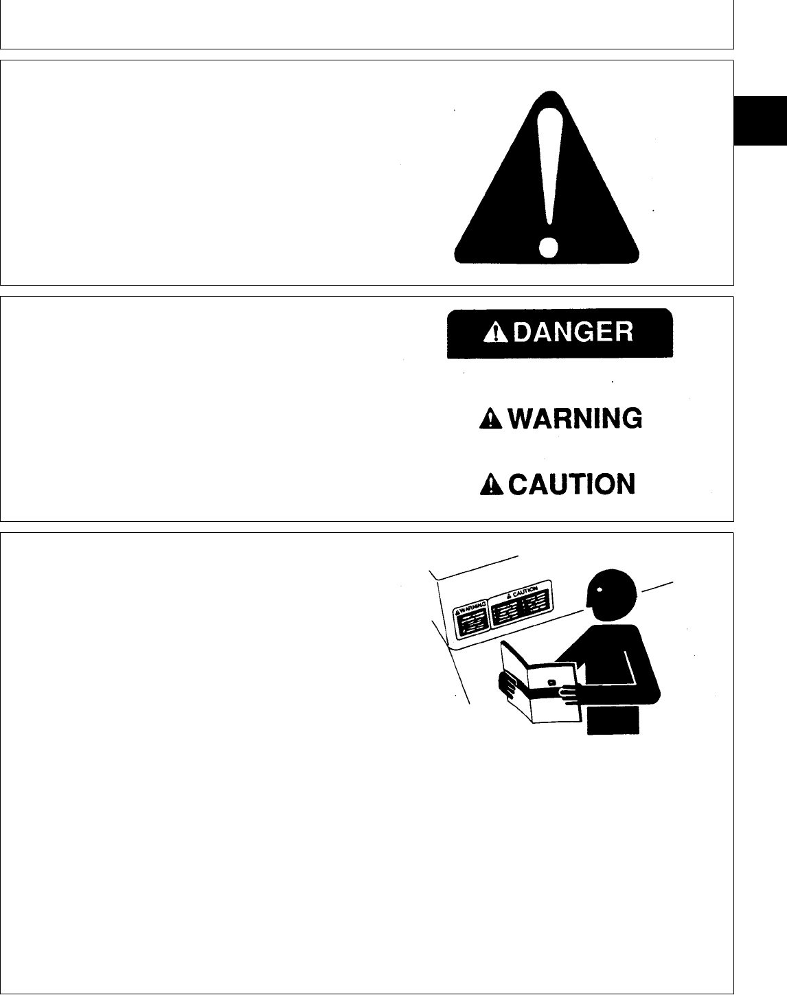
RECOGNIZE SAFETY INFORMATION
This is the safety-alert symbol. When you see this
symbol on your machine or in this manual, be alert to
the potential for personal injury.
Follow recommended precautions and safe operating
practices.
T81389 -UN-07DEC88
UNDERSTAND SIGNAL WORDS
A signal word—DANGER, WARNING, or CAUTION—is
used with the safety-alert symbol. DANGER identifies the
most serious hazards.
DANGER or WARNING safety signs are located near
specific hazards. General precautions are listed on
CAUTION safety signs. CAUTION also calls attention to
safety messages in this manual.
TS187 -19-30SEP88
FOLLOW SAFETY INSTRUCTIONS
Carefully read all safety messages in this manual and on
your machine safety signs. Keep safety signs in good
condition. Replace missing or damaged safety signs. Be
sure new equipment components and repair parts include
the current safety signs. Replacement safety signs are
available from your John Deere dealer.
Learn how to operate the machine and how to use
controls properly. Do not let anyone operate without
instruction.
Keep your machine in proper working condition.
Unauthorized modifications to the machine may impair
the function and/or safety and affect machine life.
If you do not understand any part of this manual and
need assistance, contact your John Deere dealer.
TS201 -UN-23AUG88
DX,ALERT -19-03MAR93
DX,SIGNAL -19-03MAR93
DX,READ -19-03MAR93
Group 05
Safety
TM1591 (15JUL95) 10-05-1 322,330,332 & 430 Lawn & Garden Tractors
030895
10
05
1
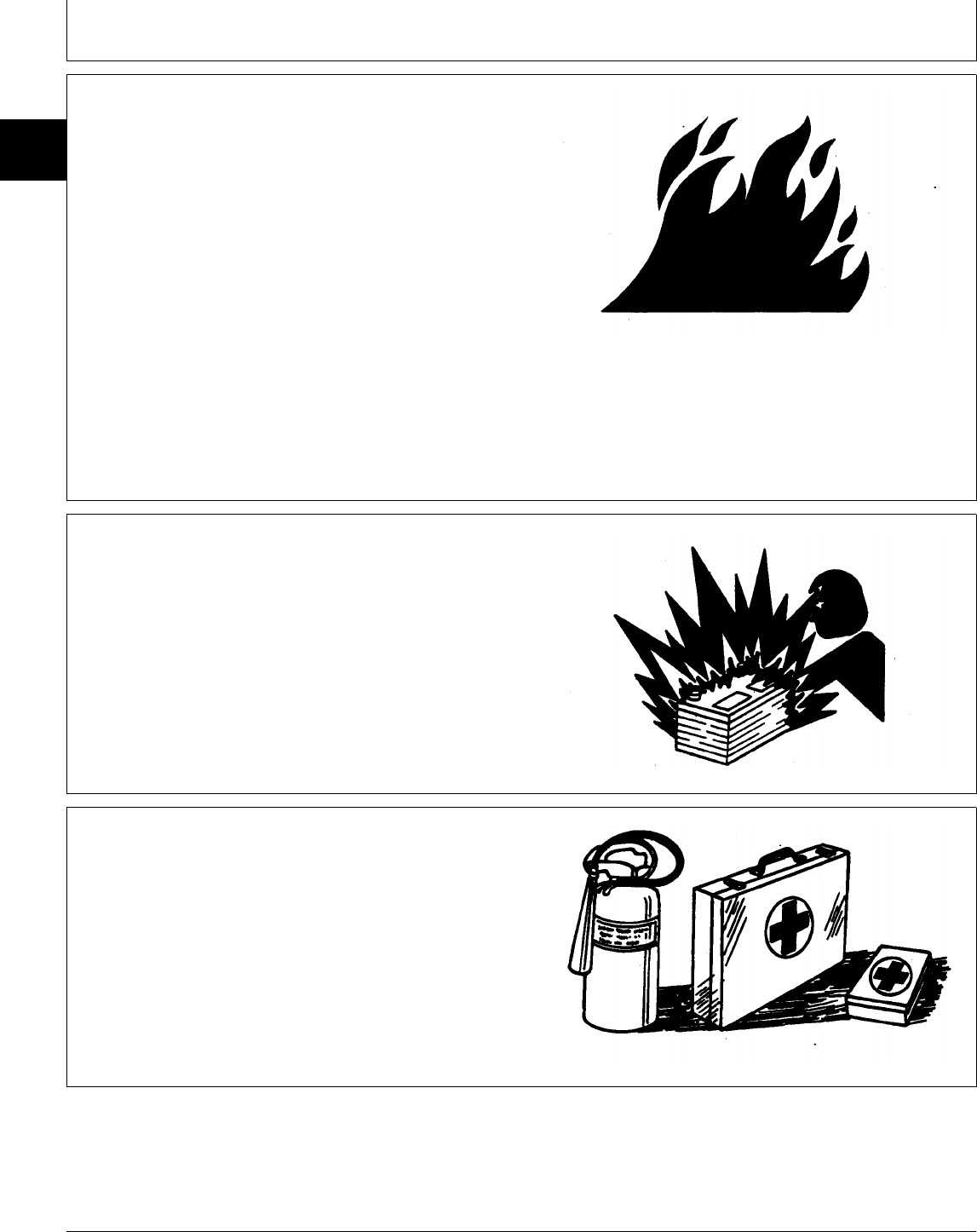
HANDLE FLUIDS SAFELY—AVOID FIRES
When you work around fuel, do not smoke or work near
heaters or other fire hazards.
Store flammable fluids away from fire hazards. Do not
incinerate or puncture pressurized containers.
Make sure machine is clean of trash, grease, and debris.
Do not store oily rags; they can ignite and burn
spontaneously.
TS227 -UN-23AUG88
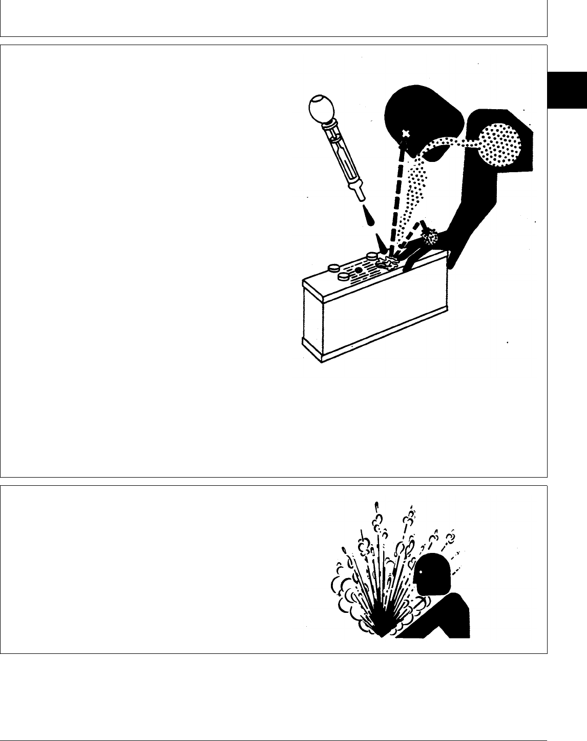
PREVENT BATTERY EXPLOSIONS
Keep sparks, lighted matches, and open flame away
from the top of battery. Battery gas can explode.
Never check battery charge by placing a metal object
across the posts. Use a volt-meter or hydrometer.
Do not charge a frozen battery; it may explode. Warm
battery to 16˚C (60˚F).
TS204 -UN-23AUG88
PREPARE FOR EMERGENCIES
Be prepared if a fire starts.
Keep a first aid kit and fire extinguisher handy.
Keep emergency numbers for doctors, ambulance
service, hospital, and fire department near your
telephone.
TS291 -UN-23AUG88
DX,FLAME -19-04JUN90
DX,SPARKS -19-03MAR93
DX,FIRE2 -19-03MAR93
Safety
TM1591 (15JUL95) 10-05-2 322,330,332 & 430 Lawn & Garden Tractors
030895
10
05
2
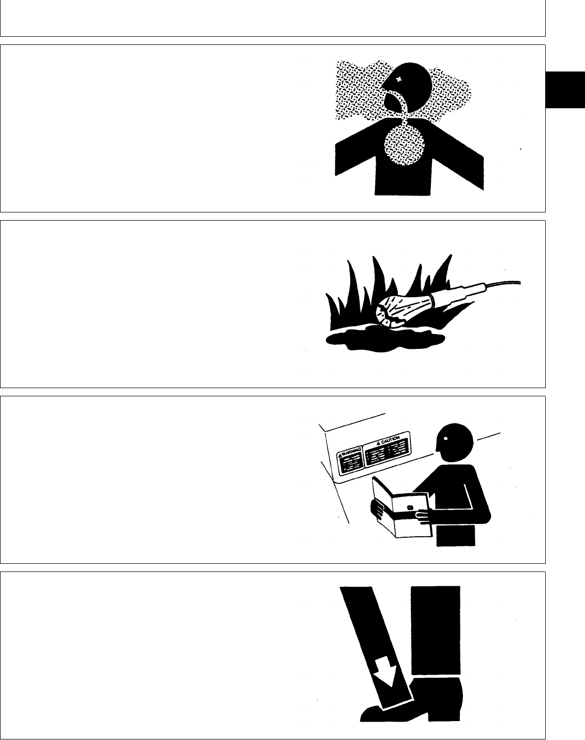
PREVENT ACID BURNS
Sulfuric acid in battery electrolyte is poisonous. It is
strong enough to burn skin, eat holes in clothing, and
cause blindness if splashed into eyes.
Avoid the hazard by:
1. Filling batteries in a well-ventilated area.
2. Wearing eye protection and rubber gloves.
3. Avoiding breathing fumes when electrolyte is added.
4. Avoiding spilling or dripping electrolyte.
5. Use proper jump start procedure.
If you spill acid on yourself:
1. Flush your skin with water.
2. Apply baking soda or lime to help neutralize the acid.
3. Flush your eyes with water for 15—30 minutes. Get
medical attention immediately.
If acid is swallowed:
1. Do not induce vomiting.
2. Drink large amounts of water or milk, but do not
exceed 2 L (2 quarts).
3. Get medical attention immediately.
TS203 -UN-23AUG88
SERVICE COOLING SYSTEM SAFELY
Explosive release of fluids from pressurized cooling
system can cause serious burns.
Shut off engine. Only remove filler cap when cool
enough to touch with bare hands. Slowly loosen cap to
first stop to relieve pressure before removing completely.
TS281 -UN-23AUG88
DX,POISON -19-21APR93
DX,RCAP -19-04JUN90
Safety
TM1591 (15JUL95) 10-05-3 322,330,332 & 430 Lawn & Garden Tractors
030895
10
05
3
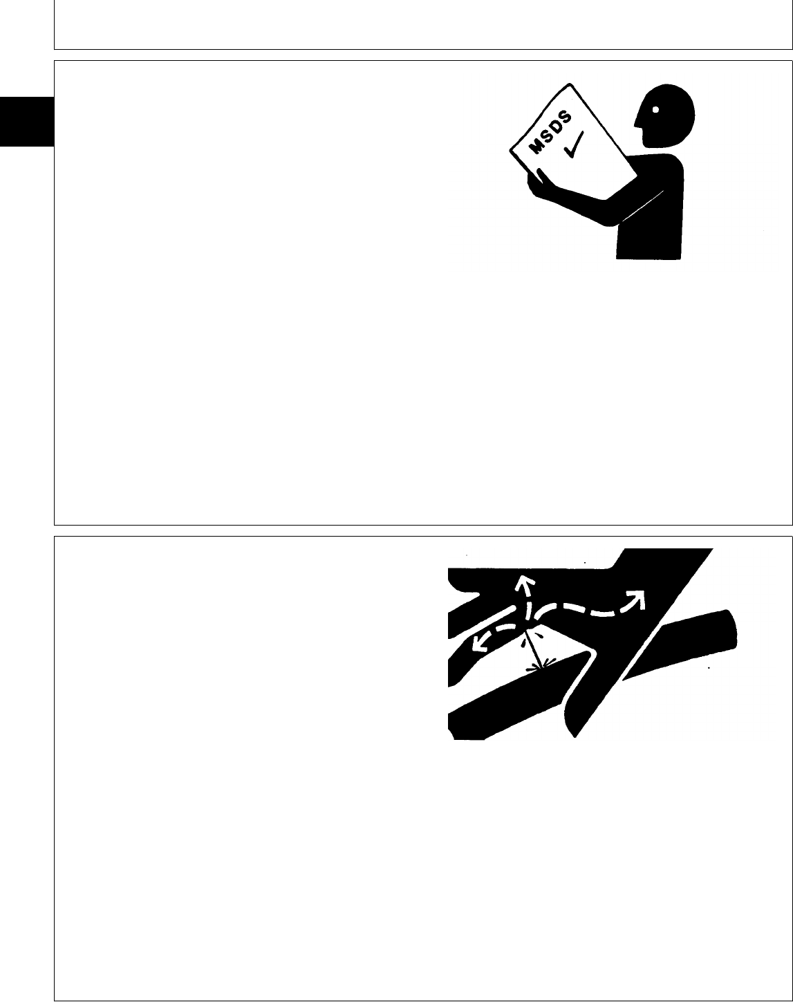
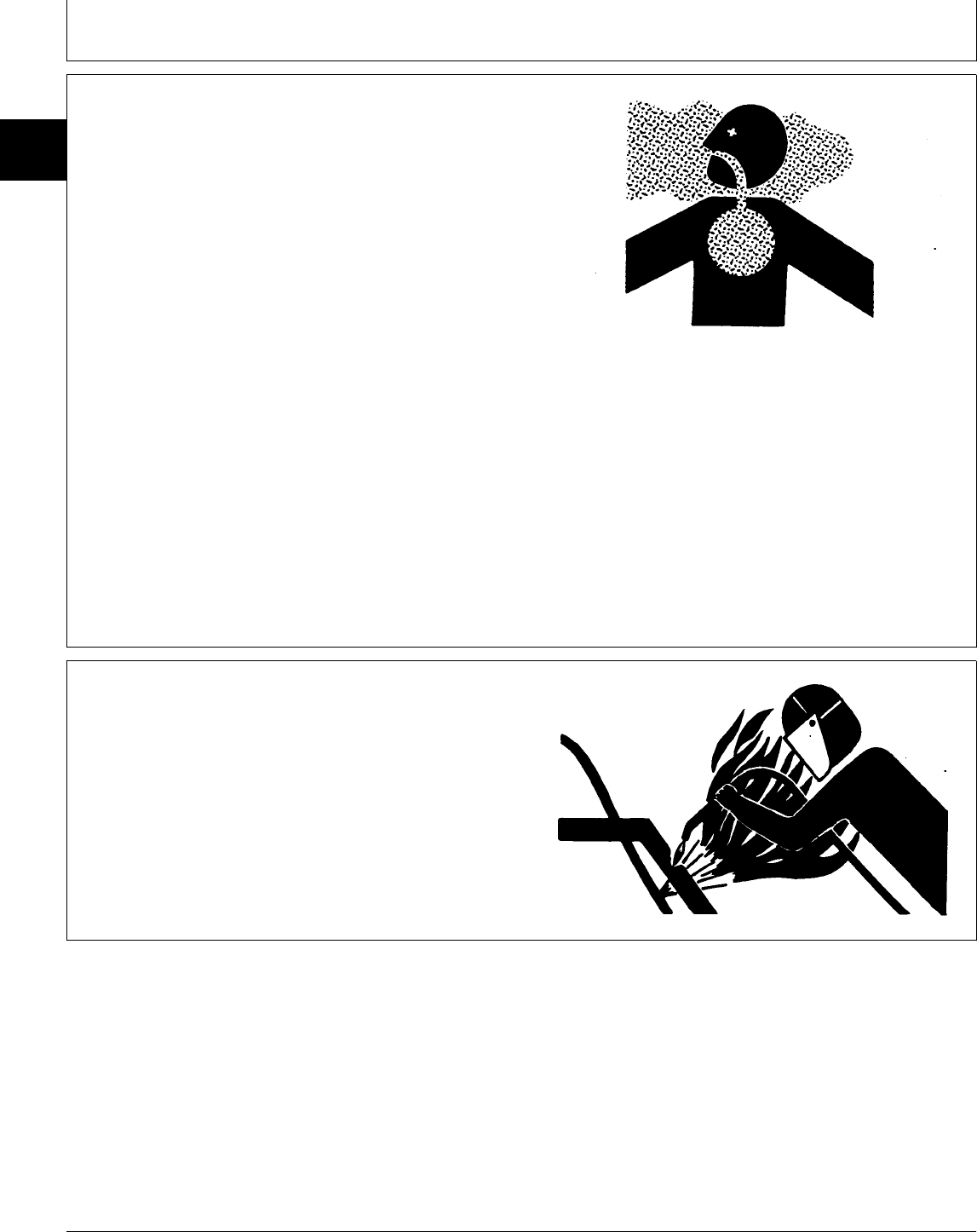
HANDLE CHEMICAL PRODUCTS SAFELY
Direct exposure to hazardous chemicals can cause
serious injury. Potentially hazardous chemicals used with
John Deere equipment include such items as lubricants,
coolants, paints, and adhesives.
A Material Safety Data Sheet (MSDS) provides specific
details on chemical products: physical and health
hazards, safety procedures, and emergency response
techniques.
Check the MSDS before you start any job using a
hazardous chemical. That way you will know exactly
what the risks are and how to do the job safely. Then
follow procedures and recommended equipment.
(See your John Deere dealer for MSDS’s on chemical
products used with John Deere equipment.)
TS1132 -UN-26NOV90
AVOID HIGH-PRESSURE FLUIDS
Escaping fluid under pressure can penetrate the skin
causing serious injury.
Avoid the hazard by relieving pressure before
disconnecting hydraulic or other lines. Tighten all
connections before applying pressure.
Search for leaks with a piece of cardboard. Protect
hands and body from high pressure fluids.
If an accident occurs, see a doctor immediately. Any
fluid injected into the skin must be surgically removed
within a few hours or gangrene may result. Doctors
unfamiliar with this type of injury should reference a
knowledgeable medical source. Such information is
available from Deere & Company Medical Department in
Moline, Illinois, U.S.A.
X9811 -UN-23AUG88
DX,MSDS,NA -19-03MAR93
DX,FLUID -19-03MAR93
Safety
TM1591 (15JUL95) 10-05-4 322,330,332 & 430 Lawn & Garden Tractors
030895
10
05
4
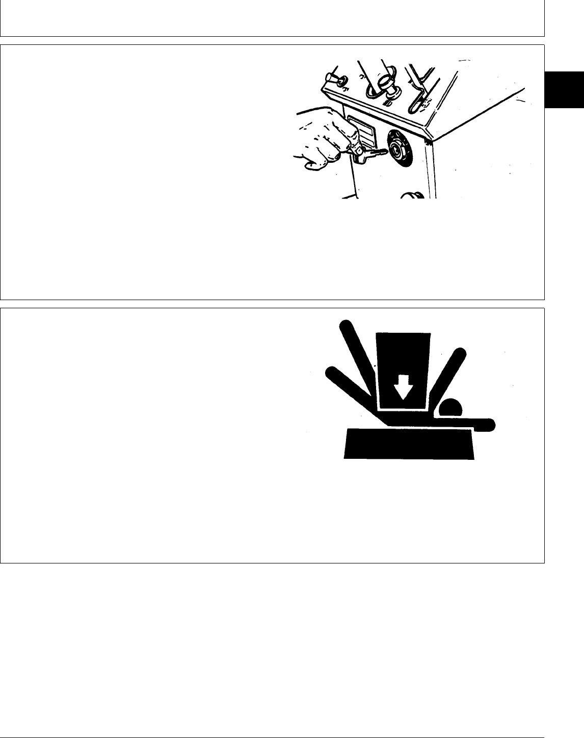
PREPARE MACHINE FOR REPAIR
1. Move hydrostatic control lever to STOP position.
2. Disengage PTO’s
3. Lower all equipment to the ground.
4. Engage park brake.
5. Stop the engine and remove the key.
6. Operate all hydraulic control levers to release
hydraulic pressure in the system.
Before you leave the operator’s seat, wait for engine and
attachment parts to stop moving.
M34228 -UN-24APR89
SUPPORT MACHINE PROPERLY
Always lower the attachment or implement to the ground
before you work on the machine. If you must work on a
lifted machine or attachment, securely support the
machine or attachment.
Do not support the machine on cinder blocks, hollow
tiles, or props that may crumble under continuous load.
Do not work under a machine that is supported solely by
a jack. Follow recommended procedures in this manual.
TS229 -UN-23AUG88
MX,1005R,8 -19-01APR86
DX,LOWER -19-04JUN90
Safety
TM1591 (15JUL95) 10-05-5 322,330,332 & 430 Lawn & Garden Tractors
030895
10
05
5
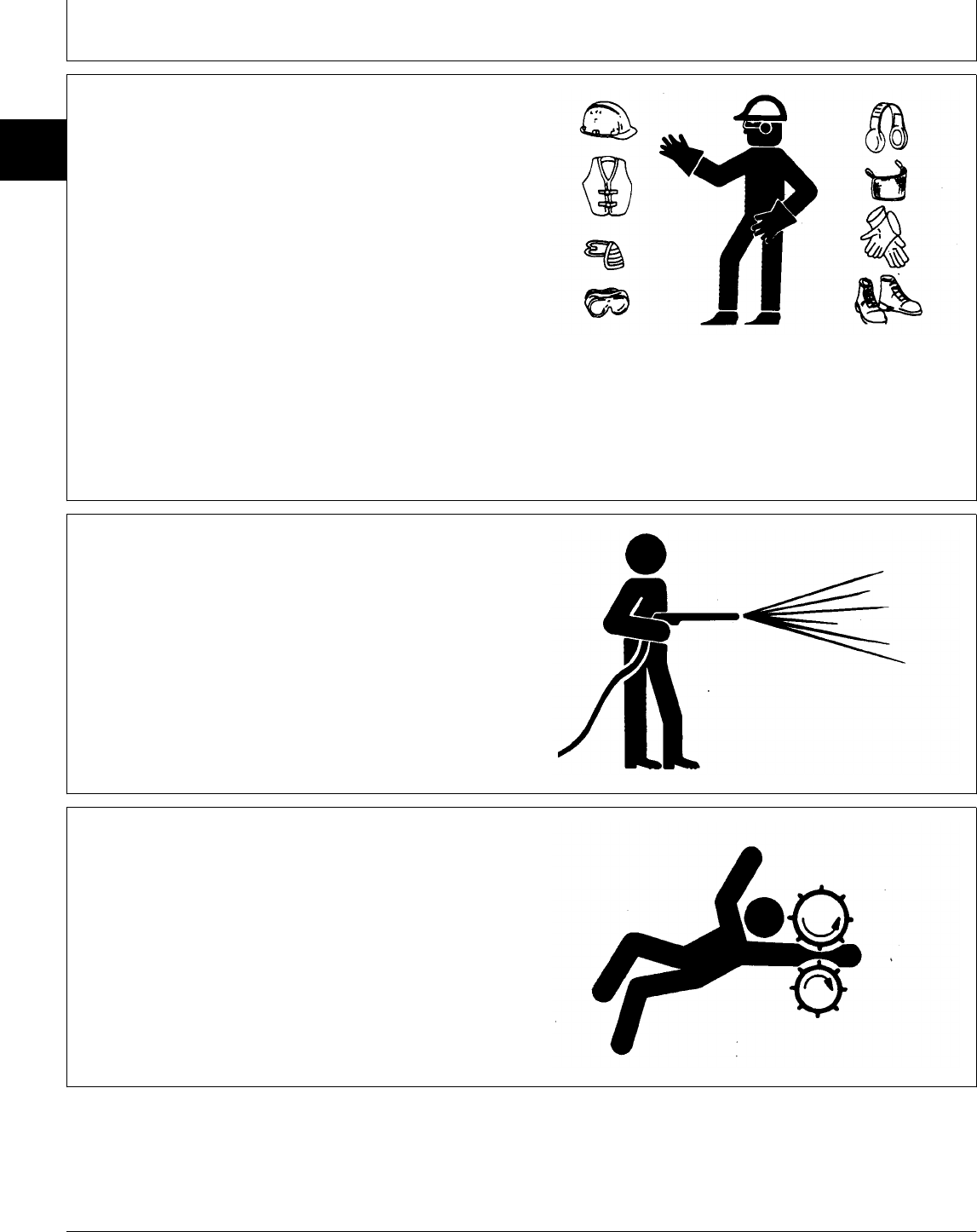
WEAR PROTECTIVE CLOTHING
Wear close fitting clothing and safety equipment
appropriate to the job.
Prolonged exposure to loud noise can cause impairment
or loss of hearing.
Wear a suitable hearing protective device such as
earmuffs or earplugs to protect against objectionable or
uncomfortable loud noises.
Operating equipment safely requires the full attention of
the operator. Do not wear radio or music headphones
while operating machine.
TS206 -UN-23AUG88
WORK IN CLEAN AREA
Before starting a job:
• Clean work area and machine.
• Make sure you have all necessary tools to do your job.
• Have the right parts on hand.
• Read all instructions thoroughly; do not attempt
shortcuts.
T6642EJ -UN-18OCT88
SERVICE MACHINES SAFELY
Tie long hair behind your head. Do not wear a necktie,
scarf, loose clothing, or necklace when you work near
machine tools or moving parts. If these items were to get
caught, severe injury could result.
Remove rings and other jewelry to prevent electrical
shorts and entanglement in moving parts.
TS228 -UN-23AUG88
DX,WEAR -19-10SEP90
DX,CLEAN -19-04JUN90
DX,LOOSE -19-04JUN90
Safety
TM1591 (15JUL95) 10-05-6 322,330,332 & 430 Lawn & Garden Tractors
030895
10
05
6
WORK IN VENTILATED AREA
Engine exhaust fumes can cause sickness or death. If it
is necessary to run an engine in an enclosed area,
remove the exhaust fumes from the area with an
exhaust pipe extension.
If you do not have an exhaust pipe extension, open the
doors and get outside air into the area.
TS220 -UN-23AUG88
ILLUMINATE WORK AREA SAFELY
Illuminate your work area adequately but safely. Use a
portable safety light for working inside or under the
machine. Make sure the bulb is enclosed by a wire
cage. The hot filament of an accidentally broken bulb
can ignite spilled fuel or oil.
TS223 -UN-23AUG88
REPLACE SAFETY SIGNS
Replace missing or damaged safety signs. See the
machine operator’s manual for correct safety sign
placement.
TS201 -UN-23AUG88
USE PROPER LIFTING EQUIPMENT
Lifting heavy components incorrectly can cause severe
injury or machine damage.
Follow recommended procedure for removal and
installation of components in the manual.
TS226 -UN-23AUG88
DX,AIR -19-04JUN90
DX,LIGHT -19-04JUN90
DX,SIGNS1 -19-04JUN90
DX,LIFT -19-04JUN90
Safety
TM1591 (15JUL95) 10-05-7 322,330,332 & 430 Lawn & Garden Tractors
030895
10
05
7
REMOVE PAINT BEFORE WELDING OR
HEATING
Avoid potentially toxic fumes and dust.
Hazardous fumes can be generated when paint is
heated by welding, soldering, or using a torch.
Do all work outside or in a well ventilated area. Dispose
of paint and solvent properly.
Remove paint before welding or heating:
• If you sand or grind paint, avoid breathing the dust.
Wear an approved respirator.
• If you use solvent or paint stripper, remove stripper
with soap and water before welding. Remove solvent or
paint stripper containers and other flammable material
from area. Allow fumes to disperse at least 15 minutes
before welding or heating.
TS220 -UN-23AUG88
AVOID HEATING NEAR PRESSURIZED
FLUID LINES
Flammable spray can be generated by heating near
pressurized fluid lines, resulting in severe burns to
yourself and bystanders. Do not heat by welding,
soldering, or using a torch near pressurized fluid lines or
other flammable materials. Pressurized lines can be
accidentally cut when heat goes beyond the immediate
flame area.
TS953 -UN-15MAY90
DX,PAINT -19-03MAR93
DX,TORCH -19-03MAR93
Safety
TM1591 (15JUL95) 10-05-8 322,330,332 & 430 Lawn & Garden Tractors
030895
10
05
8
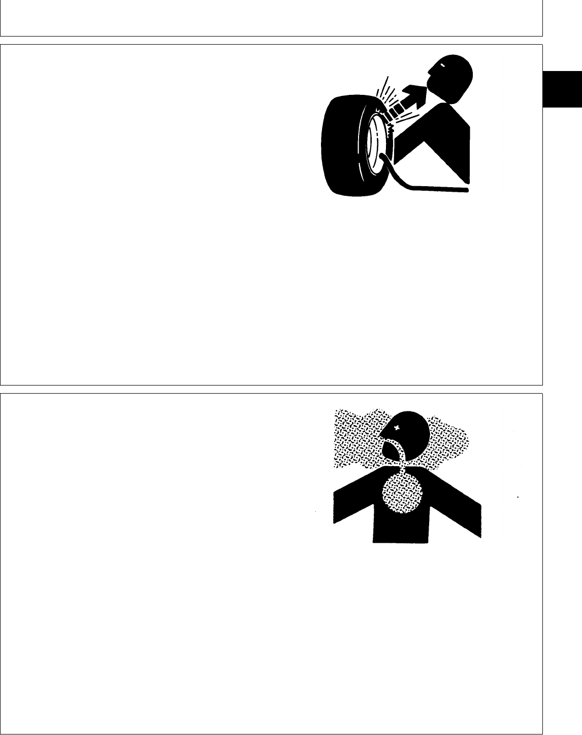
SERVICE TIRES SAFELY
Explosive separation of a tire and rim parts can cause
serious injury or death.
Do not attempt to mount a tire unless you have the
proper equipment and experience to perform the job.
Always maintain the correct tire pressure. Do not inflate
the tires above the recommended pressure. Never weld
or heat a wheel and tire assembly. The heat can cause
an increase in air pressure resulting in a tire explosion.
Welding can structurally weaken or deform the wheel.
When inflating tires, use a clip-on chuck and extension
hose long enough to allow you to stand to one side and
NOT in front of or over the tire assembly. Use a safety
cage if available.
Check wheels for low pressure, cuts, bubbles, damaged
rims or missing lug bolts and nuts.
TS952 -UN-12APR90
AVOID HARMFUL ASBESTOS DUST
Avoid breathing dust that may be generated when
handling components containing asbestos fibers. Inhaled
asbestos fibers may cause lung cancer.
Components in products that may contain asbestos fibers
are brake pads, brake band and lining assemblies, clutch
plates, and some gaskets. The asbestos used in these
components is usually found in a resin or sealed in
some way. Normal handling is not hazardous as long as
airborne dust containing asbestos is not generated.
Avoid creating dust. Never use compressed air for
cleaning. Avoid brushing or grinding material containing
asbestos. When servicing, wear an approved respirator.
A special vacuum cleaner is recommended to clean
asbestos. If not available, apply a mist of oil or water on
the material containing asbestos.
Keep bystanders away from the area.
TS220 -UN-23AUG88
DX,TIRECP -19-24AUG90
DX,DUST -19-15MAR91
Safety
TM1591 (15JUL95) 10-05-9 322,330,332 & 430 Lawn & Garden Tractors
030895
10
05
9
PRACTICE SAFE MAINTENANCE
Understand service procedure before doing work. Keep
area clean and dry.
Never lubricate, service, or adjust machine while it is
moving. Keep hands, feet , and clothing from
power-driven parts. Disengage all power and operate
controls to relieve pressure. Lower equipment to the
ground. Stop the engine. Remove the key. Allow
machine to cool.
Securely support any machine elements that must be
raised for service work.
Keep all parts in good condition and properly installed.
Fix damage immediately. Replace worn or broken parts.
Remove any buildup of grease, oil, or debris.
Disconnect battery ground cable (-) before making
adjustments on electrical systems or welding on
machine.
TS218 -UN-23AUG88
USE PROPER TOOLS
Use tools appropriate to the work. Makeshift tools and
procedures can create safety hazards.
Use power tools only to loosen threaded parts and
fasteners.
For loosening and tightening hardware, use the correct
size tools. DO NOT use U.S. measurement tools on
metric fasteners. Avoid bodily injury caused by slipping
wrenches.
Use only service parts meeting John Deere
specifications.
TS779 -UN-08NOV89
DX,SERV -19-03MAR93
DX,REPAIR -19-04JUN90
Safety
TM1591 (15JUL95) 10-05-10 322,330,332 & 430 Lawn & Garden Tractors
030895
10
05
10
DISPOSE OF WASTE PROPERLY
Improperly disposing of waste can threaten the
environment and ecology. Potentially harmful waste used
with John Deere equipment include such items as oil,
fuel, coolant, brake fluid, filters, and batteries.
Use leakproof containers when draining fluids. Do not
use food or beverage containers that may mislead
someone into drinking from them.
Do not pour waste onto the ground, down a drain, or
into any water source.
Air conditioning refrigerants escaping into the air can
damage the Earth’s atmosphere. Government regulations
may require a certified air conditioning service center to
recover and recycle used air conditioning refrigerants.
Inquire on the proper way to recycle or dispose of waste
from your local environmental or recycling center, or from
your John Deere dealer.
TS1133 -UN-26NOV90
LIVE WITH SAFETY
Before returning machine to customer, make sure
machine is functioning properly, especially the safety
systems. Install all guards and shields.
TS231 -19-07OCT88
DX,DRAIN -19-03MAR93
DX,LIVE -19-25SEP92
Safety
TM1591 (15JUL95) 10-05-11 322,330,332 & 430 Lawn & Garden Tractors
030895
10
05
11

Safety
TM1591 (15JUL95) 10-05-12 322,330,332 & 430 Lawn & Garden Tractors
030895
10
05
12

MACHINE SPECIFICATIONS—322 AND 330
322 330
ENGINE
Manufacturer . . . . . . . . . . . . . . . . . . . . . . Yanmar . . . . . . . . . . . . . . . . Yanmar
Model Number . . . . . . . . . . . . . . . . . . . . . 3TG66UJ . . . . . . . . . . . . . . . 3TN66UJ
Horsepower (SAEJ1349) . . . . . . . . . . . . . . 13.4 kW (18 hp) . . . . . . . . . . 12 kW (16 hp)
Torque . . . . . . . . . . . . . . . . . . . . . . . . . . 4.2 kg m (30.3 ft lbs) . . . . . . . 4.2 kg m (30.3 ft lbs)
Engine Rated Speeds
Fast Idle (No Load) . . . . . . . . . . . . . . . . 3500 rpm . . . . . . . . . . . . . . . 3450 rpm
Low Idle (No Load) . . . . . . . . . . . . . . . . 1300 rpm . . . . . . . . . . . . . . . 1300 rpm
Number of Cylinders . . . . . . . . . . . . . . . . . 3 . . . . . . . . . . . . . . . . . . . . 3
Crankshaft Alignment . . . . . . . . . . . . . . . . . Horizontal . . . . . . . . . . . . . . Horizontal
Stroke/Cycle . . . . . . . . . . . . . . . . . . . . . . . 4 Cycle . . . . . . . . . . . . . . . . 4 Cycle
Bore . . . . . . . . . . . . . . . . . . . . . . . . . . . . 66 mm (2.6 in.) . . . . . . . . . . 66 mm (2.6 in.)
Stroke . . . . . . . . . . . . . . . . . . . . . . . . . . . 64.2 mm (2.5 in.) . . . . . . . . . 64.2 mm (2.5 in.)
Displacement . . . . . . . . . . . . . . . . . . . . . . 658 cm3 (40.1 cu in.) . . . . . . . 658 cm3 (40.1 cu in.)
Compression Ratio . . . . . . . . . . . . . . . . . . 8.7:1 . . . . . . . . . . . . . . . . . . 22.4:1
Cooling . . . . . . . . . . . . . . . . . . . . . . . . . . Liquid . . . . . . . . . . . . . . . . . Liquid
Coolant Capacity . . . . . . . . . . . . . . . . . . . . 2.8 L (3 U.S. qt) 2.8 L (3 U.S. qt)
Air Filter Type . . . . . . . . . . . . . . . . . . . . . Dry with Primary and Dry with Primary and
Secondary Elements . . . . . . . Secondary Elements
Lubrication System . . . . . . . . . . . . . . . . . . Full Pressure w/Filter . . . . . . . Full Pressure w/Filter
Crankcase Capacity (w/o Filter) . . . . . . . . . . 2.5 L (2.6 U.S. qt) . . . . . . . . . 2.5 L (2.6 U.S. qt)
Oil Filter . . . . . . . . . . . . . . . . . . . . . . . . . Replaceable . . . . . . . . . . . . . Replaceable
Spark Plugs . . . . . . . . . . . . . . . . . . . . . . . NGK BPR4BS . . . . . . . . . . . N/A
Champion RN11YC
FUEL SYSTEM
Fuel Tank Location . . . . . . . . . . . . . . . . . . Rear . . . . . . . . . . . . . . . . . . Rear
Fuel Gauge . . . . . . . . . . . . . . . . . . . . . . . Standard . . . . . . . . . . . . . . . Standard
Fuel Tank Capacity . . . . . . . . . . . . . . . . . . 17 L (4.5 U.S. gal) . . . . . . . . 17 L (4.5 U.S. gal)
Fuel . . . . . . . . . . . . . . . . . . . . . . . . . . . . 85 Octane Unleaded . . . . . . . No.1 or No.2 Diesel
Fuel Pump Location . . . . . . . . . . . . . . . . . Frame . . . . . . . . . . . . . . . . . Frame
Fuel Pump Type . . . . . . . . . . . . . . . . . . . . Electric . . . . . . . . . . . . . . . . Electric
Fuel Delivery . . . . . . . . . . . . . . . . . . . . . . Fixed Jet Carburetor . . . . . . . Indirect Injection
Injection Pump Type . . . . . . . . . . . . . . . . . N/A . . . . . . . . . . . . . . . . . . In-Line Multi-Plunger
Fuel Shutoff . . . . . . . . . . . . . . . . . . . . . . . Electric Solenoid . . . . . . . . . . Manual
ELECTRICAL SYSTEM
Ignition . . . . . . . . . . . . . . . . . . . . . . . . . . Electronic . . . . . . . . . . . . . . N/A
Type of Starter . . . . . . . . . . . . . . . . . . . . . 12 Volts, Solenoid . . . . . . . . . 12 Volts, Solenoid
Charging System . . . . . . . . . . . . . . . . . . . Remote Alt. 20 amp . . . . . . . Remote Alt. 20 amp
Battery Type . . . . . . . . . . . . . . . . . . . . . . BCI Group, U1 . . . . . . . . . . . BCI Group, U1
Battery Voltage . . . . . . . . . . . . . . . . . . . . . 12V . . . . . . . . . . . . . . . . . . 12V
Battery Reserve Capacity @25 amp . . . . . . . 44 minutes . . . . . . . . . . . . . . 44 minutes
Battery
Cold Cranking amp @0˚F . . . . . . . . . . . . . . 342 amp . . . . . . . . . . . . . . . 342 amp
Headlights . . . . . . . . . . . . . . . . . . . . . . . . Standard . . . . . . . . . . . . . . . Standard
Reflector/Tail Lights . . . . . . . . . . . . . . . . . . Standard . . . . . . . . . . . . . . . Standard
Dash Indicator Lights . . . . . . . . . . . . . . . . . Standard . . . . . . . . . . . . . . . Standard
Operator Presence System . . . . . . . . . . . . . Standard . . . . . . . . . . . . . . . Standard
Hourmeter . . . . . . . . . . . . . . . . . . . . . . . . Standard . . . . . . . . . . . . . . . Standard
Continued on next page. MX,15911010,1 -19-13JUL95
Group 10
General Specifications
TM1591 (15JUL95) 10-10-1 322,330,332 & 430 Lawn & Garden Tractors
030895
10
10
1

322 330
POWER TRAIN
Transmission Type . . . . . . . . . . . . . . . . . . Hydrostatic . . . . . . . . . . . . . Hydrostatic
Number of Speeds . . . . . . . . . . . . . . . . . Infinite . . . . . . . . . . . . . . . . Infinite
Travel Speeds
Forward . . . . . . . . . . . . . . . . . . . . . . . 0—12.38 km/h . . . . . . . . . . 0—12.38 km/h
(0—7.69 mph) (0—7.69 mph)
Reverse . . . . . . . . . . . . . . . . . . . . . . . 0—6.19 km/h . . . . . . . . . . . 0—6.19 km/h
(0—3.85 mph) (0—3.85 mph)
Transmission Capacity (w/Filter) . . . . . . . . . 6.1 L (13 U.S. pt) . . . . . . . . 6.1 L (13 U.S. pt)
Trans. Oil Cooler . . . . . . . . . . . . . . . . . . . Optional . . . . . . . . . . . . . . . N/A
Trans. Oil Filter . . . . . . . . . . . . . . . . . . . . Standard . . . . . . . . . . . . . . Standard
Differential Lock . . . . . . . . . . . . . . . . . . . N/A . . . . . . . . . . . . . . . . . . N/A
STEERING
Type . . . . . . . . . . . . . . . . . . . . . . . . . . . Power, Hydrostatic . . . . . . . . Manual
BRAKES
Location . . . . . . . . . . . . . . . . . . . . . . . . . Rear Wheels . . . . . . . . . . . Rear Wheels
Individual Control . . . . . . . . . . . . . . . . . . . Standard . . . . . . . . . . . . . . N/A
Type . . . . . . . . . . . . . . . . . . . . . . . . . . . Shoe and Drum . . . . . . . . . Shoe and Drum
Return-to-Neutral Braking . . . . . . . . . . . . . Standard . . . . . . . . . . . . . . Standard
Parking . . . . . . . . . . . . . . . . . . . . . . . . . Yes . . . . . . . . . . . . . . . . . . Yes
HYRAULIC SYSTEM
Type . . . . . . . . . . . . . . . . . . . . . . . . . . . Two-Function . . . . . . . . . . . Single-Function
(One w/Float)
Hydraulic Couplers . . . . . . . . . . . . . . . . . . Two Sets . . . . . . . . . . . . . . One Set
PTO
Front . . . . . . . . . . . . . . . . . . . . . . . . . . . Standard . . . . . . . . . . . . . . Standard
Rear . . . . . . . . . . . . . . . . . . . . . . . . . . . Optional . . . . . . . . . . . . . . . Optional
Type . . . . . . . . . . . . . . . . . . . . . . . . . . . Electric Clutch . . . . . . . . . . . Electric Clutch
Control . . . . . . . . . . . . . . . . . . . . . . . . . Elec. Switch on Dash . . . . . . Elec. Switch on Dash
PTO rpm (No Load)
Front . . . . . . . . . . . . . . . . . . . . . . . . . 3500 . . . . . . . . . . . . . . . . . 3450
Rear . . . . . . . . . . . . . . . . . . . . . . . . . 2000 . . . . . . . . . . . . . . . . . 2000
MOWER ATTACHMENT
Compatibility . . . . . . . . . . . . . . . . . . . . . . 38, 46 and 50 Inch . . . . . . . 38, 46 and 50 Inch
Lift System . . . . . . . . . . . . . . . . . . . . . . . Hydraulic . . . . . . . . . . . . . . Hydraulic
WHEEL TREAD
Front . . . . . . . . . . . . . . . . . . . . . . . . . . . 813 mm (32 in.) . . . . . . . . . 813 mm (32 in.)
Rear
Narrow . . . . . . . . . . . . . . . . . . . . . . . . 775 mm (30.5 in.) . . . . . . . . 775 mm (30.5 in.)
Wide . . . . . . . . . . . . . . . . . . . . . . . . . 834 mm (32.8 in.) . . . . . . . . 834 mm (32.8 in.)
Continued on next page. MX,15911010,2 -19-13JUL95
General Specifications/Machine Specifications
TM1591 (15JUL95) 10-10-2 322,330,332 & 430 Lawn & Garden Tractors
030895
10
10
2

322 330
TIRES
Standard Tires
Front Turf . . . . . . . . . . . . . . . . . . . . . . 16 x 6.50-8, 2 PR . . . . . . . . 16 x 6.50-8, 2 PR
Rear Turf or Bar . . . . . . . . . . . . . . . . . 23 x 10.50-12, 2 PR . . . . . . 23 x 10.50-12, 2 PR
Optional Tires
Front (Turf) . . . . . . . . . . . . . . . . . . . . . 16 x 6.50-8, 4 PR . . . . . . . . 16 x 6.50-8, 4 PR
Rear (Turf or Bar) . . . . . . . . . . . . . . . . . 23 x 8.50-12, 2 PR . . . . . . . 23 x 8.50-12, 2 PR
Inflation Pressure
Front . . . . . . . . . . . . . . . . . . . . . . . . . 41—110 kPa (6—16 psi) . . . 41—110 kPa (6—16 psi)
Rear . . . . . . . . . . . . . . . . . . . . . . . . . 34—69 kPa (5—10 psi) . . . . 34—69 kPa (5—10 psi)
SEAT
Style . . . . . . . . . . . . . . . . . . . . . . . . . . . High-Back . . . . . . . . . . . . . High-Back
Suspension . . . . . . . . . . . . . . . . . . . . . . 2 Spring . . . . . . . . . . . . . . 2 Spring
Adjustment . . . . . . . . . . . . . . . . . . . . . . . Slide Rail . . . . . . . . . . . . . . Slide Rail
DIMENSIONS
Wheel Base . . . . . . . . . . . . . . . . . . . . . . 1.2 m (46 in.) . . . . . . . . . . . 1.2 m (46 in.)
Overall Length . . . . . . . . . . . . . . . . . . . . 1.8 m (69.5 in.) . . . . . . . . . . 1.8 m (69.5 in.)
Overall Height . . . . . . . . . . . . . . . . . . . . . 1.1 m (44.5 in.) . . . . . . . . . . 1.1 m (44.5 in.)
Overall Width (max.) . . . . . . . . . . . . . . . . 1.1 m (43.3 in.) . . . . . . . . . . 1.1 m (43.3 in.)
Overall Width (min.) . . . . . . . . . . . . . . . . . 1.04 m (41 in.) . . . . . . . . . . 1.04 m (41 in.)
Turning Radius
Inside Rear Wheel . . . . . . . . . . . . . . . . 0.66 m (26 in.) . . . . . . . . . . 0.66 m (26 in.)
Outside Front Wheel . . . . . . . . . . . . . . . 2.0 m (80 in.) . . . . . . . . . . . 2.0 m (80 in.)
NET WEIGHT (No Fuel) . . . . . . . . . . . . . . 408 kg (900 lbs) . . . . . . . . . 408 kg (900 lbs)
SHIPPING WEIGHT . . . . . . . . . . . . . . . . . 445 kg (980 lbs) . . . . . . . . . 445 kg (980 lbs)
(Specifications and design subject to change without notice.) MX,15911010,3 -19-13JUL95
General Specifications/Machine Specifications
TM1591 (15JUL95) 10-10-3 322,330,332 & 430 Lawn & Garden Tractors
030895
10
10
3

MACHINE SPECIFICATIONS—332 AND 430
332 430
ENGINE
Manufacturer . . . . . . . . . . . . . . . . . . . . . . Yanmar . . . . . . . . . . . . . . . . Yanmar
Model Number . . . . . . . . . . . . . . . . . . . . . 3TN66UJ . . . . . . . . . . . . . . 3TNA72UJ
Horsepower (SAEJ1349) . . . . . . . . . . . . . . 12 kW (16 hp) . . . . . . . . . . . 15 kW (20 hp)
Torque . . . . . . . . . . . . . . . . . . . . . . . . . . 4.2 kg m (30.3 ft lbs) . . . . . . 5.1 kg m (36.8 ft lbs)
Engine Rated Speeds
Fast Idle (No Load) . . . . . . . . . . . . . . . . 3425 rpm . . . . . . . . . . . . . . 3400 rpm
Low Idle (No Load) . . . . . . . . . . . . . . . . 1400 rpm . . . . . . . . . . . . . . 1300 rpm
Number of Cylinders . . . . . . . . . . . . . . . . . 3 . . . . . . . . . . . . . . . . . . . . 3
Crankshaft Alignment . . . . . . . . . . . . . . . . Horizontal . . . . . . . . . . . . . . Horizontal
Stroke/Cycle . . . . . . . . . . . . . . . . . . . . . . 4 Cycle . . . . . . . . . . . . . . . . 4 Cycle
Bore . . . . . . . . . . . . . . . . . . . . . . . . . . . . 66 mm (2.6 in.) . . . . . . . . . . 72 mm (2.84 in.)
Stroke . . . . . . . . . . . . . . . . . . . . . . . . . . 64.2 mm (2.5 in.) . . . . . . . . . 72 mm (2.84 in.)
Displacement . . . . . . . . . . . . . . . . . . . . . . 658 cm3 (40.1 cu in.) . . . . . . 879 cm3 (53.6 cu in.)
Compression Ratio . . . . . . . . . . . . . . . . . . 22.4:1 . . . . . . . . . . . . . . . . . 21.6:1
Cooling . . . . . . . . . . . . . . . . . . . . . . . . . . Liquid . . . . . . . . . . . . . . . . . Liquid
Coolant Capacity . . . . . . . . . . . . . . . . . . . 2.8 L (3 U.S. qt) . . . . . . . . . . 3.8 L (1 U.S. gal)
Air Filter Type . . . . . . . . . . . . . . . . . . . . . Dry with Primary and Dry with Primary and
Secondary Elements . . . . . . . Secondary Elements
Lubrication System . . . . . . . . . . . . . . . . . . Full Pressure w/Filter Full Pressure w/Filter
Crankcase Capacity (w/o Filter) . . . . . . . . . . 2.5 L (2.6 U.S. qt) . . . . . . . . 2.9 L (3.1 U.S. qt)
Oil Filter . . . . . . . . . . . . . . . . . . . . . . . . . Replaceable . . . . . . . . . . . . Replaceable
FUEL SYSTEM
Fuel Tank Location . . . . . . . . . . . . . . . . . . Rear . . . . . . . . . . . . . . . . . Rear
Fuel Gauge . . . . . . . . . . . . . . . . . . . . . . . Standard . . . . . . . . . . . . . . . Standard
Fuel Tank Capacity . . . . . . . . . . . . . . . . . . 17 L (4.5 U.S. gal) . . . . . . . . 24.6 L (6.5 U.S. gal)
Fuel . . . . . . . . . . . . . . . . . . . . . . . . . . . . No.1 or No.2 Diesel . . . . . . . No.1 or No.2 Diesel
Fuel Pump Location . . . . . . . . . . . . . . . . . Frame . . . . . . . . . . . . . . . . Frame
Fuel Pump Type . . . . . . . . . . . . . . . . . . . Electric . . . . . . . . . . . . . . . . Electric
Fuel Delivery . . . . . . . . . . . . . . . . . . . . . . Indirect Injection . . . . . . . . . . Indirect Injection
Injection Pump Type . . . . . . . . . . . . . . . . . In-Line Multi-Plunger . . . . . . . In-Line Multi-Plunger
Fuel Shutoff . . . . . . . . . . . . . . . . . . . . . . . Electric Solenoid . . . . . . . . . . Electric Solenoid
ELECTRICAL SYSTEM
Ignition . . . . . . . . . . . . . . . . . . . . . . . . . . N/A . . . . . . . . . . . . . . . . . . N/A
Type of Starter . . . . . . . . . . . . . . . . . . . . . 12 Volts, Solenoid . . . . . . . . 12 Volts, Solenoid
Charging System
Early Machines . . . . . . . . . . . . . . . . . . . Remote Alt. 20 amp . . . . . . . Remote Alt. 35 amp
Later Machines . . . . . . . . . . . . . . . . . . . Remote Alt. 20 amp . . . . . . . Remote Alt. 40 amp
Battery Type . . . . . . . . . . . . . . . . . . . . . . BCI Group, U1 . . . . . . . . . . . BCI Group, 22F
Battery Voltage . . . . . . . . . . . . . . . . . . . . 12V . . . . . . . . . . . . . . . . . . 12V
Battery Reserve Capacity @25 amp . . . . . . 44 minutes . . . . . . . . . . . . . 102 minutes
Battery
Cold Cranking amp @0˚F . . . . . . . . . . . . . 342 amp . . . . . . . . . . . . . . . 491 amp
Headlights . . . . . . . . . . . . . . . . . . . . . . . . Standard . . . . . . . . . . . . . . . Standard
Reflector/Tail Lights . . . . . . . . . . . . . . . . . Standard . . . . . . . . . . . . . . . Standard
Dash Indicator Lights . . . . . . . . . . . . . . . . Standard . . . . . . . . . . . . . . . Standard
Operator Presence System . . . . . . . . . . . . . Standard . . . . . . . . . . . . . . . Standard
Hourmeter . . . . . . . . . . . . . . . . . . . . . . . . Standard . . . . . . . . . . . . . . . Standard
Continued on next page. MX,15911010,4 -19-13JUL95
General Specifications/Machine Specifications
TM1591 (15JUL95) 10-10-4 322,330,332 & 430 Lawn & Garden Tractors
030895
10
10
4

332 430
POWER TRAIN
Transmission Type . . . . . . . . . . . . . . . . . . Hydrostatic . . . . . . . . . . . . . Hydrostatic, 2 Ranges
Number of Speeds . . . . . . . . . . . . . . . . . . Infinite . . . . . . . . . . . . . . . . Infinite
Travel Speeds
Forward . . . . . . . . . . . . . . . . . . . . . . . . 0—12.38 km/h . . . . . . . . . . . N/A
(0—7.69 mph)
Reverse . . . . . . . . . . . . . . . . . . . . . . . . 0—6.19 km/h . . . . . . . . . . . . N/A
(0—3.85 mph)
Forward, High . . . . . . . . . . . . . . . . . . . . N/A . . . . . . . . . . . . . . . . . . 0—16.09 km/h
(0—10 mph)
Forward, Low . . . . . . . . . . . . . . . . . . . . N/A . . . . . . . . . . . . . . . . . . 0—9.35 km/h
(0—5.80 mph)
Reverse, High . . . . . . . . . . . . . . . . . . . . N/A . . . . . . . . . . . . . . . . . . 0—6.44 km/h
(0—4 mph)
Reverse, Low . . . . . . . . . . . . . . . . . . . . N/A . . . . . . . . . . . . . . . . . . 0—4.66 km/h
(0—2.90 mph)
Transmission Capacity (w/Filter) . . . . . . . . . 6.1 L (13 U.S. pt) . . . . . . . . . 7.1 L (15 U.S. pt)
Trans. Oil Cooler . . . . . . . . . . . . . . . . . . . Optional . . . . . . . . . . . . . . . Standard
Trans. Oil Filter . . . . . . . . . . . . . . . . . . . . Standard . . . . . . . . . . . . . . . Standard
Differential Lock . . . . . . . . . . . . . . . . . . . . N/A . . . . . . . . . . . . . . . . . . Standard
STEERING
Type . . . . . . . . . . . . . . . . . . . . . . . . . . . Power, Hydrostatic . . . . . . . . Power, Hydrostatic
BRAKES
Location . . . . . . . . . . . . . . . . . . . . . . . . . Rear Wheels . . . . . . . . . . . . Rear Wheels
Individual Control . . . . . . . . . . . . . . . . . . . Standard . . . . . . . . . . . . . . . Standard
Type . . . . . . . . . . . . . . . . . . . . . . . . . . . Shoe and Drum . . . . . . . . . . Shoe and Drum
Return-to-Neutral Braking . . . . . . . . . . . . . . Standard . . . . . . . . . . . . . . . Standard
Parking . . . . . . . . . . . . . . . . . . . . . . . . . . Yes . . . . . . . . . . . . . . . . . . Yes
HYRAULIC SYSTEM
Type . . . . . . . . . . . . . . . . . . . . . . . . . . . Two-Function . . . . . . . . . . . . Three-Function
(One w/Float) (One w/Float)
Hydraulic Couplers . . . . . . . . . . . . . . . . . . Two Sets . . . . . . . . . . . . . . Two Sets
PTO
Front . . . . . . . . . . . . . . . . . . . . . . . . . . . Standard . . . . . . . . . . . . . . . Standard
Rear . . . . . . . . . . . . . . . . . . . . . . . . . . . Optional . . . . . . . . . . . . . . . Optional
Type . . . . . . . . . . . . . . . . . . . . . . . . . . . Electric Clutch . . . . . . . . . . . Electric Clutch
Control . . . . . . . . . . . . . . . . . . . . . . . . . . Elec. Switch on Dash . . . . . . Elec. Switch on Dash
PTO rpm (No Load)
Front . . . . . . . . . . . . . . . . . . . . . . . . . . 3425 . . . . . . . . . . . . . . . . . 3400
Rear . . . . . . . . . . . . . . . . . . . . . . . . . . 2000 . . . . . . . . . . . . . . . . . 2000
MOWER ATTACHMENT
Compatibility . . . . . . . . . . . . . . . . . . . . . . 38, 46 and 50 Inch . . . . . . . . 50 and 60 Inch,
260 Rotary
Lift System . . . . . . . . . . . . . . . . . . . . . . . Hydraulic . . . . . . . . . . . . . . . Hydraulic
Continued on next page. MX,15911010,5 -19-13JUL95
General Specifications/Machine Specifications
TM1591 (15JUL95) 10-10-5 322,330,332 & 430 Lawn & Garden Tractors
030895
10
10
5

332 430
WHEEL TREAD
Front . . . . . . . . . . . . . . . . . . . . . . . . . . . 813 mm (32 in.) . . . . . . . . . . 914 mm (36 in.)
Rear
Narrow . . . . . . . . . . . . . . . . . . . . . . . . 775 mm (30.5 in.) . . . . . . . . . 818 mm (32 in.)
Wide . . . . . . . . . . . . . . . . . . . . . . . . . . 834 mm (32.8 in.) . . . . . . . . . 980 mm (38.6 in.)
TIRES
Standard Tires
Front Turf . . . . . . . . . . . . . . . . . . . . . . . 16 x 6.50-8, 2 PR . . . . . . . . 18 x 8.50-8, 4 PR
Rear Turf or Bar . . . . . . . . . . . . . . . . . . 23 x 10.50-12, 2 PR . . . . . . . 26 x 12.00-12, 2 PR
Optional Tires
Front (Turf) . . . . . . . . . . . . . . . . . . . . . . 16 x 6.50-8, 4 PR . . . . . . . . N/A
Rear (Turf or Bar) . . . . . . . . . . . . . . . . . 23 x 8.50-12, 2 PR . . . . . . . . N/A
Inflation Pressure
Front . . . . . . . . . . . . . . . . . . . . . . . . . . 41—110 kPa (6—16 psi) . . . . 41—152 kPa (6—22 psi)
Rear . . . . . . . . . . . . . . . . . . . . . . . . . . 34—69 kPa (5—10 psi) . . . . . 34—69 kPa (5—10 psi)
SEAT
Style . . . . . . . . . . . . . . . . . . . . . . . . . . . High-Back/Tilt . . . . . . . . . . . High-Back/Tilt
Suspension . . . . . . . . . . . . . . . . . . . . . . . 2 Spring . . . . . . . . . . . . . . . Deluxe Seat Suspension
Adjustment . . . . . . . . . . . . . . . . . . . . . . . Slide Rail . . . . . . . . . . . . . . Slide Rail
DIMENSIONS
Wheel Base . . . . . . . . . . . . . . . . . . . . . . . 1.2 m (46 in.) . . . . . . . . . . . 1.3 m (52 in.)
Overall Length . . . . . . . . . . . . . . . . . . . . . 1.8 m (69.5 in.) . . . . . . . . . . 2.13 m (84 in.)
Overall Height . . . . . . . . . . . . . . . . . . . . . 1.1 m (44.5 in.) . . . . . . . . . . 1.22 m (48.5 in.)
Overall Width (max.) . . . . . . . . . . . . . . . . . 1.1 m (43.3 in.) . . . . . . . . . . 1.31 m (51.5 in.)
Overall Width (min.) . . . . . . . . . . . . . . . . . 1.04 m (41 in.) . . . . . . . . . . . 1.14 m (45 in.)
Turning Radius
Inside Rear Wheel . . . . . . . . . . . . . . . . . 0.66 m (26 in.) . . . . . . . . . . . 0.66 m (26 in.)
Outside Front Wheel . . . . . . . . . . . . . . . 2.0 m (80 in.) . . . . . . . . . . . 2.2 m (86 in.)
NET WEIGHT (No Fuel) . . . . . . . . . . . . . . 408 kg (900 lbs) . . . . . . . . . . 533 kg (1116 lbs)
SHIPPING WEIGHT . . . . . . . . . . . . . . . . . 445 kg (980 lbs) . . . . . . . . . . 567 kg (1219 lbs)
(Specifications and design subject to change without notice.) MX,15911010,6 -19-13JUL95
General Specifications/Machine Specifications
TM1591 (15JUL95) 10-10-6 322,330,332 & 430 Lawn & Garden Tractors
030895
10
10
6

REPAIR SPECIFICATIONS
Item Specifications
ENGINE
For all repair specifications—Use CTM12 (322) and CTM3 (330, 332 and 430)
Engine Mounting Cap Screw/Nut Torque . . . . . . . . . . . . . . . . . . . . . . . . . . . . . . . . . . . . . 49 N·m (36 lb-ft)
Drive Shaft to Engine Cap Screw Torque
330 and 430 . . . . . . . . . . . . . . . . . . . . . . . . . . . . . . . . . . . . . . . . . . . . . . . . . . . . . . 27 N·m (20 lb-ft)
322 and 332 . . . . . . . . . . . . . . . . . . . . . . . . . . . . . . . . . . . . . . . . . . . . . . . . . . . . . . 37 N·m (27 lb-ft)
Drive Shaft Universal Joint Cap Screw Torque . . . . . . . . . . . . . . . . . . . . . . . . . . . . . . . . . 60 N·m (45 lb-ft)
PTO Belt Tension Spring Length (430) . . . . . . . . . . . . . . . . . . . . . . . . . . . . . . . . . . . . . 35 mm (1.38 in.)
Fuel/Water Separator Cap Screw Torque (430) . . . . . . . . . . . . . . . . . . . . . . . . . . . . . . 20 N·m (180 lb-in.)
ELECTRICAL
Front PTO Clutch-to-Crankshaft Cap Screw Torque . . . . . . . . . . . . . . . . . . . . . . . . . . . . . 47 N·m (35 lb-ft)
PTO Clutch Armature to Rotor Clearance . . . . . . . . . . . . . . . . . . . . . . . . . . . . . . . . . 0.46 mm (0.018 in.)
PTO Belt Tension Spring Length (430) . . . . . . . . . . . . . . . . . . . . . . . . . . . . . . . . . . . . . 35 mm (1.380 in.)
POWER TRAIN
Transmission
Charge Pump-to-Transmission Cap Screw Torque . . . . . . . . . . . . . . . . . . . . . . . . . . . . . 70 N·m (52 lb-ft)
Transmission Cover Bearing Installation Height . . . . . . . . . . . . . . . 3 mm (0.118 in.) above housing surface
Center Section-to-Housing Cap Screw Torque . . . . . . . . . . . . . . . . . . . . . . . . . . . . . . . 35 N·m (26 lb-ft)
Transmission-to-Differential Cap Screw Torque 45 N·m (33 lb-ft)
Axle Housing-to-Frame Cap Screw Torque . . . . . . . . . . . . . . . . . . . . . . . . . . . . . . . . . 100 N·m (75 lb-ft)
Brake Rod Spring Length . . . . . . . . . . . . . . . . . . . . . . . . . . . . . . . . . . . . . . . . . . . . 42 mm (1.650 in.)
Differential-to-Frame Support Cap Screw Torque . . . . . . . . . . . . . . . . . . . . . . . . . . . . . . 61 N·m (45 lb-ft)
Swashplate Control Arm-to-Control Shaft Nut Torque . . . . . . . . . . . . . . . . . . . . . . . . . . . 60 N·m (44 lb-ft)
Drive Shaft Clamping Yoke-to-Transmission Pump Shaft Cap Screw Torque . . . . . . . . . . . 60 N·m (44 lb-ft)
Differential
Case and Cover Oil Groove Depth (Minimum) . . . . . . . . . . . . . . . . . . . . . . . . . . . . 0.25 mm (0.010 in.)
Carrier Cap Screw Torque . . . . . . . . . . . . . . . . . . . . . . . . . . . . . . . . . . . . . . . . . . . . . 53 N·m (39 lb-ft)
Cover-to-Case Cap Screw Torque . . . . . . . . . . . . . . . . . . . . . . . . . . . . . . . . . . . . . 23 N·m (204 lb-in.)
Axle Housing
Differential Seal Depth . . . . . . . . . . . . . . . . . . . . . . . . . . . . . 3 mm (0.118 in.) below differential surface
Axle Housing-to-Differential Cap Screw Torque . . . . . . . . . . . . . . . . . . . . . . . . . . . . . . . 81 N·m (60 lb-ft)
Brake Plate-to-Axle Housing Cap Screw Torque . . . . . . . . . . . . . . . . . . . . . . . . . . . . . . 68 N·m (50 lb-ft)
Axle Housing-to-Frame Cap Screw Torque . . . . . . . . . . . . . . . . . . . . . . . . . . . . . . . . . 100 N·m (75 lb-ft)
Brake Rod Spring Length . . . . . . . . . . . . . . . . . . . . . . . . . . . . . . . . . . . . . . . . . . . . 42 mm (1.650 in.)
Brake Drum Nut Torque . . . . . . . . . . . . . . . . . . . . . . . . . . . . . . . . . . . . . . . . . . . . . . 88 N·m (65 lb-ft)
Rear Wheel Cap Screw Torque . . . . . . . . . . . . . . . . . . . . . . . . . . . . . . . . . . . . . . . . . 70 N·m (52 lb-ft)
Drive Shaft—322 and 332
Isolator-to-Engine Cap Screw Torque . . . . . . . . . . . . . . . . . . . . . . . . . . . . . . . . . . . . . 37 N·m (27 lb-ft)
Drive Shaft Cap Screws and Lock Nut Torque
Flange-to-Isolator . . . . . . . . . . . . . . . . . . . . . . . . . . . . . . . . . . . . . . . . . . . . . . . . . 27 N·m (20 lb-ft)
Clamping Yoke-to-Transmission Pump Shaft . . . . . . . . . . . . . . . . . . . . . . . . . . . . . . . 60 N·m (44 lb-ft)
Drive Shaft—330
Isolator-to-Engine Cap Screw Torque . . . . . . . . . . . . . . . . . . . . . . . . . . . . . . . . . . . . . 27 N·m (20 lb-ft)
Drive Shaft Cap Screws and Lock Nut Torque
Flange-to-Isolator . . . . . . . . . . . . . . . . . . . . . . . . . . . . . . . . . . . . . . . . . . . . . . . . . 27 N·m (20 lb-ft)
Clamping Yoke-to-Transmission Pump Shaft . . . . . . . . . . . . . . . . . . . . . . . . . . . . . . . 60 N·m (44 lb-ft)
Continued on next page. MX,15911015,1 -19-13JUL95
Group 15
Repair Specifications
TM1591 (15JUL95) 10-15-1 322,330,332 & 430 Lawn & Garden Tractors
030895
10
15
1

Item Specifications
POWER TRAIN, continued
Drive Shaft—430
Flange-to-Engine Cap Screw Torque . . . . . . . . . . . . . . . . . . . . . . . . . . . . . . . . . . . . . . 27 N·m (20 lb-ft)
Clamping Yoke-to-Transmission Pump Shaft Cap Screw Torque . . . . . . . . . . . . . . . . . . . 60 N·m (44 lb-ft)
Tube Yoke Shaft-to-Bushing Yoke Tube Lock Nut Torque . . . . . . . . . . . . . . . . . . . . . . . . 3 N·m (25 lb-in.)
STEERING AND BRAKES
Steering—330
Gearbox Mounting Cap Screw Torque . . . . . . . . . . . . . . . . . . . . . . . . . . . . . . . . . . . . . 95 N·m (70 lb-ft)
Steering Wheel-to-Shaft Nut Torque . . . . . . . . . . . . . . . . . . . . . . . . . . . . . . . . . . . . . 15 N·m (133 lb-in.)
Pitman Arm Nut Torque . . . . . . . . . . . . . . . . . . . . . . . . . . . . . . . . . . . . . . . . . . . . . 224 N·m (165 lb-ft)
Preload Adjuster Maximum End Clearance . . . . . . . . . . . . . . . . . . . . . . . . . . . . . . . . 0.05 mm (0.002 in.)
Side Cover-to-Gearbox Housing Cap Screw Torque . . . . . . . . . . . . . . . . . . . . . . . . . . . . 40 N·m (30 lb-ft)
Worm Bearing Preload Rolling Torque . . . . . . . . . . . . . . . . . . . . . . . . . . . . . . 0.60—1.0 N·m (5—8 lb-in.)
Over-Center Preload Rolling Torque . . . . . . . . . . . . . . . . . . . . . . . . . . . . . . 0.50—1.20 N·m (4—10 lb-in.)
Preload Adjuster Lock Nut Torque . . . . . . . . . . . . . . . . . . . . . . . . . . . . . . . . . . . . . . . 34 N·m (25 lb-ft)
Steering Shaft Universal Joint-to-Worm Shaft Cap Screw Torque . . . . . . . . . . . . . . . . . . 24 N·m (212 lb-in.)
Steering—322, 332 and 430
Steering Wheel-to-Shaft Nut Torque . . . . . . . . . . . . . . . . . . . . . . . . . . . . . . . . . . . . . 15 N·m (133 lb-in.)
Rotor-to-Stator Maximum Allowable Clearance . . . . . . . . . . . . . . . . . . . . . . . . . . . . 0.08 mm (0.003 in.)
Steering Tube Bushing Depth . . . . . . . . . . . . . . . . . . . . . . . . . . . . 2.5 mm (0.100 in.) below top of tube
Commutator Cover-to-Commutator Screw Torque . . . . . . . . . . . . . . . . . . . . . . . . . . . . 1.4 N·m (12 lb-in.)
Port Cover Nut Torque . . . . . . . . . . . . . . . . . . . . . . . . . . . . . . . . . . . . . . . . . . . . . . . 30 N·m (22 lb-ft)
Check Ball Plug Torque (Early Version) . . . . . . . . . . . . . . . . . . . . . . . . . . . . . . . . . . 14 N·m (124 lb-in.)
Steering Cylinder Mounting Nut Torque . . . . . . . . . . . . . . . . . . . . . . . . . . . . . . . . . . 163 N·m (120 lb-ft)
Brakes
Brake Plate-to-Axle Housing Cap Screw Torque . . . . . . . . . . . . . . . . . . . . . . . . . . . . . . 68 N·m (50 lb-ft)
Axle Housing-to-Frame Cap Screw Torque . . . . . . . . . . . . . . . . . . . . . . . . . . . . . . . . . 100 N·m (75 lb-ft)
Brake Rod Spring Length . . . . . . . . . . . . . . . . . . . . . . . . . . . . . . . . . . . . . . . . . . . . 42 mm (1.650 in.)
Brake Drum-to-Axle Nut Torque . . . . . . . . . . . . . . . . . . . . . . . . . . . . . . . . . . . . . . . . . 88 N·m (65 lb-ft)
Rear Wheel Cap Screw Torque . . . . . . . . . . . . . . . . . . . . . . . . . . . . . . . . . . . . . . . . . 70 N·m (52 lb-ft)
HYDRAULICS
Single-Spool Valve
Spool Screw Torque . . . . . . . . . . . . . . . . . . . . . . . . . . . . . . . . . . . . . . . . . . . . . . . . . 4 N·m (35 lb-in.)
Spool Cap-to-Body Screw Torque . . . . . . . . . . . . . . . . . . . . . . . . . . . . . . . . . . . . . . . . 4 N·m (35 lb-in.)
Check Valve Plug Torque . . . . . . . . . . . . . . . . . . . . . . . . . . . . . . . . . . . . . . . . . . . . . 31 N·m (23 lb-ft)
Two-Spool Valve
Versions One and Two
Spool Cap-to-Body Screw Torque . . . . . . . . . . . . . . . . . . . . . . . . . . . . . . . . . . . . . . 31 N·m (23 lb-ft)
Versions Three and Four
Spool Screw and Detent Torque . . . . . . . . . . . . . . . . . . . . . . . . . . . . . . . . . . . . . . . 4 N·m (35 lb-in.)
Spool Cap-to-Body Screw Torque . . . . . . . . . . . . . . . . . . . . . . . . . . . . . . . . . . . . . . 4 N·m (35 lb-in.)
Check Valve Plug Torque . . . . . . . . . . . . . . . . . . . . . . . . . . . . . . . . . . . . . . . . . . . . 31 N·m (23 lb-ft)
Three-Spool Valve
Spool Screws and Detent Torque . . . . . . . . . . . . . . . . . . . . . . . . . . . . . . . . . . . . . . . . 4 N·m (35 lb-in.)
Spool Cap-to-Body Screw Torque . . . . . . . . . . . . . . . . . . . . . . . . . . . . . . . . . . . . . . . . 4 N·m (35 lb-in.)
Check Valve Plug Torque . . . . . . . . . . . . . . . . . . . . . . . . . . . . . . . . . . . . . . . . . . . . . 31 N·m (23 lb-ft)
Continued on next page. MX,15911015,2 -19-13JUL95
Repair Specifications/Repair Specifications
TM1591 (15JUL95) 10-15-2 322,330,332 & 430 Lawn & Garden Tractors
030895
10
15
2

Item Specifications
MISCELLANEOUS
Front Axle
PTO Belt Tension Spring Length (430) . . . . . . . . . . . . . . . . . . . . . . . . . . . . . . . . . . . 35 mm (1.380 in.)
Toe-In . . . . . . . . . . . . . . . . . . . . . . . . . . . . . . . . . . . . . . . . . . . . . . . . . . . . . . . . . 4.8 mm (3/16 in.)
Mower Blade Spindles
Driven Sheave-to-Spindle Lock Nut Torque . . . . . . . . . . . . . . . . . . . . . . . . . . . . . . . . 140 N·m (103 lb-ft)
Blade-to-Spindle Cap Screw Torque . . . . . . . . . . . . . . . . . . . . . . . . . . . . . . . . . . . . . . 73 N·m (54 lb-ft)
Mower Blade Jack Sheave
Jack Sheave-to-Spindle Lock Nut Torque . . . . . . . . . . . . . . . . . . . . . . . . . . . . . . . . . . 140 N·m (103 lb-ft)
Blade-to-Spindle Cap Screw Torque . . . . . . . . . . . . . . . . . . . . . . . . . . . . . . . . . . . . . . 73 N·m (54 lb-ft)
50-Inch Mower Gear Case
Plug Installation Depth . . . . . . . . . . . . . . . . . . . . . . . . . . . . 1.59 mm (0.062 in.) below gear case surface
Retainer Seal Installation Depth . . . . . . . . . . . . . . . . . . . . . . . . 2.54 mm (0.100 in.) below retainer surface
Retainer-to-Gear Case Cap Screw Torque . . . . . . . . . . . . . . . . . . . . . . . . . . . . . . . . . . 30 N·m (22 lb-ft)
Pillow Block Seal Installation Depth . . . . . . . . . . . . . . . . . . . . . . . 2.54 mm (0.100 in.) below block surface
Pillow Block-to-Gear Case Cap Screw Torque . . . . . . . . . . . . . . . . . . . . . . . . . . . . . . . 30 N·m (22 lb-ft)
Early 60-Inch Mower Gear Case
Cap-to-Gear Case Cap Screw Torque . . . . . . . . . . . . . . . . . . . . . . . . . . . . . . . . . . . . . 30 N·m (22 lb-ft)
Output Shaft Endplay . . . . . . . . . . . . . . . . . . . . . . . . . . . . . . . . . . . 0.025—0.076 mm (0.001—0.003 in.)
Input Shaft Backlash . . . . . . . . . . . . . . . . . . . . . . . . . . . . . . . . . . . 0.076—0.130 mm (0.003—0.005 in.)
Later 60-Inch Mower Gear Case
Gear Case Seal Installation Depth . . . . . . . . . . . . . . . . . . . . 2.54 mm (0.100 in.) below gear case surface
Retainer-to-Gear Case Cap Screw Torque . . . . . . . . . . . . . . . . . . . . . . . . . . . . . . . . . . 30 N·m (22 lb-ft)
Pillow Block Seal Installation Depth . . . . . . . . . . . . . . . . . . . . . . . 2.54 mm (0.100 in.) below block surface
Pillow Block-to-Gear Case Cap Screw Torque . . . . . . . . . . . . . . . . . . . . . . . . . . . . . . . 30 N·m (22 lb-ft)
260 Rotary Mower Gear Case
End Cap-to-Gear Case Cap Screw Torque . . . . . . . . . . . . . . . . . . . . . . . . . . . . . . . . . . 30 N·m (22 lb-ft)
Input Shaft Endplay . . . . . . . . . . . . . . . . . . . . . . . . . . . . . . . . . . . . 0.025—0.076 mm (0.001—0.003 in.)
Output Shaft Backlash . . . . . . . . . . . . . . . . . . . . . . . . . . . . . . . . . . 0.076—0.130 mm (0.003—0.005 in.)
Housing-to-Gear Case Cap Screw Torque . . . . . . . . . . . . . . . . . . . . . . . . . . . . . . . . . . 30 N·m (22 lb-ft)
MX,15911015,3 -19-13JUL95
Repair Specifications/Repair Specifications
TM1591 (15JUL95) 10-15-3 322,330,332 & 430 Lawn & Garden Tractors
030895
10
15
3
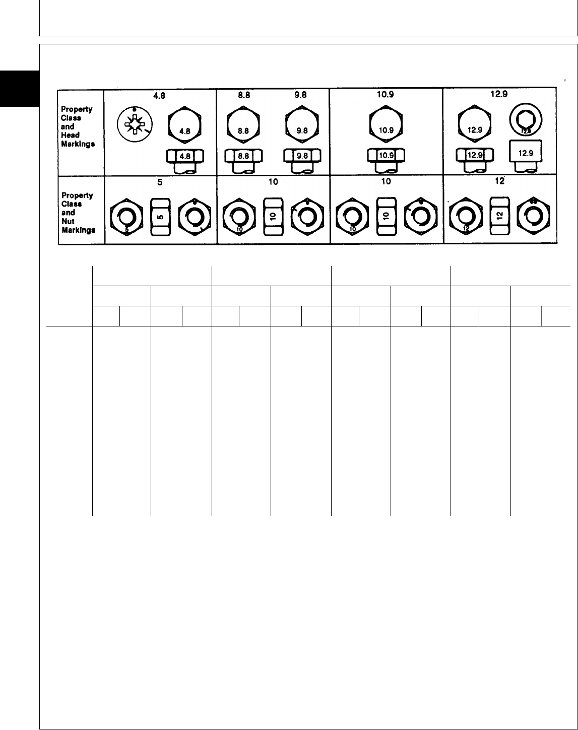
METRIC BOLT AND CAP SCREW TORQUE VALUES
Class 4.8 Class 8.8 or 9.8 Class 10.9 Class 12.9
Size LubricatedaDryaLubricatedaDryaLubricatedaDryaLubricatedaDrya
N·m lb-ft N·m lb-ft N·m lb-ft N·m lb-ft N·m lb-ft N·m lb-ft N·m lb-ft N·m lb-ft
M6 4.8 3.5 6 4.5 9 6.5 11 8.5 13 9.5 17 12 15 11.5 19 14.5
M8 12 8.5 15 11 22 16 28 20 32 24 40 30 37 28 47 35
M10 23 17 29 21 43 32 55 40 63 47 80 60 75 55 95 70
M12 40 29 50 37 75 55 95 70 110 80 140 105 130 95 165 120
M14 63 47 80 60 120 88 150 110 175 130 225 165 205 150 260 190
M16 100 73 125 92 190 140 240 175 275 200 350 255 320 240 400 300
M18 135 100 175 125 260 195 330 250 375 275 475 350 440 325 560 410
M20 190 140 240 180 375 275 475 350 530 400 675 500 625 460 800 580
M22 260 190 330 250 510 375 650 475 725 540 925 675 850 625 1075 800
M24 330 250 425 310 650 475 825 600 925 675 1150 850 1075 800 1350 1000
M27 490 360 625 450 950 700 1200 875 1350 1000 1700 1250 1600 1150 2000 1500
M30 675 490 850 625 1300 950 1650 1200 1850 1350 2300 1700 2150 1600 2700 2000
M33 900 675 1150 850 1750 1300 2200 1650 2500 1850 3150 2350 2900 2150 3700 2750
M36 1150 850 1450 1075 2250 1650 2850 2100 3200 2350 4050 3000 3750 2750 4750 3500
DO NOT use these values if a different torque value
or tightening procedure is given for a specific
application. Torque values listed are for general use
only. Check tightness of fasteners periodically.
Shear bolts are designed to fail under predetermined
loads. Always replace shear bolts with identical
property class.
Fasteners should be replaced with the same or
higher property class. If higher property class
fasteners are used, these should only be tightened to
the strength of the original.
Make sure fasteners threads are clean and that you
properly start thread engagement. This will prevent
them from failing when tightening.
Tighten plastic insert or crimped steel-type lock nuts
to approximately 50 percent of the dry torque shown
in the chart, applied to the nut, not to the bolt head.
Tighten toothed or serrated-type lock nuts to the full
torque value.
a “Lubricated” means coated with a lubricant such as engine oil, or
fasteners with phosphate and oil coatings. “Dry” means plain or zinc
plated without any lubrication.
TS1163 -19-04MAR91
DX,TORQ2 -19-20JUL94
Repair Specifications/Metric Series Torque Chart
TM1591 (15JUL95) 10-15-4 322,330,332 & 430 Lawn & Garden Tractors
030895
10
15
4
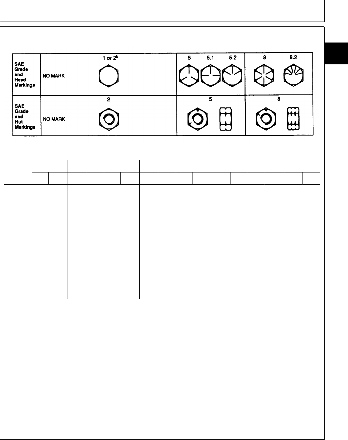
UNIFIED INCH BOLT AND CAP SCREW TORQUE VALUES
Grade 1 Grade 2bGrade 5, 5.1, or 5.2 Grade 8 or 8.2
Size LubricatedaDryaLubricatedaDryaLubricatedaDryaLubricatedaDrya
N·m lb-ft N·m lb-ft N·m lb-ft N·m lb-ft N·m lb-ft N·m lb-ft N·m lb-ft N·m lb-ft
1/4 3.7 2.8 4.7 3.5 6 4.5 7.5 5.5 9.5 7 12 9 13.5 10 17 12.5
5/16 7.7 5.5 10 7 12 9 15 11 20 15 25 18 28 21 35 26
3/8 14 10 17 13 22 16 27 20 35 26 44 33 50 36 63 46
7/16 22 16 28 20 35 26 44 32 55 41 70 52 80 58 100 75
1/2 33 25 42 31 53 39 67 50 85 63 110 80 120 90 150 115
9/16 48 36 60 45 75 56 95 70 125 90 155 115 175 130 225 160
5/8 67 50 85 62 105 78 135 100 170 125 215 160 240 175 300 225
3/4 120 87 150 110 190 140 240 175 300 225 375 280 425 310 550 400
7/8 190 140 240 175 190 140 240 175 490 360 625 450 700 500 875 650
1 290 210 360 270 290 210 360 270 725 540 925 675 1050 750 1300 975
1-1/8 400 300 510 375 400 300 510 375 900 675 1150 850 1450 1075 1850 1350
1-1/4 570 425 725 530 570 425 725 530 1300 950 1650 1200 2050 1500 2600 1950
1-3/8 750 550 950 700 750 550 950 700 1700 1250 2150 1550 2700 2000 3400 2550
1-1/2 1000 725 1250 925 990 725 1250 930 2250 1650 2850 2100 3600 2650 4550 3350
DO NOT use these values if a different torque value
or tightening procedure is given for a specific
application. Torque values listed are for general use
only. Check tightness of fasteners periodically.
Shear bolts are designed to fail under predetermined
loads. Always replace shear bolts with identical grade.
Fasteners should be replaced with the same or
higher grade. If higher grade fasteners are used,
these should only be tightened to the strength of the
original.
Make sure fasteners threads are clean and that you
properly start thread engagement. This will prevent
them from failing when tightening.
Tighten plastic insert or crimped steel-type lock nuts
to approximately 50 percent of the dry torque shown
in the chart, applied to the nut, not to the bolt head.
Tighten toothed or serrated-type lock nuts to the full
torque value.
a “Lubricated” means coated with a lubricant such as engine oil, or
fasteners with phosphate and oil coatings. “Dry” means plain or zinc
plated without any lubrication.
b Grade 2 applies for hex cap screws (not hex bolts) up to 152 mm
(6-in.) long. Grade 1 applies for hex cap screws over 152 mm (6-in.)
long, and for all other types of bolts and screws of any length.
TS1162 -19-04MAR91
DX,TORQ1 -19-20JUL94
Repair Specifications/Inch Series Torque Chart
TM1591 (15JUL95) 10-15-5 322,330,332 & 430 Lawn & Garden Tractors
030895
10
15
5
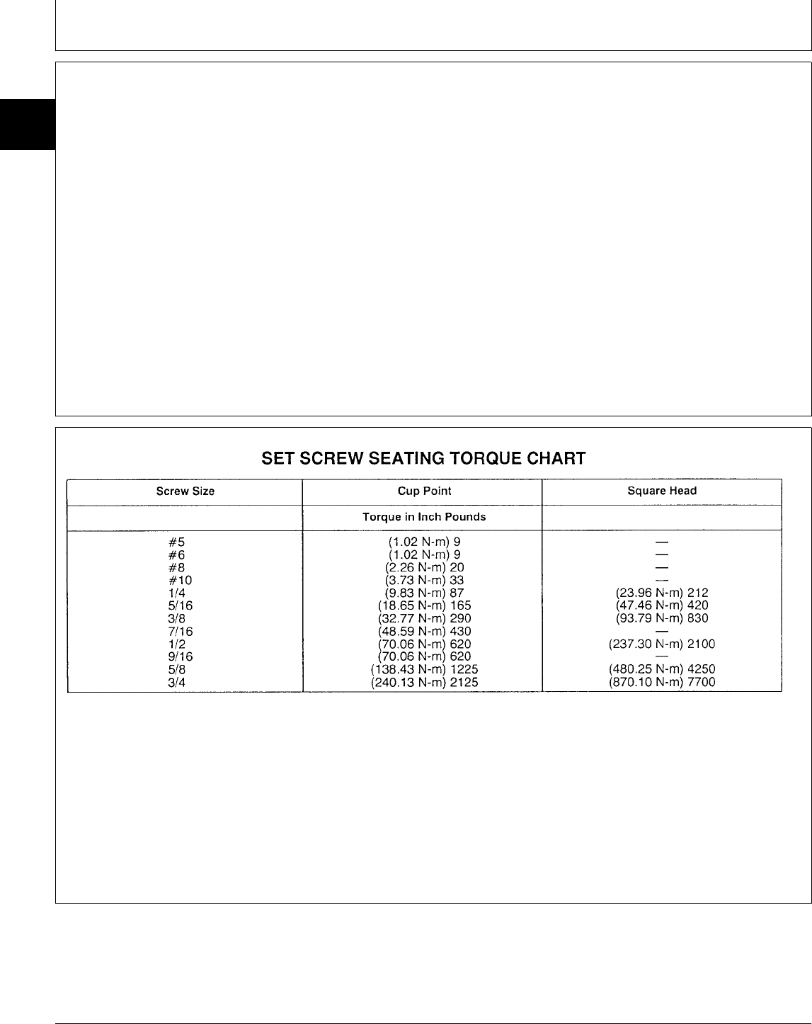
METRIC CAP SCREW TORQUE
VALUES—GRADE 7
NOTE: When bolting aluminum parts, tighten to 80% of
torque specified in table.
Size N·m (lb-ft)
M6 9.5 - 12.2 (7-9)
M8 20.3 - 27.1 (15-20)
M10 47.5 - 54.2 (35-40)
M12 81.4 - 94.9 (60-70)
M14 128.8 - 146.4 (95-108)
M16 210.2 - 240 (155-177)
NOTE: Allow a tolerance of plus or minus 10 per cent
on all torques given in this chart.
Divide readings by 12 for foot-pound values.
M77900 -19-15DEC94
MX,15901015,3 -19-01MAR95
MX,TORQ,SET -19-09DEC94
Repair Specifications/Set Screw Torque Chart
TM1591 (15JUL95) 10-15-6 322,330,332 & 430 Lawn & Garden Tractors
030895
10
15
6
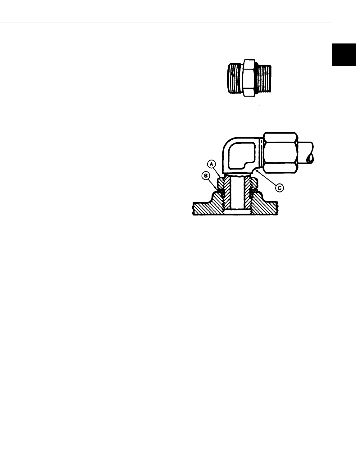
SERVICE RECOMMENDATIONS FOR O-RING
BOSS FITTINGS
STRAIGHT FITTING
1. Inspect O-ring boss seat for dirt or defects.
2. Lubricate O-ring with petroleum jelly. Place electrical
tape over threads to protect O-ring. Slide O-ring over
tape and into O-ring groove of fitting. Remove tape.
3. Tighten fitting to torque value shown on chart.
ANGLE FITTING
1. Back-off lock nut (A) and back-up washer (B)
completely to head-end (C) of fitting.
2. Turn fitting into threaded boss until back-up washer
contacts face of boss.
3. Turn fitting head-end counterclockwise to proper index
(maximum of one turn).
4. Hold fitting head-end with a wrench and tighten
locknut and back-up washer to proper torque value.
NOTE: Do not allow hoses to twist when tightening
fittings.
TORQUE VALUE
Thread Size N·m lb-ft
3/8-24 UNF . . . . . . . . . . . . . . . . 8 . . . . . . . . . . . . . . 6
7/16-20 UNF . . . . . . . . . . . . . . . 12 . . . . . . . . . . . . . . 9
1/2-20 UNF . . . . . . . . . . . . . . . 16 . . . . . . . . . . . . . 12
9/16-18 UNF . . . . . . . . . . . . . . . 24 . . . . . . . . . . . . . 18
3/4-16 UNF . . . . . . . . . . . . . . . 46 . . . . . . . . . . . . . 34
7/8-14 UNF . . . . . . . . . . . . . . . 62 . . . . . . . . . . . . . 46
1-1/16-12 UN . . . . . . . . . . . . . . . 102 . . . . . . . . . . . . . 75
1-3/16-12 UN . . . . . . . . . . . . . . . 122 . . . . . . . . . . . . . 90
1-5/16-12 UN . . . . . . . . . . . . . . . 142 . . . . . . . . . . . . 105
1-5/8-12 UN . . . . . . . . . . . . . . . 190 . . . . . . . . . . . . 140
1-7/8-12 UN . . . . . . . . . . . . . . . 217 . . . . . . . . . . . . 160
NOTE: Torque tolerance is ± 10%.
T6243AE -UN-18OCT88T6520AB -UN-18OCT88
MX,159110153,A -19-13JUL95
Repair Specifications/Set Screw Torque Chart
TM1591 (15JUL95) 10-15-7 322,330,332 & 430 Lawn & Garden Tractors
030895
10
15
7
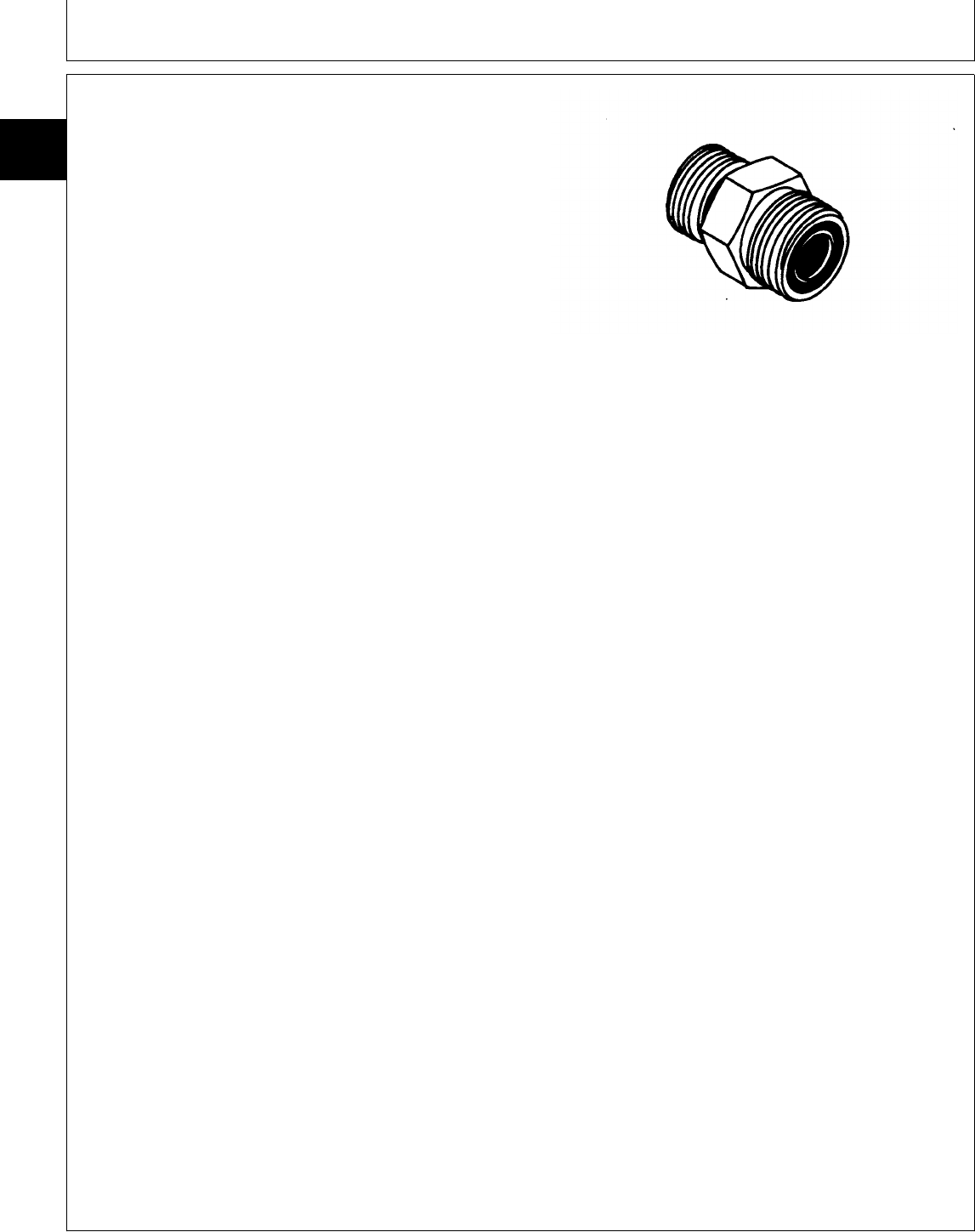
SERVICE RECOMMENDATIONS FOR FLAT
FACE O-RING SEAL FITTINGS
1. Inspect the fitting sealing surfaces. They must be free
of dirt or defects.
2. Inspect the O-ring. It must be free of damage or
defects.
3. Lubricate O-rings and install into groove using
petroleum jelly to hold in place.
4. Push O-ring into the groove with plenty of petroleum
jelly so O-ring is not displaced during assembly.
5. Index angle fittings and tighten by hand pressing joint
together to insure O-ring remains in place.
6. Tighten fitting or nut to torque valve shown on the
chart per dash size stamped on the fitting. Do not allow
hoses to twist when tightening fittings.
FLAT FACE O-RING SEAL FITTING TORQUE
Nominal Thread Swivel Nut Bulkhead
Tube O.D. Dash Size Torque Nut Torque
mm (in.) Size In. N·m (lb-ft) N·m (lb-ft)
6.35 0.250 -4 9/16-18 16 12 5.0 3.5
9.52 0.375 -6 11/16-16 24 18 9.0 6.5
12.70 0.500 -8 13/16-16 50 37 17.0 12.5
15.88 0.625 -10 1-14 69 51 17.0 12.5
19.05 0.750 -12 1 3/16-12 102 75 17.0 12.5
22.22 0.875 -14 1 3/16-12 102 75 17.0 12.5
25.40 1.000 -16 1 7/16-12 142 105 17.0 12.5
31.75 1.250 -20 1 11/16-12 190 140 17.0 12.5
38.10 1.500 -24 2-12 217 160 17.0 12.5
NOTE: Torque tolerance is +15 -20%.
T6243AD -UN-18OCT88
OR,SEAL,FIT -19-03MAR89
Repair Specifications/Service Recommendations
TM1591 (15JUL95) 10-15-8 322,330,332 & 430 Lawn & Garden Tractors
030895
10
15
8

TUBE AND HOSE FITTING, 37˚ FLARE AND
30˚ CONE SEAT CONNECTOR SERVICE
RECOMMENDATIONS
1. Inspect the flare and the flare seat. They must be free
of dirt and defects. If repeated leaks occur, inspect for
defects with a magnifying glass. If burrs and raised nicks
on the connector body cannot be removed with a slip
stone, replace the connector.
2. Defects in the tube flare cannot be repaired. Replace
the tube. Overtightening a defective flared fitting will not
stop leaks.
3. As a field repair, a ductile truncated cone shaped
washer can be used between the tube flare and
connector body. These washers are soft enough to fill
defects in the seat and flare. They will also seal the
connection. Ductile washers are available from industrial
supply houses.
4. Align the tube with the fitting before attempting to start
the nut. Failure to do so can cause a deformed flare and
subsequent leaks. Install hoses without twists. A twisted
hose attempts to straigten out when pressure is applied.
This exerts a torque on the connection, eventually
causing failure.
5. Lubricate the connection with hydraulic fluid, petroleum
jelly or soap. Tighten the swivel nut by hand until it is
snug.
6. Mark a line across the nut and connector body. This
line will serve as a visual indicator as to whether the nut
has been tightened and by how much.
7. Using two wrenches, one on the connector body and
a torque wrench on the nut, tighten the nut to the torque
value as shown in the chart. In the case of a hose, it
may be necessary to use three wrenches to prevent
twisting.
MX,15901015,4 -19-17JAN95
Repair Specifications/Service Recommendations
TM1591 (15JUL95) 10-15-9 322,330,332 & 430 Lawn & Garden Tractors
030895
10
15
9

TUBE AND HOSE FITTING, 37˚ FLARE AND 30˚ CONE SEAT CONNECTOR TORQUE
Thread Torque1New2Used 3
Size N·m (lb-ft) Number of Flats Number of Flats
3/8-24 UNF 8 (6) 2-1/2 1
7/16-20 UNF 12 (9) 2-1/2 1
1/2-20 UNF 16 (12) 2-1/2 1
9/16-18 UNF 24 (18) 2 1
3/4-16 UNF 46 (34) 2 1
7/8-14 UNF 62 (46) 1-1/2 1
1-1/16-12 UN 102 (75) 1 3/4
1-3/16-12 UN 122 (90) 1 3/4
1-5/16-12 UN 142 (105) 3/4 3/4
1-5/8-12 UN 190 (140) 3/4 3/4
1-7/8-12 UN 217 (160) 1/2 1/2
1. Tolerance of ± 10 percent.
2. To be used if a torque wrench cannot be used. After tightening fitting by hand, put a mark across the
fittings, then tighten fitting the number of flats shown.
3. Flare connection seal by deforming or squeezing the tube between the nut and the connector. More
deformation is possible with new parts than with old. Therefore, if a torque
rench is not used for re-assembly, the values in this column must be used to
revent damage.
MX,15901015,5 -19-17JAN95
Repair Specifications/Service Recommendations
TM1591 (15JUL95) 10-15-10 322,330,332 & 430 Lawn & Garden Tractors
030895
10
15
10

TEST AND ADJUSTMENT SPECIFICATIONS
Item Specifications
ENGINE—322
Slow Idle Speed
3TG66UJ . . . . . . . . . . . . . . . . . . . . . . . . . . . . . . . . . . . . . . . . . . . . . . . . . . . . . . . . 1350 ± 50 rpm
Fast Idle Speed
3TG66UJ . . . . . . . . . . . . . . . . . . . . . . . . . . . . . . . . . . . . . . . . . . . . . . . . . . . . . . . . 3450 ± 50 rpm
Fuel Pump
Minimum Fuel Flow
3TG66UJ . . . . . . . . . . . . . . . . . . . . . . . . . . . . . . . . . . . . . . . . . . . . . . . 200 mL (7 oz.)/30 seconds
Minimum Fuel Pressure
3TG66UJ . . . . . . . . . . . . . . . . . . . . . . . . . . . . . . . . . . . . . . . . . . . . . . . . . . . . . . . . 14 kPa (2 psi)
Choke Plate Clearance (Later models) . . . . . . . . . . . . . . . . . . . . . . . . . . . . . . . . . . . . . . . 2 mm (0.78 in.)
Oil Pressure
3TG66UJ . . . . . . . . . . . . . . . . . . . . . . . . . . . . . . . . . . . . . . . . . . . . . . . . 294—440 kPa (43—64 psi)
Spark Plug Gap
3TG66UJ . . . . . . . . . . . . . . . . . . . . . . . . . . . . . . . . . . . . . . . . . . . . . . . . . . . . . 0.80 mm (0.032 in.)
Cooling System Pressure Test
3TG66UJ . . . . . . . . . . . . . . . . . . . . . . . . . . . . . . . . . . . . . . . . . . . . . . . . . . . . . . . 117 kPa (17 psi)
Minimum Pressure After After 15 Seconds
3TG66UJ . . . . . . . . . . . . . . . . . . . . . . . . . . . . . . . . . . . . . . . . . . . . . . . . . . . . . . . 90 kPa (13 psi)
Radiator Cap
Opening Pressure
3TG66UJ . . . . . . . . . . . . . . . . . . . . . . . . . . . . . . . . . . . . . . . . . . . . . . . . 97—104 kPa (14—15 psi)
Compression
Minimum
3TG66UJ . . . . . . . . . . . . . . . . . . . . . . . . . . . . . . . . . . . . . . . . . . . . . . . . . . . . . 779 kPa (113 psi)
Maximum Difference Between Cylinders
3TG66UJ . . . . . . . . . . . . . . . . . . . . . . . . . . . . . . . . . . . . . . . . . . . . . . . . . . . . . . . 97 kPa (14 psi)
Engine Cranking Speed
3TG66UJ . . . . . . . . . . . . . . . . . . . . . . . . . . . . . . . . . . . . . . . . . . . . . . . . . . . . . . . . . . . . 300 rpm
MX,15911020,1 -19-13JUL95
Group 20
Test and Adjustment Specifications
TM1591 (15JUL95) 10-20-1 322,330,332 & 430 Lawn & Garden Tractors
030895
10
20
1

Item Specifications
ENGINE—330, 332, and 430
Fuel Pump
Minimum Fuel Flow
3TN66UJ . . . . . . . . . . . . . . . . . . . . . . . . . . . . . . . . . . . . . . . . . . . . . . . 200 mL (7 oz.)/30 seconds
3TNA72UJ . . . . . . . . . . . . . . . . . . . . . . . . . . . . . . . . . . . . . . . . . . . . . 600 mL (20 oz.)/30 seconds
Minimum Fuel Pressure
3TN66UJ . . . . . . . . . . . . . . . . . . . . . . . . . . . . . . . . . . . . . . . . . . . . . . . . . . . . . . . . 21 kPa (3 psi)
3TNA72UJ . . . . . . . . . . . . . . . . . . . . . . . . . . . . . . . . . . . . . . . . . . . . . . . . . . . . . . . 21 kPa (3 psi)
Compression
Minimum
3TN66UJ . . . . . . . . . . . . . . . . . . . . . . . . . . . . . . . . . . . . . . . . . . . . . . . . . . . . . 2448 kPa (355 psi)
3TNA72UJ . . . . . . . . . . . . . . . . . . . . . . . . . . . . . . . . . . . . . . . . . . . . . . . . . . . . 2448 kPa (355 psi)
Maximum Difference Between Cylinders
3TN66UJ . . . . . . . . . . . . . . . . . . . . . . . . . . . . . . . . . . . . . . . . . . . . . . . . . . . . . . 490 kPa (71 psi)
3TNA72UJ . . . . . . . . . . . . . . . . . . . . . . . . . . . . . . . . . . . . . . . . . . . . . . . . . . . . . 490 kPa (71 psi)
Miniumum Engine Cranking Speed . . . . . . . . . . . . . . . . . . . . . . . . . . . . . . . . . . . . . . . . . . . . 250 rpm
Oil Pressure
3TN66UJ . . . . . . . . . . . . . . . . . . . . . . . . . . . . . . . . . . . . . . . . . . . . . . . . . 365 ±69 kPa (53 ±10 psi)
3TNA72UJ . . . . . . . . . . . . . . . . . . . . . . . . . . . . . . . . . . . . . . . . . . . . . . . . 365 ±69 kPa (53 ±10 psi)
Slow Idle Speed
3TN66UJ and Later 3TNA72UJ . . . . . . . . . . . . . . . . . . . . . . . . . . . . . . . . . . . . . . . . . . 1350 ± 50 rpm
Early 3TNA72UJ . . . . . . . . . . . . . . . . . . . . . . . . . . . . . . . . . . . . . . . . . . . . . . . . . . . 1300 ± 50 rpm
Fast Idle Speed
3TN66UJ and Later 3TNA72UJ . . . . . . . . . . . . . . . . . . . . . . . . . . . . . . . . . . . . . . . . . . 3450 ± 50 rpm
Early 3TNA72UJ . . . . . . . . . . . . . . . . . . . . . . . . . . . . . . . . . . . . . . . . . . . . . . . . . . . 3400 ± 50 rpm
Cooling System Pressure Test
3TN66UJ . . . . . . . . . . . . . . . . . . . . . . . . . . . . . . . . . . . . . . . . . . . . . . . . . . . . . . . 117 kPa (17 psi)
3TNA72UJ . . . . . . . . . . . . . . . . . . . . . . . . . . . . . . . . . . . . . . . . . . . . . . . . . . . . . . 117 kPa (17 psi)
Minimum Pressure After After 15 Seconds
3TN66UJ . . . . . . . . . . . . . . . . . . . . . . . . . . . . . . . . . . . . . . . . . . . . . . . . . . . . . . . 90 kPa (13 psi)
3TNA72UJ . . . . . . . . . . . . . . . . . . . . . . . . . . . . . . . . . . . . . . . . . . . . . . . . . . . . . . 90 kPa (13 psi)
Radiator Cap
Opening Pressure
3TN66UJ . . . . . . . . . . . . . . . . . . . . . . . . . . . . . . . . . . . . . . . . . . . . . . . . 97—104 kPa (14—15 psi)
3TNA72UJ . . . . . . . . . . . . . . . . . . . . . . . . . . . . . . . . . . . . . . . . . . . . . . . 97—104 kPa (14—15 psi)
Fuel Injection Pump Cover Nut Torque
3TN66UJ and Later 3TNA72UJ . . . . . . . . . . . . . . . . . . . . . . . . . . . . . . . . . . . . . . . . . 9 N·m (78 lb-in.)
Fuel Injection Pump Cover Cap Screw Torque
Early 3TNA72UJ . . . . . . . . . . . . . . . . . . . . . . . . . . . . . . . . . . . . . . . . . . . . . . . . . . 9 N·m (78 lb-in.)
MX,15911020,3 -19-13JUL95
Test and Adjustment Specifications
TM1591 (15JUL95) 10-20-2 322,330,332 & 430 Lawn & Garden Tractors
030895
10
20
2

Item Specifications
ELECTRICAL SYSTEM
Pulser Coils—322
Minimum Voltage Output . . . . . . . . . . . . . . . . . . . . . . . . . . . . . . . . . . . . . . . . . . . . . . . . . . . 0.05 VAC
Resistance . . . . . . . . . . . . . . . . . . . . . . . . . . . . . . . . . . . . . . . . . . . . . . . . . . . . . . . 15.5—23.3 ohms
Ignition Coils—322
Primary Coil Resistance . . . . . . . . . . . . . . . . . . . . . . . . . . . . . . . . . . . . . . . . . . . . . . . . 3.8—5.2 ohms
Secondary Coil Resistance . . . . . . . . . . . . . . . . . . . . . . . . . . . . . . . . . . . . . . . . . . . 10.8—16.2 K-ohms
Glow Plugs—330, 332 and 430
Minimum Resistance . . . . . . . . . . . . . . . . . . . . . . . . . . . . . . . . . . . . . . . . . . . . . . . . . . . . 1.00 ohms
PTO Clutch Armature-to-Rotor Clearance . . . . . . . . . . . . . . . . . . . . . . . . . . . . . . . . . . 0.46 mm (0.018 in.)
Starter—322, 330 and 332
Current Draw (Maximum) . . . . . . . . . . . . . . . . . . . . . . . . . . . . . . . . . . . . . . . . . . . . . . . . . . 230 amps
No-Load rpm (Minimum) . . . . . . . . . . . . . . . . . . . . . . . . . . . . . . . . . . . . . . . . . . . . . . . . . . . 7000 rpm
No-Load Amp Draw (Maximum) . . . . . . . . . . . . . . . . . . . . . . . . . . . . . . . . . . . . . . . . . . . . . . . 60 amps
Starter—430
Current Draw (Maximum) . . . . . . . . . . . . . . . . . . . . . . . . . . . . . . . . . . . . . . . . . . . . . . . . . . 230 amps
No-Load rpm (Minimum) . . . . . . . . . . . . . . . . . . . . . . . . . . . . . . . . . . . . . . . . . . . . . . . . . . . 3000 rpm
No-Load Amp Draw (Maximum) . . . . . . . . . . . . . . . . . . . . . . . . . . . . . . . . . . . . . . . . . . . . . . . 90 amps
Fuel Shutoff Solenoid (430 S.N. —420468)
Lever-to-Stop Clearance . . . . . . . . . . . . . . . . . . . . . . . . . . . . . . . . . . . . . . . . . . . . . . 2 mm (0.080 in.)
Alternator—322, 330 and 332
Regulated Voltage Output . . . . . . . . . . . . . . . . . . . . . . . . . . . . . . . . . . . . . . . . . . . . . . . 13.5—15 volts
Unregulated Voltage Output (Minimum) . . . . . . . . . . . . . . . . . . . . . . . . . . . . . . . . . . . . . . . . . . 30 volts
Regulated Current Output (Minimum) . . . . . . . . . . . . . . . . . . . . . . . . . . . . . . . . . . . . . . . . . . . 18 amps
Alternator—430
Regulated Voltage Output . . . . . . . . . . . . . . . . . . . . . . . . . . . . . . . . . . . . . . . . . . . . . . 13.8—14.7 volts
Unregulated Current Output (Minimum)
(S.N. —420468) . . . . . . . . . . . . . . . . . . . . . . . . . . . . . . . . . . . . . . . . . . . . . . . . . . . . . . 35 amps
(S.N. 420469— ) . . . . . . . . . . . . . . . . . . . . . . . . . . . . . . . . . . . . . . . . . . . . . . . . . . . . . . 40 amps
POWER TRAIN
Oil Temperature for Hydraulic Tests . . . . . . . . . . . . . . . . . . . . . . . . . . . . . . . . . . . . . . . . . . . 43˚C (110˚F)
Charge Pump Pressure . . . . . . . . . . . . . . . . . . . . . . . . . . . . . . . . . . . . . . . 620—1240 kPa (90—180 psi)
Implement Relief Valve Pressure . . . . . . . . . . . . . . . . . . . . . . . . . . . . . . . . 5861—6722 kPa (850—975 psi)
Minimum Charge Pump Flow at 3450 kPa (500 psi) . . . . . . . . . . . . . . . . . . . . . . . . . . . . . 11 L/min (3 gpm)
322, 332 and 430; Steering Valve Pressure in Neutral Position . . . . . . . . . . . . . 620—1240 kPa (90—180 psi)
Hydrostatic Lever Tension . . . . . . . . . . . . . . . . . . . . . . . . . . . . . . . . . . . . . . . 31—44.5 N (7—10 lb force)
Turnbuckle Lock Nut Torque
(Transmission Control Lever Linkage,
330 and Version One—322, 332 and 430) . . . . . . . . . . . . . . . . . . . . . . . . . . . . . . . . . . . 33 N·m (24 lb-ft)
Detent Spring Length (Transmission Control Lever
Linkage, Later Versions—322, 332 and 430) . . . . . . . . . . . . . . . . . . . . . . . . . . . . . . . . . 50 mm (1.970 in.)
MX,15911020,2 -19-13JUL95
Test and Adjustment Specifications
TM1591 (15JUL95) 10-20-3 322,330,332 & 430 Lawn & Garden Tractors
030895
10
20
3

Item Specifications
STEERING AND BRAKES
Oil Temperature for Hydraulic Tests . . . . . . . . . . . . . . . . . . . . . . . . . . . . . . . . . . . . . . . . . . . 43˚C (110˚F)
Steering System Leakage Test at Slow Idle
Torque Applied to Steering Wheel Nut . . . . . . . . . . . . . . . . . . . . . . . . . . . . . . . . . . . . 6.8 N·m (60 lb-in.)
Maximum Left and Right Turn rpm . . . . . . . . . . . . . . . . . . . . . . . . . . . . . . . . . . . . . . . . . . . . . . . 6 rpm
HYDRAULIC SYSTEM
Oil Temperature for Hydraulic Tests . . . . . . . . . . . . . . . . . . . . . . . . . . . . . . . . . . . . . . . . . . . 43˚C (110˚F)
Control Valve Leakage Test
Control Valve Pressure . . . . . . . . . . . . . . . . . . . . . . . . . . . . . . . . . . . . . 5860—6550 kPa (850—950 psi)
Control Valve Leakage . . . . . . . . . . . . . . . . . . . . . . . . . . . . . . . . . . . . . . . . . . 15 mL/min (1/2 fl oz/min)
MX,15911020,4 -19-13JUL95
Test and Adjustment Specifications
TM1591 (15JUL95) 10-20-4 322,330,332 & 430 Lawn & Garden Tractors
030895
10
20
4

FUEL—322
NCAUTION: Handle fuel carefully. If the engine
is hot or running, do not fill the fuel tank. Do
not smoke while you fill the fuel tank or
service the fuel system. Fill fuel tank only to
bottom of filler neck.
IMPORTANT: DO NOT mix oil with gasoline.
1. Unleaded fuel is recommended. Regular leaded
gasoline with an anti-knock index of 87 or higher may be
used. Avoid switching from unleaded to regular gasoline
to prevent engine damage.
Use of gasohol is acceptable as long as the ethyl
alcohol blend does not exceed 10 percent. Unleaded
gasohol is preferred over leaded gasohol.
2. Fill fuel tank at end of each day’s operation. Fill fuel
tank only to bottom of filler neck.
M33122 -UN-25AUG88
MX,15911025,1 -19-13JUL95
Group 25
Fuels and Lubricants
TM1591 (15JUL95) 10-25-1 322,330,332 & 430 Lawn & Garden Tractors
030895
10
25
1
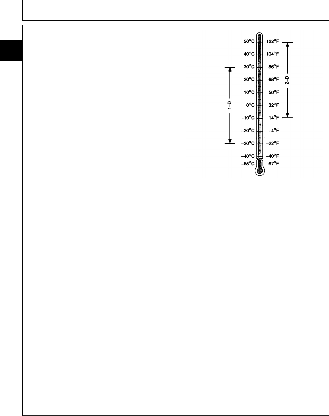
DIESEL FUEL—330, 332 AND 430
Consult your local fuel distributor for properties of the
diesel fuel available in your area.
In general, diesel fuels are blended to satisfy the low
temperature requirements of the geographical area in
which they are marketed. Recommended standard
grades are shown on the temperature charts.
Diesel fuels meeting Military Specification VV-F-800E are
preferred. If diesel fuel specified to ASTM D975 is used,
the fuel must meet the following properties:
• Cetane Number 40 minimum.
Cetane number greater than 50 is preferred, especially
for temperatures below -20˚C (-4˚F) or elevations above
1500 m (5000 ft).
• Cold Filter Plugging Point (CFPP) below the expected
low temperature OR Cloud Point at least 5˚C (9˚F) below
the expected low temperature North America ASTM D975
• Sulfur content:
— Sulfur content should not exceed 0.5% Sulfur content
less than 0.05% is preferred.
— If diesel fuel with sulfur content greater than 0.5%
sulfur content is used, reduce the service interval for
engine oil and filter by 50%
— DO NOT use diesel fuel with sulfur content greater
than 1.0%
• Lubricity
— Fuel lubricity must pass the BOCLE scuffing test at
3300 gram minimum load level.
— If fuel of low or unknown lubricity is used, add John
Deere All-Season Diesel Fuel Conditioner at specified
concentration.
Bio-diesel fuels with these properties and meeting an
appropriate specification may be used as an alternative
to petroleum-based diesel fuel.
Arctic fuels (such as Military Specification VV-F-800E,
Grade DF-A) may be used at temperatures below -30˚C
(-22˚F).
NCAUTION: Handle fuel carefully. Do not fill the
fuel tank when engine is running. DO NOT
smoke while you fill the fuel tank or service
the fuel system.
TS1611 -UN-31JAN94
MX,15911025,2 -19-13JUL95
Fuels and Lubricants/Diesel Fuel—330, 332 and 430
TM1591 (15JUL95) 10-25-2 322,330,332 & 430 Lawn & Garden Tractors
030895
10
25
2

STORING FUEL
If there is a very slow turnover of fuel in the fuel tank or
supply tank, it may be necessary to add a fuel
conditioner to prevent water condensation. Contact your
John Deere dealer for proper service or maintenance
recommendations.
DO NOT USE GALVANIZED CONTAINERS
IMPORTANT: Diesel fuel stored in galvanized
containers reacts with zinc coating
on the container to form zinc flakes.
If fuel contains water, a zinc gel will
also form. The gel and flakes will
quickly plug fuel filters and damage
fuel injectors and fuel pumps.
DO NOT USE a galvanized container to store diesel
fuel.
Store fuel in:
—plastic containers.
—aluminum containers.
—specially coated steel containers made for diesel
fuel.
DO NOT USE brass-coated containers: brass is an
alloy of copper and zinc.
DX,FUEL -19-03MAR93
M21,FLQ,B1 -19-02AUG85
Fuels and Lubricants/Do Not Use Galvanized Containers
TM1591 (15JUL95) 10-25-3 322,330,332 & 430 Lawn & Garden Tractors
030895
10
25
3
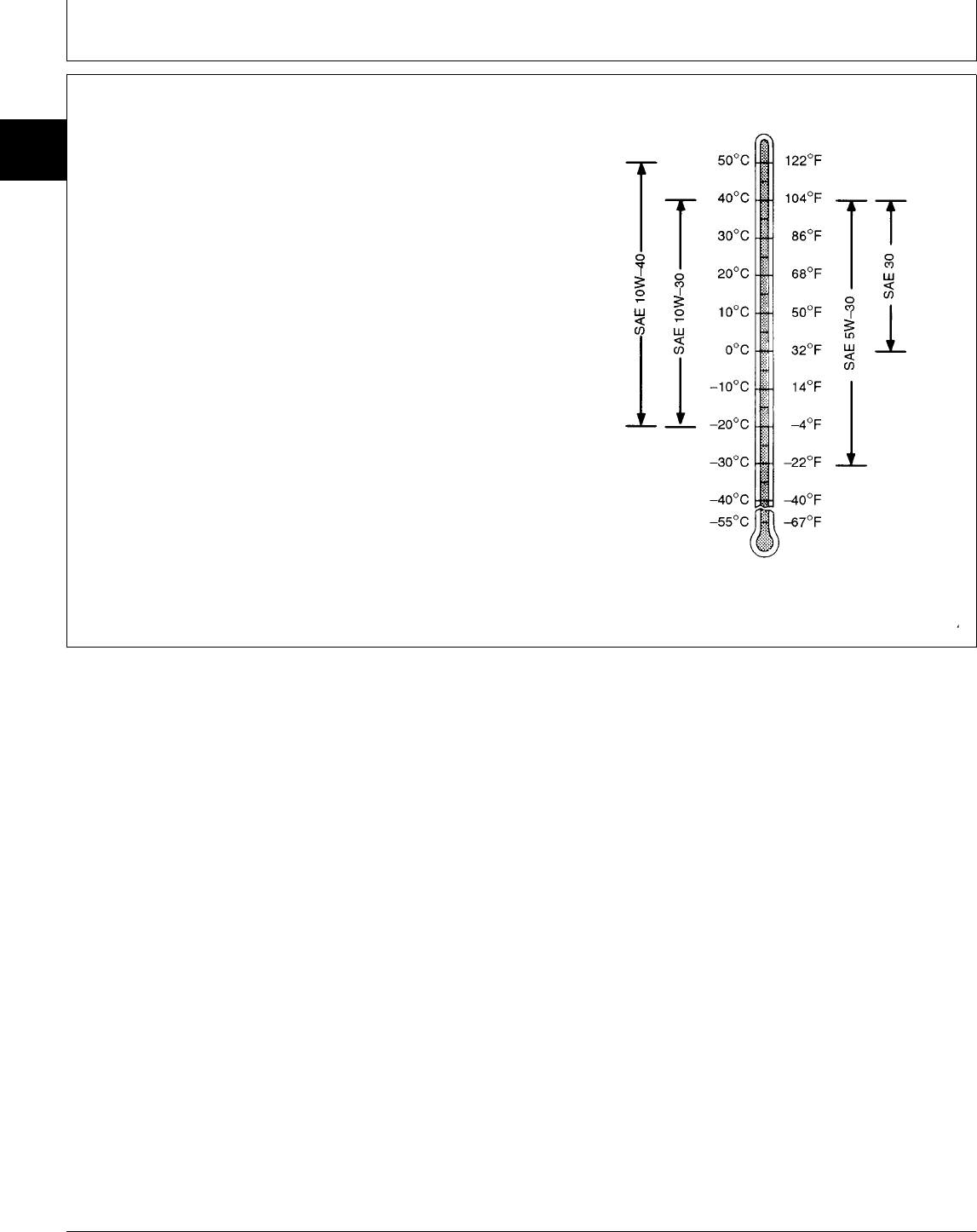
ENGINE OIL—322
Use oil viscosity based on the expected air temperature
range during the period between oil changes.
The following oils are preferred:
• John Deere TURF-GARD™
• John Deere PLUS-4®
Other oils may be used if they meet one or more of the
following:
• API Service Classification SH
• API Service Classification SG
• CCMC Specification G5
Arctic oils (such as Military Specification MIL-L-46167B)
may be used at temperature below -30˚C (-22˚F).
TS1624 -UN-07NOV94
MX,15911025,3 -19-13JUL95
Fuels and Lubricants/Engine Oil—322
TM1591 (15JUL95) 10-25-4 322,330,332 & 430 Lawn & Garden Tractors
030895
10
25
4
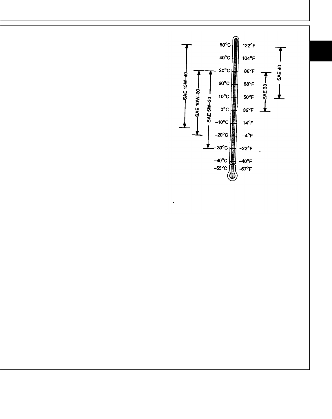
DIESEL ENGINE OIL—330, 332 AND 430
Use oil viscosity based on the expected air temperature
range during the period between oil changes.
Viscosity grade SAE 15W-40 is preferred.
If other viscosity grades are used, reduce the service
interval for oil and filter changes by 50%
The following oil is preferred:
• John Deere TORQ-GARD SUPREME© PLUS-50™
If John Deere TORQ-GARD SUPREME PLUS-50 engine
oil and a John Deere oil filter are used, the service
interval for oil and filter changes may be extended by 50
hours.
The following oil is also recommended:
• John Deere TORQ-GARD SUPREME©
Other oils may be used if they meet one or more of the
following:
• API Service Classification CG4
• API Service Classification CF4
• API Service Classification CE
Oils meeting one of the following may be used, but
reduce the service interval for engine oil and filter
changes by 50%:
• John Deere UNI-GARD™
• CCMC Specification D5
• CCMC Specification D4
If diesel fuel with sulfur content greater than 0.5% is
used, reduce the service interval for engine oil and filter
by 50%
Arctic oils (such as Military Specification MIL-L-46167B)
may be used at temperatures below -30˚C (-22˚F).
Reduce the service interval for oil and filter changes by
50%
TS1618 -UN-22JUL94
MX,15911025,4 -19-13JUL95
Fuels and Lubricants/Diesel Engine Oil—330, 332 and 430
TM1591 (15JUL95) 10-25-5 322,330,332 & 430 Lawn & Garden Tractors
030895
10
25
5

ENGINE COOLANT
John Deere Low Silicate Antifreeze is recommended.
Also recommended is low silicate antifreeze
formulated to GM6038M or equivalent.
Other antifreezes that may be used:
• Ethylene-glycol type.
• Those containing not more than 0.1 percent
anhydrous metasilicate.
• Those meeting General Motors Performance
Specification GM1899M
IMPORTANT: Some types of ethylene-glycol
antifreeze are intended for
automotive use. These products are
often labeled for use in aluminum
engines and usually contain more
than 0.1 percent of anhydrous
metasilicate.
Check container label or consult with antifreeze
supplier before using.
Mix 50-67 percent low silicate antifreeze with 33-50
percent distilled or deionized water.
Low silicate antifreeze provides:
• Adequate heat transfer.
• Corrosion-resistant environment within the cooling
system.
• Compatibility with cooling system hose and seal
material.
• Protection during cold and hot weather operations.
Certain geographical areas may require special
antifreeze or coolant practices. If you have any
questions, consult your authorized servicing dealer to
obtain the latest information and recommendations.
LIQUID COOLANT CONDITIONER
John Deere Liquid Coolant Conditioner is recommended
for wet-sleeve diesel engines not having a coolant filter
option. Other conditioners may be used if it contains
non-chromate inhibitors.
IMPORTANT: If engine is equipped with a John Deere
Coolant Filter Conditioner, the correct
inhibitors are contained in the filter. If
both are used, a gel-type deposit is
created which could inhibit heat
transfer and block coolant flow. John
Deere Liquid Coolant Conditioner does
not protect against freezing.
Various sizes of coolant conditioners are available from
your John Deere dealer.
RG4690 -UN-14DEC88
DX,COOL -19-04JUN90
DX,COOL1 -19-04JUN90
Fuels and Lubricants/Liquid Coolant Conditioner
TM1591 (15JUL95) 10-25-6 322,330,332 & 430 Lawn & Garden Tractors
030895
10
25
6
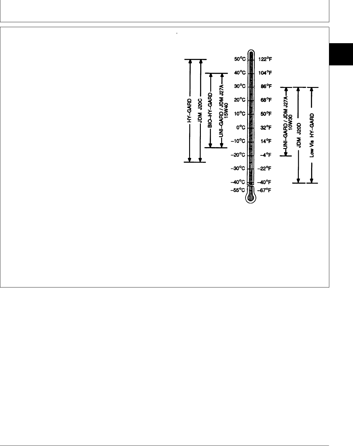
TRANSMISSION AND HYDRAULIC OIL
Use oil viscosity based on the expected air temperature
range during the period between oil changes.
The following oils are preferred:
• John Deere HY-GARD®
• John Deere Low Viscosity HY-GARD®
The following oils are also recommended:
• John Deere UNI-GARD™
• John Deere BIO-HY-GARD™1
Other oils may be used if they meet one of the following:
• John Deere Standard JDM J20C
• John Deere Standard JDM J20D
• John Deere Standard JDM J27A
IMPORTANT: Do not use engine oil for this
application.
Arctic oils (such as Military Specification MIL-L-46167B)
may be used at temperatures below -30˚C (-22˚F).
1BIO-HY-GARD meets or exceeds the minimum biodegradability of 80%
within 21 days according to CEC-L-33-T-82 test method. BIO-HY-GARD
should not be mixed with mineral oils because this reduces the
biodegradability and makes proper oil recycling impossible.
TS1413 -UN-31JAN94
DX,ANTI -19-01FEB94
Fuels and Lubricants/Transmission and Hydraulic Oil
TM1591 (15JUL95) 10-25-7 322,330,332 & 430 Lawn & Garden Tractors
030895
10
25
7
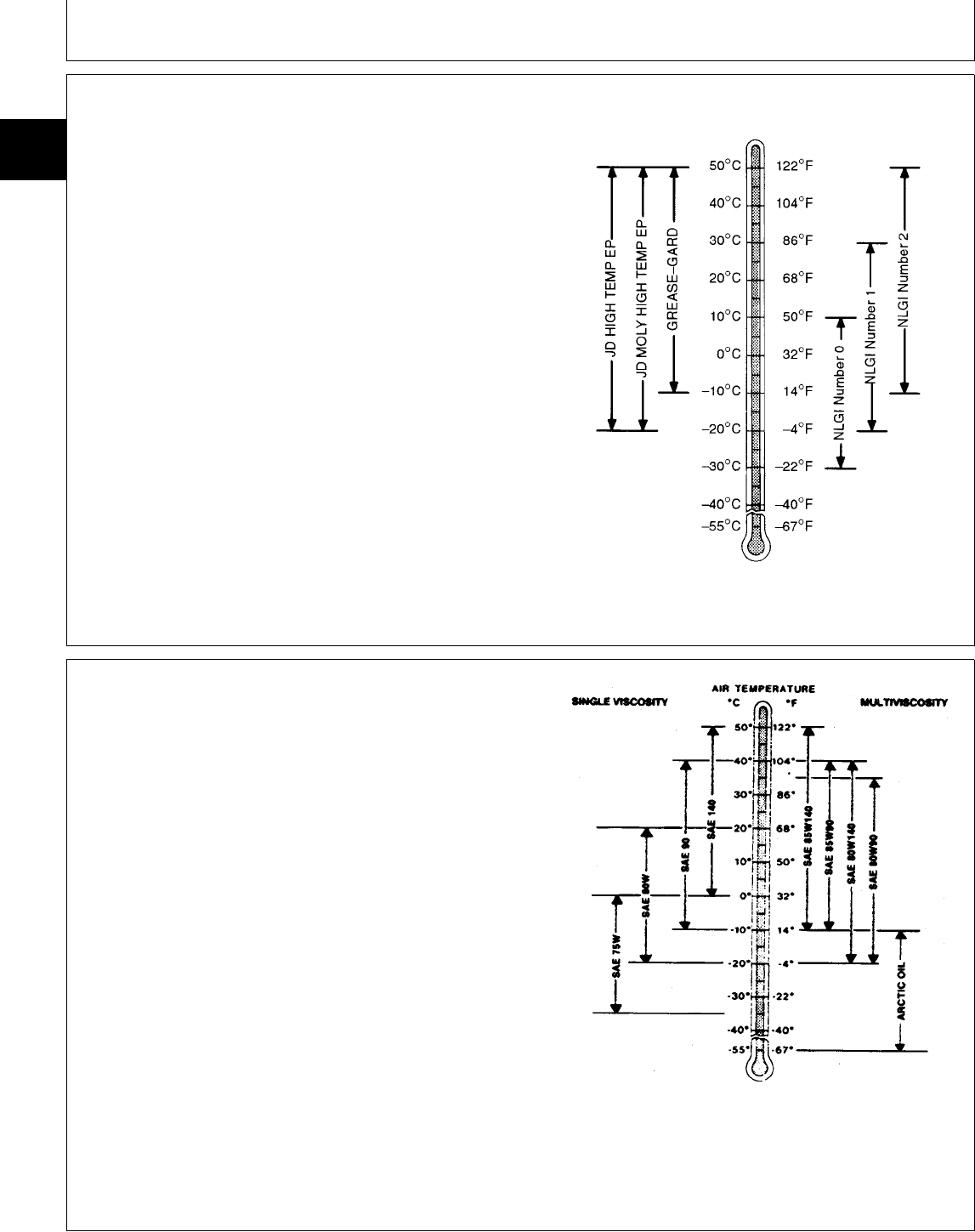
GREASE
Use grease based on the expected air temperature
range during the service interval.
The following greases are preferred:
• John Deere MOLY HIGH TEMPERATURE EP
GREASE
• John Deere HIGH TEMPERATURE EP GREASE
• John Deere GREASE-GARD™
Other greases may be used if they meet one of the
following:
• SAE Multipurpose EP Grease with a maximum of
5% molybdenum disulfide
• SAE Multipurpose EP Grease
Greases meeting Military Specification MIL-G-10924F
may be used as arctic grease.
TS1622 -UN-02NOV94
MOWER DECK GEAR CASE OIL
Depending upon the expected air temperature range
during the drain interval, use oil viscosity shown on the
adjoining temperature chart.
John Deere API GL-5 Gear Oil is recommended. If other
oils are used, they must meet performance requirements
of:
•API Service Classification GL-5
•Military Specificaiton MIL-L-2105C
X9322 -19-30SEP88
DX,GREA1 -19-02NOV94
MX,15901025,3 -19-14FEB95
Fuels and Lubricants/Mower Deck Gear Case Oil
TM1591 (15JUL95) 10-25-8 322,330,332 & 430 Lawn & Garden Tractors
030895
10
25
8

ALTERNATIVE AND SYNTHETIC LUBRICANTS
Conditions in certain geographical areas may require
lubricant recommendations different from those
printed in this manual. Some John Deere lubricants
may not be available in your location. Consult your
John Deere dealer to obtain information and
recommendations.
Synthetic lubricants may be used if they meet the
performance requirements listed in this manual.
LUBRICANT STORAGE
Your equipment can operate at top efficiency only if
clean lubricants are used.
Use clean containers to handle all lubricants.
Whenever possible, store lubricants and containers in
an area protected from dust, moisture, and other
contamination. Store containers on their side to avoid
water and dirt accumulation.
MIXING OF LUBRICANTS
In general, avoid mixing different brands or types of oil.
Oil manufacturers blend additives in their oils to meet
certain specifications and performance requirements.
Mixing different oils can interfere with the proper
functioning of these additives and degrade lubricant
performance.
DX,ALTER -19-01FEB94
DX,LUBST -19-01FEB94
DX,LUBMIX -19-01FEB94
Fuels and Lubricants/Mixing of Lubricants
TM1591 (15JUL95) 10-25-9 322,330,332 & 430 Lawn & Garden Tractors
030895
10
25
9

Fuels and Lubricants/Mixing of Lubricants
TM1591 (15JUL95) 10-25-10 322,330,332 & 430 Lawn & Garden Tractors
030895
10
25
10
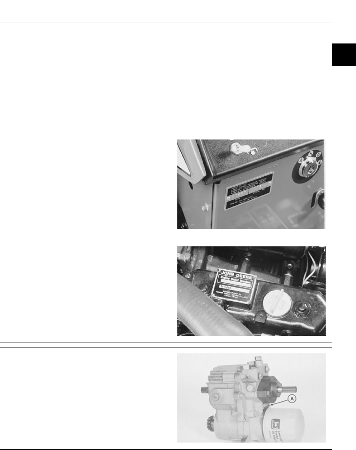
SERIAL NUMBERS
When working on machines or components that are
covered by warranty, it is IMPORTANT that you include
the tractor Product Identification Number and the
component serial number on the warranty claim form.
The location of component serial number plates are
shown below.
PRODUCT IDENTIFICATION NUMBER
NOTE: All identification number plates are located on the
pedestal. On some models, the plate is on the
right-hand side. On others, front top left corner.
M34494 -UN-08NOV89
ENGINE SERIAL NUMBER
M34495 -UN-08NOV89
TRANSMISSION SERIAL NUMBER
Serial number plate (A) location.
M38478 -UN-29AUG88
MX,M21,1030R,1 -19-22APR85
MX,15901030,1 -19-12MAY95
MX,15911030,1 -19-13JUL95
MX,15901030,3 -19-12MAY95
Group 30
Serial Number Locations
TM1591 (15JUL95) 10-30-1 322,330,332 & 430 Lawn & Garden Tractors
030895
10
30
1
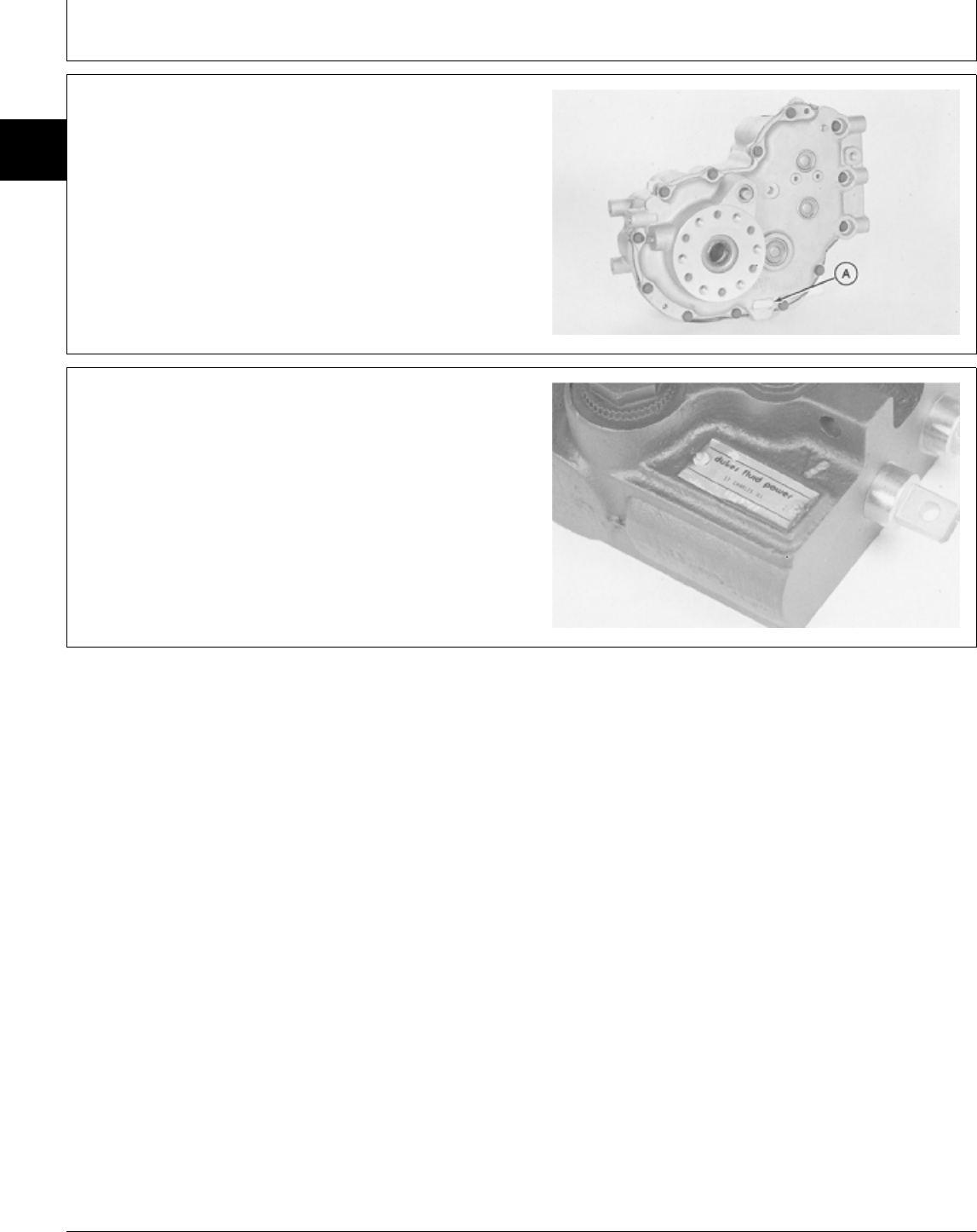
DIFFERENTIAL SERIAL NUMBER
Serial number plate (A) location.
M38479 -UN-29AUG88
CONTROL VALVE SERIAL NUMBER
M38480 -UN-29AUG88
MX,15901030,4 -19-12MAY95
MX,15901030,5 -19-12MAY95
Serial Number Locations/Serial Numbers
TM1591 (15JUL95) 10-30-2 322,330,332 & 430 Lawn & Garden Tractors
030895
10
30
2

Section 20
ENGINE REPAIR
Contents
Page
Group 05—Engine—322
Repair—Use CTM12 . . . . . . . . . . . . . . . 20-05-1
Remove and Install . . . . . . . . . . . . . . . 20-05-1
Group 06—Engine—330, 332 and 430
Repair—Use CTM3 . . . . . . . . . . . . . . . 20-06-1
Remove and Install—330 and 332 . . . . . 20-06-1
Remove—430 . . . . . . . . . . . . . . . . . . . 20-06-4
Install—430 . . . . . . . . . . . . . . . . . . . . . 20-06-8
TM1591 (15JUL95) 20-1 322,330,332 & 430 Lawn & Garden Tractors
030895
20

Contents
TM1591 (15JUL95) 20-2 322,330,332 & 430 Lawn & Garden Tractors
030895
20
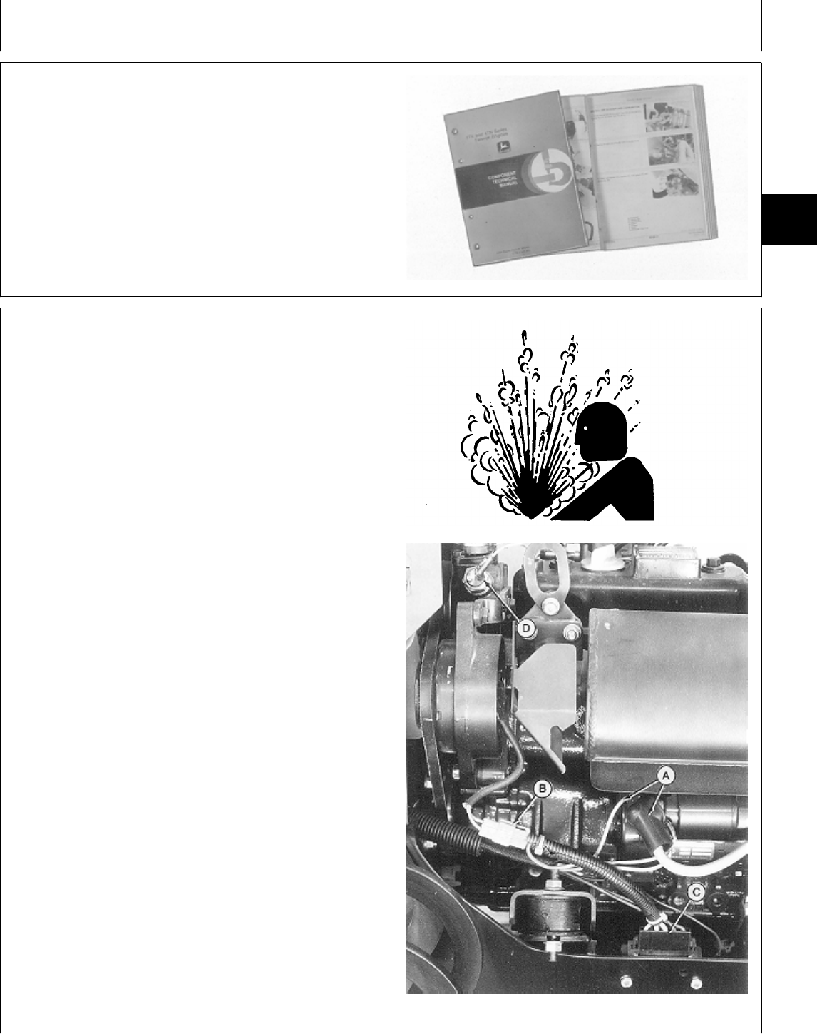
YANMAR GASOLINE ENGINE REPAIR—USE
CTM12
For complete repair information, the component technical
manual (CTM) is also required. Use the component
technical manual in conjunction with this machine
manual.
TS225 -UN-17JAN89
REMOVE AND INSTALL ENGINE—322
1. Remove grille, side panels, battery, battery base and
belly screen.
2. Disconnect headlight and hour meter leads.
3. Remove hood, hood support and battery base
support.
NCAUTION: Explosive release of fluids from
pressurized cooling system can cause serious
burns.
Shut off engine. Only remove filler cap when
cool enough to touch with bare hands. Slowly
loosen cap to first stop to relieve pressure
before removing completely.
4. Drain radiator. Approximate capacity is 2.8 L (3 U.S.
qt).
5. Disconnect items (A—D).
A—Starter Cable and Leads
B—Alternator Lead
C—Voltage Regulator Lead
D—Temperature Coolant Lead
TS281 -UN-23AUG88M77901 -UN-15DEC94
MX,15912005,1 -19-13JUL95
MX,15912005,2 -19-13JUL95
Group 05
Engine—322
TM1591 (15JUL95) 20-05-1 322,330,332 & 430 Lawn & Garden Tractors
030895
20
05
1
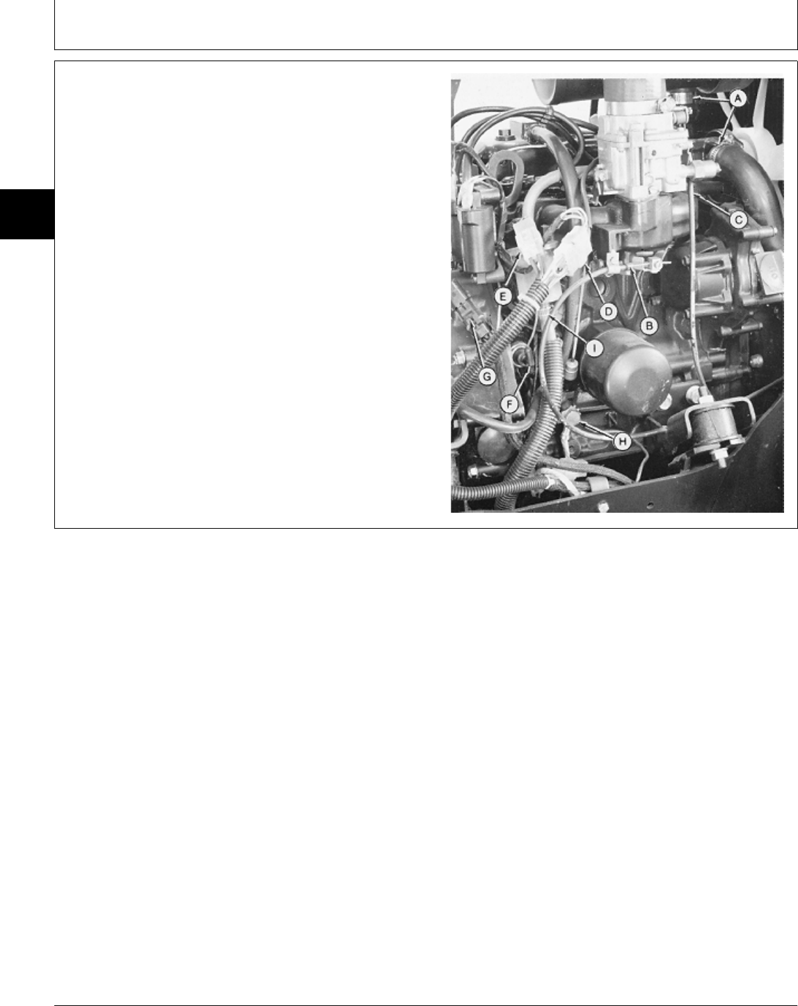
6. Disconnect items (A—I).
A—Radiator Hoses
B—Throttle Cable
C—Choke Cable
D—Ignition Coil Lead
E—Ignition Trigger Lead
F—Oil Pressure Sensor Lead
G—PTO Clutch Lead
H—Wire Harness Ground and Frame to Engine
Ground
I—Fuel Line at Filter
M49504 -UN-20DEC89
MX,5M3,2005K,H -19-18DEC87
Engine—322/Remove and Install
TM1591 (15JUL95) 20-05-2 322,330,332 & 430 Lawn & Garden Tractors
030895
20
05
2

7. Remove cap screws (A) holding rubber drive shaft
isolator to engine.
8. Loosen cap screws at universal joint at transmission
input shaft and slide drive shaft toward transmission.
This will eliminate any preload on the drive shaft when
reassembling.
9. Remove engine mounting nuts.
10. Attach load positioning sling to lift eyes and remove
engine.
11. Make repairs as necessary. (See CTM12.)
12. Installation is done in the reverse order of removal.
• Tighten engine mounting nuts to specifications.
• When connecting drive shaft, tighten cap screws to
specifications.
• Close drain valve and fill radiator with proper coolant
until coolant is 13—25 mm (0.500—1 in.) below bottom
of filler neck. (See Engine Coolant in Section 10, Group
25.)
NOTE: On Early models, the choke is activated manually
by a cable. On Later models, the choke operates
automatically.
• Early models; Adjust choke cable. (See Section 220,
Group 10.)
• Adjust slow and fast idle. (See Section 220, Group 10.)
TORQUE SPECIFICATIONS
Engine Mounting Nuts . . . . . . . . . . . . . . . . . . . . . 49 N·m (36 lb-ft)
Drive Shaft
Engine Mounting Cap Screws . . . . . . . . . . . . . . 37 N·m (27 lb-ft)
Universal Joint Cap Screws . . . . . . . . . . . . . . . . 60 N·m (45 lb-ft)
M49505 -UN-20DEC89
MX,15912005,3 -19-13JUL95
Engine—322/Remove and Install
TM1591 (15JUL95) 20-05-3 322,330,332 & 430 Lawn & Garden Tractors
030895
20
05
3

Engine—322/Remove and Install
TM1591 (15JUL95) 20-05-4 322,330,332 & 430 Lawn & Garden Tractors
030895
20
05
4
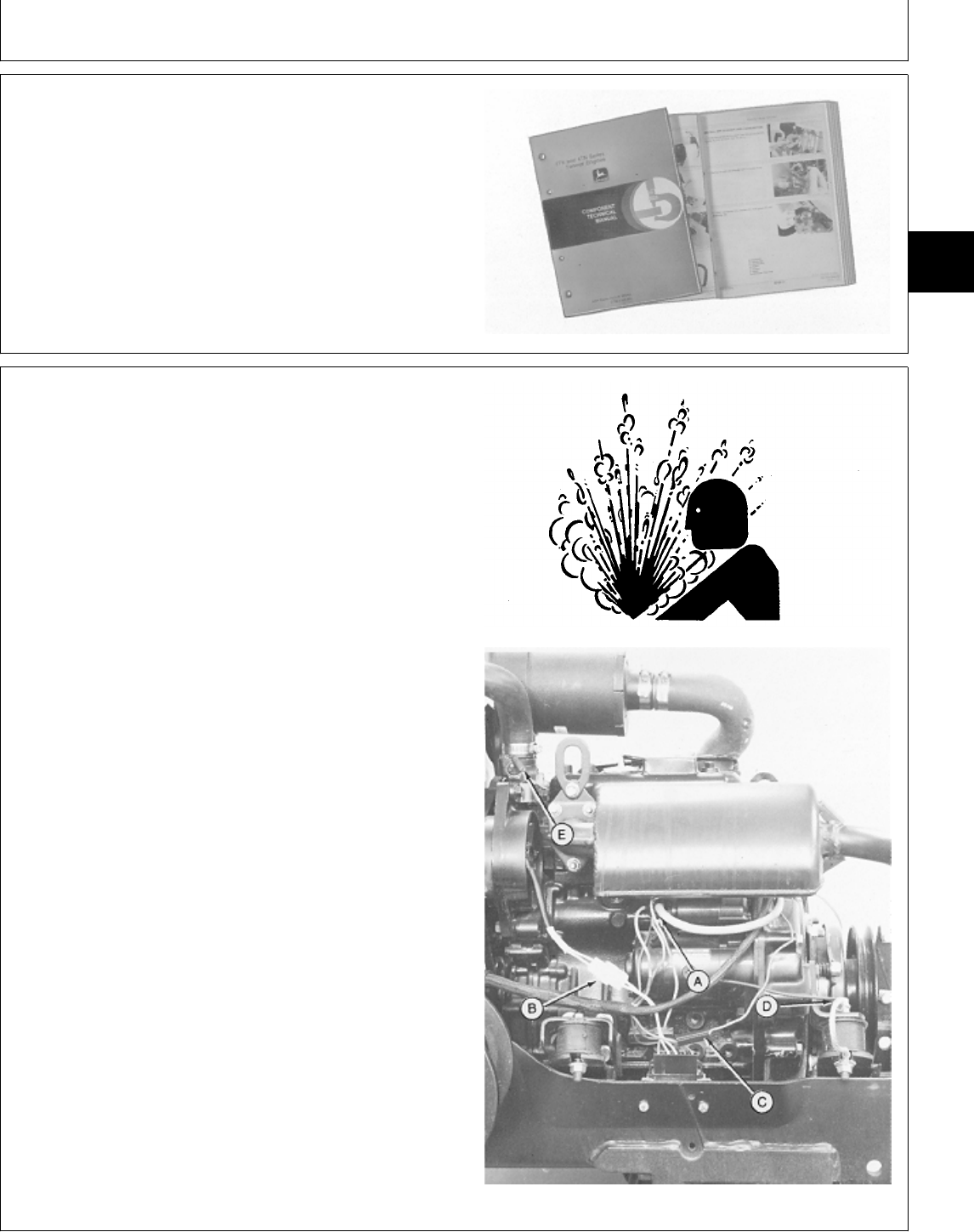
YANMAR DIESEL ENGINE REPAIR—USE
CTM3
For complete repair information, the component technical
manual (CTM) is also required. Use the component
technical manual in conjunction with this machine
manual.
TS225 -UN-17JAN89
REMOVE AND INSTALL ENGINE—330 AND
332
1. Remove grille, side panels, battery, battery base and
belly screen.
2. Disconnect headlight and hour meter leads.
3. Remove hood, hood support and battery base
support.
NCAUTION: Explosive release of fluids from
pressurized cooling system can cause serious
burns.
Shut off engine. Only remove filler cap when
cool enough to touch with bare hands. Slowly
loosen cap to first stop to relieve pressure
before removing completely.
4. Drain radiator. Approximate capacity is 2.8 L (3 U.S.
qt).
NOTE: On 330, wiring harness ground and
engine-to-frame ground (D) are connected to rear
engine mount.
5. Disconnect items (A—E).
A—Battery Positive (+) Cable and Starter Leads
B—Alternator Lead
C—PTO Clutch Lead
D—Wiring Harness Ground and Engine to Frame
Ground
E—Coolant Temperature Lead
TS281 -UN-23AUG88M49506 -UN-20DEC89
MX,15912006,1 -19-13JUL95
MX,15912006,2 -19-13JUL95
Group 06
Engine—330, 332 and 430
TM1591 (15JUL95) 20-06-1 322,330,332 & 430 Lawn & Garden Tractors
030895
20
06
1
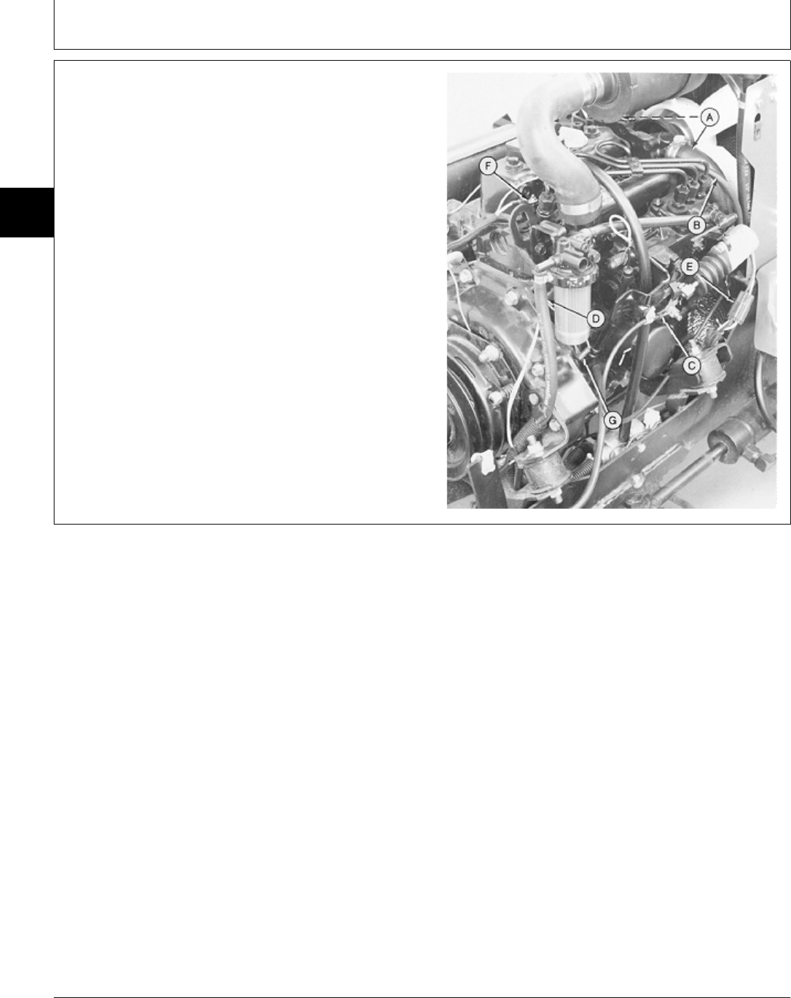
NOTE: On Early 330, fuel shutoff solenoid is activated
manually by a cable. On 332 and Later 330, fuel
shutoff solenoid is activated electronically.
6. Disconnect items (A—G).
A—Radiator Hoses
B—Return Fuel Line
C—Throttle Cable
D—Fuel Pump Hose
E—Fuel Shutoff Solenoid Connector (332, Later
330)
—Fuel Shutoff Solenoid Cable (Early 330)
F—Glow Plug Lead
G—Oil Pressure Sensor Lead
M49507 -UN-20DEC89
MX,15912006,3 -19-13JUL95
Engine—330, 332 and 430/Remove and Install—330 and 332
TM1591 (15JUL95) 20-06-2 322,330,332 & 430 Lawn & Garden Tractors
030895
20
06
2

7. Remove cap screws (A) holding rubber drive shaft
isolator to engine.
8. Loosen cap screws at universal joint at transmission
input shaft and slide drive shaft toward transmission.
This will eliminate any preload on the drive shaft when
reassembling.
9. Remove engine mounting nuts.
10. Attach load positioning sling to lift eyes and remove
engine.
11. Make repairs as necessary. (See CTM3.)
12. Installation is done in the reverse order of removal.
• Tighten engine mounting nuts to specifications.
• When connecting drive shaft, tighten cap screws to
specifications.
• Close drain valve and fill radiator with proper coolant
until coolant is 13—25 mm (0.500—1 in.) below bottom
of filler neck. (See Engine Coolant in Section 10, Group
25.)
• Bleed the fuel system. (See Section 220, Group 10.)
• Adjust slow and fast idle. (See Section 220, Group 10.)
TORQUE SPECIFICATIONS
Engine Mounting Nuts . . . . . . . . . . . . . . . . . . . . . 49 N·m (36 lb-ft)
Drive Shaft
Engine Mounting Cap Screws
330 . . . . . . . . . . . . . . . . . . . . . . . . . . . . . . . 27 N·m (20 lb-ft)
332 . . . . . . . . . . . . . . . . . . . . . . . . . . . . . . . 37 N·m (27 lb-ft)
Universal Joint Cap Screws . . . . . . . . . . . . . . . . 60 N·m (45 lb-ft)
M49505 -UN-20DEC89
MX,15912006,4 -19-13JUL95
Engine—330, 332 and 430/Remove and Install—330 and 332
TM1591 (15JUL95) 20-06-3 322,330,332 & 430 Lawn & Garden Tractors
030895
20
06
3
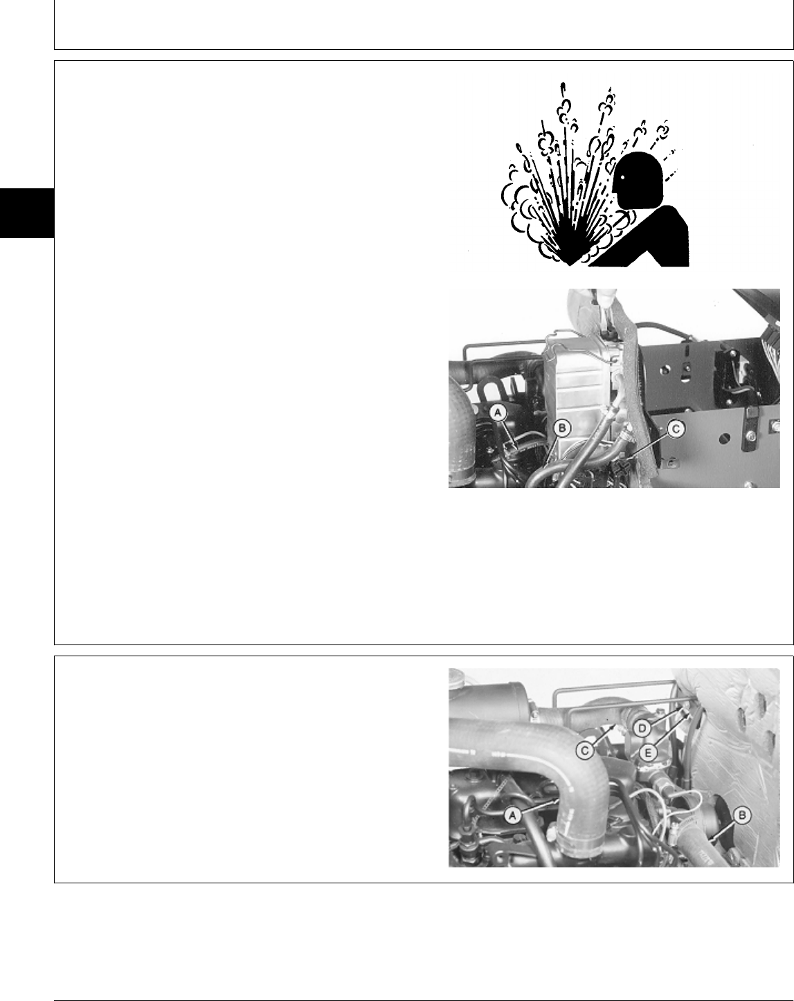
REMOVE ENGINE—430
1. Remove grille, side panels, battery and battery base.
NCAUTION: Explosive release of fluids from
pressurized cooling system can cause serious
burns.
Shut off engine. Only remove filler cap when
cool enough to touch with bare hands. Slowly
loosen cap to first stop to relieve pressure
before removing completely.
2. Drain radiator. Approximate capacity is 3.8 L (4 U.S.
qt).
3. Turn air vent on fuel/water separator counterclockwise
to open air vent.
4. Turn drain plug (C) counterclockwise to drain fuel from
separator.
5. Disconnect fuel injection pump inlet hose (B) and
leak-off hose (A).
6. Remove three cap screws and fuel/water separator.
TS281 -UN-23AUG88M77902 -UN-15DEC94
7. Disconnect hoses (A—C).
8. Remove cap screw (D) and clamp (E).
A—Air Cleaner Hose
B—Water Pump Inlet Hose
C—Water Pump Outlet Hose
D—Cap Screw
E—Clamp
M35461 -UN-16NOV89
MX,15912006,5 -19-13JUL95
MX,15912006,6 -19-13JUL95
Engine—330, 332 and 430/Remove—430
TM1591 (15JUL95) 20-06-4 322,330,332 & 430 Lawn & Garden Tractors
030895
20
06
4
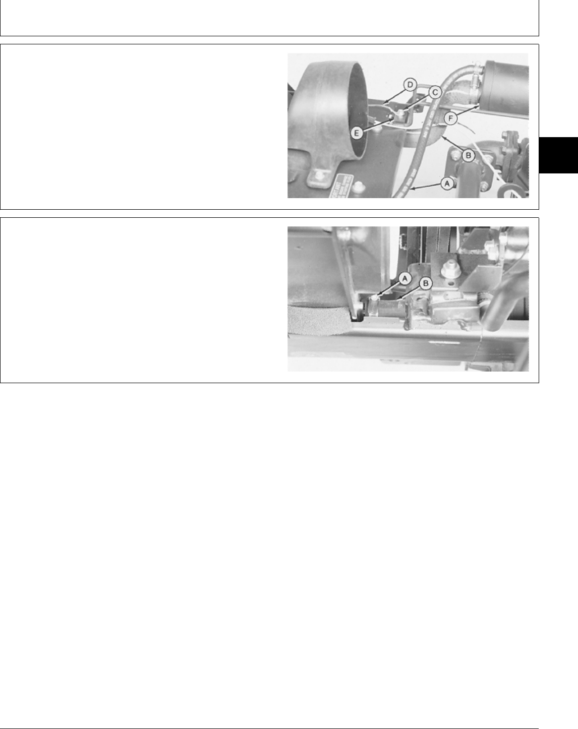
9. Disconnect hoses (A and B).
10. Remove cap screw (C), ground wire (D)(Early
Models), clamp (E) and coolant recovery tank (F).
A—Upper Radiator Hose
B—Radiator Inlet Hose
C—Cap Screw
D—Headlight Ground Wire (Early Models)
E—Clamp
F—Coolant Recovery Tank
M35462 -UN-16NOV89
11. Loosen hose clamp (A) to remove water pump inlet
hose (B).
12. Remove two cap screws and washers to disconnect
fan shroud.
13. Disconnect headlight wiring lead.
14. Remove four cap screws and hood assembly.
M35463 -UN-16NOV89
MX,15912006,7 -19-13JUL95
MX,15912006,8 -19-13JUL95
Engine—330, 332 and 430/Remove—430
TM1591 (15JUL95) 20-06-5 322,330,332 & 430 Lawn & Garden Tractors
030895
20
06
5
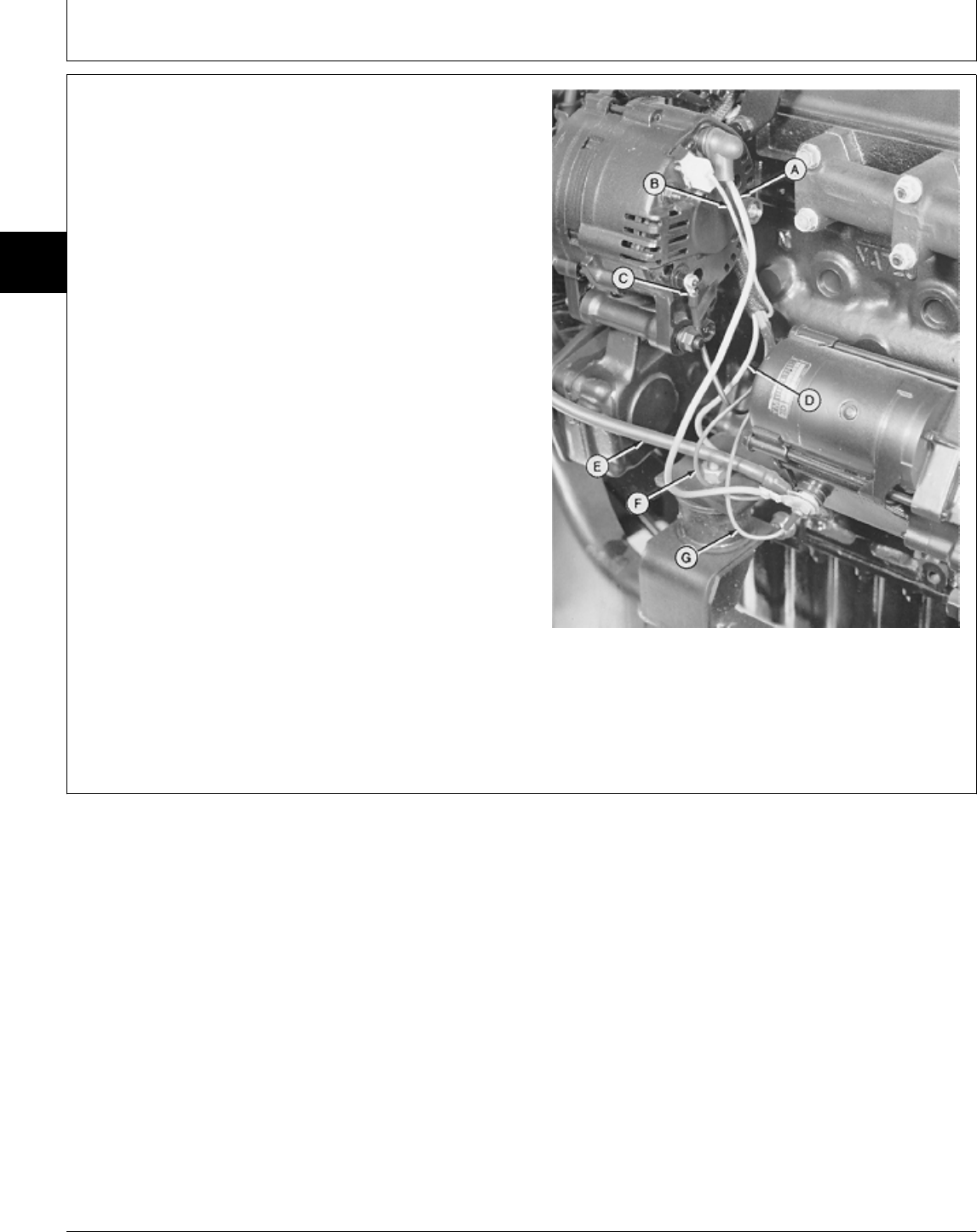
15. Disconnect wiring leads (A—G).
16. Disconnect battery negative (—) cable from right rear
engine mount.
17. Remove battery cables.
A—Alternator-to-Starting Motor (Output)
B—Alternator-to-Key Switch (Field)
C—Alternator-to-Control Module
D—Starting Motor Solenoid-to-Safe-Start Relay
E—Battery Positive (+) Cable
F—Starting Motor-to-Key Switch
G—Starting Motor-to-Glow Plug Controller
Right-Hand Side
M35466 -UN-16NOV89
MX,15912006,9 -19-13JUL95
Engine—330, 332 and 430/Remove—430
TM1591 (15JUL95) 20-06-6 322,330,332 & 430 Lawn & Garden Tractors
030895
20
06
6
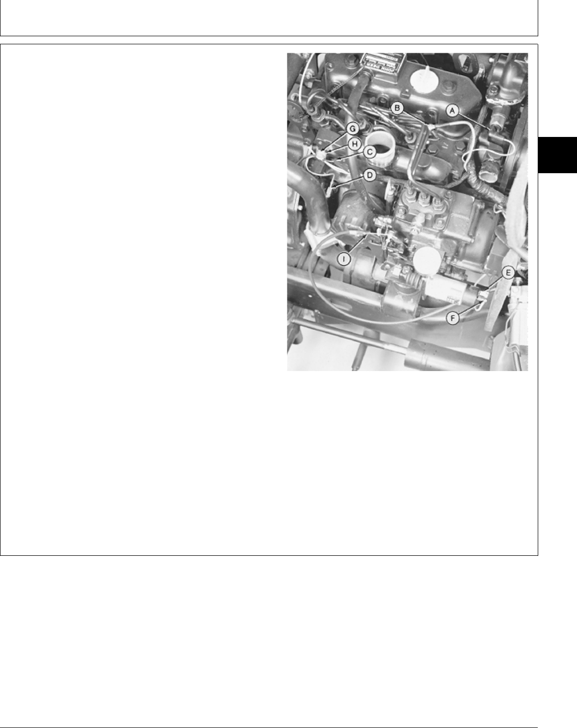
18. Disconnect wiring leads (A—F).
19. Remove cap screw (G) and clamp (H).
20. Disconnect throttle cable (I).
21. Turn steering wheel to full left turn position to aid in
muffler removal.
22. Remove muffler.
23. Remove PTO belt guard.
24. Loosen PTO belt tension and remove belts from
engine.
25. Disconnect drive shaft at engine.
26. Remove fan shroud.
NOTE: Rear engine mounts have a nut and two
washers.
27. Remove engine mounting nuts and washers, if
equipped.
28. Attach load positioning sling to lift eyes and remove Left-Hand Side
engine.
29. Make repairs as necessary. (See CTM3.) A—Coolant Temperature Sender
B—Glow Plug
C—Front PTO Clutch
D—Oil Pressure Sender
E—Fuel Shutoff Solenoid-to-Circuit Breaker (Early
Models)
F—Fuel Shutoff Solenoid-to-Control Module
G—Cap Screw
H—Clamp
I—Throttle Cable
M35469 -UN-16NOV89
MX,15912006,10 -19-13JUL95
Engine—330, 332 and 430/Remove—430
TM1591 (15JUL95) 20-06-7 322,330,332 & 430 Lawn & Garden Tractors
030895
20
06
7

INSTALL ENGINE—430
1. If necessary, loosen one front engine mount nut. Align
engine mount stud with hole in front engine mounting
bracket. Install the engine. Align front engine mount
dowel pin with hole in frame mounting bracket. Tighten
nut.
NOTE: Rear engine mounts have a nut and two
washers.
2. Install two washers, if equipped, and engine mounting
nuts. Tighten nuts to specifications.
3. Install fan shroud.
4. Connect drive shaft to engine. Tighten cap screws to
specifications.
5. Install two belts on PTO pulley. Tighten adjuster nut
until spring is 35 mm (1.380 in.) long.
6. Install PTO belt guard.
TORQUE SPECIFICATIONS
Engine Mounting Nuts . . . . . . . . . . . . . . . . . . . . . 49 N·m (36 lb-ft)
Drive Shaft Mounting Cap Screws . . . . . . . . . . . . . 27 N·m (20 lb-ft)
M35665 -UN-27NOV89
MX,15912006,11 -19-13JUL95
Engine—330, 332 and 430/Install—430
TM1591 (15JUL95) 20-06-8 322,330,332 & 430 Lawn & Garden Tractors
030895
20
06
8
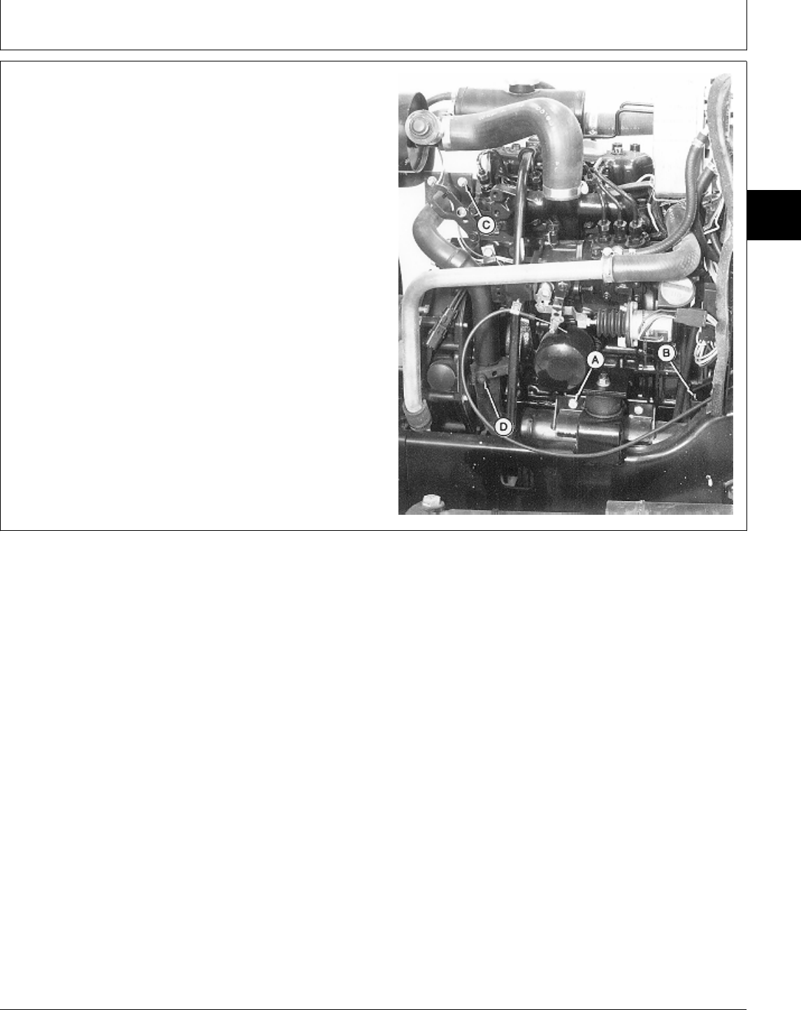
7. Loosen four cap screws (C).
8. Install muffler. Tighten mounting hardware finger-tight.
IMPORTANT: Tighten exhaust mounting hardware in
sequence described. Failure to do so,
may create binding around exhaust
system resulting in muffler breaking
off.
9. Tighten exhaust mounting hardware in the following
sequence:
A—Muffler-to-Engine Mount Cap Screw (2 used)
B—Muffler-to-Gear Case Cover Cap Screw (2 used)
C—Exhaust Pipe-to-Manifold Cap Screw (4 used)
D—Muffler Clamp Nut (2 used)
M77310 -UN-15DEC94
MX,15912006,12 -19-13JUL95
Engine—330, 332 and 430/Install—430
TM1591 (15JUL95) 20-06-9 322,330,332 & 430 Lawn & Garden Tractors
030895
20
06
9
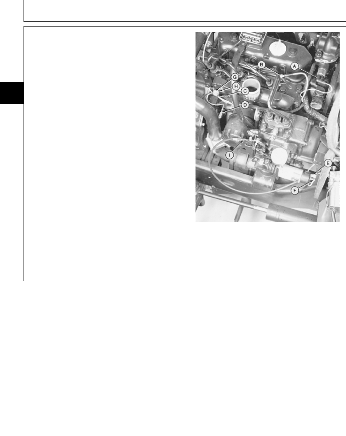
10. Connect throttle cable (I).
11. Install clamp (H) and cap screw (G).
12. Connect wiring leads (A—F).
A—Coolant Temperature Sender
B—Glow Plug
C—Front PTO Clutch
D—Oil Pressure Sender
E—Fuel Shutoff Solenoid-to-Circuit Breaker (Early
Models)
F—Fuel Shutoff Solenoid-to-Control Module
G—Cap Screw
H—Clamp
I—Throttle Cable
Left-Hand Side
M35469 -UN-16NOV89
MX,15912006,13 -19-13JUL95
Engine—330, 332 and 430/Install—430
TM1591 (15JUL95) 20-06-10 322,330,332 & 430 Lawn & Garden Tractors
030895
20
06
10
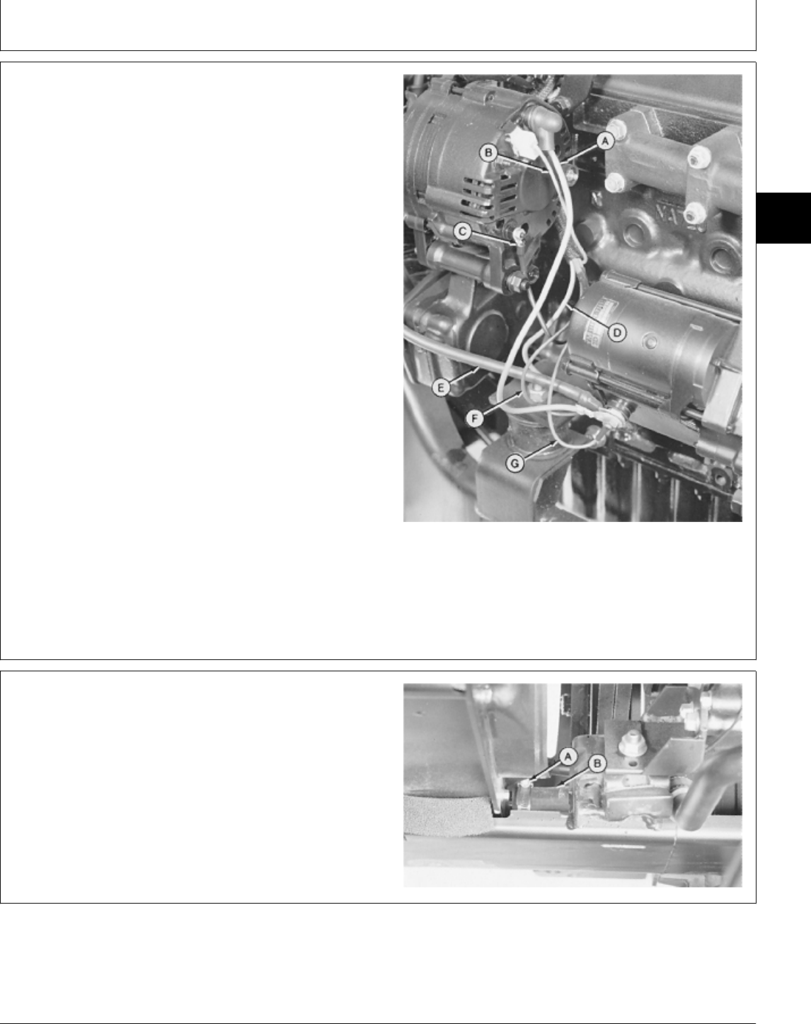
13. Install battery cables.
14. Connect battery negative (—) cable to right rear
engine mount. Tighten cap screw to 49 N·m (36 lb-ft).
15. Connect wiring leads (A—G).
A—Alternator-to-Starting Motor (Output)
B—Alternator-to-Key Switch (Field)
C—Alternator-to-Control Module
D—Starting Motor Solenoid-to-Safe-Start Relay
E—Battery Positive (+) Cable
F—Starting Motor-to-Key Switch
G—Starting Motor-to-Glow Plug Controller
Right-Hand Side
M35466 -UN-16NOV89
16. Install hood assembly.
17. Install two washers and cap screws connect fan
shroud to hood assembly.
18. Connect headlight wiring lead.
19. Install water pump inlet hose (B). Tighten hose
clamp (A).
M35463 -UN-16NOV89
MX,15912006,14 -19-13JUL95
MX,15912006,15 -19-13JUL95
Engine—330, 332 and 430/Install—430
TM1591 (15JUL95) 20-06-11 322,330,332 & 430 Lawn & Garden Tractors
030895
20
06
11
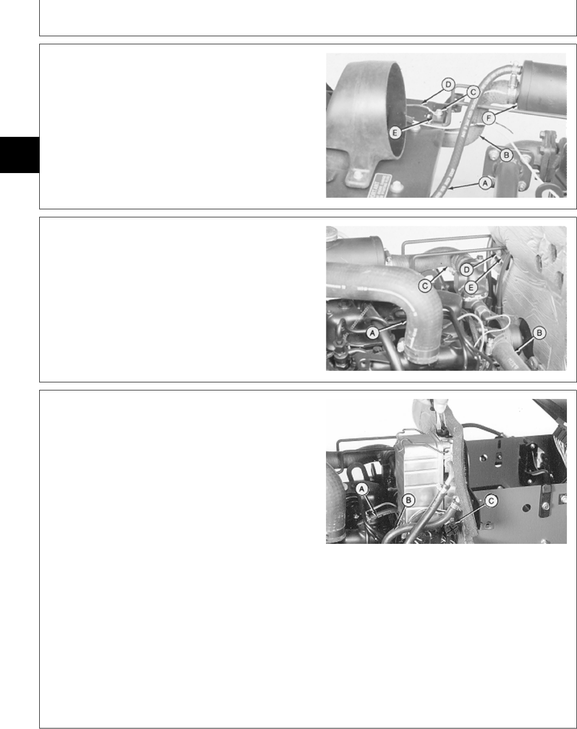
20. Install coolant recovery tank (F), clamp (E), ground
wire (D)(Early Models) and cap screw (C).
21. Connect hoses (A and B).
A—Upper Radiator Hose
B—Radiator Inlet Hose
C—Cap Screw
D—Headlight Ground Wire (Early Models)
E—Clamp
F—Coolant Recovery Tank
M35462 -UN-16NOV89
22. Install clamp (E) and cap screw (D).
23. Connect hoses (A—C).
A—Air Cleaner Hose
B—Water Pump Inlet Hose
C—Water Pump Outlet Hose
D—Cap Screw
E—Clamp
M35461 -UN-16NOV89
24. Install fuel/water separator. Tighten cap screws to 20
N·m (180 lb-in.).
25. Connect fuel injection pump inlet hose (B) and
leak-off hose (A).
26. Turn drain plug (C) and air vent plug clockwise to
close.
27. Install battery base and battery.
28. Close drain valve and fill radiator with proper coolant
until coolant is 13—25 mm (0.500—1 in.) below bottom
of filler neck. (See Engine Coolant in Section 10, Group
25.)
29. Bleed the fuel system. (See Section 220, Group 11.)
30. Adjust slow and fast idle. (See Section 220, Group
11.)
31. Install side panels and grille.
M77902 -UN-15DEC94
MX,15912006,16 -19-13JUL95
MX,15912006,17 -19-13JUL95
MX,15912006,18 -19-13JUL95
Engine—330, 332 and 430/Install—430
TM1591 (15JUL95) 20-06-12 322,330,332 & 430 Lawn & Garden Tractors
030895
20
06
12

Section 40
ELECTRICAL REPAIR
Contents
Page
Group 05—Front PTO Clutch
Other Materials . . . . . . . . . . . . . . . . . . 40-05-1
Remove—322, 330 and 332 . . . . . . . . . 40-05-1
Remove—430 . . . . . . . . . . . . . . . . . . . 40-05-2
Disassemble, Inspect and Assemble . . . . 40-05-4
Install—322, 330 and 332 . . . . . . . . . . . 40-05-6
Install—430 . . . . . . . . . . . . . . . . . . . . . 40-05-7
TM1591 (15JUL95) 40-1 322,330,332 & 430 Lawn & Garden Tractors
030895
40

Contents
TM1591 (15JUL95) 40-2 322,330,332 & 430 Lawn & Garden Tractors
030895
40
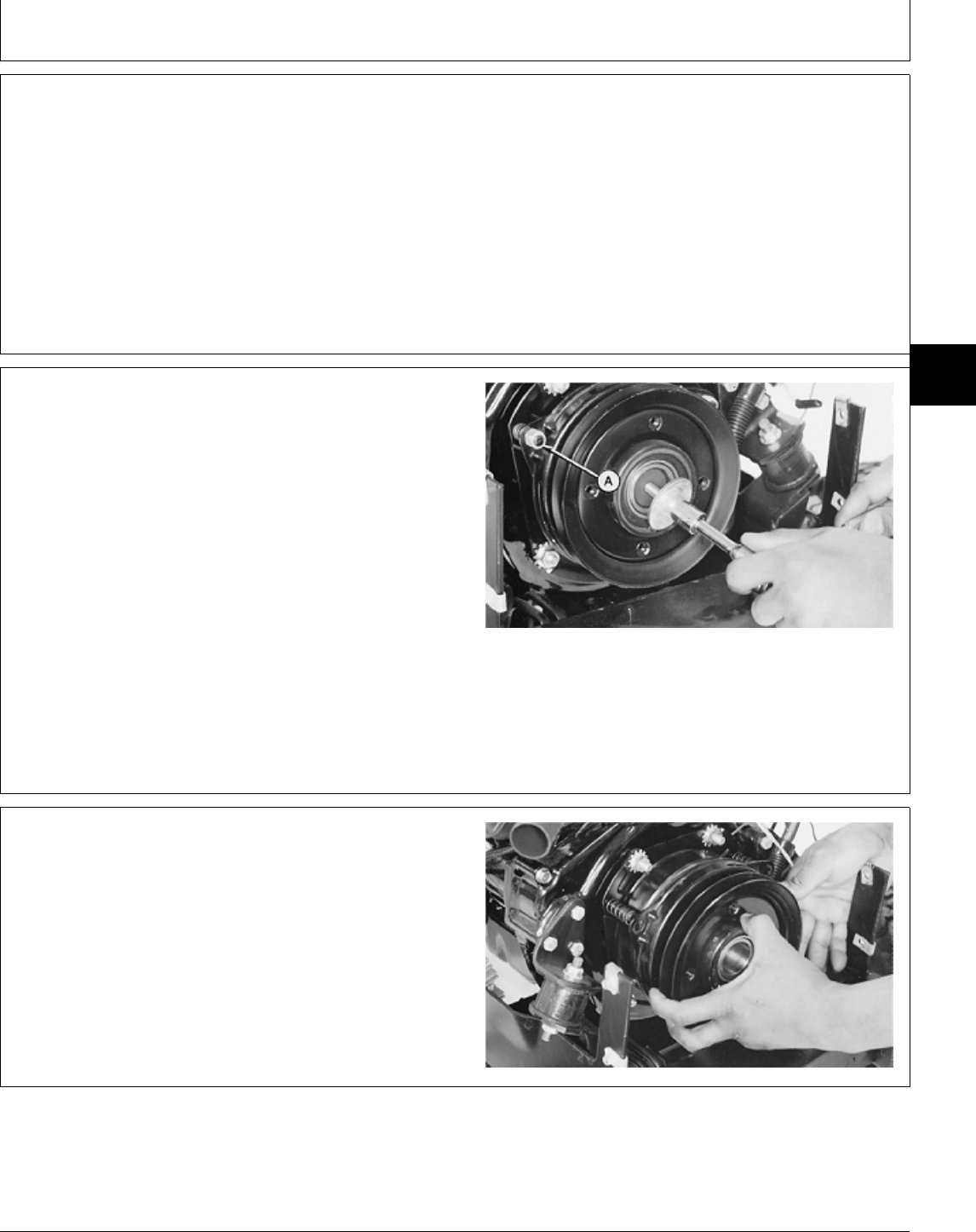
OTHER MATERIAL
Number Name Use
LOCTITE® PRODUCTS
U.S./Canadian/LOCTITE No.
T43512/TY9473/242 Thread Lock and Sealer (Medium Apply to threads of front PTO
Strength) clutch-to-crankshaft cap screw.
®LOCTITE is a registered trademark of the Loctite Corp.
REMOVE FRONT PTO CLUTCH—322, 330
AND 332
1. Remove grille and left-hand side panel.
2. Loosen PTO belt tension and remove belt from PTO
clutch sheave.
3. Disconnect PTO clutch wire lead.
4. Remove cap screw and washer holding clutch to
crankshaft.
5. Remove three lock nuts (A).
M55045 -UN-09DEC89
6. Remove armature, pulley and brake assembly from
field coil.
7. Remove three springs.
M55046 -UN-09DEC89
MX,15914005,20 -19-13JUL95
MX,15914005,1 -19-13JUL95
MX,15914005,2 -19-13JUL95
Group 05
Front PTO Clutch
TM1591 (15JUL95) 40-05-1 322,330,332 & 430 Lawn & Garden Tractors
030895
40
05
1
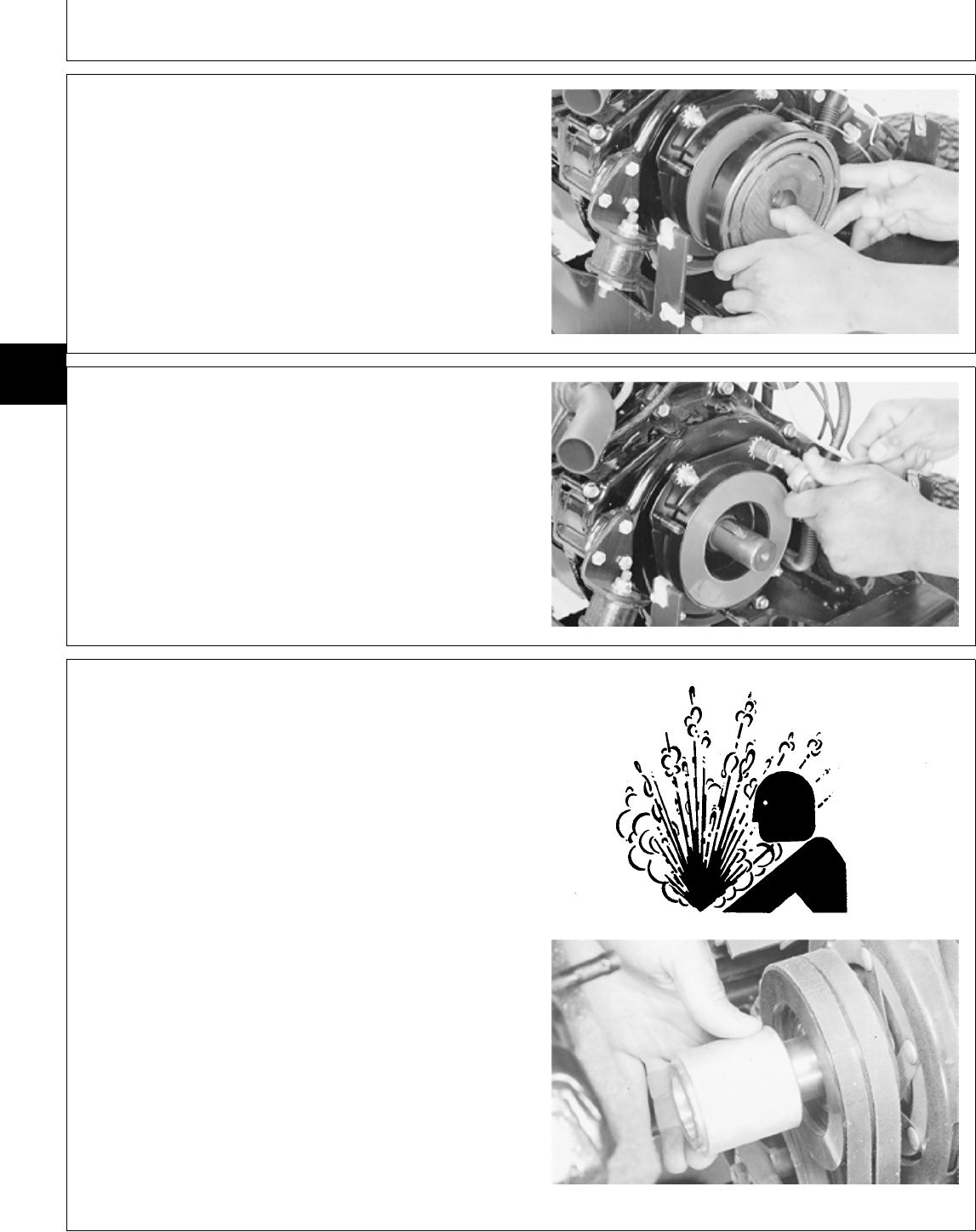
8. Remove rotor from field coil.
9. Remove key from shaft.
M55048 -UN-09DEC89
NOTE: Note position of clutch wire lead to aid in
installation.
10. Remove field coil.
M55049 -UN-09DEC89
REMOVE FRONT PTO CLUTCH—430
NCAUTION: Explosive release of fluids from
pressurized cooling system can cause serious
burns.
Shut off engine. Only remove filler cap when
cool enough to touch with bare hands. Slowly
loosen cap to first stop to relieve pressure
before removing completely.
1. Drain and remove radiator. Approximate capacity is
3.8 L (4 U.S. qt).
2. Remove fan and fan spacer.
TS281 -UN-23AUG88M36821 -UN-25JAN90
MX,15914005,3 -19-13JUL95
MX,15914005,4 -19-13JUL95
MX,15914005,5 -19-13JUL95
Front PTO Clutch/Remove—430
TM1591 (15JUL95) 40-05-2 322,330,332 & 430 Lawn & Garden Tractors
030895
40
05
2
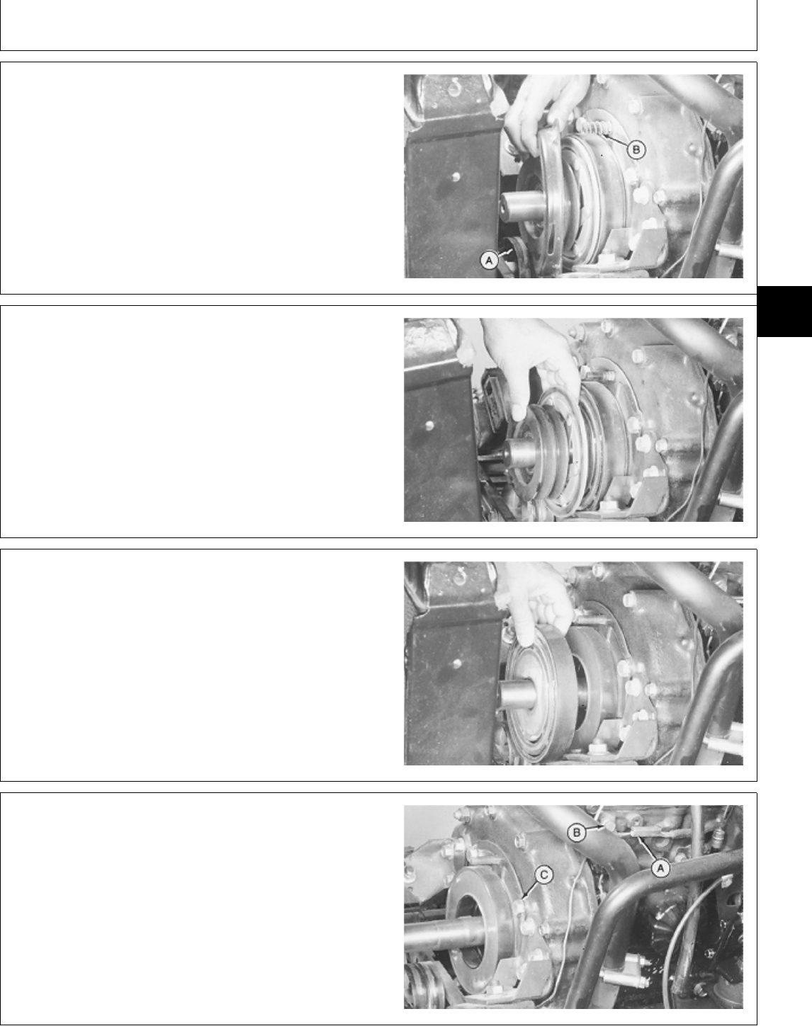
3. Loosen PTO belt tension and remove adjusting
assembly.
4. Remove belts from PTO clutch sheaves.
5. Remove three lock nuts holding brake plate to field
coil.
6. Push idler (A) back and remove brake plate.
7. Remove three springs (B).
M36824 -UN-25JAN90
8. Remove armature assembly from field coil.
M36825 -UN-25JAN90
9. Remove rotor from field coil.
10. Remove key from shaft.
M36826 -UN-25JAN90
NOTE: Note position of clutch wire lead to aid in
installation.
11. Disconnect PTO clutch wire lead (A).
12. Loosen cap screw (B) to disconnect lead from clip.
13. Remove four cap screws and lock washers (C) and
field coil.
M36827 -UN-25JAN90
MX,15914005,6 -19-13JUL95
MX,15914005,7 -19-13JUL95
MX,15914005,8 -19-13JUL95
MX,15914005,9 -19-13JUL95
Front PTO Clutch/Remove—430
TM1591 (15JUL95) 40-05-3 322,330,332 & 430 Lawn & Garden Tractors
030895
40
05
3
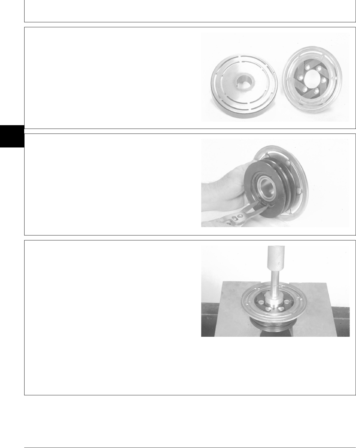
DISASSEMBLE, INSPECT AND ASSEMBLE
FRONT PTO CLUTCH
1. Inspect armature for bent, weak or broken contact
springs. Replace armature if damaged.
2. Inspect rotor and armature face contacts for wear.
Replace if worn or grooved. Clean face contacts of dirt
or foreign material.
M32117 -UN-03AUG89
NOTE: Bearing is press-fit in armature. Remove only if
replacement is necessary.
3. Inspect armature bearing for wear or damage.
Replace if necessary.
4. To replace armature bearing; remove snap ring.
M32113 -UN-03AUG89
5. Remove hub and bearing from armature using a press
and a 1-11/16 in. driver disk. Make sure assembly is
supported on pulley, NOT on armature plate.
6. Remove shim washer from inside pulley hub.
7. Remove hub from bearing using a press and a 1-3/4
in. driver disk.
8. Install hub into new bearing using a press and driver
disk.
9. Install shim washer in bottom of pulley hub.
M32114 -UN-03AUG89
MX,15904005,3 -19-12MAY95
MX,15904005,4 -19-14DEC94
MX,15904005,5 -19-14DEC94
Front PTO Clutch/Disassemble, Inspect and Assemble
TM1591 (15JUL95) 40-05-4 322,330,332 & 430 Lawn & Garden Tractors
030895
40
05
4
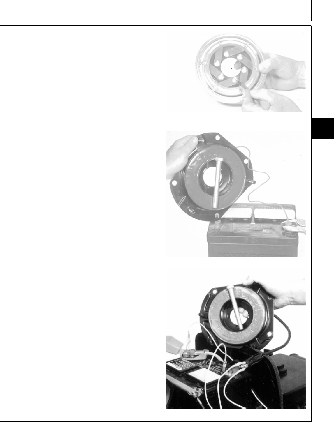
IMPORTANT: Support the armature assembly on the
spring rivets when installing
bearing/hub assembly into armature
assembly, or damage to armature and
springs will occur.
10. Support armature on spring rivets and install
bearing/hub assembly into pulley hub with a press and a
2-15/16 in. driver disk.
11. Install snap ring.
M32120 -UN-03AUG89
12. Inspect field coil for wear or damage. Replace if
necessary.
13. Test field coil for electrical continuity.
Early version:
—Attach field coil lead to positive (+) terminal of a
charged storage battery.
—Set coil base on negative (—) battery terminal.
—Put a steel bolt across coil. Electromagnetic action will
hold bolt to coil if coil is good. If bolt does not stick
to coil, replace the coil.
Later version:
—Attach a jumper wire from one terminal of two-pin
connector to negative (—) battery terminal.
—Attach another jumper wire from the remaining terminal Early Version
of two-pin connector to positive (+) battery terminal.
—Put a steel bolt across coil. Electromagnetic action will
hold bolt to coil if coil is good. If bolt does not stick
to coil, replace the coil.
Later Version
M32118 -UN-03AUG89M77321 -UN-25JAN95
MX,15904005,6 -19-14DEC94
MX,15904005,7 -19-19JAN95
Front PTO Clutch/Disassemble, Inspect and Assemble
TM1591 (15JUL95) 40-05-5 322,330,332 & 430 Lawn & Garden Tractors
030895
40
05
5
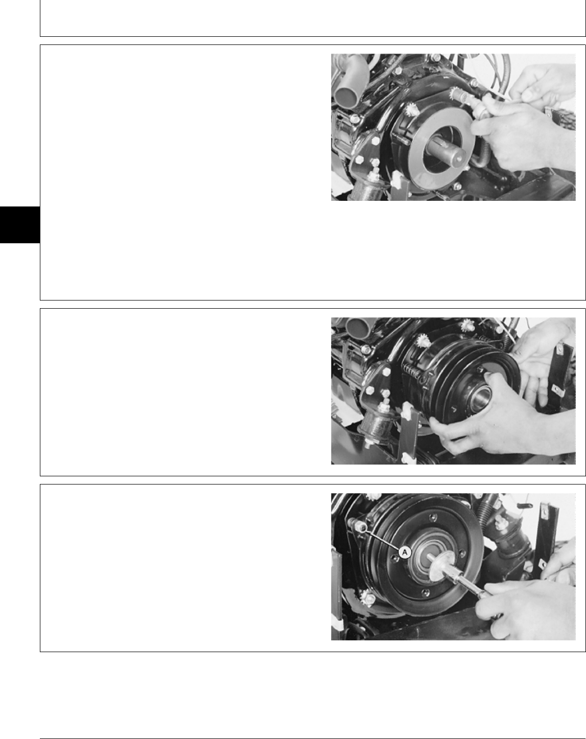
INSTALL FRONT PTO CLUTCH—322, 330
AND 332
IMPORTANT: Make sure clutch wire lead is in same
position as when removed, to prevent
shorting of wires.
1. Install field coil and fasten with four cap screws and
star washers. Be sure centering lugs on backside of coil
are properly seated in engine face. Tighten cap screws.
2. Install rotor and key.
M55049 -UN-09DEC89
3. Install three springs on mounting studs.
4. Install armature, pulley and brake plate assembly.
M55046 -UN-09DEC89
5. Install three lock nuts (A). DO NOT tighten nuts.
6. Install washer and cap screw on end of crankshaft.
Tighten cap screw to 47 N·m (35 lb-ft).
7. Connect PTO clutch wire lead.
M55045 -UN-09DEC89
MX,15914005,10 -19-13JUL95
MX,15914005,11 -19-13JUL95
MX,15914005,12 -19-13JUL95
Front PTO Clutch/Install—322, 330 and 332
TM1591 (15JUL95) 40-05-6 322,330,332 & 430 Lawn & Garden Tractors
030895
40
05
6
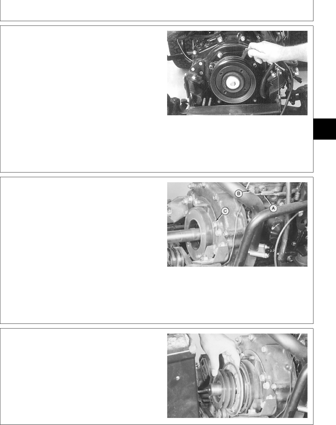
8. Put a 0.46 mm (0.018 in.) flat feeler gauge through
slots in brake plate between rotor and armature. Turn
lock nuts until space between rotor and armature is 0.46
mm (0.018 in.). Be sure all three nuts are adjusted so
space between armature and rotor is adjusted to
specification at each of three slots in brake plate.
9. After adjusting, turn ignition switch ON. Move PTO
switch ON and OFF several times to seat parts. Turn
ignition switch OFF. Recheck clearance and adjust as
necessary.
10. Install PTO clutch belt.
11. Install side panel and grille.
M77322 -UN-13FEB95
INSTALL FRONT PTO CLUTCH—430
IMPORTANT: Make sure clutch wire lead is in same
position as when removed, to prevent
shorting of wires.
1. Install field coil and fasten with four cap screws and
lock washers (C). Be sure centering lugs on backside of
coil are properly seated in engine face. Tighten cap
screws.
2. Install PTO clutch wire lead in clip (B) and tighten cap
screw.
3. Connect PTO wire lead (A).
4. Install rotor and key.
M36827 -UN-25JAN90
5. Install armature assembly. Make sure slot in hub
aligns with shaft key.
M36825 -UN-25JAN90
MX,15914005,13 -19-13JUL95
MX,15914005,14 -19-13JUL95
MX,15914005,15 -19-13JUL95
Front PTO Clutch/Install—430
TM1591 (15JUL95) 40-05-7 322,330,332 & 430 Lawn & Garden Tractors
030895
40
05
7
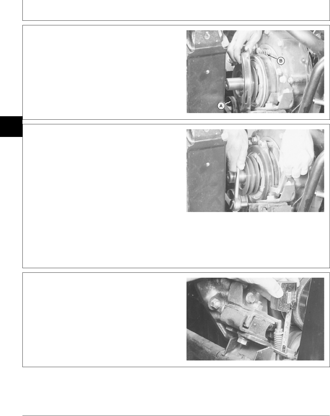
6. Install three springs (B).
7. Push idler (A) back and install brake plate.
8. Install three lock nuts (A). DO NOT tighten nuts.
M36824 -UN-25JAN90
9. Put a 0.46 mm (0.018 in.) flat feeler gauge through
slots in brake plate between rotor and armature. Turn
lock nuts until space between rotor and armature is 0.46
mm (0.018 in.). Be sure all three nuts are adjusted so
space between armature and rotor is adjusted to
specification at each of three slots in brake plate.
10. After adjusting, turn ignition switch ON. Move PTO
switch ON and OFF several times to seat parts. Turn
ignition switch OFF. Recheck clearance and adjust as
necessary.
M36829 -UN-25JAN90
11. Install PTO clutch belts.
12. Install idler adjustment assembly.
13. Lubricate idler shaft with multipurpose grease.
14. Adjust PTO belt tension; tighten nut until spring
measures 35 mm (1.380 in.).
M36830 -UN-25JAN90
MX,15914005,16 -19-13JUL95
MX,15914005,17 -19-13JUL95
MX,15914005,18 -19-13JUL95
Front PTO Clutch/Install—430
TM1591 (15JUL95) 40-05-8 322,330,332 & 430 Lawn & Garden Tractors
030895
40
05
8

15. Install fan spacer with grooved end of spacer facing
away from engine.
16. Install fan.
17. Apply thread lock and sealer (medium strength) to
threads of cap screw. Install cap screw and tighten to 47
N·m (35 lb-ft).
18. Install radiator.
19. Close drain valve and fill radiator with proper coolant
until coolant is 13—25 mm (0.500—1 in.) below bottom
of filler neck. (See Engine Coolant in Section 10, Group
25.)
M36821 -UN-25JAN90
MX,15914005,19 -19-13JUL95
Front PTO Clutch/Install—430
TM1591 (15JUL95) 40-05-9 322,330,332 & 430 Lawn & Garden Tractors
030895
40
05
9

Front PTO Clutch/Install—430
TM1591 (15JUL95) 40-05-10 322,330,332 & 430 Lawn & Garden Tractors
030895
40
05
10

Section 50
POWER TRAIN REPAIR
Contents
Page
Group 05—Transmission
Other Materials . . . . . . . . . . . . . . . . . . 50-05-1
Service Parts Kits . . . . . . . . . . . . . . . . 50-05-1
Charge Pump
Remove and Install . . . . . . . . . . . . . . 50-05-2
Disassemble and Inspect . . . . . . . . . . 50-05-3
Assemble . . . . . . . . . . . . . . . . . . . . 50-05-4
Remove and Install
Charge Relief Valve . . . . . . . . . . . . . 50-05-5
Implement Relief Valve . . . . . . . . . . . 50-05-6
Remove Transmission . . . . . . . . . . . . . . 50-05-6
Disassemble
Transmission Cover . . . . . . . . . . . . . . 50-05-11
Pump and Motor . . . . . . . . . . . . . . . . 50-05-14
Pump and Motor Housing . . . . . . . . . . 50-05-16
Assemble
Pump and Motor Housing . . . . . . . . . . 50-05-19
Pump and Motor . . . . . . . . . . . . . . . . 50-05-21
Transmission Cover . . . . . . . . . . . . . . 50-05-22
Install Transmission . . . . . . . . . . . . . . . 50-05-25
Group 10—Transmission Control Linkage
Inspect and Repair Control Linkage—330 . 50-10-1
Inspect and Repair Control Linkage—322,
332 and 430
Version One—322 and 332 . . . . . . . . 50-10-2
Version One—430 . . . . . . . . . . . . . . . 50-10-3
Version Two . . . . . . . . . . . . . . . . . . . 50-10-4
Version Three . . . . . . . . . . . . . . . . . 50-10-5
Inspect and Repair Differential Lock and
Two-Speed Linkage (430) . . . . . . . . . . 50-10-6
Group 15—Differential
Other Materials . . . . . . . . . . . . . . . . . . 50-15-1
Service Parts Kits . . . . . . . . . . . . . . . . 50-15-1
Remove and Install . . . . . . . . . . . . . . . 50-15-2
Disassemble and Inspect . . . . . . . . . . . . 50-15-2
Assemble . . . . . . . . . . . . . . . . . . . . . . 50-15-12
Group 20—Rear Axles
Other Materials . . . . . . . . . . . . . . . . . . 50-20-1
Remove . . . . . . . . . . . . . . . . . . . . . . . 50-20-1
Install . . . . . . . . . . . . . . . . . . . . . . . . . 50-20-4
Page
Group 25—Drive Shaft—322, 330 and 332
Other Materials . . . . . . . . . . . . . . . . . . 50-25-1
Remove and Install—322 and 332 . . . . . 50-25-2
Remove and Install—330 . . . . . . . . . . . 50-25-3
Disassemble and Inspect . . . . . . . . . . . . 50-25-4
Assemble . . . . . . . . . . . . . . . . . . . . . . 50-25-5
Group 26—Drive Shaft—430
Other Materials . . . . . . . . . . . . . . . . . . 50-26-1
Remove and Install
Early Models . . . . . . . . . . . . . . . . . . 50-26-1
Later Models . . . . . . . . . . . . . . . . . . 50-26-4
Disassemble and Inspect . . . . . . . . . . . . 50-26-5
Assemble . . . . . . . . . . . . . . . . . . . . . . 50-26-7
TM1591 (15JUL95) 50-1 322,330,332 & 430 Lawn & Garden Tractors
030895
50

Contents
TM1591 (15JUL95) 50-2 322,330,332 & 430 Lawn & Garden Tractors
030895
50

OTHER MATERIAL
Number Name Use
M79292 MPG-2® Multi-Purpose Polymer Prevents parts from seizing. Apply
Grease to splines of transmission input
shaft.
®MPG-2 is a registered trademark of DuBois USA.
SERVICE PARTS KITS
The following kits are available through your parts
catalog:
Charge Relief Valve Shim Pack Kit
Implement Relief Valve Shim Pack Kit
Differential Frame Support Bracket Replacement Kit for
Early Models
Motor Valve Plate Replacement Part for Early Models
MX,15905005,OTH-19-07MAR95
MX,15905005,KIT-19-23FEB95
Group 05
Transmission
TM1591 (15JUL95) 50-05-1 322,330,332 & 430 Lawn & Garden Tractors
030895
50
05
1
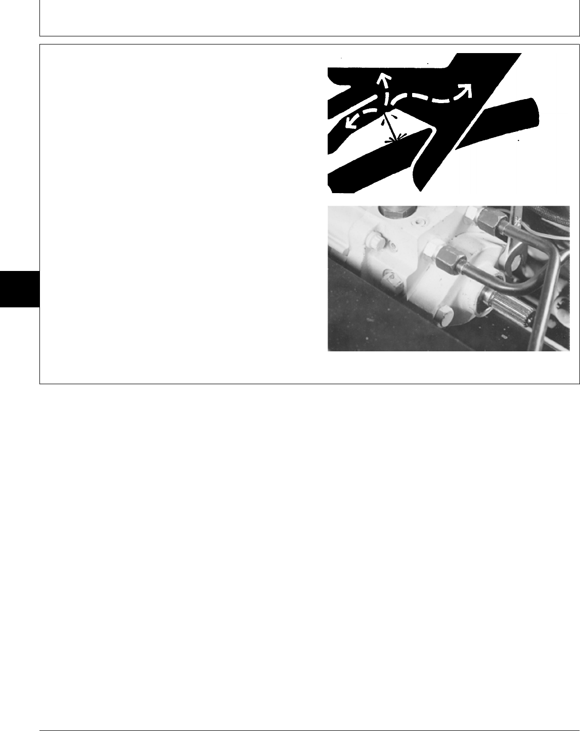
REMOVE AND INSTALL CHARGE PUMP
1. Remove fender deck and fuel tank.
2. Remove drive shaft. (See procedure in Group 25.)
NCAUTION: To avoid injury from escaping fluid
under pressure, stop engine and relieve the
pressure in the system before disconnecting or
connecting hydraulic or other lines. Tighten all
connections before applying pressure.
3. Remove two cap screws and charge pump.
430 Shown
X9811 -UN-23AUG88
M36534 -UN-25JAN90
MX,15915005,2 -19-13JUL95
Transmission/Charge Pump
TM1591 (15JUL95) 50-05-2 322,330,332 & 430 Lawn & Garden Tractors
030895
50
05
2
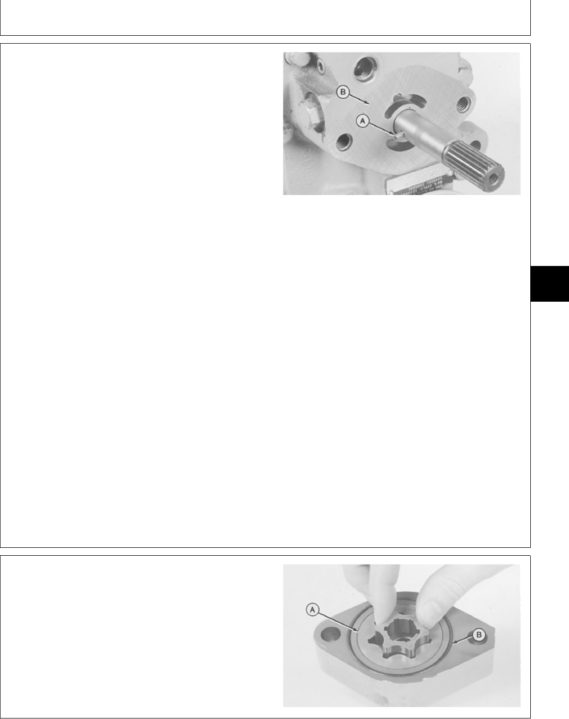
NOTE: Transmission is removed for photographic
purpose only.
4. Remove pin (A). Inspect pin for straightness and
rounded ends. Replace if necessary.
5. Inspect machined surface (B) of transmission for
severe scoring. If scoring is noted replace transmission.
6. Make repairs as necessary. (See Disassemble,
Inspect and Assemble Charge Pump.)
7. Installation is done in the reverse order of removal.
• Apply clean John Deere Low Viscosity HY-GARD® oil
on all internal components.
• Apply petroleum jelly to pin (A) (to hold in place) and
lip of oil seal.
IMPORTANT: Tape end of transmission input shaft to
prevent seal damage during charge
pump installation.
• Apply tape around end of transmission input shaft.
• Install charge pump onto shaft. Turn pump until flat
side of casting is on relief valve side.
• Install mounting cap screws and tighten to 70 N·m (52
lb-ft).
• Remove tape from shaft and apply MPG-2®
Multi-Purpose Polymer Grease on splines.
M36084 -UN-29AUG88
DISASSEMBLE AND INSPECT CHARGE
PUMP
1. Remove inner ring and rotor ring (A).
2. Remove O-ring (B).
M36085 -UN-29AUG88
MX,15905005,3 -19-07MAR95
MX,15905005,4 -19-23FEB95
Transmission/Charge Pump
TM1591 (15JUL95) 50-05-3 322,330,332 & 430 Lawn & Garden Tractors
030895
50
05
3
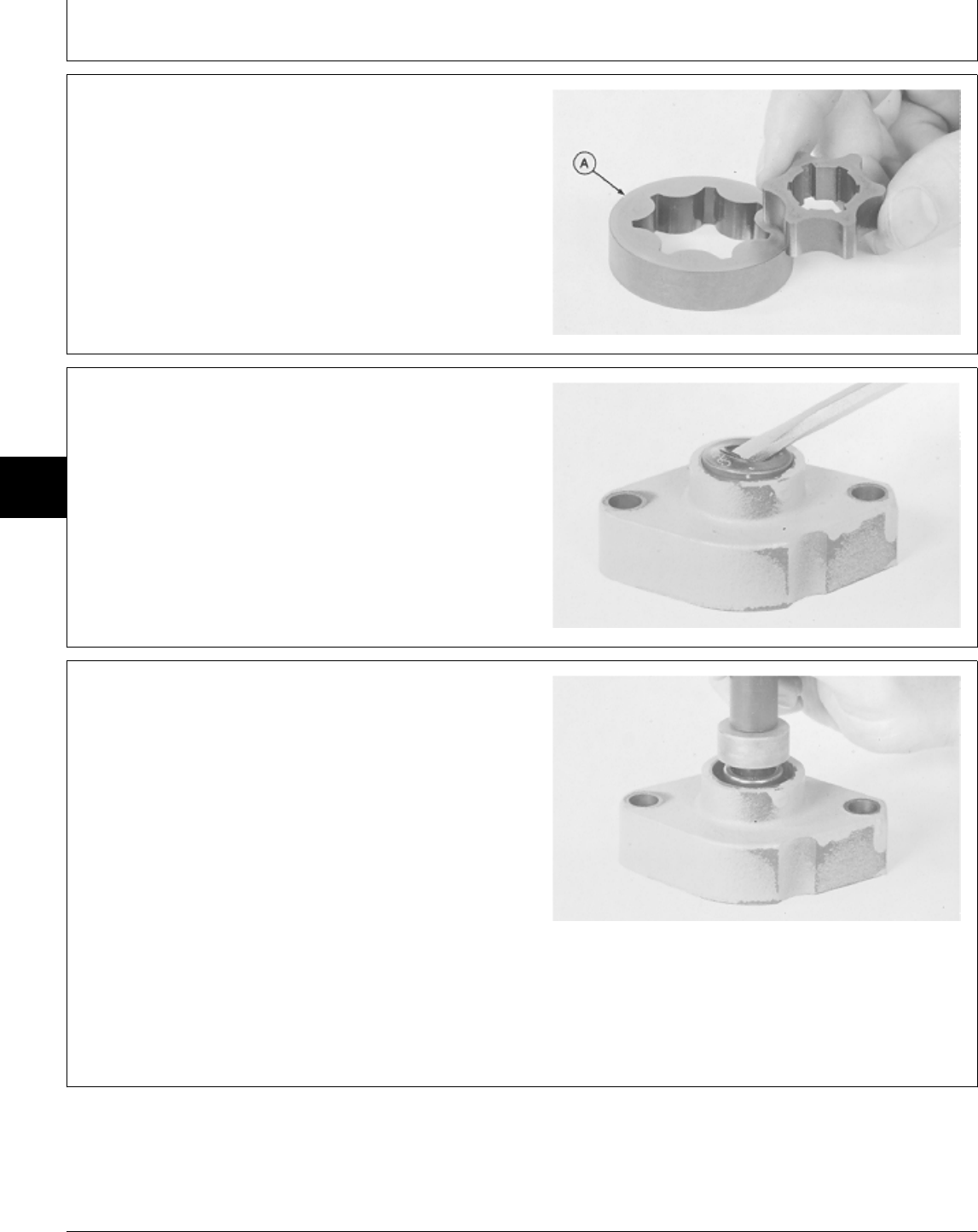
3. Inspect inner ring key way for damage or shear pin
debris.
4. Inspect rotor ring (A) for cracks or signs of scoring on
the outer edge.
5. Inspect gerotor set for wear or damage. If any
component is worn or damaged, replace gerotor set as
an assembly.
M36086 -UN-29JAN90
6. Pry out seal using a screwdriver.
NOTE: Bearing is press-fit in housing. Remove bearing
only if replacement is necessary.
7. Inspect bearing for wear or damage. Remove bearing
using a driver set.
8. Inspect housing for wear or damage. Replace entire
charge pump if necessary.
M36087 -UN-29AUG88
ASSEMBLE CHARGE PUMP
IMPORTANT: Always use new seals and O-rings.
Damaged or used parts will leak.
NOTE: Lubricate all seals and O-rings with petroleum
jelly during assembly.
1. Apply clean John Deere Low Viscosity HY-GARD® oil
on all internal parts.
2. If removed, press bearing into housing using a 1-1/8
in. driver disk. Install bearing until flush with housing
surface.
3. Install new seal using a 1-5/8 in. driver disk. Install
seal with lip (spring side) toward inside of housing.
M36089 -UN-29AUG88
MX,15905005,5 -19-23FEB95
MX,15905005,6 -19-23FEB95
MX,15905005,7 -19-23FEB95
Transmission/Charge Pump
TM1591 (15JUL95) 50-05-4 322,330,332 & 430 Lawn & Garden Tractors
030895
50
05
4
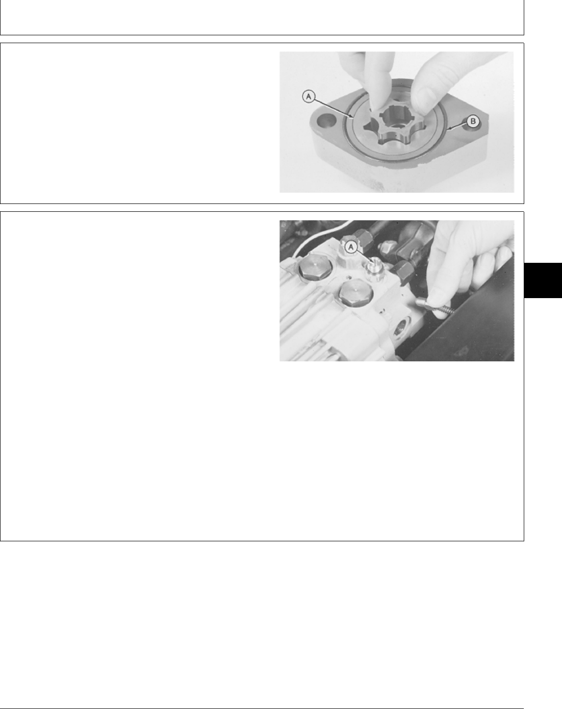
4. Install new O-ring (B). Apply petroleum jelly to seal
and housing to hold O-ring in its groove.
5. Install rotor ring (A) and inner ring. The gerotor set
must spin freely in housing.
M36085 -UN-29AUG88
REMOVE AND INSTALL CHARGE RELIEF
VALVE
1. Remove fender deck and fuel tank.
2. Remove charge relief valve plug from right side of
transmission housing.
IMPORTANT: If relief valve is being disassembled to
be cleaned, the same number and
thicknesses of shims must be installed
when assembled. 430 Shown
3. Remove shims (A) if equipped, spring and valve.
4. Inspect valve and housing for wear or damage. Valve
must slide freely in bore. Replace parts if required.
5. Installation is done in the reverse order of removal.
• Apply clean John Deere Low Viscosity HY-GARD® oil
on valve and spring.
M36537 -UN-25JAN90
MX,15905005,8 -19-23FEB95
MX,15915005,3 -19-13JUL95
Transmission/Remove and Install
TM1591 (15JUL95) 50-05-5 322,330,332 & 430 Lawn & Garden Tractors
030895
50
05
5
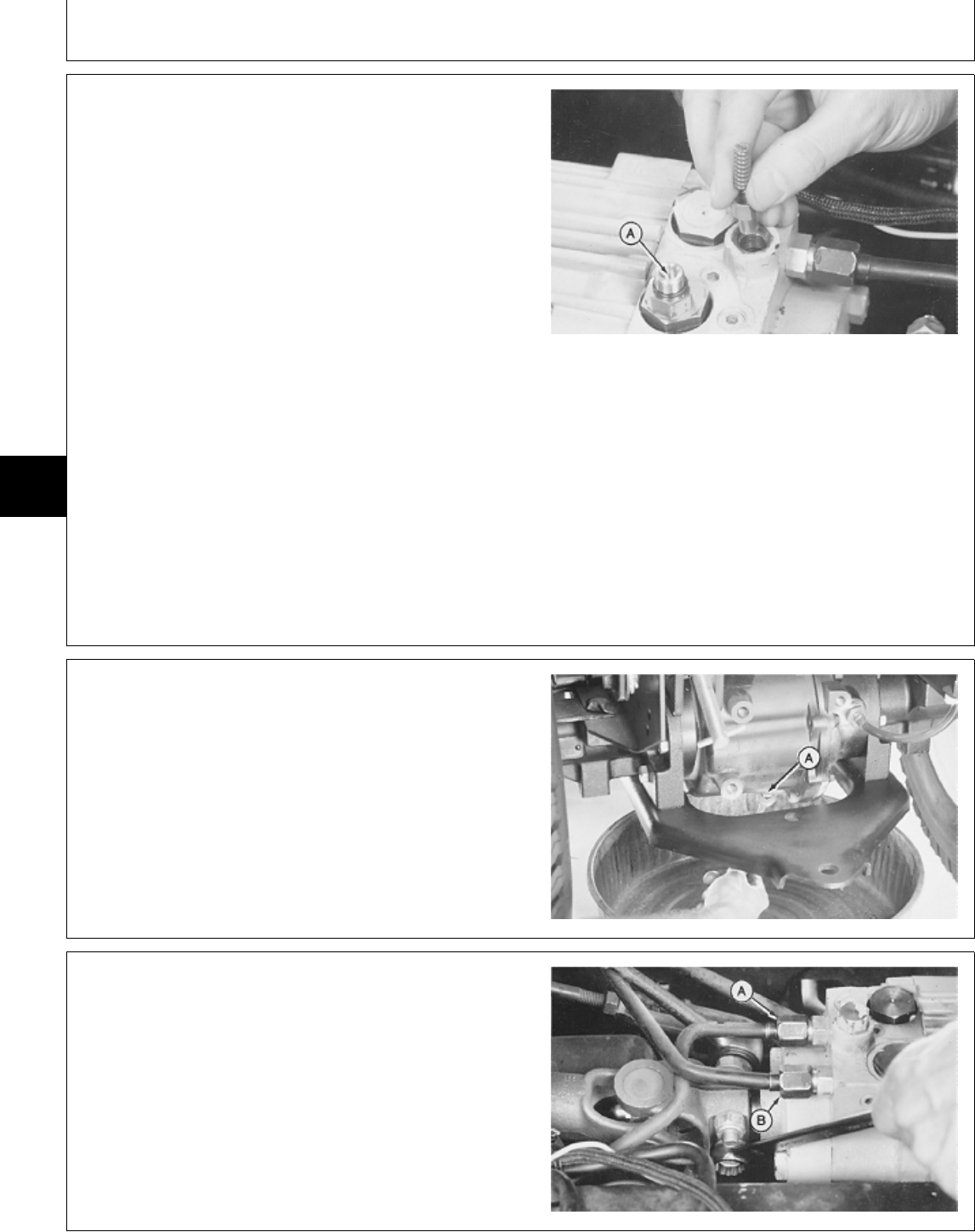
REMOVE AND INSTALL IMPLEMENT RELIEF
VALVE
1. Remove fender deck and fuel tank.
2. Remove implement relief valve plug from top of
transmission housing.
IMPORTANT: If relief valve is being disassembled to
be cleaned, the same number and
thicknesses of shims must be installed
when assembled. 430 Shown
3. Remove shims (A) if equipped, spring and valve.
4. Inspect valve and housing for wear or damage. Valve
must slide freely in bore. Replace parts as necessary.
5. Installation is done in the reverse order of removal.
• Apply clean John Deere Low Viscosity HY-GARD® oil
on valve and spring.
M36539 -UN-25JAN90
REMOVE TRANSMISSION
1. Remove drain plug (A) to drain transmission oil.
Approximate capacity is 4.7 L (5 U.S. qt).
2. Remove fender deck and fuel tank.
3. Remove belly screen/pan.
M33430 -UN-25AUG88
4. Loosen two lock nuts and cap screws, if equipped.
5. On 330; Remove deflector shields with foam at rear of
transmission.
6. Remove hydraulic pressure line (A) and return line
(B). Close all openings with caps and plugs.
430 Shown
M36540 -UN-25JAN90
MX,15915005,4 -19-13JUL95
MX,15905005,11 -19-23FEB95
MX,15915005,5 -19-13JUL95
Transmission/Remove Transmission
TM1591 (15JUL95) 50-05-6 322,330,332 & 430 Lawn & Garden Tractors
030895
50
05
6
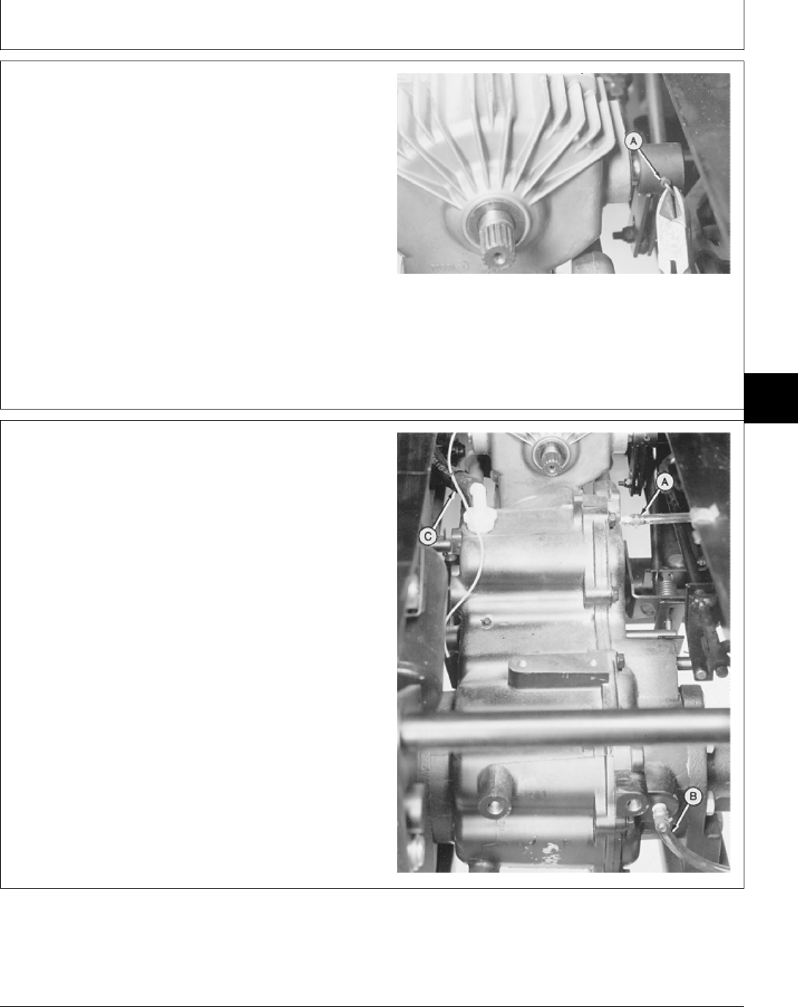
NOTE: There are different versions of the swashplate
control arm. Also, attaching swashplate control
arm to the control shaft on transmission is
different. Some machines use a safety wire and
roll pin, others use a nut and cap screw.
7. Remove safety wire and roll pin (A) or nut and cap
screw to disconnect transmission control linkage.
Early Model Shown
M36541 -UN-25JAN90
8. Disconnect two hoses (A and B).
9. Disconnect oil fill tube hose (C).
M36542 -UN-25JAN90
MX,15915005,6 -19-13JUL95
MX,15915005,7 -19-13JUL95
Transmission/Remove Transmission
TM1591 (15JUL95) 50-05-7 322,330,332 & 430 Lawn & Garden Tractors
030895
50
05
7

NOTE: Steps 10 through 12 are for 430 only. Go to Step
13 to continue removal procedures for all
machines.
10. Move 2-speed axle shift lever to fast (rabbit) position
to aid in removal of linkage.
11. Remove cotter pin (A), washer (B) and pin (G) to
disconnect two-speed differential linkage (C).
12. Remove cotter pin (F) and pin (E) to disconnect
differential lock linkage (D).
A—Cotter Pin
B—Washer
C—Two-Speed Differential Linkage
D—Differential Lock Linkage
E—Pin
F—Cotter Pin
G—Pin
M36543 -UN-19JAN95
MX,15915005,8 -19-13JUL95
Transmission/Remove Transmission
TM1591 (15JUL95) 50-05-8 322,330,332 & 430 Lawn & Garden Tractors
030895
50
05
8
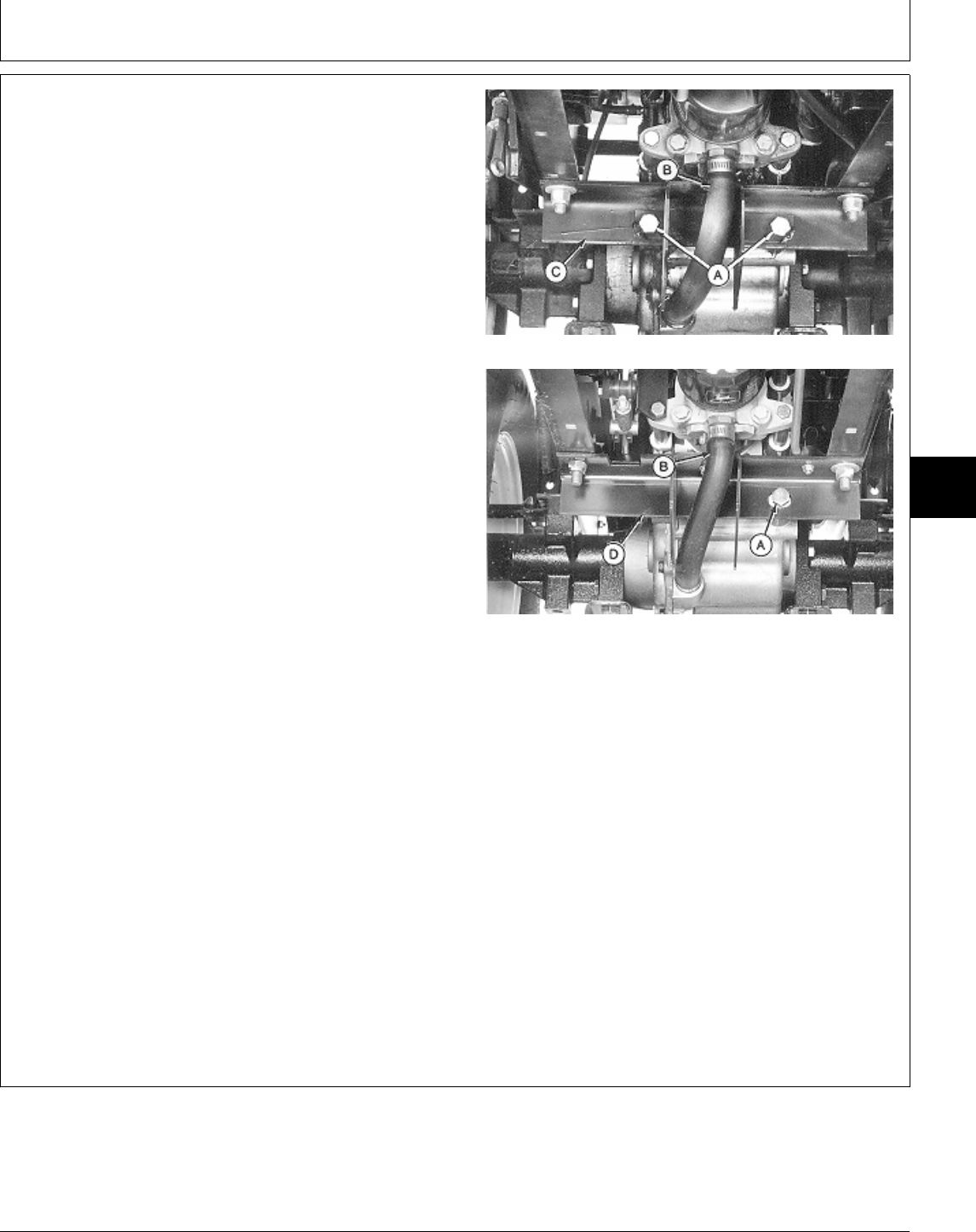
13. Use a floor jack to support transmission and place
jack stands under tractor frame.
NOTE: Early models had two bolts (A) attaching
differential to frame support bracket (C). Later
models have one shoulder bolt (A) or one bolt
with a washer and spacer.
14. Remove two bolts or shoulder bolt (A) or bolt,
washer and spacer.
15. Disconnect suction hose (B) from transmission. Close
all openings using caps and plugs. Early Models
16. Disconnect all other mounting bolts, hoses and
clamps needed to remove the transmission and
differential.
IMPORTANT: It is recommended to replace the early
model differential frame support
bracket (C) with the later configuration
(D). The early models attached the
differential to the frame support bracket
with two bolts (A). One in the
differential case and the other in the
differential cover. When the machine Later Models
went over rough terrain, the flexing of
the cover and case caused the
differential gasket to leak. With the later A—Bolt(s)
model frame support bracket installed, B—Suction Hose
the slotted hole and single shoulder C—Differential Frame Support Bracket (Early
bolt (A) (attached to the case only) will Models)
allow for flexing, eliminating any D—Differential Frame Support Bracket (Later
Models)
possible leaks.
17. Early models; Remove differential frame support
bracket (C).
M77300 -UN-24FEB95M77301 -UN-24FEB95
MX,15915005,9 -19-13JUL95
Transmission/Remove Transmission
TM1591 (15JUL95) 50-05-9 322,330,332 & 430 Lawn & Garden Tractors
030895
50
05
9
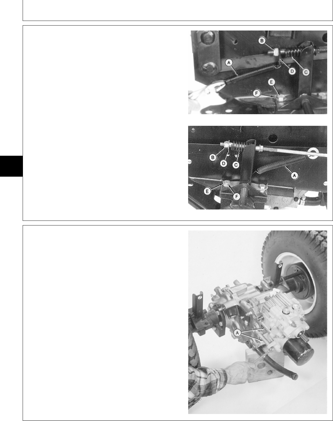
NOTE: Disconnect brakes on both sides of machine.
18. Disconnect spring (A).
19. Remove nut (B), plate or washer (D) and spring (C).
20. Bend tabs (F) flat. Remove two cap screws (E) from
each side of machine.
21. Lower differential and transmission assembly and roll
away from frame.
Early 430
A—Return Spring
B—Nut
C—Spring
D—Plate (Early 430)
—Washer (All and Later 430)
E—Mounting Cap Screw (2 used)
F—Lock Plate Tab
All and Later 430
M77903 -UN-19JAN95M77332 -UN-13FEB95
22. Thoroughly clean outside surface of differential
assembly with steam cleaner or cleaning solvent.
IMPORTANT: Mark spacers and cap screws before
disassembly. Each spacer must be
installed in its original location.
23. Remove four cap screws and spacers (A) to remove
transmission.
24. Make repairs as necessary. (See procedures in this
group.)
M36550 -UN-25JAN90
MX,15915005,10 -19-13JUL95
MX,15915005,11 -19-13JUL95
Transmission/Remove Transmission
TM1591 (15JUL95) 50-05-10 322,330,332 & 430 Lawn & Garden Tractors
030895
50
05
10
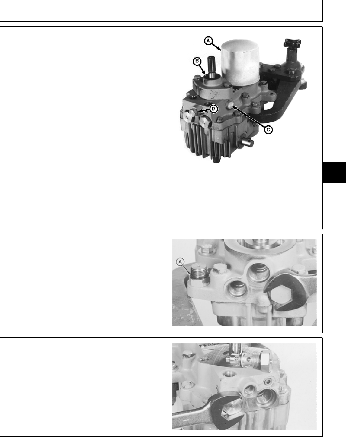
DISASSEMBLE TRANSMISSION COVER
1. Thoroughly clean outside surface of transmission
using a steam cleaner or cleaning solvent.
2. Install transmission on a bench fixture.
3. Remove charge pump (B). (See procedure in this
group.)
4. Remove implement relief valve (D). (See procedure in
this group.)
5. Remove charge relief valve (C). (See procedure in
this group.)
6. Remove filter (A).
A—Oil Filter
B—Charge Pump
C—Charge Relief Valve
D—Implement Relief Valve
M77333 -UN-21FEB95
7. Remove hose connector.
8. Remove two plugs and O-rings (A).
M36100 -UN-29AUG88
9. Remove two check valves.
M36101 -UN-29AUG88
MX,15905005,19 -19-14MAR95
5M3,5005K,O -19-18DEC87
5M3,5005K,P -19-18DEC87
Transmission/Disassemble
TM1591 (15JUL95) 50-05-11 322,330,332 & 430 Lawn & Garden Tractors
030895
50
05
11
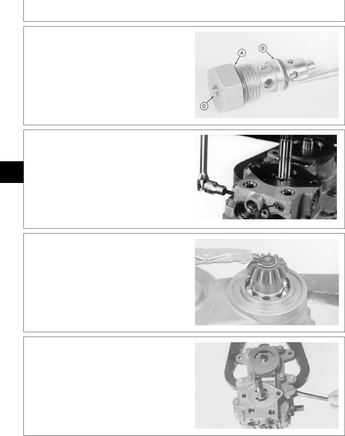
10. Remove O-ring, backup ring (B) and O-ring (A).
NOTE: Originally equipped 430 transmissions do not
have manually operated check valves. If check
valves have been replaced; service replacements
will have manually operated check valves.
11. Internal valve (C) must move freely inside check
valve.
M36102 -UN-29AUG88
12. Remove four pipe plugs.
M77334 -UN-21FEB95
13. Remove snap ring to remove output shaft drive gear.
14. Remove O-ring.
M36104 -UN-29AUG88
IMPORTANT: Do not disassemble the transmission
any further while in the bench fixture.
15. LOOSEN eight cap screws (do not remove). Remove
transmission from bench fixture.
M36522 -UN-25JAN90
MX,15915005,17 -19-13JUL95
MX,15905005,41 -19-14MAR95
5M3,5005K,S -19-18DEC87
5M3,5005K,T -19-18DEC87
Transmission/Disassemble
TM1591 (15JUL95) 50-05-12 322,330,332 & 430 Lawn & Garden Tractors
030895
50
05
12
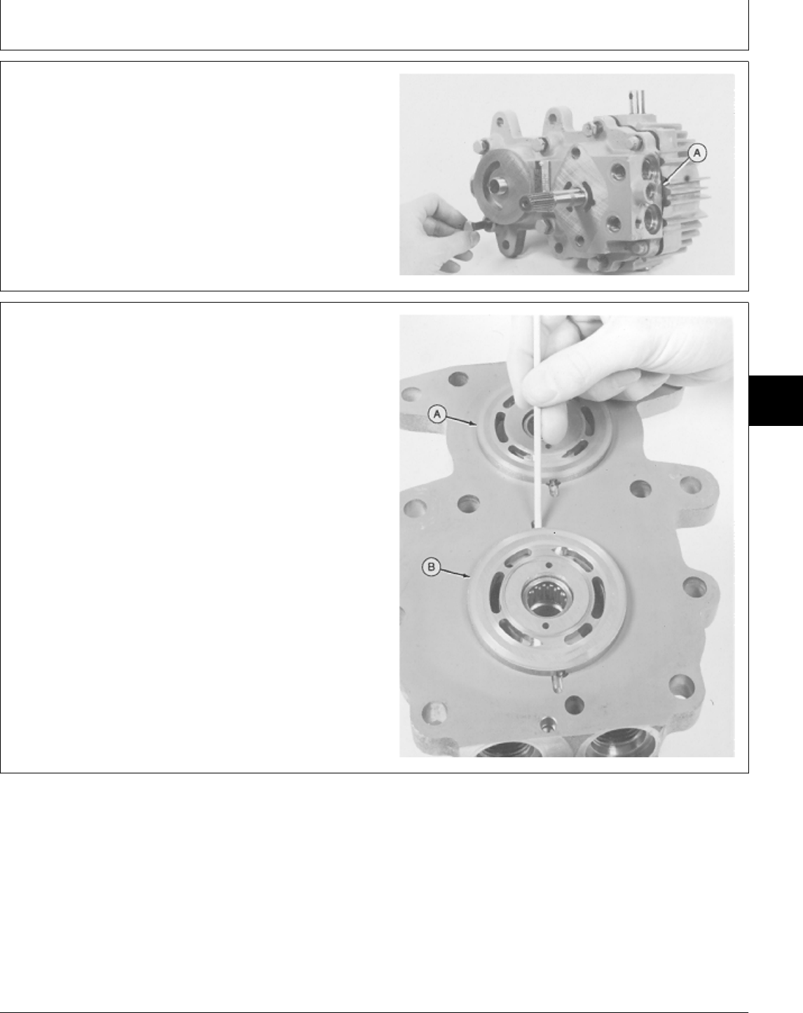
IMPORTANT: Do not allow internal parts to fall when
removing center section.
16. Put transmission on work bench and remove cap
screws, center section and gasket (A).
M36523 -UN-25JAN90
IMPORTANT: Do not nick or scratch lapped or
machined surfaces of the center
section, valve plates or cylinder blocks.
Keep pump and motor components
separate, they are not interchangeable.
17. Remove valve plates (A and B). If it is necessary to
pry valve plates loose from center section, use a wooden
dowel and pry only at dowel pin grooves.
If valve plates do not come off with center section,
remove valve plates from cylinder block assemblies.
It may be necessary to apply diesel fuel between valve
plate and cylinder block to cut oil film.
M36107 -UN-31JAN90
5M3,5005K,U -19-18DEC87
5M3,5005K,V -19-19DEC87
Transmission/Disassemble
TM1591 (15JUL95) 50-05-13 322,330,332 & 430 Lawn & Garden Tractors
030895
50
05
13
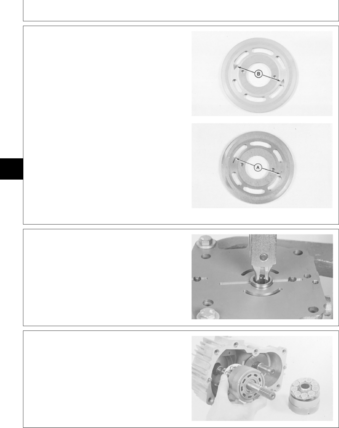
18. Inspect bearing plates. Bearing plates should be flat,
free of all nicks, burrs, scratches and erosion around the
ports. The bronze metal should show no scoring,
smearing or be discolored.
NOTE: Scoring is indicated by fine scratches or grooves
cut into the plate.
When these scratches can be detected by feel,
finger nail or lead pencil, the plate should be
replaced.
Some models may have a narrow slot (A) rather
then a wide slot (B). While others may NOT have
slots at all.
M49510 -UN-20DEC89M49511 -UN-20DEC89
19. Inspect both bearings in center section, replace if
necessary.
20. Install center section in bench fixture and remove
bearing using a 2-jaw puller and a slide hammer.
M36109 -UN-29AUG88
DISASSEMBLE PUMP AND MOTOR
IMPORTANT: Do not nick or scratch lapped surface
of cylinder blocks.
Piston-to-Bore relationship need not be
maintained; keep pump and motor
components separate, they are not
interchangeable.
1. Remove motor and pump cylinder blocks.
M36110 -UN-29AUG88
MX,15905005,20 -19-23FEB95
5M3,5005K,X -19-18DEC87
MX,15905005,21 -19-23FEB95
Transmission/Disassemble
TM1591 (15JUL95) 50-05-14 322,330,332 & 430 Lawn & Garden Tractors
030895
50
05
14
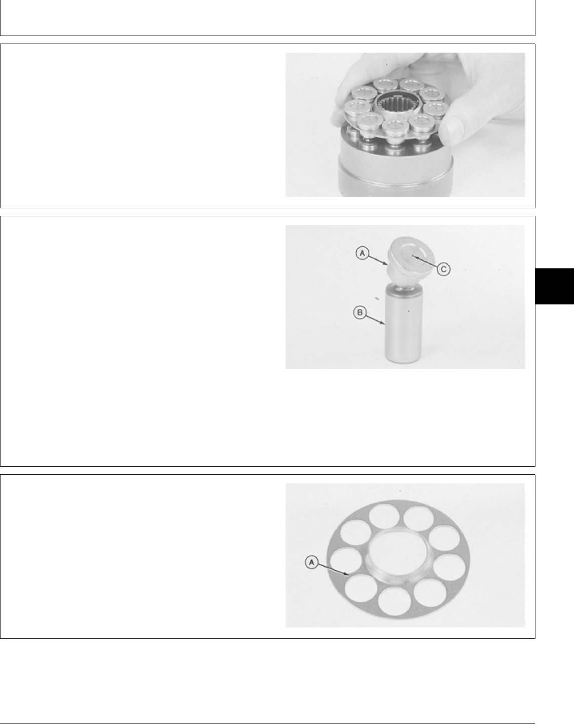
2. Inspect cylinder block assemblies.
IMPORTANT: Do not interchange pistons between
motor and pump cylinder blocks.
Pistons and cylinder blocks are
matched.
Lift piston retainer and pistons from cylinder block.
Check for free movement of pistons in cylinder bores.
M36111 -UN-29AUG88
3. Remove and inspect all pistons.
Check barrel (B) for scoring, discoloration, or any signs
of separation of slippers.
Check slipper (A) for scoring, smearing, rolled edges and
a full 360˚ free rotation on barrel.
Check lubrication hole (C) for blockage. Clean with
compressed air.
If any component of the piston is damaged, the cylinder
block assembly must be replaced.
M36112 -UN-29AUG88
4. Remove and inspect both piston retainers.
Check retainer for flatness, nicks, burrs and discoloration.
Check area around piston slippers (A) for scoring.
If any part of the piston retainer is damaged, the cylinder
block assembly must be replaced.
M36113 -UN-29AUG88
M45,5005A,51 -19-11JAN85
M45,5005A,52 -19-11JAN85
M45,5005A,53 -19-11JAN85
Transmission/Disassemble
TM1591 (15JUL95) 50-05-15 322,330,332 & 430 Lawn & Garden Tractors
030895
50
05
15
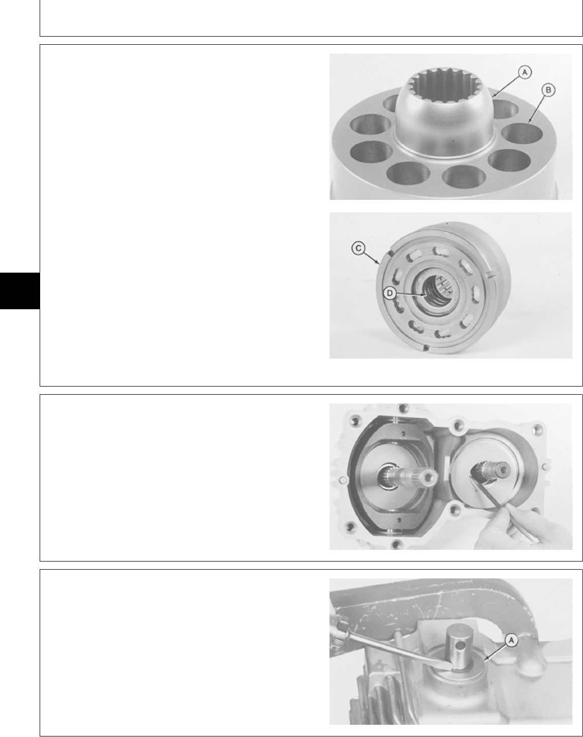
5. Inspect both cylinder blocks.
Check ball guide area (A) for scoring, wear and damage.
Check nine cylinder bores (B) for burrs and scoring.
Check lapped surface (C) for wear and damage.
Check spring assembly (D) for damage and free
movement.
If any part of the cylinder block is damaged, the cylinder
block assembly must be replaced.
M36114 -UN-29AUG88M36115 -UN-29AUG88
IMPORTANT: Do not scratch machined surfaces of
thrust plates or swashplates.
6. Remove pump and motor thrust plates using a brass
O-ring pick.
7. Inspect thrust plates. Check plates for scoring and
smeared bronze material.
M36116 -UN-29AUG88
DISASSEMBLE PUMP AND MOTOR
HOUSING
1. Remove snap ring and washer (A) from both trunnion
and control shafts.
M36524 -UN-25JAN90
M45,5005A,54 -19-11JAN85
M45,5005A,55 -19-11JAN85
MX,15905005,22 -19-23FEB95
Transmission/Disassemble
TM1591 (15JUL95) 50-05-16 322,330,332 & 430 Lawn & Garden Tractors
030895
50
05
16
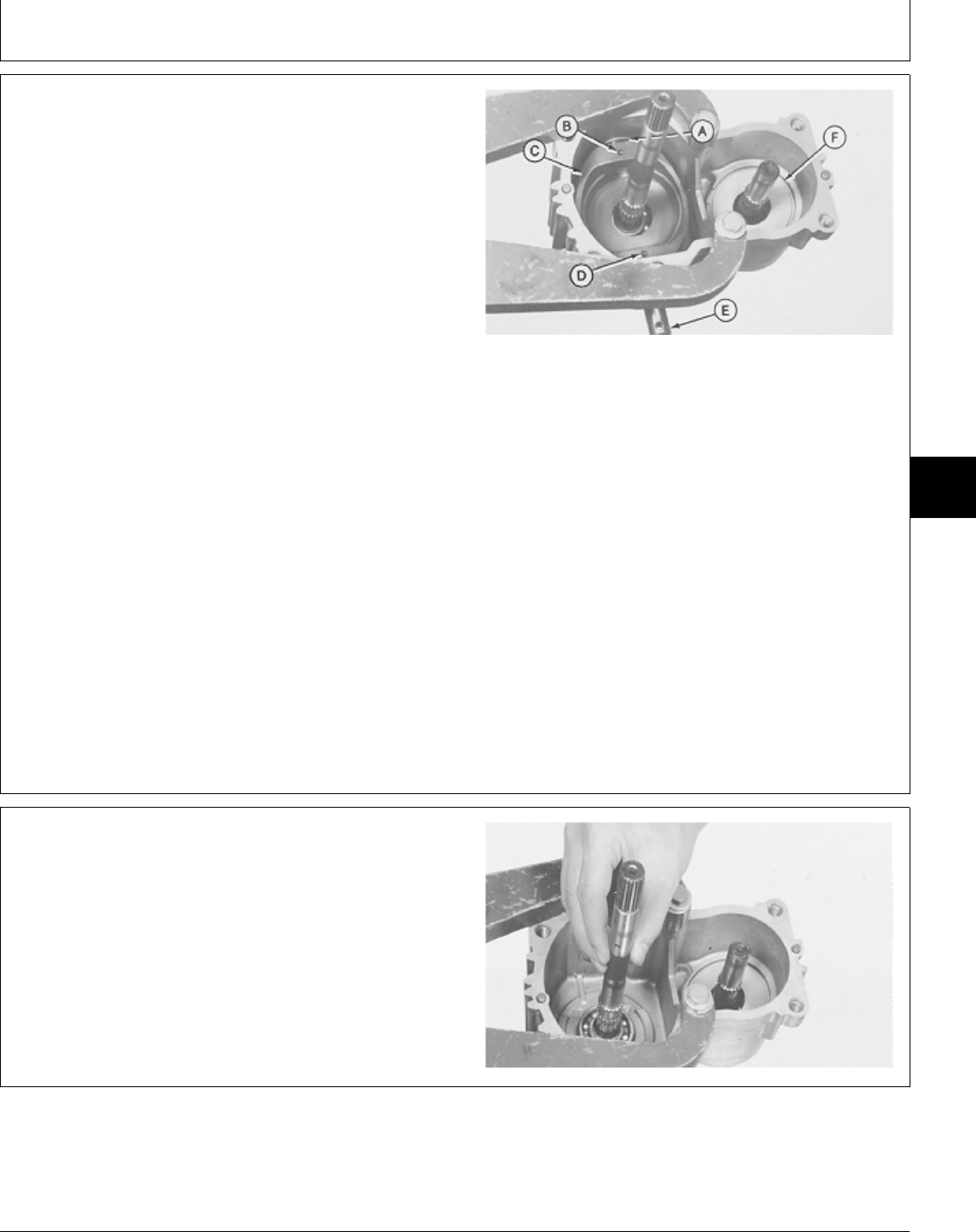
IMPORTANT: Pump shaft and bearing assembly
could restrict movement of swashplate.
Full swashplate movement is
approximately 25 mm (1 in.) in each
direction. If necessary tap shaft with a
soft faced hammer.
2. Push top of swashplate (C) down until it contacts the
stops in the housing.
IMPORTANT: DO NOT drive pins after they bottom.
Housing damage will result.
3. Drive pin (B) until it bottoms in housing.
A—Trunnion Shaft
B—Spring Pin
4. Drive two pins (D) until the lower one bottoms in C—Pump Swashplate
housing. D—Spring Pin (2 used)
E—Control Shaft
5. Turn swashplate to the neutral position. Pins should F—Motor Housing
fall into housing.
6. Repeat the above steps to remove second pin (D).
7. Remove control shaft (E) and trunnion shaft (A) to
remove swashplate.
8. Inspect swashplate and motor housing (F).
M36525 -UN-25JAN90
9. Remove pump shaft.
M36119 -UN-29AUG88
5M3,5005K,Z -19-18DEC87
M45,5005A,58 -19-11JAN85
Transmission/Disassemble
TM1591 (15JUL95) 50-05-17 322,330,332 & 430 Lawn & Garden Tractors
030895
50
05
17
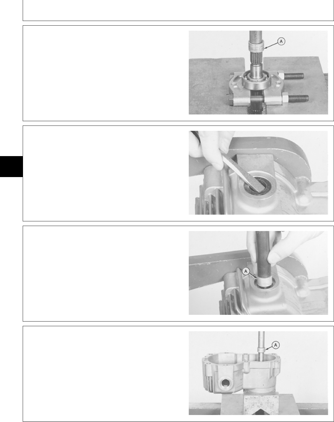
10. Inspect bearing, replace if necessary.
IMPORTANT: Be sure to hold shaft while removing
bearing.
11. Remove bearing using a 1 in. driver disk (A), bearing
puller attachment and a press.
M36120 -UN-29AUG88
12. Remove three seals from housing.
M36121 -UN-29AUG88
NOTE: Some transmissions will have bearings, while
others will have bushings.
13. Inspect trunnion bearing and control shaft bearing.
Replace if necessary.
14. Drive bearings or bushings through housing using a
13/16 in. driver disk (A) for bearings and a 7/8 in. driver
disk for bushings.
M36122 -UN-29AUG88
IMPORTANT: Be sure to hold shaft and bearing when
removing from housing.
15. Remove motor shaft and bearing. Using a 1-in. driver
disk (A), and a press.
M36123 -UN-29AUG88
M45,5005A,59 -19-13MAR85
M45,5005A,60 -19-11JAN85
5M3,5005K,AA -19-18DEC87
M45,5005A,62 -19-13MAR85
Transmission/Disassemble
TM1591 (15JUL95) 50-05-18 322,330,332 & 430 Lawn & Garden Tractors
030895
50
05
18
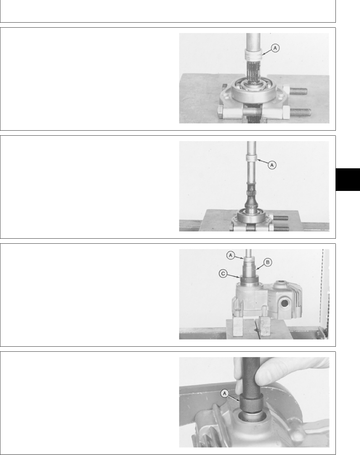
16. Inspect bearing, replace if necessary.
IMPORTANT: Be sure to hold shaft while removing
bearing.
17. Remove bearing using a 1 in. driver disk (A), bearing
puller attachment and a press.
M36124 -UN-29AUG88
ASSEMBLE PUMP AND MOTOR HOUSING
IMPORTANT: Always use new seals and O-rings.
Damaged or used parts will leak.
NOTE: Lubricate all seals and O-rings with petroleum
jelly during assembly.
1. Push motor shaft into bearing until it is on the shaft
shoulder using 1 in. driver disk (A), bearing puller
attachment, and a press.
M36126 -UN-29AUG88
IMPORTANT: To prevent bearing damage, press only
on outer race of bearing when
installing motor shaft assembly.
2. Push motor shaft assembly into housing until bearing
is at the bottom of bore using a 1-7/16 in. driver disk
(A), socket (B) and a donut type disk (C) and a press.
NOTE: There will be approximately 5 mm (3/16 in.) of
the bearing race above the mounting surface.
M36127 -UN-29AUG88
3. Install housing on bench fixture.
4. Drive bearings or bushings into housing until they are
flush with surface using a 1-1/8 in. driver disk (A).
5. Install three oil seals. Install seal with lip of seal
(spring side) toward inside of housing using a 1-7/16 in.
driver disk.
M36128 -UN-29AUG88
M45,5005A,63 -19-26APR85
MX,15905005,24 -19-23FEB95
M45,5005A,66 -19-13MAR85
MX,15905005,25 -19-23FEB95
Transmission/Assemble
TM1591 (15JUL95) 50-05-19 322,330,332 & 430 Lawn & Garden Tractors
030895
50
05
19
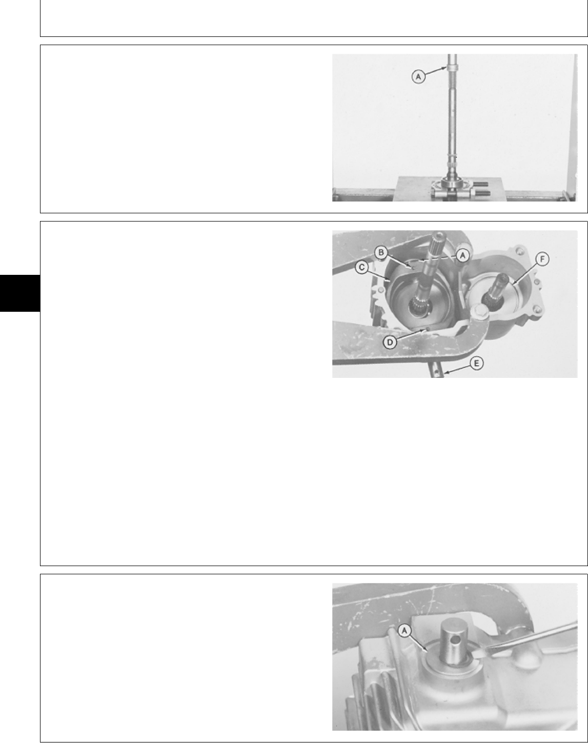
6. Push pump shaft into bearing until it is on the shaft
shoulder using a 1-in. driver disk (A) bearing puller
attachment and a press.
M36130 -UN-29AUG88
NOTE: Tape over splines to protect seals from possible
damage when installing shafts, remove tape after
installation.
7. Install pump shaft.
8. Install swashplate (C), control shaft (E), and shaft (A).
IMPORTANT: Pump shaft and bearing assembly
could restrict movement of swashplate.
Full swashplate movement is
approximately 25 mm (1 in.) each
direction. If necessary tap shaft with a
soft faced hammer to seat bearing.
A—Trunnion Shaft
B—Spring Pin
9. Drive pin (B) into swashplate and shaft until pin is C—Pump Swashplate
about 6 mm (1/4 in.) below swashplate surface. D—Spring Pin (2 used)
E—Control Shaft
10. Drive two pins (D) into swashplate and control shaft F—Motor Housing
until top pin is about 6 mm (1/4 in.) below swashplate
surface.
M36525 -UN-25JAN90
11. Install washer (A) and snap ring on trunnion and
control shaft.
12. Remove housing from bench fixture.
M36526 -UN-25JAN90
M45,5005A,69 -19-13MAR85
MX,15905005,26 -19-23FEB95
5M3,5005K,AF -19-18DEC87
Transmission/Assemble
TM1591 (15JUL95) 50-05-20 322,330,332 & 430 Lawn & Garden Tractors
030895
50
05
20
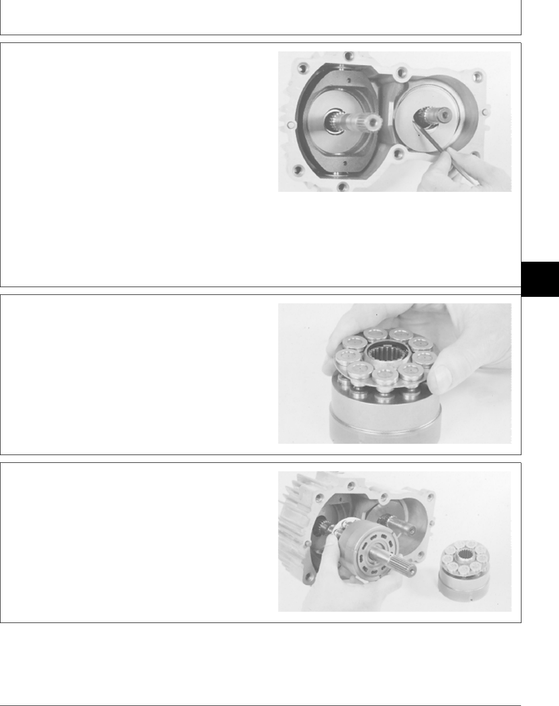
ASSEMBLE PUMP AND MOTOR
IMPORTANT: Do not nick or scratch lapped surface
of cylinder blocks.
Piston-to-Bore relationship need not be
maintained; keep pump and motor
components separate, they are not
interchangeable.
1. Put clean John Deere Low Viscosity HY-GARD® oil or
an equivalent on all internal parts.
2. Install pump and motor thrust plates.
M36116 -UN-29AUG88
3. Install pistons and piston retainer.
Lift piston retainer and piston from cylinder block. Check
for free movement of pistons in cylinder block before
installing in housing.
M36111 -UN-29AUG88
4. Install pump and motor cylinder blocks.
M36110 -UN-29AUG88
MX,15905005,27 -19-23FEB95
M45,5005A,74 -19-14JAN85
M45,5005A,75 -19-14JAN85
Transmission/Assemble
TM1591 (15JUL95) 50-05-21 322,330,332 & 430 Lawn & Garden Tractors
030895
50
05
21
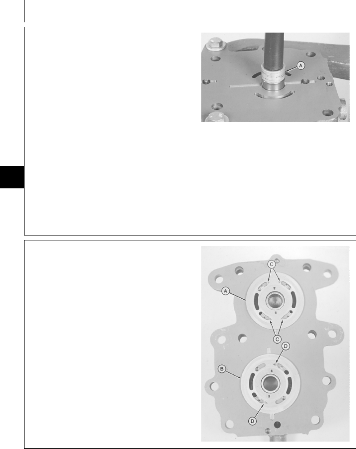
ASSEMBLE TRANSMISSION COVER
IMPORTANT: Do not nick or scratch lapped or
machined surfaces of the center
section, valve plates or cylinder block.
Keep pump and motor components
separate. They are not interchangeable.
Always use new seals and O-rings.
Damaged or used parts will leak.
NOTE: Lubricate all seals and O-rings with petroleum
jelly during assembly.
1. Install two needle bearings. Drive bearings into
housing until they are approximately 3 mm (0.118 in.)
above the surface of the housing using a 5/8 in. driver
disk (A).
M36132 -UN-29AUG88
2. Put clean John Deere Low Viscosity HY-GARD® oil on
valve plates and housing surface.
IMPORTANT: Pump valve plate (B) has TWO slotted
ports (D).
Motor valve plate (A) may, or may not
have slotted ports. Early models have
FOUR slotted ports (C). Quiet hydro’s
(later models) have no slotted ports. All
service or replacement plates will not
have slotted ports.
NOTE: The motor valve plates are interchangeable
between quiet hydros and early models.
3. Install pump valve plate (B) and motor valve plate (A)
over the protruding bearings and align slots in plates
with pins in housing.
A—Motor Valve Plate
B—Pump Valve Plate
C—Slotted Ports (4) (Early Models)
D—Slotted Ports (2)
M36133 -UN-22NOV89
MX,15905005,28 -19-23FEB95
MX,15905005,29 -19-23FEB95
Transmission/Assemble
TM1591 (15JUL95) 50-05-22 322,330,332 & 430 Lawn & Garden Tractors
030895
50
05
22
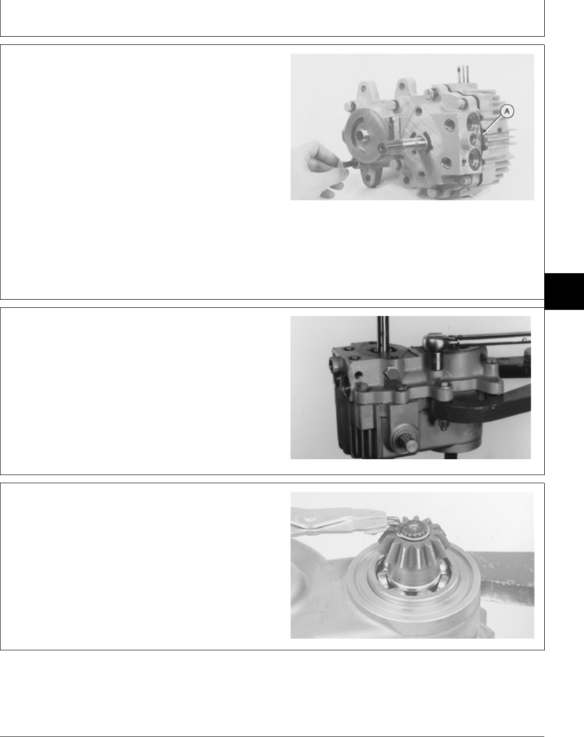
IMPORTANT: Use extreme care when assembling the
center section, valve plates and
cylinder block to avoid dropping,
nicking or scratching lapped surfaces.
4. Install center section and gasket (A) on housing and
install eight cap screws. Tighten cap screws evenly.
NOTE: Center section will seem springy, this is because
the springs inside the cylinder blocks are being
compressed.
M36523 -UN-25JAN90
5. Install transmission in bench fixture.
IMPORTANT: Check for proper internal assembly by
slowly rotating pump, motor and
control shaft while tightening cap
screws.
6. Tighten cap screws to 35 N·m (26 lb-ft).
M77335 -UN-21FEB95
7. Install gear on motor shaft (output shaft). Install snap
ring.
M36104 -UN-29AUG88
5M3,5005K,AG -19-18DEC87
MX,15905005,30 -19-14MAR95
M45,5005A,80 -19-14JAN85
Transmission/Assemble
TM1591 (15JUL95) 50-05-23 322,330,332 & 430 Lawn & Garden Tractors
030895
50
05
23
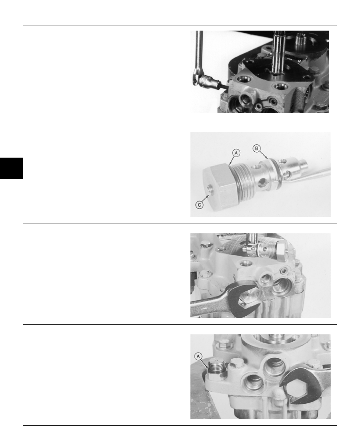
8. Install and tighten four pipe plugs.
M77334 -UN-21FEB95
9. Install O-ring (A), backup ring (B) and O-ring. Internal
valve (C) must move freely.
M36102 -UN-29AUG88
10. Install and tighten two check valves.
M36101 -UN-29AUG88
11. Install plugs and O-rings (A).
12. Install suction line fitting.
M36100 -UN-29AUG88
MX,15905005,42 -19-14MAR95
M45,5005A,82 -19-13MAR85
M45,5005A,83 -19-14JAN85
5M3,5005K,AI -19-18DEC87
Transmission/Assemble
TM1591 (15JUL95) 50-05-24 322,330,332 & 430 Lawn & Garden Tractors
030895
50
05
24
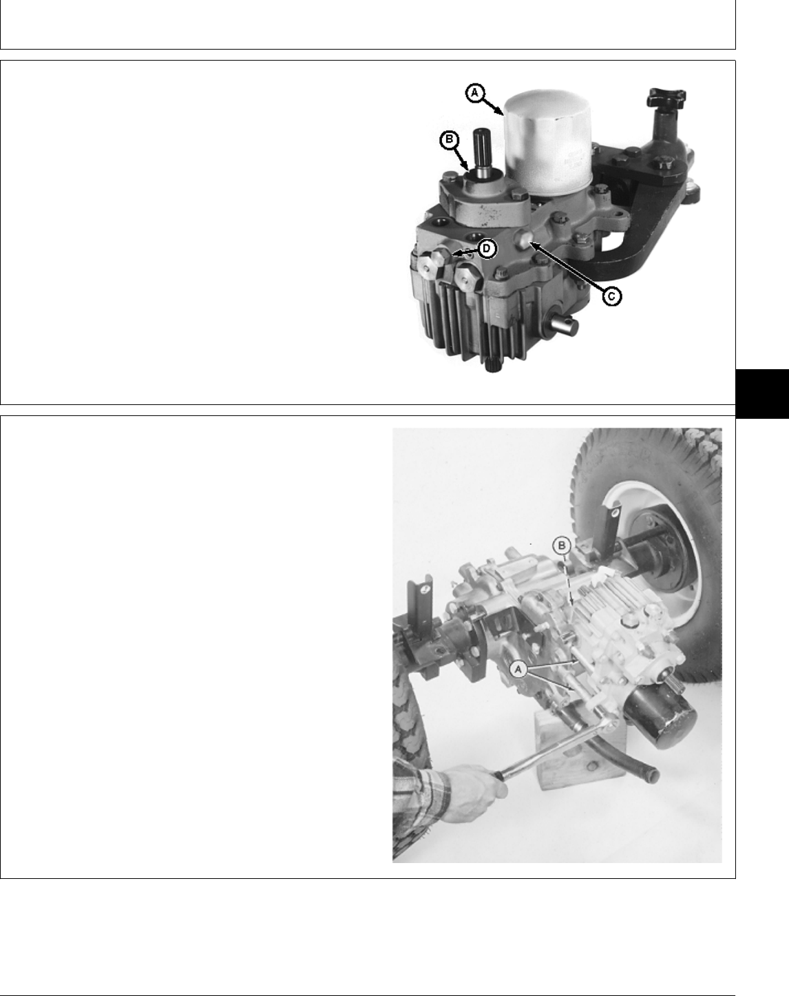
13. Install new filter (A).
14. Install charge relief valve (C), implement relief valve
(D) and charge pump (B). (See procedures in this
group.)
A—Oil Filter
B—Charge Pump
C—Charge Relief Valve
D—Implement Relief Valve
M77333 -UN-21FEB95
INSTALL TRANSMISSION
IMPORTANT: Always use new seals and O-rings.
Damaged or used parts will leak.
NOTE: Lubricate all seals and O-rings with petroleum
jelly during assembly.
1. Install new O-ring (B).
2. Install transmission; engage transmission output gear
with differential gear.
3. Install four spacers and cap screws (A) in their
original locations as marked during removal. Tighten cap
screws to 45 N·m (33 lb-ft).
M36551 -UN-25JAN90
MX,15905005,31 -19-14MAR95
MX,15905005,32 -19-23FEB95
Transmission/Install Transmission
TM1591 (15JUL95) 50-05-25 322,330,332 & 430 Lawn & Garden Tractors
030895
50
05
25
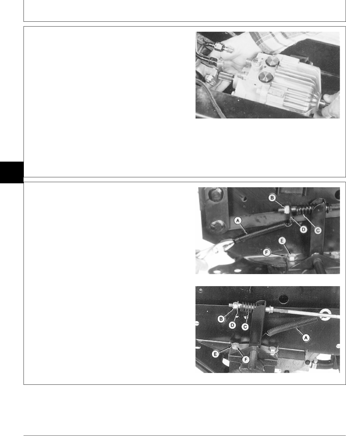
4. Position differential assembly under tractor.
5. On 430; Hold differential lock linkage away from
differential using wire, tape, etc.
6. Lift and position differential assembly. Put driveshaft
on transmission input shaft. Turn pump shaft to align
splines.
430 Shown
M36578 -UN-25JAN90
7. Position brake linkage and install install cap screws
(E) on each side of machine. Tighten cap screws to 100
N·m (75 lb-ft). Bend tabs (F) over flat of cap screws.
NOTE: Connect brakes on both sides of machine.
8. Install spring (C), plate or washer (D) and nut (B).
9. Connect spring (A).
A—Return Spring
B—Nut
C—Spring Early 430
D—Plate (Early 430)
—Washer (All and Later 430)
E—Mounting Cap Screw (2 used)
F—Lock Plate Tab
All and Later 430
M77903 -UN-19JAN95M77332 -UN-13FEB95
MX,15915005,12 -19-13JUL95
MX,15915005,18 -19-13JUL95
Transmission/Install Transmission
TM1591 (15JUL95) 50-05-26 322,330,332 & 430 Lawn & Garden Tractors
030895
50
05
26
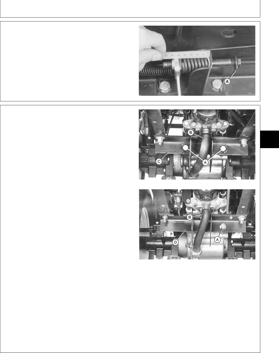
10. Lock brake pedals together (322, 332, 430) and
apply park brake.
11. Loosen lock nut (A).
12. Turn nut until spring is 42 mm (1.650 in.) long.
Tighten lock nut.
M36554 -UN-25JAN90
NOTE: Early models have two bolts (A) attaching
differential to frame support bracket (C). Later
models have one shoulder bolt (A) or one bolt
with a washer and spacer.
IMPORTANT: It is recommended to replace the early
model differential frame support
bracket (C) with the later configuration
(D). The early models attached the
differential to the frame support bracket
with two bolts (A). One in the
differential case and the other in the
differential cover. When the machine Early Models
went over rough terrain, the flexing of
the cover and case caused the
differential gasket to leak. With the later
model frame support bracket installed,
the slotted hole and single shoulder
bolt (A) (attached to the case only) will
allow for flexing, eliminating any
possible leaks.
13. Early models; Install new differential frame support
bracket (D).
14. Install shoulder bolt (A) or bolt, washer and spacer. Later Models
Tighten to 61 N·m (45 lb-ft).
15. Attach all mounting bolts, hoses and clamps. A—Bolt(s)
B—Suction Hose
16. Connect suction hose (B). C—Differential Frame Support Bracket (Early
Models)
17. Remove jack stands and lower tractor. D—Differential Frame Support Bracket (Later
Models)
M77300 -UN-24FEB95M77301 -UN-24FEB95
MX,15915005,13 -19-13JUL95
MX,15905005,36 -19-23FEB95
Transmission/Install Transmission
TM1591 (15JUL95) 50-05-27 322,330,332 & 430 Lawn & Garden Tractors
030895
50
05
27
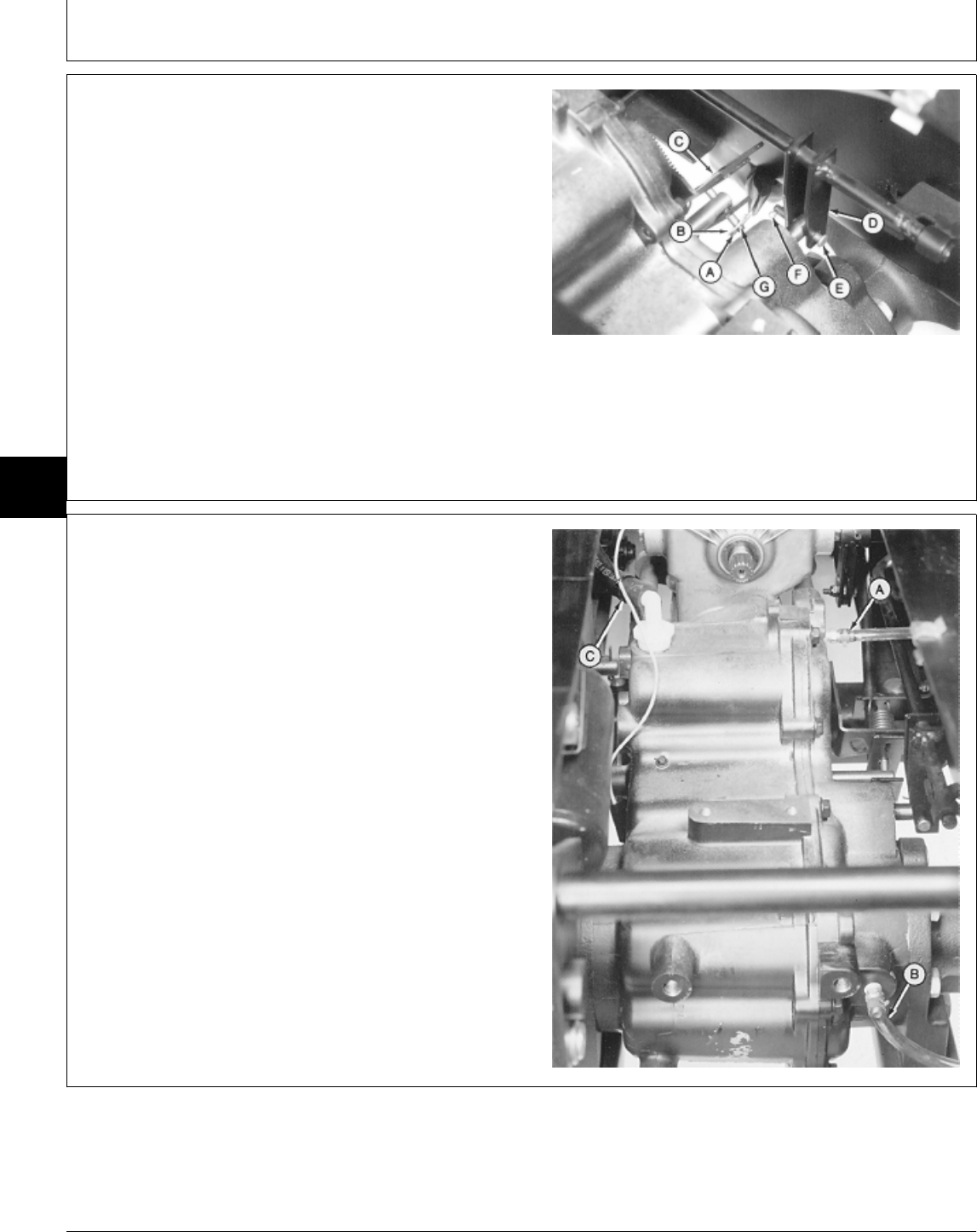
NOTE: Steps 18 and 19 are for 430 only. Go to Step 20
to continue installation procedures for all
machines.
18. Connect differential lock linkage (D). Install pin (E)
and cotter pin (F).
19. Connect two-speed differential linkage (C). Install pin
(G), washer (B) and cotter pin (A).
A—Cotter Pin
B—Washer
C—Two-Speed Differential Linkage
D—Differential Lock Linkage
E—Pin
F—Cotter Pin
G—Pin
M36543 -UN-19JAN95
20. Connect oil fill tube hose (C).
21. Connect two hoses (A and B).
M36542 -UN-25JAN90
MX,15915005,14 -19-13JUL95
MX,15905005,38 -19-23FEB95
Transmission/Install Transmission
TM1591 (15JUL95) 50-05-28 322,330,332 & 430 Lawn & Garden Tractors
030895
50
05
28
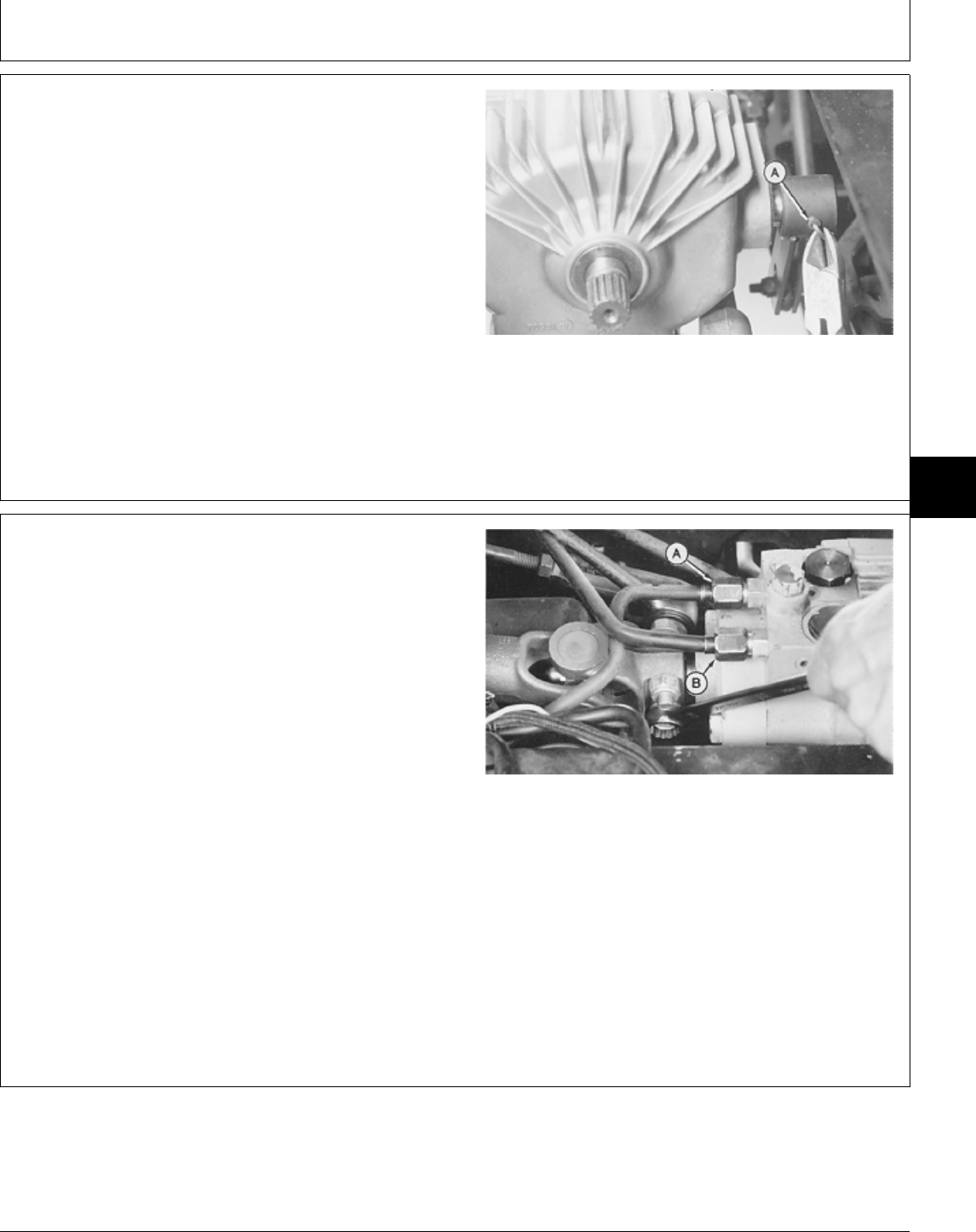
NOTE: There are different versions of the swashplate
control arm. Also, attaching swashplate control
arm to the control shaft on transmission is
different. Some machines use a safety wire and
roll pin, others use a nut and cap screw.
22. Attach swashplate control arm to control shaft with
roll pin and safety wire or cap screw and nut. Tighten
nut to 60 N·m (44 lb-ft).
23. On 330; Install deflector shields with foam at rear of
transmission. Early Models Shown
M36541 -UN-25JAN90
24. Connect hydraulic pressure line (A) and return line
(B).
25. Tighten two nuts and cap screws, if equipped, on
drive shaft to 60 N·m (44 lb-ft) or install drive shaft, if
necessary. (See procedure in Group 25.)
26. Install drain plug.
27. Install belly screen/pan.
28. Install fuel tank and fender deck. 430 Shown
29. Fill transmission with the recommended amount of
John Deere Low Viscosity HY-GARD® oil.
30. Bleed the hydraulic system. (See procedure in
Section 270, Group 20.)
31. If tractor creeps forward or reverse while in neutral,
adjust neutral and neutral return linkage. (See
procedures in Section 250, Group 15.)
M36540 -UN-25JAN90
MX,15915005,15 -19-13JUL95
MX,15915005,16 -19-13JUL95
Transmission/Install Transmission
TM1591 (15JUL95) 50-05-29 322,330,332 & 430 Lawn & Garden Tractors
030895
50
05
29

Transmission/Install Transmission
TM1591 (15JUL95) 50-05-30 322,330,332 & 430 Lawn & Garden Tractors
030895
50
05
30
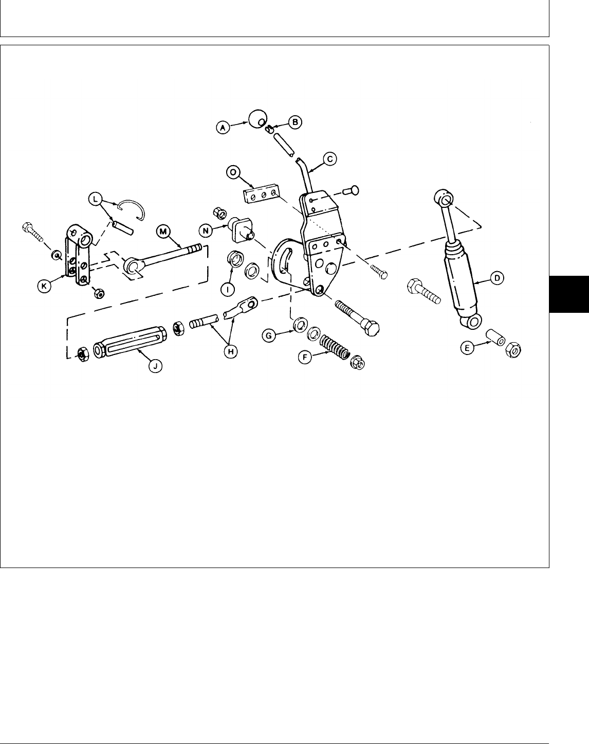
INSPECT AND REPAIR TRANSMISSION CONTROL LINKAGE—330
A—Knob E—Spacer I—Spacer M—Eyebolt
B—Clip F—Compression Spring J—Turnbuckle N—Guide
C—Speed Control Lever G—Friction Disc (2 used) K—Swashplate Arm O—Weld Nut
D—Shock Absorber H—Speed Control Rod L—Spring Pin and Lock Wire
1. Remove belly screen, fender deck and fuel tank.
2. Remove engine side panels.
3. Remove right-hand pedestal side panel.
4. Inspect linkage for wear or damage. Replace parts
as necessary.
5. Adjust hydrostatic lever friction and neutral return
linkage. (See procedures in Section 250, Group 15.)
M78044 -UN-13MAR95
MX,15915010,1 -19-13JUL95
Group 10
Transmission Control Linkage
TM1591 (15JUL95) 50-10-1 322,330,332 & 430 Lawn & Garden Tractors
030895
50
10
1
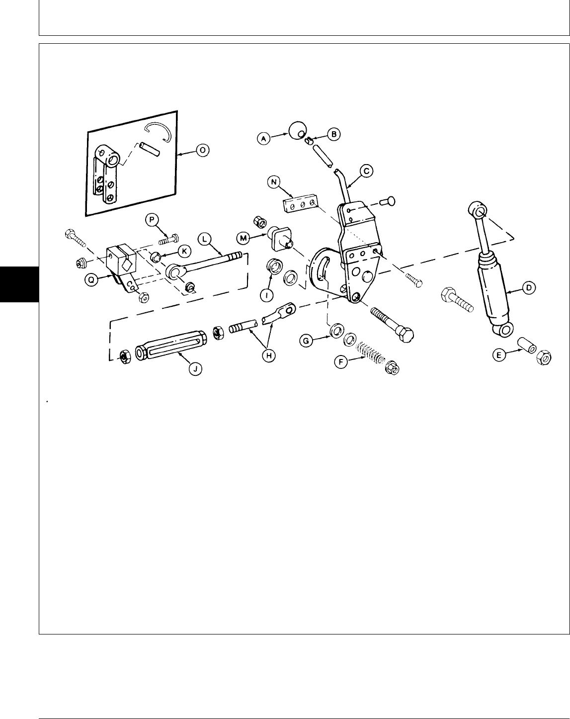
INSPECT AND REPAIR TRANSMISSION CONTROL LINKAGE—VERSION ONE (322 AND
332)
A—Knob G—Friction Disc (2 used) L—Eyebolt P—Cap Screw (Later
B—Clip H—Speed Control Rod M—Guide Models—322 and 332)
C—Speed Control Lever I—Spacer N—Weld Nut Q—Swashplate Arm (Later
D—Shock Absorber J—Turnbuckle O—Swashplate Arm Models—322 and 332)
E—Spacer K—Spacer Assembly (Early
F—Compression Spring Models—332)
1. Remove belly screen, fender deck and fuel tank.
2. Remove engine side panels.
3. Remove right-hand pedestal side panel.
4. Inspect linkage for wear or damage. Replace parts
as necessary.
5. Adjust hydrostatic lever friction. (See procedure in
Section 250, Group 15.)
6. After connecting swashplate arm (Q) to
transmission control shaft, tighten cap screw (P) to 60
N·m (44 lb-ft).
7. Adjust neutral return linkage. (See procedure in
Section 250, Group 15.)
M77908 -UN-13MAR95
MX,15915010,2 -19-13JUL95
Transmission Control Linkage/Inspect and Repair Control Linkage—322, 332 and 430
TM1591 (15JUL95) 50-10-2 322,330,332 & 430 Lawn & Garden Tractors
030895
50
10
2
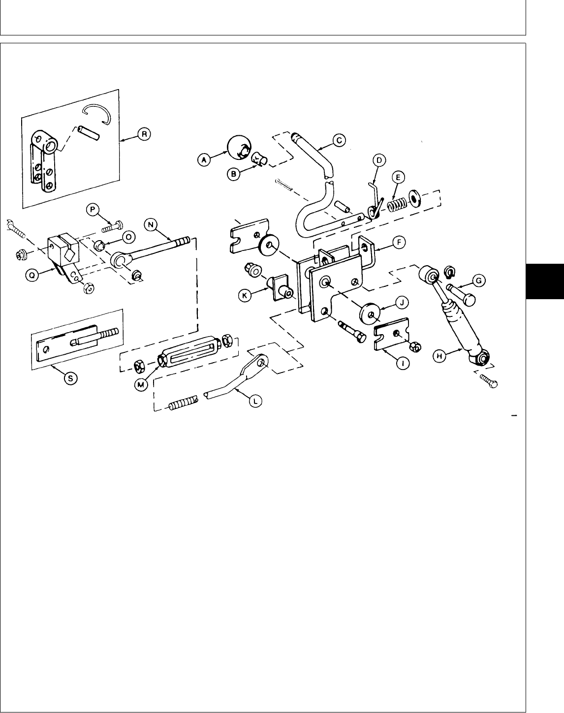
INSPECT AND REPAIR TRANSMISSION CONTROL LINKAGE—VERSION ONE (430)
A—Knob G—Pin L—Speed Control Rod Q—Swashplate Arm (Later
B—Clip H—Shock Absorber M—Turnbuckle Models)
C—Speed Control Lever I—Brake Plate (2 used) N—Eyebolt (Later Models) R—Swashplate Arm
D—Torsion Spring J—Friction Disc (2 used) O—Spacer Assembly (Early Models)
E—Compression Spring K—Guide P—Cap Screw (Later Models) S—Stud (Early Models)
F—Bracket
1. Remove belly pan, fender deck and fuel tank.
2. Remove front grille and engine side panels.
3. Remove battery and battery base.
4. Remove right-hand pedestal side panel.
5. Inspect linkage for wear or damage. Replace parts
as necessary.
6. Adjust hydrostatic lever friction. (See procedure in
Section 250, Group 15.)
7. After connecting swashplate arm (Q) to
transmission control shaft, tighten cap screw (P) to 60
N·m (44 lb-ft).
8. Adjust neutral return linkage. (See procedure in
Section 250, Group 15.)
M78045 -UN-17FEB95
MX,15915010,3 -19-13JUL95
Transmission Control Linkage/Inspect and Repair Control Linkage—322, 332 and 430
TM1591 (15JUL95) 50-10-3 322,330,332 & 430 Lawn & Garden Tractors
030895
50
10
3
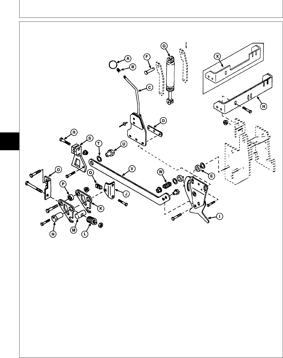
INSPECT AND REPAIR TRANSMISSION CONTROL LINKAGE—VERSION TWO (ALL)
A—Knob H—Bracket (322, 332) N—Adjustable Eccentric S—Swashplate Arm
B—Clip I—Control Plate Bearing T—Spring Washer
C—Speed Control Lever J—Angle Bracket O—Bracket U—Nut (2 used)
D—Weld Nut K—Detent Arm (2 used) P—Ball Bearing V—Speed Control Link
E—Friction Disc (2 used) L—Compression Spring Q—Clamp-On Nut W—Compression Spring
F—Pin M—Pivot Pin R—Cap Screw X—Bracket (430)
G—Torsional Dampener
1. Remove belly screen/pan, fender deck and fuel
tank.
2. Remove front grille and engine side panels.
3. On 430; Remove battery and battery base.
4. Remove right-hand pedestal side panel.
5. Inspect linkage for wear or damage. Replace parts
as necessary.
6. After connecting swashplate arm (S) to
transmission control shaft, tighten cap screw (R) to
60 N·m (44 lb-ft).
7. Adjust neutral and neutral return linkage. (See
procedure in Section 250, Group 15.)
8. Adjust hydrostatic lever friction. (See procedure in
Section 250, Group 15.)
M78057 -UN-14MAR95
MX,15915010,4 -19-13JUL95
Transmission Control Linkage/Inspect and Repair Control Linkage—322, 332 and 430
TM1591 (15JUL95) 50-10-4 322,330,332 & 430 Lawn & Garden Tractors
030895
50
10
4
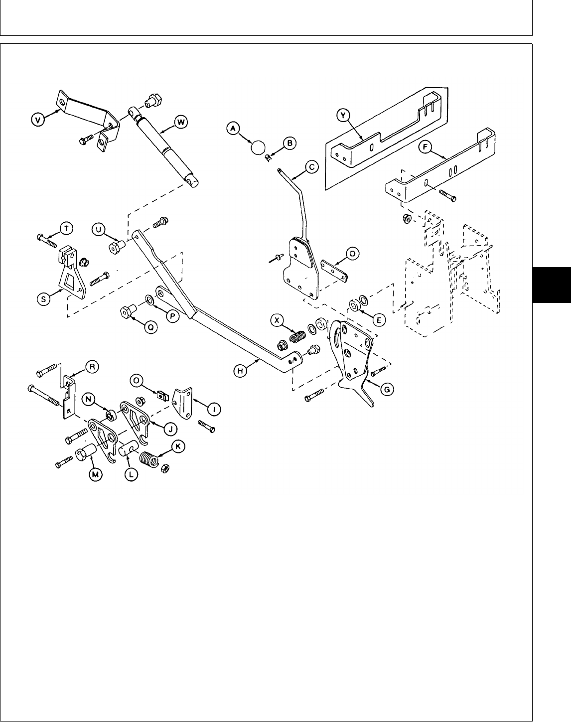
INSPECT AND REPAIR TRANSMISSION CONTROL LINKAGE—VERSION THREE (ALL)
A—Knob H—Speed Control Link N—Ball Bearing T—Cap Screw
B—Clip I—Angle Bracket O—Clamp-On Nut U—Spacer Nut (2 used)
C—Speed Control Lever J—Detent Arm (2 used) P—Spring Washer V—Bracket
D—Weld Nut K—Compression Spring Q—Nut (2 used) W—Torsional Dampener
E—Friction Disc (2 used) L—Pivot Pin R—Bracket X—Compression Spring
F—Bracket (322, 332) M—Adjustable Eccentric S—Swashplate Arm Y—Bracket (430)
G—Control Plate Bearing
1. Remove belly screen/pan, fender deck and fuel
tank.
2. Remove front grille and engine side panels.
3. On 430; Remove battery and battery base.
4. Remove right-hand pedestal side panel.
5. Inspect linkage for wear or damage. Replace parts
as necessary.
6. After connecting swashplate arm (S) to
transmission control shaft, tighten cap screw (T) to 60
N·m (44 lb-ft).
7. Adjust neutral and neutral return linkage. (See
procedure in Section 250, Group 15.)
8. Adjust hydrostatic lever friction. (See procedure in
Section 250, Group 15.)
M78046 -UN-17FEB95
MX,15915010,5 -19-13JUL95
Transmission Control Linkage/Inspect and Repair Control Linkage—322, 332 and 430
TM1591 (15JUL95) 50-10-5 322,330,332 & 430 Lawn & Garden Tractors
030895
50
10
5
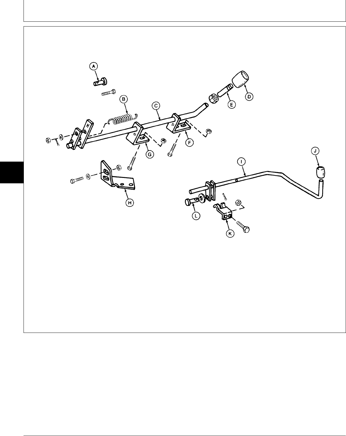
INSPECT AND REPAIR DIFFERENTIAL LOCK AND TWO-SPEED CONTROL LINKAGE
(430)
A—Pin D—Knob G—Rear Angle Bracket J—Knob
B—Spring E—Stud Extension H—Two-Speed Bracket K—Clip (2 used)
C—Two-Speed Control Rod F—Front Angle Bracket I—Differential Lock Rod L—Pin
1. Remove belly pan.
2. Inspect linkage for wear or damage. Replace parts
as necessary.
3. Adjust two-speed axle lever detent, if necessary.
(See procedure in Section 250, Group 15.)
M77912 -UN-13FEB95
MX,15915010,6 -19-13JUL95
Transmission Control Linkage/Inspect and Repair Differential Lock and Two-Speed Linkage (430)
TM1591 (15JUL95) 50-10-6 322,330,332 & 430 Lawn & Garden Tractors
030895
50
10
6

OTHER MATERIAL
Number Name Use
LOCTITE® PRODUCTS
U.S./Canadian/LOCTITE No.
TY6305/TY9485/764 Clean and Cure Primer Cleans parts and speeds cure of
sealant.
T43512/TY9473/242 Thread Lock and Sealer (Medium Apply to threads of carrier cap
Strength) screws.
TY6304/TY9484/518 Flexible Sealant Apply to mating surfaces of
differential cover and case halves.
®LOCTITE is a registered trademark of the Loctite Corp.
SERVICE PARTS KITS
The following kits are available through your parts
catalog:
Differential Tabbed Thrust Washer Kit for Early Models
MX,15905015,OTH-19-23FEB95
MX,15905015,KIT-19-23FEB95
Group 15
Differential
TM1591 (15JUL95) 50-15-1 322,330,332 & 430 Lawn & Garden Tractors
030895
50
15
1
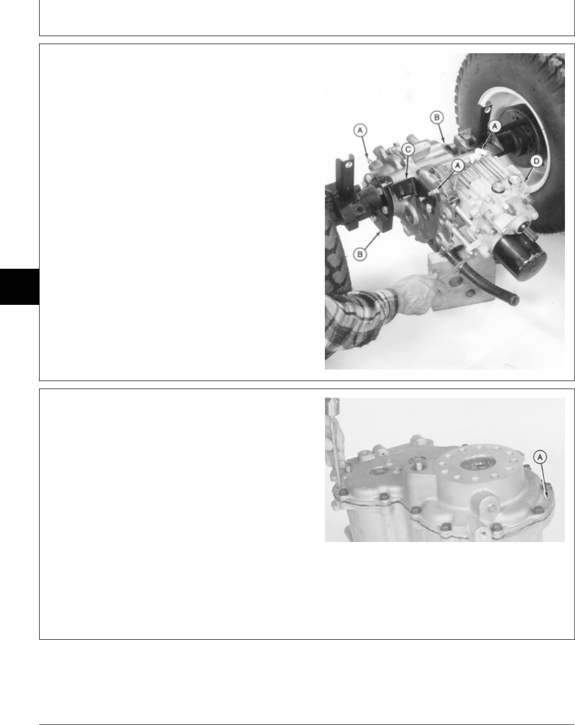
REMOVE AND INSTALL DIFFERENTIAL
1. Remove transmission (D). (See procedure in Group
05.)
2. Remove both axles (B). (See procedure in Group 20.)
3. Remove bracket (C) and fittings (A).
4. Installation is done in the reverse order of removal.
M36557 -UN-19JAN95
DISASSEMBLE AND INSPECT
DIFFERENTIAL
NOTE: This disassembly procedure is for the One-Speed
Differential (322, 330 and 332) and the
Two-Speed Differential with Differential Lock
(430). The differences are noted.
1. Drive two dowel pins (A) into differential case just far
enough to clear the cover.
2. Remove cap screws to remove cover and gasket.
M36226 -UN-22NOV89
MX,15905015,1 -19-23FEB95
MX,15915015,1 -19-13JUL95
Differential/Disassemble and Inspect
TM1591 (15JUL95) 50-15-2 322,330,332 & 430 Lawn & Garden Tractors
030895
50
15
2
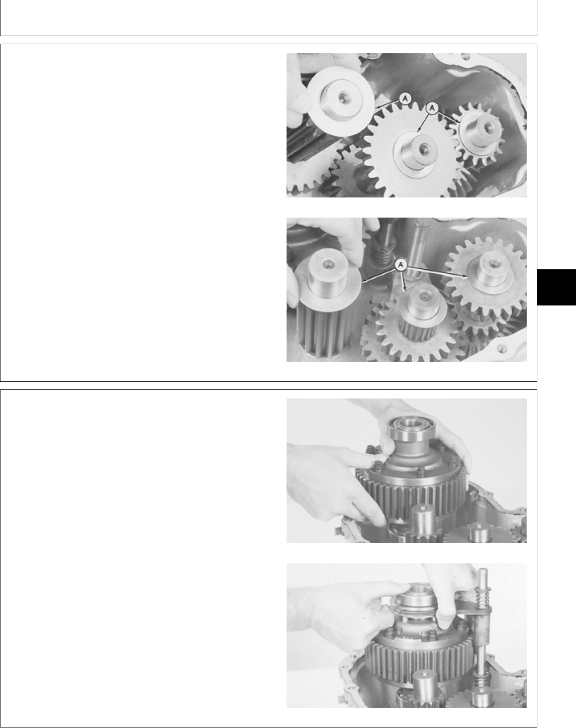
NOTE: Early models have FLAT thrust washers. Later
models have TABBED thrust washers. All service
or replacement thrust washers will have the tabs.
IMPORTANT: It is recommended to replace the early
model (flat) thrust washers with the
later model (tabbed) thrust washers.
The early model washers may spin with
their respective shafts, causing wear to
the cover bearing surfaces.
3. Remove three thrust washers (A). One-Speed Differential
Two-Speed Differential
M36168 -UN-29AUG88M36228 -UN-22NOV89
4. Remove differential; if equipped with differential lock,
remove shift rod assembly with differential.
Without Differential Lock
With Differential Lock
M36170 -UN-22NOV89M36169 -UN-29AUG88
MX,15905015,3 -19-23FEB95
MX,15905015,4 -19-23FEB95
Differential/Disassemble and Inspect
TM1591 (15JUL95) 50-15-3 322,330,332 & 430 Lawn & Garden Tractors
030895
50
15
3
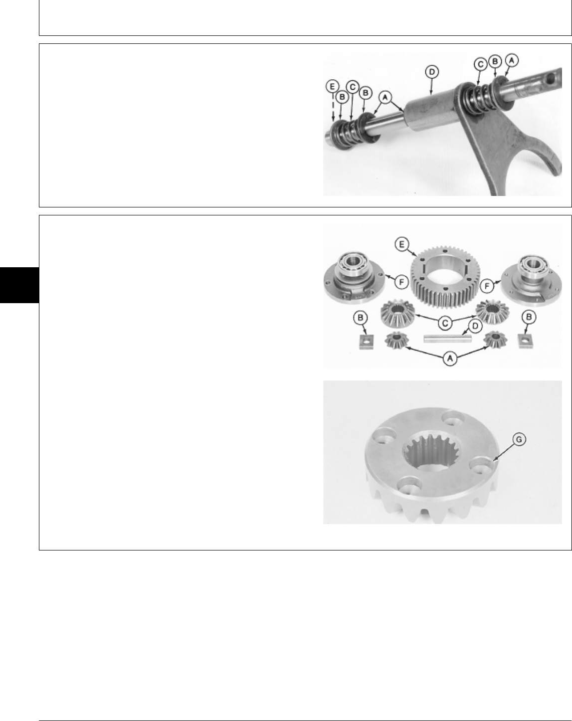
5. If equipped with differential lock; disassemble shift rod
assembly by removing three E-Rings (A) washers (B),
springs (C), fork (D), and snap ring (E).
Inspect shaft for straightness or damage. Replace if
necessary.
A—E-Ring (3 used)
B—Washer (3 used)
C—Spring (2 used)
D—Fork
E—Snap Ring
M36230 -UN-19JAN95
NOTE: Early model with differential lock shown.
6. Remove cap screws to separate carriers (F) from ring
gear (E).
7. Disassemble and inspect pinion assembly.
Inspect pinion gears (A), bevel gears (C), ring gear (E),
pinion blocks (B), and cross shaft (D) for wear or
damage. Replace if necessary.
If equipped with differential lock, inspect bevel gear with
holes (G) for wear or damage. Replace if necessary.
A—Pinion Gear (2 used)
B—Pinion Block (2 used)
C—Bevel Gear (2 used)
D—Cross Shaft
E—Ring Gear
F—Carrier (2 used)
G—Bevel Gear with Holes
M31977 -UN-25AUG88M36173 -UN-29AUG88
MX,15905015,5 -19-23FEB95
MX,15905015,6 -19-20MAR95
Differential/Disassemble and Inspect
TM1591 (15JUL95) 50-15-4 322,330,332 & 430 Lawn & Garden Tractors
030895
50
15
4
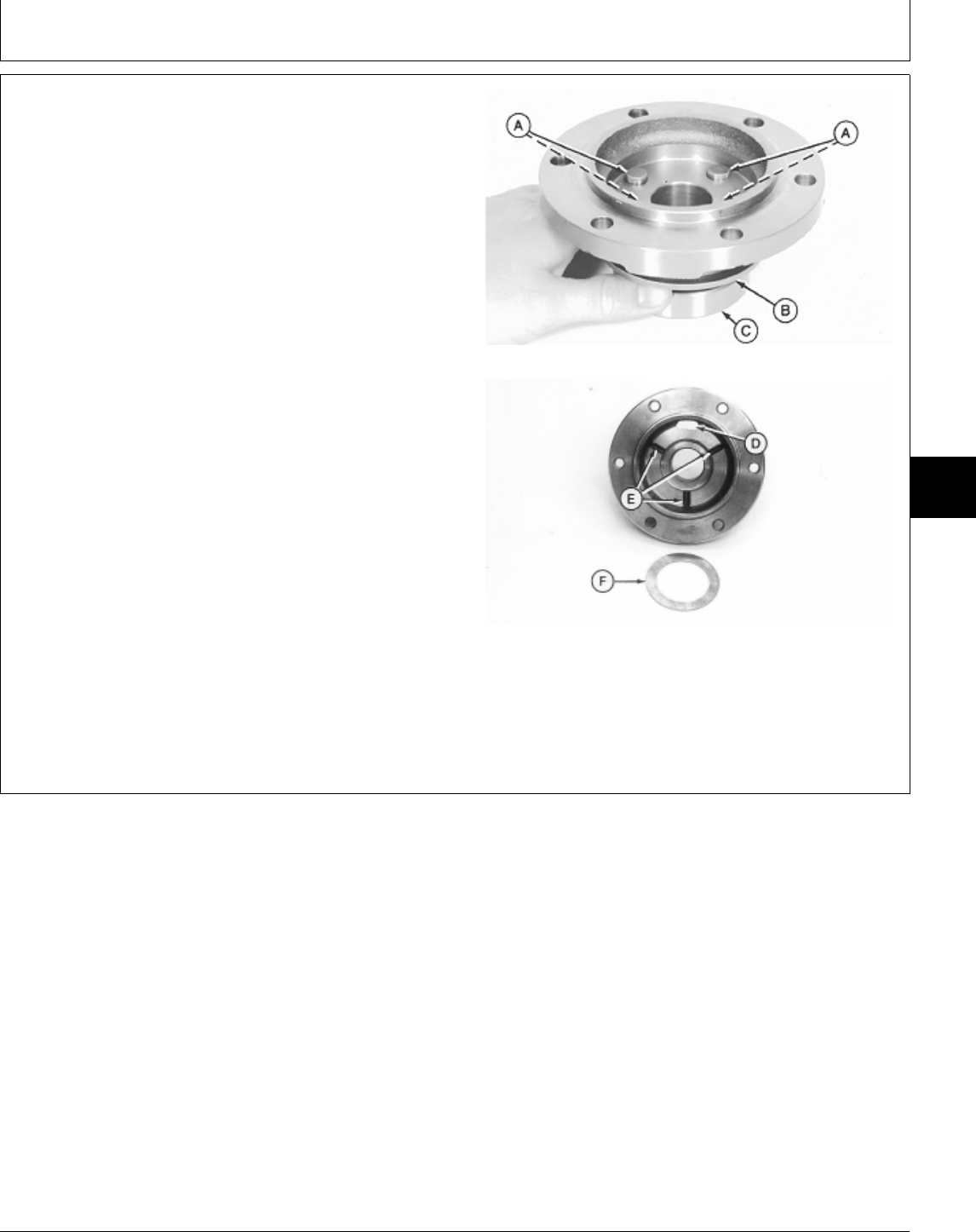
NOTE: Later models have oil grooves (E), an oil hole (D)
and a thrust washer (F) in carriers.
Machines without differential lock have one thrust
washer in each carrier. Machines with differential
lock have one thrust washer and one new style
carrier on the non-differential lock side only.
All service or replacement carriers will have these
features.
Bearings (C) are press-fit on carriers. Remove
bearings only if replacement is necessary. With Differential Lock
8. Inspect bearings (C) for wear or damage. Replace if
necessary.
9. Remove bearings using a knife-edge puller set.
10. Inspect carriers and thrust washers (F), if equipped,
for wear or damage. Replace if necessary.
11. With differential lock; inspect locking pins (A) and
collar (B). Replace collar if necessary.
A—Locking Pins
B—Collar
C—Bearing
D—Oil Hole
E—Oil Grooves
F—Thrust Washer
M31971 -UN-03AUG89M77309 -UN-19JAN95
MX,15905015,7 -19-23FEB95
Differential/Disassemble and Inspect
TM1591 (15JUL95) 50-15-5 322,330,332 & 430 Lawn & Garden Tractors
030895
50
15
5
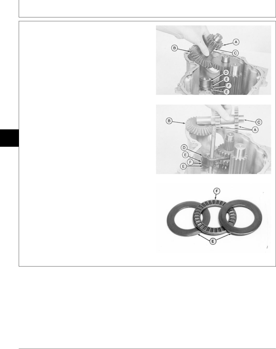
12. Remove and inspect countershaft assembly.
Inspect spur gear (A) and bevel gear (B) for worn or
damaged teeth.
Inspect countershaft (C) for worn or damaged splines or
bearing surfaces.
13. Remove spacer (D), thrust washers (E) and thrust
bearing (F).
Inspect parts for wear or damage. Replace if necessary. One-Speed Differential
A—Spur Gear
B—Bevel Gear
C—Countershaft
D—Spacer
E—Thrust Washer (2 used)
F—Thrust Bearing
Two-Speed Differential
M36175 -UN-29AUG88M36232 -UN-22NOV89M77905 -UN-19JAN95
MX,15905015,8 -19-23FEB95
Differential/Disassemble and Inspect
TM1591 (15JUL95) 50-15-6 322,330,332 & 430 Lawn & Garden Tractors
030895
50
15
6
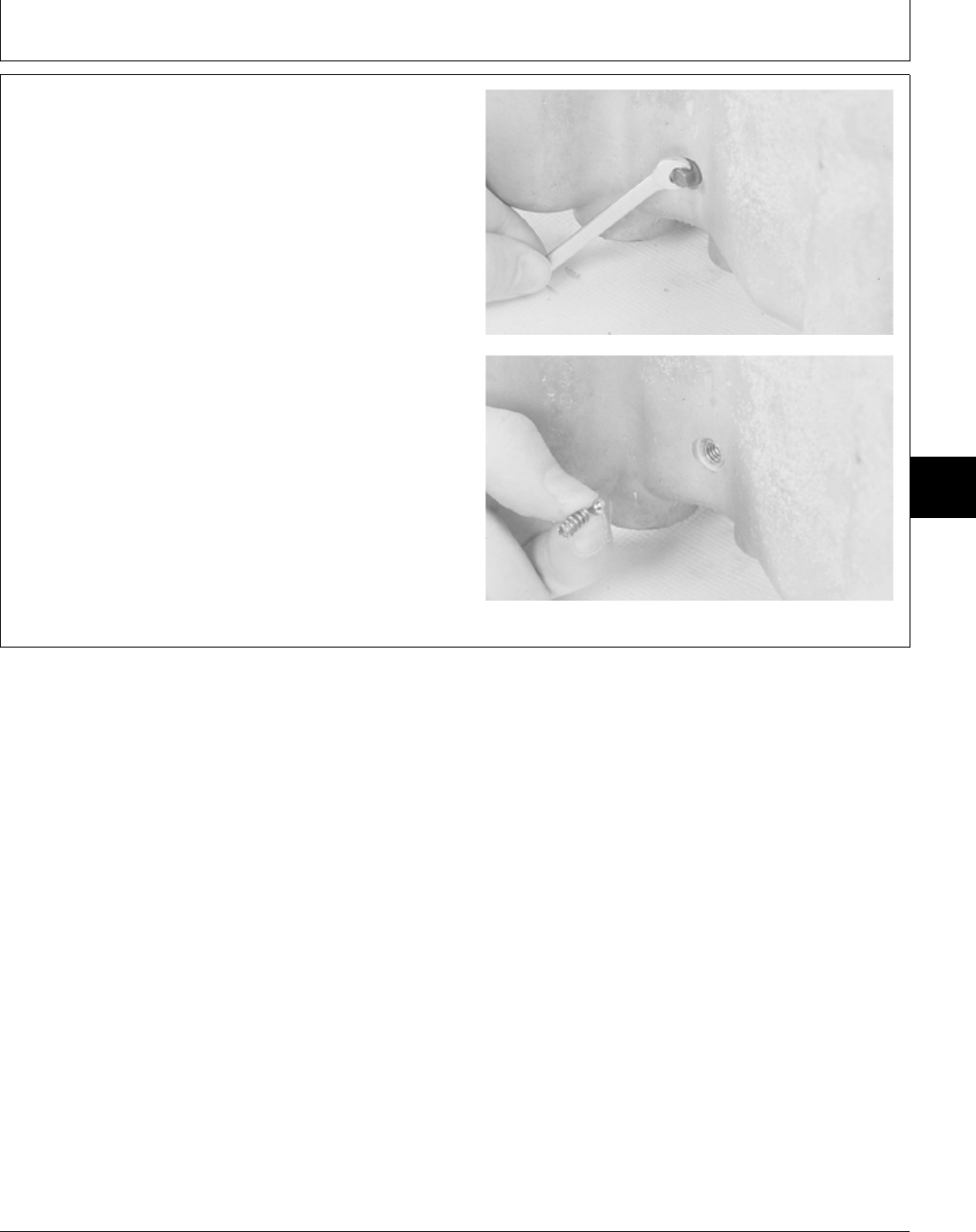
14. Two-speed differential; remove set screw, spring, and
detent ball.
M36233 -UN-22NOV89M36234 -UN-22NOV89
MX,15905015,9 -19-23FEB95
Differential/Disassemble and Inspect
TM1591 (15JUL95) 50-15-7 322,330,332 & 430 Lawn & Garden Tractors
030895
50
15
7
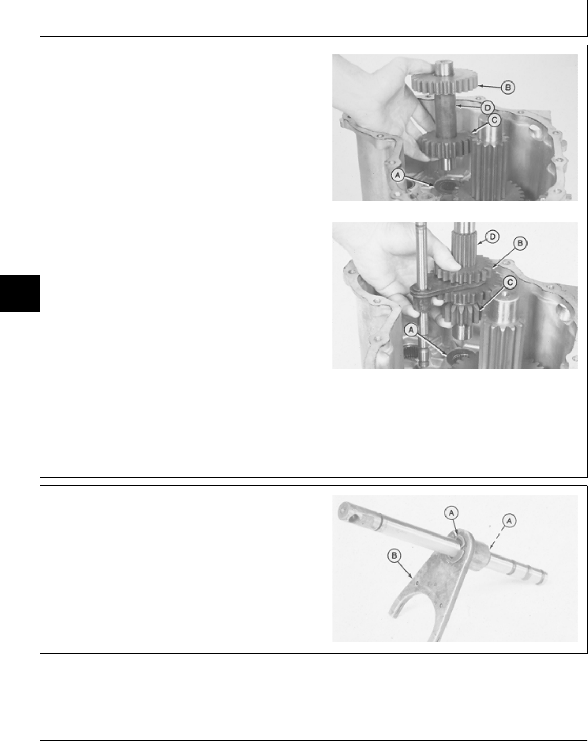
15. Remove and inspect intermediate shaft assembly; if
equipped with two-speed differential, remove shift rod
assembly with intermediate shaft.
Inspect intermediate gears (B and C) for worn or
damaged teeth.
Inspect intermediate shaft (D) for worn or damaged
splines or bearing surfaces.
NOTE: Early models have a FLAT thrust washer. Later
models have a TABBED thrust washer. All
service or replacement thrust washers will have One-Speed Differential
the tabs.
IMPORTANT: It is recommended to replace the early
model (flat) thrust washers with the
later model (tabbed) thrust washers.
The early model washers may spin with
their respective shafts, causing wear to
the case bearing surface.
16. Remove and inspect thrust washer (A) for wear or
damage.
A—Thrust Washers Two-Speed Differential
B—Intermediate Gear
C—Intermediate Gear
D—Intermediate Shaft
M36176 -UN-29AUG88M36235 -UN-22NOV89
17. Two-speed differential; disassemble shift rod by
removing two E-rings (A) and fork (B).
Inspect shaft for straightness, burrs, and damaged detent
lands. Replace if necessary.
M36236 -UN-22NOV89
MX,15905015,10 -19-23FEB95
MX,15905015,11 -19-23FEB95
Differential/Disassemble and Inspect
TM1591 (15JUL95) 50-15-8 322,330,332 & 430 Lawn & Garden Tractors
030895
50
15
8
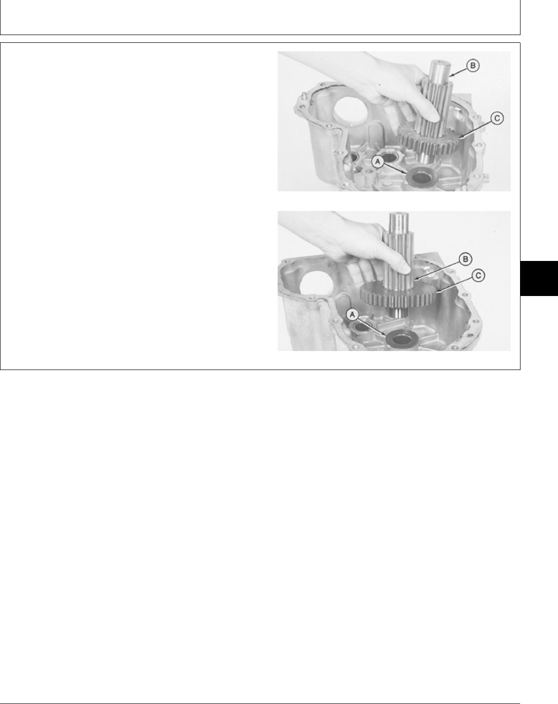
18. Remove and inspect output shaft assembly.
Inspect output gear (C) for worn or damaged teeth.
Inspect output shaft (B) for wear on splined surfaces.
NOTE: Early models have a FLAT thrust washer. Later
models have a TABBED thrust washer. All
service or replacement thrust washers will have
the tabs.
IMPORTANT: It is recommended to replace the early
model (flat) thrust washers with the One-Speed Differential
later model (tabbed) thrust washers.
The early model washers may spin with
their respective shafts, causing wear to
the case bearing surface.
19. Remove and inspect thrust washer (A) for wear or
damage.
Two-Speed Differential
M36177 -UN-29AUG88M36237 -UN-22NOV89
MX,15905015,12 -19-23FEB95
Differential/Disassemble and Inspect
TM1591 (15JUL95) 50-15-9 322,330,332 & 430 Lawn & Garden Tractors
030895
50
15
9
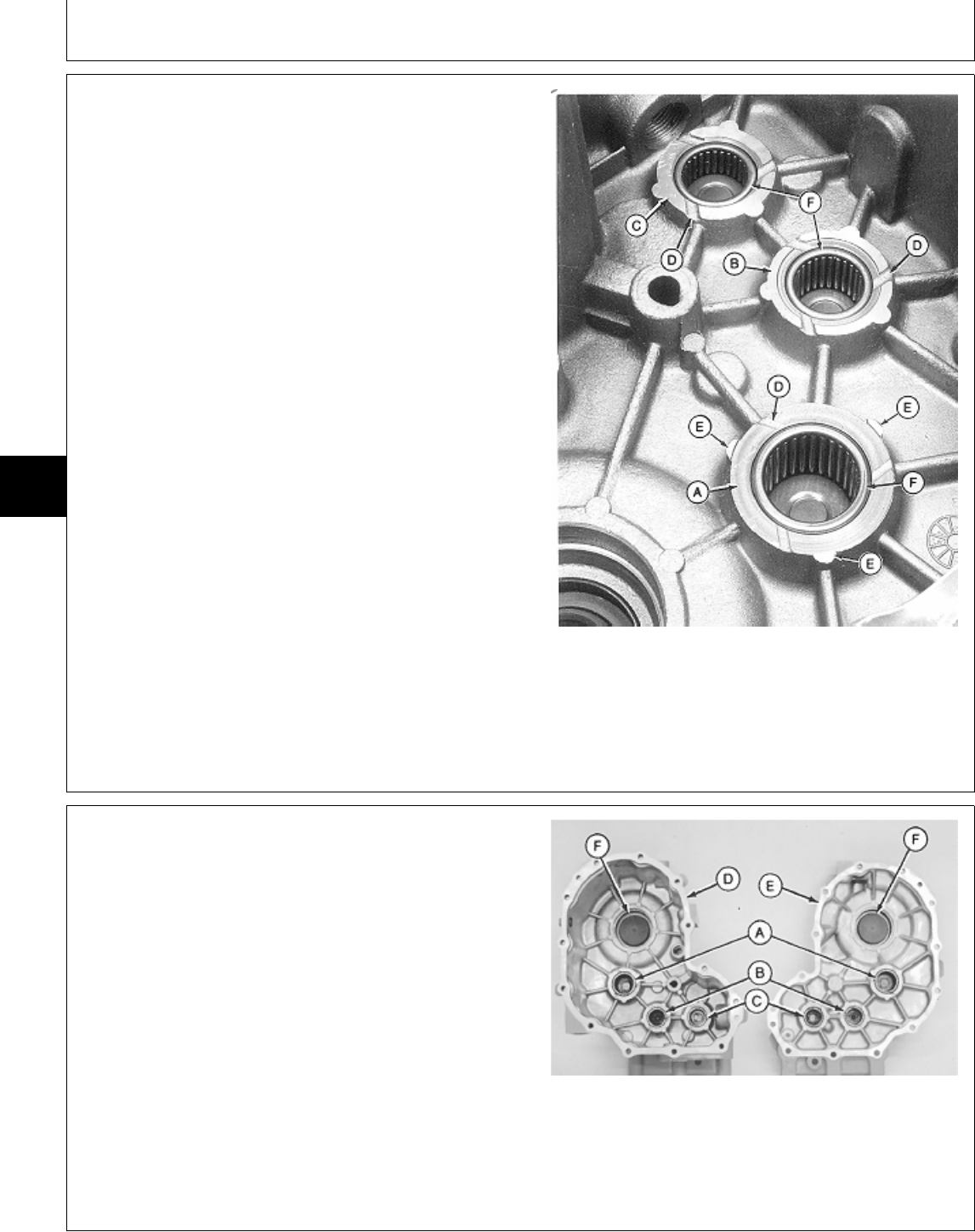
20. Inspect differential case and cover for wear, cracks
or damage. Replace case and/or cover if necessary.
Inspect case and cover bearing surfaces of output shaft
(A), intermediate shaft (B) and countershaft (C) for wear,
cracks or damage.
Inspect depth of oil grooves (D) in case and cover. If
depth of grooves are less than 0.25 mm (0.010 in.),
replace case and/or cover.
Inspect reinforcement ribs (E). If ribs protrude above
wear surface, file or grind flush.
Inspect bearing races (F) for wear. If bearing race is
worn away, replace bearings.
A—Output Shaft Bearing Surface
B—Intermediate Shaft Bearing Surface
C—Countershaft Bearing Surface
D—Oil Grooves
E—Reinforcement Ribs
F—Bearing Races
Differential Case Shown
M74073 -UN-24FEB95
21. Inspect output shaft bearings (A), intermediate shaft
bearings (B) and countershaft bearings (C) in case (D)
and cover (E) for wear, damage or corrosion.
Check that bearings turn freely.
Inspect case and cover for cracks.
Inspect axle shaft seals (F) in case and cover.
Two-Speed with differential lock; inspect shift rod seals
for wear or damage.
A—Output Shaft Bearings
B—Intermediate Shaft Bearings
C—Countershaft Bearings
D—Differential Case
E—Differential Cover
F—Axle Shaft Seals
M31920 -UN-28JUL89
MX,15905015,13 -19-23FEB95
MX,15905015,14 -19-23FEB95
Differential/Disassemble and Inspect
TM1591 (15JUL95) 50-15-10 322,330,332 & 430 Lawn & Garden Tractors
030895
50
15
10

22. Replace bearings if necessary.
Removal or Side Driven Pilot Driver
Bearing Installation From Size Size
Output Pinion Bearing Remove Outside 1-1/4 in. 1-9/16 in.
Install Inside 1-1/4 in. 1-9/16 in.
Shifter Shaft Bearing Remove Outside 1-1/4 in.
Install Inside 1 in. 1-1/4 in.
Countershaft Bearing Remove Outside 1-1/4 in.
Install Inside 1 in. 1-1/4 in.
MX,15905015,15 -19-23FEB95
Differential/Disassemble and Inspect
TM1591 (15JUL95) 50-15-11 322,330,332 & 430 Lawn & Garden Tractors
030895
50
15
11
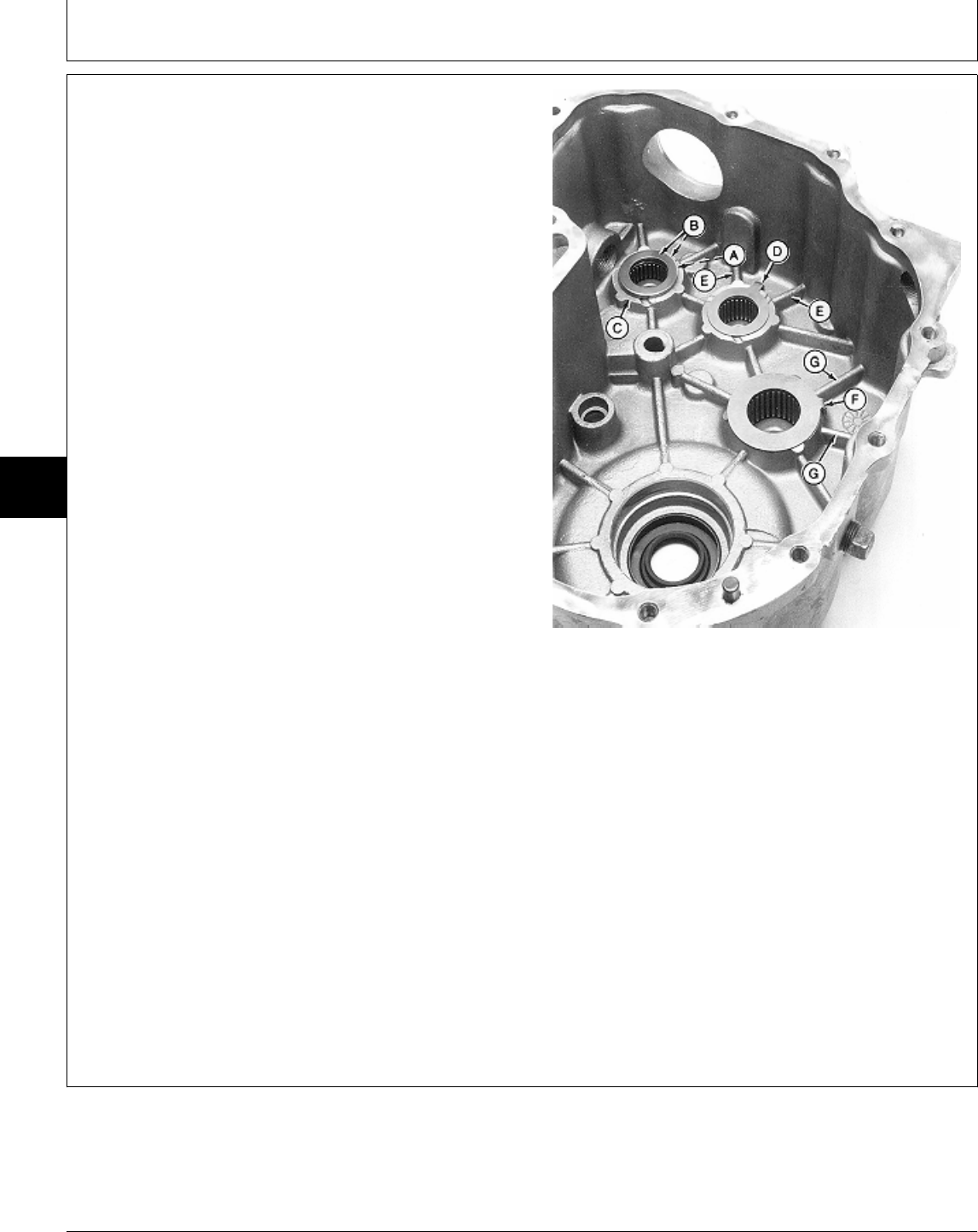
ASSEMBLE DIFFERENTIAL
NOTE: This assembly procedure is for the One-Speed
Differential (322, 330 and 332) and the
Two-Speed Differential with Differential Lock
(430). The differences are noted.
Lubricate all seals with petroleum jelly during
assembly.
Early models have FLAT thrust washers. Later
models have TABBED thrust washers. All service
or replacement thrust washers will have the tabs.
IMPORTANT: It is recommended to replace the early
model (flat) thrust washers with the
later model (tabbed) thrust washers.
The early model washers may spin with
their respective shafts, causing wear to
case bearing surfaces.
Always use new seals. Damaged or
used parts will leak.
1. Put clean John Deere Low Viscosity HY-GARD® oil or
an equivalent on all internal parts during assembly.
2. Put needle bearing (A) between two flat thrust
washers (B). Put assembly on case countershaft bearing
surface (C).
3. Put small tabbed thrust washer on intermediate shaft
bearing surface with tab (D) pointing down between
reinforcement ribs (E).
4. Put large tabbed thrust washer on output shaft
bearing surface with tab (F) pointing down between
reinforcement ribs (G).
M74075 -UN-24FEB95
MX,15915015,2 -19-13JUL95
Differential/Assemble
TM1591 (15JUL95) 50-15-12 322,330,332 & 430 Lawn & Garden Tractors
030895
50
15
12
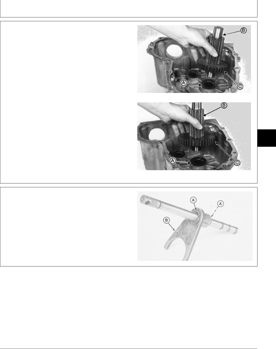
5. Assemble gear (C) and shaft (B).
6. Install output shaft assembly through tabbed thrust
washer (A).
One-Speed Differential
Two-Speed Differential
M77336 -UN-21FEB95M77337 -UN-21FEB95
7. Two-speed differential; assemble shift rod by installing
fork (B) and two E-rings (A).
M36236 -UN-22NOV89
MX,15905015,19 -19-14MAR95
MX,15905015,20 -19-23FEB95
Differential/Assemble
TM1591 (15JUL95) 50-15-13 322,330,332 & 430 Lawn & Garden Tractors
030895
50
15
13
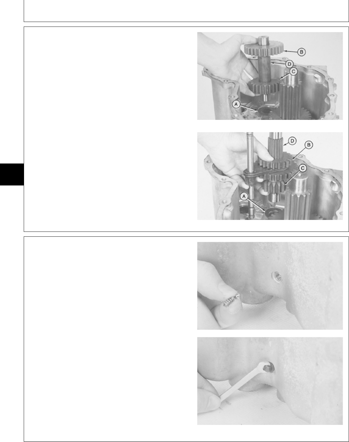
8. Assemble gears (B and C) and shaft (D).
9. Install intermediate shaft assembly through tabbed
thrust washer (A); if equipped with two-speed, install shift
rod assembly with intermediate shaft assembly.
A—Thrust Washer
B—Intermediate Gear
C—Intermediate Gear
D—Intermediate Shaft
One-Speed Differential
Two-Speed Differential
M36176 -UN-29AUG88M36235 -UN-22NOV89
10. Two-speed differential; install detent ball, spring and
set screw.
M36234 -UN-22NOV89M36233 -UN-22NOV89
MX,15905015,21 -19-23FEB95
MX,15905015,22 -19-23FEB95
Differential/Assemble
TM1591 (15JUL95) 50-15-14 322,330,332 & 430 Lawn & Garden Tractors
030895
50
15
14
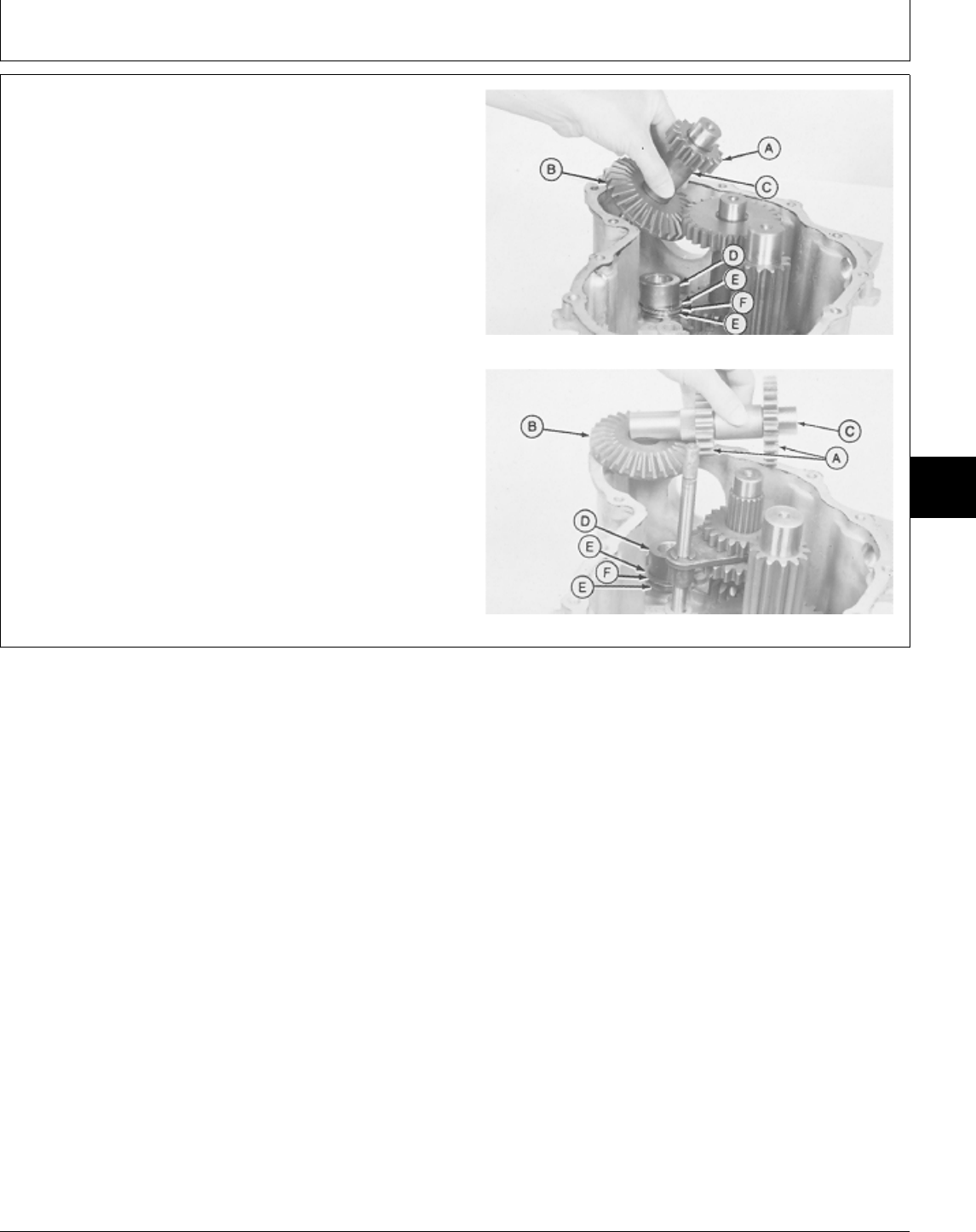
11. Assemble gears (A and B) and shaft (C).
12. Install countershaft assembly through spacer (D),
thrust bearing (F) and thrust washers (E).
A—Spur Gear
B—Bevel Gear
C—Countershaft
D—Spacer
E—Thrust Washer (2 used)
F—Thrust Bearing
One-Speed Differential
Two-Speed Differential
M36175 -UN-29AUG88M36232 -UN-22NOV89
MX,15905015,23 -19-23FEB95
Differential/Assemble
TM1591 (15JUL95) 50-15-15 322,330,332 & 430 Lawn & Garden Tractors
030895
50
15
15
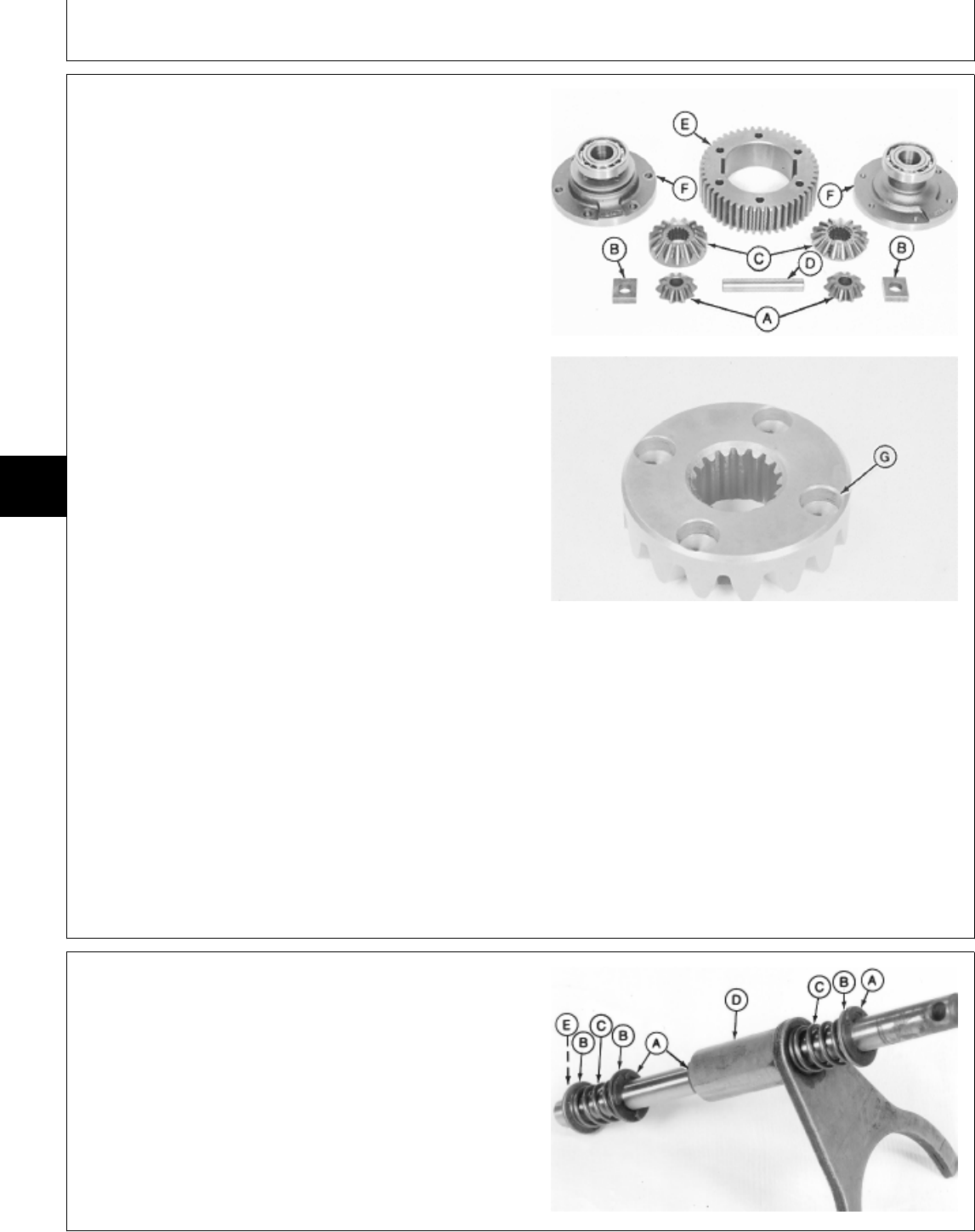
NOTE: Early model with differential lock shown.
13. If removed, install collar (with differential lock) and
bearings on carriers (F) using a driver set and a press.
Install bearings flush with shaft surfaces.
NOTE: Carriers on later models have oil grooves, an oil
hole and a thrust washer in carriers.
Machines without differential lock have one thrust
washer in each carrier. Machines with differential
lock have one thrust washer and one new style
carrier on the non-differential lock side only.
All service or replacement carriers will have these
features.
14. Install thrust washers, if equipped, in carriers (F).
15. Assemble carriers (F), ring gear (E), pinion gears
(A), bevel gears (C), cross shaft (D), and pinion blocks
(B).
If equipped with differential lock, install bevel gear with
holes (G) toward carrier with lock pins and collar.
16. Clean the threads of all six cap screws and threaded
carrier, using Clean and Cure Primer. Apply thread lock A—Pinion Gear (2 used)
and sealer (medium strength) to the threads of cap B—Pinion Block (2 used)
screws. C—Bevel Gear (2 used)
D—Cross Shaft
E—Ring Gear
17. Install cap screws and tighten to 53 N·m (39 lb-ft). F—Carrier (2 used)
G—Bevel Gear with Holes
M31977 -UN-25AUG88M36173 -UN-29AUG88
18. If equipped with differential lock, assemble shift rod,
snap ring (E), washers (B), springs (C), fork (D), and
E-rings (A).
A—E-Ring (3 used)
B—Washer (3 used)
C—Spring (2 used)
D—Fork
E—Snap Ring
M36230 -UN-19JAN95
MX,15905015,24 -19-20MAR95
MX,15905015,25 -19-23FEB95
Differential/Assemble
TM1591 (15JUL95) 50-15-16 322,330,332 & 430 Lawn & Garden Tractors
030895
50
15
16
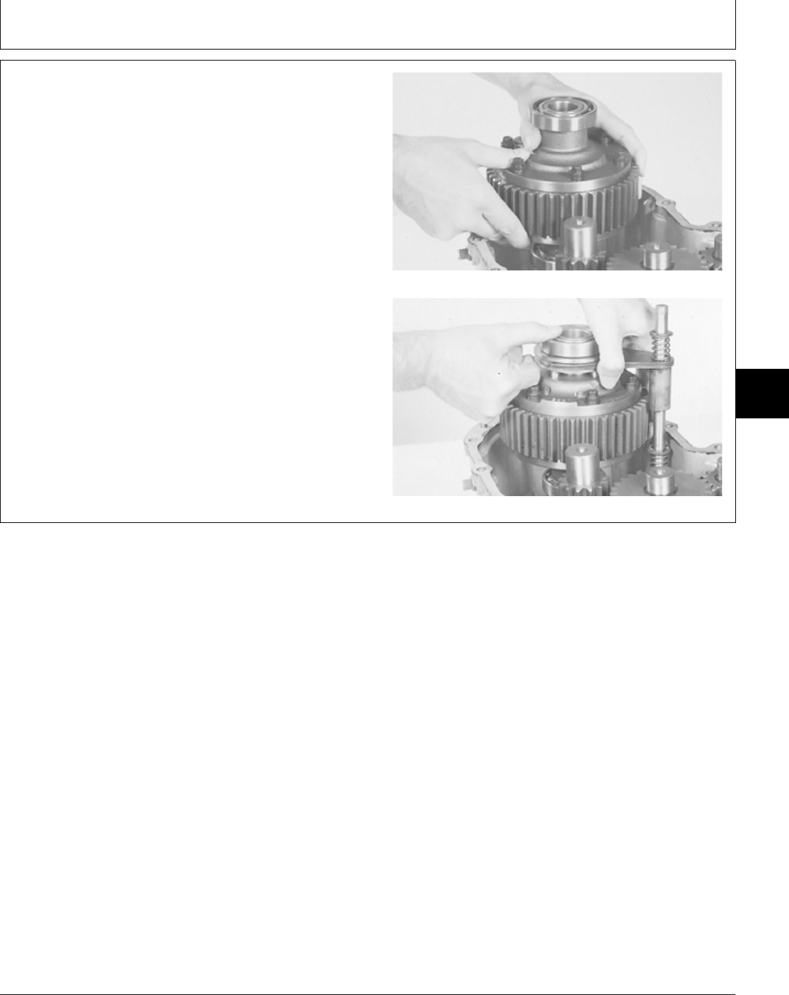
19. Install differential; if equipped with differential lock,
install shift rod assembly with differential.
Without Differential Lock
With Differential Lock
M36170 -UN-22NOV89M36169 -UN-29AUG88
MX,15905015,26 -19-23FEB95
Differential/Assemble
TM1591 (15JUL95) 50-15-17 322,330,332 & 430 Lawn & Garden Tractors
030895
50
15
17

NOTE: Early models have FLAT thrust washers. Later
models have TABBED thrust washers. All service
or replacement thrust washers will have the tabs.
IMPORTANT: It is recommended to replace the early
model (flat) thrust washers with the
later model (tabbed) thrust washers.
The early model washers may spin with
their respective shafts, causing wear to
the cover bearing surfaces.
20. Put a small tabbed thrust washer on countershaft
gear with tab (A) pointing up so it will be between the
two cover reinforcement ribs that correspond to the same
case reinforcement ribs.
21. Put other small tabbed thrust washer on intermediate
shaft gear with tab (B) pointing up so it will be between
the two cover reinforcement ribs that correspond to the
same case reinforcement ribs.
22. Put large tabbed thrust washer on output shaft with
tab (C) pointing up so it will be between the two cover
reinforcement ribs that correspond to the same case
reinforcement ribs.
Two-Speed Differential Shown
M77906 -UN-24FEB95
MX,15905015,27 -19-23FEB95
Differential/Assemble
TM1591 (15JUL95) 50-15-18 322,330,332 & 430 Lawn & Garden Tractors
030895
50
15
18

IMPORTANT: If replacement gasket is made of rubber
coated laminated metal, clean mating
surfaces of differential case and cover
and install gasket. Do not apply
sealant. It will cause oil to leak.
If replacement gasket is made of paper,
clean mating surfaces of differential
case and cover, apply recommended
sealant, then install gasket.
23. Clean the mating surfaces of differential case and
cover using Clean and Cure Primer. Apply a coat of
Flexible Sealant or an equivalent to differential cover and
case when using paper gasket only.
24. Install gasket, cover, and 13 cap screws. Install cap
screws finger-tight.
25. Drive two dowel pins into differential cover.
26. Tighten cap screws to 23 N·m (204 lb-in.).
M36181 -UN-29AUG88
MX,15905015,28 -19-23FEB95
Differential/Assemble
TM1591 (15JUL95) 50-15-19 322,330,332 & 430 Lawn & Garden Tractors
030895
50
15
19

Differential/Assemble
TM1591 (15JUL95) 50-15-20 322,330,332 & 430 Lawn & Garden Tractors
030895
50
15
20
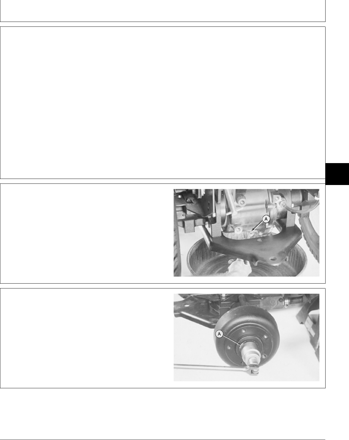
OTHER MATERIAL
Number Name Use
M79292 MPG-2® Multi-Purpose Polymer Prevents parts from seizing. Apply
Grease to axle shafts.
LOCTITE® PRODUCTS
U.S./Canadian/LOCTITE No.
TY6305/TY9485/764 Clean and Cure Primer Cleans parts and speeds cure of
sealant.
T43512/TY9473/242 Thread Lock and Sealer (Medium Apply to threads of brake
Strength) plate-to-axle cap screws.
®MPG-2 is a registered trademark of DuBois USA.
®LOCTITE is a registered trademark of the Loctite Corp.
REMOVE AXLE
1. Disconnect battery negative (—) cable.
2. Remove drain plug (A) to drain transmission oil.
Approximate capacity is 4.7 L (5 U.S. qt). After oil is
completely drained, install and tighten drain plug.
3. Raise rear of tractor and install support stands.
4. Remove rear wheel.
M33430 -UN-25AUG88
5. Bend edge of washer (A) flat against drum.
6. Remove nut and washer.
7. Pull drum off axle.
If drum hits shoes, turn the adjuster to reduce the drag
on the drum from shoes.
If drum is tight on shaft from corrosion, remove drum
using a three-leg wheel puller. Do not use impact puller.
M36560 -UN-25JAN90
MX,15905020,OTH-19-07MAR95
MX,15905020,1 -19-23FEB95
5M3,5020K,C -19-18DEC87
Group 20
Rear Axles
TM1591 (15JUL95) 50-20-1 322,330,332 & 430 Lawn & Garden Tractors
030895
50
20
1
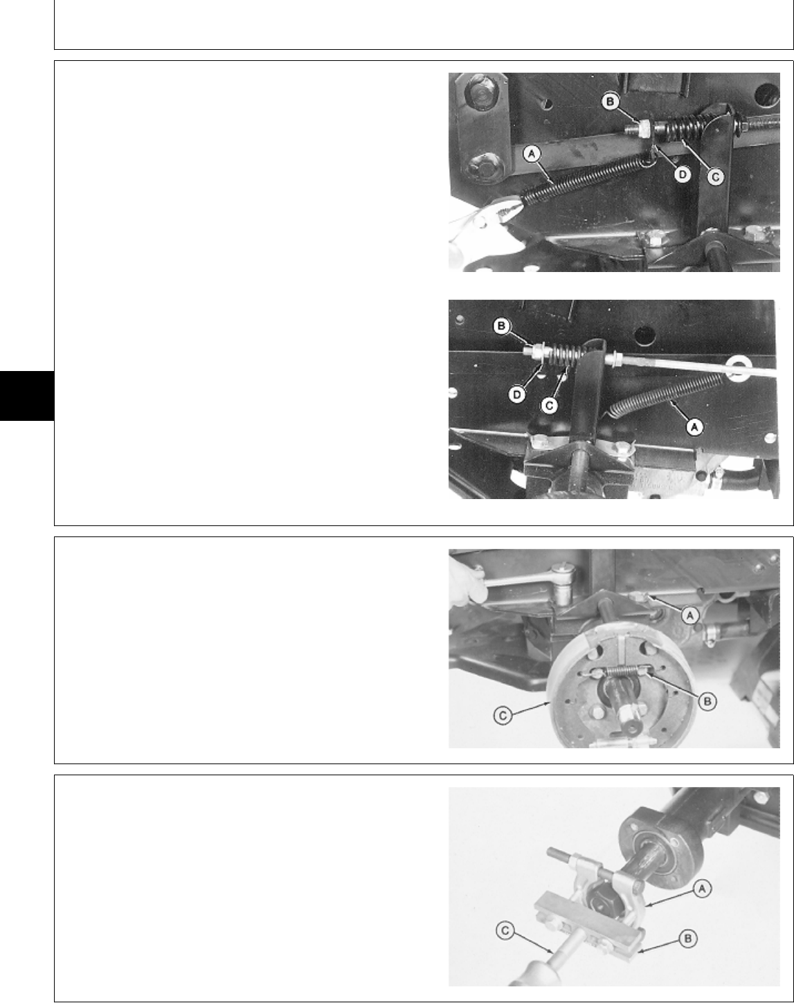
8. Disconnect spring (A).
9. Remove nut (B), plate or washer (D) and spring (C).
A—Return Spring
B—Nut
C—Spring
D—Plate (Early 430)
—Washer (All and Later 430)
Early 430
All and Later 430
M78048 -UN-13FEB95M78049 -UN-13FEB95
10. Bend tabs (A) flat and remove two cap screws.
11. Remove four cap screws and washers (B) to remove
brake plate assembly (C).
M36562 -UN-25JAN90
12. Remove axle shaft assembly using a bearing puller
(A), H-Bar (B), and slide hammer (C).
M36563 -UN-25JAN90
MX,15915020,2 -19-13JUL95
5M3,5020K,E -19-18DEC87
MX,15905020,2 -19-23FEB95
Rear Axles/Remove
TM1591 (15JUL95) 50-20-2 322,330,332 & 430 Lawn & Garden Tractors
030895
50
20
2
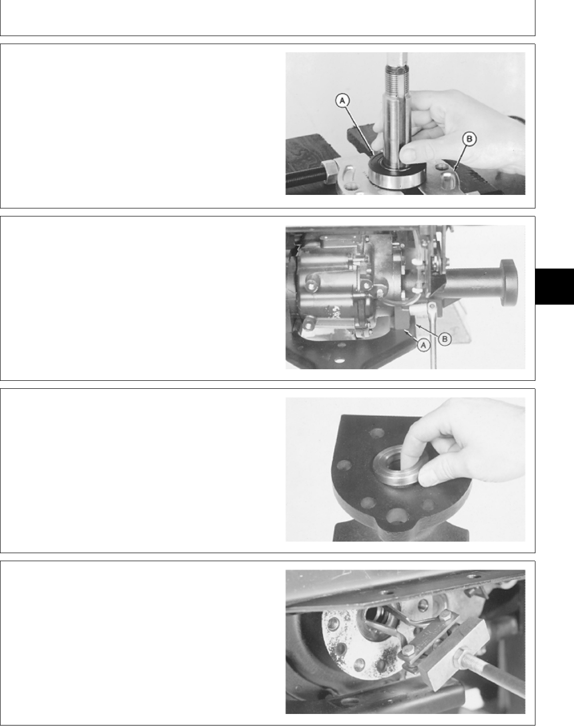
13. Inspect bearing (A), replace if necessary.
IMPORTANT: Be sure to hold shaft while removing
bearing.
14. Remove bearing using a bearing puller (B) and a
press.
M31951 -UN-25AUG88
15. Remove two cap screws (A) to disconnect axle from
hitch plate (B).
16. Remove six cap screws to remove axle housing.
M36564 -UN-25JAN90
17. Remove spacer.
M36565 -UN-25JAN90
18. Remove seal from differential using a 2-jaw puller
and a slide hammer.
M36566 -UN-25JAN90
5M3,5020K,G -19-18DEC87
5M3,5020K,H -19-18DEC87
5M3,5020K,I -19-18DEC87
5M3,5020K,J -19-18DEC87
Rear Axles/Remove
TM1591 (15JUL95) 50-20-3 322,330,332 & 430 Lawn & Garden Tractors
030895
50
20
3
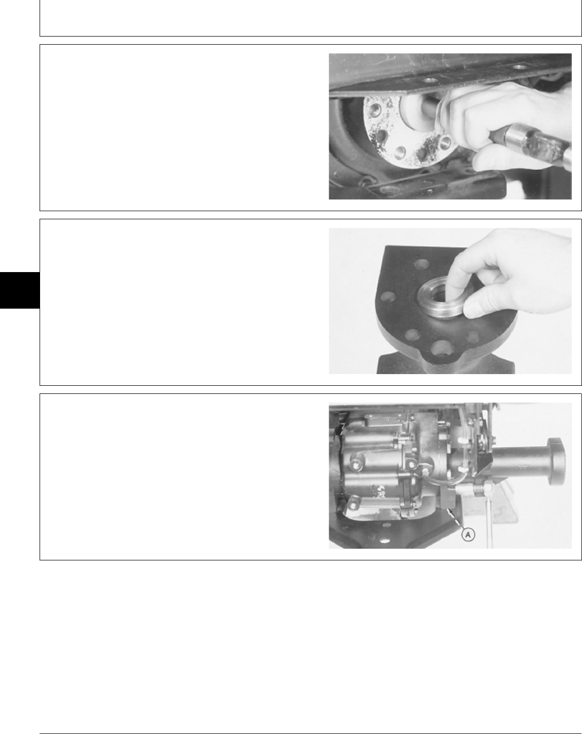
INSTALL AXLE
IMPORTANT: Always use new seals. Damaged or
used parts will leak.
NOTE: Lubricate all seals with petroleum jelly during
assembly.
1. Install new seal 3 mm (0.118 in.) below machined
surface of differential using a 2-1/16 in. driver disk.
M36567 -UN-25JAN90
2. Install spacer.
M36565 -UN-25JAN90
3. Install axle housing and fasten with six cap screws.
Tighten cap screws to 81 N·m (60 lb-ft).
4. Install and tighten two hitch plate cap screws (A).
M36568 -UN-25JAN90
MX,15905020,3 -19-23FEB95
M21,5020R,15 -19-14MAY85
MX,15905020,8 -19-23FEB95
Rear Axles/Install
TM1591 (15JUL95) 50-20-4 322,330,332 & 430 Lawn & Garden Tractors
030895
50
20
4
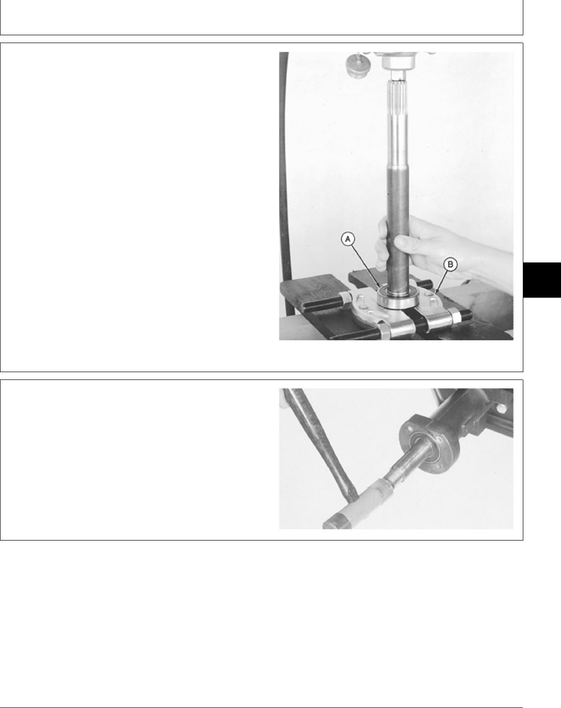
5. Install bearing (A) on axle shaft using a bearing puller
(B) and a press. Push bearing tight against axle shaft
shoulder.
M31952 -UN-25AUG88
6. Apply clean transmission fluid to the splined end of
the axle shaft.
7. Carefully install axle shaft into housing and through
seal in differential. Align splines on shaft with splined
gear inside differential.
8. Tap shaft assembly into axle housing until bearing is
flush with housing.
M36569 -UN-25JAN90
M21,5020R,17 -19-14MAY85
M21,5020R,18 -19-14MAY85
Rear Axles/Install
TM1591 (15JUL95) 50-20-5 322,330,332 & 430 Lawn & Garden Tractors
030895
50
20
5
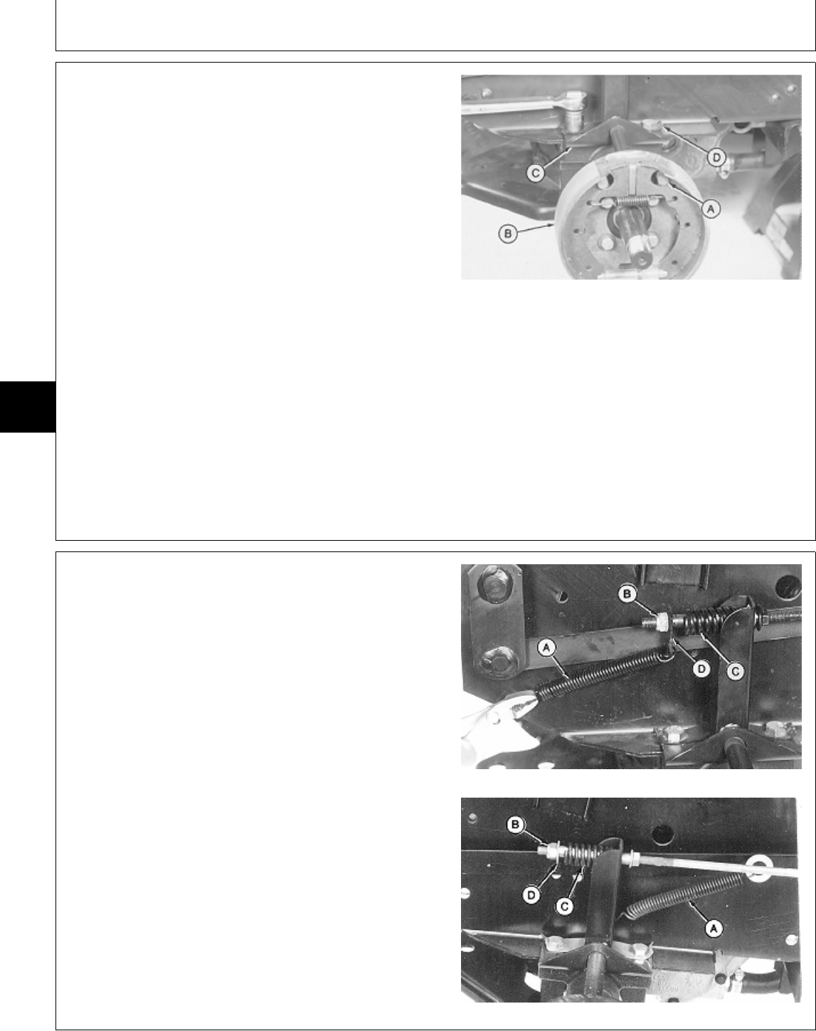
9. Clean the threads of all four brake plate cap screws
and threaded axle housing using Clean and Cure Primer.
10. Apply thread lock and sealer (medium strength) on
threads of brake plate cap screws (A).
11. Install brake rod in brake arm hole.
12. Install brake plate assembly (B) on axle. Install and
tighten four cap screws (A) to specifications.
13. Install brake support (C), lock plate (D) and two cap
screws. Tighten cap screws to specifications. Bend lock
plate tabs over flat of cap screws.
A—Cap Screw (4 used)
TORQUE SPECIFICATIONS B—Brake Plate Assembly
C—Brake Support
D—Lock Plate
Brake Plate-to-Axle Housing
Cap Screws . . . . . . . . . . . . . . . . . . . . . . . . . . . . 68 N·m (50 lb-ft)
Axle Housing-to-Frame Cap Screws . . . . . . . . . . . 100 N·m (75 lb-ft)
M36570 -UN-25JAN90
14. Install spring (C), plate or washer (D) and nut (B).
15. Connect spring (A).
A—Return Spring
B—Nut
C—Spring
D—Plate (Early 430)
—Washer (All and Later 430)
Early 430
All and Later 430
M78048 -UN-13FEB95M78049 -UN-13FEB95
MX,15905020,4 -19-08MAY95
MX,15915020,3 -19-13JUL95
Rear Axles/Install
TM1591 (15JUL95) 50-20-6 322,330,332 & 430 Lawn & Garden Tractors
030895
50
20
6
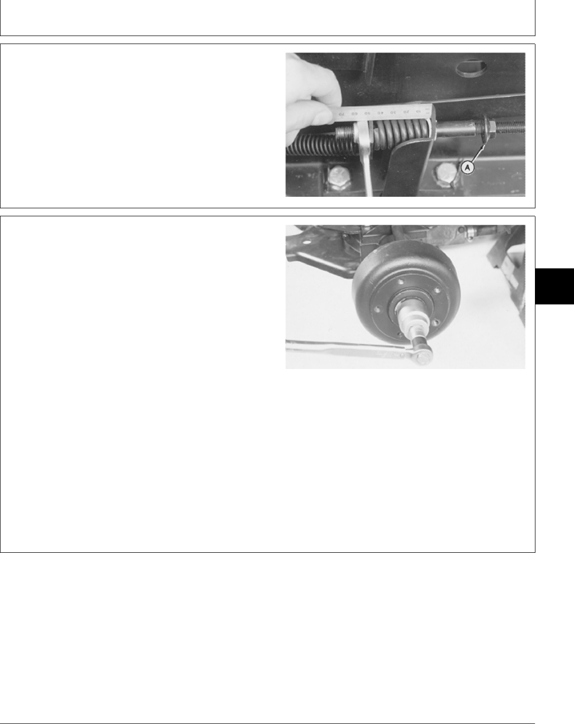
16. Lock brake pedals together (322, 332 and 430) and
apply park brake.
17. Loosen lock nut (A).
18. Turn nut until spring is 42 mm (1.650 in.) long.
Tighten lock nut.
M36554 -UN-25JAN90
19. Apply MPG-2® Multi-Purpose Polymer Grease on
axle shaft.
20. Install key and brake drum.
21. Install washer and nut. Tighten nut to specifications.
22. Bend one side of washer over nut to lock nut in
place.
23. Install wheel. Tighten cap screws to specifications.
24. Remove support stands.
25. Fill differential with the recommended amount of
John Deere Low Viscosity HY-GARD® oil.
26. Connect battery negative (—) cable.
TORQUE SPECIFICATIONS
Brake Drum-to-Axle Nut . . . . . . . . . . . . . . . . . . . . 88 N·m (65 lb-ft)
Rear Wheel Cap Screws . . . . . . . . . . . . . . . . . . . 70 N·m (52 lb-ft)
M36571 -UN-25JAN90
MX,15915020,1 -19-13JUL95
MX,15905020,6 -19-07MAR95
Rear Axles/Install
TM1591 (15JUL95) 50-20-7 322,330,332 & 430 Lawn & Garden Tractors
030895
50
20
7

Rear Axles/Install
TM1591 (15JUL95) 50-20-8 322,330,332 & 430 Lawn & Garden Tractors
030895
50
20
8

OTHER MATERIAL
Number Name Use
M79292 MPG-2® Multi-Purpose Polymer Prevents parts from seizing. Apply
Grease to splines of transmission input
shaft.
®MPG-2 is a registered trademark of DuBois USA. MX,15905005,OTH-19-07MAR95
Group 25
Drive Shaft—322, 330 and 332
TM1591 (15JUL95) 50-25-1 322,330,332 & 430 Lawn & Garden Tractors
030895
50
25
1
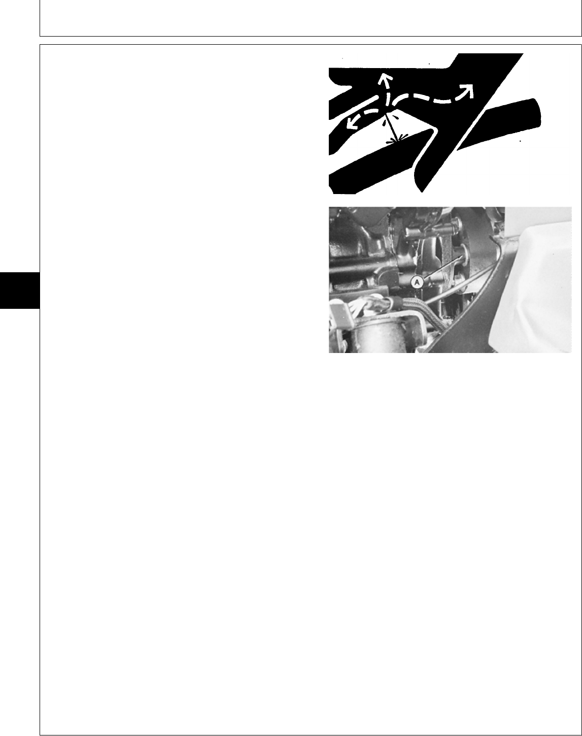
REMOVE AND INSTALL DRIVE SHAFT—322
AND 332
1. Disconnect battery negative (—) cable.
2. Remove belly screen and left-hand engine side panel.
3. Remove three cap screws and lock nuts (A) holding
drive shaft to rubber isolator.
4.Remove three cap screws and washers holding rubber
isolator to engine. Remove isolator.
5. Loosen two lock nuts and cap screws on drive shaft
at transmission pump shaft end.
NCAUTION: To avoid injury from escaping fluid
under pressure, stop engine and relieve the
pressure in the system before disconnecting or
connecting hydraulic or other lines. Tighten all
connections before applying pressure.
6. Disconnect hydraulic line directly under drive shaft.
(Control valve-to-left front inside coupler.)
7. Remove drive shaft by sliding forward to remove from
transmission, then rearward and drop out.
8. Installation is done in the reverse order of removal.
• Before installing drive shaft, apply MPG-2®
Multi-Purpose Polymer Grease on splines of transmission
input shaft.
• Apply multipurpose grease to lubrication fittings.
• Bleed hydraulic system. (See procedure in Section 270,
Group 20.)
TORQUE SPECIFICATIONS
Isolator-to-Engine Cap Screws . . . . . . . . . . . . . . . 37 N·m (27 lb-ft)
Drive Shaft Cap Screws and Lock Nuts
Flange-to-Isolator . . . . . . . . . . . . . . . . . . . . . . 27 N·m (20 lb-ft)
Clamping Yoke-to-Transmission
Pump Shaft . . . . . . . . . . . . . . . . . . . . . . . . . . 60 N·m (44 lb-ft)
X9811 -UN-23AUG88
M49505 -UN-20DEC89
MX,15915025,1 -19-13JUL95
Drive Shaft—322, 330 and 332/Remove and Install—322 and 332
TM1591 (15JUL95) 50-25-2 322,330,332 & 430 Lawn & Garden Tractors
030895
50
25
2
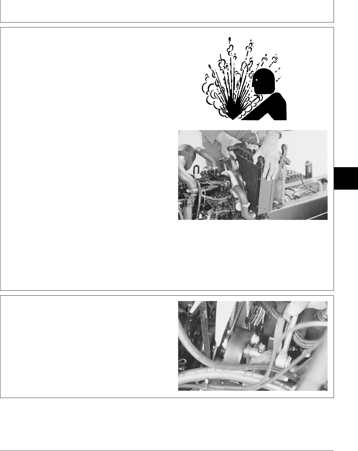
REMOVE AND INSTALL DRIVE SHAFT—330
1. Disconnect battery negative (—) cable.
2. Remove fender deck.
3. Lift hood and remove engine side panels.
4. Remove right and left pedestal side panels.
NCAUTION: Explosive release of fluids from
pressurized cooling system can cause serious
burns.
Shut off engine. Only remove filler cap when
cool enough to touch with bare hands. Slowly
loosen cap to first stop to relieve pressure
before removing completely.
5. Drain radiator. Approximate capacity is 2.8 L (3 U.S.
qt).
6. Loosen block drain valve. Drain engine coolant from
engine block. Tighten drain valve.
7. Remove radiator.
TS281 -UN-23AUG88M55053 -UN-09DEC89
8. Loosen two lock nuts and cap screws on drive shaft
at transmission pump shaft end.
9. Remove three cap screws and lock nuts holding drive
shaft to rubber isolator. Push drive shaft rearward.
M55058 -UN-09DEC89
MX,15915025,2 -19-13JUL95
MX,15915025,3 -19-13JUL95
Drive Shaft—322, 330 and 332/Remove and Install—330
TM1591 (15JUL95) 50-25-3 322,330,332 & 430 Lawn & Garden Tractors
030895
50
25
3
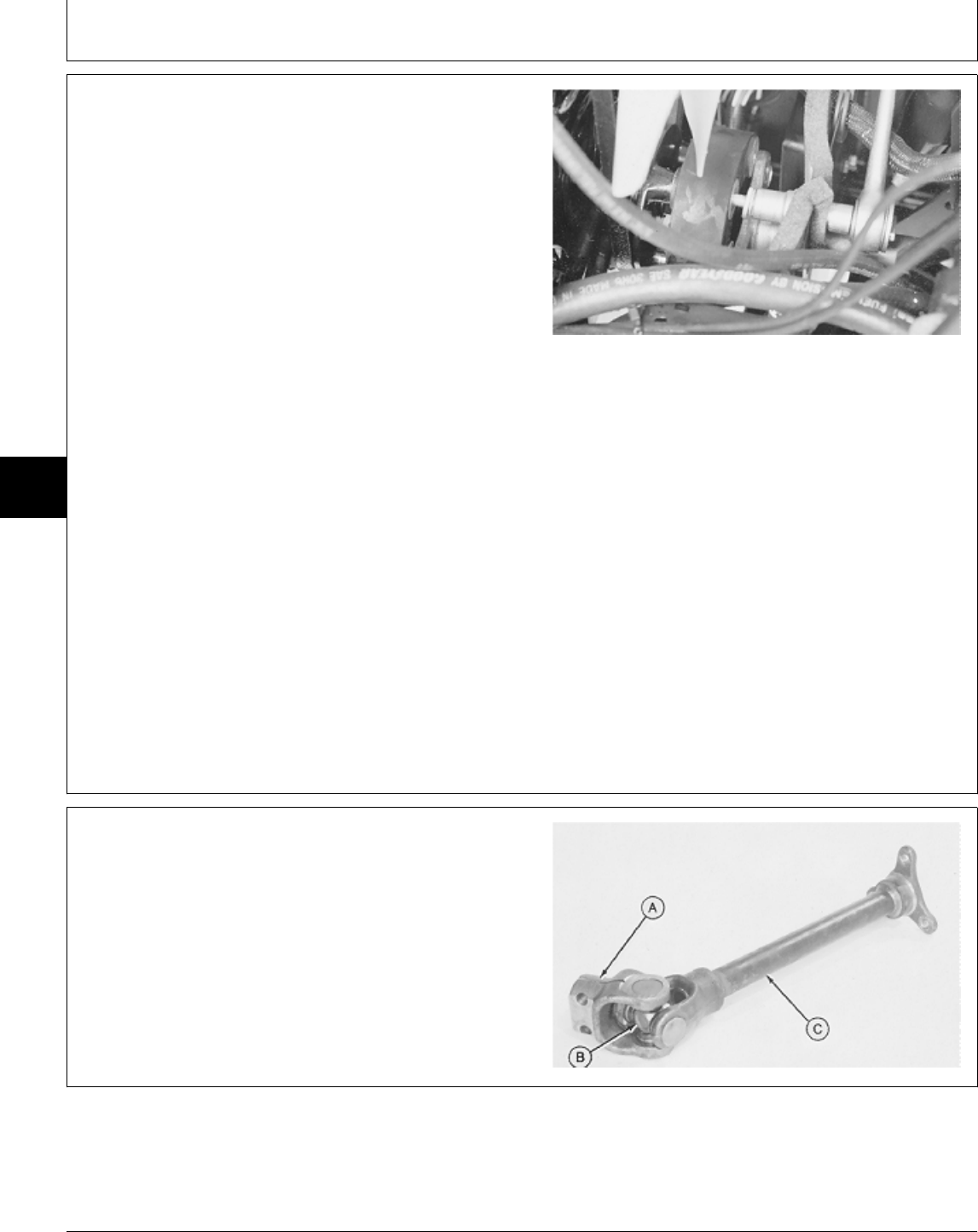
10. Remove three cap screws and washers holding
rubber isolator to engine. Remove isolator.
11. Pull drive shaft forward to remove from transmission
pump shaft. Remove drive shaft from machine.
12. Installation is done in the reverse order of removal.
• Before installing drive shaft, apply MPG-2®
Multi-Purpose Polymer Grease on splines of transmission
input shaft.
• Apply multipurpose grease to lubrication fittings.
• Close drain valve and fill radiator with proper coolant
until coolant is 13—25 mm (0.500—1 in.) below bottom
of filler neck. (See Engine Coolant in Section 10, Group
25.)
TORQUE SPECIFICATIONS
Isolator-to-Engine Cap Screws . . . . . . . . . . . . . . . 27 N·m (20 lb-ft)
Drive Shaft Cap Screws and Lock Nuts
Flange-to-Isolator . . . . . . . . . . . . . . . . . . . . . . 27 N·m (20 lb-ft)
Clamping Yoke-to-Transmission
Pump Shaft . . . . . . . . . . . . . . . . . . . . . . . . . . 60 N·m (44 lb-ft)
M55059 -UN-09DEC89
DISASSEMBLE AND INSPECT DRIVE SHAFT
1. Inspect splined yoke (A), cross and bearing assembly
(B) and front tube yoke (C) for cracks, wear or damage.
M55060 -UN-09DEC89
MX,15915025,4 -19-13JUL95
MX,15915025,5 -19-13JUL95
Drive Shaft—322, 330 and 332/Disassemble and Inspect
TM1591 (15JUL95) 50-25-4 322,330,332 & 430 Lawn & Garden Tractors
030895
50
25
4
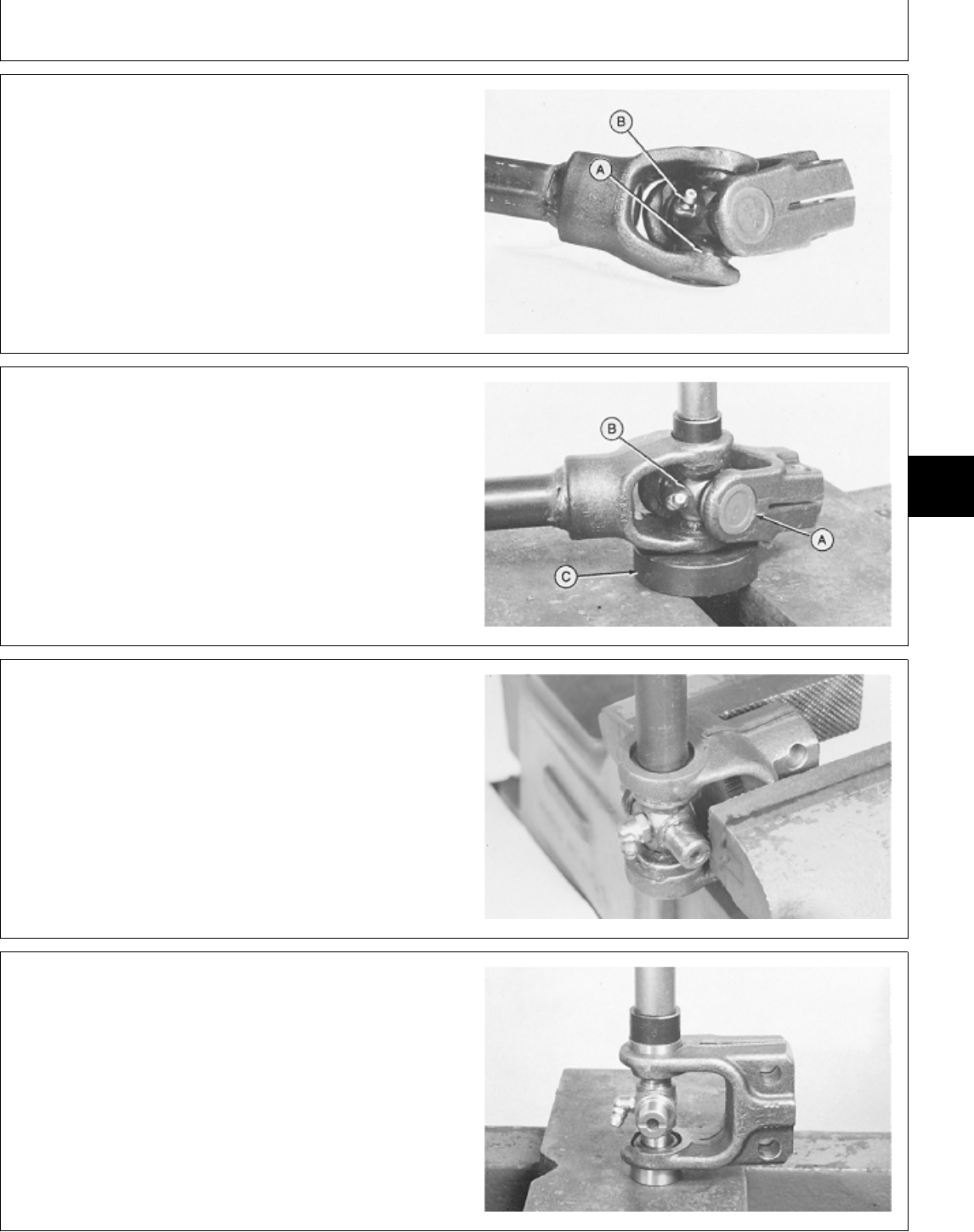
NOTE: Note position of grease zerk (B) so after
reassembly and installation, drive shaft can be
lubricated.
2. Remove four snap rings (A).
M49512 -UN-20DEC89
3. Remove bearings (A) and cross (B) using a brass
drift. Push a bearing down into a donut type press plate
(C) until it can be removed from the bottom.
4. Turn cross and bearing assembly over and repeat
procedure.
5. Separate end yoke from front tube yoke.
M49513 -UN-20DEC89
6. Remove cross and bearing assembly using a brass
drift. Push bearing down until bottom bearing can be
removed.
7. Remove cross and top bearing.
M36591 -UN-25JAN90
ASSEMBLE DRIVE SHAFT
IMPORTANT: Be careful not to damage needle rollers
and seal while installing cross and
bearing assembly.
1. Press bearings onto cross only until snap rings can be
installed.
M49514 -UN-20DEC89
MX,15915025,6 -19-13JUL95
MX,15915025,7 -19-13JUL95
MX,15915025,8 -19-13JUL95
MX,15915025,9 -19-13JUL95
Drive Shaft—322, 330 and 332/Assemble
TM1591 (15JUL95) 50-25-5 322,330,332 & 430 Lawn & Garden Tractors
030895
50
25
5
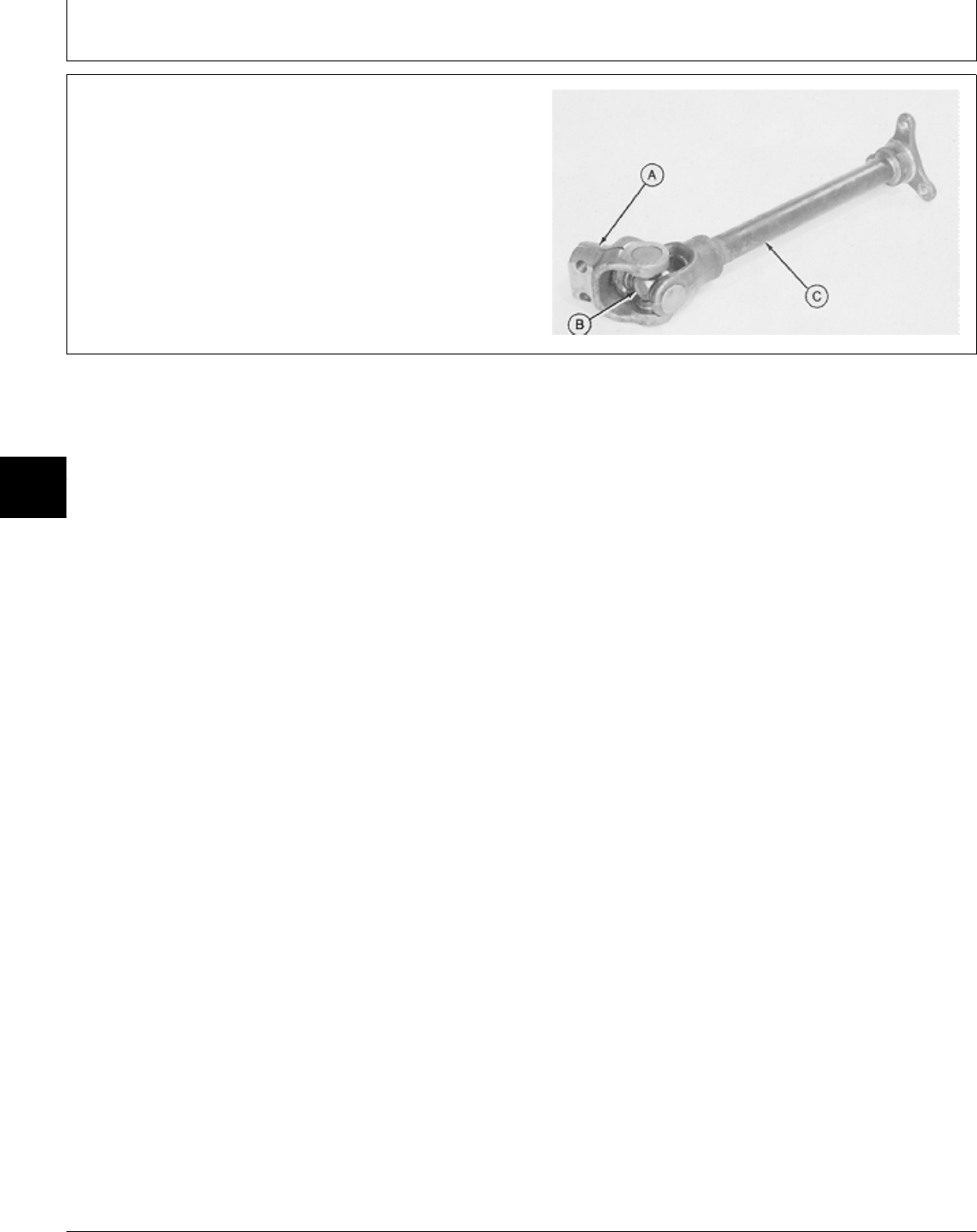
2. Install cross (B) in front tube yoke (C) with grease
fitting toward tube yoke.
3. Press bearing down until snap ring groove is inside
front tube yoke.
4. Turn cross and bearing assembly, and end yoke (A)
over and install other bearing.
5. Install four snap rings.
M55060 -UN-09DEC89
MX,15915025,10 -19-13JUL95
Drive Shaft—322, 330 and 332/Assemble
TM1591 (15JUL95) 50-25-6 322,330,332 & 430 Lawn & Garden Tractors
030895
50
25
6
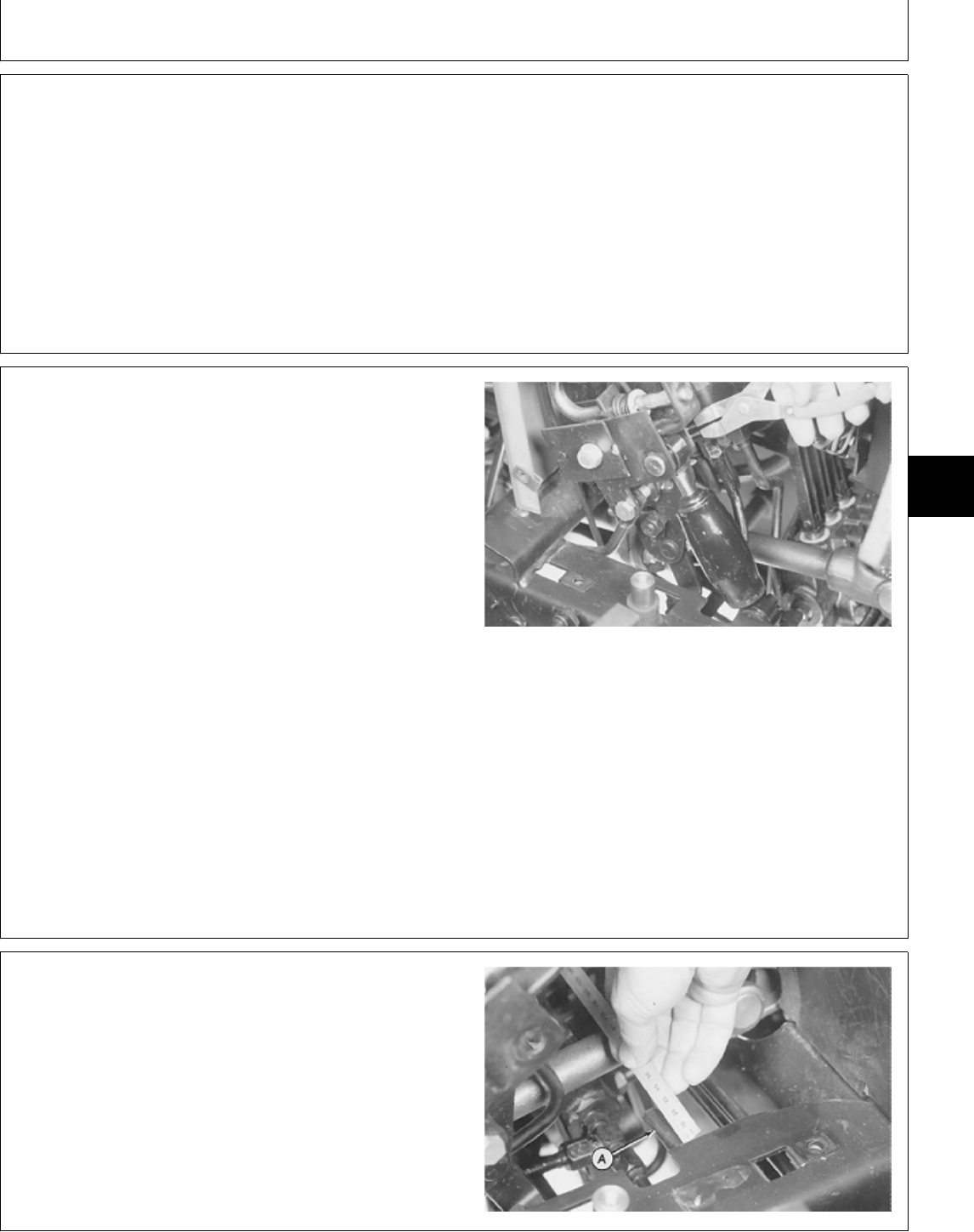
OTHER MATERIAL
Number Name Use
M79292 MPG-2® Multi-Purpose Polymer Prevents parts from seizing. Apply
Grease to splines of transmission input
shaft.
®MPG-2 is a registered trademark of DuBois USA.
REMOVE AND INSTALL DRIVE
SHAFT—EARLY MODELS
1. Lift hood and remove front grille and engine side
panels.
2. Remove battery and battery base.
3. Remove fender deck.
4. Remove belly pan.
5. Remove right pedestal side.
NOTE: There are three versions of the transmission
control linkage. Version one is shown. See Group
10, in this section, to confirm which version your
machine is equipped with. It may not be
necessary to perform some steps if equipped with
later versions of linkage on later models.
6. Remove snap ring and pin to remove shock absorber.
M36501 -UN-29JAN90
NOTE: On some models the cylinder mounting pin (A)
may be longer than 30 mm (1.181 in.). Any extra
length will need to be cut off, to provide
clearance to remove drive shaft.
7. Measure length of cylinder mounting pin (A). If more
than 30 mm (1.181 in.) long, cut off extra length.
M36581 -UN-25JAN90
MX,15905005,OTH-19-07MAR95
MX,15915026,1 -19-13JUL95
MX,15915026,2 -19-13JUL95
Group 26
Drive Shaft—430
TM1591 (15JUL95) 50-26-1 322,330,332 & 430 Lawn & Garden Tractors
030895
50
26
1
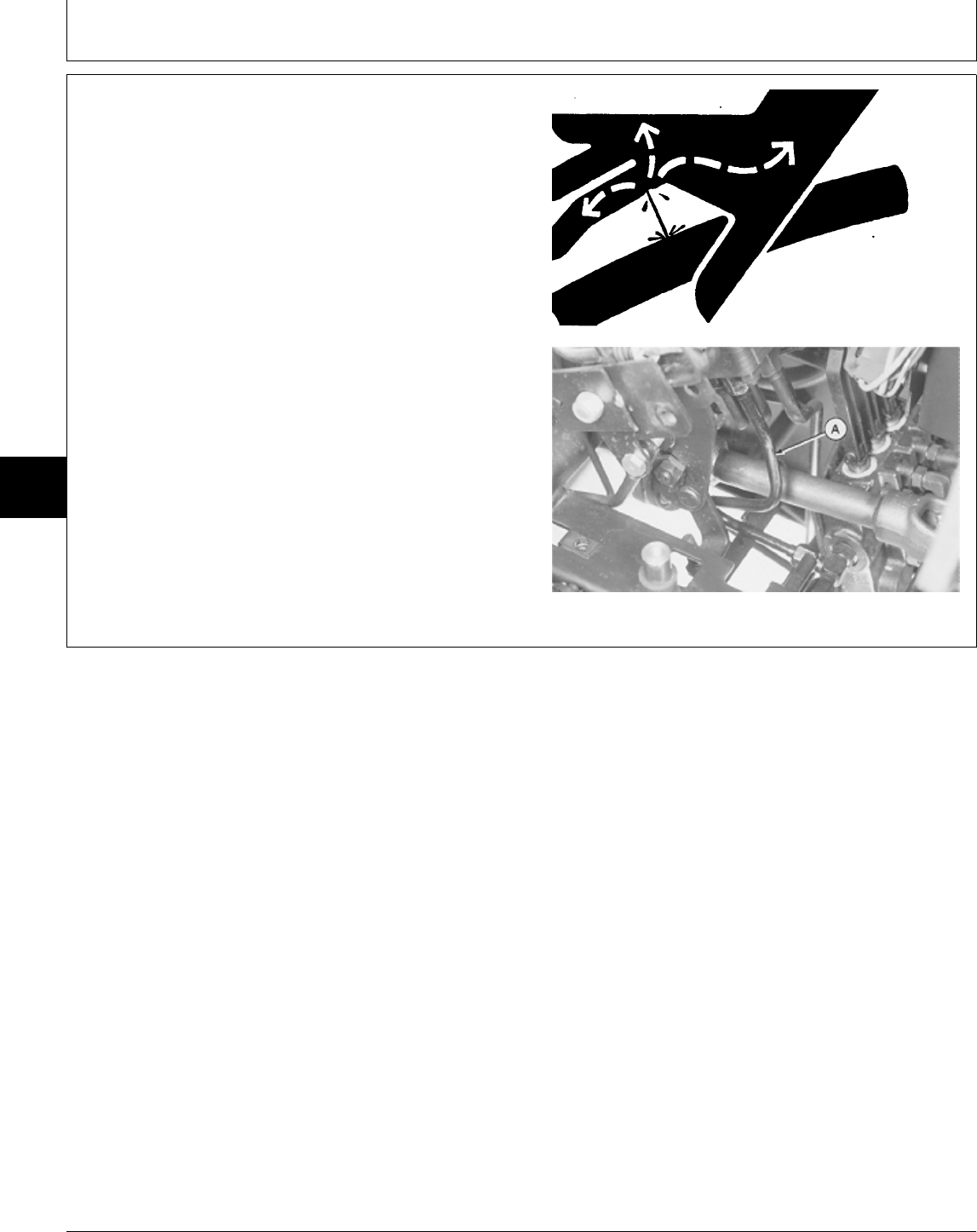
NCAUTION: To avoid injury from escaping fluid
under pressure, stop engine and relieve the
pressure in the system before disconnecting or
connecting hydraulic or other lines. Tighten all
connections before applying pressure.
8. Remove hydraulic line (A).
9. Loosen two lock nuts and cap screws, if equipped, on
drive shaft at transmission pump shaft end.
X9811 -UN-23AUG88
M36582 -UN-25JAN90
MX,15915026,3 -19-13JUL95
Drive Shaft—430/Remove and Install
TM1591 (15JUL95) 50-26-2 322,330,332 & 430 Lawn & Garden Tractors
030895
50
26
2
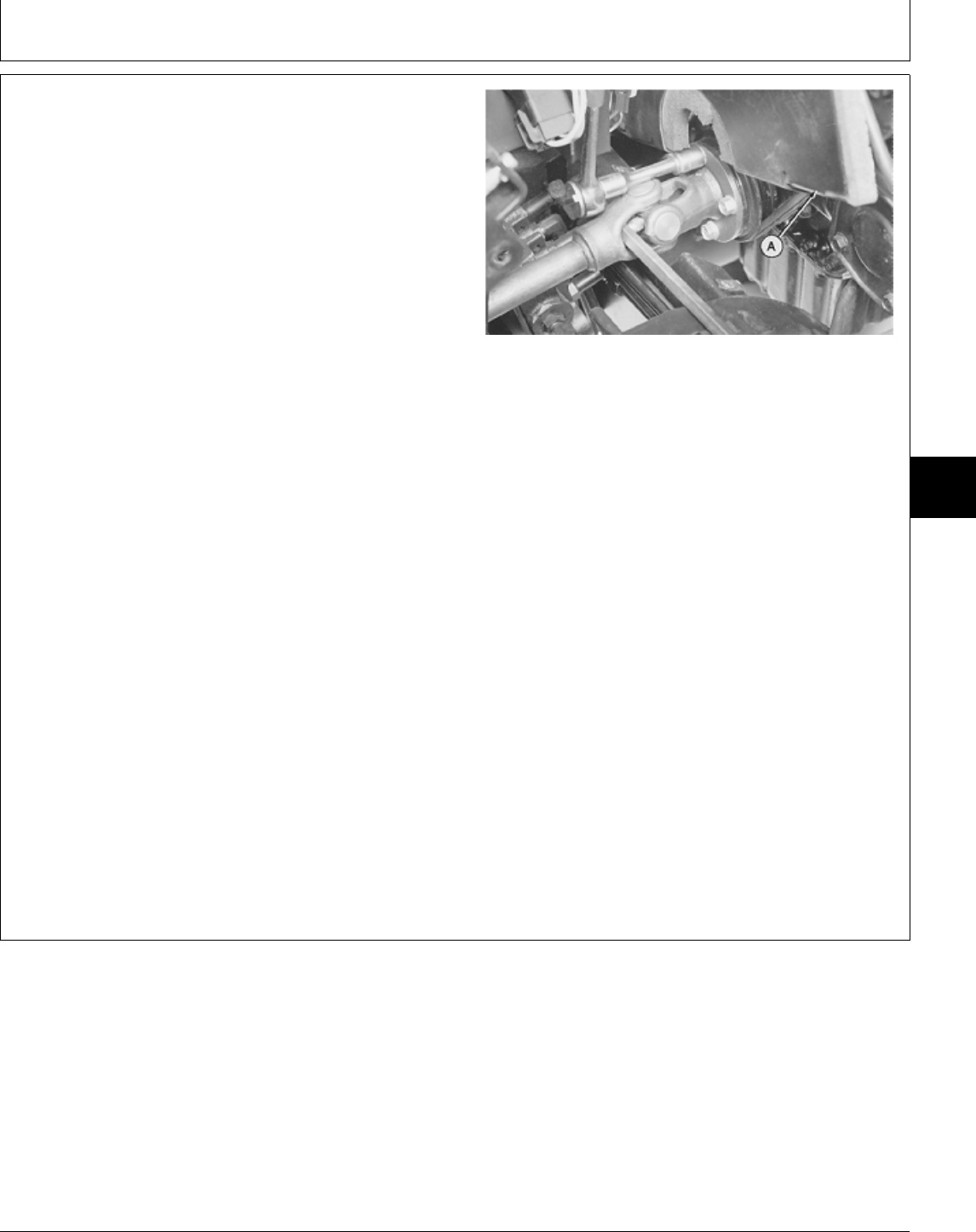
10. Remove four cap screws to disconnect partition (A)
from pedestal.
11. Lift partition to access drive shaft-to-engine cap
screws.
12. Hold drive shaft using a screwdriver. Remove four
cap screws to disconnect drive shaft from engine.
13. Pull drive shaft all the way back onto transmission
pump shaft. Turn front flanged yoke to clear crankshaft
pulley.
14. Push drive shaft forward to disconnect from
transmission pump shaft.
15. Remove drive shaft.
16. Installation is done in the reverse order of removal.
• Before installing drive shaft, apply MPG-2®
Multi-Purpose Polymer Grease on splines of transmission
input shaft.
• Apply multipurpose grease to lubrication fittings.
• Bleed hydraulic system. (See procedure in Section 270,
Group 20.)
TORQUE SPECIFICATIONS
Drive Shaft Cap Screws and/or Lock Nuts
Flange-to-Engine . . . . . . . . . . . . . . . . . . . . . . 27 N·m (20 lb-ft)
Clamping Yoke-to-Transmission
Pump Shaft . . . . . . . . . . . . . . . . . . . . . . . . . . 60 N·m (44 lb-ft)
M36585 -UN-25JAN90
MX,15915026,4 -19-13JUL95
Drive Shaft—430/Remove and Install
TM1591 (15JUL95) 50-26-3 322,330,332 & 430 Lawn & Garden Tractors
030895
50
26
3
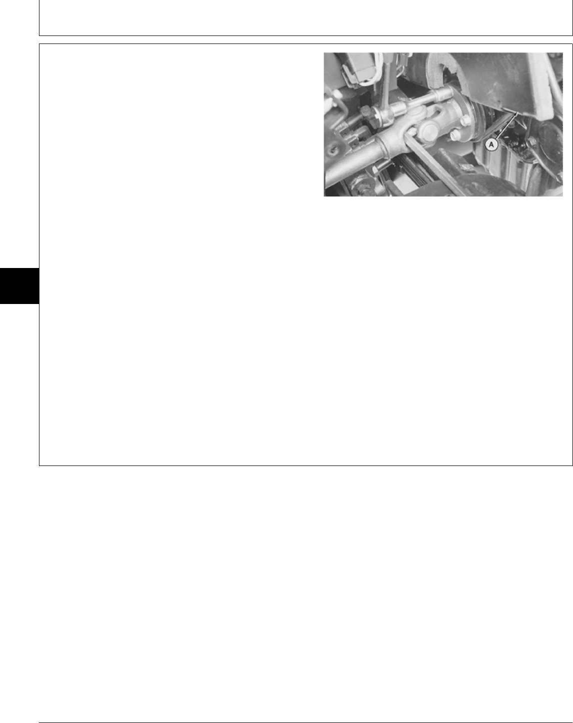
REMOVE AND INSTALL DRIVE
SHAFT—LATER MODELS
1. Lift hood and remove front grille and engine side
panels.
2. Remove battery and battery base.
3. Remove belly pan.
4. Loosen two lock nuts and cap screws, if equipped, on
drive shaft at transmission pump shaft end.
5. Remove four cap screws to disconnect partition (A)
from pedestal.
6. Lift partition to access drive shaft-to-engine cap
screws.
7. Hold drive shaft using a screwdriver. Remove four cap
screws to disconnect drive shaft from engine.
8. Pull drive shaft all the way back onto transmission
pump shaft. Turn front flanged yoke to clear crankshaft
pulley.
M36585 -UN-25JAN90
MX,15915026,13 -19-13JUL95
Drive Shaft—430/Remove and Install
TM1591 (15JUL95) 50-26-4 322,330,332 & 430 Lawn & Garden Tractors
030895
50
26
4
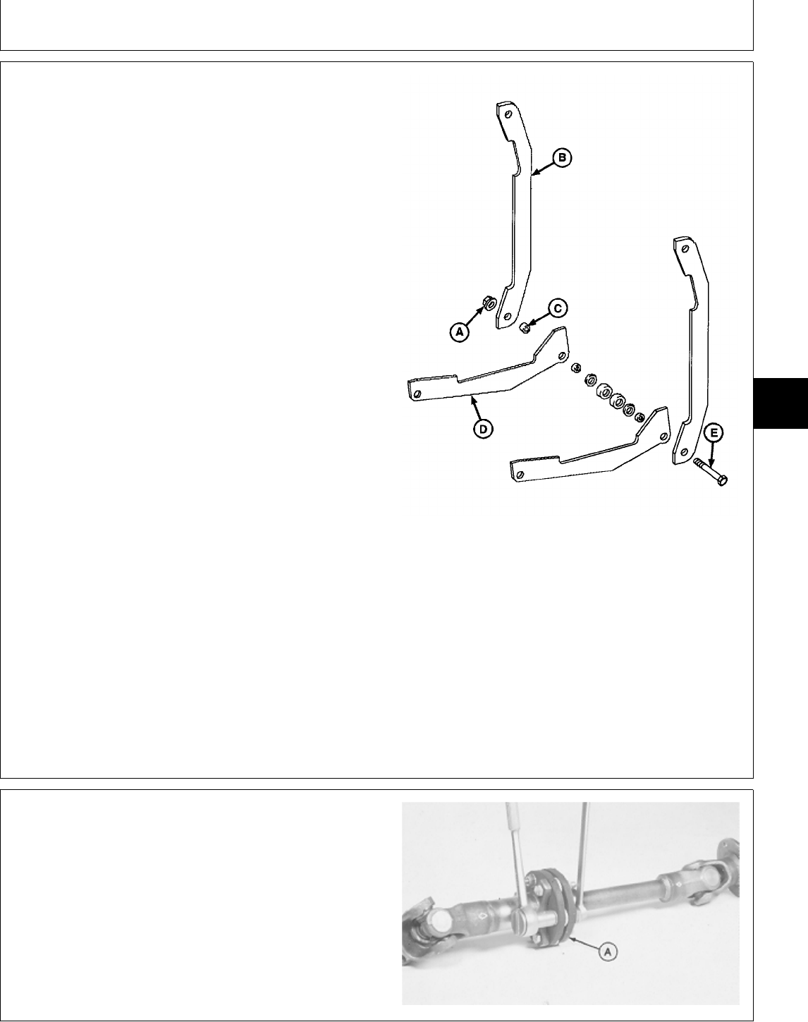
NOTE: There are three versions of the transmission
control and brake pedal and neutral control
linkages. Version two is shown. See Group 10, in
this section, and/or Section 60, Group 10 to
confirm which version your machine is equipped
with. It may not be necessary to perform some
steps if equipped with later versions of linkage on
later models.
9. To provide clearance to remove drive shaft; remove
nut (A), strap (B), spacer (C) and arm (D) from cap
screw (E).
10. Depress either brake pedal for arm (D) to drop out of
the way. Put nut (A) back onto cap screw (E) to hold
remaining assembly together. Push assembly toward
brake pedals to move out of the way.
11. Push drive shaft up and forward to disconnect from
transmission pump shaft.
12. Remove drive shaft.
13. Installation is done in the reverse order of removal.
• Before installing drive shaft, apply MPG-2®
Multi-Purpose Polymer Grease on splines of transmission
input shaft.
A—Nut
• Apply multipurpose grease to lubrication fittings. B—Strap
C—Spacer
D—Arm
TORQUE SPECIFICATIONS E—Cap Screw
Drive Shaft Cap Screws and/or Lock Nuts
Flange-to-Engine . . . . . . . . . . . . . . . . . . . . . . 27 N·m (20 lb-ft)
Clamping Yoke-to-Transmission
Pump Shaft . . . . . . . . . . . . . . . . . . . . . . . . . . 60 N·m (44 lb-ft)
M78702 -UN-14MAR95
DISASSEMBLE AND INSPECT DRIVE SHAFT
1. Inspect coupling assembly for cracked disks (A), wear
or damage.
2. Remove cap screws and washers to disconnect
coupling assembly.
3. Pull drive shaft apart to remove disks.
M36587 -UN-25JAN90
MX,15915026,14 -19-13JUL95
MX,15915026,5 -19-13JUL95
Drive Shaft—430/Disassemble and Inspect
TM1591 (15JUL95) 50-26-5 322,330,332 & 430 Lawn & Garden Tractors
030895
50
26
5
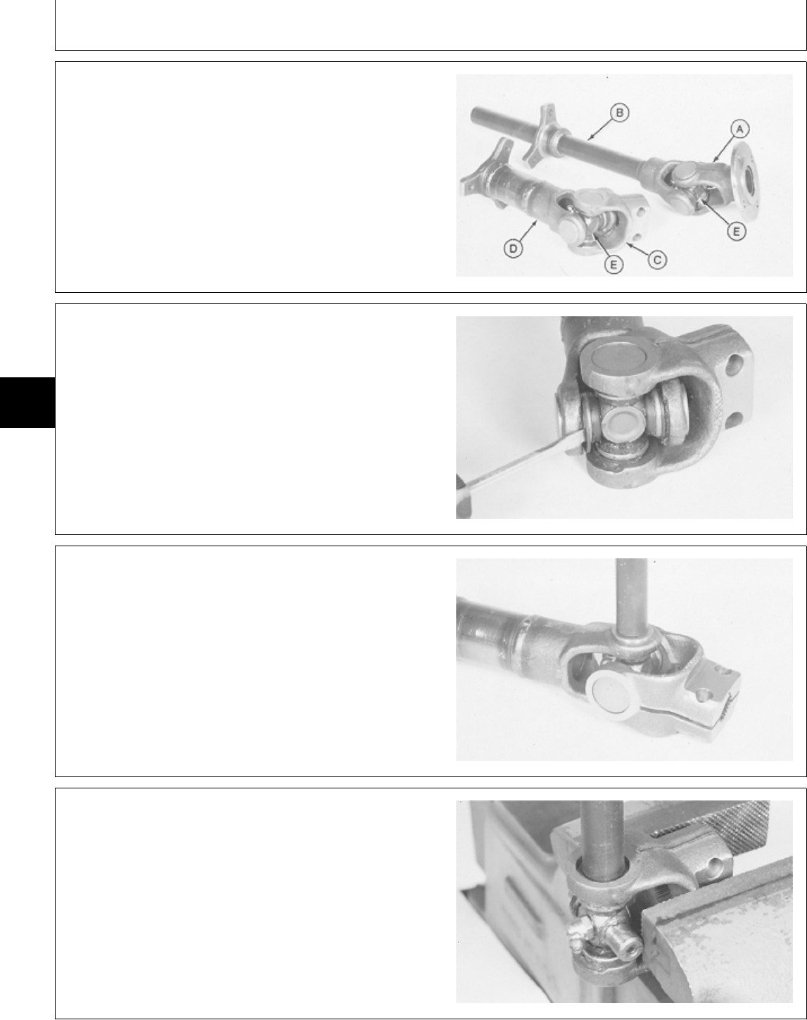
4. Inspect yokes (A—D) and cross and bearing
assemblies (E) for cracks, wear or damage.
A—Flanged Yoke
B—Tube Yoke
C—End Yoke
D—Bushing Yoke
E—Cross and Bearing Assembly (2 used)
M36588 -UN-25JAN90
NOTE: Cross and bearing disassembly procedures are
the same for both drive shaft yoke assemblies.
Drive shaft bushing yoke with end yoke is shown.
5. Remove four snap rings.
M36589 -UN-25JAN90
6. Remove cross and bearing assembly using a brass
drift. Push bearing down until it can be removed from the
bottom.
7. Turn cross and bearing assembly over and repeat
procedure.
8. Separate end yoke from drive shaft bushing yoke.
M36590 -UN-25JAN90
9. Remove cross and bearing assembly using a brass
drift. Push bearing down until bottom bearing can be
removed.
10. Remove cross and top bearing.
M36591 -UN-25JAN90
MX,15915026,6 -19-13JUL95
MX,15915026,7 -19-13JUL95
MX,15915026,8 -19-13JUL95
MX,15915026,9 -19-13JUL95
Drive Shaft—430/Disassemble and Inspect
TM1591 (15JUL95) 50-26-6 322,330,332 & 430 Lawn & Garden Tractors
030895
50
26
6
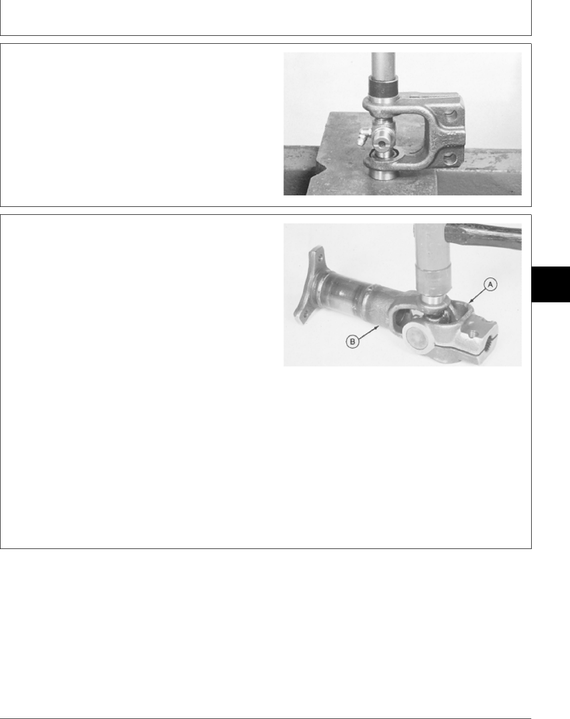
ASSEMBLE DRIVE SHAFT
IMPORTANT: Be careful not to damage needle rollers
and seal while installing cross and
bearing assembly.
1. Press bearings onto cross only until snap rings can be
installed.
M49514 -UN-20DEC89
NOTE: Cross and bearing disassembly procedures are
the same for both drive shaft yoke assemblies.
Drive shaft bushing yoke with end yoke is shown.
Be sure to connect end yoke (A) to bushing yoke
(B) and flanged yoke to tube yoke.
2. Install cross in bushing yoke with grease fitting toward
bushing yoke.
3. Install bearing using a soft-faced hammer. Push
bearing down until snap ring groove is inside bushing
yoke.
4. Turn cross and bearing assembly over and install
other bearing.
5. Install four snap rings.
M36593 -UN-25JAN90
MX,15915026,10 -19-13JUL95
MX,15915026,11 -19-13JUL95
Drive Shaft—430/Assemble
TM1591 (15JUL95) 50-26-7 322,330,332 & 430 Lawn & Garden Tractors
030895
50
26
7
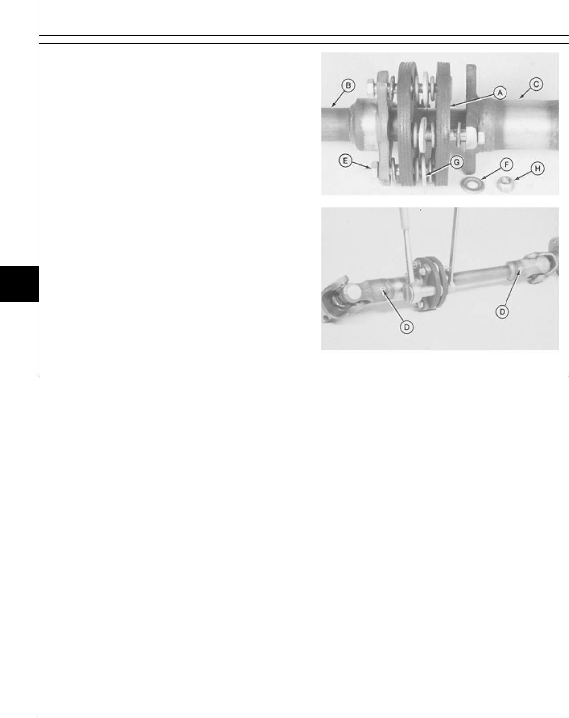
6. Install disks (A) on tube yoke shaft (B). Insert tube
yoke shaft into bushing yoke tube (C).
IMPORTANT: Align arrows (D) on tube yoke shaft
and bushing yoke tube to prevent drive
shaft imbalance.
7. Install cap screws (E), beaded washers (F), special
washers (G) and lock nuts (H). Tighten lock nuts to 3
N·m (25 lb-in.).
A—Disk (2 used)
B—Tube Yoke Shaft
C—Bushing Yoke Tube
D—Arrows
E—Cap Screw (6 used)
F—Beaded Washer (24 used)
G—Special Washer (6 used)
H—Lock Nut (6 used)
M36595 -UN-25JAN90M36596 -UN-25JAN90
MX,15915026,12 -19-13JUL95
Drive Shaft—430/Assemble
TM1591 (15JUL95) 50-26-8 322,330,332 & 430 Lawn & Garden Tractors
030895
50
26
8

Section 60
STEERING AND BRAKE REPAIR
Contents
Page
Group 05—Steering—330
Special or Essential Tools . . . . . . . . . . . 60-05-1
Service Parts Kits . . . . . . . . . . . . . . . . 60-05-1
Gearbox and Shaft
Remove and Install . . . . . . . . . . . . . . 60-05-1
Disassemble and Inspect . . . . . . . . . . 60-05-5
Assemble . . . . . . . . . . . . . . . . . . . . 60-05-12
Group 06—Steering—322, 332 and 430
Other Materials . . . . . . . . . . . . . . . . . . 60-06-1
Service Parts Kits . . . . . . . . . . . . . . . . 60-06-1
Steering Valve and Column
Remove and Install—322 and 332 . . . . 60-06-2
Remove and Install—430 . . . . . . . . . . 60-06-4
Disassemble and Inspect . . . . . . . . . . 60-06-6
Assemble . . . . . . . . . . . . . . . . . . . . 60-06-15
Steering Cylinder
Remove and Install . . . . . . . . . . . . . . 60-06-25
Group 10—Brakes
Other Materials . . . . . . . . . . . . . . . . . . 60-10-1
Brakes
Remove . . . . . . . . . . . . . . . . . . . . . 60-10-2
Install . . . . . . . . . . . . . . . . . . . . . . . 60-10-5
Adjust . . . . . . . . . . . . . . . . . . . . . . . 60-10-7
Brake Pedal(s) and Neutral Return
Linkage
Inspect and Repair—330 . . . . . . . . . . 60-10-8
Inspect and Repair—322 and 332 . . . . 60-10-10
Inspect and Repair—430 . . . . . . . . . . 60-10-14
Inspect and Repair Park Brake Lever . . . 60-10-19
TM1591 (15JUL95) 60-1 322,330,332 & 430 Lawn & Garden Tractors
030895
60

Contents
TM1591 (15JUL95) 60-2 322,330,332 & 430 Lawn & Garden Tractors
030895
60
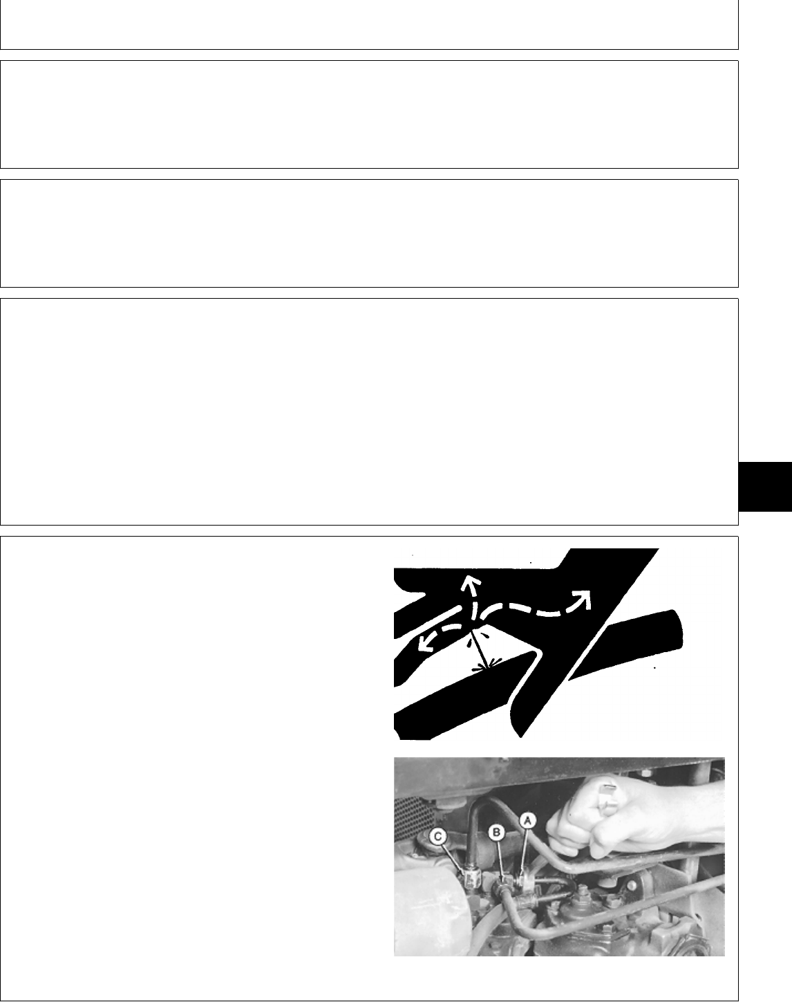
SPECIAL OR ESSENTIAL TOOLS
NOTE: Order tools according to information given in the
U.S. SERVICE-GARD™ Catalog or in the
European Microfiche Tool Catalog (MTC).
Steering Gear Service Set....................JDG457
Used to service steering gearbox.
SERVICE PARTS KITS
The following kits are available through your parts
catalog:
Return Guide Clamp Kit
Side Cover Kit
REMOVE AND INSTALL STEERING
GEARBOX AND SHAFT
1. Remove drive shaft. (See procedure in Section 50,
Group 25.)
IMPORTANT: Do not pound on end of steering shaft
or damage to steering shaft will occur.
2. Remove steering wheel.
3. Remove belly screen.
NCAUTION: To avoid injury from escaping fluid
under pressure, stop engine and relieve the
pressure in the system before disconnecting or
connecting hydraulic or other lines. Tighten all
connections before applying pressure.
4. Disconnect lines (A, B and C) from hydraulic control
valve.
X9811 -UN-23AUG88
M33937 -UN-03OCT89
DX,TOOLS -19-05JUN91
MX,JDG457 -19-01MAR95
MX,15906005,KIT-19-01MAR95
MX,15916005,1 -19-13JUL95
Group 05
Steering—330
TM1591 (15JUL95) 60-05-1 322,330,332 & 430 Lawn & Garden Tractors
030895
60
05
1
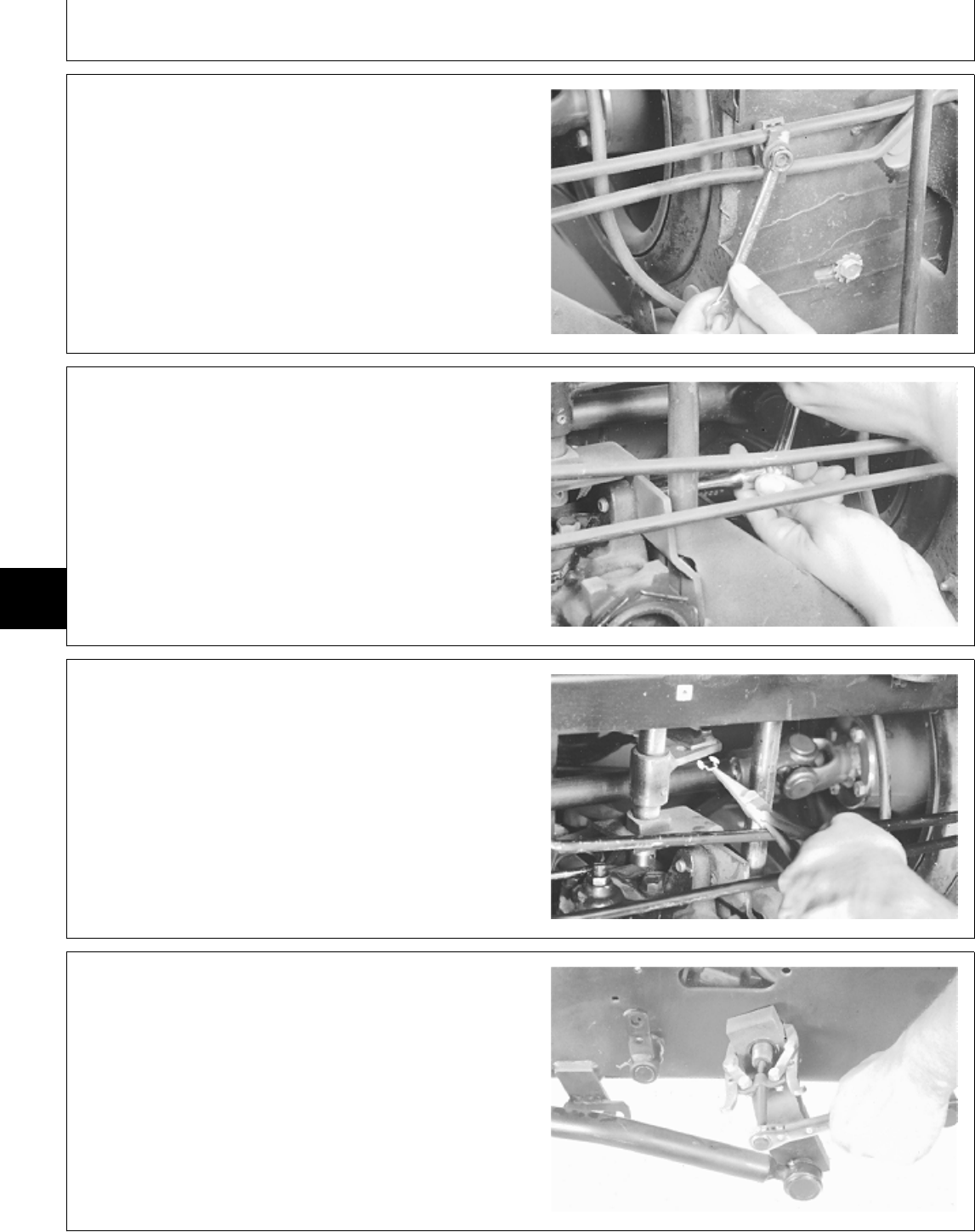
5. Remove nut and line clamp.
M33938 -UN-03OCT89
6. Remove bracket mounting cap screw.
M33939 -UN-03OCT89
7. Remove clip and disconnect brake neutral return
linkage.
M33940 -UN-03OCT89
8. Remove pitman arm nut and washer. Remove pitman
arm using a two-jaw puller.
M33942 -UN-03OCT89
MX,15916005,2 -19-13JUL95
MX,15916005,3 -19-13JUL95
MX,15916005,4 -19-13JUL95
MX,15916005,5 -19-13JUL95
Steering—330/Gearbox and Shaft
TM1591 (15JUL95) 60-05-2 322,330,332 & 430 Lawn & Garden Tractors
030895
60
05
2
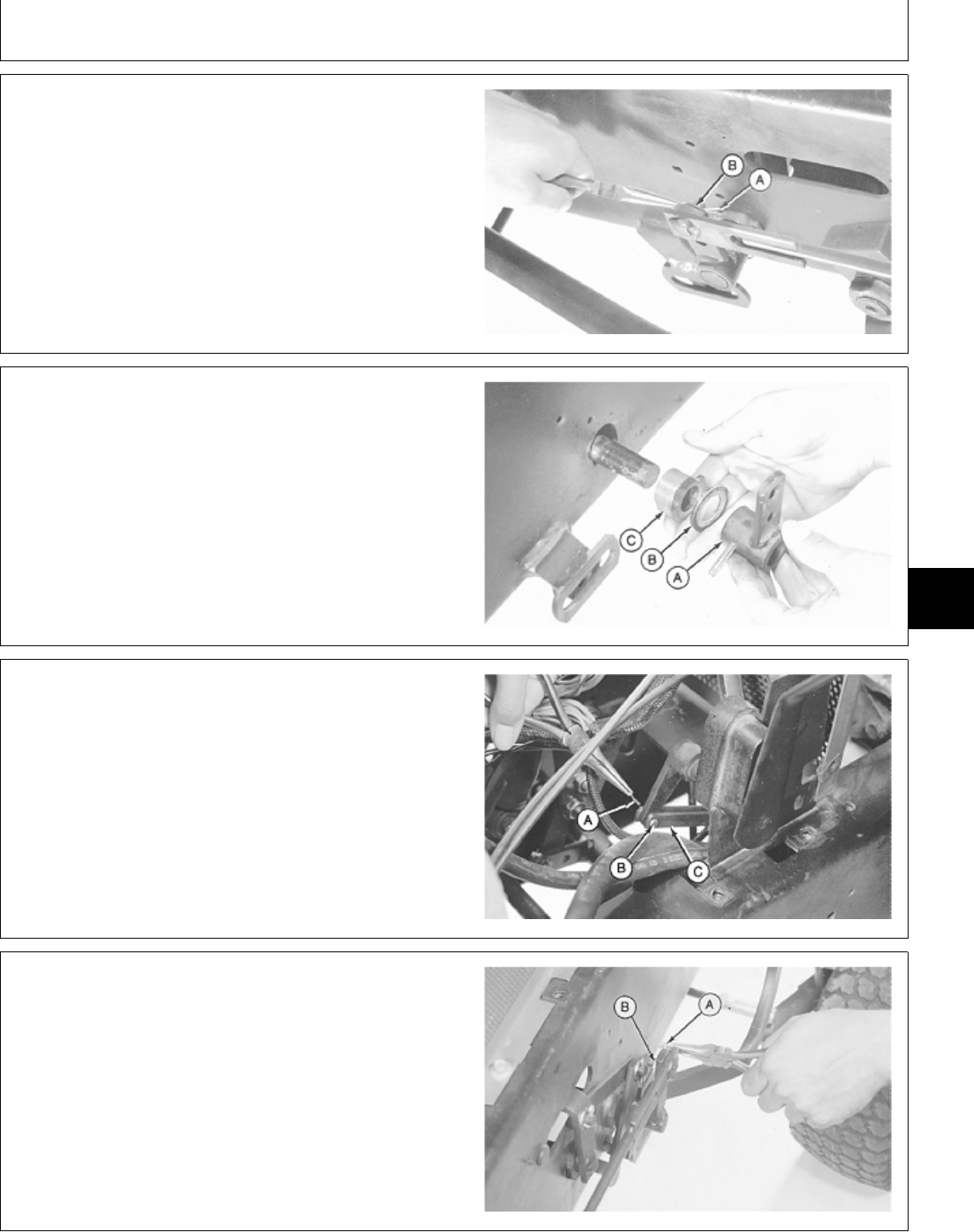
9. Remove cotter pin (A) and washer (B) to disconnect
brake llinkage on left side of machine frame.
M33943 -UN-03OCT89
10. Remove safety wire and spring pin to remove brake
arm (A), washer (B) and bushing (C).
M33958 -UN-03OCT89
11. Remove left side of pedestal.
12. Remove cotter pin (A) and draft pin (B). Turn
rockshaft control valve linkage (C) to gain access for
steering shaft removal.
M33961 -UN-03OCT89
13. Remove cotter pins (A) and washers (B) to
disconnect brake linkage on right side of machine frame.
M34170 -UN-08NOV89
MX,15916005,6 -19-13JUL95
MX,15916005,7 -19-13JUL95
MX,15916005,8 -19-13JUL95
MX,15916005,9 -19-13JUL95
Steering—330/Gearbox and Shaft
TM1591 (15JUL95) 60-05-3 322,330,332 & 430 Lawn & Garden Tractors
030895
60
05
3
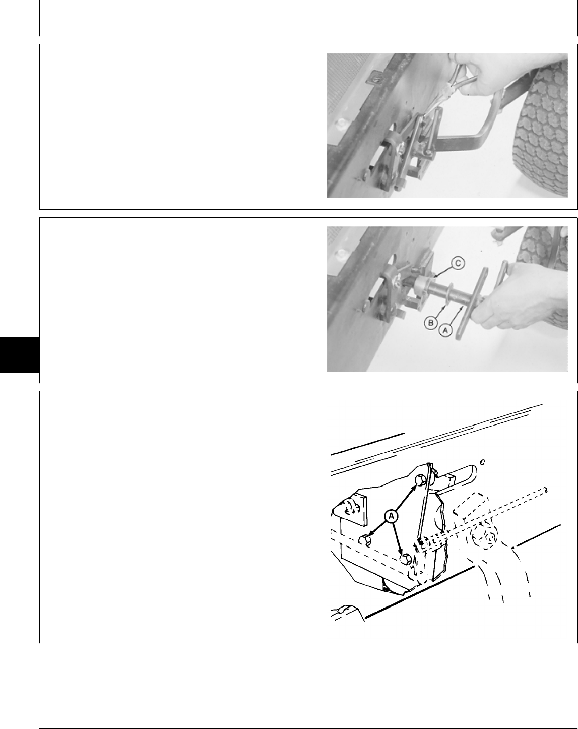
14. Remove cotter pin and washer to disconnect link
from brake linkage.
M33962 -UN-03OCT89
15. Remove brake arm (A), washer (B) and bushing (C).
M33963 -UN-03OCT89
16. Remove three cap screws (A) from gearbox
mounting plate.
M77339 -UN-14MAR95
MX,15916005,10 -19-13JUL95
MX,15916005,11 -19-13JUL95
MX,15916005,12 -19-13JUL95
Steering—330/Gearbox and Shaft
TM1591 (15JUL95) 60-05-4 322,330,332 & 430 Lawn & Garden Tractors
030895
60
05
4
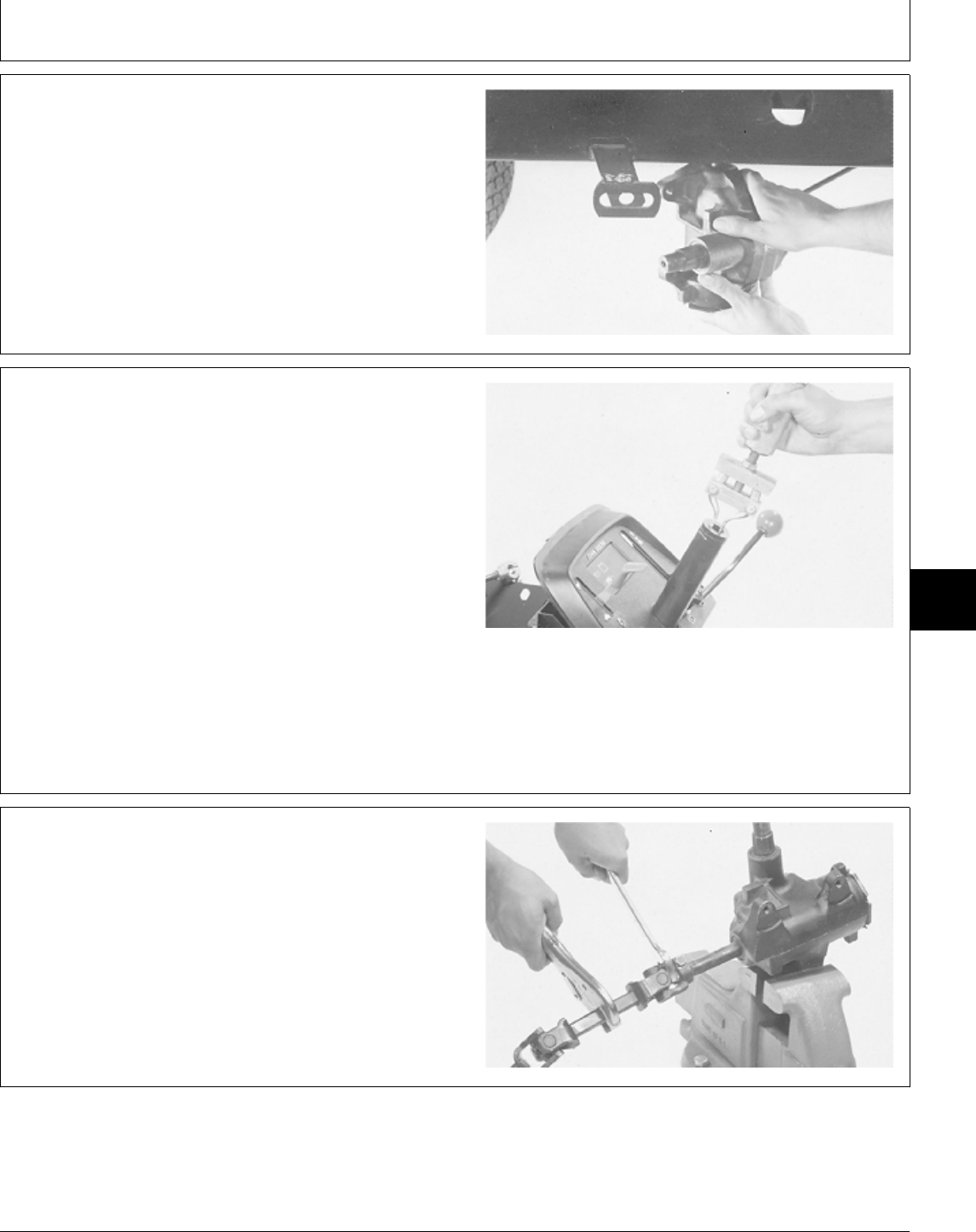
17. Remove steering gearbox and shaft as an assembly,
from bottom of machine.
18. Make repairs as necessary. (See procedure in this
group.)
M33965 -UN-03OCT89
19. Inspect steering shaft bushings for wear or damage.
Replace if necessary.
20. Remove bushings using a pilot bearing puller.
21. Installation is done in the reverse order of removal.
• If removed, install steering shaft bushings using a
driver set.
• Apply multipurpose grease to I.D. of steering shaft
bushings.
TORQUE SPECIFICATIONS
Gearbox Mounting Cap Screws . . . . . . . . . . . . . . . 95 N·m (70 lb-ft)
Steering Wheel-to-Shaft Nut . . . . . . . . . . . . . . . . 15 N·m (133 lb-in.)
Pitman Arm Nut . . . . . . . . . . . . . . . . . . . . . . . . 224 N·m (165 lb-ft)
M34018 -UN-03OCT89
DISASSEMBLE AND INSPECT STEERING
GEARBOX AND SHAFT
1. Put an open-end wrench between both steering shaft
universal joints.
2. Turn steering shaft using locking pliers to determine
amount of play at universal joints. Replace steering shaft
if play exists.
M33966 -UN-03OCT89
MX,15916005,13 -19-13JUL95
MX,15916005,14 -19-13JUL95
MX,15916005,15 -19-13JUL95
Steering—330/Gearbox and Shaft
TM1591 (15JUL95) 60-05-5 322,330,332 & 430 Lawn & Garden Tractors
030895
60
05
5
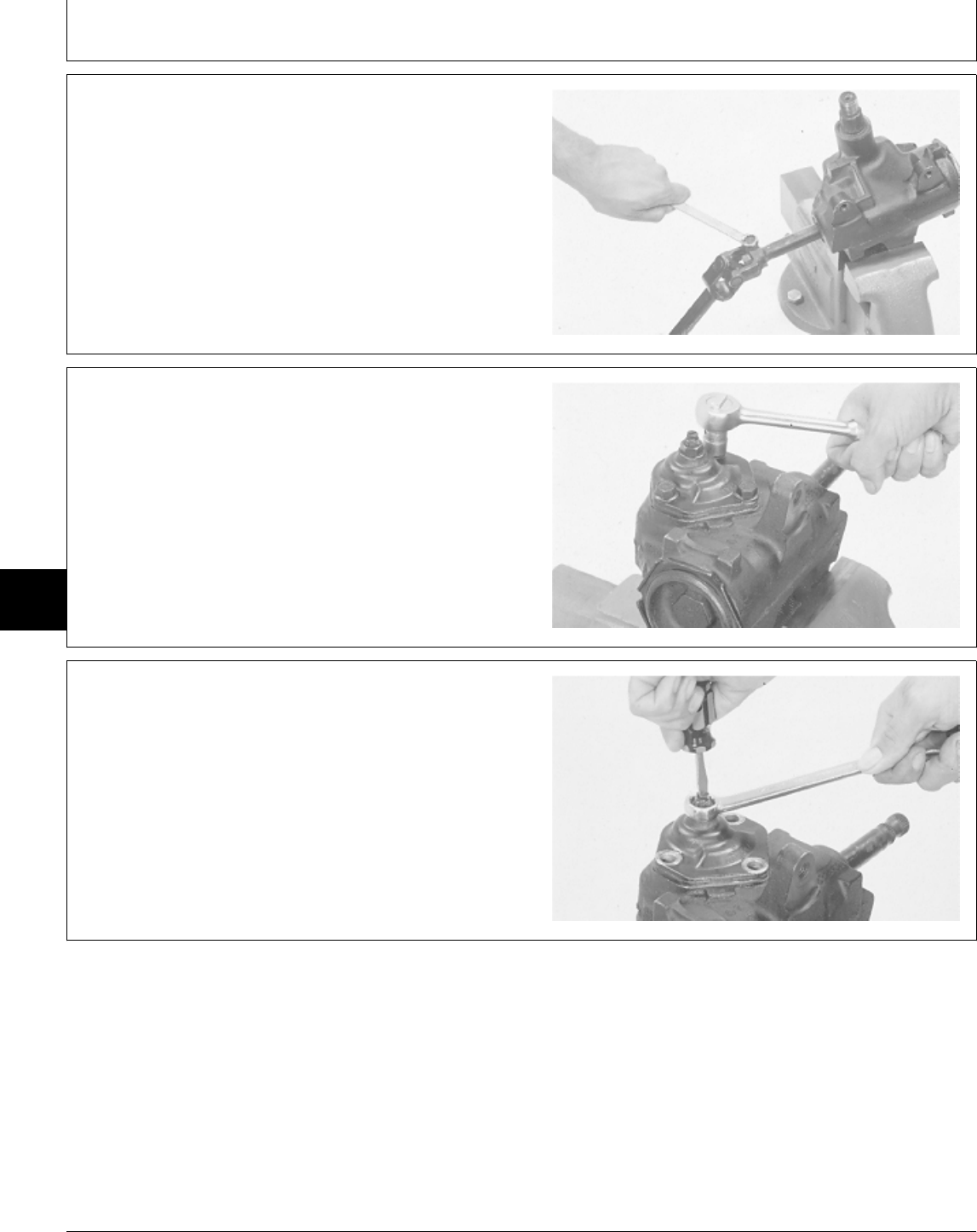
3. Remove cap screw and washer from universal joint.
4. Remove steering shaft from gearbox.
5. Inspect steering shaft spline for wear or damage.
Replace if necesary.
M33967 -UN-03OCT89
6. Put gearbox in a vise.
7. Remove three side cover cap screws.
M33969 -UN-03OCT89
NOTE: If replacing side cover gasket only, it is not
necessary to remove preload adjuster nut.
8. Hold preload adjuster screw and remove adjuster nut.
M33970 -UN-03OCT89
MX,15906005,16 -19-01MAR95
MX,15906005,17 -19-01MAR95
MX,15906005,18 -19-01MAR95
Steering—330/Gearbox and Shaft
TM1591 (15JUL95) 60-05-6 322,330,332 & 430 Lawn & Garden Tractors
030895
60
05
6
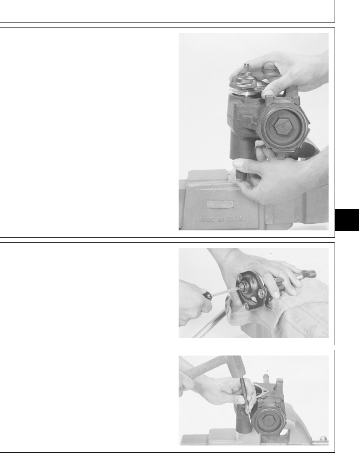
9. Remove pitman shaft, gasket and side cover as an
assembly.
M33971 -UN-03OCT89
10. Remove preload adjuster and shim, if equipped, from
side cover.
M33972 -UN-03OCT89
11. Remove worm bearing adjuster lock nut using a
punch and hammer.
M33973 -UN-03OCT89
MX,15906005,19 -19-01MAR95
MX,15906005,20 -19-01MAR95
MX,15906005,21 -19-01MAR95
Steering—330/Gearbox and Shaft
TM1591 (15JUL95) 60-05-7 322,330,332 & 430 Lawn & Garden Tractors
030895
60
05
7
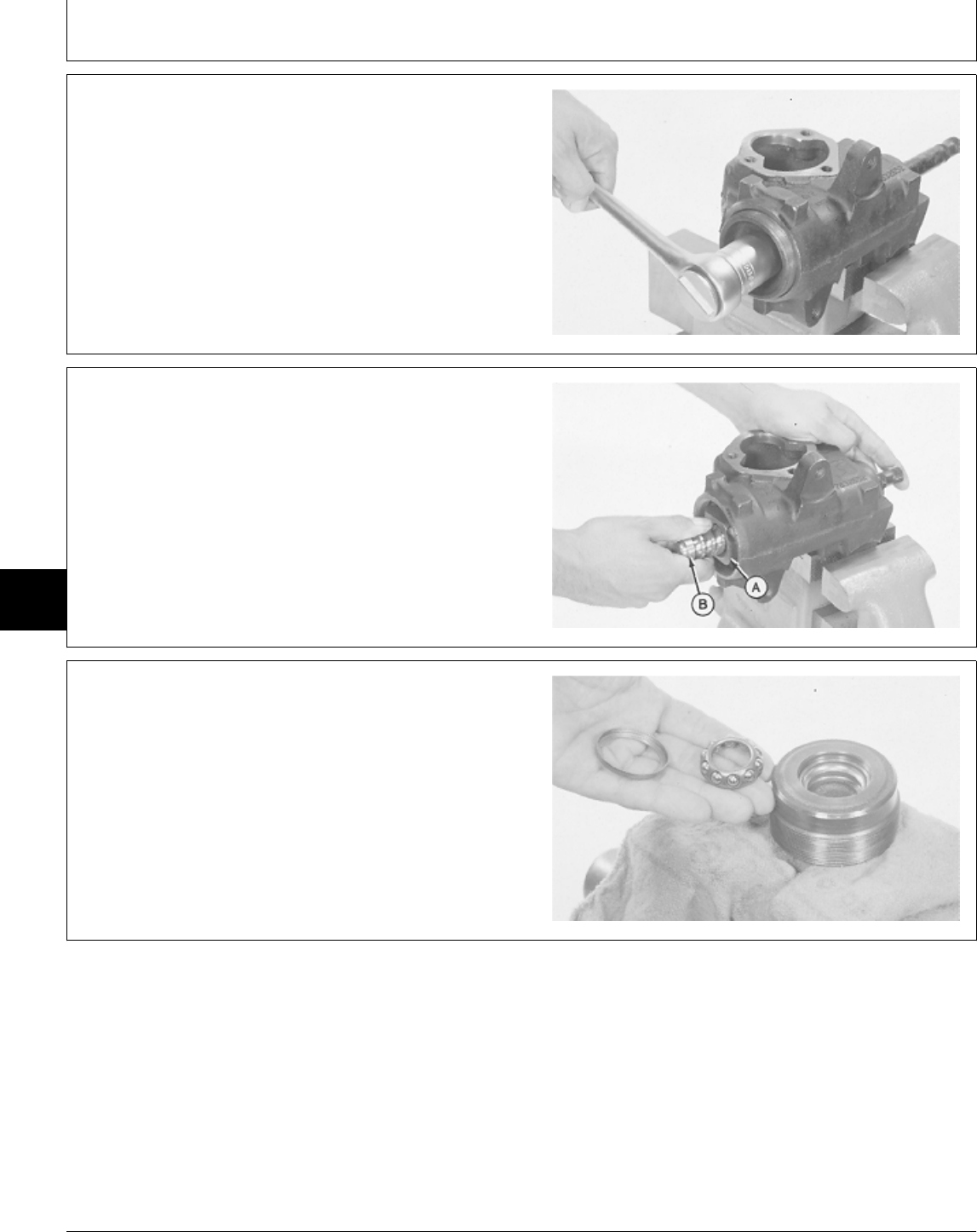
12. Remove worm bearing adjuster.
M33974 -UN-08NOV89
IMPORTANT: Do not allow worm shaft to turn to the
end of its travel or damage can occur
to the ends of the ball guides.
13. Remove ball nut (A) and worm shaft (B).
M33978 -UN-03OCT89
14. Pry out lower bearing retainer using a screwdriver.
15. Remove lower worm bearing cone.
M33976 -UN-03OCT89
MX,15906005,22 -19-01MAR95
MX,15906005,23 -19-01MAR95
MX,15906005,24 -19-01MAR95
Steering—330/Gearbox and Shaft
TM1591 (15JUL95) 60-05-8 322,330,332 & 430 Lawn & Garden Tractors
030895
60
05
8
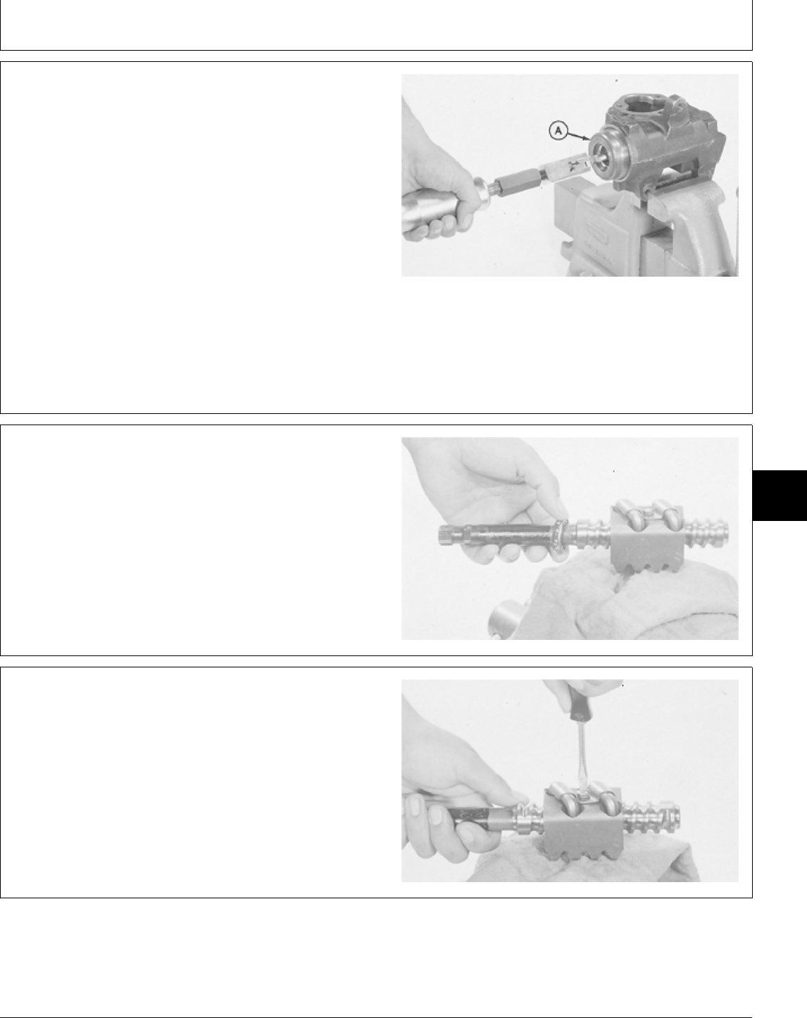
NOTE: Bearing cup is press-fit in bearing adjuster.
Remove bearing cup only if replacement is
necessary.
Bearing cups and cones are matched and must
be replaced as complete assemblies.
16. Inspect bearing cup in bearing adjuster for wear or
damage. Replace if necessary.
17. Screw bearing adjuster (A) into gearbox housing.
Remove bearing cup using a slide hammer and puller
from JDG457 Steering Gear Service Set.
M33977 -UN-03OCT89
18. Remove upper worm bearing cone from shaft or
gearbox housing.
M33979 -UN-03OCT89
19. Remove ball guide screw and clamp.
M33980 -UN-03OCT89
MX,15906005,25 -19-01MAR95
MX,15906005,26 -19-01MAR95
MX,15906005,27 -19-01MAR95
Steering—330/Gearbox and Shaft
TM1591 (15JUL95) 60-05-9 322,330,332 & 430 Lawn & Garden Tractors
030895
60
05
9
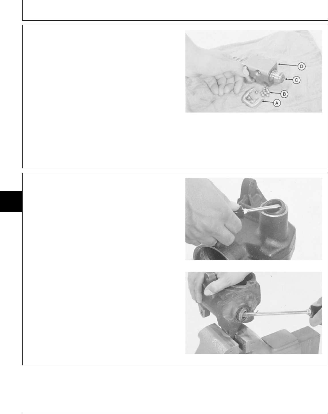
20. Remove ball guides (A), balls (B) and ball nut (D)
from worm shaft (C).
NOTE: Ball nut and worm shaft are matched and must
be replaced as a complete assembly.
If any ball becomes lost or damaged, install new
balls as a complete set.
21. Inspect all parts for wear or damage. Replace as
necessary.
A—Ball Guides
B—Balls (50 used)
C—Worm Shaft
D—Ball Nut
M33981 -UN-03OCT89
22. Remove pitman shaft and worm shaft seals from
gearbox housing.
Pitman Shaft Seal
Worm Shaft Seal
M34019 -UN-03OCT89M34020 -UN-03OCT89
MX,15906005,28 -19-01MAR95
MX,15906005,29 -19-01MAR95
Steering—330/Gearbox and Shaft
TM1591 (15JUL95) 60-05-10 322,330,332 & 430 Lawn & Garden Tractors
030895
60
05
10
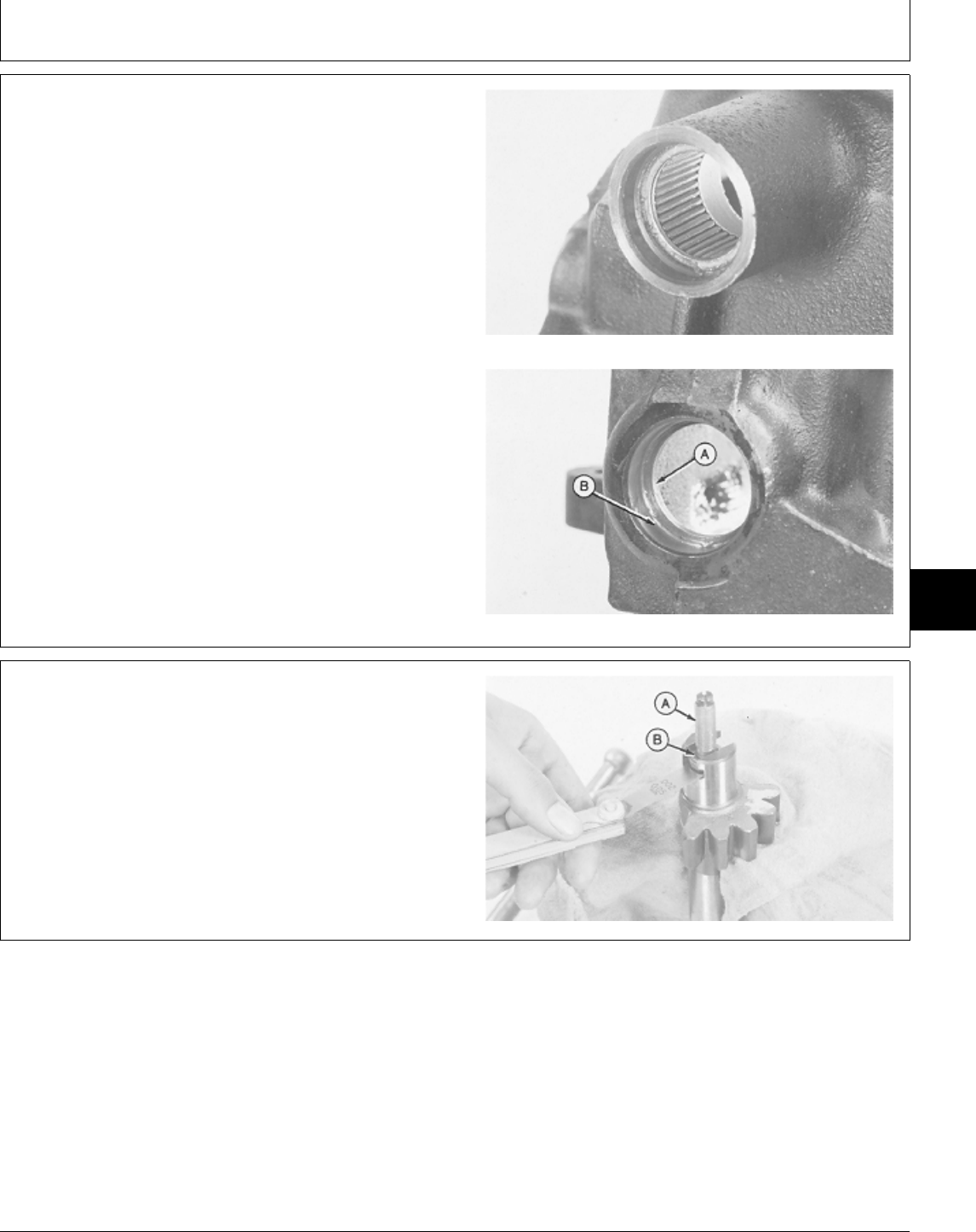
NOTE: Pitman shaft needle bearing and worm shaft
bearing cup are press-fit in gearbox housing.
Remove bearing or cup only if replacement is
necessary.
Lip (B) is part of gearbox housing, not part of
bearing race.
23. Inspect needle bearing and bearing cup (A) in
gearbox housing for wear or damage. Replace if
necessary.
24. Remove needle bearing using a driver from JDG457 Needle Bearing
Steering Gear Service Set.
25. Remove bearing cup using a driver set.
26. Inspect pitman shaft for roller wear or other damage.
Replace if necessary.
Bearing Cup
M33987 -UN-03OCT89M34021 -UN-03OCT89
NOTE: A steering gearlash adjustment shim is available
through the parts catalog.
27. Check preload adjuster (A) end clearance with a
feeler gauge as shown. If clearance is greater than 0.05
mm (0.002 in.), order and install shim (B).
M33989 -UN-03OCT89
MX,15906005,30 -19-10MAR95
MX,15906005,31 -19-10MAR95
Steering—330/Gearbox and Shaft
TM1591 (15JUL95) 60-05-11 322,330,332 & 430 Lawn & Garden Tractors
030895
60
05
11
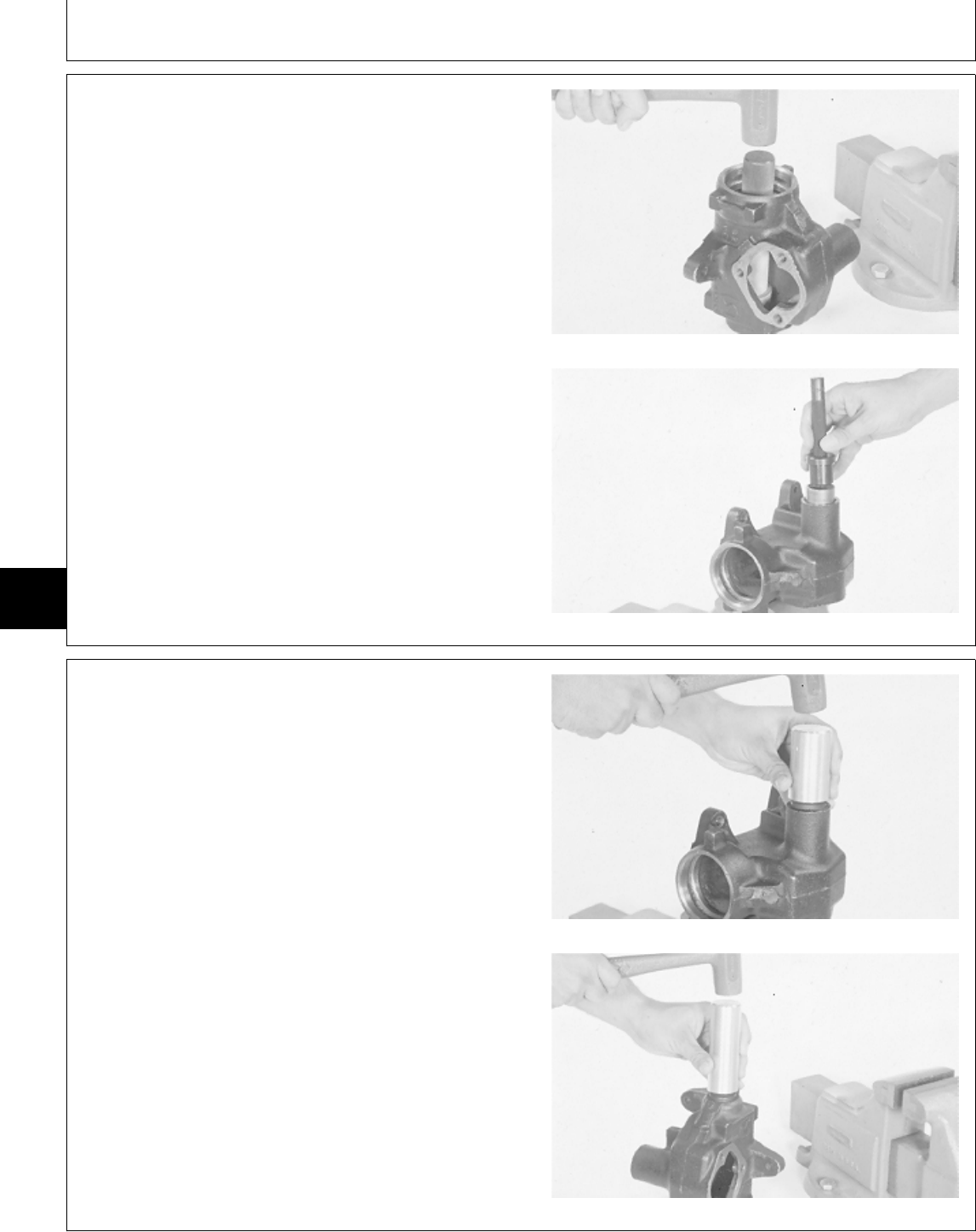
ASSEMBLE STEERING GEARBOX AND
SHAFT
IMPORTANT: Always use new seals and gasket.
Damaged or used parts will leak.
NOTE: Apply clean multipurpose grease on all internal
parts during assembly.
1. Install new worm shaft bearing cup in gearbox
housing, if removed, using a driver set.
2. Install new needle bearing in gearbox housing, if Bearing Cup
removed, using a driver from JDG457 Steering Gear
Service Set.
Needle Bearing
M34159 -UN-08NOV89M34160 -UN-08NOV89
3. Install new pitman shaft and worm shaft seals into
gearbox housing using drivers from JDG457 Steering
Gear Service Set.
4. Apply multipurpose grease to lip of seals.
Pitman Shaft Seal
Worm Shaft Seal
M34161 -UN-08NOV89M34158 -UN-08NOV89
MX,15916005,16 -19-13JUL95
MX,15906005,33 -19-01MAR95
Steering—330/Gearbox and Shaft
TM1591 (15JUL95) 60-05-12 322,330,332 & 430 Lawn & Garden Tractors
030895
60
05
12
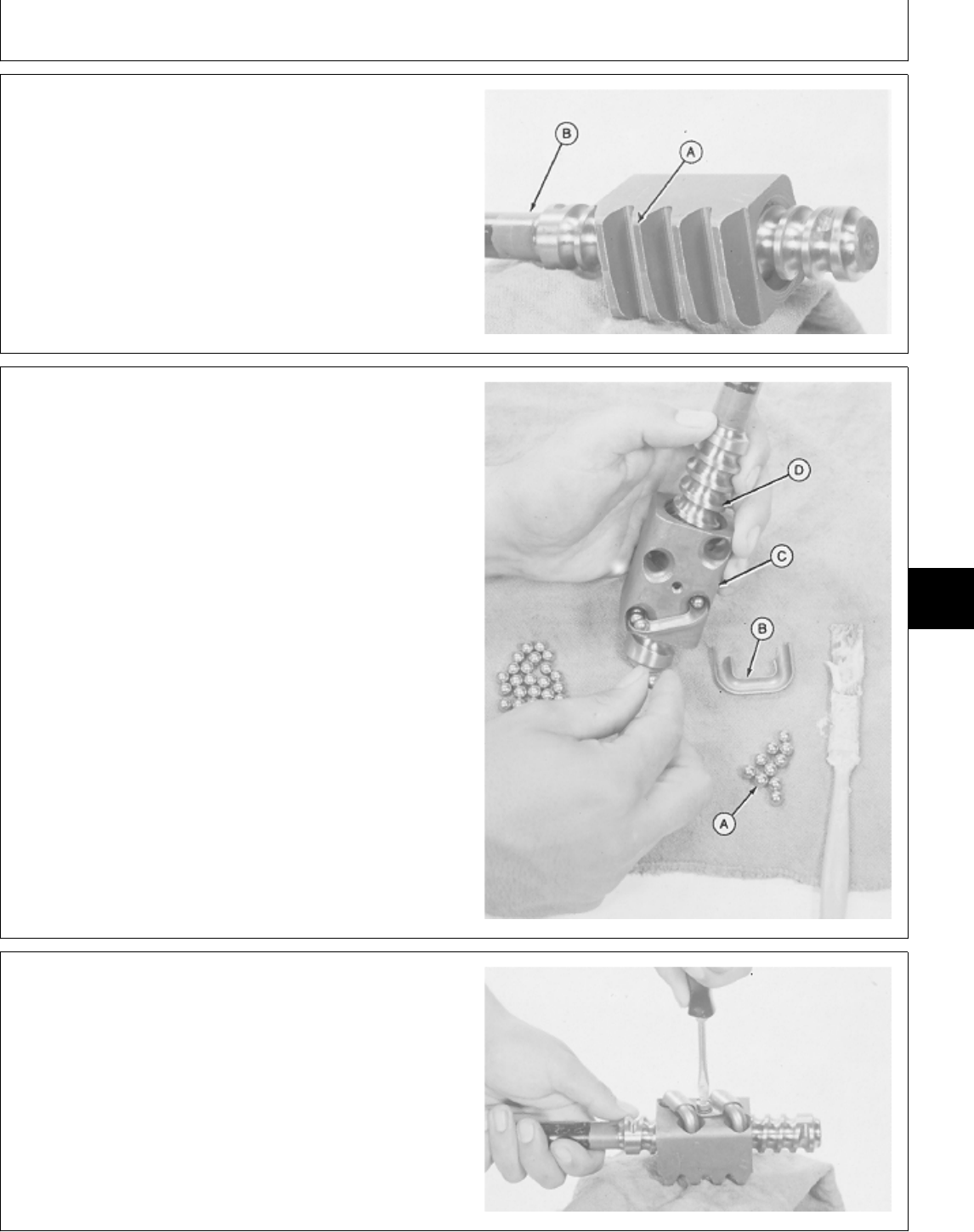
IMPORTANT: Install ball nut onto worm shaft as
shown. An improperly installed ball nut
could cause gear damage or steering
lockup.
5. Assemble ball nut and worm shaft (B) with narrow end
of ball nut teeth up (A) and worm shaft at the left.
M33988 -UN-03OCT89
6. Insert ball guide half into ball nut (C) as shown.
7. Fill circuit with 27 balls (A) and install other half of ball
guide (B).
8. Repeat procedures on other circuit with remaining
balls and guides.
M33992 -UN-03OCT89
9. Install ball guide clamp with screws and tighten
securely.
M33980 -UN-03OCT89
MX,15906005,34 -19-01MAR95
MX,15906005,35 -19-01MAR95
MX,15906005,36 -19-01MAR95
Steering—330/Gearbox and Shaft
TM1591 (15JUL95) 60-05-13 322,330,332 & 430 Lawn & Garden Tractors
030895
60
05
13
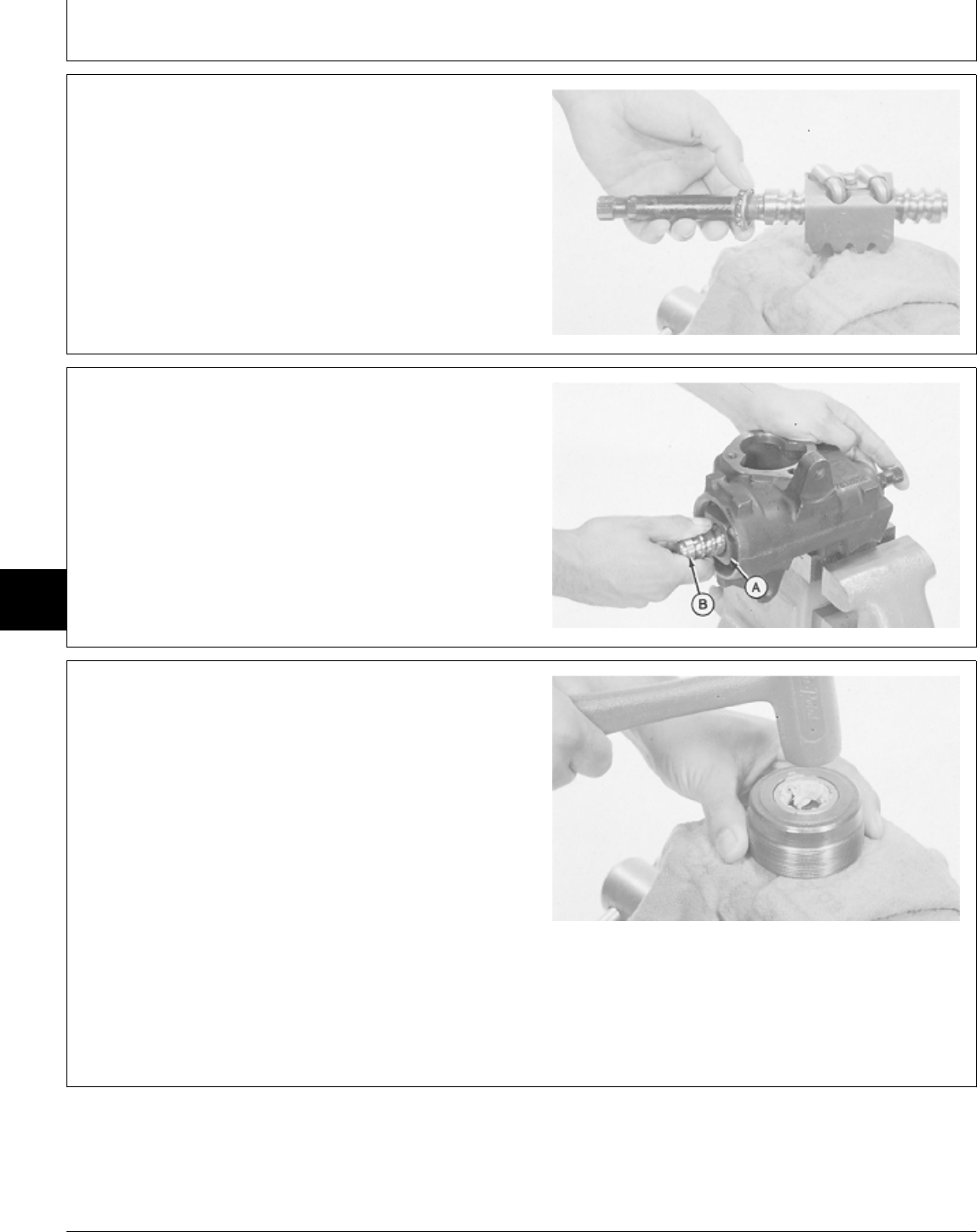
10. Pack upper worm bearing cone with multipurpose
grease.
11. Install upper worm bearing on shaft with small O.D.
facing away from ball nut.
M33979 -UN-03OCT89
IMPORTANT: Tape splined end of worm shaft to
prevent seal damage during shaft
installation.
12. Apply tape around splined end of worm shaft.
13. Install ball nut (A) and worm shaft (B) with bearing
cone, into gearbox housing. Remove tape.
M33978 -UN-03OCT89
14. Install new bearing cup in worm bearing adjuster, if
removed, using a driver set.
15. Pack lower worm bearing cone with multipurpose
grease.
16. Install lower worm bearing cone into worm bearing
adjuster with large O.D. facing away from threaded end
of adjuster.
17. Install retainer until flush with outside surface of
adjuster, using a plastic hammer.
18. Apply a coat of a lithium base grease to threads of
worm bearing adjuster.
M33996 -UN-03OCT89
MX,15906005,37 -19-01MAR95
MX,15906005,38 -19-01MAR95
MX,15906005,39 -19-01MAR95
Steering—330/Gearbox and Shaft
TM1591 (15JUL95) 60-05-14 322,330,332 & 430 Lawn & Garden Tractors
030895
60
05
14
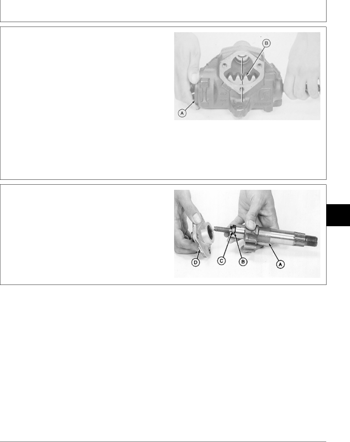
19. Install worm bearing adjuster (A).
IMPORTANT: Ball nut must be centered during
assembly. If not, the steering will only
turn fully in one direction and damage
can be done by bottoming the worm
drive against the ball nut.
20. Center ball nut (B) in gearbox housing as shown.
21. Fill gearbox with approximately 312 g (11 oz) of
multipurpose grease.
M33997 -UN-03OCT89
22. Assemble pitman shaft (A) with preload adjuster (B)
and shim (C), if equipped.
23. Install side cover (D) onto shaft with preload
adjuster.
24. Turn preload adjuster screw counterclockwise until it
bottoms. Then, back screw off one-half turn.
A—Pitman Shaft
B—Preload Adjuster
C—Shim (if equipped)
D—Side Cover
M33999 -UN-06MAR95
MX,15906005,40 -19-01MAR95
MX,15906005,41 -19-01MAR95
Steering—330/Gearbox and Shaft
TM1591 (15JUL95) 60-05-15 322,330,332 & 430 Lawn & Garden Tractors
030895
60
05
15
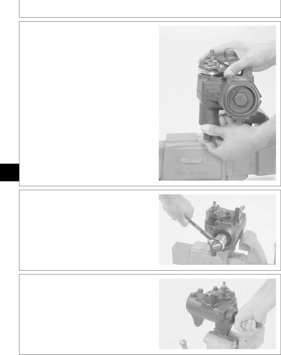
25. Install new gasket on side cover.
IMPORTANT: Tape end of pitman shaft to prevent
seal damage during shaft installation.
26. Apply tape around end of pitman shaft.
27. Center teeth of pitman shaft with teeth on ball nut.
28. Install pitman shaft into gearbox housing. Remove
tape.
29. Install three side cover cap screws. Tighten cap
screws to 40 N·m (30 lb-ft).
M33971 -UN-03OCT89
30. Adjust worm bearing preload:
• Tighten worm bearing adjuster until it bottoms, then
loosen one-quarter turn.
M34006 -UN-03OCT89
• Carefully turn worm shaft all the way to end of travel,
then turn back one-half turn.
M34003 -UN-03OCT89
MX,15906005,42 -19-01MAR95
MX,15906005,43 -19-01MAR95
MX,15906005,44 -19-01MAR95
Steering—330/Gearbox and Shaft
TM1591 (15JUL95) 60-05-16 322,330,332 & 430 Lawn & Garden Tractors
030895
60
05
16
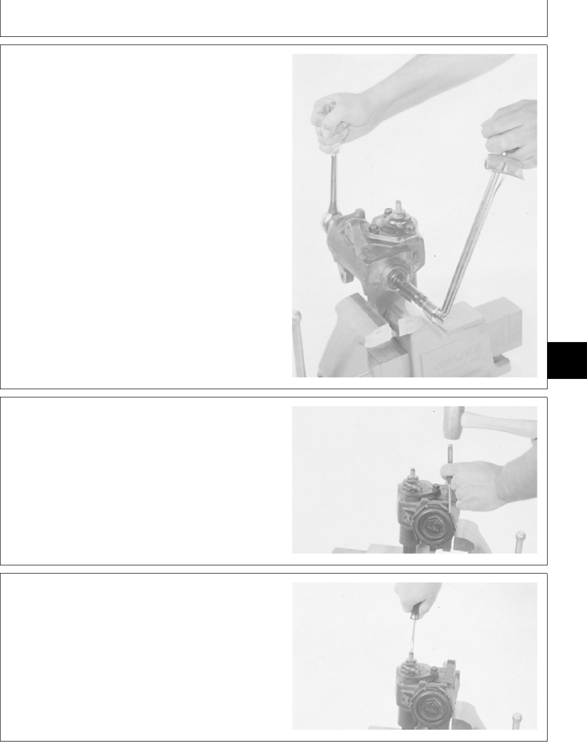
NOTE: Due to tolerances, some 11/16 in. sockets
require a wrapping of card stock around the
serrations on end of worm shaft.
• Install 1-1/8 in. socket with ratchet on worm bearing
adjuster and an 11/16 in. 12-point socket with torque
wrench on end of worm shaft.
NOTE: If worm shaft begins to bottom while reading the
torque wrench, back worm shaft out and start
torque reading again.
• Tighten worm bearing adjuster until torque wrench
reads 0.60—1.0 N·m (5—8 lb-in.) rolling torque.
M34004 -UN-03OCT89
• Install lock nut on worm bearing adjuster and tighten
using a punch and hammer.
M34005 -UN-03OCT89
31. Adjust over center preload:
• Back off preload adjuster until it stops, then turn it in
one full turn.
• Center gear travel by rotating shaft.
• Check torque required to turn worm shaft. Record
reading.
M34002 -UN-03OCT89
MX,15906005,45 -19-01MAR95
MX,15906005,46 -19-01MAR95
MX,15906005,47 -19-01MAR95
Steering—330/Gearbox and Shaft
TM1591 (15JUL95) 60-05-17 322,330,332 & 430 Lawn & Garden Tractors
030895
60
05
17
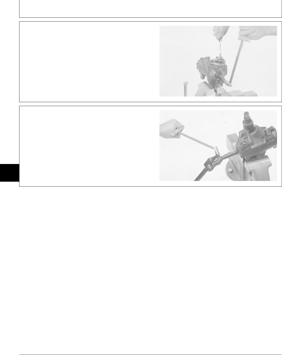
• Turn preload adjuster in, until rolling torque required to
turn worm shaft is 0.50—1.20 N·m (4—10 lb-in.) more
than first reading.
• Install lock nut. Hold preload adjuster screw and tighten
lock nut to 34 N·m (25 lb-ft).
M34008 -UN-03OCT89
32. Install steering shaft onto worm shaft as shown.
Tighten cap screws to 24 N·m (212 lb-in.).
M34010 -UN-03OCT89
MX,15906005,48 -19-01MAR95
MX,15906005,49 -19-01MAR95
Steering—330/Gearbox and Shaft
TM1591 (15JUL95) 60-05-18 322,330,332 & 430 Lawn & Garden Tractors
030895
60
05
18

OTHER MATERIAL
Number Name Use
LOCTITE® PRODUCTS
U.S./Canadian/LOCTITE No.
TY6305/TY9485/764 Clean and Cure Primer Cleans parts and speeds cure of
sealant.
TY9369/NA/222 Thread Lock and Sealer (Low Apply to threads of metering
Strength) assembly screws.
®LOCTITE is a registered trademark of the Loctite Corp.
SERVICE PARTS KITS
The following kits are available through your parts
catalog:
Steering Column (Tube) Bushing Kit
Steering Valve
Seal Kit
Needle Roller Kit
Metering Kit
Spring Kit
Port Cover and Check Valve Kit
MX,15906006,OTH-19-01MAR95
MX,15916006,KIT-19-13JUL95
Group 06
Steering—322, 332 and 430
TM1591 (15JUL95) 60-06-1 322,330,332 & 430 Lawn & Garden Tractors
030895
60
06
1
REMOVE AND INSTALL STEERING VALVE
AND COLUMN—322 AND 332
NOTE: Removal and installation procedures for later
models may vary slightly.
1. Remove fender deck.
2. Remove engine side panels.
3. Remove right and left-hand pedestal sides.
NCAUTION: Explosive release of fluids from
pressurized cooling system can cause serious
burns.
Shut off engine. Only remove filler cap when
cool enough to touch with bare hands. Slowly
loosen cap to first stop to relieve pressure
before removing completely.
4. Drain radiator. Approximate capacity is 2.8 L (3 U.S.
qt).
5. Loosen block drain valve. Drain engine coolant from
engine block. Tighten drain valve.
6. Remove radiator and air cleaner shroud.
TS281 -UN-23AUG88
MX,15916006,1 -19-13JUL95
Steering—322, 332 and 430/Steering Valve and Column
TM1591 (15JUL95) 60-06-2 322,330,332 & 430 Lawn & Garden Tractors
030895
60
06
2
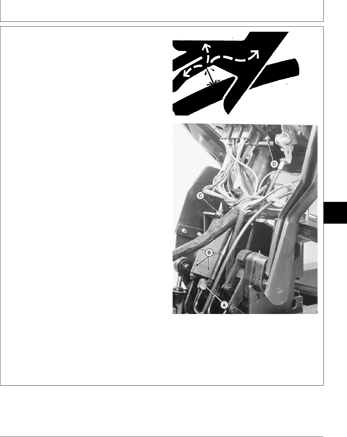
IMPORTANT: Do not pound on end of steering shaft
or damage to steering shaft will occur.
7. Remove steering wheel.
NCAUTION: To avoid injury from escaping fluid
under pressure, stop engine and relieve the
pressure in the system before disconnecting or
connecting hydraulic or other lines. Tighten all
connections before applying pressure.
8. Disconnect five hydraulic lines (A) from bottom of
steering valve.
9. Hold top of steering column and remove mounting
nuts (C).
10. Remove steering column-to-dash panel mounting
bracket (D).
11. Remove steering unit out the right side of the
machine.
12. Make repairs as necessary. (See procedure in this
group.)
13. Installation is done in the reverse order of removal.
• Install steering unit with alignment grooves (B) in port
manifold and cover, facing engine.
• Tighten steering wheel-to-shaft nut to 15 N·m (133
lb-in.).
•Close drain valve and fill radiator with proper coolant
until coolant is 13—25 mm (0.500—1 in.) below bottom
of filler neck. (See Engine Coolant in Section 10, Group
25.)
• Bleed hydraulic system. (See procedure in Section 270, A—Hydraulic Lines (5)
Group 20.) B—Alignment Grooves
C—Mounting Nuts
D—Mounting Bracket
X9811 -UN-23AUG88
M49509 -UN-20DEC89
MX,15916006,2 -19-13JUL95
Steering—322, 332 and 430/Steering Valve and Column
TM1591 (15JUL95) 60-06-3 322,330,332 & 430 Lawn & Garden Tractors
030895
60
06
3
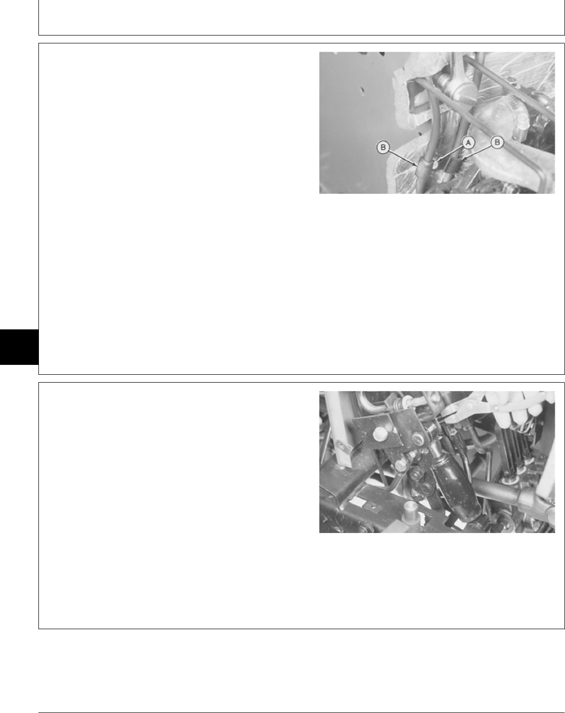
REMOVE AND INSTALL STEERING VALVE
AND COLUMN—430
NOTE: Removal and installation procedures for later
models may vary slightly.
1. Remove fender deck.
2. Remove belly pan.
3. Lift hood and remove front grille and engine side
panels.
4. Remove battery and battery base.
5. Remove cap screw and clamp.
6. Remove cap screw (A) and clamps (B).
7. Remove right-hand pedestal side.
M36498 -UN-29JAN90
NOTE: There are three versions of the transmission
control linkage. Version one on early models is
shown. See Group 10, in this section, to confirm
which version your machine is equipped with. It
may not be necessary to perform some Steps if
equipped with later versions of linkage on later
models.
8. Early Models; Remove snap ring and pin to remove
shock absorber.
Early Models Shown
M36501 -UN-29JAN90
MX,15916006,3 -19-13JUL95
MX,15916006,4 -19-13JUL95
Steering—322, 332 and 430/Steering Valve and Column
TM1591 (15JUL95) 60-06-4 322,330,332 & 430 Lawn & Garden Tractors
030895
60
06
4
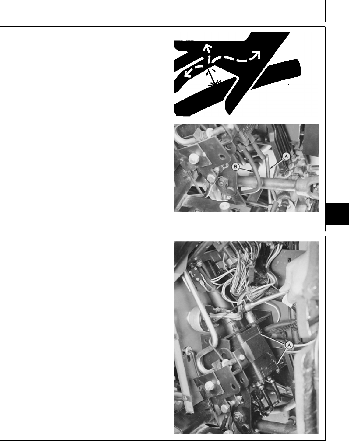
NCAUTION: To avoid injury from escaping fluid
under pressure, stop engine and relieve the
pressure in the system before disconnecting or
connecting hydraulic or other lines. Tighten all
connections before applying pressure.
9. Remove hydraulic lines (A and B).
10. Disconnect three remaining hydraulic lines from
bottom of steering valve.
X9811 -UN-23AUG88
M36817 -UN-25JAN90
IMPORTANT: Do not pound on end of steering shaft
or damage to steering shaft will occur.
11. Remove steering wheel.
12. Hold top of steering column and remove four
mounting nuts. Remove steering unit from machine.
13. Make repairs as necessary. (See procedure in this
group.)
14. Installation is done in the reverse order of removal.
• Install steering unit with alignment grooves (A) in port
manifold and cover, facing engine.
• Tighten steering wheel-to-shaft nut to 15 N·m (133
lb-in.).
• Bleed hydraulic system. (See procedure in Section 270,
Group 20.)
M36820 -UN-25JAN90
MX,15916006,5 -19-13JUL95
MX,15916006,6 -19-13JUL95
Steering—322, 332 and 430/Steering Valve and Column
TM1591 (15JUL95) 60-06-5 322,330,332 & 430 Lawn & Garden Tractors
030895
60
06
5
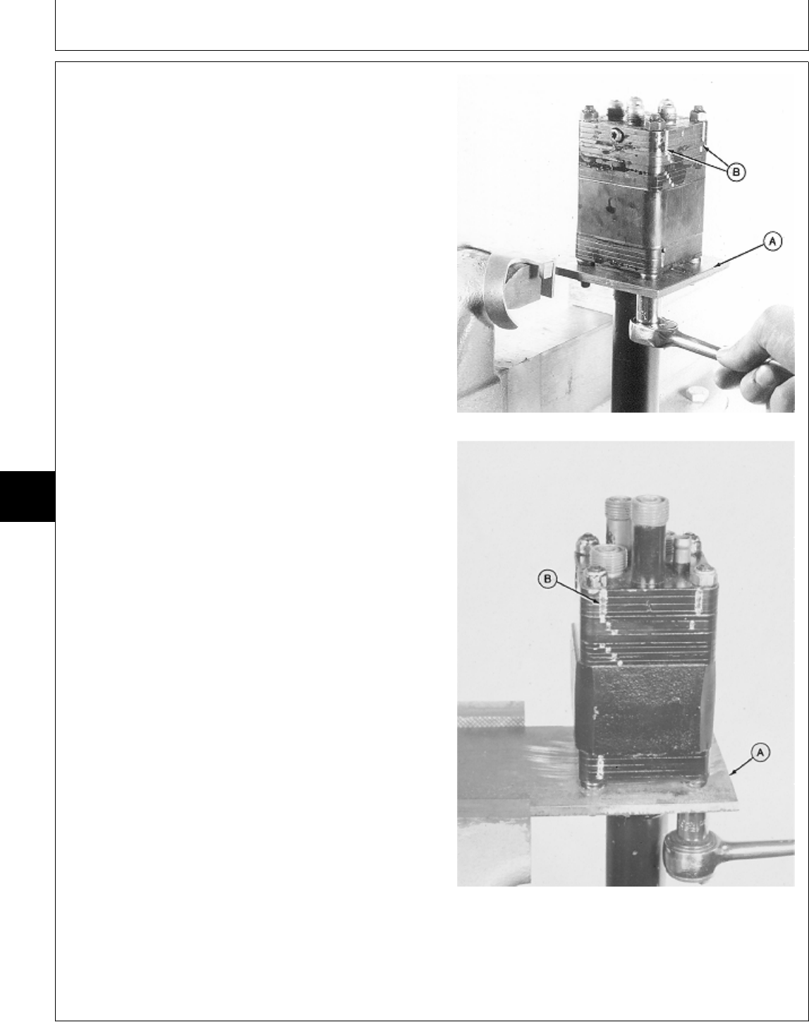
DISASSEMBLE AND INSPECT STEERING
VALVE AND COLUMN
NOTE: There are early and later versions of steering
valve. The early version had a plug, O-ring and
check ball in the side of the port cover. The later
version has a check ball in the center of the port
cover (internal) and no external plug or O-ring.
IMPORTANT: Use DFMX1 Steering Valve Fixture
when servicing control valve. Holding
control valve in a vise can damage
valve.
1. Install DFMX1 Steering Valve Fixture (A) in a vise.
(See Section 299 for instructions to make fixture.)
2. Install steering valve, with steering column down, in
fixture. Fasten valve to fixture using four 5/16-24 UNF
nuts. Early Version—322 and 332
3. Check position of alignment grooves (B) to aid in
assembly.
Early Version—430
M43839 -UN-06MAR95M36831 -UN-29AUG88
MX,15916006,7 -19-13JUL95
Steering—322, 332 and 430/Steering Valve and Column
TM1591 (15JUL95) 60-06-6 322,330,332 & 430 Lawn & Garden Tractors
030895
60
06
6
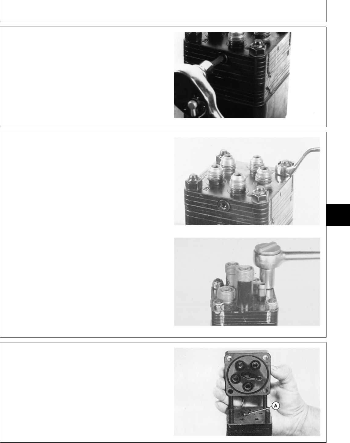
4. Early version; Loosen plug one turn.
M77338 -UN-21FEB95
IMPORTANT: Do not damage fittings during nut
removal. Do not nick or scratch the
machined surfaces of the steering
valve.
5. Remove nuts to remove port cover assembly (four
plates bonded together).
Early Version—322 and 332
Early Version—430
M43841 -UN-08JAN90M36833 -UN-29AUG88
6. Later version; Remove port cover and check ball (A).
M77303 -UN-06MAR95
MX,15916006,16 -19-13JUL95
MX,15916006,8 -19-13JUL95
MX,15916006,17 -19-13JUL95
Steering—322, 332 and 430/Steering Valve and Column
TM1591 (15JUL95) 60-06-7 322,330,332 & 430 Lawn & Garden Tractors
030895
60
06
7
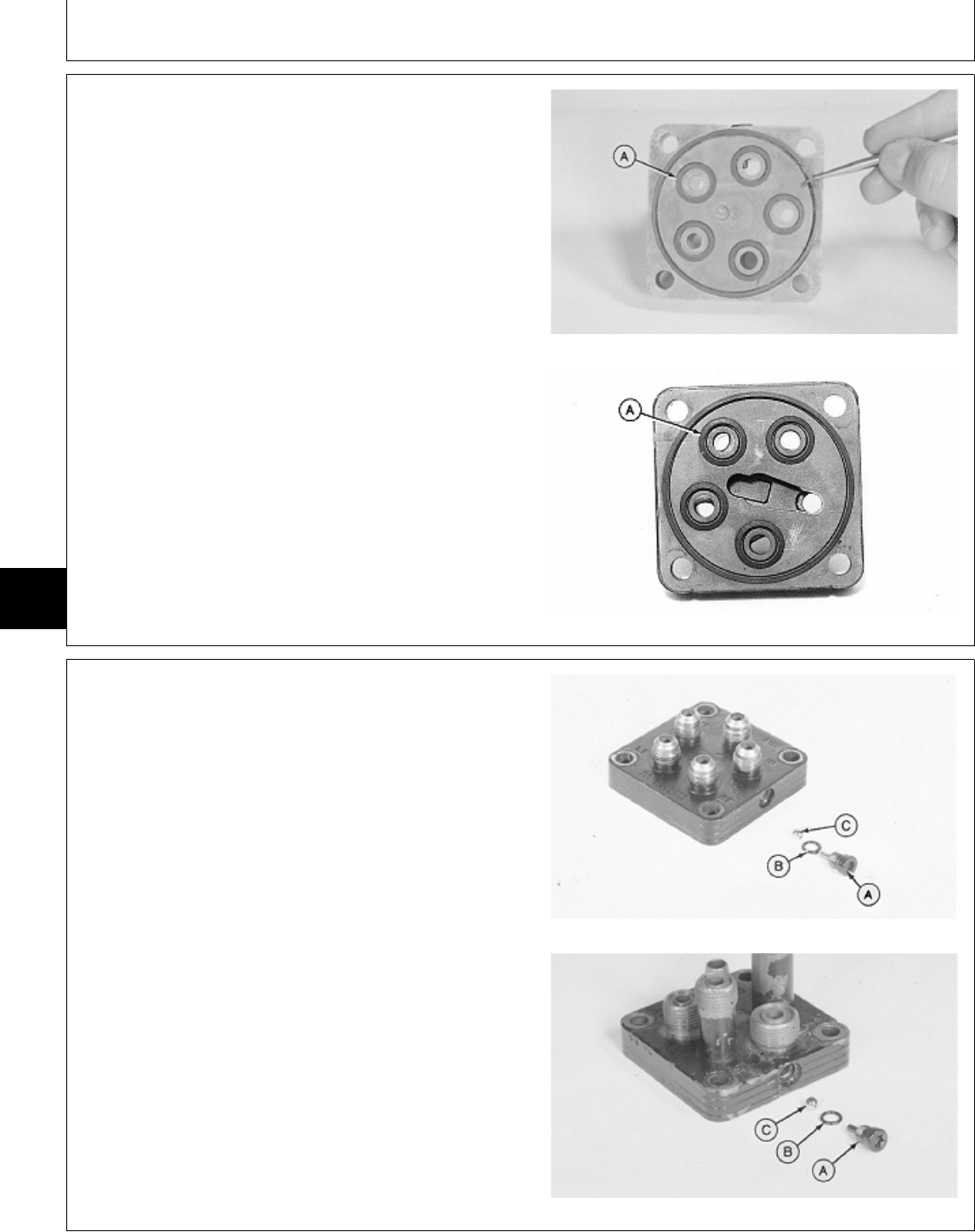
7. Remove seal ring and O-rings (A).
8. Inspect port cover for scratches on machined surfaces
or damage to fittings. Replace cover if damaged.
Early Version
Later Version
M36834 -UN-29AUG88M78056 -UN-06MAR95
9. Early version; Remove plug (A), O-ring (B) and check
ball (C).
322 and 332
430
M43832 -UN-08JAN90M36835 -UN-29AUG88
MX,15916006,18 -19-13JUL95
MX,15916006,9 -19-13JUL95
Steering—322, 332 and 430/Steering Valve and Column
TM1591 (15JUL95) 60-06-8 322,330,332 & 430 Lawn & Garden Tractors
030895
60
06
8
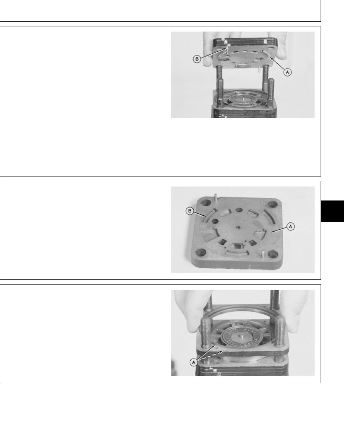
NOTE: Port manifold has three springs which may come
loose during disassembly.
10. Carefully remove port manifold (three plates bonded
together).
IMPORTANT: Do not interchange springs. The
steering valve has two sets of springs.
Keep springs with respective manifold.
11. Remove three springs (A).
NOTE: If one or more springs are damaged, all six
springs in valve must be replaced.
12. Inspect springs and pins (B) for distortion, wear, or
damage.
M36836 -UN-29AUG88
13. Inspect port manifold machined surfaces (A) for
scratches or scoring. A polished pattern from the rotation
of the valve plate and hex drive assembly is normal. All
edges (B) must be sharp, free of nicks and burrs.
NOTE: Scoring is indicated by fine scratches or grooves
cut into the manifold. When these scratches can
be detected by feel finger nail or lead pencil, the
manifold should be replaced.
M36837 -UN-29AUG88
14. Remove the valve ring and two seal rings (A). Check
valve ring for nicks and scoring. If the valve ring is
damaged, it must be replaced.
M36838 -UN-29AUG88
MX,15906006,10 -19-10MAR95
MX,15906006,11 -19-01MAR95
MX,15906006,12 -19-01MAR95
Steering—322, 332 and 430/Steering Valve and Column
TM1591 (15JUL95) 60-06-9 322,330,332 & 430 Lawn & Garden Tractors
030895
60
06
9
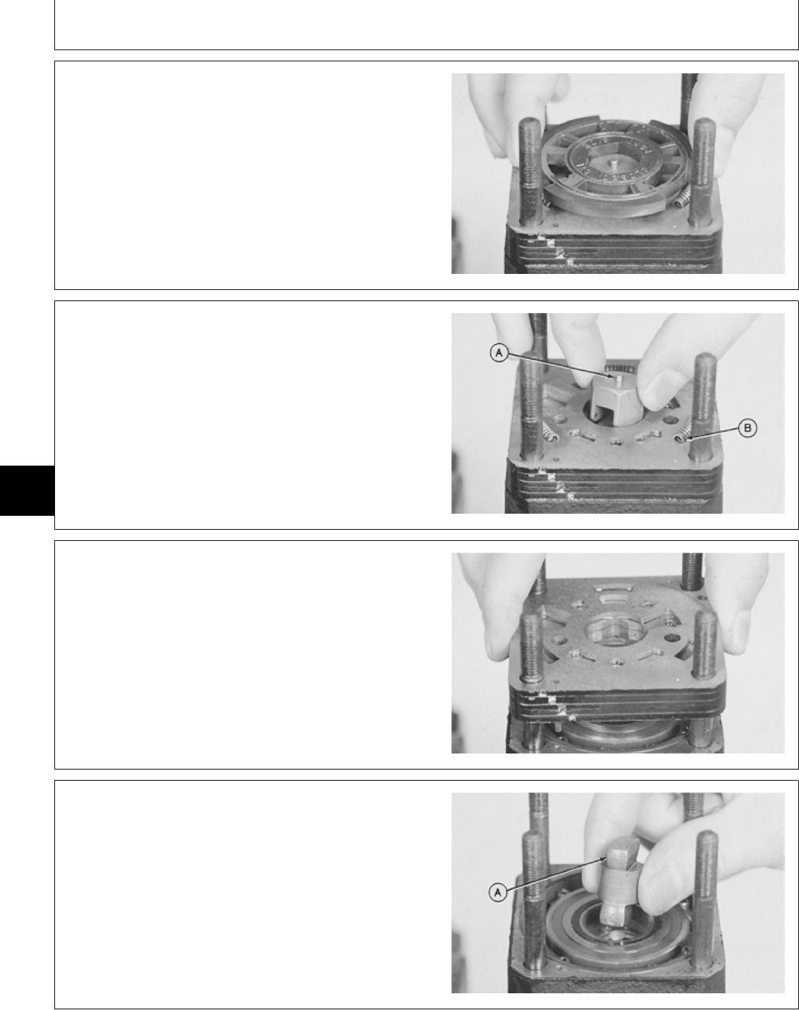
15. Remove valve plate. Inspect the slots and ground
surfaces for nicks or wear. If the valve plate is scored or
the edges are not sharp, the valve plate and valve ring
both must be replaced.
M36839 -UN-29AUG88
16. Remove and inspect hex drive assembly. Check
sides and slot for wear, grooves, or scoring. Pin (A)
should be tight and show no wear or damage.
17. Remove three springs (B).
18. Inspect springs for broken coils, wear, or damage.
M36840 -UN-29AUG88
19. Remove the isolation manifold (four plates bonded
together). Check manifold surface, holes and edges for
nicks, or unusual wear. A polished pattern from the
rotation of the valve plate and commutator cover is
normal.
M36841 -UN-29AUG88
20. Remove drive link. Check the four crowned surfaces
(A) for wear or scoring.
M36842 -UN-29AUG88
MX,15906006,13 -19-01MAR95
MX,15906006,14 -19-01MAR95
MX,15906006,15 -19-01MAR95
MX,15906006,16 -19-01MAR95
Steering—322, 332 and 430/Steering Valve and Column
TM1591 (15JUL95) 60-06-10 322,330,332 & 430 Lawn & Garden Tractors
030895
60
06
10
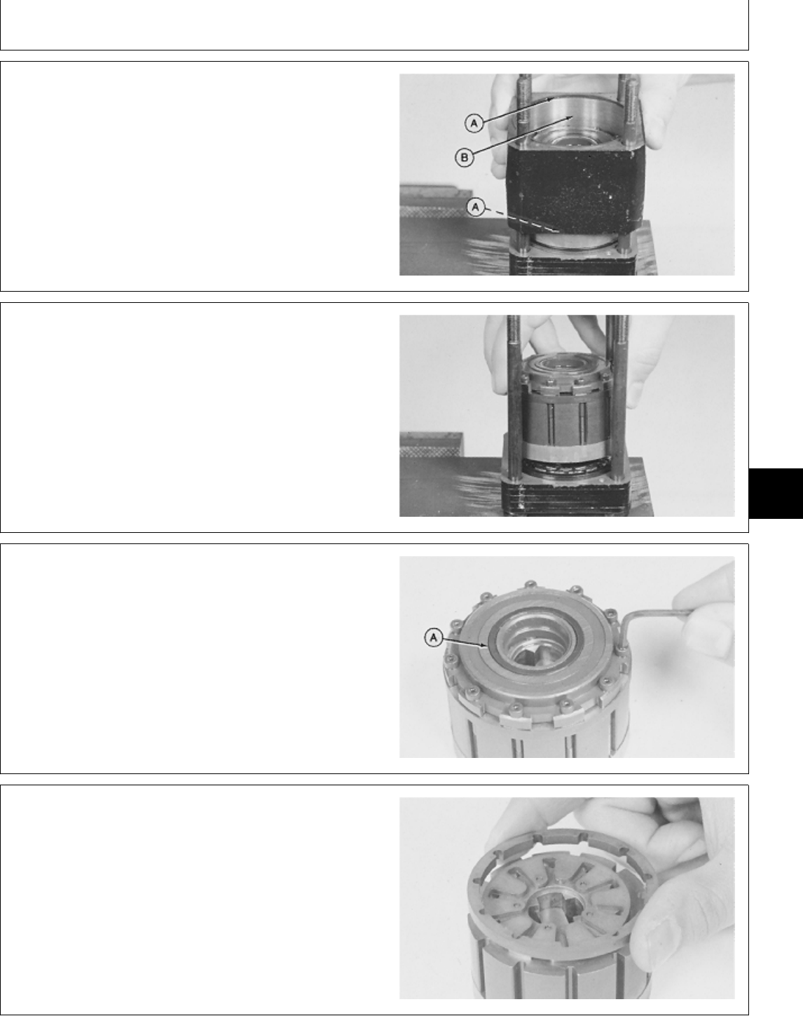
21. Remove metering ring and upper and lower seals
(A). If the bore (B) is scored, the metering ring must be
replaced.
M36843 -UN-29AUG88
IMPORTANT: Do not clamp metering assembly in a
vise.
22. Remove metering assembly. Put assembly on a
clean surface.
M36844 -UN-29AUG88
23. Remove commutator seal (A).
24. Remove 11 screws to remove commutator cover.
Inspect screws for damage and replace if necessary.
25. Check commutator cover machined surface for nicks,
burrs, scoring, or unusual wear. A polished pattern due
to rotation of the commutator is normal.
M36845 -UN-29AUG88
IMPORTANT: Handle commutator ring with care; it is
easily broken.
26. Remove commutator ring and inspect for wear, burrs,
cracks, or scoring.
NOTE: The commutator ring and commutator are a
matched set. If either is worn or damaged, both
must be replaced.
M36847 -UN-29AUG88
MX,15906006,17 -19-01MAR95
MX,15906006,18 -19-01MAR95
MX,15906006,19 -19-01MAR95
MX,15906006,20 -19-01MAR95
Steering—322, 332 and 430/Steering Valve and Column
TM1591 (15JUL95) 60-06-11 322,330,332 & 430 Lawn & Garden Tractors
030895
60
06
11
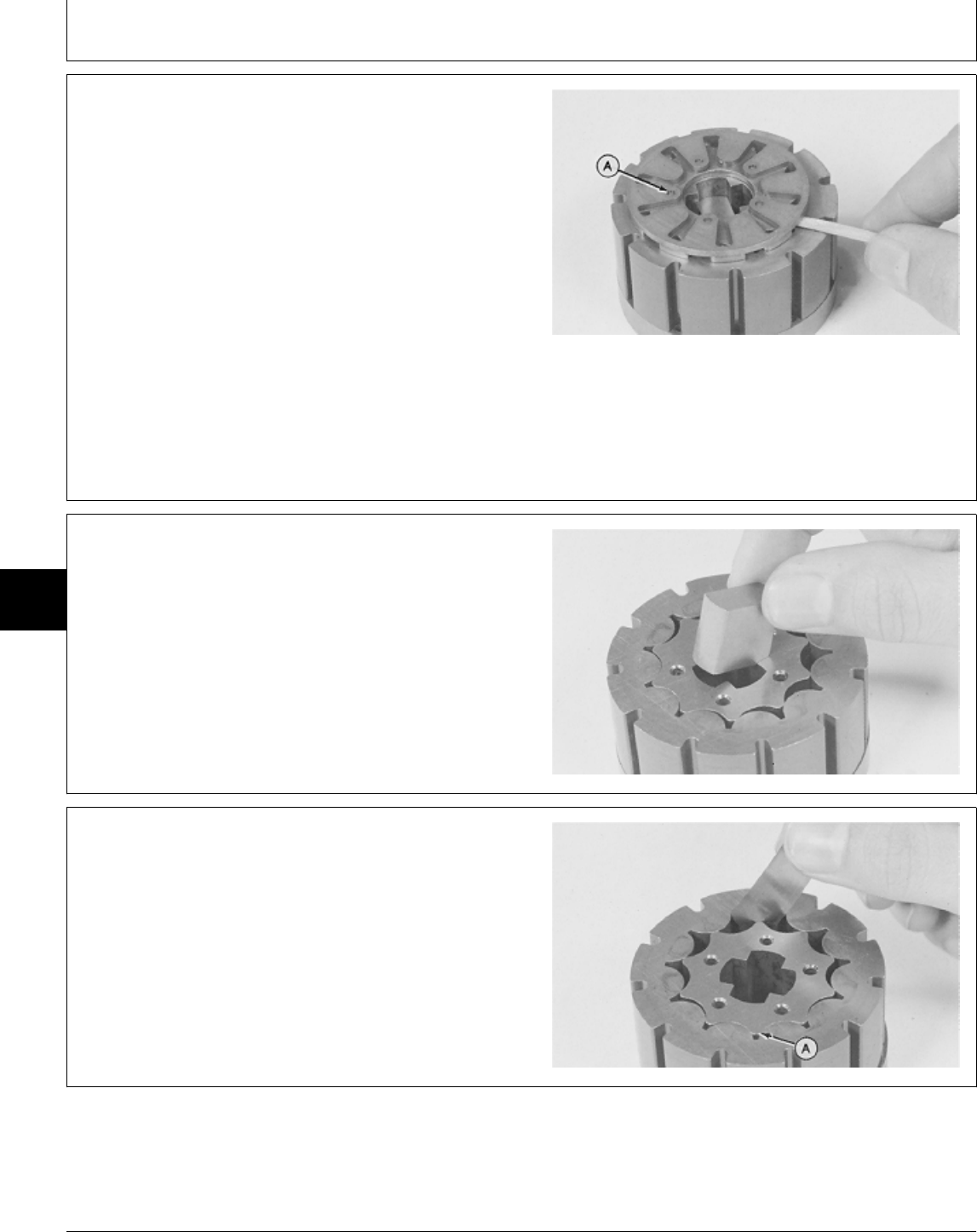
IMPORTANT: DO NOT use a screwdriver to remove
commutator. Commutator can be
damaged.
27. Remove commutator and five pins (A) using a wood
dowel or equivalent.
NOTE: The commutator is made up of two plates
bonded together. It is a permanent assembly and
cannot be disassembled.
28. Check commutator machined surface, holes and
edges for nicks. Edges must be sharp.
M36848 -UN-29AUG88
29. Remove drive link spacer. Check spacer for grooves,
wear, or damage.
30. The rotor should rotate and orbit freely within the
stator. Check commutator side of stator face for grooves
or scoring.
NOTE: Stator and rotor are a matched set. If either are
worn or damaged, both must be replaced.
M36849 -UN-29AUG88
31. Measure rotor-to-stator clearance. Center rotor lobe
(A) between stator lobes and check clearance directly
opposite lobe (A).
If rotor-to-stator clearance is more than 0.08 mm (0.003
in.), replace rotor and stator.
M36850 -UN-29AUG88
MX,15906006,21 -19-01MAR95
MX,15906006,22 -19-01MAR95
MX,15906006,23 -19-01MAR95
Steering—322, 332 and 430/Steering Valve and Column
TM1591 (15JUL95) 60-06-12 322,330,332 & 430 Lawn & Garden Tractors
030895
60
06
12
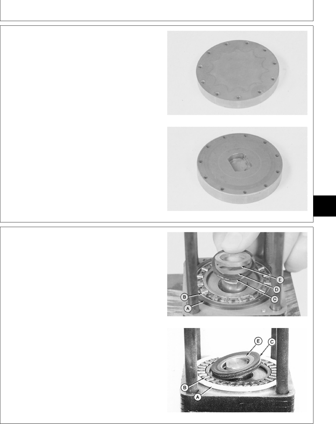
32. Lift the rotor and stator from the drive plate.
33. Check the drive plate side of the rotor assembly for
nicks, grooves, or scoring. A spiral pattern due to rotor
movement is normal.
The thrust bearing side of the plate should also show a
normal wear pattern without grooves, flaking, or dents.
The flat sides of the input shaft hole should not be
grooved or worn.
Drive Plate Side
Thrust Bearing Side
M36851 -UN-29AUG88M36852 -UN-29AUG88
NOTE: Early versions had a seal spacer and backup
ring. Later versions have a seal spacer only.
34. Remove parts (A—E).
35. Inspect parts for wear or damage. Replace if
necessary.
A—Thrust Bearing Spacer
B—Thrust Bearing
C—Face Seal
D—Backup-Ring (Early Version)
E—Seal Spacer Early Version
Later Version
M36853 -UN-29AUG88M77305 -UN-06MAR95
MX,15906006,24 -19-01MAR95
MX,15916006,19 -19-13JUL95
Steering—322, 332 and 430/Steering Valve and Column
TM1591 (15JUL95) 60-06-13 322,330,332 & 430 Lawn & Garden Tractors
030895
60
06
13
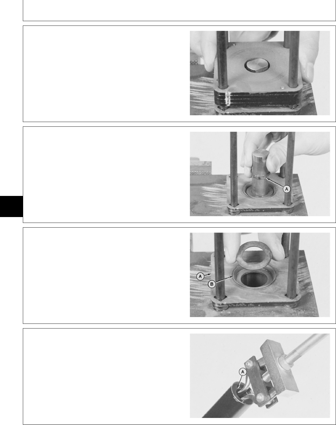
36. Remove upper cover plate (four plates bonded
together).
37. Check plate surface for grooves, dents, or metal
flakes. A polished pattern due to the action of the seal is
normal.
M36854 -UN-29AUG88
38. Remove steering shaft and snap ring (A).
39. Inspect steering shaft serrations, threads, and flats
for grooves, wear, or damage.
M36855 -UN-29AUG88
40. Remove washer and steering tube (A).
NOTE: Steering tube and retaining plate (B) are a
matched set. If either part is worn or damaged,
both must be replaced.
M36856 -UN-29AUG88
IMPORTANT: Hold steering tube in a soft-jaw vice.
Be careful not to crush steering tube.
41. Inspect bushing (A) for wear or damage. If bushing
replacement is necessary, straighten crimped area of
steering tube using a punch.
42. Remove bushing using a 2-jaw puller and slide
hammer.
M36857 -UN-29AUG88
MX,15906006,26 -19-01MAR95
MX,15906006,27 -19-01MAR95
MX,15906006,28 -19-01MAR95
MX,15906006,29 -19-01MAR95
Steering—322, 332 and 430/Steering Valve and Column
TM1591 (15JUL95) 60-06-14 322,330,332 & 430 Lawn & Garden Tractors
030895
60
06
14
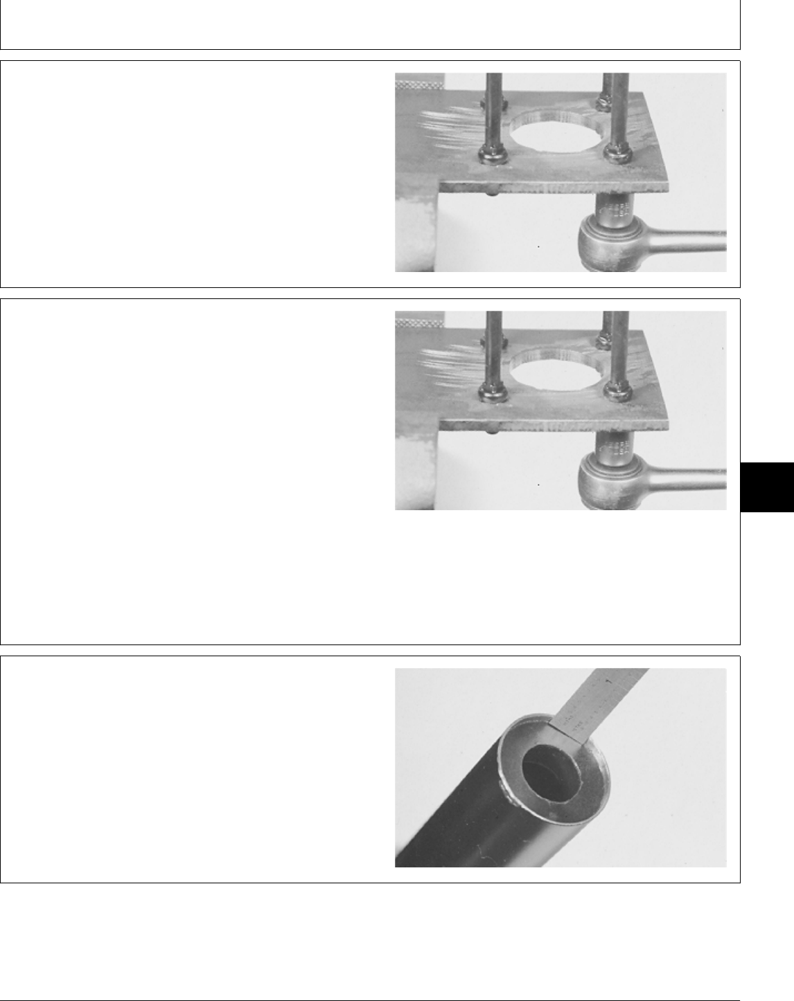
43. Remove nuts holding the four bolts to the fixture,
and remove the bolts.
44. Inspect bolts for wear or damage. Replace if
necessary.
M36858 -UN-29AUG88
ASSEMBLE STEERING VALVE AND
COLUMN
IMPORTANT: Always use new seals and O-rings.
Damaged or used parts will leak.
NOTE: Lubricate all seals and O-rings with petroleum
jelly during assembly.
1. Apply clean John Deere Low Viscosity HY-GARD® oil
on all internal parts.
2. Install four bolts, with short threaded end down, in
fixture. Install nuts and tighten finger tight.
M36858 -UN-29AUG88
3. Install bushing into steering tube with recess facing
into tube, using a driver set. Install bushing 2.5 mm
(0.100 in.) below top of steering tube.
4. Slightly bend edges of steering tube over bushing
using a punch.
5. Apply multipurpose grease to inside of bushing.
M36860 -UN-29AUG88
MX,15906006,30 -19-01MAR95
MX,15916006,10 -19-13JUL95
MX,15906006,32 -19-01MAR95
Steering—322, 332 and 430/Steering Valve and Column
TM1591 (15JUL95) 60-06-15 322,330,332 & 430 Lawn & Garden Tractors
030895
60
06
15
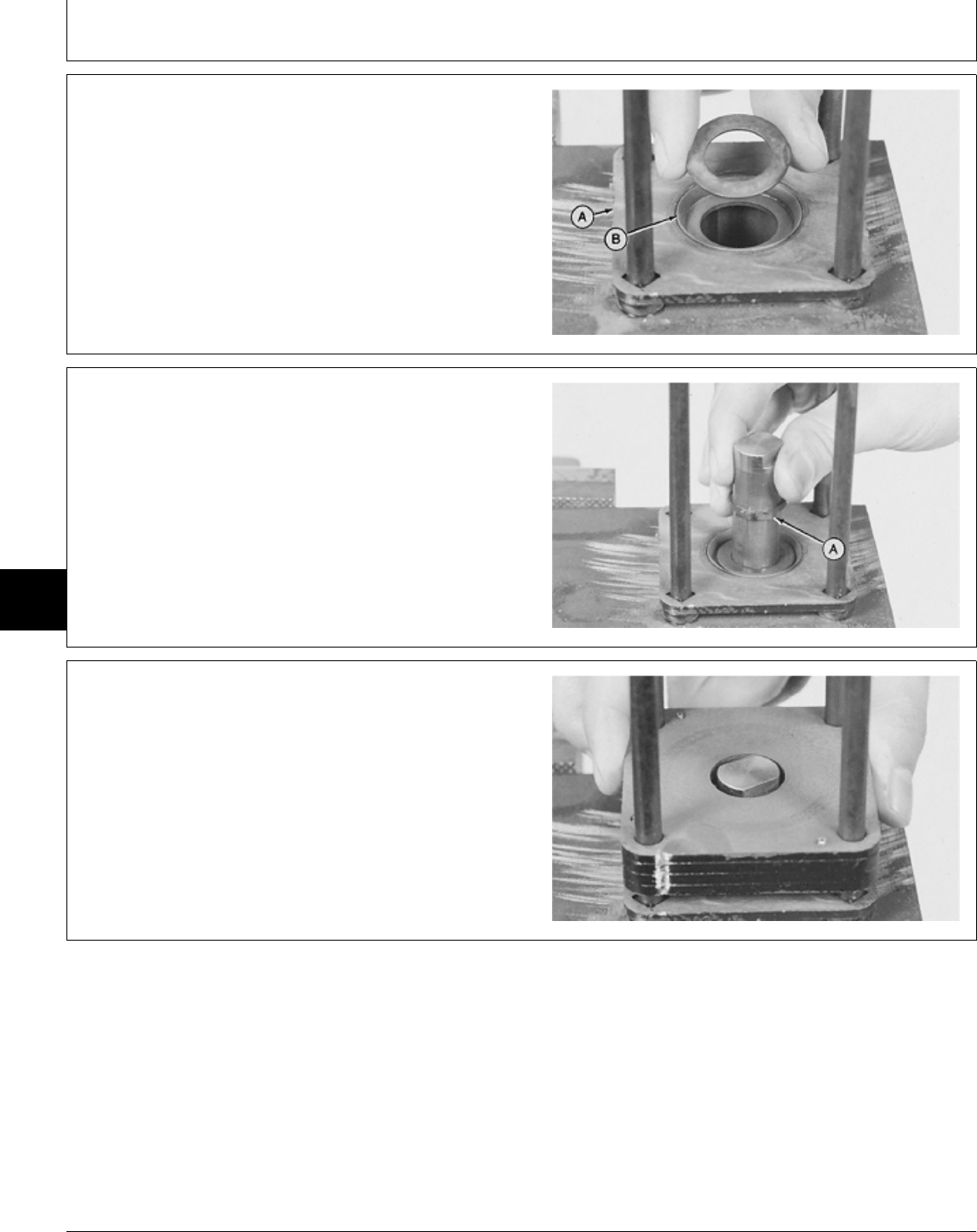
6. Install steering tube (A) on bolts. Be sure the square
holes in the steering tube are seated on the square
shoulders of the bolts.
7. Apply multipurpose grease on retainer plate (B) and
washer.
8. Install washer.
M36856 -UN-29AUG88
9. Install snap ring (A) on steering shaft.
10. Install steering shaft with threaded end down into
steering tube.
M36855 -UN-29AUG88
IMPORTANT: Alignment grooves must be on only
one side of steering valve for proper
valve operation.
11. Install upper cover plate over four bolts with the
highly polished surface up.
M36854 -UN-29AUG88
MX,15906006,33 -19-01MAR95
MX,15906006,34 -19-01MAR95
MX,15906006,35 -19-01MAR95
Steering—322, 332 and 430/Steering Valve and Column
TM1591 (15JUL95) 60-06-16 322,330,332 & 430 Lawn & Garden Tractors
030895
60
06
16
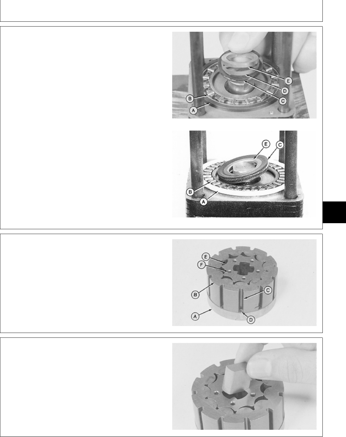
12. Apply multipurpose grease on the face of the upper
cover plate, steering shaft end and thrust bearing (B).
NOTE: Wide shoulder of spacer (A) faces up, away from
upper cover plate.
13. Install parts (A—E).
A—Thrust Bearing Spacer
B—Thrust Bearing
C—Face Seal
D—Backup-Ring (Early Version)
E—Seal Spacer Early Version
Later Version
M36853 -UN-29AUG88M77305 -UN-06MAR95
14. Put drive plate (A) on a clean surface with slot
downward.
15. Install and turn stator (B) until the stator slots (C) are
aligned with drive plate holes (D).
16. Install rotor (E) with five pin holes (F) up.
A—Drive Plate D—Drive Plate Hole (11)
B—Stator E—Rotor
C—Stator Slot (11) F—Pin Hole (5)
M36861 -UN-29AUG88
17. Apply multipurpose grease on spacer.
18. Install spacer in rotor drive slot.
M36849 -UN-29AUG88
MX,15916006,20 -19-13JUL95
MX,15906006,37 -19-01MAR95
MX,15906006,38 -19-01MAR95
Steering—322, 332 and 430/Steering Valve and Column
TM1591 (15JUL95) 60-06-17 322,330,332 & 430 Lawn & Garden Tractors
030895
60
06
17
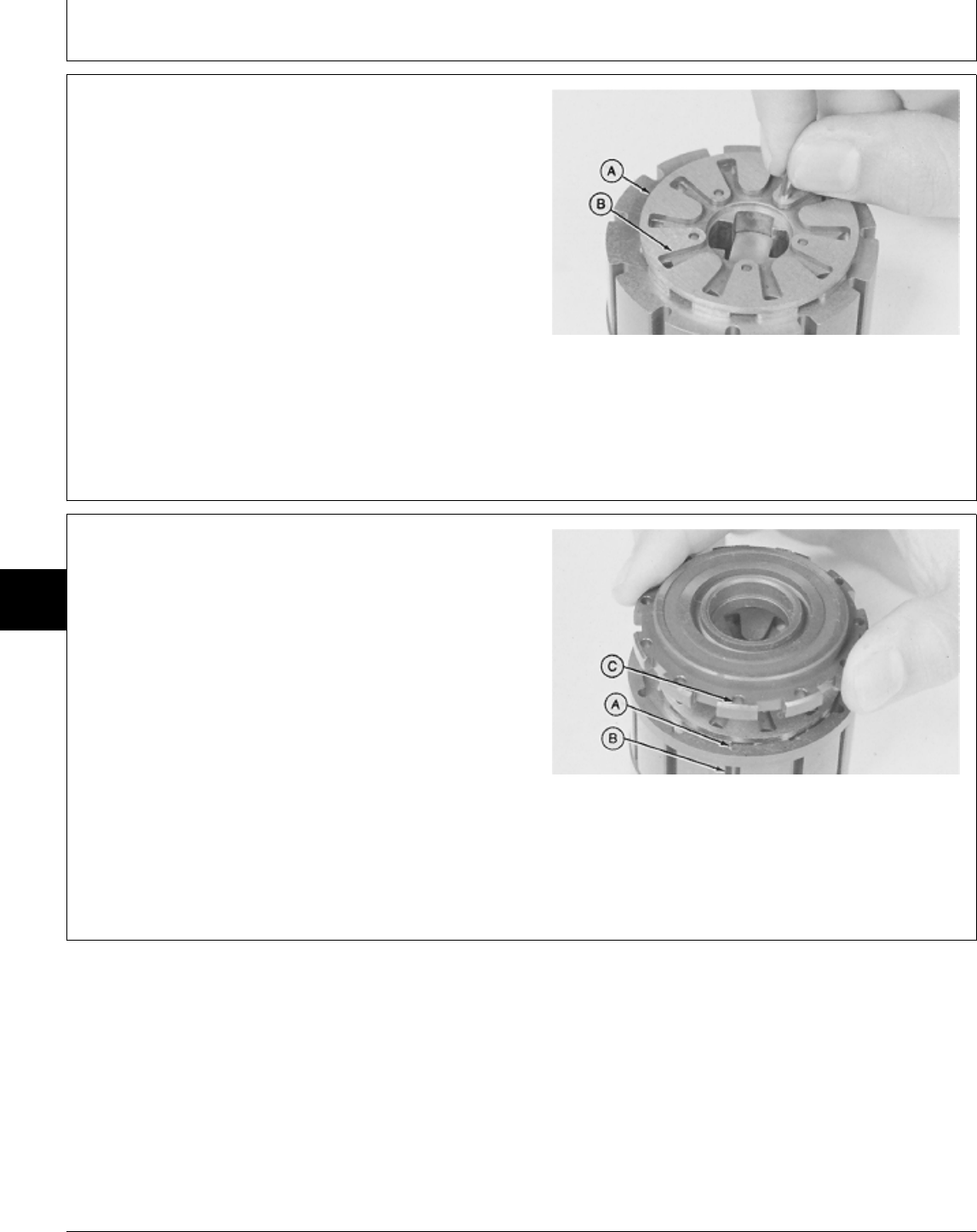
19. Install commutator (A) on rotor, with long grooves (B)
upward.
IMPORTANT: Pins must be installed below the
surface of the commutator to prevent
commutator cover damage.
20. Align commutator holes with rotor holes and install
five pins.
21. Put a few drops of clean John Deere Low Viscosity
HY-GARD® oil into each groove of the commutator.
M36862 -UN-29AUG88
22. Align commutator ring slots (A) with stator slots (B)
and install commutator ring.
23. Align commutator cover holes (C) with commutator
ring slots. Install commutator cover with flat surface
toward commutator.
24. Clean screw threads using Clean and Cure Primer.
Apply Thread Lock and Sealer (low strength) to threads
of commutator cover-to-commutator screws.
25. Install 11 screws into metering assembly. DO NOT
tighten screws at this time.
M36863 -UN-29AUG88
MX,15906006,39 -19-01MAR95
MX,15906006,40 -19-01MAR95
Steering—322, 332 and 430/Steering Valve and Column
TM1591 (15JUL95) 60-06-18 322,330,332 & 430 Lawn & Garden Tractors
030895
60
06
18
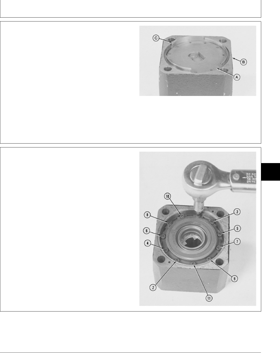
IMPORTANT: The following procedure must be used
to minimize an out-of-round condition
between commutator ring and drive
plate. The commutator ring is
self-centering when the drive plate is
shimmed. Use DFMX2 Alignment
Shims.
26. Install metering assembly, with drive plate (A) up into
metering ring (B).
27. Install two DFMX2 Alignment Shims (C) each
between drive plate and metering ring 120˚ apart. (See
Section 299 for instructions to make shims.)
M36864 -UN-29AUG88
28. Turn metering ring over on a flat surface and push
metering assembly down. Tighten 11 screws in several
steps and in the sequence shown to 1.4 N·m (12 lb-in.).
M36865 -UN-29AUG88
MX,15916006,11 -19-13JUL95
MX,15906006,42 -19-01MAR95
Steering—322, 332 and 430/Steering Valve and Column
TM1591 (15JUL95) 60-06-19 322,330,332 & 430 Lawn & Garden Tractors
030895
60
06
19
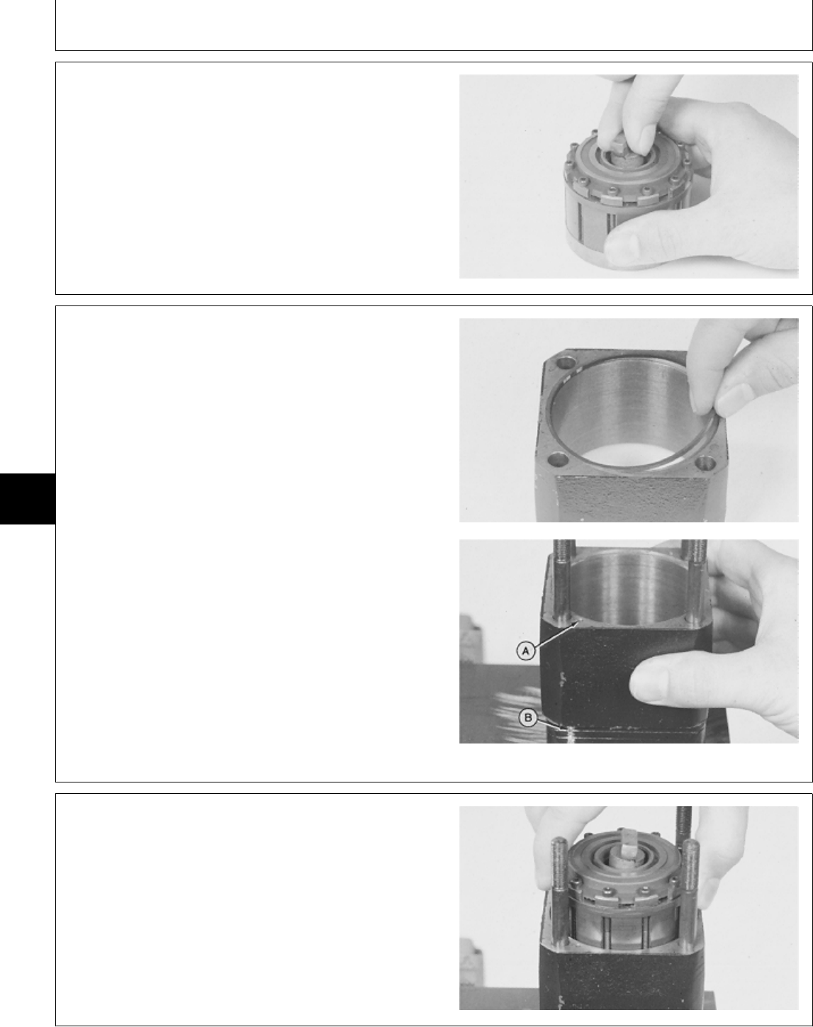
29. Remove Shims and metering assembly from
metering ring.
30. Install THICK end of drive link into the slot in the
rotor. Hold the drive link and rotate the metering
assembly by hand. The rotor should turn freely inside the
stator.
If the rotor binds or does not move, disassemble and
inspect to find the cause.
M36866 -UN-29AUG88
31. Apply petroleum jelly on seal ring. Install seal ring on
metering ring end without pin holes.
IMPORTANT: Align pin hole (A) in metering ring with
groove (B) on upper cover plate so that
remaining parts can be aligned
correctly.
32. Install metering ring over bolts with pin holes up.
M36867 -UN-29AUG88M36879 -UN-29AUG88
33. Apply multipurpose grease on drive plate surface.
34. Install metering assembly, with drive plate down, into
metering ring. Turn metering assembly until the steering
shaft engages the drive plate hole. When properly
seated, the metering assembly is below the surface of
the metering ring.
M36868 -UN-29AUG88
MX,15906006,43 -19-29MAR95
MX,15906006,44 -19-01MAR95
MX,15906006,45 -19-01MAR95
Steering—322, 332 and 430/Steering Valve and Column
TM1591 (15JUL95) 60-06-20 322,330,332 & 430 Lawn & Garden Tractors
030895
60
06
20
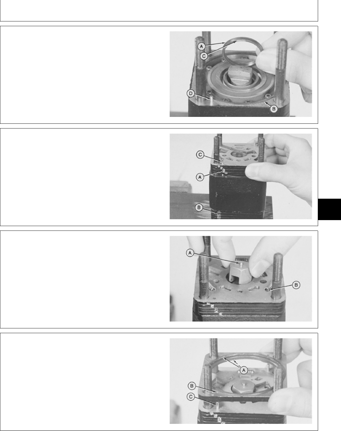
35. Apply petroleum jelly on new commutator seal (A)
and seal ring (B).
36. Install new commutator seal with yellow mark (C) or
narrow edge, down into commutator cover.
37. Install seal ring (B) and pins (D).
A—Commutator Seal
B—Seal Ring
C—Yellow Mark or Narrow Edge
D—Pin (2 used)
M36869 -UN-29AUG88
IMPORTANT: Align grooves (A) in isolation manifold
with groove (B) in upper cover plate.
38. Install isolation manifold, with recessed slots up, on
metering ring.
39. Install pins (C).
M36870 -UN-29AUG88
40. Install three 13 mm (1/2 in.) springs (B) in recessed
slots of the isolation manifold.
41. Install hex drive assembly, with pin (A) up, on drive
link.
M36840 -UN-29AUG88
42. Apply petroleum jelly on new seal rings (A). Install
seal rings on valve ring.
43. Align valve ring holes (B) with pins (C) to install
valve ring.
M36871 -UN-29AUG88
MX,15906006,46 -19-01MAR95
MX,15906006,47 -19-01MAR95
MX,15906006,48 -19-01MAR95
MX,15906006,49 -19-01MAR95
Steering—322, 332 and 430/Steering Valve and Column
TM1591 (15JUL95) 60-06-21 322,330,332 & 430 Lawn & Garden Tractors
030895
60
06
21
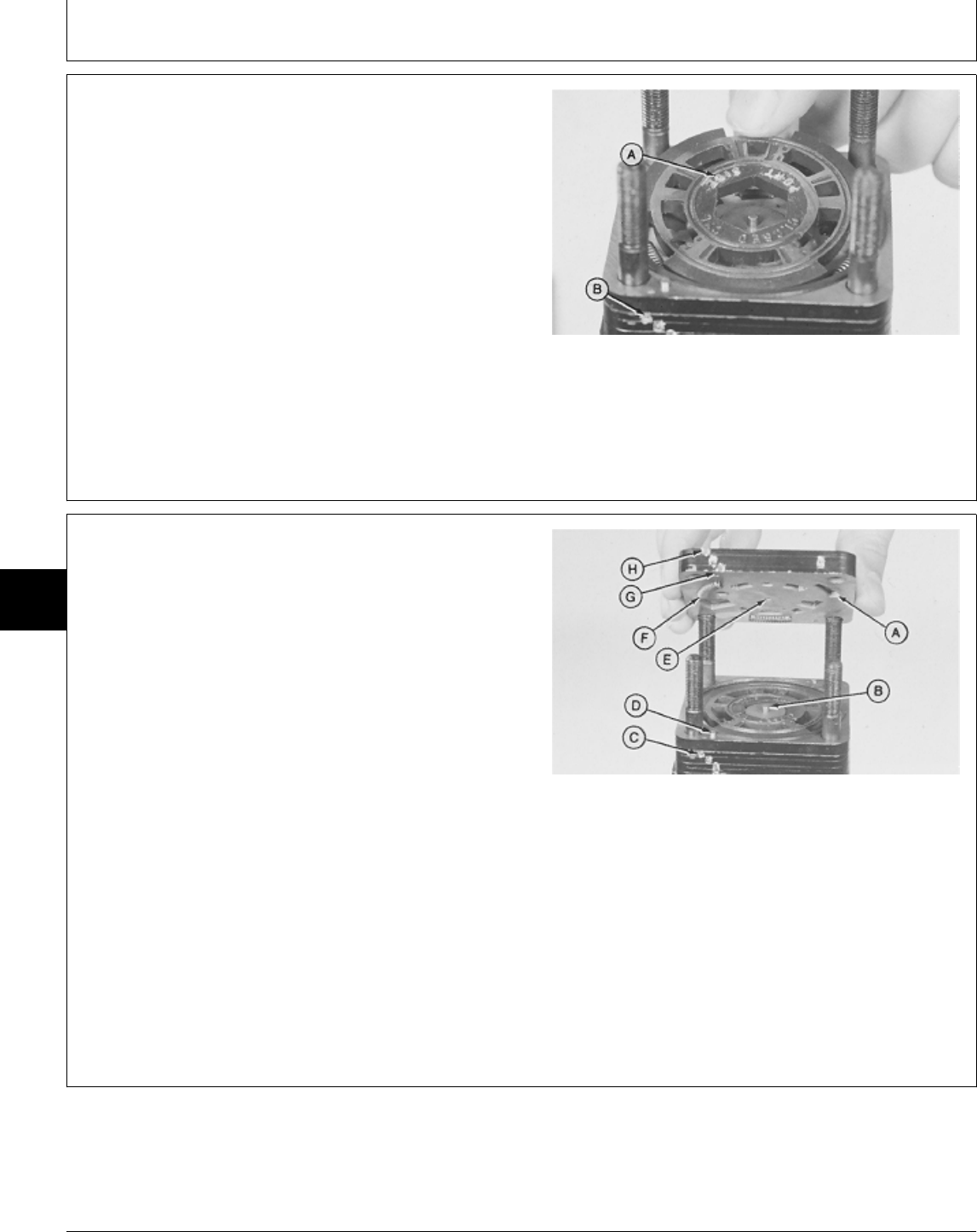
IMPORTANT: Valve plate must be installed with
“PORT SIDE” (A) directly opposite (12
o’clock position) from alignment groves
(B) for proper operation. Valve plate
spring slots and springs must be
aligned to prevent spring damage when
installing port manifold.
44. Install valve plate, with “PORT SIDE” up, on isolation
manifold. Turn valve plate to make sure springs are
centered in valve plate spring slots.
45. Apply clean John Deere Low Viscosity HY-GARD® oil
on valve plate.
M36872 -UN-29AUG88
46. Install three 25 mm (1 in.) springs (F) in recessed
slots (A) of the port manifold.
IMPORTANT: Align grooves (H) in port manifold with
grooves (C) in isolation manifold. Be
careful not to damage springs while
installing port manifold.
47. Install port manifold with springs toward valve plate.
Be sure pins (D) engage alignment holes (G) in port
manifold. Be sure hex drive assembly pin (B) engages
center hole (E) in port manifold.
A—Recessed Slots
B—Hex Drive Assembly Pin
C—Isolation Manifold Grooves
D—Pin (2 used)
E—Port Manifold Center Hole
F—25 mm (1 in.) Spring (3 used
G—Port Manifold Alignment Hole (2 used)
H—Port Manifold Grooves
M36873 -UN-29AUG88
MX,15906006,50 -19-01MAR95
MX,15906006,51 -19-12MAY95
Steering—322, 332 and 430/Steering Valve and Column
TM1591 (15JUL95) 60-06-22 322,330,332 & 430 Lawn & Garden Tractors
030895
60
06
22
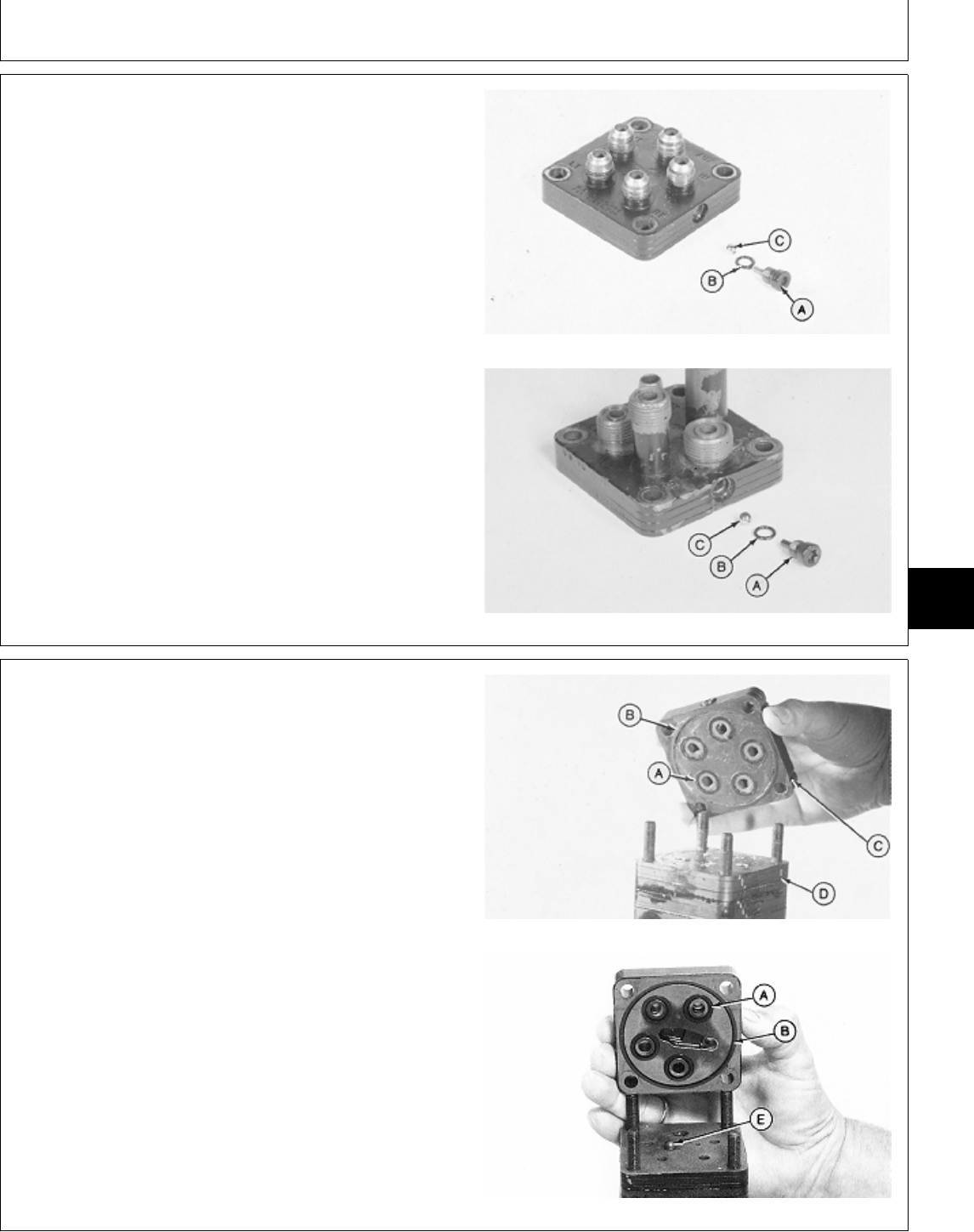
48. Early version; Install new O-ring (B) on plug (A).
Install check ball (C). Be sure check ball is seated in
bottom of hole. Install plug. Do not tighten.
322 and 332
430
M43832 -UN-08JAN90M36835 -UN-29AUG88
49. Later version; Install check ball (E) in countersunk
hole (hole closest to the center of the port manifold).
50. Apply petroleum jelly on new O-rings (A) and new
seal ring (B). Install O-rings and seal ring in port cover.
IMPORTANT: Align grooves (C) in port cover with
grooves (D) in manifold.
51. Install port cover with seals toward port manifold.
A—O-Ring (5 on Early Version
O—Ring (4 on Later Version) Early Version
B—Seal Ring
C—Port Cover Alignment Grooves
D—Port Manifold Alignment Grooves
E—Check Ball (Later Version)
Later Version
M43843 -UN-08JAN90M78055 -UN-06MAR95
MX,15916006,12 -19-13JUL95
MX,15916006,21 -19-13JUL95
Steering—322, 332 and 430/Steering Valve and Column
TM1591 (15JUL95) 60-06-23 322,330,332 & 430 Lawn & Garden Tractors
030895
60
06
23
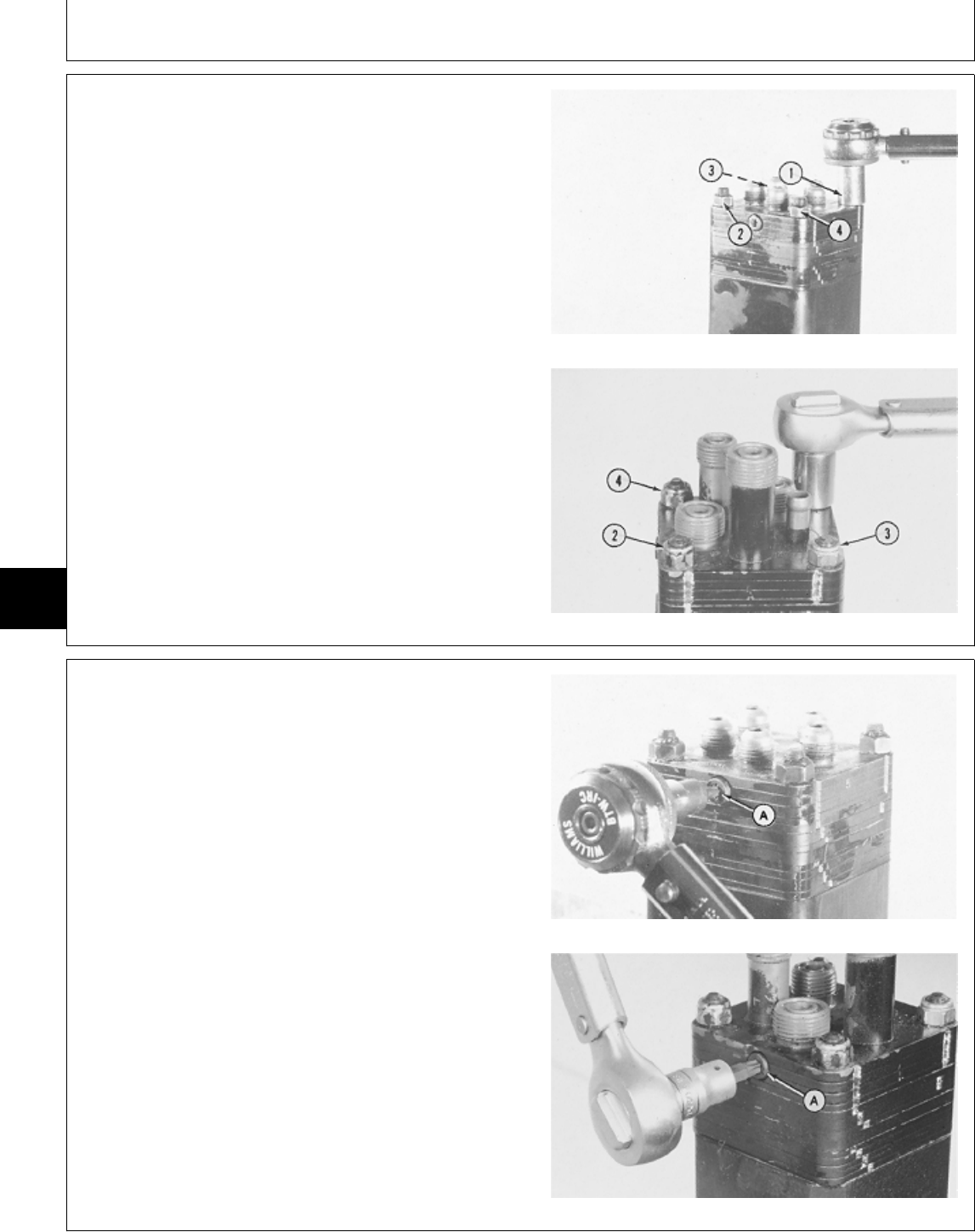
52. Install and tighten four nuts in the sequence shown.
Tighten in several steps to 30 N·m (22 lb-ft).
Early Version—322 and 332
Early Version—430
M43845 -UN-11NOV89M36875 -UN-29AUG88
53. Early version; Tighten plug (A) to 14 N·m (124 lb-in.).
54. Remove steering valve from fixture.
322 and 332
430
M43844 -UN-08JAN90M36876 -UN-29AUG88
MX,15916006,13 -19-13JUL95
MX,15916006,14 -19-13JUL95
Steering—322, 332 and 430/Steering Valve and Column
TM1591 (15JUL95) 60-06-24 322,330,332 & 430 Lawn & Garden Tractors
030895
60
06
24
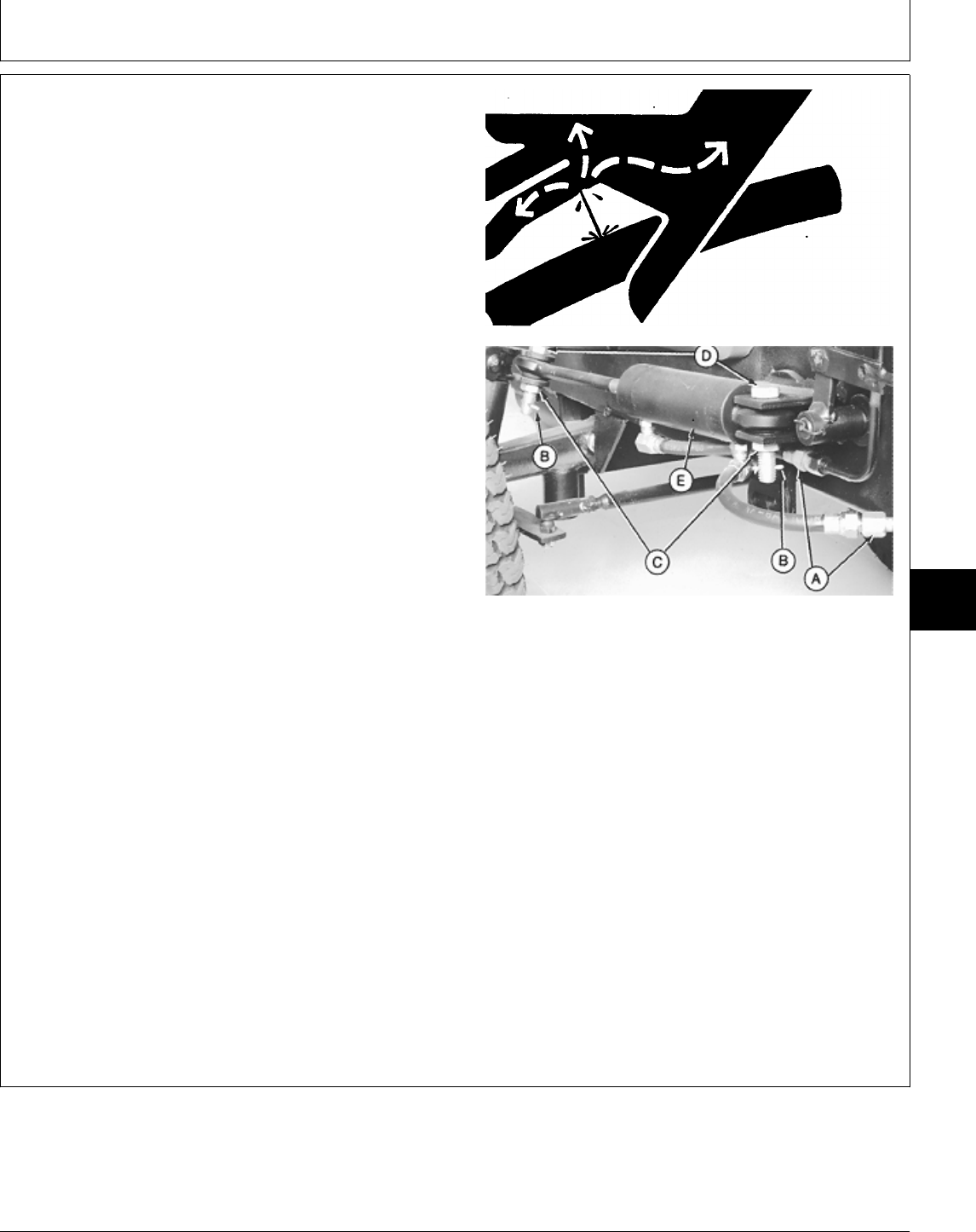
REMOVE AND INSTALL STEERING
CYLINDER
NCAUTION: Escaping fluid under pressure can
penetrate the skin causing serious injury.
Avoid the hazard by relieving pressure before
disconnecting hydraulic or other lines. Tighten
all connections before applying pressure.
Search for leaks with a piece of cardboard.
Protect hands and body from high pressure
fluids.
If an accident occurs, see a doctor
immediately. Any fluid injected into the skin
must be surgically removed within a few hours
or gangrene may result. Doctors unfamiliar
with this type of injury should reference a
knowledgeable medical source. Such
information is available from Deere & Company
Medical Department in Moline, Illinois, U.S.A.
1. Disconnect hydraulic hoses at lines (A).
Early Model Shown
2. Support cylinder and remove cotter pins (B), if
equipped, nuts (C) and bolts (D).
A—Hydraulic Lines
3. Remove steering cylinder (E). B—Cotter Pins (if equipped)
C—Nuts (Early Models)
NOTE: Cylinder is not repairable. If defective, replace —Lock Nuts (Later Models)
complete assembly. D—Bolts
E—Steering Cylinder
4. Installation is done in the reverse order of removal.
• Tighten nuts (C) to 163 N·m (120 lb-ft).
• Bleed the hydraulic system. (See procedure in Section
270, Group 20.)
X9811 -UN-23AUG88
M31822 -UN-28JUL89
MX,15916006,15 -19-13JUL95
Steering—322, 332 and 430/Steering Cylinder
TM1591 (15JUL95) 60-06-25 322,330,332 & 430 Lawn & Garden Tractors
030895
60
06
25

Steering—322, 332 and 430/Steering Cylinder
TM1591 (15JUL95) 60-06-26 322,330,332 & 430 Lawn & Garden Tractors
030895
60
06
26

OTHER MATERIAL
Number Name Use
M79292 MPG-2® Multi-Purpose Polymer Prevents parts from seizing. Apply
Grease to axle shafts.
LOCTITE® PRODUCTS
U.S./Canadian/LOCTITE No.
TY6305/TY9485/764 Clean and Cure Primer Cleans parts and speeds cure of
sealant.
T43512/TY9473/242 Thread Lock and Sealer (Medium Apply to threads of brake
Strength) plate-to-axle cap screws.
®MPG-2 is a registered trademark of DuBois USA.
®LOCTITE is a registered trademark of the Loctite Corp. MX,15905020,OTH-19-07MAR95
Group 10
Brakes
TM1591 (15JUL95) 60-10-1 322,330,332 & 430 Lawn & Garden Tractors
030895
60
10
1
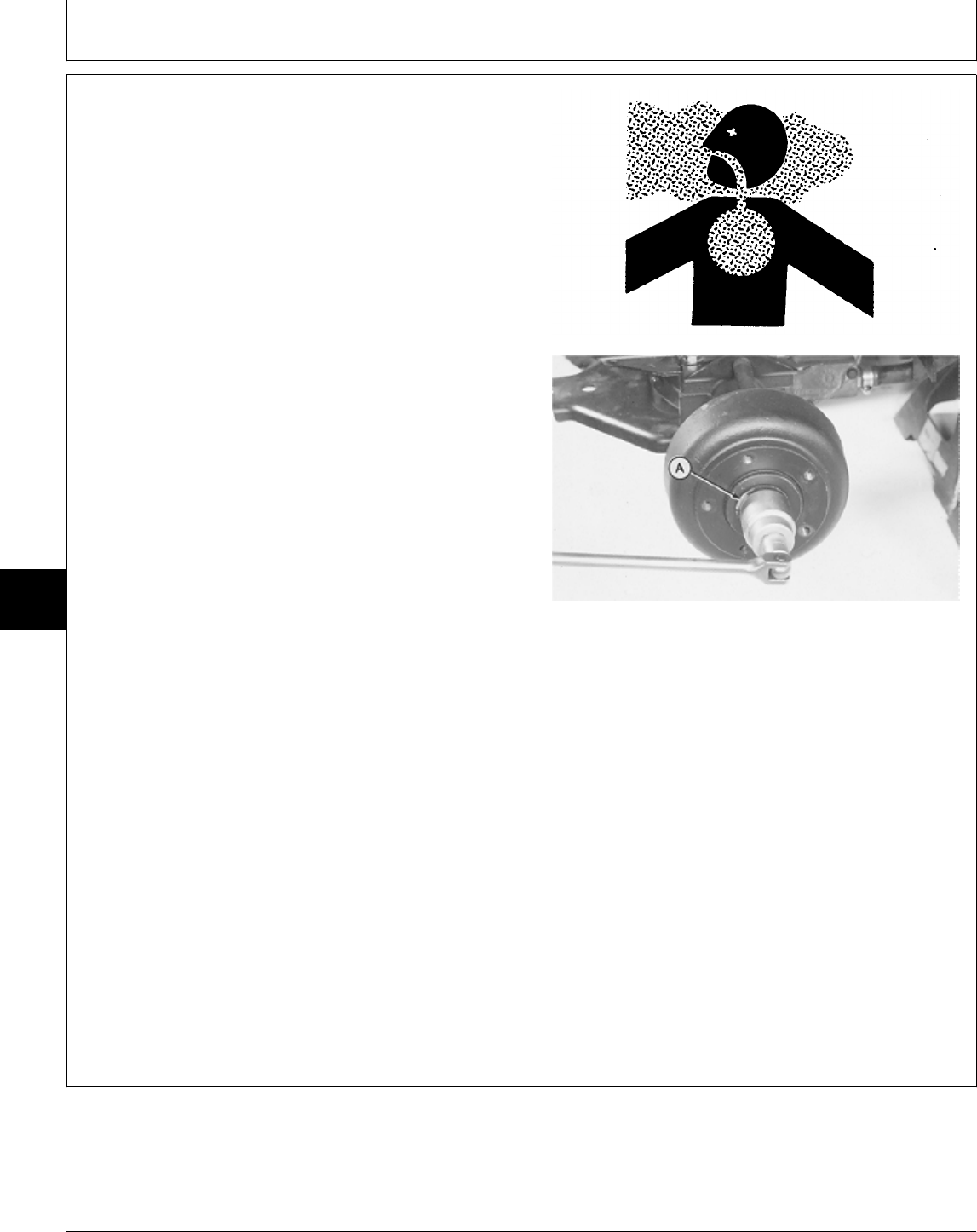
REMOVE BRAKES
NCAUTION: Avoid breathing dust that may be
generated when handling components
containing asbestos fibers. Inhaled asbestos
fibers may cause lung cancer. Normal handling
is not hazardous as long as airborne dust
containing asbestos is not generated.
Avoid creating dust. Never use compressed air
for cleaning. Avoid brushing or grinding
material containing asbestos. When servicing,
wear an approved respirator. A special vacuum
cleaner is recommended to clean asbestos. If
not available, apply a mist of oil or water on
the material containing asbestos.
Keep bystanders away from the area.
1. Disconnect battery negative (—) cable.
2. Raise rear of machine and install support stands
under frame.
3. Remove rear wheel.
4. Bend edge of washer (A) flat against drum.
5. Remove nut and washer.
6. Pull drum off axle.
If drum hits shoes, turn the adjuster to reduce the drag
on drum.
If drum is tight on shaft from corrosion, remove drum
using a three-leg wheel puller. DO NOT use an impact
puller.
TS220 -UN-23AUG88M36560 -UN-25JAN90
MX,15905010,19 -19-14FEB95
Brakes/Brakes
TM1591 (15JUL95) 60-10-2 322,330,332 & 430 Lawn & Garden Tractors
030895
60
10
2
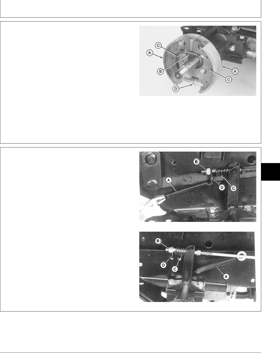
7. Inspect lining on brake shoes (A) for wear or oil
contamination. Replace shoes if worn. Inspect axle oil
seal if shoes are oily.
8. Inspect return spring (B) and hold-down springs (C)
for wear or stretching.
9. Check adjuster assembly (D) for ease of movement.
10. Remove brake return spring (B), hold-down springs
(C), adjuster (D), and shoes (A).
A—Brake Shoes
B—Return Spring
C—Hold-Down Springs
D—Adjuster Assembly
M36573 -UN-25JAN90
11. Disconnect return spring (A).
12. Remove nut (B), plate or washer (D) and spring (C).
A—Return Spring
B—Nut
C—Spring
D—Plate (Early 430)
—Washer (All and Later 430)
Early 430
All and Later 430
M78048 -UN-13FEB95M78049 -UN-13FEB95
MX,15905010,20 -19-14FEB95
MX,15915010,13 -19-13JUL95
Brakes/Brakes
TM1591 (15JUL95) 60-10-3 322,330,332 & 430 Lawn & Garden Tractors
030895
60
10
3
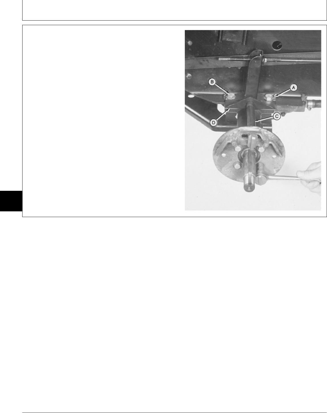
13. Bend lock plate tabs (A) flat. Remove two cap
screws (B).
14. Remove four cap screws and washers to remove
brake plate assembly.
15. Remove brake arm (C) and brake support (D).
A—Lock Plate Tab (2)
B—Cap Screw (2 used)
C—Brake Arm
D—Brake Support
M36576 -UN-25JAN90
MX,15905010,22 -19-07MAR95
Brakes/Brakes
TM1591 (15JUL95) 60-10-4 322,330,332 & 430 Lawn & Garden Tractors
030895
60
10
4
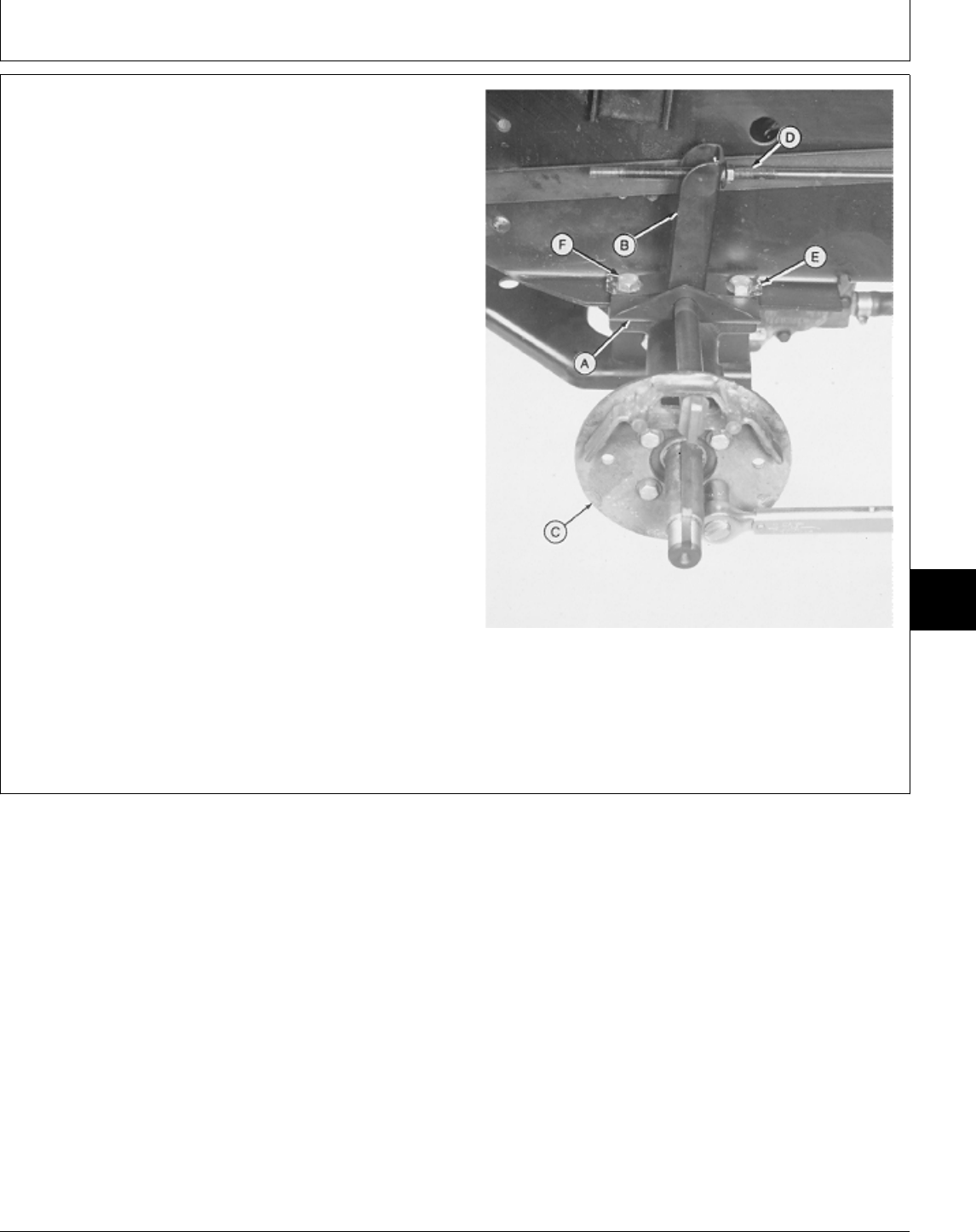
INSTALL BRAKES
1. Install brake support (A) on brake arm (B).
2. Install brake arm in brake plate (C).
3 Clean the threads of all four brake plate cap screws
and threaded axle housing using Clean and Cure Primer.
4 Apply thread lock and sealer (medium strength) on
threads of brake plate cap screws.
5. Install brake rod (D) in brake arm hole.
6. Install brake plate assembly on axle. Install and
tighten four cap screws to specificctions.
7. Install brake support (A), lock plate (E) and two cap
screws (F). Tighten cap screws to specifications. Bend
lock plate tabs over flat of cap screws.
TORQUE SPECIFICATIONS
Brake Plate-to-Axle Housing
Cap Screws . . . . . . . . . . . . . . . . . . . . . . . . . . . . 68 N·m (50 lb-ft)
Axle Housing-to-Frame Cap Screws . . . . . . . . . . . 100 N·m (75 lb-ft)
A—Brake Support
B—Brake Arm
C—Brake Plate
D—Brake Rod
E—Lock Plate
F—Cap Screw (2 used)
M36577 -UN-25JAN90
MX,15905010,23 -19-08MAY95
Brakes/Brakes
TM1591 (15JUL95) 60-10-5 322,330,332 & 430 Lawn & Garden Tractors
030895
60
10
5
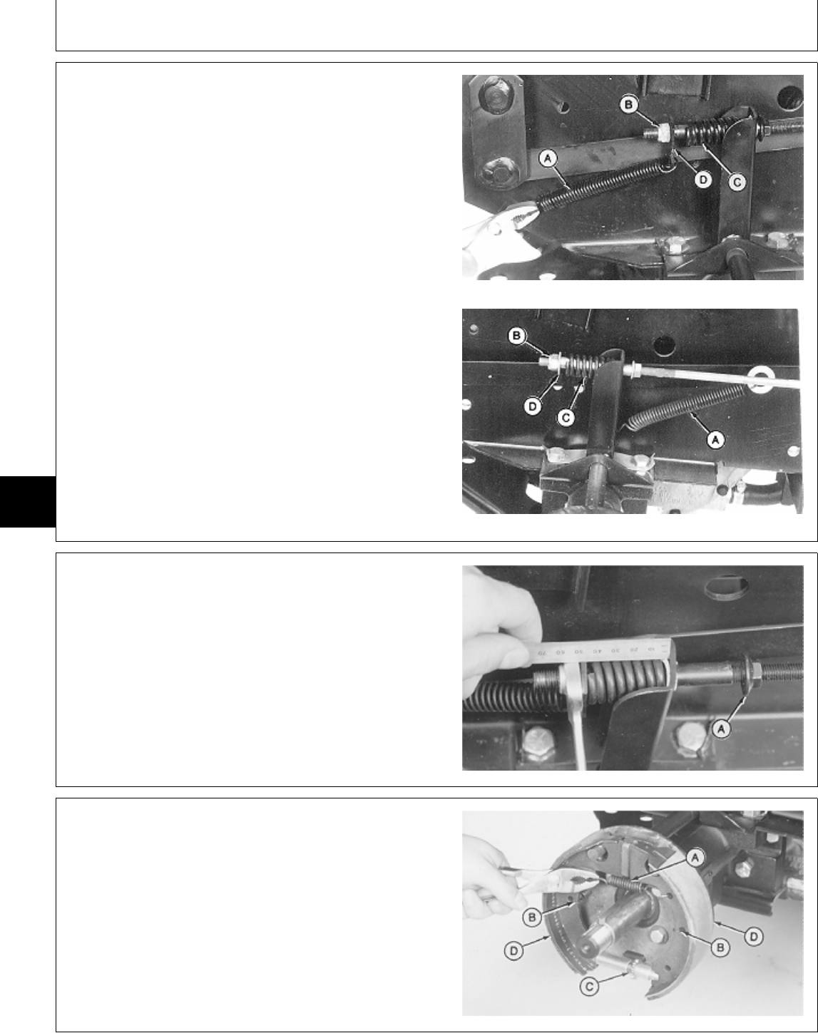
8. Install spring (C), plate or washer (D) and nut (B).
9. Connect return spring (A).
A—Return Spring
B—Nut
C—Spring
D—Plate (Early 430)
—Washer (All and Later 430)
Early 430
All and Later 430
M78048 -UN-13FEB95M78049 -UN-13FEB95
10. Lock brake pedals together (322, 332 and 430) and
apply park brake.
11. Loosen lock nut (A).
12. Turn nut until spring is 42 mm (1.650 in.) long.
Tighten lock nut.
M36554 -UN-25JAN90
13. Install shoes (D), adjuster (C), hold-down springs (B),
and brake return spring (A).
A—Brake Return Spring
B—Hold-Down Springs
C—Adjuster
D—Shoes
M36574 -UN-25JAN90
MX,15915010,14 -19-13JUL95
MX,15915010,15 -19-13JUL95
MX,M21,6010R,12-19-24JUN85
Brakes/Brakes
TM1591 (15JUL95) 60-10-6 322,330,332 & 430 Lawn & Garden Tractors
030895
60
10
6
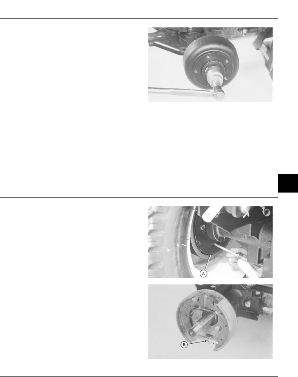
14. Apply MPG-2® Multi-Purpose Polymer Grease to axle
shaft.
15. Install key and brake drum.
16. Install washer and nut. Tighten nut to specifications.
17. Bend one side of washer over nut to lock nut in
place.
18. Install wheel. Tighten cap screws to specifications.
19. Remove support stands.
20. Connect battery negative (—) cable.
21. Adjust brakes. (See procedure in this group.)
TORQUE SPECIFICATIONS
Brake Drum-to-Axle Nut . . . . . . . . . . . . . . . . . . . . 88 N·m (65 lb-ft)
Rear Wheel Cap Screws . . . . . . . . . . . . . . . . . . . 70 N·m (52 lb-ft)
M36571 -UN-25JAN90
ADJUST BRAKES
1. Disconnect battery negative (—) cable.
2. Raise rear of machine and install support stands
under frame.
NOTE: Wheel and brake drum are removed for
photographic purpose only.
3. Reach through slot in back plate (A) with screwdriver
for access to star adjuster (B).
4. Turn wheel by hand. Turn adjusting star until brake
shoes begin to drag on drum.
5. Push brake pedal(s) down firmly to seat brake shoes
and check adjustment. Adjust brakes so brake shoes just
clear drums and do not drag when pedal(s) are released.
M31941 -UN-28JUL89M36881 -UN-25JAN90
MX,15905020,26 -19-07MAR95
MX,15905010,27 -19-14FEB95
Brakes/Brakes
TM1591 (15JUL95) 60-10-7 322,330,332 & 430 Lawn & Garden Tractors
030895
60
10
7
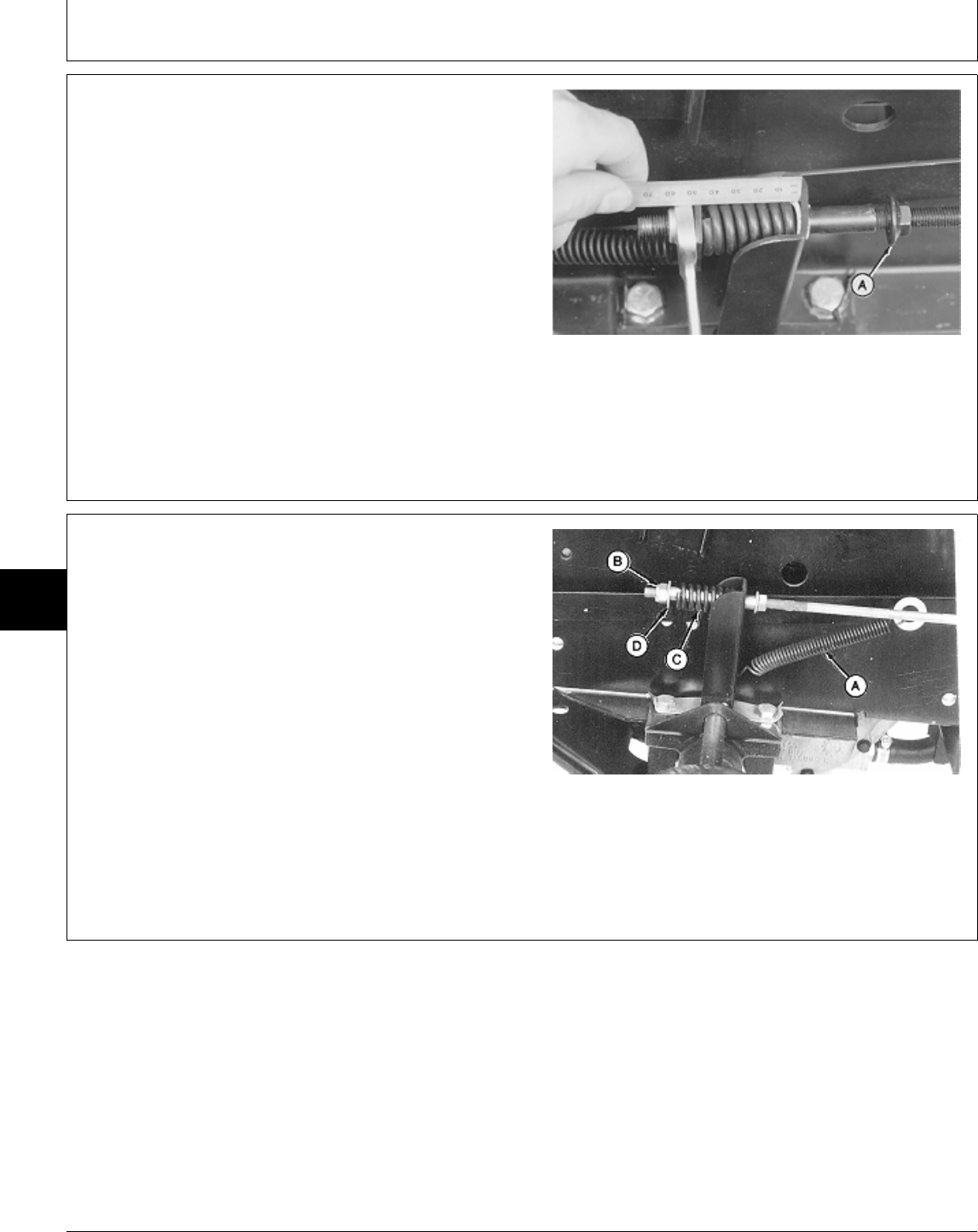
6. Lock brake pedals together (322, 332 and 430) and
apply parking brake.
7. Check length of spring on both sides of machine.
Spring should be approximately 42 mm (1.650 in.).
8. If necessary, adjust length of spring.
9. Loosen lock nut (A).
10. Turn nut until spring is 42 mm (1.650 in.) long.
Tighten lock nut.
11. Remove support stands.
12. Connect battery negative (—) cable.
M36554 -UN-25JAN90
INSPECT AND REPAIR BRAKE PEDAL AND
NEUTRAL RETURN LINKAGE—330
1. Remove belly screen and fender deck.
NOTE: Disconnect brake rods from both sides of
machine.
2. Disconnect return spring (A).
3. Remove nut (B), washer (D) and spring (C). Inspect
springs for weak coils.
4. Disconnect brake rods from brake pedal.
A—Return Spring
B—Nut
C—Spring
D—Washer
M78049 -UN-13FEB95
MX,15915010,16 -19-13JUL95
MX,15916010,1 -19-13JUL95
Brakes/Brake Pedal(s) and Neutral Return Linkage
TM1591 (15JUL95) 60-10-8 322,330,332 & 430 Lawn & Garden Tractors
030895
60
10
8
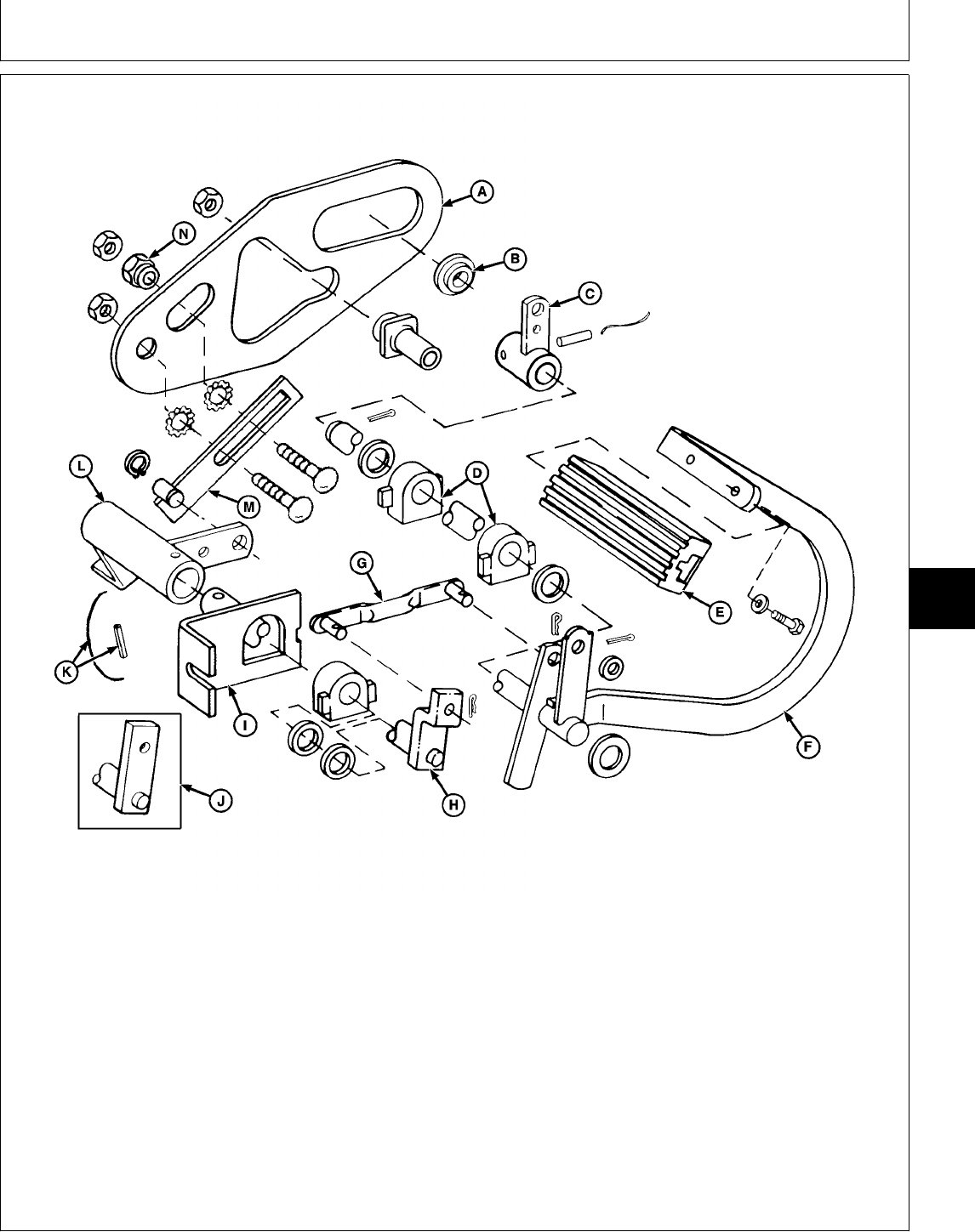
A—Neutral Return Cam Plate F—Brake Pedal I—Bracket L—Neutral Return Arm
B—Spacer G—Neutral Return Link J—Neutral Return Shaft M—Neutral Return Sliding
C—Left-Hand Brake Arm H—Neutral Return Shaft (Early Models) Lever
D—Bearing (4 used) (Later Models) K—Lock Wire and Spring Pin N—Eccentric Adjustment Nut
E—Pedal Pad
5. Inspect linkage for wear or damage. Replace parts
as necessary.
6. If necessary to replace neutral return cam plate
(A), remove transmission control lever assembly. (See
Inspect and Repair Transmission Control
Linkage—330 in Section 50, Group 10.)
M78047 -UN-14MAR95
MX,15916010,2 -19-13JUL95
Brakes/Brake Pedal(s) and Neutral Return Linkage
TM1591 (15JUL95) 60-10-9 322,330,332 & 430 Lawn & Garden Tractors
030895
60
10
9
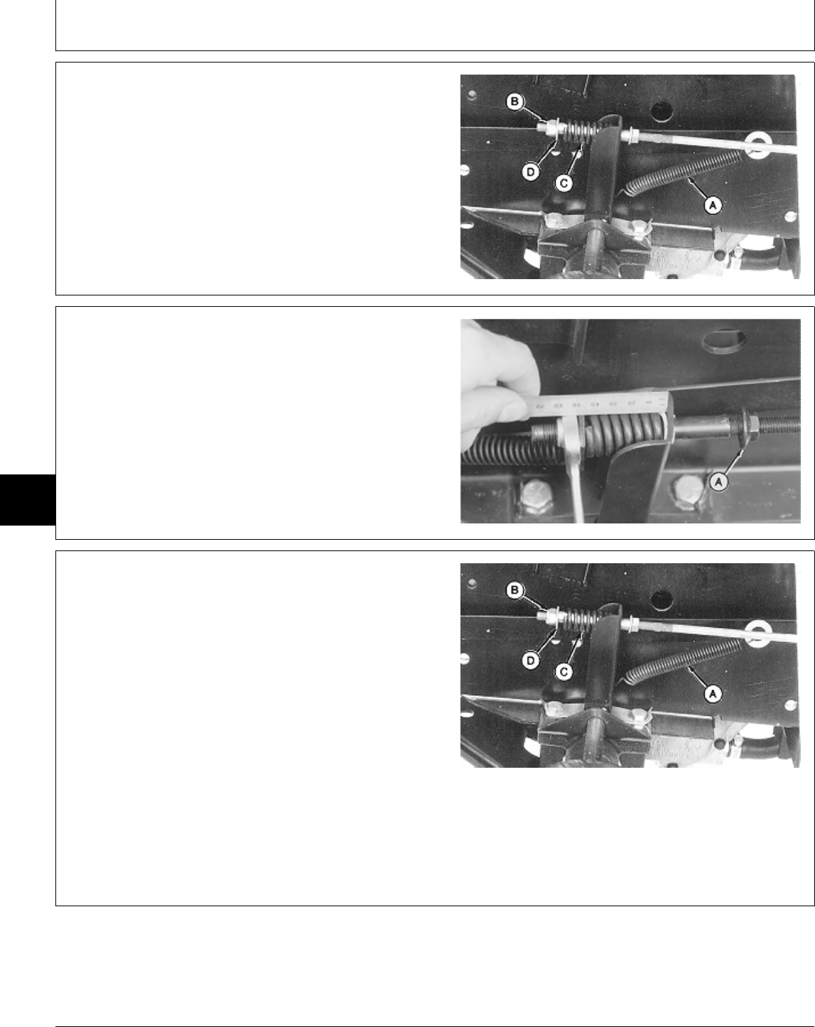
7. Install all parts.
8. Connect brake rods to brake pedal.
9. Install spring (C), washer (D) and nut (B).
10. Connect return spring (A).
A—Return Spring
B—Nut
C—Spring
D—Washer
M78049 -UN-13FEB95
11. Apply parking brake.
12. Loosen lock nut (A).
13. Turn nut until spring is 42 mm (1.650 in.) long.
Tighten lock nut.
14. Install fender deck and belly screen.
M36554 -UN-25JAN90
INSPECT AND REPAIR BRAKE PEDALS
AND NEUTRAL RETURN LINKAGE—322
AND 332
1. Remove belly screen and fender deck.
NOTE: Disconnect brake rods from both sides of
machine.
2. Disconnect spring (A).
3. Remove nut (B), washer (D) and spring (C). Inspect
springs for weak coils.
4. Disconnect brake rods from brake pedal. A—Return Spring
B—Nut
C—Spring
D—Washer
M78049 -UN-13FEB95
MX,15916010,3 -19-13JUL95
MX,15906010,6 -19-14FEB95
MX,15916010,4 -19-13JUL95
Brakes/Brake Pedal(s) and Neutral Return Linkage
TM1591 (15JUL95) 60-10-10 322,330,332 & 430 Lawn & Garden Tractors
030895
60
10
10
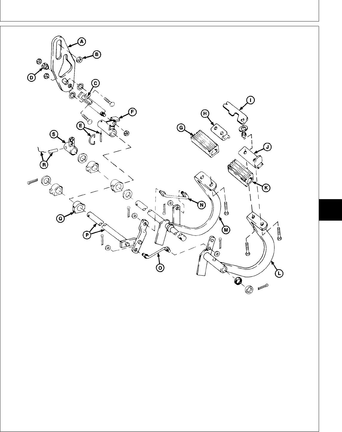
A—Neutral Return Cam Plate E—Lock Wire and Spring Pin J—Support O—Neutral Return Link
B—Spacer F—Neutral Return Arm K—Right Pedal Pad P—Neutral Return Shaft
C—Neutral Return Sliding G—Left Pedal Pad L—Right Brake Pedal Q—Bearing (4 used)
Lever H—Plate M—Left Brake Pedal R—Lock Wire and Spring Pin
D—Eccentric Adjustment Nut I—Strap N—Neutral Return Link S—Left-Hand Brake Arm
Version One (322 and 332)
NOTE: Brake pedal and neutral return
linkage—Version One, is used on machines
equipped with transmission control
linkage—Version One for 322 and 332 only.
5. Inspect linkage for wear or damage. Replace parts
as necessary.
6. If necessary to replace neutral return cam plate
(A), remove transmission control lever assembly. (See
Inspect and Repair Transmission Control
Linkage—Version One for 322 and 332 only in
Section 50, Group 10.)
M77918 -UN-14MAR95
MX,15916010,5 -19-13JUL95
Brakes/Brake Pedal(s) and Neutral Return Linkage
TM1591 (15JUL95) 60-10-11 322,330,332 & 430 Lawn & Garden Tractors
030895
60
10
11
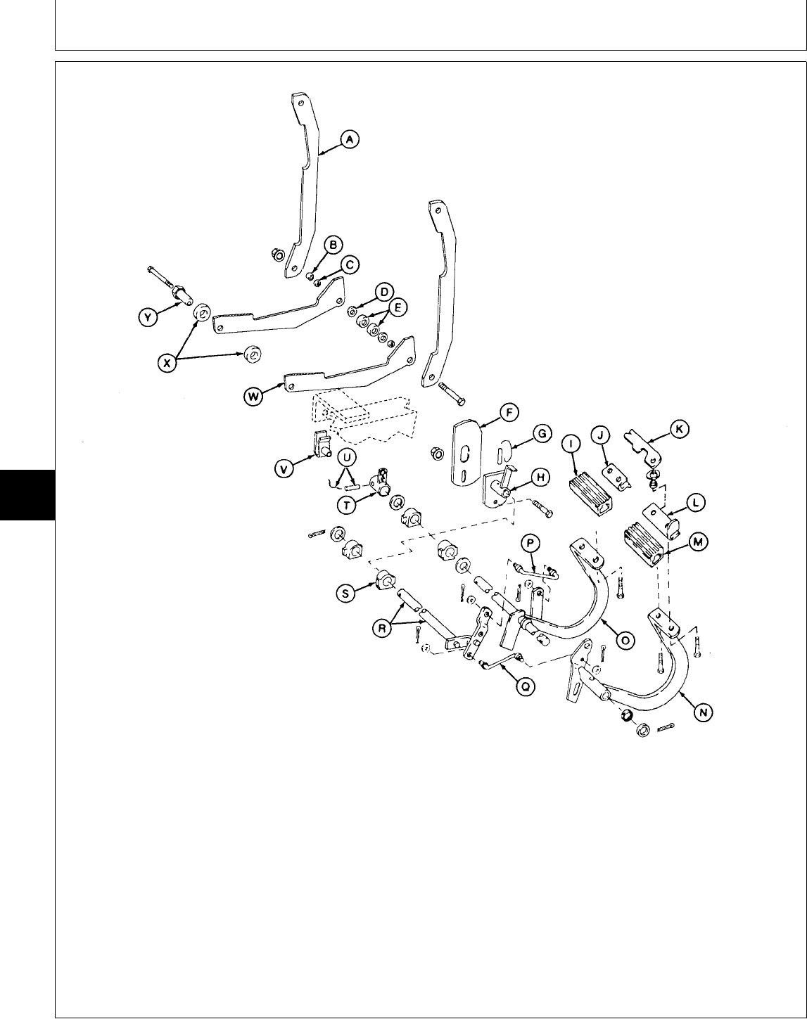
A—Strap (2 used) H—Neutral Return Arm O—Left Brake Pedal U—Lock Wire and Spring Pin
B—Spacer I—Left Pedal Pad P—Neutral Return Link V—Clamp-On Nut
C—Bushing (2 used) J—Plate Q—Neutral Return Link W—Speed Control Arm (2
D—Washer (2 used) K—Strap R—Neutral Return Shaft used)
E—Ball Bearings L—Support S—Bearing (4 used) X—Bushings
F—Neutral Return Cam M—Right Pedal Pad T—Left-Hand Brake Arm Y—Eccentric Adjustment Nut
G—Safety Wire and Spring N—Right Brake Pedal
Pin
Version Two (322 and 332)
NOTE: Brake pedal and neutral return
linkage—Version Two, is used on machines
equipped with transmission control
linkage—Version Two only.
M77919 -UN-13FEB95
MX,15916010,6 -19-13JUL95
Brakes/Brake Pedal(s) and Neutral Return Linkage
TM1591 (15JUL95) 60-10-12 322,330,332 & 430 Lawn & Garden Tractors
030895
60
10
12
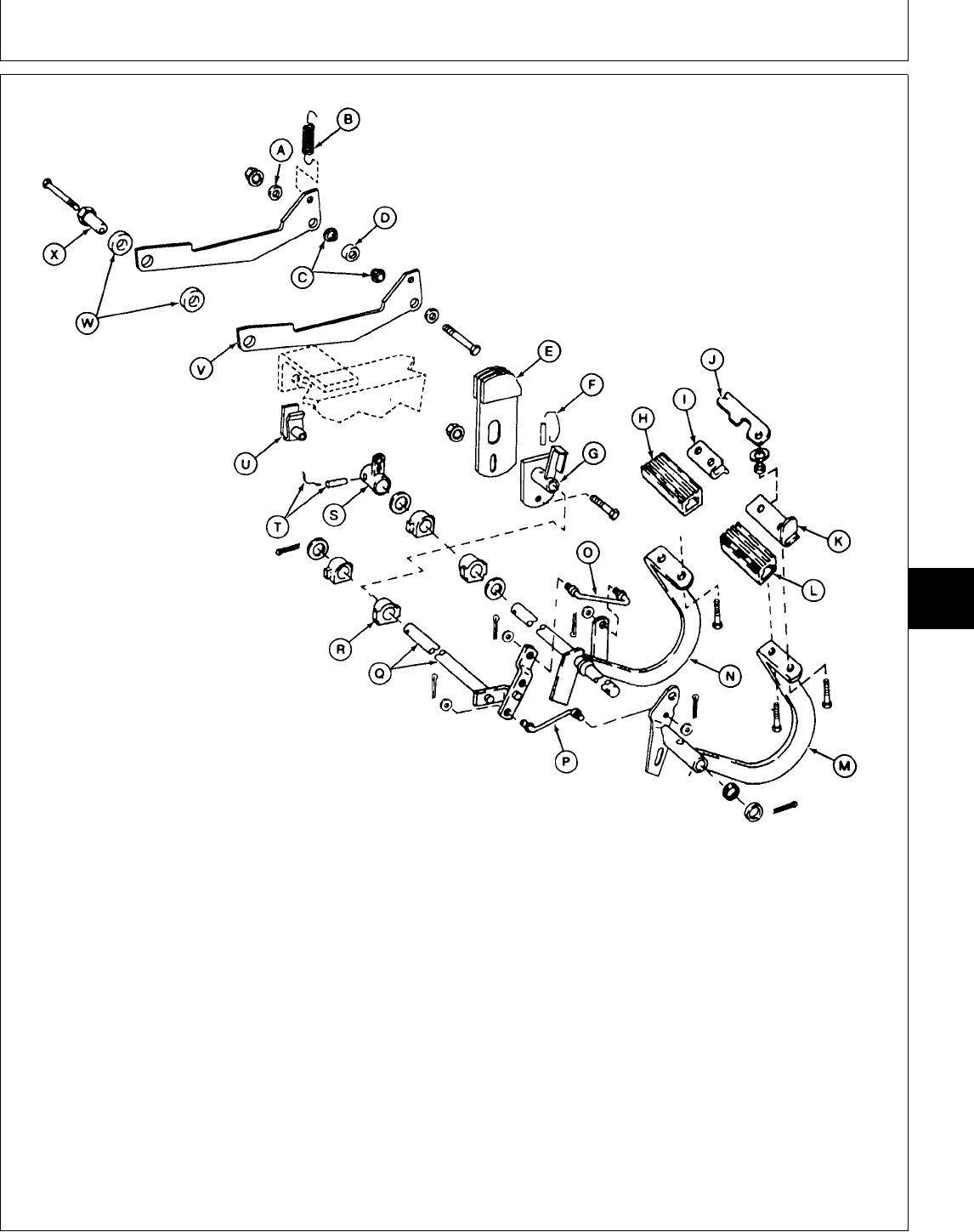
A—Washer (2 used) G—Neutral Return Arm N—Left Brake Pedal T—Lock Wire and Spring Pin
B—Spring H—Left Pedal Pad O—Neutral Return Link U—Clamp-On Nut
C—Bushings I—Plate P—Neutral Return Link V—Speed Control Arm (2
D—Ball Bearing J—Strap Q—Neutral Return Shaft used)
E—Neutral Return Cam K—Support R—Bearing (4 used) W—Bushings
F—Safety Wire and Spring L—Right Pedal Pad S—Left-Hand Brake Arm X—Eccentric Adjustment Nut
Pin M—Right Brake Pedal
Version Three (322 and 332)
NOTE: Brake pedal and neutral return
linkage—Version Three, is used on machines
equipped with transmission control
linkage—Version Three only.
M78040 -UN-13JAN95
MX,15916010,7 -19-13JUL95
Brakes/Brake Pedal(s) and Neutral Return Linkage
TM1591 (15JUL95) 60-10-13 322,330,332 & 430 Lawn & Garden Tractors
030895
60
10
13
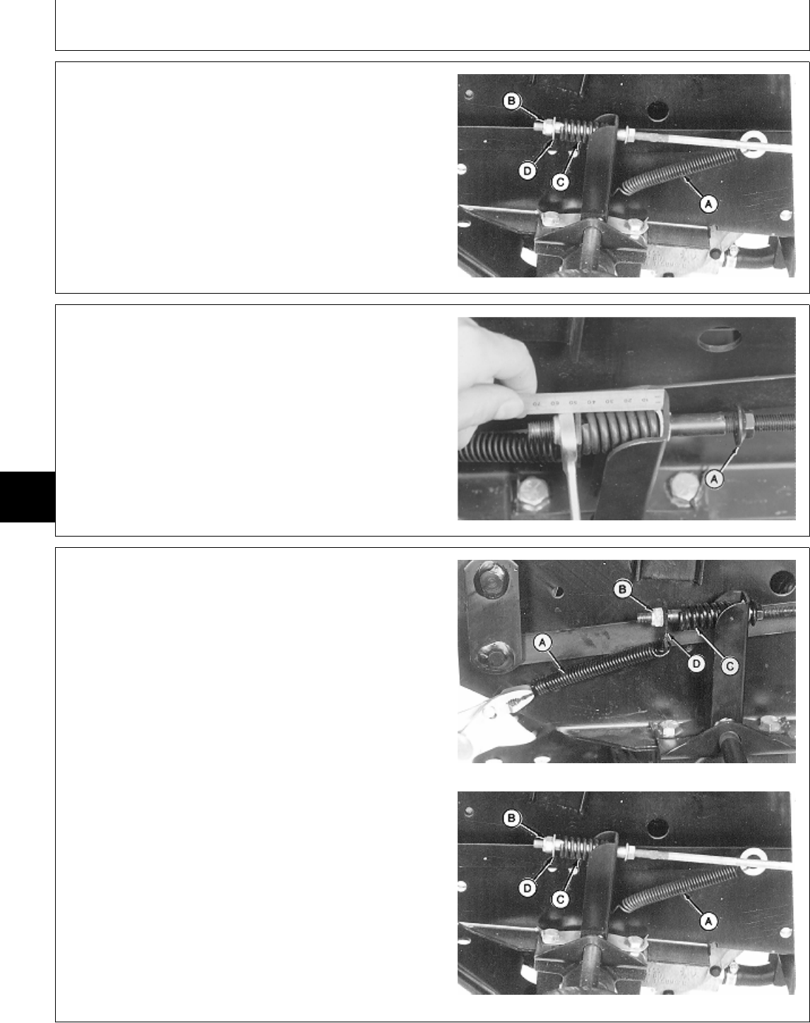
7. Install all parts.
8. Connect brake rods to brake pedal.
9. Install spring (C), washer (D) and nut (B).
10. Connect return spring (A).
A—Return Spring
B—Nut
C—Spring
D—Washer
M78049 -UN-13FEB95
11. Lock brake pedals together and apply parking brake.
12. Loosen lock nut (A).
13. Turn nut until spring is 42 mm (1.650 in.) long.
Tighten lock nut.
14. Install fender deck and belly screen.
M36554 -UN-25JAN90
INSPECT AND REPAIR BRAKE PEDALS
AND NEUTRAL RETURN LINKAGE—430
1. Remove belly pan and fender deck.
NOTE: Disconnect brake rods from both sides of
machine.
2. Disconnect return spring (A).
3. Remove nut (B), plate or washer (D) and spring (C).
Inspect springs for weak coils. Early Models
4. Disconnect brake rods from brake pedal.
A—Return Spring
B—Nut
C—Spring
D—Plate (Early Models)
—Washer (Later Models)
Later Models
M78048 -UN-13FEB95M78049 -UN-13FEB95
MX,15916010,3 -19-13JUL95
MX,15906010,12 -19-14FEB95
MX,15916010,8 -19-13JUL95
Brakes/Brake Pedal(s) and Neutral Return Linkage
TM1591 (15JUL95) 60-10-14 322,330,332 & 430 Lawn & Garden Tractors
030895
60
10
14
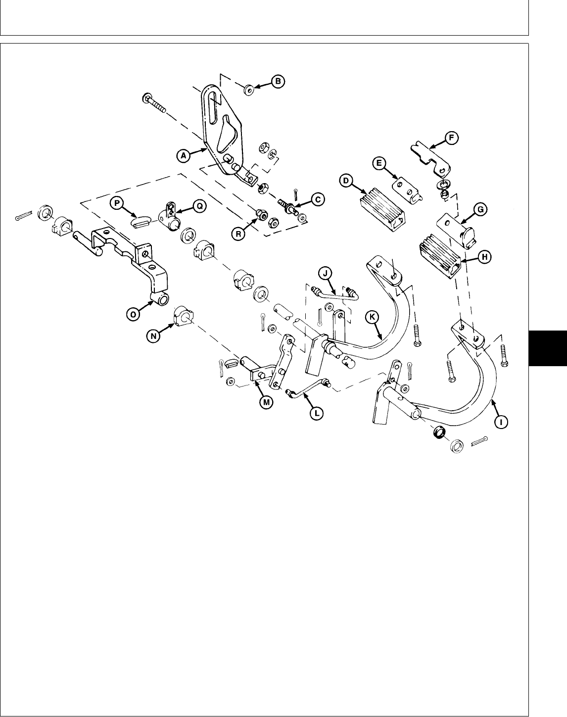
A—Neutral Return Cam Plate F—Strap K—Left Brake Pedal P—Lock Wire and Spring Pin
B—Spacer G—Support L—Neutral Return Link Q—Left-Hand Brake Arm
C—J-Bolt H—Right Pedal Pad M—Neutral Return Shaft R—Eccentric Adjustment Nut
D—Left Pedal Pad I—Right Brake Pedal N—Bearing (4 used)
E—Plate J—Neutral Return Link O—Neutral Return Welded
Shaft
Version One (430)
NOTE: Brake pedal and neutral return
linkage—Version One, is used on machines
equipped with transmission control
linkage—Version One for 430 only.
5. Inspect linkage for wear or damage. Replace parts
as necessary.
6. If necessary to replace neutral return cam plate
(A), remove transmission control lever assembly. (See
Inspect and Repair Transmission Control
Linkage—Version One for 430 only in Section 50,
Group 10.)
M78041 -UN-14MAR95
MX,15916010,9 -19-13JUL95
Brakes/Brake Pedal(s) and Neutral Return Linkage
TM1591 (15JUL95) 60-10-15 322,330,332 & 430 Lawn & Garden Tractors
030895
60
10
15
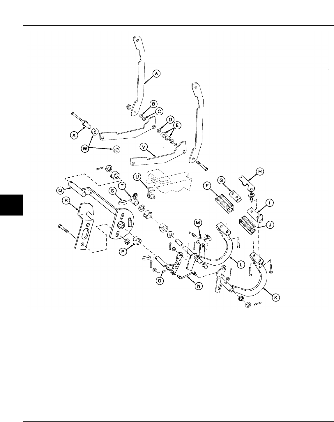
A—Strap (2 used) H—Strap O—Neutral Return Shaft T—Left-Hand Brake Arm
B—Spacer I—Support (Short) U—Clamp-On Nut
C—Bushing (2 used) J—Right Pedal Pad P—Bearing (4 used) V—Speed Control Arm (2
D—Washer (2 used) K—Right Brake Pedal Q—Neutral Return Shaft used)
E—Ball Bearings L—Left Brake Pedal (Long) W—Bushings
F—Left Pedal Pad M—Neutral Return Link R—Neutral Return Cam X—Eccentric Adjustment Nut
G—Plate N—Neutral Return Link S—Lock Wire and Spring Pin
Version Two (430)
NOTE: Brake pedal and neutral return
linkage—Version Two, is used on machines
equipped with transmission control
linkage—Version Two only.
M78042 -UN-13MAR95
MX,15916010,10 -19-13JUL95
Brakes/Brake Pedal(s) and Neutral Return Linkage
TM1591 (15JUL95) 60-10-16 322,330,332 & 430 Lawn & Garden Tractors
030895
60
10
16
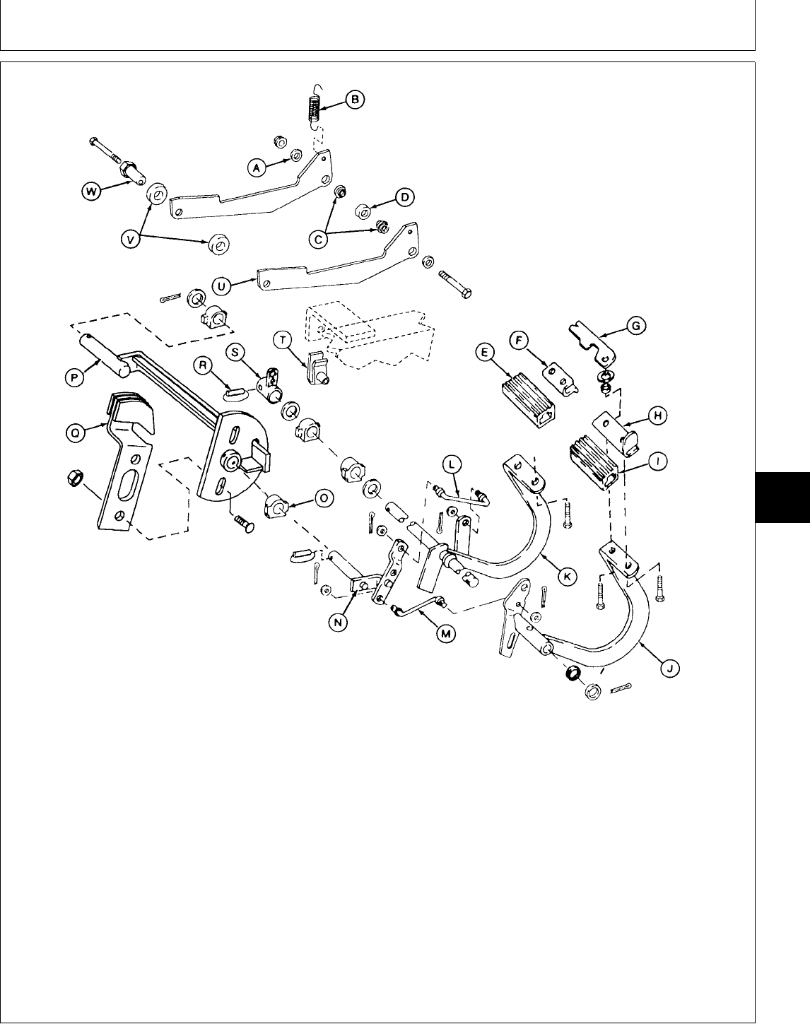
A—Washer (2 used) H—Support O—Bearing (4 used) T—Clamp-On Nut
B—Spring I—Right Pedal Pad P—Neutral Return Shaft U—Speed Control Arm (2
C—Bushings J—Right Brake Pedal (Long) used)
D—Ball Bearing K—Left Brake Pedal Q—Neutral Return Cam V—Bushings
E—Left Pedal Pad L—Neutral Return Link R—Lock Wire and Spring Pin W—Eccentric Adjustment Nut
F—Plate M—Neutral Return Link S—Left-Hand Brake Arm
G—Strap N—Neutral Return Shaft
(Short)
Version Three (430)
NOTE: Brake pedal and neutral return
linkage—Version Three, is used on machines
equipped with transmission control
linkage—Version Three only.
M78043 -UN-13MAR95
MX,15916010,11 -19-13JUL95
Brakes/Brake Pedal(s) and Neutral Return Linkage
TM1591 (15JUL95) 60-10-17 322,330,332 & 430 Lawn & Garden Tractors
030895
60
10
17
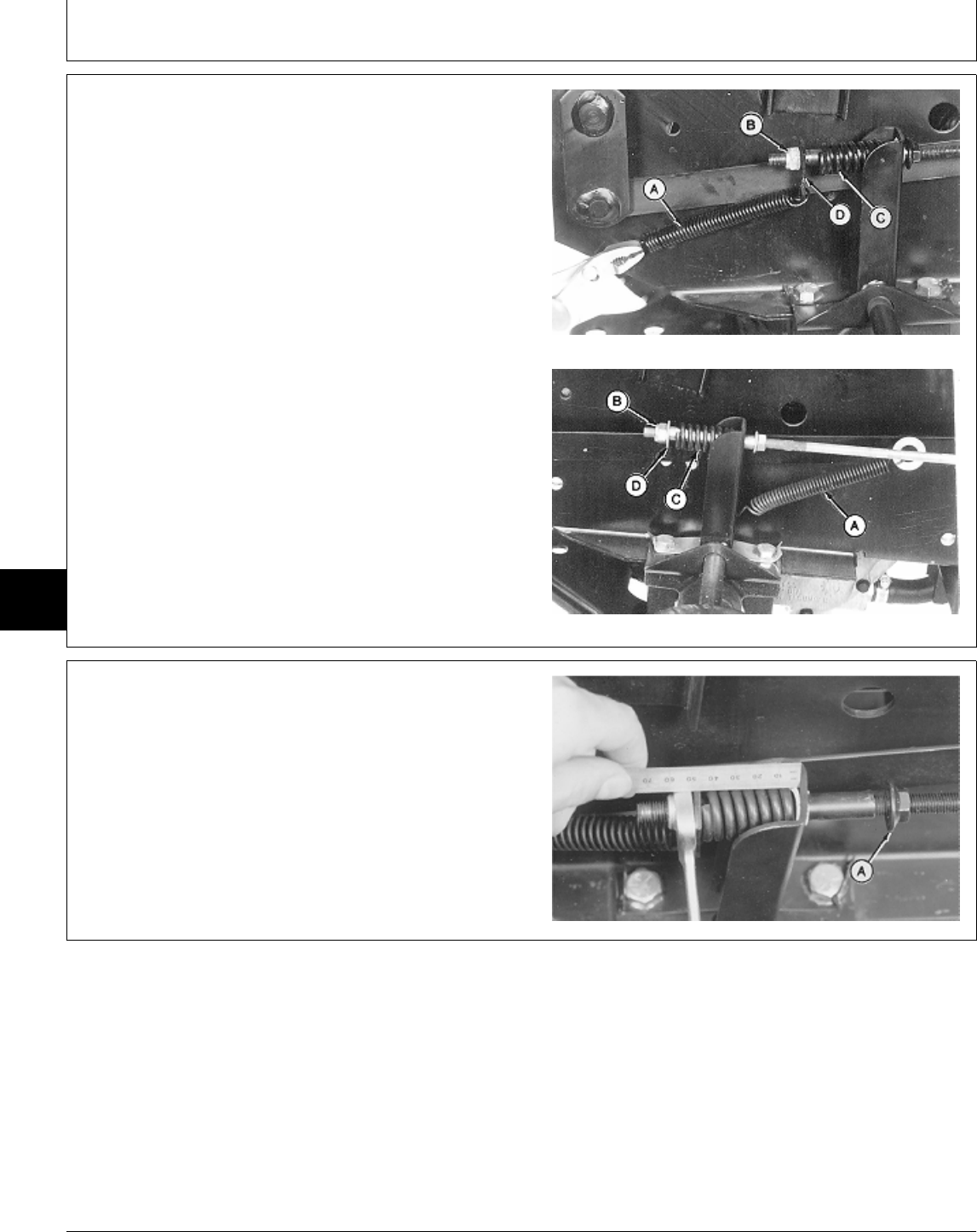
7. Install all parts.
8. Connect brake rods to brake pedal.
9. Install spring (C), plate or washer (D) and nut (B).
10. Connect return spring (A).
A—Return Spring
B—Nut
C—Spring
D—Plate (Early Models)
—Washer (Later Models) Early Models
Later Models
M78048 -UN-13FEB95M78049 -UN-13FEB95
11. Lock brake pedals together and apply parking brake.
12. Loosen lock nut (A).
13. Turn nut until spring is 42 mm (1.650 in.) long.
Tighten lock nut.
14. Install fender deck and belly pan.
M36554 -UN-25JAN90
MX,15916010,12 -19-13JUL95
MX,15906010,17 -19-14FEB95
Brakes/Brake Pedal(s) and Neutral Return Linkage
TM1591 (15JUL95) 60-10-18 322,330,332 & 430 Lawn & Garden Tractors
030895
60
10
18
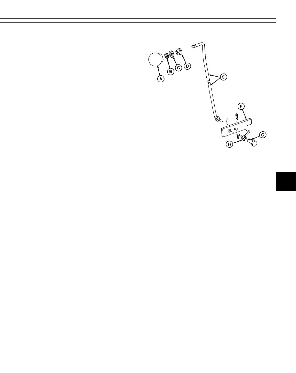
INSPECT AND REPAIR PARK BRAKE
LEVER
1. Remove belly screen/pan.
2. Inspect all parts for wear or damage. Replace as
necessary.
A—Knob
B—Lock Washer
C—Washer
D—Weld Nut
E—Park Brake Rod
F—Lock Plate
G—Pin
H—Torsion Spring
M77913 -UN-13FEB95
MX,15906010,18 -19-12MAY95
Brakes/Inspect and Repair Park Brake Lever
TM1591 (15JUL95) 60-10-19 322,330,332 & 430 Lawn & Garden Tractors
030895
60
10
19

Brakes/Inspect and Repair Park Brake Lever
TM1591 (15JUL95) 60-10-20 322,330,332 & 430 Lawn & Garden Tractors
030895
60
10
20

Section 70
HYDRAULIC REPAIR
Contents
Page
Group 05—Hydraulic Control Valve
Other Materials . . . . . . . . . . . . . . . . . . 70-05-1
Service Parts Kits . . . . . . . . . . . . . . . . 70-05-1
Remove and Install
322 and 332 . . . . . . . . . . . . . . . . . . 70-05-2
330 . . . . . . . . . . . . . . . . . . . . . . . . 70-05-3
430 . . . . . . . . . . . . . . . . . . . . . . . . 70-05-6
Disassemble, Inspect and Assemble
Single-Spool . . . . . . . . . . . . . . . . . . . 70-05-9
Two-Spool . . . . . . . . . . . . . . . . . . . . 70-05-10
Three-Spool . . . . . . . . . . . . . . . . . . . 70-05-12
TM1591 (15JUL95) 70-1 322,330,332 & 430 Lawn & Garden Tractors
030895
70

Contents
TM1591 (15JUL95) 70-2 322,330,332 & 430 Lawn & Garden Tractors
030895
70

OTHER MATERIAL
Number Name Use
M79292 MPG-2® Multi-Purpose Polymer Prevents parts from seizing. Apply
Grease to spool springs and end cap
cavities.
LOCTITE® PRODUCTS
U.S./Canadian/LOCTITE No.
TY6305/TY9485/764 Clean and Cure Primer Cleans parts and speeds cure of
sealant.
T43512/TY9473/242 Thread Lock and Sealer (Medium Apply to threads spool screws.
Strength)
®MPG-2 is a registered trademark of DuBois USA.
®LOCTITE is a registered trademark of the Loctite Corp.
SERVICE PARTS KITS
The following kits are available through your parts
catalog:
Single-Spool Valve
Spring Center Kit
Load Check Kit
Seal Kit
Two-Spool Valve
Versions One and Two
Seal Kit
Detent Replacement Kit
Versions Three and Four
Seal Kit
Load Check Kit
Spring Center Kit
Float Detent Kit
Valve Detent Kit
Three-Spool Valve
Seal Kit
Load Check Kit
Spring Center Kit
Float Detent Kit
MX,15907005,OTH-19-20APR95
MX,15917005,KIT-19-13JUL95
Group 05
Hydraulic Control Valve
TM1591 (15JUL95) 70-05-1 322,330,332 & 430 Lawn & Garden Tractors
030895
70
05
1
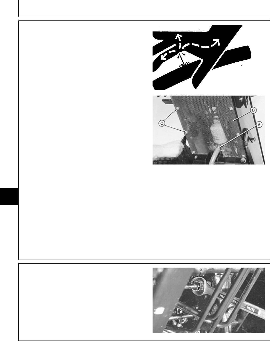
REMOVE AND INSTALL HYDRAULIC
CONTROL VALVE—322 AND 332
NCAUTION: Escaping fluid under pressure can
penetrate the skin causing serious injury.
Avoid the hazard by relieving pressure before
disconnecting hydraulic or other lines. Tighten
all connections before applying pressure.
Search for leaks with a piece of cardboard.
Protect hands and body from high pressure
fluids.
If an accident occurs, see a doctor
immediately. Any fluid injected into the skin
must be surgically removed within a few hours
or gangrene may result. Doctors unfamiliar
with this type of injury should reference a
knowledgeable medical source. Such
information is available from Deere & Company
Medical Department in Moline, Illinois, U.S.A.
NOTE: Removal and installation procedures for later
models may vary slightly.
1. Remove ten cap screws (C) and belly screen (B).
2. Disconnect suction hose (A) to drain transmission oil.
Approximate capacity is 4.7 L (5 U.S. qt).
3. Remove hydraulic filter.
X9811 -UN-23AUG88
M31751 -UN-28JUL89
4. Remove fender deck.
5. Disconnect hydraulic lines from control valve.
6. Disconnect control linkage.
M32026 -UN-03AUG89
MX,15917005,1 -19-13JUL95
MX,15917005,2 -19-13JUL95
Hydraulic Control Valve/Remove and Install
TM1591 (15JUL95) 70-05-2 322,330,332 & 430 Lawn & Garden Tractors
030895
70
05
2
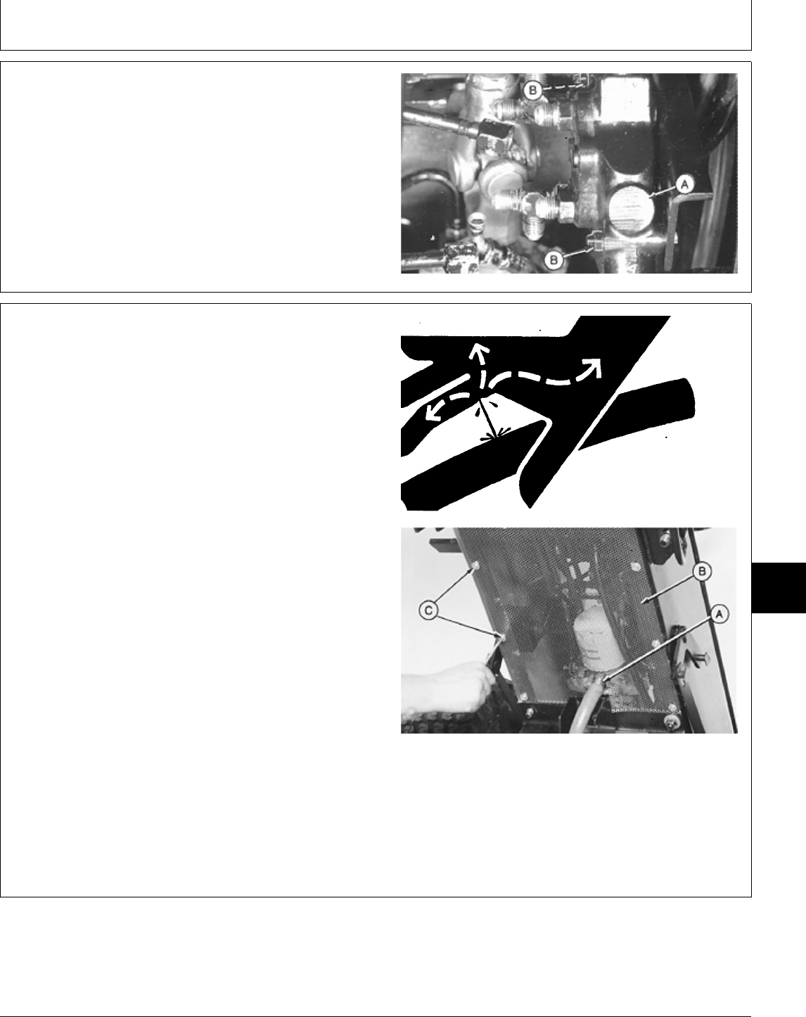
7. Remove two mounting bolts (B) and control valve (A).
8. Installation is done in the reverse order of removal.
• Fill transmission with the recommended amount of
John Deere Low Viscosity HY-GARD® oil.
• Bleed the hydraulic system. (See procedure in Section
270, Group 20.)
M32046 -UN-03AUG89
REMOVE AND INSTALL HYDRAULIC
CONTROL VALVE—330
NCAUTION: Escaping fluid under pressure can
penetrate the skin causing serious injury.
Avoid the hazard by relieving pressure before
disconnecting hydraulic or other lines. Tighten
all connections before applying pressure.
Search for leaks with a piece of cardboard.
Protect hands and body from high pressure
fluids.
If an accident occurs, see a doctor
immediately. Any fluid injected into the skin
must be surgically removed within a few hours
or gangrene may result. Doctors unfamiliar
with this type of injury should reference a
knowledgeable medical source. Such
information is available from Deere & Company
Medical Department in Moline, Illinois, U.S.A.
1. Remove ten cap screws (C) and belly screen (B).
2. Disconnect suction hose (A) to drain transmission oil.
Approximate capacity is 4.7 L (5 U.S. qt).
3. Remove hydraulic filter.
X9811 -UN-23AUG88
M31751 -UN-28JUL89
MX,15917005,3 -19-13JUL95
MX,15917005,4 -19-13JUL95
Hydraulic Control Valve/Remove and Install
TM1591 (15JUL95) 70-05-3 322,330,332 & 430 Lawn & Garden Tractors
030895
70
05
3
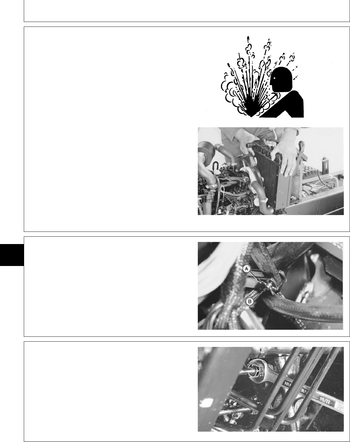
4. Lift hood and remove engine side panels.
5. Remove fender deck.
6. Remove right and left pedestal side panels.
NCAUTION: Explosive release of fluids from
pressurized cooling system can cause serious
burns.
Shut off engine. Only remove filler cap when
cool enough to touch with bare hands. Slowly
loosen cap to first stop to relieve pressure
before removing completely.
7. Drain radiator. Approximate capacity is 2.8 L (3 U.S.
qt).
8. Loosen block drain valve. Drain engine coolant from
engine block. Tighten drain valve.
9. Remove radiator.
TS281 -UN-23AUG88M55053 -UN-09DEC89
10. Remove cotter pin (A) from draft pin (B). Disconnect
control linkage.
M55071 -UN-09DEC89
11. Disconnect hydraulic lines from control valve.
M32026 -UN-03AUG89
MX,15917005,5 -19-13JUL95
MX,15917005,6 -19-13JUL95
MX,15917005,7 -19-13JUL95
Hydraulic Control Valve/Remove and Install
TM1591 (15JUL95) 70-05-4 322,330,332 & 430 Lawn & Garden Tractors
030895
70
05
4

12. Remove two mounting bolts (B) and control valve
(A).
13. Installation is done in the reverse order of removal.
• Close drain valve and fill radiator with proper coolant
until coolant is 13—25 mm (0.500—1 in.) below bottom
of filler neck. (See Engine Coolant in Section 10, Group
25.)
• Fill transmission with the recommended amount of
John Deere Low Viscosity HY-GARD® oil.
• Bleed the hydraulic system. (See procedure in Section
270, Group 20.)
M32046 -UN-03AUG89
MX,15917005,8 -19-13JUL95
Hydraulic Control Valve/Remove and Install
TM1591 (15JUL95) 70-05-5 322,330,332 & 430 Lawn & Garden Tractors
030895
70
05
5
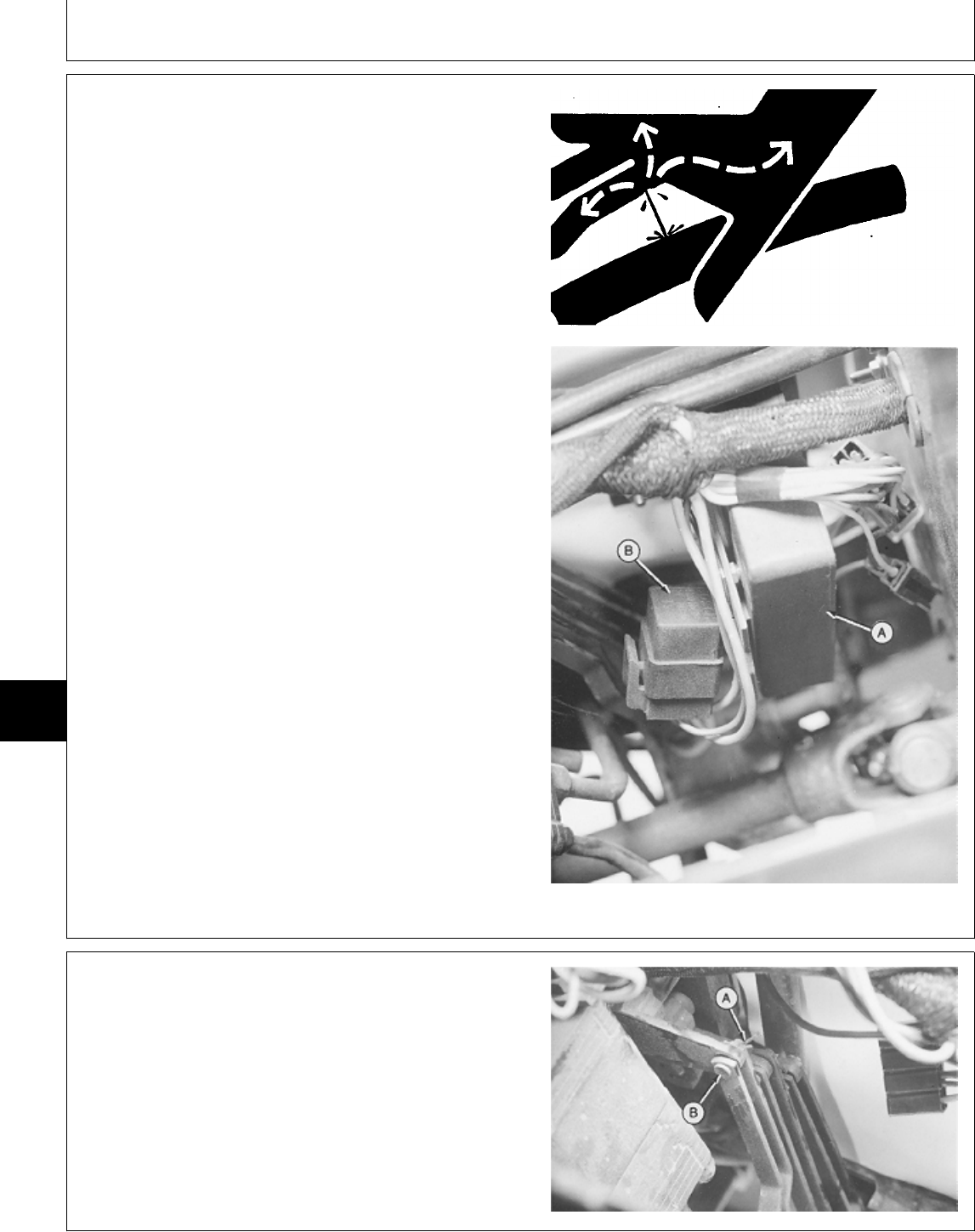
REMOVE AND INSTALL HYDRAULIC
CONTROL VALVE—430
NCAUTION: Escaping fluid under pressure can
penetrate the skin causing serious injury.
Avoid the hazard by relieving pressure before
disconnecting hydraulic or other lines. Tighten
all connections before applying pressure.
Search for leaks with a piece of cardboard.
Protect hands and body from high pressure
fluids.
If an accident occurs, see a doctor
immediately. Any fluid injected into the skin
must be surgically removed within a few hours
or gangrene may result. Doctors unfamiliar
with this type of injury should reference a
knowledgeable medical source. Such
information is available from Deere & Company
Medical Department in Moline, Illinois, U.S.A.
NOTE: Removal and installation procedures for later
models may vary slightly.
1. Remove battery and battery tray.
2. Remove TDC module (A) and neutral start relay (B).
X9811 -UN-23AUG88
M36784 -UN-25JAN90
3. Remove three cotter pins (A) (one from each linkage)
and pins (B).
M36785 -UN-25JAN90
MX,15917005,9 -19-13JUL95
MX,15917005,10 -19-13JUL95
Hydraulic Control Valve/Remove and Install
TM1591 (15JUL95) 70-05-6 322,330,332 & 430 Lawn & Garden Tractors
030895
70
05
6
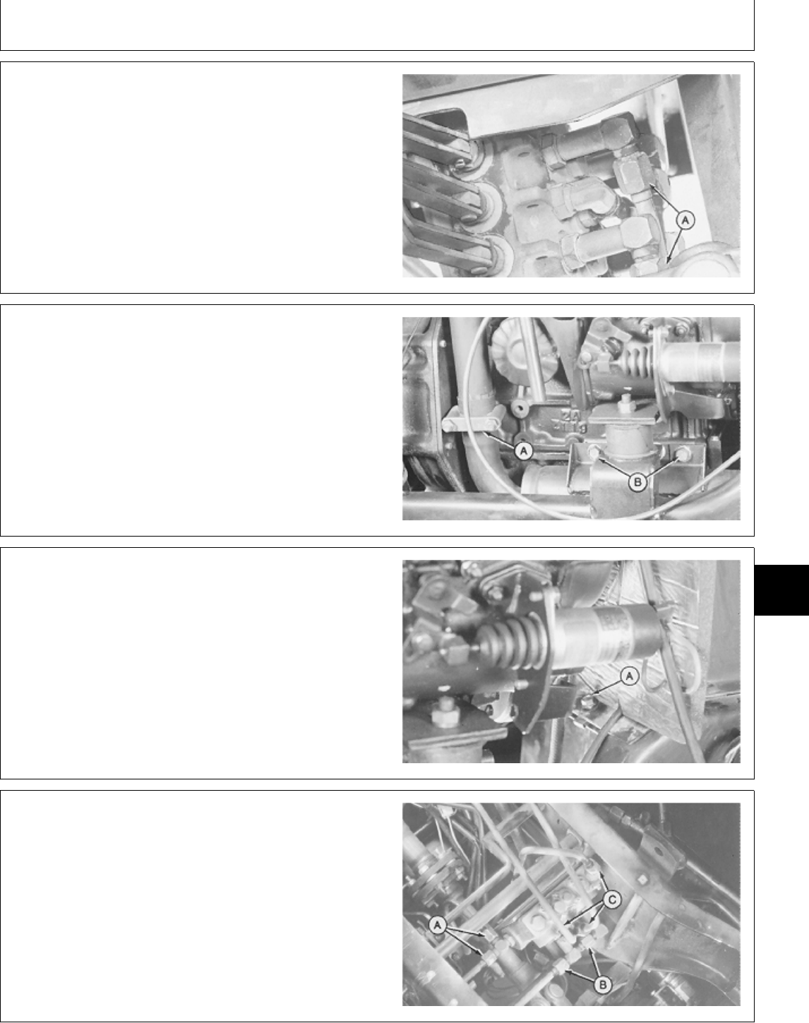
4. Disconnect two hydraulic lines (A) from top side of
control valve.
M36786 -UN-25JAN90
5. Remove both engine side panels.
6. Loosen muffler clamp (A) and remove two cap screws
(B).
7. Remove belly pan.
M36787 -UN-25JAN90
8. Remove two cap screws (A) (one on each side of
firewall) that fasten lower shield plate.
9. Remove two small cap screws fastening muffler to
engine block. Remove muffler.
M36788 -UN-25JAN90
10. Remove shield plate from under machine.
11. Disconnect remaining hydraulic lines (A, B and C)
from bottom side of control valve.
12. Remove two mounting bolts and control valve.
13. Make repairs as necessary. (See procedures in this
group.)
M36790 -UN-25JAN90
MX,15917005,11 -19-13JUL95
MX,15917005,12 -19-13JUL95
MX,15917005,13 -19-13JUL95
MX,15917005,14 -19-13JUL95
Hydraulic Control Valve/Remove and Install
TM1591 (15JUL95) 70-05-7 322,330,332 & 430 Lawn & Garden Tractors
030895
70
05
7
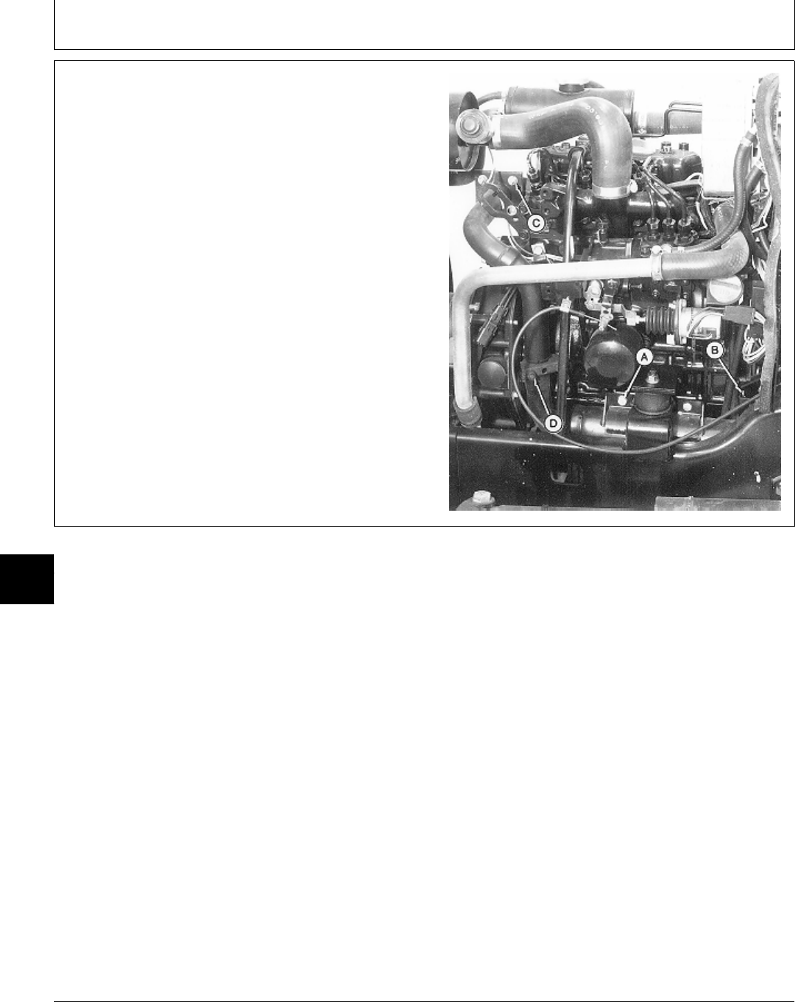
14. Installation is done in the reverse order of removal.
IMPORTANT: Tighten exhaust mounting hardware in
sequence described. Failure to do so,
may create binding around exhaust
system resulting in muffler breaking
off.
• Install muffler as follows:
—Loosen four cap screws (C).
—Install muffler. Tighten mounting hardware finger-tight.
—Tighten exhaust mounting hardware in the following
sequence:
A—Muffler-to-Engine Mount Cap Screw (2 used)
B—Muffler-to-Gear Case Cover Cap Screw (2 used)
C—Exhaust Pipe-to-Manifold Cap Screw (4 used)
D—Muffler Clamp Nut (2 used)
• Bleed the hydraulic system. (See procedure in Section
270, Group 20.)
M77310 -UN-15DEC94
MX,15917005,15 -19-13JUL95
Hydraulic Control Valve/Remove and Install
TM1591 (15JUL95) 70-05-8 322,330,332 & 430 Lawn & Garden Tractors
030895
70
05
8
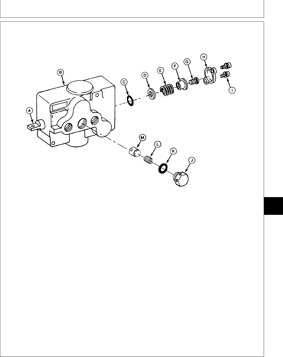
DISASSEMBLE, INSPECT AND ASSEMBLE HYDRAULIC CONTROL
VALVE—SINGLE-SPOOL
A—Spool E—Spring H—Cap K—O-Ring
B—Body F—Spring Retainer I—Screw (2 used) L—Spring
C—O-Ring G—Screw J—Plug M—Poppet
D—Washer
IMPORTANT: Spool and body are matched and
must be replaced as a unit.
Always use new O-rings. Damaged
or used parts will leak.
NOTE: Note location and position of fittings and
linkage to aid in assembly.
Lubricate all O-rings with petroleum jelly
during assembly.
Inspect all parts for wear or damage. Replace as
necessary.
• Apply clean John Deere Low Viscosity HY-GARD®
oil on all internal parts during assembly.
• Clean threads in end of spool (A) and on screw (G)
using Clean and Cure Primer. Apply thread lock and
sealer (medium strength) on threads of screw (G).
• Apply MPG-2® Multi-Purpose Polymer Grease on
spring (E) and inside of cap (H).
• Tighten screws (G and I) and plug (J) to
specifications.
TORQUE SPECIFICATIONS
Screws (G and I) . . . . . . . . . . . . . . . . . . . . . . 4 N·m (35 lb-in.)
Plug (J) . . . . . . . . . . . . . . . . . . . . . . . . . . . . 31 N·m (23 lb-ft)
M78058 -UN-24MAR95
MX,15907005,6 -19-25APR95
Hydraulic Control Valve/Disassemble, Inspect and Assemble
TM1591 (15JUL95) 70-05-9 322,330,332 & 430 Lawn & Garden Tractors
030895
70
05
9
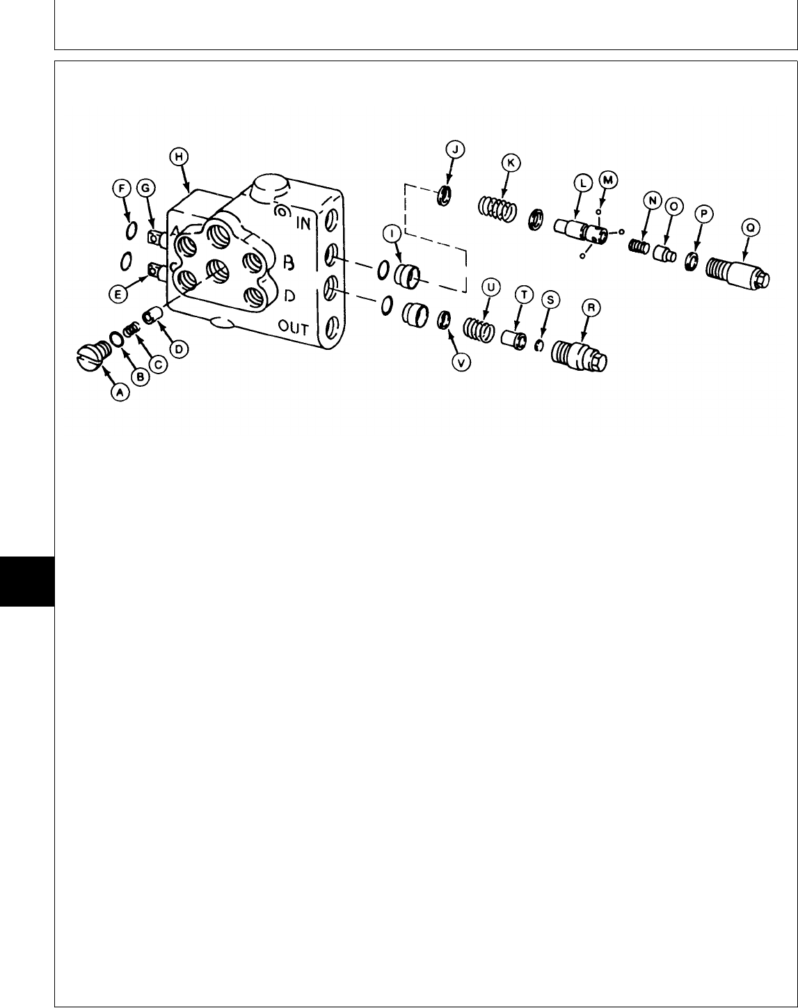
DISASSEMBLE, INSPECT AND ASSEMBLE HYDRAULIC CONTROL VALVE—TWO-SPOOL
A—Check Valve Plug (2 F—O-Ring (4 used) L—Detent R—Cap
used) G—Float Detent Spool M—Ball (3 used) S—Snap Ring
B—O-Ring (2 used) H—Body N—Spring T—Spacer
C—Spring (2 used) I—Bushing (2 used) O—Cap U—Spring
D—Poppet (2 used) J—Washer (2 used) P—Washer V—Washer
E—Spool K—Spring Q—Cap
Versions One and Two
NOTE: There are four versions of this valve.
Disassembly and assembly procedures may
vary slightly.
IMPORTANT: Spools and body are matched and
must be replaced as a unit. Spools
must be installed into the same
bores from which they were
removed for proper operation of
each function.
Always use new O-rings. Damaged
or used parts will leak.
NOTE: Note location and position of fittings and
linkages to aid in assembly.
Lubricate all O-rings with petroleum jelly
during assembly.
Inspect all parts for wear or damage. Replace as
necessary.
• Apply clean John Deere Low Viscosity HY-GARD®
oil on all internal parts during assembly.
• Apply MPG-2® Multi-Purpose Polymer Grease on
springs (K, N and U) and inside of caps (Q and R).
• Tighten caps (Q and R) to 31 N·m (23 lb-ft).
M78840 -UN-14APR95
MX,15917005,16 -19-13JUL95
Hydraulic Control Valve/Disassemble, Inspect and Assemble
TM1591 (15JUL95) 70-05-10 322,330,332 & 430 Lawn & Garden Tractors
030895
70
05
10
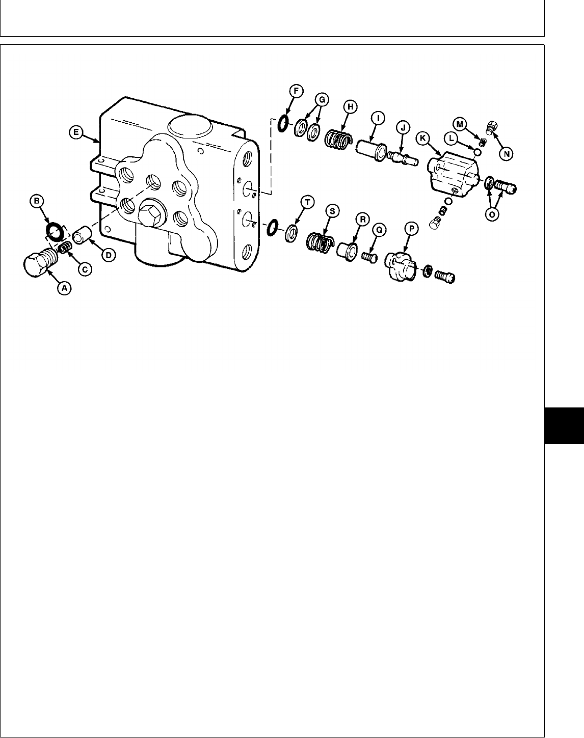
A—Check Valve Plug (2 F—O-Ring (4 used) L—Ball (2 used) P—Cap
used) G—Washers M—Spring (2 used) Q—Screw
B—O-Ring (2 used) H—Spring N—Plug (2 used) R—Spacer
C—Spring (2 used) I—Spacer O—Screw and Washer (4 S—Spring
D—Poppet (2 used) J—Detent used) T—Washer
E—Spools and Body K—Cap
Versions Three and Four
IMPORTANT: Spools and body are matched and
must be replaced as a unit. Spools
must be installed into the same
bores from which they were
removed for proper operation of
each function.
Always use new O-rings. Damaged
or used parts will leak.
NOTE: Note location and position of fittings and
linkages to aid in assembly.
Lubricate all O-rings with petroleum jelly
during assembly.
Inspect all parts for wear or damage. Replace as
necessary.
• Apply clean John Deere Low Viscosity HY-GARD®
oil on all internal parts during assembly.
• Clean threads in end of spools, detent (J) and
screw (Q) using Clean and Cure Primer. Apply thread
lock and sealer (medium strength) on threads of
detent (J) and screw (Q).
• Apply MPG-2® Multi-Purpose Polymer Grease on
springs (H and S) and inside of caps (K and P).
• Tighten detent (J), screw (Q), screw and washers
(O) and plugs (A) to specifications.
TORQUE SPECIFICATIONS
Detent (J), Screw (Q) and
Screw and Washers (O) . . . . . . . . . . . . . . . . . 4 N·m (35 lb-in.)
Plugs (A) . . . . . . . . . . . . . . . . . . . . . . . . . . . 31 N·m (23 lb-ft)
M78841 -UN-14APR95
MX,15917005,17 -19-13JUL95
Hydraulic Control Valve/Disassemble, Inspect and Assemble
TM1591 (15JUL95) 70-05-11 322,330,332 & 430 Lawn & Garden Tractors
030895
70
05
11
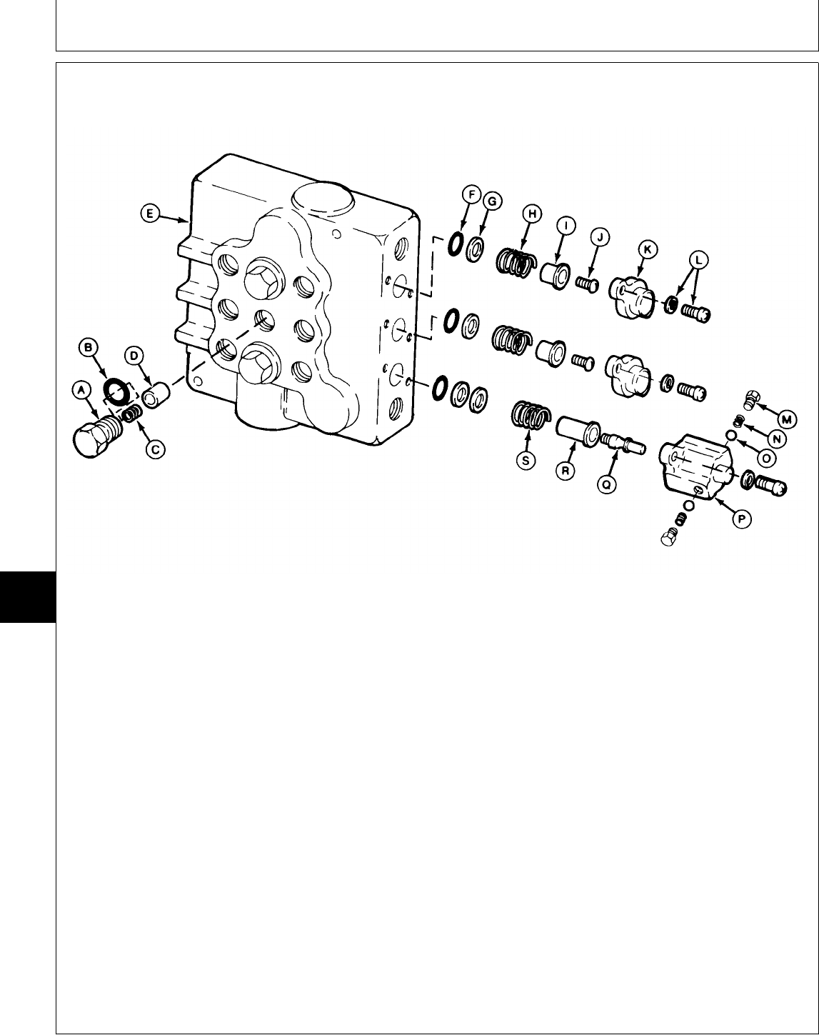
DISASSEMBLE, INSPECT AND ASSEMBLE HYDRAULIC CONTROL
VALVE—THREE-SPOOL
A—Check Valve Plug (3 F—O-Ring (6 used) K—Cap (2 used) O—Ball (2 used)
used) G—Washer (4 used) L—Screw and Washer (6 P—Cap
B—O-Ring (3 used) H—Spring (2 used) used) Q—Detent
C—Spring (3 used) I—Spacer (2 used) M—Plug (2 used) R—Spacer
D—Poppet (3 used) J—Screw (2 used) N—Spring (2 used) S—Spring
E—Spools and Body
IMPORTANT: Spools and body are matched and
must be replaced as a unit. Spools
must be installed into the same
bores from which they were
removed for proper operation of
each function.
Always use new O-rings. Damaged
or used parts will leak.
NOTE: Note location and position of fittings and
linkages to aid in assembly.
Lubricate all O-rings with petroleum jelly
during assembly.
Inspect all parts for wear or damage. Replace as
necessary.
• Apply clean John Deere Low Viscosity HY-GARD®
oil on all internal parts during assembly.
• Clean threads in end of spools, detent (Q) and
screws (J) using Clean and Cure Primer. Apply
thread lock and sealer (medium strength) on threads
of detent (Q) and screws (J).
• Apply MPG-2® Multi-Purpose Polymer Grease on
springs (H and S) and inside of caps (K and P).
• Tighten detent (Q), screws (J), screw and washers
(L) and plugs (A) to specifications.
TORQUE SPECIFICATIONS
Detent (Q), Screws (J) and
Screw and Washers (L) . . . . . . . . . . . . . . . . . 4 N·m (35 lb-in.)
Plugs (A) . . . . . . . . . . . . . . . . . . . . . . . . . . . 31 N·m (23 lb-ft)
M78843 -UN-14APR95
MX,15917005,18 -19-13JUL95
Hydraulic Control Valve/Disassemble, Inspect and Assemble
TM1591 (15JUL95) 70-05-12 322,330,332 & 430 Lawn & Garden Tractors
030895
70
05
12

Section 80
MISCELLANEOUS REPAIR
Contents
Page
Group 05—Front Axle
Special or Essential Tools . . . . . . . . . . . 80-05-1
Front Axle—322, 330 and 332
Remove and Install . . . . . . . . . . . . . . 80-05-1
Inspect and Replace Pivot Bushings . . . 80-05-2
Front Axle—430
Remove . . . . . . . . . . . . . . . . . . . . . 80-05-3
Disassemble and Inspect Pivot Pin . . . 80-05-5
Assemble Pivot Pin . . . . . . . . . . . . . . 80-05-6
Install . . . . . . . . . . . . . . . . . . . . . . . 80-05-7
Spindles
Remove and Install . . . . . . . . . . . . . . 80-05-9
Inspect and Replace Bushings . . . . . . 80-05-11
Inspect and Replace Wheel Bearings . . . 80-05-12
Adjust Toe-in . . . . . . . . . . . . . . . . . . . . 80-05-12
Group 10—Mower Spindle and Jack Sheave
Repair
Mower Blade Spindles
38 (Early), 46 and 50-Inch Mower . . . . 80-10-1
38-Inch Mower (Later) . . . . . . . . . . . . 80-10-1
Early 60-Inch and 260 Rotary Mower . . 80-10-2
Later 60-Inch and 260 Rotary Mower . . 80-10-3
Mower Blade Jack Sheaves
46 and 50-Inch Mower . . . . . . . . . . . . 80-10-4
Group 15—Mower Gear Case Repair
Other Materials . . . . . . . . . . . . . . . . . . 80-15-1
50-Inch Mower
Disassemble and Inspect . . . . . . . . . . 80-15-1
Assemble . . . . . . . . . . . . . . . . . . . . 80-15-6
Early 60-Inch Mower (Curtis)
Disassemble and Inspect . . . . . . . . . . 80-15-10
Assemble . . . . . . . . . . . . . . . . . . . . 80-15-14
Later 60-Inch Mower (Peerless)
Disassemble and Inspect . . . . . . . . . . 80-15-19
Assemble . . . . . . . . . . . . . . . . . . . . 80-15-23
260 Rotary Mower
Disassemble and Inspect . . . . . . . . . . 80-15-27
Assemble . . . . . . . . . . . . . . . . . . . . 80-15-32
TM1591 (15JUL95) 80-1 322,330,332 & 430 Lawn & Garden Tractors
030895
80

Contents
TM1591 (15JUL95) 80-2 322,330,332 & 430 Lawn & Garden Tractors
030895
80
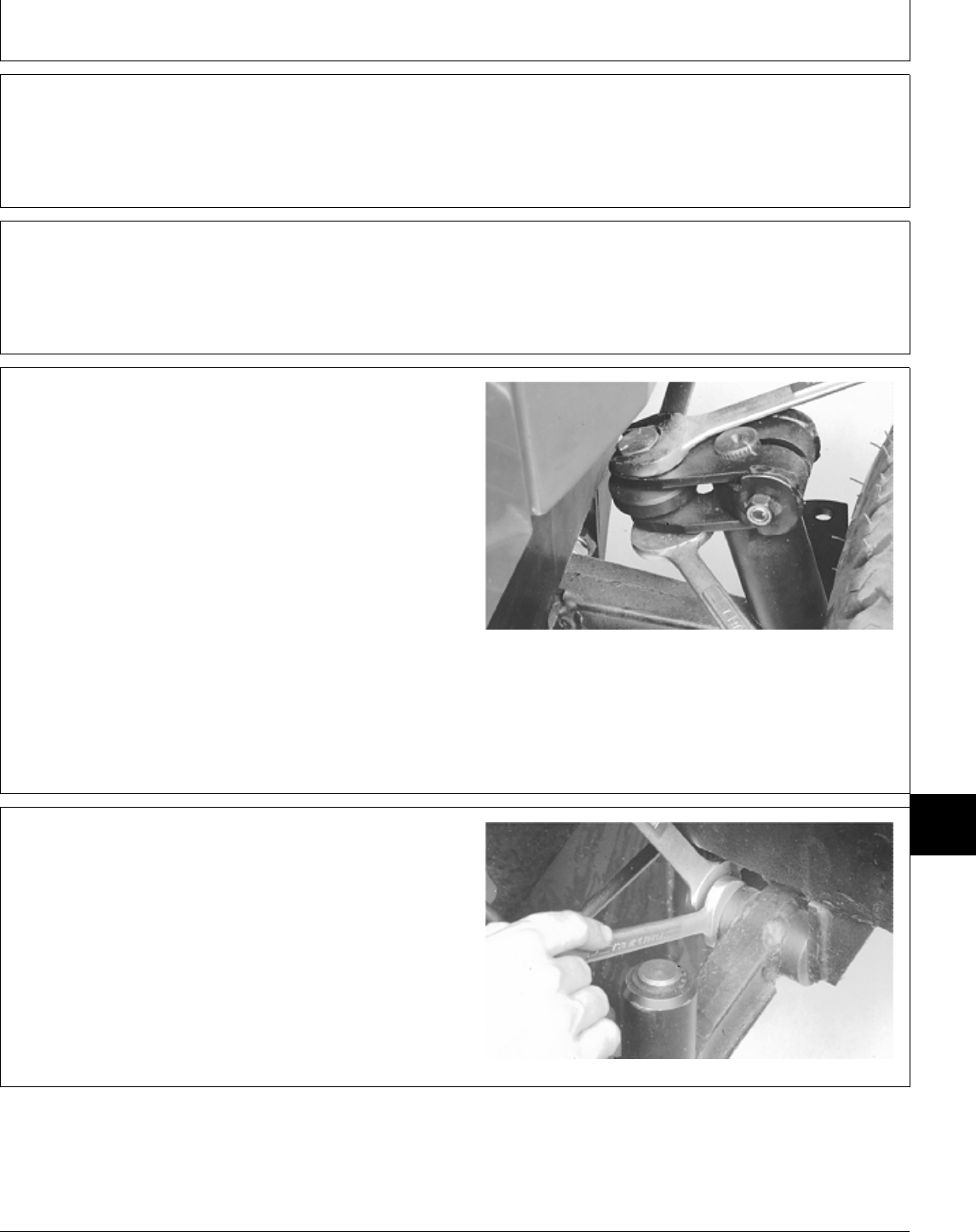
SPECIAL OR ESSENTIAL TOOLS
NOTE: Order tools according to information given in the
U.S. SERVICE-GARD™ Catalog or in the
European Microfiche Tool Catalog (MTC).
Installer Sleeve.............................JDM8-3
For 430 tractor; Used to install PTO shaft asssembly into
pivot pin.
REMOVE AND INSTALL FRONT AXLE—322,
330 AND 332
NOTE: The 330 has manual steering and is connected
to the steering arm by a drag link. The 322 and
332 have power steering and are connected to
the steering arm by a cylinder.
1. Raise front of machine and block securely with jack
stands.
2. Remove cotter pin, if equipped, from steering
link/cylinder at steering arm on spindle. 322 and 332 Shown
3. Remove nut and bolt (322 and 332) from arm.
4. Disconnect steering link/cylinder from spindle.
M31963 -UN-28JUL89
5. Loosen axle deflector adjustment bolts and turn in to
allow maximum clearance.
M32000 -UN-03AUG89
DX,TOOLS -19-05JUN91
MX,15918005,A -19-08MAR95
MX,15918005,1 -19-13JUL95
MX,15908005,2 -19-15FEB95
Group 05
Front Axle
TM1591 (15JUL95) 80-05-1 322,330,332 & 430 Lawn & Garden Tractors
030895
80
05
1
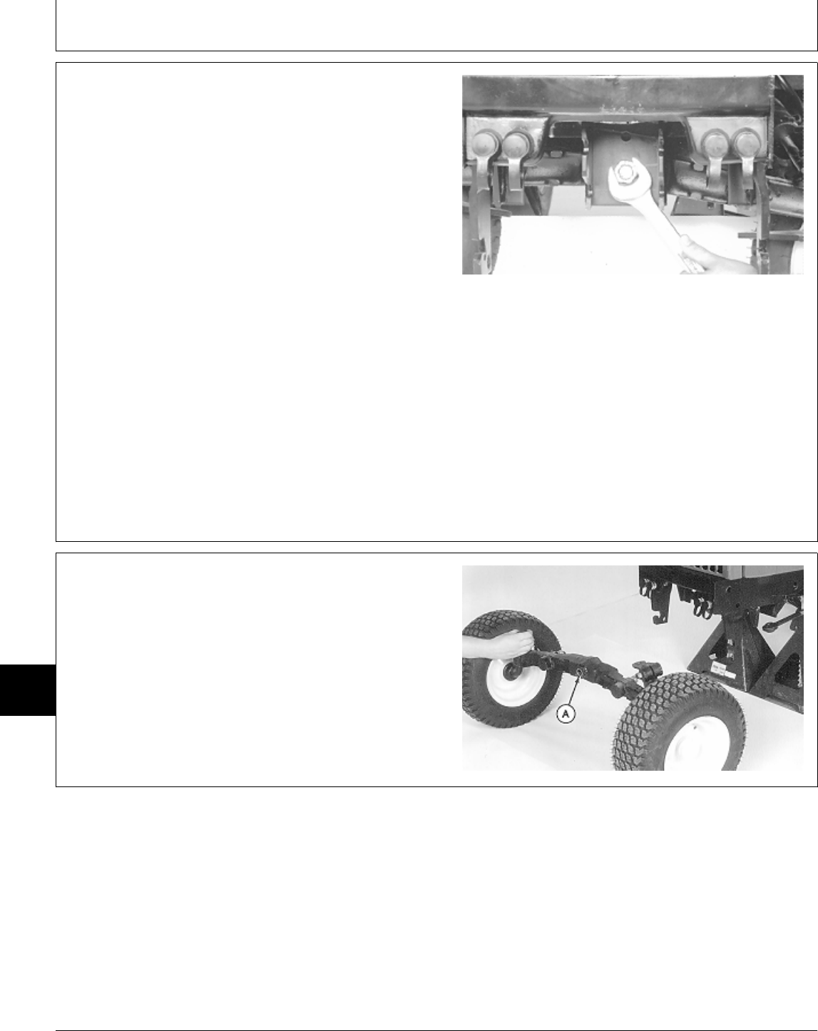
6. Place a floor jack under center of axle.
7. Remove cotter pin from pivot bolt.
8. Remove pivot bolt nut and remove bolt through axle
(towards rear). Remove axle.
9. Inspect axle and pivot bushings for damage or wear.
(See procedure in this group.)
10. Installation is done in the reverse order of removal.
• Apply multipurpose grease to pivot bolt before
installing.
• Tighten pivot bolt nut until axle is snug, but still free to
pivot.
• Adjust axle deflector adjustment bolts for smooth up
and down operation of axle. Axle should move freely
without sticking in one spot.
M32002 -UN-03AUG89
INSPECT AND REPLACE PIVOT
BUSHINGS—322, 330 AND 332
1. Inspect pivot bushings (A) and pivot bolt for wear or
damage. The pivot bolt should not be bent or have
stripped threads.
2. Replace bushings if necessary, using a driver set.
3. Inspect the axle for bends, cracks, or damage.
Replace any damaged components.
M31582 -UN-17FEB95
MX,15908005,3 -19-08MAR95
MX,15918005,2 -19-13JUL95
Front Axle/Front Axle—322, 330 and 332
TM1591 (15JUL95) 80-05-2 322,330,332 & 430 Lawn & Garden Tractors
030895
80
05
2
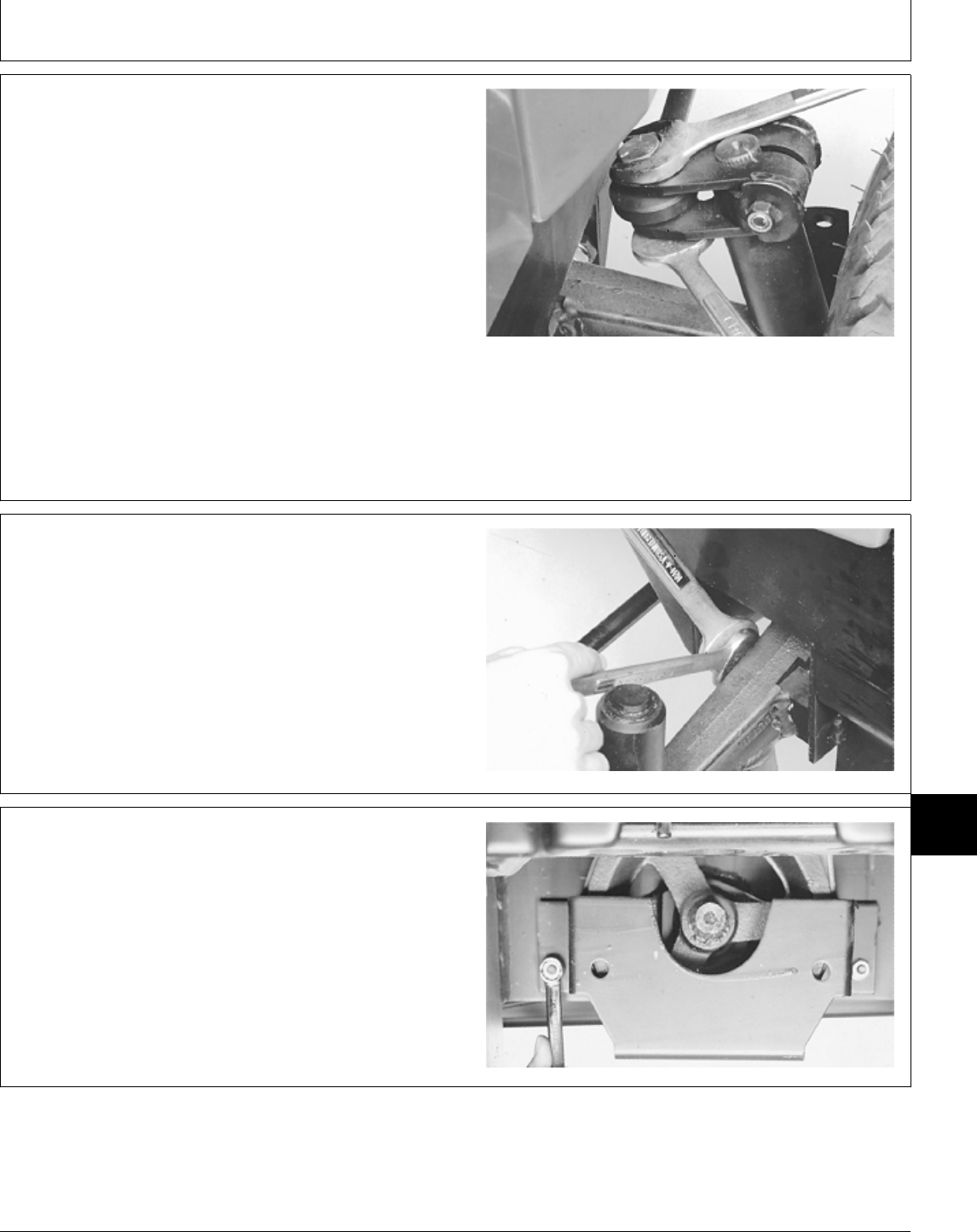
REMOVE FRONT AXLE—430
1. Raise front of machine and block securely with jack
stands.
2. Remove front PTO extension, if equipped.
3. Remove cotter pin, if equipped, from steering cylinder
at steering arm on spindle.
4. Remove nut and bolt from steering arm. Disconnect
steering cylinder from steering arm.
M31963 -UN-28JUL89
5. Loosen axle deflector adjustment bolts and turn in to
allow maximum clearance.
M31970 -UN-03AUG89
6. Remove engine side panels and front grille.
7. Remove two nuts to remove belt guard.
M35471 -UN-16NOV89
MX,15918005,3 -19-13JUL95
MX,15908005,6 -19-15FEB95
MX,15918005,4 -19-13JUL95
Front Axle/Front Axle—430
TM1591 (15JUL95) 80-05-3 322,330,332 & 430 Lawn & Garden Tractors
030895
80
05
3
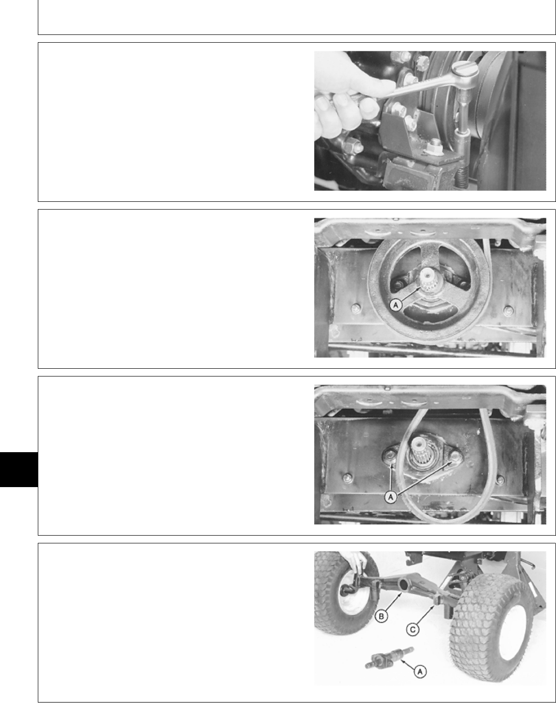
8. Loosen belt tensioning nut as far as possible.
M35472 -UN-16NOV89
9. Remove snap ring (A) from PTO shaft.
10. Remove belts from drive pulley.
NOTE: It may be necessary to remove the four radiator
shroud-to-radiator screws. This allows shroud to
move to allow clearance for removing PTO
pulley.
11. Remove drive pulley from PTO shaft.
M36800 -UN-25JAN90
12. Remove two pivot pin retaining nuts (A).
M36801 -UN-29JAN90
13. Place a floor jack under center of axle.
14. Slide pivot pin (A) out towards front of tractor.
Remove axle.
15. Inspect pivot pin bore (B) and axle (C) for damage
or excessive wear. Replace axle if necessary.
16. Inspect pivot pin for damage or wear. (See
procedure in this group.)
M31998 -UN-03AUG89
MX,15918005,5 -19-13JUL95
MX,15918005,6 -19-13JUL95
MX,15918005,7 -19-13JUL95
MX,15918005,8 -19-13JUL95
Front Axle/Front Axle—430
TM1591 (15JUL95) 80-05-4 322,330,332 & 430 Lawn & Garden Tractors
030895
80
05
4
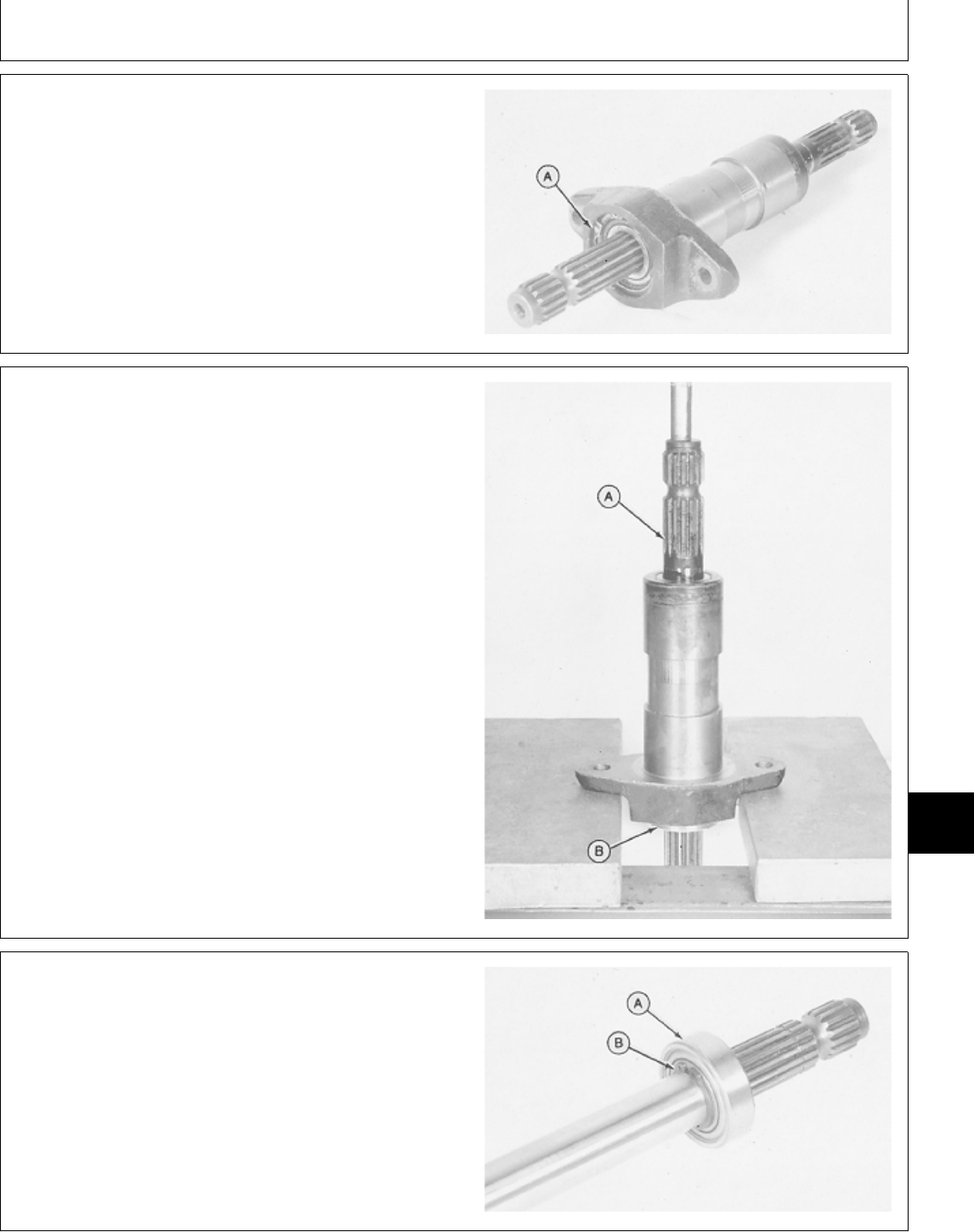
DISASSEMBLE AND INSPECT PIVOT
PIN—430
1. Remove snap ring (A).
M36802 -UN-29JAN90
2. Push PTO shaft (A) and bearing (B) from pivot pin
using a press.
M36803 -UN-25JAN90
3. Inspect PTO shaft bearing (A) for wear or damage.
Replace if necessary.
4. If replacing bearing, remove snap ring (B).
5. Push PTO shaft from bearing using a press and a
knife-edge puller.
M36804 -UN-29JAN90
MX,15918005,9 -19-13JUL95
MX,15908005,13 -19-15FEB95
MX,15908005,14 -19-15FEB95
Front Axle/Front Axle—430
TM1591 (15JUL95) 80-05-5 322,330,332 & 430 Lawn & Garden Tractors
030895
80
05
5
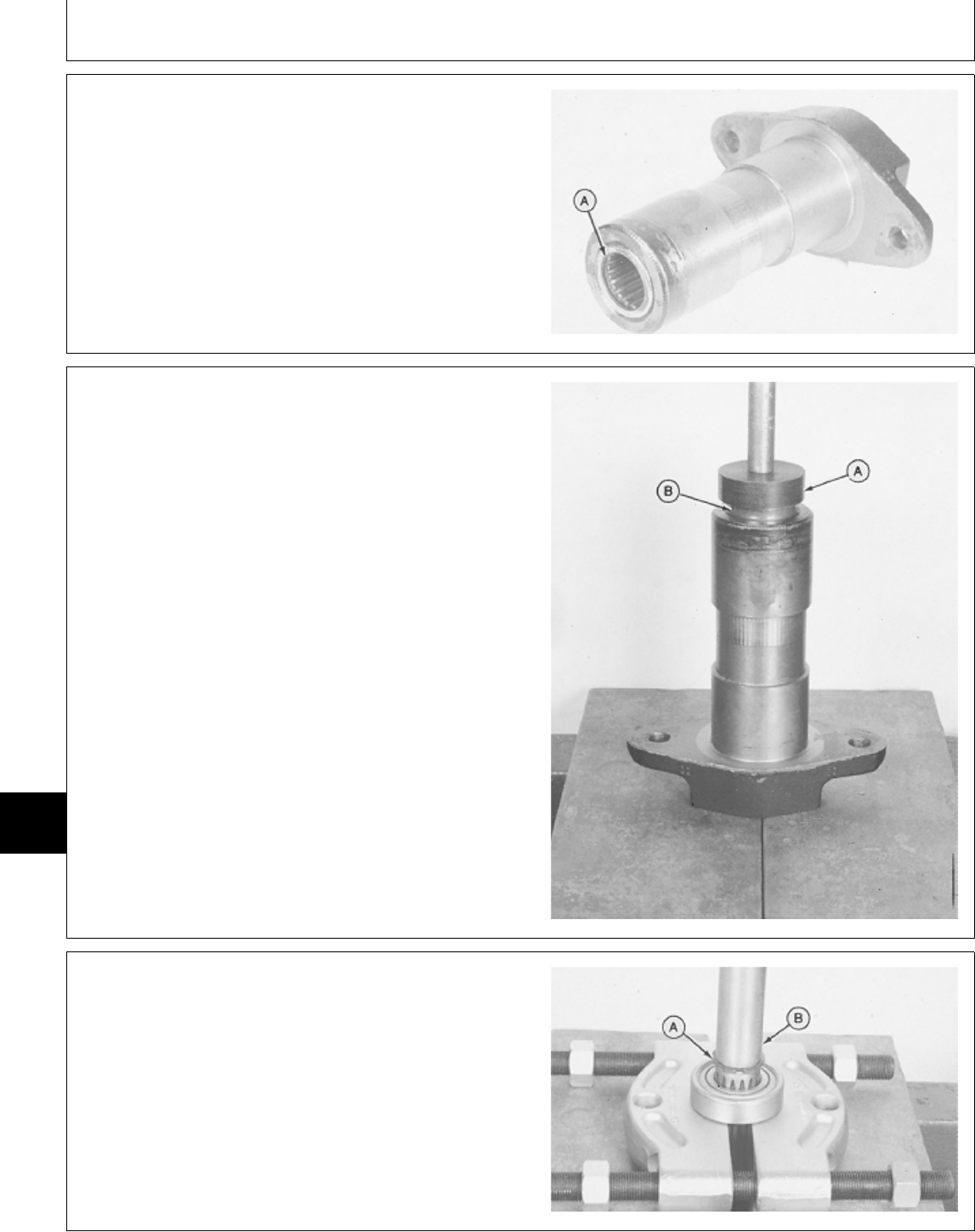
6. Inspect caged needle bearing (A) for wear or damage.
Replace if necessary.
7. Remove needle bearing using a blind hole puller set
and a slide hammer.
M36806 -UN-25JAN90
ASSEMBLE PIVOT PIN—430
1. Support pivot pin on a press. Put a driver disk (A) on
bearing (B). Install bearing using a press until disk
bottoms on pivot pin.
M36808 -UN-25JAN90
2. Install snap ring (A) on PTO shaft.
3. Support bearing on a knife-edge puller. Press PTO
shaft (B) into bearing until it bottoms on snap ring.
M36809 -UN-25JAN90
MX,15908005,15 -19-15FEB95
MX,15918005,10 -19-13JUL95
MX,15908005,17 -19-07MAR95
Front Axle/Front Axle—430
TM1591 (15JUL95) 80-05-6 322,330,332 & 430 Lawn & Garden Tractors
030895
80
05
6
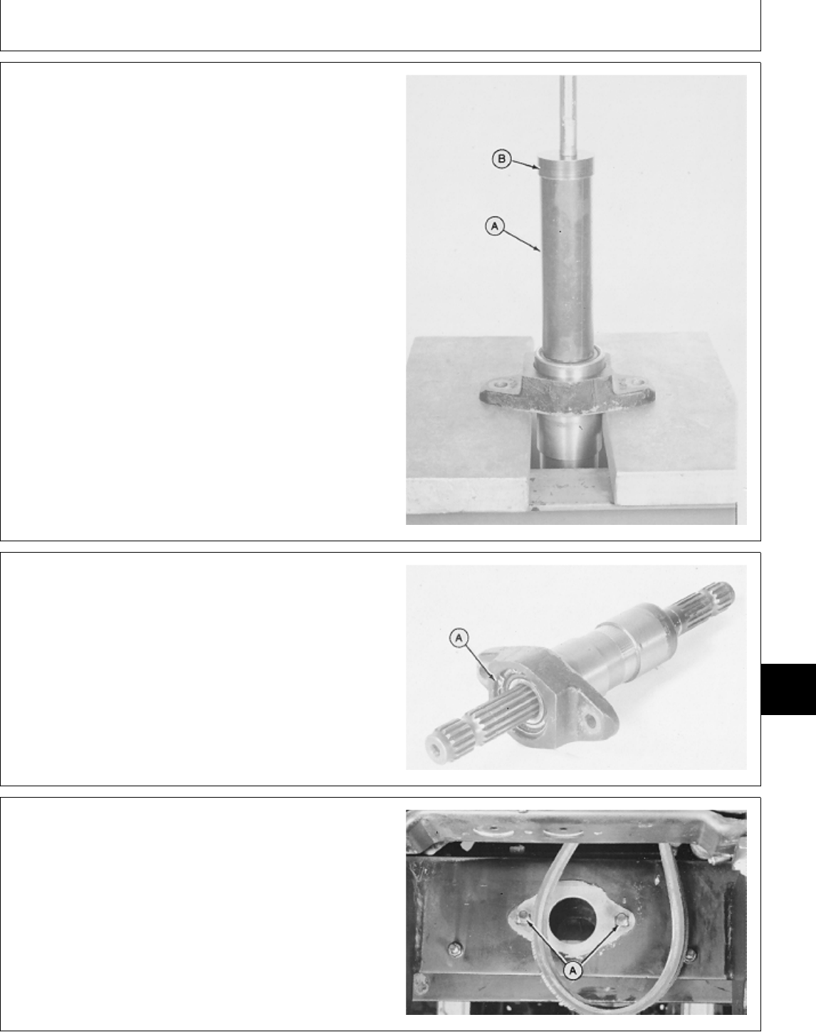
4. Support pivot pin on a press. Install PTO shaft
assembly into pivot pin.
5. Put JDM8-3 Installation Sleeve (A) or a piece of pipe
over PTO shaft. Put a suitable size driver disk (B) on
Sleeve or pipe.
6. Press shaft assembly into pivot pin until bearing
bottoms in bore.
M36810 -UN-25JAN90
7. Install snap ring (A).
M36802 -UN-29JAN90
INSTALL FRONT AXLE—430
1. Install two pivot pin bolts (A) through machine frame.
2. Fasten cap screws with tape to back of frame to keep
them from falling out when installing axle.
M36811 -UN-25JAN90
MX,15908005,18 -19-07MAR95
MX,15908005,19 -19-15FEB95
MX,15918005,11 -19-13JUL95
Front Axle/Front Axle—430
TM1591 (15JUL95) 80-05-7 322,330,332 & 430 Lawn & Garden Tractors
030895
80
05
7
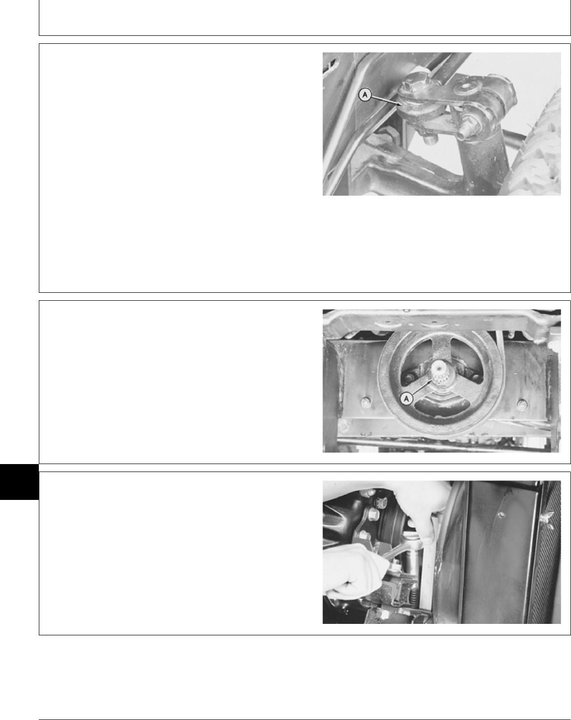
3. Install axle under front of machine.
4. Raise left wheel off ground enough to connect
steering cylinder end (A) to steering arm. Then put
blocks under left front wheel.
5. Lift right side of axle to align pivot hole with hole in
frame.
6. Slide pivot pin through frame and axle.
7. Secure pivot pin to frame with retaining nuts.
M36812 -UN-25JAN90
8. Slide drive pulley onto PTO shaft.
9. Install snap ring (A) in PTO shaft groove.
10. Install belts on pulley.
11. Install PTO pulley guard.
12. Install radiator shroud-to-radiator screws, if removed.
M36800 -UN-25JAN90
13. Tighten belt tensioning nut until spring measures 35
mm (1.380 in.).
14. Install front grille and engine side panels.
15. Install front PTO extension, if equipped.
M35665 -UN-27NOV89
MX,15918005,12 -19-13JUL95
MX,15918005,13 -19-13JUL95
MX,15918005,14 -19-13JUL95
Front Axle/Front Axle—430
TM1591 (15JUL95) 80-05-8 322,330,332 & 430 Lawn & Garden Tractors
030895
80
05
8
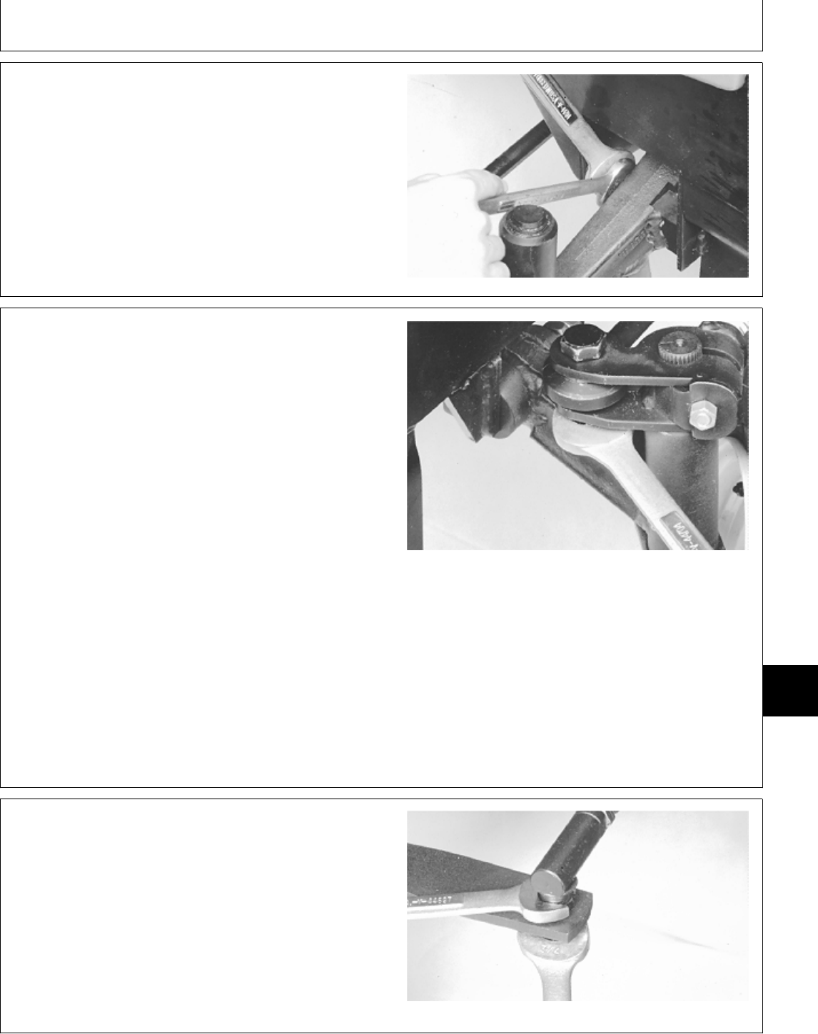
16. Adjust axle deflector bolts for smooth up and down
operation of axle.
17. Test for proper axle deflector adjustment, by pushing
down on a wheel. The axle should move freely without
sticking in one spot. Readjust if necessary.
18. Lower tractor from jack stands.
M31970 -UN-03AUG89
REMOVE AND INSTALL SPINDLES
NOTE: The 330 has manual steering and is connected
to the steering arm by a drag link. The 322, 332
and 430 have power steering and are connected
to the steering arm by a cylinder.
1. Raise front of machine and block securely with jack
stands.
2. Remove front wheels.
3. Remove cotter pin, if equipped, from steering
link/cylinder at steering arm on left spindle. 322 and 332 Shown
4. Remove nut and bolt (322, 332 and 430) from arm.
5. Disconnect steering link/cylinder from steering arm.
M32067 -UN-03AUG89
6. Disconnect both tie rod ends and remove tie rod.
M32068 -UN-03AUG89
MX,15918005,16 -19-13JUL95
MX,15918005,15 -19-13JUL95
MX,15908005,27 -19-15FEB95
Front Axle/Spindles
TM1591 (15JUL95) 80-05-9 322,330,332 & 430 Lawn & Garden Tractors
030895
80
05
9
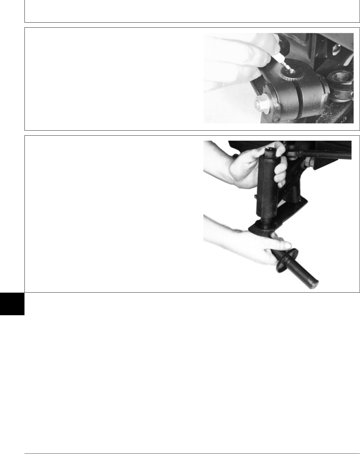
7. Put an alignment mark across top of steering arm and
left spindle to aid in installation.
8. Remove nut, washer (if equipped), bolt and steering
arm from left spindle.
M32069 -UN-03AUG89
9. Slide left spindle down out of axle to remove.
M78701 -UN-14MAR95
MX,15908005,28 -19-15FEB95
MX,15908005,29 -19-14MAR95
Front Axle/Spindles
TM1591 (15JUL95) 80-05-10 322,330,332 & 430 Lawn & Garden Tractors
030895
80
05
10
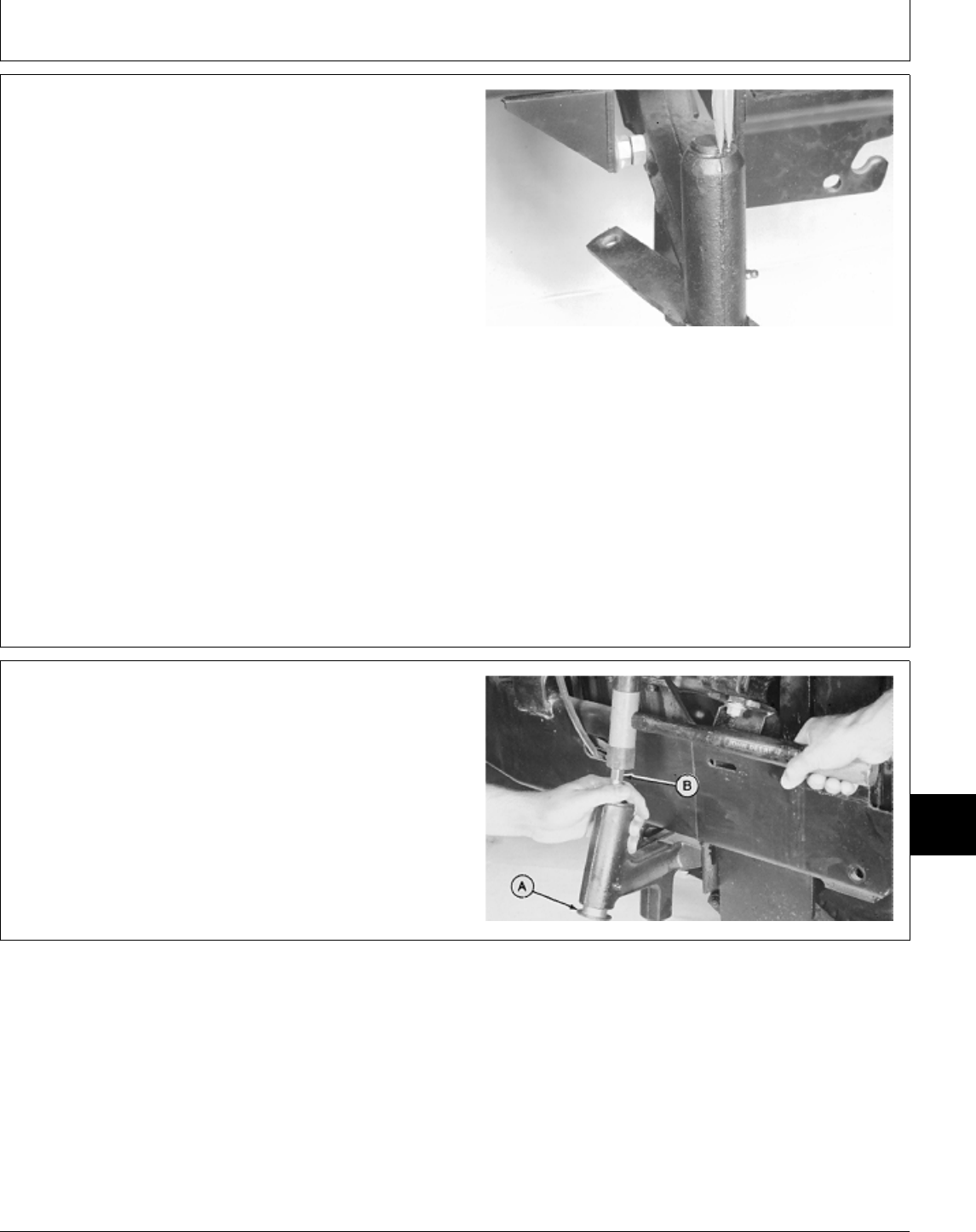
10. Remove snap ring from top of right spindle.
11. Slide right spindle down out of axle to remove.
12. Inspect spindles for wear or damage. Replace if
necessary.
13. Inspect bushings for wear or damage. Replace if
necessary. (See procedure in this group.)
14. Installation is done in the reverse order of removal.
• On left-hand side; align marks made on steering arm
and spindle shaft.
• Apply multipurpose grease to lubrication fittings.
• Adjust toe-in. (See procedure in this group.)
M32072 -UN-03AUG89
INSPECT AND REPLACE SPINDLE
BUSHINGS
1. Remove spindles. (See procedure in this group.)
2. Remove bushings (A) from axle using a long brass
drift and a plastic headed hammer.
3. Install new bushings using a plastic headed hammer.
Install bushings until they bottom against axle.
M36815 -UN-25JAN90
MX,15908005,30 -19-07MAR95
MX,15908005,31 -19-15FEB95
Front Axle/Spindles
TM1591 (15JUL95) 80-05-11 322,330,332 & 430 Lawn & Garden Tractors
030895
80
05
11
INSPECT AND REPLACE WHEEL BEARINGS
1. Remove front wheels.
2. The front wheels are equipped with sealed roller
bearings in both the front and rear of hub. Check the
bearings for damage by spinning the inner race by hand.
If the bearing binds or shows excessive wear, it must be
replaced.
3. Tap the bearings out from the back side with a long
drift and a hammer.
4. Install new bearings using a driver set.
M32007 -UN-03AUG89
ADJUST TOE-IN
1. Position wheels so they are pointing straight ahead.
2. Measure distance between the inner edges of the tires
at the rear.
M32064 -UN-28APR89
3. Measure front distance between tires. When properly
adjusted, front distance should be 4.8 mm (3/16 in.)
shorter than rear distance (a slight toe-in).
M32065 -UN-28APR89
MX,15908005,32 -19-12MAY95
MX,15908005,33 -19-12MAY95
MX,15908005,34 -19-15FEB95
Front Axle/Adjust Toe-in
TM1591 (15JUL95) 80-05-12 322,330,332 & 430 Lawn & Garden Tractors
030895
80
05
12

4. Loosen jam nuts and adjust tie rod to lengthen or
shorten distance.
IMPORTANT: Make sure there is free movement of
ball joints after tightening jam nuts.
5. Make certain to securely tighten jam nuts after
adjusting tie rod.
M32066 -UN-03AUG89
MX,M21,7005K,X -19-04NOV82
Front Axle/Adjust Toe-in
TM1591 (15JUL95) 80-05-13 322,330,332 & 430 Lawn & Garden Tractors
030895
80
05
13

Front Axle/Adjust Toe-in
TM1591 (15JUL95) 80-05-14 322,330,332 & 430 Lawn & Garden Tractors
030895
80
05
14
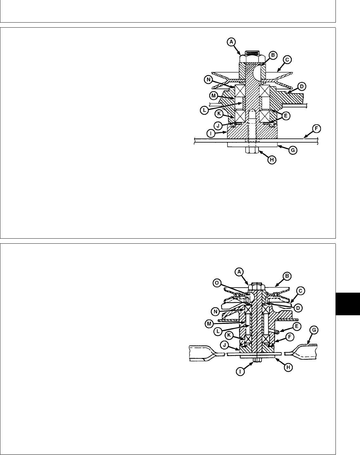
SERVICE MOWER BLADE SPINDLES—38
(EARLY), 46 AND 50-INCH MOWER
NOTE: On 50-Inch, Three-Point Hitch Mowers; some
spindles may have a grease zerk in the top end
of the spindle shaft.
If, for any reason the spindle must be disassembled, be
sure to lubricate and torque parts as required.
When assembling bearings and spacer, fill cavities (J
and M) 75 percent full of multipurpose grease.
TORQUE SPECIFICATIONS
Lock Nut (A) . . . . . . . . . . . . . . . . . . . . . . . . . . 140 N·m (103 lb-ft)
Cap Screw (H) . . . . . . . . . . . . . . . . . . . . . . . . . . 73 N·m (54 lb-ft)
A—Lock Nut H—Cap Screw
B—Key I—Spindle
C—Driven Sheave J—Grease Cavity
D—Hub K—Bearing
E—Snap Rings L—Spacer
F—Mower Blade M—Grease Cavity
G—Washer N—Bearing
M78050 -UN-21FEB95
SERVICE MOWER BLADE
SPINDLES—38-INCH MOWER (LATER)
NOTE: Some spindles may not have fan (C).
If, for any reason the spindle must be disassembled, be
sure to lubricate and torque parts as required.
After assembly, fill grease cavity (M) by applying
multipurpose grease to grease zerk (E).
TORQUE SPECIFICATIONS
Lock Nut (A) . . . . . . . . . . . . . . . . . . . . . . . . . . 140 N·m (103 lb-ft)
Cap Screw (I) . . . . . . . . . . . . . . . . . . . . . . . . . . . 73 N·m (54 lb-ft)
A—Lock Nut I—Cap Screw
B—Driven Sheave J—Spindle
C—Fan K—Bearing
D—Washer L—Spacer
E—Grease Zerk M—Grease Cavity
F—Hub N—Bearing
G—Mower Blade O—Key
H—Washer
M78051 -UN-21FEB95
MX,15908010,1 -19-13MAR95
MX,15908010,2 -19-15FEB95
Group 10
Mower Spindle and Jack Sheave Repair
TM1591 (15JUL95) 80-10-1 322,330,332 & 430 Lawn & Garden Tractors
030895
80
10
1
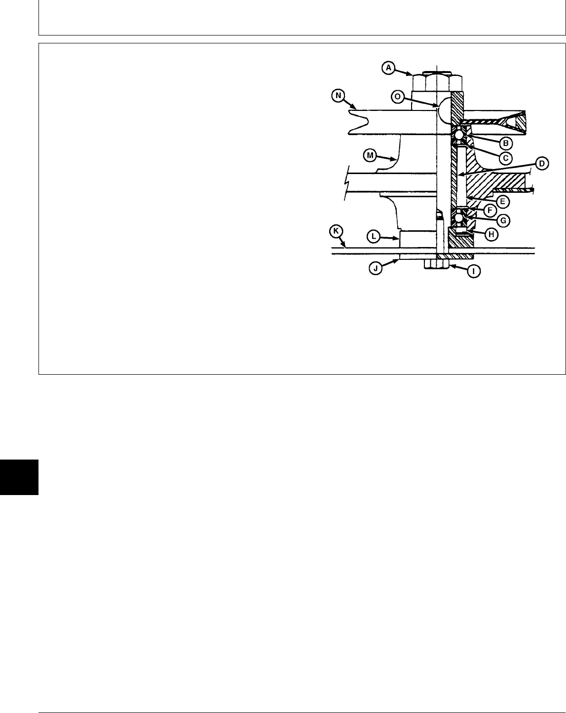
SERVICE MOWER BLADE
SPINDLES—EARLY 60-INCH AND 260
ROTARY MOWER
If, for any reason the spindle must be disassembled, be
sure to lubricate and torque parts as required.
When assembling bearings and spacer, fill cavities (E
and H) 75 percent full of multipurpose grease.
TORQUE SPECIFICATIONS
Lock Nut (A) . . . . . . . . . . . . . . . . . . . . . . . . . . 140 N·m (103 lb-ft)
Cap Screw (I) . . . . . . . . . . . . . . . . . . . . . . . . . . . 73 N·m (54 lb-ft)
A—Lock Nut I—Cap Screw
B—Bearing J—Washer
C—Snap Ring K—Mower Blade
D—Spacer L—Spindle
E—Grease Cavity M—Hub
F—Snap Ring N—Driven Sheave
G—Bearing O—Key
H—Grease Cavity
M78052 -UN-21FEB95
MX,15908010,3 -19-13MAR95
Mower Spindle and Jack Sheave Repair/Mower Blade Spindles
TM1591 (15JUL95) 80-10-2 322,330,332 & 430 Lawn & Garden Tractors
030895
80
10
2
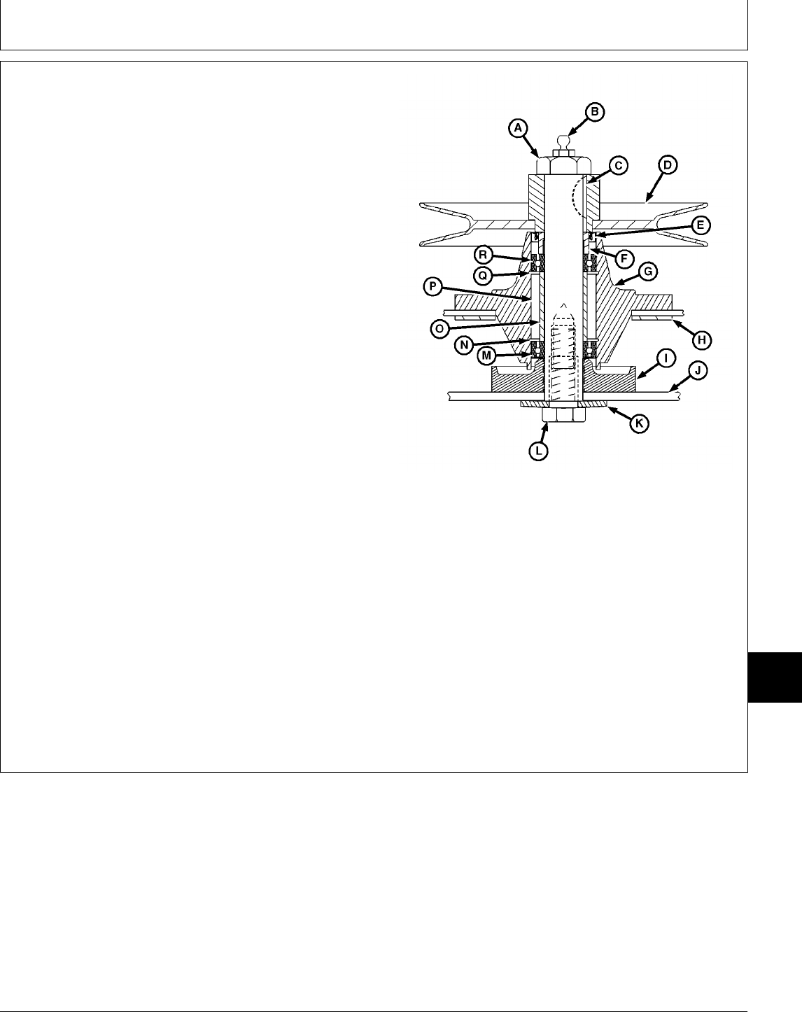
SERVICE MOWER BLADE
SPINDLES—LATER 60-INCH AND 260
ROTARY MOWER
If, for any reason the spindle must be disassembled, be
sure to lubricate and torque parts as required.
IMPORTANT: Bushing (F) must be installed with
grease grooves on end of bushing
facing bearing (R) or bearings won’t get
any grease.
Bearing (M) must be install with sealed
surface side facing away from snap
ring (N) to keep grease within grease
cavity (P) and bearing.
During assembly, install bushing (F) with grease grooves
on end of bushing facing toward bearing (R). Also, install
bearing (M) with sealed surface side facing away from
snap ring (N).
After assembly, fill grease cavity (P) by applying
multipurpose grease to grease zerk (B).
TORQUE SPECIFICATIONS
A—Lock Nut
Lock Nut (A) . . . . . . . . . . . . . . . . . . . . . . . . . . 140 N·m (103 lb-ft) B—Grease Zerk
Cap Screw (L) . . . . . . . . . . . . . . . . . . . . . . . . . . 73 N·m (54 lb-ft) C—Key
D—Driven Sheave
E—Seal
F—Bushing
G—Hub
H—Washer
I—Spindle
J—Mower Blade
K—Washer
L—Cap Screw
M—Bearing
N—Snap Ring
O—Spacer
P—Grease Cavity
Q—Snap Ring
R—Bearing
M78053 -UN-21FEB95
MX,15908010,4 -19-15FEB95
Mower Spindle and Jack Sheave Repair/Mower Blade Spindles
TM1591 (15JUL95) 80-10-3 322,330,332 & 430 Lawn & Garden Tractors
030895
80
10
3
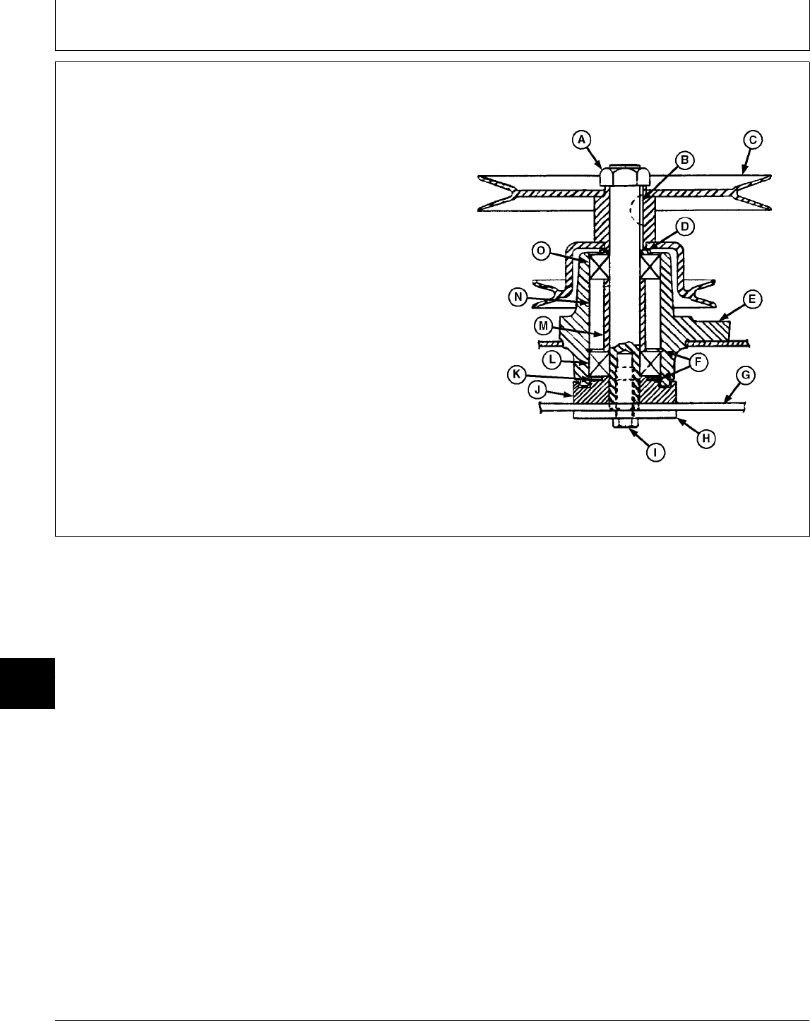
SERVICE MOWER BLADE JACK
SHEAVES—46 AND 50-INCH MOWER
Mower blade jack sheaves normally require no lubrication
or service. If, for any reason the jack sheave must be
disassembled, be sure to lubricate and torque parts as
required.
When assembling bearings and spacer, fill cavities (K
and N) 75 percent full of multipurpose grease.
TORQUE SPECIFICATIONS
Lock Nut (A) . . . . . . . . . . . . . . . . . . . . . . . . . . 140 N·m (103 lb-ft)
Cap Screw (I) . . . . . . . . . . . . . . . . . . . . . . . . . . . 73 N·m (54 lb-ft)
A—Lock Nut I—Cap Screw
B—Key J—Spindle
C—Jack Sheave K—Grease Cavity
D—Washer L—Bearing
E—Hub M—Spacer
F—Snap Rings N—Grease Cavity
G—Mower Blade O—Bearing
H—Washer
M78054 -UN-21FEB95
MX,15908010,5 -19-15FEB95
Mower Spindle and Jack Sheave Repair/Mower Blade Jack Sheaves
TM1591 (15JUL95) 80-10-4 322,330,332 & 430 Lawn & Garden Tractors
030895
80
10
4
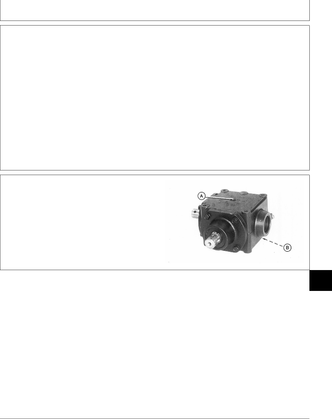
OTHER MATERIAL
Number Name Use
LOCTITE® PRODUCTS
U.S./Canadian/LOCTITE No.
TY6305/TY9485/764 Clean and Cure Primer Cleans parts and speeds cure of
sealant.
TY15130/NA/395 Form-In-Place Gasket Sealant Early 60-Inch Mower and 260
Rotary Mower; Apply to mating
surfaces of gear case and caps.
®LOCTITE is a registered trademark of the Loctite Corp.
DISASSEMBLE AND INSPECT MOWER
GEAR CASE—50-INCH MOWER
1. Remove drain plugs (A and B) and drain oil from gear
case.
M77316 -UN-24FEB95
MX,15908015,OTH-19-22FEB95
MX,15908015,1 -19-22FEB95
Group 15
Mower Gear Case Repair
TM1591 (15JUL95) 80-15-1 322,330,332 & 430 Lawn & Garden Tractors
030895
80
15
1
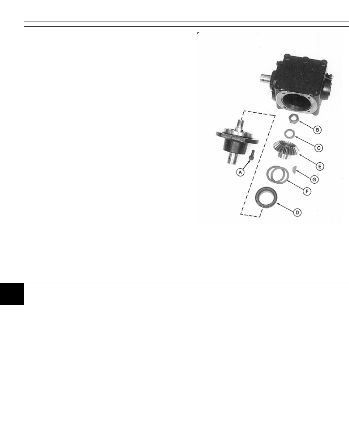
2. Remove four cap screws (A) and input shaft
assembly.
3. Remove lock nut (B), washer (C) and bevel gear (E)
and bearing from shaft.
NOTE: Bearing cone is press-fit on bevel gear. Remove
bearing only if replacement is necessary.
Bearing cone, cup in pillow block and shim(s) are
matched and must be replaced as complete
assemblies.
4. Inspect bearing cone (D) for wear or damage.
Replace if necessary.
5. Remove bearing cone from bevel gear using a
knife-edge puller and a press.
6. Remove shim(s) (F) and key (G).
A—Cap Screw (4 used)
B—Lock Nut
C—Washer
D—Bearing Cone
E—Bevel Gear
F—Shims (as required)
G—Key Input Shaft Side
M77317 -UN-24FEB95
MX,15908015,2 -19-22FEB95
Mower Gear Case Repair/50-Inch Mower
TM1591 (15JUL95) 80-15-2 322,330,332 & 430 Lawn & Garden Tractors
030895
80
15
2
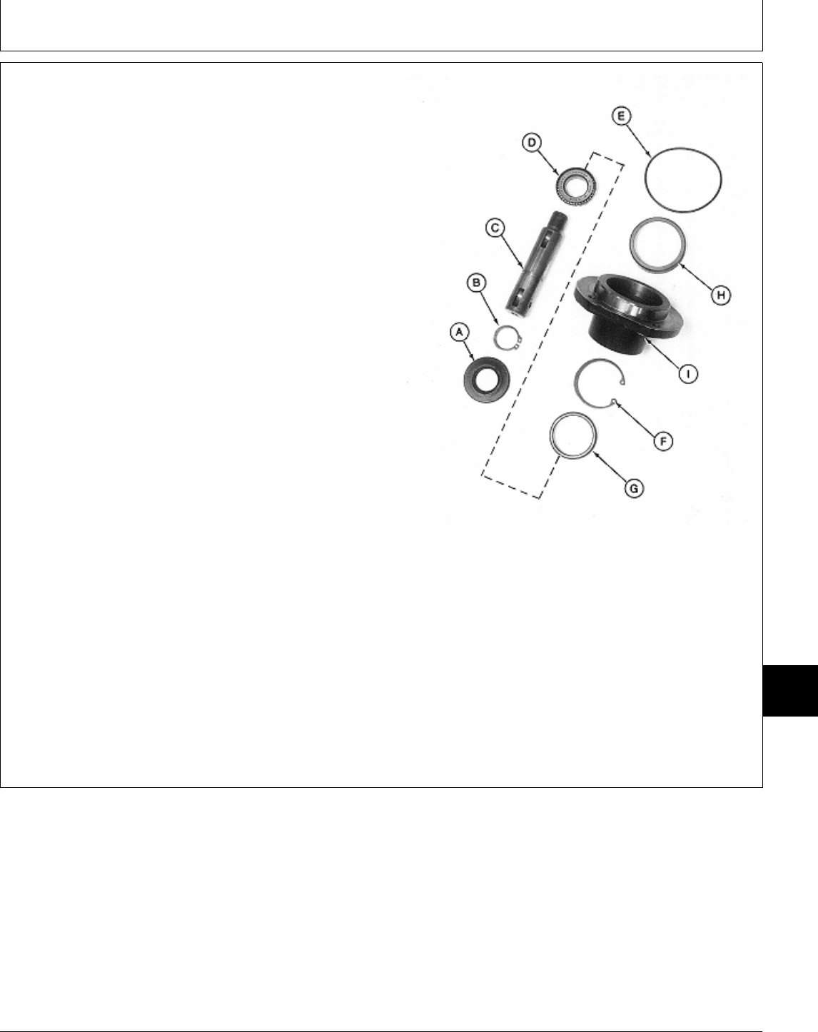
7. Press on threaded end of input shaft (C) to remove
seal (A) and input shaft assembly from pillow block (I).
NOTE: Bearing cone is press-fit on input shaft. Remove
bearing only if replacement is necessary.
Bearing cups are press-fit in pillow block.
Remove cups only if replacement is necessary.
Bearing cones and cups are matched and must
be replaced as complete assemblies.
8. Inspect bearing cone (D) and cups (G and H) for wear
or damage. Replace as necessary.
9. Remove snap ring (B) and press input shaft (C) from
bearing (D).
10. Remove O-ring (E) and snap ring (F).
IMPORTANT: Remove bearing cups using a press
and driver disk, if possible. Using a
punch and hammer can damage pillow
block. Use only if necessary.
11. Remove bearing cups (G and H) using a press and
driver set or punch and hammer. Input Shaft Assembly
A—Seal
B—Snap Ring
C—Input Shaft
D—Bearing Cone
E—O-Ring
F—Snap Ring
G—Bearing Cup
H—Bearing Cup
I—Pillow Block
M77318 -UN-24FEB95
MX,15908015,3 -19-13MAR95
Mower Gear Case Repair/50-Inch Mower
TM1591 (15JUL95) 80-15-3 322,330,332 & 430 Lawn & Garden Tractors
030895
80
15
3
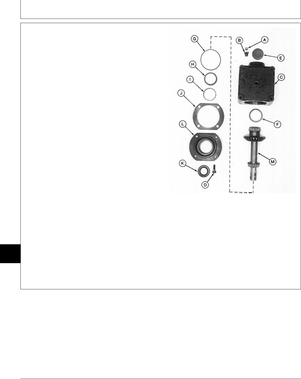
12. Remove vent plug (A) and adapter (B) from gear
case (C).
13. Remove four cap screws (D). Remove retainer (L)
and output shaft assembly (M).
14. Remove output shaft assembly (M) from retainer (L).
IMPORTANT: Remove and discard crush ring (I). A
new crush ring must be installed
during assembly to achieve proper
output shaft end play.
15. Remove O-ring (G), shim (J), bearing cup (H) and
crush ring (I). Discard crush ring.
16. Press out seal (K) from retainer (L).
NOTE: Bearing cup (F) and plug (E) are press-fit in gear
case. Remove bearing cup (F) only if
replacement is necessary.
Bearing cones and cups are matched and must
be replaced as complete assemblies.
17. Inspect bearing cups (F and H) for wear or damage.
Replace as necessary. Output Shaft Side
18. Press out plug (E) and bearing cup (F).
A—Vent Plug
B—Adapter
C—Gear Case
D—Cap Screw (4 used)
E—Plug
F—Bearing Cup
G—O-Ring
H—Bearing Cup
I—Crush Ring
J—Shim (as required)
K—Seal
L—Retainer
M—Output Shaft Assembly
M77319 -UN-24FEB95
MX,15908015,4 -19-29MAR95
Mower Gear Case Repair/50-Inch Mower
TM1591 (15JUL95) 80-15-4 322,330,332 & 430 Lawn & Garden Tractors
030895
80
15
4
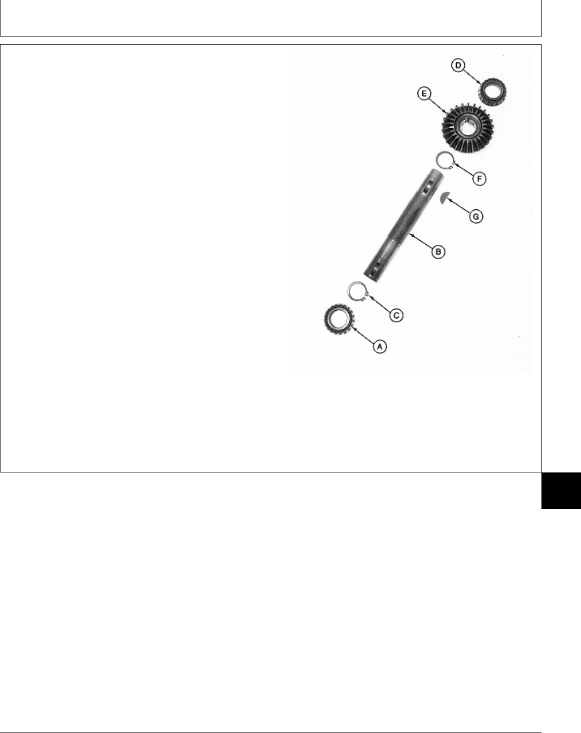
NOTE: Bearing cones are press-fit on output shaft.
Remove bearings only if replacement is
necessary.
Bearing cones and cups are matched and must
be replaced as complete assemblies.
20. Inspect bearing cones (A and D) for wear or
damage. Replace if necessary.
21. Press output shaft (B) from bearing cone (A).
Remove snap ring (C).
22. Remove bearing cone (D) from output shaft (B) using
a knife-edge puller and a press.
23. Remove bevel gear (E), snap ring (F) and key (G).
24. Inspect all parts for wear or damage. Replace as
necessary.
A—Bearing Cone
B—Output Shaft
C—Snap Ring
D—Bearing Cone
E—Bevel Gear
F—Snap Ring
G—Key Output Shaft Assembly
M77320 -UN-24FEB95
MX,15908015,5 -19-29MAR95
Mower Gear Case Repair/50-Inch Mower
TM1591 (15JUL95) 80-15-5 322,330,332 & 430 Lawn & Garden Tractors
030895
80
15
5
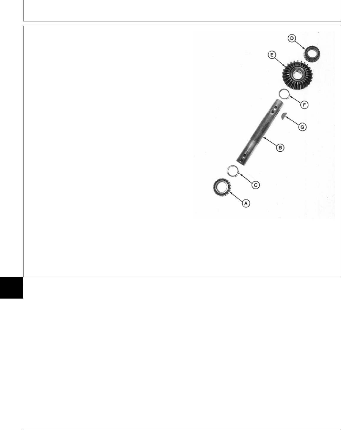
ASSEMBLE MOWER GEAR CASE—50-INCH
MOWER
IMPORTANT: Always use new seals and O-rings.
Damaged or used parts will leak.
NOTE: Lubricate all O-rings with petroleum jelly during
assembly.
Apply clean gear case oil on all internal parts
during assembly.
1. Install snap ring (F), key (G) and bevel gear (E).
Install bevel gear on output shaft, small O.D. first.
2. Press bearing cone (D) on output shaft (B) with small
O.D. facing away from bevel gear (E). Install bearing
until it bottoms against bevel gear.
3. Install snap ring (C).
4. Press bearing cone (A) on output shaft with small
O.D. facing away from bevel gear (E). Install bearing
until it bottoms against snap ring.
A—Bearing Cone
B—Output Shaft Output Shaft Assembly
C—Snap Ring
D—Bearing Cone
E—Bevel Gear
F—Snap Ring
G—Key
M77320 -UN-24FEB95
MX,15908015,6 -19-13MAR95
Mower Gear Case Repair/50-Inch Mower
TM1591 (15JUL95) 80-15-6 322,330,332 & 430 Lawn & Garden Tractors
030895
80
15
6
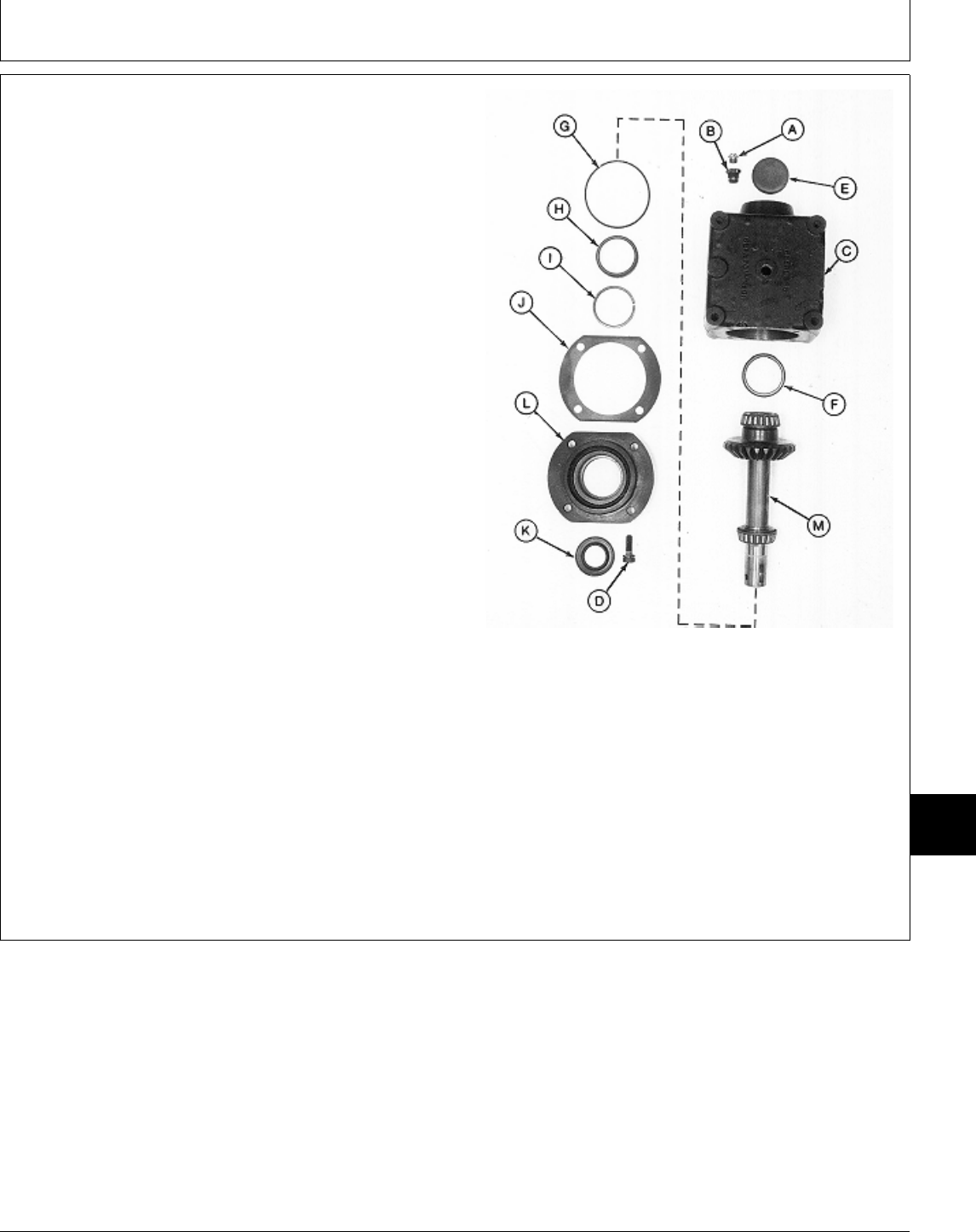
5. Install new bearing cup (F), if removed, using a driver
set.
6. Press plug (E) into gear case (C) with lip facing away
from gear case. Install plug until recessed 1.59 mm
(0.062 in.) below gear case surface.
7. Install adapter (B) and vent plug (A).
8. Press new seal (K) into retainer (L) until top of seal is
recessed 2.54 mm (0.100 in.) below retainer surface.
9. Apply multipurpose grease to lip of seal.
IMPORTANT: A new crush ring must be installed
during assembly. The ring collapses
when retainer is tightened to gear case
to achieve proper output shaft end
play.
10. Install new crush ring (I) and bearing cup (H).
11. Install shim (J) and new O-ring (G).
IMPORTANT: Tape end of output shaft to prevent
seal damage during shaft installation.
Output Shaft Side
12. Apply tape around end of output shaft.
13. Assemble output shaft assembly (M) and retainer (L). A—Vent Plug
Remove tape. B—Adapter
C—Gear Case
D—Cap Screw (4 used)
14. Install retainer and output shaft assembly into gear E—Plug
case (C). F—Bearing Cup
G—O-Ring
15. Install four cap screws (D) and tighten to 30 N·m (22 H—Bearing Cup
lb-ft). I—Crush Ring
J—Shim (as required)
K—Seal
L—Retainer
M—Output Shaft Assembly
M77319 -UN-24FEB95
MX,15908015,7 -19-13MAR95
Mower Gear Case Repair/50-Inch Mower
TM1591 (15JUL95) 80-15-7 322,330,332 & 430 Lawn & Garden Tractors
030895
80
15
7
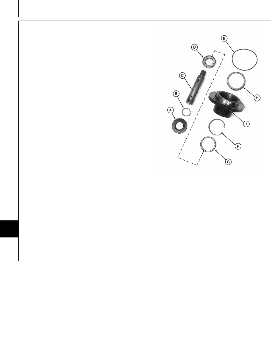
16. Install snap ring (F).
17. Install new bearing cups (G and H), if removed,
using a driver set. Press into pillow block (I) until seated
against snap ring and housing.
18. Install snap ring (B) on input shaft (C).
19. Press bearing cone (D) on input shaft with small
O.D. facing away from snap ring (B). Install bearing until
it bottoms against snap ring.
IMPORTANT: Tape end of input shaft to prevent seal
damage during seal installation.
20. Apply tape around large end of input shaft.
21. Install input shaft assembly into pillow block (I).
22. Apply multipurpose grease to lip of new seal (A).
23. Press new seal (A) into pillow block (I) until top of
seal is recessed 2.54 mm (0.100 in.) below block
surface. Remove tape from end of shaft.
24. Install new O-ring (E).
Input Shaft Assembly
A—Seal
B—Snap Ring
C—Input Shaft
D—Bearing Cone
E—O-Ring
F—Snap Ring
G—Bearing Cup
H—Bearing Cup
I—Pillow Block
M77318 -UN-24FEB95
MX,15908015,8 -19-13MAR95
Mower Gear Case Repair/50-Inch Mower
TM1591 (15JUL95) 80-15-8 322,330,332 & 430 Lawn & Garden Tractors
030895
80
15
8
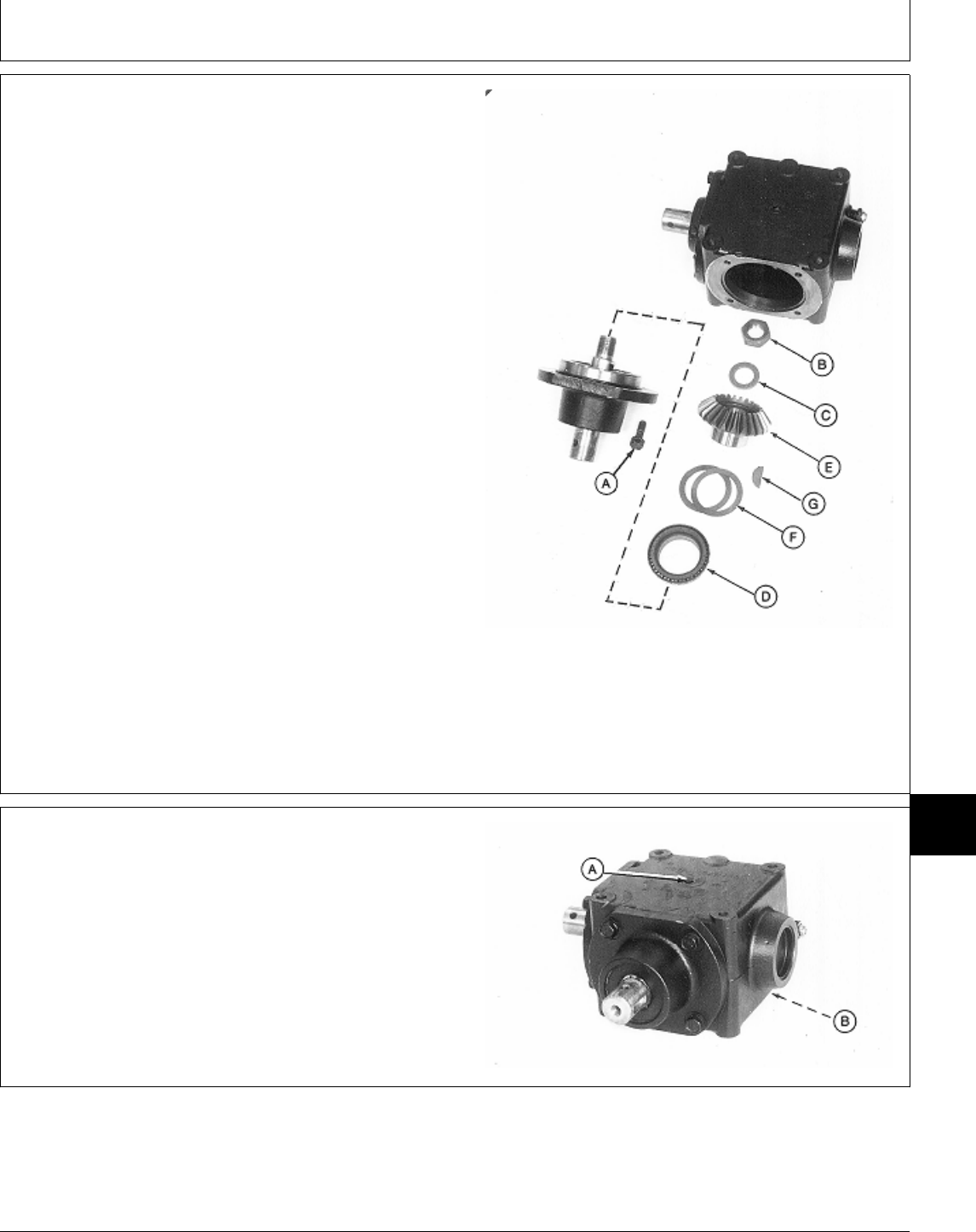
25. Install shims (F) on bevel gear (E).
26. Press bearing cone (D) on bevel gear (E) with small
O.D. facing away from bevel gear. Install bearing until it
bottoms against shims.
27. Install key (G) into input shaft.
28. Install bevel gear assembly onto input shaft.
IMPORTANT: DO NOT overtighten lock nut (B).
Overtightening can damage bearing
cone (D).
29. Install washer (C) and lock nut (B). Tighten lock nut
until there is zero endplay in input shaft.
30. Install input shaft assembly into gear case.
31. Install four cap screws (A) and tighten to 30 N·m (22
lb-ft).
A—Cap Screw (4 used)
B—Lock Nut
C—Washer
D—Bearing Cone
E—Bevel Gear
F—Shims (as required) Input Shaft Side
G—Key
M77317 -UN-24FEB95
32. AFTER installing gear case on mower deck, fill gear
case to proper level with John Deere API GL-5 Gear Oil.
33. Install plugs (A and B).
M77316 -UN-24FEB95
MX,15908015,9 -19-22FEB95
MX,15908015,10 -19-22FEB95
Mower Gear Case Repair/50-Inch Mower
TM1591 (15JUL95) 80-15-9 322,330,332 & 430 Lawn & Garden Tractors
030895
80
15
9
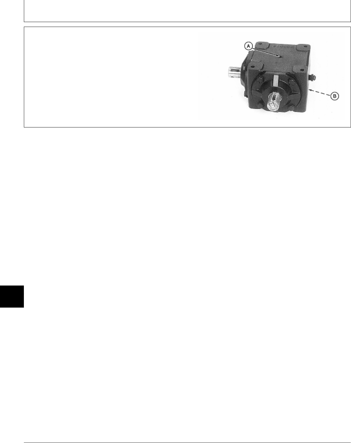
DISASSEMBLE AND INSPECT MOWER
GEAR CASE—EARLY 60-INCH MOWER
(CURTIS)
1. Remove drain plugs (A and B) and drain oil from gear
case.
2. Scribe an alignment mark across caps and gear case.
Mark both caps in relation to the case side they are
removed from to aid in assembly.
M77328 -UN-24FEB95
MX,15908015,11 -19-13MAR95
Mower Gear Case Repair/Early 60-Inch Mower (Curtis)
TM1591 (15JUL95) 80-15-10 322,330,332 & 430 Lawn & Garden Tractors
030895
80
15
10

3. Remove four cap screws and lock plates (A).
4. Remove cap (B) and input shaft assembly from gear
case (C).
5. Remove shims (D) and input shaft assembly from cap
(B).
6. Pry out seal (E).
NOTE: Bearing cup is press-fit in cap. Remove bearing
cup only if replacement is necessary.
Bearing cone (K) is press-fit on input shaft.
Bearing cones and cups (one in gear case
housing) are matched and must be replaced as
complete assemblies.
7. Inspect bearing cup (F) for wear or damage. Replace
if necessary.
IMPORTANT: Remove bearing cups using a press
and driver disk, if possible. Using a
punch and hammer can damage cap.
Use only if necessary.
Input Shaft Side
8. Remove bearing cup (F) using a press and driver set
or punch and hammer.
A—Cap Screw and Lock Plate (4 used)
9. Slide bearing cone (G) off of input shaft (H). B—Cap
C—Gear Case
D—Shims (as required)
10. Remove spring pin (I) using a punch and hammer. E—Seal
F—Bearing Cup
11. Press shaft (H) from bevel gear (J) and bearing cone G—Bearing Cone
(K). H—Input Shaft
I—Spring Pin
J—Bevel Gear
12. Remove key (L). K—Bearing Cone
L—Key
M77329 -UN-24FEB95
MX,15908015,12 -19-13MAR95
Mower Gear Case Repair/Early 60-Inch Mower (Curtis)
TM1591 (15JUL95) 80-15-11 322,330,332 & 430 Lawn & Garden Tractors
030895
80
15
11

13. Remove four cap screws and lock plates (A).
14. Remove cap (B) and output shaft assembly from
gear case (C).
15. Remove shims (D) and output shaft assembly from
cap (B).
16. Pry out seal (E).
NOTE: Bearing cup is press-fit in cap. Remove bearing
cup only if replacement is necessary.
Bearing cone (K) is press-fit on input shaft.
Bearing cones and cups (one in gear case
housing) are matched and must be replaced as
complete assemblies.
17. Inspect bearing cup (F) for wear or damage. Replace
if necessary.
IMPORTANT: Remove bearing cups using a press
and driver disk, if possible. Using a
punch and hammer can damage cap.
Use only if necessary.
Output Shaft Side
18. Remove bearing cup (F) using a press and driver set
or punch and hammer.
A—Cap Screw and Lock Plate (4 used)
19. Slide bearing cone (G) off of output shaft (H). B—Cap
C—Gear Case
D—Shims (as required)
20. Remove spring pin (I) using a punch and hammer. E—Seal
F—Bearing Cup
21. Press shaft (H) from bevel gear (J) and bearing cone G—Bearing Cone
(K). H—Output Shaft
I—Spring Pin
J—Bevel Gear
22. Remove key (L). K—Bearing Cone
L—Key
M77330 -UN-24FEB95
MX,15908015,13 -19-13MAR95
Mower Gear Case Repair/Early 60-Inch Mower (Curtis)
TM1591 (15JUL95) 80-15-12 322,330,332 & 430 Lawn & Garden Tractors
030895
80
15
12
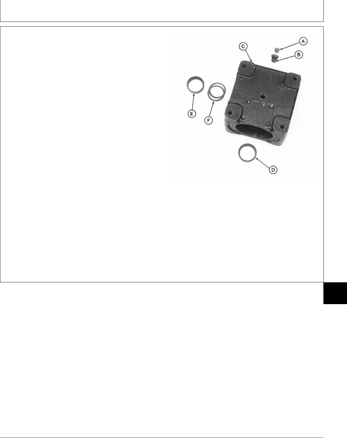
23. Remove vent plug (A) and adapter (B).
NOTE: Bearing cups are press-fit in gear case. Remove
bearing cups only if replacement is necessary.
Bearing cups and cones are matched and must
be replaced as complete assemblies.
24. Inspect bearing cups (D and E) for wear or damage.
Replace if necessary.
IMPORTANT: Remove bearing cups using a slide
hammer and inside puller, if possible.
Using a punch and hammer can
damage gear case. Use only if
necessary.
25. Remove bearing cups from gear case (C) using a
slide hammer and inside puller or punch and hammer.
26. Remove shims (F), if equipped.
A—Vent Plug
B—Adapter
C—Gear Case
D—Bearing Cup
E—Bearing Cup
F—Shims (as required)
M77331 -UN-24FEB95
MX,15908015,14 -19-13MAR95
Mower Gear Case Repair/Early 60-Inch Mower (Curtis)
TM1591 (15JUL95) 80-15-13 322,330,332 & 430 Lawn & Garden Tractors
030895
80
15
13
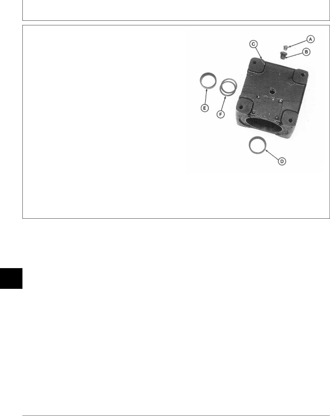
ASSEMBLE MOWER GEAR CASE—EARLY
60-INCH MOWER (CURTIS)
IMPORTANT: Always use new seals. Damaged or
used seals will leak.
NOTE: Apply clean gear case oil on all internal parts
during assembly.
1. Install shims (F), if equipped, into gear case (C).
2. Install new bearing cups (E and D), if removed, using
a driver set.
3. Install adapter (B) and vent plug (A).
A—Vent Plug
B—Adapter
C—Gear Case
D—Bearing Cup
E—Bearing Cup
F—Shims (as required)
M77331 -UN-24FEB95
MX,15908015,15 -19-13MAR95
Mower Gear Case Repair/Early 60-Inch Mower (Curtis)
TM1591 (15JUL95) 80-15-14 322,330,332 & 430 Lawn & Garden Tractors
030895
80
15
14
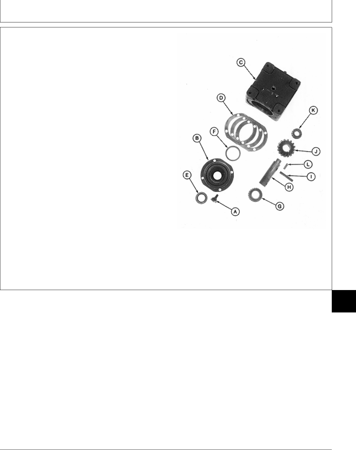
4. Install key (L) and bevel gear (J), shoulder end first,
onto shaft (H).
5. Align holes in bevel gear and shaft and install spring
pin (I).
6. Press bearing cone (K) on shaft with small O.D.
facing away from bevel gear (J). Install bearing cone
until seated.
7. Slide bearing cone (G) onto other end of output shaft
(H).
IMPORTANT: Do not press seal in until seated or
bottomed out. Seal will become
damaged and will leak.
8. Press new seal (E) into cap (B) until seal is flush with
first recess in bottom of cap.
9. Install new bearing cup (F), if removed, using a driver
set.
10. Apply multipurpose grease to lip of seal.
A—Cap Screw and Lock G—Bearing Cone
Plate (4 used) H—Output Shaft Output Shaft Side
B—Cap I—Spring Pin
C—Gear Case J—Bevel Gear
D—Shims (as required) K—Bearing Cone
E—Seal L—Key
F—Bearing Cup
M77330 -UN-24FEB95
MX,15908015,16 -19-13MAR95
Mower Gear Case Repair/Early 60-Inch Mower (Curtis)
TM1591 (15JUL95) 80-15-15 322,330,332 & 430 Lawn & Garden Tractors
030895
80
15
15
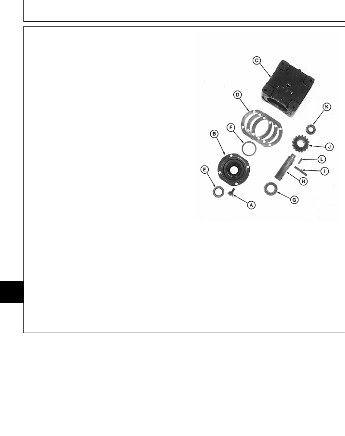
IMPORTANT: Tape end of output shaft to prevent
seal damage during shaft installation.
11. Apply tape around end of output shaft.
12. Assemble output shaft assembly and cap (B).
Remove tape.
NOTE: Flat sides of cap must align with flat sides of
gear case. Gear case mounting surface must be
flat to install gear case on mower deck.
13. Install shims (D). Align marks made during
disassembly and install output shaft assembly into gear
case (C).
14. Install four cap screws and lock plates (A) and
tighten to 30 N·m (22 lb-ft).
15. Check output shaft endplay. Endplay should be
within 0.025—0.076 mm (0.001—0.003 in.). If necessary,
remove cap and output shaft assembly and add or
remove shims (D) as needed.
16. Again, remove four cap screws and lock plates (A)
and cap and output shaft assembly.
Output Shaft Side
17. Clean mating surfaces of cap, shims and gear case
using Clean and Cure Primer. Apply a bead of
Form-In-Place Gasket, or an equivalant, between inside A—Cap Screw and Lock Plate (4 used)
edge of top shim and lip on cap (B). B—Cap
C—Gear Case
D—Shims (as required)
18. Align and install cap and output shaft assembly into E—Seal
gear case. Install four cap screws and lock plates (A) F—Bearing Cup
and tighten to 30 N·m (22 lb-ft). Bend lock plates up G—Bearing Cone
around cap screws. H—Output Shaft
I—Spring Pin
J—Bevel Gear
K—Bearing Cone
L—Key
M77330 -UN-24FEB95
MX,15908015,39 -19-13MAR95
Mower Gear Case Repair/Early 60-Inch Mower (Curtis)
TM1591 (15JUL95) 80-15-16 322,330,332 & 430 Lawn & Garden Tractors
030895
80
15
16
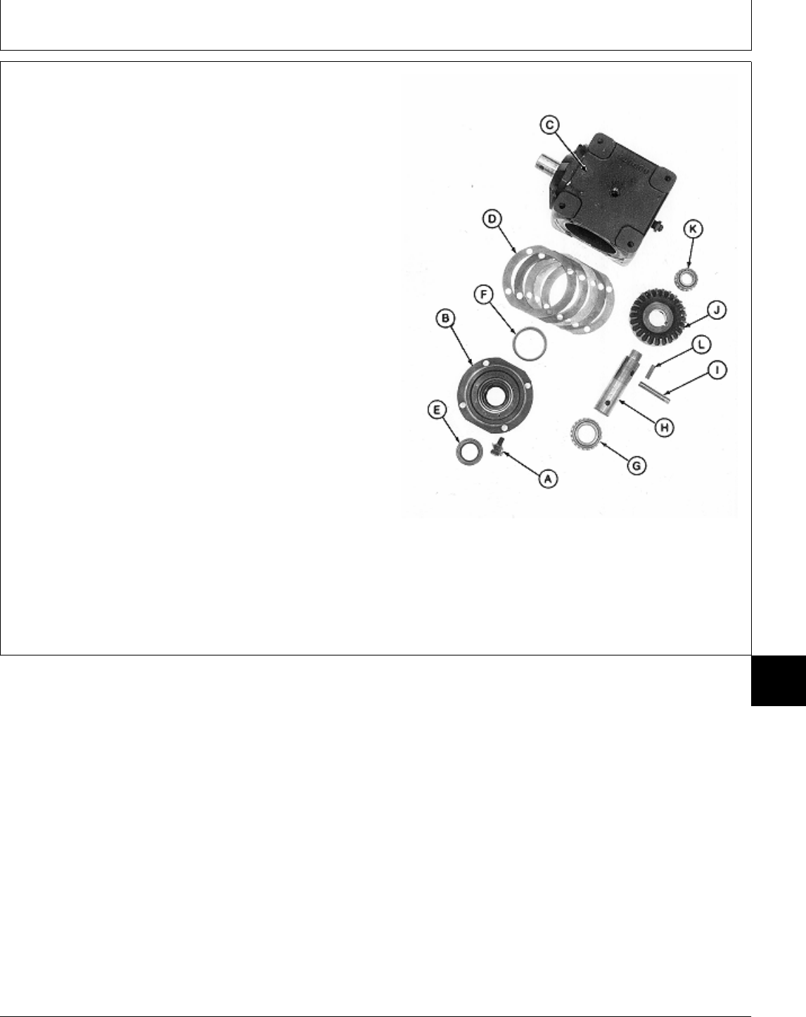
19. Install key (L) and bevel gear (J), shoulder end first,
onto shaft (H).
20. Align holes in bevel gear and shaft and install spring
pin (I).
21. Press bearing cone (K) on shaft with small O.D.
facing away from bevel gear (J). Install bearing until
seated.
22. Slide bearing cone (G) onto other end of input shaft
(H).
IMPORTANT: Do not press seal in until seated or
bottomed out. Seal will become
damaged and will leak.
23. Press new seal (E) into cap (B) until seal is flush
with first recess in bottom of cap.
24. Install new bearing cup (F), if removed, using a
driver set.
25. Apply multipurpose grease to lip of seal.
A—Cap Screw and Lock G—Bearing Cone
Plate (4 used) H—Input Shaft Input Shaft Side
B—Cap I—Spring Pin
C—Gear Case J—Bevel Gear
D—Shims (as required) K—Bearing Cone
E—Seal L—Key
F—Bearing Cup
M77329 -UN-24FEB95
MX,15908015,17 -19-29MAR95
Mower Gear Case Repair/Early 60-Inch Mower (Curtis)
TM1591 (15JUL95) 80-15-17 322,330,332 & 430 Lawn & Garden Tractors
030895
80
15
17
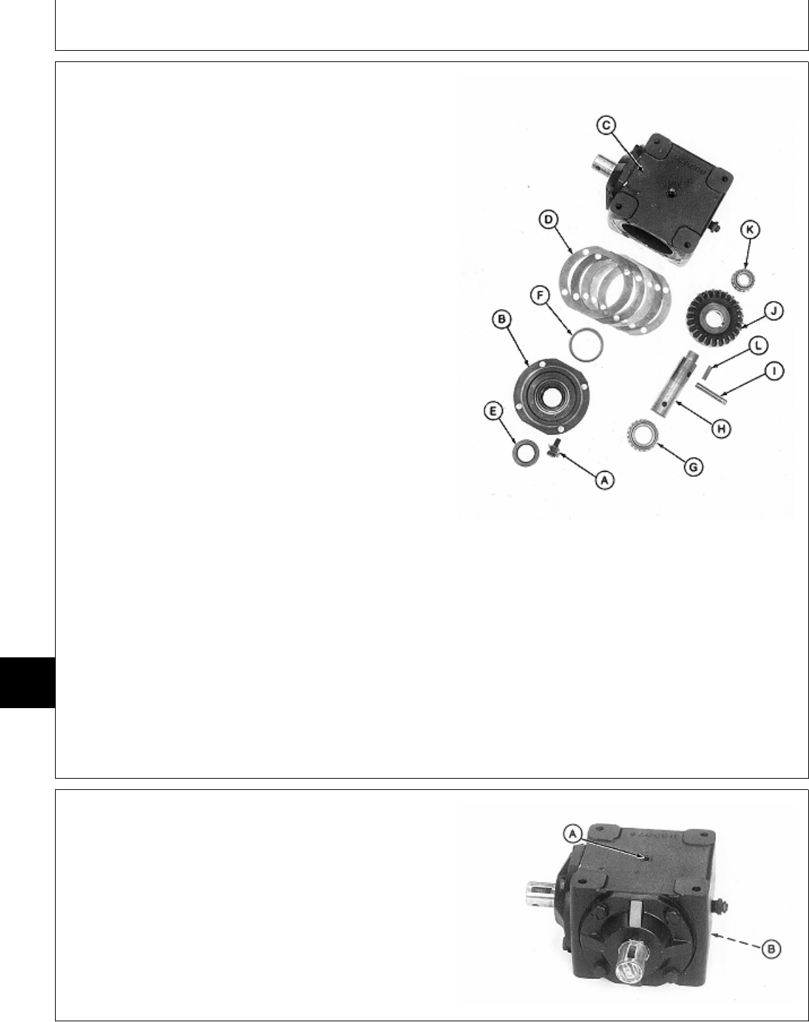
IMPORTANT: Tape end of input shaft to prevent seal
damage during shaft installation.
26. Apply tape around end of input shaft.
27. Assemble input shaft assembly and cap (B). Remove
tape.
NOTE: Flat sides of cap must align with flat sides of
gear case. Gear case mounting surface must be
flat to install gear case on mower deck.
28. Install shims (D). Align marks made during
disassembly and install input shaft assembly into gear
case (C).
29. Install four cap screws and lock plates (A) and
tighten to 30 N·m (22 lb-ft).
30. Hold output shaft securely and check input shaft
backlash. Backlash should be within 0.076—0.130 mm
(0.003—0.005 in.). If necessary, remove cap and input
shaft assembly and add or remove shims (D) as needed.
31. Again, remove four cap screws and lock plates (A)
and cap and input shaft assembly.
Input Shaft Side
32. Clean mating surfaces of cap, shims and gear case
using Clean and Cure Primer. Apply a bead of
Form-In-Place Gasket, or an equivalant, between inside A—Cap Screw and Lock Plate (4 used)
edge of top shim and lip on cap (B). B—Cap
C—Gear Case
D—Shims (as required)
33. Align and install cap and input shaft assembly into E—Seal
gear case. Install four cap screws and lock plates (A) F—Bearing Cup
and tighten to 30 N·m (22 lb-ft). Bend lock plates up G—Bearing Cone
around cap screws. H—Input Shaft
I—Spring Pin
J—Bevel Gear
K—Bearing Cone
L—Key
M77329 -UN-24FEB95
34. AFTER installing gear case on mower deck, fill gear
case to proper level with John Deere API GL-5 Gear Oil.
35. Install plugs (A and B).
M77328 -UN-24FEB95
MX,15908015,40 -19-13MAR95
MX,15908015,18 -19-22FEB95
Mower Gear Case Repair/Early 60-Inch Mower (Curtis)
TM1591 (15JUL95) 80-15-18 322,330,332 & 430 Lawn & Garden Tractors
030895
80
15
18
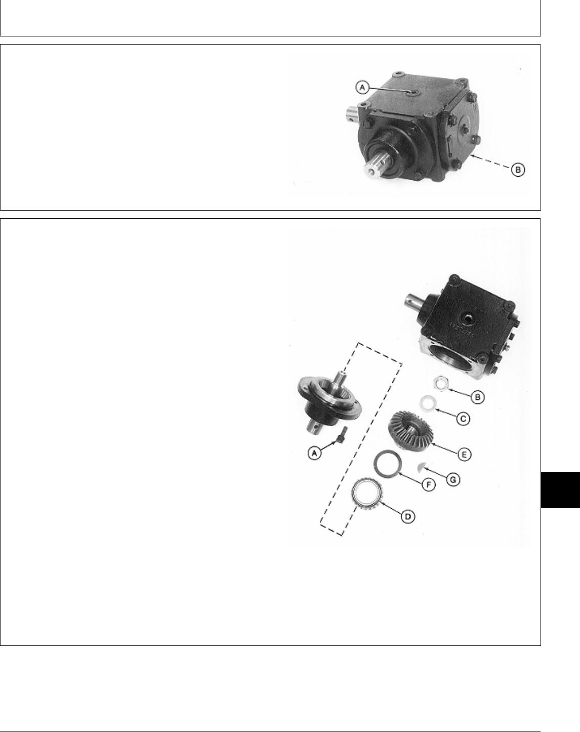
DISASSEMBLE AND INSPECT MOWER
GEAR CASE—LATER 60-INCH MOWER
(PEERLESS)
1. Remove drain plugs (A and B) and drain oil from gear
case.
M77311 -UN-24FEB95
2. Remove four cap screws (A) and input shaft
assembly.
3. Remove lock nut (B), washer (C) and bevel gear (E)
and bearing from shaft.
NOTE: Bearing cone is press-fit on bevel gear. Remove
bearing cone only if replacement is necessary.
Bearing cone, cup in pillow block and shim(s) are
matched and must be replaced as complete
assemblies.
4. Inspect bearing cone (D) for wear or damage.
Replace if necessary.
5. Remove bearing cone from bevel gear using a
knife-edge puller and a press.
6. Remove shim(s) (F) and key (G).
A—Cap Screw (4 used)
B—Lock Nut
C—Washer
D—Bearing Cone
E—Bevel Gear
F—Shim (as required)
G—Key Input Shaft Side
M77312 -UN-24FEB95
MX,15908015,19 -19-22FEB95
MX,15908015,20 -19-13MAR95
Mower Gear Case Repair/Later 60-Inch Mower (Peerless)
TM1591 (15JUL95) 80-15-19 322,330,332 & 430 Lawn & Garden Tractors
030895
80
15
19
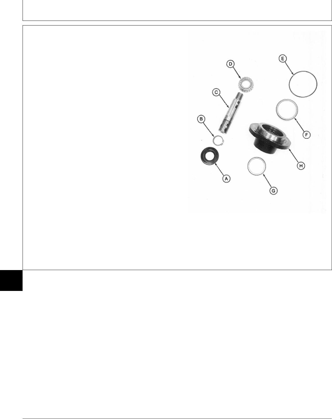
7. Press on threaded end of input shaft (C) to remove
seal (A) and input shaft assembly from pillow block (H).
NOTE: Bearing cone is press-fit on input shaft. Remove
bearing only if replacement is necessary.
Bearing cups are press-fit in pillow block.
Remove cups only if replacement is necessary.
Bearing cones and cups are matched and must
be replaced as complete assemblies.
8. Inspect bearing cone (D) and cups (F and G) for wear
or damage. Replace as necessary.
9. Remove snap ring (B) and press shaft (C) from
bearing (D).
10. Remove bearing cups (F and G) using a brass drift
or punch and hammer.
11. Remove O-ring (E).
A—Seal
B—Snap Ring
C—Input Shaft
D—Bearing Cone Input Shaft Assembly
E—O-Ring
F—Bearing Cup
G—Bearing Cup
H—Pillow Block
M77313 -UN-24FEB95
MX,15908015,21 -19-13MAR95
Mower Gear Case Repair/Later 60-Inch Mower (Peerless)
TM1591 (15JUL95) 80-15-20 322,330,332 & 430 Lawn & Garden Tractors
030895
80
15
20
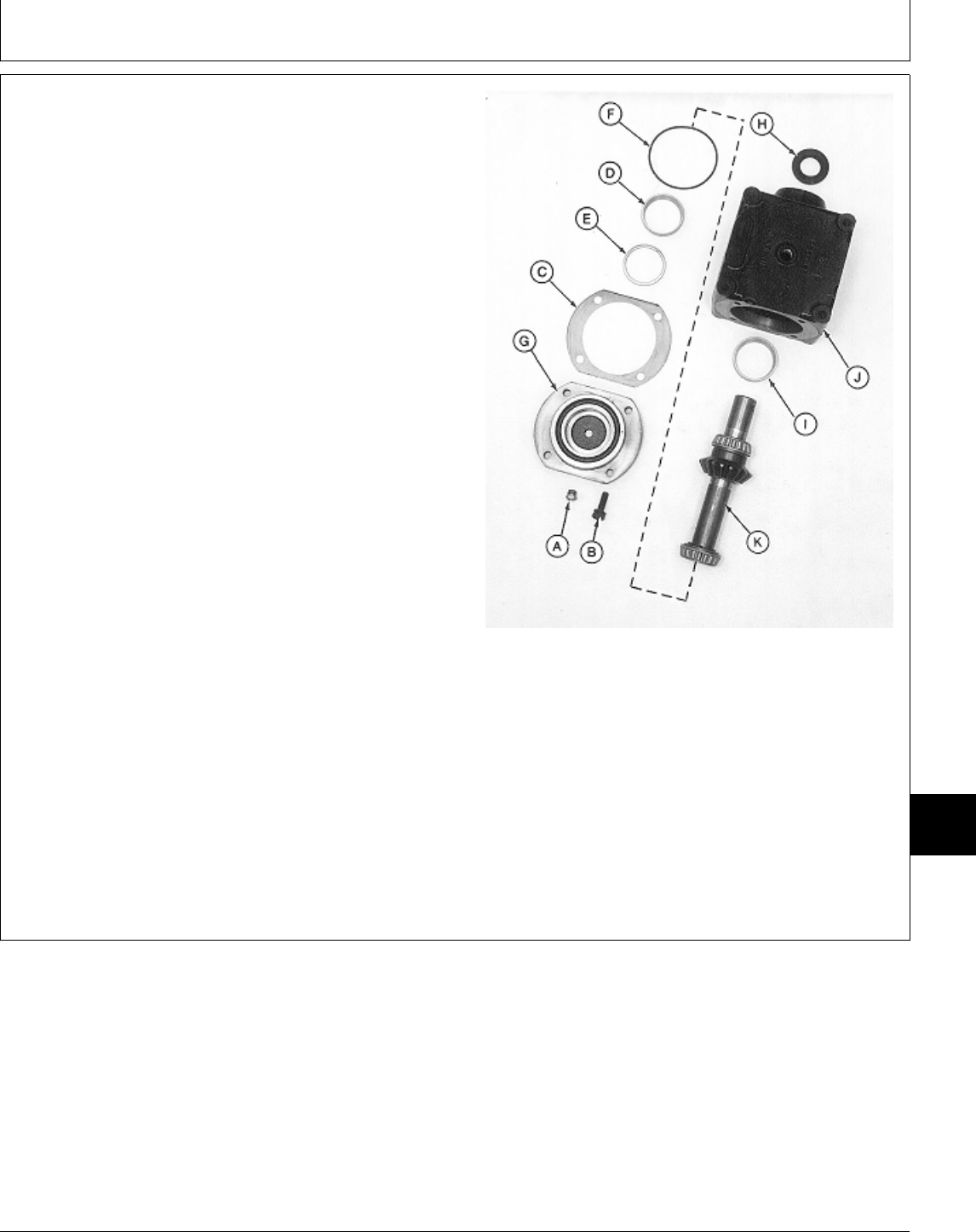
12. Remove vent plug (A) from retainer (G).
13. Remove four cap screws (B). Remove retainer (G)
and output shaft assembly (K) by tapping on end of shaft
with a rubber mallet.
14. Remove output shaft assembly (K) from retainer (G).
15. Remove O-ring (F) and shim (C) from retainer (G).
IMPORTANT: Remove and discard crush ring (E). A
new crush ring must be installed
during assembly to achieve proper
output shaft end play.
16. Remove bearing cup (D) and crush ring (E). Discard
crush ring.
17. Pry out seal (H).
NOTE: Bearing cup is press-fit in gear case. Remove
bearing cup only if replacement is necessary.
Bearing cones and cups are matched and must
be replaced as complete assemblies.
18. Inspect bearing cups (D and I) for wear or damage. Output Shaft Side
Replace as necessary.
19. Remove bearing cup (I) using a brass drift or punch A—Vent Plug
and hammer. B—Cap Screw (4 used)
C—Shim (as required)
D—Bearing Cup
E—Crush Ring
F—O-Ring
G—Retainer
H—Seal
I—Bearing Cup
J—Gear Case
K—Output Shaft Assembly
M77314 -UN-24FEB95
MX,15908015,22 -19-13MAR95
Mower Gear Case Repair/Later 60-Inch Mower (Peerless)
TM1591 (15JUL95) 80-15-21 322,330,332 & 430 Lawn & Garden Tractors
030895
80
15
21
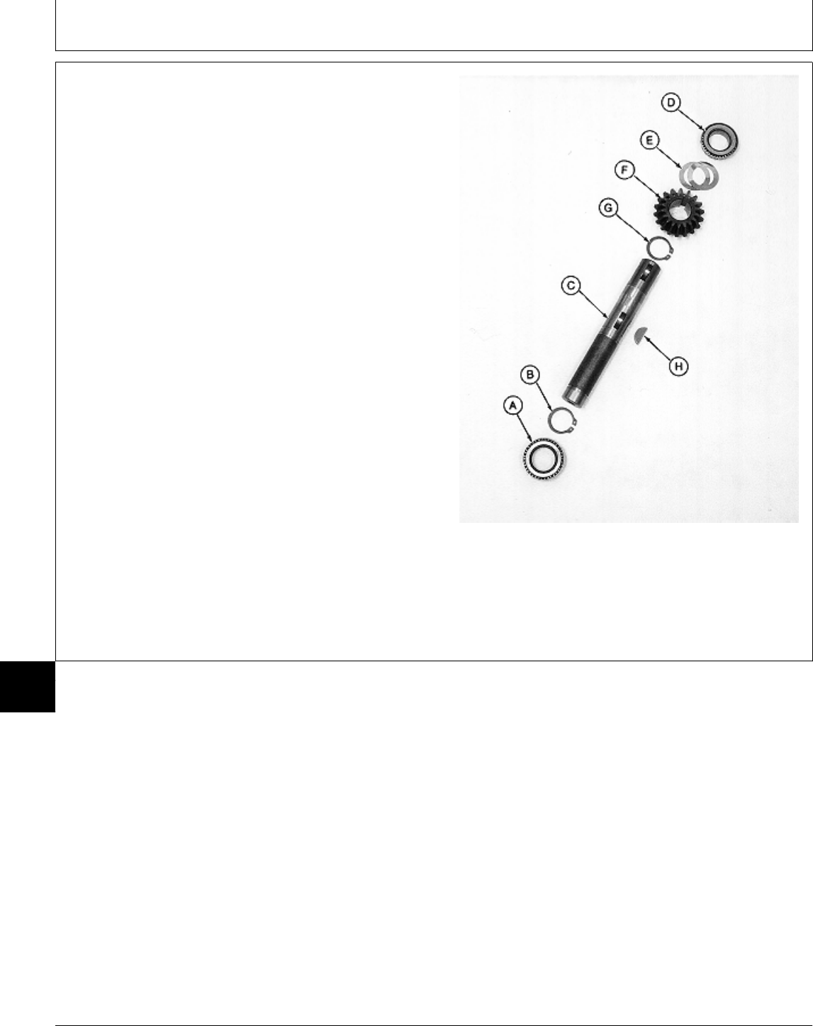
NOTE: Bearing cones are press-fit on output shaft.
Remove bearings only if replacement is
necessary.
Bearing cones and cups are matched and must
be replaced as complete assemblies.
20. Inspect bearing cones (A and D) for wear or
damage. Replace if necessary.
21. Press shaft (C) from bearing cone (A). Remove snap
ring (B).
22. Remove bearing cone (D) from shaft (C) using a
knife-edge puller and a press.
23. Remove shims (E), bevel gear (F), snap ring (G) and
key (H).
24. Inspect all parts for wear or damage. Replace as
necessary.
A—Bearing Cone
B—Snap Ring
C—Output Shaft
D—Bearing Cone
E—Shims (as required)
F—Bevel Gear Output Shaft Assembly
G—Snap Ring
H—Key
M77315 -UN-24FEB95
MX,15908015,23 -19-13MAR95
Mower Gear Case Repair/Later 60-Inch Mower (Peerless)
TM1591 (15JUL95) 80-15-22 322,330,332 & 430 Lawn & Garden Tractors
030895
80
15
22
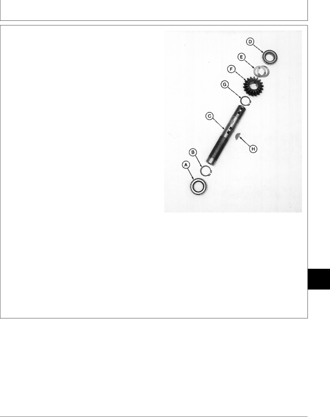
ASSEMBLE MOWER GEAR CASE—LATER
60-INCH MOWER (PEERLESS)
IMPORTANT: Always use new seals and O-rings.
Damaged or used parts will leak.
NOTE: Lubricate all O-rings with petroleum jelly during
assembly.
Apply clean gear case oil on all internal parts
during assembly.
1. Install snap ring (G) in first groove under keyway for
key (H).
2. Install key (H), bevel gear (F) and shims (E). Install
bevel gear on shaft with shoulder facing away from snap
ring (G).
3. Press bearing cone (D) on output shaft (C) with small
O.D. facing away from shims (E). Install bearing cone
until it bottoms against shims.
4. Install snap ring (B).
5. Press bearing cone (A) on output shaft with small
O.D. facing away from bevel gear (F). Install bearing Output Shaft Assembly
until it bottoms against snap ring.
A—Bearing Cone
B—Snap Ring
C—Output Shaft
D—Bearing Cone
E—Shims (as required)
F—Bevel Gear
G—Snap Ring
H—Key
M77315 -UN-24FEB95
MX,15908015,24 -19-13MAR95
Mower Gear Case Repair/Later 60-Inch Mower (Peerless)
TM1591 (15JUL95) 80-15-23 322,330,332 & 430 Lawn & Garden Tractors
030895
80
15
23
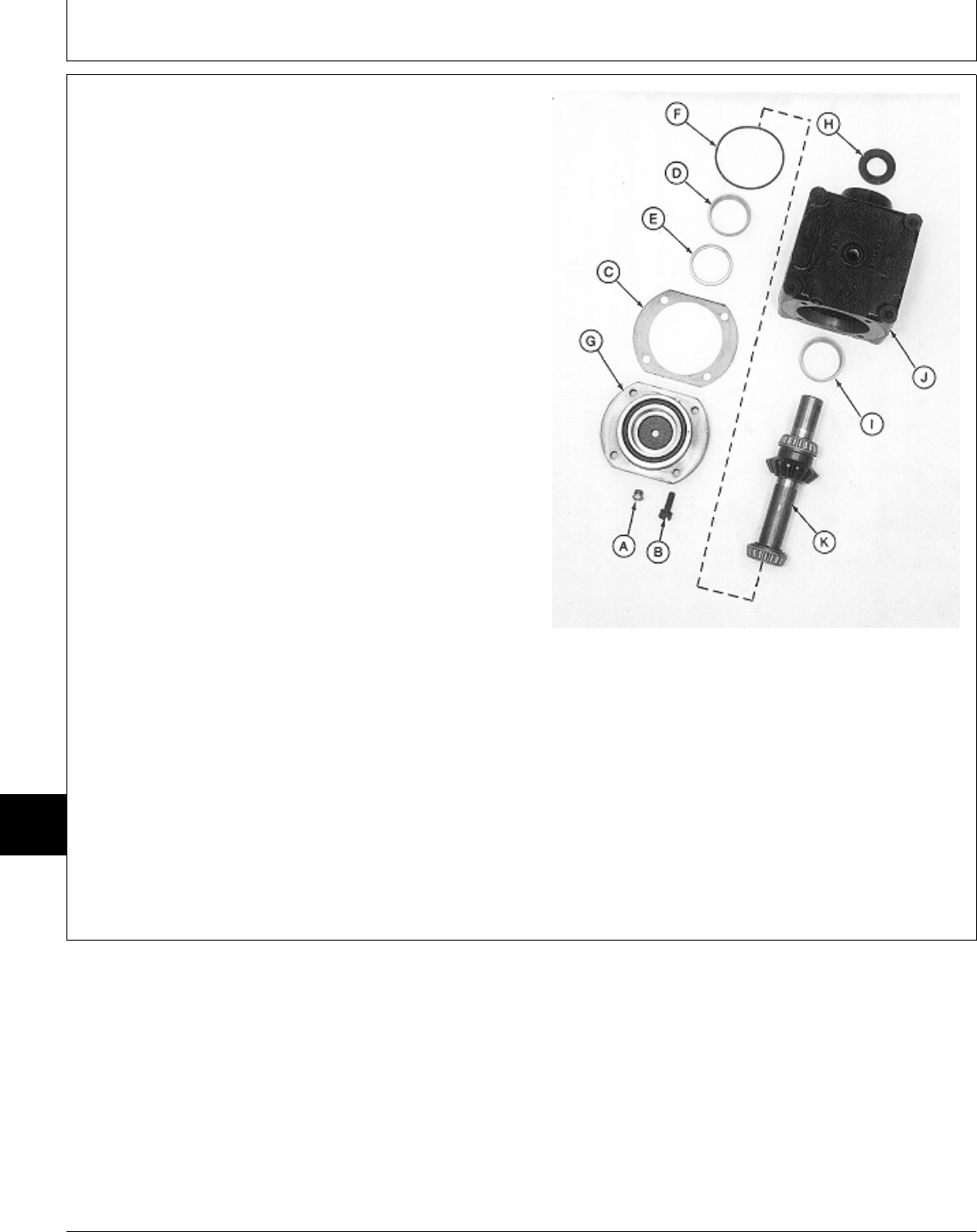
6. Install new bearing cup (I), if removed, into gear case
(J) using a driver set.
7. Press new seal (H) into gear case (J) until top of seal
is recessed 2.54 mm (0.100 in.) below gear case
surface.
8. Apply multipurpose grease to lip of seal.
9. Install vent plug (A).
IMPORTANT: A new crush ring must be installed
during assembly. The ring collapses
when retainer is tightened to gear case
to achieve proper output shaft end
play.
10. Install new crush ring (E) and bearing cup (D).
11. Install shim (C) and new O-ring (F).
IMPORTANT: Tape end of output shaft to prevent
seal damage during shaft installation.
12. Apply tape around end of output shaft.
13. Install output shaft assembly (K) into gear case (J). Output Shaft Side
Remove tape.
14. Install retainer assembly and four cap screws (B). A—Vent Plug
Tighten cap screws to 30 N·m (22 lb-ft). B—Cap Screw (4 used)
C—Shim (as required)
D—Bearing Cup
E—Crush Ring
F—O-Ring
G—Retainer
H—Seal
I—Bearing Cup
J—Gear Case
K—Output Shaft Assembly
M77314 -UN-24FEB95
MX,15908015,25 -19-13MAR95
Mower Gear Case Repair/Later 60-Inch Mower (Peerless)
TM1591 (15JUL95) 80-15-24 322,330,332 & 430 Lawn & Garden Tractors
030895
80
15
24
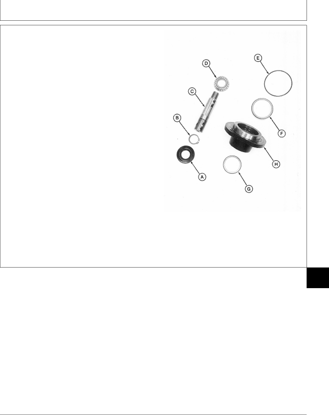
15. Install new bearing cups (F and G), if removed,
using a driver set. Press into pillow block (H) until seated
against housing.
16. Install snap ring (B) onto input shaft (C).
17. Press bearing cone (D) on input shaft with small
O.D. facing away from snap ring (B). Install bearing until
it bottoms againt snap ring.
IMPORTANT: Tape end of input shaft to prevent seal
damage during seal installation.
18. Apply tape around large end of input shaft.
19. Install input shaft assembly into pillow block (H).
20. Apply multipurpose grease to lip of new seal (A).
21. Press new seal (A) into pillow block (H) until top of
seal is recessed 2.54 mm (0.100 in.) below pillow block
surface. Remove tape from end of shaft.
22. Install new O-ring (E).
A—Seal
B—Snap Ring Input Shaft Assembly
C—Input Shaft
D—Bearing Cone
E—O-Ring
F—Bearing Cup
G—Bearing Cup
H—Pillow Block
M77313 -UN-24FEB95
MX,15908015,26 -19-13MAR95
Mower Gear Case Repair/Later 60-Inch Mower (Peerless)
TM1591 (15JUL95) 80-15-25 322,330,332 & 430 Lawn & Garden Tractors
030895
80
15
25
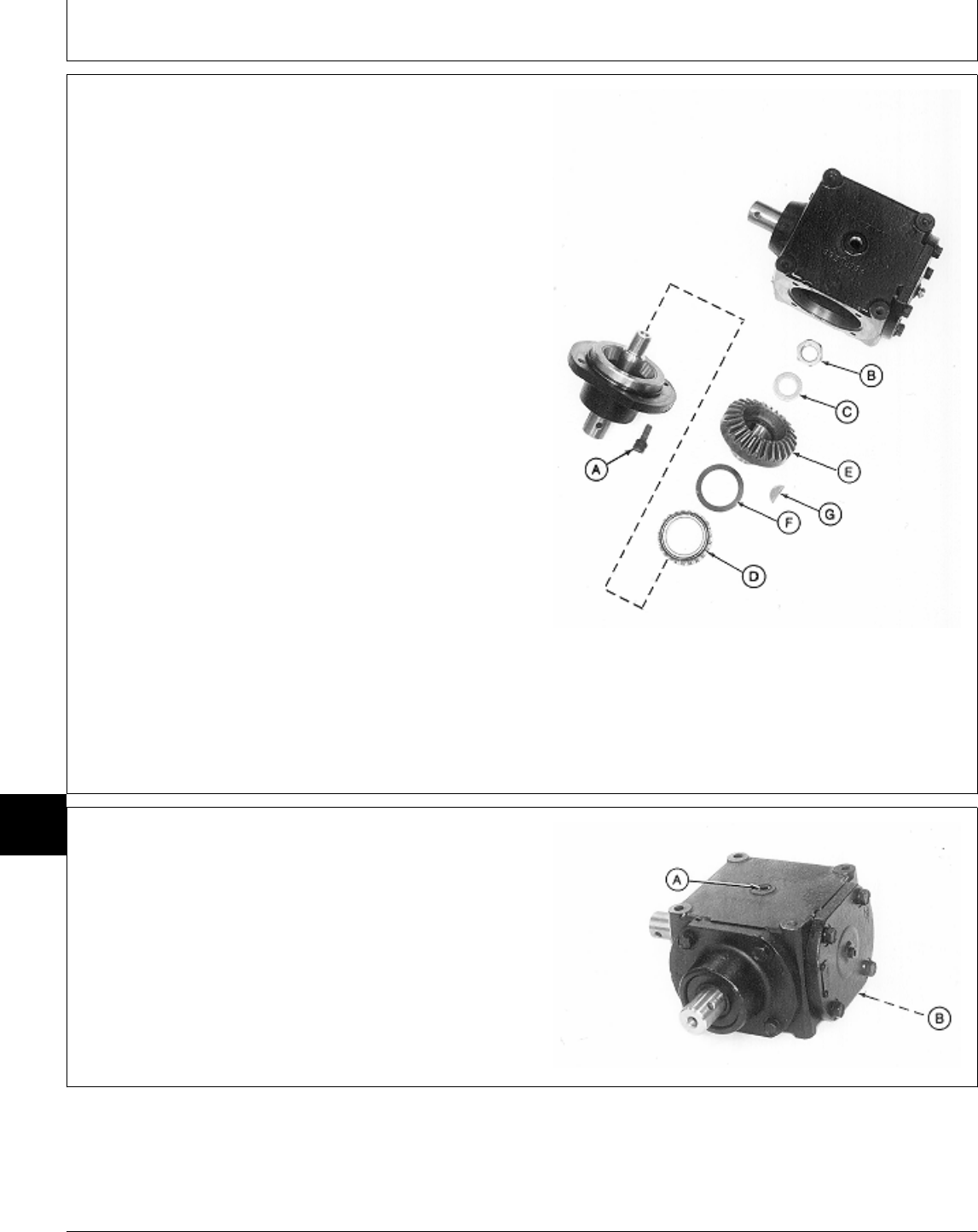
23. Install shim (F) on bevel gear (E).
24. Press bearing cone (D) on bevel gear (E) with small
O.D. facing away from bevel gear. Install bearing until it
bottoms against shim.
25. Install key (G) into input shaft.
26. Install bevel gear assembly onto input shaft.
IMPORTANT: DO NOT overtighten lock nut (B).
Overtightening can damage bearing
cone (D).
27. Install washer (C) and lock nut (B). Tighten lock nut
until there is zero endplay in input shaft.
28. Install input shaft assembly into gear case.
29. Install four cap screws (A) and tighten to 30 N·m (22
lb-ft).
A—Cap Screw (4 used)
B—Lock Nut
C—Washer
D—Bearing Cone
E—Bevel Gear
F—Shim (as required) Input Shaft Side
G—Key
M77312 -UN-24FEB95
30. AFTER installing gear case on mower deck, fill gear
case to proper level with John Deere API GL-5 Gear Oil.
31. Install plugs (A and B).
M77311 -UN-24FEB95
MX,15908015,27 -19-13MAR95
MX,15908015,28 -19-13MAR95
Mower Gear Case Repair/Later 60-Inch Mower (Peerless)
TM1591 (15JUL95) 80-15-26 322,330,332 & 430 Lawn & Garden Tractors
030895
80
15
26
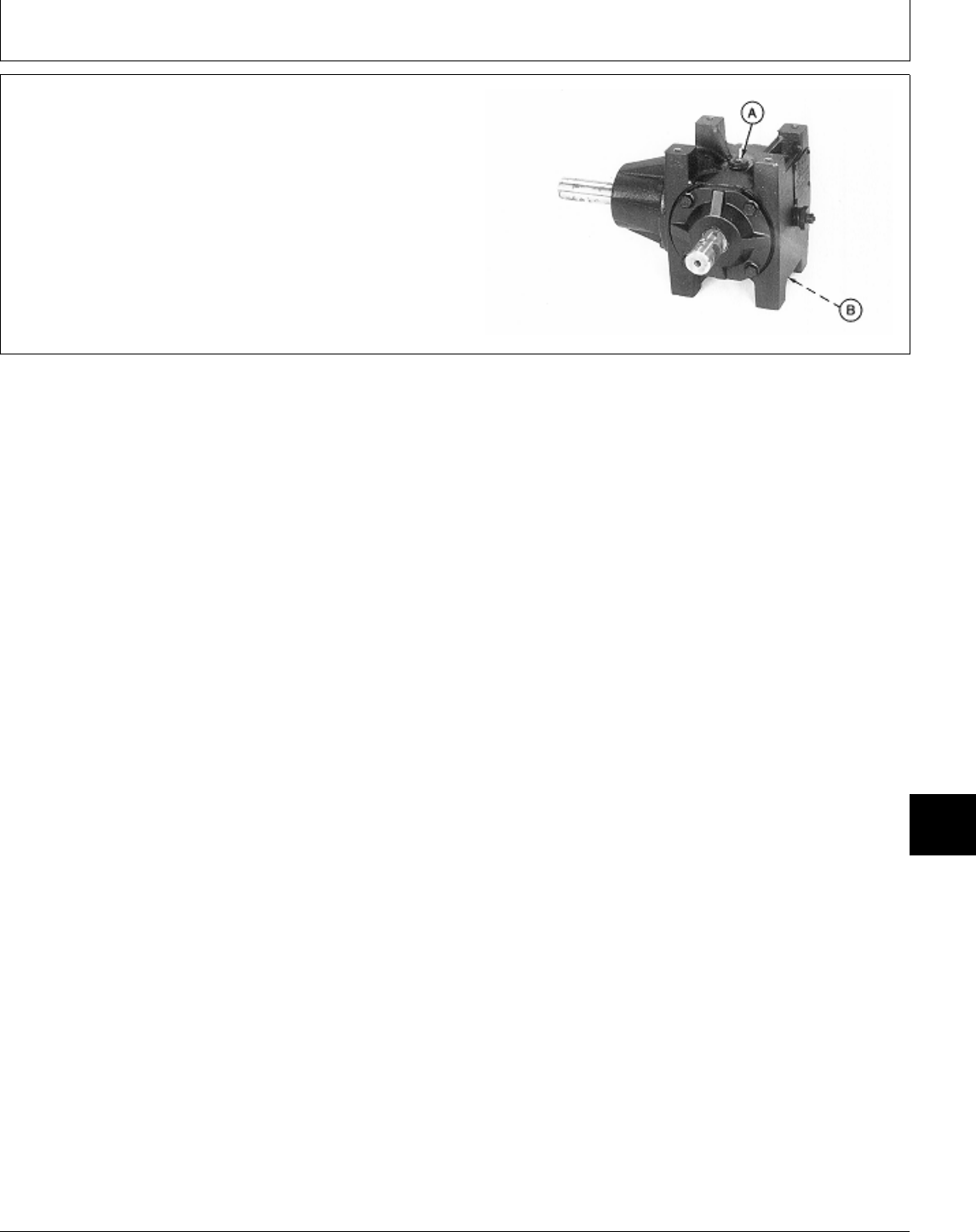
DISASSEMBLE AND INSPECT MOWER
GEAR CASE—260 ROTARY MOWER
1. Remove drain plugs (A and B) and drain oil from gear
case.
M77323 -UN-24FEB95
MX,15908015,29 -19-22FEB95
Mower Gear Case Repair/260 Rotary Mower
TM1591 (15JUL95) 80-15-27 322,330,332 & 430 Lawn & Garden Tractors
030895
80
15
27
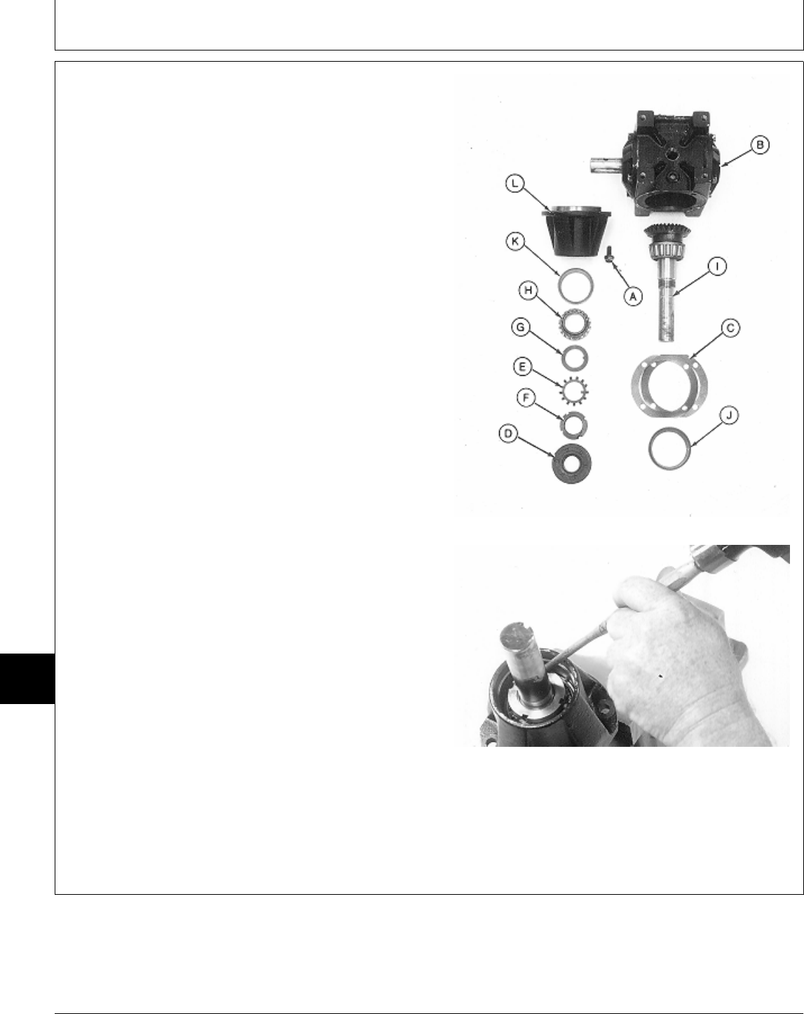
2. Remove four cap screws (A).
3. Remove output shaft assembly and housing from gear
case (B).
4. Remove shims (C).
5. Punch a hole in seal (D) and pry out of housing (L).
6. Bend out exterior locking tab on toothed washer (E)
from lock nut (F).
7. Turn lock nut (F) counterclockwise using a hammer
and punch. Remove lock nut.
8. Bend interior locking tab on toothed washer (E) away
from groove in shaft (I). Remove toothed washer.
9. Remove tabbed washer (G) and bearing cone (H).
10. Remove output shaft assembly (I) from housing (L).
NOTE: Bearing cups are press-fit in housing. Remove
bearing cups only if replacement is necessary.
Bearing cones and cups are matched and must
be replaced as complete assemblies. Output Shaft Side
11. Inspect bearing cups (K and J) for wear or damage.
Replace if necessary.
12. Remove bearing cups using a brass drift or punch
and hammer.
A—Cap Screw (4 used)
B—Gear Case
C—Shims (as required)
D—Seal
E—Toothed Washer
F—Lock Nut
G—Tabbed Washer
H—Bearing Cone
I—Output Shaft Assembly
J—Bearing Cup
K—Bearing Cup
L—Housing
M77324 -UN-24FEB95M32175 -UN-27FEB95
MX,15908015,30 -19-22FEB95
Mower Gear Case Repair/260 Rotary Mower
TM1591 (15JUL95) 80-15-28 322,330,332 & 430 Lawn & Garden Tractors
030895
80
15
28
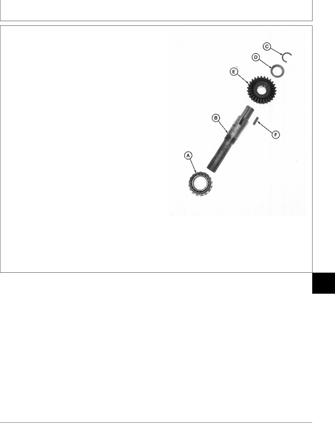
13. Remove bearing cone (A) from shaft (B) using a
knife-edge puller and a press.
14. Remove c-ring (C), locking collar (D), bevel gear (E)
and key (F).
15. Inspect all parts for wear or damage. Replace as
necessary.
A—Bearing Cone
B—Output Shaft
C—C-Ring
D—Locking Collar
E—Bevel Gear
F—Key
Output Shaft Assembly
M77325 -UN-24FEB95
MX,15908015,31 -19-22FEB95
Mower Gear Case Repair/260 Rotary Mower
TM1591 (15JUL95) 80-15-29 322,330,332 & 430 Lawn & Garden Tractors
030895
80
15
29
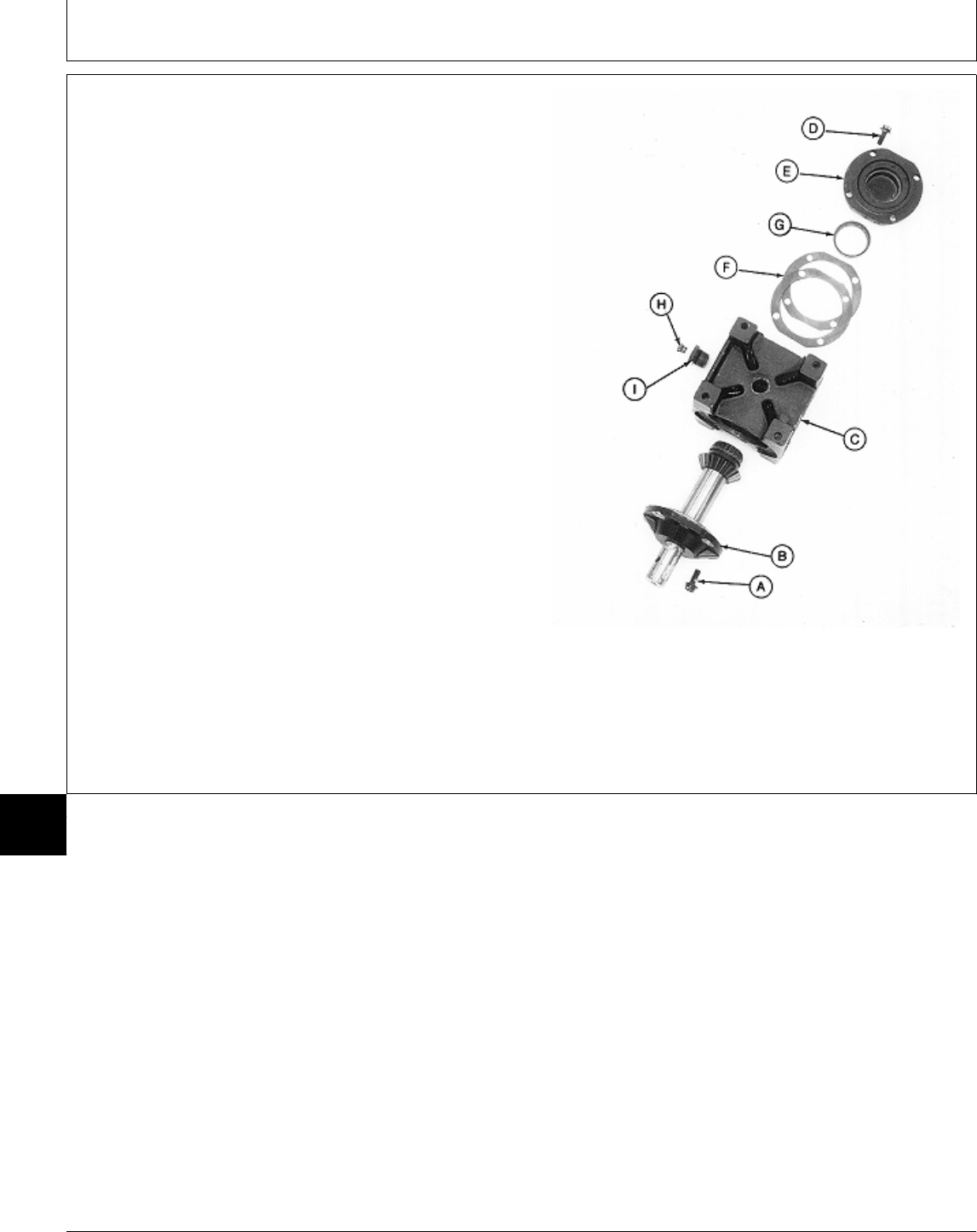
16. Remove four cap screws (A).
17. Remove input shaft assembly (B) from gear case
(C).
18. Remove four cap screws (D), end cap (E) and shims
(F).
19. Remove vent plug (H) and adapter (I).
NOTE: Bearing cup is press-fit in end cap. Remove
bearing cup only if replacement is necessary.
Bearing cones and cups are matched and must
be replaced as complete assemblies.
20. Inspect bearing cup (G) for wear or damage.
Replace if necessary.
21. Remove bearing cup (G) using a slide hammer and
a three-jaw puller.
A—Cap Screw (4 used)
B—Input Shaft Assembly
C—Gear Case
D—Cap Screw (4 used)
E—End Cap
F—Shims (as required) Input Shaft Side
G—Bearing Cup
H—Vent Plug
I—Adapter
M77326 -UN-24FEB95
MX,15908015,32 -19-22FEB95
Mower Gear Case Repair/260 Rotary Mower
TM1591 (15JUL95) 80-15-30 322,330,332 & 430 Lawn & Garden Tractors
030895
80
15
30
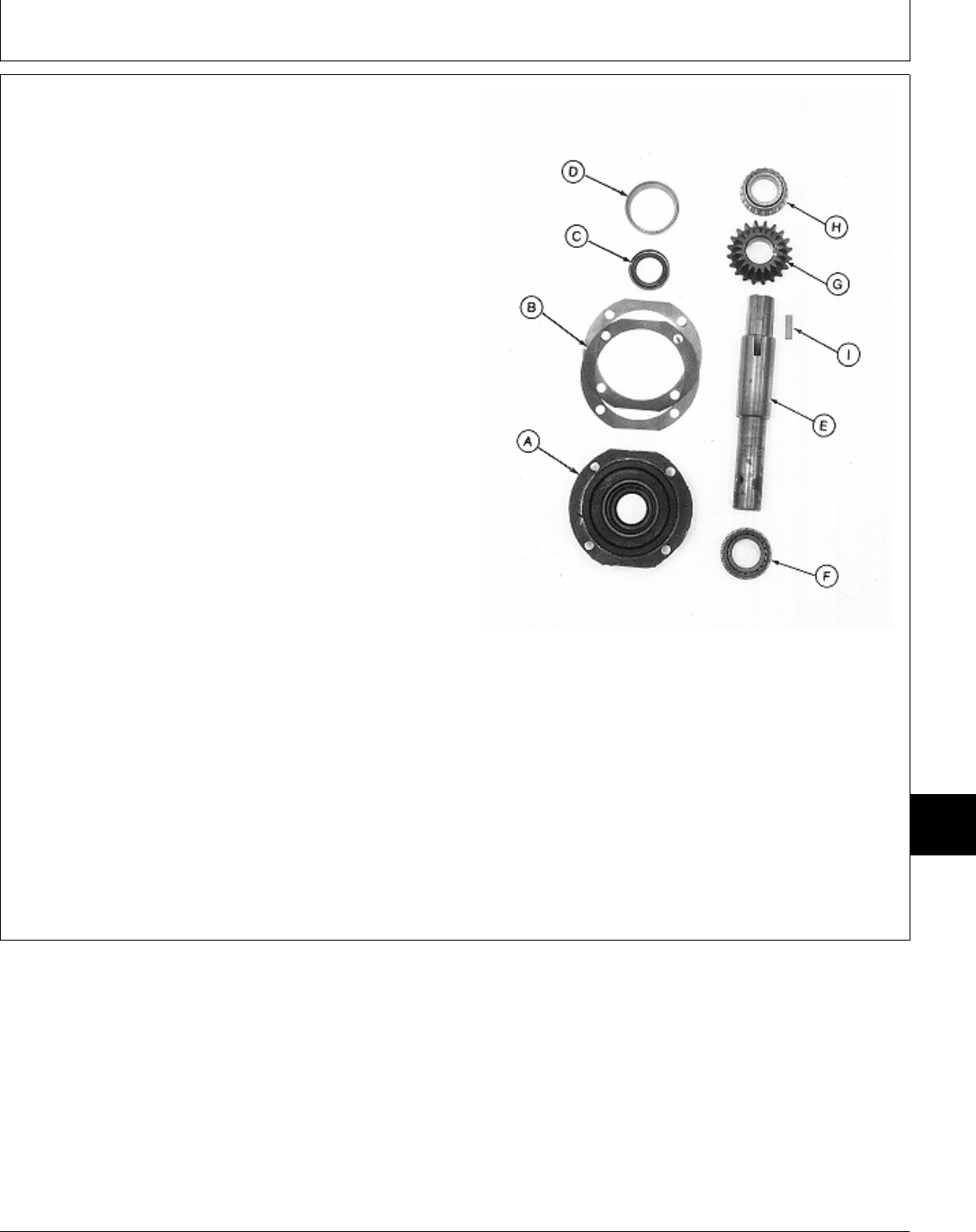
22. Remove input shaft assembly from cap (A).
23. Remove shims (B).
24. Remove seal (C) using a punch and hammer.
NOTE: Bearing cup is press-fit in cap. Remove bearing
cup only if replacement is necessary.
Bearing cups and cones are matched and must
be replaced as complete assemblies.
25. Inspect bearing cup (D) for wear or damage.
Replace if necessary.
26. Remove bearing cup using a brass drift or punch
and hammer.
27. Press shaft (E) from bearing cone (F).
28. Press shaft (E) from bevel gear (G) and bearing
cone (H).
29. Remove key (I).
30. Inspect all parts for wear or damage. Replace as
necessary. Input Shaft Assembly
A—Cap
B—Shims (as required)
C—Seal
D—Bearing Cup
E—Input Shaft
F—Bearing Cone
G—Bevel Gear
H—Bearing Cone
I—Key
M77327 -UN-24FEB95
MX,15908015,33 -19-29MAR95
Mower Gear Case Repair/260 Rotary Mower
TM1591 (15JUL95) 80-15-31 322,330,332 & 430 Lawn & Garden Tractors
030895
80
15
31
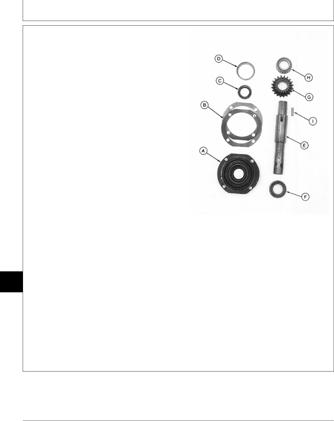
ASSEMBLE MOWER GEAR CASE—260
ROTARY MOWER
IMPORTANT: Always use new seals. Damaged or
used seals will leak.
NOTE: Apply clean gear case oil on all internal parts
during assembly.
1. Install key (I) into input shaft (E).
2. Press bevel gear (G), tapered end first, onto shaft (E)
until started.
3. Press bearing cone (H) on shaft with small O.D.
facing away from bevel gear (G). Install both bearing
cone and bevel gear until bearing bottoms against shaft.
4. Press bearing cone (F) onto other end of input shaft
(E) with small O.D. facing away from bevel gear.
IMPORTANT: Do not press seal in until seated or
bottomed out. Seal will become
damaged and will leak.
5. Press new seal (C) into cap (A) until top of seal is
flush with first recess inside cap. Input Shaft Assembly
6. Apply multipurpose grease to lip of seal.
A—Cap
7. Install new bearing cup (D), if removed, using a driver B—Shims (as required)
set. C—Seal
D—Bearing Cup
E—Input Shaft
IMPORTANT: Tape end of input shaft to prevent seal F—Bearing Cone
damage during shaft installation. G—Bevel Gear
H—Bearing Cone
8. Apply tape around end of input shaft. I—Key
9. Assemble input shaft assembly and cap (A). Remove
tape.
10. Install shims (B) on cap (A).
M77327 -UN-24FEB95
MX,15908015,34 -19-29MAR95
Mower Gear Case Repair/260 Rotary Mower
TM1591 (15JUL95) 80-15-32 322,330,332 & 430 Lawn & Garden Tractors
030895
80
15
32
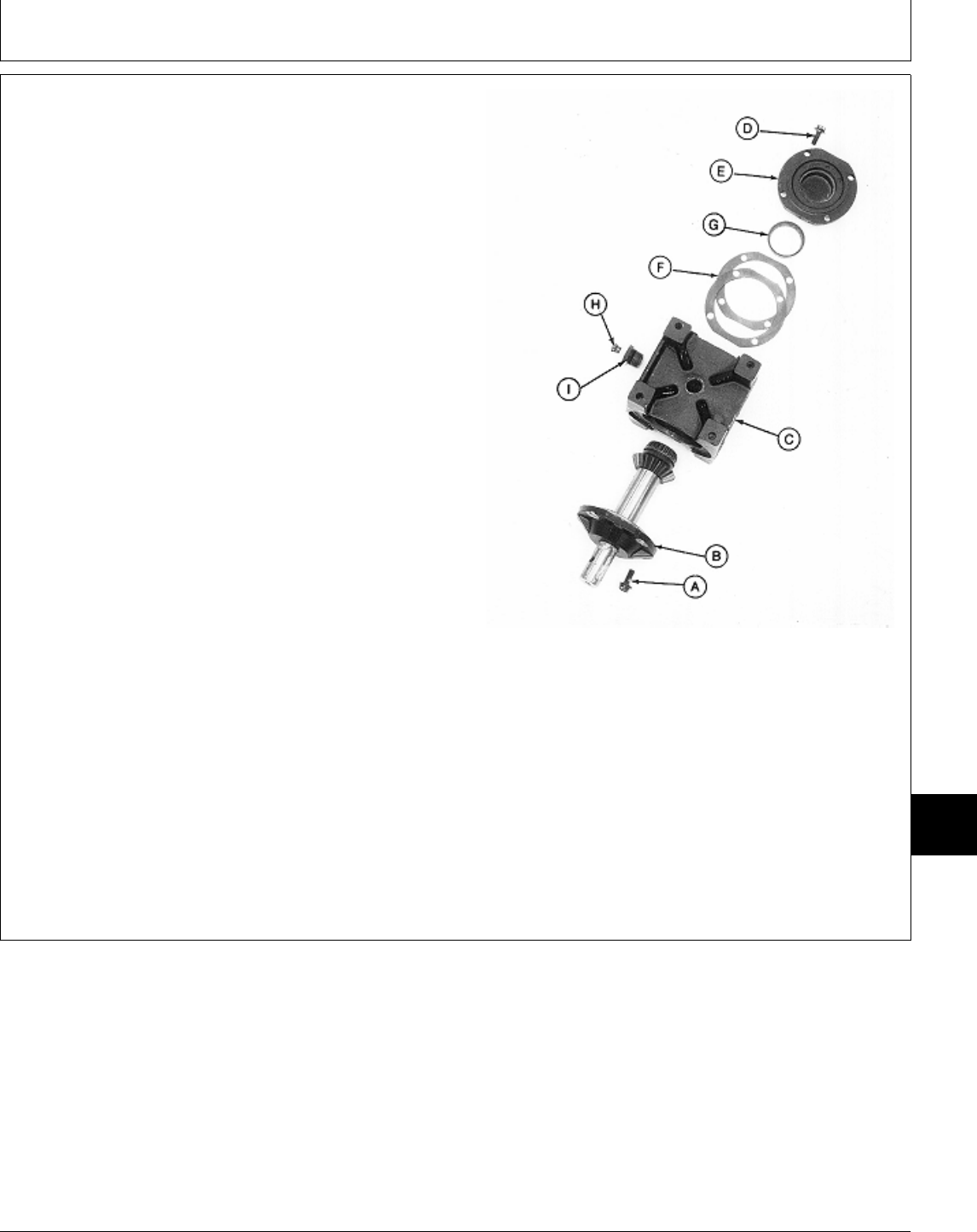
11. Install new bearing cup (G), if removed, into end cap
(E) using a driver set.
12. Install shims (F) onto end cap (E).
13. Clean mating surfaces of cap, shims and gear case
using Clean and Cure Primer. Apply a bead of
Form-In-Place Gasket, or an equivalant, between inside
edge of top shim and flange on end cap (E).
14. Install end cap and four cap screws (D) onto gear
case (C). Tighten cap screws to 30 N·m (22 lb-ft).
15. Install input shaft assembly (B) into gear case (C).
16. Install four cap screws (A) and tighten to 30 N·m (22
lb-ft).
17. Check input shaft endplay. Endplay should be within
0.025—0.076 mm (0.001—0.003 in.). If necessary,
remove four cap screws (D) and end cap (E) and add or
remove shims (F) as needed.
18. Remove input shaft assembly (B).
19. Clean mating surfaces of cap, shims and gear case
using Clean and Cure Primer. Apply a bead of Input Shaft Side
Form-In-Place Gasket, or an equivalant, between inside
edge of top shim and flange on cap.
A—Cap Screw (4 used)
20. Install input shaft assembly and four cap screws (D). B—Input Shaft Assembly
Tighten cap screws to 30 N·m (22 lb-ft). C—Gear Case
D—Cap Screw (4 used)
E—End Cap
21. Install adapter (I) and vent plug (H). F—Shims (as required)
G—Bearing Cup
H—Vent Plug
I—Adapter
M77326 -UN-24FEB95
MX,15908015,35 -19-29MAR95
Mower Gear Case Repair/260 Rotary Mower
TM1591 (15JUL95) 80-15-33 322,330,332 & 430 Lawn & Garden Tractors
030895
80
15
33
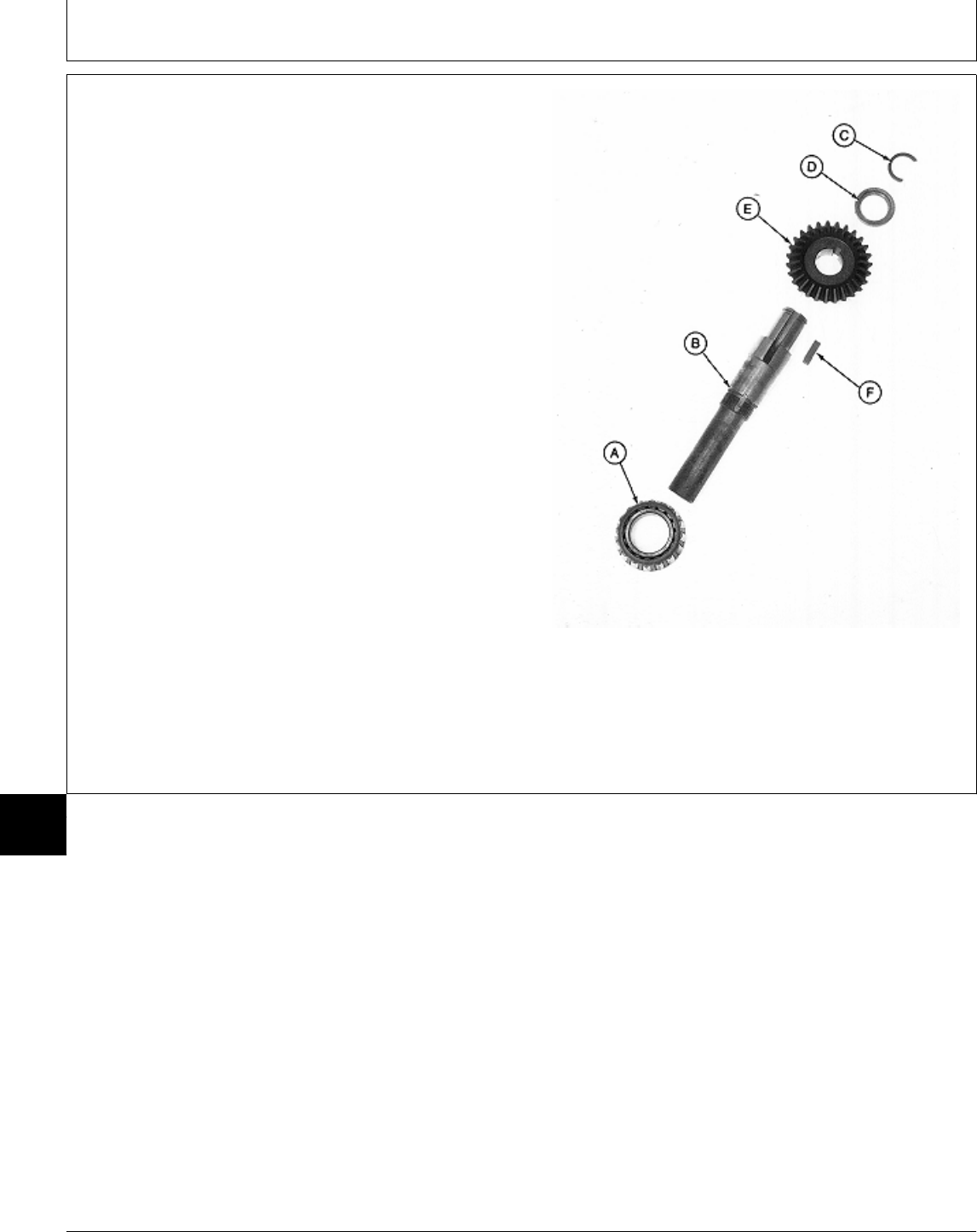
22. Install key (F) and bevel gear (E) on shaft (B). Install
bevel gear with shoulder end toward threaded end of
shaft.
23. Install locking collar (D) with groove facing away
from bevel gear. Install c-ring (C).
24. Press bearing cone (A) on shaft with small O.D.
facing away from bevel gear (E). Install bearing until it
bottoms locking collar (D) against c-ring (C).
A—Bearing Cone
B—Output Shaft
C—C-Ring
D—Locking Collar
E—Bevel Gear
F—Key
Output Shaft Assembly
M77325 -UN-24FEB95
MX,15908015,36 -19-13MAR95
Mower Gear Case Repair/260 Rotary Mower
TM1591 (15JUL95) 80-15-34 322,330,332 & 430 Lawn & Garden Tractors
030895
80
15
34
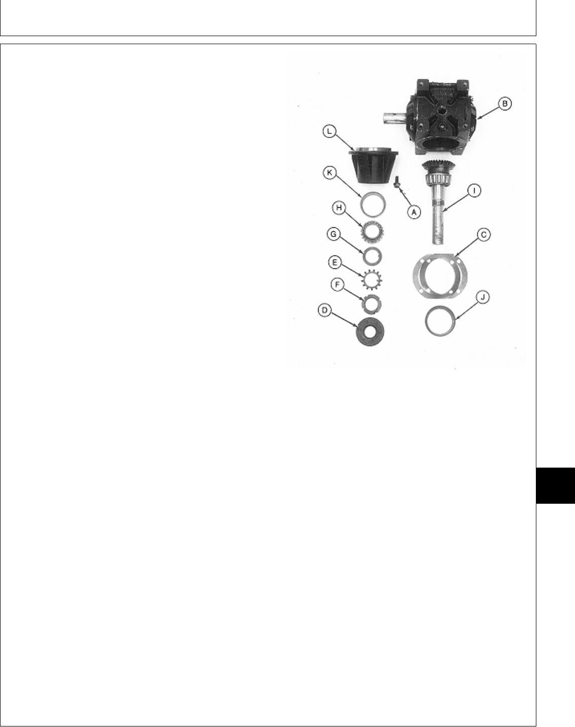
25. Install new bearing cups (K and J), if removed, into
housing (L) using a driver set.
26. Install output shaft assembly (I) into housing (L).
27. Slide bearing cone (H) on shaft with small O.D.
facing toward housing (L).
28. Install tabbed washer (G) and toothed washer (E).
Press internal tab on toothed washer (E) into slot on
shaft using a screwdriver.
29. Install lock nut (F). Tighten lock nut, using a punch
and hammer, until there is zero endplay in output shaft.
Bend up one tab from toothed washer (E), that is in
alignment with a slot in lock nut (F), to secure nut in
place.
IMPORTANT: Tape end of output shaft to prevent
seal damage during shaft installation.
30. Apply tape around end of output shaft.
31. Apply multipurpose grease to lip of seal.
32. Press new seal (D) into housing (L) until seal is flush
with top of housing. Remove tape. Output Shaft Side
33. Install shims (C) on housing (L).
A—Cap Screw (4 used)
34. Install output shaft assembly and housing into gear B—Gear Case
case (B). C—Shims (as required)
D—Seal
E—Toothed Washer
35. Install four cap screws (A) and tighten to 30 N·m (22 F—Lock Nut
lb-ft). G—Tabbed Washer
H—Bearing Cone
36. Hold input shaft securely and check output shaft I—Output Shaft Assembly
J—Bearing Cup
backlash. Backlash should be within 0.076—0.130 mm K—Bearing Cup
(0.003—0.005 in.). If necessary, remove four cap screws L—Housing
(A) and housing and output shaft assembly and add or
remove shims (C) as needed.
37. Again, remove four cap screws (A) and housing and
output shaft assembly.
38. Clean mating surfaces of housing, shims and gear
case using Clean and Cure Primer. Apply a bead of
Form-In-Place Gasket, or an equivalant, between inside
edge of top shim and flange on housing (L).
39. Install housing and output shaft assembly into gear
case. Install four cap screws (A) and tighten to 30 N·m
(22 lb-ft).
M77324 -UN-24FEB95
MX,15908015,37 -19-13MAR95
Mower Gear Case Repair/260 Rotary Mower
TM1591 (15JUL95) 80-15-35 322,330,332 & 430 Lawn & Garden Tractors
030895
80
15
35
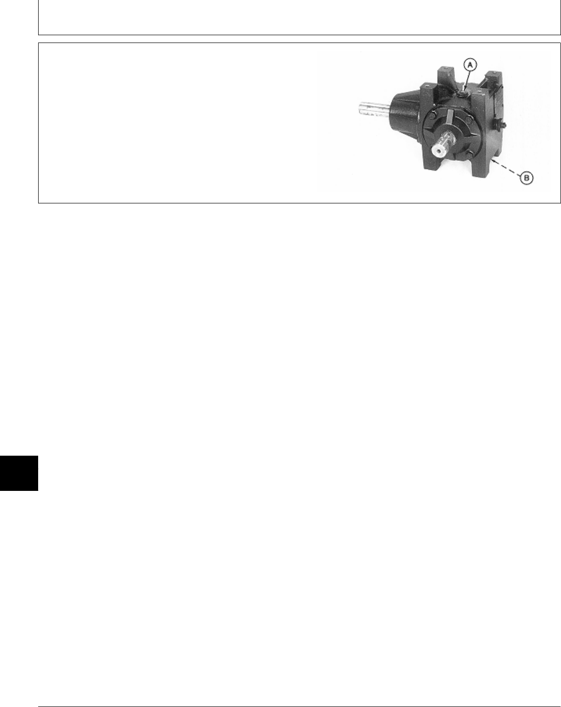
40. AFTER installing gear case on mower deck, fill gear
case to proper level with John Deere API GL-5 Gear Oil.
41. Install plugs (A and B).
M77323 -UN-24FEB95
MX,15908015,38 -19-13MAR95
Mower Gear Case Repair/260 Rotary Mower
TM1591 (15JUL95) 80-15-36 322,330,332 & 430 Lawn & Garden Tractors
030895
80
15
36

Section 220
ENGINE, FUEL AND AIR SYSTEM
CHECKOUT AND DIAGNOSIS
Contents
Page
Group 05—Engine, Fuel and Air System
Checkout
Before You Start . . . . . . . . . . . . . . . . . 220-05-1
Engine Oil Leak Check . . . . . . . . . . . . . 220-05-1
Engine Cooling System Leak Check . . . . 220-05-2
Air Cleaner and Radiator Screen Check . . 220-05-2
Fan and Belt Check . . . . . . . . . . . . . . . 220-05-3
Throttle Lever Check . . . . . . . . . . . . . . 220-05-3
Governor Linkage Check . . . . . . . . . . . . 220-05-4
Fuel System Check . . . . . . . . . . . . . . . 220-05-5
Engine Start Check . . . . . . . . . . . . . . . 220-05-6
Choke Lever Check (Early 322) . . . . . . . 220-05-6
Fuel Shutoff Lever Check (330) . . . . . . . 220-05-7
Engine Oil Pressure Check . . . . . . . . . . 220-05-7
Engine Performance Check . . . . . . . . . . 220-05-7
Operator Complaint Not Identified . . . . . . 220-05-8
Group 10—Diagnosis, Tests and
Adjustments—322
About This Group . . . . . . . . . . . . . . . . 220-10-1
Troubleshooting Guide . . . . . . . . . . . . . 220-10-1
Radiator Bubble Test . . . . . . . . . . . . . . 220-10-5
Throttle Lever Adjustment . . . . . . . . . . . 220-10-5
Carburetor Idle Mixture Screw Adjustment . 220-10-6
Governor Linkage and Idle Speed
Adjustments . . . . . . . . . . . . . . . . . . . 220-10-6
Throttle Cable Adjustment . . . . . . . . . . . 220-10-7
Fuel Transfer Pump Test . . . . . . . . . . . . 220-10-8
Choke Adjustment . . . . . . . . . . . . . . . . 220-10-8
Engine Oil Pressure Test . . . . . . . . . . 220-10-11
Ignition Spark Test . . . . . . . . . . . . . . . 220-10-11
Cooling System Pressure Test . . . . . . . 220-10-12
Compression Pressure Test . . . . . . . . . 220-10-12
Group 11—Diagnosis, Tests and
Adjustments—330, 332 and 430
About This Group . . . . . . . . . . . . . . . . 220-11-1
Troubleshooting Guide . . . . . . . . . . . . . 220-11-2
Radiator Bubble Test . . . . . . . . . . . . . . 220-11-6
Throttle Lever Adjustment . . . . . . . . . . . 220-11-6
Throttle Cable Adjustment . . . . . . . . . . . 220-11-6
Fuel Transfer Pump Test . . . . . . . . . . . . 220-11-7
Page
Bleed Fuel Injection System . . . . . . . . . . 220-11-8
Compression Pressure Test . . . . . . . . . 220-11-10
Engine Oil Pressure Test . . . . . . . . . . 220-11-11
Idle Speed Adjustment . . . . . . . . . . . . 220-11-12
Cooling System Pressure Test . . . . . . . 220-11-14
Fuel Controller Adjustment . . . . . . . . . . 220-11-15
TM1591 (15JUL95) 220-1 322,330,332 & 430 Lawn & Garden Tractors
030895
220

Contents
TM1591 (15JUL95) 220-2 322,330,332 & 430 Lawn & Garden Tractors
030895
220

BEFORE YOU START
Always begin with this group to identify a failure in
the engine, fuel or air system. The step-by-step
procedures will provide you with a quick check of the
system. No special tools are required to perform
these checks. If a failure is indicated, you will be
referred to a more detailed check, adjustment, or test.
Always start with the first step and follow the
sequence from left to right. Read each step
completely before performing the check.
This procedure is designed as a quick check of the
system. While performing the check, concentrate only
on the check you are performing and disregard
signals from unrelated components.
NOTE: 322 (S.N. —010713); Manual choke.
322 (S.N. 010714— ); Automatic choke.
NOTE: When instructed to “turn the key switch ON”:
322 and 430; Turn the key switch to the
“RUN” position.
330 and 332; Turn the key switch to the “ON”
position.
For clarity in this section, machines including
and before serial numbers listed below will be
referred to as “Early Models”. Machines
including and after serial number listed below
will be referred to as “Later Models”.
Later model machines have a brake switch
added to the neutral start circuit, which is
activated by depressing the brake pedals.
MODEL EARLY LATER
322 (S.N. —596005) (S.N. 596006— )
330 (S.N. —420000) N/A
332 (S.N. —475000) (S.N. 475001— )
430 (S.N. —596047) (S.N. 596048— )
; ENGINE OIL LEAK
CHECK
Check engine oil level,
condition and viscosity.
M44146 -UN-08JAN90
LOOK: Oil level must
be between add and
full marks.
LOOK: Oil must not
look “milky”.
SMELL: Oil must not
smell burned.
If oil level is low, add
oil. Inspect for external
oil leakage from oil pan
gasket, drain plug,
valve cover gasket,
seals, dipstick and oil
filter. Repair as
necessary.
OK: GO TO ‘
NOT OK:
OIL LOOKS “MILKY”
(Indicates water in oil):
322; GO TO ‘, Group
10
330, 332 and 430; GO
TO ‘, Group 11
OIL SMELLS BURNED:
(Indicates cooling
system malfunction) GO
TO ‘
MX,159122005,1A-19-13JUL95
MX,159122005,1 -19-13JUL95
Group 05
Engine, Fuel and Air System Checkout
TM1591 (15JUL95) 220-05-1 322,330,332 & 430 Lawn & Garden Tractors
030895
220
05
1
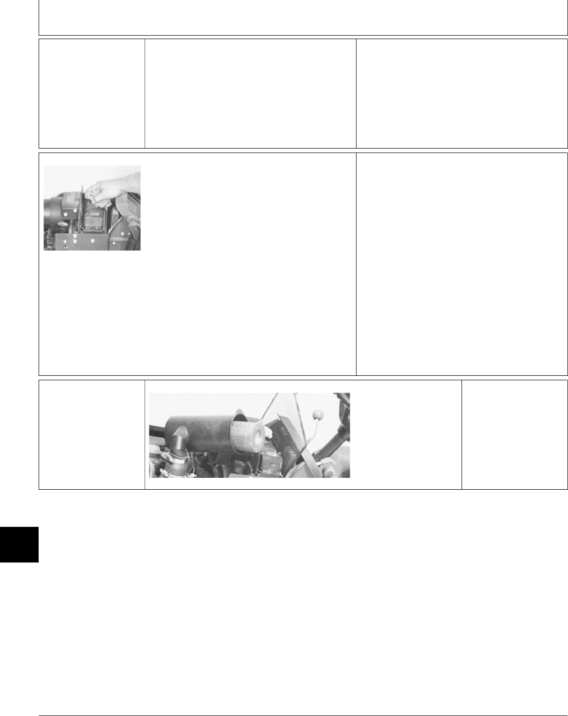
‘ ENGINE COOLING
SYSTEM LEAK
CHECK
NCAUTION: DO NOT REMOVE RADIATOR
CAP UNLESS ENGINE IS COOL. THEN TURN
CAP SLOWLY TO THE STOP. RELEASE ALL
PRESSURE BEFORE YOU REMOVE CAP.
M49179 -UN-20DEC89
Remove radiator cap and check coolant level
and condition.
LISTEN: If radiator is warmer than air
temperature a “whoosh” must be heard when
radiator cap is opened to first stop position.
LOOK: The radiator cap must have a good seal
and gasket. The seal must move freely and the
spring must not be corroded.
LOOK: The coolant must not be oily, foamy, or
rusty.
LOOK: Inspect for external leakage from radiator,
water pump, thermostat cover and radiator
hoses.
LOOK: Inspect radiator for bent or clogged fins.
OK: GO TO Æ
NOT OK:
RADIATOR CAP DEFECTIVE: Replace cap.
COOLANT OILY OR FOAMY:
322; GO TO ‘, Group 10
330, 332 and 430; GO TO ‘, Group 11
COOLANT RUSTY: Drain, flush, and put in new
coolant.
COOLING SYSTEM LEAKS OR RADIATOR
FINS BENT OR CLOGGED: Repair, replace or
clean as necessary, then GO TO Æ.
Æ AIR CLEANER AND
RADIATOR SCREEN
CHECK
M49176 -UN-20DEC89
Remove air cleaner
cover.
Inspect air cleaner, grill
and radiator screen for
debris or plugged
condition.
Clean or replace as
required, then GO TO
Å
MX,159122005,2 -19-13JUL95
MX,159122005,3 -19-13JUL95
Engine, Fuel and Air System Checkout/Air Cleaner and Radiator Screen Check
TM1591 (15JUL95) 220-05-2 322,330,332 & 430 Lawn & Garden Tractors
030895
220
05
2
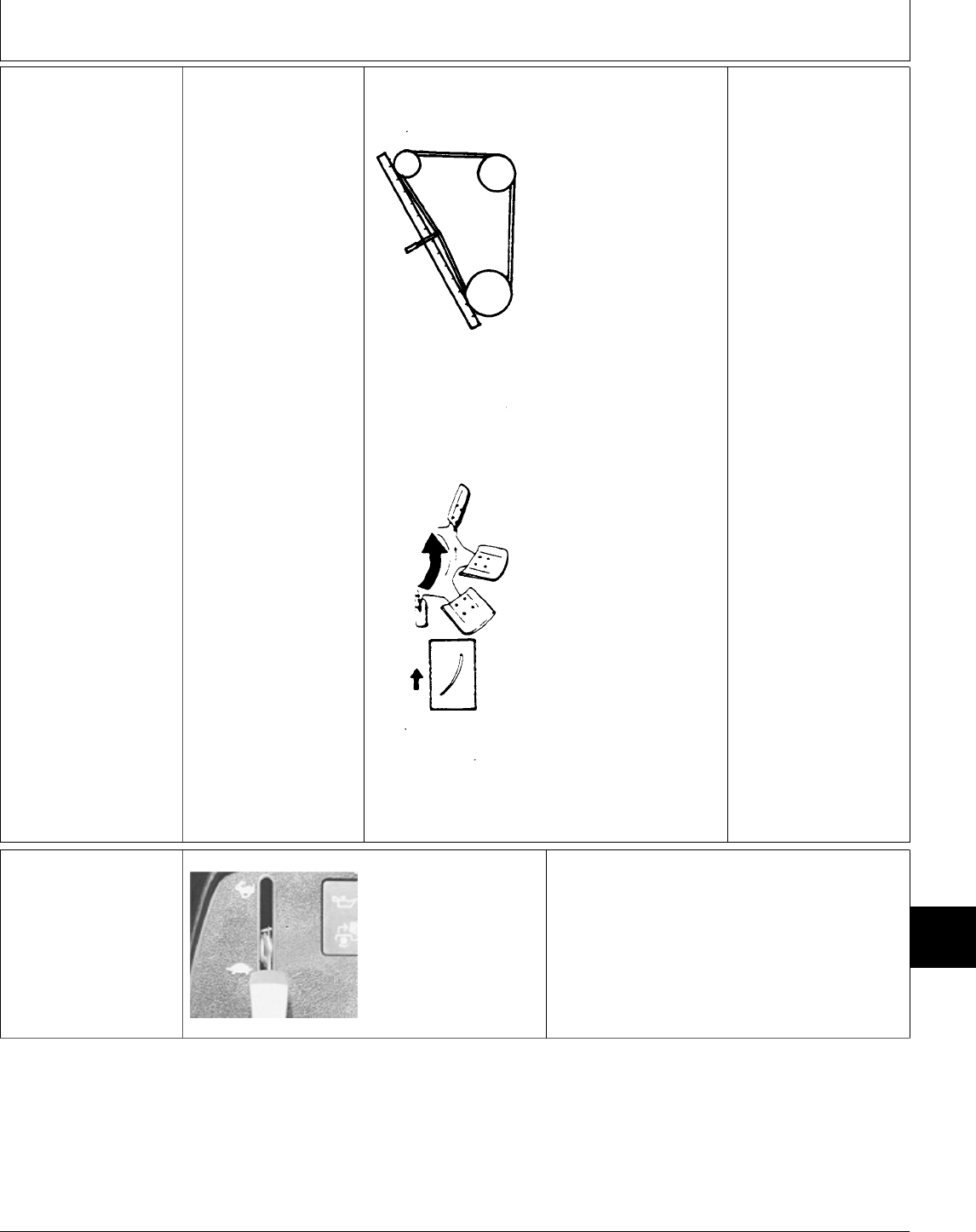
Å FAN AND BELT
CHECK
Inspect fan blade, belts,
and sheaves for
damage.
Check fan for loose
mounting cap screws.
Check crankshaft
sheave to be sure it is
not slipping on the
crankshaft.
T6171CA -UN-25MAY89
T6171CB -UN-25MAY89
LOOK: Fan belt
deflection should be
approximately 13 mm
(0.500 in.) when a
10—11 kg (22—24 lb)
force is applied midway
between alternator and
crankshaft sheave.
LOOK: Fan belt must
not have any cracks or
contact bottom of
sheave grooves.
LOOK: Make sure there
is no oil on belt.
LOOK: Cupped side of
fan blades must be
away from radiator and
mounting cap screws
must be tight.
NOTE: If the fan blade
has been installed
backwards about 50%
of its capacity is lost.
OK: GO TO Ö
NOT OK:
Adjust fan belt as
necessary.
FAN BELT WORN,
OILY, OR DAMAGED;
Clean or replace as
necessary.
FAN ON
BACKWARDS; Remove
and install fan correctly.
After making necessary
repairs or adjustments,
then GO TO Ö
Ö THROTTLE LEVER
CHECK
M49006 -UN-08JAN90
Move throttle lever from
slow idle position to
fast idle position.
FEEL: Throttle lever
must move smoothly
with a slight drag.
OK:
322; GO TO 6a
330, 332 and 430;
GO TO 6b
NOT OK:
322; GO TO Æ, Group 10
330, 332 and 430; GO TO Æ, Group 11
MX,159122005,4 -19-13JUL95
MX,159122005,5 -19-13JUL95
Engine, Fuel and Air System Checkout/Throttle Lever Check
TM1591 (15JUL95) 220-05-3 322,330,332 & 430 Lawn & Garden Tractors
030895
220
05
3
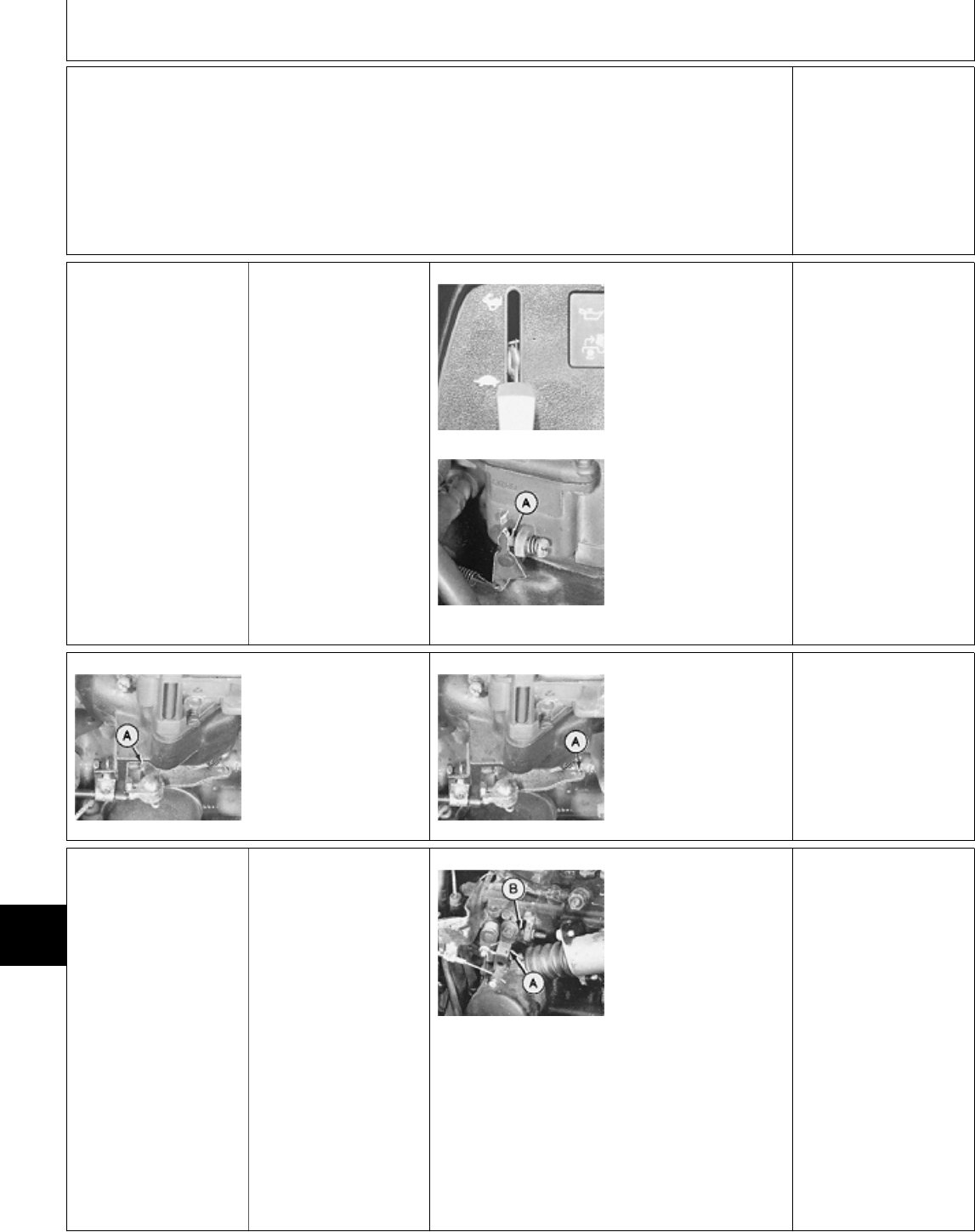
Ò GOVERNOR
LINKAGE CHECK
6a 322 Remove left engine
side panel.
M49006 -UN-08JAN90
M44150 -UN-08JAN90
Move throttle lever to
slow idle position.
LOOK: Carburetor
governor linkage must
be against stop (A).
M44151 -UN-08JAN90
Move throttle lever to
fast idle position.
LOOK: Carburetor
governor linkage must
be against stop (A).
M44152 -UN-08JAN90
LOOK: If bracket is
equipped with more
than one hole, spring
(A) must be in outer
hole.
OK: GO TO 7a
NOT OK: GO TO Ö,
Group 10.
6b 330, 332 and 430 Remove left engine
side panel.
M49180 -UN-20DEC89
Move throttle lever on
instrument panel to
slow idle.
LOOK: Injection pump
lever (A) must strike
slow idle stop screw
(B).
Move throttle lever on
instrument panel to fast
idle.
FEEL: Injection pump
lever (A) must strike
fast idle stop screw.
(Located inside
governor housing).
OK: GO TO 7b
NOT OK: GO TO Å,
Group 11.
MX,159122005,6 -19-13JUL95
MX,159122005,7 -19-13JUL95
MX,159122005,8 -19-13JUL95
Engine, Fuel and Air System Checkout/Governor Linkage Check
TM1591 (15JUL95) 220-05-4 322,330,332 & 430 Lawn & Garden Tractors
030895
220
05
4
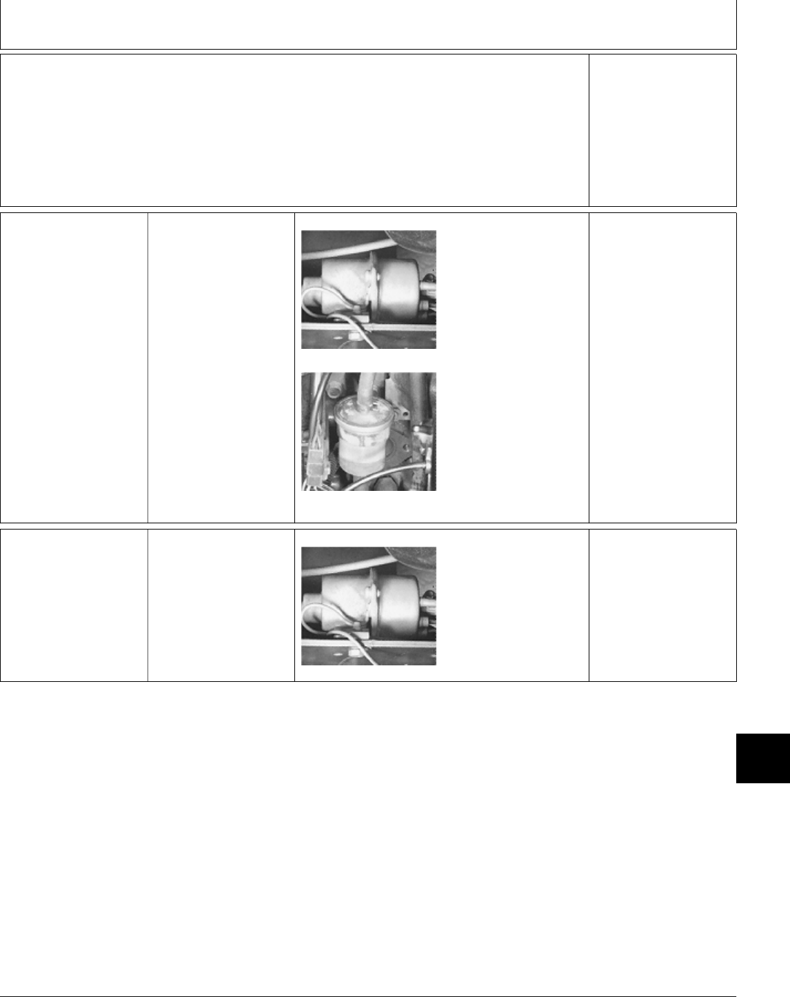
Õ FUEL SYSTEM
CHECK
7a 322 Turn key switch to RUN
position.
M49009 -UN-08JAN90
M44154 -UN-08JAN90
LISTEN: Fuel pump
must run making a
“ticking” sound.
LOOK: Fuel level in
filter must rise when
fuel transfer pump is
turned on.
OK: GO TO 8a
NOT OK:
Fuel pump not OK; GO
TO Section 240.
No fuel in filter; GO TO
Õ, GROUP 10.
7b 330, 332 and 430 Be sure fuel tank has
the correct grade of
diesel fuel in it.
Turn key switch to
ON/RUN position.
M49009 -UN-08JAN90
LISTEN: Fuel pump
must run making a
“ticking” sound.
LOOK: 332 and 430;
Fuel shutoff solenoid
must pull in and hold.
OK: GO TO 8b
NOT OK: Go to Section
240.
MX,159122005,9 -19-13JUL95
MX,159122005,10-19-13JUL95
MX,159122005,11-19-13JUL95
Engine, Fuel and Air System Checkout/Fuel System Check
TM1591 (15JUL95) 220-05-5 322,330,332 & 430 Lawn & Garden Tractors
030895
220
05
5
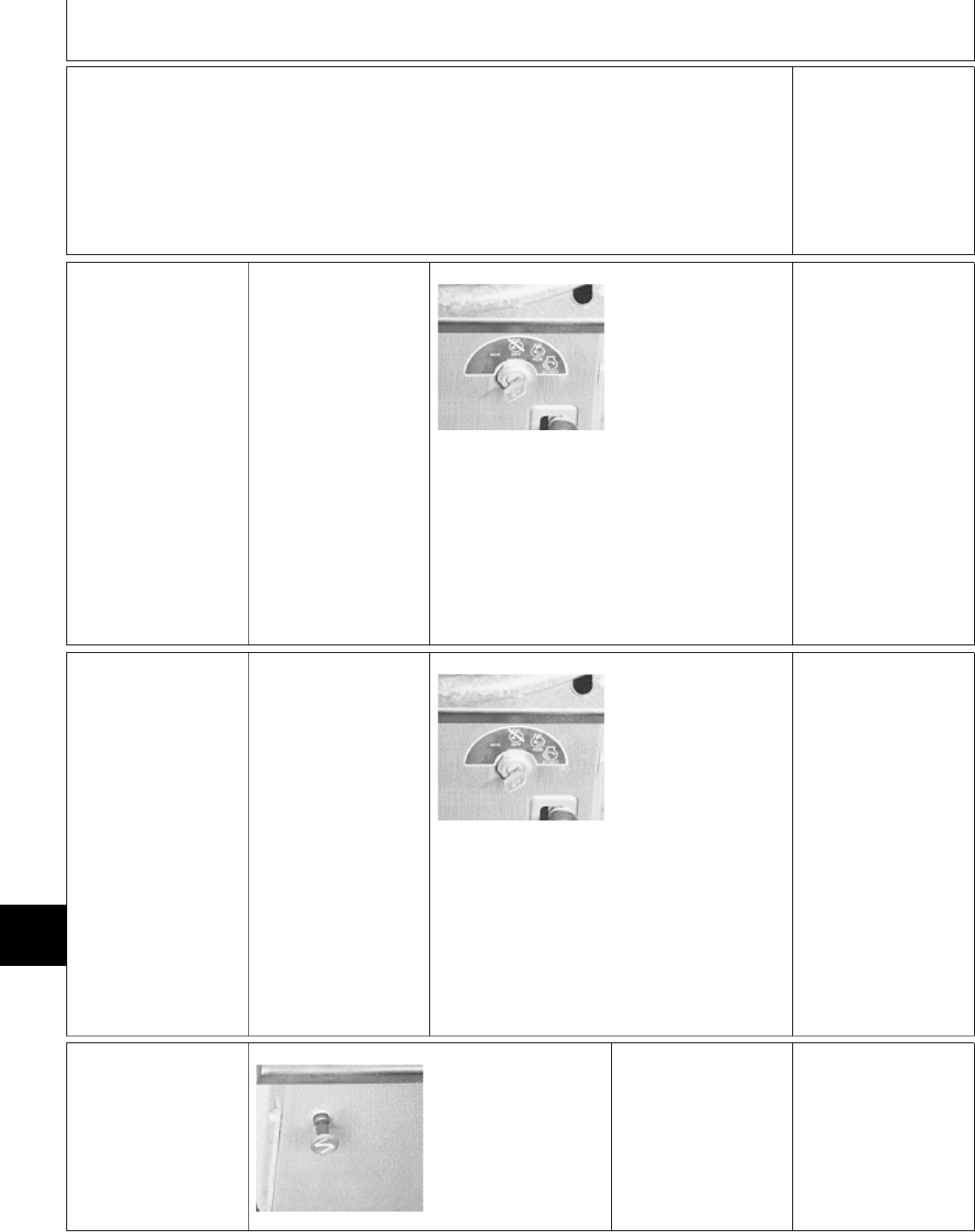
Ú ENGINE START
CHECK
8a 322 Operator on seat.
Put hydrostatic control
lever in N/STOP
position.
PTO switch OFF.
Later Models; Depress
brake pedals. M49177 -UN-20DEC89
Turn key to START
position.
LISTEN: Starter must
crank. Engine must
start.
OK:
Early Models with
choke lever, GO TO Ü
Later Models without
choke lever, GO TO
1!
NOT OK:
STARTER DOES NOT
CRANK; GO TO
Section 240.
STARTER CRANKS
BUT ENGINE WILL
NOT START; GO TO
A, Group 10.
8b 330, 332 and 430 Operator on seat.
Put hydrostatic control
lever in N/STOP
position.
PTO switch OFF.
Later Models; Depress
brake pedal(s). M49177 -UN-20DEC89
Turn key to ON/RUN
position. After glow plug
lamp goes off, turn key
to START.
LISTEN: Starter must
crank. Engine must
start.
OK:
332 and 430; GO TO
1!
330; GO TO 1Ô
NOT OK:
STARTER DOES NOT
CRANK; GO TO
Section 240.
STARTER CRANKS
BUT ENGINE WILL
NOT START; GO TO
A, Group 11.
Ü CHOKE LEVER
CHECK (EARLY 322)
M49178 -UN-20DEC89
Start and run engine at
half throttle.
Quickly pull choke knob
fully out, then push in.
LISTEN: Engine must
falter, then resume
speed.
OK: GO TO 1!
NOT OK: GO TO Ú,
Group 10.
MX,159122005,12-19-13JUL95
MX,159122005,13-19-13JUL95
MX,159122005,14-19-13JUL95
MX,159122005,15-19-13JUL95
Engine, Fuel and Air System Checkout/Choke Lever Check (Early 322)
TM1591 (15JUL95) 220-05-6 322,330,332 & 430 Lawn & Garden Tractors
030895
220
05
6
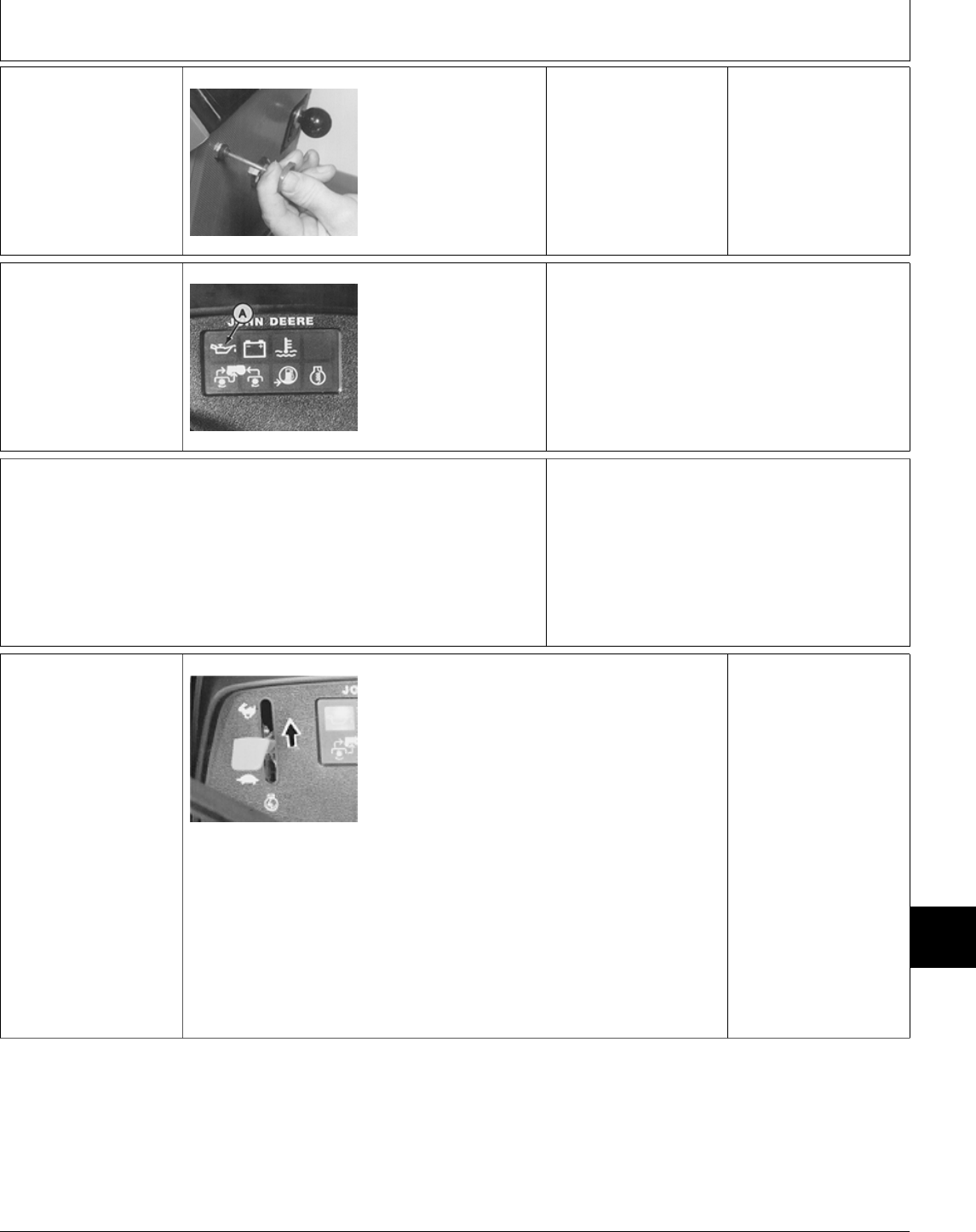
1Ô FUEL SHUTOFF
LEVER CHECK
(330)
M79120 -UN-21JUN95
Start and run engine at
half throttle.
Quickly pull fuel shutoff
knob fully out, then
push in.
LISTEN: Engine must
falter, then resume
speed.
OK: GO TO 1!
NOT OK: Inspect
linkage for binding.
Replace if necessary.
1! ENGINE OIL
PRESSURE CHECK
M79121 -UN-21JUN95
Start and run engine at
half throttle.
LOOK: Immediately
after engine starts oil
pressure lamp (A) must
go off.
OK: GO TO 1@
NOT OK:
OIL PRESSURE LAMP STAYS ON; Test oil
pressure switch. See Section 240.
If switch is OK and lamp is still on:
322; GO TO Ü, Group 10
330, 332 and 430; GO TO Ú, Group 11
1@ ENGINE
PERFORMANCE
CHECK
NCAUTION: ENGINE EXHAUST FUMES CAN
CAUSE SICKNESS OR DEATH. IF RUNNING
AN ENGINE IN AN ENCLOSED AREA,
REMOVE THE EXHAUST FUMES FROM THE
AREA WITH AN EXHAUST PIPE EXTENSION.
IF YOU DO NOT HAVE AN EXHAUST PIPE
EXTENSION, OPEN THE DOORS AND GET
OUTSIDE AIR INTO THE AREA.
1<a Engine Under
No-Load
M55061 -UN-09DEC89
Operator on seat.
PTO switch OFF.
Start engine.
Move throttle lever from slow idle to fast idle.
LISTEN: Engine must accelerate smoothly,
without hesitation.
LOOK: Exhaust must be clear.
LISTEN: Governor must hold engine at a
constant rpm and not surge.
LISTEN: Engine must not make any abnormal
sounds or backfire.
OK: GO TO 1<b
NOT OK:
322; GO TO ;, Group
10
330, 332 and 430; GO
TO ;, Group 11
MX,15912200515A-19-13JUL95
MX,159122005,16-19-13JUL95
MX,159122005,17-19-13JUL95
MX,159122005,19-19-13JUL95
Engine, Fuel and Air System Checkout/Engine Performance Check
TM1591 (15JUL95) 220-05-7 322,330,332 & 430 Lawn & Garden Tractors
030895
220
05
7

1<b Engine Under
Load
M55019 -UN-09DEC89
Start engine and run at half throttle.
Engage PTO lever with implement attached.
Move throttle lever to fast idle position.
Cycle attached implement, if possible, to load
engine.
LISTEN: Governor must increase and decrease
engine rpm to match load condition.
LOOK: Exhaust must be clear.
LISTEN: Engine must not make any abnormal
sounds or backfire.
LISTEN: Engine must not hesitate or stumble.
OK: System Normal.
NOT OK:
322; GO TO ;, Group
10
330, 332 and 430; GO
TO ;, Group 11
1# OPERATOR
COMPLAINT NOT
IDENTIFIED
If you completed the checkout procedure and did
not isolate a malfunction, the problem may be
intermittent.
Try to duplicate the conditions of the malfunction
identified by the operator.
Repeat system checkout in this group.
IF A MALFUNCTION IS NOT IDENTIFIED
AFTER REPEATING SYSTEM CHECKOUT
PROCEDURE, FACTORY ASSISTANCE IS
AVAILABLE THROUGH THE DEALER
TECHNICAL ASSISTANCE CENTER (DTAC).
MX,159122005,20-19-13JUL95
MX,159122005,18-19-13JUL95
Engine, Fuel and Air System Checkout/Operator Complaint Not Identified
TM1591 (15JUL95) 220-05-8 322,330,332 & 430 Lawn & Garden Tractors
030895
220
05
8

ABOUT THIS GROUP
Always perform the system checkout procedures in
Group 05 BEFORE making any tests or adjustments
in this group. The step-by-step procedures in this
group provide you with the detailed diagnostic
information you will need to isolate a malfunction.
Basic diagnostic equipment is used.
It is assumed that you are familiar with the machine
and its engine, fuel and air system components.
Engine rpm and temperature are critical in most
engine tests. Be sure to follow test specifications
carefully.
Always start with the first step and follow the
sequence from left to right. Read each step
completely before performing the test.
Upon completing a test or adjustment, check to see
whether the problem is corrected by performing the
checkout procedures in Group 05.
NOTE: For clarity in this section, machines (S.N.
—596005) will be referred to as “Early
Models”. Machines (S.N. 596006— ) will be
referred to as “Later Models”.
Later model machines have a brake switch
added to the neutral start circuit, which is
activated by depressing the brake pedals.
; TROUBLESHOOTING GUIDE
If engine does not operate properly, select the appropriate symptom from the list below. (If engine does not
crank, see Section 240.)
• ENGINE WILL NOT START OR STARTS HARD: GO TO A
• ENGINE BACKFIRES: GO TO B
• ENGINE MISSES: GO TO C
• ENGINE SURGES OR STALLS FREQUENTLY: GO TO D
• ENGINE DOES NOT DEVELOP FULL POWER: GO TO E
• ENGINE RUNS ERRATICALLY: GO TO F
• ENGINE OVERHEATS OR RUNS COLD: GO TO G
• ABNORMAL ENGINE NOISE: GO TO H
• LOW OIL PRESSURE: GO TO I
• ENGINE USES TOO MUCH OIL: GO TO J
• ENGINE USES TOO MUCH FUEL: GO TO K
MX,159122010,1A-19-13JUL95
MX,159122010,1 -19-13JUL95
Group 10
Diagnosis, Tests and Adjustments—322
TM1591 (15JUL95) 220-10-1 322,330,332 & 430 Lawn & Garden Tractors
030895
220
10
1

A ENGINE WILL NOT START OR STARTS HARD
• Test ignition spark and spark plugs: GO TO 1Ô
• Test fuel shutoff solenoid: See Section 240.
• Test fuel transfer pump: GO TO Õ
• Inspect and adjust choke: GO TO Ú
• Adjust idle mixture screw: GO TO Å
• Check carburetor float adjustment: See Engine CTM12.
B ENGINE BACKFIRES
• Check ignition system: See Section 240.
• Adjust idle mixture screw: GO TO Å
• Check for sticking valves: See Engine CTM12.
• Check and adjust valve clearance: See Engine CTM12.
C ENGINE MISSES
• Test ignition spark and spark plugs: GO TO 1Ô
• Adjust idle mixture screw: GO TO Å
• Check for wet or deteriorated spark plug wires.
• Check ignition system: See Section 240.
• Check carburetor float adjustment: See Engine CTM12.
• Check and adjust valve clearance: See Engine CTM12.
MX,159122010,2 -19-13JUL95
MX,159122010,3 -19-13JUL95
MX,159122010,4 -19-13JUL95
Diagnosis, Tests and Adjustments—322/Troubleshooting Guide
TM1591 (15JUL95) 220-10-2 322,330,332 & 430 Lawn & Garden Tractors
030895
220
10
2

D ENGINE SURGES OR STALLS FREQUENTLY
• Test fuel transfer pump: GO TO Õ
• Adjust idle mixture screw: GO TO Å
• Inspect and adjust choke: GO TO Ú
• Check carburetor gasket and intake manifold gasket for air leaks.
• Check carburetor float adjustment: See Engine CTM12.
• Test cooling system: GO TO 1!
• Test thermostat: See Engine CTM12.
• Test compression pressure: GO TO 1@
• Check and adjust valve clearance: See Engine CTM12.
E ENGINE DOES NOT DEVELOP FULL POWER
• Adjust idle mixture screw: GO TO Å
• Check and adjust idle speeds: GO TO Ö
• Test ignition spark and spark plugs: GO TO 1Ô
• Test fuel transfer pump: GO TO Õ
• Check muffler for restriction or plugged condition.
• Test compression pressure: GO TO 1@
• Check and adjust valve clearance: See Engine CTM12.
F ENGINE RUNS ERRATICALLY
• Adjust idle mixture screw: GO TO Å
• Check carburetor for plugged passages and float level adjustment: See Engine CTM12.
• Check for loose electrical connections: See Section 240.
• Test ignition spark and spark plugs: GO TO 1Ô
• Check ignition system: See Section 240.
• Test fuel transfer pump: GO TO Õ
• Test compression pressure: GO TO 1@
• Check and adjust valve clearance: See Engine CTM12.
MX,159122010,5 -19-13JUL95
MX,159122010,6 -19-13JUL95
MX,159122010,7 -19-13JUL95
Diagnosis, Tests and Adjustments—322/Troubleshooting Guide
TM1591 (15JUL95) 220-10-3 322,330,332 & 430 Lawn & Garden Tractors
030895
220
10
3

G ENGINE OVERHEATS OR RUNS COLD
• Test coolant temperature lamp and switch: See Section 240.
• Test thermostat: See Engine CTM12.
• Test cooling system: GO TO 1!
• Check muffler for restriction or plugged condition.
• Adjust idle mixture screw: GO TO Å
• Check engine oil pressure: GO TO Ü
• Check for defective water pump: See Engine CTM12.
• Check for carbon build-up in combustion chamber: See Engine CTM12.
H ABNORMAL ENGINE NOISE
• Check for loose flywheel: See Engine CTM12.
• Check and adjust valve clearance: See Engine CTM12.
• Check for carbon build-up in combustion chamber: See Engine CTM12.
• Inspect engine for worn cylinder walls, loose or worn connecting rods, excessive main bearing end play,
and excessive crankshaft or camshaft end play: See Engine CTM12.
I LOW OIL PRESSURE
• Test oil pressure lamp and switch: See Section 240.
• Check engine oil pressure: GO TO Ü
• Check for excessive main bearing clearance and connecting rod bearing clearance: See Engine CTM12.
MX,159122010,8 -19-13JUL95
MX,159122010,9 -19-13JUL95
MX,159122010,10-19-13JUL95
Diagnosis, Tests and Adjustments—322/Troubleshooting Guide
TM1591 (15JUL95) 220-10-4 322,330,332 & 430 Lawn & Garden Tractors
030895
220
10
4
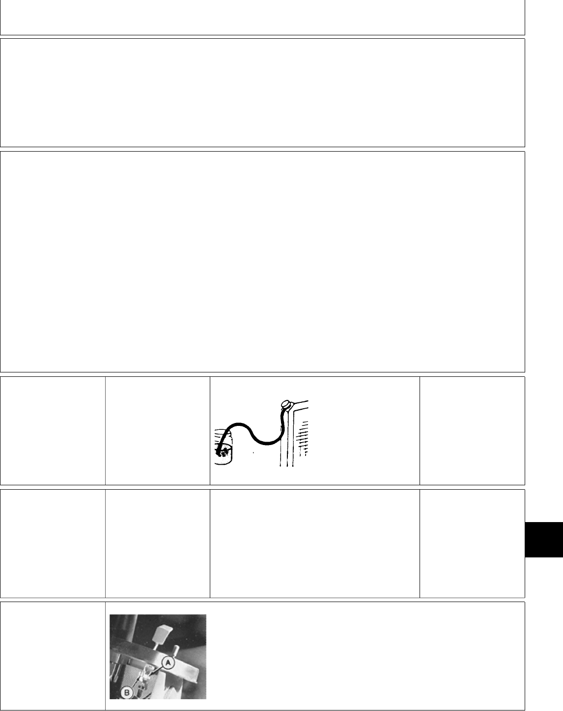
J ENGINE USES TOO MUCH OIL
• Test compression pressure: GO TO 1@
• Check valve stem seals: See Engine CTM12.
K ENGINE USES TOO MUCH FUEL
• Test spark plugs: GO TO 1Ô
• Adjust idle mixture screw: GO TO Å
• Inspect and adjust choke: GO TO Ú
• Check carburetor float adjustment: See Engine CTM12.
‘ RADIATOR BUBBLE
TEST
Coolant at proper level.
Radiator cap tightened.
Start and run engine to
bring it to operating
temperature.
T6171AR -UN-25MAY89
Put end of radiator
overflow hose in a
container of water.
LOOK: While engine is
running, check for
bubbles coming from
hose.
NO BUBBLES:
Continue with test.
BUBBLES PRESENT:
Replace head gasket,
See engine CTM12.
Change engine oil.
Check old oil for water
contamination.
Drain and flush cooling
system.
Refill cooling system
with new coolant.
Operate machine normally. Periodically monitor
the engine oil and coolant for signs of
contamination.
If oil and coolant are OK after several hours of
operation, the original problem was caused by
condensation or the use of contaminated oil.
COOLANT IN OIL OR
OIL IN COOLANT:
Check for blown head
gasket, cracked block
or cracked cylinder
head. See engine
CTM12.
Æ THROTTLE LEVER
ADJUSTMENT
M49159 -UN-20DEC89
Tighten or loosen nut (A) until throttle lever
moves from slow to fast idle with a slight drag.
Replace friction washers (B) if necessary.
Throttle lever must hold in all positions.
MX,159122010,11-19-13JUL95
MX,159122010,12-19-13JUL95
MX,159122010,13-19-13JUL95
MX,15912201013A-19-13JUL95
MX,159122010,14-19-13JUL95
Diagnosis, Tests and Adjustments—322/Throttle Lever Adjustment
TM1591 (15JUL95) 220-10-5 322,330,332 & 430 Lawn & Garden Tractors
030895
220
10
5

Å CARBURETOR IDLE
MIXTURE SCREW
ADJUSTMENT
Raise hood.
Remove left engine
side panel.
M44139 -UN-08JAN90
IMPORTANT: Forcing
the idle mixture screw
tight will damage the
needle and seat.
Turn idle mixture screw
(A) clockwise until
lightly seated then
counterclockwise 1-1/2
turns.
Start and run engine to
bring it to normal
operating temperature.
Move throttle lever to
slow idle position.
M44140 -UN-07SEP88
NCAUTION: ENGINE WILL BE HOT. BE
CAREFUL NOT TO BURN HANDS.
Hold throttle lever against low speed stop.
Turn idle mixture screw (A) in until engine speed
drops, then out until engine speed increases and
begins to drop again.
Adjust idle mixture screw for highest engine
speed between drops, then turn screw out an
additional 1/8 turn.
Ö GOVERNOR
LINKAGE AND IDLE
SPEED
ADJUSTMENTS
NOTE: Carburetor idle
mixture must be
adjusted before making
idle speed adjustments.
GO TO ÅM45278 -UN-12JAN90
M44156 -UN-08JAN90
Engine OFF.
Move throttle control
lever to fast idle
position.
Loosen jam nut (A).
Turn start adjust screw
(B) to align throttle
plate indicator (C) with
index mark (D).
Tighten jam nut (A).
Continued on next
page
MX,159122010,15-19-13JUL95
MX,159122010,16-19-15JUL95
Diagnosis, Tests and Adjustments—322/Governor Linkage and Idle Speed Adjustments
TM1591 (15JUL95) 220-10-6 322,330,332 & 430 Lawn & Garden Tractors
030895
220
10
6
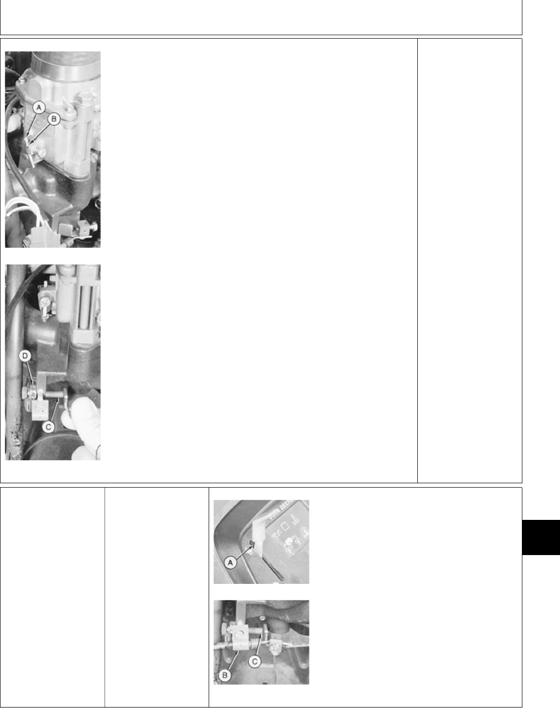
M45279 -UN-12JAN90
M45280 -UN-08JAN90
Start and run engine to
bring it to normal
operating temperature.
Disconnect throttle
cable.
NOTE: Check engine
speeds using JT05719
Hand-Held Digital
Tachometer. Read rpm
at front universal joint
of drive shaft or
flywheel.
Remove rubber plug
from flywheel viewing
hole.
Hold throttle plate
indicator (A) against
stop screw (B). Turn
screw (B) until slow idle
is 1350 ±50 rpm.
Hold governor lever
against fast idle stop
bolt (C). Fast idle
should be 3450 ±50
rpm.
If fast idle rpm is not
correct, loosen nut (D)
and turn bolt (C) until
fast idle speed is
correct. Tighten nut (D).
OK: Connect throttle
cable, then GO TO Ò
Ò THROTTLE CABLE
ADJUSTMENT
Remove left engine
side panel.
M45281 -UN-08JAN90
M45282 -UN-08JAN90
Move throttle lever (A) to fast idle position on
instrument panel.
Loosen throttle cable clamp (B).
Pull cable and hold governor lever against fast
idle stop bolt (C) and tighten clamp (B).
MX,15912201016A-19-13JUL95
MX,159122010,17-19-13JUL95
Diagnosis, Tests and Adjustments—322/Throttle Cable Adjustment
TM1591 (15JUL95) 220-10-7 322,330,332 & 430 Lawn & Garden Tractors
030895
220
10
7
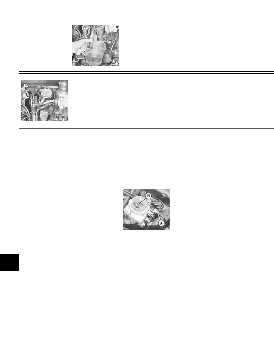
Õ FUEL TRANSFER
PUMP TEST
M49171 -UN-20DEC89
Disconnect fuel hose from carburetor. Put end of
hose in a graduated container.
Turn key switch to RUN position for 30 seconds
and record amount of fuel in container. DO NOT
start engine.
Minimum fuel flow is 200 mL/30 seconds (7
oz/30 seconds).
M49172 -UN-20DEC89
Connect JDG356 Pressure Test Kit to outlet side
of fuel filter.
Turn key switch to RUN position, then record
pressure reading. DO NOT start engine.
Minimum pressure is 14 kPa (2 psi).
OK: Connect fuel hose.
NOT OK: Check fuel filter, fuel lines and fuel tank
suction screen for plugged condition.
Repeat test. If pump output still low, replace fuel
transfer pump.
Ú CHOKE
ADJUSTMENT
Remove air intake hose
from carburetor.
8a Early Models
(Choke Cable)
Inspect choke linkage
for loose screws, wear
or damage.
Pull choke knob out,
then push knob in.
LOOK: Choke plate
must be completely
closed, then completely
open. M44143 -UN-07SEP88
If necessary, loosen
screw (A) and push
choke control knob in.
Hold choke plate (B)
straight up in carburetor
and tighten screw (A).
Check for completely
open and completely
closed positions.
Install air intake hose
on carburetor.
MX,159122010,18-19-13JUL95
MX,159122010,19-19-13JUL95
MX,159122010,20-19-13JUL95
Diagnosis, Tests and Adjustments—322/Choke Adjustment
TM1591 (15JUL95) 220-10-8 322,330,332 & 430 Lawn & Garden Tractors
030895
220
10
8
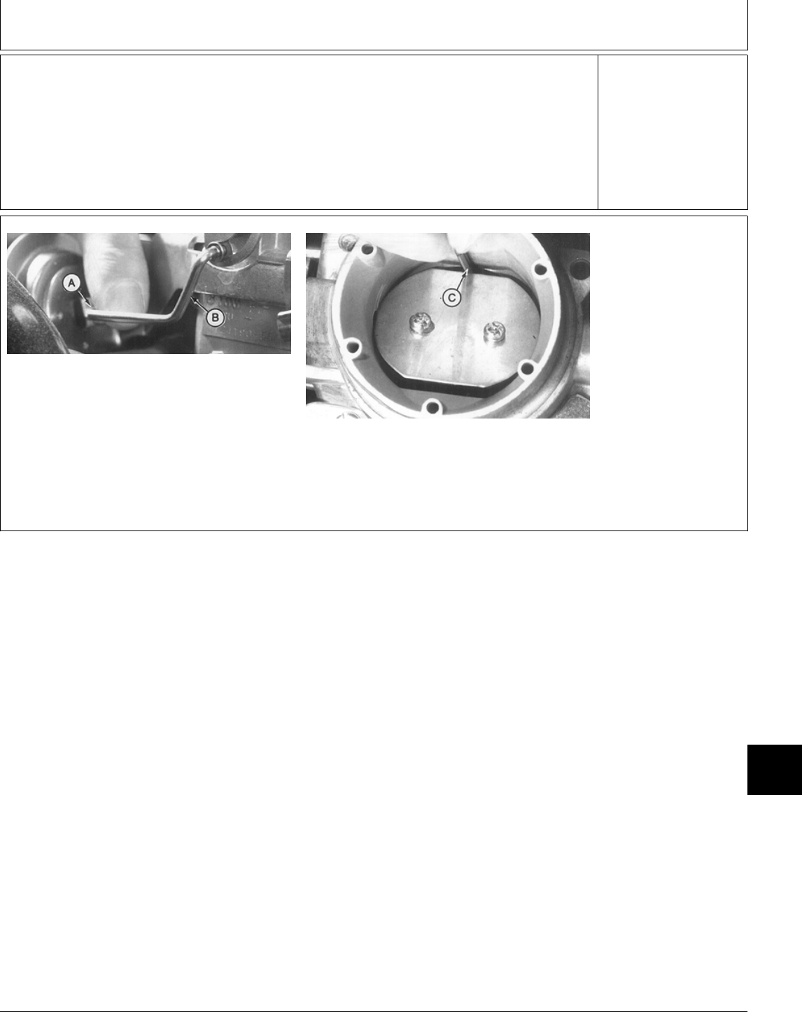
8b Later Models
(Automatic Choke)
IMPORTANT: Engine
must be cold for this
adjustment. Choke
plate must be closed.
M78977 -UN-21JUN95
M78978 -UN-21JUN95
MX,159122010,21-19-13JUL95
Diagnosis, Tests and Adjustments—322/Choke Adjustment
TM1591 (15JUL95) 220-10-9 322,330,332 & 430 Lawn & Garden Tractors
030895
220
10
9

NOTE: DO NOT touch
linkage rod (B) when
pushing in on vacuum
diaphragm lever (A) or
it will affect opening
position of the choke
plate.
Push in on vacuum
diaphragm lever (A)
until it bottoms out. Be
careful not to touch
linkage rod (B).
Put a 2 mm (5/64 in.)
drill bit (C) between
bottom of choke plate
and carburetor venturi.
If clearance is not 2
mm (5/64 in.), bend rod
(B) to adjust gap.
Start engine and check
clearance. Stop engine
and readjust as
necessary.
NOTE: This check must
be done quickly, while
engine is still cold.
Once engine starts to
warm up, the automatic
choke coil will start to
open the choke plate.
Continued on next
page
M78979 -UN-21JUN95
IMPORTANT: Engine must be cold for this
adjustment. Choke plate must be closed.
Put a mark (A) across plastic and metal housings
for starting point reference.
Loosen three screws securing coil housing.
IMPORTANT: DO NOT turn coil too far or
spring and adjustment tang will disengage
and choke will not work.
Start engine.
Rotate housing 1/8 turn or less in either direction
to obtain desired engine performance; clockwise
for less choke (leaner) or counterclockwise for
more choke (richer).
Tighten screws.
Install air intake hose
on carburetor.
Adjust governor linkage
and idle speed; GO TO
Ö
MX,15912201021B-19-15JUL95
MX,15912201021A-19-13JUL95
Diagnosis, Tests and Adjustments—322/Choke Adjustment
TM1591 (15JUL95) 220-10-10 322,330,332 & 430 Lawn & Garden Tractors
030895
220
10
10
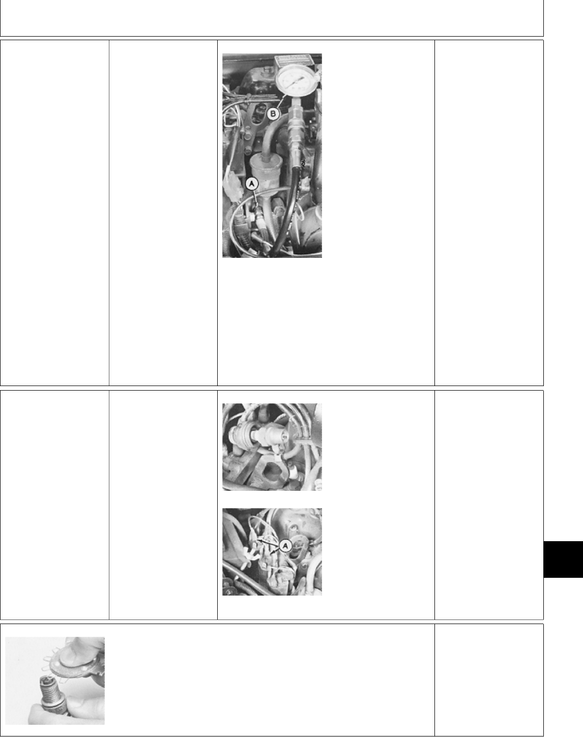
Ü ENGINE OIL
PRESSURE TEST
IMPORTANT: If oil
pump has failed
completely, running
engine will cause
extensive damage to
engine.
Remove left engine
side panel.
M44164 -UN-08JAN90
Disconnect wiring lead
and remove oil
pressure switch.
Install JT03349 Adapter
(A) in oil pressure
switch port.
Connect JT03017 Hose
Assembly and JT05577
0—700 kPa (0—100
psi) Gauge (B).
Start and run engine for
five minutes at fast idle,
to warm oil to normal
operating temperature.
Record pressure
reading.
Engine oil pressure
should be 294—440
kPa (43—64 psi).
OK: Install oil pressure
switch and connect
wiring lead.
NOT OK: If pressure
reading is low, check
oil pressure regulating
valve for a broken
spring or a stuck or
damaged valve. See
Engine CTM12.
If pressure does not
increase, check for a
worn or damaged oil
pump. See Engine
CTM12.
1Ô IGNITION SPARK
TEST
Perform this test on all
three spark plugs.
M49173 -UN-20DEC89
M49174 -UN-20DEC89
Connect spark plug
wire to JDM-74-5
Ignition Test Plug or
D-05351ST Spark
Tester.
Disconnect positive (+)
wires (A) from coils of
cylinders not being
tested.
Crank engine and
watch for spark.
LOOK: Ignition Test
Plug or Tester must
spark.
OK: SPARK “BLUE”
HOT; Continue with
test.
NOT OK: NO SPARK
OR “YELLOW” WEAK
SPARK; Go to Section
240.
M44166 -UN-08JAN90
Remove spark plugs.
Inspect spark plugs for wet or fouled condition or
damage. Replace plugs if worn or damaged.
Check spark plug gap. Spark plug gap should be
0.80 mm (0.032 in.).
Repeat spark test with original plugs.
NOT OK: NO SPARK;
Replace plugs.
MX,159122010,22-19-13JUL95
MX,159122010,23-19-13JUL95
MX,15912201023A-19-13JUL95
Diagnosis, Tests and Adjustments—322/Ignition Spark Test
TM1591 (15JUL95) 220-10-11 322,330,332 & 430 Lawn & Garden Tractors
030895
220
10
11
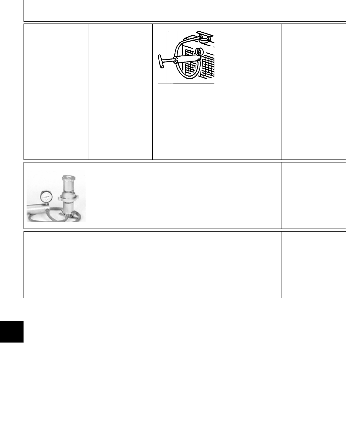
1! COOLING SYSTEM
PRESSURE TEST NCAUTION: DO NOT
REMOVE RADIATOR
CAP UNTIL
RADIATOR HOSE IS
COOL TO THE
TOUCH.
M44123 -UN-26APR89
Remove radiator cap
and attach D05104ST
Cooling System
Pressure Pump to
radiator.
Pressurize cooling
system to 117 kPa (17
psi). Minimum pressure
after 15 seconds should
be 90 kPa (13 psi).
OK: Continue with test.
NOT OK: If pressure
does not meet
specification, check
radiator, hoses, and
connections for
leakage. Repair leaks
or replace parts as
necessary.
If pressure test still
indicates leakage and
all external leaks have
been stopped, a blown
head gasket or cracked
block may be the
cause.
M44093 -UN-08JAN90
Wet sealing surfaces of radiator cap and install
on D05104ST Cooling System Pressure Pump.
Pressurize radiator cap until it opens. Pressure
valve in cap should open at 97—104 kPa
(14—15 psi).
NOT OK: If cap leaks,
retighten then test
again. Replace cap if it
does not meet
specifications.
1@ COMPRESSION
PRESSURE TEST
Start and run engine
approximately five
minutes at fast idle, to
bring it to normal
operating temperature.
Stop engine.
MX,159122010,24-19-13JUL95
MX,15912201024A-19-13JUL95
MX,159122010,25-19-13JUL95
Diagnosis, Tests and Adjustments—322/Compression Pressure Test
TM1591 (15JUL95) 220-10-12 322,330,332 & 430 Lawn & Garden Tractors
030895
220
10
12
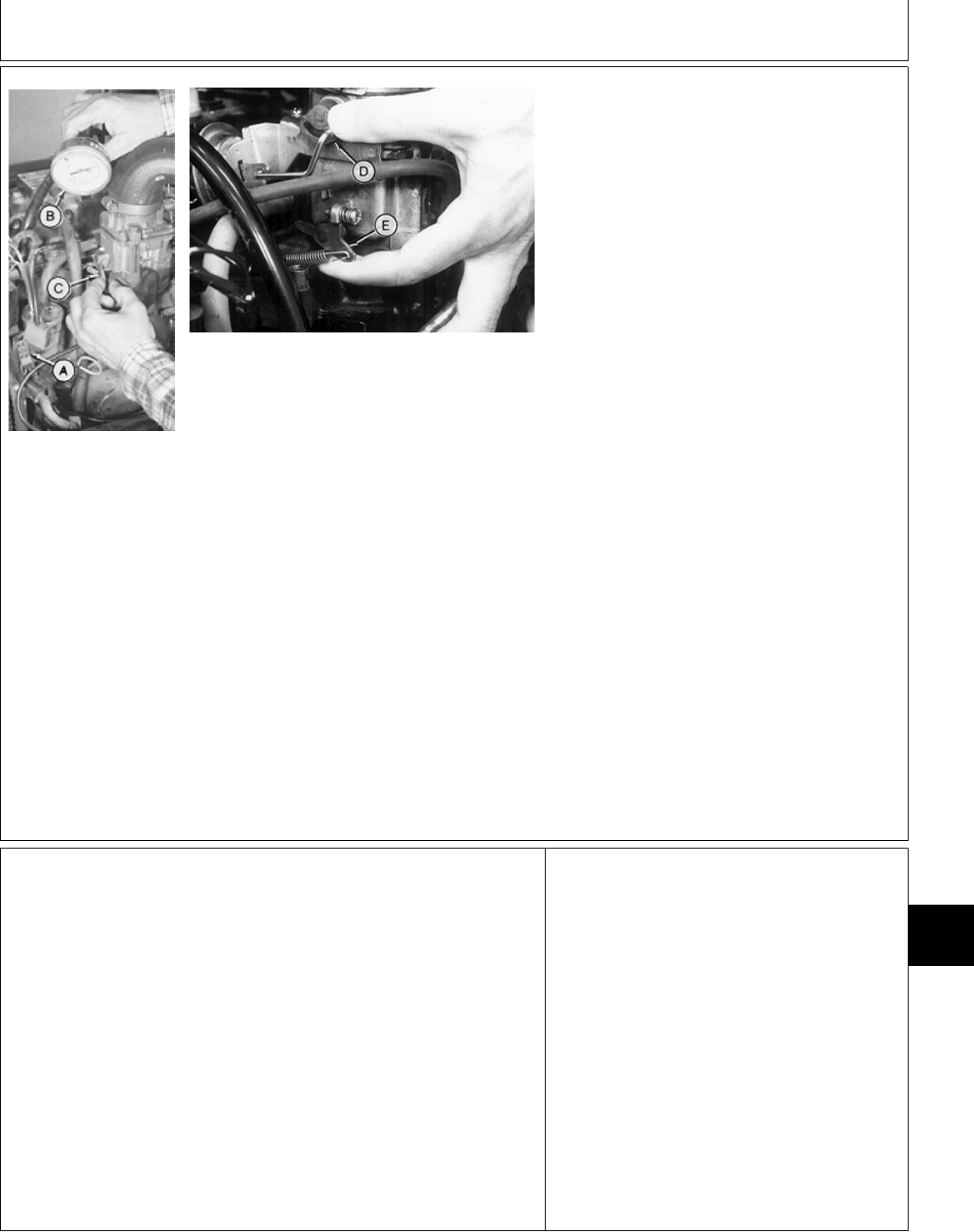
M44167 -UN-08JAN90
M79122 -UN-23JUN95
NOTE: Far left photo: Early models (choke
cable).
Right photo: Later models (automatic choke).
Disconnect positive (+) coil lead connectors (A)
from all three coils.
Remove spark plugs.
Connect JDM59 Compression Gauge (B) to
spark plug port.
Early Models:
Make sure choke plate is in wide open position
(choke knob pushed in).
Move throttle lever to fast idle position. Pull
throttle plate lever (C) to wide open position.
Later Models:
Move throttle lever to fast idle position. Push
choke plate lever (D) down toward engine. Pull
throttle plate lever (E) up to fully open position.
IMPORTANT: DO NOT overheat starting motor
during test.
Crank engine for a few seconds with starting
motor. Record pressure reading for each
cylinder.
TEST SPECIFICATIONS
Minimum Pressure . . . . . . . . . . . 779 kPa (113 psi)
Maximum Difference Between
Cylinders . . . . . . . . . . . . . . . . . . . . 97 kPa (14 psi)
Engine Cranking Speed . . . . . . . . . . . . . . . 300 rpm
OK: If compression pressure is to specifications,
install spark plugs. Connect coil lead connectors.
NOT OK:
If pressure reading is not to specification, put
clean engine oil on piston rings through spark
plug ports. Repeat compression pressure test.
If compression pressure increases significantly,
check rings, piston, and cylinder bore for broken
rings, scoring, wear, or damage. See Engine
CTM12.
If compression pressure does not increase
significantly after retest, check for leaking valves,
valve seats, or cylinder head gasket. See Engine
CTM12.
MX,15912201025A-19-13JUL95
Diagnosis, Tests and Adjustments—322/Compression Pressure Test
TM1591 (15JUL95) 220-10-13 322,330,332 & 430 Lawn & Garden Tractors
030895
220
10
13

Diagnosis, Tests and Adjustments—322/Compression Pressure Test
TM1591 (15JUL95) 220-10-14 322,330,332 & 430 Lawn & Garden Tractors
030895
220
10
14

ABOUT THIS GROUP
Always perform the system checkout procedures in
Group 05 BEFORE making any tests or adjustments
in this group. The step-by-step procedures in this
group provide you with the detailed diagnostic
information you will need to isolate a malfunction.
Basic diagnostic equipment is used.
It is assumed that you are familiar with the machine
and its engine, fuel and air system components.
Engine rpm and temperature are critical in most
engine tests. Be sure to follow test specifications
carefully.
Always start with the first step and follow the
sequence from left to right. Read each step
completely before performing the test.
Upon completing a test or adjustment, check to see
whether the problem is corrected by performing the
checkout procedures in Group 05.
NOTE: When instructed to “turn the key switch ON”:
330 and 332; Turn the key switch to the “ON”
position.
430; Turn the key switch to the “RUN”
position.
For clarity in this section, machines including
and before serial numbers listed below will be
referred to as “Early Models”. Machines
including and after serial number listed below
will be referred to as “Later Models”.
Later model machines have a brake switch
added to the neutral start circuit, which is
activated by depressing the brake pedals.
MODEL EARLY LATER
330 (S.N. —420000) N/A
332 (S.N. —475000) (S.N. 475001— )
430 (S.N. —596047) (S.N. 596048— )
MX,159122011,1A-19-13JUL95
Group 11
Diagnosis, Tests and Adjustments—330, 332 and 430
TM1591 (15JUL95) 220-11-1 322,330,332 & 430 Lawn & Garden Tractors
030895
220
11
1

; TROUBLESHOOTING GUIDE
If engine does not operate properly, select the appropriate symptom from the list below. (If engine does not
crank, see Section 240.)
• ENGINE WILL NOT START OR STARTS HARD: GO TO A
• ENGINE SURGES OR STALLS FREQUENTLY: GO TO B
• ENGINE MISSES: GO TO C
• ENGINE DOES NOT DEVELOP FULL POWER: GO TO D
• EXCESSIVE BLACK OR GRAY EXHAUST SMOKE: GO TO E
• WHITE EXHAUST SMOKE: GO TO F
• SLOW ACCELERATION: GO TO G
• ABNORMAL ENGINE NOISE: GO TO H
• LOW OIL PRESSURE: GO TO I
• OIL IN COOLANT OR COOLANT IN OIL: GO TO J
• ENGINE OVERHEATS: GO TO K
A ENGINE WILL NOT START OR STARTS HARD
• 330; Inspect fuel shutoff linkage for binding.
• 332 and 430; Test fuel shutoff solenoid: See Section 240.
• Test fuel transfer pump: GO TO Ö
• Bleed fuel injection system: GO TO Ò
• Test glow plug controller: See Section 240.
• Test compression pressure: GO TO Õ
• Test injection nozzles: See Engine CTM3.
• Check injection pump timing: See Engine CTM3 (AUG93 or later).
• Check and adjust valve clearance: See Engine CTM3.
• Remove fuel injection pump and have it tested: See Engine CTM3.
MX,159122011,1 -19-13JUL95
MX,159122011,2 -19-13JUL95
Diagnosis, Tests and Adjustments—330, 332 and 430/Troubleshooting Guide
TM1591 (15JUL95) 220-11-2 322,330,332 & 430 Lawn & Garden Tractors
030895
220
11
2

B ENGINE SURGES OR STALLS FREQUENTLY
• Test fuel transfer pump: GO TO Ö
• Bleed fuel injection system: GO TO Ò
• Test injection nozzles: See Engine CTM3.
• Check injection pump timing: See Engine CTM3 (AUG93 or later).
• Test cooling system: GO TO 1Ô
• Check thermostat: See Engine CTM3.
• Remove fuel injection pump and have it tested: See Engine CTM3.
• Test compression pressure: GO TO Õ
• Check and adjust valve clearance: See Engine CTM3.
C ENGINE MISSES
• Test fuel transfer pump: GO TO Ö
• Bleed fuel injection system: GO TO Ò
• Test injection nozzles: See Engine CTM3.
• Check injection pump timing: See Engine CTM3 (AUG93 or later).
• Remove fuel injection pump and have tested: See Engine CTM3.
• Check and adjust valve clearance: See Engine CTM3.
D ENGINE DOES NOT DEVELOP FULL POWER
• Check and adjust idle speeds: GO TO Ü
• Test fuel transfer pump: GO TO Ö
• Bleed fuel injection system: GO TO Ò
• Test injection nozzles: See Engine CTM3.
• Check injection pump timing: See Engine CTM3 (AUG93 or later).
• Remove fuel injection pump and have tested: See Engine CTM3.
• Test compression pressure: GO TO Õ
• Check and adjust valve clearance: See Engine CTM3.
MX,159122011,3 -19-13JUL95
MX,159122011,4 -19-13JUL95
MX,159122011,5 -19-13JUL95
Diagnosis, Tests and Adjustments—330, 332 and 430/Troubleshooting Guide
TM1591 (15JUL95) 220-11-3 322,330,332 & 430 Lawn & Garden Tractors
030895
220
11
3

E EXCESSIVE BLACK OR GRAY EXHAUST SMOKE
• Test injection nozzles: See Engine CTM3.
• Check injection pump timing: See Engine CTM3 (AUG93 or later).
• Adjust fuel controller: GO TO 1!
F WHITE EXHAUST SMOKE
• Test injection nozzles: See Engine CTM3.
• Check injection pump timing: See Engine CTM3 (AUG93 or later).
• Test compression pressure: GO TO Õ
G SLOW ACCELERATION
• Test fuel transfer pump: GO TO Ö
• Test injection nozzles: See Engine CTM3.
• Check injection pump timing: See Engine CTM3 (AUG93 or later).
• Remove fuel injection pump and have it tested: See Engine CTM3.
H ABNORMAL ENGINE NOISE
• Test injection nozzles: See Engine CTM3.
• Check injection pump timing: See Engine CTM3 (AUG93 or later).
• Check and adjust valve clearance: See Engine CTM3.
• Inspect pistons, piston pins, pin bushings, connecting rod bearings, and rod caps: See Engine CTM3.
• Inspect main bearings and bearing caps: See Engine CTM3.
MX,159122011,6 -19-13JUL95
MX,159122011,7 -19-13JUL95
MX,159122011,8 -19-13JUL95
MX,159122011,9 -19-13JUL95
Diagnosis, Tests and Adjustments—330, 332 and 430/Troubleshooting Guide
TM1591 (15JUL95) 220-11-4 322,330,332 & 430 Lawn & Garden Tractors
030895
220
11
4

I LOW OIL PRESSURE
• Test oil pressure lamp and switch: See Section 240.
• Check engine oil pressure: GO TO Ú
• Inspect for excessive main bearing clearance and connecting rod bearing clearance: See Engine CTM3.
• Inspect for cracked cylinder block.
J OIL IN COOLANT OR COOLANT IN OIL
• Test compression pressure for leaking cylinder head gasket: GO TO Õ
• Inspect for cracked cylinder block.
K ENGINE OVERHEATS
• Test coolant temperature lamp and switch: See Section 240.
• Check thermostat: See Engine CTM3.
• Test cooling system: GO TO 1Ô
• Check for excessive hydraulic system temperature: See Section 270.
• Test injection nozzles: See Engine CTM3.
• Check injection pump timing: See Engine CTM3 (AUG93 or later).
• Adjust fuel controller: GO TO 1!
• Inspect for scored piston: See Engine CTM3.
MX,159122011,10-19-13JUL95
MX,159122011,11-19-13JUL95
MX,159122011,12-19-13JUL95
Diagnosis, Tests and Adjustments—330, 332 and 430/Troubleshooting Guide
TM1591 (15JUL95) 220-11-5 322,330,332 & 430 Lawn & Garden Tractors
030895
220
11
5
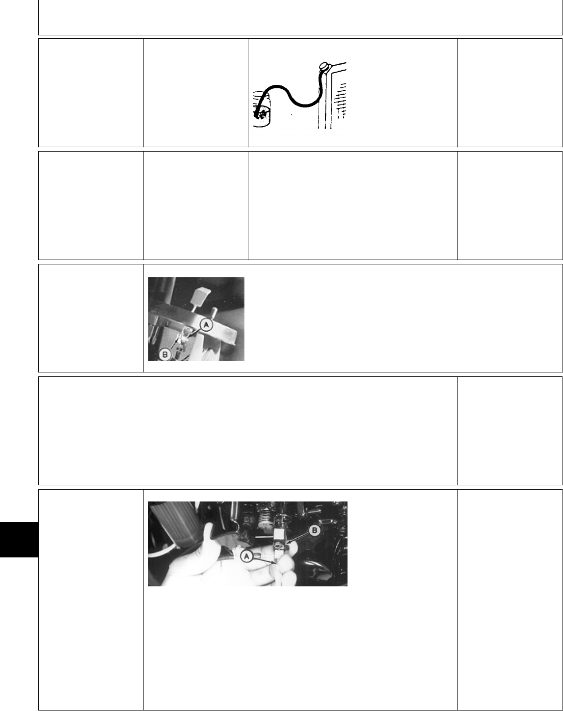
‘ RADIATOR BUBBLE
TEST
Coolant at proper level.
Radiator cap tightened.
Start and run engine to
bring it to operating
temperature.
T6171AR -UN-25MAY89
Put end of radiator
overflow hose in a
container of water.
LOOK: While engine is
running, check for
bubbles coming from
hose.
NO BUBBLES:
Continue with test.
BUBBLES PRESENT:
Replace head gasket,
See engine CTM3.
Change engine oil.
Check old oil for water
contamination.
Drain and flush cooling
system.
Refill cooling system
with new coolant.
Operate machine normally. Periodically monitor
the engine oil and coolant for signs of
contamination.
If oil and coolant are OK after several hours of
operation, the original problem was caused by
condensation or the use of contaminated oil.
COOLANT IN OIL OR
OIL IN COOLANT:
Check for blown head
gasket, cracked block
or cracked cylinder
head. See engine
CTM3.
Æ THROTTLE LEVER
ADJUSTMENT
M49159 -UN-20DEC89
Tighten or loosen nut (A) until throttle lever
moves from slow to fast idle with a slight drag.
Replace friction washers (B) if necessary.
Throttle lever must hold in all positions.
Å THROTTLE CABLE
ADJUSTMENT
Remove left engine
side panel.
4a 330 and 430
M79123 -UN-21JUN95
Move throttle lever on
instrument panel to fast
idle position.
Loosen throttle cable
set screw (A).
Hold injection pump
throttle lever (B)
forward against fast idle
stop, then tighten
throttle cable set screw
(A).
Install left engine side
panel.
MX,159122011,13-19-13JUL95
MX,15912201113A-19-13JUL95
MX,159122011,14-19-13JUL95
MX,159122011,15-19-13JUL95
MX,15912201115A-19-13JUL95
Diagnosis, Tests and Adjustments—330, 332 and 430/Throttle Cable Adjustment
TM1591 (15JUL95) 220-11-6 322,330,332 & 430 Lawn & Garden Tractors
030895
220
11
6

4b 332
M49170 -UN-20DEC89
Move throttle lever on
instrument panel to
slow idle position.
Loosen throttle cable
nut (A) and set screw
(B). Governor throttle
arm must strike slow
idle stop screw (C).
Be sure throttle lever is
striking bottom of slot
on instrument panel,
then tighten throttle
cable set screw (B) and
nut (A).
Install left engine side
panel.
Ö FUEL TRANSFER
PUMP TEST
M49160 -UN-20DEC89
NOTE: 330/332 Shown.
Perform test at room temperature.
Disconnect fuel transfer pump outlet hose from
fuel filter (330, 332) or fuel/water separator (430).
Put end of hose in a graduated container.
Turn key switch to ON/RUN position for 30
seconds and record amount of fuel in container.
DO NOT start engine.
MINIMUM FUEL FLOW
330 and 332 . . . . . . . . . . . . . . 200 mL/30 seconds
(7 oz/30 seconds)
430 . . . . . . . . . . . . . . . . . . . . 600 mL/30 seconds
(20 oz/30 seconds)
M49161 -UN-20DEC89
Connect JDG356 Pressure Test Kit to outlet
hose.
Turn key switch to ON/RUN position, then record
pressure reading. DO NOT start engine.
Minimum pressure is 21 kPa (3 psi).
OK: GO TO Ò
NOT OK: Check fuel filter (330, 332) or fuel/water
separator (430), fuel lines and fuel tank suction
screen for plugged condition.
Repeat test. If pump output still low, replace fuel
transfer pump. Then GO TO Ò
MX,15912201115B-19-13JUL95
MX,159122011,16-19-13JUL95
MX,15912201116A-19-13JUL95
Diagnosis, Tests and Adjustments—330, 332 and 430/Fuel Transfer Pump Test
TM1591 (15JUL95) 220-11-7 322,330,332 & 430 Lawn & Garden Tractors
030895
220
11
7
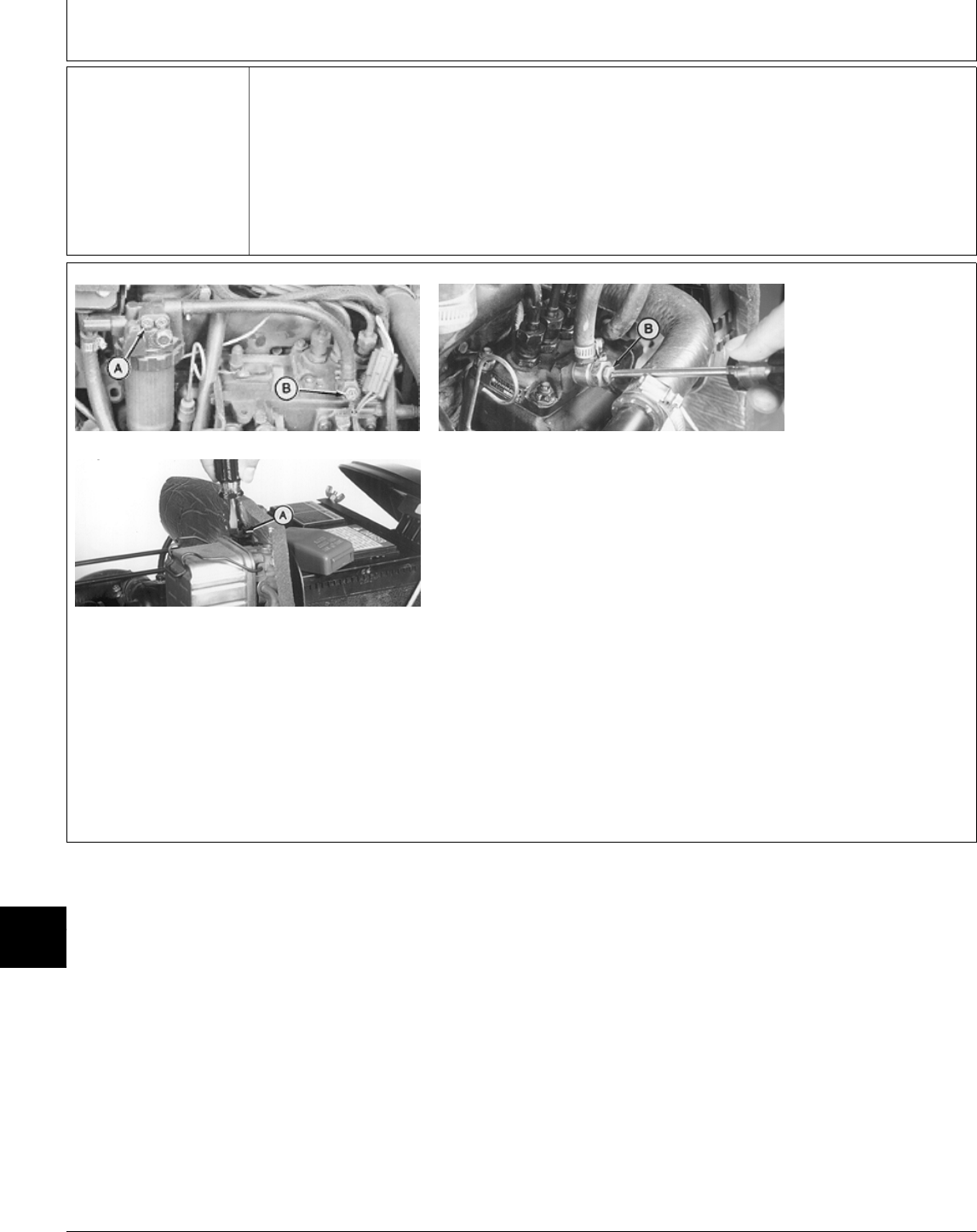
Ò BLEED FUEL
INJECTION SYSTEM
M43915 -UN-31AUG88
M78720 -UN-21JUN95
M79124 -UN-21JUN95
NOTE: Top left photo
shows 330/332.
Other photos show 430.
Loosen bleed
screw/plug (A) on fuel
filter (330, 332) or
fuel/water separator
(430). Turn key switch
to ON/RUN position.
Fuel transfer pump will
run. Tighten bleed
screw/plug (A) when
fuel appears.
Loosen bleed screw
(B). Turn key switch to
ON/RUN position. Fuel
transfer pump will run.
When fuel apppears at
line and no air bubbles
are visible, close bleed
screw (B).
Continued on next page
Diagnosis, Tests and Adjustments—330, 332 and 430/Bleed Fuel Injection System
TM1591 (15JUL95) 220-11-8 322,330,332 & 430 Lawn & Garden Tractors
030895
220
11
8

M43916 -UN-31AUG88
Start engine.
IMPORTANT: When loosening or tightening
fuel injection lines, DO NOT turn pump
delivery valve fittings. Turning pump fittings
can damage pump internally.
NOTE: 330/332 shown.
If engine does not start or if it runs rough, loosen
fuel injection line fitting (A) at injection nozzle.
If engine is not running, use starter to turn
engine over.
When fuel appears at nozzle and no air bubbles
are visible, tighten fuel line.
Repeat procedure for remaining injection nozzles,
if necessary.
Start engine.
If engine does not start,
repeat bleed procedure.
MX,159122011,17-19-13JUL95
Diagnosis, Tests and Adjustments—330, 332 and 430/Bleed Fuel Injection System
TM1591 (15JUL95) 220-11-9 322,330,332 & 430 Lawn & Garden Tractors
030895
220
11
9
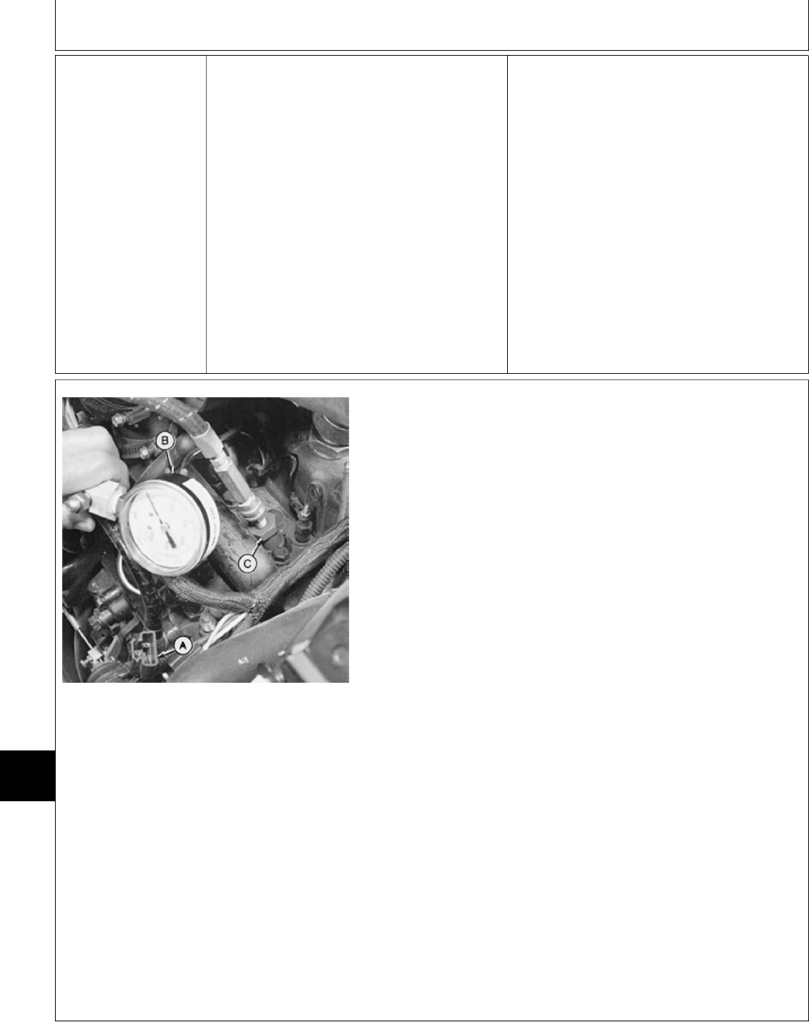
Õ COMPRESSION
PRESSURE TEST
Start and run engine
approximately five
minutes at fast idle, to
bring it to normal
operating temperature.
Stop engine.
Remove left engine
side panel.
NCAUTION: ESCAPING FLUID UNDER
PRESSURE CAN PENETRATE THE SKIN
CAUSING SERIOUS INJURY. RELIEVE
PRESSURE BEFORE DISCONNECTING
HYDRAULIC OR OTHER LINES. TIGHTEN ALL
CONNECTIONS BEFORE APPLYING
PRESSURE. KEEP HANDS AND BODY AWAY
FROM PIN-HOLES AND NOZZLES WHICH
EJECT FLUIDS UNDER HIGH PRESSURE.
USE A PIECE OF CARDBOARD OR PAPER
TO SEARCH FOR LEAKS.
IF ANY FLUID IS INJECTED INTO THE SKIN,
IT MUST BE SURGICALLY REMOVED WITHIN
A FEW HOURS BY A DOCTOR FAMILIAR
WITH THIS TYPE OF INJURY OR GANGRENE
MAY RESULT.
M43993 -UN-07SEP88
NOTE: 332 Shown.
Motorite Compression Tester can be used using
JT01681 and JDG472 Adapter or use
Compression Test Kit JT01674.
330; Pull fuel shutoff knob on dash all the way
out.
332 and 430; Disconnect fuel shutoff solenoid
wiring connector/leads (A).
Remove fuel injection nozzles. See engine
CTM3. Remove heat protectors from injection
nozzle ports.
Connect JT01682 Pressure Gauge and Hose (B)
to fuel injection nozzle port using JDG472
Adapter (C).
IMPORTANT: DO NOT overheat starting motor
during test.
Crank engine for a few seconds with starting
motor.
Record pressure reading for each cylinder.
TEST SPECIFICATIONS
Minimum Pressure . . . . . . . . . . 2448 kPa (355 psi)
Maximum Difference Between
Cylinders . . . . . . . . . . . . . . . . . . . 490 kPa (71 psi)
Minimum Engine Cranking Speed . . . . . . . . 250 rpm
MX,159122011,21-19-13JUL95
Diagnosis, Tests and Adjustments—330, 332 and 430/Compression Pressure Test
TM1591 (15JUL95) 220-11-10 322,330,332 & 430 Lawn & Garden Tractors
030895
220
11
10
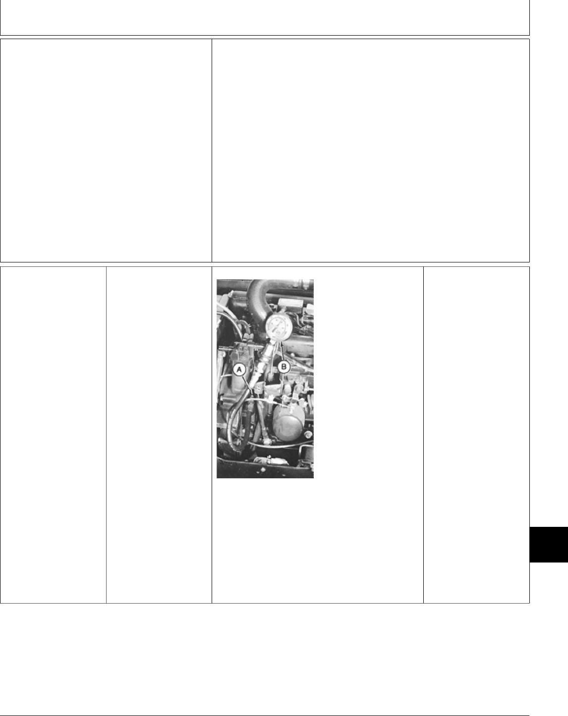
OK: If compression pressure is to
specifications;
—Install heat protectors and
injection nozzles.
—330; Push fuel shutoff knob all
the way in.
—332 and 430; Connect fuel shutoff
solenoid wiring connector/leads.
—Bleed fuel injection system: GO
TO Ò
NOT OK:
If pressure reading is not to
specification, put clean engine oil on
piston rings through injection nozzle
ports. Repeat compression pressure
test.
If compression pressure increases
significantly, check rings, piston, and
cylinder bore for broken rings,
scoring, wear, or damage. See
engine CTM3.
If compression pressure does not
increase significantly after retest,
check for leaking valves, valve
seats, or cylinder head gasket. See
engine CTM3.
Ú ENGINE OIL
PRESSURE TEST
IMPORTANT: If oil
pump has failed
completely, running
engine will cause
extensive damage to
engine.
Remove left engine
side panel.
M49167 -UN-20DEC89
NOTE: 332 shown.
Disconnect wiring lead
and remove oil
pressure switch.
330 and 332; Install
JT03349 Adapter (A) in
oil pressure switch port.
430; Install JT03338
Adapter in oil pressure
switch port.
Connect JT03017 Hose
Assembly and JT05577
0—700 kPa (0—100
psi) Gauge (B).
Start and run engine for
five minutes at fast idle,
to warm oil to normal
operating temperature.
Record pressure
reading.
Engine oil pressure
should be 365 ±69 kPa
(53 ±10 psi).
OK: Install oil pressure
switch and connect
wiring lead.
NOT OK:
If pressure reading is
low, check oil pressure
regulating valve for a
broken spring or a
stuck or damaged
valve. If oil pressure
regulating valve is not
damaged, add shims to
inside of cap. See
engine CTM3.
Check connecting rod
and main bearing
journals for excessive
wear. See engine
CTM3.
If pressure does not
increase, check for a
worn or damaged oil
pump. See engine
CTM3.
MX,15912201121A-19-13JUL95
MX,159122011,22-19-13JUL95
Diagnosis, Tests and Adjustments—330, 332 and 430/Engine Oil Pressure Test
TM1591 (15JUL95) 220-11-11 322,330,332 & 430 Lawn & Garden Tractors
030895
220
11
11
Ü IDLE SPEED
ADJUSTMENT
Start and run engine
approximately five
minutes at fast idle to
bring it to normal
operating temperature.
Disconnect throttle
cable.
9a 330, 332 and Later
430
M49168 -UN-20DEC89
NOTE: Check engine
speeds using JT05719
Hand-Held Digital
Tachometer. Read rpm
at front universal joint
of drive shaft or
flywheel.
Remove rubber plug
from flywheel viewing
hole.
Slow idle speed:
Hold injection pump
throttle lever rearward,
away from flywheel,
and read Tachometer.
Slow idle speed should
be 1350 ±50 rpm.
M43995 -UN-07SEP88
If slow idle rpm is not
correct, loosen nut (A)
and turn screw (B) to
adjust slow idle. After
adjustment, tighten nut
(A).
M49169 -UN-20DEC89
Fast idle speed:
Hold injection pump
throttle lever forward,
toward flywheel, and
read Tachometer. Fast
idle speed should be
3450 ±50 rpm.
M43998 -UN-07SEP88 M43999 -UN-07SEP88
If fast idle rpm is not
correct, remove wire
and cap (A). Loosen
nut (B). Turn screw (C)
until fast idle speed is
to specification. After
adjustment, tighten nut
(B). Install cap (A).
OK: Install new sealing wire. Fasten and identify
lead seal using JDF10 Sealing Wire Pliers, then
GO TO Å
NOT OK: If engine will not meet fast idle
specification, replace regulator spring. See
engine CTM3.
MX,159122011,23-19-13JUL95
MX,15912201123B-19-13JUL95
Diagnosis, Tests and Adjustments—330, 332 and 430/Idle Speed Adjustment
TM1591 (15JUL95) 220-11-12 322,330,332 & 430 Lawn & Garden Tractors
030895
220
11
12
9b Early 430
M78729 -UN-21JUN95
NOTE: Check engine
speeds using JT05719
Hand-Held Digital
Tachometer. Read rpm
at front universal joint
of drive shaft or
flywheel.
Remove rubber plug
from flywheel viewing
hole.
Slow idle speed:
Hold injection pump
throttle lever rearward,
away from flywheel,
and read Tachometer.
Slow idle speed should
be 1300 ±50 rpm.
M78726 -UN-21JUN95
If slow idle rpm is not
correct, remove sealing
wire (A).
Loosen lock nut (B)
and turn screw (C) to
adjust slow idle. After
adjustment, tighten lock
nut (B).
M78730 -UN-21JUN95
Fast idle speed:
Hold injection pump
throttle lever forward,
toward flywheel, and
read Tachometer. Fast
idle speed should be
3400 ±50 rpm.
Continued on next page
Diagnosis, Tests and Adjustments—330, 332 and 430/Idle Speed Adjustment
TM1591 (15JUL95) 220-11-13 322,330,332 & 430 Lawn & Garden Tractors
030895
220
11
13
M78727 -UN-21JUN95
If fast idle rpm is not
correct, remove cap
(B). Loosen lock nut
(C). Turn screw (A)
until fast idle speed is
to specification. After
adjustment, tighten lock
nut (C). Install cap (B).
OK: Install new sealing
wire. Fasten and
identify lead seal using
JDF10 Sealing Wire
Pliers, then GO TO Å
NOT OK: If engine will
not meet fast idle
specification, replace
regulator spring. See
engine CTM3.
1Ô COOLING
SYSTEM
PRESSURE TEST
NCAUTION: DO NOT
REMOVE RADIATOR
CAP UNTIL
RADIATOR HOSE IS
COOL TO THE
TOUCH.
M44123 -UN-26APR89
Remove radiator cap
and attach D05104ST
Cooling System
Pressure Pump to
radiator.
Pressurize cooling
system to 117 kPa (17
psi). Minimum pressure
after 15 seconds should
be 90 kPa (13 psi).
OK: Continue with test.
NOT OK: If pressure
does not meet
specification, check
radiator, hoses, and
connections for
leakage. Repair leaks
or replace parts as
necessary.
If pressure test still
indicates leakage and
all external leaks have
been stopped, a blown
head gasket or cracked
block may be the
cause.
M44093 -UN-08JAN90
Wet sealing surfaces of radiator cap and install
on D05104ST Cooling System Pressure Pump.
Pressurize radiator cap until it opens. Pressure
valve in cap should open at 97—104 kPa
(14—15 psi).
NOT OK: If cap leaks,
retighten then test
again. Replace cap if it
does not meet
specifications.
MX,15912201123C-19-13JUL95
MX,159122011,24-19-13JUL95
MX,15912201024A-19-13JUL95
Diagnosis, Tests and Adjustments—330, 332 and 430/Cooling System Pressure Test
TM1591 (15JUL95) 220-11-14 322,330,332 & 430 Lawn & Garden Tractors
030895
220
11
14
1! FUEL
CONTROLLER
ADJUSTMENT
1:a 330, 332 and
Later 430
NOTE: The fuel
controller may be
referred to in other
manuals as the “Torque
Spring Capsule”.
M44001 -UN-09JAN90
NOTE: 332 shown.
Remove left engine
side panel.
Remove spring pin (A)
and washer.
Remove four nuts (B)
to remove injection
pump cover and fuel
shutoff solenoid.
Move solenoid aside.
M44002 -UN-09JAN90
Move fuel shutoff lever
(A) to full fuel position
(toward fuel shutoff
solenoid) and use a
wire to hold it.
Remove cap screw (B)
to remove oil dipstick
tube.
M44003 -UN-09JAN90
Remove sealing wire
and cap (A).
Remove three cap
screws to remove
governor housing cover
(B).
Continued on next page
MX,159122011,25-19-13JUL95
MX,15912201125F-19-13JUL95
MX,15912201125A-19-15JUL95
Diagnosis, Tests and Adjustments—330, 332 and 430/Fuel Controller Adjustment
TM1591 (15JUL95) 220-11-15 322,330,332 & 430 Lawn & Garden Tractors
030895
220
11
15
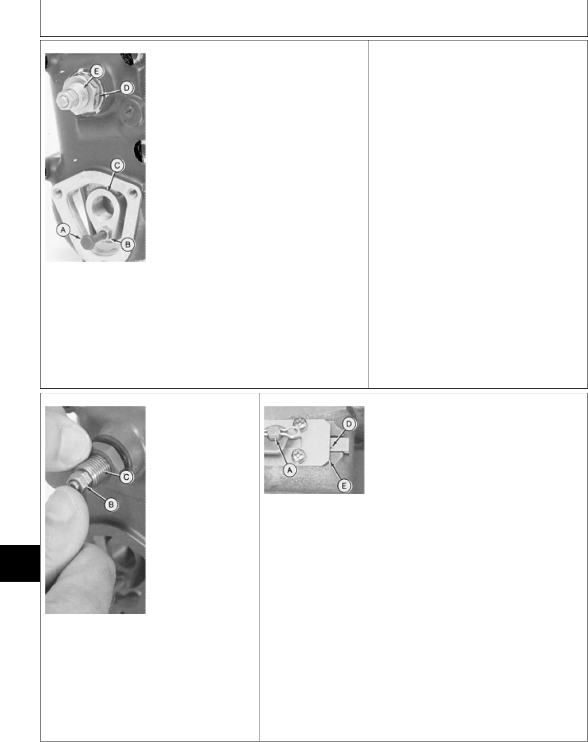
M44004 -UN-09JAN90
A—4 mm Fine Thread
Screw
B—Nut
C—Fuel Control Lever
D—Jam Nut
E—Torque Spring
Assembly
Install a 4 mm fine thread bolt (A) and nut (B)
through bottom hole of fuel control lever (C) and
into hole of governor lever. Turn bolt two turns
only.
Pull bolt outward until governor spring is
completely compressed, then tighten nut (B).
IMPORTANT: If governor spring is not
completely compressed or if bolt (A) extends
through the governor lever and hits governor
flyweights, the torque spring capsule
adjustment will be incorrect.
Loosen nut (D).
Turn torque spring assembly (E)
counterclockwise to obtain clearance between
assembly and fuel control lever.
IMPORTANT: DO NOT disassemble torque
spring assembly. The inner spring assembly
is factory adjusted and is only serviced as a
complete assembly.
M44008 -UN-09JAN90
A—Injection Pump Rack
B—Small Nuts (2 used)
C—Torque Spring
Assembly
D—Alignment Mark
E—Plate
M44009 -UN-09JAN90
IMPORTANT: DO NOT
compress inner
torque spring during
adjustment. If the
small nuts on the
torque spring
assembly are moving
outward (toward
flywheel), the torque
spring is being
compressed.
Push injection pump
rack (A) toward torque
spring assembly. Push
and hold small nuts (B)
tight against threaded
body (C) during
adjustment. Turn torque
spring assembly
clockwise until mark (D)
on the injection pump
rack aligns with the
right edge of plate (E).
Continued on next page
MX,15912201125B-19-13JUL95
MX,15912201125C-19-15JUL95
Diagnosis, Tests and Adjustments—330, 332 and 430/Fuel Controller Adjustment
TM1591 (15JUL95) 220-11-16 322,330,332 & 430 Lawn & Garden Tractors
030895
220
11
16

M44004 -UN-09JAN90
A—4 mm Fine Thread
Screw
B—Nut
C—Fuel Control Lever
D—Jam Nut
E—Torque Spring
Assembly
Hold torque spring
assembly (E) and
tighten nut (D).
Check alignment of
mark and plate to be
sure the torque spring
assembly has not
moved.
Remove screw (A) and
nut (B).
M44003 -UN-09JAN90
Install governor housing
cover (B). Fasten it with
three cap screws.
Install and tighten cap
(A).
Install a new sealing
wire. Fasten and
identify lead seal using
JDF10 Sealing Wire
Pliers.
Install oil dipstick tube.
M44001 -UN-09JAN90
Install fuel shutoff
solenoid and fuel
injection pump cover.
Install and tighten four
nuts (B) to 9 N·m (78
lb-in.).
Connect fuel shutoff
lever. Fasten it with a
washer and spring pin
(A).
MX,15912201125D-19-13JUL95
MX,15912201125E-19-13JUL95
Diagnosis, Tests and Adjustments—330, 332 and 430/Fuel Controller Adjustment
TM1591 (15JUL95) 220-11-17 322,330,332 & 430 Lawn & Garden Tractors
030895
220
11
17
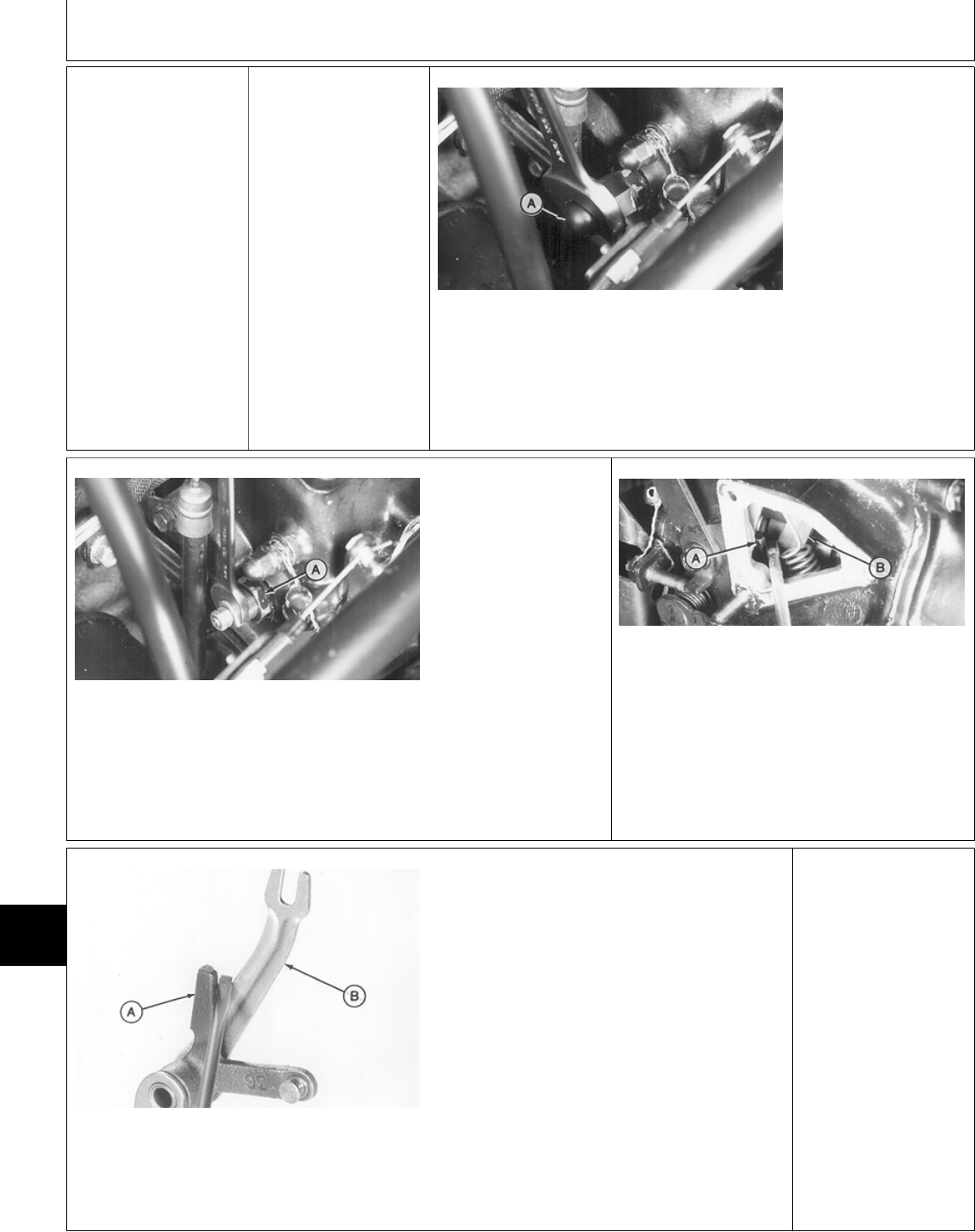
1:b Early 430 Remove front grille and
left engine side panel.
Remove two cap
screws and nut to
remove oil fill/cover and
gasket from injection
pump.
M78732 -UN-21JUN95
Remove cap (A).
M78733 -UN-21JUN95
Loosen lock nut (A).
Turn fuel controller
counterclockwise to
obtain clearance
between fuel controller
and fuel control lever.
Push injection pump
rack forward.
IMPORTANT: DO NOT
disassemble fuel
controller spring
assembly. The spring
assembly is factory
adjusted and is only
serviced as a
complete assembly.
M78734 -UN-21JUN95
M78735 -UN-21JUN95
Turn key to RUN position. DO NOT start engine.
Install a screwdriver between the fuel control
lever (A) and governor shaft lever (B). Push
down and twist screwdriver slightly to separate
levers and to compress governor spring. The
governor spring must be completely compressed
for this adjustment.
IMPORTANT: Keep slight downward pressure
on screwdriver between levers. DO NOT push
fuel control lever forward against fuel
controller during adjustment. If the governor
spring is not compressed or fuel control lever
is pushed forward, the fuel controller
adjustment will be incorrect.
Continued on next page
Diagnosis, Tests and Adjustments—330, 332 and 430/Fuel Controller Adjustment
TM1591 (15JUL95) 220-11-18 322,330,332 & 430 Lawn & Garden Tractors
030895
220
11
18
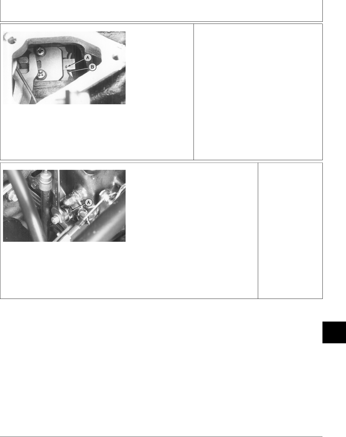
M78736 -UN-21JUN95
Turn fuel controller
clockwise until the mark
(A) on the injection
pump rack is in
alignment with the
reference face (B) on
the injection pump
body.
M78733 -UN-21JUN95
Hold fuel controller and
tighten lock nut (A).
Check alignment of
mark and reference
face to be sure the fuel
controller has not
moved.
Install and tighten cap.
Install new gasket.
Install oil fill/cover to
side of injection pump
and fasten with two cap
screws and nut. Tighten
cap screws and nut to
9 N·m (78 lb-in.).
Install left engine side
panel and front grille.
MX,15912201125G-19-13JUL95
Diagnosis, Tests and Adjustments—330, 332 and 430/Fuel Controller Adjustment
TM1591 (15JUL95) 220-11-19 322,330,332 & 430 Lawn & Garden Tractors
030895
220
11
19

Diagnosis, Tests and Adjustments—330, 332 and 430/Fuel Controller Adjustment
TM1591 (15JUL95) 220-11-20 322,330,332 & 430 Lawn & Garden Tractors
030895
220
11
20

Section 240
ELECTRICAL SYSTEM CHECKOUT,
OPERATION AND DIAGNOSIS
Contents
Page
Group 05—Electrical System Checkout
Before You Start . . . . . . . . . . . . . . . . . 240-05-1
Dash Lamp Circuit Check . . . . . . . . . . . 240-05-2
PTO Clutch and Lamp Check . . . . . . . . 240-05-2
Starting Circuit Check . . . . . . . . . . . . . . 240-05-3
Fuel Shutoff Solenoid Check (322, 332
and 430) . . . . . . . . . . . . . . . . . . . . . 240-05-4
Fuel Transfer Pump Check . . . . . . . . . . 240-05-5
Glow Plug Controller Check (330, 332
and 430) . . . . . . . . . . . . . . . . . . . . . 240-05-5
Ignition Circuit Check (322) . . . . . . . . . . 240-05-5
Hour Meter Check . . . . . . . . . . . . . . . . 240-05-6
Lighting Check . . . . . . . . . . . . . . . . . . 240-05-6
Operator Complaint Not Identified . . . . . . 240-05-7
Group 10—Electrical Schematics
Electrical Schematic Information . . . . . . . 240-10-1
Main Electrical Schematics
322 . . . . . . . . . . . . . . . . . . . . . . . . 240-10-3
330 . . . . . . . . . . . . . . . . . . . . . . . . 240-10-4
332 (S.N. —475000) . . . . . . . . . . . . 240-10-7
332 (S.N. 475001— ) . . . . . . . . . . . . 240-10-8
430 (S.N. —420468) . . . . . . . . . . . 240-10-11
430 (S.N. 420469— ) . . . . . . . . . . . 240-10-12
Light Circuit Schematic—All Machines . . 240-10-14
Group 15—Component Location and Operation
About This Group . . . . . . . . . . . . . . . . 240-15-1
Electrical Component Location
Glow Plug Control Module—330 and
332 . . . . . . . . . . . . . . . . . . . . . . . 240-15-1
Glow Plug Control Module—430 . . . . . 240-15-1
TDC Module and Neutral Start
Relay—322, 330 and 332 . . . . . . . . 240-15-1
TDC Module and Neutral Start
Relay—430 . . . . . . . . . . . . . . . . . . 240-15-2
TDC 8-Pin and 2-Pin Connectors—322
and 330 . . . . . . . . . . . . . . . . . . . . 240-15-2
TDC 8-Pin and 2-Pin Connectors—430
(S.N. —420468) . . . . . . . . . . . . . . 240-15-2
Page
Electrical Component Location—Continued
TDC 6-Pin and 3-Pin Connectors—332 . 240-15-3
TDC 6-Pin and 3-Pin Connectors—430 (S.N.
420469— ) . . . . . . . . . . . . . . . . . . . 240-15-3
Engine Oil Pressure Switch . . . . . . . . 240-15-3
Engine Coolant Temperature Switch . . . 240-15-4
Transmission Neutral Start Switch . . . . 240-15-4
Fuel Transfer Pump—322, 330, 332 . . . 240-15-5
Fuel Transfer Pump—430 . . . . . . . . . . 240-15-5
Fuel Shutoff Solenoid—322 . . . . . . . . . 240-15-5
Fuel Shutoff Solenoid—332 and 430 . . 240-15-5
Water-In-Fuel Sensor (430) . . . . . . . . . 240-15-6
Voltage Regulator/Rectifier (322, 330
and 332) . . . . . . . . . . . . . . . . . . . 240-15-6
Transistor Module (322) . . . . . . . . . . . 240-15-6
Ignition and Pulsar Coils (322) . . . . . . 240-15-7
Theory of Operation
Starting Circuit . . . . . . . . . . . . . . . . . 240-15-8
Ignition and Fuel Shutoff Solenoid
Circuit (322) . . . . . . . . . . . . . . . . 240-15-10
PTO Circuit—322, 330 and 430 (S.N.
—420468) . . . . . . . . . . . . . . . . . 240-15-14
PTO Circuit—332 and 430 (S.N.
420469— ) . . . . . . . . . . . . . . . 240-15-18
Charging Circuit—322, 330 and 332 . . 240-15-22
Charging Circuit—430 . . . . . . . . . . . 240-15-24
Fuel Shutoff Solenoid Circuit—430
(S.N. —420468) . . . . . . . . . . . . . 240-15-26
Fuel Shutoff Solenoid Circuit—332 and
430 (S.N. 420469— ) . . . . . . . . . 240-15-28
Engine Preheat Circuit (330, 332 and
430) . . . . . . . . . . . . . . . . . . . . . . 240-15-30
Water-In-Fuel Circuit (430) . . . . . . . . 240-15-32
Low Fuel Level Circuit (322, 332 and
430) . . . . . . . . . . . . . . . . . . . . . . 240-15-34
Group 20—Electrical System Diagnosis
About This Group . . . . . . . . . . . . . . . . 240-20-1
Continued on next page
TM1591 (15JUL95) 240-1 322,330,332 & 430 Lawn & Garden Tractors
030895
240

Page
Verify System Grounds
322 and 332 . . . . . . . . . . . . . . . . . . 240-20-1
330 . . . . . . . . . . . . . . . . . . . . . . . . 240-20-3
430 . . . . . . . . . . . . . . . . . . . . . . . . 240-20-3
Battery Tests . . . . . . . . . . . . . . . . . . . . 240-20-4
Dash Lamp Circuit Tests . . . . . . . . . . . . 240-20-7
PTO Clutch and Lamp Circuit Tests . . . 240-20-18
Starting Circuit Tests . . . . . . . . . . . . . 240-20-24
Fuel Shutoff Solenoid Circuit Tests . . . . 240-20-30
Fuel Transfer Pump Circuit Tests . . . . . 240-20-35
Glow Plug Controller Circuit Tests (330,
332 and 430) . . . . . . . . . . . . . . . . . 240-20-37
Ignition Circuit Tests (322) . . . . . . . . . . 240-20-38
Hour Meter Circuit Test . . . . . . . . . . . . 240-20-47
Head and Tail Light Circuit Tests . . . . . 240-20-48
Group 25—Electrical System Component Tests
and Adjustments
Before You Start . . . . . . . . . . . . . . . . . 240-25-1
Dash Lamps Sensor Tests . . . . . . . . . . 240-25-1
PTO Clutch Adjustment Check . . . . . . . . 240-25-3
Starting System Component Tests . . . . . 240-25-4
Fuel Shutoff Solenoid Adjustment . . . . . . 240-25-9
Charging System Tests . . . . . . . . . . . . 240-25-10
System Short Circuit Tests
10-Amp Fuse . . . . . . . . . . . . . . . . . 240-25-16
25-Amp Fuse . . . . . . . . . . . . . . . . . 240-25-17
Contents
TM1591 (15JUL95) 240-2 322,330,332 & 430 Lawn & Garden Tractors
030895
240

BEFORE YOU START
Always begin with this group to identify a failure in
the electrical system. The step-by-step procedures will
provide you with a quick check of the system. No
special tools are required to perform these checks. If
a failure is indicated, you will be referred to a more
detailed check, adjustment, or test located in Groups
20 and 25.
Always start with the first step and follow the
sequence from left to right. Read each step
completely before performing the check.
This procedure is designed as a quick check of the
system. Concentrate only on the check being
performed and disregard signals from unrelated
components. If unfamiliar with the operation or
location of system components, refer to Group 15 in
this section.
NOTE: When instructed to “turn the key switch ON”:
322 and 430; Turn the key switch to the
“RUN” position.
330 and 332; Turn the key switch to the “ON”
position.
For clarity in this section, machines including
and before serial numbers listed below will be
referred to as “Early Models”. Machines
including and after serial number listed below
will be referred to as “Later Models”.
Later model machines have a brake switch
added to the neutral start circuit, which is
activated by depressing the brake pedals.
MODEL EARLY LATER
322 (S.N. —596005) (S.N. 596006— )
330 (S.N. —420000) N/A
332 (S.N. —475000) (S.N. 475001— )
430 (S.N. —596047) (S.N. 596048— )
MX,159124005,1 -19-13JUL95
Group 05
Electrical System Checkout
TM1591 (15JUL95) 240-05-1 322,330,332 & 430 Lawn & Garden Tractors
030895
240
05
1
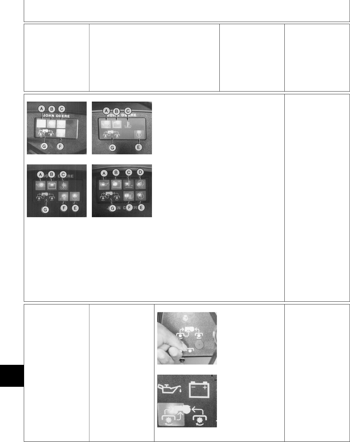
; DASH LAMP
CIRCUIT CHECK
322, 330 and 332; Move PTO switch to ON
position or hold hydrostatic lever to the right,
away from N/STOP switch.
Turn key switch to START position. (Engine
should not crank, but dash lamps should light.)
430; Turn key switch
fully counterclockwise
to lamp test position.
M45174 -UN-09JUN95
M78857 -UN-09JUN95
M55016 -UN-09JUN95
M78858 -UN-09JUN95
LOOK: All lamps ON except PTO lamp(s) (G).
NOTE: 330, 332 and 430; The engine preheat
lamp will turn off in 8 seconds or less depending
on engine compartment temperature. If engine
compartment is warm, preheat lamp may not
come on.
430; The water-in-fuel lamp will turn off after
approximately 3 seconds.
PHOTO ORIENTATION
Model Position
322 . . . . . . . . . . . . . . . . . . . . . . . . . . Upper Left
330 . . . . . . . . . . . . . . . . . . . . . . . . . Upper Right
332 . . . . . . . . . . . . . . . . . . . . . . . . . . Lower Left
430 . . . . . . . . . . . . . . . . . . . . . . . . . Lower Right
(Key) Lamp
(A) . . . . . . . . . . . . . . . . . . . . . Engine Oil Pressure
(B) . . . . . . . . . . . . . . . . . . . . . . Battery Discharge
(C) . . . . . . . . . . . . . . . . . . . . Coolant Temperature
(D) . . . . . . . . . . . . . . . . . . . . . . . . . Water-In-Fuel
(E) . . . . . . . . . . . . . . . . . . . . . . . . Engine Preheat
(F) . . . . . . . . . . . . . . . . . . . . . . . . Low Fuel Level
(G) . . . . . . . . . . . . . . . . . . . . . . . . . . . PTO Lamp
OK: GO TO ‘
NOT OK: Check 10-amp
fuse. Fuse OK, then
GO TO ;, Group 20.
‘ PTO CLUTCH AND
LAMP CHECK
Sit on seat.
PTO switch OFF.
Hydrostatic lever in
N/STOP position.
M55019 -UN-09DEC89
M36492 -UN-29JAN90
Turn key switch to
ON/RUN position.
Move PTO switch to
ON position.
LOOK: PTO lamp must
come ON.
LISTEN: PTO clutch
must “click” on.
OK: GO TO 2a
NOT OK: Check 25-amp
fuse and 10-amp fuse,
then GO TO ‘, Group
20.
MX,159124005,2 -19-13JUL95
MX,159124005,13-19-13JUL95
Electrical System Checkout/PTO Clutch and Lamp Check
TM1591 (15JUL95) 240-05-2 322,330,332 & 430 Lawn & Garden Tractors
030895
240
05
2
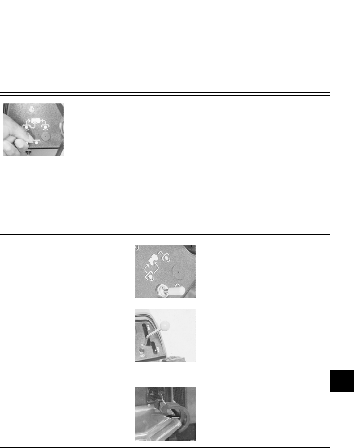
2a Seat Switch Check
For PTO
Sit on seat.
PTO switch OFF.
Hydrostatic lever in
N/STOP position.
Later Models; Engage
park brake.
M55019 -UN-09DEC89
Turn key switch to ON/RUN
position.
Move PTO switch to ON position.
Raise off seat for 2—3 seconds.
LOOK/LISTEN: PTO lamp must turn
off and PTO clutch “click” off.
Sit back down on seat.
Lamp and clutch must stay off.
Turn key switch to START position.
LISTEN: Engine must NOT crank.
Turn PTO switch OFF, then ON.
Raise off seat and quickly sit back
down before one second elapses.
LOOK/LISTEN: PTO lamp and
clutch must stay ON. OK: GO TO Æ
NOT OK: GO TO ‘,
Group 20.
Æ STARTING CIRCUIT
CHECK
Sit on seat.
PTO switch OFF.
Hydrostatic lever in
N/STOP position.
Later Models; Depress
brake pedal(s).
M36488 -UN-29JAN90
M55026 -UN-09DEC89
Turn key switch to
START position.
LISTEN: Starter must
crank engine.
OK:
For machines:
322 (S.N. 596006— )
332 (S.N. 475001— )
430 (S.N. 596048— ),
GO TO 3a
For all other machines,
GO TO 3b
NOT OK: Check 25-amp
fuse, then GO TO Æ,
Group 20.
3a Brake Switch
Neutral Start
Check
322 (SN 596006— )
332 (SN 475001— )
430 (SN 596048— )
PTO switch OFF.
Hydrostatic lever in
N/STOP position.
M77933 -UN-17JAN95
Brake pedal(s)
completely released.
Turn key switch to
START position.
LISTEN: Engine must
NOT crank.
OK: GO TO 3b
NOT OK: GO TO 3f,
Group 20.
MX,159124005,14-19-13JUL95
MX,159124005,7 -19-13JUL95
MX,159124005,8 -19-13JUL95
Electrical System Checkout/Starting Circuit Check
TM1591 (15JUL95) 240-05-3 322,330,332 & 430 Lawn & Garden Tractors
030895
240
05
3
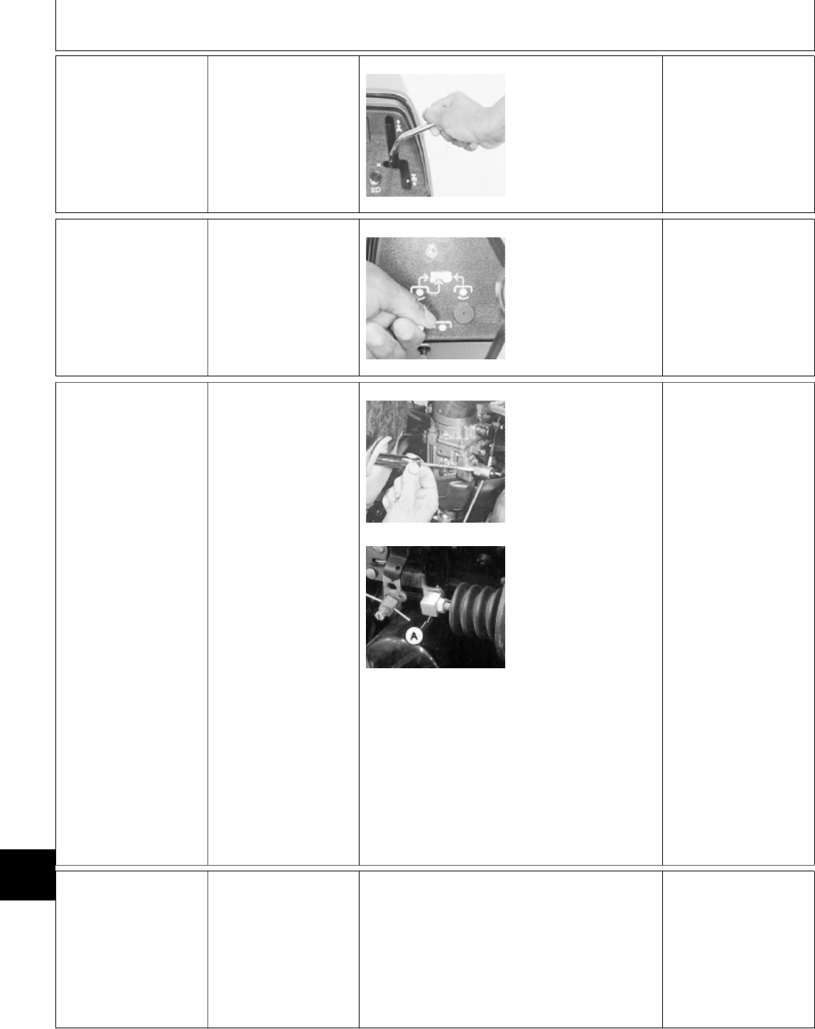
3b Transmission
Switch Neutral
Start Check
PTO switch OFF.
Later Models; Engage
park brake.
M55018 -UN-09DEC89
Move hydrostatic lever
to the right away from
N/STOP switch.
Turn key switch to
START position.
LISTEN: Engine must
NOT crank.
OK: GO TO 3c
NOT OK: GO TO 3i,
Group 20.
3c PTO Switch
Neutral Start Check
Hydrostatic lever in
N/STOP position.
Later Models; Depress
brake pedal(s).
M55019 -UN-09DEC89
Move PTO switch to
ON position.
Turn key switch to
START position.
LISTEN: Engine must
NOT crank.
OK: GO TO Å
NOT OK: GO TO 3m,
Group 20.
Å FUEL SHUTOFF
SOLENOID CHECK
(322, 332 and 430)
PTO switch OFF.
Hydrostatic lever in
N/STOP position.
Later Models; Engage
park brake.
Open hood.
332 and 430; Remove
left engine side panel.
M44161 -UN-08JAN90
M78964 -UN-27APR95
NOTE: 322; Hold a
screwdriver against the
fuel shutoff solenoid.
Screwdriver will amplify
sound.
Do not confuse the
“click” from the neutral
start relay with “click”
from the fuel shutoff
solenoid.
Turn key switch ON,
then OFF a few times.
LISTEN: Fuel shutoff
solenoid must “click”
when key is turned ON.
LOOK: 332 and 430;
Solenoid armature must
move fuel shutoff
linkage to ON position.
OK: GO TO 4a
NOT OK: GO TO Å,
Group 20.
4a Seat Switch
Check For Fuel
Shutoff
(322, 332 and 430)
Sit on seat.
PTO switch OFF.
Hydrostatic lever in
N/STOP position.
Later Models; Engage
park brake.
Start engine and operate at slow idle.
Move hydrostatic lever fully to right while keeping
lever in the N/STOP slot.
Raise off seat for 2—3 seconds.
LISTEN: Engine must stop.
Continued on next page
MX,159124005,9 -19-13JUL95
MX,159124005,10-19-13JUL95
MX,159124005,4 -19-13JUL95
Electrical System Checkout/Fuel Shutoff Solenoid Check (322, 332 and 430)
TM1591 (15JUL95) 240-05-4 322,330,332 & 430 Lawn & Garden Tractors
030895
240
05
4
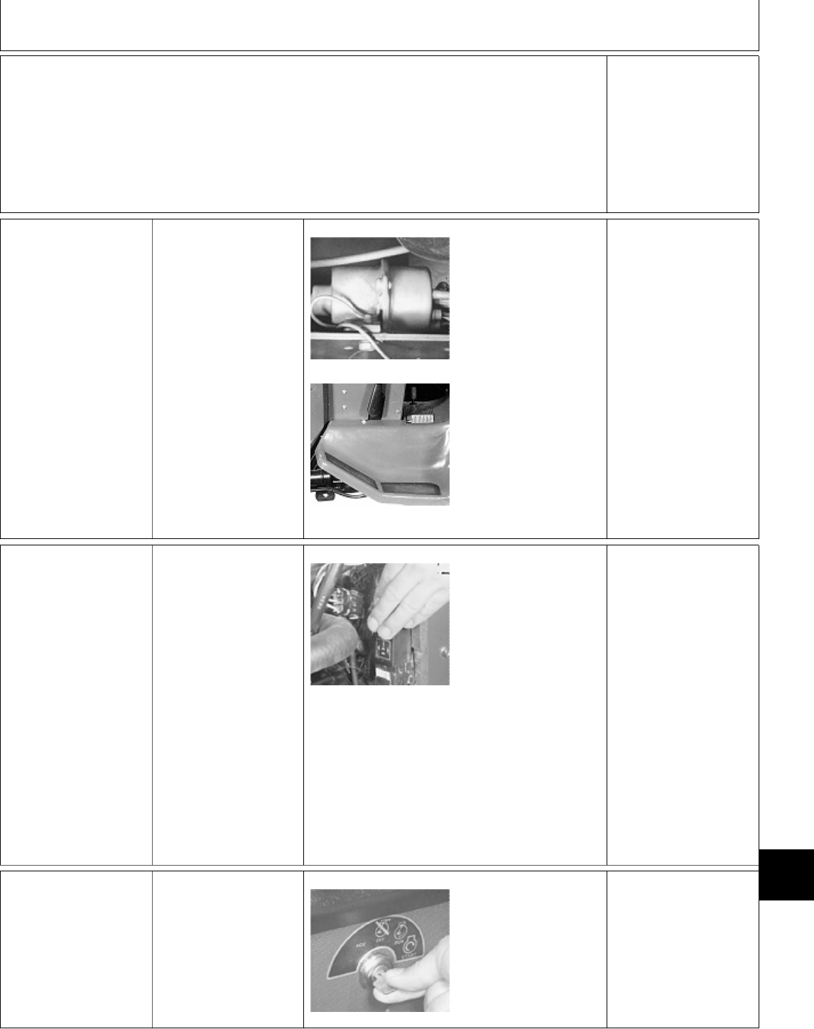
Restart engine.
Again, move hydrostatic lever to the
right while keeping lever in the
N/STOP slot.
Raise off seat and quickly sit back
down before one second elapses.
LISTEN: Engine may falter, but
must stay running. OK: GO TO Ö
NOT OK: GO TO 4p,
Group 20.
Ö FUEL TRANSFER
PUMP CHECK
Turn key switch to
ON/RUN position.
M49009 -UN-08JAN90
M36486 -UN-12APR95
LISTEN: Fuel transfer
pump must “click”
continuously.
NOTE: 322, 330 and
332; The fuel transfer
pump is located behind
left engine panel,
mounted to machine
frame. (Upper photo.)
430; The fuel transfer
pump is located inside
the left side of machine
frame behind the left
footrest. (Lower photo.)
OK:
322; GO TO Õ
330, 332 and 430; GO
TO Ò
NOT OK: Check 10-amp
fuse (322, 330 and
332) or 25-amp fuse
(430), then GO TO Ö,
Group 20.
Ò GLOW PLUG
CONTROLLER
CHECK
(330, 332 and 430)
Open hood.
Remove left engine
side panel.
M36487 -UN-29JAN90
Put hand on glow plug
controller.
Turn key switch to
ON/RUN position.
FEEL: Glow plug
controller must
disengage in 30
seconds or less.
NOTE: If you listen
near the controller, you
can also hear it “click”.
OK: GO TO Ú
NOT OK: OR CAN’T
TELL; Check 10-amp
fuse, then GO TO Ò,
Group 20.
Õ IGNITION CIRCUIT
CHECK (322)
PTO switch OFF.
Hydrostatic lever in
N/STOP position.
Later Models; Engage
park brake.
M45176 -UN-08JAN90
Turn key switch to
START position.
LISTEN: Engine must
start and run.
Stop engine after
check.
OK: GO TO 7a
NOT OK: Engine does
not run or engine
misfires; GO TO Õ,
Group 20.
MX,159124005,5 -19-13JUL95
MX,159124005,3 -19-13JUL95
MX,159124005,6 -19-13JUL95
MX,159124005,11-19-13JUL95
Electrical System Checkout/Ignition Circuit Check (322)
TM1591 (15JUL95) 240-05-5 322,330,332 & 430 Lawn & Garden Tractors
030895
240
05
5
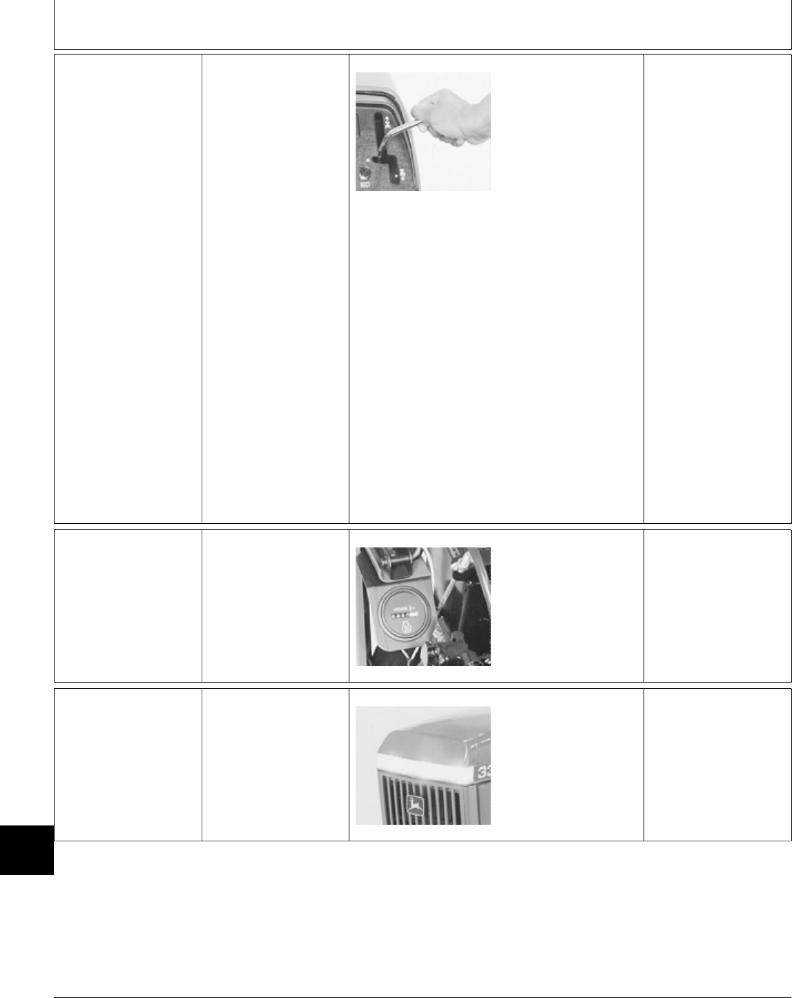
7a Seat Switch Check
For Ignition
Sit on seat.
PTO switch OFF.
Hydrostatic lever in
N/STOP position.
Later Models; Engage
park brake.
M55018 -UN-09DEC89
Start engine and
operate at slow idle.
Move hydrostatic lever
to the right away from
the N/STOP switch.
Raise off seat for 2—3
seconds.
LISTEN: Engine must
stop.
Restart engine.
Again, move hydrostatic
lever to the right away
from the N/STOP slot.
Raise off seat and
quickly sit back down
before one second
elapses.
LISTEN: Engine must
stay running.
OK: GO TO Ú
NOT OK: GO TO 7n,
Group 20.
Ú HOUR METER
CHECK
Turn key switch to
ON/RUN position.
M55017 -UN-11DEC89
LOOK: Hour meter
must operate. OK: GO TO Ü
NOT OK: GO TO Ú,
Group 20.
Ü LIGHTING CHECK Turn key switch to
ON/RUN position.
M55080 -UN-09DEC89
Pull light switch ON.
LOOK: All headlights
and tail lights (if
equipped) must be on.
OK: System normal.
NOT OK: GO TO Ü,
Group 20.
MX,159124005,12-19-13JUL95
MX,159124005,15-19-13JUL95
MX,159124005,16-19-13JUL95
Electrical System Checkout/Lighting Check
TM1591 (15JUL95) 240-05-6 322,330,332 & 430 Lawn & Garden Tractors
030895
240
05
6

1Ô OPERATOR
COMPLAINT NOT
IDENTIFIED
If you completed the
checkout procedure and
did not isolate a
malfunction, the
problem may be
intermittent.
Try to duplicate the
conditions of the
malfunction identified by
the operator.
Perform battery tests
and ground tests as
instructed in Group 20.
Verify system grounds
and battery condition.
(See steps A and B
in Group 20).
PERFORM BATTERY TESTS AND GROUND
TESTS AS INSTRUCTED IN GROUP 20 AND
AND REPEAT THE CHECKOUT PROCEDURE
IN THIS GROUP.
IF A MALFUNCTION IS NOT IDENTIFIED
AFTER REPEATING SYSTEM CHECKOUT
PROCEDURE, FACTORY ASSISTANCE IS
AVAILABLE THROUGH THE DEALER
TECHNICAL ASSISTANCE CENTER (DTAC).
MX,159124005,17-19-13JUL95
Electrical System Checkout/Operator Complaint Not Identified
TM1591 (15JUL95) 240-05-7 322,330,332 & 430 Lawn & Garden Tractors
030895
240
05
7

Electrical System Checkout/Operator Complaint Not Identified
TM1591 (15JUL95) 240-05-8 322,330,332 & 430 Lawn & Garden Tractors
030895
240
05
8

ELECTRICAL SCHEMATIC INFORMATION
The electrical schematics are made up of sections (SE)
which are laid out from left-to-right in logical sequence
(e.g. SE-1 Starting Circuit, SE-2 PTO Circuit, etc.).
Each section contains subsystems which are made up of
groups of related components. The sections are named
to reflect the function of the group of components.
The electrical schematics are drawn showing the power
in (battery positive) circuit across the top and the ground
(battery negative) circuit across the bottom. The flow is
(if possible) from top to bottom through each circuit and
component. All components are shown in the off
position.
NOTE: 332 and 430; Two schematics for each model
are provided to show component, component
wiring and ground circuit changes for different
versions of machines.
MX,159124010,1A-19-13JUL95
Group 10
Electrical Schematics
TM1591 (15JUL95) 240-10-1 322,330,332 & 430 Lawn & Garden Tractors
030895
240
10
1

MAIN ELECTRICAL SCHEMATIC LEGEND—322
A1—Time Delay Control P6—Engine Oil Pressure X4—Front PTO Switch 3-Pin X18—Engine Harness 2-Pin
(TDC) Module Lamp Connector Connector
A3—Transistor Module P7—Hour Meter X5—Rear PTO Harness 3-Pin X19—Fuel Pump 2-Pin
B1—No.1 Pulser Coil R2—Electric Choke Connector Connector
B2—No.2 Pulser Coil (S.N. 010714— ) X6—Rear PTO Switch 2-Pin X20—No.1 Pulser Coil 2-Pin
B3—No.3 Pulser Coil S1—Key Switch Connector (Optional) Connector
B4—Low Fuel Level Sensor S2—Front PTO Switch X7—Rear PTO Switch 3-Pin X21—No.2 Pulser Coil 2-Pin
B5—Engine Coolant S3—Rear PTO Switch Connector (Optional) Connector
Temperature Switch (Optional) X8—Transmission Neutral X22—No.3 Pulser Coil 2-Pin
B6—Engine Oil Pressure S4—Brake Switch Switch 1-Pin Connector Connector
Switch (S.N. 596006— ) X9—Transmission Neutral X23—Low Fuel Level Sensor
E1—Spark Plug S5—Transmission Neutral Switch 1-Pin Connector 2-Pin Connector
E2—Spark Plug Switch X10—Front PTO Clutch 2-Pin X24—Pulsar Coil Harness
E3—Spark Plug S6—Seat Switch Connector 4-Pin Connector
F1—25-Amp Fuse T1—No.1 Ignition Coil X11—Rear PTO Lamp 1-Pin X25—Transistor Module 4-Pin
F2—10-Amp Fuse T2—No.2 Ignition Coil Connector (Ground) Connector
F4—Fusible Link T3—No.3 Ignition Coil X12—Rear PTO Clutch 1-Pin X26—Transistor Module 6-Pin
G1—Battery V1—Diode Connector (Optional) Connector
G2—Alternator V2—Diode X13—TDC Module 8-Pin X27—Ignition Coil Harness
K1—Neutral Start Relay W1—Engine Ground Connector 6-Pin Connector
M1—Starter Motor W3—Frame Ground X14—TDC Module 2-Pin X28—Fuel Shutoff Solenoid
M2—Fuel Pump W4—Frame Ground at Connector and Electric Choke
N1—Voltage Voltage X15—Seat Switch 2-Pin 2-Pin Connector
Regulator/Rectifier Regulator/Rectifier Connector (S.N. 010714— )
P1—Front PTO Lamp X1—Neutral Start Relay 4-Pin X16—Voltage Y1—Front PTO Clutch
P2—Rear PTO Lamp Connector Regulator/Rectifier Y2—Rear PTO Clutch
(Optional) X2—Brake Switch 2-Pin 5-Pin Connector (Optional)
P3—Battery Discharge Lamp Connector X17—Alternator 2-Pin Y3—Fuel Shutoff Solenoid
P4—Low Fuel Level Lamp (S.N. 596006— ) Connector
P5—Engine Coolant X3—Front PTO Switch 2-Pin
Temperature Lamp Connector
NOTE: 1. For machines not equipped with optional
rear PTO, a jumper wire is used at connector
(X5) in place of rear PTO switch (S3). The
jumper wire connects purple wire “750” to
wires “770” (purple) and “771” (purple/white).
The blue wire “780” deadends at connector
(X5).
NOTE: 2. Machines (S.N. —596005); Brake switch
(S4) is not used. Purple wire “811” connects
transmission neutral switch (S5) directly to
neutral start relay (K1).
NOTE: 3. Machines (S.N. 010714— ); Electric
choke (R2) is used. 2-Pin connector (X28)
distributes current to fuel shutoff solenoid (Y3)
and the electric choke.
MX,159124010,1 -19-13JUL95
Electrical Schematics/Electrical Schematic Information
TM1591 (15JUL95) 240-10-2 322,330,332 & 430 Lawn & Garden Tractors
030895
240
10
2
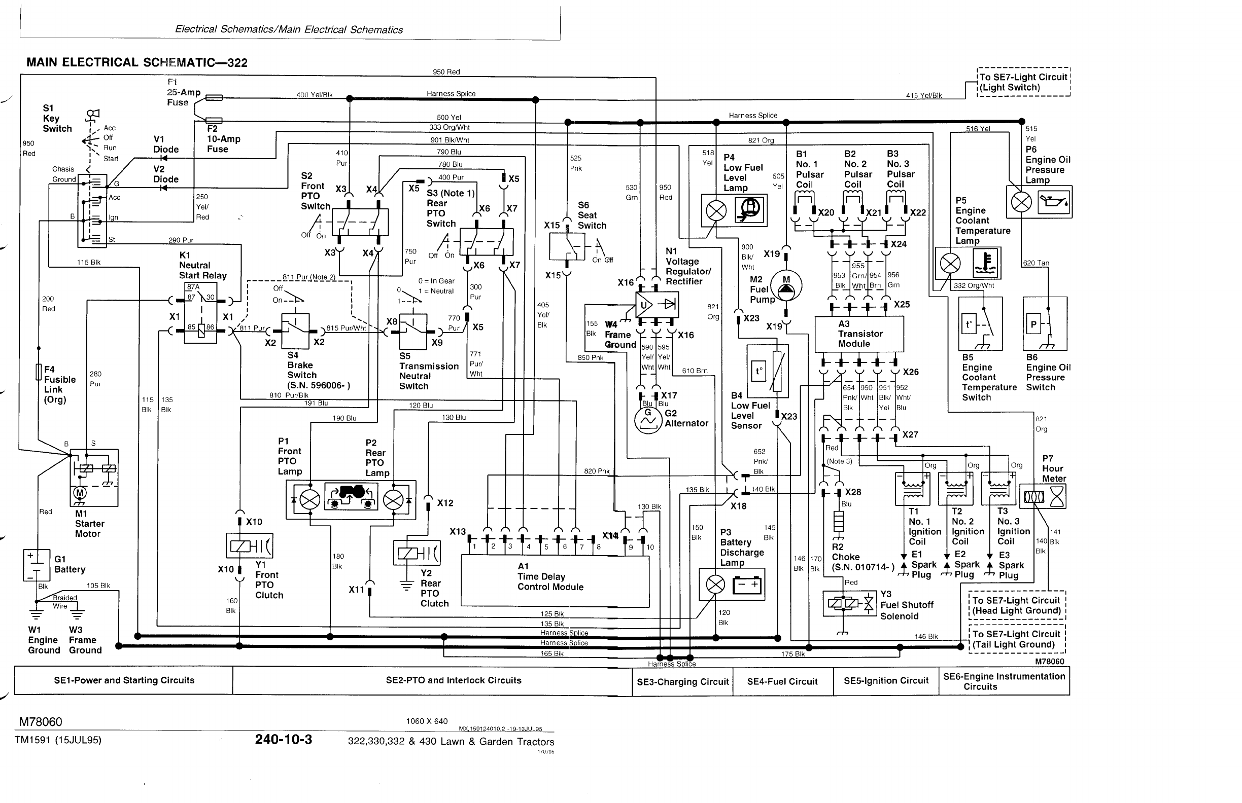
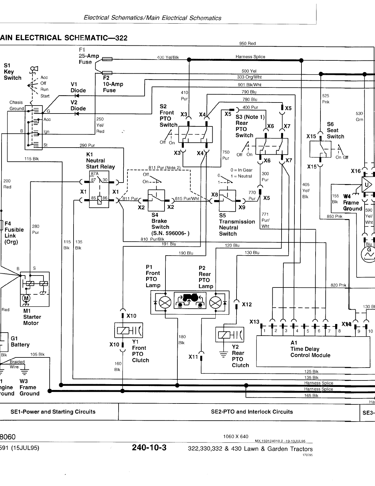
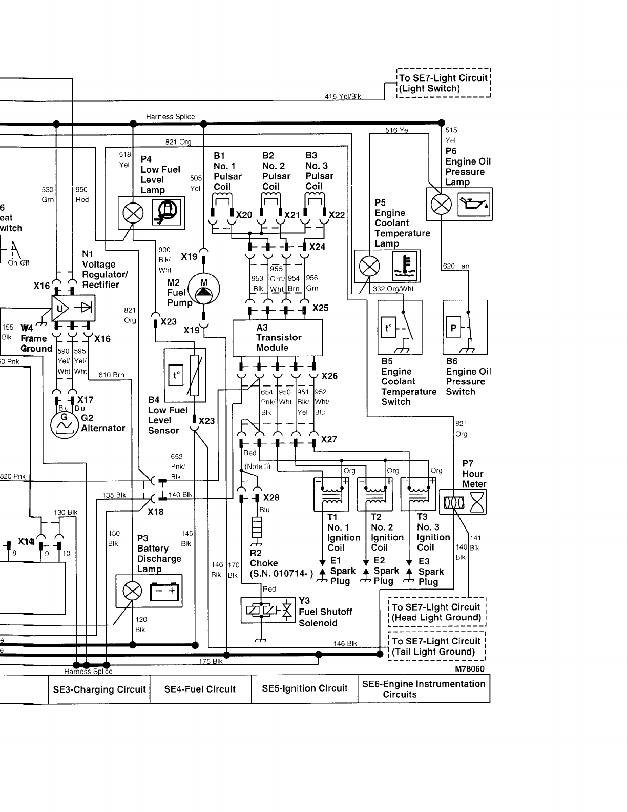
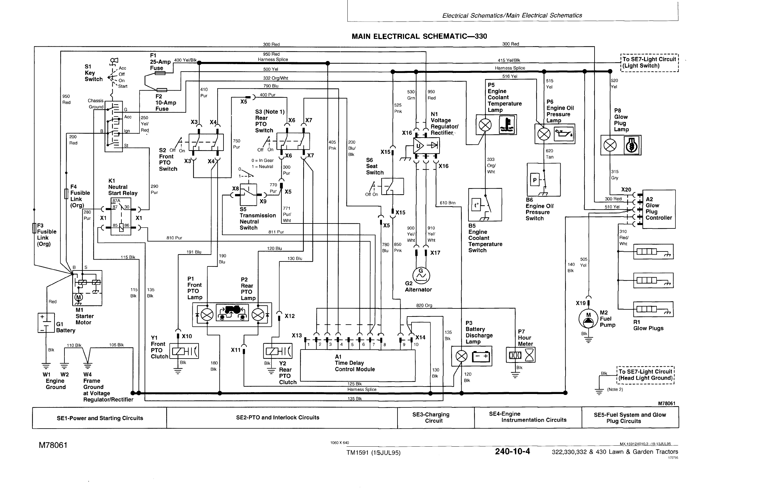
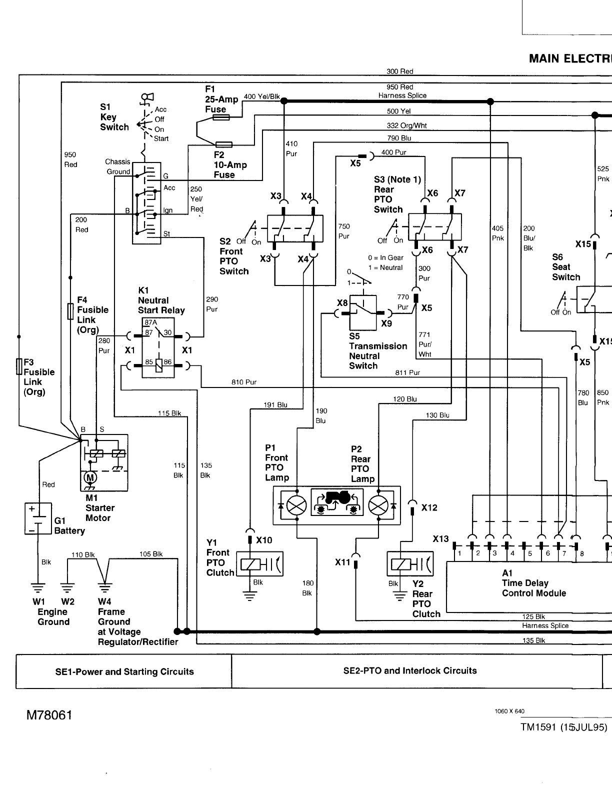
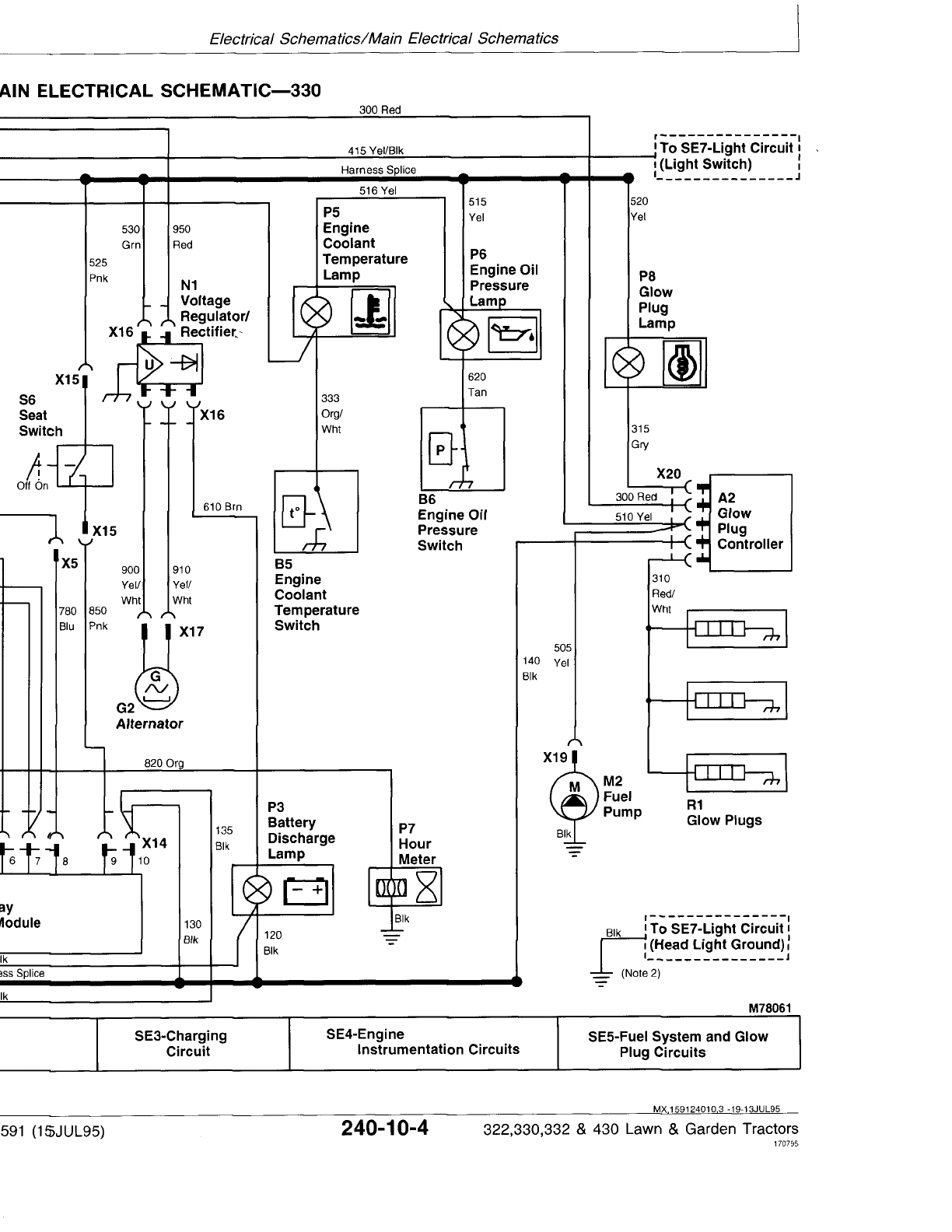

MAIN ELECTRICAL SCHEMATIC LEGEND—330
A1—Time Delay Control P3—Battery Discharge Lamp X1—Neutral Start Relay 4-Pin X12—Rear PTO Clutch 1-Pin
(TDC) Module P5—Engine Coolant Connector Connector (Optional)
A2—Glow Plug Controller Temperature Lamp X3—Front PTO Switch 2-Pin X13—TDC Module 8-Pin
B5—Engine Coolant P6—Engine Oil Pressure Connector Connector
Temperature Switch Lamp X4—Front PTO Switch 3-Pin X14—TDC Module 2-Pin
B6—Engine Oil Pressure P7—Hour Meter Connector Connector
Switch P8—Glow Plug Lamp X5—Rear PTO Harness 3-Pin X15—Seat Switch 2-Pin
F1—25-Amp Fuse R1—Glow Plugs (3 used) Connector Connector
F2—10-Amp Fuse S1—Key Switch X6—Rear PTO Switch 2-Pin X16—Voltage
F3—Fusible Link S2—Front PTO Switch Connector (Optional) Regulator/Rectifier
F4—Fusible Link S3—Rear PTO Switch X7—Rear PTO Switch 3-Pin 5-Pin Connector
G1—Battery (Optional) Connector (Optional) X17—Alternator 2-Pin
G2—Alternator S5—Transmission Neutral X8—Transmission Neutral Connector
K1—Neutral Start Relay Switch Switch 1-Pin Connector X19—Fuel Pump 1-Pin
M1—Starter Motor S6—Seat Switch X9—Transmission Neutral Connector
M2—Fuel Pump W1—Engine Ground Switch 1-Pin Connector X20—Glow Plug Controller
N1—Voltage W2—Engine Ground X10—Front PTO Clutch 1-Pin 5-Pin Connector
Regulator/Rectifier W4—Frame Ground at Connector Y1—Front PTO Clutch
P1—Front PTO Lamp Voltage X11—Rear PTO Lamp 1-Pin Y2—Rear PTO Clutch
P2—Rear PTO Lamp Regulator/Rectifier Connector (Ground) (Optional)
(Optional)
NOTE: 1. For machines not equipped with optional
rear PTO, a jumper wire is used at connector
(X5) in place of rear PTO switch (S3). The
jumper wire connects purple wire “750” to
wires “770” (purple) and “771” (purple/white).
The blue wire “780” deadends at connector
(X5).
NOTE: 2. Model 330 does not come equipped with
rear tail lights. Red reflectors are used
instead.
MX,159124010,4 -19-13JUL95
Electrical Schematics/Main Electrical Schematics
TM1591 (15JUL95) 240-10-5 322,330,332 & 430 Lawn & Garden Tractors
030895
240
10
5

MAIN ELECTRICAL SCHEMATIC LEGEND—332 (S.N. —475000)
A1—Time Delay Control P4—Low Fuel Level Lamp X1—Neutral Start Relay 4-Pin X14—TDC Module 3-Pin
(TDC) Module P5—Engine Coolant Connector Connector
A2—Glow Plug Controller Temperature Lamp X3—Front PTO Switch 2-Pin X15—Seat Switch 2-Pin
B4—Low Fuel Level Sensor P6—Engine Oil Pressure Connector Connector
B5—Engine Coolant Lamp X4—Front PTO Switch 3-Pin X16—Voltage
Temperature Switch P7—Hour Meter Connector Regulator/Rectifier
B6—Engine Oil Pressure P8—Glow Plug Lamp X5—Rear PTO Harness 3-Pin 5-Pin Connector
Switch R1—Glow Plugs (3 used) Connector X17—Alternator 2-Pin
F1—25-Amp Fuse S1—Key Switch X6—Rear PTO Switch 2-Pin Connector
F2—10-Amp Fuse S2—Front PTO Switch Connector (Optional) X19—Fuel Pump 1-Pin
F3—Fusible Link S3—Rear PTO Switch X7—Rear PTO Switch 3-Pin Connector
F4—Fusible Link (Optional) Connector (Optional) X20—Glow Plug Controller
G1—Battery S5—Transmission Neutral X8—Transmission Neutral 5-Pin Connector
G2—Alternator Switch Switch 1-Pin Connector X21—Fuel Shutoff Solenoid
K1—Neutral Start Relay S6—Seat Switch X9—Transmission Neutral 3-Pin Connector
M1—Starter Motor V1—Diode Switch 1-Pin Connector X23—Low Fuel Level Sensor
M2—Fuel Pump V2—Diode X10—Front PTO Clutch 1-Pin 2-Pin Connector
N1—Voltage W1—Engine Ground Connector Y1—Front PTO Clutch
Regulator/Rectifier W2—Engine Ground X11—Rear PTO Lamp 1-Pin Y2—Rear PTO Clutch
P1—Front PTO Lamp W3—Frame Ground Connector (Ground) (Optional)
P2—Rear PTO Lamp W4—Frame Ground at X12—Rear PTO Clutch 1-Pin Y3—Fuel Shutoff Solenoid
(Optional) Voltage Connector (Optional)
P3—Battery Discharge Lamp Regulator/Rectifier X13—TDC Module 6-Pin
Connector
NOTE: 1. For machines not equipped with optional
rear PTO, a jumper wire is used at connector
(X5) in place of rear PTO switch (S3). The
jumper wire connects purple wire “750” to
wires “770” (purple) and “771” (purple/white).
The blue wire “780” deadends at connector
(X5).
MX,159124010,5 -19-13JUL95
Electrical Schematics/Main Electrical Schematics
TM1591 (15JUL95) 240-10-6 322,330,332 & 430 Lawn & Garden Tractors
030895
240
10
6
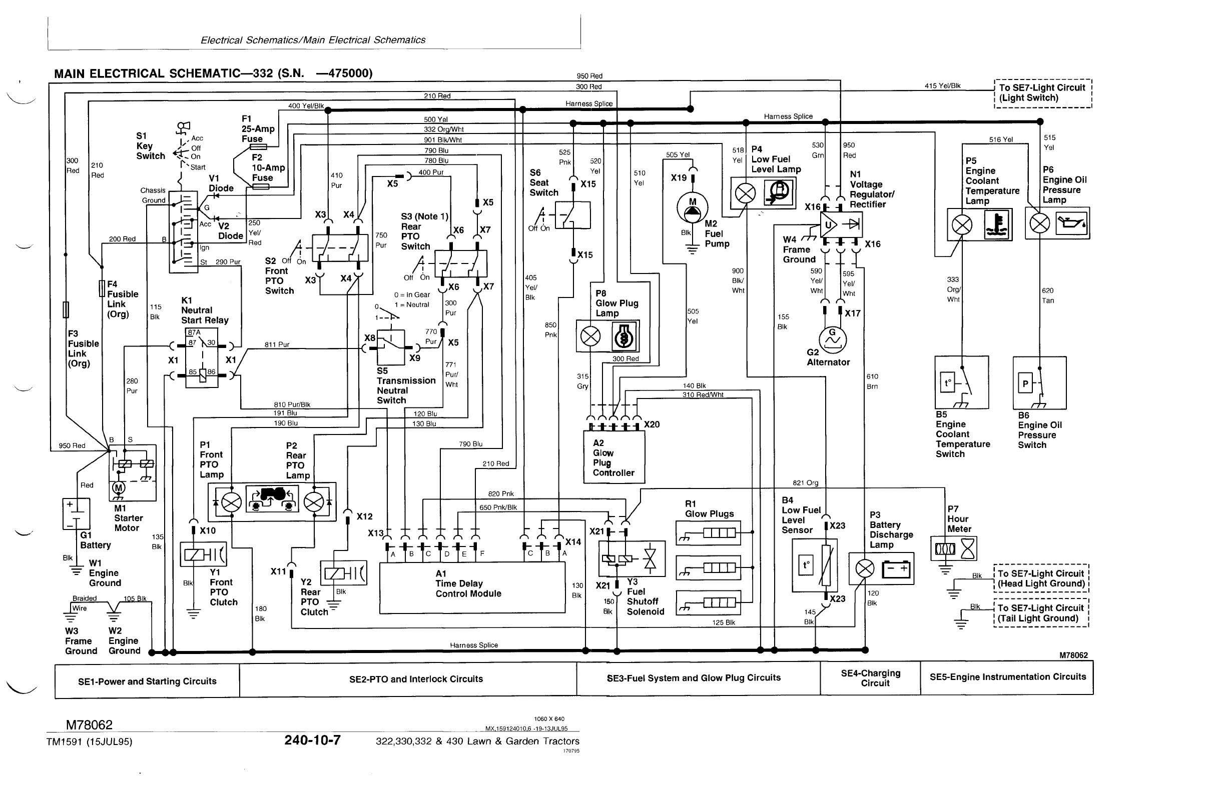
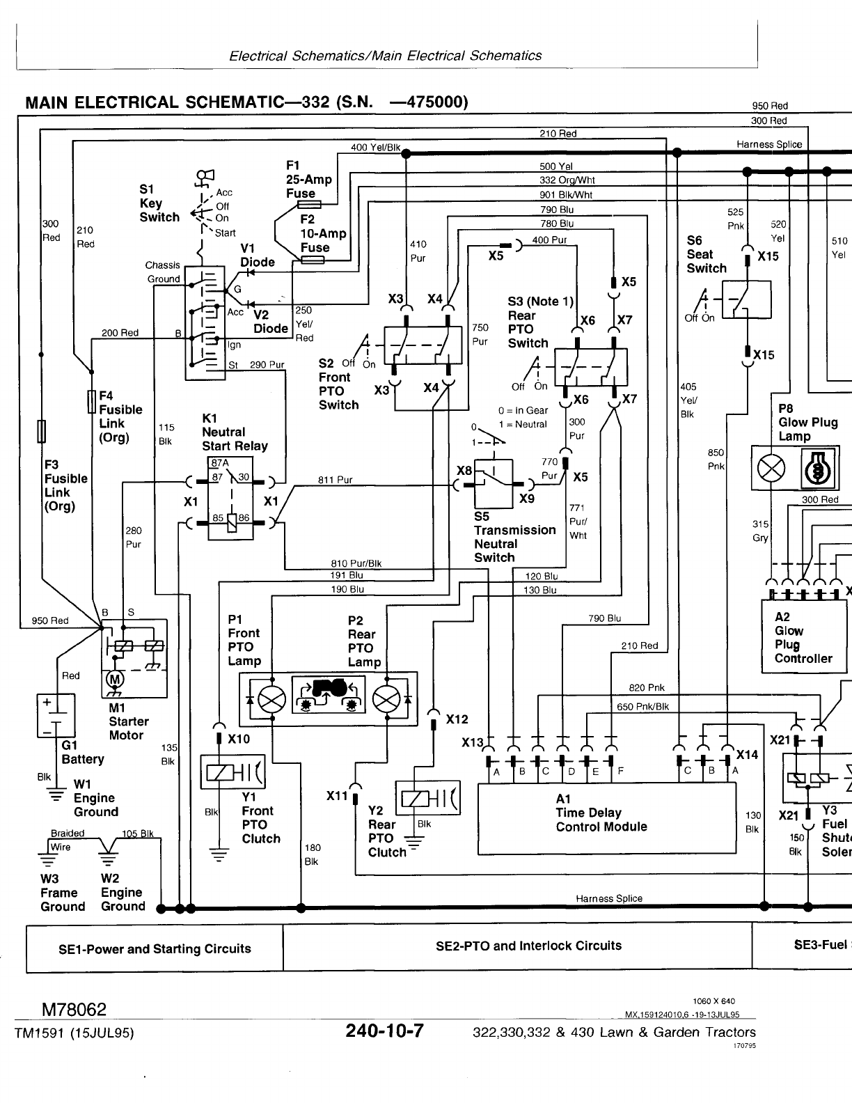
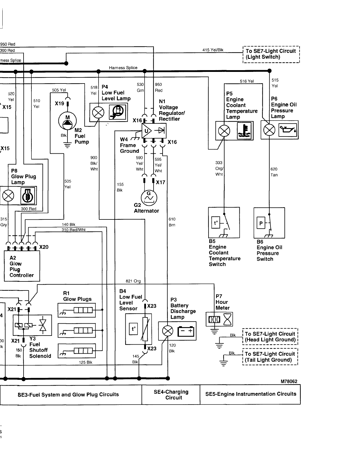
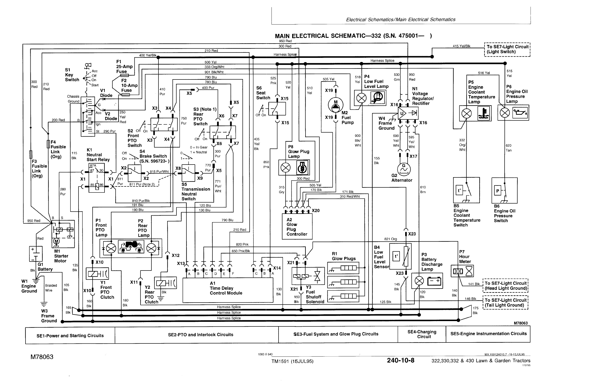
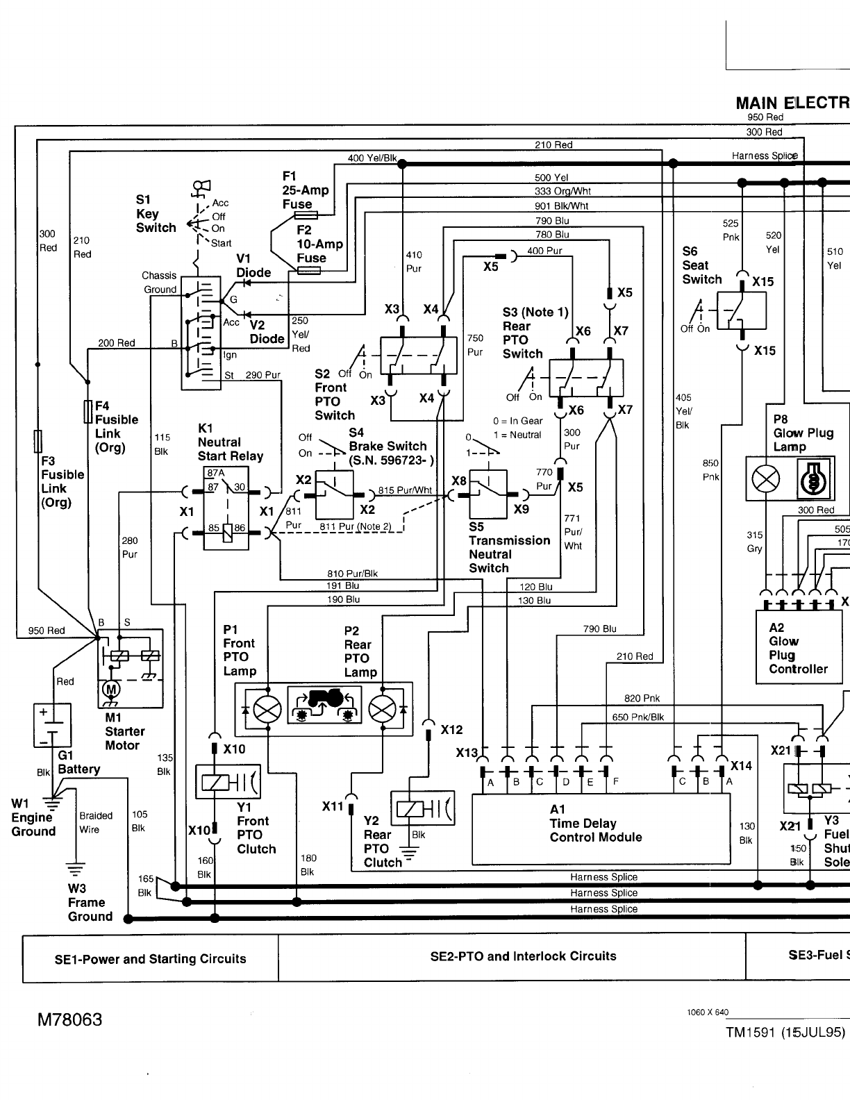
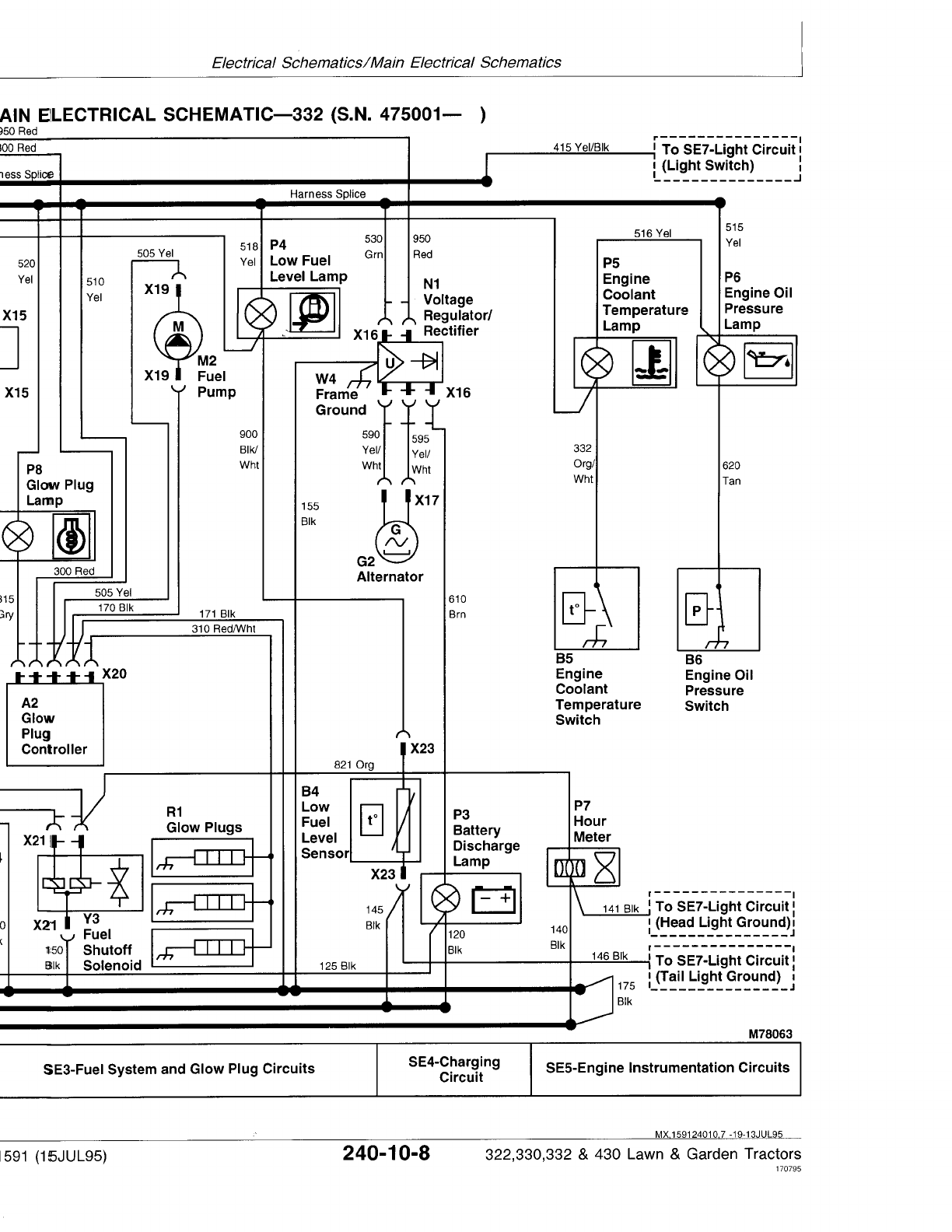

MAIN ELECTRICAL SCHEMATIC LEGEND—332 (S.N. 475001— )
A1—Time Delay Control P5—Engine Coolant X2—Brake Switch 2-Pin X13—TDC Module 6-Pin
(TDC) Module Temperature Lamp Connector (S.N. Connector
A2—Glow Plug Controller P6—Engine Oil Pressure 596723— ) X14—TDC Module 3-Pin
B4—Low Fuel Level Sensor Lamp X3—Front PTO Switch 2-Pin Connector
B5—Engine Coolant P7—Hour Meter Connector X15—Seat Switch 2-Pin
Temperature Switch P8—Glow Plug Lamp X4—Front PTO Switch 3-Pin Connector
B6—Engine Oil Pressure R1—Glow Plugs (3 used) Connector X16—Voltage
Switch S1—Key Switch X5—Rear PTO Harness 3-Pin Regulator/Rectifier
F1—25-Amp Fuse S2—Front PTO Switch Connector 5-Pin Connector
F2—10-Amp Fuse S3—Rear PTO Switch X6—Rear PTO Switch 2-Pin X17—Alternator 2-Pin
F3—Fusible Link (Optional) Connector (Optional) Connector
F4—Fusible Link S4—Brake Switch (S.N. X7—Rear PTO Switch 3-Pin X19—Fuel Pump 2-Pin
G1—Battery 596723— ) Connector (Optional) Connector
G2—Alternator S5—Transmission Neutral X8—Transmission Neutral X20—Glow Plug Controller
K1—Neutral Start Relay Switch Switch 1-Pin Connector 5-Pin Connector
M1—Starter Motor S6—Seat Switch X9—Transmission Neutral X21—Fuel Shutoff Solenoid
M2—Fuel Pump V1—Diode Switch 1-Pin Connector 3-Pin Connector
N1—Voltage V2—Diode X10—Front PTO Clutch 2-Pin X23—Low Fuel Level Sensor
Regulator/Rectifier W1—Engine Ground Connector 2-Pin Connector
P1—Front PTO Lamp W3—Frame Ground X11—Rear PTO Lamp 1-Pin Y1—Front PTO Clutch
P2—Rear PTO Lamp W4—Frame Ground at Connector (Ground) Y2—Rear PTO Clutch
(Optional) Voltage X12—Rear PTO Clutch 1-Pin (Optional)
P3—Battery Discharge Lamp Regulator/Rectifier Connector (Optional) Y3—Fuel Shutoff Solenoid
P4—Low Fuel Level Lamp X1—Neutral Start Relay 4-Pin
Connector
NOTE: 1. For machines not equipped with optional
rear PTO, a jumper wire is used at connector
(X5) in place of rear PTO switch (S3). The
jumper wire connects purple wire “750” to
wires “770” (purple) and “771” (purple/white).
The blue wire “780” deadends at connector
(X5).
NOTE: 2. Machines (S.N. —596722); Brake switch
(S4) is not used. Purple wire “811” connects
transmission neutral switch (S5) directly to
neutral start relay (K1).
MX,159124010,8 -19-13JUL95
Electrical Schematics/Main Electrical Schematics
TM1591 (15JUL95) 240-10-9 322,330,332 & 430 Lawn & Garden Tractors
030895
240
10
9

MAIN ELECTRICAL SCHEMATIC LEGEND—430 (S.N. —420468)
A1—Time Delay Control P3—Battery Discharge Lamp X1—Neutral Start Relay 4-Pin X13—TDC Module 8-Pin
(TDC) Module P4—Low Fuel Level Lamp Connector Connector
A2—Glow Plug Controller P5—Engine Coolant X3—Front PTO Switch 2-Pin X14—TDC Module 2-Pin
B4—Low Fuel Level Sensor Temperature Lamp Connector Connector
B5—Engine Coolant P6—Engine Oil Pressure X4—Front PTO Switch 3-Pin X15—Seat Switch 2-Pin
Temperature Switch Lamp Connector Connector
B6—Engine Oil Pressure P7—Hour Meter X5—Rear PTO Harness 3-Pin X19—Fuel Pump 1-Pin
Switch P8—Glow Plug Lamp Connector Connector
B7—Water-In-Fuel Sensor P9—Water-In-Fuel Lamp X6—Rear PTO Switch 2-Pin X20—Glow Plug Controller
F1—25-Amp Fuse R1—Glow Plugs (3 used) Connector (Optional) 5-Pin Connector
F2—10-Amp Fuse S1—Key Switch X7—Rear PTO Switch 3-Pin X21—Fuel Shutoff Solenoid
F3—Fusible Link S2—Front PTO Switch Connector (Optional) 1-Pin Connector
F4—Fusible Link S3—Rear PTO Switch X8—Transmission Neutral X22—Water-In-Fuel 3-Pin
F5—8-Amp Circuit Breaker (Optional) Switch 1-Pin Connector Connector
G1—Battery S5—Transmission Neutral X9—Transmission Neutral X23—Low Fuel Level Lamp
G2—Alternator Switch Switch 1-Pin Connector 1-Pin Connector
K1—Neutral Start Relay S6—Seat Switch X10—Front PTO Clutch 1-Pin Y1—Front PTO Clutch
M1—Starter Motor V1—Diode Connector Y2—Rear PTO Clutch
M2—Fuel Pump V2—Diode X11—Rear PTO Lamp 1-Pin (Optional)
P1—Front PTO Lamp V3—Diode Connector (Ground) Y3—Fuel Shutoff Solenoid
P2—Rear PTO Lamp W1—Engine Ground X12—Rear PTO Clutch 1-Pin
(Optional) W5—Frame (Pedestal) Connector (Optional)
Ground
NOTE: 1. For machines not equipped with optional
rear PTO, a jumper wire is used at connector
(X5) in place of rear PTO switch (S3). The
jumper wire connects purple wire “750” to
wires “770” (purple) and “771” (purple/white).
The blue wire “780” deadends at connector
(X5).
MX,159124010,9 -19-13JUL95
Electrical Schematics/Main Electrical Schematics
TM1591 (15JUL95) 240-10-10 322,330,332 & 430 Lawn & Garden Tractors
030895
240
10
10
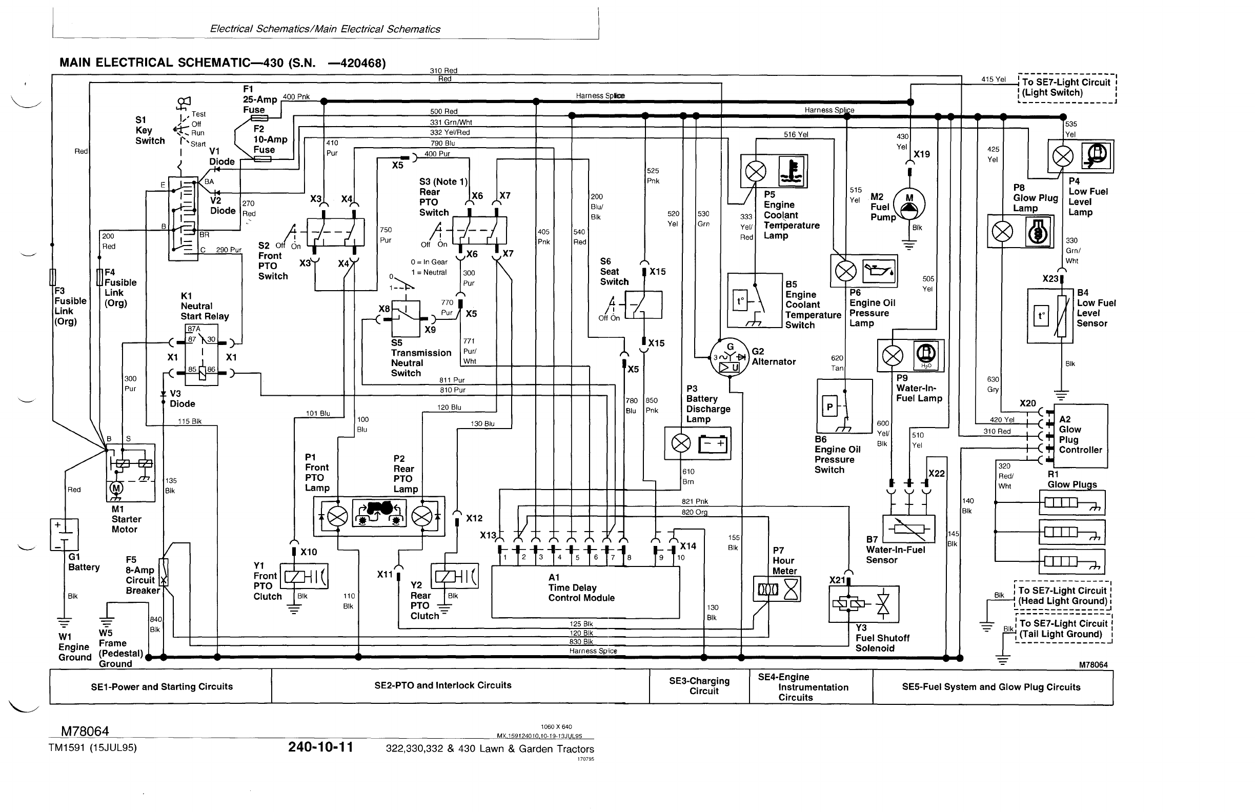
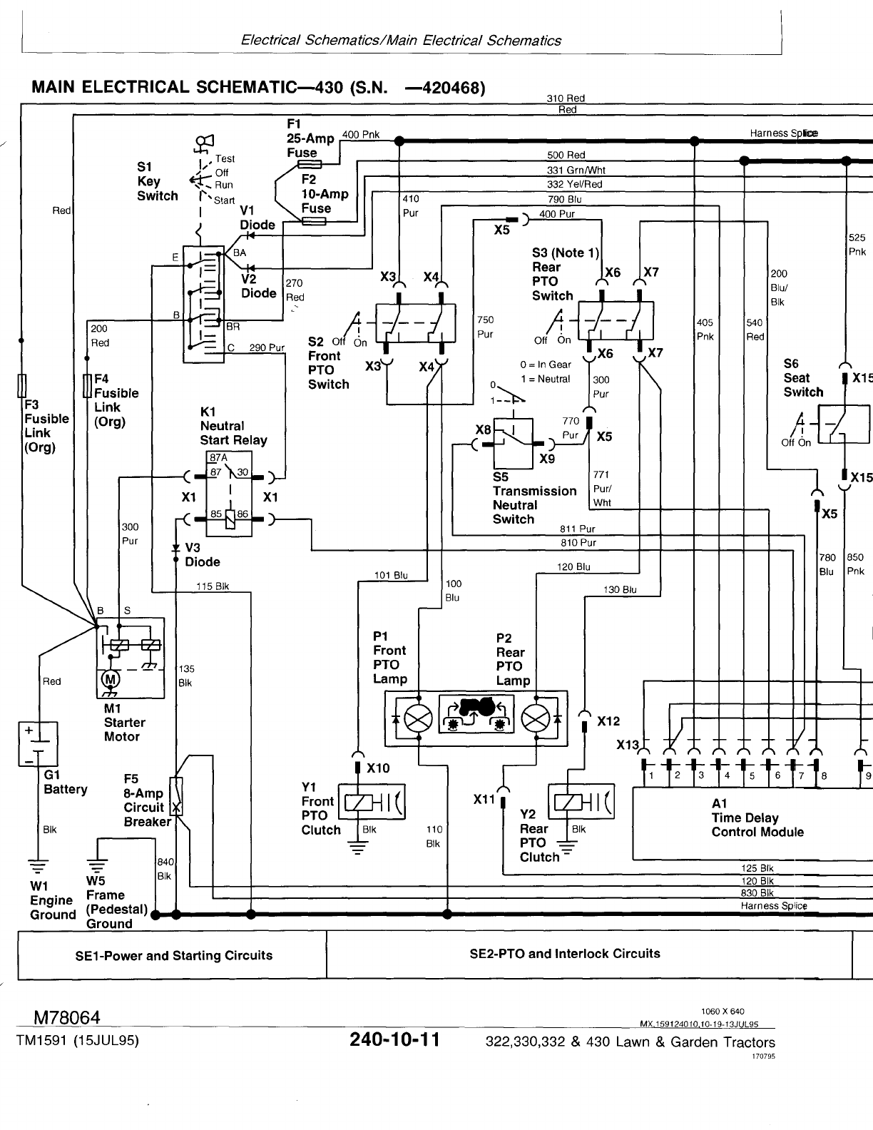
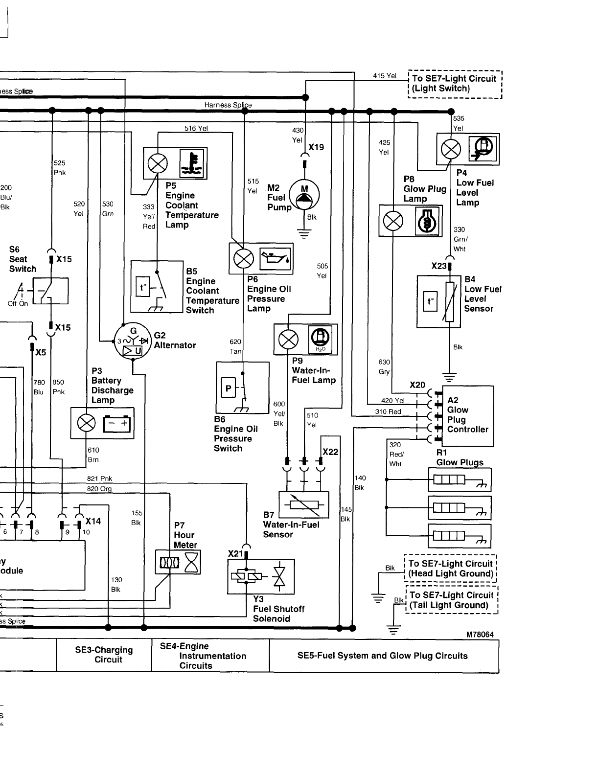
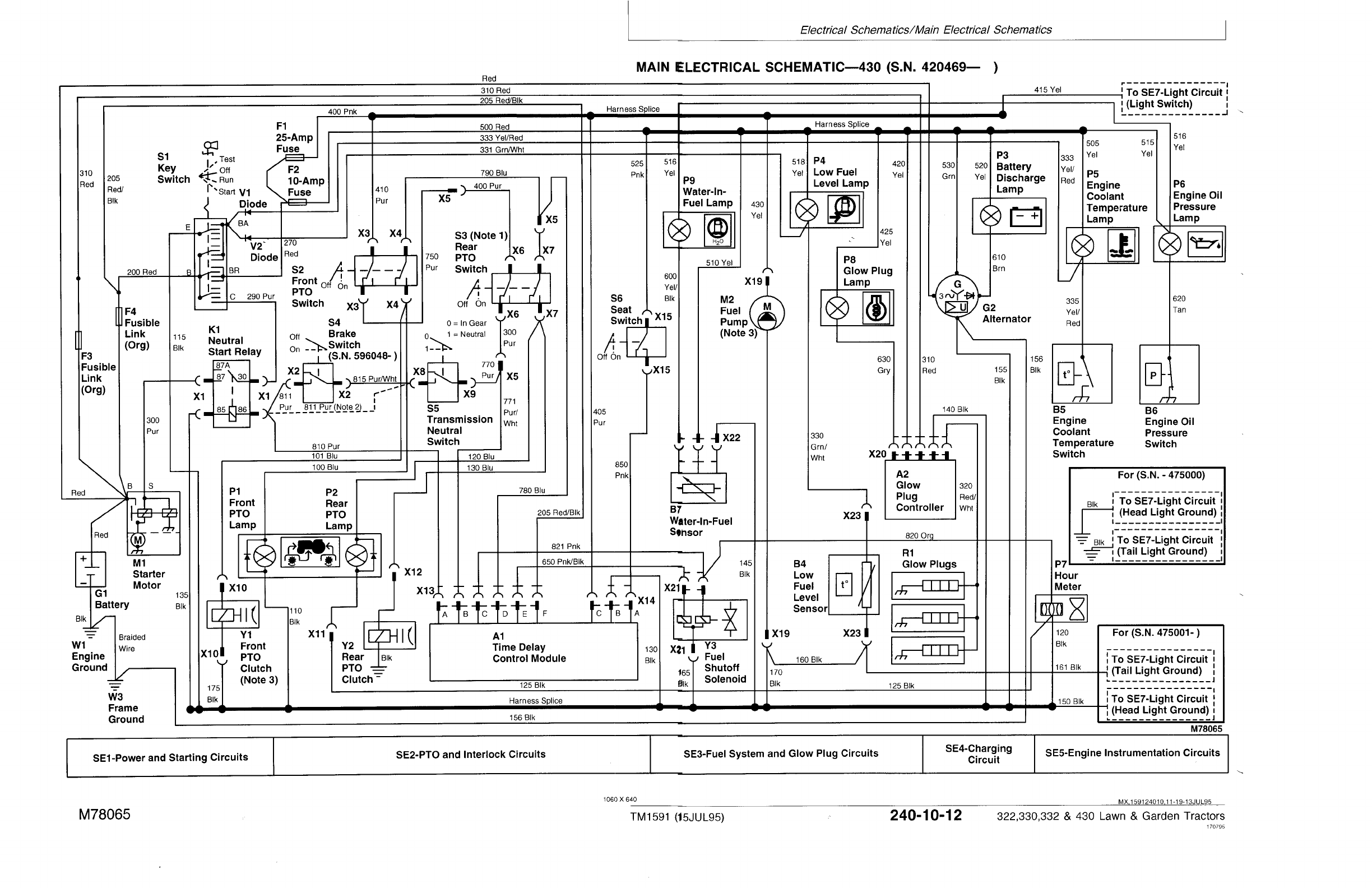
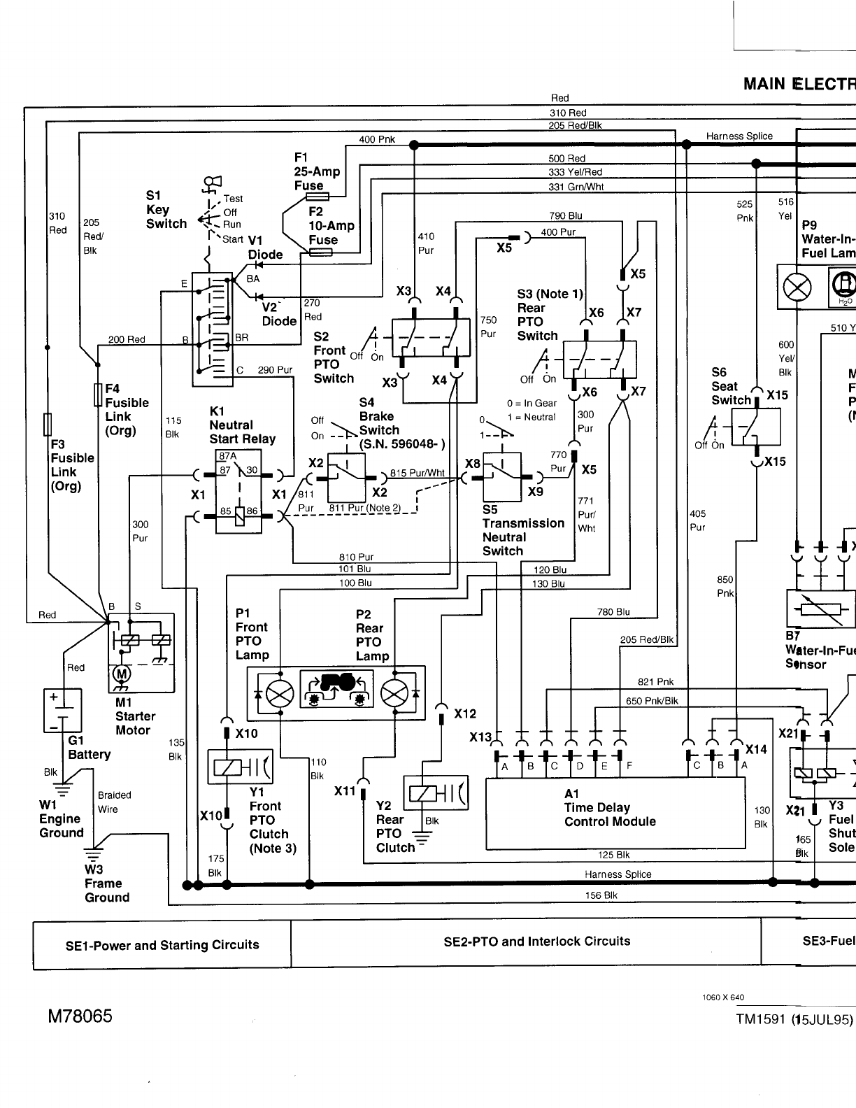
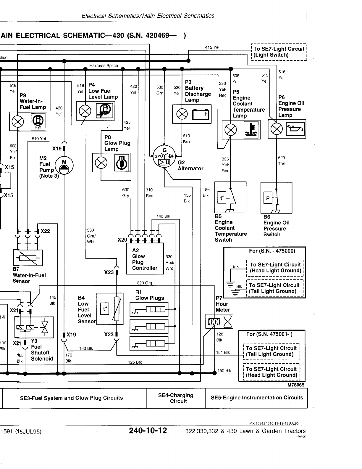

MAIN ELECTRICAL SCHEMATIC LEGEND—430 (S.N. 420469— )
A1—Time Delay Control P6—Engine Oil Pressure X3—Front PTO Switch 2-Pin X13—TDC Module 6-Pin
(TDC) Module Lamp Connector Connector
A2—Glow Plug Controller P7—Hour Meter X4—Front PTO Switch 3-Pin X14—TDC Module 3-Pin
B4—Low Fuel Level Sensor P8—Glow Plug Lamp Connector Connector
B5—Engine Coolant P9—Water-In-Fuel Lamp X5—Rear PTO Harness 3-Pin X15—Seat Switch 2-Pin
Temperature Switch R1—Glow Plugs (3 used) Connector Connector
B6—Engine Oil Pressure S1—Key Switch X6—Rear PTO Switch 2-Pin X19—Fuel Pump:
Switch S2—Front PTO Switch Connector (Optional) (S.N. —475000) 1-Pin
B7—Water-In-Fuel Sensor S3—Rear PTO Switch X7—Rear PTO Switch 3-Pin Connector
F1—25-Amp Fuse (Optional) Connector (Optional) (S.N. 475001— ) 2-Pin
F2—10-Amp Fuse S4—Brake Switch (S.N. X8—Transmission Neutral Connector
F3—Fusible Link 596048— ) Switch 1-Pin Connector X20—Glow Plug Controller
F4—Fusible Link S5—Transmission Neutral X9—Transmission Neutral 5-Pin Connector
G1—Battery Switch Switch 1-Pin Connector X21—Fuel Shutoff Solenoid
G2—Alternator S6—Seat Switch X10—Front PTO Clutch: 3-Pin Connector
K1—Neutral Start Relay V1—Diode (S.N. —475000) 1-Pin X22—Water-In-Fuel 3-Pin
M1—Starter Motor V2—Diode Connector Connector
M2—Fuel Pump W1—Engine Ground (S.N. 475001— ) 2-Pin X23—Low Fuel Level Sensor
P1—Front PTO Lamp W3—Frame Ground Connector 2-Pin Connector
P2—Rear PTO Lamp X1—Neutral Start Relay 4-Pin X11—Rear PTO Lamp 1-Pin Y1—Front PTO Clutch
(Optional) Connector Connector (Ground) Y2—Rear PTO Clutch
P3—Battery Discharge Lamp X2—Brake Switch 2-Pin X12—Rear PTO Clutch 1-Pin (Optional)
P4—Low Fuel Level Lamp Connector (S.N. Connector (Optional) Y3—Fuel Shutoff Solenoid
P5—Engine Coolant 596048— )
Temperature Lamp
NOTE: 1. For machines not equipped with optional
rear PTO, a jumper wire is used at connector
(X5) in place of rear PTO switch (S3). The
jumper wire connects purple wire “750” to
wires “770” (purple) and “771” (purple/white).
The blue wire “780” deadends at connector
(X5).
NOTE: 2. Machines (S.N. —596047); Brake switch
(S4) is not used. Purple wire “811” connects
transmission neutral switch (S5) directly to
neutral start relay (K1).
NOTE: 3. Machines (S.N. —475000); Component
ground wire connects directly to machine
frame.
MX,159124010,12-19-13JUL95
Electrical Schematics/Main Electrical Schematics
TM1591 (15JUL95) 240-10-13 322,330,332 & 430 Lawn & Garden Tractors
030895
240
10
13
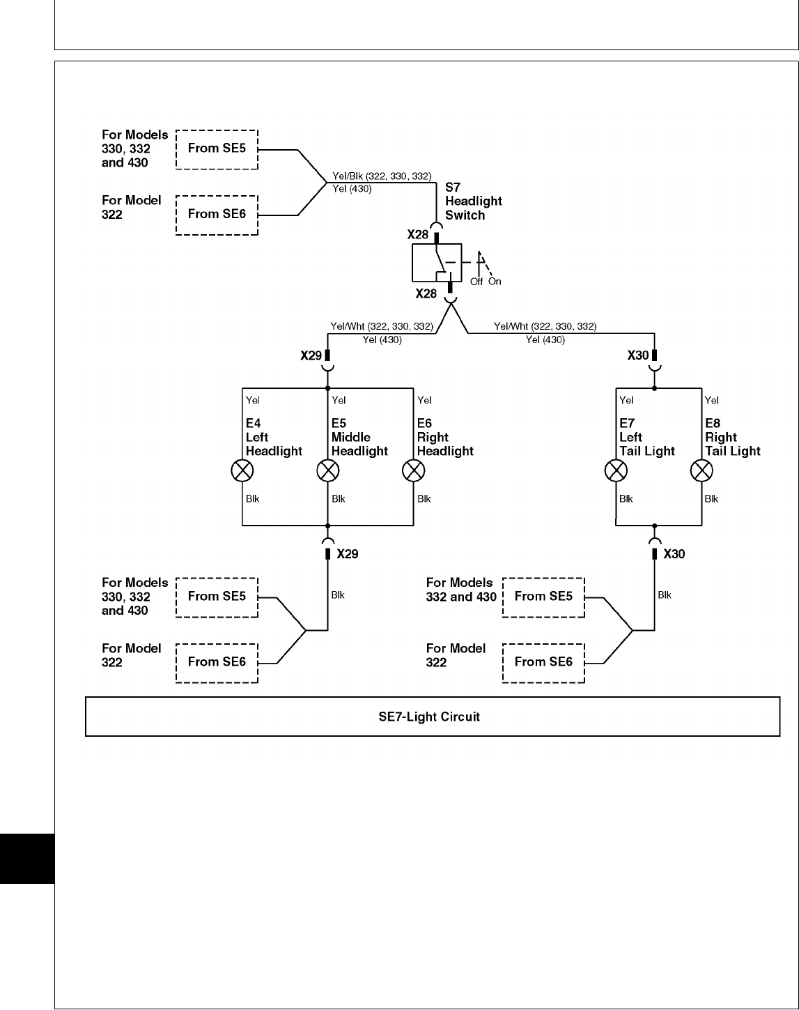
LIGHT CIRCUIT SCHEMATIC—ALL MACHINES
E4—Left Headlight E8—Right Tail Light X29—Headlight 2-Pin X30—Tail Light 2-Pin
E5—Middle Headlight S7—Light Switch Connector Connector
E6—Right Headlight X28—Light Switch 2-Pin (S.N. 475001— ) (S.N. 475001— )
E7—Left Tail Light Connector
NOTE: 330; Headlight connector (X29) is a 1-pin
connector. The headlight ground wires
connect directly to machine frame.
332/430 (S.N. —475000); Head and tail light
connectors (X29 and X30) are 1-pin
connectors. The head and tail light ground
wires connect directly to machine frame.
NOTE: “SE” boxes with dashed lines indicate wire
comes from circuit number (shown in “SE”
box) located on main electrical schematics.
M78066 -19-23JUN95
MX,159124010,13-19-13JUL95
Electrical Schematics/Light Circuit Schematic—All Machines
TM1591 (15JUL95) 240-10-14 322,330,332 & 430 Lawn & Garden Tractors
030895
240
10
14
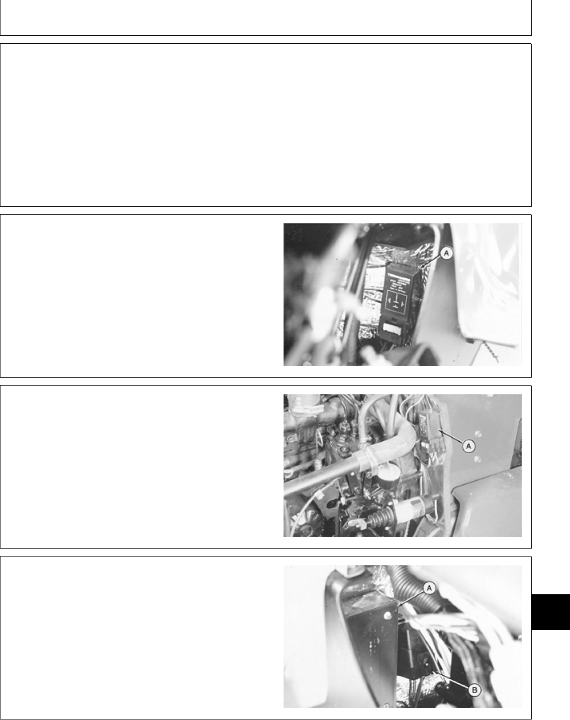
ABOUT THIS GROUP
The information that follows will help you locate and
access many of the electrical components on the
machines. Obvious components such as the starter,
alternator, key switch, etc. will not be shown. See
CTM3 or CTM12 for more specific information on
removal and installation of electrical components.
Theory of operation and diagrams for specific circuits
follow the component location information.
NOTE: The operation of the fuel pump, engine
coolant temperature, and engine oil pressure
circuits are not discussed or shown in detail
because of the simplicity of these circuits.
GLOW PLUG CONTROL MODULE—330 AND
332
The glow plug control module (A) is located on the lower
left side of the engine firewall.
Open hood and remove left engine side panel to access
the control module.
M55119 -UN-09DEC89
GLOW PLUG CONTROL MODULE—430
The glow plug control module (A) is located on the upper
left side of the engine firewall.
Open hood and remove left engine side panel to access
the control module.
M36704 -UN-25JAN90
TIME DELAY CONTROL (TDC) MODULE AND
NEUTRAL START RELAY—322, 330 AND 332
The TDC module (A) and neutral start relay (B) are
located on the lower right side of the engine firewall.
Remove right engine side panel to access the TDC
module relay.
M55120 -UN-09DEC89
MX,159124015,1 -19-13JUL95
MX,159124015,2 -19-13JUL95
MX,159124015,3 -19-13JUL95
MX,159124015,4 -19-13JUL95
Group 15
Component Location and Operation
TM1591 (15JUL95) 240-15-1 322,330,332 & 430 Lawn & Garden Tractors
030895
240
15
1
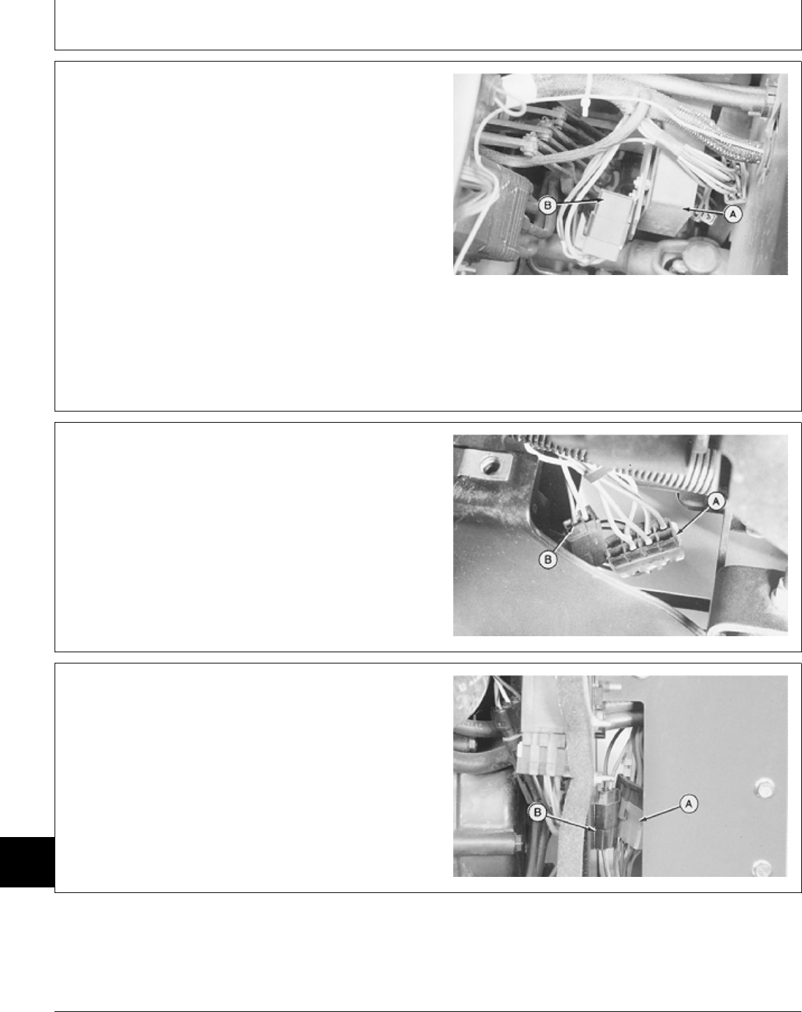
TIME DELAY CONTROL (TDC) MODULE AND
NEUTRAL START RELAY—430
The TDC module (A) is located in the compartment
directly under the battery tray. The module is mounted to
the left side of the pedestal.
The neutral start relay (B) is mounted onto the TDC
module.
Remove battery and battery tray to access TDC module
and relay.
M36705 -UN-25JAN90
TDC EIGHT-PIN AND TWO-PIN
CONNECTORS—322 AND 330
The 8-pin (A) and 2-pin (B) TDC connectors are located
in the engine compartment directly ahead of lower right
side of engine firewall.
Open hood and remove right engine side panel to
access connectors.
M45237 -UN-12JAN90
TDC EIGHT-PIN AND TWO-PIN
CONNECTORS—430 (S.N. —420468)
The 8-pin (A) and 2-pin (B) TDC connectors are located
in the compartment directly under the battery tray.
Connectors can be accessed through the opening in the
pedestal just behind the firewall.
M36706 -UN-25JAN90
MX,159124015,5 -19-13JUL95
MX,159124015,6 -19-13JUL95
MX,159124015,7 -19-13JUL95
Component Location and Operation/Electrical Component Location
TM1591 (15JUL95) 240-15-2 322,330,332 & 430 Lawn & Garden Tractors
030895
240
15
2
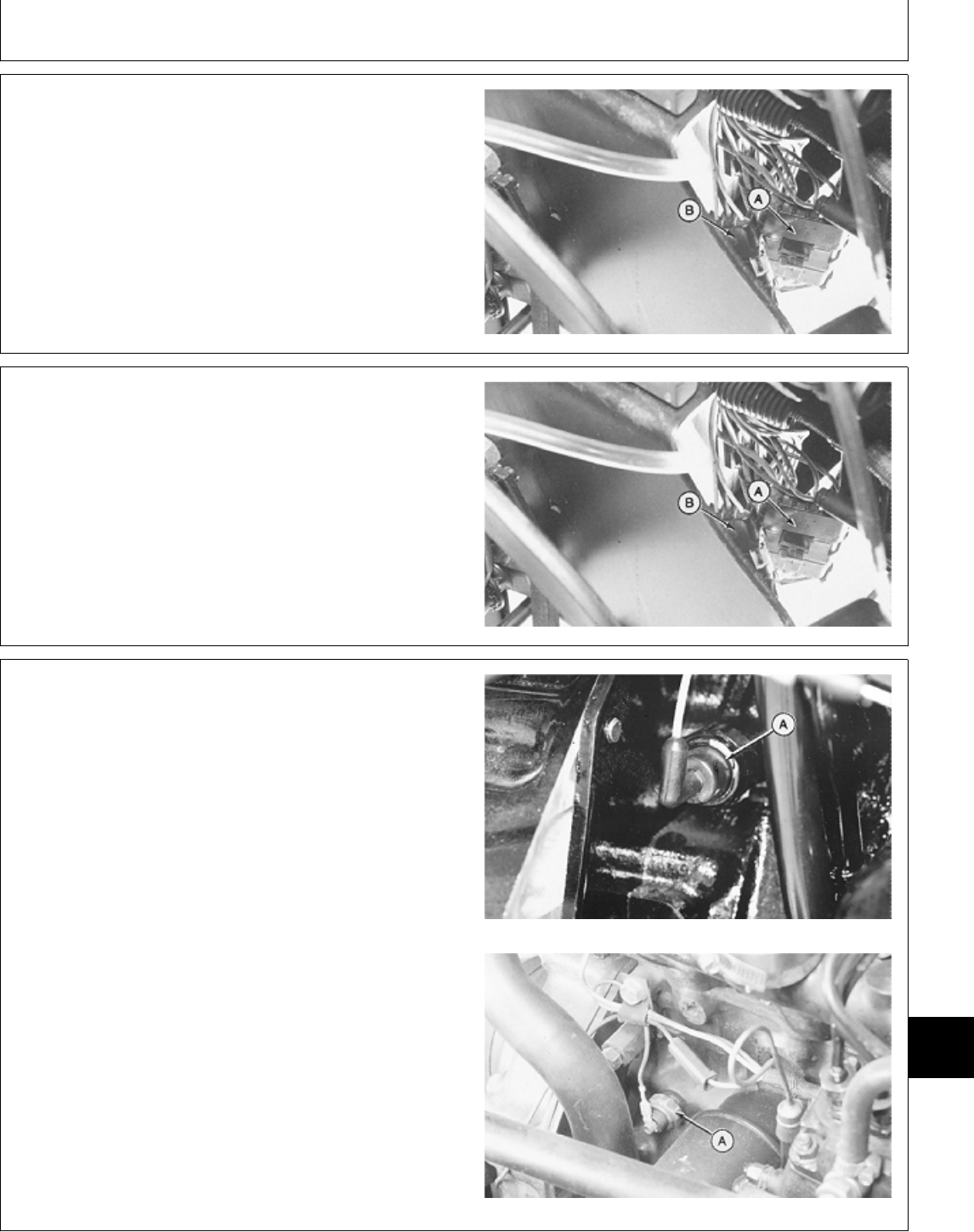
TDC SIX-PIN AND THREE-PIN
CONNECTORS—332
The 6-pin (A) and 3-pin (B) TDC connectors are located
in the engine compartment directly ahead of lower right
side of engine firewall.
Open hood and remove right engine side panel to
access connectors.
M49024 -UN-08JAN90
TDC SIX-PIN AND THREE-PIN
CONNECTORS—430 (S.N. 420469— )
The 6-pin (A) and 3-pin (B) TDC connectors are located
in the compartment directly under the battery tray.
Connectors can be accessed through the opening in the
pedestal just behind the firewall.
M49024 -UN-08JAN90
ENGINE OIL PRESSURE SWITCH
The engine oil pressure switch (A) is located on the left
side of engine toward the front.
Remove left engine side panel to access switch.
322, 330 and 332
430
M55122 -UN-09DEC89M36709 -UN-25JAN90
MX,159124015,8 -19-13JUL95
MX,159124015,9 -19-13JUL95
MX,159124015,10-19-13JUL95
Component Location and Operation/Electrical Component Location
TM1591 (15JUL95) 240-15-3 322,330,332 & 430 Lawn & Garden Tractors
030895
240
15
3
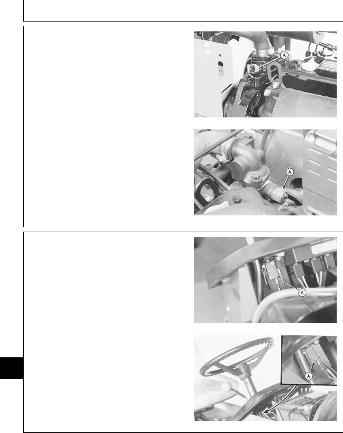
ENGINE COOLANT TEMPERATURE SWITCH
The engine coolant temperature switch (A) is mounted in
the thermostat housing.
Open hood to access the switch.
NOTE: 430 (S.N. 420469— ); Coolant temperature
switch is located on opposite side of thermostat
housing.
322, 330 and 332
430 (S.N. —420468)
M55123 -UN-09DEC89M36710 -UN-25JAN90
TRANSMISSION NEUTRAL START SWITCH
The transmission neutral start switch (A) is located under
the dash panel, next to the hydrostatic control lever.
Open hood to access switch.
322, 330 and 332
430
M55124 -UN-09DEC89M36711 -UN-25JAN90
MX,159124015,11-19-13JUL95
MX,159124015,12-19-13JUL95
Component Location and Operation/Electrical Component Location
TM1591 (15JUL95) 240-15-4 322,330,332 & 430 Lawn & Garden Tractors
030895
240
15
4
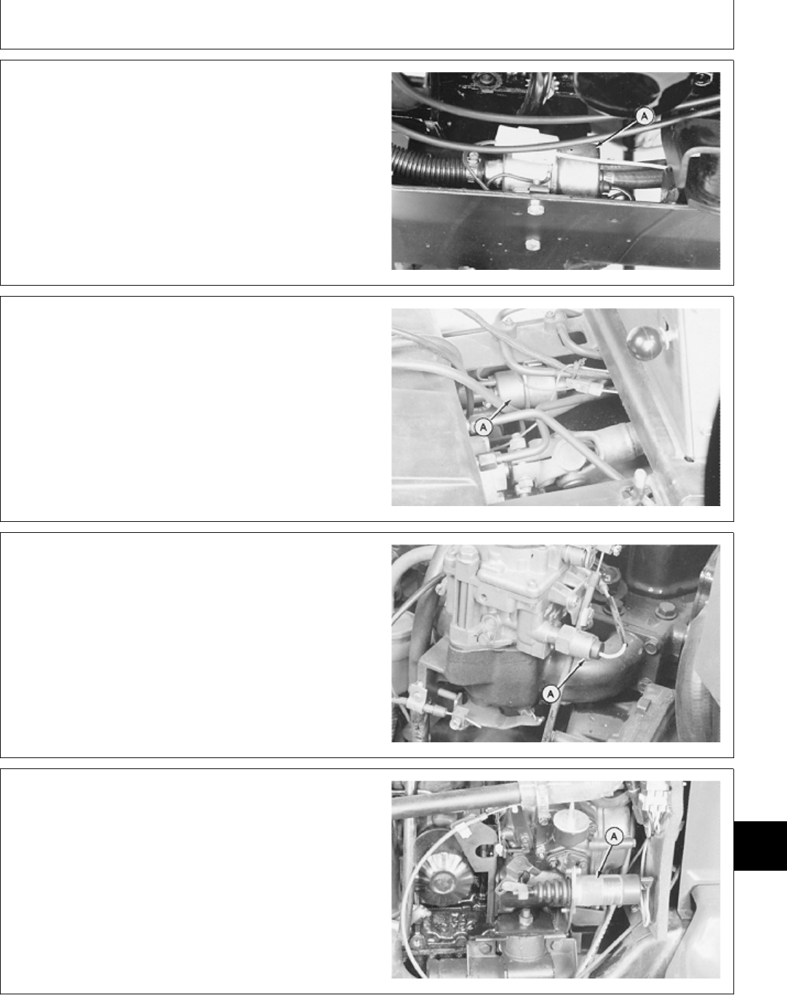
FUEL TRANSFER PUMP—322, 330 AND 332
The electric fuel transfer pump (A) is located inside the
left side frame directly above the front axle.
Open hood and remove left side engine panel to access
the pump.
M55125 -UN-09DEC89
FUEL TRANSFER PUMP—430
The electric fuel transfer pump (A) is located inside the
left side frame behind the left foot rest.
Remove fender deck or bottom guard plate from tractor
frame to access pump.
M36712 -UN-25JAN90
FUEL SHUTOFF SOLENOID—322
The fuel shutoff solenoid (A) is mounted on the rear of
the carburetor.
Open hood and remove left engine side panel to access
the solenoid.
M45242 -UN-12JAN90
FUEL SHUTOFF SOLENOID—332 AND 430
The fuel shutoff solenoid (A) is located on the left side of
the engine.
Open hood and remove left engine side panel to access
the solenoid.
430 (S.N. —420468) Shown
M36707 -UN-25JAN90
MX,159124015,13-19-13JUL95
MX,159124015,14-19-13JUL95
MX,159124015,15-19-13JUL95
MX,159124015,16-19-13JUL95
Component Location and Operation/Electrical Component Location
TM1591 (15JUL95) 240-15-5 322,330,332 & 430 Lawn & Garden Tractors
030895
240
15
5
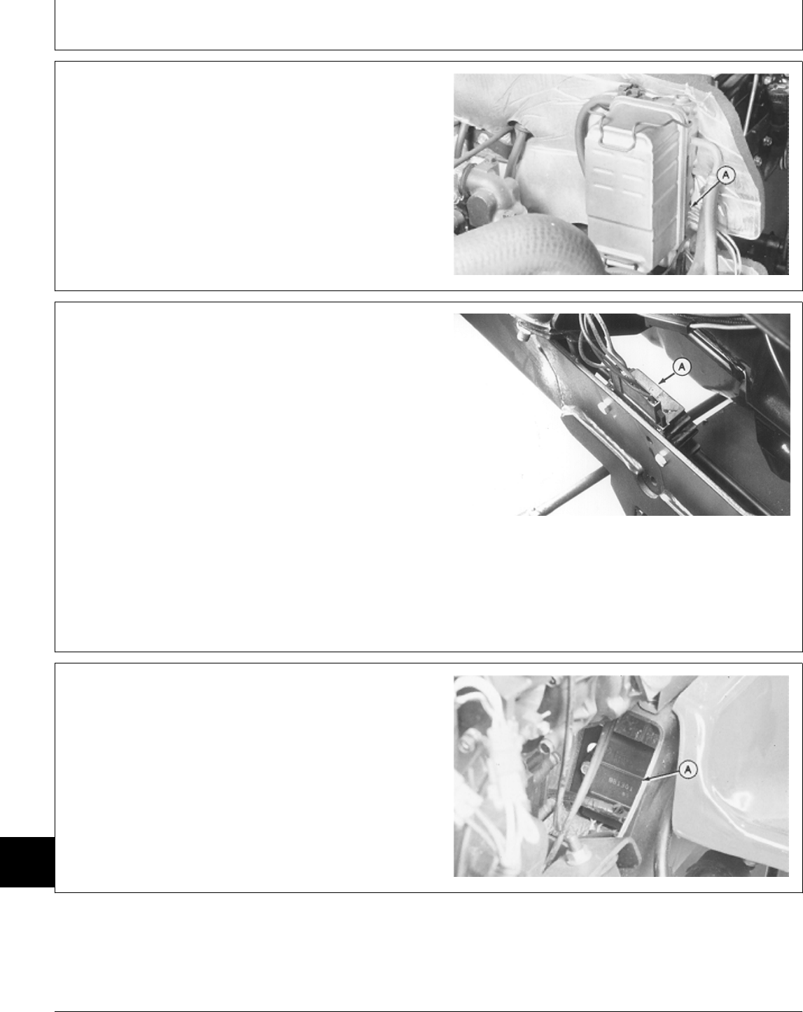
WATER-IN-FUEL SENSOR (430)
The water-in-fuel sensor is located inside the fuel filter
base (A).
Remove filter and filter base as an assembly to access
the sensor.
M36708 -UN-25JAN90
VOLTAGE REGULATOR/RECTIFIER (322, 330
AND 332)
322; Voltage regulator/rectifier is located at right side of
engine compartment and is attached inside the machine
frame near pedestal.
330 and 332; Voltage regulator/rectifier (A) is located at
right side of engine compartment and is attached inside
the machine frame.
332 Shown
M49023 -UN-13JUL95
TRANSISTOR MODULE (322)
The transistor module (A) is located on the lower left
side of the engine firewall.
Open hood and remove left engine side panel to access
the module.
M45238 -UN-12JAN90
MX,159124015,17-19-13JUL95
MX,159124015,18-19-13JUL95
MX,159124015,19-19-13JUL95
Component Location and Operation/Electrical Component Location
TM1591 (15JUL95) 240-15-6 322,330,332 & 430 Lawn & Garden Tractors
030895
240
15
6
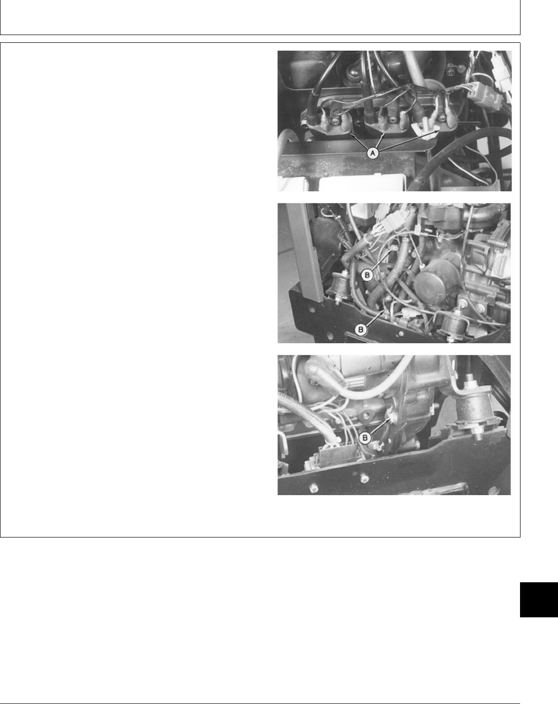
IGNITION AND PULSAR COILS (322)
The ignition coils (A) are located above the flywheel. The
pulsar coils (B) are mounted to the flywheel housing
plate.
Open hood and remove both engine side panels to
access coils.
M45239 -UN-09JUN95M45240 -UN-12JAN90M45241 -UN-12JAN90
MX,159124015,20-19-13JUL95
Component Location and Operation/Electrical Component Location
TM1591 (15JUL95) 240-15-7 322,330,332 & 430 Lawn & Garden Tractors
030895
240
15
7

STARTING CIRCUIT OPERATION
The function of the starting circuit is to crank the
engine by energizing starter motor (M1). PTO
switches (S2 and S3), transmission neutral switch
(S5), and brake switch (S4) are used as interlock
switches within the starter circuit.
For the starter motor to energize, the following
conditions must be met:
• Front and rear PTO switches in “OFF” position.
• Hydrostatic Control Lever in N/STOP position.
• Brake pedal depressed.
322 (S.N. 596006— )
332 (S.N. 596723— )
430 (S.N. 596048— )
• Key Switch in “START” position.
PTO switches (S2 and S3) are used in the starting
circuit to prevent the engine from cranking while the
PTO is engaged. Each PTO switch contains two sets
of contacts; one for the PTO circuit and the other as
a safety interlock for the starting circuit. When the
PTO switch is in the ON position (PTO engaged), the
PTO switch “interlock” contacts are open, preventing
starter operation. When the PTO switch is in the OFF
position (PTO disengaged), the “interlock” contacts
are closed, allowing current to flow to transmission
neutral switch (S5).
The transmission neutral switch is used in the starting
circuit to prevent the engine from cranking when the
transmission is in gear. When the hydrostatic control
lever is in the forward or reverse position, the
transmission neutral switch contacts are open,
preventing starter operation. Moving the hydrostatic
control lever to the N/STOP position closes the
contacts, allowing current to flow to brake switch
(S4).
NOTE: Brake switch equipped on 322 (S.N.
596006— ), 332 (S.N. 596723— ) and
430 (S.N. 596048— ) only. For all other
machines, current flows from the transmission
switch, directly to neutral start relay (K1).
The brake switch will prevent the engine from
cranking unless the brake pedal is depressed.
Depressing the brake pedal closes the brake switch
contacts, allowing current to flow to neutral start relay
(K1).
Key switch (S1) initiates current flow through the
starting circuit. When the key switch is turned to the
START position, the ignition contacts (A) and start
contacts (B) close. If all the interlock switch contacts
in the start circuit are closed, current from the battery
positive (+) terminal flows through fusible link (F4) to
terminal “B” on the key switch. Current flows across
contacts (A) and out terminal “IGN” (322, 330 and
332) or terminal “BR” (430) to the 25 amp fuse (F1).
From fuse (F1), current flows through the PTO,
transmission, and brake (if equipped) switches to
terminal “86” of the neutral start relay. The current
flows through the relay coil windings and out terminal
“85” to ground, thus energizing the relay and closing
the normally open relay contacts (D).
The closed relay contacts complete the starter circuit
which allows current to flow from key switch start
contacts (B) to terminal “30” on the neutral start relay.
Current flows across the relay contacts and out
terminal “87”. From terminal “87”, current flows to
starter solenoid (K2), through the solenoid coil
windings, then to ground.
Starter solenoid (K2) contains two coils; one called
the pull-in and the other called the hold-in. Current
flowing through these coils produces a strong
magnetic field, which pulls a plunger inward and
closes solenoid main contacts (C). Because the
starter is a shift type (solenoid is mounted on starter),
the plunger also moves the starter drive gear outward
to mesh with the flywheel ring gear.
When the solenoid contacts close, high current from
the battery flows across the solenoid contacts to
starter motor (M1), causing it to turn. Because the
pull-in coil is grounded through the starter, current will
flow through the pull-in coil only as long as the
solenoid main contacts are open.
When the solenoid contacts close, both ends of the
pull-in coil have the same voltage. This causes the
current to stop flowing through the pull-in coil. Current
continues to flow through the hold-in coil, which is
grounded directly to the chassis. This keeps the
solenoid energized (main contacts closed; starter
drive engaged) until the key switch is released to the
ON/RUN position or turned to the OFF position.
MX,159124015,21-19-13JUL95
Component Location and Operation/Theory of Operation
TM1591 (15JUL95) 240-15-8 322,330,332 & 430 Lawn & Garden Tractors
030895
240
15
8
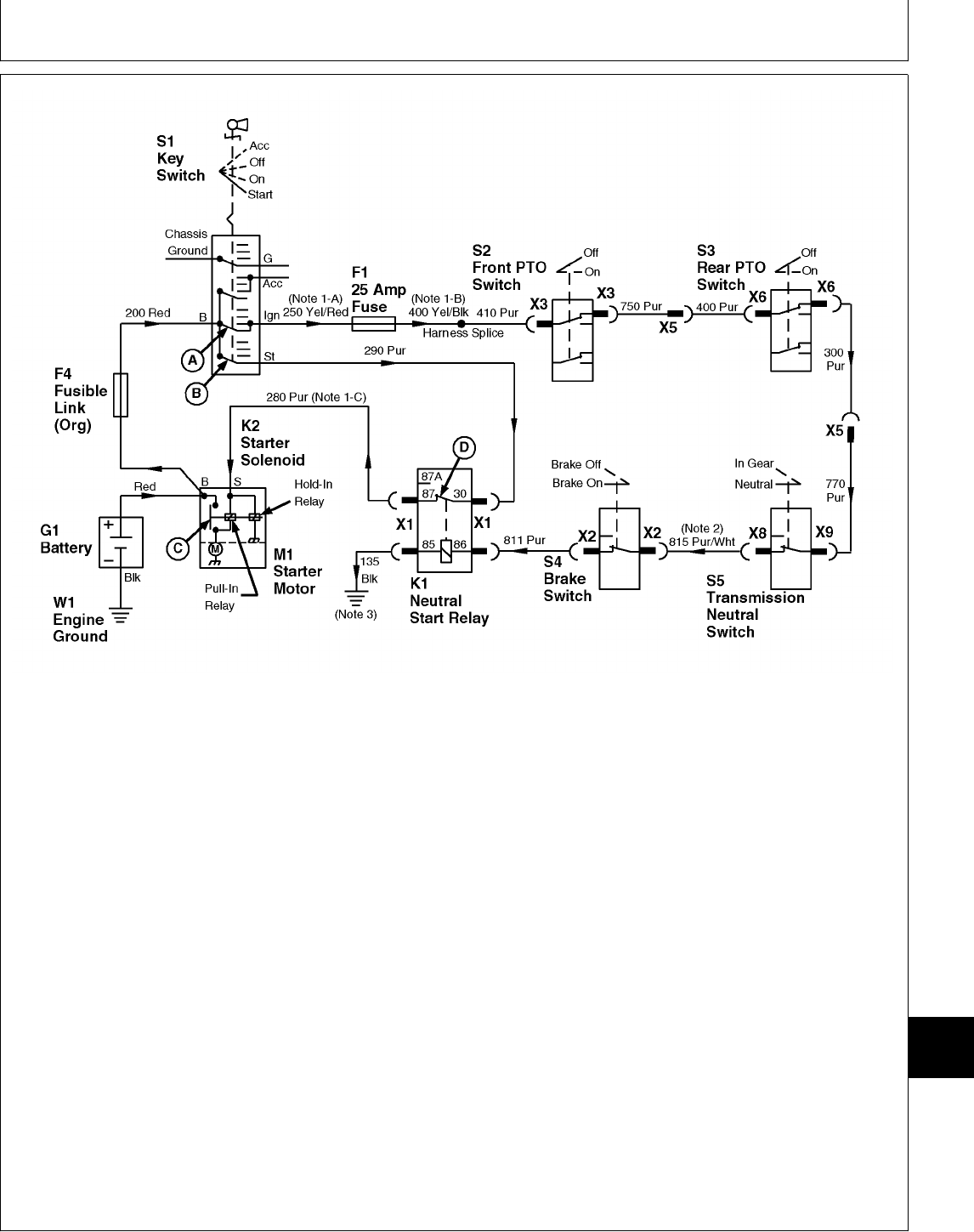
A—Key Switch ON or RUN G1—Battery S5—Transmission Neutral X5—Rear PTO Harness 3-Pin
Contact K1—Neutral Start Relay Switch Connector
B—Key Switch START K2—Starter Solenoid W1—Engine Ground X6—Rear PTO Switch 2-Pin
Contact M1—Starter Motor X1—Neutral Start Relay 4-Pin Connector
C—Starter Solenoid Main S1—Key Switch Connector X8—Transmission Neutral
Contact S2—Front PTO Switch X2—Brake Switch 2-Pin Switch 1-Pin Connector
D—Neutral Start Relay S3—Rear PTO Switch Connector X9—Transmission Neutral
Contact (Optional) X3—Front PTO Switch 2-Pin Switch 1-Pin Connector
F1—25 Amp Fuse S4—Brake Switch: Connector
F4—Fusible Link 322 (S.N. 596006— )
332 (S.N. 596723— )
430 (S.N. 596048— )
NOTE: Illustration shows key switch configuration for
322, 330 and 332. For 430, terminal
designation “BR” is used instead of “IGN”.
NOTE: 1. 430; The following wire numbers/color apply
where noted on drawing:
-A) 270 Red
-B) 400 Pink
-C) 290 Purple
-D) 210 Red
NOTE: 2. 322 (S.N. —496005) and 332 (S.N.
—596722); Purple wire “811” connects the
transmission neutral switch to the neutral start
relay.
330 and 430 (S.N. —420468); Purple wire
“811” connects the transmission neutral switch
to the TDC module 8-pin connector. Another
purple wire (wire “810”) connects the neutral
start relay to the same 8-pin connector
terminal used by the “811” wire.
NOTE: 3. Because ground circuits differ between
models and versions, refer to the Main
Electrical Schematics in Group 10 for more
detail on ground circuit.
M78067 -19-14JUN95
MX,159124015,22-19-13JUL95
Component Location and Operation/Theory of Operation
TM1591 (15JUL95) 240-15-9 322,330,332 & 430 Lawn & Garden Tractors
030895
240
15
9

IGNITION AND FUEL SHUTOFF SOLENOID CIRCUIT OPERATION (322)
NOTE: Power is supplied to the fuel shutoff solenoid,
whenever the ignition circuit is energized.
When energized, the solenoid opens a valve
in the fuel line to allow fuel to flow into the
carburetor. When de-energized, the solenoid
closes the valve and stops fuel flow.
Because the ignition and fuel shutoff solenoid
circuits share the same control circuitry from
the TDC module, only the ignition circuit will
be discussed in detail. Control of power to the
fuel shutoff solenoid is the same as for the
ignition circuit.
The function of the ignition circuit is to produce spark
across the gap of spark plugs (E1—E3) at the correct
time. The circuit is a “distributorless”, battery ignition
type. The circuit uses pulsars (B1—B3) to make and
break (trigger) the primary circuit and provide the
proper timing to fire the spark plugs. The timing is
fixed and cannot be adjusted.
The ignition circuit is made up of three separate
circuits, one for each cylinder. Each spark plug has
its own separate pulsar, transistor switch [located
inside transistor module (A2)] and ignition coil. This
system eliminates the need for a distributor.
The ignition circuit uses seat switch (S6) and time
delay control module (A1) to automatically stop the
engine anytime the operator rises from the seat for
more than one second when the tractor is IN GEAR
or if PTO is ENGAGED.
OPERATOR ON SEAT—MACHINE IN GEAR
AND/OR PTO ENGAGED:
When the key switch (S1) is turned to the RUN or
START position, current flows from the positive (+)
terminal of battery (G1), through fusible link (F4), to
key switch terminal “B”. From terminal “B”, current
flows across the key switch contacts to terminal
“IGN”, then to 25-amp fuse (F1) and 10-amp fuse
(F2). From fuse (F2), current flows across the closed
contacts of the seat switch to pin “9” of TDC module
connector (X14). Inside the TDC module, current
flows through time delay integrated circuit (IC) (E),
then to switch transistor (D).
As long as current from IC (E) flows to transistor (D),
the transistor is “switched on”. In this state, the
transistor completes the path to ground for TDC
ignition relay coil (B). The ground path allows current
to flow from fuse (F1) to pin “3” of the TDC module
8-pin connector (X13). Inside the TDC module,
current flows through the ignition relay coil and
transistor (D) to ground. This energizes the relay coil
which closes ignition relay contacts (A). Current from
fuse (F1) then flows across the relay contacts and
out pin “2” of connector (X13). From pin “2”, current
flows to transistor module (A2), and to the positive (+)
terminal of ignition coils (T1—T3). The transistor
module provides a path to ground for the primary
circuit of each coil. This allows current to flow though
the primary windings to induce a magnetic field in the
ignition coil windings.
Pulsars (B1—B3) are mounted at fixed locations
around the flywheel. These positions provide the
correct ignition timing for each cylinder.
When the flywheel is turning, a notch in the flywheel
travels past the pulsars and induces a voltage (pulse)
in each pulsar. The voltage flows from the pulsars to
transistors located inside the transistor module. The
transistors provide a path to ground for the ignition
coil primary windings.
The pulse from each pulsar causes its respective
transistor, in the transistor module, to momentarily
“switch off”. This “switching off” breaks the respective
ignition coils primary windings path to ground, thus
interrupting current flowing through the primary
windings. When the primary current stops flowing, the
magnetic field in the primary windings collapses
across the ignition coil secondary windings. The
collapsing field induces a high voltage into the
secondary winding, which travels to ground by
jumping the spark plug gap.
Continued
MX,159124015,23-19-13JUL95
Component Location and Operation/Theory of Operation
TM1591 (15JUL95) 240-15-10 322,330,332 & 430 Lawn & Garden Tractors
030895
240
15
10

A—TDC Ignition Relay E3—Spark Plug X14—TDC Module 2-Pin X25—Transistor Module 4-Pin
Contacts F1—25 Amp Fuse Connector Connector
B—TDC Ignition Relay Coil F2—10 Amp Fuse X15—Seat Switch 2-Pin X26—Transistor Module 6-Pin
C—Transistor F4—Fusible Link Connector Connector
D—Time Delay Transistor G1—Battery X18—Main Harness-to- X27—Engine Harness-to-
E—Time Delay Integrated M1—Starter Motor Engine Harness 2-Pin Ignition Coils 6-Pin
Circuit (IC) R2—Electric Choke Connector Connector
A1—Time Delay Control (S.N. 010714— ) X20—No.1 Pulser Coil 2-Pin X28—Electric Choke 2-Pin
(TDC) Module S1—Key Switch Connector Connector (S.N.
A2—Transistor Module S6—Seat Switch X21—No.2 Pulser Coil 2-Pin 010714— )
B1—No.1 Pulsar Coil T1—No.1 Ignition Coil Connector Y3—Fuel Shutoff Solenoid
B2—No.2 Pulsar Coil T2—No.2 Ignition Coil X22—No.3 Pulser Coil 2-Pin
B3—No.3 Pulsar Coil T3—No.3 Ignition Coil Connector
E1—Spark Plug W1—Engine Ground X24—Engine Harness-to-
E2—Spark Plug X13—TDC Module 8-Pin Pulsar Coils 4-Pin
Connector Connector
M78068 -19-14JUN95
MX,159124015,24-19-13JUL95
Component Location and Operation/Theory of Operation
TM1591 (15JUL95) 240-15-11 322,330,332 & 430 Lawn & Garden Tractors
030895
240
15
11

IGNITION AND FUEL SHUTOFF SOLENOID CIRCUIT OPERATION (322)—CONTINUED
When the operator rises from the seat, the seat
switch contacts open, causing current to stop flowing
to time delay IC (E). If the operator does not return to
the seat within approximately one second, the time
delay IC stops current flow to transistor (D). The
transistor will “switch off”, causing current through
relay coil (B) to stop flowing and de-energize the coil.
With the coil no longer energized, relay contacts (A)
will open. Current stops flowing to transistor module
(A2), ignition coils (T1—T3) and fuel shutoff solenoid
(Y3), thus stopping the engine.
NOTE: (S.N. 010714— ); An electric choke (R2) is
used. The choke recieves power from the
same source as the fuel shutoff does.
Driving the machine over rough terrain can
cause the seat switch contacts to momentarily
open and close. If this happens, the time
delay IC allows the engine to operate without
interruption.
If the operator returns to the seat within
approximately one second, current flow is
re-established to the time delay IC before it has a
chance to “time out” and stop current flow to the
transistor. Current flow is NOT interrupted to the
transistor module, ignition coils, and fuel shutoff
solenoid, allowing the engine to continue operating.
OPERATOR OFF SEAT—MACHINE IN NEUTRAL
AND PTO DISENGAGED:
NOTE: (S.N. 596006— ); The park brake must be
engaged.
When operator is off the seat, current to the ignition
components can still be maintained through the
interlock circuit. For current to flow through the
interlock circuit, key switch (S1) must be turned to the
RUN or START position, the hydrostatic control lever
in the N/STOP position, the PTO switches in the OFF
position (PTO disengaged) and park brake engaged
(S.N. 596006— ).
With these conditions met, current flows from terminal
(IGN) of the key switch to 25-amp fuse (F1). From
fuse (F1), current flows through the PTO switch
interlock contacts, transmission neutral switch, brake
switch (if equipped) and neutral start relay to pin “7”
of the TDC module connector (X13). Inside the TDC
module, current flows from pin “7” to transistor (C).
As long as current from the interlock circuit flows to
transistor (C), the transistor is “switched on”. In this
state, the transistor provides an alternate path to
ground for relay coil (B). The energized relay closes
the ignition relay contacts, allowing current to flow to
the transistor module, ignition coils and fuel shutoff
solenoid.
The 25 amp fuse (F1) and 10 amp fuse (F2) protect
the ignition circuit from excessive current.
MX,159124015,25-19-13JUL95
Component Location and Operation/Theory of Operation
TM1591 (15JUL95) 240-15-12 322,330,332 & 430 Lawn & Garden Tractors
030895
240
15
12
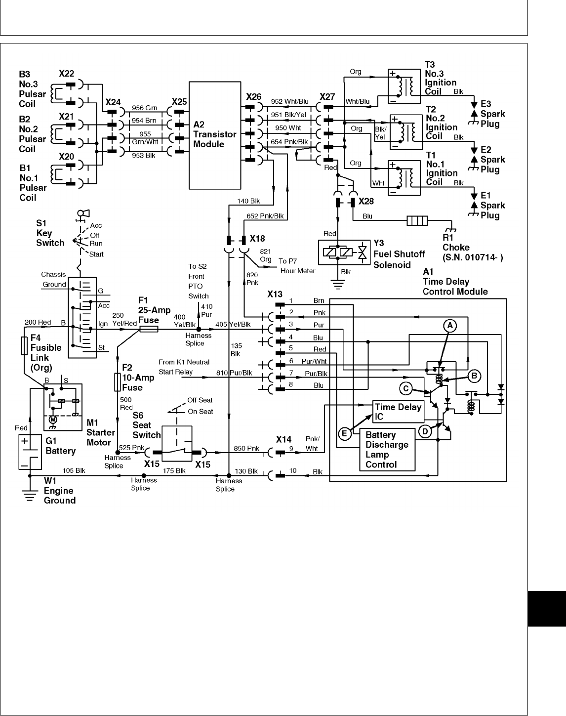
A—TDC Ignition Relay E3—Spark Plug X14—TDC Module 2-Pin X25—Transistor Module 4-Pin
Contacts F1—25 Amp Fuse Connector Connector
B—TDC Ignition Relay Coil F2—10 Amp Fuse X15—Seat Switch 2-Pin X26—Transistor Module 6-Pin
C—Transistor F4—Fusible Link Connector Connector
D—Time Delay Transistor G1—Battery X18—Main Harness-to- X27—Engine Harness-to-
E—Time Delay Integrated M1—Starter Motor Engine Harness 2-Pin Ignition Coils 6-Pin
Circuit (IC) R2—Electric Choke Connector Connector
A1—Time Delay Control (S.N. 010714— ) X20—No.1 Pulser Coil 2-Pin X28—Electric Choke 2-Pin
(TDC) Module S1—Key Switch Connector Connector (S.N.
A2—Transistor Module S6—Seat Switch X21—No.2 Pulser Coil 2-Pin 010714— )
B1—No.1 Pulsar Coil T1—No.1 Ignition Coil Connector Y3—Fuel Shutoff Solenoid
B2—No.2 Pulsar Coil T2—No.2 Ignition Coil X22—No.3 Pulser Coil 2-Pin
B3—No.3 Pulsar Coil T3—No.3 Ignition Coil Connector
E1—Spark Plug W1—Engine Ground X24—Engine Harness-to-
E2—Spark Plug X13—TDC Module 8-Pin Pulsar Coils 4-Pin
Connector Connector
M78068 -19-14JUN95
MX,159124015,24-19-13JUL95
Component Location and Operation/Theory of Operation
TM1591 (15JUL95) 240-15-13 322,330,332 & 430 Lawn & Garden Tractors
030895
240
15
13

PTO CIRCUIT OPERATION—322, 330 AND 430 (S.N. —420468)
A—Time Delay Integrated F4—Fusible Link X4—Front PTO Switch 3-Pin X12—Rear PTO Clutch 1-Pin
Circuit (IC) G1—Battery Connector Connector
B—Time Delay Switch M1—Starter Motor X5—Rear PTO Harness 3-Pin X13—TDC Module 8-Pin
Transistor P1—Front PTO Lamp Connector Connector
C—Isolation Diode P2—Rear PTO Lamp X6—Rear PTO Switch 2-Pin X14—TDC Module 2-Pin
D—TDC PTO Relay Contacts (Optional) Connector Connector
E—Isolation Diode S1—Key Switch X7—Rear PTO Switch 3-Pin X15—Seat Switch 2-Pin
F—Isolation Diode S2—Front PTO Switch Connector Connector
G—TDC PTO Relay Coil S3—Rear PTO Switch X10—Front PTO Clutch 2-Pin Y1—Front PTO Clutch
A1—Time Delay Control (Optional) Connector Y2—Rear PTO Clutch
(TDC) Module S6—Seat Switch X11—Rear PTO Lamp 1-Pin (Optional)
F1—25-Amp Fuse W1—Engine Ground Connector (Ground)
F2—10-Amp Fuse X3—Front PTO Switch 2-Pin
Connector
Legend For PTO Circuit
The function of the PTO circuit is to energize the
front PTO clutch and/or optional rear PTO clutch and
turn on the PTO indicator lamp(s). Also, the PTO
circuit uses a time delay controller and a seat switch
to automatically disengage the PTO clutch(es)
anytime the operator rises off the seat for more than
one second.
To engage the PTO clutch(es), the following
conditions must be met:
• Operator on seat.
• PTO switch(es) initially at OFF position.
• Key switch turned to ON position (330)
or RUN position (322 and 430).
• PTO switch moved to ON position.
The normally open contacts of seat switch (S6) close
when the operator sits on the seat. When the key
switch (S1) is turned to the ON position (330) or RUN
position (322 and 430), current flows from the positive
terminal of battery (G1), through fusible link (F4),
across key switch contacts, to 25-amp fuse (F1) and
10-amp fuse (F2). From fuse (F2), current flows
across the closed contacts of seat switch (S6) to pin
“9” of TDC module 2-pin connector (X14).
Inside the TDC module, current flows through time
delay integrated circuit (IC) (A), to transistor (B). As
long as current from IC (A) flows to transistor (B), the
transistor is “switched on”. In this state, the transistor
completes the path to ground for PTO relay coil (G).
NOTE: If machine is not equipped with optional rear
PTO, a jumper wire at connector (X5) is used
in place of the rear PTO switch.
Front PTO switch (S2) and optional rear PTO
switches (S3) have two sets of contacts each.
One set is used to actuate the clutch(es) and
the other set is used in the interlock circuit
(See Starting Circuit Operation in this group).
The interlock current enables the PTO circuit
by causing PTO relay contacts (D) to close.
When the ground path is completed by transistor (B)
and PTO switch(es) are in the OFF position, current
will flow from fuse (F1) to connector (X3) on the front
PTO switch. Current flows across the PTO switch
interlock contacts, then to 3-pin connector (X5). If
equipped with optional rear PTO, current will flow
from connector (X5) to connector (X6) on the rear
PTO switch. Current flows across the rear PTO
switch interlock contacts and back out to connector
(X5). From connector (X5), the interlock current flows
to the TDC module across pin “6” of 8-pin connector
(X13).
Inside the TDC module, the interlock current flows
through diodes (E and F), to PTO relay coil (G), then
through transistor (B) to ground. The interlock current
causes PTO relay contacts (D) to close.
When PTO relay contacts (D) close, current from
25-amp fuse (F1), flows across pin “3” of 8-pin
connector (X13) and PTO relay contacts (D). From
the PTO relay contacts, current flows through PTO
relay coil (G) then through transistor (B) to ground.
Continued
MX,159124015,26-19-13JUL95
Component Location and Operation/Theory of Operation
TM1591 (15JUL95) 240-15-14 322,330,332 & 430 Lawn & Garden Tractors
030895
240
15
14
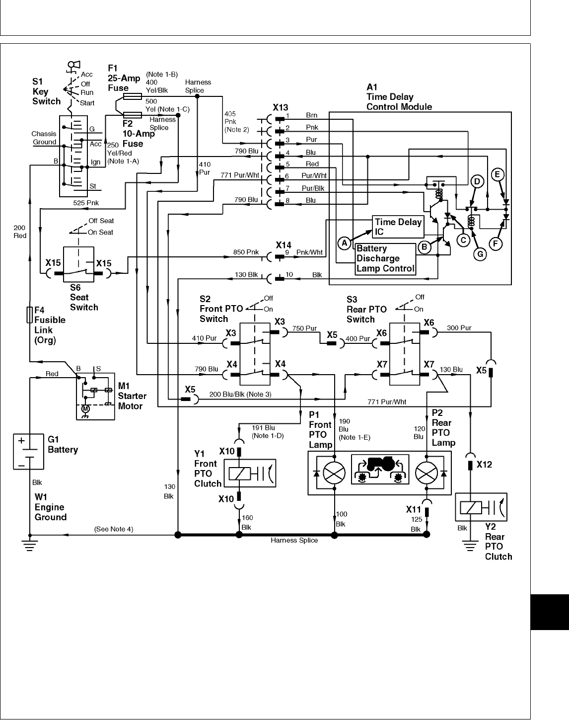
NOTE: 1. 430; The following wire numbers/color apply
where noted on drawing:
-A) 270 Red
-B) 400 Pink
-C) 500 Red
-D) 101 Blue
-E) 100 Blue
NOTE: 2. 322; The color of “405” wire is yellow/black.
NOTE: 3. 322; Pin “8” of connector (X13) is not used.
Blue wire “780” connects to blue wire “790” at
connector (X4) and to connector (X7) at the
rear PTO switch.
NOTE: 4. Because ground circuits differ between
models and versions, refer to the Main
Electrical Schematics in Group 10 for more
detail on ground circuit.
M78072 -19-14JUN95
MX,159124015,27-19-13JUL95
Component Location and Operation/Theory of Operation
TM1591 (15JUL95) 240-15-15 322,330,332 & 430 Lawn & Garden Tractors
030895
240
15
15

PTO CIRCUIT OPERATION—322, 330 AND 430 (S.N. —420468) (CONTINUED)
A—Time Delay Integrated F4—Fusible Link X4—Front PTO Switch 3-Pin X12—Rear PTO Clutch 1-Pin
Circuit (IC) G1—Battery Connector Connector
B—Time Delay Switch M1—Starter Motor X5—Rear PTO Harness 3-Pin X13—TDC Module 8-Pin
Transistor P1—Front PTO Lamp Connector Connector
C—Isolation Diode P2—Rear PTO Lamp X6—Rear PTO Switch 2-Pin X14—TDC Module 2-Pin
D—TDC PTO Relay Contacts (Optional) Connector Connector
E—Isolation Diode S1—Key Switch X7—Rear PTO Switch 3-Pin X15—Seat Switch 2-Pin
F—Isolation Diode S2—Front PTO Switch Connector Connector
G—TDC PTO Relay Coil S3—Rear PTO Switch X10—Front PTO Clutch 2-Pin Y1—Front PTO Clutch
A1—Time Delay Control (Optional) Connector Y2—Rear PTO Clutch
(TDC) Module S6—Seat Switch X11—Rear PTO Lamp 1-Pin (Optional)
F1—25-Amp Fuse W1—Engine Ground Connector (Ground)
F2—10-Amp Fuse X3—Front PTO Switch 2-Pin
Connector
Legend For PTO Circuit
The current flowing across PTO relay contacts (D)
keeps the PTO relay coil energized (latched) as long
as transistor (B) provides a path to ground. When the
PTO relay is latched, current from the interlock circuit
is no longer required. At this point, the PTO
switch(es) can be moved to the ON position to
energize the PTO clutch(es).
When front PTO switch (S2) is moved to the ON
position, current flowing across the PTO relay
contacts (D) will also flow out pin “4” of 8-pin
connector (X13) to connector (X4) on the front PTO
switch. Current flows across the PTO switch contacts
to front PTO clutch (Y1), engaging the clutch. Current
also flows to front PTO lamp (P1), turning the lamp
on.
NOTE: Operation of optional rear PTO is same as
front PTO except power comes from pin “8” of
connector (X13) (330 and 430 only).
322; Pin “8” is not used. Power comes from
pin “4”, same as front PTO.
When the operator rises from the seat, the seat
switch (S6) contacts open, causing current to stop
flowing to the time delay integrated circuit (IC) (A). If
the operator does not return to the seat within
approximately one second, the time delay IC stops
current flow to transistor (B). The transistor will
“switch off”, stopping current flow through PTO relay
coil (G), which de-energizes the coil. At this point
PTO relay contacts (D) will open and stop current
flow to the PTO clutch(es) and lamp(s), thus
disengaging the PTO clutch(es) and turning the
lamp(s) off.
NOTE: Driving the machine over rough terrain can
cause the seat switch contacts to momentarily
open and close. If this happens, the time
delay IC delays the opening of PTO relay
contacts (D), which allows the PTO(s) to
operate without interruption.
If the operator returns to the seat within
approximately one second, current flow is
re-established to the time delay IC before it has a
chance to “time out” and stop current flow to the
transistor. Current flow is NOT interrupted, allowing
the PTO(s) to continue operating.
The 25 amp fuse (F1) and 10 amp fuse (F2) protect
the PTO circuit from excessive current.
MX,159124015,28-19-13JUL95
Component Location and Operation/Theory of Operation
TM1591 (15JUL95) 240-15-16 322,330,332 & 430 Lawn & Garden Tractors
030895
240
15
16

NOTE: 1. 430; The following wire numbers/color apply
where noted on drawing:
-A) 270 Red
-B) 400 Pink
-C) 500 Red
-D) 101 Blue
-E) 100 Blue
NOTE: 2. 322; The color of “405” wire is yellow/black.
NOTE: 3. 322; Pin “8” of connector (X13) is not used.
Blue wire “780” connects to blue wire “790” at
connector (X4) and to connector (X7) at the
rear PTO switch.
NOTE: 4. Because ground circuits differ between
models and versions, refer to the Main
Electrical Schematics in Group 10 for more
detail on ground circuit.
M78072 -19-14JUN95
MX,159124015,27-19-13JUL95
Component Location and Operation/Theory of Operation
TM1591 (15JUL95) 240-15-17 322,330,332 & 430 Lawn & Garden Tractors
030895
240
15
17

PTO CIRCUIT OPERATION—332 AND 430 (S.N. 420469— )
A—Seat Switch Time Delay G1—Battery X4—Front PTO Switch 3-Pin X11—Rear PTO Lamp 1-Pin
Integrated Circuit (IC) M1—Starter Motor Connector Connector (Ground)
B—Time Delay Switch P1—Front PTO Lamp X5—Rear PTO Harness 3-Pin X12—Rear PTO Clutch 1-Pin
Transistor P2—Rear PTO Lamp Connector Connector
C—Isolation Diode (Optional) X6—Rear PTO Switch 2-Pin X13—TDC Module 6-Pin
D—TDC PTO Relay Contacts S1—Key Switch Connector Connector
E—Isolation Diode S2—Front PTO Switch X7—Rear PTO Switch 3-Pin X14—TDC Module 3-Pin
F—Isolation Diode S3—Rear PTO Switch Connector Connector
G—TDC PTO Relay Coil (Optional) X10—Front PTO Clutch X15—Seat Switch 2-Pin
A1—Time Delay Control S6—Seat Switch 1-Pin Connector Connector
(TDC) Module W1—Engine Ground (Early) Y1—Front PTO Clutch
F1—25-Amp Fuse X3—Front PTO Switch 2-Pin 2-Pin Connector Y2—Rear PTO Clutch
F2—10-Amp Fuse Connector (Later) (Optional)
F4—Fusible Link
Legend For PTO Circuit
The function of the PTO circuit is to energize the
front PTO clutch and/or optional rear PTO clutch and
turn on the PTO indicator lamp(s). Also, the PTO
circuit uses a time delay controller and a seat switch
to automatically disengage the PTO clutch(es)
anytime the operator rises off the seat for more than
one second.
To engage the PTO clutch(es), the following
conditions must be met:
• Operator on seat.
• PTO switch(es) initially at OFF position.
• Key switch turned to ON position (332)
or RUN position (430).
• PTO switch moved to ON position.
The normally open contacts of seat switch (S6) close
when the operator sits on the seat. When the key
switch (S1) is turned to the ON position (332) or RUN
position (430), current flows from the positive terminal
of battery (G1), through fusible link (F4), across key
switch contacts, to 25-amp fuse (F1) and 10-amp
fuse (F2). From fuse (F2), current flows across the
closed contacts of seat switch (S6) to pin “A” of 3-pin
connector (X14). Inside the TDC module, current
flows through seat switch time delay integrated circuit
(IC) (A), to transistor (B).
As long as current from IC (A) flows to transistor (B),
the transistor is “switched on”. In this state, the
transistor completes the path to ground for PTO relay
coil (G).
NOTE: Front PTO switch (S2) and optional rear PTO
switch (S3) have two sets of contacts each.
One set is used to actuate the clutch(es) and
the other set is used in the interlock circuit
(See Starting Circuit Operation in this group).
The interlock current enables the PTO circuit
by causing PTO relay contacts (D) to close.
If machine is not equipped with optional rear
PTO, a jumper wire at connector (X5) is used
in place of the rear PTO switch.
When the ground path is completed by transistor (B)
and PTO switch(es) are in the OFF position, current
will flow from fuse (F1) to connector (X3) on the front
PTO switch. Current flows across the switch interlock
contacts, then to 3-pin connector (X5). If equipped
with optional rear PTO, current will flow from
connector (X5) to connector (X6) on the rear PTO
switch. Current flows across the PTO switch interlock
contacts and back out to connector (X5). From
connector (X5), current flows to pin “B” of the TDC
module 6-pin connector (X13).
Inside the TDC module, the interlock current flows
through diode (E), to PTO relay coil (G), then through
transistor (B) to ground. The interlock current causes
the PTO relay contacts (D) to close.
When PTO relay contacts (D) close, current from
25-amp fuse (F1) flows across pin “C” of 3-pin
connector (X14) and PTO relay contacts (D). From
the PTO relay contacts current flows through diode
(F) and PTO relay coil (G), then through transistor (B)
to ground.
Continued
MX,159124015,29-19-13JUL95
Component Location and Operation/Theory of Operation
TM1591 (15JUL95) 240-15-18 322,330,332 & 430 Lawn & Garden Tractors
030895
240
15
18
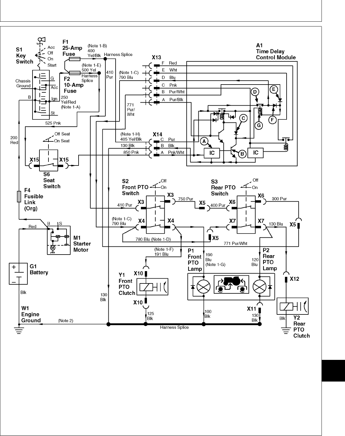
NOTE: 1. 430; The following wire numbers/color apply
where noted on drawing:
-A) 270 Red
-B) 400 Pink
-C) 780 Blue
-D) 790 Blue
-E) 500 Red
-F) 101 Blue
-G) 100 Blue
-H) 405 Purple
NOTE 1. 430; Blue wires “780” and “790” terminate
together at connector (X5) not at connector (X4) as
shown in drawing.
NOTE: 2. Because ground circuits differ between
models and versions, refer to the Main
Electrical Schematics in Group 10 for more
detail on ground circuit.
M78078 -19-14JUN95
MX,159124015,30-19-13JUL95
Component Location and Operation/Theory of Operation
TM1591 (15JUL95) 240-15-19 322,330,332 & 430 Lawn & Garden Tractors
030895
240
15
19

PTO CIRCUIT OPERATION—332 AND 430 (S.N. 420469— ) (CONTINUED)
A—Seat Switch Time Delay G1—Battery X4—Front PTO Switch 3-Pin X11—Rear PTO Lamp 1-Pin
Integrated Circuit (IC) M1—Starter Motor Connector Connector (Ground)
B—Time Delay Switch P1—Front PTO Lamp X5—Rear PTO Harness 3-Pin X12—Rear PTO Clutch 1-Pin
Transistor P2—Rear PTO Lamp Connector Connector
C—Isolation Diode (Optional) X6—Rear PTO Switch 2-Pin X13—TDC Module 6-Pin
D—TDC PTO Relay Contacts S1—Key Switch Connector Connector
E—Isolation Diode S2—Front PTO Switch X7—Rear PTO Switch 3-Pin X14—TDC Module 3-Pin
F—Isolation Diode S3—Rear PTO Switch Connector Connector
G—TDC PTO Relay Coil (Optional) X10—Front PTO Clutch X15—Seat Switch 2-Pin
A1—Time Delay Control S6—Seat Switch 1-Pin Connector Connector
(TDC) Module W1—Engine Ground (Early) Y1—Front PTO Clutch
F1—25-Amp Fuse X3—Front PTO Switch 2-Pin 2-Pin Connector Y2—Rear PTO Clutch
F2—10-Amp Fuse Connector (Later) (Optional)
F4—Fusible Link
Legend For PTO Circuit
The current flowing across PTO relay contacts (D)
keeps the PTO relay coil energized (latched) as long
as transistor (B) provides a path to ground. When the
PTO relay is latched, current from the interlock circuit
is no longer required. At this point, the PTO
switch(es) can be moved to the ON position to
energize the PTO clutch(es).
When the front PTO switch is moved to the ON
position, current flowing across the relay contacts will
also flow out pin “D” of 6-pin connector (X13) to
connector (X4) on the front PTO switch. Current flows
across the PTO switch contacts to front PTO clutch
(Y1), engaging the clutch. Current also flows to front
PTO lamp (P1), turning the lamp on.
NOTE: Operation of optional rear PTO is same as
front PTO.
When the operator rises from the seat, the seat
switch contacts open, causing current to stop flowing
to seat switch time delay IC (A). If the operator does
not return to the seat within approximately one
second, the time delay IC stops current flow to
transistor (B). The transistor will “switch off”, stopping
current flow through PTO relay coil (G), which
de-energizes the coil. At this point PTO relay contacts
(D) will open and stop current flow to the PTO
clutch(es) and lamp(s), thus disengaging the PTO
clutch(es) and turning the lamp(s) off.
NOTE: Driving the machine over rough terrain can
cause the seat switch contacts to momentarily
open and close. If this happens, the seat
switch time delay IC delays the opening of
PTO relay contacts (D), which allows the
PTO(s) to operate without interruption.
If the operator returns to the seat within
approximately one second, current flow is
re-established to the time delay IC before it has a
chance to “time out” and stop current flow to the
transistor. Current flow is NOT interrupted, allowing
the PTO(s) to continue operating.
The 25 amp fuse (F1) and 10 amp fuse (F2) protect
the PTO circuit from excessive current.
MX,159124015,31-19-13JUL95
Component Location and Operation/Theory of Operation
TM1591 (15JUL95) 240-15-20 322,330,332 & 430 Lawn & Garden Tractors
030895
240
15
20

NOTE: 1. 430; The following wire numbers/color apply
where noted on drawing:
-A) 270 Red
-B) 400 Pink
-C) 780 Blue
-D) 790 Blue
-E) 500 Red
-F) 101 Blue
-G) 100 Blue
-H) 405 Purple
NOTE 1. 430; Blue wires “780” and “790” terminate
together at connector (X5) not at connector (X4) as
shown in drawing.
NOTE: 2. Because ground circuits differ between
models and versions, refer to the Main
Electrical Schematics in Group 10 for more
detail on ground circuit.
M78078 -19-14JUN95
MX,159124015,30-19-13JUL95
Component Location and Operation/Theory of Operation
TM1591 (15JUL95) 240-15-21 322,330,332 & 430 Lawn & Garden Tractors
030895
240
15
21

CHARGING CIRUIT OPERATION—322, 330 AND 332
The function of the charging circuit is to keep the
battery properly charged by supplying approximately
13.5—15.0 VDC to the battery while the engine is
operating.
The alternator (G2) produces a high (AC) output
current at high engine rpm. This output current is
controlled by voltage regulator/rectifier (N1), which is
mounted separately from alternator. Battery discharge
lamp (P3) warns the operator when alternator output
is low. The battery discharge lamp DOES NOT
monitor battery state of charge.
When the engine is operating, alternating current (AC)
from the alternator flows to the voltage
regulator/rectifier. The rectifier portion of the voltage
regulator/rectifier converts the alternating current to
direct current (DC). The regulator portion stabilizes
the direct current and increases or decreases current
flow as required by the battery. It does this by
comparing battery voltage at fuse (F2) with voltage
output from the alternator.
When battery voltage is low (voltage difference not
within specifications), the regulator/rectifier allows
current produced by the alternator to flow directly to
the battery through wire (A). When the battery is fully
charged, the regulator/rectifier stops current flow to
the battery.
When the engine is not operating and the key switch
is in the ON position (330 and 332) or RUN position
(322), the regulator/rectifier senses no current output
from the alternator. In this state the regulator/rectifier
allows current to flow to the discharge lamp, turning
the lamp on. During engine operation, the regulator
will also allow current to the battery discharge lamp
when alternator output is below specification.
When the engine is operating and the alternator
produces current output that’s over the minimum
specification, the regulator/rectifier senses the current
output and stops current flowing to the discharge
lamp, turning the lamp off.
The 10-amp fuse (F2) protects the battery discharge
lamp circuit from excessive current.
MX,159124015,32-19-13JUL95
Component Location and Operation/Theory of Operation
TM1591 (15JUL95) 240-15-22 322,330,332 & 430 Lawn & Garden Tractors
030895
240
15
22
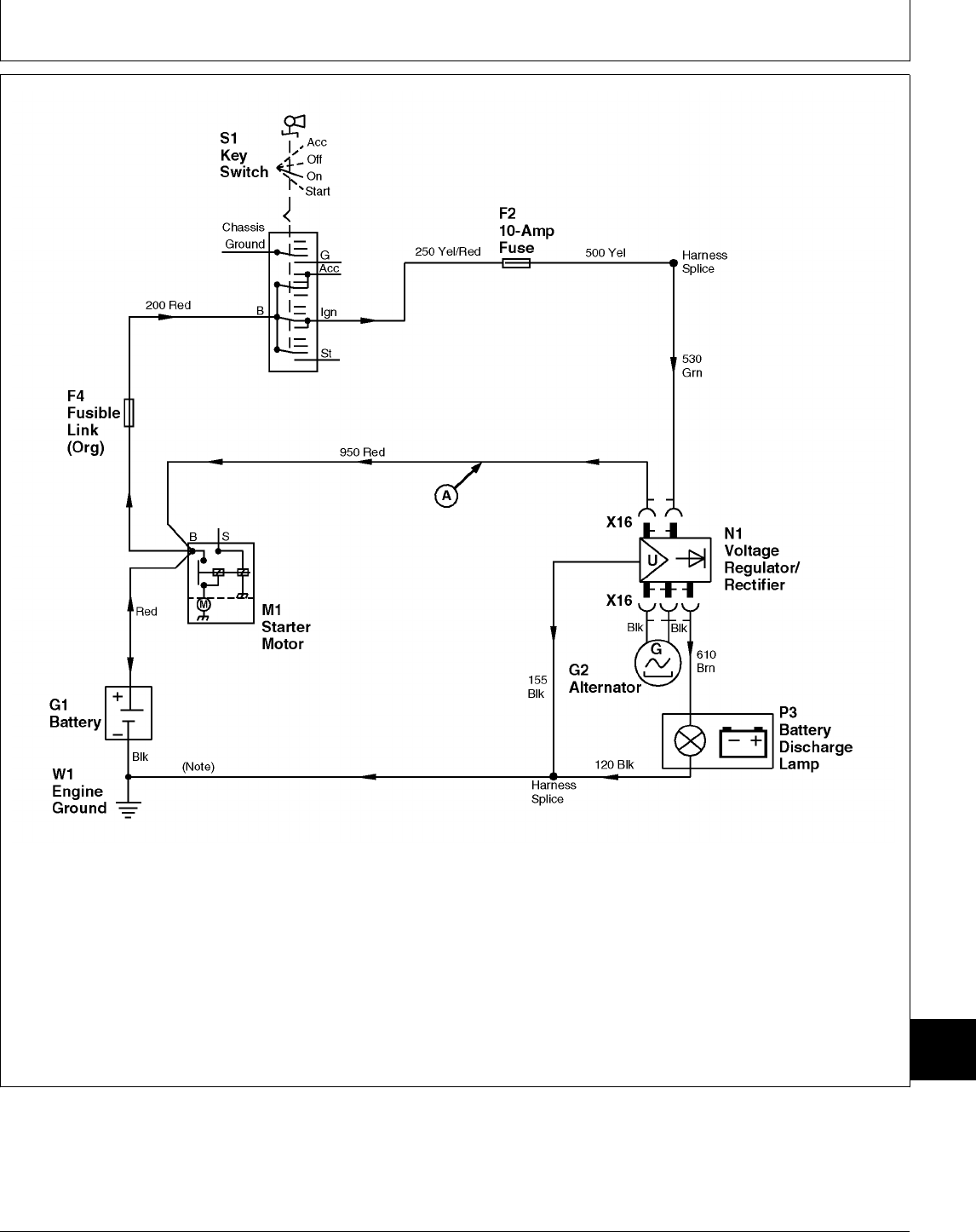
A—Voltage F4—Fusible Link N1—Voltage W1—Engine Ground
Regulator/Rectifier- G1—Battery Regulator/Rectifier X16—Voltage Regulator/
to-Battery Wire G2—Alternator P3—Battery Discharge Lamp Rectifier 5-Pin
F2—10 Amp Fuse M1—Starter Motor S1—Key Switch Connector
NOTE: Because ground circuits differ between models
and versions, refer to the Main Electrical
Schematics in Group 10 for more detail on
ground circuit.
M78069 -19-14JUN95
MX,159124015,33-19-13JUL95
Component Location and Operation/Theory of Operation
TM1591 (15JUL95) 240-15-23 322,330,332 & 430 Lawn & Garden Tractors
030895
240
15
23

CHARGING CIRUIT OPERATION—430
A—Alternator-to-Battery Wire F4—Fusible Link P3—Battery Discharge Lamp X13—TDC Module 8-Pin
B—Battery Discharge G1—Battery S1—Key Switch Connector
Lamp Controller G2—Alternator W1—Engine Ground X14—TDC Module 2-Pin
A1—TDC Module M1—Starter Motor W3—Frame Ground Connector
F2—10 Amp Fuse
Legend For Charging Circuit
The function of the charging circuit is to keep the
battery properly charged by supplying approximately
13.5—15.0 VDC to the battery while the engine is
operating.
Alternator (G2) is made up of a rotor (rotating
electromagnet), stator, rectifier, and regulator. The
rotor is belt driven by the engine crankshaft.
When key switch (S1) is turned to the RUN position,
current from battery (G1) flows through fusible link
(F4) to terminal “B” on the key switch. Current flows
across the key switch contacts to terminal “BR”. From
terminal “BR”, current flows to 10 amp fuse (F2) and
then to the regulator located inside the alternator.
From the regulator, current flows to the rotor field
windings, which induces a magnetic field around the
rotor and stator windings. As the rotor turns, the
magnetic field cuts across the stator windings. This
produces an alternating current (AC) in the stator
windings.
The rectifier converts the (AC) current from the stator
windings to direct current (DC). The regulator
stabilizes the direct current and then compares
battery voltage at 10-amp fuse (F2) with the
alternator output voltage to battery. The regulator then
varies the strength of the magnetic field accordingly,
by varing the current flow to the rotor field windings.
The strength of the magnetic field increases and
decreases proportionally with the amount of current to
the rotor. The stronger the magnetic field, the higher
the alternator output.
Output current from the alternator flows directly to the
battery through wire (A).
For (S.N. —420468):
Battery discharge lamp (P3) warns the operator when
battery voltage is low (battery voltage below
specification). The battery discharge lamp DOES NOT
monitor current output from the alternator.
Battery discharge lamp controller (B) senses battery
voltage present at fuse (F2). If the lamp controller
senses low voltage (less than 12.3 volts), the lamp
controller provides a path to ground for the battery
discharge lamp. Since battery voltage is always
available at the discharge lamp when the key switch
is at the RUN position, the ground path provided by
the lamp controller will allow battery current from fuse
(F2) to flow through the battery discharge lamp and
lamp controller, causing the discharge lamp to turn
on. The discharge lamp will stay on until battery
voltage increases to approximately 12.7 volts. At this
point, the lamp controller will break the path to
ground, turning the discharge lamp off.
For (S.N. 420469— ):
Battery discharge lamp (P3) warns the operator when
alternator output is low. It DOES NOT monitor battery
state of charge.
When the engine is not operating and the key switch
is in the RUN position, the regulator senses no
current output from the alternator. In this state, the
regulator provides a path to ground for the battery
discharge lamp, turning the lamp on. During engine
operation, the regulator will also provide a path to
ground for the battery discharge lamp when current
output is below specification (less than 12.3 volts).
When the engine is operating and the alternator
produces current output that’s over the minimum
specification (approximately 12.7 volts), the regulator
senses the current output and breaks the ground path
to the discharge lamp, turning the lamp off.
MX,159124015,34-19-13JUL95
Component Location and Operation/Theory of Operation
TM1591 (15JUL95) 240-15-24 322,330,332 & 430 Lawn & Garden Tractors
030895
240
15
24
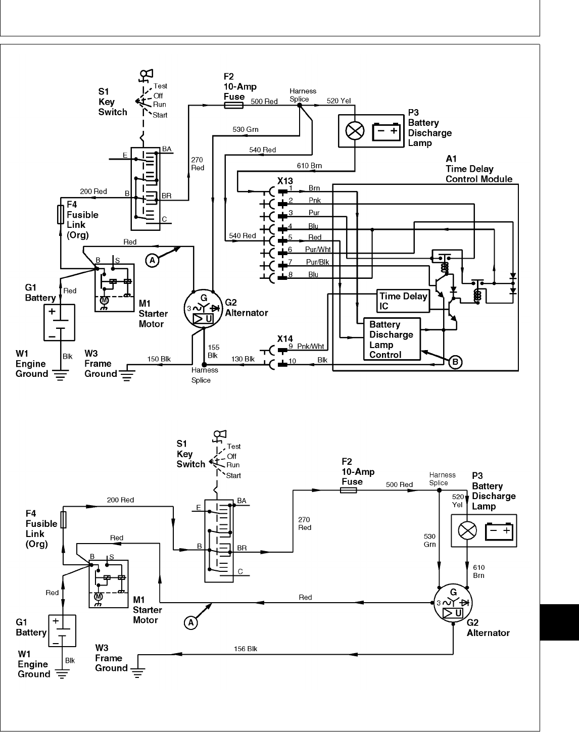
430 (S.N. —420468)
430 (S.N. 420469— )
M78070 -19-14JUN95M78071 -19-14JUN95
MX,159124015,35-19-13JUL95
Component Location and Operation/Theory of Operation
TM1591 (15JUL95) 240-15-25 322,330,332 & 430 Lawn & Garden Tractors
030895
240
15
25

FUEL SHUTOFF SOLENOID CIRCUIT OPERATION—430 (S.N. —420468)
The function of the fuel shutoff solenoid circuit is to
stop engine operation by shutting off fuel flow to the
fuel injector pump. This is accomplished either
manually using the key switch or automatically when
the operator rises from the seat for more than one
second with machine in gear or PTO engaged.
OPERATOR ON SEAT—MACHINE IN GEAR
AND/OR PTO ENGAGED:
The normally open contacts of seat switch (S6) close
when the operator sits on the seat. When the key
switch (S1) is turned to the RUN or START position,
current flows from the positive (+) terminal of battery
(G1), through fusible link (F4) to terminal “B” of the
key switch. Current flows across the key switch
contacts to terminal “BR”. From terminal “BR”,
currrent flows to 25-amp fuse (F1) and 10-amp fuse
(F2). From fuse (F2), current flows across the closed
contacts of the seat switch to pin “9” of TDC module
2-pin connector (X14).
Inside the TDC module, current flows through seat
time delay integrated circuit (IC) (E), then to seat time
delay transistor (D). As long as current from the time
delay IC flows to the transistor, the transistor is
“switched on”. In this state, the transistor completes
the path to ground for fuel shut-off relay coil (B). The
ground path allows current to flow from fuse (F1) to
pin “3” of the TDC module 8-pin connector (X13).
Inside the TDC module, current flows through the fuel
shut-off relay coil to ground. This energizes the relay
coil which closes fuel shut-off relay contacts (A).
Current from fuse (F1) then flows across the relay
contacts and out pin “2” of 8-pin connector (X13).
From pin “2”, current flows to fuel shutoff solenoid
(Y3). From solenoid (Y3), current flows through 8-amp
circuit breaker (F5) to ground, energizing the
solenoid. The energized solenoid moves the fuel
shutoff linkage to the ON position. This opens a valve
and allows fuel to flow into the fuel injector pump.
When the operator rises from the seat, the seat
switch contacts open, causing current to stop flowing
to the seat time delay IC. If the operator does not
return to the seat within approximately one second,
the time delay IC stops current flow to transistor (D).
The transistor will “switch off”, causing current through
the fuel shut-off relay coil to stop flowing, which
opens the fuel shutoff relay contacts. The open relay
contacts stops current flow to the fuel shutoff
solenoid, de-energizing the solenoid. The
de-energized solenoid moves the fuel shutoff linkage
to the OFF position. This shuts off the fuel flow, thus
stopping the engine.
NOTE: Driving the machine over rough terrain can
cause the seat switch contacts to momentarily
open and close. If this happens, the seat time
delay IC delays the opening of fuel shutoff
relay contacts (A), which allows the engine to
operate without interruption.
If the operator returns to the seat within
approximately one second, current flow is
re-established to the time delay IC before it has a
chance to “time out” and stop current flow to the
transistor. Current flow is NOT interrupted to the fuel
shutoff solenoid, allowing the engine to continue
operating.
OPERATOR OFF SEAT—MACHINE IN NEUTRAL
AND PTO DISENGAGED:
When operator is off the seat, current to the fuel
shutoff solenoid can still be maintained through the
interlock circuit. For current to flow through the
interlock circuit, the key switch must be turned to the
RUN or START position, the hydrostatic control lever
in the N/STOP position, and PTO switch(es) in the
OFF position (PTO disengaged).
With these conditions met, current flows from fuse
(F1) through the interlock contacts of the PTO
switches, transmission neutral switch, to pin “7” of
TDC module 8-pin connector (X13). Inside the TDC
module, current flows from pin “7” to fuel shut-off
transistor (C). As long as current from the interlock
circuit flows to transistor (C), the transistor is
“switched on”. In this state, the transistor provides an
alternate path to ground for the fuel shut-off relay
coil. The fuel shutoff relay contacts close, allowing
current to flow to the fuel shutoff solenoid.
The 25-amp fuse (F1) and 10-amp fuse (F2) protect
the fuel shutoff circuit from excessive current.
The 8-amp circuit breaker (F5) disables the start
circuit and fuel shutoff solenoid (solenoid will not
energize) if breaker is tripped.
MX,159124015,36-19-13JUL95
Component Location and Operation/Theory of Operation
TM1591 (15JUL95) 240-15-26 322,330,332 & 430 Lawn & Garden Tractors
030895
240
15
26
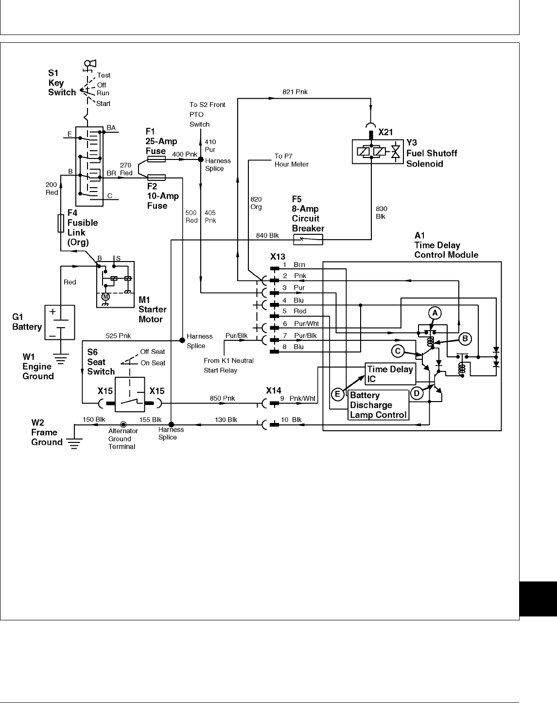
A—Fuel Shutoff Relay A1—Time Delay Control M1—Starter Motor X14—TDC Module 2-Pin
Contacts (TDC) Module S1—Key Switch Connector
B—Fuel Shutoff Relay Coil F1—25 Amp Fuse S6—Seat Switch X15—Seat Switch 2-Pin
C—Fuel Shutoff Transistor F2—10 Amp Fuse W1—Engine Ground Connector
D—Seat Time Delay F4—Fusible Link W2—Frame Ground Y3—Fuel Shutoff Solenoid
Transistor F5—8-Amp Circuit Breaker X13—TDC Module 8-Pin
E—Seat Time Delay G1—Battery Connector
Integrated Circuit (IC)
M78073 -19-14JUN95
MX,159124015,37-19-13JUL95
Component Location and Operation/Theory of Operation
TM1591 (15JUL95) 240-15-27 322,330,332 & 430 Lawn & Garden Tractors
030895
240
15
27

FUEL SHUTOFF SOLENOID CIRCUIT OPERATION—332 AND 430 (S.N. 420469— )
The function of the fuel shutoff solenoid circuit is to
stop engine operation by shutting off fuel flow to the
fuel injector pump. This is accomplished either
manually using the key switch or automatically when
the operator rises from the seat for more than one
second with machine in gear or PTO engaged.
OPERATOR ON SEAT—MACHINE IN GEAR
AND/OR PTO ENGAGED:
When the key switch (S1) is turned to the ON
position, current flows from the positive (+) terminal of
battery (G1), through fusible link (F4) to the key
switch. Current flows across key switch contacts to
25-amp fuse (F1) and 10-amp fuse (F2). From fuse
(F2), current flows across the closed contacts of seat
switch (S6) to pin “A” of TDC module 3-pin connector
(X14).
Inside the TDC module, current flows to seat time
delay IC (J), then to time delay transistor (H). As long
as current from IC (J) flows to transistor (H), the
transistor is “switched on”. In this state, the transistor
completes the path to ground, allowing current from
the seat switch to flow through relay coil (D),
energizing the relay. This closes contacts (C), which
allows current from fuse (F1), to flow to solenoid (Y3)
hold-in windings (B). The magnetic field produced in
the hold-in windings is not strong enough to move the
armature of fuel shutoff solenoid by itself.
From relay contacts (C), current also flows to pull-in
time delay IC (G) and pull-in relay coil (F). IC (G)
provides a path to ground for relay coil (F), causing
the relay to energize and close relay contacts (E).
This allows high current from the battery to flow
through fusible link (F4), across relay contacts (E), to
solenoid pull-in windings (A). This energizes the
pull-in coil, which pulls the fuel shutoff solenoid
armature in and moves the injection pump linkage to
the ON position.
After approximately one second, IC (G) breaks the
pull-in relay’s path to ground, thus stopping current
flow through the relay coil. The relay contacts (E)
open, causing current to stop flowing to the solenoid
pull-in windings.
Current continues to flow to the solenoid hold-in
windings. The magnetic field produced by this current
is strong enough to hold the solenoid armature in,
thus keeping the injector pump linkage at the ON
position.
When the operator rises from the seat, the seat
switch contacts open, causing current to stop flowing
to seat time delay IC (J). If the operator does not
return to the seat within approximately one second,
IC (J) stops current flow to transistor (H). The
transistor will “switch off”, stopping current flowing
through relay coil (D), causing relay contacts (C) to
open. Current stops flowing to the solenoid hold-in
windings, de-energizing the fuel shutoff solenoid. With
the solenoid no longer energized, a return spring
moves the injector pump linkage back to the OFF
position, thus stopping fuel flow to the injection pump.
NOTE: Driving the machine over rough terrain can
cause the seat switch contacts to momentarily
open and close. If this happens, the seat time
delay IC allows the engine to operate without
interruption.
If the operator returns to the seat within
approximately one second, current flow is
re-established to IC (J) before it has a chance to
“time out” and stop current flow to transistor (H).
Current flow is NOT interrupted to the fuel shutoff
solenoid, allowing the engine to continue operating.
OPERATOR OFF SEAT—MACHINE IN NEUTRAL
AND PTO DISENGAGED:
NOTE: 332 (S.N. 596723— ) and 430 (S.N.
596048— ); Park brake must be engaged.
When operator is off the seat, current to the fuel
shutoff solenoid can still be maintained through the
interlock circuit. For current to flow through the
interlock circuit, the key switch must be turned to the
ON or START position, the hydrostatic control lever in
the N/STOP position, the PTO switches in the OFF
position (PTO disengaged) and park brake engaged
(332 (S.N. 596723— ) and 430 (S.N. 596048— )
only).
With these conditions met, current flows from fuse
(F1), through the interlock contacts of the PTO
switches, transmission neutral switch, and brake
switch (if equipped) to pin “A” of TDC module 6-pin
connector (X13). Inside the TDC module, the interlock
current flows to transistor (I), causing the transistor to
“switch on”. In this state, the transistor provides an
alternate path to ground for relay coil (D). The relay
coil energizes, closing relay contacts (C), thus
allowing current to flow to the fuel shutoff solenoid
hold-in windings (B).
MX,159124015,38-19-13JUL95
Component Location and Operation/Theory of Operation
TM1591 (15JUL95) 240-15-28 322,330,332 & 430 Lawn & Garden Tractors
030895
240
15
28
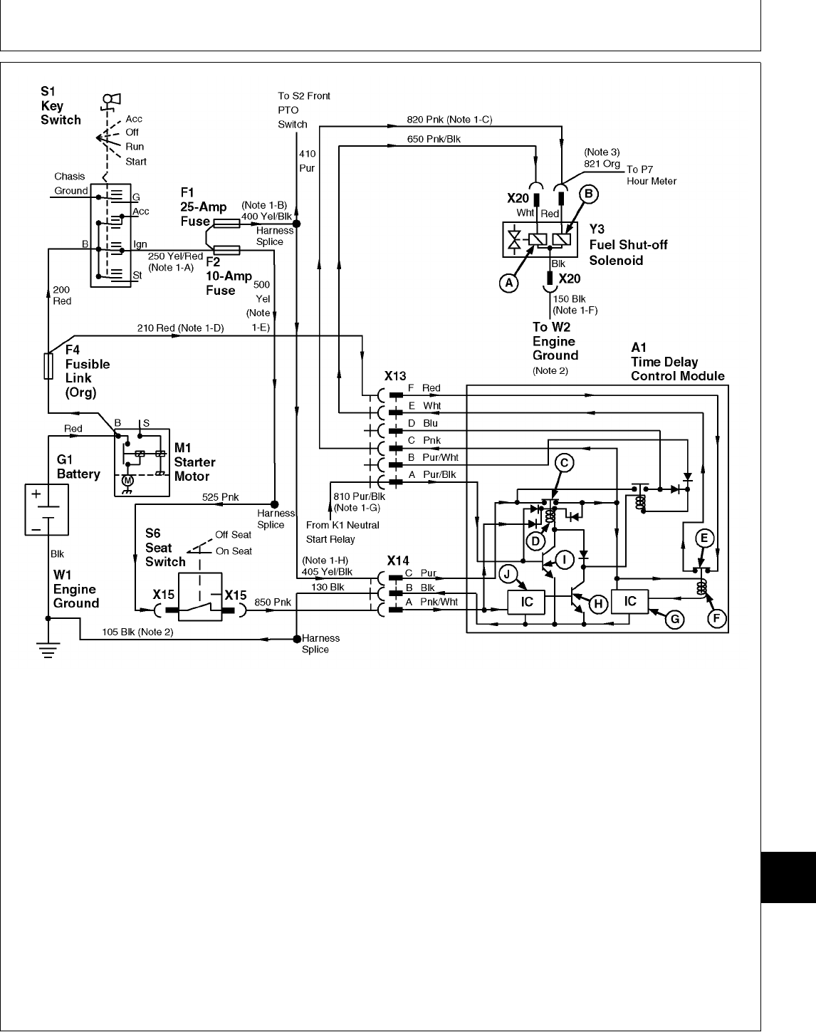
A—Solenoid Pull-In Windings H—Seat Time Delay F4—Fusible Link X14—TDC Module 3-Pin
B—Solenoid Hold-In Transistor G1—Battery Connector
Windings I—Hold-In Transistor M1—Starter Motor X15—Seat Switch 2-Pin
C—Hold-In Relay Contacts J—Seat Time Delay IC S1—Key Switch Connector
D—Hold-In Relay Coil A1—Time Delay Control S6—Seat Switch X20—Fuel Shutoff 3-Pin
E—Pull-In Relay Contacts (TDC) Module W1—Engine Ground Connector
F—Pull-In Relay Coil F1—25 Amp Fuse X13—TDC Module 6-Pin Y3—Fuel Shutoff Solenoid
G—Pull-In Time Delay F2—10 Amp Fuse Connector
Integrated Circuit (IC)
NOTE: Illustration shows key switch configuration for
332.
NOTE: 1. 430; The following wire numbers/color apply
where noted on drawing:
-A) 270 Red -E) 500 Red
-B) 400 Pink -F) 165 Black
-C) 821 Pink -G) 810 Purple
-D) 205 Red/Black -H) 405 Purple
NOTE: 2. 430; Harness ground wire number is “156”
and connects to frame ground.
NOTE: 3. 430; Orange wire number is “820”.
M78074 -19-14JUN95
MX,159124015,39-19-13JUL95
Component Location and Operation/Theory of Operation
TM1591 (15JUL95) 240-15-29 322,330,332 & 430 Lawn & Garden Tractors
030895
240
15
29

ENGINE PREHEAT CIRCUIT OPERATION (330, 332 AND 430)
The function of the engine preheat circuit is to supply
current to the glow plugs for easier starting of the
engine in cold weather. The circuit also informs the
operator when the engine is ready to start. The
system is fully automatic and does not require any
operator interaction. The system functions only when
the key switch is in the ON position (330 and 332) or
RUN position (430) or START position and engine
compartment temperature is approximately 20˚C
(68˚F) or lower.
When the engine compartment temperature is less
than 20˚C (68˚F), turning key switch (S1) to the ON
position (330 and 332) or RUN position (430) or
START position allows current from the positive (+)
terminal of battery (G1) to flow to fusible link (F4).
From the fusible link, current flows across key switch
contacts, through 10 amp fuse (F2), to pin “3” on
5-pin connector (X20) of glow plug controller (A2).
Inside the glow plug controller, current flows to the
integrated circuits (ICs) (D—F) and to thermistor (G).
Temperature changes causes the thermistor’s
resistance to change in value, which increases or
decreases current flow to IC (F). The current from
thermistor (G) controls IC (F). IC (F) controls ICs (D
and E).
Current from IC (E) causes transistor (C) to “switch
on”, completing a path to ground for glow plug lamp
(P8). Current flows from fuse (F2), through the glow
plug lamp, then through transistor (C) to ground,
causing the lamp to turn on.
After approximately 8 seconds has elapsed, a timer in
IC (E) will stop current flowing to transistor (C). This
causes the transistor to “switch off”, turning the glow
plug lamp off.
Current from IC (D) causes transistor (B) to “switch
on”, completing a path to ground for glow plug relay
(A).The ground path allows current from fuse (F2) to
flow through the glow plug relay coil, which energizes
the relay and closes the relay contacts. The closed
relay contacts allow current to flow directly from the
battery, through fusible link (F3), across the relay
contacts, then out to glow plugs (R1).
After approximately 30 seconds has elapsed, a timer
in IC (D) will stop current flow to transistor (B),
causing the transistor to “switch off”. This stops
current flow to the relay coil, which causes the relay
contacts to open, thus stopping current flow to the
glow plugs.
MX,159124015,40-19-13JUL95
Component Location and Operation/Theory of Operation
TM1591 (15JUL95) 240-15-30 322,330,332 & 430 Lawn & Garden Tractors
030895
240
15
30
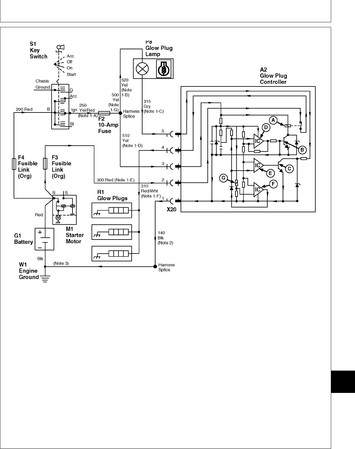
A—Glow Plug Relay E—Glow Plug Lamp IC F3—Fusible Link R1—Glow Plugs
B—Relay Transistor F—Temperature Controlled IC F4—Fusible Link S1—Key Switch
C—Glow Plug Lamp G—Thermistor G1—Battery W1—Engine Ground
Transistor A2—Glow Plug Controller M1—Starter Motor X20—Glow Plug Controller
D—Glow Plug Integrated F2—10-Amp Fuse P8—Glow Plug Lamp 5-Pin Connector
Circuit (IC)
NOTE: Illustration shows key switch configuration for
330 and 332.
NOTE: 1. 430; The following wire numbers/color apply
where noted on drawing:
-A) 270 Red -E) 310 Red
-B) 425 Yellow -F) 320 Red/White
-C) 630 Gray -G) 500 Red
-D) 420 Yellow
NOTE: 2. 332 (S.N. 475001— ); Wire number “171”
is used instead of “140”.
NOTE: 3. Because ground circuits may differ between
models and versions, refer to the Main
Electrical Schematics in Group 10 for more
detail on ground circuit connections.
M78075 -19-14JUN95
MX,159124015,41-19-13JUL95
Component Location and Operation/Theory of Operation
TM1591 (15JUL95) 240-15-31 322,330,332 & 430 Lawn & Garden Tractors
030895
240
15
31

WATER-IN-FUEL CIRCUIT OPERATION (430)
The function of the water-in-fuel circuit is to warn the
operator when water is present in the fuel system.
This is done by a sensor that’s located in the fuel filter
base that senses the resistance of the fuel. Since diesel
fuel has a higher resistance than water, fuel
contaminated with water will have a lower resistance.
Turning key switch (S1) to the RUN position allows
current to flow from the positive (+) terminal of battery
(G1), through fusible link (F4), to key switch terminal “B”.
Current flow across the key switch contacts to terminal
“BR”. From terminal “BR”, current flows through 10-amp
fuse (F2), to water-in-fuel sensor (B7), energizing the
sensor. When the sensor is initially energized, it
completes a path to ground for water-in-fuel lamp (P9),
turning the lamp on. The lamp will stay on for a few
seconds then, if there is no water present in the fuel, the
sensor will break the path to ground, turning the lamp
off.
Inside the sensor, current flows to a probe that is
submersed in the fuel. From the probe, current flows
through the fuel to ground. When water is present in the
fuel, the resistance through the fuel to ground is lowered,
causing increased current flow. Current flow will continue
to increase until a transistor in the sensor “switches on”,
completing the path to ground for the water-in-fuel lamp.
As long as there is water in the filter base, the lamp will
stay on when the key switch is in the RUN position.
MX,159124015,42-19-13JUL95
Component Location and Operation/Theory of Operation
TM1591 (15JUL95) 240-15-32 322,330,332 & 430 Lawn & Garden Tractors
030895
240
15
32
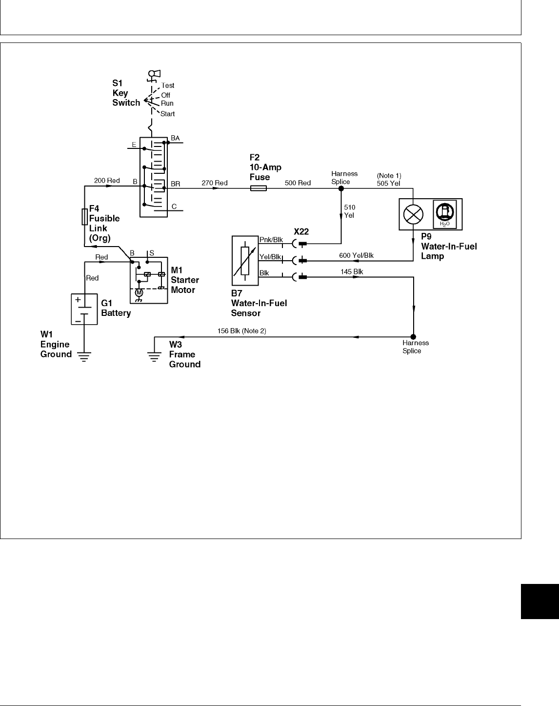
B7—Water-In-Fuel Sensor G1—Battery S1—Key Switch X22—Water-In-Fuel Sensor
F2—10-Amp Fuse M1—Starter Motor W1—Engine Ground 3-Pin Connector
F4—Fusible Link P9—Water-In-Fuel Lamp W3—Frame Ground
NOTE: 1. 430 (S.N. 420469— ); Wire number “516”
is used instead of “505”.
The “516” yellow wire connects to “515”
yellow wire at the engine oil pressure lamp.
The “515” wire connects the oil pressure lamp
to the fuse (F2) harness splice.
NOTE: 2. 430 (S.N. —420468); Harness ground wire
connects to frame ground at pedestal.
M78076 -19-14JUN95
MX,159124015,43-19-13JUL95
Component Location and Operation/Theory of Operation
TM1591 (15JUL95) 240-15-33 322,330,332 & 430 Lawn & Garden Tractors
030895
240
15
33

LOW FUEL LEVEL CIRCUIT OPERATION (322, 332 AND 430)
The function of the low fuel level circuit is to warn the
operator when the fuel level in the fuel tank is low.
Also, a “lamp test” function is provided to check the
warning lamp circuit.
The low fuel level sensor (B4) is actually a
temperature sensor that increases or decreases
current flow through low fuel level lamp (P4) as
sensor temperature increases or decreases.
When the sensor is submersed in fuel, the fuel cools
the sensor. The cooled sensor prevents current flow
to ground. When the sensor is dry (fuel level is below
sensor), the sensor heats up, allowing current to flow.
The amount of current flow is directly proportional to
the temperature of the sensor. Because of this, a
partially exposed sensor will allow a small amount of
current flow, causing the low fuel level lamp to glow
dimmly. When the sensor is completely exposed, full
current flows through the lamp, turning the lamp on
fully.
When key switch (S1) is turned to the ON position
(330 and 332) or RUN position (322 and 430) and
the fuel level sensor is exposed, current from the
positive (+) terminal of battery (G1) flows through
fusible link (F4) to key switch terminal “B”. Current
flows across the key switch contacts to terminal “IGN”
(322 and 332) or terminal “BR” (430). From the key
switch, current flows to 10-amp fuse (F2). From the
fuse, current flows through the low fuel level lamp,
through the sensor, then to ground.
Diodes (V1 and V2) block engine coolant temperature
lamp access to the ground provided by the low fuel
level sensor. This prevents the coolant temperature
lamp from turning on when the low fuel level lamp
turns on.
322 and 332; When the key switch is turned to the
START position, a separate set of contacts in the key
switch connects the low fuel level lamp directly to
ground to provide the lamp test function.
430; When the key switch is turned to the TEST
position (key switch turned fully counterclockwise), a
separate set of contacts in the key switch connects
the low fuel level lamp directly to ground to provide
the lamp test function.
MX,159124015,44-19-13JUL95
Component Location and Operation/Theory of Operation
TM1591 (15JUL95) 240-15-34 322,330,332 & 430 Lawn & Garden Tractors
030895
240
15
34
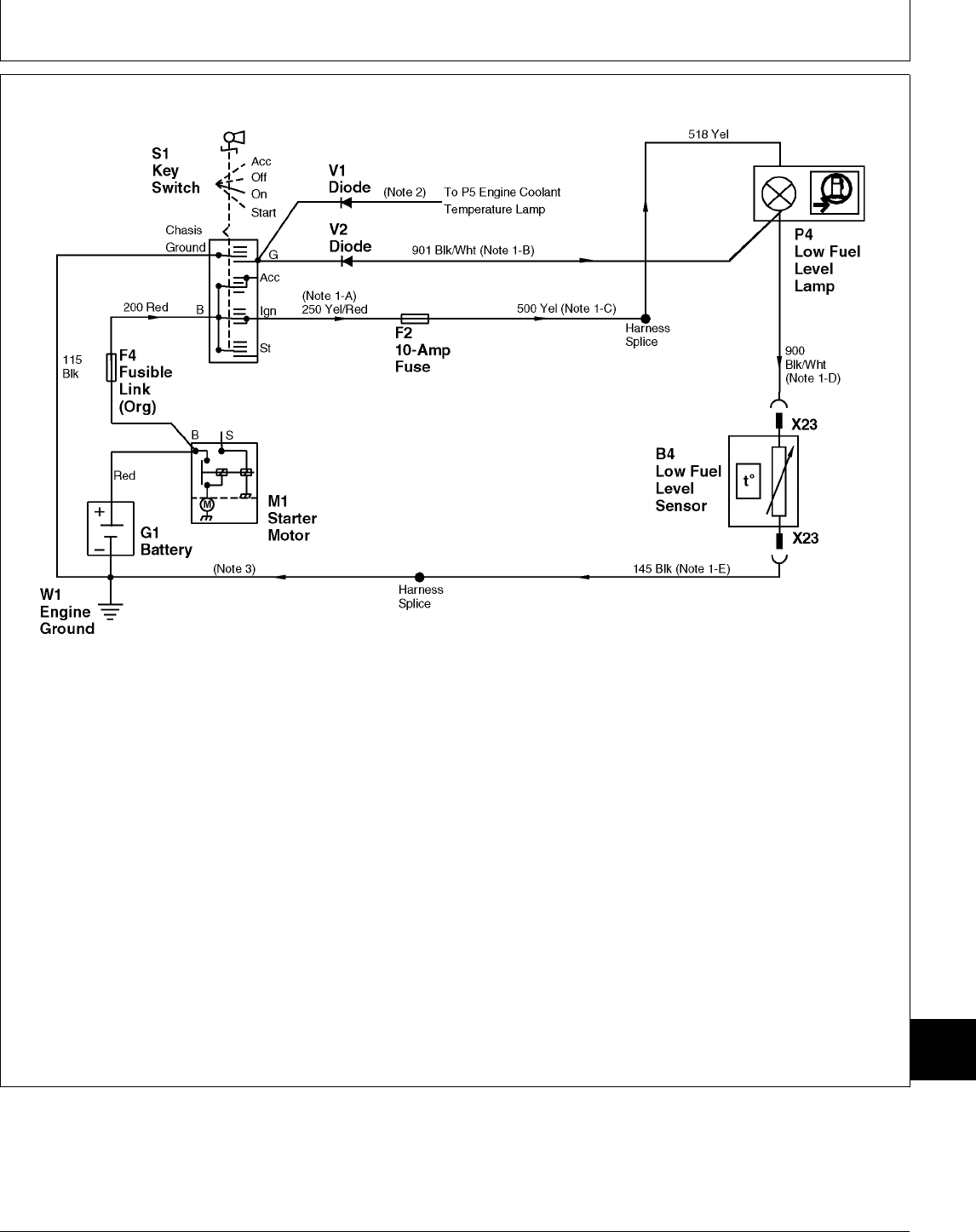
B4—Low Fuel Level Sensor G1—Battery S1—Key Switch W1—Engine Ground
F2—10-Amp Fuse M1—Starter Motor V1—Isolation Diode X23—Low Fuel Level Sensor
F4—Fusible Link P4—Low Fuel Level Lamp V2—Isolation Diode 2-Pin Connector
NOTE: Illustration shows key switch configuration for
322 and 332.
NOTE: 1. 430; The following wire number/color apply
where noted on drawing:
-A) 270 Red
-B) 331 Green/White
-C) 500 Red
-D) 330 Green/White
NOTE: 2. Refer to the following chart for wire
number/color of coolant temperature lamp
ground “test” wire.
MACHINE MODEL WIRE NUMBER/COLOR
322 . . . . . . . . . . . . . . . . . . . . . . . . . . . . . . 333 Orange/White
332 (S.N. 475001— ) . . . . . . . . . . . . . . . . . 333 Orange/White
332 (S.N. —475000) . . . . . . . . . . . . . . . . . 332 Orange/White
430 ( —420468) . . . . . . . . . . . . . . . . . . . . . . 332 Yellow/Red
430 (S.N. 420469— ) . . . . . . . . . . . . . . . . . . . 333 Yellow/Red
NOTE: 3. Because ground circuits differ between
models and versions, refer to the Main
Electrical Schematics in Group 10 for more
detail on ground circuit connections and wire
numbers.
M78077 -19-14JUN95
MX,159124015,45-19-13JUL95
Component Location and Operation/Theory of Operation
TM1591 (15JUL95) 240-15-35 322,330,332 & 430 Lawn & Garden Tractors
030895
240
15
35

Component Location and Operation/Theory of Operation
TM1591 (15JUL95) 240-15-36 322,330,332 & 430 Lawn & Garden Tractors
030895
240
15
36

ABOUT THIS GROUP
Always perform the system checkout procedures in
Group 05 BEFORE doing any tests in this group. The
step-by-step procedures in this group provide you
with the detailed diagnostic information you will need
to isolate a malfunction. Always start with the first
step and follow the sequence from left to right. Read
each step completely before performing the test.
Basic diagnostic equipment is used. It is assumed
that you are familiar with the machine and its
electrical components.
IMPORTANT: Before doing any testing, verify the
system ground circuits and test the
battery. All ground connections
must be clean and tight and the
battery fully charged.
With any component failure, it is usually best to trace
current flow from the component back to the battery.
If there is voltage at the component, verify its ground
connection, then repair or replace the component.
Use the electrical schematics in Group 10 to trace
current flow.
Upon completing a test or adjustment, check to see
whether the problem is corrected by performing the
checkout procedure for that step in Group 05.
NOTE: For clarity in this section, machines including
and before serial numbers listed below will be
referred to as “Early Models”. Machines
including and after serial number listed below
will be referred to as “Later Models”.
Later model machines have a brake switch
added to the neutral start circuit, which is
activated by depressing the brake pedals.
MODEL EARLY LATER
322 (S.N. —596005) (S.N. 596006— )
330 (S.N. —420000) N/A
332 (S.N. —475000) (S.N. 475001— )
430 (S.N. —596047) (S.N. 596048— )
A VERIFY SYSTEM GROUNDS—322 AND 332
NOTE: 332 (S.N. —475000); The PTO clutch,
fuel pump and head and tail lights are
individually grounded to the machine frame. All
other electrical components are grounded
through the harness. Inside the harness, the
ground circuits are spliced together with one wire
connecting the ground circuits to engine ground,
then to frame ground.
332 (S.N. 475001— ) and 322 (All); All
electrical system components are grounded
through the harness. Inside the harness, the
ground circuits are spliced together with two
wires connecting the ground circuits to the
machine frame. One goes to frame at
regulator/rectifier and the other, first to engine
then to frame.
Continued on next page
MX,159124020,1 -19-13JUL95
Group 20
Electrical System Diagnosis
TM1591 (15JUL95) 240-20-1 322,330,332 & 430 Lawn & Garden Tractors
030895
240
20
1

M45227 -UN-12JAN90
M45228 -UN-12JAN90
M45177 -UN-08JAN90
NOTE: Upper and
lower left photos show
battery, harness and
frame ground
connections for Early
332.
Right photo shows 322
(All) and Later 332.
Harness, battery and
frame ground are
connected to the left
front side of engine
block. Later 332; A
second harness ground
is connected to
regulator/rectifier to
frame on right side of
engine compartment.
322 (All); A second
harness ground is
connected to
regulator/rectifier to
frame on right side of
engine compartment
near pedestal.
Key switch OFF.
Verify the system
grounds using a
continuity tester or
ohmmeter.
Check for good
continuity between
battery negative (—)
terminal and the
following ground
connections located on
engine block, frame
and regulator/rectifier to
frame:
A—Battery Ground
B—Harness Ground
C—Frame Ground
NOT OK: Clean and
tighten ground
connections as
necessary.
OK: GO TO B
MX,159124020,2 -19-13JUL95
Electrical System Diagnosis/Verify System Grounds
TM1591 (15JUL95) 240-20-2 322,330,332 & 430 Lawn & Garden Tractors
030895
240
20
2

–! VERIFY SYSTEM
GROUNDS—330
NOTE: The PTO clutch,
fuel pump, head light
and hour meter are
individually grounded to
the machine frame. All
other electrical
components are
grounded through the
harness. Inside the
harness, the ground
circuits are spliced
together with one wire
connecting the ground
circuits to the engine
mounting bracket, then
to frame.
M55097 -UN-09DEC89
M55099 -UN-28APR95
M55098 -UN-09DEC89
Key switch OFF.
Verify the system
grounds using a
continuity tester or
ohmmeter.
Check for good
continuity between
battery negative (—)
terminal and the
following:
A—Alternator/Regulator
Ground Connection
to Frame
B—Wiring Harness
Ground Connection
to Engine Mounting
Bracket then to
Frame
C—Battery Ground
Connection at
Engine Block
NOT OK: Clean and
tighten ground
connections as
necessary.
OK: GO TO B
–@ VERIFY SYSTEM
GROUNDS—430
NOTE: 430 (S.N. —475000); The PTO clutch,
fuel pump, low fuel sensor and head and tail
lights are individually grounded to the machine
frame. All other electrical components are
grounded through the harness. Inside the
harness, the ground circuits are spliced together
with one wire connecting the ground circuits to
the machine frame.
430 (S.N. 475001— ); All electrical system
components are grounded through the harness.
Inside the harness, the ground circuits are
spliced together with one wire connecting the
ground circuits to the machine frame.
Continued on next page
MX,159124020,3 -19-13JUL95
Electrical System Diagnosis/Verify System Grounds
TM1591 (15JUL95) 240-20-3 322,330,332 & 430 Lawn & Garden Tractors
030895
240
20
3
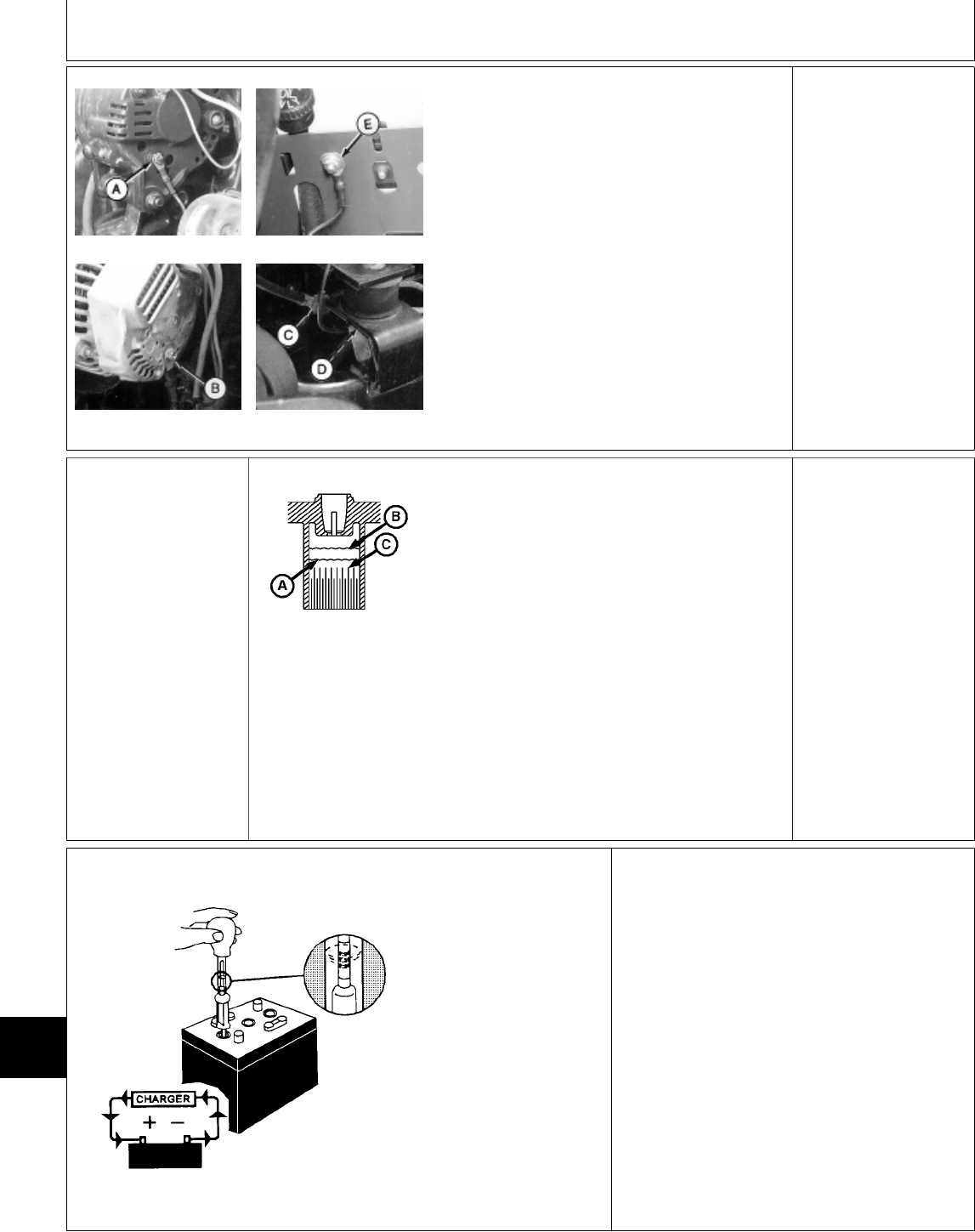
M36662 -UN-27APR95
M78968 -UN-27APR95
M36663 -UN-27APR95
M78969 -UN-27APR95
Key switch OFF.
Verify the system grounds using a continuity
tester or ohmmeter.
Check for good continuity between battery
negative (—) terminal and the following:
(S.N. —475000):
• Alternator ground connection (A)
• Wiring harness-to-frame ground connection (E)
at pedestal
• Battery ground connection (C) at engine block
(S.N. 475001— ):
• Battery ground connection (C) at engine block
• Engine block-to-frame ground connection at
engine mount (D)
• Alternator ground connection (B) to engine
mount
NOT OK: Clean and
tighten ground
connections as
necessary.
OK: GO TO B
B BATTERY TESTS
NOTE: If problem is
with starting circuit,
perform all battery
tests. If problem is with
other components,
perform battery tests
only if starter does not
crank engine
satisfactorily. M78970 -UN-09MAY95
A—Minimum electrolyte
level—No less than 6
mm (0.250 in.) above
plate separators
B—Maximum electrolyte
level—No more than 13
mm (0.500 in.) above
plate separators
C—Plate Separators
Check electrolyte level
in each cell of battery.
If low, add the proper
amount of electrolyte or
DISTILLED water.
M78971 -UN-09MAY95
Check specific gravity
of each cell with a
hydrometer.
SPECIFIC GRAVITY
ALL CELLS LESS THAN 1.175: GO TO —@
ALL CELLS MORE THAN 1.225 WITH LESS THAN 50
(0.050) GRAVITY POINT VARIATION: GO TO —#
ALL CELLS LESS THAN 1.225 WITH LESS THAN 50
(0.050) GRAVITY POINT VARIATION: GO TO —!
CELLS VARY MORE THAN 50 POINTS: Replace
Battery.
MX,159124020,4 -19-13JUL95
MX,159124020,4A-19-13JUL95
MX,159124020,4B-19-13JUL95
Electrical System Diagnosis/Battery Tests
TM1591 (15JUL95) 240-20-4 322,330,332 & 430 Lawn & Garden Tractors
030895
240
20
4

—! Test Battery
Voltage
NOTE: Battery need
not be disconnected
from machine.
IMPORTANT: Before connecting JT05685
Tester to battery, make sure load knob is
turned fully counterclockwise.
Check battery voltage with voltmeter or JT05685
Battery Tester.
12.4 VOLTS OR
MORE: GO TO —%
LESS THAN 12.4
VOLTS: GO TO —@
—@ Charge Battery Connect a variable-rate
type charger to battery.
Start charger at a slow
rate. Increase charge
rate one setting at a
time. Check ammeter
(on charger) after 1
minute at each setting.
Try to maintain a 10
amp charge rate. Use
boost setting as
necessary.
The maximum charging
time at boost setting is
10 minutes. Allow an
additional 5 minutes for
each 10˚F below 70˚F.
BATTERY DID NOT REQUIRE WATER AT
STEP B AND IS ACCEPTING A 10-AMP
CHARGE: GO TO —$
BATTERY REQUIRED WATER AT STEP B OR
ALL CELLS WERE BELOW 1.175, BUT
BATTERY IS ACCEPTING A 10-AMP CHARGE:
GO TO —#
BATTERY DOES NOT ACCEPT A 10-AMP
CHARGE AFTER 10 MINUTES AT BOOST
SETTING: Replace Battery.
—# Increase Charge
Rate
Set charger at 15—25
amps. IMPORTANT:
Decrease charge rate
if battery gases or
bubbles excessively
or becomes too warm
to hold.
Check specific gravity
after 30 minutes. VARIATION BETWEEN
CELLS IS MORE
THAN 50 SPECIFIC
GRAVITY POINTS
(0.050): Replace
Battery.
VARIATION BETWEEN
CELLS IS LESS THAN
50 SPECIFIC GRAVITY
POINTS (0.050): GO
TO —$
MX,159124020,6 -19-13JUL95
MX,159024025,5 -19-16MAY95
MX,159024025,7 -19-16MAY95
Electrical System Diagnosis/Battery Tests
TM1591 (15JUL95) 240-20-5 322,330,332 & 430 Lawn & Garden Tractors
030895
240
20
5
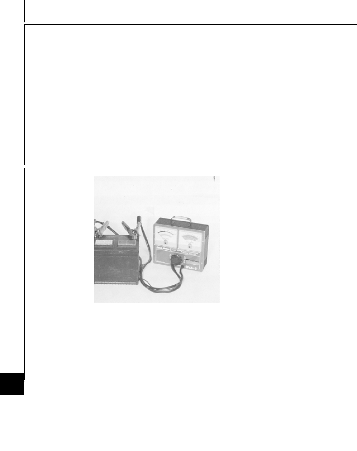
—$ Continue Charging
Battery
IMPORTANT:
Decrease charge rate
if battery gases or
bubbles too much or
if battery gets too
warm to hold.
Continue charging
battery until specific
gravity is 1.230—1.265
points.
BATTERY WAS DISCHARGED AT A SLOW
RATE OR DISCHARGE RATE IS UNKNOWN:
Charge battery at 10—15 amps for 6—12 hours.
(Maintenance free battery may require 12—24
hours.)
THEN GO TO —%
BATTERY WAS DISCHARGED AT A FAST
RATE: Charge battery at 20—25 amps. Battery
may require 2—4 hours charging time.
(Maintenance free battery may need 4—8 hours.)
THEN GO TO —%
—% Load Test Battery
M36665 -UN-29AUG88
Connect JT05685
Tester to battery.
Follow instructions on
back of meter for
testing battery.
REPLACE BATTERY
AS NEEDED.
MX,159024025,8 -19-16MAY95
MX,159024025,9 -19-16MAY95
Electrical System Diagnosis/Battery Tests
TM1591 (15JUL95) 240-20-6 322,330,332 & 430 Lawn & Garden Tractors
030895
240
20
6
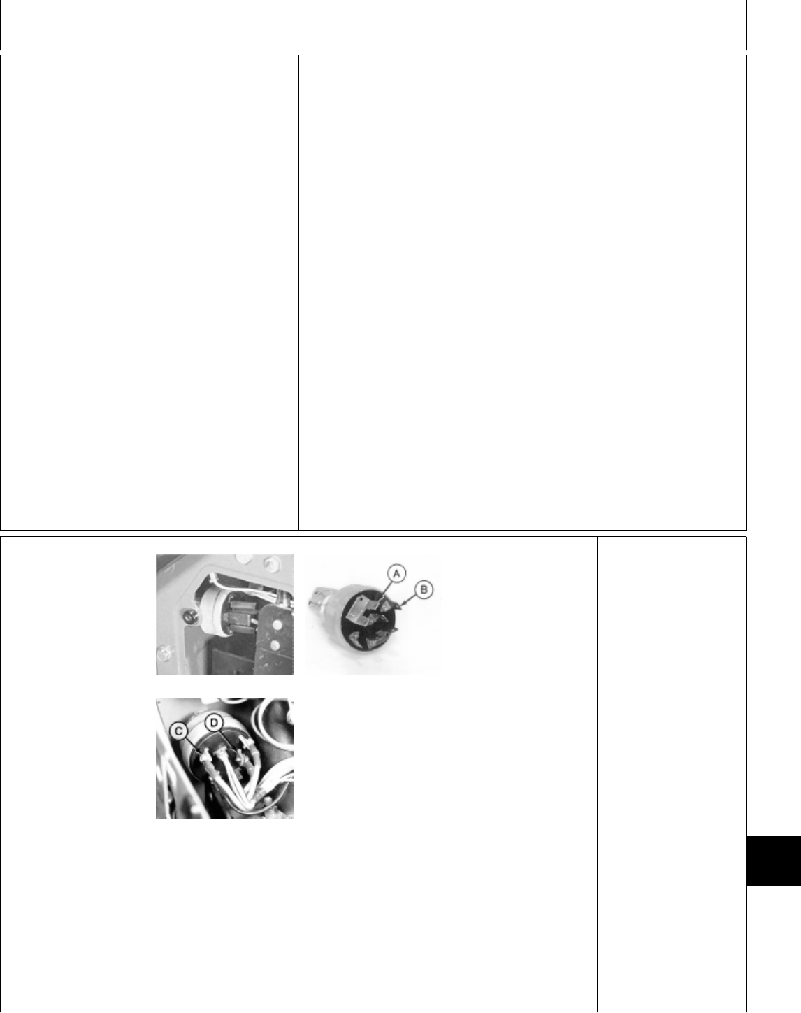
; DASH LAMP
CIRCUIT TESTS
Listed at right are
symptoms that may
occur in a
malfunctioning dash
lamp circuit. Locate the
symptom that applies,
then proceed to the
appropriate test.
LAMP CIRCUIT SYMPTOMS:
—Fuses Blow When Any Of The
Lamp Circuits Are Energized. Check
For Shorts In The Power Circuit:
GO TO Ò, Group 25.
—No Lamps Come ON: GO TO
1a
—Oil Pressure Lamp Does Not
Come On: GO TO 1c
—Oil Pressure Lamp On All The
Time: GO TO 1e
—Coolant Temperature Lamp Does
Not Come On: GO TO 1f
—Coolant Temperature Lamp On All
The Time: GO TO 1h
—Coolant Temperature Lamp
Comes On When Low Fuel Lamp
Comes On: GO TO 1i.
—Low Fuel Lamp Does Not Come
On—322/332 (All) and 430 (S.N.
475001— ): GO TO 1k
—Low Fuel Lamp Does Not Come
On—430 (S.N. —475000): GO TO
1l
—Low Fuel Lamp On All The Time:
GO TO 1n
—Battery Discharge Lamp Does Not
Come On—322, 330 and 332: GO
TO 1o
—Battery Discharge Lamp Does Not
Come On—430: GO TO 1p
—Battery Discharge Lamp On All
The Time—430: GO TO 1s
—Engine Preheat Lamp Does Not
Come On: GO TO 1t
—Engine Preheat Lamp On All The
Time: GO TO 1v
—Water-In-Fuel Lamp Does Not
Come On—430: GO TO 1w
—Water-In-Fuel Lamp On All The
Time—430: GO TO 1×a
1a No Lamps Work
NOTE: The dash lamps
receive power from the
10-amp fuse. When no
lamps work, check for a
problem in the power
circuit.
Check 10-amp fuse.
M49010 -UN-08JAN90
M36599 -UN-27APR95
M55135 -UN-28APR95
NOTE: Top photos
show key switch for
322, 330 and 332.
Lower photo shows key
switch for 430.
322, 330 and 332;
Check for voltage at
“BAT” terminal (B).
430; Check for voltage
at “B” terminal (D).
NO VOLTAGE: GO TO
1b
VOLTAGE: Turn key
switch to ON/RUN
position.
322, 330 and 332;
Check for voltage at
“IGN” terminal (A).
430; Check for voltage
at “BR” terminal (C).
VOLTAGE: Power
circuit and key switch
OK. Check for voltage
at 10-amp fuse. If no
voltage at fuse, wire
between key switch and
fuse is open. Repair or
replace wire as
necessary, then GO TO
;, Group 05.
NO VOLTAGE: GO TO
Æ, Group 25.
MX,159124020,11-19-13JUL95
MX,159124020,12-19-13JUL95
Electrical System Diagnosis/Dash Lamp Circuit Tests
TM1591 (15JUL95) 240-20-7 322,330,332 & 430 Lawn & Garden Tractors
030895
240
20
7
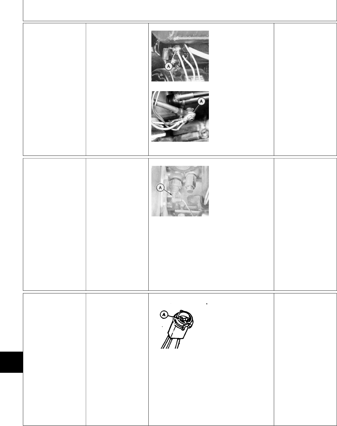
1b Key Switch
Fusible Link Test
Key switch OFF.
M45229 -UN-12JAN90
M36600 -UN-27APR95
NOTE: Top
photo—322, 330 and
332.
Bottom photo—430.
Check for voltage at
starter common
terminal (A).
VOLTAGE: Replace
fusible link.
NO VOLTAGE: Check
battery terminals and
cables. Repair or
replace as needed.
1c Engine Oil
Pressure Lamp
Test
Check 10-amp fuse.
NOTE: If lamp stays on
at all times: GO TO
1e
Remove left engine
side panel.
Key switch ON/RUN
position.
M43250 -UN-15JAN90
Remove wire (A) from
oil pressure switch.
Touch wire (A) to
ground.
LOOK: Lamp should be
ON.
OK: Replace switch,
then GO TO ;, Group
05.
NOT OK: GO TO 1d
1d Engine Oil
Pressure Lamp
Voltage Test
Remove bulb socket
from dash.
Remove bulb.
M36632 -UN-26AUG88
Check for voltage at
terminal with two yellow
wires (A).
VOLTAGE: Tan wire to
oil pressure switch is
open. Repair or replace
wire, then GO TO ;,
Group 05.
NO VOLTAGE: Wire
between 10-amp fuse
and lamp socket is
open. Repair or replace
wire, then GO TO ;,
Group 05.
MX,159124020,13-19-13JUL95
MX,159124020,14-19-13JUL95
MX,159124020,15-19-13JUL95
Electrical System Diagnosis/Dash Lamp Circuit Tests
TM1591 (15JUL95) 240-20-8 322,330,332 & 430 Lawn & Garden Tractors
030895
240
20
8
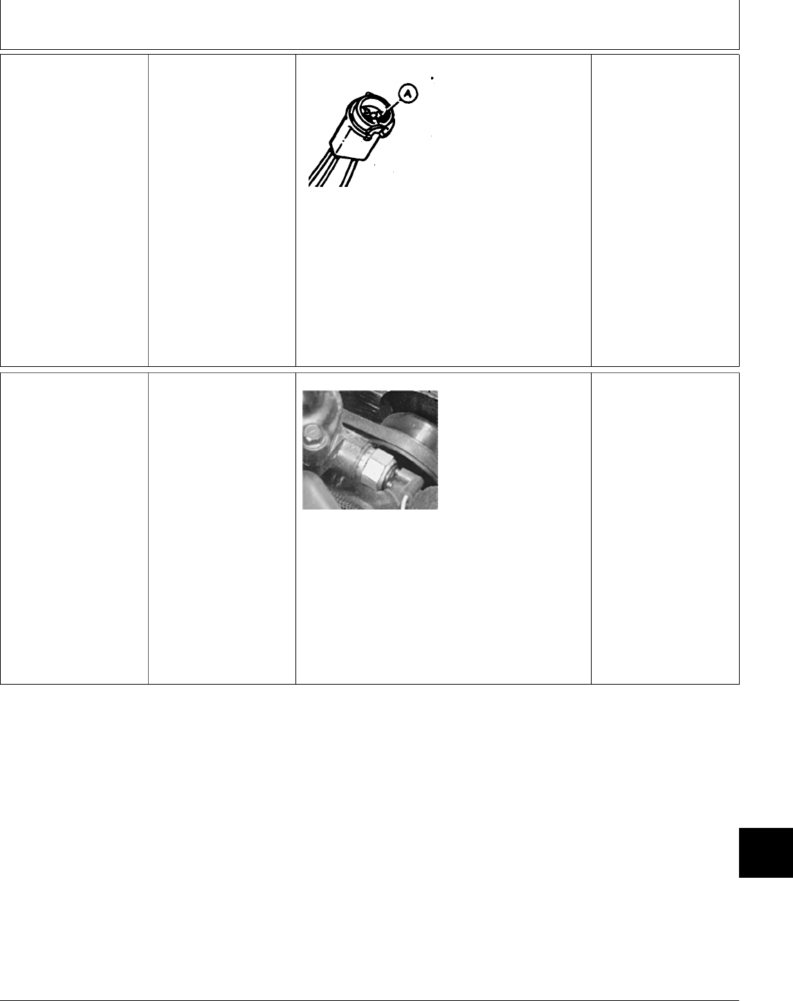
1e Engine Oil
Pressure Lamp
Short Circuit Test
Key switch OFF.
Remove left engine
side panel.
Disconnect tan lead
from oil pressure
switch.
Remove bulb socket
from dash.
Remove bulb.
M36633 -UN-24APR89
Check for continuity
between terminal with
tan wire (A) and
ground.
CONTINUITY: The tan
wire is shorted to
ground. Repair or
replace, then GO TO ;,
Group 05.
NO CONTINUITY:
Circuit is OK. Check
engine oil pressure.
(See Section 220.)
1f Engine Coolant
Temperature Lamp
Test
Check 10-amp fuse.
If lamp stays on at all
times: GO TO 1h
M36603 -UN-25JAN90
Turn key switch to
ON/RUN position.
Disconnect wire from
temperature switch.
Touch temperature
switch wire to ground.
LOOK: Lamp should be
ON.
OK: Replace switch,
then GO TO ;, Group
05.
NOT OK: GO TO 1g
MX,159124020,16-19-13JUL95
MX,159124020,17-19-13JUL95
Electrical System Diagnosis/Dash Lamp Circuit Tests
TM1591 (15JUL95) 240-20-9 322,330,332 & 430 Lawn & Garden Tractors
030895
240
20
9
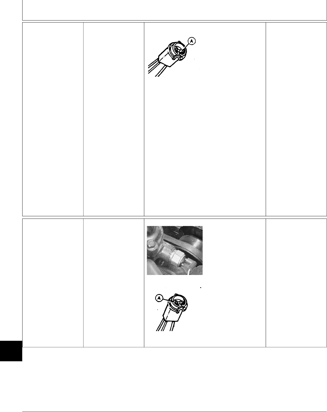
1g Engine Coolant
Temperature Lamp
Voltage Test
Remove bulb socket
from dash.
Remove bulb.
Turn key switch to
ON/RUN position.
M36636 -UN-08SEP88
Check for voltage at
terminal with single
yellow wire (A).
VOLTAGE: Wire
between temperature
switch and bulb socket
is open. Repair or
replace wire, then GO
TO ;, Group 05.
NO VOLTAGE: Check
for voltage at terminal
with two yellow wires
on oil pressure lamp
socket.
VOLTAGE: Yellow wire
between oil pressure
lamp and coolant
temperature lamp is
open. Repair or replace
wire, then GO TO ;,
Group 05.
NO VOLTAGE: Wire
between oil pressure
lamp and 10-amp fuse
is open. Repair or
replace wire, then GO
TO ;, Group 05.
1h Engine Coolant
Temperature Lamp
Short Circuit Test
Key switch OFF.
Remove lamp socket
from dash.
Remove bulb.
M36603 -UN-25JAN90
M36632 -UN-26AUG88
Disconnect wire from
coolant temperature
switch.
Check continuity
between contact with
two wires (A) at lamp
socket and ground.
NOTE: Because this
circuit contains a diode,
there may be continuity
to ground in one
direction only.
Reverse meter leads,
then check continuity
again.
CONTINUITY: Wire
between temperature
switch and lamp socket
or wire between lamp
socket and key switch
is shorted to ground.
Repair or replace wire,
then GO TO ;, Group
05.
NO CONTINUITY:
Circuit is OK. Check
engine oil pressure.
(See Section 220.)
MX,159124020,18-19-13JUL95
MX,159124020,19-19-13JUL95
Electrical System Diagnosis/Dash Lamp Circuit Tests
TM1591 (15JUL95) 240-20-10 322,330,332 & 430 Lawn & Garden Tractors
030895
240
20
10
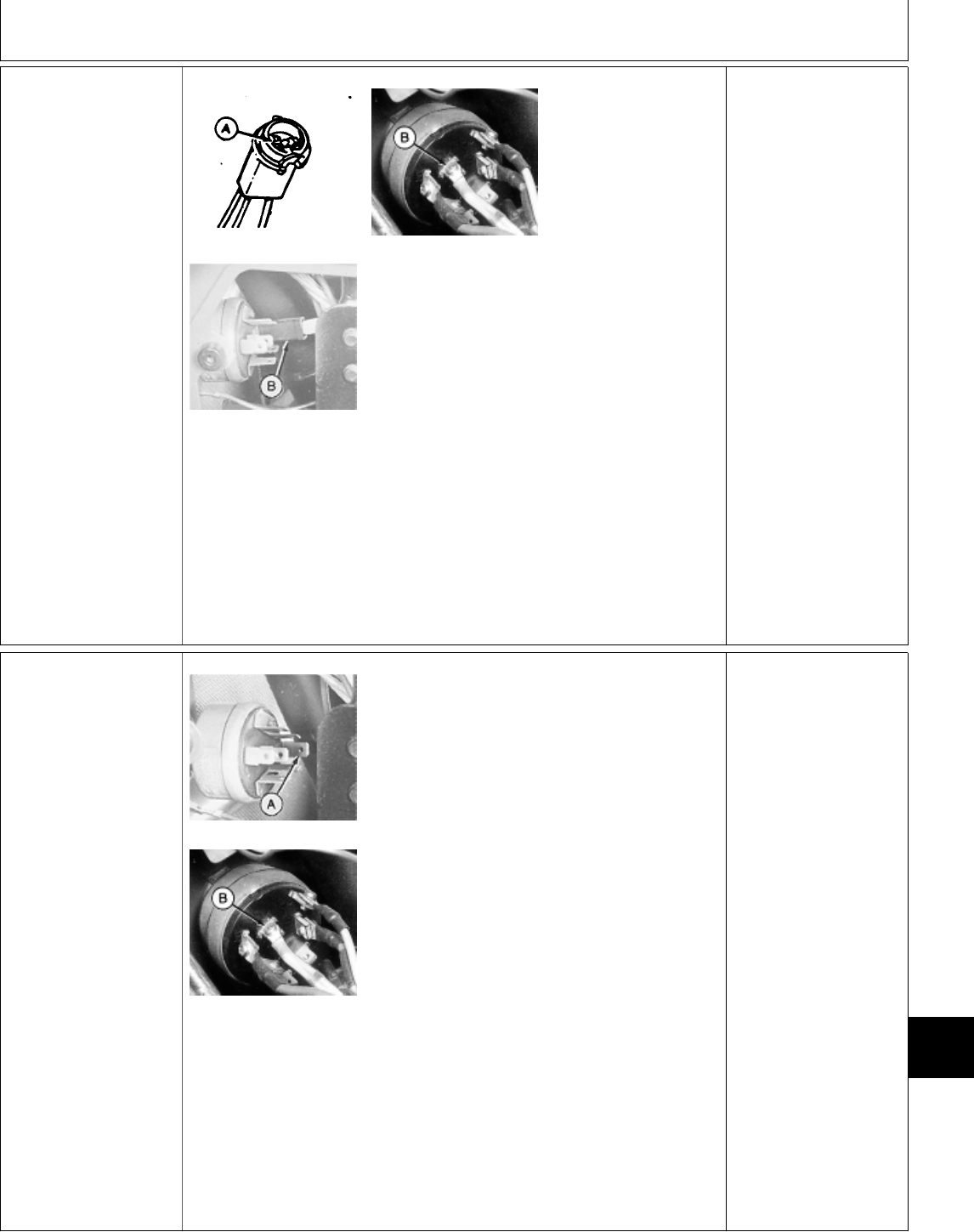
1i Diode and Lamp
Ground Circuit Test
NOTE: Diodes are
designed to allow
current flow in only one
direction.
The 330 does not use
diodes in the lamp test
circuit. M36632 -UN-26AUG88
M45185 -UN-08JAN90
M36604 -UN-27APR95
NOTE: Upper right
photo shows key switch
used in 430.
Lower left photo shows
key switch used in 322,
330 and 332.
Key switch OFF.
Remove either
defective low fuel or
coolant temperature
bulb socket from dash.
Remove bulb.
Check continuity
between the two wire
contact (A) on the bulb
socket and terminal (B)
of key switch.
Reverse meter leads
and check continuity
again.
CONTINUITY ONE
DIRECTION: Diode OK,
GO TO 1j
CONTINUITY IN BOTH
DIRECTIONS: Diode
shorted. Replace diode,
then GO TO ;, Group
05.
NO CONTINUITY:
Diode or wire between
diode and lamp socket
is open. Replace diode
and/or repair wire, then
GO TO ;, Group 05.
1j Key Switch
Ground Circuit Test
NOTE: Upper photo
shows key switch used
in 322, 330 and 332.
Lower photo shows key
switch used in 430.
M45184 -UN-08JAN90
M36604 -UN-27APR95
322, 330 and 332:
—Disconnect key
switch connector.
—Turn key switch to
START position.
—Check continuity
between key
switch “G”
terminal (A) and
ground.
430:
—Disconnect battery
negative (—) cable.
—Disconnect lead with
yellow/red and
green/white wires
from “BA” terminal
(B).
—Turn key switch fully
counterclockwise to
the lamp test
position.
—Check continuity
between terminal
(B) and ground.
CONTINUITY: Ground
circuit OK.
NO CONTINUITY:
322, 330 and 332;
Check continuity
between key switch
chassis and ground.
430; Check continuity
between terminal “E” on
key switch and ground.
CONTINUITY: Replace
key switch, then GO
TO ;, Group 05.
NO CONTINUITY:
Black wire between key
switch and ground is
open or ground wire
has poor connection.
Repair or replace as
necessary, then GO TO
;, Group 05.
MX,159124020,20-19-13JUL95
MX,159124020,21-19-13JUL95
Electrical System Diagnosis/Dash Lamp Circuit Tests
TM1591 (15JUL95) 240-20-11 322,330,332 & 430 Lawn & Garden Tractors
030895
240
20
11
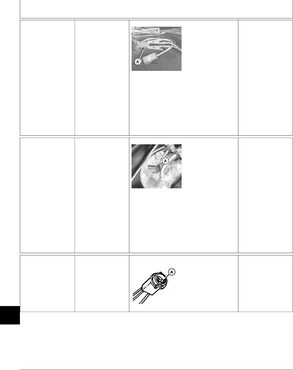
1k Low Fuel Circuit
Test—322, 332 and
430 (SN 475001— )
NOTE: The problem
maybe a blown fuse or
burned out bulb. Check
the 10-amp fuse and
low fuel lamp bulb
before preceding with
circuit test.
Remove fender deck to
access low fuel sensor.
M45182 -UN-08JAN90
Disconnect low fuel
sensor 2-pin connector.
Connect a jumper wire
across terminals of
harness side of
connector (A).
Turn key switch to
ON/RUN position.
LOOK: Low fuel lamp
must come ON.
OK: GO TO ;, Group
25.
NOT OK: Connect
jumper wire from
black/white wire at
connector to ground.
LAMP ON: Black wire
between sensor and
ground is open. Repair
or replace wire, then
GO TO ;, Group 05.
LAMP NOT ON: GO
TO 1m
1l Low Fuel Circuit
Test—430 (SN
—475000)
NOTE: The problem
maybe a blown fuse or
burned out bulb. Check
the 10-amp fuse and
low fuel lamp bulb
before preceding with
circuit test.
Remove fender deck to
access low fuel sensor.
M36610 -UN-27APR95
Disconnect green/white
wire (A) from sensor
terminal.
Connect jumper wire
from the green/white
wire to ground.
Turn key switch to
ON/RUN position.
LOOK: Low fuel lamp
must come ON.
OK: GO TO ;, Group
25.
NOT OK: GO TO 1m
1m Low Fuel Lamp
Voltage Test
Remove bulb socket
from dash.
Remove bulb.
M36636 -UN-08SEP88
Turn key switch to
ON/RUN position.
Check for voltage at
yellow wire contact (A).
VOLTAGE: Replace
wire between sensor
and bulb socket.
NO VOLTAGE: Replace
wire between 10-amp
fuse and bulb socket.
MX,159124020,22-19-13JUL95
MX,159124020,23-19-13JUL95
MX,159124020,24-19-13JUL95
Electrical System Diagnosis/Dash Lamp Circuit Tests
TM1591 (15JUL95) 240-20-12 322,330,332 & 430 Lawn & Garden Tractors
030895
240
20
12
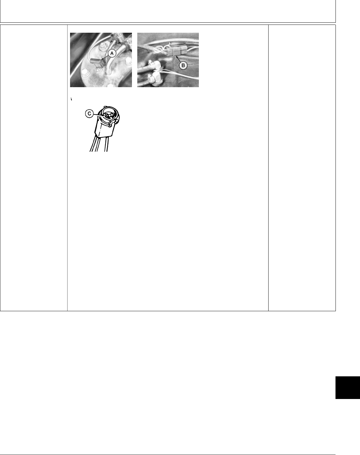
1n Low Fuel Lamp
Short Circuit Test
M36610 -UN-27APR95
M78963 -UN-27APR95
M49016 -UN-28APR95
Key switch OFF.
Remove fender deck to
access low fuel sensor.
430 (S.N. —475000);
Disconnect green/white
wire (A) from low fuel
sensor.
322/332 (All) and 430
(S.N. 475001— );
Disconnect low fuel
sensor 2-pin connector
(B).
Remove low fuel bulb
socket from dash and
remove bulb.
Check continuity
between bulb socket
contact with two wires
(C) and ground.
NOTE: Because this
circuit contains a diode,
there may be continuity
to ground in one
direction only.
Reverse meter leads,
then check continuity
again.
CONTINUITY: Wire
between sensor and
lamp socket or wire
between lamp socket
and key switch is
shorted to ground.
Repair or replace wire,
then GO TO ;, Group
05.
NO CONTINUITY:
Circuit is OK.
MX,159124020,25-19-13JUL95
Electrical System Diagnosis/Dash Lamp Circuit Tests
TM1591 (15JUL95) 240-20-13 322,330,332 & 430 Lawn & Garden Tractors
030895
240
20
13
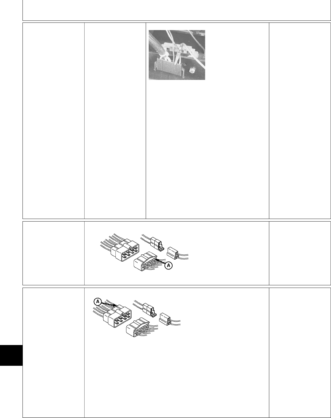
1o Battery Discharge
Lamp Test—322,
330 and 332
Check 10 amp fuse.
NOTE: If discharge
stays on at all times,
test voltage output of
charging system. GO
TO Ö, Group 25.
M45179 -UN-08JAN90
Disconnect
regulator/rectifier
connector.
Connect jumper wire
from brown lead in
connector to positive
(+) battery terminal.
LOOK: Discharge lamp
must come ON.
OK: Verify good ground
at black wire terminal of
regulator/rectifier. Turn
key switch ON/RUN to
check for voltage at
green wire terminal of
regulator/rectifier
connector. If voltage
and ground OK, replace
regulator/rectifier.
NOT OK: Brown wire
between
regulator/rectifier and
lamp socket is open or
black wire between
discharge lamp socket
and ground is open or
has bad ground
connection. Repair or
replace as necessary,
then GO TO ;, Group
05.
1p Battery Discharge
Lamp Test—430
Check 10 amp fuse.
NOTE: If discharge
lamp stays on at all
times, GO TO 1s
M36634 -UN-09JUN95
Connect a jumper wire
from brown wire (A) to
ground.
Turn key switch to
ON/RUN position.
LOOK: Discharge lamp
must come ON.
OK: GO TO 1q
NOT OK: GO TO 1r
1q Battery Discharge
Lamp Ground
Circuit Test—430
M78975 -UN-09JUN95
Key switch OFF.
Check continuity
between terminal with
brown wire (A) (TDC
side of 8-pin connector)
and ground.
CONTINUITY: Circuit
OK.
NO CONTINUITY:
Disconnect 2-pin
connector and check
continuity between
terminal with black wire
(harness side of
connector) and ground.
CONTINUITY: Replace
TDC module, then GO
TO ;, Group 05.
NO CONTINUITY:
Repair or replace black
wire, then GO TO ;,
Group 05.
MX,159124020,26-19-13JUL95
MX,159124020,27-19-13JUL95
MX,159124020,28-19-13JUL95
Electrical System Diagnosis/Dash Lamp Circuit Tests
TM1591 (15JUL95) 240-20-14 322,330,332 & 430 Lawn & Garden Tractors
030895
240
20
14
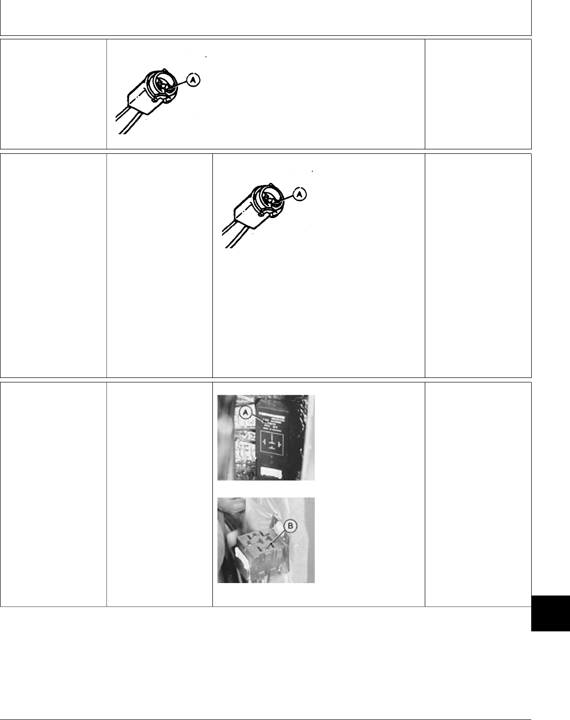
1r Battery Discharge
Lamp Voltage
Test—430
M36635 -UN-24APR89
Remove battery discharge bulb socket from
dash.
Remove bulb.
Turn key switch to ON/RUN position.
Check for voltage at terminal with single yellow
wire (A).
VOLTAGE: Circuit OK.
Replace bulb.
NO VOLTAGE: Yellow
wire between 10-amp
fuse and lamp socket is
open. Repair or replace
wire, then GO TO ;,
Group 05.
1s Battery Discharge
Lamp Short Circuit
Test—430
Key switch OFF.
M36635 -UN-24APR89
Remove battery
discharge bulb socket
from dash.
Remove bulb.
(S.N. —420468);
Disconnect TDC
module 8-pin connector.
(S.N. 420469— );
Disconnect 2-pin
connector from
alternator.
Check continuity
between terminal with
brown wire (A) and
ground.
CONTINUITY: Brown
wire is shorted to
ground. Repair or
replace wire, then GO
TO ;, Group 05.
NO CONTINUITY:
Circuit OK. Test voltage
output of charging
circuit; GO TO 5d,
Group 25.
1t Engine Preheat
Lamp Test (330,
332, 430)
NOTE: If lamp stays on
at all times, GO TO
1v
Check 10-amp fuse.
Remove left engine
side panel.
M55103 -UN-09DEC89
M36609 -UN-25JAN90
Remove glow plug
controller (A).
Connect jumper wire
from grey lead wire
terminal (B) of
connector to ground.
LOOK: Engine preheat
lamp must come ON.
OK: GO TO Å
NOT OK: Check bulb,
then GO TO 1u
MX,159124020,29-19-13JUL95
MX,159124020,30-19-13JUL95
MX,159124020,31-19-13JUL95
Electrical System Diagnosis/Dash Lamp Circuit Tests
TM1591 (15JUL95) 240-20-15 322,330,332 & 430 Lawn & Garden Tractors
030895
240
20
15
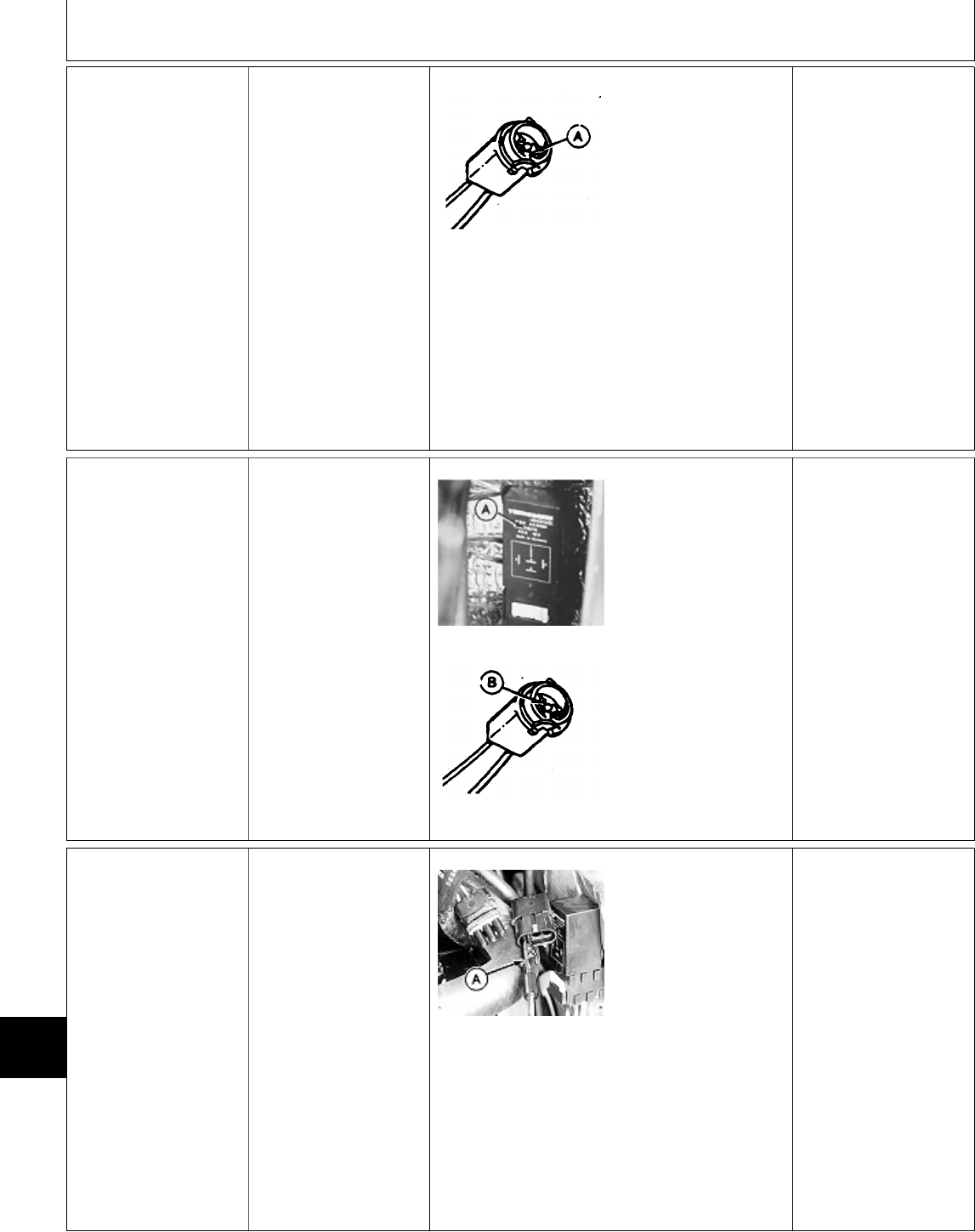
1u Engine Preheat
Lamp Circuit Test
(330, 332, 430)
Remove bulb socket
from dash.
Remove bulb.
Turn key switch to
ON/RUN position.
M36635 -UN-24APR89
Check for voltage at
terminal with yellow
lead (A).
VOLTAGE: Repair or
replace grey wire to
glow plug controller
socket, then GO TO ;,
Group 05.
NO VOLTAGE: Repair
or replace wire between
10-amp fuse and bulb
socket, then GO TO ;,
Group 05.
1v Engine Preheat
Lamp Short Circuit
Test (330, 332, 430)
Key switch OFF.
M55103 -UN-09DEC89
M36637 -UN-24APR89
Remove glow plug
controller (A).
Remove bulb socket
from dash. Remove
bulb.
Check for continuity
between terminal with
grey lead (B) and
ground.
CONTINUITY: Grey
lead to controller is
shorted. Repair or
replace as necessary,
then GO TO ; Group
05.
NO CONTINUITY:
Install controller and
lamp socket, then GO
TO Å
1w Water-In-Fuel
Lamp Test (430)
If lamp stays on at all
times, GO TO 1×a
Remove left engine
side panel.
Turn key switch to RUN
position.
M36605 -UN-12APR95
Disconnect 3-pin
connector at fuel filter
base.
Connect a jumper wire
(A) from yellow/black
wire to ground.
LOOK: Water-in-fuel
lamp must come ON.
OK: GO TO 1z
NOT OK: Check bulb,
then GO TO 1x
MX,159124020,32-19-13JUL95
MX,159124020,33-19-13JUL95
MX,159124020,34-19-13JUL95
Electrical System Diagnosis/Dash Lamp Circuit Tests
TM1591 (15JUL95) 240-20-16 322,330,332 & 430 Lawn & Garden Tractors
030895
240
20
16
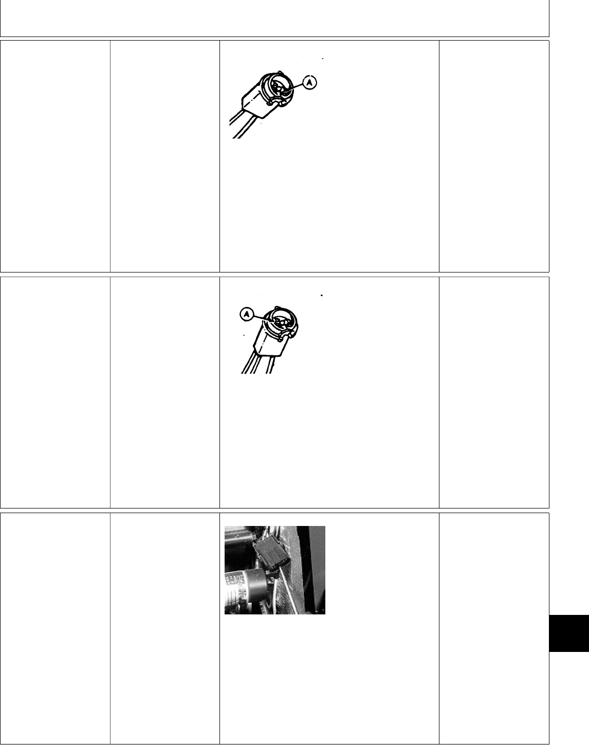
1x Water-In-Fuel
Lamp Circuit Test
(430)
Remove water-in-fuel
bulb socket from dash.
Remove bulb.
Turn key switch to RUN
position.
M36635 -UN-24APR89
Check for voltage at
terminal with yellow
wire (A).
VOLTAGE: Repair or
replace yellow/black
wire between bulb
socket and sensor
connector, then GO TO
;, Group 05.
NO VOLTAGE:
For (S.N. —420468);
Repair or replace wire
between 10-amp fuse
and bulb socket, then
GO TO ;, Group 05.
For (S.N. 420469— );
GO TO 1y
1y Water-In-Fuel
Lamp Circuit
Test—Continued
(430)
Remove engine oil
pressure bulb socket
from dash.
Remove bulb.
Turn key switch to RUN
position.
M36632 -UN-26AUG88
Check for voltage at oil
pressure socket
terminal with two yellow
wires (A).
VOLTAGE: Repair or
replace yellow wire
between water-in-fuel
bulb socket and oil
pressure bulb socket,
then GO TO ;, Group
05.
NO VOLTAGE: Repair
or replace wire between
10-amp fuse and oil
pressure bulb socket,
then GO TO ;, Group
05.
1z Water-In-Fuel
Sensor Circuit Test
(430)
Remove left engine
side panel.
Turn key switch to RUN
position.
M36606 -UN-12APR95
Check for voltage at
yellow wire of 3-pin
sensor connector.
VOLTAGE: Test
water-in-fuel sensor,
GO TO ;, Group 25.
NO VOLTAGE: Repair
or replace wire between
10-amp fuse and 3-pin
connector, then GO TO
;, Group 05.
MX,159124020,35-19-13JUL95
MX,15912402035A-19-13JUL95
MX,159124020,36-19-13JUL95
Electrical System Diagnosis/Dash Lamp Circuit Tests
TM1591 (15JUL95) 240-20-17 322,330,332 & 430 Lawn & Garden Tractors
030895
240
20
17
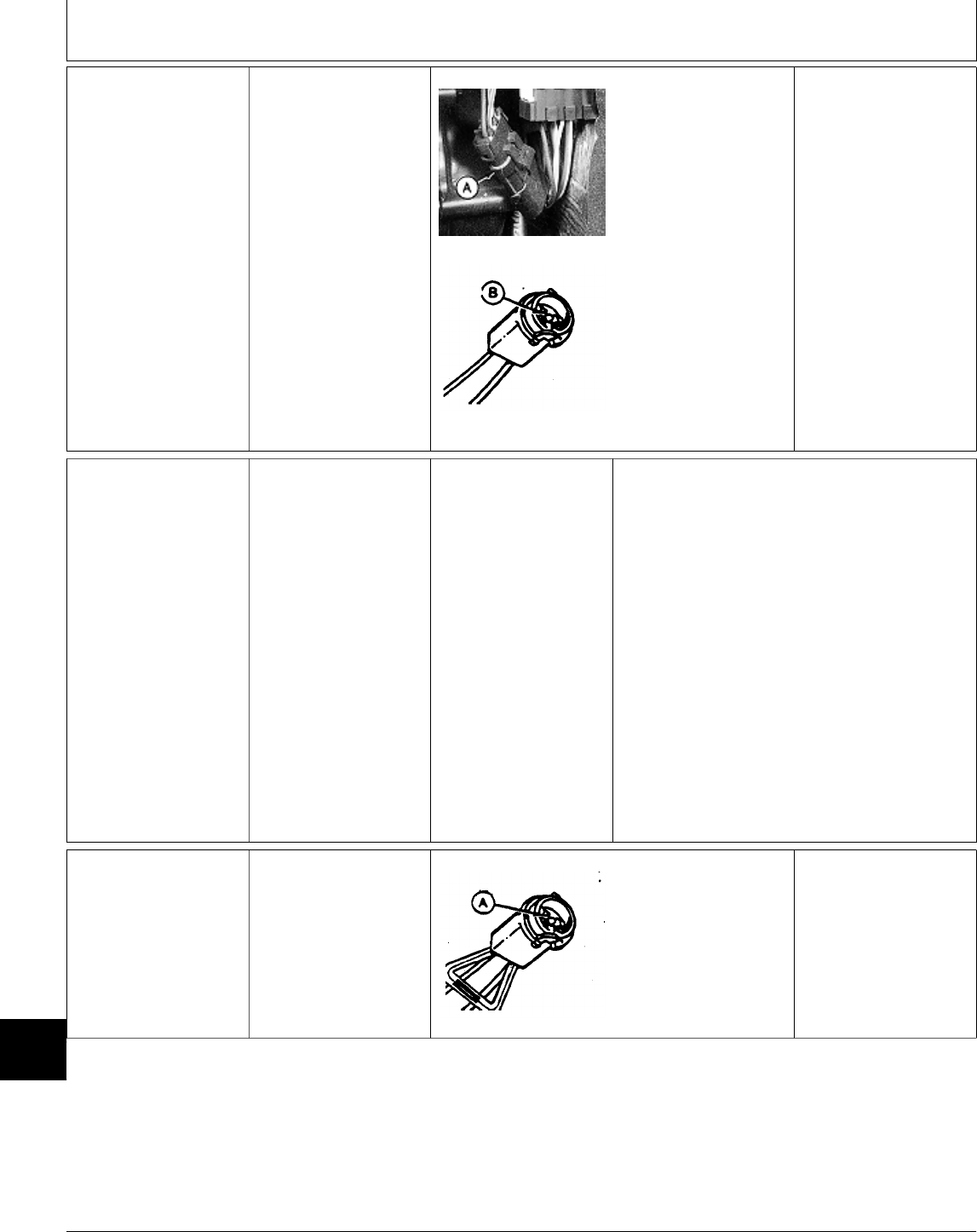
1×a Water-In-Fuel
Lamp Short
Circuit Test (430)
Key switch OFF.
M36607 -UN-12APR95
M36637 -UN-24APR89
Disconnect 3-pin
connector (A) at fuel
filter base.
Remove bulb socket
from dash.
Remove bulb.
Check for continuity
between terminal with
yellow/black wire (B)
and ground.
CONTINUITY;
Yellow/black wire is
shorted to ground.
Repair or replace as
needed, then GO TO
;, Group 05.
NO CONTINUITY:
Circuit OK. Test sensor,
GO TO ;, Group 25.
‘ PTO CLUTCH AND
LAMP CIRCUIT
TESTS
Check 10-amp and
25-amp fuses.
Listed at right are
symptoms that may
occur if the PTO clutch
circuit malfunctions.
Locate the symptom
that applies, then
proceed to the
appropriate test.
IMPORTANT: Test
battery and verify
system ground
connections before
testing PTO circuit.
(See A and B at the
beginning of this
group.)
PTO CLUTCH CIRCUIT SYMPTOMS:
—PTO Lamp Does Not Come On, But
Clutch Engages: GO TO 2a
—PTO Lamp Burns Out Frequently:
GO TO 2b
—PTO Lamp Comes On, But Clutch Doesn’t
Engage: GO TO 2c
—PTO Lamp Does Not Come On And
Clutch Doesn’t Engage: GO TO 2d
—PTO Doesn’t Disengage When Operator
Raises From Seat For One Second Or
Longer: GO TO 2k
—PTO Clutch Slips: GO TO ‘, Group 25.
2a PTO Lamp Test Remove PTO lamp
socket from dash.
Remove and check
bulb. Replace as
necessary.
M36643 -UN-29AUG88
If bulb is OK, check for
continuity between
terminal with black lead
(A) and ground.
NO CONTINUITY:
Repair or replace
ground wire as needed.
CONTINUITY: Repair
or replace blue wire
between PTO switch
and bulb socket.
MX,159124020,37-19-13JUL95
MX,159124020,93-19-13JUL95
MX,159124020,94-19-13JUL95
Electrical System Diagnosis/PTO Clutch and Lamp Circuit Tests
TM1591 (15JUL95) 240-20-18 322,330,332 & 430 Lawn & Garden Tractors
030895
240
20
18

2b PTO Lamp Diode
Test
NOTE: Diodes are
designed to allow
current flow in one
direction only.
Remove dash lamp
socket. Remove bulb. Check diode with
ohmmeter or continuity
tester. If using a digital
meter, use the DIODE
CHECK position on
meter.
Check for continuity
across terminals of bulb
socket. Reverse leads
and check again.
LOOK: There should be
continuity in one
direction only.
CONTINUITY ONE
DIRECTION ONLY:
Circuit probably has an
intermittent short.
Check all connections
and grounds.
CONTINUITY BOTH
DIRECTIONS OR NO
CONTINUITY: Replace
diode, then GO TO ‘,
Group 05.
2c PTO Clutch Test NOTE: To test the optional rear PTO clutch,
remove fender deck and raise fuel tank off
frame. Disconnect the rear PTO clutch wire
connector located along left side of rear machine
frame, then follow same test procedure used for
front PTO clutch.
M45186 -UN-08JAN90
NOTE: 322 (All) and 332/430 (S.N. 475001— )
use a 2-pin connector for the PTO clutch.
330 and 332/430 (S.N. —475000); A 1-pin
connector is used. The clutch ground wire
connects directly to the machine frame.
Disconnect PTO clutch wire connector.
322 (All) and 332/430 (S.N. 475001— );
Connect one end of a jumper wire to terminal (B)
(black wire) at clutch connector and the other
end to ground.
All machines; Connect one end of a jumper wire
to battery positive (+) terminal and the other end
to terminal (A) (blue wire) at clutch connector.
CLUTCH ENGAGES:
330 and 332/430 (S.N. —475000); Blue wire
between PTO switch and PTO clutch is open.
Repair or replace wire, then GO TO ‘, Group
05.
322 (All) and 332/430 (S.N. 475001— ); Verify
ground at black wire (harness side) of 2-pin
connector. If ground OK, blue wire between PTO
switch and PTO clutch is open. Repair or replace
wire, then GO TO ‘, Group 05.
CLUTCH DOES NOT ENGAGE:
322 (All) and 332/430 (S.N. 475001— ); Repair
clutch. GO TO Section 40.
330 and 332/430 (S.N. —475000); Check for
good ground. If ground OK, repair clutch. GO TO
Section 40.
MX,159124020,95-19-13JUL95
MX,159124020,96-19-13JUL95
Electrical System Diagnosis/PTO Clutch and Lamp Circuit Tests
TM1591 (15JUL95) 240-20-19 322,330,332 & 430 Lawn & Garden Tractors
030895
240
20
19
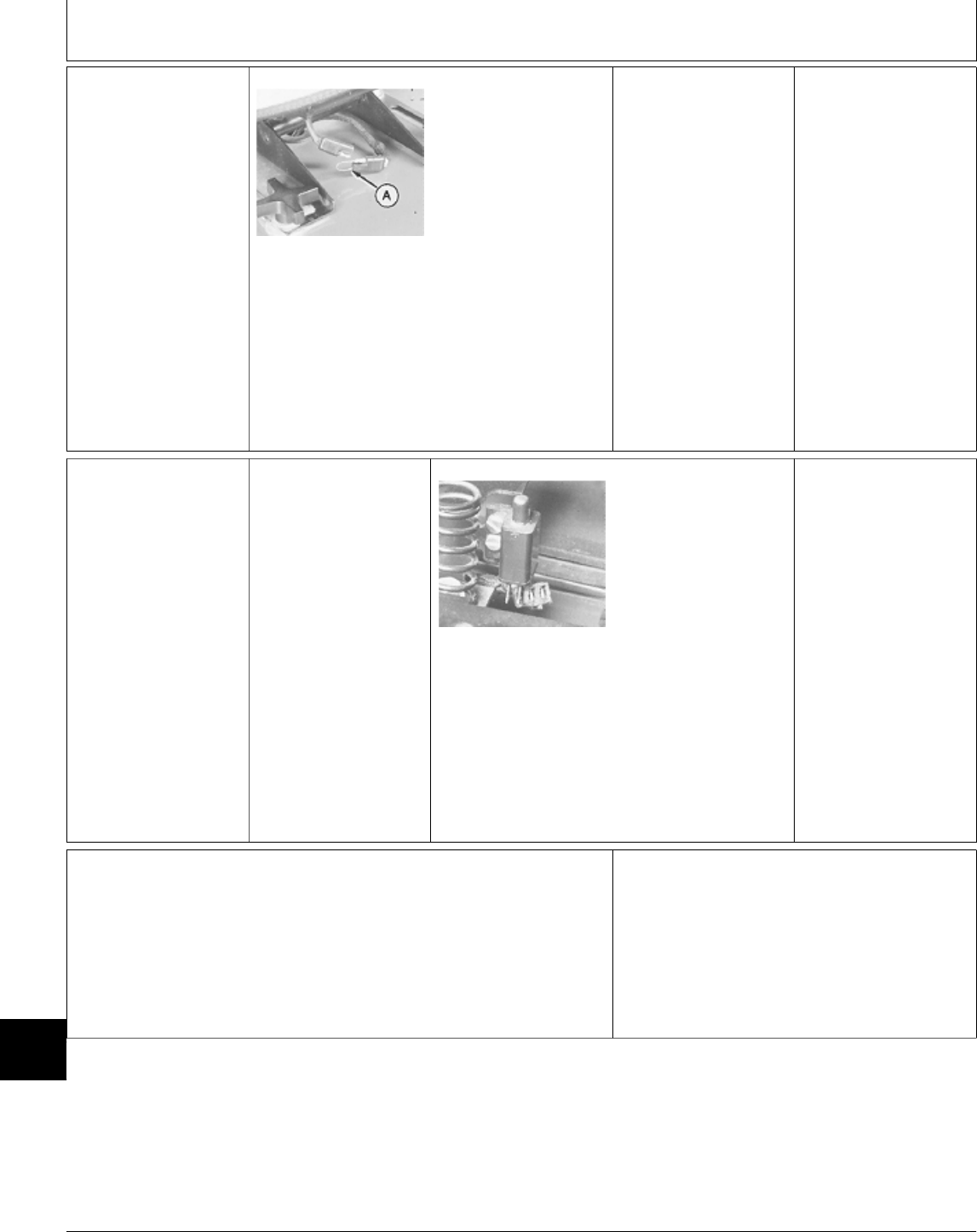
2d PTO Clutch Circuit
Test
M36627 -UN-25JAN90
Install jumper wire (A)
across seat switch
connector (harness side
of connector).
NOTE: Seat switch for
330 and 332/430 (S.N.
—475000) shown.
Turn key switch to
ON/RUN position.
Move PTO switch to
ON position.
LOOK/LISTEN: PTO
lamp must come ON.
Clutch must “click” to
engage.
OK: Replace seat
switch, then GO TO ‘,
Group 05.
NOT OK: GO TO 2e
2e Voltage Test At
Seat Connector
Turn key switch to
ON/RUN position.
M45187 -UN-08JAN90
NOTE: Seat switch for
322 (All) and 332/430
(S.N. 475001— )
shown.
Check for voltage at
seat connector.
VOLTAGE:
322, 330 and 430 (S.N.
—420468), GO TO
2f
332 (All) and 430 (S.N.
420469— ), GO TO
2g
NO VOLTAGE: Pink
wire between seat
switch connector and
10-amp fuse is open.
Repair or replace wire
as necessary, then GO
TO ‘, Group 05.
2f PTO Circuit
Voltage Test At
TDC Module—322,
330 and
430 (SN —420468)
NOTE: Perform all continuity and
voltage tests before going to the
result column.
Continued on next page
Check both sides of connector when
testing for voltage and continuity. If
test OK at only one side of
connector, repair or replace
connector as needed.
MX,159124020,97-19-13JUL95
MX,159124020,98-19-13JUL95
Electrical System Diagnosis/PTO Clutch and Lamp Circuit Tests
TM1591 (15JUL95) 240-20-20 322,330,332 & 430 Lawn & Garden Tractors
030895
240
20
20

M36645 -UN-28APR95
PTO switch OFF.
Key switch OFF.
Install jumper wire
across harness side of
seat switch connector.
At TDC Module 2-pin
connector:
—Check for continuity
between terminal
with black wire (B)
and ground.
—Turn key switch to
ON/RUN position.
—Check for voltage
at terminal with pink
wire (A).
At TDC Module 8-pin
connector:
—Check for voltage
at terminal with
purple/white wire
(F).
—Check for voltage
at terminal with pink
wire (E) (yellow/
black wire, 322).
—Check for voltage
at terminal with blue
wire (C).
NOTE: For machines
equipped with optional
rear PTO (except 322),
Check for voltage at
terminal with blue wire
(D).
CONTINUITY AND
VOLTAGE OK: GO TO
2j
NO CONTINUITY
BETWEEN TERMINAL
(B) AND GROUND:
Black wire between
TDC 2-pin connector
and ground is open.
Repair or replace wire
as necessary, then GO
TO ‘, Group 05.
NO VOLTAGE AT
TERMINAL (A): Pink
wire between TDC
2-pin connector and
seat switch connector is
open. Repair or replace
wire as necessary, then
GO TO ‘, Group 05.
NO VOLTAGE AT
TERMINAL (F): GO TO
2h
NO VOLTAGE AT
TERMINAL (E): Wire
between 8-pin
connector and 25-amp
fuse is open. Repair or
replace wire, then GO
TO ‘, Group 05.
NO VOLTAGE AT
TERMINALS (C) OR
(D) WHEN ALL OTHER
TERMINALS TEST OK:
Replace TDC module.
2g PTO Circuit
Voltage Test At
TDC Module—332
(All) and
430 (SN 420469— )
NOTE: Perform all voltage and
continuity tests before going to the
result column.
Continued on next page
Check both sides of connector when
testing for voltage and continuity. If
test OK at only one side of
connector, repair or replace
connector as needed.
MX,159124020,99-19-13JUL95
Electrical System Diagnosis/PTO Clutch and Lamp Circuit Tests
TM1591 (15JUL95) 240-20-21 322,330,332 & 430 Lawn & Garden Tractors
030895
240
20
21
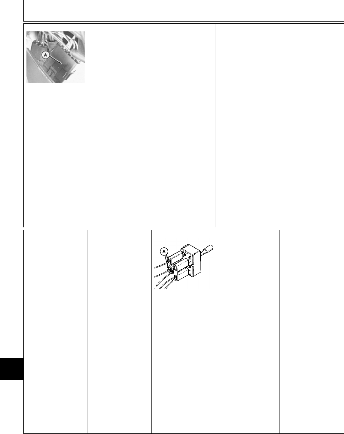
M49012 -UN-08JAN90
PTO switch OFF.
Key switch OFF.
Install jumper wire across harness side of seat
switch connector.
At TDC Module 3-pin connector:
—Check for continuity
of black wire
between terminal
“B” of connector
and ground.
—Turn key switch to
ON/RUN position.
—Check for voltage
at pink wire at
terminal “A” of
connector.
At TDC Module 6-pin connector (A):
—Check for voltage
at purple/white wire
at terminal “B” of
connector.
—Check for voltage
at blue wire at
terminal “D” of
connector.
CONTINUITY AND VOLTAGE OK: GO TO 2j
NO CONTINUITY BETWEEN TERMINAL “B” OF
3-PIN CONNECTOR AND GROUND: Black wire
between connector and ground is open. Repair
or replace wire as necessary, then GO TO ‘,
Group 05.
NO VOLTAGE AT TERMINAL “A” OF 3-PIN
CONNECTOR: Pink wire between connector and
seat switch connector is open. Repair or replace
wire as necessary, then GO TO ‘, Group 05.
NO VOLTAGE AT TERMINAL “B” OF 6-PIN
CONNECTOR: GO TO 2h
NO VOLTAGE AT TERMINAL “D” OF 6-PIN
CONNECTOR WHEN ALL OTHER TERMINALS
TEST OK: Replace TDC module.
2h Neutral Start
Circuit Voltage Test
At Rear PTO
Switch
NOTE: This test is for
machines equipped with
the optional rear PTO.
If machine is equipped
with front PTO only,
GO TO 2i.
PTO switches OFF.
Turn key switch to
ON/RUN position.
M36642 -UN-28APR95
Check for voltage at
terminals with purple
wires (A) on rear PTO
switch.
VOLTAGE AT BOTH
TERMINALS:
Purple/white wire
between TDC 8-pin
connector and rear
PTO harness 3-pin
connector or purple
wire between rear PTO
harness 3-pin connector
rear PTO switch is
open. Repair or replace
as necessary, then GO
TO ‘, Group 05.
VOLTAGE AT ONE
TERMINAL: Replace
switch, then GO TO ‘,
Group 05.
NO VOLTAGE AT
BOTH TERMINALS:
GO TO 2i
MX,159124020100-19-13JUL95
MX,159124020101-19-13JUL95
Electrical System Diagnosis/PTO Clutch and Lamp Circuit Tests
TM1591 (15JUL95) 240-20-22 322,330,332 & 430 Lawn & Garden Tractors
030895
240
20
22
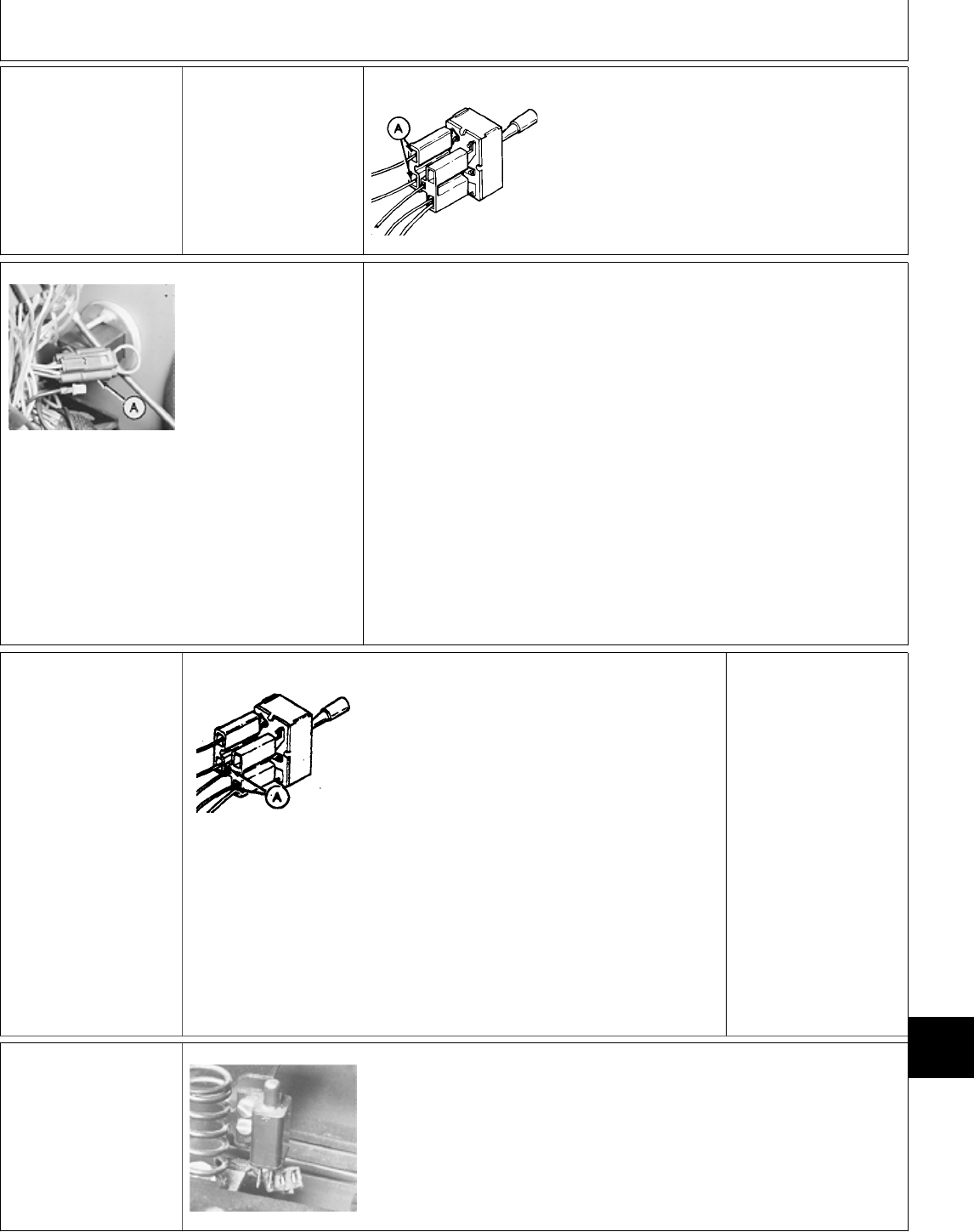
2i Neutral Start
Circuit Voltage Test
At Front PTO
Switch
PTO switch OFF.
Turn key switch to
ON/RUN position.
M36642 -UN-28APR95
Check for voltage at terminals with purple wires
(A) on front PTO switch.
M36624 -UN-25JAN90
NOTE: For machines
not equipped with the
optional rear PTO, a
jumper wire located at
rear PTO harness
connector (A) is used
to complete the circuit
to the transmission
neutral start switch.
VOLTAGE AT BOTH TERMINALS:
For machines equipped with
optional rear PTO, purple wire or
rear PTO harness 3-pin connector
between rear PTO switch and front
PTO switch is open. Repair or
replace as necessary, then GO TO
‘, Group 05.
For machines equipped with front
PTO only, purple/white wire, or
purple wire, or 3-pin connector with
jumper wire (A) between TDC 8-pin
connector and front PTO switch is
open. Repair or replace as
necessary, then GO TO ‘, Group
05.
VOLTAGE AT ONLY ONE
TERMINAL: Replace switch, then
GO TO ‘, Group 05.
NO VOLTAGE AT EITHER
TERMINAL: Wire between front
PTO switch and 25-amp fuse is
open. Repair or replace wire as
necessary, then GO TO ‘, Group
05.
2j PTO Circuit
Voltage Test At
PTO Switch
M36646 -UN-24APR89
Install jumper wire
across harness side of
seat switch connector.
Turn key switch to
ON/RUN position.
Move PTO switch to
ON position.
Check for voltage at
both terminals with blue
wires (A) on PTO
switch.
VOLTAGE AT ONE
TERMINAL: Replace
PTO switch.
VOLTAGE AT BOTH
TERMINALS: Repair or
replace wires between
PTO switch and clutch
and/or PTO switch and
lamp.
2k Seat Switch Test
M45187 -UN-08JAN90
NOTE: Seat switch for 322 and
332/430 (S.N. 475001— ) shown.
Key switch OFF.
Disconnect seat switch connector.
Connect ohmmeter or continuity
tester across switch terminals.
Continued on next page
There should NOT be continuity.
MX,159124020102-19-13JUL95
MX,159124020108-19-13JUL95
MX,159124020103-19-13JUL95
Electrical System Diagnosis/PTO Clutch and Lamp Circuit Tests
TM1591 (15JUL95) 240-20-23 322,330,332 & 430 Lawn & Garden Tractors
030895
240
20
23
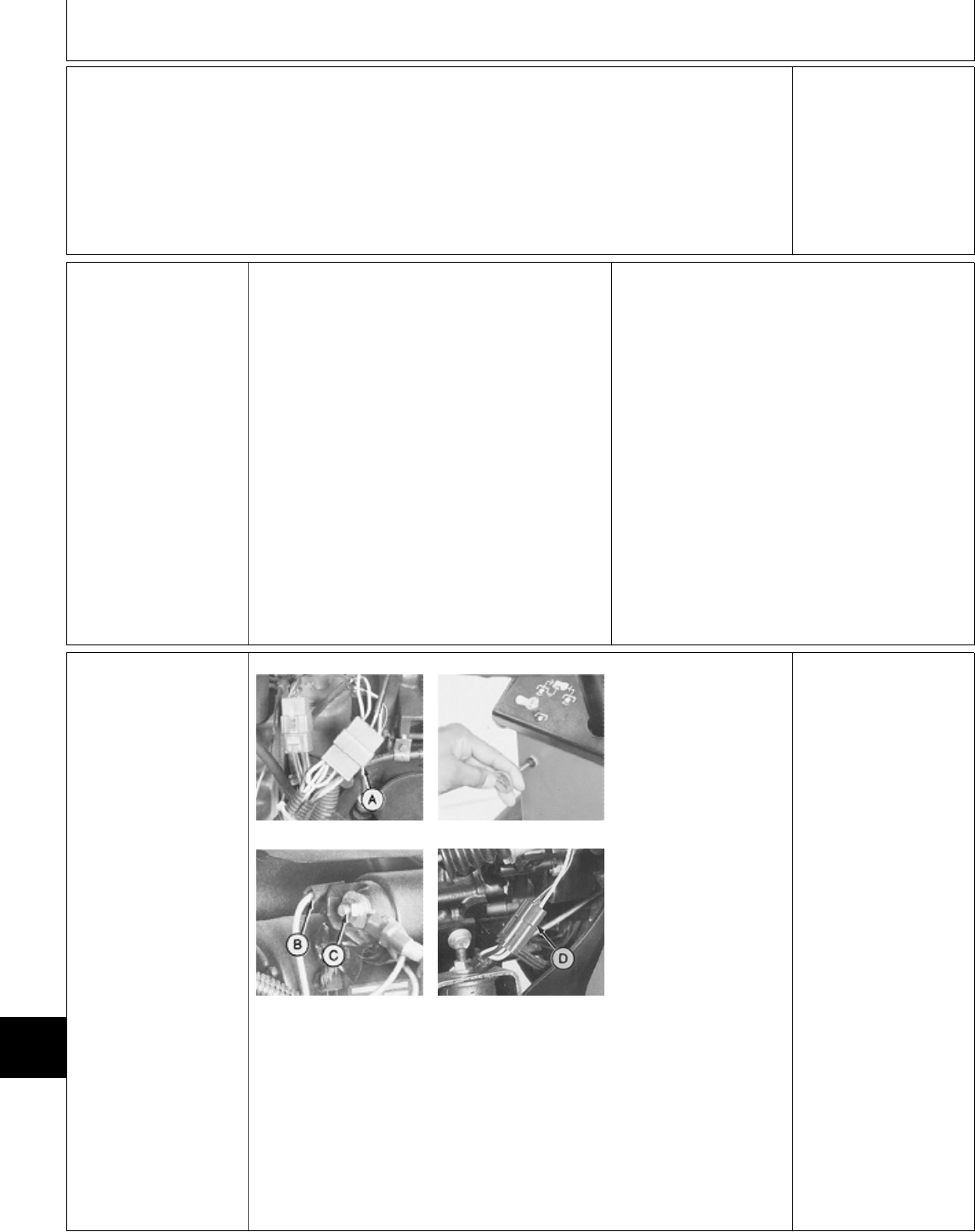
Press down on seat
switch button.
There should be
continuity.
OK: Connect seat
switch connector.
NOT OK: Replace
switch, then GO TO
2a, Group 05.
Æ STARTING CIRCUIT
TESTS
Listed at right are
symptoms that may
occur in a
malfunctioning starting
circuit. Locate the
symptom that applies,
then proceed to the
appropriate test.
IMPORTANT: Test
battery and verify
grounds before
testing starting
circuit. (See steps A
and B at the
beginning of this
group.)
STARTING CIRCUIT SYMPTOMS:
—Starter Operates, But Doesn’t Crank Engine:
Repair starter. (See CTM3 or CTM12.)
—Solenoid Doesn’t Click, Starter Doesn’t
Operate:
322, 330 and 332, GO TO 3a
430, GO TO 3b
—Solenoid Clicks, Starter Doesn’t Operate:
GO TO 3c
—Starter Cranks Engine Slowly Or Erratically:
GO TO 3d, Group 25.
3a Starter Test—322,
330 and 332
M45190 -UN-08JAN90
M45191 -UN-08JAN90
M55022 -UN-09DEC89
M45234 -UN-10JUL95
Key switch OFF.
PTO switch OFF.
Hydrostatic lever in
N/STOP position.
Engage park brake.
322; Disconnect ignition
coil 6-pin connector (A).
330; Pull fuel stop knob
all the way out.
332; Disconnect fuel
shutoff solenoid
connector (D).
Disconnect purple wire
(B) from starter
solenoid. Connect
jumper wire to terminal.
Briefly jump across to
large starter terminal
(C).
LISTEN: Starter must
run.
OK: GO TO 3d
NOT OK: GO TO 3c
Connect wires after
testing.
MX,159124020104-19-13JUL95
MX,159124020,61-19-13JUL95
MX,159124020,62-19-13JUL95
Electrical System Diagnosis/Starting Circuit Tests
TM1591 (15JUL95) 240-20-24 322,330,332 & 430 Lawn & Garden Tractors
030895
240
20
24
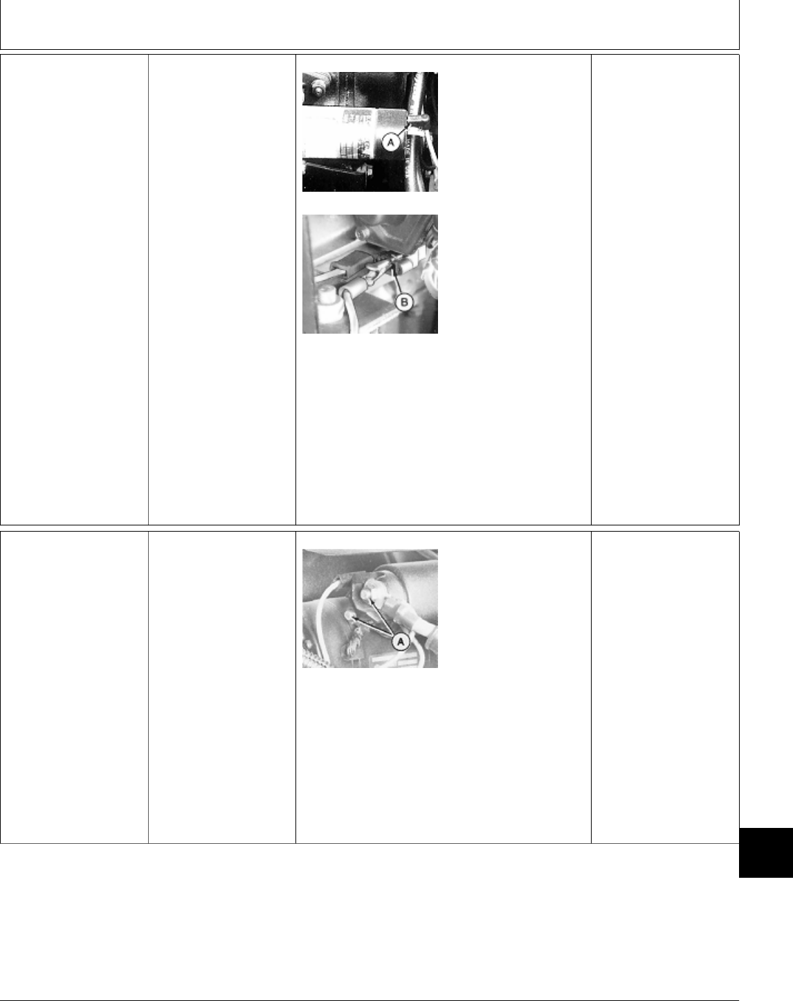
3b Starter Test—430 Key switch OFF.
PTO switch OFF.
Hydrostatic lever in
N/STOP position.
Park brake engaged.
M36602 -UN-12APR95
M36630 -UN-27APR95
NOTE: 430 (S.N.
—420468) shown.
430 (S.N. 420469— );
The fuel shutoff
solenoid uses a 3-pin
connector.
Disconnect red wire (A)
or 3-Pin connector from
fuel shutoff solenoid.
Disconnect purple wire
from starter solenoid.
Connect jumper wire
(B) to terminal.
Briefly jump across to
large starter terminal.
LISTEN: Starter must
run.
OK: GO TO 3d
NOT OK: GO TO 3c
Connect wires after
testing.
3c Starter Solenoid
Test
Key switch OFF.
PTO switch OFF.
Hydrostatic lever in
N/STOP position.
Park brake engaged.
M45192 -UN-08JAN90
322; Ignition coil 6-pin
connector disconnected.
330; Fuel stop knob all
the way out.
332 and 430; Fuel
shutoff solenoid
connector disconnected.
Briefly jump between
two large starter
terminals (A).
LISTEN: Starter must
run.
OK: Replace solenoid.
NOT OK: Check battery
and starter wiring
connections. If OK,
repair starter. (See
CTM3 or CTM12.)
MX,159124020,63-19-13JUL95
MX,159124020,64-19-13JUL95
Electrical System Diagnosis/Starting Circuit Tests
TM1591 (15JUL95) 240-20-25 322,330,332 & 430 Lawn & Garden Tractors
030895
240
20
25

3d Neutral Start
Circuit Test at
Neutral Start Relay
PTO switch OFF.
Hydrostatic lever in
N/STOP position.
Later Models; Engage
park brake.
332 and 430;
Disconnect the fuel
shutoff solenoid
connector.
M45196 -UN-08JAN90
Put hand on neutral
start relay (A).
Turn key switch to
ON/RUN position.
LISTEN/FEEL: Neutral
start relay must “click”.
OK: GO TO 3n
NOT OK:
For machines:
322 (S.N. 596006— )
332 (S.N. 475001— )
430 (S.N. 596048— ),
GO TO 3e
For machines:
330
430 (S.N. —420468),
GO TO 3g
For machines:
322 (S.N. —596005)
332 (S.N. —475000)
430 (S.N. 420469—
596047), GO TO 3h
Connect shutoff
solenoid connector after
test.
3e Neutral Start
Circuit Test at
Brake Switch
322 (SN 596006— )
332 (SN 475001— )
430 (SN 596048— )
PTO switch OFF.
Hydrostatic lever in
N/STOP position.
Park brake engaged.
M77931 -UN-17JAN95
Turn key switch to
ON/RUN position.
Check for voltage at
terminal with purple
wire (A).
VOLTAGE: Purple wire
between brake switch
and neutral start relay
is open. Repair or
replace wire as
necessary, then GO TO
Æ, Group 05.
NO VOLTAGE AT (A):
Check for voltage at
terminal (B).
VOLTAGE: GO TO 3f
NO VOLTAGE: GO TO
3h
MX,159124020,65-19-13JUL95
MX,159124020,66-19-13JUL95
Electrical System Diagnosis/Starting Circuit Tests
TM1591 (15JUL95) 240-20-26 322,330,332 & 430 Lawn & Garden Tractors
030895
240
20
26
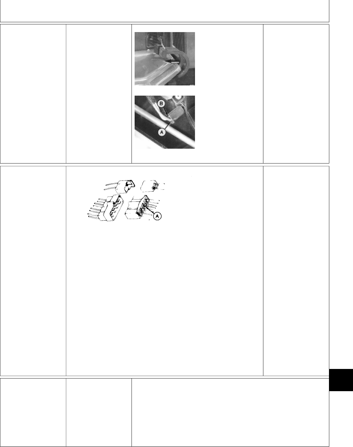
3f Brake Switch
Test
322 (SN 596006— )
332 (SN 475001— )
430 (SN 596048— )
PTO switch OFF.
Hydrostatic lever in
N/STOP position.
M77933 -UN-17JAN95
M77931 -UN-17JAN95
Release brake pedal
completely.
Turn key switch to
ON/RUN position.
Check for voltage at
purple lead (A).
VOLTAGE: Check for
proper switch
engagement. If OK;
replace switch, then
GO TO Æ, Group 05.
NOTE: Brake switch
engagement can be
adjusted by slightly
bending the
engagement pad that’s
welded on the brake
linkage shaft. Check for
proper brake
adjustment before
bending the tab. (See
Section 60, Group 10.)
3g Neutral Start
Circuit Test at
TDC 8-Pin
Connector
330 and
430 (SN —420468)
M36641 -UN-13APR95
PTO switch OFF.
Hydrostatic lever in
N/STOP position.
Turn key switch to
ON/RUN position.
NOTE: It is not
necessary to disconnect
the TDC module 8-pin
connector for this test.
Make sure both purple
wires are attached
securely to connector
terminal.
Check for voltage at
the TDC 8-pin
connector at terminal
with two purple wires
(A).
VOLTAGE: Purple wire
between TDC module
8-pin connector and
neutral start relay is
open. Repair or replace
wire as necessary, then
GO TO Æ, Group 05.
NO VOLTAGE: GO TO
3h
3h Neutral Start
Circuit Test at
Transmission
Switch
PTO switch OFF.
Hydrostatic lever in
N/STOP position.
Turn key switch to
ON/RUN position.
Continued on next page
MX,159124020,67-19-13JUL95
MX,159124020,68-19-13JUL95
Electrical System Diagnosis/Starting Circuit Tests
TM1591 (15JUL95) 240-20-27 322,330,332 & 430 Lawn & Garden Tractors
030895
240
20
27
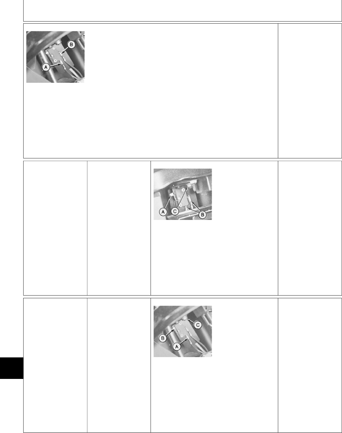
M36623 -UN-25JAN90
Check voltage at terminal (A).
VOLTAGE:
322 (S.N. —596005), 332 (S.N.
—475000), and 430 (S.N.
420469—596047) ; Voltage at (A)
indicates either a faulty neutral start
relay, poor relay ground, or the wire
between the transmission neutral
start switch and neutral start relay is
open. Repair or replace as
necessary, then GO TO Æ, Group
05.
330 and 430 (S.N. —420468);
Voltage at (A) indicates purple wire
between TDC module 8-pin
connector and transmission neutral
start switch is open. Repair or
replace wire as necessary, then GO
TO Æ, Group 05.
322 (S.N. 596006— ), 332 (S.N.
475001— ), and 430 (S.N.
596048— ); Voltage at (A)
indicates purple/white wire between
brake switch and transmission
neutral start switch is open. Repair
or replace wire as necessary, then
GO TO Æ, Group 05.
NO VOLTAGE: Check for voltage at
(B).
VOLTAGE AT (B): GO
TO 3i
NO VOLTAGE: GO TO
3j
NOTE: To test the
neutral start relay; GO
TO Æ, Group 25.
3i Transmission
Switch Test
Key switch OFF.
Put hydrostatic lever in
REVERSE position.
M45195 -UN-08JAN90
With arm (A) fully
released, check for
continuity across
terminals (B).
CONTINUITY: Replace
switch.
NO CONTINUITY:
Push switch arm (A)
fully in. Check for
continuity across
terminals (B) again.
NO CONTINUITY:
Replace switch.
CONTINUITY: Adjust
switch. GO TO 3j
3j Transmission
Switch Adjustment
Key switch OFF.
Put hydrostatic lever in
N/STOP position.
M36647 -UN-25JAN90
IMPORTANT: After
tightening nut (C),
make sure hydrostatic
lever does not push
switch arm (B)
against switch body,
otherwise, damage to
switch may result.
Loosen adjusting nut
(C) and slide switch
toward hydrostatic lever
until switch closes.
Tighten nut.
After replacing or
adjusting switch; GO
TO 3b, Group 05.
MX,159124020,69-19-13JUL95
MX,159124020,70-19-13JUL95
MX,15912402070A-19-13JUL95
Electrical System Diagnosis/Starting Circuit Tests
TM1591 (15JUL95) 240-20-28 322,330,332 & 430 Lawn & Garden Tractors
030895
240
20
28
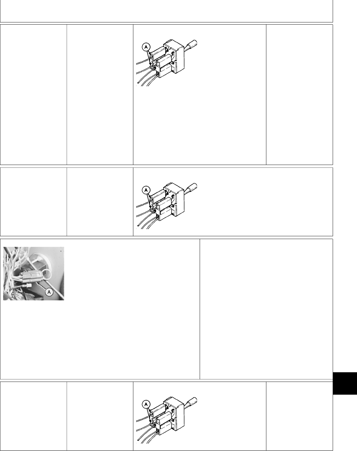
3k Neutral Start
Circuit Test At Rear
PTO Switch
NOTE: This test is for
machines equipped with
the optional rear PTO.
If machine is equipped
with front PTO only,
GO TO 3l.
PTO switches OFF.
Turn key switch to
ON/RUN position.
M36642 -UN-28APR95
Check for voltage at
terminals with purple
wires (A) on rear PTO
switch.
VOLTAGE AT BOTH
TERMINALS: Purple
wire between rear PTO
switch and transmission
neutral start switch or
rear PTO harness 3-pin
connector is open.
Repair or replace as
necessary, then GO TO
Æ Group 05.
VOLTAGE AT ONE
TERMINAL: Replace
switch, then GO TO Æ
Group 05.
NO VOLTAGE AT
BOTH TERMINALS:
GO TO 3l
3l Neutral Start
Circuit Test At
Front PTO Switch
PTO switch OFF.
M36642 -UN-28APR95
Turn key switch to ON/RUN position.
Check for voltage at terminals with purple wires
(A) on front PTO switch.
M36624 -UN-25JAN90
NOTE: For machines
not equipped with the
optional rear PTO, a
jumper wire located at
rear PTO harness
connector (A) is used
to complete the circuit
to the transmission
neutral start switch.
VOLTAGE AT BOTH TERMINALS:
For machines equipped with optional rear PTO,
purple wire between rear PTO switch and front
PTO switch is open. Repair or replace wire as
necessary, then GO TO Æ Group 05.
For machines equipped with front PTO only,
purple wire between transmission neutral start
switch and front PTO switch or connector with
jumper wire (A) is open. Repair or replace wire
as necessary, then GO TO Æ Group 05.
VOLTAGE AT ONLY ONE TERMINAL: Replace
switch, then GO TO Æ Group 05.
NO VOLTAGE AT EITHER TERMINAL: Wire
between front PTO switch and 25-amp fuse is
open. Repair or replace as necessary, then GO
TO Æ Group 05.
3m PTO Switch Test Turn key switch ON.
Move PTO switch to
ON position.
M36642 -UN-28APR95
Check for voltage at
terminals with purple
wires (A).
VOLTAGE AT BOTH
TERMINALS: Replace
switch, then GO TO
3c, Group 05.
VOLTAGE AT ONE
TERMINAL: Switch OK.
MX,159124020,71-19-13JUL95
MX,159124020,72-19-13JUL95
MX,159124020109-19-13JUL95
MX,159124020,73-19-13JUL95
Electrical System Diagnosis/Starting Circuit Tests
TM1591 (15JUL95) 240-20-29 322,330,332 & 430 Lawn & Garden Tractors
030895
240
20
29

3n Neutral Start
Circuit Test At Key
Switch
M49010 -UN-08JAN90
NOTE: 332 shown in photo.
Turn key switch to START position.
322, 330 and 332; Check for voltage at key
switch terminal “ST”.
430; Check voltage at key switch terminal “C”.
VOLTAGE: Purple wire
between key switch and
neutral start relay is
open.
NO VOLTAGE: Check
key switch and fusible
link.
Å FUEL SHUTOFF
SOLENOID CIRCUIT
TESTS
322; GO TO 4a
332 (All) and 430 (S.N. 420469— ):
—If fuel shutoff solenoid doesn’t “pull in”;
GO TO 4c
—If fuel shutoff solenoid doesn’t “hold in”;
GO TO 4d
430 (S.N. —420468); GO TO 4l
4a Fuel Shutoff
Solenoid Test—322
M45202 -UN-08JAN90
M45203 -UN-08JAN90
Key switch OFF.
Disconnect ignition coil
harness 6-pin
connector.
Connect one end of a
jumper wire to terminal
with red wire (A) on
solenoid side of
connector. Connect
other end to positive
(+) battery terminal.
LISTEN: Solenoid (B)
should “click”.
OK: Solenoid OK, GO
TO 7c
NOT OK: GO TO 4b
4b Fuel Shutoff
Solenoid Bench
Test—322
NCAUTION:
GASOLINE WILL
DRAIN FROM
CARBURETOR WHEN
SOLENOID IS
REMOVED. KEEP
GAS AWAY FROM
SPARKS, FLAME OR
HOT ENGINE PARTS.
M45204 -UN-08JAN90
Remove solenoid from
carburetor.
Connect one jumper
wire from red wire on
solenoid to battery
positive (+) terminal
and connect a second
jumper wire from
solenoid body to
negative (—) terminal.
LOOK: Solenoid should
retract when connected
to battery and extend
when disconnected
from battery.
OK: Install solenoid,
then GO TO 7c
NOT OK: Replace
solenoid, then GO TO
Å, Group 05.
MX,159124020,74-19-13JUL95
MX,159124020,42-19-13JUL95
MX,159124020,43-19-13JUL95
MX,159124020,44-19-13JUL95
Electrical System Diagnosis/Fuel Shutoff Solenoid Circuit Tests
TM1591 (15JUL95) 240-20-30 322,330,332 & 430 Lawn & Garden Tractors
030895
240
20
30
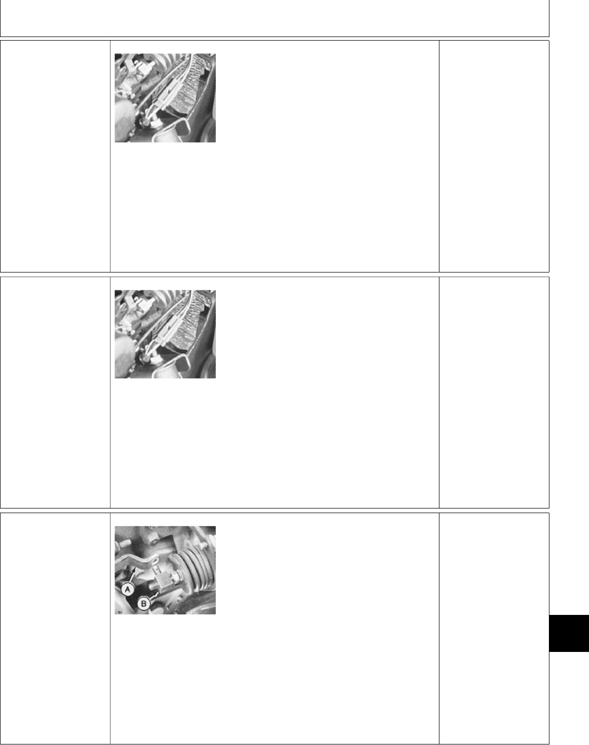
4c Fuel Shutoff
Solenoid Pull-In
Test
332 (All) and
430 (SN 420469— )
NOTE: If linkage is
bent, binding or
solenoid is being
replaced GO TO Å,
Group 25. M49008 -UN-08JAN90
Disconnect fuel shutoff
solenoid connector.
Connect one end of a
jumper wire to black
wire on solenoid side of
the 3-pin connector.
Connect other end to
machine frame.
Connect one end of a
jumper wire to white
lead on solenoid side of
the 3-pin connector.
Connect other end to
positive (+) battery
terminal.
LOOK: Solenoid must
retract.
OK: Connect solenoid
connector, then GO TO
4f
NOT OK: Replace
solenoid.
4d Fuel Shutoff
Solenoid Hold-In
Test
332 (All) and
430 (SN 420469— )
NOTE: If linkage is
bent, binding or
solenoid is being
replaced GO TO Å,
Group 25. M49008 -UN-08JAN90
Disconnect fuel shutoff solenoid connector.
Connect one end of a jumper wire to black wire
on solenoid side of the 3-pin connector. Connect
other end to machine frame.
Connect one end of a jumper wire to red wire on
solenoid side of the 3-pin connector. Connect
other end to positive (+) battery terminal.
Push solenoid arm in.
LOOK: Solenoid must stay in.
OK: GO TO 4f
NOT OK: GO TO 4e
4e Fuel Shutoff
Solenoid Hold-In
Test (Linkage
Removed)
332 (All) and
430 (SN 420469— )
M43343 -UN-15JAN90
Disconnect fuel shutoff arm (A) from solenoid
arm (B).
Connect one end of a jumper wire to black wire
on solenoid side of the 3-pin connector. Connect
other end to machine frame.
Connect one end of a jumper wire to red wire on
solenoid side of the 3-pin connector. Connect
other end to positive (+) battery terminal.
Push solenoid arm in.
LOOK: Solenoid must stay in.
OK: Adjust solenoid
linkage. GO TO Å,
Group 25.
NOT OK: Replace
solenoid.
MX,159124020,45-19-13JUL95
MX,159124020,46-19-13JUL95
MX,159124020,47-19-13JUL95
Electrical System Diagnosis/Fuel Shutoff Solenoid Circuit Tests
TM1591 (15JUL95) 240-20-31 322,330,332 & 430 Lawn & Garden Tractors
030895
240
20
31
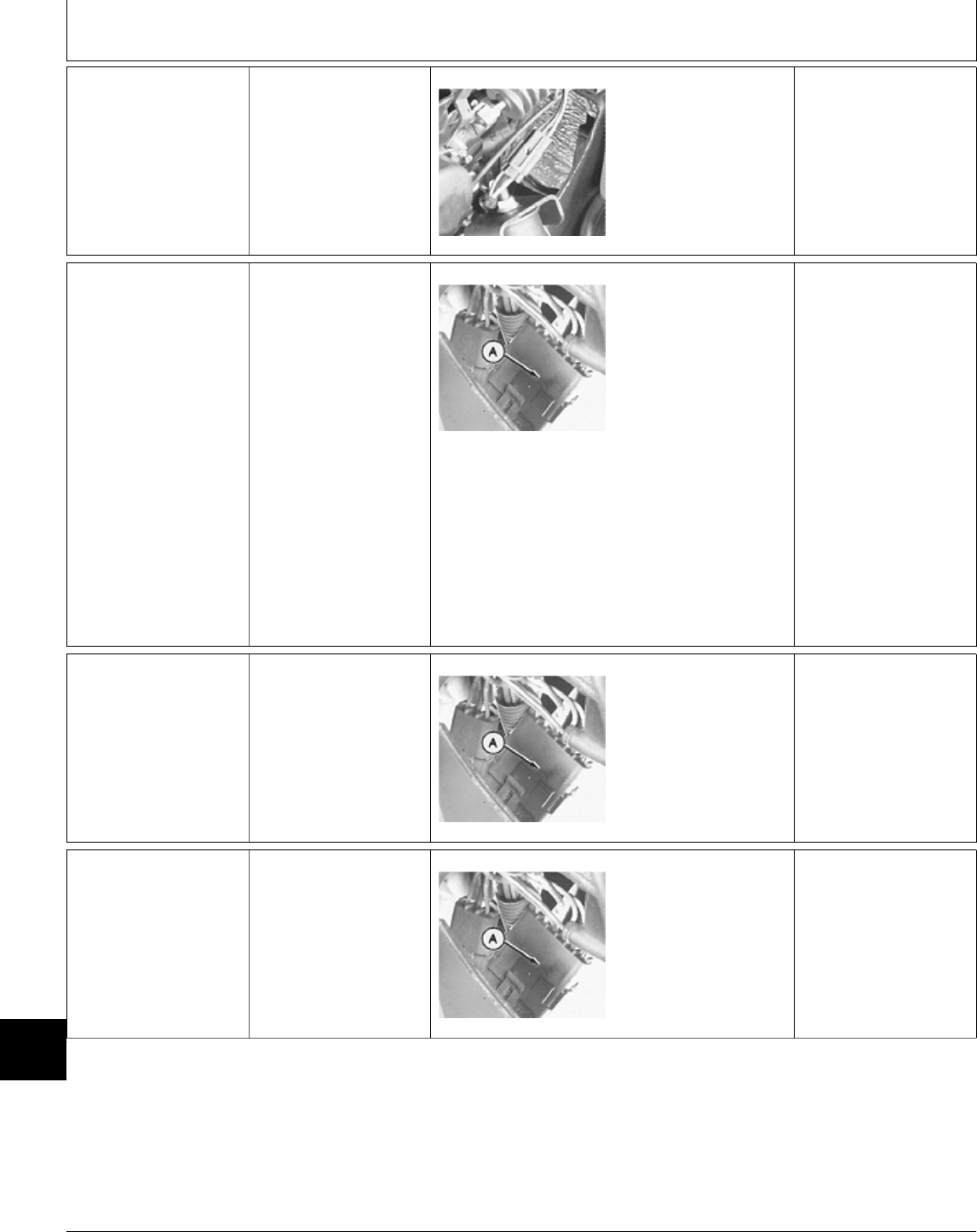
4f Fuel Shutoff
Solenoid Ground
Test
332 (All) and
430 (SN 420469— )
Key switch OFF.
M49008 -UN-08JAN90
Disconnect solenoid
3-pin connector.
Check continuity
between black wire on
harness side of
connector and ground.
CONTINUITY:
—If testing “pull-in”
circuit; GO TO 4g
—If testing “hold-in”
circuit; GO TO 4h
NO CONTINUITY:
Repair or replace black
ground wire.
4g Fuel Shutoff
Solenoid Pull-In
Voltage Test at
TDC Module
332 (All) and
430 (SN 420469— )
Key switch OFF.
Install jumper wire
across harness side of
seat switch connector.
M49012 -UN-08JAN90
Connect a voltmeter or
test light to terminal “E”
of TDC module 6-pin
connector (A).
NOTE: “E” is terminal
with white wire on TDC
side of connector.
Turn key switch to
ON/RUN position.
LOOK: Voltage, then
after 1 second, no
voltage.
VOLTAGE (FOR 1
SECOND): Wire is
open between TDC
module and solenoid.
NO VOLTAGE: GO TO
4h
VOLTAGE FOR LESS
THAN 1/2 SECOND
OR MORE THAN 1
SECOND: Replace
TDC module.
4h Fuel Shutoff
Solenoid Hold-In
Voltage Test at
TDC Module
332 (All) and
430 (SN 420469— )
Install a jumper wire
across harness side of
seat switch connector.
Turn key switch to
ON/RUN position.
M49012 -UN-08JAN90
Check for voltage at
terminal “C” of TDC
module 6-pin connector
(A).
NOTE: “C” is terminal
with large pink wire on
TDC side of connector.
VOLTAGE: Pink wire to
solenoid connector is
open.
NO VOLTAGE: GO TO
4i
4i TDC Module Input
(Pull-In) Voltage
Test
332 (All) and
430 (SN 420469— )
Key switch OFF.
M49012 -UN-08JAN90
Check for voltage at
terminal “F” of TDC
module 6-pin connector
(A).
NOTE: “F” is terminal
with red wire on TDC
side of connector.
NO VOLTAGE: Check
fusible link at starter
terminal.
VOLTAGE: GO TO 4j
MX,159124020,48-19-13JUL95
MX,159124020,49-19-13JUL95
MX,159124020,50-19-13JUL95
MX,159124020,51-19-13JUL95
Electrical System Diagnosis/Fuel Shutoff Solenoid Circuit Tests
TM1591 (15JUL95) 240-20-32 322,330,332 & 430 Lawn & Garden Tractors
030895
240
20
32

4j TDC Input
(Interlock) Voltage
Test
332 (All) and
430 (SN 420469— )
PTO switch OFF.
Hydrostatic lever in
N/STOP position.
Later Models; Engage
park brake.
Turn key switch to
ON/RUN position. M49012 -UN-08JAN90
Check for voltage at
terminal “A” of TDC
module 6-pin connector
(A).
NOTE: “A” is terminal
with purple/black wire
on TDC side of
connector.
VOLTAGE: GO TO 4k
NO VOLTAGE: GO TO
3d
4k TDC Input
(Hold-In) Voltage
Test
332 (All) and
430 (SN 420469— )
Turn key switch to
ON/RUN position.
M49017 -UN-08JAN90
Check for voltage at
terminal “C” of TDC
module 3-pin connector
(A).
NOTE: “C” is terminal
with purple wire on
TDC side of connector.
VOLTAGE: Verify
ground at terminal “B”
(black wire) of TDC
module 3-pin connector.
If ground OK, replace
TDC module.
NO VOLTAGE: Wire
between terminal “C” of
3-pin connector and
25-amp fuse is open.
Repair or replace wire.
4l Fuel Shutoff
Solenoid Circuit
Test
430 (SN —420468)
M36602 -UN-12APR95
M36611 -UN-12APR95
Disconnect red wire (A)
from solenoid.
Connect one end of a
jumper wire to positive
(+) battery terminal.
Connect other end to
solenoid terminal (B).
SOLENOID
OPERATES: GO TO
4m
SOLENOID DOESN’T
OPERATE: Check
black wire on solenoid
for good ground. If
solenoid has good
ground, replace
solenoid.
MX,159124020,52-19-13JUL95
MX,159124020,53-19-13JUL95
MX,159124020,54-19-13JUL95
Electrical System Diagnosis/Fuel Shutoff Solenoid Circuit Tests
TM1591 (15JUL95) 240-20-33 322,330,332 & 430 Lawn & Garden Tractors
030895
240
20
33
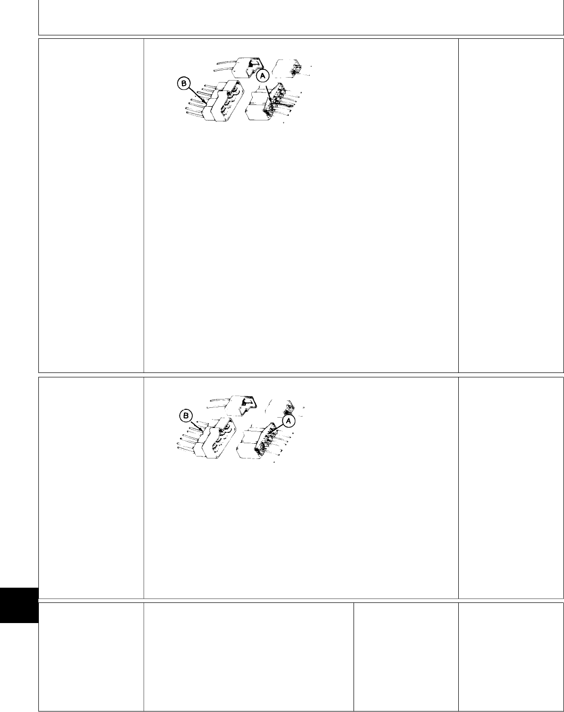
4m Fuel Shutoff
Solenoid Voltage
Test At TDC
Module
430 (SN —420468)
M36638 -UN-12APR95
Install jumper wire
across harness side of
seat switch connector.
Turn key switch to RUN
position.
NOTE: Do not
disconnect the 8-pin
connector for this test.
Check for voltage at
terminal with pink and
orange wires (A).
VOLTAGE: Pink wire
between TDC module
connector and fuel
shut-off solenoid is
open. Repair or replace
wire as needed.
NO VOLTAGE: Check
for voltage at single
pink wire (B) (TDC
module side of
connector).
VOLTAGE: Repair or
replace connector, then
GO TO Å, Group 05.
NO VOLTAGE: GO TO
4n
4n TDC Module
Power Circuit
Test
430 (SN —420468)
M36639 -UN-12APR95
Turn key switch to RUN
position.
NOTE: Do not
disconnect the 8-pin
connector for this test.
Check for voltage at
terminal with large
single pink wire (A).
NO VOLTAGE: Wire
between TDC module
connector and 25-amp
fuse is open. Repair or
replace wire as needed,
then GO TO Å, Group
05.
VOLTAGE: Check for
voltage at purple wire
(B) (TDC module side
of connector).
NO VOLTAGE: Repair
or replace connector as
needed, then GO TO
Å, Group 05.
VOLTAGE: GO TO 4o
4o Neutral Start
Circuit Voltage
Test At TDC
Module
430 (SN —420468)
PTO switch OFF.
Hydrostatic lever in
N/STOP position.
Turn key switch to RUN
position.
MX,159124020,55-19-13JUL95
MX,159124020,56-19-13JUL95
Electrical System Diagnosis/Fuel Shutoff Solenoid Circuit Tests
TM1591 (15JUL95) 240-20-34 322,330,332 & 430 Lawn & Garden Tractors
030895
240
20
34
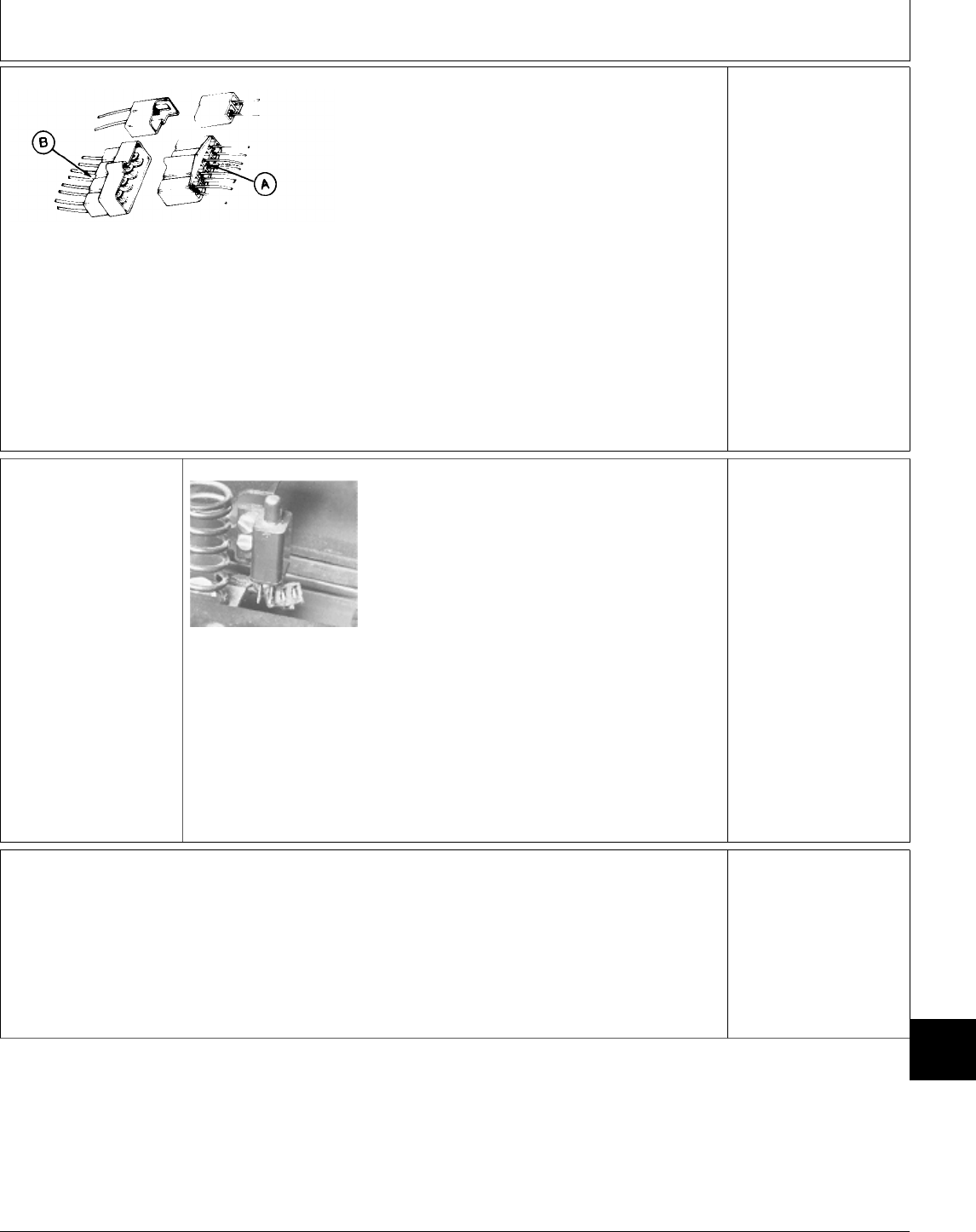
M36640 -UN-12APR95
NOTE: Do not
disconnect the 8-pin
connector for this test.
Check for voltage at
terminal with two purple
wires (A).
NO VOLTAGE: GO TO
3d
VOLTAGE: Check for
voltage at terminal with
purple wire (B) (TDC
module side of
connector).
NO VOLTAGE: Repair
or replace connector as
needed, then GO TO
Å, Group 05.
VOLTAGE: Replace
TDC module, then GO
TO Å, Group 05.
4p Seat Switch Test
M45187 -UN-08JAN90
NOTE: Seat switch for 322 and 332/430 (S.N.
475001— ) shown.
Key switch OFF.
Disconnect seat switch connector.
Connect ohmmeter or continuity tester across
switch terminals.
There should NOT be continuity.
330 and 332/430 (S.N. —475000); Sit on or
push down on surface of seat.
322 and 332/430 (S.N. 475001— ); Push seat
switch button down.
There should be continuity.
OK: Connect seat
switch connector.
NOT OK: Replace
switch, then GO TO Å,
Group 05.
Ö FUEL TRANSFER
PUMP CIRCUIT
TESTS
322; GO TO 5a
330, 332 and 430; GO
TO 5b
MX,159124020,57-19-13JUL95
MX,15912402055A-19-13JUL95
MX,159124020,38-19-13JUL95
Electrical System Diagnosis/Fuel Transfer Pump Circuit Tests
TM1591 (15JUL95) 240-20-35 322,330,332 & 430 Lawn & Garden Tractors
030895
240
20
35
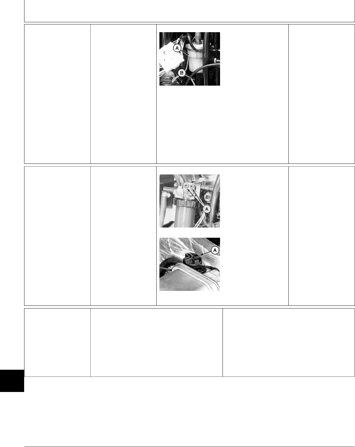
5a Fuel Transfer
Pump Test—322
Open hood.
Remove left engine
side panel.
M78859 -UN-12APR95
Disconnect fuel hose
(B) from fuel filter (A).
Put end of hose in a
container.
Turn key switch to RUN
position.
LOOK: Fuel must flow
from end of hose.
OK: Connect fuel hose.
NOT OK: Test pump
circuit, GO TO 5c
NOTE: If problem is
poor engine
performance, GO TO
Section 220.
5b Fuel Transfer
Pump Test—330,
332 and 430
Open hood.
Remove left engine
side panel.
Turn key switch to
ON/RUN position.
M55101 -UN-09DEC89
M36617 -UN-13APR95
NOTE: Top photo
shows 330 and 332.
Bottom photo shows
430.
Loosen vent
screw(s)/plug (A).
LOOK: Fuel must flow
from vent screw(s)/plug.
OK: Tighten vent
screw(s)/plug.
NOT OK: GO TO 5c
5c Fuel Transfer
Pump Circuit Test
Key switch OFF.
322, 330 and 332; Remove left engine side
panel to access fuel transfer pump.
430; Remove fender deck to access fuel transfer
pump.
Disconnect fuel pump wire connector.
Continued on next page
MX,159124020,39-19-13JUL95
MX,159124020,40-19-13JUL95
Electrical System Diagnosis/Fuel Transfer Pump Circuit Tests
TM1591 (15JUL95) 240-20-36 322,330,332 & 430 Lawn & Garden Tractors
030895
240
20
36

M45220 -UN-12JAN90
NOTE: 322 (All) and 332/430 (S.N. 475001— )
use a 2-pin connector for the fuel pump. All other
machines use a 1-pin connector and a ground
wire. The ground wire connects directly to the
machine frame.
For machines equipped with 2-pin connector,
check for continuity between terminal with black
wire (A) (harness side of connector) and ground.
For machines equipped with 1-pin connector,
check fuel pump ground connection.
Turn key switch to ON/RUN position.
Check for voltage at yellow wire (B) at the
connector.
CONTINUITY/GROUND
AND VOLTAGE OK:
Replace fuel transfer
pump.
NO CONTINUITY OR
POOR GROUND:
Repair or replace
ground wire or clean
ground connection.
NO VOLTAGE: Repair
or replace yellow wire
between connector and
fuse.
Ò GLOW PLUG
CONTROLLER
CIRCUIT TEST (330,
332, 430)
NOTE: Glow plug
controller must be
installed for this test.
M36619 -UN-25JAN90
Connect voltmeter or test light to glow plug
power lead (A).
Turn key switch to ON/RUN position.
LOOK: Voltmeter or test light should indicate
voltage.
After approximately 15 seconds, voltage to glow
plugs should “switch off” (no voltage indicated).
NOTE: The 15 seconds elapsed time is when the
engine compartment is at 20˚C (68˚F). Colder
temperatures will increase length of time, warmer
temperatures will decrease length of time.
VOLTAGE, THEN NO
VOLTAGE AFTER
SPECIFIED ELAPSED
TIME: Circuit OK.
VOLTAGE, BUT
CONTROLLER
DOESN’T “SWITCH
OFF” (NO VOLTAGE):
Replace controller.
NO VOLTAGE AT ANY
TIME: GO TO 6a
6a Glow Plug
Controller Circuit
Test—Continued
Remove glow plug
controller from socket.
Turn key switch to
ON/RUN position.
M45232 -UN-12JAN90
M36620 -UN-13APR95
NOTE: Top photo
shows 330 and 332.
Bottom photo shows
430.
Check for voltage at
terminal with red wire
(A).
VOLTAGE: Verify good
ground at terminal with
black wire (B), if ground
OK, replace glow plug
controller, then GO TO
Ò, Group 05.
NO VOLTAGE: GO TO
6b
MX,159124020,41-19-13JUL95
MX,159124020,58-19-13JUL95
MX,159124020,59-19-13JUL95
Electrical System Diagnosis/Glow Plug Controller Circuit Tests (330, 332 and 430)
TM1591 (15JUL95) 240-20-37 322,330,332 & 430 Lawn & Garden Tractors
030895
240
20
37
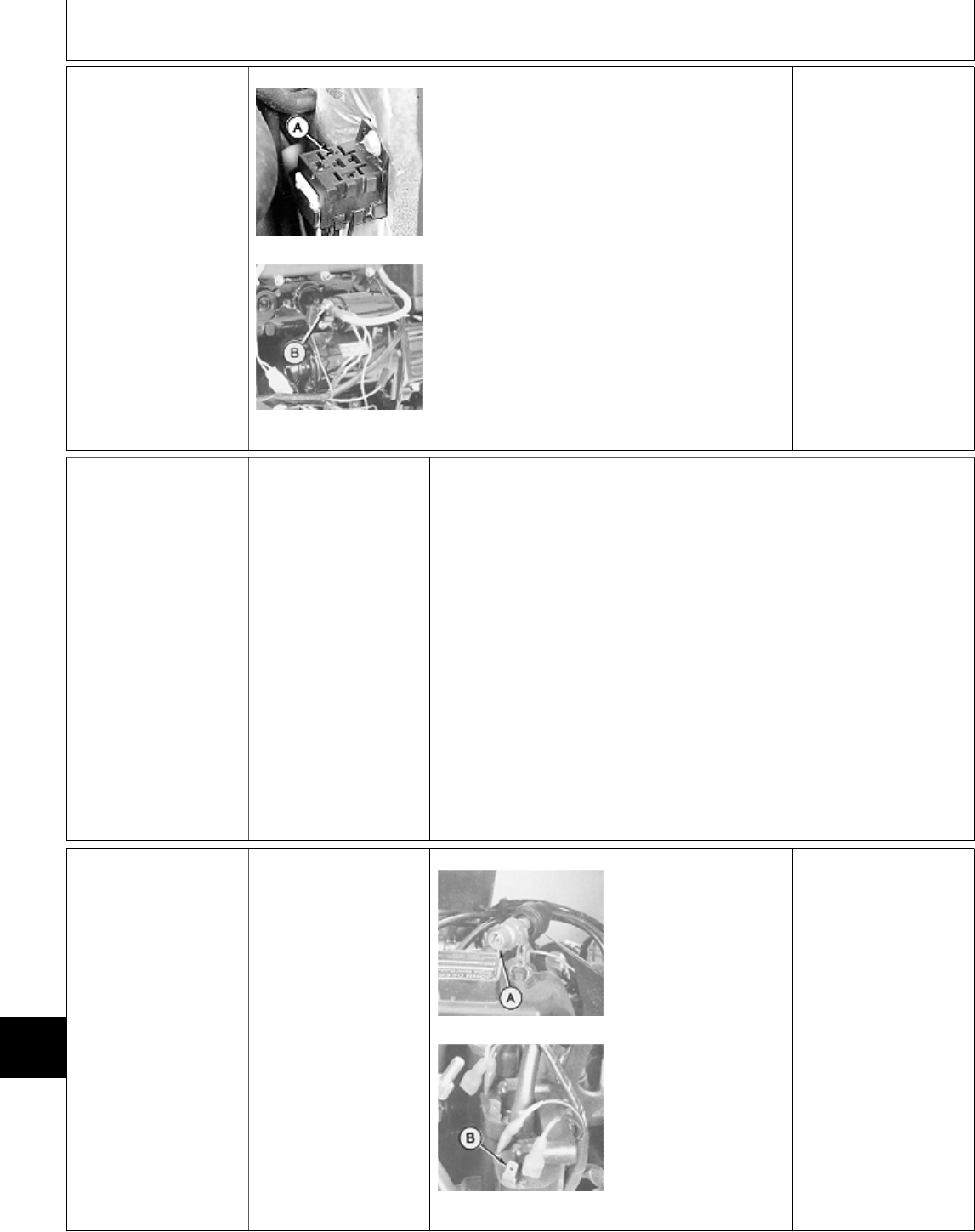
6b Glow Plug
Controller Fusible
Link Test
M36621 -UN-13APR95
M55114 -UN-09DEC89
NOTE: 330 and 332
shown.
Turn key switch OFF.
Check continuity
between controller
terminal with red wire
(A) and starter terminal
(B).
NO CONTINUITY:
Repair or replace the
red wire or fusible link,
then GO TO Ò, Group
05.
Õ IGNITION CIRCUIT
TESTS (322)
Listed at right are
symptoms that may
occur in a
malfunctioning ignition
circuit. Locate the
symptom that applies,
then proceed to the
appropriate test or
series of tests.
IMPORTANT: Test
battery and verify
grounds before
testing ignition circuit.
(See steps A and B
at the beginning of
this group.)
IGNITION CIRCUIT SYMPTOMS:
Starter Cranks Engine Satisfactorily,
But:
—Engine Doesn’t Start,
Or
Engine Starts, But Runs
Rough; GO TO 7a
—Engine Starts, But Misfires:
GO TO 7q
—Engine Stops With Operator On
Seat When:
PTO Switch Is Turned On,
Or
Hydrostatic Lever Is Moved
To Forward Or Reverse Position,
Or
Brake Pedal Is Released On
(S.N. 596006— ) Machines,
GO TO 7n
7a Ignition Spark
Test
Check 10-amp and
25-amp fuses.
PTO switch OFF.
Hydrostatic lever in
N/STOP position.
Later Models; Engage
park brake.
M45200 -UN-08JAN90
M45201 -UN-08JAN90
NOTE: Perform spark
test for all three spark
plugs.
Install a spark tester
(A) on plug wire of
cylinder to be tested.
Disconnect orange wire
from each ignition coil
positive (+) terminal (B)
of cylinders NOT being
tested.
Crank engine to check
for spark.
NO SPARK FROM ALL
CYLINDERS: GO TO
7b
NO SPARK FROM
ONE CYLINDER: GO
TO 7f
POOR, WEAK, OR
YELLOW SPARK: GO
TO 7j
GOOD, SHARP BLUE
SPARK: GO TO 4a
GOOD, SHARP BLUE
SPARK, BUT ENGINE
MISFIRES: GO TO 7q
MX,159124020,60-19-13JUL95
MX,159124020,75-19-13JUL95
MX,159124020,76-19-13JUL95
Electrical System Diagnosis/Ignition Circuit Tests (322)
TM1591 (15JUL95) 240-20-38 322,330,332 & 430 Lawn & Garden Tractors
030895
240
20
38
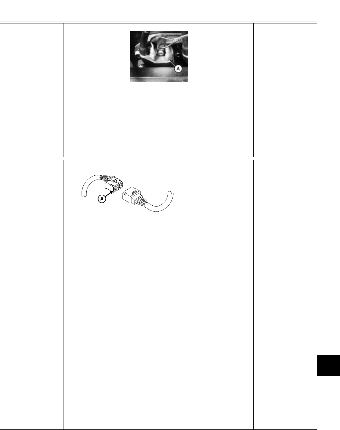
7b Ignition Circuit
Voltage Test At
Ignition Coils
PTO switch OFF.
Hydrostatic lever in
N/STOP position.
Later Models; Park
brake engaged.
Turn key switch to RUN
position. M78962 -UN-27APR95
Check for voltage at
orange wire (A) at
positive (+) terminal of
coils.
VOLTAGE: GO TO 7f
NO VOLTAGE: GO TO
7c
7c Ignition Circuit
Voltage Test At
Ignition Coils 6-Pin
Connector
M78960 -UN-27APR95
NOTE: Do not
disconnect the ignition
coil 6-pin connector to
perform this test .
PTO switch OFF.
Hydrostatic lever in
N/STOP position.
Later Models: Park
brake engaged.
Key switch to RUN
position.
Check for voltage at
double pink/black wire
terminal (A) at ignition
coil 6-pin connector.
Check for voltage on
both sides of the
connector.
VOLTAGE AT BOTH
SIDES OF
CONNECTOR:
If testing ignition circuit,
orange wire between
6-pin connector and
coils is open. Repair or
replace wire, then GO
TO Õ, Group 05.
If testing fuel shutoff
solenoid circuit,
pink/black wire between
6-pin connector and
solenoid is open.
Repair or replace wire,
then GO TO Å, Group
05.
VOLTAGE AT ONE
SIDE OF
CONNECTOR: Repair
connector, then
For fuel shutoff
solenoid, GO TO Æ,
Group 05.
For ignition circuit, GO
TO Õ, Group 05.
NO VOLTAGE: GO TO
7d
MX,159124020,77-19-13JUL95
MX,159124020,78-19-13JUL95
Electrical System Diagnosis/Ignition Circuit Tests (322)
TM1591 (15JUL95) 240-20-39 322,330,332 & 430 Lawn & Garden Tractors
030895
240
20
39
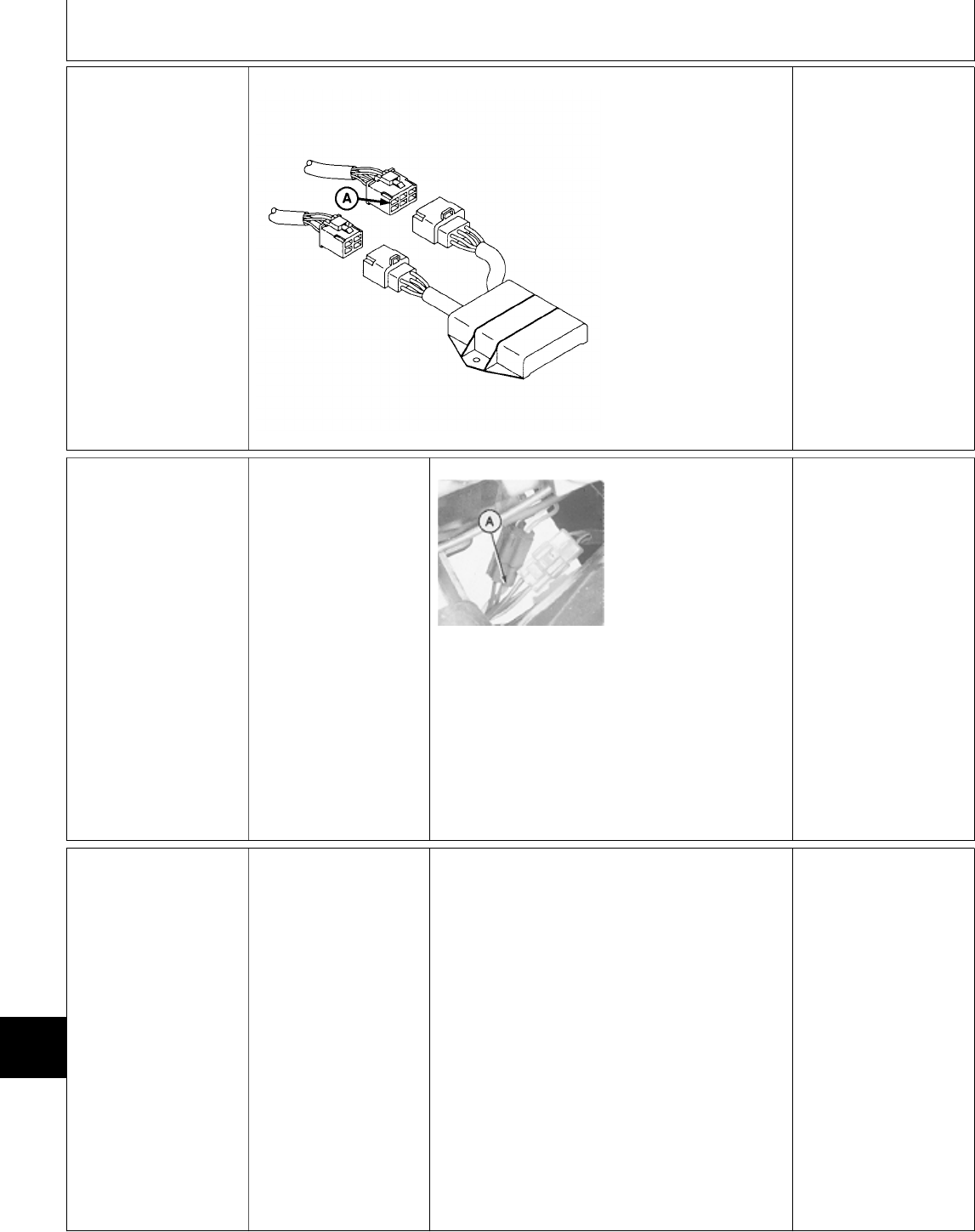
7d Ignition Circuit
Voltage Test At
Transistor Module
M78961 -UN-27APR95
PTO switch OFF.
Hydrostatic lever in
N/STOP position.
Later Models; Park
brake engaged.
Key switch in RUN
position.
Check for voltage at
double pink/black wire
terminal (A) at
transistor module 6-pin
connector.
VOLTAGE: Pink/black
wire between transistor
module 6-pin connector
and ignition coil 6-pin
connector is open.
Repair or replace wire
as necessary, then GO
TO Õ, Group 05.
NO VOLTAGE: GO TO
7e
7e Ignition Circuit
Voltage Test At
Engine Harness
2-Pin Connector
PTO switch OFF.
Hydrostatic lever in
N/STOP position.
Later Models; Park
brake engaged.
Key switch in RUN
position. M45205 -UN-08JAN90
Check for voltage at
double pink/black wires
(A) at engine harness
2-pin connector.
VOLTAGE: Pink/black
wire between engine
harness 2-pin connector
and transistor module
6-pin connector is
open. Repair or replace
wire as necessary, then
GO TO Õ, Group 05.
NO VOLTAGE: GO TO
7o
7f Ignition System
Operational Test
PTO switch OFF.
Hydrostatic lever in
N/STOP position.
Later Models; Park
brake engaged.
Determine which pulsar unit operates with each
ignition coil.
Pulsars and coils are identified as follows:
No. 1 Pulsar (A)— GRN/WHT (right
side of engine)
No. 2 Pulsar (B)— BRN (left side of
engine)
No. 3 Pulsar (C)— GRN (left side of
engine)
NOTE: Ignition coils are identified by position or
color of wire at negative terminal.
No. 1 coil is toward left side of engine.
No. 1 Coil (D)— White wire
No. 2 Coil (E)— Black/Yellow wire
No. 3 Coil (F)— White/Blue wire
Continued on next page
MX,159124020,79-19-13JUL95
MX,159124020,80-19-13JUL95
Electrical System Diagnosis/Ignition Circuit Tests (322)
TM1591 (15JUL95) 240-20-40 322,330,332 & 430 Lawn & Garden Tractors
030895
240
20
40

M45212 -UN-08JAN90
M45211 -UN-08JAN90
M45213 -UN-28APR95
Put a test light on
negative terminal (G) of
coil being tested. DO
NOT disconnect wires
from coil.
Start engine and
operate at slow idle.
LOOK: Test light must
blink rapidly.
Perform test on each
coil.
NOTE: If the problem is
not isolated by
performing the tests
indicated, then it will be
necessary to perform
tests on all the other
related components in
the circuit to determine
the problem.
PROBLEM IS
INTERMITTENT: GO
TO 7g
ALL COIL CIRCUITS
FAIL: Check transistor
module first. GO TO
7m
ONE COIL CIRCUIT
FAILS: Check pulsar for
that coil first. GO TO
7h
COIL CIRCUIT
PASSES TEST, BUT
STILL NO SPARK AT
RESPECTIVE
CYLINDER: Check
ignition coil first. GO
TO 7j
7g Ignition Circuit
Wire Connections
Test
PTO switch OFF.
Hydrostatic lever in N/STOP position.
Later Models; Park brake engaged.
Turn key switch to RUN position.
Continued on next page
MX,159124020,81-19-13JUL95
Electrical System Diagnosis/Ignition Circuit Tests (322)
TM1591 (15JUL95) 240-20-41 322,330,332 & 430 Lawn & Garden Tractors
030895
240
20
41

Check for voltage difference between battery
voltage and coil voltage as follows:
—Measure voltage between battery positive (+)
and negative (—) terminals by touching voltmeter
leads to top of battery posts, not to the battery
cable clamps.
—Measure voltage at the positive (+) terminal of
each ignition coil. Attach ground lead of voltmeter
to the engine block. Do not attach ground lead to
battery negative (—) terminal or machine frame.
NO VOLTAGE DIFFERENCE: (Voltage at battery
and at each coil is the same or is less than 0.7
volts difference), GO TO 7h
VOLTAGE DIFFERENCE IS 0.7 VOLTS OR
MORE: Check the following connections:
Battery terminals.
Battery ground at engine block.
Wire connections between battery (+) terminal
and ignition coil (+) terminal.
Repair connections as necessary, then GO TO
Õ, Group 05.
7h Pulsar Coil
Voltage Output
Test
PTO switch OFF.
Hydrostatic lever in
N/STOP position.
Later Models; Park
brake engaged.
NOTE: Pulsar coils are
identified by wire color
at pulsar 4-pin
connector.
No. 1 Pulsar—GRN/
WHT
No. 2 Pulsar—BRN
No. 3 Pulsar—GRN
M45214 -UN-12JAN90
Disconnect pulsar 4-pin
connector.
Attach black (ground)
lead of voltmeter to
terminal with black wire
(A) (Pulsar side of
connector).
Attach red lead of
voltmeter to one of the
three remaining
terminals.
Crank engine to check
for AC voltage from
pulsar. Each pulsar
should produce a
minimum of 0.05 VAC.
Repeat voltage check
at two remaining
terminals.
VOLTAGE 0.05 VAC
OR MORE: Pulsars
OK. Check all circuit
connections. If OK, GO
TO 7m
VOLTAGE LESS THAN
0.05 VAC: GO TO 7i
MX,159124020,82-19-13JUL95
MX,159124020,83-19-13JUL95
Electrical System Diagnosis/Ignition Circuit Tests (322)
TM1591 (15JUL95) 240-20-42 322,330,332 & 430 Lawn & Garden Tractors
030895
240
20
42

7i Pulsar Coil
Resistance Tests
Key switch OFF.
Disconnect pulsar 4-pin
connector located near
fuel filter.
NOTE: Pulsar coils are
identified by wire color
at pulsar 4-pin
connector.
No. 1 pulsar—GRN/
WHT
No. 2 pulsar—BRN
No. 3 pulsar—GRN
M45214 -UN-12JAN90
Measure resistance
between terminal with
black ground wire (A)
(pulsar side of
connector) and each of
the remaining three
terminals.
Resistance should be
15.5—23.3 ohms.
OK: GO TO 7j
NOT OK: Replace
pulsar coils as needed.
NO CONTINUITY: Wire
between pulsar 4-pin
connector and pulsar
coil is open. Repair or
replace wire as
necessary, then GO TO
Õ, Group 05.
7j Ignition Coil Test
(Primary Windings)
Key switch OFF.
Disconnect wires from
coil.
M45215 -UN-12JAN90
Measure resistance of
primary coil across
terminals (A).
Resistance should be
3.8—5.2 ohms.
Repeat test for each
coil.
OK: Connect wires,
then GO TO 7k
NOT OK: Replace coil,
then GO TO Õ, Group
05.
7k Ignition Coil Tests
(Secondary
Windings)
Key switch OFF.
Disconnect plug wires
from spark plugs.
M45216 -UN-12JAN90
Measure resistance
between coil positive
(+) terminal (A) and
terminal located at
spark plug end of plug
wire (B).
Resistance should be
10.8—16.2 K-ohms.
Repeat test for each
coil.
OK: GO TO 7l
NOT OK: Replace coil,
then GO TO Õ, Group
05.
MX,159124020,84-19-13JUL95
MX,159124020,85-19-13JUL95
MX,159124020,86-19-13JUL95
Electrical System Diagnosis/Ignition Circuit Tests (322)
TM1591 (15JUL95) 240-20-43 322,330,332 & 430 Lawn & Garden Tractors
030895
240
20
43
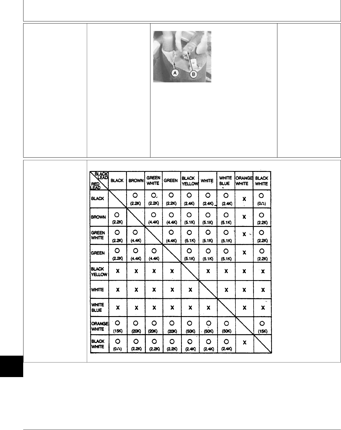
7l Ignition Coil Tests
(Core Insulation)
Key switch OFF.
M45217 -UN-12JAN90
Check for continuity
between negative
terminal (A), and coil
casing (B).
There should be no
continuity (infinite
resistance).
Repeat test for each
coil.
NO CONTINUITY: Coil
OK. Check wires and
connections between
coil and transistor
module. If OK, GO TO
7m
CONTINUITY: Replace
coil, then GO TO Õ,
Group 05.
7m Transistor Module
Test
Key switch OFF.
Transistor module
connectors
disconnected.
Use an ohmmeter to
check resistance across
terminals as indicated
in the chart.
NOTE: The resistance
value shown is an
approximation. The
tested value may vary
depending on ambient
temperature and the
condition of ohmmeter
battery. What’s most
important is, either
there is continuity or
there isn’t continuity.
“O” = Continuity
(resistance)
“X” = No Continuity
(infinite resistance)
M45129 -19-03JAN89
OK: Transistor module
OK. Check circuit wires
and ground
connections.
NOT OK: Replace
transistor module.
MX,159124020,87-19-13JUL95
MX,159124020,88-19-13JUL95
Electrical System Diagnosis/Ignition Circuit Tests (322)
TM1591 (15JUL95) 240-20-44 322,330,332 & 430 Lawn & Garden Tractors
030895
240
20
44

7n Seat Switch Test
for Ignition Circuit.
M45187 -UN-08JAN90
NOTE: Seat switch for 322 and 332/430 (S.N.
475001— ) shown in photo.
Key switch OFF.
Disconnect seat switch connector.
Connect ohmmeter or continuity tester across
switch terminals.
There should NOT be continuity.
330 and 332/430 (S.N. —475000); Sit on or
push down on surface of seat.
322 and 332/430 (S.N. 475001— ); Push seat
switch button down.
There should be continuity.
OK: Connect seat
switch connector, then
GO TO 7o
NOT OK: Replace
switch, then GO TO Õ,
Group 05.
7o TDC Module Test for Ignition
Circuit
NOTE: Perform all voltage and
continuity tests before going to
result column.
Check both sides of connector when
testing for voltage and continuity. If
test OK at only one side of
connector, repair or replace
connector as necessary.
M45218 -UN-12JAN90
PTO switch OFF.
Hydrostatic lever at
N/STOP.
Later Models; Park
brake engaged.
Key switch OFF.
Install jumper wire
across harness side of
seat switch connector.
At TDC module 2-pin
connector:
—Check for continuity
between terminal
with black wire (A)
and ground.
—Turn key switch to
RUN position.
—Check for voltage
at pink wire (B).
At TDC module 8-pin
connector:
—Check for voltage at:
pink wire (C)
yellow/blk wire (D)
purple/blk wire (E)
CONTINUITY AND VOLTAGE OK: Pink wire
between TDC 8-pin connector and engine
connector is open. Repair or replace wire.
NO CONTINUITY OF BLACK WIRE BETWEEN
TERMINAL (A) AND GROUND: Repair or
replace wire.
NO VOLTAGE AT TERMINAL (B): Pink wire
between seat switch and TDC 2-pin connector or
wire between seat switch and 10-amp fuse is
open. Repair or replace.
NO VOLTAGE AT TERMINAL (C) (PINK WIRE)
WHEN ALL OTHER TERMINALS TEST OK:
Replace TDC module.
NO VOLTAGE AT TERMINAL (D): Yellow/black
wire between TDC 8-pin connector and 25-amp
fuse is open. Repair or replace wire.
NO VOLTAGE AT TERMINAL (E): Purple/black
wire between TDC 8-pin connector and neutral
start relay is open. Repair or replace wire.
After the repair has been made; GO TO Õ,
Group 05.
MX,159124020,89-19-13JUL95
MX,159124020,90-19-13JUL95
Electrical System Diagnosis/Ignition Circuit Tests (322)
TM1591 (15JUL95) 240-20-45 322,330,332 & 430 Lawn & Garden Tractors
030895
240
20
45
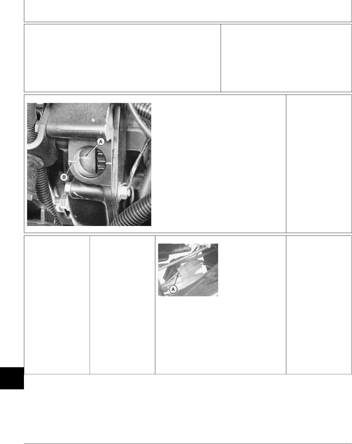
7q Ignition Timing Check
NOTE: Ignition timing is not
adjustable, but can be checked for
diagnositic purposes if a misfire
condition exists.
Do not be concerned with alignment
between BTDC mark (A) and
flywheel housing mark (B) because
timing is determined by pulsars and
flywheel notch.
What’s important is that the timing
light shows each cylinder timing
mark (A) in the same position as
the other cylinder timing marks.
M45225 -UN-12JAN90
Connect timing light to ignition system following
manufacturer’s instructions.
NOTE: Flywheel has three BTDC marks and one
TDC mark for each cylinder.
Remove rubber plug from flywheel housing.
Start engine and operate at slow idle.
Aim timing light at flywheel through flywheel
housing hole. Check and compare center BTDC
mark (A) with flywheel housing mark (B) for all
three cylinders.
LOOK: BTDC mark must be in same position for
ALL cylinders.
OK: GO TO SECTION
220.
NOT OK:
ONE BTDC MARK
NOT IN SAME
POSITION: GO TO 7r
7r Transistor Module
Input Voltage Test
PTO switch OFF.
Hydrostatic lever in
N/STOP position.
Later Models; Park
brake engaged.
M45219 -UN-12JAN90
Start engine and
operate at slow idle.
Measure voltage across
black ground wire (A) in
transistor 4-pin
connector and each of
the remaining three
wires.
Voltage of all three
wires must be the
same.
DIFFERENT
VOLTAGES: Wire from
transistor module to
pulsar is shorted to
ground or pulsar is
defective. If wire OK,
GO TO 7h
MX,159124020,91-19-13JUL95
MX,159124020,92-19-13JUL95
Electrical System Diagnosis/Ignition Circuit Tests (322)
TM1591 (15JUL95) 240-20-46 322,330,332 & 430 Lawn & Garden Tractors
030895
240
20
46

Ú HOUR METER
CIRCUIT TEST
Check 10-amp and
25-amp fuses.
Key switch OFF.
PTO switch OFF.
Hydrostatic lever in
N/STOP position.
Later Models; Park
brake engaged.
M45221 -UN-12JAN90
Check for continuity
between terminal with
black wire (A) and
ground.
Turn key switch to
ON/RUN position.
Check for voltage at
terminal with orange
wire (B).
CONTINUITY AND
VOLTAGE OK: Replace
hour meter.
NO CONTINUITY:
Black wire between
hour meter and ground
is open. Repair or
replace wire, then GO
TO Ú, Group 05.
NO VOLTAGE:
322; Orange wire
between hour meter
and engine connector is
open.
330 and 430 (S.N.
—420468); Orange
wire between hour
meter and TDC module
8-pin connector is
open.
332 (all) and 430 (S.N.
420469— ); Orange
wire between hour
meter and fuel shutoff
solenoid is open.
Repair or replace wire
as necessary, then GO
TO Ú, Group 05.
MX,159124020105-19-13JUL95
Electrical System Diagnosis/Hour Meter Circuit Test
TM1591 (15JUL95) 240-20-47 322,330,332 & 430 Lawn & Garden Tractors
030895
240
20
47

Ü HEAD AND TAIL
LIGHT CIRCUIT
TESTS
NOTE: 322 (All) and
332/430 (S.N.
475001— ); 2-pin
connectors are used on
the headlight and tail
light harnesses.
330; 1-pin connectors
are used. The headlight
ground wires connect
directly to the machine
frame.
332/430 (S.N.
—475000); 1-pin
connectors are used.
The head and tail light
ground wires connect
directly to the machine
frame.
The following procedure
applies to either head
or tail lights.
M45223 -UN-12JAN90
Key switch OFF.
Disconnect head and/or
tail light connector(s).
For machines equipped
with 2-pin connector,
check for continuity
between terminal with
black wire (A) and
ground on harness side
of connection.
For machines equipped
with 1-pin connector,
check for good ground.
Turn key switch to
ON/RUN position.
Pull light switch ON.
NOTE: 430; A yellow
wire is used between
connector and light
switch.
Check for voltage at
terminal with
yellow/white wire (B).
CONTINUITY AND
VOLTAGE OK: Replace
headlight or tail light
wiring harness.
NO CONTINUITY:
Black wire between
terminal (A) and ground
is open. Repair or
replace wire as
necessary, then GO TO
Ü, Group 05.
NO VOLTAGE: GO TO
9a
9a Light Switch Test
NOTE: If either head or
tail lamp comes on,
light switch is OK.
Check 25-amp fuse.
Check headlight and
tail light bulbs.
Key switch ON/RUN
position.
Light switch ON.
M77928 -UN-17JAN95
Check for voltage at
terminal with double
yellow wires.
VOLTAGE: Wire
between head or tail
light connector and light
switch is open. Repair
or replace wire as
necessary, then GO TO
Ü, Group 05.
NO VOLTAGE: Check
for voltage at terminal
(A).
NO VOLTAGE: Wire
between light switch
and 25-amp fuse is
open. Repair or replace
wire as necessary, then
GO TO Ü, Group 05.
VOLTAGE: Replace
switch, then GO TO Ü,
Group 05.
MX,159124020106-19-13JUL95
MX,159124020107-19-13JUL95
Electrical System Diagnosis/Head and Tail Light Circuit Tests
TM1591 (15JUL95) 240-20-48 322,330,332 & 430 Lawn & Garden Tractors
030895
240
20
48
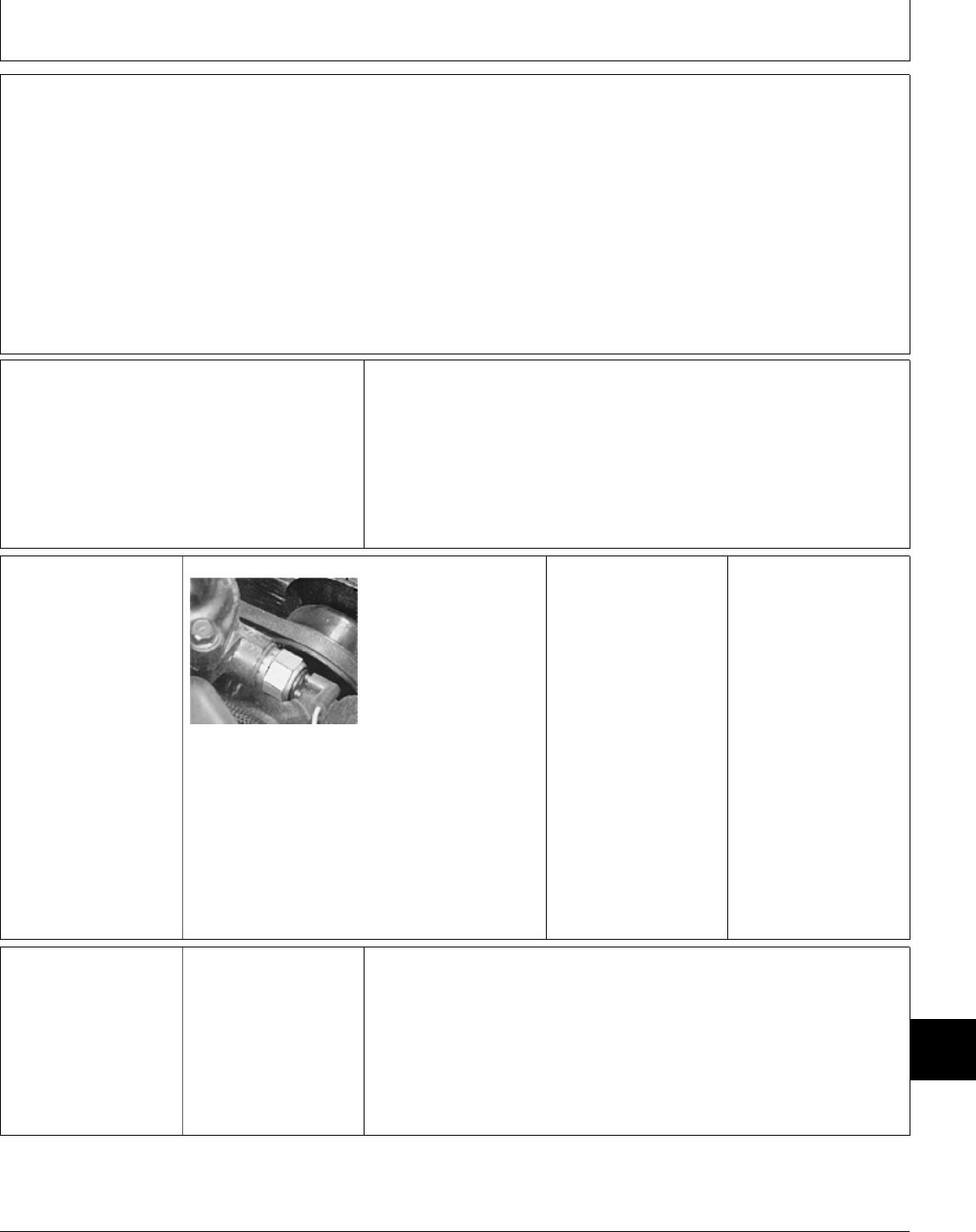
BEFORE YOU START
Always perform the system checkout procedures in
Group 05 and the System Diagnosis in Group 20
before doing any tests in this group.
The step-by-step procedures in this group provide the
detailed information necessary for the component test
or adjustment. These procedures include any special
tooling required to identify a failure.
Always start with the first step and follow the
sequence from left to right. Read each step
completely before performing the test or adjustment.
Make the the necessary repairs or adjustments, then
perform the System Checkout in Group 05 to make
certain the problem has been solved.
; DASH LAMPS
SENSOR TESTS
Engine Coolant Temperature Switch
Test, GO TO 1a
Low Fuel Sensor Test:
322, 332, 430 (S.N. 475001— ),
GO TO 1b
430 (S.N. —475000), GO TO 1c
Water-In-Fuel Sensor Test (430),
GO TO 1d
Glow Plug Test (330, 332, 430), GO
TO 1e
1a Engine Coolant
Temperature Switch
Test
M36603 -UN-25JAN90
Remove engine coolant
temperature switch from
thermostat housing.
Put switch in a
container filled with
coolant.
Heat the coolant to
approximately 107˚C
(225˚F).
Remove switch from
coolant and test for
continuity between the
switch wire terminal
and switch body.
CONTINUITY: Switch
OK.
NO CONTINUITY:
Replace switch.
1b Low Fuel Sensor
Test—322, 332 and
430 (SN 475001— )
Remove fender deck to
access low fuel sensor.
Continued on next page
MX,159124025,1 -19-13JUL95
MX,159124025,2 -19-13JUL95
MX,159124025,3 -19-13JUL95
Group 25
Electrical System Component Tests and Adjustments
TM1591 (15JUL95) 240-25-1 322,330,332 & 430 Lawn & Garden Tractors
030895
240
25
1
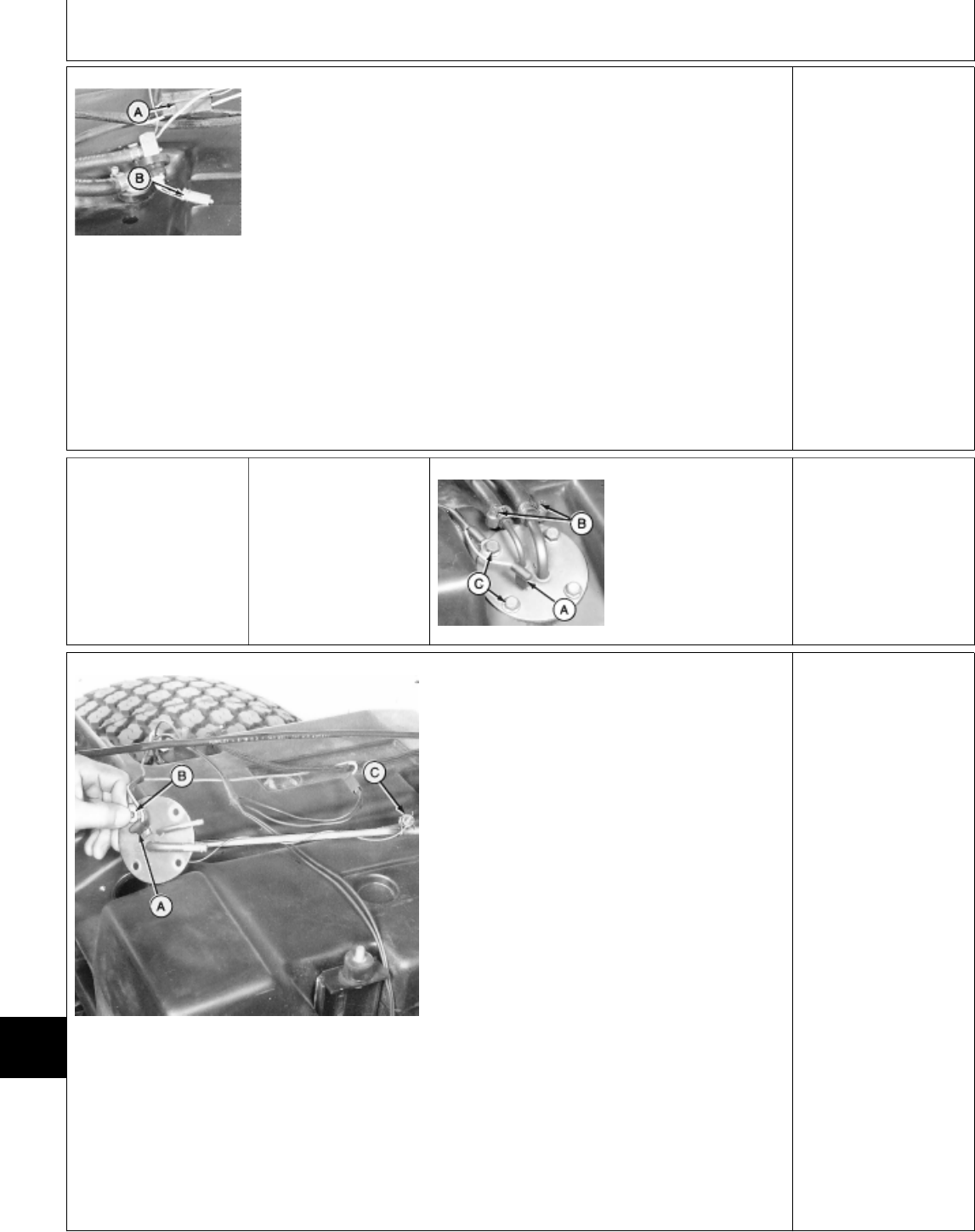
M49019 -UN-08JAN90
Disconnect low fuel sensor connector (A).
Remove low fuel sensor from fuel tank.
Connect low fuel sensor connector (A).
Turn key switch to ON/RUN position.
LOOK: Low fuel lamp should come on in
approximately 30 seconds.
Turn key switch OFF and allow sensor tip (B) to
cool for about 10 seconds.
Insert sensor into fuel tank and immerse in fuel.
Turn key switch to ON/RUN position.
LOOK: Low fuel lamp should NOT come on.
OK: Install low fuel
sensor.
NOT OK: Replace or
repair sensor as
necessary, then GO TO
;, Group 05.
1c Low Fuel Sensor
Test
430 (SN —475000)
Remove fender deck to
access low fuel sensor.
M36651 -UN-28APR95
Disconnect wire (A) and
fuel lines (B).
Remove four cap
screws (C).
Remove low fuel
sensor from fuel tank.
M36631 -UN-27APR95
Connect wire (A) to low fuel sensor.
Hold ground wire ring terminal (B) to sensor
base plate.
Turn key switch to RUN position.
LOOK: Low fuel lamp should come on in
approximately 30 seconds.
Turn key switch OFF and allow sensor tip (C) to
cool for about 10 seconds.
Insert sensor into fuel tank and immerse in fuel.
Turn key switch to RUN position.
LOOK: Low fuel lamp should NOT come on.
NOTE: Make sure the plastic isolators are
properly installed on both sides of the plate.
OK: Install low fuel
sensor.
NOT OK: Replace or
repair sensor as
necessary, then GO TO
;, Group 05.
MX,159124025,4 -19-13JUL95
MX,159124025,5 -19-13JUL95
Electrical System Component Tests and Adjustments/Dash Lamps Sensor Tests
TM1591 (15JUL95) 240-25-2 322,330,332 & 430 Lawn & Garden Tractors
030895
240
25
2
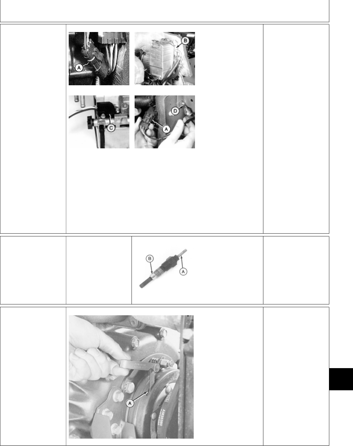
1d Water-In-Fuel
Sensor Test (430)
M36607 -UN-12APR95
M78966 -UN-27APR95
M78965 -UN-27APR95
M78967 -UN-27APR95
Disconnect water-in-fuel
sensor connector (A).
Remove fuel filter/base
(B) from firewall.
Remove water-in-fuel
sensor (C) from back of
filter base.
Connect water-in-fuel
sensor connector (A).
Turn key switch to RUN
position.
Ground sensor tip (D)
to machine frame.
LOOK: Water-in-fuel
lamp should come ON.
OK: Install water-in-fuel
sensor.
NOT OK: Replace
sensor, then GO TO ;,
Group 05.
1e Glow Plug Test
(330, 332, 430)
Disconnect glow plug
wire lead.
Remove glow plug(s).
M78976 -UN-09JUN95
Measure resistance
across terminal (A) and
body (B).
Resistance should be a
minimum of 1.00 ohms.
OK: Install glow plug(s)
and connect wire lead.
NOT OK: Replace glow
plug(s).
‘ PTO CLUTCH
ADJUSTMENT
CHECK
NOTE: Front PTO
clutch is shown. Use
same procedure for
rear PTO clutch if
equipped.
M36659 -UN-25JAN90
Key switch OFF.
NOTE: There are three
slots around the clutch
for checking clearance.
Using a feeler gauge,
check armature-to-rotor
clearance at each of
the three slots (A)
located around the
clutch.
Clearance should be
0.46 mm (0.018 in.).
OK: Repair or replace
clutch assembly as
necessary. (See
Section 40).
NOT OK: Adjust
clearance as
necessary. (See
Section 40.)
MX,159124025,6 -19-13JUL95
MX,159124025,32-19-13JUL95
MX,159124025,7 -19-13JUL95
Electrical System Component Tests and Adjustments/PTO Clutch Adjustment Check
TM1591 (15JUL95) 240-25-3 322,330,332 & 430 Lawn & Garden Tractors
030895
240
25
3

Æ STARTING SYSTEM
COMPONENT TESTS
Key Switch Test:
—322, 330 and 332; GO TO 3a
—430; GO TO 3b
Neutral Start Relay Test; GO TO 3c
Starter Amp Draw Test; GO TO 3d
Starter No Load Running Test:
—322, 330 and 332; GO TO 3e
—430; GO TO 3h
Starter No Load RPM Test:
—322, 330 and 332; GO TO 3f
—430; GO TO 3i
Starter No Load Amp Draw Test:
—322, 330 and 332; GO TO 3g
—430; GO TO 3j
3a Key Switch
Test—322,
330 and 332
M55137 -UN-18APR89
Check for continuity between all key switch
terminals at each of the key switch positions.
Refer to illustration and chart for switch position
and continuity.
Key
Position Continuity
ACC . . . . . . . . . . . . . . . . . . . . . . . . . BAT + ACC
OFF . . . . . . . . . . . . . . . . . . . . . . . . . . . . . NONE
ON/RUN . . . . . . . . . . . . . . . . . . BAT + ACC + IGN
START . . . . . . . . . . . . . . . . . . . . BAT + IGN + ST,
G + Switch Body
NOTE: The labeling of the key switch positions
for the 322 is “ACC”, “OFF”, “RUN” and START.
The continuity checks are same for all machines.
CONTINUITY ONLY
BETWEEN
DESIGNATED
TERMINALS AT
SPECIFIED SWITCH
POSITION: Key switch
OK.
CONTINUITY
BETWEEN
NONDESIGNATED
TERMINALS AT
SPECIFIED SWITCH
POSITION: Replace
key switch.
NO CONTINUITY
BETWEEN
DESIGNATED
TERMINALS AT
SPECIFIED SWITCH
POSITION: Replace
key switch.
MX,159124025,8 -19-13JUL95
MX,159124025,9 -19-13JUL95
Electrical System Component Tests and Adjustments/Starting System Component Tests
TM1591 (15JUL95) 240-25-4 322,330,332 & 430 Lawn & Garden Tractors
030895
240
25
4

3b Key Switch
Test—430
M36664 -UN-27APR95
Check for continuity between all key switch
terminals at each of the key switch positions.
Refer to illustration and chart for switch position
and continuity.
Key
Position Continuity
TEST . . . . . . . . . . . . . . . . . . . . . . . B + BR + R1,
E + BA
OFF . . . . . . . . . . . . . . . . . . . . . . . . . . . . E + BA
RUN . . . . . . . . . . . . . . . . . . . . . . . . B + BA + BR
START . . . . . . . . . . . . . . . . B + BA + BR + R2 + C
CONTINUITY ONLY
BETWEEN
DESIGNATED
TERMINALS AT
SPECIFIED SWITCH
POSITION: Key switch
OK.
CONTINUITY
BETWEEN
NONDESIGNATED
TERMINALS AT
SPECIFIED SWITCH
POSITION: Replace
key switch.
NO CONTINUITY
BETWEEN
DESIGNATED
TERMINALS AT
SPECIFIED SWITCH
POSITION: Replace
key switch.
3c Neutral Start Relay
Test
M36660 -UN-25JAN90
Remove neutral start relay.
Check for continuity between terminals.
There should be continuity between the following:
—Terminal 30 and 87a
—Terminal 85 and 86
There should NOT be continuity between
terminals 30 and 87.
CONTINUITY NOT OK: Replace relay, then GO
TO Æ, Group 05.
CONTINUITY OK: Connect a jumper wire
between terminal 86 and battery positive (+)
terminal. Connect a jumper wire between
terminal 85 and battery negative (—) terminal.
LISTEN: Relay should “click” to engage.
With relay engaged, check for continuity between
terminals:
30 and 87,
30 and 87a.
There should be continuity between 30 and 87.
There should NOT be continuity between
terminals 30 and 87a.
CONTINUITY OK:
Relay OK.
CONTINUITY NOT OK:
Replace relay, then GO
TO Æ, Group 05.
MX,159124025,10-19-13JUL95
MX,159124025,11-19-13JUL95
Electrical System Component Tests and Adjustments/Starting System Component Tests
TM1591 (15JUL95) 240-25-5 322,330,332 & 430 Lawn & Garden Tractors
030895
240
25
5
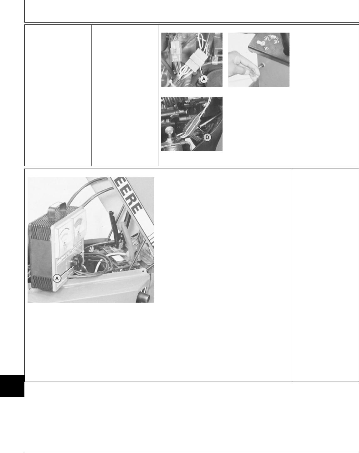
3d Starter Amp Draw
Test
Before performing
starter draw test, test
battery. (See Battery
Tests B in Group 20
of this section.)
M45190 -UN-08JAN90
M45234 -UN-10JUL95
M55022 -UN-09DEC89
322; Disconnect ignition
coils 6-pin connector
(A).
330; Pull fuel stop knob
all the way out.
332 and 430;
Disconnect fuel shutoff
connector.
M45235 -UN-12JAN90
IMPORTANT: Before connecting JT05685
Battery Tester to battery, turn load knob (A)
fully counterclockwise.
Connect JT05685 Battery Tester or equivalent to
battery:
Red lead to positive (+) battery terminal.
Black lead to negative (—) battery terminal.
Crank engine with starter and read voltage on
meter while cranking.
Check engine rpm while cranking using JT05719
Photo Tachometer or equivalent.
With key switch at OFF position, adjust load
knob until battery voltage reads the same as
when cranking.
Read amperage on meter. Amperage should
read 230 amps or less.
Turn load knob fully counterclockwise.
230 AMPS OR LESS
BUT RPM IS LESS
THAN 300:
—322, 330 and 332;
GO TO 3f
—430; GO TO 3i
230 AMPS OR LESS
AT 300 RPM: Starter
OK.
MORE THAN 230
AMPS:
—322, 330 and 332;
GO TO 3e
—430; GO TO 3h
MX,159124025,12-19-13JUL95
Electrical System Component Tests and Adjustments/Starting System Component Tests
TM1591 (15JUL95) 240-25-6 322,330,332 & 430 Lawn & Garden Tractors
030895
240
25
6

3e Starter No Load
Running Test—322,
330 and 332
M45133 -UN-08JAN90
Disconnect battery
ground cable.
Remove starter.
Mount starter in a vice.
Use jumper cables to
connect starter to
machine battery or one
of similar capacity.
Connect positive clamp
to starter common
terminal (A).
Connect negative clamp
to starter body (B).
Connect one end of a
jumper wire to starter
terminal (C) and
connect other end to
positive cable clamp as
shown.
Starter should engage
and run.
SOLENOID “CLICKS”
OR CHATTERS,
MOTOR DOESN’T
RUN: Replace solenoid.
PINION GEAR
ENGAGED BUT
MOTOR DOESN’T
RUN: Repair or replace
starter motor. (See
CTM3 or CTM12.)
STARTER ENGAGES
AND RUNS: GO TO
3f
3f Starter No Load
RPM Test—322, 330
and 332
M45134 -UN-08JAN90
Mount starter in a vice
and connect to a
battery as instructed in
step 3e.
With starter running,
check no load rpm with
a tachometer such as
JT05719. Follow
manufacturer
instructions with the
tachometer.
No load rpm should be
about 7000.
RPM 7000 OR MORE:
GO TO 3g
RPM BELOW 7000:
Make sure battery is of
proper rating size and
fully charged.
Repeat test as needed
with fully charged
battery. If battery is OK,
repair or replace starter
(See CTM3 or CTM12.)
MX,159124025,13-19-13JUL95
MX,159124025,14-19-13JUL95
Electrical System Component Tests and Adjustments/Starting System Component Tests
TM1591 (15JUL95) 240-25-7 322,330,332 & 430 Lawn & Garden Tractors
030895
240
25
7
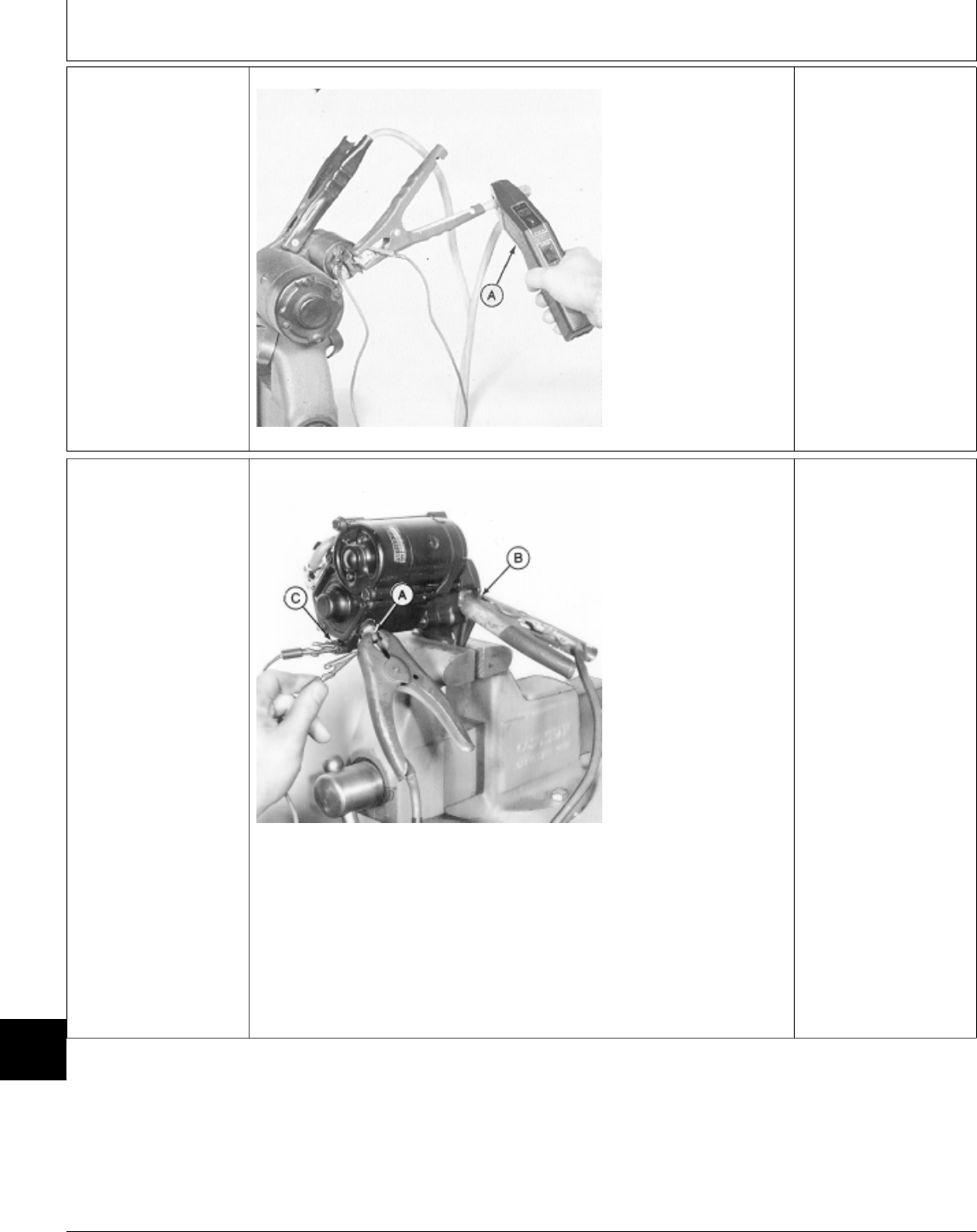
3g Starter No Load
Amp Draw
Test—322, 330 and
332
M45135 -UN-12JAN90
Mount starter in a vise
and connect to a
battery as instructed in
step 3e.
With starter running,
check amperage with
JT05712 Current Gun
(A).
Starter should draw 60
amps or less at 7000
rpm.
AMPERAGE 60 OR
LESS: Starter OK.
Malfunction is in wiring
on machine. Check all
connections and
grounds.
AMPERAGE MORE
THAN 60: Repair or
replace starter. (See
CTM3 or CTM12.)
3h Starter No Load
Running Test—430
M36656 -UN-28APR95
Disconnect battery
ground cable.
Remove starter.
Mount starter in a vice.
Use jumper cables to
connect starter to
machine battery or one
of similar capacity.
Connect positive clamp
to starter common
terminal (A).
Connect negative clamp
to starter body (B).
Connect one end of a
jumper wire to starter
terminal (C) and
connect other end to
positive cable clamp as
shown.
Starter should engage
and run.
SOLENOID “CLICKS”
OR CHATTERS,
MOTOR DOESN’T
RUN: Replace solenoid.
PINION GEAR
ENGAGED BUT
MOTOR DOESN’T
RUN: Repair or replace
starter motor. (See
CTM3.)
STARTER ENGAGES
AND RUNS: GO TO
3i
MX,159124025,15-19-13JUL95
MX,159124025,16-19-13JUL95
Electrical System Component Tests and Adjustments/Starting System Component Tests
TM1591 (15JUL95) 240-25-8 322,330,332 & 430 Lawn & Garden Tractors
030895
240
25
8
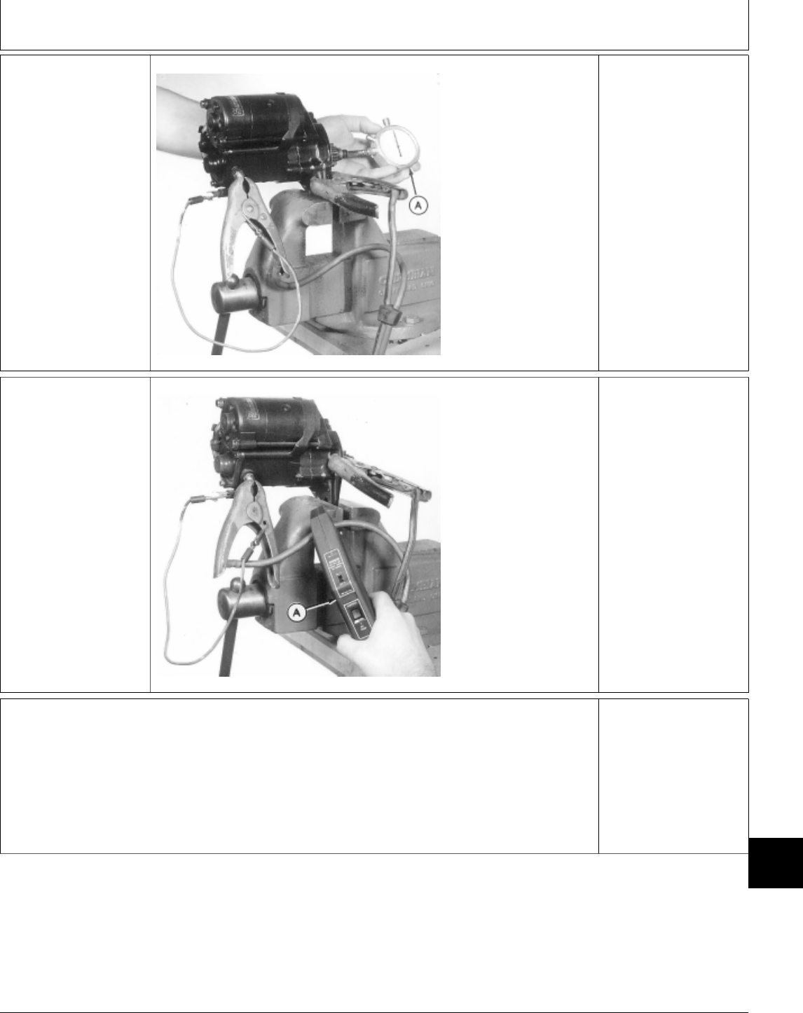
3i Starter No Load
RPM Test—430
M36657 -UN-28APR95
Mount starter in a vice
and connect to a
battery as instructed in
step 3h.
With starter running,
check no load rpm with
a tachometer (A).
Follow manufacturer
instructions with the
tachometer.
No load rpm should be
about 3000.
RPM 3000 OR MORE:
GO TO 3j
RPM BELOW 3000:
Make sure battery is of
proper rating size and
fully charged.
Repeat test as needed
with fully charged
battery. If battery is OK,
repair or replace starter
(See CTM3.)
3j Starter No Load
Amp Draw
Test—430
M36658 -UN-28APR95
Mount starter in a vise
and connect to a
battery as instructed in
step 3h.
With starter running,
check amperage with
JT05712 Current Gun
(A).
Starter should draw 90
amps or less at 3000
rpm.
AMPERAGE 90 OR
LESS: Starter OK.
Malfunction is in wiring
on machine. Check all
connections and
grounds.
AMPERAGE MORE
THAN 90: Repair or
replace starter. (See
CTM3.)
Å FUEL SHUTOFF
SOLENOID
ADJUSTMENT
332 (All) and 430 (S.N.
420469— ); GO TO
4a
430 (S.N. —420468);
GO TO 4b
MX,159124025,17-19-13JUL95
MX,159124025,18-19-13JUL95
MX,159124025,19-19-13JUL95
Electrical System Component Tests and Adjustments/Fuel Shutoff Solenoid Adjustment
TM1591 (15JUL95) 240-25-9 322,330,332 & 430 Lawn & Garden Tractors
030895
240
25
9
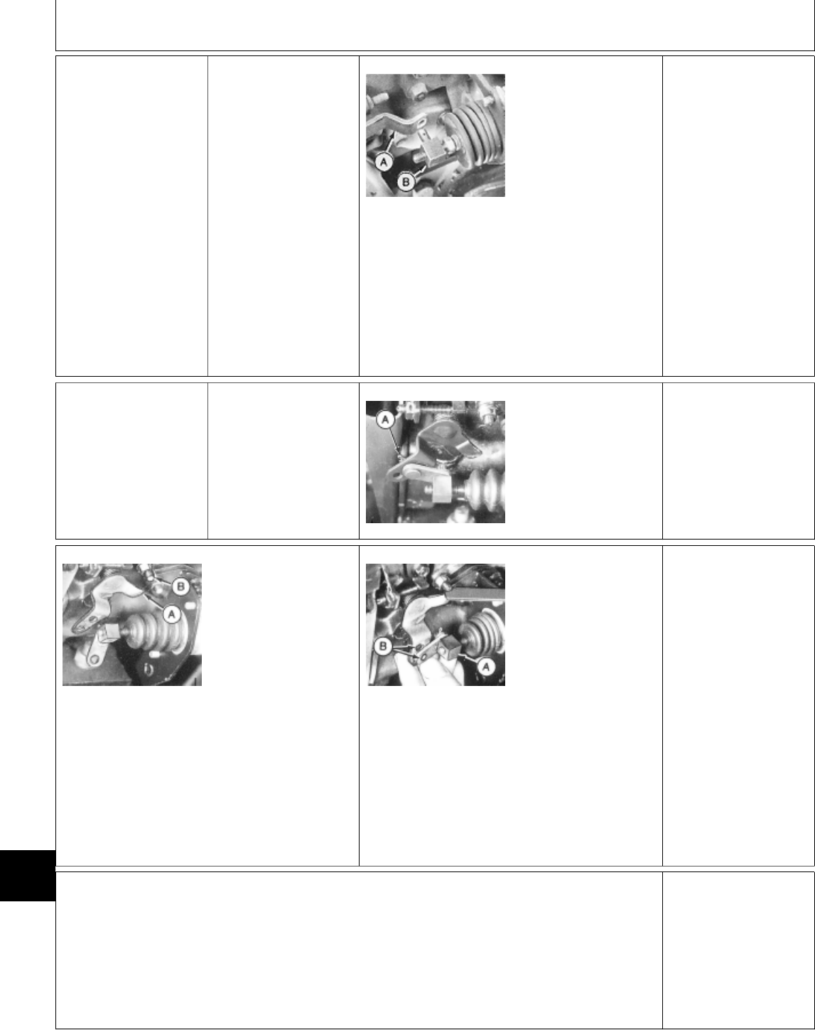
4a Fuel Shutoff
Solenoid
Adjustment—332
and
430 (SN 420469— )
Install jumper wire
across harness side of
seat switch connector.
Disconnect fuel shutoff
arm from solenoid
plunger.
Turn key switch to
ON/RUN position.
Push solenoid plunger
in.
M43343 -UN-15JAN90
Push fuel shutoff lever
(A) toward solenoid
until it stops.
Turn adjustable link (B)
until link aligns with
lever hole.
Turn link out 2 turns.
Assemble linkage.
AFTER ADJUSTMENT:
GO TO Å, Group 05.
4b Fuel Shutoff
Solenoid
Adjustment
430 (SN —420468)
Install jumper wire
across harness side of
seat switch connector.
M36612 -UN-27APR95
Remove cotter pin (A)
to disconnect solenoid
linkage from lever.
M36613 -UN-27APR95
NOTE: If 8-amp circuit
breaker trips with
linkage disconnected,
replace solenoid.
Turn key switch to RUN
position.
Insert feeler gauge
blade thickness of
approximately 2 mm
(0.080 in.) between
lever (A) and stop (B).
M36614 -UN-27APR95
While holding lever tight
against feeler gauge,
rotate turnbuckle (A)
until holes (B) are
aligned.
Install pin and cotter
pin.
AFTER ADJUSTMENT:
GO TO Å, Group 05.
Ö CHARGING SYSTEM
TESTS
322, 330 and 332; GO
TO 5a
430; GO TO 5d
MX,159124025,20-19-13JUL95
MX,159124025,21-19-13JUL95
MX,159124025,22-19-13JUL95
Electrical System Component Tests and Adjustments/Charging System Tests
TM1591 (15JUL95) 240-25-10 322,330,332 & 430 Lawn & Garden Tractors
030895
240
25
10

5a Regulated Voltage
Output Test—322,
330 and 332
M45190 -UN-08JAN90
M45234 -UN-10JUL95
M55022 -UN-09DEC89
322; Disconnect ignition
coils connector (A).
330; Pull fuel stop knob
all the way out.
332; Disconnect fuel
shutoff solenoid
connector.
Crank engine for 10
seconds to remove
battery surface charge.
322 and 332; Connect
wire connector.
330; Push fuel stop
knob in.
Measure and record
battery voltage.
Start engine and let run
at fast idle for 1—2
minutes.
After 1—2 minutes has
elapsed, check battery
voltage again while
engine is still running.
VOLTAGE IS 13.5—15:
Regulator is OK.
VOLTAGE ABOVE 15:
Replace regulator.
VOLTAGE BELOW
13.5: GO TO 5b
5b Unregulated
Voltage Output
Test—322,
330 and 332
PTO switch OFF.
Hydrostatic lever in
N/STOP position.
Later Models; Engage
park brake.
Continued on next page
MX,159124025,23-19-13JUL95
Electrical System Component Tests and Adjustments/Charging System Tests
TM1591 (15JUL95) 240-25-11 322,330,332 & 430 Lawn & Garden Tractors
030895
240
25
11
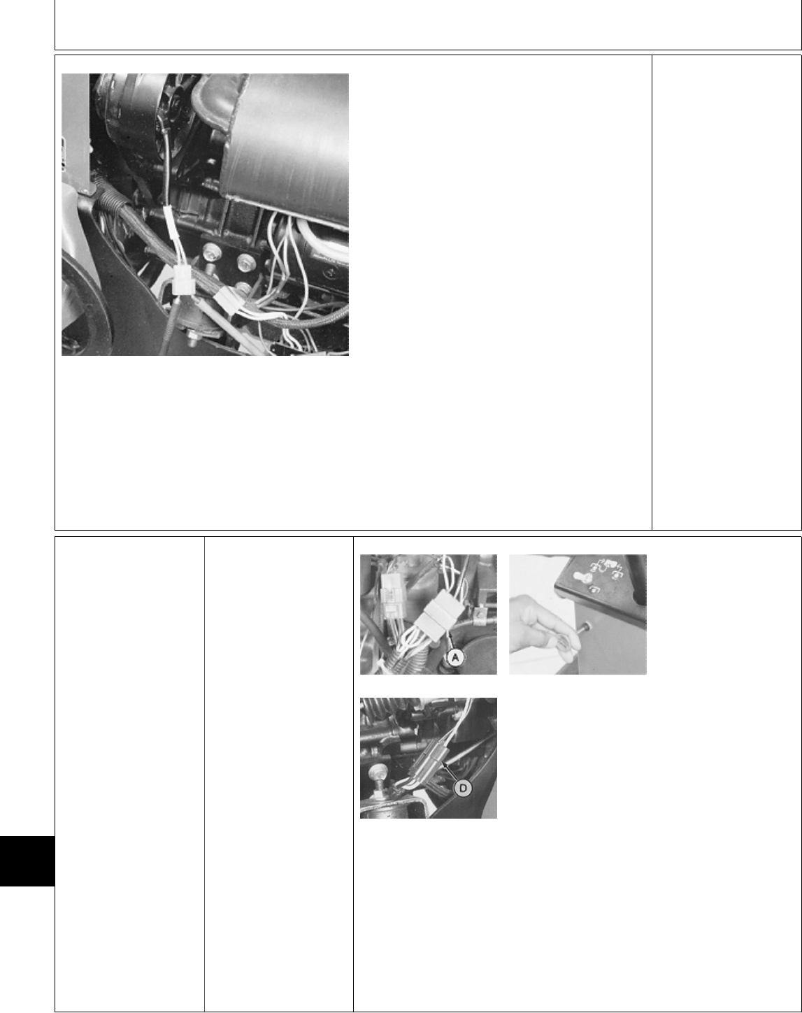
M45236 -UN-12JAN90
Disconnect alternator
2-pin connector.
Start engine and
operate at fast idle.
Measure AC voltage
across alternator
terminal connector as
shown.
OUTPUT 30 VOLTS
OR MORE: Check
current output, GO TO
5c.
OUTPUT LESS THAN
30 VOLTS: Low voltage
may indicate weak
magnets in alternator
flywheel. Repair or
replace alternator as
necessary. (See CTM3
OR CTM12.)
5c Regulated Current
Output Test—322,
330 and 332
PTO switch OFF.
Hydrostatic lever in
N/STOP position.
Later Models; Engage
park brake.
M45190 -UN-08JAN90
M45234 -UN-10JUL95
M55022 -UN-09DEC89
322; Disconnect ignition
coils connector (A).
330; Pull fuel stop knob
all the way out.
332; Disconnect fuel
shutoff solenoid
connector.
Crank engine for
10—15 seconds to
remove battery surface
charge.
322 and 332; Connect
wire connector.
330; Push fuel stop
knob in.
Continued on next page
MX,159124025,24-19-13JUL95
Electrical System Component Tests and Adjustments/Charging System Tests
TM1591 (15JUL95) 240-25-12 322,330,332 & 430 Lawn & Garden Tractors
030895
240
25
12
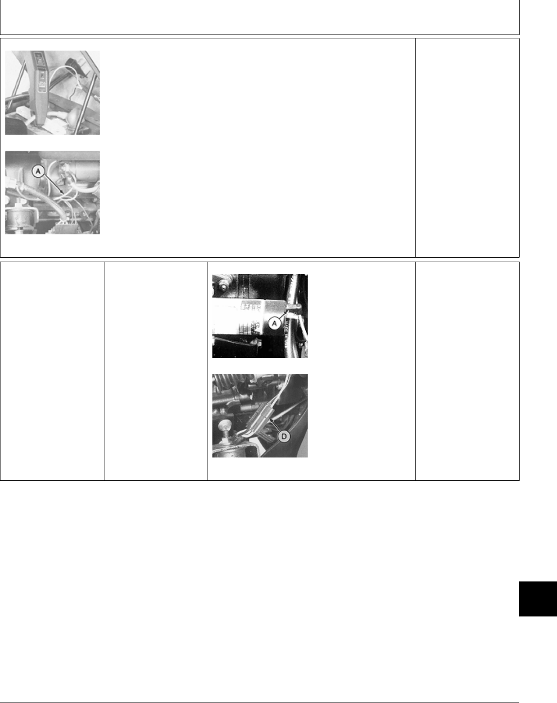
M45198 -UN-08JAN90
M45199 -UN-08JAN90
Clamp JT05712 Current Gun or equivalent
around positive (+) battery cable. Set gun for DC
current. Make sure arrow on gun points in
direction of current flow.
If current gun is not available, connect an
ammeter in series to red wire (A) that runs
between starter and voltage regulator/rectifier.
Start engine and operate at fast idle.
LOOK: Current output should start out high
(approximately 18 amps or more), then decrease
as battery voltage increases.
18 AMPS OR MORE:
Alternator OK.
LESS THAN 18 AMPS:
Verify voltage
regulator/rectifier has
good ground. Verify
voltage at green wire
terminal of voltage
regulator/rectifier.
If voltage and ground
OK, replace voltage
regulator/rectifier.
5d Regulated
Volt/Amp Output
Test—430
PTO switch OFF.
Hydrostatic lever in
N/STOP position.
Later Models; Engage
park brake.
M36602 -UN-12APR95
M45234 -UN-10JUL95
NOTE: 430 (S.N.
—420468) shown.
Disconnect fuel shutoff
solenoid connector.
Crank engine for 10
seconds to remove
battery surface charge,
then connect wire
connector.
Continued on next page
MX,159124025,25-19-13JUL95
Electrical System Component Tests and Adjustments/Charging System Tests
TM1591 (15JUL95) 240-25-13 322,330,332 & 430 Lawn & Garden Tractors
030895
240
25
13
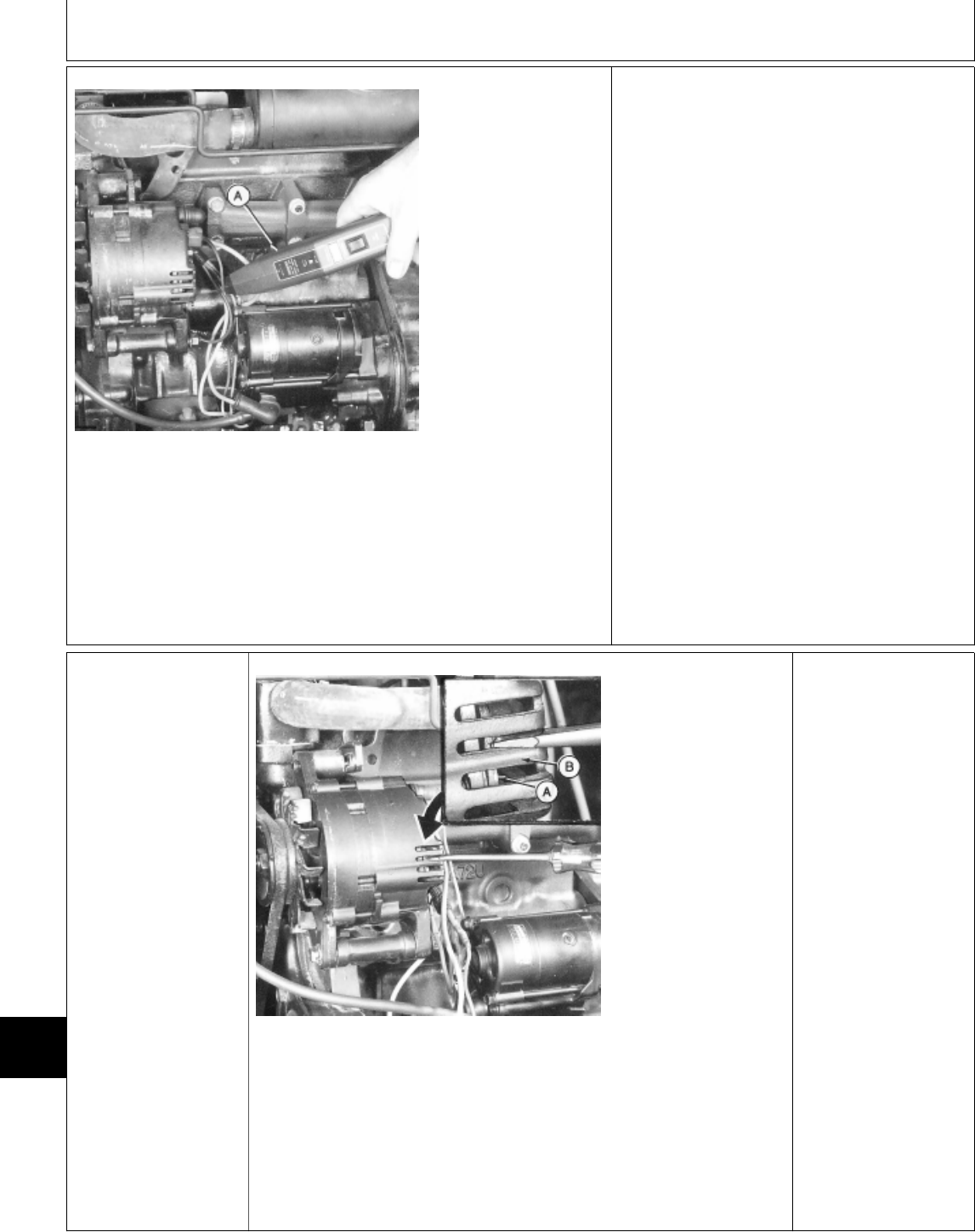
M36666 -UN-27APR95
Clamp JT05712 Current
Gun or equivalent
around large red wire
at back of alternator.
Set gun for DC current.
Make sure arrow on
gun points in direction
of current flow.
Measure and record
battery voltage (engine
not running).
Start engine and
operate at fast idle.
LOOK: Current output
should start out high
(unregulated output is
approximately 35
amps), then decrease
as battery voltage
increases.
After 1—2 minutes has
elapsed, check battery
voltage again while
engine is still running.
AMP OUTPUT HIGH, BUT BATTERY VOLTAGE
DOESN’T INCREASE (VOLTAGE BELOW 13.8):
Faulty battery or poor battery terminal
connections or ground connections. Repair or
replace as necessary, then perform
voltage/current test again.
AMP OUTPUT HIGH, VOLTAGE INCREASES
TO 13.8—14.7: Alternator/regulator OK.
AMP OUTPUT DOESN’T INCREASE, BATTERY
VOLTAGE ABOVE 15: Replace regulator. (See
CTM3.)
AMP OUTPUT IS LOW, BUT VOLTAGE
EVENTUALLY INCREASES:
—430 (S.N. —420468); GO TO 5e
—430 (S.N. 420469— ); GO TO 5f
5e Unregulated
Current Output
Test
430 (SN —420468)
M36661 -UN-28APR95
Connect JT05712
Current Gun or
equivalent as instructed
in step 5d
Start engine and
operate at fast idle.
IMPORTANT:
Complete the
unregulated current
output test in less
than 10 seconds or
battery will be
damaged.
Ground the regulator to
alternator frame using a
screwdriver. Insert
screwdriver blade
through cooling vent as
shown. Touch side of
blade against alternator
frame while touching
blade tip to base of
regulator.
Read amp output on
ammeter.
OUTPUT 35 AMPS OR
MORE: Alternator OK.
Check charging system
wiring.
OUTPUT LESS THAN
35 AMPS: Repair or
replace alternator. (See
CTM3.)
MX,159124025,26-19-13JUL95
MX,159124025,27-19-13JUL95
Electrical System Component Tests and Adjustments/Charging System Tests
TM1591 (15JUL95) 240-25-14 322,330,332 & 430 Lawn & Garden Tractors
030895
240
25
14
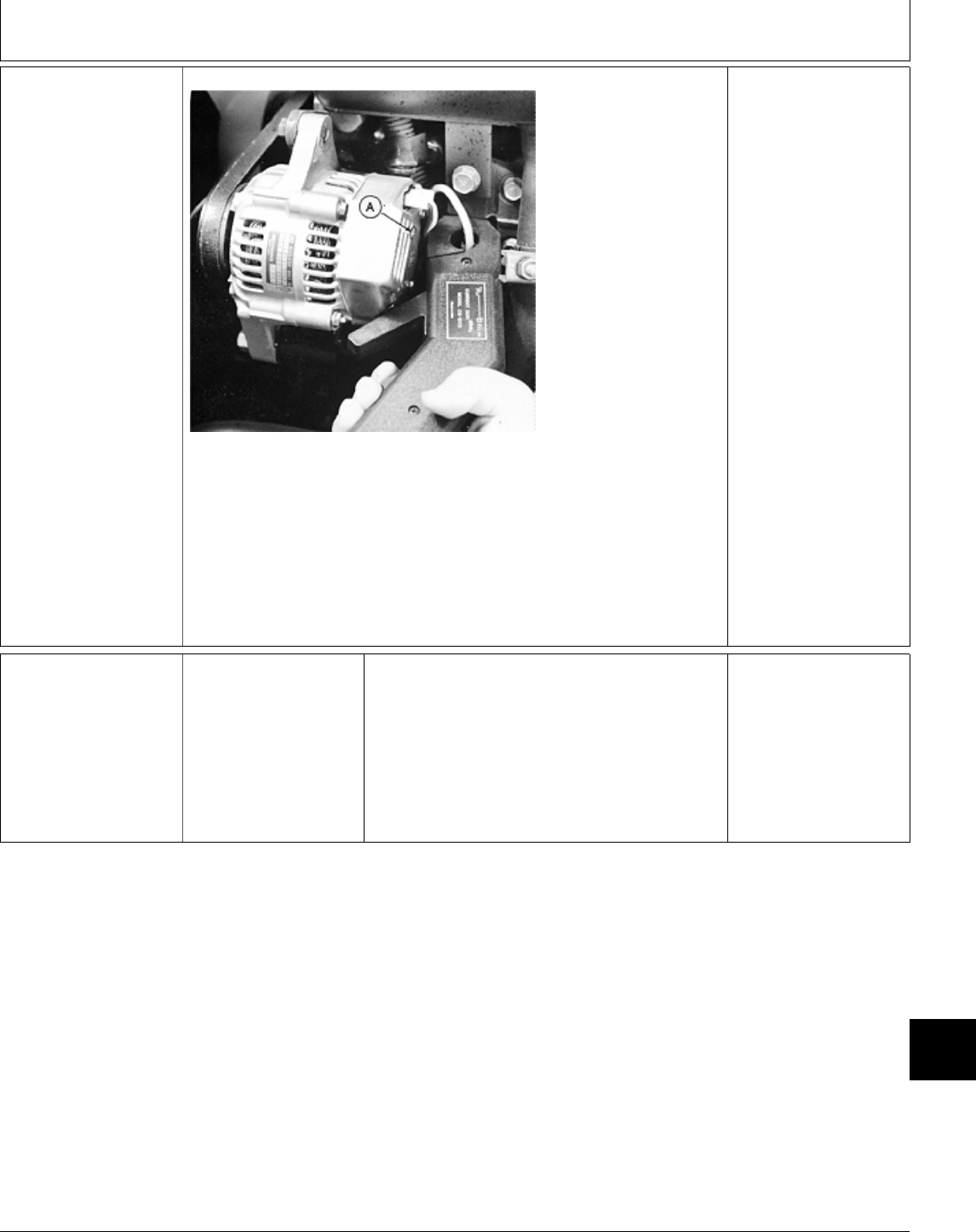
5f Unregulated
Current Output
Test
430 (SN 420469— )
M48576 -UN-11DEC89
Connect JT05712
Current Gun or
equivalent as instructed
in step 5d
Start engine and
operate at fast idle.
IMPORTANT:
Complete the
unregulated current
output test in less
than 10 seconds or
battery will be
damaged.
Insert a phillips
screwdriver through
small round hole (A) to
ground terminal “F” to
alternator rear cover.
Read current output on
ammeter.
OUTPUT 40 AMPS OR
MORE: Alternator OK.
Check charging system
wiring.
OUTPUT LESS THAN
35 AMPS: Repair or
replace alternator. (See
CTM3.)
Ò SYSTEM SHORT
CIRCUIT TESTS
If the 10-amp fuse
blows each time the
key switch is turned
ON/RUN or machine is
operated, there is
probably a short in the
power circuit of a
component protected by
the 10-amp fuse.
If the 25-amp fuse
blows each time the
key switch is turned ON
or machine is operated,
there is probably a
short in the power
circuit of a component
protected by the
25-amp fuse.
Short in the 10-Amp
Fuse Circuits, GO TO
6a
Short in the 25-Amp
Fuse Circuits, GO TO
6b
MX,159124025,28-19-13JUL95
MX,159124025,29-19-13JUL95
Electrical System Component Tests and Adjustments/Charging System Tests
TM1591 (15JUL95) 240-25-15 322,330,332 & 430 Lawn & Garden Tractors
030895
240
25
15

6a Short Circuit Tests
For 10-Amp Fuse
The 10-AMP FUSE PROVIDES
CURRENT TO:
• ALL DASH PANEL INDICATOR
LAMPS EXCEPT PTO LAMP:
A short in the wires between the
10-amp fuse and dash lamps will
cause the fuse to blow when the
key switch is turned to ON/RUN
position.
• THE SEAT SAFETY SWITCH:
A short in the pink wire between
10-amp fuse and the seat switch
will cause the fuse to blow when
the key switch is turned to ON/RUN
position.
A short in the pink wire between the
seat switch and TDC module will
cause the fuse to blow when the
key switch is in the ON/RUN
position and operator sits on seat.
This will cause the engine to stop
each time the PTO’s are turned ON
or when machine is shifted out of
N/STOP position.
• THE GLOW PLUG CONTROL
MODULE—330, 332 AND 430:
A short in the yellow wire running
between the 10-amp fuse and the
glow plug control module would
blow the fuse when the key switch
is turned to ON/RUN position.
Because current from the 10-amp
fuse is needed for the glow plug
controller to operate, no current will
flow to the glow plugs if fuse is
blown.
• CHARGING CIRCUIT:
A short in the green wire between
the 10-amp fuse and the
regulator/rectifier (322, 330 and 332)
or alternator (430) will cause the
fuse to blow when the key switch is
turned to ON/RUN position.
• THE FUEL TRANSFER
PUMP—322, 330 and 332:
A short in the yellow wire running
between the 10-amp fuse and the
pump will cause the fuse to blow
when the key switch is turned to
ON/RUN position.
THE MOST LIKELY
AREAS TO CHECK IF
THE 10-AMP FUSE
BLOWS ARE:
• The engine side of
the fire wall where the
main harness goes
through the
firewall. Check for
proper installation of
the firewall grommet.
• The water pump belt
or idler pulley. Check if
wires are rubbing
against
belt or pulley.
• The drive shaft flex
coupling. Check if wires
are rubbing against
drive
shaft.
These are the wires for
the fuel pump, low fuel
sensor and seat safety
switch.
To check, remove the
belly screen/pan from
bottom of the machine.
• Seat switch wiring
through fender deck.
Check for proper
installation of
grommet in fender
deck.
MX,159124025,30-19-13JUL95
Electrical System Component Tests and Adjustments/System Short Circuit Tests
TM1591 (15JUL95) 240-25-16 322,330,332 & 430 Lawn & Garden Tractors
030895
240
25
16

6b Short Circuit Tests
For 25-Amp Fuse
THE 25-AMP FUSE PROVIDES CURRENT TO:
• THE STARTER SAFETY INTERLOCK
CIRCUIT:
A short in this circuit will cause the 25-amp fuse
to blow when the key switch is turned to the
START position.
• THE HOUR METER/FUEL SHUTOFF
SOLENOID/IGNITION CIRCUIT:
This circuit runs through the TDC module. If the
fuse blows only when the key switch is in
ON/RUN position, with PTO switch OFF,
hydrostatic lever in N/STOP position and park
brake engaged (later machines), the short is
NOT in the TDC module.
The short will be in the wires running between
the TDC module and hour meter and/or fuel
shutoff solenoid (322, 332 and 430) and/or
ignition system (322).
• THE PTO CLUTCH:
This circuit runs through the TDC module. If the
fuse blows only after the PTO is turned ON, the
short is NOT in the TDC module. The short will
be in the wires running to the PTO clutch or
PTO lamp.
• THE HEAD LAMPS:
A short in the yellow wires between light switch
and head or tail lights will cause the 25-amp fuse
to blow when the key switch is in ON/RUN
position and light switch is pulled ON.
• THE FUEL TRANSFER PUMP—430:
A short in the yellow wire between 25-amp fuse
and fuel pump will cause the fuse to blow when
the key switch is turned to the RUN position.
MOST LIKELY AREAS TO CHECK IF THE
25-AMP FUSE BLOWS ARE:
• At engine side of the firewall where main
harness goes through the firewall. Check for
proper installation of the firewall grommet.
• At front PTO clutch. Check if PTO clutch wire
may be pinched against the engine block where
it comes out from behind the coil mounting plate.
• At engine exhaust manifold. Check if the
insulation has burned off the blue wire for the
PTO clutch.
• At rear PTO clutch. Check if wires have
gotten tangled in the drive shaft.
• At PTO clutch connector. Check if the metal
terminal of clutch connector is pushed into the
insulation all the way.
• At front of engine next to the exhaust
manifold. Check if the insulation has burned off
the yellow wire for the headlight.
• At the hood hinge area. Check if yellow wire
for the headlight is pinched.
• At headlight harness connector. Check if the
metal terminal of connector is pushed into the
insulation all the way. If exposed, the bare
terminal could ground against the engine shroud.
• Under the fender deck. Check if the yellow
wire to tail lamps (if equipped) is pinched
between deck and frame.
• 322; Check pulsar wires for shorts near
engine mounts and flywheel.
MX,159124025,31-19-13JUL95
Electrical System Component Tests and Adjustments/System Short Circuit Tests
TM1591 (15JUL95) 240-25-17 322,330,332 & 430 Lawn & Garden Tractors
030895
240
25
17

Electrical System Component Tests and Adjustments/System Short Circuit Tests
TM1591 (15JUL95) 240-25-18 322,330,332 & 430 Lawn & Garden Tractors
030895
240
25
18

Section 250
POWER TRAIN CHECKOUT, OPERATION
AND DIAGNOSIS
Contents
Page
Group 05—Power Train Checkout
Before You Start . . . . . . . . . . . . . . . . . 250-05-1
Transmission Oil Leak Check . . . . . . . . . 250-05-1
Hydrostatic Lever Friction Check . . . . . . . 250-05-1
Transmission Neutral Check . . . . . . . . . 250-05-1
Neutral Return Check . . . . . . . . . . . . . . 250-05-2
Transmission Drive Check . . . . . . . . . . . 250-05-2
Speed Reduction Check (322, 332 and
430) . . . . . . . . . . . . . . . . . . . . . . . . 250-05-2
Two-Speed Axle Lever Check (430) . . . . 250-05-3
Differential Lock Check (430) . . . . . . . . . 250-05-3
Operator Complaint Not Identified . . . . . . 250-05-3
Group 10—Theory of Operation
Hydrostatic Transmission Operation . . . . . 250-10-2
Group 15—Diagnosis, Tests and Adjustments
About This Group . . . . . . . . . . . . . . . . 250-15-1
Troubleshooting Guide . . . . . . . . . . . . . 250-15-1
Check Valve Debris Check . . . . . . . . . . 250-15-5
Charge Pump
Pressure Test . . . . . . . . . . . . . . . . . . 250-15-5
Suction Line Check . . . . . . . . . . . . . . 250-15-6
Charge Relief Valve
Check . . . . . . . . . . . . . . . . . . . . . . . 250-15-6
Adjustment . . . . . . . . . . . . . . . . . . . . 250-15-6
Implement Relief Valve
Pressure Test . . . . . . . . . . . . . . . . . . 250-15-7
Check . . . . . . . . . . . . . . . . . . . . . . . 250-15-7
Adjustment . . . . . . . . . . . . . . . . . . . . 250-15-7
Charge Pump Flow Test . . . . . . . . . . . . 250-15-8
Welch Plug Location Check . . . . . . . . . . 250-15-8
Hydraulic Oil Warm-Up Procedure . . . . . . 250-15-9
Steering Valve Neutral Check (322, 332
and 430) . . . . . . . . . . . . . . . . . . . . . 250-15-9
Hydrostatic Lever Friction Adjustment . . 250-15-10
Neutral Return Linkage Adjustment (330,
and Early 322, 332, 430) . . . . . . . . . 250-15-10
Neutral Adjustment (330 and Early 322,
332, 430) . . . . . . . . . . . . . . . . . . . . 250-15-13
Page
Neutral and Neutral Return Linkage
Adjustment (Later 322, 332, 430) . . . . 250-15-14
Two-Speed Axle Lever Linkage Check
(430) . . . . . . . . . . . . . . . . . . . . . . 250-15-17
Differential Lock Linkage Check (430) . . 250-15-17
TM1591 (15JUL95) 250-1 322,330,332 & 430 Lawn & Garden Tractors
030895
250

Contents
TM1591 (15JUL95) 250-2 322,330,332 & 430 Lawn & Garden Tractors
030895
250
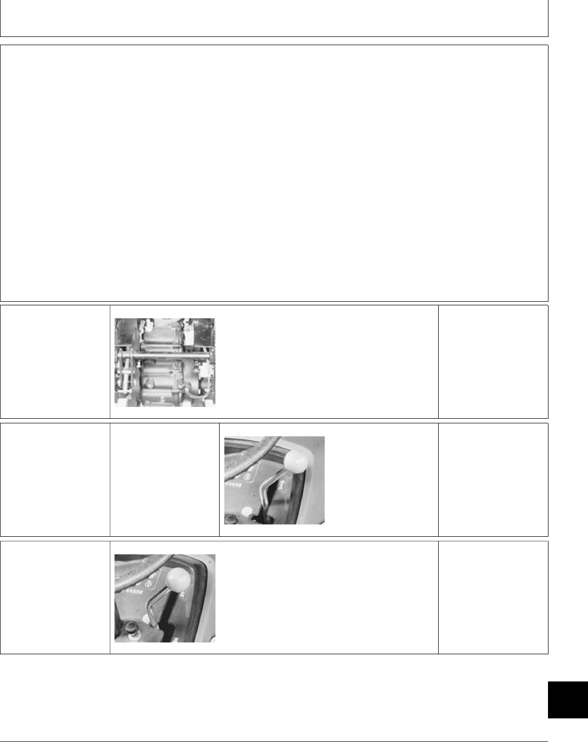
BEFORE YOU START
Always begin with this group to identify a failure in
the power train. The step-by-step procedures will
provide you with a quick check of the system. No
tools are required to perform these checks. If a failure
is indicated, you will be referred to a more detailed
check, adjustment, or test.
Always start with the first step and follow the
sequence from left to right. Read each step
completely before performing the check.
This procedure is designed as a quick check of the
system. While performing the check, concentrate only
on the check you are performing and disregard
signals from unrelated components.
; TRANSMISSION OIL
LEAK CHECK
M36695 -UN-25JAN90
Check transmission oil level and oil condition.
Inspect for external transmission oil leakage from
transmission filter, drain plug, lines, fittings,
charge pump gasket, charge pump shaft seal
and differential gasket.
OK: GO TO ‘
NOT OK: Repair or
replace then GO TO ‘
‘ HYDROSTATIC
LEVER FRICTION
CHECK
Start and run engine at
fast idle.
M36669 -UN-25JAN90
Move hydrostatic lever
to slow forward
position.
LOOK: Hydrostatic
lever must move freely
and not move after
released.
OK: GO TO Æ
NOT OK: GO TO Ü,
GROUP 15.
Æ TRANSMISSION
NEUTRAL CHECK
M36668 -UN-25JAN90
Move hydrostatic lever
to “STOP” position.
Start and run engine at
half throttle.
LOOK: Machine must
not creep in neutral.
OK: GO TO Å
NOT OK: GO TO
GROUP 15:
330, Early 322, 332
and 430: 1!
Later 322, 332 and
430: 1@
MX,159025005,1 -19-20APR95
MX,159025005,2 -19-20APR95
MX,159025005,3 -19-20APR95
MX,159125005,1 -19-13JUL95
Group 05
Power Train Checkout
TM1591 (15JUL95) 250-05-1 322,330,332 & 430 Lawn & Garden Tractors
030895
250
05
1
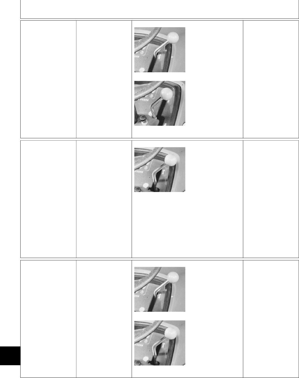
Å NEUTRAL RETURN
CHECK
322, 332 and 430; Lock
pedals together.
M36667 -UN-25JAN90
M36668 -UN-25JAN90
Move hydrostatic lever
to full forward or
reverse position.
Depress brake pedal(s).
LOOK: Hydrostatic
lever must move to
“STOP” position from
forward or reverse.
OK: GO TO Ö
NOT OK: GO TO 1Ô,
GROUP 15.
Ö TRANSMISSION
DRIVE CHECK
Start and run engine at
fast idle. Operate
machine under no load
and then under load
conditions.
M36669 -UN-25JAN90
Move hydrostatic lever
from slow forward, to
full forward, to full
reverse.
LOOK: Machine must
move and increase
speed, slow down,
change direction and
increase speed as lever
is moved from full
forward to full reverse.
FEEL: Speed increase
must be smooth.
Transmission suction
line must not be
uncomfortable to touch.
OK: GO TO Ò
NOT OK: Check
transmission oil level.
OIL LEVEL OK: GO TO
;, GROUP 15.
Ò SPEED REDUCTION
CHECK (322, 332 and
430)
Start engine and run at
half throttle.
M36667 -UN-25JAN90
M36669 -UN-25JAN90
Move hydrostatic lever
to full forward position.
Depress right brake
pedal.
LOOK: Hydrostatic
lever must move to
slow forward position.
Right wheel must stop;
left wheel must
continue to turn.
Move hydrostatic lever
to full forward position.
Continued on next page
MX,159125005,2 -19-13JUL95
MX,159025005,6 -19-20APR95
Power Train Checkout/Speed Reduction Check (322, 332 and 430)
TM1591 (15JUL95) 250-05-2 322,330,332 & 430 Lawn & Garden Tractors
030895
250
05
2
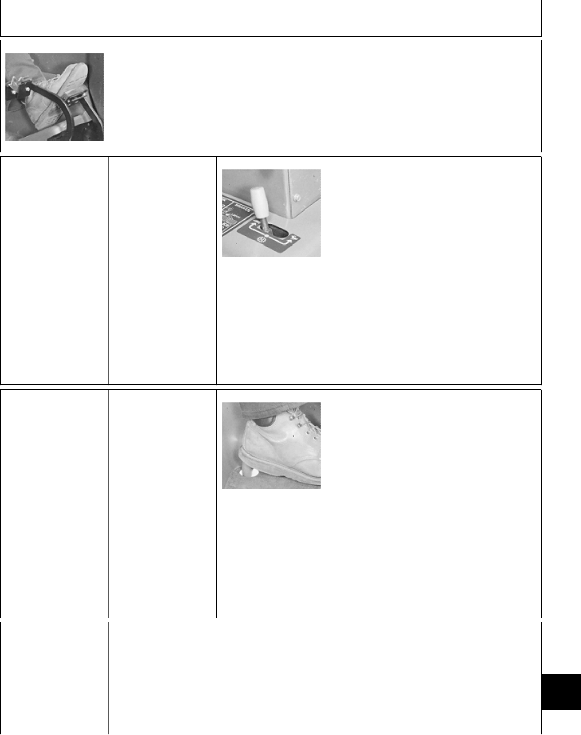
M36671 -UN-25JAN90
Depress left brake
pedal.
LOOK: Hydrostatic
lever must move to
slow forward position.
Left wheel must stop;
right wheel must
continue to turn.
OK: GO TO Õ
NOT OK: GO TO Ü,
GROUP 15.
Õ TWO-SPEED AXLE
LEVER CHECK (430)
Start and run engine at
half throttle.
M36672 -UN-25JAN90
Move two-speed axle
lever to slow speed
position. Move
hydrostatic lever to full
forward position.
LOOK: Observe ground
speed.
Move two-speed axle
lever to fast speed
position. Move
hydrostatic lever to full
forward position.
LOOK: Ground speed
must be approximately
twice as fast.
OK: GO TO Ú
NOT OK: GO TO 1#,
GROUP 15.
Ú DIFFERENTIAL
LOCK CHECK (430)
Start and run engine at
fast idle.
Move hydrostatic lever
to slow forward
position.
M36673 -UN-25JAN90
Turn steering wheel left
or right.
Depress differential lock
and turn left or right.
LOOK: With differential
lock depressed,
machine must try to go
straight forward when
steering wheel is turned
or rear tire must show
scuffing on the ground.
OK: System Normal.
NOT OK: GO TO 1$,
GROUP 15.
Ü OPERATOR
COMPLAINT NOT
IDENTIFIED
If you completed the checkout procedure and did
not isolate a malfunction, the problem may be
intermittent.
Try to duplicate the conditions of the malfunction
identified by the operator.
IF A MALFUNCTION IS NOT IDENTIFIED
AFTER SYSTEM CHECKOUT PROCEDURE;
FACTORY ASSISTANCE IS AVAILABLE
THROUGH DEALER TECHNICAL ASSISTANCE
CENTER (DTAC).
MX,159125005,3 -19-13JUL95
MX,159125005,5 -19-13JUL95
MX,159125005,6 -19-13JUL95
MX,159025005,11-19-20APR95
Power Train Checkout/Operator Complaint Not Identified
TM1591 (15JUL95) 250-05-3 322,330,332 & 430 Lawn & Garden Tractors
030895
250
05
3

Power Train Checkout/Operator Complaint Not Identified
TM1591 (15JUL95) 250-05-4 322,330,332 & 430 Lawn & Garden Tractors
030895
250
05
4

Group 10
Theory of Operation
TM1591 (15JUL95) 250-10-1 322,330,332 & 430 Lawn & Garden Tractors
030895
250
10
1

HYDROSTATIC TRANSMISSION OPERATION
Function:
Transfers power from the input (pump) shaft to the
gear drive components of the transmission. It also
provides infinitely variable speed and torque within a
range in forward and reverse directions.
Also supplies pressurized oil to the hydraulic lift and
steering systems.
Theory of Operation:
The transmission consists of a variable displacement,
axial piston pump (B) connected in a closed loop to a
fixed displacement, axial piston motor (I). A charge
pump (C) and valve system is used to charge and
lubricate the transmission.
The charge pump is a gerotor-type, fixed
displacement pump. It continually pumps oil
throughout the entire hydrostatic/hydraulic system
whenever the engine is running.
As the input (pump) shaft (A) is turned by the engine
drive shaft, the pump rotating group consisting of the
variable hydrostatic pump and charge pump also turn.
The charge pump draws pressure-free oil from the
reservoir (F) through the filter (D) and pressurizes it
to approximately 620—1240 kPa (90—180 psi). The
charge oil pressure is enough to unseat the forward
and/or reverse check valve (E and M), supplying
charge pressure oil to pump (B).
The transmission also supplies pressurized oil to the
lift and hydraulic steering systems. If pressure in this
line becomes excessive, the implement relief valve
(N) will open allowing the oil to flow into the reservoir.
NEUTRAL:
With the transmission in the neutral position, springs
in the pump cylinder bores force the pump pistons
against the variable position swashplate, which is
parallel to the pump body. With the swashplate
parallel to the pump body, the pistons do not
reciprocate in the cylinder block, they merely rotate,
no oil is being drawn in or discharged from the pump.
The pump is in a zero displacement position and the
machine remains stationary.
FORWARD:
As the swashplate control arm is moved to the
forward position, the variable position swashplate is
moved from the neutral position to a forward angle
position. Springs inside the cylinder bores force the
pistons against the swashplate. As the pump rotates
the pistons follow the contour of the swashplate they
move outward, drawing oil into their bores. As the
pistons continue to rotate, the swashplate angle
forces the pistons back into the bores, forcing oil out
of the bores through the valve plate.
High pressure oil from the pump forces the forward
check valve (E) closed and supplies pressurized oil to
the drive motor (I). The motor works in conjunction
with a fixed position swashplate. Oil enters the piston
bore through a port in the valve plate at a point
where the piston is compressed in its bore.
As the oil fills the piston bore, the piston is forced out
and follows the contour of the swashplate. This
causes the motor to rotate. Oil pressure within these
components is directly proportional to the load
encountered. This is known as the high pressure side
of the system.
As the motor continues to rotate, the piston is now
compressed by the angle of the swashplate and oil is
forced from the piston bore into the other port in the
valve plate. This oil is directed back to the suction
side of the pump. There is minimal oil pressure from
the back to the motor and this is referred as the low
pressure side of the system.
The reverse check (freewheel) valve (M) remains
open to allow charge pressure oil to flow to the low
pressure side of the system to make up for any oil
lost due to internal lubrication/leakage.
REVERSE:
The operation of the transmission in reverse is similar
to forward operation, except that the reverse
swashplate position causes the pressurized oil flow to
be reversed. When oil flow is reversed, the reverse
check (freewheel) valve (M) is forced closed suppling
pressurized oil to the drive motor. The forward check
valve (E) remains open to allow charge pressure oil
to flow to the low pressure side of the system to
make up for any oil lost due to internal
lubrication/leakage.
FREEWHEEL:
When the forward/reverse check (freewheel) valves
are manually engaged, the valves are forced off their
seats and allows oil to flow from both sides of the
motor to the reservoir. Normally the motor would
have excessive resistance to movement due to
dynamic braking of the hydrostatic closed loop.
MX,159025010,1 -19-20APR95
Theory of Operation/Hydrostatic Transmission Operation
TM1591 (15JUL95) 250-10-2 322,330,332 & 430 Lawn & Garden Tractors
030895
250
10
2
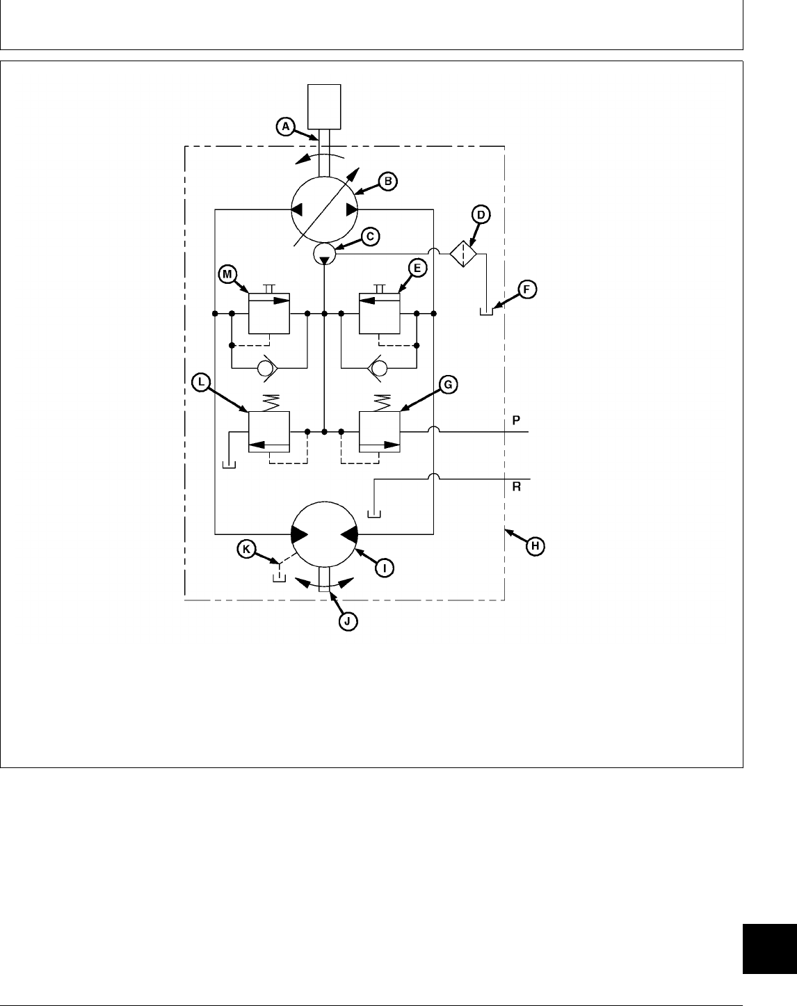
A—Input (Pump) Shaft E—Forward Check H—Hydrostatic Transmission K—Transmission Case Drain
B—Variable Hydrostatic (Freewheel) Valve Housing L—Implement Relief Valve
Pump F—Reservoir I—Hydrostatic Drive Motor M—Reverse Check
C—Charge Pump G—Charge Relief Valve J—Output (Motor) Shaft (Freewheel) Valve
D—Filter
M78856 -UN-03APR95
MX,159025010,2 -19-20APR95
Theory of Operation/Hydrostatic Transmission Operation
TM1591 (15JUL95) 250-10-3 322,330,332 & 430 Lawn & Garden Tractors
030895
250
10
3

Theory of Operation/Hydrostatic Transmission Operation
TM1591 (15JUL95) 250-10-4 322,330,332 & 430 Lawn & Garden Tractors
030895
250
10
4

ABOUT THIS GROUP
Always perform the system checkout procedures in
Group 05 BEFORE making any tests or adjustments
in this group. The step-by-step procedures in this
group provide you with the detailed diagnostic
information you will need to isolate a malfunction.
Basic diagnostic equipment is used.
It is assumed that you are familiar with the machine
and its power train components. If you need
additional information, read the theory of operation in
Group 10 or refer to the overall hydraulic schematics
in Section 270, Group 10.
Engine rpm and temperature are critical in most
hydraulic tests. Be sure to follow test specifications
carefully.
Always start with the first step and follow the
sequence from left to right. Read each step
completely before performing the test.
Upon completing a test or adjustment, check to see
whether the problem is corrected by performing the
checkout procedures in Group 05.
; TROUBLESHOOTING GUIDE
If machine does not operate properly, select the appropriate symptom from the list below.
• MACHINE MOVES IN ONE DIRECTION ONLY: GO TO A
• MACHINE WILL NOT MOVE IN EITHER DIRECTION: GO TO B
• MACHINE CREEPS IN ONE DIRECTION CONSISTENTLY: GO TO 1! OR 1@
• HYDRO CONTROL LEVER DOES NOT RETURN TO NEUTRAL WHEN BOTH BRAKES ARE APPLIED:
GO TO 1Ô
• TRANSMISSION OPERATION HAS ERRATIC OR LOW POWER OR SPEED WILL NOT INCREASE: GO
TO C
• MACHINE WILL NOT REACH FULL SPEED: GO TO D
• TRANSMISSION OPERATES HOT: GO TO E
• MACHINE FREEWHEELS: GO TO F
• HYDRAULIC SYSTEM IS NOISY: GO TO G
• NO HYDRAULICS AFTER BEING SERVICED: GO TO H
• CHARGE PUMP SEAL REPEATEDLY FAILS: GO TO I
MX,159025015,1 -19-20APR95
MX,159025015,2 -19-20APR95
Group 15
Diagnosis, Tests and Adjustments
TM1591 (15JUL95) 250-15-1 322,330,332 & 430 Lawn & Garden Tractors
030895
250
15
1

A MACHINE MOVES IN ONE DIRECTION ONLY
• Inspect transmission control linkage for wear or damage. See Section 50.
• 322, 330 and 332; Test for debris in check valves: GO TO ‘
• Inspect check valves for damaged valve seat, seals or stuck check ball. See Section 50.
• Inspect internal transmission components for wear or damage. See Section 50.
B MACHINE WILL NOT MOVE IN EITHER DIRECTION
• Inspect transmission control linkage for wear or damage. See Section 50.
• Inspect transmission drive shaft and crankshaft pulley for loose cap screws or damage.
• Check for improper charge pump installation (180 degrees off). See Section 50.
• Test charge pump pressure: GO TO Æ
• Inspect check valves for damaged valve seat, seals or stuck check ball. See Section 50.
• Inspect internal rotating group for scoring and wear (slippers, pistons and cylinder block, valve plate and
cylinder block). If internal damage is found, check for missing welch plug: GO TO Ò
C TRANSMISSION OPERATION HAS ERRATIC OR LOW POWER OR SPEED WILL
NOT INCREASE
• Inspect brakes and brake linkage for wear or damage. See Section 60.
• Inspect transmission control linkage for wear or damage. See Section 50.
• Check for improper charge pump installation (180 degrees off). See Section 50.
• Test charge pump pressure: GO TO Æ
• Inspect check valves for damaged valve seat, seals or stuck check ball. See Section 50.
• Inspect internal rotating group for scoring and wear (slippers, pistons and cylinder block, valve plate and
cylinder block). If internal damage is found, check for missing welch plug: GO TO Ò
• Check for dirt accumulation on transmission causing transmission oil to overheat: GO TO Õ
• Check for high draft loads causing transmission oil to overheat: GO TO Õ
MX,159125015,1 -19-13JUL95
MX,159025015,4 -19-20APR95
MX,159025015,5 -19-20APR95
Diagnosis, Tests and Adjustments/Troubleshooting Guide
TM1591 (15JUL95) 250-15-2 322,330,332 & 430 Lawn & Garden Tractors
030895
250
15
2

D MACHINE WILL NOT REACH FULL SPEED
• Inspect transmission control linkage for wear or damage. See Section 50.
• Inspect transmission and differential mounting cap screws for loose condition.
• Check engine fast idle speed: See Section 220.
• Inspect check valves for damaged seat, seals or stuck check ball. See Section 50.
• Inspect internal rotating group for scoring and wear (slippers, pistons and cylinder block, valve plate and
cylinder block). If internal damage is found check for missing welch plug: GO TO Ò
E TRANSMISSION OPERATES HOT
• Check transmission temperature. GO TO Õ
• Check all cooling components for plugged or restricted condition.
• 322, 332 and 430; Test steering valve for neutral return: GO TO Ú
• Test charge pump pressure: GO TO Æ
• Inspect internal transmission components for wear or damage. See Section 50.
• Check for dirt accumulation on transmission causing transmission oil to overheat: GO TO Õ
• Check for high draft loads causing transmission oil to overheat: GO TO Õ
F MACHINE FREEWHEELS
• Inspect transmission control linkage for loose connections allowing swashplate movement under load. See
Section 50.
• 322, 330 and 332; Test for debris in check valves: GO TO ‘
• Inspect check valves for damaged valve seat, seals or stuck check ball. See Section 50.
• Test charge pump pressure: GO TO Æ
• Inspect internal rotating group for scoring and wear (slippers, pistons and cylinder block, valve plate and
cylinder block). If internal damage is found check for missing welch plug: GO TO Ò
MX,159025015,6 -19-20APR95
MX,159125015,2 -19-13JUL95
MX,159125015,3 -19-13JUL95
Diagnosis, Tests and Adjustments/Troubleshooting Guide
TM1591 (15JUL95) 250-15-3 322,330,332 & 430 Lawn & Garden Tractors
030895
250
15
3

G HYDRAULIC SYSTEM IS NOISY
• Check power steering valve, if equipped, or hydraulic control valve for overheating. If either valve is too
hot to touch after 1/2 hour of operation, disassemble valve and repair internal leak. See Section 60 or 70.
• Adjust hydrostatic transmission linkage for positive neutral position: GO TO 1Ô
• Check steel hydraulic lines for vibration. Especially the line that runs from the charge pump to the steering
valve on 322, 332 and 430 models. Secure with clamps or replace with a rubber pressure hose rated at
8274 kPa (1200 psi).
• Adjust charge relief valve so that charge pressure is above 1379 kPa (200 psi). The increased charge
pressure will not cause any problems and it may eliminate the noise, if it is caused by charge relief valve
chattering: GO TO 3c
• Increase implement relief pressure to upper limit of specification: GO TO 4b
H NO HYDRAULICS AFTER BEING SERVICED
• Check for improper charge pump installation (180 degrees off). See Section 50.
• Check for proper installation of transmission output shaft bearing into aluminum case. If installed too
shallow, the motor rotating group will not contact the valve plate. See Section 50.
I CHARGE PUMP SEAL REPEATEDLY FAILS
• Inspect the seal surface on the shaft.
• Inspect seal for cuts which may be caused by installing seal over shaft without covering sharp splines.
• Check for a loose or worn U-Joint on the drive shaft.
• Inspect charge pump for wear or damage. Charge pressure may be getting into the seal area because of
internal pump leakage. See Section 50.
MX,159125015,4 -19-13JUL95
MX,159025015,10-19-20APR95
MX,159025015,11-19-20APR95
Diagnosis, Tests and Adjustments/Troubleshooting Guide
TM1591 (15JUL95) 250-15-4 322,330,332 & 430 Lawn & Garden Tractors
030895
250
15
4

‘ CHECK VALVE
DEBRIS CHECK
Engine OFF.
Service park brake
OFF.
M49216 -UN-20DEC89
322, 330 and 332;
Engage Manual Push
lever (A) and push
machine forward to
remove debris from
check valves.
Early 430; Remove
fender deck. Remove
and inspect check
valves for debris.
Repair or replace if
necessary.
Later 430; Remove
fender deck. Manually
depress check valve
“buttons” and push
machine forward to
remove debris from
check valves.
Repeat Transmission
Drive Check in Group
05.
Æ CHARGE PUMP
PRESSURE TEST
Heat hydraulic oil to 43˚C (110˚F), See Õ in this
group.
NCAUTION: TO AVOID INJURY FROM
ESCAPING HYDRAULIC OIL UNDER
PRESSURE, RELIEVE THE PRESSURE IN THE
SYSTEM BY STOPPING THE ENGINE AND
OPERATING ALL HYDRAULIC CONTROL
VALVES.
NOTE: It is normal for charge pressure to
increase as engine speed or implement pressure
increases. Charge pressure up to 3448 kPa (500
psi) at fast idle is normal.
Continued on next page
MX,159125015,5 -19-13JUL95
Diagnosis, Tests and Adjustments/Charge Pump
TM1591 (15JUL95) 250-15-5 322,330,332 & 430 Lawn & Garden Tractors
030895
250
15
5
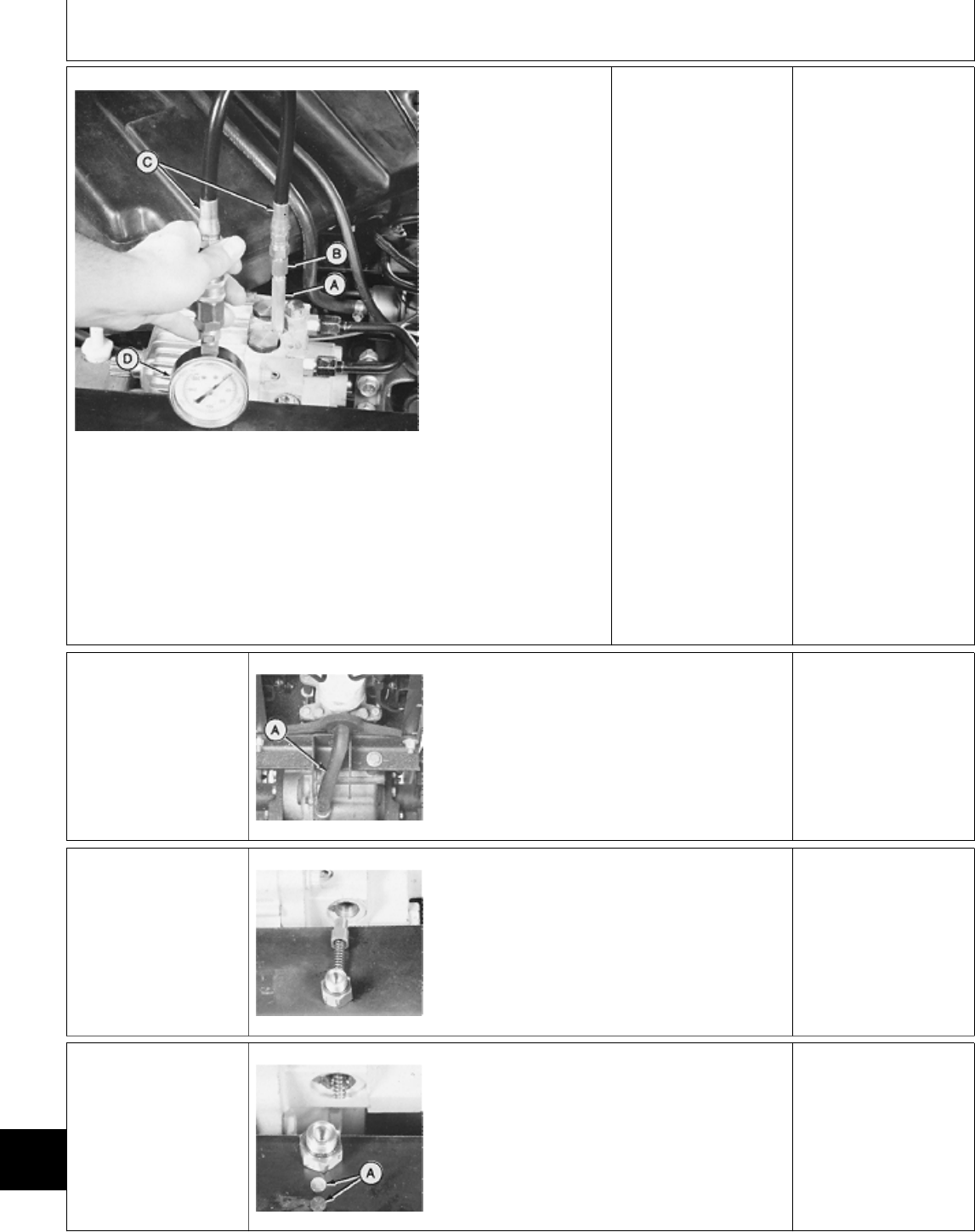
M36682 -UN-25JAN90
A—JT03339 Connector
B—JT03107 Adapter
C—JT03017 Hose
D—JT03344 Gauge, 2000
kPa (300 psi)
IMPORTANT:
Hydraulic control
levers must remain in
neutral position and
engine must be run at
slow idle.
Pressure gauge will
be damaged if a
hydraulic function is
actuated or test is run
at fast idle.
Make test connections
from JT01765 Lawn
and Grounds Care
Products Hydraulic
Fitting Kit.
Run engine at slow
idle.
LOOK: Record pressure
reading.
Charge pressure must
be 620—1240 kPa
(90—180 psi).
CHARGE PRESSURE
OK: Inspect check
valves for wear or
damage. See Section
50. Then repeat Æ
CHARGE PRESSURE
LOW: REPLACE
FILTER,
THEN...REPEAT Æ
CHARGE PRESSURE
STILL LOW: GO TO
3a
3a Charge Pump
Suction Line Check
M49217 -UN-20DEC89
Inspect suction line (A)
for restriction, loose
hose clamp, holes or
damage that would
cause air leakage.
SUCTION LINE OK:
GO TO 3b
SUCTION LINE
DAMAGED: Repair or
replace then bleed
hydraulic system. See
Section 270, Group 20.
3b Charge Relief
Valve Check
M36683 -UN-25JAN90
Remove charge relief
valve and check for a
broken spring or a
stuck or damaged
valve. Replace broken
parts.
CHARGE RELIEF
VALVE OR SPRING
WORN: GO TO 3c
CHARGE RELIEF
VALVE NOT
DAMAGED: GO TO Å
3c Charge Relief
Valve Adjustment
M36684 -UN-25JAN90
NOTE: Only use shims to increase pressure
when valve or spring are worn. Charge pressure
will not increase by adding shims if another
component is leaking.
Add shims (A) in spring retainer to increase
charge pressure to specification.
Check charge pressure.
IF CHARGE
PRESSURE IS STILL
LOW: GO TO Å
MX,159025015,13-19-20APR95
MX,159025015,14-19-20APR95
MX,159025015,15-19-20APR95
MX,159025015,16-19-20APR95
Diagnosis, Tests and Adjustments/Charge Relief Valve
TM1591 (15JUL95) 250-15-6 322,330,332 & 430 Lawn & Garden Tractors
030895
250
15
6
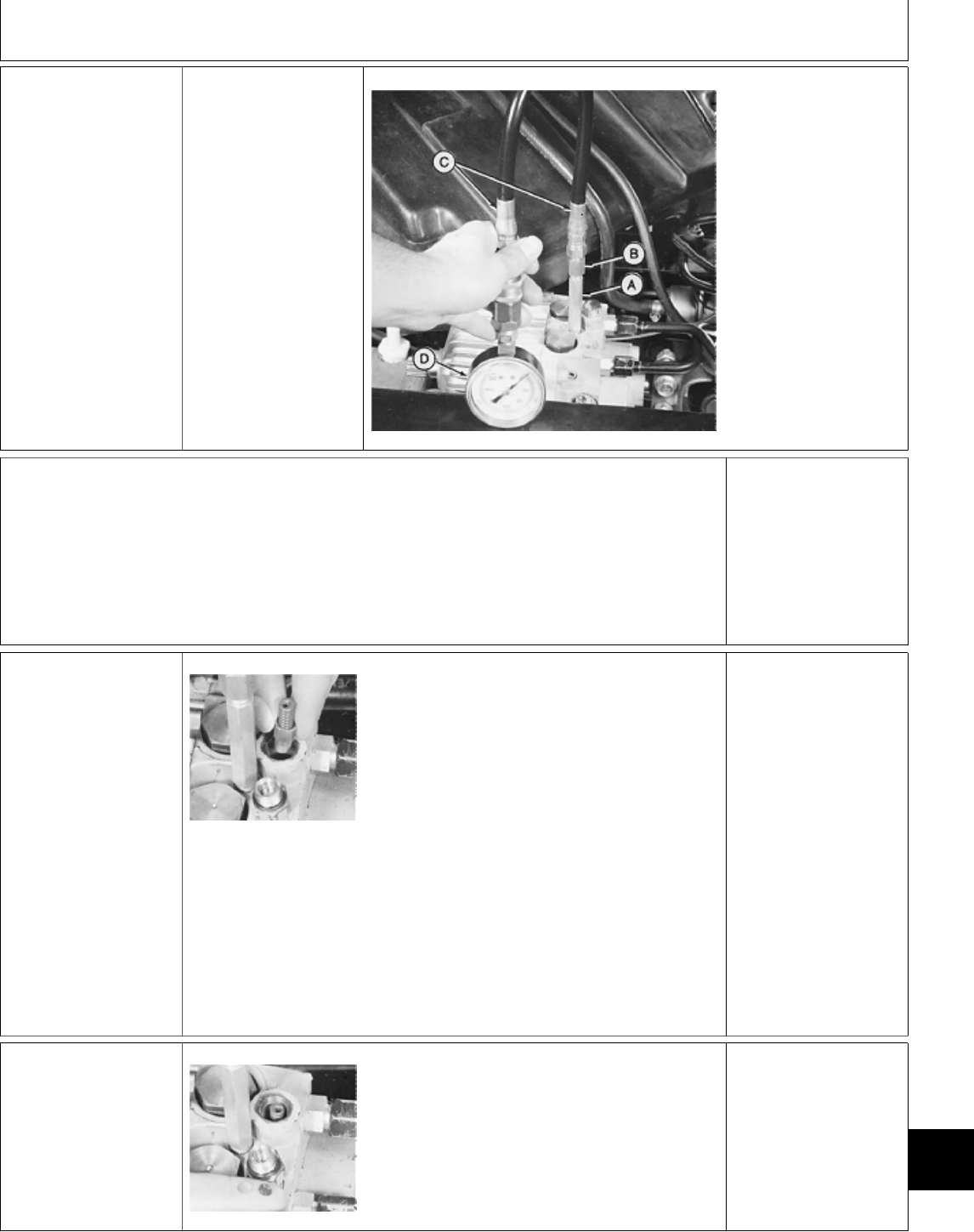
Å IMPLEMENT RELIEF
VALVE PRESSURE
TEST
NCAUTION: TO
AVOID INJURY FROM
ESCAPING
HYDRAULIC OIL
UNDER PRESSURE,
RELIEVE THE
PRESSURE IN THE
SYSTEM BY
STOPPING THE
ENGINE AND
OPERATING ALL
HYDRAULIC
CONTROL VALVES.
M36682 -UN-25JAN90
A—JT03339 Connector
B—JT03107 Adaptor
C—JT03017 Hose
D—JT03345 Gauge,
20,000 kPa (3000 psi)
Make test connections from
JT01765 Lawn and Grounds Care
Products Hydraulic Fitting Kit.
Heat hydraulic oil to 43˚C (110˚F),
see Õ in this group.
Run engine at fast idle.
Move and hold control valve lever in
full raise position.
LOOK: Record pressure reading.
Implement pressure must be
5861—6722 kPa (850—975 psi).
IMPLEMENT
PRESSURE OK: GO
TO Ö
IMPLEMENT
PRESSURE LOW: GO
TO 4a
4a Implement Relief
Valve Check
M36686 -UN-25JAN90
Remove implement
relief valve and check
for a broken spring or a
stuck or damaged
valve.
LOOK: Implement relief
valve spring is a much
heavier spring than the
charge relief valve
spring.
IMPLEMENT RELIEF
VALVE NOT
DAMAGED: GO TO
4b
IMPLEMENT RELIEF
VALVE DAMAGED:
Replace damaged valve
parts, then check
implement pressure.
IMPLEMENT
PRESSURE STILL
LOW: GO TO 4b
4b Implement Relief
Valve Adjustment
M36687 -UN-25JAN90
NOTE: Only use shims to increase pressure
when valve or spring are worn. Implement
pressure will not increase by adding shims if
another component is leaking.
Add shims in spring retainer to increase
implement pressure to specification.
Check implement pressure.
IF IMPLEMENT
PRESSURE IS STILL
LOW: GO TO Ö
MX,159025015,17-19-21APR95
MX,159025015,18-19-20APR95
MX,159025015,19-19-20APR95
Diagnosis, Tests and Adjustments/Implement Relief Valve
TM1591 (15JUL95) 250-15-7 322,330,332 & 430 Lawn & Garden Tractors
030895
250
15
7
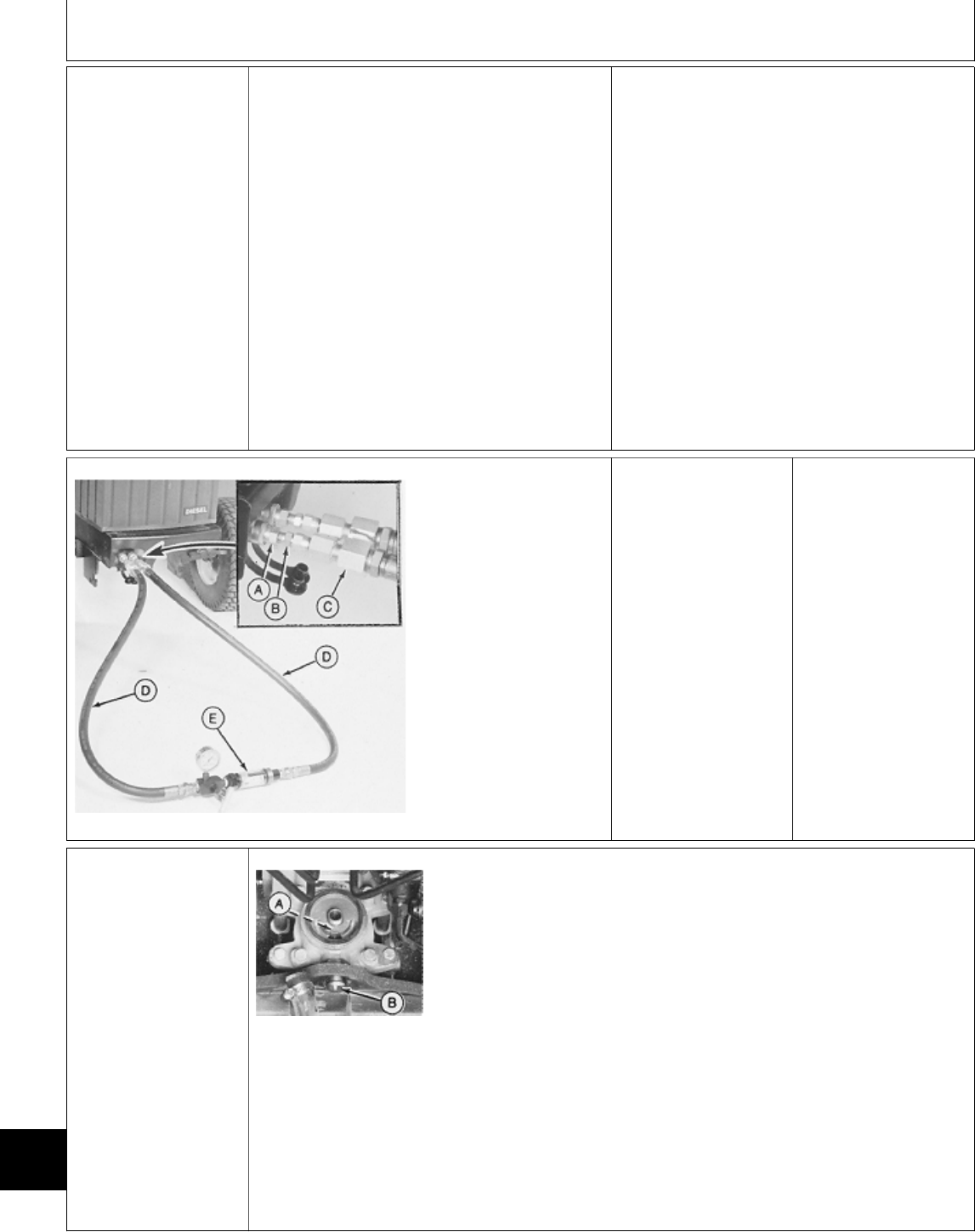
Ö CHARGE PUMP
FLOW TEST NCAUTION: TO AVOID INJURY FROM
ESCAPING HYDRAULIC OIL UNDER
PRESSURE, RELIEVE THE PRESSURE IN THE
SYSTEM BY STOPPING THE ENGINE AND
OPERATING ALL HYDRAULIC CONTROL
VALVES.
Make front outlet connections from JT01765
Lawn and Grounds Care Products Hydraulic
Fitting Kit and JT05469 Flowmeter Kit.
Heat hydraulic oil to 43˚C (110˚F), See Õ in this
group.
M36688 -UN-25JAN90
A—JT03340 Quick
Coupler
B—JT03343 Connector
C—JT03342 Coupler
D—JT05531 Hose
E—STD12 Flowmeter
Run machine at fast
idle.
Move and hold outside
hydraulic control lever
in implement lower
position. Turn load
valve until pressure
reaches 3450 kPa (500
psi).
LOOK: Pump flow must
be a minimum of 11
L/min (3 gpm)
CHARGE PUMP FLOW
OK: Inspect
transmission internal
components for wear or
damage. See Section
50.
CHARGE PUMP FLOW
NOT OK: Inspect
charge pump for
sheared drive pin, wear
or damage. Repair or
replace, then test
charge pump flow.
Ò WELCH PLUG
LOCATION CHECK
M49218 -UN-20DEC89
NOTE: If welch plug is missing, unfiltered oil is
flowing through the transmission possibly causing
excessive wear of the rotating groups and charge
pump.
Remove transmission oil filter.
Check for welch plug at position (A). Put a piece
of wire thru threaded fitting. It must hit welch
plug and not come out kidney shaped port.
If welch plug is missing install a new one through
suction hose fitting (B). Use LOCTITE thread
sealant and stake into housing.
MX,159025015,20-19-20APR95
MX,159025015,21-19-20APR95
Diagnosis, Tests and Adjustments/Welch Plug Location Check
TM1591 (15JUL95) 250-15-8 322,330,332 & 430 Lawn & Garden Tractors
030895
250
15
8
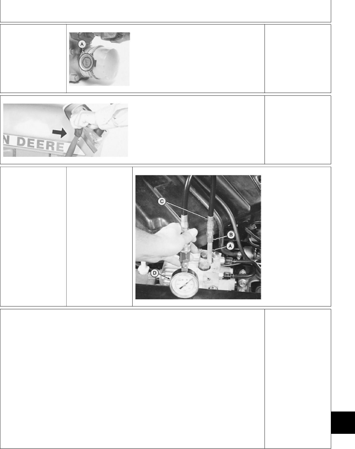
Õ HYDRAULIC OIL
WARM-UP
PROCEDURE
M43008 -UN-18JAN90
Remove belly screen/pan.
Install JDG282 Temperature Gauge (A) on
transmission oil filter.
On 430; Partially cover the radiator. Be careful
not to cover too much of the radiator causing
engine to overheat.
Apply park brake.
Start engine and run at
full throttle.
M43629 -UN-12JAN90
Move and hold control
lever in implement
“raise” position.
Periodically cycle all
hydraulic functions to
distribute heated oil.
NOTE: 330 Shown
Heat oil to temperature
specified in test.
NOTE: The hydrostatic
transmission should not
exceed 93˚C (200˚F) as
a continuous operating
temperature.
Ú STEERING VALVE
NEUTRAL CHECK
(322, 332 and 430)
NCAUTION: TO
AVOID INJURY FROM
ESCAPING
HYDRAULIC OIL
UNDER PRESSURE,
RELIEVE THE
PRESSURE IN THE
SYSTEM BY
STOPPING THE
ENGINE AND
OPERATING ALL
HYDRAULIC
CONTROL VALVES.
M36682 -UN-25JAN90
A—JT0339 Connector
B—JT03107 Adaptor
C—JT03017 Hose
D—JT03345 Gauge,
20,000 kPa (3000 psi)
Make test connections from JT01765 Lawn and
Grounds Care Products Hydraulic Fitting Kit.
Heat hydraulic oil to 43˚C (110˚F) see Õ in this
group.
Run engine at slow idle.
Move steering wheel to left and right turn
position.
LOOK: When steering wheel is being turned
pressure should increase. When steering wheel
is stopped (neutral position) pressure must drop
to approximately 620—1240 kPa (90—180 psi).
Repeat several times to ensure neutral position.
OK: STEERING VALVE
RETURNS TO
NEUTRAL.
STEERING VALVE
DOES NOT RETURN
TO NEUTRAL: Remove
and repair steering
valve. See Section 60.
MX,159125015,17-19-13JUL95
MX,159125015,6 -19-13JUL95
MX,159125015,7 -19-13JUL95
Diagnosis, Tests and Adjustments/Steering Valve Neutral Check (322, 332 and 430)
TM1591 (15JUL95) 250-15-9 322,330,332 & 430 Lawn & Garden Tractors
030895
250
15
9

Ü HYDROSTATIC
LEVER FRICTION
ADJUSTMENT
Early 430; Remove left
and right engine side
panels, battery and
battery base.
322, 330, 332 and
Later 430; Remove
right-hand pedestal
screen/panel.
M36674 -UN-25JAN90
Connect a scale to
hydrostatic control
lever.
M36675 -UN-25JAN90 M49215 -UN-20DEC89
Adjust friction disks by tightening or loosening
lock nut (A) until 31—44.5 N (7—10 lb force) is
required to move hydrostatic control lever.
NOTE: Far left photo shows Version One—430.
NOTE: Near left photo shows 330, Version
One—322, 332 and Versions Two and
Three—322, 332, 430.
1Ô NEUTRAL
RETURN LINKAGE
ADJUSTMENT
Hydrostatic lever friction
must be adjusted
previous to this
adjustment: GO TO Ü
1¡a 330 and Version One—322 and 332
(Sliding Lever Linkage)
NOTE: For Versions One—430, (J-Bolt Style
Linkage): GO TO 1¡b For later Versions of 322,
332 and 430 (Detented Neutral Style Linkage):
GO TO 1@
IMPORTANT: This
adjustment must be
made with pedestal
panels installed and
hardware tightened.
Remove belly screen
from underneath
machine.
On 322 and 332; Lock both brake
pedals together.
Apply and lock park brake.
Adjust cam plate (A) position by
loosening lock nuts (B and C) and
moving cam plate until neutral guide
(D) just enters neutral slot (E) in
cam plate. Be sure neutral guide
does not hit top of cam plate neutral
slot.
Tighten lock nuts.
Check position of hydrostatic control lever. Lever
must be in STOP notch of dash panel. If
necessary, loosen lock nut (C) and turn eccentric
nut (F) until lever is in STOP notch of dash
panel. Tighten lock nut.
MX,159125015,8 -19-13JUL95
MX,159125015,9 -19-13JUL95
MX,159125015,10-19-13JUL95
MX,159125015,11-19-13JUL95
Diagnosis, Tests and Adjustments/Neutral Return Linkage Adjustment (330, and Early 322, 332, 430)
TM1591 (15JUL95) 250-15-10 322,330,332 & 430 Lawn & Garden Tractors
030895
250
15
10
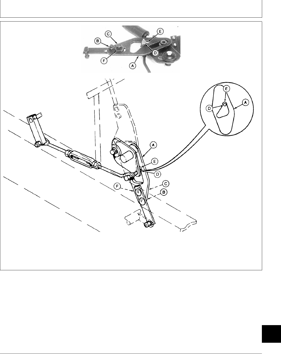
A—Cam Plate C—Lock Nut E—Neutral Slot F—Eccentric Nut
B—Lock Nut D—Neutral Guide
M49211 -UN-07APR95
M49225 -UN-04MAY95
MX,159025020,30-19-20APR95
Diagnosis, Tests and Adjustments/Neutral Return Linkage Adjustment (330, and Early 322, 332, 430)
TM1591 (15JUL95) 250-15-11 322,330,332 & 430 Lawn & Garden Tractors
030895
250
15
11

1¡b Version One—430 (J-Bolt Style Linkage)
NOTE: For 330 and Version One—322 and 332
(Sliding Lever Linkage): GO TO 1¡a For later
Versions of 322, 332 and 430 (Detented Neutral
Style Linkage): GO TO 1@
IMPORTANT: This
adjustment must be
made with pedestal
panels installed and
hardware tightened.
Remove belly
screen/pan from
underneath machine.
Lock both brake pedals together.
Apply and lock park brake.
Adjust cam plate (A) position by
tightening or loosening J-Bolt lock
nuts (B) until neutral guide (C) just
enters neutral slot (D) in cam plate.
Be sure neutral guide does not hit
top of cam plate neutral slot.
Tighten lock nuts.
Check position of hydrostatic control lever. Lever
must be in STOP notch of dash panel. If
necessary, loosen lock nut (E) and turn eccentric
nut (F) until lever is in STOP notch of dash
panel. Tighten lock nut.
MX,159125015,12-19-13JUL95
Diagnosis, Tests and Adjustments/Neutral Return Linkage Adjustment (330, and Early 322, 332, 430)
TM1591 (15JUL95) 250-15-12 322,330,332 & 430 Lawn & Garden Tractors
030895
250
15
12
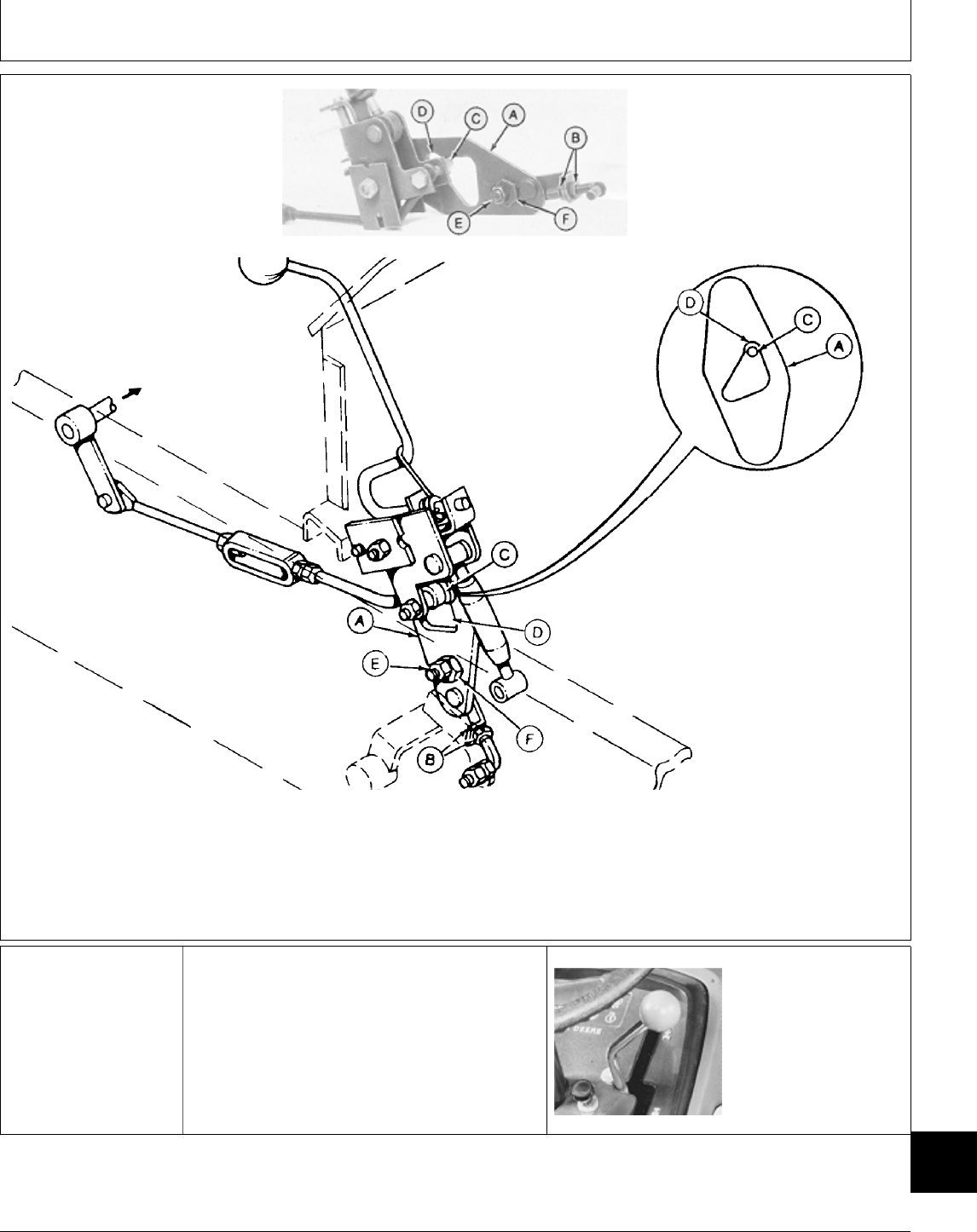
420 Shown
A—Cam Plate C—Neutral Guide E—Lock Nut F—Eccentric Nut
B—Lock Nuts D—Neutral Slot
M49213 -UN-20DEC89
M49226 -UN-04MAY95
1! NEUTRAL
ADJUSTMENT (330
and Version
One—322, 332 and
430)
IMPORTANT: This adjustment must be made
with pedestal panels installed and hardware
tightened.
Remove fender deck.
Raise rear of machine and put jack stands under
frame.
M36668 -UN-25JAN90
Move hydrostatic
control lever to STOP
position.
On 430; Move
Two-speed axle lever to
low speed position.
Continued on next page
MX,159025020,33-19-20APR95
Diagnosis, Tests and Adjustments/Neutral Adjustment (330 and Early 322, 332, 430)
TM1591 (15JUL95) 250-15-13 322,330,332 & 430 Lawn & Garden Tractors
030895
250
15
13

M36677 -UN-25JAN90
NCAUTION: USE EXTREME CAUTION WHEN
PERFORMING THIS ADJUSTMENT BECAUSE
DRIVE WHEELS ARE FREE TO SPIN AND
DRIVE SHAFT IS CLOSE TO TURNBUCKLE.
Loosen lock nuts.
Start and run engine at fast idle. Turn turnbuckle
(A) as required until the drive wheels stop
turning.
Turn engine OFF.
IMPORTANT: Tighten lock nuts to proper
torque to prevent loss of neutral.
Hold turnbuckle and tighten lock nuts to 33 N·m
(24 lb-ft).
Start engine and check for tire movement.
Readjust if necessary.
1@ NEUTRAL AND
NEUTRAL RETURN
LINKAGE
ADJUSTMENT
(Later
Versions—322, 332
and 430) (Detented
Neutral Style
Linkage)
NOTE: For 330 and
Version One—322 and
332 (Sliding Lever
Linkage): GO TO
1¡a For Version
One—430 (J-Bolt Style
Linkage): GO TO
1¡b
Remove right-hand pedestal screen, belly
screen/pan and fender deck.
Move and secure fuel tank off to the left side of
machine to gain access to linkage.
NOTE: Early machines with this style of linkage
will have the torsional dampener behind the
pedestal. Later machines will have the dampener
attached to the frame behind the swashplate on
the hydrostatic transmission. The hydroststic
control link may be different also. Both versions
are covered by this adjustment.
Raise rear wheels off the ground. Put jack
stands under frame.
Continued on next page
MX,159125015,13-19-13JUL95
Diagnosis, Tests and Adjustments/Neutral and Neutral Return Linkage Adjustment (Later 322, 332, 430)
TM1591 (15JUL95) 250-15-14 322,330,332 & 430 Lawn & Garden Tractors
030895
250
15
14
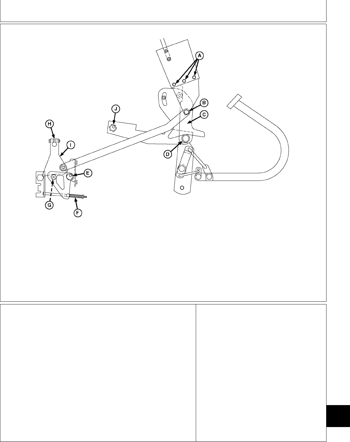
M51871 -UN-26APR95
A—Bolts D—Roller G—Roller I—Swashplate Control Arm
B—Bolt E—Eccentric H—Slot J—Eccentric
C—Cam Plate F—Detent Spring
Loosen bolts (A and B).
Place a screwdriver in slot (H) and
move swashplate control arm (I)
until roller (G) is centered in detent
notch.
Adjust length of detent spring (F) to
50 mm (1.970 in.).
NCAUTION: BE AWARE OF
SPINNING DRIVE SHAFT AND
WHEELS WHEN PERFORMING
THE NEXT ADJUSTMENT.
Start and run engine at fast idle.
Loosen bolt and adjust eccentric (E)
until rear wheels stop turning, then
tighten eccentric bolt.
Stop engine.
Continued on next page
Loosen bolt and adjust eccentric (J)
until bolt (B) is exactly centered in
hole, while making sure roller (D) is
centered in notch of cam plate (C).
Tighten bolt (B) and eccentric (J)
bolt while holding eccentric in place.
Diagnosis, Tests and Adjustments/Neutral and Neutral Return Linkage Adjustment (Later 322, 332, 430)
TM1591 (15JUL95) 250-15-15 322,330,332 & 430 Lawn & Garden Tractors
030895
250
15
15
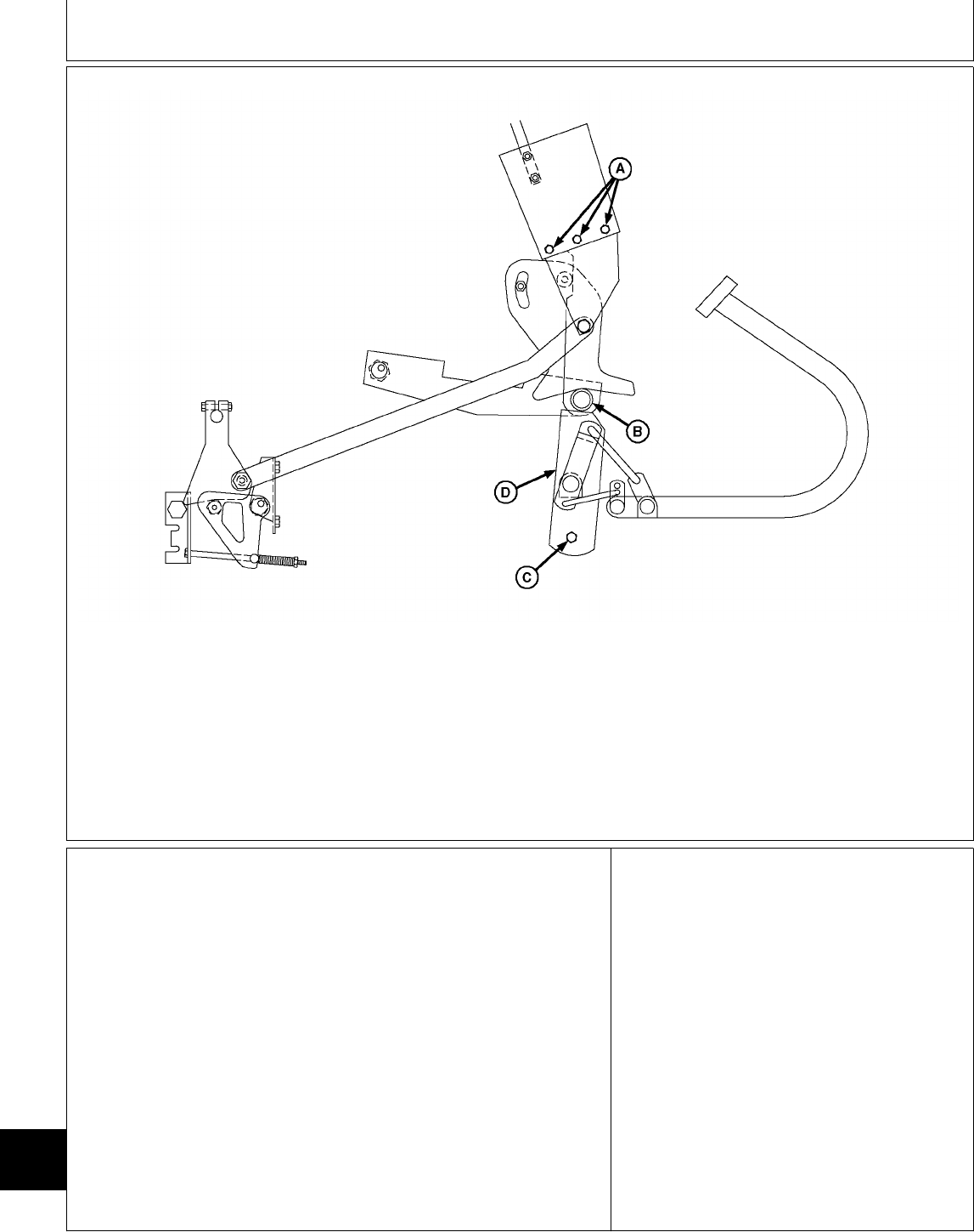
M51872 -UN-26APR95
A—Bolts B—Roller C—Bolt(s) D—Plate
Lock park brake.
Loosen bolt(s) (C). (One bolt on 316 and 318,
two bolts on 420).
Slide plate (D) upward until it firmly contacts
roller (B).
Tighten bolt(s) (C).
Place the hydrostatic shift lever in the “STOP”
position in the quadrant.
Tighten bolts (A).
Unlock park brake.
Adjust hydrostatic shift lever friction: GO TO Ü
MX,159125015,14-19-13JUL95
Diagnosis, Tests and Adjustments/Neutral and Neutral Return Linkage Adjustment (Later 322, 332, 430)
TM1591 (15JUL95) 250-15-16 322,330,332 & 430 Lawn & Garden Tractors
030895
250
15
16
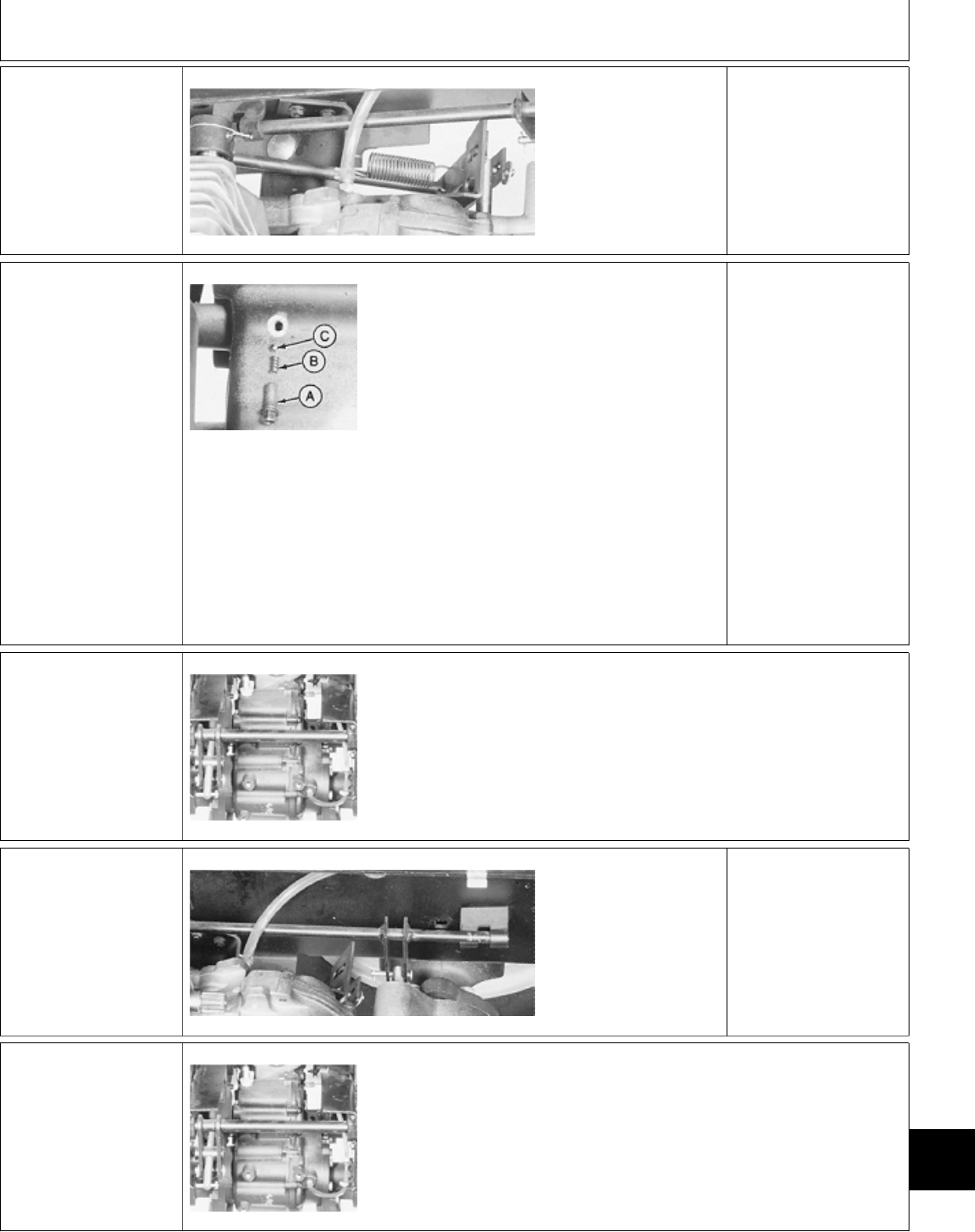
1# TWO-SPEED AXLE
LEVER LINKAGE
CHECK (430)
M36693 -UN-25JAN90
Remove belly pan.
Inspect two-speed axle
lever linkage for
missing pin, broken
spring, wear or
damage. Plate notch
must engage slots
easily.
LINKAGE OK: GO TO
1ƒa
LINKAGE DAMAGED:
Repair or replace as
necessary.
1ƒa Two-speed Axle
Lever Detent
Adjustment
M36694 -UN-25JAN90
Remove fender deck
and fuel tank.
Remove detent screw
(A), spring (B) and ball
(C). Inspect parts for
damage; replace as
necessary. Install ball
and spring.
Apply thread lock and
sealer (low strength) on
detent screw threads.
Install and tighten
detent screw. If
two-speed lever is hard
to move, turn detent
screw counterclockwise
one turn.
DETENT OK: GO TO
1ƒb
1ƒb Differential
Inspection
M36695 -UN-25JAN90
Remove and disassemble differential. (See
procedures in Section 50.)
Inspect shifter fork and two-speed gears for
improper assembly, wear or damage.
1$ DIFFERENTIAL
LOCK LINKAGE
CHECK (430)
M36696 -UN-25JAN90
Remove belly pan.
Inspect differential lock
linkage for missing pin,
bent rod, wear or
damage. Differential
lock shift rod must slide
in and out easily.
LINKAGE OK: GO TO
1´a
1´a Differential
Inspection
M36695 -UN-25JAN90
Remove and disassemble differential. (See
procedures in Section 50.)
Inspect shifter fork, shift collar, pins, shift rod,
and springs for improper assembly, wear or
damage.
MX,159125015,15-19-13JUL95
MX,159025020,40-19-20APR95
MX,159025020,41-19-20APR95
MX,159125015,16-19-13JUL95
MX,159025020,43-19-20APR95
Diagnosis, Tests and Adjustments/Differential Lock Linkage Check (430)
TM1591 (15JUL95) 250-15-17 322,330,332 & 430 Lawn & Garden Tractors
030895
250
15
17

Diagnosis, Tests and Adjustments/Differential Lock Linkage Check (430)
TM1591 (15JUL95) 250-15-18 322,330,332 & 430 Lawn & Garden Tractors
030895
250
15
18

Section 260
STEERING AND BRAKES CHECKOUT,
OPERATION AND DIAGNOSIS
Contents
Page
Group 05—Steering And Brakes System
Checkout
Before You Start . . . . . . . . . . . . . . . . . 260-05-1
Steering System Oil Leak Check (322,
332 and 430) . . . . . . . . . . . . . . . . . . 260-05-1
Hydrostatic Steering System Check (322,
332 and 430) . . . . . . . . . . . . . . . . . . 260-05-2
Service Park Brake Check . . . . . . . . . . . 260-05-3
Turn Brake Check (322, 332 and 430) . . . 260-05-3
Operator Complaint Not Identified . . . . . . 260-05-4
Group 10—Theory of Operation
Steering Valve/System Operation . . . . . . 260-10-2
Group 15—Diagnosis, Tests and Adjustments
About This Group . . . . . . . . . . . . . . . . 260-15-1
Troubleshooting Guide . . . . . . . . . . . . . 260-15-1
Hydraulic Oil Warm-Up Procedure . . . . . . 260-15-4
Steering System Leakage Test . . . . . . . . 260-15-5
Steering Valve Leakage Test . . . . . . . . . 260-15-5
TM1591 (15JUL95) 260-1 322,330,332 & 430 Lawn & Garden Tractors
030895
260

Contents
TM1591 (15JUL95) 260-2 322,330,332 & 430 Lawn & Garden Tractors
030895
260
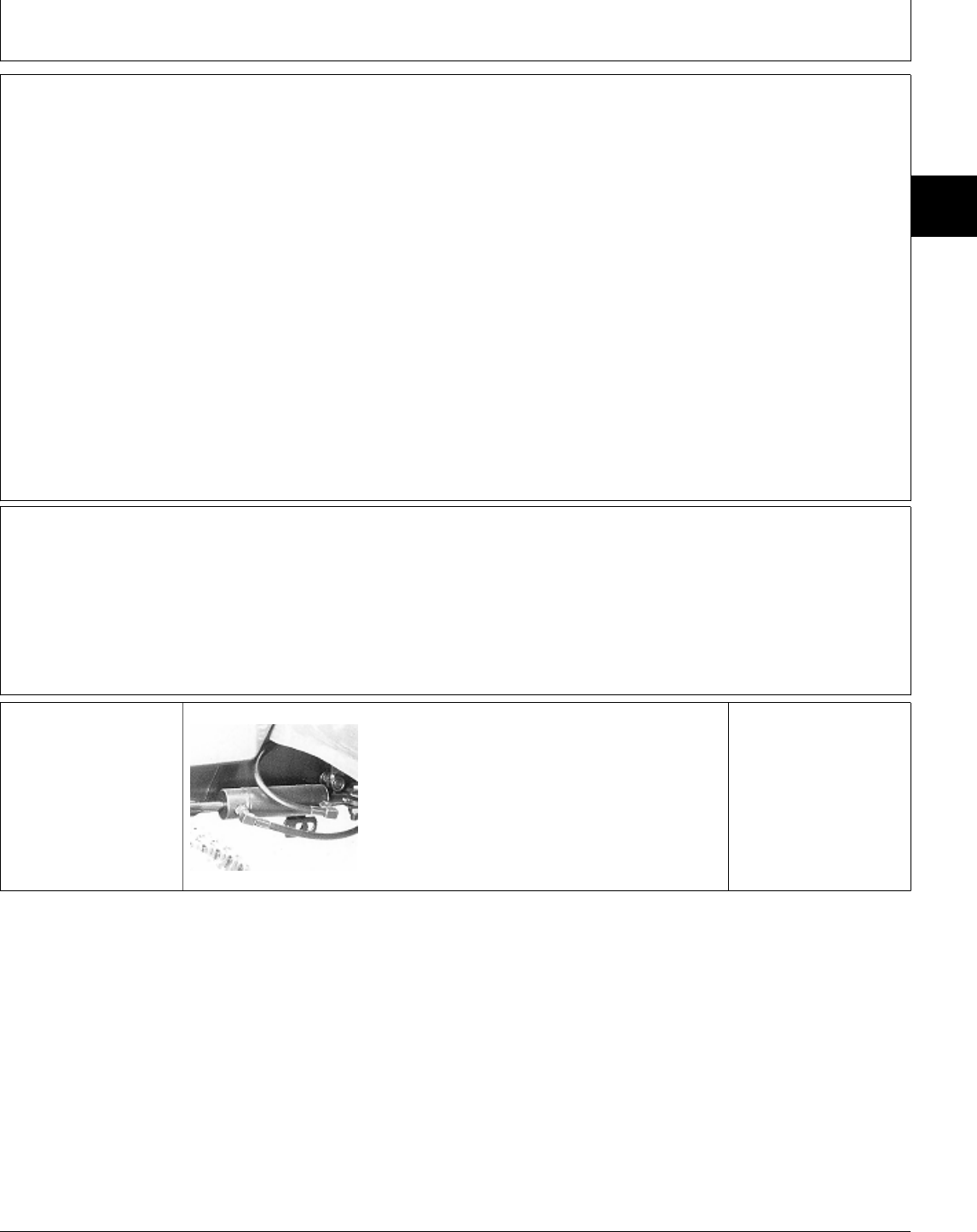
BEFORE YOU START
Always begin with this group to identify a failure in
the steering system. The step-by-step procedures will
provide you with a quick check of the system. No
special tools are required to perform these checks. If
a failure is indicated you will be referred to a more
detailed check, adjustment, or test.
Always start with the first step and follow the
sequence from left to right. Read each step
completely before performing the check.
This procedure is designed as a quick check of the
system. While performing the check, concentrate only
on the check you are performing and disregard
signals from unrelated components.
NOTE: The 330 has manual steering (gearbox).
The 322, 332 and 430 have power steering
(steering valve).
; STEERING SYSTEM OIL LEAK CHECK (322, 332 AND 430)
Check hydraulic oil
level, condition and
viscosity.
M49199 -UN-07APR95
Inspect for external
hydraulic oil leakage
from steering valve,
cylinder, lines and
fittings.
NOTE: 322/332 Shown
OK: GO TO ‘
NOT OK: Repair or
replace, then GO TO ‘
MX,159126005,1 -19-13JUL95
MX,159126005,2 -19-13JUL95
MX,159126005,4 -19-13JUL95
Group 05
Steering And Brakes System Checkout
TM1591 (15JUL95) 260-05-1 322,330,332 & 430 Lawn & Garden Tractors
030895
260
05
1
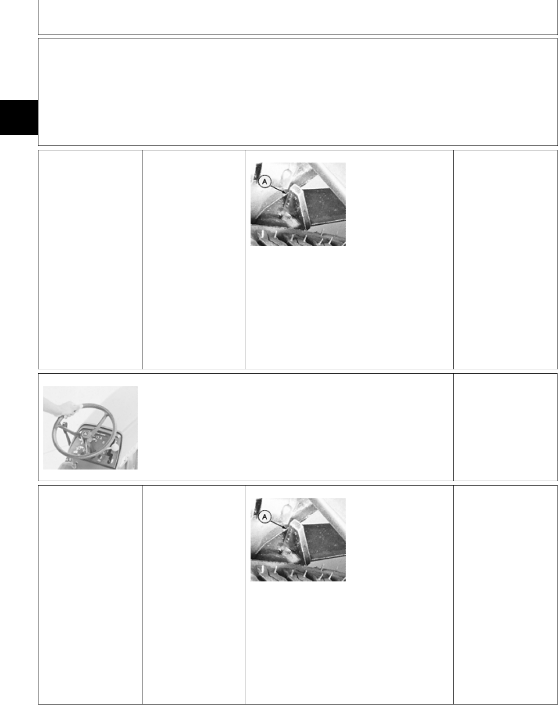
‘ HYDROSTATIC STEERING SYSTEM CHECK (322, 332 AND 430)
2a Power Steering
Check
Start engine and run at
full throttle.
M49195 -UN-02FEB90
Turn steering wheel full
left, then full right.
FEEL: Smooth,
constant effort should
be felt.
LOOK: Wheels must
stop turning when
steering wheel is
stopped.
LOOK: Wheels must
move full left and full
right. Stops (A) must
contact axle.
OK: CONTINUE WITH
TEST
WHEELS CONTINUE
TURNING AFTER
STEERING WHEEL IS
STOPPED: GO TO I,
GROUP 15.
STOPS DO NOT
CONTACT AXLE: GO
TO G, GROUP 15.
M55027 -UN-09DEC89
Count the number of revolutions of the steering
wheel from a full right turn to a full left turn then,
from a full left turn to a full right turn.
Approximate revolutions from right turn to left . . . . . . . . . . . . . . . . . . . . . . . . . 3
Approximate revolutions from left turn to right . . . . . . . . . . . . . . . . . . . . . . 2-1/2
OK: GO TO 2b
INCORRECT NUMBER
OF STEERING WHEEL
REVOLUTIONS: GO
TO Æ, GROUP 15.
2b Manual Steering
Check
Engine OFF.
M49195 -UN-02FEB90
Turn steering wheel full
left, then full right.
LOOK: Wheels must
move full left and full
right.
LOOK: Stops (A) must
contact axle.
OK: GO TO Æ
WHEELS DO NOT
MOVE FULL LEFT
AND FULL RIGHT:
Remove and inspect
steering valve check
valve. See Section 60.
STOPS DO NOT
CONTACT AXLE: GO
TO G, GROUP 15.
MX,159126005,5 -19-13JUL95
MX,159026005,4 -19-24APR95
MX,159026005,5 -19-24APR95
MX,159026005,6 -19-24APR95
Steering And Brakes System Checkout/Hydrostatic Steering System Check (322, 332 and 430)
TM1591 (15JUL95) 260-05-2 322,330,332 & 430 Lawn & Garden Tractors
030895
260
05
2
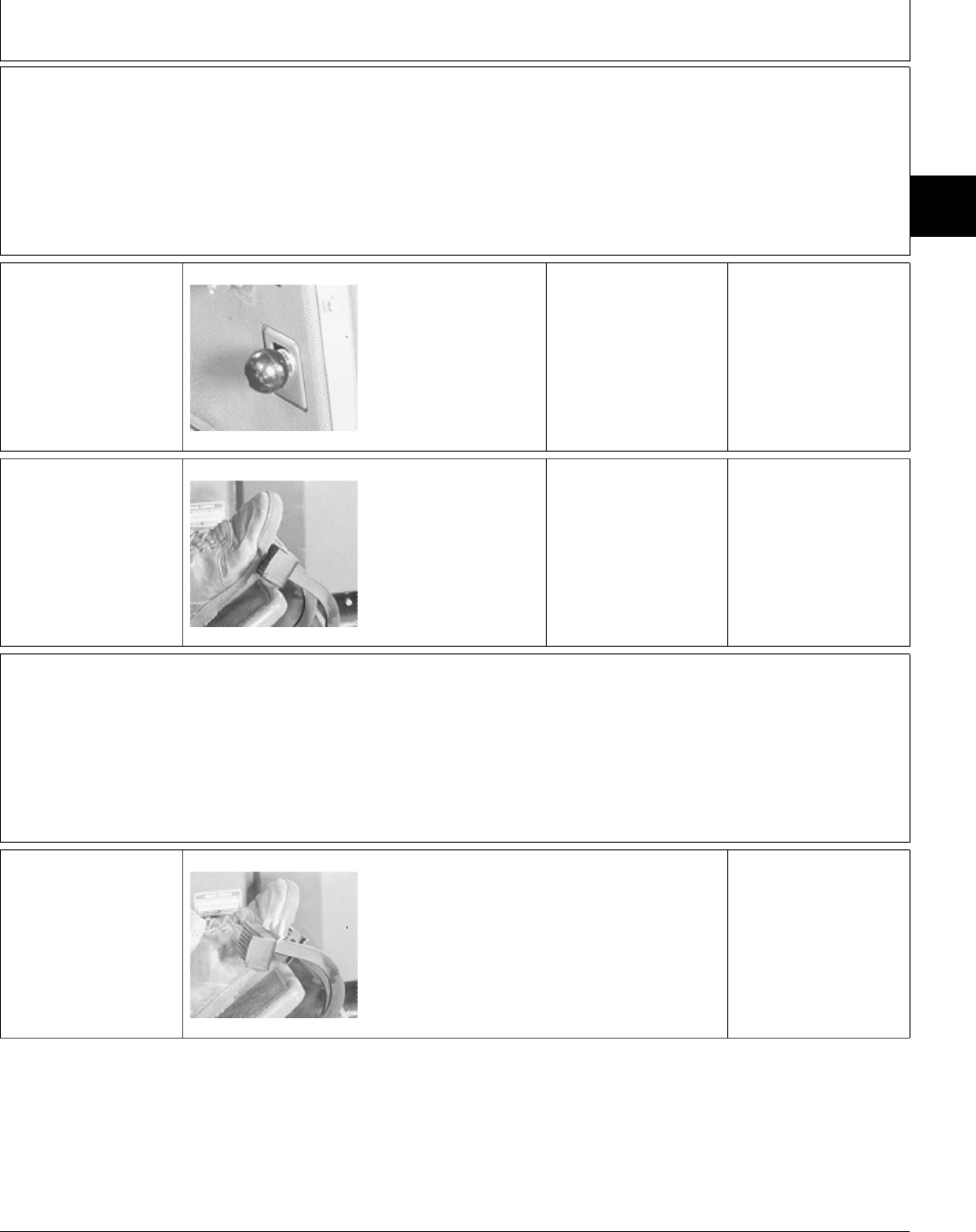
Æ SERVICE PARK BRAKE CHECK
3a Park Brake Lock
Lever Check
M49000 -UN-08JAN90
Depress brake pedal(s)
and engage service
park brake lock.
LOOK: Service park
brake must remain in
park position.
Disengage service park
brake.
Move park brake knob
up and down.
FEEL: Slight spring
pressure should be felt.
OK: GO TO 3b
NOT OK: Adjust park
brake linkage. See
Section 60.
3b Brake Pedal(s)
Check
M49001 -UN-08JAN90
Latch brake pedals
together, if equipped.
Depress brake pedal(s)
and engage service
park brake lock.
NOTE: 322 Shown
Try to move hydrostat
lever forward or
reverse.
FEEL: Lever must NOT
move from STOP
position.
OK: GO TO Å
NOT OK: Adjust park
brake linkage and
shoes. See Section 60.
Å TURN BRAKE CHECK (322, 332 AND 430)
Drive machine forward
at medium speed.
M49002 -UN-08JAN90
Depress left, then right
turn brake.
LOOK: Left, then right
wheel must stop and
other must continue
driving.
OK: System normal.
NOT OK: Inspect and
adjust brake shoes.
See Section 60.
MX,159026005,7 -19-24APR95
MX,159026005,8 -19-24APR95
MX,159126005,6 -19-13JUL95
MX,159126005,3 -19-13JUL95
MX,159126005,7 -19-13JUL95
Steering And Brakes System Checkout/Turn Brake Check (322, 332 and 430)
TM1591 (15JUL95) 260-05-3 322,330,332 & 430 Lawn & Garden Tractors
030895
260
05
3

Ö OPERATOR COMPLAINT NOT IDENTIFIED
If you completed the checkout procedure and did
not isolate a malfunction, the problem may be
intermittent.
Try to duplicate the condition of the malfunction
identified by the operator.
Repeat system
checkout in this group. IF A MALFUNCTION IS NOT IDENTIFIED
AFTER REPEATING SYSTEM CHECKOUT
PROCEDURE, FACTORY ASSISTANCE IS
AVAILABLE THROUGH THE DEALER
TECHNICAL ASSISTANCE CENTER (DTAC).
MX,159026005,11-19-24APR95
MX,159026005,14-19-24APR95
Steering And Brakes System Checkout/Operator Complaint Not Identified
TM1591 (15JUL95) 260-05-4 322,330,332 & 430 Lawn & Garden Tractors
030895
260
05
4

Group 10
Theory of Operation
TM1591 (15JUL95) 260-10-1 322,330,332 & 430 Lawn & Garden Tractors
030895
260
10
1

STEERING VALVE/SYSTEM OPERATION
Function:
Supply pressurized oil to the proper side of the
steering cylinder to turn the wheels, when the engine
is running.
Theory of Operation:
NOTE: Right-hand turn shown.
All external oil flow from the transmission is routed
through the steering valve. The steering valve is an
open center type valve. The “five-port” design
provides “power beyond” to the auxiliary hydraulic
systems only after satisfying steering valve needs.
The steering valve consists of a self-centering fluid
control valve section (E) and a fluid metering section
(H). These are hydraulically and mechanically
interconnected inside the valve (C).
NEUTRAL:
Whenever the steering wheel (G) is released, the
centering springs (D) return the control valve section
to the center (neutral) position. In this position,
charge pressure oil entering the steering valve
through port “IN” is allowed to flow through the
control valve section and out through port “AUX”.
When in neutral position, the control valve prevents
charge pressure oil from entering the fluid metering
section.
POWER TURN:
As the steering wheel is turned to the right, the
control valve section is shifted by the drive link
assembly (B). This shifting opens the steering cylinder
ports “RT” and “LT”. Oil flow to auxiliary hydraulic
systems through port “AUX” is reduced giving the
steering valve priority over the auxiliary system
components.
Oil flows from port “IN” directly to the inlet of the
control valve section. As the steering wheel is turned,
charge pressure oil is routed through the control
valve section to the fluid metering section. Metered oil
is routed to port “RT” on the steering cylinder. Return
oil from the other end of the steering cylinder is
routed back to port “LT”, through the control valve
and “OUT” port, returning to the transmission.
When the rotation of the steering wheel stops, the
centering springs (D) move the control valve section
back to the center (neutral) position, and will remain
there until the steering wheel is moved again.
MANUAL TURN:
If hydraulic pressure is lost, the machine can still be
steered without hydraulic assistance. All components
still function the same with the exception of the fluid
metering section (H). The fluid metering section now
acts as a pump, moving oil from one side of the
metering section to the other as the steering wheel is
turned.
When the rotation of the steering wheel stops, the
centering springs move the valve back to the center
(neutral) position, and will remain there until the
steering wheel is moved again.
STEERING CYLINDER OPERATION:
The steering cylinder is a double-acting design.
One end of the cylinder is attached to the frame
which prevents the cylinder from moving. The rod end
is attached to the steering arm/spindle.
As pressurized oil enters the cylinder, the piston and
rod move, moving the steering arm, causing the
machine to turn.
To turn in the other direction, pressurized oil is
applied to the other port, moving the cylinder in the
opposite direction.
MX,159126010,1 -19-13JUL95
Theory of Operation/Steering Valve/System Operation
TM1591 (15JUL95) 260-10-2 322,330,332 & 430 Lawn & Garden Tractors
030895
260
10
2
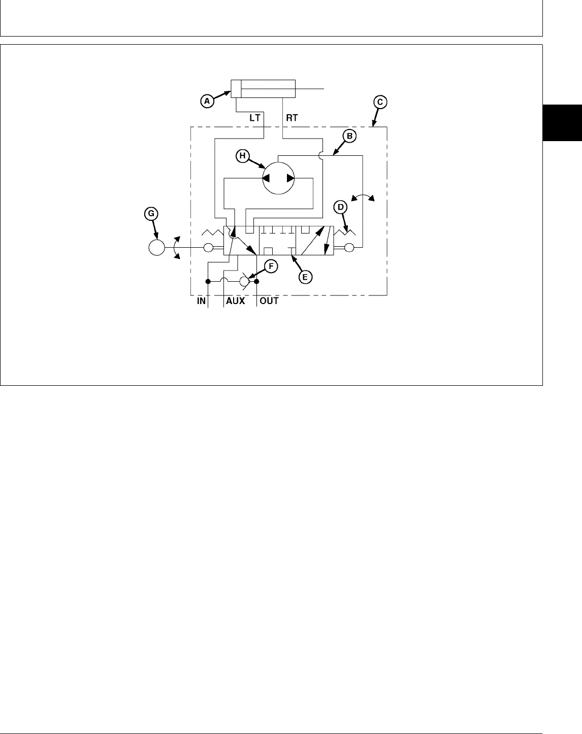
A—Steering Cylinder C—Steering Valve E—Control Valve Section G—Steering Wheel
B—Drive Link Assembly D—Centering Springs F—Check Valve H—Fluid Metering Section
M78855 -UN-26APR95
MX,159026010,3 -19-24APR95
Theory of Operation/Steering Valve/System Operation
TM1591 (15JUL95) 260-10-3 322,330,332 & 430 Lawn & Garden Tractors
030895
260
10
3

Theory of Operation/Steering Valve/System Operation
TM1591 (15JUL95) 260-10-4 322,330,332 & 430 Lawn & Garden Tractors
030895
260
10
4

ABOUT THIS GROUP
The step-by-step procedures in this group provide you
with the detailed diagnostic information you will need
to perform a test. Basic diagnostic equipment is used.
It is assumed that you are familiar with the machine
and its steering system components. If you need
additional information, read the theory of operation in
Group 10 or refer to the overall hydraulic schematics
in Section 270, Group 10.
Engine rpm and temperature are critical in most
hydraulic tests. Be sure to follow test specifications
carefully.
Always start with the first step and follow the
sequence from left to right. Read each step
completely before performing the test.
Upon completing a test or adjustment, check to see
whether the problem is corrected.
NOTE: The 330 has manual steering (gearbox).
The 322, 332 and 430 have power steering
(steering valve).
Therefore, all solutions to the symptoms may
not apply to your particular machine.
; TROUBLESHOOTING GUIDE
If the steering system does not operate properly, select the appropriate symptom from the list below.
After selecting the appropriate symptom, go to that step and perform the following checks, tests, or
adjustments in the order shown to isolate and repair the malfunction.
• STEERING WANDER: GO TO A
• STEERING SHIMMY: GO TO B
• SLUGGISH STEERING RESPONSE: GO TO C
• LOST MOTION AT THE STEERING WHEEL: GO TO D
• HIGH STEERING EFFORT IN ONE DIRECTION: GO TO E
• HIGH STEERING EFFORT IN BOTH DIRECTIONS: GO TO F
• WHEELS DO NOT HIT STOP: GO TO G
• STEERING EFFORT IS ERRATIC: GO TO H
• WHEELS CONTINUE TURNING AFTER STEERING WHEEL IS STOPPED: GO TO I
MX,159126015,1 -19-13JUL95
MX,159026015,2 -19-24APR95
Group 15
Diagnosis, Tests and Adjustments
TM1591 (15JUL95) 260-15-1 322,330,332 & 430 Lawn & Garden Tractors
030895
260
15
1

A STEERING WANDER
• Check for correct tire size.
• Check front tires for incorrect or unequal pressure.
• Check for loose or worn steering linkage parts.
• Check for worn wheel bearing or spindle bushings.
• Check Toe-In adjustment: See Section 80.
B STEERING SHIMMY
• Check for improperly mounted tire or wheel.
• Check for loose or worn steering linkage parts.
• Check for worn wheel bearings or spindle bushings.
• Bleed hydraulic system: See Section 270, Group 20.
• Check Toe-In adjustment: See Section 80.
C SLUGGISH STEERING RESPONSE
• Bleed hydraulic system: See Section 270, Group 20.
• Check for bent or restricted return line, oil cooler (if equipped) oil filter or steering linkage.
• Check for restricted oil filter or charge pump suction line.
• Check for cylinder rod binding in cylinder barrel.
• Check implement relief pressure. See Section 250.
• Test for steering system leakage. GO TO Æ
• Adjust engine rpm: See Section 220.
MX,159026015,3 -19-24APR95
MX,159026015,4 -19-24APR95
MX,159026015,5 -19-30MAR95
Diagnosis, Tests and Adjustments/Troubleshooting Guide
TM1591 (15JUL95) 260-15-2 322,330,332 & 430 Lawn & Garden Tractors
030895
260
15
2

D LOST MOTION AT STEERING WHEEL
• Check for loose or worn steering linkage.
• Check for steering valve loose at mounting.
• Bleed hydraulic system: See Section 270, Group 20.
E HIGH STEERING EFFORT IN ONE DIRECTION
• Check for binding of linkage or cylinder rod binding in cylinder barrel.
• Check for bent or restricted return line.
• Test for steering system leakage: GO TO Æ
• Inspect plate valve for sticking: See Section 60.
F HIGH STEERING EFFORT IN BOTH DIRECTIONS
• Check for improperly mounted tires or wheels.
• Check for binding of steering linkage and cylinder.
• Check for bent or restricted return line, oil cooler (if equipped) or oil filter.
• Check implement relief pressure. See Section 250.
• Check for steering valve check ball missing, damaged, or in “IN” port: See Section 60.
• Adjust engine rpm: See Section 220.
• Check for dirt accumulation on transmission causing transmission to overheat: GO TO ‘
• Check for high draft load causing transmission to overheat: GO TO ‘
MX,159026015,6 -19-30MAR95
MX,159026015,7 -19-30MAR95
MX,159026015,8 -19-30MAR95
Diagnosis, Tests and Adjustments/Troubleshooting Guide
TM1591 (15JUL95) 260-15-3 322,330,332 & 430 Lawn & Garden Tractors
030895
260
15
3
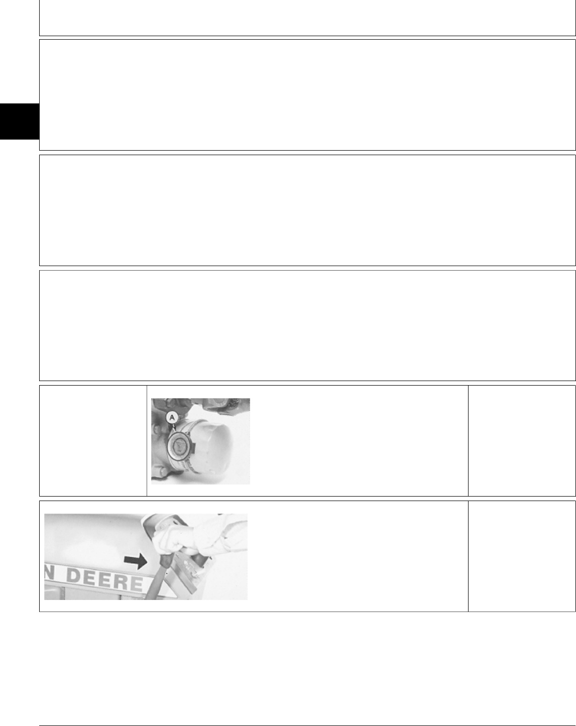
G WHEELS DO NOT HIT STOP
• Check for bent steering linkage, cylinder or cylinder rod.
H STEERING EFFORT IS ERRATIC
• Bleed hydraulic system: See Section 270, Group 20.
• Test for steering system leakage. GO TO Æ
I WHEELS CONTINUE TURNING AFTER STEERING WHEEL IS STOPPED
• Inspect valve plate for sticking: See Section 60.
• Inspect steering valve springs for wear or damage: See Section 60.
‘ HYDRAULIC OIL
WARM-UP
PROCEDURE
M43008 -UN-18JAN90
Remove belly screen/pan.
Install JDG282 Temperature Gauge (A) on
transmission oil filter.
On 430; Partially cover the radiator. Be careful
not to cover too much of the radiator causing
engine to overheat.
Apply park brake.
Start engine and run at
full throttle.
M43629 -UN-12JAN90
Move and hold control
lever in implement
“raise” position.
Periodically cycle all
hydraulic functions to
distribute heated oil.
NOTE: 330 Shown
Heat oil to temperature
specified in test.
NOTE: The hydrostatic
transmission should not
exceed 93˚C (200˚F) as
a continuous operating
temperature.
MX,159026015,9 -19-30MAR95
MX,159026015,10-19-30MAR95
MX,159026015,11-19-30MAR95
MX,159126015,3 -19-13JUL95
MX,159125015,6 -19-13JUL95
Diagnosis, Tests and Adjustments/Hydraulic Oil Warm-Up Procedure
TM1591 (15JUL95) 260-15-4 322,330,332 & 430 Lawn & Garden Tractors
030895
260
15
4
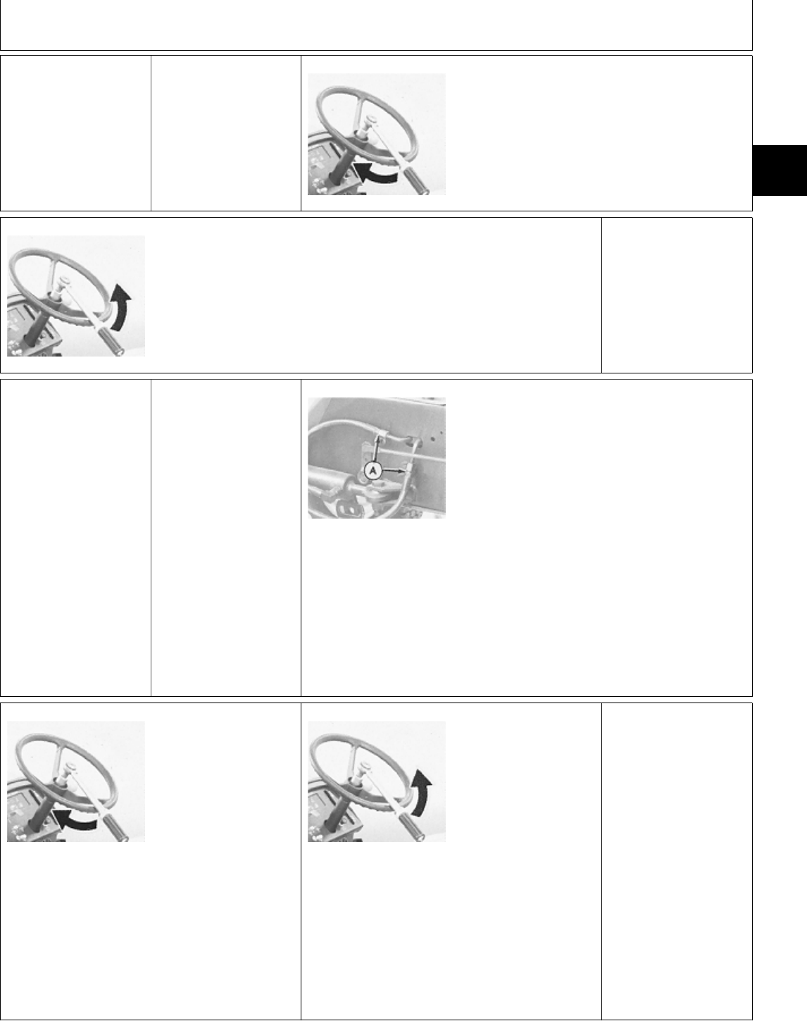
Æ STEERING SYSTEM
LEAKAGE TEST
Heat hydraulic oil to
43˚C (110˚F). See ‘ in
this group.
Start engine and run at
slow idle.
M49198 -UN-20DEC89
With wheels in a maximum right position, turn
steering wheel with a constant torque of 6.8 N·m
(60 lb-in.) for one minute.
LOOK: Count the revolutions.
RPM must not exceed 6.
M49197 -UN-20DEC89
With wheels in a maximum left position, turn
steering wheel with a constant torque of 6.8 N·m
(60 lb-in.) for one minute.
LOOK: Count the revolutions.
Rpm must not exceed 6.
6 RPM OR LESS:
STEERING SYSTEM
OK.
MORE THAN 6 RPM:
GO TO Å
Å STEERING VALVE
LEAKAGE TEST NCAUTION: TO
AVOID INJURY FROM
ESCAPING
HYDRAULIC OIL
UNDER PRESSURE,
RELIEVE THE
PRESSURE IN THE
SYSTEM BY
STOPPING THE
ENGINE AND
OPERATING ALL
HYDRAULIC
CONTROL VALVES.
M49196 -UN-20DEC89
Remove cap nut on left front side of fender deck
and raise fender deck to access hydraulic lines.
(Fender deck is removed in photo only for clarity
of procedure.)
Disconnect hydraulic lines at fittings (A) and plug
fittings (A) with JT03391 Plugs.
Start engine and run at slow idle.
M49198 -UN-20DEC89
With wheels in a
maximum right position,
turn steering wheel with
a constant torque of 6.8
N·m (60 lb-in.)
LOOK: Count the
revolutions.
RPM must not exceed
6. M49197 -UN-20DEC89
With wheels in a
maximum left position,
turn steering wheel with
a constant torque of 6.8
N·m (60 lb-in.)
LOOK: Count the
revolutions.
RPM must not exceed
6.
6 RPM OR LESS:
STEERING VALVE OK:
Replace steering
cylinder.
MORE THAN 6 RPM:
Remove and repair
steering valve. (See
Section 60.)
MX,159026015,12-19-27MAR95
MX,159026015,13-19-27MAR95
MX,159126015,2 -19-13JUL95
MX,159026015,15-19-27MAR95
Diagnosis, Tests and Adjustments/Steering Valve Leakage Test
TM1591 (15JUL95) 260-15-5 322,330,332 & 430 Lawn & Garden Tractors
030895
260
15
5

Diagnosis, Tests and Adjustments/Steering Valve Leakage Test
TM1591 (15JUL95) 260-15-6 322,330,332 & 430 Lawn & Garden Tractors
030895
260
15
6

Section 270
HYDRAULIC SYSTEM CHECKOUT,
OPERATION AND DIAGNOSIS
Contents
Page
Group 05—Hydraulic System Checkout
Before You Start . . . . . . . . . . . . . . . . . 270-05-1
Hydraulic System Oil Leak Check . . . . . . 270-05-1
Hydraulic Control Valve Check . . . . . . . . 270-05-2
Operator Complaint Not Identified . . . . . . 270-05-2
Group 10—Hydraulic Schematics
Hydraulic Circuit Symbols . . . . . . . . . . . 270-10-2
Hydraulic System Schematics
330 . . . . . . . . . . . . . . . . . . . . . . . . 270-10-5
322 and 332 . . . . . . . . . . . . . . . . . . 270-10-6
430 . . . . . . . . . . . . . . . . . . . . . . . . 270-10-9
Group 15—Theory of Operation
Hydraulic Lift System Operation
Three-Position Spool . . . . . . . . . . . . . 270-15-1
Four-Position Spool . . . . . . . . . . . . . . 270-15-2
Group 20—Diagnosis, Tests and Adjustments
About This Group . . . . . . . . . . . . . . . . 270-20-1
Troubleshooting Guide . . . . . . . . . . . . . 270-20-2
Hydraulic Oil Warm-Up Procedure . . . . . . 270-20-5
Rockshaft Cylinder Leakage Test . . . . . . 270-20-5
Control Valve Leakage Test . . . . . . . . . . 270-20-6
Bleed Hydraulic System . . . . . . . . . . . . 270-20-8
TM1591 (15JUL95) 270-1 322,330,332 & 430 Lawn & Garden Tractors
030895
270

Contents
TM1591 (15JUL95) 270-2 322,330,332 & 430 Lawn & Garden Tractors
030895
270
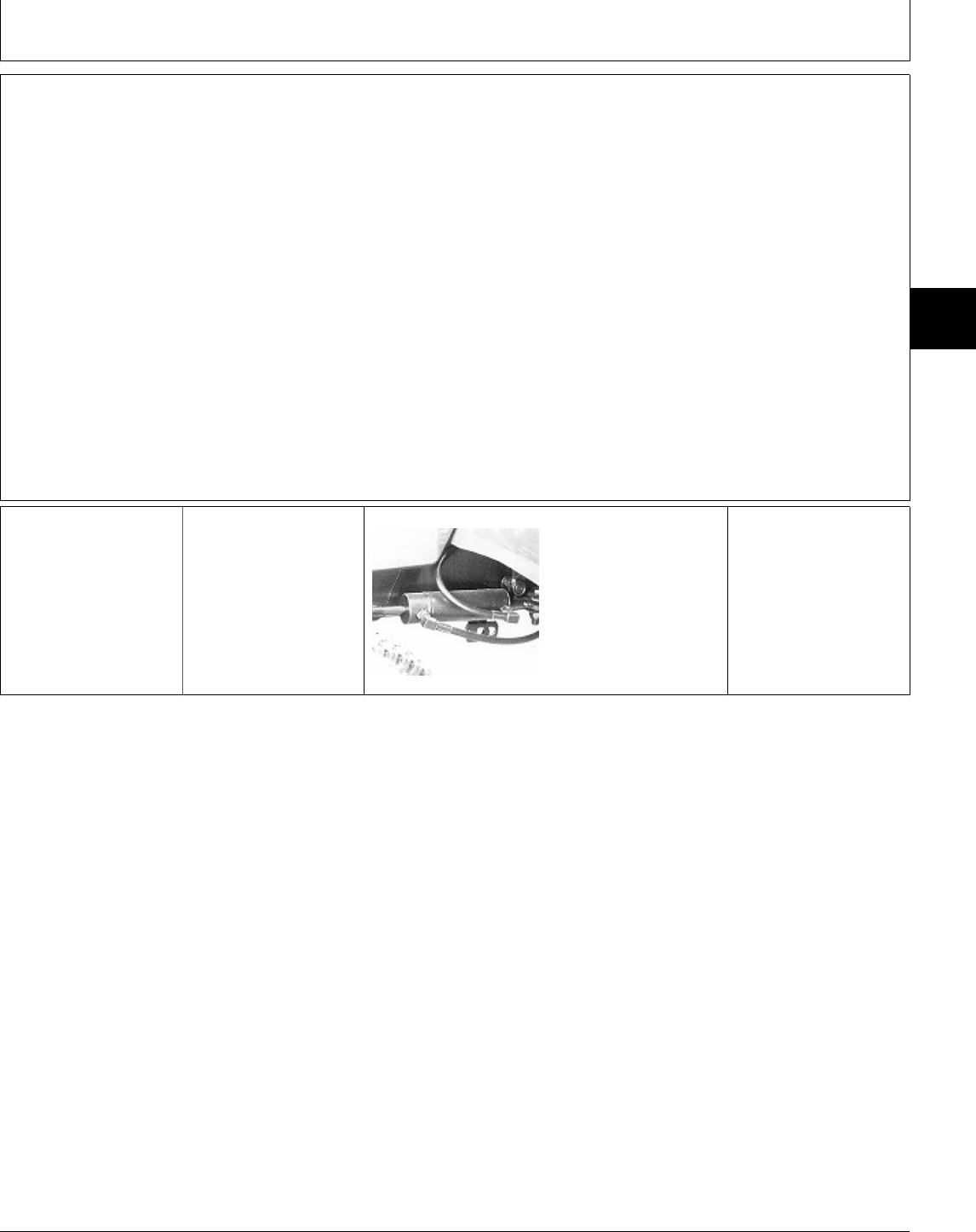
BEFORE YOU START
Always begin with this group to identify a failure in
the hydraulic system. The step-by-step procedures
will provide you with a quick check of the system. No
special tools are required to perform these checks. If
a failure is indicated, you will be referred to a more
detailed check, adjustment, or test.
Always start with the first step and follow the
sequence from left to right. Read each step
completely before performing the check.
This procedure is designed as a quick check of the
system. While performing the check, concentrate only
on the check you are performing and disregard
signals from unrelated components.
NOTE: The 330 has manual steering (gearbox),
single-spool control valve and rockshaft
cylinder.
The 322 and 332 have power steering,
steering cylinder, two-spool control valve,
rockshaft cylinder and oil cooler (optional).
The 430 has power steering, steering cylinder,
three-spool control valve, rockshaft cylinder
and oil cooler.
For further information, refer to the overall
hydraulic schematics in Group 10.
; HYDRAULIC
SYSTEM OIL LEAK
CHECK
Check hydraulic oil
level, condition and
viscosity.
M49199 -UN-07APR95
Inspect control valve,
cylinders, lines, hoses
and fittings for external
hydraulic oil leakage.
NOTE: 330 Shown
OK: GO TO ‘
NOT OK: Repair or
replace, then GO TO ‘
MX,159127005,1 -19-13JUL95
MX,159127005,2 -19-13JUL95
Group 05
Hydraulic System Checkout
TM1591 (15JUL95) 270-05-1 322,330,332 & 430 Lawn & Garden Tractors
030895
270
05
1

‘ HYDRAULIC CONTROL VALVE CHECK
NOTE: 330; Single lever controls rockshaft
cylinder and right-hand front outlets.
322 and 332 Levers;
—Inside lever controls right-hand front outlets
“float” and optional rear outlets.
—Outside lever controls rockshaft cylinder and
left-hand front outlets..
430 Levers;
—Inside lever controls right-hand front outlets
“float”.
—Middle lever controls rockshaft cylinder.
—Outside lever controls left-hand front and
optional rear outlets.
M36699 -UN-25JAN90
Run engine at full
throttle.
Pull control valve lever
rearward to raise
implement. Release
lever.
LOOK: Implement must
raise and hold position
without dropping. Lever
must return to neutral.
NOTE: 322/332 Shown
NOTE: With the exception of “float”
position, all control valve levers
should operate the same with an
attachment correctly connected to
the particular hydraulic system.
• All control valve levers except
“float” position:
Push control valve lever forward to
lower implement. Release lever.
LOOK: Implement must lower and
hold position. Lever must return to
neutral.
Pull control valve lever rearward to
raise implement. Release lever.
LOOK: Implement must raise and
hold position. Lever must return to
neutral.
• Control valve lever “float” position:
Push control valve lever forward to
float position. Release lever.
LOOK: Implement must lower to
ground and lever must stay in float
position.
• All control valve levers:
Pull control valve lever rearward
and raise implement halfway.
Turn engine OFF.
Pull control valve rearward to raise
implement.
LOOK: Implement must not move
down.
OK: Procedure
complete. System is
normal.
NOT OK: GO TO ; in
Group 20.
Æ OPERATOR
COMPLAINT NOT
IDENTIFIED
If you completed the checkout procedure and did
not isolate a malfunction, the problem may be
intermittent.
Try to duplicate the condition of the malfunction
identified by the operator.
IF A MALFUNCTION IS NOT IDENTIFIED
AFTER SYSTEM CHECKOUT PROCEDURE,
FACTORY ASSISTANCE IS AVAILABLE
THROUGH THE DEALER TECHNICAL
ASSISTANCE CENTER (DTAC).
MX,159127005,3 -19-13JUL95
MX,159027005,4 -19-24APR95
Hydraulic System Checkout/Operator Complaint Not Identified
TM1591 (15JUL95) 270-05-2 322,330,332 & 430 Lawn & Garden Tractors
030895
270
05
2

HYDRAULIC SYSTEM SCHEMATICS
The hydraulic system schematics on the following pages
can be folded out for use while diagnosing malfunctions
or while repairing hydraulic components.
MX,159027010,1 -19-24APR95
Group 10
Hydraulic Schematics
TM1591 (15JUL95) 270-10-1 322,330,332 & 430 Lawn & Garden Tractors
030895
270
10
1
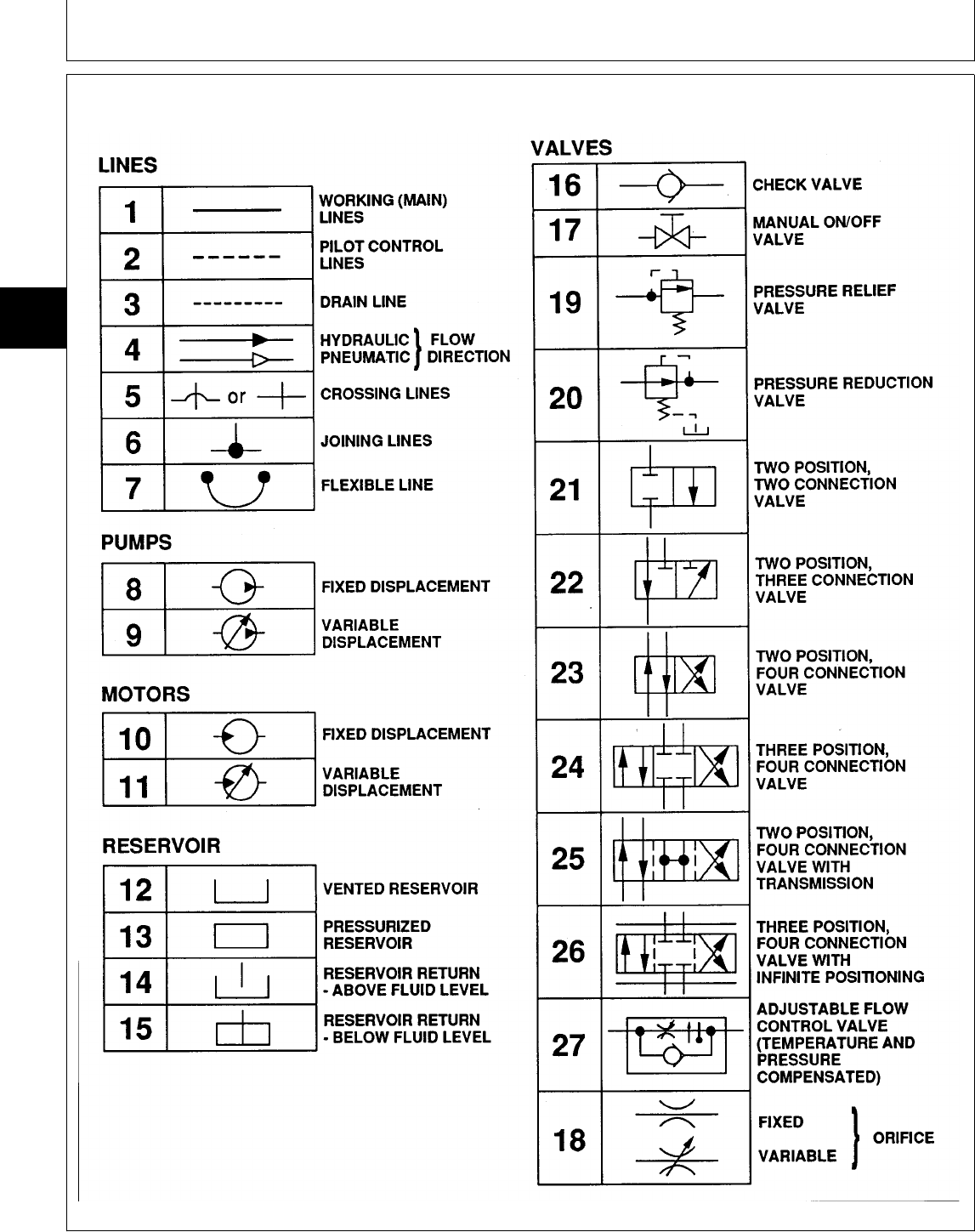
HYDRAULIC CIRCUIT SYMBOLS
M81419AE -19-19NOV92
NX,HYSYM -19-05APR94
Hydraulic Schematics/Hydraulic Circuit Symbols
TM1591 (15JUL95) 270-10-2 322,330,332 & 430 Lawn & Garden Tractors
030895
270
10
2
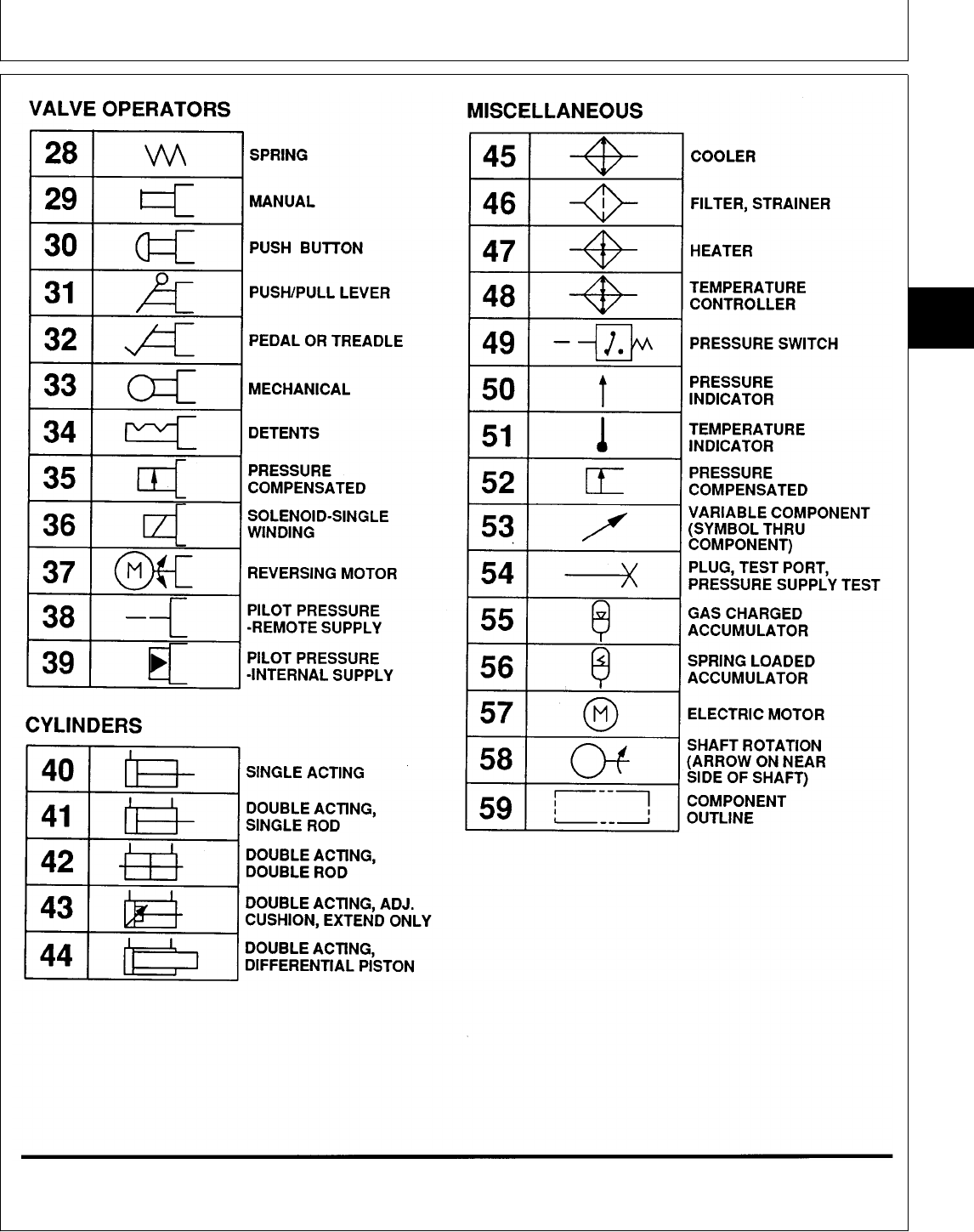
M81440AE -19-19NOV92
NX,HYSYM1 -19-05APR94
Hydraulic Schematics/Hydraulic Circuit Symbols
TM1591 (15JUL95) 270-10-3 322,330,332 & 430 Lawn & Garden Tractors
030895
270
10
3

LEGEND FOR HYDRAULIC SYSTEM SCHEMATIC—330
1—Hydrostatic Transmission 6—Implement Relief Valve 11—Input (Pump) Shaft 14—Hydraulic Control Valve
2—Output (Motor) Shaft 7—Check (Freewheel) Valves 12—Control Valve Spool 15—Rockshaft Cylinder
3—Hydrostatic Drive Motor 8—Charge Pump (Three-Position) 16—Right Front Hydraulic
4—Transmission Case Drain 9—Filter 13—Check Valve Outlets
5—Charge Relief Valve 10—Variable Hydrostatic
Pump
MX,159127010,1 -19-13JUL95
Hydraulic Schematics/Hydraulic Circuit Symbols
TM1591 (15JUL95) 270-10-4 322,330,332 & 430 Lawn & Garden Tractors
030895
270
10
4
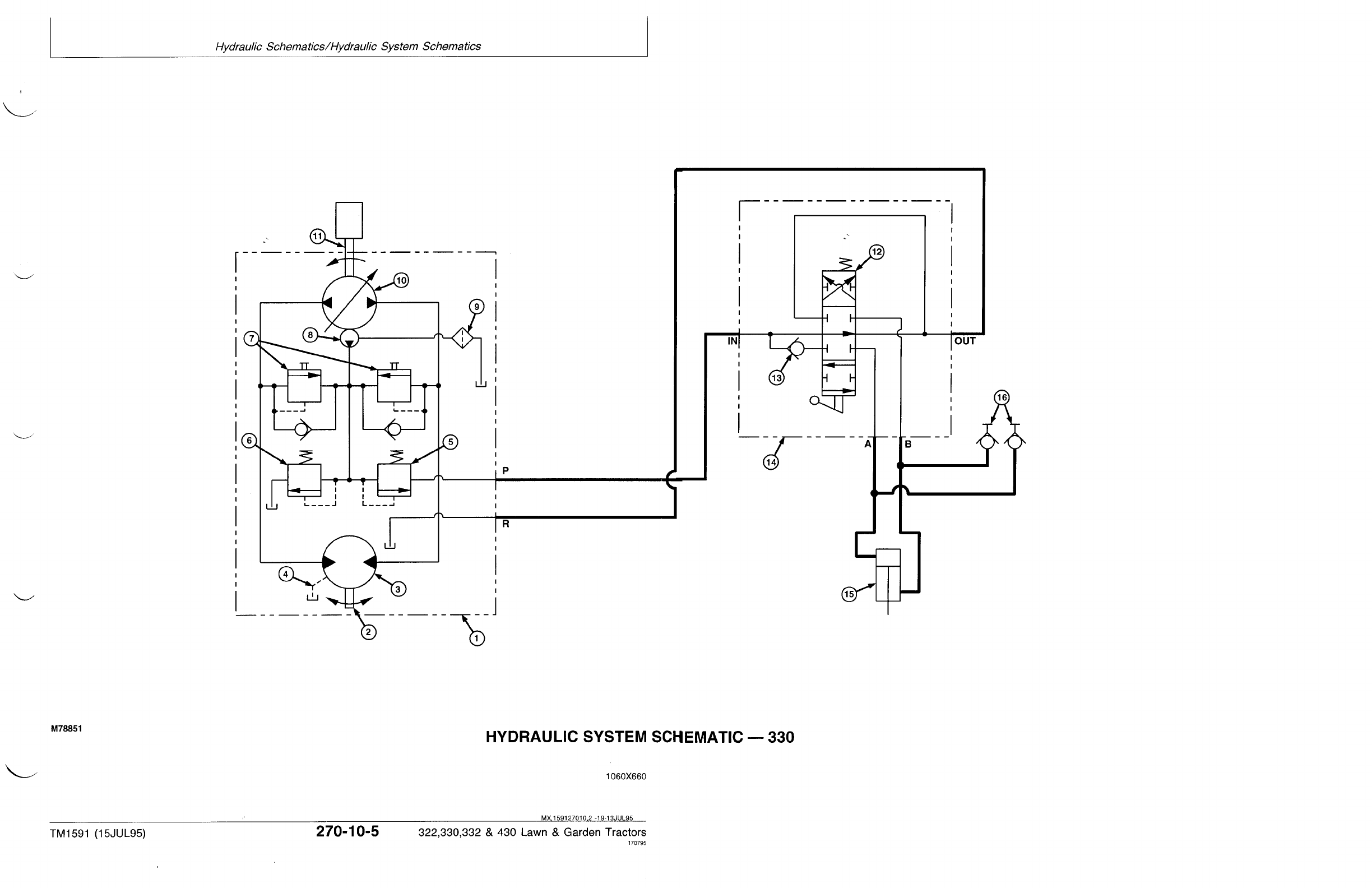
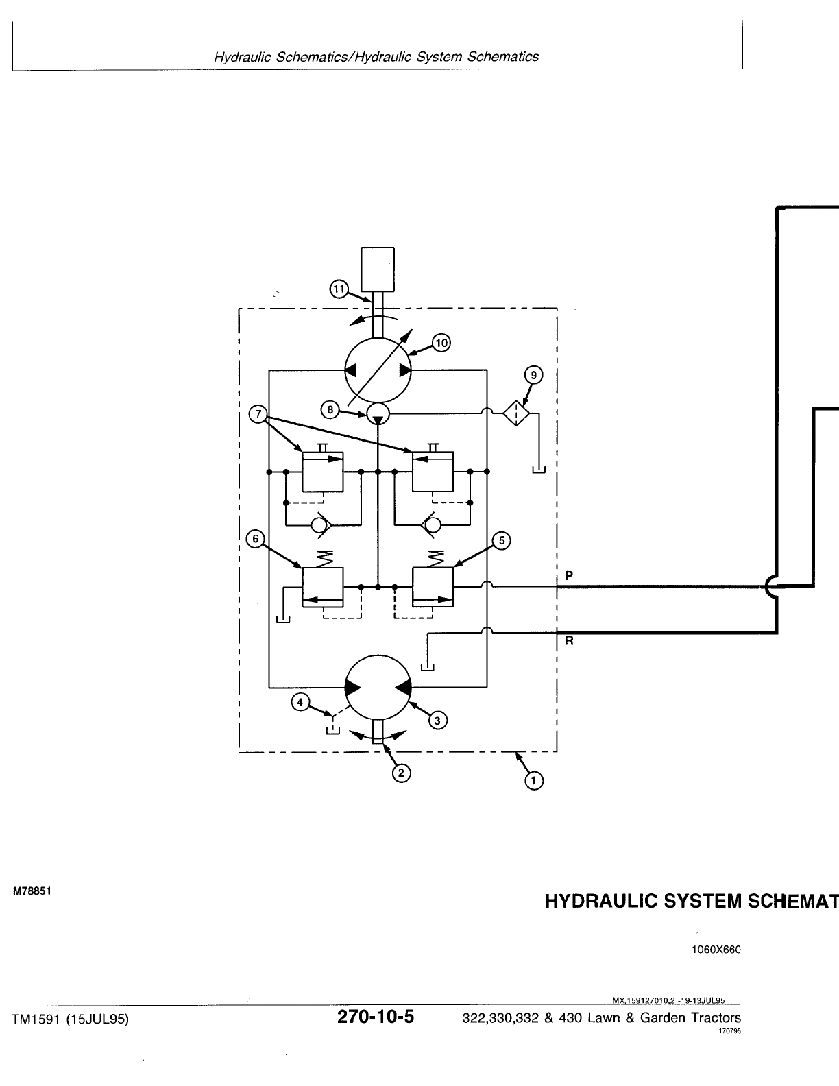
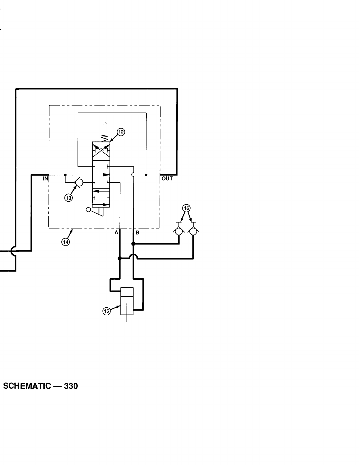
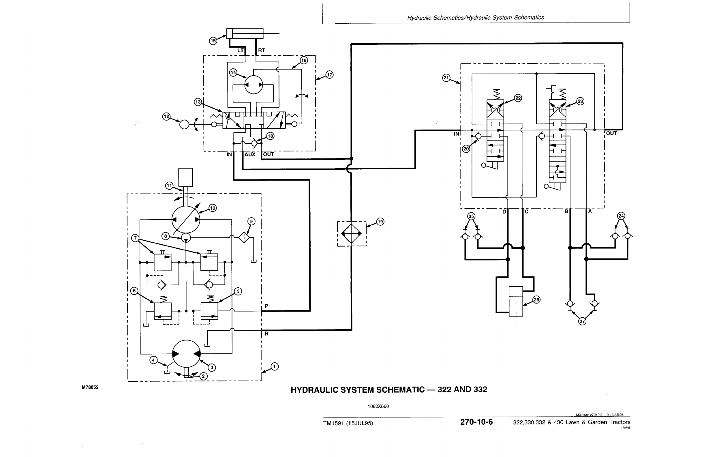
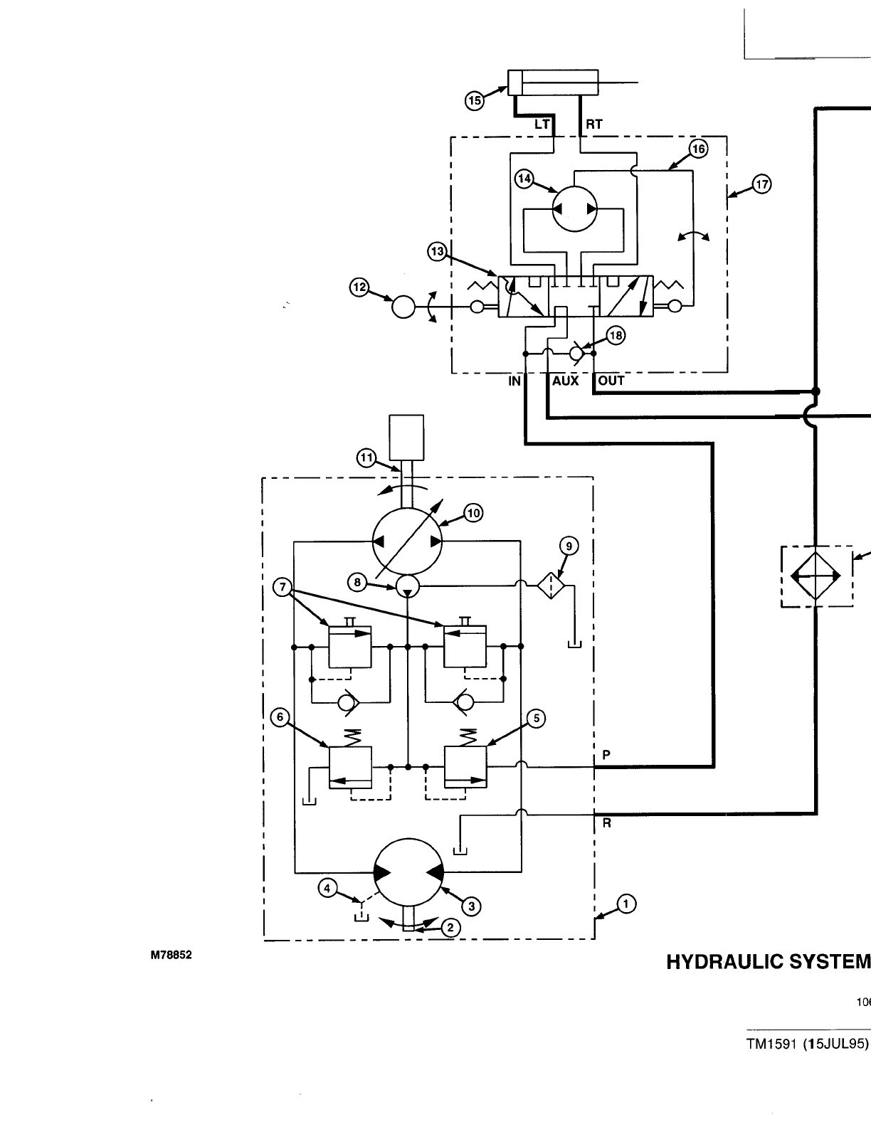
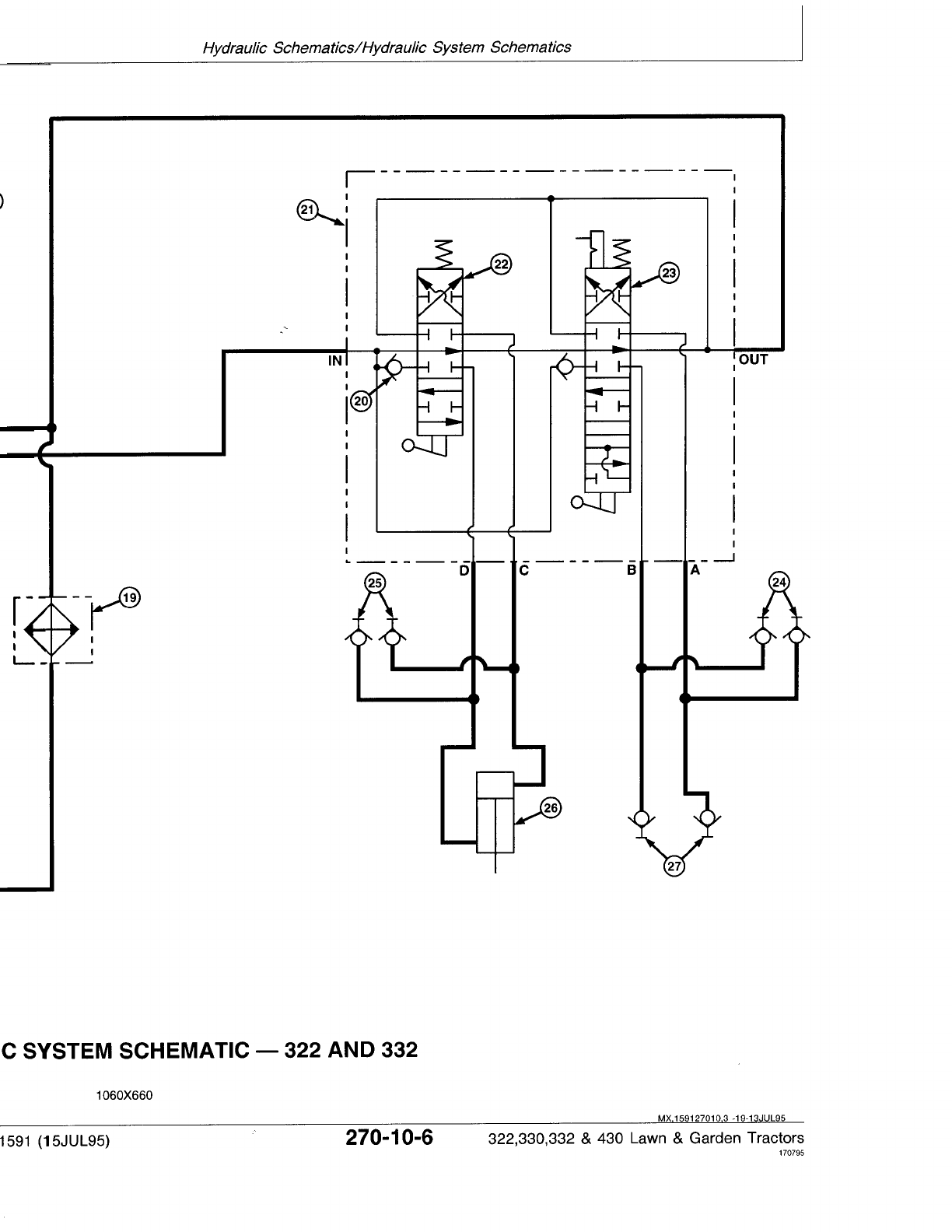

LEGEND FOR HYDRAULIC SYSTEM SCHEMATIC—322 AND 332
1—Hydrostatic Transmission 10—Variable Hydrostatic 17—Steering Valve 24—Front Hydraulic
2—Output (Motor) Shaft Pump 18—Check Valve Outlets—Right Side
3—Hydrostatic Drive Motor 11—Input (Pump) Shaft 19—Oil Cooler (Optional) 25—Front Hydraulic
4—Transmission Case Drain 12—Steering Wheel 20—Check Valve (2 used) Outlets—Left Side
5—Charge Relief Valve 13—Control Valve Section 21—Hydraulic Control Valve 26—Rockshaft Cylinder
6—Implement Relief Valve 14—Fluid Metering Section 22—Control Valve Spool 27—Rear Hydraulic Outlets
7—Check (Freewheel) Valves 15—Steering Cylinder (Three-Position) (Optional)
8—Charge Pump 16—Drive Link Assembly 23—Control Valve Spool with
9—Filter “Float” (Four-Position)
MX,159127010,4 -19-13JUL95
Hydraulic Schematics/Hydraulic System Schematics
TM1591 (15JUL95) 270-10-7 322,330,332 & 430 Lawn & Garden Tractors
030895
270
10
7

LEGEND FOR HYDRAULIC SYSTEM SCHEMATIC—430
1—Hydrostatic Transmission 10—Variable Hydrostatic 17—Steering Valve 24—Front Hydraulic
2—Output (Motor) Shaft Pump 18—Check Valve Outlets—Right Side
3—Hydrostatic Drive Motor 11—Input (Pump) Shaft 19—Oil Cooler 25—Front Hydraulic
4—Transmission Case Drain 12—Steering Wheel 20—Check Valve (3 used) Outlets—Left Side
5—Charge Relief Valve 13—Control Valve Section 21—Hydraulic Control Valve 26—Rockshaft Cylinder
6—Implement Relief Valve 14—Fluid Metering Section 22—Control Valve Spool 27—Rear Hydraulic Outlets
7—Check (Freewheel) Valves 15—Steering Cylinder (Three-Position) (2 used) (Optional)
8—Charge Pump 16—Drive Link Assembly 23—Control Valve Spool with
9—Filter “Float” (Four-Position)
MX,159127010,5 -19-13JUL95
Hydraulic Schematics/Hydraulic System Schematics
TM1591 (15JUL95) 270-10-8 322,330,332 & 430 Lawn & Garden Tractors
030895
270
10
8
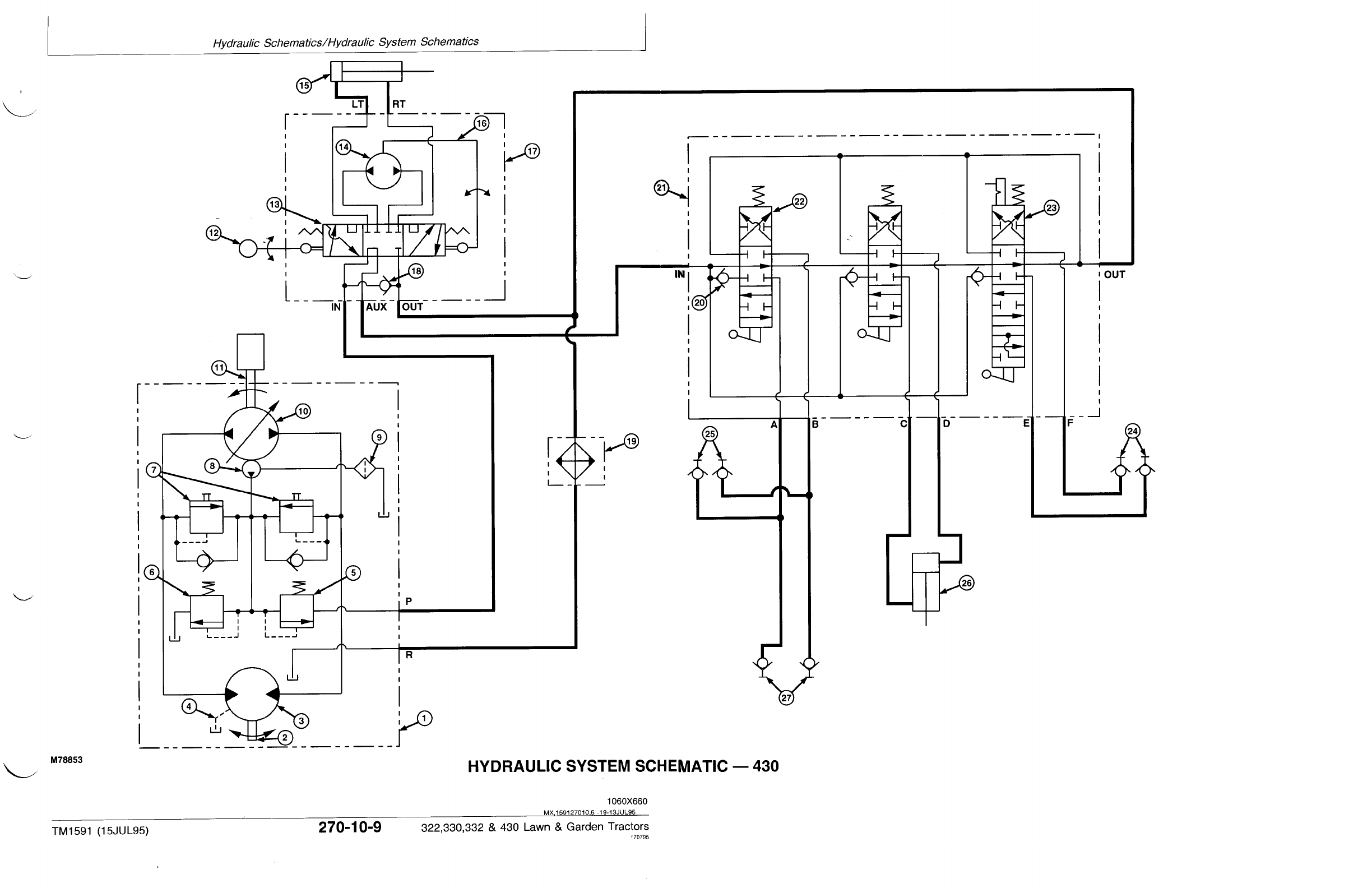
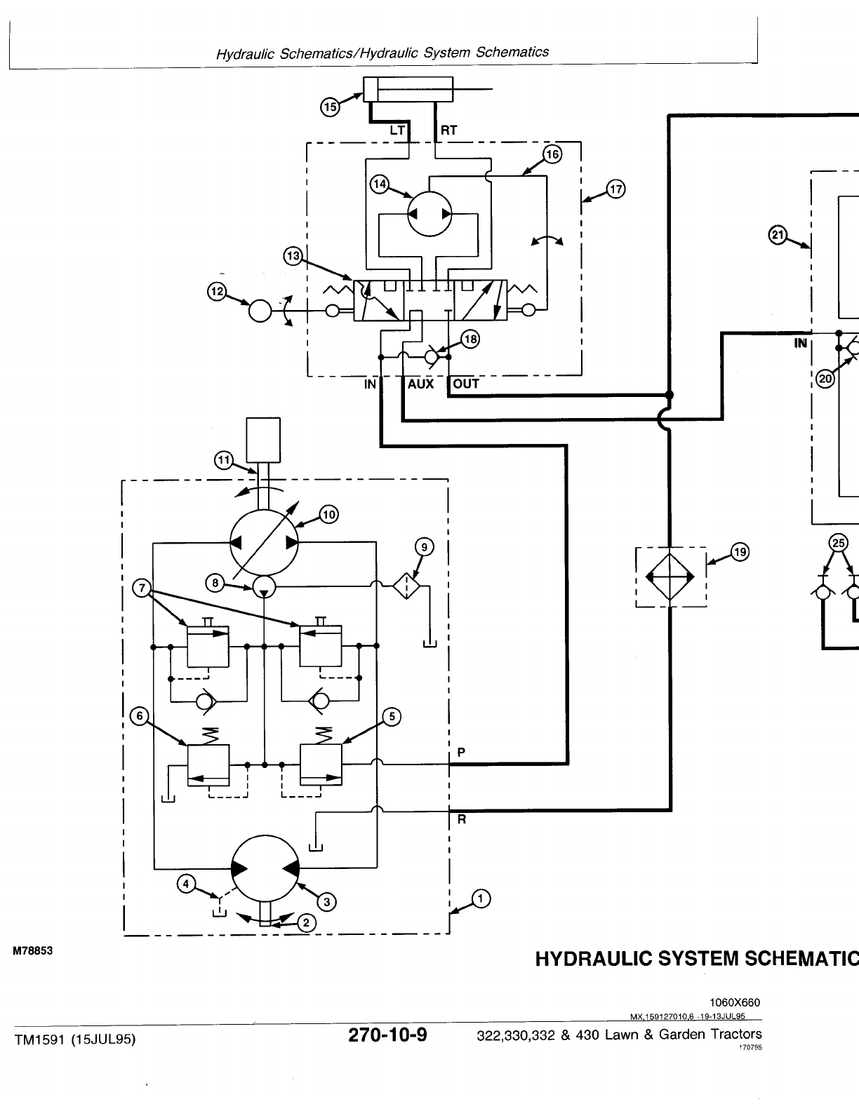
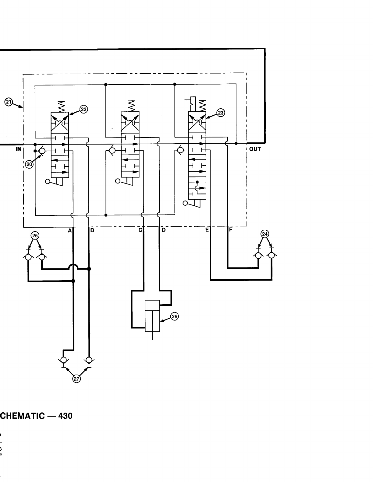

Hydraulic Schematics/Hydraulic System Schematics
TM1591 (15JUL95) 270-10-10 322,330,332 & 430 Lawn & Garden Tractors
030895
270
10
10
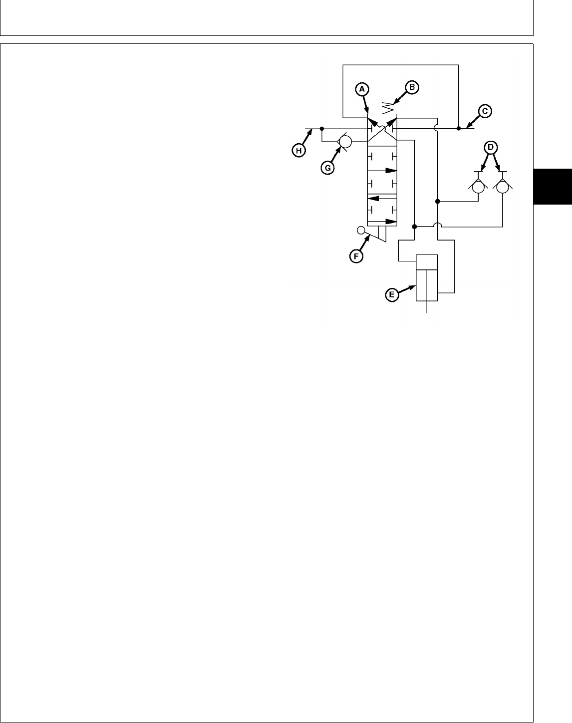
HYDRAULIC LIFT SYSTEM
OPERATION—THREE-POSITION SPOOL
Function:
To control the flow of pressurized oil to the rockshaft
cylinder or implement.
Theory of Operation:
NOTE: Lower position shown.
On 322, 332 and 430 models, pressurized oil is
routed through the steering valve before reaching
the hydraulic control valve. This design provides
“power beyond” to the auxiliary hydraulic systems
only after satisfying steering valve needs. (See
Section 260 for further information.)
LOWER:
As the handle is moved to the LOWER position, linkage
connected to the actuator (F) causes the control valve
spool (A) to change position. Pressurized oil entering the
control valve inlet (H) forces the check valve (G) to
open. Oil is then directed by the spool valve to the
rockshaft cylinder (E) or hydraulic outlets (D). A—Control Valve Spool
B—Centering Spring
Oil returning from the cylinder or implement is routed C—Return Oil to Transmission
through the control valve spool and is returned to the D—Hydraulic Outlets
transmission. E—Rockshaft Cylinder
F—Actuator
G—Check Valve
RAISE: H—Control Valve Inlet
Valve operation for RAISE is similar to LOWER, except
that spool position reverses oil flow.
NEUTRAL:
As the handle is released, the centering spring (B)
returns the control valve spool (A) to the neutral position.
Oil flow to/from the cylinder or implement is then
blocked, holding the implement in either the raised or
lowered position.
The valve spool position allows pressurized oil to flow
through the valve to other valves in the system, or return
to the transmission.
M78849 -UN-03APR95
MX,159127015,1 -19-13JUL95
Group 15
Theory of Operation
TM1591 (15JUL95) 270-15-1 322,330,332 & 430 Lawn & Garden Tractors
030895
270
15
1
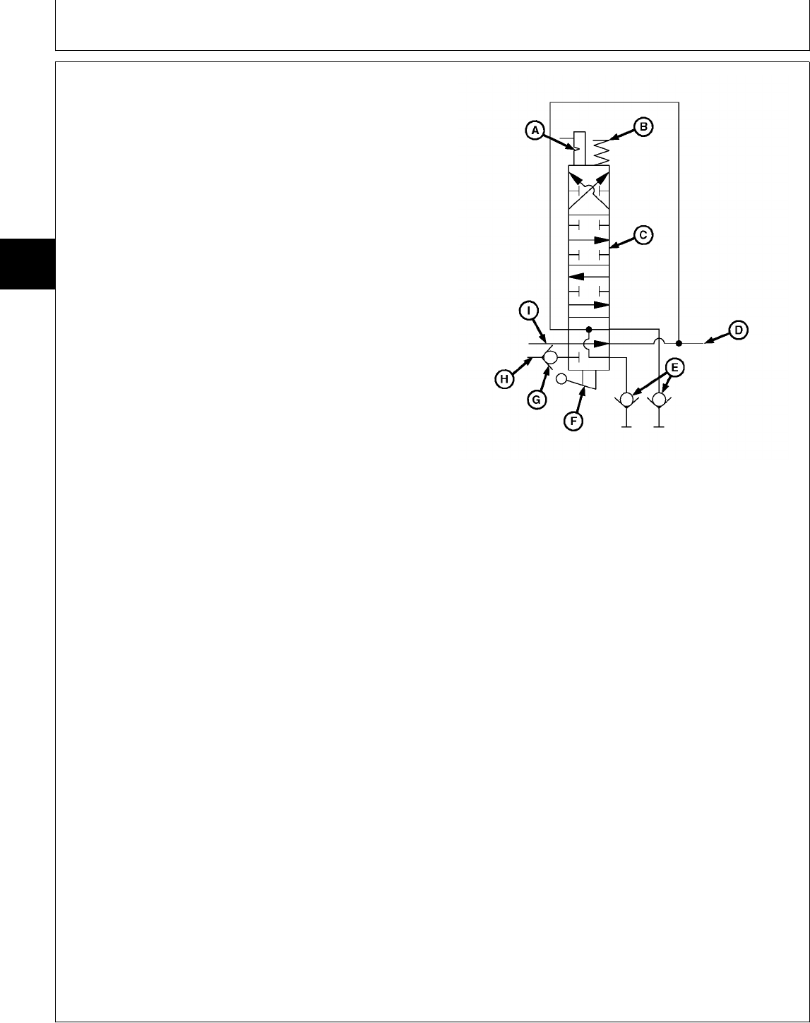
HYDRAULIC LIFT SYSTEM
OPERATION—FOUR-POSITION SPOOL
Function:
To control the flow of pressurized oil to the implement.
Theory of Operation:
NOTE: Float position shown.
On 322, 332 and 430 models, pressurized oil is
routed through the steering valve before reaching
the hydraulic control valve. This design provides
“power beyond” to the auxiliary hydraulic systems
only after satisfying steering valve needs. (See
Section 260 for further information.)
RAISE:
As the handle is moved to the RAISE position, linkage
connected to the actuator (F) causes the control valve
spool (C) to change position. Pressurized oil entering the
control valve inlet (H) forces the check valve (G) to
open. Oil is then directed by the spool valve to the
hydraulic outlets (E).
A—Detent
Oil returning from the implement is routed through the B—Centering Spring
control valve spool and is returned to the transmission. C—Control Valve Spool
D—Return Oil to Transmission
LOWER: E—Hydraulic Outlets
Valve operation for LOWER is similar to RAISE, except F—Actuator
G—Check Valve
that spool position reverses oil flow. H—Control Valve Inlet
I—Inlet from Valve Stack
NEUTRAL:
As the handle is released, the centering spring (B)
returns the control valve spool (C) to the neutral position.
Oil flow to/from the implement is then blocked, holding
the implement in either the raised or lowered position.
The valve spool position allows pressurized oil to flow
through the valve to other valves in the system, or return
to the transmission.
FLOAT:
As the handle is moved to the FLOAT position, linkage
connected to the actuator (F) causes the control valve
spool (C) to change position and engage the detent (A),
locking the valve in position. In this position, both sides
of the hydraulic outlets (E) are connected to the return
line (D) to the transmission. This allows pressure to be
released as the implement moves or “floats”.
Valve spool position also allows pressurized oil entering
from the valve stack inlet (I) to flow though the valve and
return to the transmission.
M78850 -UN-03APR95
MX,159127015,2 -19-13JUL95
Theory of Operation/Hydraulic Lift System Operation
TM1591 (15JUL95) 270-15-2 322,330,332 & 430 Lawn & Garden Tractors
030895
270
15
2

ABOUT THIS GROUP
The step-by-step procedures in this group provide you
with the detailed diagnostic information you will need
to perform a test. Basic diagnostic equipment is used.
It is assumed that you are familiar with the machine
and its hydraulic system components. If you need
additional information, read the theory of operation in
Group 15 or refer to the overall hydraulic schematics
in Group 10.
Engine rpm and temperature are critical in most
hydraulic tests. Be sure to follow test specifications
carefully.
Always start with the first step and follow the
sequence from left to right. Read each step
completely before performing the test.
Upon completing a test or adjustment, check to see
whether the problem is corrected.
NOTE: The 330 has manual steering (gearbox),
single-spool control valve and rockshaft
cylinder.
The 322 and 332 have power steering,
steering cylinder, two-spool control valve,
rockshaft cylinder and oil cooler (optional).
The 430 has power steering, steering cylinder,
three-spool control valve, rockshaft cylinder
and oil cooler.
MX,159127020,1 -19-13JUL95
Group 20
Diagnosis, Tests and Adjustments
TM1591 (15JUL95) 270-20-1 322,330,332 & 430 Lawn & Garden Tractors
030895
270
20
1

; TROUBLESHOOTING GUIDE
If hydraulic system does not operate properly, select the appropriate symptom from the list below.
After selecting the appropriate symptom, go to that step and perform the following checks, tests, or
adjustments in the order shown to isolate and repair malfunction.
• HYDRAULIC SYSTEM INOPERATIVE: GO TO A
• LOW OR SLOW HYDRAULIC POWER: GO TO B
• HYDRAULIC SYSTEM OPERATES ERRATICALLY: GO TO C
• LOAD DROPS WITH CONTROL VALVE IN NEUTRAL POSITION: GO TO D
• LOAD DROPS SLIGHTLY WHEN CONTROL VALVE IS SHIFTED TO RAISE POSITION: Check for
damaged lift check in control valve. See Section 70.
• EXCESSIVE HYDRAULIC PUMP NOISE: GO TO E
• CONTROL VALVE STICKS OR HARD TO OPERATE: GO TO F
• FREQUENT FAILURE OF HYDRAULIC LINES AND O-RINGS: GO TO G
• HYDRAULIC OIL FOAMS: GO TO H
• HYDRAULIC OIL OVERHEATS: GO TO I
• 322, 332 AND 430; ATTACHMENT OR HYDRAULIC LEVER DOES NOT STAY IN FLOAT POSITION:
Inspect control valve detent assembly for wear or damage. See Section 70.
A HYDRAULIC SYSTEM INOPERATIVE
• Check for slipping or broken transmission drive shaft. See Section 50.
• Check for proper charge pump housing installation. See Section 50.
• Check hoses for proper attaching location.
• Check for dented or restricted lines.
• Test charge pump pressure. See Section 250.
• Check suction line for air leaks. See Section 250.
• Check for plugged oil filter.
• Test implement relief valve pressure. See Section 250.
• 322, 332 and 430; Check for steering valve check ball missing, damaged, or in “IN” port. See Section 60.
MX,159127020,2 -19-13JUL95
MX,159127020,3 -19-13JUL95
Diagnosis, Tests and Adjustments/Troubleshooting Guide
TM1591 (15JUL95) 270-20-2 322,330,332 & 430 Lawn & Garden Tractors
030895
270
20
2

B LOW OR SLOW HYDRAULIC POWER
• Check for dented or restricted lines.
• Check for proper engine speed. See Section 220.
• Test charge pump pressure. See Section 250.
• Check for plugged oil filter.
• Check suction line for air leaks. See Section 250.
• Test implement relief valve pressure. See Section 250.
• Test control valve for leakage. GO TO Å
• Inspect cylinder packings for excessive wear. GO TO Æ
C HYDRAULIC SYSTEM OPERATES ERRATICALLY
• Bleed hydraulic system. GO TO Ö
• Check for restricted lines.
• Test charge pump pressure. See Section 250.
• Check for plugged oil filter.
• Check suction line for air leaks. See Section 250.
• Check for dirt in implement relief valve. See Section 50.
D LOAD DROPS WITH CONTROL VALVE IN NEUTRAL POSITION
• Check lines from control valve to rockshaft cylinder for leakage.
• Check control valve for centering when released.
• Check implement relief valve for leakage. See Section 250.
• Test control valve for leakage. GO TO Å
• Check cylinder packings and O-rings for leakage. GO TO Æ
MX,159027020,4 -19-24APR95
MX,159027020,5 -19-24APR95
MX,159027020,6 -19-24APR95
Diagnosis, Tests and Adjustments/Troubleshooting Guide
TM1591 (15JUL95) 270-20-3 322,330,332 & 430 Lawn & Garden Tractors
030895
270
20
3

E EXCESSIVE HYDRAULIC PUMP NOISE
• Bleed hydraulic system. GO TO Ö
• Check suction line for air leaks. See Section 250.
• Check for worn or damaged charge pump. See Section 50.
F CONTROL VALVE STICKS OR HARD TO OPERATE
• Check for binding control valve linkage.
• Inspect control valve for broken return spring, contaminated or scored valve bore, or bent valve spool.
See Section 70.
G FREQUENT FAILURE OF HYDRAULIC LINES AND O-RINGS
• Check hydraulic oil for contamination.
• Check hydraulic connections for proper torque.
• Test implement relief valve pressure. See Section 250.
H HYDRAULIC OIL FOAMS
• Check hydraulic lines for kinks or dents.
• Check suction line for air leaks. See Section 250.
I HYDRAULIC OIL OVERHEATS
• Operator holding control valve open too long causing implement relief valve to open.
• Check oil cooler fins (if equipped), radiator screen and transmission fins for plugged condition.
• Check for restricted lines or plugged oil filter.
• Test implement relief valve pressure. See Section 250.
• Check for high air temperatures and high draft loads. GO TO ‘
MX,159027020,7 -19-24APR95
MX,159027020,8 -19-24APR95
MX,159027020,9 -19-24APR95
MX,159027020,10-19-24APR95
MX,159127020,4 -19-13JUL95
Diagnosis, Tests and Adjustments/Troubleshooting Guide
TM1591 (15JUL95) 270-20-4 322,330,332 & 430 Lawn & Garden Tractors
030895
270
20
4
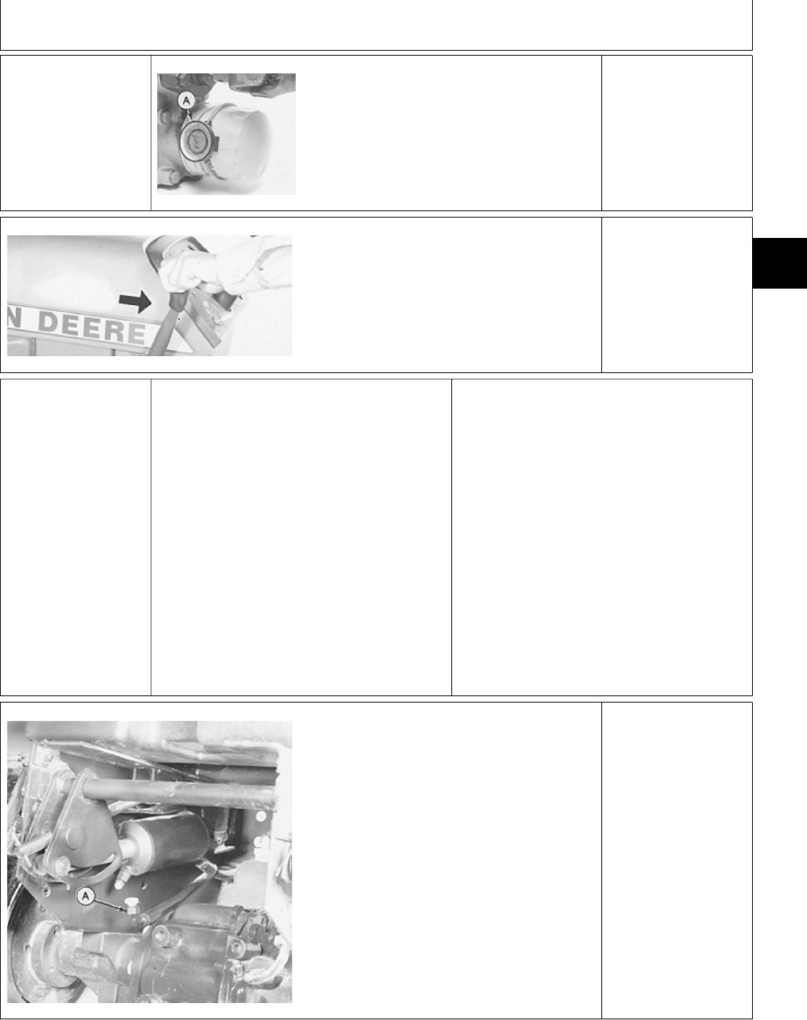
‘ HYDRAULIC OIL
WARM-UP
PROCEDURE
M43008 -UN-18JAN90
Remove belly screen/pan.
Install JDG282 Temperature Gauge (A) on
transmission oil filter.
On 430; Partially cover the radiator. Be careful
not to cover too much of the radiator causing
engine to overheat.
Apply park brake.
Start engine and run at
full throttle.
M43629 -UN-12JAN90
Move and hold control
lever in implement
“raise” position.
Periodically cycle all
hydraulic functions to
distribute heated oil.
NOTE: 330 Shown
Heat oil to temperature
specified in test.
NOTE: The hydrostatic
transmission should not
exceed 93˚C (200˚F) as
a continuous operating
temperature.
Æ ROCKSHAFT
CYLINDER LEAKAGE
TEST
Heat hydraulic oil to 43˚C (110˚F).
With implement linkage in the raised position
(cylinder extended), shut off engine.
NCAUTION: TO AVOID INJURY FROM
ESCAPING HYDRAULIC OIL UNDER
PRESSURE, RELIEVE THE PRESSURE IN THE
SYSTEM BY STOPPING THE ENGINE AND
OPERATING ALL HYDRAULIC CONTROL
VALVES.
M43631 -UN-12JAN90
Disconnect hose (A) from rod-end of cylinder.
There might be some initial dripping of hydraulic
oil from the cylinder and hose. This is not
leakage.
Put JT03393 steel Plug in disconnected hose.
Start engine and run at full throttle.
Hold control valve lever in the “lift” position.
Observe cylinder, hydraulic oil should not
continually leak out of the rod-end fitting.
IF HYDRAULIC OIL
CONTINUALLY LEAKS
OUT OF THE
ROD-END FITTING,
REPLACE CYLINDER.
MX,159126015,3 -19-13JUL95
MX,159125015,6 -19-13JUL95
MX,159027020,14-19-24APR95
Diagnosis, Tests and Adjustments/Rockshaft Cylinder Leakage Test
TM1591 (15JUL95) 270-20-5 322,330,332 & 430 Lawn & Garden Tractors
030895
270
20
5
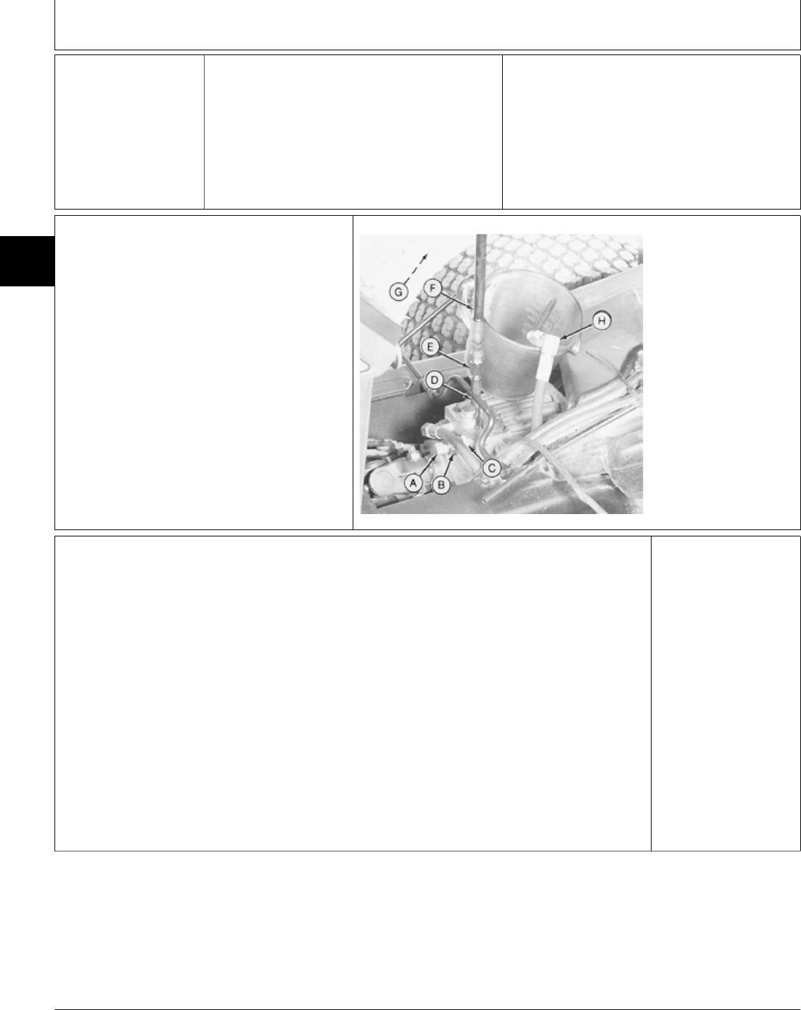
Å CONTROL VALVE
LEAKAGE TEST NCAUTION: TO AVOID INJURY FROM
ESCAPING HYDRAULIC OIL UNDER
PRESSURE, RELIEVE THE PRESSURE IN THE
SYSTEM BY STOPPING THE ENGINE AND
OPERATING ALL HYDRAULIC CONTROL
VALVES.
IMPORTANT: To avoid putting full pump flow
into container, DO NOT return control valve
lever to “neutral” or “float” (if equipped)
position with engine running. If equipped with
power steering, DO NOT move steering wheel.
4a Model 330
M43632 -UN-12JAN90
A—JT05484 Cap
B—JT03002 Adapter
C—JT03036 Connector
D—JT03339 Connector
E—JT03107 Adapter
F—JT03017 Hose
G—JT03345 Gauge
20,000 kPa (3,000
psi)(Not Shown)
H—Return Line
Heat hydraulic oil to 43˚C (110˚F). See ‘ in this
group.
Disconnect hydraulic hose (return line) (H). Put
disconnected hose into a container.
Make test port connections from JT01765 Lawn
and Grounds Care Products Hydraulic Fitting Kit.
Hold control valve lever in “raise” position.
Start engine and run at fast idle for one minute.
Stop engine. Record amount of oil in container.
Amount must be less than 15 mL/min (1/2 fl
oz/min). Pressure must be 5860—6550 kPa
(850—950 psi).
Repeat test for “lower” position.
IF PRESSURE IS NOT
WITHIN
SPECIFICATIONS: GO
TO SECTION 250 AND
TEST IMPLEMENT
RELIEF PRESSURE.
IF LEAKAGE IS MORE
THAN
SPECIFICATION:
REPLACE CONTROL
VALVE.
MX,159027020,15-19-03MAY95
MX,159127020,6 -19-13JUL95
MX,159027020,17-19-24APR95
Diagnosis, Tests and Adjustments/Control Valve Leakage Test
TM1591 (15JUL95) 270-20-6 322,330,332 & 430 Lawn & Garden Tractors
030895
270
20
6
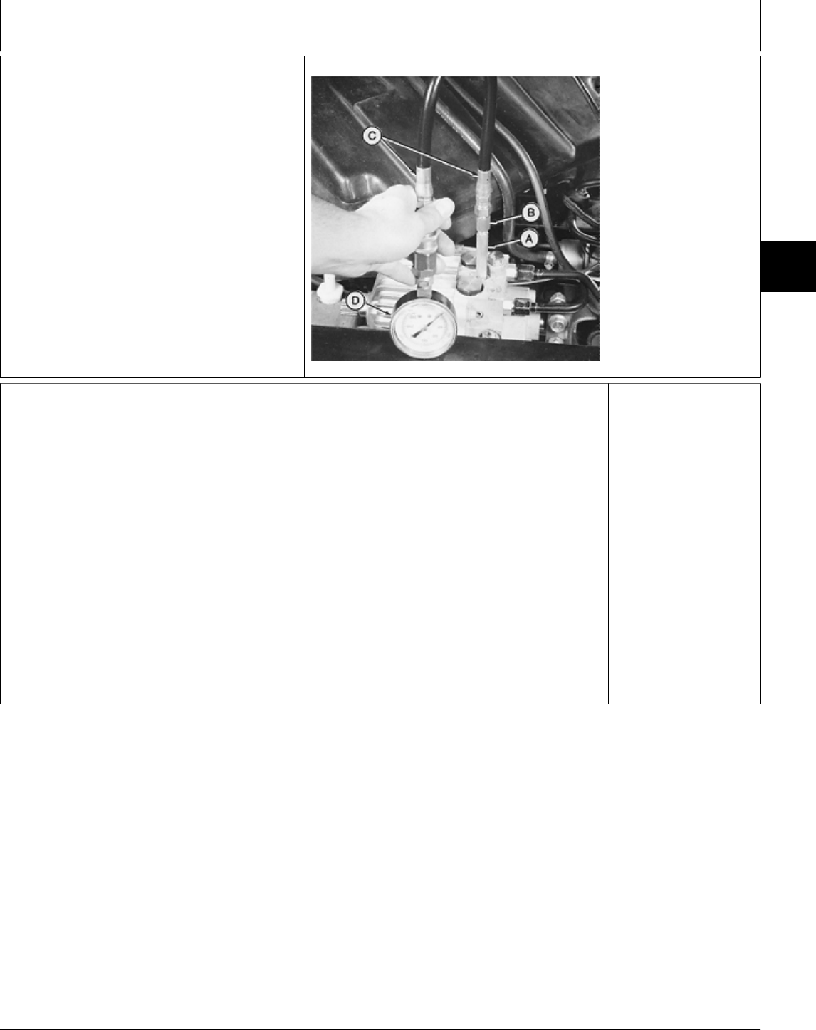
4b Models 322, 332
and 430
M36682 -UN-25JAN90
A—JT03339 Connector
B—JT03107 Adapter
C—JT03017 Hose
D—JT03345 Gauge
20,000 kPa (3,000 psi)
Heat hydraulic oil to 43˚C (110˚F).
See ‘ in this group.
Make test port connections from
JT01765 Lawn and Grounds Care
Products Hydraulic Fitting Kit.
Remove control valve return line
from “OUT” port on control valve.
If steering valve return line is
connected into control valve return
line, it must be plugged in order to
isolate only the control valve
leakage.
Put container under control valve to
catch leakage.
Hold a control valve lever in “raise”
position.
Start engine and run at fast idle for
one minute.
Stop engine. Record amount of oil
in container. Amount must be less
than 15 mL/min (1/2 fl oz/min).
Pressure must be 5860—6550 kPa
(850—950 psi).
Repeat test for “lower” position.
Repeat test for remaining control
lever(s).
IF PRESSURE IS NOT
WITHIN
SPECIFICATIONS: GO
TO SECTION 250 AND
TEST IMPLEMENT
RELIEF PRESSURE.
IF LEAKAGE IS MORE
THAN
SPECIFICATION:
REPLACE CONTROL
VALVE.
MX,159127020,7 -19-13JUL95
MX,159027020,19-19-03MAY95
Diagnosis, Tests and Adjustments/Control Valve Leakage Test
TM1591 (15JUL95) 270-20-7 322,330,332 & 430 Lawn & Garden Tractors
030895
270
20
7

Ö BLEED HYDRAULIC SYSTEM
After installing a repaired or replacement part, follow this run-in procedure to assure that air is purged from
the hydraulic system.
1. Start engine and idle for 10 minutes.
2. Run engine at high idle for one minute.
3. Turn steering wheel full left and hold for five seconds.
4. Turn steering wheel to straight forward for 10 seconds.
5. Turn steering wheel full right and hold for five seconds.
6. Return steering wheel to straight forward. Travel vehicle forward about 20 feet and then make two hard
left turns.
7. Then make two hard right turns.
8. Travel vehicle in reverse for 10 feet.
9. Cycle mower deck up and down three times.
10. Shut engine off and inspect hydraulic components for leaks.
11. Fill reservoir as required with John Deere Low Viscosity HY-GARD® oil.
MX,159027020,20-19-29MAR95
Diagnosis, Tests and Adjustments/Bleed Hydraulic System
TM1591 (15JUL95) 270-20-8 322,330,332 & 430 Lawn & Garden Tractors
030895
270
20
8

Section 299
DEALER FABRICATED TOOLS
Contents
Page
Group 00—Dealer Fabricated Tools
DFMX1 Steering Valve Fixture . . . . . . . . 299-00-1
DFMX2 Alignment Shims . . . . . . . . . . . . 299-00-1
TM1591 (15JUL95) 299-1 322,330,332 & 430 Lawn & Garden Tractors
030895
299

Contents
TM1591 (15JUL95) 299-2 322,330,332 & 430 Lawn & Garden Tractors
030895
299
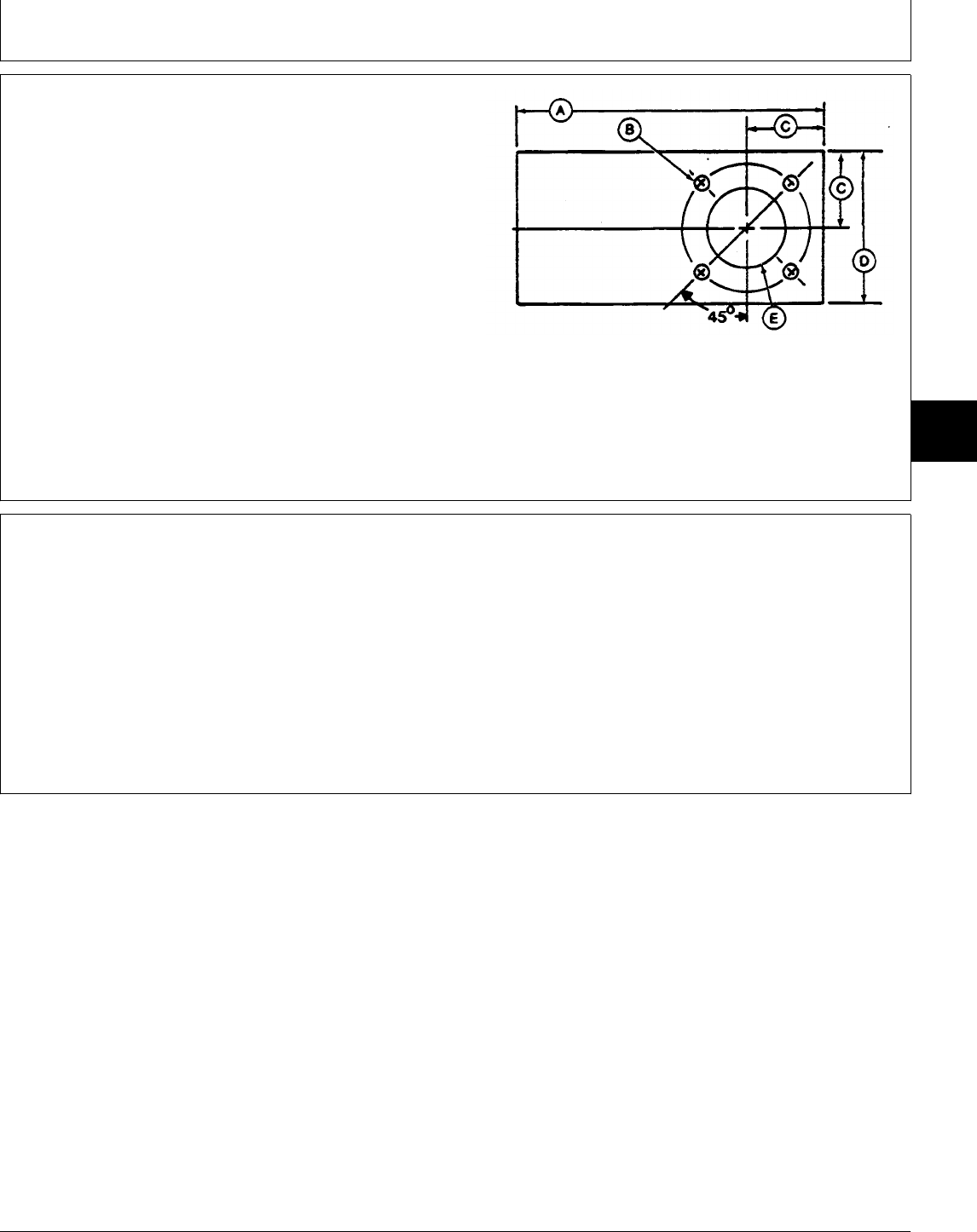
DFMX1 STEERING VALVE FIXTURE
Steering valve fixture is used to hold steering valve
during disassemby and assembly procedures.
Material required: One piece of 5 x 102 x 203 mm (3/16
x 4 x 8 in.) 1020 mild steel flat stock.
A—203 mm (8.0 in.)
B—9.5 mm (3/8 in.)*
C—51 mm (2.0 in.)
D—102 mm (4.0 in.)
E—51 mm (2.0 in.) Diameter Hole
*Four diameter holes equally spaced on a 83 mm (3-1/4 in.) diameter
circle.
M36877 -UN-28APR89
DFMX2 ALIGNMENT SHIMS
Alignment shims are used to align steering valve
metering assembly with drive plates during assembly.
Material required: Six pieces of 13 x 38 mm (1/2 x 1-1/2
in.) long, 0.18 mm (0.007 in.) thick shim stock.
MX,159129900,1 -19-13JUL95
MX,159129900,2 -19-13JUL95
Group 00
Dealer Fabricated Tools
TM1591 (15JUL95) 299-00-1 322,330,332 & 430 Lawn & Garden Tractors
030895
299
00
1

Dealer Fabricated Tools/DFMX2 Alignment Shims
TM1591 (15JUL95) 299-00-2 322,330,332 & 430 Lawn & Garden Tractors
030895
299
00
2

Page
A
Air Cleaner and Radiator Screen Check . . 220-05-2
Alternator Tests—322, 330 and 332
Regulated Current Output . . . . . . . . . 240-25-12
Regulated Voltage Output . . . . . . . . . 240-25-11
Unregulated Voltage Output . . . . . . . 240-25-11
Alternator Tests—430
Regulated Volt/Amp Output . . . . . . . . 240-25-13
Unreg. Current Output (SN —420468) 240-25-14
Unreg. Current Output (SN 420469— ) 240-25-15
B
Battery, Charge and Test . . . . . . . . . . . 240-20-4
Bleed Fuel Injection System
330 and 332 . . . . . . . . . . . . . . . . . . 220-11-8
430 . . . . . . . . . . . . . . . . . . . . . . . . 220-11-8
Bleed Hydraulic System . . . . . . . . . . . . 270-20-8
Brake Pedal Linkage
322 and 332 . . . . . . . . . . . . . . . . . . 60-10-10
330 . . . . . . . . . . . . . . . . . . . . . . . . 60-10-8
430 . . . . . . . . . . . . . . . . . . . . . . . . 60-10-14
Brake Switch
Neutral Start, Check . . . . . . . . . . . . . 240-05-3
Brakes
Adjust . . . . . . . . . . . . . . . . . . . . . . . 60-10-7
Install . . . . . . . . . . . . . . . . . . . . . . . 60-10-5
Remove . . . . . . . . . . . . . . . . . . . . . 60-10-2
C
Carburetor Idle Mixture Screw (322)
Adjustment . . . . . . . . . . . . . . . . . . . . 220-10-6
Charge Pump
Assemble . . . . . . . . . . . . . . . . . . . . 50-05-4
Disassemble and Inspect . . . . . . . . . . 50-05-3
Flow Test . . . . . . . . . . . . . . . . . . . . 250-15-8
Pressure Test . . . . . . . . . . . . . . . . . . 250-15-5
Remove and Install . . . . . . . . . . . . . . 50-05-2
Suction Line Check . . . . . . . . . . . . . . 250-15-6
Charge Relief Valve
Adjustment . . . . . . . . . . . . . . . . . . . . 250-15-6
Check . . . . . . . . . . . . . . . . . . . . . . . 250-15-6
Remove and Install . . . . . . . . . . . . . . 50-05-5
Charging System Tests—322, 330 and 332
Regulated Current Output . . . . . . . . . 240-25-12
Regulated Voltage Output . . . . . . . . . 240-25-11
Unregulated Voltage Output . . . . . . . 240-25-11
Page
Charging System Tests—430
Regulated Volt/Amp Output . . . . . . . . 240-25-13
Unreg. Current Output (SN —420468) 240-25-14
Unreg. Current Output (SN 420469— ) 240-25-15
Check Valve Debris Check . . . . . . . . . . 250-15-5
Choke Adjustment (322) . . . . . . . . . . . . 220-10-8
Choke Lever Check (Early 322) . . . . . . . 220-05-6
Compression Pressure Test
322 . . . . . . . . . . . . . . . . . . . . . . . 220-10-12
330, 332 and 430 . . . . . . . . . . . . . . 220-11-10
Coolant conditioner . . . . . . . . . . . . . . . 10-25-6
Coolant, engine . . . . . . . . . . . . . . . . . . 10-25-6
Cooling System
Leak Check . . . . . . . . . . . . . . . . . . . 220-05-2
Pressure Test—322 . . . . . . . . . . . . . 220-10-12
Pressure Test—330, 332 and 430 . . . 220-11-14
D
Dash Lamp Circuit
Check . . . . . . . . . . . . . . . . . . . . . . . 240-05-2
Tests . . . . . . . . . . . . . . . . . . . . . . . 240-20-6
Dealer Fabricated Tools
DFMX1 Steering Valve Fixture . . . . . . 299-00-1
DFMX2 Alignment Shims . . . . . . . . . . 299-00-1
Diesel Engine Oil . . . . . . . . . . . . . . . . . 10-25-5
Diesel fuel . . . . . . . . . . . . . . . . . . . . . 10-25-2
Differential
Assemble . . . . . . . . . . . . . . . . . . . . 50-15-12
Disassemble and Inspect . . . . . . . . . . 50-15-2
Remove and Install . . . . . . . . . . . . . . 50-15-2
Differential Lock (430)
Check . . . . . . . . . . . . . . . . . . . . . . . 250-05-3
Linkage Check . . . . . . . . . . . . . . . . 250-15-17
Differential Lock Linkage (430) . . . . . . . . 50-10-6
Drive Shaft
Assemble—322, 330 and 332 . . . . . . . 50-25-5
Assemble—430 . . . . . . . . . . . . . . . . . 50-26-7
Disassemble and Inspect—430 . . . . . . 50-26-5
Disassemble—322, 330 and 332 . . . . . 50-25-4
Inspect—322, 330 and 332 . . . . . . . . . 50-25-4
Remove and Install—322 and 332 . . . . 50-25-2
Remove and Install—330 . . . . . . . . . . 50-25-3
Remove and Install—430 (Early) . . . . . 50-26-1
Remove and Install—430 (Later) . . . . . 50-26-4
E
Index
Index-1 030895
INDX
1

Page
Electrical Checkout
Dash Lamps Circuit . . . . . . . . . . . . . . 240-05-2
Fuel Shutoff Solenoid Circuit . . . . . . . . 240-05-4
Fuel Transfer Pump Circuit . . . . . . . . . 240-05-5
Glow Plug Controller Circuit . . . . . . . . 240-05-5
Hour Meter . . . . . . . . . . . . . . . . . . . 240-05-6
Ignition Circuit (322) . . . . . . . . . . . . . 240-05-5
Lighting Circuit . . . . . . . . . . . . . . . . . 240-05-6
PTO Clutch and Lamp Circuits . . . . . . 240-05-2
Starting Circuit . . . . . . . . . . . . . . . . . 240-05-3
Electrical Component Location . . . . . . . . 240-15-1
Electrical Schematics
Light Circuit—All Machines . . . . . . . . 240-10-14
322 . . . . . . . . . . . . . . . . . . . . . . . . 240-10-3
330 . . . . . . . . . . . . . . . . . . . . . . . . 240-10-4
332 (S.N. 475001— ) . . . . . . . . . . . . 240-10-8
332 (S.N. —475000) . . . . . . . . . . . . 240-10-7
430 (S.N. 420469— ) . . . . . . . . . . . 240-10-12
430 (S.N. —420468) . . . . . . . . . . . 240-10-11
Electrical System Grounds, Verify
322 and 332 . . . . . . . . . . . . . . . . . . 240-20-1
330 . . . . . . . . . . . . . . . . . . . . . . . . 240-20-3
430 . . . . . . . . . . . . . . . . . . . . . . . . 240-20-3
Electrical—Component Location
Engine Coolant Temperature Switch . . . 240-15-4
Engine Oil Pressure Switch . . . . . . . . 240-15-3
Fuel Shutoff Solenoid—322 . . . . . . . . . 240-15-5
Fuel Shutoff Solenoid—332 and 430 . . 240-15-5
Fuel Transfer Pump—322, 330 and
332 . . . . . . . . . . . . . . . . . . . . . . . 240-15-5
Fuel Transfer Pump—430 . . . . . . . . . . 240-15-5
Glow Plug Control Module—330, 332 . . 240-15-1
Glow Plug Control Module—430 . . . . . 240-15-1
Ignition and Pulsar Coils (322) . . . . . . 240-15-7
Neutral Start Relay—322, 330, 332 . . . 240-15-1
Neutral Start Relay—430 . . . . . . . . . . 240-15-2
TDC Module—322, 330, 332 . . . . . . . . 240-15-1
TDC Module—430 . . . . . . . . . . . . . . . 240-15-2
TDC 2-Pin Connector—322 and 330 . . 240-15-2
TDC 2-Pin Connector—430 (Early) . . . . 240-15-2
TDC 3-Pin Connector—332 . . . . . . . . . 240-15-3
TDC 3-Pin Connector—430 (Later) . . . . 240-15-3
TDC 6-Pin Connector—332 . . . . . . . . . 240-15-3
TDC 6-Pin Connector—430 (Later) . . . . 240-15-3
TDC 8-Pin Connector—322 and 330 . . 240-15-2
TDC 8-Pin Connector—430 (Early) . . . . 240-15-2
Transistor Module (322) . . . . . . . . . . . 240-15-6
Transmission Neutral Start Switch . . . . 240-15-4
Voltage Regulator/Rectifier—322 . . . . . 240-15-6
Page
Electrical—Component Location—Continued
Voltage Regulator/Rectifier—330 . . . . . 240-15-6
Voltage Regulator/Rectifier—332 . . . . . 240-15-6
Water-In-Fuel Sensor (430) . . . . . . . . . 240-15-6
Electrical—Theory Of Operation
Charging Circuit—322, 330 and 332 . . 240-15-22
Charging Circuit—430 . . . . . . . . . . . 240-15-24
Engine Preheat Circuit—330, 332 . . . 240-15-30
Engine Preheat Circuit—430 . . . . . . . 240-15-30
Fuel Shutoff Circuit—322 . . . . . . . . . 240-15-10
Fuel Shutoff Circuit—332 . . . . . . . . . 240-15-28
Fuel Shutoff Circuit—430 (Early) . . . . 240-15-26
Fuel Shutoff Circuit—430 (Later) . . . . 240-15-28
Ignition Circuit (322) . . . . . . . . . . . . 240-15-10
Low Fuel Level Circuit—322, 332 . . . 240-15-34
Low Fuel Level Circuit—430 . . . . . . . 240-15-34
PTO Circuit—322, 330, 430 (Early) . . 240-15-14
PTO Circuit—332 and 430 (Later) . . . 240-15-18
Starting Circuit . . . . . . . . . . . . . . . . . 240-15-8
Water-In-Fuel Circuit (430) . . . . . . . . 240-15-32
Engine coolant . . . . . . . . . . . . . . . . . . 10-25-6
Engine coolant conditioner . . . . . . . . . . . 10-25-6
Engine Coolant Temperature Switch, Test . 240-25-1
Engine Oil
322 . . . . . . . . . . . . . . . . . . . . . . . . 10-25-4
330, 332, 430 . . . . . . . . . . . . . . . . . . 10-25-5
Engine—322
Oil Leak Check . . . . . . . . . . . . . . . . . 220-05-1
Oil Pressure Check . . . . . . . . . . . . . . 220-05-7
Oil Pressure Test . . . . . . . . . . . . . . 220-10-11
Performance Check . . . . . . . . . . . . . . 220-05-7
Remove and install . . . . . . . . . . . . . . 20-05-1
Repair . . . . . . . . . . . . . . . . . . . . . . . 20-05-1
Start Check . . . . . . . . . . . . . . . . . . . 220-05-6
Troubleshooting . . . . . . . . . . . . . . . . 220-10-1
Engine—330 and 332
Oil Leak Check . . . . . . . . . . . . . . . . . 220-05-1
Oil Pressure Check . . . . . . . . . . . . . . 220-05-7
Oil Pressure Test . . . . . . . . . . . . . . 220-11-11
Performance Check . . . . . . . . . . . . . . 220-05-7
Remove and install . . . . . . . . . . . . . . 20-06-1
Repair . . . . . . . . . . . . . . . . . . . . . . . 20-06-1
Start Check . . . . . . . . . . . . . . . . . . . 220-05-6
Troubleshooting . . . . . . . . . . . . . . . . 220-11-2
Engine—430
Install . . . . . . . . . . . . . . . . . . . . . . . 20-06-8
Oil Leak Check . . . . . . . . . . . . . . . . . 220-05-1
Oil Pressure Check . . . . . . . . . . . . . . 220-05-7
Oil Pressure Test . . . . . . . . . . . . . . 220-11-11
Performance Check . . . . . . . . . . . . . . 220-05-7
Index
Index-2 030895
INDX
2

Page
Engine—430—Continued
Remove . . . . . . . . . . . . . . . . . . . . . 20-06-4
Repair . . . . . . . . . . . . . . . . . . . . . . . 20-06-1
Start Check . . . . . . . . . . . . . . . . . . . 220-05-6
Troubleshooting . . . . . . . . . . . . . . . . 220-11-2
F
Fan and Belt Check . . . . . . . . . . . . . . . 220-05-3
Front Axle Spindles
Inspect and Replace Bushings . . . . . . 80-05-11
Remove and Install . . . . . . . . . . . . . . 80-05-9
Front Axle—322, 330 and 332
Inspect and Replace Pivot Bushings . . . 80-05-2
Remove and Install . . . . . . . . . . . . . . 80-05-1
Front Axle—430
Assemble Pivot Pin . . . . . . . . . . . . . . 80-05-6
Disassemble and Inspect Pivot Pin . . . 80-05-5
Install . . . . . . . . . . . . . . . . . . . . . . . 80-05-7
Remove . . . . . . . . . . . . . . . . . . . . . 80-05-3
Front PTO Clutch
Disassemble, Inspect and Assemble . . . 40-05-4
Install—322, 330 and 332 . . . . . . . . . . 40-05-6
Install—430 . . . . . . . . . . . . . . . . . . . 40-05-7
Remove—322, 330 and 332 . . . . . . . . 40-05-1
Remove—430 . . . . . . . . . . . . . . . . . 40-05-2
Fuel
Diesel . . . . . . . . . . . . . . . . . . . . . . . 10-25-2
Gasoline . . . . . . . . . . . . . . . . . . . . . 10-25-1
Storage . . . . . . . . . . . . . . . . . . . . . . 10-25-3
Fuel Controller Adjustment
330 and 332 . . . . . . . . . . . . . . . . . 220-11-15
430 . . . . . . . . . . . . . . . . . . . . . . . 220-11-15
Fuel Shutoff Lever Check (330) . . . . . . . 220-05-7
Fuel Shutoff Solenoid (322, 332, 430)
Circuit Check . . . . . . . . . . . . . . . . . . 240-05-4
Circuit Test . . . . . . . . . . . . . . . . . . 240-20-30
Seat Switch, Check . . . . . . . . . . . . . . 240-05-4
Fuel Shutoff Solenoid Adjustment
332 and 430 (SN 420469— ) . . . . . . 240-25-9
430 (SN —420468) . . . . . . . . . . . . . 240-25-9
Fuel System Check
322 . . . . . . . . . . . . . . . . . . . . . . . . 220-05-5
330, 332 and 430 . . . . . . . . . . . . . . . 220-05-5
Fuel Transfer Pump
Circuit Check . . . . . . . . . . . . . . . . . . 240-05-5
Circuit Tests . . . . . . . . . . . . . . . . . . 240-20-35
Fuel Transfer Pump Test
322 . . . . . . . . . . . . . . . . . . . . . . . . 220-10-8
330, 332 and 430 . . . . . . . . . . . . . . . 220-11-7
Page
Fuse
Short In 10-amp Circuit . . . . . . . . . . 240-25-15
Short In 25-Amp Circuit . . . . . . . . . . 240-25-15
G
Gasoline fuel . . . . . . . . . . . . . . . . . . . . 10-25-1
Glow Plug Controller Circuit
Check (330, 332, 430) . . . . . . . . . . . . 240-05-5
Test (330, 332, 430) . . . . . . . . . . . . 240-20-37
Glow Plug Test (330, 332, 430) . . . . . . . 240-25-3
Governor Linkage—322
Adjustment . . . . . . . . . . . . . . . . . . . . 220-10-6
Check . . . . . . . . . . . . . . . . . . . . . . . 220-05-4
Governor Linkage—330, 332 and 430
Check . . . . . . . . . . . . . . . . . . . . . . . 220-05-4
Grease
Extreme pressure and multipurpose . . . 10-25-8
H
Head and Tail Light, Circuit Test . . . . . 240-20-48
Hour Meter
Check . . . . . . . . . . . . . . . . . . . . . . . 240-05-6
Circuit Test . . . . . . . . . . . . . . . . . . 240-20-47
Hydraulic circuit symbols . . . . . . . . . . . . 270-10-2
Hydraulic Control Valve
Assemble—Single-Spool . . . . . . . . . . . 70-05-9
Assemble—Three-Spool . . . . . . . . . . . 70-05-12
Assemble—Two-Spool . . . . . . . . . . . . 70-05-10
Disassemble & Inspect—Single-Spool . . 70-05-9
Disassemble & Inspect—Three-Spool . . 70-05-12
Disassemble & Inspect—Two-Spool . . . 70-05-10
Leakage Test . . . . . . . . . . . . . . . . . . 270-20-6
Remove and Install—322 and 332 . . . . 70-05-2
Remove and Install—330 . . . . . . . . . . 70-05-3
Remove and Install—430 . . . . . . . . . . 70-05-6
Hydraulic oil . . . . . . . . . . . . . . . . . . . . 10-25-7
Hydraulic Oil Warm-Up Procedure . . . . . 250-15-9,
260-15-4, 270-20-5
Hydraulic Schematics
322 and 332 . . . . . . . . . . . . . . . . . . 270-10-6
330 . . . . . . . . . . . . . . . . . . . . . . . . 270-10-5
430 . . . . . . . . . . . . . . . . . . . . . . . . 270-10-9
Hydraulic System
Bleed Procedure . . . . . . . . . . . . . . . . 270-20-8
Checkout . . . . . . . . . . . . . . . . . . . . . 270-05-1
Control Valve Leakage Test . . . . . . . . 270-20-6
Rockshaft Cylinder Leakage Test . . . . . 270-20-5
Troubleshooting . . . . . . . . . . . . . . . . 270-20-2
Index
Index-3 030895
INDX
3

Page
Hydraulics—Lift System Operation
Four-Position Spool . . . . . . . . . . . . . . 270-15-2
Three-Position Spool . . . . . . . . . . . . . 270-15-1
Hydrostatic Lever
Friction Adjustment . . . . . . . . . . . . . 250-15-10
Friction Check . . . . . . . . . . . . . . . . . 250-05-1
I
Idle Speed Adjustment
322 . . . . . . . . . . . . . . . . . . . . . . . . 220-10-6
330, 332 and 430 . . . . . . . . . . . . . . 220-11-12
Ignition Circuit (322)
Check . . . . . . . . . . . . . . . . . . . . . . . 240-05-5
Seat Switch, Check . . . . . . . . . . . . . . 240-05-6
Tests . . . . . . . . . . . . . . . . . . . . . . 240-20-38
Ignition Spark Test (322) . . . . . . . . . . . 220-10-11
Implement Relief Valve
Adjustment . . . . . . . . . . . . . . . . . . . . 250-15-7
Check . . . . . . . . . . . . . . . . . . . . . . . 250-15-7
Pressure Test . . . . . . . . . . . . . . . . . . 250-15-7
Remove and Install . . . . . . . . . . . . . . 50-05-6
Inch torque values . . . . . . . . . . . . . . . . 10-15-5
K
Key Switch Test
322, 330 and 332 . . . . . . . . . . . . . . . 240-25-4
430 . . . . . . . . . . . . . . . . . . . . . . . . 240-25-5
L
Lamp Circuit, Dash
Check . . . . . . . . . . . . . . . . . . . . . . . 240-05-2
Tests . . . . . . . . . . . . . . . . . . . . . . . 240-20-6
Leakage Test
Hydraulic Control Valve . . . . . . . . . . . 270-20-6
Rockshaft Cylinder . . . . . . . . . . . . . . 270-20-5
Lighting Circuit, Check . . . . . . . . . . . . . 240-05-6
Low Fuel Sensor, Test
322, 332 and 430 (SN 475001— ) . . . 240-25-1
430 (SN —475000) . . . . . . . . . . . . . 240-25-2
Lubricant
Alternative . . . . . . . . . . . . . . . . . . . . 10-25-9
Mixing . . . . . . . . . . . . . . . . . . . . . . . 10-25-9
Storage . . . . . . . . . . . . . . . . . . . . . . 10-25-9
Synthetic . . . . . . . . . . . . . . . . . . . . . 10-25-9
Page
M
Machine Specifications
322 and 330 . . . . . . . . . . . . . . . . . . 10-10-1
332 and 430 . . . . . . . . . . . . . . . . . . 10-10-4
Metric torque values . . . . . . . . . . . . . . . 10-15-4
Mixing lubricants . . . . . . . . . . . . . . . . . 10-25-9
Mower Blade Jack Sheaves
46 and 50-Inch Mower . . . . . . . . . . . . 80-10-4
Mower Blade Spindles
Early 60-Inch and 260 Rotary Mower . . 80-10-2
Later 60-Inch and 260 Rotary Mower . . 80-10-3
38 (Early), 46 and 50-Inch Mower . . . . 80-10-1
38-Inch Mower (Later) . . . . . . . . . . . . 80-10-1
Mower Deck Gear Case Oil . . . . . . . . . . 10-25-8
Mower Gear Case—Early 60-Inch
Assemble . . . . . . . . . . . . . . . . . . . . 80-15-14
Disassemble and Inspect . . . . . . . . . . 80-15-10
Mower Gear Case—Later 60-Inch
Assemble . . . . . . . . . . . . . . . . . . . . 80-15-23
Disassemble and Inspect . . . . . . . . . . 80-15-19
Mower Gear Case—260 Rotary Mower
Assemble . . . . . . . . . . . . . . . . . . . . 80-15-32
Disassemble and Inspect . . . . . . . . . . 80-15-27
Mower Gear Case—50-Inch
Assemble . . . . . . . . . . . . . . . . . . . . 80-15-6
Disassemble and Inspect . . . . . . . . . . 80-15-1
N
Neutral Adjustment
Later 322, 332 and 430 . . . . . . . . . . 250-15-14
330 and Early 322, 332, 430 . . . . . . 250-15-13
Neutral Return Check . . . . . . . . . . . . . . 250-05-2
Neutral Return Linkage
322 and 332 . . . . . . . . . . . . . . . . . . 60-10-10
330 . . . . . . . . . . . . . . . . . . . . . . . . 60-10-8
430 . . . . . . . . . . . . . . . . . . . . . . . . 60-10-14
Neutral Return Linkage Adjustment
Later 322, 332 and 430 . . . . . . . . . . 250-15-14
330, and Early 322, 332, 430 . . . . . . 250-15-10
Neutral Start Circuit, Check
Brake Switch . . . . . . . . . . . . . . . . . . 240-05-3
PTO Switch . . . . . . . . . . . . . . . . . . . 240-05-4
Transmission Switch . . . . . . . . . . . . . 240-05-4
Neutral Start Relay, Test . . . . . . . . . . . . 240-25-5
Index
Index-4 030895
INDX
4

Page
O
O-ring boss fittings . . . . . . . . . . . . . . . . 10-15-7
Oil
Engine . . . . . . . . . . . . . . . . . . . . . . 10-25-4
Hydraulic . . . . . . . . . . . . . . . . . . . . . 10-25-7
Mower Deck Gear Case . . . . . . . . . . . 10-25-8
Transmission . . . . . . . . . . . . . . . . . . 10-25-7
P
Park Brake Lever, Inspect and Repair . . . 60-10-19
PTO Clutch Adjustment, Check . . . . . . . 240-25-3
PTO Clutch and Lamp Circuit
Check . . . . . . . . . . . . . . . . . . . . . . . 240-05-2
Seat Switch, Check . . . . . . . . . . . . . . 240-05-3
Tests . . . . . . . . . . . . . . . . . . . . . . 240-20-18
PTO Clutch, Front
Disassemble, Inspect and Assemble . . . 40-05-4
Install—322, 330 and 332 . . . . . . . . . . 40-05-6
Install—430 . . . . . . . . . . . . . . . . . . . 40-05-7
Remove—322, 330 and 332 . . . . . . . . 40-05-1
Remove—430 . . . . . . . . . . . . . . . . . 40-05-2
PTO Switch
Neutral Start, Check . . . . . . . . . . . . . 240-05-4
R
Radiator Bubble Test
322 . . . . . . . . . . . . . . . . . . . . . . . . 220-10-5
330, 332 and 430 . . . . . . . . . . . . . . . 220-11-6
Rear Axle
Install . . . . . . . . . . . . . . . . . . . . . . . 50-20-4
Remove . . . . . . . . . . . . . . . . . . . . . 50-20-1
Repair specifications . . . . . . . . . . . . . . . 10-15-1
Rockshaft Cylinder Leakage Test . . . . . . 270-20-5
S
Seat Switch
Check For Fuel Shutoff Solenoid . . . . . 240-05-4
Check For Ignition (322) . . . . . . . . . . . 240-05-6
Check For PTO . . . . . . . . . . . . . . . . 240-05-3
Sensor Tests
Glow Plug (330, 332, 430) . . . . . . . . . 240-25-3
Low Fuel—322 and 332 . . . . . . . . . . . 240-25-1
Low Fuel—430 (SN —475000) . . . . . 240-25-2
Low Fuel—430 (SN 475001— ) . . . . . 240-25-1
Water-In-Fuel (430) . . . . . . . . . . . . . . 240-25-3
Page
Serial Numbers
Control Valve . . . . . . . . . . . . . . . . . . 10-30-2
Differential . . . . . . . . . . . . . . . . . . . . 10-30-2
Engine . . . . . . . . . . . . . . . . . . . . . . 10-30-1
Product Identification . . . . . . . . . . . . . 10-30-1
Transmission . . . . . . . . . . . . . . . . . . 10-30-1
Service Park Brake Check . . . . . . . . . . . 260-05-3
Short Circuits
10-Amp Fuse . . . . . . . . . . . . . . . . . 240-25-15
25-Amp Fuse . . . . . . . . . . . . . . . . . 240-25-15
Shutoff Solenoid, Fuel (322, 332, 430)
Circuit Check . . . . . . . . . . . . . . . . . . 240-05-4
Seat Switch, Check . . . . . . . . . . . . . . 240-05-4
Specifications
Machine—322 and 330 . . . . . . . . . . . 10-10-1
Machine—332 and 430 . . . . . . . . . . . 10-10-4
Repair . . . . . . . . . . . . . . . . . . . . . . . 10-15-1
Test and adjustment . . . . . . . . . . . . . 10-20-1
Speed Reduction Check (322, 332 and
430) . . . . . . . . . . . . . . . . . . . . . . . . 250-05-2
Starter Tests
Amp Draw . . . . . . . . . . . . . . . . . . . . 240-25-6
No Load Amp Draw—322, 330 and
332 . . . . . . . . . . . . . . . . . . . . . . . 240-25-8
No Load Amp Draw—430 . . . . . . . . . . 240-25-9
No Load RPM—322, 330 and 332 . . . . 240-25-7
No Load RPM—430 . . . . . . . . . . . . . 240-25-9
No Load Running—322, 330 and 332 . . 240-25-7
No Load Running—430 . . . . . . . . . . . 240-25-8
Starting Circuit
Brake Switch, Check . . . . . . . . . . . . . 240-05-3
Circuit Test . . . . . . . . . . . . . . . . . . 240-20-24
PTO Switch, Check . . . . . . . . . . . . . . 240-05-4
Starting Circuit, Check . . . . . . . . . . . . 240-05-3
Transmission Switch, Check . . . . . . . . 240-05-4
Steering Column—322 and 332
Assemble . . . . . . . . . . . . . . . . . . . . 60-06-15
Disassemble and Inspect . . . . . . . . . . 60-06-6
Remove and Install . . . . . . . . . . . . . . 60-06-2
Steering Column—430
Assemble . . . . . . . . . . . . . . . . . . . . 60-06-15
Disassemble and Inspect . . . . . . . . . . 60-06-6
Remove and Install . . . . . . . . . . . . . . 60-06-4
Steering Cylinder (322, 332 and 430)
Remove and Install . . . . . . . . . . . . . . 60-06-25
Steering Gearbox—330
Assemble . . . . . . . . . . . . . . . . . . . . 60-05-12
Disassemble and Inspect . . . . . . . . . . 60-05-5
Remove and Install . . . . . . . . . . . . . . 60-05-1
Index
Index-5 030895
INDX
5

Page
Steering Shaft—330
Assemble . . . . . . . . . . . . . . . . . . . . 60-05-12
Disassemble and Inspect . . . . . . . . . . 60-05-5
Remove and Install . . . . . . . . . . . . . . 60-05-1
Steering System
Check (322, 332 and 430) . . . . . . . . . 260-05-2
Leakage Test . . . . . . . . . . . . . . . . . . 260-15-5
Oil Leak Check (322, 332 and 430) . . . 260-05-1
Troubleshooting . . . . . . . . . . . . . . . . 260-15-1
Steering Valve/System Operation . . . . . . 260-10-2
Steering Valve—322 and 332
Assemble . . . . . . . . . . . . . . . . . . . . 60-06-15
Disassemble and Inspect . . . . . . . . . . 60-06-6
Leakage Test . . . . . . . . . . . . . . . . . . 260-15-5
Neutral Check . . . . . . . . . . . . . . . . . 250-15-9
Remove and Install . . . . . . . . . . . . . . 60-06-2
Steering Valve—430
Assemble . . . . . . . . . . . . . . . . . . . . 60-06-15
Disassemble and Inspect . . . . . . . . . . 60-06-6
Leakage Test . . . . . . . . . . . . . . . . . . 260-15-5
Neutral Check . . . . . . . . . . . . . . . . . 250-15-9
Remove and Install . . . . . . . . . . . . . . 60-06-4
Storing lubricants . . . . . . . . . . . . . . . . . 10-25-9
Synthetic Lubricants . . . . . . . . . . . . . . . 10-25-9
T
Test and adjustment specifications . . . . . 10-20-1
Throttle Cable Adjustment
322 . . . . . . . . . . . . . . . . . . . . . . . . 220-10-7
330, 332 and 430 . . . . . . . . . . . . . . . 220-11-6
Throttle Lever—322
Adjustment . . . . . . . . . . . . . . . . . . . . 220-10-5
Check . . . . . . . . . . . . . . . . . . . . . . . 220-05-3
Throttle Lever—330, 332 and 430
Adjustment . . . . . . . . . . . . . . . . . . . . 220-11-6
Check . . . . . . . . . . . . . . . . . . . . . . . 220-05-3
Toe-In, Adjust . . . . . . . . . . . . . . . . . . . 80-05-12
Torque values
Inch . . . . . . . . . . . . . . . . . . . . . . . . 10-15-5
Metric . . . . . . . . . . . . . . . . . . . . . . . 10-15-4
Metric—Grade 7 . . . . . . . . . . . . . . . . 10-15-6
O-Ring boss fitting . . . . . . . . . . . . . . 10-15-7
Transmission
Assemble Cover . . . . . . . . . . . . . . . . 50-05-22
Assemble Pump and Motor . . . . . . . . . 50-05-21
Assemble Pump and Motor Housing . . . 50-05-19
Disassemble Cover . . . . . . . . . . . . . . 50-05-11
Disassemble Pump and Motor . . . . . . . 50-05-14
Page
Transmission—Continued
Disassemble Pump and Motor Housing . 50-05-16
Drive Check . . . . . . . . . . . . . . . . . . . 250-05-2
Install . . . . . . . . . . . . . . . . . . . . . . . 50-05-25
Neutral Check . . . . . . . . . . . . . . . . . 250-05-1
Oil Leak Check . . . . . . . . . . . . . . . . . 250-05-1
Remove . . . . . . . . . . . . . . . . . . . . . 50-05-6
Theory of Operation . . . . . . . . . . . . . 250-10-2
Troubleshooting . . . . . . . . . . . . . . . . 250-15-1
Transmission Control Linkage—322, 332
Version 1 . . . . . . . . . . . . . . . . . . . . . 50-10-2
Version 2 . . . . . . . . . . . . . . . . . . . . . 50-10-4
Version 3 . . . . . . . . . . . . . . . . . . . . . 50-10-5
Transmission Control Linkage—330 . . . . . 50-10-1
Transmission Control Linkage—430
Version 1 . . . . . . . . . . . . . . . . . . . . . 50-10-3
Version 2 . . . . . . . . . . . . . . . . . . . . . 50-10-4
Version 3 . . . . . . . . . . . . . . . . . . . . . 50-10-5
Transmission oil . . . . . . . . . . . . . . . . . . 10-25-7
Transmission Switch
Neutral Start, Check . . . . . . . . . . . . . 240-05-4
Turn Brake Check (322, 332 and 430) . . . 260-05-3
Two-Speed Axle (430)
Lever Check . . . . . . . . . . . . . . . . . . 250-05-3
Lever Linkage Check . . . . . . . . . . . . 250-15-17
Two-Speed Control Linkage (430) . . . . . . 50-10-6
W
Water-In-Fuel Sensor, Test (430) . . . . . . 240-25-3
Welch Plug Location Check . . . . . . . . . . 250-15-8
Wheel Bearings, Inspect and Replace . . . 80-05-12
Index
Index-6 030895
INDX
6
