Telc2b3.tmp TM 5 6115 545 12 GENERATOR DIESEL ENGINE DRIVEN, TACTICAL SKID MTD., 60 KW, 3 PHASE, 4 WIR 120/208 AND 240/416 VOLTS, DOD MEP 006A, UTILITY CLASS, (NSN 00 118 1243) 105A, PRECISE 50/60 (6115 1252)
TM-5-6115-545-12 GENERATOR DIESEL ENGINE DRIVEN, TACTICAL SKID MTD., 60 KW, 3 PHASE, 4 WIR 120/208 AND 240/416 VOLTS, DOD MEP-006A, UTILITY CLASS, 5 (NSN 6115-00-118-1243) DOD MEP-105A, PRECISE CLASS, 50/60 (6115-00-118-1252) DOD MEP- TM-5-6115-545-12 Military Generators == MEP 105A
TM-5-6115-545-12_Operator_Maintenance TM-5-6115-545-12_Operator_Maintenance Military Generators == MEP 006A
User Manual: TM-5-6115-545-12 GENERATOR DIESEL ENGINE DRIVEN, TACTICAL SKID MTD., 60 KW, 3 PHASE, 4 WIR 120/208 AND 240/416 VOLTS, DOD MEP-006A, UTILITY CLASS, 5 (NSN 6115-00-118-1243) DOD MEP-105A, PRECISE CLASS, 50/60 (6115-00-118-1252) DOD MEP- Military Generators == MEP 115A
Open the PDF directly: View PDF ![]() .
.
Page Count: 325 [warning: Documents this large are best viewed by clicking the View PDF Link!]
- TABLE OF CONTENTS
- LOI
- LOT
- LAST CHANGE
- WARNINGS
- CHAPTERS
- CHAPTER 1
- CHAPTER 2
- CHAPTER 3
- PARA 3-1
- PARA 3-2
- PARA 3-3
- PARA 3-4
- PARA 3-5
- PARA 3-6
- PARA 3-7
- PARA 3-8
- PARA 3-9
- PARA 3-10
- PARA 3-11
- PARA 3-12
- PARA 3-14
- PARA 3-15
- PARA 3-16
- PARA 3-17
- PARA 3-18
- PARA 3-19
- PARA 3-20
- PARA 3-21
- PARA 3-22
- PARA 3-24
- PARA 3-25
- PARA 3-26
- PARA 3-27
- PARA 3-28
- PARA 3-29
- PARA 3-30
- PARA 3-31
- PARA 3-32
- PARA 3-33
- PARA 3-34
- PARA 3-35
- PARA 3-36
- PARA 3-37
- PARA 3-38
- PARA 3-39
- PARA 3-40
- PARA 3-41
- PARA 3-42
- PARA 3-43
- PARA 3-44
- PARA 3-45
- PARA 3-46
- PARA 3-47
- PARA 3-48
- PARA 3-49
- PARA 3-50
- PARA 3-51
- PARA 3-52
- PARA 3-53
- PARA 3-54
- PARA 3-55
- PARA 3-56
- PARA 3-57
- PARA 3-58
- PARA 3-59
- PARA 3-60
- PARA 3-61
- PARA 3-62
- PARA 3-63
- PARA 3-64
- PARA 3-65
- PARA 3-66
- PARA 3-67
- PARA 3-68
- PARA 3-69
- PARA 3-70
- PARA 3-71
- PARA 3-72
- PARA 3-73
- PARA 3-74
- PARA 3-75
- PARA 3-76
- PARA 3-77
- PARA 3-78
- PARA 3-79
- PARA 3-80
- PARA 3-81
- PARA 3-82
- PARA 3-83
- PARA 3-84
- PARA 3-85
- PARA 3-86
- PARA 3-87
- PARA 3-88
- PARA 3-89
- PARA 3-90
- PARA 3-91
- PARA 3-95
- PARA 3-96
- PARA 3-97
- PARA 3-98
- PARA 3-99
- PARA 3-100
- PARA 3-101
- PARA 3-102
- PARA 3-103
- PARA 3-104
- PARA 3-105
- PARA 3-106
- PARA 3-107
- PARA 3-108
- PARA 3-109
- PARA 3-110
- PARA 3-111
- PARA 3-112
- PARA 3-113
- PARA 3-114
- PARA 3-115
- PARA 3-116
- PARA 3-117
- PARA 3-118
- PARA 3-119
- PARA 3-120
- PARA 3-121
- PARA 3-122
- PARA 3-123
- PARA 3-124
- PARA 3-125
- PARA 3-126
- PARA 3-127
- PARA 3-128
- PARA 3-129
- PARA 3-130
- PARA 3-131
- PARA 3-132
- PARA 3-133
- PARA 3-134
- PARA 3-135
- PARA 3-136
- PARA 3-137
- PARA 3-138
- PARA 3-139
- PARA 3-140
- PARA 3-141
- PARA 3-142
- PARA 3-143
- PARA 3-144
- PARA 3-145
- PARA 3-146
- PARA 3-146.1
- PARA 3-147
- PARA 3-148
- PARA 3-149
- PARA 3-150
- PARA 3-151
- PARA 3-152
- PARA 3-153
- PARA 3-154
- PARA 3-155
- PARA 3-156
- PARA 3-157
- PARA 3-158
- PARA 3-159
- PARA 3-160
- PARA 3-161
- PARA 3-162
- PARA 3-163
- PARA 3-164
- PARA 3-165
- PARA 3-166
- PARA 3-167
- PARA 3-168
- PARA 3-169
- PARA 3-170
- PARA 3-171
- PARA 3-172
- PARA 3-173
- PARA 3-174
- PARA 3-175
- PARA 3-176
- PARA 3-177
- PARA 3-178
- PARA 3-179
- PARA 3-180
- PARA 3-181
- PARA 3-182
- PARA 3-183
- PARA 3-184
- PARA 3-185
- PARA 3-186
- PARA 3-187
- PARA 3-188
- PARA 3-189
- PARA 3-190
- PARA 3-191
- PARA 3-192
- PARA 3-193
- PARA 3-194
- PARA 3-195
- PARA 3-196
- PARA 3-197
- PARA 3-198
- PARA 3-199
- PARA 3-200
- PARA 3-201
- PARA 3-202
- PARA 3-203
- PARA 3-204
- PARA 3-205
- PARA 3-206
- PARA 3-207
- PARA 3-208
- PARA 3-209
- PARA 3-210
- PARA 3-211
- PARA 3-212
- PARA 3-213
- PARA 3-214
- PARA 3-215
- PARA 3-216
- PARA 3-217
- PARA 3-218
- PARA 3-219
- PARA 3-220
- PARA 3-221
- PARA 3-222
- PARA 3-223
- PARA 3-224
- PARA 3-225
- PARA 3-226
- PARA 3-227
- PARA 3-228
- PARA 3-229
- CHAPTER 4
- PARA 4-1
- PARA 4-2
- PARA 4-3
- PARA 4-4
- PARA 4-5
- PARA 4-6
- PARA 4-7
- PARA 4-8
- PARA 4-9
- PARA 4-10
- PARA 4-11
- PARA 4-12
- PARA 4-13
- PARA 4-14
- PARA 4-15
- PARA 4-16
- PARA 4-17
- PARA 4-18
- PARA 4-19
- PARA 4-20
- PARA 4-21
- PARA 4-22
- PARA 4-23
- PARA 4-24
- PARA 4-25
- PARA 4-26
- PARA 4-27
- PARA 4-28
- PARA 4-29
- PARA 4-30
- PARA 4-31
- PARA 4-32
- PARA 4-33
- PARA 4-34
- PARA 4-35
- PARA 4-36
- PARA 4-37
- PARA 4-38
- PARA 4-39
- PARA 4-40
- PARA 4-41
- PARA 4-42
- PARA 4-43
- PARA 4-44
- PARA 4-45
- PARA 4-46
- PARA 4-47
- PARA 4-48
- PARA 4-49
- FIGURES
- FIGURE 1-1
- FIGURE 1-2
- FIGURE 1-3
- FIGURE 1-4
- FIGURE 1-5
- FIGURE 1-6
- FIGURE 1-7
- FIGURE 1-8
- FIGURE 1-9
- FIGURE 1-10
- FIGURE 1-11
- FIGURE 1-12
- FIGURE 1-13
- FIGURE 1-14
- FIGURE 1-15
- FIGURE 1-16
- FIGURE 1-17
- FIGURE 1-18
- FIGURE 1-19
- FIGURE 1-20
- FIGURE 1-21
- FIGURE 1-22
- FIGURE 1-23
- FIGURE 1-24
- FIGURE 1-25
- FIGURE 1-26
- FIGURE 1-27
- FIGURE 1-28
- FIGURE 1-29
- FIGURE 1-30
- FIGURE 2-1A
- FIGURE 2-1
- FIGURE 2-2
- FIGURE 2-3
- FIGURE 2-3.2
- FIGURE 2-4
- FIGURE 2-5
- FIGURE 2-6
- FIGURE 2-7
- FIGURE 2-8
- FIGURE 2-9
- FIGURE 2-10
- FIGURE 2-11
- FIGURE 2-12
- FIGURE 2-13
- FIGURE 2-14
- FIGURE 3-1
- FIGURE 3-2
- FIGURE 3-3
- FIGURE 3-4
- FIGURE 3-5
- FIGURE 3-6
- FIGURE 3-7
- FIGURE 3-8
- FIGURE 3-9
- FIGURE 3-10
- FIGURE 3-11
- FIGURE 3-12
- FIGURE 3-12.1
- FIGURE 3-13
- FIGURE 3-15
- FIGURE 3-16
- FIGURE 3-17
- FIGURE 3-18
- FIGURE 3-19
- FIGURE 3-20
- FIGURE 3-21
- FIGURE 3-22
- FIGURE 3-23
- FIGURE 3-24
- FIGURE 3-24.1
- FIGURE 3-24.2
- FIGURE 3-25
- FIGURE 3-26
- FIGURE 3-27
- FIGURE 3-28
- FIGURE 3-29
- FIGURE 3-30
- FIGURE 3-31
- FIGURE 3-32
- FIGURE 3-33
- FIGURE 3-34
- FIGURE 3-35
- FIGURE 3-36
- FIGURE 3-37
- FIGURE 3-38
- FIGURE 3-38.1
- FIGURE 3-39
- FIGURE 3-40
- FIGURE 3-41
- FIGURE 3-42
- FIGURE 3-43
- FIGURE 3-44
- FIGURE 3-45
- FIGURE 3-46
- FIGURE 3-47
- FIGURE 3-48
- FIGURE 3-49
- FIGURE 3-50
- FIGURE 3-51
- FIGURE 3-52
- FIGURE 3-53
- FIGURE 4-1
- FIGURE 4-2
- FIGURE 4-3
- FIGURE 4-4
- FIGURE 4-5
- FIGURE 4-6
- FIGURE 4-7
- FIGURE 4-8
- FIGURE 4-9
- FIGURE 4-10
- FIGURE 4-11
- FIGURE 4-12
- FIGURE 4-13
- FIGURE 4-14
- FIGURE 4-15
- FIGURE 4-16
- FIGURE 4-17
- FIGURE 4-18
- TABLES
- APPENDICES
- INDEX
- PAGES
- PAGE I
- PAGE II
- PAGE III
- PAGE IV
- PAGE 1-1
- PAGE 1-2
- PAGE 1-3
- PAGE 1-4
- PAGE 1-5
- PAGE 1-6
- PAGE 1-7
- PAGE 1-8
- PAGE 1-9
- PAGE 1-10
- PAGE 1-11
- PAGE 1-12
- PAGE 1-13
- PAGE 1-14
- PAGE 1-15
- PAGE 1-17
- PAGE 1-19
- PAGE 1-21
- PAGE 1-23
- PAGE 1-25
- PAGE 1-26.1
- PAGE 1-27
- PAGE 1-29
- PAGE 1-31
- PAGE 1-33
- PAGE 1-34
- PAGE 1-35
- PAGE 1-37
- PAGE 1-39
- PAGE 1-40
- PAGE 1-41
- PAGE 1-43
- PAGE 1-45
- PAGE 1-47
- PAGE 1-49
- PAGE 2-1
- PAGE 2-2
- PAGE 2-4
- PAGE 2-5
- PAGE 2-8
- PAGE 2-9
- PAGE 2-10
- PAGE 2-11
- PAGE 2-14
- PAGE 2-17
- PAGE 2-18
- PAGE 2-19
- PAGE 2-21
- PAGE 2-23
- PAGE 2-24
- PAGE 2-25
- PAGE 2-27
- PAGE 2-28
- PAGE 2-30
- PAGE 2-32
- PAGE 2-33
- PAGE 2-34
- PAGE 3-1
- PAGE 3-2
- PAGE 3-3
- PAGE 3-4
- PAGE 3-5
- PAGE 3-6
- PAGE 3-7
- PAGE 3-8
- PAGE 3-8.1
- PAGE 3-9
- PAGE 3-10
- PAGE 3-11
- PAGE 3-12
- PAGE 3-13
- PAGE 3-14
- PAGE 3-15
- PAGE 3-16
- PAGE 3-17
- PAGE 3-18
- PAGE 3-19
- PAGE 3-20
- PAGE 3-21
- PAGE 3-22
- PAGE 3-23
- PAGE 3-24
- PAGE 3-25
- PAGE 3-26
- PAGE 3-27
- PAGE 3-28
- PAGE 3-29
- PAGE 3-30
- PAGE 3-31
- PAGE 3-32
- PAGE 3-33
- PAGE 3-34
- PAGE 3-35
- PAGE 3-36
- PAGE 3-37
- PAGE 3-38
- PAGE 3-39
- PAGE 3-40
- PAGE 3-41
- PAGE 3-42
- PAGE 3-43
- PAGE 3-44
- PAGE 3-45
- PAGE 3-46
- PAGE 3-47
- PAGE 3-48
- PAGE 3-49
- PAGE 3-51
- PAGE 3-53
- PAGE 3-55
- PAGE 3-57
- PAGE 3-59
- PAGE 3-60
- PAGE 3-61
- PAGE 3-62
- PAGE 3-63
- PAGE 3-65
- PAGE 3-67
- PAGE 3-68
- PAGE 3-69
- PAGE 3-70
- PAGE 3-71
- PAGE 3-72
- PAGE 3-72.1
- PAGE 3-72.2
- PAGE 3-72.3
- PAGE 3-73
- PAGE 3-74
- PAGE 3-75
- PAGE 3-76
- PAGE 3-77
- PAGE 3-78
- PAGE 3-79
- PAGE 3-80
- PAGE 3-81
- PAGE 3-82
- PAGE 3-83
- PAGE 3-84
- PAGE 3-85
- PAGE 3-86
- PAGE 3-87
- PAGE 3-88
- PAGE 3-89
- PAGE 3-90
- PAGE 3-91
- PAGE 3-92
- PAGE 3-93
- PAGE 3-94
- PAGE 3-95
- PAGE 3-96
- PAGE 3-97
- PAGE 3-98
- PAGE 3-99
- PAGE 3-100
- PAGE 3-101
- PAGE 3-102
- PAGE 3-103
- PAGE 3-104
- PAGE 3-105
- PAGE 3-106
- PAGE 3-107
- PAGE 3-108
- PAGE 3-109
- PAGE 3-110
- PAGE 3-111
- PAGE 3-112
- PAGE 3-113
- PAGE 3-114
- PAGE 3-115
- PAGE 3-116
- PAGE 3-117
- PAGE 3-118
- PAGE 4-1
- PAGE 4-2
- PAGE 4-3
- PAGE 4-5
- PAGE 4-7
- PAGE 4-8
- PAGE 4-9
- PAGE 4-10
- PAGE 4-11
- PAGE 4-12
- PAGE 4-13
- PAGE 4-15
- PAGE 4-16
- PAGE 4-17
- PAGE 4-18
- PAGE 4-19
- PAGE 4-20
- PAGE 4-21
- PAGE 4-22
- PAGE 4-23
- PAGE 4-24
- PAGE 4-25
- PAGE 4-26
- PAGE 4-27
- PAGE 4-28
- PAGE 4-29
- PAGE 4-30
- PAGE 4-31
- PAGE 4-33
- PAGE 4-34
- PAGE 4-35
- PAGE 4-36
- PAGE 4-37
- PAGE 4-38
- PAGE 4-39
- PAGE 4-41
- PAGE A-1
- PAGE B-1
- PAGE B-2
- PAGE B-3
- PAGE C-1
- PAGE C-2
- PAGE C-4
- PAGE C-5
- PAGE C-6
- PAGE C-7
- PAGE C-8
- PAGE C-9
- PAGE C-10
- PAGE C-11
- PAGE C-12
- PAGE C-13
- PAGE C-14
- PAGE C-15
- PAGE C-16
- PAGE I-1
- PAGE I-2
- PAGE I-3
- PAGE I-4
- PAGE I-5
- PAGE I-6
- PAGE I-7
- PAGE I-8
- PAGE I-9
- PAGE I-10

ARMY TM-5-6115-545-12
AIR FORCE T0-35C2-3-444-1
This copy IS a reprint which includes currentNAVY NAVFAC P-8-626-12
pages from Changes 1 through 18.MARINE CORPS TM-00038G-12
TECHNICAL MANUAL
OPERATOR AND 0RGANIZATIONAL
MAINTENANCE MANUAL
GENERATOR SET, DIESEL ENGINE DRIVEN, TACTICAL
SKID MTD., 60 KW, 3 PHASE, 4 WIRE, 120/208 AND 240/416 VOLTS
DOD MODELS CLASS HERTZ NSN
MEP006AUTILITY 50/606115-00-118-1243
MEP105A PRECISE 50/606115-00-118-1252
MEP115A PRECISE 4006115-00-118-1253
Including Optional Kits
DOD MODELSNOMENCLATUREFSN
MEP006AWFWINTERIZATION KIT, FUEL BURNING6115-407-8314
MEP006AWEWINTERIZATION KIT, ELECTRIC6115-455-7693
MEP006ALMLOAD BANK KIT6115-407-8322
MEP006AWMWHEEL MOUNTING KIT6115-463-9092
Published under authority of the10 JUNE 1973
Departments of the Air Force, the Army, and the Navy
(Including U. S. Marine Corps)

WARNING
DANGEROUS GASES (Cont)
All specific cautions and warnings contained in this
manual shall be strictly adhered to. Otherwise, severe
injury, death and/or damage to the equipment may
result.
HIGH VOLTAGE
is produced when this generator set is in operation.
DEATH
or severe burns may result if personnel fail to observe
safety precautions. Do not operate this generator set
until the ground terminal stud has been connected to a
suitable ground. Disconnect the battery ground cable
before removing and installing components on the
engine or in the electrical control panel system.
Do not attempt to service or otherwise make any
adjustments, connections or reconnections of wires or
cables until generator set is shut-down and completely
de-energized.
DANGEROUS GASES
Batteries generate explosive gas during charging;
therefore, utilize extreme caution, do not smoke, or
use open flame in vicinity when servicing batteries.
Slave receptacle is to be used when extra cranking
power is required for starting unit. Other methods are
not authorized, as arcing at batteries could occur.
Exhaust discharge contains noxious and deadly fumes.
Do not operate generator sets in inclosed areas unless
exhaust discharge is properly vented to the outside.
When filling fuel tank maintain metal to metal
contact between filler nozzle and fuel tank. Do not
smoke or use an open flame in the vicinity.
TM 5-6115-545-12
TO 35C2-3-444-1
NAVFAC P-8-626-12
TM 00038G-12
Use extreme care, should a selenium rectifier
malfunction, to avoid inhalation of poisonous fumes.
LIQUIDS UNDER PRESSURE
are generated as a result of operation of the generator
set. Do not expose any part of the body to a high
pressure leak in the fuel or hydraulic system of the
generator set.
Relieve pressure from radiator before removing
radiator cap.
NOISE
operating level of this generator can cause hearing
damage. Ear protectors, as recommended by the
medical or safety officer, must be worn when working
near this set.
WARNING
Hot refueling of generators while they are operating
poses a safety hazard and should not be attempted.
Hot engine surfaces and sparks produced from the
engine and generator circuitry are possible sources of
ignition. Severe injury, death, and/or damage to the
equipment may result.
CAUTION
DAMAGE
to the equipment may result if personnel fail to
observe the cautions contained in this manual.
If generator set is shut-down by the operation of a
safety device, do not attempt to operate the unit until
the cause has been determined and eliminated.
Change 18 a/(b blank)

TM 5-6115–545-12
TO 35C2-3-444-1
NAVFAC P-8-626-12
TM 00038G-12
C 18
CHANGE HEADQUARTERS,
DEPARTMENTS OF THE ARMY, NAVY AND AIR FORCE
NO. 18
AND HEADQUARTERS U.S. MARINE CORPS
WASHINGTON, D. C., 12 February 1991
Operator and Organizational Maintenance Manual
GENERATOR SET, DIESEL ENGINE DRIVEN, TACTICAL
SKID MTD., 60 KW, 3 PHASE, 4 WIRE, 120/208 AND 240/416 VOLTS
DOD MODEL
CLASS
HERTZ
NSN
MEP-006A
UTILITY
50/60
6115-00-116-1243
MEP-105A
PRECISE
50/60
6115-00-118-1252
MEP-115A
PRECISE
400
6115-00-118-1253
INCLUDING OPTIONAL KITS
DOD MODEL NOMENCLATURE FSN
MEP006AWF WINTERIZATION KIT, FUEL BURNING
6115-407-8314
MEP006AWE WINTERIZATION KIT, ELECTRIC
6115-455-7693
MEP006ALM LOAD BANK KIT
6115-407-8322
MEP006AWM WHEEL MOUNTING KIT
6115-463-9092
Approved for public release; distribution is unlimited
TM 5-6115-545-12/TO 35C2-3-444-1/NAVFAC P-8-626-12/TM 00038G–12, 10 June 1973, is
changed as follows:
1. Remove and insert pages as indicated below. New or changed text material is indicated by a
vertical bar in the margin. An illustration change is indicated by a miniature pointing hand.
Remove pages Insert pages
a/(b blank) a/(b blank)
2–1 and 2–2
2–1 and 2–2
3–3 and 3-4
3–3 and 3–4
3-8.1 /(3-8.2 blank) 3-8.1 /(3-8.2 blank)
3–15 and 3–1 6
3–15 and 3–16
3–19 through 3-22 3–19 through 3–22
3–105 and 3–106 3–105 and 3–106
3–115 and 3–116 3–115 through 3–118
2. Retain this sheet in front of manual for reference purposes.
TM 5–6115-545-12
TO 35C2-3-444-1
NAVFAC P-8-626-12
TM 00038G-12
C18
By Order of the Secretaries of the Army, Air Force, and Navy (Including the Marine Corps):
CARL E. VUONO
General, United States Army
Chief of Staff
Official:
THOMAS F. SIKORA
Brigadier General, United States Army
The Adjutant Genera/
MERRILL A. McPEAK
General USAF
Chief of Staff
Official:
CHARLES C. McDONALD
General, USAF
Commander, Air Force Logistics Command
DAVID E. BUTTORFF
Rear Admiral, CEC, US Navy
Commander
Navy Facilities Engineering Command
H.E. REESE
Executive Director
Marine Corps Research, Development and
Acquisition Command
DISTRIBUTION:
To be distributed in accordance with DA Form 12-25E, (qty rqr block no. 0859)


16 April 1984


DEPARTMENT OF THE ARMY TECHNICAL MANUAL
DEPARTMENT OF THE AIR FORCE TECHNICAL ORDER
DEPARTMENT OF THE NAVY PUBLICATION
MARINE CORPS TECHNICAL MANUAL
OPERATOR AND ORGANIZATIONAL
MAINTENANCE MANUAL
Approved for public falease; distribution is unlimited.
D0D MODELS
MEPO06A
MEP105A
MEP115A
TECHNICAL MANUAL
GENERATOR SET,
SKID MTD., 60 KW, 3
DOD MODELS
MEP006AWF
MEP006AWE
MEP006ALM
MEP006AWM
TM-5-6115-545-12
TO-35C2-3-444-1
NAVFAC P-8-626-12
TM-00038G-12
HEADQUARTERS
DEPARTMENT OF THE ARMY
WASHINGTON, DC.,
DIESEL ENGINE DRIVEN, TACTICAL
PHASE, 4 WIRE, 120/208 AND 240/416 VOLTS
CLASS
HERTZ
UTILITY
50/60
PRECISE
50/60
PRECISE 400
INCLUDING OPTIONAL KITS
NOMENCLATURE
WINTERIZATION KIT,FUEL BURNING
WINTERIZATION KIT, ELECTRIC
LOAD BANK KIT
WHEEL MOUNTING KIT
TABLE OF CONTENTS
FSN
6115-118-1243
6115-118-1252
6115-118-1253
FSN
—
6115-407-8314
6115-455-7693
6115-407-8322
6115-463-9092
i
10 June 1973

TM 5-6115-545-12
TO-35C2-3-444-1
NAVFAC P-8-626-12
TM-00038G-12
Chapter Page
LIST OF ILLUSTRATIONS . . . . . . . . . . . . iii
LIST OF TABLES
iv
1lNTRODUCTION . . . . . . . . . . . . . . . . . . . .
I
General . . . . . . . . . . . . . . .
II
Description and Data . . . .
2
INSTALLATION AND OPERATION
INSTRUCTIONS . . . . . . . . . . . . . .
I
Service Upon Receipt of Material .
II
Movement to New Worksite . . . . .
III Controls and Instruments . . .
IV
Operation Under Usual Conditions . . . .
V
Operation Under Unusual
Conditions . . . . . . . . . . . . . . . .
VI
Operation of Auxiliary Material
Used in Conjunction with the
Equipment . . . . . . . . . . . . . . . .
3
OPERATOR AND ORGANIZATIONAL
I
II
III
IV
V
VI
VII
VIII
IX
X
XI
XII
XIII
XIV
XV
XVI
XVII
XVIII
XIX
xx
XXI
XXII
XXIII
XXIV
MAINTENANCE INSTRUCTIONS . . .
Operator and organizational
Maintenance Repair Parts,
Tools and Equipment . . . . . .
Lubrication . . . . . . . . . . . . . . . . .
Preventive Maintenance Checks
and Services . . . . . . . . . . . . . . . .
Operator’s Maintenance. . .
Troubleshooting. . . . . . . . . . . .
Field Expedient Repairs. . , . . . . . . .
Radio Interference Suppression. .
Organizational Maintenance
Procedures . . . . . . . . . . . . . . .
Batteries and Related Parts . . . . .
Muffler, Exhaust and Breather
Tubes . . . . . . . . . . . . . . . . . . .
Convenience Receptacle. . . . . .
(Deleted)
Plate and Sleeve Assembly. . . . . . . . .
Paralleling Receptacles . . . . . . . .
Generator Set Controls . . . . . . . ,
Engine Generator Set-Housing
Group . . . . . . . . . . . . . . . .
Engine Generator and Chassis
Interconnecting Wiring
Harnesses . . . . . . . . . . . . . . . . .
Load Connection Group. . . .
Governor Control Unit
(MEP115A) . . . . . . . . . . . . . . . .
Air Cleaner Assembly . , . .
Relay Table Group . . . . .
Generator Assembly. . . . . . . . .
Day Tank and Fuel Filter
Assembly. . . . . . . . . . . . . . . . .
Lifting Frame Assembly, Start Aid
Assembly and Fuel Transfer Pumps .
ii
Change 15
1-1
1-1
2-1
2-1
2-10
2-10
2-18
2-27
2-32
3-1
3-1
3-1
3-6
3-6
3-20
3-27
3-28
3-29
3-29
3-31
3-32
3-35
3-36
3-37
3-60
3-60
3-60
3-72
3-72.3
3-72
3-74
3-74
3-77
Chapter
XXV
XXVI
XXVII
XXVIII
XXIX
XXX
XXXI
XXXII
XXXIII
XXXIV
XXXV
XXXVI
XXXVII
XXXVIII
XXXIX
XL
XLI
XLII
XLIII
XLIV
XLV
Cooling Group. . . . . . . . . . .. . . .
Hydraulic Actuator and Sump
and Filter (C1ass 1 Sets
Only Except MEP115A)
Engine Assembly .
Alternator and Related Parts
Speed Switch. . . . .
Oil Level Gage and Filter .
Electric Starter and Adapter
Lube Oil Filters and Sensors.
Secondary Fuel Filter . .
Lube Oil Cooler . . . .
Nozzle Holder Assemblies
andLines........
Diffuser and Turbocharter
Water Pump and Fan . . .
Thermostat and Housing
Crankshaft and Pulley and
Vibration Dampener .
Idler Pulley and Mounting
Bracket . . . . . . . . .
Intake Manifold . .
Exhaust Manifold
Rocker Arm Shaft Assembly.
Base Group and Related
Components. . . .
Accessory Items . . . .
A
AUXILIARY MATERIAL USED IN CONJUNCTION
WITH THE EQUIPMENT . . . .
I
General . . . . . . . . . . . . . . . .
II Fuel Burning Winterization Kit.
III Electric Winterization Kit. . .
IV
Wheel Mounting Kit. . .
V
Load Bank . . . . . . . . . . . . . . .
APPENDIX
A
REFERENCES . . . . . . . . . . . . . .
B
BASIC ISSUE ITEM LIST AND) ITEMS
TROOP INSTALLED OR
AUTHORIZED. . . . . . . . . . . . . .
I
Introduction . . . . . . . . . . . . . . . .
II Basic Issue Items . . . . . . . . . . . . .
III Items Troop Installed or
Authorized List . . . . . . . . . .
IV
Maintenance and operating
Supplies . . . . . . . . . . . . . . .
C
MAINTENANCE ALLOCATION CHART
(ARMY and USMC only)
I
Introduction . . . . . . . . . . . . . . . . .
II Maintenance Allocation Chart.
INDEX . . . . . . . . . . . . . . . . . . . . . . . . . . . .
Page
3-81
3-84
3-87
3-87
3-91
3-92
3-93
3-93
3-94
3-96
3-96
3-100
3-103
3-103
3-106
3-106
3-108
3-110
3-110
3-112
3-116
4-1
4-1
4-1
4-11
4-21
4-29
A- 1
B-1
B-1
B-2
B-2
B-3
C-1
C-1
C-2
1-1

Number
1-1.
1-2.
1-3.
1-4.
1-5.
1-6.
1-7.
1-8.
1-9.
1-10.
1-11.
1-12.
1-13.
1-14.
1-15.
1-16.
1-17.
1-18.
1-19.
1-20.
1-21.
1-22.
1-23.
1-24.
1-25.
1-26.
1-27.
1-28.
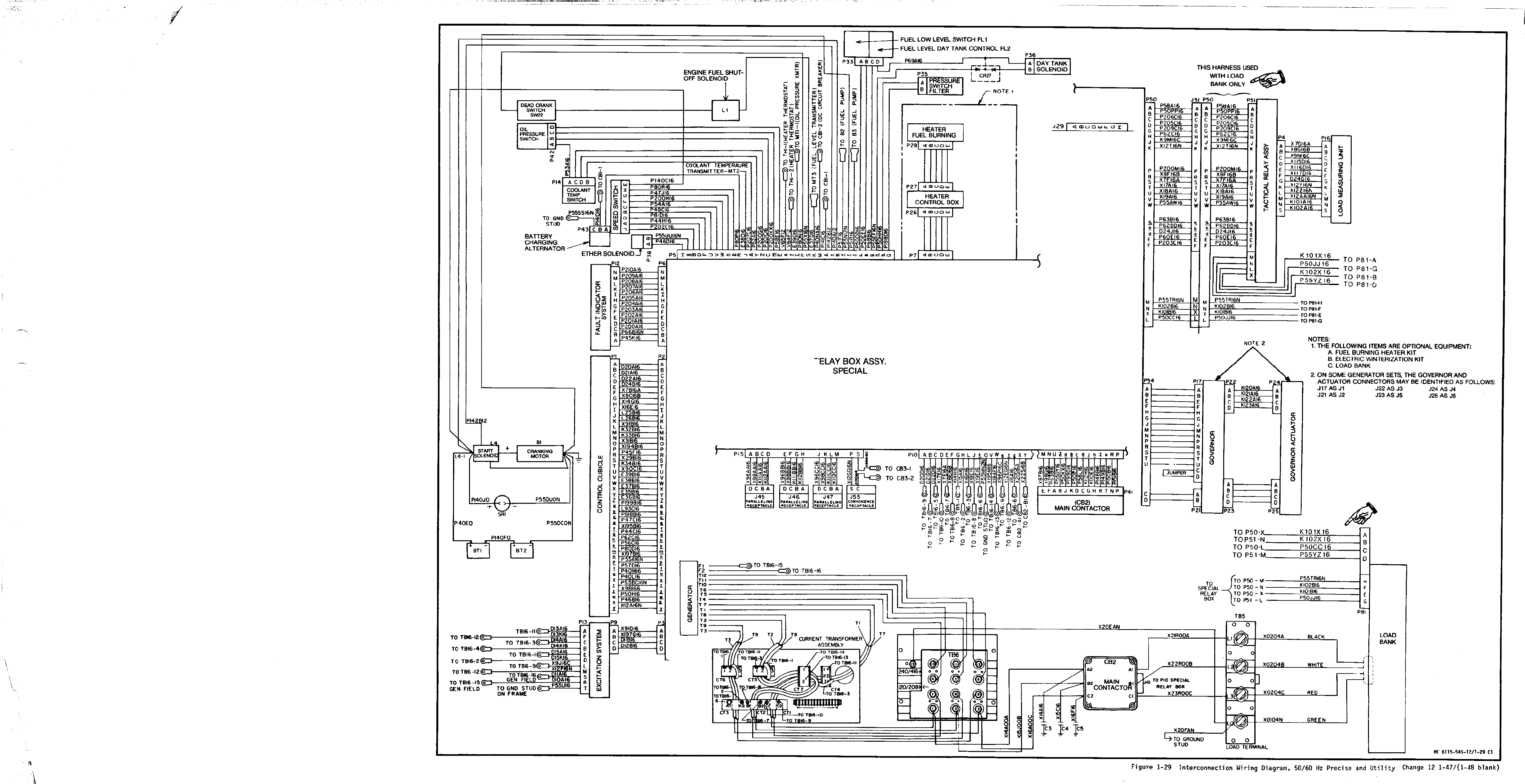
1-29.
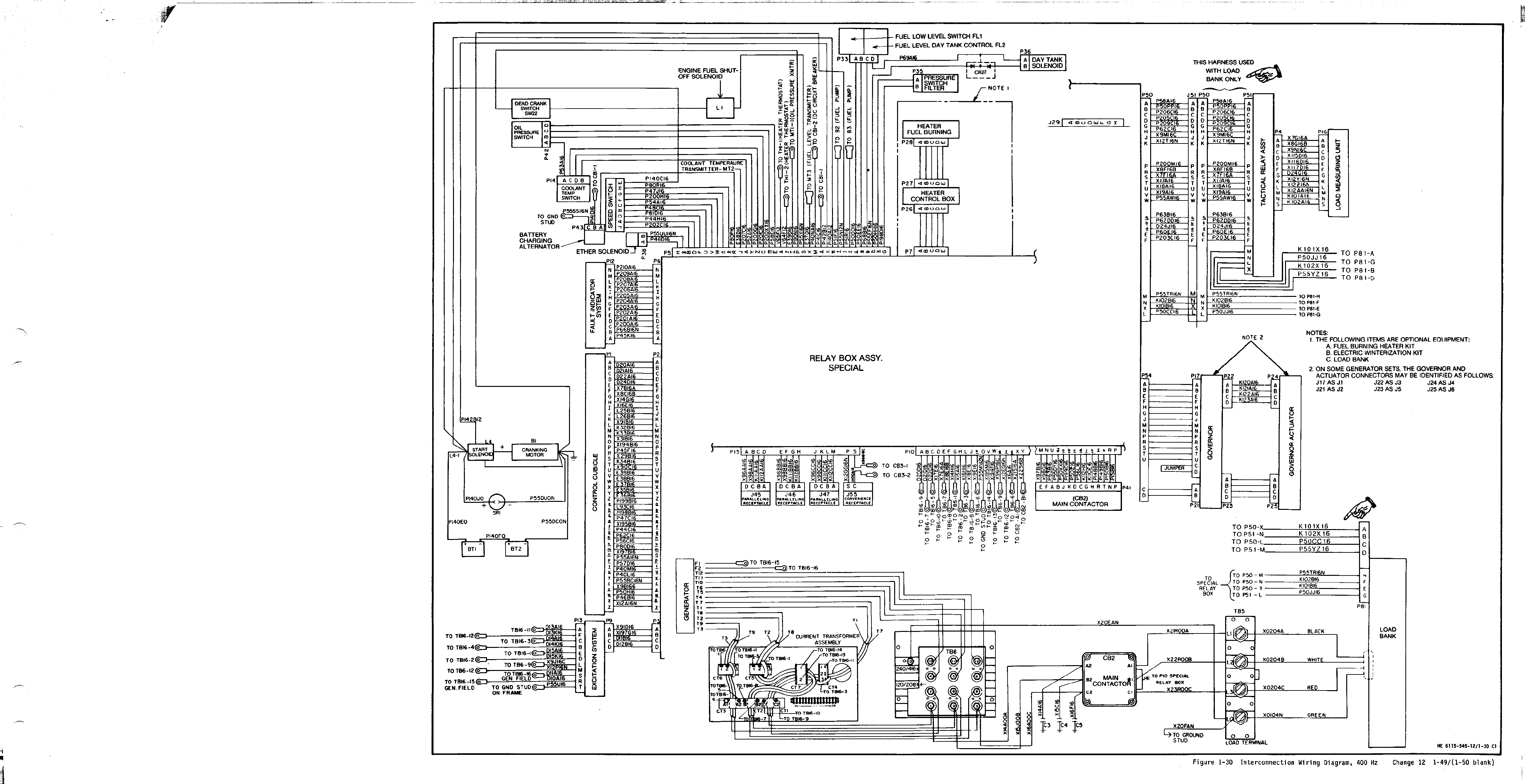
1-30.
2-1A.
2.1.
Title
Engine Generator Set. Right Front.
Three Quarter View.
Engine Generator Set. Left Rear.
Three Quarter View..
Data Instruction Plate Locations
(2 Sheets) . . . . . . . . . . . . . . . . . .
Fuel System Diagram Instruction Plate . . . .
Lifting Instructions Instruction
Plate . . . . . . . . . . . . . . .
Operating Instructions Instruction
Plate . . . . . . . .. . . . . .
Service Instruction and System
Capacities Instruction Plate . .
Voltage Reconnection Instruction
Plate . . . . . . . . . . . . . . . . . . . . .
Operational Data Information
Plate (Mode I) . . . . . . . . . . . . . .
Operational Data Information
Plate (Mode II) . . . . . . . . . . . . . .
Battery Arrangement and Connections
Instruction Plate . . . . . . . . . . . . . .
Set I.D. Plate. . . . . . . . . . . . . . .
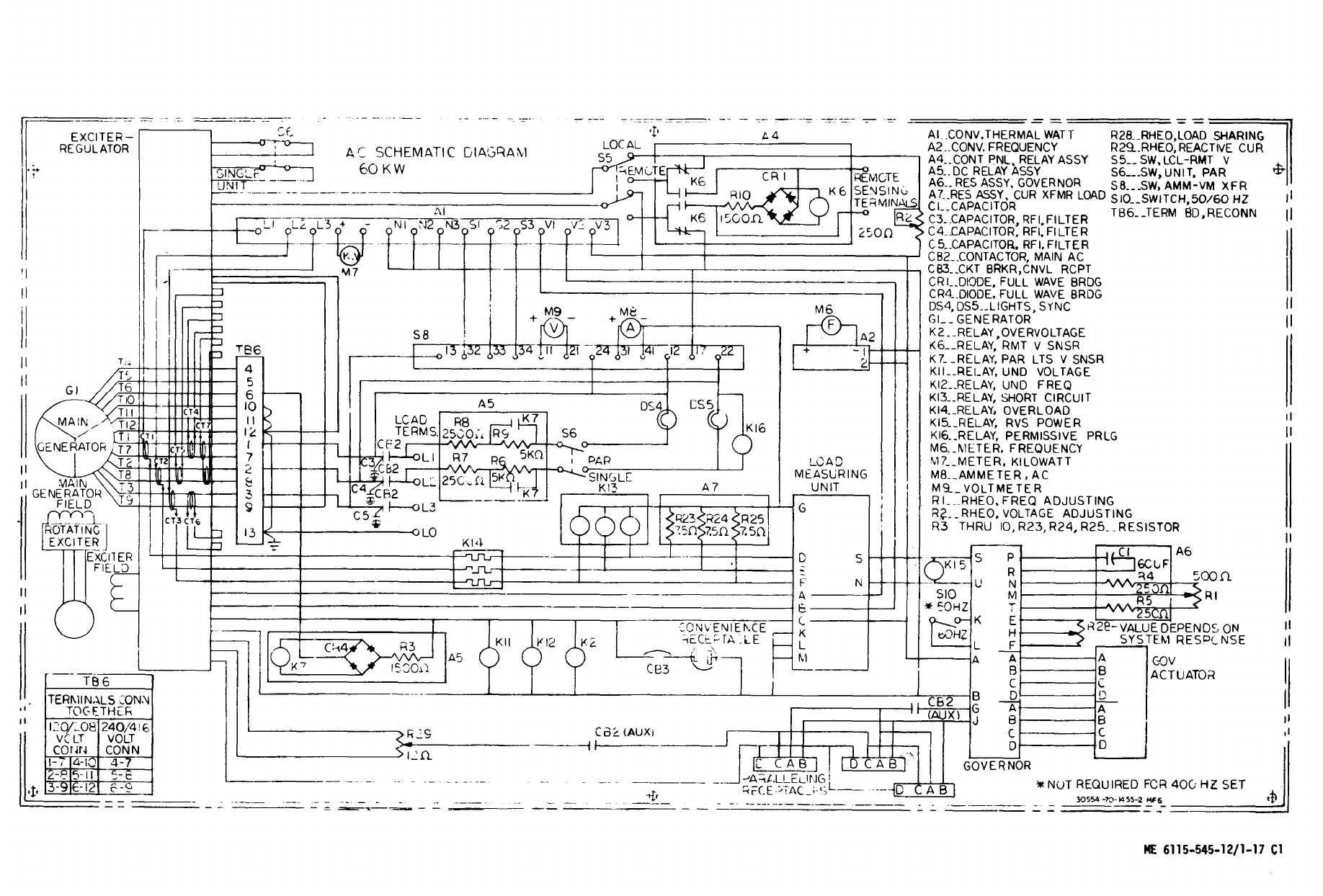
AC Troubleshooting Diagram
(Mode I)andPlate. . . . . . . . .
AC Troubleshooting Diagram
(Mode II)andPlate . . . . . . . . .
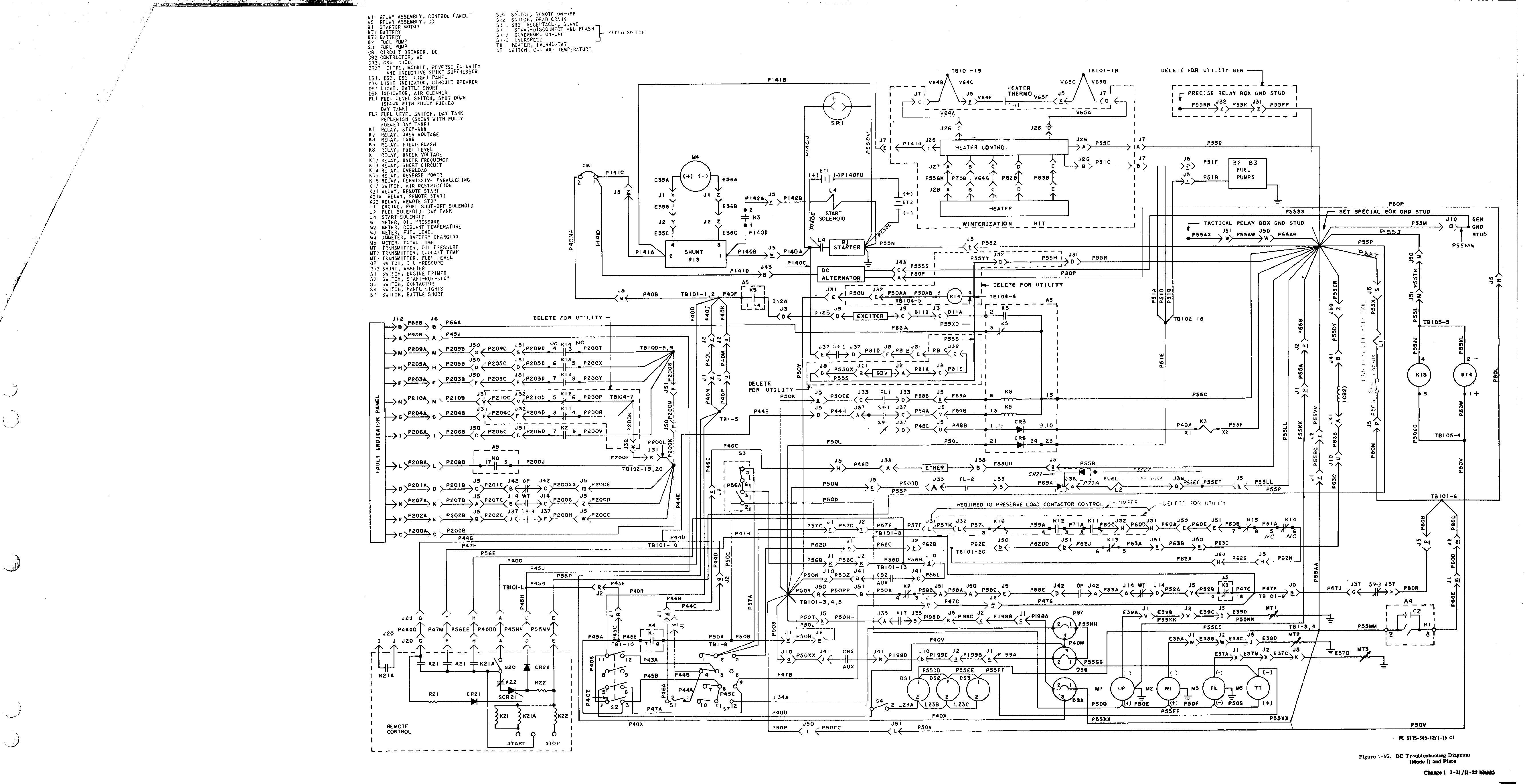
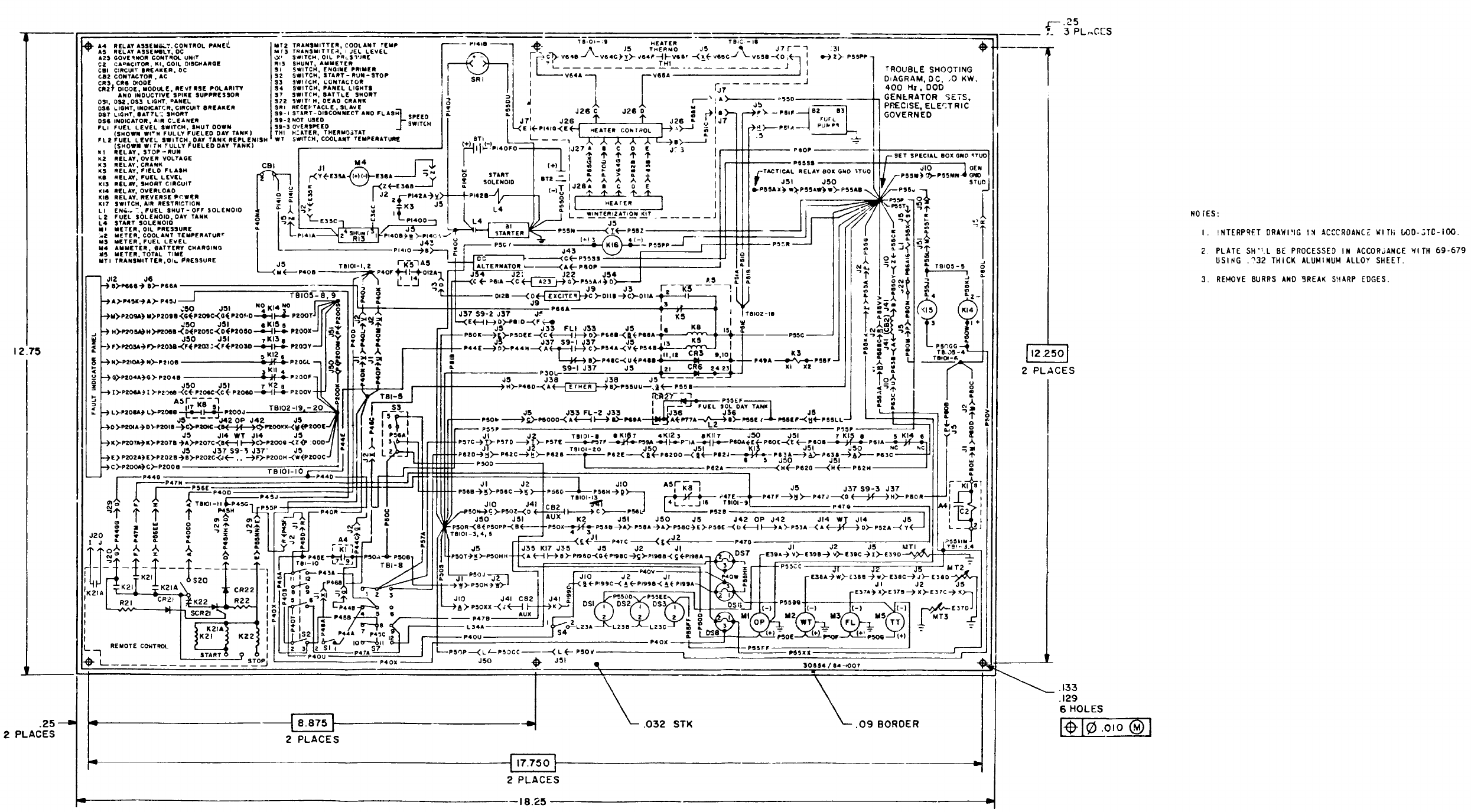
DC Troubleshooting Diagram
(Mode I) and Plate. . . . . . . . . . ..
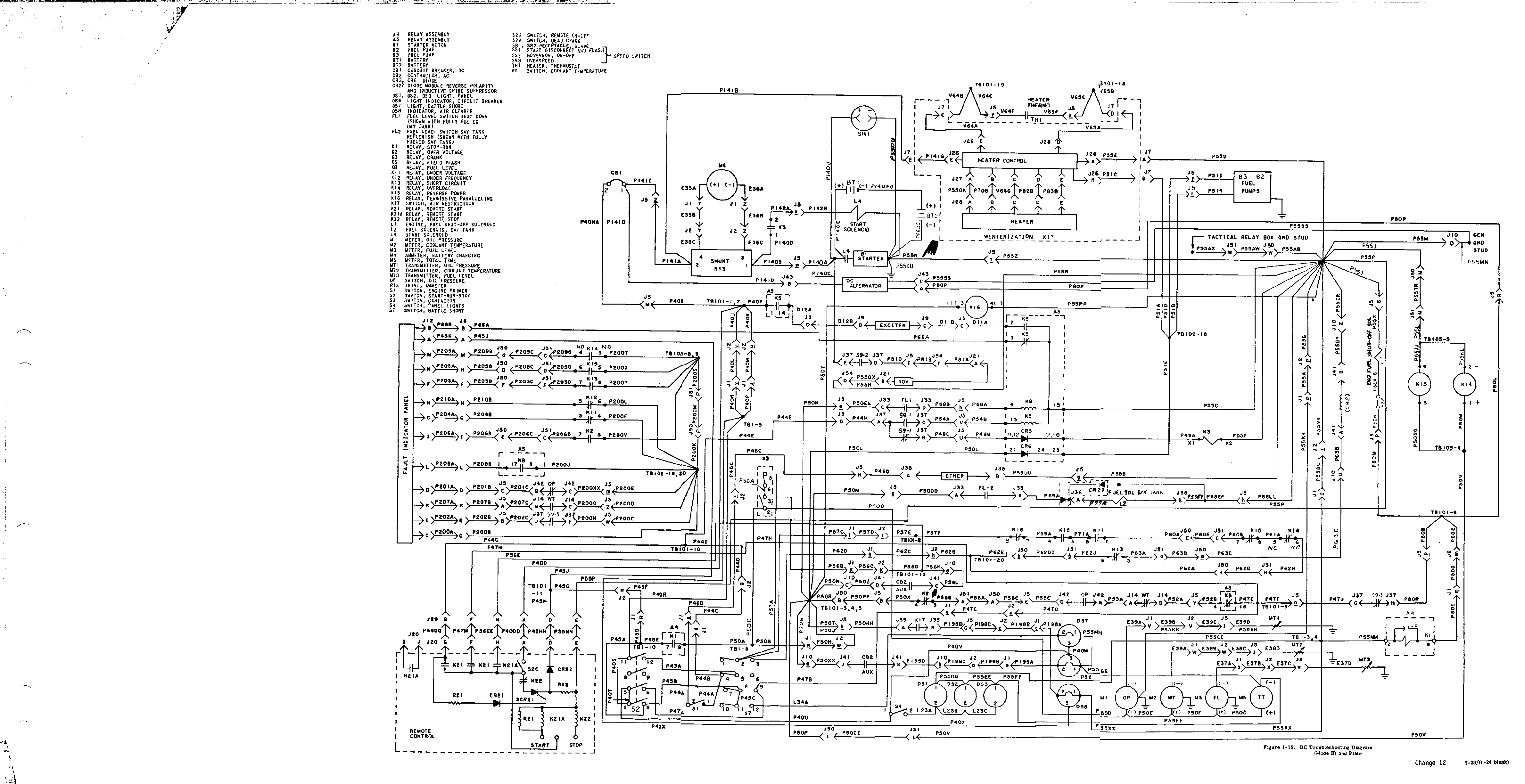
DC Troubleshooting Diagram
(Mode II) and Plate . . . . . . . . . . ..
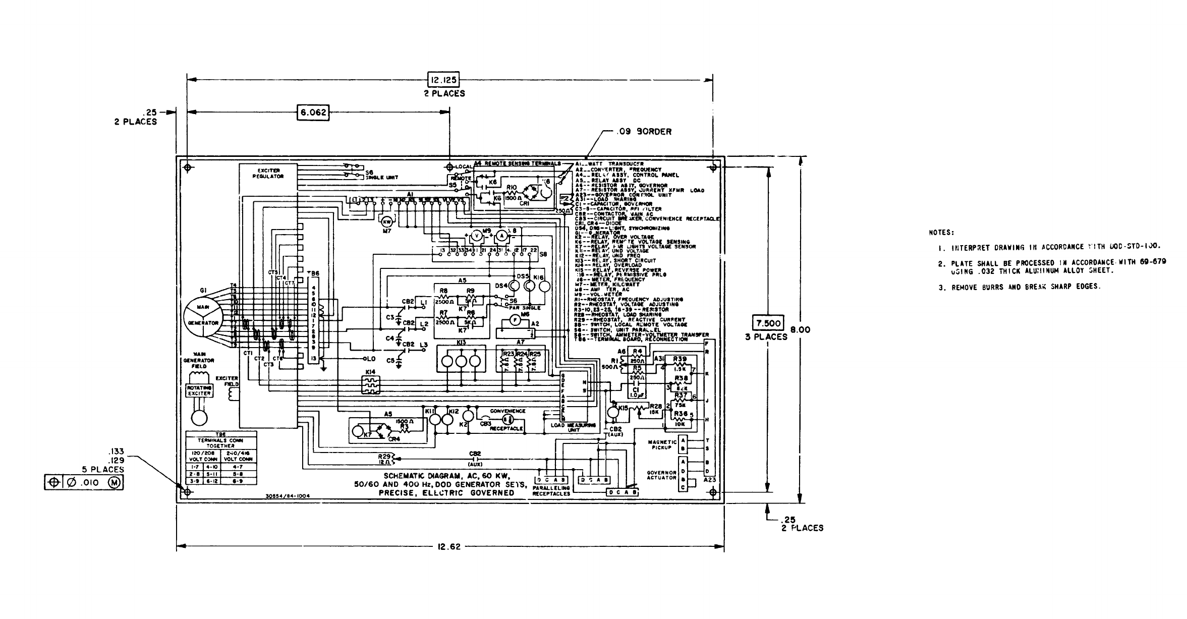
Schematic Wiring Diagram Class 1,
AC and Plate . . . . . . . . . . . .
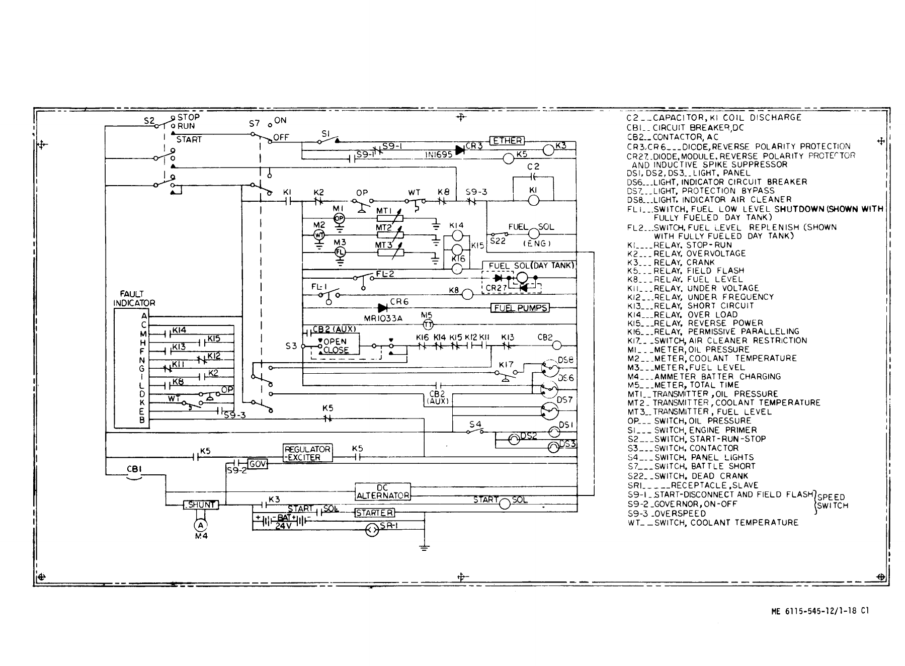
Schematic Wiring Diagram Class 1,
DC and Plate . . . . . . . . . . . . . . .
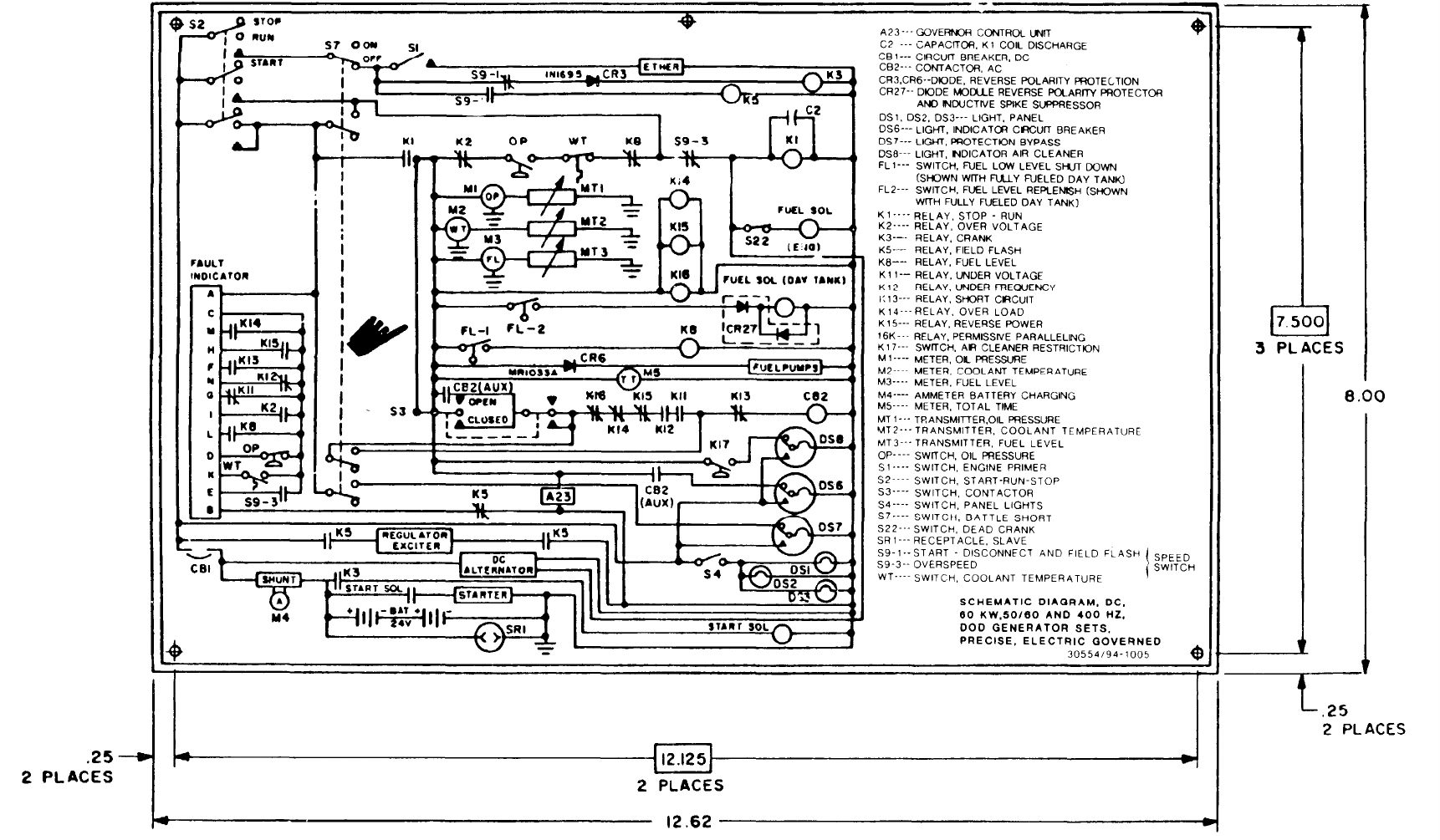
Schematic Wiring Diagram Class 2,
AC andPlate . . . . . . . . . . . . . . . . . . . . . .
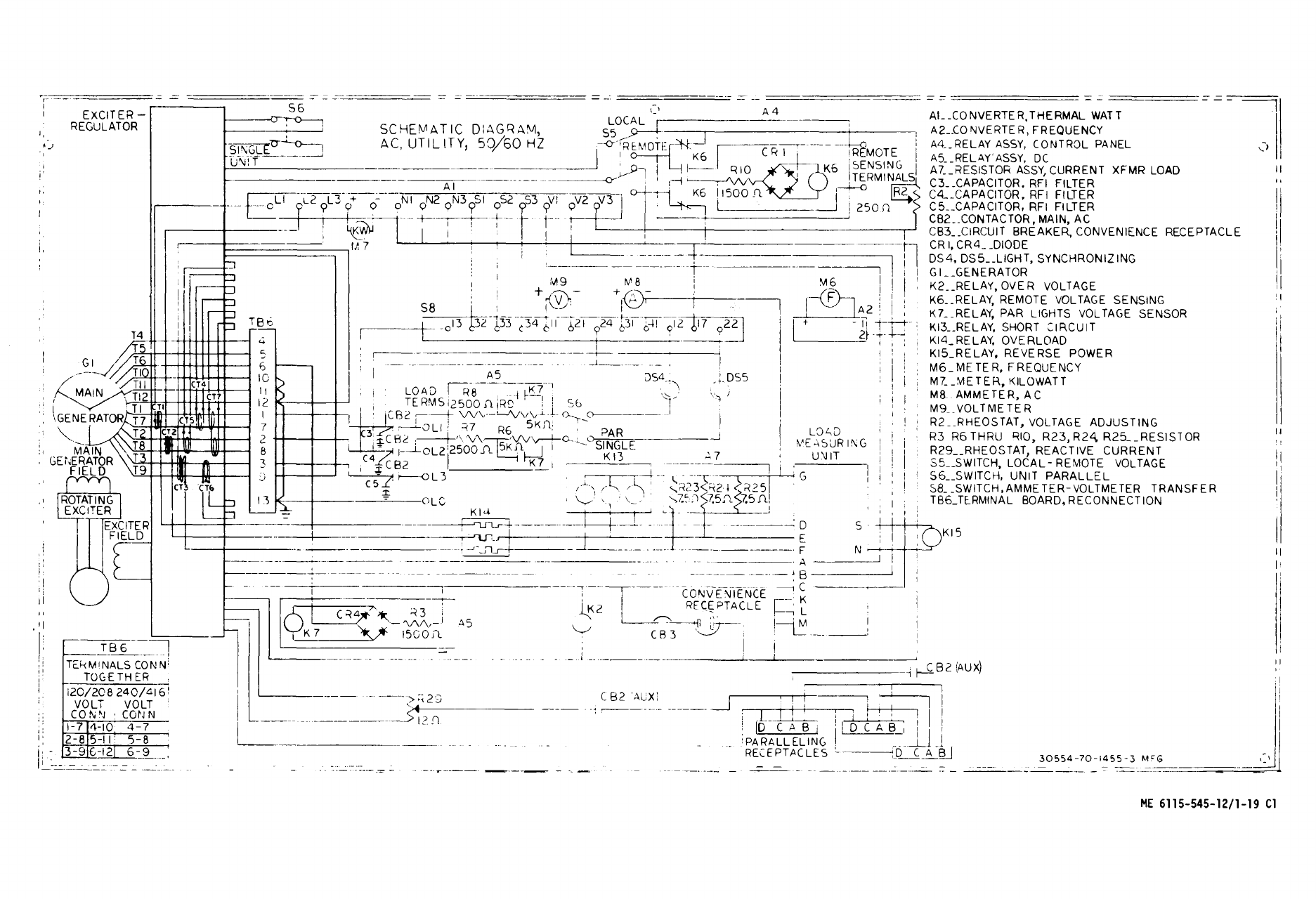
Schematic Wiring Diagram Class 2,
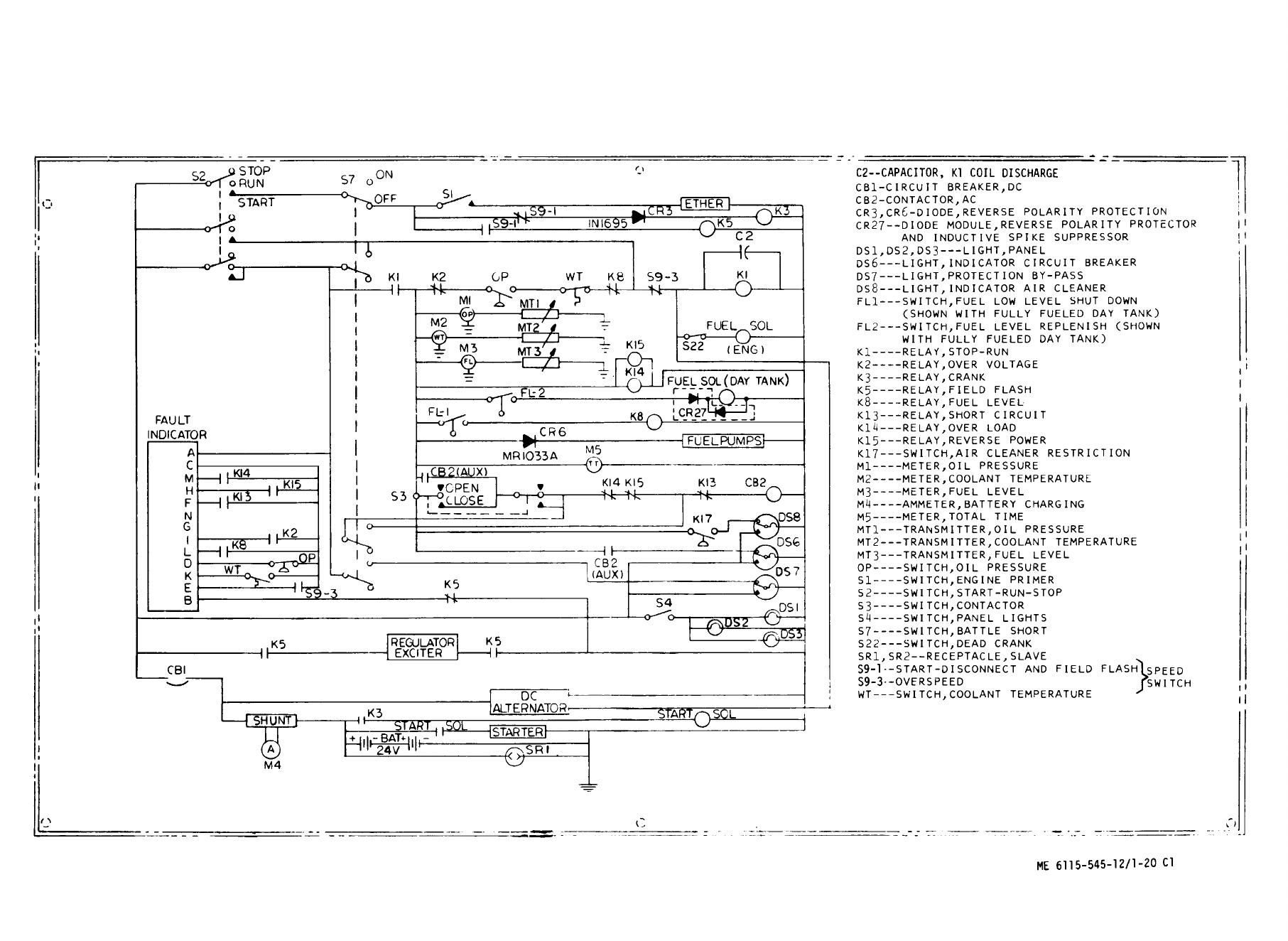
DC and Plate . . . . . . . . . . .. . . . . . . . ..
Kit Data and Instruction Plate
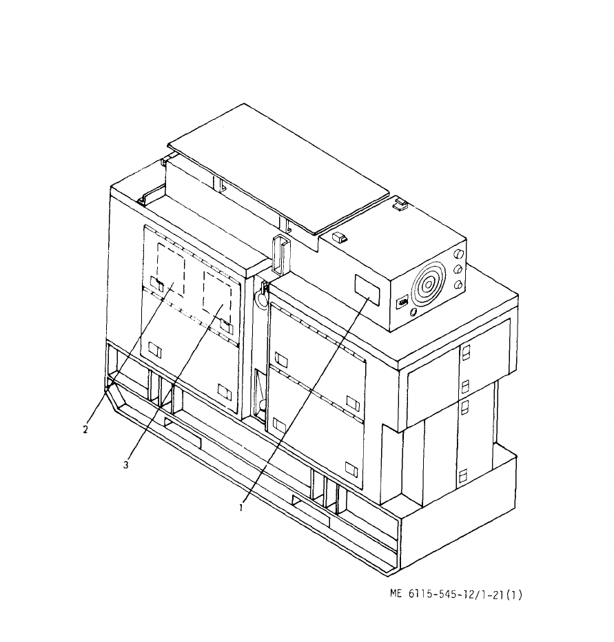
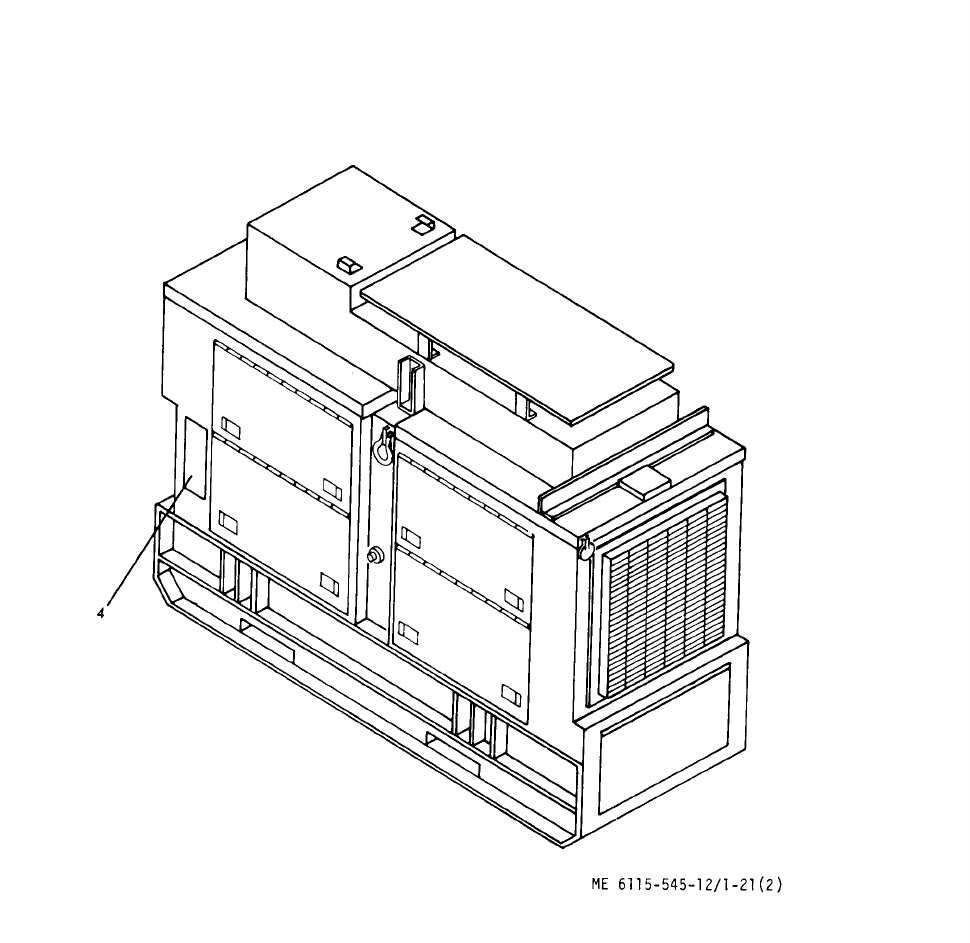
Location (2 Sheets) . . . . . . . . . . . . . . . . . . . . . .. . . . .. . .
Fuel Burning Winterization System
Diagram and Heater Control
Schematic Diagram Instruction Plate . . .
Electric Winterization System
Diagram and Electric Heater
Control Schematic Diagram
Instruction Plate . . . . . .
Load Bank Connection and Operation
Instruction Plate . . . . . . . . . . . . . . . . . . . .
Shipping Crate . . . . . . . . .
50/60 Hz Precise and Utility
Interconnecting Diagram . . . . . . . . . .
400 Hz Precise Interconnecting
Diagram. . . . . . . . . . . . .. . . . . . .
Hydraulic Flow Diagram . . . . . . . . .
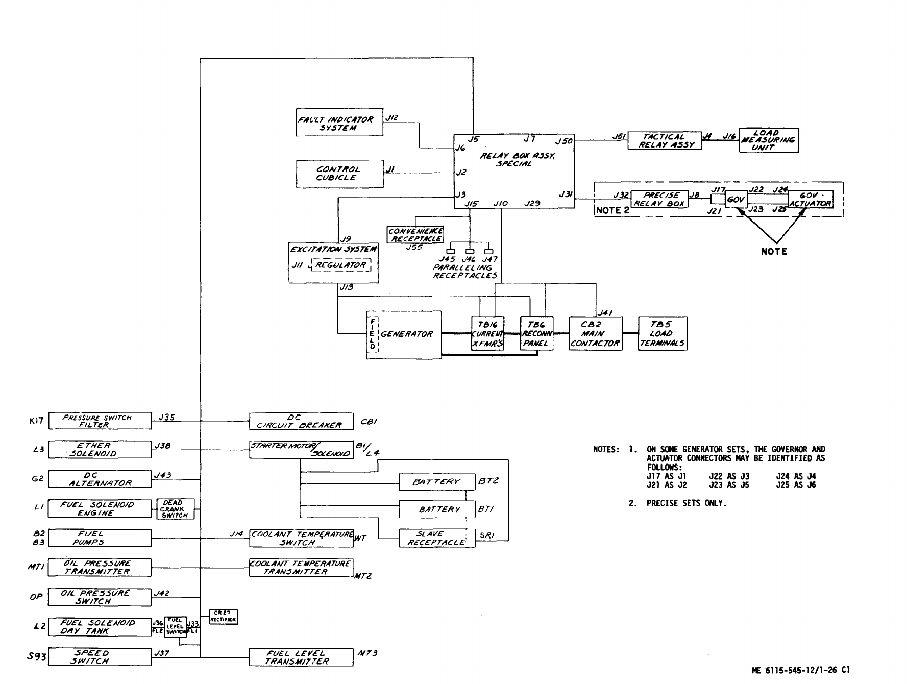
Interconnection Wiring Diagram
50/60 Hz Precise and Utility
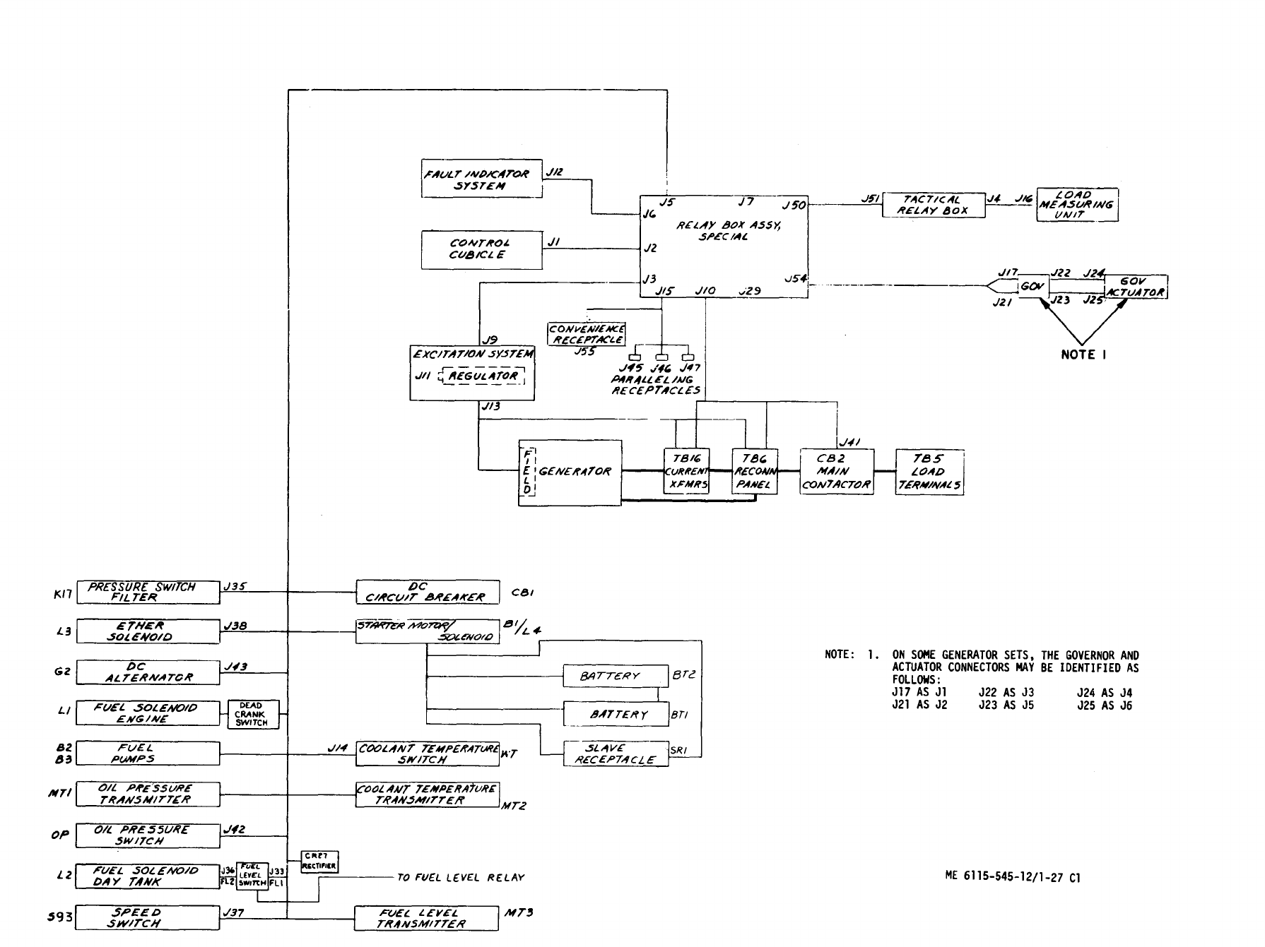
Interconnection Wiring Diagram
400 Hz. Precise and Utility . . . . . . . . . .
Noise Level Warning . . . . . . . . . .
Installation Plan . . . . . . . . . . .
TM 5-6115-545-12
TO-35C2-3-444-1
NAVFACP-8-626-12
TM-00038G-12
LIST OF ILLUSTRATIONS
Page
1-2
1-3
1-4
1-6
1-7
1-8
1-9
1-10
1-11
1-12
1-13
1-14
1-17
1-19
1-21
1-23
1-25
1-27
1-29
1-31
1-33
1-35
1-37
1-39
1-39
1-41
1-43
1-45
1-47
1-49
2-4
2-4
Number
2-2.
2-3.
2-4.
2-5.
2-6.
2-7.
2-8.
2-9.
2-10.
2-11.
2-12.
2-13.
2-14.
3-1.
3-2.
3-3.
3-4.
3-5.
3-6.
3-7.
3-8.
3-9.
3-10.
3-11.
3-12.
3-13.
3-14.
3-15.
3-16.
3-17.
3-18.
3-19.
3-20.
3-21.
3-22.
3-23.
3-24.
3-24.1
3-24.2
3-25.
3-26.
3-27.
3-28
3-29.
3-30.
3-31.
3-32.
3-33.
Title
Grounding Procedures (3 Sheets). . . . . .
Generator Load Terminal Board
Connections. . . . . . . . . . . . .
Voltage Conversion . . . . . . . . . . . . .
Generator Set Controls and
Instruments (6 Sheets) . . . . . . . . . . . . . . .
Preparation for Starting
(2 Sheets) . . . . . . . . . . . . . . . . .
Starting Instructions (2 Sheets) . . . . . . . . . . . . .
Stopping Instructions . . . . . . . . . . . . . . . . . .
Single Generator Unit, Operating
Instructions . . . . . . . . . . . . . . . . . . . . . . .. . . .
Parallel Generator Units Operating
Instructions . . . . . . . . . . . . . . . .
Fuel Burning Winterization Kit
Operating Instructions (2 Sheets) . . . . . . .
Electric Winterization Kit Operating
Instructions (2 Sheets). . . . . . . .
Wheel Mounting Kit Operation
Load Bank Operating Instructions
Lubrication Order (2 Sheets) . . . . . . . .
Oil Level Gage and Filler . . . . . . . . . .
Engine Lube Oil Filters . . . . . . . . .
Batteries and Slave Receptacles. . . . . . . . . .
Air Cleaner Service . . . . . . . . .
Fuel Filter and Strainer. . . . . . . .
Main Fuel Tank . . . . . . . . . . .. . . .
Hydraulic Sump and Filter . . . . . . . . . . . .
Secondary Fuel Filter . . . . . . . . . . .
Backwire of Fuel Injector Pump for
Class 2 0peration . . . . . . . . . . . . .
Interference Suppression Components
Removal and Installation . . . . . . . . . . . . . .
Exhaust and Breather System. . . . . . .
Convenience Receptacle . . . . . . . . . . . .
(Deleted) . . . . . . . . . . .. . . .
Plate and Sleeve Assembly . . . . . . . . . . . .
Paralleling Receptacles . . . . . . . . . . . . . . . . .
Generator Set Controls . . . . . . . . . . . .
Control Cubicle Assembly (2 Sheets) . . . . . . . . . . . .
Control Cubicle Schematic Diagram . . . . . . . . . . . .
Control Cubicle Wiring Diagram
(sheets) . . . . . . . . . . . . . . . . . .
Ammeter-Voltmeter Selector
Switch Schematic . . . . . . . . . . . . . . . . . . .
Housing Group (2 Sheets) . . . . . . . . . . . . .
Engine Generator and Chassis
Wiring Harness (2 Sheets) . . . . . . . . . . . . . . .
Load Connection Group . . . . . . . . . . . . . .
Terminal Clip Replacement . . . . . . . . . . . . . . .
Governor Control
Unit (MEP-115A) . . . . . . . . . . . . . . . . . .
Reconnections Board . . . . . . . . . . . . . . . .
Air Cleaner and Related Parts . . . . . . . . . .
Day Tank and Fuel Filter Assembly . . . . . . . .
Center Support and Related Parts . . . . . . . . . . .
Cooling Group and Related Parts . . . . . . . . . . . . .
Shutter Thermostat Replacement . . . . . . . . . . . . . .
Cooling Groups . . . . . . . . .. . . .
Hydraulic Actuator Servicing . . . . . . . . . . . . .
Hydraulic Sump and Filter . . . . . . . . . . . . . . . .
Page
2-5
2-8
2-9
2-11
2-19
2-23
2-23
2-24
2-25
2-28
2-30
2-33
2-34
3-2
3-4
3-5
3-11
3-14
3-15
3-16
3-18
3-19
3-29
3-30
3-32
3-33
3-34
3-35
3-36
3-38
3-29
3-51
3-55
3-59
3-63
3-68
3-70
3-72
3-72.2
3-72.3
3-73
3-75
3-79
3-80
3-82
3-83
3-85
3-86
Change 15 iii
TM 5-6115-545-12
TO-35C2-3-444-1
NAVFAC P-8-626-12
TM-00038G-12
LIST OF ILLUSTRATIONS (Cont)
Number Title Page
3-34.
3-35.
3-36.
3-37.
3-38.
3-38.1.
3-39.
3-40.
3-41.
3-42.
3-43.
3-44.
3-45.
3-46.
3-47.
3-48.
3-49.
3-50.
3-51.
3-52.
3-53.
4-1.
Drain Hose Removed . . . . . . . . . . 3-88
Belt Adjustment and Replacement . . . . . . 3-89
Alternator and Related Parts . . . . . . . . 3-90
Speed Switch . . . . . . . . . . . . . . . . . . 3-91
Oil Level Gage and Adapter and
Filler Elbow and Cap . . . . . . . 3-92
Electrical Starter Removal . . . . . . . . . 3-94
Secondary Fuel Filter Assembly . . . . . 3-95
Lube Oil Cooler . . . . . . . . . . . . . . . . . 3-97
Nozzle Holder and Line Assemblies. . . 3-99
Diffuser and Turbocharger . . . . . 3-101
Water Pump and Fan . . . . . . . . . . . . 3-104
Thermostat and Housing . . . . . . . . . . 3-105
Idler Pulley and Mounting Bracket . . . 3-107
Intake Manifold . . . . . . . . . . . . . . . . 3-109
Exhaust Manifold . . . . . . . . . . . 3-109
Rocker Arm Shaft Assembly . . . . . 3-111
Valve Locations . . . . . . . . . . . . . . . . 3-111
Base Group and Related Components . . . . . . . . . 3-113
Base Group . . . . . . . . . . . . . . . . . . . 3-114
Fuel Quantity Transmitter Set . . . . . . . . 3-115
Accessory Items with Attaching
Hardware . . . . . . . . . . . . . . . . . . . . 3-116
Fuel Burning Winterization Kit
(2 Sheets) . . . . . . . . . . . . . . . . . . . 4-3
Number
1-1
2-1
2-2
3-1
3-2
3-3
4-1
4-2
4-3
4-4
4-5
4-6
4-7
4-8
Number Title
Page
4-2.
4-3.
4-4.
4-5.
4-6.
4-7.
4-8.
4-9.
4-10.
4-11.
4-12.
4-13.
4-14.
4-15.
4-16.
4-17.
4-18.
LIST OF TABLES
Fuel Burning Winterization Kit
Control Box Lamp
Replacement . . . . . . . . . . . . . . 4-8
Fuel Regulator Valve Adjustment . . . . . 4-9
Adjusting Flame Switch . . . . . . . . 4-10
Thermostat Switch Replacement . . . . . . . . 4-10
Electric Winterization Kit
Schematic Wiring Diagram . . . . . . . . . 4-12
Electric Winterization Kit
(3 Sheets) . . . . . . . . . . . . . . . . . . . . . . 4-13
Coolant Pump Motor - Brush and
Connector Replacement . . . . . . . . . . 4-18
Electric Winterization Kit Control
Box Fuse and Lamp Replacement . . 4-20
Running Gear Assembly . . . . . . 4-22
Hand Lever and Bracket Assembly . . . . . . 4-24
Hub and Brake and Front Unit Axle
Assemblies (2 Sheets) . . . . . 4-26
Load Bank Schematic Diagram . . . . 4-31
Load Bank (2 Sheets) . . . . . 4-33
Fan and Motor Assembly . . . . . . 4-36
Wiring Diagram Load Bank . . . 4-39
Voltage Selector Switch Contact
Positions . . . . . . . . . . . . . . . . . 4-41
Load Selector Switch Contact
Positions . . . . . . . . . . . . . . . . . . 4-41
Title Page
Difference in Performance Characteristics . . . . . . . . . . 1-40
Freezing Points, Composition, and Specific Gravities of Military
Anti-freeze Materials . . . . . . . . . . . . . . . . . . . . . . . . . . . . . . . . . . . . . . 2-2
Fault Indicator Function . . . . . . . . . . . . . . . . . . . . . . . . . . . . . . . . . . . . . . 2-17
Preventive Maintenance Checks and Services . . . . . . . . . . . . . . . . 3-7
Fault Indicator Test Points. . . . . . . . . . . . . . . . . . . . . . . . . . . . . . . . . . . 3-13
Troubleshooting . . . . . . . . . . . . . . . . . . . . . . . . . . . . . . . . . . . . . . . . . . . . 3-21
Preventive Maintenance Checks and Services . . . . . . . . . . . . . . . . . . 4-2
Fuel Burning Winterization Kit Troubleshooting . . . . . . . . . . . . . . 4-7
Electric Winterization Kit Preventive Maintenance Checks and Services . 4-17
Electric Winterization Kit Troubleshooting . . . . . . . . . . . . . 4-19
Wheel Mounting Kit Preventive Maintenance Checks and Services . . . . . . . . . 4-23
Wheel Mounting Kit Troubleshooting . . . . . . . . . . . . . . . . . . . . . . . . . . . . . . . . 4-25
Load Bank Preventive Maintenance Checks and Services . . . . . . . 4-35
Load Bank Troubleshooting . . . . . . . . . . . . . . . . . . . . . . . . . . . . . . . . . . . . 4-37
iv
Change 13

CHAPTER 1
INTRODUCTION
Section I.
GENERAL
1-1. Scope.
a. These instructions are published for use by
personnel to whom the 60 KW Diesel Engine Driven
Generator Sets are issued.
The 50/60 Hertz (Mode I)
Tactical Utility (Class 2) Set is used in application
where exact frequency is not required. The 50/60
Hertz, (Mode I) Tactical Precise (Class 1) and 400
Hertz, (Mode II) Tactical Precise Sets are used in
applications which demand precise frequency control.
This manual provides information on the operation
and organizational maintenance of the equipment.
Also included are descriptions of main units and their
functions in relationship to other components.
b. Demolition of material to prevent enemy use
will be in accordance with the requirement of
TM 750-244-3. (Procedures For Destruction of
Equipment to Prevent Enemy Use for U.S. Army).
c. Preservation for shipment and storage for
U. S. Air Force will be in accordance with T. O.
35-1-4. Shipment and storage for U.S. Army will
be in accordance with TB 740-97-2.
1-2. Forms and Records.
THIS TECHNICAL MANUAL IS USED BY THE
ARMY, AIR FORCE, NAVY AND MARINE CORPS.
THE USE OF FORMS IN COMPLIANCE WITH
DIRECTIVES AS STATED HEREIN WILL BE AC-
COMPLISHED ONLY BY THE PERSONNEL OF
THE SERVICE TO WHICH THEY APPLY.
a. Forms and Records used by the Army will
be only those prescribed by DA Pam 738-
750. Those used by the Marine Corps will
be those prescribed by TM 4700-15/1.
Other Service users should refer to ap-
propriate specification/publications
for equipment maintenance forms and
records.
b. Report of errors, omissions, and recom-
mendations for improvement of this publication by
the individual users is encouraged. Reports
should be submitted as follows.
(1) Air Force-AFTO Form 22 direct to:
Commander, Sacramento Air Materiel Area,
McClellan Air Force Base, ATTN: MMST, California,
95652, in accordance with T0-00-5-1.
(2) Army-DA Form 2028 directly to:
Commander, U. S. Army Troop Support Com-
mand, ATTN: AMSTR-MCTS, 4300 Good fellow
Boulevard, St. Louis, MO 63120-1798.
(3) Marine Corps- NAVMC Form 10772 direct to:
Commandant, U.S. Marine Corps, ATTN: Code
LMO, Washington, D. C., 20380.
(4) Navy-by letter direct to:
Commanding Officer, U.S. Navy, Ships Parts
Control Center, ATTN: Code 783, Mechanicsburg,
Pa., 17055.
NOTE
(Army only)
Applicable Army Forms, excluding
Standard Form 46 (United States
Government Motor Vehicles Operator’s
Identification Card) which is carried by
the operator, shall be kept in manual
compartment mounted on equipment.
Section II DESCRIPTION AND DATA
1-3. Description.
a. General. The generator sets, military models
MEP105A, MEP006A and MEP115A (fig. 1-1 and 1-2),
are portable skid mounted self contained units. They
are provided with controls, instruments and acces -
series necessary for operation as a single unit or in
parallel with up to two other units of the same Class
and Mode. Each set is equipped with engine oil pan
heating elements and necessary connections for field
installation of winterization kits. The generator sets
may be mounted on trailers or wheel kits if desired.
In addition, to extend their capability, the sets have
been designed to accept and operate with the follow-
ing kits: (See chapter 4 for Items 1 thru 4.)
(1)
(2)
(3)
(4)
(5)
Load Bank.
Fuel Burning Winterization.
Electric Winterization.
Wheel Mounting.
Automatic Transfer Panel 50/60 Hz. Pro-
vides a means to monitor 60 Hz primary power and
automatically start and transfer the load to a standby
generator set in the event of abnormal primary power
fluctuation.
(See Appendix A for technical manual. )
Change 12 1-1
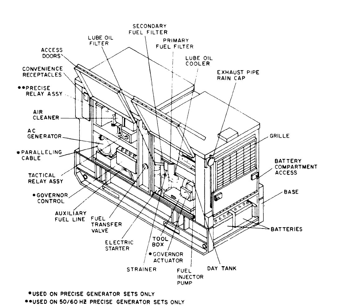
Figure 1-1. Engine Generator Set. Right Front, Three Quarter View
(6) Automatic Transfer Panel 400 Hz. Provides
the capacity to start and transfer the load from an
operating 400 Hz generator set to a like standby set
in the event the operating sets load contactor opens
due to a fault condition (See Appendix A for technical
manual).
(7) Remote Control Box. Permits starting,
stopping and voltage adjustment of the generator set
from a remote location. (See Appendix A for techni-
cal manual).
(8) Auxiliary Fuel Burning Winterization.
Provides a dependable external source of battery
power for starting of generator set in ambient
temperatures from -25°F. to -65°F. (See
Appendix A for technical manual. )
(9) Auxiliary Electric Winterization. Provides
a dependable external source of battery power for
starting of generator set in ambient temperatures
from -25°F. to -65°F. (See Appendix A for tech-
nical manual).
Change 7
1-2
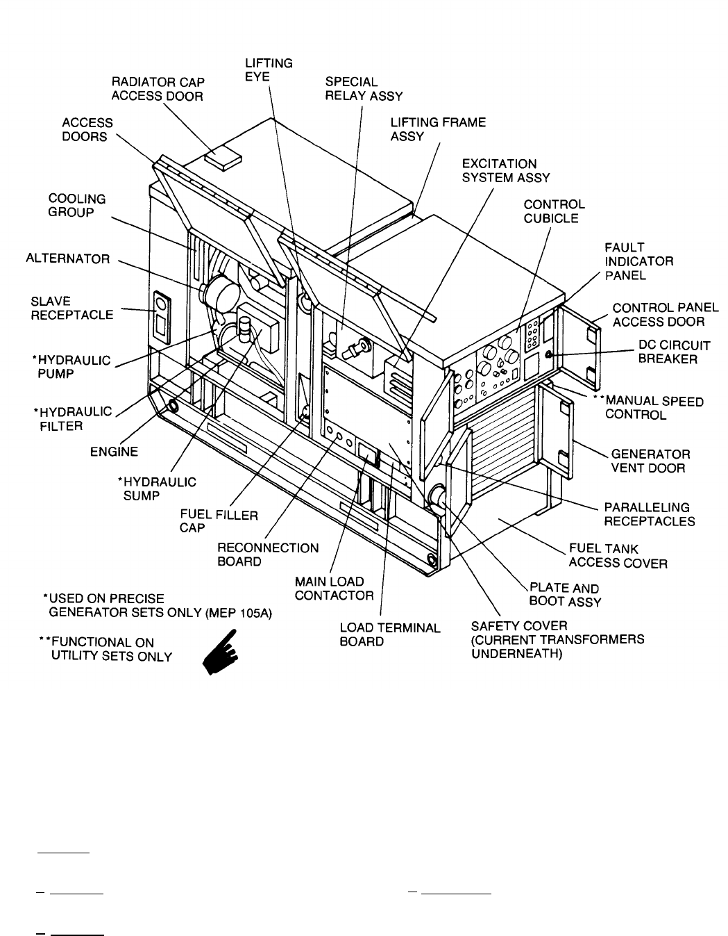
Figure 1-2. Engine Generator Set, Left Rear, Three Quarter View
b. Engine. The engine is a liquid-cooled, 6 cylinder, valve-in-
head, 4 stroke cycle, turbo-charged, diesel engine.
c. Generator. The 400 Hz generator is a 60 KW, brushless,
air-cooled rotating field generator.
d. Generator. The 50/60 Hz generator is a 50/60KW,
brushless, air-cooled rotating field generator.
1-4. Identification and Tabulated Data.
a. Identification. The generator set has data and instructional
plates located throughout the set. Figure 1-3 locates these
plates, and figures 1-4 through 1-20 illustrate their content. In-
struction plates for kits are located in figure 1-21, and figures 1-22
through 1-24 illustrate their content.
Change 11 1-3
1.
2.
3.
4.
5.
6.
7.
Fuel System Diagram Instruction Plate
(fig. 1-4)
Lifting Instructions Instruction Plate (fig.
1-5)
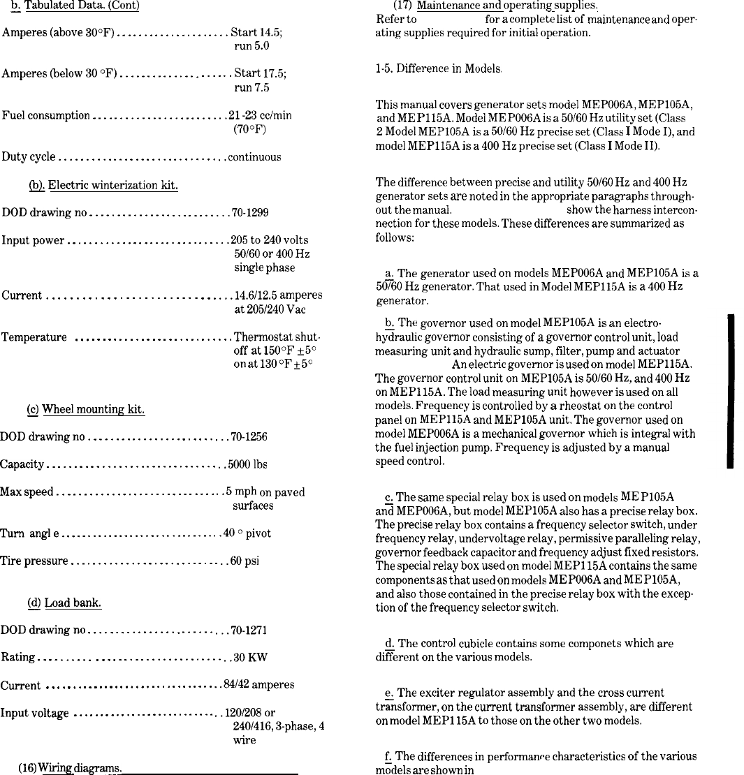
AC Troubleshooting Diagram (Mode I) and
Plate (fig. 1-13)
AC Troubleshooting Diagram (Mode II) and
Plate (fig. 1-14)
Operating Instructions Instruction Plate
(fig. 1-6)
Service Instructions and System Capacities
Instruction Plate (fig. 1-7)
Voltage Reconnection Instruction Plate
(fig. 1-8)
Operational Data Information Plate (Mode I)
(fig. 1-9)
Operational Data Information Plate (Mode II)
(fig. 1-10)
8.
9.
10.
11.
12.
13.
Schematic Wiring Diagram Class 1, AC and
Plate (fig. 1-17)
Schematic Wiring Diagram Class 2, AC and
Plate (fig. 1 -19)
Schematic Wiring Diagram Class 1, DC and
Plate (fig. 1-18)
Schematic Wiring Diagram Class 2, DC and
Plate (fig. 1-20)
DC Troubleshooting Diagram (Mode I) and
Plate (fig. 1-15)
DC Troubleshooting Diagram (Mode II) and
Plate (fig. 1-16)
Battery Arrangement and Connections
Instructions Plate (fig. 1-11)
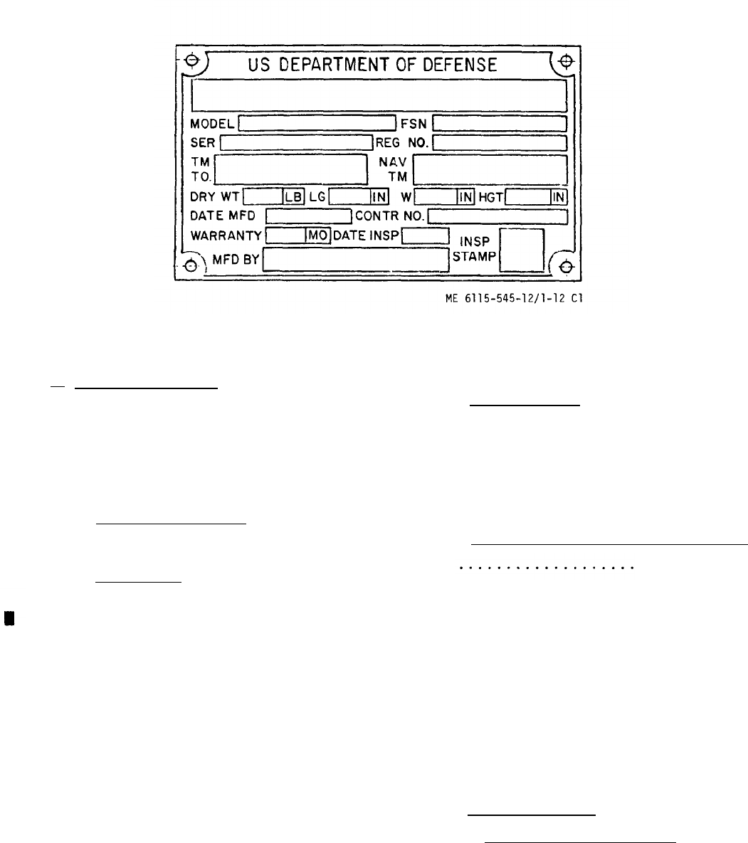
Set I.D. Plate (fig. 1 -12)
Fuel Selector Valve Instruction Plate
Figure 1-3. Data Instruction Plate Locations (Sheet 1 of 2)
1-4
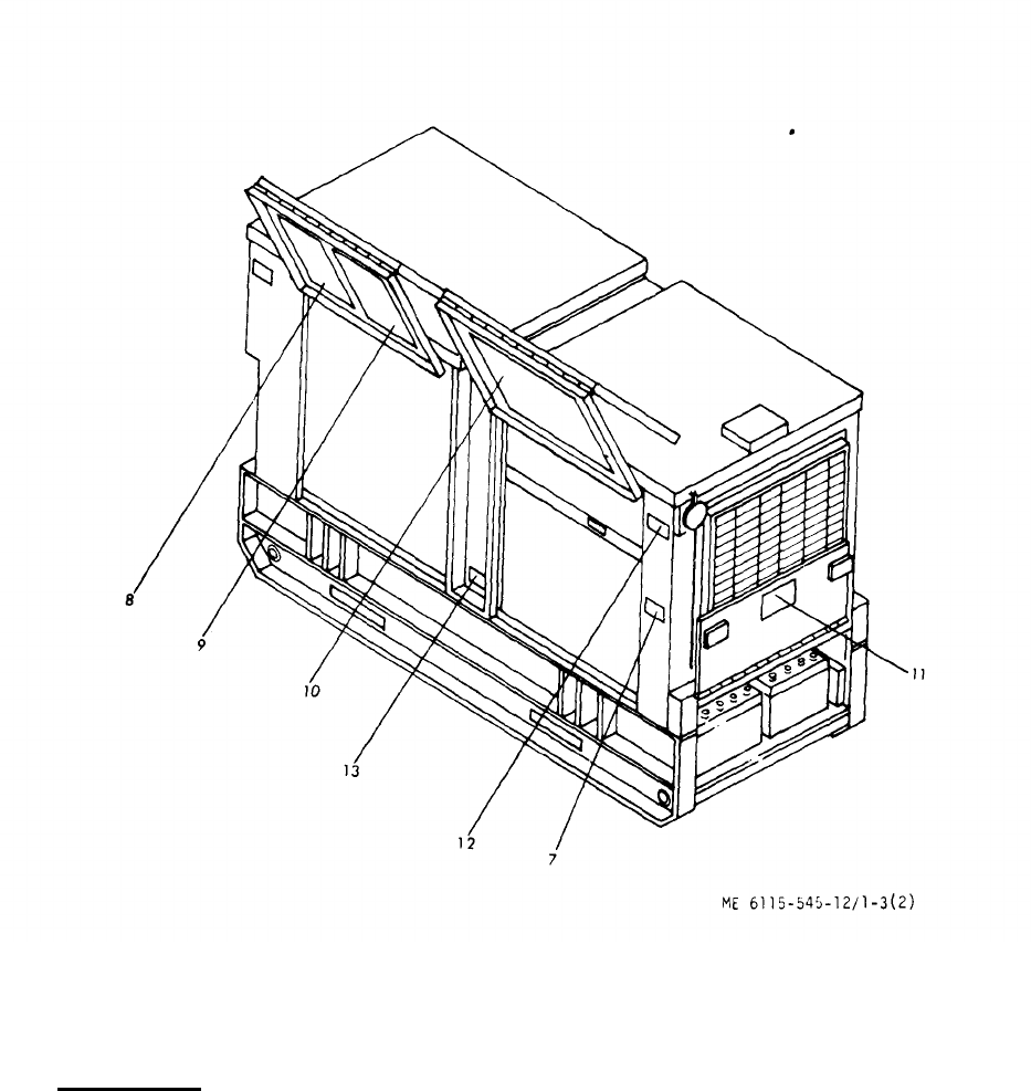
Figure 1-3.Data Instruction Plate Locations (Sheet 2 of 2)
b
_. Tabulated Data. Weight dry (less kits and optional
(1) Engine generator set (end item). equip.) . . . . . . 4300 lbs (50/60 HZ
DOD drawing no. . . . . . 70-0105 (50/60 Hz precise)
Weight dry (less kits and optional
equip.) . . . . . .
4240 lbs (50/60 H
Z
70-0006 (50/60 Hz utility)
precise set)
utility set)
70-0115 (400h Hz precise) Operating temperature
Models :
range . . . . . . . . . .
125°F to -25°F (-25° to -65°F
with winterization systems)
Model
. . . . . . . . . . . MEP105A (50/60 Hz precise)
Model
Voltage output . . . . 120/208
. . . . . . . . . . . MEP006A (50/60 Hz utility)
Model
. . . . . . . . . . .
MEP115A (400 Hz precise)
Length
. . . . . . . . . . . 87 inches
Power factor
. . . . 0.8
Width
. . . . . . . . . . . 36 inches
Height . . . . . . . . . . . 59 inches
Size . . . . . . . . . . . . . . 60 KW
Weight dry (less kits and optional
equip. )
. . . . . .
4400 lbs (400 Hz set)
volts and 240/416 volts
50 KW at 50 Hz)
1-5

b.
Tabulated Data. (Cont)
Type
(2) Engine.
COD drawing no. . . . . . . . . .
. . . . . . . . . . . . . . . . . . . .
Fuel . . . . . . . . . . . . . . . . . . . .
Firing order . . . . . . . . . . . . . . . 1-5-3-6-2-4
Rotation (viewed from
70-1049
fan end) . . . . . . . . . . . . . . . . Clockwise
6 cylinder, turbocharged
Cooling . . . . . . . . . . . . . . . . . . . . Circulating coolant
diesel
Cycle . . . . . . . . . . . . . . . . . . . . . . 4 stroke
Diesel fuel W-F-800
JP-4 or JP-5
Valves . . . . . . . . . . . . . . . . . . . . .
2 per cylinder
Maximum permissible exhaust
restriction . . . . . . . . . . . . . 2 inches of mercury
Brake horsepower
CAUTION
1500 rpm . . . . . . . . . . . . . 100
JP-4 and JP-5 fuel are considered
1800 rpm . . . . . . . . . . . . . 120
emergency fuels only.
2000 rpm . . . . . . . . . . . . . 130
Figure 1-4.Fuel System Diagram Instruction Plate
1-6Change 7
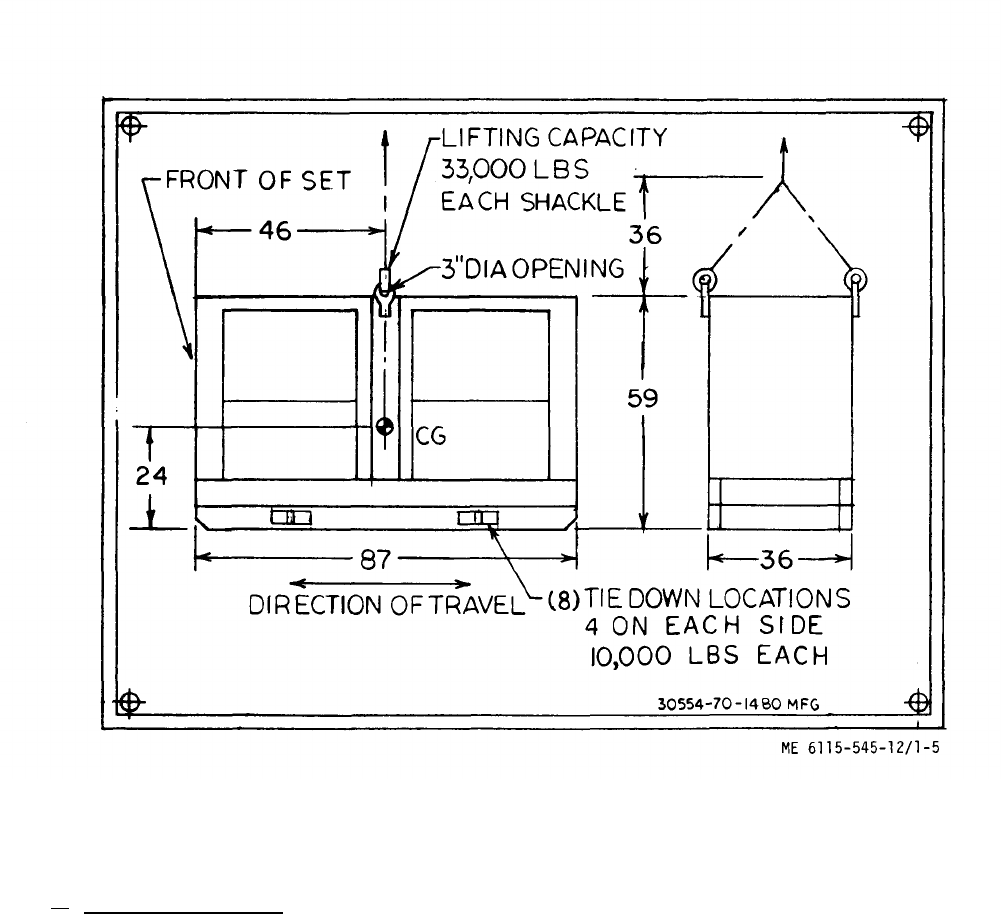
Figure 1-5. Lifting Instructions Instruction Plate
b. Tabulated Data. (Cont)
(3) Main generator (50/60 Hz tactical utility
and tactical precise).
DOD drawing no. . . . . . . . 70-1900
Type . . . . . . . . . . . . . . . Rotating field
synchronous, brushless
with integral exciter
KVA (Kilovolt amperes). ..62. 5/75
KW . . . . . . . . . . . . . . .
volts . . . . . . . . . . . . . . .
Amperes . . . . . . . . . . . .
50/60
120/208 or 240/416
(Adjustable to 197/240
or 395/480, 60 Hz
fig. 1 -9)
208/104 (173/87 at 50 Hz)
Phases . . . . . . . . . . . . . . . 3
power factor . . . . . . . . . . . . 0.8
Hertz . . . . . . . . . . . . . . . . .
50/60
Cooling . . . . . . . . . . . . . . . Air
Degree of enclosure . . . . . . . Drip-proof
Lubrication . . . . . . . . . . . . .
None required
Drive . . . . . . . . . . . . . . . . . Direct
Duty classification . . . . . . . . Continuous
Operating speed. . . . . . . . . . 1800 rpm for 60 Hz,
1500 rpm for 50 Hz
1-7
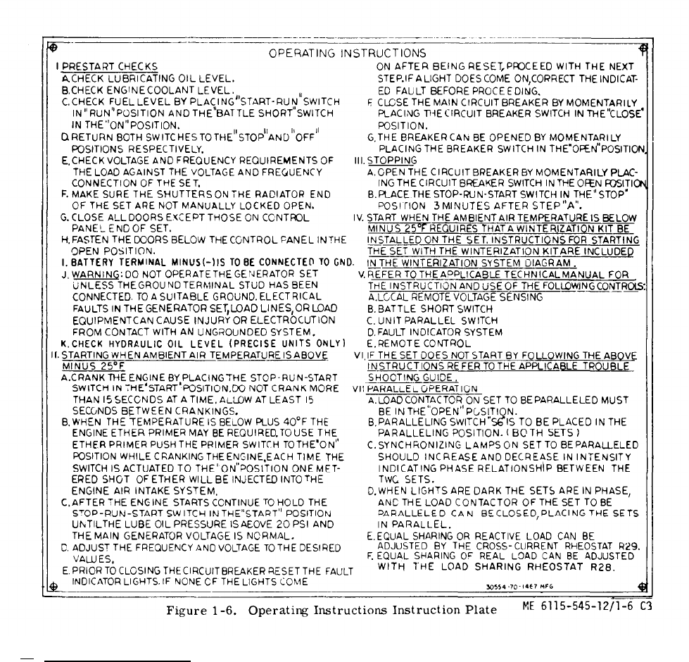
Figure 1-6.
b. Tabulated Data. (Cont)
(4) Main generator (400 Hz,
DOD drawing no. . . . . . 70-1901
tactical precise).
Type . . . . . . . . . . . . .
Rotating field synchronous,
brushless with integral
exciter
KVA (Kilovolt Amperes) . . . 75
KW . . . . . . . . . . . . . . . ..60
Hertz . . . . . . . . . . . . . . . . 400
Volts . . . . . . . . . . . . . l20/208 or 240/416
(Adjustable to 197/229 or
395 458 - fig, 1-10)
Amperes . . . . . . . . . . 208/104
Phases . . . . . . . . . . . . 3
Change 3
Power factor . . . . . . . . 0.8
Coating . . . . . . . . . .. Air
Degree of enclosure . . . . . . Drip-proof
Lubrication . . . . . . . . . . . .
None required
Drive . . . . . . . . . . . . . . . . Direct
Duty classification . . . . . . . Continuous
Operating speed . . . . . . . . .2000 rpm
(5) Fuel level switch (day tank).
DOD drawing no. . . . . . 70-1594
Type . . . . . . . . . . . . . Float
Current . . . . . . . . . . 3.0 amperes at
6 to 32 Vdc
Pressure . . . . . . . . . .
0 to 150 psi
1-8

Figure 1-7. Service Instructions and System Capacities Instruction Plate
b.
Tabulated Data. (Cont)
Switch contact data
Normal fuel level is 2.00±0.12 inches from top of tank.
Open continuity exists between connector pins A-B (upper
switch) and C-D (lower switch).
When fuel level drops below 2.75±0.12 inches from top of tank-
Upper switch is closed and lower switch opens.
When fuel level drops below 5.75
±
0.12 inches from top of tank-
Upper and lower switches are closed.
(6) Engine accessories.
(a)
Fuel transfer pumps.
Model (MS) .
. . . . . . . . . . . . . . MS5132-2
Volts . . . . . . . . . . . . . . . . . . . . .24dc
psi(max) . . . . . . . . . . . . . . . . . .7
Delivery (max) . . . . . . . . . . . . .18 gallons per hr
Change 11 1-9
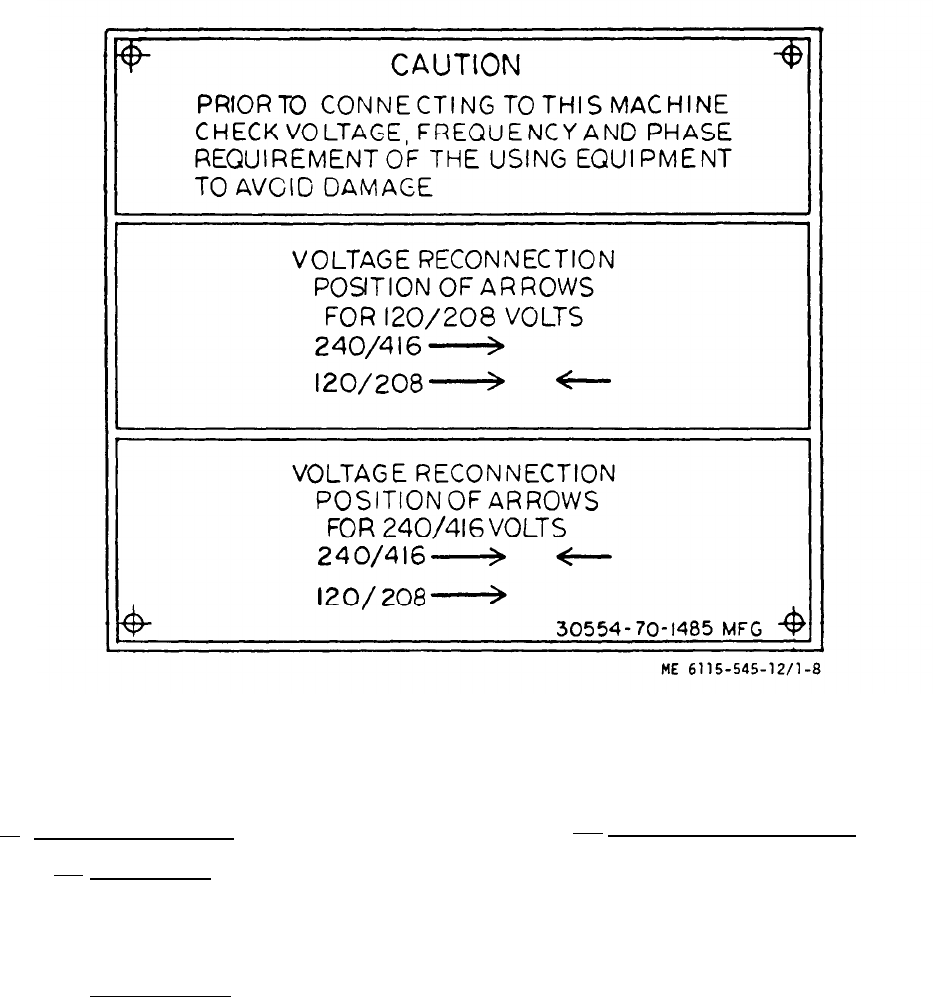
Figure 1-8. Voltage Reconnection Instruction Plate
b. Tabulated Data. (Cent)
(b) Turbocharger.
Drive . . . . . . . . . . . . . . . Engine exhaust
Type . . . . . . . . . . . . . . . Impeller
(c) Electric starter.
Service parts type no. . . . . MS53011-1
volts . . . . . . . . . . . . .
Rotation at drive end .
Torque . . . . . . . . . . .
Pinion data
Pinion teeth . . . . . . . .
Engagement . . . . . . . .
1-10
. . . 24 dc
. . Clockwise
22 ft-lbs (rein) at 400
amperes, 4.0 volts
12 tooth (on 13 tooth blank)
Positive engagement index-
ing drive with overrunning
clutch
(d) Battery charging alternator.
DOD drawing no. . . . . .69-780-2
Type drive . . . . . . . .. Belt
Rating
volts . . . . . . . . . . . ..24
Amperes . . . . . . . . ..35
Operating temperature
range . . . . . . . . . . . -65° F to + 175° F
Charge rate . . . . . . . 0 to 2 amperes adjustable
with fully charged battery
Fuse . . . . . . . . . . . . . Style AGC40, 32 volts,
40 amperes
Current output . . . . . . 0 to 15 amperes,
1900-4000 rpm
at rated temperature
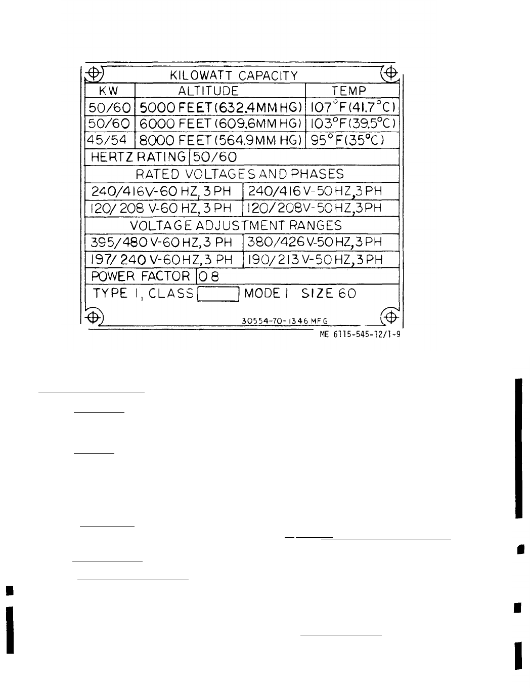
Figure 1-9. Operational Data Information Plate (Mode I)
b. Tabulated Data. (Cent)
—
(e) Oil cooler.
—
Type . . . . . . . . . Permanent tubular element
(f) Radiator.
—
DOD drawing no . . . 70-1126
Capacity .
Pressure.
(g)
Type . . .
(h)
1.
—
. . . . . . 15 quarts
. . . . . . 7 psi
Water Pump.
—
. . . . . . Belt driven
Safety devices:
Low oil pressure switch.
DOD part no. . . . . 70-1309
Contact Rating
A
. . . 10 amperes 28 volt dc resistive
B
. . . 10 amperes 125 volt ac resistive
Switch Configuration
A
. . . 1 circuit N. O.
B
. . . 1 circuit N. C.
Pressure Range:
500 psi maximum
Pressure Setting
A
. . . A-D circuit trip at 18-22 psi decreasing
(N. O.)
B
. . . B-C circuit trip at 18-22 psi decreasing
(N. C.)
2. Coolant high temperature switch.
DOD drawing no. . . 69-697-3
Rating
volts . . . . . . . . . . .
Current . . . . . . . . .
Trip temperature . . . .
3. Overspeed switch.
DOD drawing no . . . . .
28 dc
10 amperes
222° F ± 3° F
70-1105-1 (400 Hz)
70-1105-2 (50/60 Hz)
Change 1
1-11
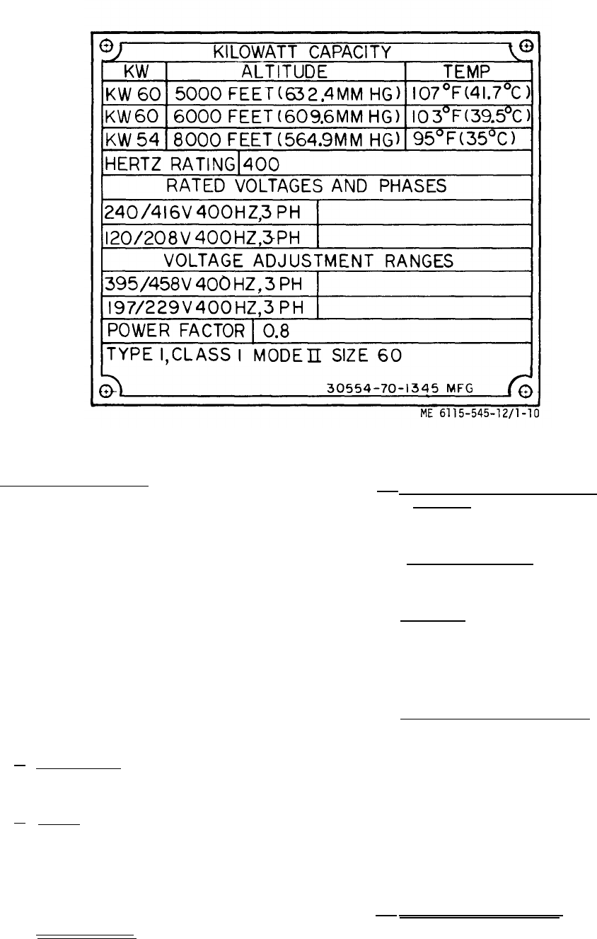
Figure 1-10.
b. Tabulated Data. (Cont)
—
Type. . . . . . . . . . Speed sensitive,
Operational Data Information Plate (Mode II)
manual reset
Overspeed trip . . . . 2400 to 2450 rpm, engine speed;
1200 to 1225 rpm, switch speed
Element trip speed . . S9-1 set - 290-310 rpm,
automatic reset 190-210 rpm.
(i)
Type . . . .
(j)
Service part
volts . . .
Connections
. .
(all sets)
S9-2 set -825-850 (400 Hz)
rpm, automatic reset 725-750
rpm. Set -590-610 rpm (50/
60 Hz) automatic reset 490-
510 rpm.
S9-3 set -1200-1225 rpm,
manual reset. (all sets)
Oil filters (2).
. . . . . . Replaceable element
Batteries (2).
type no. .
MS35000-3
. . . . . . 12 dc
. . . . . . series for 24 volts
(k) Ether solenoid.
—
DOD drawing no . . . . 70-1609
Volts . . . . . . . . .24dc
Change 1
(1) Primary fuel filter and strainer
assembly.
DOD drawing no. . . . 70-507
(m) Secondary fuel filter.
.—
Cartridge. . . . . . . . . C-1125PL
(n) Ether tank.
—
DOD drawing no. . . . 70-1608
Capacity (fluid ounces,
ethyl ether) . . . . . 26.7
(o) Lube oil pressure transmitter.
—
DOD drawing no. . . . 69-779
Voltage rating . . . . . 24 Vdc
Pressure range . . . . 0-120 psi
Resistance (ohms) pressure (psi)
0.0 to 1.0 ------ 0
1.5 to 3.0 ------ 10
14.5 to 16.5 ----- 60
28.0 to 31.0 ----- 120
(p) Temperature transmitter.
DOD drawing no. . . . 69-781
Voltage rating . . . . . 24 Vdc
Temperature range . . 120° F to 280° F
1-12
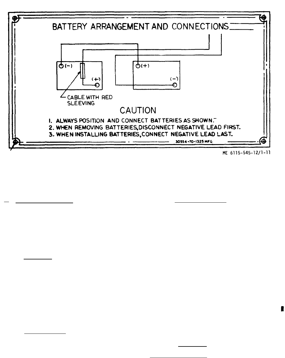
Figure 1-11. Battery Arrangement and Connections Instruction Plate
b. Tabulated Data. (Cont)
Resistance (ohms)
2360 ± 10 percent at 120° F
710 ±
5 percent at 200° F
310 ±
8 percent at 280° F
(7) Capacities.
Fuel tank . . . . . . . . 55 gallons
Usable fuel . . . . . . ..50 gallons
Engine crankcase. . . .20 quarts
Engine cooling system . . . . . . 33.5 quarts
Hydraulic governor system
(See fig. 1-28.) . . . . . . . . 5 quarts
(8) Cooling system.
stabilized coolant
temperature
(minimum) . . . . . .180° F
Water pump type . . . . Centrifugal, belt driven
(9) Lubricating system.
Type system . . . . . . . . . . . Full flow, circulating
pressure
Oil pump type Gear, positive
displacement
Oil pressure range,
hot, at rated
speed . . . . . . . . . . . . . . 30-55 psi
Pressure regulation
governed by . . . . . . . . . . Regulation valve
Nominal oil capacities:
Oil change . . . . . . . . . . . . .20 quarts
Crankcase and
oil filters . . . . . . . . . . .26 quarts
Lubricating oil
filters . . . . . . . . . . . . . Dual full flow
(10) Valve data.
Valve lash adjustment.
Intake valve clearance (hot) . . 0.015 inch
Change 3
1-13
b. Tabulated Data. (Cont)
Intake valve
clearance (cold) . . . . 0.018 inch
Figure 1-12. Set I. D. Plate
(13)
Fan drive
Exhaust valve
clearance (hot) . . . . 0.015 inch
Exhaust valve
clearance (cold). . . . 0.018 inch
(11) Governor (mechanical).
Type . . . .. .. Variable speed, flyball
Regulation . . . . . . . 2-3%
(12) Torque data.
NOTE
Torque values with threads lubricated
with engine oil.
Length108 inches crated
87 inches uncrated
Exhaust manifold screws.25 ft - lbs (12 ft lb
increments)
Engine lube oil filter
assembly mounting screws . . . . . 50 ft - lbs
Intake manifold securing
capscrews . . . . . . . . . . . . . . .33 ft - lbs
LOW oil pressure
switch . . . . . . . . .20 ft - lbs
Injector hold-down 13 ft - lbs
capscrews . . . . . . (6 ft lb increments)
Turbocharger locknuts . . . . . . . . . 21 ft - lbs
Water pump mounting screws . . . . . 33 ft - lbs
Fan to pump mounting screws . . . . 35 ft - lbs
Belt deflections.
belt . . . . . . 9/32 inch at 12 to
14 lb force (measured at
center point between pulleys)
Alternator belt . . . . . 9/64 inch at 3 to
5-1/4 lb force (measured
center point between pulleys)
(14) Shipping dimensions and weights (fig. 1-25).
Width . . . . . . . . . . . . . . . . . . . ..48 inches crated
36 inches uncrated
Height . . . . . . . . . . . . . . . . . . 72 inches crated
59 inches uncrated
Weight (50/60 Hz utility set) . . . . . 4740 lbs (approx)
(crate included)
Weight (50/60 Hz precise set) . . . . 4800 lbs (approx)
(crate included)
Weight (400 Hz set) . . . . . . . . . . . 4900 lbs (approx)
(crate included)
Volume . . . . . . . . . . . . . . . . . ..216 cubic feet
(15) Optional equipment.
(a) Fuel burning winterization kit.
—
DOD drawing no. . . . . . . . . . . . 70-1297
Volts . . . . . . . . . . . . . . . . . . . . .24Vdc
Change 1
1-14
&
Tabulated
Data.
(Cent)
Amperes
(above
30°F)
.
.
.
.
.
.
.
.
.
.
.
.
.
.
.
.
.
.
.
..
Start
14.5.
run
5.0
Amperes
(below
30
IF)
.
.
.
.
.
.
.
.
.
.
.
.
.
.
.
.
.
.
.
..
Start
17.5.
run
7.5
Fuel
consumption
.
.
.
.
.
.
.
.
.
.
.
.
.
.
.
.
.
.
.
.
.
.
.
..21
-23cc/min
(700F)
Duty
cycle
.
.
.
.
.
.
.
.
.
.
.
.
.
.
.
.
.
.
.
.
.
.
.
.
.
.
.
.
.
..continuous
(b).
Electric
winterization
kit.
—
DOD
drawing
no
.
.
.
.
.
.
.
.
.
.
.
.
.
.
.
.
.
.
.
.
.
.
.
...70-1299
Input
power
.
.
.
.
.
.
.
.
.
.
.
.
.
.
.
.
.
.
.
.
.
.
.
.
.
.
.
.
..205 t0240
volts
50/60
or
400
Hz
single
phase
Current
.
.
.
.
.
.
.
.
.
.
.
.
.
.
.
.
.
.
.
.
.
.
.
.
.
.
.
.
...14.6/12.5
amperes
at
205/240
Vac
Temperature
.
.
.
.
.
.
.
.
.
.
.
.
.
.
.
.
.
.
.
.
.
.
.
.
.
.
.
.
.
Thermostat
shut-
off
at
1500F
+5°
on
at
130
°F~50
@
Wheel
mounting
kit.
DOD
drawing
no
.
.
.
.
.
.
.
.
.
.
.
.
.
.
.
.
.
.
.
.
.
.
.
...70-1256
Capacity
.
.
.
.
.
.
.
.
.
.
.
.
.
.
.
.
.
.
.
.
.
.
.
.
.
.
.
.
.
.
.
..50001bs
Max
speed
.
.
.
.
.
.
.
.
.
.
.
.
.
.
.
.
.
.
.
.
.
.
.
.
.
.
.
.
.
..5mph
onpaved
surfaces
Tmmangle
.
.
.
.
.
.
.
.
.
.
.
.
.
.
.
.
.
.
.
.
.
.
.
.
.
.
.
.
.
..40
°pivot
Tire
pressure
.
.
.
.
.
.
.
.
.
.
.
.
.
.
.
.
.
.
.
.
.
.
.
.
.
.
.
..60psi
@
Load
bank.
DOD
drawing
no
.
.
.
.
.
.
.
.
.
.
.
.
.
.
.
.
.
.
.
.
.
.
.
...70-1271
Rating
.
.
.
.
.
.
.
.
.
..
.
.
.
.
.
.
.
.
.
.
.
.
.
.
.
.
.
.
.
.
.
.
..30KW
Current
.
.
.
.
.
.
.
.
.
.
.
.
.
.
.
.
.
.
.
.
.
.
.
.
.
.
.
.
.
.
.
.
.
.64/42
amperes
Input
voltage
.
.
.
.
.
.
.
.
.
.
.
.
.
.
.
.
.
.
.
.
.
.
.
.
.
.
.
..120/2080r
240/416,
3-phase,
4
wire
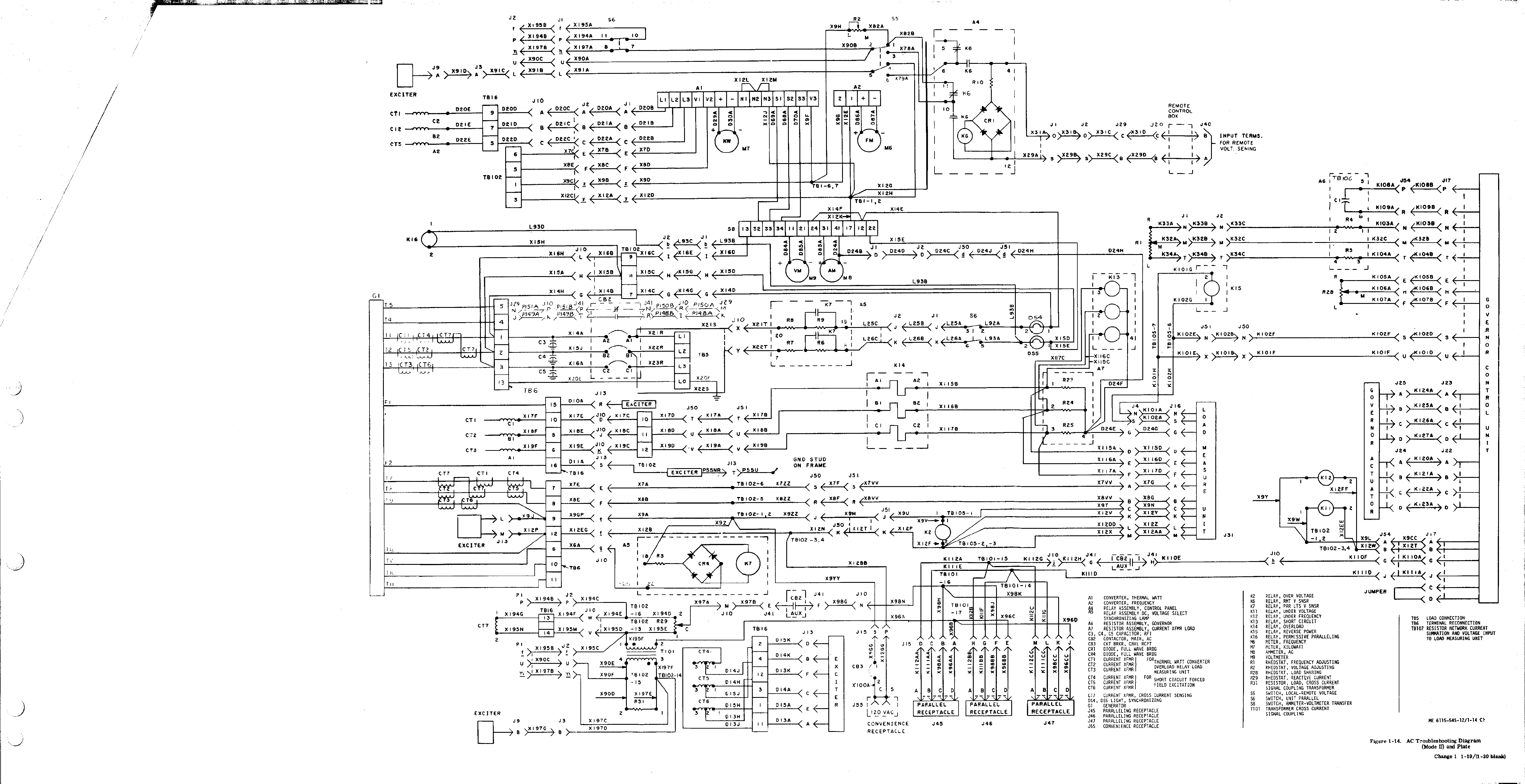
(16)
Wiring
diagrams.
(figs. 1-13 thru 1-20: 1-29 and 1-30)
(17)
Maintenance
and
operating
supplies.
Refer
to
Appendix B
for
a
complete
list
of
maintenance
and
oper-
ating
supplies
required
for
initial
operation.
1-5.
Difference
in
Models
This
manual
covers
generator
sets
model
MEPO06A,
MEP105A,
and
ME
P1
15A.
Model
ME
PO06A
is
a
50/60
Hz
utility
set
(Class
2
Model
MEP105A
is
a
50/60
Hz
precise
set
(Class
I
Mode
I),
and
model
MEP115A
is
a
400
Hz
precise
set
(Class
I
Mode
II).
The
difference
between
precise
and
utility
50/60
Hz
and
400
Hz
generator
sets
are
noted
in
the
appropriate
paragraphs
through-
out
the
manual.
Figures 1-26 and 1-27
show
the
harness
intercon-
nection
for
these
models.
These
differences
are
summarized
as
follows:
~
The
generator
used
on
models
MEPO06A
and
MEP105A
is
a
50/60
Hz
generator.
That
used
in
Model
MEP115A
is
a
400
Hz
generator.
~
The
governor
used
on
model
MEP105A
is
an
electro-
hydraulic
governor
consisting
of
a
governor
control
unit,
load
measuring
unit
and
hydraulic
sump,
filter,
pump
and
actuator
(See fig. 1-28).
An
electric
governor
is
used
on
model
MEP115A.
The
governor
control
unit
on
MEP105A
is
50/60
Hz,
and
400
Hz
on
MEP1
15A.
The
load
measuring
unit
however
is
used
on
all
models.
Frequency
is
controlled
by
a
rheostat
on
the
control
panel
on
MEP115A
and
MEP105A
unit.
The
governor
used
on
model
MEPO06A
is
a
mechanical
governor
which
is
integral
with
the
fuel
injection
pump.
Frequency
is
adjusted
by
a
manual
speed
control.
g
The
same
special
relay
box
is
used
on
models
ME
P105A
and
MEPO06A,
but
model
MEP105A
also
has
a
precise
relay
box.
The
precise
relay
box
contains
a
frequency
selector
switch,
under
frequency
relay,
undervoltage
relay,
permissive
paralleling
relay,
governor
feedback
capacitor
and
frequency
adjust
fixed
resistors.
The
special
relay
box
used
on
model
MEP1
15A
contains
the
same
components
as
that
used
on
models
ME
PO06A
and
ME
P105A,
and
also
those
contained
in
the
precise
relay
box
with
the
excep
tion
of
the
frequency
selector
switch.
<
The
control
cubicle
contains
some
componets
which
are
different
on
the
various
models.
g
The
exciter
regulator
assembly
and
the
cross
current
transformer,
on
the
current
transformer
assembly,
are
different
on
model
MEP1
15A
to
those
on
the
other
two
models.
&
The
differences
in
performance
characteristics
of
the
various
models
are
shown
in
table 1-1.
Change 11 1-15/(1-16 blank)
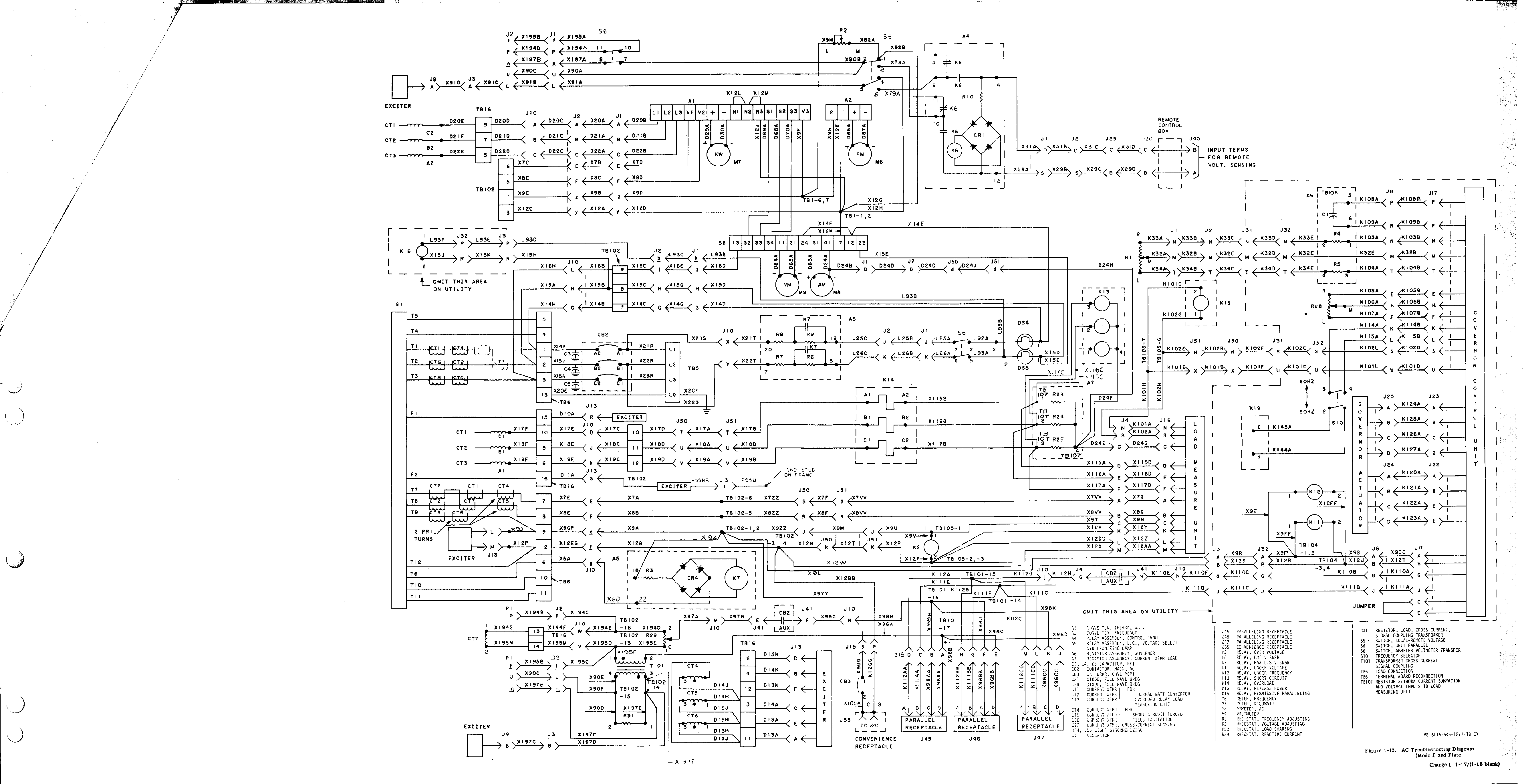
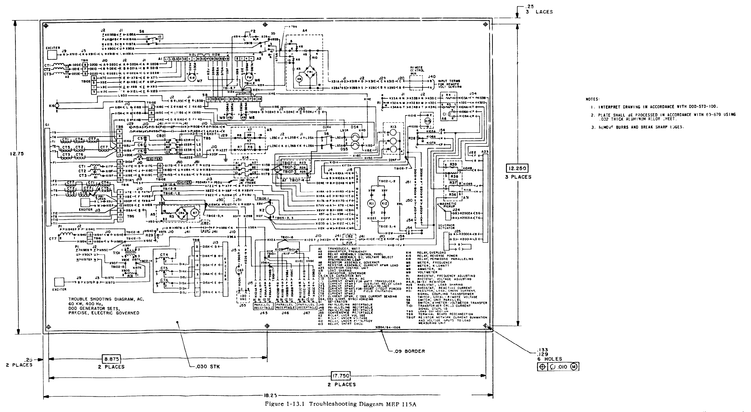
Figure 1-31.1
TM 5-6115-545-12
Change 11 1-18.1/(1-18.2 blank)
TM 5-6115-545-12
1-22.1 /(1-22.2 blank)
Figure 1-15.1 Troubleshooting Diagram, MEP115A Change 11
TM 5-6115-545-12
Figure 1-17.1 Schematic Wiring Diagram, MEP 115A
Change 11 1-26.1 /(1-26.2 blank)
TM 5-6115-545-12
TO-35C2-3-444-1
NAVFAC P-8-626-12
TM-00038G-12
Figure 1-18.1 Schematic Wiring Diagram, MEP 115A
1-28.1/(1-28.2 blank)Change 14
1. Load Bank Connection and Operation Instruction Plate (fig. 1-24).
2. Electric Winterization System Diagram and Electric Heater Control Schematic Diagram
Instruction Plate (fig. 1-23).
3. Fuel Burning Winterization System Diagram and Heater Control Schematic Diagram
Instruction Plate (fig. 1-22).
4. Remote Operation Instruction Plate.
Figure 1-21. Kit Data and Instruction Plate Location (Sheet 1 of 2)
1-33
1-34
Figure 1-21. Kit Data and Instruction Plate Location (Sheet 2 of 2)
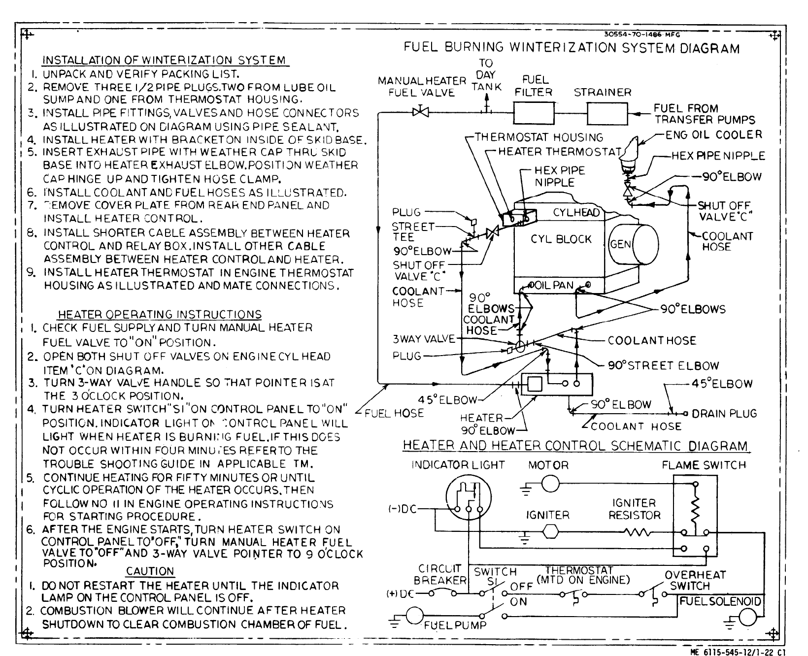
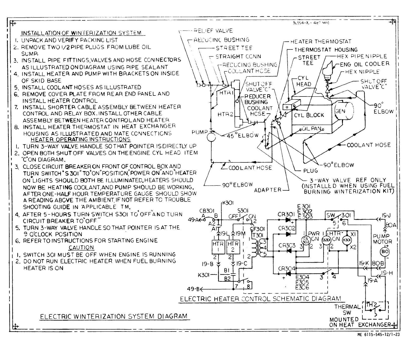
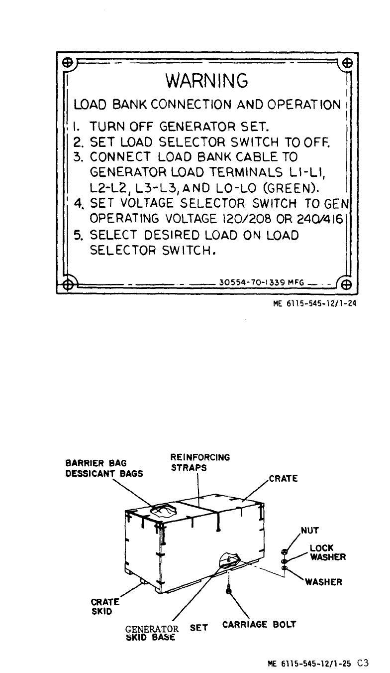

Table 1-1. Differences in Performance Characteristics
1. Voltage
(a)
(b)
(c)
(d)
Dip with application of
rated load.
Rise with rejection of
rated load.
Dip or rise with appli-
cation of simulated
motor load.
Adjustment range
2. Frequency
(a) Regulation.
(b) Short term steady state
stability.
(c) Long term steady state
stability.
(d) Undershoot with applica-
tion of rated load.
(e) Recovery after application
of rated load.
(f) Overshoot with rejection
of rated load.
(g) Recovery after rejection
of rated load.
(h) Drift (60° F change).
(i) Adjustment range
MEP006A
20% max.
20% max.
40% max.
50 Hz +2.5%
-10%
60Hz +15%
-5%
2 to 3%
Within
2% bandwidth
Within
3% bandwidth
3% max.
Within
3 seconds
4% max.
Within
3 seconds
1%
45-65 Hz
(Manual)
MEP105A
15% max.
15% max.
30% max.
50 Hz +2.5%
-10%
60Hz +15%
-5%
Within
± 0. 25%
Within
0.5% bandwidth
Within
1% bandwidth
1.5% max.
Within
1 second
1.5% max.
Within
1 second
0.5%
50 Hz
48 to 52 Hz
60 Hz
58 to 62 Hz
MEP115A
12% max.
12% max.
25% max.
400 Hz +10%
-5%
Within
±0.25%
Within
0.5% bandwidth
Within
1% bandwidth
1.5% max.
Within
1 second
1.5% max.
Within
1 second
0.5%
390 to 420 Hz
1-40


TM 5-6115-545-12
TO 35C2-3-444-l
NAVFAC P-8-626-12
TM-00038G-12
CHAPTER 2
INSTALLATION AND OPERATING INSTRUCTIONS
Section I. SERVICE UPON RECEIPT OF MATERIEL
2-1. Unloading Equipment.
The dry weight of the engine generator set is 4240 pounds
(50/60 Hz utility set), 4300 pounds (50/60 Hz precise set) or
4400 pounds (400 Hz set). A crane, fork lift or similar lifting
device or fabricated skids must be used to unload the equipment.
The equipment must be kept in the UP position while unloading.
WARNING
Do not use a lifting device with a capacity of less
than 6,000 pounds. Do not allow the crated
generator set to swing while it is suspended. Failure
to observe this warning may result in serious injury
or death to personnel.
2-2. Unpacking the Equipment.
a. Before unpacking, move the engine generator set as near
as possible to the location where it will be operated.
CAUTION
Exercise care in the use of bars, hammers, and
similar tools while uncrating the unit to avoid
damaging the equipment.
b. Remove the top and then the sides of the crate
(fig. 1-25).
c. Remove barrier bag, dessicant bags, and shipping
material from engine generator set.
d. Disconnect engine generator set from crate skid by
removing carriage bolts, nuts, washers, and lift set off of skid
crate.
2-3. Inspecting and Servicing the Equipment.
a. Preparation. Prepare the engine generator set for
inspection and operation as outlined in the following paragraphs.
For Army users refer to DA Form 2258.
b. Inspection. Inspection is to be performed as follows:
(1) Inspect radiator for damage and foreign material
(table 3-l).
(2) Inspect all air cleaner connections for tightness and
damage.
(3) Check fan belts and alternator drive belt for correct
adjustment (table 3-1 )
(4) Check engine intake (fig. 3-5) and exhaust systems
(fig. 3-12) to make certain they are unobstructed by foreign
material.
(5) Inspect the fuel, water and coolant lines for cracks,
leaks, or other damage (table 3-l).
(6) If cooling system shutoff cock (21, fig. 3-29) and/or
crankcase drain plug (11, fig. 3-50) have been removed, install
them properly. Check that these drain cocks are closed. Check
that oil cooler drain plug is installed.
(7) Check that main fuel tank drain cock (fig. 3-7) and
day tank drain cock (36, fig. 3-27) are closed.
(8) Make a thorough visual inspection of the entire
engine generator set for loose or missing mounting hardware, or
damaged or missing parts. Report all damaged or missing parts
on DD Form 6.
(9) (AF Only) Assure that the noise level warning sign
is stenciled on the top half of both rear (generator end of set)
side doors as shown on fig. 2-1 A.
c. Servicing. Servicing of the equipment is to be
performed as follows:
WARNING
Do not smoke or use an open flame in the vicinity
when filling fuel tank.
WARNING
Hot refueling of generators while they are operating
poses a safety hazard and shall not be attempted.
Hot engine surfaces and sparks produced from the
engine and generator circuitry are possible sources of
ignition. Severe injury, death and/or damage to
equipment may result.
(1) Fill fuel tank with appropriate fuel through filler
neck and set FUEL SELECTOR VALVE (A, fig. 2-5) to SET
TANK position to connect main fuel tank to electrical fuel
pumps. If an auxiliary source of fuel is to be used in operating
the engine generator set, connect fuel hose to AUXILIARY
FUEL CONNECTION and set FUEL SELECTOR VALVE to
AUXILIARY position.
(2) Fill radiator with arctic antifreeze solution, the
standard coolant for this engine generator set, in accordance
with table 2-1. In case of emergency, water with rust inhibitor
can be used. Depreservation of the cooling system includes
draining the cooling system (para 3-41) and cleaning the system
with low pressure steam or, if steam is not available, with hot
water. Depreservation requires that the coolant in the lube oil
cooler also be drained and refilled (para 3-199).
Change 18 2-1

Table 2-1. Freezing Points, Composition, and Specific Gravities of Military Antifreeze Materials.
Lowest
expected
ambient
temperature
oF
+20
+10
0
-10
-20
-30
-40
-50
-60
-75
Pints of
inhibited
glycol per
gallons of
coolant
1½
2
2¾
3¼
3½
4
4¼
Arctic
antifreeze
preferred
Compound, antifreeze
Arctic
2
Issued full strength
and ready mixed for
0o to -65oF temperatures
for both initial
installation and
replenishment of
losses.
DO NOT DILUTE
WITH WATER OR
ANY OTHER SUBSTANCE
Ethylene glycol
coolant solution
specific gravity
68
o
F3
1.022
1.036
1.047
1.055
1.062
1.067
1.073
1
Maximum protection is obtained at 60 percent by volume (4.8 pints of ethylene glycol per gallon of solution.)
2
Military Specification MI L-A-11755 Arctic type, nonvolatile antifreeze compound is intended for use in the cooling system of liquid-cooled
internal combustion engines. It is used for protection against freezing primarily in Arctic regions where the ambient temperature remains
for extended periods close to -40
o
F or drops below, to as low as -75°F.
3
Use an accurate hydrometer. To test hydrometer, use 1 part ethylene glycol antifreeze to 2 parts water. This should produce a hydrometer
reading of 0
o
F. Fasten a tag near the radiator tiler cap indicating the type antifreeze,
WARNING
Do not smoke or use an open flame in the vi.
cinity when servicing batteries. Batteries
generate
hydrogen, a
highly explosive gas.
Electrolyte contains sulfuric acid and can
cause severe burns. Handle it with care. If
the solution comes in contact with the body,
eyes or clothing, rinse immediately with
clean water. Avoid spilling electrolyte on
painted surfaces.
Slave receptacle is to be used
when extra cranking power is
required for starting unit.
The electrolyte level must be rechecked approximately 30
minutes after initial filling as the plates and separators will ab-
sorb the solution, thus, resulting in a low level. If the battery is
not used within 12 hours after initial filling,it should be put on
a charger and brought up to the correct specific gravity. Test
batteries as described in paragraph 8-82 b. for the ambient tem-
perature in effect.
(4) Check crankcase oil level (para3-3c.) and add oil as
necessary (para 3-4c. ) in accordance with the lubrication order
(fig. 3-l). Depreservation requires that the crankcase be drained
and refilled (para 3-46).
(4a) Class 1 sets only. (MEP105A). Check hydraulic oil level
and add oil as necessary in accordance with the lubrication order
(fig. 3-1).
Other methods are not author-
(5) Perform the before operation preventive maintenance
ized,as arcing at batteries
services specified in table 3-1.
could occur.
2-4. Installation of Separately Packed Components.
(3) Batteries are shipped in a dry state. Battery electrolyte No separately packed components are shipped with generator
must be requisitioned separately. To activate the battery remove sets.
cell caps and fill battery cells with electrolyte. Make sure vent
holes in cell caps are open, and replace caps.
2-2
Change 12
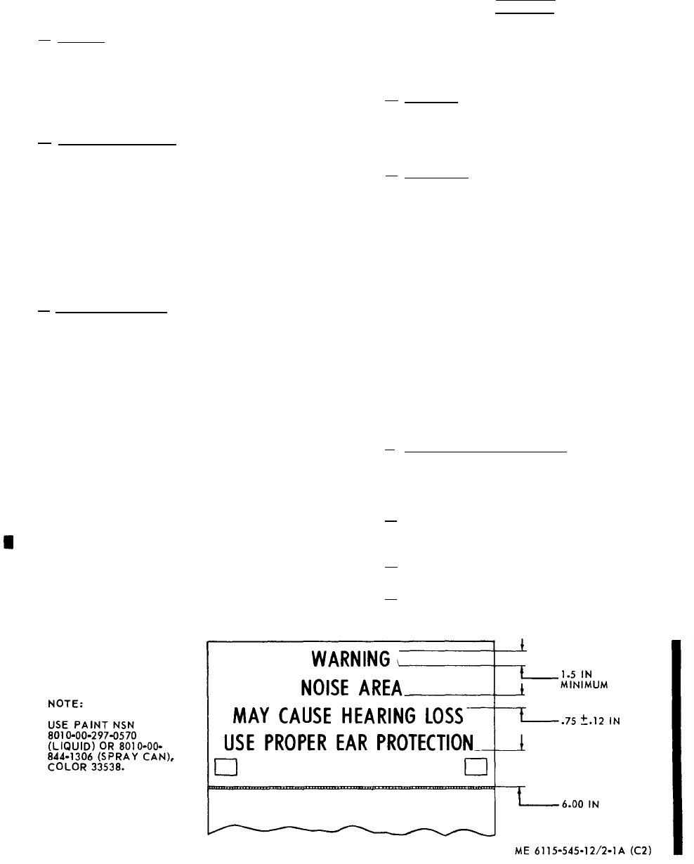
2-5. Installation and Setting-up Instructions.
a. General. The engine generator set should be
installed on a level site, clear of obstacles, and with
ample ventilation. The site must be within 25 feet
of any paralleled generator set, 25 feet of any auxi-
liary fuel supply and 500 feet of any remote control
area.
b. Outdoor Installation. When preparing for a
permanent installation, be sure the base is solid
enough to support the weight of the unit. See figure
2-1 for dimensions of the base. Select a location
where there will be sufficient space on all sides for
servicing and operation of the engine generator set.
When preparing a temporary installation, move the
engine generator set as close to the worksite as
practical. Use suitable planks, logs, or other
material for a base in an area where the ground is
soft .
c. Indoor Installation. Keep the area well venti-
lated at all times, so that the engine generator set
will receive a maximum supply of air. If a free
supply of fresh air is not available, provide duct
work, with an opening at least as large as the radiator,
to the outside of the installation. If louvers are used
at the air entrance, increase the duct work size by
25 to 50 percent. Loosen the screw and nut which
secure the weather cap to the exhaust outlet and re -
move the weather cap. Install a gas-tight metal pipe
exhaust from the exhaust outlet to the outside of the
installation. The termination of the exhaust pipe
shall be such that hot gases or sparks will be dis -
charged harmlessly and will not be directed against
combustible material or into an area containing
flammable gases or vapors. Use as few bends in
the pipe and as short a pipe as possible. The ex-
haust pipe should include a low point with suitable
means for draining of condensate. Provide metal
shields, 12 inches larger in diameter than the ex-
haust pipe where the line passes through flammable
walls. Wrap the exhaust pipe with asbestos if there
is any danger of anyone touching it. Refer to figure
2-1 for dimensions, air flow requirements and floor
loading requirements.
WARNING
Do not operate the engine generator set in an
enclosed area unless the exhaust gases are
piped to the outside. Inhalation of exhaust
fumes will result in serious illness or death.
d. Leveling, The engine generator set is a
portable unit and is designed to operate satisfactorily
up to 15° out-of-level. Set up the unit as level as
possible and keep it as level as possible during
operation.
e. Grounding. The engine generator set must be
grounded prior to operation. The ground can be, in
order of preference, (1) an underground metallic
water piping system, (2) a driven metal rod or
(3) a buried metal plate (fig. 2-2). If the effectively
grounded portion of the buried metallic water pipe
is less than 10 feet due to insulated sections or
joints, this preferred grounding method must be
supplemented by an additional driven metal rod
ground or a buried metal plate ground. A driven
metal ground rod must have a minimum diameter
of 5/8 inch if solid or 3/4 inch if pipe, and driven
to a minimum depth of 8 feet. A buried metal
ground plate must have a minimum area of 9 square
feet, minimum thickness of 1/4 inch, and be buried
at a minimum depth of 4 feet. The ground lead
must be at least No. 6 AWG (American Wire Gauge)
copper wire. Ground rods are available as optional
equipment. The procedures for making a ground
connection are shown in figure 2-2.
f. Generator Load Connections. Instructions
for making the required generator load connections
are designated in figure 2-3.
2-6. Equipment Conversion.
a. Conversion instructions for equipment opera-
tion at 120/208 Vac or 240/416 Vac are given in
figure 2-4.
b. Conversion instructions for equipment opera-
tion of 50 or 60 Hz are given in figure 2-6.
c. Conversion instructions for remote operation
by removal and relocation of the control cubicle are
given in paragraph 2-23.
Figure 2-1A. Noise level warning.
Change 2 2-3
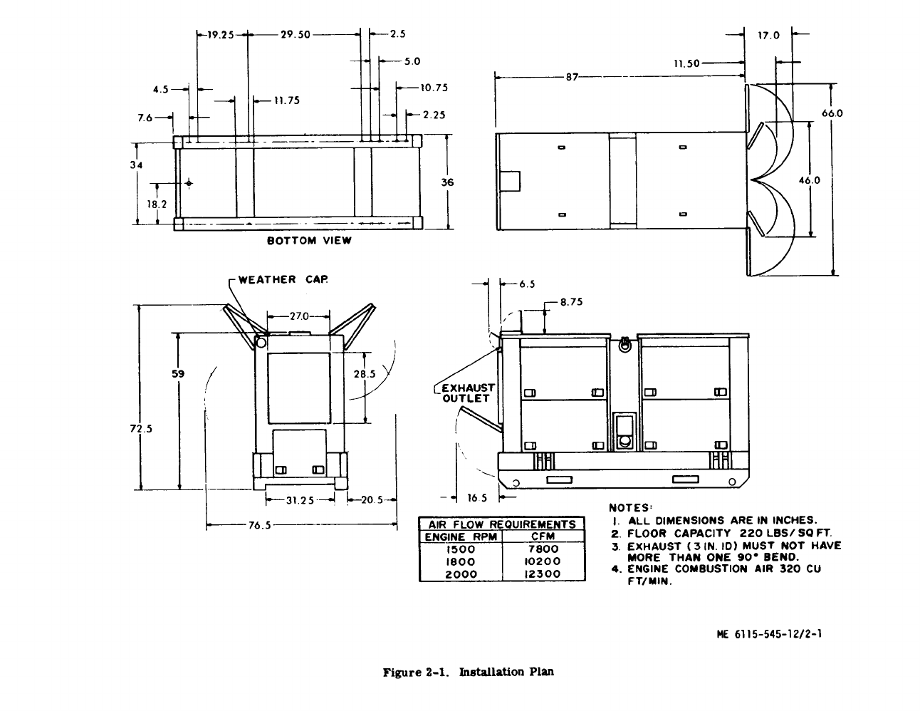
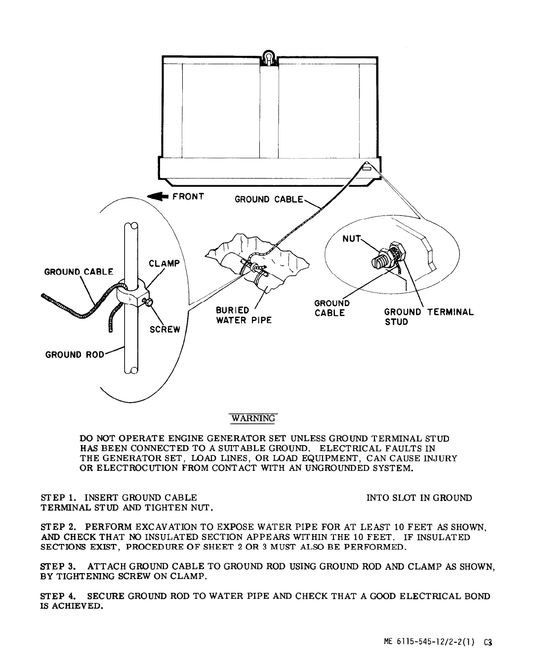
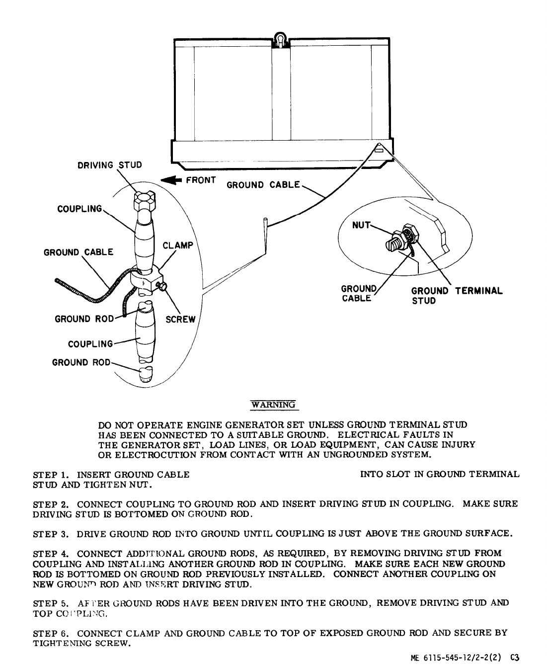
Figure 2-2. Grounding Procedures (Sheet 2 of 3)
2-6 Change 3

TM 5-6115-545-12
TO-35C2-3-444-1
NAVFAC P-8-626-12
TM-00038G-12
Figure 2-2. Grounding Procedures (Sheet 3 of 3)
Change 32-7

TM 5-6115-545-12
TO-35C2-3-444-1
NAVFAC P-8-626-12
TM-00038G-12
WARNING
LETHAL VOLTAGES ARE PRESENT AT THE LOAD CONNECTION BOARD OF
THE GENERATOR SET DURING OPERATION. DO NOT ATTEMPT TO CON-
NECT OR DISCONNECT LOAD LEADS WHILE THE GENERATOR SET IS
OPERATING.
DO NOT ATTEMPT TO CONNECT OR DISCONNECT LOAD
LEADS WITH THE GENERATOR SET SHUTDOWN AND THE LOAD CONNECTED
TO ANOTHER POWER SOURCE, OR WHILE THE GENERATOR SET IS
PARALLELED TO ANOTHER THAT IS OPERATING. WHEN MAKING ANY
ELECTRICAL CONNECTIONS, MAKE SURE THE DC CONTROL CIRCUIT
BREAKER (FIG. 2-5) IS OPEN AND THE NEGATIVE BATTERY TERMINAL
IS DISCONNECTED.
TO PREVENT WATER AND MOISTURE DAMAGE TO CABLE,
ROUTE THE POWER CABLE THROUGH THE LEATHER OR CANVAS BOOT.
AFTER THE END OF THE BLACK INSULATION IS INTO THE BOOT,
SECURE THE BOOT AROUND THE CABLE BY PULLING THE DRAW STRING.
NEXT ROUTE THE CABLES OVER THE TERMINAL BOARD. THEN DOWN
AND AROUND TO THE PROPER TERMINAL.
NOTE
ONE OR MORE SINGLE-PHASE LOADS CAN BE SERVED ALONE OR IN
COMBINATION WITH 3-PHASE LOADS, BUT THE LOAD ON ANY ONE
PHASE MUST NOT EXCEED 33 PERCENT OF THE CURRENT RATING OF
THE ENGINE GENERATOR SET (PHASE BALANCE IS 5 PERCENT).
STEP 1.
208V OR 416V SINGLE-PHASE LOAD CONNECTIONS. USING WRENCH PROVIDED, CONNECT
FIRST LOAD TO L1 AND L2. CONNECT SECOND LOAD TO L2 AND L3. CONNECT THIRD LOAD TO
L1 AND L3.
STEP 2.
120V OR 240V SINGLE-PHASE LOAD CONNECTIONS. CONNECT FIRST LOAD TO L1 AND L0.
CONNECT SECOND LOAD TO L2 and L0. CONNECT THIRD LOAD TO L3 AND L0.
STEP 3.
3-PHASE LOAD CONNECTIONS. THE PHASE SEQUENCE OF THE ENGINE GENERATOR SET
OUTPUT IS L1-L2-L3 AND INSURE THAT THE EXTERNAL LOAD IS APPROPRIATELY CONNECTED.
Figure 2-3.
Generator Load Terminal Board Connections
Change 14
2-8
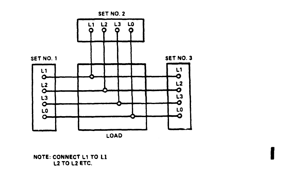
TM 5-6115-545-12
TO-35C2-3-444-1
NAVFAC P-8-626-12
TM-00038G-12
Figure 2-3.1.
Parallel Connection
Change 14
2-8.1
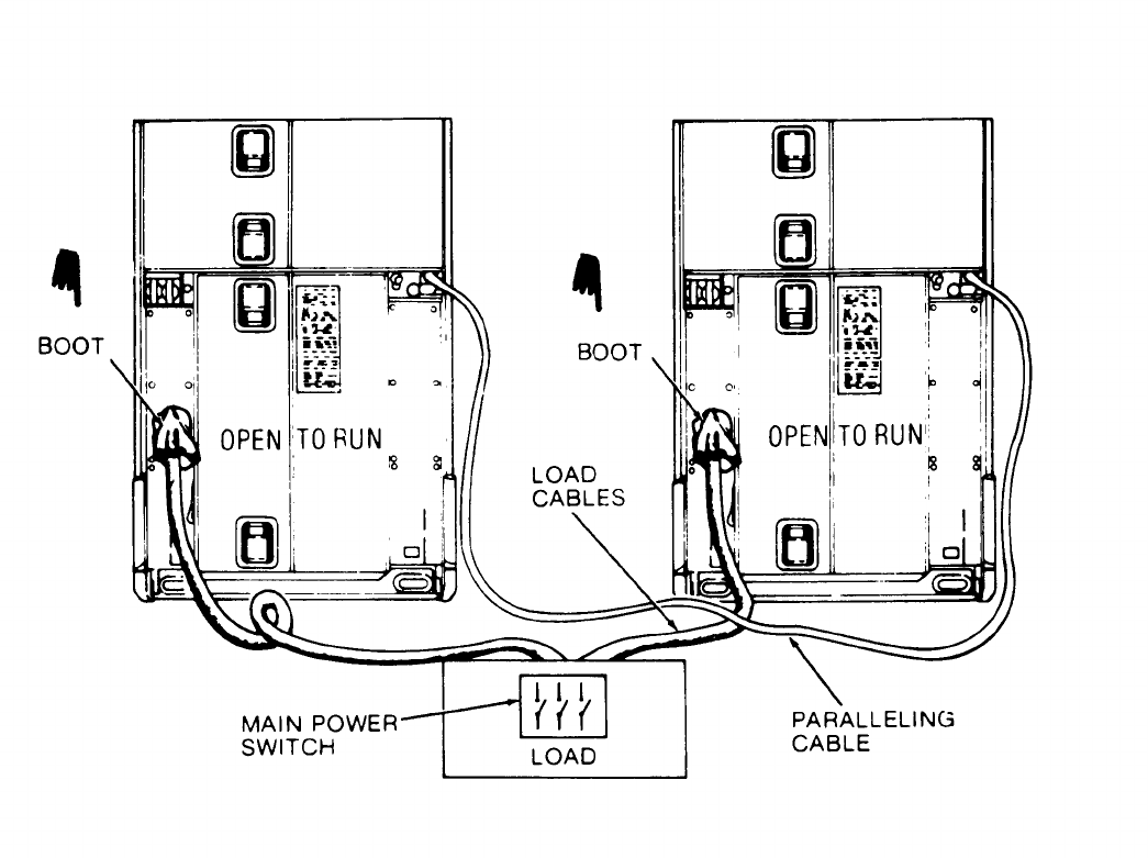
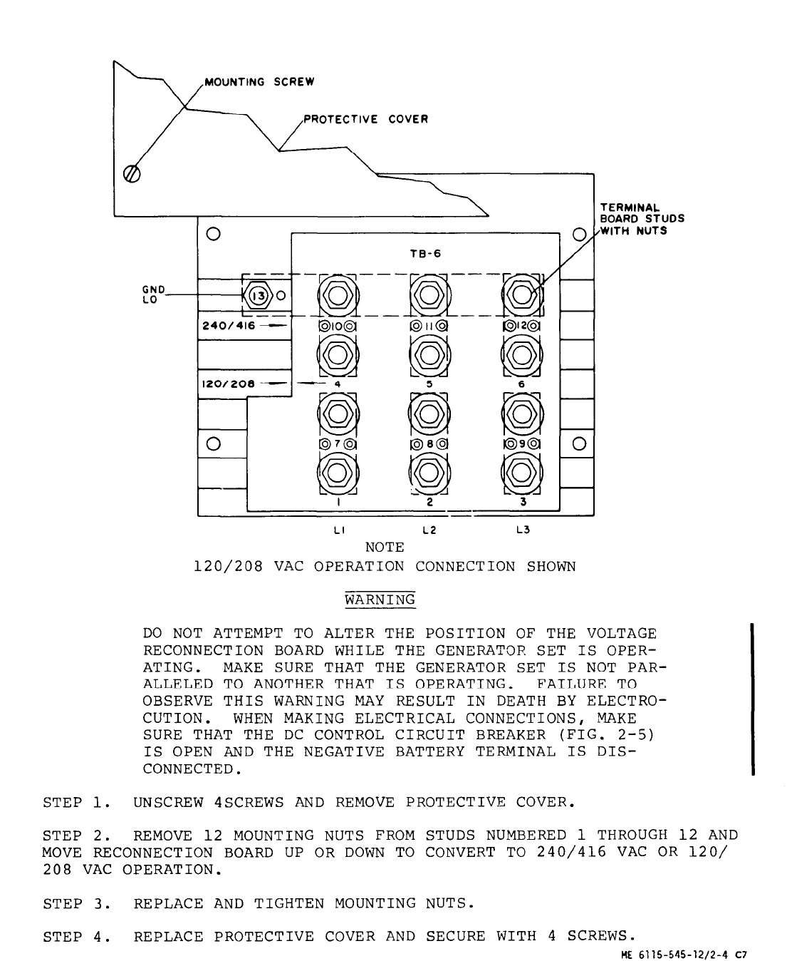

Section II. MOVEMENT TO NEW WORKSITE
2-7. Dismantling for Movement.
WARNING
Make certain that engine generator set is
not operating in a standby mode, or con-
nected to a parallel bus.
a. Preparation for Movement.
(1) Disconnect the load cables from the load
terminal board (fig. 2-3) and tag for identifica-
tion.
(2) Remove the exhaust pipe extension, if
used .
(3) Drain fuel (fig. 3-7) and coolant (para
3-41) if transportation by railroad is anticipated
or the distance to be traveled is great.
(4) Refer to the basic issue item list
(Appendix B) and make sure that all items are
present and properly stowed.
(5) Disconnect the ground lead from the
ground terminal stud (fig. 2-2).
(6) Disconnect any other external hoses,
lines and cables, if used.
(7) Close and secure all doors and panels.
b. Movement.
(1) If the engine generator set is to be
moved only a short distance and the terrain is
suitable, attach a suitable towing device to the
towing openings of the engine generator set and
tow the engine generator set to the new worksite.
(2) If the engine generator set is to be
moved a long distance, or if the terrain is
unsuitable for towing, prepare engine generator
set for moving as described in paragraph 2-7 a.
2-8. Reinstallation after Movement.
Refer to paragraph 2-5 for reinstallation after
movement to a new worksite.
Section III.
CONTROLS AND INSTRUMENTS
2-9. General.
2-10.
Controls and Instruments.
This section describes and illustrates the various The purpose of the generator set controls and
controls and instruments required for generator instruments and the normal and scale readings of
set operation. the instruments are illustrated in figure 2-5.
2-10
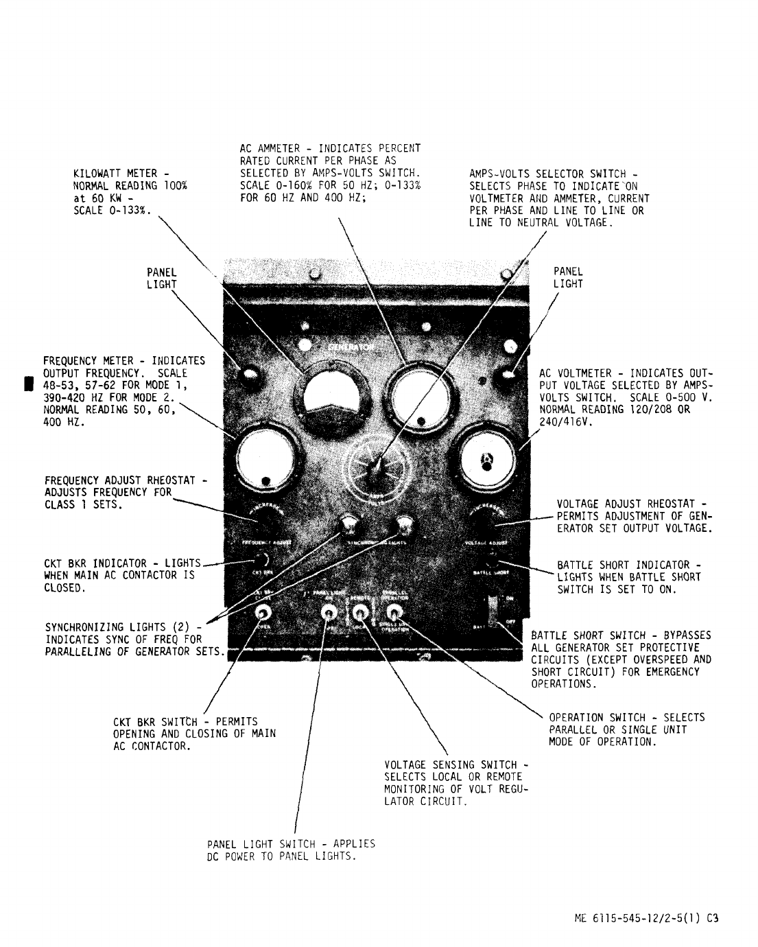

Figure 2-5. Generator Set Controls and Instruments (Sheet 2 of 6)
2-12
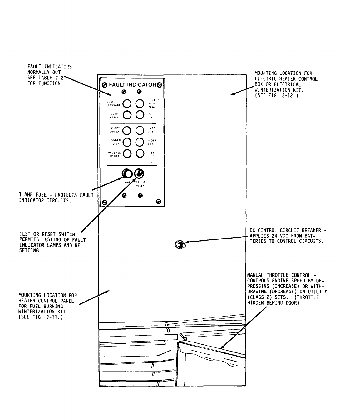
Figure 2-5. Generator Set Controls and Instruments (Sheet 3 of 6)
Change l
2-13
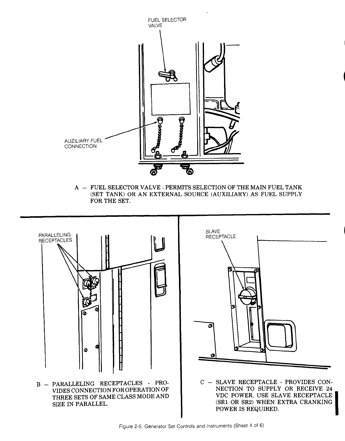
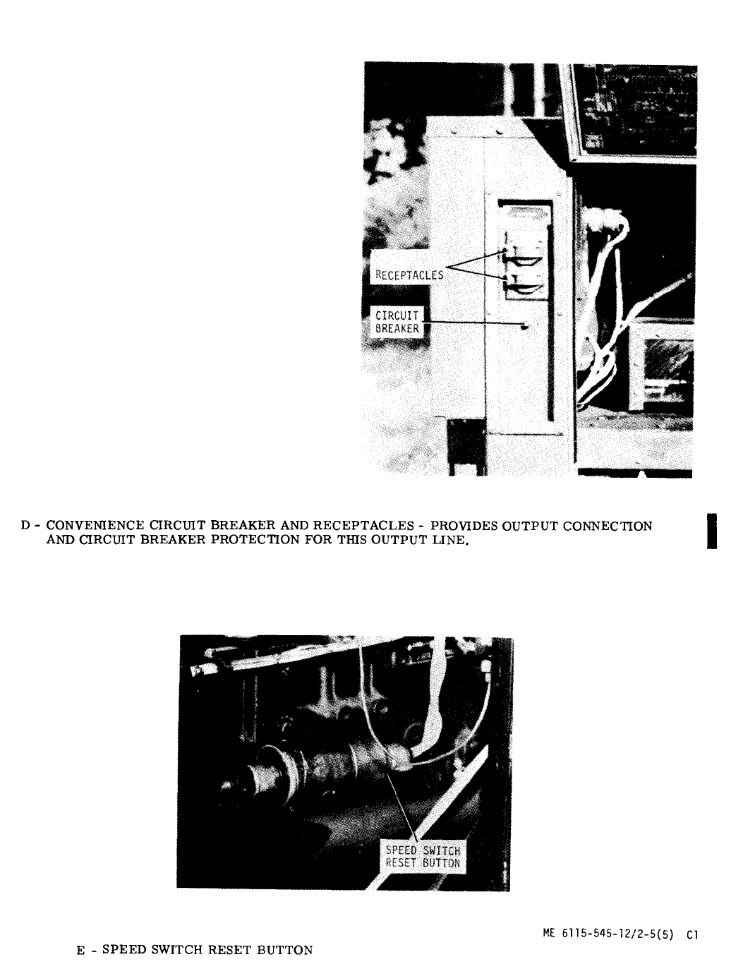
Figure 2-5. Generator Set Controls and Instruments (Sheet 5 of 6)
Change 1
2-15
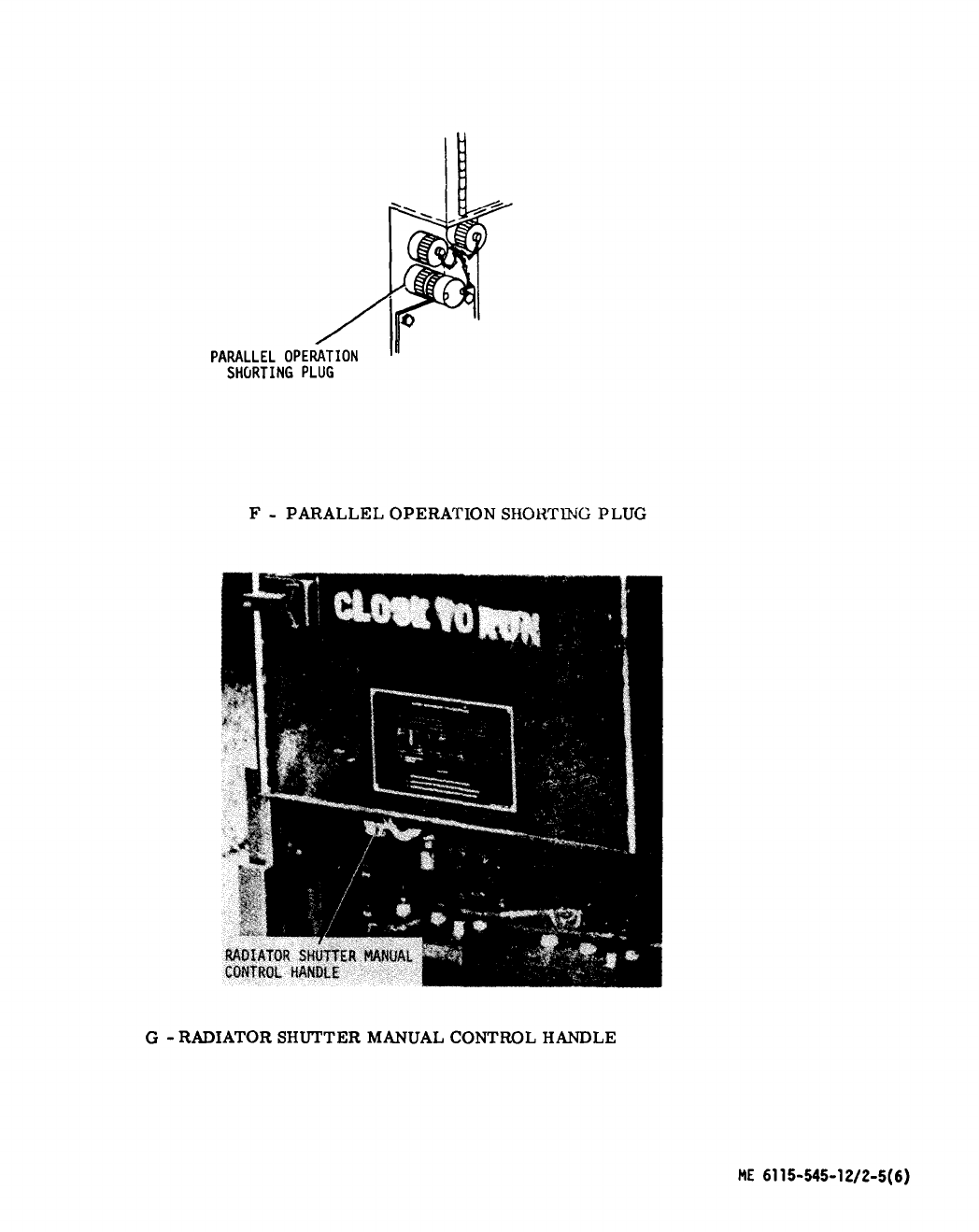
Figure 2-5. Generator Set Controls and Instruments (Sheet 6 of 6)
2-16

Table 2-2. Fault Indicators Function
INDICATOR FUNCTION
(Fig. 2-5)
LOW OIL PRESSURE Lights if oil pressure drops below 20 ± 2 psi.
COOLANT HIGH TEMP Lights if coolant temperature rises above
222 ± 3° F.
OVERSPEED Lights if engine rpm reaches 2400 to 2450 rpm.
NO FUEL Lights if fuel in day tank falls to level permitting
only one minute of engine operation.
SHORT CIRCUIT
Lights if output reaches 425 ± 25% of rated current.
OVER LOAD
Lights if any phase current exceeds 110% of
rated load.
UNDER VOLT
Lights (Class 1 sets only) instantaneously if output
falls below 48 volts, or 6 ± 2 sec after output
reaches 99 ± 4 volts.
UNDER FREQ Lights on (Class 1 sets only) when output freq drops
to: Mode I - 46 ± 1 Hz for 50 Hz operation, 55 ± 1
Hz for 60 Hz operation, Mode II - 370 ± 5 Hz for
400 Hz.
REVERSE POWER Lights if power flow into set exceeds 20% of rated
value.
OVER VOLT Lights if output voltage rises above 153 ± 3 volts.
Change 1 2-17

Section IV. OPERATION UNDER USUAL CONDITIONS
2-11. General. 2-14. Operation of Equipment.
a. Instructions in this section are provided for
information and guidance of personnel responsible
for operation of the engine generator set.
b. The operator must know how to perform every
operation of which the engine generator set is capable.
This section gives instructions on starting and stop-
ping the engine generator set, operation of the gener-
ator set and coordinating the basic motions to perform
the specific tasks for which the equipment is de-
signed. Since nearly every job presents a different
problem, the operator may have to vary procedures
to fit the individual job.
2-12. Starting.
a. Preparation for Starting. Instructions to be
followed when preparing to start the engine genera-
tor set are shown in figure 2-6. Preventive main-
tenance procedures to be performed before opera-
tion are given in table 3-1.
b. Starting. After performing the preparation
for starting procedure of paragraph 2-12a, start the
engine generator set as shown in figure 2-7. If the
engine will not start or if any other abnormality is
observed, notify organizational maintenance
personnel.
2-13. Stopping.
a. Normal Stopping. (See figure 2-8). Preventive
maintenance procedures to be performed after equip-
ment operation are given in table 3-1.
b. Stopping by Safety Devices. The engine gen-
erator set is equipped with safety device electrical
circuits that will automatically stop the engine and
simultaneously open the main ac contactor in case
of; (1) high coolant temperature, (2) low oil pressure,
(3) engine overspeed, (4) over-voltage or, (5) no fuel.
A short circuit, overload, or reverse power protec-
tive relay will automatically open the main ac con-
tactor but will not stop the engine. On precise class
1 engine generator sets only, under voltage and under
frequency relay protective circuits will similarly
open the main ac contactor but will also not stop the
engine. A specific FAULT INDICATOR (fig. 2-5)
will light when any of these abnormal conditions occur.
Refer to table 2-2 for the specific criteria for which
these safety device electrical circuits operate. Once
the engine generator set has been stopped due to the
action of one of these safety devices, the problem
must be corrected before the engine generator set is
placed back in operation.
c. Emergency Stopping. To stop the engine
generator set in an emergency, open DC CONTROL
CIRCUIT BREAKER (fig. 2-8).
a. Single Engine Generator Set Operation.
See-fig. 2-9 for single engine generator set operating
instructions.
b. Parallel Operation of Engine Generator Sets,
See-fig. 2-10 for parallel operation instructions for
up to 3 engine generator sets of the same class,
mode and size.
c. Emergency Operation. If any emergency
situation requires continued operation of the engine
generator set after being shut down by one of the
safety device electrical circuits (para 2-13 b), the
BATTLE SHORT switch (fig. 2-7) can be used to
override all safety devices except the overspeed and
short circuit operation of this switch is as follows:
(1) Place BATTLE SHORT switch in OFF
position.
(2) Hold START-RUN-STOP switch in START
POSITION and start engine (fig. 2-7).
(3) Lift cover and push BATTLE SHORT
switch to ON position.
(4) Release START switch and push BATTLE
SHORT switch to OFF position as soon as possible
after emergency has passed.
NOTE
The BATTLE SHORT switch
may be actuated, as necessary,
any time the engine generator
set is operating.
d.
Load Connections for Parallel Op-
eration.
NOTE
Prior to attempting parallel operation,
ensure all generator sets have the same
frequency and voltage output.
WARNING
Lethal voltages are present at the load
terminal board of the generator set
during operation. Do not attempt to
connect or disconnect load leads while
the generator set is operating. Do not
attempt to connect or disconnect load
leads with the generator set shut down
and the load connected to another power
2-18 Change 12

source, or while the generator set is
paralleled to another set which is op-
erating.
WARNING
Do not attempt to connect the paral-
leling cable while either or both of
the sets to be paralleled is operating.
Make sure that there is no input to the
load from another source. Failure to
observe this warning may result in
death by electrocution.
CAUTION
Precise generator sets equipped with
the electric governor system cannot be
paralleled with sets that have the
electro hydraulic governor system.
(1) If the generator sets are to
share a load greater than the KW rat-
ing of a single set, connect load ter-
minal boards as shown in figure 2-3A.
This arrangement allows for sharing or
transferring of the load between gen-
erator sets.
(2) Open the left access door to
the set compartment and remove the
safety cover from the terminal board
(figure 2-3).
(3) Insert load leads through
plate and sleeve assembly (figure 2-3)
located to the left of the generator
set air intake.
NOTE
The load terminal boards will accommo-
date 2-wire single phase and 4-wire
three phase loads. One or more single
phase loads can be served alone or in
combinations with three phase loads; but
the load on any one phase must not ex-
ceed 100 percent of the current rating
of that phase. Be sure that wire sizes
are correct for load to be carried.
(4) Connect the load to terminals
marked L1, L2, L3 and L0 (figure 2-3).
NOTE
Make certain that the load terminal
boards of the sets to be paralleled are
connected properly. Reading left to
right, phase rotation for the phase
loads is L1, L2, L3. Be sure L1 is
connected to L1, L2 is connected to L2,
etc.
(5) Connect load leads and paral-
leling cables as shown in figures 2-3A
and 2-3B.
NOTE
After load connection, tighten binding
nuts with plastic/phenolic box end
wrench and install safety cover.
NOTE
Paralleling of tactical precise genera-
tor sets requires that paralleling ca-
bles be installed and the shorting plug
located on one of the paralleling re-
ceptacles of each generator set be re-
moved.
2-15. Exercise of Engine on Standby Service.
A diesel engine on standby service that is custom-
arily operated under optimum conditions should be
exercised at least every 30 days. However, under
environmental conditions involving extreme tempera-
tures, humidity, dust, sand, etc., it maybe found
necessary to shorten the interval between exercise
periods teas often as weekly. Exercise period
should be long enough to enable the engine to attain
normal operating temperature (160°-200°F) while
carrying, if possible, at least 50 percent of its
normal load. To exercise engine, proceed as
follows:
a. Perform the preparation for starting instruc-
tion shown in figure 2-6. Make complete visual
inspection of unit to be sure it is in operating condi-
tion.
b. Start engine as shown in figure 2-7. After an
acceptable warm-up period, run engine at rated speed
with whatever load is available, up to full load, for
Change 12 2-18.1/(2-18.2 blank)
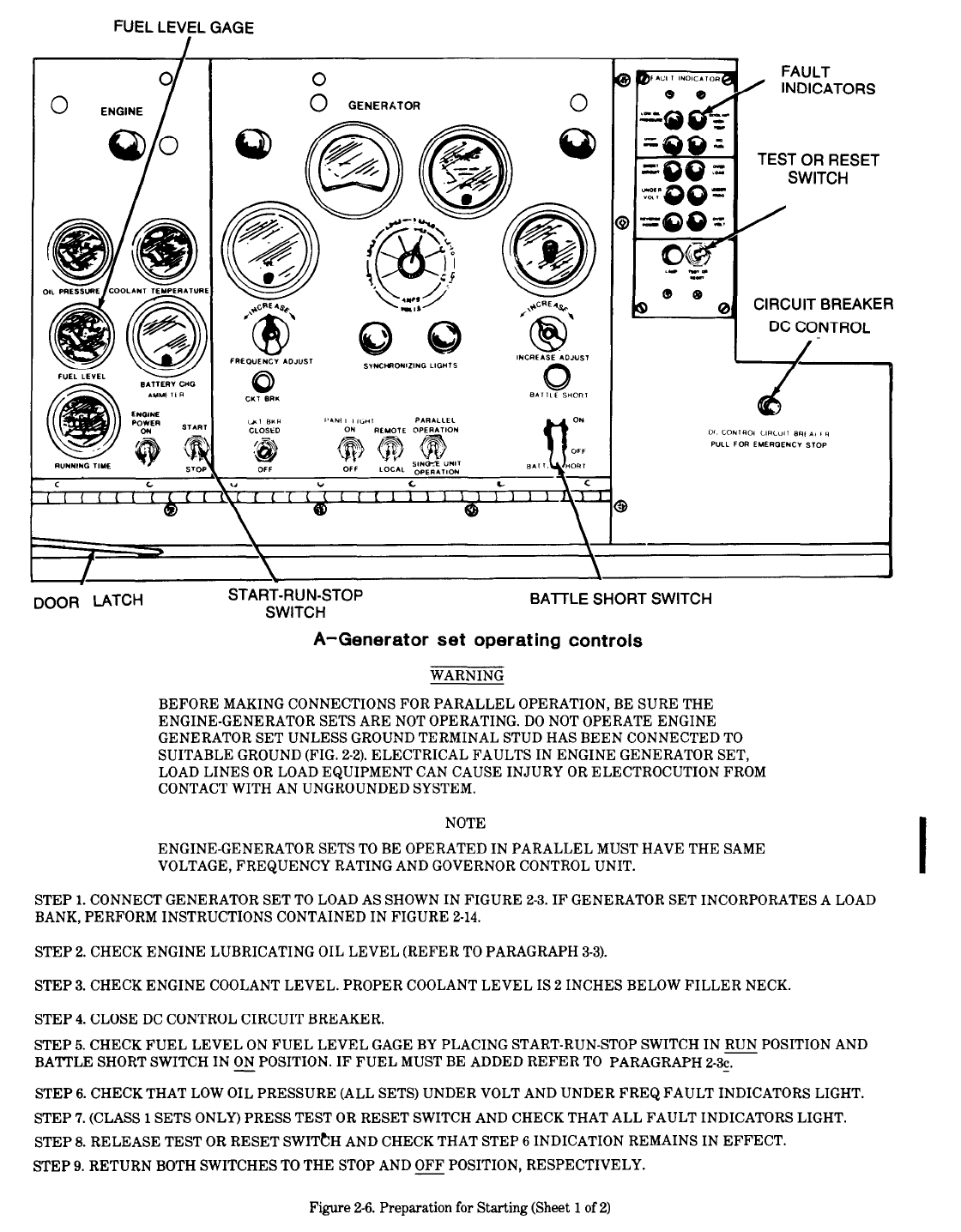
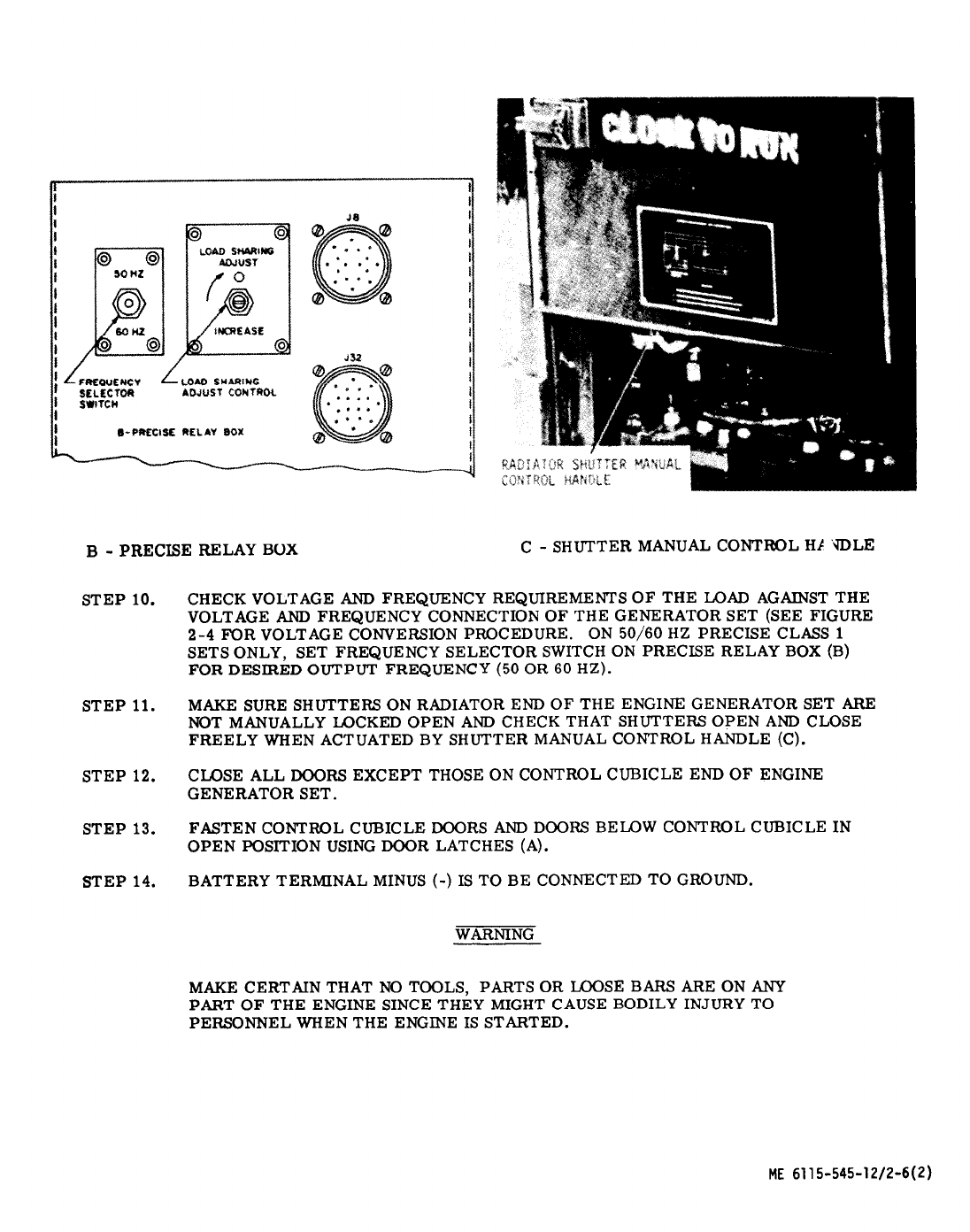
Figure 2-6. Preparation for Starting (Sheet 2 of 2)
2-20

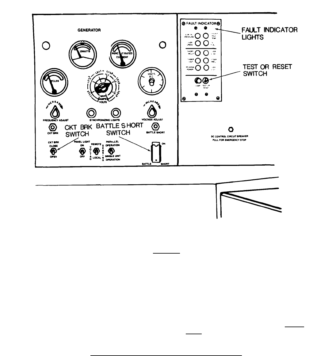
Step 6. ALLOW ENGINE TO WARM UP TO NORMAL OPERATING TEMPERATURE (100 - 150
O
F) WITH
NO LOAD APPLIED.
CAUTION
TO PREVENT ENGINE CARBON DEPOSITS DO NOT RUN ENGINE-GENERATOR
SETS FOR MORE THAN 5 MINUTES AT GOVERNED SPEED WITHOUT LOAD.
STEP 7.
RESET FAULT INDICATOR LIGHTS BY PRESSING TEST OR RESET SWITCH. IF FAULT
INDICATORS, ARE EXTINGUISHED AFTER BEING RESET, PROCEED WITH STEP (8). IF ANY FAULT
INDICATOR LIGHTS, THE INDICATED FAULT (TABLE 2-2) MUST BE CORRECTED BEFORE PROCEED-
ING .
STEP 8.
CLOSE MAIN AC CONTACTOR BY MOMENTARILY PLACING CKT BKR SWITCH IN CLOSE PO-
SITION.
MOMENTARILY PLACING CKT BKR SWITCH IN OPEN POSITION WILL OPEN THE AC CON-
TACTOR.
AMBIENT AIR TEMPERATURE BELOW MINUS 25° F
STEP 1.
PREHEAT ENGINE COOLANT AND LUBRICATING OIL USING EITHER THE FUEL BURNING
OR ELECTRIC WINTERIZATION KIT CONTROLS AS SHOWN IN FIGURES 2-11 and 2-12 RESPECTIVE-
LY .
STEP 2.
PERFORM STARTING PROCEDURE OF STEPS 1 THROUGH 8 SPECIFIED FOR ABOVE MINUS
25° F.
Figure 2-7. Starting Instructions (Sheet 2 of 2)
2-22 Change 3
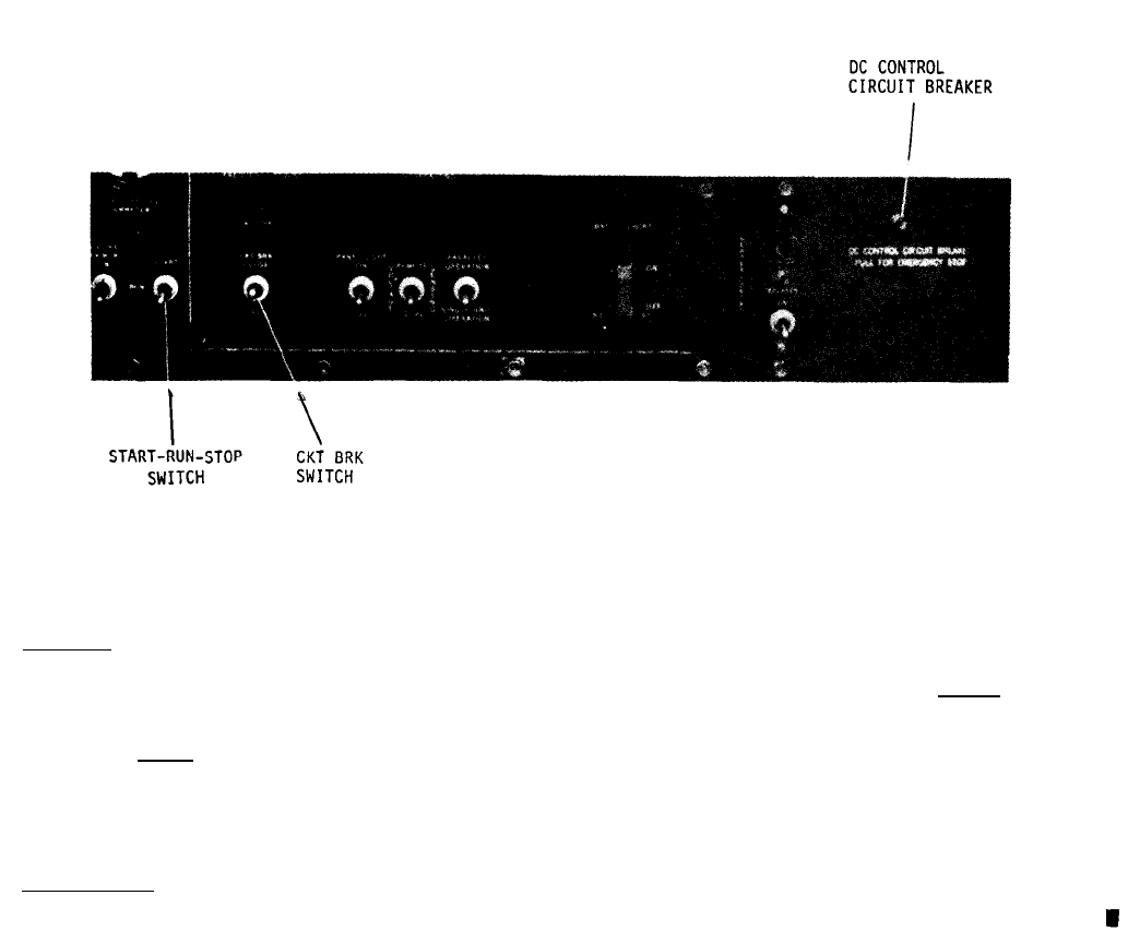
NORMAL
STEP 1. OPEN MAIN AC CONTACTOR BY MOMENTARILY PLACING CKT BRK SWITCH IN OPEN POSITION.
STEP 2. ALLOW 3 MINUTES TO ELAPSE AFTER PERFORMING STEP 1 AND PLACE START-RUN-STOP
SWITCH IN STOP POSITION.
STEP 3. AFTER ENGINE STOPS, REMOVE DC CONTROL POWER BY OPENING DC CONTROL CIRCUIT
BREAKER.
EMERGENCY
PULL DC CONTROL CIRCUIT BREAKER.
ME 6115-545-12/2-8 C3
Figure 2-8. Stopping Instructions
Change 3 2-23
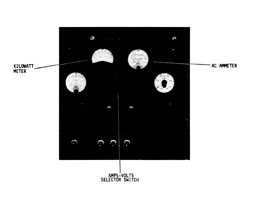
STEP 1.
STEP 2.
STEP 3.
PREPARE ENGINE GENERATOR SET FOR STARTING (FIG. 2-6).
START ENGINE GENERATOR SET (FIG. 2-7).
ROTATE AMPS-VOLTS SELECTOR SWITCH TO EACH PHASE POSITION WHILE OBSERVING AC
AMMETER. IF MORE THAN 100% RATED CURRENT IS INDICATED IN ANY PHASE POSITION, REDUCE
THE LOAD.
STEP 4. IF MORE THAN THE 100% PERCENT LOAD IS INDICATED ON THE KILOWATT METER, REDUCE
THE LOAD.
ME 6115-545-12/2-9
Figure 2-9. Single Generator Unit, Operating Instructions
2-24
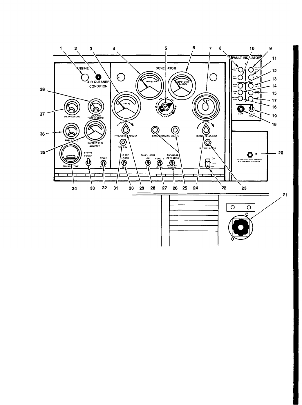
1.
2.
3.
4.
5.
6.
7.
8.
9.
10.
11.
12.
13.
14.
15.
16.
17.
18.
19.
Panel illumination light
Air cleaner condition indicator
Frequency meter
Kilowatt meter
Volts-amps transfer switch
AC ammeter
AC voltmeter
Low oil pressure indicator
Coolant high temperature indicator
Overspeed indicator
No fuel indicator
Short circuit indicator
Overload indicator
Under voltage indicator
Under frequency indicator
Reverse power indicator
Over voltage indicator
Fault location indicator fuse
Test or reset switch
20.
21.
22.
23.
24.
25.
26.
27.
28.
29.
30.
31.
32.
33.
34.
35.
36.
37.
38.
DC circuit breaker
Manual speed control
Battle short switch
Battle short indicator
Voltage adjust rheostat
Synchronizing lights
Operations switch
Voltage sensing switch
Panel light switch
Frequency adjust rheostat
Circuit breaker switch
Circuit breaker indicator
Start-run-stop switch
Engine primer switch
Running time meter
Battery charge ammeter
Fuel level gauge
Oil pressure gauge
Coolant temperature gauge
Figure 2-10. Parallel Operation (Load Sharing and Load Transfer) (Sheet 1 of 5)
Change 12 2-25

A-
PARALLEL OPERATION (LOAD SHARING)
STEP 1.
THE FIRST SET STARTED SHALL BE DESIGNATED AS “ON-LINE” AND THE SETS IN PAR-
ALLEL OPERATION SHALL BE DESIGNATED “ON-COMING.” WITH ALL SETS SHUT DOWN INSTALL
THE PARALLELING CABLE AND CONNECT THE LOAD TERMINAL BOARDS AS DESCRIBED IN FIGURE
2-3A.
CHECK THAT THE VOLTAGE RECONNECTION BOARDS (FIGURE 2-4) OF THE SETS
TICALLY POSITIONED.
CAUTION
DO NOT PLACE THE CIRCUIT BREAKER SWITCH ON ANY OF THE GEN-
ERATOR SETS IN THE CLOSE POSITION UNTIL SPECIFICALLY DI-
RECTED TO DO SO. CLOSING THE CIRCUIT BREAKER SWITCH AT
ANY OTHER TIME MAY SEVERELY DAMAGE ONE OR MORE OF THE GEN-
ERATOR SETS.
CAUTION
CHECK THAT THE MAIN POWER SWITCH (FIGURE 2-3.2) AT THE LOAD
IS OPEN BEFORE ATTEMPTING TO PLACE A GENERATOR SET ON LINE.
STEP 2.
START THE GENERATOR SETS AS DESCRIBED IN FIGURES 2-6 AND 2-7. DO
FORM STEP 8 OF FIGURE 2-7.
ARE IDEN-
NOT PER-
STEP 3.
HOLD THE CKT BRK SWITCH (FIGURE 2-5) OF THE “ON-LINE” SET IN THE CLOSE PO-
SITION UNTIL THE CKT BRK INDICATOR LIGHT ILLUMINATES. PLACE THE OPERATION SWITCH
IN THE PARALLEL POSITION.
STEP 4.
ADJUST THE VOLTAGE ON BOTH SETS TO THE REQUIRED VALUE. ADJUST THE FREQUEN-
CY OF THE “ON-LINE” SET TO THE REQUIRED VALUE. PLACE THE OPERATION SWITCH OF THE
“ON-COMING” SET IN THE PARALLEL POSITION.
NOTE
OBSERVE THE SYNCHRONIZING LIGHTS OF THE “ON-COMING” SET.
THE LIGHTS SHOULD GO ON AND OFF SIMULTANEOUSLY.
IF THE
LIGHTS GO ON AND OFF ALTERNATELY, SETS ARE OUT OF PHASE.
STOP BOTH SETS AND CORRECT INTERCONNECTION CABLES AS DE-
SCRIBED IN (FIGuRE 2-3.1).
IF THE PROBLEM PERSISTS, RE-
FER TO NEXT HIGHER LEVEL OF MAINTENANCE.
STEP 5.
ADJUST THE FREQUENCY OF THE “ON-COMING” SET A LITTLE HIGHER THAN THE “ON-
LINE” SET.
THEN REDUCE THE FREQUENCY SLOWLY WITH THE FREQUENCY ADJUST RHEOSTAT UN-
TIL THE SYNCHRONIZING LIGHTS REMAIN ON OR OFF AT 2 TO 3 SECOND INTERVALS.
STEP 6.
CAREFULLY OBSERVE THE SYNCHRONIZING LIGHTS OF THE “ON-COMING” SET AND, AT
THE INSTANT BOTH LIGHTS GO DARK, PLACE THE CKT BRK SWITCH OF THE “ON-COMING” SET TO
THE CLOSE POSITION. WHEN THE CKT BRK INDICATOR LIGHT ILLUMINATES, THE SETS ARE OP-
ERATING IN PARALLEL.
Figure 2-10. Parallel Operation (Load Sharing and Load Transfer) (Sheet 2 of 5)
2-26 Change 12

CAUTION
THE KILOWATT METER AND AC AMMETER INDICATE PERCENTAGES AND
DO NOT INDICATE TRUE KW AND AMPERE READINGS.
STEP 7.
WITH NO EXTERNAL LOAD ON THE PARALLELED SETS, ADJUST THE FREQUENCY ADJUST
RHEOSTAT OF THE “ON-COMING” SET UNTIL BOTH RATED LOAD METERS (KILOWATT) READ ZERO.
ADJUST THE VOLTAGE ADJUST RHEOSTAT OF THE “ON-COMING SET UNTIL THE PERCENT OF RATED
CURRENT METERS (AMMETERS) ON BOTH SETS READ ZERO. TURNING COUNTERCLOCKWISE WILL DE-
CREASE READINGS.
STEP 8.
APPLY LOAD TO THE SETS. THE KILOWATT LOAD SHOULD DIVIDE SO THAT THE LOAD
ON EACH SET IS EQUAL. IF THE LOAD AND CURRENT ARE NOT SHARED EQUALLY, ADJUST THE
VOLTAGE AND FREQUENCY RHEOSTATS OF THE “ON-COMING” SET UNTIL LOAD AND CURRENT ARE
DIVIDED EQUALLY BETWEEN THE GENERATOR SETS.
STEP 9.
THE CURRENT SHOULD DIVIDE SO THAT THE OBSERVED DIFFERENCE BETWEEN THE CUR-
RENT ON ANY PHASE BETWEEN THE “ON-LINE” AND “ON-COMING” SETS IS NOT MORE THAN 20
PERCENT. IF
STEP 10. TO
THE READINGS ARE NOT WITHIN 20 PERCENT, NOTIFY HIGHER LEVEL MAINTENANCE.
NOTE
IF THE REVERSE POWER INDICATOR OF EITHER SET ILLUMINATES
AND THE MAIN LOAD CONTACTOR OPENS, OPEN THE MAIN POWER
SWITCH AND REPARALLEL THE GENERATOR SETS.
CAUTION
WHEN GENERATOR SETS ARE BEING OPERATED IN PARALLEL, ONE OR
MORE OPERATORS MUST REMAIN WITH THE SETS TO MONITOR THE RAT-
ED LOAD AND CURRENT METERS.
NOTE
TWO OR MORE GENERATOR SETS CAN BE OPERATED IN PARALLEL.
PARALLELING PROCEDURES-ARE THE SAME AS THOSE DESCRIBED
ABOVE.
ONE GENERATOR AT A TIME IS BROUGHT ON LINE.
CAUTION
PRIOR TO REMOVAL OF GENERATOR SETS FROM PARALLEL OPERATION,
MAKE SURE THE LOAD DOES NOT EXCEED THE FULL LOAD RATING OF
GENERATOR SETS(S) REMAINING ON LINE.
REMOVE A GENERATOR SET FROM PARALLEL OPERATION, PLACE THE CIRCUIT
BREAKER SWITCH OF THE SET IN THE OPEN POSITION. STOP THE SET AS DESCRIBED IN FIGURE
2-8.
B-
PARALLEL OPERATION (LOAD TRANSFER)
THE FOLLOWING METHOD OF PARALLEL OPERATION IS TO BE USED WHEN IT IS NECESSARY TO
TRANSFER THE LOAD FROM ONE SET TO THE OTHER WITHOUT INTERRUPTING POWER.
Figure 2-10. Parallel Operation (Load Sharing and Load Transfer) (Sheet 3 of 5)
Change 12
2-26.1

NOTE
VISUALLY CHECK THAT THE POWER CABLE AND PARALLEL CABLE ARE
IN ACCORDANCE WITH FIGURE 2-3B. IF THE CABLES ARE NOT AT-
TACHED AS INDICATED, SHUT DOWN THE “ON-LINE” SET AND FOL-
LOW INSTRUCTIONS IN PARAGRAPH 2-14D.
CAUTION
DO NOT ATTEMPT LOAD CONNECTS IN PARAGRAPH 2-14D UNLESS ALL
SETS ARE OFF AND NO OTHER EXTERNAL VOLTAGE IS APPLIED TO
THE LOAD.
STEP 1.
THE SET IN OPERATION SHALL BE DESIGNATED AS “ON-LINE” AND THE SETS PLACED
IN PARALLEL OPERATION SHALL BE DESIGNATED “ON-COMING.”
STEP 20
PLACE THE OPERATIONS SWITCH (FIGURE 2-5) ON BOTH SETS IN THE PARALLEL OPER-
ATION POSITION.
CAUTION
DO NOT CLOSE THE CIRCUIT BREAKER SWITCH AFTER STARTING THE
“ON-COMING” SET AS SERIOUS DAMAGE TO ONE OR BOTH GENERATOR
SETS MAY RESULT.
STEP 3.
REFER TO FIGURE 2-6 AND 2-7 (DO NOT PERFORM STEP 8 OF FIGURE 2-7), AND START
THE “ON-COMING” SET.
STEP 4.
NOTE THE VOLTAGE INDICATED ON THE “ON-LINE" SET. ADJUST THE VOLTAGE OF THE
“ON-COMING" SET TO THE VOLTAGE NOTED ON THE “ON-LINE” SET.
STEP 5.
ADJUST THE FREQUENCY OF THE “ON-COMING” SET TO A HIGHER VALUE THAN THAT OF
THE “ON-LINE” SET.
STEP 6.
SLOWLY REDUCE THE FREQUENCY OF THE “ON-COMING” SET UNTIL THE SYNCHRONIZING
LIGHTS (FIGURE 2-5) FLASH AT 2 TO 3 SECOND INTERVALS.
CAUTION
DO NOT PLACE THE CIRCUIT BREAKER SWITCH OF THE “ON-COMING”
SET IN THE CLOSE POSITION WHILE THE SYNCHRONIZING LIGHTS
ARE LIT AS DAMAGE TO ONE OR BOTH GENERATOR SETS MAY RESULT.
STEP 7.
CAREFULLY WATCH THE SYNCHRONIZING LIGHTS OF THE “ON-COMING” SET. AT THE
INSTANT BOTH LIGHTS GO DARK, MOVE THE CIRCUIT BREAKER SWITCH OF THE “ON-COMING” SET
TO THE CLOSE POSITION.
STEP 8.
LOAD AND
STEP 9.
STEP 10.
ADJUST THE VOLTAGE AND FREQUENCY RHEOSTATS OF THE “ON-COMING” SET UNTIL
CURRENT ARE DIVIDED EQUALLY BETWEEN THE TWO GENERATOR SETS.
MOVE THE CIRCUIT BREAKER SWITCH OF THE “ON-LINE” SET TO THE OPEN POSITION.
PLACE THE OPERATIONS SWITCH OF THE “ON-COMING” SET TO THE SINGLE UNIT OPER-
ATION POSITION.
Figure 2-10. Parallel Operation (Load Sharing and Load Transfer)
2-26.2
Change 12
(Sheet 4 of 5)

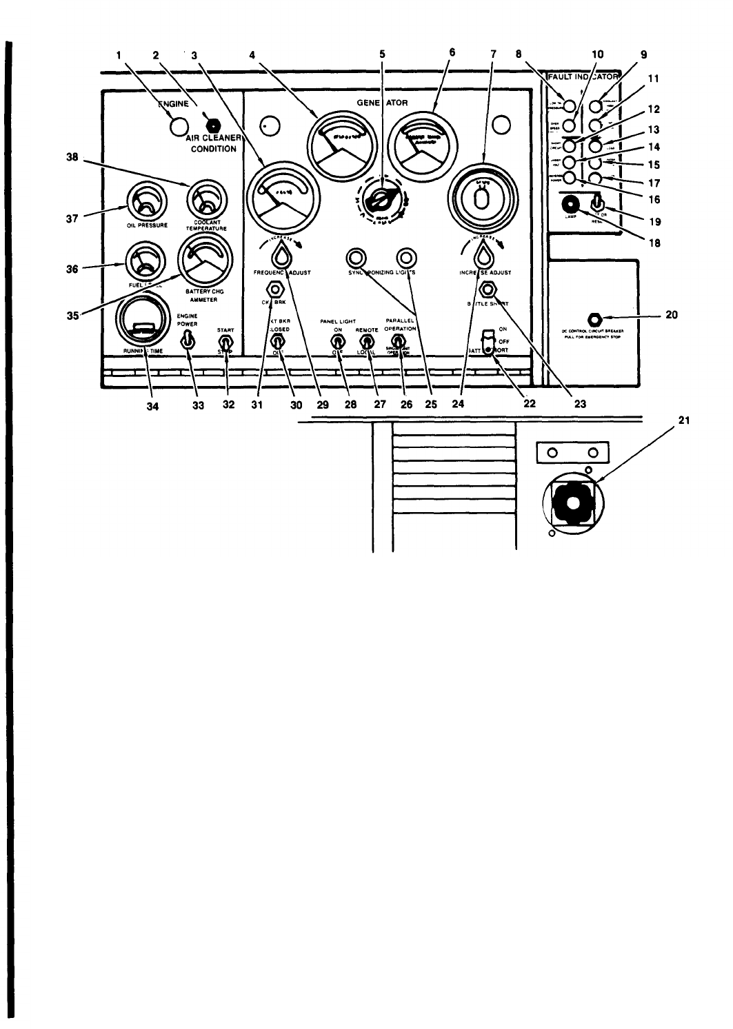
1. Panel illumination light
2. Air cleaner condition indicator
3. Frequency meter
4. Kilowatt meter
5. Volts-amps transfer switch
6. AC ammeter
7. AC voltmeter
8. Low oil pressure indicator
9. Coolant high temperature indicator
10. Overspeed indicator
11. No fuel indicator
12. Short circuit indicator
13. Overload indicator
14. Under voltage indicator
15. Under frequency indicator
16. Reverse power indicator
17. Over voltage indicator
18. Fault location indicator fuse
19. Test or reset switch
20.
21.
22.
23.
24.
25.
26.
27.
28.
29.
30.
31.
32.
33.
34.
35.
36.
37.
38.
DC circuit breaker
Manual speed control
Battle short switch
Battle short indicator
Voltage adjust rheostat
Synchronizing lights
Operations switch
Voltage sensing switch
Panel light switch
Frequency adjust rheostat
Circuit breaker switch
Circuit breaker indicator
Start-run-stop switch
Engine primer switch
Running time meter
Battery charge ammeter
Fuel level gauge
Oil pressure gauge
Coolant temperature gauge
Figure 2-10A. Parallel Operation of Tactical Utility Generator Sets
(Load Sharing and Load Transfer) (Sheet 1 of 4)
Change 12
2-26.4

A-
PARALLEL OPERATION OF TACTICAL UTILITY GENERATOR SETS (LOAD SHARING)
STEP 1.
THE FIRST SET STARTED SHALL BE DESIGNATED AS “ON-LINE” AND THE SETS IN PAR-
ALLEL OPERATION SHALL BE DESIGNATED “ON-COMING.” WITH ALL SETS SHUT DOWN CONNECT
THE LOAD TERMINAL BOARDS AS DESCRIBED IN FIGURE 2-3. CHECK THAT THE VOLTAGE RECON-
NECTION BOARDS (FIGURE 2-4) OF THE SETS ARE IDENTICALLY POSITIONED.
CAUTION
DO NOT PLACE THE CIRCUIT BREAKER SWITCH ON ANY OF THE
GENERATOR SETS IN THE CLOSE POSITION UNTIL SPECIFICAL-
LY DIRECTED TO DO SO. CLOSING THE CIRCUIT BREAKER
SWITCH AT ANY OTHER TIME MAY SEVERELY DAMAGE ONE OR
MORE OF THE GENERATOR SETS.
CAUTION
CHECK THAT THE MAIN POWER SWITCH (FIGURE 2-3.2) AT THE
LOAD IS OPEN BEFORE ATTEMPTING TO PLACE A GENERATOR SET
ON LINE.
STEP 2.
START THE GENERATOR SETS AS DESCRIBED IN FIGURES 2-6 AND 2-7. DO NOT PER-
FORM STEP 8 OF FIGURE 2-7.
STEP 3.
HOLD THE CKT BRK SWITCH (FIGURE 2-5) OF THE “ON-LINE” SET IN THE CLOSE PO-
SITION UNTIL THE CKT BRK INDICATOR LIGHT ILLUMINATES. PLACE THE OPERATION SWITCH IN
THE PARALLEL POSITION.
STEP 4.
SET “VOLT-AMPS TRANSFER SWITCH” IN THE LI-LO POSITION. ADJUST THE VOLTAGE
ADJUST RHEOSTAT UNTIL THE AC VOLTMETER INDICATES 122 VOLTS FOR THE 120/208 CONNEC-
TION AND 244 VOLTS FOR THE 240/416 CONNECTION. ADJUST MANUAL SPEED CONTROL UNTIL
THE FREQUENCY METER INDICATES 61 HERTZ. PLACE THE OPERATION SWITCH OF THE “ON-COM-
ING” SET IN THE PARALLEL POSITION.
NOTE
OBSERVE THE SYNCHRONIZING LIGHTS OF THE “ON-COMING” SET.
THE LIGHTS SHOULD GO ON AND OFF SIMULTANEOUSLY
IF THE
LIGHTS GO ON AND OFF ALTERNATELY, SETS ARE OUT OF PHASE.
STOP BOTH SETS AND CORRECT INTERCONNECT CABLES (FIGURE
2-3.1). IF PROBLEM PERSISTS, REFER TO NEXT HIGHER LEVEL
OF MAINTENANCE.
STEP 5.
ADJUST THE MANUAL SPEED CONTROL OF THE “ON-COMING” SET UNTIL THE SYNCHRON-
IZING LIGHTS, SIMULTANEOUSLY, REMAIN ON OR OFF AT 2 TO 3 SECOND INTERVALS.
STEP 6.
CAREFULLY OBSERVE THE SYNCHRONIZING LIGHTS OF THE “ON-COMING” SET AND, AT
THE INSTANT BOTH LIGHTS GO DARK, PLACE THE CKT BRK SWITCH OF THE “ON-COMING” SET TO
THE CLOSE POSITION. WHEN THE CKT BRK INDICATOR LIGHT ILLUMINATES, THE SETS ARE OP-
ERATING IN PARALLEL.
Figure 2-10A. Parallel Operation of Tactical Utility Generator Sets
(Load Sharing and Load Transfer) (Sheet 2 of 4)
Change 12
2-26.5

STEP 7.
WITH NO EXTERNAL LOAD ON THE PARALLELED SETS, ADJUST THE MANUAL SPEED CON-
TROL OF THE “ON-COMING” SET UNTIL BOTH PERCENT POWER METERS (KILOWATT) INDICATE
ZERO .
ADJUST THE VOLTAGE ADJUST RHEOSTAT OF THE “ON-COMING” SET UNTIL THE PERCENT
OF RATED CURRENT METERS (AMMETERS) ON BOTH SETS INDICATE ZERO. TURNING COUNTER-
CLOCKWISE WILL DECREASE READINGS.
STEP 8.
APPLY LOAD TO THE SETS. THE KILOWATT LOAD SHOULD DIVIDE SO THAT THE LOAD
ON EACH SET IS EQUAL. IF THE LOAD AND CURRENT ARE NOT SHARED EQUALLY, ADJUST THE
LOAD BY OBSERVING THE SET WHICH HAS THE HIGHER READING ON THE KILOWATT METER. DE-
CREASE THE ENGINE SPEED OF THIS SET BY ADJUSTING COUNTERCLOCKWISE THE MANUAL SPEED
CONTROL IN SMALL INCREMENTS. INCREASE THE ENGINE SPEED OF THE SET WITH THE LOWER
KILOWATT READING BY ADJUSTING CLOCKWISE THE MANUAL SPEED CONTROL IN SMALL INCREMENTS.
ADJUSTMENTS SHOULD BE MADE BETWEEN BOTH SETS UNTIL THE KILOWATT METERS ARE BALANCED.
STEP 9.
THE CURRENT SHOULD DIVIDE SO THAT THE OBSERVED DIFFERENCE BETWEEN THE CUR-
RENT ON ANY PHASE BETWEEN THE “ON-LINE” AND “ON-COMING” SETS IS NOT MORE THAN 20
PERCENT.
IF THE READINGS ARE NOT WITHIN 20 PERCENT, NOTIFY HIGHER LEVEL MAINTENANCE.
CAUTION
WHEN GENERATOR SETS ARE BEING OPERATED IN PARALLEL, ONE
OR MORE OPERATORS MUST REMAIN WITH THE SETS TO MONITOR THE
RATED LOAD AND CURRENT METERS. MAKE FURTHER ADJUSTMENTS
AS REQUIRED TO MAINTAIN EQUAL LOAD ON THE PARALLELED SETS.
CAUTION
PRIOR TO REMOVAL OF GENERATOR SET FROM PARALLEL OPERATION,
MAKE SURE THE LOAD DOES NOT EXCEED THE FULL LOAD RATING OF
SETS(S) REMAINING ON LINE.
STEP 10. TO REMOVE A GENERATOR SET FROM PARALLEL OPERATION, PLACE THE CIRCUIT BREAK-
ER SWITCH OF THAT SET IN THE OPEN POSITION. STOP THE SET AS DESCRIBED IN FIGURE 2-8.
B-
PARALLEL OPERATION (LOAD TRANSFER)
THE FOLLOWING METHOD OF PARALLEL OPERATION IS TO BE USED WHEN IT IS NECESSARY TO
TRANSFER THE LOAD FROM ONE SET TO THE OTHER WITHOUT INTERRUPTING POWER.
NOTE
VISUALLY CHECK THAT THE POWER CABLE AND PARALLEL CABLE ARE
IN ACCORDANCE WITH FIGURE 2-3.2. IF THE CABLES ARE NOT AT-
TACHED AS INDICATED, SHUT DOWN THE “ON-LINE” SET AND FOLLOW
INSTRUCTIONS IN PARAGRAPH 2-14D.
CAUTION
DO NOT ATTEMPT LOAD CONNECTS IN PARAGRAPH 2-14D UNLESS ALL
SETS ARE OFF AND NO OTHER EXTERNAL VOLTAGE IS APPLIED TO
THE LOAD.
Figure 2-l0.l.
Parallel Operation of Tactical Utility Generator Sets
(Load Sharing and Load Transfer) (Sheet 3 of 4)
2-26.6
Change 12

STEP 1.
THE SET IN OPERATION SHALL BE DESIGNATED AS “ON-LINE” AND THE SETS PLACED
IN PARALLEL OPERATION SHALL BE DESIGNATED “ON-COMING.”
STEP 2.
PLACE THE OPERATIONS SWITCH (FIGURE 2-5) ON BOTH SETS IN THE PARALLEL OPER-
ATION POSITION.
CAUTION
DO NOT CLOSE THE CIRCUIT BREAKER SWITCH AFTER STARTING THE
“ON-COMING” SET AS SERIOUS DAMAGE TO ONE OR BOTH GENERATOR
SETS MAY RESULT.
STEP 3.
REFER TO FIGURE 2-6 AND 2-7 (DO NOT PERFORM STEP 8 OF FIGURE 2-7), AND START
THE “ON-COMING” SET.
STEP 4.
NOTE THE VOLTAGE INDICATED ON THE “ON-LINE” SET. ADJUST THE VOLTAGE OF THE
“ON-COMING” SET TO THE VOLTAGE NOTED ON THE “ON-LINE” SET.
STEP 5.
ADJUST THE FREQUENCY OF THE “ON-COMING” SET TO A HIGHER VALUE THAN THAT OF
THE “ON-LINE” SET.
STEP 6.
SLOWLY REDUCE
LIGHTS FLASH AT 2 TO 3
THE FREQUENCY OF THE “ON-COMING” SET UNTIL THE
SECOND INTERVALS. SYNCHRONIZING
CAUTION
DO NOT PLACE THE CIRCUIT BREAKER SWITCH OF THE “ON-COMING”
SET IN THE CLOSE POSITION WHILE THE SYNCHRONIZING LIGHTS ARE
LIT AS DAMAGE TO ONE OR BOTH GENERATOR SETS MAY RESULT.
STEP 7.
CAREFULLY WATCH THE SYNCHRONIZING LIGHTS OF THE “ON-COMING” SET. AT THE
INSTANT BOTH LIGHTS GO DARK, MOVE THE CIRCUIT BREAKER SWITCH OF THE “ON-COMING”
TO THE CLOSE POSITION.
STEP 8.
ADJUST THE VOLTAGE AND FREQUENCY RHEOSTATS OF BOTH SETS UNTIL LOAD AND
RENT ARE DIVIDED EQUALLY BETWEEN THE TWO GENERATOR SETS,AS EXPLAINED IN FIGURE
2-10.1, PARAGRAPH A, STEPS 7 AND 8.
SET
CUR-
STEP 9.
MOVE THE CIRCUIT BREAKER SWITCH OF THE “ON-LINE” SET TO THE OPEN POSITION.
STEP 10. PLACE THE OPERATIONS SWITCH OF THE “ON-COMING” SET TO THE SINGLE UNIT OPER-
ATION POSITION.
STEP 11. READJUST VOLTAGE AND FREQUENCY OF THE “ON-COMING” SET AS NECESSARY.
STEP 12. REFER TO FIGURE 2-8 AND STOP THE “ON-LINE” SET.
Figure 2-10.1.
Parallel Operation of Tactical Utility Generator Sets
(Load Sharing and Load Transfer) (Sheet 4 of 4)
Change 12 2-26.7/(2-26.8 blank)

the period of time required to obtain two consecutive
od) during a six-month period, it is
water temperature readings of 160° F minimum,
recommended that the filters and lubri-
taken at a 15-minute interval. Then continue to eating oil be changed (para 3-4). If
operate engine for 30 minutes. Check and correct
any coolant or oil leaks.
the accumulated hours of operation dur-
ing the above exercise periods do not
c.
Stop engine as shown in figure
total 100 hours (recommended fuel filter
2-8.
If the accumulated hours of opera- change period) during a 12-month period,
tion during the above exercise periods it is recommended that the fuel filter
do not total 300 hours (recommended lube element be replaced (para 3-160).
filters and lubricating oil change peri-
Section V. OPERATION UNDER UNUSUAL CONDITIONS
2-16. Operation in Extreme Cold (Below- 25°F).
a. General. The engine generator set is designed
to operate in temperatures down to - 25°F without
winterization equipment. To operate successfully at
temperatures below -25° F, the engine must be heated
by integrally mounted electric winterization heating
equipment (fig. 2-12) which receives auxiliary power
from an external source or by a fuel burning winteriza-
tion system (fig. 2-11). Operate fuel burning winter-
ization system for 55 minutes or until fuel burning
winterization system cycles off. Operate electric win-
terization for 5 hrs.
b. Fuel System. Keep the fuel tank as full as pos-
sible to prevent condensation of moisture. Be sure
the proper grade of fuel is used for existing tempera-
tures. Service the fuel filters and strainers (para
3-34b) more frequently than normal. Remove ice,
snow, and moisture from the filler cap and filler
neck. At end of day’s operation, drain water from
fuel tank (fig. 3-7) and from the fuel filters (para 3-56).
c. Engine Electrical System. Clean the batteries
and cables and inspect for cracked or damaged cases.
Be sure the battery terminals are tight, clean, and
lightly greased. See that the battery cap vent holes
are open. The electrolyte level must be 3/8 inch
above the plates. To prevent the batteries from freez-
ing, see that they are kept fully charged. Inspect all
electrical wiring for cracks, breaks, and fraying.
Tighten loose connections.
NOTE
After adding water to the batteries
in freezing temperatures, run the
engine for at least an hour to thor-
oughly mix the water with the
electrolyte.
d. Lubrication. Lubricate the engine generator set
in accordance with instructions in paragraphs 3-3 and
3-4.
e.
Cooling System. Inspect the level of the coolant
in the radiator. Inspect the cooling system for leaks,
aying particular attention to gaskets and hose con-
nections. Verify that antifreeze mixture is in ac-
cordance with table 2-1.
f. Air Cleaner. Refer to paragraph 3-32 for proper
maintenance of air cleaner.
2-17. Operation in Extreme Heat (up to + 125° F).
a. Keep the cooling system free from rust and
scale. If necessary, add an approved rust inhibitor.
Keep cooling system filled with clean, approved
coolant. Avoid, if possible, the use of alkaline water
or salt water, which cause the accumulation of rust
and scale. Inspect the belts for proper adjustment.
Be sure that the engine generator set is free of dust
and dirt. Check for obstructions in the cooling fins
of the radiator and make sure shutter controls are
operating properly.
b. Lubricate the engine in accordance with the
instructions in paragraph 3-3 and 3-4.
c. Do not fill the fuel tank too full; allow sufficient
room for fuel expansion.
d.
Inspect battery electrolyte level daily. The
plates should be covered with 3/8 inch of water. Add
water if necessary.
WARNING
Exhaust discharge contains nox-
ious and deadly fumes. Do not
operate generator sets in in-
closed areas unless exhaust dis-
charge is properly vented to
the outside.
e.
Check that the engine generator
—
set is free of air-flow restrictions.
When operating indoors, make provisions
for adequate ventilation and the vent-
ing of exhaust fumes to the outside. T
O
prevent excessive back pressure, it is
recommended that an exhaust extension
of flexible tubing be no longer than 20
feet
f.
g.
allow
2-18.
(maximum).
Keep external surface of engine clean.
The unit should be allowed to run at no load to
the engine to cool prior to shutdown.
Operation in Dusty or Sandy Areas.
Change 12
2-27
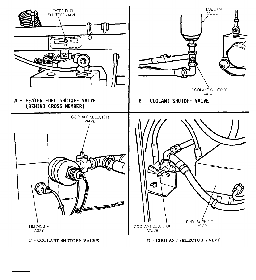
NOTE
ELECTRIC AND FUEL BURNING WINTERIZATION KITS CAN NOT
BE OPERATED SIMULTANEOUSLY.
STARTING
STEP 1. CHECK FUEL SUPPLY AND TURN MANUAL HEATER FUEL SHUT-OFF VALVE (A) TO ON
STEP 2. OPEN BOTH COOLANT SHUTOFF VALVES LOCATED NEXT TO LUBE OIL COOLER (B) AND
THERMOSTAT ASSEMBLY (C).
STEP 3. OPEN COOLANT SELECTOR VALVE (D) BY PLACING HANDLE (IN 3-O’CLOCK POSITION)
POINTING TOWARDS FUEL BURNING HEATER.
Figure 2-11. Fuel Burning Winterization Kit Operating Instructions (Sheet 1 of 2)
2-28
Change 12
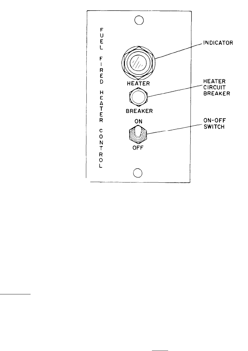
E - HEATER CONTROL PANEL
STEP 4. PRESS HEATER CIRCUIT BREAKER AND PRESS THE PRESS-TO-TEST INDICATOR, INDICATOR
LAMP SHALL LIGHT.
STEP 5. SET ON - OFF SWITCH TO ON. INDICATOR LAMP SHALL LIGHT WHEN HEATER GOES INTO RUN
CYCLE (APPROXIMATELY THREE MINUTES). OPERATE HEATER FOR 50 MINUTES OR UNTIL CYCLE
OPERATION OCCURS AS INDICATED BY EXTINGUISHING OF INDICATOR LAMP.
NOTE
IF INDICATOR LAMP DOES NOT LIGHT IN APPROXIMATELY FOUR MINUTES,
SET ON-OFF SWITCH TO OFF. WAIT THREE MINUTES BEFORE ATTEMPTING
TO RESTART HEATER.
STOPPING
STEP 1. SET ON-OFF SWITCH TO OFF. INDICATOR LAMP SHALL REMAIN ILLUMINATED UNTIL HEATER
COMPLETE PURGE CYCLE (APPROXIMATELY 4-1/2 MINUTES).
STEP 2. AFTER INDICATOR LAMP EXTINGUISHES, REENERGIZE BREAKER.
STEP 3. CLOSE BOTH COOLANT SHUTOFF VALVES (B AND C).
STEP 4. TURN MANUAL HEATER FUEL VALVE TO OFF.
STEP 5. PLACE COOLANT SELECTOR VALVE (D) HANDLE (IN 9-O'CLOCK POSITION) POINTING DIRECTLY
AWAY FROM FUEL BURNING HEATER.
ME 6115-545-12/2-11(2) C1
Figure 2-11. Fuel Burning Winterization Kit Operating Instructions (Sheet 2 of 2)
Change 1 2-29
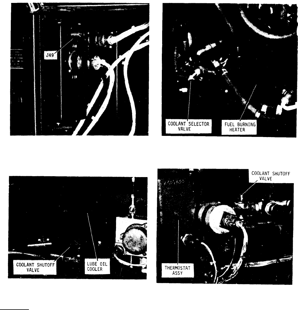
A - RECEPTACLE J49 B -COOLANT SELECTOR VALVE
C - SHUTOFF VALVE D - SHUT OFF VALVE
STARTING
NOTE
ELECTRIC AND FUEL WINTERIZATION KITS CAN NOT BE OPERA-
TED SIMULTANEOUSLY.
STEP 1. INSURE THAT A 205-240 VOLT, 50/60 OR 400 HZ, SINGLE PHASE SOURCE OF EXTERNAL POW-
ER TO ELECTRIC WINTERIZATION KIT RECEPTACLE 49 (A) HAS BEEN CONNECTED,
STEP 2. PLACE COOLANT SELECTOR VALVE (B) HANDLE (IN 12-0’CLOCK POSITION) POINTING
STRAIGHT UP.
STEP 3. OPEN BOTH COOLANT SHUTOFF VALVES (C & D) LOCATED NEXT TO LUBE OIL COOLER AND
THERMOSTAT ASSEMBLY.
ME 6115-545-12/2-12 (1)
2-30Figure 2-12. Electric Winterization Kit, Operating Instructions (Sheet 1 of 2)
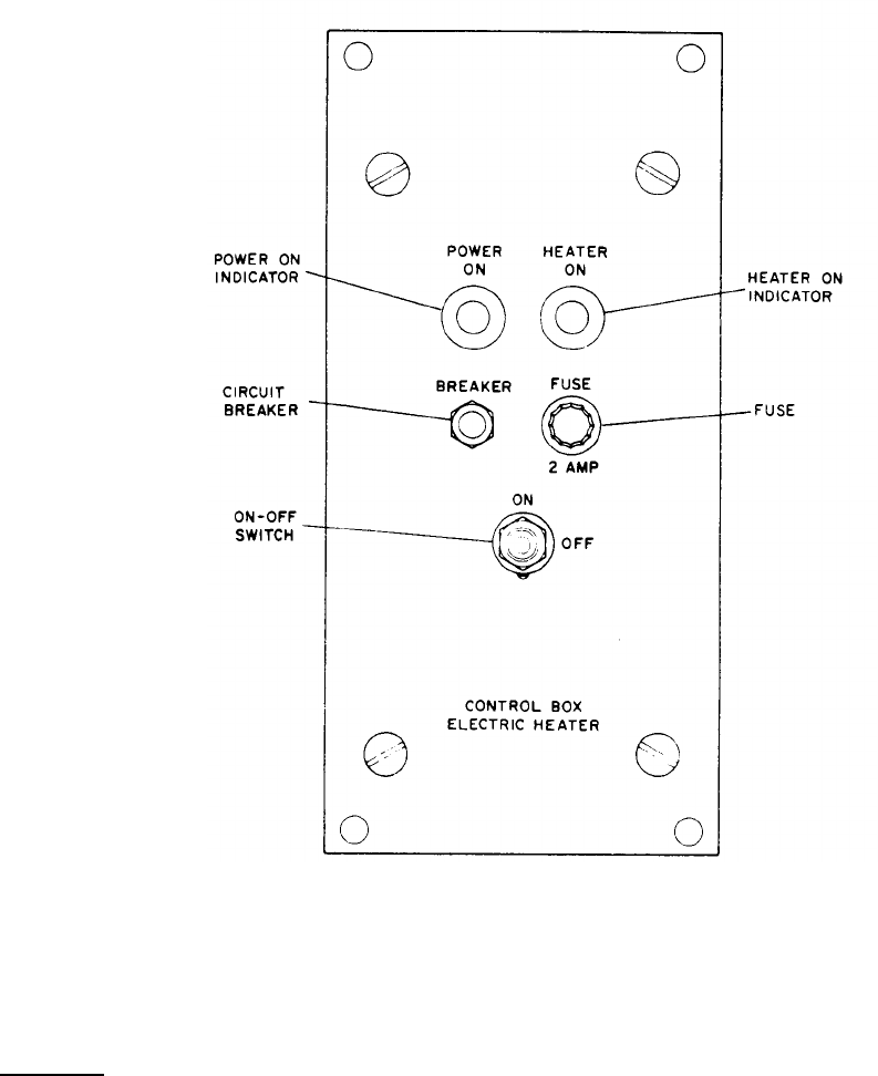
E - ELECTRIC HEATER CONTROL BOX
STEP 4. CLOSE CIRCUIT BREAKER (E) AND SET ON-OFF SWITCH TO ON, CHECK THAT POWER ON AND
HEATER ON INDICATORS LIGHT.
STEP 5. COOLANT IS NOW BEING HEATED AND PUMP IS OPERATING.
STOPPING
STEP 1. SET ON-OFF SWITCH TO OFF AND OPEN CIRCUIT BREAKER. POWER ON AND HEATER ON
INDICATORS SHOULD BE EXTINGUISHED.
STEP 2. PLACE COOLANT SELECTOR VALVE (A) HANDLE (IN 9-O’CLOCK POSITION) POINTING
DIRECTLY AWAY FROM FUEL BURNING HEATER.
Figure 2-12. Electric Winterization Kit. Operating Instructions (Sheet 2 of 2)
2-31

a. Where water is available, keep the immediate
area wetted down. Keep the unit as clean as possible,
paying special attention to the screens and grilles.
b. Clean filters and strainers more frequently
than under normal conditions. Be sure that all lub-
ricant containers are tightly sealed and stored in
an area free from dust and sand.
c. Take all necessary precautions to keep dirt and
grit out of the fuel tank.
2-19. Operation Under Rainy or Humid Conditions.
Keep the fuel tank full to prevent forming of conden-
sation. During dry periods when the set is not
operating, open the doors and allow the set to dry out.
Drain water and sediment from fuel tank (fig. 3-7)
more frequently,
2-20. Operation in Salt Water Areas.
a. Salt water causes corrosive action on metal.
Care must be taken to avoid equipment contact with
salt water. If contact is made, or if the unit is ex-
posed to salt spray, wash the generator set frequently
with clean. fresh water.
b. Remove rust or other corrosion and paint all
damaged preprinted surfaces in accordance with ser-
vices requirements.
2-21. Operation at High Altitudes.
The engine generator set will operate at elevations
up to 5,000 feet above sea level without special ad-
justment or reduction in load. At 8, 000 feet above
sea level, the 50/60 kw rating is reduced to 45 54
kw. Since higher altitudes also increase the possi-
bility of freezing, the coolant antifreeze protection
should be checked (table 2-1) and the batteries should
be tested (paragraph 3-82 b). A reduction in the load
may be also be necessary since engines are more
likely to overheat at high altitudes.
2-22. Operation in Snow.
Keep the fuel tank full to prevent forming of condensa-
tion. Drain water and sediment from fuel tank (fig.
3-7) more frequently. Check coolant antifreeze pro-
tection (table 2-1) and test the batteries (para 3-82b).
Insure that drifting snow does not obstruct normal –
cooling air flow.
2-23. Control Cubicle Removal for Remote Operation.
The set is designed for operation with the control panel
located up to 500 feet from the set.
If a remote location is desired, prepare a suitable lo-
cation for mounting the panel. Disconnect and remove
wiring harness (1, Fig. 3-17) and control cubicle as-
sembly (7). Fabricate a new cable of required length
using wire compatible with the connectors P1 and P2.
Section VI. OPERATION OF AUXILIARY MATERIAL USED IN CONJUNCTION WITH THE EQUIPMENT
2-24. General.
This section contains operating instructions for all
kits and auxiliary equipment. Included are the fuel
burning winterization kit, electric winterization kit,
wheel mounting kit, and load bank.
2-25. Fuel Burning Winterization Kit.
The fuel burning winterization kit is utilized to pre-
heat engine coolant and lubricating oil in extreme
cold weather. The fuel burning winterization kit is
installed as described in paragraph 4-4. In ambient
temperature of -65° F, the kit should be placed in
operation a minimum of 55 minutes prior to starting.
Operating time may be reduced or increased for
warmer or colder temperatures, respectively. Op-
erating instructions for the fuel burning winterization
kit are shown in figure 2-11.
2-26. Electrical Winterization Kit.
The electrical winterization kit consists of a heat ex-
changer, control box, coolant pump, thermostat and
accessories. The primary purpose of the kit is to
maintain the set in a heated condition, at any ambient
temperature from 125° F. to -65° F. to enable it to
accept 75% of rated load in one step within 20 seconds
after starting action is initiated. The coolant temper-
ature is thermostatically controlled at 130° F. to
150° F.
The kit can also be used to warm the Generator Set for
initial starting within 5 hours at any ambient tempera-
ture down to -65°F.
Power for operation of the kit may be obtained from
any power source that supplies 205 to 240 volts at
50, 60 or 400 Hz single phase. For electrical winter-
ization kit operating instructions refer to Fig. 2-12.
2-27. Wheel Mounting Kit.
The wheel mounting kit provides a means of mobility
for the generator set. The maximum towing speed is
5 mph on paved surfaces. Operation of the wheel
mounting kit is illustrated in figure 2-13.
2-28. Load Bank.
The load bank provides up to 50% of the rated load of
the generator set to compensate for underrated loads.
Operating instructions for the load bank are illustrated
in figure 2-14.
2-32
Change 12
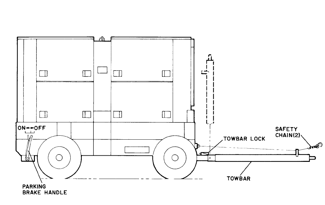
STEP 1. RELEASE TOWBAR LOCK AND CONNECT TOWBAR AND SAFETY CHAIN TO THE TOWING VEHICLE.
STEP 2. RELEASE PARKING BRAKE HANDLE AND TOW GENERATOR SET TO DESIRED LOCATION.
STEP 3. ENGAGE PARKING BRAKES AND REMOVE TOWBAR AND SAFETY CHAINS FROM THE TOWING
VEHICLE.
STEP 4. RAISE TOWBAR UNTIL TOWBAR LOCK ENGAGES.
ME 6115-545-12/2-13
Figure 2-13. Wheel Mounting Kit Operation
2-33
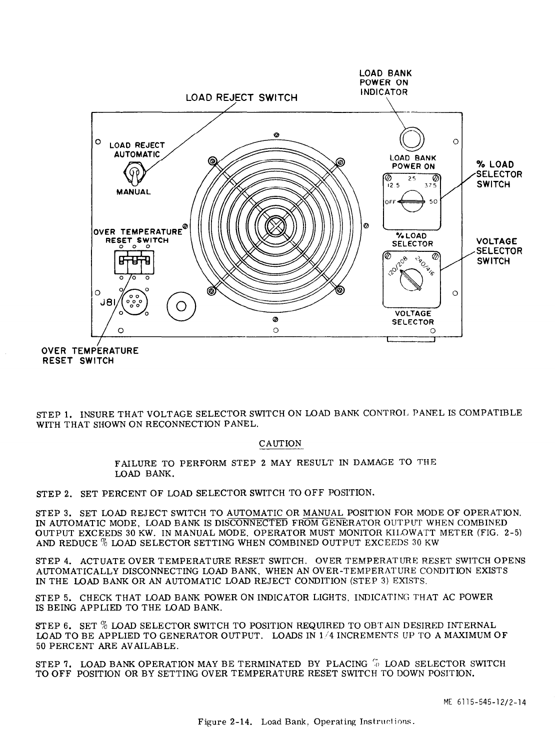

CHAPTER 3
OPERATOR AND ORGANIZATIONAL MAINTENANCE INSTRUCTIONS
Section I. OPERATOR AND ORGANIZATIONAL MAINTENANCE
REPAIR PARTS, TOOLS, AND EQUIPMENT
3-1. Tools and Equipment. are required by operator or organizational mainten-
ance personnel for maintenance of the engine gen-
a. Basic Issue (Army). Tools and repair parts erator set.
issued with or authorized for use with the engine
generator set are listed in the basic issue items list, 3-2. Organizational Maintenance Repair Parts (Army).
Appendix B of this manual.
Organizational maintenance repair parts are listed
b. Special Tools. No special tools or equipment and illustrated in the publications listed in Appendix A.
Section II. LUBRICATION
3-3. General Lubrication Information.
WARNING
To avoid accidental engine cranking
or startup, set CKT BRK switch
(fig. 2-5) to OPEN position and dis-
connect cable from battery negative
terminal, prior to servicing the
engine generator set. Reconnect
cable at completion of service
procedures.
a. This paragraph contains a reproduction of the
lubrication order and lubrication instructions which
are supplemental to, and not covered in the lubrica-
tion order.
b. The lubrication order shown in figure 3-1 is an
exact reproduction of the approved lubrication order.
Refer
to DA Pam 310-4 (Army) for the current LO.
c. The oil level gage (fig. 3-2) is the shielded
type which allows the operator to
check
oil level while
the engine is either stopped or running. The gage is
stamped on both sides to indicate two different oil
level locations. The engine RUNNING side is stamped
ADD, FULL, and RUNNING. The engine STOPPED
side is stamped ADD, FULL, and STOPPED.
CAUTION
Use appropriate ADD and FULL
marks depending upon whether
the engine is stopped or running.
d. The engine cannot be operated safely when the
oil level has dropped to the add mark on the oil level
gage, oil must be added to raise its level to the full
mark. When oil level is at the full mark, the proper
amount of oil is in the crankcase. Never fill crank-
case above full marks.
e. A seal in the oil level gage cap prevents oil
from leaking to the outside of the engine and foreign
material from entering. For these reasons, the
gage must be kept tight on the level gage adaptor.
Each time oil is changed, inspect the seal to make
certain it is in good condition.
f. The purpose of the breather tubes
2, 6, & 8, fig. 3-12.1) is to vent the
inside of the engine thus preventing
pressure buildup and removing harmful
vapors from the crankcase , gear train,
and valve compartment . Fumes are redi-
rected into the air intake system and
burned in the combustion of the engine.
If the tubes become clogged, vapors are
trapped within the engine, and pressure
buildup could force oil past crankcase
seals, oil level gauge or cylinder head
cover gasket.
3-4. Detailed Lubrication information.
a. General. Keep all lubricants in closed con-
tainers and store in a clean, dry place away from
external heat. Allow no dust, dirt or other foreign
material to mix with the lubricants. Keep all
lubrication equipment clean and ready for use.
NOTE
When changing oil, drain valve
must be open to drain crankcase
and closed before refilling.
(1) Lubricating oil must be in accordance
with the requirements of figure 3-1. Keep oil free
of water and abrasives by proper handling and
storage.
(2) Before each period of operation, check
oil level in the crankcase. If necessary, add oil
to bring level to full mark on the oil level gage,
Inspect engine for evidence of oil leaks and make
necessary repairs.
(3) After each operation interval of 100 hours,
Change 12 3-1
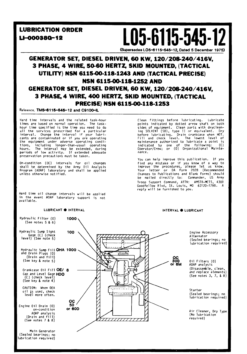
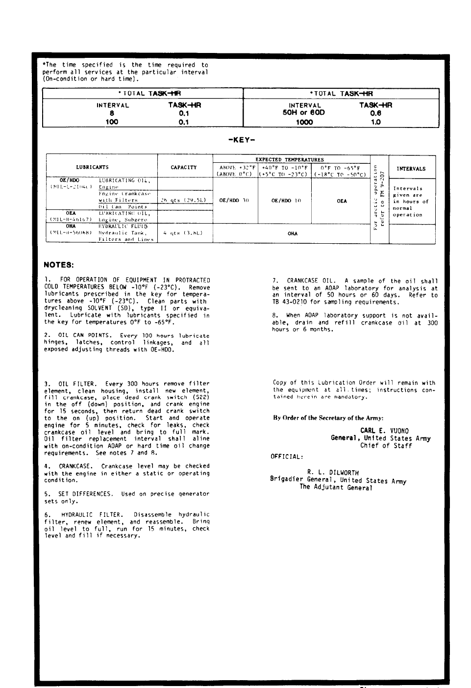
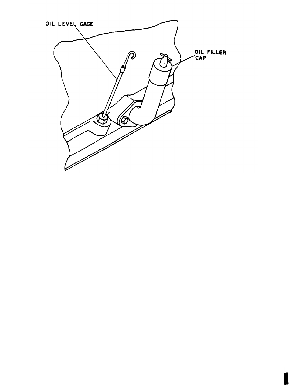
TM 5-6115-545-12
TO 35C2-3-444-1
NAVFAC P-8-626-12
TM 00038G-12
Figure 3-2.
remove breather tubes (2, 6 & 8, fig. 3-12.1) from the valve
cover, crankcase, oil separator and air intake system. Clean
inside of tubes with cleaning solvent, blow out with compressed
air, and replace on engine and oil separator.
b. Cleaning. Keep all external parts not requiring
lubrication clean of lubricants. Before lubricating equipment,
wipe all lubrication points free of dirt and grease. Clean all
lubrication points after lubrication to prevent accumulation of
foreign matter.
c. Oil Level.
CAUTION
To prevent overfill of the oil sump, remove oil filler
cap when checking oil with set running.
(1) Crankcase oil level must be checked frequently.
(2) Oil may require changing more frequently than
usual because of contamination by dilution and because sludge
formation will increase under cold weather operation conditions.
(3) Before draining the oil system, operate the engine
until a minimum coolant temperature of 160° F is obtained.
Shut engine off, open the engine oil drain valve and remove the
oil drain plug from the skid and allow the oil to drain into
appropriate container. Refer to para 3-4 d. for oil filter service.
Oil Level Gage and Filler
(4) Install the drain plug, close the oil drain valve and
fill the crankcase with 26 quarts of the specified grade of
lubricant to the FULL mark on the oil level gage. Use the side
of the oil level gage stamped STOPPED.
(5) Place dead crank switch (49, fig. 3-27) in the off
(down) position and crank engine for 15 seconds, then place
dead crank switch in on (up) position.
(6) Start and operate the engine for approximately 5
minutes.
(7) Stop the engine and allow several minutes for the oil
to drain back to the crankcase before checking the oil level.
(8) Using the oil level gage, (fig. 3-2) check the oil
level and add oil as necessary to raise the level even with the
FULL mark on the oil level gage.
(9) Observe the engine for oil leakage. Repair oil leaks
before continuing operation.
d. Oil Filter Service
See figure 3-3 and service the oil
filters as follows:
CAUTION
Disconnect negative lead from battery prior to
servicing oil falter.
(1) Drain oil filter by removing plug (l). Drain oil into
appropriate container.
3-4 Change 18
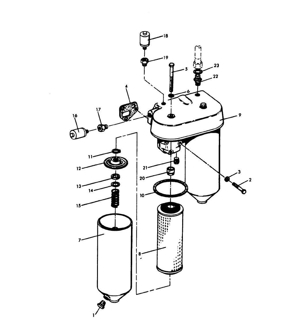

(2) Remove screw (5), and washer (6), and
remove filter body (7) and filter element (8) as an
assembly from the header (9).
(3) Remove filter element (8) from filter body
(7). Remove and discard filter element (8) and
gasket (10).
(4) Thoroughly wash and dry interior of filter
body (7), header (9), and surrounding area. Install
the new filter element (8) and gasket (10) in filter
body (7) using reverse procedure of disassembly.
(6) Tighten screw (5) to a torque of 45 to 50
ft. - lbs.
(7) Add oil as described in paragraphs 3-4 c
(4) through 3-4 c (9).
(8) Place dead crank switch (49, fig. 3-27) in
off (down) position and crank engine in 15 second
cranks followed by 3 minute rests until oil pressure
gauge shows pressure. Then place dead crank switch
in on (up) position
(9) Observe the engine lube oil filter for oil
leakage and be certain that filter
(5) Replace plug (1) in filter body (7). (10) are properly installed.
Section III.
PREVENTIVE MAINTENANCE CHECKS AND SERVICES
body (7) and gasket
3-5. General.
To insure that the engine generator set is ready for
operation at all times, it must be inspected systema-
tically so that defects may be discovered and cor-
rected before thay result in serious damage or fail-
ure. The necessary preventive maintenance services
to be performed are listed and described in para-
graphs 3-6 and 3-7. Item numbers indicate the se-
quence of minimum inspection requirements. Defects
discovered during operation of the unit shall be noted
for future correction, to be made as soon as operation
has ceased. Stop operation immediately if a defi-
ciency is noticed which would damage the equipment
if operation were continued. Air Force users shall
refer to the applicable inspection manuals and work
card sets in T. O. 35C2-3-Series for periodic pre-
ventive maintenance requirements and table 3-1
for detailed procedures. Marine Corps users should
refer to the current issue of TM 11275-15/1.
3-6. Daily Preventive Maintenance Checks and
Services (Army and Navy).
Table 3-1 contains a tabulated listing of Pre-
ventive maintenance services which must be per-
formed daily by the operator. The item numbers
are listed consecutively and indicate the sequence of
minimum requirements.
3-7. Monthly and Semi-annual Preventive Mainten-
ance Checks and Services (Army and Navy).
a. Table 3-1.1 contains a tabulated
listing of preventive maintenance checks
and service: which must be performed by
organizational maintenance personnel at
monthly and semi-annual intervals.
b. The item numbers are listed con-
secutively and indicate the sequence of
minimum requirements.Refer to table
3-1.1 for the preventive maintenance
services.
3-7.1.
Perform weekly as well as before
PMCS if:
a.
You are the assigned operator and
have not operated the item since the
last weekly inspection.
b.
You are operating the item for
the first time.
3-7.2.
Leakage definitions for operator/
crew PMCS shall be classified as fol-
lows :
CLASS I
Seepage of fluid (as indicat-
ed by wetness or discolora-
tion) not great enough to form
drops.
CLASS II Leakage of fluid great enough
to form drops but not enough
to cause drops to drip from
item being checked/inspected.
CLASS III Leakage of fluid great enough
to form drops that fall from
the item being checked/in-
spected.
3-6Change 12

Section IV. OPERATOR’S MAINTENANCE
3-8. General. 3-10. Slave Receptacle Inspection.
Instructions in this section are provided to assist the A slave receptacle (17, fig. 3-4) is located in a
operator in maintaining the engine generator set. receptacle box on the forward left side of the housing.
Inspect the slave receptacle for loose mounting,
3-9. Batteries. loose electrical connections, loose covers, corrosion
and other damage.
a. Inspection. See figure 3.4 and remove screws
(9),and washers (10) and studs (8) which attach bat- 3-11. Muffler, Exhaust Pipe and Breather System Inspection
tery tray (11) to base and slide storage batteries and Inspect muffler and exhaust pipes (fig. 3-12) and breather
trays (11) out. Inspect storage batteries for cracks system (Fig. 3-12.1) for crocks, leaks, breaks, loose mounting,
and leaks. Check for loose cables (1, 2 and 3) and
and other damage.
mountings and excessive corrosion. 3-12. Convenience Receptacle Assembly
b. Service. Refer to table 3-1. Fill to 3/8 inch Inspection.
above plates. In freezing weather, run engine a mini-
mum of 1 hour after adding distilled water. Apply Inspect convenience receptacles assembly
grease to cable connectors. and components for loose mounting, loose
corrosion and other damage.
(fig. 3-13)
covers,
Change 12 3-6.1/(3-6.2 blank)
TM 5-6115-545-12
TO-35C2-3-444-1
NAVFAC P-8-626-12
TM-00038G-12
Table 3-1. OPERATOR/CREW PREVENTIVE MAINTENANCE CHECKS AND SERVICES
ITEM
NO.
1
B – BEFORE OPERATION D – DURING OPERATION A – AFTER OPERATION
INTERVAL
B
●
●
●
D
—AITEM TO BE
INSPECTED PROCEDURES
Generator Set
Dead Crank Switch
Do not attempt to service
(make adjustments, connec-
tions, reconnection of wires
or cables) or correct anything
inside the generator set until
the generator set is shut down
and completely de-energized.
●
●
●
Equipment operation is allow-
able with minor leakages
(Class I or II). Of course, you
must consider the fluid capa-
city in the item/system being
checked/inspected. When in
doubt, notify your supervisor.
When operating with Class I
or Class II leaks, continue to
check fluid levels as required
in your PMCS.
Class III leaks should be re-
ported to your supervisor or
organizational maintenance,
Visually inspect unit for fuel, oil,
coolant, and hydraulic leaks. Check
for proper levels.
Visually inspect the generator
for missing,loose or damaged
parts and hardware , and for
unusual wear or deterioration.
Check for proper ground connection.
(Para. 2-5e, fig. 2-2).
Place dead crank switch in the run
position.
EQUIPMENT WILL
BE REPORTED NOT
READY (RED) IF:
Class III oil, coolant,
and hydraulic fluid are
found during inspection
Generator set not
properly grounded.
If switch
malfunctions.
Change 133-7

TM 5-6115-545-12
TO-35C2-3-444-1
NAVFAC P-8-626-12
TM-00038G-12
Table 3-1. OPERATOR/CREW PREVENTIVE MAINTENANCE CHECKS AND SERVICES (Cent)
B – BEFORE OPERATION D – DURING OPERATION A – AFTER OPERATION
ITEM
NO.
2
INTERVAL
B
●
●
D
●
A
ITEM TO BE
INSPECTED
Batteries
Fuel Selector Valve
Controls and instruments:
a.
b.
c.
d.
e.
f.
g.
Battery charging
ammeter
Coolant temp gage
Voltmeter
Oil pressure gage
A.C. ammeter
Wattmeter
Frequency meter
PROCEDURES
Remove corrosion and apply grease
to cable connectors. Tighten loose
cables and mountings. Inspect for
cracks and leaks. Fill batteries to
3/8 inch above the plates. Clean
vent hole in filler cap before instal-
ling. In freezing weather run engine
a minimum of 1 hour after adding
water.
Turn fuel selector valve to the
correct position.
Instruments shall indicate within
specified limits. (Fig. 2-5)
Green portion of scale
180° to 200° F
120/208 - 240/416
30 to 55 psi
Indicates percentage of applied
current. Not to exceed 100%
Indicates applied load. Not to
exceed 100%.
400 Hz - 50/60 Hz
EQUIPMENT WILL
BE REPORTED NOT
READY (RED) IF:
Cable connections
cannot be tightened,
or battery is cracked
or leaking.
Fuel selector valve is
inoperable.
Ammeter does not
indicate charging
current.
Temp exceeds 200° F.
Voltage cannot be
properly adjusted.
Pressure is below
30 psi.
Meter is
nonfunctional.
Meter is
nonfunctional.
Frequency cannot be
properly adjusted.
3-8
Change 13

TM 5-6115-545-12
TO 35C2-3-444-1
NAVFAC P-8-626-12
TM 00038G-12
Table 3-1. OPERATOR/CREW PREVENTIVE MAINTENANCE CHECKS AND SERVICES
B - BEFORE OPERATION D -DURING OPERATION A - AFTER OPERATION
ITEM
NO.
3
4
5
6
INTERVAL
B
●
●
•
D
●
A
●
●
●
ITEM TO BE
INSPECTED
PROCEDURES
EQUIPMENT WILL
BE REPORTED NOT
READY (RED) IF
h. Fault indicator
panel
Fuel tank
Oil level
Fuel filters and
strainers
Day Tank
All lights out during operation. Check bulb opera-
tion using test or reset switch on panel.
Fill fuel tank at completion of operation.
para 2-16b, 2-17c, 2-19, and 2-22)
(Fig. 1-2;
Check engine oil and add as required as indicated by
oil level gage. (Fig. 3-2; para 3-4a, 3-4b, 3-4c,
(l-9))
Check for leaks. Drain water and sediment.
NOTE
In freezing weather, drain shortly
after operation. Allow to drain
until fuel runs clear.
Drain water and sediment.
NOTE
In freezing weather, drain shortly
after operation. Allow to drain
until fuel runs clear.
Fault light will not extin-
guish when switch is placed
to TEST RESET position,
then released.
Class III leakage is detected.
Change 18
3-8.1 /(3.8-2 blank)
Table 3-1.1. ORGANIZATIONAL PREVENTIVE MAINTENANCE CHECKS AND SERVICES
W-WEEKLY (40 HOURS) S-SEMIANNUAL (500 HOURS)
ITEM
NO.
1
2
3
4
5
6
M
—
INTERVAL
H
M-MONTHLY(1O0
ITEM TO BE
INSPECTED
Fluid level
a. Lubricat-
ing oil
b. Hydraulic
sump
c. Cooling
system
Fuel tank
Fuel fil-
ters and
strainers
Batteries
Day tank
Generator
set
HOURS)
H-HOURS (AS INDICA
PROCEDURES
Check fluid levels.
Check oil and add as required.
(Fig. 3-1; 3-2)
Check and add fluid as required.
(Fig. 3-44)
Check coolant level.
Proper level
is 2 inches below filler neck.
(Para 2-3 c 2).
Drain water and sediment from
fuel tank. (Fig. 1-4; para 3-62b2)
Note:
In
freezing weather, tank
should be drained shortly after
operation.
Close drain cocks as
soon as clean fuel begins to run
out.
Drain water and sediment from
filters and strainers.
Note:
In freezing weather, fil-
ters and strainers should be
drained shortly after operation.
Close
clean
(Fig.
Check
(Para
check
prior
drain cocks as soon as
fuel begins to run out.
1-1; para 3-6 and 3-9)
battery electrolyte level.
3-9) Perform a hydrometer
of the battery electrolyte
to adding distilled water.
Recharge or replace battery if
specific gravity reading is low.
(Para 3-82 b)
Drain water and sediment from day
tank.
Note:
In freezing weather, tank
should be drained shortly after
operation.
Close drain cock as
soon as clean fuel begins to run
out. (Para 3-33 b)
Inspect entire unit for loose,
damaged, or missing parts; and
unusual wear or deterioration.
TED)
-
EQUIPMENT WILL
BE REPORTED NOT
READY (RED) IF:
Change 6
3-9
Table. 3-1.1. ORGANIZATIONAL PREVENTIVE MAINTENANCE CHECKS AND SERVICES--continued
W-WEEKLY (40 HOURS) S-SEMIANNUAL (500 HOURS)
ITEM
NO.
7
8
9
10
11
12
13
14
15
s
—
●
●
●
H
●
●
M-MONTHLY(1O0
ITEM TO BE
INSPECTED
V-belts
Air filters
Deleted.
Engine oil
Oil filters
Fuel filters
and strainer:
Hydraul
sump
Hydraul
filter
ic
ic
Hydraulic
actuator
HOURS )
H-HOURS (AS INDICI
PROCEDURES
Inspect
for worn, frayed, oil
soaked, or cracked belts. Check
adjustment of V-belts.
Pro-
per adjustment for fan belt is a
deflection of 9/32 inch with ap-
plication of 12-14 lb pressure
midway between accessory drive
pulley.
For alternator drive
belt, a deflection of 9/64 inch
with application of 3-5 lb pres-
sure midway between alternator
pulley and accessory drive pulley.
(Fig. 3-35)
This unit is equipped with an air
filter condition indicating light
that will indicate when the filter
elements need cleaning.
Clean
elements when necessary as indi-
cated by the light.
Drain engine oil and refill.
(Para 3-4c)
Change lubricating oil every 300
hours or 6 months.
Replace lubricating oil filters.
(Para 3-4d)
Change lubricating oil filters
every 300 hours or 6 months.
Replace primary and secondary fuel
filters, and clean fuel strainers
every 100 hours.
(Para 3-34, 3-36, and 3-165 a)
Drain and refill hydraulic sump.
(Para 3-44)
Replace hydraulic filter.
(Para 3-45)
Clean actuator filter screen.
(Para 3-175)
ED)
EQUIPMENT WILL
BE REPORTED NOT
READY (RED)
IF:
3-10 Change 7
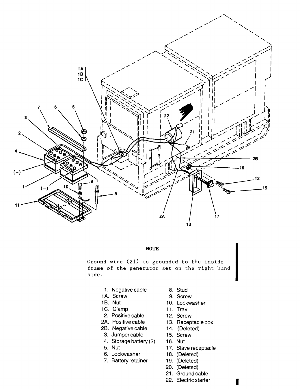

3-13. (Deleted)
3-14. Plate and Sleeve Assembly Inspection.
Inspect plate and sleeve assembly (fig. 3-15) for
tears, dents and other damage.
3-15. Paralleling Receptacles Inspection.
Inspect the paralleling receptacles (fig. 3-16) for
loose electrical connection, loose mounting, bent
pins, cracks, breaks, corrosion, and other damage.
Inspect the connector leads for broken or frayed
insulation and other damage.
3-16. DC Circuit Breaker Inspection and Fault
Indicator Lamp Test.
Inspect DC CONTROL CIRCUIT BREAKER (27, fig.
3-17) for loose mounting, loose electrical connec-
tions, or damage and check lamp operation as
follows:
a. Close DC CONTROL CIRCUIT BREAKER
(fig. 2-5).
b. Set START-RUN-STOP switch to RUN,
c. Set and hold fault indicator TEST OR RESET
switch to test and check that all fault indicators
light.
b. Set START-RUN-STOP switch to RUN.
c. Set and hold fault indicator TEST OR RESET
switch to test and check that all fault indicators
light.
3-17. AC Voltmeter.
a. Inspection. Inspect ac voltmeter (42, fig. 3-18)
for cracks, breaks, corroded and/or loose terminals,
and other damage.
b. Adjustment. With generator off, adjust volt-
meter zero control until the pointer is at zero.
3-18. Kilowatt Meter.
a. Inspection. Inspect kilowatt meter (39, fig.
3-18) for cracks, breaks, corroded and/or loose
terminals, and other damage.
b. Adjustment. With generator off, adjust kilo-
watt meter zero control until pointer is at zero.
Change 1
3-19. AC Ammeter.
a. Inspection. Inspect ac ammeter (8, fig. 3-18)
for cracks, breaks, corroded and/or loose terminals,
and other damage.
b. Adjustment. With generator off, adjust ac
ammeter zero control until pointer is at zero.
3-20. Frequency Meter.
Inspect freq meter (7, fig. 3-18) for cracks, breaks,
loose and/or corroded terminals, and other damage.
3-21. Control Cubicle Panel Switches Inspection.
Inspect switches on the control cubicle panel (96,
fig. 3-18), for cracks, breaks, corroded terminals,
loose electrical connections, loose mounting, and
other damage.
3-22. Control Cubicle Panel Gages Inspection.
Inspect gages on the control cubicle panel (96, fig.
3-18), for cracks, breaks, corroded terminals,
loose electrical connection, loose mounting, and
other damage.
3-23. Running Time Meter Inspection.
Inspect RUNNING TIME meter on the control cubicle
panel (96, fig. 3-18), for cracks, breaks, corroded
terminals, loose electrical connections, loose
mounting, and other damage.
3-24. Battery Charge Ammeter Inspection.
Inspect BATTERY CHG AMMETER (77, fig. 3-18)
on the control cubicle panel for cracks, breaks,
corroded terminals, loose electrical connections,
loose mounting, and other damage.
3-25. Panel Light Assemblies.
a. Inspection.
—
(1) Inspect lens (17, fig. 3-18) for cracks,
breaks, loose mounting.
loose
b.
—
lamp.
(2) Inspect lamp (24, fig. 3-18) for breaks or
mounting.
Test and Replacement.
(1) Close DC circuit breaker.
(2) Set PANEL LIGHT switch to ON position.
(3) If any panel lamps do not light, replace
3-26. Press-to-Test Light Assemblies.
a. Inspection.
—
(1) Inspect lens (26 and 33, fig. 3-18) for cracks,
breaks, loose mounting.
3-12

Table 3-2. Fault Indicator Test Points
Fault indicator
LOW OIL PRESSURE
OVER SPEED
COOLANT HIGH TEMP
NO FUEL
SHORT CIRCUIT
UNDER VOLTAGE
REVERSE POWER
OVER LOAD
UNDER FREQ
OVER VOLT
(2) Inspect lamps (31 and 38, fig. 3-18) for
breaks or loose mounting.
b.
Test and Replacement,
(1) Close DC circuit breaker.
(2) Press press-to-test light assemblies.
(3) If lamp doesn’t light, unscrew lens and
replace lamp.
(4) Re-install lens.
3-27. Synchronizing Light Assembly Inspection.
Remove lens and inspect lamp (of synchronizing
(16, fig. 3-18) for damage or loose mounting.
3-28. Door Holders Inspection
lights
Open door and inspect door holder (85, fig. 3-18)
for damage.
3-29. Crosspin Assembly Inspection.
Open door to gain access to rear of control cubicle
panel and examine crosspin (94, fig. 3-18) for
damage.
3-30. Control Cubicle Door Inspection.
Open door and inspect both sides for damage.
3-31. Housing Group Inspection.
Inspect engine generator set doors for proper opera-
tion. Inspect doors, covers, and panels for loose
mounting, dents or other damage (fig. 3 -22).
Pin no.
12-D
12-E
12-K
12-L
12-F
12-G
12-H
12-M
12-N
12-I
3-32. Air Cleaner Assembly.
a. Inspection.
(1) (Deleted)
(2) (Deleted)
(3) Inspect air cleaner condition switch for
loose mounting, loose connector wires, and other
damage.
(4) Inspect air cleaner filter element for
signs of blockage, holes, and other damage.
b. Service. Service the air cleaner as described
and illustrated in figure 3-5.
3-33. Day Tank Assembly.
a. Inspection. Inspect the day tank assembly
(fig. 3-27) for cracks, breaks, holes, loose elec-
trical connector and other damage.
b.Service.Service the day tank
—
assembly at intervals shown in table
3-1.1, item 5 and proceed as follows:
Open the drain cock (36) at the bottom
of the day tank and let the tank drain
until clean fuel is seen, then close
the drain cock.
3-34. Fuel Filter and Strainer Assembly.
a. Inspection. Inspect fuel filter and strainer
assembly (fig. 3-6) for leaks, cracks, breaks, dents
and other damage.
Change 12 3-13
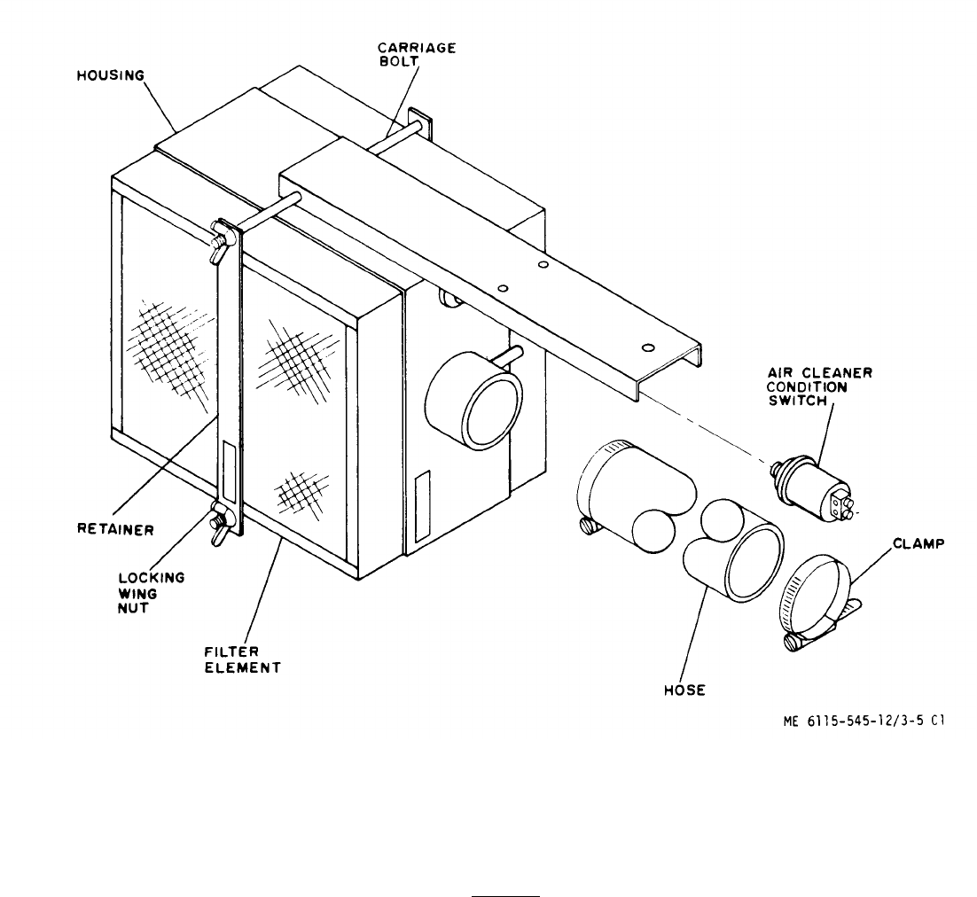
STEP 1. REMOVE WING NUTS AND RETAINER.
STEP 2. CAREFULLY REMOVE DIRTY FILTER ELEMENT.
STEP 3. CLEAN INSIDE OF HOUSING.
STEP 4. CLEAN FILTER ELEMENT BY EITHER METHOD A OR B
DESCRIBED BELOW.
CAUTION
DO NOT CLEAN IN GASOLINE OR
OTHER PETROLEUM SOLVENT.
METHOD A. COMPRESSED AIR
DIRECT COMPRESSED AIR (100 PSI MAX.) THROUGH PANEL OPPOSITE DIRECTION
OF ARROWS ON ELEMENT DECAL OR OPPOSITE AIRFLOW DIRECTION.
METHOD B. WASHING WITH WATER
SOAK 15 MINUTES IN WATER AND MILD DETERGENT. RINSE UNTIL CLEAN. AIR DRY
DO NOT USE COMPRESSED AIR.
STEP 5. INSTALL FILTER ELEMENT.
STEP 6. INSTALL WING NUTS AND RETAINER AND TIGHTEN WING NUTS
FINGER TIGHT.
Figure 3-5. Air Cleaner Service
3-14 Change 7
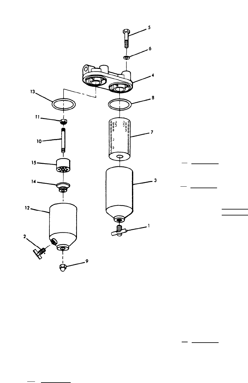
1. Drain Cock 9. Nut
2. Drain Cock 10. Stud
3. Filter body 11. Nut
4. Header 12. Strainer body
5. Screw 13. Gasket
6. Gasket 14. Retainer
7. Filter cartridge 15. Strainer element
8. Gasket
Figure 3-6. Fuel Filter and Strainer
b.Service.Service the fuel fil-
ter assembly at intervals shown in ta-
ble 3-1.1, item 12, and proceed as fol-
lows :
(1) Open the drain cocks (1 and 2, fig. 3-6) at
bottom of filter and strainer and allow to drain into
suitable container.
(2) Remove filter body (3) from header (4) by
removing screw (5) and gasket (6).
(3) Remove and discard filter cartridge (7) and
gasket (8). Unscrew nut (9) from stud (10) and re-
move strainer body (12) and gasket (13).
(4) Remove retainer (14) and strainer element
(15).
(5) Clean the strainer element (15) and all parts
including interior of strainer body (12) with cleaning
solvent Federal Specification P-D-680.
(6) Dry with compressed air or lint free cloth.
(7) See figure 3-6 and install new filter cart-
ridge (7) and gasket (8) and replace fuel filter and
strainer in reverse order of removal.
3-35. Start Aid Assembly.
a. Inspection. Inspect ether tank (8, fig.. 3-28),
solenoid valve, and tank bracket for loose mounting,
dents, loose fittings, and other damage.
b. Servicing. Either tank must be replaced by
Organizational Maintenance personnel when empty
(tank weighs 2 lbs. 4 oz. when full; 1 lb. when
empty). Service the starting aid assembly as follows:
WARNING
Be careful not to inhale ether gas
as drowsiness and unconsciousness
may result.
(1) Disconnect atomizer (2, fig. 3-28) and
tube (1) from intake manifold and solenoid valve
adapter (3).
(2) Crank engine and momentarily actuate
ENGINE PRIMER switch while an observer watches
adapter opening. If no spray is observed, notify
Organizational Maintenance personnel.
(3) Clean atomizer and tube with a source of
compressed air.
3-36. Filler Cap, Gasket and Strainer.
a. Inspection. (See fig. 3-7)
(1) Inspect main fuel tank cap and strainer for
breaks, cracks, holes or other evidence of damage.
(2) Inspect main fuel tank cap gasket for tears
or deterioration. Check that valve opening in cap IS
clear of obstruction.
(3) Inspect fuel tank filler hose for leaks.
cracks, loose mounting, deterioration or other evi-
dence of damage.
Change 123-15
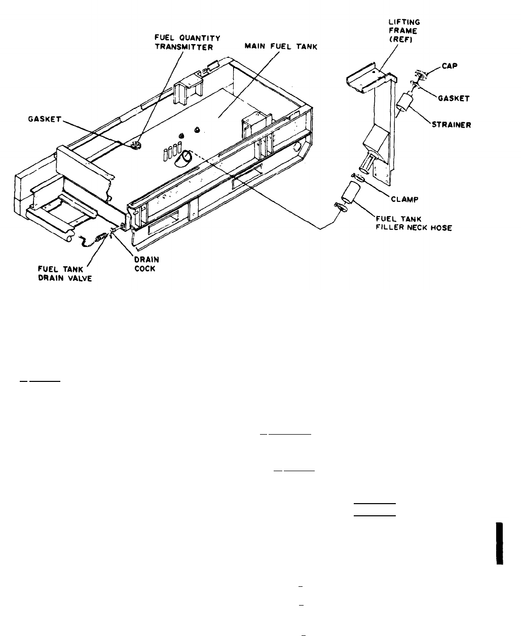
TM 5-6115-545-12
TO 35C2-3-444-1
NAVFAC P-8-626-12
TM 00038G-12
Figure 3-7. Main Fuel Tank
(4) Inspect main fuel tank vent hoses for cracks, loose 3-40. Shutter and Shutter Thermostat Inspection.
mounting, deterioration or other evidence of damage. Verify that the linkage connecting the shutter control assembly
b. Service. (See fig. 3-7.)
(10, fig. 3-30), which houses the shutter thermostat (6) to the
shutter (2, fig. 3-31 ) is secure and not damaged. Check
(1) Remove main fuel tank cap, gasket, and strainer.
thermostat housing for cracks, leaks or other damage.
(2) Clean all metal parts and dry thoroughly. 3-41. Radiator.
a. Inspection. Inspect the radiator assembly (35, fig. 3-29)
(3) Replace a damaged or defective gasket.
for leaks.
(4) Replace a damaged or defective main fuel tank b. Service.
strainer.
(1) Service the radiator as follows:
3-37. Fuel Transfer Pump.
WARNING
Inspect fuel transfer pumps (37 and 38, fig. 3-28) for leaks,
loose correctors, dents, cracks and other damages.
3-38. Radiator Grille.
Inspect radiator grille (fig. 3-31) for dirt, foreign matter, cracks,
dents, leaks, and other damage.
3-39. Fan Guard Inspection.
Inspect the LH and RH fan guards (25 and 26, fig. 3-29) for
dirt, cracks, dents or other damage.
Change 18
Scalding can result from steam in the coolant system
escaping when the radiator cap is removed. Always
allow coolant to cool and remove the radiator cap
slowly to permit any pressure to escape.
( a ) Open radiator cap access door and remove cap.
( b ) Refer to Table 2-1 for proper coolant and fill
radiator until coolant level is two inches below filler neck.
( c ) Fasten tag near radiator cap indicating date, type
of coolant and level of protection.
3-16

NOTE
At the time the cooling system is required to
be drained, the coolant in the lube oil cooler
should also be drained as described in para-
graph 3-199 b.
(d) To drain the radiator place suitable container to collect
coolant. Remove radiator cap.
(e) Open radiator shutoff cock (21) and drain radiator
coolant into container. Needle valve (9, fig. 3-34) should be also
opened to drain the engine block.
(f) Close shutoff cock (21, fig. 3-29) and close needle
valve (9, fig. 3-34).
3-42. Hydraulic Cooler (MEP105A Only) Inspection.
Inspect fins and lines of hydraulic cooler (19, fig. 3-29) for cracks,
breaks, dents, leaks, loose mounting and other damage.
3-43. Hydraulic Sump (MEP105A Only) Inspection.
Inspect hydraulic actuator (fig. 3-32) for loose mounting, loose hose con-
nections, loose connectors, loose linkage, and other damage.
3-44. Hydraulic Sump (MEP105A Only).
a. Inspection. Inspect hydraulic sump (1, fig. 3-8) for cracks,
leaks, breaks and other damage. Inspect filler cap (3) for secure
fitting. Inspect seal on tiller cap (3) for excessive wear and other
damage. Inspect hydraulic sump sight glass (2) for legibility of
marking, loose fitting, and other damage. Inspect hydraulic sump
for cracks, loose mounting, leaks and other damage.
b. Service. To service hydraulic sump (1, fig. 3-8) refer to table
3-1 and proceeds as follows:
(1) Check oil level; level should be up to sight glass (2, fig.
3-8).
(2) Remove tiller cap (3). Add hydraulic oil conforming to
Military Specification MIL-H-5606 to obtain proper level.
(3) To drain tank, place suitable container beneath drain plug
(4) and remove drain plug. Repeat step (2) to refill sump tank.
3-45. Hydraulic Filter (MEP105A Only).
a. Inspection. Inspect hydraulic filter (fig. 3-8) for cracks,
breaks, and other damage.
b. Service. To service the hydraulic filter refer to table 3-1 and
figure 3-8 and proceed as follows:
(1) Cut lockwire (5). Remove filter body (6) and filter element
(7). Discard filter element.
(2) Clean filter body with cleaning solvent, Federal Specifica-
tion P-D-680 and dry thoroughly.
(3) Soak new filter element in clean hydraulic oil conforming
to Military Specification MIL-H-5606 to remove air trapped in
filter material.
(4) Install new preformed packing (8) and backup rings (9).
(5) Apply a light coat of hydraulic oil to the preformed pack-
ing (8), and backup rings (9), header (10), and the threads of the
filter body (6).
(6) Install new element in filter body (6) and fill bowl with
clean hydraulic fluid. Install filter body (6) in header (10) and
tighten. Lockwire header to filter body on the threads of the
filter body.
3-46. Engine Assembly Service.
Refer to table 3-1 and service the engine crankcase as follows:
a. Check crankcase lubricating oil level using oil level gage
(fig. 3-2).
b. Remove engine lubricating oil filler cap and add oil as
required to obtain full level on oil level gage. See figure 3-1 for
proper lubricating oil.
c. To drain the crankcase, remove plug and place suitable
container at drain hose.
d. Open engine lubricating shutoff cock valve and drain oil into
container.
e. Close shutoff cock and replace plug.
f. To refill the crankcase; remove the oil filler cap and add oil
until crankcase is full; verify crankcase is full by checking oil lev-
el gage.
3-47. Fan Belts Inspection
Inspect drive belts (fig. 3-35) for signs of wear, damage or oil
soaking.
3-48. Battery Charging Alternator Inspection.
Inspect battery charging alternator (fig. 3-36) for cracks, loose
mounting, dents, loose or damaged connector, and other defects.
3-49. Speed Switch Inspection.
Inspect speed switch (fig. 3-37) for loose mounting, loose connec-
tor and other damage.
3-50. Angle Adapter Inspection.
Inspect angle adapter (fig. 3-38) for loose mounting, breaks,
cracks and other damage.
3-51. Hydraulic Pump and Drive Assembly (MEP105A Only) In-
spection.
Inspect hydraulic pump and drive assembly (fig. 1-2) for leaks
and loose mounting.
Change 113-17
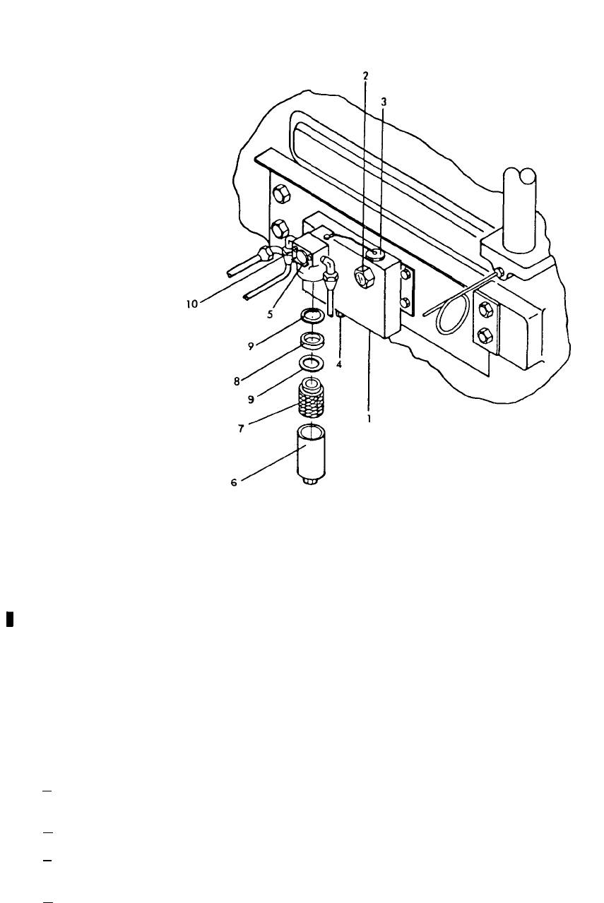
1. Hydraulic sump
6. Filter body
2. Sight glass 7. Filter element
3. Filler cap 8. Preformed packing
4. Drain plug 9. Backup rings
5. Lockwire 10. Header
Figure 3-8. Hydraulic Sump and Filter (MEP105A)
3-52. Oil Level Gage and Filler Inspection.
See figure 3-2 and proceed as follows:
a. Inspect oil level gage legibility of marking, loose
fitting and other damage.
b. Inspect oil filler cap for secure fitting.
c. Inspect seal on oil filler cap for excessive wear, and
other damage.
d. Inspect oil filler for cracks, loose mounting, and other
damage.
3-53. Starter Assembly Inspection.
Inspect starter assembly for cracks, dents, loose, damaged or
missing parts, loose mounting, loose electrical connections, and
other damage.
3-54. Oil Pressure Transmitter Inspection.
Inspect transmitter (18, fig. 3-3) for leaks, cracks, loose mounting,
loose electrical connection and other damage.
3-55. Lube Oil Filter Assemblies Inspection.
Inspect lube oil filters (fig. 3-3) for leaks, cracks, breaks, dents
and other damage.
3-18 Change 11
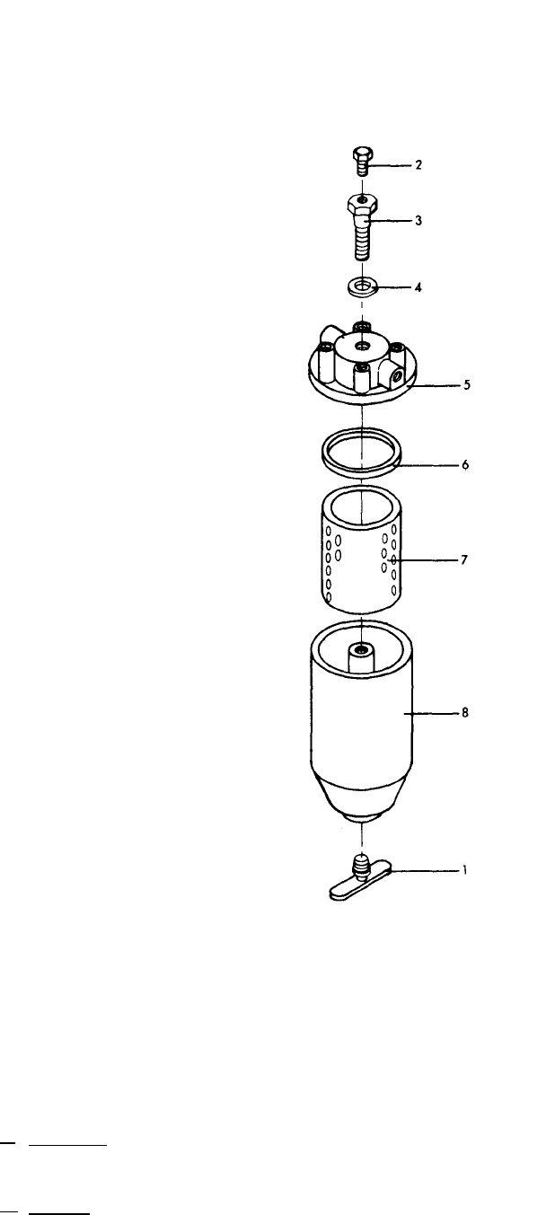
TM 5-6115-545-12
TO 35C2-3-444-1
NAVFAC P-8-626-12
TM 00038G-12
1. Drain cock 4. Gasket 7. Filter element
2. Bleed screw 5. Header 8. Bowl
3. Capscrew 6. Gasket
Figure 3-9. Secondary Fuel Filter
3-56. Secondary Fuel Filter. (1) Uncouple line from day tank at filter, and
raise line above day tank level.
a. Inspection. Inspect secondary fuel filter
(fig. 3-9) for breaks or cracks. Inspect threaded (2) Open drain cock (1, fig. 3-9) and drain
parts for damage or stripped threads. filter.
b. Service. To service the fuel filter proceed (3) Open bleed screw (2)
as follows: and remove and discard gasket remove capscrew (3)
(6) and filter element.
3-19

TM 5-6115-545-12
TO 35C2-3-444-1
NAVFAC P-8-626-12
TM 00038G-12
(4) Clean interior of bowl (8) with cleaning solvent
Federal Specification P-D-680. Dry with compressed air or lint
free cloth.
(5) Install new filter element (7) and new gasket (6) in
the reverse order of removal.
(6) Close drain cock (l), and bleed fuel filter and
recouple fuel line to fuel filter.
c. Fuel System Bleeding Procedure.
(1) Open bleed screw (2) on secondary filter,
(2) Depress the DC Circuit Breaker (20, fig. 2-10A).
(3) Place the battle short switch to the ON position
(22, fig. 2-10A).
(4) Place the start-run-stop switch to the run position
(32, fig. 2-10A).
(5) Observe fuel coming from top of secondary filter.
When air free fuel is flowing, tighten bleed screw (2).
(6) Place the start-run-stop switch to stop position
(32, fig. 2-10A),
(7) Open the DC Circuit Breaker (20, fig. 2-10A).
(8) Place the battle short switch to the OFF position
(22, fig. 2-10A),
3-57. Fuel Injection Pump Inspection.
Inspect fuel injection pump (fig. 1-1 ) for dents, cracks, breaks,
leaky connections and other damage.
3-58. Water Pump Inspection.
a. Inspect water pump (18, fig. 3-43) for leaks, cracks,
breaks, loose mounting and other damage.
b. With engine running check that excessive noise is not
heard from water pump.
3-59. Fan Inspection.
Inspect fan for cracks, breaks, loose mounting and other
damage.
3-60. Temperature Transmitter Inspection.
Inspect coolant temperature transmitter (10, fig, 3-44) for leaks,
cracks, loose mounting, loose electrical connections and other
damage.
3-61. Oil Pan Assembly Inspection.
a. Inspect oil heater coolant line connections for leaks
around fittings, loose line connections, cracks, and other
damage.
b. Inspect drain fitting, valve, hose connections and plug
for leaks, cracks, loose mounting, and other damage.
c. Inspect hose for deterioration, tears and other damage.
Inspect oil pan for cracks, dents, leaks and other damage.
3-62. Main Fuel Tank.
a. Inspection.
(1) Inspect main fuel tank (fig. 3-7) for loose mounting.
(2) Inspect main fuel tank for leaks, cracks, breaks and
other damage.
(3) Inspect fuel quantity transmitter gasket and electrical
connection.
(4) Refer to paragraph 3-36 a for fuel tank cap, gasket
and strainer inspection procedure.
b. Service.
(1) Refer to paragraph 3-36 b for fuel tank cap, gasket
and strainer servicing procedure.
(2) Connect auxiliary fuel line (fig. 1-1) to hose
connector at end of fuel tank drain valve (fig. 3-7), located at
the engine end of the fuel tank. Drain into suitable container.
Open drain cock and allow water and sediment to completely
drain off. Close drain cock when clean fuel runs out.
(3) Add fuel as required.
3-63. Paralleling Cable Inspection.
Inspect the parallel cable (fig. 1-1 ) for loose connections,
damaged connectors/pins, loose mounting, damaged cable, and
other damage.
3-64. Auxiliary Fuel Line Inspection.
Inspect the auxiliary fuel line (fig. 1-1) for loose connections,
leaks, cracks, breaks, and other damage.
3-20
Change 18

TM 5-6115-545-12
TO 35C2-3-444-1
NAVFAC P-8-626-12
TM 000838G-12
Section V. TROUBLESHOOTING
3-65. General
maintenance. The engine generator set must be completely
Table 3-3 provides information useful in diagnosing and serviced with fuel, coolant, and lubricating oil. Before
troubleshooting, check that all electrical connections are correct
correcting unsatisfactory operation or failure of the engine and operating controls are in the correct positions.
generator set and its components. Each malfunction stated is
followed by a list of the probable causes of the trouble. The
corrective action recommended is described opposite the NOTE
probable cause. Any trouble beyond the scope of organizational Air Force and Navy users are authorized to perform
maintenance shall be reported to the next higher level of maintenance within the scope of their capability.
Table 3-3 Troubleshooting
MALFUNCTION
1.
Engine
fails to crank
when START-STOP-
RUN switch is moved
to START position.
2. Engine cranks but will
not start.
PROBABLE CAUSE
a.
b.
c.
d.
e.
f.
g.
h.
a.
b.
c.
d.
e.
f.
g.
h.
i.
i.
k.
Improper starting
procedure.
Batteries weak,
Batteries improperly
installed.
Defective, corroded or loose
battery cables.
Defective or loose control
wires.
Defective DC CONTROL
CIRCUIT BREAKER.
Defective START-RUN-STOP
switch
Defective speed switch
Improper starting procedure.
Fuel supply exhausted
Water in fuel supply
Air in fuel system.
Restricted fuel supply line.
Defective day tank float
switch.
Defective fuel solenoid
valve.
Clogged fuel fitter and
strainer elements,
Clogged secondary filter
element.
Defective nozzle holder
assembly.
Clogged air intake system.
CORRECTIVE ACTION
a.
b.
c.
d.
e.
f.
g.
h.
a.
b.
c.
d.
e.
f.
g.
h.
i.
i.
k.
Perform starting procedure as described in
paragraph 2-12.
Recharge or replace batteries (para 3-82).
Refer to page 2-14, fig. 2-5c and page 2-21,
step 1, prior to replacing batteries.
Connect batteries as indicated in figure 3-4.
Tighten all loose connections and clean corrosion
from all terminals. (Refer to item 16, table 3-1.)
Inspect control wires and repair or tighten
as necessary.
Replace DC CONTROL CIRCUIT BREAKER
(para 3-100).
Replace START-RUN-STOP switch (para 3-119).
Replace defective speed switch (para 3-186).
Perform starting procedure as described in
paragraph 2-12.
Fill fuel tank or use auxiliary fuel supply
(para 2-3).
Drain fuel system, service with proper grade of
fuel (para l-4b).
Bleed fuel system (para 3-56c).
Clean restriction or replace tine.
Replace float switch (para 3-159).
Replace fuel solenoid valve (para 3-158).
Service filter and strainer (para 3-34).
Service filter (pars 3-197).
Replace nozzle holder assembly (para 3-201).
Service air filter assembly (fig. 3-5).
Change 18
3-21
TM 5-6115-545-12
TO 35C2-3-444-1
NAVFAC P-8-626-12
TM 00038G-12
Table 3-3 Troubleshooting (Cont)
MALFUNCTION
1.
3.
Engine runs when START
-RUN-STOP SWITCH is
held in START position
but stops when switch
is set to RUN.
4.
Engine runs errati-
tally or misfires
5.
Engine exhaust
excessively black
6.
Engine exhaust white
or blue.
PROBABLE CAUSE
Contaminated or improper
m.
n.
o.
a.
b.
c.
d.
e.
a.
b.
c.
d.
e.
f.
a.
b.
c.
d.
e.
a.
b.
c.
d.
e.
grade of fuel.
Speed switch not reset
after overspeed shutdown.
Open or defective dead
crank switch.
Closed fuel shutoff lever
(Class I only).
Switch not held in start
position sufficient amount
of time to enable engine to
exceed 600 rpm.
Defective speed switch.
Defective START-RUN-
STOP switch.
Defective oil pressure switch.
High coolant temperature.
Contaminated or improper
fuel.
Air in fuel system.
Restricted fuel fines.
Defective nozzle holder
assembly.
Dirty air cleaner.
Defective turbocharger.
Improper fuel.
Clogged air intake
Defective turbocharger.
Clogged turbo.
Generator set overloaded.
Improper timing.
Improper fuel.
Engine operating temperature
too low due to faulty thermostat.
Oil level too high.
Defective nozzle holder
assembly.
improperly adjusted valves.
CORRECTIVE ACTION
l.
m.
n.
o.
a.
b.
c.
d.
e.
a.
b.
c.
d.
e.
f.
a.
b.
c.
d.
e.
a.
b.
c.
d.
e.
Drain fuel supply, service with proper grade
of fuel (para l-4b).
Reset speed switch by depressing reset button
on back end of switch.
Close switch (49, fig. 3-27) and test for
continuity. Replace if defective.
Open lever for fuel inlet to injection pump.
Hold in start for a longer period (para 2-12).
Replace speed switch (para 3-186).
Replace switch (para 3-119).
Replace oil pressure switch (para 3-194).
Refer to malfunction item 11.
Drain fuel system and fill with proper fuel
(para 1-4).
Bleed fuel lines (pars 3-56).
Clean fuel lines.
Replace nozzle holder assembly (para 3-201).
Service air filters (fig. 3-5).
Replace turbocharger (para 3-203).
Drain fuel system and fill with proper fuel (para 1-4).
Service sir filter assembly (fig. 3-5).
Replace turbocharger (para 3-203).
Reduce load to rated level.
Correct timing.
Drain fuel system and fill with proper fuel (para 1-4).
Replace thermostat (para 3-209).
Drain crankcase until proper level is indicated
on oil level gage (para 3-4).
Replace nozzle holder assembly (para 3-201).
Adjust valves (para 3-220).
3-22 Change 18

Table 3-3. Troubleshooting (Cont)
MALFUNCTION
7. LOW oil pressure indi-
cated on oil pressure
gage.
8. Noisy turbocharger.
9. Turbocharger leaks
oil.
10. High oil pressure
indicated on oil
pressure gage.
11. High coolant temper-
ature indicated on
coolant temperature
gage.
PROBABLE CAUSE
a.
—
b.
c.
—
d.
—
e.
—
f.
—
g.
a.
—
b.
—
a.
—
b.
a.
—
b.
—
a.
—
b.
—
c.
—
d.
—
e.
—
f.
—
g.
h.
—
i.
j.
k.
—
Oil level too low.
Defective oil pressure
gage.
Defective oil pressure
transmitter.
Clogged lube oil filters.
Improper viscosity oil
Worn oil pump.
Worn bearings.
Improper turbocharger
lubrication.
Loose turbocharger end
plates.
Loose turbocharger
end plates.
Defective turbocharger
housing.
See b, c and e from
malfunction 7.
Oil pressure regulator.
Coolant level low.
High coolant temperature
due to incorrect coolant.
Lube oil level low.
Defective or improperly
adjusted fan belts.
Insufficient heat transfer
through radiator.
Defective coolant
thermostat.
Defective water pump.
Clogged radiator.
Generator set over-
loaded.
Defective coolant tem-
perature transmitter.
Defective coolant tem-
perature gage.
CORRECTIVE ACTION
a.
b.
c.
d.
—
e.
f.
—
g.
a.
—
b.
a.
—
b.
—
a.
—
b.
—
a.
—
b.
—
c.
—
d.
—
e.
—
f.
g.
h
i.
j.
k.
Add oil until proper level is indicated on oil
level gage (para 3-4).
Replace gage (para 3-121).
Replace transmitter (para 3-193).
Service filters (para 3-4).
Drain crankcase and fill with proper lube oil
(fig. 3-l).
Replace oil pump.
Replace bearings.
Clean turbocharger oil passages (para 3-203).
Tighten end plate screws (para 3 -203).
Tighten turbocharger end plate screws
(para 3-203).
Inspect housing. Replace turbocharger
(para 3-203).
See b. c and e of malfunction 7.
—
—
Replace oil pressure regulator
Add coolant (para 3-41).
Check for proper coolant mixture. Correct
or replace as necessary (para 3-41).
Add lube oil (fig. 3-l).
Adjust or replace fan belts (para 3-183).
Check that air inlet doors are open.
Check shutter operation (para 3-171).
Insure that there is at least 10.200 CFM or
12,300 CFM cu. ft. air supply (fig. 2-l).
Replace thermostat (para 3-209).
Replace water pump (para 3-206).
Replace radiator (para 3-172).
Check that the generator load does not ex-
ceed the ratings specified on the kilowatt
capacity nameplate 70-1345 (M2), 70-1346
(Ml).
Replace transmitter (para 3-209).
Replace gage (para 3-120).
Change 3
3-23

MALFUNCTION
11.
12.
13.
14.
15.
(Deleted)
Low coolant tempera-
ture indicated on
coolant temperature
gage.
c.
Battery charging
ammeter shows no
charging when bat-
teries are low or
discharged.
c.
Battery charging
ammeter indicates
excessive charging
rate after prolonged
operation.
Ac voltmeter does
not indicate any
set voltage,
PROBABLE CAUSE
Table 3-3. Troubleshooting (Cont)
CORRECTIVE ACTION
l.
a.
—
b.
—
c.
—
d.
—
a.
—
b.
—
c.
—
d.
—
e.
—
f.
—
a.
—
b.
—
c.
—
d.
e.
—
a.
—
b.
—
c.
—
& m. (Deleted)
Defective coolant thermo-
stat.
Defective or improperly
adjusted radiator
shutter and control
assembly.
Defective coolant temp-
erature transmitter.
Defective coolant
temperature gage.
Blown alternator fuse.
Improperly adjusted
alternator.
Defective or improperly
adjusted alternator belt.
Defective alternator.
Defective battery
charging ammeter.
Open wire in charging
circuit.
Improperly adjusted
alternator.
Defective batteries.
Low resistance or short
to ground.
Defective alternator.
Defective battery
charging ammeter.
Defective speed switch.
Defective VOLTS-AMPS
selector switch.
Defective ac voltmeter.
l. & m. (Deleted)
a. replace thermostat (para 3-209).
b.
—
d.
—
a.
—
b.
—
d.
—
e.
—
f.
—
a.
—
b.
—
c.
—
d.
e.
—
a.
b.
—
c.
—
Adjust or replace shutter or control assembly
(para 3-171).
Replace transmitter (para 3-209).
Replace gage (para 3-120).
Replace fuse located at back end of alternator.
Adjust alternator (para 3-184).
Adjust or replace belt (para 3-183).
Replace alternator- (para 3-184).
Replace ammeter (para 3-124).
Find open wire and repair.
Adjust alternator (para 3-184).
Service or replace batteries (para 3-82).
Inspect wiring and repair as necessary.
Replace alternator (para 3-184).
Replace ammeter (para 3-108).
Replace speed switch (para 3-186).
Replace switch (para 3-11 2).
Replace voltmeter (para 3-105).
Change 1
3-24

Table 3-3. Troubleshooting (Cont)
MALFUNCTION
16.
17.
18.
19.
20.
21.
22.
Ac voltage too high
or too low.
Ac voltmeter indi-
cates voltage but
frequency is off
scale to left.
Ac voltage
fluctuates.
Erratic frequency
indicator on fre-
quency meter.
Frequency meter
fails to register.
Kilowatt. meter fails
to register.
Engine generator set
shuts down, NO FUEL
indicator illuminates,
but sufficient fuel re-
mains in main tank
for operation.
PROBABLE CAUSE
a.
b.
a.
b.
c.
d.
a.
b.
c.
d.
a.
b.
a.
b.
c.
d.
e.
—
Defective VOLTAGE
ADJUST rheostat.
Engine speed too low.
Defective meter or
transducer.
Loose electrical
connection.
Defective VOLTS-AMPS
switch.
Defective VOLTAGE
ADJUST rheostat.
Defective ac voltmeter.
Air in fuel.
Defective nozzle holder
assembly.
Improperly adjusted
valves.
Defective frequency
transducer or fre-
quency meter.
Frequency meter
defective.
Frequency transducer
defective.
Kilowatt meter defective,
Defective day tank
float switch.
Defective fuel solenoid
valve.
Clogged fuel filter or
strainer.
Clogged fuel transfer
pump screens.
Defective fuel transfer
pumps.
CORRECTIVE ACTION
a.
b.
a.
b.
c.
d.
a.
b.
c.
d.
a.
b.
a.
b.
c.
d.
e.
Replace rheostat (para 3-110).
Adjust frequency adjust control (precise).
Increase speed manually (utility).
Replace meter and transducer (para 3-111).
Inspect harness and connectors and repair
(para 3-139).
Replace switch (para 3-112).
Replace Rheostat (para 3-110).
Replace meter (para 3-105).
Bleed fuel system (para 3-56).
Replace nozzle holder assembly (para 3-201).
Adjust valves (para 3-220).
Replace transducer and meter (para 3-111).
Replace meter and transducer (para 3-111).
Replace frequency meter and transducer
(para 3-111).
Replace meter (para 3-106).
Replace float switch (para 3-159).
Replace solenoid valve (para 3-158).
Service filter and strainer. (para 3-34).
Service fuel transfer pumps (para 3-165).
Replace pumps (para 3-165).
3-25

MALFUNCTION
23.
24.
25.
26.
27.
28.
Engine generator set
shuts down, HIGH
COOLANT TEMP
indicator illuminates
but coolant tempera-
ture is normal.
Engine generator set
shuts down, low oil
pressure indicator
illuminates, but oil
pressure is normal.
Engine generator set
shuts down, over -
speed indicator il-
luminates, but engine
speed is normal.
All meters read cor-
rectly except volt -
meter reads off scale
high.
Circuit breaker
switch is closed and
indicator does not
light.
Main AC contactor
(CB2) will not close.
Table 3-3. Troubleshooting (Cont)
PROBABLE CAUSE
Defective coolant
temperature switch.
Defective oil pressure
switch.
Defective overspeed
switch.
Defective voltage adjust
rheostat.
a.
b.
Defective load circuit
breaker switch.
Lamp burned out.
Main AC contactor (CB2)
defective.
CORRECTIVE ACTION
Replace switch (para 3-209).
Replace switch (para 3-194).
Replace switch (para 3-186).
Replace rheostat (para 3-110).
a. Replace circuit breaker switch (para 3-117).
b.
Replace lamp (para 3-26).
Measure continuity of coil pins A and B. If no
continuity, replace contactor (para 3-141).
3-26 Change 8
Section VI.FIELD EXPEDIENT REPAIRS
Trouble3-66. General.
Organizational
maintenance
level
troubles
may
oc-
cur
while
the
engine
generator
set
is
operating
in
the
field
where
supplies
and
repair
parts
are
not
available
and
normal
corrective
action
cannot
be
performed.
When
this
condition
exists,
the
follow-
ing
expedient
repairs
may
be
used
in
emergencies
upon
the
decision
of
the
unit
commander. Equip-
ment
so
repaired
must
be
removed
from
operation
as
soon
as
possible
and
properly
repaired
before
being
placed
in
operation
again.
3-67. Fuel is not Strained.
Trouble
Expedient
Remedy
Fuel
tank
strainer
Run
engine
generator
set,
element
defective.
with
defective
strainer
element
installed
until
replacement
is
obtained
(para 3-34).
3-68. Housing Filled With Smoke.
Trouble
Expedient
Remedy
Defective
exhaust
pipe.
Run
engine
generator
set
with
defective
exhaust
pipe
until
replacement
is
ob-
tained
(para 3-86).
3-69. Engine Overheating.
Trouble
Shutter
control
assembly
not
operational.
3-70. Loss of Coolant.
Trouble
Leaking
coolant
hose.
Leaking
radiator.
Expedient
Remedy
If
the
engine
is
running
too
hot,
manually
open
shutter
with
the
lever
to
keep
shutters
open
until
the
engine
is
normally
shut
down
for
n>ainten-
ance
or
other
reason.
Expedient
Remedy
If
necessary
shut
down
engine,
drain
coolant,
tightly
wrap
leaky
area
of
hose
with
plastic
elec
-
tricians
tape.
Keep
moni-
toring
repaired
hose
area
while
engine
is
operating
until
replacement
hose
is
obtained.
Liberally
apply
epoxy,
tar,
putty,
or
other
nonsoluble
substance
to
leaking
area
of
radiator.
Let
dry.
Fill
radiator
and
operate
engine
until
replacement
radiator
is
obtained.
Do
Expedient Remedy
WARNING
not
add
coolant
to
radiator
until
pressure
has
been
relieved.
Water
pump
leaks. Loosen
radiator
cap
so
as
to
relieve
pressure.
Cont-
inue
engine
operation
adding
coolant
to
radiator
as
frequently
as
necessary
to
maintain
water
level
above
top
of
radiator
coil
assembly
until
engine
can
be
conveniently
shut
down
for
water
pump
re-
placement.
3-71. Engine Heat Up.
Trouble
Expedient
Remedy
Badly
worn
fan
belt.
Continue
engine
operation
with
defective
fan
belt
installed
until
replacement
belt
is
obtained,
or
until
engine
can
be
shut
down.
Frequently
observe
fan
belt
(Para 3-183. )
3-72. Engine Cranks But Will Not Start or Starts
and Runs Erratically or Misfires.
Trouble
Clogged
fuel
filter.
Clogged
fuel
transfer
pump
screen.
Defective
fuel
line.
Expedient
Remedy
Shut
down
engine
and
remove
fuel
filter
cartridge
and
strainer
element
(para
3-34b).
Use
compressed
air,
If
available,
or
shake
vigorously,
to
clear
ob
-
struction.
Reassemble
and
continue
operation
until
re-
placement
parts
are
ob
-
tained.
Shut
down
engine
and
remove
pump
screen
(para 3-165).
Use
compressed
air,
if
available,
or
shake
vigor-
OUSIY,
to
clear
obstruction.
Reassemble
and
continue
operation
until
replacement
parts
are
obtained.
Shut
down
engine
and
tightly
wrap
area
of
line
leak
with
plastic
electrician’s
tape.
Keep
monitoring
repaired
line
while
engine
is
until
a
replacement
is
obtained.
operating
fuel
line
3-27
3-72. Engine Cranks But Will Not Start or Starts
and Runs Erratically or Misfires.(Cont)
Trouble
Clogged
air
filter.
Defective
fuel
selector
valve,
3-73.
Expedient
Remedy
If
repaired
fuel
line
leaks,
shut
down
engine.
Shut
down
engine
and
re-
move
filter
element
(fig.
3-5).
Use
compressed
air,
if
available,
or
shake
vigor
ously,
to
clear
obstruction.
Reassemble
and
continue
operation
until
replacement
parts
are
obtained.
Shut
down
engine
and
dis
-
connect
fuel
selector
valve
(para 3-166).
Connect
hose
assembly
(21, fig.
3-28)
directly
to
hose
as-
sembly
(24).
Use
hose
assembly
(15)
connection
and
plastic
electrician’s
tape
as
necessary
to
comp-
lete
connection.
Keep
moni-
toring
reconnected
fuel
line
while
engine
is
operating
until
a
replacement
fuel
selector
valve
is
obtained.
If
reconnected
fuel
line
leaks,
shut
down
engine.
Engine Shuts Down
and
LOW OIL PRESSURE
Indicator Lights.
Trouble
Expedient
Remedy
Defective
oil
line. Tightly
wrap
area
of
oil
line
leak
with
plastic
electrician’s
Trouble
3-74. Battery Charging
Trouble
Battery
charging
alter-
nator
defective.
Expedient
Remedy
tape.
Keep
monitoring
re-
paired
line
while
engine
is
operating
and
a
replacement
oil
line
is
obtained.
Ammeter Shows No Charge.
Expedient
Remedy
Continue
engine
operation
with
defective
battery
charg
-
ing
alternator
installed
until
replacement
is
obtained
or
until
engine
can
be
shut
down
for
battery
charging
alter-
nator
service
or
repair.
3-75. Loss of Frequency Control (Class 1 Sets Only).
Trouble
Expedient
Remedy
Governor
system
fails
Shut
down
the
engine
genera-
to
operate
properly. tor
set
and
disconnect
plugs
J17
and
J21
on
the
electrical
governor
control
(fig. l-l).
Remove
cover
(12, fig. 3-17).
Loosen
screw
(13)
and
move
fuel
pump
lever
all
the
way
forward
and
tighten
screw,
Move
actuator
linkage
to
the
retracted
position.
Operate
set
as
class
2
unit
until
fault
in
governor
system
can
be
corrected.
NOTE
If
actuator
linkage
does
not
re-
main
in
retracted
position
dis
-
connect
actuator
linkage
and
wire
arm
(3, fig, 3-32)
in
the
down
position
(fig. 3-10).
Section VII. RADIO INTERFERENCE SUPPRESSION
3-76. General Methods Used to Attain Proper
Suppression.
Essentially,
suppression
is
attained
by
providing
a
low
resistance
path
to
ground
for
the
stray
currents.
The
methods
used
include
shielding
high
frequency
wires,
grounding
the
frame
with
bonding
straps,
and
using
capacitors, inductors
and
resistors.
3-77. Interference Suppression Components.
a.
Primary
Suppression
Components.
The
pri%ary
suppression
components
are
those
whose
function
is
to
suppress
radio
interference.
The
exciter
regulator
contains
an
Electromagnetic
Interference
(EMI)
suppression
assembly
to
suppress
EMI
from
this
assembly.
The
fuel
pumps,
main
ac
contactor,
day
tank
solenoid
valve,
battery
charg
-
ing
alternator
and
load
bank
(if
installed)
contain
primary
suppression
components.
3-28
b.
Secondary
Suppression
Components.
These
components
have
radio
interference
suppression
functions
which
are
incidental
or
secondary
to
their
primary
function.
No
secondarv
suppression
compo-
nents
are
included
on
this
generator
set,
3-78. Replacement of Suppression Components.
a.
Fuel
Pumps.
Replace
fuel
pumps
with
integral
rad<o
interference
suppression
components
as
des
-
cribed
in
paragraph 3-165.
b.
Battery
Charging
Alternator.
Replace
the
—
alternator
with
integral
RFI
suppression
diodes
as
described
in
paragraph 3-184.
c.
Load
Bank.
RFI
suppression
capacitors
C301
thr~ugh
C306
(fig. 4-14)
are
replaced
in
the
Load
Bank
as
described
in
paragraph 4-38.
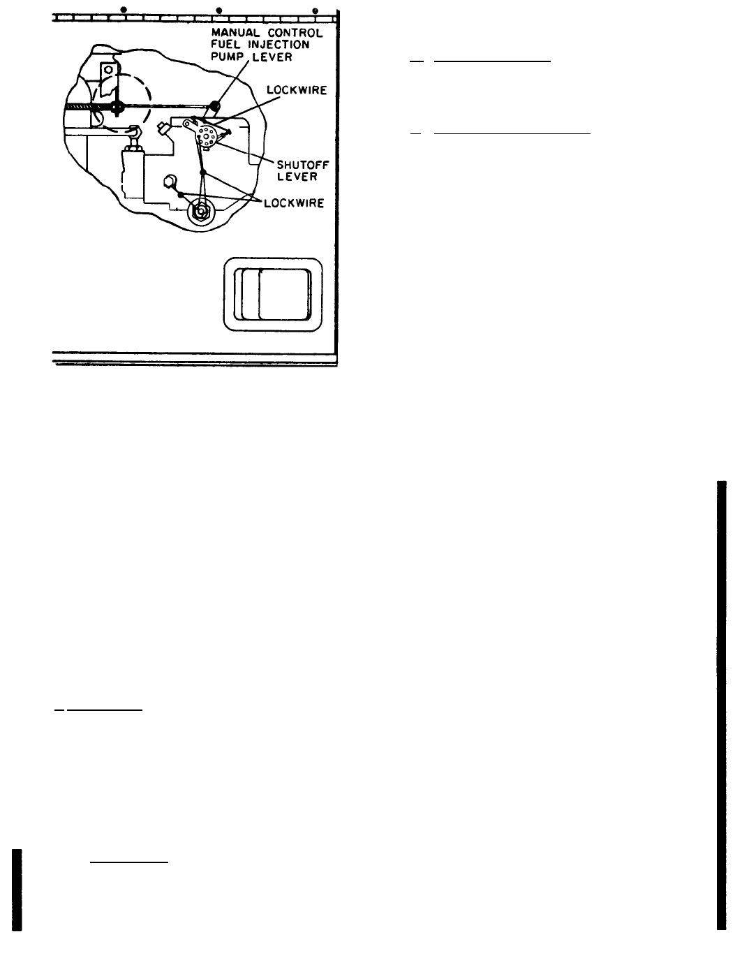
TM 5-6115-545-12
TO-35C2-3-444-1
NAVFAC P-8-626-12
TM-00038G-12
3.78 Replacement of Suppression Components, (Cont)
d. Main AC Contactor Three RFI suppression
capacitors C3, C4 and C5 are connected between terminals
A2, B2, and C2 respectively, of the main ac contractor CB2
and ground. Replace suppression capacitors as shown in A
of figure 3–11.
e. Day
Tank Solenoid Valve. Diode suppressors
CR27 are provided at the connector of the day tank solenoid
valve. Replace diode suppressors as shown in B of figure
3-11.
3-79. Testing of Radio Interference Suppression
Components.
Test the capacitors for leaks and shorts using a multimeter or
other capacitor tester. Replace defective capacitors. If test
equipment is not available and interference is indicated,
isolate the cause of interference by the trial and error method
of re- placing each component in turn until the cause of
interference is located and eliminated.
Figure 3-10. Lockwire of Fuel Injector Pump
for Class 2 Operation
Section VIII. ORGANIZATIONAL MAINTENANCE
3-80. General
maintain the engine generator set at the organizational level.
Instructions are provided in sections IX through XLIV for Where essential, sections are arranged in the most logical
the information and guidance of responsible personnel to
order of disassembly of equipment.
Section IX. BATTERIES, AND RELATED PARTS
3-81. General.
This section contains information on the batteries,
battery tray and slave receptacles of the engine generator set.
Two 12-volt 100 ampere, lead acid type batteries are
mounted side by side on a battery tray. The batteries are
electrically connected in series to supply 24 Vdc for starting
the engine generator set. There is a slave receptacle
electrically connected in parallel with the batteries. The
receptacle facilitates external connection with the batteries,
in order to supply or receive an auxiliary source of electrical
power. A source of 24 Vdc electrical power is therefore
available for other development. Normally, the engine
generator set should be operating so as not to run down the
batteries when supplying this source of dc power.
3-82. Batteries.
a. Replacement. To replace one or both batteries, see
figure 3-4 and proceed as follows:
(1) Remove screw (lA), nut (lB) and clamp (lC).
Disconnect battery negative cable (1) positive cable (2) and
jumper cable (3) from storage batteries (4)
(2) Remove two nuts (5) and lockwashers (6),
which secure battery retainer (7) to studs (8), and remove
storage batteries (4).
(3) Install new storage battery in reverse order of
removal.
b.
Battery Testing.
NOTE
Failure to perform this task prior to
adding distilled water will result in an
erroneous reading.
Battery hydrometer readings should be tested on all
cells monthly. Always test a battery for a degree of charge
before adding water. The specific gravity between the cells
should be within .05. A dangerously low point of charge
indicated by a hydrometer reading of 1.150 or less will
permit the battery to freeze at a temperature of 5° F. A
specific gravity of 1.250 will permit the battery to withstand
temperatures as low as -65°F without freezing. An
acceptable hydrometer reading of 1.210-1.220 at 80°F will
be obtained from a fully charged battery (2.0-2.2 volts dc
per cell).
Battery reading of less than 1.200 or cell variance of .05
or greater will be replaced if attempts to restore the battery
fail. Compare specific gravity readings with previous
readings for cell deterioration.
NOTE
The 6TN and 6TL batteries can be mixed or matched.
However, maintenance–free batteries cannot be mixed or
matched with military batteries. The 6TN and or the 6TL
batteries will perform properly in hot weather as long as
electrolyte levels are carefully monitored. If the electrolyte
expands and causes the level to rise, some fluid must be
removed. If the level becomes too low due to evaporation,
distilled water may be used to obtain the proper level. A
good grade of drinking water (excluding mineral waters)
may be used if distilled water is not available.
Electrolyte (NSNs 6810-00-249-9354 and
6810-00-843-1640) have a specific gravity of 1.280 and
should be used in these batteries. Do NOT adjust the
electrolyte in wet batteries to a lower specific gravity.
Change 17
3-29

temperatures as low as -65°F. without freezing. An
acceptable hydrometer reading of 1.210 - 1.220 at 80°F will
be obtained from a fully charged battery (2.0-2.2 volts dc
per cell).
c. Battery Preparation
WARNING
Do not smoke or use an open flame in
the vicinity when servicing batteries.
Batteries generate hydrogen during
charging, a highly explosive gas. A
severe
bum will result when
electrolyte is spilled on the skin or
clothing.
Use extreme care in
handling while filling batteries.
(1) Remove cell caps and fill battery cells with
electrolyte to 38 inches above the plates.
(2) Make sure vent holes in cell caps are open and
install caps.
TM 5-6115-545-12
TO-35C2-3-444-l
NAVFAC P-8-626-12
TM-00038G-12
3-83. Battery Tray Replacement
To replace the battery tray, remove batteries as described in
paragraph 3-82a. Remove screws (9, fig. 3-4) and
lockwashers (10) which secures battery tray (11) in
position, and install new battery tray.
3-84. Slave Receptacle Replacement.
To replace the slave receptacle, see figure 3-4 and proceed
as follows:
a. Disconnect battery negative cable (1).
b. Remove six screws (12) which secure receptacle
box (13) to housing and tilt box forward to gain access to
wiring connections.
Disconnect
wiring connections,
clamps, harness ties and tag for ease of Installation.
c.
Remove four screws (IS) and nuts (16) which
secure slave receptacle (I”), and remove receptacle.
d. (Deleted)
e.
install receptacle in reverse order of removal.
Section X. MUFFLER AND EXHAUST PIPES AND BREATHER SYSTEM
3.85. General.
Thin section contains information on the muffler and
exhaust pipes and breather system of the engine generator
set. The muffler and exhaust pipes provide a method for
expelling exhaust gases from the engine generator set. The
exhaust pipe allows the exhaust gases from the engine to he
discharged from an opening above the grille. The discharge
opening is covered by a cap that is opened by exhaust
pressure when the engine generator set is running. The
breather system provides a method for returning oil to the
crankcase and improving the atmosphere around the engine
generator set. Accumulated oil residue and gases in the valve
cover pass through an oil separator which separates the oil
and the gases. The oil is returned to the crankcase and the
gases exhaust into the air cleaner inlet. The breather system
is removed as outlined in paragraph 3-87.
3-86. Muffler and Exhaust Pipe Replacement.
To replace the exhaust pipe, see figure 3-12 and proceed as
follows
cap (3).
WARNING
Allow exhaust pipe to cool if engine has
been running.
Loosen nut (1) from screw (2) and remove weather
b. Loosen nuts (4) which secure 0-bolt (6) and
bracket (7) to nozzle (8) and muffler (9) pipes, and slide
0-bolt (6) and bracket (7) toward muffler.
Remove screws (10) which secure nozzle (8) to
housing. Place 0-bolt (6) on muffler (9) pipe and remove
nozzle (8).
d. Loosen nuts (11) which secure 0-bolt (13) and
bracket (14) to muffler (9) and exhaust pipe (15). Place
0-bolt (13) with bracket (14) on muffler pipe and remove
muffler and both 0-bolt assemblies.
e.
Disconnect exhaust pipe (15) from engine and
remove exhaust pipe.
f. Install new exhaust pipe in reverse order of removal.
3-87. Breather System Replacement.
To replace the breather system. see figure 3-12.1 and
proceed as follows:
Loosen clamps (1) and disconnect hose (2) from oil
separator (4) and elbow (3).
b. Loosen clamps (5) and disconnect hose (6) from oil
separator (4) and valve cover crankcase breather.
c. Loosen clamps (7) and disconnect hose (8) from oil
separator (4) and air cleaner inlet (9).
d. Loosen clamp (10) and slide out oil separator (4)
Remove nuts (1 1). camp and bracket (10), nuts
(12), and screws (13).
f. Install breather system in reverse order of removal.
Change 17 3-31
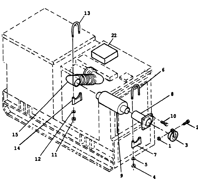
TM 5-6115-545-12
TO-35C2-344-1
NAVFAC P–8-626-12
TM-00038G-12
1. Nut 5. Washer
9. Muffler 13. u–bolt
22. Document Compartment
2. Screw 6. U-bolt
10. Screw 14. Bracket
3. Weather Cap 7. Bracket
11. Nut 15. Exhaust Pipe
4. Nut 8. Nozzle
12. Washer 16.-21. Deleted
Figure 3-12. Exhaust Pipe
Section XI. CONVENIENCE RECEPTACLE
3-88. General. c. Remove grommet (12) from box (3) and feed
This section contains information on the convenience
electrical wires back through grommet hole. Tag all
receptacle and associated circuit breaker.
electrical connections for positive identification during
installation.
3-89. Convenience
Receptacle
Box
Assembly
d. Install new convenience receptacle box assembly
Replacement. in reverse order of removal.
See figure 3-13 and proceed as follows 3-90. Convenience Receptacle Replacement.
Remove six screws (1) which secure box cover (2) and box
See figure 3-13 and proceed as follows
(3) to frame (4).
a. Remove six screws (1) which secure box cover (2)
b. Tilt box cover (2) and disconnect electrical
and box (3) to frame (4).
connections from receptacle (5) and circuit breaker (9) and
b. Tilt box cover (2) and disconnect electrical
remove box cover and assembly.
connections from receptacle (5).
3-32
Change 7

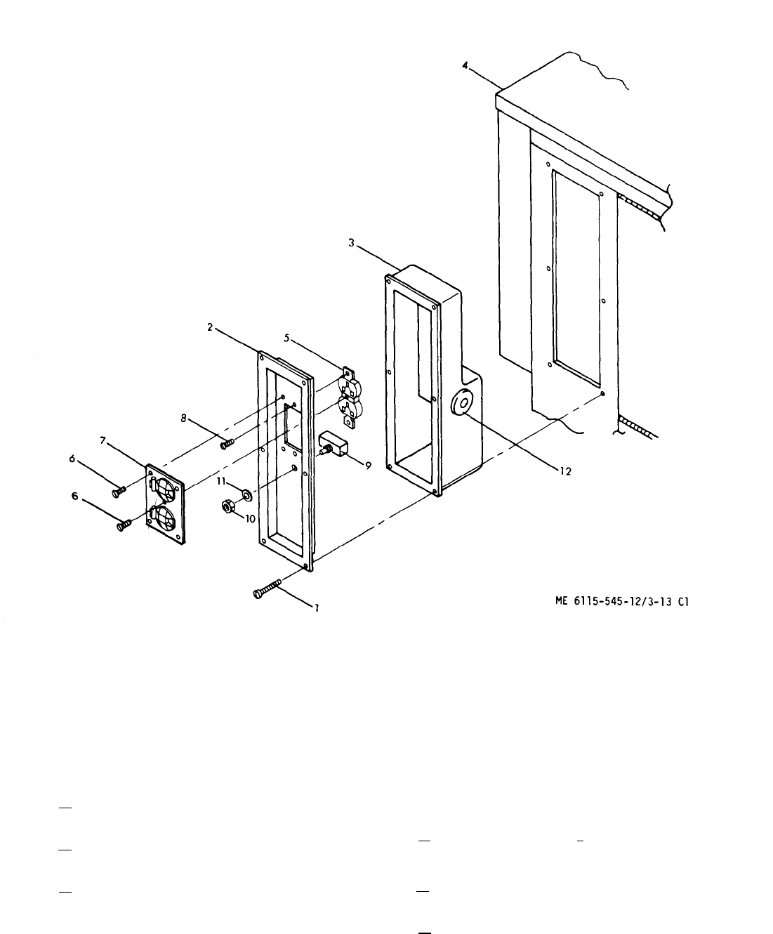
1. Screw 4. Frame 7. Cover 10. Nut
2. Box cover 5. Receptacle 8. Screw 11. Washer
3. Box 6. Screw 9. Circuit breaker 12. Grommet
Figure 3-13. Convenience Receptacle
c. Remove five screws (6) which secure re- Close circuit breaker and test for continuity. If de-
ceptacle cover (7) to box cover (2). fective see figure 3-13 and proceed as follows:
d. Remove two screws (8) which secure re- a. Repeat paragraph 3-89 a and tilt box cover (2)
to disconnect electrical connections from circuit
ceptacle (5) to rear of box cover. breaker (9).
e. Redate receptacle with new one in reverse b. Remove nut (10) and washer (11) which
sequence of removal.
3-91. Circuit Breaker
Change 7
secure circuit breaker to box cover.
c. Replace circuit breaker with new one in
Test and Replacement. reverse sequence of removal.
3-34
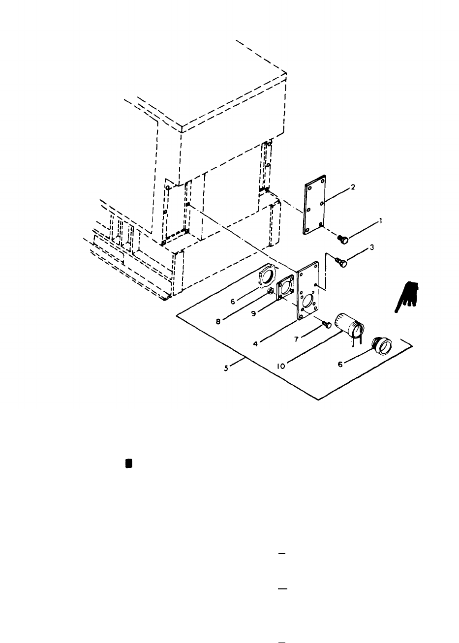
1. Screw
2. Cover
3. Screw
4. Plate7. Screw 10. Cloth sleeve
5. Plate and sleeve assy 8. Nut
6. Bushing 9. Retaining plate
Figure 3-15. Plate and Sleeve Assembly.
Section XIII. PLATE AND SLEEVE ASSEMBLY
3-95. General. a. Remove screws (1) which secure cover (2) to
housing. Remove screws (3) which secure plate (4)
This section contains information on the plate and of plate and sleeve assembly (5) to housing.
sleeve assembly. The plate and sleeve assembly
provides an opening for kit installation. and load b. Remove screws (7) and nuts (8) which secure
cable, with a cover to secure the opening.
retaining plate (9) and cloth sleeve (10) to plate.
Remove bushing (6), cloth sleeve (10) and retain-
3-96. Replacement. ing plate (9).
To replace the cover plate and sleeve assembly see c. Install a new plate and sleeve assembly, or
figure 3-15, and proceed as follows: parts thereof, in the reverse order of removal.
Change 9 3-35
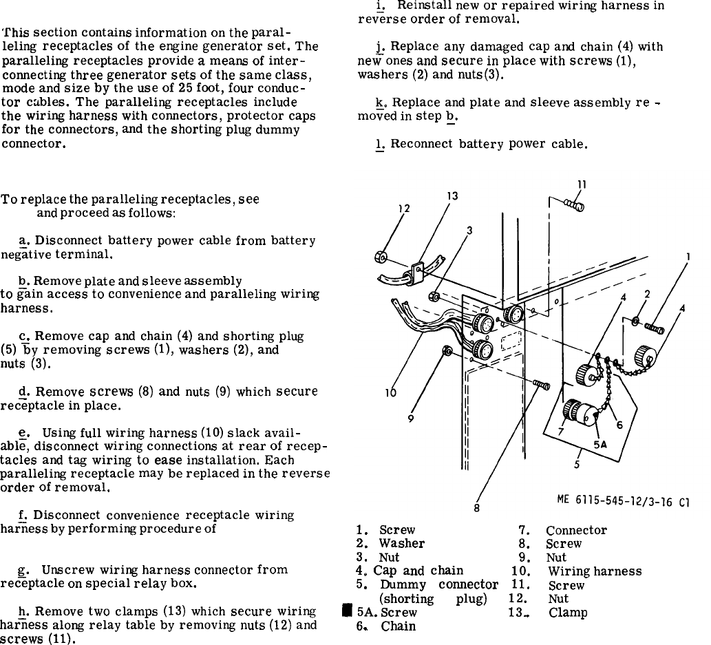
Section XIV.PARALLELING RECEPTACLES
3-97. General.
This
section
contains
information
on
the
paral-
leling
receptacles
of
the
engine
generator
set.
The
paralleling
receptacles
provide
a
means
of
inter-
connecting
three
generator
sets
of
the
same
class,
mode
and
size
by
the
use
of
25
foot,
four
conduc-
tor
cables.
The
paralleling
receptacles
include
the
wiring
harness
with
connectors,
protector
caps
for
the
connectors,
and
the
shorting
plug
dummy
connector.
3-98. Replacement.
To
replace
the
paralleling
receptacles,
see
figure
3-16
and
proceed
as
follows:
a.
Disconnect
battery
power
cable
from
battery
neg;tive
terminal.
~.
Remove
plate
and
sleeve
assembly
(para 3-96)
to
gain
access
to
convenience
and
paralleling
wiring
harness.
c.
Remove
cap
and
chain
(4)
and
shorting
plug
(5)
%y
removing
screws
(l),
washers
(2),
and
nuts
(3).
Q.
Remove
screws
(8)
and
nuts
(9)
which
secure
receptacle
in
place.
e.
Using
full
wiring
harness
(10)
slack
avail-
abl~,
discomect
wiring
connections
at
rear
of
recep-
tacles
and
tag
wiring
to
ease
installation.
Each
paralleling
receptacle
may
be
replaced
in
the
reverse
order
of
removal.
&
Disconnect
convenience
receptacle
wiring
harness
by
performing
procedure
of
paragraph 3-89a
through c.
—
—
g.
Unscrew
wiring
harness
connector
from
receptacle
on
special
relay
box.
~.
Remove
two
clamps
(13)
which
secure
wiring
harness
along
relay
table
by
removing
nuts
(12)
and
screws
(11).
i.
Reinstall
new
or
repaired
wiring
harness
in
rev%rse
order
of
removal.
&
Replace
any
damaged
cap
and
chain
(4)
with
new
ones
and
secure
in
place
with
screws
(l),
washers
(2)
and
nuts(3).
k.
Replace
and
plate
and
sleeve
assembly
re
-
moved
in
step
b.
—
1.
Reconnect
battery
power
cable.
—
1.
Screw
7.
Connector
2.
Washer
8.
Screw
3.
Nut
9.
Nut
4.
Cap
and
chain
10.
Wiring
harness
5.
Dummy
connector
11.
Screw
(shorting
plug)
~~.
Nut
~
;A.
Screw
.
Clamp
.
Chain
Figure 3-16.Paralleling Receptacles
Change 1
3-36
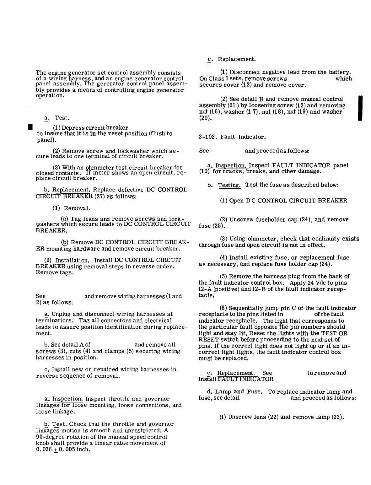
SECTION XV. GENERATOR SET CONTROLS
3-99. General.
The
engine
generator set control assembly consists
of
a
wiring harness,
and
an
engine
generator control
panel assembly. The generator control panel
assem-
bly provides
a
means
of controlling
engine
generator
operation.
3-100. DC Control Circuit Breaker.
a. Test.
—
(1)
Depress
circuit
breaker (27, fig. 3-17)
to insure
that
it
is
in
the
reset
position (flush to
panel).
(2)
Remove
screw
and
lockwasher
which
se-
cure leads to
one
terminal of
circuit
breaker.
(3)
With
an
ohmmeter test
circuit
breaker
for
closed
contacts. If meter shows
an
open
circuit,
re-
place
circuit
breaker.
b.
Replacement. Replace defective
DC
CONTROL
CI~CUfT BREAKER
(27)
as
follows:
(1)
Removal.
(a)
Tag leads
and
remove
screws
and
lock-
washers
wlich
secure
leads to
DC
CONTROL
CIRCUIT
BREAKER.
(b)
Remove
DC
CONTROL
CIRCUIT
BREAK-
ER
mount~~ hardware
and
remove
circuit
breaker.
(2)
Installation. Install
DC
CONTROL
CIRCUIT
BREAKER using removal steps
in
reverse
order.
Remove tags.
3-101. Wiring Harness Replacement.
See
figure 3-17
and
remove wiring harnesses
(1
and
2)
as
follows:
a.
Unplug
and
disconnect wiring harnesses
at
terfiinations.
Tag all connectors
and
electrical
leads to assure position identification during
replace-
ment.
b.
See
detail
A
of figure 3-17,
and
remove all
scr;ws
(3),
nuts
(4)
and
clamps
(5)
securing wiring
harnesses
in
position.
c.
Install
new
or repaired wiring harnesses
in
rev<rse
sequence of removal.
3-102. Manual Speed Control.
a. Inspection. Inspect throttle
and
governor
liti-~es
for
loose
mounting,
loose connections,
and
loose linkage.
b. Test. Check
that
the
throttle
and
governor
li&~es
motion is smooth
and
unrestricted.
A
90-degree rotation of
the
manual
speed control
knob
shall provide
a
linear cable movement of
0.036
+
0.005 inch.
—
c. Replacement.
—
(1)
Disconnect negative lead
from
the
battery.
On
Class
1
sets,
remove
screws
(11, fig. 3-17) which
secures
cover
(12)
and
remove
cover.
(2)
See
detail
B
and
remove
manual
control
assembly
(21
)
by loosening screw
(13)
and
removing
nut
(16), washer
(1
7),
nut
(18),
nut
(19)
and
washer
(20).
3-103.
Fault
Indicator.
See
figure 3-17
and
proceed
as
follows
a. Inspection. Inspect FAULT INDICATOR panel
(10~
for
cracks,
Ii
reaks,
and
other damage.
b. Testing. Test
the
fuse as
described
below:
—
(1)
Open
DC
CONTROL
CIRCUIT BREAKER
(27, fig. 3-17).
(2)
Unscrew fuseholder cap (24),
and
remove
fuse (25).
(3)
Using
ohmmeter, check
that
continuity exists
through fuse
and
open
circuit
is
not
in
effect.
(4)
Install existing fuse, or replacement fuse
as
necessary,
and
replace fuse holder cap (24).
(5)
Remove
the
harness plug
from
the
back of
the
fault indicator control box. Apply
24
Vdc to pins
12-A (positive)
and
12-B of
the
fault
indicator
recep-
tacle.
(6)
Sequentially jump pin
C
of
the
fault indicator
receptacle
to
the
pins listed
in
table 3-2 of
the
fault
indicator
receptacle.
The
light
that
corresponds
to
the
particular fault opposite
the
pin numbers should
light
and
stay lit. Reset the lights
with
the
TEST
OR
RESET switch
before
proceeding to
the
next
set of
pins. If
the
correct
light does
not
light
up
or if
an
in-
correct
light lights,
the
fault indicator control box
must be replaced.
Replacement.
See
figure 3-17 to remove
and
ins&H FAULT
INDICATOR
panel (10).
d.
Lamp
and
Fuse. To replace indicator
lamp
and
fus~, see detail C of figure 3-17
and
proceed
as
follows
(1)
Unscrew lens
(22)
and
remove lamp
(23).
Change 1
3-37

1. Wiring harness 8.
2. Wiring harness 9.
3. Screw
10.
4. Nut 11.
5. Clamp 12.
6. Wiring harness 13.
7. Control cubicle
13A.
assembly
14.
Blank panel
Blank panel
Fault indicator panel
Screw
Cover(Class 1 sets)
Screw, stop lever
Throttle lever
assembly
(Deleted)
15. (Deleted)
16. Nut
17. Washer
18. Nut
19. Nut
20. Washer
21. Manual control
assembly
Figure 3-17. Generator Set Controls
(2) Unscrew fuse holder cap (24) and remove
fuse (25). Install new fuse and replace fuse holder
cap (24).
3-104. Control Cubicle Assembly.
See figures 3-18, 19 and 20, and proceed as follows:
a. Inspection. Inspect the generator control
cubicle for defective, broken, cracked, or otherwise
defective components.
b. Testing. Testing of components of the control
cubicle is described under the appropriate heading
in paragraphs 3-105 through 3-130.
c. Repair. Repair by replacement of components
which do not function properly during testing.
Change 1
22. Lens
23. Lamp
24. Fuse holder cap
25. Fuse
26. Test or reset
switch
27. Dc control
circuit breaker
CAUTION
Turn engine off and remove the
battery negative connection be-
fore removing any electrical
leads to avoid possible short
circuit and resulting damage.
d. Replacement. If a component needs replace-
ment, gain access to the rear of the control cubicle
panel (96, fig. 3-18) by loosening the three quarter-
turn fastener and permitting the control cubicle panel
to pivot about its hinges in a forward direction. Re-
place control cubicle panel components which do not
function properly in step b (testing) as indicated in
following paragraphs. Replace control box (123, fig.
3-18) as described in paragraph 3-135 b.
3-38

3-105. AC Voltmeter Replacement.
See (42, fig. 3-18) and replace the ac voltmeter as
follows:
CAUTION
Open DC CONTROL CIRCUIT
BREAKER before testing or
replacing the ac voltmeter.
a. Testing.
(1) Gain access to rear of control cubicle
panel (96).
(2) Connect multimeter with appropriate ac
voltmeter connections across ac voltmeter terminals.
(3) Perform preparation for starting proced-
ure (fig. 2-6) and zero ac voltmeter with front panel
VOLTAGE ADJUST control.
(4) Perform starting procedure (fig. 2-7) steps
1 through 4.
(5) Check that readings on multimeter and ac
voltmeter do not differ by a voltage greater than that
listed below for each setting of the AMPS-VOLTS
selector switch.
(a) 240/416 V operation.
AMPS -VOLTS setting Voltage Difference
L1-L2 . . . . . . . . . . . . . . . ...34 V
L1-L0 . . . . . . . . . . . . . . . ...22 V
(b) 120/208 V operation.
AMPS -VOLTS setting Voltage Difference
L1-L2 . . . . . . . . . . . . . . . ...21 V
L1-L0 . . . . . . . . . . . . . . . ...11 V
(6) If voltage differences, greater than those
specified above are obtained, the ac voltmeter is
faulty and must be replaced. Faulty ac voltmeter
must be forwarded to higher maintenance level for
repair.
(7) Stop engine generator (fig. 2-8).
(8) Disconnect multimeter and secure control
cubicle panel.
b. Removal.
(1) Gain access to rear of control cubicle
panel (96).
(2) Tag and remove ac voltmeter (42) leads.
(3) Remove screws (40) and nuts (41) which
secure ac voltmeter and remove ac voltmeter.
c. Installation. Install replacement ac voltmeter
using removal steps in reverse order. Remove tags.
3-106. Kilowatt Met er Replacement.
See (39, fig. 3-18) and replace the kilowatt meter as
follows:
a. Removal.
—
(1) Gain access to rear of control cubicle
panel (96).
(2) Tag and remove kilowatt meter (39) leads.
(3) Remove three screws and nuts which secure
kilowatt meter and remove kilowatt meter.
b. Installation. Install replacement kilowatt
meter using removal steps in reverse order. Remove
tags.
3-107. Watt meter Converter Inspection and Replace -
ment.
See (102, fig. 3-18) and proceed as follows:
a. Inspection. Gain access to interior of control
cubicle and inspect wattmeter converter for signs of
corrosion, loose mounting, loose electrical connec-
t ions, or evidence of damage.
b. Removal.
—
(1) Gain access to rear of control cubicle
panel (96).
(2) Tag and remove electrical leads.
(3) Remove screws (100) and nuts (101) which
secure wattmeter converter (102) and remove watt-
meter converter.
c. Installation. Install replacement wattmeter
converter (102) using removal steps in reverse
order. Remove tags.
3-108. AC Ammeter Replacement,
See (8, fig. 3-18) and replace the ac ammeter (8) as
follows:
a. Removal.
—
(1) Gain access to rear of control cubicle
panel (96).
(2) Tag and remove ac ammeter leads.
(3) Remove three screws and nuts which secure
ac ammeter (8) and remove ac ammeter.
b. Installation. Install replacement ac am-
meter (8) removal steps in reverse order.
Remove tags.
3-39

3-109. Frequency Adjust Rheostat.
See (57, fig. 3-18) and proceed as follows:
a. Inspection.
(1) Gain access to rear of control
panel (96).
(2) Inspect FREQUENCY ADJUST
for breaks, loose mounting, evidence of
or other damage.
b. Testing.
cubicle
rheostat (57)
corrosion,
(1) Tag leads and remove screws which secure
leads to the FREQUENCY ADJUST rheostat (57).
(2) Connect an ohmmeter probe to each of the
outer terminals on the FREQUENCY ADJUST rheo-
stat (57), The ohmmeter should read 500 ohms ±3%.
(3) To check wiper arm of the FREQUENCY
ADJUST rheostat (57), connect one ohmmeter probe
to either outer terminal and the other probe to the
center terminal (wiper arm). Turn the FREQUENCY
ADJUST rheostat slowly throughout its range, which
should be 0 to 500 ohms. As the shaft is rotated, the
ohmmeter indicator should move at the same rate as
the rotating shaft. If the pointer does not move, or
moves unevenly, the FREQUENCY ADJUST rheostat
is defective and should be replaced.
(4) Reconnect leads as tagged using screws and
washers. Remove tags.
c. Replacement. Replace defective FREQUENCY
ADJUST rheostat (57) as follows:
(1) Removal.
(a) Tag leads and remove three nuts and
lockwashers which secure the three leads to FRE-
QUENCY ADJUST rheostat (57).
(b) Remove knob and hardware which se-
cure rheostat to panel and remove rheostat,
(2) Installation. Install FREQUENCY ADJUST
rheostat (57) using removal steps in reverse order.
Remove tags.
3-110. Voltage Adjust Rheostat.
See (54, fig. 3-18) and proceed as follows:
a. Inspection.
—
(1) Gain access to rear of control cubicle
panel (96).
(2) Inspect VOLTAGE ADJUST rheostat (54)
for breaks, loose mounting, cracks, evidence of
corrosion, and other damage.
b. Testing.
—
(1) Tag and unsolder leads from VOLTAGE
ADJUST rheostat (54) and test rheostat as described
for FREQUENCY ADJUST rheostat (para 3 -109),
3-40
except that the resistance value is 250 ohms ±3%
and the range is 0 - 250 ohms.
(2) Resolder leads to terminals as tagged.
Remove tags.
c. Replacement.
—
(1) Removal.
(a) Tag leads and unsolder leads from
VOLTAGE ADJUST rheostat (54).
(b) Remove knob and hardware which secure
VOLTAGE ADJUST rheostat (54) to panel (96) and
remove rheostat.
(2) Installation. Install VOLT AGE ADJUST
rheostat (54) using removal steps in reverse order.
Solder leads to rheostat. Remove tags.
3-111. Frequency Transducer and Meter. (See
fig. 3-18. )
a. Inspection. Inspect transducer (6) and frequency
meter (7) for loose mounting, loose leads and other
damage.
b. Replacement. The transducer (6) and frequency
meter (7) are a matched set (5) and must be replaced
by another matched set. Replace frequency meter and
transducer as follows:
(1) Removal.
(a) Gain access to rear of control cubicle
panel (96).
(b) Tag and remove frequency meter (7) leads.
(c) Remove screws (3) and nuts (4) which
secure the frequency meter to the panel (96) and re-
move frequency meter (7).
(d) Tag and remove transducer (6) leads.
(e) Remove screws (1) and nuts (2) which
secure transducer (6) to the rear panel and remove
the transducer.
(2) Installation. Install frequency meter (7) and
transducer (6) using removal steps in reverse order.
Remove tags.
3-112. AMPS-VOLTS Selector Switch.
See (48, fig. 3-18) and proceed as follows:
a. Testing.
—
(1) Gain access to rear of control cubicle
panel (96).
(2) Tag AMPS-VOLTS selector switch (48) leads
and removes crews and lockwashers which secure leads
to AMPS-VOLTS selector switch (48) and test AMPS-
VOLTS selector switch for continuity using ohmmeter
and schematic, figure 3-21. Sequentially select each
position,
starting
with
L1
-L2
(volts),
and
rotate
AMPS-VOLTS
selector
switch
clockwise
a
step
at
a
time.
The
circuit
for
the
L1
-L2
position
is
illus
-
trated
in
figure 3-21.
As
the
selector
switch
is
rotated
clockwise
(CW),
the
contacts
rotate
CW
as
shown.
(3)
Install
leads
as
kwged
and
remove
tags.
b.
Replacement.
Replace
defective
AMPS-VOLTS
sel;ctor
switch
(48)
as
follows:
(1)
Removal.
(a)
Tag
AMPS-VOLTS
selector
switch
(48)
leads
and~emove
screws
and
lockwashers
which
secure
the
leads
to
the
AMPS-VOLTS
switch.
(b)
Remove
knob
(43)
and
hardware
which
secure
AMPS-VOLTS
selector
switch
(48)
to
panel
(96)
and
remove
switch.
(2)
Installation.
Install
AMPS-VOLTS
selector
switch
(48)
using
removal
steps
in
reverse
order
and
remove
3-113.
See
(66,
tags.
Panel Light Switch.
fig. 3-18)
and
proceed
as
follows:
CAUTION
a.
—
panel
Open
DC
CONTROL
CIRCUIT
BREAKER
(27, fig. 3-17)
be-
fore
testing
or
replacing
PANEL
LIGHT
switch.
i
esting.
(1)
Gain
access
to
rear
of
control
cubicle
(96, fig. 3-18).
(2)
Remove
screw
that
secures
one
of
the
leads
to
PANE!.
LIGHT
switch
(66).
(3)
With
an
ohmmeter
test
PANEL
LIGHT
switch
for
continuity
in
ON
position.
(4)
Test
PANEL
LIGHT
switch
for
open
con-
tacts
no
continuity
in
OFF
position.
(5)
Reconnect
lead
to
PANEL
LIGHT
switch.
~.
Replacement. Replace
defective
PANEL
LIGHT
switch
(66)
as
follows:
(1)
Removal.
(~)
Tag
PANEL
LIGHT
switch
leads
and
re-
move
screws
and
lockwashers
which
secure
leads
to
switch.
(Q)
Remove
mounting
hardware
which
sec-
ures
PANEL
LIGHT
switch
to
panel
and
remove
switch.
(2)
Installation. Install
PANEL
LIGHT
switch
(66)
usin~
removal
steps
in
reverse
order
and
remove
tags.
3-114. Voltage Sensing Switch, Local-Remote.
See
(67, fig. 3-18)
and
proceed
as
follows:
CAUTION
Open
DC
CONTROL
CIRCUIT
BREAKER
(27, figure 3-17)
before
testing
or
replaciqq
VOLTAGE
SENSING
switch.
a.
Testing.
.
(1)
Gain
access
to
rear
of
control
cubicle
panel
(96, fig. 3-18).
(2)
Tag
all
VOLTAGE
SENSING
switch
(67)
leads.
(3)
Remove
screws
and
lockwashers
which
secure
tagged
leads
to
VOLTAGE
SENSING
switch.
(4)
Place
VOLTAGE
SENSING
switch
to
RE-
MOTE
position.
With
an
ohmmeter,
test
for
contin-
uity,
(closed
contacts)
from
center
contacts
to
upPer
COIltaC&.
NOT
E
Upper
contacts
are
those
closest
to
panel
hinge.
(5)
Place
VOLTAGE
SENSING
switch
in
LOCAL
position,
Test
for
continuity
(closed
contacts)
from
center
contacts
to
lower
contacts.
(6)
If
the
VOLTAGE
SENSING
switch
does
not
operate
correctly
replace
it.
(7)
Reconnect
leads,
as
tag~ecf,
and
remove
tags.
b.
Replacement. Replace
VOLTAGE
SENSING
swi~ch
(67)
as
follows:
(1]
Removal.
(a)
Tag
VOLTAGE
SENSING
switch
leads
and
remove
screws
and
lockwashers
which
secure
leads
to
the
VOLTAGE
SENSING
switch.
(~)
Remove
mounting
hardware
which
secures
VOLTAGE
SENSING
switch
to
panel
(96)
and
remove
switch.
(2)
Installation. Install
VOLTAGE
SENSING
switch
(67)
using
removal
steps
in
reverse
order.
Remove
tags.
3-41
3-115. Single/Parallel Operation Switch.
See
(68, fig. 3-18)
and
proceed
as
follows:
CAUTION
Open
DC
CONTROL
CIRCUIT
BREAKER
(27, fig. 3-17)
before
testing
or
replacing
OPERATION
switch
(68).
a.
Testing.
(1)
Gain
access
to
rear
of
control
cubicle
panel
(96, fig. 3-18).
(2)
Tag
the
center
leads
of
BATTLE
SHORT
switch
(62).
(3)
Remove
screws
and
lockwashers
which
sec-
ure
tagged
leads
to
BATTLE
SHORT
switch.
g.
Testing.
(4)
Place
BATTLE
SHORT
switch
in
ON
posi-
tion.
With
an
ohmmeter
test
for
continuity
(closed
(1)
Gain
access
to
rear
of
control
cubicle contacts)
from
center
contacts
to
upper
contacts.
panel
(96, fig. 3-18).
NOT
E
(2)
Tag
all
OPERATION
switch
(68)
leads.
(3)
Remove
screws
and
lockwashers
which
secure
tagged
leads
to
the
OPERATION
switch.
(4),
Place
OPERATION
switch
in
PARALLEL
OPERATION
position.
With
an
ohmmeter,
test
for
continuity
(closed
contacts)
from
center
contacts
to
upper
contacts.
NOTE
Upper
contacts
are
those
closest
to
the
panel
hinge,
(5)
Place
OPERATION
switch
in
SINGLE
UNIT
OPERATION
position.
Test
for
continuity
(closed
contacts)
from
center
contacts
to
lower
contacts.
(6)
If
the
OPERATION
switch
does
not
operate
correctly,
replace
it.
(7)
Reconnect
leads,
as
tagged,
and
remove
tags.
Upper
contacts
are
those
closest
to
the
panel
hinge.
(5)
Place
BATTLE
SHORT
switch
in
OFF
posi-
tion.
Test
for
continuity
(closed
contacts)
from
cent
er
contacts
to
lower
contacts.
(6)
If
the
BATTLE
SHORT
switch
does
not
operate
correctly,
replace
it.
b.
Replacement.
Replace
defective
BATTLE
SH~RT
switch
(62)
as
follows
(1)
Removal.
(a)
Tag
BATTLE
SHORT
switch
(62)
leads
and
remov–e
screws
and
lockwashers
which
secure
leads
to
BATTLE
SHORT
switch.
(~)
Remove
BATTLE
SHORT
switch
mount
-
ing
hardware
and
remove
switch.
(g)
Remove
BATTLE
SHORT
switch
cover.
b.
Replacement. Replace
defective
OPERATION
(2)
Installation. Install
BATTLE
SHORT
switch
SWitC
h
138~s-=w
S:
(62)
using
removal
steps
in
reverse
order.
Remove
tags
.
(1)
Removal.
3-117. Circuit Breaker Switch.
(~)
Tag
OPERATION
switch
leads
and
re-
move
screws
and
lockwashers
which
secure
leads
to See
(65, fig. 3-18)
and
proceed
as
follows:
OPERATION
switch.
CAUTION
(~)
Remove
mounting
hardware
which
secures
OPERATION
switch
(68)
to
panel
(96)
and
remove
Open
DC
CONTROL
CIRCUIT
OPERATION
switch.
BREAKER
(27, fig. 3-17)
before
testing
or
replacing
(2)
Installation. Install
OPERATION
switch
CKT
BRK
switch.
(68)
using
removal
steps
in
reverse
order.
Remove
tags.
3-116. Battle Short Switch.
See
(62, fig. 3-18)
and
proceed
as
follows
CAUTION
Open
DC
CONTROL
CIRCUIT
BREAKER
(27, fig. 3-17)
be-
fore
testing
or
replacing
BATTLE
SHORT
switch.
3-42
a,
Testing.
—
(1)
Gain
access
to
rear
of
control
cubicle
panel
(96, fig. 3-18).
(2)
Check
that
spring
return
is
in
its
center
position.
(3)
Tag
and
remove
all
leads
from
CKT
BRK
switch
(65, fig. 3-18).
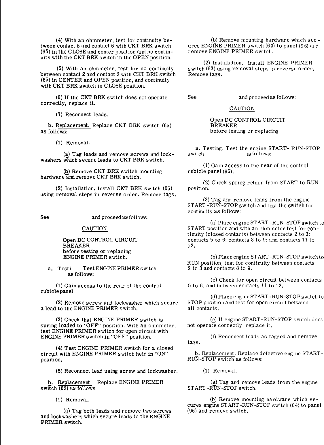
(4)
With
an
ohmmeter,
test
for
continuity
be-
tween
contact
5
and
contact
6
with
CKT
BRK
switch
(65)
in
the
CLOSE
and
center
position
and
no
contin-
uity
with
the
CKT
BRK
switch
in
the
OPEN
position.
(5)
With
an
ohmmeter,
test
for
no
continuity
between
contact
2
and
contact
3
with
CKT
BRK
switch
(65)
in
CENTER
and
OPEN
position,
and
continuity
with
CKT
BRK
switch
in
CLOSE
position.
(6)
If
the
CKT
BRK
switch
does
not
operate
correctly,
replace
it.
(7)
Reconnect
leads.
b.
Replacement.
Replace
CKT
BRK
switch
(65)
as
rollows:
(1)
Removal.
(~)
Tag
leads
and
remove
screws
and
lock-
washers
which
secure
leads
to
CKT
BRK
switch.
~)
Remove
CKT
BRK
switch
mounting
hardware
and
remove
CKT
BRK
switch.
(2)
Installation.
Install
CKT
BRK
switch
(65)
using
removal
steps
in
reverse
order.
Remove
tags.
3-118. Engine Primer Switch.
See
(63, fig. 3-18)
and
proced
as
follows:
CAUTION
Open
DC
CONTROL
CIRCUIT
BREAKER
(27, fig. 3-17)
before
testing
or
replacing
ENGINE
PRIMER
switch.
a.
Testi
Test
ENGINE
PRIMER
switch
(63,
fig. 3-18
as
follows:
(1)
Gain
access
to
the
rear
of
the
control
cubicle
panel
(96).
(2)
Remove
screw
and
lockwa.sher
which
secure
a
lead
to
the
ENGINE
PRIMER
switch.
(3)
Check
that
ENGINE
PRIMER
switch
is
spring
loaded
to
“OFF”
position.
With
an
ohmmeter,
test
ENGINE
PRIMER
switch
for
open
circuit
with
ENGINE
PRIMER
switch
in
“OFF”
position.
(4)
Test
ENGINE
PRIMER
switch
for
a
closed
circpit
with
ENGINE
PRIMER
switch
held
in
“ON’
posit
ion.
(5)
Reconnect
lead
using
screw
and
lockwasher.
b.
Replacement. Replace
ENGINE
PRIMER
swi~ch
(63)
as
follows:
(1)
Removal.
(~)
Tag
both
leads
and
remove
two
screws
and
lockwashers
which
secure
leads
to
the
ENGINE
PRIMER
switch.
(Q)
Remove
mounting
hardware
which
sec
-
ures
ENGINE
PRIMER
switch
(63)
to
panel
(96)
and
remove
ENGINE
PRIMER
switch.
(2)
Installation. Install
ENGINE
PRIMER
switch
(63)
using
removal
steps
in
reverse
order.
Remove
tags.
3-119. Engine Start-Run-Stop Switch.
See
(64, fig. 3-18)
and
proceed
as
follows:
CAUTION
Open
DC
CONTROL
CIRCUIT
BREAKER
(27, fig. 3-17)
before
testing
or
replacing
START-RUN-STOP switch.
a.
Testing.
Test
the
engine
START-
RUN-STOP
swi~ch
(64, fig. 3-18)
as
follows:
(1)
Gain
access
to
the
rear
of
the
control
cubicle
panel
(96).
(2)
Check
spring
return
from
START
to
RUN
position.
(3)
Tag
and
remove
leads
from
the
engine
START
-RUN-STOP
switch
and
test
the
switch
for
continuity
as
follows:
(~
Place
engine
START
-RUN-STOP
switch
to
START
position
and
with
an
ohmmeter
test
for
con-
tinuity
(closed
contacts)
between
contacts
2
to
3;
contacts
5
to
6;
coutacts
8
to
9:
and
contacts
11
to
12.
(b)
Place
engine
START
-RUN-STOP
switch
to
RUN
position,
test
for
continuity
between
contacts
2
to
3
and
contacts
8
to
9.
(c)
Check
for
open
circuit
between
contacts
5
to
6.
an~between
contacts
11
to
12.
(~)
Place
engine
START
-RUN-STOP
switch
to
STOP
position
and
test
for
open
circuit
between
all
contacts.
(~)
If
engine
START-RUN-STOP
switch
does
not
operate
correctly,
replace
it.
@
Reconnect
leads
as
tagged
and
remove
tags
.
~.
Replacement.
Replace
defective
engine
START-
RUN-STOP
switch
as
follows:
(1)
Removal.
(q)
Tag
and
remove
leads
from
the
engine
START
-RUN-STOP
switch.
(b)
Remove
mounting
hardware
which
se-
cures
eng~ne
START-RUN-STOP
switch
(64)
to
panel
(96)
and
remove
switch.
3-43

(2) Installation. Install engine START-RUN-
STOP (64) switch using removal steps in reverse
order. Remove tags.
3-120. Coolant Temperature Gage.
See (80, fig. 3-18) and proceed as follows:
a. Testing.
—
(1) Gain access to the rear of the control
cubicle panel (96).
CAUTION
Disconnect negative battery terminal prior
to making circuit changes. Reconnect this
terminal prior to checking meters, gages
and indicating lights.
(2) Tag and remove the lead from the SEND
contact of the COOLANT TEMPERATURE gage (80).
(3) The O to 500 ohm FREQUENCY ADJUST
rheostat on the control cubicle panel (96) can be used
to check the COOLANT TEMPERATURE gage. Dis-
connect and tag all leads from the FREQUENCY AD-
JUST rheostat.
(4) Connect a multimeter between the wiper
arm terminal and either other terminal of the FRE-
QUENCY ADJUST rheostat and adjust the rheostat
until the multimeter reads precisely 460 ohms. Dis-
connect the multimeter but do not disturb the rheostat
setting.
(5) Check that START-RUN-STOP switch (fig.
2-5) is set to RUN, BATTLE SHORT switch (fig. 2-5)
to ON, and the DC CONTROL CIRCUIT BREAKER
(27, fig. 3-17) is in closed ON position. Connect the
460 ohm resistance of the FREQUENCY ADJUST
rheostat in series with ground and the SEND terminal
of the coolant temperature gage. Gage should read
approximately 240°F.
(6) Disconnect rheostat from circuit and re-
connect leads removed in paragraph (3) above/
(7) If the COOLANT TEMPERATURE gage
does not operate correctly, replace it.
b. Replacement. Replace the COOLANT TEM-
PERATURE gage as follows:
(1) Removal.
(a) Gain access to the rear of the control
cubicle panel (96).
(b) Tag and remove the leads from
COOLANT-TEMPERATURE gage (80).
(c) Remove the two nuts (81), two washers
(82), and clamp (83) which secure the COOLANT
TEMPERATURE gage (80) and remove gage.
(2) Installation.Install COOLANT TEMPERA-
TURE gage (80) using removal steps in reverse
order, Remove tags.
3-121. Oil Pressure Gage.
See (78, fig. 3-18) and proceed as follows:
a. Testing
(1) Gain access to the rear of the control
cubicle panel (96).
CAUTION
Connect battery negative terminal prior
to checking the OIL PRESSURE gage (78)
readings.Remove this terminal prior
to making circuit changes.
(2) Tag and remove the lead from the SEND
terminal of the OIL PRESSURE gage.
(3) The 0-500 ohm FREQUENCY ADJUST
rheostat can be used to check the OIL PRESSURE
gage. Disconnect and tag all leads from the
FREQUENCY ADJUST rheostat.
(4) Connect a multimeter between the wiper
arm terminal and either terminal of the FREQUENCY
ADJUST rheostaL and adjust FREQUENCY ADJUST-
MENT rheostat until the multimeter reads precisely
30 ohms. Disconnect the multimeter but do not
disturb rheostat setting.
(5) Set START-RUN-STOP switch to RUN,
BATTLE SHORT switch to ON, and DC CONTROL
CIRCUIT BREAKER to the closed ON position.
Connect the 30 ohm resistance of the FREQUENCY
ADJUST rheostat in series with ground to the SEND
terminal of the OIL PRESSURE gage. Gage should
read approximately 120 psi.
(6) Disconnect FREQUENCY ADJUST rheostat
from circuit and reconnect leads removed in
paragraph (3) above.
(7) If the OIL PRESSURE gage does not operate
correctly, replace it.
b. Replacement. Replace the OIL PRESSURE
gage (78) as follows
(1) Removal.
(a) Gain access to the rear of the control
cubicle panel (96).
(b) Tag and remove the leads from the OIL
PRESSURE gage/
(c) Remove the two nuts, two washers, and
clamp which secure the OIL PRESSURE gage and
remove gage.
3-44

(2) Installation. Install OIL PRESSURE gage
(78) using removal steps in reverse order.
3-122. Fuel Level Gage.
See (79, fig. 3-18) and proceed as follows:
a. Testing.
—
(1) Gain access to the rear of the cubicle
control panel (96).
CAUTION
Connect battery negative terminal
prior to checking the gage read-
ings. Remove this terminal prior
to making circuit changes.
(2) Tag and remove the lead from FUEL
LEVEL gage (79). Check that START-RUN-STOP
switch is set to RUN. BATTLE SHORT switch to
ON, and that DC CONTROL CIRCUIT BREAKER
is in closed (on) position. Apply ground (0 ohms)
to SEND terminal of the gage. Gage should read
EMPTY.
(3) The 0-500 ohm FREQUENCY ADJUST
rheostat can be used to check the FUEL LEVEL
gage. Discomect and tag all leads from the
FREQUENCY ADJUST rheostat.
(4) Connect a multimeter between the wiper
arm terminal and either other terminal of the
rheostat and adjust the FREQUENCY ADJUST-
MENT rheostat until the multimeter reads 30
ohms. Disconnect the multimeter but do not
disturb rheostat setting.
(5) Check that START-RUN-STOP switch is
set to RUN, BATTLE SHORT switch to ON, and
that DC CONTROL CIRCUIT BREAKER is in closed
(on) position. Connect the 30 ohm resistance of the
FREQUENCY ADJUST rheostat in series with
ground to the SEND terminal of the FUEL LEVEL
gage. FUEL LEVEL gage should read FULL.
(6) Disconnect FREQUENCY ADJUST
rheostat from circuit and reconnect leads
removed in paragraph (3) above.
(7) If the FUEL LEVEL gage does not operate
correctly, replace it.
b. Replacement. Replace the FUEL LEVEL
gage (79) as follows:
(1) Removal.
(a) Gain access to the rear of the control
cubicle panel (96).
(b) Tag and remove the leads from FUEL
LEVEL gage.
(c) Remove the two nuts, two washers, and
clamp which secure the FUEL LEVEL gage and re-
move gage.
(2) Installation. Install FUEL LEVEL gage
(79) using removal steps in reverse order. Remove
tags.
3-123. Running Time Meter.
See (74, fig. 3-18) and proceed as follows:
a. Testing. Check that START-RUN-STOP switch
is set to RUN, BATTLE SHORT switch to ON, and
that DC CONTROL CIRCUfT BREAKER is in closed
(on) position. RUNNING TIME meter should operate
and change by one-tenth of an hour. Check for 24
Vdc input to meter. If voltage is present and the
meter does not operate, replace it.
b. Replacement. Replace RUNNING TIME
meter
(74)
as follows:
(1) Removal.
(a) Gain access to the rear of the control
cubicle panel (96).
(b) Tag and remove the leads from tne
RUNNING TIME meter.
(c) Remove the three screws (72) and nuts
(73) which secure the RUNNING TIME meter (74)
and remove meter.
(2) Installation. Install RUNNING TIME
meter (74) using removal steps in reverse order.
Remove tags.
3-124. Battery Charging Ammeter.
See (77, fig. 3-18) and proceed as follows:
a. Testing.
—
(1) Gain access to the rear of the control
cubicle panel (96).
CAUTION
Disconnect battery negative terminal prior
to checking the indicator readings or
making circuit changes.
(2) Set VOLTMETER to R Xl scale and connect
across terminals of BATTERY CHG AMMEtER (77).
Reading on voltmeter should be zero and BATTERY
CHG AMMETER should indicate a charge or discharge
reading. If voltmeter does not read zero, replace
BATTERY CHG AMMETER.
b. Replacement. Replace
AMMETER (77) as follows
(1) Removal.
the BATTERY CHG
(a) Gain access to the rear of the control
cubicle panel (96). 3-45

(b) Tag and remove the leads from the
BATTERY CHG AMMETER.
3-128. Panel Light Assembly.
See (9, fig. 3-18) and proceed as follows:
(c) Remove the three screws (75) and nuts
(76) which secure the BATTERY CHG AMMETER
(77) and remove meter.
a. Replacement. Replace panel light assemblies
as follows:
(2) Installation.Install BATTERY CHG
AMMETER (77) using removal steps in reverse
order.Remove tags.
(1) Removal.
(a) Tag leads and remove screws which
secure leads to panel light assembly.
3-125. DC Control Circuit Breaker.
(b) Remove panel light assembly mounting
hardware and remove panel light assembly.
Test and replacement instructions for DC circuit
breaker are contained in paragraph 3-100.b. Installation. Install panel light assembly
using removal steps in reverse order. Remove tags.
3-126. Control Box Relay Assembly.
3-129. Press-to-Test Light Assembly Replacement.
See (99, fig. 3-18) and proceed as follows:
a. Removal. See (25, 32, 124, fig. 3-18) and
proceed as follows
a. Inspection. Visually inspect for damaged
components.
(1) Tag leads and unsolder leads to light
assembly.(b). Replacement.
(1) Removal.(2) Remove light assembly mounting hardware
and remove light assembly.
(a) Gain access to inside of control box
(123). b. Installation. Install light assembly using re-
moval steps in reverse order. Solder leads to light
assembly. Remove tags.(b) Tag and remove the leads from relay
assembly (99).
3-130. Synchronizing Lights.
(c) Remove the relay assembly (99) by
removing the four attaching nuts (98). See (16, fig. 3-18) and proceed as follows:
(2) Installation. Install relay assembly (99)
using removal steps in reverse order. Remove tags.
a. Testing.
—
(1) Gain access to the rear of the control
cubicle panel (96).3-127. Terminal Board Assembly.
See (105, fig. 3-18) and proceed as follows: NOTE
a. Inspection. Visually inspect for broken bar-
riers, loose hardware and other damage.
Make certain DC CONTROL
CIRCUIT BREAKER is open.
(2) Remove screw which secures lead to one
terminal of SYNCHRONIZING LIGHT assembly (16).
b. Replacement.
—
(1) Removal.
(3) With an ohmmeter, test lamp (24) for
continuity.If meter shows an open circuit, replace
lamp.
(a) Gain access to inside of control box
(123).
(b) Tag and remove the leads from the
terminal board (105).
(4) Reconnect lead.
b. Replacement. Replace SYNCHRONIZING LIGHT
assemblies (16) as follows:
(1) Removal.
(c) Remove jumper (107) by removing
screws (106) and note location of jumper.
(d) Remove the four screws (103) and
nuts (104) and remove terminal board (105). (a) Tag leads and remove screws which
secure leads to light assembly.
(b) Remove light assembly mounting hardware
and remove light assembly.
(2) Installation. Install terminal board (105)
assembly using removal steps in reverse order. Re-
move tags. Make certain to replace jumper (107)
across same terminals in removal procedures.
3-46

c. Installation. Install SYNCHRONIZING LIGHT
assembly (16) using removal steps in reverse order.
Remove tags.
3-131. Door Holder.
See (85, fig. 3-18) and proceed as follows:
a. Removal and Installation.
(1) Remove screw (88), nut (87) and washer
(86) which secures one end of door holder (85) to
panel.
(2) Unhook other end of door holder from
bracket in control box (123) and remove door holder
(85).
(3) Install door holder using removal steps
in reverse order.
3-132. Crosspin Assembly.
See (94, fig. 3-18) and proceed as follows:
a. Removal and Installation.
(1) Gain access to rear of control cubicle
panel (96).
(2) Press out crosspin (94) through stud.
(3) Remove stud (93) and grommet (95) from
panel (96).
(4) Install in reverse order of removal.
3-133. Control Cubicle Panel Replacement.
See (96, fig. 3-18) and proceed as follows:
Remove the six screws (89) and nuts (92) which at-
tach the panel (96) to the hinge (90) and remove
panel.Replace panel (96) in reverse order of re-
moval.
3-134. Control Box Wiring Harness.
See (119, fig 3-18) and proceed as follows:
a.
bent,
tion.
b.
Inspection.
(1) Inspect connectors for damaged threads;
loose, or missing pins.
(2) Inspect terminal lug for security and condi-
(3) Inspect wiring for defective insulation.
Repair.
(2) If a wire is broken from a terminal lug, re-
place the lug. If a wire is broken from a connector,
resolder and reassemble.
CAUTION
Under no condition leave the
bare connection exposed.
(3) If a break in the wire is inaccessible within
wiring harness (119), disconnect it at both ends and
tape both ends. Lace a new lead of the same gage and
insulation outside the wiring harness and connect it
to the proper terminals or pins. Properly tag both
ends of all replacement wires.
c.Replacement. If 30% of the harness wires are
defective, the wiring harness must be rebuilt by
intermediate maintenance, and replaced by organi-
zational maintenance.Tag all wires, connectors,
and terminals for positive identification when a
defective wiring harness is removed. To remove
wiring harness, remove four screws and nuts which
attach connector to box. Remove the four clamps
71, 110, 113 and 116 with the associated attaching
hardware and remove wiring harness. Install wiring
harness in reverse order of removal. Remove tags.
3-135. Control Box.
See (123, fig. 3-18) and proceed as follows:
a.Inspection. Visually inspect control box for
damage.
b. Replacement.
—
(1) Removal.
(a) Disconnect all electrical connections at
rear of control box.
(b) Remove control cubicle panel (96)
from hinge (90) by removing six screws (89) and
nuts (92).
(c) Remove 14 screws (97) and attached
washers which secure control box (123) to frame and
remove control box.
(d) Remove six rivets (89A) which secure
the hinge (9O) and spacer (91) to the control box (123).
(2) Installation.Install box in reverse order
of removal.
(1) If a broken wire is accessible; remove
sufficient insulation from each side of the break to
allow a good connection of the bared ends by twisting
them together. Solder the connection and wrap with
electrical tape.
Change 1 3-47

KEY to fig. 3-18:
1.
2.
3.
4.
5.
6.
7.
8.
9.
10.
11.
12.
13.
14.
15.
16.
17.
18.
19.
20.
21.
22.
23.
24.
25.
26.
27.
28.
29.
30.
31.
32.
33.
34.
35.
36.
37.
38.
39.
40.
41.
42.
43.
44.
45.
46.
47.
48.
49.
50.
51.
52.
53.
54.
55.
56.
57.
58.
59.
60.
61.
62.
63.
Screw
Nut
Screw
Nut
Freq meter and transducer (Matched Set)
Transducer
Freq meter
AC ammeter
Panel light (3)
Hood
Nut
Washer
Washer
Holder
Lamp
Synchronizing lights (2)
Lens
Washer
Nut
Washer
Washer
Gasket
Holder
Lamp
Air cleaner condition light assembly
Lens
Nut
Washer
Nut
Light Assembly
Lamp
Ckt bkr light assembly
Lens
Nut
Washer
Nut
Holder
Lamp
Kilowatt meter
Screw
Nut
Ac voltmeter
Knob
Nut
Washer
Washer
Nut
Amps-volts selector switch
Knob
Nut
Washer
Washer
Nut
Voltage adjust rheostat
Knob
Nut
Frequency adjust rheostat
Guard
Nut
Washer
Washer
Battle short switch
Engine prlrner switch
64. Start-run-stop switch
65. Ckt bkr switch
66. Panel light switch
67. Voltage sensing switch
68. single/parallel operation switch
69. Screw
70. Nut
71. Clamp
72. Screw
73. Nut
74. Running time meter
75. Screw
76. Nut
77. Battery chg ammeter
78. Oil pressure gage
79. Fuel level gage
80. Coolant temperature gage
81. Nut
82. Washer
83. Clamp
84. Hook
85. Door holder
86. Washer
87. Nut
88. Screw
89. Screw
89A. Rivet
90. Hinge
91. blacer
92. Nut
93. Stud
94. Cross pin
95. Grommet
96. Panel
97. Screw
98. Nut
99. Relay assembly
100. Screw
101. Nut
102. Wattmeter converter
103. Screw
104. Nut
105. Terminal board
106. Screw
107. Jumper
108. Screw
109. Nut
110. Clamp
111. Screw
112. Nut
113. Clamp
113A. Nut
114. Screw
115. Nut
116. ClaInp
1170 Screw
118. Nut
119. Wiring harness
120. Rivet
121. Receptacle
122. (Deleted)
123. Control box
124. Battle short light assembly
Change 1
3-48
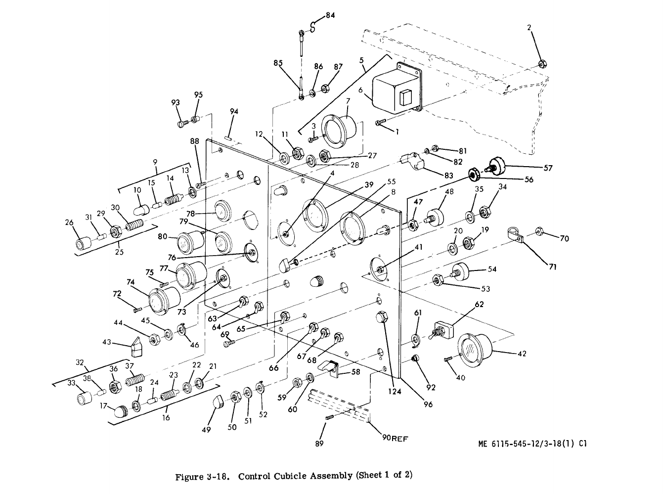

Figure 3-18.
Change 1
3-50
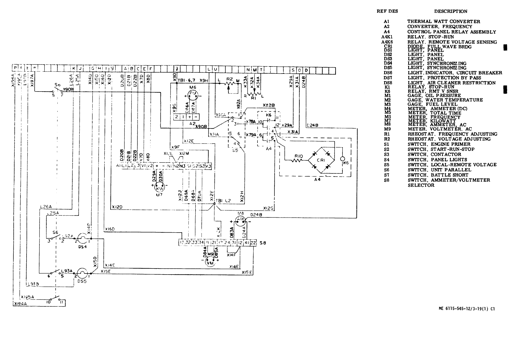
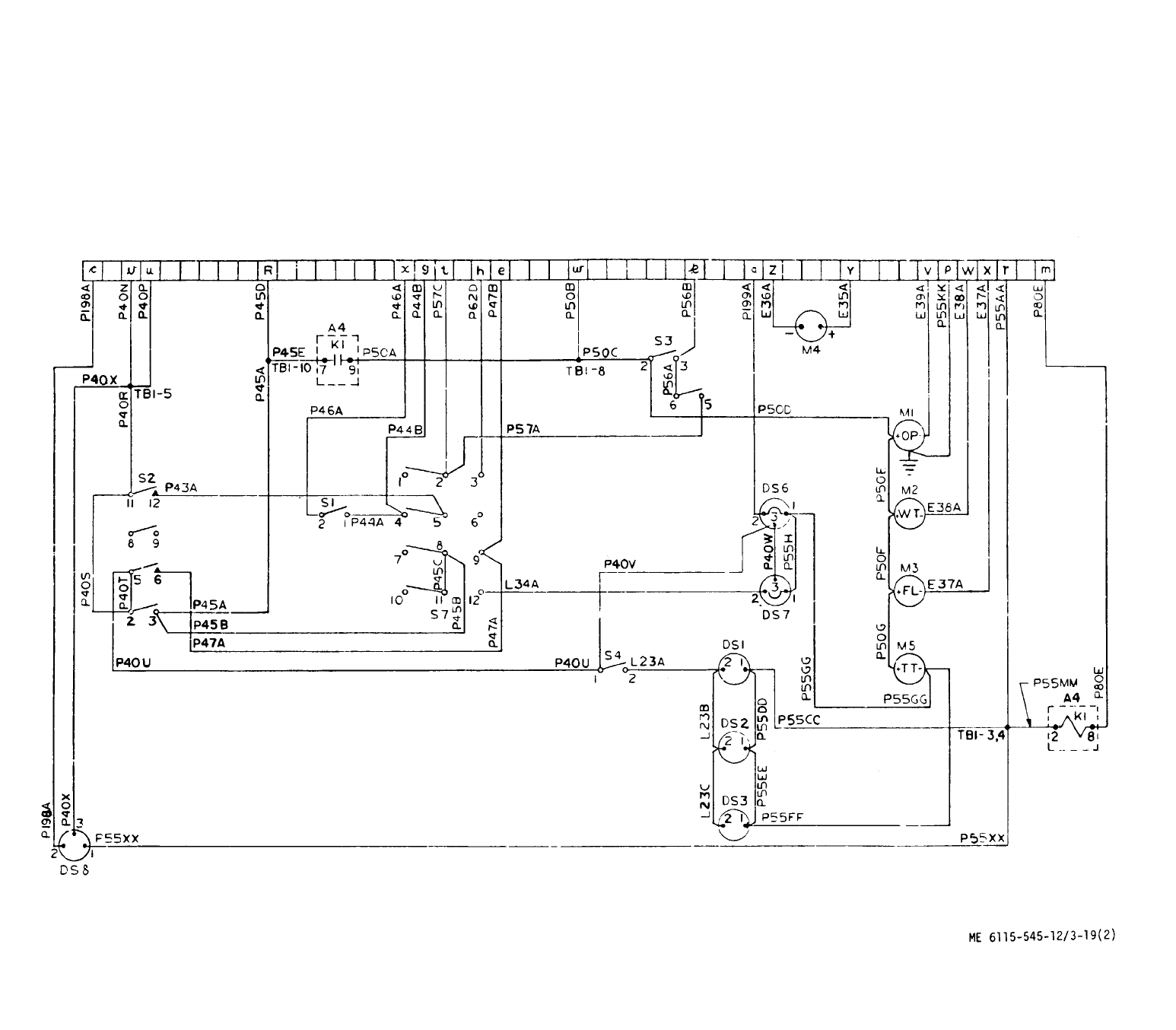
Figure 3-19. Control Cubicle Schematic Diagram
(Sheet 2 of 2)
3-53/(3-54 blank)
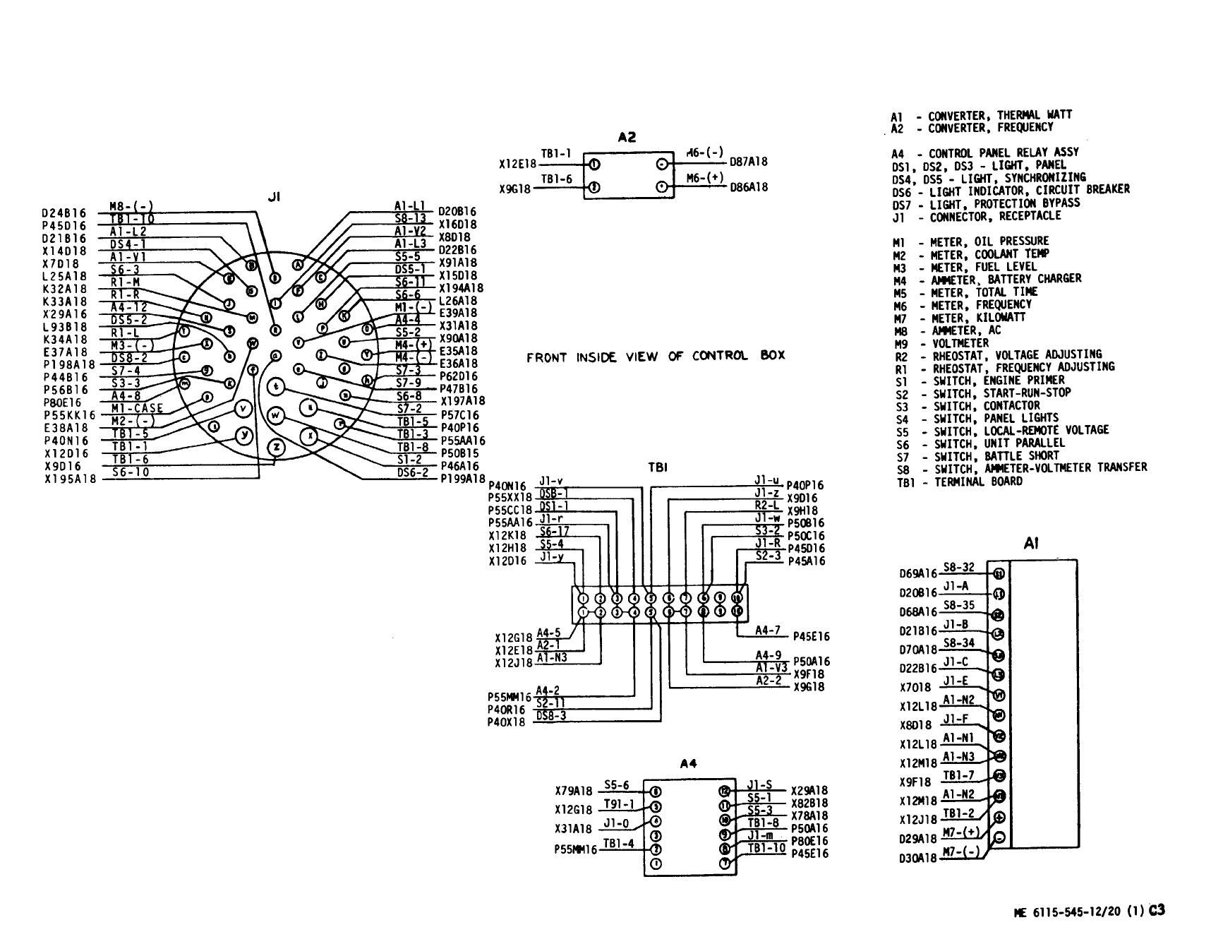
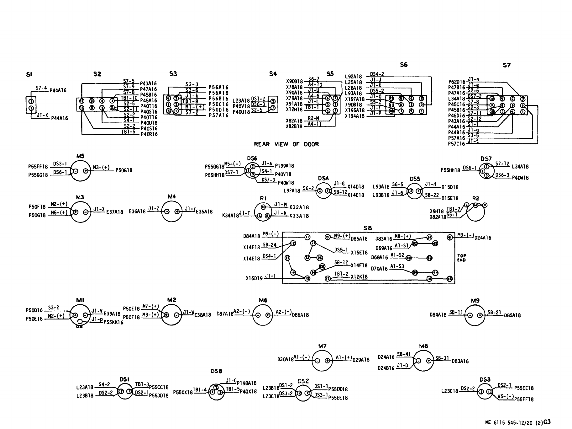
Figure 3-20. Control Cubicle Wiring Diagram
(Sheet 2 of 2)
Change 3 3-57/(3-58 blank)


Section XVI. ENGINE GENERATOR SET HOUSING GROUP
3-136. General.3-137. Removal and Replacement.
This
section
contains
information
on
the
housing
See
figure 3-22
and
remove
and
replace
damaged
group
which
encloses
the
engine
generator
set.
The
doors,
covers,
panels,
and
associated
hardware
of
housing
group
is
made
up
of
covers
and
panels
the
housing
group.
Remove
the
load
bank,
if
in-
which
are
bolted
together,
and
hinged
doors
which
stalled,
as
described
in
paragraph 4-49.
provide
access
to
components:
Section XVII. ENGINE GENERATOR AND CHASSIS
INTERCONNECTING WIRING HARNESSES
3-138. General.
This
section
contains
information
on
interconnect-
ing
wiring
harnesses
of
the
engine
generator
and
chassis.
The
wiring
harnesses
provides
electrical
interconnection
between
major
assemblies
of
the
engine
generator
set.
3-139. Inspection, Test, Repair and Replacement.
See
figure 3-23
and
proceed
as
follows:
CAUTION
As
a
precaution
against
short
circuits,
disconnect
the
bat
-
tery
ground
cable
from
the
batteries
before
inspecting,
testing,
or
replacing
any
wiring.
~.
Inspection.
(1)
Inspect
connectors
for
damaged
threads;
bent,
loose,
or
missing
pins.
(2)
Inspect
terminal
lug
for
security
and
condi-
tion.
(3)
Inspect
wiring
for
defective
insulation.
b.
Test.
Perform
continuity
check,
using
multi-
me~er
between
connecting
points
in
the
wiring
harness
using
the
wiring
data
contained
in
figs. 1-13
through 1-16.
Check
for
short
circuits
between
con-
nector
pins
of
the
same
receptacle
or
terminal
board
following
data
shown
in
figs. 1-13 through
1-16.
c.
Repair.
—
(1)
If
a
broken
wire
is
accessible,
remove
sufficient
insulation
from
each
side
of
the
break
to
allow
a
good
connection
of
the
bared
ends
by
twist-
ing
them
together.
Solder
the
connection
and
wrap
with
electrical
tape.
(2)
If
a
wire
is
broken
from
a
terminal
lug,
replace
the
lug. If
a
wire
is
broken
from
a
connec-
t
or,
resolder
and
reassemble.
CAUTION
Under
no
condition
leave
the
bare
connection
exposed.
(3)
If
a
break
in
the
wire
is
inaccessible
with-
in
the
wiring
harness,
disconnect
it
at
ooth
ends
and
tape
both
ends.
Lace
a
new
lead
of
the
same
gage
and
insulation
outside
the
harness
and
connect
it
to
the
proper
terminals
or
pins.
Properly
tag
both
ends
of
all
replacement
wires.
~.
Replacement.
If
30%
of
the
harness
wires
are
defective,
the
harness
must
be
rebuilt
by
inter-
mediate
maintenance,
but
may
be
replaced
by
org
-
anizational
maintenance.
Tag
all
wires,
connectors,
and
terminal
boards
for
positive
identification
when
a
defective
harness
is
removed.
Disconnect
harness
connectors
from
receptacles
by
unscrewing
connec-
tors
in
counterclockwise
direction.
Remove
all
clamps
which
secure
harness
in
position.
Install
new
or
repaired
harness
in
reverse
sequence
of
removal.
Section
XVIII
LOAD
CONNECTION
GROUP
3-140. General.3-141. Main AC Contactor.
The
lend
connection
group
(fig. 3-24)
is
used
to
pro-
See
figure 3-24
and
proceed
as
follows:
vide
the
electrical
connection
between
the
engine
a.
Inspection.
Inspect
mam
ac
contactor
(3),
generator
set
and
the
external
equipment
to
be whi?h
is
located
at
the
right
of
the
reconnection
board
operated.
(15),
for
secure
mounting,
loose
electrical
connec
-
tions,
frayed
cables
or
insulation,
loose
connector
mating
and
other
damage.
3-60

KEY to fig. 3-22.
1.
2.
3.
4.
5.
6.
7.
8.
9.
10.
11.
12.
13.
14.
15.
16.
17.
18.
19.
20.
21.
22.
23.
24.
25.
26.
27.
28.
29.
30.
31.
32.
33.
34.
35.
Screw
Nut
Rubber
seal
Paddle
lock
Access
door
Screw
Nut
Access
door
Rivet
Plate,
information,
dc
troubleshooting
Screw
Nut
Access
door
Screw
Nut
Access
door
Rivet
Plate.
information,
dc
schematic
Rivet
Plate,
information,
ac
schematic
Screw
Nut
Access
door
Screw
Nut
Access
door
Screw
Nut
Access
door
Screw
Nut
Access
door
Rivet
Plate,
information
Safety
cover
assembly
36.
Screw
36A.Washer
37.
38.
39.
40.
41,
42,
43.
44.
45,
46.
47.
48.
49.
50.
51.
52.
53.
54.
55.
56.
57.
58.
59.
60.
61.
62.
63.
Cover
Rivet
Plate,
operational
data
Rivet
Plate,
operational
data
Screw
Nut
Access
cover,
radiator
cap
Oval
stud
Retainer
stud
Screw
Nut
Receptacle,
lock
Screw
Compartment,
document
Screw
Lockwasher
Nut
Screw
Nut
Housing,
top,
front
Screw
Nut,
cage
Side
housing,
left
front
Side
housing,
right
front
Screw
Nut
64.
Housing,
top
rear
65.
Screw
66.
Nut,
cage
67.
Screw
68.
Nut
69.
Post,
left
hand,
rear
70.
Screw
71.
Nut
72.
Side
housing,
right
rear
73.
Screw
74.
Nut
75.
Side
housing,
left
rear
76.
Screw
77.
Nut,
cage
78.
Grille
79.
Screw
80.
Screw
81.
Washer
82.
Nut
83.
Door
holder
84.
Screw
85.
Nut
86.
Battery
access
door
87.
Rivet
88.
Battery
connection
instruction
plate
89.
Screw
90.
Nut,
cage
91.
Screw
92.
Nut,
cage
93.
Housing,
lower
front
94.
Screw
95.
Nut
96.
Housing,
upper
front
97.
Screw
98.
Nut
99.
Screw
100.
Nut
101.
Control
and
access
door,
right
102.
Door
hook
103.
Rivet
104.
Instruction
plate,
service
instructions
105.
Screw
106.
Nut
107.
Control
panel,
access
door,
left
108.
Door
hook
109.
Rivet
110.
Instruction
plate,
operating
111.
Screw
112.
Nut
113.
Air
inlet
door,
right
114.
Door
hook
115.
Screw
116.
Nut
117.
Air
inlet
door,
left
118.
Door
hook
119.
Screw
120.
Control
box,
mounting
121.
Screw
122.
Nut
123.
Rear
corner
panel,
left
hand
124.
Screw
125.
Rear
corner
panel,
right
hand
126.
Screw
127.
Screw
128.
Panel,
air
intake
Change 1 3-61
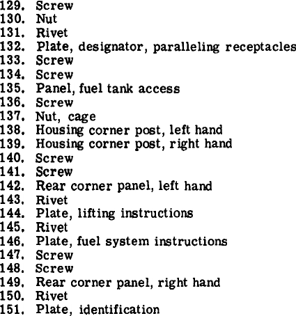
KEY to fig. 3-22. (Cont)
129.
130.
131.
132.
133.
134.
135.
136.
13’7.
138.
139.
140.
141.
142.
143.
144.
145.
146.
147.
148.
149.
150.
151.
Screw
Nut
Rivet
Plate,
designator,
paralleling
receptacles
Screw
Screw
Panel,
fuel
tank
access
Screw
Nut,
cage
Housing
corner
post,
left
hand
Housing
corner
post,
right
hand
Screw
Screw
Rear
corner
panel,
left
hand
Rivet
Plate,
lifting
instructions
Rivet
Plate,
fuel
system
instructions
Screw
Screw
Rear
corner
panel,
right
hand
Rivet
Plate,
identification
3-62
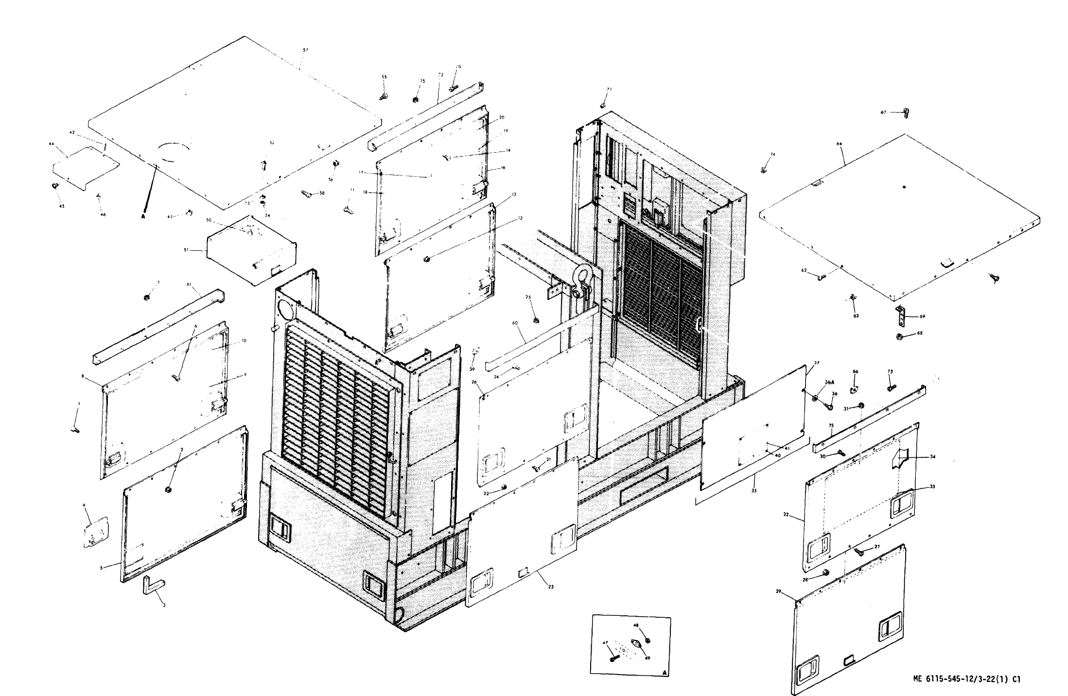
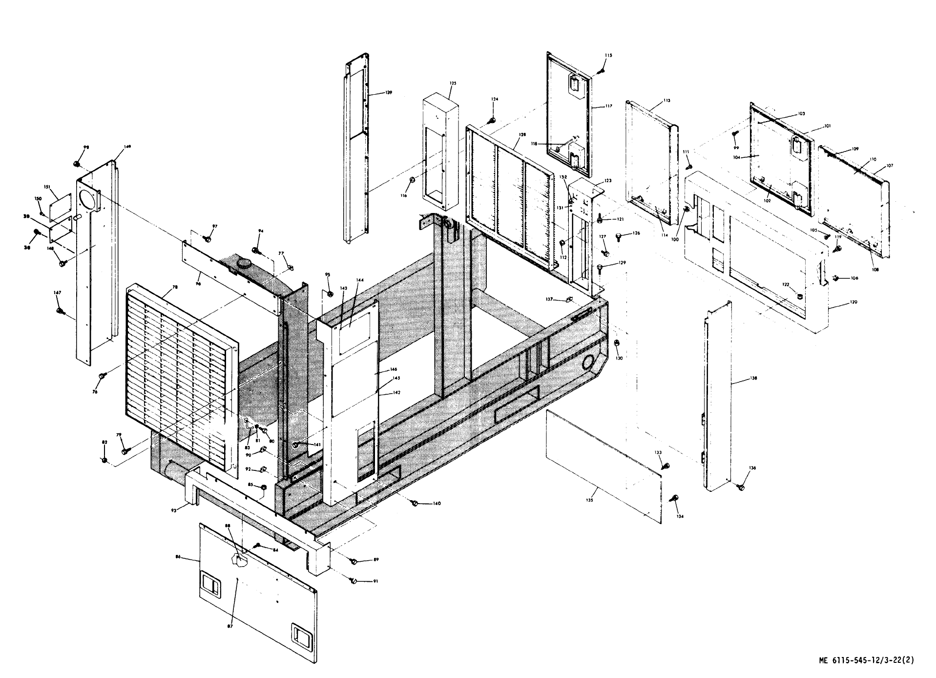
Figure 3-22. Housing Group, Front and Rear
(Sheet 2 of 2)
3-65/(3-66 blank)
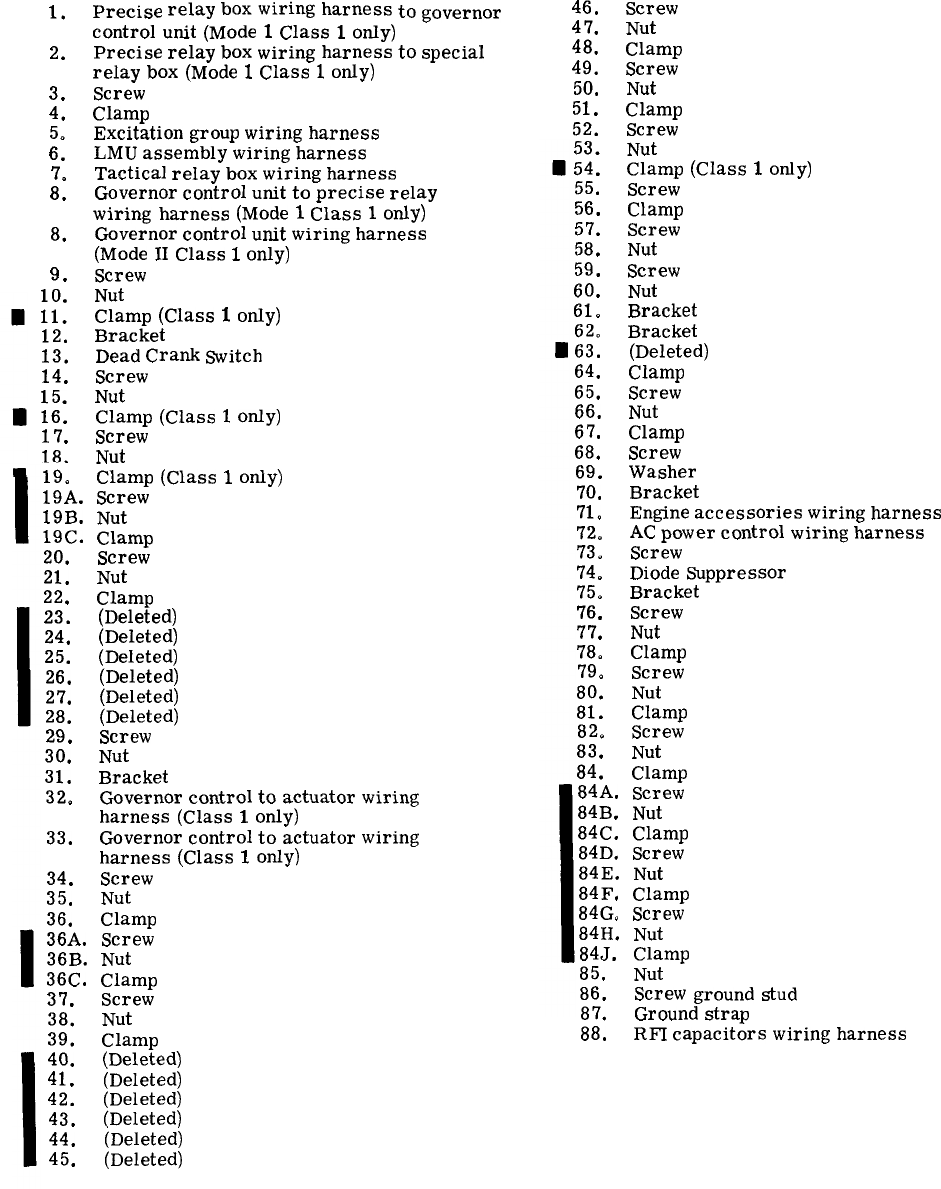
KEY to fig. 3-23.
1.
2.
3.
4.
::
7.
8.
8.
9.
+::
12.
13.
14.
;::
17.
18.
Precise
relay
boxwiring
harness
to
governor
control
unit
(Mode
1
Class
1
only)
Precise
relay
box
wiring
harness
to
special
relay
box
(Mode
1
Class
1
only)
Screw
Clamp
Excitation
group
wiring
harness
LMU
assembly
wiring
harness
Tactical
relay
box
wiring
harness
Governor
control
unit
to
precise
relay
wiring
harness
(Mode
1
Class
1
only)
Governor
control
unit
wiring
harness
(Mode
11
Class
1
only)
Screw
Nut
Clamp
(Class
1
only)
Bracket
Dead
Crank
Switch
Screw
Nut
Clamp
(Class
1
only)
Screw
Nut
Clamp
(Class
1
only)
19:
19A.
Screw
19B.
Nut
19C.
Clamp
20.
21.
22.
23.
24.
25.
26.
27.
28.
Screw
Nut
Clamp
(Deleted)
(Deleted)
(Deleted)
(Deleted)
(Deleted)
(Deleted)
29.
Screw
30.
Nut
31.
Bracket
32.
Governor
control
to
actuator
wiring
harness
(Class
1
only)
33.
Governor
control
to
actuator
wiring
harness
(Class
1
only)
34.
Screw
35.
Nut
36. Clamp
36A.
Screw
36B.
Nut
36C.
Clamp
37. Screw
38.
Nut
39.
Clamp
40.
(Deleted)
41. (Deleted)
42. (Deleted)
43. (Deleted)
44.
(Deleted)
45. (Deleted)
46. Screw
47.
Nut
48. Clamp
49. Screw
50. Nut
51.
Clamp
52.
Screw
Nut
:::
Clamp
(Class
1
only)
55.
Screw
56.
Clamp
57.
Screw
58. Nut
59.
Screw
60.
Nut
61.
Bracket
Bracket
:::
(Deleted)
64. Clamp
65.
Screw
66.
Nut
67.
Clamp
68.
Screw
69.
Washer
70.
Bracket
71.
Engine
accessories
wiring
harness
72.
AC
power
control
wiring
harness
73.
Screw
74.
Diode
Suppressor
75.
Bracket
76.
Screw
77. Nut
78.
Clamp
79.
Screw
80.
Nut
81. Clamp
82.
Screw
83.
Nut
84.
Clamp
84A.
Screw
84B.
Nut
84C.
Clamp
84D.
Screw
84E.
Nut
84F,
Clamp
84G.
Screw
84H.
Nut
84J.
Clamp
85.
Nut
86.
Screw
ground
stud
87.
Ground
strap
88.
RFI
capacitors
wiring
harness
Change 13-67
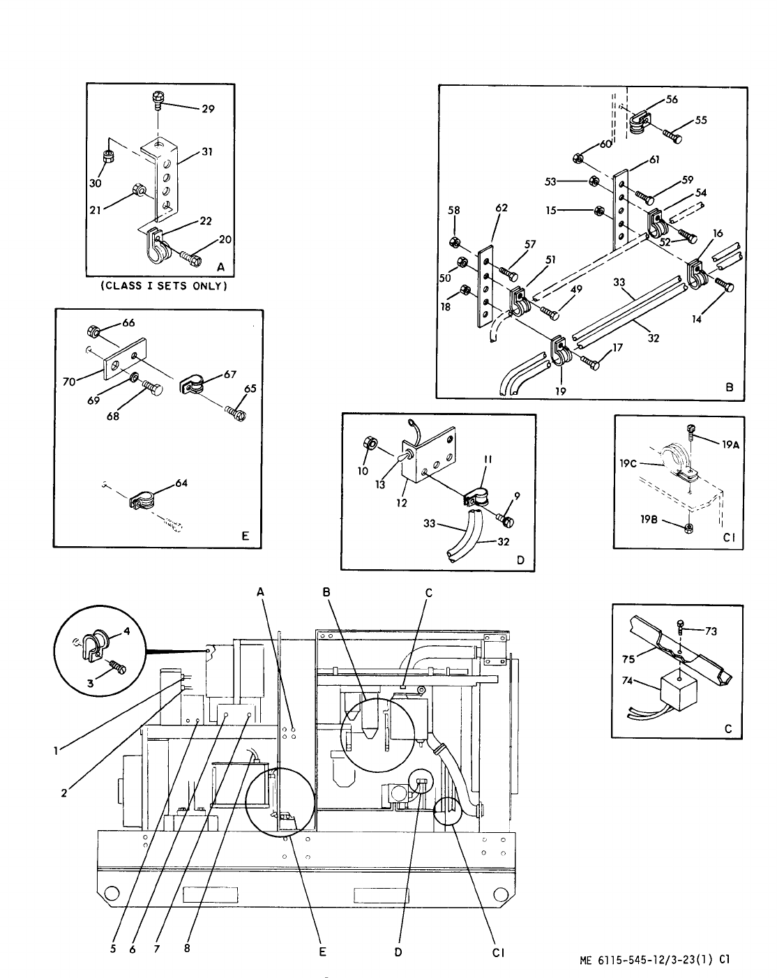
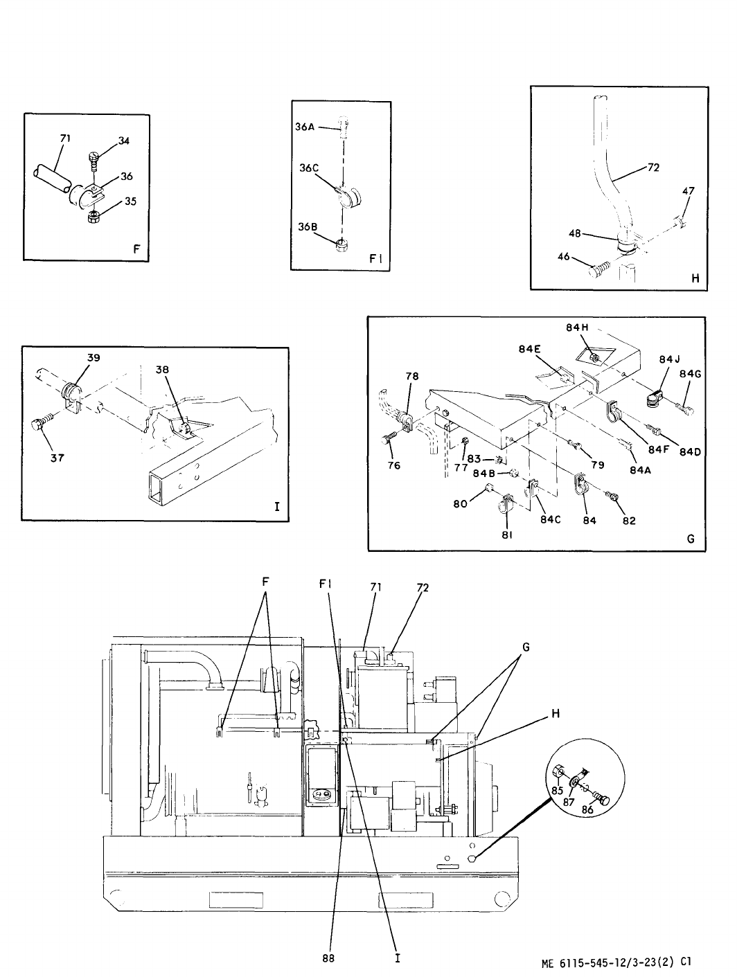
Figure 3-23. Engine Generator and Chassis Wiring Harness (Sheet 2 of 2)
Change 1 3-69
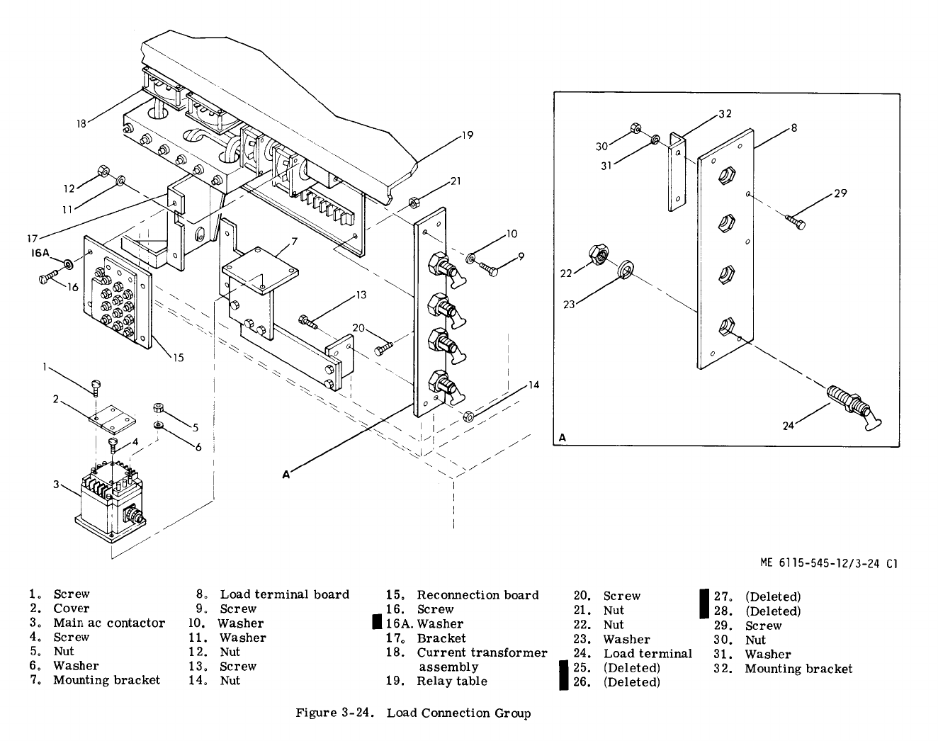

TM 5-6115-545-12
TO-35C2-3-444-1
NAVFAC P-8-626-12
TM-00038G-12
b.
?estirw,
—
(~ply
24
Vdc
at
pins
A
and
B
of
main
ac
contactor
(3)
connector.
When
main
ac
contactor
operates,
it
should
create
a
distinctive
noise.
(2)
With
an
ohmmeter,
check
for
continuity
between
terminal
Al
to
A2,
B1
to
B2,
and
Cl
to
C2
on
top
of
the
main
ac
contactor.
(3)
At
the
connector,
check
for
continuity
b~tween
pins
C
to
D,
E
to
F,
G
to
H,
J
to
K,
and
R
to
T.
(4)
At
the
connector,
check
for
an
open
cir-
cuit
between
pins
L
to
M,
N
to
P,
and
R
to
S.
(5)
Remove
the
24
Vdc
and
check
for
the
oppo-
site
of
the
conditions
(continuity
or
open
circuit)
listed
in
steps
(2),
(3),
and
(4).
c.
Replacement.
See
figure 3-24
and
replace
the—main
ac
contactor
(3)
as
follows:
(1)
Removal.
(a)
Remove
four
screws
( 1 )
which
secure
covers
(2)
on
top
of
main
ac
contactor
(3).
(b)
Tag
and
remove
electrical
connections
to
main
ac
contactor
by
removing
six
nuts
and
washers
(
5
and
6).
(c)
Remove
four
screws
(4)
which
secure
main
ac
contactor
to
mounting
bracket
(7).
(2)
Installation.
See
figure 3-24
and
install
the
main
ac
contactor
(3)
in
reverse
order
of
removal.
3-142. Repair of Load Terminal Board.
a.
Inspection.
See
figure 3-24
and
inspect
the
loa~terminal
board
(8)
for
cracks,
breaks,
loose
terminals
and
other
damage.
Inspect
all
electrical
leads
for
broken
or
frayed
insulation
and
other
darnage.
~
Replacement
of
Load
Terminal
Board.
See
figure
3-24
and
replace
the
load
terminal
board
(8)
as
follows:
(
1
)
Removal.
(a)
Tag
and
remove
electrical
connections
to
load
terminal
board
(8).
(b)
Remove
the
two
screws
(9),
four
washers
(10
and
11),
and
two
nuts
(12)
at
the
top
and
the
two
screws
(
13)
and
nuts
(14)
at
the
bottom
and
remove
the
load
terminal
board
(8).
(C)
Disassemble
load
terminal
board
(8)
as
shown
in
detail
A.
(d)
Inspect
load
terminal
board
(8)
for
dam-
aged
threads
on
studs,
and
signs
of
physical
damage.
(e)
Reassemble
in
the
reverse
order
of
disassembly.
(2)
Installation.
See
figure 3-24
and
install
load
terminal
board
in
reverse
order
of
removal.
c.
Replacement
of
Lost
or
Broken
Terminal
Clip
(R~ainer,
Safety
Clip).
The
terminal
clip
is
a
compo-
nent
of
both
the
load
terminal
and
the
ground
terminal.
If
the
terminal
clip
is
lost
or
broken,
fabricate
as
follows:
(1)
Requisition
bulk
wire
NSN
9505-00-804-3814
(0.042
inch
diameter)
for
the
ground
terminal
(ground
stud).
Requisition
bulk
wire
NSN
9505-01-049-0144
(0.050
inch
diameter)
for
the
load
terminal.
(2)
Cut
off
about
3
inches
of
the
wire;
short
enough
to
keep
the
clips
from
touching
another
terminal
or
the
generator
frame
in
the
open
or
closed
position.
(3)
Slip
the
wire
through
the
hole
in
the
terminrd.
(4)
Hold
the
terminal
as
shown
(Detail
A,
figure
3-24.1)
and
bend
both
ends
of
the
wire
straight
up
keep-
ing
the
wire
in
as
straight
a
line
as
you
can
with
the
terminal
body.
(5)
Bend
the
wire
into
back-to-back
90°
angles
(Detail
B,
figure 3-24.1)
so
that
the
legs
of
both
angles
are
about
one-half
inch
long.
(6)
Bend
the
ends
of
each
90°
angle
down
and
around
into
a
U-shape
(Detail
C,
figure 3-24.1)
so
that
if
done
properly,
the
clip
will
hold
the
nut
when
it
is
un-
screwed
to
install
the
cable
(Detail
D,
figure 3-24.1).
d.
Repair.
Repair
damaged
threads
with
a
die
or
by
fili~
w~ne
mill
triangular
file,
3-143. Current Transformer Assembly.
See
figure 3-24
and
inspect
the
current
transformer
assembly
(18
)
for
cracks,
breaks,
loose
mounting,
loose
connections,
corrosion
and
other
damage.
3-144. Reconnection Board.
See
figure 3-25
and
proceed
as
follows:
a.
Inspection.
Inspect
reconnection
board
(
15,
fig. 3-24)
for
cracks,
breaks,
loose
mounting
nuts,
and
other
damage.
&
Testing.
Test
reconnection
board
for
continuity
as
follows:
(1)
Remove
12
nuts
(1, fig. 3-25)
holding
insula-
tor
(20)
and
remove
insulator
(2o).
(2)
Inspect
bus
bars
(19)
on
rear
of
insulator
(20)
and
replace
bus
bars
if
damaged
or
missing,
(3)
See
figure 2-4
and
check
for
continuity
be-
tween
studs
1
and
4;2
and
5;3
and
6;7
and
10;8
and
11;
and
9
and
12.
If
no
continuity,
check
respective
studs
for
continuity
on
insulator
(24, fig. 3-25),
If
continuity
is
not
obtained,
generator
is
at
fault.
If
check
indicates
continuity,
replace
reconnection
panel.
c.
Replacement.
Replace
reconnection
board
(15,
fig. 3-24)
as
follows:
(1)
Removal.
(a)
Remove
four
screws
(
16)
which
secure
the
reconnection
board
(15)
to
the
brackets
(17).
(b)
Tag
and
disconnect
wires
at
back
of
recon-
nection
board.
(c)
Remove
reconnection
board
(15
).
(2)
Installation.
Install
reconnection
board
(15
)
using
removal
steps
in
reverse
order.
Q.
Repair.
Repair
reconnection
board
(see
fig. 3-25)
by
replacement
of
damaged
components.
Change 133-71

TM 5-6115-545-12
TO-35C2-3-444-1
NAVFAC P-8-626-12
TM-00038G-12
DETAIL
A
DETAIL
B
DETAILC
DETAIL
D
Figure
3-24.1
Terminal
Clip
Replacement
SECTION XIX. GOVERNOR CONTROL UNIT (CLASS 1 ONLY)
3-145. General.
The
governor
control
unit
is
the
control
position
of
the
governing
system
on
precise
generator
sets.
This
section
contains
information
on
organizational
maintenance
inspection
requirements
for
the
governor
control
unit.
3-146. Governor Control Unit Inspection.
Inspect
the
governor
control
unit
(fig. 1-1)
for
cracks,
breaks,
loose
mounting,
damage
or
loose
connectors,
and
other
damage.
3-72Change 13

TM 5-6115-545-12
TO-35C2-3-444-1
NAVFAC P-8-626-12
TM-00038G-12
3-146.1 Electric Governor Control Box Frequency
Adjust Rheostat (MEP115A).
g.
The
frequency
adjust
rheostat
(1, Fig 3-24.2)
will
adjust
the
oscillator
frequency
of
the
control
box
(2).
The
control
box
compares
the
oscillator
frequency
with
the
signal
frequency
sent
from
the
magnetic
pick
up
speed
sensor
(3).
This
sends
the
proper
voltage
to
the
electric
governor
actuator
(4)
which
controls
the
speed
of
the
engine.
NOTE
Normally
this
rheostat
is
only
adjusted
when
the
control
box
is
changed
or
when
there
is
a
requirement
to
change
the
frequency
of
the
governor
set.
~.
If
the
frequency
of
the
generator
fluctuates
or
is
incorrect
and
cannot
be
adjusted
by
the
Frequency
Adjust
(29, Fig 2-10)
control
located
on
the
generator
set
control
panel,
do
not
adjust
the
rheostat
on
the
Electric
Governor
Control
Box
until
the
following
checks
are
made:
(1)
Frequency
Adjust
(29, Fig 2-10)
on
generator
set
control
panel
is
in
mid-position.
(2)
The
magnetic
pickup
speed
sensor
is
checked
by
removing
its
connector
plug
and
sensor
(3, Fig 3-24.2).
Ensure
there
is
no
dirt
or
magnetic
particles
on
the
sensor’s
end.
To
install
the
sensor,
turn
slightly
by
hand
until
the
tip
contacts
the
top
of
the
Ring
Gear
Tooth
(5).
Then
back
out
three-
quarters
of
a
turn
and
secure
with
jam
nut
(6).
Reconnect
wiring
on
the
magnetic
pickup
speed
sensor
(3).
WARNING
Ensure
DC
power
source
is
disconnected
before
the
following
step
is
accomplished.
Serious
injury
could
result
if
this
procedure
is
not
followed.
(3)
Remove
connector
plug
(P22)
from
J-22
(7)
and
using
a
multimeter
the
following
checks
should
be
made:
on
P22;
pin
“G”
to
ground
should
be
O
ohms;
pin
“B”
to
“D”
8
ohms;
pins
“T”
to
“S”
should
read
between
50
to
500
ohms;
pins
“F”
to
“R
500
ohms;
pins
“R”
to
“K”
2,000
ohms
and
pins
“J”
to
“H”
should
read
85,000
ohms.
Reconnect
the
battery,
DC
Control
Circuit
Breaker
(20, Fig 2-10)
pushed
in
and
the
Start,
Run,
Stop
Switch
(32, Fig 2-10)
placed
in
the
Run
position.
Connect
the
Multimeter
between
pin
“C”
and
ground.
A
reading
of
24
VDC
should
be
obtained.
Disconnect
DC
power
source
and
connect
plug
(P22)
to
J22
(7, Fig 3-24.2);
(4)
Check
for
loose
and/or
binding
electric
governor
actuator
linkage.
CAUTION
The
Frequency
Adjust
Rheostat
(1, Fig 3-24.2)
is
a
multi
turn
rheostat
and
will
not
handle
excessive
twisting
and
turning,
otherwise
damage
to
the
rheostat
will
result.
Adjust
with
care.
(5)
If
the
generator
frequency
is
either
high
of
low
with
the
Frequency
Adjust
(29, Fig 2-10)
control
located
on
the
generator
set
control
panel
in
mid
position,
adjust
the
Frequency
Adjust
rheostat
(1, Fig 3-24.2)
in
small
increments.
Check
the
Frequency
Meter
(3, Fig 2-10)
on
the
generator
control
panel
after
each
increment.
Adjust
until
the
proper
frequency
is
attained.
(6)
If
you
cannot
get
the
correct
frequency
after
completing
all
of
the
above
checks,
notify
higher
level
of
maintenance
for
troubleshooting
and
repair.
Change 153-72.1
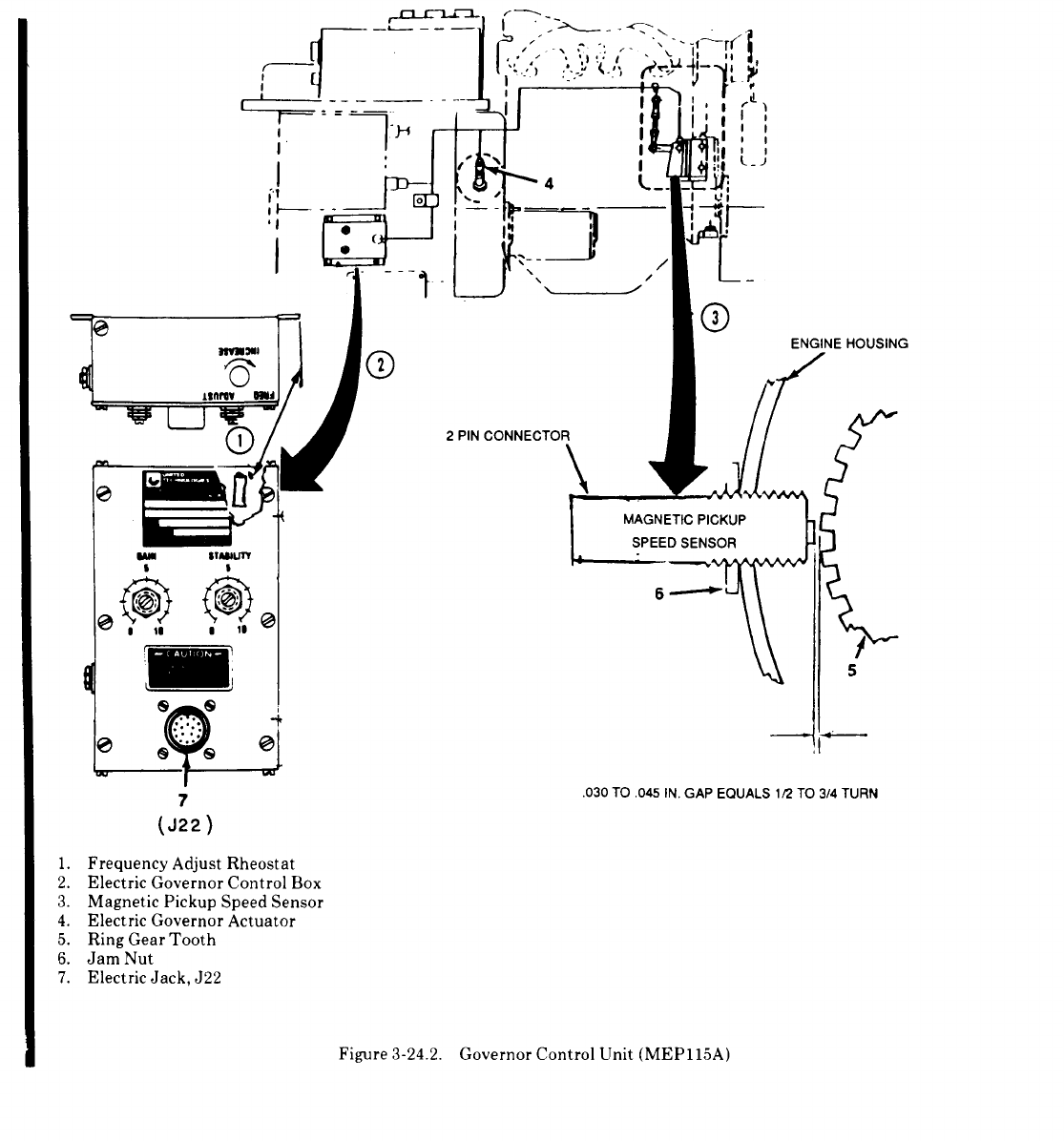

TM 5-6115-545-12
TO-35C2-3-444-1
NAVFAC P-8-626-12
TM-00038G-12
Figure 3-25. Reconnection Board
SECTION XX. AIR CLEANER ASSEMBLY
3-147. Air Cleaner Assembly.
~.
Replacement.
See
figure
3-26
and
remove
air
cleaner
assembly
in
accordance
with
the
sequence
of
index
numbers.
See
paragraph
3-87
for
removal
and
replacement
a.
Removal.
The
air
cleaner
assembly
filters
incoming
of
hose
connecting
air
cleaner
inlet
to
oil
separator,
Install
combustion
air
to
the
engine. air
cleaner
assembly
in
reverse
order
of
removal.
Removal
and
replacement
of
filter
element
is
shown
in
figure
3-5.
SECTION XXI. RELAY TABLE GROUP
3-148. General.
to
control
the
generator
set
during
paralleling
and
to
provide
monitoring
of
voltages
and
frequencies.
a.
This
section
contains
information
on
the
relay
table
~:
On
Class
1,
Mode
I
generator
sets
there
is
a
grofip.
The
relay
table
boxes
are
located
behind
the
control
precw.e
relay
assembly
that
provides
under
frequency,
cubicle
on
a
relay
table
(19, Fig 3-24)
above
the
generator. under
voltage
and
permissive
paralleling
monitors
The
relay
boxes
contain
protective
relays
and
devices
used
of
the
generator
set
for
more
complex
ap-
Change 153-72.3 /(3-72.4 blank)

Figure 3-26.Air Cleaner and Related Parts
plicat
ions.
These
monitors
are
included
in
the c.
Inspect
wiril~
for
fraying,
corrosion
and
Mcxie
II,
Class
1
sets
within
the
set
special
box.
oth;r
damage.
3-149. Tactical Relay Assembly Inspection.
a.
Remove
nine
screws
which
secure
cover
find
rell=ove
cover.
b.
Inspect
tern]
lnill
I>tr.irds
for
loose
nluuntin:,
IooEe
terminal
connecllt)ns.
corrosion.
and
other
damage.
f.
Reassemble
the
assembly
by
replacing
cover
a]ld-nine
screws.
3-150. Precise Relay Assembly Class 1 (50 60 Hz
Sets) Inspection.
1
Inspect
[he
two
connectors
for
bent
or
broken
. .
pin;
and
other
ciaml:e.
c. Inspect connectors for bent or broken pins
and other damage.
b.
Inspect
{he
50
60
Hz
switch
for
loose
mcmnting.
cor;’osion
and
other
damage.
3-151. Special Relay Assembly (50 60 Hz) Inspection.
d. Inspect relays for loose mounting, loose
wiring corrosion and other damage.
Change 73-73
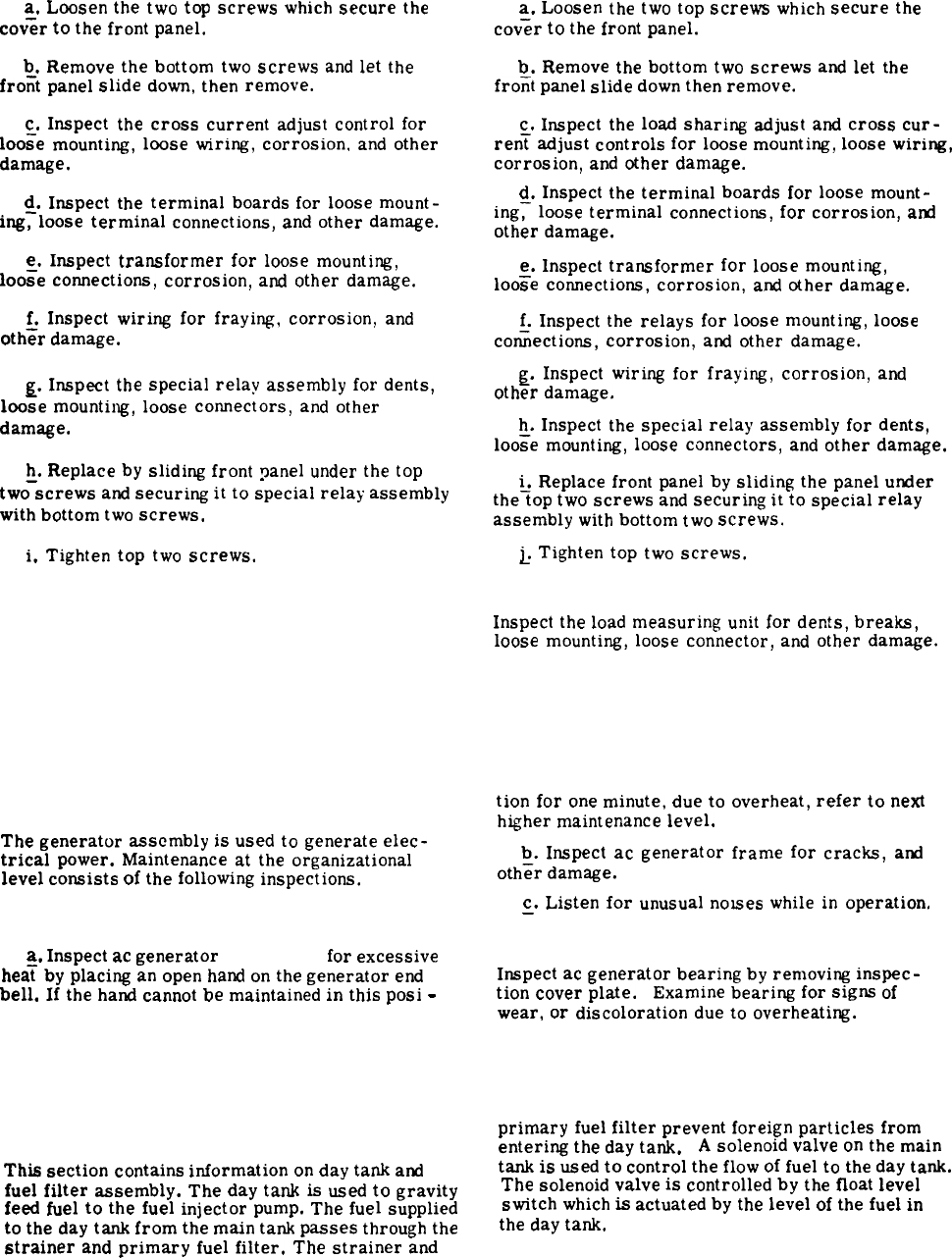
a,
Loosen
the
two
top
screws
which
secure
the
cov;r
to
the
front
panel.
b.
Remove
the
bottom
two
screws
and
let
the
frofit
panel
slide
down,
then
remove.
c.
Inspect
the
cross
current
adjust
control
for
loo;e
mounting,
loose
wiring,
corrosion,
and
other
damage.
~.
Inspect
the
terminal
boards
for
loose
mount-
ing,
loose
terminal
connections,
and
other
damage.
e.
Inspect
transformer
for
loose
mounting,
Ioo;e
connections,
corrosion,
and
other
damage.
&
Inspect
wiring
for
fraying,
corrosion,
and
other
damage.
~.
Inspect
the
special
relay
assembly
for
dents,
loose
mounting,
loose
connectors,
and
other
damage.
~.
Replace
by
sliding
front
panel
under
the
top
two
screws
and
securing
it
to
special
relay
assembly
with
bottom
two
screws.
i.
Tighten
top
two
screws.
3-152. Special Relay Assembly (400 Hz) Inspection.
a.
Loosen
the
two
top
screws
which
secure
the
cov;r
to
the
front
panel.
b.
Remove
the
bottom
two
screws
and
let
the
frofit
panel
slide
down
then
remove.
c.
Inspect
the
load
sharing
adjust
and
cross
cur-
ren~
adjust
controls
for
loose
mounting,
loose
wiring,
corrosion,
and
other
damage.
d.
Inspect
the
terminal
boards
for
loose
mount-
ing~
loose
terminal
connections,
for
corrosion,
and
other
damage.
~.
Inspect
transformer
for
loose
mounting,
loose
connections,
corrosion,
and
other
damage.
f.
Inspect
the
relays
for
loose
mounting,
loose
cofiections,
corrosion,
and
other
damage.
~.
Inspect
wiring
for
fraying,
corrosion,
and
other
damage.
h.
Inspect
the
special
relay
assembly
for
dents,
loo;e
mounting,
loose
connectors,
and
other
damage.
i.
Replace
front
panel
by
sliding
the
panel
under
the~op
two
screws
and
securing
it
to
special
relay
assembly
with
bottom
two
screws.
~
Tighten
top
two
screws.
3-153. Load Measuring Unit Inspection.
Inspect
the
load
measuring
unit
for
dents,
breaks,
loose
mounting,
loose
connector,
and
other
damage.
Section XXII. GENERATOR ASSEMBLY
3-154. General.
The
generator
assembly
is
used
to
generate
elec-
trical
power.
Maintenance
at
the
organizational
level
consists
of
the
following
inspections.
3-155. Generator Inspection.
a.
Inspect
ac
generator
(fig. 1-1)
for
excessive
hea~
by
placing
an
open
hand
on
the
generator
end
bell.
If
the
hand
cannot
be
maintained
in
this
posi
-
tion
for
one
minute,
due
to
overheat,
refer
to
next
higher
maintenance
level.
b.
Inspect
ac
generator
frame
for
cracks,
and
oth~r
damage.
c.
Listen
for
unusual
nowes
while
in
operation.
—
3-156. Generator Bearing Inspection.
Inspect
ac
generator
bearing
by
removing
inspec-
tion
cover
plate.
Examine
bearing
for
signs
of
wear,
or
discoloration
due
to
overheating.
Section XXIII. DAY TANK AND FUEL FILTER ASSEMBLY
3-157. General.
primary
fuel
filter
prevent
foreign
particles
from
entering
the
day
tank.
A
solenoid
valve
on
the
main
This
section
contains
information
on
day
tank
and
tank
is
used
to
control
the
flow
of
fuel
to
the
day
tank.
fuel
filter
assembly.
The
day
tank
is
used
to
gravity
The
solenoid
valve
is
controlled
by
the
float
level
feed
fuel
to
the
fuel
injector
pump.
The
fuel
supplied switch
which
is
actuated
by
the
level
of
the
fuel
in
to
the
day
tank
from
the
main
tank
passes
through
the the
day
tank.
strainer
and
primary
fuel
filter.
The
strainer
and
3-74
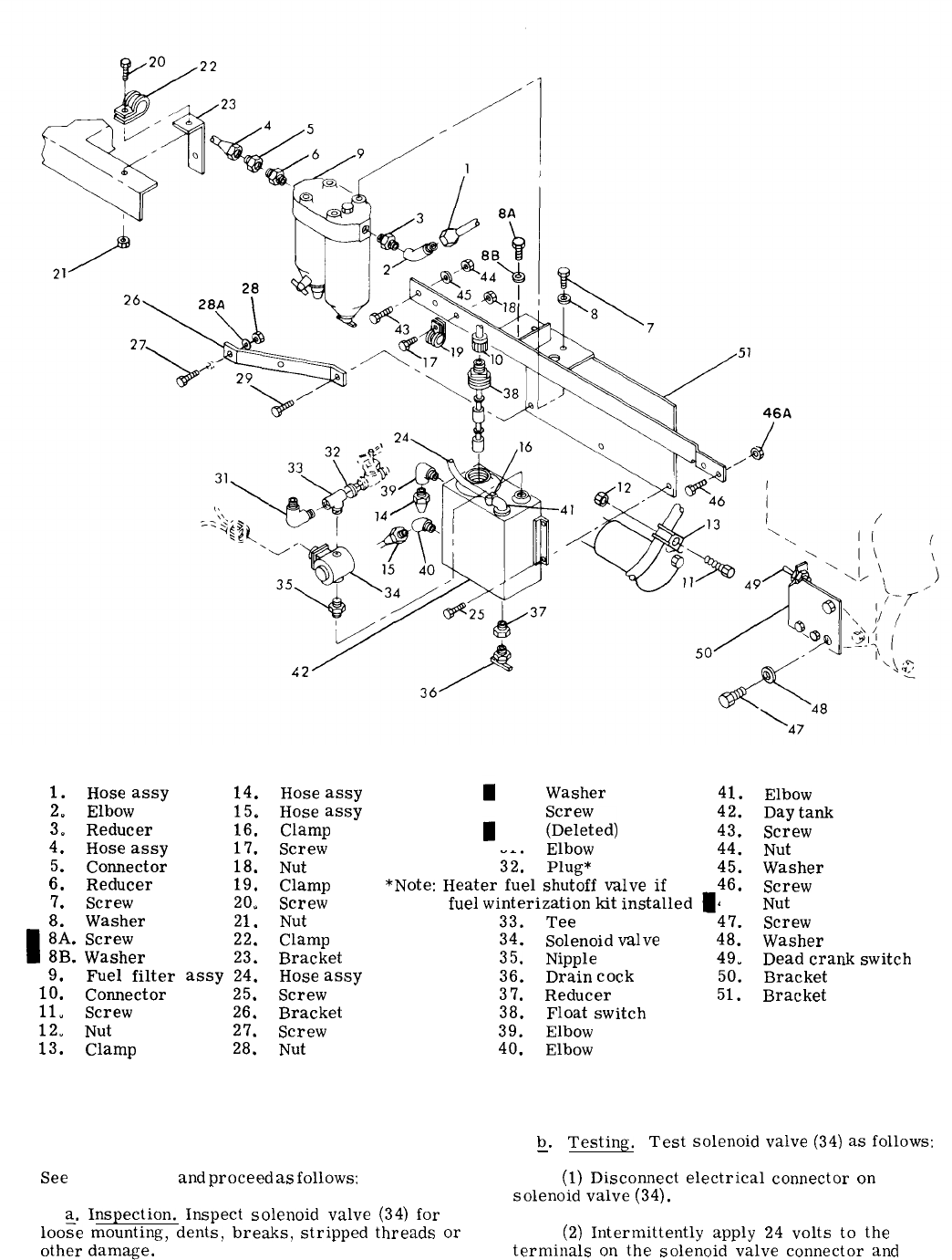
1.
Hose
assy
14.
2. Elbow
15.
3.
Reducer
16.
4. Hose
assy
17.
5.
Connector
18.
6.
Reducer
19.
7.
Screw
20.
8.
Washer
21.
8A.
Screw
22.
8B.
Washer
23.
9.
Fuel
filter
assy
24.
10.
Connector
25.
11”
Screw
26.
12.
Nut 27.
13. Clamp
28.
Hose
assy
Hose
assy
Clamp
Screw
Nut
Clamp
Screw
Nut
Clamp
Bracket
Hose
assy
Screw
Bracket
Screw
Nut
28A.
Washer
41.
Elbow
42. Day
tank
:
~;;jed)
43.
Screw
Elbow
44.
Nut
32:
Plug*
45.
Washer
*Note:
Heater
fuel
shutoff
valve
if
46. Screw
fuel
winterization
kit
installed
46A.
Nut
33. Tee 47.
Screw
34. Solenoid
valve 48.
Washer
35. Nipple
49.
Dead
crank
switch
36.
Drain
cock
50.
Bracket
37.
Reducer
51.
Bracket
38.
Float
switch
39.
Elbow
40.
Elbow
Figure 3-27.Day Tank and Fuel Filter Assembly
3-158. Solenoid Valve.
b.
Testing.
Test
solenoid
valve
(34)
as
follows:
—
See
figure 3-27
and
proceed
as
follows:
(1)
Disconnect
electrical
connector
on
solenoid
valve
(34).
a.
Inspection.
Inspect
solenoid
valve
(34)
for
loo;e
mounting,
dents,
breaks,
stripped
threads
or
(2)
Intermittently
apply
24
volts
to
the
other
damage.
terminals
on
the
solenoid
valve
connector
and
Change 13-75
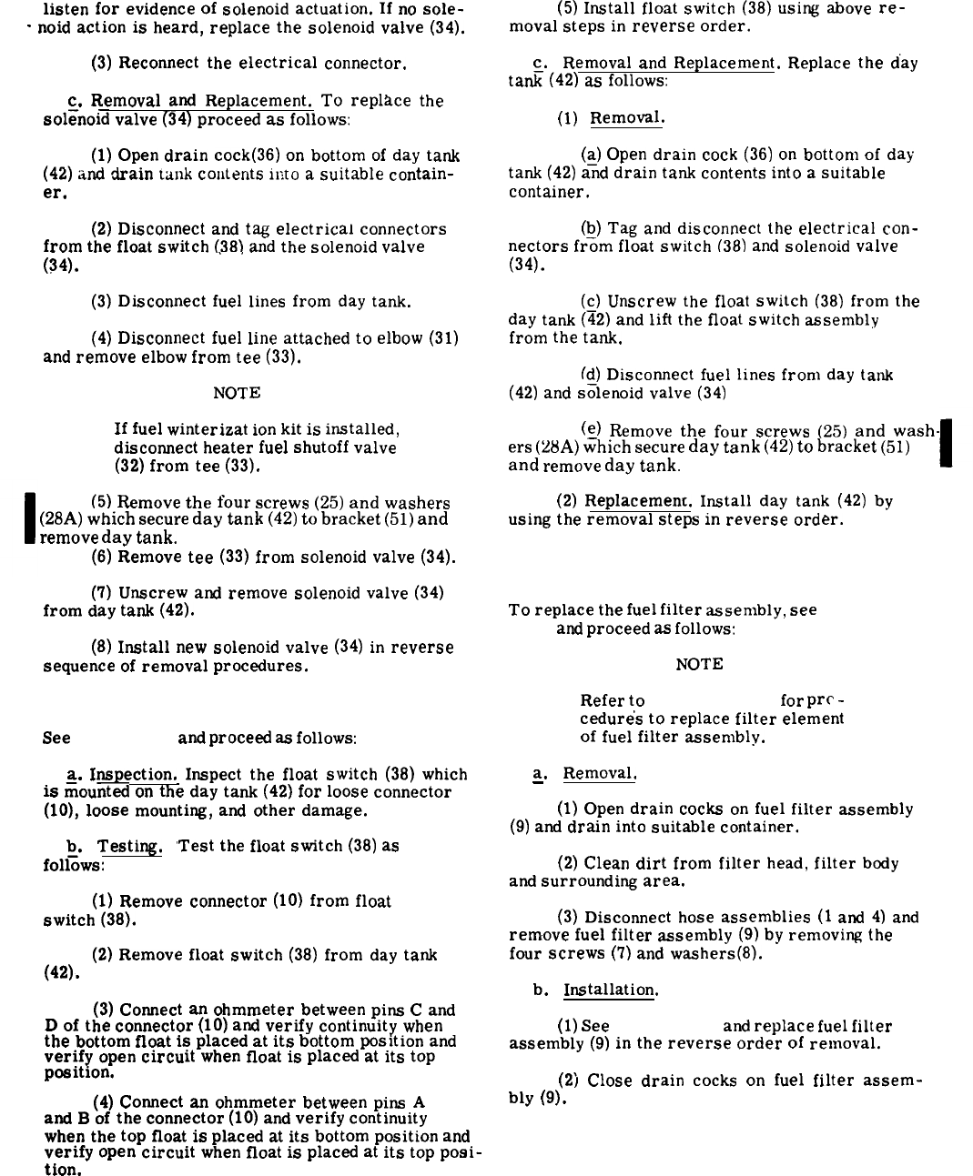
listen
for
evidence
of
solenoid
actuation.
If
no
sole-
(5)
Install
float
switch
(38)
using
above
re-
-
noid
action
is
heard,
replace
the
solenoid
valve
(34).
moval
steps
in
reverse
order.
(3)
Reconnect
the
electrical
connector.
c.
Removal
and
Replacement.
Replace
the
day
tati–
(42)
as
follows:
c.
Removal
and
Replacement.
To
repltice
the
sol=noid
valve
(34)
proceed
as
follows:
(1)
Removal.
(1)
Open
drain
cock(36)
on
bottom
of
day
tank
(~)
Open
drain
cock
(36)
on
bottom
of
day
(42)
and
drain
talk
coutents
ir,to
a
suitable
contain-
tank
(42)
and
drain
tank
contents
into
a
suitable
er.
container.
(2)
Disconnect
and
tag
electrical
connectors
(b)
Tag
and
disconnect
the
electrical
con-
from
the
float
switch
(38)
and
the
solenoid
valve
nectors
frfim
float
switch
(38)
and
solenoid
valve
.,
(34). (34).
(3)
Disconnect
fuel
lines
from
day
tank.
(~)
Unscrew
the
float
switch
(38)
from
the
day
tank
(42)
and
lift
the
float
switch
assembly
(4)
Disconnect
fuel
line
attached
to
elbow
(31)
from
the
tank.
and
remove
elbow
from
tee
(33).
(d)
Discomect
fuel
lines
from
day
tank
NOT
E
(42)
and
s~lenoid
valve
(34)
If
fuel
winterizat
ion
kit
is
installed,
(~)
Remove
the
four
screws
(25)
and
wash-
disconnect
heater
fuel
shutoff
valve
(32)
from
tee
(33).
ers
(28A)
which
secure
day
tank
(42)
to
bracket
(51)
and
remove
day
tank.
(5)
Remove
the
four
screws
(25)
and
washers
(2)
Replacement.
Install
day
tank
(42)
by
(28A)
which
secure
day
tank
(42)
to
bracket
(51)
and
using
the
removal
steps
in
reverse
order.
remove
day
tank.
(6)
Remove
tee
(33)
from
solenoid
valve
(34).
3-160. Fuel Filter Assembly Removal and Replace-
ment.
(7)
Unscrew
and
remove
solenoid
valve
(34)
from
day
tank
(42).
To
replace
the
fuel
filter
assembly,
see
figure
3-27
and
proceed
as
follows:
(8)
Install
new
solenoid
valve
(34)
in
reverse
sequence
of
removal
procedures.
NOT
E
3-159. Day Tank and Float Switch
Refer
to
paragraph 3-34
for
prc
-
cedure’s
to
replace
filter
element
See
figure 3-27
and
proceed
as
follows:
of
fuel
filter
assembly.
a.
Inspection.
Inspect
the
float
switch
(38)
which
is
iiiounted
on
the
day
tank
(42)
for
loose
connector
(10),
loose
mounting,
and
other
damage.
~.
Testing.
‘Test
the
float
switch
(38)
as
follows:
(1)
Remove
connector
(10)
from
float
switch
(38).
(2)
Remove
float
switch
(38)
from
day
tank
(42).
(3)
Connect
an
ohmmeter
between
pina
C
and
D
of
the
connector
(10)
and
verify
continuity
when
the
bottom
float
is
placed
at
its
bottom
position
and
verify
open
circuit
when
float
is
placed
at
its
top
position.
(4)
Connect
an
ohmmeter
between
pins
A
and
B
of
the
connector
(10)
and
verify
continuity
when
the
top
float
is
placed
at
its
bottom
position
and
verify
open
circuit
when
float
is
placed
at
its
top
posi-
t
ion.
a.
Removal.
—
(1)
Open
drain
cocks
on
fuel
filter
assembly
(9)
and
drain
into
suitable
container.
(2)
Clean
dirt
from
filter
head,
filter
body
and
surrounding
area.
(3)
Disconnect
hose
assemblies
(1
and
4)
and
remove
fuel
filter
assembly
(9)
by
removing
the
four
screws
(7)
and
washers(8).
b.
Installation.
(1)
See
figure 3-27
and
replace
fuel
filter
assembly
(9)
in
the
reverse
order
of
removal.
(2)
Close
drain
cocks
on
fuel
filter
assem-
blv
(9).
.
.
.
3-76 Change 9
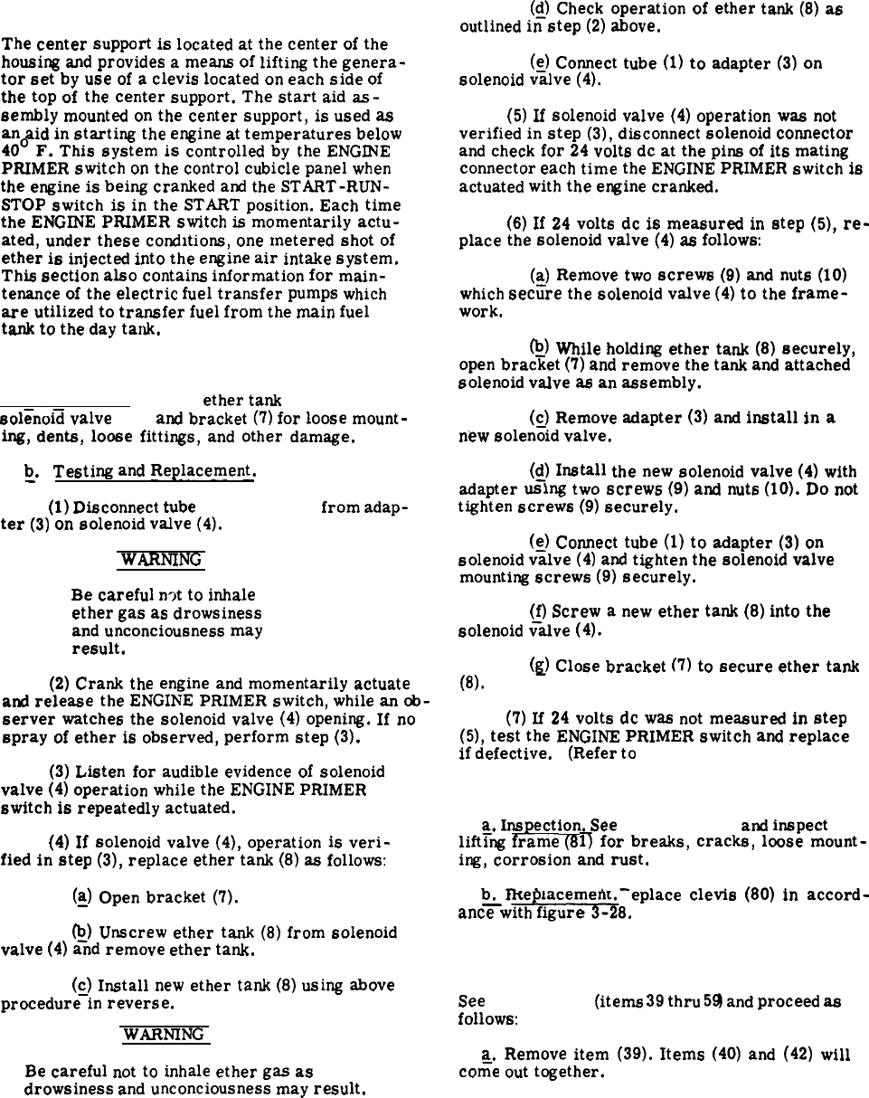
Section XXIV. LIFTING FRAME ASSEMBLY, START AID ASSEMBLY
AND FUEL TRANSFER PUMPS
3-161. General.
The
center
support
is
located
at
the
center
of
the
housing
and
provides
a
means
of
lifting
the
genera-
tor
set
by
use
of
a
clevis
located
on
each
side
of
the
top
of
the
center
support.
The
start
aid
as-
sembly
mounted
on
the
center
support,
is
used
as
an
aid
in
starting
the
engine
at
temperatures
below
40°
F.
This
system
is
controlled
by
the
ENGINE
PRIMER
switch
on
the
control
cubicle
panel
when
the
engine
is
being
cranked
aml
the
START-RUN-
STOP
switch
is
in
the
START
position.
Each
time
the
ENGINE
PRIMER
switch
is
momentarily
actu-
ated,
under
these
conditions,
one
metered
shot
of
ether
is
injected
into
the
engine
air
intake
system.
This
section
also
contains
information
for
main-
tenance
of
the
electric
fuel
transfer
pumps
which
are
utilized
to
transfer
fuel
from
the
main
fuel
tank
to
the
day
tank.
3-162. Start Aid Assembly.
a. Inspection. Inspect
ether
tank
(8, fig. 3-28)
sol=nold
valve
(4)
and
bracket
(7)
for
loose
mount-
ing,
dents,
loose
fittings,
and
other
damage.
~.
Testi
w
and
Replacement.
(1)
Disconnect
tube
(1, fig. 3-28)
from
adap-
ter
(3)
on
solenoid
valve
(4),
WARNING
Be
careful
n~t
to
inhale
ether
gas
as
drowsiness
and
unconsciousness
may
result.
(2)
Crank
the
engine
and
momentarily
actuate
and
release
the
ENGINE
PRIMER
switch,
while
an
ob-
server
watches
the
solenoid
valve
(4)
opening.
If
no
spray
of
ether
is
observed,
perform
step
(3).
(3)
Listen
for
audible
evidence
of
solenoid
valve
(4)
operation
while
the
ENGINE
PRIMER
switch
is
repeatedly
actuated.
(4)
If
solenoid
valve
(4),
operation
is
veri-
fied
in
step
(3),
replace
ether
tank
(8)
as
follows:
(~)
Open
bracket
(7).
@)
Unscrew
ether
tank
(8)
from
solenoid
valve
(4)
and
remove
ether
tank.
(c)
Install
new
ether
tank
(8)
using
above
procedure–in
reverse.
WARNING
Be
careful
not
to
inhale
ether
gas
as
drowsiness
and
unconsciousness
may
result.
(Q)
Check
operation
of
ether
outlined
in
step
(2)
above.
tank
(8)
as
(s)
Connect
tube
(1)
to
adapter
(3)
on
solenoid
valve
(4).
(5)
If
solenoid
valve
(4)
operation
was
not
verified
in
step
(3),
disconnect
solenoid
connector
and
check
for
24
volts
dc
at
the
pins
of
its
mating
connector
each
time
the
ENGINE
PRIMER
switch
is
actuated
with
the
engine
cranked.
(6)
If
24
volts
dc
is
measured
in
step
(5),
re-
place
the
solenoid
valve
(4)
as
follows:
(~)
Remove
two
screws
(9)
and
nuts
(10)
which
secure
the
solenoid
valve
(4)
to
the
frame-
work.
~)
while
holding
ether
tank
(8)
securely,
open
bracket
(7)
and
remove
the
tank
and
attached
solenoid
valve
as
an
assembly.
(c)
Remove
adapter
(3)
and
install
in
a
new
solen~id
valve.
(~)
Install
the
new
solenoid
valve
(4)
with
adapter
using
two
screws
(9)
and
nuts
(10).
Do
not
tighten
screws
(9)
securely.
(g)
Connect
tube
(1)
to
adapter
(3)
on
solenoid
valve
(4)
and
tighten
the
solenoid
valve
mounting
screws
(9)
securely.
(f)
Screw
a
new
ether
tank
(8)
into
the
solenoid
~itlve
(4).
(g)
Close
bracket
(7)
to
secure
ether
tank
(8).
(7)
If
24
volts
dc
was
not
measured
in
step
(5),
test
the
ENGINE
PRIMER
switch
and
replace
if
defective. (Refer
to
paragraph 3-118a.)
3-163. Lifting Frame.
a.
Inspection.
See
figure 3-28
and
inspect
lift~W
irame
(8 1)
for
breaks,
cracks,
loose
mount-
ing,
corrosion
and
rust.
b.
Re
lacement.
Replace
clevis
(80)
in
accord-
-
+8.
ante
with
figure
3-164. Filler Cap, Gasket, Strainer, and Hose
Replacement.
See
figure 3-28
(items
39
thru
59
and
proceed
as
follows:
a.
Remove
item
(39).
Items
(40)
and
(42)
will
co~e
out
together.
3-77
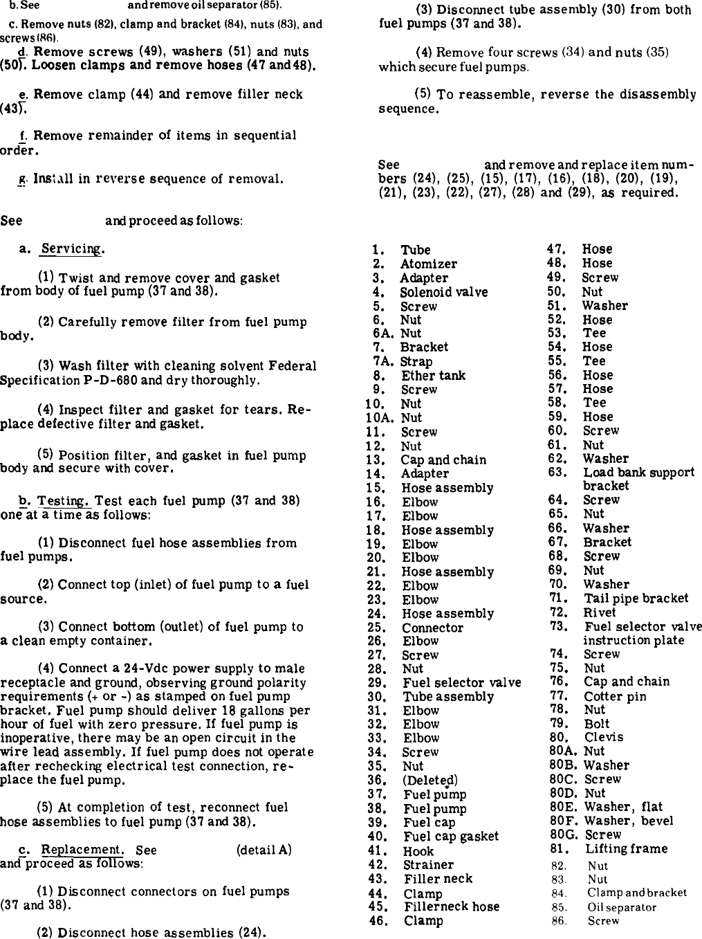
b.
see
paragraph 3-87
and
remove
oil
separator
(85).
c.
Remove
nuts
(82),
clamp
and
bracket
(84),
nuts
(83),
and
screws
(W.
d.
Remove
screws
(49),
washers
(51)
and
nuts
(50T
Loosen
clamps
and
remove
hoses
(47
and48).
e.
Remove
clamp
(44)
and
remove
filler
neck
(43L
f.
Remove
remainder
of
items
in
sequential
ordir.
~.
InSt._dl
in
reverse
sequence
of
removal.
3-165. Fuel Transfer Pumps.
See
figure 3-28
and
proceed
as
follows:
a.
Servicing.
(1)
Twist
and
remove
cover
and
gasket
from
body
of
fuel
pump
(3’7
and
38).
(2)
Carefully
remove
filter
from
fuel
pump
body.
(3)
Wash
filter
with
cleaning
solvent
Federal
Specification
P-D-680
and
dry
thoroughly.
(4)
Inspect
filter
and
gasket
for
tears.
Re-
place
defective
filter
and
gasket.
(5)
Position
filter,
and
gasket
in
fuel
pump
body
and
secure
with
cover.
~.
Testing.
Test
each
fuel
pump
(37
and
38)
one
at
a
time
as
follows:
(1)
Disconnect
fuel
hose
assemblies
from
fuel
pumps.
(2)
Connect
top
(inlet)
of
fuel
pump
to
a
fuel
source.
(3)
Connect
bottom
(outlet)
of
fuel
pump
to
a
clean
empty
container.
(4)
Connect
a
24-Vdc
power
supply
to
male
receptacle
and
ground,
observing
ground
polarity
requirements
(+
or
-)
as
stamped
on
fuel
pump
bracket.
Fuel
pump
should
deliver
18
gallons
per
hour
of
fuel
with
zero
pressure.
If
fuel
pump
is
inoperative,
there
may
be
an
open
circuit
in
the
wire
lead
assembly.
If
fuel
pump
does
not
operate
after
rechecking
electrical
test
connection,
re-
place
the
fuel
pump.
(5)
At
completion
of
test,
reconnect
fuel
hose
assemblies
to
fuel
pump
(37
and
38).
c.
Replacement.
See
figure 3-28
(detail
A)
and-proceed
as
follows:
(1)
Disconnect
connectors
on
fuel
pumps
(37
and
38).
(2)
Disconnect
hose
assemblies
(24).
3-78Change 9
(3)
Disconnect
tube
assembly
(30)
from
both
fuel
pumps
(37
and
38).
(4)
Remove
four
screws
(34)
and
nuts
(35)
which
secure
fuel
pumps.
(5)
To
reassemble,
reverse
the
disassembly
sequence.
3-166. Fuel Selector Valve and Lines Replacement.
See
figure 3-28
and
remove
and
replace
item
num-
bers
(24),
(25),
(15),
(17),
(16),
(18),
(20),
(19),
(21),
(23),
(22),
(27),
(28)
and
(29),
as
required.
KEY to fig. 3-28:
1. Tube
2.
Atomizer
3.
Adapter
4. Solenoid
valve
5.
Screw
6.
Nut
6A.
Nut
7.
Bracket
7A.
Strap
8.
Ether
tank
9. Screw
10.
Nut
lOA.
Nut
11. Screw
12.
Nut
13. Cap
and
chain
14. Adapter
15.
Hose
assembly
16.
Elbow
17.
Elbow
18.
Hose
assembly
19.
Elbow
20.
Elbow
21.
Hose
assembly
22. Elbow
23.
Elbow
24.
Hose
assembly
25.
Connector
26.
Elbow
27.
Screw
28.
Nut
29.
Fuel
selector
valve
30. Tube
assembly
31.
Elbow
32.
Elbow
33.
Elbow
34.
Screw
35.
Nut
36.
(Deletefi)
37.
Fuel
pump
38.
Fuel
pump
39. Fuel
cap
40. Fuel
cap
gasket
41.
Hook
42.
Strainer
43.
Filler
neck
44.
Clamp
45.
Fillerneck
hose
46.
Clamp
47.
48.
49.
50.
51,
52.
53.
54.
55.
56.
57.
58.
59.
60.
Hose
Hose
Screw
Nut
Washer
Hose
Tee
Hose
Tee
Hose
Hose
Tee
Hose
Screw
61.
Nut
62.
Washer
63.
Load
bank
support
bracket
64. Screw
65.
Nut
66.
Washer
67.
Bracket
68.
Screw
69.
Nut
70.
Washer
71.
Tail
pipe
bracket
72.
Rivet
73.
Fuel
selector
valve
instruction
plate
74.
Screw
75. Nut
76.
Cap
and
chain
77.
Cotter
pin
78. Nut
79.
Bolt
80.
Clevis
80A.
Nut
80B.
Washer
80C.
Screw
80D.
Nut
80E.
Washer,
flat
80F.
Washer,
bevel
80G.
Screw
81.
Lifting
frame
82.
Nut
83.
Nut
84.
Clamp
and
bracket
85.
Oil
separator
86.
Screw
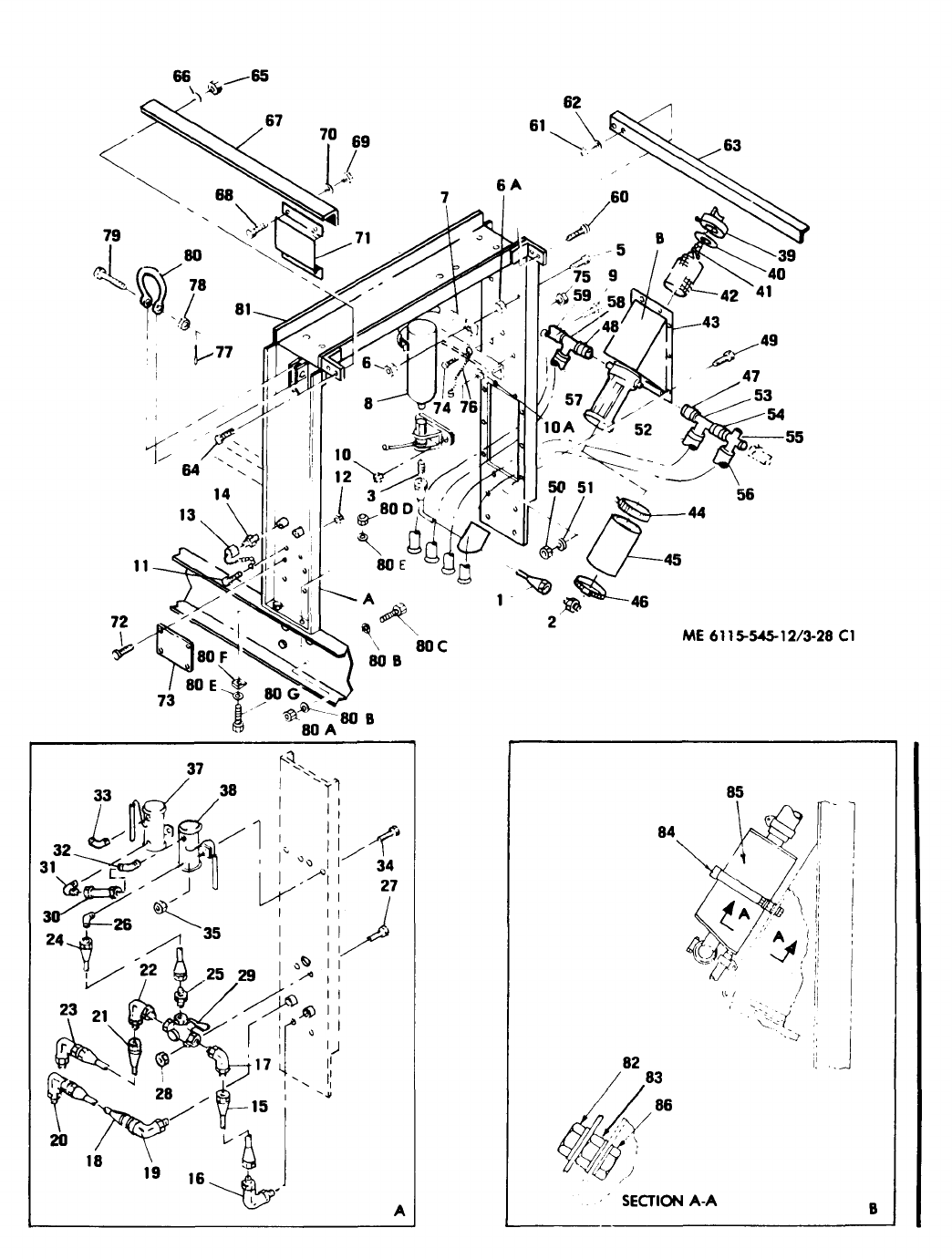
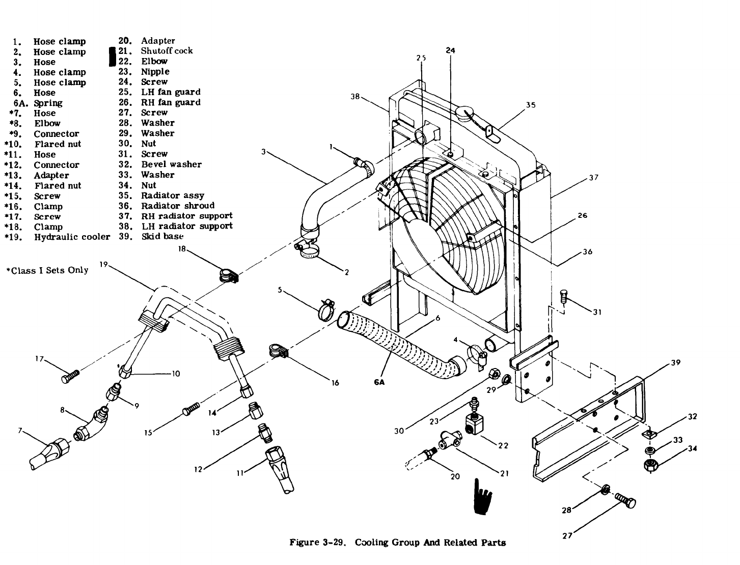
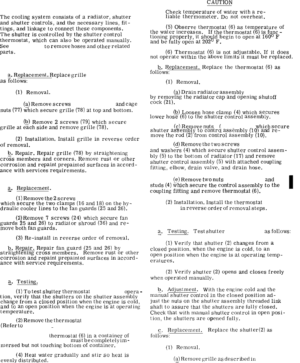
3-167. General.
Section XXV.COOLING GROUP
CAUTION
The
cooling
system
consists
of
a
radiator,
shutter
and
shutter
controls,
and
the
necessary
lines,
fit-
tings,
and
linkage
to
connect
these
components.
The
shutter
is
controlled
by
the
shutter
control
thermostat,
which
can
also
be
operated
manually.
See
figure 3-29
to
remove
hoses
and
other
related
parts.
3-168. Grille.
~.
Replacemerit.
Replace
grille
(78, fig. 3-22)
as
follows:
(1)
Removal.
(~)
Remove
screws
(76, fig. 3-22)
and
cage
nuts
(77)
which
secure
grille
(78)
at
top
and
bottom.
(Q)
Remove
2
screws
(79)
which
secure
grille
at
each
side
and
remove
grille
(78).
(2)
Installation.
Install
grille
in
reverse
order
of
removal.
~.
Repair.
Repair
grille
(78)
by
straightening
cross
members
and
corners.
Remove
rust
or
other
corrosion
and
repaint
prepainted
surfaces
in
accord-
ance
with
services
requirements.
3-169. Fan Guard.
a.
Replacement.
—
(1)
Remove
the
2
screws
(15 and 17, fig. 3-29)
which
secure
the
two
clamps
(16
and
18)
on
the
hy-
draulic
cooler
lines
to
the
fan
guards
(25
and
26).
(2
Remove
7
screws
(24)
which
secure
fan
[
guards
25
and
26)
to
radiator
shroud
(36)
and
re-
move
both
fan
guards.
(3)
Re-install
in
reverse
order
of
removal.
b.
Repair.
Repair
fan
guard
(25
and
26)
by
strZig
htemng
cross
members.
Remove
rust
or
other
corrosion
and
repaint
preprinted
surfaces
in
accord-
ance
with
service
requirements.
3-170. Shutter Thermostat.
a.
Testing.
—
(1)
To
test
shutter
thermostat
(fig. 3-30)
opera
-
tion,
verify
that
the
shutters
on
the
shutter
assembly
change
from
a
closed
position
when
the
engine
is
cold,
and
to
an
open
position
when
the
engine
is
at
operating
temperature.
(2)
Remove
the
thermostat
(6, fig. 3-30).
(Refer
to
paragraph b below).
(3) Suspend
thermostat
(6)
in
a
container
of
clean water. Thermostat
must
be
completely
im-
mersed
but
not
touching
bottom
of
container.
(4)
Heat
water
gradually
and
stir
so
heat
is
evenly
distributed.
Check
temperature
of
water
with
a
re-
liable
thermometer.
DO
not
overheat.
(5)
Observe
thermostat
(6)
as
temperature
of
the
water
increases.
If
the
thermostat
(6)
is
func
-
tioning
properly,
it
should
begin
to
open
at
160°
F
and
be
fully
open
at
202°
F.
(6)
Thermostat
(6)
is
not
adjustable.
If
it
does
not
operate
within
the
above
limits
it
must
be
replaced,
b.
Replacement.
Replace
the
thermostat
(6)
as
follmws:
(1)
Removal.
(a)
Drain
radiator
assembly
(35, fig. 3-29)
by
removfig
the
radiator
cap
and
opening
shutoff
cock
(21).
(b)
Loosen
hose
clamp
(4)
which
secures
lower
hosF
(6)
to
the
shutter
control
assembly.
(c)
Remove
nuts
1, fig. 3-30)
which
secure
\
shutter
assembly
to
contro
assembly
(10)
and
re-
move
the
rod
(2)
from
control
assembly
(10).
(~)
Remove
the
two
screws
(3, fig. 3-31)
and
washers
(4)
which
secure
shutter
control
assem-
bly
(5)
to
the
bottom
of
radiator
(17)
and
remove
shutter
control
assembly
(5)
with
attached
coupling
fitti~-,
elbow,
drain
valve,
and
drain
hose.
(e)
Remove
two
nuts
(3, fig. 3-30)
and
studs
(4)
w“hich
secure
the
control
assembly
to
the
coupling
fitting
and
remove
thermostat
(6).
(2)
Installation.
Install
the
thermostat
(6,
fig. 3-30)
in
reverse
order
of
removal
steps.
3-171. Shutter Assembly.
a.
Testing. Test
shutter
(2, fig. 3-31)
as
follows:
—
(1)
Verify
that
shutter
(2)
changes
from
a
closed
position,
when
the
engine
is
cold,
to
an
open
position
when
the
engine
is
at
operating
temp-
eratures.
(2)
Verify
shutter
(2)
opens
and
closes
freely
when
operated
manually.
b.
Adjustment.
With
the
engine
cold
and
the
ma~ual
shutter
control
in
the
closed
position
ad-
just
the
nuts
on
the
shutter
assembly
threaded
link
shaft
to
assure
that
the
shutters
are
fully
closed.
Check
that
with
manual
shutter
control
in
open
posi-
tion,
the
shutters
are
opened
fully.
c.
Replacement. Replace
the
shutter(2)
as
foll;ws:
(1)
Removal.
(~)
Remove
~rille
as
described
in
paragraph
3-168a.
—
Change 13-81
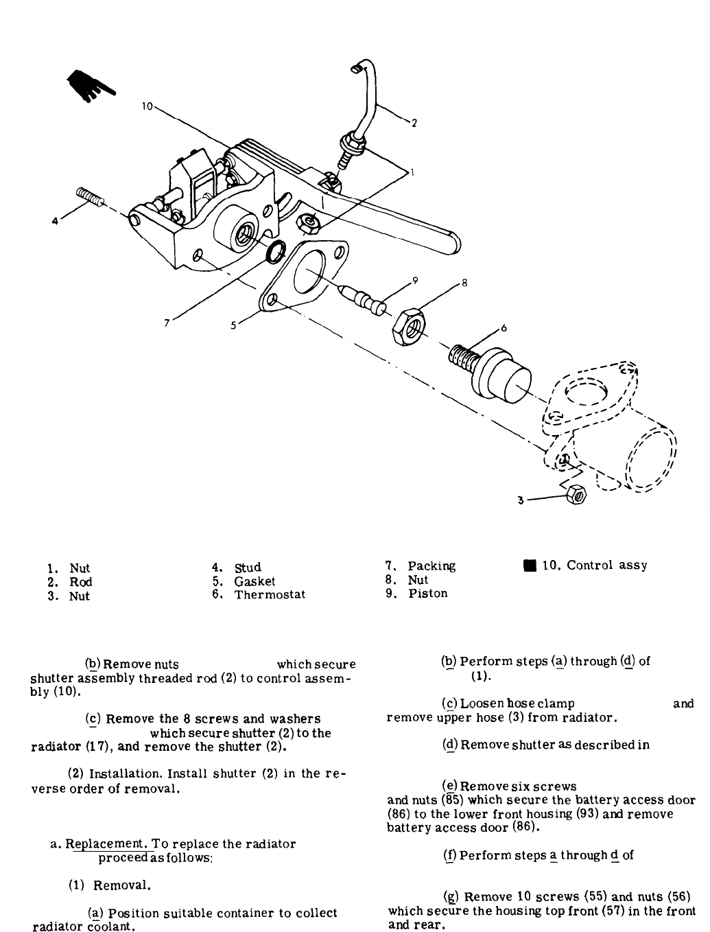
1.
Nut 4.
stud
7.
Packing
W
10.
Control
assy
2.
Rod
5.
Gasket
8.
Nut
3.
Nut 6.
Thermostat
9.
Piston
Figure 3-30. Shutter Thermostat Replacement
(~)
Remove
nuts
(1, fig. 3-30)
which
secure
shutter
assembly
threaded
rod
(2)
to
control
assem-
bly
(10).
(~)
Remove
the
8
screws
and
washers
(1, 1A, fig. 3-31)
w~ch
secure
shutter
(2)
to
the
radiator
(17),
and
remove
the
shutter
(2).
(2)
Installation.
Install
shutter
(2)
in
the
re-
verse
order
of
removal.
3-172. Radiator.
a.
Replacement.
To
replace
the
radiator
(17,
fig. 3-31)
proceed
as
follows:
(~)
Perform
steps
(s)
through
@)
of
para-
graph 3-170b
(1).
(c)
Loosen
hose
clamp
(1, fig. 3-29)
and
remove
up–per
hose
(3)
from
radiator.
(y)
Remove
shutter
as
described
in
paragraph
3-171.
(s)
Remove
six
screws
(84, fig. 3-22)
and
nuts
(85)
which
secure
the
battery
access
door
(86)
to
the
lower
front
housing
(93)
and
remove
battery
access
door
(86).
~)
Perform
steps
~
through
~
of
paragraph
3-87.
(1)
Removal.
(g)
Remove
10
screws
(55)
and
nuts
(56)
(~)
Position
suitable
container
to
collect
which
secure
the
housing
top
front
(57)
in
the
front
radiator
coolant.
and
rear.
Change 9
3-82
1. Screw
fA.
Washer
2.
Shutter
3. Screw
4. Washer
5.
Shutter
control
assy
9.
Screw
14.
LH
radiator
support
6. Gasket
10.
Washer
15.
Cap
7.
Screw
11.
(Delete) 16.
Drain
hose
7A.
Washer
12.
Shroud
17.
Radiator
8.
(Delete)
13.
RH
radiator
support
Figure 3-31. Cooling Group
(Q)
Remove
12
screws
(58)
and
cage
nuts
(j)
Remove
7
screws
(24)
which
secure
(59)
which
secure
the
housing
top
front
(57)
on
the
fan
guards
(25
and
26)
to
radiator
shroud
(36)
and
sides,
and
remove
the
cover. remove
both
fan
guards.
(i)
Remove
the
2
screws
(15 and 17, fig.
(k)
Disconnect
wiring
connections
(14,
3-29)
whi~h
secure
the
two
clamps
(16
and
18)
on
fig. 3-4)
Z
the
battery
slave
receptacles.
the
hydraulic
cooler
lines
to
the
fan
guards
(25
and
26).
Change 93-83
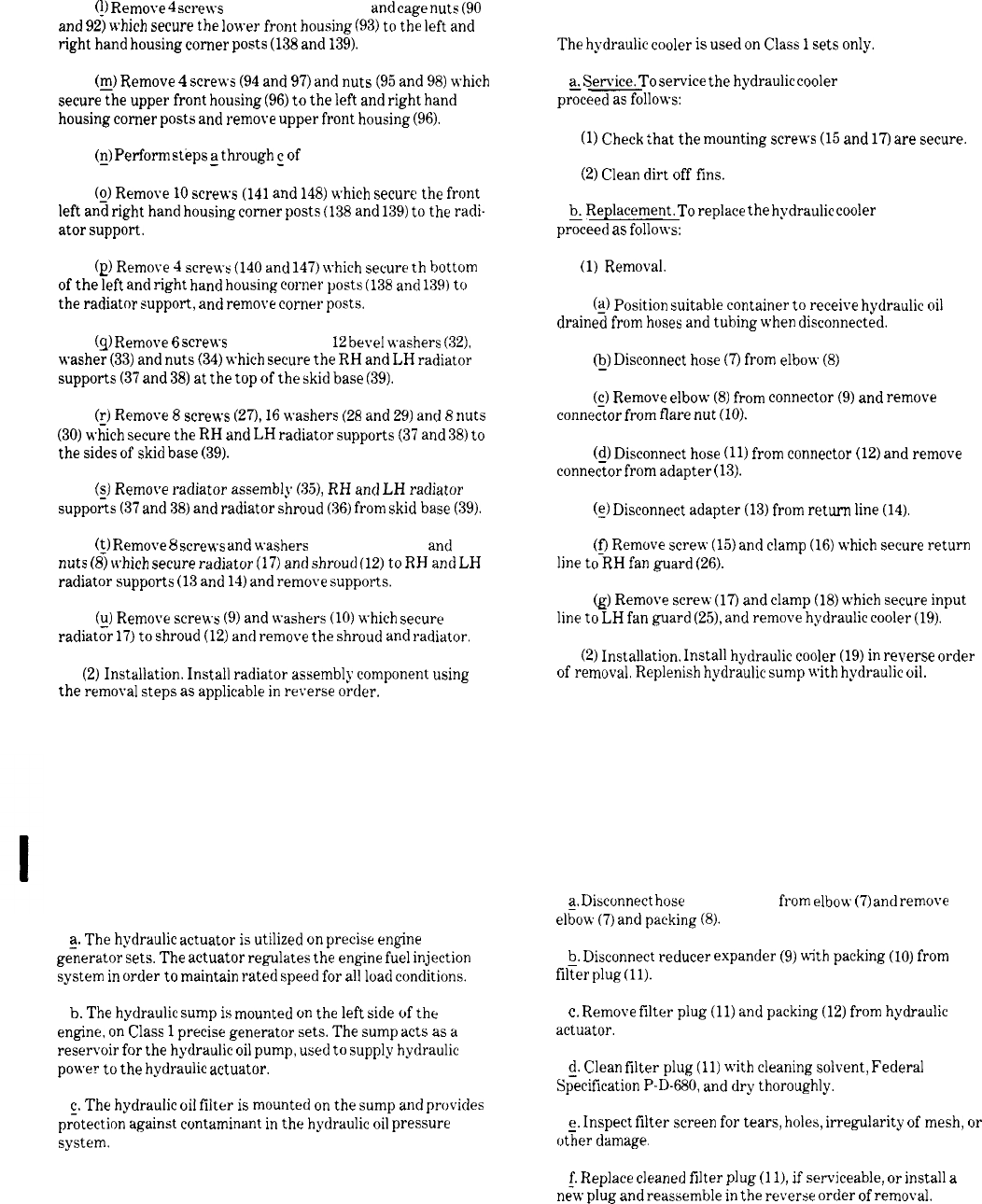
(!)
Remove
4
screws
(89 and 91, fig. 3-22)
and
cage
nuts
(90
and
92)
which
secure
the
lower
front
housing
(93)
to
the
left
and
right
hand
housing
corner
posts
(138
and
139).
(@
Remove
4
screws
(94
and
97)
and
nuts
(95
and
98)
which
secure
the
upper
front
housing
(96)
to
the
left
and
right
hand
housing
corner
posts
and
remove
upper
front
housing
(96).
(g)
Perform
steps
~
through
~
of
paragraph 3-86.
(g)
Remove
10
screws
(141
and
148)
which
secure
the
front
left
and
right
hand
housing
corner
posts
(138
and
139)
to
the
radi-
ator
support.
(p)
Remove
4
screws
(140
and
147)
which
secure
th
bottom
of
the
left
and
right
hand
housing
corner
posts
(138
and
139)
to
the
radiator
support,
and
remove
corner
posts.
(q)
Remove
6
screws
(31, fig. 3-29), 12
bevel
washers
(32),
washer
(33)
and
nuts
(34)
which
secure
the
RH
and
LH
radiator
supports
(37
and
38)
at
the
top
of
the
skid
base
(39).
(1)
Remove
8
screws
(27),
16
washers
(28
and
29)
and
8
nuts
(30)
which
secure
the
RH
and
LH
racliator
supports
(37
and
38)
to
the
sides
of
skid
base
(39).
(~)
Remove
radiator
assembly
(35),
RH
and
LH
radiator
supports
(37
and
38)
and
radiator
shroud
(36)
from
skid
base
(39).
(~)
Remove
8
screws
and
washers
(7, 7A, fig. 3-31)
and
nuts
(8)
which
secure
radiator
(17)
and
shroud
(12)
to
RH
and
LH
radiator
supports
(13
and
14)
and
remove
supports.
(y)
Remove
screws
(9)
and
washers
(10)
which
secure
radiator
17)
to
shroud
(12)
and
remove
the
shroud
and
radiator.
(2)
Installation.
Install
radiator
assembly
component
using
the
removal
steps
as
applicable
in
reverse
order.
3-174. General (See fig. 1-28.)
3-173. Hydraulic Cooler.
The
hydraulic
cooler
is
used
on
Class
1
sets
only.
a.
Service.
To
service
the
hydraulic
cooler
(19, fig. 3-29)
.—
proceed
as
follows:
(1)
Check
that
the
mounting
screws
(1.5
and
17)
are
secure.
(2)
Clean
dirt
off
fins.
~
Replacement.
To
replace
the
hydraulic
cooler
(19, fig. 3-29)
proceed
as
follows:
(1)
Removal.
(q)
Position
suitable
container
to
receive
hydraulic
oil
drained
from
hoses
and
tubing
when
disconnected.
@)
Disconnect
hose
(7)
from
elbow
(8)
(g)
Remove
elbow
(8)
from
connector
(9)
and
remove
connector
from
flare
nut
(10).
(~)
Disconnect
hose
(11)
from
connector
(12)
and
remove
connector
from
adapter
(13).
(s)
Disconnect
adapter
(13)
from
return
line
(14).
(~
Remove
screw
(15)
and
clamp
(16)
which
secure
return
line
to
RH
fan
guard
(26).
@
Remove
screw
(17)
and
clamp
(18)
which
secure
input
line
to
LH
fian
guard
(25),
and
remove
hydraulic
cooler
(19).
(2)
Installation.
Install
hydraulic
cooler
(19)
in
reverse
order
of
removal,
Replenish
hydraulic
sump
with
hydraulic
oil.
Section XXVI. HYDRAULIC ACTUATOR AND SUMP AND FILTER
(MEP105A ONLY)
a.
The
hydrwdic
actuator
is
utilized
on
precise
engine
ge;emtor
sets.
The
actuator
regulates
the
engine
fuel
injection
system
in
order
to
maintain
rated
speed
for
all
load
conditions.
b.
The
hydraulic
sump
is
mounted
on
the
left
side
of
the
engine,
on
Class
1
precise
generator
sets.
The
sump
acts
as
a
reservoir
for
the
hydraulic
oil
pump,
used
to
supply
hydraulic
power
to
the
hydraulic
actuator.
c.
The
hydrmdic
oil
filter
is
mounted
on
the
sump
and
provides
pr%ection
against
contaminant
in
the
hydraulic
oil
pressure
system.
3-175. Hydraulic Actuator Service.
a.
Disconnect
hose
(6, fig. 3-32)
from
elbow
(7)
and
remove
el~ow
(7)
and
packing
(8).
Q,
Disconnect
reducer
expander
(9)
w-ith
packing
(10)
from
filter
plug
(11).
c.
Remove
filter
plug
(11)
and
packing
(12)
from
hydraulic
actuator.
~,
Clean
filter
plug
(11)
with
cleaning
solvent,
Federal
Specification
P-D-680,
and
dry
thoroughly.
e.
Inspect
filter
screen
for
tears,
holes,
irregularity
of
mesh,
or
—
other
damage,
$
Replace
cleaned
filter
plug
(1 1),
if
serviceable,
or
install
a
new
plug
and
reassemble
in
the
reverse
order
of
removal.
3-84Change 11
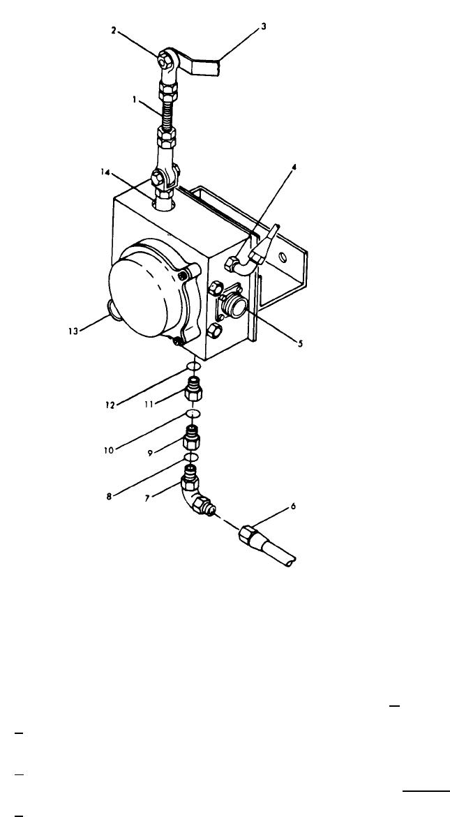
3-176. Removal, of Sump and Filter.
Figure 3-32. Hydraulic Actuator Servicing (MEP105A)
1. Throttle linkage
2. Nut self-locking
3. Lever arm
4. Return Adapter
5. Connector J25
6. Hose
7. Elbow assembly bulkhead
8. Packing
9. Reducer expander
10. Packing
11. Filter plug
12. Packing
13. Connector J24
14. Piston
d. See figure 3-33 and remove sump and filter as illustrated.
a. Remove plug (1, fig. 3-33) on sump tank (21). Drain sump
and discard oil.
3-177. Cleaning and Inspection of Sump and Filter.
b. Remove hose assembly (2) from elbow assembly (7). Remove
two loop clamps and associated hardware front of engine. a. Cleaning.
—
c. Remove hose assembly (3) from elbow assembly (7) and from (1) Flush sump tank (21) thoroughly with hot water or steam
elbow assembly (3A). under pressure.
Change 113-85
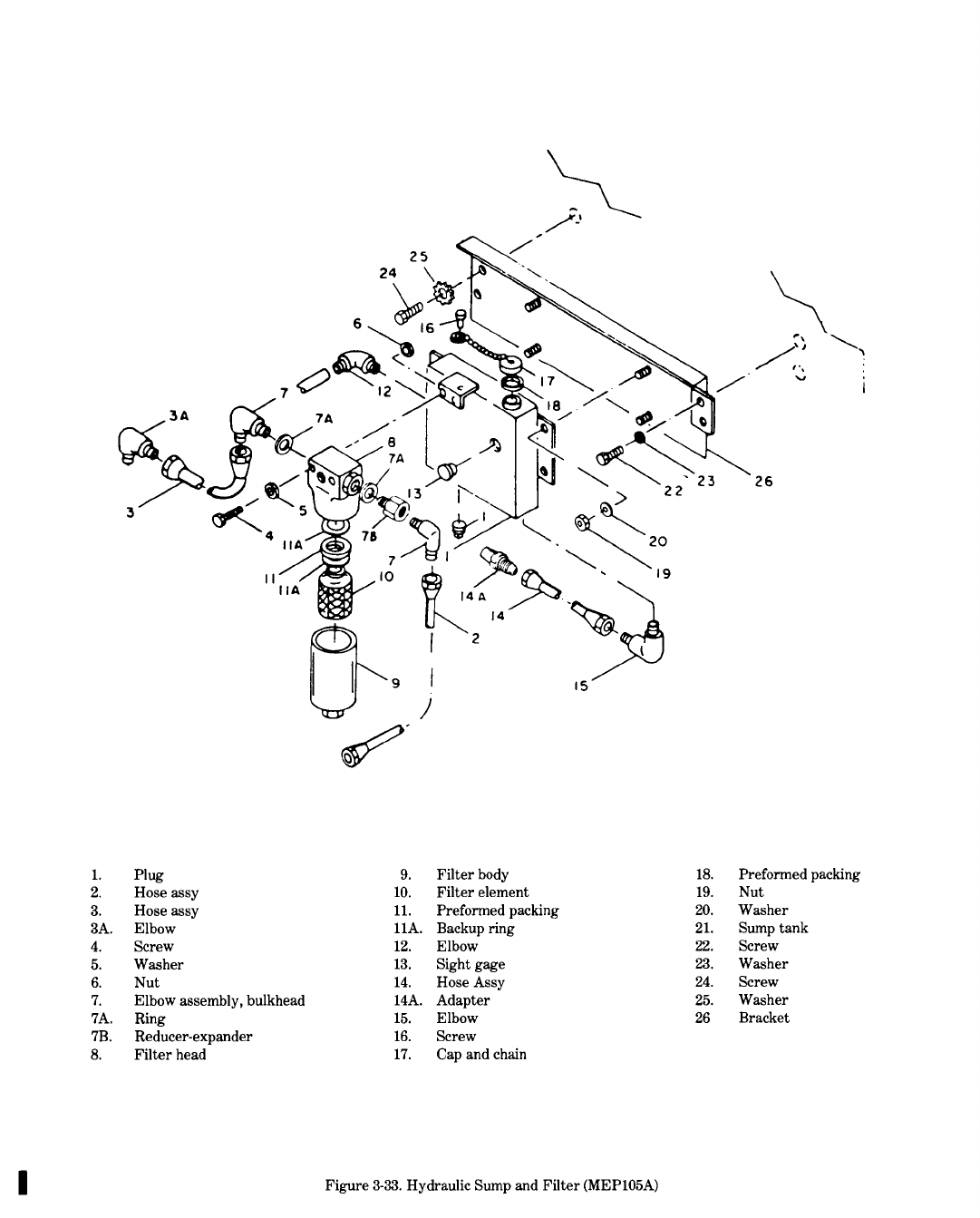
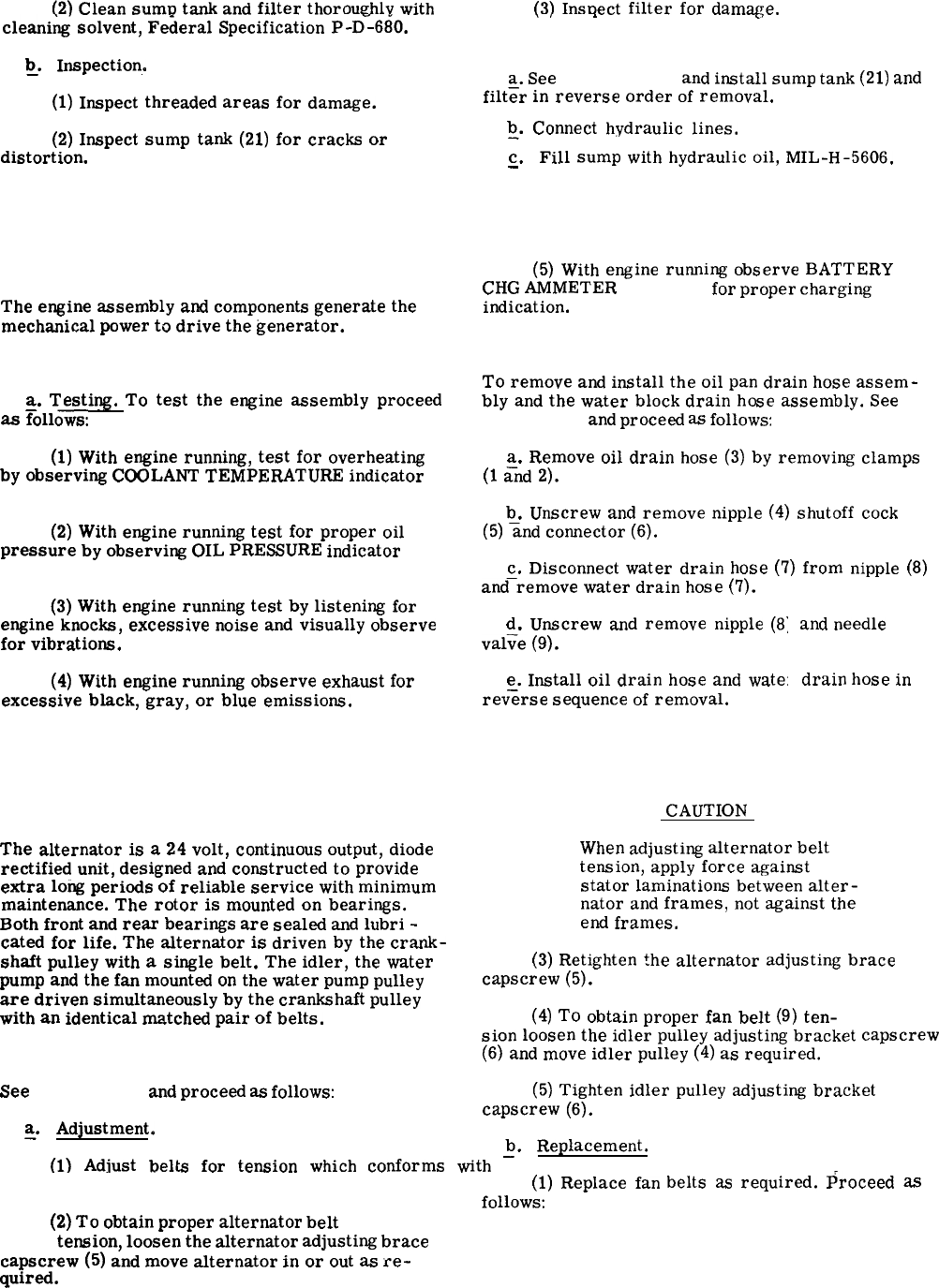
(2)
Clean
sumv
tank
and
filter
thorou~hlv
with
[3)
Ins~ect
filter
for
damze.
cleani~
solvent,
Fe~eral
Specification
P-D--680.
b.
Inspection.
—
(1)
Inspect
threaded
areas
for
damage.
(2)
Inspect
sump
tank
(21)
for
cracks
or
distort
ion.
Section XXVII.
3-179. General.
The
engine
assembly
and
components
generate
the
mechanical
power
to
drive
the
generator.
3-180. Engine Assembly Testing.
a.
Testing.
To
test
the
engine
assembly
proceed
as
Follows:
(1)
With
engine
running,
test
for
overheating
by
observing
COOLANT
TEMPERATURE
indicator
(fig. 2-5).
(2)
With
engine
running
test
for
proper
oil
pressure
by
observing
OIL
PRESSURE
indicator
(fig. 2-5).
(3)
With
engine
running
test
by
listening
for
engine
knocks,
excessive
noise
and
visually
observe
for
vibrations.
(4)
With
engine
ruining
observe
exhaust
for
excessive
black,
gray,
or
blue
emissions.
.,.
<.
3-178. Installation.
a.
See
figure 3-33
and
install
sump
tank
(21)
and
filt=r
in
reverse
order
of
removal.
~.
Connect
hydraulic
lines.
c.
Fill
sump
with
hydraulic
oil,
MIL-H-5606.
—
ENGINE ASSEMBLY
(5)
With
engine
running
observe
BATTERY
CHG
AMMETER
(fig. 2-5)
for
proper
charging
indication.
3-181. Drain Hoses.
To
remove
and
install
the
oil
pan
drain
hose
assem-
bly
and
the
water
block
drain
hcse
assembly.
See
figure 3-34
and
proceed
as
follows:
a.
Remove
oil
drain
hose
(3)
by
removing
clamps
(1
;nd
2).
b.
Unscrew
and
remove
nipple
(4)
shutoff
cock
(5)
=nd
connector
(6).
c.
Disconnect
water
drain
hose
(7)
from
nipple
(8)
and–remove
water
drain
hose
(7).
d.
Unscrew
and
remove
nipple
(8
val;e
(9).
e.
Install
oil
drain
hose
and
wate:
rev<rse
sequence
of
removal.
Section XXVIII. ALTERNATOR AND RELATED PARTS
3-182. General.
CAUTION
The
alternator
is
a
24
volt,
continuous
output,
diode
rectified
unit,
designed
and
constructed
to
provide
extra
long
periods
of
reliable
service
with
minimum
maintenance.
The
rotor
is
mounted
on
bearings.
Both
front
and
rear
bearings
are
sealed
and
lubri
-
cated
for
life.
The
alternator
is
driven
by
the
crank-
shaft
pulley
with
a
single
belt.
The
idler,
the
water
pump
and
the
fan
mounted
on
the
water
pump
pulley
are
driven
simultaneously
by
the
crankshaft
pulley
with
an
identical
matched
pair
of
belts.
3-183. Drive Belts.
See
figure 3-35.
and
proceed
as
follows:
and
needle
drain
hose
in
When
adjusting
alternator
belt
tension,
apply
force
against
stator
laminations
between
alter-
nator
and
frames,
not
against
the
end
frames.
(3)
Retighten
the
alternator
adjusting
brace
capscrew
(5).
(4)
To
obtain
proper
fan
belt
(9)
ten-
sion
loosen
the
idler
pulley
adjusting
bracket
capscrew
(6)
and
move
idler
pulley
(4)
as
required.
(5)
Tighten
idler
pulley
adjusting
bracket
capscrew
(6).
~.
Adjustment.
b.
Replacement.
(1)
Adiust
belts
for
tension
which
conforms
with
–
table 3-1.
(1)
Replace
fan
follows:
(2)
To
obtain
proper
altermtor
belt
(7, fig.
3-35)
tension,
loosen
the
alternator
adjusting
brace
caPscrew
(5)
and
move
alternator
in
or
out
as
re-
quired.
belts
as
required.
Proceed
as
3-87
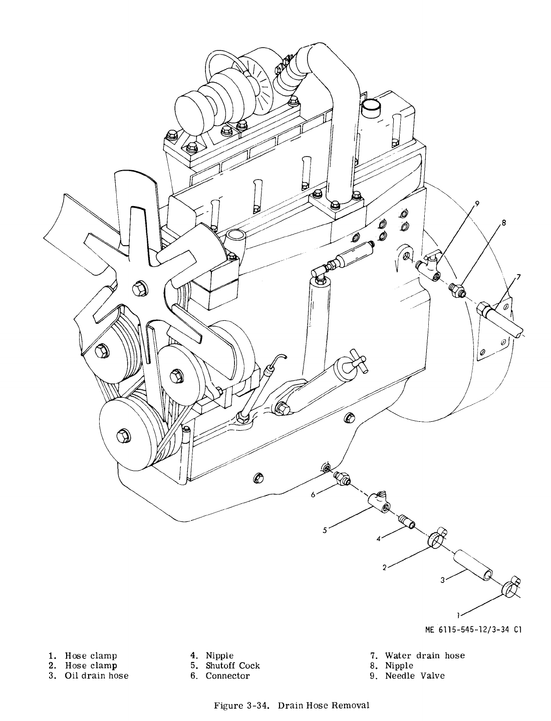
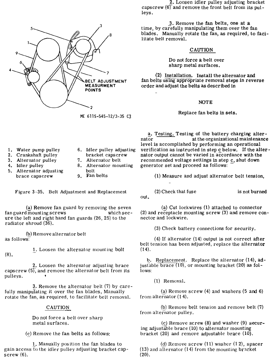
Figure 3-35.
(~)
Remove
fan
guard
by
removing
the
seven
fan
guard
mounting
screws
(24, fig. 3-29),
which
sec-
ure
the
left
and
right
hand
fan
guards
(26,
25)
to
the
radiator
shroud
(36).
(~)
Remove
alternator
belt
(7, fig. 3-35)
as
follows:
~.
Loosen
the
alternator
mounting
bolt
(8).
2.
Loosen
the
alternator
adjusting
brace
capscrew
(5L
and
remove
the
alternator
belt
from
its
pulleys.
@
3.
Remove
the
alternator
belt
(7)
by
care-
fully
manipu~ating
it
over
the
fan
blades,
Manually
rotate
the
fan,
as
required,
to
facilitate
belt
removal.
CAUTION
—
Do
not
force
a
belt
over
sharp
metal
surfaces.
(~)
Remove
the
fan
belts
as
follows:
1.
Manually
position
the
fan
blades
to
gain
access~o
the
idler
pulley
adjusling
bracket
cap-
screw
(6).
2.
Loosen
idler
pulley
adjusting
bracket
capscrew
(6~and
remove
the
front
belt
from
its
pul-
leys.
3.
Remove
the
fan
belts,
one
at
a
time,
by
ca~efully
manipulating
them
over
the
fan
blades.
Manually
rotate
the
fan,
as
required,
to
faci-
litate
belt
removal.
CAUTION
Do
not
force
a
belt
over
sharp
metal
surfaces.
(2)
Installation.
Install
the
alternator
and
fan
belts
using
appropriate
removal
steps
in
reverse
order
and
adjust
the
belts
as
described
in
paragraph
3-183 a (1) and (2).
NOTE
Replace
fan
belts
in
sets.
3-184. Battery Charging Alternator.
a.
Testing.
Testing
of
the
battery
charging
alter-
nat;r
(14, fig. 3-36)
at
the
organizational
maintenance
level
is
accomplished
by
performing
an
operational
verification
as
instructed
in
step
c
below.
If
the
alter-
nator
output
cannot
be
varied
in
a~cordance
with
the
recommended
voltage
settings
in
step
~,
shut
down
generator
set
and
proceed
as
follows:
(1)
Measure
and
adjust
alternator
belt
tension,
(para 3-183 a (1) and (2).
(2)
Check
that
fuse
(21, fig. 3-36)
is
not
burned
out
,
(~)
Cut
lockwires
(1)
attached
to
connector
(2)
and
receptacle
mounting
screw
(3)
and
remove
con-
nector
and
lockwire.
(3)
Check
battery
connections
for
security.
(4)
If
alternator
(14)
output
is
not
correct
after
belt
tension
has
been
adjusted,
replace
the
alternator
(14).
b.
Replacement. Replace
the
alternator
(14),
ad-
jus~able
brace
(10),
or
mounting
bracket
(20)
as
fol-
lows:
(1)
Removal.
(a)
Remove
screw
(4)
and
washers
(5
and
6)
from
alte~nator
(1
4).
(b)
Remove
belt
tension
and
remove
belt
(7)
from
altei+nator
pulley.
(c)
Remove
screw
(8)
and
washer
(9)
secur-
ing
adjust~ble
brace
(10)
to
alternator
mounting
bracket
(20)
and
remove
adjustable
brace
(10).
(d)
Remove
screw
(11)
washer
(1
2),
spacer
(13)
and
afiernator
(14)
from
the
mounting
bracket
(20).
Change 33-89
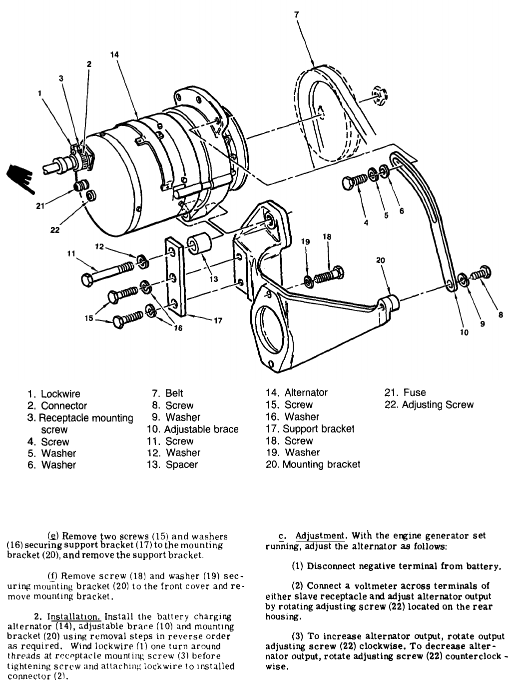
1.
Lockwire
7.
Belt
2,
Connector
8.
Screw
3.
Receptacle
mounting
9.
Washer
screw
10.
Adjustable
brace
4.
Screw
11.
Screw
5.
Washer
12.
Washer
6.
Washer
13.
Spacer
14,
Alternator 21.
Fuse
15.
Screw
22.
Adjusting
Screw
16.
Washer
17.
Support
bracket
18.
Screw
19.
Washer
20.
Mounting
bracket
Figure 3-36. Alternator and Related Parts
(Q)
Remove
two
screws
(15)
and
washers
(16)
securing
support
bracket
(17)
to
the
mounting
bracket
(20),
and
remove
the
support
bracket.
(j)
Remove
screw
(18)
and
washer
(19)
sec-
uring
mounting
bracket
(20)
to
the
front
cover
and
re-
move
mounting
bracket.
2.
Installation.
Install
the
battery
charging
alternator
(14),
adjustable
brace
(10)
and
mounting
bracket
(20)
using
removal
steps
in
reverse
order
as
required.
Wind
lockwire
(1)
one
turn
around
threads
at
rcct-ptacle
mounting
screw
(3)
before
tightening
screw
and
attach:ng
iockwlre
to
Installed
comector
(2).
c. Adjustment.
With
the
engine
generator
set
run;ing,
adjust
the
alternator
as
follows:
(1)
Discomect
negative
terminal
from
battery.
(2)
Comect
a
voltmeter
across
terminals
of
either
slave
receptacle
ad
adjust
alternator
output
by
rotating
adjusting
screw
(22)
located
on
the
rear
housing.
(3)
To
increase
alternator
output,
rotate
output
adjusting
screw
(22)
clockwise.
To
decrease
alter-
nator
output,
rotate
adjusting
screw
(22)
countercIock
-
wise.
3-90 Change 12
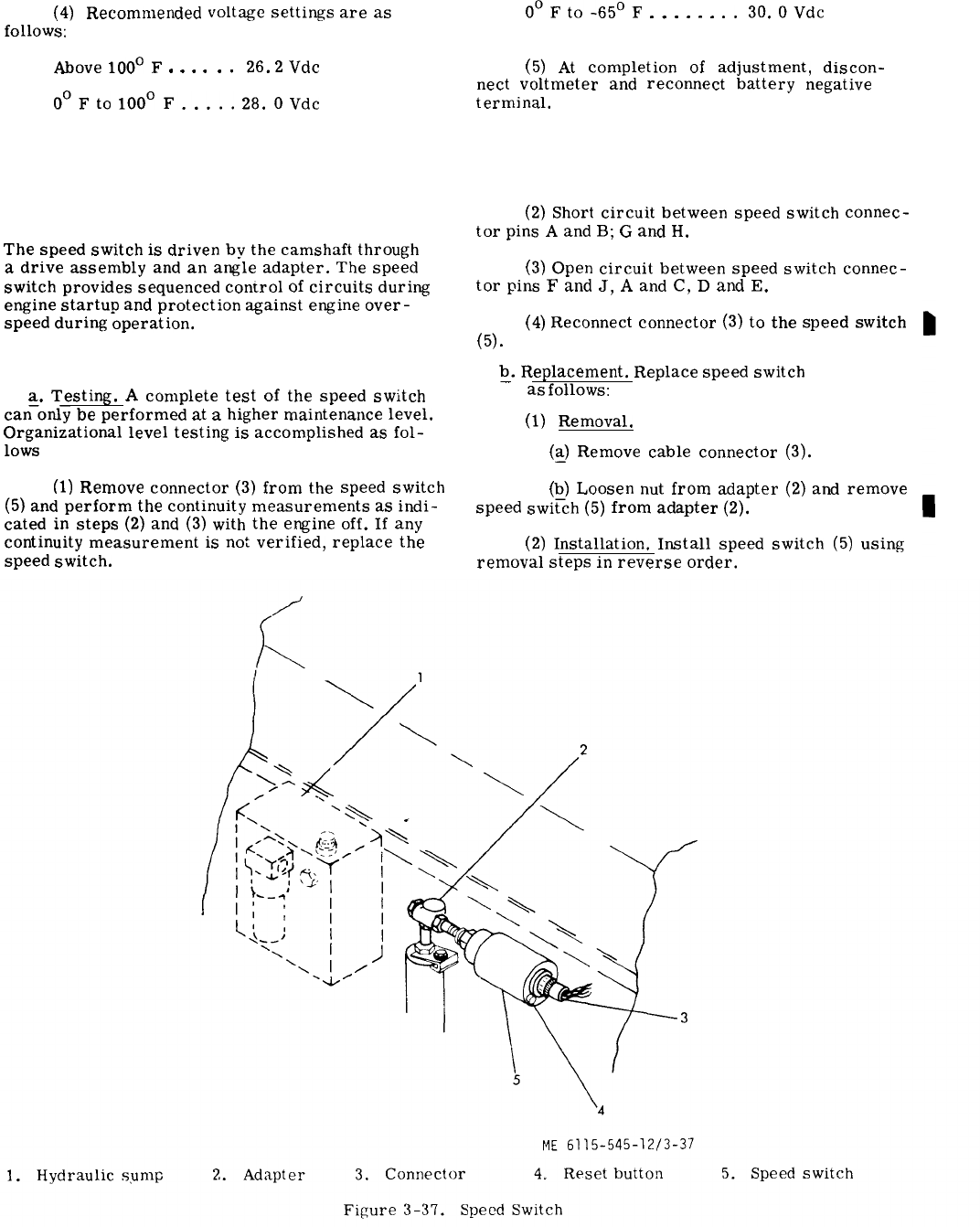
Figure 3-37.
(4)
follows:
Recommended
Above
100°
F
. . . .
voltage
settings
are
as
.
.
26.2
Vdc
O°Fto
1000
F.....
28.
OVdc
Section XXIX.
3-185. General.
The
speed
switch
is
driven
by
the
camshaft
through
a
drive
assembly
and
an
angle
adapter.
The
speed
switch
provides
sequenced
control
of
circuits
during
engine
startup
and
protection
against
engine
over-
speed
during’
operation.
3-186. Testing and Replacement.
a.
Testing.
A
complete
test
of
the
speed
switch
can–only
be
performed
at
a
higher
maintenance
level.
Organizational
level
testing
is
accomplished
as
fol-
lows
(see fig. 3-37).
(1)
Remove
connector
(3)
from
the
speed
switch
(5)
and
perform
the
continuity
measurements
as
indi-
cated
in
steps
(2)
and
(3)
with
the
engine
off.
If
any
continuity
measurement
is
not
verified,
replace
the
speed
switch.
0°Fto-650F
. . . . . .
..30.
OVdc
(5)
At
completion
of
adjustment,
discon-
nect
voltmeter
and
reconnect
battery
negative
terminal.
SPEED SWITCH
(2)
Short
circuit
between
speed
switch
connec-
tor
pins
A
and
B;
G
and
H.
(3)
open
circuit
between
speed
switch
connec-
tor
pins
F
and
J,
A
and
C,
D
and
E.
(4)
Reconnect
connector
(3)
to
the
speed
switch
(5).
Q.
Replacement.
Replace
speed
switch
(5, fig.
3-37)
as
follows:
(1)
Removal.
(~)
Remove
cable
connector
(3).
(Q)
Loosen
nut
from
adapter
(2)
and
remove
speed
switch
(5)
from
adapter
(2).
(2)
Installation.
Install
speed
switch
(5)
using
removal
steps
in
reverse
order.
Change 3 3-91
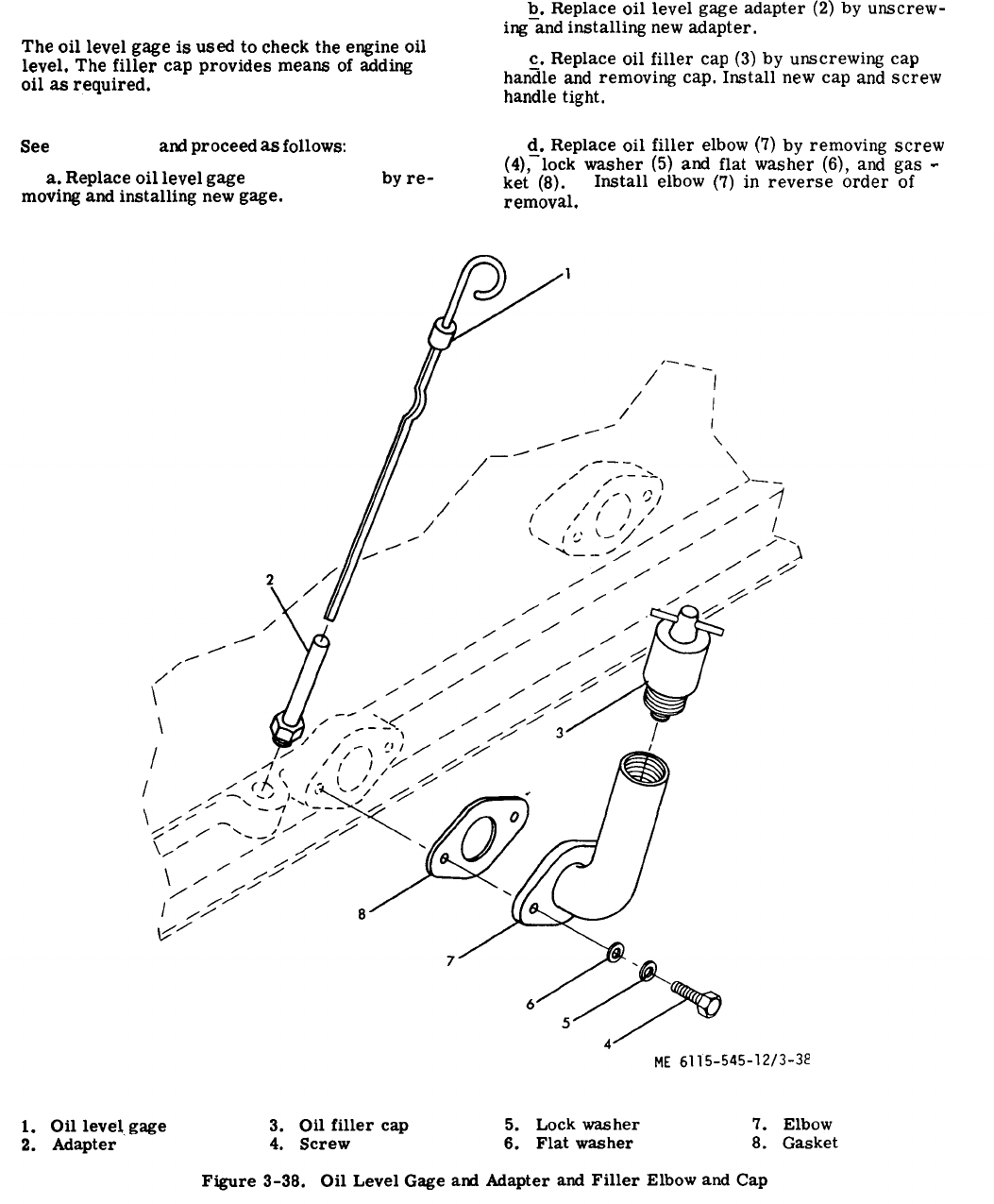
Figure 3-38.
Section XXX. OIL LEVEL GAGE AND FILLER
3-187. General.
The
oil
level
gage
is
used
to
check
the
engine
oil
level.
The
filler
cap
provides
means
of
adding
oil
as
required.
3-188. Replacement.
See
figure 3-38
and
proceed
as
follows:
a.
Replace
oil
level
gage
(1, fig. 3-38)
by
re-
moving
and
installing
new
gage.
b.
Replace
oil
level
gage
adapter
(2)
by
unscrew-
ing-and
installing
new
adapter.
c.
Replace
oil
filler
cap
(3)
by
unscrewing
cap
han~le
and
removing
cap.
Install
new
cap
and
screw
handle
tight.
d.
Replace
oil
filler
elbow
(7)
by
removing
screw
(4),-lock
washer
(5)
and
flat
washer
(6),
and
gas
-
ket
(8).
Install
elbow
(7)
in
reverse
order
of
removal.
3-92
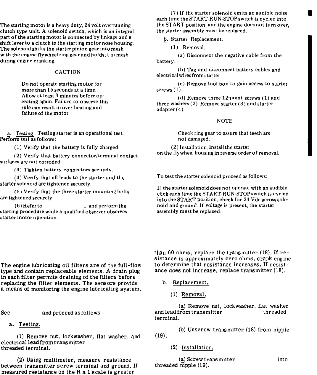
TM 5-6115-545-12
TO-35C2-3-444-1
NAVFAC P-8-626-12
TM-00038G-12
Section XXXI. ELECTRIC STARTER AND ADAPTER
3-189. General.
The
starting
motor
is
a
heavy
duty,
24
volt
overrunning
clutch
type
unit.
A
solenoid
switch,
which
is
an
integral
part
of
the
starting
motor
is
connected
by
linkage
and
a
shift
lever
to
a
clutch
in
the
starting
motor
nose
housing.
The
solenoid
shifts
the
starter
pinion
gear
into
mesh
with
the
engine
flywheel
ring
gear
and
holds
it
in
mesh
during
engine
cranking.
CAUTION
Do
not
operate
starting
motor
for
more
than
15
seconds
at
a
time.
Allow
at
least
3
minutes
before
op-
erating
again.
Failure
to
observe
this
rule
can
result
in
over
heating
and
failure
of
the
motor.
3-190. Starter Assembly.
~.
Testing. Testing
starter
is
an
operational
test.
Perform
test
as
follows:
(1)
Verify
that
the
battery
is
fully
charged
(2)
Verify
that
battery
connector/terminal
contact
surfaces
are
not
corroded.
(3)
Tighten
battery
connectors
securely.
(4)
Verify
that
all
leads
to
the
starter
and
the
starter
solenoid
are
tightened
securely.
(5)
Verify
that
the
three
starter
mounting
bolts
are
tightened
securely.
(6)
Refer
to
paragraph 2-12 b
and
perform
the
starting
procedure
while
a
qualified
observer
observes
starter
motor
operation.
(7)
If
the
starter
solenoid
emits
an
audible
noise
each
time
the
START-RUN-STOP
switch
is
cycled
into
the
START
position,
and
the
engine
does
not
turn
over,
the
starter
assembly
must
be
replaced.
b.
Starter
Replacement.
—
(1)
Removal.
(a)
Disconnect
the
negative
cable
from
the
battery.
(b)
Tag
and
disconnect
battery
cables
and
electrical
wires
from
starter
(3, fig. 3-38.1).
(c)
Remove
tool
box
to
gain
access
to
starter
screws
(l).
(d)
Remove
three
12-point
screws
(1)
and
three
washers
(2).
Remove
starter
(3)
and
starter
adapter
(4).
NOTE
Check
ring
gear
to
assure
that
teeth
are
not
damaged.
(2)
Installation.
Install
the
starter
(3, fig. 3-38.1)
on
the
flywheel
housing
in
reverse
order
of
removal.
3-191. Starter Solenoid.
To
test
the
starter
solenoid
proceed
as
follows:
If
the
starter
solenoid
does
not
operate
with
an
audible
click
each
time
the
START-RUN-STOP
switch
is
cycled
into
the
START
position,
check
for
24
Vdc
across
sole-
noid
and
ground.
If
voltage
is
present,
the
starter
assembly
must
be
replaced.
Section XXXII. LUBE OIL FILTERS AND SENSORS
3-192. General.
The
engine
lubricating
oil
filters
are
of
the
full-flow
type
and
contain
replaceable
elements.
A
drain
plug
in
each
filter
permits
draining
of
the
filters
before
replacing
the
filter
elements.
The
sensors
provide
a
means
of
monitoring
the
engine
lubricating
system.
3-193. Oil Pressure Transmitter.
See
figure 3-3
and
proceed
as
follows:
a.
Testing.
(1)
Remove
nut,
lockwasher,
flat
washer,
and
electrical
lead
from
transmitter
(18, fig. 3-3)
threaded
terminal.
(2)
Using
multimeter,
measure
resistance
between
transmitter
screw
terminal
and
ground.
If
measured
resistance
on
the
R
x
1
scale
is
greater
than
60
ohms,
replace
the
transmitter
(18).
If
re-
sistance
is
approximately
zero
ohms,
crank
engine
to
determine
that
resistance
increases.
If
resist-
ance
does
not
increase,
replace
transmitter
(18).
b.
Replacement.
(1)
Removal.
(~)
Remove
nut,
lockwasher,
flat
washer
and
lead
from
transmitter
(18, fig. 3-3)
threaded
terminal.
(~)
Unscrew
transmitter
(18)
from
nipple
(19).
(2)
Installation.
(a)
Screw
transmitter
(18, fig. 3-3)
into
threaded
fipple
(19).
Change 133-93
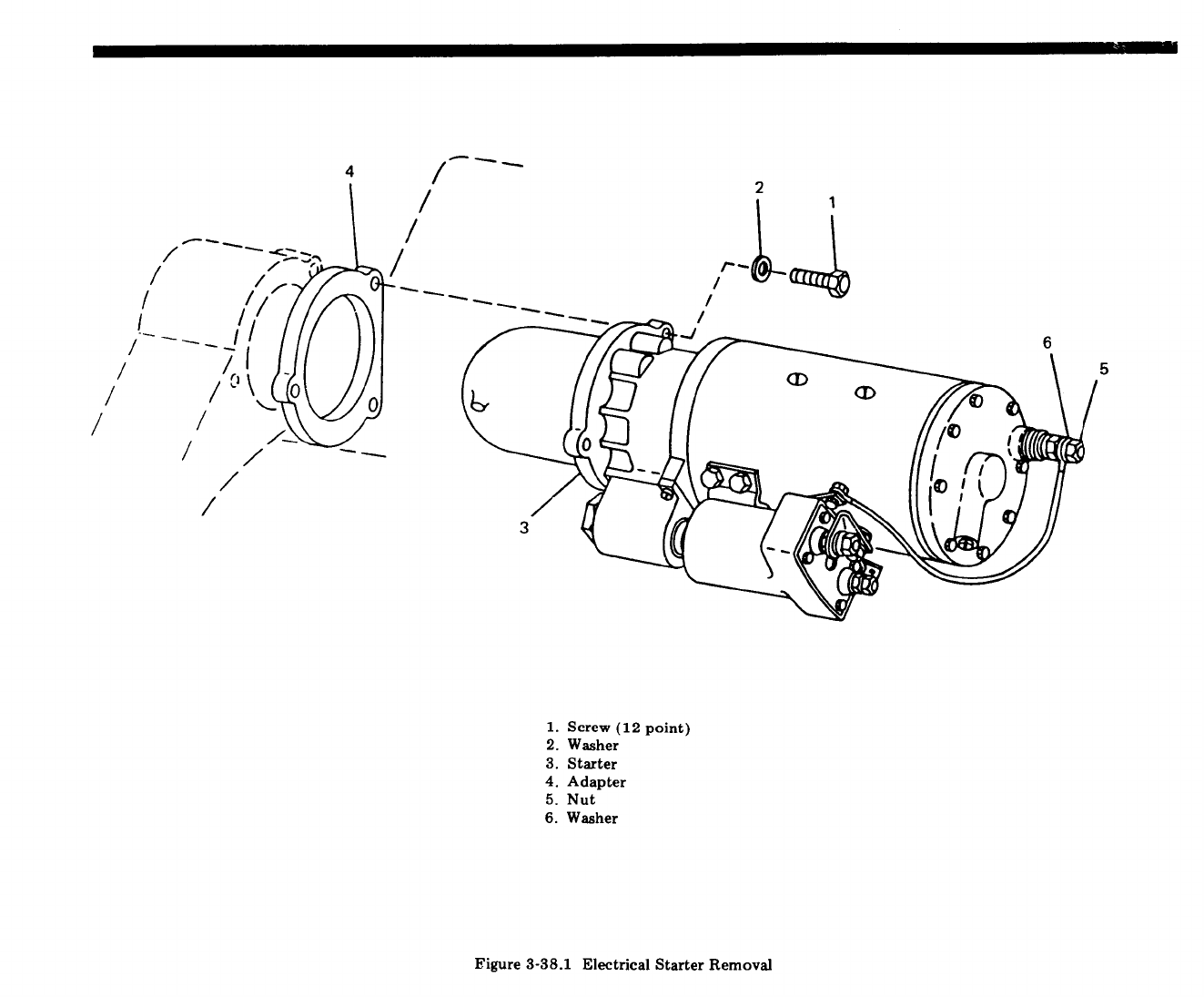

(~)
Reconnect
electrical
lead
using
nut,
lock-
waaher,
and
flat
washer.
3-194. Low Oil Pressure Shutdown Switch.
See
figure 3-3
and
proceed
as
follows:
a.
Inspection.
Inspect
the
switch
(16, fig. 3-3)
for
loo~e
mounting,
loose
connector,
dents,
and
other
damage.
Q.
Testing.
To
test
the
switch
(16, fig. 3-3),
discon-
nect
the
connector
and
connect
a
multimeter
between
pins
B
and
C
of
the
switch
and
verify
continuity.
Then
connect
multimeter
between
pins
A
and
D
and
verify
open
circuit.
If
switch
does
not
check
out
properly,
replace
switch.
c.
Replacement.
Replace
switch
(16, fig. 3-3)
as
folbws
:
(1)
Removal.
(Q)
Disconnect
connector
from
switch
(
16),
(Q)
Unscrew
switch
(
16)
from
nipple
(
17).
(2)
Installation.
Screw
switch
(16, fig. 3-3)
into
nipple
(17
)
and
tighten
to
20
foot-pounds.
Reconnect
connector
to
switch.
3-196. General.
TM 5-6115-545-12
TO-35C2-3-444-1
NAVFAC P-8-626-12
TM-00038G-12
3-195. Oil Filter Assembly.
~.
Replacement.
To
replace
the
oil
filter
assembly,
see
figure 3-3
and
remove
and
install
as
illustrated,
while
observing
the
following:
(1)
Drain
oil
system
as
described
in
paragraph
3-4c (3)
and
drain
filter
by
removing
plug
(1, fig. 3-3)
and
draining
into
a
suitable
container.
(2)
Remove
screw
(5)
and
washer
(6)
and
remove
both
filter
bodies
(7)
and
filter
elements
(8)
as
assem-
blies
from
header
(9).
(3)
Disconnect
and
tag
oil
line
and
electrical
connections
and
remove
screws
(2)
and
washers
(3)
which
secure
header
(9)
to
engine
block.
Remove
straight
connector
(22)
and
gasket
(4).
(4)
Install
using
a
new
gasket
(4)
and
mount
onto
engine
block
with
screws
(2)
and
washers
(3).
Tighten
center
screw
(
5
)
to
a
torque
of
45
to
50
foot-pounds.
Replace
straight
connector
and
reconnect
oil
line
and
electrical
connections
(22
).
Q.
Check
the
engine
lube
oil
filter
for
oil
leakage
and
be
certain
that
filter
body
(
7
)
and
gasket
(
10)
are
properly
installed.
Section XXXIII. SECONDARY FUEL FILTER
The
secondary
fuel
filter
is
the
final
filtration
device
in
the
fuel
system.
It
removes
contaminated
particles
of
five
micron
and
larger
from
the
fuel.
3-197. Replacement.
To
replace
the
secondary
fuel
filter,
see
figure 3-39
and
proceed
as
follows:
~
Open
drain
cock
(1).
~.
Drain
fuel
into
suitable
container.
(1)
Removal.
(~)
Remove
fuel
lines
to
filter
and
remove
elbows
(2
and
3)
from
filter
assembly
(6).
(Q)
Remove
four
screws
(4)
and
lockwashers
(5)
holding
filter
assembly
(6)
to
bracket
(9)
and
remove
filter
assembly
(6).
(g)
Remove
two
screws
(7)
lockwashers
(8)
and
washer
(8A)
and
remove
bracket
(9)
from
engine,
(2)
Installation.
(~)
Close
drain
cock
(1).
(Q)
Install
bracket
(9)
and
filter
assembly
(6)
in
the
reverse
order
of
removal.
Change 93-94.1/(3-94.2 blank)

Section XXXIV.
LUBE OIL COOLER
3-198. General.
The
engine
lube
(JI1
c{mh’r,
of
the
cncine. consists of
a
localeci
on
the
right
side
corrosion
resistant
,,
cooling c[)re
and
tank.
The
water
pump
circulates
coolant
t
hrtw~h
the
coolir~
core
tubes,
and
the
e~~-
ine
oil
pr-ussurp
pump
circulates oil
through
the
tank
and
around
(he
outside of
the
tubes
of
the
cool-
ing
core.
thereby controlling oil temperature.
3-199. Inspection and Replacement.
See
figure 3-40
,ind
proceed
as
follows:
~.
hw])f:clif)n.
lIISIJW1
(jIl
cw}lir
for
internal
l~~ll~s,
”;’;;
(;ii.
--li;,,se
Ill[JUlltlllg,
:ii)cf
other
damage.
b.
Fk!pl;l(’rment
Replace
the
engine
oil
cooler
——.
—
.
.
..
———
-
.“
as
fi)llows:
(1)
Renl(w:li.
(~)
[t(hfer
[
o
paragraph 3-41 md
cfrwn
cu(dir~ system.
Also
drain coolant frotn
lube
oil
cooler
by
rclll,)vll~
rfr:lll]
Illug
(1, fig. 3-40) or
]f
winter
izati~m
kit
is
mstallqci
by
opening shutoff
cock
(45, fig. 4-1) after removing
hose
(34) from
elbow
(46).
(~)
Drain secondary
fuel
fllt
er
in(o
a
two
~allon
container. Refer
to
paragraph 3-197
and
re-
move secnndarv
fuel
filter.
(g)
Remove
fuel
fr
It
er
head
with
filter
element intact.
(Q)
Refer
to
paragraph 3-203
and
remove
turbocharger oil drain
tube
assembly
between
turbocharger
ancl
cylinder block.
(~)
Renlovef]v
screws (2 and 5, fig. 3-40)
and
lockwashers
(3)
and
(6)
and
securing
lube
oil
cooler
(7)
to
cylinder block.
Fifth
screw
(2)
and
lockwasher
(3)
secures
manualc
ontrolb
racket
(4)
to
lube
oil
cooler
(7). Remove
Iube
oil
cooler
(7)
by
pulling
t[]WArdS
the
rear of
engine.
~~)
Remove preformed
packing
(8)
from
lube
oil
cooler
(7).
(g)
Remove
coo!er
tube
(9)
with
preformed
packing
(10)
from
the
lube
oil
cooler
(7)
volute.
(h)
Remove winterization
kit
nipple,
shutoff
cock,
and
elbow from
lube
oil
cooler
(7)
drain
plug
(1)
receptacle.
(2)
Installation.
NOT
E
If winterization
kit
1s
installed,
install
kit,
nipple,
shutoff cock,
and
elbow
in
lube
oil
cooler
(7,
fig. 3-40) drain
plug
(1)
receptacle.
(~)
Assemble
new
preformed packing (10,
fig. 3-40)
on
cooler
tube
(9)
and
install
one
end
of cooler
tube
(9)
into
lube
oil
cooler
(7)
volute.
Irustall
new
preformed
packing
(8)
in
the
back of
the
lube
oil
cooler
(7).
Hold
packing
in
place
with
a
light
coating of
grease.
(~)
Inslall
lube
oil
cooler
(7)
by positioning
header over
lhe
rear
end
of
cooler
tube
(9)
and
pushing
forward.
(~)
Install
five
screws
(2)
and
(5),
five
lockwashers
(3)
and
(6)
and
manual
control bracket
(4). Secure
lube
oil
cooler
(7)
to cvlinder block
tightening
screws
(2)
and
(5)
secur”ely.
(d)
Install
lube
oil
cooler
drain
plug
(1)
or
connect hose (34, fig. 4-1)
to
elbow
(46)
and
open
shutoff cock
(45).
(~)
Refer
to
paragraph 3-203
and
install
turbocharger oil drain
tube
assembly
between
turbo
charger
and
cylinder block.
(f)
Refer
to
paragraph 3-197
and
install
secondary–filter.
(g)
Refer to paragraph 3-41
and
fill cooling
system.
(~)
Operate
engine
and
check for
oil
and
water
leaks
at
oil
cooler
(7, fig. 3-40) connections.
Correct
any
leaks
found.
Stop
engine.
Refer to
paragraph 3-46
and
check
mcrankcase
moil
level
in
oil
pan
adding
oil as necessary to raise oil level
to
the
full
mark
on
the
oil level gage. Refer
to
para-
graph 3-41
and
check coolant level
in
the
radiator
adding
coolant
as
necessary.
Section XXXV.
NOZZLE HOLDER ASSEMBLIES AND LINES
3-200. General. 3-201. Inspection, Testing, and Replacement.
There
is
a
nozzle bolder assembly for each cylinder
See
figure 3-41
and
proceed
as
follows:
consisting of
a
fuel
injection nozzle holder. The
nozzle holder assemblies are used to position
the
a. Inspection.
injection nozzles
in
the
cylinder
head.
The
lines
provide
a
means
of delivering
the
fuel from
the (1)
Check
for
a
sufficient
fuel
level for
fuel
injection
pump
to
the
nozzle. operation.
3-96
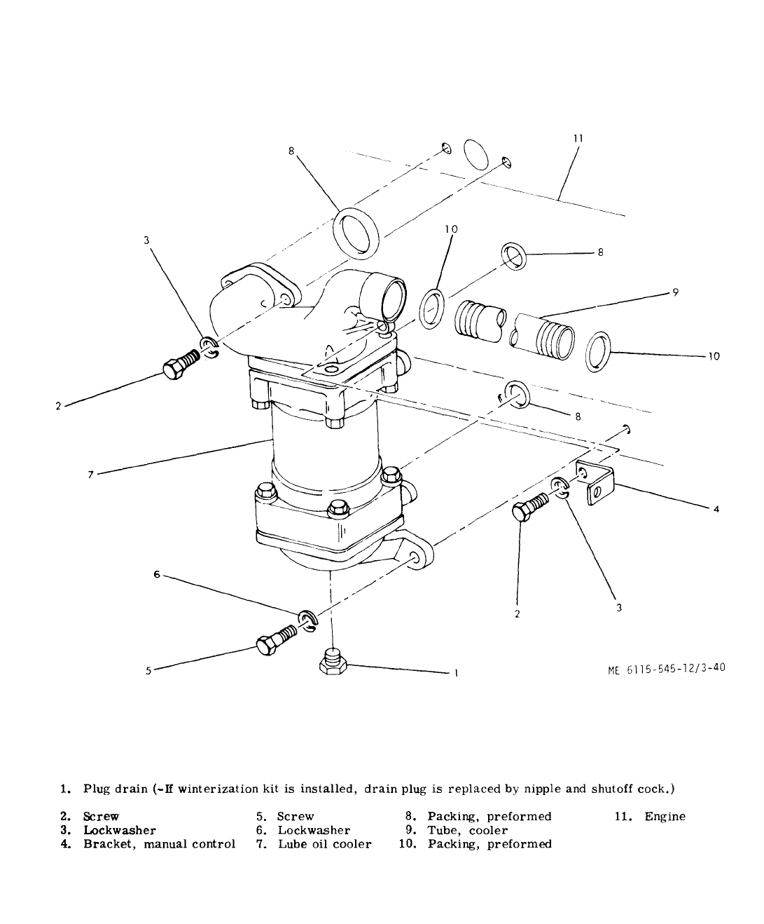
(2)
Examine
all
fuel
lines
(3, 8, and 23 through
28, fig. 3-41)
and
nozzle
holder
assemblies
(32)
for
signs
of
leakage.
b.
Testing.
.-
——
(1)
With
engine
running,
one
by
one
loosen
the
fuel
input
connection
to
each
injector
while
ob-
serving
the
engine
action
and
listening
to
the
sound.
Fuel
should
flow
out
when
the
connection
is
loosened.
When
the
input
to
a
faulty
injector
is
loosened,
there
should
be
little
or
no
change
in
engine
sound
or
ac-
tion.
The
engine
action
(or
symptom)
should
be-
come
worse
when
the
input
to
a
good
injector
is
loosened.
(2)
To
verify
a
low
compression
condition
as
opposed
to
an
injector
malfunction,
proceed
as
follows:
(a)
With
the
engine
stopped
and
the
DEAD
CRANK
swit~h
in
down
position,
remove
the
injector
assembly
from
number
one
cylinder
(or
the
cylinder
which
has
a
suspected
failure).
(b)
Insert
a
compression
gage
into
the
in-
j
ector
openini.
(~)
Turn
the
START-STOP-RUN
switch
the
START
position
for
a
period
of
5
to
15
seconds
to
obtain
a
compression
reading
while
the
engine
is
cranking.
Return
the
switch
to
the
STOP
position.
CAUTION
—..———
Do
not
crank
more
than
15
seconds
at
a
time.
A11ow
at
least
15
seconds
before
operating
again.
(d)
A
compression
gage
reading
of
400
psi
(at
sea
level)
is
normal
for
a
new
engine.
If
a
difference
in
compression
readings
in
excess
of
50
lbs
between
high
and
low
cylinders
exists
refer
to
next
higher
maintenance
level.
c.
Replacement.
To
replace
the
nozzle
holder
.-—
..—
—
assZmbIf6s
and
lines,
see
figure 3-41
and
proceed
as
follows
(1)
Removal.
(a)
Thoroughly
clean
nozzle
holders
(32
fig. 3-41),
Ii=es
(3),
(8),
and
(23)
through
(28),
con-
nections
and
surrounding
area.
Gain
access
to
noz-
zle
holder
assemblies
(32)
from
right
side
reaching
over
the
engine
valve
cover.
CAUTION
——.———
Cleanliness
is
extremely
impor-
tant
when
working
with
fuel
in-
j
ectors.
Injection
nozzle
service
troubles
are,
in
most
instances,
caused
by
dirt.
Use
clean
paper
on
the
work
bench
and
place
com-
ponents
in
a
container
of
clean
diesel
fuel
as
they
are
removed.
3-98 Change 9
to
(:)
‘e.qnve
fuel
return
line
(8)
by
dis-
connecting
connectors
(ti)
;.C
th~
fll~l
iniection
pump
(detail
A)
and
tee
(4).
(c)
Disconnect
fuel
injection
lines
(23)
through
(28),–nuts
(9)
at
the
nozzle
holder
assem-
blies
(32)
and
screws
(11
)
at
the
fuel
injection
pump
(detail
A).
NOTE
Gain
access
to
screws
(11)
and
washers
(12)
Which
secure
fuel
lines
(23
through
28)
to
fuel
injection
pump
by
removing
self-locking
nut
(see
fig. 3-32)
and
swing-
ing
lever
arm
of
hydraulic
actuator. Temporarily
stow
self-
locking
nut
back
in
place.
Remove
coupling
nuts
(1, fig. 3-41)
and
washers
(12)
from
fuel
in-
jection
pump,
remove
lines
from
pump,
and
temporarily
stow
screws
and
washers
on
pump.
LNOT
E
Clamps
(16,
21
and
29)
must
be
unclamped
(detail
B
and
C)
before
removing
lines
(23
through
28).
(d)
Remove
manifold
drip
line
(3)
by
disconnecting
coupling
nut
(1)
from
tee
(4)
and
nozzle-holder
assemblies
(32).
CAUTION
Do
not
bend
lines
when
disconnecting.
Cover
all
openings
immediately
to
prevent
entrance
of
dirt.
(e)
Remove
two
capscrews
(30)
and
two
Iockwashers
731)
securing
nozzle-holder
assemblies
(32)
to
cylinder
head.
(f)
Remove
~,ozzle-holder
assemblies
(32)
from
c
ylinde~
head
by
using
two
small
pry
bars,
or
by
using
a
slide
hammer
with
an
adapter.
Mark
each
inject
or
nozzle
with
the
number
of
the
cylinder
from
which
it
was
removed.
Insure
that
nozzle
gasket
(34)
is
removed.
CAUTION
Use
care
when
removing
an
injector
nozzle
to
tmevent
striking
nozzle
tip
again~
a
hard
object
&hich
could
result
in
damage
to
the
tip.
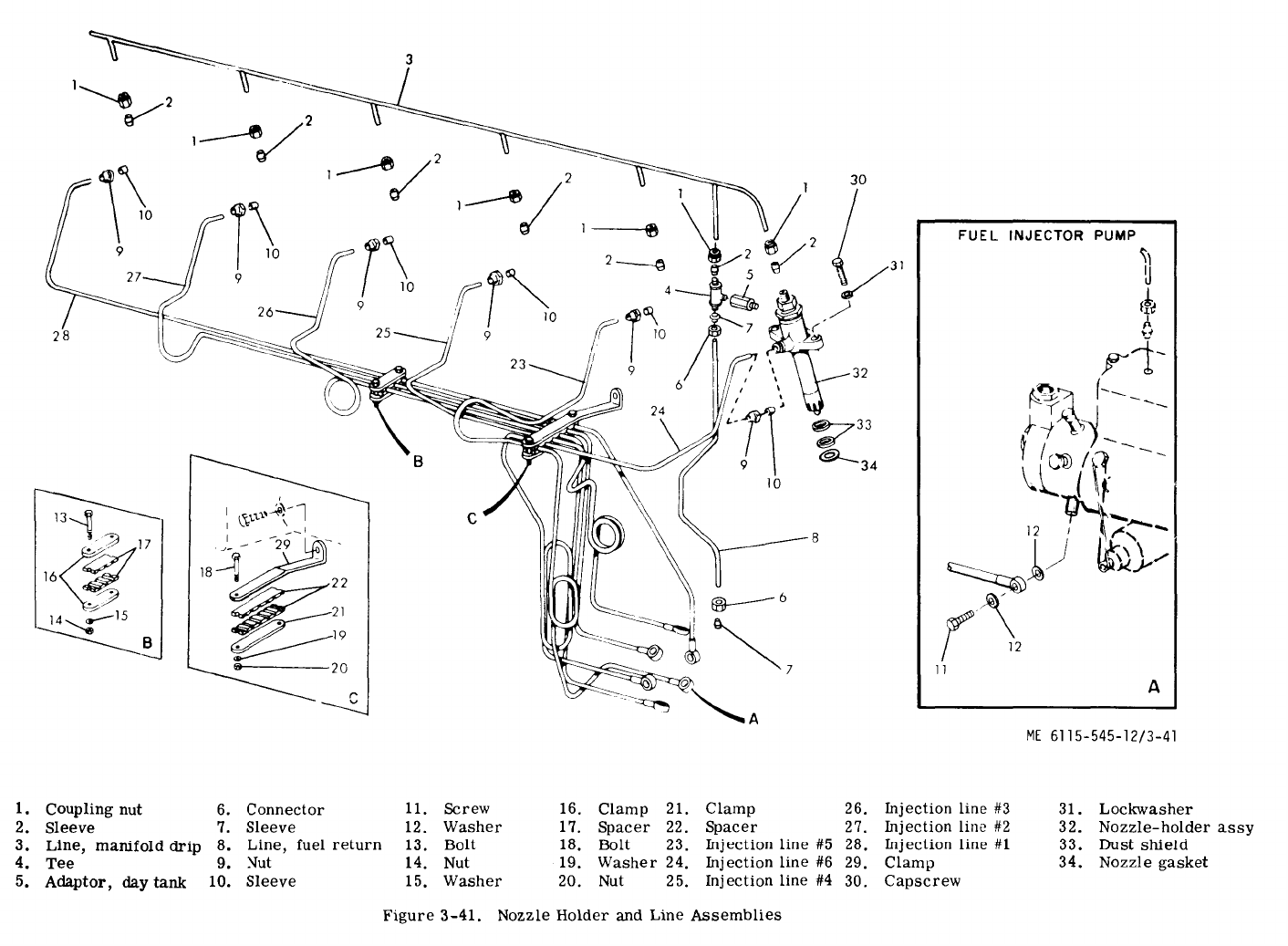
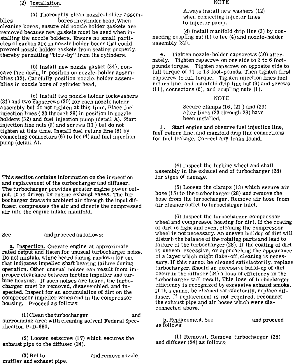
(2)
Installation.
.——
—..
(a)
Thoroughly
clean
nozzle-holder
assem-
blies
(32, fig. 3-41)
bores
in
cylinder
head.
When
cleaning
bores,
ensure
old
nozzle
holder
gaskets
are
removed
because
new
gaskets
must
be
used
when
in-
stalling
the
nozzle
holders.
Ensure
no
small
parti-
cles
of
carbon
are
in
nozzle
holder
bores
that
could
prevent
nozzle
holder
gaskets
from
seating
properly,
thereby
permitting
“blow-by”
from
the
cylinders.
(b)
Install
new
nozzle
gasket
(34),
con-
cave
face
dew-n,
in
position
on
nozzle-holder
assem-
blies
(32).
Carefully
position
nozzle-holder
assem-
blies
in
nozzle
bore
of
cylinder
head.
(~)
Install
two
nozzle
holder
Iockwashers
(31)
and
two
capscrews
(30)
for
each
nozzle
holder
assembly
but
do
not
tighten
at
this
time.
Place
fuel
injection
lines
(
23
through
28)
in
position
in
nozzle
holders
(32)
and
fuel
injection
pump
(detail
A).
Start
injection
line
nuts
(9)
and
screws
(11
)
but
do
not
tighten
at
this
time.
Install
fuel
return
line
(8)
by
connecting
connectors
(6)
to
tee
(4)
and
fuel
injection
pump
(detail
A).
NOTE
Always
install
new
washers
(12)
when-connecting
injector
lines
to
injector
pump.
(d)
Install
manifold
drip
line
(3)
by
con-
necting
coupling
nut
(1)
to
tee
(4)
and
nozzle-holder
assembly
(32).
e.
Tighten
nozzle-holder
capscrews
(30)
alter-
natd
y.
Tighten
capscrew
on
one
side
to
3
to
6
foot-
pounds
torque.
Tighten
capscrew
on
opposite
side
to
full
torque
of
11
to
13
foot-pounds.
Then
tighten
first
capscrew
to
full
torque.
Tighten
injection
lines
fuel
return
line,
and
manifold
drip
line
nut
(9)
and
screws
(11),
connectors
(6),
and
coupling
nuts
(1).
NOTE
Secure
clamps
(16,
(21
)
and
(29)
after
lines
(23
through
28)
have
been
installed.
f.
Start
engine
and
observe
fuel
injection
line,
fuel
return
line,
and
manifold
drip
line
connections
for
fuel
leakage.
Correct
any
leaks
found.
Section XXXVI.DIFFUSER AND TURBOCHARGER
3-202. General.
This
section
contains
information
on
the
inspection
and
replacement
of
the
turbocharger
and
diffuser.
The
turbocharger
provides
greater
engine
power
out-
put.
It
is
driven
by
engine
exhaust
gases.
The
tur-
bocharger
draws
in
ambient
air
through
the
input
dif-
fuser,
compresses
the
air
and
directs
the
compressed
air
into
the
engine
intake
manifold.
3-203. Turbocharger.
See
figure 3-42
and
proceed
as
follows:
a.
Inspection.
Operate
engine
at
approximate
rat~d
o~listen
for
unusual
turbocharger
noise.
Do
not
mistake
whine
heard
during
rundown
for
one
that
indicates
impeller
shaft
bearing
failure
during
operation.
Other
unusual
noises
can
result
from
im-
proper
clearance
between
turbine
impeller
and
tur-
bine
housing. If
such
noises
are
heard,
the
turbo-
charger
must
be
removed,
disassembled,
and
in-
spected.
Inspect
for
an
accumulation
of
dirt
on
the
compressor
impeller
vanes
and
in
the
compressor
housing.
Proceed
as
follows:
(1)
Clean
the
turbocharger
(28, fig. 3-42)
and
surrounding
area
with
cleaning
solvent
Federal
Spec-
ification
P-D-680.
(2)
Loosen
setscrew
(17)
which
secures
the
exhaust
pipe
to
the
diffuser
(24).
(3)
Ref
to
paragraph 3-86
and
remove
nozzle,
muffler
and
exhaust
pipe.
(4)
Inspect
the
turbine
wheel
and
shaft
assembly
in
the
exhaust
end
of
turbocharger
(28)
for
signs
of
damage.
(5)
Loosen
the
clamps
(13)
which
secure
air
hose
(15)
to
the
turbocharger
(28)
and
remove
the
hose
from
the
turbocharger.
Remove
air
hose
from
air
cleaner
outlet
to
turbocharger
inlet.
(6)
Inspect
the
turbocharger
compressor
wheel
and
compressor
housing
for
dirt.
If
the
coating
of
dirt
is
light
and
even,
cleaning
the
compressor
wheel
is
not
necessary.
An
uneven
buildup
of
dirt
will
disturb
the
balance
of
the
rotating
parts
and
lead
to
failure
of
the
turbocharger
(28).
If
the
coating
of
dirt
is
uneven,
excessive,
or
approaching
the
appearance
of
a
layer
which
might
flake-off,
cleaning
is
neces-
sary.
If
this
cannot
be
cleaned
satisfactorily,
replace
turbocharger.
Should
an
excessive
build-up
of
dirt
occur
in
the
diffuser
(24)
a
loss
of
efficiency
in
the
turbocharger
will
result.
This
loss
of
turbocharger
efficiency
is
recognized
by
excessive
exhaust
smoke.
if
this
cannot
be
cleaned
satisfactorily,
replace
dif-
fuser.
If
replacement
is
not
required,
reconnect
the
exhaust
pipe
and
air
hoses
which
were
dis-
connected
above.
‘
b.
Replacement.
See
figure 3-42
and
proceed
as
Tollows:
(1)
Removal.
Remove
turbocharger
(28)
and
diffuser
(24)
as
follows:
3-100
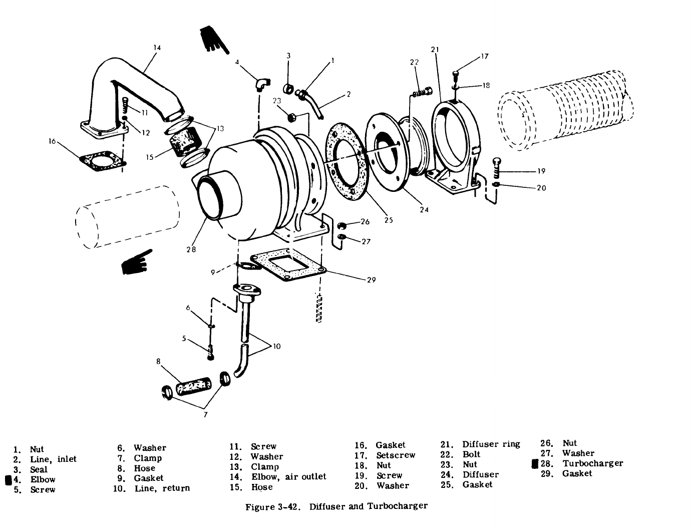
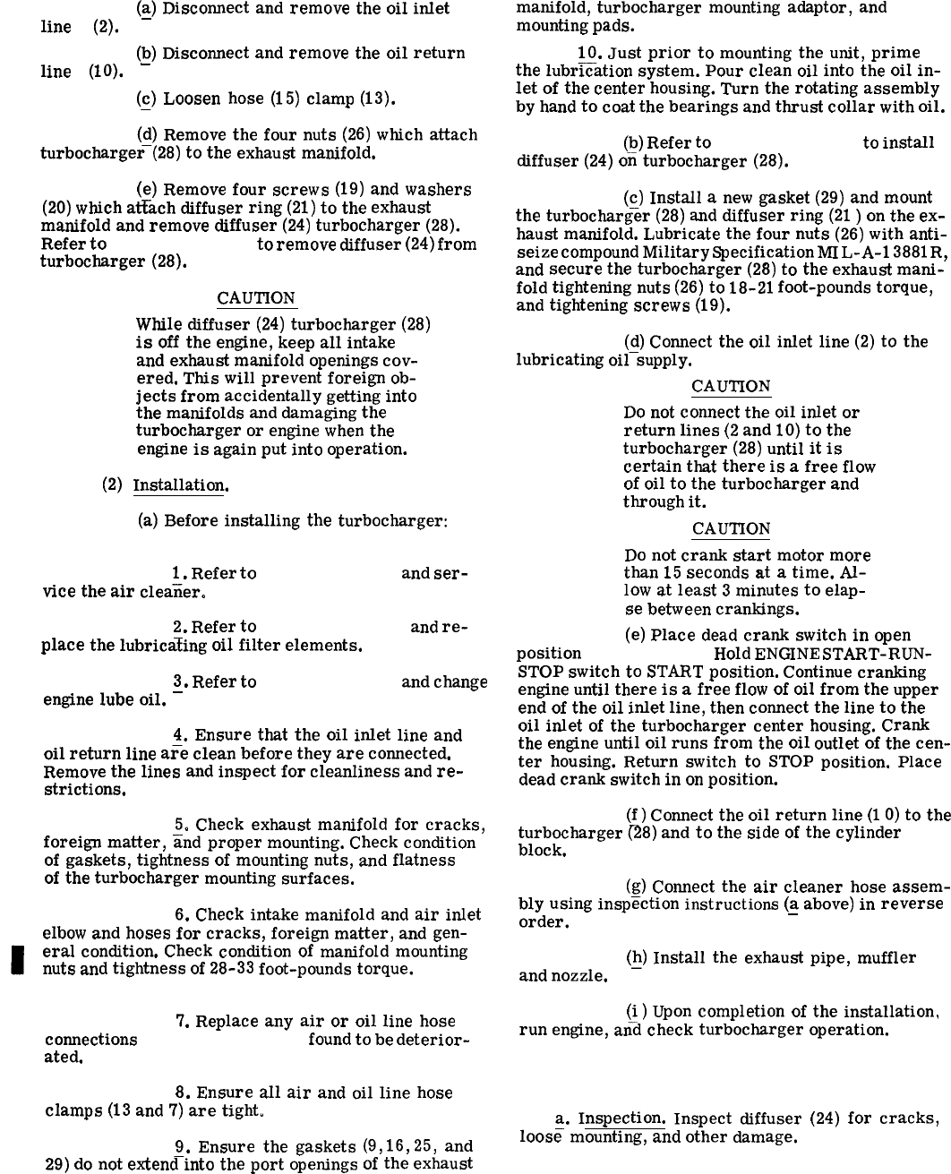
(a)
Disconnect
and
remove
the
oil
inlet
line
(2).
-
(b)
Disconnect
and
remove
the
oil
return
line
(10).
-
(~)
Loosen
hose
(15)
clamp
(13).
(d)
Remove
the
four
nuts
(26)
which
attach
turbocharger-(28)
to
the
exhaust
manifold.
(e)
Remove
four
screws
(19)
and
washers
(20)
which
atiach
diffuser
ring
(21)
to
the
exhaust
manifold
and
remove
diffuser
(24)
turbocharger
(28).
Refer
to
paragraph 3-204
to
remove
diffuser
(24)
from
turbocharger
(28).
(2)
CAUTION
While
diffuser
(24)
turbocharger
(28)
is
off
the
engine,
keep
all
intake
and
exhaust
manifold
openings
cov-
ered.
This
will
prevent
foreign
ob-
jects
from
accidentally
getting
into
the
manifolds
and
damaging
the
turbocharger
or
engine
when
the
engine
is
again
put
into
operation.
Installation.
(a)
Before
installing
the
turbocharger:
(28, fig. 3-42):
1.
Refer
to
paragraph 3-32
and
ser-
vice
the
air
cleaiier.
2.
Refer
to
paragraph 3-195
and
re-
place
the
lubricating
oil
filter
elements.
3.
Refer
to
paragraph 3-46
and
change
engine
lube
oil.
–
4.
Ensure
that
the
oil
inlet
line
and
oil
return
line
a~e
clean
before
they
are
connected.
Remove
the
lines
and
inspect
for
cleanliness
and
re-
strictions.
5.
Check
exhaust
manifold
for
cracks,
foreign
matter,
iind
proper
mounting.
Check
condition
of
gaskets,
tightness
of
mounting
nuts,
and
flatness
of
the
turbocharger
mounting
surfaces.
6.
Check
intake
manifold
and
air
inlet
elbow
and
hoses
for
cracks,
foreign
matter,
and
gen-
eral
condition.
Check
condition
of
manifold
mounting
nuts
and
tightness
of
28-33
foot-pounds
torque.
7.
Replace
any
air
or
oil
line
hose
connections
(15 and 8, fig. 3-42)
found
to
be
deterior-
ated.
8.
Ensure
all
air
and
oil
line
hose
clamps
(13
and
7)
are
tight.
9.
Ensure
the
gaskets
29)
do
not
extend-into
the
port
openings
3-102 Change 1
(9,16,25,
and
of
the
exhaust
manifold,
turbocharger
mounting
adaptor,
and
mounting
pads.
10.
Just
prior
to
mounting
the
unit,
prime
the
lubr~ation
system.
Pour
clean
oil
into
the
oil
in-
let
of
the
center
housing.
Turn
the
rotating
assembly
by
hand
to
coat
the
bearings
and
thrust
collar
with
oil.
(b)
Refer
to
paragraph 3-204
to
install
diffuser
(24)
o~
turbocharger
(28).
(c)
Install
a
new
gasket
(29)
and
mount
the
turbocharger
(28)
and
diffuser
ring
(21
)
on
the
ex-
haust
manifold.
Lubricate
the
four
nuts
(26)
with
anti-
seize
compound
Military
Specification
MI
L-A-1
3881
R,
and
secure
the
turbocharger
(28)
to
the
exhaust
mani-
fold
tightening
nuts
(26)
to
18-21
foot-pounds
torque,
and
tightening
screws
(19).
(d)
Connect
the
oil
inlet
line
(2)
to
the
lubricating
oil–supply.
CAUTION
Do
not
connect
the
oil
inlet
or
return
lines
(2
and
10)
to
the
turbocharger
(28)
until
it
is
certain
that
there
is
a
free
flow
of
oil
to
the
turbocharger
and
through
it.
CAUTION
Do
not
crank
start
motor
more
than
15
seconds
at
a
time.
Al-
low
at
least
3
minutes
to
elap-
se
between
crankings.
(e)
Place
dead
crank
switch
in
open
position
(49, fig. 3-27).
Hold
ENGINE
START-RUN-
STOP
switch
to
START
position.
Continue
cranking
engine
until
there
is
a
free
flow
of
oil
from
the
upper
end
of
the
oil
inlet
line,
then
connect
the
line
to
the
oil
inlet
of
the
turbocharger
center
housing.
Crank
the
engine
until
oil
runs
from
the
oil
outlet
of
the
cen-
ter
housing.
Return
switch
to
STOP
position.
Place
dead
crank
switch
in
on
position.
(f)
Connect
the
oil
return
line
(1
O)
to
the
turbocharger
(28)
and
to
the
side
of
the
cylinder
block.
(g)
Connect
the
air
cleaner
hose
assem-
bly
using
inspection
instructions
(a
above)
in
reverse
—
order.
(~)
Install
the
exhaust
pipe,
muffler
and
nozzle.
(i)
Upon
completion
of
the
installation,
run
engine,
an–d
check
turbocharger
operation.
3-204. Exhaust Diffuser.
a.
Inspection.
Inspect
diffuser
(24)
for
cracks,
loos=
mounting,
and
other
damage.
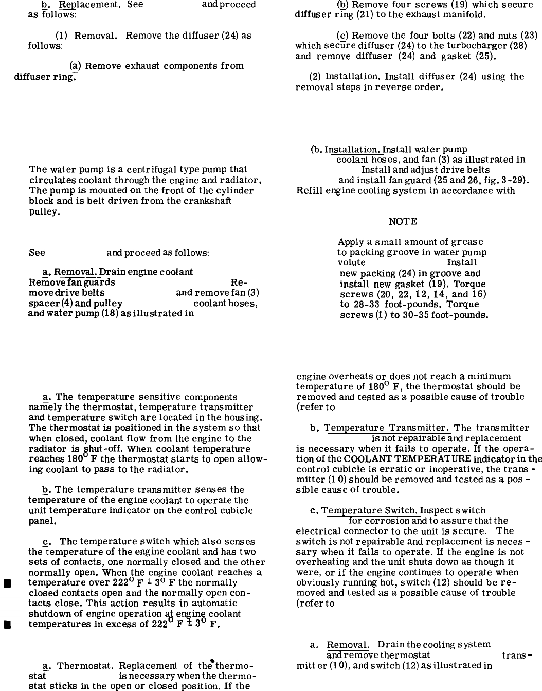
b.
Replacement.
as
~ollows:
(1)
Removal.
follows:
See
figure 3-42
and
proceed
(b)
Remove
four
screws
(19)
which
secure
diffuser
r~~
(21)
to
the
exhaust
manifold.
Remove
the
diffuser
(24)
as
(~)
Remove
the
four
bolts
(22)
and
nuts
(23)
which
secure
diffuser
(24)
to
the
turbocharger
(28)
and
remove
diffuser
(24)
and
gasket
(25).
(a)
Remove
exhaust
components
from
diffuser
ring;
(2)
Installation.
Install
diffuser
(24)
using
the
removal
steps
in
reverse
order.
Section XXXVII. WATER PUMP AND FAN
3-205. General.
The
water
pump
is
a
centrifugal
type
pump
that
circulates
coolant
through
the
engine
and
radiator.
The
pump
is
mounted
on
the
front
of
the
cylinder
block
and
is
belt
driven
from
the
crankshaft
pulley.
3-206. Replacement.
See
figure 3-43
and
proceed
as
follows:
a.
Removal.
Drain
engine
coolant
(para 3-41).
——.
Remove
fan
guards
(25 and 26, fig. 3-39).
Re-
move
drive
belts
(para 3-183),
and
remove
fan
(3)
spacer
(4)
and
pulley
(5, fig. 3-43)
coolant
hoses,
and
water
pump
(18)
as
illustrated
in
figure 3-43.
(b.
Installation.
Install
water
pump
(18, fig.
3-43),
coolant
hoses,
and
fan
(3)
as
illustrated
in
figure 3-43.
Install
and
adjust
drive
belts
(para
3-183)
and
install
fan
guard
(25
and
26,
fig.
3-29).
Refill
engine
cooling
system
in
accordance
with
table 2-1.
NOTE
Apply
a
small
amount
of
grease
to
packing
groove
in
water
pump
volute
(25, fig. 3-43).
Install
new
packing
(24)
in
groove
and
install
new
gasket
(19).
Torque
screws
(20,
22,
12,
14,
and
16)
to
28-33
foot-pounds.
Torque
screws
(1)
to
30-35
foot-pounds.
Section XXXVIII. THERMOSTAT AND HOUSING
3-207. General.
a.
The
temperature
sensitive
components
nafiely
the
thermostat,
temperature
transmitter
and
temperature
switch
are
located
in
the
housing.
The
thermostat
is
positioned
in
the
system
so
that
when
closed,
coolant
flow
from
the
engine
to
the
radiator
is
shut-off.
When
coolant
temperature
reaches
180°
F
the
thermostat
starts
to
open
allow-
ing
coolant
to
pass
to
the
radiator.
b.
The
temperature
transmitter
senses
the
tem–perature
of
the
engine
coolant
to
operate
the
unit
temperature
indicator
on
the
control
cubicle
panel.
c. The
temperature
switch
which
also
senses
the~emperature
of
the
engine
coolant
and
has
two
sets
of
contacts,
one
normally
closed
and
the
other
normally
open.
When
the
engine
coolant
reaches
a
temperature
over
222°
F
*
3°
F
the
normally
closed
contacts
open
and
the
normally
open
con-
tacts
close.
This
action
results
in
automatic
shutdown
of
engine
operation
at
engine
coolant
temperatures
in
excess
of
222°
F
~
3°
F.
3-208. Inspection and Operational Check.
a.
Thermostat.
Replacement
of
the*thermo-
sta~
(8, fig. 3-44)
is
necessary
when
the
thermo-
stat
sticks
in
the
open
or
closed
position.
If
the
engine
overheats
or
does
not
reach
a
minimum
temperature
of
180°
F,
the
thermostat
should
be
removed
and
tested
as
a
possible
cause
of
trouble
(refer
to
para 3-209).
b.
Temperature
Transmitter.
The
transmitter
(10, fig. 3-44)
is
not
repairable
and
replacement
is
necessary
when
it
fails
to
operate.
If
the
opera-
tion
of
the
COOLANT
TEMPERATURE
indicator
in
the
control
cubicle
is
erratic
or
inoperative,
the
trans
-
mitter
(1
O)
should
be
removed
and
tested
as
a
pos
-
sible
cause
of
trouble.
c.
Temperature
Switch.
Inspect
switch
(12,
fig. 3-44)
for
corrosion
and
to
assure
that
the
electrical
connector
to
the
unit
is
secure.
The
switch
is
not
repairable
and
replacement
is
neces
-
sary
when
it
fails
to
operate.
If
the
engine
is
not
overheating
and
the
unit
shuts
down
as
though
it
were,
or
if
the
engine
continues
to
operate
when
obviously
running
hot,
switch
(12)
should
be
re-
moved
and
tested
as
a
possible
cause
of
trouble
(refer
to
para 3-209).
3-209. Removal, Testing and Installation.
a.
Removal.
Drain
the
cooling
system
(para
3-41)
and
remove
thermostat
(8, fig. 3-44),
trans
-
mitt
er
(1
O),
and
switch
(12)
as
illustrated
in
figure
3-44).
Change 13-103
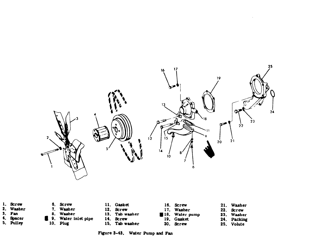

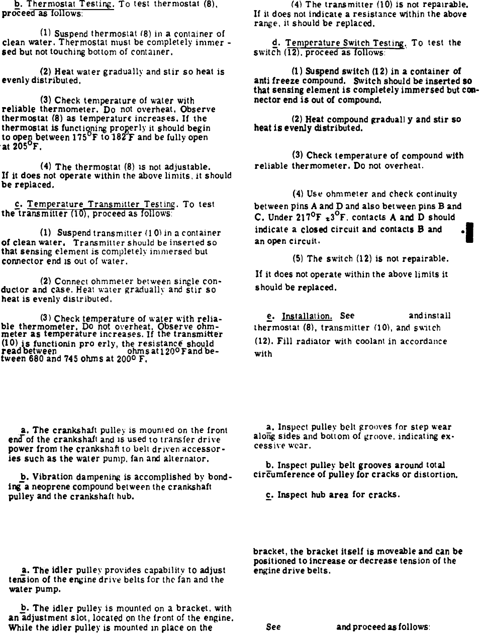
TM 5-6115-545-12
TO 35C2-3-444-1
NAVFAC P-8-826-12
TM 00038G-12
~.
Thermostat
Testing.
To
test
thermostat
(8),
proceed
as
follows:
(1)
Suspend
thermostat
(8)
in
a
container
of
Clean
water.
Thermostat
must
be
completely
inlnler
-
sed
but
not
touching
bottom
of
contmner.
(2)
Heat
water
gradually
and
stir so
heat
is
evenly
distributed.
(3)
Check
temperature
of
water
with
reliable thermometer.
DO
not
overheat,
Observe
thermostat
(8)
as
temperature
increases.
If
the
thermostat
is
functioning
pro~erly
it
should
begin
to
open
between
175°F
to
182
F
and
be
fully
open
at
205°F.
(4)
The
thermostat
(8)
M
not
adjustable.
If
it
does
not
operate
within
the
above
lit-nits,
it
should
be
replaced.
$.
Temperature Transmitter
Testing.
To
test
the
transmitter
(10),
proceed
as
follows:
of clean
(la)ektspend
transmitter
(1
O)
in
a
container
.
Transmitter
should
be
inserted
so
that
sensing
element
is
completely’
imn)ersed
but
connector
end
M
out
of
water.
(2)
Connect
ohmmeter
between
single
con-
ductor
and
case.
Heat
water
gradually
and
stir so
heat
is
evenly
distributed,
(3)
Check
temperature
of
water
with
relia-
ble thermometer.
Do
not
overheat.
Observe
ohm-
meter as
temperature
increases.
If
the
transmitter
(10)
is
functioning
pro erly,
the
resistanc~
should
read
between
2100 and 2600
ohms
at
1200
F
and
be-
tween
680
and
745
ohms
at
2000
F.
Section XXXIX. CRANKSHAFT PULLEY
3-210. General.
a.
The
crankshaft
pulley
is
moumed
on
the
front
eflof
the
crankshaft
and
M
used
to
transfer drive
power
from
the
crankshaft
to
belt
dr]ven
accessor-
ies
such
as
the
water
pump,
fan
and
alternator.
p.
Vibration
dampenihg
is
accomplished
by
bond-
ing
a
neoprene
compound
between
the
crankshaft
pulley
and
the
crankshaft
hub.
(4)
The
transmitter
(10)
is
not
repamable.
If
it
does
not
indicate
a
resistance
within
the
above
range,
it
should
be
replaced.
~.
T~.
To
test
the
switch
(12).
proceed
as
follows:
(1)
Suspend
switch
(12)
in
a
container
of
anti
freeze
compound.
Switch
should
be
inserted
so
that
sensing
element
is completely immersed
but
con-
nector
end
is
out
of
compound.
(2)
Heat
compound
gradual]
y
and
stir
so
heat
is
evenly
distributed.
(3)
Check
temperature
of
compound
with
reliable thermometer.
Do
not
overheat.
(4)
Use
ohmmeter
and
check
continuity
between
pins
A
and
D
and
also
between
pins
B
and
C.
Under
217°F
S3°F.
contacts
A
and
D
should
indicate
a
closed circuit
and
contacts
B
and
C
an
open
circuit.
(5)
The
switch
(12)
is
not
repairable.
If
it
does
not
operate
within
the
above
limits
it
should
be
replaced.
g.
Installation. See
figure 3-44
and
install
thermostat
(8),
transmitter
(]0),
and
suitch
(12).
Fill
radiator
with
coolant
in
accordance
with
table 2-1.
AND VIBRATION DAMPENER
3-211. Inspection.
a.
Inspect
pulley
belt
grooves for
step
wear
aloiii
sides
and
bottom
of
groove.
indicating
ex.
cessive
wear,
b.
Inspect
pulley
belt
grooves
around
total
circumference of
pulley
for cracks or
distortion.
~.
Inspect
hub
area for cracks.
Section XL. IDLER PULLEY AND MOUNTING BRACKET
3-212. General. bracket,
the
bracket
itself
is
moveable
and
can
be
positioned
to increase or decrease
tension
of
the
a.
The
idler
pulley
provides
capability
to
adjust engine
drive belts.
ten%ion
of
the
engine
drive
belts
for
the
fan
and
the
water
pump.
3-213.
~.
The
idler
pulley
is
mounted
on
it
bracket,
with
an
adjustment
slot,
located
on
the
front
of
the
engine.
While
the
idler
pulley
is
mounted
m
place
on
the
See
3-106
Change 18
Inspection, Removal and Installation.
figure 3-45
and
proceed
as
follows:
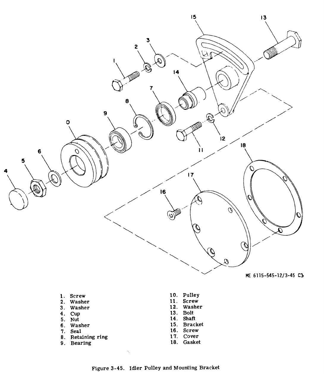

a. Inspection. Inspect the idler pulley to assure
freedom of rotation and that there is no evidence of
cracking or signs of excessive wear.
b. Removal. To remove and disassemble the
idler pulley, proceed as follows:
(1) Refer to paragraph 3-183 and remove
engine drive belts from around idler pulley (1 O,
fig. 3-45).
(2) See figure 3-45 and remove bracket (15)
with pulley (1 O) still in place on the bracket (15).
(3) Remove pulley (10) and related hardware
from bracket (15).
c. Installation.
(1) Install pulley (10) and related hardware on
mounting bracket (15).
(2) Install bracket (15) onto engine.
(3) Torque nut (5) to 140 lb-ft (lubricated).
(4) Pack areas between bearing (9) and two seals
(4) and (7) 2/3 - full of BR grease.
NOTE
Do not repack bearing
(5) Refer to paragraph 3-183 and install engine
drive belts onto pulley (10). Position bracket (15)
for proper belt tension.
d. Repair. Repair of the idler pulley and mount-
ing-bracket is accomplished by replacement of defec -
tive components.
Section XLI. INTAKE MANIFOLD
3-214. General.
a. The air intake system consists of components
which convey filtered air to the engine cylinders.
The intake system includes the air cleaner, com-
pressor side of the turbocharger, and the intake
manifold.
b. The intake manifold is sealed to the cylinder
head with a one piece gasket and secured in place with
screws and washers.
3-215. Removal and Replacement.
See figure 3-46 and proceed as follows
a. Removal.
(1) Disconnect atomizer (1, fig. 3-46) and
tube (1A) from intake manifold (6).
(2) Remove screws (11, fig. 3-42) and washers
(12) securing turbocharger air outlet elbow (14) to
top of intake manifold (6, fig. 3-46). Loosen clamp
(13, fig. 3-42) and remove air outlet elbow (14) and
gasket (16).
(3) Remove screws (2, fig. 3-46) washers (3),
securing intake manifold (6) to cylinder head; remove
brackets (5), intake manifold (6), and gasket (7).
b. Inspection. Proceed as follows:
(1) Wash and clean intake manifold with
cleaning solvent, Federal Specification P-D-680.
(2) Check manifold for foreign deposits. Clear
and remove obstructions found within the manifold.
(3) If manifold is cracked, it must be replaced.
(4) If the mounting surface of the intake
manifold is warped enough so that it will not seal,
the manifold must be replaced.
(5) Inspect and clean the mounting surface on
the cylinder head to make certain it is free of gasket
particles or foreign matter.
c. Installation. Proceed as follows
(1) Install the intake manifold (6, fig. 3-46)
to the engine in reverse order of removal.
(2) Always use a new gasket (7) when in-
stalling the intake manifold (6).
(3) Torque the intake manifold securing screws
(2) to 28-33 foot -pounds.
(3A) Install atomizer and tighten atomizer so
that locating dots on hex are located as shown in view
A of figure 3-46.
(4) After the engine is run and the water
temperature reaches approximately 170°F, again
torque screws (2) to 28-33 foot-pounds.
3-108 Change 8
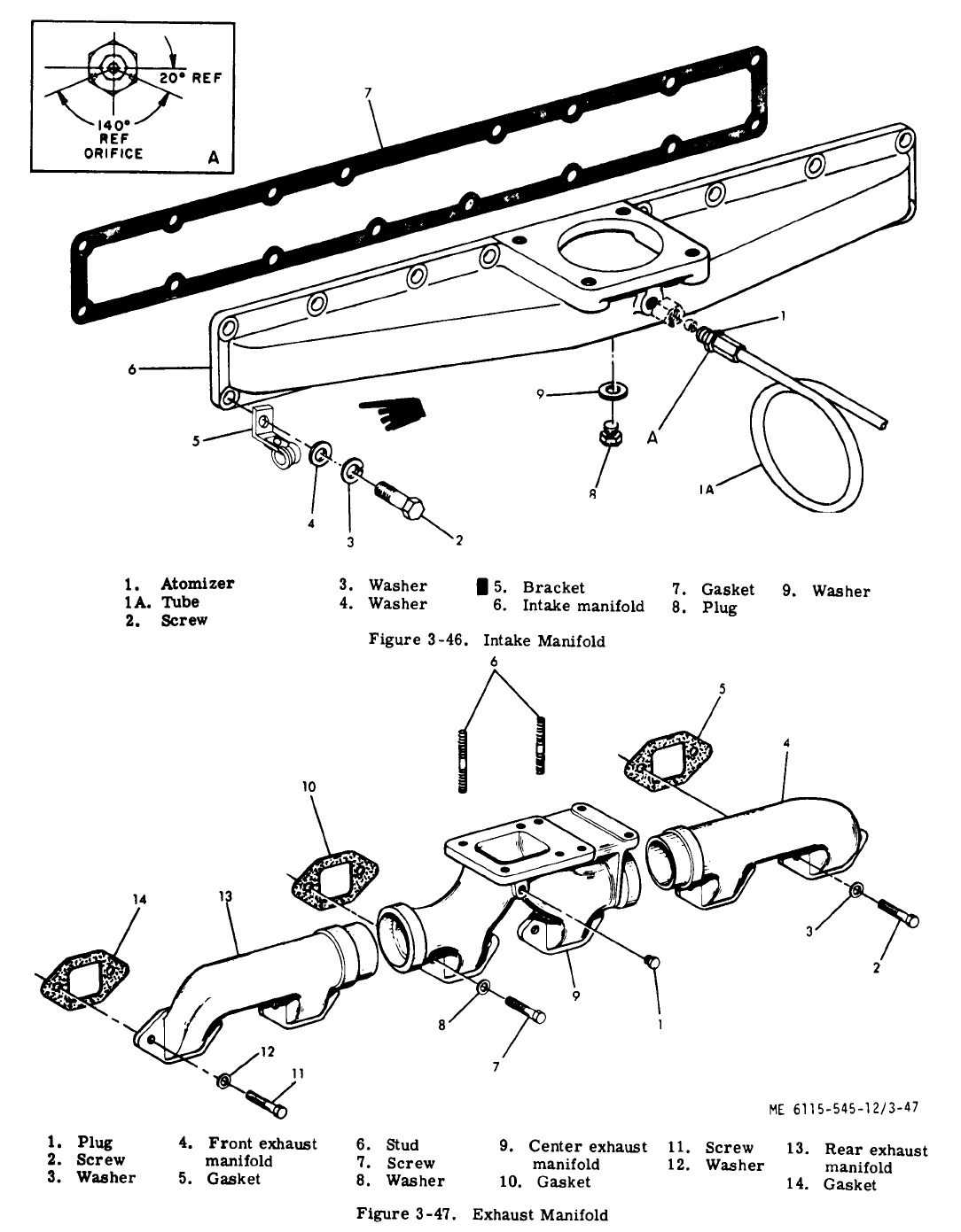
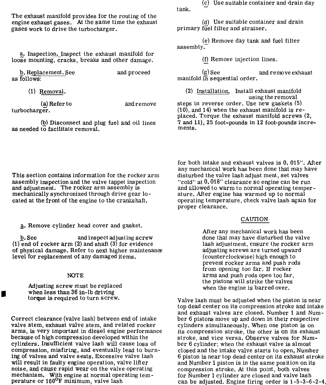
Section XLII. EXHAUST
3-216. General.
The
exhaust
manifold
provides
for
the
routing
of
the
engine
exhaust
gases.
At
the
same
time
the
exhaust
gases
work
to
drive
the
turbocharger.
3-217. Inspection and Replacement.
a.
Inspection.
Inspect
the
exhaust
manifold
for
loo=e
mounting,
cracks,
breaks
and
other
damage.
b.
Replacement.
See
figure 3-47
and
proceed
as
Follows:
(1)
Removal.
(~)
Refer
to
paragraph 3-203
and
remove
turbocharger.
&)
Disconnect
and
plug
fuel
and
oil
lines
as
needed
to
facilitate
removal.
MANIFOLD
(g)
tank.
(d)
Use
suitable
container
and
drain
day
Use
suitable
container
and
drain
primary
fiiel
filter
and
strainer.
(e)
Remove
day
tank
and
fuel
filter
assembly.–
(f)
Remove
injection
lines.
—
(g)
See
figure 3-47
and
remove
exhaust
manifold
in
sequential
order.
(2)
Installation. Install
exhaust
manifold
(4, 9, and 13, fig. 3-47)
using
the
removal
steps
in
reverse
order.
Use
new
gaskets
(5)
(10),
and
14)
when
the
exhaust
manifold
is
re-
placed.
Torque
the
exhaust
manifold
screws
(2,
7
and
11),
25
foot-pounds
in
12
foot-pounds
incre-
ments.
Section XLIII. ROCKER ARM SHAFT ASSEMBLY
3-218. General.
This
section
contains
information
for
the
rocker
arm
assembly
inspection
and
the
valve
tappet
inspection
and
adjustment.
The
rocker
arm
assembly
is
mechanically
synchronized
through
drive
gear
lo-
cated
at
the
front
of
the
engine
to
the
crankshaft.
3-219. Rocker Arm Shaft Assembly Inspection.
&
Remove
cylinder
head
cover
and
gasket.
~.
See
figure 3-48
and
inspect
adjusting
screw
(1)
end
of
rocker
arm
(2)
and
shaft
(3)
for
evidence
of
physical
damage.
Refer
to
next
higher
maintenance
level
for
replacement
of
any
damaged
items.
NOTE
Adjusting
screw
must
be
replaced
when
less
than
36
in-lb
driving
torque
is
required
to
turn
screw.
3-220. Valve Tappet Clearance Adjustment.
Correct
clearance
(valve
lash)
between
end
of
intake
valve
stem,
exhaust
valve
stem,
and
related
rocker
arms,
is
very
important
in
diesel
engine
performance
because
of
high
compression
developed
within
the
cylinders.
Insufficient
valve
lash
will
cause
10SS
of
compression,
misfiring,
and
eventually
lead
to
burn-
ing
of
valves
and
valve
seats.
Excessive
valve
lash
will
result
in
faulty
engine
operation,
valve
lifter
noise,
and
cause
rapid
wear
on
the
valve
operating
mechanism.
With
engine
at
normal
operating
tem-
perature
or
160°F
minimum,
valve
lash
for
both
intake
and
exhaust
valves
is
O.
015”.
After
any
mechanical
work
has
been
done
that
may
have
disturbed
the
valve
lash
adjust
ment,
set
valves
“cold”
at
0.018”
clearance
so
engine
can
be
run
and
allowed
to
warm
to
normal
operating
temper-
ature.
After
engine
has
warmed
up
to
normal
operating
temperature,
check
valve
lash
again
for
proper
clearance.
CAUTION
After
any
mechanical
work
has
been
done
that
may
have
disturbed
the
valve
lash
adjustment,
ensure
the
rocker
arm
adjusting
screws
are
turned
upward
(counterclockwise)
high
enough
to
prevent
rocker
arms
and
push
rcxds
from
opening
too
far.
If
rocker
arms
and
push
rods
open
too
far,
the
pistons
will
strike
the
valves
when
the
engine
is
barred
over.
Valve
lash
must
be
adjusted
when
the
piston
is
near
top
dead
center
on
its
compression
stroke
and
intake
and
exhaust
valves
are
closed.
Number
1
and
Num-
ber
6
pistons
move
up
and
down
in
their
respective
cylinders
simultaneously.
When
one
piston
is
on
its
compression
stroke,
the
other
is
on
its
exhaust
stroke,
and
vice
versa.
Observe
valves
for
Num-
ber
6
cylinder;
when
the
exhaust
valve
is
almost
closed
and
the
intake
valve
starts
to
open,
Number
6
piston
is
near
top
dead
center
on
its
exhaust
stroke
and
Number
1
piston
is
in
the
same
position
on
its
compression
stroke.
At
this
point,
both
valves
for
Number
1
cylinder
are
closed
and
valve
lash
can
be
adjusted.
Engine
firing
order
is
1-5-3-6-2-4,
3-110 Change 1
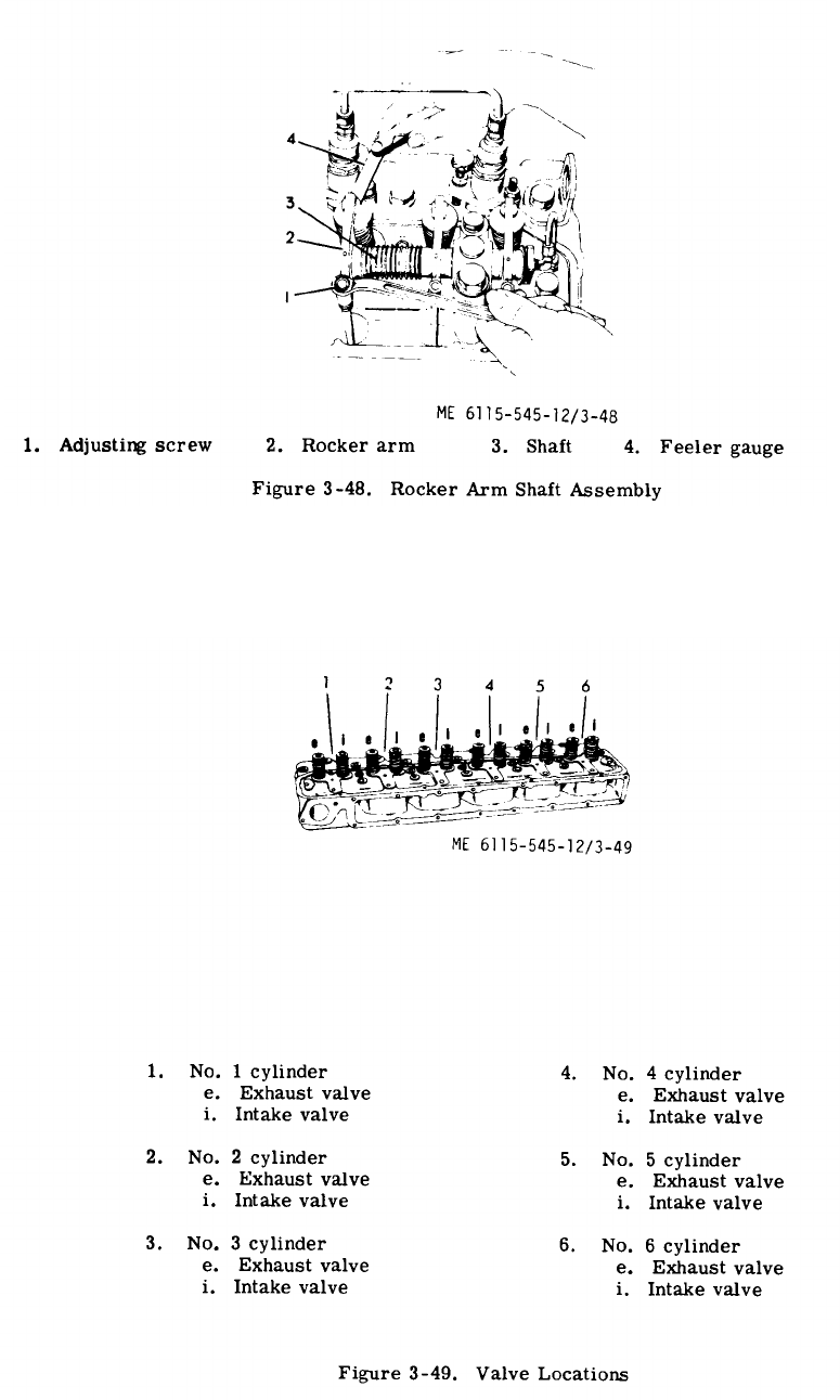
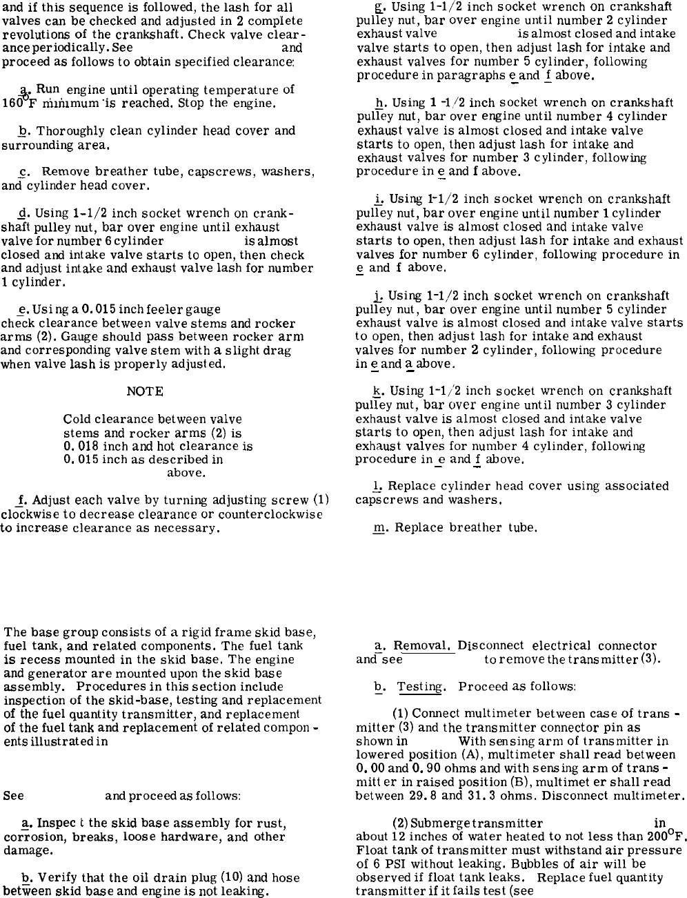
and
if
this
sequence
is
followed,
the
lash
for
all
valves
can
be
checked
and
adjusted
in
2
complete
revolutions
of
the
crankshaft.
Check
valve
clear-
ance
periodically.
See
figures 3-48 and 3-49
and
proceed
as
follows
to
obtain
specified
clearance
#
Run.
engine
until
operating
temperature
of
160
F
mmlmum
is
reached.
Stop
the
engine.
-Q.
Thoroughly
clean
cylinder
head
cover
and
surrounding
area.
c
Remove
breather
tube,
capscrews,
washers,
and–;ylinder
head
cover.
Q.
Using
1-1/2
inch
socket
wrench
on
crank-
shaft
pulley
nut,
bar
over
engine
until
exhaust
valve
for
number
6
cylinder
(fig. 3-49)
is
almost
closed
and
intake
valve
starts
to
open,
then
check
and
adjust
intake
and
exhaust
valve
lash
for
number
1
cylinder.
e.
Using
a
O.
015
inch
feeler
gauge
(4, fig. 3-48)
ch;ck
clearance
between
valve
stems
and
rocker
arms
(2).
Gauge
should
pass
between
rocker
arm
and
corresponding
valve
stem
with
a
slight
drag
when
valve
lash
is
properly
adjusted.
NOT
E
Cold
clearance
between
valve
stems
and
rocker
arms
(2)
is
O.
018
inch
and
hot
clearance
is
O.
015
inch
as
described
in
paragraph 3-220
above.
J.
Adjust
each
valve
by
turning
adjusting
screw
(1)
clockwise
to
decrease
clearance
or
counterclockwise
to
increase
clearance
as
necessary.
E.
Using
1-1/2
inch
socket
wrench
on
crankshaft
pulley
nut,
bar
over
engine
until
number
2
cylinder
exhaust
valve
(fig. 3-49)
is
almost
closed
and
intake
valve
starts
to
open,
then
adjust
lash
for
intake
and
exhaust
valves
for
number
5
cylinder,
following
procedure
in
paragraphs
e
and
~
above.
—
~.
Using
1
-1,/2
inch
socket
wrench
on
crankshaft
pulley
nut,
bar
over
engine
until
number
4
cylinder
exhaust
valve
is
almost
closed
and
intake
valve
starts
to
open,
then
adjust
lash
for
intake
and
exhaust
valves
for
number
3
cylinder,
following
procedure
in
e
and
f
above.
.
~.
Using
1-1/2
inch
socket
wrench
on
crankshaft
pulley
nut,
bar
over
engine
until
number
1
cylinder
exhaust
valve
is
almost
closed
and
intake
valve
starts
to
open,
then
adjust
lash
for
intake
and
exhaust
valves
for
number
6
cylinder,
following
procedure
in
e
and
f
above.
—
&
Using
1-1/2
inch
socket
wrench
on
crankshaft
pulley
nut,
bar
over
engine
until
number
5
cylinder
exhaust
valve
is
almost
closed
and
intake
valve
starts
to
open,
then
adjust
lash
for
intake
and
exhaust
valves
for
number
2
cylinder,
following
procedure
in
e
and
a
above.
— —
~.
Using
1-1/2
inch
socket
wrench
on
crankshaft
pulley
nut,
bar
over
engine
until
number
3
cylinder
exhaust
valve
is
almost
closed
and
intake
valve
starts
to
open,
then
adjust
lash
for
intake
and
exhaust
valves
for
number
4
cylinder,
following
procedure
in
e
and
f
above.
——
l_.
Replace
cylinder
head
cover
using
associated
capscrews
and
washers.
N.
Replace
breather
tube.
Section XLIV. BASE GROUP AND RELATED COMPONENTS
3-221. General.
The
base
group
consists
of
a
rigid
frame
skid
base,
fuel
tank,
and
related
components.
The
fuel
tank
is
recess
mounted
in
the
skid
base.
The
engine
and
generator
are
mounted
upon
the
skid
base
assembly.
Procedures
in
this
section
include
inspection
of
the
skid-base,
testing
and
replacement
of
the
fuel
quantity
transmitter,
and
replacement
of
the
fuel
tank
and
replacement
of
related
compon
-
ents
illustrated
in
figures 3-50 and 3-51.
3-222. Skid Base Inspection.
See
figure 3-50
and
proceed
as
follows:
a.
Inspec
&
the
skid
base
assembly
for
rust,
cor~osion,
breaks,
loose
hardware,
and
other
damage.
~.
Verify
that
the
oil
drain
plug
(10)
and
hose
between
skid
base
and
engine
is
not
leaking.
3-223. Fuel Quantity Transmitter Removal, Test-
ing and Replacement.
a.
Removal.
Disconnect
electrical
connector
and–see
figure 3-50
to
remove
the
transmitter
(3).
~.
Testing. Proceed
as
follows:
(1)
Connect
multimeter
between
case
of
trans
-
mitter
(3)
and
the
transmitter
connector
pin
as
shown
in
3-52.
With
sensing
arm
of
transmitter
in
lowered
position
(A),
multimeter
shall
read
between
O.
00
and
O.
90
ohms
and
with
sensing
arm
of
trans
-
mitt
er
in
raised
position
(B),
multimet
er
shall
read
between
29.8
and
31.3
ohms.
Disconnect
multimeter.
(2)
Submerge
transmitter
(3, figure 3-50)
in
about
12
inches
of
water
heated
to
not
less
than
200°F.
Float
tank
of
transmitter
must
withstand
air
pressure
of
6
PSI
without
leaking.
Bubbles
of
air
will
be
observed
if
float
tank
leaks.
Replace
fuel
quantity
transmitter
if
it
fails
test
(see
fig. 3-52).
3-112
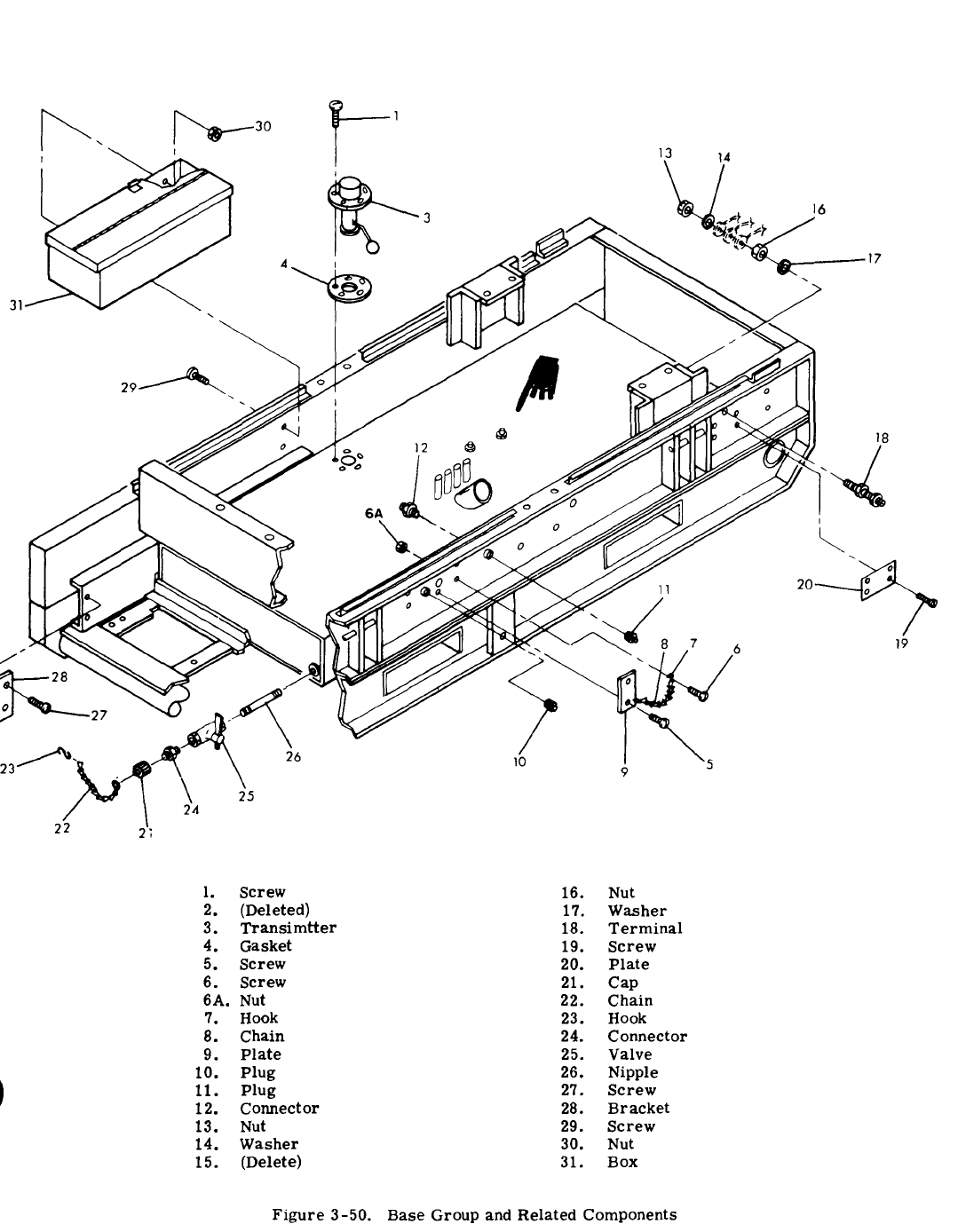
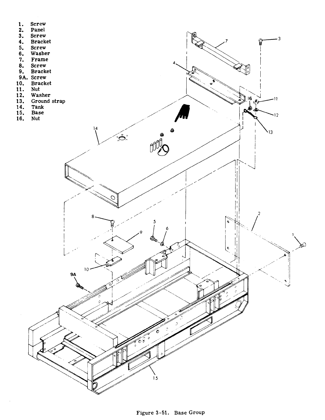

ReDla
mm.
See
figure 3-50
and
replace
transmitter
(3)Qk
reverse’&ptence
of
removal.
3-224. Related Components Replacement.
~.
See
figure 3-50
to
remove
and
replace
related
components
as
required.
~.
Replace
lost
or
broken
terminal
clip
(Retainer,
Safety
Clip).
For
fabrication
procedure,
see
Chapter 3, Section XVIII,
Organizational Maintenance of the Generator Electrical System,
paragraph 3-142.
1
Load
Terminaf
Board
Assembly.
3-225. Metal Fuel Tank Removal, Cleaning and Inspection,
and Installation.
~.
~emoval.
See
figures 3-7, 3-50, and 3-51
and
pro–
teed
as
follows:
(1)
Remove
cap
(21, fig. 3-50)
and
connect
auxiliary
fuel
hose
to
cormector
(24)
at
end
of
valve
(25).
(2)
Operr
valve
(25)
and
allow
water
and
sediment
to
completely
drain
off
into
a
suitable
container.
Close
valve
(25)
when
clean
diesel
fuel
runs
out.
Drain
clean
fuel
into
suitable
container.
Discorutect
auxiliary
fuel
hose.
(3)
Refer
to
paragraph 3-223
and
remove
fuel
quantity
transmitter
(3, fig. 3-50).
(4)
Disconnect
four
vent
hoses
and
two
fuel
lines
from
tank
(14, fig. 3-51),
tagging
each
hose
and
line.
(5)
Disconnect
main
metal
fuel
tank
filler
hose
from
tank
(14).
(6)
See
figure 3-51,
and
remove
metal
tank
(14)
from
base
(15)
using
sequential
order
of
indexes.
b.
~lefin~
~d
~soect
iou.
(1)
Flush
inside
of
metal
fuel
tank
with
steam
under
pressure.
Rinse
with
hot
water
and
detergent
to
insure
that
rust
flakes
and
other
foreign
material
are
removed.
(2)
Insptxt
metal
fuel
tank
for
cracks
and
distortion.
(3)
Inspect
tapped
holes
for
darnaged
threads.
s.
bsd
latio~.
(1)
See
figure 3-51,
and
install
metal
tank
(14)
into
base
(15)
in
reverse
order
of
removal
procedure.
(2)
Connect
main
fuel
tank
filler
hose
to
plastic
tank
(14).
(3)
Connect
four
vent
hoses
and
two
fuel
lines
to
tank
(14)
as
tagged.
TM 5-6115-545-12
TO 35C2-3-444-1
NAVFAC P-8-626-12
TM 00038G-12
(4)
Refer
to
paragraph 3-223
and
instafl
transmitter
(3, fig. 3-50).
(5)
Close
valve
(25),
replace
cap
(21
)
on
connector
(24),
and
add
diesel
fuel
as
required.
3-225A. Plastic Fuel Tank Removal, Cleaning and Inspection,
and Installation.
a.
&tDQ@
See
figures 3-7 and 3-51A
~d
proceed
~
follows:
(1)
Remove
cap
(17, fig. 3-51A)
from
connector
(18)
and
comect
auxiliary
fuel
hose
to
valve
(19).
(2)
Open
vafve
(19)
and
allow
water
and
sediment
to
completely
drain
off
into
a
suitable
container.
Close
valve
(19)
when
clean
diesel
fuel
runs
out.
Drain
clean
fuel
into
suitable
container.
Disconnect
auxiliary
fuel
hose.
(3)
Refer
to
paragraph 3-323
and
remove
fuel
quantity
transmitter
(3, fig. 3-50).
(4)
Disconnect
vent
hoses
(13A, fig. 3-51A),
fuel
lines
and
ground
terminal
from
tank
(14),
tagging
each
hose
and
line.
(5)
fuel
tank
(
(6)
from
base
Discomect
main
fuel
tank
filler
hose
from
plastic
4).
See
figure 3-51A
and
remove
p]aslic
tank
(14)
15)
using
sequential
order
of
indexes.
~.
Cleaning
and
Inspection.
(1)
Rinse
inside
of
plastic
fuel
tank
(14)
with
hot
water
and
detergent
to
insure
foreign
material
is
removed.
(2)
Inspect
plastic
fuel
tank
(14)
for
cracks
and
distortion.
(3)
Inspect
tapped
holes
for
damaged
threads.
G.
Ins
tall
at
ion.
(1)
See
figure 3-51A
and
install
plastic
tank
(14)
into
base
(15)
in
reverse
order
of
removal
procedure.
(2)
Connect
main
fuel
tank
filler
hose
to
plastic
tank
(14).
(3)
Connect
vent
hoses
(13A),
fuel
Iincs
and
ground
terminal
to
tank
(14)
as
tagged.
(4)
Refer
to
paragraph 3-223
and
install
transmiucr
(3, fig. 3-50).
(5)
Close
valve
(19, fig. 3-51A),
rcplacc
cap
(17)
on
connector
(18),
and
add
diesel
fuel
as
required.
Change 18 3-115
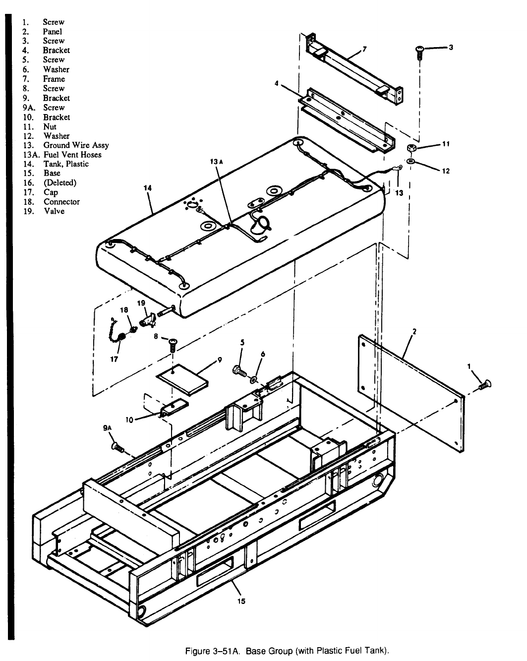
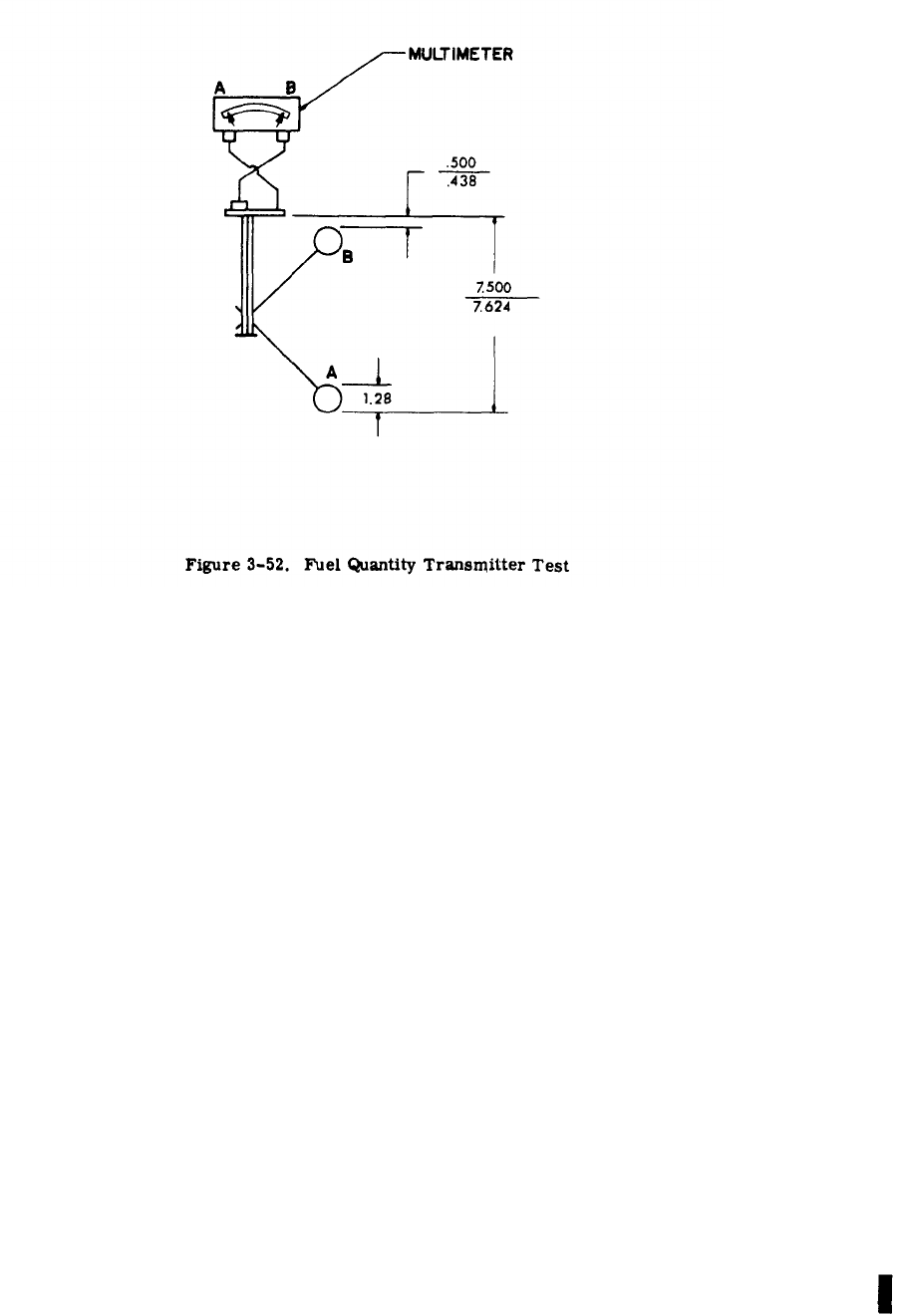
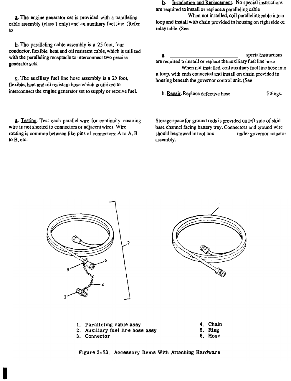
Figure 3-53.
TM 5-6115-545-12
TO 35C2-3-444-1
NAVFAC P-8-626-12
TM 00038G-12
Section XLV. ACCESSORY ITEMS
3-226. General.
~.
The
engine
generator
set
is
provided
with
a
paralleling
cable
assembly
(class
1
only)
and
an
auxiliary
fuel
line.
(Refer
to
fig. 3-53.)
~.
The
paralleling
cable
assembly
is
a
25
foot,
four
conductor,
flexible,
heat
and
oil
resistant
cable,
which
is
utilized
with
the
paralleling
receptacle
to
interconnect
two
precise
generator
sets.
Q.
The
auxiliary
fuel
line
hose
assembly
is
a
25
foo~
flexible,
heat
and
oil
resistant
hose
which
is
utilized
to
intercmmect
the
engine
generator
set
to
supply
or
receive
fuel.
3-227. Paralleling Cable Assembly
Q.
-.
Test
each
parallel
wire
for
continuity,
ensuring
wire
is
not
shorted
to
connectors
or
adjacent
wires.
Wire
routing
is
common
between
like
pins
of
connectors:
A
to
A,
B
to
B,
etc.
b.
~.
No
special
instructions
are
required
to
install
or
replace
a
paralleling
cable
(1, fig. 3-53).
When
not
installed,
coil
paralleling
cable
into
a
loop
and
install
with
chain
provided
in
housing
on
right
side
of
relay
table.
(See
fig. 1-1.).
3-228. Auxiliary Fuel Line Hose Assembly.
a.
Installation and Replacement. No
special
instructions
we
required
to
install
or
replace
the
auxiliary
fuel
line
hose
(2,
fig. 3-53).
When
not
installed
coil
auxiliary
fuel
line
hcse
into
a
loop,
with
ends
connected
and
install
on
chain
provided
in
housing
beneath
the
governor
control
unit.
(See
figure l-l.)
b.
&p&.
Replace
defective
hose
(6, fig. 3-53)
fittings.
3-229. Storage Space.
Storage
space
for
ground
rods
is
provided
on
left
side
of
skid
base
charmel
facing
battery
tray.
Connectors
and
ground
wire
should
be
stowed
in
tool
box
(fig. 1-1)
under
governor
actuator
assembly.
3-118
Change 18
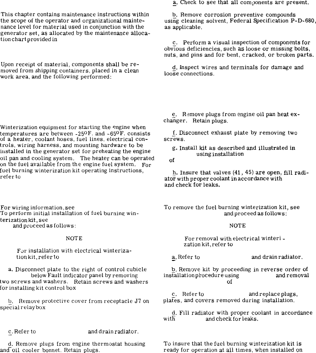
CHAPTER 4
AUXILIARY MATERIAL USED IN CONJUNCTION WITH THE EQUIPMENT
4-1. Scope.
Section I. GENERAL
This
chapter
contains
maintenance
instructions
within
the
scope
of
the
operator
and
organizational
mainte-
nance
level
for
material
used
in
conjunction
with
the
generator
set,
as
allocated
by
the
maintenance
alloca-
tion
chart
provided
in
Appendix C.
4-2. Service upon Receipt of Material.
Upon
receipt
of
material,
components
shall
be
re-
moved
from
shipping
containers,
placed
in
a
clean
work
area,
and
the
following
performed:
a.
Check
to
see
that
all
components
are
present.
—
b.
Remove
corrosion
preventive
compounds
usi;g
cleaning
solvent,
Federal
Specification
P-D-680,
as
applicable.
c.
Perform
a
visual
inspection
of
components
for
obvious
deficiencies,
such
as
loose
or
missing
bolts,
nuts,
and
pins
and
for
bent,
cracked,
or
broken
parts.
d.
Inspect
wires
and
terminals
for
damage
and
loo;e
connections.
Section II.FUEL BURNING WINTERIZATION KIT
4-3. General.
Winterization
equipment
for
starting
the
engine
when
temperatures
are
between
-25°F.
and
-65°F.
consists
of
a
heater,
coolant
hoses,
fuel
lines,
electrical
con-
trols,
wiring
harness,
and
mounting
hardware
to
be
installed
in
the
generator
set
for
preheating
the
engine
oil
pan
and
cooling
system.
The
heater
can
be
operated
on
the
fuel
available
from
the
engine
fuel
system.
For
fuel
burning
winterization
kit
operating
instructions,
refer
to
paragraph 2-24.
4-4. Installation.
For
wiring
information,
see
figures 1-15 or 1-16.
To
perform
initial
installation
of
fuel
burning
win-
terization
kit,
see
figure 1-22, 1-26 or 1-27 and
4-1
and
proceed
as
follows:
NOTE
F~r
installation
with
electrical
winteriza-
tion
kit,
refer
to
paragraph 4-18.
a.
Disconnect
plate
to
the
right
of
control
cubicle
(fig. 1-2)
below
Fault
indicator
panel
by
removing
two
screws
and
washers.
Retain
screws
and
washers
for
installing
kit
control
box
(14, fig. 4-l).
b.
Remove
protective
cover
from
receptacle
J7
on
spe~ial
relay
box
(fig. 1-2).
~.
Refer
to
paragraph 3-41
and
drain
radiator.
~.
Remove
plugs
from
engine
thermostat
housing
and
oil
cooler
bonnet.
Retain
plugs.
e.
Remove
plugs
from
engine
oil
pan
heat
ex-
cha~ger. Retain
plugs.
f.
Disconnect
exhaust
plate
by
removing
two
scr=ws.
g.
Install
kit
as
described
and
illustrated
in
figure 1-22
using
installation
sequence 74 through
1
of
figure 4-1.
h.
Insure
that
valves
(41,
45)
are
open,
fill
radi-
ato~
with
proper
coolant
in
accordance
with
table 2-1
and
check
for
leaks.
4-5. Removal.
To
remove
the
fuel
burning
winterization
kit,
see
figures 1-22 and 4-1
and
proceed
as
follows:
NOTE
For
removal
with
electrical
winteri
-
zation
kit,
refer
to
paragraph 4-19.
a.
Refer
to
paragraph 3-41
and
drain
radiator.
—
b.
Remove
kit
by
proceeding
in
reverse
order
of
ins~allation
pkocedure
using
figure 1-22
and
removal
sequence 1 through 74
of
figure 4-1.
c.
Refer
to
paragraph 4-4
and
replace
plugs,
pla~es,
and
covers
removed
during
installation.
d.
Fill
radiator
with
proper
coolant
in
accordance
witfi
table 2-1
and
check
for
leaks.
4-6. Preventive Maintenance.
To
insure
that
the
fuel
burning
winterization
kit
is
ready
for
operation
at
all
times,
when
installed
on
4-1
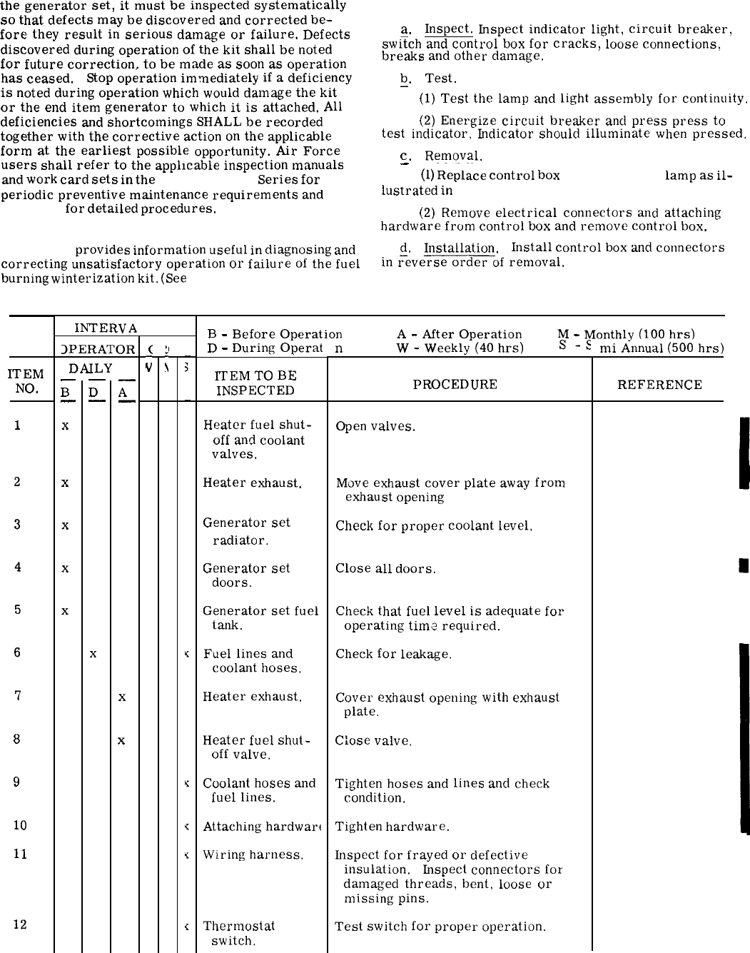
the
generator
set,
it
must
be
inspected
systematically
4-8. Control Box Inspection, Testing, and Replacement.
so
that
defects
may
be
discovered
and
corrected
be-
fore
they
result
in
serious
damage
or
failure.
Defects
a.
Inspect.
Inspect
indicator
light,
circuit
breaker,
discovered
during
operation
of
the
kit
shall
be
noted
swi~ch
and
control
box
for
cracks,
loose
connections,
for
future
correction,
to
be
made
as
soon
as
operation
breaks
and
other
damage.
has
ceased.
Stop
operation
immediately
if
a
deficiency
is
noted
during
operation
which
would
damage
the
kit
or
the
end
item
generator
to
which
it
is
attached.
All
deficiencies
and
shortcomings
SHALL
be
recorded
together
with
the
corrective
action
on
the
applicable
form
at
the
earliest
possible
opportunity.
Air
Force
users
shall
refer
to
the
applicable
inspection
manuals
and
work
card
sets
in
the
T. O. 35C2-3-
Series
for
periodic
preventive
maintenance
requirements
and
table 4-1
for
detailed
procedures.
4-7. Troubleshooting.
Table 4-2
provides
information
useful
in
diagnosing
and
correcting
unsatisfactory
operation
or
failure
of
the
fuel
burning
winterization
kit.
(See
figure 1-22, 1-15 or 1-16.)
ITEM
NO.
1
2
3
4
5
6
7
8
9
10
11
12
INTERVA
3PERATOR
DAILY
—
B
—
x
x
x
x
x
—
D
—
x
—
A
—
x
x
(
i
b.
Test.
—
(1)
Test
the
lamp
and
light
assembly
for
continuity.
(2)
Energize
circuit
breaker
and
press
press
to
test
indicator.
Indicator
should
illuminate
when
pressed.
c.
Removal.
—
(1)
R-eplace
control
box
(14, fig. 4-1)
lamp
as
il-
lustrated
in
figure 4-2.
(2)
Remove
electrical
connectors
and
attaching
hardware
from
control
box
and
remove
control
box.
d.
Installation. Install
control
box
and
connectors
in
~eve=d=of
removal.
Table 4-1.Preventive Maintenance Checks and Services
:(
i
B
-
Before
Operation
A
-
After
Operation
M
-
Monthly
(100
hrs)
D
-
During
Operat
ITEM
TO
BE
INSPECTED
Heater
fuel
shut-
off
and
coolant
valves.
Heater
exhaust.
Generator
set
radiator.
Generator
set
doors.
Generator
set
fuel
tank.
Fuel
lines
and
coolant
hoses.
Heater
exhaust.
Heater
fuel
shut-
off
valve.
Coolant
hoses
and
fuel
lines.
Attaching
hardwart
Wiring
harness.
Thermostat
switch.
n
W
-
Weekly
(40
hrs)
S.-s
PROCEDURE
Open
valves.
Move
exhaust
cover
plate
away
from
exhaust
opening
Check
for
proper
coolant
level,
Close
all
doors.
Check
that
fuel
level
is
adequate
for
operating
time
required.
Check
for
leakage.
Cover
exhaust
opening
with
exhaust
plate.
C:ose
valve.
Tighten
hoses
and
lines
and
check
condition.
Tighten
hardware.
Inspect
for
frayed
or
defective
insulation. Inspect
connectors
for
damaged
threads,
bent,
loose
or
missing
pins.
Test
switch
for
proper
operation.
mi
Annual
(500
hrs)
REFERENCE
(fig. 2-11)
(para 4-9)
(para 2-3 and 3-41
(fig. 1-1 and 1-2)
(para 2-3)
(para 4-16)
(para 4-9)
(fig. 2-11)
(para 4-16)
(para 4-16)
(para 3-139)
(para 4-15)
4-2Change 1
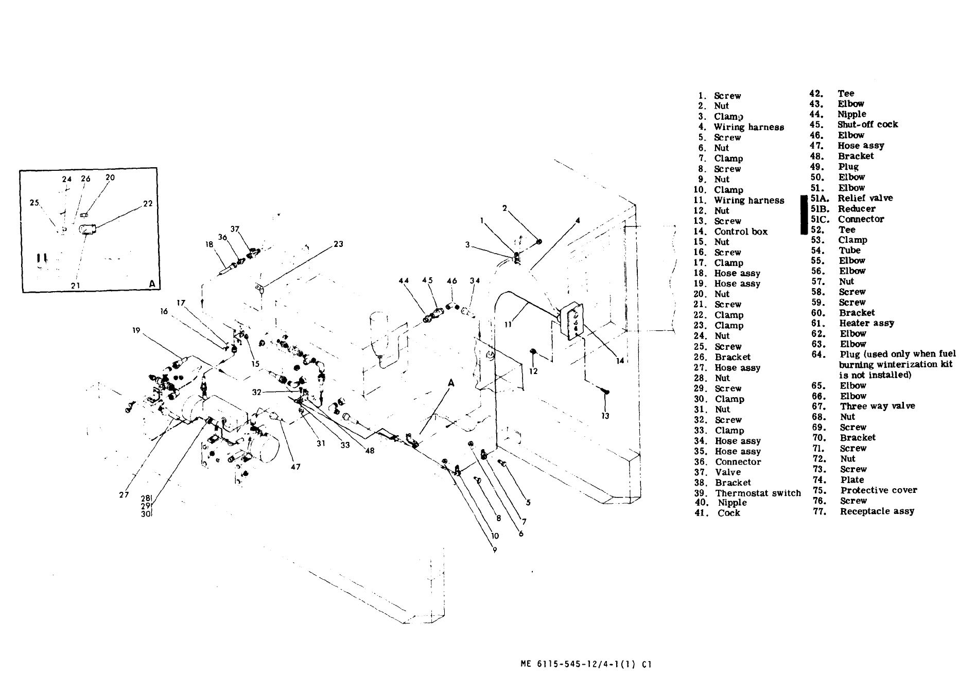
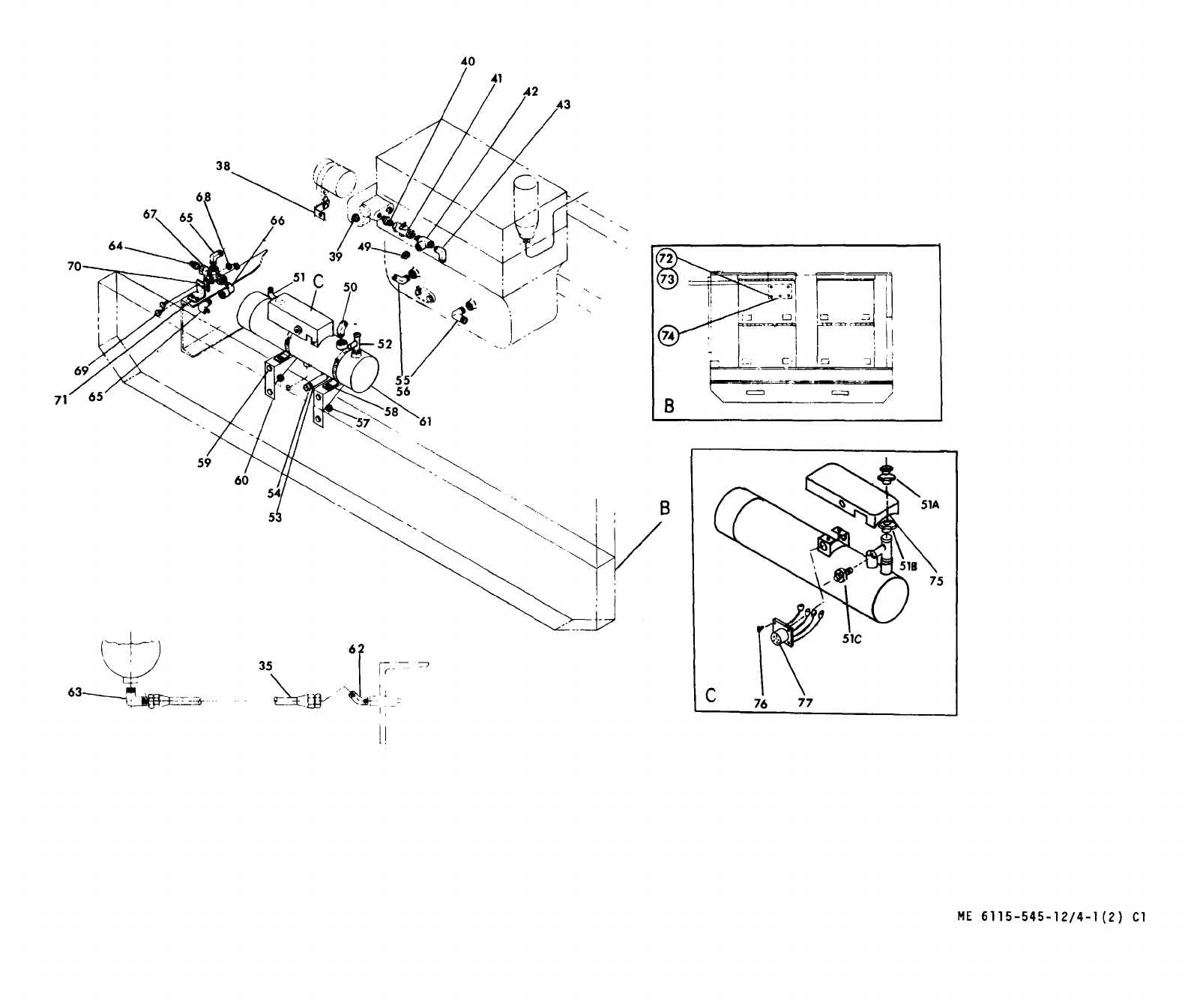
Figure 4-1. Fuel Burning Winterization Kit
(Sheet 2 of 2)
4-5/(4 -6 blank)
Change 1

Table 4-2.Fuel Burning Winterization Kit Troubleshooting
MALFUNCTION
I
PR013AI+I,
E
CAUSE
1.
Press
to
test
light
a.
does
not
illuminate
‘-
when
pressed.
b.
—
t
c.
,..-
2.
Switch
positioned
to
a.
ON
and
nothing
happens.
1-
]
h.
3.
Heater
pump
operates
but
will
not
ignite.
4.
Heater
does
not
ignite
(fuel
present).
Heater overheat switch
tripped
Defective heater.
4-13.)
5.
Heater
will
not
shutoff
when
switch
is
positioned
to
OFF
(after
purge
cycle!.
Circuit
breaker
open.
Defective
lamp.
Defective
control
box.
Circuit
breaker
open.
Deacl
generator
set
batter]
es.
c.
.
.
d.
—
a,
b.
—
c.
.-
C1.
-.
a.
-.
b
.
.
“
c.
Lf
-“
e,
.
a.
.
.
Defective
controi
bt)x.
Open
thermostat
switrh.
Heater
t’uel
shut-off
valve
not
opel],
Generator
set
i!]cl
supply
mhau
st
ed.
Restri(tiutl
in
t’ucl
supply.
Df:fcwtive
generator
set
fuel
transfer
pure,].
D?iective
ttl(’I’ll”l
OSi&t
switch.
Low
ot
e]
~aLI[:
voltage
tu
hf’ater,
1)(.ltct:l
[’
(!olltrul
Iwx,
CORRECTNE
ACTION
a.
—
b.
—
c,
—
a.
.-
b.
c.
.
c1
a.
—
b.
—
(’
—
d.
—
a.
t).
c
.
—
d.
.
.
(!,
-.
a.
Reset
circuit
breaker.
(Refer
to
paragraph
4-8.)
Replace
lamp.
(Reier
to
paragraph 4-8.)
Replace
if
defective.
(Refer
to
paragraph
4-8.)
Reset
circuit
breaker.
(Refer
to
paragraph
4-8.)
Charge
or
replace
batl
cries,
(Refer
to
paragraphs 2-3 and 3-82.)
Replace
if
defective.
(Refer
to
paragraph
4-8.)
Test
and
replace
if
defective.
(Refer
to
paragraph 4-15.)
Ol)en
[alve.
(Rei’cr
to
paragraph 2-24.)
Adcl
f[!cl
as
rwuireci.
(
Refer
to
paragraph 2-3.)
Remwe
restriction.
Replace
if
defective.
(Refer
to
paragraph
3-165.)
Pern]it
heutcr
to
cool
and
restart.
I?eplace
heater,
(Next
higher
lwel
of
maintenan~
c.
)
‘rest
and
I’ephce
if
deiwtive,
(Refe~
to
paragraph 4-15.)
C[)l,rC4~[
i’dLISC
L)]
lltI[)rOf)er
VOltEige.
Replace if defective. (Refer
to
paragraph
Replace if defective. (Refer to paragraph
4-8.)
4-7
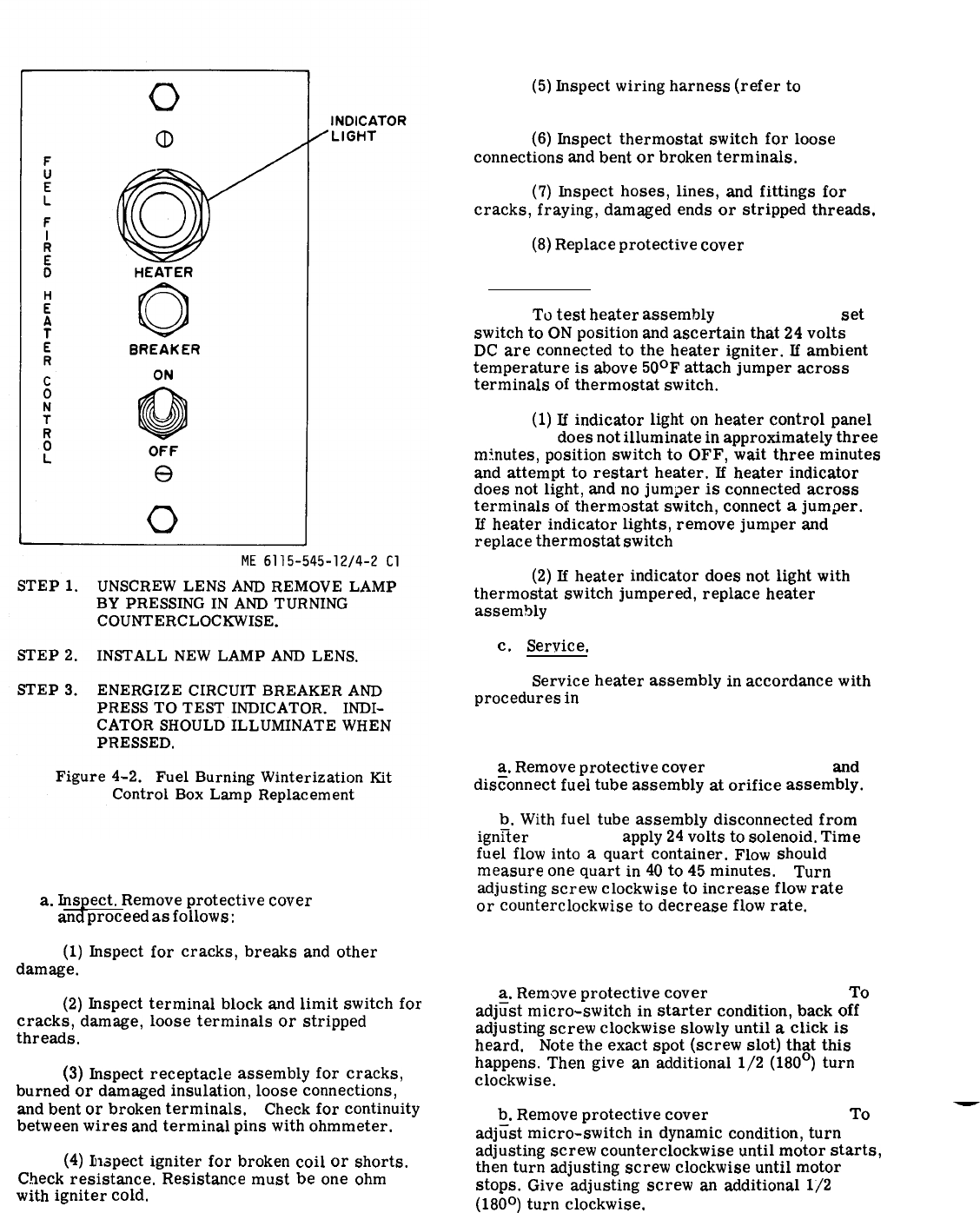
Figure 4-2.
b. Test.
4-9.Heater Assembly Inspect, Test, Service, and
Adjust.
a.
Inspect.
Remove
protective
cover
(75, fig.
4-1)
and
proceed
as
follows:
(1)
Inspect
for
cracks,
breaks
and
other
damage.
(2)
Inspect
terminal
block
and
limit
switch
for
cracks,
damage,
loose
terminals
or
stripped
threads.
(3)
Inspect
receptacle
assembly
for
cracks,
burned
or
damaged
insulation,
loose
connections,
and
bent
or
broken
terminals.
Check
for
continuity
between
wires
and
terminal
pins
with
ohmmeter.
(4)
Inspect
igniter
for
broken
coil
or
shorts.
Check
resistance.
Resistance
must
be
one
ohm
with
igniter
cold.
(5)
Inspect
wiring
harness
(refer
to
para-
graph 3-139).
(6)
Inspect
thermostat
switch
for
loose
connections
and
bent
or
broken
terminals.
(7)
Inspect
hoses,
lines,
and
fittings
for
cracks,
fraying,
damaged
ends
or
stripped
threads.
(8)
Replace
protective
cover
(75, fig. 4-l).
To
test
heater
assembly
(61, fig. 4-l),
set
switch
to
ON
position
and
ascertain
that
24
volts
DC
are
connected
to
the
heater
igniter.
If
ambient
temperature
is
above
50°F
attach
jumper
across
terminals
of
thermostat
switch.
(para 4-5)
(1)
If
indicator
light
on
heater
control
panel
(fig. 4-2)
does
not
illuminate
in
approximately
three
minutes,
position
switch
to
OFF,
wait
three
minutes
and
attempt
to
restart
heater.
If
heater
indicator
does
not
light,
and
no
jumper
is
connected
across
terminals
of
thermostat
switch,
connect
a
jumper.
Jf
heater
indicator
lights,
remove
jumper
and
replace
thermostat
switch
(39, fig. 4-1).
(2)
If
heater
indicator
does
not
light
with
thermostat
switch
jumpered,
replace
heater
assembly
(61, fig. 4-l).
c.
Service.
Service
heater
assembly
in
accordance
with
procedures
in
table 4-1.
4-10. Fuel Regulator Valve Adjustment (fig. 4-3).
a.
Remove
protective
cover
(75, fig. 4-1)
and
disconnect
fuel
tube
assembly
at
orifice
assembly.
b.
With
fuel
tube
assembly
disconnected
from
ign~ter
(fig. 4-3)
apply
24
volts
to
solenoid.
Time
fuel
flow
into
a
quart
container.
Flow
should
measure
one
quart
in
40
to
45
minutes.
Turn
adjusting
screw
clockwise
to
increase
flow
rate
or
counterclockwise
to
decrease
flow
rate.
4-11. Flame Micro-switch Adjustment (fig. 4-4).
a.
Rem.we
protective
cover
(75, fig. 4-l).
To
adj~st
micro-switch
in
starter
condition,
back
off
adjusting
screw
clockwise
slowly
until
a
click
is
heard.
Note
the
exact
spot
(screw
slot)
that
this
happens.
Then
give
an
additional
1/2
(180°)
turn
clockwise.
b.
Remove
protective
cover
(75, fig. 4-l).
To
—
adjtist
micro-switch
in
dynamic
condition,
turn
adjusting
screw
counterclockwise
until
motor
starts,
then
turn
adjusting
screw
clockwise
until
motor
stops.
Give
adjusting
screw
an
additional
1/2
(180°)
turn
clockwise.
4-8Change 1
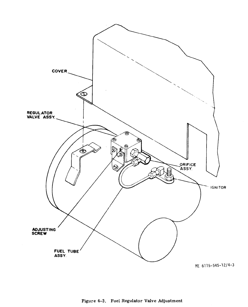
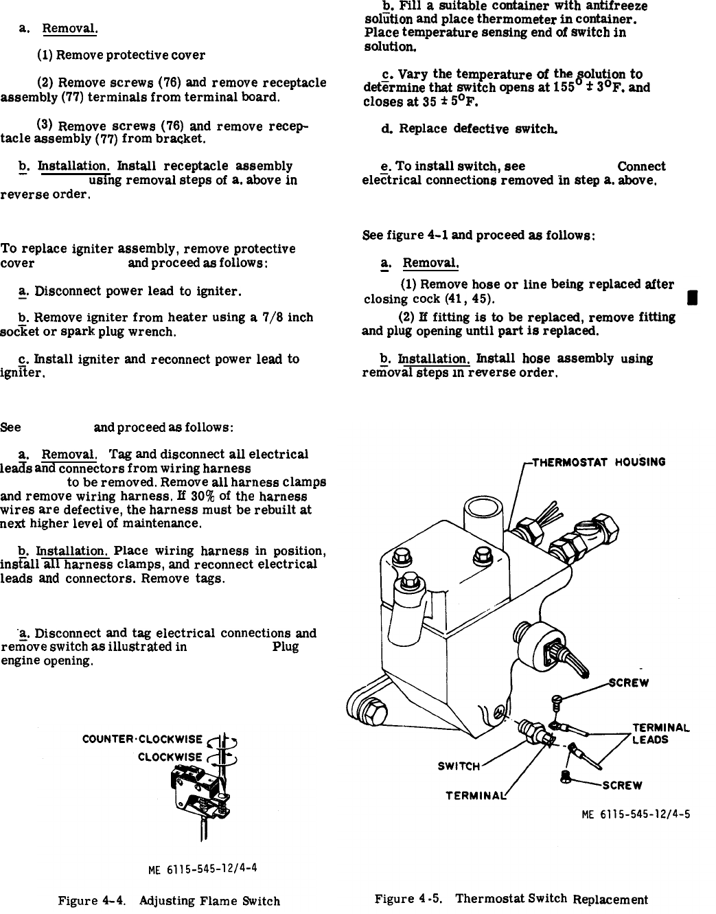
Figure 4-4. Figure 4-5.
4-12. Receptacle Assembly Replacement.
a.
Removal.
(1)
Remove
protective
cover
(75, fig. 4-1).
b.
Fill
a
suitable
container
with
antifreeze
soliition
and
place
thermometer
in
container.
Place
temperature
sensing
end
of
switch
in
Solutiom
(2)
Remove
screws
(76)
and
remove
receptacle
assembly
(77)
terminals
from
terminal
board.
(3)
Remove
screws
(76)
and
remove
recep-
tacle
assembly
(77)
from
br~ket.
Q.
Installation.
Install
receptacle
assembly
(77, fig. 4-1)
using
removal
steps
of
a,
above
in
reverse
order.
4-13. Igniter Assembly Replacement.
To
replace
igniter
assembly,
remove
protective
cover
(75, fig. 4-1)
and
proceed
as
follows:
~.
Disconnect
power
lead
to
igniter.
~.
Remove
igniter
from
heater
using
a
7/8
inch
socket
or
spark
plug
wrench.
c.
Install
igniter
and
reconnect
power
lead
to
ign~ter,
4-14. Wiring Harness Replacement.
See
figure 4-1
and
proceed
as
follows:
a.
Removal,
Tag
and
disconnect
all
electrical
le~s
and
connectors
from
wiring
harness
(4 or 11,
fig. 4-1)
to
be
removed.
Remove
all
harness
clamps
and
remove
wiring
harness,
If
30%
of
the
harness
wires
are
defective,
the
harness
must
be
rebuilt
at
next
higher
level
of
maintenance.
b.
Installation.
Place
wiring
harness
in
position,
ins~all
all
harness
clamps,
and
reconnect
electrical
leads
and
connectors.
Remove
tags.
4-15. Thermostat Switch Testing and Replacement.
“a.
Disconnect
and
tag
electrical
connections
and
refiove
switch
as
illustrated
in
figure 4-5.
Plug
engine
opening.
c.
Vary
the
temperature
of
the
solution
to
det~rmine
that
switch
opens
at
155°
*
3°F.
and
closes
at
35
*
5°F.
d.
Replace
defective
switch.
e.
To
install
switch,
see
figure 4-5.
Connect
ele~trical
connections
removed
in
step
a.
above.
4-16. Hoses, Lines, and Fittings Replacement.
See
figure
4-1
and
proceed
as
follows:
~.
Removal.
(1)
Remove
hose
or
line
being
replaced
after
closing
cock
(41,
45).
(2)
If
fitting
is
to
be
replaced,
remove
fitting
and
plug
opening
until
part
is
replaced.
b.
Installation.
Install
hose
assembly
using
reriioval
steps
m
reverse
order.
4-10 Change 3
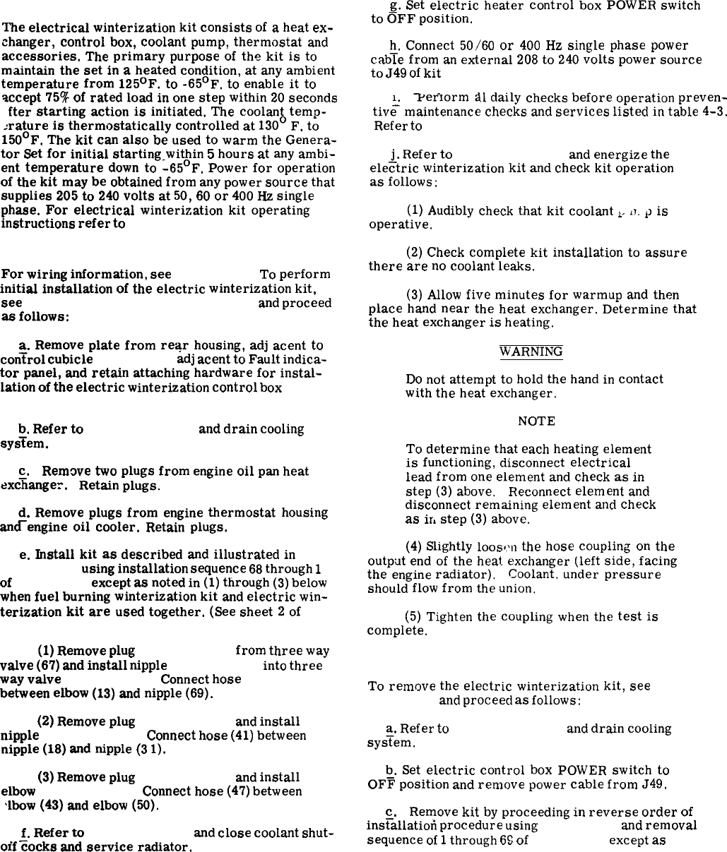
Section III. ELECTRIC WINTERIZATION KIT
4-17. General.
The
electrical
winterization
kit
consists
of
a
heat
ex-
changer,
control
box,
coolant
pump,
thermostat
and
accessories.
The
primary
purpose
of
the
kit
is
to
maintain
the
set
in
a
heated
condition,
at
any
ambient
temperature
from
125°F.
to
-65°F.
to
enable
it
to
accept
75%
of
rated
load
in
one
step
within
20
seconds
fter
starting
action
is
initiated.
The
coolant
temp-
erature
is
thermostatically
controlled
at
130°
F.
to
150°F.
The
kit
can
also
be
used
to
warm
the
Genera-
tor
Set
for
initial
starting
within
5
hours
at
any
ambi-
ent
temperature
down
to
-65°F.
Power
for
operation
of
the
kit
may
be
obtained
from
any
power
source
that
supplies
205
to
240
volts
at
50,
60
or
400
HZ
single
phase.
For
electrical
winterization
kit
operating
instructions
refer
to
fig. 2-11.
4-18. Installation.
For
wiring
information,
see
figure 4-6.
To
perform
initial
installation
of
the
electric
winterization
kit,
see
figures 1-23, 1-26 or 1-27, and 4-7
and
proceed
as
follows:
a.
Remove
plate
from
redr
housing,
adj
scent
to
con~rol
cubicle
(figure 1-2)
adj
scent
to
Fault
indica-
tor
panel,
and
retain
attaching
hardware
for
instal-
lation
of
the
electric
winterization
control
box
(45,
fig. 4-7).
~.
Refer
to
paragraph 3-41
and
drain
cooling
system.
c. Remove
two
plugs
from
engine
oil
pan
heat
exc%anger.
Retain
plugs.
~.
Remove
plugs
from
engine
thermostat
housing
and
engine
oil
cooler.
Retain
plugs.
e.
Install
kit
as
described
and
illustrated
in
figure 1-23
using
installation
sequence
68
through
1
of
figure 4-7
except
as
noted
in
(1)
through
(3)
below
when
fuel
burning
winterization
kit
and
electric
win-
terization
kit
are
used
together.
(See
sheet
2
of
figure 4-7.)
(1)
Remove
plug
(64, fig. 4-1)
from
three
way
valve
(67)
and
install
nipple
(69, fig. 4-7)
into
three
way
valve
(67, fig. 4-1).
Connect
hose
(70, fig. 4-7)
between
elbow
(13)
and
nipple
(69).
(2)
Remove
plug
(49, fig. 4-1)
and
install
nipple
(18, fig. 4-7).
Connect
hose
(41)
between
nipple
(18)
and
nipple
(3
I).
(3)
Remove
plug
(19, fig. 4-7)
and
install
elbow
(43, fig. 4-l).
Connect
hose
(47)
between
lbow
(43)
and
elbow
(50).
~.
Refer
to
paragraph 2-3
and
close
coolant
shut-
off
cocks
and
service
radiator.
g.
Set
electric
heater
control
box
POWER
switch
to
OFF
position.
h.
Connect
50/60
or
400
Hz
single
phase
power
cab~e
from
an
external
208
to
240
volts
power
source
to
J49
of
kit
(figures 1-26 or 1-27).
Perform
all
daily
checks
before
operation
preven-
tiv;
maintenance
checks
and
services
listed
in
table
4-3.
Refer
to
paragraph 4-20.
~.
Refer
to
paragraph 2-24
and
energize
the
electric
winterization
kit
and
check
kit
operation
as
follows:
(1)
Audibly
check
that
kit
coolant
~,
‘T.
P
is
operative.
(2)
Check
complete
kit
installation
to
assure
there
are
no
coolant
leaks.
(3)
Allow
five
minutes
for
warmup
and
then
place
hand
near
the
heat
exchanger.
Determine
that
the
heat
exchanger
is
heating.
WARNING
Do
not
attempt
to
hold
the
hand
in
contact
with
the
heat
exchanger.
NOTE
To
determine
that
each
heating
element
is
functioning,
disconnect
electrical
lead
from
one
element
and
check
as
in
step
(3)
above.
Reconnect
element
and
disconnect
remaining
element
and
check
as
ir,
step
(3)
above.
(4)
Slightly
100S,W
the
hose
coupling
on
the
outp~t
end
of
the
heat
exchanger
(left
side,
facing
the
engine
radiator).
Coolant,
under
pressure
should
flow
from
the
union.
(5)
Tighten
the
coupling
when
the
test
is
complete.
4-19. Removal.
To
remove
the
electric
winterization
kit,
see
figure 4-7
and
proceecl
as
follows:
a.
Refer
to
paragraph 3-41
and
drain
cooling
sys~em.
b.
Set
electric
control
box
POWER
switch
to
OFF
position
and
remove
power
cable
from
J49.
c. Remove
kit
by
proceeding
in
reverse
order
of
ins~allatiori
procedure
using
figure 1-24
and
removal
sequence
of
1
through
69
of
figure 4-7
except
as
4-11
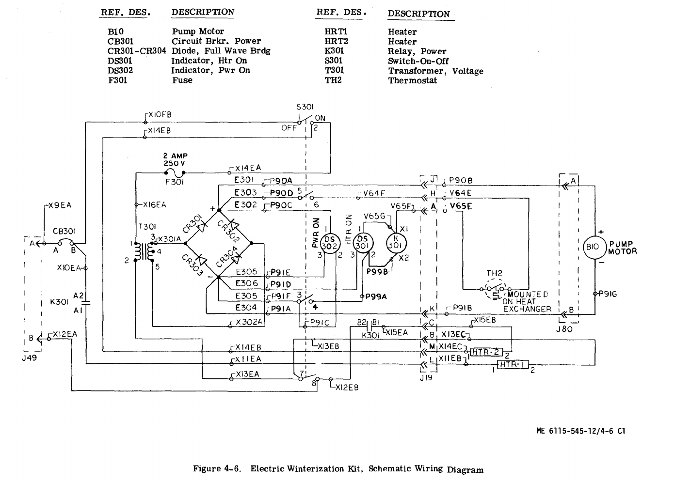
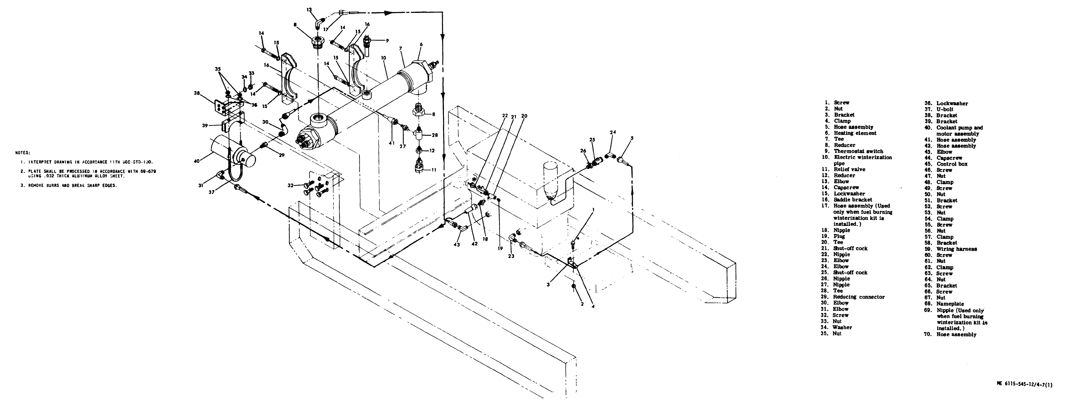
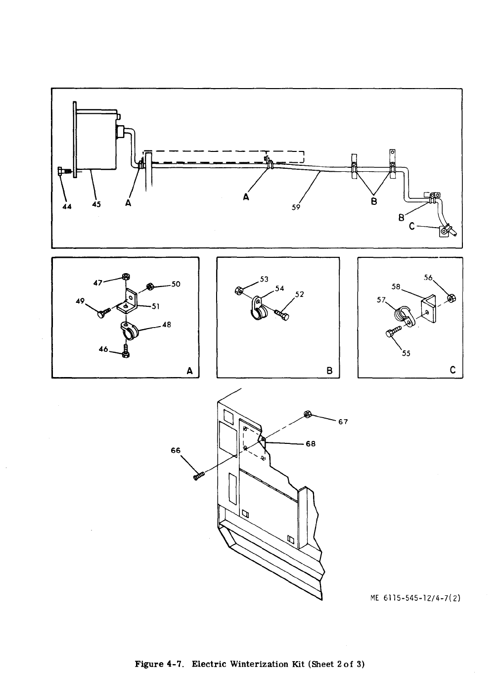
Figure 4-7.
4-15
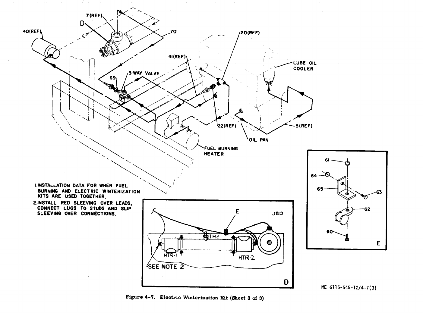
Figure 4-7.
4-16
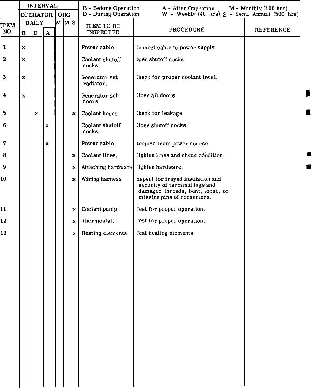
Table 4-3. Electric Winterization Kit Preventive Maintenance Checks and Services
ITEM
NO.
1
2
3
4
5
6
7
8
9
10
11
12
13
DAILY
B
-
Before
Operation
A
-
After
Operation
M
-
Monthly
(100
hrs)
D
-
During
Operation
W
-
Weekly-(40
hrs)
S
-
Semi
A-nnual
(500
hrs)
l’TEM TO BE
INSPECTED
Power
cable.
Coolant
shutoff
cocks.
;enerator
set
radiator.
Senerator
set
doors.
Coolant
hoses
Coolant
shutoff
cocks.
Power
cable.
Coolant
lines.
Attaching
hardwart
Wiring
harness.
Coolant
pump.
Thermostat.
Heating
elements.
PROCEDURE
:onnect
cable
to
power
supply.
)pen
shutoff
cocks.
:heck
for
proper
coolant
level.
;lose
all
doors.
;heck
for
leakage.
;lose
shutoff
cocks.
temove
from
power
source.
?ighten
lines
and
check
~ndition.
~ighten
hardware.
nspect
for
frayed
insulation
and
security
of
terminal
lugs
and
damaged
threads,
bent,
loose,
or
missing
pins
of
connectors.
rest
for
proper
operation.
rest
for
proper
operation.
pest
heating
elements.
REFERENCE
(para 2-25 and 4-18)
(para 2-25)
(para 3-41)
(fig. 1-1 and 1-2)
(para 4-22)
(para 2-25)
(para 2-25 and 4-19)
(para 4-22)
(para 4-22)
(para 4-26)
(para 4-22)
(para 4-23)
(para 4-24)
Change 1 4-17

Figure 4-8.
noted
below
when
fuel
burning
winterization
kit
and
electric
winterization
kit
are
used
together.
(See
sheet
2
of
figure 4-7.)
(1)
Disconnect
hose
(70)
from
elbow
(13)
and
elbow
(69).
Remove
nipple
(69)
from
three
way
valve
(67, fig. 4-1)
and
install
plug
(64)
into
three
way
valve
(67).
(2)
Disconnect
hose
(42, fig. 4-7)
from
nipple
(18)
and
elbow
(31).
Remove
adapter
(18)
and
replace
plug
(49, fig. 4-l).
(3)
Disconnect
hose
(47, fig. 4-1)
from
elbow
(43)
and
elbow
(50).
Remove
elbow
(43)
and
replace
plug
(19, fig. 4-7).
~.
Refer
to
paragraph 4-18
and
replace
plugs
and
plates
removed
during
installation.
e.
FiLl
radiator
with
proper
coolant
in
accordance
witii
table 2-1
and
check
for
leaks.
4-20. Preventive Maintenance.
To
insure
that
the
electric
winterization
kit
is
ready
for
operation
at
all
times,
when
installed
on
the
generator
set,
”
it
must
be
inspected
systematically
so
that
defects
may
be
discovered
and
corrected
before
they
result
in
serious
damage
or
failure.
Defects
discovered
during
operation
of
the
kit
shall
be
noted
for
future
correction,
to
be
made
as
soon
as
opera-
tion
has
ceased.
Stop
operation
immediately
if
a
deficiency
is
noted
during
operation
which
would
damage
the
kit
or
the
end
item
generator
to
which
it
is
attached.
All
deficiencies
and
shortcomings
SHALL
be
recorded
together
with
the
corrective
action
on
the
applicable
form
at
the
earliest
possible
opportunity.
Air
Force
users
shall
refer
to
the
ap-
plicable
inspection
manuals
and
work
card
sets
in
the
T. O. 35C2-3-
Series
for
periodic
preventive
maintenance
requirements
and
table 4-3
for
detailed
procedure.
4-21. Troubleshooting.
Table 4-4
provides
information
useful
in
diagnosing,
isolating,
and
correcting
unsatisfactory
operation
or
failure
of
the
electric
winterization
kit.
(See
figures
1-23, 1-26 or 1-27, and 4-6.)
4-22. Coolant Pump and Motor Assembly Inspection,
Testing, and Replacement.
a.
Inspection.
Proceed
as
follows:
(1)
See
figure 4-7
and
inspect
motor
assembly
for
overheating
and
inspect
coolant
pump
for
leaks,
loose
connections
and
loose
mounting.
(2)
See
figure 4-8,
remove
brushcap
(1)
and
check
motor
brush
and
spring
(2)
for
damage
or
excessive
wear.
Brushes
should
be
at
least
1/4
inch
Long.
(3)
See
figure 4-8
and
check
connector
(4)
for
bent
pins
or
damaged
threads.
Change 1
b.
Testing.
Coolant
pump
and
motor
assembly
(40, fig. 4-7) testing
consists
of
an
operational
verification
and
is
performed
as
follows:
(1)
Set
heat
control
switch
to
OFF
position.
(2)
Crack
the
fitting
on
the
output
of
the
coolant
pump
until
a
very
slow
leak
is
observed.
(3)
Set
heater
control
switch
to
ON
position
and
observe
the
leak
just
created
in
step
(2)
above.
If
the
leakage
rate
does
not
increase,
the
pump
is
defective
and
must
be
replaced.
(4)
Tighten
the
fitting
loosened
in
step
(2)
above.
~.
Replacement.
Proceed
as
follows:
(1)
See
figure 4-8
to
remove
and
replace
worn
or
damaged
brushes
(2)
and
connector
(4).
(2)
See
figure 4-7
to
remove
and
replace
coolant
pump
assembly
(40).
4-23. Thermostat Switch Inspection, Testing and
Replacement.
a.
Inspection.
fnspect
the
thermostat
switch
(9,
4-18
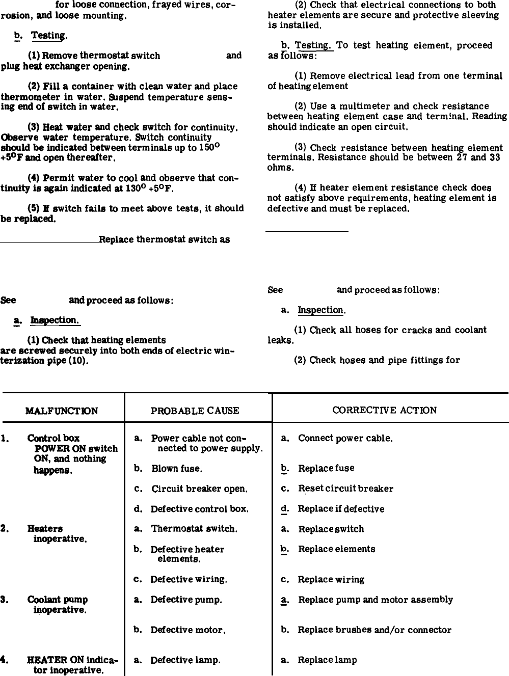
fig. 4-7)
for
loose
connection,
frayed
wires,
cor-
rosion,
and
loose
mounting.
~.
Testing.
(1)
Remove
thermostat
switch
(9, fig. 4-7)
and
plug
heat
exchanger
opening.
(2)
Fill
a
container
with
clean
water
and
place
thermometer
in
water.
tWspend
temperature
sens-
ing
end
of
switch
in
water.
(3)
Heat
water
and
check
switch
for
continuity.
Observe
water
temperature.
Switch
continuity
should
be
indicated
between
terminals
up
to
150°
+5°F
and
open
thereafter.
(4)
Permit
water
to
cool
and
observe
that
con-
tinuity
is
again
indicated
at
130°
+50F.
(5)
If
switch
fails
to
meet
above
tests,
it
should
be
replaced.
illustrated (9, fig. 4-7).
c. Replacement.
Replace
thermostat
switch
as
4-24. Heating Elements Inspection, Testing and
Replacement.
See
figure 4-7
and
proceed
as
follows:
&
Inspection.
(1)
Check
that
heating
elements
(6, fig. 4-7)
are
screwed
securely
into
both
ends
of
electric
win-
terisation
pipe
(10).
(2)
Check
that
electrical
connections
to
both
heater
elements
are
secure
and
protective
sleeving
is
installed.
b.
Testing.
To
test
heating
element,
proceed
as
~ollows:
(1)
Remove
electrical
lead
from
one
terminal
of
heating
element
(6, fig. 4-7).
(2)
Use
a
multimeter
and
check
resistance
between
heating
element
case
and
terminal.
Reading
should
indicate
an
open
circuit.
(3)
Check
resistance
between
heating
element
terminals.
Resistance
should
be
between
27
and
33
ohms.
(4)
If
heater
element
resistance
check
does
not
satisfy
above
requirements,
heating
element
is
defective
and
must
be
replaced.
c. Replacement. Remove and replace heating
elements (6) as illustrated in figure 4-7.
4-25. Hoses and Fittings Inspection, Repair and
Replacement.
See
figure 4-7
and
proceed
as
follows:
a.
Inspection.
(1)
Check
all
hoses
for
cracks
and
coolant
leaks.
(2)
Check
hoses
and
pipe
fittings
for
MALFUNCTK)N
1.
2.
3.
4.
control
box
POWER
ON
switch
ON,
and
nothing
-s.
Heaters
inoperative.
coolant
pump
iqoperattve.
HEATER
ON
indica-
tor
inoperative.
Table 4-4. Electric Winterization Kit Troubleshooting
PROBABLE
CAUSE
a.
b.
c.
d.
a.
b.
c.
a.
b.
a.
Power
cable
not
con-
nected
to
power
supply.
Blown
fuse.
Circuit
breaker
open.
Defective
control
box.
Thermostat
switch.
Defective
heater
elements.
Defective
wiring.
Defective
pump.
Defective
motor.
Defective
lamp.
CORRECTIVE
ACTION
a.
b
-“
c.
d
—“
a.
b
—’
c.
a.
—
b.
a.
Connect
power
cable.
Replace
fuse
(para 4-28).
Reset
circuit
breaker
(para 4-27).
Replace
if
defective
(para 4-27).
Replace
switch
(para 4-23).
Replace
elements
(para 4-24).
Replace
wiring
(para 4-26).
Replace
pump
and
motor
assembly
(para 4-22).
Replace
brushes
and/or
connector
(para 4-22).
Replace
lamp
(para 4-28).
4-19
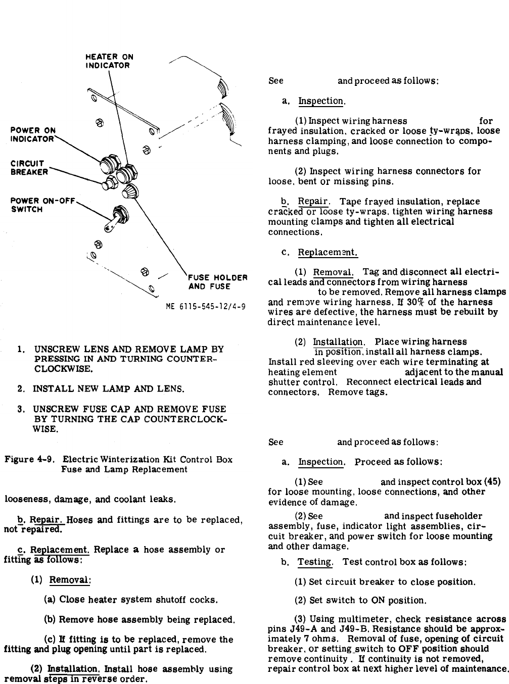
Figure 4-9.
4-26. Wiring Harnesses Inspection, Repair, and
Replacement.
See
figure 4-7
and
proceed
as
follows:
a.
Inspection.
(1)
Inspect
wiring
harness
(59, fig. 4-7)
for
frayed
insulation.
cracked
or
loose
ty-wraps,
loose
har-ness
clamping,
and
loose
connection
to
‘co’mpo-
nents
and
plugs.
(2)
Inspect
wiring
harness
connectors
for
loose,
bent
or
missing
pins.
b.
Repair.
Tape
frayed
insulation,
replace
cra?ked
or
loose
ty-wraps.
tighten
wiring
harness
mounting
clamps
and
tighten
all
electrical
connections.
c.
Replacem
mt.
(1)
Removal. Tag
and
disconnect
all
electri-
cal
leads
and
connectors
from
wiring
harness
(59,
fig. 4-7)
to
be
removed.
Remove
all
harness
clamps
and
remove
wiring
harness.
If
30%
of
the
harness
wires
are
defective,
the
harness
must
be
rebuilt
by
direct
maintenance
level.
(2)
Installation. Place
wiring
harness
(59,
fig. 4-7)
in
position,
install
all
harness
clamps.
Install
red
sleeving
over
each
wire
terminating
at
heating
element
(6, fig. 4-7),
adjacent
to
the
manual
shutter
control.
Reconnect
electrical
leads
and
connectors.
Remove
tags.
4-27. Control Box Inspection, Testing, and
Replacement.
See
figure 4-7
and
proceed
as
follows:
a.
Inspection.
Proceed
as
follows:
(1)
See
figure 4-7
and
inspect
control
box
(45)
for
loose
mounting,
loose
connections,
and
other
evidence
of
damage.
looeeness,
damage,
and
coolant
leaks.
(2)
See
figure 4-9,
and
inspect
fuseholder
assembly,
fuse,
indicator
light
assemblies,
cir-
cuit
breaker,
and
power
switch
for
loose
mounting
and
other
damage.
b.
Repair.
Hoses
and
fittings
are
to
be
replaced,
not-rep=
c.
Replacement.
Replace
a
hose
assembly
or
fitt~ng
as
follows:
b.
Testing.
Test
control
box
as
follows:
(1)
Removal:
(1)
Set
circuit
breaker
to
close
position.
(a)
Close
heater
system
shutoff
cocks.
(2)
Set
switch
to
ON
position.
(3)
Using
multimeter,
check
resistance
across
pins
J49-A
and
J49-B.
Resistance
should
be
approx-
(b)
Remove
hose
aseembly
being
replaced,
(c)
If
fitting
is
to
be
replaced,
remove
the
fitting
and
plug
opening
until
part
is
replaced.
imately
7
ohms.
Removal
of
fuse,
opening
of
circuit
breaker,
or
setting
switch
to
OFF
position
should
remove
continuity
.-
If
continuity
is-not
removed,
repair
control
box
at
next
higher
level
of
maintenance.
(2)
Installation.
Install
hose
assembly
using
removal
steps
in
reverse
order,
4-20
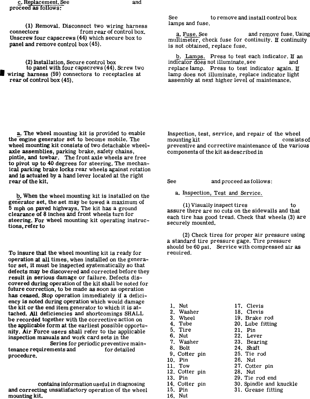
c.
Replacement.
See
figures 4-8 and 4-9
and
4-28. Control Box Fuse and Lamp Testing and
pro~eed
as
follows:
Replacement.
See
figure 4-9
to
remove
and
install
control
box
(1)
Removal.
Disconnect
two
wiring
harness
lamps
and
fuse.
connectors
(59, fig. 4-7)
from
rear
of
control
box.
Unscrew
four
capscrews
(44)
which
secure
box
to a.
Fuse.
See
figure 4-9
and
remove
fuse.
Using
mumimeter,
check
fuse
for
continuity.
If
continuity
panel
and
remove
control
box
(45).
is
not
obtained,
replace
fuse.
b.
Lamps.
Press
to
test
each
indicator.
If
an
(2)
Installation.
Secure
control
box
(45, fig.
ind~cat~s
not
illuminate,
see
figure 4-9
and
4-7)
to
panel
with
four
capscrews
(44).
Screw
two
~
wiring
harness
(59)
connectors
to
receptacles
at
replace
lamp.
Press
to
test
indicator
again.
E
lamp
does
not
illuminate,
replace
indicator
light
rear
of
control
box
(45).
assembly
at
next
higher
level
of
maintenance.
Section IV. WHEEL MOUNTING KIT
4-29. General.
a.
The
wheel
mounting
kit
is
provided
to
enable
the-engine
generator
set
to
become
mobile.
The
wheel
mounting
kit
consists
of
two
detachable
wheel-
axle
assemblies,
parking
brake,
safety
chains,
pintle,
and
towbar.
The
front
axle
wheels
are
free
to
pivot
up
to
40
degrees
for
steering.
The
mechan-
ical
parking
brake
locks
rear
wheels
against
rotation
and
is
actuated
by
a
hand
lever
located
at
the
right
rear
of
the
kit.
b.
When
the
wheel
mounting
kit
is
installed
on
the
gen%rator
set,
the
set
may
be
towed
a
maximum
of
5
mph
on
paved
highways.
The
kit
has
a
ground
clearance
of
8
inches
and
front
wheels
turn
for
steering.
For
wheel
mounting
kit
operating
instruc-
tions,
refer
to
paragraph 2-26.
4-30. Preventive Maintenance.
To
insure
that
the
wheel
mounting
kit
is
ready
for
operation
at
all
times,
when
installed
on
the
genera-
tor
set,
it
must
be
inspected
systematically
so
that
defects
may
be
discovered
and
corrected
before
they
result
@
serious
damage
or
failure.
Defects
dis-
covered
during
operation
of
the
kit
shall
be
noted
for
future
correction,
to
be
made
as
soon
as
operation
has
ceased.
Stop
operation
immediately
if
a
defici-
ency
is
noted
during
operation
which
would
damage
the
kit
or
the
end
item
generator
to
which
it
is
at-
tached.
ml
deficiencies
and
shortcomings
SHALL
be
record&
together
with
the
corrective
action
on
the
applicable
form
at
the
earliest
possible
opportu-
nity.
Air
Force
users
shall
refer
to
the
applicable
inspection
manuals
and
work
card
sets
in
the
T. O. 35C2-3-
Series
for
periodic
preventive
main-
tenance
requirements
and
table 4-5
for
detailed
procedure.
4-31. Troubleshooting.
Table 4-6
contains
information
useful
in
diagnosing
and
correcting
unsatisfactory
operation
of
the
wheel
mounting
kit.
4-32. Kit Maintenmce Procedures.
Inspection,
test,
service,
and
repair
of
the
wheel
mounting
kit
(figures 4-10, 4-11 and 4-12)
consists
of
preventive
and
corrective
maintenance
of
the
various
components
of
the
kit
as
described
in
table 4-5 and
paragraphs 4-33 through 4-35.
4-33. Wheels and Tires.
See
figure 4-10
and
proceed
as
follows:
a.
Inspection,
Test
and
Service.
(1)
Visually
inspect
tires
(5, fig. 4-10)
to
assure
there
are
no
cuts
on
the
sidewalls
and
that
each
tire
has
good
tread.
Check
that
wheels
(3)
are
securely
mounted.
(2)
Check
tires
for
proper
air
pressure
using
a
standard
tire
pressure
gage.
Tire
pressure
should
be
60
psi. Service
with
compressed
air
as
required,
KEY to fig. 4-10.
1.
Nut
2.
Washer
3.
Wheel
4.
Tube
5.
Tire
6.
Nut
7.
Washer
8.
Bolt
9.
Cotter
pin
10.
Pin
11.
Tow
12.
Cotter
pin
13.
Pin
14.
Cotter
pin
15.
Pin
16.
Nut
17.
Clevis
18.
Clevis
19.
Brake
rod
20.
Lube
fitting
21.
Pin
22.
Lever
23.
Bearing
24.
Shaft
25.
Tie
rod
26.
Nut
27.
Cotter
pin
28.
Nut
29.
Tie
rod
end
30.
Spindle
and
knuckle
31.
Grease
fitting
Change 14-21
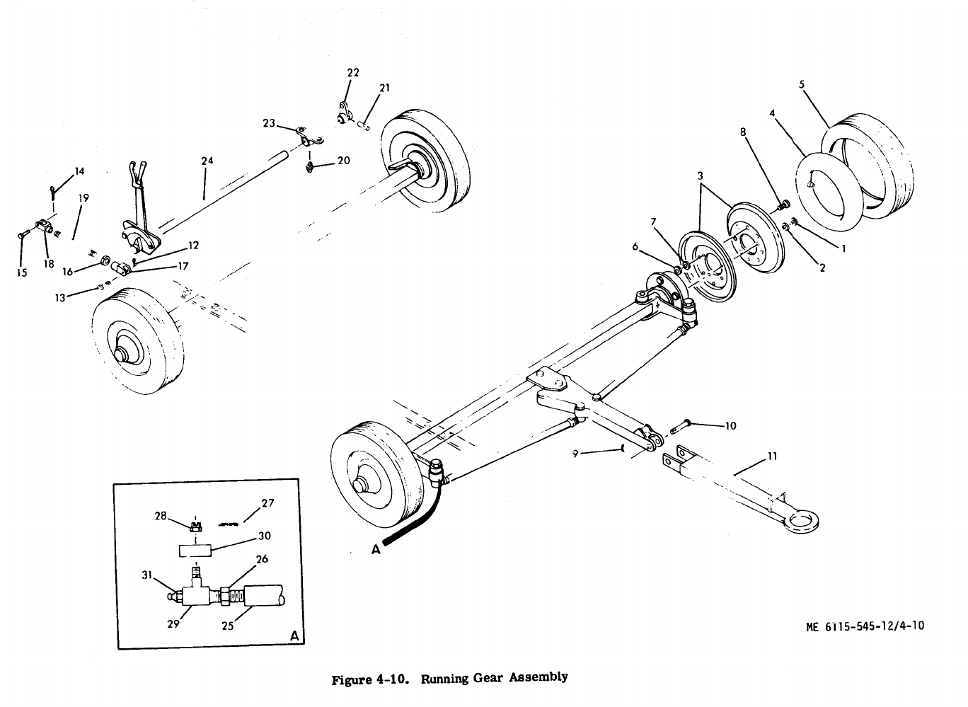
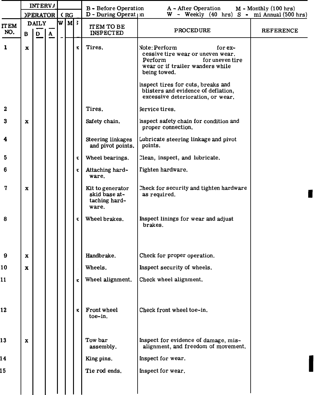
Table 4-5. Wheel Mounting Kit Preventive Maintenance Checks and Services
ITEM
NO.
1
2
3
4
5
6
7
8
9
10
11
12
13
14
15
INTERVA
)PERATOR
DAILY
B
x
x
x
x
x
x
—
D
—
—
A
—
B
-
Before
Operation
A
-
After
Operation
M
-
Monthly
(100
hrs)
D
-
During
Operat
ITEM
TO
BE
INSPECTED
Tires.
Tires.
Safety
chain.
Steering
linkages
and
pivot
points.
Wheel
bearings.
Attaching
hard-
ware.
Kit
to
generator
skid
base
at-
taching
hard-
ware.
Wheel
brakes.
Handbrake.
Wheels.
Wheel
alignment.
Front
wheel
toe-in.
Tow
bar
assembly.
King
pins.
Tie
rod
ends.
mW
-
Weekly
(40
hrs)
S
-
PROCEDURE
Note:
Perform
Item No. 10
for
ex-
cessive
tire
wear
or
uneven
wear.
Perform
Item No. 11
for
uneven
tire
wear
or
if
trailer
wanders
while
being
towed.
hspect
tires
for
cuts,
breaks
and
blisters
and
evidence
of
deflation,
excessive
deterioration,
or
wear.
Service
tires.
hspect
safety
chain
for
condition
and
proper
connection.
Lubricate
steering
linkage
and
pivot
points.
:lean,
inspect,
and
lubricate.
I’ighten
hardware.
Zheck
for
security
and
tighten
hardware
as
required.
fnspect
linings
for
wear
and
adjust
brakes.
Check
for
proper
operation.
Inspect
security
of
wheels.
Check
wheel
alignment.
Check
front
wheel
toe-in.
inspect
for
evidence
of
damage,
mis-
alignment,
and
freedom
of
movement.
tnspect
for
wear.
Lnspect
for
wear.
mi
Annual
(5OO
hrs)
REFERENCE
(para 4-33)
(para 4-33)
(para 2-26)
(para 3-3 and 3-4)
(para 4-34)
(para 4-42)
(para 4-35)
(para 2-26)
(para 4-33)
(para 4-36)
(para 4-37)
(para 2-26)
(fig. 4-12)
(fig. 4-12)
Change 14-23
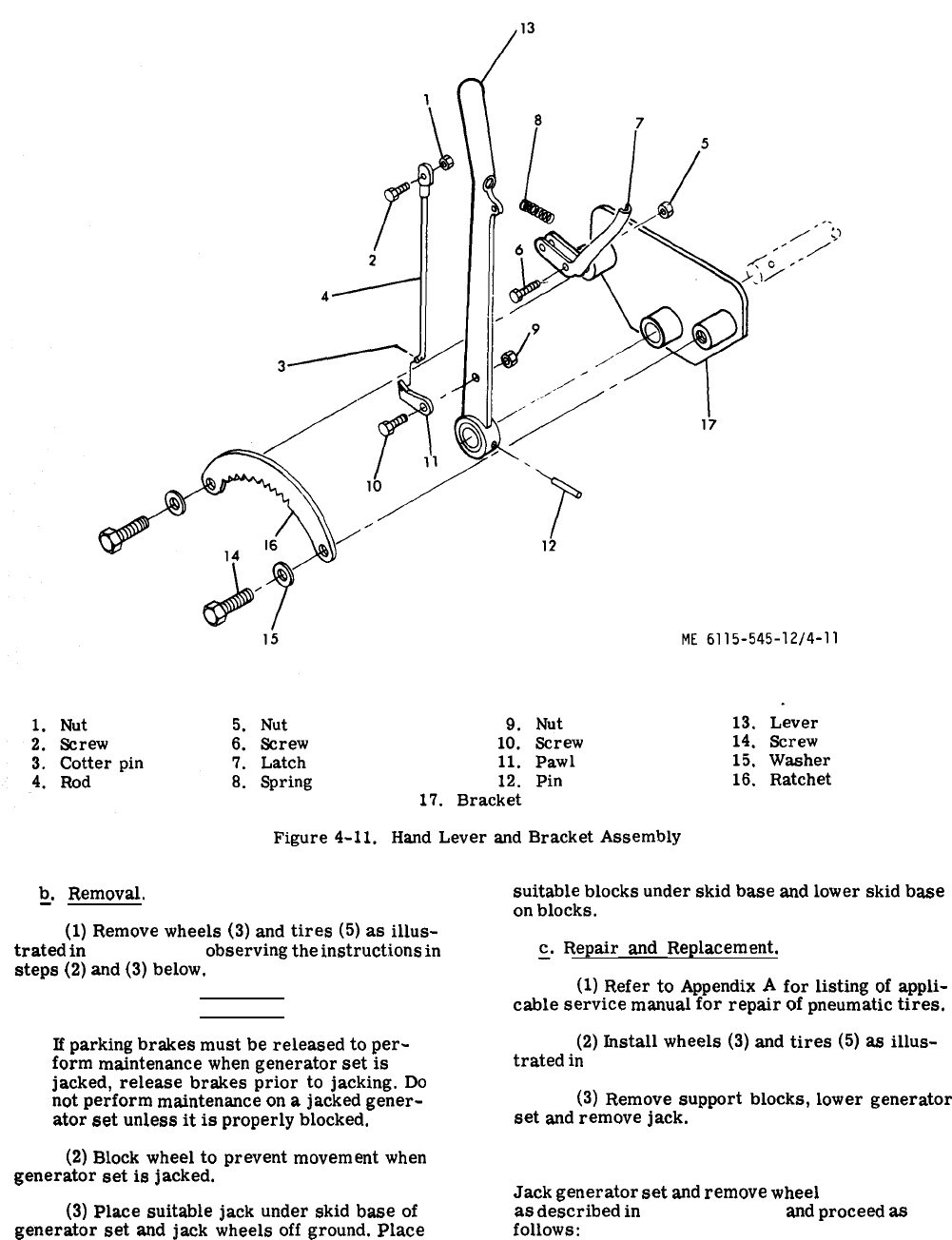
Figure 4-11.
b.
Removal,
—
(1)
Remove
wheels
(3)
and
tires
(5)
as
illus-
trated
in
figure 4-10,
observing
the
instructions
in
steps
(2)
and
(3)
below.
WARNING
If
parking
brakes
must
be
released
to
per-
form
maintenance
when
generator
set
is
jacked,
release
brakes
prior
to
jacking.
Do
not
perform
maintenance
on
a
jacked
gener-
ator
set
unless
it
is
properly
blocked.
suitable
blocks
under
skid
base
and
lower
skid
base
on
blocks.
~.
Repair
and
Replacement.
(1)
Refer
to
Appendix
A
for
listing
of
appli-
cable
service
manual
for
repair
of
pneumatic
tires.
(2)
Install
wheels
(3)
and
tires
(5)
as
illus-
trated
in
figure 4-10.
(3)
Remove
support
blocks,
lower
generator
set
and
remove
jack.
(2)
Block
wheel
to
prevent
movement
when
4-34. Wheel Bearings.
generator
set
is
jacked.
Jack
generator
set
and
remove
wheel
(3, fig. 4-10)
(3)
Place
suitable
jack
under
skid
base
of
as
described
in
paragraph 4-33
and
proceed
as
generator
set
and
jack
wheels
off
ground.
Place
follows:
4-24
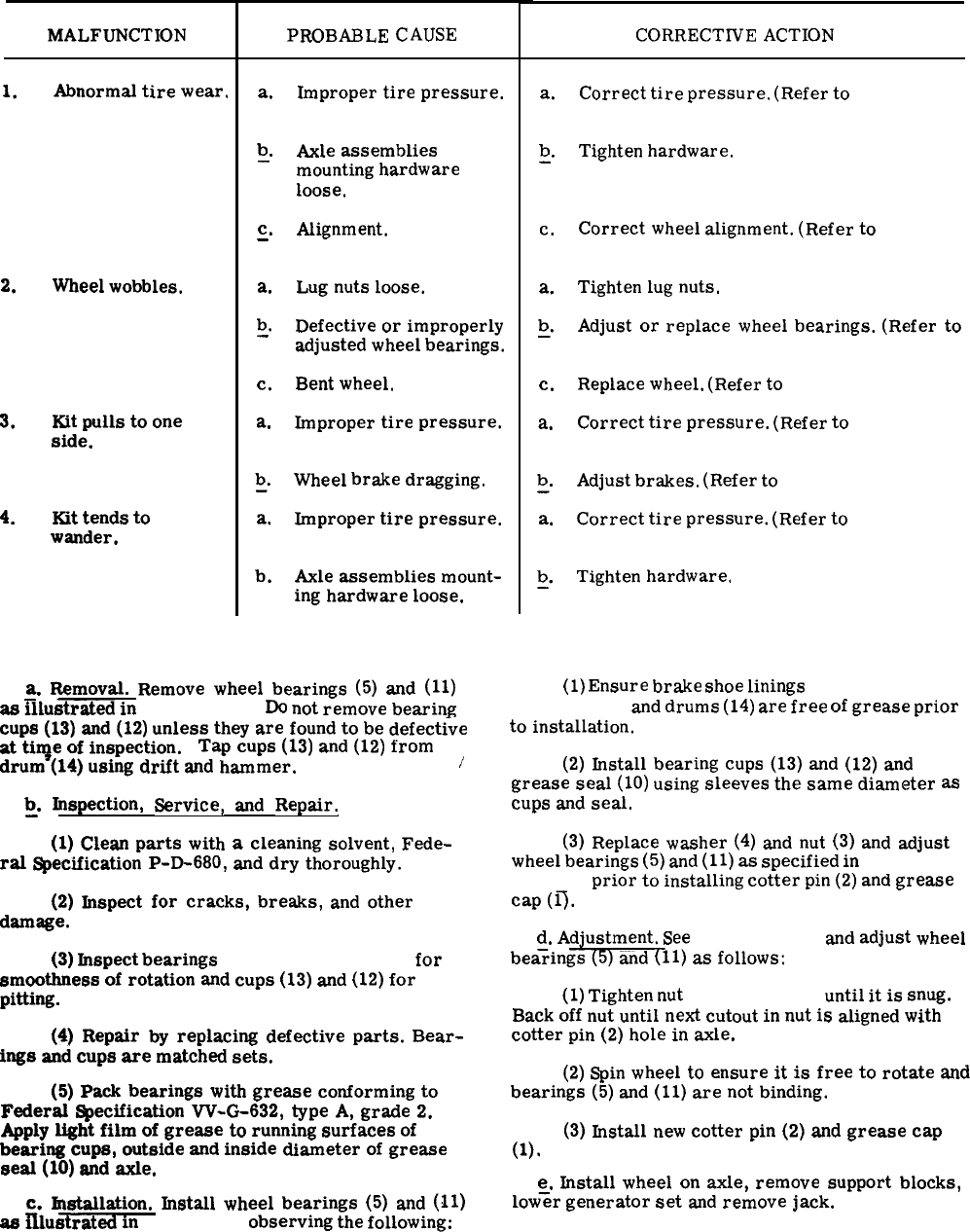
Table 4-6. Wheel Mounting Kit Troubleshooting
MALFUNCTION
1.
2.
3.
4.
Abnormal
tire
wear.
Wheel
wobbles.
Kit
pulls
to
one
side.
Kit
tends
to
wander.
PROBABLE
CAUSE
a.
b
—“
c.
—
a.
b
-“
c.
a.
b
—“
a.
b.
Improper
tire
pressure.
Axle
assemblies
mounting
hardware
loose,
Alignment.
Lug
nuts
loose.
Defective
or
improperly
adjusted
wheel
bearings.
Bent
wheel.
Improper
tire
pressure.
Wheel
brake
dragging.
Improper
tire
pressure.
Axle
assemblies
mount-
ing
hardware
loose.
a.
Removal.
Remove
wheel
bearings
(5)
and
(11)
as
illustrated
in
figure 4-12.
Do
not
remove
bearing
cups
(13)
and
(12)
unless
they
are
found
to
be
defective
at
ti~e
of
inspection.
Tap
cups
(13)
and
(12)
from
drum
(14)
using
drift
and
hammer.
/
~.
Inspection,
Service,
and
Repair.
(1)
Clean
parts
with
a
cleaning
solvent,
Fede-
ral
Specification
P-D-680,
and
dry
thoroughly.
(2)
Inspect
for
cracks,
breaks,
and
other
damage.
(3)
Inspect
bearings
(5 and 11, fig. 4-12)
for
smoothness
of
rotation
and
cups
(13)
and
(12)
for
pitting.
(4)
Repair
by
replacing
defective
parts.
Bear-
ings
and
cups
are
matched
sets.
(5)
Pack
bearings
with
grease
conforming
to
Federal
~ecification
W-G-632,
type
A,
grade
2.
Apply
light
film
of
grease
to
running
surfaces
of
bearing
cups,
outside
and
inside
diameter
of
grease
seal
(10)
and
axle.
c.
Installation.
Jnstall
wheel
bearings
(5)
and
(11)
as
Illustrated
in
figure 4-12
observing
the
following:
CORRECTIVE
ACTION
a.
Correct
tire
pressure.
(Refer
to
paragraph
4-33.)
b
Tighten
hardware.
—.
c.
a.
b
—.
c.
a.
b
—.
a.
b
—.
Correct
wheel
alignment.
(Refer
to
para-
graph 4-36.)
Tighten
lug
nuts.
Adjust
or
replace
wheel
bearings.
(Refer
to
paragraph 4-34.)
Replace
wheel.
(Refer
to
paragraph 4-33.)
Correct
tire
pressure.
(Refer
to
paragraph
4-33.)
Adjust
brakes.
(Refer
to
paragraph 4-35.)
Correct
tire
pressure.
(Refer
to
paragraph
4-33.)
Tighten
hardware.
(1)
Ensure
brake
shoe
linings
(17 and 18,
figure 4-12)
and
drums
(14)
are
free
of
grease
prior
to
installation.
(2)
Install
bearing
cups
(13)
and
(12)
and
grease
seal
(10)
using
sleeves
the
same
diameter
as
cups
and
seal.
(3)
Replace
washer
(4)
and
nut
(3)
and
adjust
wheel
bearings
(5)
and
(11)
as
specified
in
paragraph
4-34 d.
prior
to
installing
cotter
pin
(2)
and
grease
cap
(0.
d.
Adjustment.
See
figure 4-12
and
adjust
wheel
bea;ings
(5)
and
(!11)
as
follows:
(1)
Tighten
nut
(3, fig. 4-12)
until
it
is
snug.
Back
off
nut
until
next
cutout
in
nut
is
aligned
with
cotter
pin
(2)
hole
in
axle.
(2)
Spin
wheel
to
ensure
it
is
free
to
rotate
and
bearings
(5)
and
(11)
are
not
binding.
(3)
Install
new
cotter
pin
(2)
and
grease
cap
(l).
e.
Install
wheel
on
axle,
remove
support
blocks,
low%
generator
set
and
remove
jack.
4-25

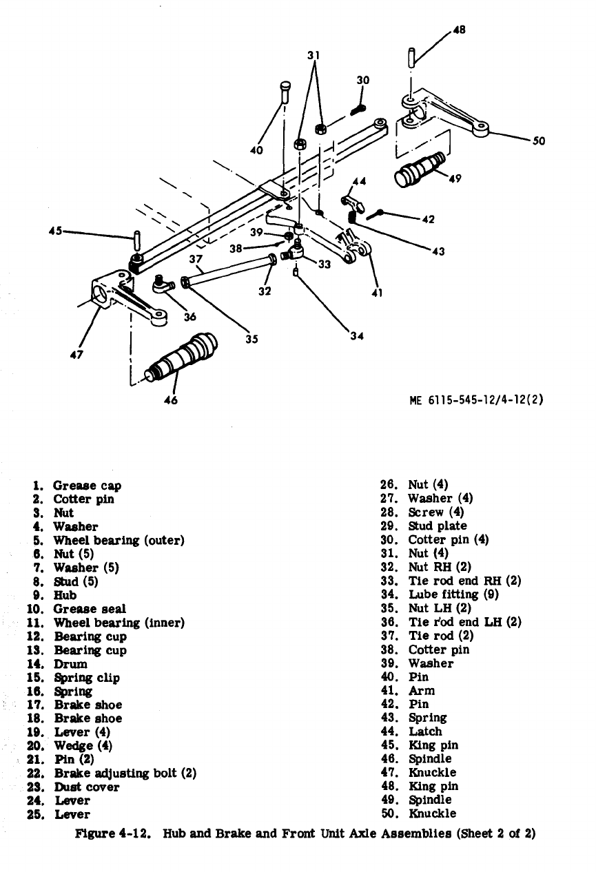
Figure 4-12.
4-27
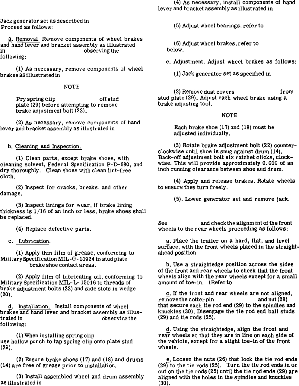
4-35. Wheel Brakes and Hand Lever and Bracket
Assembly.
Jack
generator
set
as
described
in
paragraph 4-33.
Proceed
as
follows:
a.
Removal,
Remove
components
of
wheel
brakes
and-hand
lever
and
bracket
assembly
as
illustrated
in
figures 4-10, 4-11 and 4-12
observing
the
following:
(1)
As
necessary,
remove
components
of
wheel
brakes
as
illustrated
in
figures 4-10 and 4-12.
NOTE
Pry
spring
clip
(15, fig. 4-12)
off
stud
plate
(29)
before
attempting
to
remove
brake
adjustment
bolt
(22).
(2)
As
necessary,
remove
components
of
hand
lever
and
bracket
assembly
as
illustrated
in
figure
4-11.
b.
Cleaning
and
Inspection.
(1)
Clean
parts,
except
brake
shoes,
with
cleaning
solvent,
Federal
Specification
P-D-680,
and
dry
thoroughly.
Clean
shoes
with
clean
lint-free
cloth.
(2)
Inspect
for
cracks,
breaks,
and
other
damage,
(3)
Inspect
linings
for
wear,
if
brake
lining
thickness
is
1/16
of
an
inch
or
less,
brake
s“hoes
shall
be
replaced.
(4)
Replace
defective
parts.
c.
Lubrication.
(1)
Apply
thin
film
of
grease,
conforming
to
Military
Specification
MIL-G-
10924
to
stud
plate
(29,
fig. 4-12)
brake
shoe
contact
areas.
(2)
Apply
film
of
lubricating
oil,
conforming
to
Military
Specification
MIL-L-
15016
to
threads
of
brake
adjustment
bolts
(22)
and
side
slots
in
wedge
(20).
d.
Installation. Install
components
of
wheel
brfies
and
hand
lever
and
bracket
assembly
as
illus-
trated
in
figures 4-10, 4-11 and 4-12
observing
the
following:
(1)
When
installing
spring
clip
(15, fig. 4-12),
use
hollow
punch
to
tap
spring
clip
onto
plate
stud
(29).
(2)
Ensure
brake
shoes
(17)
and
(18)
and
drums
(14)
are
free
of
grease
prior
to
installation.
(3)
Install
assembled
wheel
and
drum
assembly
as
illustrated
in
figures 4-10 and 4-12.
(4)
As
necessary,
install
components
of
hand
lever
and
bracket
assembly
as
illustrated
in
figure
4-11.
(5)
Adjust
wheel
bearings,
refer
to
paragraph
4-34.
(6)
Adjust
wheel
brakes,
refer
to
paragraph
e.
below.
e.
Adjustment.
Adjust
wheel
brakes
as
follows:
(1)
Jack
generator
set
as
specified
in
para-
graph 4-33.
(2)
Remove
dust
covers
(23, fig. 4-12)
from
stud
plate
(29).
Adjust
each
wheel
brake
using
a
brake
adjusting
tool.
NOTE
Each
brake
shoe
(17)
and
(18)
must
be
adjusted
individually.
(3)
Rotate
brake
adjustment
bolt
(22)
counter-
clockwise
until
shoe
is
snug
against
drum
(14).
Back-off
adjustment
bolt
six
ratchet
clicks,
clock-
wise.
This
will
provide
approximately
0.010
of
an
inch
running
clearance
between
shoe
and
drum.
(4)
Apply
and
release
brakes.
Rotate
wheels
to
ensure
they
turn
freely.
(5).
Lower
generator
set
and
remove
jack.
4-36. Wheel Alignment.
See
figure 4-10
and
check
the
alignment
of
the
front
wheels
to
the
rear
wheels
proceeding
as
follows:
a.
Place
the
trailer
on
a
hard,
flat,
and
level
sur~ace,
with
the
front
wheels
placed
in
the
straight-
ahead
position.
b.
Use
a
straightedge
position
across
the
sides
of
tiie
front
and
rear
wheels
to
check
that
the
front
wheels
align
with
the
rear
wheels
except
for
a
small
amount
of
toe-in.
(Refer
to
paragraph 4-37.)
c.
If
the
front
and
rear
wheels
are
not
aligned,
refiove
the
cotter
pin
(27, fig. 4-10)
and
nut
(28)
that
secure
each
tie
rod
end
(29)
to
the
spindles
and
knuckles
(30).
Disengage
the
tie
rod
end
ball
studs
(29)
and
tie
rods
(25).
d.
Using
the
straightedge,
align
the
front
and
rea~
wheels
so
that
they
are
in
line
on
each
side
of
the
vehicle,
except
for
a
slight
toe-in
of
the
front
wheels.
e.
Loosen
the
nuts
(26)
that
lock
the
tie
rod
ends
(29Tto
the
tie
rods
(25).
Turn
the
tie
rod
ends
in
or
out
on
the
tie
rods
(25)
until
the
tie
rod
ends
(29)
are
aligned
with
the
holes
in
the
spindles
and
knuckles
(30).
4-28
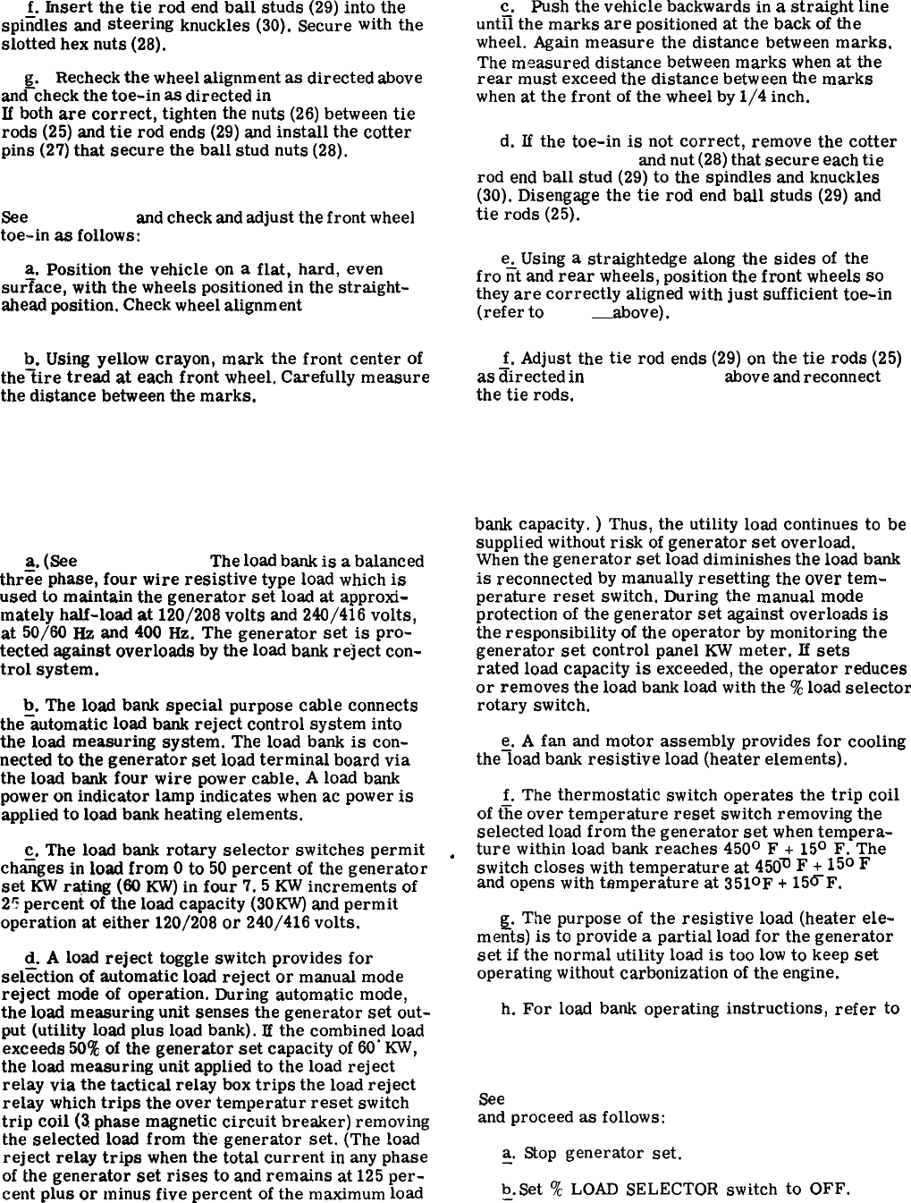
f.
Insert
the
tie
rod
end
ball
studs
(29)
into
the
spiiidles
and
steering
knuckles
(30).
Secure
with
the
slotted
hex
nuts
(28).
Recheck
the
wheel
alignment
as
directed
above
and%heck
the
toe-in
as
directed
in
paragraph 4-37.
If
both
are
correct,
tighten
the
nuts
(26)
between
tie
rods
(25)
and
tie
rod
ends
(29)
and
install
the
cotter
pins
(27)
that
secure
the
ball
stud
nuts
(28).
4-37. Front Wheel Toe-In Adjustment.
See
figure 4-10
and
check
and
adjust
the
front
wheel
toe-in
as
follows:
a.
Position
the
vehicle
on
a
flat,
hard,
even
sur~ace,
with
the
wheels
positioned
in
the
straight-
ahead
position.
Check
wheel
alignment
(paragraph
4-36).
b.
Using
yellow
crayon,
mark
the
front
center
of
the~ire
tread
at
each
front
wheel.
Carefully
measure
the
distance
between
the
marks.
Section V.
4-38. General.
a.
(See
figure 4-13).
The
load
bank
is
a
balanced
thr~e
phase,
four
wire
resistive
type
load
which
is
used
to
maintain
the
generator
set
load
at
approxi-
mately
half-load
at
120/208
volts
and
240/416
volts,
at
50/60
HZ
and
400
Hz.
The
generator
set
is
pro-
tected
against
overloads
by
the
load
bank
reject
con-
trol
system.
b.
The
load
bank
special
purpose
cable
connects
the-automatic
load
bank
reject
control
system
into
the
load
measuring
system.
The
load
bank
is
con-
nected
to
the
generator
set
load
terminal
board
via
the
load
bank
four
wire
power
cable.
A
load
bank
power
on
indicator
lamp
indicates
when
ac
power
is
applied
to
load
bank
heating
elements.
c.
The
load
bank
rotary
selector
switches
permit
ch@es
in
load
from
O
to
50
percent
of
the
generator
set
KW
ra$ing
(60
KW)
in
four
7.5
KW
increments
of
2!
percent
of
the
load
capacity
(30KW)
and
permit
operation
at
either
120/208
or
240/416
volts.
~.
A
load
reject
toggle
switch
provides
for
selection
of
automatic
load
reject
or
manual
mode
reject
mode
of
operation.
During
automatic
mode,
the
load
measuring
unit
senses
the
generator
set
out-
put
(utility
load
plus
load
bank).
If
the
combined
load
exceeds
509+
of
the
generator
set
capacity
of
60”
KW,
the
load
measuring
unit
applied
to
the
load
reject
relay
via
the
tactical
relay
box
trips
the
load
reject
relay
which
trips
the
over
temperature
reset
switch
trip
coil
(3
phase
magnetic
circuit
breaker)
removing
the
selected
load
from
the
generator
set.
(The
load
reject
relay
trips
when
the
total
current
in
any
phase
of
the
generator
set
rises
to
and
remains
at
125
per-
cent
plus
or
minus
five
percent
of
the
maximum
load
c.
Push
the
vehicle
backwards
in
a
straight
line
unt~l
the
marks
are
positioned
at
the
back
of
the
wheel.
Again
measure
the
distance
between
marks.
The
measured
distance
between
marks
when
at
the
rear
must
exceed
the
distance
between
the
marks
when
at
the
front
of
the
wheel
by
1/4
inch.
d.
If
the
toe-in
is
not
correct,
remove
the
cotter
pin_(27, fig. 4-10)
and
nut
(28)
that
secure
each
tie
rod
end
ball
stud
(29)
to
the
spindles
and
knuckles
(30).
Disengage
the
tie
rod
end
ball
studs
(29)
and
tie
rods
(25).
e.
Using
a
straightedge
along
the
sides
of
the
fro
fit
and
rear
wheels,
position
the
front
wheels
so
they
are
correctly
aligned
with
just
sufficient
toe-in
(refer
to
step c.
above).
f.
Adjust
the
tie
rod
ends
(29)
on
the
tie
rods
(25)
as
directed
in
paragraph 4-36
above
and
reconnect
the
tie
rods.
LOAD BANK
.
bank
capacity.
)
Thus,
the
utility
load
continues
to
be
supplied
without
risk
of
generator
set
overload.
When
the
generator
set
load
diminishes
the
load
bank
is
reconnected
by
manually
resetting
the
over
tem-
perature
reset
switch.
During
the
manual
mode
protection
of
the
generator
set
against
overloads
is
the
responsibility
of
the
operator
by
monitoring
the
generator
set
control
panel
KW
meter.
If
sets
rated
load
capacity
is
exceeded,
the
operator
reduces
or
removes
the
load
bank
load
with
the
‘%
load
selector
rotary
switch.
e.
A
fan
and
motor
assembly
provides
for
cooling
the~oad
bank
resistive
load
(heater
elements).
f.
The
thermostatic
switch
operates
the
trip
coil
of
t~e
over
temperature
reset
switch
removing
the
selected
load
from
the
generator
set
when
tempera-
ture
within
load
bank
reaches
450°
F
+-
15°
F.
The
switch
closes
with
temperature
at
450m
F
+-
15°
F
and
opens
with
temperature
at
3510F
+
15~F.
g.
The
purpose
of
the
resistive
load
(heater
ele-
mefits)
is
to
provide
a
partial
load
for
the
generator
set
if
the
normal
utility
load
is
too
low
to
keep
set
operating
without
carbonization
of
the
engine.
h.
For
load
bank
operating
instructions,
refer
to
paragraph 2-27.
4-39. Installation.
See
figures 1-1, 1-2, 1-21, 1-26 or 1-27, and 4-13
and
proceed
as
follows:
~.
Stop
generator
set.
b
Set
%
LOAD
SELECTOR
switch
to
OFF.
—“
Change 14-29
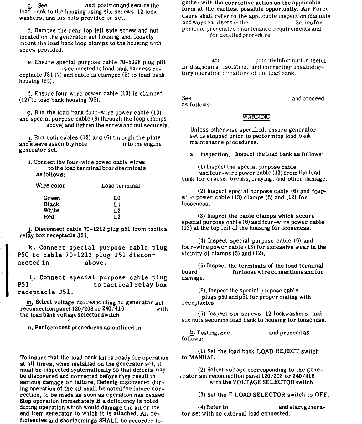
c.
See
figure 1-21
and,
position
and
secure
the
load
bank
to
the
housing
using
six
screws,
12
lock
washers,
and
six
nuts
provided
on
set.
d.
Remove
the
rear
top
left
side
screw
and
nut
loc<ted
on
the
generator
set
housing
and,
loosely
mount
the
load
bank
loop
clamps
to
the
housing
with
screw
provided,
e,
Ensure
special
purpose
cable
70-5098
plug
p81
(6, fig. 4-14)
is
connected
to
load
bank
harness
re-
ceptacle
J81
(7)
and
cable
is
clamped
(5)
to
load
bank
housing
(95).
~.
Ensure
four
wire
power
cable
(13)
is
clamped
(12)
to
load
bank
housing
(95),
~.
Run
the
load
bank
four-wire
power
cable
(13)
and
special
purpose
cable
(6)
through
the
loop
clamps
(step d.
above)
and
tighten
the
screw
and
nut
securely,
~.
Run
both
cables
(13)
and
(6)
through
the
plate
and
sleeve
assembly
hole
(fig. 3-15)
into
the
engine
generator
set.
i,
Connect
the
four-wire
power
cable
wires
(13,
fig.-4-14)
to
the
load
terminal
board
terminals
(figure
3-24)
as
follows:
Wire
color
Load
terminal
Green
LO
Black
L1
White
L2
Red
L3
j.
Disconnect
cable
70-1212
plug
p51
from
tactical
relay
box
receptacle
J51.
~.
Connect
special
purpose
cable
plug
P50
to
cable
70-1212
plug
J51
discon-
nected
in
step j.
above.
~.
Connect
special
purpose
cable
plug
P51
(6, fig. 4-14)
to
tactical
relay
box
receptacle
J51.
m.
Select
voltage
corresponding
to
generator
set
re~onnection
panel
120/208
or
240/416
(fig, 2-4)
with
theload
bank
voltage
selector
switch
(fig. 2-9).
e
n.
Perform
test
procedures
asoutlinedin
para-
graph 4-42 b.
4-40. Preventive Maintenance.
To
insure
that
theload
bank
kit
is
ready
for
operation
at
all
times,
when
installed
on
the
generator
set,
it
must
be
inspected
systematically
so
that
defects
may
rediscovered
andcorrected
before
they
result
in
serious
damage
or
failure.
Defects
discovered
ciur-
ing
operation
of
the
kit
shall
be
noted
for
future
cor-
rection,
to
be
made
as
soon
as
o?eration
has
ceased.
Stop
operation
immediately
if
a
deficiency
is
noted
during
operation
which
would
damaget
hekit
or
the
end
item
generator
to
which
it
is
attached.
All
de-
ficiencies
and
shortcomings
SHALL
be
recorded
to-
gether
with
thecorrective
action
on
the
applicable
form
at
the
earliest
possible
opportunity.
Air
Force
users
shall
refer
to
the
applicable
inspection
manuals
and
work
carcl
sets
in
the
T. O. 35C2-3-
Series
for
periodic
preventive
maintenance
requirements
and
table 4-7
for
detailed
procedure.
4-41. Troubleshooting.
Table 4-8
anti
figure 4-13
provide
information
useful
in
diagnosing.
isolating,
and
correcting
unsatisfac-
tory
operation
or
failure
uf
the
load
bank.
4-42. Kit Maintenance Procedures.
See
figures 4-13 through 4-14 and 4-16
and
proceed
as
follows:
WARNING
Unless
otherwise
specified.
ensure
generator
set
is
stopped
prior
to
performing
load
bank
maintenance
procedures.
a.
Inspection. Inspect
the
load
bank
as
follows:
(1)
Inspect
thespecial
purpose
cable
(6, fig.
4-14
and
four-wire
power
cable
(13)
from
the
load
bank
for
cracks,
breaks,
fraying,
and
other
damage.
(2)
fnspect
special
purpose
cable
(6)
and
fou~
wire
power
cable
(13)
clamps
(5)
and
(12)
for
looseness.
(3)
Inspect
the
cable
clamps
which
secure
special
purpose
cable
(6)
and
four-wire
power
cable
(13)
at
the
top
left
of
the
housing
for
looseness.
(4)
Inspect
special
purpose
cable
(6)
and
four-wire
power
cable
(13)
for
excessive
wear
in
the
vicinity
of
clamps
(5)
and
(12).
(5)
Jnspect
the
terminals
of
the
load
terminal
board
(fig. 3-24)
for
loose
wire
connections
and
for
damage.
(6).
Inspect
the
special
purpose
cable
(6, fig.
4-14)
plugs
P50
and
p51
for
proper
mating
with
receptacles.
(7)
fnspect
six
screws,
12
lockwashers,
and
six
nuts
securing
load
bank
to
housing
for
looseness.
~.
Testing.
See
figure 2-9
and
proceed
as
follows:
(1)
Set
the
load
bank
LOAD
REJECT
switch
to
MANUAL.
(2)
Select
voltage
corresponding
to
the
gene-
.
rator
set
reconnection
panel
120/208
or
240/416
(fig. 2-4
with
the
VOLTAGE
SELECTC)R
switch.
(3)
Set
the
‘?
LOAD
SELECTOR
switch
to
OFF,
(4)
Refer
to
paragraph 2-12
and
start
genera-
tor
set
with
no
external
load
connected.
—
4-30Change 12
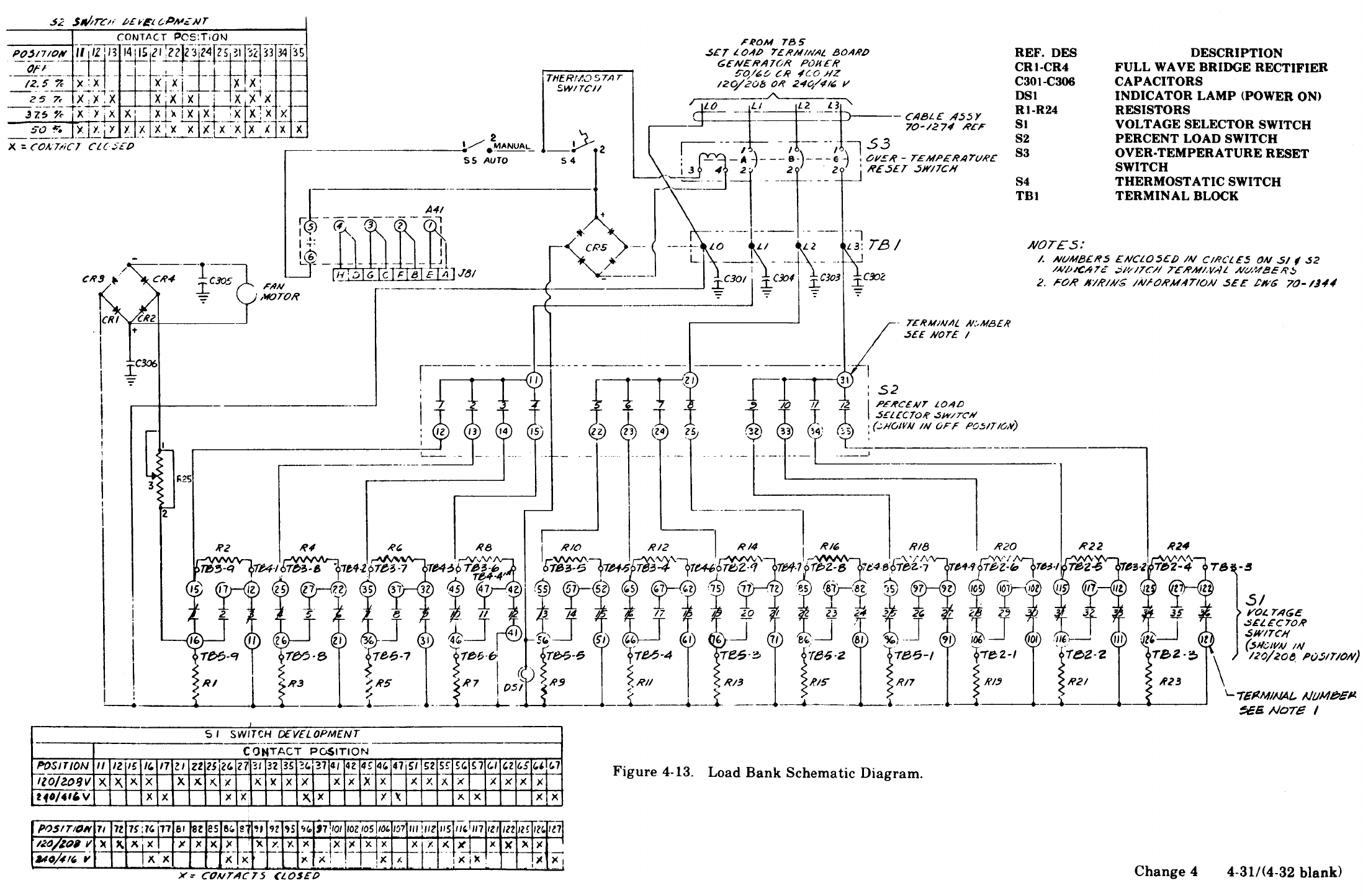

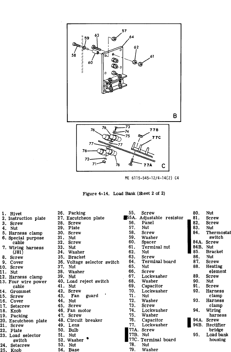
Figure 4-14.
1.
Rivet
2,
Instruction
plate
3.
Screw
4.
Nut
5.
Harness
clamp
6.
Special
purpose
cable
7.
Wiring
harness
(J81)
8.
Screw
9,
Cover
10.
Screw
11.
Nut
12.
Harness
clamp
13,
Four
wire
power
cable
14,
Grommet
15.
Screw
16.
Cover
17.
Setscrew
18.
Knob
19.
Packing
20.
Escutcheon
plate
21.
Screw
22.
Plate
23.
Load
selector
switch
24.
Setscrew
25.
Knob
26.
Packing
27.
Escutcheon
plate
28.
Screw
29,
Plate
30.
Screw
31.
Nut
32.
Screw
33.
Nut
34.
Washer
35.
Bracket
36.
Voltage
selector
switch
37.
Nut
38.
Washer
39.
Nut
40.
Load
reject
switch
41.
Nut
42.
Screw
43.
Fan
guard
‘
44.
Nut
45.
Screw
46.
Fan
motor
47.
Screw
48.
Circuit
breaker
49.
Lens
50.
Bulb
51.
Nut
52.
Washer
l
53.
Nut
54.
Base
55.
Screw
55A.
Adjustable
resistor
56.
Panel
5’7.
Nut
58.
Screw
59.
Washer
60.
Spacer
61.
Terminal
nut
62.
Nut
63. Screw
64.
Terminal
board
65.
Nut
66.
Screw
67. LockWasher
68.
Washer
69.
Capacitor
70.
LockWasher
71. Nut
72.
Washer
73.
Screw
7’4.
LockWasher
’75.
Washer
76.
Capacitor
77.
Lockwasher
77A.
Screw
77B.
Nut
77C.
Terminal
board
78. Nut
79.
Washer
80.
Nut
81.
Screw
82.
Screw
83.
Nut
84.
Thermostat
switch
84A.
Screw
84B.
Nut
85.
Bracket
86.
Nut
87.
Screw
88.
Heating
element
89.
Screw
90.
Nut
91. Screw
92.
Harness
clamp
93.
Harness
clamp
94.
Wiring
harness
94A.
Screw
94B.
Rectifier
bridge
95.
Load
bank
housing
4-34Change 4
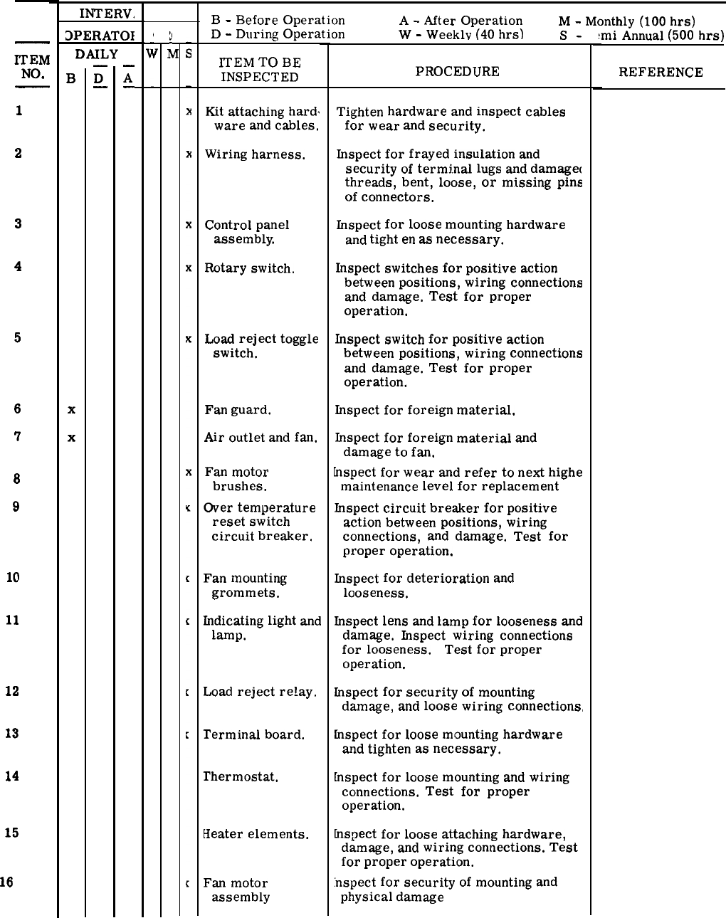
Table 4-7. Load Bank Preventive Maintenance Checks and Services
ITEM
NO.
1
2
3
4
5
6
7
8
9
10
11
12
13
14
15
16
INTERV,
DPERATOI
DAILY
B
x
x
—
D
—
—
A
.
;(
i
B
-
Before
Operation
A
-
After
Operation
M
-
Monthly
(100
hrs)
D
-
During
Operation
W
-
Weeklv
(40
hrs)
s-
:mi
Annual
(500
hrs)
lTEM
TO
BE
INSPECTED PROCEDURE
Kit
attaching
hard.
ware
and
cables,
Wiring
harness.
Control
panel
assembly.
Rotary
switch.
Load
reject
toggle
switch.
Fan
guard.
Air
outlet
and
fan.
Fan
motor
brushes.
Over
temperature
reset
switch
circuit
breaker,
Fan
mounting
grommets.
Indicating
light
and
lamp.
Load
reject
re!ay.
Terminal
board.
Thermostat.
Heater
elements.
Fan
motor
assembly
Tighten
hardware
and
inspect
cables
for
wear
and
security.
Inspect
for
frayed
insulation
and
security
of
termj.nal
lugs
and
damaget
threads,
bent,
loose,
or
missing
pins
of
connectors.
Inspect
for
loose
mounting
hardware
and
tight
en
as
necessary.
Inspect
switches
for
positive
action
between
positions,
wiring
connections
and
damage.
Test
for
proper
operation.
Inspect
switch
for
positive
action
between
positions,
wiring
connections
and
damage.
Test
for
proper
operation.
Inspect
for
foreign
material.
Inspect
for
foreign
material
and
damage
to
fan.
hspect
for
wear
and
refer
to
next
highe
maintenance
level
for
replacement
Inspect
circuit
breaker
for
positive
action
between
positions,
wiring
connections,
and
darnage.
Test
for
proper
operation.
Inspect
for
deterioration
and
looseness.
Inspect
lens
and
lamp
for
looseness
and
damage.
Inspect
wiring
connections
for
looseness. Test
for
proper
operation.
Inspect
for
security
of
mounting
damage,
and
loose
wiring
connections,
hspect
for
loose
mounting
hardware
and
tighten
as
necessary.
kspect
for
loose
mounting
and
wiring
connections.
Test
for
proper
operation.
hspect
for
loose
attaching
hardware,
damage,
and
wiring
connections.
Test
for
proper
operation.
:nspect
for
security
of
mounting
and
physical
damage
REFERENCE
(para 4-42)
(para 4-43)
(para 4-44)
(para 4-44)
(para 4-44)
(para 4-44)
(para 4-44)
(para 4-44)
(para 4-44)
para 4-44)
(para 4-44)
(para 4-45)
(para 4-46)
(para 4-47)
(para 4-48)
(para 4-44)
4-35
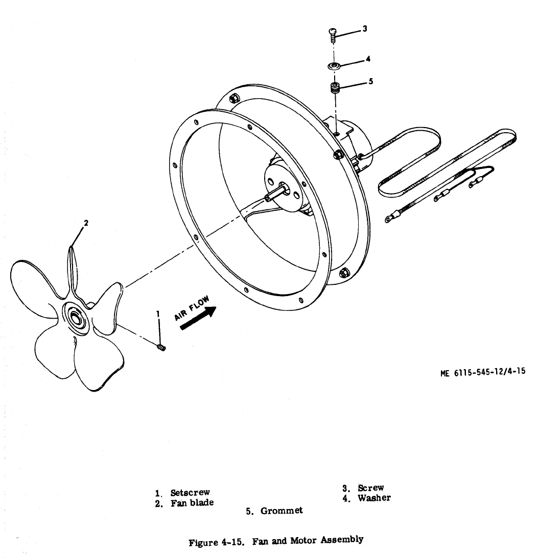

Table 4-8. Load Bank Troubleshooting
MALFUNCTION
1.
2.
3.
4.
5.
6.
Load
bank
does
not
apply
load
to
genera-
tor
set.
Over
temperature
reset
switch
does
not
remain
engaged
in
ON
position
while
in
manual
load
reject
mode.
Over
temperature
reset
switch
does
not
remain
engaged
in
ON
position
while
in
automatic
load
reject
mode.
Load
bank
does
not
disconnect
from
generator
set
with
rated
kilowatt
meter
above
30
W
while
in
automatic
load
reject
mode.
Fan
and
motor
ae-
sembly
not
operating
properly.
Indicator
does
not
illuminate
when
load
back
is
in
operation.
PROBABLE
CAUSE
a.
b
-“
c.
a.
b.
c.
d
-“
a.
b.
a.
b.
a.
—
b
-“
c.
a.
b
-“
c.
Refer
to
malfunction
2
and
3
below.
Defective
load
selector
switch.
Defective
wiring
harness.
Defective
fan
and
motor
assembly.
Defective
thermostat
switch.
Defective
over
tempera-
ture
reset
switch.
Defective
wiring.
me
as
2
above.
If
rated
kilowatt
meter
within
load
limits
of
30
W,
defective
load
reject
relay.
Defective
load
reject
switch.
Defective
wiring
harness.
Defective
fan
end
motor
assembly.
Defective
diode
bridge.
Defective
wiring
harness.
Defective
lamp.
Defective
light.
Defective
wiring
harness.
Corrective
ACTION
a.
b
-“
c.
a.
b
-“
c.
d.
a.
b.
a.
b
-“
a.
b
-“
c.
a.
b
-“
c.
Refer
to
malfunction
2
and
3
below,
Test
and
replace
switch
if
defective.
(Refer
to
paragraph 4-44.)
Repsir
or
replace
wiring
harness.
(Refer
to
paragraph 4-43.)
Check
fan
and
motor
assembly
for
proper
operation
as
in
5
below.
Test
switch
and
replace
if
defective.
(Refer
to
paragraph 4-47.)
Test
switch
and
replace
if
defective,
(Refer
to
paragraph 4-44.)
Repair
or
replace
wiring.
(Refer
to
paragraph
4-43.)
Same
as
2
above.
Test
relay
and
replace
if
defective
(higher
level
of
maintenance
required).
Test
switch
and
replace
if
defective.
(Refer
to
paragraph 4-44.)
Repair
or
replace
wiring
harness.
(Refer
to
paragraph 4-43.)
Test
assembly
and
refer
to
next
higher
level
of
maintenance,
if
defective,
Test
bridge
and
replace
diode(s)
if
defective.
(Higher
level
of
maintenance
required.
)
Repair
or
replace
wiring
harness.
(Refer
to
paragraph 4-43.)
Test
lamp
snd
replace
if
defective.
(Refer
to
paragraph 4-44.)
Test
light
and
replace
if
defective.
(Refer
to
paragraph 4-44.)
Repair
or
replace
wiring
harness.
(Refer
to
paragraph 4-43.)
4-37
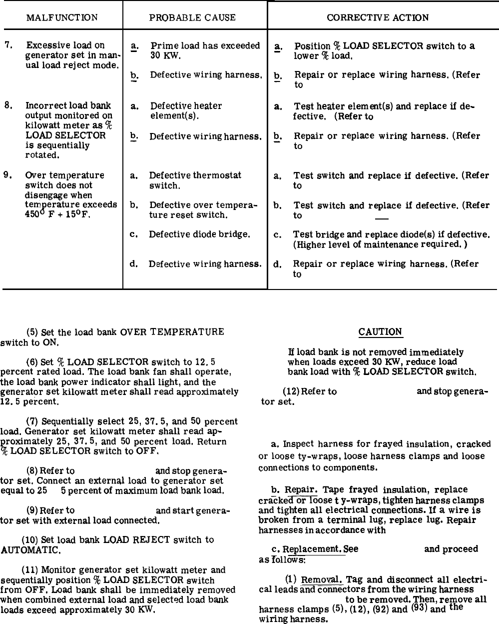
MALFUNCTION
7.
8,
9.
Excessive
load
on
generator
set
in
man-
ual
load
reject
mode.
Incorrect
load
bank
output
monitored
on
kilowatt
meter
as
%
LOAD SELECTOR
is
sequentially
rotated.
Over
temperature
switch
does
not
disengage
when
temperature
exceeds
450°
F
+
15°F.
Table 4-8. Load Bank Troubleshooting (Cont)
CORRECTIVE ACTION
PROBABLE CAUSE
a.
Prime
load
has
exceeded
—
30
Kw.
b
Defective
wiring
harness.
-“
a. Defective
heater
element(s).
b
Defective
wiring
harness.
-“
a.
Defective
thermostat
switch.
b.
Defective
over
tempera-
ture
reset
switch.
c.
Defective
diode
bridge.
d,
Defective
wiring
harness.
(5)
Set
the
load
bank
OVER
TEMPERATURE
switch
to ON.
(6) Set
%
LOAD SELECTOR
switch
to
12.5
percent
rated
load.
The
load
bank
fan
shall
operate,
the
load
bank
power
indicator
shall
light,
and
the
generator
set
kilowatt
meter
shall
read
approximately
12.5
percent.
(7)
Sequentially
select
25,
37.5,
and
50
percent
load.
Generator
set
kilowatt
meter
shall
read
ap-
proximately
25,
37.5,
and
50
percent
load.
Return
%
LOAD SELECTOR
switch
to
OFF.
(8)
Refer
to
paragraph 2-13 and
stop
genera-
tor
set.
Connect
an
external
load
to
generator
set
equal
to
25
±
5
percent
of
maximum
Ioad
bank
load.
(9)
Refer
to
paragraph 2-12 and
start
genera-
tor
set
with
external
load
connected.
(10) Set
load
bank
LOAD
REJECT
switch
to
AUTOMATIC.
(11)
Monitor
generator
set
kilowatt
meter
and
sequentially
position
%
LOAD SELECTOR
switch
from
OFF.
Load
bank
shall
be
immediately
removed
when
combined
external
load
and
selected
load
bank
loads
exceed
approximately
30
KW.
4-38
a.
—
b
-“
a.
b
-“
a.
b.
c.
d.
Position
‘%
LOAD SELECTOR
switch
to
a
lower
%
load.
Repair
or
replace
wiring
harness.
(Refer
to
paragraph 4-43.)
Test
heater
element(s)
and
replace
if
de-
fective. (Refer
to
paragraph 4-48.)
Repair
or
replace
wiring
harness.
(Refer
to
paragraph 4-43.)
Test
switch
and
replace
if
defective.
(Refer
to
paragraph 4-47.)
Test
switch
and
replace
if
defective.
(Refer
to
paragraph 4-44 d.)
Test
bridge
and
replace
diode(s)
if
defective.
(Higher
level
of
maintenance
required.
)
Repair
or
replace
wiring
harness.
(Refer
to paragraph 4-43.)
CAUTION
If
load
bank
is
not
removed
immediately
when
loads
exceed
30
KW,
reduce
load
bank
load
with
‘%
LOAD SELECTOR
switch.
(12)
Refer
to
paragraph 2-13 and
stop
genera-
tor
set.
4-43. Wiring Harness. (Figure 4-16)
a.
Inspect
harness
for
frayed
insulation,
cracked
or
loose
ty-wraps,
loose
harness
clamps
and
loose
connections
to
components.
b.
Repair.
Tape
frayed
insulation,
replace
cra%ke=oose
t
y-wraps,
tighten
harness
clamps
and
tighten
all
electrical
connections.
If
a
wire
is
broken
from
a
terminal
lug,
replace
lug.
Repair
harnesses
in
accordance
with
para 3-139.
C.
Replacement.
See figure 4-14
and
proceed
as
Tolloww.
(1)
Removal.
Tag
and
disconnect
all
electri-
cal
leads
and
connectors
from
the
wiring
harness
(7
or 94, fig. 4-14)
to
be
removed.
The%
remove
all
harness
clamps
(5), (12), (92)
and
(93)
and
the
wiring
harness.
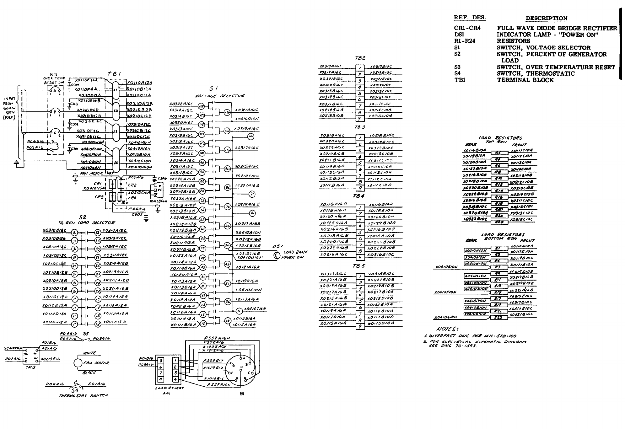
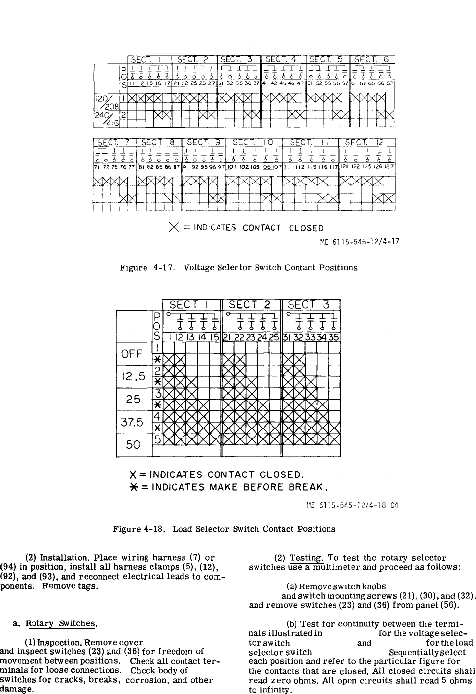
Figure 4-17.
Figure 4-18.
(2)
Installation.
Place
wiring
harness
(7)
or
(94)
in
position,
install
all
harness
clamps
(5),
(12),
(92),
and
(93),
and
reconnect
electrical
leads
to
com-
ponents.
Remove
tags.
4-44. Load Bank Control Panel Assembly.
a.
R~tary
Switches.
(1)
Inspection.
Remove
cover
(9, fig. 4-14)
and
insr)ect
switches
(23)
and
(36)
for
freedom
of
.,
movement
between
positions.
minals
for
loose
connections.
switches
for
cracks,
breaks,
damage,
‘
Check
all
contact
ter-
Check
body
of
corrosion,
and
other
(2)
Testing.
To
test
the
rotary
selector
switches
use
a
multimeter
and
proceed
as
follows:
(a)
Remove
switch
knobs
(18 and 25, fig.
4-14)
and
switch
mounting
screws
(21),
(30),
and
(32),
and
remove
switches
(23)
and
(36)
from
panel
(56).
(b)
Test
for
continuity
between
the
termi-
nals
illustrated
in
figure 4-17
for
the
voltage
selec-
tor
switch
(36, fig. 4-14)
and
figure 4-18
for
the
load
selector
switch
(23, fig. 4-14).
Sequentially
select
each
position
and
refer
to
the
particular
figure
for
the
contacts
that
are
closed.
All
closed
circuits
shall
read
zero
ohms.
All
open
circuits
shall
read
5
ohms
to
infinity.
Change 44-41
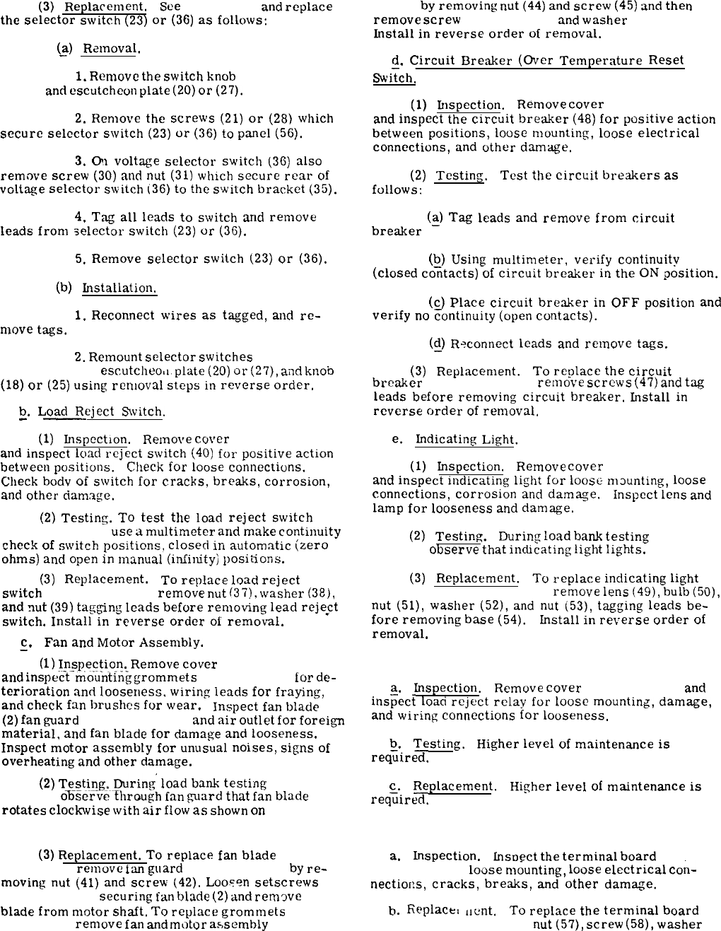
(3)
Replacement,
See
figure 4-14
and
replace
the
selector
switch
(23)
or
(36)
as
follows:
@)
Removal.
1.
Remove
the
switch
knob
(18 or 25, fig.
4-14)
and
escutcheon
plate
(20)
or
(27).
2.
Remove
the
screws
(21)
or
(28)
which
secure
selector
switch
(23)
or
(36)
to
panel
(56).
3.
On
voltage
selector
switch
(36)
also
remove
screw
(30)
and
nut
(31)
which
secure
rear
of
voltage
selector
switch
[36)
to
the
switch
bracket
(35).
4.
Tag
all
leads
to
switch
and
remove
leads
from
selector
switc!l
(23)
or
(36).
5.
Remove
selector
switch
(23)
or
(36).
(b)
installation.
1.
Reconnect
wires
as
tagged,
and
re-
move
tags.
2.
Remount
selector
switches
(23 and
36, fig. 4-14)
escutcheo,l.
plate
(20)
or
(2’7),
and
knob
(18)
or
(25)
using
removal
steps
in
reverse
order.
b.
Load
Reject
Switch.
-—
(1)
Inspection.
Remove
cover
(9, fig. 4-14)
and
inspect
load
reject
switch
(40)
for
positive
action
between
positions.
Check
for
loose
connections.
Check
bodv
of
switch
for
cracks,
breaks,
corrosion,
and
other
damage.
(2)
Testing.
To
test
the
load
reject
switch
(40, fig. 4-14),
use
a
multimeter
and
make
continuity
check
of
switch
positions,
closed
in
automatic
(zero
ohms)
and
open
in
manual
(imrinity)
positions.
(3)
Replacement.
To
replace
load
reject
switch
(40, fig. 4-14),
remove
nut
(37),
washer
(38),
and
nut
(39)
tagging
leads
before
removing
lead
reje@
switch.
Install
in
reverse
order
of
removal.
c. Fan
and
Motor
Assembly.
—
(1)
Inspection.
Remove
cover
(9, fig. 4-14)
and
inspec-t-rnciuntin~
grommets
(5, fig. 4-14)
ior
de-
terioration
and
looseness,
wiring
leads
for
fraying,
and
check
fan
brushes
for
wear.
Inspect
fan
blade
(2)
fan
guard
(43, fig. 4-14),
and
air
outlet
for
foreign
material,
and
fan
blade
for
damage
and
looseness.
Inspect
motor
assembly
for
unusual
noises,
signs
of
overheating
and
other
damage.
(2)
Testing.
During’
load
bank
testing
(para
4-42b.)
o%-scrvti-fhrough
fan
ward
that
fan
blade
rotates
clockwise
with
air
flow
as
shown
on
figure
4-15.
(3)
Replacement.
To
replace
fan
blade
(2,
fig. 4-15),
remove
tan
guard
(43, fig. 4-14)
by
re-
moving
nut
(41)
and
screw
(42).
Loo.?en
setscrews
(1, fig. 4-15)
securing
fan
blade
(2)
and
remcwe
blade
from
motor
shaft.
To
replace
grommets
(5,
fig. 4-15),
renlove
fan
and
motor
assembly
(46, fig.
4-42
4-14)
by
removing
nut
(44)
and
screw
(45)
and
then
remove
screw
(3, fig. 4-15)
and
washer
(4, fig. 4-15).
fnstall
in
reverse
order
of
removal.
d.
Circuit
Breaker
(Over
Temperature
Reset
Swi?ch.
(1)
Inspection.
Remove
cover
(9, fig. 4-14)
and
inspect
the
circuit
breaker
(48)
for
positive
action
between
positions,
loose
mounting,
loose
electrical
connections,
and
other
damage,
(2)
Testing. Test
the
circuit
breakers
as
follows:
bre&er
(~)
Tag
leads
and
remove
from
circuit
(b)
Using
multimeter,
verify
continuity
(closed
co=tacts)
of
circuit
breaker
in
the
ON
position.
(c)
Place
circuit
breaker
in
OFF
position
and
verify
no
~ontinuity
(open
contacts).
(cJ)
R?connect
leads
and
remove
tags.
(3)
Replacement.
To
replace
the
circuit
breaker
(48, fig. 4-14),
remove
screws
(47)
and
tag
leads
before
removing
circuit
breaker.
fnstall
in
reverse
order
of
removal.
e.
Indicating
Light.
(1)
Inspection.
Remove
cover
(9, fig. 4-14)
and
inspect
indicating
light
for
100SC
m~unting,
loose
connections,
corrosion
and
dam>~e.
Inspect
lens
and
lamp
for
looseness
and
damage.
(2)
Testing.
During
load
bank
testing
(para
4-42b.),
observe
that
indicating
light
lights.
(3)
Replacement.
To
replace
indicating
light
(49 through 54, fig. 4-14),
remove
lens
(49),
bulb(50),
nut
(51),
washer
(52),
and
nut
(53),
tagging
leads
be-
fore
removing
base
(54).
Install
in
reverse
order
of
removal.
4-45. Load Reject Relay.
a.
Inspection.
Remove
cover
(9, fig. 4-14),
and
ins~ect
load
reject
relay
for
loose
mounting,
damage,
and
wiring
connections
for
looseness.
b.
Testing.
Higher
level
of
maintenance
is
req~ired.
c.
Replacement. Higher
level
of
maintenance
is
req~ired.
4-46. Terminal Board.
a.
Impection.
fnspect
the
terminal
board
(64,
fig. 4-14) for
loose
nl&nting,
loose
electrical
con-
nectioiis,
cracks,
breaks,
and
other
damage.
b.
Replace,
[]cmt.
To
repIace
the
terminal
board
(64 fig. 4-14), remove
nut
(57),
screw
(58),
washer

(59)
and
spacer
(60)
tagging
leads
before
removing
terminal
board
(64),
Remove
terminal
nut
(61),
nut
(62),
and
screw
(63).
Install
in
reverse
order
of
re-
moval.
Diodes
are
tested
and
replaced
at
a
higher
level
of
maintenance.
4-47. Thermostat Switch.
a.
Inspection.
Remove
cover
(16, fig. 4-14)
and
ins~ect
thermostat
switch
(85)
for
loose
mounting
and
wiring
connections.
Test
for
proper
operation.
b.
Testing.
(1)
See
figures 4-13, 4-14, and 4-16
and
re-
move
switch
in
accordance
with
paragraph c.
below.
(2)
Fill
suitable
container
with
clean
oil
having
a
flash
point
above
600°F.
(3)
Suspend
thermostat
switch
in
container
of
oil.
Aiso,
suspend
a
thermometer
in
container
of
oil.
(4)
Connect
multimeter
between
switch
terminals.
WARNING
Ensure
oil
in
container
has
a
flash
point
exceeding
600°
F,
oil
is
heated
gradually,
and
necessary
fire
precautions
are
taken.
(5)
Heat
container
of
oil
gradually,
and
stir
so
heat
is
evenly
distributed.
(6)
Observe
multimeter
and
thermometer
for
indication
of
infinity
(open
switch)
below
4500F
+
150F.
At
4500F
+
150F,
multimeter
shall
indicate
continuity
(switch
closed).
(7)
Permit
oil
to
cool,
multimeter
shall
indi-
cate
infinity
{switch
open)
at
351°F
*
15°F.
Replace
if
defective.
c.
Replacement.
To
replace
thermostat
switch
(85, fig. 4-14)
remove
nut
(82),
washer
(83),
and
screw
(84)
tag~ing
leads
before
removing
switch.
Install
switch
in
reverse
order
of
removal.
4-48. Heater Elements.
w
ARNING
Ensure
heater
elements
are
cold
and
load
bank
is
disconnected
from
generator
set.
a.
Inspection.
Remove
cover
(16, fig. 4-14)
and
insfiect
heater
elements
(88)
for
loose
mounting.
loose
electrical
connections,
cracks,
breaks,
cor-
rosion,
and
other
damage.
b.
Testing,
(1)
Remove
one
end
of
heating
elem,3nt.
nut
which
secures
harness
lead
to
element
and
remove
lead
from
(2)
Test
heating
element
for
continuity.
If
open,
replace
heating
element.
(3)
Measure
resistance
between
terminals.
Re.
sistance
should
be
approximately
10
ohms,
(4)
Reconnect
lead.
Replacement.
To
replace
the
heating
elements
(88,fig.4-14),
remove
nut
(86)
and
screw
(87)
tag-
ging
leads
before
removing
elements.
Install
in
re-
verse
order
of
removal.
4-49. Removal.
See
figures 1-1, 1-2, 1-21, 1-26 or 1-27, and 4-13,
and
proceed
as
follows:
~.
Refer
to
paragraph 2-13
and
stop
generator
set.
b.
Set
%
LOAD
SELECTOR
SWITCH
to
OFF.
c.
Disconnect
special
purpose
cable
plug
P50
(6, fig. 4-14)
from
tactical
relay
box
receptacle
J50.
d.
Disconnect
special
purpose
cable
plug
P51
froti
cable
70-1212
plug
P51.
e.
Connect
cable
70-1212
plug
P51
to
tactical
rel~y
box
receptacle
J51.
f.
Disconnect
load
bank
four-wire
power
cable
(13Tfrom
load
terminal
board
terminals
(fig. 3-24).
~.
Remove
load
bank
four-wire
power
cable
(13,
fig. 4-14)
and
special
purpose
cable
(6)
from
the
gene-
rator
set
through
the
plate
and
sleeve
assembly
hole
(fig. 3-15).
h.
Remove
load
bank
four-wire
power
cable
(13,
fig. 4-14)
and
special
purpose
cable
(6)
from
loop
clamps
at
rear
top
left
side
of
housing.
Replace
screws
in
housing
after
removal
of
cables
and
clamps.
i.
Remove
six
screws,
12
lockwashers,
and
six
nut~
securing
load
bank
to
set
housing
and
remove
load
bank
from
housing.
4-43/(4-44 blank)
APPENDIX A
REFERENCES
A-1.Fire Protection.
TB 5-4200-200-10
A-2.Lubrication.
C9100-IL
LO 5-6115-545-12
A-3.Painting.
T.O. 35-1-3
TM 9-213
A-4.Radio Suppression.
MIL-STD-461
TM 11-483
A-5.Maintenance.
T.O. 00-25-225
T.O. 00-25-234
T.O. 1-1-1
T.O. 1-1-2
T.O. 1-1A-14
T.O. 31-1-75
T.O. 35-1-11
T.O. 35-1-12
T.O. 35-1-26
T.O. 35-1-524
TM 9-1870-1
TM 9-2610-200-20
Hand Portable Fire Extinguisher Approved for Army
Users.
Identification List for Fuels, Lubricants, Oils and
Waxes.
Lubrication Order.
Painting and Marking of USAF Aerospace Ground
Equipment.
Painting Instructions for Field Use.
Radio Interference Suppression.
Radio Interference Suppression.
Repair of External Power Cables, Aerospace Ground
Equipment.
General Shop Practice Requirements for the Repair,
Maintenance and Test of Electric Equipment.
Cleaning of Aerospace Equipment.
Corrosion Control and Treatment for Aerospace
Equipment.
Installation Practices for Aircraft Electric and Elec-
tronic Wiring.
General Maintenance Practices.
Organization, Intermediate and Depot Level Maintenance
for FSC 6115 Non-Airborne Equipment.
Components and Procedures for Cleaning Aerospace
Ground Equipment.
Repair/Replacement Criteria for FSC 6115 Aerospace
Ground Equipment.
USAF Equipment Registration Number System Appli-
cable to FSC 6115 Equipment.
Care and Maintenance of Pneumatic Tires.
Organizational Care, Maintenance and Repair of
Pneumatic Tires and Inner Tubes.
A-1

TM 9-2610-200-34
T.O. 36Y32-1-142
TB 750-651
DA Pam 738-750
TM 5-6115-545-12
T.O.35C2-3-444-1
NAVFAC P-8-626-12
TM00038G-12
TM 5-6115-545-34
T.O. 35C2-3-444-2
NAVFAC P-8-626-34
TM 00038G-35
TM 5-6115-545-24P
T.O. 35C2-3-444-4
NAVFAC P-8-626-25P
SL-4-00038G
TM 9-6140-200-15
TM 5-6115-588-14
T.O. 35CA-1-111
NAFAC P-8-601
TM-6115-15/4
A-6.Shipment and storage.
T.O. 35-1-4
T.O. 38-1-5
TB 740-97-2
TM 740-90-1
A-7.Destruction of Material.
TM 750-244-3
A-8.Radioactive Material
TB 750-248
Direct Support and G. S. Maintenance Manual (Including
Depot Rebuild) Pneumatic Tires and Inner Tubes.
Care and Maintenance of Pneumatic Tires.
Use of Antifreeze Solutions and Cleaning Compounds
in Engine Cooling Systems.
The Army Maintenance Management Systems.
Operator and Organizational Maintenance Manual.
Intermediate (Field) (Direct and General Support) and
Depot Maintenance Manual.
Organizational, Intermediate (Field), Direct and General
Support, and Depot Maintenance Repair Parts and
Special Tools List.
Operation and Organizational, Field. and Depot
Maintenance Storage Batteries, Lead Acid Type.
Operator, Organizational, Intermediate (Field) (Direct
and General Support) and Depot Maintenance Manual
Including Repair Parts and Special Tools List for
Auxiliary Equipment 15 Through 200 KW, DOD
Family Generator Sets.
Processing and Inspection of Aerospace Ground
Equipment for Storage and Shipment.
Processing and Inspection of Non-Mounted, Non-Air-
craft Gasoline and Diesel Engines for Storage and
Shipment.
Preservation of USAMEC Mechanical Equipment for
Shipment and Storage.
Administrative Storage of Equipment.
Procedures for Destruction of Equipment to Prevent
Enemy Use.
Instructions for Safe Handling, Maintenance, Storage,
and Disposal of Radioactive Commodities Managed
by U.S. Army Mobility Equipment Command.
A-2Change 12

APPENDIX B
BASIC ISSUE ITEM LIST AND ITEMS
TROOP INSTALLED OR AUTHORIZED
(SECTIONS I, II, AND III NOT Applicable TO USAF)
Section I. INTRODUCTION
B-1. Scope.
This appendix lists basic issue items, items troop
installed or authorized which accompany the diesel
driven generator set, and required by the crew/oper-
ator for operation. installation, or operator’s main-
tenance.
B-2. General.
This basic issue items, items troop installed or
authorized list and maintenance and operating sup-
plies is divided into the following sections
a. Basic Issue Items List - Section II. A list, in
alphabetical sequence, of items which are furnished
with and which must be turned in with the end item.
b. Items Troop Installed or Authorized List -
Section III. A list, in alphabetical sequence of Items
which atthe discretion of the unit commander may
accompany the end item, but are NOT subject to be
turned in with the end item.
c. Maintenance and Operating Supplies - Sec -
tion IV.Alisting of maintenance and operating sup-
plies required for initial operation.
B-3. Explanation of Columns.
The following provides an explanation of columns in
the tabular list of Basic Issue Items List, Section
II, and Items Troop Installed or Authorized List,
Section III.
a. Source, Maintenance, and Recoverability
Code(s) (SMR):
(1) Source code, indicates the source for the
listed item. Source codes are
CodeExplanation
PRepair parts, special tools and test
equipment supplied from GSA/DSA or
Army supply system and authorized
for use at indicated maintenance
levels.
P2Repair parts, special tools and test
equipment which are procured and
stocked for insurance purposes be-
cause the combat or military essen-
tiality of the end item dictates that a
minimum quantity be available in
the supply system.
(2) Maintenance code, indicates the lowest
level of maintenance authorized to install the listed
item. The maintenance level code is:
CodeExplanation
CCrew/Operator
(3) Recoverability code, indicates whether un-
serviceable items should be returned for recovery
or salvage.Items not coded are non-recoverable.
Recoverability y codes are:
CodeExplanation
RApplied to repair parts (assemblies and
components), special tools and test equip-
ment which are considered economically
reparable at direct and general support
maintenance levels.
SRepair parts, special tools, test equip-
ment and assemblies which are econom-
ically reparable at DSU and GSU activ-
ities and which normally are furnished
by supply on an exchange basis.
b. Federal Stock Number. This column indicates
the-Federal stock number assigned to the item and
will be used for requisitioning purposes.
c. Description. This column indicates the Fed-
eral item name and any additional description of the
item required.
d. Unit of Measure (U/M). A 2 character alpha-
betic abbreviation indicating the amount or quantity
of the item upon which the allowances are based,
e.g. , ft, ea, pr, etc.
e. Quantity Furnished With Equipment (BIIL
Only).This column indicates the quantity of an item
furnished with the equipment.
f. Quantity Authorized (Items Troop Installed or
Authorized Only).This column indicates the quan-
tity of the item authorized to be used with the equip-
ment.
g. Illustration (Basic Issue Items List Only).
This column isdivided as folIows:
B-1
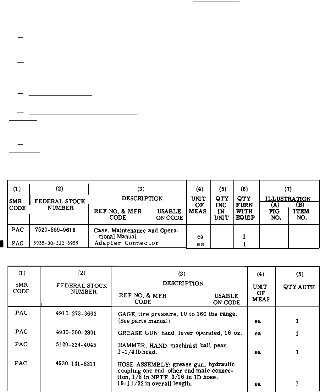
(1) Figure Number. Indicates the figure num-
ber of the illustration in which the items is shown.
(2) Item Number. Indicates the callout number
used to reference the item in the illustration.
B-4. Explanation of Columns in the Tabular List of
Maintenance and Operating Supplies - Section IV.
a. Component Application, Column 1. This
colimn identifies the component application of each
maintenance or operating supply item.
b. Federal Stock Number, Column 2. This
column indicates the Federal stock number assigned
to the item and will be used for requisitioning pur-
poses.
c. Description, Column 3. This column indica-
tes the item name and b
rief de
scription.
d. Quantity Required for Initial Operation,
Column 4. This column indicates the quantity of
each maintenance or operating supply item required
for inttial operation of the equipment.
e. Quantity Required for 8 Hours Operation,
Column 5. This column indicates the estimated
quantities required for an average 8 hours of oper-
ation.
f. Notes, Column 6. This column indicates in-
formative notes keyed to data appearing in a pre-
ceding column.
B-5. Special Information. (Not applicable).
B-6. Abbreviations.
Abbreviation: Explanation:
hv- duty
heavy-duty
deg degree
ea each
hd
head
ID
inside diameter
in inch
lb(s) pound(s)
max maximum
nom
nominal
oz ounce
sgl single
w/with
Section II. BASIC ISSUE
(1)
I
(2)
I
(3)
SMR
I
FEDERAL
STOCK
DESCRIPTION
CODE
NUMBER
I
REF
NO.
&
MFR
USABLE
CODE ON
CODE
PAC
7520-559-9618
Case,
Maintenance and Opera-
tional Manual
PAC
5935-00-322-8959
Adapter
Connector
ITEMS
(4)
UNIT
OF
MEAS
ea
ea
(5)
QTY
INC
IN
UNIT
(6)
QTY
FURN
WITH
EQUIP
1
1
Section III. ITEMS TROOP INSTALLED OR AUTHORIZED LIST
(1) (2)
SMR
FEDERAL
STOCK
CODE
NUMBER
1
PAC
4910-273-3663
PAC
4930-360-2801
PAC
5120-224-4045
PAC
4930-141-8311
(3)
DESCRIPTION
REF
NO.
&
MFR
USABLE
CODE ON
CODE
GAGE:
tire
pressure,
10
to
160
lbs
range.
(See
parts
manual)
GREASE
GUN
hand,
lever
operated,
16
oz.
HAMMER,
I-LAW
machinist
ball
pean,
1
-1/4
lb head,
HOSE
ASSEMBLY
grease
gun,
hydraulic
coupling
one
end, other end
male
connec-
tion, 1/8 in NPTF, 3/16 in
ID
hose,
19-1
1/32 in
overall
length.
(7)
ILLUSTRATION
(A)
(B)
FIG
I
ITEM
NO. NO.
(4)
UNf
T
OF
MEAS
ea
ea
ea
ea
(5)
QTY
AUTH
1
1
1
B-2
Change 12
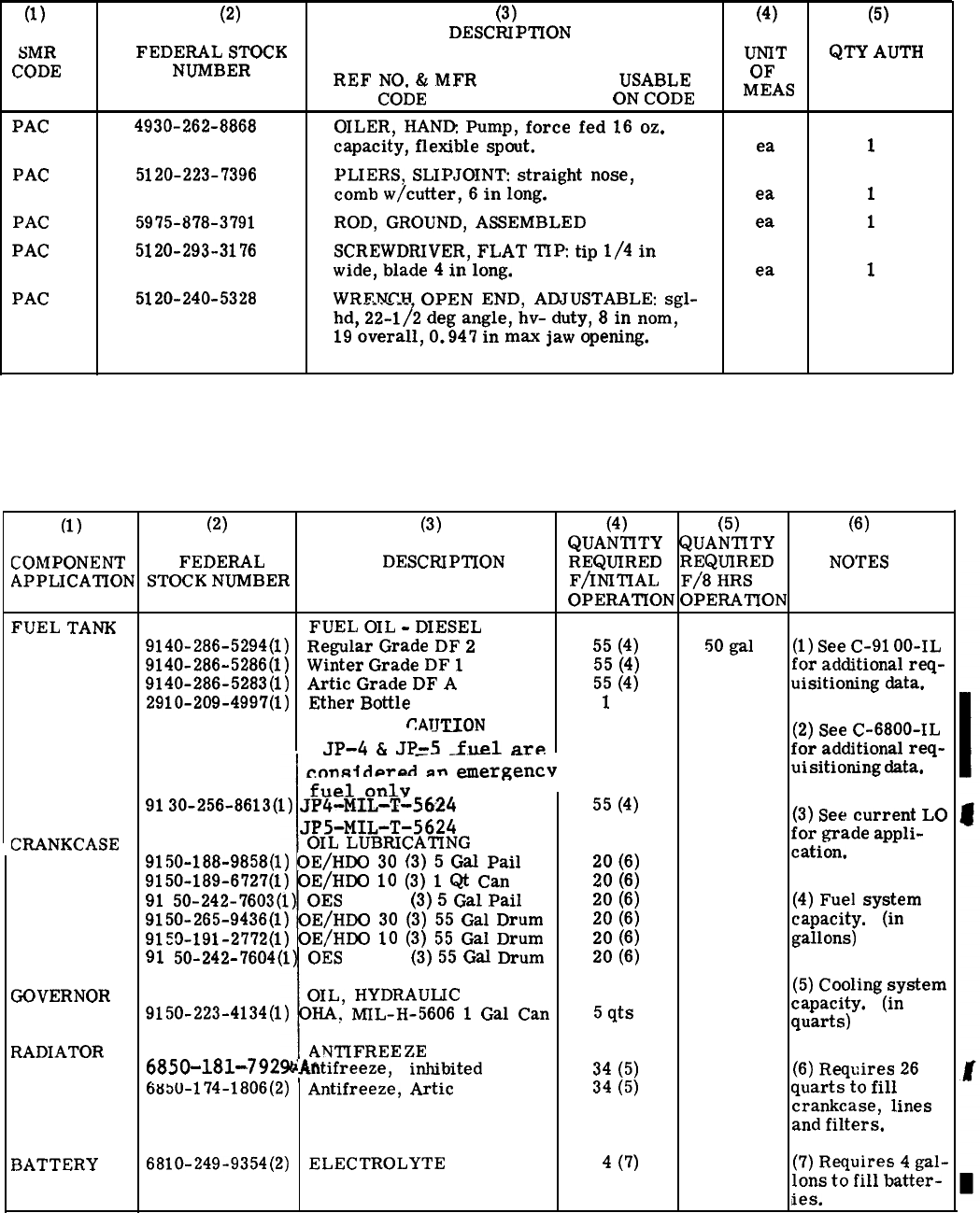
Section III. ITEMS TROOP INSTALLED OR AUTHORIZED LIST (cont)
(1) (2) (3) (4) (5)
DESCRIPTION
SMR
FEDERAL
STOCK UNIT
QTY
AUTH
CODE
NUMBER
REF
NO.
&
MFR
USABLE
OF
CODE ON
CODE MEAS
PAC
4930-262-8868 OILER,
HAND
Pump,
force
fed
16
oz.
capacity,
flexible
spout. ea
1
PAC
5120-223-7396 PLIERS,
SLIPJOINT
straight
nose,
comb
w/cutter,
6
in
long. ea
1
PAC
5975-878-3791
ROD,
GROUND,
ASSEMBLED
ea
1
PAC
5120-293-3176
SCREWDRIVER,
FLAT
TIP
tip
1/4
in
wide,
blade
4
in
long.
ea
1
PAC
5120-240-5328
WRENCH
OPEN
END,
ADJUSTABLE:
sgl-
hd,
22-112
deg
angle,
hv-
duty,
8
in
nom,
19
overall,
O.947
in
max
jaw
opening.
Section IV. MAINTENANCE AND OPERATING SUPPLIES
(1) (2) (3) (4) (5) (6)
QUANTITY
QUAN~TY
COMPONENT FEDERAL DESCRIPTION REQUfRED REQUIRED NOTES
APPLICATION
STOCK
NUMBER
F/INITIAL
F/8
HRS
OPERATION OPERATION
FUEL
TANK
FUEL
OIL
-
DIESEL
9140-286-5294(1)
Regular
Grade
DF
2
55
(4) 50
gal
(1)
See
C-91
OO-IL
9140-286-5286(1) Winter
Grade
DF
1
55
(4)
for
additional
req-
9140-286-5283(1)
Artic
Grade
DF
A
55
(4)
uisitioning
data.
2910-209-4997(1)
Ether
Bottle
1
f!
AL?TION
(2)
See
C-6800-IL
/
JP-4
&
JP=5
-fuel
are
for
additional
req-
ctmsiclertd
~fi
memencv
ui
sitioning
data.
fuel
onlv
91
30-256-8613(1)
JP4-MIL-T-5b24
55
(4)
JP5-MIL-T-5624
(3)
See
current
LO
CRANKCASE
OIL
LUBRICATING
for
grade
appli-
9150-188-9858(1)
OE/HDO
30
(3)
5
Gal
Pail
20
(6)
cation.
9150-189-6727(1)
OE/HDO
10
(3)
1
Qt
Can
20
(6)
91
50-242-7603(1)
OES
(3)
5
Gal
Pail
20
(6) (4)
Fuel
system
9150-265-9436(1)
OE/HDO
30
(3)
55
Gal
Drum
20
(6)
capacity.
(in
915!3-191-2772(1)
OE/HDO
10
(3)
55
Gal
Drum
20
(6)
gallons)
91
50-242-7604(1)
OES
(3)
55
Gal
Drum
20
(6)
GOVERNOR
OIL,
HYDRAULIC
(5)
Cooling
system
9150-223-4134(1)
OHA,
MIL-H-5606
1
Gal
Can
5
qts
capacity.
(in
quarts)
RADIATOR
ANTIFREEZE
6850-181-792
Antifreeze,
inhibited
34
(5) (6)
Requires
26
6ww-174-1806(2)
Antifreeze,
Artic
34
(5)
quarts
to
fill
crankcase,
lines
and
filters.
BATTERY
6810-249-9354(2) ELECTROLYTE
4
(7) (7)
Requires
4
gal-
lons
to
fill
batter-
ies.
Change 3B-3/B-4 blank)

APPENDIX C
MAINTENANCE ALLOCATION CHART
Section I. INTRODUCTION
ARMY and USMC only
C-1. General.
a. This section provides a general explanation of
all maintenance and repair functions authorized at
various maintenance levels.
b. Section II designates overall responsibility for
the performance of maintenance functions on the
identified end item or component. The implementa-
tion of the maintenance functions upon the end item
or component will be consistent with the assigned
maintenance functions.
c. Section III lists the tools and test equipment
required for each maintenance function as refer-
enced from Section II.
d. Section IV contains supplemental instructions,
explanatory notes and/or illustrations required for
a particular maintenance function.
C-2. Explanation of Columns in Section II.
a. Group Number. Column 1. The assembly
group is a numerical group assigned to each assem-
bly in a top down breakdown sequence. The appli-
cable assembly groups are listed on the MAC in dis-
assembly sequence beginning with the first assem-
bly removed in a top down disassembly sequence.
b. Group Title. Column 2. This column contains
a brief description of the components of each assem-
bly group.
c. Maintenance Functions, Column 3. This
column lists the various maintenance functions (A
through K) and indicates the lowest maintenance
category authorized to perform these functions. The
symbol designations for the various maintenance
categories are as follows
C - Operator or crew
O - Organizational maintenance
F - Direct support maintenance (DS)
H - General support maintenance (GS)
D - Depot maintenance
The maintenance functions are defined as follows
A - Inspect. To determine serviceability of an
item by comparing its physical, mechanical, and
electrical characteristics with established standards.
B - Test. To verify serviceability and to de-
tect electrical or mechanical failure by use of test
equipment.
C - Service. To clean, to preserve, to charge,
and to add fuel, lubricants, cooling agents, and air.
If it is desired that elements, such as painting and
lubricating, be defined separately, they may be so
listed.
D - Adjust. To rectify to the extent necessary
to bring into proper operating range.
E - Align. To adjust specified variable ele-
ments of an item to bring to optimum performance.
F - Calibrate. To determine the corrections
to be made in the readings of instruments or test
equipment used in precise measurement. Consists
of the comparison of two instruments, one of which
is a certified standard of known accuracy, to detect
and adjust any discrepancy in the accuracy of the in-
strument being compared with the certified standard.
G - Install. To set up for use in an operational
environment as an emplacement, site, or
vehicle.
H - Replace. To replace unserviceable items
with serviceable like items.
I - Repair. Those maintenance operations
necessary to restore an item to serviceable condition
through correction of material damage or a specific
failure. Repair may be accomplished at each cate-
gory of maintenance.
J - Overhaul. Normally, the highest degree of
maintenance performed by the Army in order to min-
imize time work in process is consistent with quality
and economy of operation. It consists of that main-
tenance necessary to restore an item to completely
serviceable condition as prescribed by maintenance
standards in technical publications for each item of
equipment. Overhaul normally does not return an
item to like new, zero mileage, or zero hour condi-
tion.
K - Rebuild. The highest degree of material
maintenance consists of restoring equipment as
nearly as possible to new condition in accordance
with original manufacturing standards. Rebuild is
performed only when required by operational consid-
erations or other paramount factors and then only at
the depot maintenance category. Rebuild reduces to
zero the hours or miles the equipment, or component
C-1
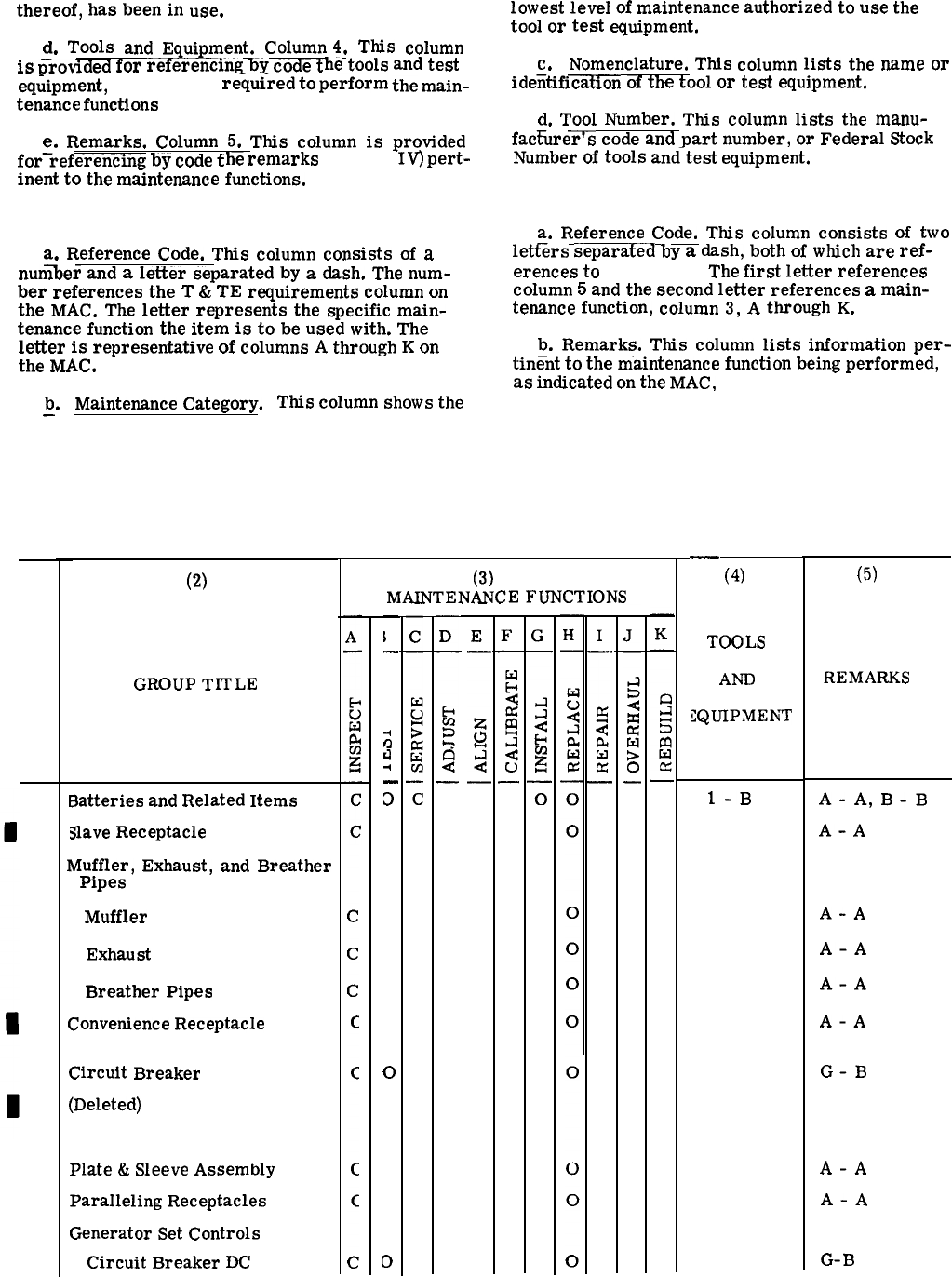
thereof,
has
been
in
use.
d.
Tools
and
Equipment.
Column4.
This
column
is
Crovided
for
referencing
by
code
t
he
tools
and
test
eq;ipment,
(Section III)
requi-red
to
perform
the
main-
tenance
functions
(Section II).
e.
Remarks.
Column
5.
This
column
is
provided
for–referencing
by
code
t
he
remarks
(Section
IV)
pert-
inent
to
the
maintenance
functions.
C-3. Explanation of Columns in Section III.
a.
Reference
Code.
This
column
consists
of
a
num%er
and
a
letter
separated
by
a
dash.
The
num-
ber
references
the
T
&
TE
requirements
column
on
the
MAC.
The
letter
represents
the
specific
main-
tenance
function
the
item
is
to
be
used
with.
The
letter
is
representative
of
columns
A
through
K
on
the
MAC.
b.
—
R
(1)
G
O
U
P
O.
N
01
02
03
04
05
06
07
C-2
Maintenance
Category. This
column
shows
the
lowest
level
of
maintenance
authorized
to
use
the
tool
or
test
equipment.
c. Nomenclature.
This
column
lists
the
name
or
ideiitificatlon
of
th
e
tool
or
test
equipment.
d.
Tool
Number.
This
column
lists
the
manu-
fac~urer’s
code
and
part
number,
or
Federal
Stock
Number
of
tools
and-test
equipment.
C-4. Explanation of Columns in Section IV.
a.
Reference
Code.
This
column
consists
of
two
letl%rs
separafed
b
y
a
dash,
both
of
which
are
ref-
erences
to
Section II.
The
first
letter
references
column
5
and
the
second
letter
references
a
main-
tenance
function,
column
3,
A
through
K.
b.
Remarks.
This
column
lists
information
per-
tini%t
to
th
e
maintenance
function
being
performed,
as
indicated
on
the
MAC,
Section II.
Section II. MAINTENANCE ALLOCATION CHART
ARMY and USMC only
For DOD Generator Set Family 60 KW, Tactical, Precise and Utility, 50/60 and 400 Hz
(2)
GROUP
TITLE
Batteries
and
Related
Items
Nave
Receptacle
Muffler,
Exhaust,
and
Breather
Pipes
Muffler
Exhaust
Breather
Pipes
Convenience
Receptacle
Circuit
Breaker
(Deleted)
Plate
&
Sleeve
Assembly
Paralleling
Receptacles
Generator
Set
Controls
Circuit
Breaker
DC
Change 1
(3)
MAINTENANCE
FUNCTIONS
—
1
.
4
rY
d
•1
—
D
o
D
—
(4)
TOOLS
AND
IQUIPMENT
1-B
(5)
REMARKS
A-
A,
B-B
A-A
A-A
A-A
A-A
A-A
G-B
A-A
A-A
G-B
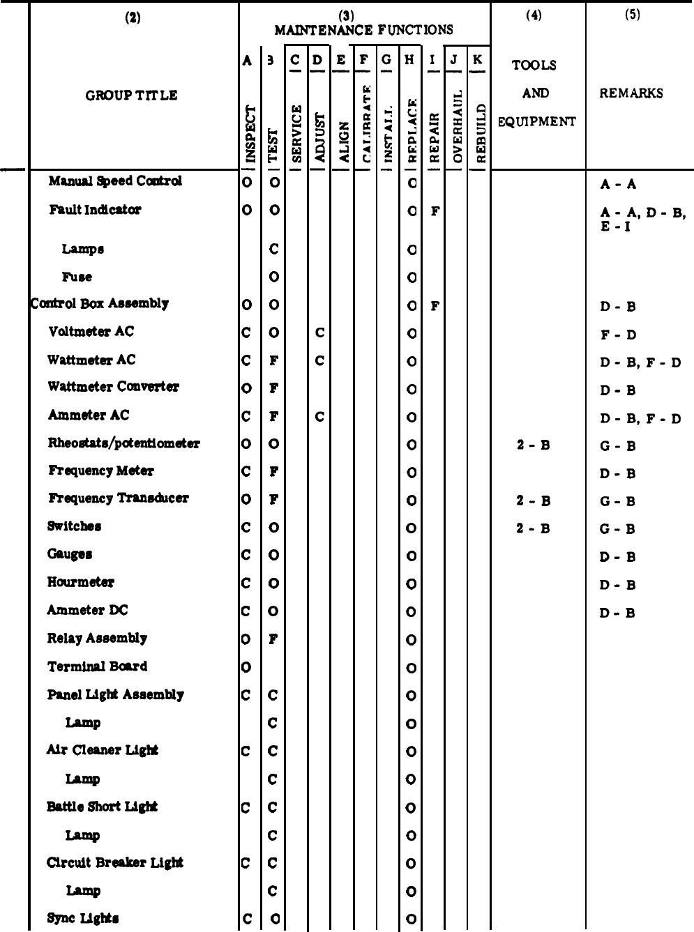
(1)
G
O
P
N
O.
R
(2)
GROUP
TITLE
U
07
(Cont)
Manual
Speed
C-d
Fhult
IncMcatcw
Lamp8
lnlee
‘kxdml
Box
Aesembly
Voltmeter
AC
Wattmeter
AC
Wattmeter
Cowerter
Ammeter
AC
Rheoetats/potenuometer
Frequency
Meter
FYequency
lkanechcer
switches
Gauges
Hourmeter
Ammeter
DC
Relay
Assembly
Terminal
Beard
panel
LigM
Assembly
Lamp
Air
Cleaner
LigM
Battle
Short
1A*
Clrcult
Breaker
LigM
mc
LlgMs
A
*
u
w
g
~
G
o
0
c
c
o
c
o
c
o
c
c
c
c
o
0
c
c
c
c
c
(3)
MAINTENANCE
FUNCTIONS
3
~
*
i
o
c
o
0
0
F
F
F
o
F
F
o
0
0
0
F
c
c
c
c
c
c
c
c
0
H
:
<
z
E
a
i
o
0
0
0
0
0
0
0
0
0
0
0
0
0
0
0
0
0
0
0
0
0
0
0
0
0
(4)
TOOLS
AND
EQUIPMENT
2-B
2-B
2-B
(5)
REMARKS
A-A
A-
A,
D-B,
E-
I
D-B
F-D
D-
B,
F-D
D-B
D-
B,
F-D
G-B
D-B
G-B
G-B
D-B
D-B
D-B
c-3
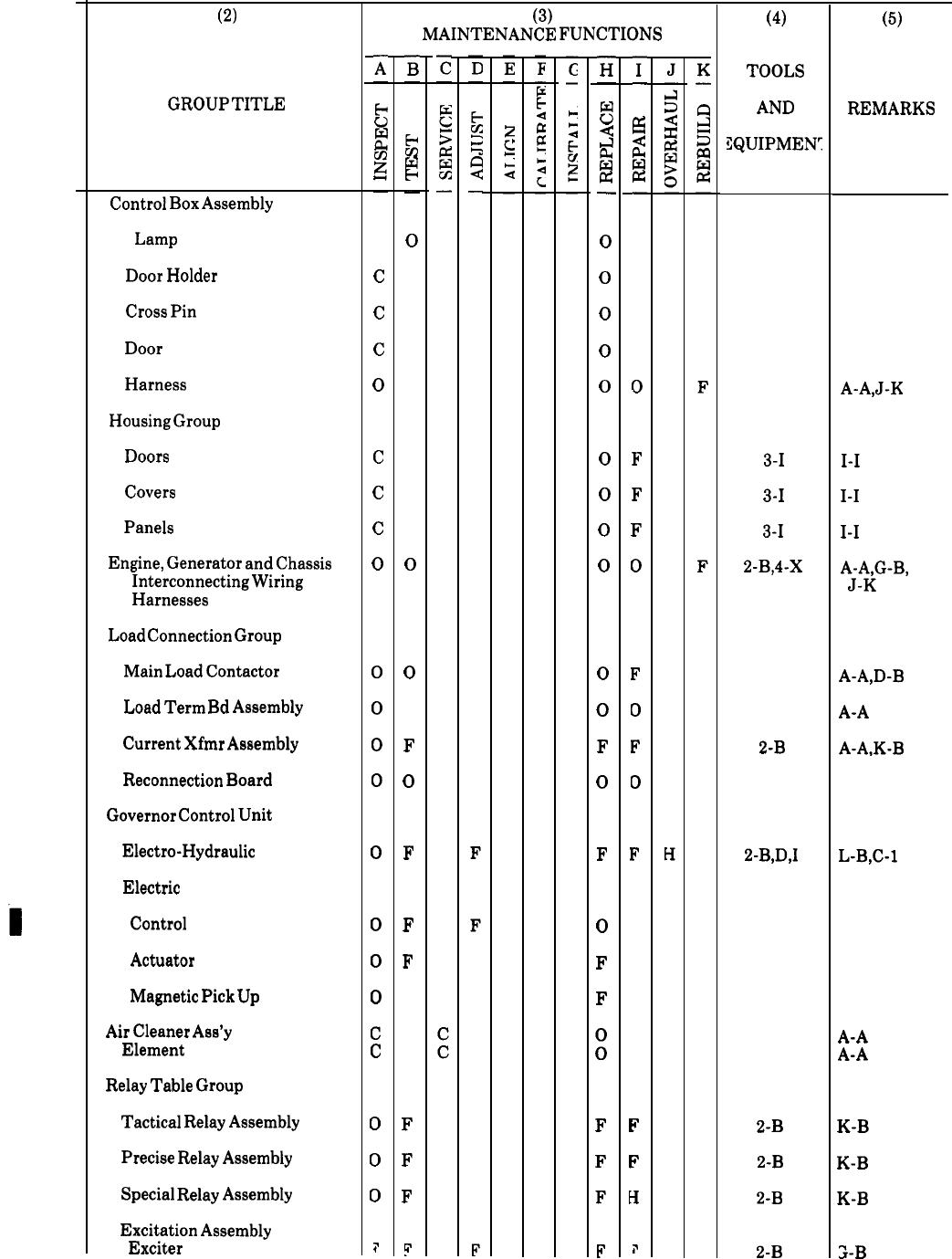
(1)
G
R
U
P
N
o.
(cont)
08
09
10
11
12
13
C-4
(2)
O
GROUP
TITLE
07
Control
Box
Assembly
Lamp
Door
Holder
Cross
Pin
Door
Harness
Housing
Group
Doors
Covers
Panels
Engine,
Generator
and
Chassis
Interconnecting
Wiring
Harnesses
Load
Connection
Group
Main
Load
Contactor
Load
Term
Bd
Assembly
Current
Xfmr
Assembly
Reconnection
Board
Governor
Control
Unit
Electro-Hydraulic
Electric
Control
Actuator
Magnetic
Pick
Up
Air
Cleaner
Ass’y
Element
Relay
Table
Group
Tactical
Relay
Assembly
Precise
Relay
Assembly
Special
Relay
Assembly
Excitation
Assembly
Exciter
Change 15
x
—
6
E
g
—
c
c
c
o
c
c
c
o
0
0
0
0
0
0
0
0
c
c
o
0
0
i’
z
—
$
cd
H
—
o
0
0
F
o
F
F
F
F
F
F
~
(3)
MAINTENANCE
FUNCTIONS
E
—
5
~
a
z
—
0
0
0
0
0
0
0
0
0
0
0
F
0
F
0
F
F
:
F
F
F
F
-i
—
&l
~
&
W
Z
—
0
F
F
F
0
F
0
F
D
F
F
F
H
i’
(4)
TOOLS
AND
3QUIPMEW
3-1
3-1
3-1
2-B,4-X
2-B
2-B,D,I
2-B
2-B
2-B
2-B
(5)
REMARKS
A-A,J-K
1-1
1-1
1-1
A-A,G-B,
J-K
A-A,D-B
A-A
A-A,K-B
L-B,C-l
A-A
A-A
K-B
K-B
K-B
2-B

TM 5-6115-545-12
TO-35C2-3-444-1
NAVFAC P-8-626-12
TM-00038G-12
(1)
G
R
o
u
P
N
o.
13
(Cont)
14
15
16
17
(2)
GROUP
TITLE
Relay
Table
Group
Voltage
Regulator
Load
Measuring
Unit
Generator
Assembly
Bearing
Rectifier
Rotating
Fan
Generator
Rotor
Assembly
Stator
Exciter
Assembly
Stator
Generator
Assembly
Day
Tank
and
Fuel
Filter
Assembly
Solenoid
Valve
Day
Tank
Float
Switch
Fuel
Filter
Assembly
Lifting
Frame
Assembly
Start
Aid
Assembly
Filler
Cap,
Gasket
and
Strainer
Hoses
Lifting
Frame
Fuel
Transfer
Pump
Cooling
Group
Grill
Fan
Guard
A
—
&
c1
5
~
—
F
o
0
0
F
F
F
F
F
o
c
o
c
c
c
c
o
c
c
c
(3)
MAINTENANCE
FUNCTIONS
F
F
F
F
o
0
0
c
c
c
c
o
H
M
~
A
a
F
F
F
F
F
F
F
F
F
o
0
0
0
0
0
0
F
o
0
0
(4)
TOOLS
AND
EQUIPMENT
2–B,
5–I,
J
6,7–H,
8–B
9–I,
J
10–
H
2–B,
11–1
2–B
2-B
2–B
2–B
(5)
REMARKS
D–B
E–I
D–B
N–A
G–B
O–B,
P–K
O–B,
P–K
O–B,
P–K
G–B
Q–C
Q–C
Change 13C-5
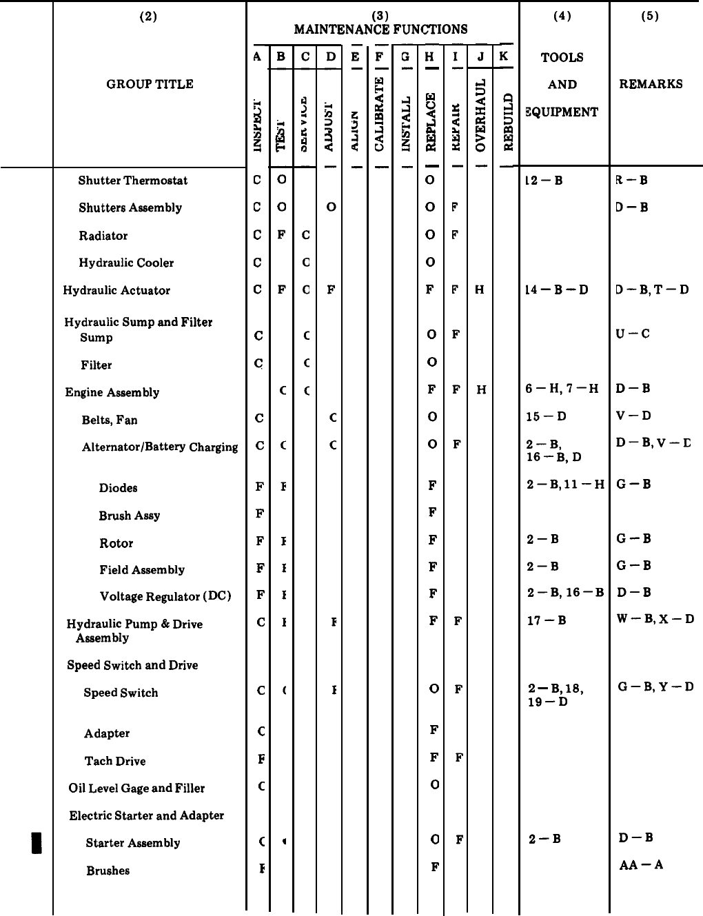
TM 5-6115-545-12
TO-35C2-3-444-1
NAVFAC P-8-626-12
TM-00038G-12
(1)
G
R
O
U
P
N
O.
(Cont)
18
19
20
C-6
(2)
GROUP
TITLE
17
Shutter
Thermostat
Shutters
Assembly
Radiator
Hydraulic
Cooler
Hydraulic
Actuator
Hydraulic
Sump
and
Filter
Sump
Filter
Engine
Assembly
Belts,
Fan
Alternator/Battery
Charging
Diodes
Brush
ASSY
Rotor
Field
Assembly
Voltage
Regulator
(DC)
Hydraulic
Pump
&
Drive
Assembly
Speed
Switch
and
Drive
Speed
Switch
Adapter
Tach
Drive
Oil
Level
Gage
and
Filler
Electric
Starter
and
Adapter
Starter
Assembly
Brushes
Change 13
:
L1
b
*
b
n
q
c
c
c
c
c
c
c
c
c
F
F
F
F
F
c
c
c
F
c
c
E
(3)
MAINTENANCE
FUNCTIONS
F
—
w
c)
-j
a
a!
—
o
0
0
0
F
o
0
F
o
0
F
F
F
F
F
F
o
F
F
o
0
F
(4)
TOOLS
AND
EQUIPMENT
12–B
14–B–D
6–H,7–
H
15–D
2–B,
16–
B,D
2–B,
ll–
H
2–B
2–B
2–B,16–
B
17–B
2
–
B,
18,
19–D
2–B
(5)
REMARKS
R–B
D–B
D–B,
T–D
u–c
D–B
V–D
D–B,
V–E
G–B
G–B
G–B
D–B
W–B,
X–D
G–B,
Y–D
D–B
AA–A
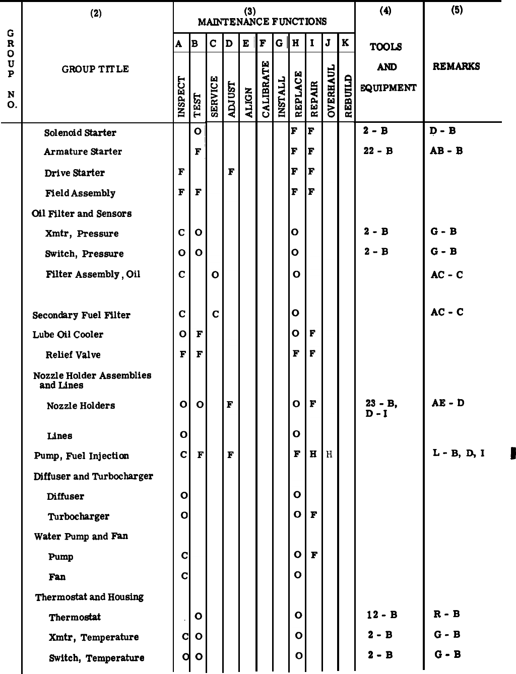
(1)
(Cont)
(2)
GROUP
T~LE
20
Solenoid
Starter
Armature
Starter
Drive
Starter
Field
Assembly
Oil
Filter
and
Sensors
Xmtr,
Pressure
Switch,
Pressure
Filter
Assembly,
Oil
Secondary
Fuel
Filter
Lube
Oil
Cooler
Relief
Valve
Nozzle
Holder
Assemblies
and
Lines
Nozzle
Holders
Lines
Pump,
Fuel
Injection
Diffuser
and
Turbocharger
Diffuser
Turbocharger
Water
Pump
and
F%n
Pump
Fan
Thermostat
and
Housing
Thermostat
Xmtr,
Temperature
Switch,
Temperature
(3)
MAINTENANCE FUNCTIONS
(4)
TOOLS
2QUIPME~
2-B
22-B
2-B
2-B
23-
B,
D-
I
12-B
2-B
2-B
(5)
REMARKS
D-B
AB-B
G-B
G-B
AC-C
AC-C
AE-D
L-
B,QI
D
R-B
G-B
G-B
Change 8 C-7

(1)
G
R
O
U
P
N
O.
20
(Cont)
Timing Gear and Cover
C-8
(2)
GROUP
TITLE
Dampener,
Vibration
and
Crankshaft
Pulley
Idler
Pulley
Assembly
Intake
Manifold
EXhSUSt
Manifold
Engine
FYcmt
Support
Oil
Pan
Assembly
011
pump
Flywheel
end
Housing
Flywheel
Assembly
Eungcear
Flywheel
Housiw
Cylinder
Head
and
Vslve
Operating
Mechanism
Rocker
Arm
Shaft
Assem.
bly
Rocker
Arm
Assembly
Pushrod
Cylinder
Head
Assembly
Valves
Intake
and
Exkuet
qx’ings
Valvw
Seats
Intake
and
Exhaust
valves
Guides
Valve
Head,
Cylinder
Lifters,
Valve
camshaft
Change 8
(3)
MMNTENANCE
FUNCTIONS
—
H
5
j
A
w
&
—
F
o
0
0
F
F
H
H
H
H
H
F
F
F
F
F
F
H
H
H
H
H
(4)
‘TOOLS
ZQUIPMENI
21-D
24-1,25-
26-1
27-H
28-H
29-H
(5)
REMARUS
V-D
AF-1
D-B
AG-B
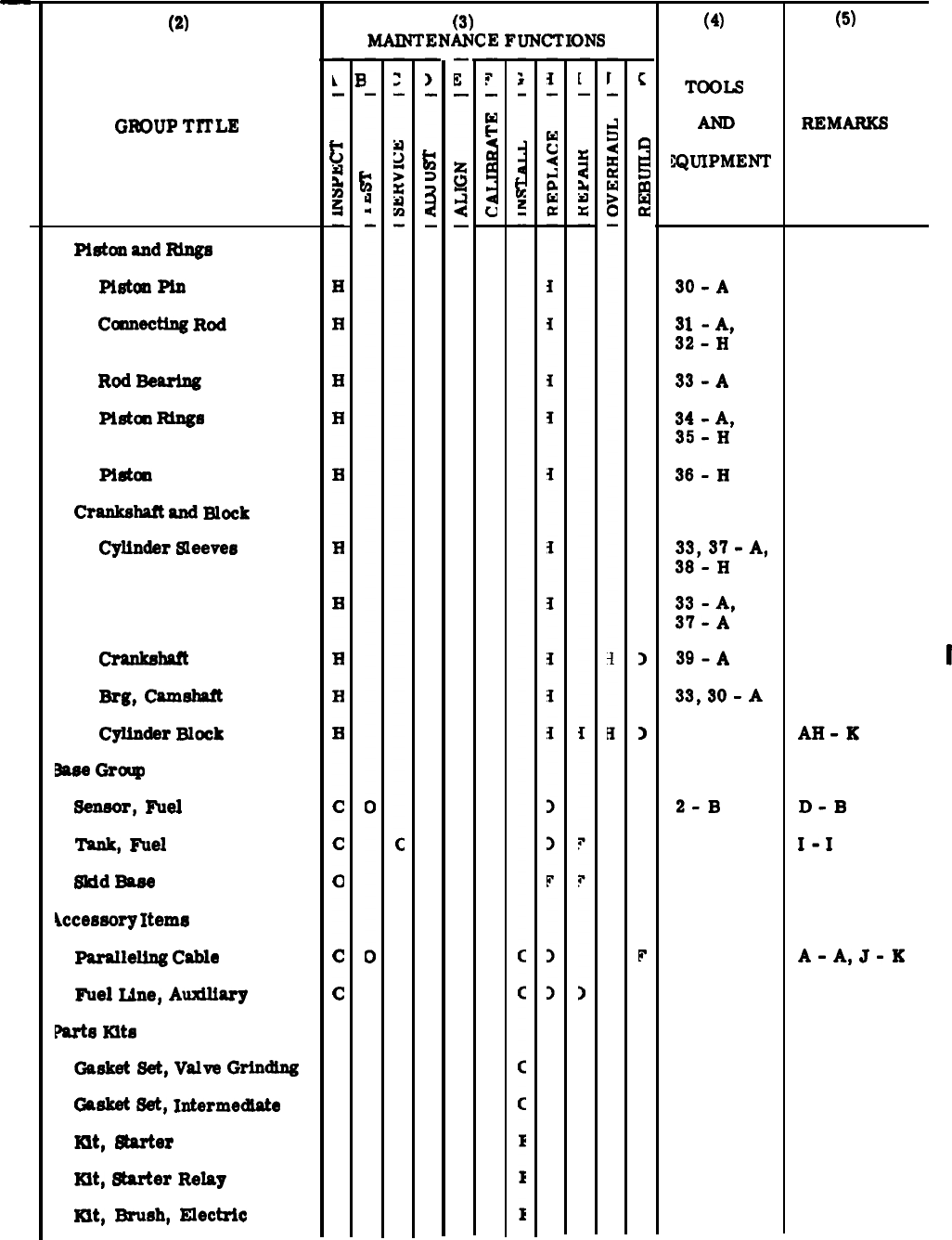
(1)
G
O
U
P
O.
—
(Cont)
21
22
23
(2)
GROUP
TITLE
R
N
20
Piston
snd
I@s
Pietun
P&
Camecting
Rod
Rod
Beu’tng
Plstal
Rtngs
Plstal
Crankshaft
snd
mock
Cylinder
Sleeves
Main Bearings
Craukshatt
Brg,
camshaft
Cylinder
Block
2sss
Graup
sensor,
Fuel
‘Iknk,
Fuel
Skid
Base
Jccessory
Items
Psralleltng
Cable
Fuel
Line,
Auxilisry
Farts
Kits
Garket
Set,
Vslve
Grindlw
Gasket
Set,
Intermediate
Hit,
Starter
Kit,
Starter
Relsy
mt,
Brush,
Electric
(3)
MAINTENANCE
FUNCTIONS
c
9
5
m
ha
a
)
)
F
(4)
TOOLS
lQUIPMEIW
30-A
31-
A,
32-H
33-A
34-
A,
35-H
36-H
33,
37-A,
38-H
33-
A,
37-A
39-A
33,
30-
A
2-B
(5)
REMARKS
I
AH-K
D-B
I-
I
A-
A,
J-K
Change 8C-9
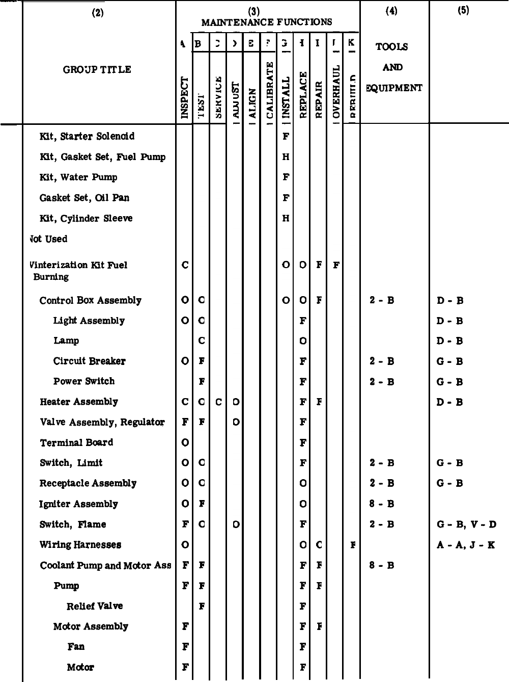
(1)
G
O
u
P
O.
—
(Cont)
24
25
(2)
R
REMARKS
GROUP
TITLE
N
23
Kit,
Starter
Solenoid
Ktt,
Gasket
Set,
Fuel
Pump
Kit,
Water
Pump
Gasket
Set,
Oil
Pan
Kit,
Cylinder
Sleeve
Jot
Used
Vinterization
Kit
Fuel
Burning
Control
Box
Assembly
Light
Assembly
Lamp
Circuit
Breaker
Power
Switch
Heater
Assembly
Valve
Assembly,
Regulator
Terminal
Board
Switch,
Limit
Receptacle
Assembly
Igniter
Assembly
Switch,
Flame
Wiring
Harnesses
Coolant
Pump
and
Motor
Ass
Pump
Relief
Valve
Motor
Assembly
Fan
M&M
4
c-
LI
w
tJ
g
c
0
0
0
c
F
0
0
0
0
F
0
F
F
F
F
F
(3)
MAINTENANCE
FUNCTIONS
i
w
u
~
A
w
a
o
0
F
o
F
F
F
F
F
F
o
0
F
o
F
F
F
F
F
F
I
~
w
a
F
F
F
c
F
F
F
(4)
TOOLS
EQUIPMENT
2-B
2-B
2-B
2-B
2-B
8-B
2-B
8-B
(5)
D-B
D-B
D-B
G-B
G-B
D-B
G-B
G-B
G-
B,
V-D
A-
A,
J-K
C-10
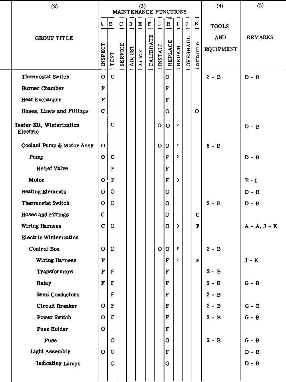
(1)
G
O
U
P
O.
R
N
(Cont)
26
(2)
GROUP
TITLE
25
Thermostat
Switch
Burner
Chamber
Heat
Exchanger
Hoses,
Lines
and
Fittings
Ieater
Kit,
Winterization
Electric
Coolant
Pump
&
Motor
Assy
Pump
Relief
Valve
Motor
Heating
Elements
Thermostat
Switch
Hoses
and
Fifflngs
Wiring
Harness
Electric
Winterization
Control
Box
Wiring
Hmmess
‘iYansformers
Relay
Semi
Conductors
Circuit
Breaker
Power
Switch
Fuse
Holder
Fuse
Light
Assembly
Indicating
lamps
(3)
MAINTENANCE
FUNCTIONS
o
0
c
c
o
F
F
F
o
0
0
0
0
0
0
0
F
F
F
F
F
o
0
c
—
H
—
M
u
4
d
&
w
E
—
0
F
F
0
0
0
F
F
F
0
0
0
0
0
F
F
F
F
F
F
F
0
F
0
(4)
TOOLS
AND
EQUIPMENr
2-B
8-B
2-B
2-B
2-B
2-B
2-B
2-B
2-B
2-B
(5)
REMARKS
D-B
D-B
D-B
E-
I
D-B
D-B
A-
A,
J-K
J-K
G-B
G-B
G-B
G-B
D-B
D-B
C-11
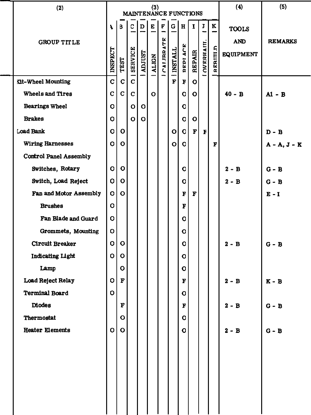
(1)
G
O
U
P
N
o.
27
28
(2)
R
GROUP
TITLE
Kit-Wheel
Mounting
Wheels
and
Tires
Bearings
Wheel
Brakes
Load
Bank
Wiring
Harnesses
Control
Panel
Assembly
Switches,
Rotary
Switch,
Load
Reject
Fan
and
Motor
Assembly
Brushes
Fan
Blade
and
Guard
Grommets,
Mounting
Circuit
Breaker
Indicating
Light
Lamp
Load
Reject
Relay
Terminal
Board
Diodes
Thermostat
Heater
Elements
A
H
u
w
&
~
c
c
o
0
0
0
0
0
0
0
0
0
0
0
0
0
0
(3)
MAINTENANCE
FUNCTIONS
—
B
g
H
c
c
o
0
0
0
0
0
0
0
F
F
o
0
H
:
4
E
E
E
F
0
0
a
c1
o
(1
o
F
F
o
0
0
0
0
F
o
F
o
0
I
5
a
G
o
0
0
F
F
(4)
TOOLS
EQUIPMENT
40-B
2-B
2-B
2-B
2-B
2-B
2-B
(5)
REMARKS
Al-B
D-B
A-
A,
J-K
G-B
G-B
E-
I
G-B
K-B
G-B
G-B
C-12
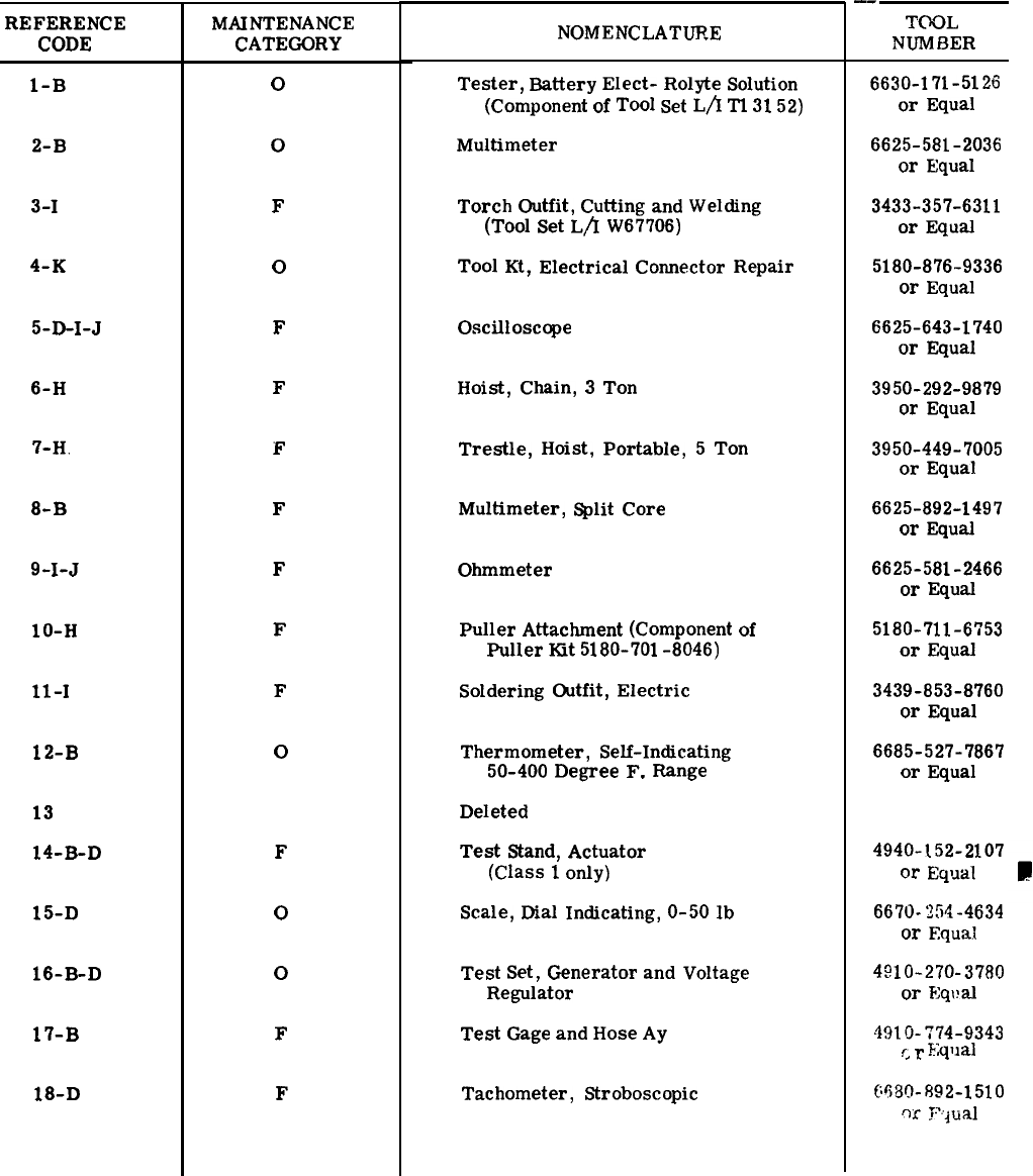
REFERENCE
CODE
1-B
2-B
3-I
4-K
5-D-I-J
6-H
7-H.
8-B
9-I-J
1O-H
11-1
12-B
13
14-B-D
15-D
16-B-D
17-B
18-D
Section III. MAINTENANCE ALLOCATION CHART
ARMY and USMC only
For DOD Generator Sets, 60 KW, 50/60 and 400 Hz
TOOL AND TEST EQUIPMENT REQUIREMENTS
MAINTENANCE
CATEGORY
o
0
F
o
F
F
F
F
F
F
F
o
F
o
0
F
F
NOMENCLATURE
Tester,
Battery
Elect-
Rolyte
Solution
(Component
of
Tool
Set
L/x
Tl
31
52)
Multimeter
Torch
Outfit,
Cutting
and
Welding
(Tool
Set
L/I
W67706)
Tool
Kt,
Electrical
Connector
Repair
Oscilloscope
Hoist,
Chain,
3
Ton
Trestle,
Hoist,
Portable,
5
Ton
Multimeter,
Split
Core
Ohmmeter
Puller
Attachment
(Component
of
Puller
Kit
5180-701
-8046)
Soldering
Outfit,
Electric
Thermometer,
Self-Indicating
50-400
Degree
F.
Range
Deleted
Test
Stand,
Actuator
(Class
1
only)
Scale,
Dial
Indicating,
O-50
lb
Test
Set,
Generator
and
Voltage
Regulator
Test
Gage
and
Hose
Ay
Tachometer,
Stroboscopic
-.
TOOL
NUMBER
6630-171-5126
or
Equal
6625-581-2036
or
Equal
3433-357-6311
or
Equal
5180-876-9336
or
Equal
6625-643-1740
or
Equal
3950-292-9879
or
Equal
3950-449-7005
or
Equal
6625-892-1497
or
Equal
6625-581-2466
or
Equal
5180-711-6753
or
Equal
3439-853-8760
or
Equal
6685-527-7867
or
Equal
4940-152-2107
or
~qWd~
6670-254-4634
or
Equal
4~10-270.37~0
or
Eqval
4910-774-9343
f.
r
~ql]a]
6630-892-1510
w
Yjual
Change 3C-13
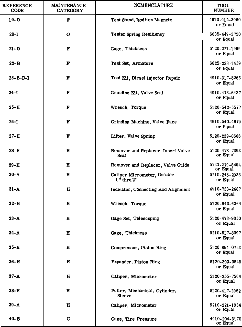
REFERENCE
CODE
19-D
20-I
21-D
22-B
23-B-~1
24-I
25-H
26-I
27-H
28-H
29-H
30-A
31
-A
32-H
33-A
34-A
35-H
36-H
37-A
38-H
39-A
40-B
MAINTENANCE
CATEGORY
F
o
F
F
F
F
F
F
F
H
H
H
H
H
H
H
H
H
H
H
H
c
NOMENCLATURE TOOL
NUMBER
Test
Stand,
Ignition
Magneto
Tester
Spring
Resiliency
Gage,
Thickness
Test
Set,
Armature
Tool
Kit,
Diesel
Injector
Repair
Grinding
Kt,
Valve
Seat
Wrench,
Torque
Grinding
Machine,
Valve
Face
Lifter,
Valve
Spring
Remover
and
Replacer,
Insert
Valve
Seat
Remover
and
Replacer,
Valve
Guide
Caliper
Micrometer,
Outside
1
“
thru
2“
Indicator,
Connecting
Rod
Alignment
Wrench,
Torque
Gage
Set,
Telescoping
Gage,
~
Thickness
Compressor,
Piston
Ring
Expander,
Piston
Ring
Caliper,
Micrometer
Puller,
Mechanical,
Cylinder,
Sleeve
Caliper,
Micrometer
Gage,
Tire
Pressure
4910-912-3960
or
Equal
I
6635-449-3750
or
Equal
5120-221-1999
or
Equal
6625-233-1459
or
Equal
4910-317-8265
or
Equal
4910-473-6437
or
Equal
5120-542-5577
or
Equal
4910-540-4679
or
Equal
5120-239-8686
or
Equal
5120-473-7393
or
Equal
5120-219-8404
or
Equal
5210-243-2933
or
Equal
4910-733-2487
or
Equal
5120-640-6364
or
Equal
5120-473-9350
or
Equal
5210-517-8097
or
Equal
5120-894-0753
or
Equal
5120-393-0549
or
Equal
5120-255-7564
or
Equal
5120
-417
-’2952
or
Equal
5210-221-1934
or
Equal
4910-204-3170
or
Equal
C-14
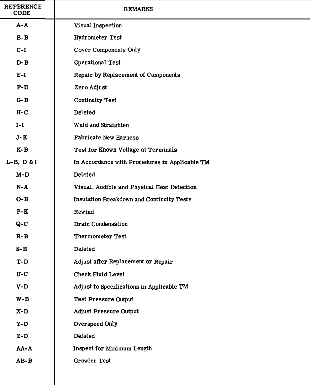
REFERENCE
CODE
A-A
B-B
C-I
D-B
E-I
F-D
GB
H-C
I-I
J-K
K-B
L-B,
D&I
M-D
N-A
O-B
P-K
Q-C
R-B
S-B
T-D
u-c
V-D
W-B
X-D
Y-D
Z-D
M-A
A&B
Section IV. MAINTENANCE ALLOCATION CHART
ARMY and USMC only
REMARKS
Visual
Inspection
Hydrometer
Test
Cover
Components
Only
Operational
Test
Repair
by
Replacement
of
Components
Zero
Adjust
Continuity
Test
Deleted
Weld
and
Straighten
Fabricate
New
Harness
Test
for
Known
Voltage
at
Terminals
In
Accordance
with
Procedures
in
Applicable
TM
Deleted
Visual,
Audible
and
Physical
Heat
Detection
Insulation
Breakdown
and
Continuity
Tests
Rewind
Drain
Condensation
Thermometer
Test
Deleted
Adjust
after
Replacement
or
Repair
Check
Fluid
Level
Adjust
to
Specifications
in
Applicable
TM
Test
Pressure
Output
Adjust
Pressure
Output
Overspeed
Only
Deleted
Inspect
for
Minimum
Length
Growler
Test
C-15
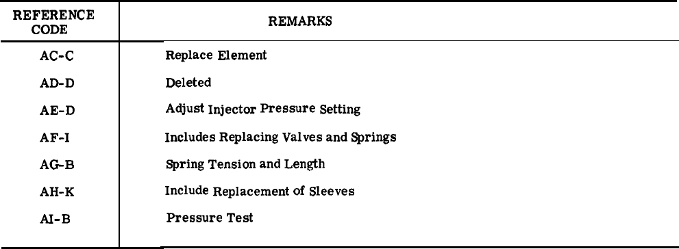
REFERENCE
CODE
AC-C
AD-D
AE-D
AF-I
AG
B
AH-
K
AI-B
REMARKS
Replace
Element
Deleted
Adjust
Injector
Pressure
Setting
Includes
Replacing
Valves
and
Springs
Spring
Tension
and
Length
Include
Replacement
of
Sleeves
Pressure
Test
C-16

ALPHABETICAL INDEX
Subject
Paragraph,
Figure, Table,
Number
A
Abbreviations . . . .
Accessory Items
Accessory Items
General. . . . .
Hose Assembly .
Paralleling Cable Assembly.
Storage Space . . . . . .- .
Adjusting Flame Switch . . . .
Adjustment
Flame Micro-Switch . . . .
Fuel Regulator . . . . . .
Fuel Regulator Valve . . .
Valve Tappet Clearance . .
Air Cleaner Service . . . . . .
Alternator and Related Parts
Assembly . . . . . . . . .
Battery Charging Alternator
.
Belt Adjustment and Replacement
Drive Belts . . . . . . . . . .
General . . . . . . . . . . .
B
Base Group and Related Components
Assembly . . . . . . . . . . . . . . . . . . . . . . . .
Base Group . . . . . . . . . . . . . . . . . . . . . . .
Fuel Tank Removal, Cleaning and Inspection and Installation .
Fuel Quantity Transmitter Removal, Testing and Replacement
Fuel Quantity Transmitter Test . .
General, . . . . . . . . . . . .
Related Components . . . . . . .
Skid Base Inspection . . . . . . .
Basic Issue Items List, Section II . . .
Batteries and Related Parts
Batteries . . . . . . .
General . . . . . . . . .
Batteries and Slave Receptacles .
C
Controls and Instruments
Controls and Instruments . ,
General, . . . . . . . . .
Convenience Receptacle
Convenience Receptacle . . .
Box Assembly Replacement ,
Circuit Breaker Test Replacement. .
General . . . . . . . . . . . . . .
Replacement . . . . . . . . . . .
(Deleted)
(Deleted)
(Deleted)
(Deleted)
(Deleted)
Coolant PumpMotor -Brush and Connector Replacement.
.
B-6
F3-53
3-226
3-228
3-227
3-229
F4-4
4-11
4-10
F4-3
3-220
F3-5
F3-36
3-184
F3-35
3-183
3-182
F3-50
F3-51
3-225
3-223
F3-52
3-221
3-224
3-222
B-2
3-82
3-81
F3-4
2-10, F2-5
2-9
F3-13
3-89
3-91
3-88
3-90
F3-14
3-94
3-92
3-93
F4-8
Change 1I-1

ALPHABETICAL INDEX (Cont)
Cooling Group
Cooling Group, . . . . . . . . . . . . . . . .
Cooling Group and Related Parts . . . . . . . .
Fan Guard . . . . . . . . . . . . . . . . . .
General . . . . . . . . . . . . . . . . . . .
Grille . . . . . . . . . . . . . . . . . . . .
Hydraulic Cooler . . . . . . . . . . . . . . .
Radiator . . . . . . . . . . . . . . . . . . .
Shutter Assembly . . . . . . . . . . . . . . .
Shutter Thermostat . . . . . . . . . . . . .
Shutter Thermostat Replacement . . . . . . . .
Crankshaft Pulley and Vibration Dampener
General . . . . . . . . . . . . . . . . . . . .
Inspection . . . . . . . . . . . . . . . . . .
D
Data Instruction Plate Locations. . . . . . . . . . . .
Day Tank Fuel Assembly
Day Tank and Float Switch . . . . . . . . . . . .
Day Tank and Fuel Filter Assembly . . . . . . . .
Fuel Filter Assembly Removal and Replacement . .
Solenoid Valve, . . . . . . . . . . .
Description and Data
Description . . . . . . . . . . . . .
Difference in Models . . . . . . . . .
Identification and Tabulated Data . . .
Destruction of Material . . . . . . . . .
Differences in Performance Characteristics
Diffusers and Turbocharger
Assembly . . . . . . . . . . . . . .
Exhaust Diffuser . . . . . . . . . .
General . . . . . . . . . . . . . .
Turbocharger, . . . . . . . . . . .
E
Electric Starter and Adapter
General . . . . . . . . . . . . .
Starter Assembly . . . . . . . . . .
Starter Solenoid . . . . . . . . . . . .
Electric Winterization Kit
Assembly . . . . . . . . . . . . . . .
Control Box Fuse and Lamp Replacement
General . . . . . . . . . . . . . . . .
Installation . . . . . . . . . . . . . .
Operation . . . . . . . . . . . . . . .
Preventive Maintenance . . . . . . . .
Preventive Maintenance Checks and Services . . . . . .
Removal . . . . . . . . . . . . . . . . . . . . . .
schematic Wiring . . . . . . . . . . . . . . . . . .
Troubleshooting . . . . . . . . . . . . . . . . . . .
Engine Assembly
Drain Hoses . . . . . . . . . . . .
Engine Assembly Testing. . . . . . . . . . . . . . .
General . . . . . . . . . . . . . . . . . . . . . . . .
Engine Generator and Chassis Interconnecting Wiring Harnesses
Engine Generator and Chassis Wiring Harnesses . . . . .
General . . . . . . . . . . . . . . . . . . . . . . . .
Inspection, Test, Repair and Replacement . . . . . . . .
Engine Generator Set
Left Rear, Three Quarter View . . . . . . . . . . . . .
Right Front, Three Quarter View . . . . . . . . . . . .
I-2
F3-31
F3-29
3-169
3-167
3-168
3-173
3-172
3-171
3-170
F3-30
3-210
3-211
F1-3
3-159
F3-27
3-160
3-158
1-3
1-5
1-4
A-7
T1-1
F3-42
3-204
3-202
3-203
3-189
3-190
3-191
F4-7
F4-9
4-17
4-18
2-26
4-20
T4-3
4-19
F4-6
4-21, T4-4
3-181
3-180
3-179
F3-23
3-138
3-139
F1-2
F1-1

ALPHABETICAL INDEX (Cont)
Engine Generator Set Housing Group
General . . . . . . . . . . . . . . . . . . . . . . . . . . . . . . . . . . . .
Housing Group . . . . . . . . . . . . . . . . . . . . . . . . . . . . . . . . .
Removal and Replacement . . . . . . . . . . . . . . . . . . . . . . . . . . . .
Equipment
Inspecting and servicing . . . . . . . . . . . . . . . . . . . . . . . . . . . . . .
Unloading. . . . , . . . . . . . . . . . . . . . . . . . . . . . . . . . . . . .
Unpacking. . . . . . . . . . . . . . . . . . . . . . . . . . . . . . . . . . . . .
Equipment Conversion. . . . . . . . . . . . . . . . . . . . . . . . . . . . . . . .
Exhaust and Breather Pipe . . . . . . . . . . . . . . . . . . . . . . . . . . . . . .
Exhaust Manifold Assembly. . . . . . . . . . . . . . . . . . . . . . . . . . . .
General . . . . . . . . . . . . . . . . . . . . . . . . . . . . . . . . . . . .
Inspection and Replacement. . . . . . . . . . . . . . . . . . . . . . . . . . . .
Explanation of Columns . . . . . . . . . . . . . . . . . . . . . . . . . . . . .
Explanation of Columns in Section II. . . . . . . . . . . . . . . . . . . . . . . . . .
Explanation of Columns in Section III . . . . . . . . . . . . . . . . . . . . . . . . .
Explanation of Columns in Section IV . . . . . . . . . . . . . . . . . . . . . . . . .
Explanation of Columns in the Tabular List of Maintenance
and Operating Supplies - Section IV. . . . . . .
Fan and Motor Assembly. . . . . . . . . . . .
Fault Indicator Test Points . . . . . . . . . . .
Fault Indicators Function . . . . . . . . . . . .
Field Expedient Repairs
Battery Charging Ammeter Shows No Charge .
Engine Cranks But Will Not Start or Starts and
Engine Heat Up . . . . . . . . . . . . . .
Engine Overheating . . . . . . . . . . . .
F
Runs Erratically or Misfires . . . . . .
Engine Shuts Down-and Low Oil Pressure Indicator Lights . . . . . . . . . . .
Fuel is Not Strained . . . . . . . . . . . . . . . . . . . . . . . . . . . .
General . . . . . . . . . . . . . . . . . . . . . . . . . . . . . . . . .
Housing Filled with Smoke... . . . . . . . . . . . . . . . . . . . ..
Loss of Frequency Control (Class 1 sets Only) . . . . . . . . . . . . . . . .
Fire Protection, . . . . . . . . . . . . . . . . . . . . . . . . . . . . . . .
Forms and Records . . . . . . . . . . . . . . . . . . . . . . . . .
Freezing Points, Composition, and Specific Gravities of Military Antifreeze Materials
Fuel Burning Winterization Kit
Assembly . . . . . . . . . . . . . . . . . . . . . . . . . . . . . . .
Control Box and Lamp Replacement . . . . . . . . . . . . . . . . . . . . .
General, . . . . . . . . . . . . . . . . . . . . . . . . . . . . . . . . .
Installation . . . . . . . . . . . . . . . . . . . . . . . . . . . . . . . .
Operation . . . . . . . . . . . . . . . . . . . . . . . . . . . . . . . . .
Preventive Maintenance . . . . . . . . . . . . . . . . . . . . . . . . . .
Removal . . . . . . . . . . . . . . . . . . . . . . . . . . . . . . . . . .
Troubleshooting . . . . . . . . . . . . . . . . . . . . . . . . . . . . . .
G
General. . . . . . . . . . . . . . . . . . . . . . . . . . . . . . . . .
Generator Assembly
General . . . . . . . . . . . . . . . . . . . . . . . . . . . . . . . . . . . .
Generator Bearing Inspection.. . . . . . . . . . . . . . . . . . . . . . . . . .
Generator Inspection . . . . . . . . . . . . . . . . . . . . . . . . . . . . . . .
Generator Load Terminal Board Connections . . . . . . . . . . . . . . . . . . . . . .
Generator Set Controls
AC Ammeter Replacement . . . . . . . . . . . . . . . . . . . . . . . . . .
AC Voltmeter Replacement . . . . . . . . . . . . . . . . . . . . . . . . .
Ammeter-Voltmeter Selector Switch Schematic . . . . . . . . . . . . . . . . . . .
AMPS-VOLTS Selector Switch, . . . . . . . . . . . . . . . . . . . . . . . . .
Assembly . . . . . . . . . . . . . . . . . . . . . . . . . . . . . . . . . . . .
Battery Charging Ammeter . . . . . . . . . . . . . . . . . . . . . . . . . . . .
3-136
F3-22
3-137
2-3
2-1
2-2
2-6
F3-12
F3-47
3-216
3-217
B-3
C-2
C-3
C-4
B-4
F4-15
T3-2
T2-2
3-74
3-72
3-71
3-69
3-73
3-67
3-66
3-68
3-75
A-1
1-2
T2-1
F4-1
F4-2
4-3
4-4
2-25
4-6
4-5
4-7, T4-2
B-2, C-1
3-154
3-156
3-155
F2-3
3-108
3-105
F3-21
3-112
F3-17
3-124
I-3

Generator Set Controls (Cont)
Battle Short Switch . . . . . . . . . . . . . . . . . . . . . . . . . . . . . . . . . . . . . . . . . . . . . . . . . . . . . . . . . . . . . . . . . . . . .
Circuit Breaker Switch . . . . . . . . . . . . . . . . . . . . . . . . . . . . . . . . . . . . . . . . . . . . . . . . . . . . . . . . . . . . . . . . . . .
Control Box. . , , . . . . . . . . . . . . . . . . . . . . . . . . . . . . . . . . . . . . . . . . . . . . . . . . . . . . . . . . . . . . . . . . . . . . . .
Control Box Relay Assembly . . . . . . . . . . . . . . . . . . . . . . . . . . . . . . . . . . . . . . . . . . . . . . . . . . . . . . . . . . . . .
Control Box Wiring Harness . . . . . . . . . . . . . . . . . . . . . . . . . . . . . . . . . . . . . . . . . . . . . . . . . . . . . . . . . . . . . .
Control Cubicle Assembly . . . . . . . . . . . . . . . . . . . . . . . . . . . . . . . . . . . . . . . . . . . . . . . . . . . . . . . . . . . . . . . .
Control Cubicle Panel Replacement. . . . . . . . . . . . . . . . . . . . . . . . . . . . . . . . . . . . . . . . . . . . . . . . . . . . . . .
Control Cubicle Schematic Diagram. . . . . . . . . . . . . . . . . . . . . . . . . . . . . . . . . . . . . . . . . . . . . . . . . . . . . . .
Control Cubicle Wiring Diagram . . . . . . . . . . . . . . . . . . . . . . . . . . . . . . . . . . . . . . . . . . . . . . . . . . . . . . . . . .
Coolant Temperature Gage . . . . . . . . . . . . . . . . . . . . . . . . . . . . . . . . . . . . . . . . . . . . . . . . . . . . . . . . . . . . . . .
Crosspin Assembly . . . . . . . . . . . . . . . . . . . . . . . . . . . . . . . . . . . . . . . . . . . . . . . . . . . . . . . . . . . . . . . . . . . . . .
DC Control Circuit Breaker . . . . . . . . . . . . . . . . . . . . . . . . . . . . . . . . . . . . . . . . . . . . . . . . . . . . . . . . . . . . . .
Door Holder . . . . . . . . . . . . . . . . . . . . . . . . . . . . . . . . . . . . . . . . . . . . . . . . . . . . . . . . . . . . . . . . . . . . . . . . . . . .
Engine Primer Switch . . . . . . . . . . . . . . . . . . . . . . . . . . . . . . . . . . . . . . . . . . . . . . . . . . . . . . . . . . . . . . . . . . .
Engine Start-Run-StopSwitch. . . . . . . . . . . . . . . . . . . . . . . . . . . . . . . . . . . . . . . . . . . . . . . . . . . . . . . .
Fault Indicator, . . . . . . . . . . . . . . . . . . . . . . . . . . . . . . . . . . . . . . . . . . . . . . . . . . . . . . . . . . . . . . . . . . . . . . . . .
Frequency Adjust Rheostat . . . . . . . . . . . . . . . . . . . . . . . . . . . . . . . . . . . . . . . . . . . . . . . . . . . . . . . . . . . . . . .
Frequency Transducer and Meter . . . . . . . . . . . . . . . . . . . . . . . . . . . . . . . . . . . . . . . . . . . . . . . . . . . . . . . . .
Fuel Level Gage . . . . . . . . . . . . . . . . . . . . . . . . . . . . . . . . . . . . . . . . . . . . . . . . . . . . . . . . . . . . . . . . . . . . . . . . .
General . . . . . . . . . . . . . . . . . . . . . . . . . . . . . . . . . . . . . . . . . . . . . . . . . . . . . . . . . . . . . . . . . . . . . . . . . . . . . . . .
Kilowatt Meter Replacement . . . . . . . . . . . . . . . . . . . . . . . . . . . . . . . . . . . . . . . . . . . . . . . . . . . . . . . . . . . . .
Manual Speed Control . . . . . . . . . . . . . . . . . . . . . . . . . . . . . . . . . . . . . . . . . . . . . . . . . . . . . . . . . . . . . . . . . . .
Oil Pressure Gage . . . . . . . . . . . . . . . . . . . . . . . . . . . . . . . . . . . . . . . . . . . . . . . . . . . . . . . . . . . . . . . . . . . . . . .
Single/Parallel Operation Switch . . . . . . . . . . . . . . . . . . . . . . . . . . . . . . . . . . . . . . . . . . . . . . . . . . . . . . . . .
Panel Light Assembly . . . . . . . . . . . . . . . . . . . . . . . . . . . . . . . . . . . . . . . . . . . . . . . . . . . . . . . . . . . . . . . . . . . .
Panel Light Switch . . . . . . . . . . . . . . . . . . . . . . . . . . . . . . . . . . . . . . . . . . . . . . . . . . . . . . . . . . . . . . . . . . . . . .
Press-to-Test Light Assembly Replacement . . . . . . . . . . . . . . . . . . . . . . . . . . . . . . . . . . . . . . . . . . . . . . . .
Running Time Meter . . . . . . . . . . . . . . . . . . . . . . . . . . . . . . . . . . . . . . . . . . . . . . . . . . . . . . . . . . . . . . . . . . . .
Synchronizing Lights . . . . . . . . . . . . . . . . . . . . . . . . . . . . . . . . . . . . . . . . . . . . . . . . . . . . . . . . . . . . . . . . . . . .
Terminal Board Assembly . . . . . . . . . . . . . . . . . . . . . . . . . . . . . . . . . . . . . . . . . . . . . . . . . . . . . . . . . . . . . . . .
Voltage Adjust Rheostat . . . . . . . . . . . . . . . . . . . . . . . . . . . . . . . . . . . . . . . . . . . . . . . . . . . . . . . . . . . . . . . . .
Voltage Sensing Switch, Local-Remote . . . . . . . . . . . . . . . . . . . . . . . . . . . . . . . . . . . . . . . . . . . . . . . . . . . .
Wattmeter Conversion Inspection and Replacement . . . . . . . . . . . . . . . . . . . . . . . . . . . . . . . . . . . . . . . . .
Wiring Harness Replacement . . . . . . . . . . . . . . . . . . . . . . . . . . . . . . . . . . . . . . . . . . . . . . . . . . . . . . . . . . . . .
Governor Control Unit
Air Cleaner and Related Parts . . . . . .. . . . . . . . . . . . . . . . . . . . . . . . . . . . . . . . . . . . . . . . . . . . . . . . . . .
Air Cleaner Assembly. . . . . . . . . . . . . . . . . . . . . . . . . . . . . . . . . . . . . . . . . . . . . . . . . . . . . . . . . .
General . . . . . . . . . . . . . . . . . . . . . . . . . . . . . . . . . . . . . . . . . . . . . . . . . . . . . . . . . . . . . . . . .
Governor Control Unit Inspection. . . . . . . . . . . . . . . . . . . . . . . . . . . . . . . . . . . . . . . . . . . .
Governor Control Box Frequency Adjust Rheostat. . . . . . . . . . . . . . . . . . . . . . . . . . . . . . . . . . . . . . .
Grounding Procedures . . . . . . . . . . . . . . . . . . . . . . . . . . . . . . . . . . . . . . . . . . . . . . . . .
Hand Lever and Bracket Assembly-. . . . . . . . . . . . . . . . . . . . . . . . . . . . . . . . . . . . . . . . . . . . . . . . . . . . . . . . . .
Heater Elements. . . . . . . . . . . . . . . . . . . . . . . . . . . . . . . . . . . . . . . . . . . . . . . .
Hub and Brake and Front Unit Axle Assemblies. . . . . . . . . . . . . . . . . . . . . . . . . . . . . . . . .
Hydraulic Actuator and Sump and Filter (MEP105AOnly)
. . . . . . . . . . . . . . . . . . . . . . . . . . . . . . . . . . . . . . . . . . . . . . . . . . . . . . . . . . . . . .
Hydraulic Actuator Service . . . . . . . . . . . . . . . . . . . . . . . . . . . . . . . . . . . . . . . . . . . . . . . . . . . . . . . . . . . . . . .
Hydraulic Actuator Servicing. . . . . . . . . . . . . . . . . . . . . . . . . . . . . . . . . . . . . . . . . . . . . . . . . .
Hydraulic Sump and Filter . . . . . . . . . . . . . . . . . . . . . . . . . . . . . . . . . . . . . . . . . . . . . . . . . . . . . . . . . . . . . . .
Hydraulic Sump and Filter (MEP105A Only Except MEP115A)
Cleaning and Inspection of Sump and Filter. . . . . . . . . . . . . . . . . . . . . . . . . . . . . . . .
Drain Hose Removal. . . . . . . . . . . . . . . . . . . . . . . . . . . . . . . . . . . . . . . . . . . . . . . . .
Hydraulic Sump and Filter . . . . . . . . . . . . . . . . . . . . . . . . . . . . . . . . . . . . . . . . . . . . . . . . . . . . . . . . . . . . . . .
Installation. . . . . . . . . . . . . . . . . . . . . . . . . . . . . . . . . . . . . . . . . . . . . . . . . . . . . . . . . . .
Removal of Sump and Filter . . . . . . . . . . .
Idler Pulley and Mounting Bracket
Assembly. . . . . . . . . . . . . . . . . . . . . . . . .
I
3-116
3-117
3-135
3-126
3-134
3-104, F3-18
3-133
F3-19
F3-20
3-120
3-132
3-100, 3-125
3-131
3-118
3-119
3-103
3-109
3-111
3-122
3-99
3-106
3-102
3-121
3-115
3-128
3-113
3-129
3-123
3-130
3-127
3-110
3-114
3-107
3-101
F3-26
3-147
3-145
3-146
3-146.1
F2-2
F4-11
4-48
F4-12
3-174
3-175
F3-32
F3-8
3-177
F3-34
F3-33
3-178
3-176
F3-45
I-4Change15

ALPHABETICAL INDEX (Cont)
Idler Pulley and Mounting Bracket (Cont)
General . . . . . . . . . . . . . . . . . . . . . . . . . . . . . . . . . . . . . . . . . . . . . . . . . . . . . . . . . . . . . . . . . . . . . . . . . . . . . . . . . . . . . . . . . . .
Inspection, Removal and Installation.. . . . . . . . . . . . . . . . . . . . . . . . . . . . . . . . . . . . . . . . . . . . . . . . . . . . . . . . . . . . . . . .
Inspect, Test, Service, and Adjust Heater Assembly . . . . . . . . . . . . . . . . . . . . . . . . . . . . . . . . . . . . . . . . . . . . . . . . . . .
Inspection
Auxiliary Fuel Line. . . . . . . . . . . . . . . . . . . . . . . . . . . . . . . . . . . . . . . . . . . . . . . . . . . . . . . . . . . . . . . . . . . . . . . . . . . . . . . .
Angle Adapter . . . . . . . . . . . . . . . . . . . . . . . . . . . . . . . . . . . . . . . . . . . . . . . . . . . . . . . . . . . . . . . . . . . . . . . . . . . . . . . . . . . . .
Battery Charge Ammeter . . . . . . . . . . . . . . . . . . . . . . . . . . . . . . . . . . . . . . . . . . . . . . . . . . . . . . . . . . . . . . . . . . . . . . . . . . .
Battery Charging Alternator . . . . . . . . . . . . . . . . . . . . . . . . . . . . . . . . . . . . . . . . . . . . . . . . . . . . . . . . . . . . . . . .
Control Cubicle Door . . . . . . . . . . . . . . . . . . . . . . . . . . . . . . . . . . . . . . . . . . . . . . . . . . . . . . . . . . . . . . . . . . . . . . . . . . . . . . .
Control Cubicle Panel Gages . . . . . . . . . . . . . . . . . . . . . . . . . . . . . . . . . . . . . . . . . . . . . . . . . . . . . . . . . . . . . . . . . . . . . . . .
Control Cubicle Panel Switches . . . . . . . . . . . . . . . . . . . . . . . . . . . . . . . . . . . . . . . . . . . . . . . . . . . . . . . . . . . . . . . . . . . . . .
Convenience Receptacle Assembly.. . . . . . . . . . . . . . . . . . . . . . . . . . . . . . . . . . . . . . . . . . . . . . . . . . . . . . . . . . . . . . . . . .
(Deleted). . . . . . . . . . . . . . . . . . . . . . . . . . . . . . . . . . . . . . . . . . . . . . . . . . . . . . . . . . . . . . . . . . . . . . . . . . . . . . . . . . . . . . . . . .
Crankshaft Pulley Vibration Dampener . . . . . . . . . . . . . . . . . . . . . . . . . . . . . . . . . . . . . . . . . . . . . . . . . . . . . . . . . . . . . . .
Crosspin Assembly . . . . . . . . . . . . . . . . . . . . . . . . . . . . . . . . . . . . . . . . . . . . . . . . . . . . . . . . . . . . . . . . . . . . . . . . . . . . . . . . .
DC Circuit Breaker and Fault Indicator Lamp Test . . . . . . . . . . . . . . . . . . . . . . . . . . . . . . . . . . . . . . . . . . . . . . . . . . . .
Door Holders . . . . . . . . . . . . . . . . . . . . . . . . . . . . . . . . . . . . . . . . . . . . . . . . . . . . . . . . . . . . . . . . . . . . . . . . . . . . . . . . . . . . . .
Fan . . . . . . . . . . . . . . . . . . . . . . . . . . . . . . . . . . . . . . . . . . . . . . . . . . . . . . . . . . . . . . . . . . . . . . . . . . . . . . . . . . . . . . . . . . . . . .
Fan Belts . . . . . . . . . . . . . . . . . . . . . . . . . . . . . . . . . . . . . . . . . . . . . . . . . . . . . . . . . . . . . . . . . . . . . . . . . . . . . . . . . . . . . . . . .
Fan Guard . . . . . . . . . . . . . . . . . . . . . . . . . . . . . . . . . . . . . . . . . . . . . . . . . . . . . . . . . . . . . . . . . . . . . . . . . . . . . . . . . . . . . . . .
Fuel Injection Pump . . . . . . . . . . . . . . . . . . . . . . . . . . . . . . . . . . . . . . . . . . . . . . . . . . . . . . . . . . . . . . . . . . . . . . . . . . . . . . . .
Housing Group . . . . . . . . . . . . . . . . . . . . . . . . . . . . . . . . . . . . . . . . . . . . . . . . . . . . . . . . . . . . . . . . . . . . . . . . . . . . . . . . . . . .
Hydraulic Actuator (MEP105A Only) . . . . . . . . . . . . . . . . . . . . . . . . . . . . . . . . . . . . . . . . . . . . . . . . . . . . . . . . . . . . . . . . .
Hydraulic Coler (MEP105A Only) . . . . . . . . . . . . . . . . . . . . . . . . . . . . . . . . . . . . . . . . . . . . . . . . . . . . . . . . . . . . . . . . . . . .
Hydraulic Pump and Drive Assembly (MEP105A Only) . . . . . . . . . . . . . . . . . . . . . . . . . . . . . . . . . . . . . . . . . . . . . . . . .
Lube Oil Filters Assemblies . . . . . . . . . . . . . . . . . . . . . . . . . . . . . . . . . . . . . . . . . . . . . . . . . . . . . . . . . . . . . . . . . . . . . . . . .
Muffler Exhaust and Breather Pipes . . . . . . . . . . . . . . . . . . . . . . . . . . . . . . . . . . . . . . . . . . . . . . . . . . . . . . . . . . . . . . . . .
Oil Level Gage and Filler . . . . . . . . . . . . . . . . . . . . . . . . . . . . . . . . . . . . . . . . . . . . . . . . . . . . . . . . . . . . . . . . . . . . . . . . . . .
Oil Pan . . . . . . . . . . . . . . . . . . . . . . . . . . . . . . . . . . . . . . . . . . . . . . . . . . . . . . . . . . . . . . . . . . . . . . . . . . . . . . . . . . . . . . . . . . .
Oil Pressure Transmitter . . . . . . . . . . . . . . . . . . . . . . . . . . . . . . . . . . . . . . . . . . . . . . . . . . . . . . . . . . . . . . . . . . . . . . . . . . .
Paralleling Cable . . . . . . . . . . . . . . . . . . . . . . . . . . . . . . . . . . . . . . . . . . . . . . . . . . . . . . . . . . . . . . . . . . . . . . . . . . . . . . . . . . .
Paralleling Receptacles . . . . . . . . . . . . . . . . . . . . . . . . . . . . . . . . . . . . . . . . . . . . . . . . . . . . . . . . . . . . . . . . . . . . . . . . . . . . .
Plate and Sleeve Assembly. . . . . . . . . . . . . . . . . . . . . . . . . . . . . . . . . . . . . . . . . . . . . . . . . . . . . . . . . . . . . . . . . .
Rocker Arm Shaft Assembly . . . . . . . . . . . . . . . . . . . . . . . . . . . . . . . . . . . . . . . . . . . . . . . . . . . . . . . . . . . . . . . . . . . . . . . .
Skid Base . . . . . . . . . . . . . . . . . . . . . . . . . . . . . . . . . . . . . . . . . . . . . . . . . . . . . . . . . . . . . . . . . . . . . . . . . . . . . . . . . . . . . . . . .
Slave Receptacles . . . . . . . . . . . . . . . . . . . . . . . . . . . . . . . . . . . . . . . . . . . . . . . . . . . . . . . . . . . . . . . . . . . . . . . . . . . . . . . . . .
Starter Assembly. . . . . . .. . . . .. . . . . . . . . . . . . . . . . . . . . . . . . . . . . . . . . . . . . . . . . . . . . . ..
Speed Switch . . . . . . . . . . . . . . . . . . . . . . . . . . . . . . . . . . . . . . . . . . . . . . . . . . . . . . . . . . . . . . . . . . . . . . . . . . . . . . . . . . . . . .
Synchronizing Light Assembly . . . . . . . . . . . . . . . . . . . . . . . . . . . . . . . . . . . . . . . . . . . . . . . . . . . . . . . . . . . . . . . . . . . . . .
Temperature Transmitter . . . . . . . . . . . . . . . . . . . . . . . . . . . . . . . . . . . . . . . . . . . . . . . . . . . . . . . . . . . . . . .
Water Pump. . . . . . . . . . . . . . . . . . . . . . . . . . . . . . . . . . . . . . . . . . . . . . . . . . . . . . . . . . . . . . ..
Inspection, Repair and Replacement
Hoses and Fittings . . . . . . . . . . . . . . . . . . . . . . . . . . . . . . . . . . . . . . . . . . . . . . . . . . . . . . . . . . . . . . . . . . . . . . . . . .
Wiring Harnesses . . . . . . . . . . . . . . . . . . . . . . . . . . . . . . . . . . . . . . . . . . . . . . . . . . . . . . . . . . . . . . . . . . . . . . . . . . . . . . . . . .
Inspection, Testing, and Replacement
Control Box. . . . . . . . . . . . . . . . . . . . . . . . . . . . . . . . . . . . . . . . . . . . . . . . . . . . . . . . . . . . . . . . . . . . . . . . . . . . . . . .
Coolant Pump and Motor Assembly . . . . . . . . . . . . . . . . . . . . . . . . . . . . . . . . . . . . . . . . . . . . . . . . . . . . . . . . . . . . . . . . . .
Heating Elements . . . . . . . . . . . . . . . . . . . . . . . . . . . . . . . . . . . . . . . . . . . . . . . . . . . . . . . . . . . . . . . . . . . . . . . . . .
Nozzle Holder and Line Assemblies . . . . . . . . . . . . . . . . . . . . . . . . . . . . . . . . . . . . . . . . . . . . . . . . . . . .
Thermostat Stitch . . . . . . . . . . . . . . . . . . . . . . . . . . . . . . . . . . . . . . . . . . . . . . . . . . . . . . . . . . . . . . . . . . . . . . . . . . . . . . . . .
Installation
And Setting -up Instructions . . . . . . . . . . . . . . . . . . . . . . . . . . . . . . . . . . . . . . . . . . . . . . . . . . . . . . . . . . . . . . . . . . . . . . . . .
Hydraulic Actuator Sump and Filter (MEP105A Only) . . . . . . . . . . . . . . . . . . . . . . . . . . . . . . . . . . . . . . . . . . . . . . . . . .
Load Bank . . . . . . . . . . . . . . . . . . . . . . . . . . . . . . . . . . . . . . . . . . . . . . . . . . . . . . . . . . . . . . . . . . . . . . . . . . . . . . . . . . . . . . . .
Of Separately Packed Components. . . . . . . . . . . . . . . . . . . . . . . . . . . . . . . . . . . . . . . . . . . . . . . . . . . . . . . . . . . . . . . . . . .
Plan . . . . . . . . . . . . . . . . . . . . . . . . . . . . . . . . . . . . . . . . . . . . . . . . . . . . . . . . . . . . . . . . . . . . . . . . . . . . . . . . . . . . . . . . . . . . . .
Instruction Plate
Battery Arrangement and Connection . . . . . . . . . . . . . . . . . . . . . . . . . . . . . . . . . . . . . . . . . . . . . . . . . . . . . . . . . . . . . . . .
Electric Winterization System Diagram and Electric Heater Control Schematic Diagram . . . . . . . . . . . . . . . . . . .
Fuel Burning Winterization System Diagram and Heater Control Schematic Diagram . . . . . . . . . . . . . . . . . . . . .
Fuel System Diagram . . . . . . . . . . . . . . . . . . . . . . . . . . . . . . . . . . . . . . . . . . . . . . . . . . . . . . . . . . . . . . . . . . . . . . . . . . . . . .
Lifting Instructions . . . . . . . . . . . . . . . . . . . . . . . . . . . . . . . . . . . . . . . . . . . . . . . . . . . . . . . . . . . . . . . . . . . . . . . . . . . . . . . .
Lead Bank Connection and Operation . . . . . . . . . . . . . . . . . . . . . . . . . . . . . . . . . . . . . . . . . . . . . . . . . . . . . . . . . . . . . . . .
3-212
3-213
4-9
3-64
3-50
3-24
3-48
3-30
3-22
3-21
3-12
3-13
3-211
3-29
3-16
3-28
3-59
3-47
3-39
3-57
3-31
3-43
3-42
3-51
3-55
3-11
3-52
3-61
3-54
3-63
3-15
3-14,F3-15
3-219
3-222
3-10
3-53
3-49
3-27
3-60
3-58
4-25
4-26
4-8,4-27
4-22
4-24
F3-41
4-23
2-5
3-178
4-39
2-4
F2-1
F1-11
F1-23
F1-22
F1-4
F1-5
F1-24
Change 11I-5

ALPHABETICAL INDEX (Cont)
Instruction Plate (Cont)
Operating Instructions . . . . . . . . . . .
Service Instructions and System Capacities . . . . .
Voltage Reconnection . . . . . . . .
Intake Manifold
Assembly . . . . . . . . . . . . . . . . . . . . . . . .
General . . . . . . . . . . . . . .
Removal and Replacement . . . . . . . .
Interconnecting Diagram
50/60 HZ Precise and Utility . . . . .
400 Hz Precise . . . . . . . . . . .
Interference Suppression Components
Replacement . . . . . . . . . . . .
Items Troop Installed or Authorized List, Section III . .
K
Kit Data and Instruction Plate Location. . . . . . . .
L
Lifting Frame Start Aid Assembly and Fuel Transfer Pumps Assembly
Center Support and Related Parts . . . . . . . .
Filler Cap, Gasket, Strainer, and Hose Replacement . . .
Fuel Selector Valve and Lines Replacement .
Fuel Transfer Pumps . . . . .
General . . . . . . . . . . .
Lifting Frame . , . . . . .
Start Aid Assembly . . . . .
Load Bank
Assembly . . . . . . . . . . .
Control Panel Assembly . . . .
General . . . . . . . . . .
Installation . . . . . . . .
Kit Maintenance Procedures . .
Operation . . . . . . . . .
Preventive Maintenance . . . .
Preventive Maintenance Checks and Services .
Removal . . . . . . . . . . . .
Schematic Diagram . . . . . . . . .
Troubleshooting . . . . . . . . .
Wiring Diagram . . . . . . .
Wiring Harness . . . . . . . . . . . .
Load Connection Group
Assembly . . . . . . . . . . . .
Current Transformer Assembly . . . .
General . . . . . . . . . . .
Main AC Contactor . . . .
Load Terminal Board . . . . . .
Reconnection Board . . . . . .
Reconnection Board . . . . . . . .
Load Reject Relay . . . . . . . . .
Load Selector Switch Contact Positions
Lockwire of Fuel Injector Pump for Class 2 Operation .
Lube Oil Cooler
Assembly . . . . . . . . . . . .
General . . . . . . . . . . . . .
Inspection and Replacement . . . .
Lube Oil Filters and Sensors
General . . . . . . . . . . . . .
Low Oil Pressure Shutdown Switch.
Oil Filter Assembly . . . . .
Oil Pressure Transmitter . . . . . .
I-6
F1-6
F1-7
F1-8
F3-46
3-214
3-215
F1-26
F1-27
3-78
B-2
F1-21
F3-28
3-164
3-166
3-165
3-161
3-163
3-162
F4-14
4-44
4-38
4-39
4-42
2-28
4-40
T4-7
4-49
F4-13
4-41, T4-8
F4-16
4-43
F3-24
3-143
3-140
3-141
3-142
3-144
F3-25
4-45
F4-18
F3-10
F3-40
3-198
3-199
3-192
3-194
3-195
3-193

ALPHABETICAL INDEX (Cont)
Lubrication
Detailed Lubrication Information . . . . . . . . . . . . . . . . . . . . . . . . . .
Engine Lube Oil Filters . . . . . . . . . . . . . . . . . . . . . . . . . . . . . .
General Lubrication Information . . . . . . . . . . . . . . . . . . . . . . . . . .
Lubrication . . . . . . . . . . . . . . . . . . . . . . . . . . . . . . . . . . . .
Lubrication Order . . . . . . . . . . . . . . . . . . . . . . . . . . . . . . . .
Oil Level Gage and Filler . . . . . . . . . . . . . . . . . . ... . . . . . . . . . . . . . . . . . . . . . . . . . . . . . . . . . . . . . . . . . . . . .
M
Maintenance . . . . . . . . . . . . . . . . . . . . . . . . . . . . . . . . . . . . .
Maintenance and Operating Supplies, Section IV . . . . . . . . . . . . . . . . . . . .
Material, Service upon Receipt of . . . . . . . . . . . . . . . . . . . . . . . . . . . .
Movement
Dismantling for . . . . . . . . . . . . . . . . . . . . . . . . . . . . . . . . . .
Reinstallation after . . . . . . . . . . . . . . . . . . . . . . . . . . . . . . . .
Muffler, Exhaust and Breather Pipes - General . . . . . . . . . . . . . . . . .
N
Nozzle Holder Assemblies and Lines
General . . . . . . . . . . . . . . . . . . . . . . . . . . . . . . . . . . . . .
Inspection, Testing, and Replacement . . . . . . . . . . . . . . . . . . .
Nozzle Holder and Line Assemblies . . . . . . . . . . . . . . . . . . . . . . . . .
0
Oil Level Gage and Filler
General . . . . . . .. . . . . . . . . . . . . . . .
Oil Level Gage and Adapter and Filler Elbow and Cap . . . . . . . . . . . . . . . . . . .
Replacement . . . . . . . . . . . . . . . . . . . . . . . . . . . . . . . . . . .
Operation Instructions
Electric Winterization Kit . . . . . . . . . . . . . . . . . . . . . . . . . .
Fuel Burning Winterization Kit . . . . . . . . . . . . . . . . . . . . . . . . .
Load Bank . . . . . . . . . . . . . . . . . . . . . . . . . . . . . . . . . . . .
Parallel Generator Units . . . . . . . . . . . . . . . . . . . . . . . . . .
Single Generator Unit . . . . . . . . . . . . . . . . . . . . . . . . . .
Operation of Auxiliary Material used in Conjunction with the Equipment
Electric Winterization Kit . . . . . . . . . . . . . . . . . . . . . . . . . .
Fuel Burning Winterization Kit . . . . . . . . . . . . . . . . . . . . . . . . . . .
General
Load Bank . . . . . . . . . . . . . . . . . . . . . . . . .. . . . . . .. . . .. . . . . . . . . . . . . . . . . . . .
Wheel Mounting Bit . . . . . . . . . . . . . . . . . . . . . . . . . . . . . . . .
Operation Under Unusual Conditions
Control Cubicle Removal for Remote Operation . . . . . . . . . . . . . . . . . . . .
Operation at High Altitudes . . . . . . . . . . . . . . . . . . . . . . . . . . . . .
Operation in Dusty or Sandy Areas
Operation in Extreme Cold (Below -25oF) . . . . . . . . . . . . . . . . . . . . . . . . . .
Operation in Extreme Heat (Up to +125oF) . . . . . . . . . . . . . . . . . . . . .
Operation in Silt Water Areas . . . . . . . . . . . . . . . . . . . . . . . . .
Operation in Snow . . . . . . . . . . . . . . . . . . . . . . . . . . . . . . . .
Operation Under Rainy or Humid Conditions . . . . . . . . . . . . . . . . . . . .
Operation Under Usual Conditions
Exercise of Engine on Standby Service . . . . . . . . . . . . . . . . . . . . . . . .
General
Operation of Equipment
Preparation for Starting
Starting . . . . . . .
Starting Instructions . .
Sopping . . . . . . .
Stopping Instructions
Operational Data Information
(Mode I) . . . . . . . . .
(Mode II) . . . . . . . . . .
Plate
3-4
F3-3
3-3
A-2
F3-1
F3-2
A-5
B-2
4-2
2-7
2-8
3-85
3-200
3-201
F3-41
3-187
F3-38
3-188
F2-12
F2-11
F2-14
F2-10
F2-9
2-26
2-25
2-24
2-28
2-27
2-23
2-18
2-16
2-17
2-20
2-22
2-19
2-15
2-11
2-14
F2-6
2-12
F2-7
2-13
F2-8
F1-9
F1-10
I-7
2-21

ALPHABETICAL INDEX (Cont)
Operator’s Maintenance
AC Ammeter . . . . . . . . . . . . . . . . . . . . . . . . . . . . . . . . . . . . . . . . . . . . . . . . . . . . . . . . . . . . . . . . . . . . . . . . . . . . . . . . . . . . . .
AC Voltmeter . . . . . . . . . . . . . . . . . . . . . . . . . . . . . . . . . . . . . . . . . . . . . . . . . . . . . . . . . . . . . . . . . . . . . . . . . . . . . . . . . . . . .
Air Cleaner Assembly. . . . . . . . . . . . . . . . . . . . . . . . . . . . . . . . . . . . . . . . . . . . . . . . . . . . . . . . . . . . . . . . . . . . . . . . . . . . . .
Batteries . . . . . . . . . . . . . . . . . . . . . . . . . . . . . . . . . . . . . . . . . . . . . . . . . . . . . . . . . . . . . . . . . . . . . . . . . . . . . . . . . . . . . . . . . .
Day Tank Assembly . . . . . . . . . . . . . . . . . . . . . . . . . . . . . . . . . . . . . . . . . . . . . . . . . . . . . . . . . . . . . . . . . . . . . . . . . . . . . . . .
Engine Assembly Service . . . . . . . . . . . . . . . . . . . . . . . . . . . . . . . . . . . . . . . . . . . . . . . . . . . . . . . . . . . . . . . . . . . . . . . . . . .
Filler Cap, Gasket and Strainer . . . . . . . . . . . . . . . . . . . . . . . . . . . . . . . . . . . . . . . . . . . . . . . . . . . . . . . . . . . . . . . . . . . . . .
Frequency Meter . . . . . . . . . . . . . . . . . . . . . . . . . . . . . . . . . . . . . . . . . . . . . . . . . . . . . . . . . . . . . . . . . . . . . . . . . . . . . . . . . .
Fuel Filter and Strainer Assembly . . . . . . . . . . . . . . . . . . . . . . . . . . . . . . . . . . . . . . . . . . . . . . . . . . . . . . . . . . . . . . . . . . .
Fuel Transfer Pump . . . . . . . . . . . . . . . . . . . . . . . . . . . . . . . . . . . . . . . . . . . . . . . . . . . . . . . . . . . . . . . . . . . . . . . . . . . . . . . .
General . . . . . . . . . . . . . . . . . . . . . . . . . . . . . . . . . . . . . . . . . . . . . . . . . . . . . . . . . . . . . . . . . . . . . . . . . . . . . . . . . . . . . . . . . . .
Hydraulic Sump (MEP105A Only) . . . . . . . . . . . . . . . . . . . . . . . . . . . . . . . . . . . . . . . . . . . . . . . . . . . . . . . . . . . . . . . . . . . .
Hydraulic Filter (MEP105A Only) . . . . . . . . . . . . . . . . . . . . . . . . . . . . . . . . . . . . . . . . . . . . . . . . . . . . . . . . . . . . . . . . . . . .
Kilowatt Meter . . . . . . . . . . . . . . . . . . . . . . . . . . . . . . . . . . . . . . . . . . . . . . . . . . . . . . . . . . . . . . . . . . . . . . . . . . . . . . . . . . . .
Main Fuel Tank . . . . . . . . . . . . . . . . . . . . . . . . . . . . . . . . . . . . . . . . . . . . . . . . . . . . . . . . . . . . . . . . . . . . . . . . . . . . . . . . . . . .
Panel Light Assemblies . . . . . . . . . . . . . . . . . . . . . . . . . . . . . . . . . . . . . . . . . . . . . . . . . . . . . . . . . . . . . . . . . . . . . . . . . . . . .
Press-To-Test Light Assemblies . . . . . . . . . . . . . . . . . . . . . . . . . . . . . . . . . . . . . . . . . . . . . . . . . . . . . . . . . . . . . . . . . . . . .
Preventive Maintenance Checks and Services . . . . . . . . . . . . . . . . . . . . . . . . . . . . . . . . . . . . . . . . . . . . . . . . . . . . . . . . .
Radiator . . . . . . . . . . . . . . . . . . . . . . . . . . . . . . . . . . . . . . . . . . . . . . . . . . . . . . . . . . . . . . . . . . . . . . . . . . . . . . . . . . . . . . . . . .
Radiator Grille . . . . . . . . . . . . . . . . . . . . . . . . . . . . . . . . . . . . . . . . . . . . . . . . . . . . . . . . . . . . . . . . . . . . . . . . . . . . . . . . . . . . .
Start Air Assembly . . . . . . . . . . . . . . . . . . . . . . . . . . . . . . . . . . . . . . . . . . . . . . . . . . . . . . . . . . . . . . . . . . . . . . . . . . . . . . . .
Secondary Fuel Filter . . . . . . . . . . . . . . . . . . . . . . . . . . . . . . . . . . . . . . . . . . . . . . . . . . . . . . . . . . . . . . . . . . . . . . . . . . . . . .
Organization Maintenance-General . . . . . . . . . . . . . . . . . . . . . . . . . . . . . . . . . . . . . . . . . . . . . . . . . . . . . . . . . . . . . . . . . . .
Organizational Maintenance Repair Parts (Army) . . . . . . . . . . . . . . . . . . . . . . . . . . . . . . . . . . . . . . . . . . . . . . . . . . . . . .
P
Painting. . . . . . . . . . . . . . . . . . . . . . . . . . . . . . . . . . . . . . . . . . . . . . . . . . . . . . . . . . . . . . . . . . . . . . . . . . . . . . . . . . . . . . . . . . . . . . . .
Paralleling Receptacles
Assembly . . . . . . . . . . . . . . . . . . . . . . . . . . . . . . . . . . . . . . . . . . . . . . . . . . . . . . . . . . . . . . . . . . . . . . . . . . . . . . . . . . . . . . . . .
General . . . . . . . . . . . . . . . . . . . . . . . . . . . . . . . . . . . . . . . . . . . . . . . . . . . . . . . . . . . . . . . . . . . . . . . . . . . . . . . . . . . . . . . . . .
Replacement. . . . . . . . . . . . . . . . . . . . . . . . . . . . . . . . . . . . . . . . . . . . . . . . . . . . . . . . . . . . . . . . . . . . . . . . . . . . . . . . . . . . . .
Plate and Sleeve Assembly
Assembly. . . . . . . . . . . . . . . . . . . . . . . . . . . . . . . . . . . . . . . . . . . . . . . . . . . . . . . . . . . . . . . . . . . . . . . . . . . . . . . . . . . . . . . . .
General . . . . . . . . . . . . . . . . . . . . . . . . . . . . . . . . . . . . . . . . . . . . . . . . . . . . . . . . . . . . . . . . . . . . . . . . . . . . . . . . . . . . . . . . . . .
Replacement. . . . . . . . . . . . . . . . . . . . . . . . . . . . . . . . . . . . . . . . . . . . . . . . . . . . . . . . . . . . . . . . . . . . . . . . . . . . . . . . . . . . . .
Preventive Maintenance Checks and Services
Daily (Army and Navy) . . . . . . . . . . . . . . . . . . . . . . . . . . . . . . . . . . . . . . . . . . . . . . . . . . . . . . . . . . . . . . . . . . . . . . . . . . . . .
Fuel Buring Winterization Kit . . . . . . . . . . . . . . . . . . . . . . . . . . . . . . . . . . . . . . . . . . . . . . . . . . . . . . . . . . . . . . . . . . . . . . .
General. . . . . . . . . . . . . . . . . . . . . . . . . . . . . . . . . . . . . . . . . . . . . . . . . . . . . . . . . . . . . . . . . . . . . . . . . . . . . . . . . . . . . . . . . . .
Monthly and Semi-Annual (Army and Navy) . . . . . . . . . . . . . . . . . . . . . . . . . . . . . . . . . . . . . . . . . . . . . . . . . . . . . . . . . . .
Operators. . . . . . . . . . . . . . . . . . . . . . . . . . . . . . . . . . . . . . . . . . . . . . . . . . . . . . . . . . . . . . . . . . . . . . . . . . . . . . . . . . . . . . . . .
R
Radio Interference Suppression
General Methods Used to Attain Proper Suppression . . . . . . . . . . . . . . . . . . . . . . . . . . . . . . . . . . . . . . . . . . . . . . . . . . .
Interference Suppression Components . . . . . . . . . . . . . . . . . . . . . . . . . . . . . . . . . . . . . . . . . . . . . . . . . . . . . . . . . . . . . . . .
Removal and Installation . . . . . . . . . . . . . . . . . . . . . . . . . . . . . . . . . . . . . . . . . . . . . . . . . . . . . . . . . . . . . . . . . .
Replacement and Suppression Components . . . . . . . . . . . . . . . . . . . . . . . . . . . . . . . . . . . . . . . . . . . . . . . . . . . . . . . . . . .
Radio Suppression . . . . . . . . . . . . . . . . . . . . . . . . . . . . . . . . . . . . . . . . . . . . . . . . . . . . . . . . . . . . . . . . . . . . . . . . . . . . . . . . . . . . . . .
Radioactive Material . . . . . . . . . . . . . . . . . . . . . . . . . . . . . . . . . . . . . . . . . . . . . . . . . . . . . . . . . . . . . . . . . . . . . . . . . . . . . . . . . . . . .
Relay Table Group
General . . . . . . . . . . . . . . . . . . . . . . . . . . . . . . . . . . . . . . . . . . . . . . . . . . . . . . . . . . . . . . . . . . . . . . . . . . . . . . . . . . . . . . . . . . .
Load Measuring Unit Inspection . . . . . . . . . . . . . . . . . . . . . . . . . . . . . . . . . . . . . . . . . . . . . . . . . . . . . . . . . . . . . . . . . . . . .
Precise Relay Assembly Class l (50/60 Hz) Inspection . . . . . . . . . . . . . . . . . . . . . . . . . . . . . . . . . . . . . . . . . . . . . . . . . .
Special Relay Assembly (50/60 Hz) Inspection. . . . . . . . . . . . . . . . . . . . . . . . . . . . . . . . . . . . . . . . . . . . . . . . . . . . . . . . .
Special Relay Assembly (400 Hz) Inspection . . . . . . . . . . . . . . . . . . . . . . . . . . . . . . . . . . . . . . . . . . . . . . . . . . . . . . . . . . .
Tactical Relay Assembly Inspection . . . . . . . . . . . . . . . . . . . . . . . . . . . . . . . . . . . . . . . . . . . . . . . . . . . . . . . . . . . . . . . . . .
Replacement
AC Ammeter . . . . . . . . . . . . . . . . . . . . . . . . . . . . . . . . . . . . . . . . . . . . . . . . . . . . . . . . . . . . . . . . . . . . . . . . . . . . . . . . . . . . . .
AC Voltmeter . . . . . . . . . . . . . . . . . . . . . . . . . . . . . . . . . . . . . . . . . . . . . . . . . . . . . . . . . . . . . . . . . . . . . . . . . . . . . . . . . . . . .
3-19
3-17
3-32
3-9
3-33
3-46
3-36
3-20
3-34,F3-6
3-37
3-8
3-44
3-45
3-18
3-62,F3-7
3-25
3-26
T3-1
3-41
3-38
3-35
3-56,F3-9
3-80
3-2
A-3
F3-16
3-97
3-98
F3-15
3-95
3-96
3-6
T4-1
3-5
3-7
T3-1
3-76
3-77
F3-11
3-78
A-4
A-8
3-148
3-153
3-150
3-151
3-152
3-149
3-108
3-105
I-8Change 11

ALPHABETICAL INDEX (Cont)
Replacement (Cont)
Base Group and
Batteries . .
Battery Tray .
Breather Pipe .
Control Cubicle
Exhaust Pipe .
Related Components . . . . . . . . . . . . . . . . . . . . . . . . .
. . . . . . . . . . . . . . . . . . . . . . . . . . .
. . . . . . . . . . . . . . . . . . . . . . . . .
. . . . . . .. . . . . .. . . . . . .. . . . . . . . .
. . . . . . . . . . . . . . . . . . . . . . . . . . . . . . . . . .
Hose, Lines, and Fittings . . . . . . . . . . . . . . . . . . . . . . . . . . . . .
Igniter Assembly . . . . . . . . . . . . . . . . . . . . . . . . . . . .
Kilowatt Meter . . . . . . . . . . . . . . . . . . . . . . . . . . . . . . . . . .
Gil Level Gage and Filler . . . . . . . . . . . . . . . . . . . . . . . . . .
Press-To-Test Light Assembly . . . . . . . . . . . . . . . . . . . . . . . . .
Receptacle Assembly . . . . . . . . . . . . . . . . . . . . . . . . . . . . . . .
Secondary Fuel Filter . . . . . . . . . . . . . . . . . . . . . . . . . . . . . . .
Shutter Thermostat . . . . . . . . . . . . . . . . . . . . . . . . . . . . . . .
Slave Receptacle . . . . . . . . . . . . . . . . . . . . . . . . . . . . . . . . .
Thermostat Switch . . . . . . . . . . . . . . . . . . . . . . . . . . . . . . . . .
Water Pump and Fan . . . . . . . . . . . . . . . . . . . . . . . . . .
Wiring Harness . . . . . . . . . . . . . . . . . . . . . . . . . . . . . . . . . .
Rocker Arm Shaft Assembly
Assembly . . . . . . . . . . . . . . . . . . . . . . . . . . . . . . . . . . . . .
General . . . . . . . . . . . . . . . . . . . . . . . . . . . . . . . . . . .
Inspection . . . . . . . . . . . . . . . . . . . . . . . . . . . . . . . . . . .
Valve Locations. . . . . . . . . . . . . . . . . . . . . . . . . . . . .
Valve Tappet Clearance Adjustment . . . . . . . . . . . . . . . . . . . . . . . . .
Running Gear Assembly . . . . . . . . . . . . . . . . . . . . . . . . . . . . . . . .
S
Schematic Wiring Diagram
AC, Class l, and Plate . . .
AC, Class 2, and Plate . . .
DC, Class l, and Plate . . .
DC, Class 2, and Plate . . .
Scope . . . . . . . . . . . .
Secondary Fuel Filter
Assembly. . . . . . . . . .
General . . . . . . . . .
Replacement . . . . . . . .
Set I.D. Plate. . . . . . . . . .
Shipment and Storage . . . . . .
Shipping Crate . . . . . . . . .
Special Information (Not Applicable)
Speed Switch
Assembly . . . . . . . . .
General. . . . . . .
Testing and Replacement . . .
T
Terminal Board . . . . . . . . . . . . . . . . . . . . . . . . . . . . . . . . . . . .
Testing and Replacement
Control Box Fuse and Lamp . . . . . . . . . . . . . . . . . . . . . . . . .
Speed Switch . . . . . . . . . . . . . . . . . . . . . . . . . . . . . . . . . . .
Thermostat Switch . . . . . . . . . . . . . . . . . . . . . . . . . . . . . . . .
Thermostat and Housing
Assembly . . . . . . . . . . . . . . . . . . . . . . . . . . . . . . . . . . . .
General, . . . . . . . . . . . . . . . . . . . . . . . . . . . . . . . . . . . . .
Inspection and Operational Check . . . . . . . . . . . . . . . . . . . . . . . . . .
Removal, Testing and Installation . . . . . . . . . . . . . . . . . . . . . . . . . .
Thermostat Switch . . . . . . . . . . . . . . . . . . . . . . . . . . . . . . . . . . . .
Tools and Equipment . . . . . . . . . . . . . . . . . . . . . . . . . . . . . . . . .
3-224
3-82
3-83
3-87
3-133
3-86
4-16
4-13
3-106
3-188
3-129
4-12
3-197
F3-30
3-84
F4-5
3-206
3-101,4-14
F3-48
3-218
3-219
F3-49
3-220
F4-10
F1-17
F1-19
F1-18
F1-20
1-1, 4-l, B-1
F3-39
3-196
3-197
F1-12
A-6
F1-25
B-5
F3-37
3-185
3-186
4-46
4-28
3-186
4-15
F3-44
3-207
3-208
3-209
4-47
3-1
1-9

ALPHABETICAL INDEX (Cont)
Troubleshooting
General . . . . . . .
Troubleshooting . . . .
Troubleshooting Diagram
AC, (Mode I) and Plate
AC, (Mode II) and Plate
DC, (Mode I) and Plate
DC, (Mode II) and Plate
Voltage Selector Switch Contact Positions . . . . .
Voltage Conversion . . . . . . . . . . . . . . .
Water Pump and Fan
Assembly . . . . . . . . . . . . . . . . . .
General . . . . . . . . . . . . . . . . . .
Replacement . . . . . . . . . . . . . . . .
Wheel Alignment . . . . . . . . . . . . . . .
Wheel Bearings . . . . . . . . . . . . . . . .
V
. .
. .
W
. .
. .
. .
. .
. .
Wheel Brakes and Hand Lever and Bracket Assembly .
Wheel Mounting Kit
General . . . . . . . . . . . . . . . . . . . .
Kit Maintenance Procedures . . . . . . . . . . .
Operation . . . . . . . . . . . . . . . . . . .
Preventive Maintenance . . . . . . . . . . . . .
Preventive Maintenance Checks and Services . . .
Troubleshooting . . . . . . . . . . . . . . . .
Wheels and Tires . . . . . . . . . . . . . . . . . .
3-65
T3-3
F1-13
F1-14
F1-15
F1-16
F4-17
F2-4
F3-43
3-205
3-206
4-36
4-34
4-35
4-29
4-32
F2-13
4-30
T4-5
4-31, T4-6
4-33
I-10
By Order of the Secretaries of the Army, the Navy, and the Air Force:
Official:
VERNE L. BOWERS
Major General, United States Army
The Adjutant General
Official:
DWIGHT W. COVELL, Colonel,
USAF
Director of Administration
CREIGHTON W. ABRAMS
General, United States Army
Chief of Staff
A. R. MARSCHALL
Rear Admiral, CEC, USN
Commander, Naval Facilities
Engineering Command
JOHN D. RYAN, General,
USAF
Chief of Staff
Distribution:
Army:
To be distributed in accordance with DA Form 12-25D, operator maintenance requirements for
Generator Sets: 60 KW, 60 HZ, Precise Power; 60 KW, 400 HZ Precise Power; 60 KW, 60 HZ,
Utility.
MARCORPS CODE:
AGC
PIN: 013548-000
