Zald2b3.tmp TM 5 6115 628 14 And P POWER PLANT AN/MJQ 15 (NSN 00 400 7591) MEP 113A 1 HZ GENERATOR SETS, M200A1 2 WHEEL, 4 TIRE, MODIFIED TRA (THIS ITEM IS INCLUDED ON EM 0086)
User Manual: TM-5-6115-628-14-and-P POWER PLANT AN/MJQ-15 (NSN 6115-00-400-7591) MEP-113A 1 400 HZ GENERATOR SETS, M200A1 2-WHEEL, 4-TIRE, MODIFIED TRA (THIS ITEM IS INCLUDED ON EM 0086) Military Generators == MEP 113A
Open the PDF directly: View PDF ![]() .
.
Page Count: 166 [warning: Documents this large are best viewed by clicking the View PDF Link!]
- TABLE OF CONTENTS
- LOI
- LOT
- LAST CHANGE
- WARNING
- CHAPTERS
- FIGURES
- FIGURE 1-1
- FIGURE 1-2
- FIGURE 4-1
- FIGURE 4-2
- FIGURE 4-3
- FIGURE 4-4
- FIGURE 4-5
- FIGURE 4-6
- FIGURE 4-7
- FIGURE 4-8
- FIGURE 4-9
- FIGURE 4-10
- FIGURE 4-11
- FIGURE 4-12
- FIGURE 4-13
- FIGURE 4-14
- FIGURE 4-15
- FIGURE 4-16
- FIGURE 5-1
- FIGURE 5-2
- FIGURE 5-3
- FIGURE 5-4
- FIGURE 5-5
- FIGURE 5-6
- FIGURE B-1
- FIGURE B-2
- FIGURE D-1
- FIGURE D-2
- FIGURE D-3
- FIGURE D-4
- FIGURE D-5
- FIGURE D-6
- FIGURE D-7
- FIGURE D-8
- FIGURE D-9
- FIGURE D-10
- FIGURE D-11
- FIGURE D-12
- FIGURE D-13
- TABLES
- APPENDICES
- PAGES
- PAGE 1-1
- PAGE 1-2
- PAGE 1-3
- PAGE 1-4
- PAGE 2-1
- PAGE 2-3
- PAGE 2-4
- PAGE 3-1
- PAGE 3-4
- PAGE 3-19
- PAGE 4-1
- PAGE 4-2
- PAGE 4-6
- PAGE 4-7
- PAGE 4-8
- PAGE 4-9
- PAGE 4-10
- PAGE 4-14
- PAGE 4-15
- PAGE 4-16
- PAGE 4-17
- PAGE 4-18
- PAGE 4-20
- PAGE 4-22
- PAGE 4-23
- PAGE 4-25
- PAGE 4-26
- PAGE 4-27
- PAGE 4-30
- PAGE 4-31
- PAGE 4-32
- PAGE 5-1
- PAGE 5-2
- PAGE 5-3
- PAGE 5-4
- PAGE 5-5
- PAGE 5-6
- PAGE 5-8
- PAGE 6-1
- PAGE A-1
- PAGE B-1
- PAGE B-2
- PAGE B-3
- PAGE C-1
- PAGE D-1
- PAGE D-10
- PAGE D-12
- PAGE D-15
- PAGE D-24
- PAGE D-26
- PAGE D-28
- PAGE D-32
- PAGE D-36
- PAGE D-38
- PAGE D-40
- PAGE D-42
- PAGE D-44
- PAGE D-46

TM 5-6115-628-14&P
TECHNICAL MANUAL
OPERATOR, UNIT, INTERMEDIATE DIRECT SUPPORT
AND GENERAL SUPPORT MAINTENANCE MANUAL
(INCLUDING REPAIR PARTS AND
SPECIAL TOOLS LISTS)
POWER PLANT
AN/MJQ-15 (NSN 6115-00-400-7591)
(2) MEP-113A 15 KW 400 HZ
GENERATOR SETS
(2) M200A1 2-WHEEL, 4-TIRE,
MODIFIED TRAILERS
Approved for public release; distribution is unlimited.
This manual supersedes Chapter 9 of TM 5-6115-594-14&P dated 25 September 1984.
HEADQUARTERS, DEPARTMENT OF THE ARMY
20 JUNE 1988

TM 5-6115-628-14&P
C4
CHANGE HEADQUARTERS
DEPARTMENT OF THE ARMY
NO. 4
WASHINGTON, D.C., 15 DECEMBER 1993
Operator, Unit, Intermediate Direct Support
and General Support Maintenance Manual
(Including Repair Parts and Special Tools Lists)
POWER PLANT
AN/MJQ-15 (NSN 6115-00-400-7591)
(2) MEP-113A 15 KW 400 HZ
GENERATOR SETS
(2) M200A1 2-WHEEL, 4-TIRE,
MODIFIED TRAILERS
DISTRIBUTION STATEMENT A: Approved for public release; distribution is unlimited.
TM 5-6115-628-14&P, 20 June 1988, is changed as follows:
1.
Remove and insert pages as indicated below. New or changed text material is
indicated by a vertical bar in the margin. An illustration change is indicated
by a miniature pointing hand.
Remove pages Insert pages
4-7 and 4-8 4-7 and 4-8
2.
Retain this sheet in front of manual for reference purposes.
DISTRIBUTION :
To be distributed in accordance with DA Form 12-25-E, block no. 3864, require-
ments for TM 5-6115–628-14&P.

TM 5-6115-628-14&P
SAFETY STEPS TO FOLLOW IF SOMEONE IS THE
VICTIM OF ELECTRICAL SHOCK
DO NOT TRY TO PULL OR GRAB THE INDIVIDUAL
IF POSSIBLE, TURN OFF THE ELECTRICAL POWER
IF YOU CANNOT TURN OFF THE ELECTRICAL
POWER, PULL, PUSH, OR LIFT THE PERSON TO
SAFETY USING A WOODEN POLE OR A ROPE OR
SOME OTHER INSULATING MATERIAL
SEND FOR HELP AS SOON AS POSSIBLE
AFTER THE INJURED PERSON IS FREE OF
CONTACT WITH THE SOURCE OF ELECTRICAL
SHOCK, MOVE THE PERSON A SHORT DISTANCE
AWAY AND IMMEDIATELY START ARTIFICIAL
RESUSCITATION
a

TM 5-6115-628-14&P
WARNING
All specific cautions and warnings contained in this manual shall be strictly
adhered to. Otherwise, severe injury, death and/or damage to the equipment
may result.
HIGH VOLTAGE
is produced when this power plant is in operation.
DEATH
or severe burns may result if personnel fail to observe safety precautions. Do
not operate this power plant until the ground terminal studs have been
connected to a suitable ground. Disconnect the battery ground cable on the
generator set before removing and installing components on the engine or in
the electrical control panel system. Remove all rings, watches, and other
jewelry when performing maintenance on this equipment. Loose fitting
clothing should be secured to prevent it catching in moving parts. Do not
attempt to service or otherwise make any adjustments, connections or recon-
nection of wires or cables until generator set is shut down and completely
de-energized.
DANGEROUS GASES
Batteries generate explosive gas during charging: therefore, utilize extreme
caution. Do not smoke, or use open flame in the vicinity of the generator sets
when servicing batteries.
Exhaust discharge contains noxious and deadly fumes. Do not operate power
plant generator sets in enclosed areas unless exhaust discharge is properly
vented to the outside.
To avoid sparking between filler nozzle and fuel tank, always maintain metal to
metal contact between filler nozzle and fuel tank when filling generator set fuel
tanks.
Do not smoke or use open flame in the vicinity of the power plant while fueling
generator sets.
LIQUIDS UNDER HIGH PRESSURE
are generated as a result of operation of the power plant generator sets. Do
not expose any part of the body to a high pressure leak in the fuel injection
system.
NOISE
Operating noise level of the generator set can cause hearing damage. Ear
protectors, as recommended by the medical or safety officer, must be worn
when working near this power plant.
b

TM 5-6115-628-14&P
WARNING
Clean parts in a well–ventilated area. Avoid inhalation of solvent fumes and prolonged exposure of
skin to cleaning solvent. Wash exposed skin thoroughly. Dry cleaning solvent (P-D-680) used to
clean parts is potentially dangerous to personnel and property. Do not smoke or use near open
flame or excessive heat. Flash point of solvent is 100
O
F to 138
O
F (38
O
C to 59
O
C).
WARNING
Hot refueling of generators while they are running poses a safety hazard and should not be
attempted. Hot engine surfaces and sparks produced from the engine and generator circuitry are
possible sources of ignition. Severe injury, death and/or damage to equipment may result.
Change 2 c/(d blank)
TM 5-6115-628-14&P
TECHNICAL MANUAL 5-6115-628-14&P
HEADQUARTERS
DEPARTMENT OF THE ARMY
WASHINGTON, DC,
Operator, Unit, Intermediate Direct Support and General Support
Maintenance Manual (Including Repair Parts and Special Tools Lists)
for
POWER PLANT, AN/MJQ-15
(NSN 6115-00-400-7591)
(2) MEP-113A 15 KW 400 HZ GENERATOR SETS
(2) M200A1 2-WHEEL, 4-TIRE, MODIFIED TRAILERS
Page
CHAPTER 1.
Section I.
Section Il.
CHAPTER 2.
Section I.
Section Il.
Section Ill.
CHAPTER 3.
Section I.
Section Il.
Section Ill.
Section IV.
Section V.
CHAPTER 4.
Section I.
Section Il.
Section Ill.
Section IV.
Section V.
Section VI.
Section VIl.
Section Vlll.
Section IX.
This manual
INTRODUCTION
General . . . . . . . . . . . . . . . . . . . . . . . . . . . . . . . . . . . . . . . . . . . . . . . . . . . . . . . . . . . . . . . . . . . . . . . . . . . . . . . . . . . . . . . . . . . . . . . . . . . . . . . . . . . . . . . . . . . . . 1-1
Description and Data . . . . . . . . . . . . . . . . . . . . . . . . . . . . . . . . . . . . . . . . . . . . . . . . . . . . . . . . . . . . . . . . . . . . . . . . . . . . . . . . . . . . . . . . . . . . . . . 1-2
OPERATING INSTRUCTIONS
Operating Procedures . . . . . . . . . . . . . . . . . . . . . . . . . . . . . . . . . . . . . . . . . . . . . . . . . . . . . . . . . . . . . . . . . . . . . . . . . . . . . 2-1
Operation of Auxiliary Equipment . . . . . . . . . . . . . . . . . . . . . . . . . . . . . . . . . . . . . . . . . . . . . . . . . . . . . . . . . . . . . . . . . . . . . . . . . . 2-3
Operation Under Unusual Conditions . . . . . . . . . . . . . . . . . . . . . . . . . . . . . . . . . . . . . . . . . . . . . . . . . . . . . . . . . . . . . . . . . . . . 2-4
OPERATOR/CREW MAINTENANCE INSTRUCTIONS
Consumable Operating and Maintenance Supplies . . . . . . . . . . . . . . . . . . . . . . . . . . . . . . . . . . . . . . . . . . . . . 3-1
Lubrication Instructions . . . . . . . . . . . . . . . . . . . . . . . . . . . . . . . . . . . . . . . . . . . . . . . . . . . . . . . . . . . . . . . . . . . . . . . . . . . . . . . . . . . . . . . . . . 3-1
Preventive Maintenance Checks and Services (PMCS) . . . . . . . . . . . . . . . . . . . . . . . . . . . . . . . . . . . . . . . . 3-1
Troubleshooting . . . . . . . . . . . . . . . . . . . . . . . . . . . . . . . . . . . . . . . . . . . . . . . . . . . . . . . . . . . . . . . . . . . . . . . . . . . . . . . . . . . . . . . . . . . 3-19
Operator/Crew Maintenance . . . . . . . . . . . . . . . . . . . . . . . . . . . . . . . . . . . . . . . . . . . . . . . . . . . . . . . . . . . . . . . . . . . . . . . . . . . . . . . . . . . 3-19
UNIT MAINTENANCE
Service Upon Receipt of Equipment . . . . . . . . . . . . . . . . . . . . . . . . . . . . . . . . . . . . . . . . . . . . . . . . . . . . . . . . . . . . . . . . . . . . . .
Movement to a New Worksite . . . . . . . . . . . . . . . . . . . . . . . . . . . . . . . . . . . . . . . . . . . . . . . . . . . . . . . . . . . . . . . . . . . . . . . . . . . . . . . . .
Repair Parts, Special Tools, Special Test, Measurement
and Diagnostic Equipment (TMDE) . . . . . . . . . . . . . . . . . . . . . . . . . . . . . . . . . . . . . . . . . . . . . . . . . . . . . . . . . . . . . . . . . . . . . .
Lubrication Instructions . . . . . . . . . . . . . . . . . . . . . . . . . . . . . . . . . . . . . . . . . . . . . . . . . . . . . . . . . . . . . . . . . . . . . . . . . . . . . . . . . . . . . . . . . .
Preventive Maintenance Checks and Services . . . . . . . . . . . . . . . . . . . . . . . . . . . . . . . . . . . . . . . . . . . . . . . . . . . . .
Troubleshooting . . . . . . . . . . . . . . . . . . . . . . . . . . . . . . . . . . . . . . . . . . . . . . . . . . . . . . . . . . . . . . . . . . . . . . . . . . . . . .
Radio Interference Suppression . . . . . . . . . . . . . . . . . . . . . . . . . . . . . . . . . . . . . . . . . . . . . . . . . . . . . . . . . . . . . . . . . . . . . . . . . . . . .
Maintenance of Power Plant Trailers . . . . . . . . . . . . . . . . . . . . . . . . . . . . . . . . . . . . . . . . . . . . . . . . . . . . . . . . . . . . . . . . . . . . .
Maintenance of Electrical System . . . . . . . . . . . . . . . . . . . . . . . . . . . . . . . . . . . . . . . . . . . . . . . . . . . . . . . . . . . . . . . . . . . . . . . . .
Approved for public release;distribution is unlimited.
4-1
4-7
4-8
4-8
4-9
4-14
4-15
4-16
4-26
supersedes Chapter 9 of TM 5-6115-594-14&P dated 25 September 1984.
i
20 June, 1988
TM 5-6115-628-14&P
CHAPTER 5.
Section I.
Section Il.
Section Ill.
Section IV.
CHAPTER 6.
Section I.
Section Il.
Section Ill.
APPENDIX A.
APPENDIX B.
APPENDIX C.
APPENDIX D.
INTERMEDIATE (FIELD), DIRECT SUPPORT AND GENERAL SUPPORT
MAINTENANCE INSTRUCTIONS
Introduction . . . . . . . . . . . . . . . . . . . . . . . . . . . . . . . . . . . . . . . . . . . . . . . . . . . . . . . . . . . . . . . . . . . . . . . . . . . . . . . . . . . . . . . . .
Maintenance of Power Plant Trailers . . . . . . . . . . . . . . . . . . . . . . . . . . . . . . . . . . . . . . . . . . . . . . . . . . . . . . . . . . . . . . . . . . . . .
Generator Set . . . . . . . . . . . . . . . . . . . . . . . . . . . . . . . . . . . . . . . . . . . . . . . . . . . . . . . . . . . . . . . . . . . . . . . . . . . . . . . . . . . . . . . . . . . . . . . . .
Maintenance of Electrical System . . . . . . . . . . . . . . . . . . . . . . . . . . . . . . . . . . . . . . . . . . . . . . . . . . . . . . . . . . . . . . . . . . . . . . . . .
TEST AND INSPECTION AFTER REPAIR
General Requirements . . . . . . . . . . . . . . . . . . . . . . . . . . . . . . . . . . . . . . . . . . . . . . . . . . . . . . . . . . . . . . . . . . . . . . . . . . . . . . . . . . . . . . . . . . . .
Inspection . . . . . . . . . . . . . . . . . . . . . . . . . . . . . . . . . . . . . . . . . . . . . . . . . . . . . . . . . . . . . . . . . . . . . . . . . . . . . . . . . . . . . . . . . . . . . . . . . . . . . . . .
Operational Tests . . . . . . . . . . . . . . . . . . . . . . . . . . . . . . . . . . . . . . . . . . . . . . . . . . . . . . . . . . . . . . . . . . . . . . . . . . . . . . . . . . . . . . . . . . . . . . .
REFERENCES . . . . . . . . . . . . . . . . . . . . . . . . . . . . . . . . . . . . . . . . . . . . . . . . . . . . . . . . . . . . . . . . . . . . . . . . . . . . . . . . . . . . . . . . .
COMPONENTS OF END ITEM AND BASIC ISSUE ITEMS LISTS . . . . . . . . . . . . . . . . . . . . . . . .
MAINTENANCE ALLOCATION CHART . . . . . . . . . . . . . . . . . . . . . . . . . . . . . . . . . . . . . . . . . . . . . . . . . . . . . . . . . . . . . . . . .
UNIT, INTERMEDIATE (FIELD) (DIRECT SUPPORT AND
GENERAL SUPPORT) AND DEPOT MAINTENANCE REPAIR
PARTS AND SPECIAL TOOLS LIST . . . . . . . . . . . . . . . . . . . . . . . . . . . . . . . . . . . . . . . . . . . . . . . . . . . . . . . . . . . . . . . . . . . . .
Page
5-1
5-1
5-3
5-5
6-1
6-1
6-1
A-1
B-1
C-1
D-1
ii
TM 5-6115-628-14&P
Figure
1-1
1-2
4-1
4-2
4-3
4-4
4-5
4-6
4-7
4-8
4-9
4-10
4-11
4-12
4-13
4-14
4-15
4-16
5-1
5-2
5-3
5-4
5-5
5-6
B-1
B-2
D-1
D-2
D-3
D-4
D-5
D-6
D-7
D-8
D-9
D-10
D-11
D-12
D-13
Number
3-1
3-2
4-1
4-2
LIST OF ILLUSTRATIONS
Title
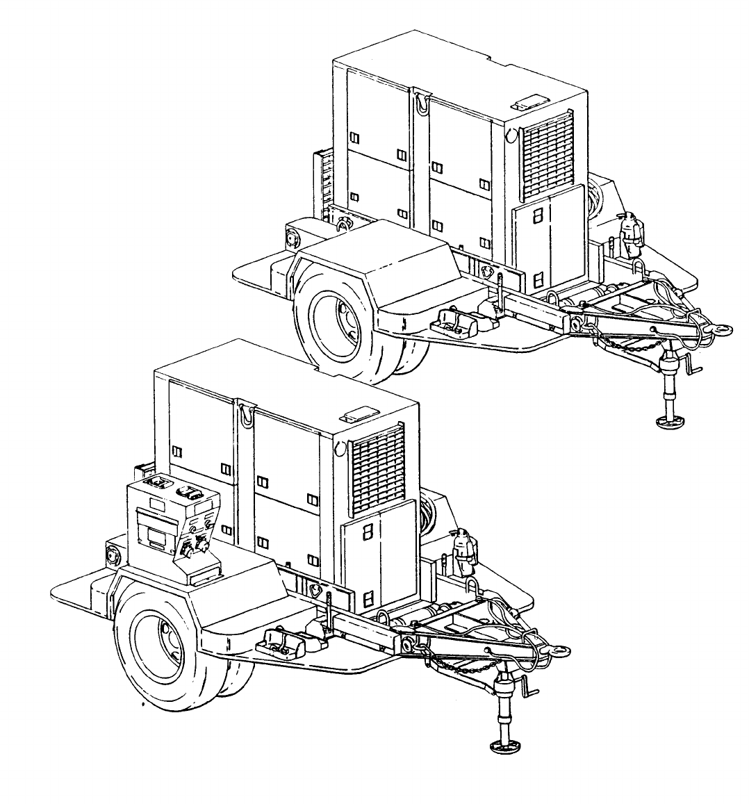
Power Plant, Curbside Front, Three-Quater View . . . . . . . . . . . . . . . . . . . . . . . . . . . . . . . . . . . . . . . . . . . . . . . . . . . . . . . . . . .
Power Plant, Roadside Rear, Three-Quarter View . . . . . . . . . . . . . . . . . . . . . . . . . . . . . . . . . . . . . . . . . . . . . . . . . . . . . . . . . . .
Power Unit B, with Switch Box, Packed for Shipment . . . . . . . . . . . . . . . . . . . . . . . . . . . . . . . . . . . . . . . . . . . . . . . . . . . .
Unpacking Power Plant - Power Unit B Shown . . . . . . . . . . . . . . . . . . . . . . . . . . . . . . . . . . . . . . . . . . . . . . . . . . . . . . . . . . . . .
Power Plant Installation . . . . . . . . . . . . . . . . . . . . . . . . . . . . . . . . . . . . . . . . . . . . . . . . . . . . . . . . . . . . . . . . . . . . . . . . . . . . . . . . . . . . . . . . . . . . . . . . . . . . .
External Fuel Line Connection . . . . . . . . . . . . . . . . . . . . . . . . . . . . . . . . . . . . . . . . . . . . . . . . . . . . . . . . . . . . . . . . . . . . . . . . . . . . . . . . . . . . . . . . . .
Fuel Can Bracket Replacement . . . . . . . . . . . . . . . . . . . . . . . . . . . . . . . . . . . . . . . . . . . . . . . . . . . . . . . . . . . . . . . . . . . . . . . . . . . . . . . . . . . . . . . .
Accessory Box Replacement . . . . . . . . . . . . . . . . . . . . . . . . . . . . . . . . . . . . . . . . . . . . . . . . . . . . . . . . . . . . . . . . . . . . . . . . . . . . . . . . . . . . . . . . . . . .
Fire Extinguisher Bracket Replacement . . . . . . . . . . . . . . . . . . . . . . . . . . . . . . . . . . . . . . . . . . . . . . . . . . . . . . . . . . . . . . . . . . . . . . . . . . .
Front Steps Replacement . . . . . . . . . . . . . . . . . . . . . . . . . . . . . . . . . . . . . . . . . . . . . . . . . . . . . . . . . . . . . . . . . . . . . . . . . . . . . . . . . . . . . . . . . . . . . . . . . .
Rear Steps Replacement . . . . . . . . . . . . . . . . . . . . . . . . . . . . . . . . . . . . . . . . . . . . . . . . . . . . . . . . . . . . . . . . . . . . . . . . . . . . . . . . . . . . . . . . . . . . . . . . . . .
Fender Replacement . . . . . . . . . . . . . . . . . . . . . . . . . . . . . . . . . . . . . . . . . . . . . . . . . . . . . . . . . . . . . . . . . . . . . . . . . . . . . . . . . . . . . . . . . . . . . . . . . . . . . . . . . .
Personnel Platform Replacement . . . . . . . . . . . . . . . . . . . . . . . . . . . . . . . . . . . . . . . . . . . . . . . . . . . . . . . . . . . . . . . . . . . . . . . . . . . . . . . . . . . . .
Holddown Strap Replacement . . . . . . . . . . . . . . . . . . . . . . . . . . . . . . . . . . . . . . . . . . . . . . . . . . . . . . . . . . . . . . . . . . . . . . . . . . . . . . . . . . . . . . . . . .
Power Cable Wiring Diagram . . . . . . . . . . . . . . . . . . . . . . . . . . . . . . . . . . . . . . . . . . . . . . . . . . . . . . . . . . . . . . . . . . . . . . . . . . . . . . . . . . . . . . . . . . . .
Switch Box Wiring Diagram . . . . . . . . . . . . . . . . . . . . . . . . . . . . . . . . . . . . . . . . . . . . . . . . . . . . . . . . . . . . . . . . . . . . . . . . . . . . . . . . . . . . . . . . . . . . . . .
Connector Replacement . . . . . . . . . . . . . . . . . . . . . . . . . . . . . . . . . . . . . . . . . . . . . . . . . . . . . . . . . . . . . . . . . . . . . . . . . . . . . . . . . . . . . . . . . . . . . . . . . . . .
Load Terminal Replacement . . . . . . . . . . . . . . . . . . . . . . . . . . . . . . . . . . . . . . . . . . . . . . . . . . . . . . . . . . . . . . . . . . . . . . . . . . . . . . . . . . . . . . . . . . . . .
Accessory Box Repair . . . . . . . . . . . . . . . . . . . . . . . . . . . . . . . . . . . . . . . . . . . . . . . . . . . . . . . . . . . . . . . . . . . . . . . . . . . . . . . . . . . . . . . . . . . . . . . . . . . . . . .
Power Plant Markings . . . . . . . . . . . . . . . . . . . . . . . . . . . . . . . . . . . . . . . . . . . . . . . . . . . . . . . . . . . . . . . . . . . . . . . . . . . . . . . . . . . . . . . . . . . . . . . . . . . . . . . .
Detaching Generator Set From Trailer . . . . . . . . . . . . . . . . . . . . . . . . . . . . . . . . . . . . . . . . . . . . . . . . . . . . . . . . . . . . . . . . . . . . . . . . . . . . .
Lifting Generator Set . . . . . . . . . . . . . . . . . . . . . . . . . . . . . . . . . . . . . . . . . . . . . . . . . . . . . . . . . . . . . . . . . . . . . . . . . . . . . . . . . . . . . . . . . . . . . . . . . . . . . . . . . .
Power Cable Repair . . . . . . . . . . . . . . . . . . . . . . . . . . . . . . . . . . . . . . . . . . . . . . . . . . . . . . . . . . . . . . . . . . . . . . . . . . . . . . . . . . . . . . . . . . . . . . . . . . . . . . . . . . . .
Switch Box Replacement . . . . . . . . . . . . . . . . . . . . . . . . . . . . . . . . . . . . . . . . . . . . . . . . . . . . . . . . . . . . . . . . . . . . . . . . . . . . . . . . . . . . . . . . . . . . . . . . . . .
Components of End Item . . . . . . . . . . . . . . . . . . . . . . . . . . . . . . . . . . . . . . . . . . . . . . . . . . . . . . . . . . . . . . . . . . . . . . . . . . . . . . . . . . . . . . . . . . . . . . . . . . .
Basic Issue Items . . . . . . . . . . . . . . . . . . . . . . . . . . . . . . . . . . . . . . . . . . . . . . . . . . . . . . . . . . . . . . . . . . . . . . . . . . . . . . . . . . . . . . . . . . . . . . . . . . . . . . . . . . . . . . .
Generator Set . . . . . . . . . . . . . . . . . . . . . . . . . . . . . . . . . . . . . . . . . . . . . . . . . . . . . . . . . . . . . . . . . . . . . . . . . . . . . . . . . . . . . . . . . . . . . . . . . . . . . . . . . . . . . . . . . . . . . .
Power Cables . . . . . . . . . . . . . . . . . . . . . . . . . . . . . . . . . . . . . . . . . . . . . . . . . . . . . . . . . . . . . . . . . . . . . . . . . . . . . . . . . . . . . . . . . . . . . . . . . . . . . . . . . . . . . . . . . . . . . .
Switch Box Assembly . . . . . . . . . . . . . . . . . . . . . . . . . . . . . . . . . . . . . . . . . . . . . . . . . . . . . . . . . . . . . . . . . . . . . . . . . . . . . . . . . . . . . . . . . . . . . . . . . . . . . . . .
Switch Box . . . . . . . . . . . . . . . . . . . . . . . . . . . . . . . . . . . . . . . . . . . . . . . . . . . . . . . . . . . . . . . . . . . . . . . . . . . . . . . . . . . . . . . . . . . . . . . . . . . . . . . . . . . . . . . . . . . . . . . ...
Switch Box Cable Assemblies and Harness Assembly . . . . . . . . . . . . . . . . . . . . . . . . . . . . . . . . . . . . . . . . . . . . . . . . . .
Ground Wire Assembly and Electrical Leads . . . . . . . . . . . . . . . . . . . . . . . . . . . . . . . . . . . . . . . . . . . . . . . . . . . . . . . . . . . . . . . . . .
Trailer Body . . . . . . . . . . . . . . . . . . . . . . . . . . . . . . . . . . . . . . . . . . . . . . . . . . . . . . . . . . . . . . . . . . . . . . . . . . . . . . . . . . . . . . . . . . . . . . . . . . . . . . . . . . . . . . . . . . . . . . . ...
Accessory Box . . . . . . . . . . . . . . . . . . . . . . . . . . . . . . . . . . . . . . . . . . . . . . . . . . . . . . . . . . . . . . . . . . . . . . . . . . . . . . . . . . . . . . . . . . . . . . . . . . . . . . . . . . . . . . . . . . . .
Front Steps . . . . . . . . . . . . . . . . . . . . . . . . . . . . . . . . . . . . . . . . . . . . . . . . . . . . . . . . . . . . . . . . . . . . . . . . . . . . . . . . . . . . . . . . . . . . . . . . . . . . . . . . . . . . . . . . . . . . . . . .
Rear Steps . . . . . . . . . . . . . . . . . . . . . . . . . . . . . . . . . . . . . . . . . . . . . . . . . . . . . . . . . . . . . . . . . . . . . . . . . . . . . . . . . . . . . . . . . . . . . . . . . . . . . . . . . . . . . . . . . . . . . . . . . . .
Fenders . . . . . . . . . . . . . . . . . . . . . . . . . . . . . . . . . . . . . . . . . . . . . . . . . . . . . . . . . . . . . . . . . . . . . . . . . . . . . . . . . . . . . . . . . . . . . . . . . . . . . . . . . . . . . . . . . . . . . . . . . . . . . . .
Personnel Platform . . . . . . . . . . . . . . . . . . . . . . . . . . . . . . . . . . . . . . . . . . . . . . . . . . . . . . . . . . . . . . . . . . . . . . . . . . . . . . . . . . . . . . . . . . . . . . . . . . . . . . . . . . . . .
Handbrakes . . . . . . . . . . . . . . . . . . . . . . . . . . . . . . . . . . . . . . . . . . . . . . . . . . . . . . . . . . . . . . . . . . . . . . . . . . . . . . . . . . . . . . . . . . . . . . . . . . . . . . . . . . . . . . . . . . . . . . . . .
Page
1-3
1-4
4-1
4-2
4-6
4-7
4-16
4-17
4-18
4-20
4-22
4-23
4-25
4-26
4-27
4-30
4-31
4-32
5-1
5-2
5-3
5-4
5-6
5-8
B-2
B-3
D-10
D-12
D-15
D-24
D-26
D-28
D-32
D-36
D-38
D-40
D-42
D-44
D-46
LIST OF TABLES
Title
Page
Consumable Operating and Maintenance Supplies . . . . . . . . . . . . . . . . . . . . . . . . . . . . . . . . . . . . . . . . . . . . . . . . . . . . . . . . . . . 3-1
Operator/Crew Preventive Maintenance
Checks and Services (PMCS) . . . . . . . . . . . . . . . . . . . . . . . . . . . . . . . . . . . . . . . . . . . . . . . . . . . . . . . . . . . . . . . . . . . . . . . . . . . . . . . . . . . . . . . . . . 3-4
Unit Preventive Maintenance Checks and Services (PMCS) . . . . . . . . . . . . . . . . . . . . . . . . . . . . . . . . . . . . . . . . . . . 4-10
Troubleshooting . . . . . . . . . . . . . . . . . . . . . . . . . . . . . . . . . . . . . . . . . . . . . . . . . . . . . . . . . . . . . . . . . . . . . . . . . . . . . . . . . . . . . . . . . . . . . . . . . . . . . . 4-14
iii/(iv blank)
TM 5-6115-628-14&P
CHAPTER 1
INTRODUCTION
Section I. GENERAL
1-1.
Scope. This manual is for your use in operating and maintaining the Power Plant, AM/MJQ-15.
The AN/MJQ-15 is a mobile power plant used to supply 15 KW of 400 Hz input operating power to the
Fire Direction Control Center for Artillery. In addition to operating instructions and operator, unit, and
intermediate direct support and general support maintenance procedures, this manual contains a
Repair Parts and Special Tools List for the power plant.
1-2.
Limited Applicability. Some portions of this publication are not applicable to both services.
These portions are prefixed to indicate the service to which they pertain: (A) for Army, and (F) for Air
Force. Portions not prefixed are applicable to both services.
1-3.
a.
b.
1-4.
Maintenance Forms and Records.
(A) Maintenance forms and records used by Army personnel are prescribed by DA Pam
738-750.
(F) Maintenance forms and records used by Air Force personnel are prescribed in AFM66-1
and the applicable 00-20 Series Technical Orders.
Reporting of Errors. Reporting of errors and omissions and recommendations for improvement
of this publication by the individual user is encouraged. Reports should be submitted as follows:
a. (A) Army - DA Form 2028 directly to: Commander, US Army Troop Support Command, ATTN:
AMSTR-MCTS, 4300 Goodfellow Boulevard, St. Louis, MO, 63120-1798.
b. (F) Air Force – AFTO Form 22 directly to: Commander, Sacramento Air Logistics Center,
ATTN: SM-ALC-MMEDTA, McClellan Air Force Base, CA, 95652-5609, in accordance with
TO-00-5-1.
1-5.
Reporting Equipment Improvement Recommendations (EIR). ElR’s will be prepared using SF
368 Product Quality Deficiency Report. Instructions for preparing ElR’s are provided in DA Pam 738-
750, The Army Maintenance Management System. ElR’s should be mailed directly to: Commander,
US Army Troop Support Command, ATTN: AMSTR-QX, 4300 Goodfellow Boulevard, St. Louis, MO,
63120-1798.
1-6. Levels of Maintenance Accomplishment.
a. (A) Army users shall refer to the Maintenance Allocation Chart (MAC) for tasks and levels of
maintenance to be performed.
b. (F) Air Force users shall accomplish maintenance at the user level consistent with their
capability in accordance with policies established in AFM 66-1.
1-7.
Destruction of Army Materiel. Destruction of Army materiel to prevent enemy use shall be in
accordance with TM 750-244-3.
1-1

TM 5-6115-628-14&P
1-8. Administrative Storage.
a. Army equipment placed in administrative storage will have preventive maintenance performed
in accordance with the PMCS tables before storage. When equipment is removed from stor-
age, PMCS will be performed to ensure operational readiness.
b. (F) For administrative storage procedures for Air Force equipment, refer to TO 35-1-4, Pro-
cessing and Inspection of Aerospace Ground Equipment for Storage and Shipment.
1-9.
Preparation for Shipment and Storage.
a. (A) Army -
Refer to TB 740-97-2.
b. (F) Air Force - Refer to TO 35-1-4 for component of end item generator sets and TO 38-1-5
for installed engine.
Section Il. DESCRIPTION AND DATA
1-10.
Description. Power Plant AN/MJQ-15 is made up of two PU-732/M power units. Each power
unit is, in turn, made up of one Tactical Precise Generator Set, DOD Model MEP-113A mounted on a
modified M200A1 trailer. These generator sets are liquid-cooled, diesel engine-driven units, each
with a load capacity of 15 KW at 400 Hz. The trailers are two-wheeled units with dual tires mounted.
Each trailer has a 2 1/2-ton carrying capacity. The modifications to the basic trailers provide stowage
for the accessories and all equipment necessary for mobile operation as well as providing a work plat-
form for the operator and maintenance personnel. Output from the power plant is applied to the system
or equipment being powered through a switch box. Figures 1-1 and 1-2 illustrate the power plant.
1-11.
Tabulated Data. The tabulated data provides operator and unit level personnel with the
dimensions and weights for Power Plant, AN/MJQ-15. These specifications are computed from the
combined dimensions and weights of the two power units that make up the power plant. Specifications
for a single PU-732/M power unit can be found in TM 5-6115-594-14&P. For additional information
concerning Generator Set DOD Model MEP-113A, refer to TM 5-6115-464-12, - 34, and - 24P. For
additional information on the M200A1 trailer, refer to TM 9-2330-205-14&P. The tabulated data also
includes the location and content of all data plates unique to the power plant.
a. Identification, Information, and Warning Plates.
(1) Modification identification plate.
(a) Location. This plate is located on front roadside frame between the trailer body and
Iunette.
(b) Content.
MODIFIED FOR POWER PLANT AN/MJQ-15
NSN 6115-00-400-7591
UNIT A (or B, as applicable)
1-2
TM 5-6115-628-14&P
(2) Identification plate.
(a) Location. This plate is located below ground stud above curbside front step.
(b) Content.
GROUND TERMINAL
(3) Wiring diagram designation plate.
(a) Location. This plate is located on switch box rear cover.
(b) Contents. (See figure 4-14.)
(4) Identification plate.
(a) Location. This plate is located on circuit breaker side of switch box.
(b) Content.
SWITCH BOX
ASSEMBLY
PART NO. 97403-13220E6400
SERIAL NO.
NSN 6120-01-090-2789
MANUFACTURER
US
(5) Designation plate.
(a) Location. This plate is located on circuit breaker side of switch box above switch S1.
(b) Content.
CIRCUIT BREAKER
(6) Designation plate.
(a) Location. This plate is located on circuit breaker side of switch box above switch S2.
(b) Content.
CIRCUIT BREAKER
(7) Designation plate.
(a) Location. This plate is located on circuit breaker side of switch box below switch S1.
(b) Content.
GEN NO. 1
1-5
TM 5-6115-628-14&P
(8) Designation plate.
(a) Location. This plate is located on circuit breaker side of switch box below switch S2.
(b) Content.
GEN NO. 2
(9) Identification plate.
(a) Location. This plate is located on outside of switch access door.
(b) Content.
CIRCUIT BREAKERS
(10) Identification plate.
(a) Location. This plate is located on outside of power output cover.
(b) Content.
POWER OUTPUT
(11) Instruction plate.
(a) Location. This plate is located on outside of switch access door.
(b) Content.
CAUTION
DO NOT TRIP SWITCH UNLESS ALL MAINTENANCE AND OPERATING PERSONNEL ARE
CLEAR OF RELATED GENERATOR SET AND OPERATING EQUIPMENT.
(12) Identification plate.
(a) Location. This plate is located on connector side of switch box above ground stud.
(b) Content.
GROUND TERMINAL
(13) Instruction plate.
(a) Location. This plate is located on power output cover.
(b) Content.
DANGER
HIGH VOLTAGE
1-6
TM 5-6115-628-14&P
(14) Designation plate.
(a) Location. This plate is located on load terminal side of switch box above indicator lamp.
(b) Content.
PILOT LIGHT
OUTPUT
(15) Designation plate.
(a) Location. This plate is located on connector side of switch box above indicator lamp
DS1 .
(b) Content.
PILOT LIGHT
GEN NO. 1
INPUT
(16) Designation plate.
(a) Location. This plate is located on connector side of switch box above indicator lamp
DS2.
(b) Content.
PILOT LIGHT
GEN NO. 2
INPUT
(17) Designation plate.
(a) Location. This plate is located on connector side of switch box above connector J1.
(b) Content.
POWER CABLE
GEN NO. 1
INPUT
(18) Designation plate.
(a) Location. This plate is located on connector side of switch box above connector J2.
(b) Content.
POWER CABLE
GEN NO. 2
INPUT
1-7

TM 5-6115-628-14&P
(19) Designation plate.
(a) Location. This plate is located on connector side of switch box above connector J3.
(b) Content.
PARALLEL CABLE
GEN NO. 1
INPUT
(20) Designation plate.
(a) Location. This plate is located on connector side of switch box above connector J4.
(b) Content.
PARALLEL CABLE
GEN NO. 2
INPUT
(21) Instruction plate.
(a) Location. This plate is located on connector side of switch box.
(b) Content.
GENERATOR
POWER INPUT
b. Tabulated Data for Power Plant.
Overall Length
166 3/8 inches (423.6 centimeters)
Overall Width 95 1/2 inches (242.6 centimeters)
Overall Height 84 inches (213 centimeters)
Net Weight (empty)
11,260 pounds (5106 kilograms)
Net Weight (filled)
11,600 pounds (5261 kilograms)
Shipping Weight
11,620 pounds (5270 kilograms)
Cubage 1,576 cubic feet (45 cubic meters)
1-12.
Differences Between Models.
There are no differences between models, serial numbers, or
serial number groups applicable to this equipment.
1-8

TM 5-6115-628-14&P
CHAPTER 2
OPERATING INSTRUCTIONS
Section I. OPERATING PROCEDURES
2-1.
Power Plant Operating Procedures. The typical mission for any mobile power generating equip-
ment can be described in three steps or phases. In the first phase, the power plant is towed to the
worksite and installed by unit level technicians (paragraph 4-2). In the second phase of the mission,
the operator starts the generator sets, runs them to power a system or equipment, and eventually
shuts them down. In the final phase, the power plant is dismantled, packed up and either moved to a
new worksite or returned to standby status (paragraph 4-3). This final phase is also accomplished by
unit level technicians.
a. Generator Set Operating Procedures.
WARNING
Do not operate power plant generator set(s) until properly grounded
(paragraph 4-2, b.) Serious injury or death by electrocution can result from
operating an ungrounded generator set.
Operating noise level of generator sets can cause hearing damage. Ear
protectors, as recommended by medical or safety officer, must be worn when
working near power unit.
CAUTION
To avoid damage to equipment, make certain of voltage, frequency, and
phase requirements of load connected to power plant.
NOTE
Before starting generator set, do your Before PMCS as described in table 3-2.
Detailed procedures for prestarting, starting, operating, and shutting down the power plant generator
sets are found in TM 5-6115-464-12 and on the Operating Instructions data plates found on the equip-
ment. Refer to the data plate, located inside the right hand control panel door, to start and run the
generator sets. Monitor and adjust power output as required during operation. At the end of the mis-
sion, shut down the generator sets in accordance with the operating instructions on the data plate.
b. Switch Box Operating Procedures. Start and stop generator sets in accordance with paragraph
2-1, a., when instructed to do so in the following procedures.
CAUTION
Close all doors on generator sets except doors over control panels and
louvers.
2-1
TM 5-6115-628-14&P
(1) Alternate operation of power units.
(a) Set circuit breakers on both power unit generator sets to OFF position.
(b) Set both switches on switch box to OFF position.
(c) Start one power unit and bring generator set up to rated speed, voltage, and frequency.
(d) Set generator set circuit breaker to ON position.
(e) Set associated switch on switch box to ON position.
NOTE
When the power plant generator set in operation must be shut down, follow
steps (f) thru (j) to continue to supply power to system or equipment being
powered.
(f) Start second power unit and bring generator set up to rated speed, voltage, and
frequency.
(g) Set generator set circuit set breaker to ON position.
(h) At switch box, set switch associated with first generator set to OFF position.
(i)
(j)
(2)
(a)
(b)
(c)
(d)
(e)
(f)
(g)
2-2
Set switch box switch associated with second generator set to ON position.
Shut down first power plant generator set.
Parallel operation of power units.
NOTE
Parallel operation of both power plant power units requires prior installation of
paralleling cables between each power unit generating set and the switch box.
Refer to paragraph 4-2.
Set circuit breakers on both power plant generator sets to OFF position.
Set both switches on switch box to OFF position.
Start one power unit and bring generator set up to rated speed, voltage, and frequency.
Set SINGLE/PARALLEL switch on operating generator set to PARALLEL position and set
circuit breaker to ON.
Start second, incoming, power unit and bring generator set up to rated speed, voltage,
and frequency.
Set SINGLE/PARALLEL switch on incoming generator set to PARALLEL position.
Observe SYNCHRONIZING LIGHTS on incoming generator set. Both lights must be going
on and off simultaneously.

(h)
(i)
(j)
(k)
(l)
(m)
(n)
TM 5-6115-628-14&P
NOTE
If SYNCHRONIZING LIGHTS are going on and off alternately, generator sets are
out of phase. Stop one generator set. Start, and if still out of phase, notify
higher level of maintenance.
Adjust frequency of first, operating, generator set to proper value.
Adjust frequency of second, incoming, generator set until SYNCHRONIZING LIGHTS go
on and off slowly at 2-3 second intervals.
CAUTION
Do not set circuit breaker of second, incoming, generator set to ON position
while SYNCHRONIZING LIGHTS are on. Failure to observe this caution could
result in damage to one or both generator sets.
Observe SYNCHRONIZING LIGHTS on incoming generator set. At the instant both lights
are out, set circuit breaker to ON position. The two power plant power units are now
operating in parallel.
Readjust VOLTAGE ADJUST rheostats on both power plant generator sets until both AC
AMMETERS indicate zero.
Readjust FREQUENCY ADJUST rheostats on both power plant generator sets until both
PERCENT POWER kilowatt meters indicate zero.
NOTE
When load is applied to power plant in step (m), the difference in the kilowatt
load between generator sets must not exceed 10%. The difference between
current on any phase must not exceed 10%. If necessary, adjust R28 and/or
R29 respectively, to correct a kilowatt load or current imbalance.
Set both switches on switch box to ON position.
CAUTION
Before removing either power unit from parallel operation, make certain the
load applied to the power plant through the switch box does not exceed rating of
remaining power unit.
To remove either power unit from parallel operation, set generator set circuit breaker to
OFF position.
c. Trailer Operating Procedures. Refer to TM 9-2330-205-14&P for specific operating
procedures for the M200A1 trailer.
Section Il. OPERATION OF AUXILIARY EQUIPMENT
2-2. Operation of Auxiliary Equipment. There is no auxiliary equipment supplied with the power plant.
2-3
TM 5-6115-628-14&P
Section III. OPERATION UNDER UNUSUAL CONDITIONS
2-3. Operation Under Unusual Conditions. When operating the power unit under unusual conditions
such as extremes in temperature or difficult terrain, there are steps that must be taken to protect the
equipment.
a. Refer to TM 5-6115-464-12 for special procedures when operating the generator sets under
unusual conditions.
b. Refer to TM 9-2330-202-14&P for special procedures when operating the trailers under
unusual conditions.
2-4

TM 5-6115-628-14&P
CHAPTER 3
OPERATOR/CREW MAINTENANCE INSTRUCTIONS
Section I. CONSUMABLE OPERATING AND MAINTENANCE SUPPLIES
3-1.
Consumable Supplies. Consumable supplies used in the maintenance and operation of the
power plant are listed in Table 3-1.
Table 3-1. Consumable Operating and Maintenance Supplies.
(1) (2) (3) (4) (5) (6)
Qty Qty
National required required
Component stock for initial 8 hours
application number Description operation operation Notes
General
6850-00-664-5685
Solvent, Drycleaning, 1 quart As required
Cleaning
P-D-680
Personnel
9150-00-186-6681
Oil, Lubricating, 1 quart As required
Platform
OE/HDO-30
9150-00-402-4478
Oil, Lubricating, OEA 1 quart As required
Section Il. LUBRICATION INSTRUCTIONS
3-2. General. Detailed instructions for the lubrication of the major components of the power plant are
contained in the applicable Lubrication Orders (LO’s). Refer to DA Pam 25-30 to ensure the latest
editions of the LO’s are used.
3-3. Generator Lubrication. Refer to LO 5-6115-464-12.
3-4. Trailer Lubrication. There are no operator/crew lubrication requirements for the power plant
trailers.
Section Ill. PREVENTIVE MAINTENANCE CHECKS AND SERVICES (PMCS)
NOTE
The PMCS chart in this section contains all necessary Operator/Crew
preventive maintenance checks and services for this equipment.
3-5. General. The preventive maintenance checks and services listed in Table 3-2 are grouped
according to stages of equipment operation or time intervals. Using the following as a guide, do the
checks and services at the intervals shown.
a.
b.
c.
Before you operate, perform your before (B) PMCS. Observe all CAUTIONS and WARNINGS.
While you operate, perform your during (D) PMCS. Observe all CAUTIONS and WARNINGS.
After you operate, be sure to perform your after (A) PMCS.
3-1

TM 5-6115-628-14&P
d. Do (W) PMCS weekly.
e. Do (M) PMCS monthly.
f. If equipment fails to operate, refer to Section IV, Troubleshooting. If the problem cannot be
corrected, see paragraph 3-8, Reporting Deficiencies.
3-6. Purpose of PMCS Table. The purpose of the PMCS table is to provide a systematic method of
inspecting and servicing the equipment. In this way, small defects can be detected early before they
become a major problem causing the equipment to fail to complete its mission. The PMCS table is
arranged with the individual PMCS procedures listed in sequence under assigned intervals. The most
logical time (before, during, or after operation) to perform each procedure determines the interval to
which it is assigned. Make a habit of doing the checks and services in the same order each time and
anything wrong will be seen quickly. See paragraph 3-7 for an explanation of the columns in
table 3-2.
3-7. Explanation of Columns. The following is a list of the PMCS table column headings with a
description of the information found in each column.
a. Item No. This column shows the sequence in which the checks and services are to be
performed, and is used to identify the equipment area on the Equipment Inspection and Maintenance
Worksheet, DA Form 2404.
b. Interval This column shows when each check is to be done.
c. Item to be Inspected/Procedures. This column identifies the general area or specific part
where the check or service is to be done, and the checks or services to be done, and explains how to
do them.
d. Equipment is Not Ready/Available If. This column lists conditions that make the equipment
unavailable for use because it is unable to perform its mission or because it would represent a safety
hazard. Do not accept or operate equipment with a condition in the “Equipment is Not Ready/Available
If” column.
3-8. Reporting Deficiencies. If you discover any problem with the equipment during PMCS or while
operating it that you are unable to correct, it must be reported. Refer to DA Pam 738-750 and report
the deficiency using the proper forms.
3-9. Special Instructions. Preventive maintenance is not limited to performing the checks and ser-
vices listed in the PMCS table. Covering unused receptacles, stowing unused equipment and other
routine procedures such as equipment inventory, cleaning components, and touch-up painting are
not listed in the PMCS table. These are things you should do any time you see they need to be done. If
a routine check is listed in the PMCS table it is because other operators have reported problems with
this item. Take along tools and cleaning cloths needed to perform the required checks and services.
Use the information in the following paragraphs to help you identify problems at any time.
a. Routine Inspections. Use the following information to help identify potential problems before
and during checks and services.
3-2

TM 5-6115-628-14&P
WARNING
Drycleaning solvent P-D-680 is both toxic and flammable. Wear safety goggles
and gloves and use in a well-ventilated area. Avoid prolonged breathing of
vapors and avoid skin contact. Do not smoke or use near open flame or exces-
sive heat. Flash point of solvent is 100OF to 138°F (38°C to 59°C). If you
become dizzy while using P-D-680, get fresh air immediately and get medical
aid. If P-D-680 contacts eyes, flush with water and get medical aid
immediately.
(1) Keep it clean. Dirt, grease, and oil get in the way and may cover up a serious problem.
Use drycleaning solvent P-D-680, to clean metal surfaces. Use soap and water to clean
rubber or plastic parts and material.
(2) Bolts, nuts, and screws. Check them all to make sure they’re not loose, missing, bent, or
broken. Don’t try to check them all with a tool, but look for chipped paint, bare metal, or
rust around bolt heads. If you find one loose, tighten it or report it to unit maintenance.
(3) Welds. Look for loose or chipped paint, rust, or gaps where parts are welded together.
If a broken weld is found, report it to higher level of maintenance.
(4) Electrical wires, connectors, terminals and receptacles. Look for cracked or broken
insulation, bare wires, and loose or broken connectors. Tighten loose connectors and
make sure the wires are in good condition. Examine terminals and receptacles for
serviceability.
(5) Hoses and fluid lines. Look for wear, damage, and leaks. Make sure clamps and fittings
are tight. Wet spots and stains around a fitting or connector can mean a leak. If a leak
comes from a loose connector, tighten it. If something is broken or worn out, report it to
unit maintenance.
b. Leakage Definitions. It is necessary for you to know how fluid leakage affects the status of your
equipment. The following are definitions of the types/classes of leakage you need to know to be able
to determine the status of your equipment. Learn and be familiar with them. When in doubt, NOTIFY
YOUR SUPERVISOR!
Leakage Definitions:
Class I
Class II
Class Ill
Seepage of fluid (as indicated by wetness or discoloration) not great
enough to form drops.
Leakage of fluid great enough to form drops but not enough to cause
drops to drip from item being checked/inspected.
Leakage of fluid great enough to form drops that fall from the item
being checked/inspected.
3-3
ARMY TM 5-6115-628-14&P
AIR FORCE TO-35C2-3-487-1
CAUTION
Equipment operation is allowable with minor leakage (Class I or II) of any fluid
except fuel. Of course, consideration must be given to the fluid capacity in the
item being checked/inspected. When in doubt, notify your supervisor.
When operating with Class I or II leaks, continue to check fluid level more often
than required in the PMCS. Parts without fluid will stop working and/or cause
equipment damage.
Class III leaks should be reported to your supervisor or unit maintenance.
Table 3-2. Operator/Crew Preventive Maintenance Checks and Services (PMCS)
NOTE
If the equipment must be kept in continuous operation, check and service only
those items that can be checked and serviced without disturbing operation.
Make the complete checks and services when the equipment can be shut
down.
Within designated interval, these checks are to be performed in the order
listed.
B - Before D – During A – After W - Weekly
WARNING
Before performing any mainte-
nance that requires climbing on or
under trailer, set trailer hand-
brakes, chock wheels, and lower
rear leveling jacks. Injury to per-
sonnel could result from trailer
suddenly rolling or tipping.
M - Monthly
3-4
TM 5-6115-628-14&P
Table 3-2. Operator/Crew Preventive Maintenance Checks and Services (PMCS) – CONT.
B - Before D - During A - After W - Weekly M - Monthly
1
2
●
●
NOTE
This PMCS table lists the checks
and services as performed on a
single power unit. These pro-
cedures must be duplicated on
each of the two power units that
make up the AN/MJQ-15.
Perform weekly as well as before
PMCS if:
You are the assigned operator but
have not operated the equipment
since the last weekly inspection.
You are operating the equipment
for the first time.
GENERATOR SET EXTERIOR
a.
b.
c.
Check on, around, and beneath
generator set for fuel or oil and
coolant leaks.
Check that generator set ground is
properly installed and grounding
connections are tight.
Manually open and close radiator
louver doors to check for proper
operation.
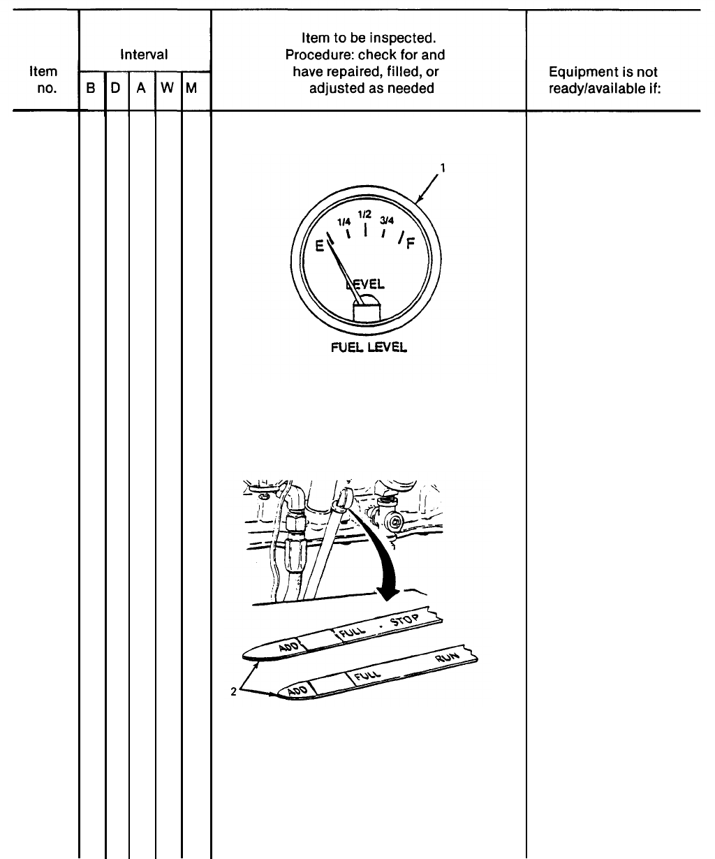
FUEL GAGE
Check fuel gage (1) for sufficient fuel for
continuous operation.
A Class Ill coolant or
lubrication oil leak or
any class fuel leak is
detected.
Not properly
grounded.
3-5
TM 5-6115-628-14&P
Table 3-2. Operator/Crew Preventive Maintenance Checks and Services (PMCS) - CONT.
B
- Before
D
- During A - After W - Weekly M - Monthly
2
3
4
3-6
●
●
●
● ●
FUEL GAGE – CONT
ENGINE OIL LEVEL
Check oil filler dipstick (2) for proper
oil level. Add oil as required.
ACCESSORIES
Check that the following accessories are
not missing.
a. Sledge hammer
TM 5-6115-628-14&P
Table 3-2. Operator/Crew Preventive Maintenance Checks and Services (PMCS) – CONT.
B - Before D - During A - After W - Weekly M - Monthly
4
5
6
7
ACCESSORIES - CONT
b. Fire extinguisher
c.
Driver/puller
d. Ground rods
BRACKETS
Check fire extinguisher and fuel can
mounting brackets for loose hardware
and broken fittings.
TIRES
a.
b.
Check for cuts, foreign objects or
unusual tread wear. Remove any
stones from between the treads.
Check that tire pressure is 35 psi
(241 .22 kPa) when tires are cool.
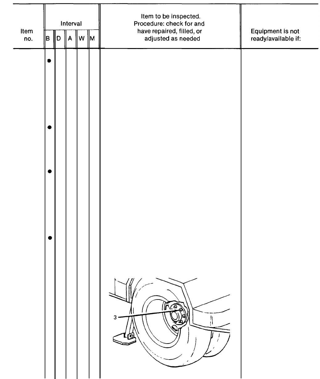
WHEELS
Check for wheel damage and for loose
or missing stud nuts (3).
Fire extinguishers are
missing.
Ground rods are
missing.
One tire is flat,
missing or
unserviceable.
One wheel is damaged.
One stud nut is loose
or missing.
3-7
TM 5-6115-628-14&P
Table 3-2. Operator/Crew Preventive Maintenance Checks and Services (PMCS) - CONT.
B-Before D - During A - After W - Weekly M - Monthly
8
9
10
11
3-8
●
●
●
●
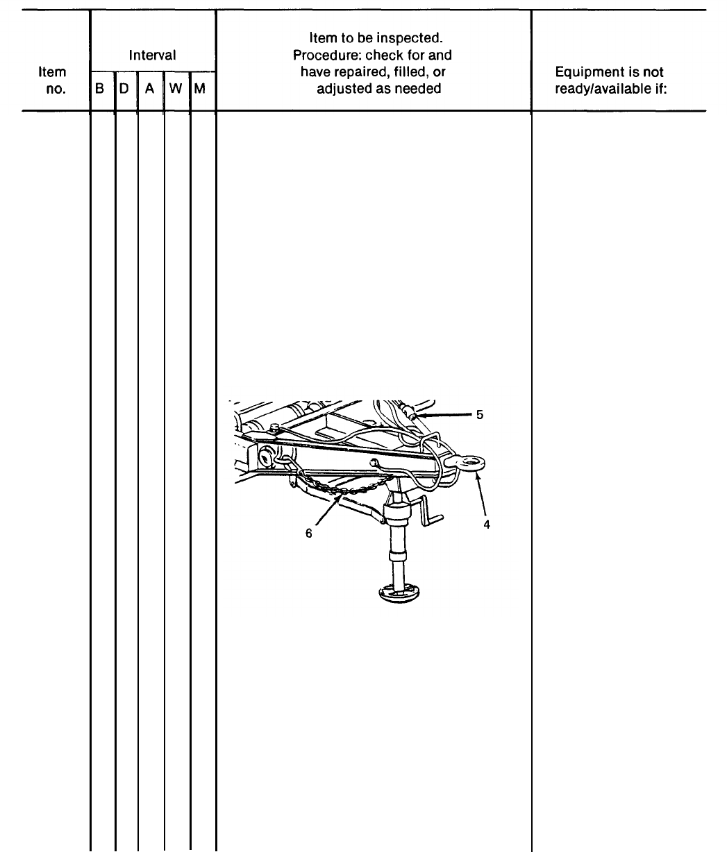
LUNETTE
Check Iunette (4) for insecure mount-
ing and obvious damage.
INTERVEHICULAR CABLE
Check cable (5) and connector for cuts
and breaks.
SAFETY CHAINS
Check safety chains (6) for insecure
mounting and obvious damage.
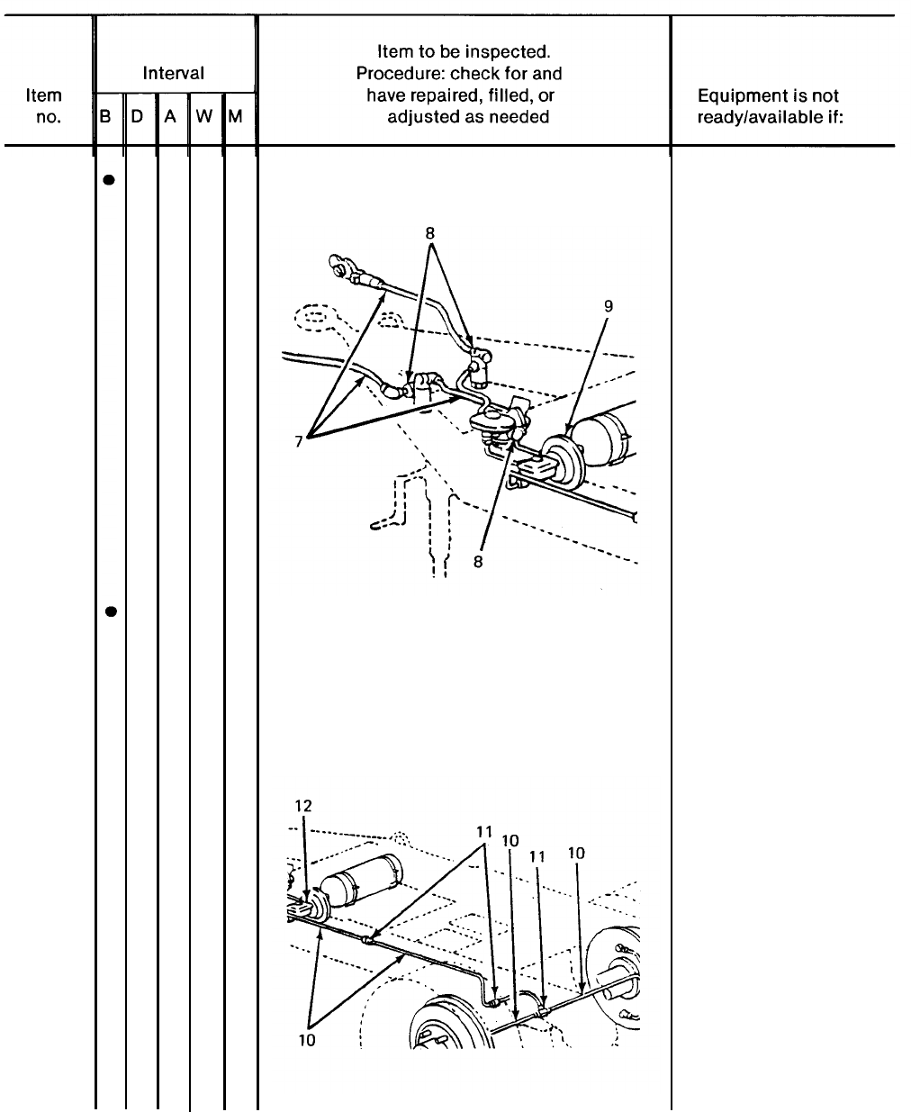
AIR HOSES, FITTINGS AND BRAKE AIR
CHAMBER
Check air hoses (7), fittings (8) and
brake air chamber (9) for signs of
damage or leaks.
Lunette is loose or
bent.
Intervehicular cable
is broken or missing.
Safety chains are
missing or
unsecured.
Damage or leaks
are detected.
TM 5-6115-628-14&P
Table 3-2. Operator/Crew Preventive Maintenance Checks and Services (PMCS) - CONT.
B - Before D - During A - After W - Weekly M - Monthly
11
12
AIR HOSES, FITTINGS AND BRAKE AIR
CHAMBER - CONT
HYDRAULIC HOSES, FITTINGS AND MASTER
CYLINDER
Check brake system hoses (10) and fit-
tings (11) and master cylinder (12),
and check under vehicle for signs of
brake fluid leaks.
A class Ill brake fluid
leak is detected.
3-9
TM 5-6115-628-14&P
Table 3-2. Operator/Crew Preventive Maintenance Checks and Services(PMCS) - CONT.
B - Before D - During A - After W - Weekly
M
- Monthly
13
14
3-10
●
●
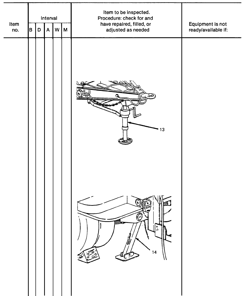
LANDING LEG
Check condition of landing leg (13).
LEVELING JACK
Check condition of leveling jack (14).
There is indication that
leg might collapse.
There is indication that
a jack might collapse.
TM 5-6115-628-14&P
Table 3-2. Operator/Crew Preventive Maintenance Checks and Services (PMCS) - CONT.
B - Before
D
- During A - After W - Weekly
M
- Monthly
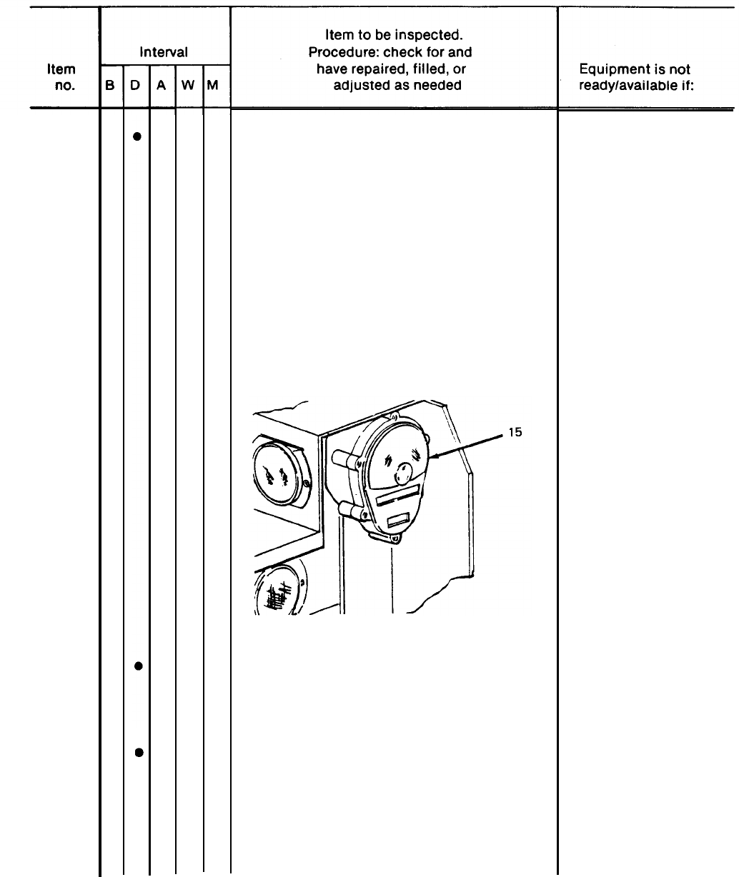
15
16
17
LIGHTS
a. With intervehicular cable connected to
towing vehicle, operate vehicle light
switch through all settings and check
lights (15).
NOTE
An assistant is required while
checking brake lights.
b. Step on brake pedal and check brake
lights (15).
BRAKE SYSTEM
Test brake system by hooking trailer
to towing vehicle and applying brakes.
TRAILER OPERATION
a. Be alert for any unusual noises while
towing trailer. Stop and investigate
any unusual noises.
Service brakes fail to
operate.
3-11
TM 5-6115-628-14&P
Table 3–2. Operator/Crew Preventive Maintenance Checks and Services (PMCS) - CONT.
B -
17
18
3-12
Before
D -During A - After W - Weekly
Change 2
TRAILER OPERATION - CONT
b. Ensure that trailer is tracking/following correctly behind
towing vehicle with no side pull.
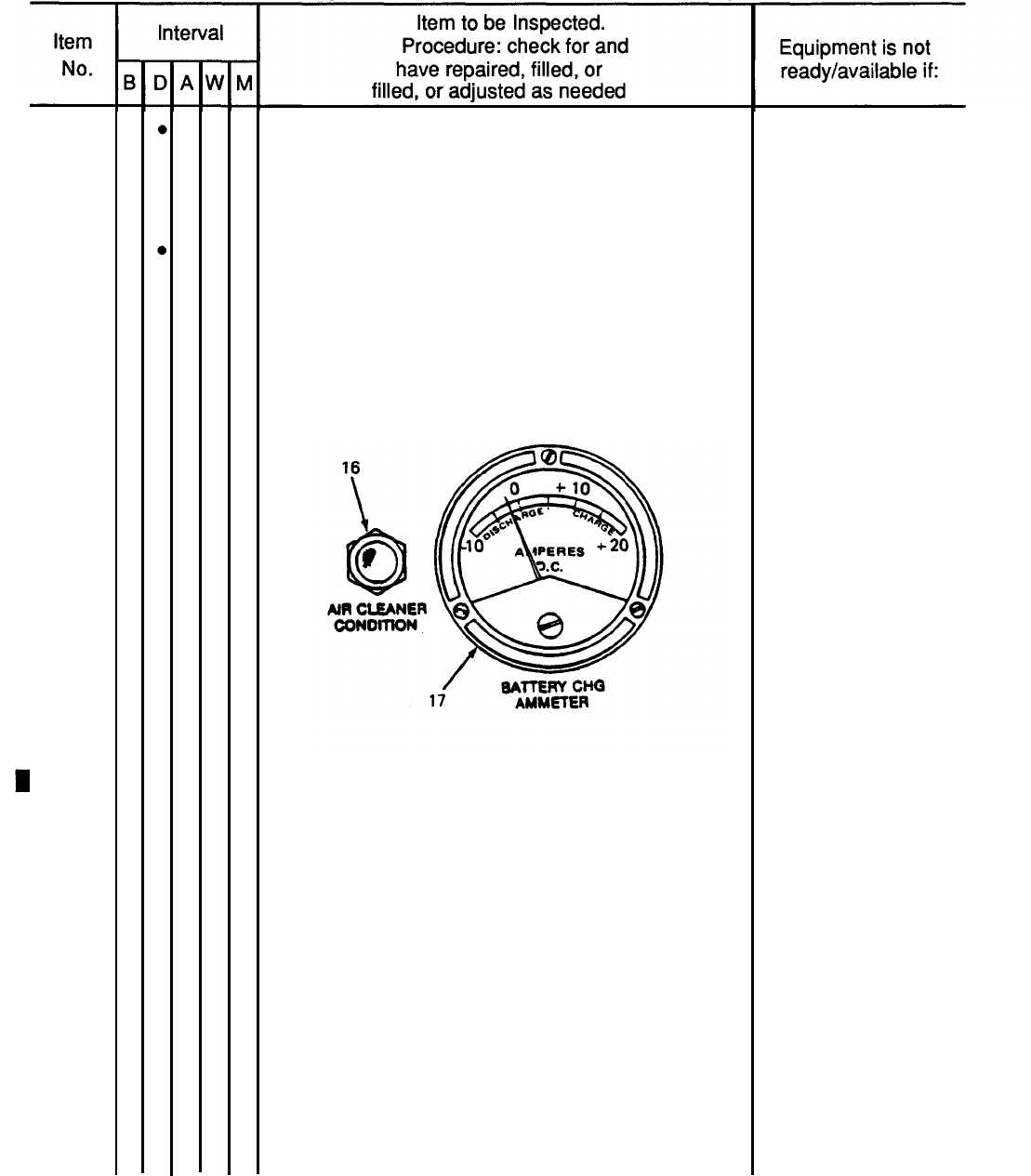
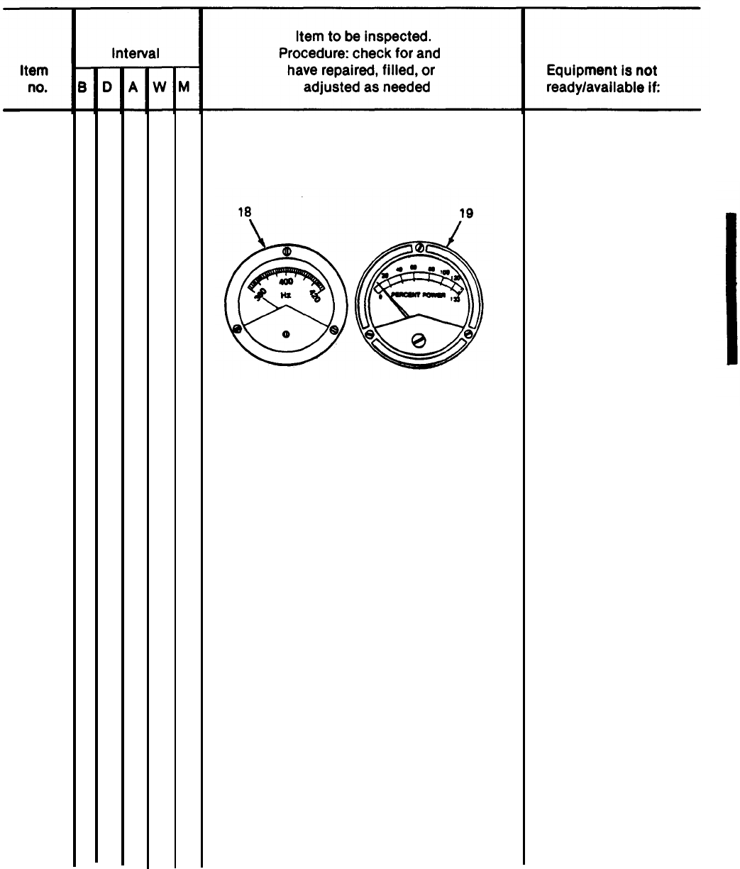
GENERATOR SET GAGES AND INSTRUMENTS
a.
b.
c.
d.
Check that air cleaner condition indicator (16)
does not indicate a clogged air cleaner. Press-to-test.
Check that battery charging ammeter (17) is in
green area during normal operation.
Check that frequency meter (18) indicates 400 Hz
(red
line) when generator is operating under load.
Check that kilowatt meter (19) reading does not
exceed 100%.
M - Monthly
Light remains on
during operation.
Battery indicator not
in green area.
Correct frequency
cannot be maintained.
TM 5-6115-628-14&P
Table 3-2. Operator/Crew Preventive Maintenance Checks and Services (PMCS) - CONT.
B - Before D - During A - After W - Weekly M - Monthly
18
GENERATOR SET GAGES AND
INSTRUMENTS – CONT
e. Check that A.C. ammeter (20) read-
ing does not exceed 100% of rated
current or more than 5% load dif-
ference between phases.
f. Check that A.C. voltmeter (21) in-
dicates desired output voltage as
determined by load connections and
amps-volts selector switch.
g. Check engine oil pressure gage (22)
for 30 to 55 psig indication.
No indication when
load is applied.
Desired voltage can-
not be obtained and
maintained.
Oil pressure drops
below 30 psig.
Change 2
3-13
TM 5-6115-628-14&P
Table 3-2. Operator/Crew Preventive Maintenance Checks and Services (PMCS) - CONT.
B - Before D - During A - After W - Weekly M - Monthly
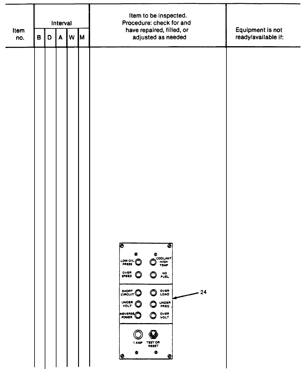
18
3-14
GENERATOR SET GAGES AND
INSTRUMENTS - CONT
h. Check coolant temperature gage (23)
for 170° to 200°F (76.7° to
93.3°C) indication.
i.
Check that all lights on fault in-
dicator panel (24) are out during
operation. Check bulb operation
with TEST or RESET switch on paneI.
Temperature exceeds
200°F (93.3°C).
Fault light will not go
out when switch is set
to TEST or RESET posi-
tion, then released,
All bulbs should be lit
when switch is in TEST
or RESET position.
TM 5-6115-628-14&P
Table 3-2. Operator/Crew Preventive Maintenance Checks and Services (PMCS) – CONT.
B
- Before
D
- During A - After W - Weekly M - Monthly
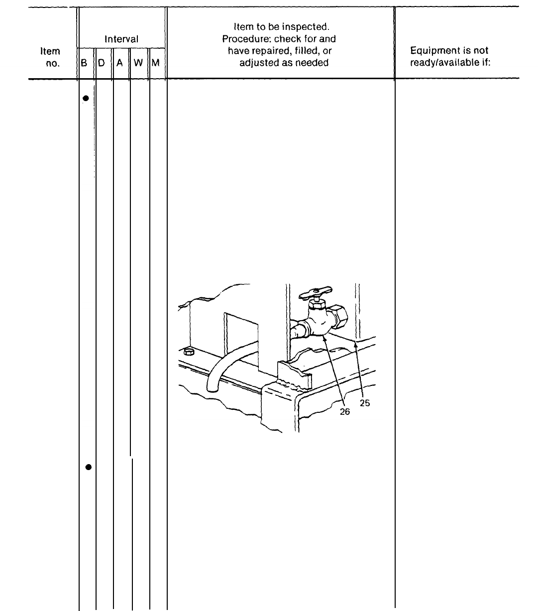
19
20
FUEL TANK
a. Fill tank (25) upon completion of
operation.
NOTE
Fuel system temperature must be
above freezing when draining
water and sediment.
b. Open drain (26) and drain water and
sediment from fuel tank. Allow to drain
until fuel runs clean.
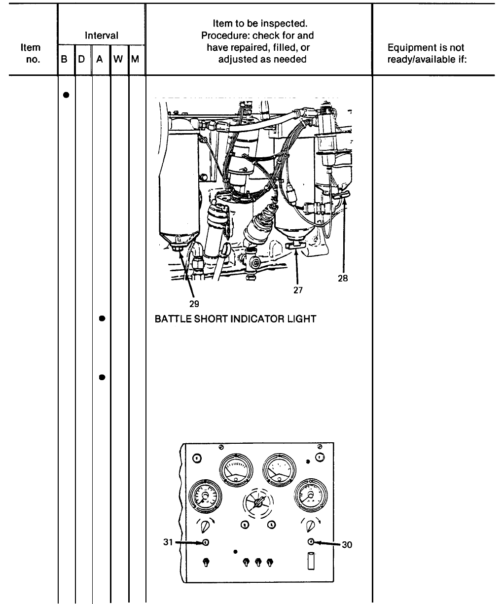
FUEL STRAINER AND FILTERS
Drain water and sediment from strainer (27),
primary (28) and secondary (29) filters.
Allow to drain until fuel runs clean.
3-15
TM 5-6115-628-14&P
Table 3-2. Operator/Crew Preventive Maintenance Checks and Services (PMCS) – CONT.
B
- Before D - During A - After W - Weekly
M
- Monthly
20
21
22
3-16
FUEL STRAINER AND FILTERS - CONT
Push in on lens housing. Light (30) should
illuminate. If not, replace bulb.
CIRCUIT BREAKER INDICATOR LIGHT
Push in on lens housing. Light (31) should
illuminate. If not, replace bulb.
TM 5-6115-628-14&P
Table 3-2. Operator/Crew Preventive Maintenance Checks and Services (PMCS) – CONT.
B
- Before D - During A - After
w
- Weekly M - Monthly
23
24
25
BRAKE DRUMS AND HUBS
WARNING
A defect in the operation of the
brake or hub can cause these
parts to get hot enough to cause
serious burns. Use extreme cau-
tion when attempting to detect
heat in this area.
Feel drums and hubs for overheating to
detect dragging or binding.
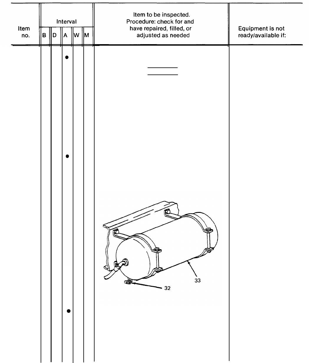
AIR RESERVOIR
Open draincock (32) to drain moisture
from air reservoir (33) and close when
finished.
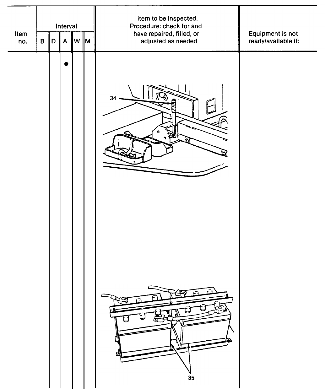
HANDBRAKES
With trailer hooked to towing vehicle,
set handbrakes (34). Move trailer
slightlyt to see if handbrakes hold
wheels. Adjust as required.
Brakes or hub are
dragging or binding.
Handbrakes cannot be
adjusted.
3-17
TM 5-6115-628-14&P
Table 3-2. Operator/Crew Preventive Maintenance Checks and Services (PMCS) - CONT.
B – Before D - During A - After W - Weekly
M
- Monthly
25
26
27
3-18
●
●
HANDBRAKES - CONT
REFLECTORS
Check for damaged or missing reflectors.
BATTERIES
Check battery (35) electrolyte level. Level
should be about 3/4 inch above top of plates.
Add water if level is low. Use clean water
(distilled water if available).

TM 5-6115-628-14&P
Table 3-2. Operator/Crew Preventive Maintenance Checks and Services (PMCS) – CONT.
B - Before D - During A - After W - Weekly M - Monthly
28
●
FIRE EXTINGUISHER
Inspect and weigh fire extinguisher.
(See paragraph 3-11.)
29
●
TRAILER FRAME
Inspect entire chassis frame for damage,
Frame is obviously broken
cracks, and broken welds. or cracked.
30 ●COLLANT LEVEL
Check level of fluid in cooling system.
Proper level is 2 inches below overflow
pipe. Add coolant as required.
Section IV. TROUBLESHOOTING
3-10. Power Plant Troubleshooting. There are no troubleshooting procedures authorized at operator level
for the power plant end item. Troubleshooting procedures for the individual generator sets and trailers
are contained in their respective technical manuals referenced below.
a.
Generator Set Troubleshooting. Refer to TM 5-6115-464-12 for, troubleshooting procedures
applicable to the generator set.
b.
Trailer Troubleshooting. Refer
to the trailer.
Section V.
3-11.
Fire Extinguisher Maintenance.
extinguishers. Maintenance is limited
to TM 9-2330-205-14&P for troubleshooting procedures applicable
OPERATOR/CREW MAINTENANCE
The AN/MJQ-15 Power Plant is equipped with two 5 lb C02 fire
to weighing the fire extinguishers monthly to insure that they are
sufficiently charged. Fully charged, each extinguisher weighs 13 Ibs. Send the unit to specialized
activity for recharging if it weighs 12.5 lb or less.
CAUTION
Do not attempt to verify readiness of a fire extinguisher by partially
discharging unit. Any discharge of contents will require refilling.
Change 1 3-19/(3-20 blank)
TM 5-6115-628-14&P
CHAPTER 4
UNIT MAINTENANCE
Section I. SERVICE UPON RECEIPT OF EQUIPMENT
4-1.
Inspecting and Servicing Equipment. The power plant is unpacked, inspected, and serviced as
described in the following paragraphs. Unpacked equipment must be checked against the Equipment
Packing List to ensure completeness. Discrepancies must be reported in accordance with instructions
in DA Pam 738-750.
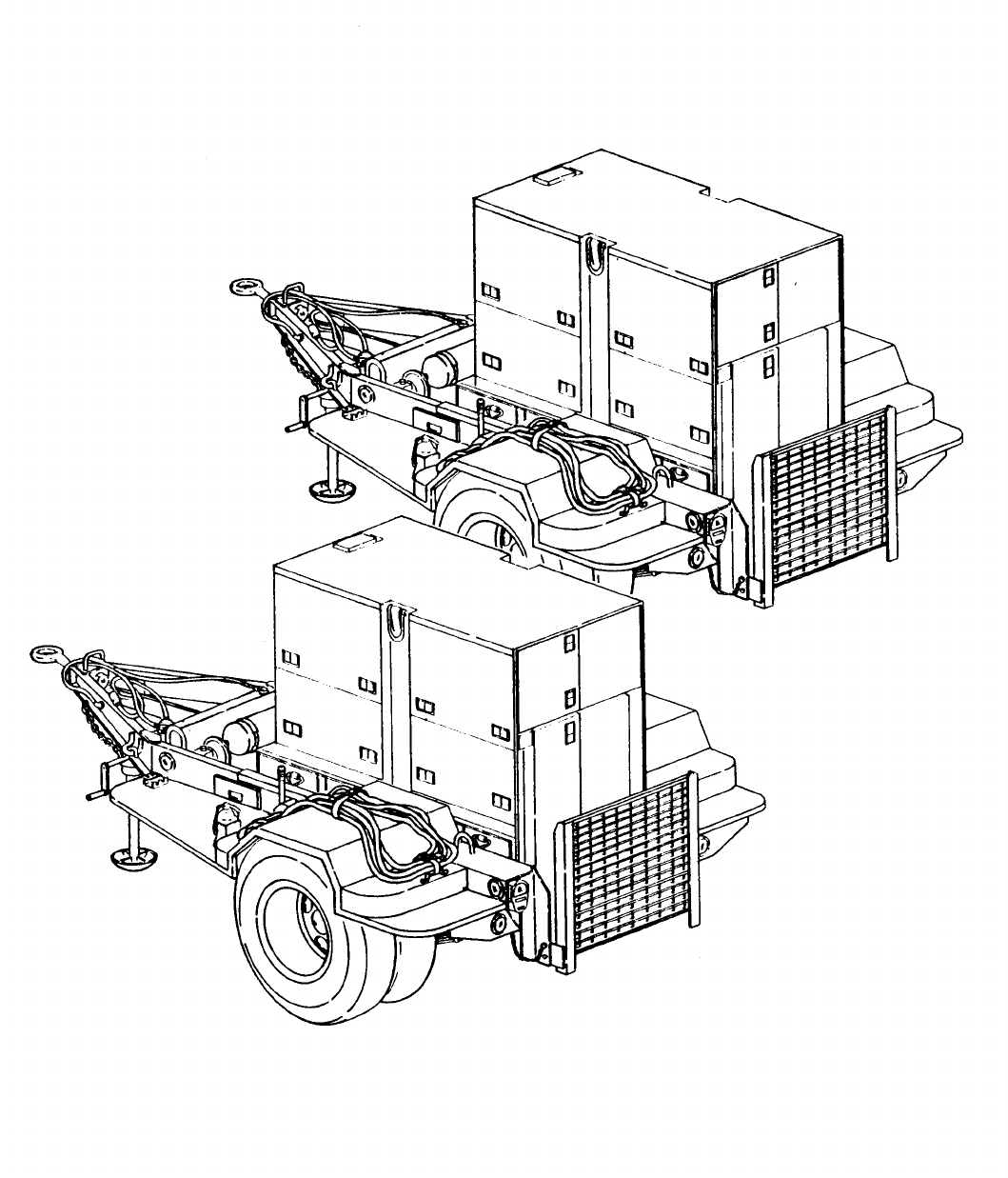
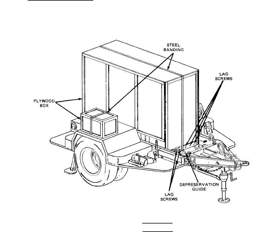
a. Unpacking Power Plant. (See figures 4-1 and 4-2.) The two power units that makeup the
AN/MJQ-15 power plant are identical except for the addition of the switch box installed on the curbside
fender of one of the units. Therefore, the unpacking procedures are typical for both. Each generator
set is packed in place on its respective trailer. Before beginning the unpacking procedure, locate and
remove Depreservation Guide.
Figure 4-1. Power Unit B, with Switch Box, Packed for Shipment.
WARNING
The steel banding used in packaging of power plant has sharp edges. Care
should be taken when cutting and handling banding to avoid injury to
personnel.
(1) Remove steel banding around plywood box(es) covering generator set and, when
unpacking unit B, the switch box.
4-1
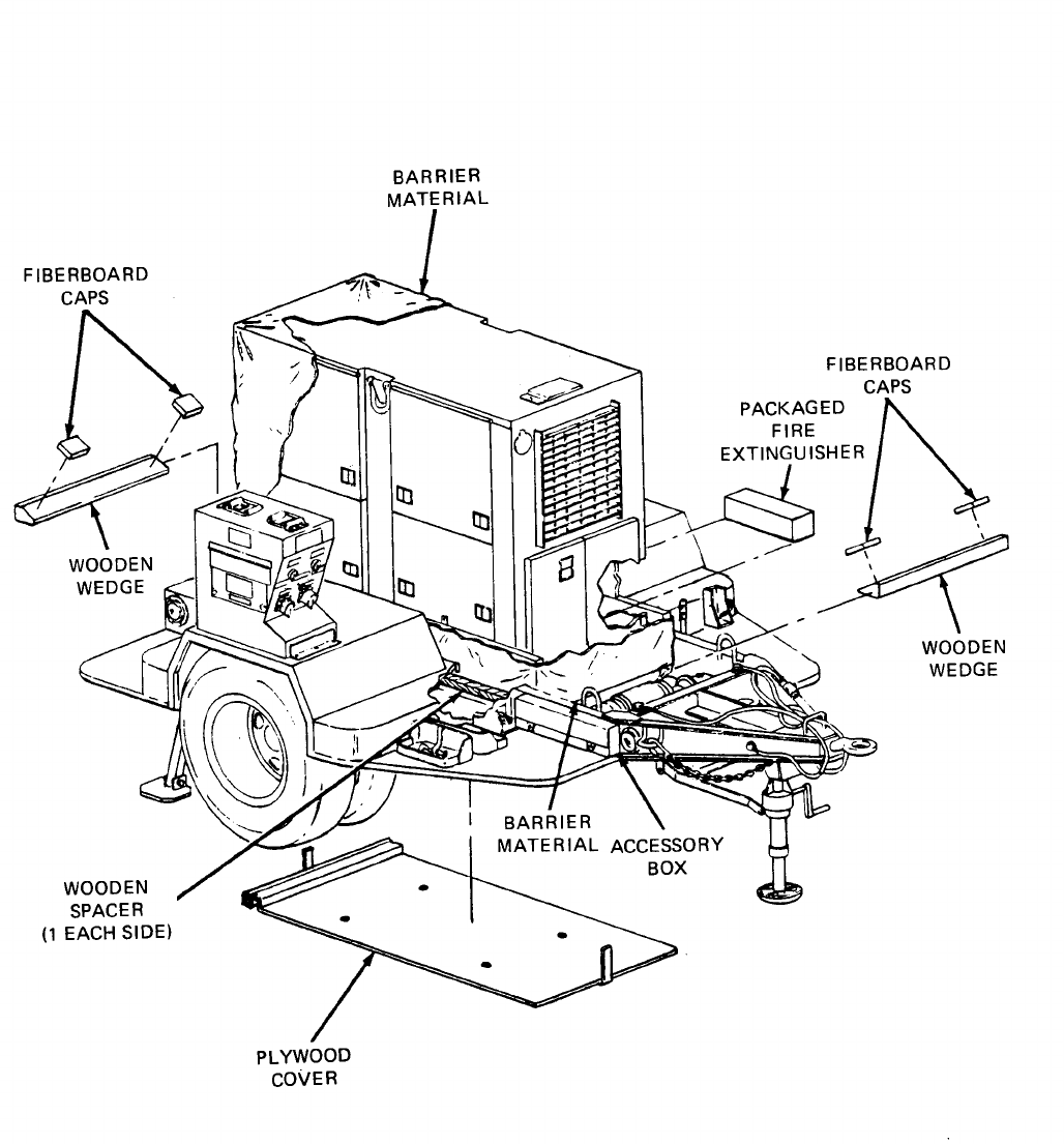

(2)
(3)
(4)
(5)
(6)
(7)
(8)
(9)
(10)
(11)
(12)
TM 5-6115-628-14&P
Remove lag screws securing plywood box cover over generator set and lift off cover.
Remove wooden wedges and spacers from around generator set base. Loosen switch box
attaching hardware and remove any steel banding remaining beneath switch box.
Remove and save package of technical manuals secured to barrier material.
Remove four sets of attaching hardware and drop plywood cover under trailer.
Remove barrier material and fiberboard caps from generator set.
Remove packaged fire extinguisher from within generator set enclosure. Unpack and
secure fire extinguisher in bracket on front roadside step.
Remove steel banding around accessory box, unpack and inventory contents.
Refer to DA Form 2258, Depreservation Guide for Vehicles and Equipment, packed with
power unit and follow instructions given for putting unit into service.
Stow technical manuals in box on inside of generator set enclosure rear curbside door.
Stow all authorized accessories in the accessory box.
Remove all tape and packing film from trailer air hoses and intervehicular cable.
b. Inspection and Servicing of Generator Set. Refer to Servicing Upon Receipt of Materiel in TM
5-6115-464-12 for initial inspection and servicing procedures.
c. Inspection and Servicing of Trailers. Refer to Servicing Upon Receipt of Materiel in
TM 9-2330-205-14&P for initial inspection and servicing procedures.
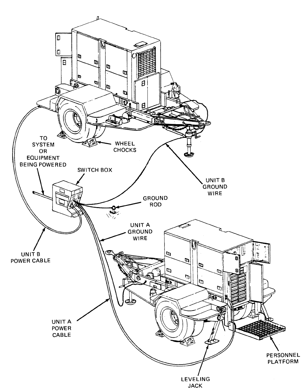
4-2.
Installation. (See figure 4-3.) Installation of the power plant at a worksite involves positioning
both the power unit trailers and the switch box, and grounding the equipment.
a. Positioning Power Plant. Position the power plant on the worksite as follows:
(1) Select an area as level as possible to install power plant and position both power units.
(2) Set handbrakes and lower landing legs on both trailers.
(3) Chock both sets of dual wheels on each trailer.
(4) Lower both rear leveling jacks on each trailer and secure leveling jacks with Iockpins.
Extend lower tubes on leveling jacks by stepping on hinged pads.
WARNING
Remove fire extinguishers and fuel cans from individual power units when
power plant is in operation. This will insure that in the event of fire, extra fuel
will not be involved and extinguishers will remain accessible.
(5) Locate fuel cans and fire extinguishers on ground halfway between the two power units.
4-3

TM 5-6115-628-14&P
(6) Remove switch box from fender of power unit B and stow attaching hardware in accessory
box.
(7) Position switch box assembly on ground halfway between two power units.
(8) Unstrap and remove power cables from fenders of both power units.
NOTE
When performing step 10, note that the power cables, the individual wires in
the cables, and the generator set load terminals are all marked for identifica
tion. Make certain these markings correspond when connecting power
cables.
(9) Connect power cable to each generator set load terminal board as follows:
(a) White wire to load terminal L0.
(b) Black wire to load terminal L1.
(c) Red wire to load terminal L2.
(d) Blue wire to load terminal L3.
(10) Connect both power cables to switch box.
(11) When power plant power units are to be operated in parallel, install paralleling cables
between generator sets and switchbox.
WARNING
Do not operate power plant until both power units have been properly grounded
(paragraph 4-2, b.) Serious injury or death by electrocution can result from
operating an ungrounded power plant.
CAUTION
To avoid damage to equipment, make certain of voltage, frequency, and
phase requirements of load being connected to power plant.
NOTE
The following information is applicable when AN/MJQ-15 Power Plant is used
with the TAC-FIRE System. Remove wire No, X13B4N from generator load
connection L0 and ground stud E6 (generator skid base grounding stud). This
wire must be replaced when the generator set is turned back into supply
system.
(12) Connect power plant switch box to system or equipment to be powered. Refer to
TM 5-6115-464-12.
(13) Remove quick-release pins securing both power unit personnel platforms and lower
platforms.
4-4

TM 5-6115-628-14&P
(14) On both power units, open control panel doors and the two doors immediately below the
control panels.
b. Grounding. Check that the individual power unit generator sets are grounded to the GROUND
TERMINAL studs on their respective trailer frames. Using ground wire supplied with power plant,
connect GROUND TERMINAL lug on switch box to a suitable ground as described below. The following
sources of a good ground are listed in order of preference.
NOTE
As a substitute for the supplied ground wire, any copper wire of at least No. 6
AWG may be used.
(1) Underground water system. Ground power plant to one of the accessible pipes in an
underground water system. Make certain underground pipe is made of metal and there is no
insulation, such as a water meter, between ground wire and the earth.
(2) Ground rod. Drive grounding rod a minimum of eight feet into earth. A ground rod must
have a minimum diameter of 5/8-inch, if solid, or 3/4-inch if pipe.
NOTE
It maybe necessary to saturate the area around ground rod with water if soild
conditions are dry.
(3) Ground plate. Ground power plant to a metal plate buried four feet deep. Ground plate
should cover a minimum area of nine square feet.
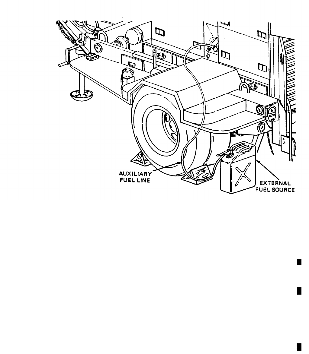
c. External Fuel Line Connection. (See figure 4-4.) Either or both of the power units that make up
the power plant can be fueled from an external source. The external source could be a five-gallon fuel
can or a 55-galIon drum. This eliminates the need for frequent refilling of a generator set’s fuel tank
during long intervals of operation.
(1)
(2)
(3)
(4)
(5)
Remove fuel can adapter and fuel pickup tube from storage locations on power unit and
assemble by threading pickup tube into adapter.
Thread one end of auxiliary fuel line onto fuel can adapter fitting and tighten.
Connect free end of auxiliary fuel line to AUXILIARY FUEL CONNECTION. This connection is
located next to the fuel filler above the trailer roadside fender.
Insert fuel can adapter into external fuel source and secure by pressing down on lever.
Set FUEL SELECTOR VALVE beneath fuel filler to AUXILIARY position.
4-5
TM 5-6115-628-14&P
Figure 4-4. External Fuel Line Connection.
Section II. MOVEMENT TO A NEW WORKSITE
4-3. Dismantling for Movement.
Because the power plant is designed to be mobile, a minimum amount of
effort is required to relocate to a new worksite. Procedures are as follows:
a.
a1.
b.
c.
d.
e.
f.
g.
Shut down generator set and position switches in off position.
Disconnect power plant from system or equipment being powered.
Disconnect ground cables between switch box and GROUND TERMINAL studs on both power units.
Roll up cables and store in accessory boxes.
Using slide hammer, remove ground rods. Disassemble, clean, and stow ground rods in accessory
boxes.
Disconnect power plant from external fuel sources, if applicable.
Disconnect ground wires between switch box and GROUND rod. Roll up ground wires and store in
accessory boxes.
Disconnect power cables from both power units and from switch box. Roll up cables and secure each
to roadside fender of respective power unit using straps provided.
Close switch box access door and cap connectors. Position switch box on curbside fender of power
unit B and secure with hardware provided.
Change 4 4-7

TM 5-6115-628-14&P
h.
i.
j.
k.
l.
m.
n.
o.
Stow any remaining authorized equipment in accessory box.
Secure fire extinguishers and fuel cans in their respective mounting brackets.
Close all doors on the generator set enclosures.
On each power unit, swing personnel platform up into traveling position and secure with two
platform anchor quick-release pins.
WARNING
Use care when releasing spring-loaded lower tube of leveling jacks. The lower
tube will return to retracted position with considerable force and can cause
injury.
Retract lower tubes of leveling jacks. Swing Ieveling jacks up, into traveling position and secure
with Iockpins.
Remove wheel chocks.
Attach power units to towing vehicles. Refer to TM9-2330-205-14&P.
Release trailer handbrakes on both power units.
4-4. Reinstallation After Movement. After movement to a new worksite, install power plant in
accordance with paragraph 4-2.
Section Ill. REPAIR PARTS, SPECIAL TOOLS, SPECIAL TEST, MEASUREMENT AND
DIAGNOSTIC EQUIPMENT (TMDE)
4-5. Tools and Equipment. There are no special tools or equipment required to maintain the
AN/MJQ-15 power plant.
4-6. Maintenance Repair Parts. Repair parts and equipment for maintenance of this power plant are
listed and illustrated in the repair parts and special tools list in Appendix D of this manual.
Section IV. LUBRICATION INSTRUCTIONS
4-7. General. Detailed instructions for the lubrication of the major components of the power plant are
contained in the applicable Lubrication Orders (LO’s). Refer to DA Pam 25-30 to ensure that the latest
editions of the L.O.’S are used. This section contains lubrication instructions that are not included in
the Lubrication Orders.
4-8. Generator Lubrication. Refer to LO 5-6115-464-12 for generator set Lubrication Order.
4-9. Trailer Assembly Lubrication.
a. Trailer Lubrication. Refer to TM 9-2330-205-14&P for trailer Lubrication Order.
b. Personnel Platform Lubrication. The personnel platform is a modification to the standard
M200A1 trailer and, as such, does not appear in the associated L.O. Lubricate the personnel
platform semiannually as follows:
4-8
PIN:
064446-004

TM 5-6115-628-14&P
WARNING
Clean parts in a well-ventilated area. Avoid inhalation of solvent fumes and
prolonged exposure of skin to cleaning solvent. Wash exposed skin thoroughly.
Dry cleaning solvent (P-D-680) used to clean parts is potentially dangerous
to personnel and property. Do not smoke or use near open flame or
excessive heat. Flash point of solvent is 100o F to 138oF (38oC to 59o C).
(1) Using P-D-680, or equivalent, clean area to be lubricated.
(2) Apply OE lubricating oil to personnel platform
release pins.
Section V. PREVENTIVE MAINTENANCE
NOTE
pivot points and to platform
CHECKS AND SERVICES
The PMCS chart in this section contains all necessary Unit preventive main-
tenance checks and services for this equipment.
4-10. General. The trailer assemblies and generator sets must be inspected and serviced
anchor quick-
systematically
to insure that the power plant is ready for operation at all times. Inspection will allow defects to be dis-
covered and corrected before they result in serious damage or failure. Table 4-1 contains a tabulated list
of preventive maintenance checks and services to be performed by unit maintenance personnel. All of the
unit PMCS on the trailers is scheduled to be performed Semiannually. Unit PMCS on the generator sets
is scheduled weekly or on a per-hours-of-operation basis. The running time meters on the control panels
are used to determine the operating time of the generator sets. Using the following as a guide, do the
checks and services at the intervals shown. Observe all CAUTIONS and WARNINGS.
a.
b.
c.
d.
e.
f.
For PMCS performed on an operating time basis, perform your hourly (H) PMCS as close as possible
to the time intervals indicated.
NOTE
For units in continuous operation, perform PMCS before starting operation
if continuous operation will extend service interval past that which is shown.
Perform your weekly (W) PMCS every week or 40 hours of generator set operating time.
Perform your monthly (M) PMCS every month or 100 hours of generator set operating time.
Do your semiannual (S) PMCS once every six months.
Do your annual (A) PMCS once every year.
If you discover a problem with the equipment, refer to Section VI, Troubleshooting. If you cannot
correct the problem, refer to paragraph 4-12, Reporting Deficiencies.
4-11. Explanation of Columns. The following is a list of the PMCS table column headings with a descrip-
tion of the information found in each column.
a.
Item No. This column shows the sequence in which checks and services are to be done, identify
the equipment area on the Equipment Inspection and Maintenance Worksheet, DA Form 2404.
Change 1 4-9
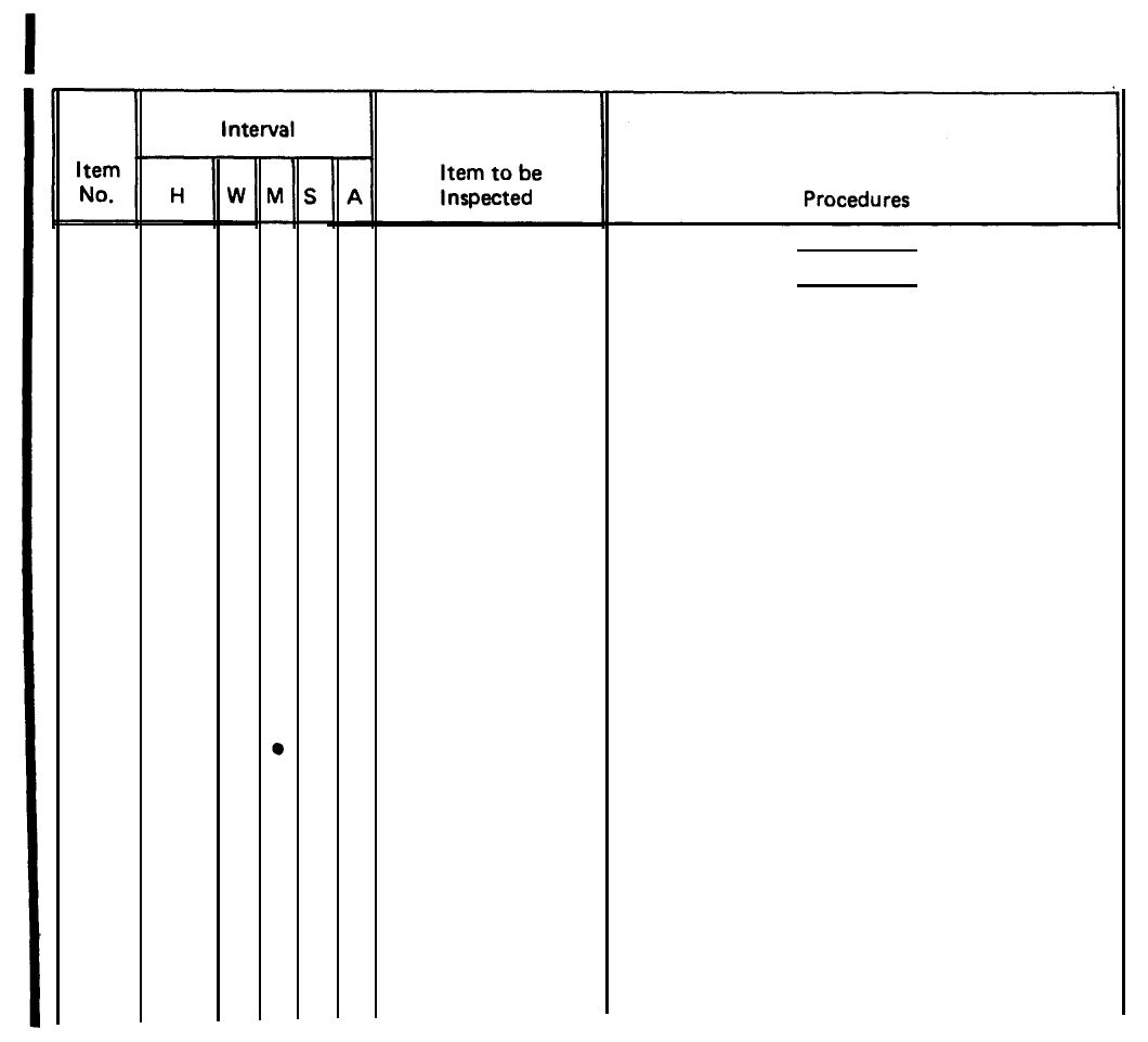
TM 5-6115-625-14&P
b. Interval. This column shows when each check is to be done.
c. Item to be Inspected. This column identifies the general area or specific part where the check or
service is to be done.
d. Procedures. This column lists the checks or services you have to do and explains how to do them.
4-12. Reporting Deficiencies. If you discover any problem with the equipment during PMCS that you
are unable to correct, it must be reported. Refer to DA Pam 738-750 and report the deficiency using
the proper forms.
Table 4-1.
H - Hours of operation
(As indicated)
●
Unit Preventive Maintenance Checks and Services (PMCS).
W - Weekly M - Monthly S - Semiannually
(40 hours) (100 hours) (500 hours)
1Hydraulic Sump
Generator Set
Exterior
A – Annually
(1,000 hours)
WARNING
Before performing any maintenance that
requires climbing on or under trailer, set
trailer, handbrakes, chock wheels and
lower rear leveling jacks. Injury to
personnel could result from trailer
suddenly rolling or tipping.
NOTE
This PMC table lists the checks and
services as performed on a single power
unit. These procedures must be duplicated
on each of the two power units that
make up the AN/MJQ-15.
Check the fluid level. Add fluid as required.
2Inspect generator set for fuel and oil leaks,
loose or missing components and hardware,
and unusual wear or deterioration.
Clean generator set.
NOTE
Fuel system must be above freezing;
temperature when draining water and
sediment from strainer, filters and tank.
4-10
Change 1
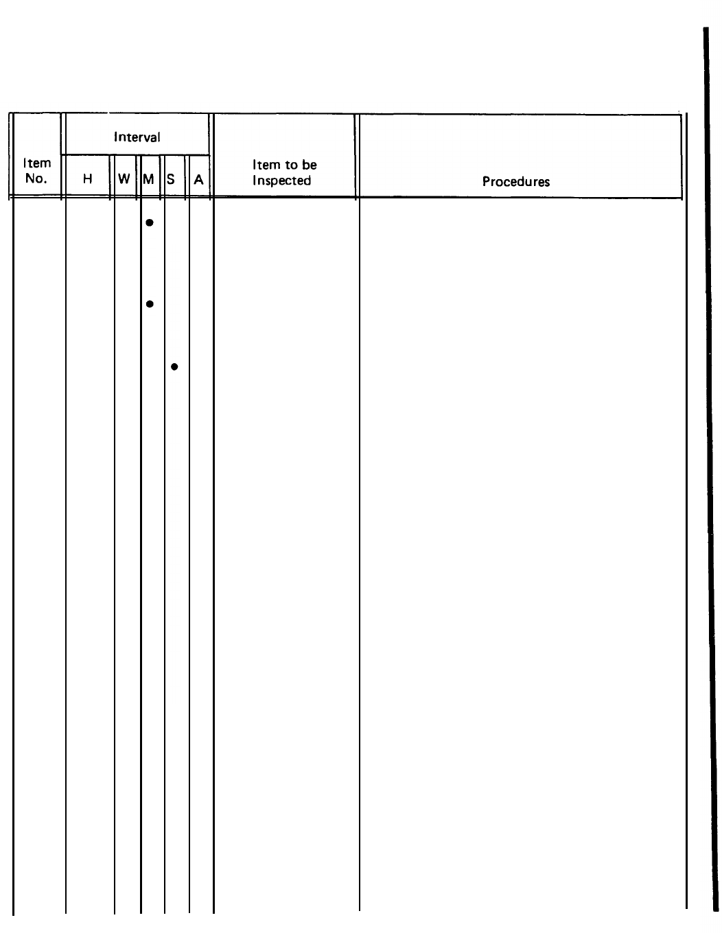
TM 5-6115-628-14&P
Table 4-1. Unit Preventive Maintenance Checks and Services (PMCS).
H – Hours of operation W - Weekly M - Monthly S - Semiannually A - Annually
(As indicated) (40 hours) (100 hours) (500 hours) (1,000 hours)
3
4
5
6
7
8
9
10
11
12
13
14
100
100
100
300
300
300
500
500
500
Fuel Strainer and
Filters
Fuel Tanks
Fuel Pumps
Batteries
V-Belt
Fuel Filters
Fuel Strainer
Lubricating Oil
and Filters
Breather and
Breather Tube
Hydraulic Sump
Hydraulic Filter
Hydraulic Actuator
Open drains on fuel strainer and primary and
secondary fuel filters. Drain water and
sediment. Allow to drain until fuel runs
clean.
Open drains on main fuel tank and day tank.
Drain water and sediment. Allow to drain
until fuel runs clean.
Clean or replace, as necessary, fuel strainer
in bottom of fuel pump.
Perform a hydrometer test on batteries every
100 hours. Refer to TM 5-6115-464-12
for test procedures.
Inspect for worn, frayed, cracked or oil-
soaked belt. Check adjustment. If necessary,
adjust for a 1/2-inch deflection when belt
is depressed at a point midway between
alternator and water pump pulley.
Replace filter elements every 100 hours
of operation.
Clean fuel strainer every 300 hours of
operation.
Change lubricating oil and filters every 300
hours of operation or six months.
Inspect for damage. Clean breather and tube
at oil change interval.
Drain and refill (para 3-97,
TM 5-6115-464-12)
Replace filter (para 3-97,
TM 5-6115-464-12)
Clean filter (para 3-98,
TM 5-6115-464-12)
Change 1
4-11
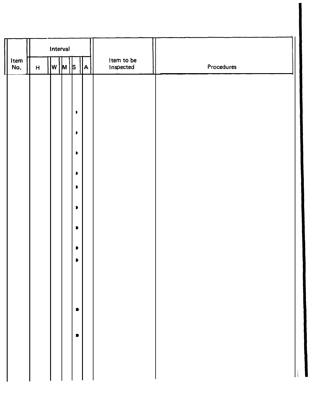
TM 5-6115-628-14&P
Table 4-1. Unit Preventive Maintenance Checks and Services (PMCS).
H - Hours of operation W - Weekly M - Monthly S - Semiannually A - Annually
(As indicated) (40 hours) (100 hours) (500 hours) (1,000 hours)
15
16
17
18
19
20
21
22
23
24
25
26
AR Air Cleaner
Taillights
Intervehicular
Cable
Lunette
Safety Chains
RefIectors
Data Plates and
Markings
Landing Leg
Leveling Jacks
Suspension
Assemblies
Axle
Wheels and Tires
CIean air cleaner element whenever necessary
aS indicated by air filter condition
indicator light.
Replace any broken or cracked lenses or
defective bulbs.
Check for cuts, breaks, frayed wires and
damaged plug.
Check security of mounting. Inspect for
excessive wear.
Inspect for broken links or missing chain(s).
Replace any cracked, broken or missing
refIectors.
Make sure data plates are legible and securely
mounted. Replace illegible data plates.
Inspect landing leg and brace for bent or
broken parts.
Inspect leveling jacks for bent or broken parts.
a.
b.
a.
Inspect shackles, bearings, pins, leaf springs
and spring eyes for damage and broken
parts.
Inspect mounting brackets for cracks or
loose or missing hardware.
Check for damaged axle tube.
b. Check for loose or missing U-bolts or nuts.
a. Check serviceability of tires as indicated
in TM 9-2610-200-24.
b. Tighten wheel stud nuts to 460 to 500
ft-lb (611 to 678 N-m).
4-12
Change 1
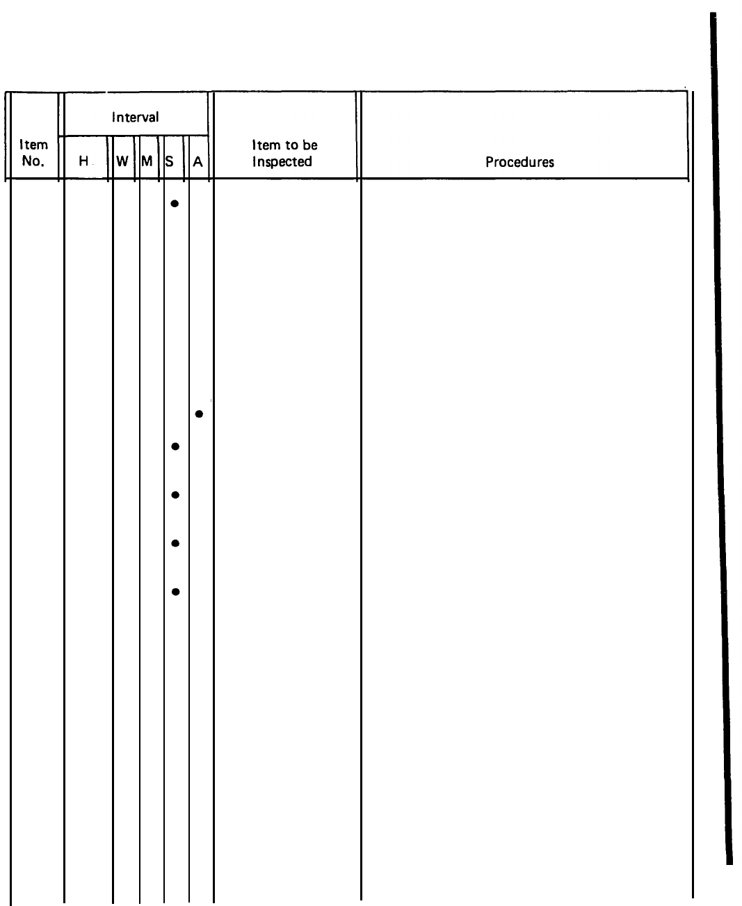
TM 5-6115-628-14&P TM 5-6115-628-14&P
Table 4-1. Unit Preventive Maintenance Checks and Services (PMCS).
H - Hours of operation W – Weekly M - Monthly S - Semiannually A - Annually
(As indicated) (40 hours) (100 hours) (500 hours)(1,000 hours)
27
28
29
30
31
32
Brakes
Wheel Bearings
Hydraulic Brake
Hoses and Fittings
Air Hoses and
Fittings
Brake Master
Cylinder
Trailer Road Test
a. Inspect brake linings for wear. Replace if
brake shoe lining is less than 1/8-inch
(3.2 mm) thick.
b. Inspect brake adjusting screw, retaining
pins, springs, and clips for corrosion
and wear.
c. Inspect hydraulic wheel cylinders for
leaks.
d. Adjust brakes.
Clean and repack wheel bearings.
Inspect for dents, cracks, loose connections
and leaks.
Inspect for dents, cracks, loose connections
and leaks.
Check fluid level. Fill to 1/2 inch from top.
Perform road test paying special attention
to items that were repaired or adjusted,
in accordance with TM 9-2330-205-14&P.
Change 1
4-13

TM 5-6115-628-14&P
Section VI. TROUBLESHOOTING
4-13.
General. Troubleshooting procedures for components unique to the power plant end item are
given in paragraph 4-14. Troubleshooting information for the individual generator sets and trailers are
contained in their respective manuals referenced below:
a. Generator Set Troubleshooting. Refer to TM 5-6115-464-12 for troubleshooting procedures
applicable to the generator set.
b. Trailer Troubleshooting. Refer to TM 9-2330-205-14&P for troubleshooting procedures
applicable to the trailers.
4-14.
Power Plant Troubleshooting. Table 4-2 contains troubleshooting information for locating and
correcting operating troubles which may develop in components unique to the power plant end item.
Each malfunction is followed by a list of tests or inspections which will help determine probable cause
and corrective actions to take. Perform the tests/inspections and corrective actions in the order
listed. This manual cannot list all malfunctions that may occur, nor all tests or inspections and
corrective actions. If a malfunction is not listed or cannot be corrected by listed corrective actions,
notify your supervisor.
Table 4-2. Troubleshooting.
Malfunction
Test or inspection Corrective action
1. POWER IS ABSENT AT SWITCH BOX LOAD TERMINAL(S) WHEN ONE PARTICULAR POWER UNIT IS
SELECTED.
Step 1.
Step 2.
Step 3.
Step 4.
Step 5.
4-14
Check if associated generator set circuit breaker is set to ON position.
If circuit breaker is in OFF position, reset to ON position.
Verify associated generator set output is as desired. Check generator output at
load terminals.
If power is absent at generator set load terminals, troubleshoot
generator set. (Refer to TM 5-6115-464-12.)
Perform continuity check on associated power unit power cable.
If cable is defective, notify higher level of maintenance.
Perform continuity check on associated switchbox connector.
If connector is defective, notify higher level of maintenance.
Perform continuity check on associated switch.
If switch is defective, notify higher level of maintenance.
✩U.S. Government Printing Office: 1989-654-030/00368
PIN: 06446 001

TM 5-6115-628-14&P
Table 4-2. Troubleshooting – CONT.
MalfunctionTest or inspection Corrective action
2. POWER IS ABSENT AT ONE OR MORE SWITCH BOX LOAD TERMINALS WHEN EITHER POWER UNIT
IS SELECTED.
Step 1.
Check load terminal(s) for looseness or damage.
a. If terminal is loose, tighten.
b. If terminal is damaged, notify higher level of maintenance.
Step 2.
Inside switchbox, check wires associated with inoperative terminal(s) for
looseness or broken wire terminals.
Tighten loose connection, repair or replace broken wires.
3. ONE OR MORE INDICATOR LAMPS DO NOT LIGHT WHEN POWER IS APPLIED BY POWER PLANT
THROUGH SWITCH BOX.
Step 1.
Check bulb(s).
Replace bulb(s) if defective.
Step 2.
Inspect wires associated with inoperative indicator. Check wire terminals for
looseness.
Tighten loose connections. Replace broken wires.
Step 3.
Perform continuity check on indicator housing.
If indicator housing is defective, replace.
Section VIl. RADIO INTERFERENCE SUPPRESSION
4-15.
General Methods Used to Attain Proper Suppression. Essentially, suppression is attained by
providing a low resistance path to ground for stray currents. The methods used include shielding igni-
tion and high-frequency wires, grounding the frame with bonding straps, and using filtering systems.
4-16.
Radio Interference Suppression Components. All component parts on the power plant end
item, whose primary or secondary function is radio interference suppression, are on the generator
sets. Refer to TM 5-6115-464-12 for location of radio interference suppression components.
4-15
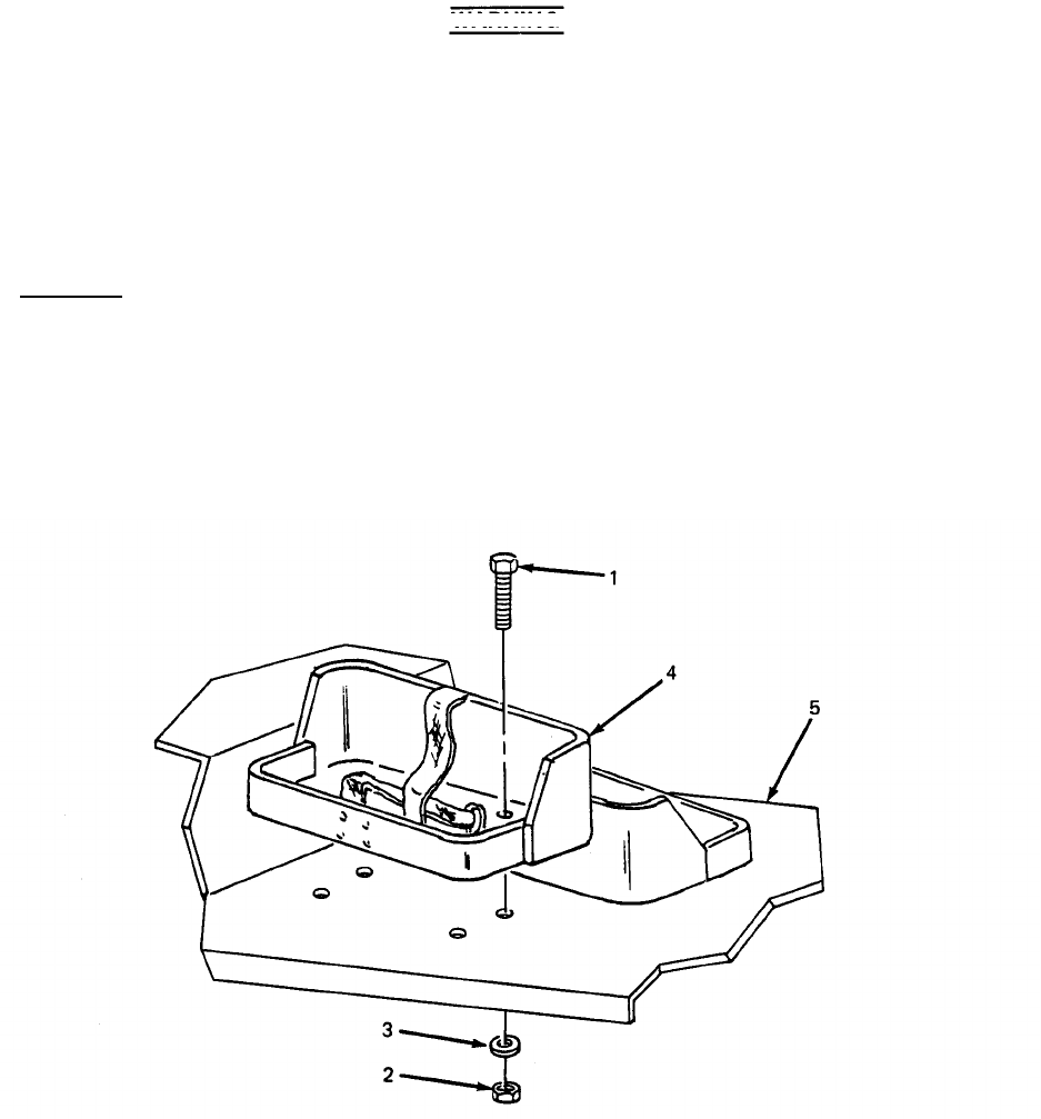
TM 5-6115-628-14&P
Section Vlll. MAINTENANCE OF POWER PLANT TRAILERS
4-17.
General. This section of the manual contains unit level maintenance procedures for compo-
nents of the M200A1 trailer added when the trailer is used as part of the AN/MJQ-15 power plant.
These components are not covered in the overall trailer maintenance manual. For all other unit
maintenance procedures on the trailer, refer to TM 9-2330-205-14&P.
WARNING
Before performing any maintenance that requires climbing on or under trailer,
set trailer handbrakes, chock both wheels, and lower rear leveling jacks.
Injury to personnel could result from trailer suddenly rolling or tipping.
4-18.
Fuel Can Bracket Replacement. (See figure 4-5.) There are four fuel can brackets supplied
with the AN/MJQ-15. Two brackets are mounted on top of the curbside front steps on each power unit.
Replacement procedures described below are typical for all.
a. Removal.
(1) Remove four screws (1, figure 4-5), four nuts (2) and four flat washers (3) securing
bracket (4) to step (5).
(2) Remove bracket (4) from step (5).
4-16
Figure 4-5. Fuel Can Bracket Replacement.
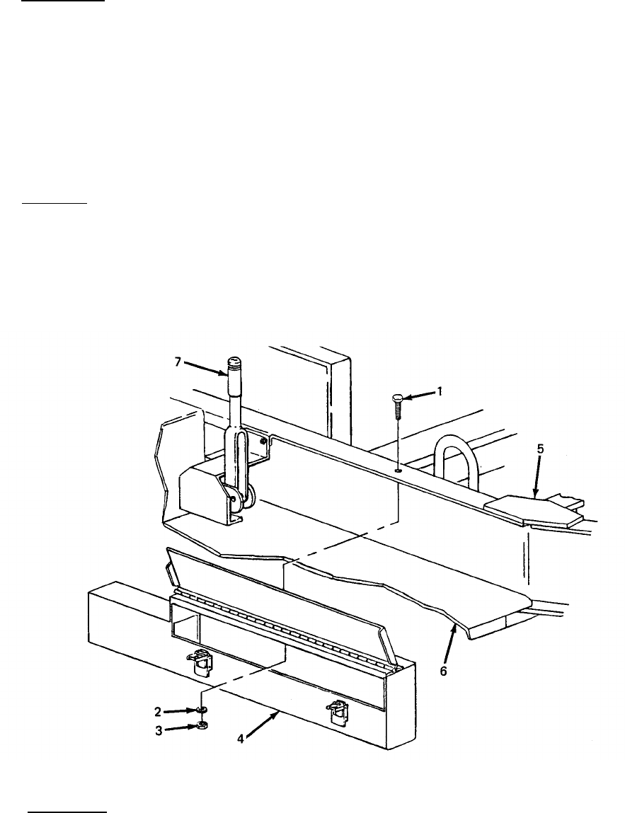
TM 5-6115-628-14&P
b. Installation.
(1) Position fuel can bracket (4) on step (5).
(2) Insert four screws (1) down through bracket (4) and through step (5).
(3) Install one washer (3) and one nut (2) on each screw (1). Tighten hardware to secure
bracket (4).
4-19.
Accessory Box Replacement. (See figure 4-6.) The accessory boxes are mounted to the
trailer frames at the curbside front steps. Replacement procedures are typical.
a. Removal.
(1) Remove three screws (1, figure 4-6), three flat washers (2), and three nuts (3) securing
accessory box (4) to trailer frame (5).
(2) Slide accessory box (4) forward and off of front step (6).
Figure 4-6. Accessory Box Replacement.
b. Installation.
(1) Position accessory box (4) on front trailer step (6) with narrow end between handbrake
lever (7) and trailer frame (5).
(2) Lift accessory box (4) so that top of box contacts lip of trailer frame (5).
4-17
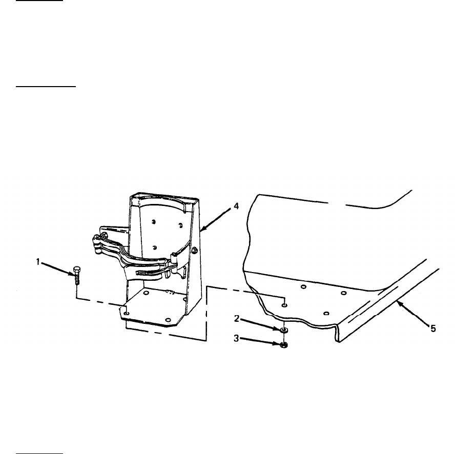
TM 5-6115-628-14&P
(3) Insert three screws (1) down through trailer frame (5) into accessory box (4).
(4) Install one nut (3) and one washer (2) on each screw (1) and tighten.
4-20.
Fire Extinguisher Bracket Replacement. (See figure 4-7.) The fire extinguishers supplied with
the power plant are carried in brackets mounted on the front roadside steps of the trailers.
a. Removal.
(1) Remove four screws (1, figure 4-7), four flat washers (2), and four nuts (3) securing
bracket (4) to step (5).
(2) Remove bracket (4) from step (5).
b. Installation.
(1) Position fire extinguisher bracket (4) on step (5).
(2) Insert four screws (1) down through bracket (4) and through step (5).
(3) Install one washer (2) and one nut (3) on each screw (1). Tighten hardware to secure
bracket (4).
Figure 4-7. Fire Extinguisher Bracket Replacement.
4-21.
Front Steps Replacement. (See figure 4-8.) The roadside and curbside front steps on both
trailers are symmetrical, and replacement procedures are the same except where noted in the steps
below.
a. Removal.
NOTE
When removing roadside front step, omit steps (1) and (2).
(1) Remove fuel can brackets (paragraph 4-18, a).
(2) Remove accessory box (paragraph 4-19, a).
4-18

TM 5-6115-628-14&P
(3) Remove cotter pin (1, figure 4-8) and clevis pin (2) securing handbrake cable (3) to
handbrake lever mechanism (4).
(4) Remove two screws (5), two flat washers (6) and two nuts (7) securing handbrake bracket
(8) to trailer frame (9).
(5) Remove two screws (10), two flat washers (11) and two nuts (12) securing handbrake
cable (13) to front step (14).
NOTE
There are two screws, flat washers, and nuts securing handbrake bracket to
front step. It is only necessary to remove one set of attaching hardward to
remove front step from trailer frame.
(6) Remove screw (15), flat washer (16), Iockwasher (17) and nut (18) directly beneath
pivot point of handbrake lever (4).
(7) Remove seven screws (19), 14 flat washers (20) and seven nuts (21) securing front step
(14) to front edge of fender (22).
(8) Remove four screws (23, 24 and 25), eight flat washers (26) and four nuts (27) securing
front step (14) to edge of trailer frame (9).
(9) Remove three screws (28), three flat washers (29) and three nuts (30) securing front step
(14) to trailer cross braces (31) and remove front step.
b. Installation.
NOTE
Three different length screws are used to mount the front step. Screws with
index numbers (5), (10), (18) and (23) in Figure 4-8 are one inch long.
Screw with index number (24) is 1-1/4 inch long. Screws with index numbers
(15), (22) and (27) are 1-3/4 inch long. Observe lengths and locations
when installing hardware.
(1) Position front step (14) on cross braces (31) and trailer frame (9). Insert clevis on
handbrake cable (3) through hole in front step (14).
(2) Insert four screws (23, 24 and 25) with flat washers (26) through front step (14) and
trailer frame (9).
(3) Insert three screws (28) with flat washers (29) through front step (14) and trailer cross
brackes (31).
(4) Working under step, install one nut (30) on each screw (28) securing front step (14)
to cross braces (31), and install one flat washer (26) and one nut (27) on each screw
(23, 24 and 25) securing step to trailer frame (9). Tighten seven sets of hardware.
4-19
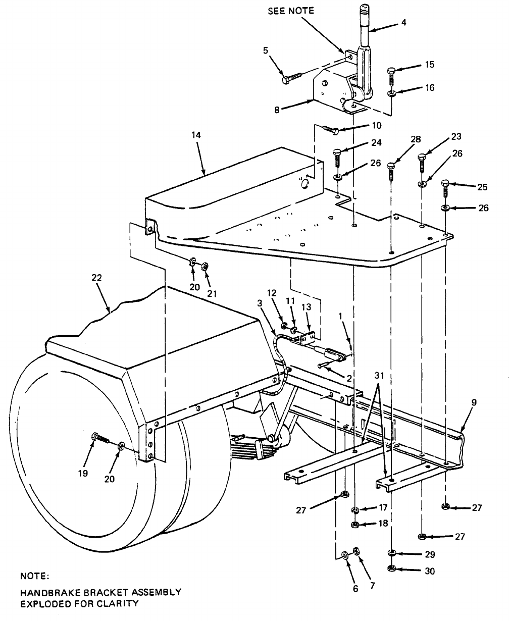

(5)
(6)
(7)
(8)
(9)
(10)
(11)
TM 5-6115-628-14&P
Secure front step (14) to fender (22) with seven screws (19), 14 flat washers (20) and
seven nuts (21).
Insert screw (15) with flat washer (16) through handbrake bracket (8), front step (14)
and cross brace (31). Install Iockwasher (17) and nut (18) on screw from underneath
and tighten.
Insert two screws (5) with flat washers (6) through handbrake bracket (8) and trailer
frame (9). Install one nut (7) on each screw and tighten.
Insert two screws (10) through front step (14) and handbrake cable bracket (13). Install
one flat washer (11) and one nut (12) on each screw and tighten.
Position handbrake cable clevis (31) on handbrake lever mechanism (4). Insert clevis pin
(2) and secure with cotter pin (1).
NOTE
When installing roadside front step, omit steps (10) and (11).
Install accessory box (paragraph 4-19, b).
Install fuel can brackets (paragraph 4-18, b).
4-22.
Rear Steps Replacement. (See figure 4-9.) The roadside and curbside rear steps on both
trailers are symmetrical, and replacement procedures are the same for all.
a. Removal.
(1) Remove two screws (1, figure 4-9), two flat washers (2) and two nuts (3) securing rear
step bracket (4) and platform anchor (5) to trailer frame (6) under taillight (7).
(2) Remove two screws (8), four flat washers (9) and two nuts (10) securing rear step (11) to
trailer frame (6).
(3) Remove five screws (12), ten flat washers (13) and five nuts (14) securing rear step (11)
to fender (15). Remove rear step from trailer.
b. Installation.
(1) Position rear step (11) on trailer frame (6).
(2) Secure rear step (11) to trailer frame (6) with two screws (8), four flat washers (9) and
two nuts (10).
(3) Secure rear step (11) to fender (15) with five screws (12), ten flat washers (13) and five
nuts (14).
(4) Aline two mounting holes in rear step bracket (4) with holes in trailer frame (6) under
taillight (7) and insert two screws (1),
(5) Slide S-hook at chain end of platform anchor (5) onto threaded end of lower screw (1)
inside trailer frame (6).
4-21
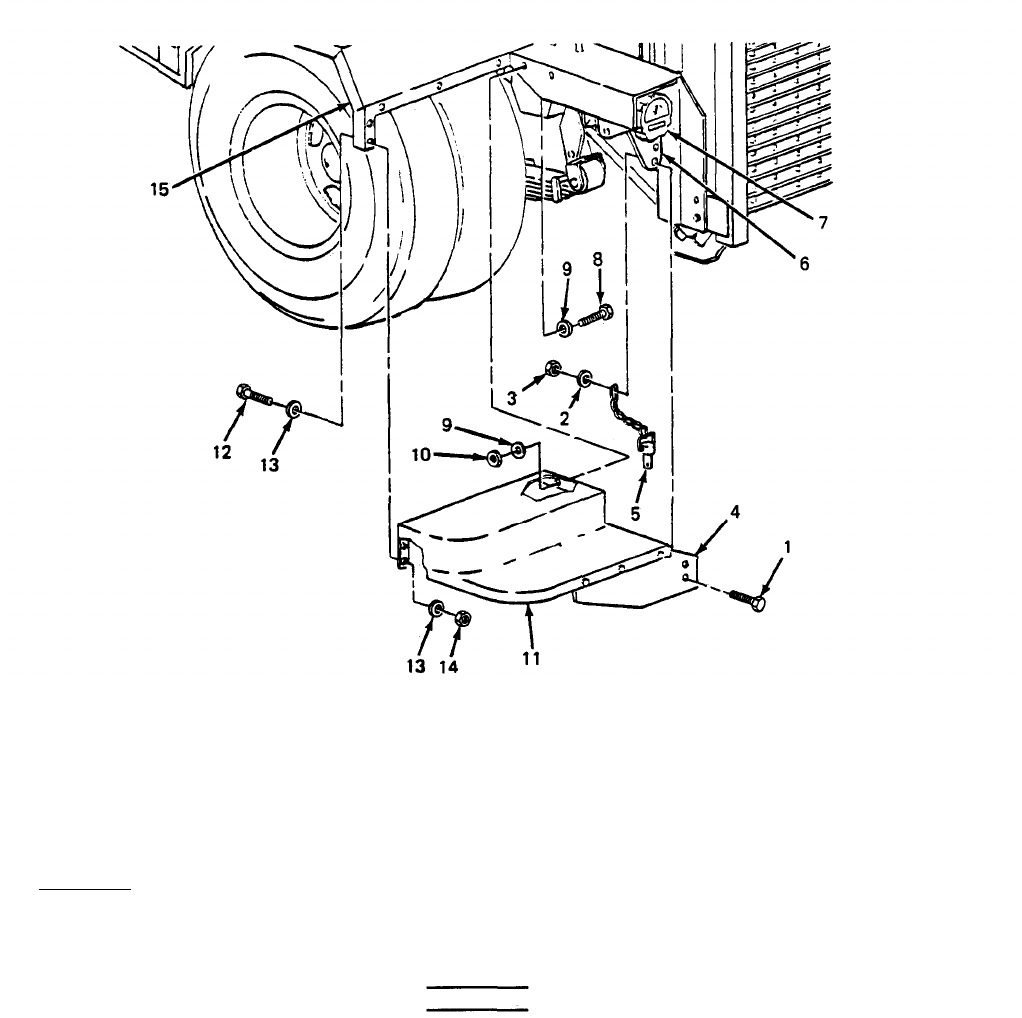
TM 5-6115-628-14&P
Figure 4-9. Rear Steps Replacement.
(6)
Install one flat washer (2) and one nut (3) on each screw (1) and tighten.
4-23.
Fender Replacement.
(See
figure 4-10.) The fenders on the trailer assemblies are
symmetrical, and replacement procedures are the same for all.
a. Removal.
(1) Remove five screws (1, figure 4-10), ten flat washers (2) and five nuts (3) securing
fender (4) to trailer frame (5).
WARNING
There are five sets of hardware securing fender to rear step and seven sets of
hardware securing fender to front step. This hardware should be removed in
sequence from trailer frame outward. In this way, last two screws on front and
rear lower fender edge will support fender until you are out from underneath.
(2) Remove six screws (6), 12 flat washers (7) and six nuts (8) securing fender (4) to front
step (9).
(3) Remove fours screws (10), eight flat washers (11) and four nuts (12) securing fender (4)
to rear step (13).
4-22
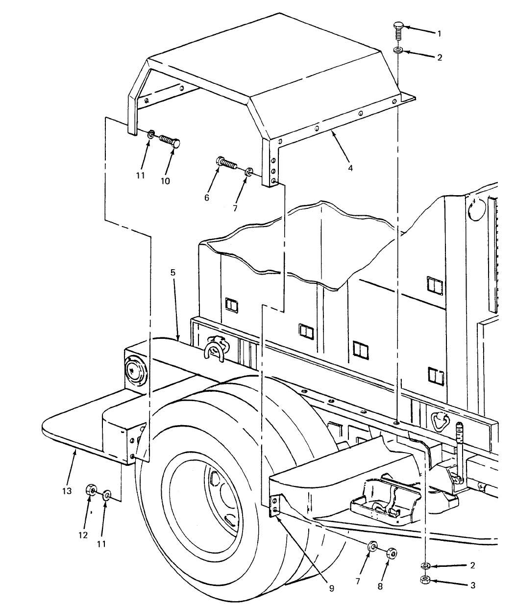

TM 5-6115-628-14&P
WARNING
Support fender while removing remaining two screws. When screws are
removed, fender will drop.
(4) Remove one screw (6), two flat washers (7) and one nut (8) securing fender (4) to front
step (9).
(5) Remove one screw (10), two flat washers (11) and one nut (12) securing fender (4) to
rear step (13).
(6) Remove fender (4).
b. Installation.
(1)
(2)
(3)
(4)
(5)
(6)
(7)
Position fender (4) on trailer.
Insert one screw (10) with flat washer (11) through lower outside edge of fender (4) into
rear step (13), and insert one screw (6) with flat washer (7) through lower outside edge of
fender (4) into front step (9).
Install one washer (11) and one nut (12) on screw (10), and one washer (7) and one
nut (8) on screw (6). Tighten hardware.
Insert five screws (1) with flat washers (2) down through fender (4) into trailer frame (5).
Working under fender, install one flat washer (2) and one nut (3) on each screw (1) and
tighten.
Insert six screws (6) with flat washers (7) through fender (4) into front step (9). Install
one washer (7) and one nut (8) on each screw (6) and tighten.
Insert four screws (10) with flat washers (11) through fender (4) into rear step (13).
Install one washer (11) and one nut (12) on each screw (10) and tighten.
4-24.
Personnel Platform Replacement. (See figure 4-11). This platform is mounted on the rear of
each trailer to facilitate access to generator set controls and indicators.
a. Removal.
(1) Remove two screws (1, figure 4-11), four flat washers (2) and two nuts (3) securing
platform (4) to mounting brackets (5).
WARNING
Support platform while removing anchors. When anchors are removed,
platform will drop.
(2) Remove two platform anchors (6) by pushing in on button on head of pin while pulling pin
out of mounting hole.
4-24
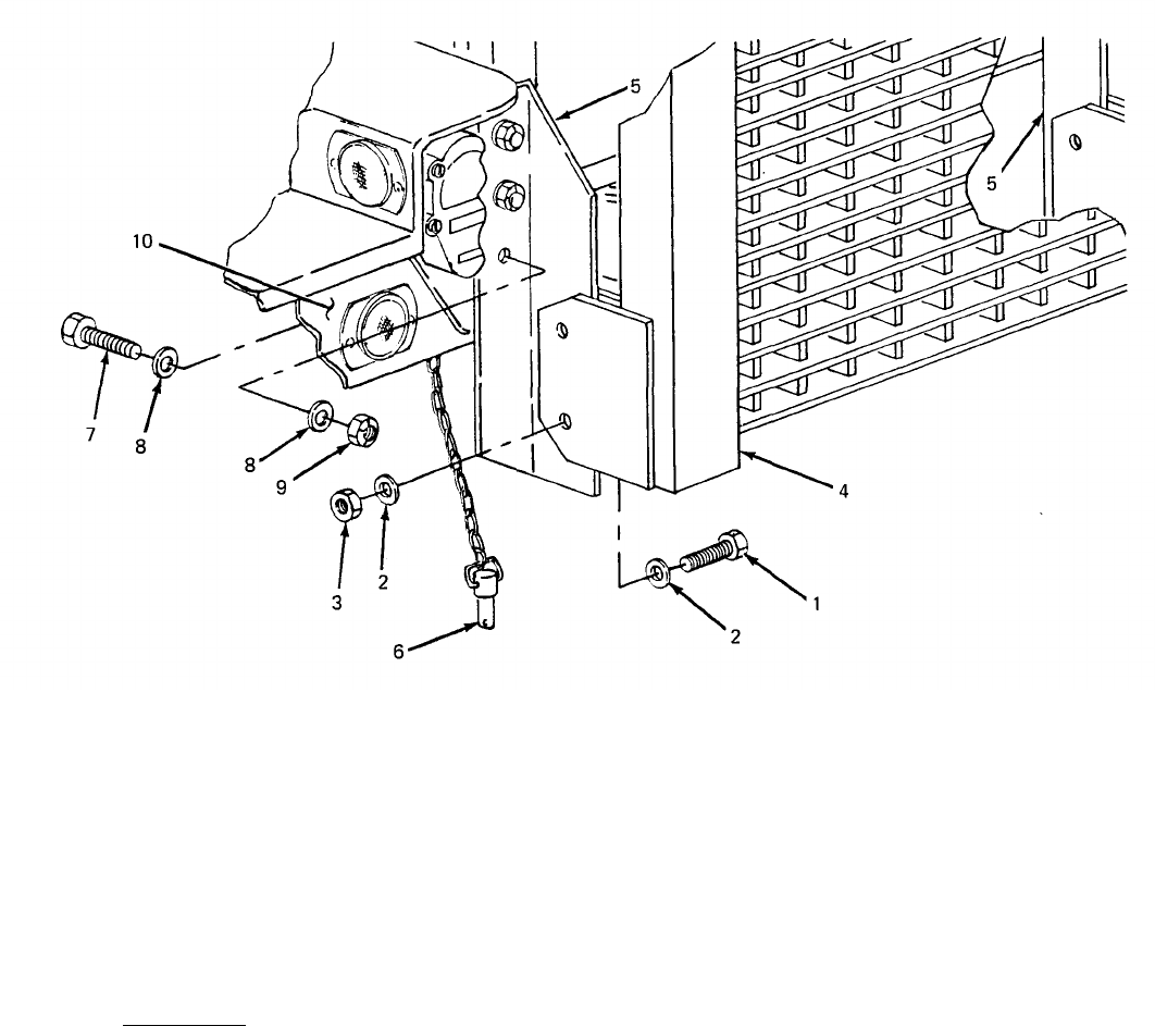
TM 5-6115-628-14&P
Figure 4-11. Personnel Platform Replacement.
NOTE
Mounting brackets are fastened with lock nuts. Removal may inhibit locking
capability when reinstalled. Do not remove mounting brackets unless they are
damaged.
(3) Remove three screws (7), six flat washers (8) and three nuts (9) from each mounting
bracket (5) and take mounting brackets off of trailer frame (10).
b. Installation.
NOTE
If mounting brackets have not been removed, omit step (1),
(1) Position each mounting bracket (5) on trailer frame (10). Insert three screws (7) with flat
washers (8) through frame into each bracket. Install one washer (8) and one nut (9) on
each screw and tighten.
4-25
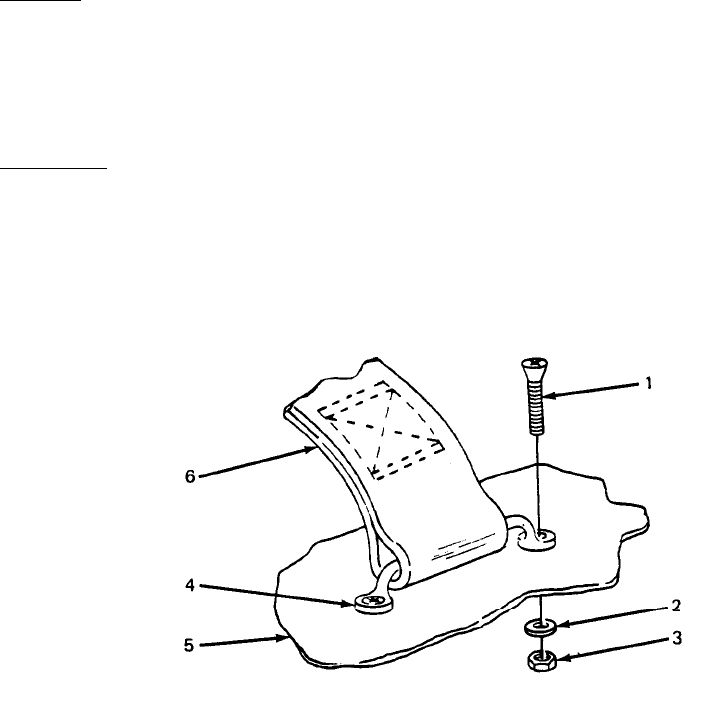
TM 5-6115-628-14&P
(2) Holding platform (4) in vertical position, position platform on mounting brackets (5) so
holes in platform line up with holes in brackets and install platform anchors (6) in upper
mounting hole on each side of platform.
(3) Secure platform (4) to brackets (5) with two screws (1), four flat washers (2) and two
nuts (3).
4-25.
Holddown Strap Replacement. (See figure 4-12). Three holddown straps are provided on the
roadside fender of each power unit. These straps are used to secure the power cables when the power
plant is in transit. Replacement procedure is typical.
a.
b.
4-26.
Removal.
(1) Remove two screws (1, figure 4-12), two washers (2), and two nuts (3) securing foot-
mans loop (4) to trailer (5).
(2) Slide holddown strap (6) off footmans loop (4).
Installation.
(1) Slide holddown strap (6) onto footmans loop (4).
(2) Position footmans loop (4) on
washers (2), and two nuts (3). trailer body (5) and secure with two screws (1), two
Figure 4-12. Holddown Strap Replacement.
SECTION IX. MAINTENANCE OF ELECTRICAL SYSTEM
General. This section of the manual contains unit level maintenance procedures for electrical
components that are unique to the AN/MJQ-15 power plant. Specifically, this includes the switch box
and the power cables.
4-27.
Cable Testing. A continuity test is used to detect opens or shorts in the power plant power
cables. The following test procedure is typical for both.
a. Set multimeter controls to prepare unit for continuity testing.
4-26
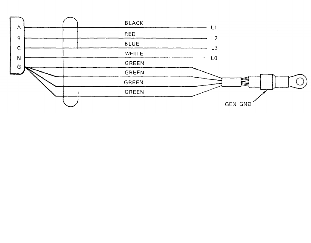
TM 5-6115-628-14&P
NOTE
The contacts in the connector end of cable are labeled A, B, C, N, and G.
The individual colored wires at the other end of cable are labeled L0, L1, L2,
L3, and GEN GND.
b. Touch one probe to contact A in connector and touch remaining probe to black wire labeled
L1. Multimeter must indicate continuity. If it does not, cable is open.
c. With first probe still in contact A, touch remaining probe to wires labeled L2, L3, L0, and
GEN GND. Multimeter must not indicate continuity. If it does, cable is shorted.
d. Refer to figure 4-13, and repeat steps b. and c. at connector contacts B, C, and N. In each
case, continuity must exist between corresponding points and only between corresponding
points.
Figure 4-13. Power Cable Wiring Diagram.
e. Connect one multimeter probe to GEN GND lug on cable and touch remaining probe to contact
G in connector. Multimeter must indicate continuity.
f. If continuity test detects any opens or shorts in cable, refer cable to higher level of
maintenance.
4-28.
Switch Box Testing. The power plant switch box assembly is tested by performing a series of
continuity checks on the component parts and internal wiring.
NOTE
All internal switch box wiring is labeled for identification with reference
designations of its points of connection. If labeling has been removed, or is
illegible, tag wires for identification before removing them.
a. Switch Testing. The switch box contains two three-pole, single-throw switches. Testing
procedures are typical for both.
4-27

TM 5-6115-628-14&P
WARNING
To avoid risk of injury or death by electrocution, do not remove switch box rear
cover while either power unit is still connected to switch box.
(1) Remove 18 screws, 18 Iockwashers, and 18 flat washers securing rear cover to switch
box and remove cover.
(2) Set multimeter controls to prepare unit for continuity testing.
(3) Set switch being tested to ON position.
NOTE
Observe that the switch terminals are arranged in two rows of three terminals each. Each terminal is
paired with the one directly above or below it. There is one pair of terminals for each pole of the
switch.
(4) Select any pair of terminals associated with same pole of switch. Touch one multimeter test
probe to each terminal. Multimeter must indicate continuity.
(5) Repeat step (4) on both remaining poles of switch.
(6) If multimeter does not indicate continuity across all three poles of switch, switch is
defective. Refer switch to higher level of maintenance.
b. Connector Testing. The switch box has four male cable connectors. The larger connectors, J1
and J2, are the power input connectors. Together with their associated wiring, they comprise the
switch box cable assemblies. This procedure tests the entire cable assembly. The procedure is as
follows:
(1)
(2)
(3)
(4)
(5)
4-28
WARNING
To avoid risk of injury or death by electrocution, do not remove switch box rear
cover while either power unit is still connected to switch box.
NOTE
Observe that pins on power input connectors are labeled A, B, C, N, and G.
Remove 18 screws, 18 Iockwashers, and 18 flat washers securing rear cover to switch
box and remove cover.
Set multimeter controls to prepare unit for continuity testing.
Touch one multimeter test probe to pin A in connector being tested and touch remaining
probe to terminal C on associated switch. Multimeter must indicate continuity. If it does
not, there is an open in connector or associated wire.
With first probe still in contact with pin A, touch remaining probe to all other pins in
connector. Multimeter must not indicate continuity. If it does, connector is shorted.
Repeat steps (3) and (4) for pins B and C. Multimeter must indicate continuity only
between these pins and switch terminals B and A, respectively.

TM 5-6115-628-14&P
(6) Touch one multimeter test probe to connector pin N. Touch remaining probe to switch box
load terminal L0. Multimeter must indicate continuity.
(7) Touch one multimeter test probe to connector pin G. Touch remaining probe to GROUND
TERMINAL stud on switch box. Multimeter must indicate continuity.
(8) If continuity test detects any opens or shorts, connector cable assembly is defective:
c. Wiring Test. (Refer to wiring diagrams, Figure 4-14.) The internal switch box wiring is tested
by performing a continuity check(s) on suspect wires or connections.
WARNING
To avoid risk of injury or death by electrocution, do not remove switch box rear
cover while either power unit is still connected to switch box.
NOTE
All internal switch box wiring is labeled for identification with reference
designations of its points of connection. If labeling has been removed, or is
illegible, tag wires for identification before removing them.
(1) Remove 18 screws, 18 Iockwashers, and 18 flat washers securing rear cover to switch
box and remove cover.
(2) Before testing wires, make sure there are no loose connections or broken terminals.
Tighten any loose connections and refer broken terminals to higher level of maintenance.
(3) Set multimeter controls to prepare unit for continuity testing.
(4) Refer to applicable wiring diagram in Figure 4-14, and test continuity of suspect wires
between origin and destination specified in diagram.
4-29.
Switch Box Repair. The power plant switch box assembly is repaired by replacing defective
components. Components authorized for replacement at unit level of maintenance include connector
cable assemblies, load terminals, and individual wires.
NOTE
All internal switch box wiring is labeled for identification with reference
designations of its points of connection. If labeling has been removed, or is
illegible, tag wires for identification before removing them.
a. Connector Replacement. (See figure 4-15.) A damaged or defective connector is replaced by
replacing the entire connector cable assembly.
WARNING
To avoid risk of injury or death by electrocution, do not remove switch box rear
cover while either power unit is still connected to switch box.
4-29
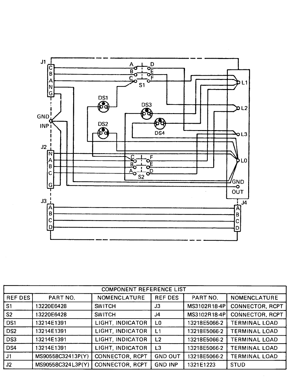
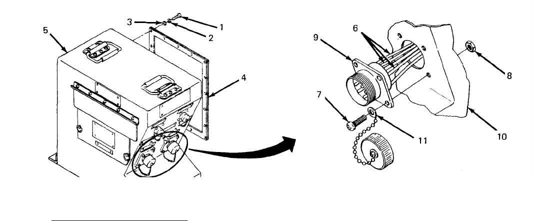
TM 5-6115-628-14&P
(1) Removal.
(a) Remove 18 screws (1, figure 4-15),18 Iockwashers (2), and 18 flat washers (3)
securing rear cover (4) to switch box (5) and remove cover.
(b) Disconnect connector cable assembly wires (6) from load terminal L0, GROUND
TERMINAL stud, and associated switch.
(c) Remove four screws (7) and four nuts (8) securing connector flange (9) to switch
box (10).
(d) Carefully remove connector and associated wiring from switch box.
(2) Installation.
(a)
(b)
(c)
(d)
washers (2), and 18 flat washers (3).
Feed connector cable assembly wires (6) through mounting hole in switch box (10).
Position connector body in mounting hole and secure with four screws (7) and four nuts
(8). Use screw in lower right-hand corner of flange to secure connector cap retaining
chain (11).
Install connector cable assembly wires (6) on load terminal L0, GROUND TERMINAL
stud, and associated switch (figure 4-14).
Position rear cover (4) on switch box (5) and secure with 18 screws (1). 18 lock-
Figure 4-15. Connector Replacement.
b. Load Terminal Replacement. (See figure 4-16.) The switch box load terminals provide
electromechanical connection points between the system or equipment being powered and the power
plant. In addition to the four output terminals, the switch box utilizes a fifth load terminal as a ground
connection for the system or equipment being powered.
4-31
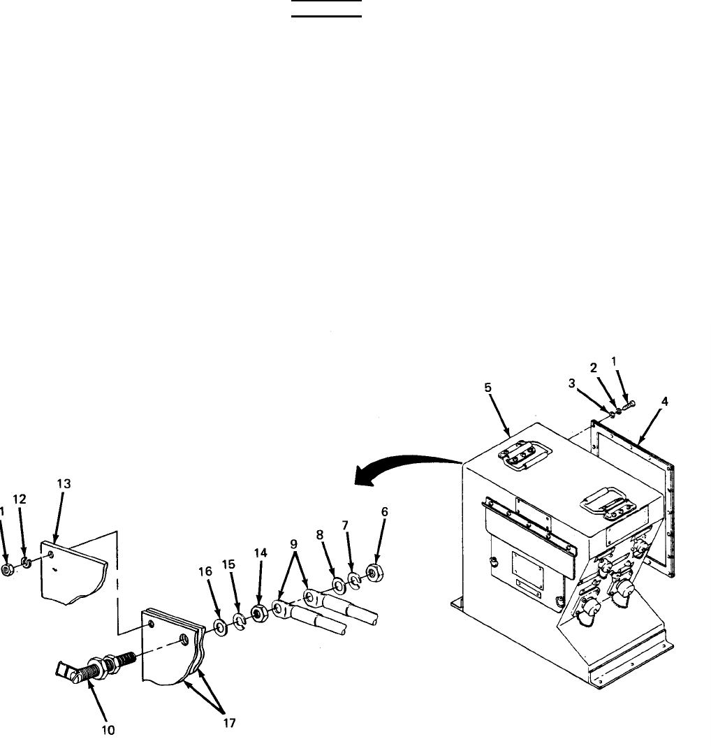
TM 5-6115-628-14&P
WARNING
To avoid risk of injury or death by electrocution, do not remove switch box rear
cover while either power unit is still connected to switch box.
(1) Removal.
(a) Remove 18 screws (1, figure 4-16),18 Iockwashers (2), and 18 flat washers (3)
securing rear cover (4) to switch box (5) and remove cover.
(b) Remove one nut (6) one Iockwasher (7), one flat washer (8), and remove associated
wires (9) from load terminal (10).
(c) Open power output cover and remove six nuts (11) and six Iockwashers (12) and remove
load terminal protective cover (13).
(d) Remove one nut (14), one Iockwasher (15), and one flat washer (16) and remove load
terminal (10) from terminal board (17).
4-32
Figure 4-16. Load Terminal Replacement.
TM 5-6115-628-14&P
(2) Installation.
(a)
(b)
(c)
(d)
Install load terminal (10) in terminal board (17) and secure with flat washer (16),
Iockwasher (15) and nut (14).
Install associated wires (9) on load terminal (10) and secure with flat washer (8),
Iockwasher (7), and nut (6).
Position load terminal protective cover (13) over terminals and secure with six nuts (11)
and six Iockwashers (12).
Position rear cover (4) on switch box (5) and secure with 18 screws (1), 18 lock-
washers (2), and 18 flat washers (3).
4-33/(4-34 blank)
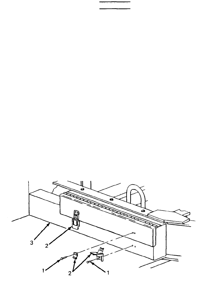
TM 5-6115-628-14&P
CHAPTER 5
INTERMEDIATE (FIELD) (DIRECT SUPPORT AND
GENERAL SUPPORT) MAINTENANCE INSTRUCTIONS
Section I. INTRODUCTION
5-1.
General. This chapter contains Intermediate Direct Support and General Support level mainte-
nance procedures for components of the M200A1 trailer added when the trailer is used as part of the
AN/MJQ-15 power plant. These components are not covered in the overall trailer maintenance
manual. For all other intermediate direct and general support maintenance procedures on the trailer,
refer to TM 9-2330-205-14&P. For intermediate direct and general support maintenance procedures
on the generator sets, refer to TM 5-6115-464-34.
WARNING
Before performing any maintenance that requires climbing on or under trailer,
set trailer handbrakes, chock wheels, and lower rear leveling jacks. Injury to
personnel could result from trailer suddenly rolling or tipping.
Section Il. MAINTENANCE OF POWER PLANT TRAILERS.
5-2. Step and Fender Repair. Repair of the front and rear steps and the fenders is limited to straight-
ening, welding and repainting. If required, repaint in accordance with MIL-T-704, Type F, Color
Green, No. 383 of MIL-C-46168.
5-3. Accessory Box Repair. (See figure 5-1.) The accessory boxes are repaired by replacing the
latch and strike assemblies. The boxes themselves may be straightened, welded and repainted. If
required, repaint in accordance with MIL-T-704, Type F, Color Green, No. 383 of MIL-C-46168.
Replace latch and strike assemblies as follows:
a. Grind off or drill out solid rivets (1, figure 5-1) securing latch and strike assembly (2) to
accessory box (3).
b. Position new latch and strike assembly (2) on accessory box (3) and secure with solid
rivets (1).
c. Touch up with paint as required.
Figure 5-1. Accessory Box Repair.
5-1
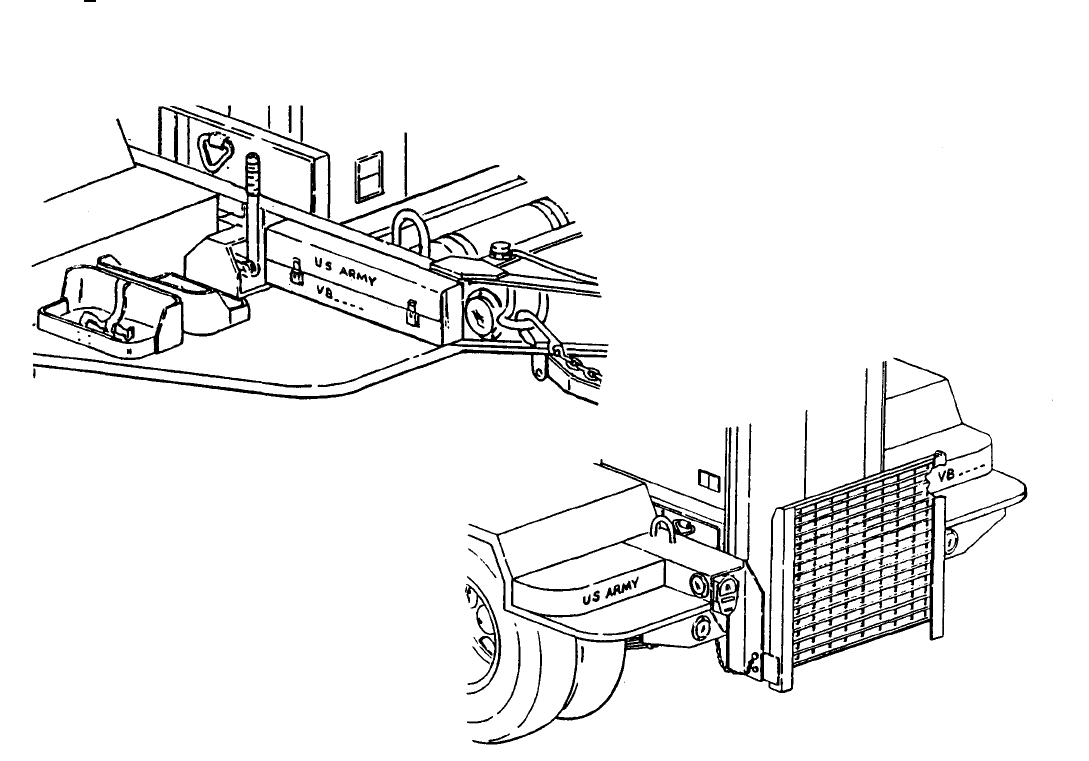
TM 5-6115-628-14&P
5-4. Marking. (See figure 5-2.) The power plant four-digit registration number, preceded by the
prefix “VB” and the words “U.S. ARMY”, is marked in three places on each power unit trailer. Marking
is done in accordance with MIL-STD-642. On the fender, over each wheel, “T.P. 35 PSI” is marked in
1.00 + .12 inch high characters in accordance with MIL-STD-130. Figure 5-2 shows the approxi-
mate location of markings on one power unit of the power plant. Markings are typical of both power
units. If required, touch-up painting of the base color shall be done in accordance with MIL-T-704,
Type F, Color Green, No. 383 of MIL-C-46168.
Figure 5-2. Power Plant Markings.
5-2
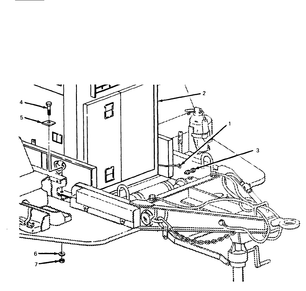
TM 5-6115-628-14&P
Section Ill. GENERATOR SET
5-5. Generator Set Replacement. (See figures 5-3 and 5-4.)
a. Removal.
(1) Disconnect ground wire (1, figure 5-3) from generator set (2) to GROUND TERMINAL stud
(3) on trailer.
NOTE
Beveled washers (5) may have been welded in place.
(2) Remove four screws (4), four beveled washers (5), four Iockwashers (6) and four nuts
(7) securing generator set (2) to trailer.
Figure 5-3. Detaching Generator Set from Trailer.
5-3
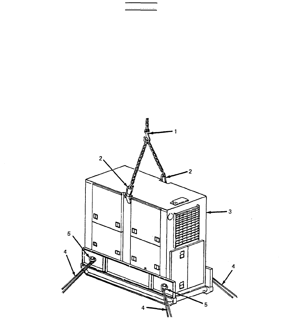
TM 5-6115-628-14&P
WARNING
5-4
When lifting generator set, use lifting equipment with a minimum lifting capa-
city of 3500 lb. Do not stand under generator while it is being lifted. Do not
permit generator set to swing. Failure to observe these precautions can cause
injury to personnel or damage to equipment.
(3) Attach lifting equipment with a minimum lifting capacity of 3500 lb (1, figure 5-4) to both
lifting eyes (2) on top edges of generator set (3). Insert a rope (4) through each of four
tiedown rings (5) on generator set.
(4) With one person at each rope to steady and guide generator set (3), lift generator set off of
trailer.
Figure 5-4. Lifting Generator Set.

TM 5-6115-628-14&P
b. Installation.
WARNING
(1)
(2)
(3)
(4)
(5)
(6)
When lifting generator set, use lifting equipment with a minimum lifting capa-
city of 3500 lb. Do not stand under generator set while it is being lifted. Do not
permit generator set to swing. Failure to observe these precautions can cause
injury to personnel or damage to equipment.
Attach lifting equipment with a minimum lifting capacity of 3500 lb (1, figure 5-4) to lifting
eyes (2) on top edges of generator set (3). Insert a rope (4) through each of four tiedown
rings (5) on generator set.
With one person at each rope to steady and guide generator set (3), lift generator set and
carefully lower it onto trailer.
Insert four screws (4, figure 5-3) with beveled washers (5) down through generator set
skids into trailer.
Working under trailer, install one Iockwasher (6) and one nut (7) on each screw (4).
Position beveled washers (5) so that screw heads are parallel to tops of washers. While
holding beveled washers in position, tighten hardware.
Connect generator set ground wire (1) to trailer GROUND TERMINAL stud (3).
Section IV. MAINTENANCE OF ELECTRICAL SYSTEM.
5-6.
Power Cable Repair. (See figure 5-5.) The power plant cables are repaired by resoldering or
replacing loose or damaged contacts inside the connector. A soldered contact can be unsoldered and
a new one installed in its place. If, however, the damaged contact is crimped onto the wire, or if the
wire is broken, the contact must be cut off. When one wire in the cable has been cut or broken, all
wires must be cut to the same length and new contacts soldered on each. Refer to TB SIG 222 (TO 31-
3-64) and TM 55-1500-323-25 (TO 1-1A-14).
a. Removal.
NOTE
Cable grip nut is left hand threaded. Turn clockwise to loosen.
(1) Unscrew cable grip nut (1, figure 5-5) from housing (2).
(2) Slide cable grip nut (1), packing gland (3) and collar (4) up cable (5) away from
housing (2).
5-5
(3) Remove three screws (6) and three washers (7) and separate housing (2) from plug
shell (8).
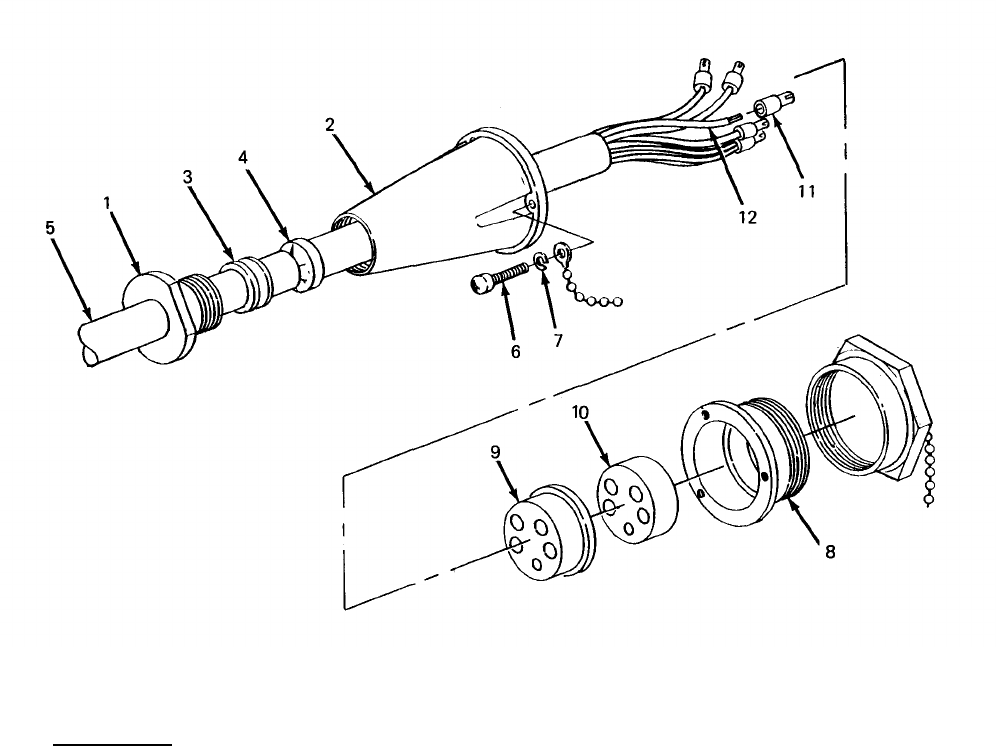
TM 5-6115-628-14&P
(4) Remove spacer (9) and insert (10) from plug shell (8).
(5) Remove contact(s) (11) being repaired or replaced from spacer (9) and insert (10).
Unsolder contact(s) (11) from wire(s) (12).
NOTE
If contact is crimped onto wire, or if wire is broken, do steps (6) through (8).
(6) Cut contacts (11) off wires (12).
(7) Strip back cable jacket to expose more of individual wires.
(8) Cut wires to equal length. Strip and tin wires in accordance with procedures given in
technical manuals referenced above.
Figure 5-5. Power Cable Repair.
b. Installation.
(1) Solder replacement contact(s) (11) on wire(s) (12).
(2) Aline and insert contact(s) (11) into spacer (9) until contacts are fully seated.
5-6

(3)
(4)
(5)
(6)
(7)
(8)
TM 5-6115-628-14&P
Aline insert (10) with plug shell (8) so key on insert matches keyway in plug shell and push
insert into shell until it seats.
Aline contacts (11) with corresponding holes in insert (10) and slide contacts into insert
until spacer (9) is flush against insert (10).
Slide housing (2) up against plug shell (8) and secure with three screws (6) and three
washers (7).
Slide collar (4) and packing gland (3) up cable (5) into housing (2).
Tighten cable grip nut (1) against housing (2).
Test cable for continuity (paragraph 4-27).
5-7.
Switch Box Repair. The power plant switch box assembly is repaired by replacing defective com-
ponents or by repairing individual wires within the switch box. Replacement of the switches is author-
ized only at the Intermediate direct support and general support levels of maintenance.
NOTE
Ail internal switch box wiring is labeled for identification with reference desig-
nations of its points of connection. If labeling has been removed, or is
illegible, tag wires for identification before removing them.
a. Switch Replacement. (See figure 5-6.)
(1) Removal.
WARNING
To avoid risk of injury or death by electrocution, do not remove switch box rear
cover while either power unit is still connected to swtich box.
(a) Remove 18 screws (1, figure 5-6), 18 Iockwashers (2), and 18 flat washers (3) secur-
ing rear cover (4) to switch box (5) and remove cover.
(b) Remove six nuts (6) and six Iockwashers (7) securing wires (8) to switch (9) and slide
wire terminals off threaded posts (10) on switch.
(c) Remove six screws (11), and six flat washers (12) securing switch (9) to switch box
(13) and remove switch.
(2) Installation.
(a) Position switch (9) in switch box (13), making certain it is right side up, and secure with
six screws (11) and six flat washers (12).
(b) Install seven wires (8) on switch (9) and secure with one nut (6) and one Iockwasher
(7) on each threaded post (10).
(c) Position rear cover (4) on switch box (5) and secure with 18 screws (1), 18 lock-
washers (2), and 18 flat washers (3).
5-7
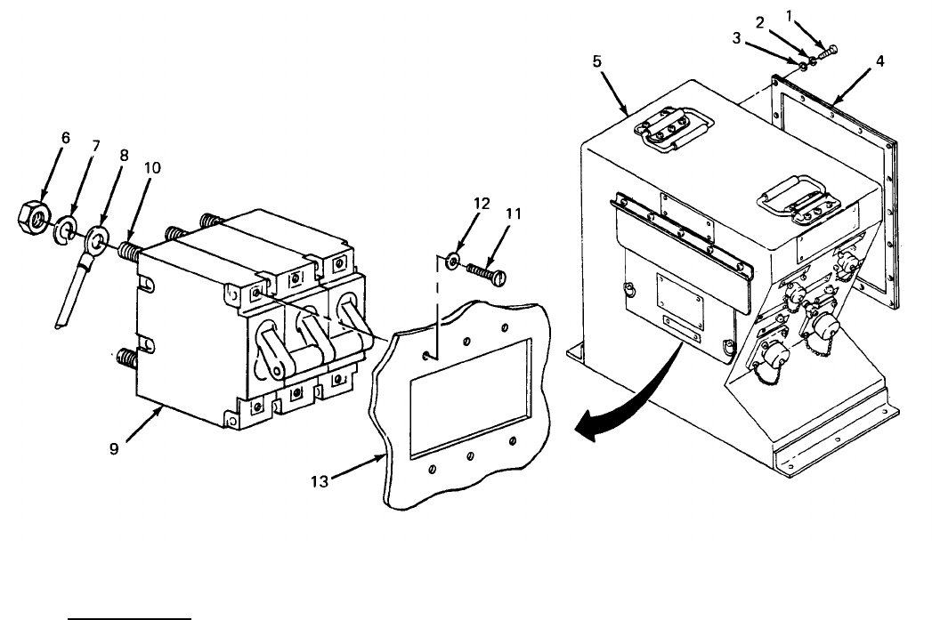
TM 5-6115-628-14&P
Figure 5-6. Switch Box Switch Replacement.
b. Wiring Repair. The switch box wiring is repaired by tightening or replacing loose or damaged
terminals. The repair parts and special tools list in this manual lists part numbers for the terminals.
The replacement terminals are soldered onto the wires in accordance with procedures given in TB SIG
222 (TO 31-3-64) and TM 55-1500-323-25 (TO 1-1A-14).
5-8
TM 5-6115-628-14&P
CHAPTER 6
TEST AND INSPECTION AFTER REPAIR
Section I. GENERAL REQUIREMENTS
6-1.
General Requirements. The activity performing the repair is responsible for the performance of
all applicable tests and inspections specified in the technical manuals referenced below. Activities
performing maintenance on any component of the power plant must perform those tests and inspec-
tions required by the applicable component or system repair instruction.
6-2. Generator Set Inspections.
ing repair of the generator sets.
Section Il. INSPECTION
Refer to TM 5-6115-464-12 and -34 for inspections required follow-
6-3. Trailer Inspections. Refer to TM 9-2330-205-14&P for inspections required following repair of
the trailers.
Section Ill. OPERATIONAL TESTS
6-4. Generator Set Operational Tests. Refer to TM 5-6115-464-12 and -34 for operational tests re-
quired to verify satisfactory performance of the generator sets.
6-5. Trailer Operational Tests. Refer to TM 9-2330-205-14&P for operational tests required to verify
satisfactory performance of the trailers.
6-1 /(6-2 blank)
TM 5-6115-628-14&P
APPENDIX A
REFERENCES
A-1. Scope. This appendix lists all pamphlets, forms, technical manuals, specifications and
miscellaneous publications referenced in this manual.
A-2. Forms and Records.
Air Force Maintenance Management Program . . . . . . . . . . . . . . . . . . . . . . . . . . . . . . . . . . . . . . . . . . . . . . . . . . . . . . . . . . .
Technical Order System Publication Improvement Report
and Reply . . . . . . . . . . . . . . . . . . . . . . . . . . . . . . . . . . . . . . . . . . . . . . . . . . . . . . . . . . . . . . . . . . . . . . . . . . . . . . . . . . . . . . . . . . . . . . . . . . .
Recommended Changes to Publications and Blank Forms . . . . . . . . . . . . . . . . . . . . . . . . . . . . . . . . . . . . . . .
Depreservation Guide for Vehicles and Equipment . . . . . . . . . . . . . . . . . . . . . . . . . . . . . . . . . . . . . . . . . . . . . . . . . .
Equipment Inspection and Maintenance Worksheet . . . . . . . . . . . . . . . . . . . . . . . . . . . . . . . . . . . . . . . . . . . . . . . . . .
Maintenance Request . . . . . . . . . . . . . . . . . . . . . . . . . . . . . . . . . . . . . . . . . . . . . . . . . . . . . . . . . . . . . . . . . . . . . . . . . . . . . . . . .
Consolidated Index of Army Publications . . . . . . . . . . . . . . . . . . . . . . . . . . . . . . . . . . . . . . . . . . . . . . . . . . . . . . . . . . . . . . . . . . .
The Army Maintenance Management System (TAMMS) . . . . . . . . . . . . . . . . . . . . . . . . . . . . . . . . . . . . . . . . . . . .
Product Quality Deficiency Report . . . . . . . . . . . . . . . . . . . . . . . . . . . . . . . . . . . . . . . . . . . . . . . . . . . . . . . . . . . . . . . . . . . . . . . . . . . . . . .
A-3. Military Specifications.
AFM 66-1
AFTO Form 22
DA Form 2028
DA Form 2258
DA Form 2404
DA Form 2407
DA PAM 25-30
DA PAM 738-750
SF 368
Chemical Agent Resistant Aliphatic Polyurethane Coating . . . . . . . . . . . . . . . . . . . . . . . . . . . . . . . . . . . . . . MIL-C-46168
Identification Marking of U.S. Military Property . . . . . . . . . . . . . . . . . . . . . . . . . . . . . . . . . . . . . . . . . . . . . . . . . . . . . . . . . . MIL-STD-130
Identification Marking of Combat and Tactical Transport . . . . . . . . . . . . . . . . . . . . . . . . . . . . . . . . . . . . . . . . . MIL-STD-642
Treatment and Painting of Materiel . . . . . . . . . . . . . . . . . . . . . . . . . . . . . . . . . . . . . . . . . . . . . . . . . . . . . . . . . . . . . . . . . . . . . . . . . . . . . . MIL-T-704
A-4. Technical Manuals.
Operator and Organizational Maintenance Manual: Generator Set,
Diesel Engine Driven, Tactical Skid Mounted, 15 KW, 3 Phase,
4 Wire; 120/208 and 240/416V (DOD Model MEP-004A) Utility
Class, 50/60 Hz (NSN 6115-00-118-1241), (Model MEP-103A),
Precise Class, 50/60 Hz (6115-00-118-1245), (Model MEP-113A),
Precise Class, 400 Hz (6115-00-118-1244) . . . . . . . . . . . . . . . . . . . . . . . . . . . . . . . . . . . . . . . . . . . . . . . . . . . . . . . . . . . . . . . . . TM 5-6115-464-12
Organizational, Intermediate (Field) (Direct Support and
General Support and Depot Maintenance Repair Parts and
Special Tools List): Generator Set, Diesel Engine Driven,
Tactical Skid Mounted, 15 KW, 3 Phase, 4 Wire, 120/208 and
240/416 V (DOD Models MEP-004A) Utility Class, 50/60 HZ
(NSN 6115-00-118-1241); (Model MEP-103A), Precise Class,
50/60 HZ (6115-00-118-1245); (Model MEP-113A), Precise
Class, 400 HZ (6115-00-118-1244) . . . . . . . . . . . . . . . . . . . . . . . . . . . . . . . . . . . . . . . . . . . . . . . . . . . . . . . . . . . . . . . . . . . . . . . . . . . . . . TM 5-6115-464-24P
Intermediate (Field) Direct and General Support and Depot
Level Maintenance Manual; Generator Set, Diesel Engine
Driven, Tactical Skid Mtd, 15 KW, 3 Phase, 4 Wire, 120/208
and 240/416 Volts DOD Model MEP-004A, Utility Class,
50/60 HZ (NSN 6115-00-118-1241); Model MEP-103A, Precise
Class, 50/60 HZ (6115-00-118-1245); Model MEP-113A, Precise
Class, 400 HZ (6115-00-118-1244) . . . . . . . . . . . . . . . . . . . . . . . . . . . . . . . . . . . . . . . . . . . . . . . . . . . . . . . . . . . . . . . . . . . . . . . . . . . . . . TM 5-6115-464-34
Installation Practices for Aircraft Electric and Electronic
Wiring [TO 1-1A-14] . . . . . . . . . . . . . . . . . . . . . . . . . . . . . . . . . . . . . . . . . . . . . . . . . . . . . . . . . . . . . . . . . . . . . . . . . . . . . . . . . . . . . . . . . . . . . . . . . . . . TM 55-1500-323-25
A-1
TM 5-6115-628-14&P
Procedures for Destruction of Equipment to Prevent Enemy
Use (Mobility Equipment Command) . . . . . . . . . . . . . . . . . . . . . . . . . . . . . . . . . . . . . . . . . . . . . . . . . . . . . . . . . . . . . . . . . . . . . . . . TM 750-244-3
Operator’s, Organizational, Direct Support and General
Support Maintenance Manual Including Repair Parts and
Special Tools List for Chassis, Trailer, Generator, 2-1/2
Ton, 2-Wheel M200A1 (NSN 2330-00-331-2307) . . . . . . . . . . . . . . . . . . . . . . . . . . . . . . . . . . . . . . . . . . . . . . . . . . . . . . . . TM 9-2330-205-14&P
Organizational Direct Support, and General Support Care
Maintenance and Repair of Pneumatic Tires and
Inner Tubes . . . . . . . . . . . . . . . . . . . . . . . . . . . . . . . . . . . . . . . . . . . . . . . . . . . . . . . . . . . . . . . . . . . . . . . . . . . . . . . . . . . . . . . . . . . . . . . . . . . . . . . . . . . . . . . . . TM 9-2610-200-24
Air Force Technical Order System . . . . . . . . . . . . . . . . . . . . . . . . . . . . . . . . . . . . . . . . . . . . . . . . . . . . . . . . . . . . . . . . . . . . . . . . . . . . . . TO-00-5-1
Painting and Marking of USAF Aerospace Ground Equipment . . . . . . . . . . . . . . . . . . . . . . . . . . . . . . . TO 35-1-3
Processing and Inspection of Aerospace Ground Equipment
for Storage and Shipment . . . . . . . . . . . . . . . . . . . . . . . . . . . . . . . . . . . . . . . . . . . . . . . . . . . . . . . . . . . . . . . . . . . . . . . . . . . . . . . . . . . . . . . . . TO 35-1-4
Processing and Inspection of Non-Mounted, Non-Aircraft
Gasoline and Diesel Engines for Storage and Shipment . . . . . . . . . . . . . . . . . . . . . . . . . . . . . . . . . . . . . . . TO 38-1-5
A-5. Technical Bulletins.
Solder and Soldering [TO 31-3-64] . . . . . . . . . . . . . . . . . . . . . . . . . . . . . . . . . . . . . . . . . . . . . . . . . . . . . . . . . . . . . . . . . . . . . . . . . . . . . . . TB SIG 222
Preservation of USAMECOM Mechanical Equipment for
Shipment and Storage . . . . . . . . . . . . . . . . . . . . . . . . . . . . . . . . . . . . . . . . . . . . . . . . . . . . . . . . . . . . . . . . . . . . . . . . . . . . . . . . . . . . . . . . . . . . . . . TB 740-97-2
A-2

TM 5-6115-628-14&P
APPENDIX B
COMPONENTS OF END ITEM AND BASIC ISSUE ITEMS LISTS
Section I. INTRODUCTION
B-1. Scope. This appendix lists components of end item and basic issue items for the power plant to
help you inventory items required for safe and efficient operation.
B-2. General. The Components of End Item and Basic Issue Items Lists are divided into the following
sections:
a. Section II. Components of End Item. This listing is for informational purposes only, and is not
authority to requisition replacements. These items are part of the end item, but are removed and sep-
arately packaged for transportation or shipment. As part of the end item, these items must be with the
end item whenever it is issued or transferred between property accounts. Illustrations are furnished to
assist you in identifying the items.
b. Section III. Basic Issue Items. These are the minimum essential items required to place the
power plant in operation, to operate it, and to perform emergency repairs. Although shipped sepa-
rately packaged, Bll must be with the power plant during operation and whenever it is transferred be-
tween property accounts. The illustrations will assist you with hard-to-identify items. This manual is
your authority to request/requisition replacement Bll, based on TOE/MTOE authorization of the end
item.
B-3. Explanation of Columns. The following provides an explanation of columns found in the tabular
listings:
a. Column (1), Illustration Number (Illus No.). This column indicates the number assigned to
the item.
b. Column (2), National Stock Number. Indicates the National stock number assigned to the
item.
c. Column (3), Description. Indicates the federal item name and, if required, a minimum des-
cription to identify and locate the item. The last line for each item indicates the FSCM (in
parentheses) followed by the part number.
If item needed differed for different models of this equipment, the model would be shown under the
“Usable on Code” heading in this column. The Usable On Code is not applicable for this equipment.
d. Column (4), Unit of Measure (U/M). Indicates the measure used in performing the actual
operational/maintenance function. This measure is expressed by a two-character alphabetical
abbreviation (eg, ea, in, pr).
e. Column (5), Quantity Required (Qty Req’d). Indicates the quantity of the item authorized to be
used with/on the equipment.
B-1
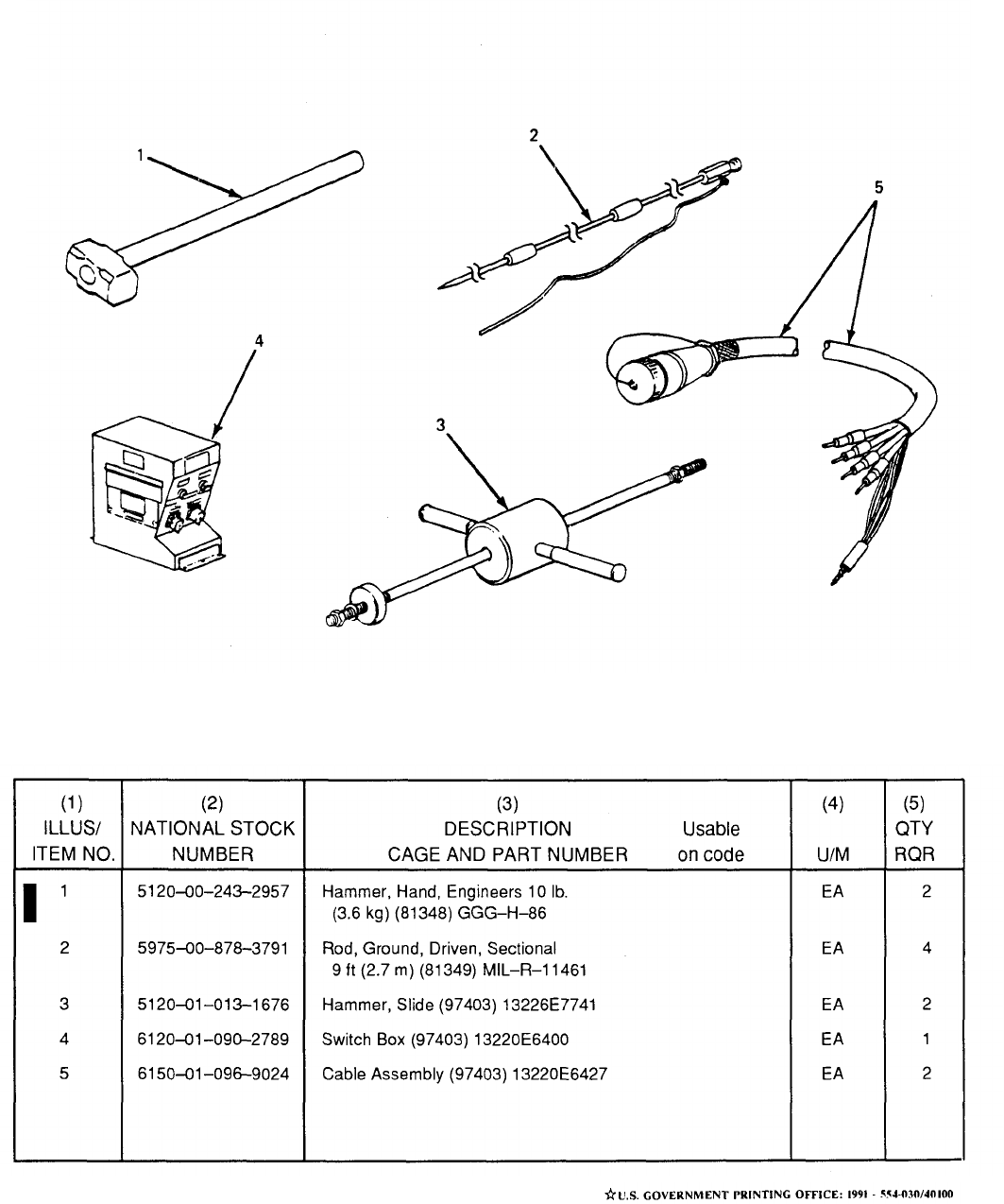
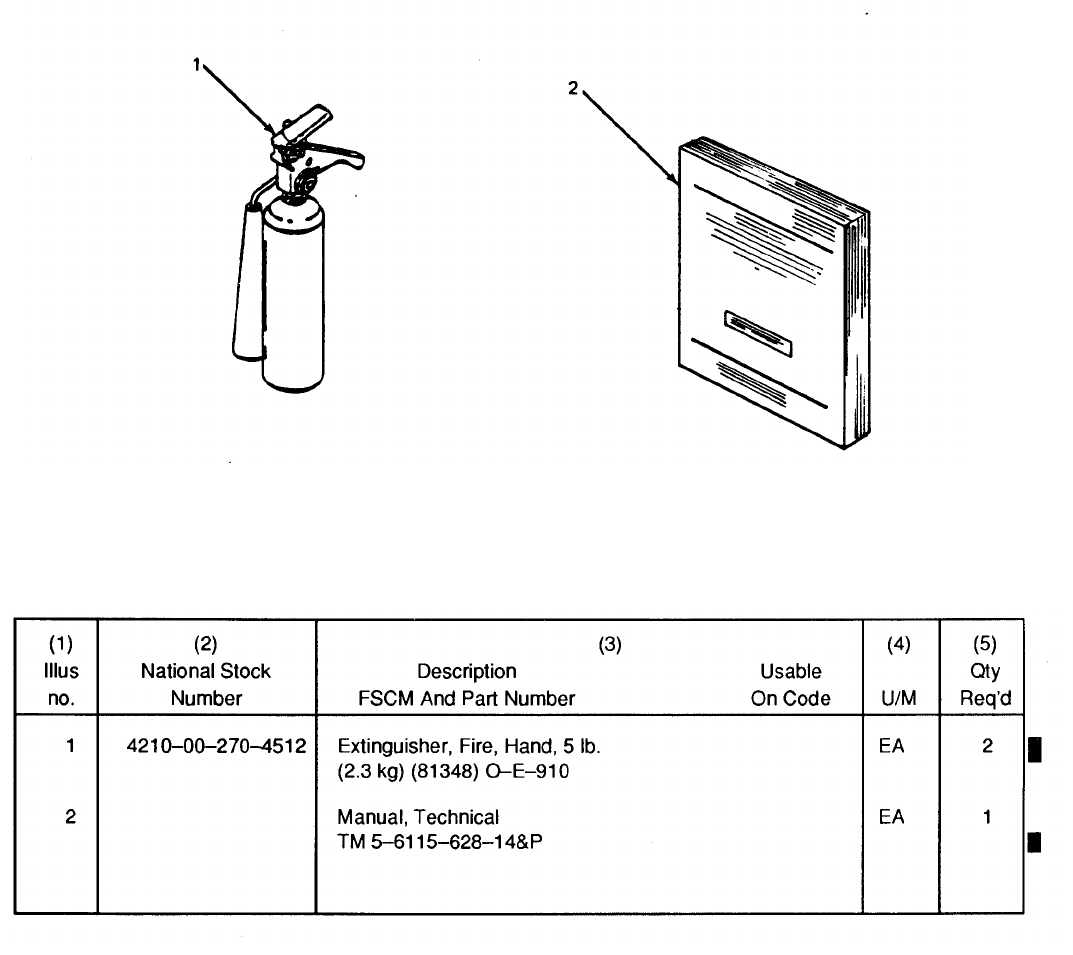

TM 5-6115-628-14&P
APPENDIX C
MAINTENANCE ALLOCATION CHART
Section I. INTRODUCTION
C-1. General.
a. This section provides a general explanation of all maintenance and repair functions authorized
at various maintenance levels.
b. Section II designates overall responsibility for the performance of maintenance functions on
the identified end item or component. The implementation of the maintenance functions upon the end
item or component will be consistent with the assigned maintenance functions.
c. Section Ill lists the tools and test equipment required for each maintenance function as
referenced from Section Il.
d. Section IV contains supplemental instructions, explanatory notes and/or illustrations required
for a particular maintenance functions.
C-2. Explanation of Columns in Section Il.
a. Group Number. Column 1. The assembly group is a numerical group assigned to each assem-
bly in a top down breakdown sequence. The applicable assembly groups are listed on the MAC in dis-
assembly sequence beginning with the first assembly removed in a top down disassembly sequence.
b. Assembly Group. Column 2. This column contains a brief description of the components of
each assembly group.
c. Maintenance Functions. Column 3. This column lists the various maintenance functions (A
through K) and indicates the lowest maintenance category authorized to perform these functions. The
symbol designations for the various maintenance categories are as follows:
C - Operator or crew
O - Unit maintenance
F - Intermediate direct support maintenance
H - Intermediate general support maintenance
D - Depot maintenance
The maintenance functions are defined as follows:
A - Inspect. To determine serviceability of an item by comparing its physical, mechanical, and
electrical characteristics with established standards.
B
- Test. To verify serviceability and to detect electrical or mechanical failure by use of test
equipment.
C - Service. To clean, to preserve, to charge, and to add fuel, lubricants, cooling agents, and
air. If it is desired that elements, such as painting and lubricating, be defined separately, they may be
so listed.
C-1

TM 5-6115-628-14&P
D - Adjust. To rectify to the extent necessary to bring into proper operating range.
E - Aline. To adjust specified variable elements of an item to bring to optimum performance.
F - Calibrate. To determine the corrections to be made in the readings of instruments or test
equipment used in precise measurement. Consists of the comparison of two instruments, one of
which is a certified standard of known accuracy, to detect and adjust any discrepancy in the accuracy
of the instrument being compared with the certified standard.
G - Install. To set up for use in an operational environment such as an emplacement, site, or
vehicle.
H - Replace. To replace unserviceable items with serviceable like items.
I - Repair. Those maintenance operations necessary to restore an item to serviceable condition
through correction of material damage or a specific failure. Repair may be accomplished at each
category of maintenance.
J - Overhaul. Normally, the highest degree of maintenance performed by the Army in order to
minimize time work in process is consistent with quality and economy of operation. It consists of that
maintenance necessary to restore an item to completely serviceable condition as prescribed by
maintenance standard in technical publications for each item of equipment. Overhaul normally does
not return an item to like new, zero mileage, or zero hour condition.
K - Rebuild. The highest degree of material maintenance. It consists of restoring equipment as
nearly as possible to new conditions in accordance with original manufacturing standards. Rebuild is
performed only w hen required by operational considerations or other paramount factors and then only
at the depot maintenance category. Rebuild reduces to zero the hours or miles the equipment, or
component thereof, has been in use.
d. Symbols. The uppercase letter placed in the appropriate column indicates the lowest level at
which that particular maintenance function is to be performed.
e. Tools and Equipment. Column 4. This column is provided for referencing by code, the special
tools and test equipment, (Section Ill) required to perform the maintenance functions (Section II).
.
f. Remarks. Column 5. This column is provided for referencing by code, the remarks (Section
IV) pertinent to the maintenance functions.
C-3. Explanation of Columns in Section Ill. Section Ill, Tools, Test, and Support Equipment
Requirements is not applicable.
C-4. Explanation of Columns in Section IV. Section IV, Remarks, is not applicable.
C-2
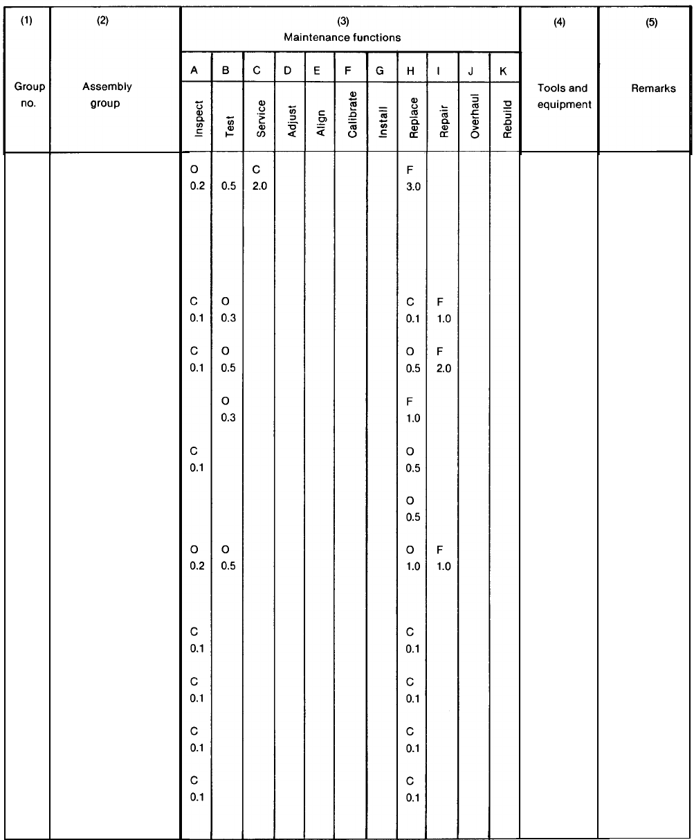
TM 5-6115-628-14&P
01
02
0201
0202
03
Section Il. MAINTENANCE ALLOCATION CHART
GENERATOR SET
ELECTRICAL
SYSTEM
Power Cables
Switch Box
Circuit
Breaker
Connector
Load Terminals
Wiring
ACCESSORIES
Sledge Hammer
Fire
Extinguisher
Slide Hammer
Ground Rods
See TM 5-
6115-464-
12, - 34 for
generator
set main-
tenance.
C-3
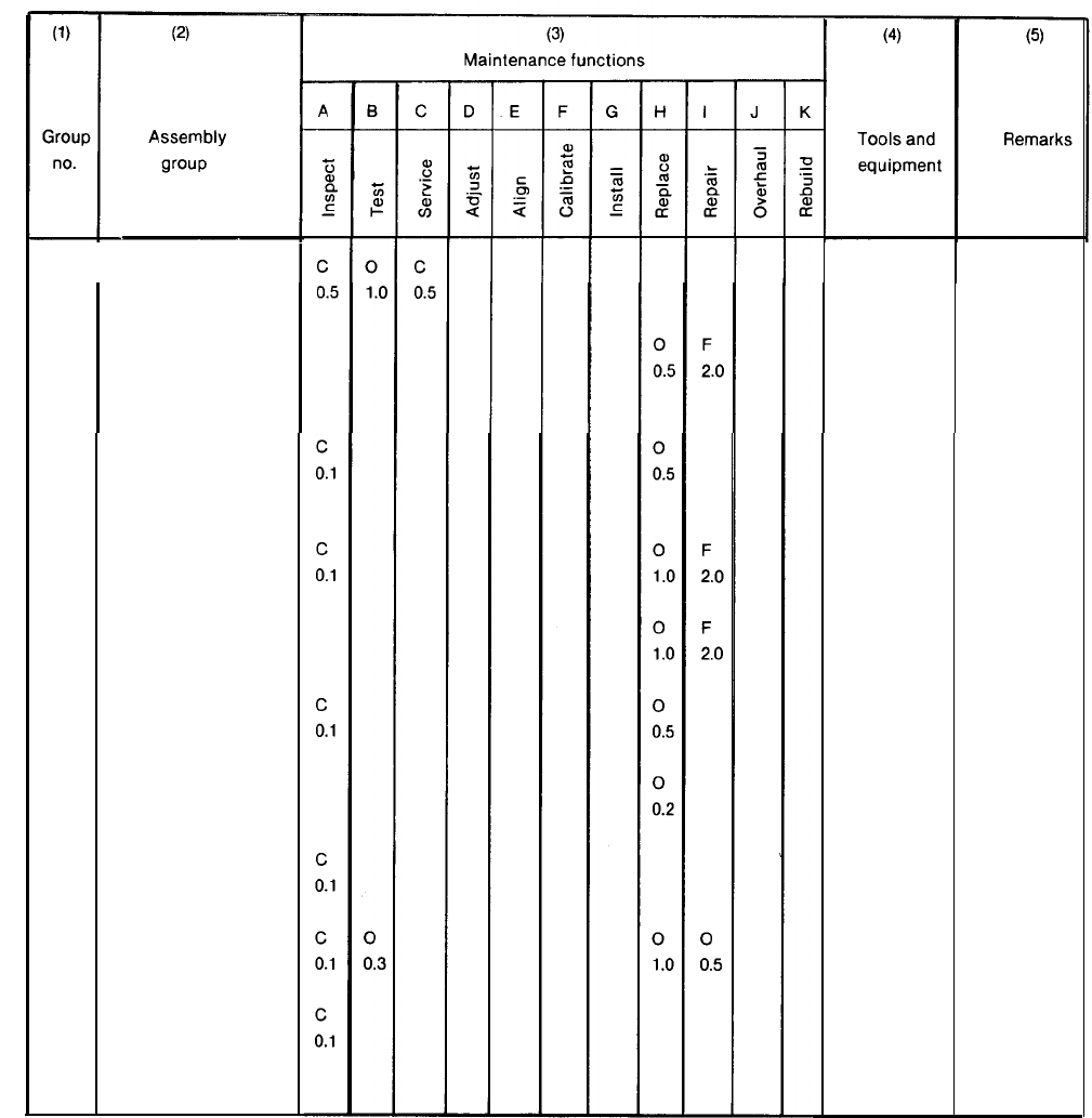
TM 5-6115-628-14&P
04
TRAILER ASSEMBLY See TM 9-
2330-205-
-14&P for
Accessory Box trailer as-
sembly
main-
tenance.
Fuel Can/Fire
Extinguisher
Brackets
Steps/Platforms
Fenders
Reflectors
Data Plates
Leveling Jack
Lighting
Handbrake
C-4

TM 5-6115-628-14&P
APPENDIX D
UNIT, INTERMEDIATE (FIELD) (DIRECT SUPPORT AND
GENERAL SUPPORT) AND DEPOT MAINTENANCE REPAIR PARTS AND
SPECIAL TOOLS LIST
Section I. INTRODUCTION
D-1. Scope. This joint Army and Air Force manual lists repair parts and special tools required for the
performance of unit, intermediate (field) (direct and general support), and depot maintenance of the
power plant. The following paragraphs are keyed to applicable users. All users should read paragraph
4, Special Information, prior to using this manual.
D-2. General. Repair Parts and Special Tools List is divided into the following sections:
a. (ALL) Repair Parts – Section II. A list of repair parts authorized for the performance of
maintenance at the unit, intermediate (field) (direct and general support), and depot level in figure
and item number sequence.
b. (ALL) Special Tools, Test and Support Equipment – Section Ill. A list of special tools, test and
support equipment authorized for the performance of maintenance at the unit, intermediate (field)
(direct and general support), and depot level.
c. National Stock Number and Reference Number Index – Section IV. A list of National stock
numbers in numerical sequence, followed by a list of reference numbers appearing in all the listings,
in alphanumeric sequence, cross-referenced to the illustration figure number and item number.
d. Reference Designator Index – Section V. The reference Designator Column includes all as-
signed reference designators arranged first in alphabetical order, second in numeric order. Opposite
each symbol is listed the figure and item number of the part in Section II and the reference number.
D-3. Explanation of columns. The following provides an explanation of columns in the tabular lists in
Sections II and Ill.
a. (ALL) Illustrations, (Column 1). This column is divided as follows:
(1) Figure Number. Indicates the figure number of the illustration on which the item is shown.
(2) Item Number. Indicates the number used to identify the item on the illustration.
b. (ALL) Source, Maintenance, and Recoverability Codes (SMR), (Column 2).
(1) Uniform Source Codes applicable to all Military Services.
D-1
TM 5-6115-628-14&P
GENERAL: Source Codes are assigned to support items to indicate the manner of acquiring support
items for maintenance, repair, or overhaul of end items. Source codes are entered in the first and
second positions of the Uniform SMR Code format as follows:
Code
Definition
PA
Item procured and stocked for anticipated or known usage.
PB
Item procured and stocked for insurance purposes because
essentiality dictates that a minimum quantity be available
in the supply systems.
PC
Item procured and stocked and which otherwise would be coded
PA except that it is deteriorative in nature.
PD
Support item, excluding support equipment, procured for initial
issue or outfitting and stocked only for subsequent or
additional initial issues or outfittings. Not subject to auto-
matic replenishment.
PE
Support equipment procured and stocked for initial issue or
outfittings to specified maintenance repair activities.
PF
Support equipment which will not be stocked but which will be
centrally procured on demand.
PG
Item procured and stocked to provide for sustained support for
the life of the equipment. It is applied to an item peculiar to the
equipment which because of probable discontinuance or shutdown
of production facilities would prove uneconomical to reproduce at
a later time.
KD
KF
KB
MO
An item of depot overhaul/repair kit and not purchased separ-
ately. Depot kit defined as a kit that provides items required
at the time of overhaul or repair.
An item of maintenance kit and not purchased separately.
Maintenance kit defined as a kit that provides an item that can
be replaced at unit or intermediate levels of maintenance.
Item included in both a depot overhaul/repair kit and a
maintenance kit.
Item to be manufactured or fabricated at unit level.
D-2
Code
MF
MD
AO
AF
AH
AD
XA
XB
XB
XD
TM 5-6115-628-14&P
Definition
Item to be manufactured or fabricated at intermediate
maintenance levels.
Air Force - Intermediate (*)
Army - General Support (*)
Item to be manufactured or fabricated at depot maintenance level.
Item to be assembled at unit level.
Item to be assembled at intermediate maintenance levels.
Air Force - Intermediate (*)
Army - Direct Support (*)
Item to be assembled at intermediate maintenance levels.
Air Force - Intermediate (*)
Army - General Support (*)
Item to be assembled at depot maintenance level.
Item is not procured or stocked because the requirements for the
item will result in the replacement of the next higher assembly.
Item is not procured or stocked. If not available through salvage,
requisition.
Installation drawings, diagram, instruction sheet, field service
drawing, that is identified by manufacturer’s part number.
A support item that is not stocked. When required, item will be
procured through normal supply channels.
(*) NOTE
For USAF and the USA Safeguard Program, only Code “F” will be used to
denote intermediate maintenance. On joint programs, use of either code F or
H by the jointing service will denote intermediate maintenance to USAF and
USA Safeguard Program.
(2) Uniform Maintenance Codes applicable to all Military Services: GENERAL Maintenance
Codes are assigned to indicate the levels of maintenance authorized to USE and REPAIR support
items. The Maintenance Codes are in the third and fourth position of the Uniform SMR Code Format.
(a) Use (Third Position): The Maintenance Code entered in the third position indicates the
lowest level maintenance level authorized to remove, replace, and use the support item. The
Maintenance Code entered in the third position indicates one of the following levels of maintenance.
D-3
TM 5-6115-628-14&P
Code
Application/Explanation
O
Support item is removed, replaced, used at the unit level of
maintenance.
F
Support item is removed, replaced, used at the following intermediate
levels:
USAF
- Intermediate (*)
USA
- Direct Support (*)
H
Support item is removed, replaced, used at the following intermediate
levels:
USAF - Intermediate (*)
USA - General Support (*)
Code
Definition
D
Support items that are removed, replaced, used at Depot only:
USAF - Depot, Mobile Depot and Specialized Repair Activity.
USA - Depot, Mobile Depot and Specialized Repair Activity
(b) Repair (Fourth Position): The maintenance code entered in the fourth position indicates
whether the item is to be repaired and identifies the lowest maintenance level with the capability to
perform complete repair (i.e., all authorized maintenance functions).
O
The lowest maintenance level capable of complete repair of the support
item is the unit level.
F
The lowest maintenance level capable of complete repair of the support
item is the following intermediate level:
USAF - Intermediate (*)
USA - General Support (*)
H
The lowest maintenance level capable of complete repair of the support
item is the following intermediate level:
USAF - Intermediate (*)
USA - General Support (*)
(*) NOTE
For USAF programs and the USA Safeguard Program, Code F will be used to
denote intermediate maintenance. On joint programs, use of either Code F or
H by the joining Service will denote intermediate maintenance to USAF and the
USA Safeguard Program.
D-4
Code
D
Definition
The lowest maintenance level capable of complete repair of the support
item is the depot level.
TM 5-6115-628-14&P
USAF - Depot, Mobile Depot, and Specialized Repair Activity.
USA - Depot, Mobile Depot, and Specialized Repair Activity.
Code
Application/Explanation
L
Repair restricted to designated Specialized Repair Activity.
Z
Nonreparable. No repair is authorized.
B
No repair is authorized. The item maybe reconditioned by adjusting,
lubricating, etc., at the user level. No parts or special tools are
procured for the maintenance of this item.
(3) Uniform Recoverability Codes applicable to all Military Services: GENERAL Recover-
ability Codes are assigned to support items to indicate the disposition action on unserviceable items.
The recoverability code is entered in the fifth position of the uniform SMR Code Format as follows:
Recoverability
Codes
Definition
Z
Nonreparable item. When unserviceable, condemn and dispose at
the level indicated in column 3.
O
Reparable item. When uneconomically reparable, condemn and
dispose at unit level.
F
Reparable item. When uneconomically reparable, condemn and
dispose at the following intermediate levels:
USAF - Intermediate (*)
USA - Direct Support (*)
H
Reparable item. When uneconomically reparable, condemn and
dispose at the following levels:
USAF - Intermediate (*)
USA - General Support (*)
(*) NOTE
For USAF programs and the USA Safeguard Program, Code F will be used to
denote intermediate maintenance. On joint programs, use of either Code F or
H by the joining Service will denote intermediate level of USAF and the USA
Safeguard Program.
D-5

TM 5-6115-628-14&P
Recoverability
Codes
D
L
A
Definition
Reparable item. When beyond lower level repair capability,
return to depot. Condemnation and disposal not authorized
below depot level.
Reparable item. Repair, condemnation and disposal not
authorized below depot/Specialized Repair Activity level.
Item requires special handling or condemnation procedure
because of specific reasons (i.e., precious metal content,
high-dollar value, critical material or hazardous material).
Refer to appropriate manuals/directives for specific
instructions.
c. (ALL) National Stock Number (Column 4). Indicates the National Stock Number assigned to
the item and will be used for requisitioning purposes.
d (ALL) Description (Column 5). Indicates the Federal item name and any additional descrip-
tions of the item required. The abbreviation “w/e” when used as part of the nomenclature, indicates
that the National Stock Number includes all armament, equipment, accessories and repair parts
issued with the item. A part number or other reference number is followed by the applicable five digit
Federal Supply Code for manufacturer in parentheses. If two reference numbers and Federal Supply
Codes for manufacturer are listed, the first listing refers to the Department of Defense Drawing
Number, the second listing refers to the actual part manufacturer. Items that are included in kits and
sets are listed below the name of the kit or set with the quantity of each item in the kit or set indicated in
the quantity incorporated in unit column.
e. (ALL) Unit of Measure (U/M) (Column 6). Indicates the standard of the basic quantity of the
listed item as used in performing the actual maintenance function. This measure is expressed by a
two-character alphabetical abbreviation (e.g., ea, in, pr, etc.). When the unit of measure differs
from the unit of issue, the lowest unit of issue that will satisfy the required units of measure will be
requisitioned.
f. (ALL) Quantity Incorporated in Unit (Column 7). Indicates the quantity of the item used in the
assembly group. A “V” appearing in this column in lieu of a quantity indicates that a definite quantity
cannot be indicated (e.g., shims, spacers, etc.).
D-4.
a.
b.
Special Information.
(ALL) Identification of Usable On Codes for this Manual is not applicable.
Army unit maintenance personnel will extract the items which they require from Section II, 3rd
or 4th position of column 2 of the intermediate direct and general support RPSTL. Parts which are
manufactured or assembled at a higher level than that authorized to install the part are indicated by the
use of higher level code in the source column.
c. Stockage Information.
(1) Air Force stockage information is contained in Initial Supply Support Lists issued separately
from this publication by Sacramento Air Logistics Center in accordance with AFM 67-1,
part 1, chapter 12.
D-6

TM 5-6115-628-14&P
(2) Army stockage is demand based in accordance with AR 710-2. Repair parts listed in this
publication represent those authorized for use at indicated maintenance levels and will be
requisitioned on an as-required basis until stockage is justified in accordance with
AR 710-2.
d. In the parts list, some items are indented to show that they area component of the item under
which they are indented.
D-5. How to Locate Repair Parts.
a. (ALL) When National Stock Number or reference number is unknown:
(1)
(2)
(3)
(4)
Using the table of contents, determine the functional group; i.e., batteries and related
parts, exhaust and breather pipes, within which the repair part belongs. This is necessary
since illustrations are prepared for functional groups.
Find the illustration covering the functional group to which the repair part belongs.
Identify the repair part on the illustration and note the illustration figure and item number of
the repair part.
Using the Repair Parts Listing, find the figure and item number noted on the illustration.
b. (ALL) When national stock number or reference number is known:
(1) Using the Index of National Stock Numbers and Reference Numbers, find the pertinent
national stock number or reference number. This index is in ascending NSN sequence
followed by a list of reference numbers in alphanumeric sequence, cross-referenced to
the illustration figure number and item number.
(2) After finding the figure and item number, locate the figure and item number in the repair
parts list.
D-6. (F) Use of the Reference Designator Index Section. This Section (Section V) is used when the
reference designator is known or identified by other technical manuals supporting this equipment. The
reference number is given in this section. If description or location is desired, note the figure and item
number. Turn to Section II to the noted figure and item number. The location of the part and
description is given in this listing.
D-7. Abbreviations.
Abbreviations Explanation
Not Applicable
D-8. Federal Supply Codes for Manufacturers.
Code
Manufacturer
Not Applicable
D-7
TM 5-6115-628-14&P
D-9. Recommendation for Maintenance Publication Improvements. Report of errors, omissions, and
recommendations for improving this publication by the individual user is encouraged. Reports should
be submitted as follows:
a. Air Force AFTO Form 22 in accordance with T.O. 00-5-1, directly to: Commander,
Sacramento Air Logistics Center, ATTN: SM-ALC-MMEDTA, McClellan AFB, CA 95652-5609.
b. Army DA Form 2028, directly to: Commander, US Army Troop Support Command, ATTN:
AMSTR-MCTS, 4300 Goodfellow Boulevard, St. Louis, MO 63120-1798.
D-8/(D-9 blank)
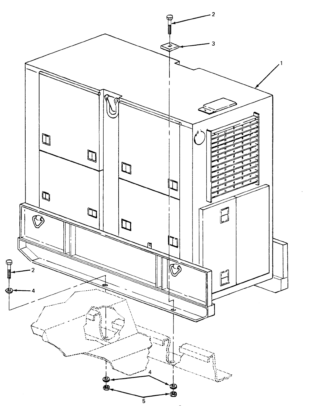
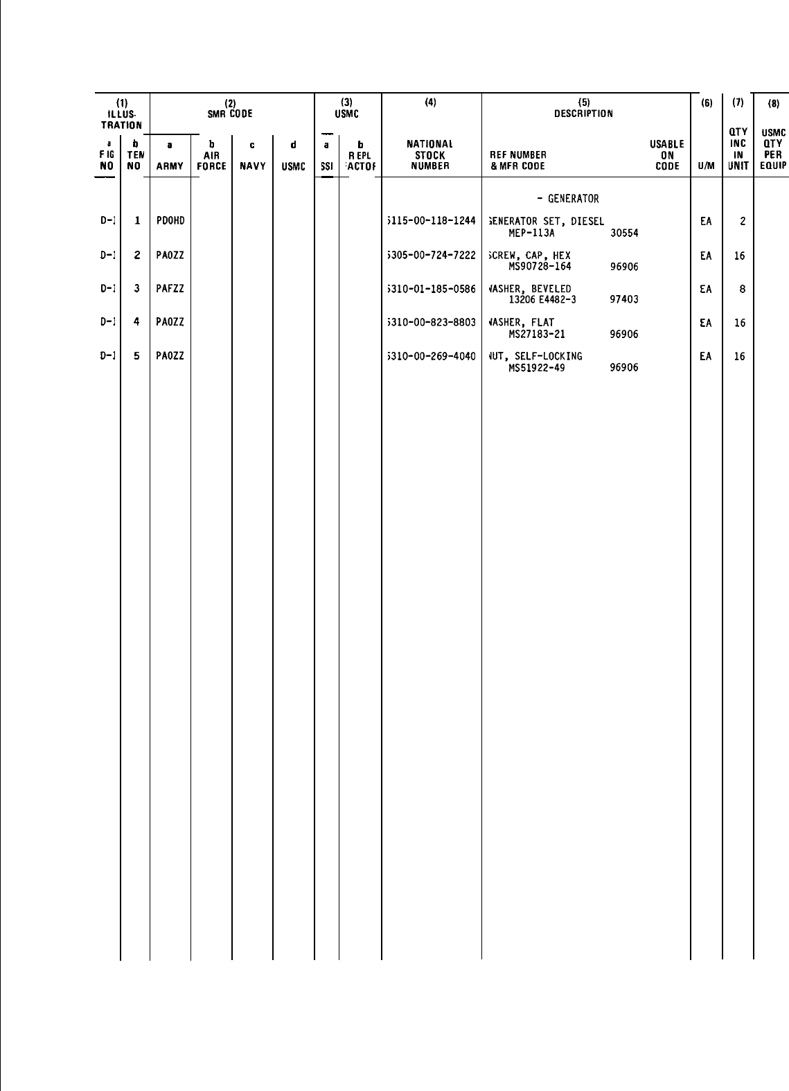
TM 5-6115-628-14&P
SECTION II
(1)
ILLUS.
TRATION
F
:G
NO
—
D-1
o-1
D-1
D-1
D-1
b
TEtJ
NO
1
2
3
4
5
a
ARMY
PDOHD
PAOZZ
PAFZZ
PAOZZ
PAOZZ
(2)
SMR COOE
b
AIR
FORCE
c
NAVY
d
USMC
(3)
USMC
—
a
WI
—
b
R
EPL
‘ACTOF
(4)
NATIONAL
STOCK
NUMBER
;115-00-118-1244
;305-00-724-7222
j31D-01-185-0586
;310-00-823-8803
;310-00-269-4040
(5)
DESCRIPTION
USA8LE
REF
NUMBER ON
&MFR
COOE
COOE
Group
01
-
GENERATOR
IENERATOR
SET,
OIESEL
MEP-113A 30554
;CREW,
CAP,
HEX
MS90728-164 96906
4ASHER,
8EVELE0
13206
E4482-3
97403
iASHER,
FLAT
MS27183-21 96906
UJT,
SELF-LOCKING
MS51922-49 96906
(6)
UIM
EA
EA
EA
EA
EA
(7)
QTY
INC
IN
UNIT
2
16
8
16
16
(8)
USMC
(lTY
PER
EQUIP
D-11
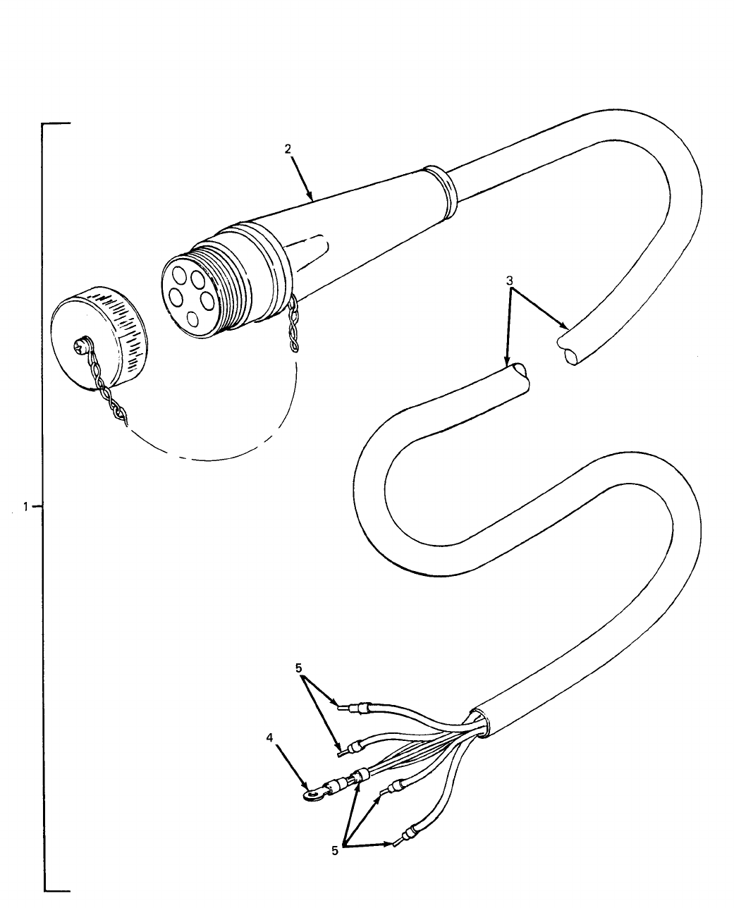
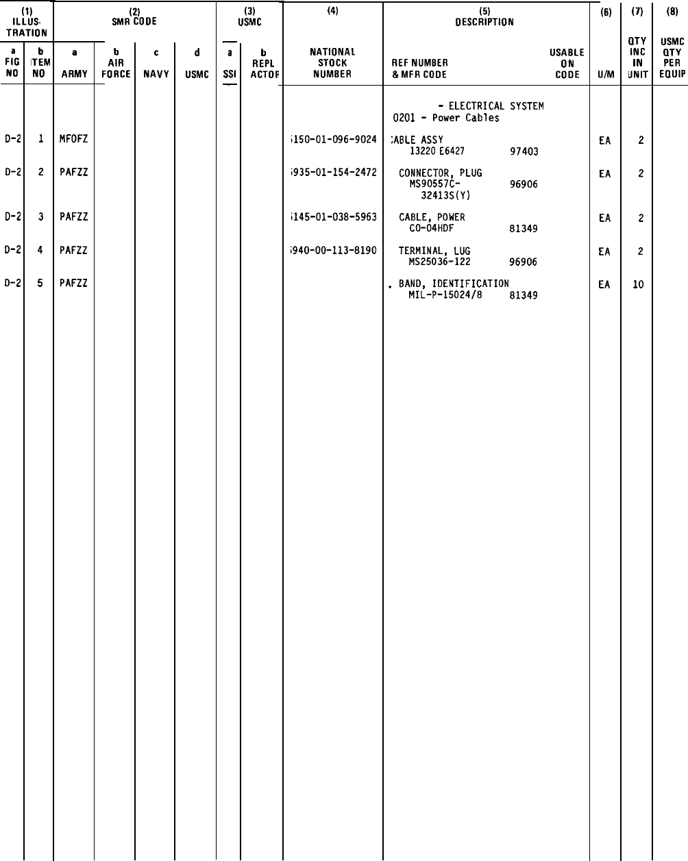
TM 5-6115-628-14&P
SECTION II
(1)
ILLUS.
TRATION
F:G
NO
D-2
o-2
0-2
D-2
D-2
b
ITEM
NO
1
2
3
4
5
a
ARMY
MFOFZ
PAFZZ
PAFZZ
PAFZZ
PAFZZ
(2)
SMR CODE
b
AIR
FORCE
c
NAVY
d
USMC
(3)
USMC
—
a
Ssl
—
b
REPL
ACTOR
(4)
NATIONAL
STOCK
NUMBER
i150-01-096-9024
i935-01-154-2472
i145-01-038-5963
i940-00-113-8190
(5)
DESCRIPTION
USA8LE
REF
NUMBER ON
&MFRCOOE
CODE
Group 02
-
ELECTRICAL
SYSTEM
0201
-
Power
Cables
;ABLE
ASSY
13220
E6427
97403
CONNECTOR,
PLUG
MS90557C-
96906
32413S(Y)
CABLE,
POWER
CO-04HDF 81349
TERMINAL,
LUG
MS25036-122
96906
.
BAND,
IDENTIFICATION
MIL-P-15024/8 81349
(6)
U/M
EA
EA
EA
EA
EA
(7)
QTY
INC
IN
UNIT
2
2
2
2
10
(8)
USMC
13TY
PER
EQUIP
D-13
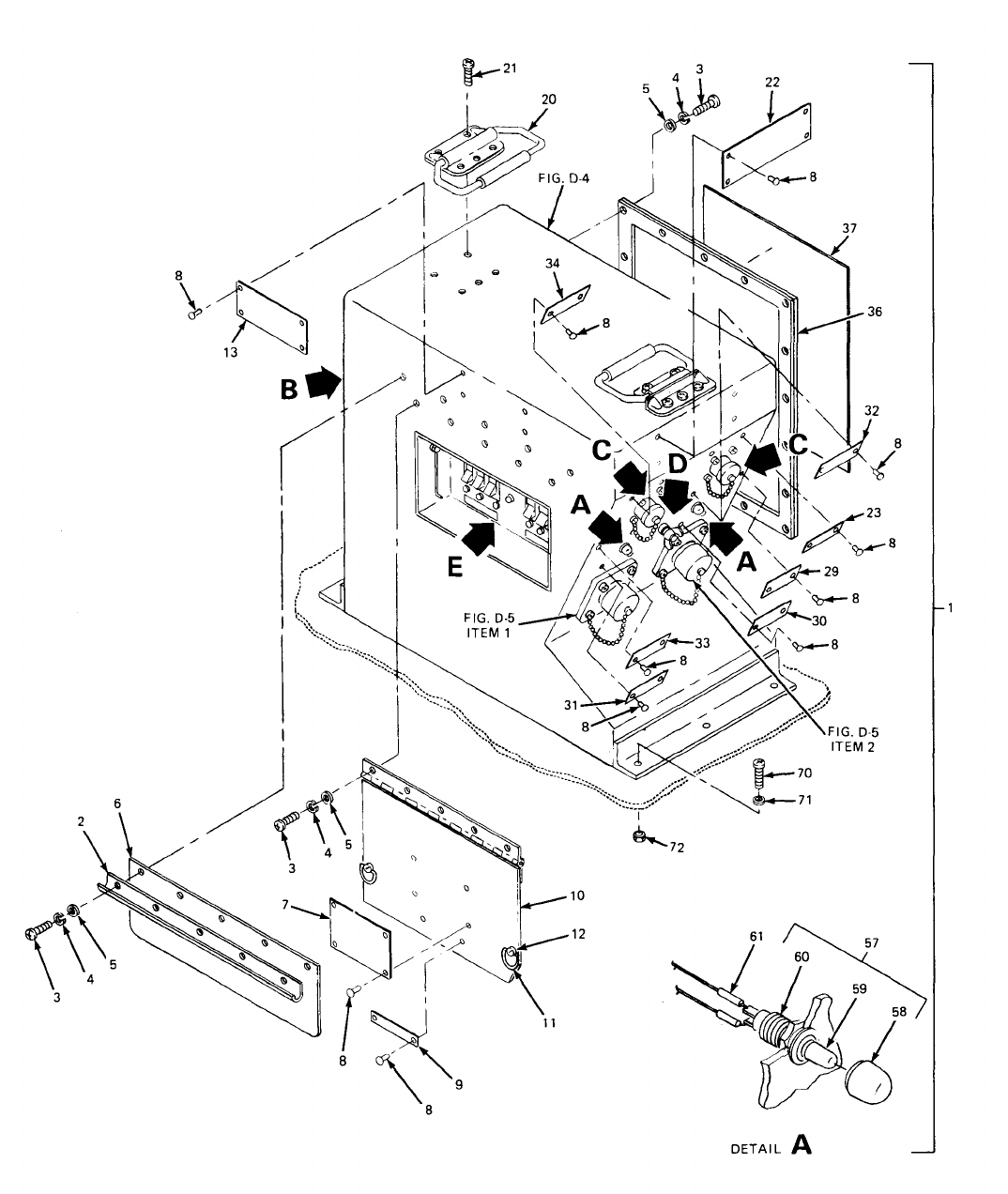
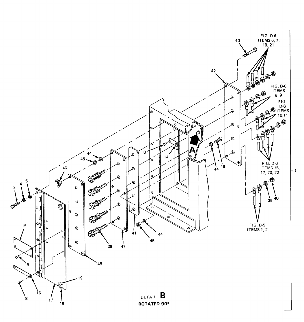
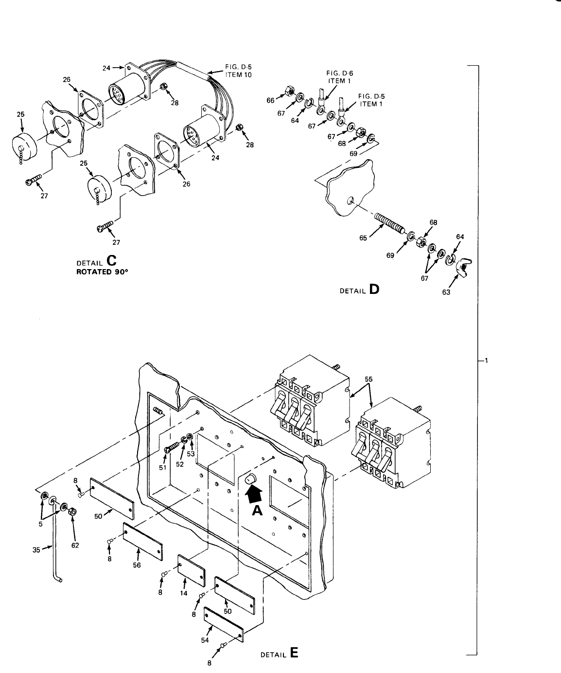
—
TM 5-6115-628-14&P
Figure D-3. Switch Box Assy (Sheet 3 of 3).
D-16
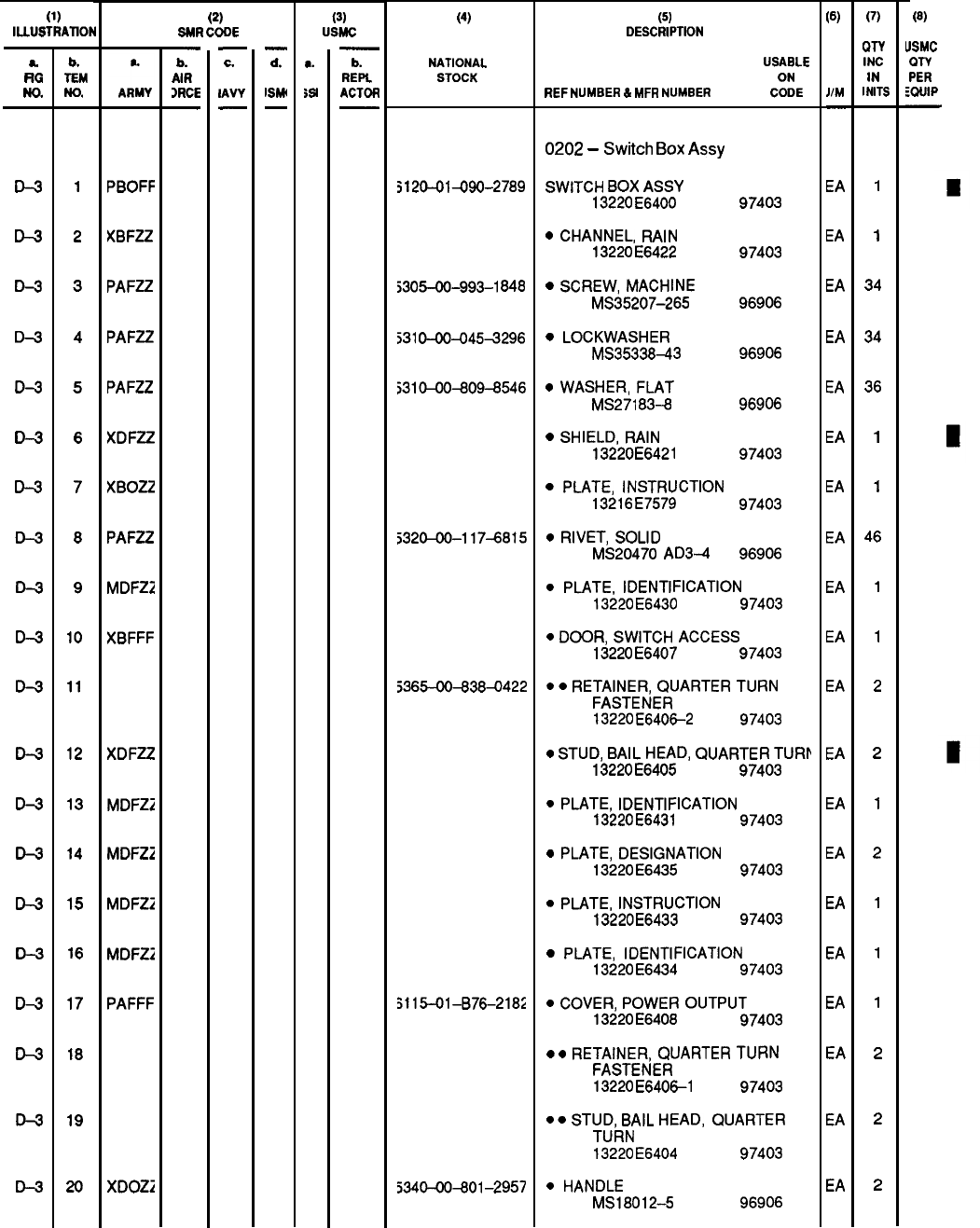
TM 5-6115-628-14&P
SECTION II
(1)
lLLU!3TRAT10N
a.
RG
No.
D-3
D-3
D-3
D-3
D-3
D-3
D-3
D-3
D-3
D-3
D-3
D-3
D-3
D-3
D-3
D-3
D-3
D-3
D-3
D-3
b.
TEM
No.
1
2
3
4
5
6
7
8
9
10
11
12
13
14
15
16
17
18
19
20
PBOFF
)(BFZZ
PAFZZ
PAFZZ
PAFZZ
XDFZZ
XBOZZ
PAFZZ
MDFZ2
XBFFF
XDFZZ
MDFZ2
MDFZ2
MDFZ2
MDFZZ
PAFFF
XDOZ2
(2)
SMR CODE
—
b.
AIR
)RCE
—
—
c.
IAVY
—
—
d.
ISM
—
(3)
USMC
●
W
b.
REPL
ACTOR
(4)
NATIONAL
STOCK
;
120-01430-2789
S305-00-993-1
848
531
0-00-045+296
5310-00-809-6546
5320-00-117-6815
j365-00+38~422
3115-01
-B76-218:
5340-00+01
–2957
(5)
DESCRIPTION
USABLE
ON
REF NUMBER 6
MFR
NUMSER CODE
0202
–
Switch
Box
Assy
SWITCH
BOX
ASSY
13220
E6400
97403
●
CHANNEL,
RAIN
13220
E6422
97403
●
SCREW,
MACHINE
MS35207-265 96906
c
LOCKWASHER
MS3533843
96906
c
WASHER,
FLAT
MS271
83-8 96906
●
SHIELD,
RAIN
13220E6421
97403
●
PLATE,
INSTRUCTION
13216
E7579
97403
●
RIVET,
SOLID
MS20470 AD3-4 96906
●
PLATE,
IDENTIFICATION
13220
E6430
97403
●
DOOR,
SWITCH
ACCESS
13220
E6407
97403
● ● RETAINER, QIJARTER TIJRN
FASTENER
13220
E640&2 97403
●
STUD,
BAIL
HEAD,
QUARTER
TURN
13220
E6405
97403
●
PLATE,
IDENTIFICATION
13220
E6431
97403
●
PLATE,
DESIGNATION
13220
E6435
97403
●
PLATE,
INSTRUCTION
13220E6433 97403
●
PLATE,
IDENTIFICATION
13220
E6434
97403
●
COVER,
POWER
OUTPUT
13220
E6408
97403
●
●
RETAINER,
QUARTER
TURN
FASTENER
13220
E640&l
97403
●
● STUD, BAIL HEAD,
QUARTER
TURN
13220
E6404
97403
●
HANDLE
MS18012-5 96906
(6)
JIM
—
EA
EA
EA
EA
EA
EA
EA
EA
EA
EA
EA
EA
EA
EA
EA
EA
EA
EA
EA
EA
(7)
WY
INC
IN
I
NITS
1
1
34
34
36
1
1
46
1
1
2
2
1
2
1
1
1
2
2
2
(8)
USMC
m-v
PER
mlJIP
Change 2
D-17
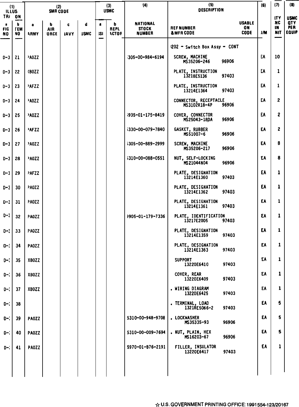
TM 5-6115-628-14&P
(1)
lLLUS-
TRJ
F
;G
NO
—
o-3
D-3
D-3
o-3
0-3
0-3
0-3
0-3
0-3
0-3
D-3
o-~
0-:
D
-:
D-:
D-:
D-:
o-:
D-:
D-:
0-:
ON
—
b
rEM
No
—
21
22
23
24
25
26
27
28
29
30
31
32
33
34
35
36
37
38
39
40
41
a
!RMY
JAOZZ
(BOZZ
~AFZ2
>AOZZ
)AOZZ
~AFZZ
~Aozz
~AOZZ
?AFZZ
PAOZZ
PAOZZ
PAOZZ
PAOZZ
PAOZZ
XBOZZ
XBOZZ
XBOZZ
PAOZZ
PAOZZ
PAOZZ
(2)
SMR
COOE
b
AIR
‘ORCE
c
IAVY
d
USMC
(3)
USMC
—
a
;s1
—
b
REP1
4CTOH
“(4)
NATIONAL
STOCK
NUMBER
305-00-984-6194
;935-01-175-8419
;330-00-079-7840
;305-00-889-2999
i310-00-088-0551
)905-01-179-7336
531
O-OO-94B-97O8
5310-00-009-7694
5970-01-876-2191
.
.
.
.
(5)
DESCRIPTION
USABLE
REF
NUMBER
ON
&
MFR
COOE
COOE
1202
-
Switch
BOX
ASSJ
-
CONT
SCREW,
MACHINE
MS35206-246 96906
PLATE,
INSTRUCTION
1321 BE5136
97403
PLATE,
INSTRUCTION
13214
E1364
97403
CONNECTOR,
RECEPTACLE
MS3102R18-4P 96906
COVER,
CONNECTOR
MS25043-18J)A 96906
GASKET,
RUB8ER
MS51OO7-6
96906
SCREW,
MACHINE
MS35206-217 96906
NUT,
SELF-LOCKING
NS21044NO4
96906
PLATE,
DESIGNATION
13214
E1360 97403
PLATE,
DESIGNATION
13214
E1362 97403
PLATE,
DESIGNATION
13214
E1361
97403
PLATE, IDENTIFICATION
13217
E2005 97403
PLATE,
DESIGNATION
13214
E1359
PLATE,
DESIGNATION
13214
E1363
SUPPORT
1322OE641O
COVER,
REAR
13220
E6409
HIRING
OIAGRAM
13220
E6425
TERMINAL,
LOAO
13218
E5066-2
LOCKHASHER
MS35335-93
NUT,
PLAIN,
HEX
MS16203-67
FILLER,
INSULATOR
13220
E6417
97403
97403
97403
97403
97403
97403
96906
96906
97403
(6)
Jm
EA
EA
EA
EA
EA
EA
EA
EA
EA
EA
EA
EA
EA
EA
EA
EA
EA
EA
EA
EA
EA
SECTION II
ii-
lTY
NC
IN
NIT
—
10
1
1
2
2
2
8
8
1
1
1
1
1
1
1
1
1
5
5
5
1
-iii-
USMC
QTV
PER
E13UIP
D-18
*
U.S.
GOVERNMENT
PRINTING
OFFICE
1991
554-123/20167
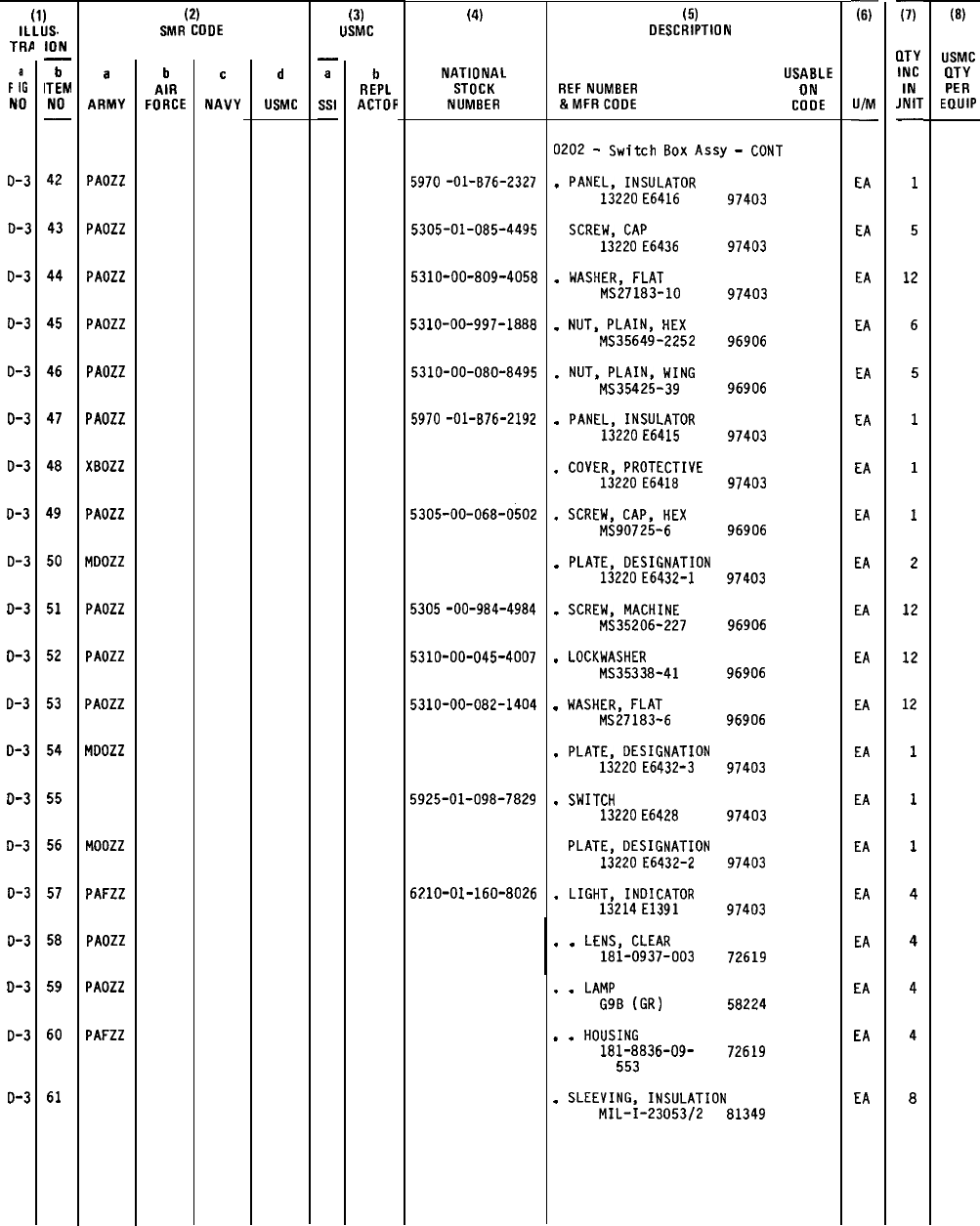
TM 5-6115-628-14&P
SECTION II
(1)
ILLUS.
TRA
F
:G
NO
o-3
0-3
D-3
D-3
D-3
o-3
D-3
D-3
D-3
D-3
D-3
o-3
0-3
0-3
D-3
D-3
D-3
o-3
D-3
D-3
ION
—
b
ITEM
NO
—
42
43
44
45
46
47
48
49
50
51
52
53
54
55
56
57
58
59
60
61
a
ARMY
PAOZZ
PAOZZ
PAOZZ
PAOZZ
PAOZZ
PAOZZ
XBOZZ
PAOZZ
MOOZZ
PADZZ
PAOZZ
PAOZZ
MOOZZ
MOOZZ
PAFZZ
PAOZZ
PAOZZ
PAFZZ
(2)
SMR COOE
b
AIR
FORCE
c
NAVY
d
USMC
(3)
USMC
—
a
Ssl
—
b
REPL
ACTOR
(4)
NATIONAL
STOCK
NUMBER
5970
-01-B76-2327
5305-01-085-4495
5310-00-809-4058
5310-00-997-1888
5310-00-080-8495
5970
-01-B76-2192
5305-00-068-0502
5305
-OO-9B4-4984
5310-00-045-4007
5310-00-082-1404
5925-01-098-7829
62?10-01-160-8026
(5)
DESCRIPTION
USABLE
REF
NUMBER ON
&MFRCOOE
COOE
0202
-
Switch
Box
Assy
-
CONT
.
PANEL,
INSULATOR
13220
E6416
97403
SCREW,
CAP
13220
E6436
97403
.
WASHER,
FLAT
MS27183-10 97403
.
NUT,
PLAIN,
HEX
MS35649-2252 96906
.
NUT,
PLAIN,
WING
MS35425-39 96906
.
PANEL,
INSULATOR
13220
E6415
97403
.
COVER,
PROTECTIVE
13220
E641B
97403
.
SCREW,
CAP,
HEX
MS90725-6
.
PLATE,
DESIGNATION
13220
E6432-I
.
SCREW,
MACHINE
MS35206-227
.
LOCKWASHER
MS35338-41
.
WASHER,
FLAT
MS27183-6
.
PLATE,
DESIGNATION
13220 E6432-3
.
SWITCH
13220
E6428
PLATE,
DESIGNATION
13220
E6432-2
.
LIGHT,
INDICATOR
13214
E1391
96906
97403
96906
96906
96906
97403
97403
97403
97403
.
.
LENS,
CLEAR
181-0937-003 72619
.
.
LAMP
G9B
(GR)
58224
.
.
HOUSING
181-8836-09-
72619
553
.
SLEEVING,
INSULATION
MIL-I-23053/2 81349
-F
U/M
—
EA
EA
EA
EA
EA
EA
EA
EA
EA
EA
EA
EA
EA
EA
EA
EA
EA
EA
EA
EA
x
QTY
INC
IN
JNIT
—
1
5
12
6
5
1
1
1
2
12
12
12
1
1
1
4
4
4
4
8
(8)
USMC
OTY
PER
EQUIP
D-19
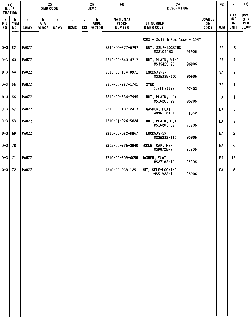
TM 5-6115-628-14&P
SECTION II
(1)
ILLUS.
TRATION
F
:G
NO
D-3
o-3
0-3
0-3
0-3
0-3
D-3
o-3
D-3
o-3
0-3
—
h
TEM
NO
—
62
63
64
65
66
67
68
69
70
71
72
a
ARMY
PAOZZ
PAOZZ
PAOZZ
PAOZZ
PAOZZ
PAOZZ
PAOZZ
PAOZZ
PAOZZ
PAOZZ
D-20/(D-21 blank)
(2)
SMR COOE
h
AIR
FORCE
c
NAVY
d
USMC
(3)
USMC
.
a
551
—
b
REPL
‘ACTOR
(4)
NATIONAL
STOCK
NUMBER
;310-00-877-5797
;310-00-543-4717
;310-00-184-8971
;307-00-227-1741
;310-00-584-7995
;310-00-187-2413
;310-01-026-5824
;310-00-022-8847
;305-00-225-3840
;310-00-809-4058
i310-00-088-1251
(5)
DESCRIPTION
USABLE
REF
NUMBER ON
&MFR
COOE
COOE
)202
-
Switch
80X
Assy
-
CONT
NUT,
SELF-LOCKING
MS21044N3
NUT,
PLAIN,
WING
MS35425-28
LOCKWASHER
MS35338-103
STUO
13214
E1223
NUT,
PLAIN,
HEX
MS16203-27
WASHER,
FLAT
AN961-616T
NUT,
PLAIN.
HEX
MS16203-39
LOCKWASHER
MS35333-11O
;CREW,
CAP,
HEX
MS90725-7
IASHER,
FLAT
MS27183-10
IUT,
SELF-LOCKING
“MS51922-1
96906
96906
96906
97403
96906
81352
96906
96906
96906
96906
96906
(6)
Ui?vl
EA
EA
EA
EA
EA
EA
EA
EA
EA
EA
EA
(7)
OTY
INC
IN
UNIT
8
1
2
1
1
5
2
2
6
12
6
(8)
USMC
(lTY
PER
ECIUIP
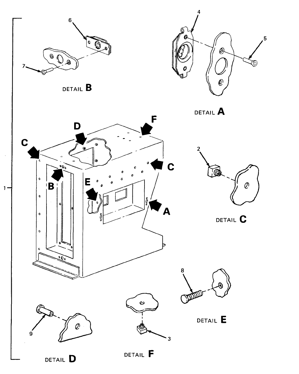
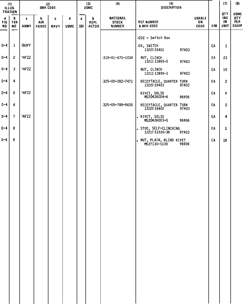
SECTION II
TM 5-6115-628-14&P
(1)
ILLUS.
TRATION
a
FIG
NO
—
D-4
D-4
D-4
D-4
D-4
D-4
D-4
D-4
D-4
—
b
TEN
NO
—
1
2
3
4
5
6
7
8
9
a
ARMY
iBOFF
‘AFZZ
~AFZZ
>AFZZ
~AFZZ
(2)
SMR COOE
b
AIR
FORCE
c
NAVY
d
USMC
(3)
USMC
—
a
KY
b
REPL
‘ACTOR
(4)
NATIONAL
STOCK
NUMBER
i310-ol-B75-lo34
;325-00-282-7471
,325-00-788-5635
(5)
DESCRIPTION
USABLE
REF
NUMBER ON
&MFR
COOE
CODE
)202
-
Switch
80X
IOX,
SWITCH
13220
E6401
97403
NUT,
CLINCH
13211
E3895-5
97403
NUT,
CLINCH
13211
E3895-3
97403
RECEPTACLE,
QUARTER
TURN
13220
E6403
97403
RIVET,
SOLIO
MS20426D04-6 96906
RECEPTACLE,
QUARTER
TURN
13220
E6402
97403
.
RIVET,
SOLID
MS20426003-5 96906
.
STUD,
SELF-CLINCHING
13217
E1526-38
97403
.
NUT,
PLAIN,
8LIN0
RIVET
MS2713O-S1OO 96906
U/M
EA
EA
EA
EA
EA
EA
EA
EA
EA
(7)
OTY
INC
IN
UNIT
1
23
10
2
4
2
4
1
18
(8)
USMC
CITY
PER
EOUIP
D-23
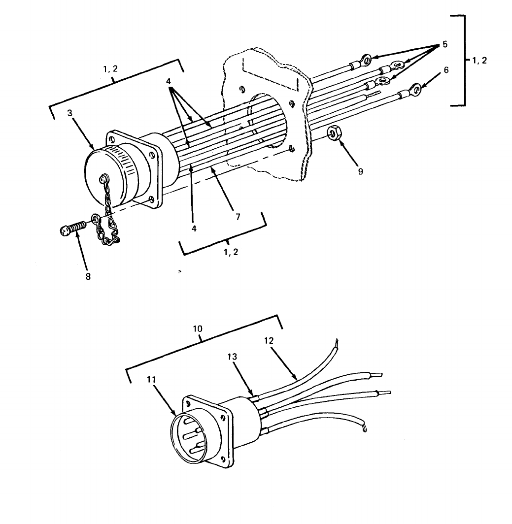
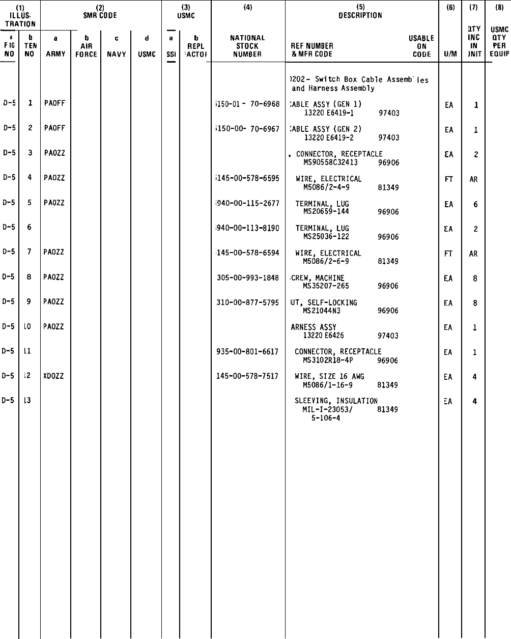
TM 5-6115-628-14&P
SECTION II
(1)
ILLUS.
TRATION
—
F
;G
NO
—
o-5
0-5
0-5
0-5
0-5
0-5
0-5
0-5
0-5
0-5
0-5
0-5
0-5
b
TEN
NO
1
2
3
4
5
6
7
8
9
10
11
L2
L3
a
ARMY
PAOFF
PAOFF
PAOZZ
PAOZZ
PAOZZ
PAOZZ
PAOZZ
PAOZZ
PAOZZ
Xoozz
(2)
SMRCOOE
b
AIR
FORCE
c
NAVY
d
USMC
(3)
USMC
—
a
Ssi
—
b
REPL
‘ACTOf
(4)
NATIONAL
STOCK
NUMBER
i150-ol
-
i150-OO-
70-6968
70-6967
i145-00-578-6595
i940-00-115-2677
1940-00-113-8190
145-00-578-6594
305-00-993-1848
310-00-877-5795
935-00-801-6617
145-00-578-7517
(5)
DESCRIPTION
USABLE
REF
NUMBER ON
&MFRCOOE
COOE
)202
-
Switch
80X
Cable
Assemb’
and
Harness
Assembly
:ABLE
ASSy
(GEN
1)
13220 E6419-1
97403
;ABLE
ASSY
(GEN
2)
13220 E6419-2
97403
.
CONNECTOR,
RECEPTACLE
MS90558C32413 96906
WIRE,
ELECTRICAL
M5086/2-4-9 81349
TERMINAL,
LUG
MS20659-144 96906
TERMINAL,
LUG
MS25036-122 96906
WIRE,
ELECTRICAL
M508612-6-9 81349
ICREW,
MACHINE
MS35207-265 96906
IUT,
SELF-LOCKING
MS21044N3
96906
ARNESS
ASSY
13220
E6426
97403
CONNECTOR,
RECEPTACLE
MS3102R18-4P
96906
WIRE,
SIZE
16
ANG
M5086/1-16-9
81349
SLEEVING,
INSULATION
MIL-I-23053/
81349
5-106-4
ies
(6)
U/M
EA
EA
EA
FT
EA
EA
Fr
EA
EA
EA
EA
EA
LA
(7)
~TY
INC
IN
JNIT
1
1
2
AR
6
2
AR
8
8
1
1
4
4
(8)
USMC
QTY
PER
EaulP
D-25
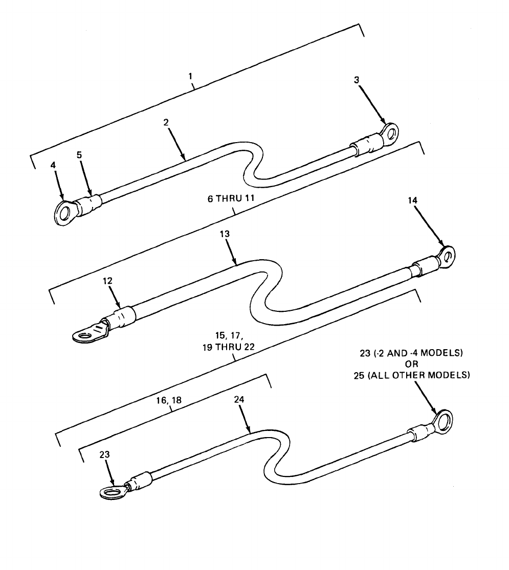
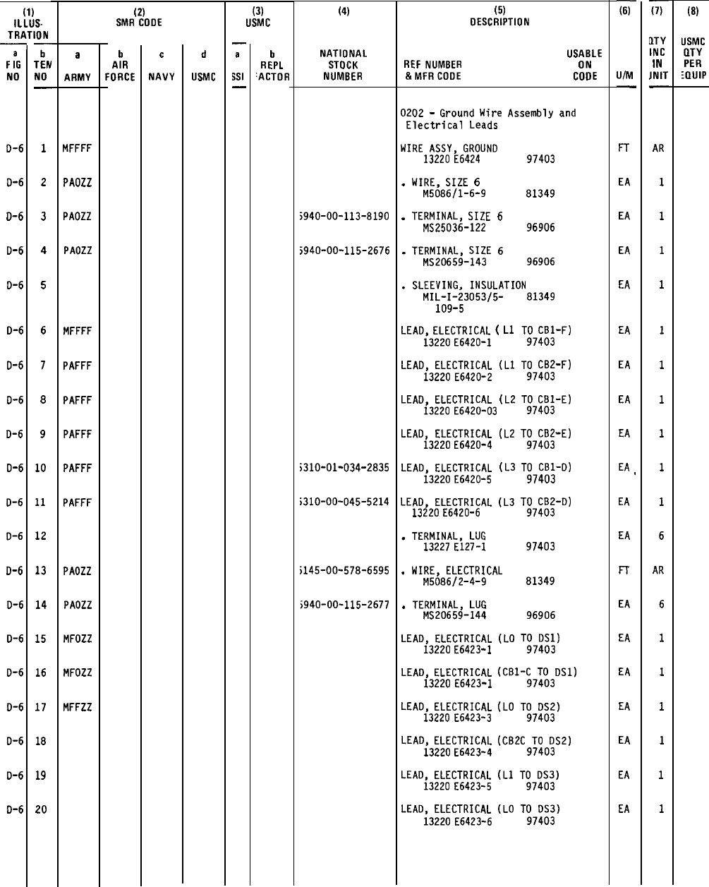
TM 5-6115-628-14&P
SECTION II
(1)
iLLUS-
TRATION
~
F
:G
NO
O-6
0-6
D-6
D-6
D-6
D-6
D-6
O-6
0-6
D-6
O-6
D-6
D-6
D-6
D-6
D-6
O-6
D-6
D-6
D-6
T
TEN
NO
—
1
2
3
4
5
6
7
8
9
10
11
12
13
14
15
16
17
18
19
20
a
ARMY
MFFFF
PAOZZ
PAOZZ
PAOZZ
MFFFF
PAFFF
PAFFF
PAFFF
PAFFF
PAFFF
PAOZZ
PAOZZ
MFOZZ
MFOZZ
MFFZZ
(2)
SMR CODE
b
AIR
FORCE
c
NAVY
d
USMC
(3)
USMC
—
a
Ssl
—
b
REPL
‘ACTOR
(4)
NATIONAL
STOCK
NUMBER
;940-00-113-8190
5940-00-115-2676
i310-01-034-2835
;310-00-045-5214
i145-00-578-6595
;940-00-115-2677
(5)
DESCRIPTION
USABLE
REF
NUMBER ON
&MFRCOOE
COOE
0202
-
Ground
Wire
Assembly
and
Electrical
Leads
WIRE
ASSY,
GROUND
13220
E6424
97403
.
WIRE,
SIZE
6
M5086/1-6-9 81349
.
TERMINAL,
SIZE
6
MS25036-122 96906
.
TERMINAL,
SIZE
6
MS20659-143 96906
.
SLEEVING,
INSULATION
MIL-I-23053/5-
109-5
LEAD,
ELECTRICAL
(
L1
13220
E6420-1
LEAD,
ELECTRICAL
(L1
13220
E6420-2
LEAO,
ELECTRICAL
(L2
13220
E6420-03
LEAD,
ELECTRICAL
(L2
13220
E6420-4
LEAO,
ELECTRICAL
(L3
13220
E6420-5
LEAD,
ELECTRICAL
(L3
13220
E6420-6
.
TERMINAL,
LUG
13227
E127-I
.
WIRE,
ELECTRICAL
M5086/2-4-9
.
TERMINAL,
LUG
MS20659-144
LEAO,
ELECTRICAL
(LO
13220
E6423-I
81349
TO
CB1-F)
97403
TO
CB2-F)
97403
TO
CBI-E)
97403
TO
CB2-E)
97403
TO
CB1-D)
97403
TO
CB2-0)
97403
97403
81349
96906
TO
DS1)
97403
LEAO,
ELECTRICAL
(CBI-C
TO
0S1)
13220
E6423-1
97403
LEAD,
ELECTRICAL
(LO
TO
DS2)
13220
E6423-3
97403
LEAD,
ELECTRICAL
(CB2C
TO
0S2)
13220
E6423-4
97403
LEAD,
ELECTRICAL
(Ll
TO
DS3)
13220
E6423-5
97403
LEAD,
ELECTRICAL
(LO
TO
0S3)
13220
E6423-6
97403
-ii-
UIM
—
FT
EA
EA
EA
EA
EA
EA
EA
EA
EA
,
EA
EA
n
EA
EA
EA
EA
EA
EA
EA
F
QTY
INC
IN
JNIT
—
AR
1
1
1
1
1
1
1
1
1
1
6
AR
6
1
1
1
1
1
1
(8)
USMC
QTY
PER
:aw
D-27
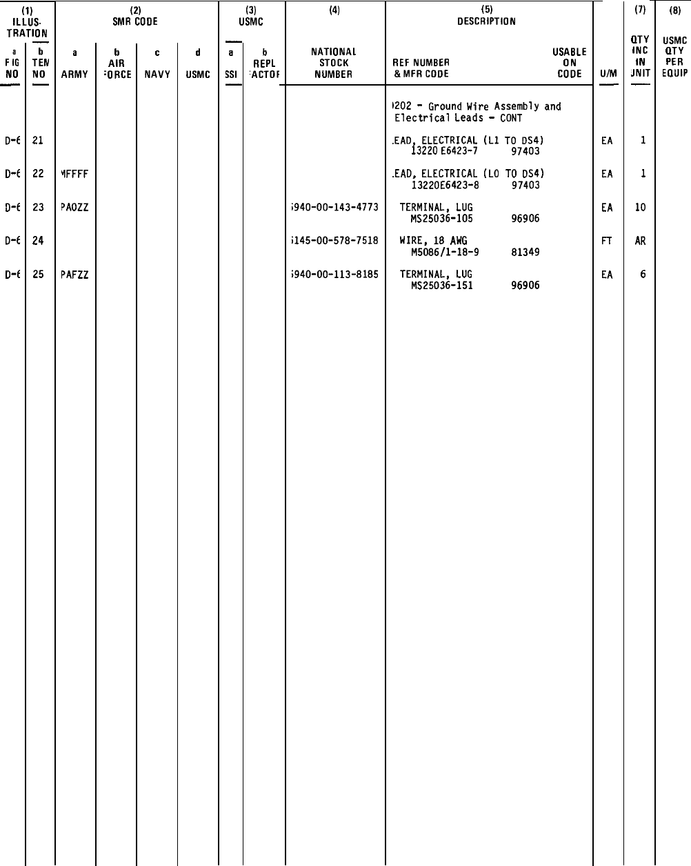
TM 5-6115-628-14&P SECTION II
(1)
ILLUS.
TRATION
F
:G
NO
—
0-6
D-6
0-6
D-t
o-f
.
b
TEN
NO
—
21
22
23
24
25
a
ARMY
YFFFF
PAOZZ
PAFZZ
(2)
SMR CODE
b
AIR
‘ORCE
c
NAVY
d
USMC
(3)
USMC
—
a
Ssl
—
b
REPL
‘ACTOF
(4)
NATIONAL
STOCK
NUMBER
i940-OO-143-4773
i145-00-578-7518
;940-00-113-8185
(5)
DESCRIPTION
USABLE
REF
NUMBER ON
&MFRCOOE
CODE
)202
-
Ground
Wire
Assembly
and
Electrical
Leads
-
CONT
.EAO,
ELECTRICAL
(L1
TO
0S4)
13220 E6423-7
97403
.EAO.
ELECTRICAL
(LO
TO
0S4)
i3220E6423-8
TERMINAL,
LUG
MS25036-105
WIRE,
18
AWG
M5086/1-18-9
TERMINAL,
LUG
MS25036-151
97403
96906
81349
96906
U/M
—
EA
EA
EA
FT
EA
(7)
0T%
INC
IN
JNIT
—
1
1
10
AR
6
(8)
USMC
(lTY
PER
EOUIP
D-28/(D-29 blank)
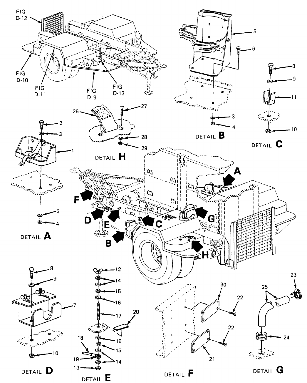
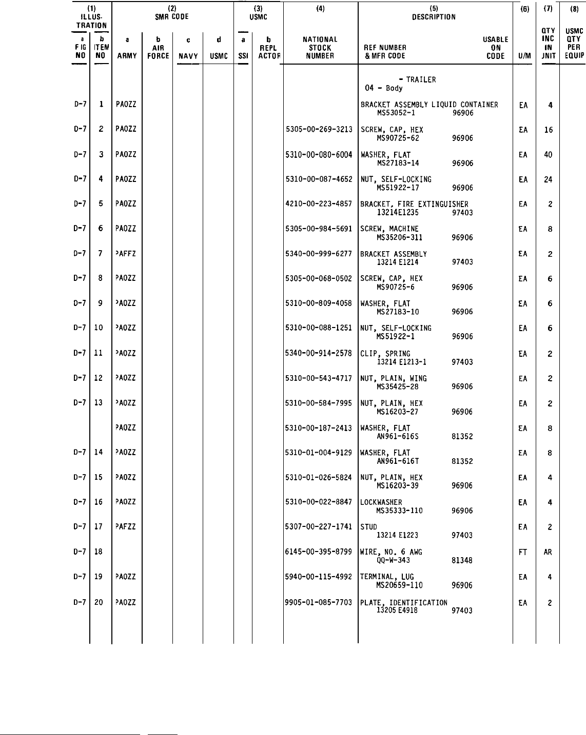
TM 5-6115-628-14&P
SECTION II
(1)
iLLUS-
TRATION
—
F
:G
NO
—
o-7
D-7
D-7
D-7
D-7
D-7
D-7
D-7
D-7
D-7
D-7
D-7
D-7
D-7
D-7
D-7
o-7
0-7
D-7
D-7
—
b
ITEM
NO
—
1
2
3
4
5
6
7
8
9
10
11
12
13
14
15
16
17
18
19
20
a
ARMY
PAOZZ
PAOZZ
PAOZZ
PAOZZ
PAOZZ
PAOZZ
~AFFZ
PAOZZ
>AOZZ
~AOZZ
~AOZZ
~AOZZ
JAOZZ
PAOZZ
~AOZZ
PAOZZ
PAOZZ
PAFZZ
PAOZZ
PAOZZ
(2)
SMR COOE
b
AIR
FORCE
c
NAVY
——
d
USMC
(3)
USMC
—
a
Ssl
—
b
REPL
ACTOR
(4)
NATIONAL
STOCK
NUMBER
5305-00-269-3213
5310-00-080-6004
5310-00-087-4652
4210-00-223-4857
5305-00-984-5691
5340-00-999-6277
5305-00-068-0502
5310-00-809-4058
5310-00-088-1251
5340-00-914-2578
5310-00-543-4717
5310-00-584-7995
5310-00-187-2413
5310-01-004-9129
5310-01-026-5824
5310-00-022-8847
5307-00-227-1741
6145-00-395-8799
5940-00-115-4992
9905-01-085-7703
(5)
DESCRIPTION
USABLE
REF
NUMBER ON
&MFR
COOE
COOE
Group 04
-
TRAILER
04
-
Body
8RACKET
ASSEMBLY
LIQUID
CONTAINER
MS53052-1
96906
SCREW,
CAP,
HEX
MS90725-62
96906
WASHER,
FLAT
MS27183-14 96906
NUT,
SELF-LOCKING
MS51922-17
96906
BRACKET.
FIRE
EXTINGUISHER
132i4E1235
SCREW,
MACHINE
MS35206-311
BRACKET
ASSEMBLY
13214
E1214
SCREW,
CAP,
HEX
MS90725-6
WASHER,
FLAT
MS27183-10
NUT,
SELF-LOCKING
MS51922-1
CLIP,
SPRING
13214
E1213-1
NUT,
PLAIN,
WING
MS35425-28
NUT,
PLAIN,
HEX
MS16203-27
WASHER,
FLAT
AN961-616S
WASHER,
FLAT
AN961-616T
NUT,
PLAIN,
HEX
MS16203-39
LOCKWASHER
MS35333-11O
STUO
13214
E1223
WIRE,
NO.
6
AWG
QQ-W-343
TERMINAL,
LUG
MS20659-11O
97403
96906
97403
96906
96906
96906
97403
96906
96906
81352
81352
96906
96906
97403
81348
96906
PLATE,
IDENTIFICATION
13205
E4918
97403
(6)
U/M
.
EA
EA
EA
EA
EA
EA
EA
EA
EA
EA
EA
EA
EA
EA
EA
EA
EA
EA
FT
EA
EA
(7)
CITY
INC
IN
JNIT
—
4
16
40
24
2
8
2
6
6
6
2
2
2
8
8
4
4
2
AR
4
2
(8)
USMC
IITY
PER
EQUIP
D-31
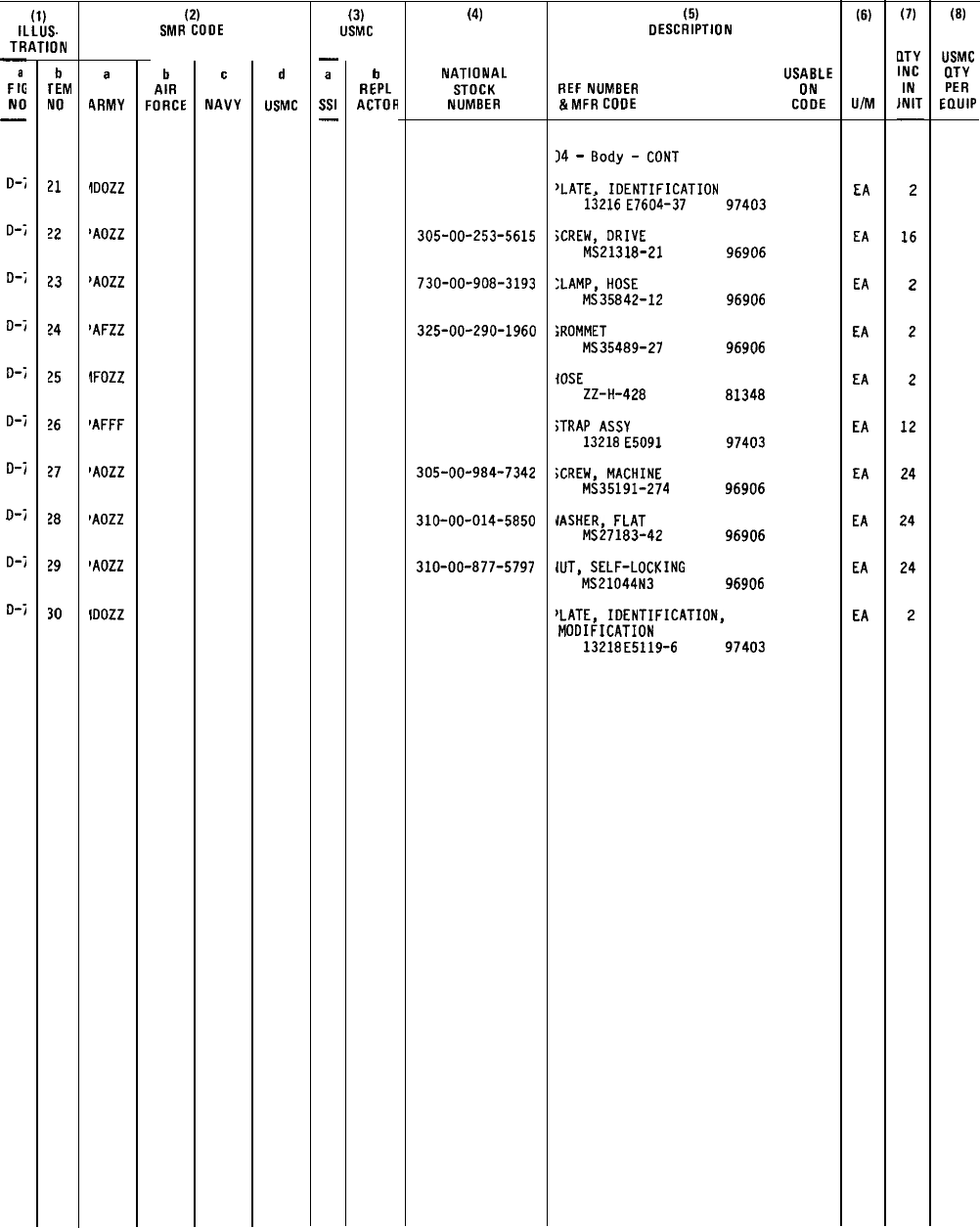
TM 5-6115-628-14&P
SECTION II
(1)
ILLUS.
TRATION
—
F
:G
NO
—
0-;
0-;
0-;
o-j
0-;
0-;
D-j
0-;
0-;
o-j
b
rEM
NO
21
?2
23
?4
25
?6
?7
?8
?9
30
a
CIRMY
!Oozz
lAOZZ
~AOZZ
~AFzz
!FOZZ
PAFFF
FAOZZ
FAOZZ
lAOZZ
!Oozz
(2)
SMR CODE
b
AIR
FORCE
c
NAVY
d
USMC
(3)
USMC
—
a
Ssl
—
b
REPL
ACTOH
(4)
NATIONAL
STOCK
NUMBER
305-00-253-5615
730-00-908-3193
325-00-290-1960
305-00-984-7342
310-00-014-5850
310-00-877-5797
(5)
DESCRIPTION
USABLE
REF
NUMBER ON
&MFR
COOE
COOE
)4
-
8ody
-
CONT
JLATE.
IDENTIFICATION
13216
E7604-37
;CREW,
DRIVE
MS21318-21
:LAMP,
HOSE
MS35842-12
;ROMMET
MS35489-27
{OSE
ZZ-H-428
;TRAP
ASSY
13218
E5091
;CREW,
MACHINE
MS35191-274
IASHER,
FLAT
MS27183-42
{UT,
SELF-LOCKING
MS21044N3
97403
96906
96906
96906
81348
97403
96906
96906
96906
‘LATE,
IDENTIFICATION,
MODIFICATION
13218
E5119-6 97403
(6)
U/M
EA
EA
EA
EA
EA
EA
EA
EA
EA
EA
(7)
DTY
INC
IN
JNIT
—
2
16
2
2
2
12
24
24
24
2
(B)
USMC
flTY
PER
EQUIP
D-32/(D-33 blank)
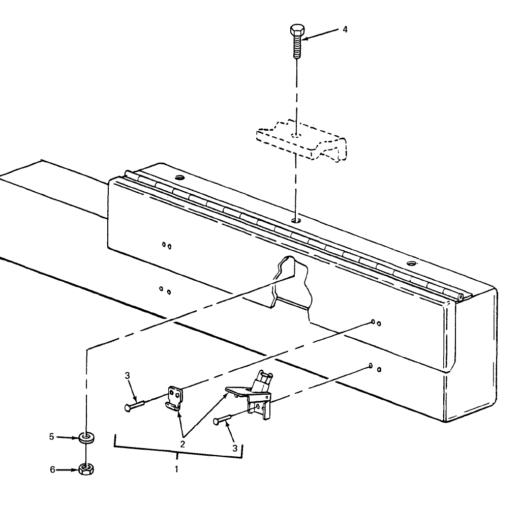
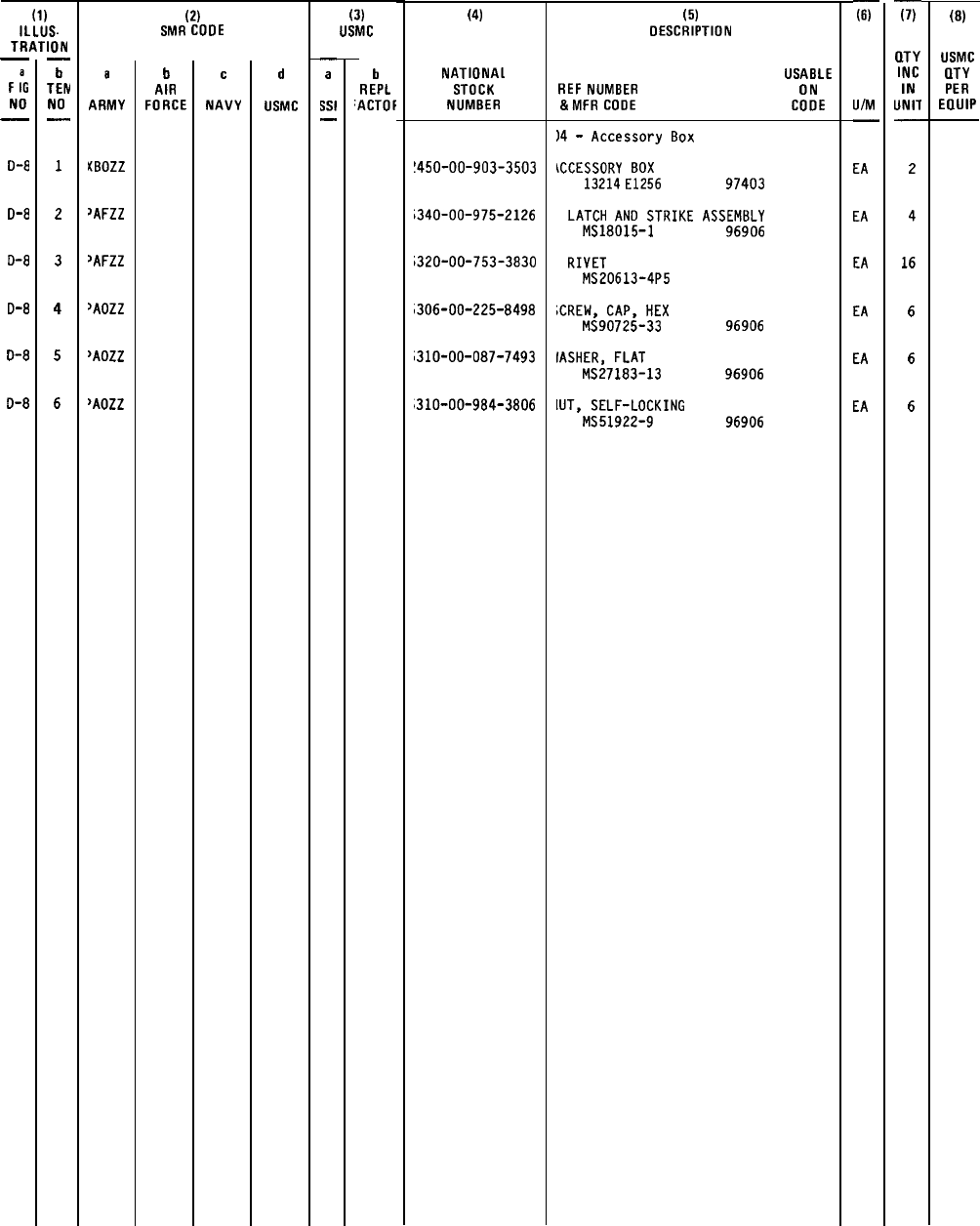
TM 5-6115-628-14&P
SECTION II
(1)
ILLUS.
TRATION
—
F
:G
NO
—
D-8
D-8
D-8
D-8
O-8
D-8
—
b
TEN
NO
—
1
2
3
4
5
6
a
ARMY
KBOZZ
>AFZZ
~AFZZ
~AOZZ
>AOZZ
>AOZZ
(2)
SMR COOE
b
AIR
FORCE
c
NAVY
d
USMC
(3)
USMC
.
a
w
.
b
REPL
‘ACTOF
(4)
NATIONAL
STOCK
NUMBER
!450-00-903-3503
i340-00-975-2126
i320-00-753-3830
,306-00-225-8498
;310-00-087-7493
310-00-984-3806
(5)
DESCRIPTION
USABLE
REF
NUMBER ON
&MFR
COOE
COOE
)4
-
Accessory
80X
\CCESSORY
80X
13214
E1256
97403
LATCH
ANO
STRIKE
ASSEM8LY
MS18015-1
96906
RIVET
MS20613-4P5
;CREW,
CAP,
HEX
MS90725-33
IASHER,
FLAT
MS27183-13
[UT,
SELF-LOCKING
MS51922-9
96906
96906
96906
F
U/M
—
EA
EA
EA
EA
EA
EA
F
(LTY
INC
IN
UNIT
—
2
4
16
6
6
6
(8)
USMC
CITY
PER
EllUIP
D-35
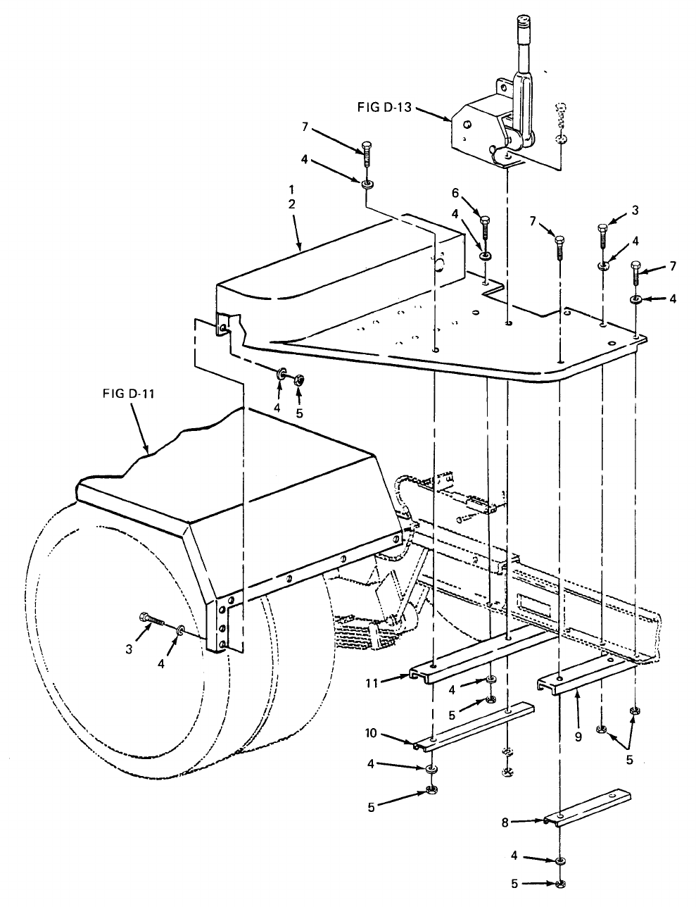
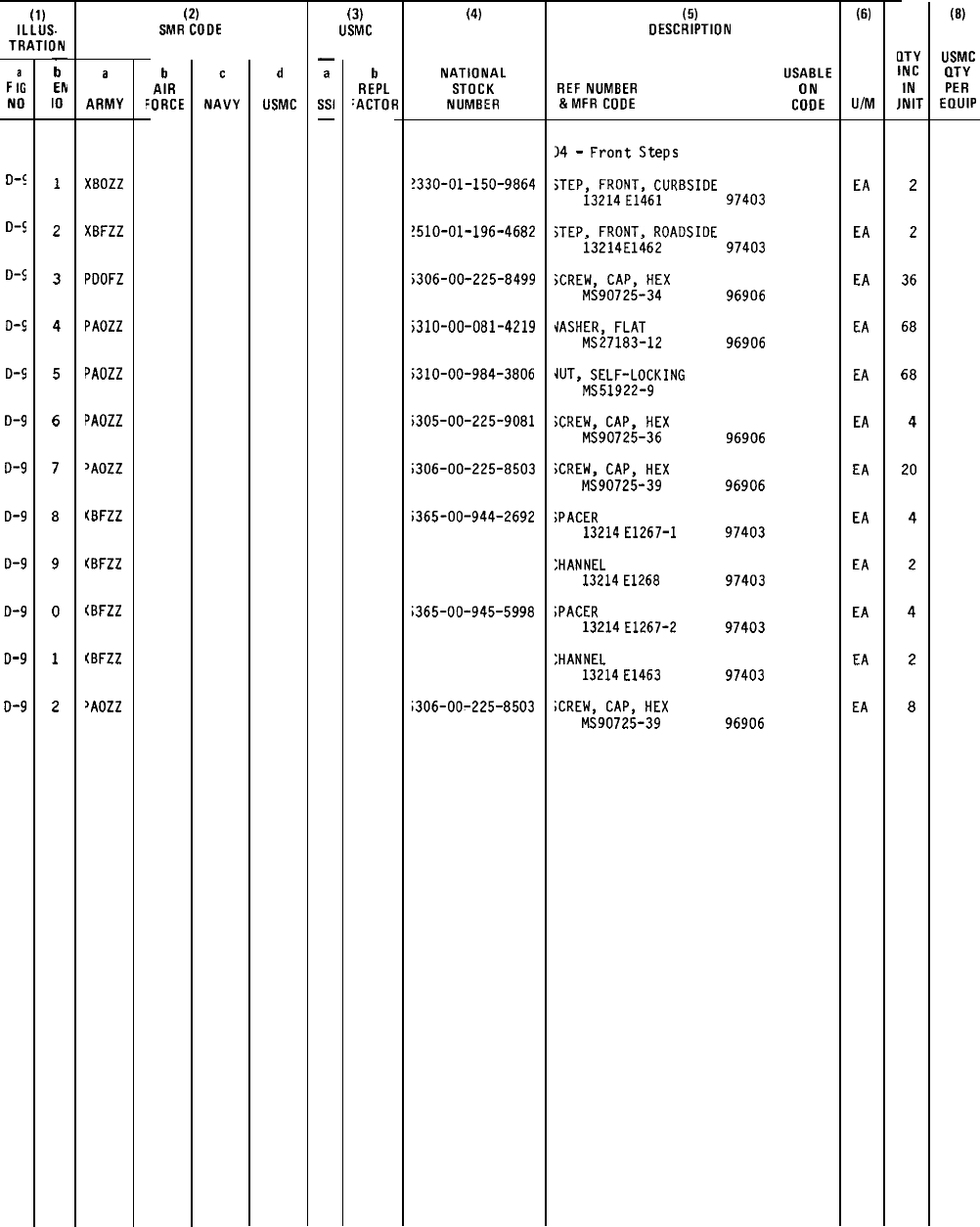
TM 5-6115-628-14&P
SECTION II
(1)
ILLUS.
TRATION
F
;G
NO
D+
D-$
D-$
D-$
D-$
D-9
D-9
D-9
D-9
D-9
D-9
D-9
—
b
EN
10
—
1
2
3
4
5
6
7
8
9
0
1
2
a
ARMY
XBOZZ
XBFZZ
PDOFZ
PAOZZ
PAOZZ
PAOZZ
~AOZZ
(BFZZ
KBFZZ
(BFZZ
[BFZZ
~AOZZ
(2)
SMR CODE
b
AIR
‘ORCE
c
NAVY
d
USMC
(3)
USMC
—
a
Ssl
—
b
REPL
‘ACTOR
(4)
NATIONAL
STOCK
NUMBER
?330-D1-150-9B64
?51O-O1-196-46B2
;306-00-225-8499
;310-00-081-4219
;310-00-984-3806
i305-00-225-9081
;306-00-225-8503
i365-OO-944-2692
;365-00-945-5998
;306-00-225-8503
(5)
DESCRIPTION
USABLE
REF
NUMBER ON
&MFR
CODE
CODE
)4
-
Front
Steps
STEP,
FRONT,
CURBSIOE
13214
E1461
97403
;TEP,
FRONT.
ROADSIDE
i3214E1462
jCREW.
CAP,
HEX
MS90725-34
JASHER.
FLAT
MS271B3-12
U-IT,
SELF-LOCKING
MS51922-9
;CREW,
CAP,
HEX
MS90725-36
;CREW,
CAP,
HEX
MS90725-39
;PACER
13214
E1267-I
:HANNEL
13214
E126B
;PACER
13214
E1267-2
:HANNEL
13214
E1463
;CREW,
CAP,
HEX
MS90725-39
97403
96906
96906
96906
96906
97403
97403
97403
97403
96906
(6)
U/M
EA
EA
EA
EA
EA
EA
EA
EA
EA
EA
EA
EA
LITY
INC
IN
JNIT
(B)
USMC
IITY
PER
EQUIP
2
2
36
68
68
4
20
4
2
4
2
8
D-37
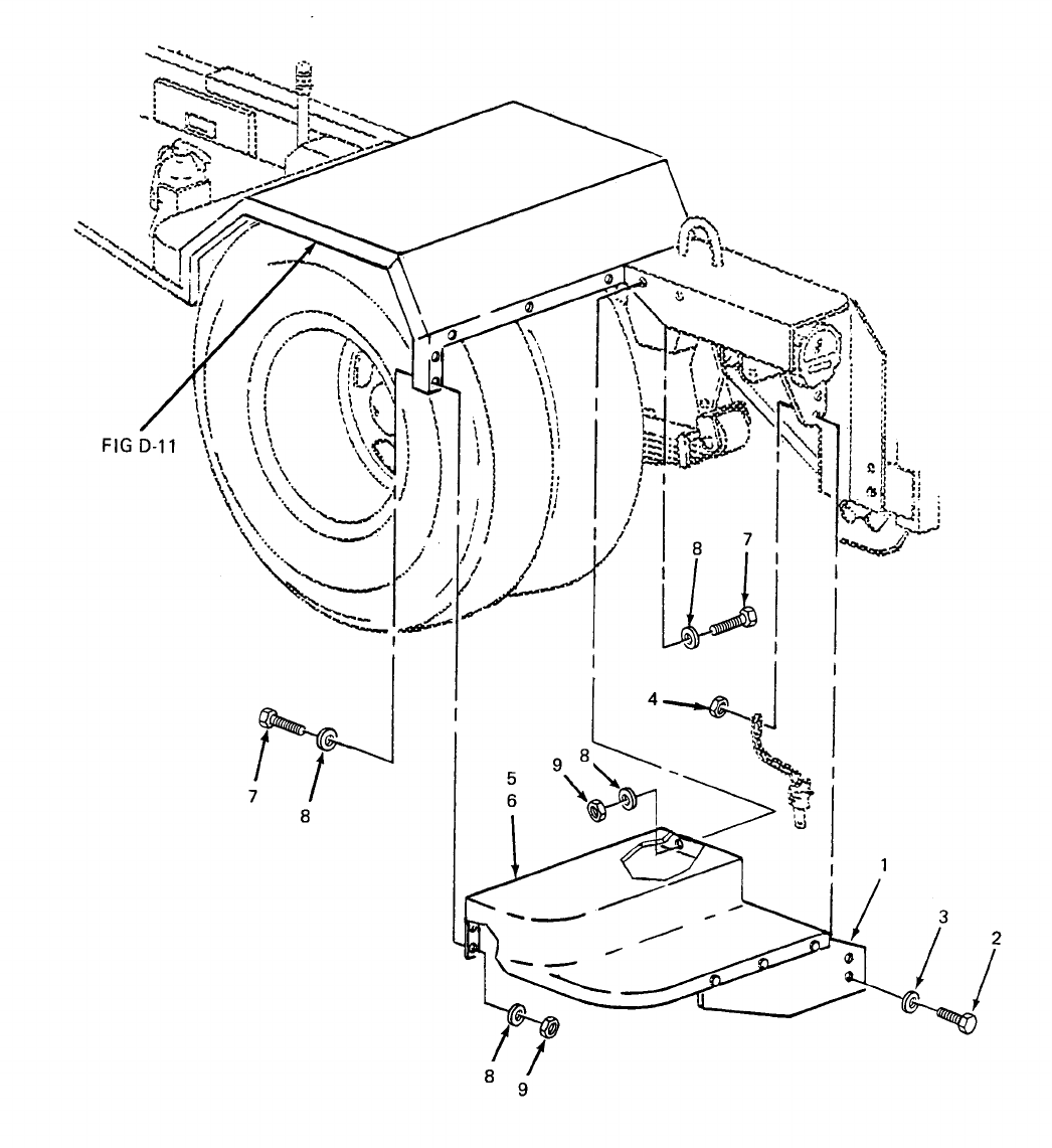
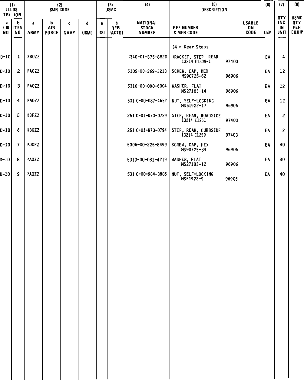
TM 5-6115-628-14&P
SECTION II
(1)
ILLUS.
TR1
F
:G
NO
D-10
o-1o
0-1o
0-1o
D-10
o-1o
0-1o
0-1o
D-10
ION
—
b
ITEM
NO
—
1
2
3
4
5
6
7
8
9
a
ARMY
XBOZZ
PAOZZ
PAOZZ
PAOZZ
KBFZZ
KBOZZ
POOFZ
>AOZZ
>AOZZ
(2)
SMR COOE
b
AIR
FORCE
c
NAVY
d
USMC
(3)
USMC
—
a
$S1
—
h
REPL
“ACTOF
(4)
NATIONAL
STOCK
NUMBER
;340-01-B75-8B20
5305-00-269-3213
5310-00-080-6004
531
O-OO-OB7-4652
251
O-O1-N73-O729
251
O-O1-N73-O794
5306-00-225-8499
5310-00-081-4219
531
O-OO-984-3BO6
(5)
DESCRIPTION
USABLE
REF
NUMBER ON
&MFRCOOE
COOE
)4
-
Rear
Steps
IRACKET,
STEP,
REAR
13214
E1309-1
SCREW,
CAP,
HEX
MS90725-62
WASHER,
FLAT
MS27183-14
NUT,
SELF-LOCKING
MS51922-17
STEP,
REAR,
ROADSIDE
13214
E1261
STEP,
REAR,
CURBSIDE
13214
E1259
SCREW,
CAP,
HEX
MS90725-34
WASHER,
FLAT
MS27183-12
NUT,
SELF-LOCKING
MS51922-9
97403
96906
96906
96906
97403
97403
96906
96906
96906
li-
U/M
EA
EA
EA
EA
EA
EA
EA
EA
EA
Ti-
QTY
INC
IN
UNIT
—
4
12
12
12
2
2
40
80
40
(8)
USMC
aTY
PER
EQUIP
D-39
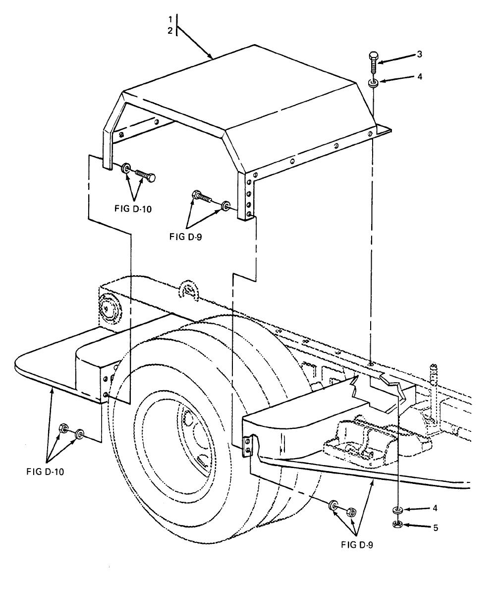
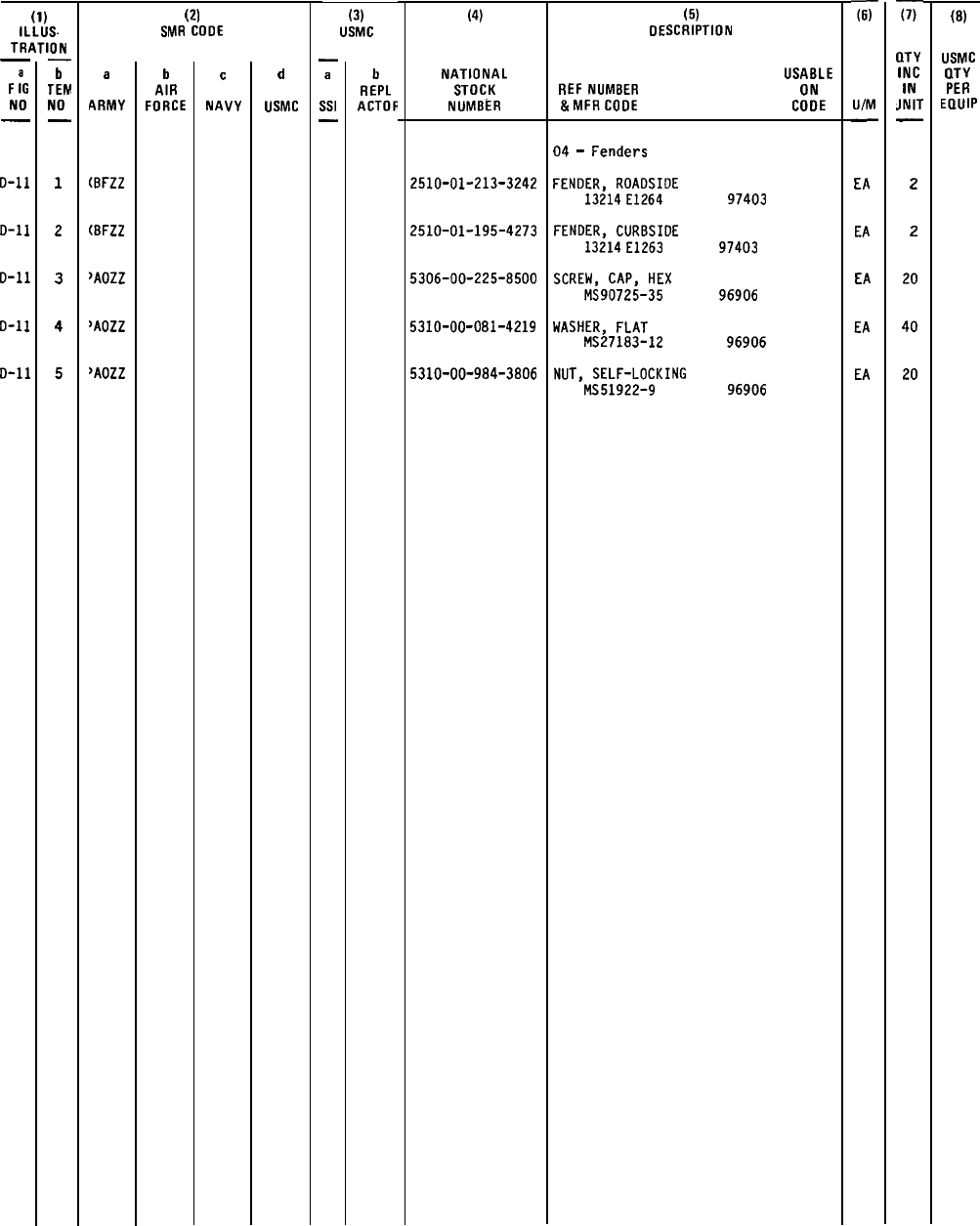
TM 5-6115-628-14&P
SECTION II
(1)
ILLUS.
TRATION
—
F
:G
NO
—
0-11
0-11
D-11
D-11
D-n
—
b
TEM
NO
—
1
2
3
4
5
a
ARMY
(BFZZ
(BFZZ
>AOZZ
>AOZZ
‘AOZZ
(2)
.-,
SMR COOE
b
AIR
FORCE
c
NAVY
d
USMC
(3)
USMC
—
a
Ssl
—
b
REPL
ACTOR
(4)
NATIONAL
STOCK
NUMBER
2510-01-213-3242
2510-01-195-4273
5306-00-225-8500
5310-00-081-4219
5310-00-984-3806
(5)
DESCRIPTION
USABLE
REF
NUMBER ON
&MFRCOOE
COOE
04
-
Fenders
FENOER,
ROAOSIDE
13214
E1264
FENOER,
CURBSIDE
13214
E1263
SCREW,
CAP,
HEX
MS90725-35
WASHER,
FLAT
MS27183-12
NUT,
SELF-LOCKING
MS51922-9
97403
97403
96906
96906
96906
x
U/M
—
E/l
EA
EA
EA
EA
-m
llTY
INC
IN
JNIT
—
2
2
20
40
20
(8)
USMC
(lTY
PER
EQUIP
D-41
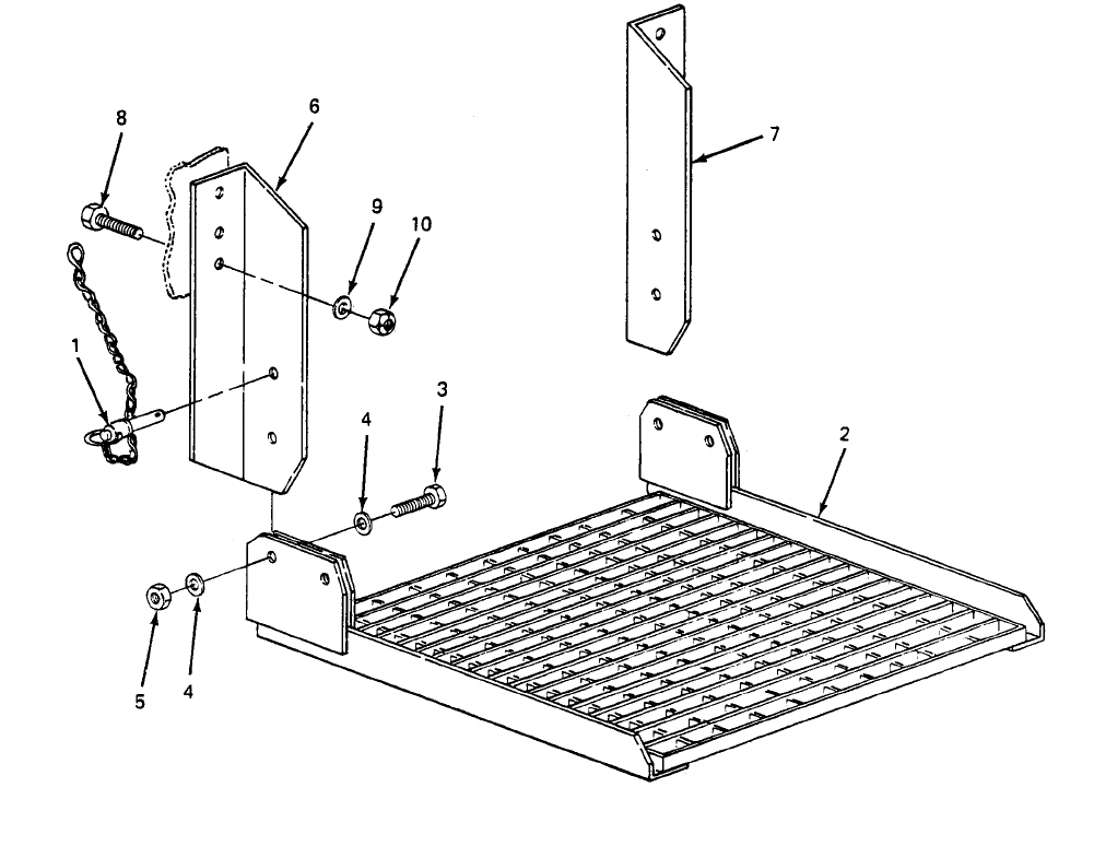
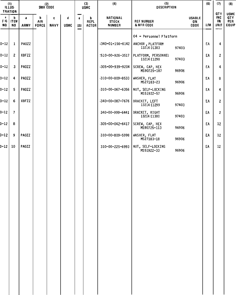
TM 5-6115-628-14&P
SECTION II
(1)
ILLUS.
TRATION
F
:G
NO
0-12
D-12
0-12
D-12
D-12
D-12
D-12
D-12
D-12
D-12
—
b
ITEM
NO
1
2
3
4
5
6
7
8
9
10
a
ARMY
PAOZZ
XBFZZ
PAOZZ
PAOZZ
PAOZZ
XBFZZ
PAOZZ
PAOZZ
(2)
SMR COOE
b
AIR
FORCE
c
NAVY
d
USMC
(3)
USMC
—
a
$S1
—
b
REPL
ACTOR
(4)
NATIONAL
STOCK
NUMBER
i340-01-156-6142
!510-00-926-3517
i305-00-939-9204
;31O-OO-BO9-8533
i310-00-067-6356
i340-00-087-7676
340-00-999-6441
,305-00-042-6417
310-00-809-5998
310-00-225-6993
(5)
DESCRIPTION
USABLE
REF
NUMBER ON
&MFR
CODE
COOE
04
-
Personnel
Platform
ANCHOR
,
PLATFORM
13214
D1303
PLATFORM,
PERSONNEL
13214
E1298
SCREW,
CAP,
HEX
MS90725-187
WASHER,
FLAT
MS271B3-23
NUT,
SELF-LOCKING
MS51922-57
BRACKET,
LEFT
13214
E1299
BRACKET,
RIGHT
13214
E1300
SCREW,
CAP,
HEX
MS90725-113
WASHER,
FLAT
MS27183-18
NUT,
SELF-LOCKING
MS51922-33
97403
97403
96906
96906
96906
97403
97403
96906
96906
96906
ii-
U/M
—
EA
EA
EA
EA
EA
EA
EA
EA
EA
EA
G
(ITY
INC
IN
UNIT
—
4
2
4
8
4
2
2
12
12
12
(8)
USMC
QTY
PER
EQUIP
D-43
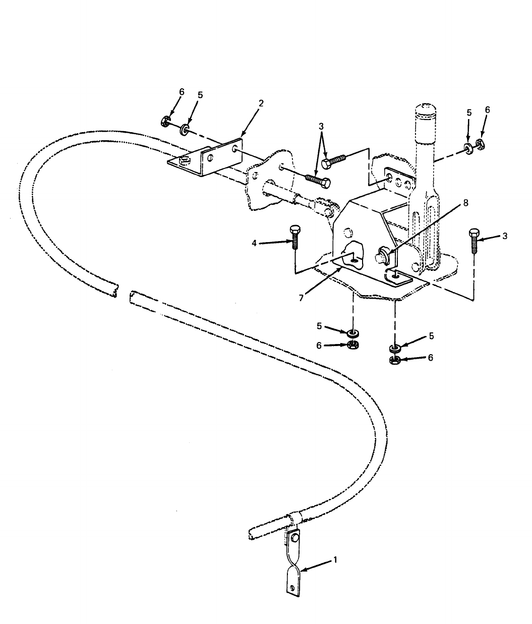
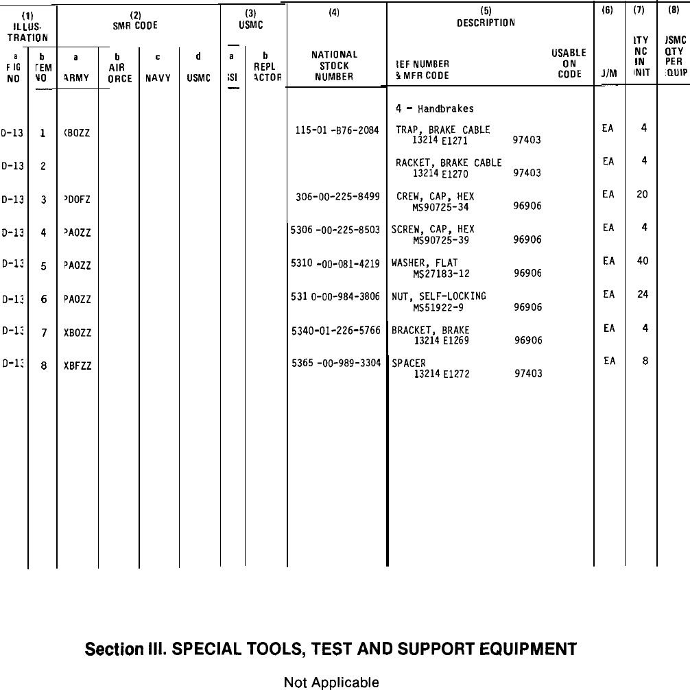
SECTION II
(1)
iLLUS-
TRATION
F
:G
NO
D-13
D-13
D-13
D-13
O-13
D-12
0-1:
D-1:
b
rEM
Vo
—
1
2
3
4
5
6
7
8
a
4RMY
(BOZZ
~DOFZ
>AOZZ
PAOZZ
PAOZZ
XBOZZ
XBFZZ
(a
SMR COOE
b
AIR
ORCE
c
NAVY
d
USMC
(3)
USMC
—
a
;s
I
—
b
REPL
4CTOR
(4)
NATIONAL
STOCK
NUMBER
115-01
-B76-20B4
306-00-225-8499
5306
-OO-225-B503
5310
-00-OB1-4219
531
O-OO-9B4-38O6
5340-01-226-5766
5365
-OO-9B9-3304
TM 5-6115-628-14&P
(5)
DESCRIPTION
USABLE
IEF
NUMBER ON
!iMFRCOOE CODE
4
-
Handbrakes
TRAP,
BRAKE
CABLE
13214
E1271
RACKET,
BRAKE
CABLE
13214
E1270
CREW,
CAP,
HEX
MS90725-34
SCREW,
CAP,
HEX
MS90725-39
WASHER,
FLAT
MS27183-12
NUT,
SELF-LOCKING
MS51922-9
BRACKET,
BRAKE
13214
E1269
SPACER
13214
E1272
97403
97403
96906
96906
96906
96906
96906
97403
(6)
JIM
.
EA
EA
EA
EA
EA
EA
EA
EA
(7)
lTY
NC
IN
INIT
4
4
20
4
40
24
4
8
(8)
JSMC
aTY
PER
.QUIP
Section
Ill.
SPECIAL
TOOLS,
TEST
AND
SUPPORT
EQUIPMENT
Not
Applicable
D-45

TM 5-6115-628-14&P
Section IV. NATIONAL STOCK NUMBER AND REFERENCE NUMBER INDEX
NSN Figure
No. Item
No. NSN Figure
No. Item
No.
2330-01-150-9864
2450-00-903-3503
2510-00-926-3517
2510-01-N73-0729
2510-01-N73-0794
2510-01-195-4273
2510-01-196-4682
2510-01-213-3242
4210-00-223-4857
4730-00-908-3193
5305-00-042-6417
5305-00-068-0502
5305-00-225-3840
5305-00-225-9081
5305-00-253-5615
5305-00-269-3213
5305-00-724-7222
5305-00-889-2999
5305-00-939-9204
5305-00-984-4984
5305-00-984-5691
5305-00-984-6194
5305-00-984-7342
5305-00-993-1848
5305-01-085-4495
5306-00-225-8498
5306-00-225-8499
5306-00-225-8500
5306-00-225-8503
5307-00-227-1741
5310-00-009-7694
5310-00-014-5850
5310-00-022-8847
5310-00-045-3296
5310-00-045-4007
5310-00-045-5214
5310-00-067-6356
5310-00-080-6004
5310-00-080-8495
5310-00-081-4219
5310-00-082-1404
5310-00-087-4652
5310-00-087-7493
5310-00-088-0551
5310-00-088-1251
5310-00-184-8971
5310-00-187-2413
5310-00-225-6993
5310-00-269-4040
5310-00-543-4717
5310-00-584-7995
5310-00-809-4058
5310-00-809-5998
D-9
D-8
D-12
D-10
D-10
D-11
D-9
D-11
D-7
D-7
D-12
D-3
D-7
D-3
D-9
D-7
D-7
D-10
D-1
D-3
D-12
D-3
D-7
D-3
D-7
D-3
D-5
D-3
D-8
D-9
D-10
D-13
D-11
D-9
D-9
D-13
D-3
D-7
D-3
D-7
D-3
D-7
D-3
D-3
D-6
D-12
D-7
D-10
D-3
D-9
D-10
D-11
D-13
D-3
D-7
D-10
D-8
D-3
D-3
D-7
D-3
D-3
D-7
D-12
D-1
D-3
D-7
D-3
D-7
D-3
D-3
D-7
D-12
1
1
2
5
6
2
2
1
5
23
8
49
8
70
6
22
2
2
2
27
3
51
6
21
27
3
8
43
4
3
7
3
3
7
12
4
65
17
40
28
69
16
4
52
11
5
3
3
46
4
8
4
5
53
4
4
5
28
72
10
64
67
14
10
5
63
12
66
13
44
71
9
9
5310-00-809-8533
5310-00-809-8546
5310-00-823-8803
5310-00-877-5797
5310-00-948-9708
5310-00-984-3806
5310-00-997-1888
5310-01-B75-1034
5310-01-004-9129
5310-01-026-5824
5310-01-034-2835
5310-01-185-0586
5320-00-117-6815
5320-00-753-3830
5325-00-282-7471
5325-00-290-1960
5325-00-788-5635
5325-01-077-3444
5330-00-079-7840
5340-00-087-7676
5340-00-914-2578
5340-00-975-2126
5340-00-999-6277
5340-00-999-6441
5340-01-B75-8820
5340-01-156-6142
5340-01-226-5766
5365-00-838-0422
5365-00-944-2692
5365-00-945-5998
5365-00-989-3340
5925-01-098-7829
5935-00-801-6617
5935-01-154-2472
5935-01-175-8419
5940-00-113-8185
5940-00-113-8190
5940-00-115-2676
5940-00-115-2677
5940-00-115-4992
5940-00-143-4773
5340-00-801-2957
5970-01-B76-2191
5970-01-B76-2192
5970-01-B76-2327
6115-00-118-1244
6115-01-B76-2084
6115-01-B76-2182
6120-01-090-2789
6145-00-395-8799
6145-00-578-6594
6145-00-578-6595
6145-00-578-7517
6145-00-578-7518
6145-01-038-5963
6150-00-170-6967
6150-01-096-9024
6150-01-170-6968
6210-01-160-8026
9905-01-085-7703
9905-01-179-7336
D-12
D-3
D-1
D-3
D-5
D-7
D-3
D-8
D-9
D-10
D-11
D-13
D-3
D-4
D-7
D-3
D-7
D-6
D-1
D-3
D-8
D-4
D-7
D-4
D-3
D-3
D-12
D-7
D-8
D-7
D-12
D-10
D-12
D-13
D-3
D-9
D-9
D-13
D-3
D-5
D-2
D-3
D-6
D-2
D-5
D-6
D-6
D-5
D-6
D-7
D-6
D-3
D-3
D-3
D-3
D-1
D-13
D-3
D-3
D-7
D-5
D-5
D-6
D-5
D-6
D-2
D-5
D-2
D-5
D-3
D-7
D-3
4
5
4
62
9
29
39
6
5
9
5
6
45
2
14
68
15
10
3
8
3
4
24
6
12
26
6
11
2
7
7
1
1
7
11
8
10
8
55
11
2
25
25
4
6
3
4
5
14
19
23
20
41
47
42
1
1
17
1
18
7
4
13
12
24
3
2
1
1
57
20
32
D-46
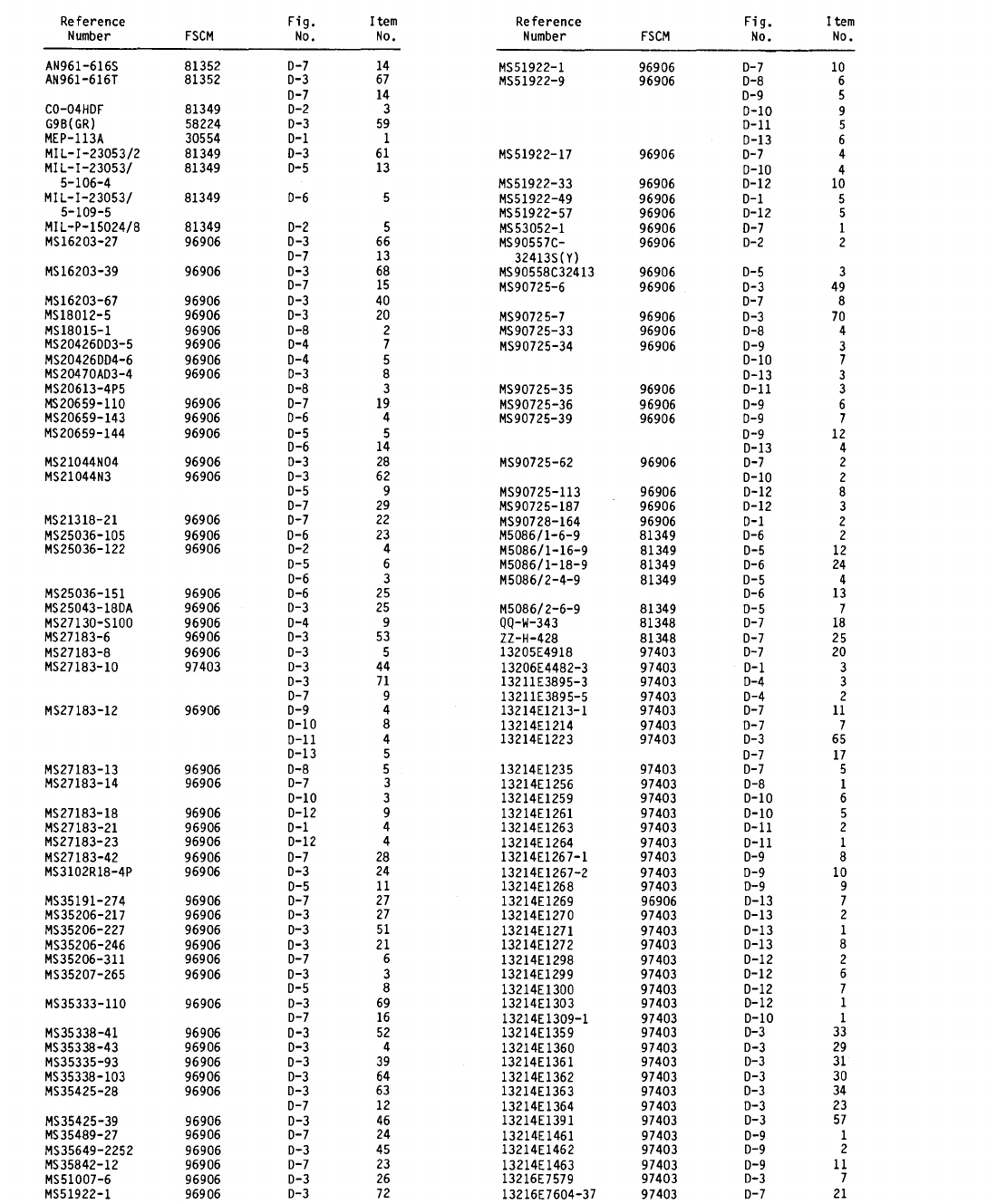
Section IV. NATIONAL STOCK NUMBER AND
TM 5-6115-628-14&P
REFERENCE NUMBER INDEX - CONT
D-47
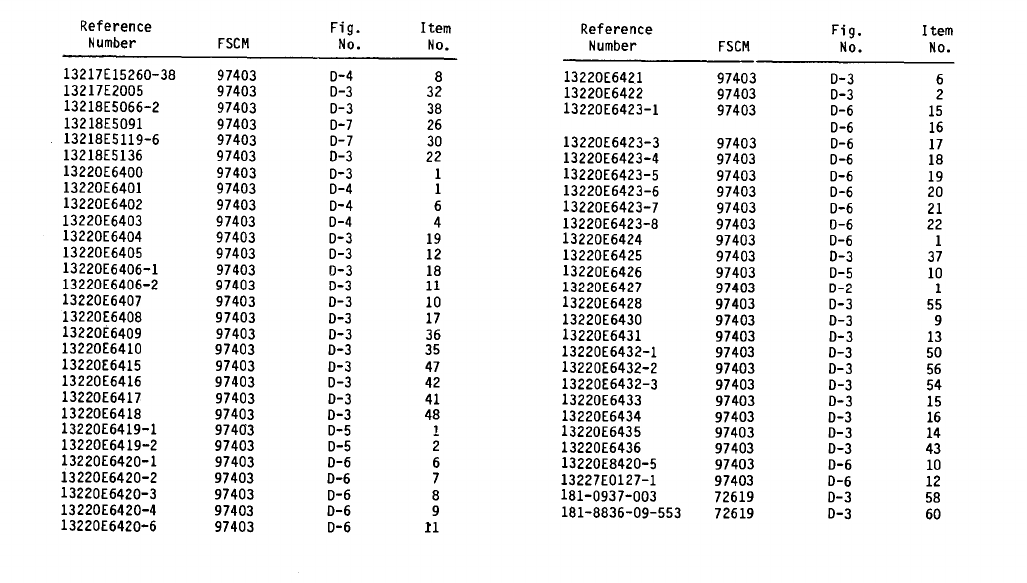
TM 5-6115-628-14&P
Section IV. NATIONAL STOCK NUMBER AND REFERENCE NUMBER INDEX - CONT
Section V. REFERENCE DESIGNATOR INDEX
Not Applicable
D-48

TM 5-6115-628-14&P
By Order of the Secretary of the Army:
Official:
R. L. DILWORTH
Brigadier General, United States Army
The Adjutant General
CARL E. VUONO
General, United States Army
Chief of Staff
DISTRIBUTION:
To be distributed in accordance with DA 12-25A, Operator, Unit, Direct Support
and General Support Maintenance Requirements for Generator Set, Diesel Engine
Driven, Trailer Mounted (TM 5-6115-594 Series).
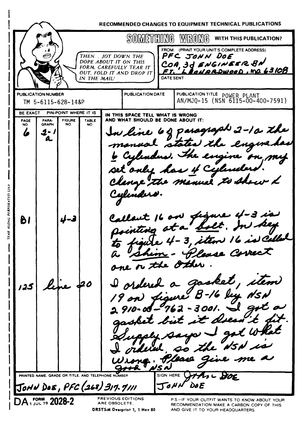

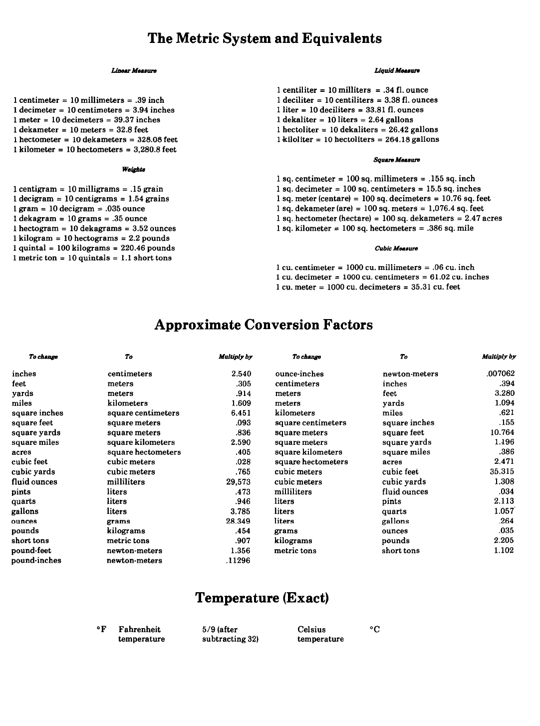
PIN: 064446-000
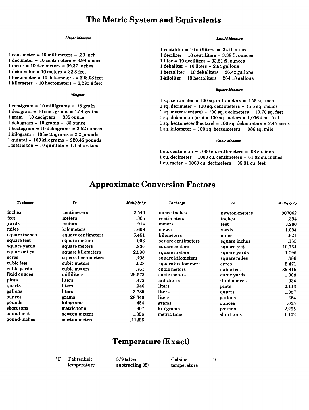
PIN: 064446-000
