6675 TM 5 348 13 And P
User Manual: 6675
Open the PDF directly: View PDF ![]() .
.
Page Count: 461 [warning: Documents this large are best viewed by clicking the View PDF Link!]
TM 5-6675-348-13&P
TECHNICAL MANUAL
OPERATOR’S,
UNIT AND
DIRECT SUPPORT
MAINTENANCE MANUAL
(INCLUDING REPAIR PARTS
AND SPECIAL TOOLS LIST)
Laser Leveling
Equipment (LLE)
USED WITH MODEL 130G Grader,
D7F, D7G, D7H, and D7R Dozers,
613B and 621B Scrapers,
and HYEX
Contract No. DAAE07-01-C-T009
HEADQUARTERS, DEPARTMENT OF THE ARMY NOVEMBER 2005
Approved for public release;
distribution is unlimited.
INTRODUCTION 1-1
GRADIO® DISPLAY SYSTEM (D7F, D7G, D7H,
AND D7R DOZERS AND 613B AND 621B
SCRAPERS) 2-1
BLADE PRO® MOTOR GRADER CONTROL
SYSTEM (130G GRADER) 3-1
BUCKET-PRO™ SYSTEM (HYEX) 4-1
1145-2 LASER TRANSMITTER, 1275 LASER
RECEIVER, AND ELEVATING BASE AND TRIPOD,
USED WITH 130G GRADER, D7F, D7G, D7H, AND
D7R DOZERS, 613B AND 621B SCRAPERS, AND
HYEX 5-1
REFERENCES A-1
MAINTENANCE ALLOCATION CHART
(MAC) B-1
REPAIR PARTS AND SPECIAL TOOLS LIST
(RPSTL) C-1
COMPONENTS OF END ITEM AND BASIC
ISSUE ITEMS LISTS D-1
ADDITIONAL AUTHORIZED LIST E-1
EXPENDABLE/DURABLE SUPPLIES AND
MATERIALS LIST F-1
DECAL GUIDE G-1
ILLUSTRATED LIST OF MANUFACTURED
ITEMS H-1
TORQUE LIMITS J-1
MANDATORY REPLACEMENT PARTS K-1

TM 5-6675-348-13&P
a
Degreasing Solvent (MIL-PRF-680, Type II) is TOXIC and flammable. Wear protective goggles and
gloves, use only in a well-ventilated area, avoid contact with skin, eyes, and clothes, and do not
breathe vapors. Keep away from heat or flame. Never smoke when using solvent; the flash point for
degreasing solvent type II is 200º F (93º C). Failure to comply may result in injury or death to
personnel.
If personnel become dizzy while using cleaning solvent, immediately get fresh air and medical help.
If solvent contacts skin or clothes, flush with cold water. If solvent contacts eyes, immediately flush
eyes with water and get immediate medical attention. Do not use diesel fuel, gasoline, or benzene
(benzol) for cleaning.
Adhesives, solvents, and sealing compounds burn easily and give off vapors that are harmful to the
skin and clothing. To avoid injury or death, keep away from open fire when using these materials,
and use only in well-ventilated areas. If adhesives, solvents, or sealing compounds contact the skin
or clothing, wash immediately with soap and water, and rinse thoroughly. Failure to comply may
result in injury or death to personnel.
Unsafe welding practices can cause serious injury from fire, explosions, or harmful agents. Allow
only authorized personnel to weld or cut metals, and follow safety precautions in TC 9-237.
Protective clothing and goggles must be worn, adequate protective equipment must be used, a
suitable fire extinguisher must be kept nearby, and requirements of TC 9-237 must be strictly
followed. Failure to comply may result in serious injury or death to personnel.
Allow solder to cool before handling wire. Failure to comply may result in injury to personnel.
CARC paint contains isocyanate (HDI), which is highly irritating to skin and respiratory system.
High concentrations of HDI can produce symptoms of itching and reddening of skin, a burning
sensation in throat and nose, and watering of the eyes. In extreme concentrations, HDI can cause
cough, shortness of breath, pain during respiration, increased sputum production, and chest
tightness. The following precautions must be taken whenever using CARC paint:
TM 5-6675-348-13&P
b
ALWAYS use air line respirators when using CARC paint, unless air sampling shows exposure to
be below standards. Use chemical cartridge respirator if air sampling is below standards.
DO NOT let skin or eyes come in contact with CARC paint. Always wear protective equipment
(gloves, ventilation mask, safety goggles, etc.).
DO NOT use CARC paint without adequate ventilation.
NEVER weld or cut CARC-coated materials.
DO NOT grind or sand painted equipment without high-efficiency air purifying respirators in use.
BE AWARE of CARC paint exposure symptoms; symptoms can occur a few days after initial
exposure. Seek medical help immediately if symptoms are detected.
Battery acid (electrolyte) is extremely harmful. Always wear safety goggles and rubber gloves, and
do not smoke when performing maintenance on batteries. Injury will result if acid contacts skin or
eyes. Wear rubber apron to prevent damage to clothing.
Remove all jewelry, such as rings, dog tags, bracelets, etc. If jewelry contacts Battery Terminal, a
direct short may result in instant heating of tools, damage to equipment, and injury or death to
personnel.
Exercise extreme caution when working under tilt platform. Falling platform could result in serious
injury or death to personnel.

TM 5-6675-348-13&P
c/(d Blank)
Turn battery disconnect switch OFF prior to performing maintenance in immediate battery area or
working on electrical system. Failure to comply can result in electrical shock to personnel or damage
to equipment.
Always disconnect the negative (-) battery cable before servicing the battery or positive (+) battery
cable. Failure to comply can result in electrical shock to personnel or damage to electrical system.
Do not allow battery cable ends to contact each other or the machine. Failure to comply can result
in damage to battery or electrical system.
Do not smoke when using cleaning solvent. Never use it near an open flame. Be sure there is a fire
extinguisher nearby and use cleaning solvent only in a well-ventilated area.
Use caution when using cleaning solvents. Cleaning solvents evaporate quickly and can irritate
exposed skin if solvents contact skin. In cold weather, contact of exposed skin with cleaning solvents
can cause frostbite.
Do not start or move Blade Pro® Motor Grader Control System while anyone is under the 130G
Grader. Failure to comply could result in severe injury or death to personnel.
Keep all personnel and equipment away from blade during calibration. Blade may move suddenly,
causing injury or death to personnel, or damage to equipment.
To avoid injury to personnel, ensure 130G Grader is shut OFF and blade is on the ground.
Do not look into 1145-2 Laser Transmitter for a long period of time. Failure to comply may cause
injury to personnel.

TM 5-6675-348-13&P
A/(B Blank)
INSERT LATEST UPDATED PAGES / WORK PACKAGES. DESTROY SUPERSEDED DATA.
LIST OF EFFECTIVE PAGES / WORK PACKAGES
NOTE: The portion of text affected by the changes is indicated by a vertical line in the outer margins of the page. Changes
to illustrations are indicated by miniature pointing hands. Changes to wiring diagrams are indicated by shaded
areas.
Dates of issue for original and changed pages / work packages are:
Original......... 0... 30 November 2005
TOTAL NUMBER OF PAGES FOR FRONT AND REAR MATTER IS 24 AND TOTAL
NUMBER OF WORK PACKAGE PAGES IS 436 CONSISTING OF THE FOLLOWING:
Page / WP
No. *Change
No. Page / WP
No. *Change
No. Page / WP
No. *Change
No.
Front Cover 0 5-1 — 5-32 0 D-1 — D-2 0
a — d 0 A-1 — A-2 0 E-1 — E-2 0
A — B 0 B-1 — B-10 0 F-1 — F-2 0
i — iv 0 C-1 — C-4 0 G-1 — G-4 0
1-1 — 1-6 0 FIG. 1 — FIG. 56-1 0 H-1 — H-2 0
2-1 — 2-32 0 KITS-1 — KITS-6 0 J-1 — J-8 0
3-1 — 3-124 0 INDEX-1 — INDEX-4 0 K-1 — K-2 0
4-1 — 4-76 0
*Zero in this column indicates an original page.

TM 5-6675-348-13&P
i
TECHNICAL MANUAL HEADQUARTERS
DEPARTMENT OF THE ARMY
No. 5-6675-348-13&P Washington, DC, 30 November 2005
OPERATOR’S, UNIT AND DIRECT SUPPORT
MAINTENANCE MANUAL
(INCLUDING REPAIR PARTS AND SPECIAL TOOLS LIST)
FOR
LASER LEVELING EQUIPMENT (LLE)
USED WITH MODEL 130G Grader, D7F, D7G, D7H,
and D7R Dozers, 613B and 621B Scrapers, and HYEX
Contract No. DAAE07-01-C-T009
TABLE OF CONTENTS
Page
CHAPTER 1 INTRODUCTION...................................................................................................... 1-1
CHAPTER 2 GRADIO® DISPLAY SYSTEM (D7F, D7G, D7H, AND D7R DOZERS AND 613B
AND 621B SCRAPERS) .......................................................................................... 2-1
Section I Gradio® Display System General Information........................................................ 2-1
Section II Gradio® Display System Preventive Maintenance Checks and Services (PMCS). 2-6
Section III Gradio® Display System Operation.......................................................................... 2-10
Section IV Gradio® Display System Troubleshooting ............................................................... 2-13
Section V Gradio® Display System Maintenance..................................................................... 2-19
CHAPTER 3 BLADE PRO® MOTOR GRADER CONTROL SYSTEM (130G GRADER)........... 3-1
Section I Blade Pro® Motor Grader Control System General Information............................ 3-2
Section II Blade Pro® Motor Grader Control System PMCS ................................................... 3-16
Section III Blade Pro® Motor Grader Control System Operation............................................. 3-22
Section IV Blade Pro® Motor Grader Control System Troubleshooting................................... 3-60
REPORTING ERRORS AND RECOMMENDING IMPROVEMENTS
You can help improve this publication. If you find any mistakes, or if you know of a way to
improve the procedures, please let us know. Submit your DA Form 2028 (Recommended
Changes to Publications and Blank Forms), through the Internet, on the Army Electronic
Product Support (AEPS) website. The Internet address is http://aeps.ria.army.mil. If you need
a password, scroll down and click on “ACCESS REQUEST FORM.” The DA Form 2028 is
located in the ONLINE FORMS PROCESSING section of the AEPS. Fill out the form and click
on SUBMIT. Using this form on the AEPS will enable us to respond quicker to your comments
and better manage the DA Form 2028 program. You may also mail, fax, or e-mail your letter or
DA Form 2028 direct to: AMSTA-LC-LPIT / TECH PUBS, TACOM-RI, 1 Rock Island Arsenal,
IL, 61299-7630. The e-mail address is TACOM-TECH-PUBS@ria.army.mil. The fax number is
(DSN) 793-0726 or Commercial (309) 782-0726.
TM 5-6675-348-13&P
ii
TABLE OF CONTENTS (CONT)
Page
CHAPTER 3 BLADE PRO® MOTOR GRADER CONTROL SYSTEM (130G GRADER)
(CONTINUED)
Section V Blade Pro® Motor Grader Control System Troubleshooting Error Messages........ 3-70
Section VI Blade Pro® Motor Grader Control System Error Log ............................................. 3-72
Section VII Blade Pro® Motor Grader Control System Maintenance........................................ 3-82
CHAPTER 4 BUCKET-PRO™ SYSTEM (HYEX)......................................................................... 4-1
Section I Bucket-Pro™ System Introduction........................................................................... 4-2
Section II Bucket-Pro™ System PMCS ..................................................................................... 4-4
Section III Bucket-Pro™ System Operation............................................................................... 4-8
Section IV Bucket-Pro™ System Troubleshooting..................................................................... 4-30
Section V Bucket-Pro™ System Maintenance.......................................................................... 4-37
CHAPTER 5 1145-2 LASER TRANSMITTER, 1275 LASER RECEIVER, AND ELEVATING BASE
AND TRIPOD, USED WITH 130G GRADER, D7F, D7G, D7H, AND D7R DOZERS,
613B AND 621B SCRAPERS, AND HYEX.............................................................. 5-1
Section I General Information.................................................................................................. 5-1
Section II 1145-2 Laser Transmitter, 1275 Laser Receiver, and Elevating Base and
Tripod PMCS.............................................................................................................. 5-15
Section III Operation.................................................................................................................... 5-19
Section IV 1145-2 Laser Transmitter Troubleshooting ............................................................. 5-27
APPENDIX A REFERENCES .......................................................................................................... A-1
APPENDIX B MAINTENANCE ALLOCATION CHART (MAC)................................................... B-1
Section I Introduction................................................................................................................ B-1
Section II MAC............................................................................................................................ B-4
Section III Tool and Test Equipment Requirements .................................................................. B-9
Section IV Remarks ..................................................................................................................... B-9
APPENDIX C REPAIR PARTS AND SPECIAL TOOLS LIST (RPSTL)........................................ C-1
Section I Introduction................................................................................................................ C-1
Section II Repair Parts List........................................................................................................ C-3
Section III Cross-Reference Indexes........................................................................................ Index-1
APPENDIX D COMPONENTS OF END ITEM AND BASIC ISSUE ITEMS LISTS ................... D-1
APPENDIX E ADDITIONAL AUTHORIZED LIST........................................................................ E-1
APPENDIX F EXPENDABLE/DURABLE SUPPLIES AND MATERIALS LIST......................... F-1
Section I Introduction................................................................................................................ F-1
Section II Expendable and Durable Items................................................................................. F-2
APPENDIX G DECAL GUIDE.......................................................................................................... G-1
Section I Introduction................................................................................................................ G-1
Section II Decals ......................................................................................................................... G-2
APPENDIX H ILLUSTRATED LIST OF MANUFACTURED ITEMS........................................... H-1
APPENDIX J TORQUE LIMITS...................................................................................................... J-1
Section I Introduction................................................................................................................ J-1
Section II Torque Limits............................................................................................................. J-1
APPENDIX K MANDATORY REPLACMENT PARTS................................................................... K-1
Section I Introduction................................................................................................................ K-1
Section II Mandatory Replacement Parts.................................................................................. K-1
TM 5-6675-348-13&P
iii
LIST OF TABLES
Number Title Page
2-1. Gradio® Display System Equipment Data ................................................................................ 2-5
2-2. Gradio® Display System Operator’s PMCS (Before/After) ....................................................... 2-8
2-3. Gradio® Display System Fault Index......................................................................................... 2-13
2-4. Gradio® Display System Troubleshooting ................................................................................. 2-14
3-1. Blade Pro® Motor Grader Control System Operator Interface Box Light Indicators ............. 3-8
3-2. Blade Pro® Motor Grader Control System Operator Interface Box Controls.......................... 3-11
3-3. Blade Pro® Motor Grader Control System Equipment Data.................................................... 3-15
3-4. Blade Pro® Motor Grader Control System Operator’s PMCS (Before/After)........................... 3-19
3-5. Blade Pro® Motor Grader Control System PMCS (Quarterly)................................................. 3-21
3-6. Blade Pro® Motor Grader Control System Fault Index............................................................ 3-60
3-7. Blade Pro® Motor Grader Control System Troubleshooting..................................................... 3-61
3-8. Error Messages............................................................................................................................ 3-71
3-9. Error Log...................................................................................................................................... 3-72
3-10. Error-to-Source Relationships .................................................................................................... 3-74
4-1. Bucket-Pro™ System Operator’s PMCS (Before/After)............................................................. 4-6
4-2. CUSTOMIZE Menu Options....................................................................................................... 4-17
4-3. System Alarms............................................................................................................................. 4-25
4-4. Bucket-Pro™ System Fault Index..............................................................................................4-30
4-5. Bucket-Pro™ System Troubleshooting....................................................................................... 4-31
5-1. 1145-2 Laser Transmitter, 1275 Laser Receiver, and Elevating Base
and Tripod System Operator’s PMCS (Before/After)............................................................. 5-18
5-2. 1145-2 Laser Transmitter Fault Index....................................................................................... 5-27
5-3. 1145-2 Laser Transmitter Troubleshooting ............................................................................... 5-28
B-1 Gradio® Control System Maintenance Allocation Chart.......................................................... B-4
B-2 Blade Pro® Motor Grader Control System Maintenance Allocation Chart ............................. B-5
B-3 Bucket-Pro™ Control System Maintenance Allocation Chart.................................................. B-7
B-4 Transmitter Control System Maintenance Allocation Chart.................................................... B-8
J-1 Torque Limits for Wet Flange Nuts............................................................................................J-2
J-2 Torque Limits for Wet Socket Head Capscrews......................................................................... J-2
J-3 Torque Limits for Dry Fasteners................................................................................................ J-4
J-4 Torque Limits for Wet Fasteners................................................................................................ J-5
J-5 Torque Limits for 37-Degree Flare Hose Connections............................................................... J-7
J-6 Torque Limits for 45-Degree Flare Hose Connections............................................................... J-7
J-7 Torque Limits for ORS Preformed Packing Face Seal Hose Connections................................ J-8
J-8 Torque Limits for NPSM Swivel Connections............................................................................ J-8
K-1 Mandatory Replacement Parts - Gradio®.................................................................................. K-1
K-2 Mandatory Replacement Parts - Blade Pro®............................................................................. K-2
K-3 Mandatory Replacement Parts - Bucket-Pro™.......................................................................... K-2
TM 5-6675-348-13&P
iv
HOW TO USE THIS MANUAL
This manual is for commercially available equipment that has been approved for military use. This is a
Commercial Off-The-Shelf (COTS) Manual with supplemental data to support military-specific maintenance. This manual is
designed to help operate and maintain the Laser Leveling Equipment. Listed below are some of the features included in this
manual to help locate and use the needed information:
• A front cover Table of Contents is provided for quick reference to chapters and sections that will
be used often.
• Warning, caution, and note headings, subject headings, and other essential information are
printed in bold type, making them easier to see.
• In addition to text, there are exploded-view illustrations showing how to take a component off and
put it back on. Cleaning and inspection criteria are also included where necessary.
• Chapter 1 of this manual describes the Laser Leveling Equipment and provides equipment data.
• Chapter 2 of the manual describes the Gradio® Display System, used with dozers and scrapers.
• Chapter 3 of the manual describes the Blade Pro® Motor Grader Control System, used with
130G Graders.
• Chapter 4 of the manual describes the Bucket-Pro™ System, used with Hydraulic Excavator
(HYEX).
• Chapter 5 of the manual describes the use of the 1145-2 Laser Transmitter and Tripod, that can
be used with the Gradio® Display System, the Blade Pro® Motor Grader Control System, or the
Bucket-Pro™ System.
• Appendix A covers the References used in this manual.
• Appendix B covers the Maintenance Allocation Chart (MAC).
• Appendix C covers the Repair Parts and Special Tools List (RPSTL).
• Appendix D covers the Components of End Item (COEI) and Basic Issue Items (BII) Lists.
• Appendix E covers the Additional Authorized List (AAL).
• Appendix F covers the Expendable/Durable Supplies and Materials List.
• Appendix G covers the Decal Guide.
• Appendix H covers the Illustrated List of Manufactured Items.
• Appendix J covers the Torque Limits.
• Appendix K covers the Mandatory Replacement Parts.
Follow these guidelines when using this manual:
• Read all WARNINGS and CAUTIONS before performing any procedures.
• Read through this manual and become familiar with the contents.
• Read the entire procedure before attempting to perform any maintenance task.
TM 5-6675-348-13&P
1-1
CHAPTER 1
INTRODUCTION
Content Para Page
Scope........................................................................................................................................... 1-1 1-1
Maintenance Forms and Records.............................................................................................. 1-2 1-1
Equipment Improvement Report and Maintenance Digest (EIR MD) and Equipment
Improvement Report and Maintenance Summary (EIR MS)............................................. 1-3 1-2
Submitting Quality Deficiency Reports (QDR)........................................................................ 1-4 1-2
Destruction of Army Materiel to Prevent Enemy Use............................................................. 1-5 1-2
Warranty Information ............................................................................................................... 1-6 1-2
Reference Information............................................................................................................... 1-7 1-3
1-1. SCOPE.
a. Type of Manual/Model Numbers/Equipment Name.
This manual is used for operation, maintenance, and installation of Laser Leveling Equipment used on
the 130G Grader, the D7F, D7G, D7H, and D7R Dozers, the 613B and 621B Scrapers, and the HYEX.
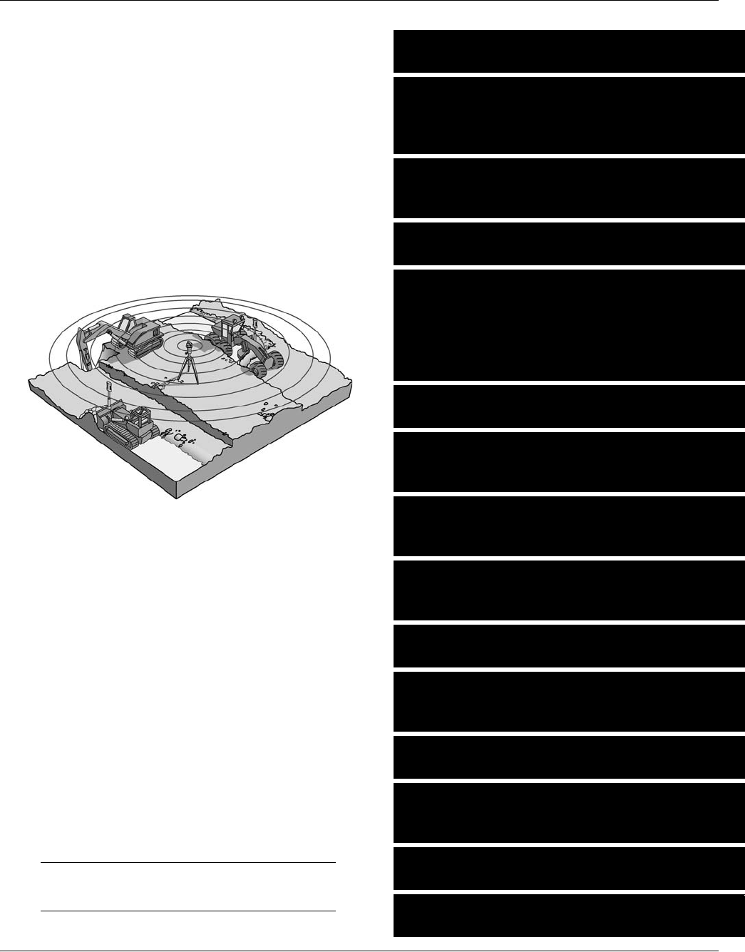
b. Purpose of Equipment.
The laser diode emits a thin, round beam of light. Energy in this light is at a wavelength that will
activate light-sensitive cells in the receiver.
The mechanism in the laser rotates the beam at a constant 600 revolutions per minute. The light beam
remains perpendicular to the axis of rotation at all times.
As the beam rotates about the axis, it describes a “plane” similar to a CD-ROM, with a radius of
1,000 ft (305 m). In theory, the beam does not waver from the plane.
As the rotating beam strikes the receiver, it activates cells at 600 times per minute (10 times per
second). This happens so fast that it gives the appearance of a solid plane of light. This solid plane of
light establishes a reference above ground. It can be adjusted up or down by mounting the laser on a
tripod.
The Laser Transmitter mounted in relation to the cutting edge (on mast) allows the Operator to
“transfer” the plane to the ground the Operator is working. It does this by showing the Operator which
direction to move the cutting edge to keep the distance from the ground to the light plane constant.
1-2. MAINTENANCE FORMS AND RECORDS.
Department of the Army forms and procedures used for equipment maintenance will be those prescribed by
DA PAM 738-750, The Army Maintenance Management System (TAMMS) (Maintenance Management
UPDATE).
TM 5-6675-348-13&P
1-2
1-3. EQUIPMENT IMPROVEMENT REPORT AND MAINTENANCE DIGEST (EIR MD) AND
EQUIPMENT IMPROVEMENT REPORT AND MAINTENANCE SUMMARY (EIR MS).
The quarterly Equipment Improvement Report and Maintenance Digest (EIR MD), TB 43-0001-62 series,
contains valuable field information on equipment covered in this manual. Information in the TB 43-0001-62
series is compiled from some of the Equipment Improvement Reports that have been prepared on equipment
covered in this manual. Many of these articles result from comments, suggestions, and improvement
recommendations that were submitted to the EIR program. The TB 43-0001-62 series contains information
on equipment improvements, minor alterations, proposed Modification of Work Orders (MWOs), warranties
(if applicable), actions taken on recommendation submitted on the DA Form 2028 (Recommended Changes
and Blank Forms), and advance information on proposed changes that may affect this manual. Significant
maintenance articles, including minor alterations and field-fixes, are republished in the Equipment
Improvement Report and Maintenance Summary (EIR MS) for TACOM Equipment (TM 43-0143). Refer to
the TB 43-0001-62 series and TM 43-0143 periodically for the most current and authoritative information on
the equipment. The information will help maintenance personnel to do a better job and will advise them of
the latest changes to this manual. Also refer to DA PAM 310-1, Consolidated Index of Army Publications and
Blank Forms, and Appendix A, References, of this manual.
1-4. SUBMITTING QUALITY DEFICIENCY REPORTS (QDR).
If your equipment needs improvement, let us know. Send us a QDR. You, the user, are the only one who can
tell us what you don’t like about your equipment. Let us know why you don’t like the design or performance.
Put it on an SF368 (Quality Deficiency Report). Mail it to:
Commander
U.S. Army Tank-automotive and Armaments Command
ATTN: AMSTA-TR-PQDR
Warren, MI 48397-5000
A reply will be sent to you.
1-5. DESTRUCTION OF ARMY MATERIEL TO PREVENT ENEMY USE.
Refer to TM 750-244-6 for instructions covering destruction of Army materiel to prevent enemy use.
1-6. WARRANTY INFORMATION.
Trimble warrants all manufactured products to be free of defects in materials and workmanship for a period
of one (1) year from the date the product is put into service. Components not manufactured by Trimble, but
sold as a part of the system, will carry a 90-day warranty, or the manufacturer warranty, whichever is greater.
Trimble warrants all installations on all heavy construction equipment to be free of defects in materials and
workmanship for a period of one (1) year from the date the installation is completed. This Installation
Warranty will apply only when Trimble personnel or authorized personnel conduct the installation.
The Trimble warranty for products and/or installation is valid worldwide.
Trimble or its Authorized Service Center will repair or replace, at its option, any defective part or component
of which notice has been given during the warranty period.
This warranty does not cover any evidence of neglect, abuse, accident, or any attempt to repair equipment by
other than factory-authorized personnel and/or parts authorized in this manual. For nonwarranty repairs, the
cost of the repair and, if required, travel and per diem expenses to and from the place where repairs are made
will be charged to the purchaser at the prevailing rates.

TM 5-6675-348-13&P
1-3
Customers should send unit(s), freight prepaid, to the nearest Authorized Service Center for warranty
repairs. In countries with Trimble Service Centers, the repaired units will be returned, freight prepaid, to the
customer.
Warranties for specific models of Laser Leveling Equipment may exceed one (1) year, and may cover use and/
or abuse. For details on these warranties, consult that model’s operating instructions manual.
Trimble will not be held responsible for any consequential loss or damage of any kind.
Checking and maintaining calibration of all equipment is the responsibility of the user.
Trimble policy for repair turnaround time for all Department of Defence (DoD) Agencies has been in effect
since 1994. This policy is as follows:
•In-House Repairs: Completed in 1 to 48 hours, depending on the extent of service required.
If the repairs required are extensive and the Trimble Service Center is unable to complete the repair within
48 hours, that DoD Agency will be offered a loaner to use until that repair is completed. If that item is under
warranty, there will be no cost to that agency. If that item is not under warranty, a rental fee may apply.
NOTENOTE
This policy covers service work conducted at Trimble Service Centers anywhere in the world.
•On-Site/On-Machine (Grader, Dozer, Scraper, Paver, etc.) Repairs: Completed in 1 to 48 hours,
depending on the extent of service required. Does not include travel time to site where repairs are to be
conducted.
If the repairs required are extensive and the on-site Trimble Service personnel are unable to complete the
repair within 48 hours, that DoD Agency will be offered a loaner to use until that repair is completed. If that
item is under warranty, there will be no cost to that agency. If that item is not under warranty, a rental fee
may apply.
NOTENOTE
This policy covers service work conducted by Trimble Service Centers anywhere in the world.
Warranty: Standard commercial warranty is one (1) year on parts, labor, and installation from the date of
installation (In Service date).
1-7. REFERENCE INFORMATION.
This listing includes a nomenclature cross-reference list and a list of abbreviations used in this manual.
a. Abbreviations.
AEPS . . . . . . . . . . . . . . . . . . . . . . . . . . . . . . . . . . . . . . . . . . . . . . . . . . . .Army Electronic Product Support
AAL . . . . . . . . . . . . . . . . . . . . . . . . . . . . . . . . . . . . . . . . . . . . . . . . . . . . . . . . Additional Authorization List
AISI . . . . . . . . . . . . . . . . . . . . . . . . . . . . . . . . . . . . . . . . . . . . . Automated Integrated Survey Instrument
amp . . . . . . . . . . . . . . . . . . . . . . . . . . . . . . . . . . . . . . . . . . . . . . . . . . . . . . . . . . . . . . . . . . . . . . . . . Amperes
ANSI . . . . . . . . . . . . . . . . . . . . . . . . . . . . . . . . . . . . . . . . . . . . . . American National Standards Institute
AOAP . . . . . . . . . . . . . . . . . . . . . . . . . . . . . . . . . . . . . . . . . . . . . . . . . . . . . . . Army Oil Analysis Program
BII . . . . . . . . . . . . . . . . . . . . . . . . . . . . . . . . . . . . . . . . . . . . . . . . . . . . . . . . . . . . . . . . . . . Basic Issue Item
C . . . . . . . . . . . . . . . . . . . . . . . . . . . . . . . . . . . . . . . . . . . . . . . . . . . . . . . . . . . . . . . . . . . . . . . . . Centigrade
CAGE . . . . . . . . . . . . . . . . . . . . . . . . . . . . . . . . . . . . . . . . . . . . . . . . Commercial and Government Entity
TM 5-6675-348-13&P
1-4
CBR . . . . . . . . . . . . . . . . . . . . . . . . . . . . . . . . . . . . . . . . . . . . . . . . . . . . Chemical, Biological, Radiological
CKT . . . . . . . . . . . . . . . . . . . . . . . . . . . . . . . . . . . . . . . . . . . . . . . . . . . . . . . . . . . . . . . . . . . . . . . . . . Circuit
cm . . . . . . . . . . . . . . . . . . . . . . . . . . . . . . . . . . . . . . . . . . . . . . . . . . . . . . . . . . . . . . . . . . . . . . . . Centimeter
COEI . . . . . . . . . . . . . . . . . . . . . . . . . . . . . . . . . . . . . . . . . . . . . . . . . . . . . . . . . . Components of End Item
COTS . . . . . . . . . . . . . . . . . . . . . . . . . . . . . . . . . . . . . . . . . . . . . . . . . . . . . . . . . Commercial Off-The-Shelf
cps . . . . . . . . . . . . . . . . . . . . . . . . . . . . . . . . . . . . . . . . . . . . . . . . . . . . . . . . . . . . . . . . . Cycles Per Second
CTA . . . . . . . . . . . . . . . . . . . . . . . . . . . . . . . . . . . . . . . . . . . . . . . . . . . . . . . . Common Table of Allowance
DA . . . . . . . . . . . . . . . . . . . . . . . . . . . . . . . . . . . . . . . . . . . . . . . . . . . . . . . . . . . . Department of the Army
DoD . . . . . . . . . . . . . . . . . . . . . . . . . . . . . . . . . . . . . . . . . . . . . . . . . . . . . . . . . . . . Department of Defense
EIR -MD . . . . . . . . . . . . . . . . . . . . . . . . . . . . . Equipment Improvement Report and Maintenance Digest
EIR -MS . . . . . . . . . . . . . . . . . . . . . . . . . . Equipment Improvement Report and Maintenance Summary
F . . . . . . . . . . . . . . . . . . . . . . . . . . . . . . . . . . . . . . . . . . . . . . . . . . . . . . . . . . . . . . . . . . . . . . . . . . Fahrenheit
ft . . . . . . . . . . . . . . . . . . . . . . . . . . . . . . . . . . . . . . . . . . . . . . . . . . . . . . . . . . . . . . . . . . . . . . . . . . . . . . . .Foot
HDI. . . . . . . . . . . . . . . . . . . . . . . . . . . . . . . . . . . . . . . . . . . . . . . . . . . . . . . . . . . . . . . . . . . . . . . . Isocyanate
HYEX . . . . . . . . . . . . . . . . . . . . . . . . . . . . . . . . . . . . . . . . . . . . . . . . . . . . . . . . . . . . . . Hydraulic Excavator
in. . . . . . . . . . . . . . . . . . . . . . . . . . . . . . . . . . . . . . . . . . . . . . . . . . . . . . . . . . . . . . . . . . . . . . . . . . . . . . . Inch
I.D. . . . . . . . . . . . . . . . . . . . . . . . . . . . . . . . . . . . . . . . . . . . . . . . . . . . . . . . . . . . . . . . . . . . Inside Diameter
O.D. . . . . . . . . . . . . . . . . . . . . . . . . . . . . . . . . . . . . . . . . . . . . . . . . . . . . . . . . . . . . . . . . . Outside Diameter
kg . . . . . . . . . . . . . . . . . . . . . . . . . . . . . . . . . . . . . . . . . . . . . . . . . . . . . . . . . . . . . . . . . . . . . . . . . . Kilogram
LACV . . . . . . . . . . . . . . . . . . . . . . . . . . . . . . . . . . . . . . . . . . . . . . . . . . . Lift and Articulation Check Valve
lb-ft . . . . . . . . . . . . . . . . . . . . . . . . . . . . . . . . . . . . . . . . . . . . . . . . . . . . . . . . . . . . . . . . . . . . . . Pound-Foot
lb. . . . . . . . . . . . . . . . . . . . . . . . . . . . . . . . . . . . . . . . . . . . . . . . . . . . . . . . . . . . . . . . . . . . . . . . . . . . . Pound
LCD . . . . . . . . . . . . . . . . . . . . . . . . . . . . . . . . . . . . . . . . . . . . . . . . . . . . . . . . . . . . . Liquid Crystal Display
LED . . . . . . . . . . . . . . . . . . . . . . . . . . . . . . . . . . . . . . . . . . . . . . . . . . . . . . . . . . . . . . Light-Emitting Diode
LLE. . . . . . . . . . . . . . . . . . . . . . . . . . . . . . . . . . . . . . . . . . . . . . . . . . . . . . . . . . . Laser Leveling Equipment
m . . . . . . . . . . . . . . . . . . . . . . . . . . . . . . . . . . . . . . . . . . . . . . . . . . . . . . . . . . . . . . . . . . . . . . . . . . . . . Meter
MAC . . . . . . . . . . . . . . . . . . . . . . . . . . . . . . . . . . . . . . . . . . . . . . . . . . . . . . . Maintenance Allocation Chart
mm . . . . . . . . . . . . . . . . . . . . . . . . . . . . . . . . . . . . . . . . . . . . . . . . . . . . . . . . . . . . . . . . . . . . . . . . Millimeter
N·m . . . . . . . . . . . . . . . . . . . . . . . . . . . . . . . . . . . . . . . . . . . . . . . . . . . . . . . . . . . . . . . . . . . Newton Meters
NPSM . . . . . . . . . . . . . . . . . . . . . . . . . . . . . . . . . . . . . . . . . . . . . . . . . National Pipe Straight Mechanical
NSN . . . . . . . . . . . . . . . . . . . . . . . . . . . . . . . . . . . . . . . . . . . . . . . . . . . . . . . . . . . . National Stock Number
OC . . . . . . . . . . . . . . . . . . . . . . . . . . . . . . . . . . . . . . . . . . . . . . . . . . . . . . . . . . . . . . . . . . . . . On-Condition
OL . . . . . . . . . . . . . . . . . . . . . . . . . . . . . . . . . . . . . . . . . . . . . . . . . . . . . . . . . . . . . . . . . . . . . . . . Over Limit
ORS . . . . . . . . . . . . . . . . . . . . . . . . . . . . . . . . . . . . . . . . . . . . . . . . . . . . . . . . . . . . . . . . . . . . . . O-Ring Seal
PMCS . . . . . . . . . . . . . . . . . . . . . . . . . . . . . . . . . . . . . . . . . Preventive Maintenance Checks and Services
QDR . . . . . . . . . . . . . . . . . . . . . . . . . . . . . . . . . . . . . . . . . . . . . . . . . . . . . . . . . .Quality Deficiency Reports
rpm . . . . . . . . . . . . . . . . . . . . . . . . . . . . . . . . . . . . . . . . . . . . . . . . . . . . . . . . . . . . . Revolutions Per Minute
RPSTL . . . . . . . . . . . . . . . . . . . . . . . . . . . . . . . . . . . . . . . . . . . . . . . . . Repair Parts and Special Tools List
SAE . . . . . . . . . . . . . . . . . . . . . . . . . . . . . . . . . . . . . . . . . . . . . . . . . . . . Society of Automotive Engineers
SMR . . . . . . . . . . . . . . . . . . . . . . . . . . . . . . . . . . . . . . . . . . . . . . .Source, Maintenance, and recoverability
TACOM . . . . . . . . . . . . . . . . . . . . . . . . . . . . . . . . . . . . . . . . Tank-automotive and Armaments Command
TAMMS . . . . . . . . . . . . . . . . . . . . . . . . . . . . . . . . . . . . . . . The Army Maintenance Management System
TM . . . . . . . . . . . . . . . . . . . . . . . . . . . . . . . . . . . . . . . . . . . . . . . . . . . . . . . . . . . . . . . . . . Technical Manual
TMDE. . . . . . . . . . . . . . . . . . . . . . . . . . . . . . . . . . . . . . . . Test, Measurement, and Diagnostic Equipment
U/M . . . . . . . . . . . . . . . . . . . . . . . . . . . . . . . . . . . . . . . . . . . . . . . . . . . . . . . . . . . . . . . . . . Unit of Measure
UOC . . . . . . . . . . . . . . . . . . . . . . . . . . . . . . . . . . . . . . . . . . . . . . . . . . . . . . . . . . . . . . . . . . . Usable on Code
v . . . . . . . . . . . . . . . . . . . . . . . . . . . . . . . . . . . . . . . . . . . . . . . . . . . . . . . . . . . . . . . . . . . . . . . . . . . . . . . Volts
Vac . . . . . . . . . . . . . . . . . . . . . . . . . . . . . . . . . . . . . . . . . . . . . . . . . . . . . . . . . . . . Volts alternating current
Vdc . . . . . . . . . . . . . . . . . . . . . . . . . . . . . . . . . . . . . . . . . . . . . . . . . . . . . . . . . . . . . . . . . Volts direct current
TM 5-6675-348-13&P
1-5/(1-6 Blank)
b. Definitions of Technical Terms.
Actual Blade Slope – The monitored slope of the blade, which is used to calculate desired cross-slope.
Actual blade slope and desired cross-slope are equal only when the blade is perpendicular to the
machine’s direction of travel.
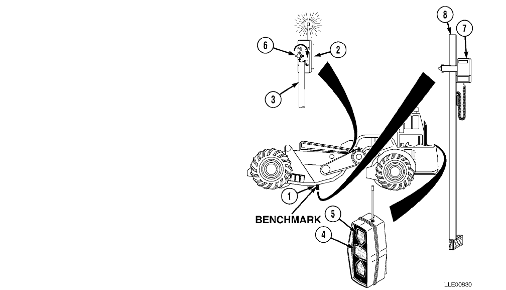
Benchmark – A point of reference from which measurements may be made.
Calculated Cross-Slope – The cross-slope is calculated by using the information provided by the
machine-mounted sensors and calculated with the Blade Pro® Motor Grader Control System.
Desired Cross-Slope – The slope that is marked on the job plans. This may be referenced from the
centerline of the road to the 1/4 crown, from shoulder to shoulder, or from shoulder to ditch, depending
on the plans. This is the slope entered into the Blade Pro® Motor Grader Control System’s Operator
Interface Box.
Elevation – The height above or below a set point.
Mainfall – The slope of the machine in the direction of travel.
Percent Slope – The change in elevation between two points divided by the distance between the
points and multiplied by 100.
Plane – A flat or level surface.
Resultant Cross-Slope – The measured slope perpendicular to the direction of the machine’s travel.
Slope – The change in elevation between two points in relation to the measured distance between the
points (e.g., 1/4 in. per 1 ft [6.4 mm per 30.5 cm]).
Elevation A Elevation B–
Distance
---------------------------------------------------------------100×Percent (%) Slope=
TM 5-6675-348-13&P
2-1
CHAPTER 2
GRADIO® DISPLAY SYSTEM
(D7F, D7G, D7H, AND D7R DOZERS
AND 613B AND 621B SCRAPERS)
Content Para Page
Gradio® Display System General Information ................................................................... Section I 2-1
Scope........................................................................................................................................... 2-1 2-1
Equipment Characteristics, Capabilities, and Features.......................................................... 2-2 2-1
Location and Description of Major Components...................................................................... 2-3 2-3
Equipment Data ........................................................................................................................ 2-4 2-5
Gradio® Display System Preventive Maintenance Checks and Services (PMCS).......... Section II 2-6
PMCS Procedures...................................................................................................................... 2-5 2-6
Shortened Maintenance Instructions....................................................................................... 2-6 2-7
Additional Maintenance Inspections........................................................................................ 2-7 2-8
PMCS Column Entry Explanation ........................................................................................... 2-8 2-8
Gradio® Display System Operator’s PMCS Table................................................................... 2-9 2-8
Gradio® Display System Operation.................................................................................. Section III 2-10
Gradio® Display System Installation of Components............................................................. 2-10 2-10
Gradio® Display System Setup................................................................................................. 2-11 2-11
Gradio® Display System Operation ......................................................................................... 2-12 2-12
Gradio® Display System Troubleshooting........................................................................ Section IV 2-13
Gradio® Display System Troubleshooting Instructions.......................................................... 2-13 2-14
Gradio® System Troubleshooting Instructions........................................................................ 2-14 2-16
Gradio® Display System Maintenance.............................................................................. Section V 2-19
Gradio® Display System Installation for Dozer ...................................................................... 2-15 2-19
Gradio® Display System Installation for Scrapers.................................................................. 2-16 2-26
SECTION I. GRADIO® DISPLAY SYSTEM GENERAL INFORMATION
2-1. SCOPE.
Chapter 2 is used for operation, maintenance, and installation of the Gradio® Display System used on the
D7F, D7G, D7H, and D7R Dozers and the 613B and 621B Scrapers.
2-2. EQUIPMENT CHARACTERISTICS, CAPABILITIES, AND FEATURES.
a. Characteristics. The RT2S Laser Receiver and DR2 Display are ideal for applications where the
RT2S Laser Receiver must be mounted many feet from the Operator (or at an inconvenient location),
such as on Dozers and Scrapers. The cableless feature means the DR2 Display can be mounted
optimally without routing the cables around or through complex or articulating machine joints.
The MM2E Manual Mast is used in machine control applications where changes in the benchmark
elevations are minimal and when manual adjustments of the RT2S Laser Receiver’s height do not
present a safety risk.

TM 5-6675-348-13&P
2-2
The RM2E-3 Rigid Mast is used in machine control applications where changes in the benchmark
elevations are minimal and when manual adjustments of the RT2S Laser Receiver’s height do not
present a safety risk.
b. Capabilities.
(1) The Gradio® Display System is capable of operating in temperatures from -20 to 140° F
(-29 to 60° C).
(2) Normal Gradio® Display System operating range (between RT2S Laser Receiver and DR2 Display)
is up to a 100-ft (30.5 m) radius.
c. Features.
(1) The RT2S Laser Receiver is an omnidirectional, 360-degree receiver that accepts signals from the
600-rpm rotating lasers.
(2) The RT2S Laser Receiver translates and sends elevation information to the DR2 Display via low-
power radio communication.
12-/24-Vdc bulbs may be used. To avoid damage to equipment, ensure proper bulb is
installed for machine’s electrical system.
(3) Five channels of grade data (high coarse, high fine, on-grade, low fine, and low coarse) are
displayed for the Operator through bright lenses in the DR2 Display.
(4) The RT2S Laser Receiver is a self-contained, battery-powered unit that can be mounted in an
optimum position without concern for cable routing and subsequent cable damage.
(5) The MM2E Manual Mast provides a mount for the RT2S Laser Receiver to slip over and clamp into
place.
(6) The MM2E Manual Mast has increment/decrement mast tape to indicate changes in position of the
MM2E Manual Mast.
(7) The RM2E-3 Rigid Mast has increment/decrement mast tape to indicate changes in position of the
RM2E-3 Rigid Mast.
(8) The RM2E-3 Rigid Mast Quick-Release Pin enables easy removal of the RM2E-3 Rigid Mast from
the mast mount.
(9) The RM2E-3 Rigid Mast Lanyard Chain connects the Quick-Release Pin to the RM2E-3 Rigid Mast
tube to prevent loss when disconnected.

TM 5-6675-348-13&P
2-3
2-3. LOCATION AND DESCRIPTION OF MAJOR COMPONENTS.
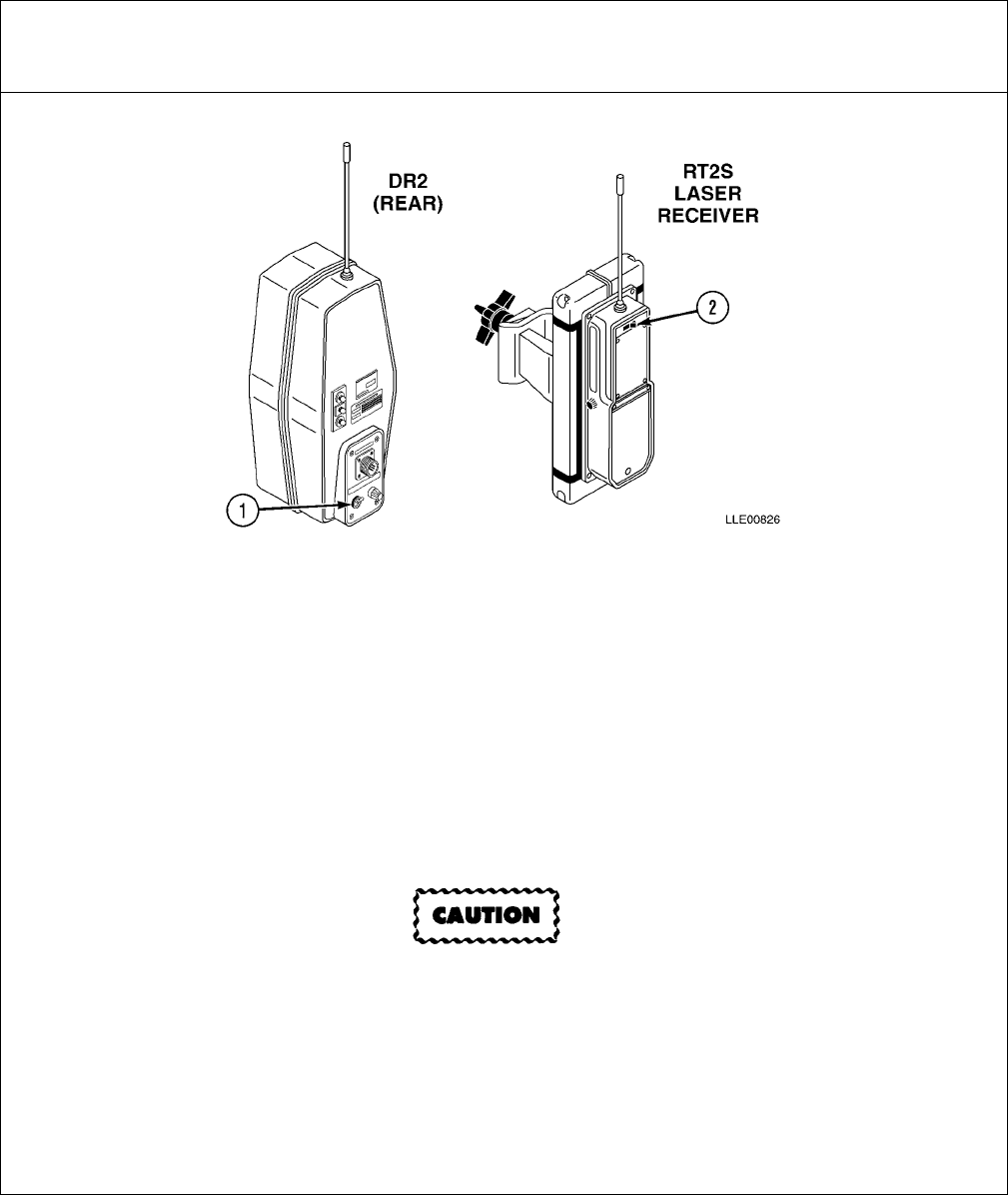
(1) BATTERY DOOR. Holds four alkaline,
C-size batteries.
(2) ON/OFF SWITCH. Used to turn the
RT2S Laser Receiver ON and OFF.
12-/24-vdc bulbs may be used. To avoid
damage to equipment, ensure 24-v bulbs
are installed for 24-v electrical system
and 12-v bulbs are installed for
12-v electrical system.
(3) RT2S LASER RECEIVER CLAMP.
“Universal” design allows RT2S Laser
Receiver to be mounted on 1 1/2-in. to
2-in. (3.81 cm to 5.1 cm) diameter round
tubing or 1 1/2-in. to 1 3/4-in. (3.81 cm to
4.45 cm) square tubing.
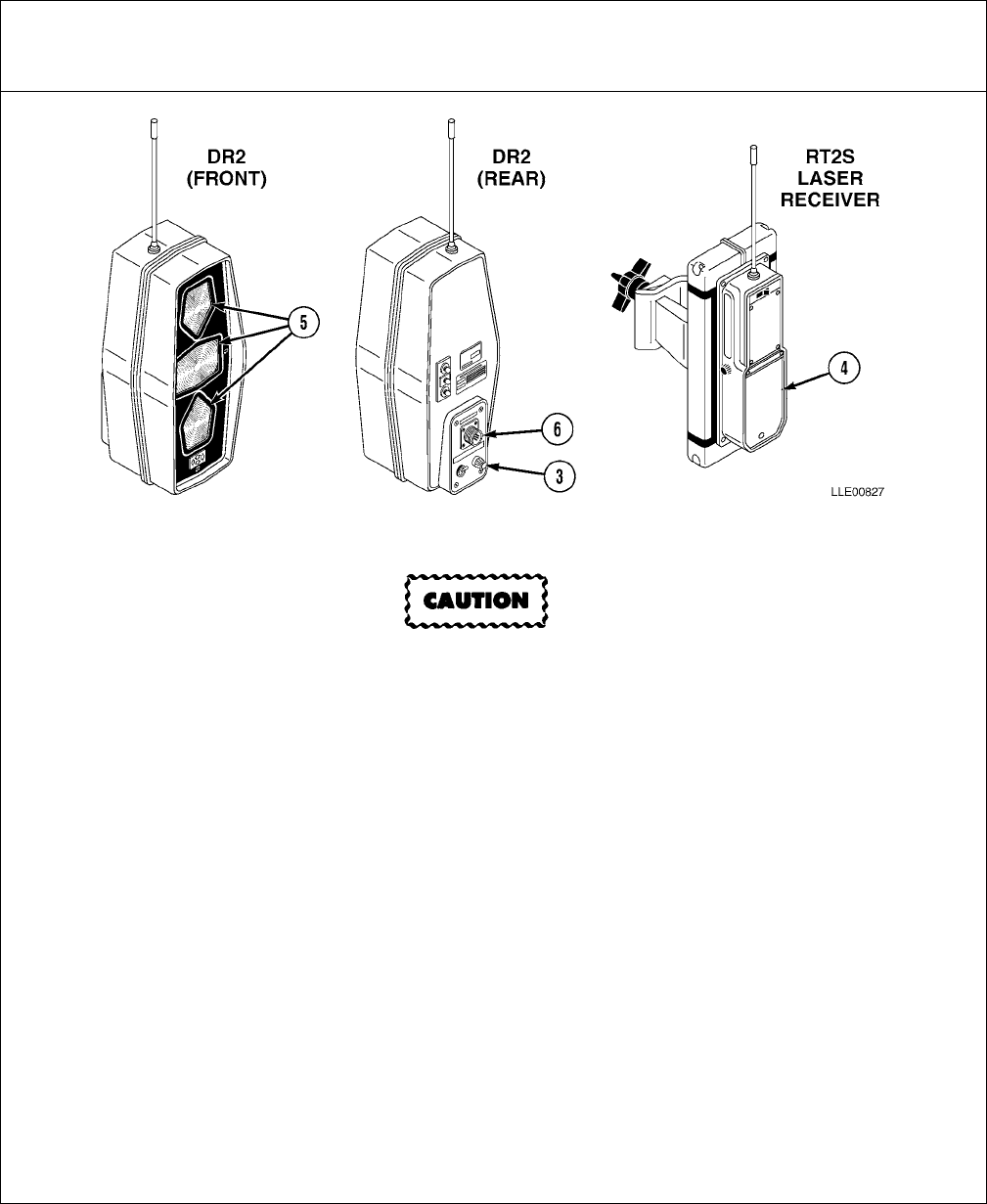
(4) OVERLOAD PROTECTION. A 5-amp
fuse is used to protect the DR2 Display.
(5) DISPLAY CONTROL SWITCH. Turns the
DR2 Display on in either bright or dim
DR2 Display mode for day or night use.
(6) CHANNEL INDICATION. Designates
channel configuration of the RT2S
Laser Receiver or the DR2 Display. Channels must match for proper operation. Matching channels
have the same color heat shrink tubing on the antenna.
(7) OPERATOR SETUP LAMPS. Light-emitting diodes (LED) on the back of the DR2 Display reflect
activity of the DR2 Display panel lights. This allows for one-soldier setup.
(8) GRADE INDICATOR LAMPS. Used to communicate grade information to the Operator.
(9) OUT-OF-BEAM INDICATOR. LEDs on the DR2 Display panel indicate which direction the
RT2S Laser Receiver must be moved to intercept the laser beam.
TM 5-6675-348-13&P
2-4
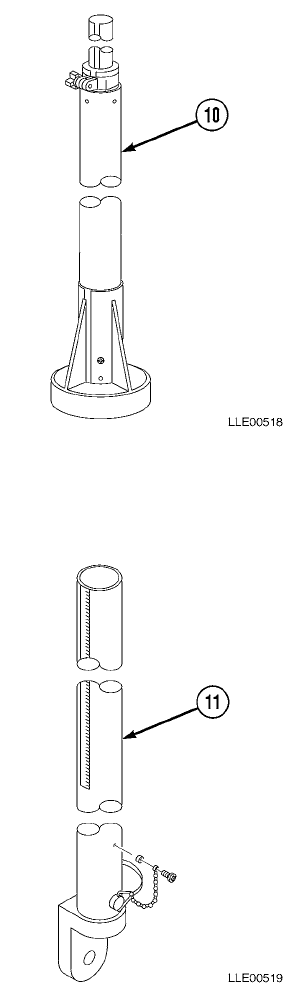
(10) MM2E MANUAL MAST. A manually telescoping
receiver mount with increment/decrement tape on
the telescoping mast tube, that allows RT2S Laser
Receiver to be positioned at known intervals.
(11) RM2E-3 RIGID MAST. A rigid receiver mount with
increment/decrement tape, that allows the RT2S
Laser Receiver to be moved at known intervals.

TM 5-6675-348-13&P
2-5
2-4. EQUIPMENT DATA.
Table 2-1. Gradio® Display System Equipment Data
Model Item
DIMENSIONS
RT2S Laser
Receiver Length: 11.3 in. (28.7 cm)
Width: 4.5 in. (11.4 cm)
Depth: 7.9 in. (20.1 cm)
DR2 Display Length: 13.5 in. (34.3 cm)
Width: 5.0 in. (12.7 cm)
Depth: 6.5 in. (16.5 cm)
MAST HEIGHT
MM2E Manual
Mast Retracted: 4.9 ft (1.5 m)
Extended: 8.8 ft (2.7 m)
RM2E-3 Rigid
Mast 3.9 ft (1.2 m)
ANTENNA LENGTH
RT2S Laser
Receiver Height: 7.2 in. (18.3 cm)
DR2 Display Height: 7.2 in. (18.3 cm)
WEIGHT
RT2S Laser
Receiver 5.1 lb. (2.3 kg)
DR2 Display 7.3 lb. (3.3 kg)
MM2E Manual
Mast 33 lb. (15 kg)
RM2E-3 Rigid
Mast 6 lb. (2.7 kg)
TAPE INCREMENTS
MM2E Manual
Mast 0.01 ft (0.0030 m)
RM2E-3 Rigid
Mast 0.01 ft (0.0030 m)
ELECTRICAL SYSTEM
RT2S Laser
Receiver Four C-size alkaline batteries provide 40 to 60 hours of use. Ni-Cad batteries (supplied
with charging kit) provide 24 hours of use per overnight charge. DO NOT TRY TO
CHARGE ALKALINE BATTERIES.
DR2 Display 12 or 24 Vdc from electrical system
TM 5-6675-348-13&P
2-6
SECTION II. GRADIO® DISPLAY SYSTEM PREVENTIVE
MAINTENANCE CHECKS AND SERVICES (PMCS)
Preventive Maintenance Checks and Services (PMCS) means systematic caring for, inspecting, and servicing
equipment to keep it in good condition and to help prevent breakdowns. As the Operator, your mission is to:
a. Be sure to perform your PMCS each time you operate the Gradio® Display System. Always do
your PMCS in the same order so it becomes a habit. Once you’ve had some practice, you’ll
quickly spot anything wrong.
b. Do your Before PMCS just before you operate the Gradio® Display System. Pay attention to
WARNINGS, CAUTIONS, and NOTES.
c. Do your During PMCS while you operate the Gradio® Display System. Pay attention to
WARNINGS, CAUTIONS, and NOTES.
d. Do your After PMCS right after operating the Gradio® Display System. Pay attention to
WARNINGS, CAUTIONS, and NOTES.
e. Do your Weekly PMCS once a week.
f. Use DA Form 2404 or DA Form 5988-E (Equipment Inspection and Maintenance Worksheet) to
record any faults that you don’t immediately fix.
2-5. PMCS PROCEDURES.
a. The PMCS Table (Table 2-2.) lists inspections and care required to keep your Gradio® Display
System in good operating condition. This table is set up so you can do Before and After PMCS
while walking around the equipment.
b. The “Interval” column tells you when to do a certain check or service.
c. The “Procedure” column tells you how to do required checks and services. Carefully follow these
instructions.
d. The “Not Fully Mission Capable If” column tells you when your Gradio® Display System is
nonmission capable and why the Gradio® Display System cannot be used.
e. When something looks wrong that you cannot fix, write down the problem on your
DA Form 2404 or DA Form 5988-E. Immediately report the problem to your supervisor.
f. When you do your PMCS, you will always need a rag or two. Following are checks that are
common to the entire Gradio® Display System.

TM 5-6675-348-13&P
2-7
• Degreasing Solvent (MIL-PRF-680, Type II) is TOXIC and flammable. Wear protective
goggles and gloves, use only in a well-ventilated area, avoid contact with skin, eyes, and
clothes, and do not breathe vapors. Keep away from heat or flame. Never smoke when
using solvent; the flash point for degreasing solvent type II is 200º F (93º C). Failure to
comply may result in injury or death to personnel.
• If personnel become dizzy while using cleaning solvent, immediately get fresh air and
medical help. If solvent contacts skin or clothes, flush with cold water. If solvent contacts
eyes, immediately flush eyes with water and get immediate medical attention. Do not
use diesel fuel, gasoline, or benzene (benzol) for cleaning.
• Adhesives, solvents, and sealing compounds burn easily and give off vapors that are
harmful to the skin and clothing. To avoid injury or death, keep away from open fire
when using these materials, and use only in well-ventilated areas. If adhesives, solvents,
or sealing compounds contact the skin or clothing, wash immediately with soap and
water, and rinse thoroughly. Failure to comply may result in injury or death to personnel.
(1) Keep It Clean. Dirt, grease, oil, and debris only get in the way and may cover up a serious
problem. Clean as you work. Use degreasing solvent (MIL-PRF-680, type II) on all metal surfaces.
Use soap and water when you clean rubber or plastic material.
(2) Rust and Corrosion. Check Gradio® Display System brackets for rust and corrosion. When any
bare metal or corrosion exists, clean surface and apply a coat of paint. Report bare metal or
corrosion to your supervisor.
(3) Bolts, Nuts, and Screws. Check all bolts, nuts, and screws for obvious looseness, missing, bent, or
broken condition. You can’t check them all with a tool, but look for chipped paint, bare metal, or
rust around bolt heads. When you find a bolt, nut, or screw you think is loose, tighten it or report it
to your supervisor.
(4) Welds. Look for loose or chipped paint, rust, or gaps where parts are welded together. When you
find a bad weld, report it to your supervisor.
(5) Electric Wires and Connectors. Look for cracked, frayed, or broken insulation, bare wires, and
loose or broken connectors. Tighten loose connectors. Report any damaged wires to your supervisor.
(6) Hydraulic Lines and Fittings. Look for wear, damage, and leaks; ensure clamps and fittings are
tight. Stains around a fitting or connector can mean a leak. If a leak comes from a loose fitting or
connector, tighten it. If something is broken or worn out, report it to Unit Maintenance.
(7) When you check operating conditions, check to see if component is serviceable.
2-6. SHORTENED MAINTENANCE INSTRUCTIONS.
Local conditions of extreme heat, dust, cold, or wetness dictate that service intervals shall be shortened.

TM 5-6675-348-13&P
2-8
2-7. ADDITIONAL MAINTENANCE INSPECTIONS.
Additional maintenance inspections are required for the following reasons:
a. Prolonged storage. Inspect Gradio® Display System components that have been stored for a
period of 3 months or more.
b. Initial preparation upon receipt.
c. Preparation for storage.
2-8. PMCS COLUMN ENTRY EXPLANATION.
a. Item No. Column. The checks and services are numbered in interval order showing a walk-around
sequence around the Gradio® Display System. Use these numbers in the “Item No.” column on
DA Form 2404 or DA Form 5988-E when recording faults that you don’t immediately fix.
b. Interval Column. This column indicates when the lubrication, check, and/or service should be
performed.
c. Location, Item to Check/Service Column. The underlined items listed in this column are divided into
groups indicating the portion of the equipment of which they are a part (e.g., brakes, fuel, engine).
Under these groupings, a few common words are used to identify the specific item being checked.
d. Procedure Column. This column contains procedures required to perform the checks and services.
e. Not Fully Mission Capable If Column. This column contains the criteria that cause the equipment to
be classified as NOT READY/AVAILABLE because of an inability to perform its primary mission. An
entry in this column will:
(1) Identify conditions that make the equipment not available for readiness reporting purposes.
(2) Deny use of the equipment until corrective maintenance has been performed.
2-9. GRADIO® DISPLAY SYSTEM OPERATOR’S PMCS TABLE.
Table 2-2. Gradio® Display System Operator’s PMCS (Before/After)
Item
No. Interval
Location
Procedure Not Fully Mission
Capable If:
Item to
Check/Service
1. Before/After Gradio®
Display System
RT2S Laser
Receiver
Wipe dirt and dust from all metal components
with dry cloth.
Inspect housing of the RT2S Laser Receiver for
damage or cracks.
Inspect windows for cracks, scratches, and dirt.
Clean windows with clean water and soft cloth.
Check antenna for breaks or cuts that will
allow antenna to rotate.
Windows are
cracked.
Antenna rotates.

TM 5-6675-348-13&P
2-9
2. Before/After Gradio®
Display System
DR2 Display
Wipe dirt and dust from all metal components
with dry cloth.
Inspect windows for cracks, scratches, and dirt.
Clean windows with clean water and soft cloth.
Inspect bottom mounting hole of DR2 Display
for dirt and debris.
To avoid damage to equipment, fuse must
be replaced with 5-amp fuse.
Ensure overload protection fuse in DR2
Display is not burned out.
Check antenna for breaks or cuts that will
allow antenna to rotate.
Check bulbs for operation.
Windows are
cracked.
Fuse is burned out.
Antenna rotates.
Bulbs do not
operate.
3. Before/After Electrical
Cables Ensure electrical cables are not frayed,
cracked, or exposed. Cables are frayed,
cracked, or exposed
wires are evident.
4. Before/After Electrical
Connections Ensure connector on back of DR2 Display is
free of dirt and damage. Connector is
damaged.
5. Before/After MM2E Manual
Mast Ensure MM2E Manual Mast will extend and
retract. MM2E Manual
Mast will not extend
or retract.
6. Before/After MM2E Manual
Mast Mounting
Plate
Check welds for cracks or breaks. Any welds are
cracked or broken.
7. Before/After RM2E-3 Rigid
Mast Check RM2E-3 Rigid Mast for damage. RM2E-3 Rigid Mast
is bent.
8. Before/After RM2E-3 Rigid
Mast Mounting
Bracket
Check welds for cracks or breaks. Any welds are
cracked or broken.
9. Before/After Voltage
Protection
Cable
Ensure cable is not frayed, cracked, or exposed. Cable is frayed,
cracked, or exposed
wires are evident.
Table 2-2. Gradio® Display System Operator’s PMCS (Before/After) (Cont)
Item
No. Interval
Location
Procedure Not Fully Mission
Capable If:
Item to
Check/Service

TM 5-6675-348-13&P
2-10
SECTION III. GRADIO® DISPLAY SYSTEM OPERATION
2-10. GRADIO® DISPLAY SYSTEM INSTALLATION OF COMPONENTS.
a. DR2 Display.
• The color of the shrink tubing on
the antenna indicates the
frequency of the display and must
match in color with the heat shrink
tubing on the antenna of the RT2S
Laser Receiver. If the heat shrink
tubing does not match, the Gradio®
Display System will not operate.
• Two adjacent frequency systems
will/can cross-communicate. If
two adjacent frequencies cross-
communicate, the Gradio®Display
System will not operate properly.
(1) Attach DR2 Display (1) to mounting
bracket (2) with screw (3).
(2) Connect Power Cable (4) to back of
DR2 Display (1).
(3) Adjust DR2 Display bright/dim
switch (5) as needed.
b. RT2S Laser Receiver.
The color of the shrink tubing on the
antenna indicates the frequency of the
display and must match in color with
the heat shrink tubing on the antenna
of the RT2S Laser Receiver. If the heat
shrink tubing does not match, the
Gradio® Display System will not
operate.
(1) Turn on RT2S Laser Receiver (6).
(2) Slide RT2S Laser Receiver (6) over
MM2E Manual Mast (7).
(3) Rotate RT2S Laser Receiver Knob (8)
clockwise to secure RT2S Laser
Receiver (6) to MM2E Manual
Mast (7).
TM 5-6675-348-13&P
2-11
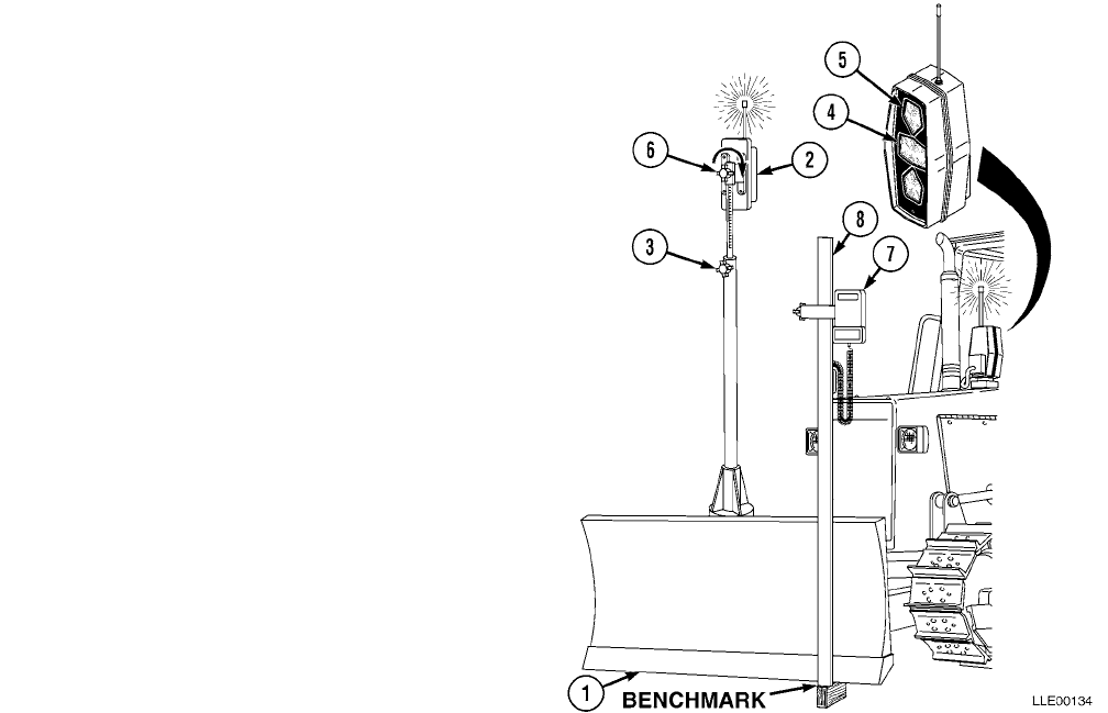
2-11. GRADIO® DISPLAY SYSTEM
SETUP.
a. Setup for Dozer.
(1) Place cutting edge (1) on benchmark.
(2) If finished grade is benchmark
elevation, move RT2S Laser
Receiver (2) up/down using MM2E
Manual Mast (3), and adjust until
ON-GRADE symbol (4) (solid green
bar) appears on DR2 Display (5).
NOTE
Moving the RT2S Laser Receiver up on
the MM2E Manual Mast lowers the
blade cutting edge. Moving the RT2S
Laser Receiver down on the
MM2E Manual Mast raises the blade
cutting edge.
(3) If finished grade is below benchmark
elevation, raise RT2S Laser
Receiver (2) using MM2E Manual
Mast (3).
Example: If the final grade is 2 in.
(5.1 cm) below benchmark, raise RT2S
Laser Receiver 2 in. (5.1 cm).
(4) Secure MM2E Manual Mast (3) by
rotating MM2E Manual Mast Adjusting Knob (6) clockwise.
(5) After making a short pass, check grade with 1275 Laser Receiver (7) on Grade Rod (8) (refer to
Chapter 5). Adjust machine-mounted RT2S Laser Receiver (2) up/down using MM2E Manual Mast
to desired grade, if needed.
TM 5-6675-348-13&P
2-12
b. Setup for Scraper.
(1) Place cutting edge (1) on
benchmark.
(2) If finished grade is benchmark
elevation, move RT2S Laser
Receiver (2) up/down on Scraper
Rigid Mast (3), adjust until
ON-GRADE symbol (4) (solid
green bar) appears on DR2
Display (5).
NOTE
Moving the RT2S Laser
Receiver (2) up on the Scraper
Rigid Mast (3) lowers the blade
cutting edge. Moving the RT2S
Laser Receiver (2) down on the
Scraper Rigid Mast (3) raises
the blade cutting edge.
(3) If finished grade is below
benchmark elevation, raise
RT2S Laser Receiver (2) on
Scraper Rigid Mast (3).
Example: If the final grade is
2 in. (5.1 cm) below benchmark, raise RT2S Laser Receiver 2 in. (5.1 cm).
(4) Secure RT2S Laser Receiver (2) by rotating RT2S Laser Receiver (2) Adjusting Knob (6) clockwise.
(5) After making a short pass, check grade with 1275 Laser Receiver (7) on Grade Rod (8) (Refer to
Chapter 5). Adjust machine-mounted RT2S Laser Receiver (2) up/down on Scraper Rigid Mast (3)
to desired grade, if needed.
2-12. GRADIO® DISPLAY SYSTEM OPERATION.
The RT2S Laser Receiver determines if cutting edge is too high, too low, or on grade in relation to the
benchmark. When the RT2S Laser Receiver transmits the grade information to the DR2 Display, the DR2
Display shows the Operator which direction the cutting edge should be adjusted (raised/lowered), if needed.
Ideal grade indication to maintain during normal operation is flashing yellow high (down) arrow, or flashing
(green) On-Grade Bar. It is not desirable to cut below grade.
During Gradio® Display System operations using the RT2S Laser Receiver, watch the DR2 Display and
operate the Dozer or Scraper normally.
Grade Indicator Lamp Correction Indicated Distance from Grade
Solid High Arrow Coarse Lower 0.11 to 0.28 ft (0.03 to 0.09 m)
Flashing High Arrow Fine Lower 0.015 to 0.11 ft (0.005 to 0.03 m)
Flashing On-Grade Bar None ±0.015 ft (±0.005 m)
Flashing Low Arrow Fine Raise 0.015 to 0.11 ft (0.005 to 0.03 m)
Solid Low Arrow Coarse Raise 0.11 to 0.28 ft (0.03 to 0.09 m)
TM 5-6675-348-13&P
2-13
SECTION IV. GRADIO® DISPLAY SYSTEM TROUBLESHOOTING
This section covers Gradio® Display System troubleshooting. The Gradio® Display System Fault Index, Table
2-3., lists faults for the Gradio® Display System.
Table 2-3. Gradio® Display System Fault Index
Fault
No. Description Page
2-1. Gradio® Display System Does Not Operate ....................................................................................2-14
TM 5-6675-348-13&P
2-14
2-13. GRADIO® DISPLAY SYSTEM TROUBLESHOOTING INSTRUCTIONS.
Table 2-4. Gradio® Display System Troubleshooting
Malfunction
Test or InspectionCorrective Action
FAULT 2-1. GRADIO® DISPLAY SYSTEM DOES NOT OPERATE.
Step 1. Ensure 1145-2 Laser Transmitter is correctly set up and operating
(Chapter 5). Verify with RT2S Laser Receiver.
If 1145-2 Laser Transmitter is correctly set up and operating, go to Step 2.
If 1145-2 Laser Transmitter is not correctly set up and operating, go to Chapter 5.
Step 2. Check bright/dim switch (1) on DR2 Display for proper position.
If bright/dim switch is in wrong position, move switch to correct position.
If bright/dim switch is damaged or faulty, return switch to manufacturer.
Dash number on back of RT2S Laser Receiver must match dash number on the DR2
Display. If dash numbers are not the same, the equipment will fail to operate.
Step 3. Check RT2S Laser Receiver ON/OFF switch (2) and channel compatibility with
DR2 Display.
If dash numbers are not the same, replace with compatible parts.
TM 5-6675-348-13&P
2-15
Step 4. Check 5-amp fuse (3) on rear of DR2 Display.
To avoid damage to equipment, fuse must be replaced with 5-amp fuse.
If fuse is faulty, replace.
Step 5. Check battery, terminals, and connections (4) in RT2S Laser Receiver.
NOTE
As battery output degrades, display may exhibit the following symptoms: loss of flashing
on grade or flashing fine correction (solid light will appear), abnormal display, or loss of all
lights (5).
If symptoms occur, replace batteries.
Step 6. Check Power Cable, at DR2 Display end, for 22 to 28 Vdc (Para 2-14).
If voltage is faulty, replace Power Cable.
Step 7. Check for good connection at Power Cable connector (6).
If cable connection is poor, properly connect Power Cable connector (6).
Table 2-4. Gradio® Display System Troubleshooting (Cont)
Malfunction
Test or InspectionCorrective Action

TM 5-6675-348-13&P
2-16
2-14. GRADIO® SYSTEM TROUBLESHOOTING INSTRUCTIONS.
a. Measurements Required for Troubleshooting.
Use properly sized test leads and ensure care is used when checking for resistance,
continuity, or voltage at connectors, or damage to equipment may result.
(1) Resistance measurements.
(a) Connect red test lead to Volt-Ohm input connector and black lead to COM input connector on
meter.
(b) Set function/range switch to desired Ohm position. If magnitude of resistance is not known,
set switch to highest range, then reduce until satisfactory reading is obtained.
(c) If resistance being measured is connected to circuit, disconnect power from circuit.
(d) Connect test leads to circuit being measured. When measuring high resistance, be careful not
to contact adjacent points, even if insulated. Some insulators have relatively low insulation
resistance, which can affect resulting measurement.
(e) Read resistance value on digital display.
(2) Continuity checks.
(a) Place function/range switch in any Ohm range.
NOTE
Some meters show “1+m”, or simply “1” when function/range switch is in any Ohm position.
(b) Connect red test lead to Volt-Ohm input connector and black lead to COM input connector on
meter. When test leads are separated or measuring an out-of-range resistance, digital display
will indicate “OL” (Over Limit).
(c) Put one test probe at one end of wire or circuit to be tested. Use other test lead to trace circuit.
When continuity is established, Ohm symbol will appear in upper left corner of digital display.
If contact in wire is maintained long enough (about 1/4 second), the OL will disappear and
resistance value of wire or circuit will appear next to symbol.
(d) If multimeter does not work in this manner, learn how it operates before performing trouble-
shooting.
(3) Voltage measurements.
(a) Connect red test lead to Volt-Ohm input connector and black lead to COM input connector on
meter. If DC-AC switch is present, ensure it is set to DC position.
(b) Set function/range switch to desired voltage position. If magnitude of voltage is not known, set
switch to range which will be able to read most voltages seen on equipment (typically, 200-V
range will do). Reduce range until satisfactory reading is obtained.

TM 5-6675-348-13&P
2-17
b. General Wire Test Procedures.
Use properly sized test leads and ensure care is used when checking for resistance,
continuity, or voltage at connectors, or damage to equipment may result.
(1) Wire voltage drop test.
(a) Disconnect connector from component (e.g., light, relay, motor, etc.) at working end of circuit.
(b) Check connector terminal(s) for damage. Repair or replace connector as necessary.
(c) Set up conditions that will create voltage at working end of wire.
(d) Check for required voltage at working end of wire.
1If required voltage is not measured at working end of wire, go to Step (e).
2If required voltage is measured at working end of wire, fault has not been isolated.
Continue with fault isolation tests or notify supervisor.
(e) Disconnect first connector in line from working end of wire to power source.
(f) Check for required voltage at working end of wire.
1If required voltage is not measured at working end of wire, go to Step (g).
2If required voltage is measured at working end of wire, fault is in the section of wire that
was most recently disconnected. Repair wire and perform voltage test again.
(g) Repeat Steps (d) and (e) until all sections of suspect wire are tested.
(2) Wire continuity test.
(a) Disconnect wire from component (e.g., light, relay, motor, etc.) at working end of circuit and
from power end of circuit.
(b) Set equipment conditions that will create desired circuit.
(c) Check continuity from power end of wire to working end of wire.
1If continuity is not measured, go to Step (d).
2If continuity is measured, fault has not been isolated. Continue with fault isolation tests
or notify supervisor.
(d) Disconnect first connector from working end of wire in line to power source.
(e) Check continuity.
1If continuity is not measured, go to Step (f).
2If continuity is measured, fault is in section of wire most recently disconnected. Repair
wire and perform continuity test again.
(f) Repeat Steps (d) and (e) until all sections of suspect wire are tested.

TM 5-6675-348-13&P
2-18
(3) Wire harness shorting wires test.
(a) Disconnect wire harness connector with wire suspected of damage.
(b) Set multimeter select switch to Ohm.
(c) Connect positive (+) multimeter lead to harness connector terminal of suspect wire.
(d) Connect negative (-) multimeter lead to all terminals in harness connector.
1If continuity is measured, suspect wire and wire where continuity is measured are
shorting together. Repair wires.
2If continuity is not measured, all wires are OK.
(4) Wire repair. Refer to TM 43-0158 for detailed instructions concerning electrical wiring repairs.
Wire harness repair is limited to splicing and taping of wires at Unit Maintenance. If wire harness
cannot be repaired, notify Direct Support Maintenance.

TM 5-6675-348-13&P
2-19
SECTION V. GRADIO® DISPLAY SYSTEM MAINTENANCE
2-15. GRADIO® DISPLAY SYSTEM INSTALLATION FOR DOZER.
This Task Covers:
a. Installation. b. Follow-On Maintenance.
INITIAL SETUP
Models
D7F Dozer (TM 5-2410-233-Series)
D7G Dozer (TM 5-2410-237-Series)
D7H Dozer
D7R Dozer
Tools and Special Tools
Tool Kit, Automotive Maintenance, Common
No. 2, Item 2, Appendix B
Tool Kit, Electric, Item 3, Appendix B
Tool Kit, Welders, Item 4, Appendix B
Materials and Parts
Cloth, Lint-Free, Item 3, Appendix F
Paint, Spray, Black, Item 8, Appendix F
Rags, Wiping, Item 9, Appendix F
Solder, Lead-Tin Alloy Item 10, Appendix F
Tags, Identification, Item 13, Appendix F
Ties, Cable, Item 15, Appendix F
Kit, Voltage Protection, Item 1, Appendix K
Label, Warning, Welding/Jump Starting;
Item 2, Appendix K
Mount, MM2E Manual Mast, Item 3,
Appendix K
Personnel Required
MOS 62B
MOS 44B
Equipment Condition
Engine OFF
(TM 5-2410-233-Series)
(TM 5-2410-237-Series).
Seat removed
(TM 5-2410-233-Series)
(TM 5-2410-237-Series).
Main Power Cable disconnected
(TM 5-3805-233-Series)
(TM 5-3805-237-Series).
TM 5-6675-348-13&P
2-20
a. Installation.
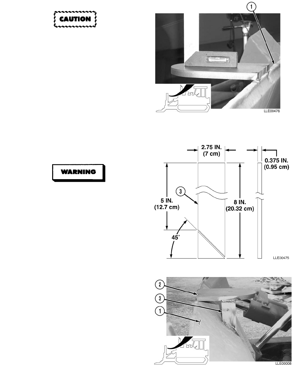
The leveling procedure must be
performed on a hard surface, such as
concrete or asphalt. Failure to
comply will cause the system to not
operate properly.
NOTE
To ease leveling of the blade, park
the Dozer on level ground.
(1) Using a straightedge and level on top
edge of blade (1), level blade.
(2) Measure and mark center of
blade (1).
(3) Cut two 8-in. (20.3 cm) metal
plates (3) at a 45-degree angle.
Unsafe welding practices can cause
serious injury from fire, explosions, or
harmful agents. Allow only
authorized personnel to weld or cut
metals, and follow safety precautions
in TC 9-237. Protective clothing and
goggles must be worn, adequate
protective equipment must be used, a
suitable fire extinguisher must be
kept nearby, and requirements of
TC 9-237 must be strictly followed.
Failure to comply may result in
serious injury or death to personnel.
NOTE
This procedure is repeated on both sides
of Mast Mount. Left side is shown.
(4) Center and level Mast Mount (2) at
center of Blade (1) and weld.
(5) Weld two metal plates (3) to Mast
Mount (2) and Blade (1).
TM 5-6675-348-13&P
2-21
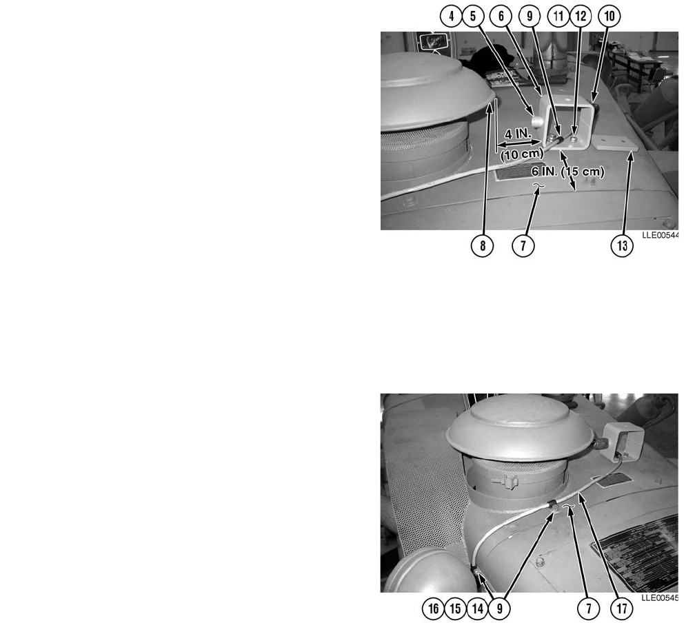
(6) Install Connector Holder (4) and screw (5) in
Display Mount (6).
(7) Tighten screw (5).
(8) Locate Display Mount (6) 6 in. (15.2 cm) from
rear edge of Engine Cover (7) and 4 in.
(10 cm) from Air Cleaner Cover (8).
(9) Mark two holes for Display Mount (6)
installation on Engine Cover (7).
(10) Center punch and drill two 1/2-in. (13 mm)
holes in Engine Cover (7).
(11) Install Loop Clamp (9) 12 in. (30.5 cm) from
female end of Power Cable (10).
NOTE
Display Mount Plate installs under
Engine Cover.
(12) Install Display Mount (6), two
lockwashers (11), hex head bolts (12), Loop
Clamp (9), and Display Mount Plate (13) on
Engine Cover (7).
(13) Tighten hex head bolts (12).
(14) Remove two hex head bolts (14),
lockwashers (15), and flat washers (16) from
Engine Cover (7).
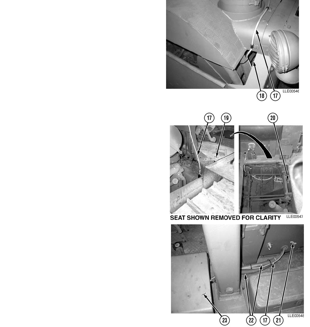
(15) Install two Loop Clamps (9) on Power
Cable (17).
(16) Install two Loop Clamps (9) on Engine
Cover (7) with two previously removed flat
washers (16), lockwashers (15), and hex head
bolts (14).
(17) Tighten hex head bolts (14).
TM 5-6675-348-13&P
2-22
NOTE
Steps (18) and (19) require the aid
of an assistant.
(18) Route Power Cable (17) through
Engine Compartment (18), under
floorboards (19), through front side of
Seat Compartment (20).
NOTE
• Install cable ties as needed.
• Leave excess Power Cable coiled
and Power Cable tied under seat.
(19) Route Power Cable (17) through left
side of Seat Compartment (21) and
along existing Battery Cables (22) into
Battery Box (23).
(20) Strip approximately 12 in. (30.5 cm) of
insulation from end of Power
Cable (17).

TM 5-6675-348-13&P
2-23
Allow solder to cool before handling wire.
Failure to comply may result in injury to
personnel.
(21) Solder two connections (24) to Red Wire (25)
and Black Wire (26).
(22) Remove two nuts (27).
(23) Install Red Wire (25) on Positive (+) Battery
Terminal (28).
(24) Install Black Wire (26) on Negative (-) Battery
Terminal (29).
(25) Install and tighten nuts (27).
(26) Drill one 1/2-in. (13 mm) hole (30) in lower left
corner of Battery Box (23), approximately
1 in. (2.54 cm) from side and 4 in. (10 cm) from
bottom.
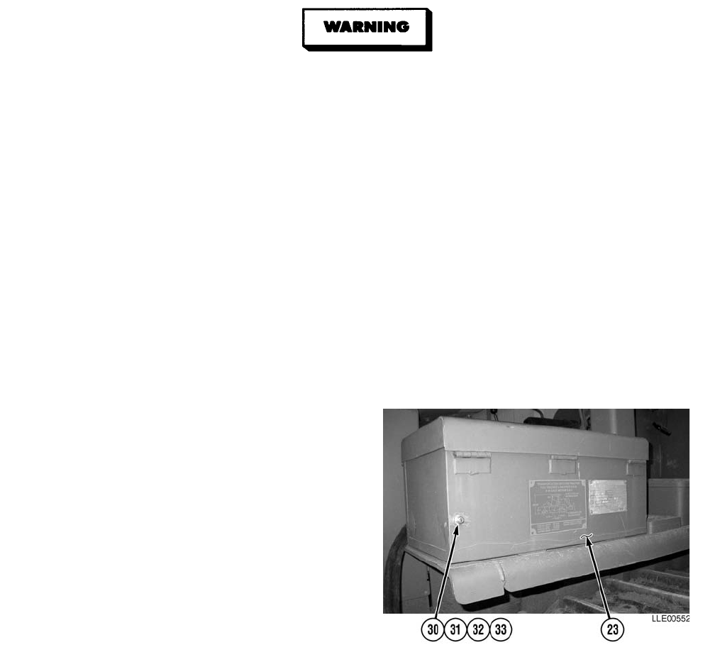
TM 5-6675-348-13&P
2-24
CARC paint contains isocyanate (HDI), which is highly irritating to skin and respiratory
system. High concentrations of HDI can produce symptoms of itching and reddening of skin,
a burning sensation in throat and nose, and watering of the eyes. In extreme concentrations,
HDI can cause cough, shortness of breath, pain during respiration, increased sputum
production, and chest tightness. The following precautions must be taken whenever using
CARC paint:
• ALWAYS use air line respirators when using CARC paint, unless air sampling shows
exposure to be below standards. Use chemical cartridge respirator if air sampling is
below standards.
• DO NOT let skin or eyes come in contact with CARC paint. Always wear protective
equipment (gloves, ventilation mask, safety goggles, etc.).
• DO NOT use CARC paint without adequate ventilation.
• NEVER weld or cut CARC-coated materials.
• DO NOT grind or sand painted equipment without high-efficiency air purifying
respirators in use.
• BE AWARE of CARC paint exposure symptoms; symptoms can occur a few days after
initial exposure. Seek medical help immediately if symptoms are detected.
(27) Remove paint from hole (30) in Battery
Box (23).
(28) Install Voltage Protection Cable (31),
washer (32), and nut (33).
(29) Tighten nut (33).
(30) Apply black spray paint to Diode
connection (31).
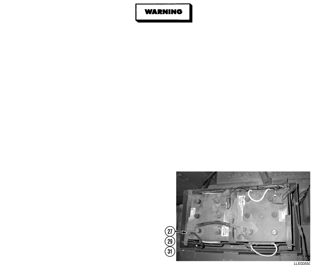
TM 5-6675-348-13&P
2-25
• Battery acid (electrolyte) is extremely harmful. Always wear safety goggles and rubber
gloves, and do not smoke when performing maintenance on batteries. Injury will result if
acid contacts skin or eyes. Wear rubber apron to prevent damage to clothing.
• Remove all jewelry, such as rings, dog tags, bracelets, etc. If jewelry contacts Battery
Terminal, a direct short may result in instant heating of tools, damage to equipment,
and injury or death to personnel.
• Exercise extreme caution when working under tilt platform. Falling platform could
result in serious injury or death to personnel.
• Turn Battery Disconnect Switch OFF prior to performing maintenance in immediate
battery area or working on electrical system. Failure to comply can result in electrical
shock to personnel or damage to equipment.
• Always disconnect the negative (-) Battery Cable before servicing the battery or positive
(+) Battery Cable. Failure to comply can result in electrical shock to personnel or damage
to electrical system.
• Do not allow Battery Cable ends to contact each other or the machine. Failure to comply
can result in damage to battery or electrical system.
(31) Install Voltage Protection Cable (31) on
Negative (-) Battery Terminal (29) with
nut (27).
(32) Tighten nut (27) on Negative (-) Battery
Terminal (29).
b. Follow-On Maintenance.
(1) Install Seat
(TM 5-2410-233-Series)
(TM 5-2410-237-Series).
(2) Connect Main Power Cable
(TM 5-2410-233-Series)
(TM 5-2410-237-Series).
(3) Start Engine
(TM 5-2410-233-Series)
(TM 5-2410-237-Series).
END OF TASK

TM 5-6675-348-13&P
2-26
2-16. GRADIO® DISPLAY SYSTEM INSTALLATION FOR SCRAPERS.
This Task Covers:
a. Installation. b. Follow-On Maintenance.
INITIAL SETUP
Models
613B Scraper (TM 5-3805-260-Series)
621B Scraper (TM 5-3805-248-Series)
Tools and Special Tools
Tool Kit, Automotive Maintenance, Common
No. 2, Item 2, Appendix B
Tool Kit, Electric, Item 3, Appendix B
Tool Kit, Welders, Item 4, Appendix B
Materials and Parts
Cloth, Lint-Free, Item 3, Appendix F
Paint, Spray, Black, Item 8, Appendix F
Rags, Wiping, Item 9, Appendix F
Solder, Item 10, Appendix F
Tags, Identification, Item 13, Appendix F
Ties, Cable, Item 15, Appendix F
Kit, Voltage Protection, Item 1, Appendix K
Label, Warning, Welding/Jump Starting,
Item 2, Appendix K
Mount, RM2E Rigid Mast, Item 4, Appendix K
Personnel Required
MOS 62B
MOS 44B
Equipment Condition
Engine OFF
(TM 5-3805-260-Series)
(TM 5-3805-248-Series).
Wheels chocked
(TM 5-3805-260-Series)
(TM 5-3805-248-Series).
Main Power Cable disconnected
(TM 5-3805-260-Series)
(TM 5-3805-248-Series).
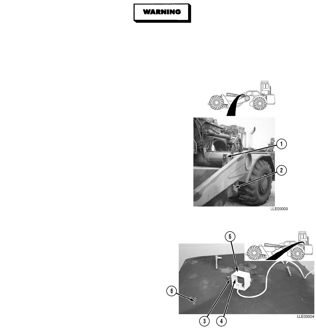
TM 5-6675-348-13&P
2-27
a. Installation.
Unsafe welding practices can cause serious injury from fire, explosions, or harmful agents.
Allow only authorized personnel to weld or cut metals, and follow safety precautions in
TC 9-237. Protective clothing and goggles must be worn, adequate protective equipment
must be used, a suitable fire extinguisher must be kept nearby, and requirements of
TC 9-237 must be strictly followed. Failure to comply may result in serious injury or death
to personnel.
(1) Weld supplied Rigid Mast Mount (1),
holes up, to right side of Bowl (2).
(2) Install Connector Holder (3) and
screw (4) on Display Mount (5).
(3) Tighten screw (4).
NOTE
• The Display Mount should be
mounted in clear view from the
Operator’s Seat.
• Steps (4) through (10) require the
aid of an assistant.
• Position connector holder towards
front of Scraper.
(4) Place Display Mount (5) on Hood (6).
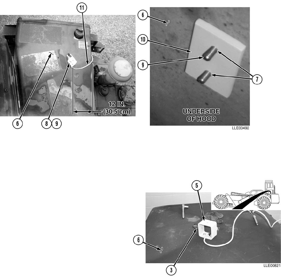
TM 5-6675-348-13&P
2-28
(5) Use existing hole in Hood (6) for left side of
Display Mount hole (7). Right side hole
located 12 in. (30.5 cm) from right side of
Hood (6).
(6) Mark right side Display Mount (5) hole
on Hood (6).
(7) Center punch and drill 1/2-in. (13 mm)
hole (7) in Hood (6).
(8) Install Display Mount (5), Loop
Clamp (8), two bolts (9), Display Mount
Plate (10) to Hood (6).
(9) Leave approximately 12 in. (30.5 cm) of
Power Cable (11) past Loop Clamp (8).
(10) Tighten bolts (9).
(11) Attach Power Cable (11) to Connector
Holder (3).
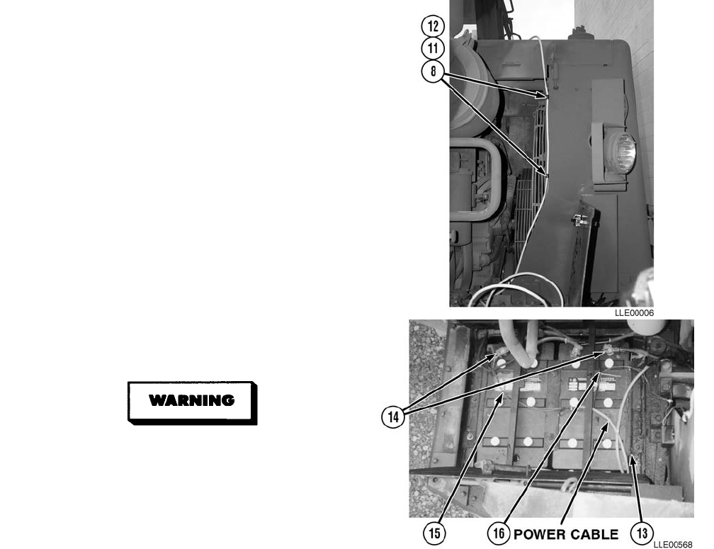
TM 5-6675-348-13&P
2-29
(12) Remove two bolts (12).
(13) Install Power Cable (11), two Loop
Clamps (8), and existing bolts (12).
(14) Tighten bolts (12).
(15) Strip approximately 12 in. (30.5 cm) of
insulation from end of Power
Cable (11).
(16) Route Power Cable (11) into left side of
Battery Box (13).
Allow solder to cool before handling
wire. Failure to comply may result in
injury to personnel.
(17) Solder two connections (14) to Red
Wire (15) and Black Wire (16).
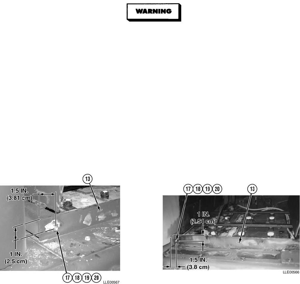
TM 5-6675-348-13&P
2-30
CARC paint contains isocyanate (HDI), which is highly irritating to skin and respiratory
system. High concentrations of HDI can produce symptoms of itching and reddening of skin,
a burning sensation in throat and nose, and watering of the eyes. In extreme concentrations,
HDI can cause cough, shortness of breath, pain during respiration, increased sputum
production, and chest tightness. The following precautions must be taken whenever using
CARC paint:
• ALWAYS use air line respirators when using CARC paint, unless air sampling shows
exposure to be below standards. Use chemical cartridge respirator if air sampling is
below standards.
• DO NOT let skin or eyes come in contact with CARC paint. Always wear protective
equipment (gloves, ventilation mask, safety goggles, etc.).
• DO NOT use CARC paint without adequate ventilation.
• NEVER weld or cut CARC-coated materials.
• DO NOT grind or sand painted equipment without high-efficiency air purifying
respirators in use.
• BE AWARE of CARC paint exposure symptoms; symptoms can occur a few days after
initial exposure. Seek medical help immediately if symptoms are detected.
(18) Drill one 1/2-in. (13 mm) hole (17) in rear corner of Battery Box (13), approximately 1 1/2-in.
(3.81 cm) from rear of Battery Box and 1 in. (2.54 cm) down from top.
(19) Clean paint from hole (17) in Battery Box (13).
(20) Install Diode Protection Cable (18), washer (19), and nut (20).
(21) Tighten nut (20).
(22) Using black spray paint, paint hole (17) in Battery Box (13).
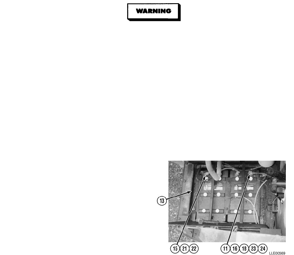
TM 5-6675-348-13&P
2-31/(2-32 Blank)
• Battery acid (electrolyte) is extremely harmful. Always wear safety goggles and rubber
gloves, and do not smoke when performing maintenance on batteries. Injury will result if
acid contacts skin or eyes. Wear rubber apron to prevent damage to clothing.
• Remove all jewelry, such as rings, dog tags, bracelets, etc. If jewelry contacts Battery
Terminal, a direct short may result in instant heating of tools, damage to equipment,
and injury or death to personnel.
• Exercise extreme caution when working under tilt platform. Falling platform could
result in serious injury or death to personnel.
• Turn battery disconnect switch OFF prior to performing maintenance in immediate
battery area or working on electrical system. Failure to comply can result in electrical
shock to personnel or damage to equipment.
• Always disconnect the negative (-) battery cable before servicing the battery or positive
(+) battery cable. Failure to comply can result in electrical shock to personnel or damage
to electrical system.
• Do not allow battery cable ends to contact each other or the machine. Failure to comply
can result in damage to battery or electrical system.
(23) Install Red Wire (15) and nut (21) to
Positive (+) Battery Terminal (22).
(24) Tighten nut (21).
(25) Install Black Wire (16) and Diode
Protection Cable (18) to Negative (-)
Battery Terminal (23) with nut (24).
Coil excess Power Cable (11) and Diode
Protection Cable (18) in Battery
Box (13).
(26) Tighten nut (24).
b. Follow-On Maintenance.
(1) Connect Main Power Cable
(TM 5-3805-260-Series)
(TM 5-3805-248-Series).
(2) Start Engine
(TM 5-3805-260-Series)
(TM 5-3805-248-Series).
(3) Remove Chocks
(TM 5-3805-260-Series)
(TM 5-3805-248-Series).
END OF TASK
TM 5-6675-348-13&P
3-1
CHAPTER 3
BLADE PRO® MOTOR GRADER CONTROL SYSTEM
(130G GRADER)
Content Para Page
Blade Pro® Motor Grader Control System General Information............................................... Section I 3-2
Scope...................................................................................................................................................... 3-1 3-2
Equipment Characteristics, Capabilities, and Features.................................................................. 3-2 3-2
Location and Description of Major Components............................................................................... 3-3 3-5
Blade Pro® Motor Grader Control System Mounting and Adjustments ....................................... 3-4 3-13
Blade Pro® Motor Grader Control System Specifications............................................................... 3-5 3-14
Blade Pro® Motor Grader Control System PMCS ..................................................................... Section II 3-16
Blade Pro® Motor Grader Control System PMCS Introduction..................................................... 3-6 3-16
PMCS Procedures................................................................................................................................. 3-7 3-16
Shortened Maintenance Instructions................................................................................................. 3-8 3-17
Additional Maintenance Inspections.................................................................................................. 3-9 3-18
Leakage Classification and Definition............................................................................................... 3-10 3-18
General Lubrication Instructions....................................................................................................... 3-11 3-18
PMCS Column Entry Explanation..................................................................................................... 3-12 3-19
Blade Pro® Motor Grader Control System Operator’s PMCS Table.............................................. 3-13 3-19
Blade Pro® Motor Grader Control System Operation.............................................................. Section III 3-22
Blade Pro® Motor Grader Control System General Information................................................... 3-14 3-22
Blade Pro® Motor Grader Control System Sensor Calibration....................................................... 3-15 3-22
Blade Pro® Motor Grader Control System Valve Calibration......................................................... 3-16 3-29
Moving Blade Pro® Motor Grader Control System Components from Grader to Grader ........... 3-17 3-35
Blade Pro® Motor Grader Control System Operation Description................................................. 3-18 3-40
Automatic Cross-Slope and Manual Elevation ................................................................................. 3-193-41
Automatic Elevation (Tracer® Sonic Grade Controller) and Cross-Slope...................................... 3-20 3-42
Dual Automatic Elevation (Tracer® Sonic Grade Controller R2S-S
Laser Receiver with EMZE-24 Electric Mast).............................................................................. 3-21 3-45
Automatic Elevation (EM2E-24 Electric Mast And R2S-S Laser Receiver) and Cross-Slope..... 3-22 3-47
Blade Pro® Motor Grader Control System User Options in Setup Mode...................................... 3-23 3-49
Programming Blade Pro® Motor Grader Control System User Options....................................... 3-24 3-50
Blade Pro® Motor Grader Control System Troubleshooting.................................................... Section IV 3-60
Blade Pro® Motor Grader Control System Troubleshooting Error Messages......................... Section V 3-70
Test/Error Log Feature ........................................................................................................................ 3-25 3-70
Blade Pro® Motor Grader Control System Error Log............................................................... Section VI 3-72
MG2P-35 Error Log.............................................................................................................................. 3-26 3-72
Configure for Transport....................................................................................................................... 3-27 3-81
Blade Pro® Motor Grader Control System Maintenance....................................................... Section VII 3-82
Blade Cutting Edge Inspection........................................................................................................... 3-28 3-82
Blade Lift Cylinder Sockets Inspection.............................................................................................. 3-29 3-82
Wear Strips (Circle Top) Inspection.................................................................................................... 3-30 3-83
Hose Tray Backlash Adjustment........................................................................................................ 3-31 3-83
Circle Slide Shoe Inspection................................................................................................................ 3-32 3-84
Blade Backlash Adjustment................................................................................................................ 3-33 3-85
Wear Strip and Shim Replacement.................................................................................................... 3-34 3-86
Blade Pro® Motor Grader Control System Installation................................................................... 3-35 3-87

TM 5-6675-348-13&P
3-2
SECTION I. BLADE PRO® MOTOR GRADER CONTROL SYSTEM GENERAL
INFORMATION
3-1. SCOPE.
Chapter 3 is used for operation and maintenance of the Blade Pro® Motor Grader Control System used on the
130G Grader with the Tracer® Sonic Grade Controller or the R2S-S Laser Receiver with EM2E-24 Electric
Mast flexibility.
3-2. EQUIPMENT CHARACTERISTICS, CAPABILITIES, AND FEATURES.
a. Characteristics.
(1) The Blade Pro® Motor Grader Control System automatically controls elevation and/or cross-slope
of the 130G Grader’s cutting edge with an Operator Interface Box. Three essential precision
sensors, read by the Blade Pro® Motor Grader Control System, accurately determine the blade’s
cross-slope relative to the direction of travel. The Blade Slope Sensor is mounted in the frame
pocket of the rotation circle to determine the blade's slope. The Circle Rotation Sensor is mounted
at the hydra-swivel component to determine the blade’s rotation. The Mainfall Slope Sensor is
mounted on right side of Gooseneck Panel of the 130G Grader to measure the slope in the direction
of travel. The blade's actual cross-slope is compared to the desired cross-slope, and is corrected as
needed.
(2) Tracer® Sonic Grade Controller uses sonic
technology to establish an elevation reference
(e.g., a curb and gutter, a string line, a previous
pass, or an existing surface). Once elevation is set,
any elevation deviations are sent to the Remote
Interface Box. The Remote Interface Box provides
correction outputs to hydraulic valve to maintain
relative distance between Tracer® Sonic Grade
Controller and reference surface.
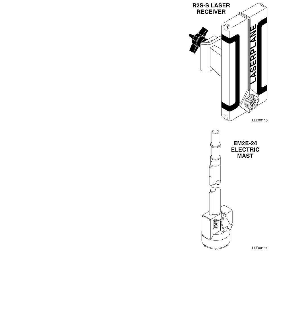
TM 5-6675-348-13&P
3-3
(3) The R2S-S Laser Receiver is an omnidirectional,
360-degree receiver that detects the position of
the laser reference plane and transmits these
signals to the Remote Interface Box. These
signals are processed to indicate the relative
position of the R2S-S Laser Receiver to the laser
reference plane.
(4) The EM2E-24 Electric Mast is a telescoping
mount driven by an electric motor. The EM2E-24
Electric Mast electronically measures vertical
movement and sends the signals to the Remote
Interface Box for processing.
b. Capabilities.
(1) The blade's elevation on one or both sides can be
controlled by using the Tracer® Sonic Grade
Controller to trace an existing surface, a string
line, a curb and gutter, or a previous pass. The
R2S-S Laser Receiver with EM2E-24 Electric
Mast, in combination with the 1145-2 Laser
Transmitter, provides a constant grade reference
up to 1,000 ft (305 m) away from the 1145-2
Laser Transmitter.
(2) The Tracer® Sonic Grade Controller replaces
contact-type followers that often give inaccurate
or inconsistent results.
c. Features.
(1) The Blade Pro® Motor Grader Control System’s automatic blade control is achieved through the
Hydraulic Control Valve. The Hydraulic Control Valve provides electrical-to-hydraulic interface for
controlling the blade’s elevation and cross-slope.
NOTE
Initial installation of these system components is to be conducted by Direct Support
personnel.
(2) Installation kits for the Blade Pro® Motor Grader Control System provides all the necessary cables,
hydraulic hoses, hydraulic fittings, mounting brackets, and fasteners to ensure proper installation
and operation.

TM 5-6675-348-13&P
3-4
(3) The Tracer® Sonic Grade Controller features:
(a) Temperature compensation - Automatically compensates for temperature changes that occur
on the job. Ensures consistent results from dawn to dusk.
(b) Rugged housing - Built to withstand the harsh environment of a construction job site.
(c) Visible display - Bright incandescent lamps indicate (to the Operator) the status of blade
position in reference to grade.
(d) Out-of-range indication - Flashing High and Low lamps indicate reference is higher than
elevation set point. Solid High and Low lamps indicate that reference is lower than elevation
set point.
(e) Plug compatibility between the Tracer® Sonic Grade Controller, the R2S-S Laser Receiver,
and the EM2E-24 Electric Mast.
(f) The Operator can lock on to a new reference elevation by pressing the RESET button.
(4) The R2S-S Laser Receiver features:
(a) Electrical connection - A control box, and a 7-pin electric mast or a stand-alone display
interface connector.
(b) Receiver clamp - Allows the receiver to slide over the mast and securely clamp into place.
(5) The EM2E-24 Electric Mast features:
(a) The EM2E-24 Electric Mast is used on 130G Graders that require remote adjustment of the
R2S-S Laser Receiver's height from the cab of the 130G Grader and when a numerical display
of the EM2E-24 Electric Mast movement is required.
(b) Receiver plug - Provides a mount for the R2S-S Laser Receiver to slip over and clamp into
place.
(c) Electrical connectors:
1One 10-pin control box interface connector
2One 7-socket receiver interface connector
(d) Electrical connector cap - Seals the electrical connector to make it water and dust resistant.
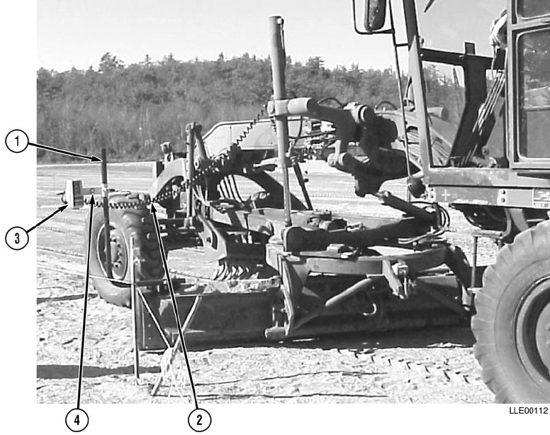
TM 5-6675-348-13&P
3-5
3-3. LOCATION AND DESCRIPTION OF MAJOR COMPONENTS.
Figure 3-1. Blade Pro® Motor Grader Control System Component Placement
(1) TRACER® SONIC GRADE CONTROLLER POLE. Mounts to the end of the blade to provide
mounting for the Tracer® Sonic Grade Controller. Tracer® Sonic Grade Controller poles are stowed
in the Tracer® Clamp and Base Mount Assembly when not in use.
(2) COIL CORD FROM TRACER® SONIC GRADE CONTROLLER
TO REMOTE INTERFACE BOX. This cable is also used when connecting to EM2E-24 Electric
Mast.
(3) TRACER® SONIC GRADE CONTROLLER. Establishes an elevation reference.
(4) BRACKET FOR TRACER® SONIC GRADE CONTROLLER. Locks to the pole mount and attaches
to the Tracer® Sonic Grade Controller. Allows for adjustment of the Tracer® Sonic Grade Controller
to be parallel with the cutting edge.
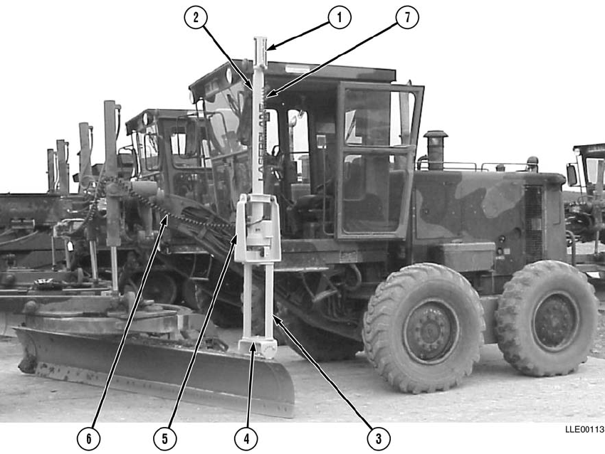
TM 5-6675-348-13&P
3-6
Figure 3-2. Blade Pro® Motor Grader Control System Mast Component Placement
(1) R2S-S LASER RECEIVER. Detects the laser beam and sends correction signals to the Remote
Interface Box. Corrections are then sent to raise/lower the grader blade.
(2) EM2E-24 ELECTRIC MAST. This is a telescoping mast for the R2S-S Laser Receiver, and is
mounted to the top edge of the blade. The EM2E-24 Electric Mast, with the R2S-S Laser Receiver,
electronically measures vertical movement and sends signals to the Remote Interface Box for
processing.
(3) MAST RISER. Attaches between the mast mount and the shock mount. Adds to the overall height
of the mast assembly to ensure the R2S-S Laser Receiver’s height over the cab can be obtained.
(4) MAST MOUNT. Used to connect the mast assembly to the machine blade. The unit is adjustable so
that the EM2E-24 Electric Mast can be put in plumb position if the blade is rolled.
(5) SHOCK MOUNT. Attaches to the EM2E-24 Electric Mast as part of the mast assembly. Protects
the EM2E-24 Electric Mast and the R2S-S Laser Receiver from vibration.
(6) COIL CORD FROM EM2E-24 ELECTRIC MAST TO REMOTE INTERFACE BOX.
(7) COIL CORD FROM R2S-S LASER RECEIVER TO EM2E-24 ELECTRIC MAST.
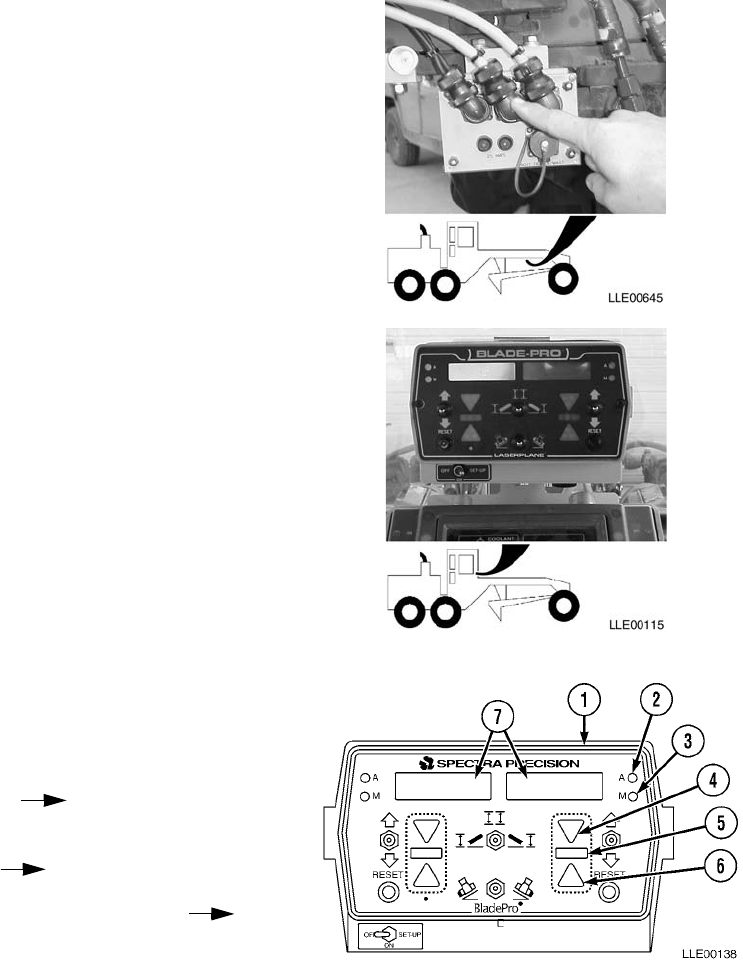
TM 5-6675-348-13&P
3-7
a. Remote Interface Box. Central controller and
processor for all sensors, inputs, and elevation
devices. Output signals are provided to the
control valves and the Operator Interface Box.
b. Operator Interface Box. Located in front of the
Operator; provides easy access to all Blade Pro®
Motor Grader Control System control functions.
(1) The operating status is indicated with
Light-Emitting Diodes (LEDs) (2) and (3),
which indicate the operating status of the
right and left sides.
Green (2) Indicator Automatic
Operation
Red (3) Indicator Manual Operation
Solid Green (2) with Flashing Red (3)
Inactive Automatic
(2) The Operator Interface Box uses bright
LEDs to indicate the blade’s position relative
to the desired grade. Operation status
windows (7) use a back-lighted Liquid
Crystal Display (LCD) to indicate
percent (%) slope, direction of slope,
elevation, and error messages. Customized
functions and features can also be displayed
when in SETUP mode.
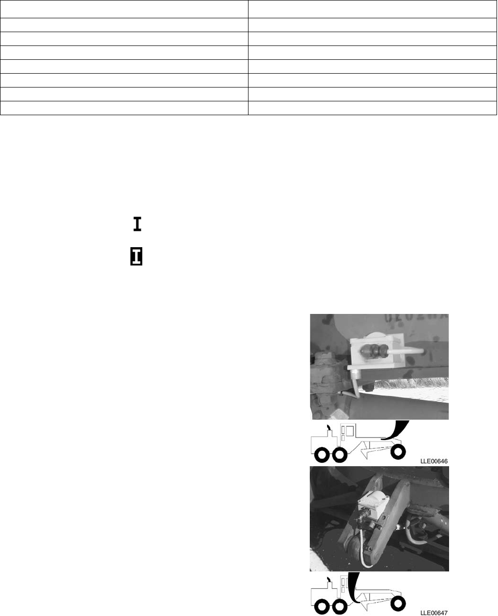
TM 5-6675-348-13&P
3-8
LCD Display Symbols
Percent Slope* 0.0%
Rise/Run* 1/4 in. (0.64 cm)
Direction of Slope > Blade is rising to the left
< Blade is rising to the right
Elevation Elevation device is in range
Elevation device is out of range or is not hooked up
* Display symbol is user-selectable.
NOTE
The Mainfall Slope Sensor and the Blade
Slope Sensor are the same and can be
interchanged. Calibration is required if
interchanged.
c. Mainfall Slope Sensor. Measures the slope
of the 130G Grader in the direction of travel.
d. Blade Slope Sensor. Measures the actual
slope across the blade.
Table 3-1. Blade Pro® Motor Grader Control System Operator Interface Box Light Indicators
Type of Grade LED Indicator
Coarse Lower Solid Yellow (4)
Medium Lower Flashing Yellow (4)
Fine Lower Flashing Yellow and Green (4 and 5)
ON GRADE Flashing Green (5)
Fine Raise Flashing Yellow and Green (5 and 6)
Medium Raise Flashing Yellow (6)
Coarse Raise Solid Yellow (6)
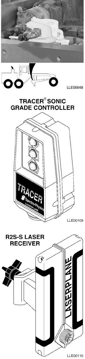
TM 5-6675-348-13&P
3-9
e. Circle Rotation Sensor. Measures the angle
of the blade relative to the 130G Grader’s
A-frame. When the blade is perpendicular to
the A-frame, 0-degree rotation is achieved.
f. Tracer® Sonic Grade Controller. Mounted at
the top outside edge of the blade, the Tracer®
Sonic Grade Controller uses sonic waves or
an R2S-S Laser Receiver to determine the
location and distance to a reference surface.
Once the Tracer® Sonic Grade Controller has
been locked onto a reference (e.g., a string
line, a curb and gutter, or a previous pass),
any change in the set point distance causes a
correction signal to be sent to the Remote
Interface Box.
g. R2S-S Laser Receiver. Detects the laser
beam and sends correction signals to the
Remote Interface Box. Corrections are then
sent to raise/lower the grader blade.
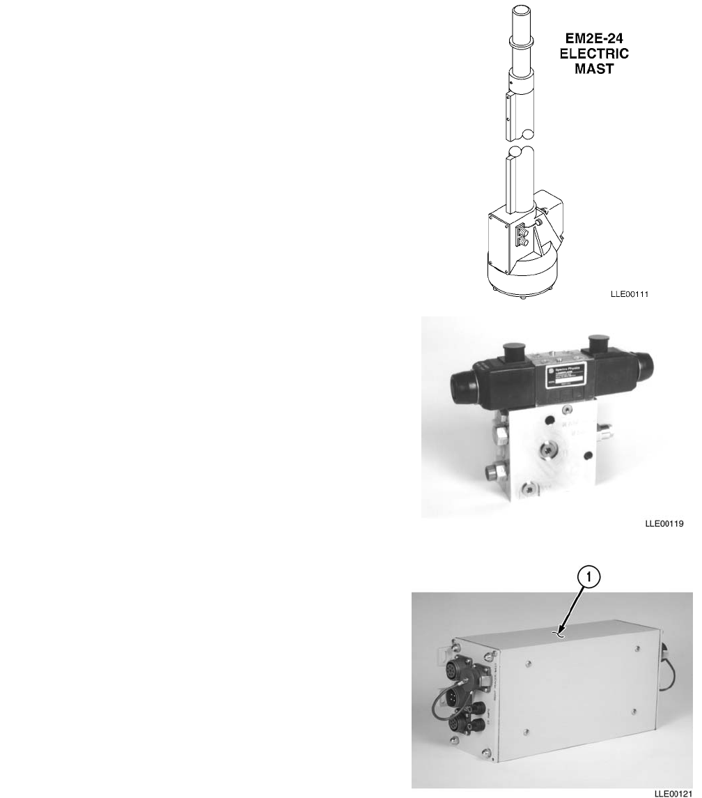
TM 5-6675-348-13&P
3-10
h. EM2E-24 Electric Mast. This is a telescoping mast
for the R2S-S Laser Receiver, and is mounted to
the top edge of the blade. The EM2E-24 Electric
Mast, with the R2S-S Laser Receiver,
electronically measures vertical movement and
sends signals to the Remote Interface Box for
processing.
i. Hydraulic Control Valves. Accepts signals from
the Remote Interface Box and provides
proportional correction rates for raising and
lowering on both sides of the blade.
NOTE
Initial installation of these system
components is to be conducted by
Direct Support personnel.
j. Blade Pro® Motor Grader Control System
Features, Functions, and Specifications. The
Remote Interface Box (1) provides necessary
system electrical interface to the Blade Slope
Sensor, the Mainfall Slope Sensor, the Circle
Rotational Sensor, the Tracer® Sonic Grade
Controller, the R2S-S Laser Receiver, and the
EM2E-24 Electric Mast. All signal processing and
control outputs occur at the Remote Interface
Control Box. Control signals are provided to the
Hydraulic Control Valves. Communications output
is provided between the Remote Interface Control
Box and the Operator Interface Box for display
information and to allow the Operator to interface
with the system. All programmable functions are
stored at the Remote Interface Control Box in
nonvolatile memory. If power loss occurs, all settings are kept.
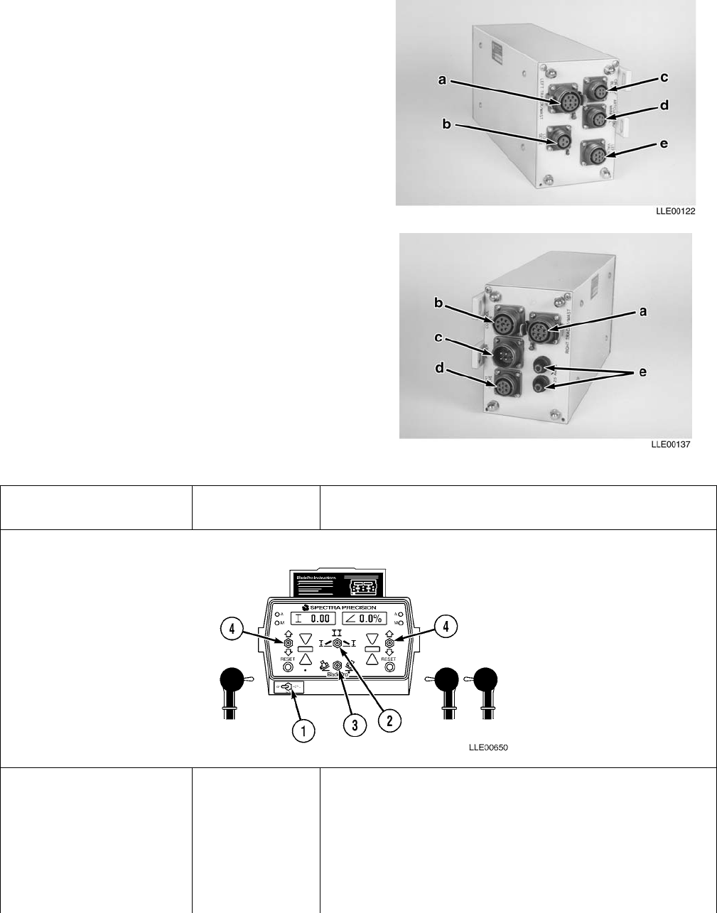
TM 5-6675-348-13&P
3-11
(1) Left-Side Connections.
(a) 10-Socket (Left Elevation Input)
(b) 3-Socket (Load Sensing Valve)
(c) 4-Socket (Blade Rotation, and Blade
Slope Sensors)
(d) 5-Socket (Mainfall Slope Sensors)
(e) 7-Socket (Left Hydraulic Valve)
(2) Right-Side Connections.
(a) 10-Socket (Right Elevation Input)
(b) 8-Socket (Operator Interface Box)
(c) 4-Pin (System Power)
(d) 7-Socket (Right Hydraulic Valve)
(e) Overload Protection (Fuse)
Table 3-2. Blade Pro® Motor Grader Control System Operator Interface Box Controls
Key Controls or
Indicator
Function
1. OFF/ON/SET-UP: In left position System is OFF.
In center position System is ON.
In right position Operator has access to the following SET-UP functions:
Elevation Reference, Customize, Test, Slope Speed, and
Elevation Speed. (For more information on SET-UP
options, refer to Section III)
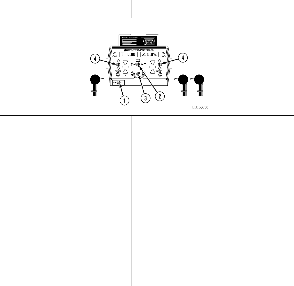
TM 5-6675-348-13&P
3-12
2. OPERATION MODE
SWITCH: Selects the
side(s) of the blade to be
controlled by elevation
or slope.
In left position Elevation controls the left side of the blade. The cross-slope
controls the right side of the blade.
In center position Elevation controls the left side of the blade.
Elevation controls the right side of the blade.
In right position Cross-slope controls the left side of the blade.
Elevation controls the right side of the blade.
3. DIRECTION OF
SLOPE: Changes the blade’s direction of slope. The blade slope
symbol > < will change in the display window to show the
direction of the slope.
4. INCREASE/
DECREASE: The value in the display window always increases when
toggled up. The value in the display window always
decreases when toggled down. The left Increase/Decrease
switch operates the left display window. The right
Increase/Decrease switch operates the right display
window. Note that when you adjust the cross-slope value,
the number will not go below 0.0%. This makes sure the
Increase/Decrease switch always operates the same way.
(For applications that adjust through 0.0%, refer to
Para 3-23)
Table 3-2. Blade Pro® Motor Grader Control System Operator Interface Box Controls (Cont)
Key Controls or
Indicator
Function
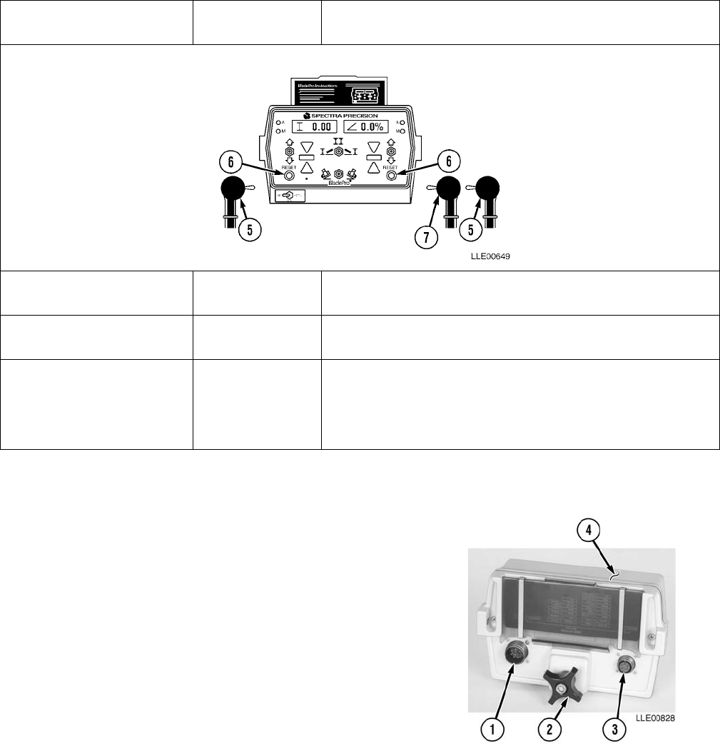
TM 5-6675-348-13&P
3-13
3-4. BLADE PRO® MOTOR GRADER CONTROL SYSTEM MOUNTING AND ADJUSTMENTS.
a. Operator Interface Box.
(1) Serial Communication Connector
(2) Mounting Knob
(3) Remote Switch Connector
b. Operator Interface Box Removal.
(1) Disconnect Remote Switch Connector (3) from back
of Operator Interface Box (4).
(2) Disconnect Serial Communication Connector (1)
from back of Operator Interface Box (4).
(3) Loosen mounting knob (2) on back of Operator Interface Box (4).
5. RIGHT/LEFT (R/L)
SWITCH: Provides remote switching of the system from automatic to
manual operation at the manual control levers.
6. RESET SWITCH: Resets Tracer® Sonic Grader Controller reference to a new
surface or object.
7. REMOTE SWITCH: Function of the switch is selected in SETUP mode.
Options include Elevation Offsets, Slope Offsets, and Auto
Raise/Lower. (For further details on these options, refer to
Para 3-23)
Table 3-2. Blade Pro® Motor Grader Control System Operator Interface Box Controls (Cont)
Key Controls or
Indicator
Function
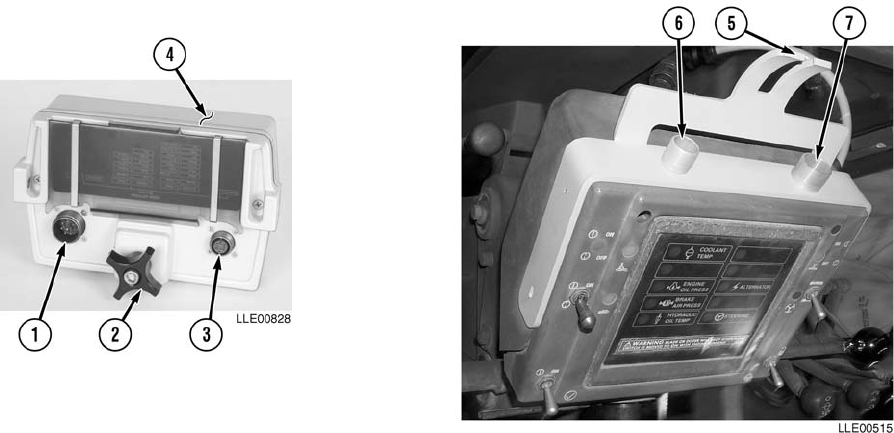
TM 5-6675-348-13&P
3-14
(4) Pull Operator Interface Box (4) up from
mounting bracket (5).
(5) Attach loose connectors (1) and (3) to
provided dust covers (6) and (7) on side of the mounting bracket (5).
c. Operator Interface Box Viewing Angle Adjustment.
(1) Loosen mounting knob (2) on back of Operator Interface Box (4).
(2) Rotate Operator Interface Box (4) for best viewing angle, then tighten mounting knob (2).
3-5. BLADE PRO® MOTOR GRADER CONTROL SYSTEM SPECIFICATIONS.
Blade Slope Sensor Resolution 0.01% slope
Mainfall Slope Sensor Resolution 0.01% slope
Circle Rotation Sensor Resolution 0.1 degree
Articulation Sensor Resolution 0.1 degree
Cross-Slope Resolution 0.01% slope
*Cross-Slope Accuracy 1/4 in./10 feet
Cross-Slope Range ±19.99%
* System accuracy is affected by the tightness of the machine. (Refer to Para 3-23 for more
information about determining the machine’s slope.)

TM 5-6675-348-13&P
3-15
Table 3-3. Blade Pro® Motor Grader Control System Equipment Data
Model Item
DIMENSIONS
ST2-20 Height: 9.0 in. (22.9 cm)
Width: 4.25 in. (10.8 cm)
Depth: 2.75 in. (7.0 cm)
R2S-S Height: 11.4 in. (29 mm)
Width: 4.60 in. (11.7 cm)
Depth: 5.8 in. (14.7 cm)
WEIGHT
ST2-20 3.5 lb. (1.6 kg)
R2S-S 2.9 lb. (1.3 kg)
ELECTRICAL SYSTEM
ST2-20 Input: 10 to 30 Vdc
R2S-S Input: 10 to 30 Vdc
Connector: Standard Military Type (Mil Spec. C-5015)
Operating Temperature: -20 to 160° F (-28.9 to 71.1° C)
Bulbs: 12-/24-volt bulbs. Ensure proper bulb is installed for machine’s electrical system.
TEMPERATURE
ST2-20 Operating Temperature Range: -20 to 160° F (-28.9 to 71.1° C)
R2S-S Operating Temperature Range: -20 to 160° F (-28.9 to 71.1° C)
SPECIFICATIONS
ST2-20 Correction Window: ±0.20 ft (6.1 cm)
On Grade Dead Bands:Narrow: ±0.015 ft (±0.46 cm)
Operating Distance: Max. 43 in. (109 cm)
Min. 8 in. (20.3 cm)
Sonic Cone Angle: 6 degrees (inclusive)
R2S-2 Vertical Sensing Range: 0.61 ft (18.6 cm)
Beam Acceptance Angle: 360 degrees
On Grade Dead Band*: ±0.015 ft (±0.46 cm)
*Typical reading with Laser Transmitters
TM 5-6675-348-13&P
3-16
SECTION II. BLADE PRO® MOTOR GRADER CONTROL SYSTEM PMCS
3-6. BLADE PRO® MOTOR GRADER CONTROL SYSTEM PMCS INTRODUCTION.
Preventive Maintenance Checks and Services (PMCS) means systematic caring for, inspecting, and servicing
equipment to keep it in good condition and to prevent breakdowns. As a Blade Pro® Motor Grader Control
System Operator, your mission is to:
a. Be sure to perform your PMCS each time you operate the Blade Pro® Motor Grader Control
System. Always do your PMCS in the same order so it becomes a habit. Once you’ve had some
practice, you’ll quickly spot anything wrong.
b. Do your Before PMCS just before you operate the Blade Pro® Motor Grader Control System. Pay
attention to WARNINGS, CAUTIONS, and NOTES.
c. Do your During PMCS while you operate the Blade Pro® Motor Grader Control System. Pay attention
to WARNINGS, CAUTIONS, and NOTES.
d. Do your After PMCS right after operating the Blade Pro® Motor Grader Control System. Pay attention
to WARNINGS, CAUTIONS, and NOTES.
e. Do your Weekly PMCS once a week.
f. Use DA Form 2404 or DA Form 5988-E (Equipment Inspection and Maintenance Worksheet) to
record any faults that you don’t immediately fix.
3-7. PMCS PROCEDURES.
a. PMCS Tables (Table 3-4., Table 3-5., and Table 3-7.) list inspections and care required to keep
your Blade Pro® Motor Grader Control System in good operating condition. These tables are set
up so you can do Before and After PMCS while walking around the Blade Pro® Motor Grader
Control System.
b. The “Interval” column tells you when to do a certain check or service.
c. The “Procedure” column tells you how to do required checks and services. Carefully follow these
instructions.
d. The “Not Fully Mission Capable If” column tells you when your Blade Pro® Motor Grader
Control System is nonmission capable and why the Blade Pro® Motor Grader Control System
cannot be used.
e. When something looks wrong that you cannot fix, write down the problem on your
DA Form 2404 or DA Form 5988-E. Immediately report the problem to your supervisor.
f. When you do your PMCS, you will always need a rag or two. Following are checks that are
common to the entire Blade Pro® Motor Grader Control System.

TM 5-6675-348-13&P
3-17
• Degreasing Solvent (MIL-PRF-680, Type II) is TOXIC and flammable. Wear protective
goggles and gloves, use only in a well-ventilated area, avoid contact with skin, eyes, and
clothes, and do not breathe vapors. Keep away from heat or flame. Never smoke when
using solvent; the flash point for degreasing solvent type II is 200º F (93º C). Failure to
comply may result in injury or death to personnel.
• If personnel become dizzy while using cleaning solvent, immediately get fresh air and
medical help. If solvent contacts skin or clothes, flush with cold water. If solvent contacts
eyes, immediately flush eyes with water and get immediate medical attention. Do not
use diesel fuel, gasoline, or benzene (benzol) for cleaning.
• Do not smoke when using cleaning solvent. Never use it near an open flame. Be sure
there is a fire extinguisher nearby and use cleaning solvent only in a well-ventilated
area.
• Use caution when using cleaning solvents. Cleaning solvents evaporate quickly and can
irritate exposed skin if solvents contact skin. In cold weather, contact of exposed skin
with cleaning solvents can cause frostbite.
(1) Keep It Clean. Dirt, grease, oil, and debris only get in the way and may cover up a serious problem.
Clean as you work. Use degreasing solvent (MIL-PRF-680, Type II) on all metal surfaces. Use soap
and water when you clean rubber or plastic material.
(2) Rust and Corrosion. Check Blade Pro® Motor Grader Control System brackets for rust and
corrosion. When any bare metal or corrosion exits, clean surface and apply a coat of paint. Report
bare metal or corrosion to your supervisor.
(3) Bolts, Nuts, and Screws. Check all bolts, nuts, and screws for obvious looseness, missing, bent, or
broken condition. You can’t check them all with a tool, but look for chipped paint, bare metal, or
rust around bolt heads. When you find a bolt, nut, or screw you think is loose, tighten it or report it
to your supervisor.
(4) Welds. Look for loose or chipped paint, rust, or gaps where parts are welded together. When you
find a bad weld, report it to your supervisor.
(5) Electric Wires and Connectors. Look for cracked, frayed, or broken insulation, bare wires, and
loose or broken connectors. Tighten loose connectors. Report any damaged wires to your supervisor.
(6) Hydraulic Lines and Fittings. Look for wear, damage, and leaks; ensure clamps and fittings are
tight. Stains around a fitting or connector can mean a leak. If a leak comes from a loose fitting or
connector, tighten it. If something is broken or worn out, report it to Unit Maintenance.
(7) When you check operating conditions, check to see if component is serviceable.
3-8. SHORTENED MAINTENANCE INSTRUCTIONS.
Local conditions of extreme heat, dust, cold, or wetness dictate that service intervals shall be shortened.

TM 5-6675-348-13&P
3-18
3-9. ADDITIONAL MAINTENANCE INSPECTIONS.
Additional maintenance inspections are required for the following reasons:
a. Prolonged storage. Inspect 130G Grader control components that have been stored for a period
of 3 months or longer.
b. Initial preparation upon receipt.
c. Preparation for storage.
3-10. LEAKAGE CLASSIFICATION AND DEFINITION.
It is necessary for you to know how fluid leakage affects the status of the Blade Pro® Motor Grader Control
System. Following are types/classes of leakage that Operator needs to know to be able to determine the status
of the Blade Pro® Motor Grader Control System. Learn these leakage definitions and remember – when in
doubt, notify your supervisor.
• Equipment operation is allowable with minor leakages (Class I or II) with exception of fuel leakage.
Of course, consideration must be given to fluid capacity in the item/system being checked/inspected.
When in doubt, notify your supervisor.
• When operating with Class I and II leaks, continue to check fluid levels as required in your PMCS.
• Any fuel leak or Class III leaks should be reported immediately to your supervisor.
a. CLASS I – Leakage of fluid (as indicated by wetness or discoloration) not great enough to form
drops.
b. CLASS II – Leakage of fluid great enough to form drops, but not enough to cause drops to drip
from item being checked/inspected.
c. CLASS III – Leakage of fluid great enough to form drops that fall from item being checked/
inspected.
3-11. GENERAL LUBRICATION INSTRUCTIONS.
Do not start or move Blade Pro® Motor Grader Control System while anyone is under the
130G Grader. Failure to comply could result in severe injury or death to personnel.
a. Intervals. Intervals (On-condition or hard-time) and related man-hour times are based on normal
operation. Man-hour time specified is time needed to do all services prescribed for a particular interval.
On-condition (OC) oil sample intervals shall be applied unless changed by the Army Oil Analysis
Program (AOAP) laboratory. Change hard-time interval when lubricants are contaminated or when
you are operating equipment under adverse operating conditions, including longer-than-usual
operating hours. Calendar interval will be extended during periods of low activity.
When extended, adequate preservation precautions must be taken. Hard-time intervals will be applied
in the event AOAP laboratory support is not available. Hard-time intervals must be applied during the
warranty period. Intervals shown in this lubrication section are based on calendar and hourly times or
calendar times and mileage. An example of a calendar and hourly lubrication is: M/60 HR, in which M
stands for monthly and 60 HR stands for 60 hours of 130G Grader operation. Lubrication is to be
performed at whichever interval occurs first for the 130G Grader. Special lubrication intervals and
services are shown by the use of an asterisk (*) symbol.

TM 5-6675-348-13&P
3-19
3-12. PMCS COLUMN ENTRY EXPLANATION.
a. Item No. Column. The checks and services are numbered in interval order showing a walk-around
sequence around the Blade Pro® Motor Grader Control System. Use these numbers in the “Item No.”
column on DA Form 2404 or DA Form 5988-E when recording faults that you don’t immediately fix.
b. Interval Column. This column indicates when the lubrication, check, and/or service should be
performed.
c. Location, Item to Check/Service Column. The underlined items listed in this column are divided into
groups indicating the portion of the equipment of which they are a part (e.g., brakes, fuel, and engine).
Under these groupings, a few common words are used to identify the specific item being checked.
d. Procedure Column. This column contains procedures required to perform the checks and services.
e. Not Fully Mission Capable If Column. This column contains the criteria that cause the equipment to
be classified as NOT READY/AVAILABLE because of an inability to perform its primary mission. An
entry in this column will:
(1) Identify conditions that make the equipment not available for readiness reporting purposes.
(2) Deny use of the equipment until corrective maintenance has been performed.
3-13. BLADE PRO® MOTOR GRADER CONTROL SYSTEM OPERATOR’S PMCS TABLE.
Table 3-4. Blade Pro® Motor Grader Control System Operator’s PMCS (Before/After)
Item
No. Interval
Location
Procedure Not Fully Mission
Capable If:
Item to
Check/Service
1. Before/After Hydraulic Tubes
and Fittings Check all hydraulic tubes and fittings
for leaks. Class III leaks are evident.
2. Before/After PSV2 Hydraulic
Valves Check all hydraulic valves for leaks. Class III leaks are evident.
3. Before/After Hydraulic Hoses Check all hydraulic hoses for leaks. Class III leaks are evident.
4. Before/After Electrical
Cables and Coil
Cords
Check all electrical cables to ensure
none are frayed, cracked, or exposed.
Check electrical connections to ensure
they are free of dirt, debris, and
damage.
Check all screws and nuts for
tightness.
Ensure dust caps are in place when
electrical connections are not being
used.
Frayed, cracked, or
exposed wires are evident.
Connectors are damaged.

TM 5-6675-348-13&P
3-20
5. Before/After Remote
Interface Box
To avoid damage to equipment,
fuse must be replaced with
25-amp fuse.
Check 25-amp fuses to ensure they are
not burned out.
Check left and right socket connectors
for any dirt, debris, or damaged
connections.
Check nuts and screws for tightness.
Fuse is blown. Replace
before operating.
Dirt, debris, and/or
damaged connectors are
present.
Nuts or screws are loose.
6. Before/After Mainfall Slope
Sensor and
Blade Slope
Sensors
Check electrical connectors for any
dirt, debris, or damage. Connectors are damaged.
7. Before/After Circle Rotation
Sensor Check electrical connectors for dirt,
debris, or damage.
Check screws for tightness.
Connectors are damaged.
8. Before/After Tracer® Sonic
Grade
Controller
Check electrical connectors and
transducer for dirt, debris, or damage.
Wipe dirt and dust from housing covers
with damp cloth. Inspect exterior for
damage or cracks.
Wipe dirt and dust from transducer,
using soft cloth or low-pressure air.
Connectors are damaged.
Transducer is soiled,
dented, or foil inside is
ripped.
9. Before/After R2S-S Laser
Receiver Check electrical connections for dirt,
debris, or damage.
Wipe dirt and dust from metal housing
cover with damp cloth.
Inspect windows for cracks and ensure
black dust seal is still in place.
Clean windows with clean water or
general purpose cleaner and soft cloth.
Check and clean breather hole.
Connectors are damaged.
Windows are cracked or
black dust seal is missing.
Breather hole is plugged.
Table 3-4. Blade Pro® Motor Grader Control System Operator’s PMCS (Before/After) (Cont)
Item
No. Interval
Location
Procedure Not Fully Mission
Capable If:
Item to
Check/Service

TM 5-6675-348-13&P
3-21
10. Before/After EM2E-24
Electric Mast Check cap seal for wear and play.
Check electrical connectors, dust cover,
screw, and hardware for damage.
Connectors are damaged.
11. Before/After Operator
Interface Box Wipe dirt and dust from all metal
components with damp cloth.
Clean screen with general purpose
cleaner and soft cloth.
Inspect exterior for cracks and any
damage to any electrical connectors. Connectors are damaged.
12. Before/After Mast Mount
Base Check all welds for cracks. Welds are cracked.
Table 3-5. Blade Pro® Motor Grader Control System PMCS (Quarterly)
Item
No. Interval
Location
Procedure
Not Fully
Mission
Capable If:
Item to
Check/Service
1. Quarterly Blade Pro® Sensor Calibration Refer to Para 3-15
2. Quarterly Valve Calibration Refer to Para 3-16
Table 3-4. Blade Pro® Motor Grader Control System Operator’s PMCS (Before/After) (Cont)
Item
No. Interval
Location
Procedure Not Fully Mission
Capable If:
Item to
Check/Service
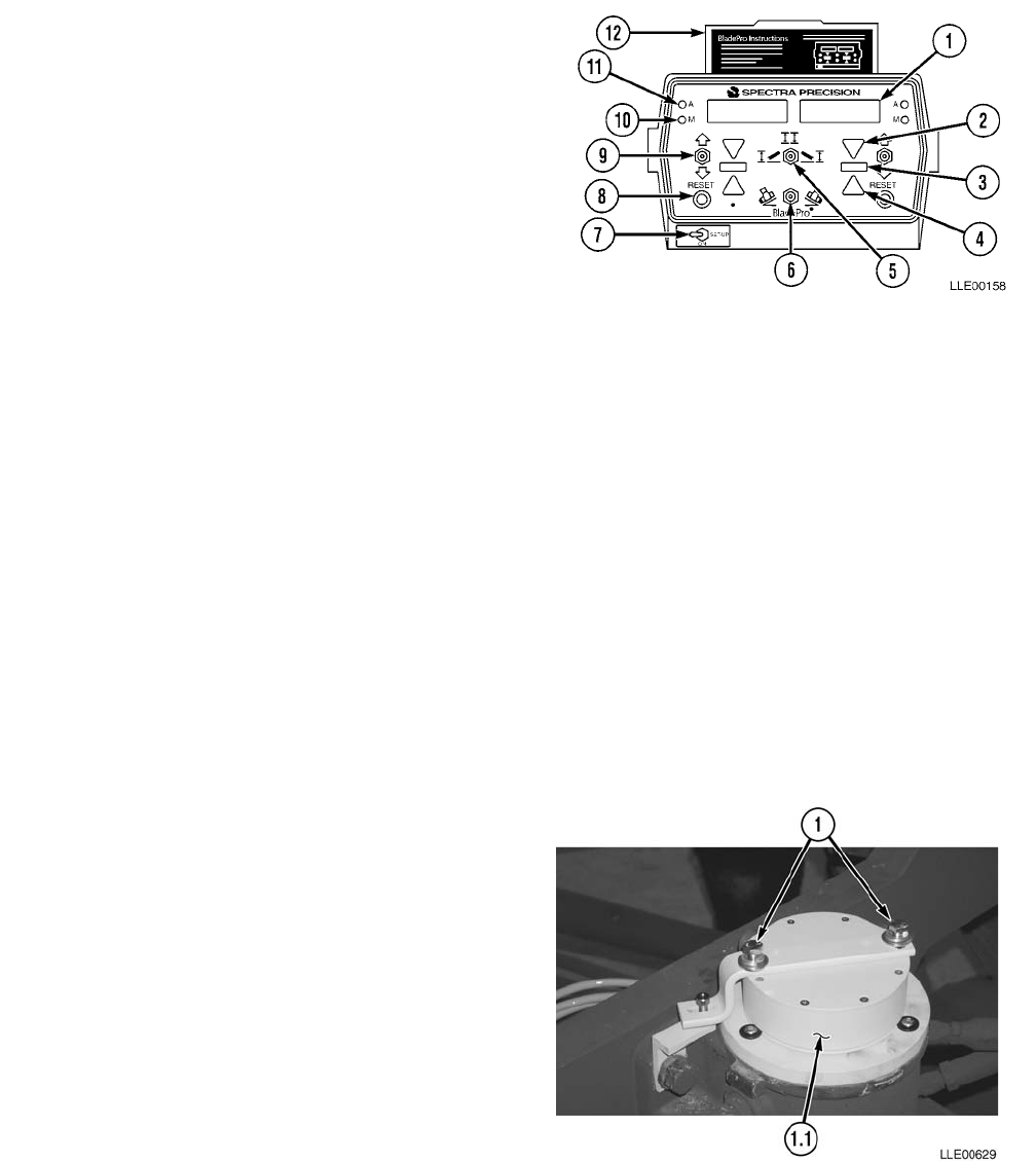
TM 5-6675-348-13&P
3-22
SECTION III. BLADE PRO® MOTOR GRADER CONTROL SYSTEM OPERATION
3-14. BLADE PRO® MOTOR GRADER CONTROL SYSTEM GENERAL INFORMATION.
Operator Interface Box Controls and Indicators.
1. Display Window.
2. Above-Grade Indicator (2) (Yellow)
3. On-Grade Indicator (2) (Green)
4. Below-Grade Indicator (2) (Yellow)
5. Mode Switch
6. Slope Switch
7. ON/OFF/SET-UP Switch
8. RESET Button (2)
9. Increase/Decrease Switch (2)
10. Manual LED (2) (Red)
11. Automatic LED (2) (Green)
12. Quick Instruction Cards
3-15. BLADE PRO® MOTOR GRADER CONTROL SYSTEM SENSOR CALIBRATION.
NOTE
• Sensor calibration requires the aid of an assistant.
• Valve calibration and sensor calibration settings are specific for the make, model,
bumper number, and serial number once calibration is completed.
a. Circle Rotation Sensor Calibration.
(1) Rotate and align chisel marks on 130G Grader’s Rotation Circle to draw bar reference.
(2) Place cutting edge firmly on ground.
(3) Loosen two bolts (1) on Rotation
Sensor (1.1).
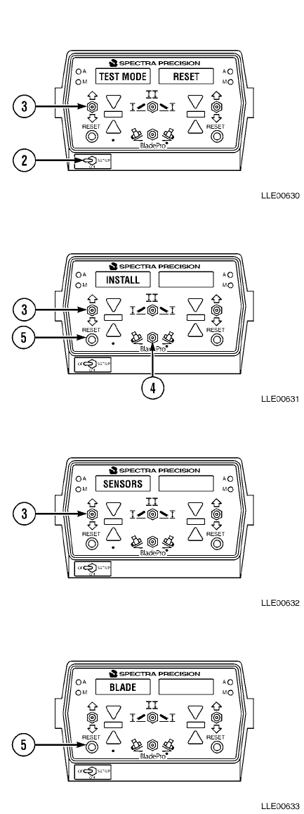
TM 5-6675-348-13&P
3-23
(4) Set ON/OFF/SET-UP Switch (2) to SETUP
position.
(5) Toggle left Increase/Decrease (3) switch
down until TEST MODE is displayed in
left window and RESET is displayed in
right window.
(6) Push Slope switch (4) right, while at the
same time pushing right RESET button (5)
in, and right Increase/Decrease switch (3)
down. INSTALL will be displayed in the
left window.
(7) Toggle left Increase/Decrease switch (3)
down until SENSORS is displayed in left
window.
(8) Press left RESET button (5). BLADE will
appear in left window.
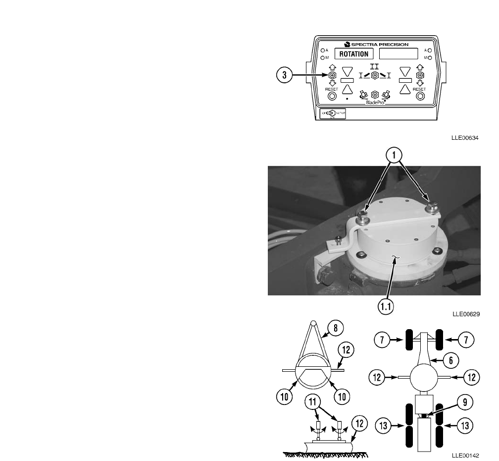
TM 5-6675-348-13&P
3-24
(9) Toggle left Increase/Decrease switch (3)
down until ROTATION is displayed in left
window.
(10) Manually turn Rotation Sensor (1.1) until
display reads 0.00 +/- 4.00 degrees.
(11) Tighten two bolts (1) on Rotation
Sensor (1.1).
b. 130G Grader Setup.
(1) Start 130G Grader (TM 5-3805-261-10).
NOTE
To ease sensor calibration, park
130G Grader on level ground.
(2) Park 130G Grader (6) on solid material
such as concrete, asphalt, or compacted
soil.
(3) Align front tires (7) vertically and position
A-frame draw bar (8) directly centered
under main frame of 130G Grader (6).
(4) Align 130G Grader (6) so that no
articulation (9) is in 130G Grader (6).
(5) Rotate and align circle marks (10) to
A-frame draw bar (8) reference.
(6) Place cutting edge firmly on ground until
cylinder sockets are not supporting any
weight. Cylinder rods (11) should rotate
freely.
(7) Mark position of blade (12) edges and
center front tires (7), then mark a line
approximately 2 ft (61 cm) long that is
parallel to wheels. Mark center of rear
tandems (13), then mark a line 2 ft (61 cm)
long that is parallel to wheels.
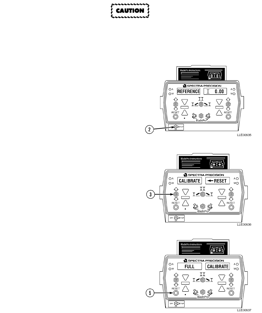
TM 5-6675-348-13&P
3-25
c. Blade Pro® Motor Grader Control System Sensor Calibration.
• Sensor calibration must be done when you change cutting edges or tires and/or remove/
install sensors from one grader to another grader.
• Sensor calibration should be redone if 130G Grader is not cutting to proper grade.
NOTE
Below is the calibration procedure for
FULL CALIBRATE.
(1) Set OFF/ON/SET-UP switch (2) to
SET-UP.
Left Display Right Display
REFERENCE 0.00
(2) Toggle left Increase/Decrease toggle
switch (3) down until following
appears:
Left Display Right Display
CALIBRATE RESET
(3) Press left RESET button (5) to enter
CALIBRATE.
Left Display Right Display
FULL CALIBRATE
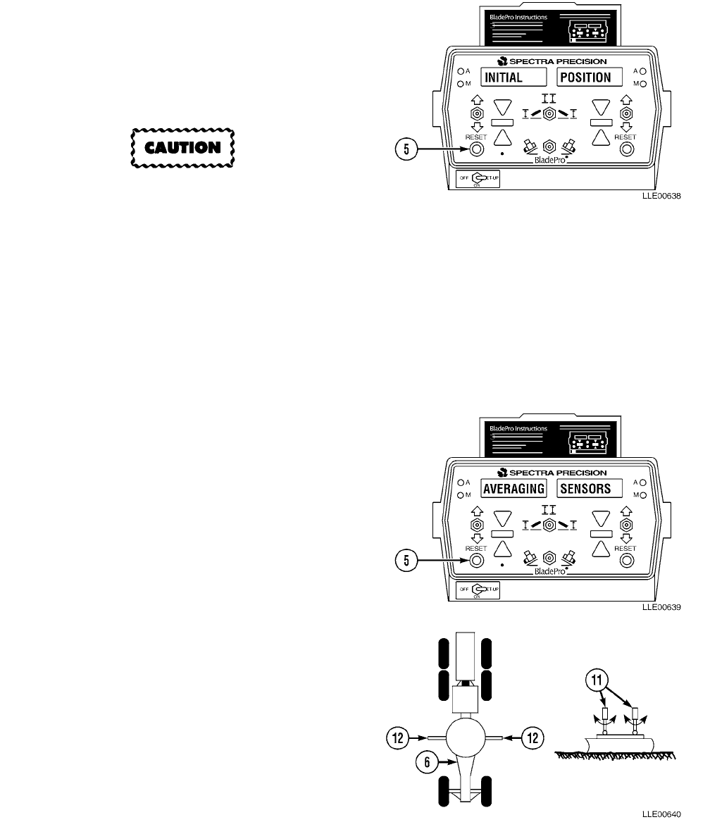
TM 5-6675-348-13&P
3-26
(4) Press left RESET button (5) to enter
FULL CALIBRATE.
Left Display Right Display
INITIAL POSITION
Do not disturb 130G Grader while
averaging sensors, or calibration will
not be correct.
NOTE
After pressing the left RESET button,
AVERAGING SENSORS will appear
and flash for 5 seconds. The system
has calibrated the Circle Rotation
Sensor and has stored the first reading
for the Blade Slope Sensor and the
Mainfall Slope Sensor.
(5) Press left RESET button (5) to
calibrate initial position.
Left Display Right Display
AVERAGING SENSORS
(6) Raise blade (12), turn 130G Grader (6)
180 degrees, and position blade (12) on
marks made in the previous step. Place
blade firmly on ground so that
Cylinder Rods (11) are not supporting
any weight. Cylinder Rods (11) should
rotate freely.
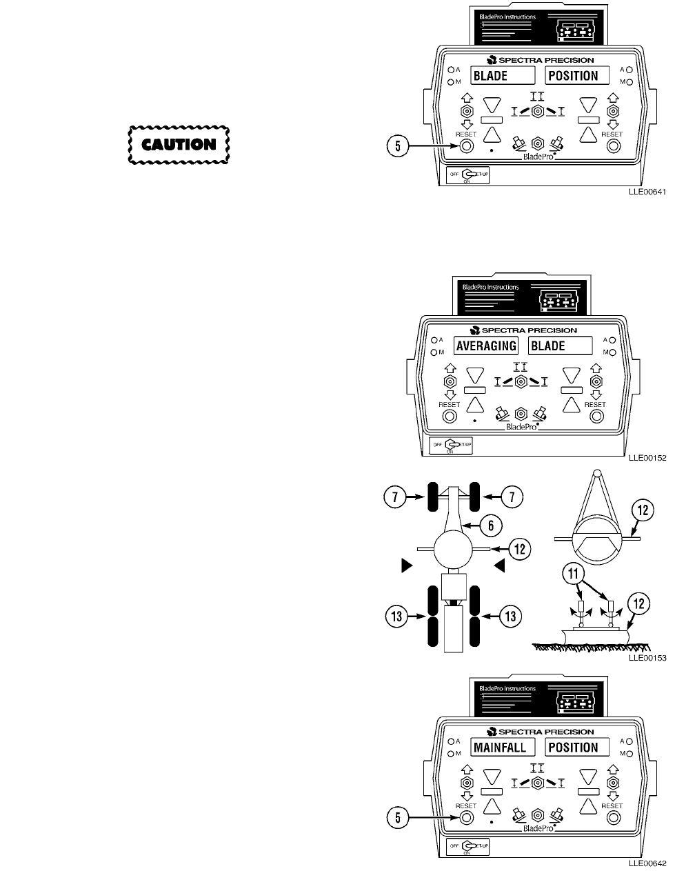
TM 5-6675-348-13&P
3-27
(7) Press left RESET button (5) to
calibrate BLADE Sensor.
Left Display Right Display
BLADE POSITION
Do not disturb 130G Grader while
averaging sensors, or calibration will
not be correct.
NOTE
AVERAGING BLADE will appear and
flash for 5 seconds. The system has
now stored a second reading for the
Blade Slope Sensor.
Left Display Right Display
AVERAGING BLADE
(8) Raise blade (12) and position
130G Grader (6) on wheel mark (7)
and wheel mark (13) made in previous
step. Place blade (12) firmly on ground
so that cylinders are not supporting
any weight. Cylinder rods (11) should
rotate freely.
(9) Press left RESET button (5) to
calibrate Mainfall Slope Sensor.
Left Display Right Display
MAINFALL POSITION
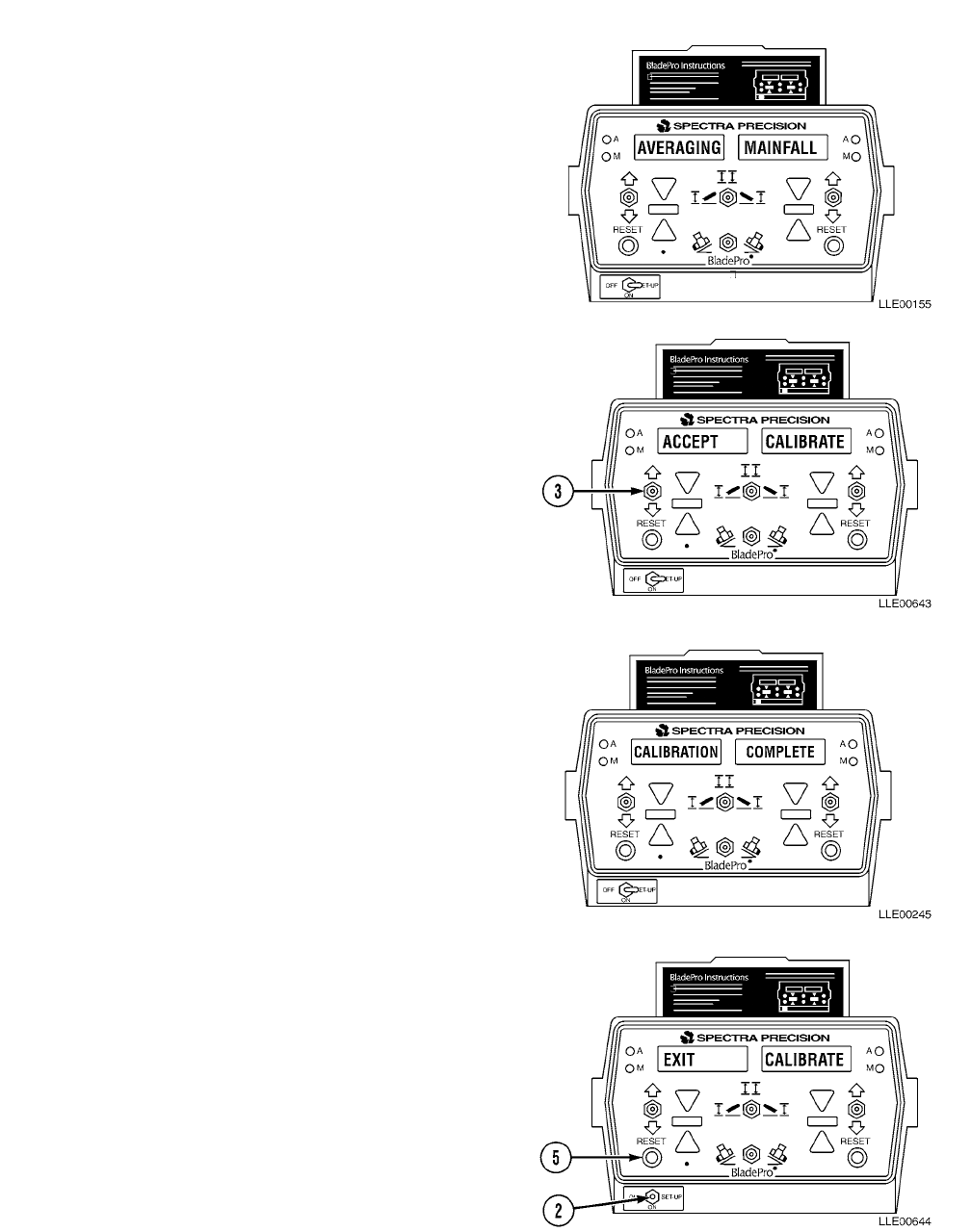
TM 5-6675-348-13&P
3-28
NOTE
AVERAGING MAINFALL Sensor will
appear and flash for 5 seconds. The
system has now stored a second
reading for the Mainfall Slope Sensor.
Left Display Right Display
AVERAGING MAINFALL
(10) The Blade Pro® Motor Grader Control
System is asking for verification that
new calibration values are to be used.
If new calibration values are not to be
used, press left Increase/Decrease
toggle switch (3) down and no change
will be made to previous calibration.
Left Display Right Display
ACCEPT CALIBRATE
NOTE
If new settings are to be used, press
left RESET button.
Left Display Right Display
CALIBRATION COMPLETE
(11) Press left RESET button (5) to exit
calibration.
Left Display Right Display
EXIT CALIBRATE
(12) Move OFF/ON/SET-UP switch (2) to
ON position.
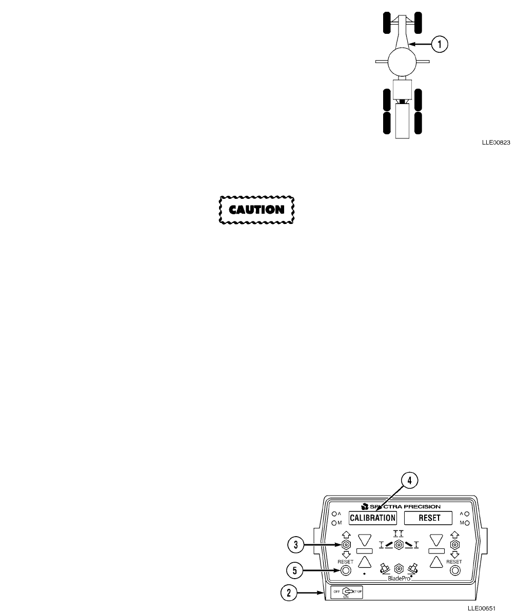
TM 5-6675-348-13&P
3-29
3-16. BLADE PRO® MOTOR GRADER CONTROL SYSTEM VALVE CALIBRATION.
a. 130G Grader Setup.
(1) Start 130G Grader (1) (TM 5-3805-261-10).
NOTE
To ease 130G Grader setup, park
grader on level surface.
(2) Park 130G Grader (1) on solid material such as
concrete, asphalt, or compacted soil.
b. Blade Pro® Motor Grader Control System Valve Calibration.
• Valve calibration is required whenever you change hoses, lift cylinders, or any other
repairs to the hydraulic system. Failure to perform valve calibration could result in
improper equipment performance or damage to equipment.
• Perform the sensor calibration procedures prior to performing the valve calibration
procedures. Failure to comply could result in improper 130G Grader performance.
• Operate the machine until the hydraulic oil has reached normal operating temperature
before starting the valve calibration. Failure to comply could result in improper Blade
Pro® Motor Grader Control System performance.
NOTE
•BladePro
® Setup will be displayed across both windows for a few seconds, then
REFERENCE and 0.00 will be displayed.
• Ensure 130G Grader is on level ground, A-frame is centered, and blade is perpendicular
to frame.
• Valve calibration and sensor calibration settings are specific for the make, model,
bumper number, and serial number once calibration is completed.
(1) Position OFF/ON/SET-UP switch (2) in
SET-UP position.
(2) Operate left Increase/Decrease toggle
switch (3) down until CALIBRATION
appears in the left window (4). Press
left RESET button (5) to enter this
menu.
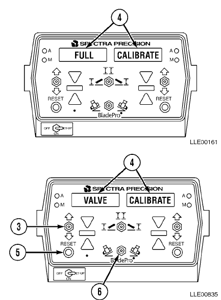
TM 5-6675-348-13&P
3-30
(3) FULL and CALIBRATE will be
displayed in the windows (4).
(4) Operate left Increase/Decrease toggle
switch (3) until VALVE CALIBRATE is
displayed in windows (4).
(5) To enter into valve calibration, hold
Slope switch (6) to the left and, at the
same time, press left RESET
button (5). Release both switches at
the same time.
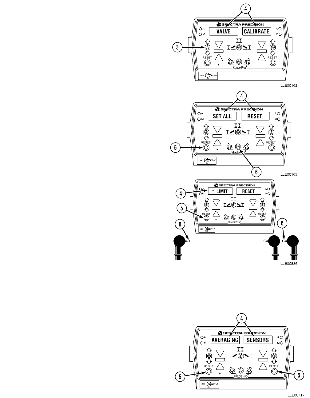
TM 5-6675-348-13&P
3-31
NOTE
• At this point, the blade needs to be
set up for calibration. Determine
which side (left or right) of blade is
going to be calibrated first. Side
shift blade to opposite side, then
move both cylinders to center of
ram.
• If VALVE TEST appears in
windows, repeat Step (5).
• VALVE CALIBRATE will flash
three times across windows (4) and
SET ALL will appear in left
window.
(6) Select which side control valve will be
calibrated first. To enter into this
menu, press left or right RESET
button (5) for side you want to
calibrate. NOTE
• This should be the same side that
is side-shifted all the way to one
side.
•↑ LIMIT should be displayed in the
left window.
(7) Set upper limit, using blade’s
R/L Switch (6), on side
to be calibrated, to lift blade
until cylinder is almost fully
retracted.
(8) Press RESET button (5) for side to be
calibrated. AVERAGING SENSORS will
flash across windows (4).
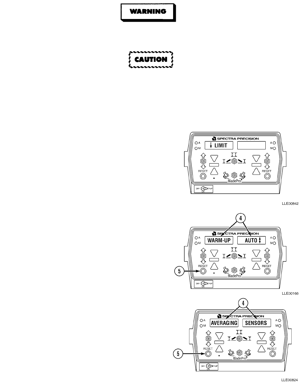
TM 5-6675-348-13&P
3-32
Keep all personnel and equipment away from blade during calibration. Blade may move
suddenly, causing injury or death to personnel, or damage to equipment.
• Do not disturb 130G grader while averaging sensors, or calibration will not be correct.
• Left or right RESET Button must be held in for duration of calibration. Failure to comply
could result in improper 130G Grader performance.
NOTE
• The system is requesting that
the upper limit be set.
•↓ LIMIT should be displayed in
the left window.
• WARM-UP should be displayed
in left window and AUTO in right
window.
• System is requesting that lower
limit be set. Set lower limit, using
blade's manual lever, and lower
blade until approximately 1 to 3 in.
(2.54 to 7.6 cm) above ground.
(9) Press RESET button (5) for side to be
calibrated. AVERAGING SENSORS will
flash across windows (4).
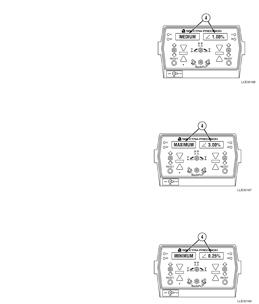
TM 5-6675-348-13&P
3-33
NOTE
• Start calibrating control valves by push-
ing left or right RESET Button or by
holding the Remote Offset Switch. This
switch is located on articulation control
lever.
• If the following calibration cannot be
performed at any time, contact Trimble
Navigation.
• This section of valve calibration is called
warm-up period and usually lasts
approximately 3 minutes. Numbers will
be displayed in the right window during
this section and they should range from
0.00% to 3.50%. If after 3 minutes a mes-
sage appears across both windows
indicating VALVE ERROR.
• The next section displayed in the left
window after the warm-up section is
completed is MAXIMUM.
• The correct number displayed in the
right window will be 3.00% ±0.10%. If
this number is not achieved, the
system will not move to the next
cycle. Repeat Step (1).
• After MAXIMUM cycle has reached
its proper calibration number, the
next section displayed in the left
window is MEDIUM.
• The correct number for this cycle will
be 1.00% ±0.01%. If this number is not
achieved, the system will not move to
the next cycle.
• Next section that will be displayed in
the window after MEDIUM has
reached its calibration number is
MINIMUM. Correct calibration
number for this cycle will be 0.25%
±0.01%. If this number is not
achieved, the system will not move to
next cycle.
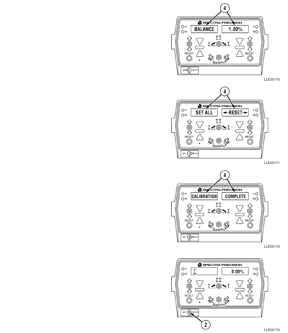
TM 5-6675-348-13&P
3-34
• Final section displayed in window
after MINIMUM has reached its
proper calibration number is
BALANCE. Correct calibration
number for this cycle will be 1.00%
±0.01. If this number is not achieved,
the system will not finish calibrating.
• Once BALANCE cycle has reached its
proper calibration number, SET ALL
will again be displayed in window.
(10) At this time, the Remote Offset Switch
located on the articulation control lever
can be released and valve calibration
complete for that side.
(11) Now it is time to calibrate the other side.
Prepare for this by using Blade Side Shift
Lever to move blade all the way to the
other side of grader. Repeat Steps (7)
through (10).
NOTE
When the final cycle of BALANCE has
completed, CALIBRATION COMPLETE
will display across both windows and
valve calibration will be complete.
(12) Exit Valve Calibration by positioning
OFF/ON/SET-UP switch (2) back to ON,
or center position.
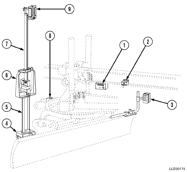
TM 5-6675-348-13&P
3-35
3-17. MOVING BLADE PRO® MOTOR GRADER CONTROL SYSTEM COMPONENTS FROM
GRADER TO GRADER.
a. Blade Pro® Motor Grader Control System Components.
1. Remote Interface Box
2. Mainfall Slope Sensor
3. Tracer® Sonic Grade Controller
4. Mast Mount
5. Mast Riser
6. Shock Mount
7. EM2E-24 Electric Mast
8. Blade Slope Sensor
9. R2S-S Laser Receiver
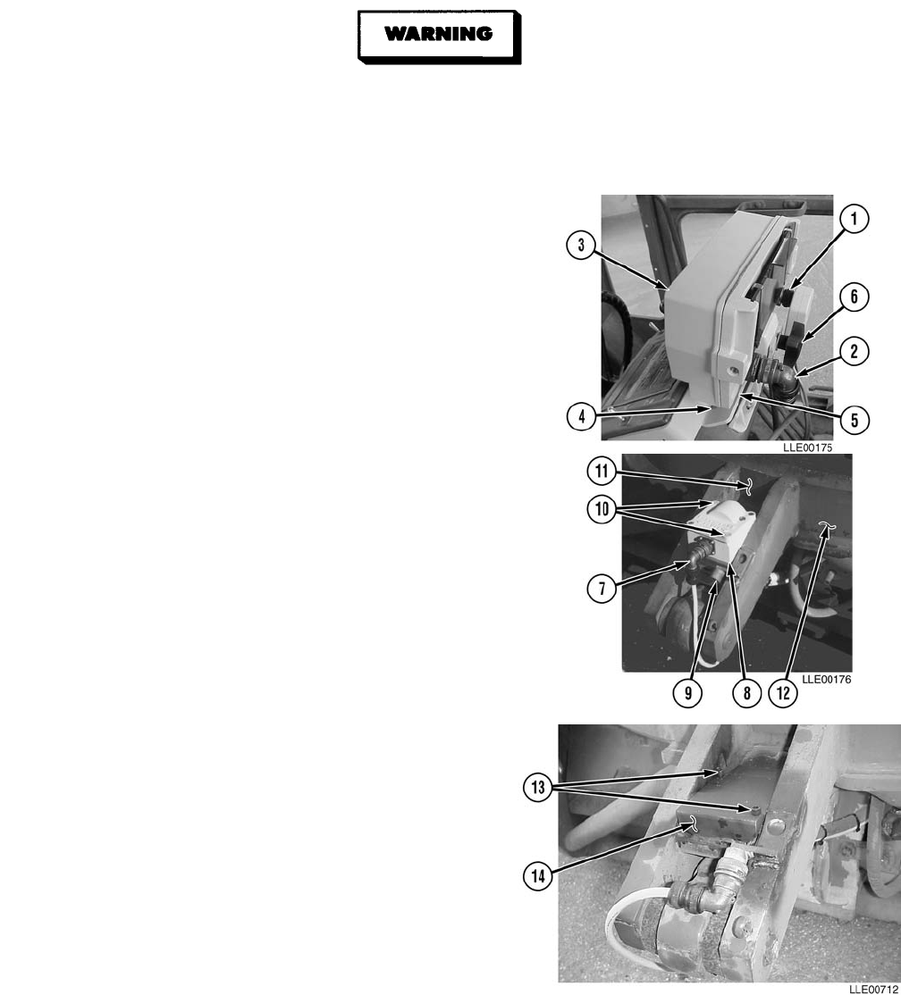
TM 5-6675-348-13&P
3-36
b. Remove.
To avoid injury to personnel, ensure 130G Grader is shut off and blade is on the ground.
NOTE
Note location and placement of components prior to removal. This will aid in installation.
(1) Remove 6-pin connector (1) and 8-socket
connector (2) from Operator Interface Box (3).
(2) Place 6-pin connector (1) and 8-socket
connector (2) onto Connector Holders (4) located
on mounting bracket (5).
(3) Loosen knob (6) on back of Operator Interface
Box (3) holding it to mounting bracket (5).
Remove Operator Interface Box (3).
(4) Remove Blade Slope Sensor Cable (7) from Blade
Slope Sensor (8) and secure to Connector
Holder (9).
(5) Remove two socket head screws (10) and Blade
Slope Sensor (8) located in pocket (11) of
130G Grader's Rotation Circle (12).
NOTE
Socket head screws are used to protect
the threads of the Slope Sensor Plate.
(6) Install two socket head screws (13) in Slope
Sensor Plate (14).
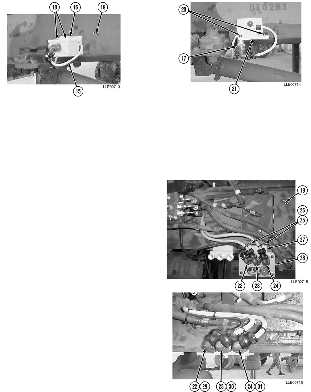
TM 5-6675-348-13&P
3-37
(7) Remove Mainfall Slope Sensor Cable (15) from Mainfall Slope Sensor (16) and secure Mainfall
Slope Sensor Cable (15) to Connector Holder (17).
(8) Remove two socket head screws (18) and Mainfall Sensor (16) located on right side of
130G Grader’s gooseneck (19).
NOTE
Socket head screws are used to protect the threads of the Mainfall Slope Sensor Mounting
Plate.
(9) Install two socket head screws (20) in Mainfall Slope Sensor Mounting Plate (21).
NOTE
• Tag and mark all cables before
disconnecting.
• Step (10) applies to both sides of the
machine. The right side is shown.
(10) Remove Connectors (22), (23), and (24),
two bolts (25), washers (26), and Remote
Box Mounting clamp (27) from Remote
Interface Box (28) located under
130G Grader’s gooseneck (19).
(11) Install Connectors (22), (23), and (24) onto
Connector Holders (29), (30), and (31).
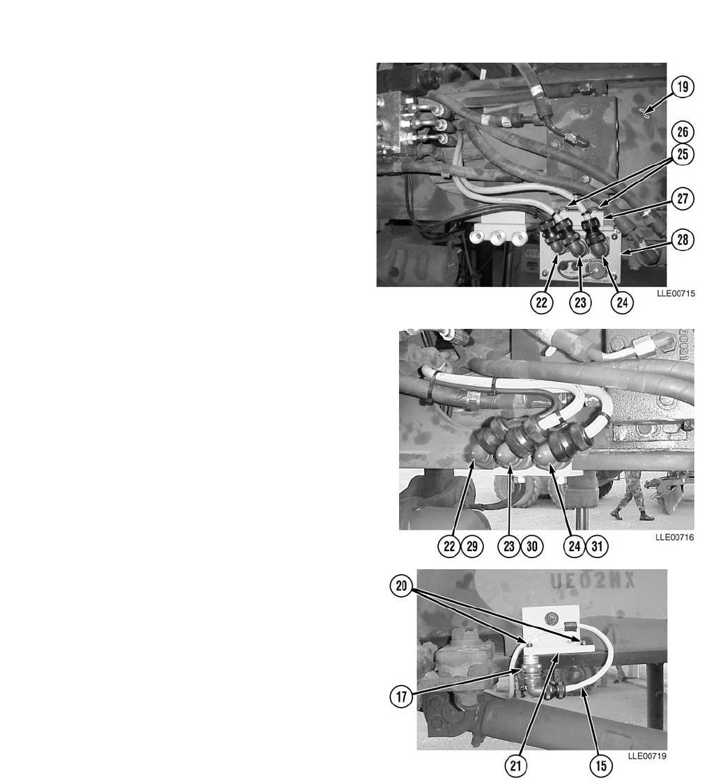
TM 5-6675-348-13&P
3-38
c. Install.
NOTE
Step (1) applies to both sides of the machine. The right side is shown.
(1) Install Remote Interface Box (28) under
130G Grader’s Gooseneck (19) with two
washers (26), bolts (25), and Remote Box
Mounting clamp (27).
(2) Tighten bolts (25).
(3) Remove Connectors (22), (23), and (24) from
Connector Holders (29), (30), and (31).
(4) Connect Connectors (22), (23), and (24) to
Remote Interface Box (28).
(5) Remove Mainfall Slope Sensor Cable (15)
from Connector Holder (17).
(6) Remove two socket head screws (20) from
Mainfall Slope Sensor Mounting
Plate (21).
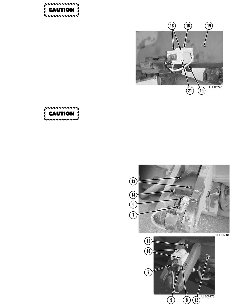
TM 5-6675-348-13&P
3-39
To ensure proper Blade-Pro® Motor
Grader Control System operation,
ensure all sensor plates are clean and
free of debris before bolting any
sensors down.
(7) Install Mainfall Slope Sensor (16),
located on right side of the
130G Grader’s Gooseneck (19), on
Mainfall Slope Sensor Mounting
Plate (21) with two socket head
screws (18).
(8) Tighten socket head screws (18).
To avoid damage to equipment,
ensure cable connector is clean
and dry.
(9) Install Mainfall Slope Sensor Cable (15)
on Mainfall Sensor (16).
(10) Remove Blade Slope Sensor Cable (7) from
Connector Holder (9).
(11) Remove two socket head screws (13) from
Slope Sensor Plate (14).
(12) Install Blade Slope Sensor (8) in
pocket (11) of 130G Grader's Rotation
Circle (12) with two socket head
screws (10).
(13) Tighten socket head screws (10).
(14) Install Blade Slope Sensor Cable (7) on
Blade Slope Sensor (8).
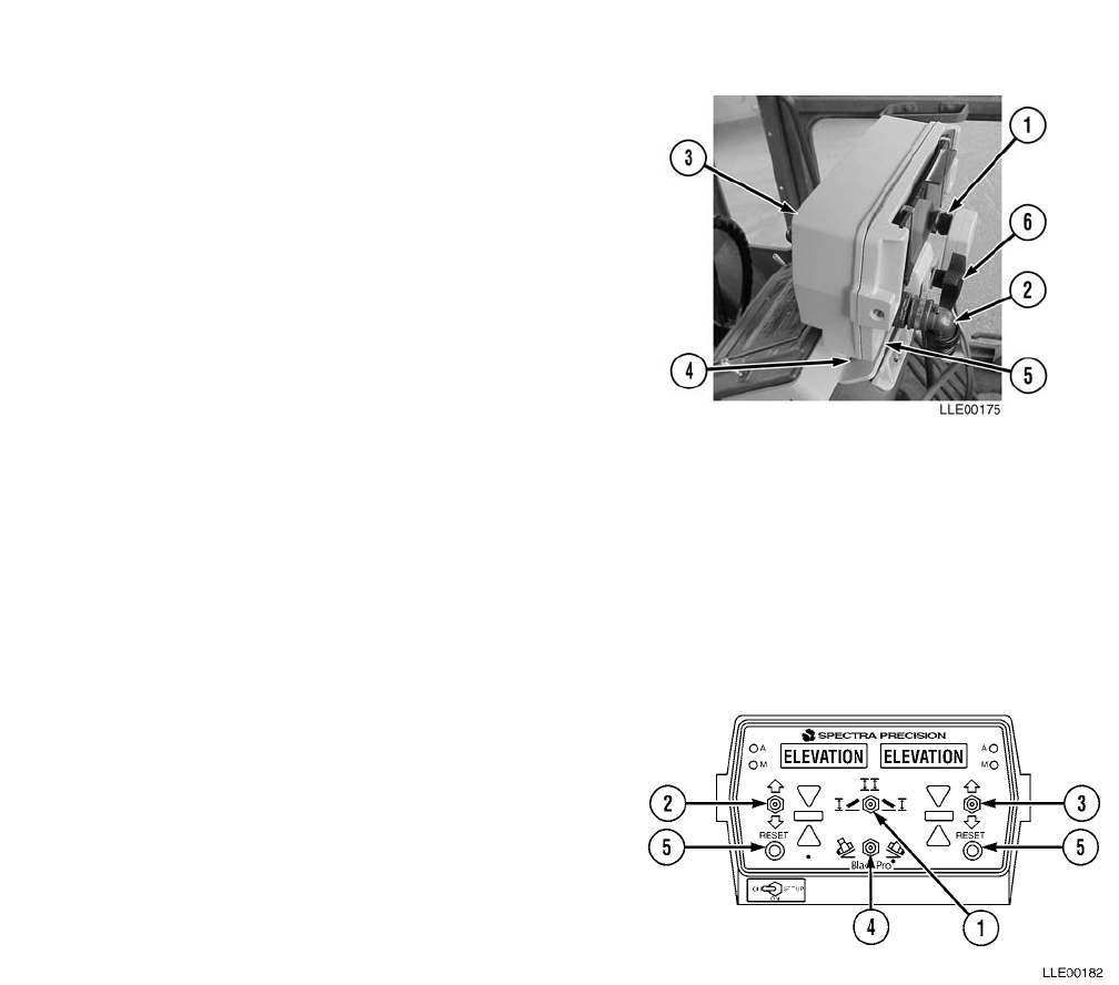
TM 5-6675-348-13&P
3-40
NOTE
Operator Interface Box mounts on bracket at top of grader console.
(15) Loosen knob (6) and slide Operator
Interface Box (3) into groove on
mounting bracket (5). Tighten
knob (6) after correct position of
Operator Interface Box (3) has been
adjusted.
(16) Remove 6-pin connector (1) and
8-socket connector (2) from Connector
Holders (4) located on mounting
bracket (5).
(17) Install 6-pin connector (1) and
8-socket connector (2) on Operator
Interface Box (3).
(18) After all these procedures have been completed, do a final walk around 130G Grader to ensure all
connectors are properly tightened and that all bolts are tight.
(19) Calibrate sensors and valves (refer to Para 3-15 and Para 3-16).
3-18. BLADE PRO® MOTOR GRADER CONTROL SYSTEM OPERATION DESCRIPTION.
Operator Interface Box. Puts all control
functions within easy reach of the Operator. One
Mode Switch is required to select operating
configuration.
(1) Mode switch (1) position and operating
configurations available:
(2) Selected operating mode is shown in two
display windows. The left window is for the130G Grader’s left side and the right window is for the
130G Grader’s right side. Left and right Increase/Decrease switches (2) and (3) adjust for elevation
and slope values. Change blade slope direction, using bottom center Slope Switch (4). Set Tracer®
Sonic Grade Controller to a reference surface by pressing RESET button (5) for side controlled by
the Tracer® Sonic Grade Controller. Two remote switches, located on the left and right manual
control levers, provide control of automatic or manual operation for the left and right sides.
(3) When desired cross-slope is entered into the Operator Interface Box, the Remote Interface Box
reads Mainfall Slope Sensor, Blade Slope Sensors, and Circle Rotation Sensor, and calculates cross-
slope. Calculated cross-slope is compared to the desired cross-slope. If an error is determined, LED
Grade Indicator displays type of correction (i.e., fine, medium, or coarse) and direction (raise or
lower) required to reach desired cross-slope. With Blade Pro® Motor Grader Control System in
automatic operation, the displayed correction is sent to hydraulic valves to reposition the blade to
desired slope. This operating speed provides very fast, smooth response to changing grade
conditions.
Switch Position Left Side Right Side
Left Position Elevation Cross-Slope
Center Position Elevation Elevation
Right Position Cross-Slope Elevation
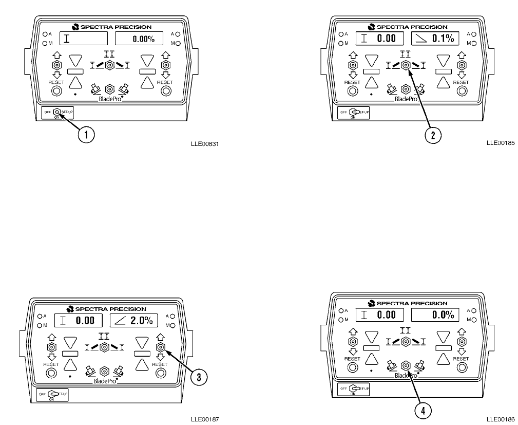
TM 5-6675-348-13&P
3-41
3-19. AUTOMATIC CROSS-SLOPE AND MANUAL ELEVATION.
a. General Information.
Automatic Cross-Slope and Manual Elevation allows the Operator to manually control the
elevation on the left side of the blade and the cross-slope on the right side of the blade is automatically
controlled. Cross-slope and manual elevation setup can be applied on projects that will use existing
elevations but require a cross-slope for drainage (e.g., tank trails and dirt road upgrades).
b. Setting Up the Blade Pro® Motor Grader Control System.
(1) Set OFF/ON/SET-UP switch (1) to ON position.
NOTE
If previous slope was 0.0, no slope symbol (<) will be shown.
(2) Set Mode switch (2) to left position.
Left Display Right Display
I 0.00 > 0.1%
(3) Enter desired cross-slope in right display window by using right Increase/Decrease switch (3).
Left Display Right Display
I 0.00 < 2.0%
(4) Change blade slope direction switch (4) to match desired slope, if required.
Left Display Right Display
I 0.00 < 0.0%
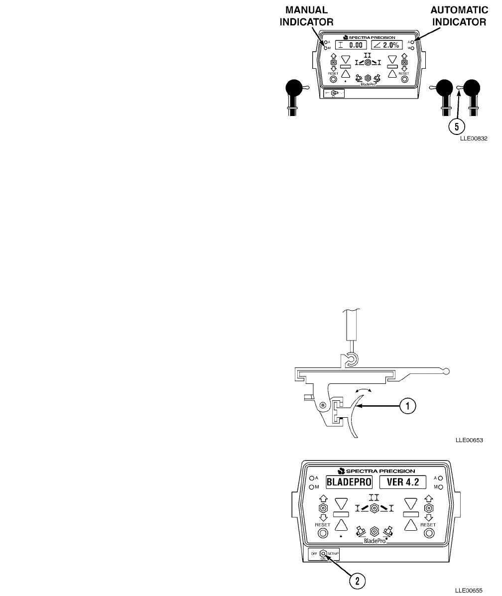
TM 5-6675-348-13&P
3-42
(5) Toggle right R/L switch (5) forward.
NOTE
• Right green automatic indicator
will be illuminated in upper right
corner of Operator Interface Box.
• Left red manual indicator should still
be illuminated in left-hand corner of
Operator Interface Box.
• Automatic operation will now start.
• If return pass is on same side of road
crown, toggle Mode switch to right.
The cross-slope-controlled side is now
left side and blade slope direction is automatically changed.
3-20. AUTOMATIC ELEVATION (TRACER® SONIC GRADE CONTROLLER) AND CROSS-SLOPE.
a. General Information.
Automatic Elevation and Cross-Slope automatically controls both the elevation on the left side of
the blade and the cross-slope on the right side of blade.
b. Setting Up the Blade Pro® Motor Grader Control System.
(1) Adjust blade (1) to desired roll.
(2) Set OFF/ON/SET-UP switch (2) to ON
position.
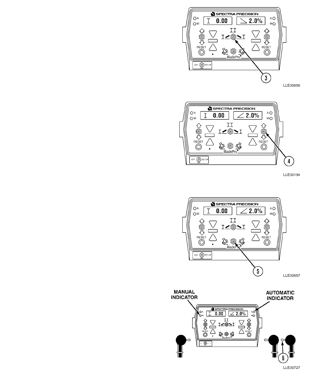
TM 5-6675-348-13&P
3-43
(3) Set Mode switch (3) to left position.
Left Display Right Display
I 0.00 > 2.0%
(4) Enter desired cross-slope value into right
display window, using right
Increase/Decrease switch (4).
Left Display Right Display
I 0.00 < 2.0%
(5) Change direction of Slope switch (5), if
required, to match desired direction of slope.
Left Display Right Display
I 0.00 < 2.0%
NOTE
• Right green automatic indicator will
be illuminated in upper right
corner of Operator Interface Box.
• The left red manual indicator should
still be illuminated in left-hand corner of
Operator Interface Box.
(6) Toggle right R/L Switch (6) forward.
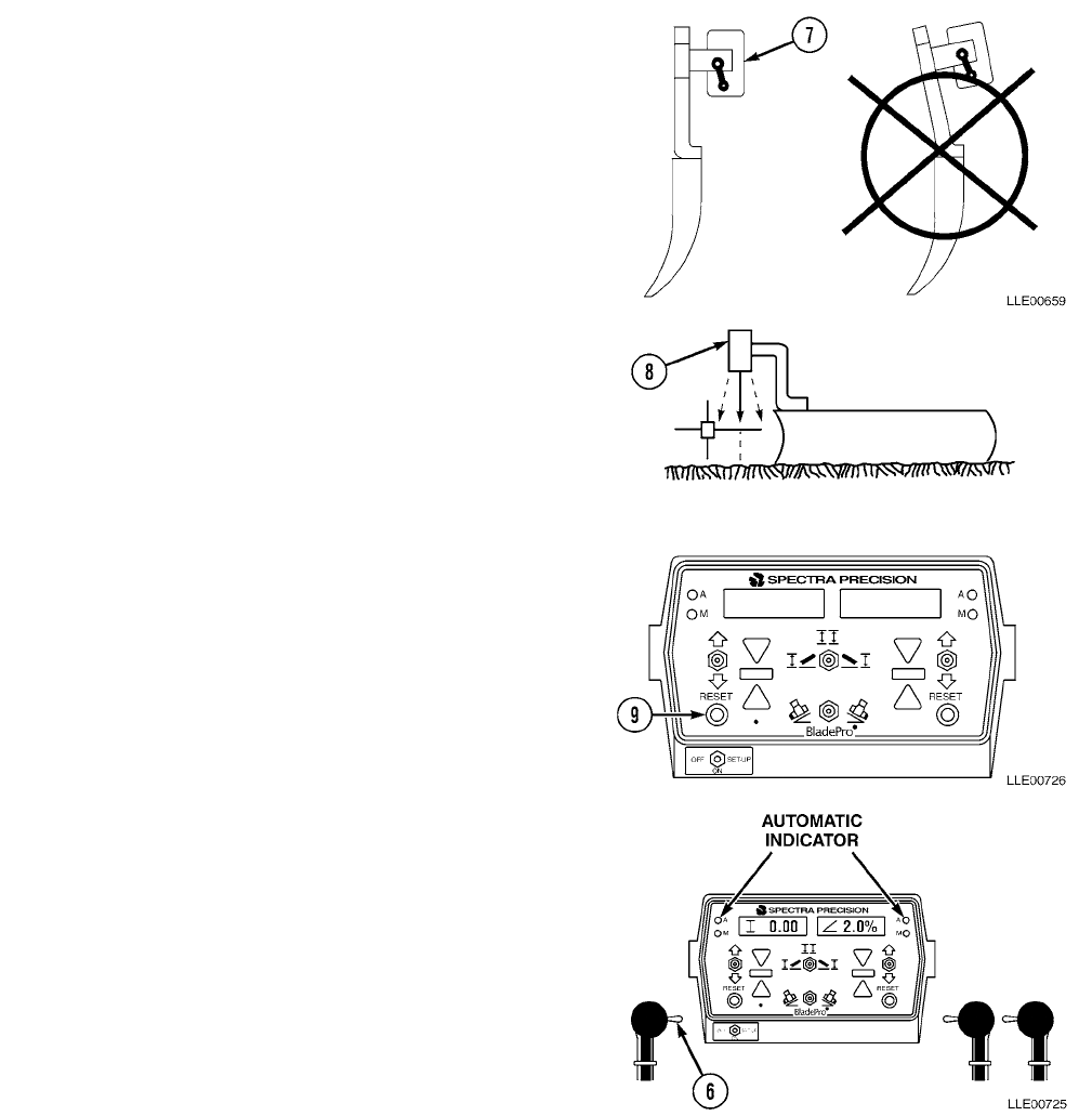
TM 5-6675-348-13&P
3-44
(7) Adjust Tracer® Sonic Grade Controller
side of blade so that it is 18 to 24 in.
(46 to 61.0 cm) above desired elevation.
(8) Center Tracer® Sonic Grade Controller (7)
over elevation reference by loosening base
tube clamp studs.
(9) Position tube vertically and center it
directly over elevation reference.
(10) Plumb Tracer® Sonic Grade Controller (8)
over elevation reference by loosening
locking knob on back of mounting arm.
(11) Vertically align Tracer® Sonic Grade
Controller (8) for plumb over reference
surface.
(12) Press left RESET button (9) to lock
Tracer® Sonic Grade Controller (8) onto
reference.
NOTE
• Left green automatic indicator will
be illuminated in upper left corner
of Operator Interface Box.
• Both right and left green automatic
indicators will be illuminated.
(13) Press left R/L switch (6) forward.
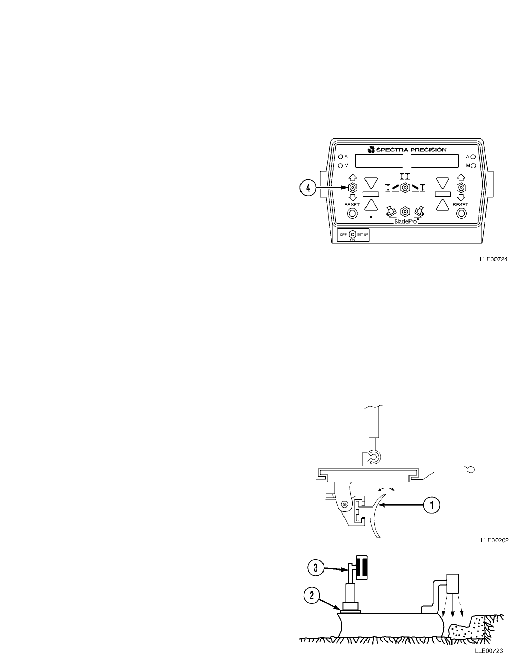
TM 5-6675-348-13&P
3-45
NOTE
• If return pass is to be on same side of crown, position Mode switch to right. The Tracer®
Sonic Grade Controller now controls right side and cross-slope left.
• Blade’s slope direction is changed automatically to match desired slope.
• If the Remote Interface Box right-side Tracer® Sonic Grade Controller has not been set
to reference elevation, press right RESET button once blade has been set to reference.
(14) The elevation of Tracer® Sonic Grade
Controller can be changed by using the left
Increase/Decrease switch (4) once the cut
has been started.
3-21. DUAL AUTOMATIC ELEVATION (TRACER® SONIC GRADE CONTROLLER R2S-S
LASER RECEIVER WITH EMZE-24 ELECTRIC MAST).
a. General Information.
Dual Automatic Elevation automatically controls elevation on both sides of the blade.
b. Setting up the Blade Pro® Motor Grader Control System.
(1) Start 130G Grader (TM 5-3805-261-10).
(2) Adjust blade (1) to desired roll.
(3) Adjust mast swivel mount (2) until mast (3)
is plumb.
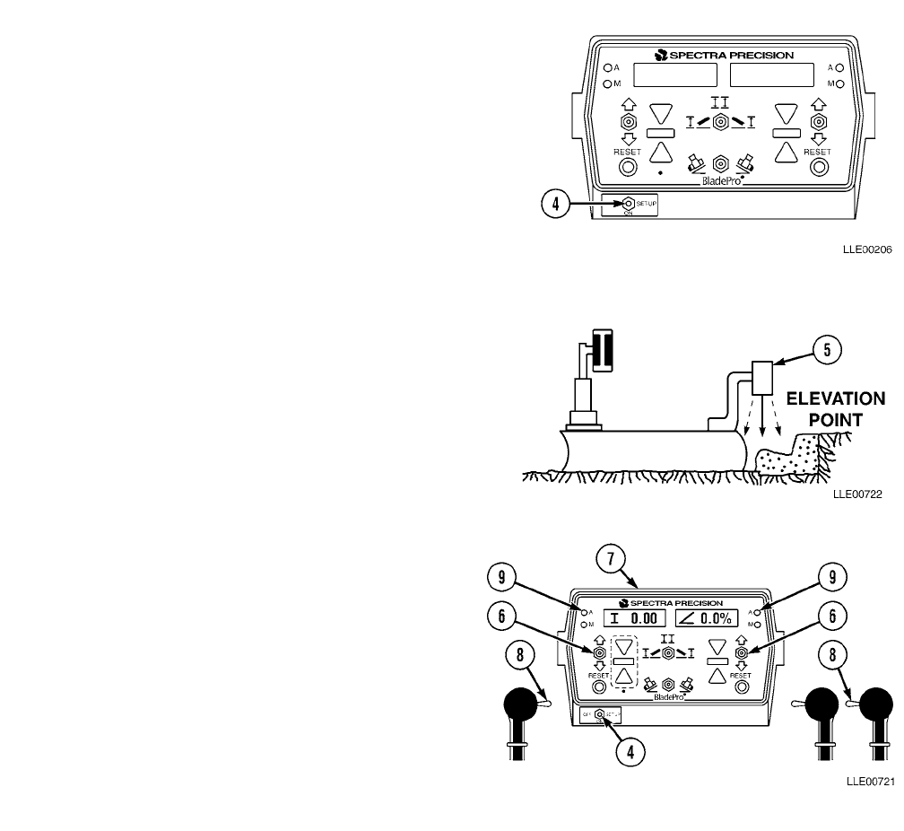
TM 5-6675-348-13&P
3-46
(4) Set OFF/ON/SET-UP switch (4) to ON position.
(5) Position Tracer® Sonic Grade Controller (5) on
left side of blade over a known elevation point.
(6) Enter zero cross-slope, using Increase/
Decrease switch (6) on right side of
Operator Interface Box (7).
(7) Place R/L Switch (8) on right side in
automatic position. Automatic
Indicator (9) should be green.
(8) Adjust Increase/Decrease switch (6) on
left side of Operator Interface Box (7)
until display is on grade, center green bar
only.
NOTE
Reference will be displayed when OFF/
ON/SET-UP switch is placed in SET-UP
position.
(9) Position OFF/ON/SET-UP switch (4) to
SET-UP position.
(10) Use Increase/Decrease switch (6) on right
side of Operator Interface Box (7) to enter
actual elevation of bottom edge of blade.
(11) Position OFF/ON/SET-UP switch (4) back
to ON position.
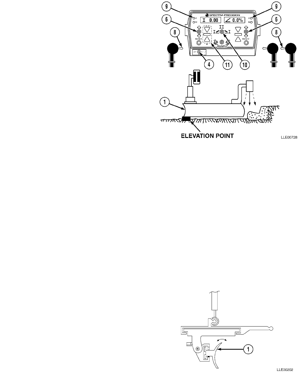
TM 5-6675-348-13&P
3-47
(12) Position Mode switch (10) to far right
position.
(13) Position right side of blade (1) over
known elevation point.
(14) Place R/L switch (8) on left side into
automatic mode with zero cross-slope.
Automatic Indicator (9) should be green.
(15) Adjust Increase/Decrease switch (6) on
right side of Operator Interface Box (7)
until center green bar (11) is illuminated
indicating on grade.
NOTE
Reference will be displayed on Operator
Interface Box.
(16) Position OFF/ON/SET-UP switch (4) to
SET-UP position.
(17) Use Increase/Decrease switch (6) on right
side of Operator Interface Box (7) to enter
actual elevation of bottom edge of blade.
(18) Place OFF/ON/SET-UP switch (4) back to ON position.
(19) Position Mode switch (10) to center position.
(20) Using right and left Increase/Decrease switches (6), raise or lower mast to desired elevation.
(21) Place right and left Auto/Manual switches (8) to Auto position.
(22) Begin grading (TM 5-3805-261-10).
3-22. AUTOMATIC ELEVATION (EM2E-24 ELECTRIC MAST AND R2S-S LASER RECEIVER) AND
CROSS-SLOPE.
a. General Information.
Automatic Elevation and Cross-Slope automatically controls elevation on the left and right side of
the blade, and positions switch to the far left position.
b. Setting up the Blade Pro® Motor Grader
Control System.
(1) Start 130G Grader (TM 5-3805-261-10).
(2) Adjust blade (1) to desired roll.
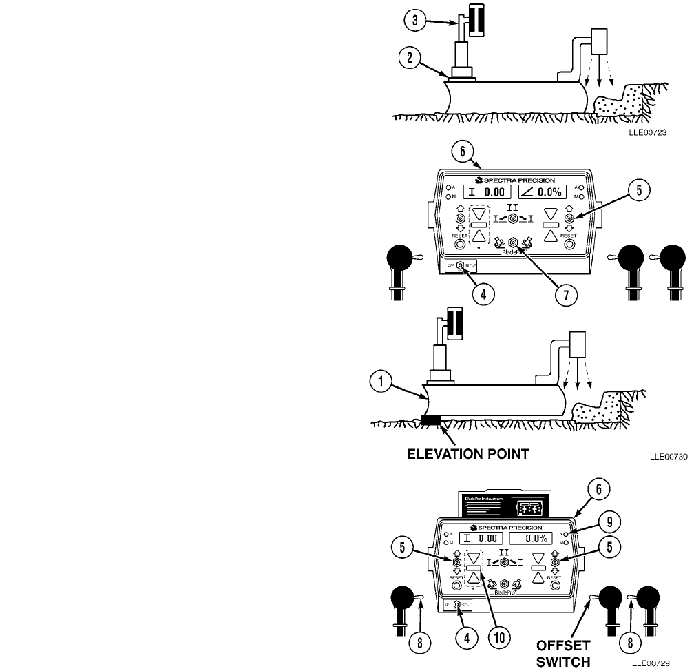
TM 5-6675-348-13&P
3-48
(3) Adjust mast swivel mount (2) until
mast (3) is plumb.
(4) Set OFF/ON/SET-UP switch (4) to ON
position.
(5) Position left side of blade (1) over known
elevation point.
(6) Enter desired cross-slope, using Increase/
Decrease switch (5) on right side of
Operator Interface Box (6). Ensure slope
direction is correct direction of Slope
switch (7).
(7) Place R/L switch (8) on right side in
automatic position. Automatic
Indicator (9) should be green.
(8) Adjust Increase/Decrease switch (5) on
left side of Operator Interface Box (6)
until center green bar (10) is illuminated,
indicating on grade.
(9) Position OFF/ON/SET-UP switch (4) to
SET-UP position.
NOTE
REFERENCE will be displayed on
Operator Interface Box.
(10) Use Increase/Decrease switch (5) on right
side of Operator Interface Box (6) to enter
actual elevation of bottom edge of blade.
(11) Place OFF/ON/SET-UP switch (4) back to
ON position.
NOTE
Both LEDs should be green.
(12) Place R/L switch (8) on left side to
automatic position, and cycle the switch
through MANUAL and back to AUTO.
(13) Begin grading (TM 5-3805-261-10).
TM 5-6675-348-13&P
3-49
3-23. BLADE PRO® MOTOR GRADER CONTROL SYSTEM USER OPTIONS IN SETUP MODE.
a. Reference. Allows a reference elevation (benchmark or sea-level elevation) to be entered into the
elevation display window. The reference elevation does not change the elevation of the blade; only the
numeric value in the display window is changed.
b. Customize. Allows the Operator to customize certain system functions and features. Functions are
OFFSETS, BEEPER ALERTS, and SLOPE DISPLAY. These functions can be turned on or off, or can
be changed through the Customize program.
c. Remote Switch. Three functions are available in OFFSET program: Slope Offset, Elevation Offset,
and Auto Raise/Lower. Only one OFFSET function can be selected at any given time. Selected
OFFSET function is activated by using Remote switch.
(1) Slope Offset allows Remote switch to function in adjusting desired cross-slope in increments of
0.1% to 19.9%. When Remote switch is toggled forward, programmed offset value is added to
displayed cross-slope value. Slope of blade is increased by same value. When Remote switch is
toggled toward Operator, programmed offset value is subtracted from displayed cross-slope value
and slope of blade is decreased by same value. Slope offset allows cross-slope to be transitioned
through zero.
(2) Elevation Offset allows Remote switch to function in adjusting Tracer® Sonic Grade Controller or
EMZE-24 Electric Mast elevation from 0.01 to 3.98 ft (0.003 to 1.213 m). When Remote switch is
toggled toward Operator, programmed offset value is added to displayed elevation value. The
blade’s elevation is raised by same value. When Remote switch is toggled forward, programmed
offset value is subtracted from displayed elevation value and blade’s elevation is lowered by same
value.
(3) Auto Raise/Lower allows Remote switch to automatically raise blade to a selectable relative
distance above grade and switches system into inactive automatic operation. Toggling Remote
switch in opposite direction automatically lowers blade to a selectable distance and switches
system into automatic control. If system does not reach desired elevation range, it will remain in
inactive auto mode and blade will have to be manually lowered and switched to automatic
operation.
d. Beeper. Beeper is used to alert the Operator that certain events are occurring. These functions can be
turned on or off depending on Operator’s preference.
Beeper On/Off. With the beeper ON, a single beep is emitted when:
• Remote switch is toggled.
• A serial communication error is detected.
• A sensor error is detected.
• An out-of-range error occurs (See Section V, Blade Pro® Motor Grader Control System
Troubleshooting Error Messages).
(1) Beeper I (Elevation).
(a) Two short beeps are emitted when elevation device is in a fine correction for more than
2 seconds or if a medium or coarse valve correction signal is sent. This alerts the Operator
that the cut is not to grade. A second pass or ripping the material may be required.
(b) Three short beeps are emitted if Tracer® Sonic Grade Controller or Laser Receiver loses its
reference. For example, if a string line is used as a grade reference and Tracer® Sonic Grade
Controller is moved off string line, then three short beeps are emitted to alert Operator.

TM 5-6675-348-13&P
3-50
(2) Beeper < (Cross-Slope). Two short beeps are emitted when cross-slope-controlled side of blade
remains in a fine correction for more than 2 seconds. If a medium or coarse correction signal is
indicated, two short beeps are emitted with no delay. This alerts the Operator that the slope has
not been cut correctly. A second pass or ripping the material may be required to cut to grade.
e. Slope. % Slope or Rise/Run Display. Allows the Operator to select how cross-slope is displayed in
display window. Options are percent slope (5) or rise/run (e.g., 1/4 in. per foot (6 mm per meter) is
displayed as 1/4” in English; 6 mm per meter is displayed as 6 mm/m metric).
f. Test. Activates all LCD segments and LED indicator lights. Visual display shows any missing LCD
segments or burned-out LED indicators. The test feature also displays errors that may have occurred.
3-24. PROGRAMMING BLADE PRO® MOTOR GRADER CONTROL SYSTEM USER OPTIONS.
a. General Information.
NOTE
SET-UP can be exited from any point in the SET-UP menu by positioning the OFF/ON/SET-
UP switch back to the ON position.
(1) Switches used in SET-UP Mode.
(a) To enter SET-UP, position the OFF/ON/
SET-UP switch (1) to SET-UP position.
NOTE
Left Increase/Decrease switch controls
the menu displayed in left display
window.
(b) Toggle left Increase/Decrease switch (2)
down to move next item in menu.
(c) Toggle left Increase/Decrease switch (2) up to move back to last displayed item.
(d) Use left RESET Button (3) to enter or exit selected menu displayed in left display window.
(e) Right Increase/Decrease switch (4) changes feature from ON to OFF or value displayed in
right window (for example: ON to OFF or 1.25 to 1.26).
(f) SET-UP can be exited from any point in the SET-UP menu by positioning the
OFF/ON/SET-UP switch (1) back to the ON position.
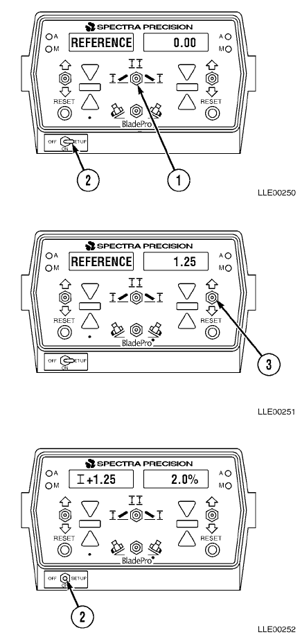
TM 5-6675-348-13&P
3-51
b. Reference Elevation.
Below are instructions for setting a reference elevation into the Operator Interface Box.
When changing reference elevation in SET-UP, new reference elevation will be displayed only on side
of Operator Interface Box in relation to Mode switch (1) position.
To enter a different reference elevation into left side position, move Mode switch (1) to the left.
Left Display Right Display
+ 0.00 < 2.0%
(1) Position OFF/ON/SET-UP switch (2) to
the right SET-UP position.
Left Display Right Display
REFERENCE 0.00
(2) Use right Increase/Decrease switch (3) to
change displayed value until desired
value is displayed.
Left Display Right Display
REFERENCE 1.25
(3) If no additional changes are required,
position OFF/ON/SET-UP switch (2) back
to ON position.
Left Display Right Display
I +1.25 2.0%
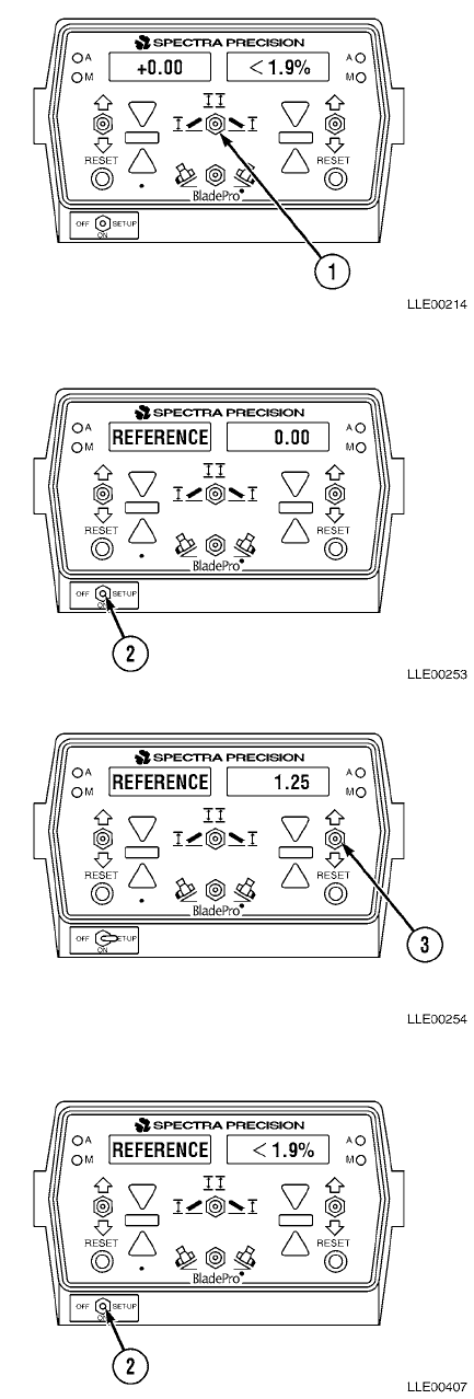
TM 5-6675-348-13&P
3-52
(4) To enter a different reference elevation
into both the left and right windows:
(a) Position Mode switch (1) to left
position.
Left Display Right Display
+ 0.00 < 1.9%
(b) Position OFF/ON/SET-UP
switch (2) to SET-UP position.
Left Display Right Display
REFERENCE 0.00
(c) Use right Increase/Decrease
switch (3) to change elevation value
in right display window for desired
reference elevation for left side of
blade.
Left Display Right Display
REFERENCE 1.25
(d) Position OFF/ON/SET-UP
switch (2) back to ON position.
Left Display Right Display
+ 1.25 < 1.9%
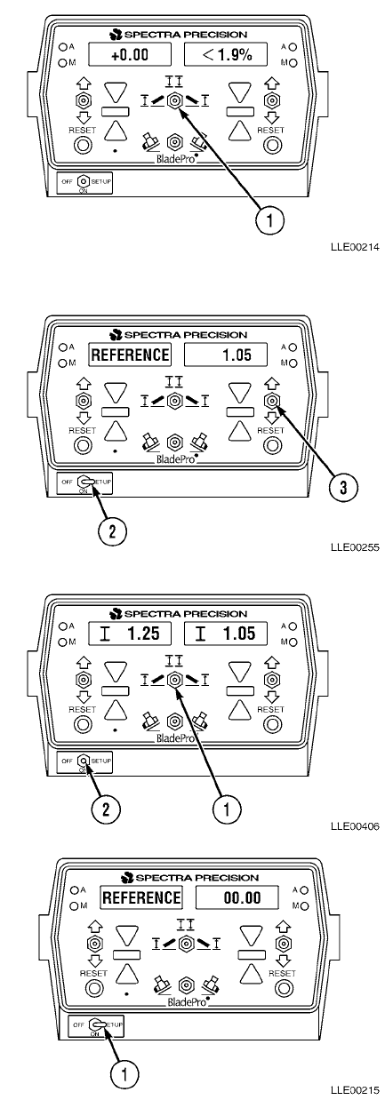
TM 5-6675-348-13&P
3-53
(e) Position Mode switch (1) to right
position.
Left Display Right Display
+ 0.00 <1.9%
(f) Position OFF/ON/SET-UP switch (2)
to SET-UP position.
(g) Use right Increase/Decrease
switch (3) to change value in right
display window for desired reference
elevation for right side of blade.
Left Display Right Display
REFERENCE 1.05
(h) Position OFF/ON/SET-UP switch (2)
back to the ON position.
Left Display Right Display
I 1.25 I 1.05
(i) Position Mode switch (1) to center
position.
c. Customize.
To enter CUSTOMIZE:
(1) Position OFF/ON/SET-UP switch (1) to
right SET-UP position.
Left Display Right Display
REFERENCE 00.00
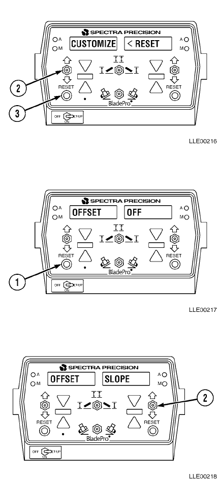
TM 5-6675-348-13&P
3-54
(2) Toggle left Increase/Decrease switch (2)
down until CUSTOMIZE appears.
Left Display Right Display
CUSTOMIZE < RESET
(3) Press left RESET button (3) to enter
CUSTOMIZE.
d. Offset.
To enter OFFSET:
(1) Press left RESET button (1).
Left Display Right Display
OFFSET OFF
(2) If an OFFSET function was previously
selected, then that OFFSET function will
be shown.
(3) Press right Increase/Decrease switch (2)
down until desired OFFSET function
appears in right window.
Left Display Right Display
OFFSET OFF
OFFSET AUTO
OFFSET ELEVATION
OFFSET SLOPE
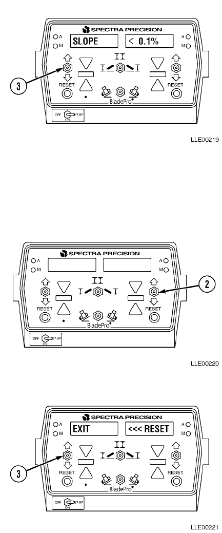
TM 5-6675-348-13&P
3-55
(4) With desired OFFSET function displayed
in right display window, toggle left
Increase/Decrease switch (3) down.
Left Display Right Display
OFFSET (TYPE) OFFSET (VALUE)
Left Display Right Display
OFFSETS NONE
AUTO >>>
ELEVATION | + 0.01 (+0.005) Metric
SLOPE < 0.1%
(5) Toggle right Increase/Decrease switch (2)
to select desired OFFSET VALUE. Note
that for AUTO RAISE/LOWER, each >
equals about 3 seconds of blade travel.
(6) With desired OFFSET VALUE entered,
toggle left Increase/Decrease switch (3)
down.
Left Display Right Display
EXIT <<< RESET
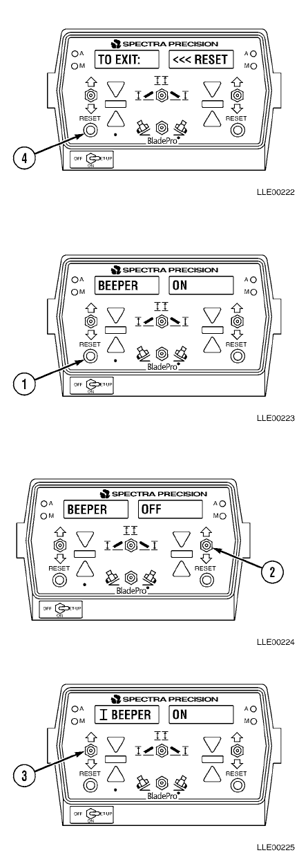
TM 5-6675-348-13&P
3-56
(7) Press left RESET button (4) to exit
OFFSETS.
e. Beeper.
To enter BEEPER:
(1) Press left RESET button (1).
Left Display Right Display
BEEPER ON
(2) To turn beeper OFF, toggle right
Increase/Decrease switch (2).
Left Display Right Display
BEEPER OFF
(3) Toggle left Increase/Decrease switch (3)
down to enter BEEPER (elevation).
Left Display Right Display
I BEEPER ON
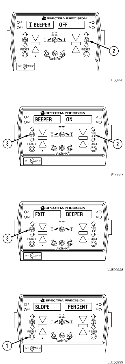
TM 5-6675-348-13&P
3-57
(4) To turn BEEPER OFF, toggle right
Increase/Decrease switch (2).
Left Display Right Display
I BEEPER OFF
(5) Toggle left Increase/Decrease switch (3)
down to enter BEEPER < (slope).
Left Display Right Display
BEEPER ON
(6) To turn BEEPER < OFF, toggle right
Increase/Decrease switch (2) down.
Left Display Right Display
BEEPER OFF
(7) Toggle left Increase/Decrease switch (3)
down.
Left Display Right Display
EXIT BEEPER
(8) To exit BEEPER, press left RESET
button (1).
Left Display Right Display
SLOPE PERCENT
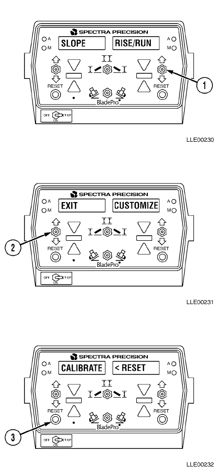
TM 5-6675-348-13&P
3-58
f. Percent Slope and Rise/Run.
To change the display from PERCENT
SLOPE to RISE/RUN:
(1) Toggle right Increase/Decrease switch (1)
down.
Left Display Right Display
SLOPE RISE/RUN
(2) Toggle left Increase/Decrease switch (2)
to exit PERCENT SLOPE RISE/RUN.
Left Display Right Display
EXIT CUSTOMIZE
(3) To exit Customize, press left RESET
button (3).
Left Display Right Display
CALIBRATE < RESET
(4) Calibrate Blade Pro® Motor Grader
Control System (Para 3-15 and Para 3-16)
or toggle left Increase/Decrease switch (2)
down to enter Test mode.
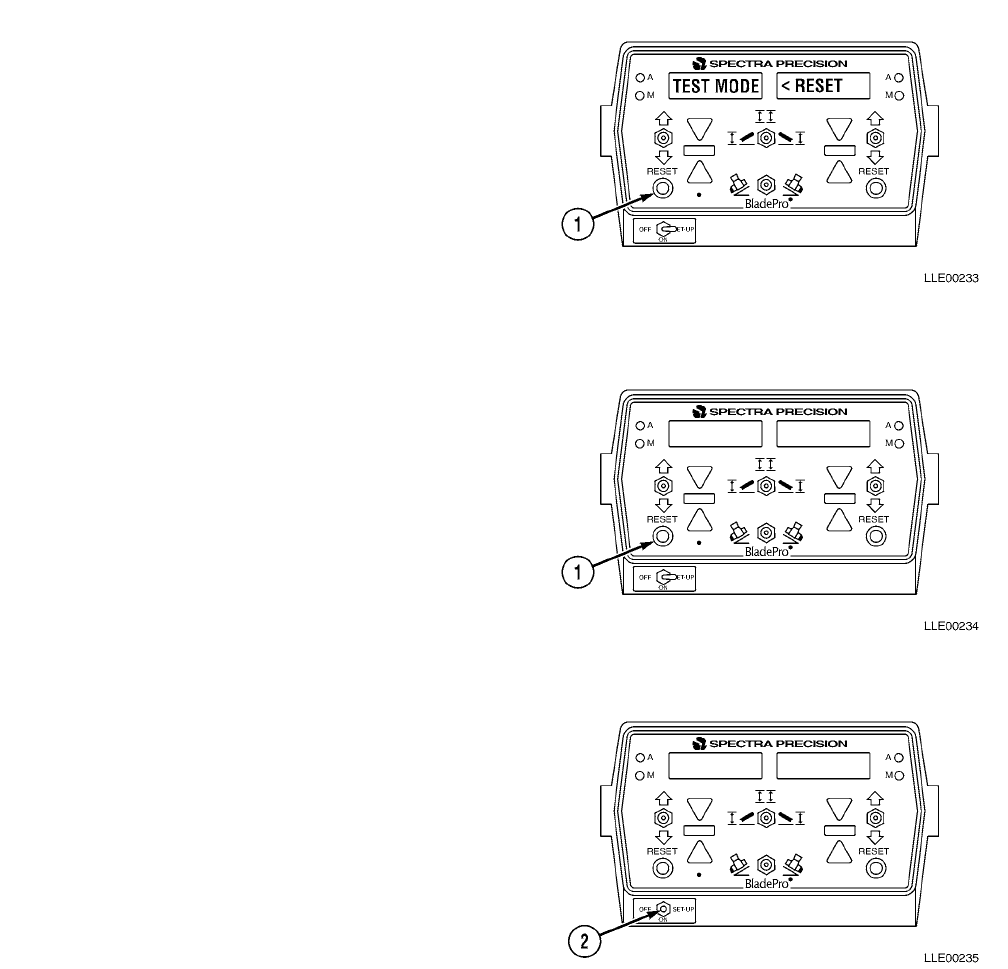
TM 5-6675-348-13&P
3-59
g. Test
(1) Press and hold left RESET button (1) to
enter self-test mode.
Left Display Right Display
TEST MODE <RESET
NOTE
• All LED segments will be activated.
This checks for inactive segments.
• All LEDs will be illuminated. This
checks for burned out LEDs.
• When RESET button is released,
Operator Interface Box will show any
error codes that have occurred since
the last power up. Refer to Blade
Pro® Motor Grader Control System
Troubleshooting Error Messages in
Section V.
(2) Toggle the OFF/ON/SET-UP switch (2) to
ON position to begin normal operation.
TM 5-6675-348-13&P
3-60
SECTION IV. BLADE PRO® MOTOR GRADER CONTROL SYSTEM
TROUBLESHOOTING
While the Blade Pro® Motor Grader Control System is a highly accurate system, you may encounter problems as
you work in the field. Use this section to troubleshoot your problems. You may want to have a qualified
maintenance person troubleshoot and fix any problems.
Table 3-6. Blade Pro® Motor Grader Control System Fault Index
Fault
No. Description Page
3-1. Operator Interface Box Will Not Turn On.........................................................................................................3-61
3-2. Auto and Manual LEDs Are Lit on Same Side of Control Box.........................................................................3-62
3-3. Right/Left Switches in Auto Position, But Automatic Control Is Not Functioning.........................................3-63
3-4. Blade Undercuts or Pulls Into a Cut..................................................................................................................3-63
3-5. Tracer® Sonic Grade Controller Will Not Reset ...............................................................................................3-64
3-6. Cross-Slope Side Does Not Cut Desired Slope ..................................................................................................3-65
3-7. Tracer® Sonic Grade Controller Keeps Losing Reference................................................................................3-66
3-8. Hydraulic Control Valves Do Not Raise or Lower in Automatic Mode, But Blade Operates Manually ........3-67
3-9. Blade Pro® Motor Grader Control System Leaves Waves in the Material......................................................3-69
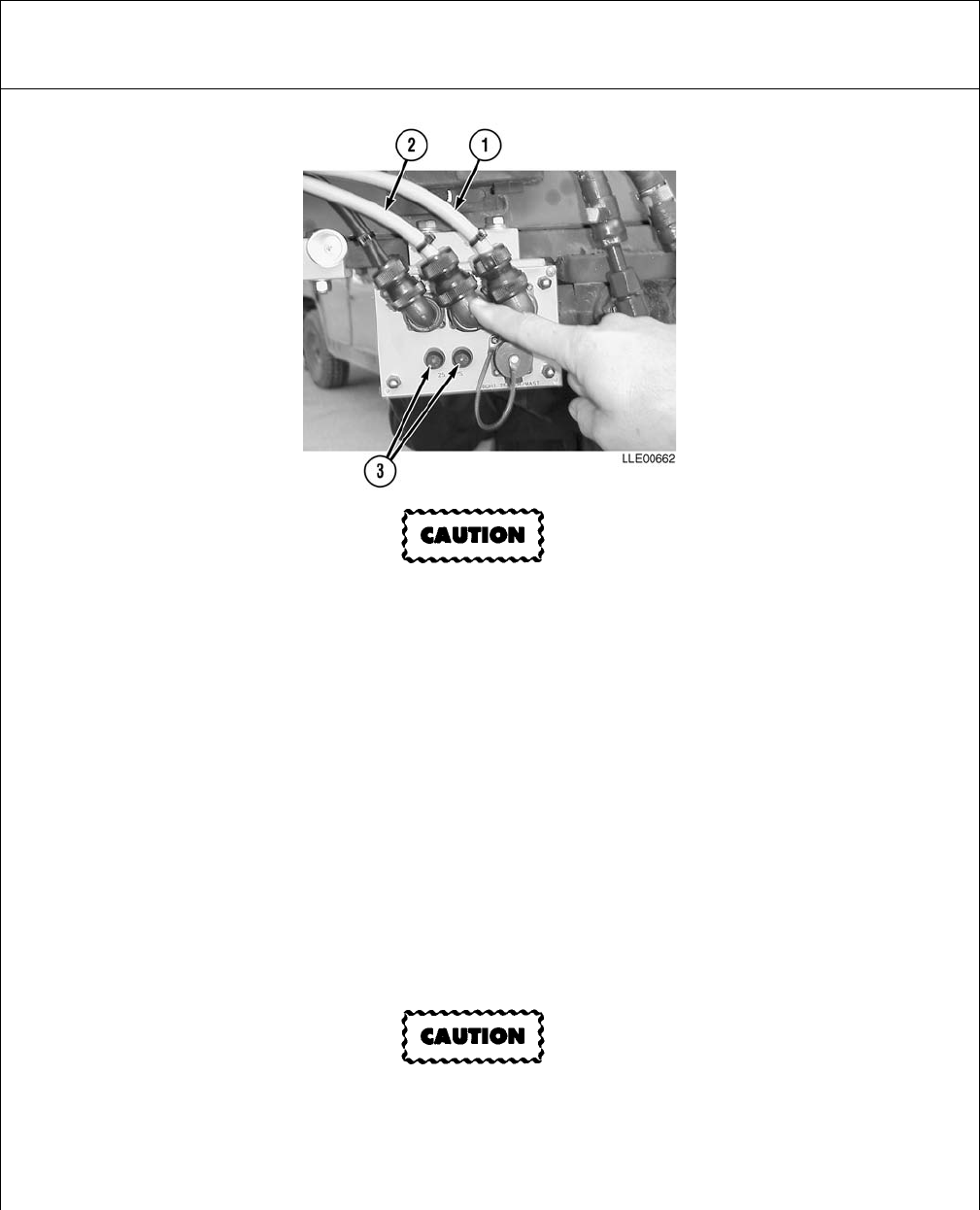
TM 5-6675-348-13&P
3-61
Table 3-7. Blade Pro® Motor Grader Control System Troubleshooting
Malfunction
Test or InspectionCorrective Action
FAULT 3-1. OPERATOR INTERFACE BOX WILL NOT TURN ON.
If connections are wet, the Remote Interface Box will be damaged.
Step 1. Check Cable (1) connector from Operator Interface Box to Remote Interface Box for
tightness and/or dirt.
Remove and inspect Cable (1) to ensure connector is clean and dry. Securely
reconnect Cable.
Step 2. Check Cable (1) from Operator Interface Box to Remote Interface Box for damage.
If Cable (1) is damaged, replace it.
Step 3. Check Power Cable (2) connector.
Remove and inspect Power Cable (2) to ensure connector are clean and dry.
Securely reconnect Power Cable (2).
Step 4. Check Power Cable (2) for damage.
If Power Cable (2) is damaged, replace it.
To avoid damage to equipment, fuse must be replaced with a 25-amp fuse.
Step 5. Check for fuses (3) in Remote Interface Box.
Step 6. Inspect fuses (3) on Remote Interface Box. Ensure they have not blown and are securely in
place. If fuses (3) are faulty, replace them.
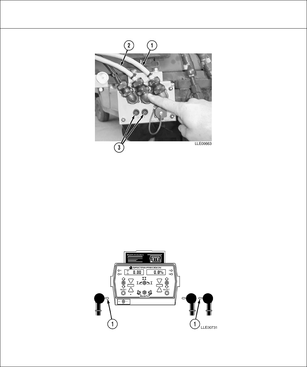
TM 5-6675-348-13&P
3-62
FAULT 3-1. OPERATOR INTERFACE BOX WILL NOT TURN ON. (Cont)
Step 7. Check for a good ground on pins B and C of Power Cable (2).
If a good ground is not found, replace Power Cable (2).
Step 8. Check for 22 to 28 Vdc on pins A and D of Power Cable (2).
If 22 to 28 Vdc is not found on pins A and B, check and service batteries, if needed
(TM 5-3805-261-20).
If batteries are serviceable, replace Power Cable (2).
FAULT 3-2. AUTO AND MANUAL LEDs ARE LIT ON SAME SIDE OF CONTROL BOX.
Step 1. Check Automatic and Manual LEDs light at same time when Blade Pro® Motor Grader
Control System is turned on and you cannot grade in Automatic.
Place R/L Switches (1) in Manual position, then place them in Automatic position.
Table 3-7. Blade Pro® Motor Grader Control System Troubleshooting (Cont)
Malfunction
Test or InspectionCorrective Action
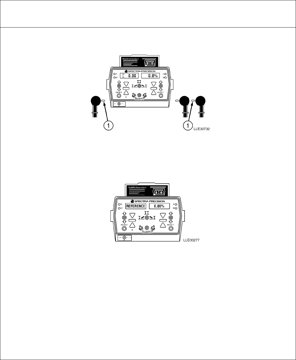
TM 5-6675-348-13&P
3-63
FAULT 3-3. RIGHT/LEFT SWITCHES IN AUTO POSITION, BUT AUTOMATIC CONTROL
IS NOT FUNCTIONING.
Step 1. Check Automatic and Manual LEDs light at same time when Blade Pro® Motor Grader
Control System is turned on and you cannot grade in Automatic.
Place R/L Switches (1) in Manual position, then place them in Automatic
position.
FAULT 3-4. BLADE UNDERCUTS OR PULLS INTO A CUT.
Step 1. When cutting variable compacted material, check if blade undercuts material that is less
compacted.
Roll blade forward to less aggressive cutting position.
If condition persists, contact Direct Support Maintenance.
Table 3-7. Blade Pro® Motor Grader Control System Troubleshooting (Cont)
Malfunction
Test or InspectionCorrective Action
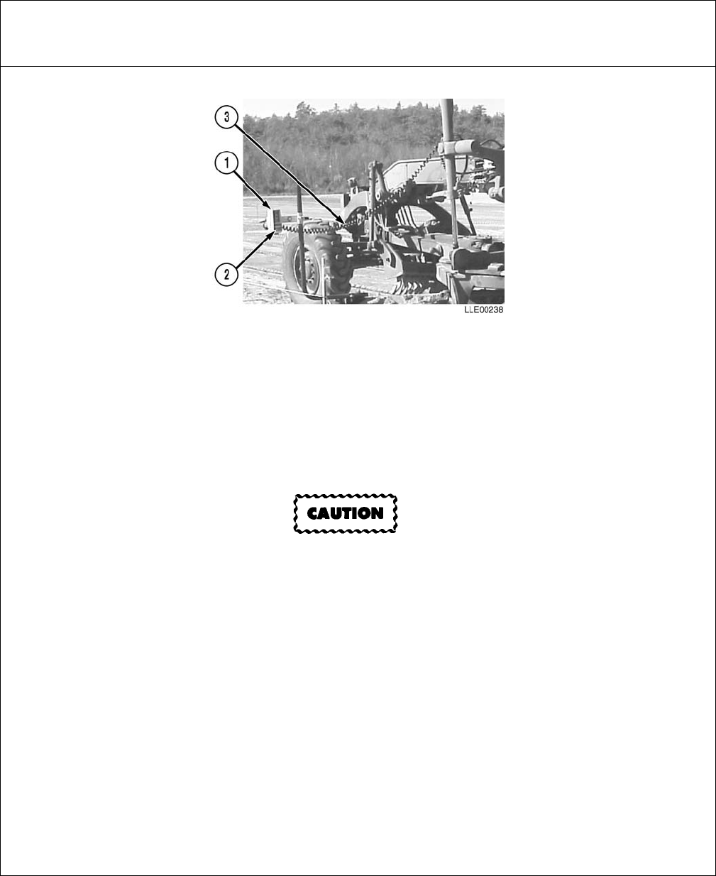
TM 5-6675-348-13&P
3-64
FAULT 3-5. TRACER® SONIC GRADE CONTROLLER WILL NOT RESET.
Step 1. Ensure Tracer® Sonic Grade Controller (1) is within its operating range.
Adjust Tracer® Sonic Grade Controller (1) to within 8 to 42 in. (20.3 to 107 cm) of
reference surface.
Step 2. Ensure Tracer® Sonic Grade Controller (1) is directly over reference surface.
Ensure Tracer® Sonic Grade Controller (1) is vertical and plumb over reference
surface. Adjust Tracer® Sonic Grade Controller (1) over reference surface.
If connections are wet, the Remote Interface Box will be damaged.
Step 3. Check Tracer® Sonic Grade Controller (1) cable connectors for looseness and/or moisture.
Ensure all connectors are clean and dry. Securely reconnect Tracer® Sonic Grade
Controller (1) cable.
Step 4. Check Coil Cable (3) between Tracer® Sonic Grade Controller (1) and Remote Interface Box
for damage.
If Coil Cable (3) is damaged, replace it.
Step 5. Check Transducer screen (2) on bottom of Tracer® Sonic Grade Controller (1) for dirt.
Clean Transducer screen (2).
Table 3-7. Blade Pro® Motor Grader Control System Troubleshooting (Cont)
Malfunction
Test or InspectionCorrective Action
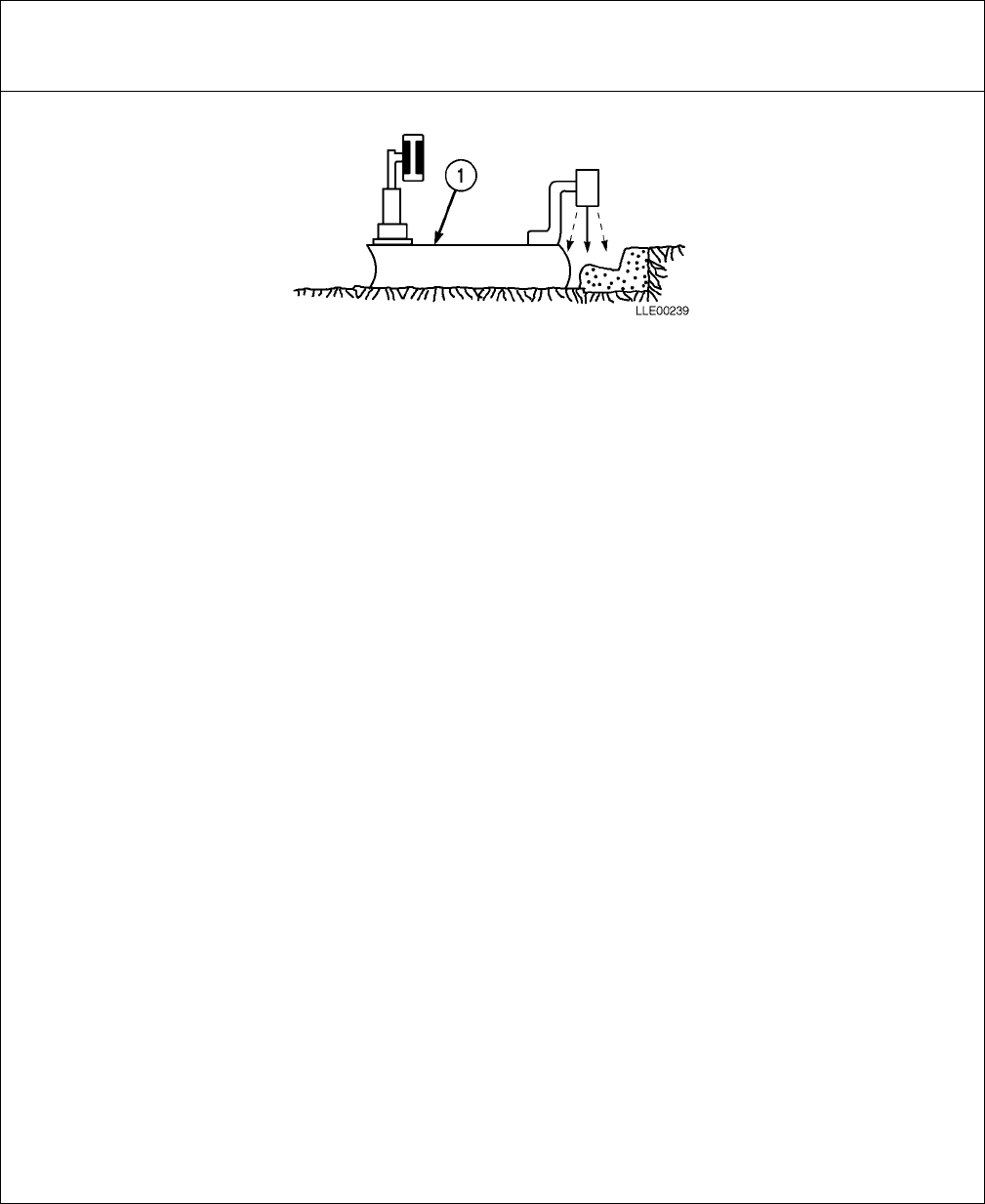
TM 5-6675-348-13&P
3-65
FAULT 3-6. CROSS-SLOPE SIDE DOES NOT CUT DESIRED SLOPE.
Step 1. The 130G Grader (1) may not be able to cut material at the depth you are trying to cut.
Try making several passes to remove material.
Step 2. The 130G Grader (1) may need to be calibrated.
Perform full calibration (Para 3-15 and Para 3-16).
NOTE
Excessive 130G Grader mechanical wear can give the Blade Pro® Motor Grader Control
System false sensor readings.
Step 3. Check 130G Grader (1) for excessive mechanical wear.
Inspect 130G Grader (1) for wear (Section VII).
Table 3-7. Blade Pro® Motor Grader Control System Troubleshooting (Cont)
Malfunction
Test or InspectionCorrective Action

TM 5-6675-348-13&P
3-66
FAULT 3-7. TRACER® SONIC GRADE CONTROLLER KEEPS LOSING REFERENCE.
Step 1. Ensure Tracer® Sonic Grade Controller (1) is within its operating range.
Adjust Tracer® Sonic Grade Controller (1) to within 8 to 42 in. (20 to 107 cm) of
reference surface (2).
Step 2. Ensure Tracer® Sonic Grade Controller (1) is directly over reference surface (2).
Ensure Tracer® Sonic Grade Controller (1) is vertical and plumb over reference
surface (2). Adjust Tracer® Sonic Grade Controller (1) over reference surface.
Step 3. Tracer® Sonic Grade Controller (1) is not following string line closely enough.
Line up Tracer® Sonic Grade Controller (1) over reference surface (2).
If using a string line, tie a brightly colored ribbon onto Tracer® Sonic Grade
Controller Pole (3), marking your line of sight where pole intersects string line.
Step 4. Tracer® Sonic Grade Controller (1) is tracing something other than what you thought.
Carefully align Tracer® Sonic Grade Controller (1), then place a pencil between
reference and ground. If the Tracer® Sonic Grade Controller (1) gives you a
correction signal, you are not picking up the correct reference.
Table 3-7. Blade Pro® Motor Grader Control System Troubleshooting (Cont)
Malfunction
Test or InspectionCorrective Action

TM 5-6675-348-13&P
3-67
FAULT 3-8. HYDRAULIC CONTROL VALVES DO NOT RAISE OR LOWER IN AUTOMATIC MODE,
BUT BLADE OPERATES MANUALLY.
Step 1. Check R/L Switches (1) for proper operation.
Put R/L Switches (1) in Auto position. If green automatic LED does not light,
replace R/L Switches (1).
If connectors are wet, the Remote Interface Box will be damaged.
Step 2. Remove Hydraulic Valve Cable connector (3) to ensure it is clean, dry, and free from damage.
If Hydraulic Valve Cable connector (3) is damaged or broken, replace connectors.
Table 3-7. Blade Pro® Motor Grader Control System Troubleshooting (Cont)
Malfunction
Test or InspectionCorrective Action
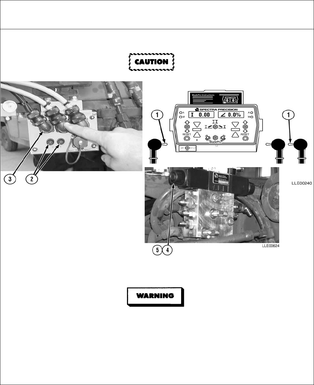
TM 5-6675-348-13&P
3-68
FAULT 3-8. HYDRAULIC CONTROL VALVES DO NOT RAISE OR LOWER IN AUTOMATIC MODE,
BUT BLADE OPERATES MANUALLY. (Cont)
To avoid damage to equipment, fuse must be replaced with a 25-amp fuse.
Step 3. Check fuse (2) in Remote Interface Box.
If fuse (2) is faulty, replace.
Do not start or move Blade Pro® Motor Grader Control System while anyone is under the
130G Grader. Failure to comply could result in severe injury or death to personnel
Step 4. With 130G Grader running and while clear of moving parts of 130G Grader, press
rubber-covered buttons (4) on ends of Valve Spools (5) to ensure Valve Spools (5) are not
frozen. Blade should move up and down when each rubber-covered button (4) is pressed.
If Valve Spools are frozen, replace Proportional Valve Assembly (Para 3-35).
Table 3-7. Blade Pro® Motor Grader Control System Troubleshooting (Cont)
Malfunction
Test or InspectionCorrective Action

TM 5-6675-348-13&P
3-69
FAULT 3-9. BLADE PRO® MOTOR GRADER CONTROL SYSTEM LEAVES WAVES IN THE
MATERIAL.
Step 1. Ensure 130G Grader’s hydraulic fluid has reached operating temperature.
Step 2. Ensure Hydraulic Valves are calibrated properly.
Perform Hydraulic Valve calibration (Para 3-16).
Step 3. If error is not corrected, contact Trimble Navigation.
Table 3-7. Blade Pro® Motor Grader Control System Troubleshooting (Cont)
Malfunction
Test or InspectionCorrective Action
TM 5-6675-348-13&P
3-70
SECTION V. BLADE PRO® MOTOR GRADER CONTROL SYSTEM
TROUBLESHOOTING ERROR MESSAGES
While the Blade Pro® Motor Grader Control System is a highly accurate system, you may see error messages
displayed as you work in the field. Use this section to troubleshoot your error messages. You may find you can
fix your problem on your own, or call Trimble Navigation.
3-25. TEST/ERROR LOG FEATURE.
Test/Error Log feature activates all LCD and LED lights, so you can see any burned out LCD or LED lights. It
also records any errors that may have occurred and gives you a total. This error log will go away when you
turn the control box off, so if the Blade Pro® Motor Grader Control System has been giving you errors, do not
turn Operator Interface Box off until you have resolved the problem or contacted Direct Support
Maintenance.
To run Test/Error Log feature:
(1) Position OFF/ON/SET-UP switch to SET-UP position. Reference and reference number appear in
display windows.
(2) Press left switch down until Test Mode < RESET appears in display windows.
(3) Press left RESET button. Blade Pro® Motor Grader Control System runs self-test. Make note of
any lights that have burned out, any error numbers, and total number of error messages.
(4) Turn OFF/ON/SET-UP switch to ON position.

TM 5-6675-348-13&P
3-71
NOTE
Record Error log number. This will be needed by Direct Support maintenance to
troubleshoot your system.
Table 3-8. Error Messages
ERROR MESSAGE WHAT TO DO ABOUT IT
ART. FAULT Check articulation sensor to ensure it is firmly in place. Ensure cable is firmly
connected and is not cut or broken.
ART. OFF Call Trimble Navigation.
ART.>>RANGE 130G Grader has been articulated too far. Call your Trimble Navigation.
BLADE FAULT Check Cross-Slope Sensor to ensure it is firmly in place. Ensure cable is firmly
connected and is not cut or broken.
BLADE OFF Call Blade Pro® Motor Grader Control System Authorized Service Center.
BLADE>>RANGE Check Cross-Slope Sensor to ensure it is firmly in place. Ensure cable is firmly
connected and is not cut or broken.
ELEVATION FAULT Call Trimble Navigation.
ELEVATION >> RANGE Your Tracer® Sonic Grade Controller is too close or far from the reference.
Adjust distance, then press RESET button for side Tracer® Sonic Grade
Controller is on.
HARDWARE FAULT Call Trimble Navigation.
MAINFALL OFF Call Trimble Navigation.
MAINFALL FAULT Check Mainfall Slope Sensor to ensure it is firmly in place. Ensure cable is
firmly connected and is not cut.
MAINFALL >> RANGE 130G Grader is on a slope that is too steep for Mainfall Slope Sensor to
measure. Move grader to less steep area, then re-evaluate.
ROTATION FAULT Check Circle Rotation Sensor to ensure it is firmly in place. Ensure cable is
firmly connected and is not cut.
ROTATION OFF Call Trimble Navigation.
ROTATION >> RANGE Blade has been rotated too far. Carefully rotate blade back to within the 0 to
96° range. If blade has not been rotated too far, your Circle Rotation Sensor
may be loose. Ensure Circle Rotation Sensor is firmly attached.
SERIAL ERROR Call Trimble Navigation.
SYSTEM FAULT Call Trimble Navigation.
VALVE ERROR Call Trimble Navigation.
VALVE FAULT Call Trimble Navigation.
VALVE OFF Call Trimble Navigation.

TM 5-6675-348-13&P
3-72
SECTION VI. BLADE PRO® MOTOR GRADER CONTROL SYSTEM ERROR LOG
3-26. MG2P-35 ERROR LOG.
Table 3-9. Error Log
Level 1 Errors Display Messages
Blade slope signal detected with sensor OFF. BLADE OFF
Mainfall signal detected with sensor OFF. MAINFALL OFF
Rotation angle signal detected with sensor OFF. ROTATION OFF
Articulation angle signal detected with sensor OFF. ART. OFF
Level 2 Errors Display Messages
Valve type not selected. VALVE OFF
Blade slope signal frequency too low with sensor ON. BLADE FAULT
Blade slope signal frequency too high with sensor ON. BLADE FAULT
Blade slope signal value too low with sensor ON. BLADE» RANGE
Blade slope signal value too high with sensor ON. BLADE» RANGE
Mainfall signal frequency too low with sensor ON. MAINFALL FAULT
Mainfall signal frequency too high with sensor ON. MAINFALL FAULT
Mainfall signal value too low with sensor ON. MAINFALL» RANGE
Mainfall signal value too high with sensor ON. MAINFALL» RANGE
Rotation angle signal frequency too low with sensor ON. ROTATION FAULT
Rotation angle signal frequency too high with sensor ON. ROTATION FAULT
Rotation angle signal value too low with sensor ON. ROTATION» RANGE
Rotation angle signal value too high with sensor ON. ROTATION» RANGE
Articulation angle signal frequency too low with sensor ON. ART. FAULT
Articulation angle signal frequency too high with sensor ON. ART. FAULT
Articulation angle signal value too low with sensor ON. ART.» RANGE
Articulation angle signal value too high with sensor ON. ART.» RANGE
Level 3 Errors Display Messages
Operator Interface Box serial transmission check sum fault detected. SERIAL ERROR
Operator Interface Box serial transmission bad ID number detected. SERIAL ERROR
Operator Interface Box serial transmission incomplete packet
detected. SERIAL ERROR
Operator Interface Box serial transmission framing fault detected. SERIAL ERROR
Operator Interface Box serial transmission noise detected. SERIAL ERROR
Operator Interface Box serial transmission overrun detected. SERIAL ERROR

TM 5-6675-348-13&P
3-73
Level 4 Errors Display Messages
Left fine lower valve voltage incorrect. VALVE ERROR
Left medium lower valve voltage incorrect. VALVE ERROR
Left coarse lower valve voltage incorrect. VALVE ERROR
Left fine raise valve voltage incorrect. VALVE ERROR
Left medium raise valve voltage incorrect. VALVE ERROR
Left coarse raise valve voltage incorrect. VALVE ERROR
Load sense valve voltage incorrect. VALVE ERROR
Right fine lower valve voltage incorrect. VALVE ERROR
Right medium lower valve voltage incorrect. VALVE ERROR
Right coarse lower valve voltage incorrect. VALVE ERROR
Right fine raise valve voltage incorrect. VALVE ERROR
Right medium raise valve voltage incorrect. VALVE ERROR
Right coarse raise valve voltage incorrect. VALVE ERROR
Unloading valve voltage incorrect. VALVE ERROR
Left valve driver overload detected. VALVE FAULT
Right valve driver overload detected. VALVE FAULT
Left EM2E-24 Electric Mast motor driver overload detected. ELEVATION FAULT
Right EM2E-24 Electric Mast motor driver overload detected. ELEVATION FAULT
Power supply overload detected. SYSTEM FAULT
Level 5 Errors Display Messages
Left elevation length increase too slow or stopped. ELEVATION >> RANGE
Left elevation length decrease too slow or stopped. ELEVATION >> RANGE
CPU reset during left elevation length change. ELEVATION FAULT
Right elevation length increase too slow or stopped. ELEVATION>> RANGE
Right elevation length decrease too slow or stopped. ELEVATION>> RANGE
CPU reset during right elevation length change. ELEVATION FAULT
Left driver board type incorrect. HARDWARE FAULT
Right driver board type incorrect. HARDWARE FAULT
Left driver board mode incorrect. HARDWARE FAULT
Right driver board mode incorrect. HARDWARE FAULT
Remote Interface Box RAM fault detected. HARDWARE FAULT
Remote Interface Box ROM fault detected. HARDWARE FAULT
Remote Interface Box EEPROM fault detected. HARDWARE FAULT
Table 3-9. Error Log (Cont)

TM 5-6675-348-13&P
3-74
Table 3-10. Error-to-Source Relationships
Level 1 Errors Abbreviation Error #
Blade slope signal detected with sensor OFF.
User turned OFF Blade Slope Sensor but did not disconnect it.
Remote Interface Box CPU board.
Blade On 1
Mainfall signal detected with sensor OFF.
User turned OFF Mainfall Slope Sensor but did not disconnect it.
Remote Interface Box CPU board.
Mainfall On 2
Rotation angle signal detected with sensor OFF.
User turned OFF rotation Angle Sensor but did not disconnect it.
Remote Interface Box CPU board.
Rotation On 3
Articulation angle signal detected with sensor OFF.
User turned OFF articulation Angle Sensor but did not disconnect it.
Remote Interface Box CPU board.
Articulation
On 4
Level 2 Errors Abbreviation Error #
Valve type not selected.
User did not yet select a valve type.
Remote Interface Box CPU board.
No Valve
Selected 5
Blade slope signal frequency too low or stopped with sensor ON.
Blade Slope Sensor or cable.
Remote Interface Box CPU board.
Remote Interface Box motherboard.
Blade Slow
6
Blade slope signal frequency too high with sensor ON.
Blade Slope Sensor or cable.
Remote Interface Box CPU board.
Remote Interface Box motherboard.
Blade Fast
7
Blade slope signal value too low with sensor ON.
Blade Slope Sensor or cable.
Remote Interface Box CPU board.
Remote Interface Box motherboard.
Blade Low
8
Blade slope signal value too high with sensor ON.
Blade Slope Sensor or cable.
Remote Interface Box CPU board.
Remote Interface Box motherboard.
Blade High
9
Mainfall signal frequency too low or stopped with sensor ON.
Mainfall Slope Sensor or cable.
Remote Interface Box CPU board.
Remote Interface Box motherboard.
Mainfall Slow
10

TM 5-6675-348-13&P
3-75
Level 2 Errors (Cont) Abbreviation Error #
Mainfall signal frequency too high with sensor ON.
Mainfall Slope Sensor or cable.
Remote Interface Box CPU board.
Remote Interface Box motherboard.
Mainfall Fast
11
Mainfall signal value too low with sensor ON.
Mainfall Slope Sensor or cable.
Remote Interface Box CPU board.
Remote Interface Box motherboard.
Mainfall Low
12
Mainfall signal value too high with sensor ON.
Mainfall Slope Sensor or cable.
Remote Interface Box CPU board.
Remote Interface Box motherboard.
Mainfall High
13
Rotation angle signal frequency too low or stopped with sensor ON.
Rotation Angle Sensor or cable.
Remote Interface Box CPU board.
Remote Interface Box motherboard.
Rotation Slow
14
Rotation angle signal frequency too high with sensor ON.
Rotation Angle Sensor or cable.
Remote Interface Box CPU board.
Remote Interface Box motherboard.
Rotation Fast
15
Rotation angle signal value too low with sensor ON.
Rotation Angle Sensor or cable.
Remote Interface Box CPU board.
Remote Interface Box motherboard.
Rotation Low
16
Rotation angle signal value too high with sensor ON.
Rotation Angle Sensor or cable.
Remote Interface Box CPU board.
Remote Interface Box motherboard.
Rotation High
17
Articulation angle signal frequency too low or stopped with sensor ON.
Articulation Angle Sensor or cable.
Remote Interface Box CPU board.
Remote Interface Box motherboard.
Articulation
Slow 18
Articulation angle signal frequency too high with sensor ON.
Articulation Angle Sensor or cable.
Remote Interface Box CPU board.
Remote Interface Box motherboard.
Articulation
Fast 19
Articulation angle signal value too low with sensor ON.
Articulation Angle Sensor or cable.
Remote Interface Box CPU board.
Remote Interface Box motherboard.
Articulation
Low 20
Table 3-10. Error-to-Source Relationships (Cont)

TM 5-6675-348-13&P
3-76
Level 3 Errors Abbreviation Error #
Articulation angle signal value too high with sensor ON.
Articulation Angle Sensor or cable.
Remote Interface Box CPU board.
Remote Interface Box motherboard.
Articulation
High 21
Operator Interface Box serial transmission check sum fault detected.
Operator Interface Box.
Operator Interface Box cable.
Remote Interface Box CPU board.
Remote Interface Box motherboard.
Serial Check
Sum 22
Operator Interface Box serial transmission ID number out of range detected.
Operator Interface Box.
Operator Interface Box cable.
Remote Interface Box CPU board.
Remote Interface Box motherboard.
Serial ID
23
Operator Interface Box serial transmission incomplete packet detected.
Operator Interface Box.
Operator Interface Box cable.
Remote Interface Box CPU board.
Remote Interface Box motherboard.
Serial Packet
24
Operator Interface Box serial transmission framing fault detected.
Operator Interface Box.
Operator Interface Box cable.
Remote Interface Box CPU board.
Remote Interface Box motherboard.
Serial Frame
25
Operator Interface Box serial transmission noise detected.
Operator Interface Box.
Operator Interface Box cable.
Remote Interface Box CPU board.
Remote Interface Box motherboard.
Serial Noise
26
Operator Interface Box serial transmission overrun detected.
Remote Interface Box CPU board. Serial
Overrun 27
Level 4 Errors Abbreviation Error #
Left fine lower valve voltage incorrect.
Remote Interface Box CPU board.
Remote Interface Box motherboard.
Remote Interface Box left driver board.
Left fine lower valve or cable.
Left Lower
Fine 28
Left medium lower valve voltage incorrect.
Remote Interface Box CPU board.
Remote Interface Box motherboard.
Remote Interface Box left driver board.
Left medium lower valve or cable.
Left Lower
Medium 29
Table 3-10. Error-to-Source Relationships (Cont)

TM 5-6675-348-13&P
3-77
Level 4 Errors (Cont) Abbreviation Error #
Left coarse lower valve voltage incorrect.
Remote Interface Box CPU board.
Remote Interface Box motherboard.
Remote Interface Box left driver board.
Left coarse lower valve or cable.
Left Lower
Coarse 30
Left fine raise valve voltage incorrect.
Remote Interface Box CPU board.
Remote Interface Box motherboard.
Remote Interface Box left driver board.
Left fine raise valve or cable.
Left Raise
Fine 31
Left medium raise valve voltage incorrect.
Remote Interface Box CPU board.
Remote Interface Box motherboard.
Remote Interface Box left driver board.
Left medium raise valve or cable.
Left Raise
Medium 32
Left coarse raise valve voltage incorrect.
Remote Interface Box CPU board.
Remote Interface Box motherboard.
Remote Interface Box left driver board.
Left coarse raise valve or cable.
Left Raise
Coarse 33
Load sense valve voltage incorrect.
Remote Interface Box CPU board.
Remote Interface Box motherboard.
Remote Interface Box left driver board.
Load sense valve or cable.
Load Sense
Valve 34
Right fine lower valve voltage incorrect.
Remote Interface Box right driver board fuse.
Remote Interface Box CPU board.
Remote Interface Box motherboard.
Remote Interface Box right driver board.
Right fine lower valve or cable.
Right Lower
Fine
35
Right medium lower valve voltage incorrect.
Remote Interface Box right driver board fuse.
Remote Interface Box CPU board.
Remote Interface Box motherboard.
Remote Interface Box right driver board.
Right medium lower valve or cable.
Right Lower
Medium
36
Right coarse lower valve voltage incorrect.
Remote Interface Box right driver board fuse.
Remote Interface Box CPU board.
Remote Interface Box motherboard.
Remote Interface Box right driver board.
Right coarse lower valve or cable.
Right Lower
Coarse
37
Table 3-10. Error-to-Source Relationships (Cont)

TM 5-6675-348-13&P
3-78
Level 4 Errors (Cont) Abbreviation Error #
Right fine raise valve voltage incorrect.
Remote Interface Box right driver board fuse.
Remote Interface Box CPU board.
Remote Interface Box motherboard.
Remote Interface Box right driver board.
Right fine raise valve or cable.
Right Raise
Fine
38
Right medium raise valve voltage incorrect.
Remote Interface Box right driver board fuse.
Remote Interface Box CPU board.
Remote Interface Box motherboard.
Remote Interface Box right driver board.
Right medium raise valve or cable.
Right Raise
Medium
39
Right coarse raise valve voltage incorrect.
Remote Interface Box right driver board fuse.
Remote Interface Box CPU board.
Remote Interface Box motherboard.
Remote Interface Box right driver board.
Right coarse raise valve or cable.
Right Raise
Coarse
40
Unloading valve voltage incorrect.
Remote Interface Box right driver board fuse.
Remote Interface Box CPU board.
Remote Interface Box motherboard.
Remote Interface Box right driver board.
Unloading valve or cable.
Unloading
Valve
41
Left valve driver overload detected.
Remote Interface Box CPU board.
Remote Interface Box left driver board.
Remote Interface Box motherboard.
Left fine raise valve or cable.
Left medium raise valve or cable.
Left coarse raise valve or cable.
Load sense valve or cable.
Left Valve
Overload
42
Right valve driver overload detected.
Remote Interface Box CPU board.
Remote Interface Box right driver board.
Remote Interface Box right driver board fuse.
Remote Interface Box motherboard.
Right fine raise valve or cable.
Right medium raise valve or cable.
Right coarse raise valve or cable.
Unloading valve or cable.
Right Valve
Overload
43
Table 3-10. Error-to-Source Relationships (Cont)

TM 5-6675-348-13&P
3-79
Level 4 Errors (Cont) Abbreviation Error #
Left EM2E-24 Electric Mast motor driver overload detected.
Remote Interface Box CPU board.
Remote Interface Box left driver board.
Remote Interface Box motherboard.
Left elevation sensor or cable.
Left EM2E-24
Electric Mast
Overload 44
Right EM2E-24 Electric Mast motor driver overload detected.
Remote Interface Box CPU board.
Remote Interface Box right driver board.
Remote Interface Box right driver board fuse.
Remote Interface Box motherboard.
Right elevation sensor or cable.
Right EM2E-
24 Electric
Mast Overload 45
Power supply overload detected.
Operator Interface Box.
Operator Interface Box cable.
Remote Interface Box CPU board.
Remote Interface Box motherboard.
Blade Slope Sensor or cable.
Mainfall Slope Sensor or cable.
Rotation Angle Sensor or cable.
Articulation Angle Sensor or cable.
Left elevation sensor or cable.
Right elevation sensor or cable.
Power
Overload
46
Level 5 Errors Abbreviation Error #
Left elevation length increase too slow or stopped.
Left elevation upper length limit reached.
Left elevation sensor or cable.
Remote Interface Box CPU board.
Remote Interface Box motherboard.
Left Elevation
Ceiling 47
Left elevation length decrease too slow or stopped.
Left elevation lower length limit reached.
Left elevation sensor or cable.
Remote Interface Box CPU board.
Remote Interface Box motherboard.
Left Elevation
Floor 48
CPU reset during left elevation length change.
User turned off system before left elevation sensor stopped.
Left elevation sensor or cable.
Remote Interface Box CPU board.
Remote Interface Box motherboard.
Left Elevation
Miscount 49
Table 3-10. Error-to-Source Relationships (Cont)

TM 5-6675-348-13&P
3-80
Level 5 Errors (Cont) Abbreviation Error #
Right elevation length increase too slow or stopped.
Right elevation upper length limit reached.
Right elevation sensor or cable.
Remote Interface Box right driver board fuse.
Remote Interface Box CPU board.
Remote Interface Box motherboard.
Right
Elevation
Ceiling 50
Right elevation length decrease too slow or stopped.
Right elevation lower length limit reached.
Right elevation sensor or cable.
Remote Interface Box right driver board fuse.
Remote Interface Box CPU board.
Remote Interface Box motherboard.
Right
Elevation
Floor 51
CPU reset during right elevation length change.
User turned off system before right elevation sensor stopped.
Right elevation sensor or cable.
Remote Interface Box CPU board.
Remote Interface Box motherboard.
Right
Elevation
Miscount 52
Remote Interface Box left driver board type incorrect.
Remote Interface Box left driver board.
Remote Interface Box CPU board.
Wrong Left
Board 53
Remote Interface Box right driver board type incorrect.
Remote Interface Box right driver board.
Remote Interface Box CPU board.
Wrong Right
Board 54
Remote Interface Box left driver board mode incorrect.
Remote Interface Box left driver board.
Remote Interface Box CPU board.
Wrong Left
Driver 55
Remote Interface Box right driver board mode incorrect.
Remote Interface Box right driver board.
Remote Interface Box CPU board.
Wrong Right
Driver 56
Remote Interface Box CPU RAM fault detected.
Remote Interface Box CPU board. RAM Fault 57
Remote Interface Box CPU ROM fault detected.
Remote Interface Box CPU board. ROM Fault 58
Remote Interface Box CPU EEPROM fault detected.
Remote Interface Box CPU board. EEPROM
Fault 59
Table 3-10. Error-to-Source Relationships (Cont)
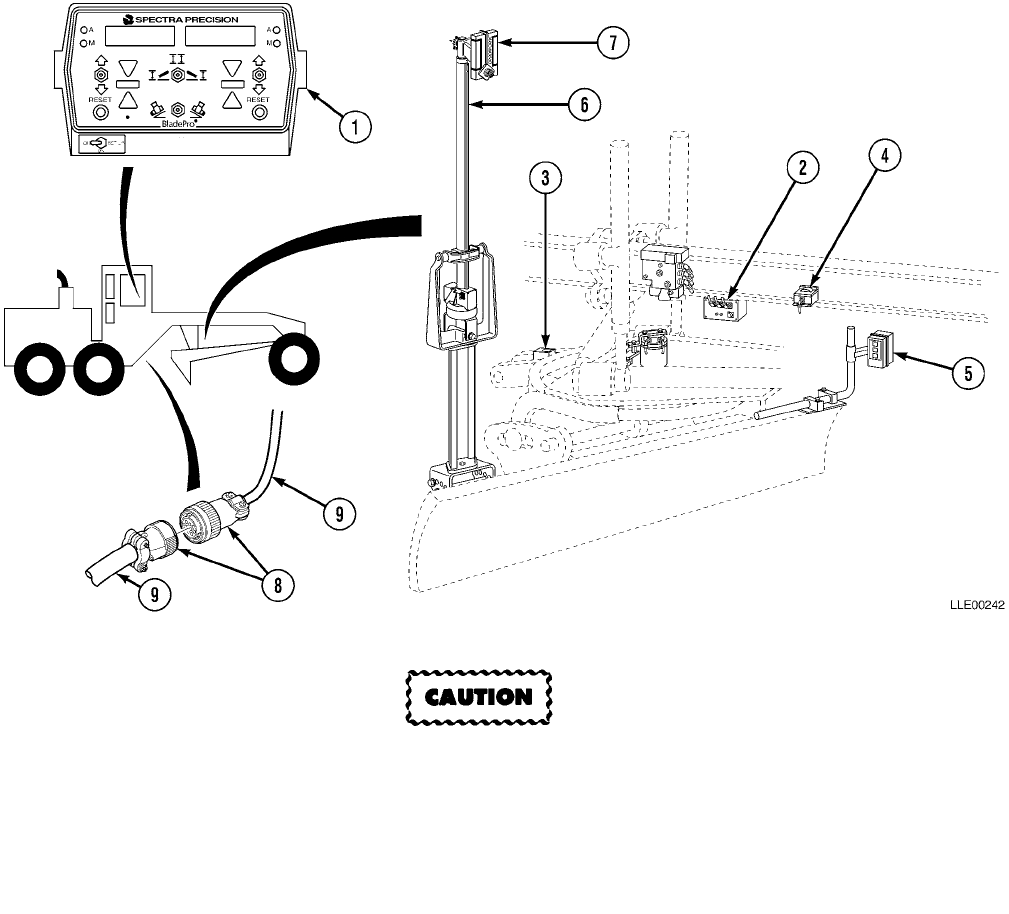
TM 5-6675-348-13&P
3-81
3-27. CONFIGURE FOR TRANSPORT.
a. Before Transport.
Blade Pro® Motor Grader Control System components are not designed to be air
dropped. Failure to comply may result in damage to equipment.
When transporting your 130G Grader(s) with Blade Pro® Motor Grader Control System by ship, train, air, or
truck, perform the following procedure:
NOTE
Perform Step (1) if you have an Airborne or Air Mobile grader.
(1) Disconnect the Main Power Cable (9) before sectionalizing your 130G Grader for transportation.
(2) Remove all components listed below, except Circle Rotation Sensor, and store in their carrying
cases during shipment and transportation:
1. Operator Interface Box
2. Remote Interface Box
3. Blade Slope Sensor
4. Mainfall Slope Sensor
5. Tracer® Sonic Grade
Controller
6. EM2E-24 Electric Mast
7. R2S-S Laser Receiver
b. After Transport.
(1) Install all components removed and do a complete calibration of components (1) through (4),
(Para 3-15 and Para 3-16).
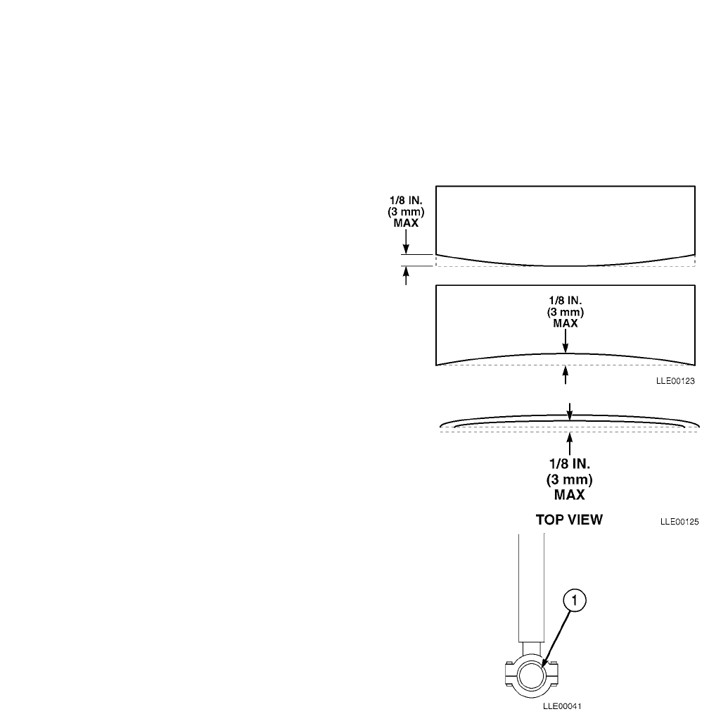
TM 5-6675-348-13&P
3-82
SECTION VII. BLADE PRO® MOTOR GRADER CONTROL
SYSTEM MAINTENANCE
NOTE
The following section deals with critical wear and maintenance areas of your 130G Grader
and Blade Pro® Motor Grader Control System.
Consistent accuracy of your Blade Pro® Motor Grader Control System is largely dependent on the
130G Grader’s condition. 130G Grader wear varies with job conditions, Operator skills, and materials. The
130G Grader wear points should be inspected on a regular basis.
3-28. BLADE CUTTING EDGE INSPECTION.
a. Blade Wear Inspection. Uneven blade wear
occurs mainly in three locations: on the
cutting edge, arcing from edges to center
creating an upward bow, and from center
wearing to either end. Blade wear can be
checked by placing the cutting edge on or
slightly above a flat surface, such as concrete
or pavement, and comparing cutting edge to
that surface. Maximum deviation from even
wear should be less than 1/8 in. (3 mm) if
accuracy within 1/100 ft (0.003 m) is desired
(TM 5-3805-261-10).
b. Blade Curvature Inspection. Curvature is a
bowing effect from edges to center, arcing
toward the rear of the machine. Check blade
curvature by placing a straightedge or string
across the corners of the blade and measuring
maximum deviation at center, 1/8 in. (3 mm)
maximum (TM 5-3805-261-10).
3-29. BLADE LIFT CYLINDER SOCKETS
INSPECTION.
Check socket (1) wear by lowering moldboard
to hard surface until ball seats firmly in upper
half of socket. Raise moldboard and measure
distance until ball seats in lower half of socket.
Maximum measured clearance should be less
than 0.040 in. (0.10 cm). Shim replacement or
removal may be necessary
(TM 5-3805-261-20).
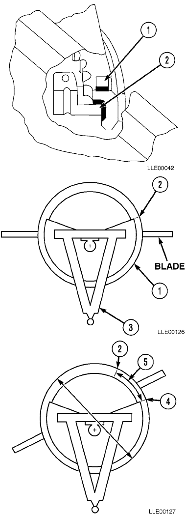
TM 5-6675-348-13&P
3-83
3-30. WEAR STRIPS (CIRCLE TOP) INSPECTION.
Wear strips between circle top surface (1) and drawbar
can be checked in a similar manner as that of checking
cylinder sockets. Lower moldboard to hard surface until
blade is loaded with downward pressure.
(1) Measure distance between circle top (2) and
drawbar. Raise moldboard off ground and
measure distance again. Difference between
two measurements should be no more than
0.02 in. (0.05 cm).
3-31. HOSE TRAY BACKLASH ADJUSTMENT.
a. Measure.
(1) Rotate circle (1) clockwise 10 degrees and
mark first mark (2) on circle relative to
A-frame (3).
(2) Rotate circle (1) counterclockwise slowly. Stop
when top plate of hydraulic swivel begins
turning. Place second mark (4) on circle.
(3) Measure distance (5) between mark (2) and
mark (4). Distance should be less than 1/2 in.
(1.3 cm). Refer to Step b. to adjust.

TM 5-6675-348-13&P
3-84
b. Adjust. NOTE
Rotational backlash is recommended to
be less than 1/2 in. (1.3 cm).
(1) If greater than 1/2 in. (1.3 cm), two joints
between Circle Rotation Sensor and circle
can be tightened.
(2) First joint is between hose tray (1) and
hydraulic swivel (2).
(3) Remove existing pin connecting hose tray
to swivel.
(4) Replace pin with 8-in. (20.3 cm) long,
3/4-10, grade 5 bolt (3) and nut (4).
(5) Use 3/4 in. flat washers (5) to remove slack between two parts.
3-32. CIRCLE SLIDE SHOE INSPECTION.
Circle Slide Shoes should also be checked for proper adjustment. Consult your 130G Grader Technical Man-
ual for this procedure (TM 5-3805-261-10).
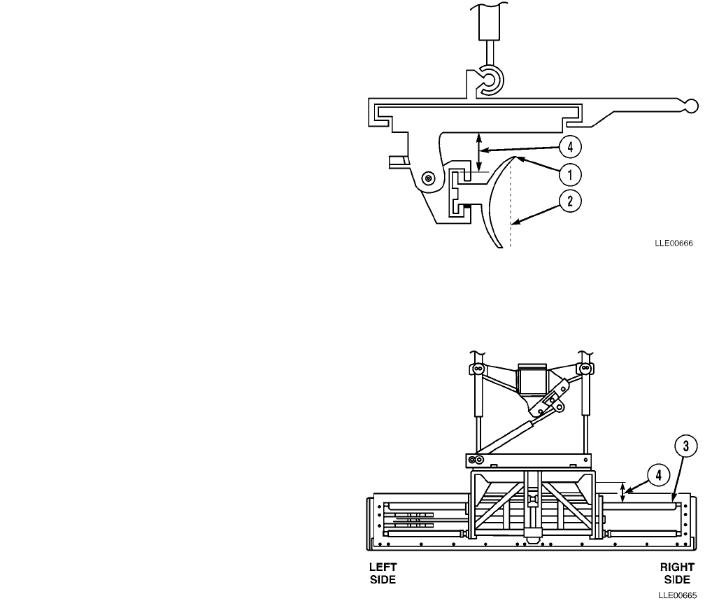
TM 5-6675-348-13&P
3-85
3-33. BLADE BACKLASH ADJUSTMENT.
a. Measure.
(1) Roll blade (1) to vertical position (2) and
sideshift blade to area of greatest wear on
slide rails (3).
(2) Let right side blade (1) hang in air while left
side blade (1) is placed firmly on ground.
NOTE
• When taking vertical distance measure-
ment, ensure blade roll backlash does
not cause errors in your reading.
• During grading, blade roll backlash is
usually loaded one way and does not
have much effect on cross-slope accuracy.
It will, however, affect elevation accuracy.
(3) Using a straightedge, measure vertical
distance (4) from bottom of circle to top of
slide rail (3) on right side.
(4) Place right side blade (1) firmly on
ground while left side blade (1) hangs in
air and repeat vertical distance
measurements on right side.
(5) Difference between two measurements is
backlash [Step (3) - Step (4) = backlash].
(6) Repeat Steps (2) through (5) on left side.
(7) Side shift blade (1) to area of least wear
on slide rails (3) and repeat Steps (2)
through (6) above.
(8) If vertical distance measurements taken
in Steps (5) for either left or right side are
over 1/8 in. (0.32 mm) greater than
vertical distance measurements from
Step (7), slide rails (3) should be repaired
or replaced. Notify Direct Support
Maintenance.
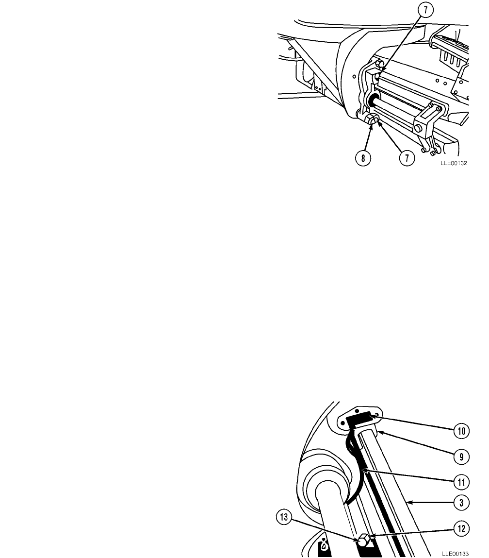
TM 5-6675-348-13&P
3-86
b. Adjust.
(1) Largest backlash is recommended to be
less than 1/8 in. (0.32 cm). If backlash is
greater than 1/8 in. (0.32 cm), two
joints (7) between circle and blade can be
tightened.
NOTE
More probable points to inspect are
wear strips between blade slide rails
and blade brackets.
(2) Tighten joints after replacing wear strips
and shims.
(3) Tighten blade roll backlash at this time.
(4) After this side has been side shifted to its minimum clearance position, (see Para 3-34), wear strips
can be formed to provide clearance of 0.005 to 0.035 in. (0.013 to 0.089 cm) between sides of rails
and wear strips.
(5) Second joint to inspect is blade pivot pin (8). If movement at pin is 1/32 in. (0.079 cm) or more,
notify Direct Support Maintenance.
3-34. WEAR STRIP AND SHIM REPLACEMENT.
NOTE
• Sensor calibration is required after these procedures (see Para 3-15).
• Use shims as required to obtain 0.005- to 0.035-in. (0.013 to 0.089 cm) clearance between
rails and wear strips at minimum clearance position found by sideshifting moldboard
through full range with shims divided as equally as possible between top and bottom
wear strips.
(1) Install wear strip (9) and shims (10) on
the slide rail (3) and in bracket (11).
(2) Position blocks (12) and install bolts (13).

TM 5-6675-348-13&P
3-87
3-35. BLADE PRO® MOTOR GRADER CONTROL SYSTEM INSTALLATION.
This Task Covers:
a. Installation. b. Follow-On Maintenance.
INITIAL SETUP
Model
130G Grader (TM 5-3805-261-Series)
Tools and Special Tools
Tool Kit, Automotive Maintenance, Common
No. 2, Item 2, Appendix B
Tool Kit, Electric, Item 3, Appendix B
Tool Kit, Welders, Item 4, Appendix B
Materials and Parts
Cloth, Lint-Free, Item 3, Appendix F
Gloves, Chemical Oil Protective, Item 4,
Appendix F
Paint, Spray, Black, Item 8, Appendix F
Rags, Wiping, Item 9, Appendix F
Tags, Identification, Item 13, Appendix F
Ties, Cable, Item 15, Appendix F
Materials and Parts (Cont.)
Base Mounting Block, Item 1, Appendix K
Label, Caution, Rotational Sensor, Item 3,
Appendix K
Label, Chart, Conversion, Item 4, Appendix K
Label, Warning, Welding/Jump Starting,
Item 5, Appendix K
Plate, Tracer Mast Mount, Item 6, Appendix K
Personnel Required
MOS 62B
MOS 44B
Equipment Condition
Engine OFF (TM 5-3805-261-10).
Wheels chocked (TM 5-3805-261-10).
130G Grader setup para (3-15).
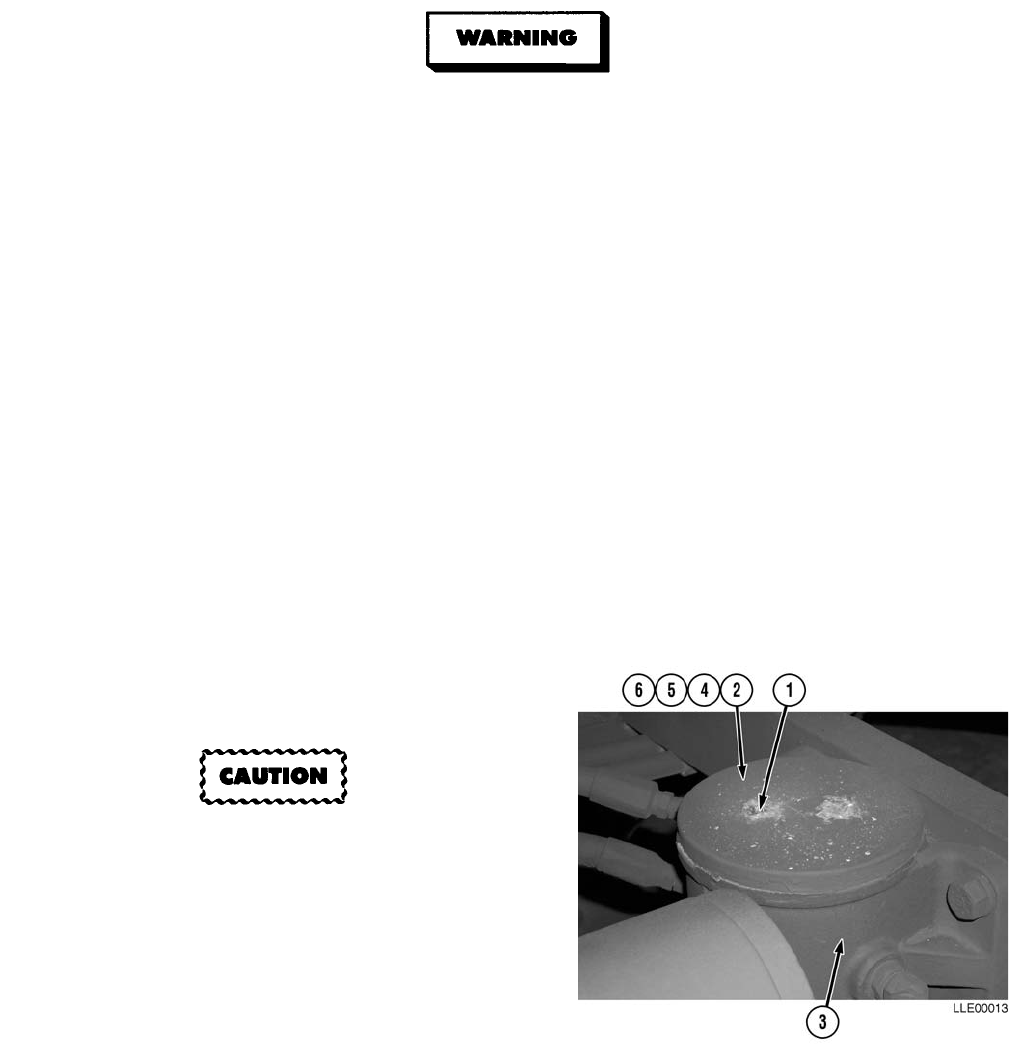
TM 5-6675-348-13&P
3-88
a. Installation.
• Ensure 130G Grader is on level ground, all hydraulic implements are lowered to the
ground, transmission control is moved to Neutral, and the lock and emergency brake are
engaged. Failure to comply could result in serious injury to personnel.
• Do not work on hydraulic oil while oil is hot. Failure to comply could result in severe
injury to personnel.
• Prolonged contact with lubricating oil, MIL-L-2105, may cause a skin rash. Skin and
clothing that come in contact with lubricating oil should be thoroughly washed
immediately. Saturated clothing should be removed immediately. Areas in which
lubricating oil is used should be well ventilated to keep fumes to a minimum.
• Hydraulic oil is slippery and can cause falls. To avoid injury, wipe up all spilled hydraulic
oil with rags.
• Remove hydraulic fill cap to vent pressure from hydraulic tank.
• Use Operator’s controls to lower all components and relieve hydraulic system pressure.
Failure to comply may result in serious injury or death to personnel.
NOTE
Retain all items (except bench stock items) removed from 130G Grader for future use.
(1) Remove hydraulic tank fill cap to vent pressure from hydraulic tank (TM 5-3805-261-10).
(2) Install hydraulic tank fill cap.
(3) Remove two screws (1) and Hydraswivel
plate (2) from Hydraswivel (3).
Install Hydraswivel Gaskets and Hydraswivel
Shims in same manner as removed or damage
to equipment could result.
(4) Remove two Hydraswivel Gaskets (4) and (5)
from Hydraswivel plate (2).
(5) Inspect Hydraswivel Gaskets (4) and (5) and
Hydraswivel Shims (6). If damaged, replace.
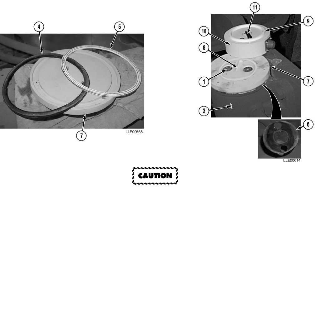
TM 5-6675-348-13&P
3-89
Failure to replace Hydraswivel Gaskets and Hydraswivel Shims in original positions may
cause leakage or damage to equipment.
(6) Install Hydraswivel Gaskets (4) and (5) into Orientation Disc (7).
(7) Install Hydraswivel Shims (6) under Orientation Disc (7).
(8) Install Orientation Disc (7) to Hydraswivel (3) with Milled Slot (8) positioned toward rear of
130G Grader.
(9) Install two screws (1) in Orientation Disc (7).
(10) Tighten screws (1).
(11) Install Teflon Ring (9) on Circle Rotation Sensor (10).
(12) Line up Dog Bone (11) with Milled Slot (8) in Orientation Disc (7).
NOTE
For ease of calibration, place 2-pin female connector of Circle Rotation Sensor toward rear of
130G Grader.
(13) Install Circle Rotation Sensor (10) onto Orientation Disc (7).
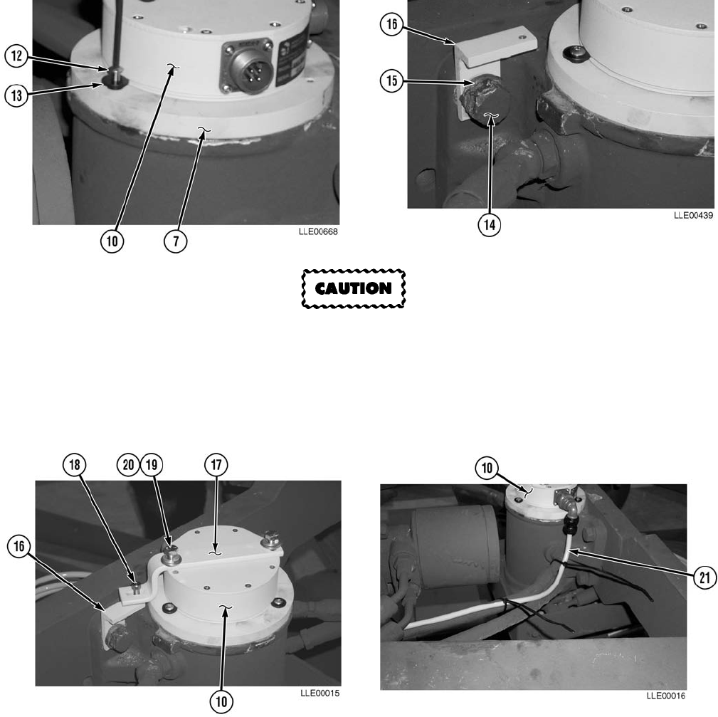
TM 5-6675-348-13&P
3-90
To prevent damage to equipment, lip on bushing must be in slot of Circle Rotation Sensor.
(14) Install three screws (12) and bushings (13) in Circle Rotation Sensor (10) and Orientation Disc (7).
(15) Remove bolt (14) and lockwasher (15). Discard lockwasher (15).
(16) Install Circle Rotation Sensor Arm Mounting Bracket (16), new lockwasher (15), and bolt (14).
(17) Level Circle Rotation Sensor Arm Mounting Bracket (16). Tighten bolt (14).
(18) Align Circle Rotation Sensor Arm (17) on Circle Rotation Sensor (10).
(19) Install screw (18) on Circle Rotation Sensor Arm Mounting Bracket (16).
(20) Tighten screw (18).
(21) Install Circle Rotation Sensor Arm (17), two washers (19), and bolts (20) on Circle Rotation
Sensor (10).
(22) Tighten bolts (20).
(23) Install Circle Rotation Sensor Cable (21) on Circle Rotation Sensor (10).
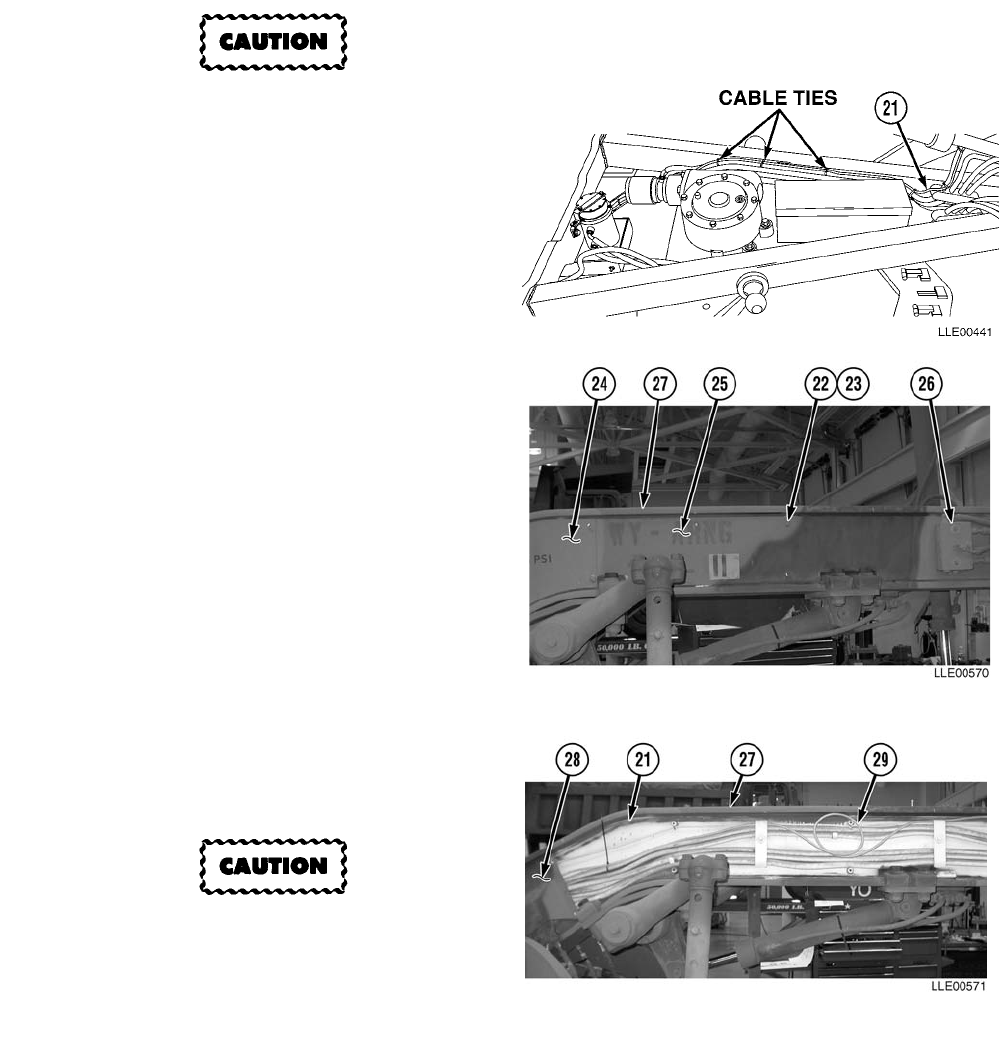
TM 5-6675-348-13&P
3-91
To prevent damage to equipment, the
Circle Rotation Sensor Cable must be
secured to hydraulic lines with cable
ties approximately every 6 in.
(15.2 cm).
NOTE
Leave approximately 2 in. (5.1 cm) of
slack in Rotation Sensor Cable for
calibration.
(24) Route Circle Rotation Sensor
Cable (21) with existing hydraulic
lines to front of 130G Grader.
NOTE
Gooseneck Panels for both sides of the
130G Grader are removed the same.
The left side is shown.
(25) Remove eight bolts (22) and
washers (23).
(26) Remove Gooseneck
Panels (24) and (25)
and Float Valve (26) from
Gooseneck (27).
(27) Route Circle Rotation Sensor
Cable (21) under Gooseneck
Panel (28).
Do not cable tie Circle Rotation Sensor
Cable Service Loop inside the
Gooseneck. Failure to comply could
result in damage to 130G Grader.
NOTE
Leave approximately 18 in. (46 cm)
hanging past 130G Grader’s Gooseneck
Panel’s rear mounting location.
(28) Create a Service Loop (29) of the extra
Circle Rotation Sensor Cable (21) inside
the Gooseneck (27).
(29) Route Circle Rotation Sensor Cable (21)
with existing hydraulic lines in Gooseneck (27).
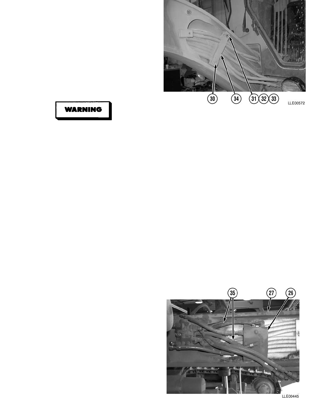
TM 5-6675-348-13&P
3-92
(30) Loosen lower Gooseneck retainer
bolt (30).
(31) Remove upper retainer bolt (31),
washer (32), and spacer (33).
(32) Rotate Gooseneck Retainer (34)
90 degrees.
(33) Tighten lower Gooseneck retainer
bolt (30).
(34) Repeat Steps (30) through (33) on right
side of 130G Grader.
• Hydraulic oil is slippery and can
cause falls. To avoid injury, wipe
up all spilled hydraulic oil with
rags.
• Float valve is held in position only
by lines. Use care during line re-
moval to prevent damage to equip-
ment or injury to personnel.
NOTE
• Inspect all hoses, lines, and fittings
for cracks, bends, nicks, dents,
stripped threads, and cuts. Replace
all damaged parts.
• Perform Steps (35) and (36) on right
side of 130G Grader only.
• Tag and mark all hoses prior to
removal.
• Plug holes and cap fittings to prevent
spilling oil.
• Cable tie as needed.
(35) Disconnect two Float Valve Lines (35)
from Float Valve (26).
(36) Pull two Float Valve lines (35) out of
Gooseneck (27).
(37) Temporarily position two Float Valve
Lines (35) over Gooseneck (27).
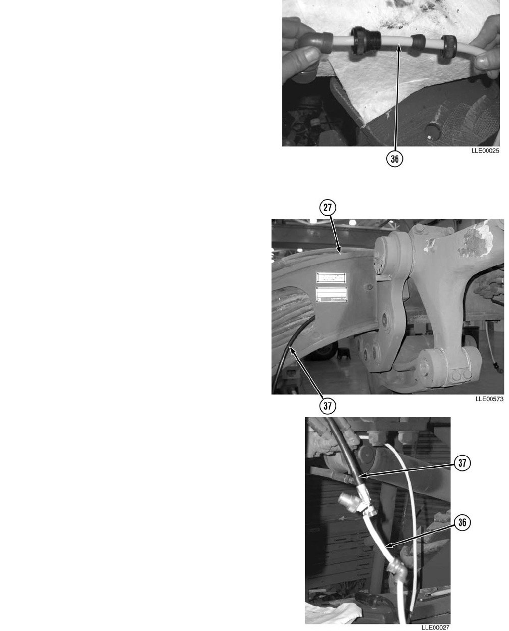
TM 5-6675-348-13&P
3-93
(38) Disassemble female end of Operator
Cable (36).
NOTE
• Hydraulic hoses for both sides of
130G Grader install the same. The
right side is shown.
• Mark return line short hose before
installation.
• For ease of installation, hold
hydraulic lines toward top of
130G Grader’s Gooseneck while
installing. If hydraulic lines hit an
obstruction during installation, twist
and push lines at the same time.
• Route straight end of hydraulic lines
through Gooseneck from front of
130G Grader to back.
• Steps (40) through (45) require the aid of
an assistant.
(39) Locate Load Sense Line (37).
(40) Push straight end of Load Sense Line (37)
through Gooseneck (27), starting from the
rear and pushing toward the front of the
Gooseneck (27).
(41) Cable tie female end of Operator Cable (36) to
Load Sense Line (37) on straight end of Load
Sense Line (37).
(42) With the aid of an assistant, pull Load Sense
Line (37) until female end of Operator
Cable (36) exits through rear side of
Gooseneck (27).
(43) Remove Load Sense Line (37).
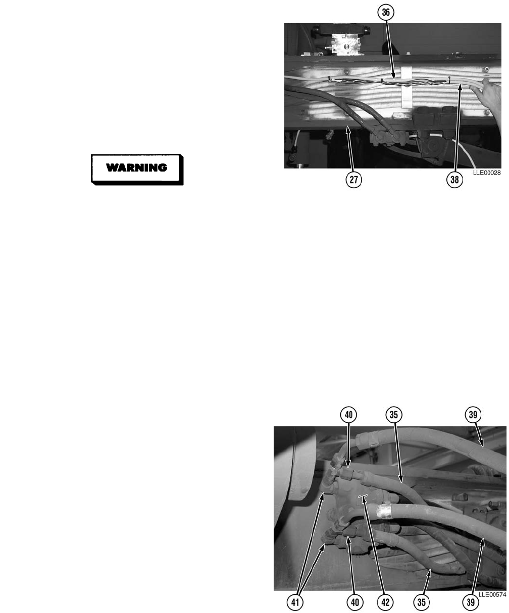
TM 5-6675-348-13&P
3-94
(44) Cable tie Main Power Cable (38) to Operator
Cable (36).7
NOTE
Leave approximately 18 in. (46 cm) of both
cables outside front of Gooseneck.
(45) With the aid of an assistant, pull Operator
Cable (36) until both Main Power Cable (38)
and Operator Cable (36) are hanging through
front and rear of Gooseneck (27).
Hydraulic oil is slippery and can cause
falls. To avoid injury, wipe up all spilled
hydraulic oil with rags.
NOTE
• Inspect all hoses, lines, and fittings for
cracks, bends, nicks, dents, stripped
threads, and cuts. Replace all damaged
parts.
• Tag and mark all existing lines prior
to removal.
• Plug holes and cap fittings to prevent
oil spills.
• Retain 90-degree fittings and T-fittings
for installation of Proportional Valve.
(46) Remove two Float Valve Lines (35), Cylinder
Lines (39), T-fittings (40), and 90-degree
fittings (41) from left Lift and Articulation
Check Valve (LACV) (42).
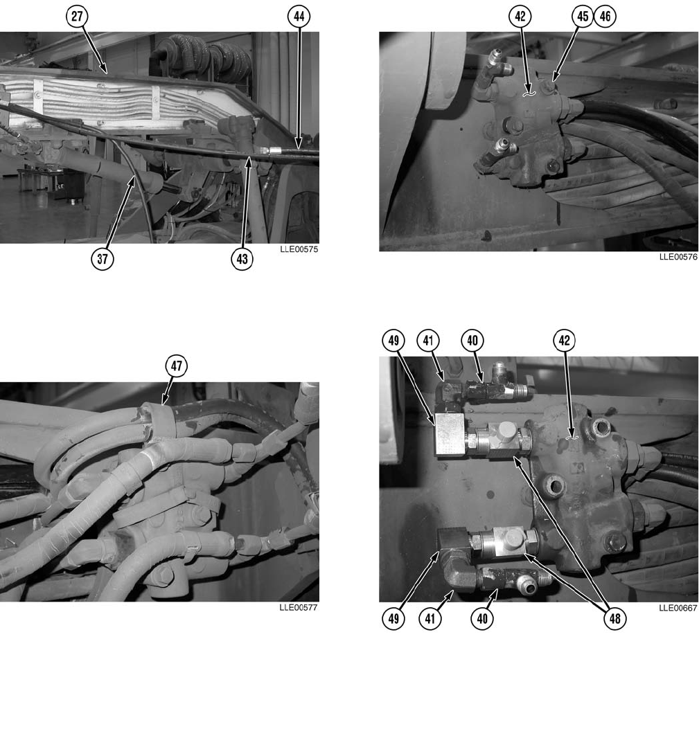
TM 5-6675-348-13&P
3-95
(47) Route Load Sense Line (37), Return Line (43), and Pressure Line (44) through Gooseneck (27).
(48) Remove two bolts (45) and flat washers (46) from LACV (42).
N
O
TE
• Step (49) applies to left side of 130G Grader only.
• Retain Loop Clamp for installation of Proportional Valve.
(49) Remove Loop Clamp (47). NOTE
Do not tighten LACV fittings until all fittings are installed.
(50) Install two T-fittings (48) in LACV (42).
(51) Install two 90-degree block fittings (49) in T-fittings (48).
(52) Install two retained 90-degree fittings (41) in block 90-degree fittings (49).
(53) Install two retained T-fittings (40) in 90-degree fittings (41).

TM 5-6675-348-13&P
3-96
NOTE
Proportional Valve Assembly can be
used on either side of 130G Grader.
(54) Remove three dust plugs (50) from side
of Proportional Valve (51).
Hydraulic oil is slippery and can cause
falls. To avoid injury, wipe up all
spilled hydraulic oil with rags.
To prevent fittings breaking off in
block, do not overtighten fittings.
NOTE
• Lubricate O-rings on O-ring seals to JIC/SAE fittings with clean hydraulic fluid before
installation.
• All other dust fittings should be tightened.
(55) Install two #6 ORS to JIC/SAE fittings (52) on Proportional Valve (51).
(56) Tighten #6 ORS to JIC/SAE fittings (52).
(57) Install #4 ORS to JIC/SAE fitting (53) on Proportional Valve (51).
(58) Tighten #4 ORS to JIC/SAE fitting (53).
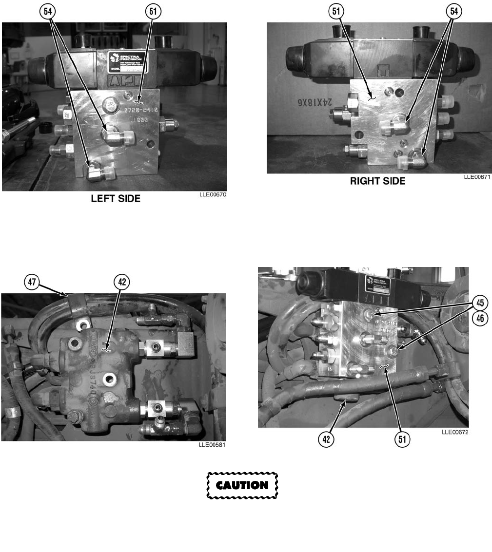
TM 5-6675-348-13&P
3-97
NOTE
For ease of installation, do not tighten 90-degree fittings.
(59) Install two 90-degree fittings (54) on Proportional Valve Assembly (51).
To prevent leaks and damage to equipment, ensure all plugs on back side of Proportional
Valve Assembly are tight before installation.
N
O
TE
• Loop Clamp is installed on back side of LACV on left side only.
• Rotate Loop Clamp 180 degrees before installation.
(60) Install Loop Clamp (47) and Proportional Valve Assembly (51) with two bolts (45) and flat
washers (46) on LACV (42).
(61) Tighten bolts (45).

TM 5-6675-348-13&P
3-98
To prevent damage to equipment, do not bend or force steel tubes to fit.
(62) Install steel tubes (55) on 90-degree
fittings (54) and T-fittings (48).
(63) Level steel tubes (55).
(64) Tighten 90-degree fittings (54) and
T-fittings (48).
(65) Install Load Sense Line (37) on
#4 JIC/SAE fitting (53).
(66) Tighten Load Sense Line (37).
(67) Install Pressure Line (44) on lower
#6 JIC/SAE fitting (52).
(68) Tighten Pressure Line (44).
(69) Install Return Line (43) on upper
#6 JIC/SAE fitting (52).
(70) Tighten Return Line (43).
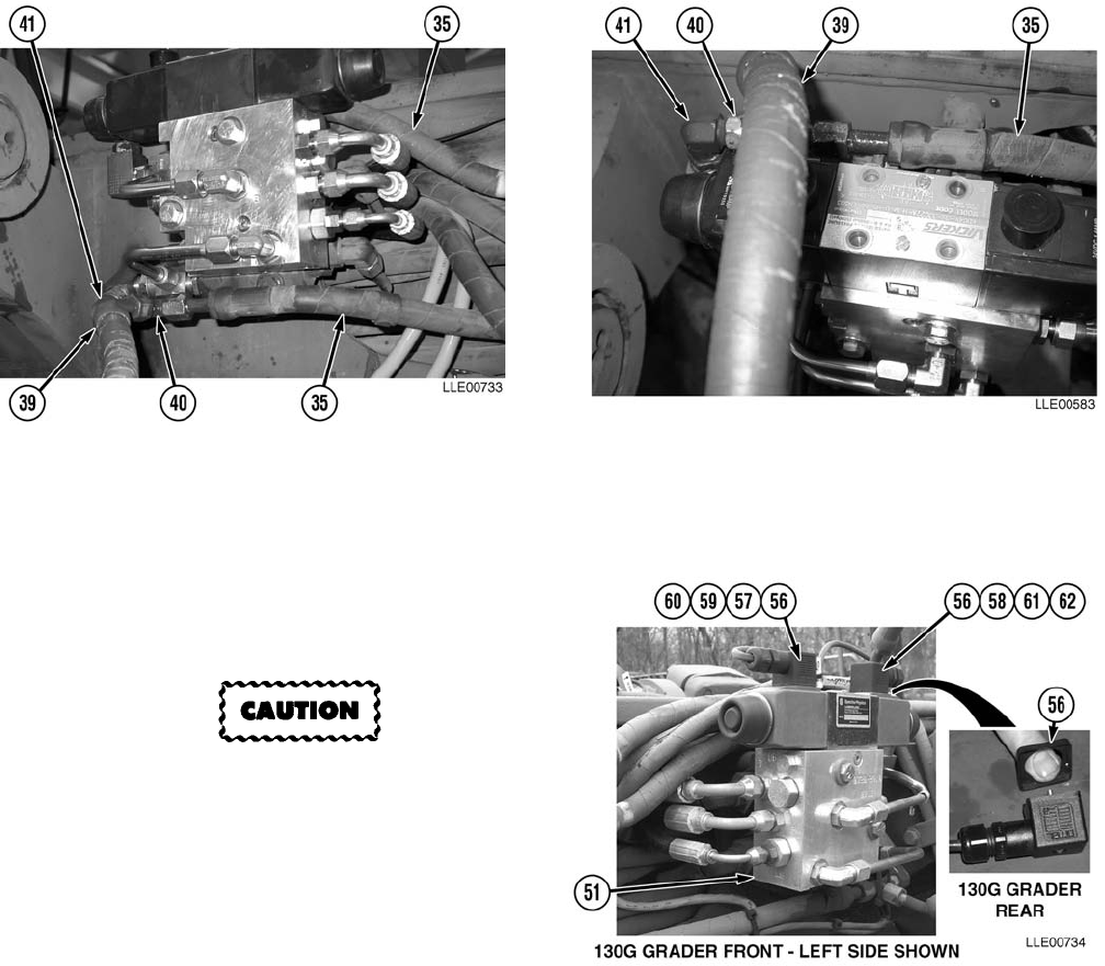
TM 5-6675-348-13&P
3-99
(71) Install two Cylinder Lines (39) and two Float Valve Lines (35) to T-fittings (40).
(72) Tighten two Cylinder Lines (39) and Float Valve Lines (35) to T-fittings (40).
(73) Tighten 90-degree fittings (41) and T-fittings (40).
(74) Install gaskets (56) on Hydraulic Valve
Cables marked RAISE (57) and
LOWER (58).
Hydraulic Valve Cables are marked
RAISE and LOWER. Failure to install
Hydraulic Valve Cables in the correct
positions may cause damage to
equipment.
NOTE
Remove protective caps from
Proportional Valve Assembly electrical
terminals before installing Hydraulic
Valve Cables.
(75) Install Hydraulic Valve Cable (RAISE) (57) on Proportional Valve Assembly Terminal (59).
(76) Secure Hydraulic Valve Cable (RAISE) (57) to Proportional Valve Assembly Terminal (59) with
screw (60).
(77) Tighten screw (60).
(78) Install Hydraulic Valve Cable (LOWER) (58) on Proportional Valve Assembly Terminal (61).
(79) Secure Hydraulic Valve Cable (LOWER) (58) to Proportional Valve Assembly Terminal (61) with
screw (62).
(80) Tighten screw (62).
(81) Route Hydraulic Valve Cables (57) and (58) behind Proportional Valve Assembly (51).
(82) Cable tie Hydraulic Valve Cables (57) and (58) together as needed.

TM 5-6675-348-13&P
3-100
(83) Repeat Steps (46) through (81) for
right-side installation.
(84) Temporarily install right-side
Gooseneck Panel (63), six
washers (64), and six bolts (65).
(85) Temporarily install Mainfall Slope
Sensor Bracket (66) to right-side
Gooseneck Panel (63), using existing
bolt (67).
(86) Level, mark, and center punch
Mainfall Slope Sensor Bracket (66)
mounting holes.
(87) Remove bolt (67), Mainfall Slope
Sensor Bracket (66), six bolts (65), six
washers (64), and right-side Gooseneck
Panel (63).
(88) Drill two 1/2-in. (13 mm) holes at
punch marks.
(89) Align Mainfall Slope Sensor Bracket (66)
to bottom of right-side Gooseneck
Panel (63).
(90) Install with two bolts (67),
lockwashers (68), and nuts (69).
(91) Tighten nuts (69).
(92) Install both right-side Gooseneck
Panels (63) and (70) and Float
Valve (26) with eight washers (64) and
bolts (65).
(93) Install two Float Valve lines (35) to Float
Valve (26).
NOTE
Position Scarifier Hydraulic Lines
clockwise as far as possible to allow
clearance for the Remote Interface Box.
(94) Reposition Scarifier Hydraulic Lines (71)
clockwise as far as possible.
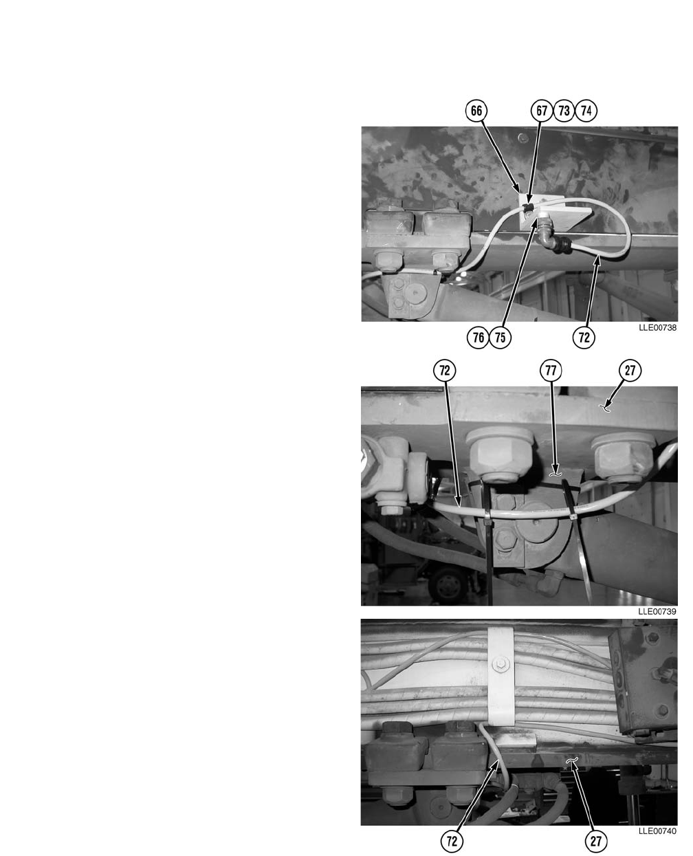
TM 5-6675-348-13&P
3-101
NOTE
Leave approximately 16 in. (40.6 cm)
of Mainfall Slope Sensor Cable on
female end, for storage, as shown.
(95) Install Mainfall Slope Sensor Cable (72),
Loop Clamp (73), washer (74), bolt (67) to
Mainfall Slope Sensor Bracket (66).
NOTE
Connector holder mounting screw is larger
than hole in dust cap.
(96) Ream connector holder (75) mounting hole
with rat-tail file.
(97) Install screw (76) and connector
holder (75) to outer rear hole of Mainfall
Slope Sensor Bracket (66).
(98) Install two cable ties around Rotating Eye
Bracket (77).
(99) Route Mainfall Slope Sensor Cable (72)
under Gooseneck (27).
(100) Attach Mainfall Slope Sensor Cable (72)
with two ties secured by cable ties
installed in Step (98).
(101) Route Mainfall Slope Sensor Cable (72)
under left-side Gooseneck (27) toward
rear of 130G Grader.
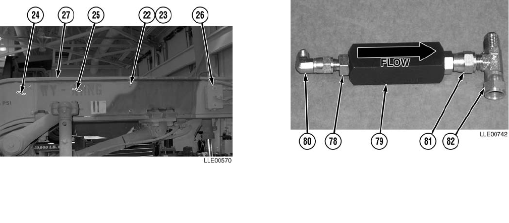
TM 5-6675-348-13&P
3-102
(102) Install both left-side Gooseneck Panels (24) and (25) and Float Valve (26), using eight flat
washers (23) and bolts (22).
N
O
TE
• Both sides of 130G Grader are installed the same.
• Lubricate O-rings on ORS to JIC/SAE fittings with clean hydraulic fluid before installa-
tion.
• Note inlet and outlet side of Check Valve before installation.
(103) Install #4 ORS to JIC/SAE fittings (78) on inlet side of Check Valve (79).
(104) Tighten #4 ORS to JIC/SAE fittings (78).
(105) Install 90-degree fitting (80) on #4 ORS to JIC/SAE fitting (78).
(106) Install #6 ORS to JIC/SAE fitting (81) on outlet side of Check Valve (79).
(107) Tighten #6 ORS to JIC/SAE fitting (81).
(108) Install T-fitting (82) on #6 ORS to JIC/SAE fitting (81).

TM 5-6675-348-13&P
3-103
Hydraulic oil is slippery and can cause falls. To avoid injury, wipe up all spilled hydraulic oil
with rags.
Inspect all hoses, lines, and fittings for cracks, bends, nicks, dents, stripped threads, and
cuts. Replace all damaged parts.
NOTE
• Tag and mark all hoses prior to removal.
• Plug holes and cap fittings to prevent oil spills.
• Cable tie as needed.
• Do not tighten 90-degree fitting or T-fitting on Check Valve until all lines are installed.
(109) Remove Load Sense Line (37) from
fitting (83).
(110) Install T-fitting (82) to fitting (83).
(111) Install original Load Sense Line (37) to
T-fitting (82).
(112) Install new Load Sense Line (84) to
90-degree fitting (80).
(113) Tighten #6 ORS to JIC/SAE fitting (81)
T-fitting (82). Tighten T-fitting (82) to
fitting (83). Tighten original Load Sense
Line (37) to T-fitting (82). Tighten new
Load Sense Line (84) to 90-degree
fitting (80).
(114) Remove plug (85) from Stack Valve (86).
Retain plug (85) for future use.
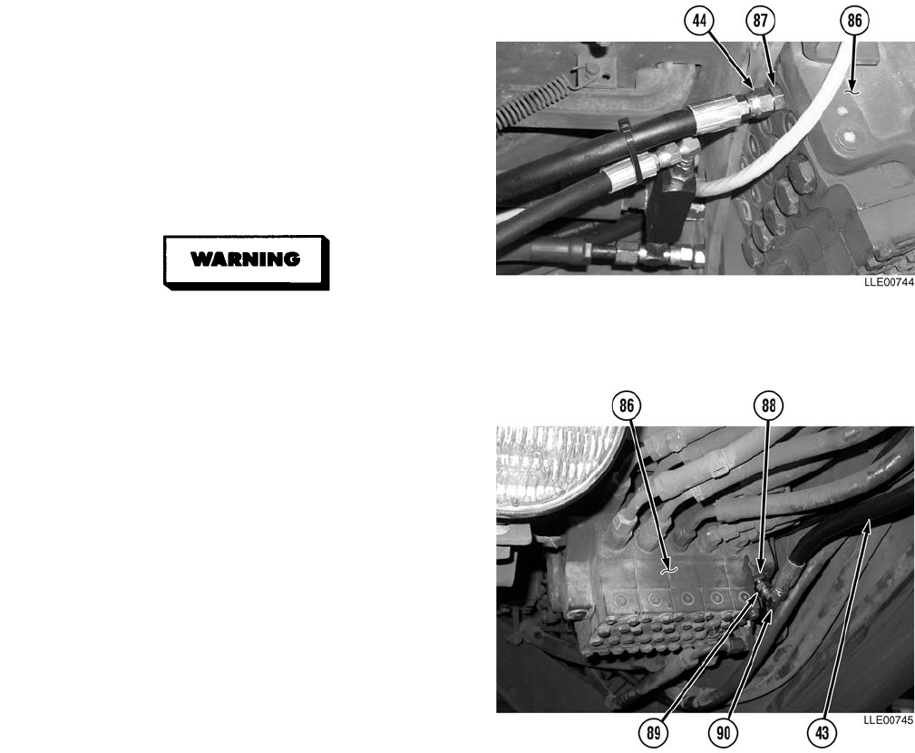
TM 5-6675-348-13&P
3-104
(115) Install #6 JIC/SAE fitting (87) on
Stack Valve (86).
(116) Tighten #6 JIC/SAE fitting (87).
(117) Install Pressure Line (44) on #6 JIC/SAE
fitting (87).
(118) Tighten Pressure Line (44) to #6 JIC/SAE
fitting (87).
Hydraulic oil is slippery and can cause
falls. To avoid injury, wipe up all spilled
hydraulic oil with rags.
(119) Remove plug (88) from Stack Valve (86).
Retain plug (88) for future use.
(120) Install fitting (89) on Stack Valve (86).
(121) Tighten fitting (89).
(122) Install 90-degree fitting (90) on fitting (89).
(123) Tighten 90-degree fitting (90).
(124) Install Return line (43) on 90-degree
fitting (90).
(125) Repeat Steps (103) through (124) for other
side of 130G Grader.
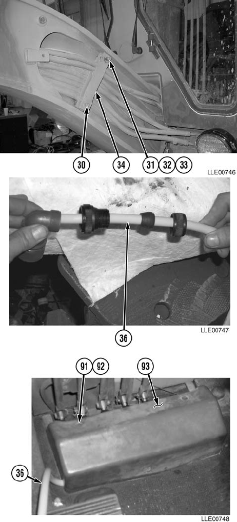
TM 5-6675-348-13&P
3-105
(126) Loosen Gooseneck lower retainer
bolt (30).
(127) Reposition lower Gooseneck
Retainer (34).
(128) Tighten bolt (30).
(129) Install Gooseneck upper retainer
bolt (31), washer (32), and spacer (33).
(130) Tighten upper retainer bolt (31).
(131) Assemble female end of Operator
Cable (36).
(132) Remove three screws (91), washers (92),
and right side Stack Valve Cover (93).
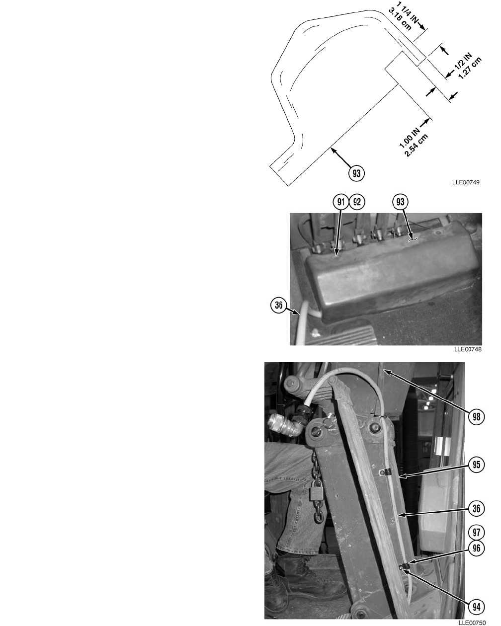
TM 5-6675-348-13&P
3-106
(133) Cut approximately 1 1/4-in. (3.2 cm) slot,
1 in. (2.54 cm) wide and 1/2 in. (1.3 cm)
deep, in left side of Stack Valve Cover (93).
(134) From under cab, route Operator Cable (36)
over hydraulic lines, under floorboard, and
into cab.
(135) Install right side of Stack Valve Cover (93),
three washers (92), and screws (91) over
Operator Cable (36).
NOTE
For ease of installation, remove only
one screw in column at a time. Work
from floorboard up column.
(136) Remove screws (94) from column (95).
(137) Install Operator Cable (36), Loop
Clamps (96), and bushings (97) on
column (95) with screws (94).
(138) Cable tie Operator Cable (36) to
Steering Column Release Lever (98).
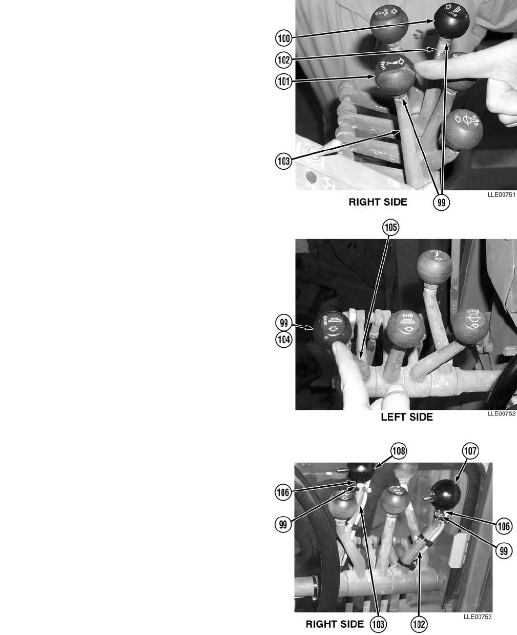
TM 5-6675-348-13&P
3-107
(139) Loosen jam nuts (99) on right-side RAISE/
LOWER Knob (100) and Articulation
Knob (101).
(140) Remove right-side RAISE/LOWER
Knob (100) from right-side RAISE/
LOWER Lever (102).
(141) Remove Articulation Knob (101) from
Articulation Lever (103).
(142) Loosen jam nut (99) on left-side RAISE/
LOWER Knob (104).
(143) Remove left-side RAISE/LOWER
Knob (104) from left-side RAISE/LOWER
Lever (105).
(144) Install second jam nuts (106) on RAISE/
LOWER Control Levers (102), (103),
and (105).
NOTE
R/L Switches are the same and can be
installed on either RAISE/LOWER
Lever.
(145) Install R/L Switch (107) on RAISE/
LOWER Lever (102).
(146) Install Remote Switch (108) on
Articulation Lever (103).
(147) Tighten jam nuts (106) and (99).
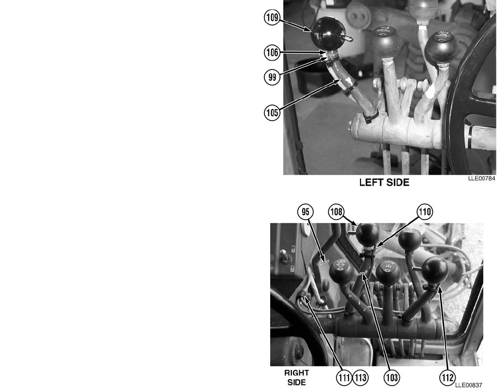
TM 5-6675-348-13&P
3-108
(148) Install R/L Switch (109) on left-side
RAISE/LOWER Lever (105).
(149) Tighten jam nuts (106) and (99).
NOTE
• Install cable ties as required.
• The Power Cables for all switches
are routed the same. The Remote
Switch on the Articulation Lever is
shown.
• Steps (150) through (153) apply to
both sides.
(150) Route Remote Switch Cable (110)
from Remote Switch (108), down
Articulation Lever (103), and across to
column (95).
(151) Remove screw (111) from column (95).
(152) Install Remote Switch Cable (110), R/L
Switch Cable (112), Loop Clamp (113),
and screw (111) on steering column (95).
(153) Cut Remote Switch Cable (110) and
R/L Switch Cable (112) to 26 in. (66 cm),
as measured from Loop Clamp (113).
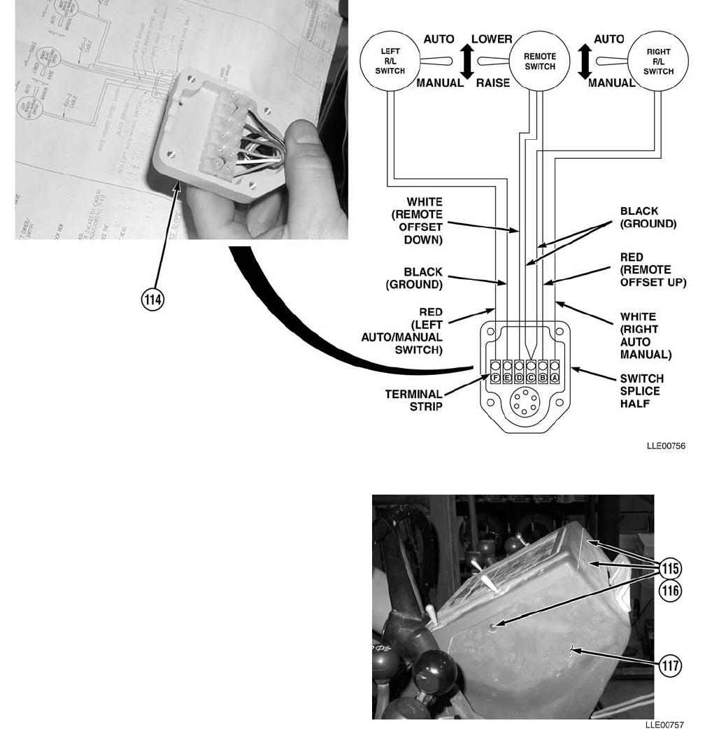
TM 5-6675-348-13&P
3-109
(154) Attach wires to Remote Splice Assembly (114), using wiring schematics.
NOTE
One screw is located on left side of
Operator Control Box.
(155) Remove four screws (115) and
washers (116) from Monitoring System
Control Panel (117).
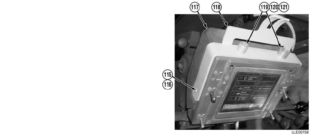
TM 5-6675-348-13&P
3-110
(156) Install Control Box Mounting
Bracket (118) on Monitoring System
Control Panel (117) with two
screws (115) and washers (116).
(157) Tighten screws (115).
NOTE
Connector holders are different sizes.
The small Connector Holder is
installed on the left and the large
Connector Holder is installed on the
right.
(158) Install two Connector Holders (119)
on Control Box Mounting
Bracket (118) with two washers (120)
and screws (121).
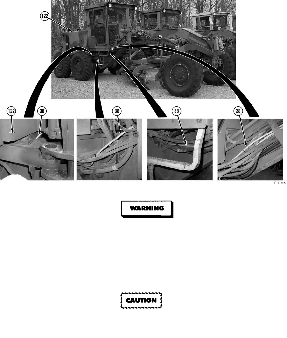
TM 5-6675-348-13&P
3-111
• Remove all jewelry, such as rings, dog tags, bracelets, etc. If jewelry contacts Battery
Terminal, a direct short may result in instant heating of tools, damage to equipment,
and injury or death to personnel.
• Exercise extreme caution when working under tilt platform. Falling platform could
result in serious injury or death to personnel.
• Turn battery disconnect switch OFF prior to performing maintenance in immediate
battery area or working on electrical system. Failure to comply can result in electrical
shock to personnel or damage to equipment.
To avoid damage to Power Cable, it must be routed through Articulation Joint (following
existing electrical cables and hoses). NOTE
Cable tie as needed.
(159) Route Main Power Cable (38) under cab, through Articulation Joint, and up through hole under
Engine Compartment (122).
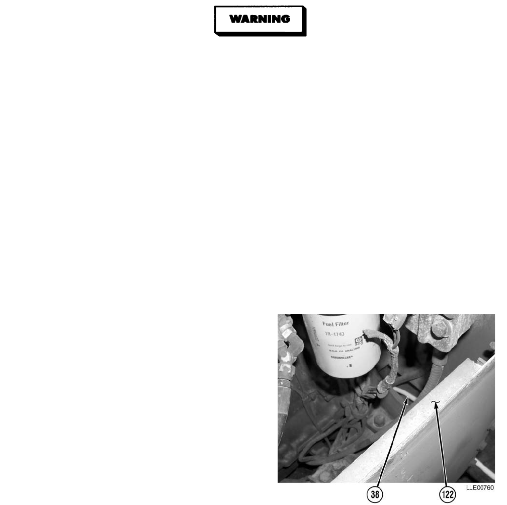
TM 5-6675-348-13&P
3-112
• Battery acid (electrolyte) is extremely harmful. Always wear safety goggles and rubber
gloves, and do not smoke when performing maintenance on batteries. Injury will result
if acid contacts skin or eyes. Wear rubber apron to prevent damage to clothing.
• Remove all jewelry, such as rings, dog tags, bracelets, etc. If jewelry contacts Battery
Terminal, a direct short may result in instant heating of tools, damage to equipment,
and injury or death to personnel.
• Exercise extreme caution when working under tilt platform. Falling platform could
result in serious injury or death to personnel.
• Turn battery disconnect switch OFF prior to performing maintenance in immediate
battery area or working on electrical system. Failure to comply can result in electrical
shock to personnel or damage to equipment.
• Always disconnect the negative (-) battery cable before servicing the battery or positive
(+) battery cable. Failure to comply can result in electrical shock to personnel or
damage to electrical system.
• Do not allow battery cable ends to contact each other or the machine. Failure to comply
can result in damage to battery or electrical system.
NOTE
Cable tie as required.
(160) Route Main Power Cable (38) into
Engine Compartment (122).
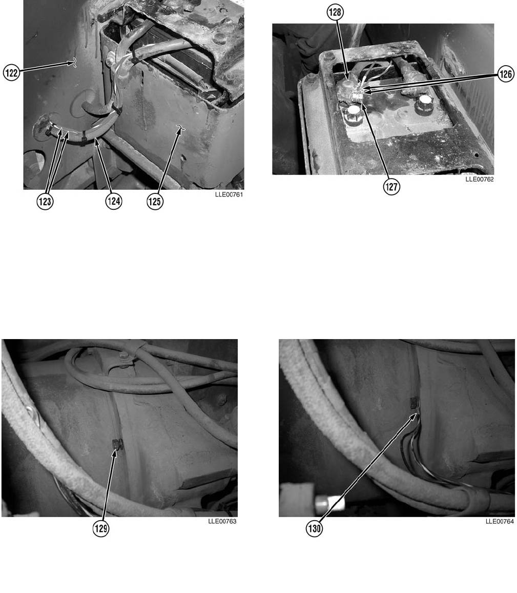
TM 5-6675-348-13&P
3-113
NOTE
Cable tie as required.
(161) Route two Red Wires (123) through Engine Compartment (122), following path of right-side
Battery Cable (124), to right side of Battery Box (125).
(162) Install two connectors (126) and nut (127) on positive Battery Terminal (128).
(163) Tighten nut (127).
(164) Remove bell housing bolt (129).
NOTE
For proper operation, a good ground is essential.
(165) Install bell housing bolt (129) and Black Wire connectors (130).
(166) Tighten bell housing bolt (129).
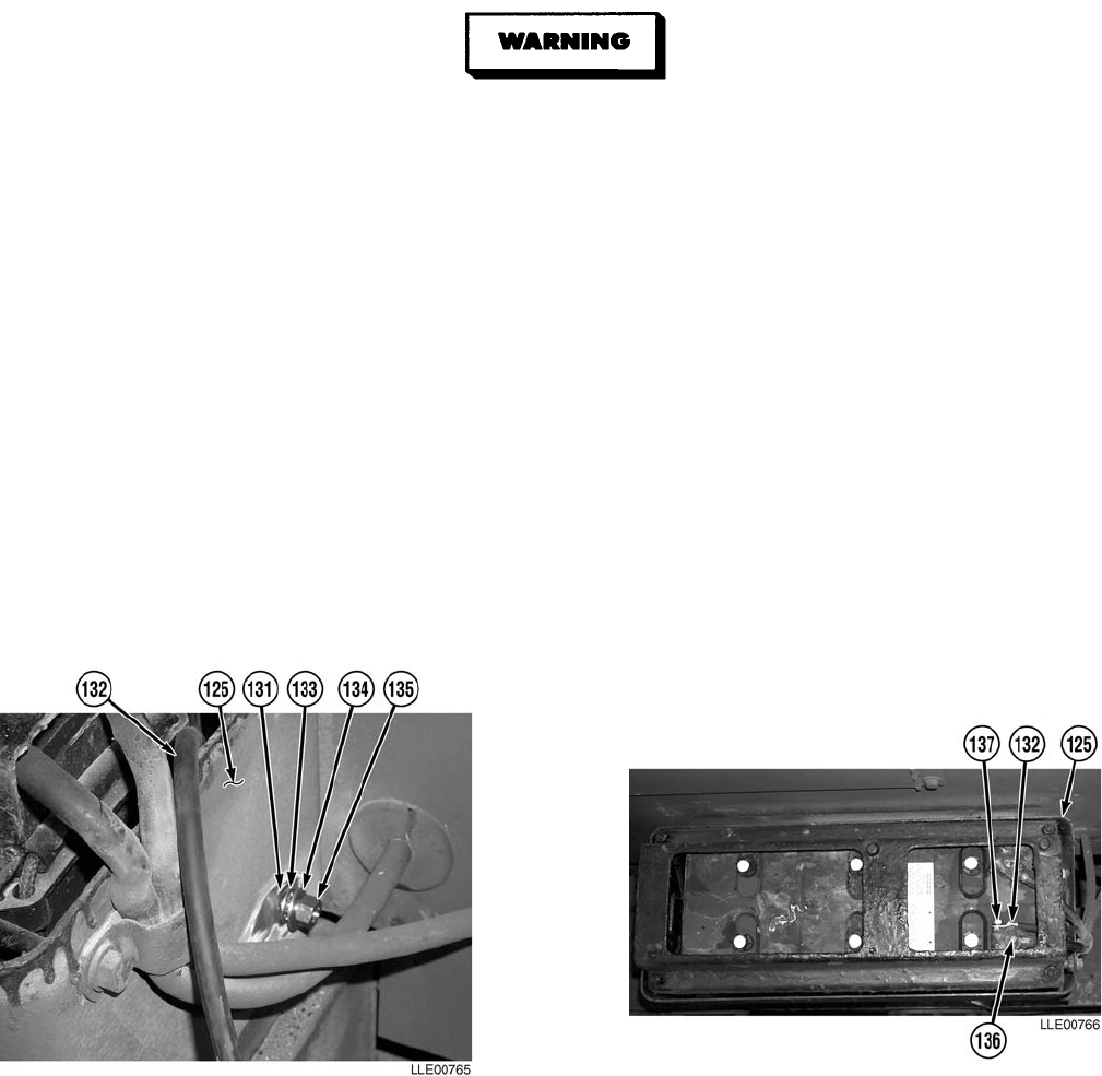
TM 5-6675-348-13&P
3-114
• CARC paint contains isocyanate (HDI), which is highly irritating to skin and
respiratory system. High concentrations of HDI can produce symptoms of itching and
reddening of skin, a burning sensation in throat and nose, and watering of the eyes. In
extreme concentrations, HDI can cause cough, shortness of breath, pain during
respiration, increased sputum production, and chest tightness. The following
precautions must be taken whenever using CARC paint:
• ALWAYS use air line respirators when using CARC paint, unless air sampling shows
exposure to be below standards. Use chemical cartridge respirator if air sampling is
below standards.
• DO NOT let skin or eyes come in contact with CARC paint. Always wear protective
equipment (gloves, ventilation mask, safety goggles, etc.).
• DO NOT use CARC paint without adequate ventilation.
• NEVER weld or cut CARC-coated materials.
• DO NOT grind or sand painted equipment without high-efficiency air purifying
respirators in use.
• BE AWARE of CARC paint exposure symptoms; symptoms can occur a few days after
initial exposure. Seek medical help immediately if symptoms are detected.
(167) Remove paint from hole (131) at rear of left side of Battery Box (125).
(168) Install Voltage Protection Cable (132), internal star-washer (133), flat washer (134), and nut (135)
through hole (131) in Battery Box (125).
(169) Tighten nut (135).
(170) Apply black spray paint to Diode connection (132).
(171) Install Voltage Protection Cable (132) on negative Battery Terminal (136) with nut (137).
(172) Loop all excess Voltage Protection Cable (132) in Battery Box (125).
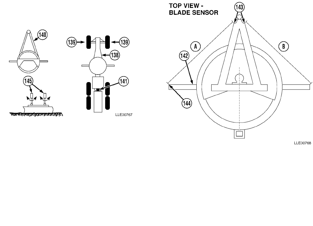
TM 5-6675-348-13&P
3-115
(173) Start 130G Grader (138) (TM 5-3805-261-10).
(174) Park 130G Grader (138) on solid material, such as concrete, asphalt, or compacted soil.
(175) Align front tires (139) vertically and position A-frame draw bar (140) directly centered under
main frame of 130G Grader (138).
(176) Align 130G Grader (138) so that holes in articulation area (141) are aligned.
NOTE
To simplify the welding procedure, roll blade fully forward.
(177) Adjust blade (142) and measure distance from front A-frame (143) to outside corners of
Moldboard (144). Dimensions (A) and (B) should be the same.
(178) Float blade until cylinder knuckles (145) are not supporting any weight. Cylinder knuckles (145)
should rotate freely.
(179) Shut OFF 130G Grader (138) (TM 5-3805-261-10).
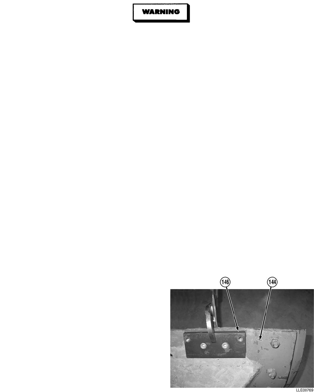
TM 5-6675-348-13&P
3-116
• Unsafe welding practices can cause serious injury from fire, explosions, or harmful
agents. Allow only authorized personnel to weld or cut metals, and follow safety
precautions in TC 9-237. Protective clothing and goggles must be worn, adequate
protective equipment must be used, a suitable fire extinguisher must be kept nearby,
and requirements of TC 9-237 must be strictly followed. Failure to comply may result in
serious injury or death to personnel.
• CARC paint contains isocyanate (HDI), which is highly irritating to skin and
respiratory system. High concentrations of HDI can produce symptoms of itching and
reddening of skin, a burning sensation in throat and nose, and watering of the eyes. In
extreme concentrations, HDI can cause cough, shortness of breath, pain during
respiration, increased sputum production, and chest tightness. The following
precautions must be taken whenever using CARC paint:
• ALWAYS use air line respirators when using CARC paint, unless air sampling shows
exposure to be below standards. Use chemical cartridge respirator if air sampling is
below standards.
• DO NOT let skin or eyes come in contact with CARC paint. Always wear protective
equipment (gloves, ventilation mask, safety goggles, etc.).
• DO NOT use CARC paint without adequate ventilation.
• NEVER weld or cut CARC-coated materials.
• DO NOT grind or sand painted equipment without high-efficiency air purifying
respirators in use.
• BE AWARE of CARC paint exposure symptoms; symptoms can occur a few days after
initial exposure. Seek medical help immediately if symptoms are detected.
NOTE
Position Tracer®/Mast Mounting Plate so threaded holes in Tracer®/Mast Mounting Plate
face front of Moldboard and setscrews face up.
(180) Remove paint from area to be welded.
(181) Weld Tracer®/Mast Mounting Plate (146)
on both sides of Moldboard (144),
approximately 5 3/4 in. (14.60 cm) from
end of Moldboard (144) and
approximately 1/4 in. (0.64 cm) from top
edge of Moldboard (144).
(182) Remove paint from area to be welded.

TM 5-6675-348-13&P
3-117
• Unsafe welding practices can cause serious injury from fire, explosions, or harmful
agents. Allow only authorized personnel to weld or cut metals, and follow safety precau-
tions in TC 9-237. Protective clothing and goggles must be worn, adequate protective
equipment must be used, a suitable fire extinguisher must be kept nearby, and require-
ments of TC 9-237 must be strictly followed. Failure to comply may result in serious
injury or death to personnel.
• CARC paint contains isocyanate (HDI), which is highly irritating to skin and respira-
tory system. High concentrations of HDI can produce symptoms of itching and redden-
ing of skin, a burning sensation in throat and nose, and watering of the eyes. In
extreme concentrations, HDI can cause cough, shortness of breath, pain during respira-
tion, increased sputum production, and chest tightness. The following precautions must
be taken whenever using CARC paint:
• ALWAYS use air line respirators when using CARC paint, unless air sampling shows
exposure to be below standards. Use chemical cartridge respirator if air sampling is
below standards.
• DO NOT let skin or eyes come in contact with CARC paint. Always wear protective
equipment (gloves, ventilation mask, safety goggles, etc.).
• DO NOT use CARC paint without adequate ventilation.
• NEVER weld or cut CARC-coated materials.
• DO NOT grind or sand painted equipment without high-efficiency air purifying
respirators in use.
• BE AWARE of CARC paint exposure symptoms; symptoms can occur a few days after
initial exposure. Seek medical help immediately if symptoms are detected.
(183) Weld Tracer® Mounting Block (147)
approximately 1/2 in. (1.3 cm) down and
approximately 1/2 in. (1.3 cm) in from
rear frame crossmember (148) end.

TM 5-6675-348-13&P
3-118
NOTE
Steps (184) through (186) apply to
both sides.
(184) Remove paint from area to be welded.
(185) Before tack welding washer (149), center
rod (150) in existing Hose Tray Rod
Bracket (151).
(186) Weld washer (149) to Hose Tray Rod
Bracket (151).
(187) Install Slope Sensor Mounting
Plate (152) approximately 1/4 in. (0.64 cm)
from front edge of Frame Pocket (153).
(188) Remove paint from area to be welded.
(189) Tack weld rear of Slope Sensor Mounting
Plate (152) in frame pocket (153).
(190) Temporarily install Slope Sensor (154) to
Slope Sensor Mounting Plate (152).
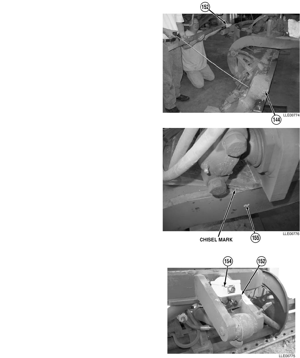
TM 5-6675-348-13&P
3-119
NOTE
• The aid of an assistant is required for
Step (191).
• Measurement is adjusted by movement
of Slope Sensor Mounting Plate.
(191) With the aid of an assistant, square Slope
Sensor Mounting Plate (152) to
Moldboard (144) using straightedge, level,
and measuring tape until distance between
straightedge and Moldboard (144) is equal
within 1/4 in. (0.64 cm) on both sides.
NOTE
Step (192) applies to both sides of vehicle.
(192) Chisel mark on 130G Grader’s Rotation
Circle (155).
(193) Remove Slope Sensor (154) from Slope
Sensor Mounting Plate (152).

TM 5-6675-348-13&P
3-120
Unsafe welding practices can cause serious
injury from fire, explosions, or harmful
agents. Allow only authorized personnel to
weld or cut metals, and follow safety precau-
tions in TC 9-237. Protective clothing and
goggles must be worn, adequate protective
equipment must be used, a suitable fire
extinguisher must be kept nearby, and
requirements of TC 9-237 must be strictly
followed. Failure to comply may result in
serious injury or death to personnel.
(194) Weld front and back of Slope Sensor
Mounting Plate (152) to Frame Pocket (153).
(195) Position and weld Connector Holder (156) to
Frame Pocket (153).
To prevent damage to the Slope Sensor
Cable, allow enough slack in Slope Sensor
Cable at Circle Rotation Sensor connection
to permit circle movement.
NOTE
Allow enough slack at Slope Sensor
Connector to reach Blade Slope Sensor.
(196) Install Slope Sensor Cable (157) to
Connector Holder (156).
NOTE
Allow enough slack in the Slope Sensor
Cable to allow for rotation of the Circle
Frame.
(197) Route Slope Sensor Cable (157) along
hydraulic lines on top of Hose Tray (158),
to Circle Rotation Sensor (10).
(198) Connect Slope Sensor Cable (157) to
Circle Rotation Sensor (10).
(199) Cable tie as needed.

TM 5-6675-348-13&P
3-121
• CARC paint contains isocyanate (HDI), which is highly irritating to skin and respira-
tory system. High concentrations of HDI can produce symptoms of itching and redden-
ing of skin, a burning sensation in throat and nose, and watering of the eyes. In
extreme concentrations, HDI can cause cough, shortness of breath, pain during respira-
tion, increased sputum production, and chest tightness. The following precautions must
be taken whenever using CARC paint:
• ALWAYS use air line respirators when using CARC paint, unless air sampling shows
exposure to be below standards. Use chemical cartridge respirator if air sampling is
below standards.
• DO NOT let skin or eyes come in contact with CARC paint. Always wear protective
equipment (gloves, ventilation mask, safety goggles, etc.).
• DO NOT use CARC paint without adequate ventilation.
• NEVER weld or cut CARC-coated materials.
• DO NOT grind or sand painted equipment without high-efficiency air purifying
respirators in use.
• BE AWARE of CARC paint exposure symptoms; symptoms can occur a few days after
initial exposure. Seek medical help immediately if symptoms are detected.
(200) Prime all new welds with black spray paint.
NOTE
Steps (201) through (207) apply to both sides of the 130G Grader. The right side is shown.
(201) Assemble Remote Box Mounting Clamp (159) to Cable Bracket (160), using two capscrews (161),
lockwashers (162), and hex nuts (163).
(202) Install Connector Holder Assembly (164) on Gooseneck (27) frame. Align with back side of
Gooseneck Panel (28).
(203) Install S-Hook (165) on Blade Lift Hydraulic Cylinder Bracket (166).

TM 5-6675-348-13&P
3-122
(204) Install Cast Clamp (167) to Tracer®/Mast
Mounting Plate (146) with two
lockwashers (168) and screws (169).
(205) Install Cast Clamp (170) to Tracer®/Mast
Mounting Block (147) with two
lockwashers (171) and bolts (172).
(206) Install Base Clamp (173) to Cast
Clamp (170) with two flat washers (174),
bolts (175), and nuts (176). Do not
tighten.
(207) Install Tracer® Tube (177) to Base
Clamp (173).
(208) Place Tracer® Tube (177) in stow
position.
(209) Tighten nuts (176).
TM 5-6675-348-13&P
4-1
CHAPTER 4
BUCKET-PRO™ SYSTEM (HYEX)
Content Para Page
Bucket-Pro™ System Introduction ...................................................................................... Section I 4-2
Scope........................................................................................................................................... 4-1 4-2
Bucket-Pro™ System Equipment Characteristics, Capabilities, and Features..................... 4-2 4-2
Location and Description of Major Components...................................................................... 4-3 4-3
Bucket-Pro™ System PMCS .............................................................................................. Section II4-4
PMCS Introduction.................................................................................................................... 4-4 4-4
PMCS Procedures...................................................................................................................... 4-5 4-4
Shortened Maintenance Instructions....................................................................................... 4-6 4-6
Additional Maintenance Inspections........................................................................................ 4-7 4-6
PMCS Column Entry Explanation ........................................................................................... 4-8 4-6
Bucket-Pro™ System Operator’s PMCS Table......................................................................... 4-9 4-6
Bucket-Pro™ System Operation....................................................................................... Section III 4-8
Button Operation..................................................................................................................... 4-10 4-8
Graphic Display Features........................................................................................................ 4-11 4-8
Graphic Display Contrast........................................................................................................ 4-12 4-9
Bucket-Pro™ System Initialization........................................................................................ 4-13 4-9
Operation Examples................................................................................................................ 4-14 4-10
Reference (Benchmark) Elevation .......................................................................................... 4-15 4-10
Set Cut Depth .......................................................................................................................... 4-16 4-12
Setting Slope Excavation......................................................................................................... 4-17 4-13
Measure Slope.......................................................................................................................... 4-18 4-15
CUSTOMIZE............................................................................................................................ 4-19 4-16
CUSTOMIZE Menu Summary................................................................................................ 4-20 4-17
Cut/Fill ..................................................................................................................................... 4-21 4-18
Switching Grades Lines........................................................................................................... 4-22 4-19
Set Markers.............................................................................................................................. 4-23 4-19
Bucket Reference..................................................................................................................... 4-24 4-21
Laser Reference ....................................................................................................................... 4-25 4-22
Swing Reference....................................................................................................................... 4-26 4-24
Deadband ................................................................................................................................. 4-27 4-24
Set Limit Alarms ..................................................................................................................... 4-28 4-25
Select Bucket............................................................................................................................ 4-29 4-27
Bucket-Pro™ System Troubleshooting............................................................................. Section IV 4-30
Bucket-Pro™ System Maintenance ................................................................................... Section V 4-37
Belly Plate Removal and Installation..................................................................................... 4-30 4-37
Bucket-Pro™ System Installation.......................................................................................... 4-31 4-38
Bucket-Pro™ System Calibration........................................................................................... 4-32 4-64

TM 5-6675-348-13&P
4-2
SECTION I. BUCKET-PRO™ SYSTEM INTRODUCTION
Before operating a HYEX equipped with the Bucket-Pro™ System, be fully aware of
machine and job site safety. Refer to appropriate sections of manufacturer’s Operating
Manual for the HYEX (TM 5-3805-280-10). Read this chapter thoroughly.
4-1. SCOPE.
This chapter is used for operation, maintenance, and installation of the Bucket-Pro™ System used on the
HYEX.
4-2. BUCKET-PRO™ SYSTEM EQUIPMENT CHARACTERISTICS, CAPABILITIES, AND
FEATURES.
a. Characteristics. The Bucket-Pro™ System is a depth-of-cut and grade display system used on the
HYEX.
b. Capabilities. Installation and calibration on a typical midsized HYEX takes approximately 1 day. The
Bucket-Pro™ System is an electromechanical system, so tampering with the hydraulic system of the
HYEX is not required.
c. Features. Standard features include a Dual-Axis Tilt Sensor that constantly compensates for frame
pitch and roll; Angle Sensors that measure boom, stick, and bucket position; Gravity Sensors that are
used on the boom and stick; and an Encoder that measures the bucket angle. A microprocessor control
box and a monochrome LCD, for real-time monitoring of bucket teeth, are also featured. The display
mounts in the cab and provides graphic information on elevation, depth of cut, percent of grade, and
reach. Five push buttons control all modes of operation. A picture of the bucket and stick’s position is in
front of the Operator at all times. Also shown on the display are numerical values, HI/LO/On-Grade
three-light display, and selectable on-grade detector audible tone.
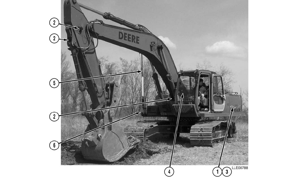
TM 5-6675-348-13&P
4-3
4-3. LOCATION AND DESCRIPTION OF MAJOR COMPONENTS.
NOTE
Bucket-Pro™ System is equipped with a Dual-Axis Tilt Sensor to compensate for frame
pitching and rolling during operation. Dual-Axis Tilt Sensor must be allowed to reach
operating temperature to function accurately. Warm-up for Dual-Axis Tilt Sensor takes
approximately 10 minutes after Bucket-Pro™ System is powered up.
(1) REMOTE CONTROL BOX. Remote Control Box contains microprocessors and software of your
Bucket-Pro™ System.
(2) ANGLE SENSORS. Three Angle Sensors measure boom, stick, and bucket angles, and feed data to
Remote Control Box.
(3) DUAL-AXIS TILT SENSOR. Dual-Axis Tilt Sensor constantly compensates for movements so that
displayed elevation and grade references remain set up as entered. Dual-Axis Tilt Sensor
constantly compensates for the EM2E-24 Electric Mast rocking out of plumb as the HYEX pitches
and rolls during digging cycle.
(4) GRAPHIC DISPLAY. Graphic LCD display with five buttons interfaces with all Bucket-Pro™
System features and functions.
(5) EM2E-24 ELECTRIC MAST. The EM2E-24 Electric Mast is a telescoping receiver mount driven by
an electric motor.
(6) SHOCK MOUNT. Attaches to the Bucket-Pro™ System and protects from vibration.
(7) 1145-2 TRANSMITTER LASER REFERENCE SYSTEM. (Not Shown) Bucket-Pro™ System Laser
Reference System allows trenching over long distances without having to benchmark Bucket-Pro™
System each time HYEX is moved.
TM 5-6675-348-13&P
4-4
SECTION II. BUCKET-PRO™ SYSTEM PMCS
4-4. PMCS INTRODUCTION.
Preventive Maintenance Checks and Services (PMCS) means systematic caring, inspecting, and servicing
equipment to keep it in good condition and to prevent breakdowns. As a Bucket-Pro™ System Operator, your
mission is to:
a. Be sure to perform your PMCS each time you operate the Bucket-Pro™ System. Always do your
PMCS in the same order so it becomes a habit. Once you’ve had some practice, you’ll quickly
spot anything wrong.
b. Do your Before PMCS just before you operate the Bucket-Pro™ System. Pay attention to
WARNINGS, CAUTIONS, and NOTES.
c. Do your During PMCS while you operate Bucket-Pro™ System. Pay attention to WARNINGS,
CAUTIONS, and NOTES.
d. Do your After PMCS right after operating Bucket-Pro™ System. Pay attention to WARNINGS,
CAUTIONS, and NOTES.
e. Do your Weekly PMCS once a week.
f. Use DA Form 2404 or DA Form 5988-E (Equipment Inspection and Maintenance Worksheet) to
record any faults that you don’t immediately fix.
4-5. PMCS PROCEDURES.
a. PMCS Table (Table 4-1.) lists inspections and care required to keep your Bucket-Pro™ System
in good operating condition. This table is set up so you can do Before and After PMCS while
walking around the Bucket-Pro™ System.
b. The “Interval” column tells you when to do a certain check or service.
c. The “Procedure” column tells you how to do required checks and services. Carefully follow these
instructions.
d. The “Not Fully Mission Capable If” column tells you when your Bucket-Pro™ System is
nonmission capable and why the Bucket-Pro™ System cannot be used.
e. When something looks wrong that you cannot fix, write down the problem on your
DA Form 2404 or DA Form 5988-E. Immediately report the problem to your Supervisor.

TM 5-6675-348-13&P
4-5
f. When you do your PMCS, you will always need a rag or two. Following are checks that are
common to the entire Bucket-Pro™ System.
• Degreasing Solvent (MIL-PRF-680, Type II) is toxic and flammable. Keep away from
heat or flame. Never smoke when using solvent. The flashpoint for Type II Degreasing
Solvent is 141 °F (61 °C). Wear protective goggles, face shield, and gloves; use only in a
well-ventilated area; avoid contact with skin, eyes, and clothes; and do not breathe
vapors. Failure to comply may result in injury or death to personnel.
• If personnel become dizzy while using cleaning solvent, immediately get fresh air and
medical help. If solvent contacts skin or clothes, flush with cold water. If solvent contacts
eyes, immediately flush eyes with water and get immediate medical attention. Do not
use diesel fuel, gasoline, or benzene (benzol) for cleaning.
• Adhesives, solvents, and sealing compounds burn easily and give off vapors that are
harmful to the skin and clothing. To avoid injury or death, keep away from open fire
when using these materials, and use only in well-ventilated areas. If adhesives, solvents,
or sealing compounds contact the skin or clothing, wash immediately with soap and
water, and rinse thoroughly. Failure to comply may result in injury or death to personnel.
(1) Keep It Clean. Dirt, grease, oil, and debris only get in the way and may cover up a serious
problem. Clean as you work. Use Degreasing Solvent (MIL-PRF-680, Type II) on all metal surfaces.
Use soap and water when you clean rubber or plastic material.
(2) Rust and Corrosion. Check Bucket-Pro™ System for rust and corrosion. When any bare metal or
corrosion exits, clean surface and apply a coat of paint. Report bare metal or corrosion to your
supervisor.
(3) Bolts, Nuts, and Screws. Check all bolts, nuts, and screws for obvious looseness, missing, bent, or
broken condition. You can’t check them all with a tool, but look for chipped paint, bare metal, or
rust around bolt heads. When you find a bolt, nut, or screw you think is loose, tighten it or report it
to your supervisor.
(4) Welds. Look for loose or chipped paint, rust, or gaps where parts are welded together. When you
find a bad weld, report it to your supervisor.
(5) Electric Wires and Connectors. Look for cracked, frayed, or broken insulation, bare wires, and
loose or broken connectors. Tighten loose connectors. Report any damaged wires to your supervisor.
(6) When you check operating conditions, check to see if component is serviceable.

TM 5-6675-348-13&P
4-6
4-6. SHORTENED MAINTENANCE INSTRUCTIONS.
Local conditions of extreme heat, dust, cold, or wetness dictate that service intervals shall be shortened.
4-7. ADDITIONAL MAINTENANCE INSPECTIONS.
Additional maintenance inspections are required for the following reasons:
a. Prolonged storage. Inspect Bucket-Pro™ System components that have been stored for a period
of 3 months or more.
b. Initial preparation upon receipt.
c. Preparation for storage.
4-8. PMCS COLUMN ENTRY EXPLANATION.
a. Item No. Column. The checks and services are numbered in interval order showing a walk-around
sequence around the Bucket-Pro™ System. Use these numbers in the “Item No.” column on
DA Form 2404 or DA Form 5988-E when recording faults that you don’t immediately fix.
b. Interval Column. This column indicates when the lubrication, check, and/or service should be
performed.
c. Location, Item to Check/Service Column. The underlined items listed in this column are divided into
groups indicating the portion of the equipment of which they are a part (e.g., brakes, fuel, engine).
Under these groupings, a few common words are used to identify the specific item being checked.
d. Procedure Column. This column contains procedures required to perform the checks and services.
e. Not Fully Mission Capable If Column. This column contains the criteria that cause the equipment to
be classified as NOT READY/AVAILABLE because of an inability to perform its primary mission. An
entry in this column will:
(1) Identify conditions that make the equipment not available for readiness reporting purposes.
(2) Deny use of the equipment until corrective maintenance has been performed.
4-9. BUCKET-PRO™ SYSTEM OPERATOR’S PMCS TABLE.
Table 4-1. Bucket-Pro™ System Operator’s PMCS (Before/After)
Item
No. Interval
Location
Procedure Not Fully Mission
Capable If:
Item to
Check/Service
1. Before/After Electrical Cables Check all electrical cables and wires to
ensure none are frayed, cracked, or
exposed.
Frayed, cracked,
or exposed wires
are evident.
2. Before/After Flat Belt Assembly Check for any dirt, debris, or damage.
Clean dirt and debris before operating.
Repair damage before operating.
Damaged,
broken, or does
not move freely.

TM 5-6675-348-13&P
4-7
3. Before/After Exit Clamp Assembly Check for any dirt, debris, or damage. Damaged.
4. Before/After Pulley Assembly Check for any dirt, debris, or damage.
Check for tightness. Clean dirt and debris
before operating. Repair damage before
operating.
Damaged.
5. Before/After Cable Encoder
Sensor Check for dirt, debris, or damage. Check
for frayed cable. Damaged. Cable
is frayed.
6. Before/After Voltage Protection
Cable Ensure cable is not frayed, cracked, or
exposed. Frayed, cracked,
or exposed wires
are evident.
7. Before/After EM2E-24 Electric
Mast Assembly Check for any dirt, debris, or damage.
Clean dirt and debris before operating.
Repair damage before operating.
Damaged.
8. Before/After Graphic Display Check for any dirt, debris, or damage.
Clean dirt and debris before operating.
Repair damage before operating.
Damaged.
9. Before/After Remote Interface Box Check for any dirt, debris, or damage.
Clean dirt and debris before operating.
Repair damage before operating.
Damaged.
10. Before/After Arm Pendulous
Angle Sensors Check for any dirt, debris, or damage.
Clean dirt and debris before operating.
Repair damage before operating.
Damaged.
Table 4-1. Bucket-Pro™ System Operator’s PMCS (Before/After) (Cont)
Item
No. Interval
Location
Procedure Not Fully Mission
Capable If:
Item to
Check/Service
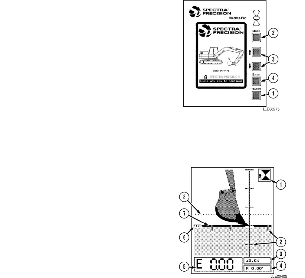
TM 5-6675-348-13&P
4-8
SECTION III. BUCKET-PRO™ SYSTEM OPERATION
4-10. BUTTON OPERATION.
Five buttons are on the front panel of the Graphic
Display. The bottom button (1) turns the system
ON/OFF.
Four buttons access Bucket-Pro™ System’s
operation and setup/calibration functions.
Operation modes (2) and calibration are accessed
using a sequence of menus. Setup and calibration
menus are pass-code protected to guard against
system setup tampering.
NOTE
All numerical entry modes have
preprogrammed minimum/maximum
values that cannot be exceeded.
Menu options are selected by pointing to the entry
you want using Up and Down (↑↓) buttons (3), then
pressing ENTER button (4). Numerical entries,
when required, are also made using Up and
Down (↑↓) buttons and are confirmed by pressing
ENTER button (4).
4-11. GRAPHIC DISPLAY FEATURES.
NOTE
Optional features are enabled at
installation or by the Operator.
The Graphic Display shows informational data
depending on which features and functions are
enabled.
Commonly used features include:
(1) Laser/Mast Indicator
(2) Distance Markers
(3) Slope Display
(4) Reach Display
(5) Elevation Display
(6) Grade Reference Indicator
(7) Main Grade Line
(8) Cut/Fill Line
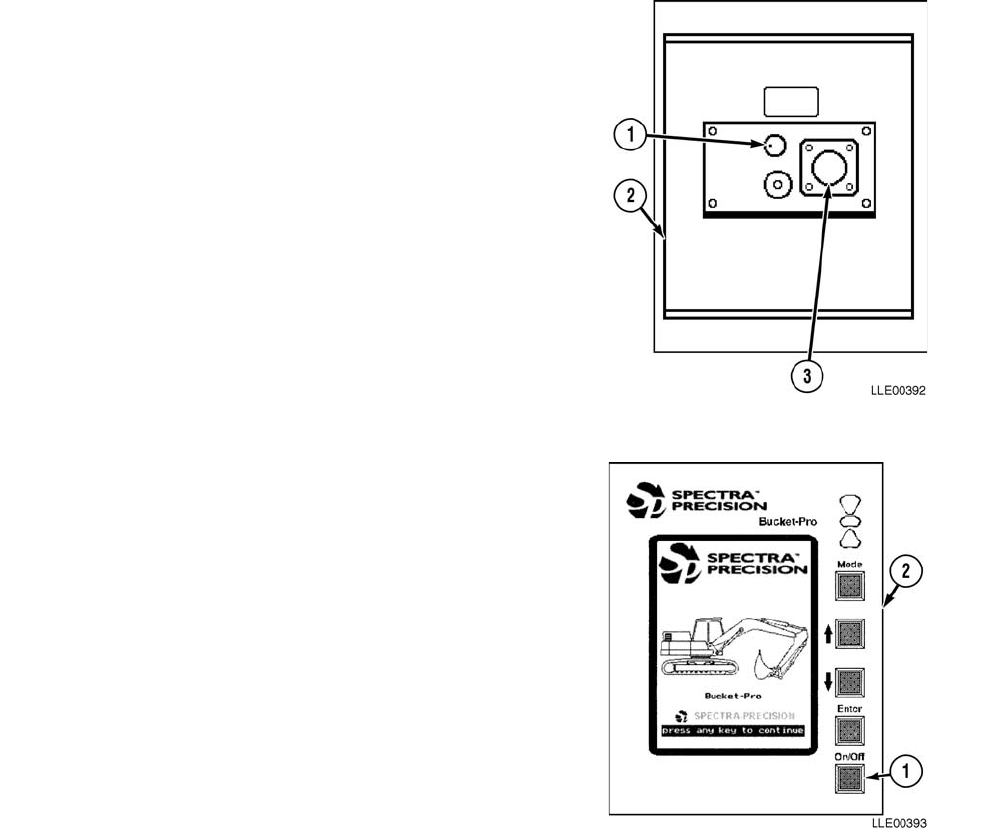
TM 5-6675-348-13&P
4-9
4-12. GRAPHIC DISPLAY CONTRAST.
NOTE
During very cold weather, the display
needs a few minutes to warm up before
a viewable contrast level is obtained.
Turning the knob (1) on the back of the Graphic
Display (2), next to the electrical connector (3),
adjusts the Graphic Display contrast level
(brightness) for ambient light conditions and
viewing angle.
4-13. BUCKET-PRO™ SYSTEM
INITIALIZATION.
(1) Press ON/OFF button (1) on front panel
of Graphic Display (2) to power up
Bucket-Pro™ System.
NOTE
• Before the Bucket-Pro™ System
operates correctly, all Angle Sensors
should be referenced for accuracy. The
Bucket Sensor reference window
appears on the screen.
• Follow instructions in window and
fully retract bucket cylinder
(TM 5-3805-280-10).
(2) Press ENTER button to confirm selection.
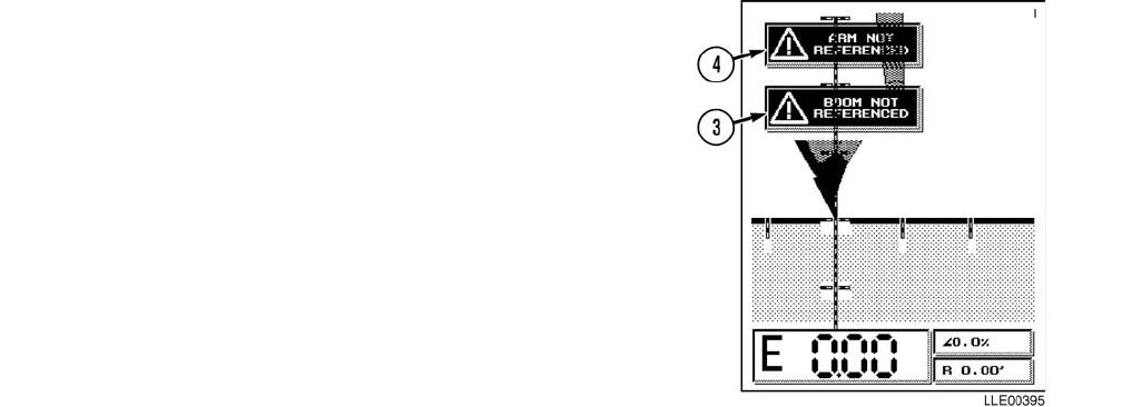
TM 5-6675-348-13&P
4-10
NOTE
ARM NOT REFERENCED and BOOM
NOT REFERENCED flags must be
removed or Bucket-Pro™ System will not
know where it is in regards to boom and
arm sensors. Main operating display
appears with two more referencing flags.
(3) Move boom through reference point
(approximately 30 degrees above
horizontal) until BOOM NOT
REFERENCED flag (3) disappears.
(4) Move arm through reference point
(approximately ±5 degrees from vertical in
each direction) until ARM NOT
REFERENCED flag (4) disappears.
4-14. OPERATION EXAMPLES.
The following examples help you understand basic daily setup for frequently used applications, including
basic trench/basement excavation and slope excavation. Although many more ways to use the system exist,
these examples show how to use the Bucket-Pro™ System.
The basis for operating the Bucket-Pro™ System revolves around three well-understood job site principles:
• Reference (Benchmark) Elevation
•Cut Depth
• Percent Slope
4-15. REFERENCE (BENCHMARK) ELEVATION.
Reference (Benchmark) Elevation is a known elevation on a job site. This elevation may be a survey
benchmark, sea- level benchmark, or elevation of an existing structure. One of these must be available prior
to excavating. A good idea is to check elevation setting whenever possible to ensure accuracy and maintain
overall job quality. In absence of a reference benchmark on a job site, Bucket-Pro™ System can be used in an
absolute mode by putting bucket’s cutting edge on ground and setting a Bench Elevation of 0.00 ft as an
artificial reference.
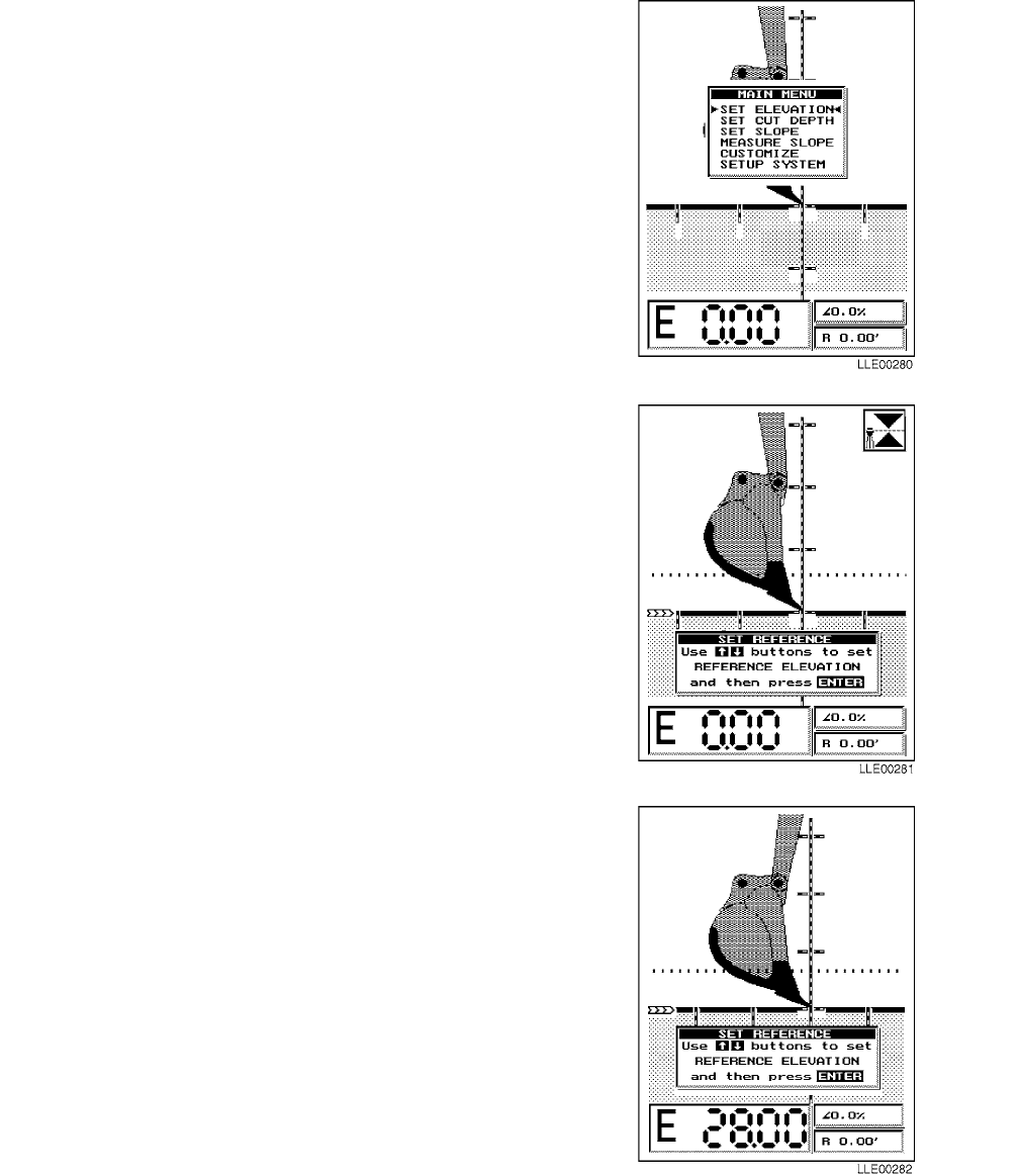
TM 5-6675-348-13&P
4-11
(1) Press MODE button to access MAIN
MENU.
(2) Point menu arrows to SET ELEVATION
mode using Up and Down (↑↓) buttons.
(3) Press ENTER button to confirm
selection.
NOTE
• Current BENCHMARK ELEVATION
appears in main elevation window in
right corner of display. Instruction
menu SET REFERENCE appears in
center of screen.
• Most elevations are staked out by
surveyors prior to the start of the job.
Stakes have a known elevation or
BENCHMARK ELEVATION marked
on them.
(4) Adjust elevation value shown beside “E”
to required BENCHMARK ELEVATION
using Up and Down (↑↓) buttons.
NOTE
If bench elevations are not known,
perform Step (5).
(5) Adjust elevation value shown beside “E”
to elevation value of 0.00 ft using Up and
Down (↑↓) buttons.
(6) Press ENTER button to confirm
selection.

TM 5-6675-348-13&P
4-12
4-16. SET CUT DEPTH.
NOTE
• A cut depth (or depth of excavation)
is the distance between bench
elevation and target grade line
(solid line) on Graphic Display.
• Positive depth cuts are above
reference elevation and negative
depth cuts are below reference
elevation.
• Majority of normal excavating uses
negative depth cuts.
(1) Press MODE button to access MAIN
MENU.
(2) Point menu arrows to SET CUT DEPTH
mode using Up and Down (↑↓) buttons.
(3) Press ENTER button to confirm selection.
(4) Current CUT DEPTH appears in lower left
corner of screen after “E.” An instruction
window SET CUT DEPTH appears in the
center of the screen.
NOTE
• Cut depth value is the vertical
distance from benchmark eleva-
tion to bottom of trench or
basement.
• To restore default cut depth of
0.00 ft, simultaneously press Up
and Down (↑↓) buttons.
(5) Adjust displayed elevation value to correct
DEPTH OF CUT using Up and Down (↑↓)
buttons.
(6) Press ENTER button to confirm selected DEPTH OF
CUT value. Normal Operating Screen returns.
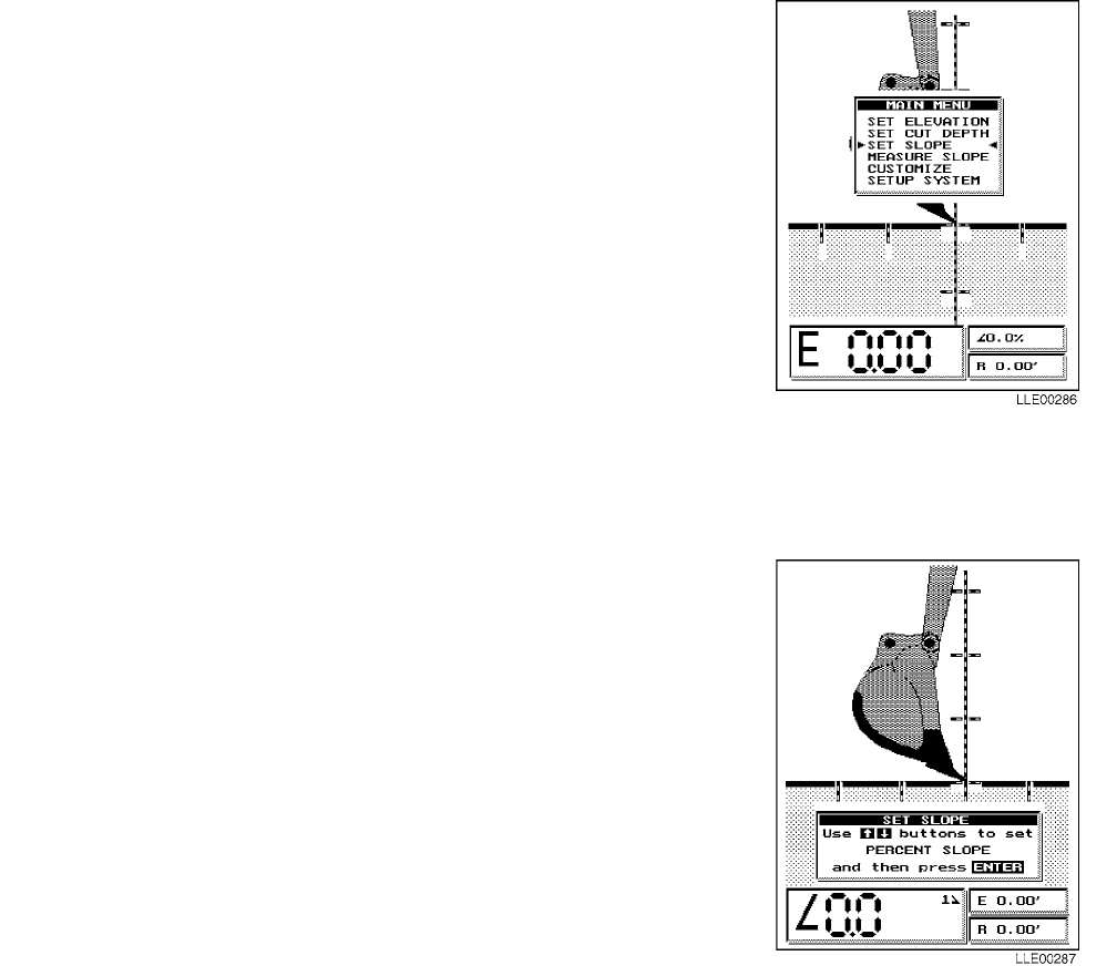
TM 5-6675-348-13&P
4-13
4-17. SETTING SLOPE EXCAVATION.
Three separate slopes can be programmed into the
Bucket-Pro™ System with the press of a button. The slope you
select can be changed easily to permit fast multiple-slope
excavations during a single setup. Benchmark elevations and cut
depths apply to slope excavation the same as to level excavation.
(1) Press MODE button to access MAIN MENU.
(2) Point menu arrows to SET SLOPE mode using Up and
Down (↑↓) buttons.
(3) Press ENTER button to confirm selection.
NOTE
• Slope display < indicates slope
is away from HYEX.
• Slope display > indicates slope
is towards HYEX.
(4) Observe current SLOPE in main elevation window in
lower left corner of display.
(5) Review SET SLOPE instructions window on main
display.
NOTE
• To set positive SLOPE (up and
away from HYEX), use Up button.
To set negative SLOPE (down and
away from HYEX), use Down button.
• SLOPE being set can be one of three
values stored in Bucket-Pro™ System’s
memory to alternate among them.
• Active slope is the slope numbered on the
Graphic Display that matches the finished
grade line.
(6) Adjust desired percent of grade value (+66% in
this example, or <66.0 as it appears on the display)
for SLOPE #1 using Up and Down (↑↓) buttons.
(7) Press ENTER button to confirm selection and to
return to Normal Operating Screen.

TM 5-6675-348-13&P
4-14
NOTE
• To restore default cut slope of 0.00%,
simultaneously press Up and Down (↑↓)
buttons.
• Slope #1 has now been set and
Bucket-Pro™ System is under normal
operation. If only one slope is needed,
which is the case for most trench work,
begin excavating.
• If you are doing multiple slopes, as
in canal work, and want to enter the
other two slopes in memory, press
Down button to set SLOPE #2.
• Screen changes and a sign appears
in main elevation window at current
2> grade setting.
(8) Repeat Steps (2) through (7), but set
SLOPE #2 (-66% in this example, or >66.0 as it
appears on display) in lower left corner
window. Repeat Steps (2) through (7) to enter a
value for SLOPE #3.
(9) Under normal SLOPE operation, change
between SLOPE #1, SLOPE #2, and
SLOPE #3 by pressing Up and Down (↑↓)
buttons.
(10) Position bucket’s teeth on canal
BENCHMARK stake.
(11) Press ENTER button to select SYSTEM
REFERENCING.
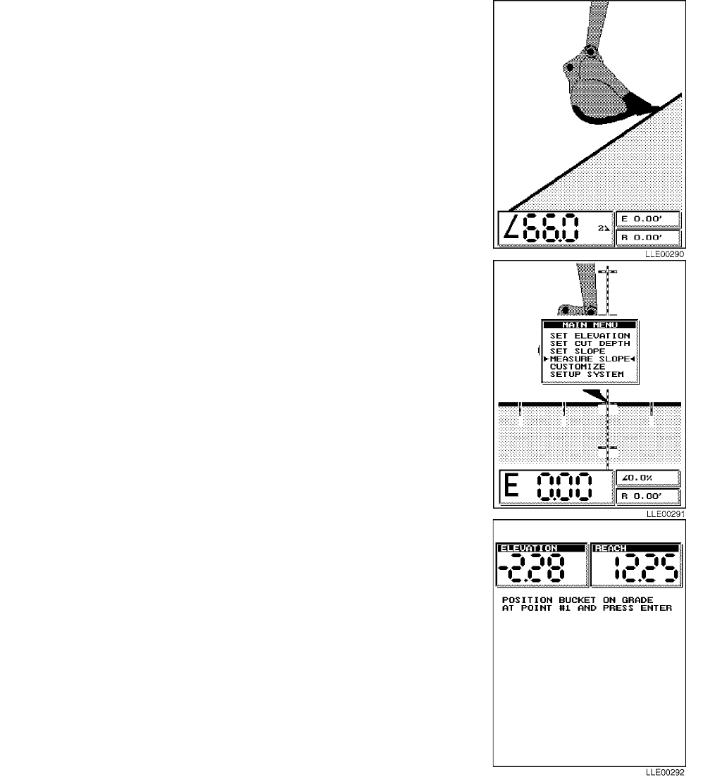
TM 5-6675-348-13&P
4-15
(12) Select YES, using Up and Down (↑↓) buttons, when “Ref.
at initial bench elevation” window appears.
NOTE
Bucket-Pro™ System is now referenced
for a canal excavation with +66% on one
bank and -66% on the other bank.
(13) Press ENTER button to confirm selection.
4-18. MEASURE SLOPE.
(1) Use MEASURE SLOPE to locate unknown grade
between two points within reach of HYEX.
(2) Press MODE button to access MAIN MENU.
(3) Point menu arrows to MEASURE SLOPE mode
using Up and Down (↑↓) buttons.
(4) Press ENTER button to confirm selection.
(5) Position bucket’s teeth on any part of
slope to be measured.
(6) Press ENTER button.
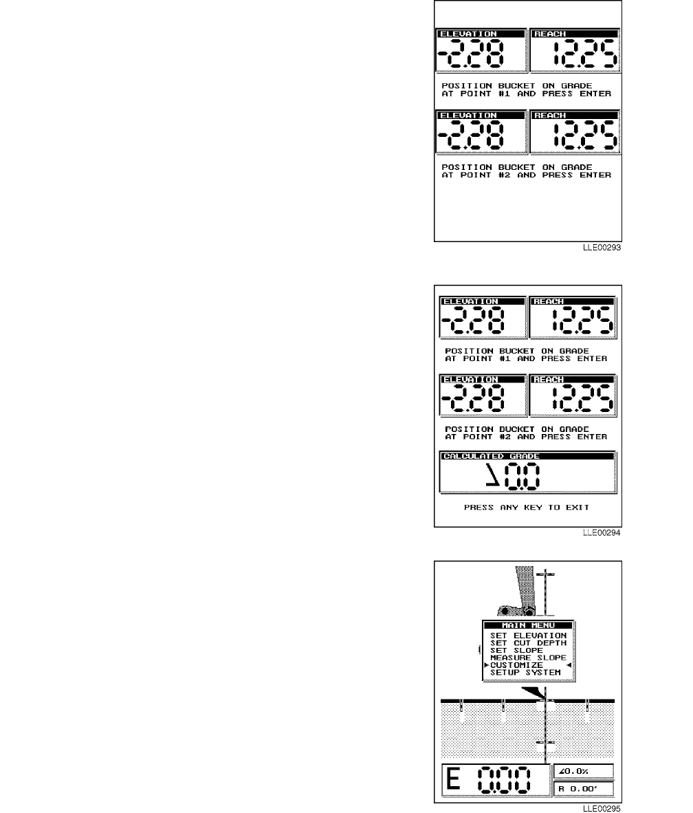
TM 5-6675-348-13&P
4-16
(7) Position bucket’s teeth on a second point
on slope and press ENTER button.
NOTE
CALCULATED GRADE appears
in a window at bottom of screen.
A 100% slope equals 45 degrees.
(8) Press any button to exit.
4-19. CUSTOMIZE.
For special applications, CUSTOMIZE menu option
in MAIN MENU allows special features and system
adjustments to be made. In CUSTOMIZE, you can
manually reference nonindexed Bucket-Pro™
system sensors. Use the following procedure to
access all CUSTOMIZED mode options.
(1) Press MODE button to access MAIN
MENU.
(2) Point menu arrows to desired option, in
this case CUSTOMIZE, using Up and
Down (↑↓) buttons.
(3) Press ENTER button to confirm
selection.
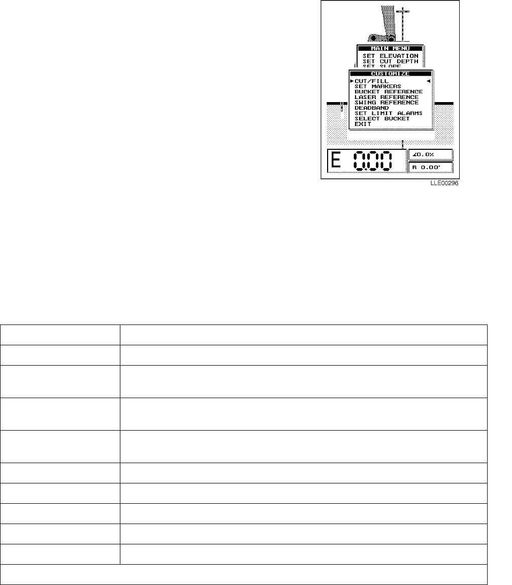
TM 5-6675-348-13&P
4-17
NOTE
• CUSTOMIZE menu appears on
Graphic Display.
• CUSTOMIZE menu contains eight
options.
(4) Point menu arrows to option that you
want using Up and Down (↑↓) buttons.
NOTE
To exit CUSTOMIZE menu, scroll down
to EXIT, or simply press MODE button.
Normal operation resumes with any
additional feature you select from
CUSTOMIZE.
(5) Press ENTER button to confirm selection.
4-20. CUSTOMIZE MENU SUMMARY.
NOTE
The following pages provide a detailed description of each selection in CUSTOMIZE menu.
Table 4-2. CUSTOMIZE Menu Options
OPTION DESCRIPTION
Cut/Fill: Adds additional CUT or FILL line to standard finished-grade line.
Set Markers: Add user-defined horizontal and vertical distance marker lines on Graphic
Display.
Bucket Reference: Allows manual referencing of Bucket Sensor without going into SETUP
mode.
Laser Reference: Allows manual search for laser beam if it is blocked longer than preset
time.
Swing Reference: Allows manual referencing of swing sensor 0° position, when enabled.*
DEADBAND: Sets system DEADBAND tolerance and selects audible tone detector style.
Set Limit Alarms: Set/select height operation limit alarms.
Select Bucket: Allows selection, addition, deletion, or editing of buckets loaded in memory.
Exit: Stores selections in memory and returns you to main operating screen.
* This feature is not available.

TM 5-6675-348-13&P
4-18
4-21. CUT/FILL.
NOTE
CUT/FILL option allows the setup on
Graphic Display a secondary dotted grade
line above or below main solid finished-
grade line. CUT/FILL line can be used to
control bedding-layer thickness, top-of-
pipe location, or a stepped trench for a
catch basin. Use the following steps to set
CUT/FILL line:
(1) Press MODE button to access MAIN
MENU.
(2) Point menu arrows to CUSTOMIZE
menu, using Up and Down (↑↓) buttons.
(3) Press ENTER button to confirm selection.
NOTE
ARE YOU SURE? window appears
on Graphic Display.
(4) Using Up and Down (↑↓) buttons, select
NO if you want to disable CUT/FILL and
return to CUSTOMIZE menu, or select
YES to continue.
NOTE
• If you chose CUT/FILL, a CUT/FILL
dimension window appears.
• A positive CUT/FILL value generates a
dotted line above solid finished-grade line.
• A negative CUT/FILL value generates a
dotted line below solid finished-grade line.
• To protect against overcut in areas having
a lot of underground facilities, a negative
CUT/FILL layer can be used in conjunction
with overcut alarm (refer to DEADBAND)
as a maximum allowable over-dig line.
(5) Enter layer thickness you want, using Up and
Down (↑↓) buttons.
(6) After selecting value wanted, press ENTER
button to return to CUSTOMIZE menu.
(7) To exit menu, press Up and Down (↑↓) buttons to highlight EXIT and press ENTER button, or
press MODE button.
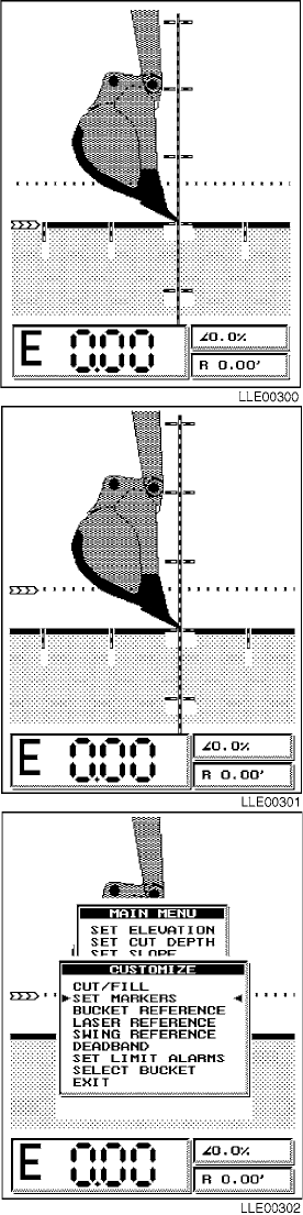
TM 5-6675-348-13&P
4-19
4-22. SWITCHING GRADES LINES.
(1) If CUT/FILL mode is being used, DEADBAND
alarm and HI/LO/On-Grade LED cluster (in upper
right corner of display) can be connected to solid
finished-grade line or dotted bedding-layer line.
Symbol shown indicates which grade line is
operating. Use Up and Down (↑↓) buttons to
change operating indicator arrow from one grade
line to other.
(2) Elevation and reach values shown on Graphic
Display always indicate bucket’s cutting edge
elevation, regardless of which grade line is
selected. Bucket’s cutting edge is always
referenced to solid finished-grade line at start of
operation. If bucket’s cutting edge is moved to
dotted bedding-layer line and rereferenced, grade
and reach values change to bedding-layer line with
respect to same BENCHMARK elevation.
4-23. SET MARKERS.
Distance markers can be set so you can rough-measure
distance horizontally or vertically in an excavation.
Undercutting required for a pipe bell is an example of a job
where rough measuring is helpful. If pipe joint is
approximately 6 ft (1.8 m) long and bell protrudes
approximately 8 in. (20.3 cm) below finished grade, markers
should be spaced approximately 6 ft (1.8 m) apart. These
markers show that each time bucket’s cutting edge comes to a
marker, it is time to undercut for pipe bell. These markers
also provide a visual view measurement instead of numbers
in lower corner of Graphic Display.
(1) Press MODE button to access MAIN MENU.
(2) Point menu arrows to CUSTOMIZE menu using
Up and Down (↑↓) buttons.
(3) Press ENTER button to confirm selection.
(4) Point menu arrows to SET MARKERS using
Up and Down (↑↓) buttons.
(5) Press ENTER button to confirm selection.
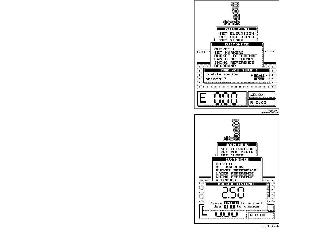
TM 5-6675-348-13&P
4-20
NOTE
ARE YOU SURE? window appears
on Graphic Display.
(6) Select NO if you want to disable SET
MARKERS and return to CUSTOMIZE
menu, or select YES to continue.
NOTE
If you chose SET MARKERS, a
dimension window labeled MARKER
DISTANCE appears.
(7) Enter MARKER DISTANCE spacing
that you want, using Up and Down (↑↓)
buttons (2.50 is displayed here).
NOTE
Maximum MARKER DISTANCE
spacing is 20 ft (6.10 m), minimum
MARKER DISTANCE spacing is 1 ft
(30.5 cm). All images displayed during
normal operation are scaled to bucket
size. This length includes viewed
distance between markers lines. If
buckets are changed, viewed distance
between marker lines also changes.
Overall grade and reach accuracy is
not affected.
(8) Press ENTER button to select value
and return to CUSTOMIZE menu.
(9) To exit menu, press Up and Down (↑↓)
buttons to highlight EXIT and press
ENTER button, or press MODE button.
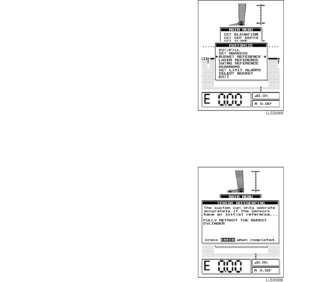
TM 5-6675-348-13&P
4-21
4-24. BUCKET REFERENCE.
BUCKET REFERENCE is used if Encoder wire
comes loose. This allows for BUCKET
REFERENCE without turning Bucket-Pro™
System Off and On and performing complete Setup
procedure.
(1) Press MODE button to access MAIN
MENU.
(2) Point menu arrows to CUSTOMIZE
menu using Up and Down (↑↓) buttons.
(3) Press ENTER button to confirm
selection.
(4) Point menu arrows to BUCKET
REFERENCE using Up and Down (↑↓)
buttons.
(5) Press ENTER button to confirm selection.
NOTE
SENSOR REFERENCING window
appears.
(6) Follow instructions in window. Fully
retract bucket cylinder, then press
ENTER button.
NOTE
After bucket cylinder is referenced,
Graphic Display reverts to the MAIN
MENU.
(7) To exit MAIN MENU, press Up and
Down (↑↓) buttons to highlight EXIT and
press ENTER button, or press MODE
button.
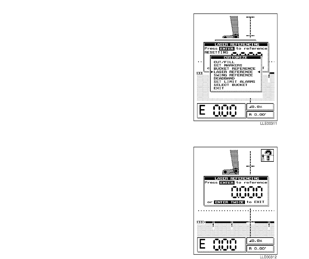
TM 5-6675-348-13&P
4-22
4-25. LASER REFERENCE.
NOTE
LASER REFERENCE provides a means
of starting a search for laser. Procedure is
used if laser reference at power up was
bypassed and Operator needs to use laser
at another time during excavation.
(1) Select LASER REFERENCE from menu.
(2) Press ENTER button.
NOTE
LASER REFERENCING will appear.
Perform Step (3) to start laser search,
or Step (4) to disable laser search.
(3) Press ENTER button one time to start
laser search.
(4) Press ENTER button two times to
disable laser search.
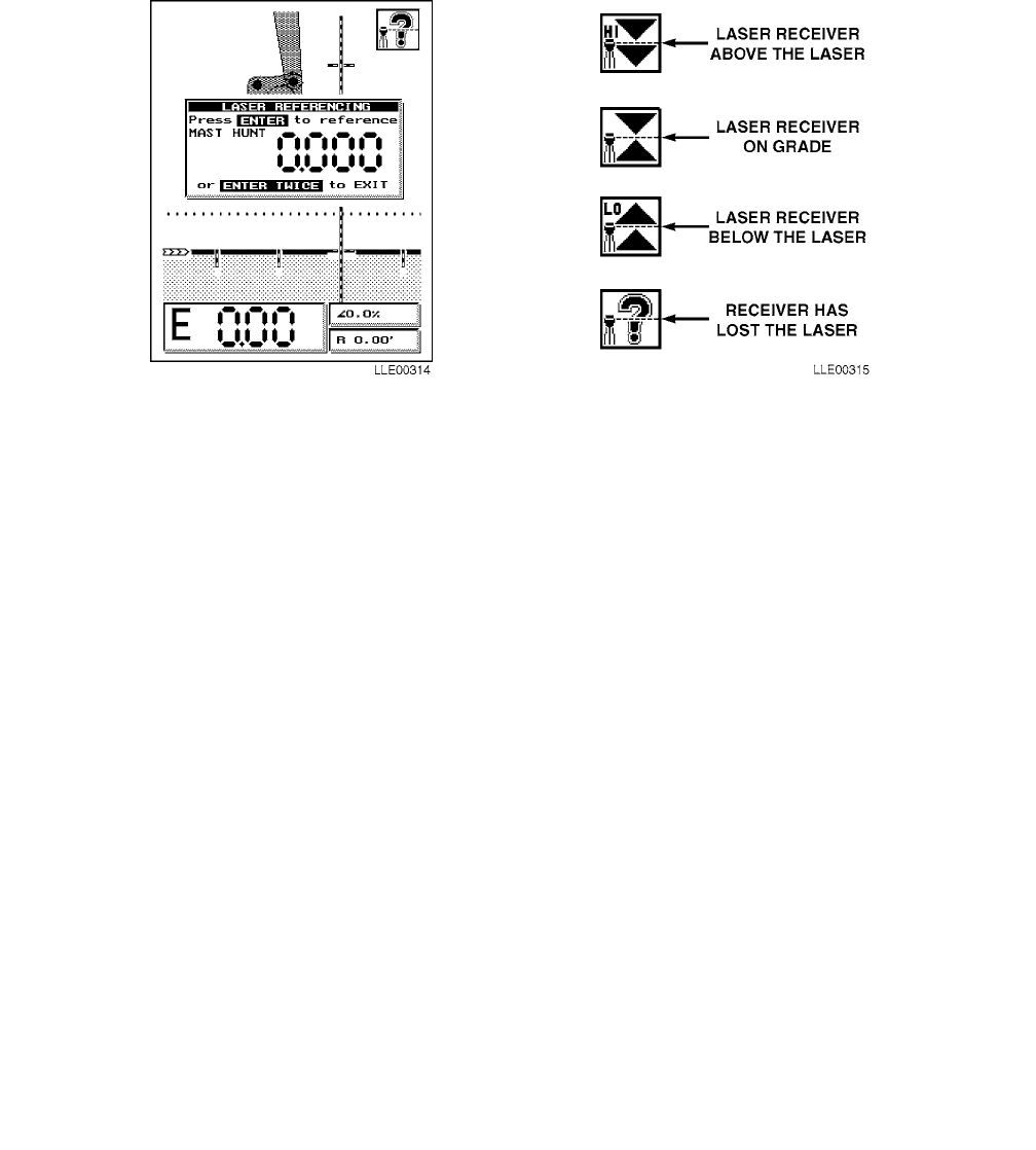
TM 5-6675-348-13&P
4-23
(5) Observe MAST HUNT in window of Graphic Display.
(6) Observe mast extension value when laser has been found. Once on-grade is found, the system
reverts to MAIN MENU.
NOTE
After LASER REFERENCING has been used, perform all benchmark elevation setting
procedures.
(7) Exit CUSTOMIZE menu when finished with all selections.
NOTE
• When laser lock has taken place, a number appears in LASER REFERENCING window.
This value is the amount of mast extension in meters. The value is for installers and has
no significance in determining Bucket-Pro™ grade calculations.
• When laser lock-on has taken place, laser beam indicator appears in upper right corner
of Graphic Display, and shows status of Laser Reference System at any given time dur-
ing operation. It has nothing to do with elevation or finished grade indication.
(8) Check mast movement in upper right corner of display.
NOTE
During each digging cycle, HYEX boom or dipper stick can momentarily block laser beam.
When blockage occurs, a question mark (?) appears on Graphic Display. If laser beam is
blocked for more than a preset amount of time (default setting is 60 seconds), LASER
REFERENCING screen automatically appears and gives instructions for achieving new
laser lock-on. Please follow these instructions.
(9) Observe symbols as EM2E-24 Electric Mast movement proceeds.
NOTE
Work can be done with Laser Reference System in 4 ft (1.22 m) extension range of EM2E-24
Electric Mast before having to rereference. Steeper slopes require shorter distance traveled
before reference must be performed again.
(10) Perform all Benchmark Elevation procedures (Para 4-15).
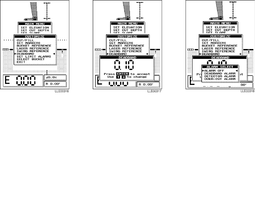
TM 5-6675-348-13&P
4-24
4-26. SWING REFERENCE.
This feature is not available.
4-27. DEADBAND.
DEADBAND is the tolerance spread for ON-GRADE indication on the Graphic Display. For close-tolerance
work, a smaller DEADBAND is required; for rough excavation, use a wider DEADBAND. While in
DEADBAND mode, three types of detector-alarm modes are also selectable.
(1) Press MODE button to access MAIN MENU.
(2) Point menu arrows to CUSTOMIZE using Up and Down (↑↓) buttons.
(3) Press ENTER button to confirm selection.
(4) Point menu arrows to DEADBAND using Up and Down (↑↓) buttons.
(5) Press ENTER button to confirm selection.
(6) Observe that DEADBAND window appears on screen.
(7) Set DEADBAND using Up and Down (↑↓) buttons.
(8) Press ENTER button to select that value.
(9) Observe that window showing alarms appears on screen.
NOTE
After selecting DEADBAND value, ALARM SELECT window with four choices appears.
(10) Point menu arrows to choice you want using Up and Down (↑↓) buttons.
(11) Press ENTER button to confirm selection.
(12) To exit MAIN MENU, press Up and Down (↑↓) buttons to highlight EXIT and press ENTER
button, or press MODE button.
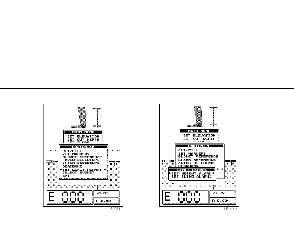
TM 5-6675-348-13&P
4-25
4-28. SET LIMIT ALARMS.
LIMIT ALARMS warns when close to height or right-of-way obstruction. Limits can be preset based on
knowledge of job conditions.
NOTE
If audible height alarm sounds at startup of HYEX with bucket on ground, perform Steps (1)
through (6). Otherwise skip to Step (7).
(1) Press MODE button twice to access MAIN MENU.
(2) Point menu arrows to CUSTOMIZE, using Up and Down (↑↓) buttons.
(3) Press ENTER button to confirm selection.
(4) Point menu arrows to SET LIMIT ALARMS, using Up and Down (↑↓) buttons.
(5) Press ENTER button to confirm selection.
Table 4-3. System Alarms
ALARM DESCRIPTION
ALARM OFF Internal audible alarm is turned off.
DEADBAND
ALARM Audible alarm sounds steady tone as long as bucket’s cutting edge is in DEADBAND and
green on-grade LED lights.
DETECTOR
ALARM Audible tone sounds fast pulsing tone (10 cps) when above DEADBAND. Audible tone
sounds a slower pulsing tone (5 cps) when below DEADBAND. Audible tone sounds
steadily while within DEADBAND. Actual ON-GRADE indication is + and - setting in
DEADBAND menu box. Minimum HI and LOW width is 0.33 ft. (4 in.). Width increases
proportionally when DEADBAND is set to over 0.16 ft. (2 in.).
OVER-CUT
ALARM Audible tone sounds steadily when bucket’s cutting edge goes below DEADBAND bottom
limit.
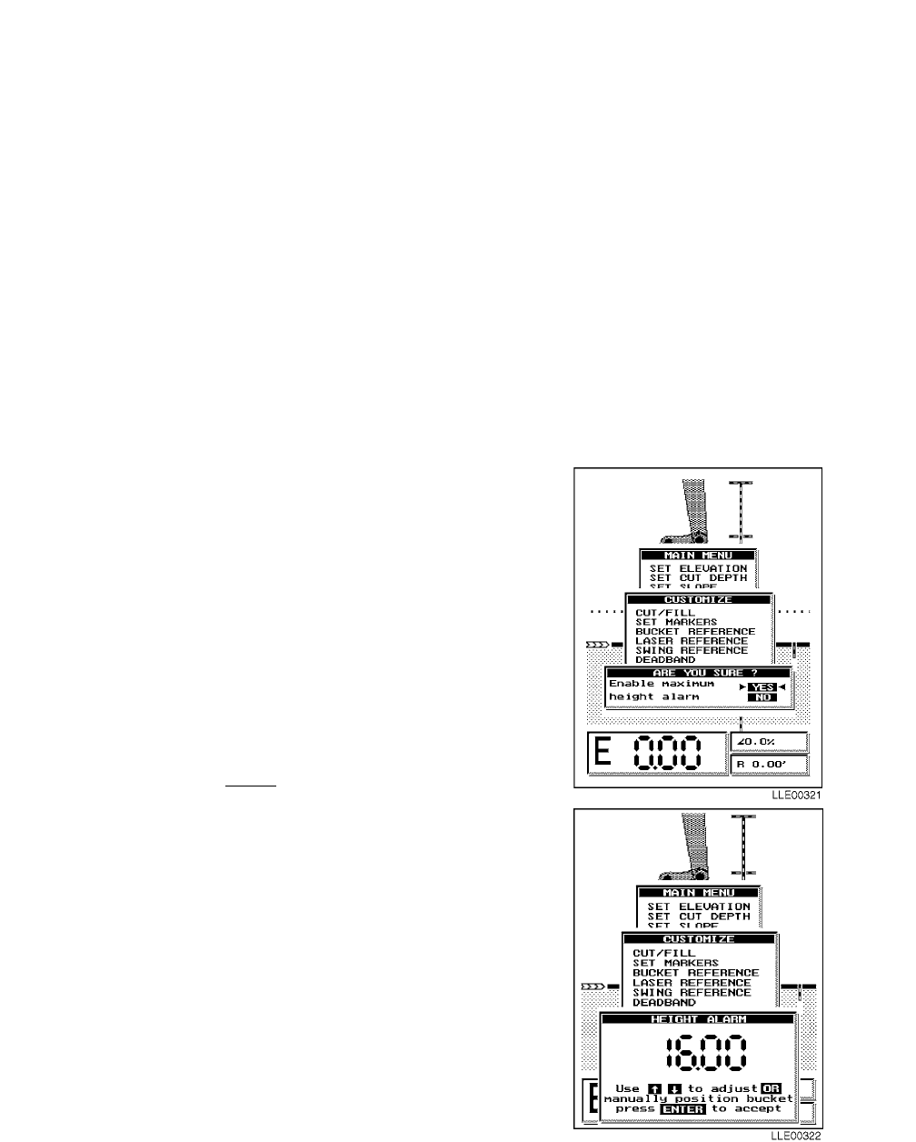
TM 5-6675-348-13&P
4-26
NOTE
When SET HEIGHT ALARM is selected, ARE YOU SURE? window appears. Selecting NO
disables HEIGHT ALARM and Bucket-Pro™ System returns to CUSTOMIZE. Selecting
YES allows setting new HEIGHT ALARM.
(6) Press ENTER button to confirm selection.
(7) Press MODE button to access MAIN MENU.
(8) Point menu arrows to CUSTOMIZE using Up and Down (↑↓) buttons.
(9) Press ENTER button to confirm selection.
(10) Point menu arrows to SET LIMIT ALARMS, using Up and Down (↑↓) buttons.
NOTE
• SET LIMIT ALARMS window appears.
• LIMIT ALARMS window gives only choice of SET HEIGHT ALARM.
(11) Press ENTER button to confirm selection.
NOTE
When SET HEIGHT ALARM is selected,
ARE YOU SURE? window appears.
Selecting NO disables HEIGHT ALARM
and Bucket-Pro™ System returns to
CUSTOMIZE. Selecting YES allows setting
new HEIGHT ALARM.
(12) Press ENTER button to confirm selection.
NOTE
HEIGHT ALARM can be set two ways. If
HYEX is moved before setting a number,
Bucket-Pro™ System uses current
real-time data from the Angle Sensors to
set the alarm height. The height displayed
is either the bucket height or the dipper
stick pivot-pin height, whichever is highest.
If a button is pressed before any HYEX
movement is detected by the Angle Sensors,
Bucket-Pro™ System assumes the manual
HEIGHT ALARM value is going to be
entered and ignores Angle Sensors inputs.
(13) Manually select height value you want
using Up and Down (↑↓) buttons.
(14) Press ENTER button to confirm selection.
(15) To exit the menu, press Up and Down (↑↓)
buttons to highlight EXIT and press
ENTER button, or press MODE button.
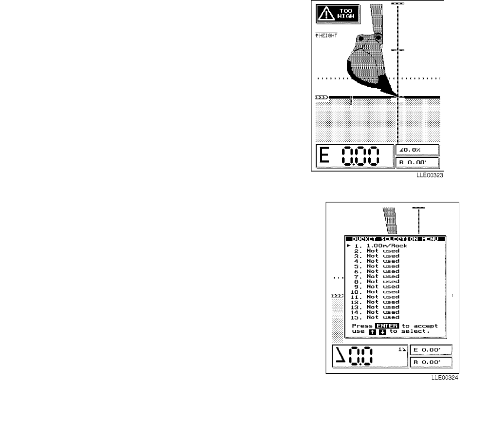
TM 5-6675-348-13&P
4-27
NOTE
When HEIGHT ALARM is selected, a
height marker is shown on left side of
Graphic Display when HYEX approaches
set height limit.
(16) Observe TOO HIGH window and audible
alarm sound when height limit has been
reached or exceeded.
4-29. SELECT BUCKET.
Because ground conditions vary, changing buckets may be
needed. Bucket-Pro™ System lets you store up to 15
different bucket sizes in Bucket-Pro™ System memory. Use
the following steps when you have to quick-change a bucket:
(1) Press MODE button to access MAIN MENU.
(2) Point menu arrows to CUSTOMIZE using Up and
Down (↑↓) buttons.
(3) Press ENTER button to confirm selection.
(4) Point menu arrows to SELECT BUCKET using
Up and Down (↑↓) buttons.
(5) Press ENTER button to confirm selection.
NOTE
BUCKET SELECTION MENU appears,
showing all stored bucket sizes. Menu
allows you to choose up to 15 different
buckets.
(6) Observe BUCKET SELECTION MENU.
(7) Point menu arrows to bucket you want
using, Up and Down (↑↓) buttons.
(8) Press ENTER button to confirm selection.
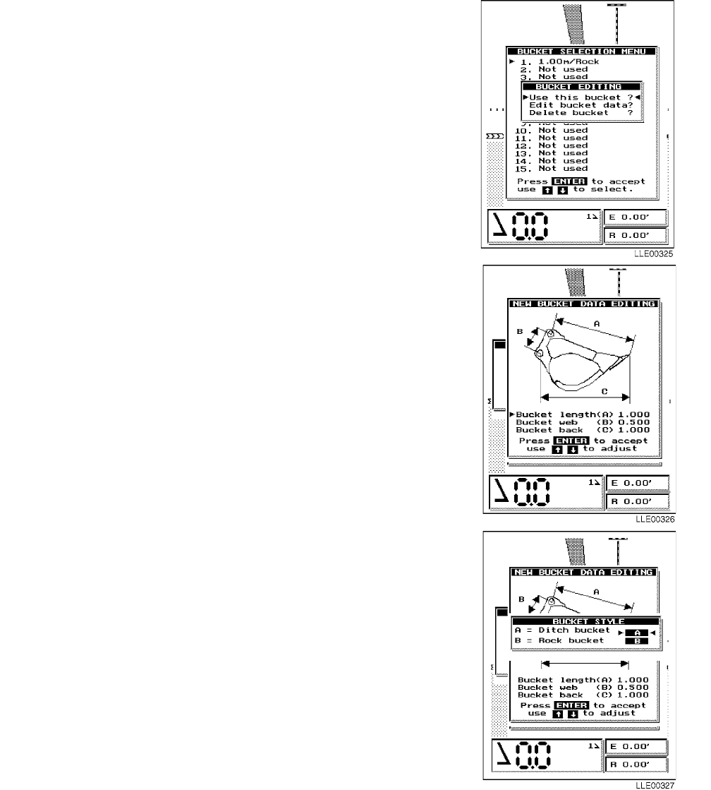
TM 5-6675-348-13&P
4-28
NOTE
• If bucket selection has a valid bucket
entry in it, BUCKET EDITING
window appears with three options.
• Menu lets you select whether bucket
listed on menu is used in its current
form, edited by changing its
dimensions, or deleted to create space
on menu.
(9) Select your choice of bucket editing using
Up and Down (↑↓) buttons.
(10) Press ENTER button to confirm selection.
NOTE
• If DELETE BUCKET is chosen, you are
returned to Step (9).
• If EDIT BUCKET DATA is chosen, NEW
BUCKET DATA EDITING menu appears
on Graphic Display. EDIT BUCKET DATA
is used to adjust for tooth wear.
• If a bucket size on the menu shows NOT
USED, add a new bucket at this time.
• When NOT USED is selected, or EDIT
BUCKET DATA selection above, NEW
BUCKET DATA EDITING menu appears
on Graphic Display.
• A bucket has three dimensions required in
calculating the bucket’s cutting-edge
elevation. Dimensions are shown as A, B,
and C in the NEW BUCKET DATA
EDITING window.
(11) Point menu arrows to dimension you want to
add/change using Up and Down (↑↓) buttons.
(12) Press ENTER button to confirm selection.
(13) Enter dimension value using Up and Down
(↑↓) buttons.
(14) Press ENTER button to confirm selection.

TM 5-6675-348-13&P
4-29
NOTE
After bucket data has been entered, the BUCKET STYLE window appears, giving a choice of
bucket types.
(15) Point menu arrows to either A, DITCH BUCKET, or B, ROCK BUCKET, using Up and Down (↑↓)
buttons.
NOTE
• This selection determines the look of
the bucket graphic on the Graphic
Display.
• When all bucket data has been
entered and the bucket style has been
selected, the BUCKET LOOKUP
TABLE window, with numbers count-
ing from 0 to 100%, appears.
• Counting can take between 10 to 30
seconds. All switches are deactivated,
except the ON/OFF switch, until the
window disappears.
• When the counting stops, the Bucket-
Pro™ System returns to CUSTOMIZE.
(16) To exit menu, press Up and Down (↑↓) buttons
to highlight EXIT and press ENTER button,
or press MODE button.
TM 5-6675-348-13&P
4-30
SECTION IV. BUCKET-PRO™ SYSTEM TROUBLESHOOTING
While Bucket-Pro™ System is a highly accurate system, you may encounter problems as you work in the
field. Use this section to troubleshoot your problems. You may want to have a qualified maintenance person
troubleshoot and fix any problems.
Table 4-4. Bucket-Pro™ System Fault Index
Fault
No. Description Page
4-1. Bucket-Pro™ System/Graphic Display Does Not Turn On..................................................................... 4-31
4-2. Sensors Do Not Work ................................................................................................................................4-32
4-3. EM2E-24 Electric Mast Does Not Work...................................................................................................4-33
4-4. Graphic Display Not Responding Properly (Direction, Speed, Location
with Respect to Grade) .........................................................................................................................4-34
4-5. Graphic Display Does Not Match Machine Geometry (Bucket and/or
Arm Not in Correct Position)................................................................................................................ 4-35
4-6. Elevation Value Does Not Match Desired Value .....................................................................................4-36
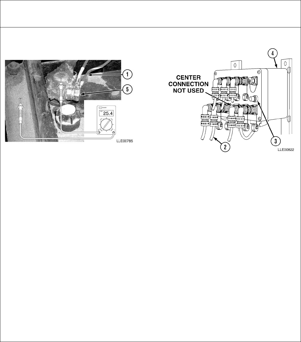
TM 5-6675-348-13&P
4-31
Table 4-5. Bucket-Pro™ System Troubleshooting
Malfunction
Test or InspectionCorrective Action
FAULT 4-1. BUCKET-PRO™ SYSTEM/GRAPHIC DISPLAY DOES NOT TURN ON.
Step 1. Ensure Power Cable (1) is connected.
Connect Power Cable (1).
Step 2. Inspect Power Cable (1) for damage.
If Power Cable (1) is damaged, replace Power Cable (1).
Step 3. Ensure Graphic Display Cable (2) is connected.
Connect Graphic Display Cable (2).
Step 4. Check Fuse (3) at Remote Interface Box (4).
If Remote Interface Box (4) Fuse (3) is faulty, replace Fuse (3).
Step 5. Check for 22 to 28 Vdc at Battery Connection (5).
If 22 to 28 Vdc is not found, service Battery.
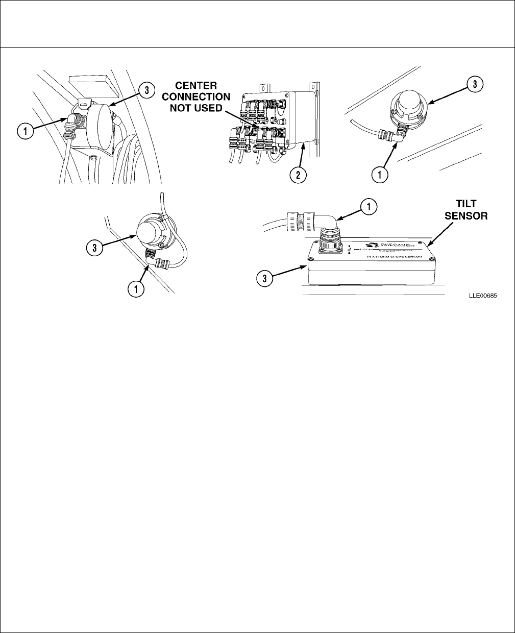
TM 5-6675-348-13&P
4-32
FAULT 4-2. SENSORS DO NOT WORK.
Step 1. Ensure Sensor Cables (1) are connected to proper Connector on Remote Interface Box (2).
Install Sensor Cables (1) on proper Remote Interface Box (2) Connector.
Step 2. Ensure all Sensor Cables (1) are connected to Sensors (3).
Inspect Sensor Cable (1). Reconnect if disconnected, or replace if damaged.
Step 3. Sensor(s) (3) are damaged.
Inspect Sensor(s) (3). If damaged, replace Sensor(s) (3).
Step 4. Ensure Voltage Protection Cable is functioning.
Replace Voltage Protection Cable.
Step 5. Check Averaging or Normal/Reversed Setup in View Sensor Menu.
Perform Setup Averaging again (Para 4-32).
Step 6. Dual-Axis Tilt Sensor is not enabled in Setup Parameters in Setup menu (Dual-Axis Tilt
Sensor failure only).
Enable-Dual Axis Tilt Sensor (Para 4-32).
Table 4-5. Bucket-Pro™ System Troubleshooting (Cont)
Malfunction
Test or InspectionCorrective Action
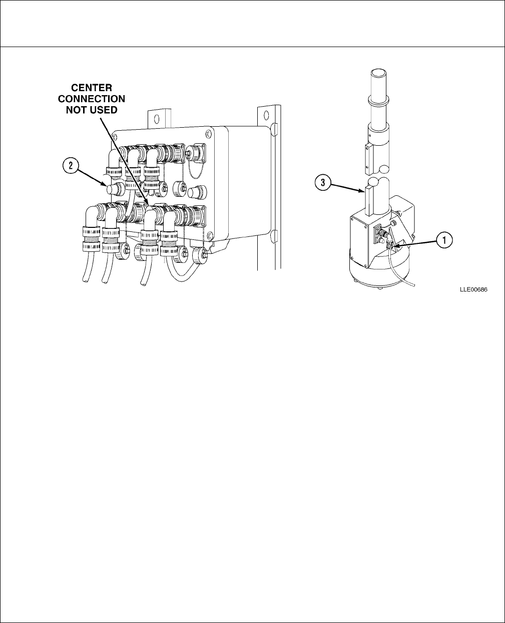
TM 5-6675-348-13&P
4-33
FAULT 4-3. EM2E-24 ELECTRIC MAST DOES NOT WORK.
Step 1. Ensure correct model Electric Mast (EM2E-24) is installed.
If wrong Electric Mast is installed, replace with EM2E-24 Electric Mast.
Step 2. Check Mast Cable (1).
If Mast Cable (1) is disconnected, reconnect Mast Cable (1).
If Mast Cable (1) is defective, replace Mast Cable (1) (Para 4-31).
Step 3. Check Remote Interface Box Mast Fuse (2).
If Remote Interface Box Mast Fuse (2) is defective, replace Remote Interface Box
Mast Fuse (2).
Step 4. Ensure EM2E-24 Electric Mast (3) is enabled in Setup Parameters.
Perform System Calibration (Para 4-32).
Table 4-5. Bucket-Pro™ System Troubleshooting (Cont)
Malfunction
Test or InspectionCorrective Action

TM 5-6675-348-13&P
4-34
FAULT 4-4. GRAPHIC DISPLAY NOT RESPONDING PROPERLY (DIRECTION, SPEED, LOCATION
WITH RESPECT TO GRADE).
Step 1. Ensure Sensor(s) (1) are attached to correct Connector (2) on Remote Interface Box (3).
If incorrect, connect Sensor(s) (1) to proper location.
Step 2. Sensor(s) (1) damaged.
Inspect Sensor(s) (1). If damaged, replace Sensor(s) (1).
Step 3. Check Sensor(s) (1) calibration.
If calibration is incorrect, perform System Calibration (Para 4-32).
Step 4. Check Bucket-Pro™ System benchmark reference.
Set Benchmark Elevation (Para 4-15).
Step 5. Check Averaging or Normal/Reversed Setup in View Sensor menu.
Perform System Calibration (Para 4-32).
Table 4-5. Bucket-Pro™ System Troubleshooting (Cont)
Malfunction
Test or InspectionCorrective Action
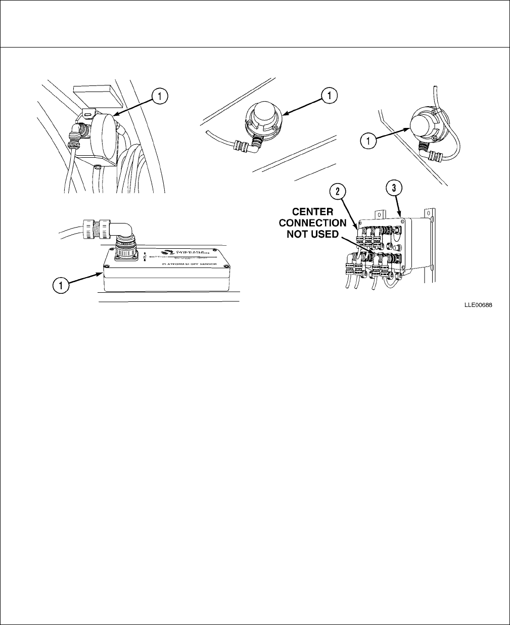
TM 5-6675-348-13&P
4-35
FAULT 4-5. GRAPHIC DISPLAY DOES NOT MATCH MACHINE GEOMETRY (BUCKET AND/OR
ARM NOT IN CORRECT POSITION).
Step 1. Ensure correct bucket is selected in Setup menu.
Select correct bucket.
Step 2. Ensure Sensor(s) (1) are connected to correct Connector (2) on Remote Interface Box (3).
If incorrect, connect Sensor(s) (1) to proper location.
Step 3. Sensor(s) (1) damaged.
Inspect Sensor(s) (1). If damaged, replace Sensor(s) (1).
Step 4. Check Sensor(s) (1) calibration.
If calibration is incorrect, recalibrate (Para 4-32).
Step 5. Check Encoder Web belt for damage.
If damaged, replace Encoder Web belt.
Step 6. Check averaging or NORMAL/REVERSED setup in View Sensor menu.
Perform System Calibration (Para 4-32).
Table 4-5. Bucket-Pro™ System Troubleshooting (Cont)
Malfunction
Test or InspectionCorrective Action
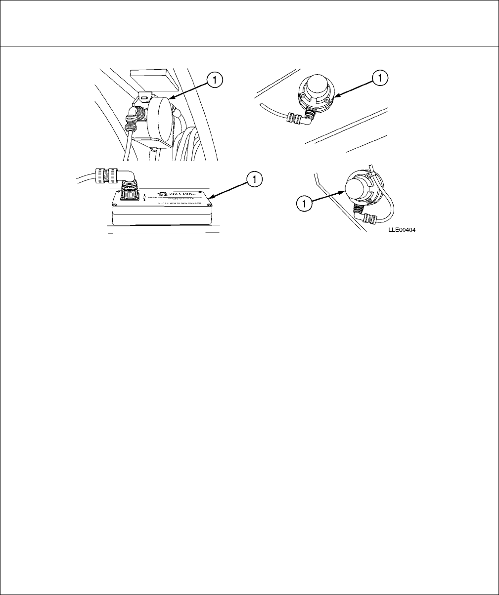
TM 5-6675-348-13&P
4-36
FAULT 4-6. ELEVATION VALUE DOES NOT MATCH DESIRED VALUE.
Step 1. Ensure correct bucket is selected in Setup menu.
Select correct bucket.
Step 2. Check Laser setup.
Perform LASER REFERENCING setup (Chapter 5).
Step 3. Check Mast mm/count setup in Edit Machine Dimensions setup menu.
If incorrect, reset measurements.
Step 4. Sensor(s) (1) damaged.
Inspect Sensor(s) (1). If damaged, replace Sensor(s) (1).
Step 5. Check Sensor(s) (1) calibration.
If calibration is incorrect, recalibrate (Para 4-32).
Step 6. Check averaging or NORMAL/REVERSED setup in View Sensor menu.
Perform System Calibration (Para 4-32).
Table 4-5. Bucket-Pro™ System Troubleshooting (Cont)
Malfunction
Test or InspectionCorrective Action
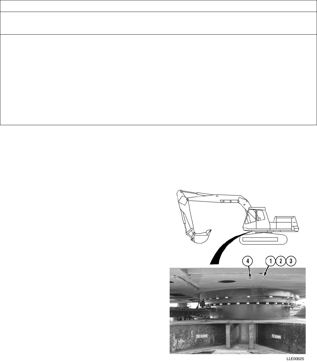
TM 5-6675-348-13&P
4-37
SECTION V. BUCKET-PRO™ SYSTEM MAINTENANCE
a. Remove.
NOTE
All four belly plates are removed the same way. The procedure for one belly plate is shown.
Remove six bolts (1), lockwashers (2), flat
washers (3), and belly plate (4).
b. Install.
NOTE
All four belly plates are installed the
same way. Procedure for one belly
plate is shown.
Install belly plate (4) with six flat washers (3),
new lockwashers (2), and bolts (1).
c. Follow-On Maintenance.
(1) Connect Batteries (TM 5-3805-280-10).
(2) Remove Chocks (TM 5-3805-280-10).
END OF TASK
4-30. BELLY PLATE REMOVAL AND INSTALLATION.
This Task Covers:
a. Remove. b. Install. c. Follow-On Maintenance.
INITIAL SETUP
Models
JD 230 LC HYEX
Tools and Special Tools
Tool Kit, Automotive Maintenance: Common
No. 2, Item 2, Appendix B
Materials and Parts
None
Personnel Required
One
Equipment Condition
Engine OFF (TM 5-3805-280-10).
Track chocked (TM 5-3805-280-10).
Batteries disconnected (TM 5-3805-280-10).
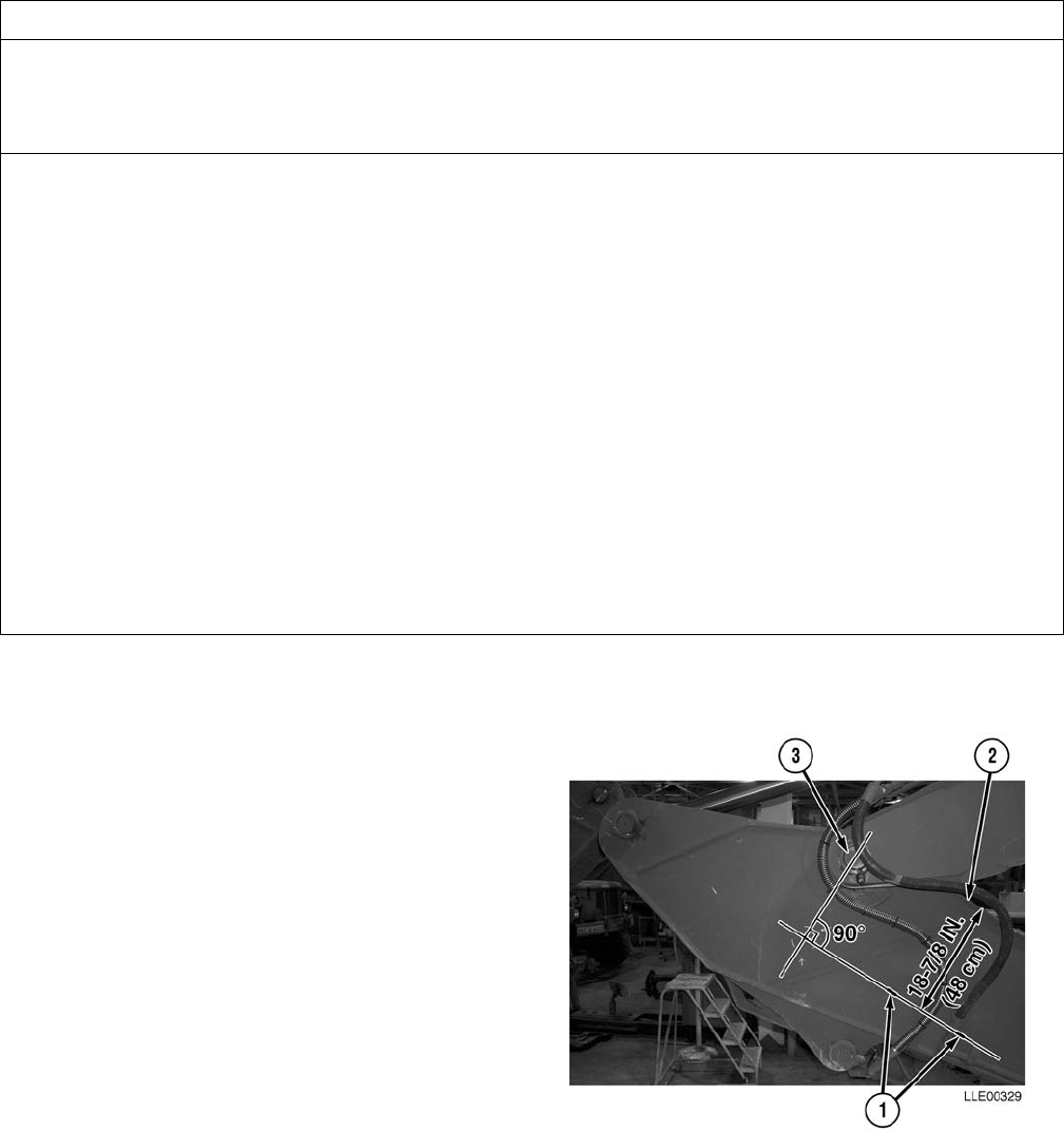
TM 5-6675-348-13&P
4-38
a. Arm Sensor.
(1) Measure and mark two points (1)
18-7/8 in. (47.9 cm) from top of
Arm (2).
(2) Using a straightedge, draw a line
under Arm Pin (3) using marks made
in Step (1).
(3) Draw a line 90 degrees to the line
drawn in Step (2), at center of Arm
Pin (3).
4-31. BUCKET-PRO™ SYSTEM INSTALLATION.
This Task Covers:
a. Arm Sensor. b. Boom Sensor. c. Tool Box.
d. Follow-On Maintenance.
INITIAL SETUP
Models
JD 230 LC HYEX
Tools and Special Tools
Tool Kit, Automotive Maintenance, Common
No. 2, Item 2, Appendix B
Tool Kit, Welders, Item 4, Appendix B
Materials and Parts
Gloves, Chemical Oil Protective, Item 4,
Appendix F
Goggles, Industrial, Item 5, Appendix F
Hook, Pile, Item 6, Appendix F
Non-Electrical, Safety Wire, Item 7,
Appendix F
Paint, Spray, Black, Item 8, Appendix F
Ties, Cable, Item 15, Appendix F
Materials and Parts (Cont.)
Label, Warning, Welding/Jump Starting,
Item 2, Appendix K
Ring, Arm Sensor Mounting, (2), Item 2,
Appendix K
Ring, Boom Sensor Mounting, Item 3,
Appendix K
Personnel Required
MOS 62B
MOS 44B
Equipment Condition
Engine OFF (TM 5-3805-280-10).
Track chocked (TM 5-3805-280-10).
Batteries disconnected (TM 5-3805-280-10).
Belly Plates removed as required (Para 4-30).

TM 5-6675-348-13&P
4-39
NOTE
To properly position Arm Sensor for
calibration, index one arm sensor mount
hole in the 9 o’clock position on the
horizontal line drawn in Step (2).
(4) Center Arm Sensor Mounting Ring (4)
on center point of lines drawn in
Steps (2) and (3).
(5) Trace center of Arm Sensor Mounting
Ring (4) on Arm (2).
Do not weld on the Arm Sensor
Mounting Ring directly under arm
sensor mounting holes. Welding under
the arm sensor mounting holes may
damage the threads.
(6) Mark location of Arm Sensor mounting
holes and welding locations on Arm (2).
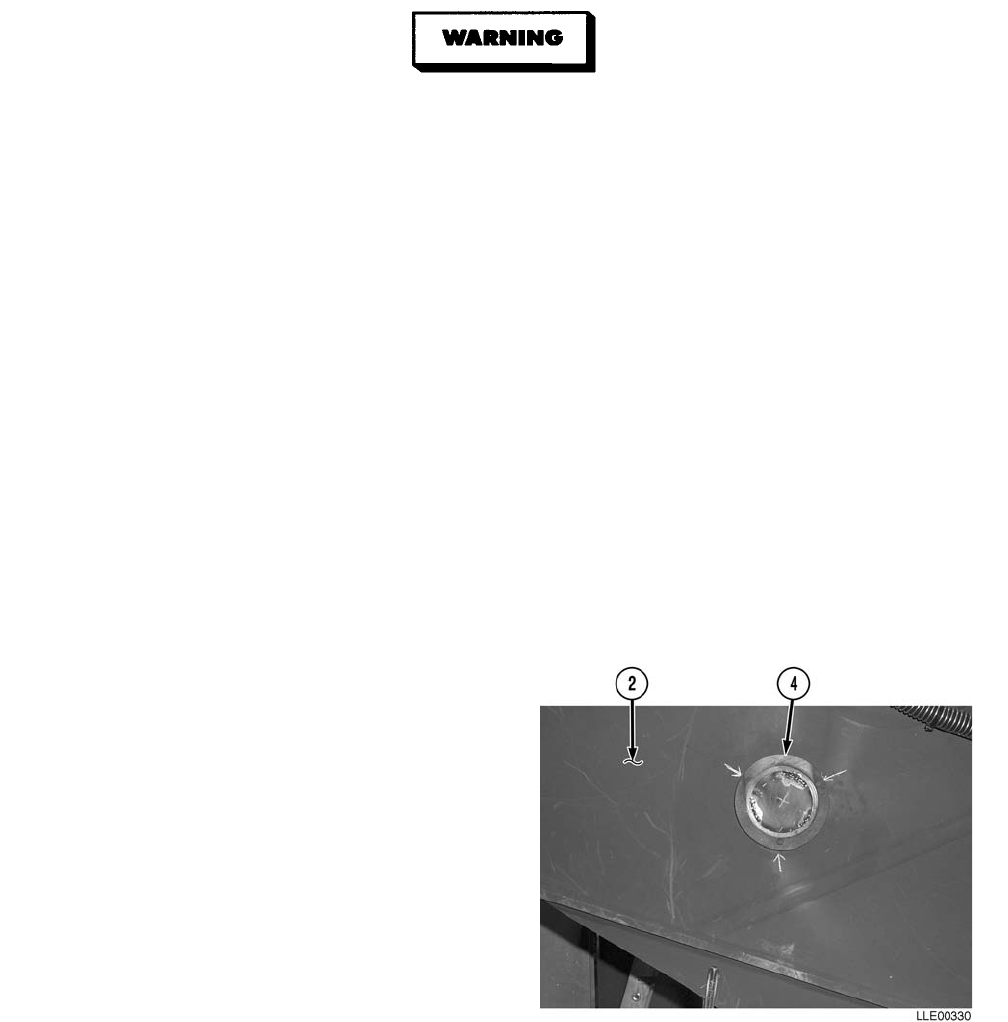
TM 5-6675-348-13&P
4-40
• CARC paint contains isocyanate (HDI), which is highly irritating to skin and respiratory
system. High concentrations of HDI can produce symptoms of itching and reddening of
skin, a burning sensation in throat and nose, and watering of the eyes. In extreme con-
centrations, HDI can cause cough, shortness of breath, pain during respiration, increased
sputum production, and chest tightness. The following precautions must be taken when-
ever using CARC paint:
• ALWAYS use air line respirators when using CARC paint, unless air sampling shows
exposure to be below standards. Use chemical cartridge respirator if air sampling is
below standards.
• DO NOT let skin or eyes come in contact with CARC paint. Always wear protective
equipment (gloves, ventilation mask, safety goggles, etc.).
• DO NOT use CARC paint without adequate ventilation.
• NEVER weld or cut CARC-coated materials.
• DO NOT grind or sand painted equipment without high-efficiency air purifying
respirators in use.
• BE AWARE of CARC paint exposure symptoms; symptoms can occur a few days after
initial exposure. Seek medical help immediately if symptoms are detected.
(7) Remove paint from area where Arm
Sensor Mounting Ring (4) will be
welded on Arm (2).
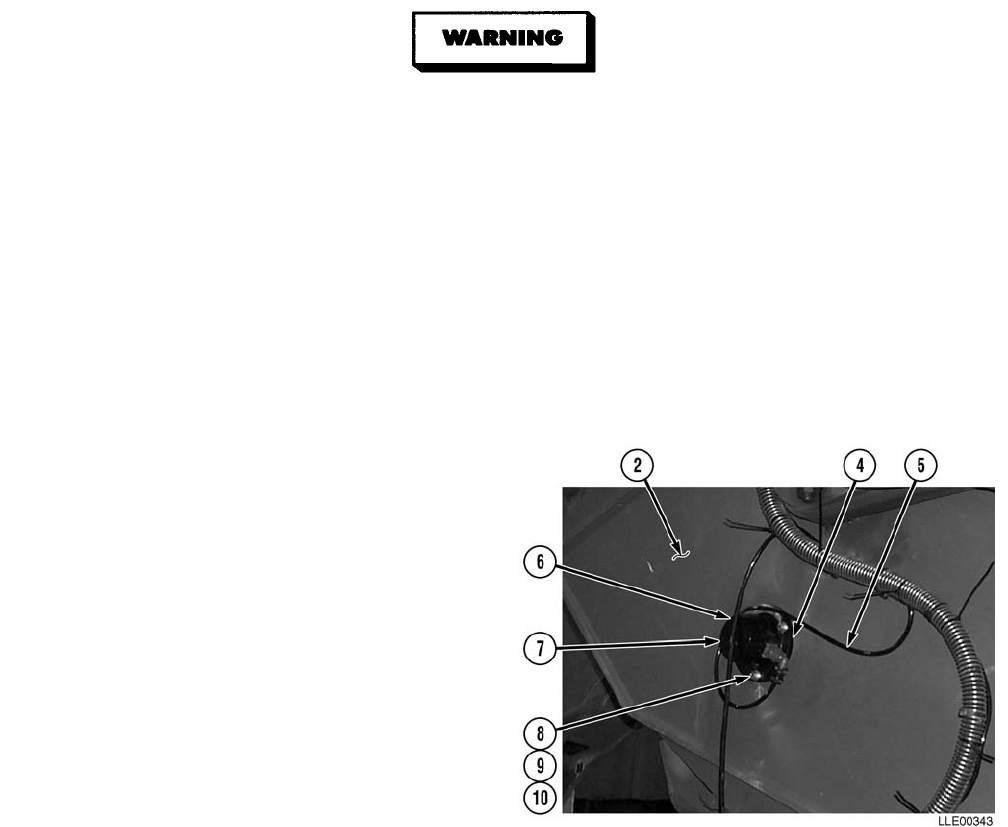
TM 5-6675-348-13&P
4-41
Unsafe welding practices can cause serious injury from fire, explosions, or harmful agents.
Allow only authorized personnel to weld or cut metals, and follow safety precautions in
TC 9-237. Protective clothing and goggles must be worn, adequate protective equipment
must be used, a suitable fire extinguisher must be kept nearby, and requirements of
TC 9-237 must be strictly followed. Failure to comply may result in serious injury or death
to personnel.
NOTE
For proper arm sensor calibration, weld within the lower lip of the Arm Sensor Mounting
Ring.
(8) Weld Arm Sensor Mounting Ring (4) to Arm (2).
(9) Paint Arm Sensor Mounting Ring (4) with black spray paint.
(10) Connect 40-ft Arm Sensor Cable (5) to
Arm Sensor (6).
(11) Install loop clamp (7) on 40-ft Arm
Sensor Cable (5).
NOTE
• The Front Arm Sensor mount bolt
is also used to attach the loop
clamp.
• The flat washer is not installed
with the loop clamp.
(12) Install Arm Sensor (6) to Arm Sensor
Mounting Ring (4) with three bolts (8),
lockwashers (9), two flat washers (10),
and one loop clamp (7).
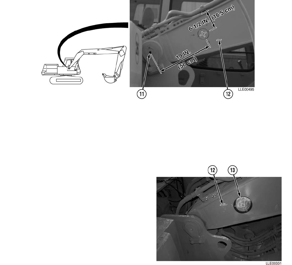
TM 5-6675-348-13&P
4-42
b. Boom Sensor.
(1) Measure and mark a point approximately 19 in. (48 cm) from center of Boom Pivot Pin (11) toward
front of vehicle.
(2) Measure and mark two points approximately 6 1/2 in. (16.5 cm) from top of Boom (12).
(3) Using a straightedge, draw a line using marks made in Step (2).
NOTE
To properly position the Boom Sensor
for calibration, index one Boom Sensor
Mount Hole in the 9 o’clock position on
the horizontal lines drawn in Steps (1)
and (2).
(4) Center Boom Sensor Mounting
Ring (13) on marks made in Steps (1)
and (2).
(5) Trace center of Boom Sensor Mounting
Ring (13) on Boom (12).
(6) Mark Boom Sensor Mounting Holes
and welding locations on Boom (12).

TM 5-6675-348-13&P
4-43
• CARC paint contains isocyanate (HDI), which is highly irritating to skin and respiratory
system. High concentrations of HDI can produce symptoms of itching and reddening of
skin, a burning sensation in throat and nose, and watering of the eyes. In extreme con-
centrations, HDI can cause cough, shortness of breath, pain during respiration, increased
sputum production, and chest tightness. The following precautions must be taken when-
ever using CARC paint:
• ALWAYS use air line respirators when using CARC paint, unless air sampling shows
exposure to be below standards. Use chemical cartridge respirator if air sampling is
below standards.
• DO NOT let skin or eyes come in contact with CARC paint. Always wear protective
equipment (gloves, ventilation mask, safety goggles, etc.).
• DO NOT use CARC paint without adequate ventilation.
• NEVER weld or cut CARC-coated materials.
• DO NOT grind or sand painted equipment without high-efficiency air purifying
respirators in use.
• BE AWARE of CARC paint exposure symptoms; symptoms can occur a few days after
initial exposure. Seek medical help immediately if symptoms are detected.
(7) Remove paint from area to be welded.
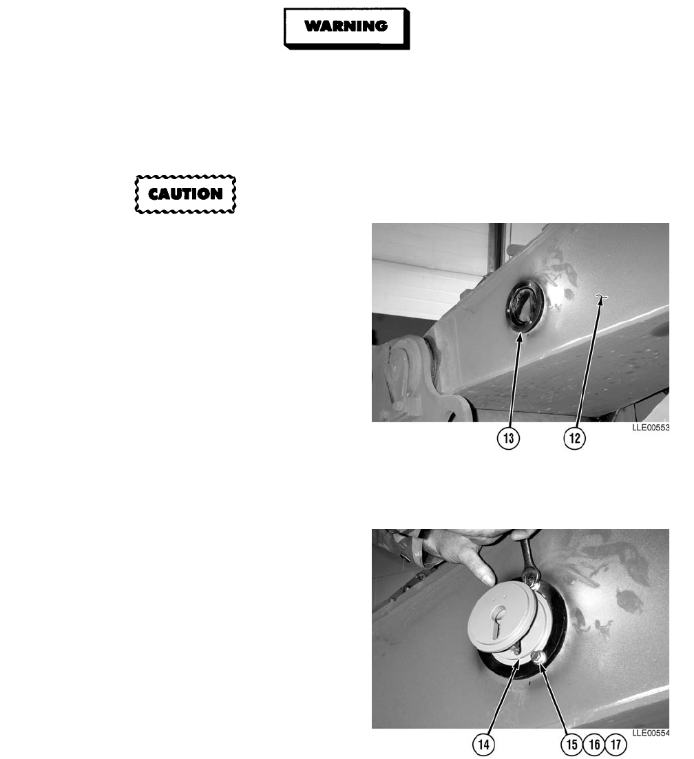
TM 5-6675-348-13&P
4-44
Unsafe welding practices can cause serious injury from fire, explosions, or harmful agents.
Allow only authorized personnel to weld or cut metals, and follow safety precautions in
TC 9-237. Protective clothing and goggles must be worn, adequate protective equipment
must be used, a suitable fire extinguisher must be kept nearby, and requirements of
TC 9-237 must be strictly followed. Failure to comply may result in serious injury or death
to personnel.
Do not weld on the Boom Sensor
Mounting Ring directly under Boom
Sensor Mounting Holes. Welding on
the boom sensor mounting holes may
damage the threads.
NOTE
For proper Boom Sensor calibration,
weld within the lower lip of the Boom
Sensor Mounting Ring.
(8) Weld Boom Sensor Mounting Ring (13)
onto Boom (12).
(9) Paint Boom Sensor Mounting
Ring (13) with black spray paint.
NOTE
To properly position the Boom Sensor
for calibration, locate the Boom Sensor
swivel mount parallel with the center
line of the boom before tightening.
(10) Install Boom Sensor Swivel Mount (14)
with three bolts (15), flat washers (16),
and lockwashers (17).
(11) Tighten bolts (15).

TM 5-6675-348-13&P
4-45
(12) Install three spacers (18) and bolts (19) on
Boom Sensor Mounting Ring (20).
(13) Install Boom Sensor (21) on Boom Sensor
Mounting Ring (20), with three flat
washers (22), lockwashers (23), and
nuts (24).
(14) Tighten nuts (24).
(15) Install Boom Sensor Cable (25) on Boom
Sensor (21).
(16) Remove two bolts (26), flat
washers (27), and Skid Plate (28) from
Arm (2); allow Hydraulic Valve (29) to
hang.
NOTE
Raise Boom for welding.
(17) Connect Battery and raise Boom
(TM 5-3805-280-10).
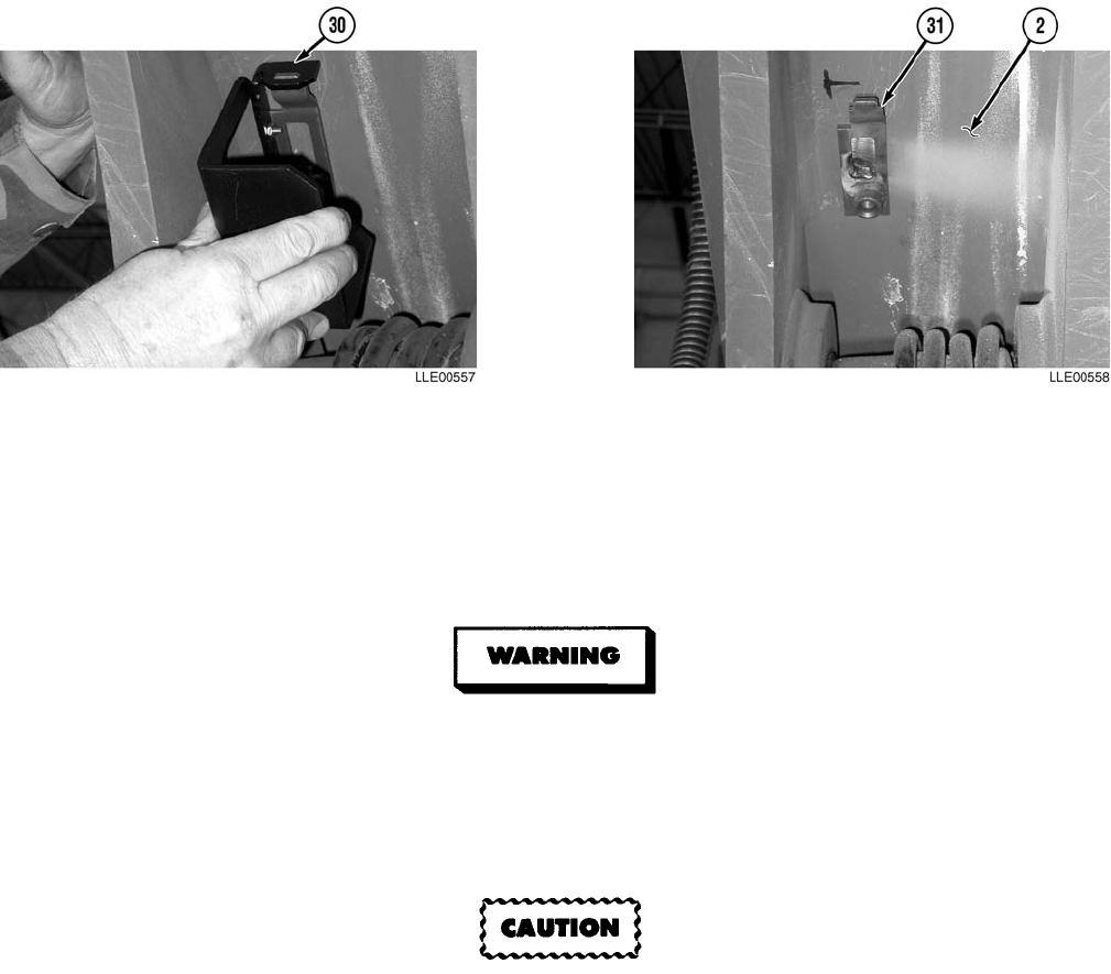
TM 5-6675-348-13&P
4-46
NOTE
For proper fitting and calibration, place Encoder Mounting Bracket’s welded bracket tightly
against the factory weld inside the Arm.
(18) Using the Encoder Mounting Bracket (30), mark position of Encoder Mounting Bracket’s welded
bracket (31), 2 in. (5.1 cm) down from Bucket Valve Adapter Plates and 0.75 in. (2 cm) in from left
side rail.
Unsafe welding practices can cause serious injury from fire, explosions, or harmful agents.
Allow only authorized personnel to weld or cut metals, and follow safety precautions in
TC 9-237. Protective clothing and goggles must be worn, adequate protective equipment
must be used, a suitable fire extinguisher must be kept nearby, and requirements of
TC 9-237 must be strictly followed. Failure to comply may result in serious injury or death
to personnel.
Do not weld across Arm. All welds must run parallel with the Arm. Failure to comply can
cause damage to the Arm.
(19) Weld Encoder Mounting Bracket’s welded bracket (31) to Arm (2).
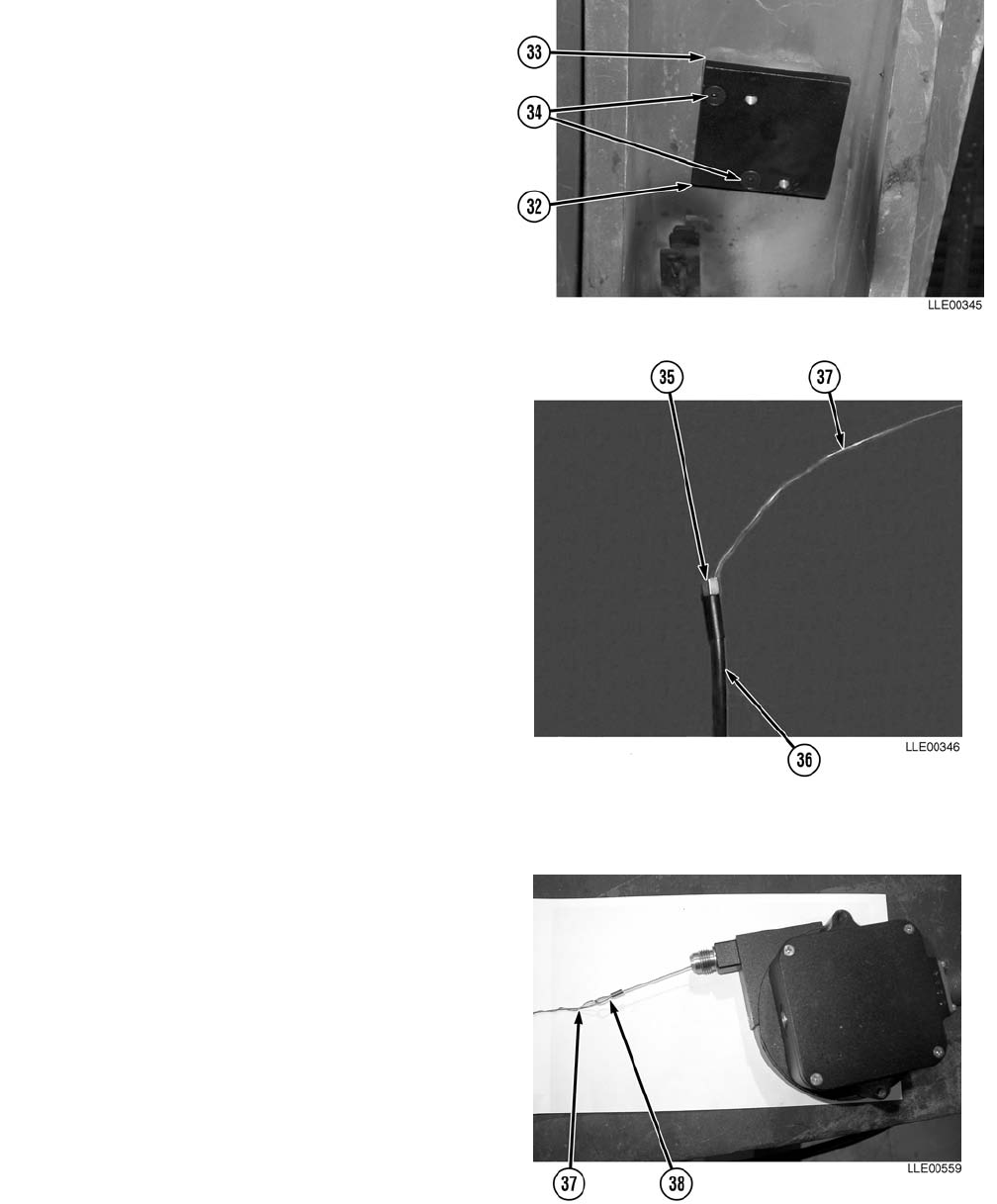
TM 5-6675-348-13&P
4-47
(20) Install Bucket Valve Adapter
Plate (32) to existing Bucket Valve
Mount Plate (33) with two Allen
screws (34).
(21) Install Poly Tube Adapter (35) onto
Poly Tube (36).
(22) Tighten Poly Tube Adapter (35).
NOTE
Bending the end of the Lacing Wire in
a loop will ease the installation
process.
(23) Feed Lacing Wire (37) through Poly
Tube (36).
NOTE
Securely attach Encoder Wire to lacing
wire to prevent Encoder Wire from
retracting back through Poly Tube
Adapter.
(24) Attach Encoder Wire (38) to Lacing
Wire (37).
(25) Pull Lacing Wire (37) and Encoder
Wire (38) through Poly Tube (36) until
Encoder Wire (38) exits Poly Tube (36).
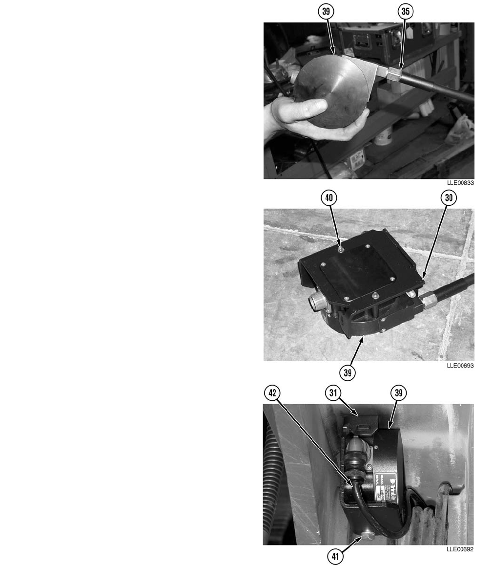
TM 5-6675-348-13&P
4-48
(26) Tighten Poly Tube Adapter (35) onto
Encoder (39).
(27) Install Encoder (39) into Encoder
Mounting Bracket (30) with two
screws (40).
(28) Tighten screws (40).
(29) Install Encoder Mounting Bracket (30)
onto Encoder Mounting Bracket’s welded
bracket (31) with bolt (41).
(30) Tighten bolt (41).
NOTE
Encoder Cable and Arm Sensor Cable
are both routed on the left side of the
Boom.
(31) Install Encoder Cable (42) to Encoder (39).
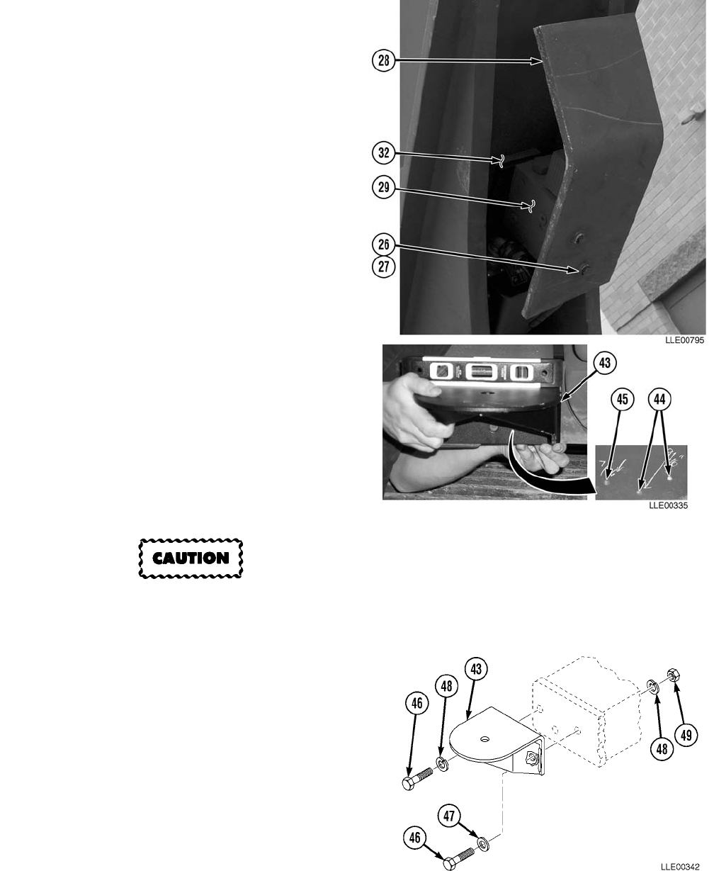
TM 5-6675-348-13&P
4-49
(32) Install Hydraulic Valve (29), Skid
Plate (28), two flat washers (27), and
bolts (26) to Bucket Valve Adapter
Plate (32).
(33) Tighten bolts (26).
NOTE
• Place bottom of the Mast Mounting
Bracket even with the lowest point
and right side on the catwalk.
• The aid of an assistant is required
for Step (34).
(34) Using Mast Mounting Bracket (43), mark
location of mast mount three bolt
holes (44) and (45).
NOTE
For ease of installation, start with a
7/16-in. (11 mm) drill bit and progress
up to 9/16-in. (14 mm) drill bit.
(35) Drill two 9/16-in. (14 mm) holes (44)
and drill one 7/16-in. (11 mm)
hole (45).
(36) Using a 1/2-13NC tap, tap 7/16-in.
(11 mm) hole (45).
Mast Mount must be level side to side
and front to rear. Failure to comply
may result in damage to equipment.
(37) Install Mast Mounting Bracket (43), three
bolts (46), flat washer (47), three
lockwashers (48), and two nuts (49).
(38) Tighten nuts (49) and bolt (46).
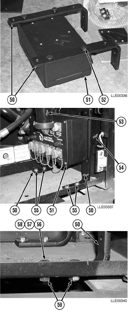
TM 5-6675-348-13&P
4-50
(39) Install two Remote Interface Box
Mounting Brackets (50) onto Remote
Interface Box (51) with four
screws (52).
(40) Tighten screws (52).
(41) Position Remote Interface Box (51),
with Remote Interface Box Mounting
Brackets (50), under Dust
Collector (53) and 6 1/2 in. (16.5 cm)
from Bulkhead (54).
(42) Mark location for mounting holes.
(43) Drill four 1/2-in. (13 mm) holes (55).
(44) Install Remote Interface Box Mounting
Brackets (50) with four bolts (56), flat
washers(57), lockwashers(58), and
nuts (59).
(45) Tighten nuts (59).
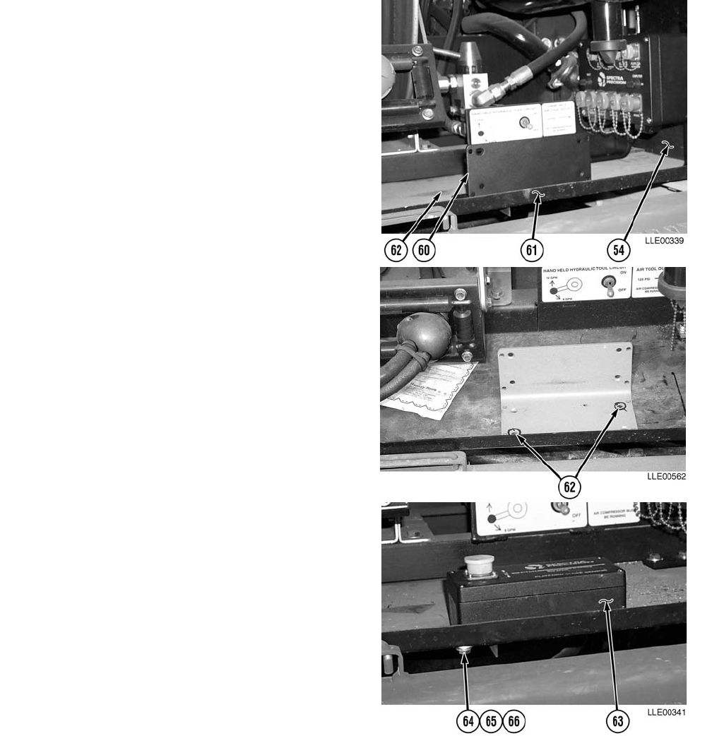
TM 5-6675-348-13&P
4-51
(46) Position Dual-Axis Tilt Sensor Mounting
Bracket (60) 10-1/2 in. (26.7 cm) from
Bulkhead (54) and 1/4 in. (0.64 cm) from
edge of platform (61).
(47) Mark location for mounting holes (62).
(48) Drill two 5/16-in. (8 mm) holes (62).
(49) Discard Slope Sensor Mounting
Bracket (60).
NOTE
Place Electrical Connector toward cab
when Dual-Axis Tilt Sensor is
installed.
(50) Install Dual-Axis Tilt Sensor (63) with
two bolts (64), lockwashers (65), and
flat washers (66).
(51) Tighten bolts (64).
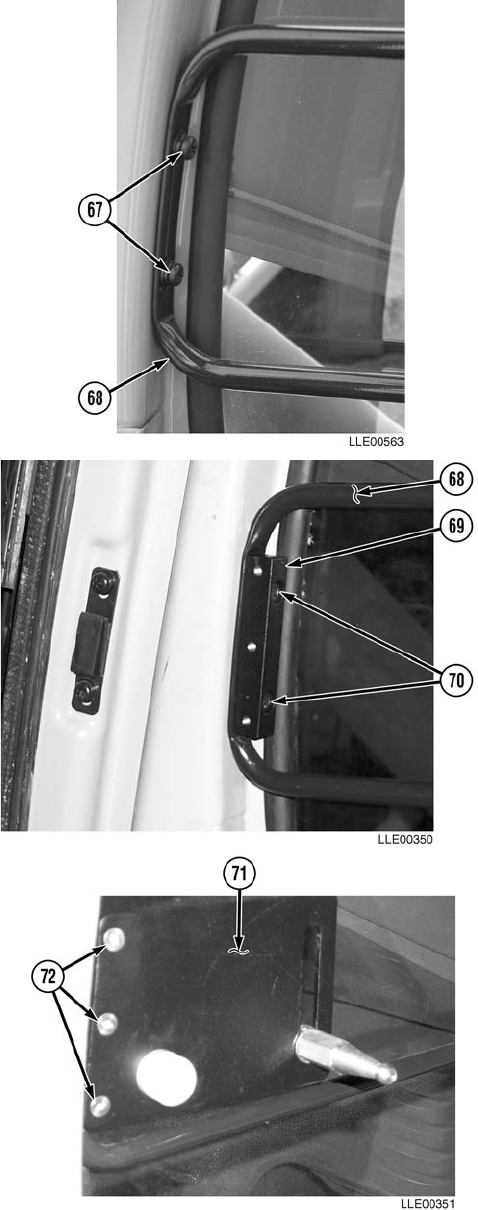
TM 5-6675-348-13&P
4-52
(52) Remove two screws (67) from lower
Side Window Guard (68). Discard
screws (67).
(53) Install Graphic Display Mounting
Block (69) to lower Side Window
Guard (68) with two screws (70).
(54) Install Graphic Display Mounting
Plate (71) on Graphic Display
Mounting Block (69) with three
screws (72).
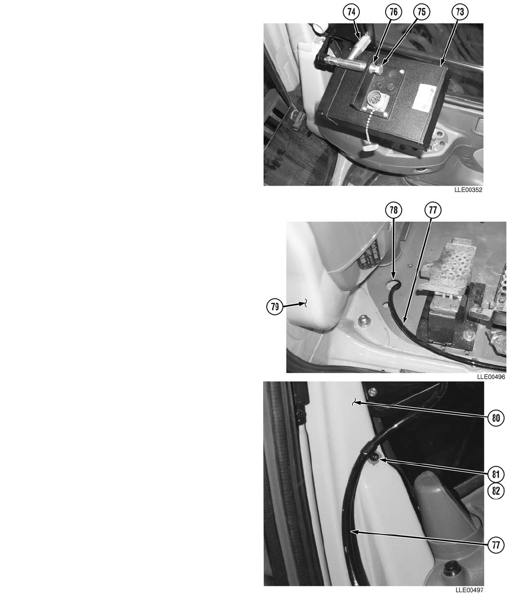
TM 5-6675-348-13&P
4-53
(55) Install Graphic Display (73) onto
Graphic Display Mounting Pin (74)
with screw (75) and washer (76).
NOTE
Before routing Display Cable, pull
back front, right corner of rubber floor
mat.
(56) Route Display Cable (77) through cab
floor (78) and along lower cab
wall (79).
(57) Install Display Cable (77) on upper cab
wall (80) with Loop Clamp (81) and
screw (82).
(58) Tighten screw (82).
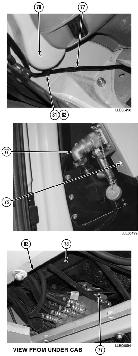
TM 5-6675-348-13&P
4-54
(59) Install Display Cable (77) on lower cab
wall (79) with Loop Clamp (81) and
screw (82).
(60) Tighten screw (82).
(61) Install Display Cable (77) on Graphic
Display (73).
(62) Route Display Cable (77) under cab
floor (78) through front floor
compartment (83).
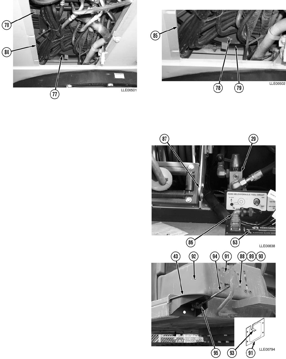
TM 5-6675-348-13&P
4-55
(63) Route Display Cable (77) under cab floor (78) through front center compartment (84).
(64) Route Display Cable (77) under cab floor (78) through rear floor compartment (85).
(65) Route Dual-Axis Tilt Sensor Cable (86)
from rear floor compartment (85) up
through Hydraulic compartment between
Hose Reel (87) and Hydraulic Valve (29).
(66) Install Dual-Axis Tilt Sensor Cable (86)
onto Dual-Axis Tilt Sensor (63).
(67) Remove four locknuts (88), eight
washers (89), four screws (90), and
plate (91) from Stowage Box (92).
Discard locknuts (88).
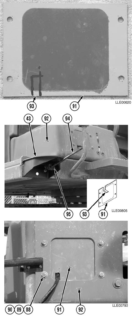
TM 5-6675-348-13&P
4-56
(68) Mark Plate (91) approximately 1 in.
(2.54 cm) upward and approximately 1 in.
(2.54 cm) over from lower left corner.
(69) Cut and bend 1/2-in. (1.3 cm ) tab (93) on
bottom of Plate (91).
(70) Install Mast Cable (94) on Stowage
Bracket (95) of Mast Mounting
Bracket (43).
(71) Route Mast Cable (94) into Stowage
Box (92).
(72) Install Plate (91) on Stowage Box (92) with
four screws (90), eight washers (89), and
four locknuts (88).
(73) Tighten locknuts (88).
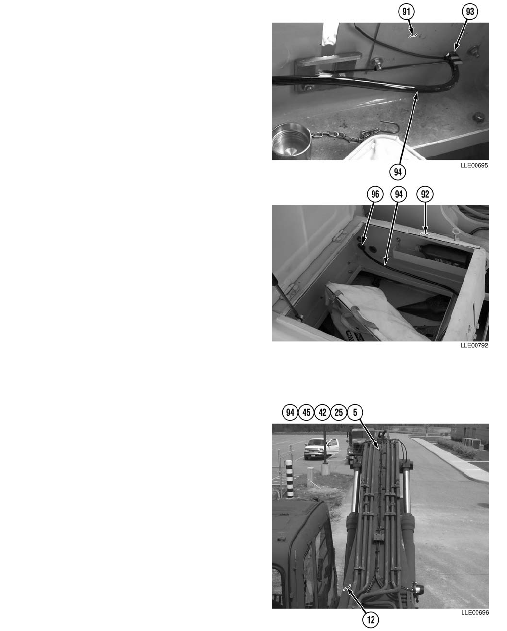
TM 5-6675-348-13&P
4-57
(74) Cable tie Mast Cable (94) to the tab (93) on
bottom of plate (91).
(75) Route Mast Cable (94) around inside lower
edge of Stowage Box (92).
(76) Remove dust plug (96) from left rear side of
Stowage Box (92).
NOTE
Cut cross-cut slit large enough to allow
Mast Cable to be routed through dust plug.
(77) Cut cross-cut slit in center of dust
plug (96).
(78) Route Mast Cable (94) through dust
plug (96) hole.
(79) Install dust plug (96) with Mast Cable (94)
in left rear side of Stowage Box (92).
(80) Route Arm Sensor Cable (5) and
Encoder Cable (42) alongside left-hand
Bucket Cylinder Hydraulic Hose (97)
to base of Boom (12).
(81) Secure Arm Sensor Cable (5) and
Encoder Cable (42) to Bucket Cylinder
Hydraulic Hose (97) with tie wraps
every 6 to 8 in. (15.2 to 20.3 cm).
(82) Route Mast Cable (94) to join Arm
Sensor Cable (5) and Encoder
Cable (42) at base of Boom (12).
(83) From end of cables, measure
approximately 6 ft (1.9 m) of Arm
Sensor Cable (5), Boom Sensor
Cable (25), and Encoder Cable (42)
Loop cables from 6 ft (1.9 m) mark to
base of Boom (12) to create a service
loop.
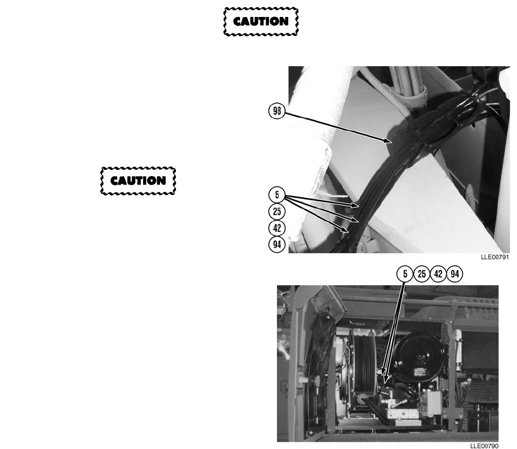
TM 5-6675-348-13&P
4-58
(84) Install cable ties 180 degrees apart on service loop.
(85) Using cable ties, secure service loop to existing John Deere service loop.
Cables must be placed in cable guide or damage to cables may result.
(86) Install Boom Sensor Cable (25), Arm
Sensor Cable (5), Encoder Cable (42),
and Mast Cable (94) in Cable
Guide (98).
(87) Close Cable Guide (98) with three
cable ties.
To prevent damage to cables, ensure
cables are routed clear of hose reel.
(88) Route Boom Sensor Cable (25), Arm
Sensor Cable (5), Encoder Cable (42),
and Mast Cable (94) through frame to
Hydraulic Compartment.
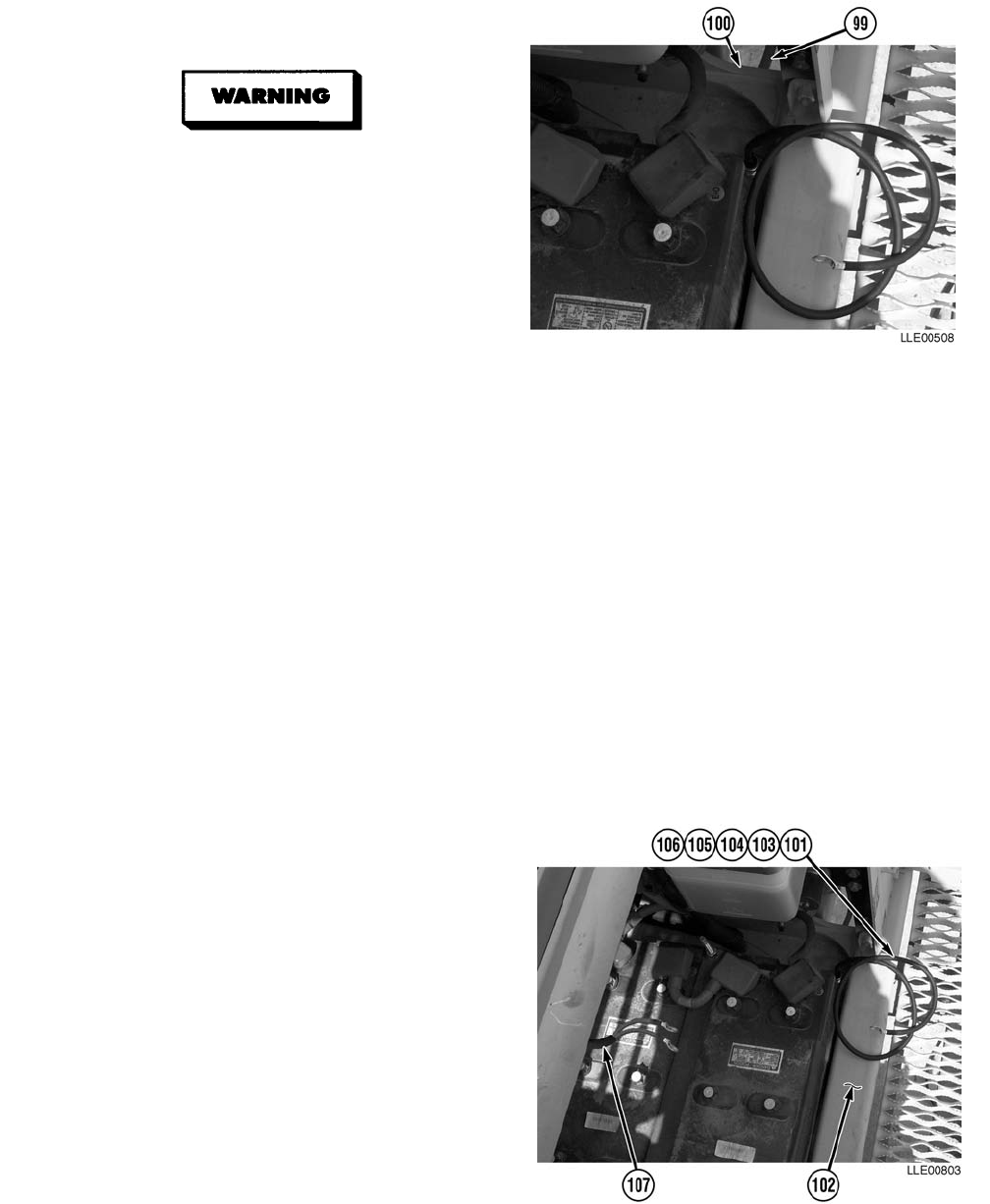
TM 5-6675-348-13&P
4-59
(89) Relocate radiator over flow tube (99) to
other side of Bracket (100).
• CARC paint contains isocyanate
(HDI), which is highly irritating to
skin and respiratory system. High
concentrations of HDI can produce
symptoms of itching and reddening
of skin, a burning sensation in
throat and nose, and watering of
the eyes. In extreme concentra-
tions, HDI can cause cough, short-
ness of breath, pain during
respiration, increased sputum pro-
duction, and chest tightness. The
following precautions must be
taken whenever using CARC paint:
• ALWAYS use air line respirators when using CARC paint, unless air sampling shows
exposure to be below standards. Use chemical cartridge respirator if air sampling is
below standards.
• DO NOT let skin or eyes come in contact with CARC paint. Always wear protective
equipment (gloves, ventilation mask, safety goggles, etc.).
• DO NOT use CARC paint without adequate ventilation.
• NEVER weld or cut CARC-coated materials.
• DO NOT grind or sand painted equipment without high-efficiency air purifying
respirators in use.
• BE AWARE of CARC paint exposure symptoms; symptoms can occur a few days after
initial exposure. Seek medical help immediately if symptoms are detected.
(90) Clean paint and material from hole (101) in
Battery Box (102) using wire brush.
(91) Install Voltage Protection Cable (103) in
hole (101) with lockwasher (104),
washer (105), and nut (106).
(92) Tighten nut (106).
(93) Paint hole (101) with black spray paint.
(94) Route Power Cable (107) to Battery
Box (102).
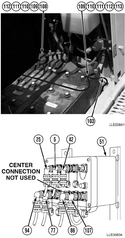
TM 5-6675-348-13&P
4-60
(95) Install Power Cable’s positive (red)
wire (108) on positive Battery Terminal
Clamp (109) with washer (110),
lockwasher (111), and nut (112).
(96) Tighten nut (112).
(97) Coil excess Voltage Protection Cable (103)
in Battery Box (102).
(98) Install Power Cable’s negative (black)
wire (113) and Voltage Protection
Cable (103) on negative Battery Terminal
Clamp (109) with washer (110),
lockwasher (111), and nut (112).
(99) Tighten nut (112).
(100)Coil excess Voltage Protection Cable (103)
in Battery Box (102).
(101) Install Power Cable (107), Boom
Sensor Cable (25), Arm Sensor
Cable (5), Encoder Cable (42), Mast
Cable (94), Display Cable (77), and
Dual-Axis Tilt Sensor Cable (86), on
Remote Interface Box (51).
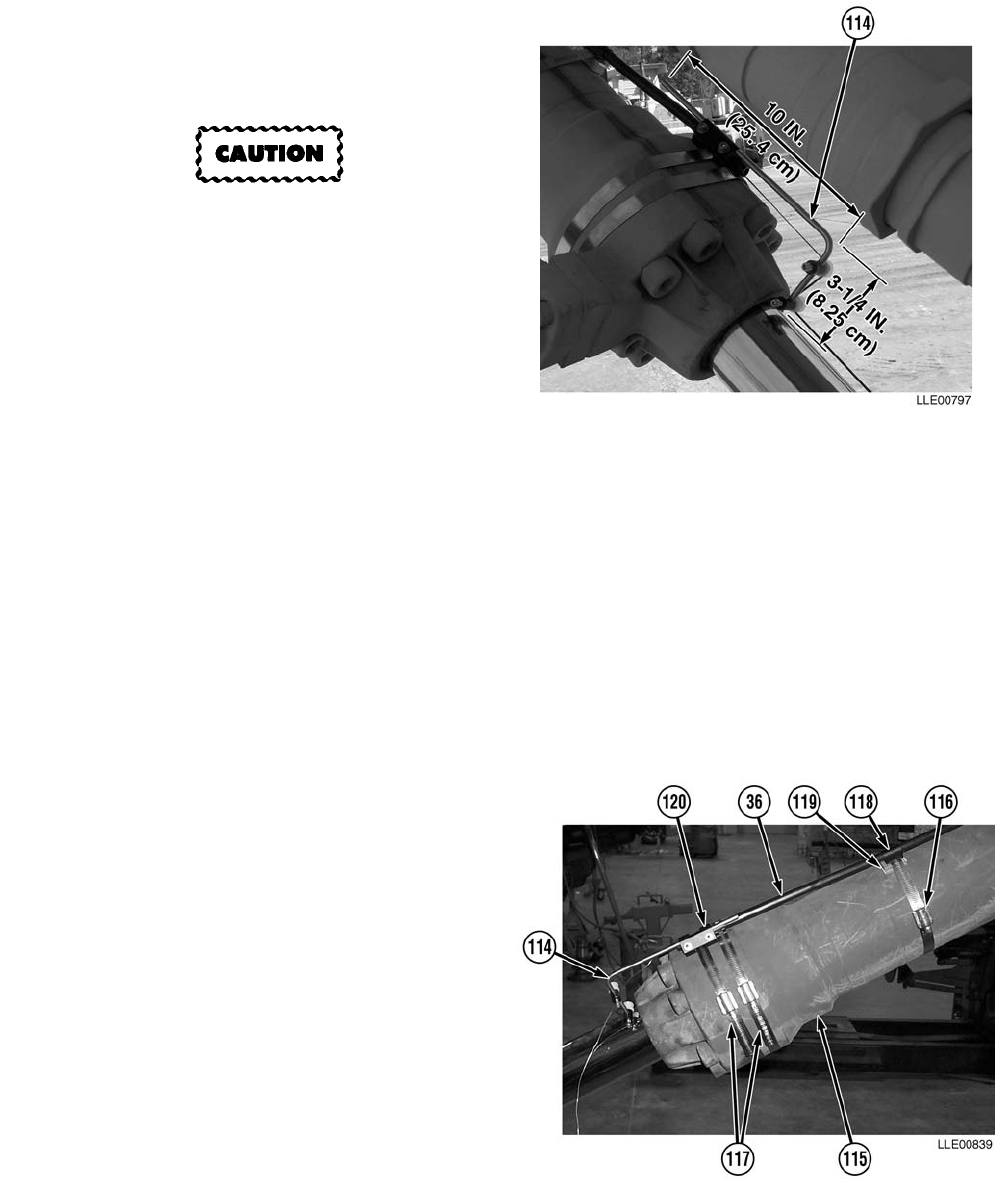
TM 5-6675-348-13&P
4-61
(102) Measure and cut Guide Rod (114) to
3-1/4-inch (8.25 cm) length on short
side and 10-inch (25.4 cm) length on
long side.
Properly position Poly Tube and
Guide Rod for calibration. Align the
Poly Tube and Guide Rod Bracket
straight on the Bucket Cylinder or
damage to equipment may result.
NOTE
• Wedges are used under the Poly
Tube clips and hose clamps to
keep the Poly Tube straight.
• Guide Rod Bracket is installed as
close as possible to the bottom
edge of the Bucket Cylinder.
• When installed properly, with the
Guide Rod Bracket, the Poly Tube
will appear straight in line with
Encoder and offset from
centerline on Bucket Cylinder.
• A combination of large and small
wedges are used to level the Poly
Tube to the Bucket Cylinder.
(103) Install Poly Tube (36) on Bucket
Cylinder (115) with five Hose
Clamps (116), two Hose
Clamps (117), four Poly Tube
Clips (118), wedges (119), and Guide
Rod Bracket (120).
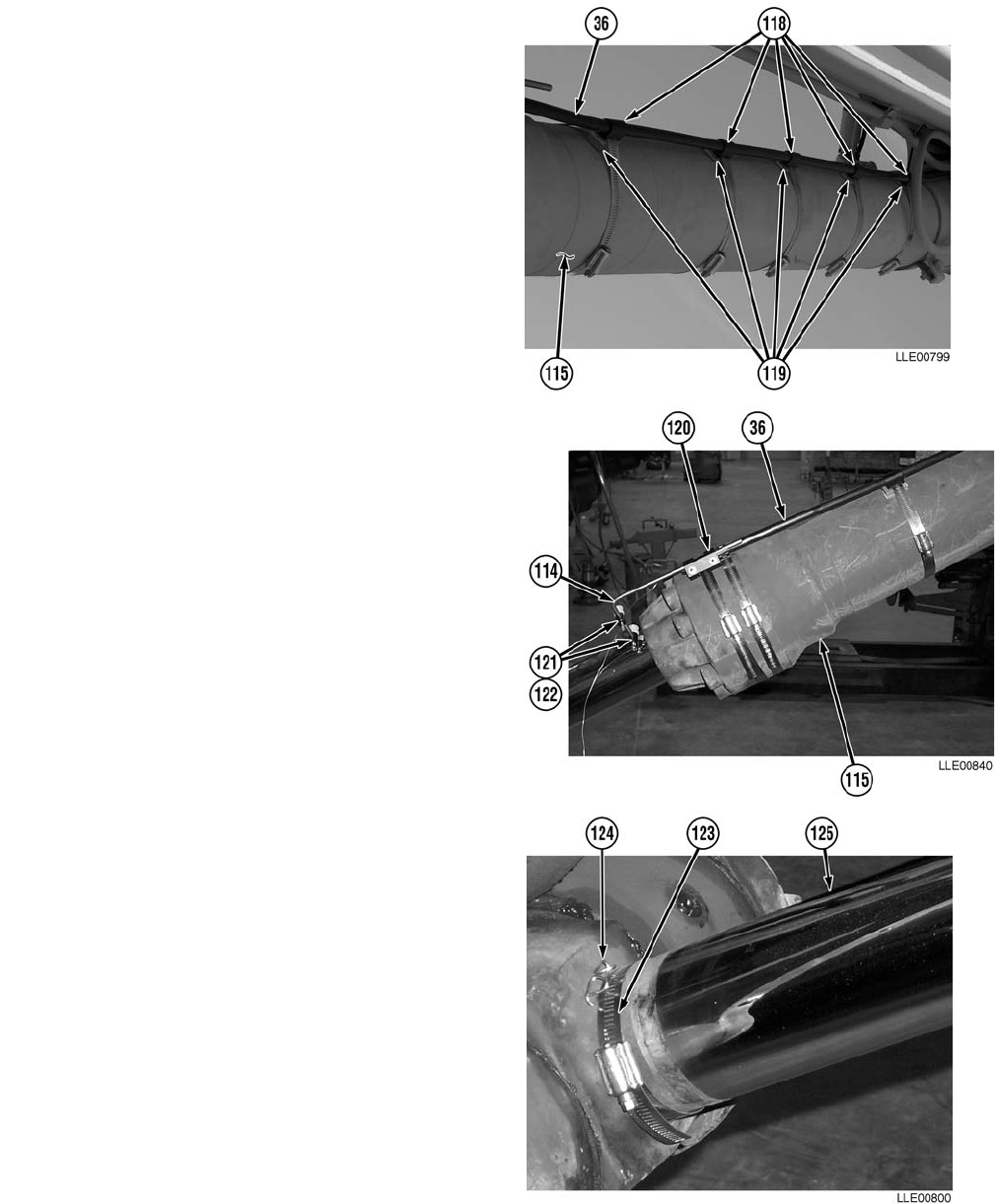
TM 5-6675-348-13&P
4-62
NOTE
Wedges are tapered. Adjust wedges by
positioning smaller end to match wider
end.
(104) Adjust wedges (119) as needed, under
Poly Tube Clips (118) and on Bucket
Cylinder (115) until Poly Tube (36) is
level.
(105) Install two Runners (121) on Guide
Rod (114) with two screws (122).
(106) Tighten screws (122).
NOTE
Poly Tube should appear relatively
straight when functioning properly.
(107) Install Guide Rod (114) in Guide Rod
Bracket (120) with Runners (121) aligned
with Poly Tube (36).
(108) Attach Hose Clamp (123) and Belt
Clip (124) to end of Bucket Cylinder
Ram (125).
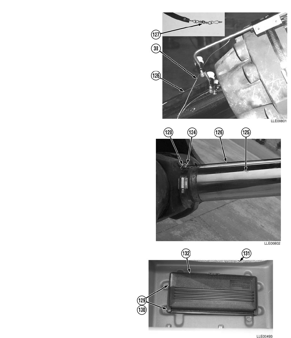
TM 5-6675-348-13&P
4-63
NOTE
• If Encoder Wire is released before
Encoder Web Belt is installed,
Steps (23) through (26) and
Steps (103) through (108) will
need to be repeated.
• Install Encoder Web Belt rough
side out.
(109) Attach Encoder Web Belt (126) to
Encoder Wire (38) using three-link
chain (127).
(110) Attach Rivet end (128) of Web
Belt (126) to Belt Clip (124) at end of
Bucket Cylinder Ram (125).
c. Tool Box.
(1) Measure and cut two hook and
pile strips (129) and apply to
stowage point (130) behind
Operator’s seat (131).
(2) Remove protective paper from
two hook and pile strips (129)
and install tool box (132).
d. Follow-On Maintenance.
(1) Install Belly Plates (Para 4-30) as
required.
(2) Connect Batteries
(TM 5-3805-280-10).
(3) Remove Chocks
(TM 5-3805-280-10).
(4) Perform Bucket-Pro™ System Calibration (Para 4-32).
END OF TASK
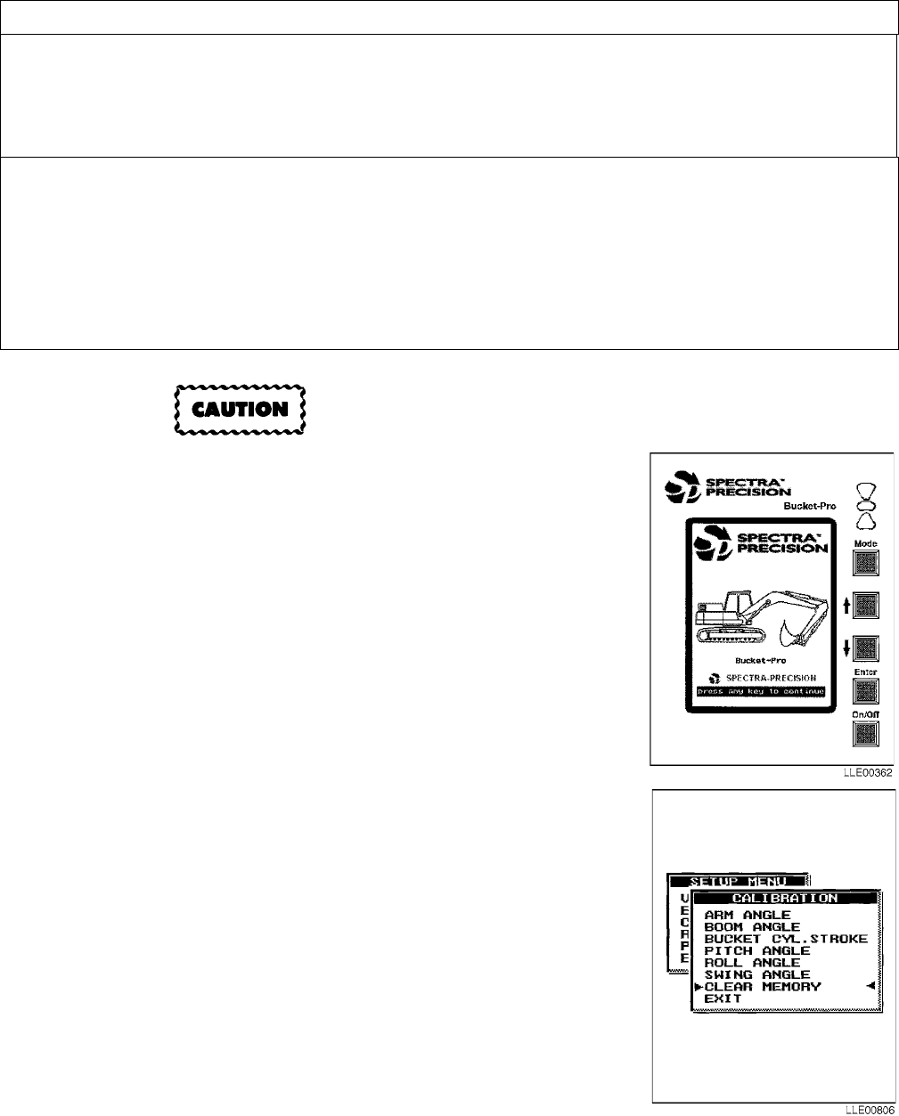
TM 5-6675-348-13&P
4-64
Memory must be cleared before machine
is calibrated. Failure to comply could result
in incorrect calibration.
a. Clear Memory.
(1) Turn on Graphic Display.
(2) Press Down (↓) button twice.
(3) Point menu arrows to SETUP SYSTEM mode, using Down (↓)
button.
(4) Press ENTER button.
(5) To bypass the entry code, press and hold Up and Down (↑↓)
buttons at the same time, while pressing ENTER button.
(6) In SETUP menu, select CALIBRATION.
(7) Press ENTER button.
(8) In CALIBRATION menu, select CLEAR MEMORY.
(9) Press ENTER button.
(10) In the ARE YOU SURE? dialog box, select YES.
(11) Press ENTER button. Bucket-Pro™ System memory is now clear.
(12) Turn off Graphic Display.
(13) To access SETUP MENU and re-enter data, repeat Steps (1)
through (5).
4-32. BUCKET-PRO™ SYSTEM CALIBRATION.
This task covers:
a. Clear Memory. b. System Setup. c. Edit Data.
d. Boom Angle Calibration. e. Arm Angle Calibration. f. Bucket Cylinder Calibration.
g. Pitch Angle Calibration. h. Roll Angle Calibration. i. Follow-On Maintenance.
INITIAL SETUP
Models
Bucket-Pro™ System
Special Tools
ANSI
Personnel Required
MOS 62B
MOS 44B
Equipment Condition
Engine running (TM 5-3805-280-10).
Tracks chocked (TM 5-3805-280-10).
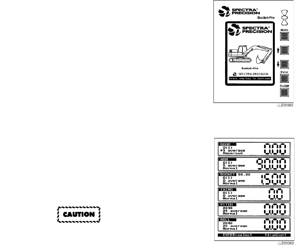
TM 5-6675-348-13&P
4-65
b. System Setup.
Calibration allows the initial setting of all sensors. The calibration settings are then constants in the
Remote Interface Box’s nonvolatile memory. After the initial calibration, the boom and arm sensors self-
align (reset) to a zero reference mark each time the boom and arm are moved through their normal
operating cycle.
(1) Press MODE button to access MAIN MENU.
(2) Point menu arrows to SETUP SYSTEM mode using Up and
Down (↑↓) buttons.
(3) Press ENTER button to confirm selection.
(4) To bypass the entry code, press and hold Up and Down (↑↓)
buttons at the same time, while pressing ENTER button.
NOTE
• VIEW SENSORS allow the raw data
values from the sensors and same
angle or position of the sensors to be
displayed on the screen.
• These values determine proper orienta-
tion and operation of the sensors during
installation and troubleshooting.
(5) Using the Up and Down (↑↓) buttons, select VIEW SENSORS.
(6) Press ENTER button.
(7) Ensure arm and boom averaging are set to 5 and count is
reversed.
(8) Ensure arm angle increases as arm is moved away from
machine frame.
The machine measurements must be entered
before calibrating the system. Failure to enter
the machine measurement before calibration
will cause an incorrect calibration
(9) Ensure boom angle increases as boom is raised.
(10) Ensure bucket counts properly.
(11) Ensure pitch and roll averaging are set to 25 and Normal for starting point.
(12) Ensure Arm and Boom Sensors locate reference mark (I) when machine is operated manually.
(13) Press ENTER button until SETUP menu is displayed.
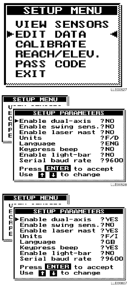
TM 5-6675-348-13&P
4-66
c. Edit Data. This allows the Operator to set up
the system and input dimensions of the
machine.
(1) Enable Dual-Axis.
Selects whether the platform tilt sensor is
turned ON or OFF. If the sensor is off, the
mast-extension elevation to the
bucket-teeth elevation is not compensated
as the machine is pitched or rolled.
(2) Disable Swing Sensor.
This feature is not available.
(3) Enable Laser Mast.
Turns on the mast search and laser
receiver function.
(4) Units.
This feature is for selecting metric (meters/
mm) or U.S. (feet/decimal or feet/inches)
display readouts. The selections are M, F/
D, or F/I.
(5) Language.
This feature is not available.
(6) Keypress Beep.
Keypress Beep turns the audible tone
feature ON/OFF. Select YES to turn on the
audible tone feedback each time a button
is pressed.
(7) Enable Light Bar.
This feature is not available.
(8) Serial Baud Rate.
This feature is not available.
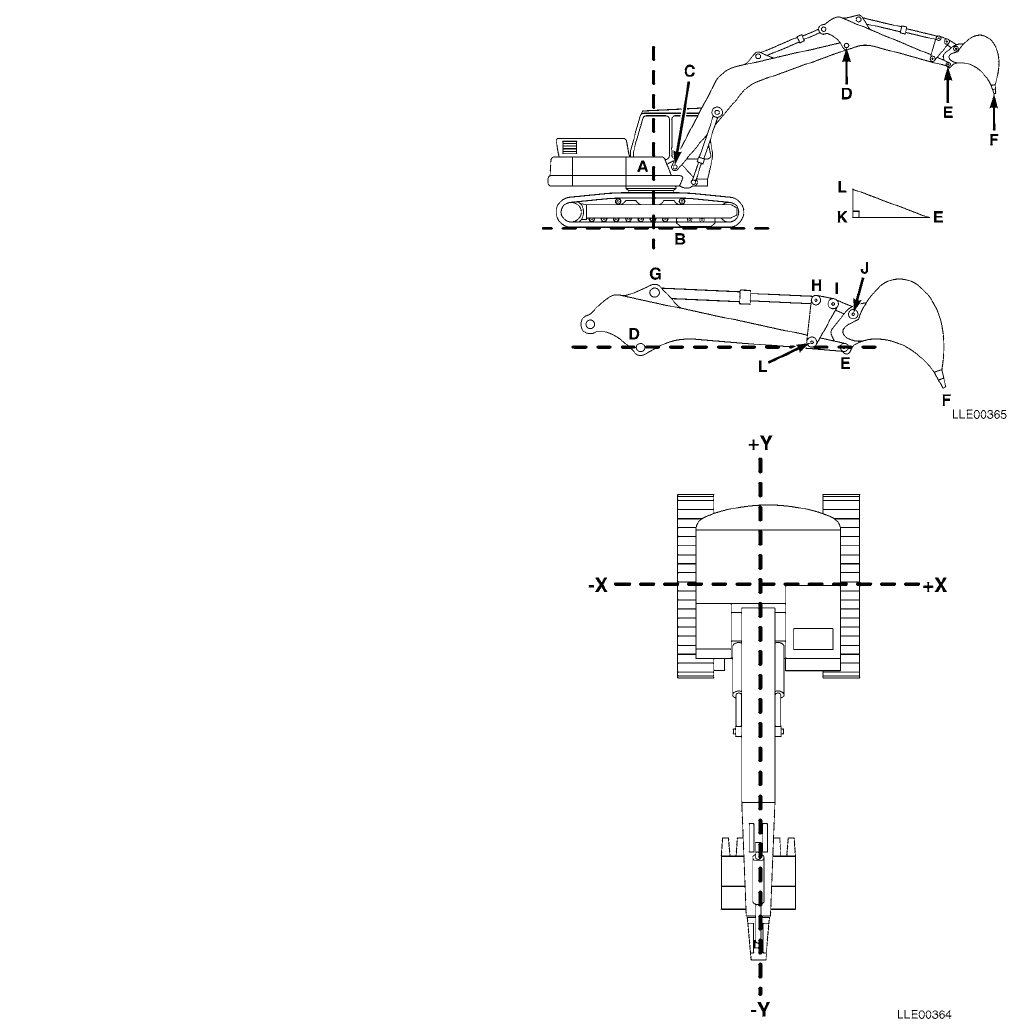
TM 5-6675-348-13&P
4-67
(9) Edit Machine Dimensions.
NOTE
• All dimensions are in meters (m).
• Cylinder Minimum-Maximum difference
cannot exceed 2,000 m.
• Under standard mast placement on
military machine (at front of right-side
catwalk), Mast Bases X, Y, and Z will
always be negative.
• Boom pivot X and Y will always be
positive.
• Bucket dimensions may be different
depending on tooth wear. Reference John
Deere manual.
Boom Length: C-D 6.007
Arm Length: D-E 2.963
Boom Pivot X: A-C 0.195
Boom Pivot Y: B-C 1.887
Control Length 1: L-H 0.618
Control Length 2: H-I 0.000
Control Length 3: I-L 0.618
Link Length: I-J 0.579
Rock Bucket
Bucket Length: E-F 1.675
Bucket Web: E-J 0.474
Bucket Back: J-F 1.840
Cylinder Position 1: G-E 2.661
Cylinder Position 2: G-J 2.213
Control X: K-E 0.457
Control Y: K-L 0.039
Cylinder Min: G-H (Min) 1.664
Cylinder Max: G-H (Max) 2.736
Mast Base X: -1.473
Mast Base Y: -0.662
Mast Base Z: -0.739
Mast Height: 1.665
Mast mm/Pulse: 0.762
Mast Average: 0
Mast Timeout: 60
Ditch Bucket
Bucket Length: 1.238
Bucket Web: 0.475
Bucket Back: 1.437
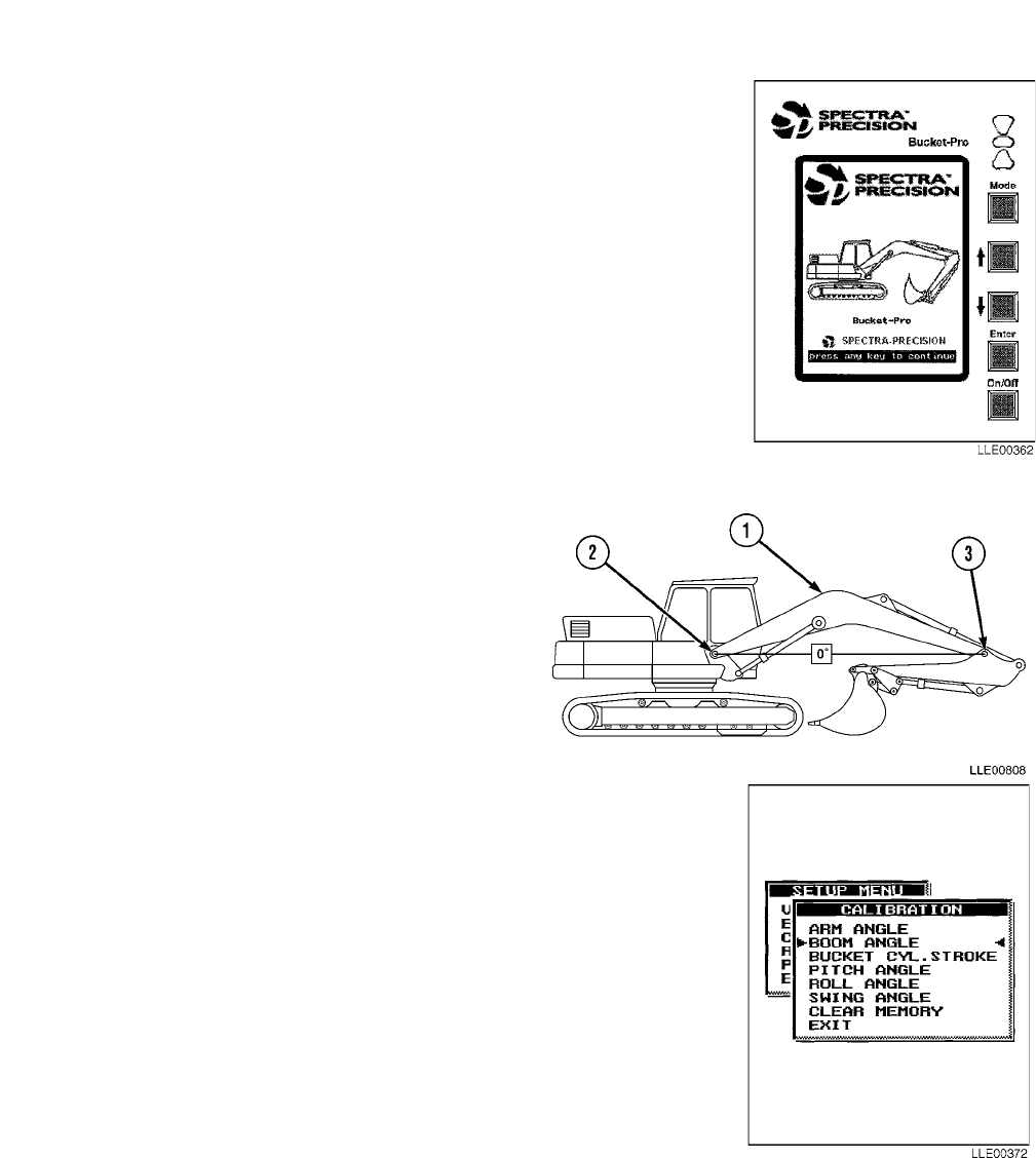
TM 5-6675-348-13&P
4-68
d. Boom Angle Calibration.
NOTE
Before performing boom angle calibration, ensure that system setup has been completed.
(1) In SETUP menu, select CALIBRATION, using Up and
Down (↑↓) buttons.
(2) Press ENTER button.
(3) In CALIBRATION menu, select BOOM ANGLE, using Up and
Down (↑↓) buttons.
NOTE
Boom sensor is correctly indexed when
sensors index mark (?) changes to sensor
index mark (I) on Graphic Display.
(4) Move boom (1) through a range of motion
to ensure boom sensor is indexed.
(5) Using an Automated Integrated Survey
Instrument (AISI), position boom pivot
pin (2) horizontally level with arm pivot
pin (3).
(6) Press ENTER button.
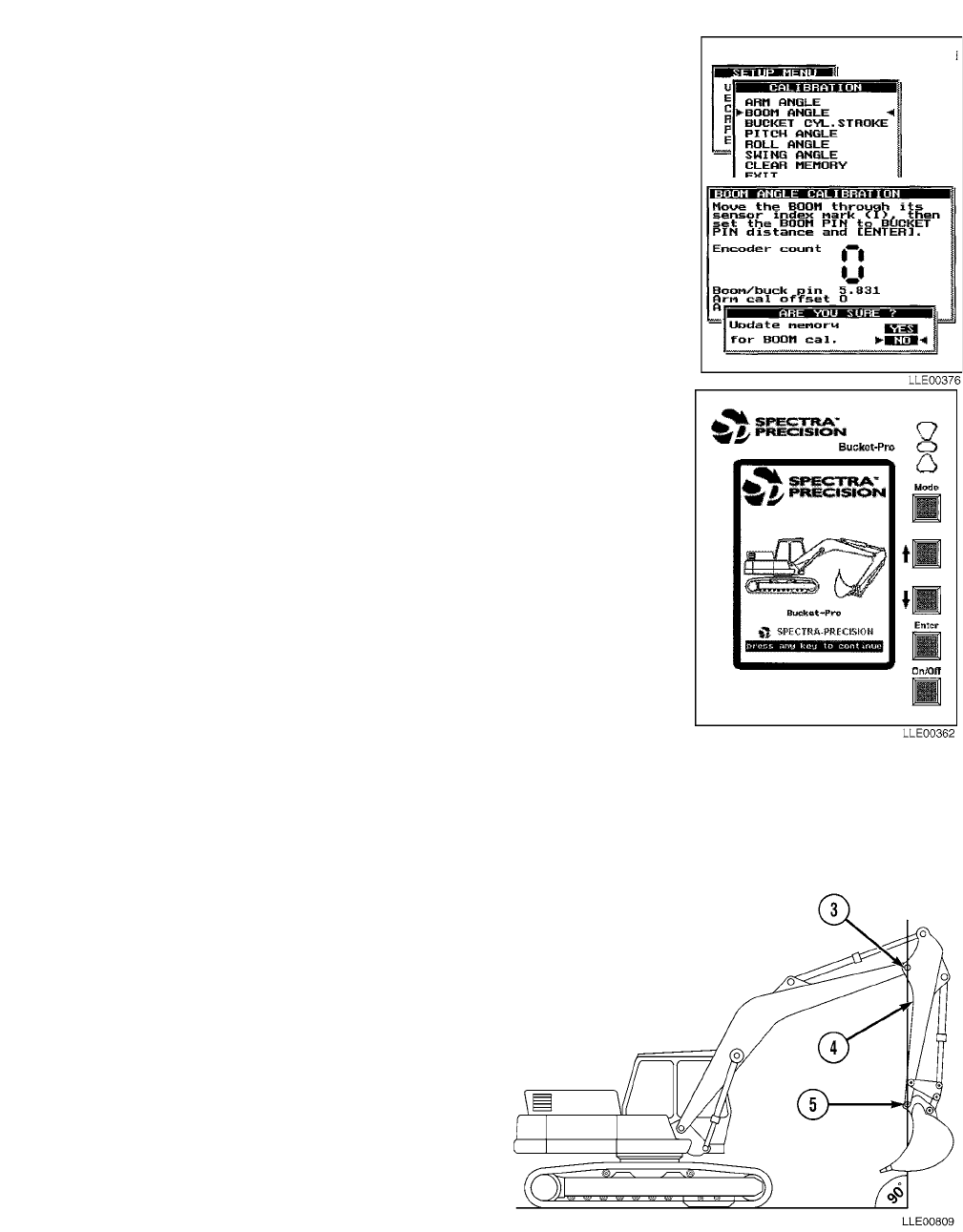
TM 5-6675-348-13&P
4-69
NOTE
The BOOM ANGLE number is used
during troubleshooting.
(7) Record BOOM ANGLE number.
(8) In the ARE YOU SURE? dialog box, select YES, using the Up
and Down (↑↓) buttons, and update data.
e. Arm Angle Calibration.
NOTE
Before performing arm angle calibration,
ensure that system setup has been
completed.
(1) In SETUP menu, select CALIBRATION using the Up
and Down (↑↓) buttons.
(2) Press ENTER button.
(3) In CALIBRATION menu, select ARM ANGLE, using
the Up and Down (↑↓) buttons.
NOTE
Arm sensor is correctly indexed when
sensor index mark (?) changes to sensor
index mark (I) on Graphic Display.
(4) Move arm (4) through a range of motion
to ensure arm sensor is indexed.
(5) Using an AISI, position arm pivot pin (3)
directly vertical over bucket pivot pin (5).
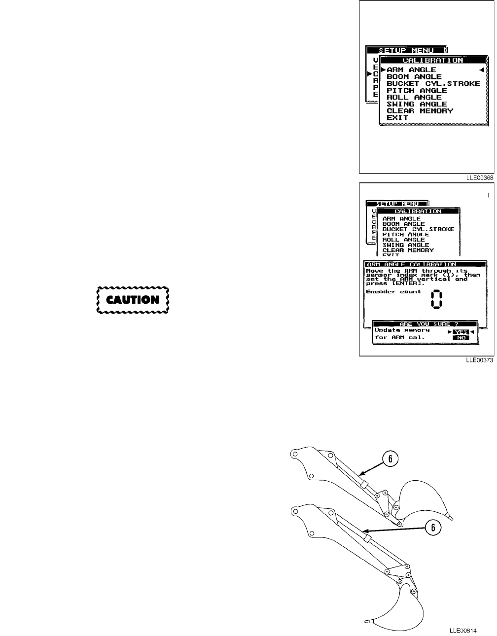
TM 5-6675-348-13&P
4-70
(6) Press ENTER button.
NOTE
The ARM ANGLE number is used
during troublshooting.
(7) Record ARM ANGLE number.
(8) In the ARE YOU SURE? dialog box, select YES, using the Up
and Down (↑↓) buttons, and update data.
f. Bucket Cylinder Calibration.
Do not strike cylinder against end stops
when retracting and extending, or damage
to equipment may result.
NOTE
Bucket cylinder calibration divides bucket
cylinder length into increments and linkage
measurements to calculate rotated position
of bucket teeth.
(1) Perform smooth extend and retract
movements of bucket cylinder (6).

TM 5-6675-348-13&P
4-71
NOTE
Maximum bucket-cylinder stroke is limited to
6 ft 6 and 23/32 in. (2.000 m). Greater length
than this may cause a display failure to
respond.
(2) Select BUCKET CYL. STROKE
CALIBRATION.
(3) Fully extend bucket cylinder (6) to curl
bucket (7) under.
(4) Press ENTER button.
(5) In the ARE YOU SURE? dialog box, select
YES, using the Up and Down (↑↓)
buttons, and update data.

TM 5-6675-348-13&P
4-72
g. Pitch Angle Calibration.
NOTE
Dual-Axis Tilt Sensor compensates
EM2E-24 Electric Mast height for
grade elevation as machine attitude
changes, by rotating the machine
180 degrees.
(1) Select PITCH ANGLE. Align frame of
machine parallel to tracks, using
swing control.
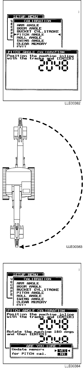
TM 5-6675-348-13&P
4-73
(2) Press ENTER button.
(3) Rotate frame of machine and align
frame parallel to tracks, using swing
control.
(4) Press ENTER button again.
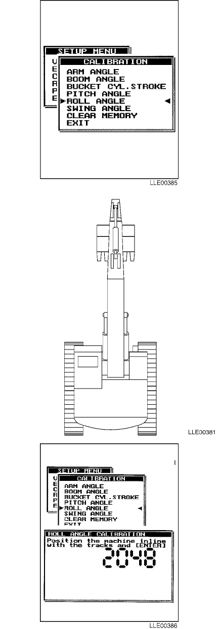
TM 5-6675-348-13&P
4-74
h. Roll Angle Calibration.
(1) Select ROLL ANGLE.
(2) Align frame of machine parallel to
tracks, using swing control.
(3) Press ENTER button.
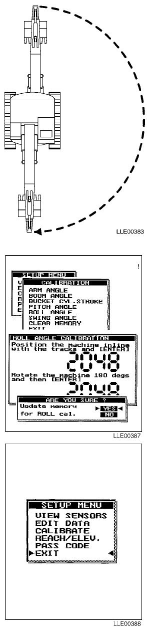
TM 5-6675-348-13&P
4-75/(4-76 Blank)
(4) Rotate frame of machine, using swing
control.
(5) Align frame of machine parallel to
tracks, using swing control.
(6) Press ENTER button again.
(7) Select EXIT.
(8) Press ENTER button.
i. Follow-On Maintenance.
(1) Turn OFF engine (TM 5-3805-280-10).
(2) Remove chocks (TM 5-3805-280-10).
END OF TASK
TM 5-6675-348-13&P
5-1
CHAPTER 5
1145-2 LASER TRANSMITTER, 1275 LASER RECEIVER, AND
ELEVATING BASE AND TRIPOD, USED WITH 130G GRADER,
D7F, D7G, D7H, AND D7R DOZERS,
613B AND 621B SCRAPERS, AND HYEX
Content Para Page
General Information ............................................................................................................. Section I 5-1
Scope........................................................................................................................................... 5-1 5-1
1145-2 Laser Transmitter Equipment Characteristics, Capabilities, and Features ............. 5-2 5-1
1145-2 Laser Transmitter Location and Description of Major Components.......................... 5-3 5-2
1275 Laser Receiver Location and Description of Major Components................................... 5-4 5-8
Elevating Base and Tripod Location and Description of Major Components ........................ 5-5 5-11
Bucket-Pro™ System Laser Operation .................................................................................... 5-6 5-12
1145-2 Laser Transmitter, 1275 Laser Receiver, and Elevating Base and
Tripod PMCS................................................................................................................... Section II 5-15
PMCS Introduction.................................................................................................................... 5-7 5-15
PMCS Procedures...................................................................................................................... 5-8 5-15
Shortened Maintenance Instructions....................................................................................... 5-9 5-16
Additional Maintenance Inspections...................................................................................... 5-10 5-17
Leakage Classification and Definition.................................................................................... 5-11 5-17
General Lubrication Instructions ........................................................................................... 5-12 5-17
PMCS Column Entry Explanation ......................................................................................... 5-13 5-17
1145-2 Laser Transmitter, 1275 Laser Receiver, and Elevating Base and
Tripod System Operator’s PMCS Table ............................................................................. 5-14 5-18
Operation............................................................................................................................ Section III 5-19
1145-2 Laser Transmitter Adjustment................................................................................... 5-15 5-19
1145-2 Laser Transmitter Calibration................................................................................... 5-16 5-19
Elevating Base and Tripod Assembly and Operation............................................................ 5-17 5-21
1145-2 Laser Transmitter Troubleshooting ..................................................................... Section IV 5-27
1145-2 Laser Transmitter and 1275 Laser Receiver Storage and Transportation.............. 5-18 5-31
SECTION I. GENERAL INFORMATION
5-1. SCOPE.
This chapter contains operation, maintenance, safety, and service information on the 1145-2 Laser Transmit-
ter and 1275 Laser Receiver. The 1275 Laser Receiver is a portable, battery-operated device that locates the
elevation of a rotating laser beam. Hand-held or rod-mounted, the 1275 Laser Receiver indicates its position
via a nine-channel LCD or with synchronous audible tones. The 1145-2 Laser Transmitter is used with the
1275 Laser Receiver.
5-2. 1145-2 LASER TRANSMITTER EQUIPMENT CHARACTERISTICS, CAPABILITIES, AND
FEATURES.
a. Characteristics. 1145-2 Laser Transmitter provides a reference plane of light above a job site. The
1145-2 Laser Transmitter is capable of generating slope in two axes for optimum control of drainage.

TM 5-6675-348-13&P
5-2
b. Capabilities. The 1145-2 Laser Transmitter electronically self-levels to within +5 degrees, whenever it
is rough leveled. The Early Warning System shuts off the laser beam if the laser setup is knocked out of
level and it turns back on again only after the electronic self-leveling system has releveled the laser
beam.
The 1145-2 Laser Transmitter is designed for use at distances up to 1000 ft (305 m). Beyond this distance,
curvature of the earth becomes a consideration. Error from the earth’s curvature affects a 1145-2 Laser
Transmitter the way it does a surveying instrument. Elevation readings at long distances will appear lower
than they actually are. The following table shows amount of error for a straight line of sight due to curvature
of the earth.
Do not look into 1145-2 Laser Transmitter for a long period of time. Failure to comply may
cause injury to personnel.
c. Features. The 1145-2 Laser Transmitter projects a beam of infrared laser light produced by a
battery-operated diode laser. The beam of light rotates at 600 rpm and establishes a flat reference
plane over a work area. The reference plane of light can be tilted up to 9.99% grade in two axes that are
perpendicular to each other. The system electronically self-levels at any combination of grade settings
preset by the user. If the 1145-2 Laser Transmitter is disturbed, the laser beam automatically shuts off
until it has releveled. The 1145-2 Laser Transmitter, with dual axes, provides precise reference
automatically for control of compound grades on a job site.
5-3. 1145-2 LASER TRANSMITTER LOCATION AND DESCRIPTION OF MAJOR COMPONENTS.
a. 1145-2 Laser Transmitter Characteristics.
The 1145-2 Laser Transmitter operating temperature range is -4 to 120° F (-20 to 49° C) and storage temper-
ature range is -40 to 140° F (-40 to 60° C).
500 ft (152 m) 0.005 ft (0.0015 m)
1000 ft (305 m) 0.02 ft (0.0060 m)
1500 ft (457 m) 0.05 ft (0.0152 m)
2000 ft (610 m) 0.08 ft (0.0244 m)
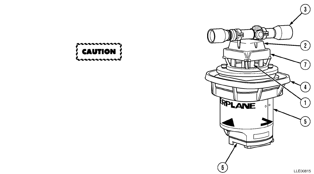
TM 5-6675-348-13&P
5-3
(1) ROTOR PENTAMIRROR ASSEMBLY. Contains a
spinning optical pentamirror, rotating at 600 rpm,
that projects the laser beam over a job site.
(2) UPPER HOUSING ASSEMBLY. Protects the
precision optics in the pentamirror assembly from
being damaged by swinging objects or being
dropped, and from wind-blown dust and rain.
(3) SIGHTING TELESCOPE. Permits precision
alignment of both grade axes when the 1145-2
Laser Transmitter is set up over the benchmark.
Sighting telescope mounting rings fit into grooves
on the upper housing assembly (2).
The 1145-2 Laser Transmitter should never be
carried by sighting telescope or upper housing
assembly. Failure to comply will damage the laser.
(4) CARRYING HANDLE. Used to transport 1145-2
Laser Transmitter and mount on accessory tripod
system.
(5) HOUSING. Provides enclosure for leveling system
to protect from rough handling and damage
suffered on busy job sites.
(6) BOTTOM MOUNTING PLATE. Includes a
quick-disconnect adapter.
(7) SHUTTERS. Block transmission of laser beam
when lowered over upper housing assembly
windows.

TM 5-6675-348-13&P
5-4
(8) CONTROL SWITCH. Used to establish the
1145-2 Laser Transmitter’s mode of operation.
aWhen the Control Switch is set to the AUTO
position, the electronic self-leveling system is
activated and the laser beam will not turn on
until it is level.
bWhen the Control Switch is set to the OFF/
CHARGE position, the system is shut off and
the internal battery-charging mode is acti-
vated.
cWhen the Control Switch is set to the MAN-
UAL position, the 1145-2 Laser Transmitter
remains in the last leveled position.
NOTE
The electronic self-leveling system
and early warning system are over-
ridden in MANUAL position so the
laser beam stays on no matter what
position the outer housing of the
1145-2 Laser Transmitter may be in.
This allows the 1145-2 Laser Transmitter
to be manually adjusted into greater than
9.99% slopes in unusual steep slope
conditions.
(9) AUTO-LEVEL INDICATOR LAMP. Flashes when
the 1145-2 Laser Transmitter is in AUTO mode
and the laser is not level. The indicator lamp
stops flashing when the electronic self-leveling
system has releveled the laser beam. The
indicator lamp stays on when the 1145-2 Laser
Transmitter is in MANUAL mode.
(10) GRADE ADJUST KNOB. Used to adjust “Y” axis
(open legged triangle).
(11) TRIPOD INTERFACE. The quick-connect adapter
connects the 1145-2 Laser Transmitter to the elevating base and tripod.
(12) STANDING FEET. Provide three-point contact when the 1145-2 Laser Transmitter is set on flat
surface, such as a wall top or other setup where a tripod is not being used.
(13) WARRANTY STICKER. A seal put over one Bottom Mounting Plate hold-down screw, used to
determine if unauthorized service has been performed on the 1145-2 Laser Transmitter.
(14) FINE THREAD ADJUSTING KNOB. An adjustment screw used for precise alignment of 1145-2
Laser Transmitter and sighting telescope to forward point of predetermined line when the
1145-2 Laser Transmitter is set up over benchmark.

TM 5-6675-348-13&P
5-5
(15) BREATHER VENT. Allows rapid evaporation
of any accumulated moisture caused when
1145-2 Laser Transmitter passes through
dew point.
(16) LOW VOLTAGE INDICATOR LAMP. A red
LED miniature warning lamp that flashes
when the 6-Vdc internal battery falls below
the safe operating voltage. The Low Voltage
Indicator Lamp stays on continuously when
transmitter is hooked to 12-Vdc external
battery, to warn that external battery has
discharged below safe operating voltage.
Laser beam automatically shuts off and
rotor pentamirror assembly stops rotating
when Low Voltage Indicator Lamp comes on.
At 60° F (16° C), battery operating time is
approximately 40 hours after battery has
been charged for 16 hours.
Do not connect the 1145-2 Laser Transmitter to a 24 Vdc charging system or damage to
equipment will result.
(17) POWER/CHARGER CONNECTOR. Receptacle for all external electrical connections. When control
switch is in OFF/Change position the internal battery charging circuit is activated. Internal
battery can be charged from the 110-/220-Vac Wall Outlet Charger or from a 12-Vdc external
vehicle battery. The 12-Vdc charging options allow you to charge the 6-Vdc internal battery from
your truck battery on remote job sites where AC electrical power is not readily available. Maximum
charge and longest battery life occurs when internal battery is charged frequently between 60° F
and 90° F (16° C and 32° C).
(18) “X” AXIS INDICATOR. A solid triangle on two sides of the 1145-2 Laser Transmitter case.
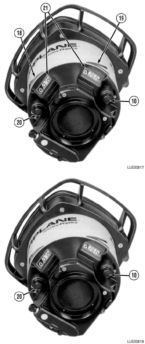
TM 5-6675-348-13&P
5-6
(19) “Y” AXIS INDICATOR. The “Y” axis
indicator is an open-legged triangle that
shows orientations of opposite grade axes.
(20) GRADE ADJUST KNOB. Used to adjust
the “X” axis slope percentage of grade
(solid triangle).
(21) GRADE COUNTER WINDOW. Has large
numerals, a decimal point, and a grade
reading indicator. Windows are tilted
downward at an angle so grade readings
are easily visible from ground level even
when tallest tripod legs are used.
b. Operation and Grade Axis Orientation.
(1) Notice relationship of “X” axis (20) and
“Y” axis (10) Grade Adjust Knobs,
Grade Counter Windows, and triangles
on transmitter housing. A solid
triangle indicates “X” axis and an open
triangle indicates “Y” axis.
(2) “Y” AXIS GRADE ADJUST KNOB
showing position of Grade Adjust
Knob, Grade Counter Window, and
Open Legged “Y” Axis Triangle on
housing.
(3) 1145-2 Laser Transmitter has two
grade axes that are marked, and when
entering the desired grade into the
rotating beam, the grade axis must be
aligned in the direction of the desired
slope. This is accomplished by sighting
through the telescope mounted on top
of the 1145-2 Laser Transmitter or
sighting along the “V” groove in the top
cover. When one grade axis is on
desired line, opposite axis will be
perpendicular. Large solid and
open-legged triangles painted on side
of unit housing indicate UP SLOPE
and DOWN SLOPE direction. Sample
grade readings.
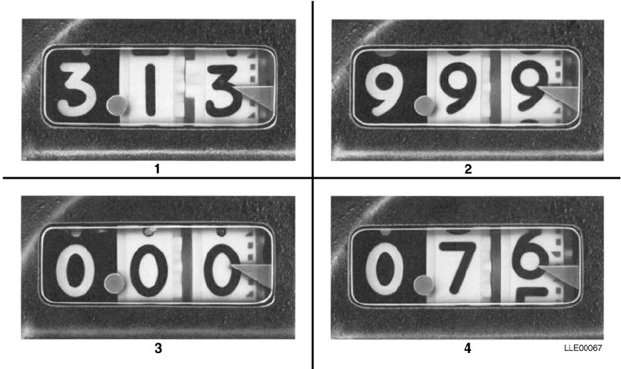
TM 5-6675-348-13&P
5-7
(4) Notice indicator marks on white outside grade counter wheel look just like marks on a typical
grade rod. The large decimal point is easily visible from ground. Here are some sample % grade
readings: (1) = 3.13%, (2) = 9.99%, (3) = 0.00%, and (4) = 0.758%.
c. 1145-2 Laser Transmitter Maintenance.
Your 1145-2 Laser Transmitter is a rugged construction tool that has met rigorous qualification tests more
severe than it will ever see in normal use on a job site. It will require little maintenance and give long years of
good service if it is properly cared for like any piece of valuable equipment. To ensure trouble-free operation,
follow these simple procedures:
(1) Always store and transport 1145-2 Laser Transmitter in its carrying case. When transporting
1145-2 Laser Transmitter in a vehicle, ensure 1145-2 Laser Transmitter is secured.
(2) Extended storage, such as for winter months, should be in a dry, heated place.
(3) Keep power cord connector clean.
(4) Clean windows with a clean, lint-free cloth and light glass-cleaning solvent. Do not use harsh
solvents that are strong enough to dissolve plastic compounds, such as solvents containing acetone,
trichloroethylene, etc.
(5) Never wipe windows with a dry cloth or your fingers, as you may scratch the windows.
(6) Never allow mud, rocks, concrete, or water to get on foam rubber shock-absorbing pads in carrying
case. Always close the carrying case after you have completed setting up the unit.
(7) Repair frayed and cracked electrical cables immediately. Be careful not to pinch electrical cords in
sides of the carrying case.
(8) Sighting telescope should be treated with the same care as the 1145-2 Laser Transmitter.
(9) Keep bottom mounting plate free of dirt and debris. Keep threads clean and ensure proper
engagement of threaded adapters. If this is not done, 1145-2 Laser Transmitter may not tighten
securely to Elevating Base and will be susceptible to ground vibration and wind.
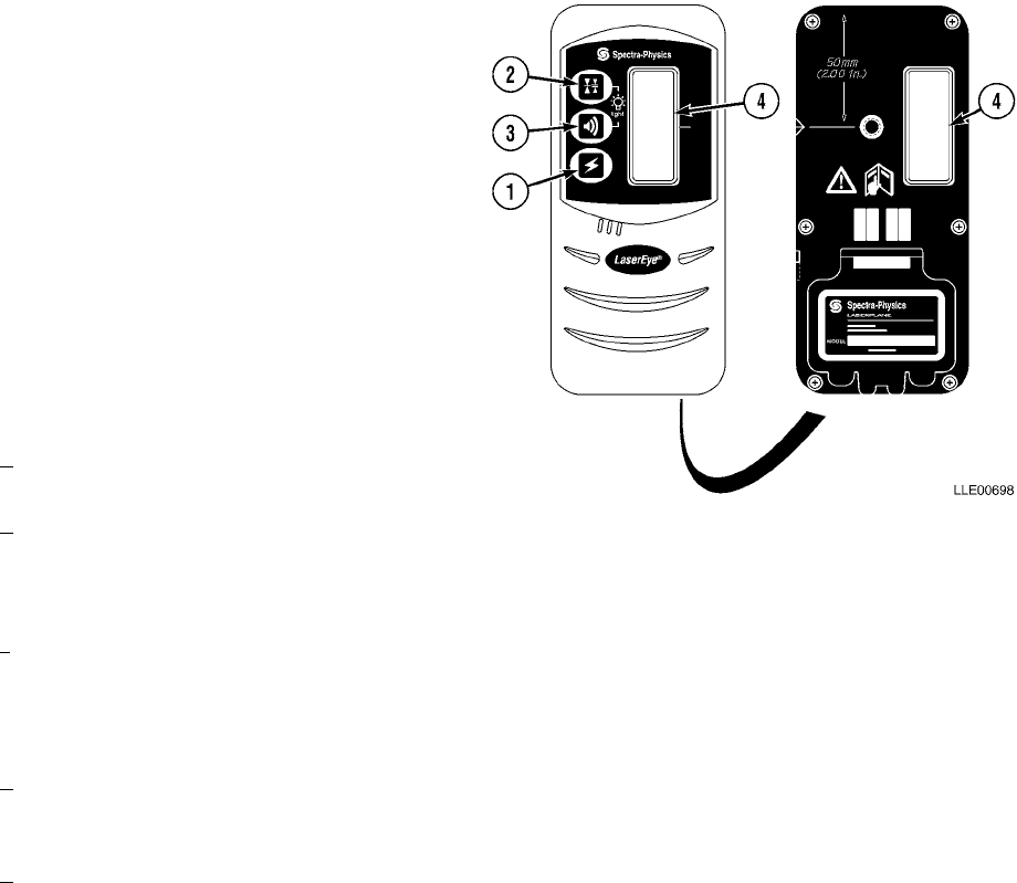
TM 5-6675-348-13&P
5-8
(10) After extended storage (3 months or more), the 1145-2 Laser Transmitter’s internal battery should
be charged for 24 to 48 hours.
(11) Battery life is extended by frequent charging. We recommend charging overnight every other night.
5-4. 1275 LASER RECEIVER LOCATION AND DESCRIPTION OF MAJOR COMPONENTS.
a. 1275 Laser Receiver Characteristics.
The 1275 Laser Receiver is a battery-operated, hand-held laser receiver designed to detect a rotating laser
beam and provide other functions as described below. The 1275 Laser Receiver operating temperature range
is -4° F to 122° F (-20° C to 50° C) and storage temperature range is -4° F to -158° F (-20° C to 70° C).
(1) POWER BUTTON. Turns the 1275 Laser
Receiver ON and OFF.
When turned on, the 1275 Laser Receiver displays
information about elevation, on-grade sensitivity,
audio status, low-battery condition, and back light-
ing.
(2) ON-GRADE SENSITIVITY BUTTON.
Changes the 1275 Laser Receiver’s
on-grade sensitivity.
Ultra Fine (1) 0.0 in. (0.0 cm)
Super Fine (2) 1/32 in. (0.08 cm)
Fine 1/16 in. (0.16 cm)
Medium 1/8 in. (0.32 cm)
Coarse 1/4 in. (0.64 cm)
aThe Graphic Display shows which sen-
sitivity is selected.
bSimultaneously pressing 1275 Laser
Receiver power and on-grade sensitiv-
ity buttons while the 1275 Laser Receiver is powering up configures 1275 Laser Receiver for a
0.0-in. (0.0 cm) on-grade sensitivity.
cThe 1275 Laser Receiver can also be service center configured for a 1/32-in. (0.79 cm) on-grade
sensitivity.
(3) AUDIO BUTTON AND SOUNDER. Turns the 1275 Laser Receiver audio sounder to Loud, Soft, or
OFF.
aThe 1275 Laser Receiver always turns ON with audio set to OFF. The 1275 Laser Receiver beeps
quickly when receiver is slightly above laser beam, slowly when below it, and continuously when
centered in laser plane or on grade.
bSimultaneously pressing the 1275 Laser Receiver’s power and audio buttons while the 1275
Laser Receiver is powering up configures the 1275 Laser Receiver to have Audio/On-Grade off
for applications where the 1275 Laser Receiver is used for monitoring.
(4) FRONT AND BACK LIQUID CRYSTAL DISPLAYS (LCD). Provide information about elevation,
on-grade sensitivity, audio status, low-battery and transmitter out-of-level conditions, and back
lighting.
Simultaneously pressing all three receiver buttons during power up configures receiver to perform a Graphic
Display self-diagnostics test, flashing each Graphic Display symbol independently until the power button is
pressed again.
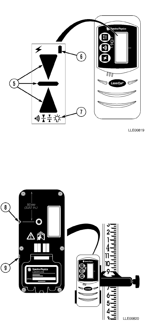
TM 5-6675-348-13&P
5-9
(5) ELEVATION DISPLAY. Shows the 1275
Laser Receiver’s position with respect
to the laser beam.
Arrows show direction receiver needs to be moved
to be centered in laser beam or on-grade. Audio
feature must be turned ON for high/low tone to
function.
(6) LOW-BATTERY INDICATION. Displays
when the 1275 Laser Receiver’s
batteries need to be replaced. Battery
life is approximately 74 hours at 68° F
(20° C).
(7) LCD BACK LIGHTING. Lights up LCD
for easy viewing in dimly lit areas. To
activate this feature, simultaneously
press audio and on-grade sensitivity
buttons until back lighting symbol
appears in LCD.
Back lighting LCDs turn OFF to conserve power
when the laser isn’t striking the 1275 Laser
Receiver. When the 1275 Laser Receiver is placed
into beam’s path, the backlighting feature
returns.
(8) MARKING NOTCH. Aligns with
on-grade portion of photocell and is
used for transferring elevation
marks.
Top of receiver is 2 in. (5.1 cm) above marking
notch.
(9) DISPLAY OUTPUT/ATTACHMENT.
Attaches the 1278 Remote Display
Accessory to the 1275 Laser
Receiver when the 1275 Laser
Receiver is being used high above
or below the Operator’s head.
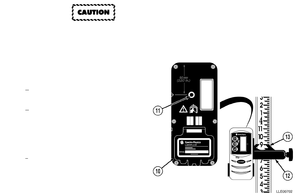
TM 5-6675-348-13&P
5-10
Batteries should be removed when storing
unit more than 30 days or batteries may
become corroded and damage to equipment
will result.
(10) BATTERY COMPARTMENT. Holds
two alkaline batteries for powering the
1275 Laser Receiver.
aUse your thumbnail or a coin to
open battery door.
bInsert batteries, noting diagram
inside housing. If batteries are
installed incorrectly, no damage
occurs, but the unit will not work.
Install batteries for proper opera-
tion.
cIf the battery symbol appears on the
LCD, replace alkaline batteries.
(11) FASTENER/RECEPTACLE. Accepts a
rod-clamp fastening screw.
(12) GENERAL PURPOSE CLAMP.
Attaches 1275 Laser Receiver to grade
rod staff, or similar measuring device
with width up to 2 1/2 in. (6.4 cm).
(13) 1275 LASER RECEIVER ROD CLAMP
REFERENCE INDICATORS. Aligned
with on-grade portion of 1275 Laser
Receiver when it is used on grade rod,
staff, or similar measuring device.
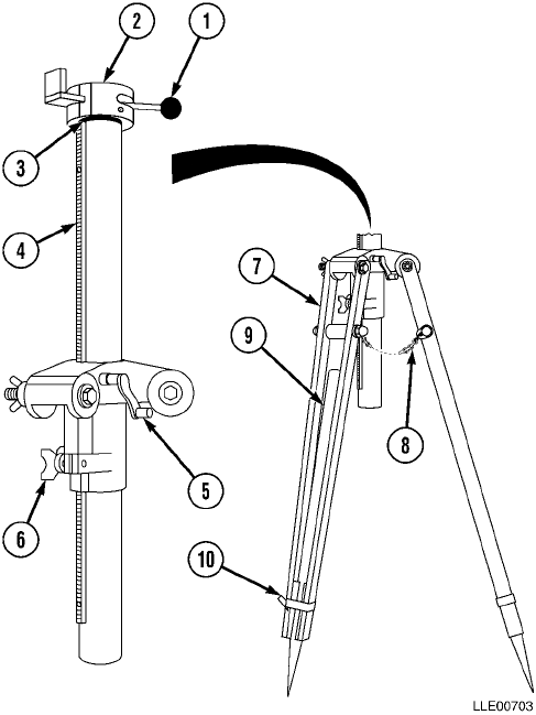
TM 5-6675-348-13&P
5-11
5-5. ELEVATING BASE AND TRIPOD LOCATION AND DESCRIPTION OF MAJOR COMPONENTS.
a. Elevating Base and Tripod Characteristic.
The Elevating Base and Tripod unit provides a telescoping and locking mount for the 1145-2 Laser Transmit-
ter. Fine 1145-2 Laser Transmitter height adjustment are made with the elevating Base. Coarse height
adjustments are made with the Leg Extensions of the Tripod.
(1) QUICK-RELEASE LEVER. Allows fast
and easy 1145-2 Laser Transmitter
setup.
(2) LOCKING RING. Enables 1145-2 Laser
Transmitter to fasten to tripod base.
(3) O-RING STOP. Helps prevent damage
to elevating base when elevating
column is lowered.
(4) STEEL RACK AND ELEVATING BASE
TUBE. Incorporates a graduated scale to
allow precise movement of the elevating
column.
(5) RAISE/LOWER CRANK. Used to move
elevating column up or down. It
incorporates an adjustable locking
mechanism to prevent transmitter
from dropping if tube is not secured.
(6) CLAMPING KNOB. Used to clamp the
elevating column in position.
(7) TRIPOD LEGS. Provide support for the
Elevating Base.
(8) CHAINS. Are connected to tripod legs
to prevent slippage on a hard surface.
(9) LEG EXTENSIONS. Provide height
adjustment. Located in ends of legs,
with footpads for pushing pointed leg
into ground.
(10) LEG CLAMP. Tightens the tripod leg
extension in place after height
adjustment.
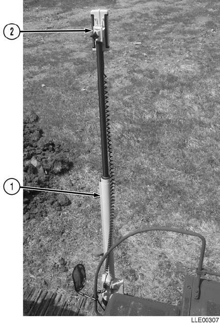
TM 5-6675-348-13&P
5-12
5-6. BUCKET-PRO™ SYSTEM LASER
OPERATION.
The Laser Reference System accessories include
EM2E-24 Electric Mast (1) and R2S-S Laser
Receiver (2). The Laser Reference System also
includes mounting brackets and electrical cables for
installation on most HYEXs.
The Laser Reference System compensates for
changes in elevation when HYEX moves. In
trenching applications, for example, the Laser
Reference System allows you to move down the
trench line several times without having to
rebenchmark the Bucket-Pro™ System. The
R2S-S Laser Receiver stays locked onto laser beam
and EM2E-24 Electric Mast retracts/extends in
response to up/down movement of the HYEX. The
EM2E-24 Electric Mast measures the change in
elevation and signals the Control Box to
compensate for the change.

TM 5-6675-348-13&P
5-13
The Laser Reference System is designed for use with Model 1145-2 Laser Transmitter (3). The 1145-2 Laser
Transmitter provides factory-guaranteed performance to specifications. R2S-S Laser Receiver (2), mounted
on EM2E-24 Electric Mast (1), is also compatible with other manufacturers’ laser transmitters.
To use the Laser Reference System with the Bucket-Pro™ System, complete the following steps:
(1) Set up tripod and 1145-2 Laser Transmitter (3) so that height of 1145-2 Laser Transmitter (3) laser
beam is within search range of R2S-S Laser Receiver (2) for terrain and placement of HYEX (4)
(Para 5-2).
NOTE
Distance and terrain make judging correct height difficult. Using 1275 Laser Receiver for
finding location of laser beam makes judging right height easier.
(2) Ensure Grade Axis of 1145-2 Laser Transmitter (3) is aligned so that one laser slope axis is on
centerline of your trench or footing.
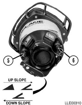
TM 5-6675-348-13&P
5-15
SECTION II. 1145-2 LASER TRANSMITTER, 1275 LASER RECEIVER,
AND ELEVATING BASE AND TRIPOD PMCS
5-7. PMCS INTRODUCTION.
Preventive Maintenance Checks and Services (PMCS) means systematic caring for, inspecting, and servicing
equipment to keep it in good condition and to prevent malfunctions. As a 1145-2 Laser Receiver, and
Elevating Base and Tripod system Operator, your mission is to:
a. Be sure to perform your PMCS each time you operate the 1145-2 Laser Receiver, and Elevating
Base and Tripod system. Always do your PMCS in the same order so it becomes a habit. Once
you’ve had some practice, you’ll quickly spot anything wrong.
b. Do your Before PMCS just before you operate the 1145-2 Laser Transmitter, 1275 Laser
Receiver, and Elevating Base and Tripod system. Pay attention to WARNINGS, CAUTIONS,
and NOTES.
c. Do your AFTER PMCS right after operating the 1145-2 Laser Transmitter, 1275 Laser Receiver,
and Elevating Base and Tripod system. Pay attention to WARNINGS, CAUTIONS, and NOTES.
d. Use DA Form 2404 or DA Form 5988-E (Equipment Inspection and Maintenance Worksheet) to
record any faults that you don’t immediately fix.
5-8. PMCS PROCEDURES.
a. PMCS table (Table 5-1.) lists inspections and care required to keep your 1145-2 Laser
Transmitter, 1275 Laser Receiver, and Elevating Base and Tripod system in good operating
condition. This table is set up so you can do BEFORE and AFTER PMCS while walking around
the 1145-2 Laser Transmitter, 1275 Laser Receiver, and Elevating Base and Tripod system.
b. The “Interval” column tells you when to do a certain check or service.
c. The “Procedure” column tells you how to do required checks and services. Carefully follow these
instructions.
d. The “Not Fully Mission Capable If” column tells you when your 1145-2 Laser Transmitter, 1275
Laser Receiver, and Elevating Base and Tripod system is nonmission capable and why the 1145-
2 Laser Transmitter, 1275 Laser Receiver, and Elevating Base and Tripod system cannot be
used.
e. When something looks wrong that you cannot fix, write down the problem on your
DA Form 2404 or DA Form 5988-E. Immediately report the problem to your supervisor.

TM 5-6675-348-13&P
5-16
f. When you do your PMCS, you will always need a rag or two. The following are checks common to
the entire 1145-2 Laser Transmitter, 1275 Laser Receiver, and Elevating Base and Tripod
system.
• Degreasing Solvent (MIL-PRF-680, Type II) is TOXIC and flammable. Wear protective
goggles and gloves, use only in a well-ventilated area, avoid contact with skin, eyes, and
clothes, and do not breathe vapors. Keep away from heat or flame. Never smoke when
using solvent; the flash point for degreasing solvent type II is 200º F (93º C). Failure to
comply may result in injury or death to personnel.
• If personnel become dizzy while using cleaning solvent, immediately get fresh air and
medical help. If solvent contacts skin or clothes, flush with cold water. If solvent contacts
eyes, immediately flush eyes with water and get immediate medical attention. Do not
use diesel fuel, gasoline, or benzene (benzol) for cleaning.
• Adhesives, solvents, and sealing compounds burn easily and give off vapors that are
harmful to the skin and clothing. To avoid injury or death, keep away from open fire
when using these materials, and use only in well-ventilated areas. If adhesives, solvents,
or sealing compounds contact the skin or clothing, wash immediately with soap and
water, and rinse thoroughly. Failure to comply may result in injury or death to personnel.
(1) Keep It Clean. Dirt, grease, oil, and debris only get in the way and may cover up a serious
problem. Clean as you work. Use degreasing solvent (MIL-PRF-680, type II) on all metal surfaces.
Use soap and water when you clean rubber or plastic material.
(2) Rust and Corrosion. Check 1145-2 Laser Transmitter, 1275 Laser Receiver, and Elevating Base
and Tripod system brackets for rust and corrosion. When any bare metal or corrosion exists, clean
and apply a coat of paint. Report bare metal or corrosion to your supervisor.
(3) Bolts, Nuts, and Screws. Check all bolts, nuts, and screws for obvious looseness, missing, bent, or
broken condition. You can’t check them all with a tool, but look for chipped paint, bare metal, or
rust around bolt heads. When you find a bolt, nut, or screw you think is loose, tighten it or report it
to your supervisor.
(4) Welds. Look for loose or chipped paint, rust, or gaps where parts are welded together. When you
find a bad weld, report it to your supervisor.
(5) Electric Wires and Connectors. Look for cracked, frayed, or broken insulation, bare wires, and
loose or broken connectors. Tighten loose connectors. Report any damaged wires to your supervisor.
(6) Hydraulic Lines and Fittings. Look for wear, damage, and leaks; ensure clamps and fittings are
tight. Stains around a fitting or connector can mean a leak. If a leak comes from a loose fitting or
connector, tighten it. If something is broken or worn out, report it to Unit Maintenance.
(7) When you check operating conditions, look to see if component is serviceable.
5-9. SHORTENED MAINTENANCE INSTRUCTIONS.
Local conditions of extreme heat, dust, cold, or wetness dictate that service intervals shall be shortened.

TM 5-6675-348-13&P
5-17
5-10. ADDITIONAL MAINTENANCE INSPECTIONS.
Additional maintenance inspections are required for the following reasons:
a. Prolonged storage. Inspect 1145-2 Laser Transmitter, 1275 Laser Receiver, and Elevating Base
and Tripod system components that have been stored for a period of 3 months or more.
b. Initial preparation upon receipt.
c. Preparation for storage.
5-11. LEAKAGE CLASSIFICATION AND DEFINITION.
There are no fluid reservoirs on 1145-2 Laser Transmitter and Elevating Base and Tripod system.
5-12. GENERAL LUBRICATION INSTRUCTIONS.
Do not look into 1145-2 Laser Transmitter for a long period of time. Failure to comply may
cause injury to personnel.
a. Intervals. Intervals (on-condition or hard time) and related man-hour times are based on normal
operation. Man-hour time specified is time needed to do all services prescribed for a particular interval.
Change hard-time interval when operating equipment under adverse operating conditions, including
longer-than-usual operating hours. The calendar interval will be extended during periods of low
activity. When extended, adequate preservation precautions must be taken. Hard-time intervals must
be applied during warranty period. Intervals shown in this section are based on calendar and hourly
times.
5-13. PMCS COLUMN ENTRY EXPLANATION.
a. Item No. Column. Checks and services are numbered in interval order showing a walk-around
sequence around the 1145-2 Laser Transmitter and Elevating Base and Tripod system. Use these
numbers in the “Item No.” column on DA Form 2404 or DA Form 5988-E when recording faults that
you don’t immediately fix.
b. Interval Column. This column indicates when the lubrication, check, and/or service should be
performed.
c. Location, Item to Check/Service Column. Underlined items listed in this column are divided into
groups indicating the portion of the equipment of which they are a part (e.g., brakes, fuel, and engine).
Under these groupings, a few common words are used to identify the specific item being checked.
d. Procedure Column. This column contains procedures required to perform checks and services.
e. Not Fully Mission Capable If Column. This column contains criteria that cause the equipment to be
classified as NOT READY/AVAILABLE because of an inability to perform its primary mission. An
entry in this column will:
(1) Identify conditions that make equipment not available for readiness reporting purposes.
(2) Deny use of equipment until corrective maintenance has been performed.

TM 5-6675-348-13&P
5-18
5-14. 1145-2 LASER TRANSMITTER, 1275 LASER RECEIVER, AND ELEVATING BASE AND
TRIPOD SYSTEM OPERATOR’S PMCS TABLE.
Table 5-1. 1145-2 LASER TRANSMITTER, 1275 LASER RECEIVER, AND ELEVATING BASE
AND TRIPOD SYSTEM OPERATOR’S PMCS (Before/After)
Item No. Interval
Location
Procedure Not Fully Mission
Capable If:
Item to
Check/Service
1 Before/After Exterior 1145-2
Laser Transmitter Wipe dirt and dust from all
metal components with a dry
cloth.
Inspect exterior of 1145-2 Laser
Transmitter for damage or
cracks.
Inspect windows for cracks,
scratches, and dirt. Clean
windows with clean water and a
soft cloth.
Inspect bottom mounting plate
for dirt and debris.
Ensure grade adjustment knobs
for “Y” and “X” axes rotate
freely and function properly.
Ensure breather vent is free of
dirt and debris.
Ensure power/charge connector
is free of dirt and damage.
Exterior of 1145-2
Laser Transmitter is
damaged or cracked.
Windows are cracked,
scratched, or dirty.
Bottom mounting
plate is dirty.
Knobs will not rotate
or adjust properly.
Breather vent is
plugged.
Broken or bent pin is
evident.
2 Before/After Electrical Cables Ensure electrical cables are not
frayed, cracked, or exposed. Frayed, cracked, or
exposed wires are
evident.
3 Before/After Elevating Base and
Tripod Check all screws, fasteners, and
legs. Screws, fasteners, or
legs are missing or
damaged.
4 Before/After 1275 Laser Receiver Inspect 1275 Laser Receiver for
cracks or any damage to
exterior.
Exterior of 1275
Laser Receiver is
cracked or damaged.
5 Before/After 1275 Laser Receiver
Grade Rod Inspect Grade Rod for cracks or
damage. Grade Rod is cracked
or damaged.

TM 5-6675-348-13&P
5-19
SECTION III. OPERATION
5-15. 1145-2 LASER TRANSMITTER ADJUSTMENT.
The 1145-2 Laser Transmitter has two horizontal level adjust screws by the windows on upper frame of unit.
These screws permit you to make minor adjustments along two axes of the horizontal plane. Axes are labeled
“X” and “Y” and rubber caps over adjustment screws tell you which axis is which.
5-16. 1145-2 LASER TRANSMITTER CALIBRATION.
a. Calibration.
(1) All calibration procedures are done at zero reading on right-hand white counter wheel – not against
mechanical stop if past zero point. The following items are required to make a calibration
adjustment on 1145-2 Laser Transmitter:
aA 5/32-in. (0.40 cm) Allen head driver.
bModel 1275 Laser Receiver.
cElevating Base and Tripod allows you to rotate 1145-2 Laser Transmitter in 90-degree
increments.
dA minimum 200-ft (60.96 m) range that is unobstructed and as close to flat as possible.
(2) Mount unit on tripod at one end of 200 ft (60.96 m) range and rough level it within +5 degrees. Set
“X” and “Y” axis grade counters at zero reading (not against counter wheel mechanical stop).
(3) Turn 1145-2 Laser Transmitter control switch to AUTO position and wait for Auto Mode Indicator
Lamp to stop flashing.
(4) Station a rodman with one of the suitable detectors at other end of range, 200 ft (60.96 m) away.
NOTE
The appropriate axis may be identified by checking triangular markings of the “X” axis
indicator.
(5) Align laser, using sighting scope or groove, such that “X” axis is pointed directly at rodman. Ensure
pentamirror is rotating and Auto Mode Indicator Lamp has stopped flashing.
(6) Have rodman take a precise reading to within 1/16 in. (0.16 cm) and mark reading as X1.
(7) Rotate transmitter 180 degrees and wait at least 2 minutes for it to relevel. Have rodman take
another accurate reading and mark reading as X2.
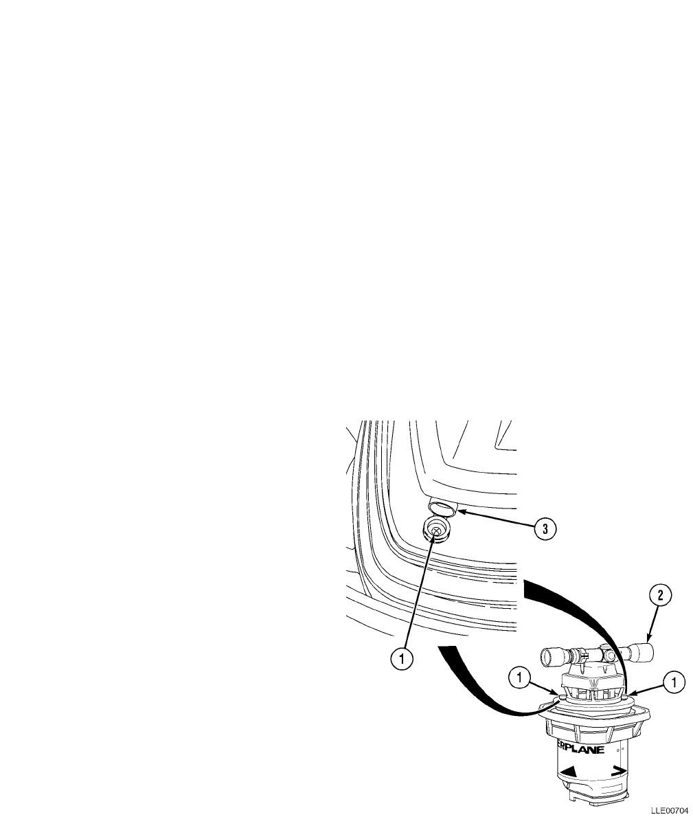
TM 5-6675-348-13&P
5-20
NOTE
• If difference between X1 and X2 is less than 0.02 ft (1/4 in. or 0.64 cm), no adjustment is
necessary.
• If difference is between 0.02 ft (1/4 in. or 0.64 cm) and 0.12 ft (1-1/2 in. or 3.81 cm), you
can continue with this procedure.
• If difference is 0.12 ft (1-1/2 in. or 3.81 cm) or greater, the unit must be recalibrated at an
authorized service center. You cannot recalibrate the unit in the field without damage to
the unit.
(8) Calculate the “X” average = (X 1 + X 2)/2 and have rodman adjust detector on rod to the “X”
average. (Center of detector is between the two readings.)
NOTE
Calibration screws are labeled “X” and “Y”.
(9) Locate the “X” calibration screw (1) and adjust it to align beam to the “X” average at 1145-2 Laser
Transmitter. One full turn of calibration screw moves beam approximately 0.04 ft (1/2 in. or 1.3 cm)
in 200 ft (60.96 m). If beam cannot be aligned by gentle turning of calibration screw (1), return unit
to an authorized service center for calibration.
(10) After adjusting beam, allow 4 minutes for unit to stabilize before taking next reading. Repeat
Steps (4) through (8) to check your work. Do a fine readjust, if necessary.
(11) After adjusting the “X” axis to rotate
1145-2 Laser Transmitter 90 degrees
to the “Y” axis.
(12) Point the “Y” axis directly at rodman.
(13) Using sighting telescope (2) or groove
and repeat above Steps (6) through
(10).
(14) Call readings Y1 and Y2 and calculate
the “Y” axis average just as you did in
Step (8).
(15) Secure rubber caps (3) over calibration
screws (1).
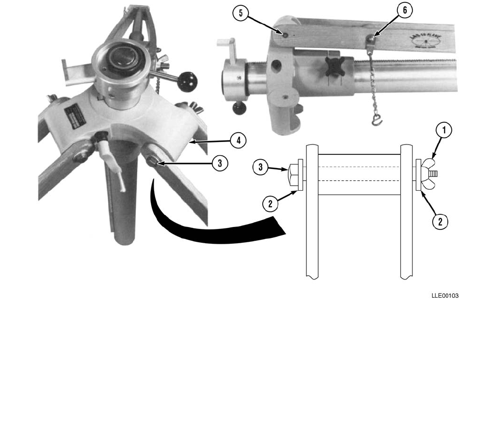
TM 5-6675-348-13&P
5-21
5-17. ELEVATING BASE AND TRIPOD ASSEMBLY AND OPERATION.
This section illustrates the assembly and the operation of the Elevating Base and Tripod assembly. Setup
may change, depending on the job site requirements.
a. Assembly.
NOTE
All tripod legs install the same. Only one leg is shown.
(1) Remove wing nuts (1), washers (2), and mounting bolts (3) from tripod base (4).
(2) Align tripod leg mounting holes (5) with the hole in tripod base (4). Chain tabs (6) need to face
inward.
NOTE
Ensure the bolt hex heads face the raise/lower crank to provide the necessary clearance to
operate the raise/lower crank.
(3) Install mounting bolt (3) through washer (2), tripod leg mounting holes (5), and tripod base (4).
(4) Install washer (2) and wing nut (1) onto mounting bolt (3).
(5) Tighten wing nut (1).
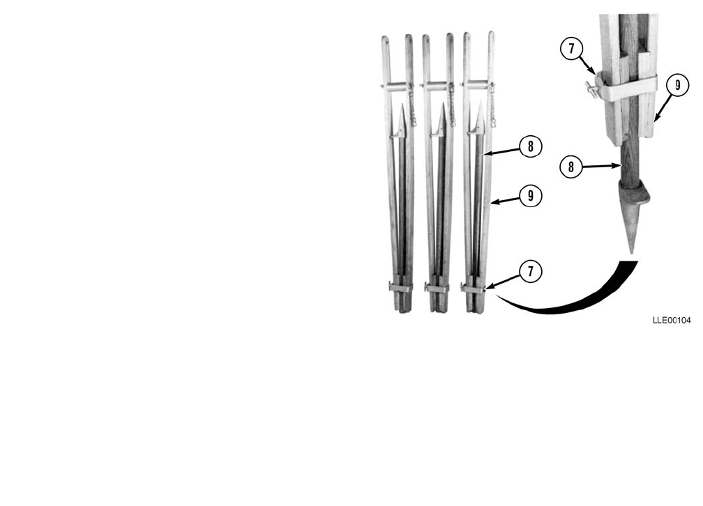
TM 5-6675-348-13&P
5-22
(6) Loosen leg clamp (7) and remove each
extension foot (8).
(7) Insert extension foot (8) into tripod
legs (9), with steps on tripod legs (9)
facing outward.
(8) Tighten leg clamps (7).
b. Operation.
NOTE
• The recommended working range
for the 1145-2 Laser Transmitter is
1000 ft (305 m).
• The area encompassed by this
sweep of laser beam is 72 acres
(29 hectares). In flat fields, the
center of the field is usually the best
location. In rolling fields, locate the
1145-2 Laser Transmitter at an
elevation so the receiver can pick up
the plane of light approximately
midway in its receiver (or survey
rod) travel.
(1) Select a location to utilize the 1145-2 Laser Transmitter.
N
O
TE
• Consistent results with the 1145-2 Laser Transmitter require that the plane of light
remains stable. For this reason, the 1145-2 Laser Transmitter, the base, and the legs are
all carefully designed to use heavy components and special materials to minimize any
tendency to vibrate or drift.
• When setting up the tripod assembly, it is important to obtain the most level and stable
base possible for the 1145-2 Laser Transmitter. The less the self-leveling mechanisms
have to work, the more stable the plane of light will be. Ground vibration, wind, or
extreme temperatures can influence the plane of light.
• Ground vibration can be a problem in certain soils when working at long range from the
transmitting unit. Peat or muck readily conducts traffic vibration to the tripod legs. A
simple test is to stand next to the tripod assembly while heavy traffic passes. If you can
feel traffic vibration in your feet and legs, you may have a problem at longer ranges
where the vibrational effect on the 1145-2 Laser Transmitter will be magnified. Select
your site for the tripod assembly carefully.
(2) Position Elevating Base and Tripod assembly with elevating base quick-release pointing upwind
and elevating base as vertical as possible.

TM 5-6675-348-13&P
5-23
(3) Chains (6) between tripod legs (9) should be slightly loose to allow for thermal expansion.
(4) On windy, gusty days, it is advisable to tie down the tripod assembly. This can be done in several
ways:
aDrive a stake (10) into ground, over foot of each tripod leg (9).
bLay a sandbag (11) over foot of each tripod leg (9).
cUse three tie-down straps or cables (12) secured midway up each tripod leg (9) and fastened to a
weight or stake on the ground.
dPosition large equipment (13) as a wind block.
(5) Keep height of 1145-2 Laser Transmitter as low as possible. When height is needed, extend tripod
legs (9) before adjusting elevating column (14) height.
(6) When setting up on frozen ground that may thaw during the day, drive pipes (15) into the ground
below the frost line and set the tripod legs (9) into the pipes (15).
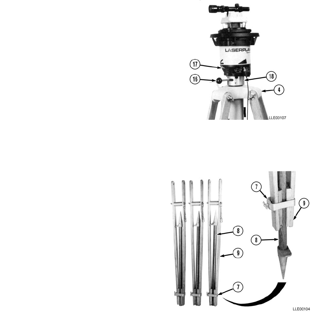
TM 5-6675-348-13&P
5-24
(7) With tripod unit properly set up,
unlock Tripod Base Quick-Release
Lever (16).
(8) Insert Transmitter Tripod Mounting
Ring (17) into Elevating Base Locking
Ring (18).
(9) Firmly lock Tripod Base Quick-Release
Lever (16) to secure the 1145-2 Laser
Transmitter to tripod unit.
(10) Set up transmitter with proper grade
and direction.
c. Coarse Height Adjustment.
NOTE
Coarse or fine height adjustments may
be required to locate plane of laser
light within 1275 Laser Receiver’s
reception range.
(1) Loosen tripod Leg Clamps (7).
(2) Adjust height of tripod Leg
Extensions (8) as required and tighten
Leg Clamps (7). Remember to
maintain Tripod Base (4) as level as
possible.
d. Fine Height Adjustment.
(1) Loosen tripod base clamping knob.
(2) Use tripod base raise/lower crank to
adjust height of plane of laser light.
(3) Tighten tripod base clamping knob to
secure plane of light at desired height.
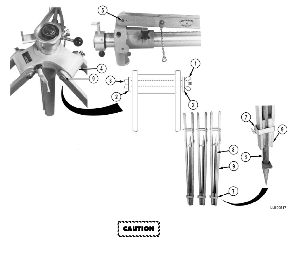
TM 5-6675-348-13&P
5-25
e. Disassembly.
Elevating Base and Tripod Assembly is top-heavy when upright. When disassembling unit,
use an assistant, or damage to equipment may occur.
NOTE
All tripod legs are removed the same. Only one leg is shown.
(1) Loosen leg clamps (7) and remove leg extensions (8) from tripod legs (9).
(2) Return each leg extension (8) to stowed position and tighten leg clamps (7).
(3) Remove wing nuts (1), washers (2), and mounting bolts (3) from tripod base (4) and tripod leg
mounting holes (5).
(4) Remove tripod legs (9) from tripod base (4).
(5) Install wing nuts (1), washers (2), and mounting bolts (3) on tripod base (4).
(6) Tighten wing nuts (1).
TM 5-6675-348-13&P
5-26
f. Elevating Base and Tripod Maintenance.
(1) Check tension on raise/lower crank handle twice a year. Tension on clutch can be adjusted by
pulling back black boot on shaft, turning exposed nut (to the right to tighten, to the left to loosen).
(2) Check condition of small O-ring stop annually. Remove and replace as required.
(3) Check condition of locking ring twice a year. Should original mating surface be worn, rotate ring
180 degrees. Remove and replace as required.
TM 5-6675-348-13&P
5-27
SECTION IV. 1145-2 LASER TRANSMITTER TROUBLESHOOTING
While the 1145-2 Laser Transmitter is a highly accurate system, you may encounter problems as you work in
the field. Use this section to troubleshoot your problems. You may want to have a qualified maintenance
person troubleshoot and fix any problems.
Table 5-2. 1145-2 Laser Transmitter Fault Index
Fault
No. Description Page
5-1. No Laser Beam..........................................................................................................................................5-28
5-2. Laser Beam Will Not Shut Off When 1145-2 Laser Transmitter is Bumped Out of Level...................5-29
5-3. 1145-2 Laser Transmitter Low Voltage Indicator Lamp is On............................................................... 5-29
5-4. Laser Beam Appears Weak.......................................................................................................................5-30
5-5. 1145-2 Laser Transmitter Will Not Self-Level ........................................................................................5-31

TM 5-6675-348-13&P
5-28
Table 5-3. 1145-2 Laser Transmitter Troubleshooting
Malfunction
Test or InpsectionCorrective Action
FAULT 5-1. NO LASER BEAM.
Connecting to 24 Vdc will damage laser. Ensure external power is 12 Vdc. Failure to
comply will result in damage to equipment
Step 1. Verify Battery Low Voltage Indicator Lamp (1) is not on.
If Battery Low Voltage Indicator Lamp (1) is on, recharge internal Battery (2) or
hook up to 12-Vdc external Battery using cables provided.
Step 2. Verify 1145-2 Laser Transmitter is set up within +5 degrees of self-leveling range.
Step 3. Ensure Control Switch (3) is in AUTO position.
Wait for a minute until Auto Mode Indicator Lamp (4) stops flashing.
Laser beam should now be lit. Check it with 1275 Laser Receiver (Para 5-4).
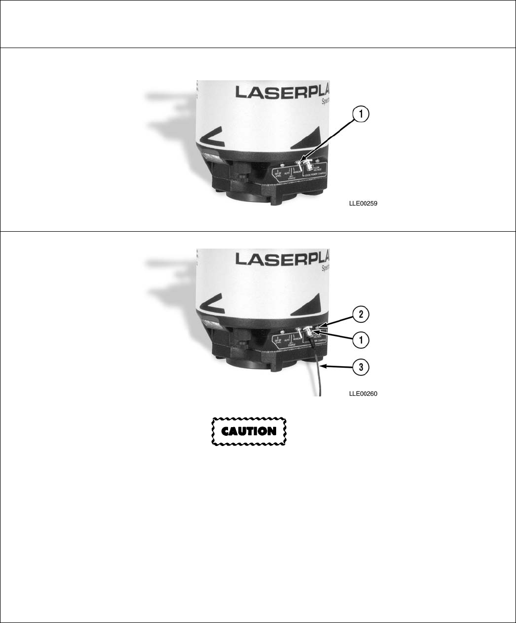
TM 5-6675-348-13&P
5-29
FAULT 5-2. LASER BEAM WILL NOT SHUT OFF WHEN 1145-2 LASER
TRANSMITTER IS BUMPED OUT OF LEVEL.
Step 1. Ensure Control Switch (1) is in AUTO position.
FAULT 5-3. 1145-2 LASER TRANSMITTER LOW VOLTAGE INDICATOR LAMP IS ON.
Connecting to 24 Vdc will damage laser. Ensure external power is 12 Vdc. Failure to
comply will result in damage to equipment
Step 1. Charge internal Battery using Power/Charge Connector (1).
Step 2. Verify sufficient charge in your external 12-Vdc battery (2).
Step 3. Check Power/Charge Connector (1) for dirt.
If Power/Charge Connector (1) is dirty, clean with clean cloth.
Step 4. Ensure twist-lock ring on Power Cord (3) is snapped in place.
Step 5. Check for a broken or frayed wire in Power Cord (3), particularly at receptacle end.
Table 5-3. 1145-2 Laser Transmitter Troubleshooting (Cont)
Malfunction
Test or InpsectionCorrective Action
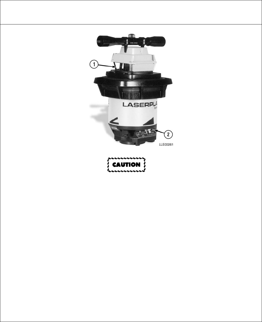
TM 5-6675-348-13&P
5-30
FAULT 5-4. LASER BEAM APPEARS WEAK.
Do not attempt to clean windows dry or damage to equipment may result.
Step 1. Windows are dirty.
Ensure windows (1) are clean under Upper Housing Assembly. Use a soft clean
cloth or lens cleaning tissue with a window cleaning solution.
Step 2. Check to see that Low Voltage Indicator Lamp (2) is not on.
If Low Voltage Indicator Lamp (2) is on, recharge battery.
Table 5-3. 1145-2 Laser Transmitter Troubleshooting (Cont)
Malfunction
Test or InpsectionCorrective Action
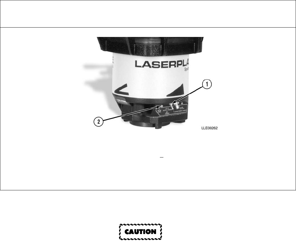
TM 5-6675-348-13&P
5-31/(5-32 Blank)
5-18. 1145-2 LASER TRANSMITTER AND 1275 LASER RECEIVER STORAGE AND
TRANSPORTATION.
1145-2 Laser Transmitter and 1275 Laser Receiver are not designed to be air dropped.
Damage to equipment may result.
a. Proper storage of 1145-2 Laser Transmitter and 1275 Laser Receiver, when they are not being
used, is essential to ensure long trouble-free operation.
b. Ensure carrying case pads are dry and rocks or other debris are removed before the 1145-2
Laser Transmitter and 1275 Laser Receiver are stored in carrying case.
c. Fully discharge battery prior to storage longer than 3 months.
FAULT 5-5. 1145-2 LASER TRANSMITTER WILL NOT SELF-LEVEL.
Step 1. Place Control Switch (1) in AUTO position.
Step 2. Verify 1145-2 Laser Transmitter is within +5 degrees self-leveling range.
Adjust as needed (Para 5-15).
Step 3. Ensure Auto Mode Indicator Lamp (2) has stopped flashing.
Table 5-3. 1145-2 Laser Transmitter Troubleshooting (Cont)
Malfunction
Test or InpsectionCorrective Action
TM 5-6675-348-13&P
A-1
APPENDIX A
REFERENCES
A-1. SCOPE.
This appendix lists forms, field manuals, technical manuals, and other publications either referenced in this
manual or which apply to the operation and maintenance of the LLE equipment.
A-2. DEPARTMENT OF THE ARMY PAMPHLETS.
Consolidated Index of Army Publications and Blank Forms . . . . . . . . . . . . . . . . . . . . . . . . . . . . DA Pam 310-1
The Army Maintenance Management System (TAMMS) . . . . . . . . . . . . . . . . . . . . . . . . . . . . . DA Pam 738-750
A-3. FORMS.
Recommended Changes to Publications and Blank Forms . . . . . . . . . . . . . . . . . . . . . . . . . . . . . DA Form 2028
Equipment Inspection and Maintenance Worksheet . . . . . . . . . . . . . . . . . . . . . . . . . . . . . . . . . . DA Form 2404
Equipment Inspection and Maintenance Worksheet. . . . . . . . . . . . . . . . . . . . . . . . . . . . . . . . . .DA Form 5988-E
Quality Deficiency Report (QDR) . . . . . . . . . . . . . . . . . . . . . . . . . . . . . . . . . . . . . . . . . . . . . . . . . . . . . . . . . SF368
A-4. TECHNICAL BULLETINS.
Equipment Improvement Report and Maintenance Digest (EIR MD)
(U.S. Army Tank-automotive and Armaments Command)
Tank-Automotive Equipment . . . . . . . . . . . . . . . . . . . . . . . . . . . . . . . . . . . . . . . . . . . . . TB 43-0001-62 Series
A-5. TECHNICAL MANUALS.
Operator's Manual for Welding Theory and Application . . . . . . . . . . . . . . . . . . . . . . . . . . . . . . . . . . . TM 9-237
Care and Use of Hand Tools and Measuring Tools . . . . . . . . . . . . . . . . . . . . . . . . . . . . . . . . . . . . . . . . .TM 9-243
Materials Used for Cleaning, Preserving, Abrading, and Cementing
Ordnance Materiel and Related Items Including Chemicals . . . . . . . . . . . . . . . . . . . . . . . . . . . . . . TM 9-247
Operator’s Manual, Tractor, Full, Tracked: (Caterpillar Model D7F). . . . . . . . . . . . . . . . . . . TM 2-2410-233-10
Operator’s Manual, Tractor, Full Tracked: (DED, Medium Drawbar Pull Model D7G) . . . . TM 5-2410-237-10
Operator’s Manual, Scraper, Earth Moving, Motorized, (DED) . . . . . . . . . . . . . . . . . . . . . . . TM 5-3805-248-10
Operator’s Manual, Scraper, Tractor, Elevating, Self-Propelled . . . . . . . . . . . . . . . . . . . . . . . TM 5-3805-260-10
Operator’s Manual, Grader, Heavy, Road, Motorized: (Caterpillar Model 130G). . . . . . . . . . TM 5-3805-261-10
Tool Outfit Hydraulic System Test and Repair Unit (HYSTRU) . . . . . . . . . . . . . . . . . . . . . . TM 9-4940-468-14
Operator, Unit, Direct Support, and General Support Maintenance
Manual for Lead Storage Batteries . . . . . . . . . . . . . . . . . . . . . . . . . . . . . . . . . . . . . . . . . . . TM 9-6140-200-14
Principals of Automotive Vehicles. . . . . . . . . . . . . . . . . . . . . . . . . . . . . . . . . . . . . . . . . . . . . . . . . . . . . .TM 9-8000
Painting Instructions for Field Use. . . . . . . . . . . . . . . . . . . . . . . . . . . . . . . . . . . . . . . . . . . . . . . . . . . TM 43-0139
Equipment Improvement Report and Maintenance Summary (EIR MS) . . . . . . . . . . . . . . . . . . . . .TM 43-0143
Basic Electrical Wire Repair . . . . . . . . . . . . . . . . . . . . . . . . . . . . . . . . . . . . . . . . . . . . . . . . . . . . . . . . .TM 43-0158
Procedures for Destruction of Tank-Automotive Equipment
to Prevent Enemy Use. . . . . . . . . . . . . . . . . . . . . . . . . . . . . . . . . . . . . . . . . . . . . . . . . . . . . . . . . . TM 750-244-6
TM 5-6675-348-13&P
A-2
A-6. OTHER PUBLICATIONS.
Army Medical Department Expendable/Durable Items. . . . . . . . . . . . . . . . . . . . . . . . . . . . . . . . . . . . CTA 8-100
Expendable/Durable Items (Except Medical, Class V, Repair Parts, and Heraldic Items). . . . . . . . CTA 50-970
Operator’s Circular Welding Theory and Application. . . . . . . . . . . . . . . . . . . . . . . . . . . . . . . . . . . . . . . .TC 9-237
TM 5-6675-348-13&P
B-1
APPENDIX B
MAINTENANCE ALLOCATION CHART (MAC)
Section I. INTRODUCTION
B-1. THE ARMY MAINTENANCE SYSTEM MAC.
a.
This introduction (Section I) provides a general explanation of all maintenance and repair functions
authorized at various maintenance levels under The Army Maintenance Management System (TAMMS)
concept.
b.
The Maintenance Allocation Chart (MAC) in Section II designates overall authority and responsibility
for the performance of maintenance functions on the identified end item or component. The application of the
maintenance functions to the end item or component will be consistent with the capacities and capabilities of
the designated maintenance levels, which are shown on the MAC in column (4) as:
•Unit - Includes two subcolumns, C (Operator/Crew) and O (Unit) maintenance.
•Direct Support - Includes an F subcolumn.
•General Support - Includes an H subcolumn.
•Depot - Includes a D subcolumn.
c.
Section III lists the tools and test equipment (both special tools and common tool sets) required for each
maintenance function as referenced from Section II.
d.
Section IV contains supplemental instructions and explanatory notes for a particular maintenance
function.
B-2. MAINTENANCE FUNCTIONS.
Maintenance functions are limited to and defined as follows:
a. Inspect.
To determine the serviceability of an item by comparing its physical, mechanical, and/or
electrical characteristics with established standards through examination (e.g., by sight, sound, or feel).
b. Test.
To verify serviceability by measuring the mechanical, pneumatic, hydraulic, or electrical
characteristics of an item and comparing those characteristics with prescribed standards.
c. Service.
Operations required periodically to keep an item in proper operating condition; i.e., to clean
(includes decontaminate, when required), to preserve, to drain, to paint, or to replenish fuel, lubricants,
chemical fluids, or gases.
d. Adjust.
To maintain or regulate, within prescribed limits, by bringing into proper position, or by setting
the operating characteristics to specified parameters.
e. Align.
To adjust specified variable elements of an item to bring about optimum or desired performance.

TM 5-6675-348-13&P
B-2
f. Calibrate.
To determine and cause corrections to be made or to be adjusted on instruments or test,
measuring, and diagnostic equipment used in precision measurement. Consists of comparisons of two
instruments, one of which is a certified standard of known accuracy, to detect and adjust any discrepancy in
the accuracy of the instrument being compared.
g. Remove/Install.
To remove and install the same item when required to perform service or other
maintenance functions. Install may be the act of emplacing, seating, or fixing into position a spare, repair
part, or module (component or assembly) in a manner to allow the proper functioning of an equipment or
system.
h. Replace.
To remove an unserviceable item and install a serviceable counterpart in its place. “Replace” is
authorized by the MAC and the assigned maintenance level is shown as the third position code of the SMR
code.
i. Repair.
The application of maintenance services1 including fault location/troubleshooting2,
removal/installation and disassembly/assembly3 procedures, and maintenance actions4 to identify troubles
and restore serviceability to an item by correcting specific damage, fault, malfunction, or failure in a part,
subassembly, module (component or assembly), end item, or system.
j. Overhaul.
That maintenance effort (service/action) prescribed to restore an item to a completely
serviceable/operational condition as required by maintenance standards in appropriate technical publications
(e.g., DMWR). Overhaul is normally the highest degree of maintenance performed by the Army. Overhaul
does not normally return an item to like-new condition.
k. Rebuild.
Consists of those services/actions necessary for the restoration of unserviceable equipment to a
like-new condition in accordance with original manufacturing standards. Rebuild is the highest degree of
material maintenance applied to Army equipment. The rebuild operation includes the act of returning to zero
those age measurements (e.g., hours/miles) considered in classifying Army equipment/components.
B-3. EXPLANATION OF COLUMNS IN THE MAC, SECTION II.
a. Column (1), Group No.
Column 1 lists functional group code numbers, the purpose of which is to
identify maintenance significant components, assemblies, subassemblies, and modules with the next higher
assembly.
b. Column (2), Component/Assembly.
Column 2 contains the item names of components, assemblies,
subassemblies, and modules for which maintenance is authorized.
c. Column (3), Maintenance Function.
Column 3 lists functions to be performed on the item listed in
Column 2. (For detailed explanation of these functions, see paragraph B-2.)
1. Services - Inspect, test, service, adjust, align, calibrate, and/or replace.
2. Fault location/troubleshooting - The process of investigating and detecting the cause of equipment malfunctioning; the act of
isolating a fault within a system or unit under test (UUT).
3. Disassembly/assembly - The step-by-step breakdown (taking apart) of a spare/functional group coded item to the level of its
least component that is assigned an SMR code for the level of maintenance under consideration (i.e., identified as
maintenance significant).
4. Actions - Welding, grinding, riveting, straightening, facing, machining, and/or resurfacing.
TM 5-6675-348-13&P
B-3
d. Column (4), Maintenance Level.
Column 4 specifies each level of maintenance authorized to perform
each function listed in Column 3, by indicating work time required (expressed as manhours in whole hours or
decimals) in the appropriate subcolumn. This work-time figure represents the active time required to perform
that maintenance function at the indicated level of maintenance. If the number or complexity of the tasks
within the listed maintenance function vary at different maintenance levels, appropriate work-time figures
are shown for each level.
The work-time figure represents the average time required to restore an item (assembly, subassembly,
component, module, end item, or system) to a serviceable condition under typical field operating conditions.
This time includes preparation time (including any necessary disassembly/assembly time), troubleshooting/
fault location time, and quality assurance time in addition to the time required to Perform the specific tasks
identified for the maintenance functions authorized in the maintenance allocation chart. The symbol
designations for the various maintenance levels are as follows:
C . . . . . . . . . . . . . . . . . . . . . . . . . . . . . . Operator or crew maintenance
O . . . . . . . . . . . . . . . . . . . . . . . . . . . . . . Unit maintenance
F . . . . . . . . . . . . . . . . . . . . . . . . . . . . . . Direct Support maintenance
H. . . . . . . . . . . . . . . . . . . . . . . . . . . . . . . General Support maintenance
D. . . . . . . . . . . . . . . . . . . . . . . . . . . . . . . Depot maintenance
e. Column (5), Tools and Equipment.
Column 5 specifies, by code, those common tool sets (not individual
tools), common TMDE, special tools, special TMDE, and special support equipment required to perform the
designated function. Codes are keyed to tools and test equipment in Section III.
f. Column (6), Remarks.
When applicable, this column contains a letter code, in alphabetical order, which
is keyed to the remarks contained in Section III.
B-4. EXPLANATION OF COLUMNS IN TOOL AND TEST EQUIPMENT REQUIREMENTS,
SECTION III.
a. Column (1), Item No.
The item number correlates with a code used in the MAC, Section II, Column 5.
b. Column (2), Maintenance Category.
The lowest level of maintenance authorized to use the tool or test
equipment.
c. Column (3), Nomenclature.
Name or identification of the tool or test equipment.
d. Column (4), National Stock Number.
The National/Nato Stock Number of the tool or test equipment.
e. Column (5), Tool No.
The manufacturer's part number, model number, or type number.
B-5. EXPLANATION OF COLUMNS IN REMARKS, SECTION IV.
a. Column (1), Reference Code.
The code recorded in the MAC, Section II, Column 6.
b. Column (2), Remarks.
This column lists information pertinent to the maintenance function being
performed as indicated in the MAC, Section II.

TM 5-6675-348-13&P
B-4
Section II. MAC
Table B-1. Gradio® Control System Maintenance Allocation Chart
(1)
Group
No.
(2)
Component/Assembly
(3)
Maintenance
Function
(4)
Maintenance Level (5)
Tools &
Equipment
(6)
Remarks
COFHD
Gradio® Control
System
06 ELECTRICAL
SYSTEM
0606 Voltage Protection
Cable Inspect
Test
Replace
0.5 0.5
0.5 2, 3
2
Cable, Electrical Inspect
Test 0.5 0.5 2
67 PRECISION
INSTRUMENTS AND
SYSTEMS,
MECHANICAL,
ELECTRICAL,
ELECTRONIC
6709 Gradio® RT2S Laser
Receiver Inspect
Test
Repair
Replace
0.5 0.5
0.5
2
2B
6711 Gradio® Display, DR2 Inspect
Test
Repair
Replace
0.5 0.5
0.5
2B
6712 Rigid Mast Mounting
Bracket Inspect
Replace 0.5 0.5 2, 4 A
6712 Manual Mast
Mounting Plate Inspect
Replace 0.5 0.5 2 A
6714 MM2E Manual Mast Inspect
Replace
Repair
0.5 0.5
0.5 4
4
RM2E-3 Rigid Mast Inspect
Replace
Repair
0.5 0.5
0.5 4
4

TM 5-6675-348-13&P
B-5
Table B-2. Blade Pro® Motor Grader Control System Maintenance Allocation Chart
(1)
Group
No.
(2)
Component/Assembly
(3)
Maintenance
Function
(4)
Maintenance Level (5)
Tools &
Equipment
(6)
Remarks
COFHD
Blade Pro® Motor
Grader Control
System
06 ELECTRICAL
SYSTEM
0606 Voltage Protection
Cable Inspect
Test
Replace
0.5 0.5
0.5 1
1
43 HYDRAULIC, FLUID,
AIR, AND VACUUM
SYSTEMS
4301 Hydraulic Tubes and
Fittings Inspect
Replace 0.5 1.0 1
4305 Hydraulic Valves Inspect
Test
Replace
Repair
Calibration 0.5
0.5
0.5
2.0
2.0
1
1
1
4316 Hydraulic Hoses Inspect
Replace 0.5 1.0 1
67 PRECISION
INSTRUMENTS AND
SYSTEMS,
MECHANICAL,
ELECTRICAL,
ELECTRONIC
6703 Mast Mounting Base Inspect
Replace 0.5 0.5 2, 4 A
6709 R2S-S Laser Receiver Inspect
Repair
Replace
0.5
0.5 1 B
6709 EM2E-24 Electric
Mast, Assembly Inspect
Repair
Replace
0.5 0.5
0.5 1 B
6711 Operator Interface
Box Inspect
Repair
Replace
0.5
0.5 1 B

TM 5-6675-348-13&P
B-6
Blade Pro® Motor
Grader Control
System (Cont.)
6711 Remote Interface Box Inspect
Repair
Replace
0.5
0.5 1 B
6711 Mainfall Slope Sensor
and Blade Slope
Sensors
Inspect
Test
Replace
Repair
Calibration
0.5
0.5
0.5
0.5 1 B
C
6711 Circle Rotation Sensor Inspect
Replace
Repair
Calibration
0.5 0.5
1.0
1.0
1
1B
C
6711 Tracer® Sonic Grade
Controller Inspect
Replace
Repair
0.5 0.5 1 B
6713 Electrical Cables and
Coil Cords Inspect
Test
Replace
0.5 0.5
0.5 1
1
Table B-2. Blade Pro® Motor Grader Control System Maintenance Allocation Chart (Cont)
(1)
Group
No.
(2)
Component/Assembly
(3)
Maintenance
Function
(4)
Maintenance Level (5)
Tools &
Equipment
(6)
Remarks
COFHD

TM 5-6675-348-13&P
B-7
Table B-3. Bucket-Pro
™
Control System Maintenance Allocation Chart
(1)
Group
No.
(2)
Component/Assembly
(3)
Maintenance
Function
(4)
Maintenance Level (5)
Tools &
Equipment
(6)
Remarks
COFHD
Bucket-Pro™
Control System
06 ELECTRICAL
SYSTEM
0606 Voltage Protection
Cable Inspect
Test
Replace
0.5 0.5
0.5 1
1
35 PULLEYS, BELTS,
SHAFTS
3501 Flat belt Assembly Inspect
Replace 0.5 1.0 1
67 PRECISION
INSTRUMENTS AND
SYSTEMS,
MECHANICAL,
ELECTRICAL,
ELECTRONIC
6709 EM2E-24 Laser
Receiver, R2S-S Inspect
Repair
Replace
0.5 0.5 1 B
6709 EM2E-24 Electric Mast
Assembly Inspect
Replace
Repair
0.5 0.5 1 B
6711 Graphic Display Inspect
Repair
Replace
0.5
0.5 1 B
6711 Remote Interface Box Inspect
Repair
Replace
0.5
0.5 1 B
6711 Arm Sensors Inspect
Calibrate
Replace
0.5 0.5 1 A
6711 Boom Pendulous Angle
Sensors Inspect
Replace 0.5 0.5 1 A
6711 Cable Encoder Sensors Inspect
Replace 0.5 0.5 1
6713 Electrical Cables and
Coil Cords Inspect
Test
Replace
0.5 0.5
0.5 1
1

TM 5-6675-348-13&P
B-8
Table B-4. Transmitter Control System Maintenance Allocation Chart
(1)
Group
No.
(2)
Component/Assembly
(3)
Maintenance
Function
(4)
Maintenance Level (5)
Tools &
Equipment
(6)
Remarks
COFHD
Transmitter Control
System
06 ELECTRICAL
SYSTEM
6702 1145-2 Laser
Transmitter Inspect
Repair
Replace
Calibrate
0.5
0.5 1.0 1 B
C
67 PRECISION
INSTRUMENTS AND
SYSTEMS,
MECHANICAL,
ELECTRICAL,
ELECTRONIC
6709 1275 Laser Receiver
and Grade Rod Inspect
Replace 0.5 0.5 1
6709 Tripod Inspect
Replace
Repair
0.5 0.5
0.5 1
1
6713 Electrical Cable and
Coil Cords Inspect
Test
Replace
0.5 0.5
0.5 1
1
6719 Elevating Base Inspect
Repair
Replace
0.5 0.5
0.5 1
1

TM 5-6675-348-13&P
B-9/(B-10 Blank)
Section III. TOOL AND TEST EQUIPMENT REQUIREMENTS
Section IV. REMARKS
Item No. Maintenance
Category Nomenclature National/
NATO
Stock Number
Tool No.
1 O, F, H Tool Kit, Automotive
Maintenance, Common No. 1
(4910-95-A73)
4910-00-754-0654 SC4910-95CLA74
2 O, F, H Tool Kit, Automotive
Maintenance, Common No. 2
(4910-95-A72)
4910-00-754-0650 SC4910-95CLA72
3 O Tool Kit, Electric Contact 5180-00-876-9336 7550526
4 F, H Tool Kit, Welders 5180-00-754-0661 SC 5180-90-N39
Reference
Code Remarks
A Limited welding
BReturn to Trimblea.
a. Trimble Navigation
5475 Kellenburger Rd.
Dayton, OH 45424
1-800-538-7800
CReturn to Trimble if calibration fails.a
TM 5-6675-348-13&P
C-1
APPENDIX C
REPAIR PARTS AND SPECIAL TOOLS LIST (RPSTL)
Section I. INTRODUCTION
C-1. SCOPE.
This RPSTL lists and authorizes spares and repair parts; special tools; special test, measurement, and
diagnostic equipment (TMDE); and other special support equipment required for performance of Unit, Direct
Support, and General Support maintenance of the Laser Leveling Equipment. It authorizes the
requisitioning, issue, and disposition of spares, repair parts, and special tools as indicated by the source,
maintenance, and recoverability (SMR) codes.
C-2. GENERAL.
In addition to Section I, Introduction, this RPSTL is divided into the following sections:
a. Section II. Repair Parts List.
A list of spares and repair parts authorized by this RPSTL for use in the
performance of maintenance. The list also includes parts which must be removed for replacement of the
authorized parts. Parts lists are composed of functional groups in ascending alphanumeric sequence,
with the parts in each group listed in ascending figure and item number sequence. Repair parts kits are
listed separately in their own functional group within Section II. Repair parts for repairable special
tools are also listed in this section. Items listed are shown on the associated illustration(s)/figure(s).
b. Section III. Cross-Reference Index.
A list, in National Item Identification Number (NIIN) sequence, of
all National Stock Numbered (NSN) items appearing in the listing, followed by a list in alphanumeric
sequence of all part numbers appearing in the listing. NSN and part numbers are cross-referenced to
each illustration figure and item number appearance. The figure and item number index lists figure
and item numbers in alphanumeric sequence and cross-reference NSN, CAGE, and part numbers.
C-3. EXPLANATION OF COLUMNS (SECTION II).
a. Item No. (Column (1)).
Indicates the number used to identify items called out in the illustrations.
b. CAGE (Column (3)).
The Commercial And Government Entity Code (CAGE) is a 5-digit numeric code
which is used to identify the manufacturer, distributor, or Government agency, etc., that supplies the
item.
c. Part Number (Column (4)).
Indicates the primary number used by the manufacturer (individual,
company, firm, corporation, or Government activity), which controls the design and characteristics of
the item by means of its engineering drawings, specifications, standards, and inspection requirements,
to identify an item or range of items.
d. Description and Usable On Codes (Column (5)).
This column includes the following information:
(1) The Federal item name and, when required, a minimum description to identify the item.
(2) Spare/repair parts that make up an assembled item are listed immediately following the assembled
item line entry.
TM 5-6675-348-13&P
C-2
e. Qty (Column (6)).
The QTY (quantity per figure column) indicates the quantity of the item used in the
breakout shown on the illustration figure, which is prepared for a functional group, subfunctional
group, or an assembly. A “V” appearing in this column in lieu of a quantity indicates that the quantity is
variable and the quantity may vary from application to application.
C-4. EXPLANATION OF COLUMNS (SECTION III).
a. Part Number Index.
Part numbers in this index are listed by part number in ascending alphanumeric
sequence (i.e., vertical arrangement of letter and number combination which places the first letter or
digit of each gorup in order A through Z, followed by the numbers 0 through 9 and each following letter
or digit in like order).
(1) PART NUMBER column. Indicates the primary number used by the manufacturer (individual,
company, firm, corporation, or Government activity), which controls the design and characteristics
of the item by means of its engineering drawings, specifications, standards, and inspection
requirements, to identify an item or range of items.
(2) FIG. column. This column lists the number of the figure where the item is identified/located in
Section II.
(3) ITEM column. The item number is that number assigned to the item as it appears in the figure
referenced in the adjacent figure number column.
C-5. SPECIAL INFORMATION.
a. Usable On Code.
Not applicable.
b. Assembly Instructions.
Detailed assembly instructions for items source coded to be assembled from
component spare/repair parts are found in chapters 2 through 4. Items that make up the assembly are
listed immediately following the assembled item entry, or reference is made to an applicable figure.
c. Kits.
Line item entries for repair kits appear in a group in Section II. (See Table of Contents.)
C-6. HOW TO LOCATE REPAIR PARTS.
a. When Part Number Is Unknown:
(1) Using the table of contents, determine the assembly group or subassembly group to which the item
belongs. This is necessary since figures are prepared for assembly groups and subassembly groups,
and listings are divided into the same groups.
(2) Find the figure covering the assembly group or subassembly group to which the item belongs.
(3) Identify the item on the figure and use the part number listed to reorder.
b. When Part Number Is Known:
(1) Locate the part number in the Part Number Index. The part numbers in the Part Number Index
are listed in ascending alphanumeric sequence (see C-4), and you can cross-reference to the
illustration figure and item number of the item you are looking for.
(2) After finding the figure and item number, verify that the item is the one you’re looking for, then
locate the item number in the repair parts list for the figure.
TM 5-6675-348-13&P
C-3
Section II. REPAIR PARTS LIST
Page Figure
Subsection A - Gradio®
Group 06 Electrical System
Dozer Voltage Protection Cable . . . . . . . . . . . . . . . . . . . . . . . . . . . . . . . 1-1 1
Scraper Voltage Protection Cable. . . . . . . . . . . . . . . . . . . . . . . . . . . . . . 2-1 2
Gradio® Carrying Case . . . . . . . . . . . . . . . . . . . . . . . . . . . . . . . . . . . . . . 3-1 3
Group 22 Body Chassis or Hull, and Accessory Items
Dozer Decals and Instruction Plates . . . . . . . . . . . . . . . . . . . . . . . . . . . 4-1 4
Scraper Decals and Instruction Plates. . . . . . . . . . . . . . . . . . . . . . . . . . 5-1 5
Group 67 Precision Instruments and Systems, Mechanical, Electrical, Electronic
Dozer/Scraper Gradio® RT2S Laser Receiver . . . . . . . . . . . . . . . . . . . . 6-1 6
Dozer/Scraper Gradio® Display . . . . . . . . . . . . . . . . . . . . . . . . . . . . . . . 7-1 7
Dozer/Scraper Gradio® Display Mount . . . . . . . . . . . . . . . . . . . . . . . . . 8-1 8
RM2E-3 Scraper Rigid Mast Mount . . . . . . . . . . . . . . . . . . . . . . . . . . . . 9-1 9
Dozer Manual Mast Mount . . . . . . . . . . . . . . . . . . . . . . . . . . . . . . . . . . . 10-1 10
Dozer MM2E Manual Mast . . . . . . . . . . . . . . . . . . . . . . . . . . . . . . . . . . 11-1 11
Dozer/Scraper Electrical Cables . . . . . . . . . . . . . . . . . . . . . . . . . . . . . . . 12-1 12
Scraper Rigid Mast . . . . . . . . . . . . . . . . . . . . . . . . . . . . . . . . . . . . . . . . . 13-1 13
Subsection B - Blade Pro® Motor Grader Control System
Group 06 Electrical System
Grader Voltage Protection Cable . . . . . . . . . . . . . . . . . . . . . . . . . . . . . . 14-1 14
Blade Pro® Carrying Cases. . . . . . . . . . . . . . . . . . . . . . . . . . . . . . . . . . . 15-1 15
Group 22 Body Chassis or Hull, and Accessory Items
Decals, Plates, and Instruction Holders. . . . . . . . . . . . . . . . . . . . . . . . . 16-1 16
Group 43 Hydraulic, Fluid, Air, and Vacuum Systems
Return Line Fittings . . . . . . . . . . . . . . . . . . . . . . . . . . . . . . . . . . . . . . . . 17-1 17
Load Sense and Return Valves and Fittings . . . . . . . . . . . . . . . . . . . . . 18-1 18
Pipes and Fittings (Per Valve) . . . . . . . . . . . . . . . . . . . . . . . . . . . . . . . . 19-1 19
Proportional Valve Assembly . . . . . . . . . . . . . . . . . . . . . . . . . . . . . . . . . 20-1 20
Hydraulic Hoses. . . . . . . . . . . . . . . . . . . . . . . . . . . . . . . . . . . . . . . . . . . . 21-1 21
Group 67 Precision Instruments and Systems, Mechanical, Electrical, Electronic
Tracer® Tube and Base Clamp Assembly . . . . . . . . . . . . . . . . . . . . . . . 22-1 22
Tracer® Arm Bracket Assembly. . . . . . . . . . . . . . . . . . . . . . . . . . . . . . . 23-1 23
Tracer® Clamp Base Mounting . . . . . . . . . . . . . . . . . . . . . . . . . . . . . . . 24-1 24
EM2E-24 Electrical Mast Assembly. . . . . . . . . . . . . . . . . . . . . . . . . . . . 25-1 25
R2S-S Laser Receiver . . . . . . . . . . . . . . . . . . . . . . . . . . . . . . . . . . . . . . . 26-1 26
Circle Rotation Sensor. . . . . . . . . . . . . . . . . . . . . . . . . . . . . . . . . . . . . . . 27-1 27
Operator Interface Box . . . . . . . . . . . . . . . . . . . . . . . . . . . . . . . . . . . . . . 28-1 28
Remote Interface Box . . . . . . . . . . . . . . . . . . . . . . . . . . . . . . . . . . . . . . . 29-1 29
Slope Sensors . . . . . . . . . . . . . . . . . . . . . . . . . . . . . . . . . . . . . . . . . . . . . . 30-1 30
Tracer® Sonic Grade Controller . . . . . . . . . . . . . . . . . . . . . . . . . . . . . . . 31-1 31
Control Knob Switches . . . . . . . . . . . . . . . . . . . . . . . . . . . . . . . . . . . . . . 32-1 32
Connector Holder Assembly . . . . . . . . . . . . . . . . . . . . . . . . . . . . . . . . . . 33-1 33
Mast Mount Base. . . . . . . . . . . . . . . . . . . . . . . . . . . . . . . . . . . . . . . . . . . 34-1 34
Mainfall Slope Sensor Bracket . . . . . . . . . . . . . . . . . . . . . . . . . . . . . . . . 35-1 35
Operator Control Box Mount . . . . . . . . . . . . . . . . . . . . . . . . . . . . . . . . . 36-1 36
Blade Slope Sensor Mount . . . . . . . . . . . . . . . . . . . . . . . . . . . . . . . . . . . 37-1 37
Cables and Coil Cords . . . . . . . . . . . . . . . . . . . . . . . . . . . . . . . . . . . . . . . 38-1 38
TM 5-6675-348-13&P
C-4
Section II. REPAIR PARTS LIST (CONT)
Page Figure
Subsection C - Bucket-Pro™
Group 06 Electrical System
HYEX Voltage Protection Cable . . . . . . . . . . . . . . . . . . . . . . . . . . . . . . . 39-1 39
Group 22 Body Chassis or Hull, and Accessory Items
Bucket-Pro™ Decals and Instruction Plates. . . . . . . . . . . . . . . . . . . . . . 40-1 40
Group 35 Pulleys, Belts, Shafts
Bucket Cylinder Belt Systems . . . . . . . . . . . . . . . . . . . . . . . . . . . . . . . . . 41-1 41
Bucket Cylinder Belt System Accessory . . . . . . . . . . . . . . . . . . . . . . . . . 42-1 42
Bucket Cylinder Belt System Tool Box . . . . . . . . . . . . . . . . . . . . . . . . . . 43-1 43
Group 67 Precision Instruments and Systems, Mechanical, Electrical, Electronic
Electrical Mast Assembly. . . . . . . . . . . . . . . . . . . . . . . . . . . . . . . . . . . . . 44-1 44
Graphic Display . . . . . . . . . . . . . . . . . . . . . . . . . . . . . . . . . . . . . . . . . . . . 45-1 45
Remote Interface Box . . . . . . . . . . . . . . . . . . . . . . . . . . . . . . . . . . . . . . . . 46-1 46
Cable Encoder Sensors. . . . . . . . . . . . . . . . . . . . . . . . . . . . . . . . . . . . . . . 47-1 47
Arm Sensors . . . . . . . . . . . . . . . . . . . . . . . . . . . . . . . . . . . . . . . . . . . . . . . 48-1 48
Boom Pendulous Angle Sensor . . . . . . . . . . . . . . . . . . . . . . . . . . . . . . . . 49-1 49
Dual Axis Sensor. . . . . . . . . . . . . . . . . . . . . . . . . . . . . . . . . . . . . . . . . . . . 50-1 50
Bucket-Pro™ Electrical Cables . . . . . . . . . . . . . . . . . . . . . . . . . . . . . . . . 51-1 51
Subsection D - Transmitter
Group 06 Electrical System
1145-2 Laser Transmitter Carrying Case. . . . . . . . . . . . . . . . . . . . . . . . 52-1 52
Group 67 Precision Instruments and Systems, Mechanical, Electrical, Electronic
1145-2 Laser Transmitter . . . . . . . . . . . . . . . . . . . . . . . . . . . . . . . . . . . . 53-1 53
1275 Laser Receiver and Grade Rod . . . . . . . . . . . . . . . . . . . . . . . . . . . . 54-1 54
Tripod . . . . . . . . . . . . . . . . . . . . . . . . . . . . . . . . . . . . . . . . . . . . . . . . . . . . 55-1 55
Elevating Base . . . . . . . . . . . . . . . . . . . . . . . . . . . . . . . . . . . . . . . . . . . . . 56-1 56
Group 33 Special Purpose Kits. . . . . . . . . . . . . . . . . . . . . . . . . . . . . . . . . . . . . . . . . . . Kits-1

TM 5-6675-348-13&P SECTION II
(1)
ITEM
NO
(2)
SMR
CODE
(3)
CAGE
CODE
(4)
PART
NUMBER
(5)
DESCRIPTION AND USABLE ON CODES (UOC)
(6)
QTY
GROUP 06 ELECTRICAL SYSTEM
GROUP 0606 ENGINE SAFETY CONTROLS
FIG. 1 DOZER VOLTAGE PROTECTION CABLE
1 56009 121022 KIT,VOLTAGE PROTECTION ..................... 1
2 56009 005274 • NUT,HEX,3/8-16 IN. ....................... 1
3 56009 003834-010 • WSHR,FL,3/8 X 1.08 IN. (10/PKG) .......... 1
4 56009 221089 • CABLE,VOLTAGE PROTECTION ................. 1
5 56009 2802-1010 • LKWSHR,INTERNAL,3/8 IN. .................. 1
END OF FIGURE
1-1

TM 5-6675-348-13&P SECTION II
(1)
ITEM
NO
(2)
SMR
CODE
(3)
CAGEC
(4)
PART
NUMBER
(5)
DESCRIPTION AND USABLE ON CODES (UOC)
(6)
QTY
GROUP 06 ELECTRICAL SYSTEM
GROUP 0606 ENGINE SAFETY CONTROLS
FIG. 2 SCRAPER VOLTAGE PROTECTION CABLE
1 56009 121022 KIT,VOLTAGE PROTECTION ..................... 1
2 56009 005274 • NUT,HEX,3/8-16 IN. ....................... 1
3 56009 003834-010 • WSHR,FL,3/8 X 1.08 IN. (10/PKG) .......... 1
4 56009 221089 • CABLE,VOLTAGE PROTECTION ................. 1
5 56009 2802-1010 • LKWSHR,INTERNAL,3/8 IN. .................. 1
END OF FIGURE
2-1
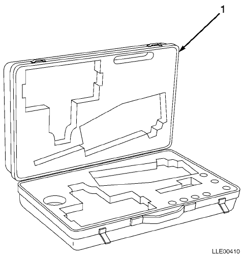
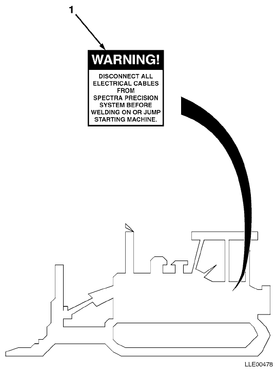
TM 5-6675-348-13&P SECTION II
(1)
ITEM
NO
(2)
SMR
CODE
(3)
CAGEC
(4)
PART
NUMBER
(5)
DESCRIPTION AND USABLE ON CODES (UOC)
(6)
QTY
GROUP 22 BODY CHASSIS OR HULL, AND ACCESSORY
ITEMS
GROUP 2210 DATA PLATES AND INSTRUCTION
HOLDERS
FIG. 4 DOZER DECALS AND INSTRUCTION PLATES
1 56009 111741 LABEL,WARNING,WELDING/JUMP STARTING ........ 1
END OF FIGURE
4-1
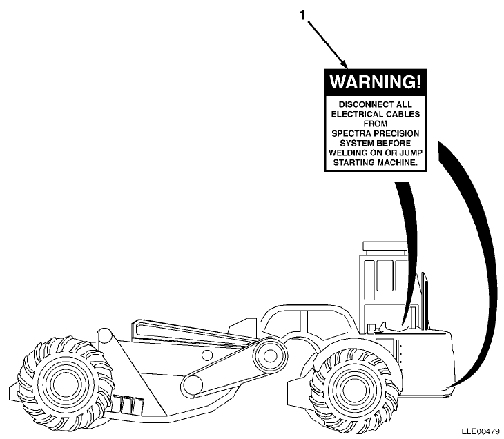
TM 5-6675-348-13&P SECTION II
(1)
ITEM
NO
(2)
SMR
CODE
(3)
CAGEC
(4)
PART
NUMBER
(5)
DESCRIPTION AND USABLE ON CODES (UOC)
(6)
QTY
GROUP 22 BODY CHASSIS OR HULL, AND ACCESSORY
ITEMS
GROUP 2210 DATA PLATES AND INSTRUCTION
HOLDERS
FIG. 5 SCRAPER DECALS AND INSTRUCTION
PLATES
1 56009 111741 LABEL,WARNING,WELDING/JUMP STARTING ........ 1
END OF FIGURE
5-1

TM 5-6675-348-13&P SECTION II
(1)
ITEM
NO
(2)
SMR
CODE
(3)
CAGEC
(4)
PART
NUMBER
(5)
DESCRIPTION AND USABLE ON CODES (UOC)
(6)
QTY
GROUP 67 PRECISION INSTRUMENTS AND SYSTEMS,
MECHANICAL, ELECTRICAL, ELECTRONIC
GROUP 6709 ANTENNAS, GROUNDS, AND RELATED
EQUIPMENT
FIG. 6 DOZER/SCRAPER GRADIO® RT2S LASER
RECEIVER
1 56009 RT2S-1 TRANSMITTER,GRADIO® (USED WITH DR2-1 GRADIO®
DISPLAY) .................................. 1
56009 RT2S-2 TRANSMITTER,GRADIO® (USED WITH DR2-2 GRADIO®
DISPLAY) .................................. 1
56009 RT2S-3 TRANSMITTER,GRADIO® (USED WITH DR2-3 GRADIO®
DISPLAY) .................................. 1
56009 RT2S-4 TRANSMITTER,GRADIO® (USED WITH DR2-4 GRADIO®
DISPLAY) .................................. 1
56009 RT2S-5 TRANSMITTER,GRADIO® (USED WITH DR2-5 GRADIO®
DISPLAY) .................................. 1
2 56009 0250-1470 • RETAINER CLAMP KNOB ...................... 1
3 56009 7181-0605-010 • SCR,MACH,RND,SST 6-32 X 5/16 IN.(10/PKG) . 1
4 56009 2508-0520 • BOOT,SWITCH (PLASTIC) .................... 1
5 56009 1409-0990 • STUD,FRONT LOAD 4MM ...................... 1
56009 1409-0980 •• RECEPTACLE,FRONT LOAD 4MM ............... 1
56009 0225-0390 •• RETAINER,STUD HALF GROMMET GP ........... 1
6 56009 7181-0806 • SCR,ROUND HEAD PHIL 8-32 (10/PKG) ........ 1
56009 2802-0250 •• WSHR,INT-T LOCK,#8 STL (10/PKG) ......... 1
7 56009 012192 • SCR,OVAL,XREC,10-32 X 4 IN. (5/PKG) ...... 1
8 56009 2802-0030-010 • LKWASH,SPLIT,#8 SST (10/PKG) ............. 1
9 56009 8201-0810 • SCR,SOCKET HEAD CAP 8-32 X 5/8 IN. ....... 8
10 56009 0225-1770 • CLAMP,BASE RECEIVER ...................... 1
11 56009 0250-1430 • KNOB,MOLDED CLAMPING ..................... 1
END OF FIGURE
6-1
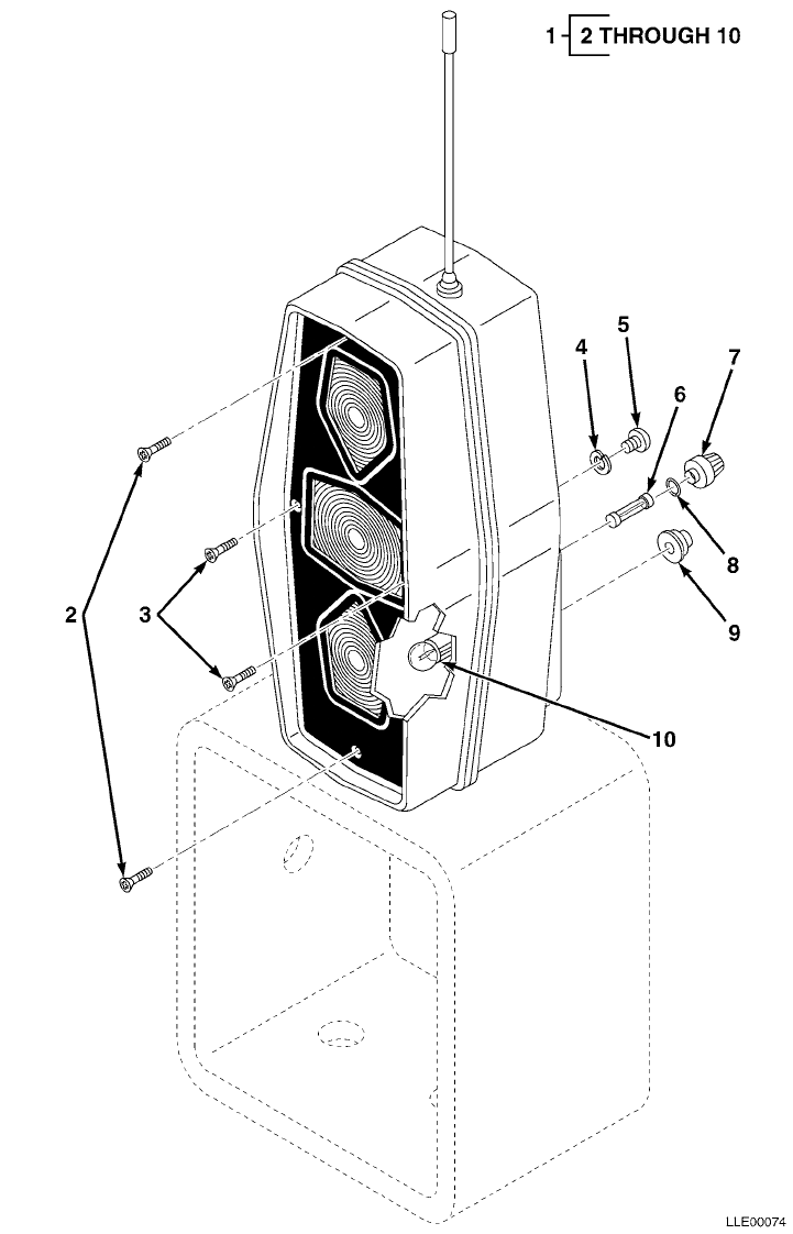
TM 5-6675-348-13&P SECTION II
(1)
ITEM
NO
(2)
SMR
CODE
(3)
CAGEC
(4)
PART
NUMBER
(5)
DESCRIPTION AND USABLE ON CODES (UOC)
(6)
QTY
GROUP 67 PRECISION INSTRUMENTS AND SYSTEMS,
MECHANICAL, ELECTRICAL, ELECTRONIC
GROUP 6711 CONTROLS, INDICATORS, AND
SPECIAL COMPONENTS
FIG. 7 DOZER/SCRAPER GRADIO® DISPLAY
1 56009 DR2-1 TRANSMITTER,GRADIO® (USED WITH RT2S-1
GRADIO® TRANSMITTER)....................... 1
56009 DR2-2 TRANSMITTER,GRADIO® (USED WITH RT2S-2
GRADIO® TRANSMITTER)....................... 1
56009 DR2-3 TRANSMITTER,GRADIO® (USED WITH RT2S-3
GRADIO® TRANSMITTER)....................... 1
56009 DR2-4 TRANSMITTER,GRADIO® (USED WITH RT2S-4
GRADIO® TRANSMITTER)....................... 1
56009 DR2-5 TRANSMITTER,GRADIO® (USED WITH RT2S-5
GRADIO® TRANSMITTER)....................... 1
2 56009 012708 • SCR,FL,XREC,1/4-20 X 1.75 IN.
(10/PKG) ................................. 1
3 56009 2816-1970 • SCR,FL,XREC,6-32 X 0.375 IN.
(10/PKG) ................................. 1
4 56009 2802-0020-010 • LKWASH,SPLIT,#6,SST (10/PKG) ............. 1
5 56009 7181-0606-010 • SCR,RND,XREC,6-32 X 3/8 IN.
(10/PKG) ................................. 1
6 56009 003376 • FUSE,5 AMP ............................... 1
7 56009 010716 • CAP,FUSE HOLDER SEAL ..................... 1
8 56009 011023 • SEAL,FUSE CAP HOLDER ..................... 1
9 56009 2508-0500 • SEAL,BOOT,TOG SW,15/32-32 NS,BL .......... 1
10 56009 011179 • LAMP,24 VOLT ............................. 3
END OF FIGURE
7-1

TM 5-6675-348-13&P SECTION II
(1)
ITEM
NO
(2)
SMR
CODE
(3)
CAGEC
(4)
PART
NUMBER
(5)
DESCRIPTION AND USABLE ON CODES (UOC)
(6)
QTY
GROUP 67 PRECISION INSTRUMENTS AND SYSTEMS,
MECHANICAL, ELECTRICAL, ELECTRONIC
GROUP 6712 MOUNTING CONNECTING DEVICE
FIG. 8 DOZER/SCRAPER GRADIO® DISPLAY MOUNT
1 56009 9837-1624-005 SCR,CAP,HEX,3/8-16 X 1-1/2 IN.
(5/PKG) ................................... 1
2 56009 003847-010 LKWSHR,SPLIT,3/8 X 0.68 X 0.09 IN.
(10/PKG) .................................. 1
3 56009 006649 CLAMP,HOSE ................................. 3
4 56009 209930 MOUNT,DISPLAY .............................. 1
5 56009 220318 PLATE,DISPLAY MOUNT ........................ 1
6 56009 9837-1820-010 SCR,CAP,HEX,1/2-13 X 1 IN.
(10/PKG) .................................. 1
7 56009 003855-010 LKWSHR,SPLIT,0.50 X 0.51 X 0.12 IN.
(10/PKG) .................................. 1
8 56009 0790-1980 BULKHEAD,BLANK #16 ......................... 1
9 56009 7121-6008-010 SCR,FL,XREC,10-32 X 0.5 IN.
(10/PKG) .................................. 1
END OF FIGURE
8-1

TM 5-6675-348-13&P SECTION II
(1)
ITEM
NO
(2)
SMR
CODE
(3)
CAGEC
(4)
PART
NUMBER
(5)
DESCRIPTION AND USABLE ON CODES (UOC)
(6)
QTY
GROUP 67 PRECISION INSTRUMENTS AND SYSTEMS,
MECHANICAL, ELECTRICAL, ELECTRONIC
GROUP 6712 MOUNTING CONNECTING DEVICE
FIG. 9 RM2E-3 SCRAPER RIGID MAST MOUNT
1 56009 209254 MOUNT,RIGID MAST,MG ........................ 1
2 56009 9837-7034 SCR,CAP,HEX,5/8-18 X 2-1/2 IN.,STL ......... 1
3 56009 003810 NUT,HEX,5/8-18 X 0.93 X 0.55 IN.,STL,CD .... 1
4 56009 003857 LKWSHR,SPLIT,5/8 X 1.07 X 0.16 IN.STL,CD ... 1
END OF FIGURE
9-1
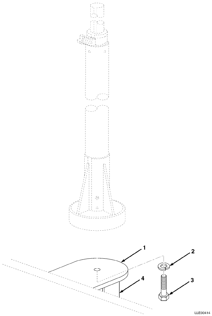
TM 5-6675-348-13&P SECTION II
(1)
ITEM
NO
(2)
SMR
CODE
(3)
CAGEC
(4)
PART
NUMBER
(5)
DESCRIPTION AND USABLE ON CODES (UOC)
(6)
QTY
GROUP 67 PRECISION INSTRUMENTS AND SYSTEMS,
MECHANICAL, ELECTRICAL, ELECTRONIC
GROUP 6712 MOUNTING CONNECTING DEVICE
FIG. 10 DOZER MANUAL MAST MOUNT
1 56009 201476 MOUNT,MAST ................................. 1
2 56009 003859-010 LKWSHR,SPLIT,3/4 X 1.27 X 0.19 IN.,STL,CD
(10/PKG) .................................. 1
3 56009 010185-005 SCR,CAP,HEX,3/4-16 X 1-1/2 IN.,STL (5/PKG .. 1
4 56009 220286 BRACKET,MAST MOUNT ......................... 2
END OF FIGURE
10-1
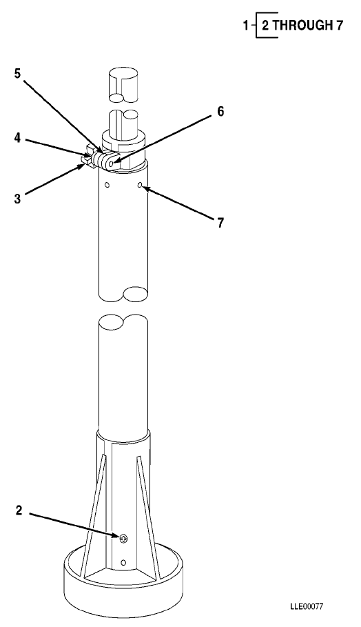
TM 5-6675-348-13&P SECTION II
(1)
ITEM
NO
(2)
SMR
CODE
(3)
CAGEC
(4)
PART
NUMBER
(5)
DESCRIPTION AND USABLE ON CODES (UOC)
(6)
QTY
GROUP 67 PRECISION INSTRUMENTS AND SYSTEMS,
MECHANICAL, ELECTRICAL,ELECTRONIC
GROUP 6714 ANTENNAS, GROUNDS, AND RELATED
EQUIPMENT
FIG. 11 DOZER MM2E-T MANUAL MAST
1 56009 MM2E-T MANUAL MAST ................................ 1
2 56009 003656 • SCR,MH FL PHIL,SSTL,
10-32 X 0.58 IN. ......................... 1
3 56009 122420 • STUD,LOCKING ASSEMBLY .................... 1
4 56009 122014 • WSHR,FL,3/8 X 0.50 X 0.03 IN. ............ 1
5 56009 0230-2080 • SPACER ................................... 1
6 56009 7181-6006-010 • SCR,RND,XREC,10-32 X 3/8 IN.
(10/PKG) ................................. 1
7 56009 003655 • SCR,FL,XREC,10-32 X 0.5 IN.
(10/PKG) ................................. 1
END OF FIGURE
11-1

TM 5-6675-348-13&P SECTION II
(1)
ITEM
NO
(2)
SMR
CODE
(3)
CAGEC
(4)
PART
NUMBER
(5)
DESCRIPTION AND USABLE ON CODES (UOC)
(6)
QTY
GROUP 67 PRECISION INSTRUMENTS AND SYSTEMS,
MECHANICAL, ELECTRICAL, ELECTRONIC
GROUP 6713 MISCELLANEOUS WIRING AND
FITTINGS
FIG. 12 DOZER/SCRAPER ELECTRICAL CABLES
1 56009 222621-200 CABLE,2 COND,BASIC POWER ................... 1
END OF FIGURE
12-1
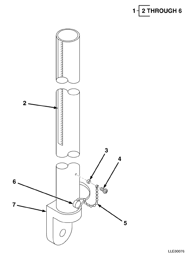
TM 5-6675-348-13&P SECTION II
(1)
ITEM
NO
(2)
SMR
CODE
(3)
CAGEC
(4)
PART
NUMBER
(5)
DESCRIPTION AND USABLE ON CODES (UOC)
(6)
QTY
GROUP 67 PRECISION INSTRUMENTS AND SYSTEMS,
MECHANICAL, ELECTRICAL, ELECTRONIC
GROUP 6714 ANTENNAS, GROUNDS, AND RELATED
EQUIPMENT
FIG. 13 SCRAPER RIGID MAST
1 56009 RM2E-3 RIGID MAST ................................. 1
2 56009 209099 • SCALE,3 FOOT MAST ........................ 1
3 56009 2507-4270-010 • SPACER,RND,0.203 X 0.312 X 0.194 IN.
(10/PKG) ................................. 1
4 56009 7181-6008-010 • SCR,RND,XREC (10/PKG) .................... 1
5 56009 3502-0420 • CHAIN .................................... 1
6 56009 2509-6780 • PIN ...................................... 1
7 56009 201634 • MOUNT,RIGID MAST,LPO ..................... 1
END OF FIGURE
13-1
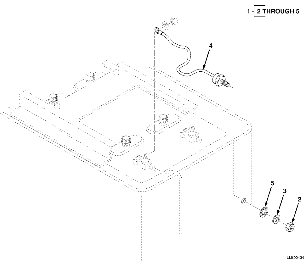
TM 5-6675-348-13&P SECTION II
(1)
ITEM
NO
(2)
SMR
CODE
(3)
CAGEC
(4)
PART
NUMBER
(5)
DESCRIPTION AND USABLE ON CODES (UOC)
(6)
QTY
GROUP 06 ELECTRICAL SYSTEM
GROUP 0606 ENGINE SAFETY CONTROLS
FIG. 14 GRADER VOLTAGE PROTECTION CABLE
1 56009 121022 KIT,VOLTAGE PROTECTION ..................... 1
2 56009 005274 • NUT,HEX,3/8-16 IN. ....................... 1
3 56009 003834-010 • WSHR,FL,3/8 X 1.08 IN. (10/PKG) .......... 1
4 56009 221089 • CABLE,VOLTAGE PROTECTION ................. 1
5 56009 2801-1010 • LKWASH,INTERNAL,3/8 ...................... 1
END OF FIGURE
14-1
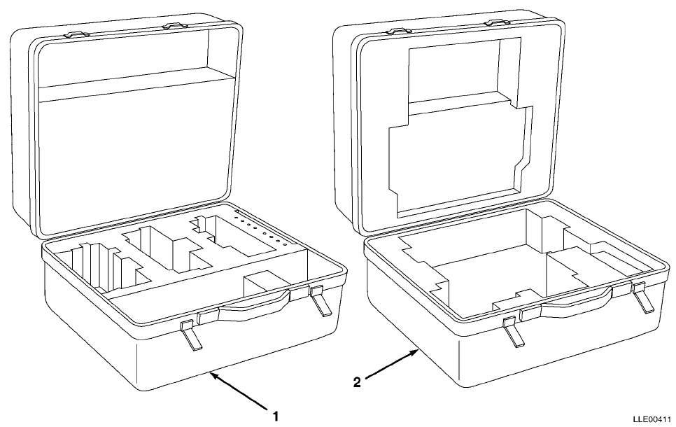
TM 5-6675-348-13&P SECTION II
(1)
ITEM
NO
(2)
SMR
CODE
(3)
CAGEC
(4)
PART
NUMBER
(5)
DESCRIPTION AND USABLE ON CODES (UOC)
(6)
QTY
GROUP 06 ELECTRICAL SYSTEM
GROUP 0612 CARRYING CASE
FIG. 15 BLADE PRO® CARRYING CASES
1 56009 0365-2630 CASE,CARRYING,LABELED,BLADE PRO®............ 1
2 56009 0225-0530 CASE,CARRYING,RT2S RCVR .................... 1
END OF FIGURE
15-1
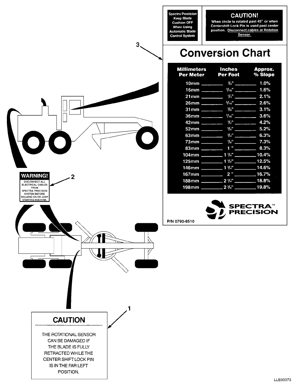
TM 5-6675-348-13&P SECTION II
(1)
ITEM
NO
(2)
SMR
CODE
(3)
CAGEC
(4)
PART
NUMBER
(5)
DESCRIPTION AND USABLE ON CODES (UOC)
(6)
QTY
GROUP 22 BODY CHASSIS OR HULL, AND ACCESSORY
ITEMS
GROUP 2210 DATA PLATES AND INSTRUCTION
HOLDERS
FIG. 16 DECALS, PLATES, AND INSTRUCTION
HOLDERS
1 56009 0355-7470 LABEL,CAUTION,ROTATIONAL SENSOR ............ 1
2 56009 111741 LABEL,WARNING,WELDING/JUMP STARTING ........ 3
3 56009 0790-8510 LABEL,CHART,CONVERSION ..................... 1
END OF FIGURE
16-1

TM 5-6675-348-13&P SECTION II
(1)
ITEM
NO
(2)
SMR
CODE
(3)
CAGEC
(4)
PART
NUMBER
(5)
DESCRIPTION AND USABLE ON CODES (UOC)
(6)
QTY
GROUP 43 HYDRAULIC, FLUID, AIR, AND VACUUM
SYSTEMS
GROUP 4301 STRAINER, FILTERS, HOSE, PIPE
FITTINGS, TUBING, ETC.
FIG. 17 RETURN LINE FITTINGS
1 56009 004196 FITTING,STR SAE-JIC #6 ..................... 2
2 56009 004277 ADAPTER,90-DEGREE ELB,#6 JIC,SWIVEL NUT .... 2
END OF FIGURE
17-1
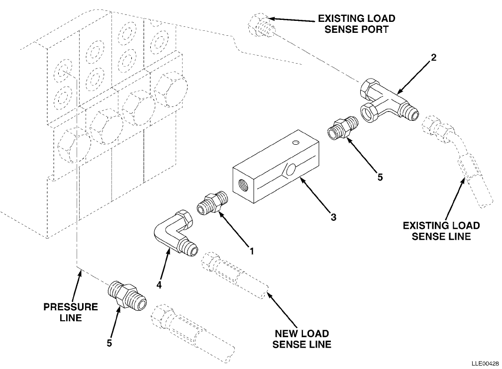
TM 5-6675-348-13&P SECTION II
(1)
ITEM
NO
(2)
SMR
CODE
(3)
CAGEC
(4)
PART
NUMBER
(5)
DESCRIPTION AND USABLE ON CODES (UOC)
(6)
QTY
GROUP 43 HYDRAULIC, FLUID, AIR, AND VACUUM
SYSTEMS
GROUP 4301 STRAINER, FILTERS, HOSE, PIPE
FITTINGS, TUBING, ETC.
FIG. 18 LOAD SENSE AND RETURN VALVES AND
FITTINGS
1 56009 004195 FITTING,STR,SAE-JIC 6 ...................... 2
2 56009 005272 FITTING,TEE,SW RUN #6 JIC .................. 2
3 56009 2523-1949 VALVE,CHECK,#6 SAE INLINE .................. 2
4 56009 005467 FITTING,90-DEGREE,#4 JIC ................... 2
5 56009 004196 FITTING,STR,SAE-JIC #6 ..................... 4
END OF FIGURE
18-1
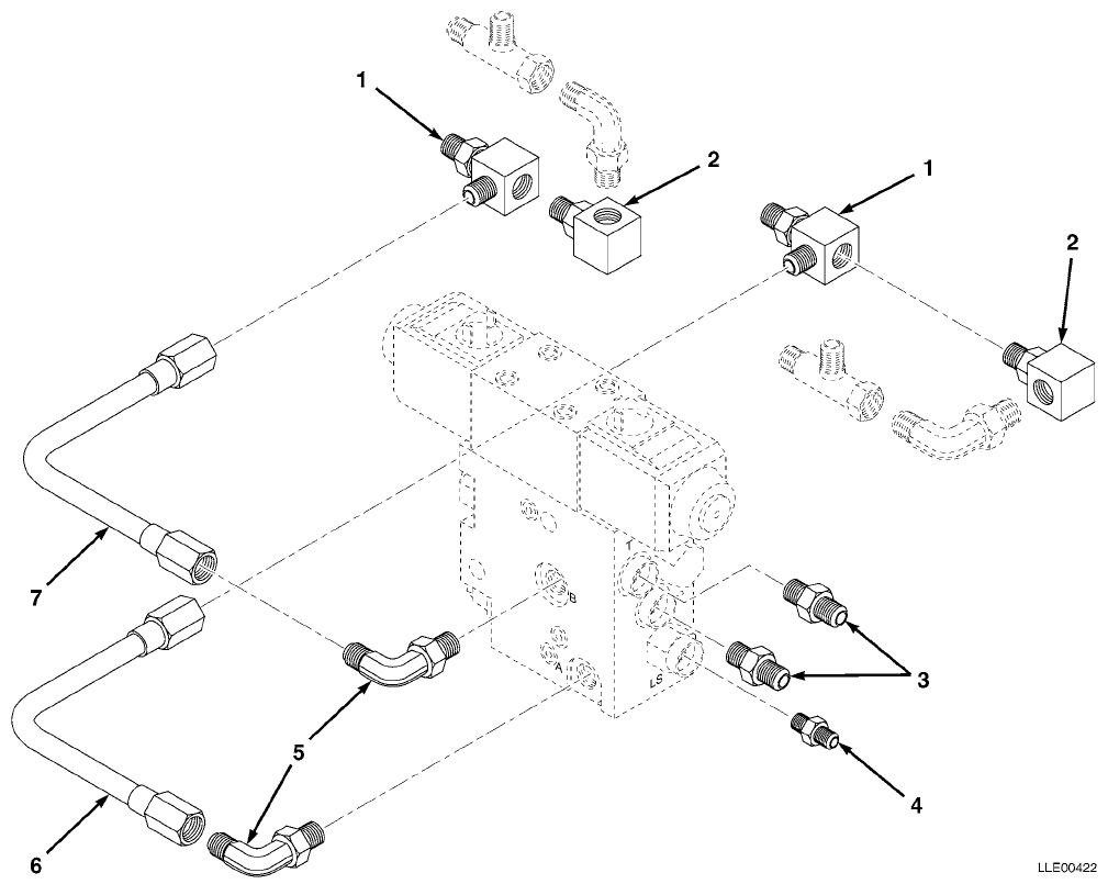
TM 5-6675-348-13&P SECTION II
(1)
ITEM
NO
(2)
SMR
CODE
(3)
CAGEC
(4)
PART
NUMBER
(5)
DESCRIPTION AND USABLE ON CODES (UOC)
(6)
QTY
GROUP 43 HYDRAULIC, FLUID, AIR, AND VACUUM
SYSTEMS
GROUP 4301 STRAINER, FILTERS, HOSE, PIPE
FITTINGS, TUBING, ETC.
FIG. 19 PIPES AND FITTINGS (PER VALVE)
1 56009 2542-0059 FITTING,TEE,#8 ............................. 2
2 56009 2542-0062 FITTING,90-DEGREE BLOCK #8 ................. 2
3 56009 004196 FITTING,STR,SAE-JIC,#6 ..................... 2
4 56009 004194 FITTING,STR,SAE-JIC,#4 ..................... 1
5 56009 004261 FITTING,90-DEGREE,SAE-JIC,#6 ............... 2
6 56009 0720-2450 TUBE,STEEL,RIGHT RAISE,G BLOCK ............. 1
56009 0720-2470 TUBE,STEEL,LEFT RAISE,
G BLOCK (NOT SHOWN) ....................... 1
7 56009 0720-2460 TUBE,STEEL,RIGHT LOWER,G BLOCK ............. 1
56009 0720-2480 TUBE,STEEL,LEFT LOWER,
G BLOCK (NOT SHOWN) ....................... 1
END OF FIGURE
19-1
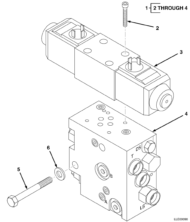
TM 5-6675-348-13&P SECTION II
(1)
ITEM
NO
(2)
SMR
CODE
(3)
CAGEC
(4)
PART
NUMBER
(5)
DESCRIPTION AND USABLE ON CODES (UOC)
(6)
QTY
GROUP 43 HYDRAULIC, FLUID, AIR, AND VACUUM
SYSTEM
GROUP 4305 MANIFOLD AND/OR CONTROL VALVES
FIG. 20 PROPORTIONAL VALVE ASSEMBLY
1 56009 PSV2D06-24 CONTROL VALVE ASSEMBLY,PROPORTIONAL ........ 2
2 56009 2816-4244-005 • SCR,SOCKET HEAD,10-24 X 1-1/4 IN. ........ 4
3 56009 0720-2400 • MANIFOLD,PROPORTIONAL W/CARTRIDGES ....... 4
4 56009 0720-2510 • VALVE,PROPORTIONAL,VICKERS ............... 1
5 56009 9839-1656-005 BOLT,CAP,HEX,3/8-16 X 4-3/4 IN.,STL (5/PKG) 4
6 56009 003834-010 WSHR,FL,3/8 IN. X 1.08 IN. (10/PKG) ........ 4
END OF FIGURE
20-1
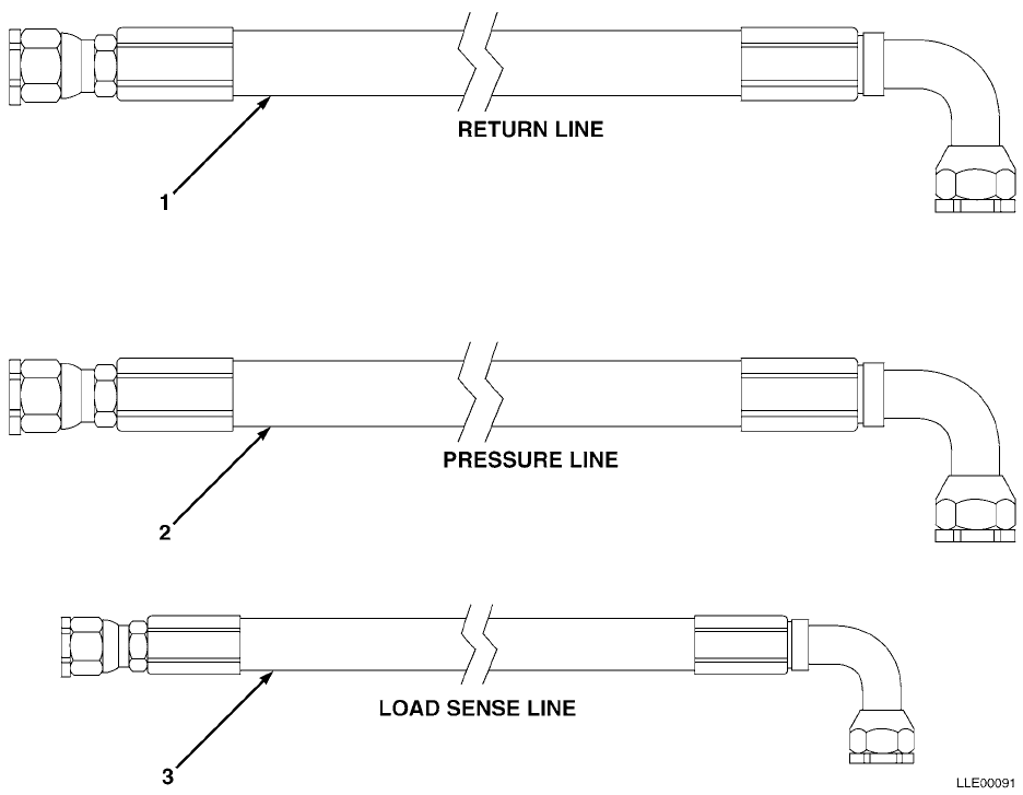
TM 5-6675-348-13&P SECTION II
(1)
ITEM
NO
(2)
SMR
CODE
(3)
CAGEC
(4)
PART
NUMBER
(5)
DESCRIPTION AND USABLE ON CODES (UOC)
(6)
QTY
GROUP 43 HYDRAULIC, FLUID, AIR, AND VACUUM
SYSTEM
GROUP 4316 ASSEMBLED HOSE, FITTINGS, LINE
BREATHERS, FILTERS, AND TRAPS
FIG. 21 HYDRAULIC HOSES
1 56009 208688-063 HOSE,3/8 ID,HYDRAULIC (RETURN LINE) ........ 2
2 56009 208688-085 HOSE,3/8 ID,HYDRAULIC (PRESSURE LINE) ...... 2
3 56009 0791-3120-085 HOSE,1/4 ID,HYDRAULIC,STR-90-DEGREE
(LOAD SENSE LINE) ......................... 2
END OF FIGURE
21-1
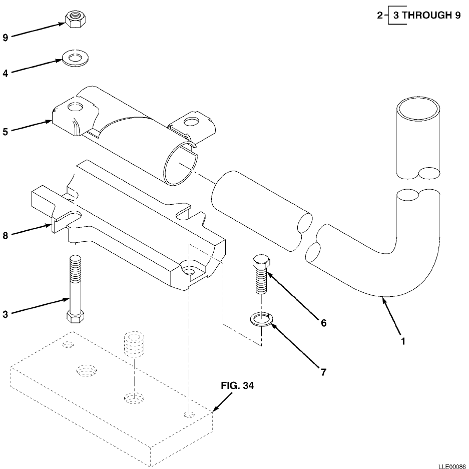
TM 5-6675-348-13&P SECTION II
(1)
ITEM
NO
(2)
SMR
CODE
(3)
CAGEC
(4)
PART
NUMBER
(5)
DESCRIPTION AND USABLE ON CODES (UOC)
(6)
QTY
GROUP 67 PRECISION INSTRUMENTS AND SYSTEMS,
MECHANICAL, ELECTRICAL, ELECTRONIC
GROUP 6703 MECHANICAL, STRUCTURAL, AND
PRECISION PARTS
FIG. 22 TRACER® TUBE AND BASE CLAMP
ASSEMBLY
1 56009 0790-8900 TUBES,TRACER,90-DEGREE ..................... 2
2 56009 0355-9600 BASE CLAMP ASSY ............................ 2
3 56009 011506 • SCR,CAP,HEX,0.5-13 X 2.75 IN.
(5/PKG) .................................. 1
4 56009 003836 • WSHR,FL,0.562 X 0.375 X 0.109 IN.
(10/PKG) ................................. 1
5 56009 0355-9630 • BASE CLAMP ............................... 2
6 56009 9837-1822 • SCR,CAP,HEX,0.50-13 X 1.25 IN.,STL ....... 8
7 56009 003855-010 • LKWSHR,SPLIT,0.50 X 0.51 X 0.12 IN.
(10/PKG) ................................. 1
8 56009 0355-8960 • CLAMP,CAST ............................... 4
9 56009 004964 • NUT,HEX,0.50-13 X 0.75 X 0.44 IN.
(10/PKG) ................................. 1
END OF FIGURE
22-1
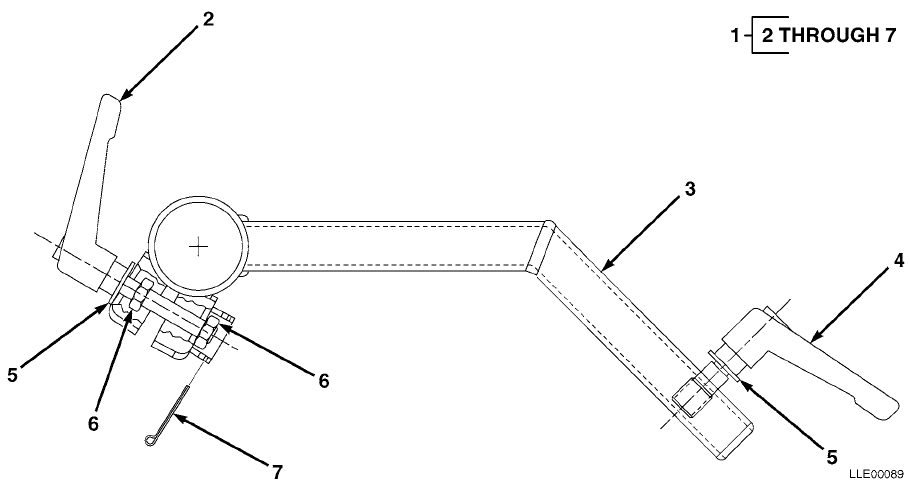
TM 5-6675-348-13&P SECTION II
(1)
ITEM
NO
(2)
SMR
CODE
(3)
CAGEC
(4)
PART
NUMBER
(5)
DESCRIPTION AND USABLE ON CODES (UOC)
(6)
QTY
GROUP 67 PRECISION INSTRUMENTS AND SYSTEMS,
MECHANICAL, ELECTRICAL, ELECTRONIC
GROUP 6703 MECHANICAL, STRUCTURAL, AND
PRECISION PARTS
FIG. 23 TRACER® ARM BRACKET ASSEMBLY
1 56009 0355-8550 BRKT,TRACER® MTG ARM........................ 1
2 56009 0355-8680 • LEVER ASSEMBLY ........................... 1
3 56009 0355-8580 • WELDMENT,TRACER ARM ...................... 1
4 56009 0355-8590 • LEVER ASSEMBLY ........................... 1
5 56009 003834-010 • WSHR,FL,3/8 X 1.08 IN.,STL,CD
(10/PKG) ................................. 1
6 56009 005274 • NUT,HEX 3/8-16 IN. ....................... 2
7 56009 2817-0051 • PIN,COTTER STD.,3/32 X 1-1/4 IN.
(10/PKG) ................................. 1
END OF FIGURE
23-1
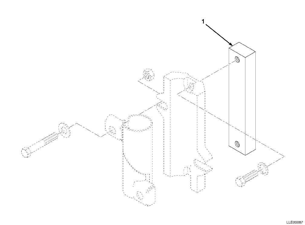
TM 5-6675-348-13&P SECTION II
(1)
ITEM
NO
(2)
SMR
CODE
(3)
CAGEC
(4)
PART
NUMBER
(5)
DESCRIPTION AND USABLE ON CODES (UOC)
(6)
QTY
GROUP 67 PRECISION INSTRUMENTS AND SYSTEMS,
MECHANICAL, ELECTRICAL, ELECTRONIC
GROUP 6703 MECHANICAL, STRUCTURAL, AND
PRECISION PARTS
FIG. 24 TRACER® CLAMP BASE MOUNTING
1 56009 0355-8620 TRACER® MOUNTING BLOCK...................... 2
END OF FIGURE
24-1

TM 5-6675-348-13&P SECTION II
(1)
ITEM
NO
(2)
SMR
CODE
(3)
CAGEC
(4)
PART
NUMBER
(5)
DESCRIPTION AND USABLE ON CODES (UOC)
(6)
QTY
GROUP 67 PRECISION INSTRUMENTS AND SYSTEMS,
MECHANICAL, ELECTRICAL, ELECTRONIC
GROUP 6709 ANTENNAS, GROUNDS, AND RELATED
EQUIPMENT
FIG. 25 EM2E-24 ELECTRIC MAST ASSEMBLY
1 56009 EM2E-24 EM2E-24 ELECTRIC MAST - ENG,24V ............ 1
2 56009 8207-1514 • SCR,CAP SKT,5/16-18 X 7/8 IN.
(10/PKG) ................................. 1
3 56009 7181-0604-010 • SCR,RND XREC,6-32 X 0.25 IN.
(10/PKG) ................................. 1
4 56009 2802-0020-010 • LKWSHR,SPLIT #6,SSTL (10/PKG) ............ 1
5 56009 7181-0612-010 • SCR,RND XREC,6-32 X 0.75 IN.
(10/PKG) ................................. 1
6 56009 2802-0030-010 • LKWSHR,SPLIT #8 SST (10/PKG) ............. 1
7 56009 7121-6007-010 • SCR,FL XREC,10-32 X 7/16 IN.
(10/PKG) ................................. 1
8 56009 012697 • RING,RETAINING ........................... 1
9 56009 7181-0608-010 • SCR,RND XREC,6-32 X 0.50 IN.
(10/PKG) ................................. 1
10 56009 003184 • DUST CAP RECEPTACLE ...................... 1
11 56009 7181-0605-010 • SCR,RND HEAD PHIL,6-32 X 5/16 IN.
(10/PKG) 1
12 56009 011887-005 • SCR,HEX 10-32 X 0.5 IN. STL,CD
(5/PKG) .................................. 1
13 56009 2802-0040-010 • LKWASH,SPLIT #10 ......................... 4
14 56009 0790-4241 RISER,MOTOR 130G GRADER MAST MOUNT ......... 1
15 56009 M2-T SHOCK MOUNT,HIGH VIBRATION ................. 1
16 56009 003859-010 LKWSHR,SPLIT,STL,CD,
3/4 X 1.27 X 0.19 IN. (10/PKG) ............ 2
17 56009 9837-7222-005 SCR,CP HEX,STL,CD,
3/4-16 X 1 IN. (5/PKG) .................... 2
18 56009 011137 SCR,CP HEX,STL,CD,
3/4-16 X 2 IN. ............................ 2
END OF FIGURE
25-1
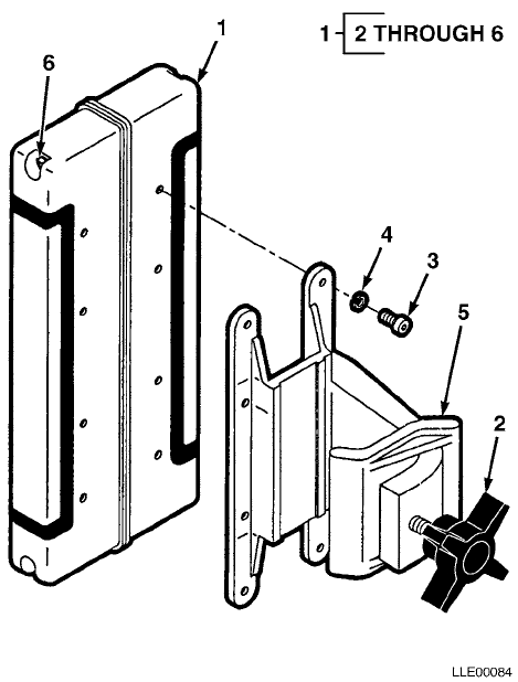
TM 5-6675-348-13&P SECTION II
(1)
ITEM
NO
(2)
SMR
CODE
(3)
CAGEC
(4)
PART
NUMBER
(5)
DESCRIPTION AND USABLE ON CODES (UOC)
(6)
QTY
GROUP 67 PRECISION INSTRUMENTS AND SYSTEMS,
MECHANICAL, ELECTRICAL, ELECTRONIC
GROUP 6709 ANTENNAS, GROUNDS, AND RELATED
EQUIPMENT
FIG. 26 R2S-S LASER RECEIVER
1 56009 R2S-S R2S-S LASER RECEIVER SB W/CASE ............. 1
2 56009 2403-1680 • KNOB,PLASTIC PRONGED ..................... 1
3 56009 8201-0808-020 • SCREW,CAP SKT 8-32 X 1/2 IN.
(20/PKG) ................................. 1
4 56009 2802-0030-010 • LKWSHR,SPLIT #8 SSTL(10/PKG) ............. 4
5 56009 321815 • CLAMP,RECEIVER ........................... 1
6 56009 012192-005 • SCREW,OVAL XREC SSTL 10-32 X 4 IN.
(5/PKG) .................................. 1
END OF FIGURE
26-1

TM 5-6675-348-13&P SECTION II
(1)
ITEM
NO
(2)
SMR
CODE
(3)
CAGEC
(4)
PART
NUMBER
(5)
DESCRIPTION AND USABLE ON CODES (UOC)
(6)
QTY
GROUP 67 PRECISION INSTRUMENTS AND SYSTEMS,
MECHANICAL, ELECTRICAL, ELECTRONIC
GROUP 6711 CONTROLS, INDICATORS, AND
SPECIAL COMPONENTS
FIG. 27 CIRCLE ROTATION SENSOR
1 56009 0365-3000 HSNG,ASSY,ROTATIONAL SNSR .................. 1
2 56009 0355-3170 • BONE,DOG ................................. 1
3 56009 0355-3190 • BEARING,TEFLON ROT SNSR HSG .............. 1
4 56009 8311-0402 • SCR,SET COP 4-40 X 0.125 IN.
(10/PKG) ................................. 1
5 56009 0355-3180 DISK,ORIENTATION ........................... 1
6 56009 0355-3130 MTG BRKT,ROTATION SNSR ARM ................. 1
7 56009 0355-3140 ARM MTG BRKT,ROTATION SNSR ................. 1
8 56009 2816-2260-010 SCR,SHLDR,SKT,10-32 X 0.75 IN.
(10/PKG) .................................. 1
9 56009 003833 WSHR,FL,5/16 X 0.87 X 0.08 IN.,STL CD
(10/PKG) .................................. 1
10 56009 003851-010 LKWASH,SPLIT,5/16 X 0.59 X 0.08 IN. STL,
CD (10/PKG) ............................... 1
11 56009 9837-1520-010 SCR,CAP,HEX,5/16-18 X 1.00 IN. (10/PKG) .... 2
12 56009 8241-6008-010 SCR,BUT,SKT,10-32 X 0.5 SST,PSVT (10/PKG) .. 3
13 56009 0365-5310 BSHG,ROTATIONAL SNSR MTG ................... 3
END OF FIGURE
27-1

TM 5-6675-348-13&P SECTION II
(1)
ITEM
NO
(2)
SMR
CODE
(3)
CAGEC
(4)
PART
NUMBER
(5)
DESCRIPTION AND USABLE ON CODES (UOC)
(6)
QTY
GROUP 67 PRECISION INSTRUMENTS AND SYSTEMS,
MECHANICAL, ELECTRICAL, ELECTRONIC
GROUP 6711 CONTROLS, INDICATORS, AND
SPECIAL COMPONENTS
FIG. 28 OPERATOR INTERFACE BOX
1 56009 0365-2040 OPERATOR INTERFACE PROP FINAL ASSY ......... 1
2 56009 8201-1626 • SCR,SOC,CAP 3/8-16 X 1-3/4 IN.,
SST F/T .................................. 1
3 56009 2403-1680 • KNOB,PLASTIC PRONGED ..................... 1
END OF FIGURE
28-1

TM 5-6675-348-13&P SECTION II
(1)
ITEM
NO
(2)
SMR
CODE
(3)
CAGEC
(4)
PART
NUMBER
(5)
DESCRIPTION AND USABLE ON CODES (UOC)
(6)
QTY
GROUP 67 PRECISION INSTRUMENTS AND SYSTEMS,
MECHANICAL, ELECTRICAL, ELECTRONIC
GROUP 6711 CONTROLS, INDICATORS, AND
SPECIAL COMPONENTS
FIG. 29 REMOTE INTERFACE BOX
1 56009 0365-1140 BOX,REMOTE,INTERFACE ....................... 1
2 56009 2117-1710 • CAP,DUST,W/WIRE ROPE 0.125 IN. DIA ....... 1
3 56009 7181-0606-010 • SCR,RND,6-32 X 3/8 IN. SST PSVT (10/PKG) . 4
4 56009 2802-0770 • LKWASH,SPLIT,6-32,STL,2N ................. 4
5 56009 011894 • FUSE,25 AMP .............................. 2
6 56009 011023 • SEAL,FUSE CAP ............................ 2
7 56009 010716 • CAP,FUSE ................................. 2
8 56009 9837-1634 SCR,CAP,HEX,1/4 X 20 X 1 IN.,
3/8 X 16 2 1/2 SSL STEEL(5/PKG) ........... 1
9 56009 0365-3160 CLAMP,REMOTE BOX MTG ....................... 2
END OF FIGURE
29-1
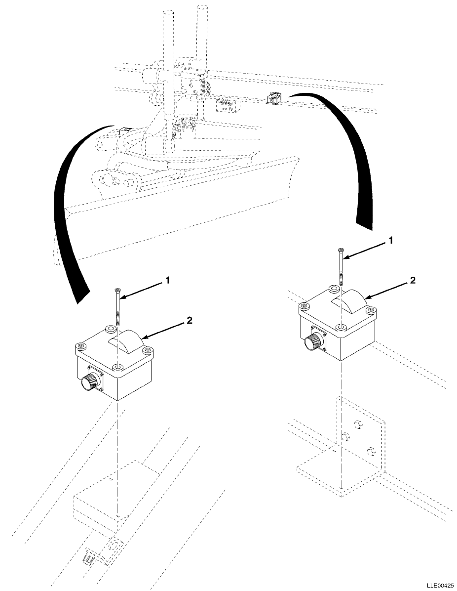
TM 5-6675-348-13&P SECTION II
(1)
ITEM
NO
(2)
SMR
CODE
(3)
CAGEC
(4)
PART
NUMBER
(5)
DESCRIPTION AND USABLE ON CODES (UOC)
(6)
QTY
GROUP 67 PRECISION INSTRUMENTS AND SYSTEMS,
MECHANICAL, ELECTRICAL, ELECTRONIC
GROUP 6711 CONTROLS, INDICATORS, AND
SPECIAL COMPONENTS
FIG. 30 SLOPE SENSORS
1 56009 8201-1432-005 SCR,CAP SOCKET,1/4-20 X 2-1/4 IN.
(5/PKG) ................................... 1
2 56009 0365-4010 SNSR,SLOPE ................................. 2
END OF FIGURE
30-1
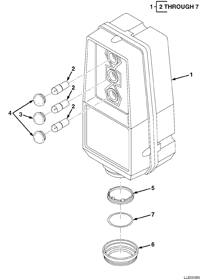
TM 5-6675-348-13&P SECTION II
(1)
ITEM
NO
(2)
SMR
CODE
(3)
CAGEC
(4)
PART
NUMBER
(5)
DESCRIPTION AND USABLE ON CODES (UOC)
(6)
QTY
GROUP 67 PRECISION INSTRUMENTS AND SYSTEMS,
MECHANICAL, ELECTRICAL, ELECTRONIC
GROUP 6711 CONTROLS, INDICATORS, AND
SPECIAL COMPONENTS
FIG. 31 TRACER® SONIC GRADE CONTROLLER
1 56009 ST2-20 NON-CONTACT SONIC TRACER ................... 1
2 56009 3901-2110 • LAMP,INCAND T3-14 ........................ 3
3 56009 3902-0603 • LENS,GREEN,0.625 IN. DIA,STOVEPIPE ....... 1
4 56009 3902-0604 • LENS,AMBER,0.625 IN. DIA,STOVEPIPE ....... 2
5 56009 5501-0151 • TRANSDUCER,SND,POLAROID,604142 ........... 1
6 56009 0365-8420 • TRANSDUCER RING .......................... 1
7 56009 2504-6000 • O-RING,1.50 ID X 1.688 OD X 0.094 IN. .... 1
END OF FIGURE
31-1

TM 5-6675-348-13&P SECTION II
(1)
ITEM
NO
(2)
SMR
CODE
(3)
CAGEC
(4)
PART
NUMBER
(5)
DESCRIPTION AND USABLE ON CODES (UOC)
(6)
QTY
GROUP 67 PRECISION INSTRUMENTS AND SYSTEMS,
MECHANICAL, ELECTRICAL, ELECTRONIC
GROUP 6711 CONTROLS, INDICATORS, AND
SPECIAL COMPONENTS
FIG. 32 CONTROL KNOB SWITCHES
1 56009 0791-1890-090 CABLE,3-CONNECTOR,REMOTE,R/L SWITCH ........ 2
2 56009 0791-1850-090 CABLE,3-CONNECTOR,REMOTE,SWITCH ............ 1
3 56009 003805-010 NUT,HEX,3/8-24 X 0.56 X 0.22 IN.
(10/PKG) .................................. 3
4 56009 0365-5310 BSHG ....................................... 6
5 56009 006649 CLAMP,HOSE ................................. 6
6 56009 0365-2700 ASSY,REMOTE SPLICE ......................... 1
END OF FIGURE
32-1
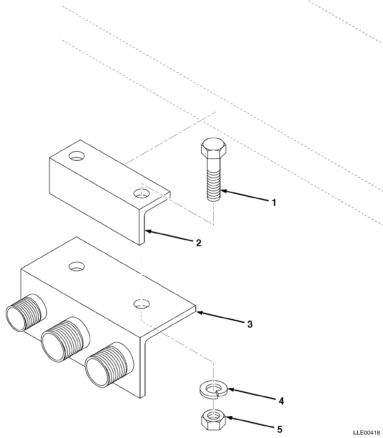
TM 5-6675-348-13&P SECTION II
(1)
ITEM
NO
(2)
SMR
CODE
(3)
CAGEC
(4)
PART
NUMBER
(5)
DESCRIPTION AND USABLE ON CODES (UOC)
(6)
QTY
GROUP 67 PRECISION INSTRUMENTS AND SYSTEMS,
MECHANICAL, ELECTRICAL, ELECTRONIC
GROUP 6712 MOUNTED CONNECTING DEVICES
FIG. 33 CONNECTOR HOLDER ASSEMBLY
1 56009 9837-1624-005 SCR,CAP,HEX,3/8-16 X 1-1/2 IN.
(5/PKG) ................................... 1
2 56009 0365-3160 BRKT,CLAMP REMOTE BOX MTG .................. 1
3 56009 0792-3910 BRKT,CABLE (RT) ............................ 1
56009 0792-3920 BRKT,CABLE (LT) ............................ 1
4 56009 0365-8740 • ANGLE, CABLE ............................. 1
5 56009 0790-1980 • BULKHEAD, BLANK, #16 ..................... 1
6 56009 0790-1990 • BULKHEAD, BLANK, #18 (RT) ................ 2
56009 0790-1970 • BULKHEAD, BLANK, #14 (LT) ................ 2
7 56009 7121-6006-010 • SCR, 10-32 X 3/8 (10/PKG) ................ 1
8 56009 003847-010 LKWASH,SPLIT 3/8 X 0.68 X 0.09 IN. ......... 4
9 56009 005274 NUT,HEX 3/8-16 IN. ......................... 4
END OF FIGURE
33-1
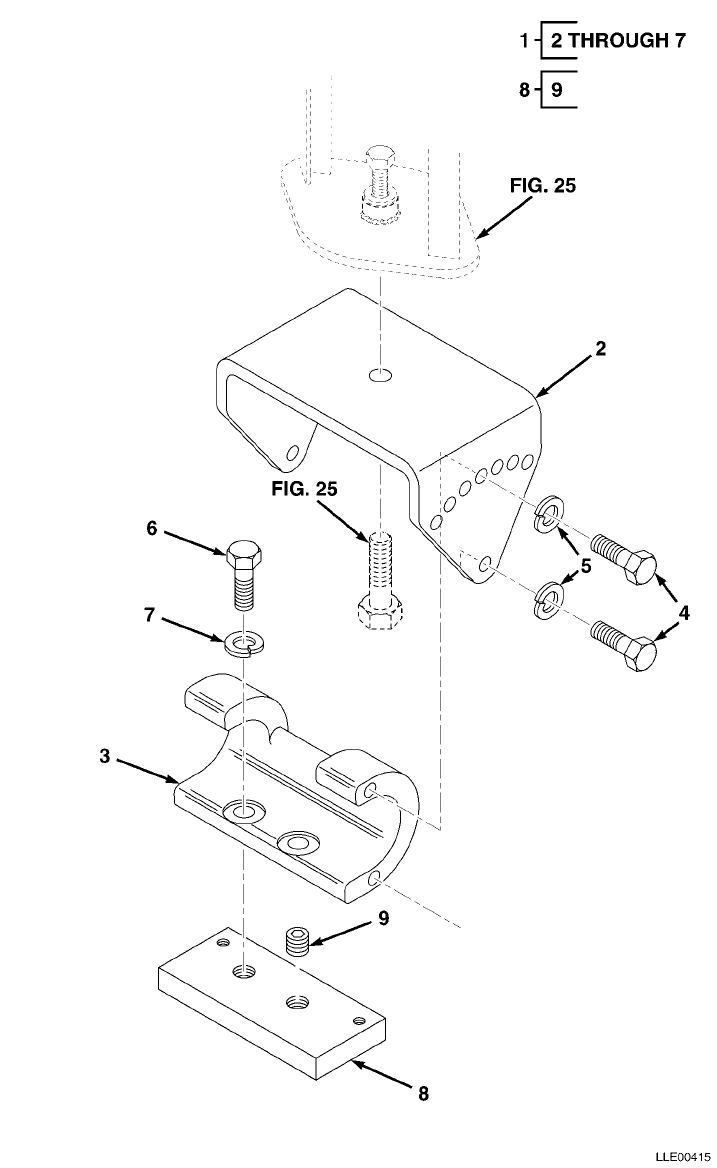
TM 5-6675-348-13&P SECTION II
(1)
ITEM
NO
(2)
SMR
CODE
(3)
CAGEC
(4)
PART
NUMBER
(5)
DESCRIPTION AND USABLE ON CODES (UOC)
(6)
QTY
GROUP 67 PRECISION INSTRUMENTS AND SYSTEMS,
MECHANICAL, ELECTRICAL, ELECTRONIC
GROUP 6712 MOUNTING CONNECTING DEVICES
FIG. 34 MAST MOUNT BASE
1 56009 0791-1740 ASSEMBLY MAST MOUNT BASE COMPLETE .......... 1
2 56009 0791-1380 • YOKE MAST MOUNT .......................... 1
3 56009 0791-1990 • MOUNT,MAST BASE .......................... 1
4 56009 2816-4315 • SCR,CAP HEX,5/8-11 X 1.25 IN. ............ 4
5 56009 003857 • LKWASH,SPLIT,5/8 IN. ..................... 4
6 56009 9837-2224 • SCR,CAP HEX,3/4-10 X 1.5 IN. STL ......... 2
7 56009 003859-010 • LKWASH,SPLIT,3/4 X 1.27 X 0.19 IN.
(10/PKG) ................................. 1
8 56009 0791-8820 PLATE,TRACER/MAST MTG ...................... 2
9 56009 8319-2212 • SCR,SET CUP,3/4-10 X 0.75 IN.,
ZNC PLT .................................. 2
END OF FIGURE
34-1
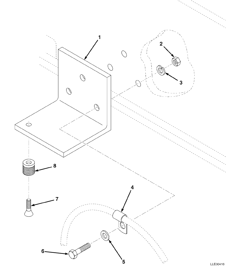
TM 5-6675-348-13&P SECTION II
(1)
ITEM
NO
(2)
SMR
CODE
(3)
CAGEC
(4)
PART
NUMBER
(5)
DESCRIPTION AND USABLE ON CODES (UOC)
(6)
QTY
GROUP 67 PRECISION INSTRUMENTS AND SYSTEMS,
MECHANICAL, ELECTRICAL, ELECTRONIC
GROUP 6712 MOUNTING CONNECTING DEVICES
FIG. 35 MAINFALL SLOPE SENSOR BRACKET
1 56009 0355-5200 BRKT,MAINFALL SNSR MTG ..................... 1
2 56009 005274 NUT,HEX .................................... 2
3 56009 003847-010 LKWSHR,SPLIT,3/8 X 0.68 X 0.09 IN.
(10/PKG) .................................. 2
4 56009 006649 CLAMP,HOSE ................................. 1
5 56009 003834-010 WSHR,FL,3/8 X 1 X 0.08 IN.,STL,
CD (10/PKG) ............................... 2
6 56009 9837-1622-010 SCR,CAP,HEX,3/8-16 X 1 1/4 IN.
STL (10/PKG) .............................. 2
7 56009 7129-1408-010 SCR,RND,XREC,10-32 X 3/8 IN.
(10/PKG) .................................. 1
8 56009 0790-1970 HOLDER,CONNECTOR #14 ....................... 1
END OF FIGURE
35-1
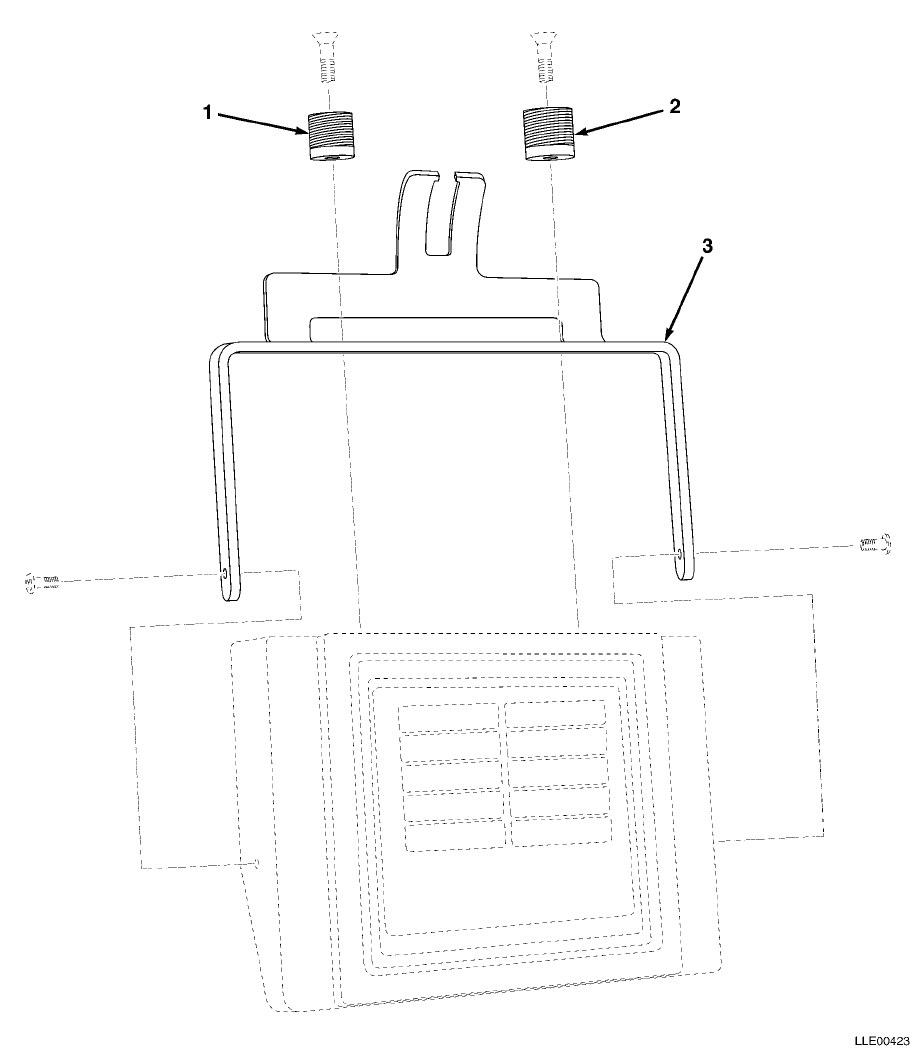
TM 5-6675-348-13&P SECTION II
(1)
ITEM
NO
(2)
SMR
CODE
(3)
CAGEC
(4)
PART
NUMBER
(5)
DESCRIPTION AND USABLE ON CODES (UOC)
(6)
QTY
GROUP 67 PRECISION INSTRUMENTS AND SYSTEMS,
MECHANICAL, ELECTRICAL, ELECTRONIC
GROUP 6712 MOUNTING CONNECTING DEVICES
FIG. 36 OPERATOR CONTROL BOX MOUNT
1 56009 0790-1970 HOLDER,CONNECTOR,#14 ....................... 1
2 56009 0790-1990 HOLDER,CONNECTOR,#18 ....................... 1
3 56009 0365-5000 MOUNT,OPERATOR CONTROL BOX ................. 1
END OF FIGURE
36-1
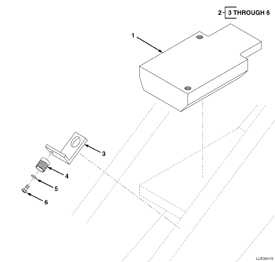
TM 5-6675-348-13&P SECTION II
(1)
ITEM
NO
(2)
SMR
CODE
(3)
CAGEC
(4)
PART
NUMBER
(5)
DESCRIPTION AND USABLE ON CODES (UOC)
(6)
QTY
GROUP 67 PRECISION INSTRUMENTS AND SYSTEMS,
MECHANICAL, ELECTRICAL, ELECTRONIC
GROUP 6712 MOUNTING CONNECTING DEVICES
FIG. 37 BLADE SLOPE SENSOR MOUNT
1 56009 0355-5100 PLATE,SLOPE SNSR MTG ....................... 1
2 56009 0792-3930 HOLDER,CONNECTOR ........................... 1
3 56009 0355-3140 • BRKT, ARM MOUNTING ....................... 1
4 56009 0790-1970 • BULKHEAD, BLANK #14 ...................... 1
5 56009 2802-0420 • WASHER, EXT-LICK, #10, STL, CD ........... 1
6 56009 7121-6006-010 • SCR, 10-32 X 3/8 IN. (10/PKG) ............ 1
END OF FIGURE
37-1
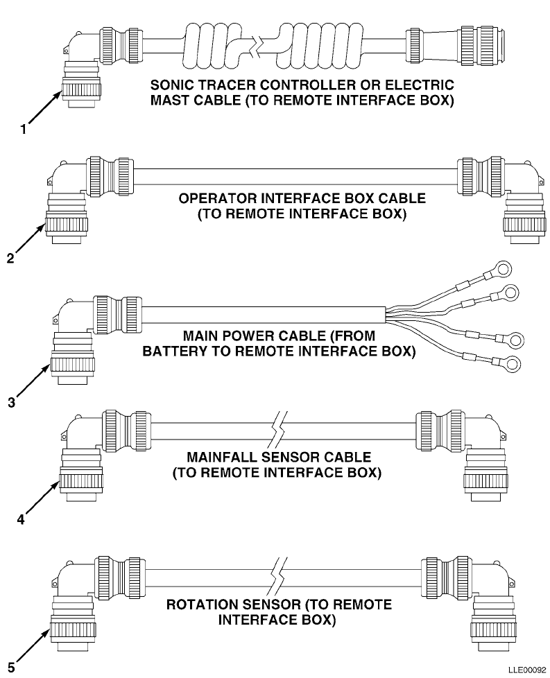
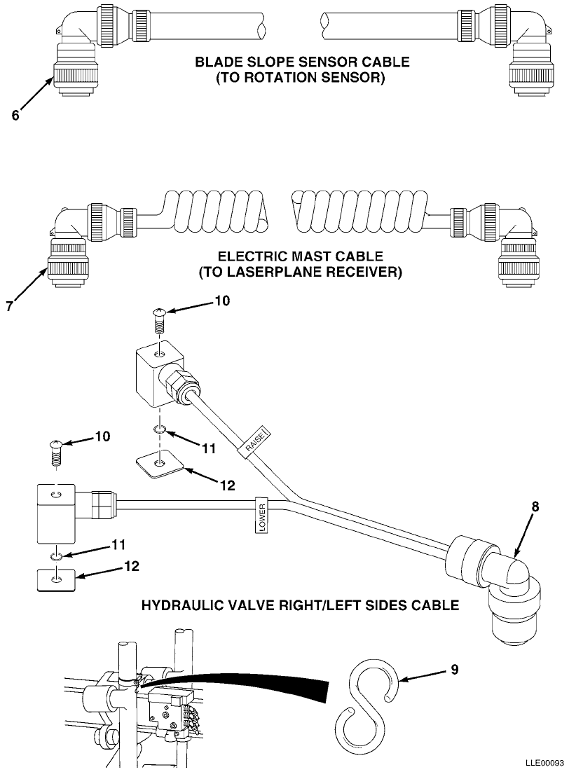
SECTION II TM 5-6675-348-13&P
FIG. 38 CABLES AND COIL CORDS (SHEET 2 OF 2)

TM 5-6675-348-13&P SECTION II
(1)
ITEM
NO
(2)
SMR
CODE
(3)
CAGEC
(4)
PART
NUMBER
(5)
DESCRIPTION AND USABLE ON CODES (UOC)
(6)
QTY
GROUP 67 PRECISION INSTRUMENTS AND SYSTEMS,
MECHANICAL, ELECTRICAL, ELECTRONIC
GROUP 6713 MISCELLANEOUS WIRING AND
FITTINGS
FIG. 38 CABLES AND COIL CORDS (SHEET 1 OF
2)
1 56009 0790-8700 CABLE,SONIC TRACER CONTROLLER OR ELECTRIC
MAST (TO REMOTE INTERFACE BOX) ............ 1
2 56009 0791-5700-150 CABLE,OPERATOR (TO REMOTE INTERFACE
BOX) ...................................... 1
3 56009 0791-5710-240 CABLE,MAIN POWER (FROM BATTERY TO REMOTE
INTERFACE BOX) ............................ 1
4 56009 0791-5680-085 CABLE,MAINFALL SENSOR (TO REMOTE INTERFACE
BOX) ...................................... 1
5 56009 0791-5690-250 CABLE,ROTATION SENSOR (TO REMOTE INTERFACE
BOX) ...................................... 1
6 56009 0790-5590-070 CABLE,BLADE SLOPE SNSR (TO ROTATION
SNSR) ..................................... 1
7 56009 0790-9000 CABLE,ELECTRIC MAST (TO LASERPLANE RECEIVER
CABLE) .................................... 1
8 56009 0792-0360-035 CABLE,PROPORTIONAL VALVE ................... 1
56009 0792-0370-035 CABLE,PROPORTIONAL VALVE (NOT SHOWN) ....... 1
9 56009 2509-6870 HOOK,S ..................................... 2
10 56009 7111-3430 SCREW,CAP M3 X 0.05 MM X 30 MM,SST ......... 2
11 56009 2504-5998-010 O-RING,0.101 X 0.07 (10/PKG) ............... 2
12 56009 2504-6025 GASKET,FLAT,SQ ............................. 2
END OF FIGURE
38-1
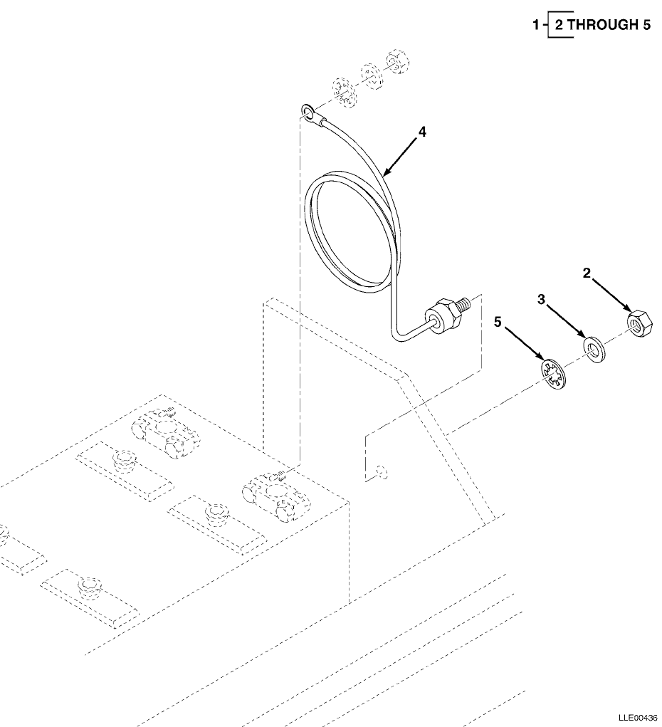
TM 5-6675-348-13&P SECTION II
(1)
ITEM
NO
(2)
SMR
CODE
(3)
CAGEC
(4)
PART
NUMBER
(5)
DESCRIPTION AND USABLE ON CODES (UOC)
(6)
QTY
GROUP 06 ELECTRICAL SYSTEM
GROUP 0606 ENGINE SAFETY CONTROLS
FIG. 39 HYEX VOLTAGE PROTECTION CABLE
1 56009 121022 KIT,VOLTAGE PROTECTION ..................... 1
2 56009 005274 • NUT,HEX,3/8-16 IN. ....................... 1
3 56009 003834-010 • WSHR,FL,3/8 X 1.08 IN. (10/PKG) .......... 1
4 56009 221089 • CABLE,VOLTAGE PROTECTION ................. 1
5 56009 2802-1010 • LKWASH,INTERNAL,3/8 IN. .................. 1
END OF FIGURE
39-1

TM 5-6675-348-13&P SECTION II
(1)
ITEM
NO
(2)
SMR
CODE
(3)
CAGEC
(4)
PART
NUMBER
(5)
DESCRIPTION AND USABLE ON CODES (UOC)
(6)
QTY
GROUP 22 BODY CHASSIS OR HULL, AND ACCESSORY
ITEMS
GROUP 2210 DATA PLATES AND INSTRUCTION
HOLDERS
FIG. 40 BUCKET-PRO™ DECALS AND INSTRUCTION
PLATES
1 56009 111741 LABEL,WARNING,WELDING ...................... 2
END OF FIGURE
40-1
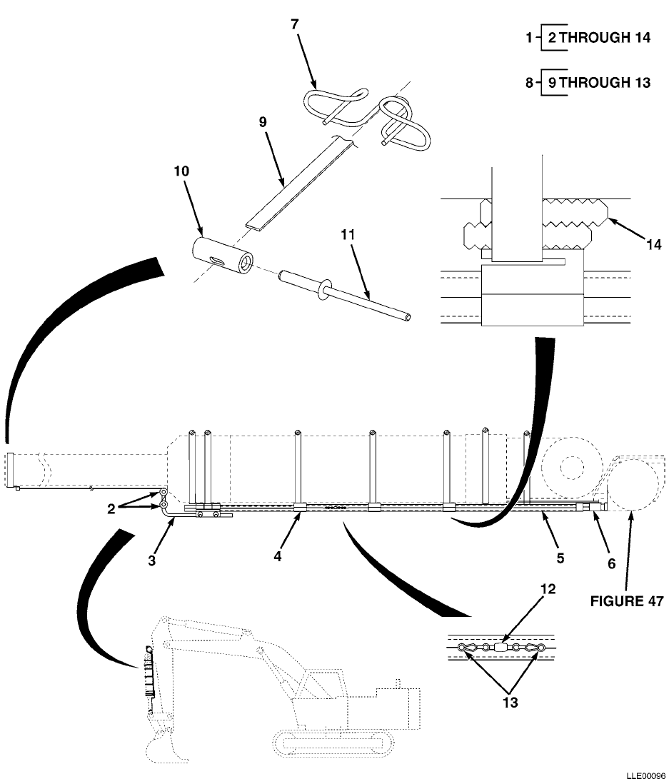
TM 5-6675-348-13&P SECTION II
(1)
ITEM
NO
(2)
SMR
CODE
(3)
CAGEC
(4)
PART
NUMBER
(5)
DESCRIPTION AND USABLE ON CODES (UOC)
(6)
QTY
GROUP 35 PULLEYS, BELTS, SHAFTS
GROUP 3501 PULLEYS, BELTS, SHAFTS
FIG. 41 BUCKET CYLINDER BELT SYSTEMS
1 56009 0389-0710 KIT,FLAT BELT DELIVERY ..................... 1
2 56009 0389-3060 • SWIVEL,RUNNERS ........................... 2
3 56009 0389-2110 • ROD,GUIDE ................................ 1
4 56009 0389-3240 • CLIP,POLY TUBE ........................... 3
5 56009 3239-0001 • TUBING,POLY 1/2 IN. O.D. X 0.062 IN. BLK . 1
6 56009 0389-3200 • ADPTR,POLY TUBE .......................... 3
7 56009 0389-3110 • CLIP,BELT ................................ 1
8 56009 0389-0720 • KIT, BELT, BUCKET PRO .................... 1
9 56009 0389-3040 •• BELT ASSY, FLAT 1
10 56009 0389-3130 •• STOP, BELT 2
11 56009 2808-0959 •• RIVET, POP DOME 2
12 56009 2509-7055 •• FASTENER, SWIVEL 2
13 56009 2509-7048 •• CLIP, SPEED 4
14 56009 0389-3300 • WEDGE, RISER 5
END OF FIGURE
41-1
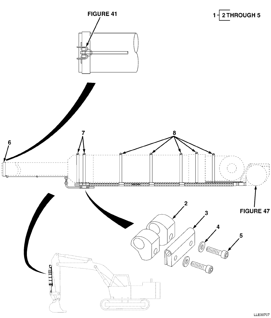
TM 5-6675-348-13&P SECTION II
(1)
ITEM
NO
(2)
SMR
CODE
(3)
CAGEC
(4)
PART
NUMBER
(5)
DESCRIPTION AND USABLE ON CODES (UOC)
(6)
QTY
GROUP 35 PULLEYS, BELTS, SHAFTS
GROUP 3501 PULLEYS, BELTS, SHAFTS
FIG. 42 BUCKET CYLINDER BELT SYSTEM
ACCESSORY
1 56009 0389-3030 BRACKET ROD, GUIDE 1
2 56009 0389-3320 •• STAND, POLY TUBE 1
3 56009 0389-1060 •• CLAMP, PULLEY TUBE 1
4 56009 2801-0040 •• WASHER, FLAT, SST, 10-24 2
5 56009 8201-1012 •• SCR, SOCKET, CAP 10-24 X 3/4 IN. 2
6 56009 2818-0910 • CLAMP,HOSE ............................... 1
7 56009 2818-0906 • CLAMP,HOSE ............................... 2
8 56009 2818-0907 • CLAMP,HOSE ............................... 5
END OF FIGURE
42-1
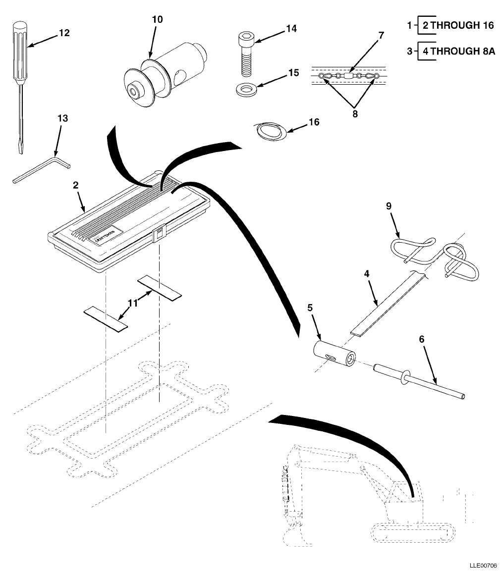
TM 5-6675-348-13&P SECTION II
(1)
ITEM
NO
(2)
SMR
CODE
(3)
CAGEC
(4)
PART
NUMBER
(5)
DESCRIPTION AND USABLE ON CODES (UOC)
(6)
QTY
GROUP 35 PULLEYS, BELTS, SHAFTS
GROUP 3501 PULLEYS, BELTS, SHAFTS
FIG. 43 BUCKET CYLINDER BELT SYSTEM TOOL
BOX
1 56009 0389-9000 BELT SYSTEM,BOX,TOOL ....................... 1
2 56009 1402-0164 • CASE, BUCKET PRO TOOL KIT ................ 1
3 56009 0389-0720 • KIT, BELT BUCKET PRO ..................... 1
4 56009 0389-3040 •• BELT ASSY, FLAT ......................... 1
5 56009 0389-3130 •• STOP,BELT ............................... 2
6 56009 2808-0959 •• RIVET, POP DOME ......................... 2
7 56009 2509-7055 •• FASTENER, SWIVEL ........................ 2
8 56009 2509-7048 •• CLIP, SPEED ............................. 4
9 56009 0389-3110 • CLIP,BELT ................................ 1
10 56009 0389-3060 • SWIVEL, RUNNERS .......................... 2
11 56009 0389-0710 • ADHESIVE,BACKING,TOOL BOX ................ 1
12 56009 5401-1555 • SCREWDRIVER, FLAT 1/4 X 1 1/4 IN. ........ 1
13 56009 5401-1560 • WRENCH, HEX, ALLEN 5/32 IN. ............. 1
14 56009 8201-1012 • SCR, CAP, SOCKET, SST 10-24 X 3/4 IN. ... 4
15 56009 2801-0040 • WASHER, FLAT, SST, 10-24 ................. 4
16 56009 005203 • WIRE, SAFETY, SS, 15 FT. ................. 1
END OF FIGURE
43-1
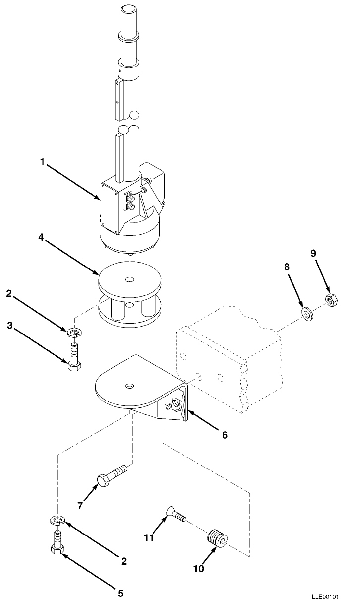
TM 5-6675-348-13&P SECTION II
(1)
ITEM
NO
(2)
SMR
CODE
(3)
CAGEC
(4)
PART
NUMBER
(5)
DESCRIPTION AND USABLE ON CODES (UOC)
(6)
QTY
GROUP 67 PRECISION INSTRUMENTS AND SYSTEMS,
MECHANICAL, ELECTRICAL, ELECTRONIC
GROUP 6709 ANTENNA, GROUNDS, AND RELATED
EQUIPMENT
FIG. 44 ELECTRICAL MAST ASSEMBLY
1 56009 EM2E-24 ELECTRIC MAST-ENG,24V ...................... 1
2 56009 003859-010 • LKWSHR,SPLIT,0.75 X 1.27 X 0.19 IN.
(10/PKG) ................................. 1
3 56009 010185-005 • SCR,CAP,HEX 0.75-16 X 1.5 IN.
(5/PKG) .................................. 1
4 56009 0389-0660 MAST,SHOCK,MOUNT ........................... 1
5 56009 003755 • SCR,FL,SKT 5-13 X 0.75 IN. STL
(5/PKG) .................................. 1
6 56009 0389-0890 BRKT,MAST MTG .............................. 1
7 56009 9837-1826 • SCR,CAP,HEX,
1/2-13 X 1 3/4 IN.,STL ................... 3
8 56009 003836 • WSHR,FL,0.562 X 0.375 X 0.109 IN.,STL,CD
(10/PKG) ................................. 1
9 56009 004964 • NUT,HEX,1/2-13 X 0.75 X 0.44 IN.
(10/PKG) ................................. 1
10 56009 7129-1408-010 • SCREW, RND X REC 10-32 X 3/8 IN. (10/PKG) 1
11 56009 0790-1990 • CANNON PLUG,BLANK ........................ 1
END OF FIGURE
44-1
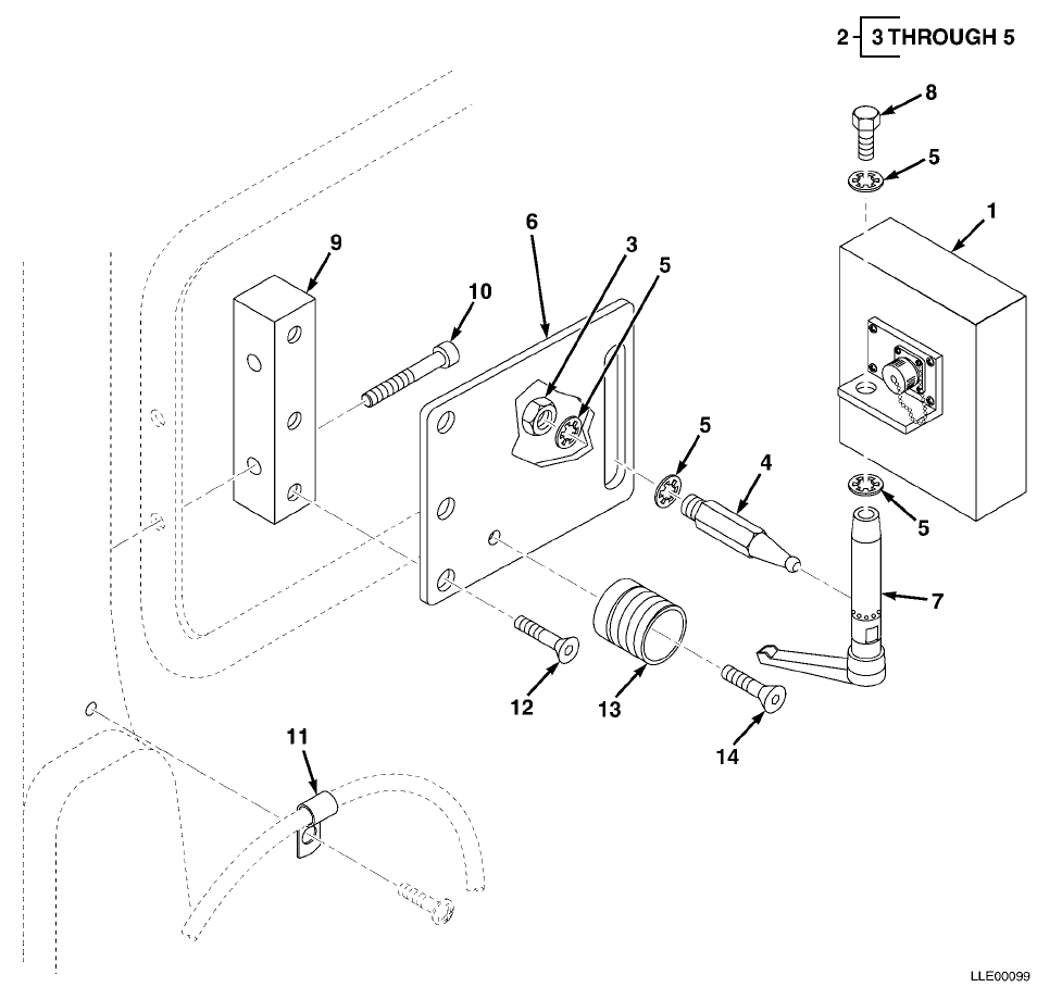
TM 5-6675-348-13&P SECTION II
(1)
ITEM
NO
(2)
SMR
CODE
(3)
CAGEC
(4)
PART
NUMBER
(5)
DESCRIPTION AND USABLE ON CODES (UOC)
(6)
QTY
GROUP 67 PRECISION INSTRUMENTS AND SYSTEMS,
MECHANICAL, ELECTRICAL, ELECTRONIC
GROUP 6711 CONTROLS, INDICATORS, AND
SPECIAL COMPONENTS
FIG. 45 GRAPHIC DISPLAY
1 56009 0389-2020 DISPLAY GRAPHICAL OPERATOR ................. 1
2 56009 0389-0310 DISPLAY BRCKT ASSY ......................... 1
3 56009 011860 • NUT,1/2-20 X 3/4 X 0.32 IN. SST .......... 1
4 56009 0389-0220 • BALL,DISPLAY MOUNT SWIVEL ................ 1
5 56009 2802-1010 • LKWASH,INTERNAL
1/2 X 0.86 X 0.035 IN. ................... 4
6 56009 0260-2870 BRKT,MPLC MTG .............................. 1
7 56009 0389-2010 RATCHETING HANDLE ASSY ..................... 1
8 56009 011860 BOLT,1/2-20 X 3/4 IN. ...................... 1
9 56009 0389-6350 BLOCK,BRACKET .............................. 1
10 56009 8202-4025 SCREW,CAP .................................. 2
11 56009 8221-1410 CLAMP,LOOP ................................. 2
12 56009 006648 SCREW ...................................... 3
13 56009 0790-1990 HOLDER,CONNECTOR ........................... 1
14 56009 7129-1408 SCREW ...................................... 1
END OF FIGURE
45-1
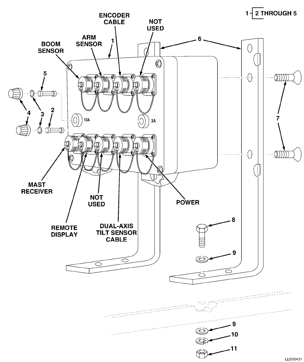
TM 5-6675-348-13&P SECTION II
(1)
ITEM
NO
(2)
SMR
CODE
(3)
CAGEC
(4)
PART
NUMBER
(5)
DESCRIPTION AND USABLE ON CODES (UOC)
(6)
QTY
GROUP 67 PRECISION INSTRUMENTS AND SYSTEMS,
MECHANICAL, ELECTRICAL, ELECTRONIC
GROUP 6711 CONTROLS, INDICATORS, AND
SPECIAL COMPONENTS
FIG. 46 REMOTE INTERFACE BOX
1 56009 0389-1000 REMOTE INTERFACE BOX ....................... 1
2 56009 5101-0170 • FUSE,AGC 3 AMP,250V ...................... 1
3 56009 011023 • SEAL,FUSE CAP ............................ 1
4 56009 010716 • FUSE CAP ................................. 1
5 56009 003378 • FUSE,AGC 10 AMP .......................... 1
6 56009 0389-7240 BRKT,REM BOX MTG.BUCKET-PRO™ ............... 2
7 56009 8822-1620 SCR,FL HF SOC,3/8-16 X 1 ................... 4
8 56009 9837-1620-010 SCR,CAP,HEX 3/8-16 X 1 ..................... 4
9 56009 003834-010 WSHR,FL,3/8 X 1.08 IN. (10/PKG) ............ 8
10 56009 003847-010 LKWSHR,SPLIT,3/8 X 0.68 X 0.09,STL,CD
(10/PKG) .................................. 4
11 56009 005274 NUT,HEX 3/8-16 X 0.56 X 0.33,STL,CD ........ 4
END OF FIGURE
46-1
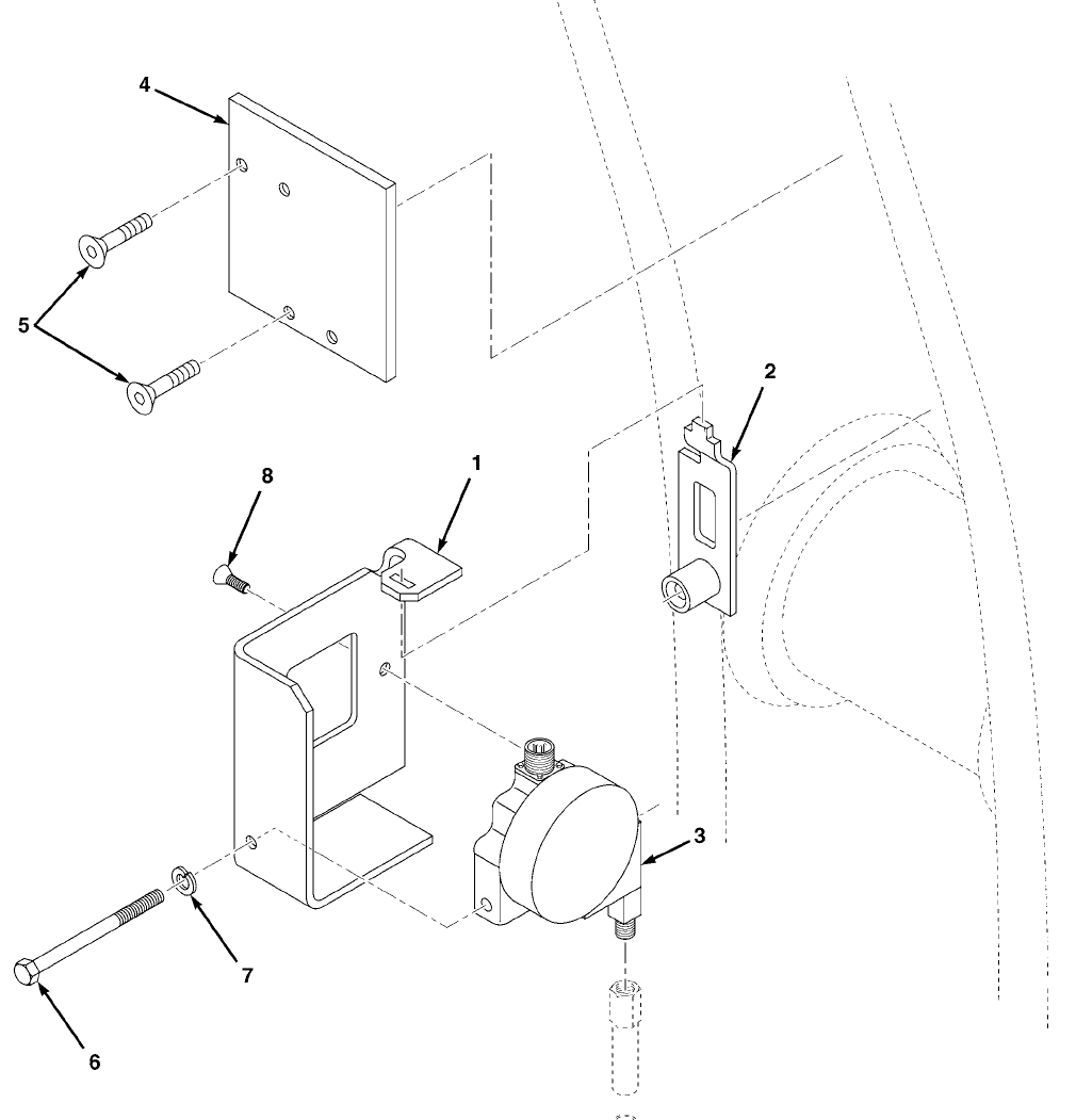
TM 5-6675-348-13&P SECTION II
(1)
ITEM
NO
(2)
SMR
CODE
(3)
CAGEC
(4)
PART
NUMBER
(5)
DESCRIPTION AND USABLE ON CODES (UOC)
(6)
QTY
GROUP 67 PRECISION INSTRUMENTS AND SYSTEMS,
MECHANICAL, ELECTRICAL, ELECTRONIC
GROUP 6711 CONTROLS, INDICATORS AND
SPECIAL COMPONENTS
FIG. 47 CABLE ENCODER
1 56009 0389-3410 BRKT,ENCDR MTG ............................. 1
2 56009 0389-3270 BRKT,WELDED,ENCODER ........................ 1
3 56009 0389-5020 ENCODER .................................... 1
4 56009 0389-6380 PLATE,ADAPTER,BUCKET VALVE ................. 1
5 56009 SCR,FL HF SOC,3/8-16 X 1 ................... 2
6 56009 9839-1656-005 BOLT,CAP,HEX,3/8-16 X 4-3/4 IN.,STL ........ 1
7 56009 003857 LKWASH,SPLIT,5/8 IN. ....................... 1
8 56009 8822-1620 SCR,FL HF SOC,3/8-16 X 1 ................... 2
END OF FIGURE
47-1
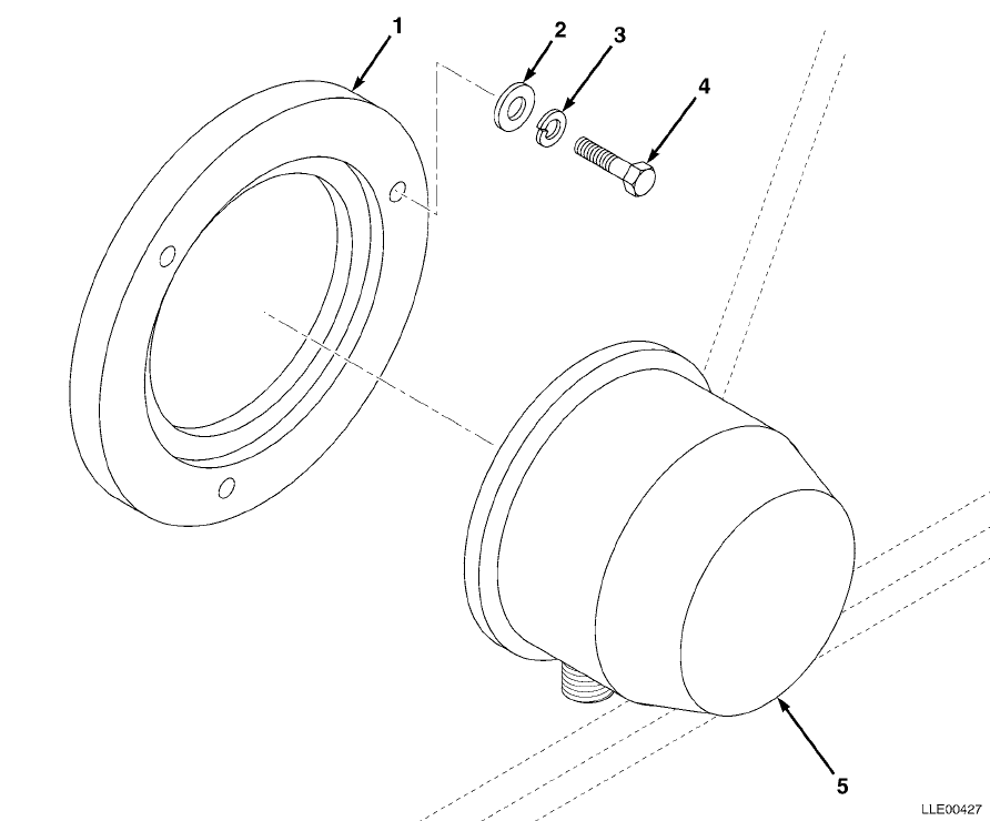
TM 5-6675-348-13&P SECTION II
(1)
ITEM
NO
(2)
SMR
CODE
(3)
CAGEC
(4)
PART
NUMBER
(5)
DESCRIPTION AND USABLE ON CODES (UOC)
(6)
QTY
GROUP 67 PRECISION INSTRUMENTS AND SYSTEMS,
MECHANICAL, ELECTRICAL, ELECTRONIC
GROUP 6711 CONTROLS, INDICATORS AND
SPECIAL COMPONENTS
FIG. 48 ARM SENSOR
1 56009 0389-4400 RING,MTG,ARM SENSOR ........................ 1
2 56009 003834-010 WSHR,FL,3/8 X 1.08 IN. (10/PKG) ............ 3
3 56009 003847-010 LKWSHR,SPLIT 3/8 X 0.68 X 0.09 IN., STL, CD
(10/PKG) .................................. 3
4 56009 004870 SCR,CAP 3/8-16 X 1/2 ....................... 3
5 56009 0389-1840 ARM SENSOR SW ASSY ......................... 1
END OF FIGURE
48-1
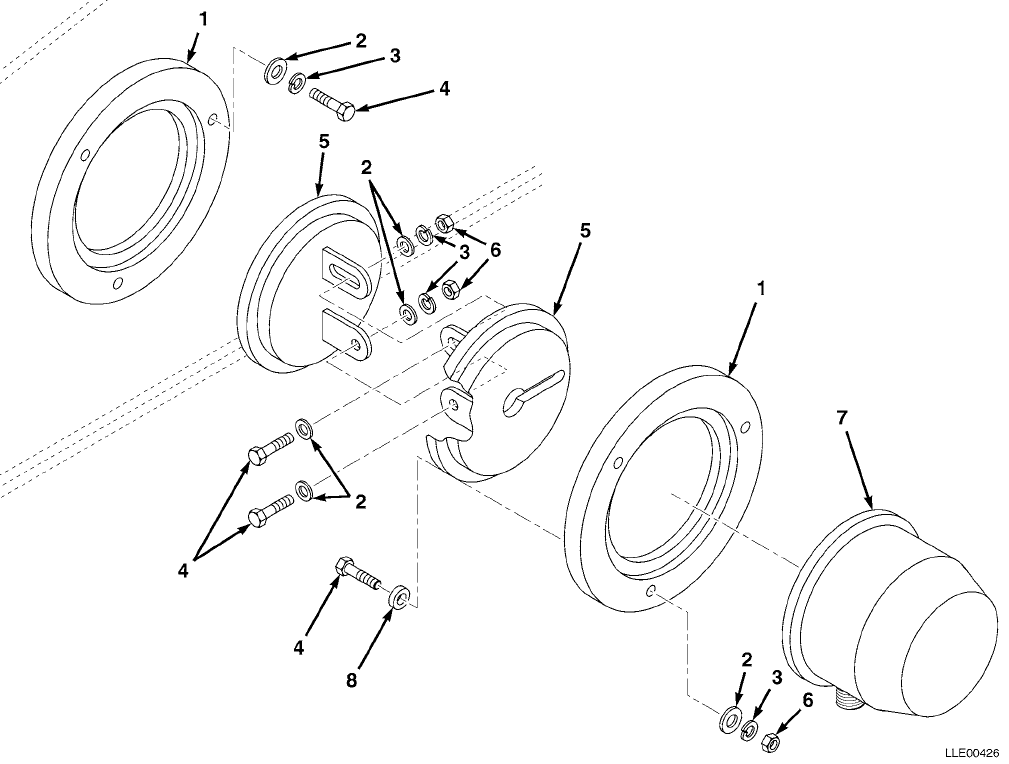
TM 5-6675-348-13&P SECTION II
(1)
ITEM
NO
(2)
SMR
CODE
(3)
CAGEC
(4)
PART
NUMBER
(5)
DESCRIPTION AND USABLE ON CODES (UOC)
(6)
QTY
GROUP 67 PRECISION INSTRUMENTS AND SYSTEMS,
MECHANICAL, ELECTRICAL, ELECTRONIC
GROUP 6711 CONTROLS, INDICATORS AND
SPECIAL COMPONENTS
FIG. 49 BOOM PENDULOUS ANGLE SENSOR
1 56009 0389-4400 RING,MTG, BOOM SENSOR ...................... 2
2 56009 003834-010 WSHR,FL,3/8 X 1.08 IN. (10/PKG) ............ 8
3 56009 003847-010 LKWSHR,SPLIT 3/8 X 0.68 X 0.09 IN., STL, CD
(10/PKG) .................................. 8
4 56009 004870 SCR,CAP 3/8-16 X 1/2 ....................... 8
5 56009 0389-1840 BOOM SENSOR SW MOUNT ....................... 2
6 56009 005275 NUT,HEX 3/8-16 ............................. 5
7 56009 0389-3000 SENSOR,BOOM ................................ 1
8 56009 0389-1810 SPACER ..................................... 3
END OF FIGURE
49-1
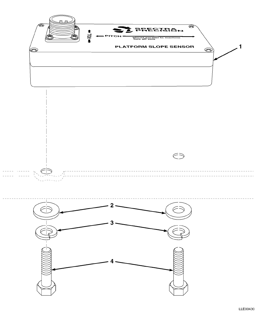
TM 5-6675-348-13&P SECTION II
(1)
ITEM
NO
(2)
SMR
CODE
(3)
CAGEC
(4)
PART
NUMBER
(5)
DESCRIPTION AND USABLE ON CODES (UOC)
(6)
QTY
GROUP 67 PRECISION INSTRUMENTS AND SYSTEMS,
MECHANICAL, ELECTRICAL, ELECTRONIC
GROUP 6711 CONTROLS, INDICATORS AND
SPECIAL COMPONENTS
FIG. 50 DUAL AXIS SENSOR
1 56009 0389-4000 SENSOR,SLOPE ............................... 1
2 56009 003831-010 WASHER,FLAT 1/4 X 0.73 X 0.06,STL .......... 2
3 56009 003851-010 WASHER,SPLIT 5/16 X 0.59 X 0.08,STL,CD
(10/PKG) .................................. 2
4 56009 9837-1420 SCREW,HEX 1/4-20 X 1 ....................... 2
END OF FIGURE
50-1
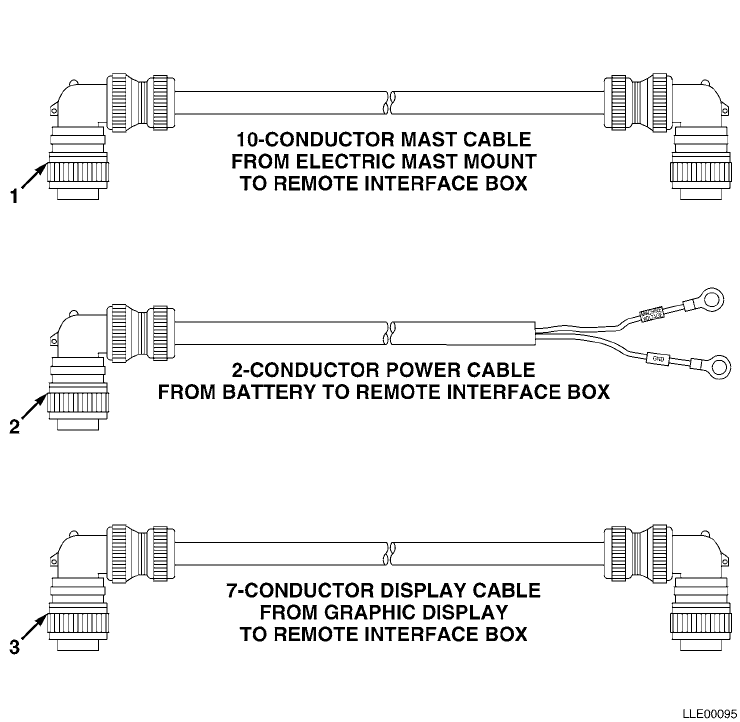
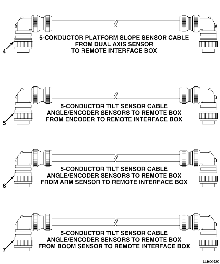
SECTION II TM 5-6675-348-13&P
FIG. 51 BUCKET-PRO™ ELECTRICAL CABLES (SHEET 2 OF 2)

TM 5-6675-348-13&P SECTION II
(1)
ITEM
NO
(2)
SMR
CODE
(3)
CAGEC
(4)
PART
NUMBER
(5)
DESCRIPTION AND USABLE ON CODES (UOC)
(6)
QTY
GROUP 67 PRECISION INSTRUMENTS AND SYSTEMS,
MECHANICAL, ELECTRICAL, ELECTRONIC
GROUP 6713 MISCELLANEOUS WIRING AND
FITTINGS
FIG. 51 BUCKET-PRO™ ELECTRICAL CABLES
(SHEET 1 OF 2)
1 56009 0792-4250-150 CABLE,10-CONDUCTOR,MAST .................... 1
2 56009 0792-4300-050 CABLE,2-CONDUCTOR,POWER .................... 1
3 56009 0792-4200-150 CABLE,7-CONDUCTOR,DISPLAY .................. 1
4 56009 0792-4100-020 CABLE,4-CONDUCTOR,PLATFORM SLOPE SENSOR .... 1
5 56009 0792-4150-450 CABLE,4-CONDUCTOR,BUCKET ................... 1
6 56009 0792-4150-400 CABLE,4-CONDUCTOR,ARM ...................... 1
7 56009 0792-4150-150 CABLE,4-CONDUCTOR,BOOM ..................... 1
END OF FIGURE
51-1

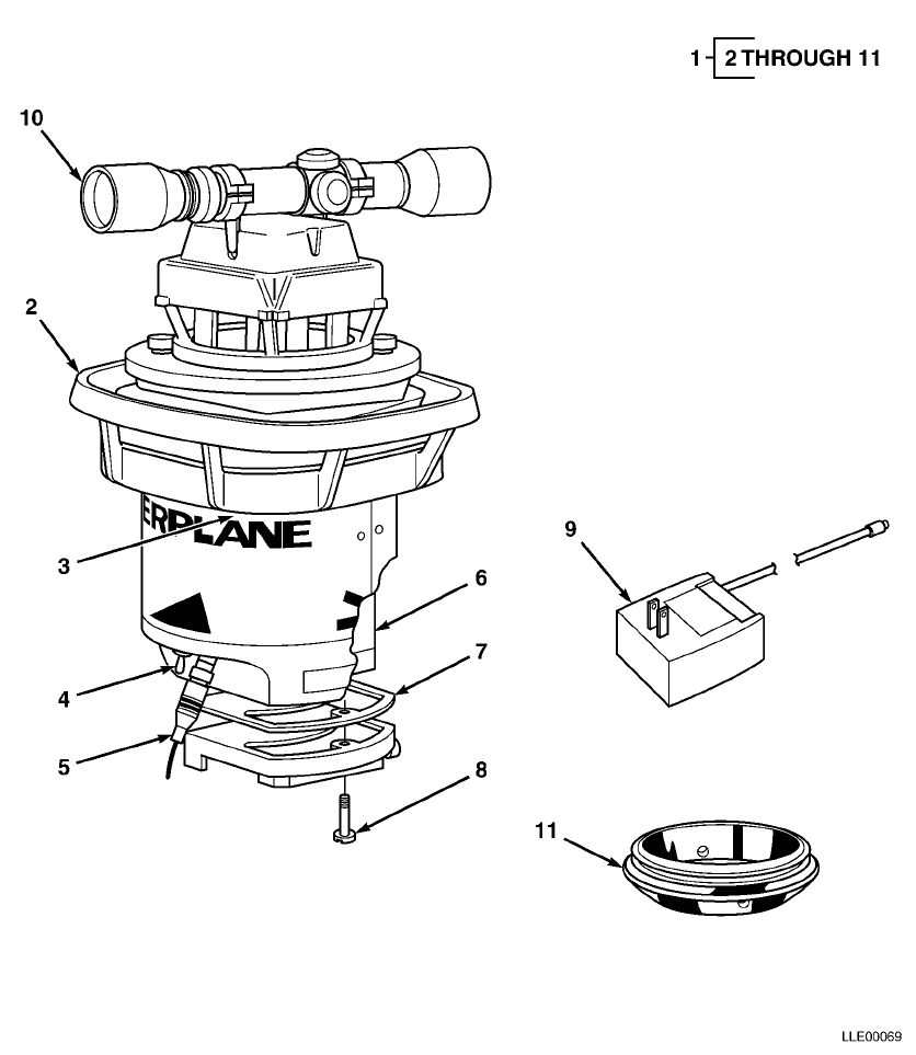
TM 5-6675-348-13&P SECTION II
(1)
ITEM
NO
(2)
SMR
CODE
(3)
CAGEC
(4)
PART
NUMBER
(5)
DESCRIPTION AND USABLE ON CODES (UOC)
(6)
QTY
GROUP 67 PRECISION INSTRUMENTS AND SYSTEMS,
MECHANICAL, ELECTRICAL,ELECTRONIC
GROUP 6702 OPTICS: REFLECTING AND
TRANSMITTING TYPE
FIG. 53 1145-2 LASER TRANSMITTER
1 56009 L1145-2 1145-2 LASER TRANSMITTER,US ................ 1
2 56009 1145-5531 • HANDLE,CARRYING .......................... 1
3 56009 003654-005 • SCREW,FLAT XREC 10-32 X 7/16 IN.
(5/PKG) .................................. 1
4 56009 5103-2320 • SWITCH,CONTROL ........................... 1
5 56009 1145-2420 • CORD,POWER ............................... 1
6 56009 1145-4270 • BATTERY,MODIFIED ......................... 1
7 56009 1145-1510 • GASKET,BASE PLATE ........................ 1
8 56009 1145-1280 • SCREW,CAPTIVE ............................ 1
9 56009 1145-2350 • POWER CHARGER,110 VAC,60HZ ............... 1
10 56009 1145-7710 • SCOPE,SIGHTING,SLOPE,1145 ................ 1
11 56009 1145-0310 • ADAPTER,QCK DISCONNECT ................... 1
END OF FIGURE
53-1
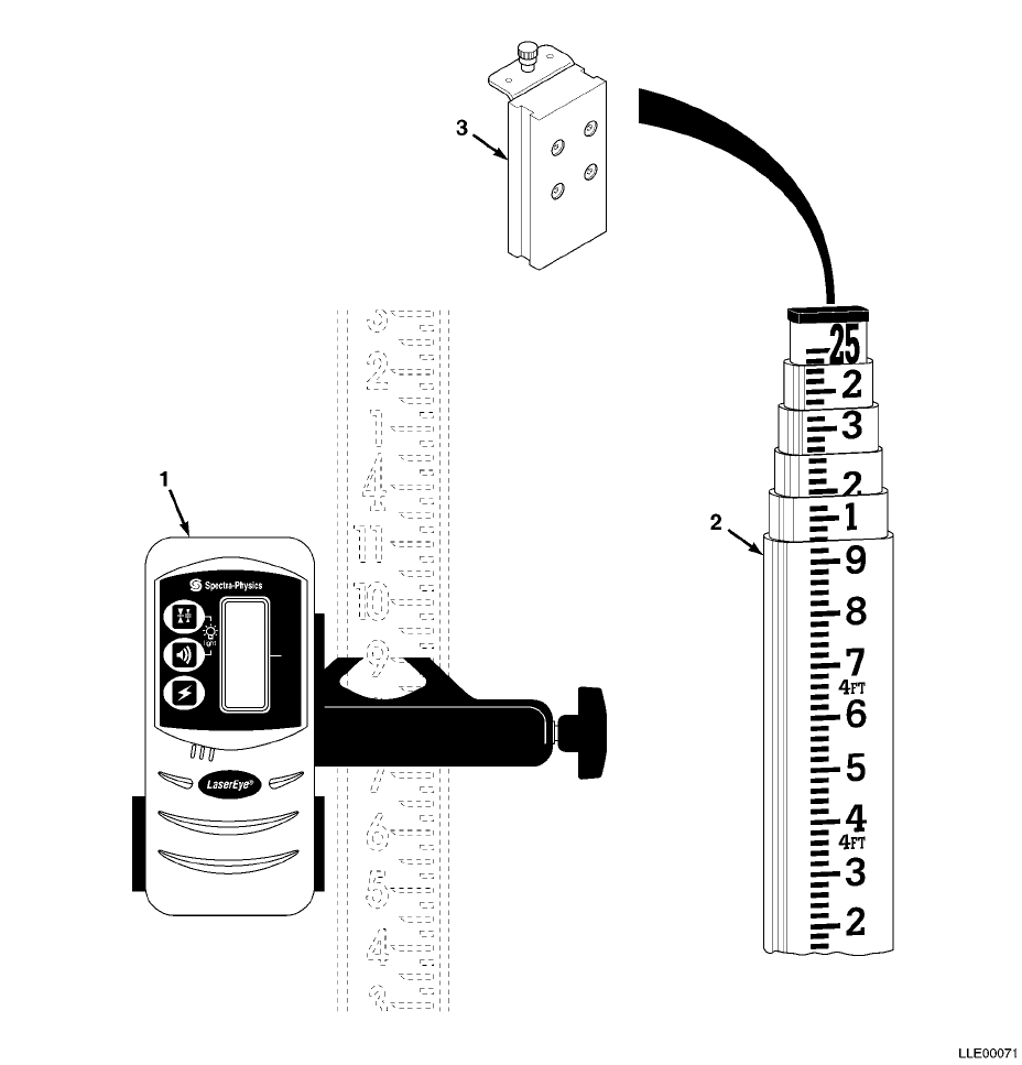
TM 5-6675-348-13&P SECTION II
(1)
ITEM
NO
(2)
SMR
CODE
(3)
CAGEC
(4)
PART
NUMBER
(5)
DESCRIPTION AND USABLE ON CODES (UOC)
(6)
QTY
GROUP 67 PRECISION INSTRUMENTS AND SYSTEMS,
MECHANICAL, ELECTRICAL, ELECTRONIC
GROUP 6709 ANTENNAS, GROUNDS, AND RELATED
EQUIPMENT
FIG. 54 1275 LASER RECEIVER AND GRADE ROD
1 56009 1275 1275 LASER RECEIVER ........................ 1
2 56009 0600-1270 GRADE ROD .................................. 1
3 56009 0600-1250 TOP MOUNT BLOCK 25 FT ...................... 1
END OF FIGURE
54-1

TM 5-6675-348-13&P SECTION II
(1)
ITEM
NO
(2)
SMR
CODE
(3)
CAGEC
(4)
PART
NUMBER
(5)
DESCRIPTION AND USABLE ON CODES (UOC)
(6)
QTY
GROUP 67 PRECISION INSTRUMENTS AND SYSTEMS,
MECHANICAL, ELECTRICAL, ELECTRONIC
GROUP 6719 TRIPODS
FIG. 55 TRIPOD
1 56009 302612-02 LASER LEGS® TRIPOD 4 FT (NOT SHOWN)......... 1
56009 302612-03 LASER LEGS® TRIPOD 6.5 FT (ISSUED).......... 1
56009 302612-04 LASER LEGS® TRIPOD 8 FT (NOT SHOWN)......... 1
56009 302612-06 LASER LEGS® TRIPOD 10 FT (NOT SHOWN)........ 1
2 56009 003369 • S-HOOK ................................... 2
3 56009 005029 • MACH CHAIN #4 BULK,BLU CHR FNSH .......... 1
4 56009 100136 • MOUNT,CHAIN .............................. 1
5 56009 003801-005 • NUT,CAP,HEX 0.25-20 X 0.48 IN.
(5/PKG) .................................. 2
6 56009 102317 • STUD,LEG ................................. 1
7 56009 100122 • SPACER,LEG ............................... 1
8 56009 100168 • CLAMP,LEG ................................ 1
9 56009 202415 • LEG,EXTENSION ............................ 1
END OF FIGURE
55-1

TM 5-6675-348-13&P SECTION II
(1)
ITEM
NO
(2)
SMR
CODE
(3)
CAGEC
(4)
PART
NUMBER
(5)
DESCRIPTION AND USABLE ON CODES (UOC)
(6)
QTY
GROUP 67 PRECISION INSTRUMENTS AND SYSTEMS,
MECHANICAL, ELECTRICAL, ELECTRONIC
GROUP 6719 TRIPODS
FIG. 56 ELEVATING BASE
1 56009 408700-03 ELEVATING BASE-ENG ......................... 1
2 56009 122420 • STUD,LOCKING ASSY ........................ 1
3 56009 003825-010 • NUT,WING-ST CD 1/2-1 (10/PKG) ............ 3
4 56009 8201-0808-020 • SCREW,CAP SOC HD STAINLESS STEEL
8-32 X 1/2 (20/PKG) ...................... 2
5 56009 003658 • SCREW,MACH. FL HD PHIL STAINLESS STEEL
10-32 X 7/8 .............................. 1
6 56009 010008 • KNOB,BALL ................................ 1
7 56009 003562-005 • O-RING STOP .............................. 1
8 56009 003868-010 • PIN,ROLL,STAINLESS STEEL (10/PKG) ........ 1
9 56009 003783 • BOLT,MH HEX,SS-1/2 ....................... 3
10 56009 003837-010 • WASHER,FL 0.5 X 1.25 X 0.10 IN.,AL
(10/PKG) ................................. 1
11 56009 208844 • CRANK,RAISE/LOWER ........................ 1
12 56009 7181-6006-010 • SCREW,ROUND XREC 10-32 X 3/8 (10/PKG) .... 1
13 56009 408040-01 • TUBE,ELEVATING BASE ...................... 1
14 56009 202407-01 • STEEL RACK ............................... 1
15 56009 408847 • ELEVATING TRIPOD BASE .................... 1
END OF FIGURE
56-1
TM 5-6675-348-13&P SECTION II
(1)
ITEM
NO
(2)
SMR
CODE
(3)
CAGEC
(4)
PART
NUMBER
(5)
DESCRIPTION AND USABLE ON CODES (UOC)
(6)
QTY
GROUP 33 SPECIAL PURPOSE KITS
GROUP 3307 SPECIAL PURPOSE KITS
FIG. 1 KITS
121022 KIT,VOLTAGE PROTECTION ................... 1
005274 NUT,HEX,3/8-16 IN. ..................... 1
003834-010 WSHR,FL,3/8 X 1.08 IN. (10/PKG) ........ 1
221089 CABLE,VOLTAGE PROTECTION ............... 1
2802-1010 LKWSHR,INTERNAL,3/8 .................... 1
121022 KIT,VOLTAGE PROTECTION ................... 1
005274 NUT,HEX,3/8-16 IN. ..................... 1
003834-010 WSHR,FL,3/8 X 1.08 IN. (10/PKG) ........ 1
221089 CABLE,VOLTAGE PROTECTION ............... 1
2802-1010 LKWSHR,INTERNAL,3/8 .................... 1
RT2S-1 TRANSMITTER,GRADIO® (USED WITH DR2-1
GRADIO® DISPLAY) ........................ 1
RT2S-2 TRANSMITTER,GRADIO® (USED WITH DR2-2
GRADIO® DISPLAY) ........................ 1
RT2S-3 TRANSMITTER,GRADIO® (USED WITH DR2-3
GRADIO® DISPLAY) ........................ 1
RT2S-4 TRANSMITTER,GRADIO® (USED WITH DR2-4
GRADIO® DISPLAY) ........................ 1
RT2S-5 TRANSMITTER,GRADIO® (USED WITH DR2-5
GRADIO® DISPLAY) ........................ 1
0250-1470 RETAINER CLAMP KNOB .................... 1
7181-0605-010 SCR,MACH,RND,SST 6-32 X 5/16 IN.
(10/PKG) ............................. 1
2508-0520 BOOT,SWITCH (PLASTIC) .................. 1
1409-0990 STUD,FRONT LOAD 4MM .................... 1
1409-0980 RECEPTACLE,FRONT LOAD 4MM .............. 1
0225-0390 RETAINER,STUD HALF GROMMET GP .......... 1
7181-0806 SCR,ROUND HEAD PHIL 8-32 (10/PKG) ...... 1
2802-0250 WSHR,INT-T LOCK,#8 STL (10/PKG) ........ 1
012192 SCR,OVAL,XREC,10-32 X 4 IN. (5/PKG) .... 1
2802-0030-010 LKWASH,SPLIT,#8 SST (10/PKG) ........... 1
8201-0810 SCR,SOCKET HEAD CAP 8-32 X 5/8 IN. ..... 8
0225-1770 CLAMP,BASE RECEIVER .................... 1
0250-1430 KNOB,MOLDED CLAMPING ................... 1
DR2-1 TRANSMITTER,GRADIO® (USED WITH RT2S-1
GRADIO® TRANSMITTER) .................... 1
DR2-2 TRANSMITTER,GRADIO® (USED WITH RT2S-2
GRADIO® TRANSMITTER) .................... 1
DR2-3 TRANSMITTER,GRADIO® (USED WITH RT2S-3
GRADIO® TRANSMITTER) .................... 1
KITS-1
SECTION II TM 5-6675-348-13&P
DR2-4 TRANSMITTER,GRADIO® (USED WITH RT2S-4
GRADIO® TRANSMITTER) .................... 1
DR2-5 TRANSMITTER,GRADIO® (USED WITH RT2S-5
GRADIO® TRANSMITTER) .................... 1
012708 SCR,FL,XREC,1/4-20 X 1.75 IN. (10/PKG) . 1
2816-1970 SCR,FL,XREC,6-32 X 0.375 IN. (10/PKG) .. 1
2802-0020-010 LKWASH,SPLIT,#6,SST (10/PKG) ........... 1
7181-0606-010 SCR,RND,XREC,6-32 X 3/8 IN. (10/PKG) ... 1
003376 FUSE,5 AMP ............................. 1
010716 CAP,FUSE HOLDER SEAL ................... 1
011023 SEAL,FUSE CAP HOLDER ................... 1
2508-0500 SEAL,BOOT,TOG SW,15/32-32 NS,BL ........ 1
011179 LAMP,24 VOLT ........................... 3
MM2E-T MANUAL MAST .............................. 1
003656 SCR,MH FL PHIL,SSTL,10-32 X 0.58 IN. ... 1
122420 STUD,LOCKING ASSEMBLY .................. 1
122014 WSHR,FL,3/8 X 0.50 X 0.03 IN. .......... 1
0230-2080 SPACER ................................. 1
7181-6006-010 SCR,RND,XREC,10-32 X 3/8 IN.(10/PKG) ... 1
003655 SCR,FL,XREC,10-32 X 0.5 IN.(10/PKG) .... 1
RM2E-3 RIGID MAST ............................... 1
209099 SCALE,3 FOOT MAST ........................ 1
2507-4270-010 SPACER,RND,0.203 X 0.312 X 0.194 IN.
(10/PKG) ................................ 1
7181-6008-010 SCR,RND,XREC (10/PKG) .................... 1
3502-0420 CHAIN .................................... 1
2509-6780 PIN ...................................... 1
201634 MOUNT,RIGID MAST,LPO ..................... 1
121022 KIT,VOLTAGE PROTECTION ................... 1
005274 NUT,HEX,3/8-16 IN. ..................... 1
003834-010 WSHR,FL,3/8 X 1.08 IN. (10/PKG) ........ 1
221089 CABLE,VOLTAGE PROTECTION ............... 1
2802-1010 LKWSHR,INTERNAL,3/8 IN. ................ 1
PSV2D06-24 CONTROL VALVE ASSEMBLY,PROPORTIONAL ...... 2
2816-4244-005 SCR,SOCKET HEAD,10-24 X 1-1/4 IN. ...... 4
0720-2400 MANIFOLD,PROPORTIONAL W/CARTRIDGES ..... 4
0720-2510 VALVE,PROPORTIONAL,VICKERS ............. 1
0355-9600 BASE CLAMP ASSY .......................... 2
011506 SCR,CAP,HEX,0.5-13 X 2.75 IN.(5/PKG) ... 1
003836 WSHR,FL,0.562 X 0.375 X 0.109 IN.
(10/PKG) ............................. 1
0355-9630 BASE CLAMP ............................. 2
9837-1822 SCR,CAP,HEX,0.50-13 X 1.25 IN.,STL ..... 8
003855-010 LKWSHR,SPLIT,0.50 X 0.51 X 0.12 IN.
(10/PKG) ............................. 1
0355-8960 CLAMP,CAST ............................. 4
(1)
ITEM
NO
(2)
SMR
CODE
(3)
CAGEC
(4)
PART
NUMBER
(5)
DESCRIPTION AND USABLE ON CODES (UOC)
(6)
QTY
KITS-2
TM 5-6675-348-13&P SECTION II
004964 NUT,HEX,0.50-13 X 0.75 X 0.44 IN.
(10/PKG) ............................. 1
0355-8550 BRKT,TRACER MTG ARM ...................... 1
0355-8680 LEVER ASSEMBLY ......................... 1
0355-8580 WELDMENT,TRACER ARM .................... 1
0355-8590 LEVER ASSEMBLY 1
003834-010 WSHR,FL,3/8 X 1.08 IN.,STL,CD
(10/PKG) ............................. 1
005274 NUT,HEX 3/8-16 IN. ..................... 2
2817-0051 PIN,COTTER STD.,3/32 X 1-1/4 IN.
(10/PKG) ............................. 1
EM2E-24 EM2E-24 ELECTRIC MAST - ENG,24V .......... 1
8207-1514 SCR,CAP SKT,5/16-18 X 7/8 IN.
(10/PKG) ............................. 1
7181-0604-010 SCR,RND XREC,6-32 X 0.25 IN.
(10/PKG) ............................. 1
2802-0020-010 LKWSHR,SPLIT #6,SSTL (10/PKG) .......... 1
7181-0612-010 SCR,RND XREC,6-32 X 0.75 IN.(10/PKG) ... 1
2802-0030-010 LKWSHR,SPLIT #8 SST (10/PKG) ........... 1
7121-6007-010 SCR,FL XREC,10-32 X 7/16 IN.(10/PKG) ... 1
012697 RING,RETAINING ......................... 1
7181-0608-010 SCR,RND XREC,6-32 X 0.50 IN.(10/PKG) ... 1
003184 DUST CAP RECEPTACLE .................... 1
7181-0605-010 SCR,RND HEAD PHIL,6-32 X 5/16 IN.
(10/PKG) ............................. 1
011887-005 SCR,HEX 10-32 X 0.5 IN. STL,CD(5/PKG) .. 1
2802-0040-010 LKWASH,SPLIT #10 ....................... 4
0790-4241 RISER,MOTOR 130G GRADER MAST MOUNT ..... 1
M2-T SHOCK MOUNT,HIGH VIBRATION ............. 1
003859-010 LKWSHR,SPLIT,STL,CD,3/4 X 1.27 X
0.19 IN. (10/PKG) .................... 2
9837-7222-005 SCR,CP HEX,STL,CD,3/4-16 X 1 IN.
(5/PKG) .............................. 2
011137 SCR,CP HEX,STL,CD,3/4-16 X 2 IN. ....... 2
R2S-S R2S-S LASER RECEIVER SB W/CASE ........... 1
2403-1680 KNOB,PLASTIC PRONGED ................... 1
8201-0808-020 SCREW,CAP SKT 8-32 X 1/2 IN.(20/PKG) ... 1
2802-0030-010 LKWSHR,SPLIT #8 SSTL(10/PKG) ........... 4
321815 CLAMP,RECEIVER ......................... 1
012192-005 SCREW,OVAL XREC SSTL 10-32 X 4 IN.
(5/PKG) .............................. 1
0365-3000 HSNG,ASSY,ROTATIONAL SNSR ................ 1
0355-3170 BONE,DOG ............................... 1
0355-3190 BEARING,TEFLON ROT SNSR HSG ............ 1
8311-0402 SCR,SET COP 4-40 X 0.125 IN.(10/PKG) ... 1
0365-2040 OPERATOR INTERFACE PROP FINAL ASSY ....... 1
8201-1626 SCR,SOC,CAP 3/8-16 X 1-3/4 IN.,
SST F/T .............................. 1
(1)
ITEM
NO
(2)
SMR
CODE
(3)
CAGEC
(4)
PART
NUMBER
(5)
DESCRIPTION AND USABLE ON CODES (UOC)
(6)
QTY
KITS-3
SECTION II TM 5-6675-348-13&P
2403-1680 KNOB,PLASTIC PRONGED ................... 1
0365-1140 BOX,REMOTE,INTERFACE ..................... 1
2117-1710 CAP,DUST,W/WIRE ROPE 0.125 IN. DIA ..... 1
7181-0606-010 SCR,RND,6-32 X 3/8 IN. SST PSVT
(10/PKG) ............................. 4
2802-0770 LKWASH,SPLIT,6-32,STL,2N ............... 4
011894 FUSE,25 AMP ............................ 2
011023 SEAL,FUSE CAP .......................... 2
010716 CAP,FUSE ............................... 2
ST2-20 NON-CONTACT SONIC TRACER ................. 1
3901-2110 LAMP,INCAND T3-14 ...................... 3
3902-0603 LENS,GREEN,0.625 IN. DIA,STOVEPIPE ..... 1
3902-0604 LENS,AMBER,0.625 IN. DIA,STOVEPIPE ..... 2
5501-0151 TRANSDUCER,SND,POLAROID,604142 ......... 1
0365-8420 TRANSDUCER RING ........................ 1
2504-6000 O-RING,1.50 ID X 1.688 OD X 0.094 IN. .. 1
0791-1740 ASSEMBLY MAST MOUNT BASE COMPLETE ........ 1
0791-1380 YOKE MAST MOUNT ........................ 1
0791-1990 MOUNT,MAST BASE ........................ 1
2816-4315 SCR,CAP HEX,5/8-11 X 1.25 IN. .......... 4
003857 LKWASH,SPLIT,5/8 IN. ................... 4
9837-2224 SCR,CAP HEX,3/4-10 X 1.5 IN. STL ....... 2
003859-010 LKWASH,SPLIT,3/4 X 1.27 X 0.19 IN.
(10/PKG) ............................. 1
0791-8820 PLATE,TRACER/MAST MTG .................... 2
8319-2212 SCR,SET CUP,3/4-10 X 0.75 IN.,ZNC PLT .. 2
0792-3930 HOLDER,CONNECTOR ......................... 1
0355-3140 BRKT, ARM MOUNTING ..................... 1
0790-1970 BULKHEAD, BLANK #14 .................... 1
2802-0420 WASHER, EXT-LICK, #10, STL, CD ......... 1
7121-6006-010 SCR, 10-32 X 3/8 IN. (10/PKG) .......... 1
121022 KIT,VOLTAGE PROTECTION ................... 1
005274 NUT,HEX,3/8-16 IN. ..................... 1
003834-010 WSHR,FL,3/8 X 1.08 IN. (10/PKG) ........ 1
221089 CABLE,VOLTAGE PROTECTION ............... 1
2802-1010 LKWASH,INTERNAL,3/8 IN. ................ 1
0389-0710 KIT,FLAT BELT DELIVERY ................... 1
0389-3060 SWIVEL,RUNNERS ......................... 2
0389-2110 ROD,GUIDE 1
0389-3240 CLIP,POLY TUBE ......................... 3
3239-0001 TUBING,POLY 1/2 IN. O.D. X 0.062 IN. BLK 1
0389-3200 ADPTR,POLY TUBE ........................ 3
0389-3110 CLIP,BELT .............................. 1
0389-0720 KIT, BELT, BUCKET PRO .................. 1
0389-3040 BELT ASSY, FLAT ........................ 1
0389-3130 STOP, BELT ............................. 2
2808-0959 RIVET, POP DOME ........................ 2
(1)
ITEM
NO
(2)
SMR
CODE
(3)
CAGEC
(4)
PART
NUMBER
(5)
DESCRIPTION AND USABLE ON CODES (UOC)
(6)
QTY
KITS-4
TM 5-6675-348-13&P SECTION II
2509-7055 FASTENER, SWIVEL ....................... 2
2509-7048 CLIP, SPEED ............................ 4
0389-3300 WEDGE, RISER ........................... 5
0389-3030 BRACKET ROD, GUIDE ....................... 1
0389-3320 STAND, POLY TUBE ....................... 1
0389-1060 CLAMP, PULLEY TUBE ..................... 1
2801-0040 WASHER, FLAT, SST, 10-24 IN. ........... 2
8201-1012 SCR, SOCKET, CAP 10-24 X 3/4 IN. ....... 2
0389-9000 BELT SYSTEM,BOX,TOOL ..................... 1
1402-0164 CASE, BUCKET PRO TOOL KIT ................ 1
0389-0720 KIT, BELT BUCKET PRO ................... 1
0389-3040 BELT ASSY, FLAT ........................ 1
0389-3130 STOP,BELT .............................. 2
2808-0959 RIVET, POP DOME ........................ 2
2509-7055 FASTENER, SWIVEL ....................... 2
2509-7048 CLIP, SPEED ............................ 4
0389-3110 CLIP,BELT .............................. 1
0389-3060 SWIVEL, RUNNERS ........................ 2
0389-0710 ADHESIVE,BACKING,TOOL BOX .............. 1
5401-1555 SCREWDRIVER, FLAT 1/4 X 1 1/4 IN. ...... 1
5401-1560 WRENCH, HEX, ALLEN 5/32 IN. ............ 1
8201-1012 SCR, CAP, SOCKET, SST 10-24 X 3/4 IN. .. 4
2801-0040 WASHER, FLAT, SST, 10-24 IN. ........... 4
005203 WIRE, SAFETY, SS, 15 FT. ............... 1
0389-0310 DISPLAY BRCKT ASSY ....................... 1
011860 NUT,1/2-20 X 3/4 X 0.32 IN. SST ........ 1
0389-0220 BALL,DISPLAY MOUNT SWIVEL .............. 1
2802-1010 LKWASH,INTERNAL 1/2 X 0.86 X 0.035 IN. . 4
0389-1000 REMOTE INTERFACE BOX ..................... 1
5101-0170 FUSE,AGC 3 AMP,250V .................... 1
011023 SEAL,FUSE CAP .......................... 1
010716 FUSE CAP ............................... 1
003378 FUSE,AGC 10 AMP ........................ 1
L1145-2 1145-2 LASER TRANSMITTER,US .............. 1
1145-5531 HANDLE,CARRYING ........................ 1
003654-005 SCREW,FLAT XREC 10-32 X 7/16 IN.
(5/PKG) .............................. 1
5103-2320 SWITCH,CONTROL ......................... 1
1145-2420 CORD,POWER ............................. 1
1145-4270 BATTERY,MODIFIED ....................... 1
1145-1510 GASKET,BASE PLATE ...................... 1
1145-1280 SCREW,CAPTIVE .......................... 1
1145-2350 POWER CHARGER,110 VAC,60HZ ............. 1
1145-7710 SCOPE,SIGHTING,SLOPE,1145 .............. 1
1145-0310 ADAPTER,QCK DISCONNECT ................. 1
302612-02 LASER LEGS TRIPOD 4 FT (NOT SHOWN) ....... 1
302612-03 LASER LEGS TRIPOD 6.5 FT (ISSUED) ........ 1
(1)
ITEM
NO
(2)
SMR
CODE
(3)
CAGEC
(4)
PART
NUMBER
(5)
DESCRIPTION AND USABLE ON CODES (UOC)
(6)
QTY
KITS-5
SECTION II TM 5-6675-348-13&P
302612-04 LASER LEGS TRIPOD 8 FT (NOT SHOWN) ....... 1
302612-06 LASER LEGS TRIPOD 10 FT (NOT SHOWN) ...... 1
003369 S-HOOK ................................. 2
005029 MACH CHAIN #4 BULK,BLU CHR FNSH ........ 1
100136 MOUNT,CHAIN ............................ 1
003801-005 NUT,CAP,HEX 0.25-20 X 0.48 IN.(5/PKG) .. 2
102317 STUD,LEG ............................... 1
100122 SPACER,LEG ............................. 1
100168 CLAMP,LEG .............................. 1
202415 LEG,EXTENSION .......................... 1
408700-03 ELEVATING BASE-ENG ....................... 1
122420 STUD,LOCKING ASSY ...................... 1
003825-010 NUT,WING-ST CD 1/2-1 IN. (10/PKG) ...... 3
8201-0808-020 SCREW,CAP SOC HD STAINLESS STEEL 8-32 X
1/2 IN. (20/PKG) ..................... 2
003658 SCREW,MACH. FL HD PHIL STAINLESS STEEL
10-32 X 7/8 IN. ...................... 1
010008 KNOB,BALL .............................. 1
003562-005 O-RING STOP ............................ 1
003868-010 PIN,ROLL,STAINLESS STEEL (10/PKG) ...... 1
003783 BOLT,MH HEX,SS-1/2 IN. ................. 3
003837-010 WASHER,FL 0.5 X 1.25 X 0.10 IN.,AL
(10/PKG) ............................. 1
208844 CRANK,RAISE/LOWER ...................... 1
7181-6006-010 SCREW,ROUND XREC 10-32 X 3/8 IN.
(10/PKG) ............................. 1
408040-01 TUBE,ELEVATING BASE .................... 1
202407-01 STEEL RACK ............................. 1
408847 ELEVATING TRIPOD BASE .................. 1
(1)
ITEM
NO
(2)
SMR
CODE
(3)
CAGEC
(4)
PART
NUMBER
(5)
DESCRIPTION AND USABLE ON CODES (UOC)
(6)
QTY
KITS-6
TM 5-6675-348-13&P SECTION III
CROSS-REFERENCE INDEXES
PART NUMBER INDEX
PART NUMBER FIG. ITEM PART NUMBER FIG. ITEM
Index-1
003184 25 10
003369 55 2
003376 7 6
003378 46 5
003562-005 56 7
003654-005 53 3
003655 11 7
003656 11 2
003658 56 5
003755 44 5
003783 56 9
003801-005 55 5
003805-010 32 3
003810 9 3
003825-010 56 3
003831-010 50 2
003833 27 9
003834-010 1 3
003834-010 2 3
003834-010 14 3
003834-010 20 6
003834-010 23 5
003834-010 35 5
003834-010 39 3
003834-010 46 9
003834-010 48 2
003834-010 49 2
003836 22 4
003836 44 8
003837-010 56 10
003847-010 8 2
003847-010 33 9
003847-010 35 3
003847-010 46 10
003847-010 48 3
003847-010 49 3
003851-010 27 10
003851-010 50 3
003855-010 8 7
003855-010 22 7
003857 9 4
003857 34 5
003857 47 7
003859-010 10 2
003859-010 25 16
003859-010 34 7
003859-010 44 2
003868-010 56 8
004194 19 4
004196 17 1
004196 18 1
004196 18 3
004196 18 5
004196 19 3
004261 19 5
004277 17 2
004277 18 2
004277 18 4
004870 48 4
004870 49 4
004964 22 9
004964 44 9
005029 55 3
005203 43 16
005274 1 2
005274 2 2
005274 14 2
005274 23 6
005274 33 10
005274 35 2
005274 39 2
005274 46 11
005275 49 6
006648 45 12
006649 8 3
006649 32 5
006649 35 4
010008 56 6
010185-005 10 3
010185-005 44 3
010716 7 7
010716 29 7
010716 46 4
011023 7 8
011023 29 6
011023 46 3
011137 25 18
011179 7 10
011506 22 3
011860 45 3
011860 45 8
011887-005 25 12
011894 29 5
012192 6 7
012192-005 26 6
012697 25 8
012708 7 2
0225-0390 6 5
0225-0520 3 1
0225-0530 15 2
0225-1770 6 10
0230-2080 11 5
0250-1430 6 11
0250-1470 6 2
0260-2870 45 6
0355-3130 27 6
0355-3140 27 7
0355-3140 37 3
0355-3170 27 2
0355-3180 27 5
0355-3190 27 3
0355-5100 37 1
0355-5200 35 1
0355-7470 16 1
0355-8550 23 1
0355-8580 23 3
0355-8590 23 4
0355-8620 24 1
0355-8680 23 2
0355-8960 22 8
SECTION III TM 5-6675-348-13&P
CROSS-REFERENCE INDEXES (CONT)
PART NUMBER INDEX
PART NUMBER FIG. ITEM PART NUMBER FIG. ITEM
Index-2
0355-9600 22 2
0355-9630 22 5
0365-1140 29 1
0365-2040 28 1
0365-2630 15 1
0365-2700 32 6
0365-3000 27 1
0365-3160 29 9
0365-3160 33 2
0365-4010 30 2
0365-5000 36 3
0365-5310 27 13
0365-5310 32 4
0365-8420 31 6
0365-8740 33 5
0389-0220 45 4
0389-0310 45 2
0389-0660 44 4
0389-0710 41 1
0389-0710 43 11
0389-0720 41 8
0389-0720 43 3
0389-0890 44 6
0389-1000 46 1
0389-1060 42 3
0389-1810 49 8
0389-1840 48 5
0389-1840 49 5
0389-2010 45 7
0389-2020 45 1
0389-2110 41 3
0389-3000 49 7
0389-3030 42 1
0389-3040 41 9
0389-3040 43 4
0389-3060 41 2
0389-3060 43 10
0389-3110 41 7
0389-3110 43 9
0389-3130 41 10
0389-3130 43 5
0389-3200 41 6
0389-3240 41 4
0389-3270 47 2
0389-3300 41 14
0389-3320 42 2
0389-3410 47 1
0389-4000 50 1
0389-4400 48 1
0389-4400 49 1
0389-5020 47 3
0389-6350 45 9
0389-6380 47 4
0389-7240 46 6
0389-9000 43 1
0600-1250 54 3
0600-1270 54 2
0720-2400 20 3
0720-2450 19 6
0720-2460 19 7
0720-2470 19 6
0720-2480 19 7
0720-2510 20 4
0790-1970 33 7
0790-1970 35 8
0790-1970 36 1
0790-1970 37 4
0790-1980 8 8
0790-1980 33 6
0790-1990 33 6
0790-1990 36 2
0790-1990 44 11
0790-1990 45 13
0790-4241 25 14
0790-5590-070 38 6
0790-8510 16 3
0790-8700 38 1
0790-8900 22 1
0790-9000 38 7
0791-1380 34 2
0791-1740 34 1
0791-1850-090 32 2
0791-1890-090 32 1
0791-1990 34 3
0791-3120-085 21 3
0791-5680-085 38 4
0791-5690-250 38 5
0791-5700-150 38 2
0791-5710-240 38 3
0791-8820 34 8
0792-0360-035 38 8
0792-0370-035 38 9
0792-3910 33 3
0792-3920 33 4
0792-3930 37 2
0792-4100-020 51 4
0792-4150-150 51 7
0792-4150-400 51 6
0792-4150-450 51 5
0792-4200-150 51 3
0792-4250-150 51 1
0792-4300-050 51 2
100122 55 7
100136 55 4
100168 55 8
102317 55 6
111741 4 1
111741 5 1
111741 16 2
111741 40 1
1145-0310 53 11
1145-1280 53 8
1145-1510 53 7
1145-2350 53 9
1145-2420 53 5
1145-4270 53 6
1145-5531 53 2
1145-7710 53 10
121022 1 1
121022 2 1
TM 5-6675-348-13&P SECTION III
CROSS-REFERENCE INDEXES (CONT)
PART NUMBER INDEX
PART NUMBER FIG. ITEM PART NUMBER FIG. ITEM
Index-3
121022 14 1
121022 39 1
122014 11 4
122420 11 3
122420 56 2
1250-0693 52 1
1275 54 1
1402-0164 43 2
1409-0980 6 5
1409-0990 6 5
201476 10 1
201634 13 7
202407-01 56 14
202415 55 9
208688-063 21 1
208688-085 21 2
208844 56 11
209099 13 2
209254 9 1
209930 8 4
2117-1710 29 2
220286 10 4
220318 8 5
221089 1 4
221089 2 4
221089 14 4
221089 39 4
222621-200 12 1
2403-1680 26 2
2403-1680 28 3
2504-5998-010 38 12
2504-6000 31 7
2507-4270-010 13 3
2508-0500 7 9
2508-0520 6 4
2509-6780 13 6
2509-6870 38 10
2509-7048 41 13
2509-7048 43 8
2509-7055 41 12
2509-7055 43 7
2542-0059 19 1
2542-0062 19 2
2801-0040 42 4
2801-0040 43 15
2801-1010 14 5
2802-0020-010 7 4
2802-0020-010 25 4
2802-0030-010 6 8
2802-0030-010 25 6
2802-0030-010 26 4
2802-0040-010 25 13
2802-0250 6 6
2802-0420 37 5
2802-0770 29 4
2802-1010 1 5
2802-1010 2 5
2802-1010 39 5
2802-1010 45 5
2808-0959 41 11
2808-0959 43 6
2816-1970 7 3
2816-2260-010 27 8
2816-4244-005 20 2
2816-4315 34 4
2817-0051 23 7
2818-0906 42 7
2818-0907 42 8
2818-0910 42 6
302612-02 55 1
302612-03 55 1
302612-04 55 1
302612-06 55 1
321815 26 5
3239-0001 41 5
3502-0420 13 5
3901-2110 31 2
3902-0603 31 3
3902-0604 31 4
408040-01 56 13
408700-03 56 1
408847 56 15
5101-0170 46 2
5103-2320 53 4
5401-1555 43 12
5401-1560 43 13
5501-0151 31 5
7111-3430 38 11
7121-6006-010 33 8
7121-6006-010 37 6
7121-6007-010 25 7
7121-6008-010 8 9
7129-1408 45 14
7129-1408-010 35 7
7129-1408-010 44 10
7181-0604-010 25 3
7181-0605-010 6 3
7181-0605-010 25 11
7181-0606-010 7 5
7181-0606-010 29 3
7181-0608-010 25 9
7181-0612-010 25 5
7181-0806 6 6
7181-6006-010 11 6
7181-6006-010 56 12
7181-6008-010 13 4
8201-0808-020 26 3
8201-0808-020 56 4
8201-0810 6 9
8201-1012 42 5
8201-1012 43 14
8201-1432-005 30 1
8201-1626 28 2
8202-4025 45 10
8207-1514 25 2
8221-1410 45 11
8241-6008-010 27 12
8311-0402 27 4
8319-2212 34 9
8822-1620 46 7
SECTION III TM 5-6675-348-13&P
CROSS-REFERENCE INDEXES (CONT)
PART NUMBER INDEX
PART NUMBER FIG. ITEM PART NUMBER FIG. ITEM
Index-4
8822-1620 47 8
9837-1420 50 4
9837-1520-010 27 11
9837-1620-010 46 8
9837-1622-010 35 6
9837-1624-005 8 1
9837-1624-005 33 1
9837-1634 29 8
9837-1820-010 8 6
9837-1822 22 6
9837-1826 44 7
9837-2224 34 6
9837-7034 9 2
9837-7222-005 25 17
9839-1656-005 20 5
9839-1656-005 47 6
DR2-1 7 1
DR2-2 7 1
DR2-3 7 1
DR2-4 7 1
DR2-5 7 1
EM2E-24 25 1
EM2E-24 44 1
L1145-2 53 1
M2-T 25 15
MM2E-T 11 1
PSV2D06-24 20 1
R2S-S 26 1
RM2E-3 13 1
RT2S-1 6 1
RT2S-2 6 1
RT2S-3 6 1
RT2S-4 6 1
RT2S-5 6 1
ST2-20 31 1
47 5
TM 5-6675-348-13&P
F-1
APPENDIX F
EXPENDABLE/DURABLE SUPPLIES AND MATERIALS LIST
Section I. INTRODUCTION
F-1. SCOPE.
This appendix lists expendable supplies and materials you will need to operate and maintain the Laser
Leveling Equipment. These items are authorized to you by CTA 50-970, Expendable/Durable Items (Except
Medical, Class V, Repair Parts, and Heraldic Items), or CTA 8-100, Army Medical Department Expendable/
Durable Items.
F-2. EXPLANATION OF COLUMNS.
a. Column (1) - Item Number.
This number is assigned to the entry in the listing and is referenced in the
narrative task box to identify the material (e.g., “Compound, Antiseize, Item 14, Appendix B”).
b. Column (2) - Level.
This identifies the level of maintenance authorized to use the material as approved
by the Maintenance Allocation Chart (MAC).
c. Column (3) - National Stock Number.
This is the National Stock Number assigned to the item; use it to
request or requisition the item.
d. Column (4) - Description.
Indicates the Federal item name and, if required, a description to identify
the item. The last line for each item indicates the Commercial and Government Entity (CAGE) code in
parentheses followed by the part number.
e. Column (5) - Unit of Measure (U/M).
Indicates the measure used in performing the actual maintenance
function. This measure is expressed by two-character alphabetical abbreviations (e.g., in., pr). If the unit of
measure differs from the unit of issue, requisition the lowest unit of issue that will satisfy your requirements.

TM 5-6675-348-13&P
F-2
Section II. EXPENDABLE AND DURABLE ITEMS
(1) (2) (3) (4) (5)
Item
Number Level
National
Stock
Number Description U/M
1 O 7920-00-291-5815 Brush, Wire ea
2 O 5340-00-450-5718 Cap and Plug Set, Moisture, Seal st
3 O 7902-00-044-9281 Cloth, Lint-Free (MIL-C-85043) 10-pound box lb
4 O 8415-00-641-4601 Gloves, Chemical Oil Protective st
5 O 4140-00-269-7912 Goggles, Industrial ea
6 O 0389-0710 Hook, Pile rl
7 O 9505-00-293-4208 Non-Electrical, Safety Wire rl
8 O 8010-00-582-5382 Paint, Spray, Black cn
9 O 7920-00-205-1711 Rags, Wiping (A-A-531) (58536) 50-pound bale lb
10 O 3439-01-297-1836 Solder, Lead-Tin Alloy rl
11
8030-01-104-5392
8030-01-014-5869
8030-01-025-1692
Sealing Compound,
MIL-S-46163A Type 2 Grade N
10-milliliter bottle
50-milliliter bottle
250-milliliter bottle
ml
ml
ml
12 C 6850-01-474-2319
6850-01-474-2317
6850-01-378-0698
6850-01-474-2316
Solvent, Degreasing, Type II (81348) MIL-PRF-680
1 - gallon can
5 - gallon can
15 - gallon can
55 - gallon can
gal
gal
gal
gal
13 O 8135-00-178-9200 Tags, Identification (MIL-S-29190) 1,000 per carton ct
14 O 9320-01-053-8266 Tape, Teflon rl
15 O 5975-00-273-8133 Ties, Cable, (56501) TY525MX ea
TM 5-6675-348-13&P
G-1
APPENDIX G
DECAL GUIDE
Section I. INTRODUCTION
G-1. SCOPE.
This appendix shows locations for data plates, decals, and stencils that are required to be in place on the
Laser Leveling Equipment.
G-2. GENERAL.
The figures on the next pages show the location of metal signs, decals, and stencils used on the vehicle. Most
of these signs and stencils contain warnings, cautions, or information needed to operate the vehicle safely.

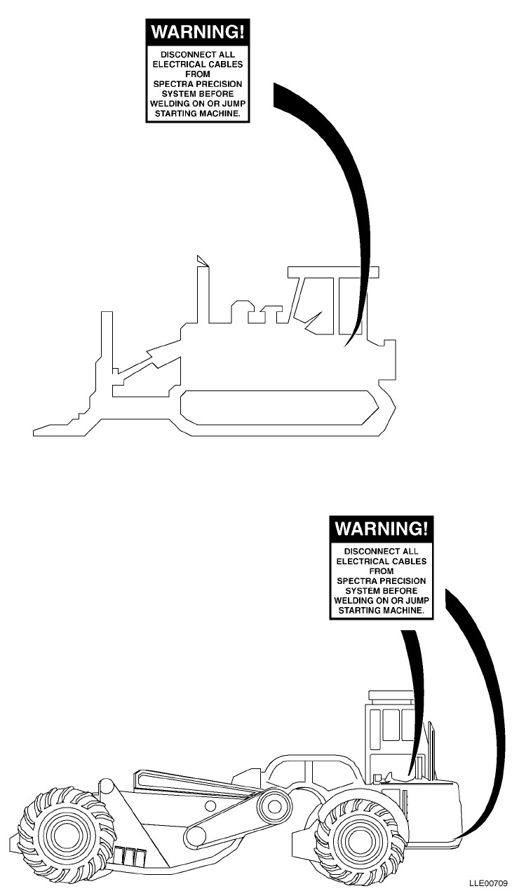
TM 5-6675-348-13&P
G-3

TM 5-6675-348-13&P
G-4
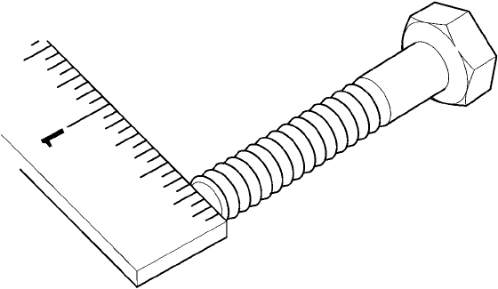
TM 5-6675-348-13&P
J-1
APPENDIX J
TORQUE LIMITS
Section I. INTRODUCTION
J-1. SCOPE.
This appendix provides general torque limits for the screws, hoses, and fittings used on the Laser Leveling
Equipment. Special torque limits are listed in the maintenance procedures for applicable components. The
general torque limits given in this appendix shall be used when specific torque limits are not indicated in the
maintenance procedure. These general torque limits cannot be applied to screws that retain rubber
components. The rubber components will be damaged before the torque limit is reached. If a special torque
limit is not given in the maintenance instructions, tighten the screw or nut until it touches the metal bracket,
then tighten it one more turn.
Section II. TORQUE LIMITS
J-2. TORQUE LIMITS.
Table J-1 lists the torque limits for wet flange nuts. Table J-2 lists the torque limits for wet socket head
capscrews. Table J-3 lists torque limits for dry fasteners. Dry torque limits are used on screws that do not
have high pressure lubricants applied to the threads. Table J-4 lists torque limit for wet fasteners. Wet torque
limits are used on screws that have high pressure lubricants applied to the threads. Table J-5 lists the torque
limits for SAE 37-degree flare hose connections. Table J-6 lists the torque limits for SAE 45-degree flare hose
connections. Table J-7 lists the torque limits for ORS preformed packing face seal hose connections. Table J-8
lists the torque limits for NPSM swivel connections.
J-3. HOW TO USE THE TORQUE TABLE.
a. Screws and Nuts.
(1) Measure the diameter of the screw
you are installing with a ruler.
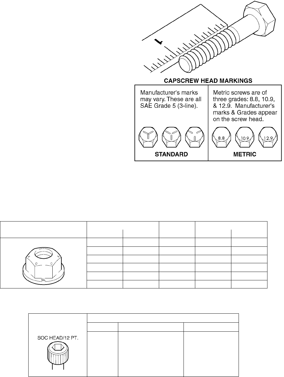
TM 5-6675-348-13&P
J-2
(2) Measure out 1 in. with a ruler and
count the number of threads per inch.
(3) Under the heading SIZE, look down
the left-hand column until you find
the diameter of the screw you are
installing (there will usually be two
lines beginning with the same size).
(4) In the second column under SIZE, find
the number of threads per inch that
matches the number of threads per
inch you counted in Step (2). (Not
required for metric screws.)
(5) To find the grade screw you are
installing, match the markings on the
head to the correct picture of
CAPSCREW HEAD MARKINGS on
the torque table.
(6) Look down the column under the
picture you found in Step (5). until you
find the torque limit (lb-ft or N•m) for
the diameter and threads per inch of
the screw you are installing.
(7) Use wet torque values.
Table J-1. Torque Limits for Wet Flange Nuts
Spiralock Flange Nut
Markings Grade 8
Diameter Threads
per In.
Torque
In. mm lb-ft N•m
1/4 6.35 20 15 20
5/16 7.94 18 25 34
3/8 9.53 16 45 61
1/2 12.70 13 110 149
5/8 15.87 11 210 285
3/4 19.05 10 375 508
Table J-2. Torque Limits for Wet Socket Head Capscrews
Torque in Ft Lb (Capscrews) Lubed
Size Socket Head or 12 Pt Socket Flat Head
0.10-24 55 2.5
0.25-20 12 6
0.31-18 25 12
0.38-16 44 22
0.50-13 70 36
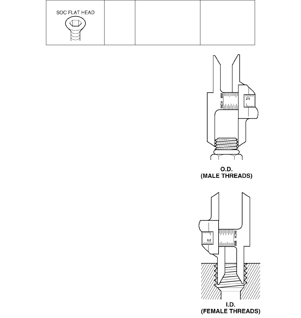
TM 5-6675-348-13&P
J-3
b. Hoses and Fittings.
NOTE
Most fluid piping system sizes are
measured by dash numbers. These are
universally used abbreviations for the
size of the component expressed at the
numerator of the fraction with the
denominator always being 16. For
example, a -04 port is 4/16 or 1/4 inch.
Dash numbers are usually nominal (in
name only) and are abbreviations that
make ordering of components easier.
(1) Measure the I.D./O.D. with a caliper as
shown.
(2) Under the heading MALE THREAD O.D.
and FEMALE THREAD I.D., match the
measurements with the row in the table
to determine proper torque.
0.56-12 106 53
0.62-11 212 106
0.75-10 375 187
1.00-8 781
Table J-2. Torque Limits for Wet Socket Head Capscrews (Continued)

TM 5-6675-348-13&P
J-4
(3) To Find the sealing surface angle, use a
protractor and measure the sealing
surface parallel to the centerline of the
fitting.
Table J-3. Torque Limits for Dry Fasteners
Size
Torque
SAE Grade
No. 2 SAE Grade
No. 5 SAE Grade
No. 6 or 7 SAE Grade
No. 8
Dia. In. Threads
per In. mm lb-ft N•m lb-ft N•m lb-ft N•m lb-ft N•m
1/4 20 6.35 5 7 8 11 10 14 12 16
1/4 28 6.35 6 8101412161419
5/16 18 7.94 11 15 17 23 21 28 25 34
5/16 24 7.94 12 16 19 26 24 33 25 34
3/8 16 9.53 2027304140544561
3/8 24 9.53 2331354745615068
7/16 1411.11 3041506860817095
7/16 20 11.11 35 47 55 75 70 95 80 108
1/2 13 12.70 50 68 75 102 95 129 110 149
1/2 20 12.70 55 75 90 122 100 136 120 163
9/16 12 14.29 65 88 110 149 135 183 150 203
9/16 18 14.29 75 102 120 163 150 203 170 231
5/8 11 15.88 90 122 150 203 190 258 220 298
5/8 18 15.88 100 136 180 244 210 285 240 325
3/4 10 19.05 160 217 260 353 320 434 380 515
3/4 16 19.05 180 244 300 407 360 488 420 570
7/8 9 22.23 140 190 400 542 520 705 600 814
7/8 14 22.23 155 210 440 597 580 786 660 895
1 8 25.40 220 298 580 786 800 1085 900 1220
1 12 25.40 240 325 640 868 860 1166 1000 1356

TM 5-6675-348-13&P
J-5
1-1/8 7 28.58 300 407 800 1085 1120 1519 1280 1736
1-1/8 12 28.58 340 461 880 1193 1260 1709 1440 1953
1-1/4 7 31.75 420 570 1120 1519 1580 2142 1820 2468
1-1/4 12 31.75 460 624 1240 1681 1760 2387 2000 2712
1-3/8 6 34.93 560 759 1460 1980 2080 2820 2380 3227
1-3/8 12 34.93 640 868 1680 2278 2380 3227 2720 3688
1-1/2 6 38.10 740 1003 1940 2631 2780 3770 3160 4285
1-1/2 12 38.10 840 1139 2200 2983 3100 4204 3560 4827
Table J-4. Torque Limits for Wet Fasteners
Size
Torque
SAE Grade
No. 2 SAE Grade
No. 5 SAE Grade
No. 6 or 7 SAE Grade
No. 8
Dia. In. Threads
per In. mm lb-ft N•m lb-ft N•m lb-ft N•m lb-ft N•m
1/4 206.35 4668811912
1/4 28 6.35 5 7 7 9 9 12 10 14
5/16 18 7.94 8 11 13 18 16 22 18 24
5/16 24 7.94 9 12 14 19 18 24 20 27
3/8 16 9.53 1520233130413547
3/8 24 9.53 1723253430413547
7/16 1411.11 2433354745615575
7/16 2011.11 2534405450686081
1/2 13 12.70 35 47 55 75 70 95 80 108
Table J-3. Torque Limits for Dry Fasteners (Continued)
Size
Torque
SAE Grade
No. 2 SAE Grade
No. 5 SAE Grade
No. 6 or 7 SAE Grade
No. 8
Dia. In. Threads
per In. mm lb-ft N•m lb-ft N•m lb-ft N•m lb-ft N•m

TM 5-6675-348-13&P
J-6
1/2 20 405465888010890122
9/16 12 14.29 50 68 80 108 100 136 110 149
9/16 18 55 75 90 122 110 149 130 176
5/8 11 15.88 70 95 110 149 140 190 170 231
5/8 18 80 108 130 176 160 217 180 244
3/4 10 19.05 120 163 200 271 240 325 280 380
3/4 16 140 190 220 298 280 380 320 434
7/8 9 22.23 110 149 300 407 400 542 460 624
7/8 14 120 163 320 434 440 597 500 678
1 8 25.40 160 217 440 597 600 814 680 922
1 12 170 231 480 651 660 895 740 1003
1-1/8 7 25.58 220 298 600 814 840 1139 960 1320
1-1/8 12 260 353 660 895 940 1275 1080 1464
1-1/4 7 31.75 320 434 840 1139 1100 1492 1360 1844
1-1/4 12 360 488 920 1248 1320 1790 1500 2034
1-3/8 6 34.93 420 570 1100 1492 1560 2115 1780 2414
1-3/8 12 460 624 1260 1709 1780 2414 2040 2776
1-1/2 6 38.10 560 760 1460 1980 2080 2820 2360 3200
1-1/2 12 620 841 1640 2224 2320 3146 2660 3607
Table J-4. Torque Limits for Wet Fasteners (Continued)
Size
Torque
SAE Grade
No. 2 SAE Grade
No. 5 SAE Grade
No. 6 or 7 SAE Grade
No. 8
Dia. In. Threads
per In. mm lb-ft N•m lb-ft N•m lb-ft N•m lb-ft N•m
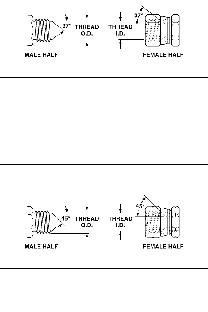
TM 5-6675-348-13&P
J-7
Table J-5. Torque Limits for 37-Degree Flare Hose Connections
INCH
SIZE DASH
NO. THREAD
SIZE TORQUE
LB-FT TORQUE
N•M
1/4 04 7/16-20 11-12 15-16
3/8 06 9/16-18 18-21 24-28
1/2 08 3/4-16 26-39 35-53
5/8 10 7/8-14 57-62 77-84
3/4 12 1 1/16-12 79-87 107-118
7/8 14 1 3/16-12 83-91 113-123
1 16 1 5/16-12 108-112 146-152
1-1/4 20 1 5/8-12 127-133 172-180
1-1/2 24 1 7/8-12 158-167 214-226
2 32 2 1/2-12 245-258 332-350
Table J-6. Torque Limits for 45-Degree Flare Hose Connections
INCH
SIZE DASH
NO. THREAD
SIZE TORQUE
LB-FT TORQUE
N•M
1/4 04 7/16-20 8-9 11-12
3/8 06 5/8-18 18-21 24-28
1/2 08 3/4-16 36-38 49-51
5/8 10 7/8-14 52-54 70-73
3/4 12 1 1/16-14 71-74 96-100

TM 5-6675-348-13&P
J-8
Table J-7. Torque Limits for ORS Preformed Packing Face Seal Hose Connections
INCH
SIZE DASH
NO. THREAD
SIZE TORQUE
LB-FT TORQUE
N•M
1/4 04 9/16-18 10-12 14-16
3/8 06 11/16-16 18-20 24-27
1/2 08 13/17-17 32-35 43-47
5/8 10 1-14 46-50 62-68
3/4 12 1 3/16-12 65-70 88-95
1 16 1 7/16-12 108-113 146-153
1 1/4 20 1 11/16-12 127-133 172-180
1 1/2 24 2-12 158-167 214-226
Table J-8. Torque Limits for NPSM Swivel Connections
INCH
SIZE DASH
NO. THREAD
SIZE TORQUE
LB-FT TORQUE
N•M
1/2 02 1/8-27 3-4 4-5
1/4 04 1/4-18 10-11 14-15
3/8 06 3/8-18 16-18 22-24
1/2 08 1/1-14 25-27 34-37
3/4 12 3/4-14 46-48 62-65
1 16 1-1 1/2 80-83 108-113
1 1/4 20 1 11/16-12 127-133 172-180
1 1/2 24 1 1/2-11/2 160-164 217-222
2 32 2-11/2 170-174 231-236

TM 5-6675-348-13&P
K-1
APPENDIX K
MANDATORY REPLACMENT PARTS
Section I. INTRODUCTION
K-1. SCOPE.
This appendix lists all mandatory replacement parts required for performance of Unit, Direct, and General
Support maintenance of Laser Leveling Equipment. It authorizes the requisitioning, issue, and disposition of
consumable repair parts. All consumable repair parts listed in the maintenance task are listed here for ease
or reference.
K-2. EXPLANATION OF COLUMNS (SECTION II).
a. Column (1) - Item No.
This number is assigned to the entry in the listing and is referenced in the narrative task box to identify the
part [e.g., Clamp (Item 12, Appendix K)].
b. Column (2) - Nomenclature.
Indicates the Federal item name and, if required, a description to identify the item.
c. Column (3) - Part Number.
This is the vendor number assigned to the item.
d. Column (4) - National Stock Number.
This is the National Stock Number assigned to the item; use it to request or requisition the item.
Section II. MANDATORY REPLACEMENT PARTS
Table K-1. Mandatory Replacement Parts - Gradio®
(1)
Item No.
(2)
Nomenclature
(3)
Part Number
(4)
National Stock Number
1 Kit, Voltage Protection 121022
2 Label, Warning, Welding/Jump Starting 111741
3 Mount, MM2E Manual Mast, Dozer 201476
4 Mount, RM2E Rigid Mast, Scraper 209254

TM 5-6675-348-13&P
K-2
Table K-2. Mandatory Replacement Parts - Blade Pro®
(1)
Item No.
(2)
Nomenclature
(3)
Part Number
(4)
National Stock Number
1 Base Mounting Block 0355-8620
2 Kit, Voltage Protection 121022
3 Label, Caution, Rotation Sensor 0355-7470
4 Label, Chart, Conversion 0790-8510
5 Label, Warning, Welding/Jump Starting 111741
6 Plate, Tracer/Mast Mount 0791-8820
Table K-3. Mandatory Replacement Parts - Bucket-Pro™
(1)
Item No.
(2)
Nomenclature
(3)
Part Number
(4)
National Stock Number
1 Label, Warning, Welding/Jump Starting 111741
2 Ring, Arm Sensor Mounting 0389-6380
3 Ring, Boom Sensor Mounting 0389-4400

By Order of the Secretary of the Army:
PETER J. SCHOOMAKER
General, United States Army
Chief of Staff
Official:
DISTRIBUTION: To be distributed in accordance with the initial distribution requirements for IDN: 256842, require-
ments for TM 5-6675-348-13&P.
0516605

.
DA FORM 2028, FEB 74 REPLACES DA FORM 2028, 1 DEC 68, WHICH WILL BE USED USAPPC V3.00
RECOMMENDED CHANGES TO PUBLICATIONS AND
BLANK FORMS
For use of this form, see AR 25-30; the proponent agency is ODISC4. Use Part II (reverse) for Repair Parts and Special
Tool Lists (RPSTL) and Supply Catalogs/Supply
Manuals (SC/SM).
DATE
TO:
(Forward to proponent of publication or form) (Include ZIP Code)
AMSTA-LC-CI TECH PUBS, TACOM-RI
1 Rock Island Arsenal
Rock Island, IL 61299-7630
FROM:
(Activity and location) (Include ZIP Code)
Your mailing address
PART I - ALL PUBLICATIONS (EXCEPT RPSTL AND SC/SM) AND BLANK FORMS
PUBLICATION/FORM NUMBER
TM 5-6675-348-13&P
DATE
30 November 2005
Title
Operator’s, Unit Maintenance, and Direct
Support Maintenance Manual for Laser
Leveling Equipment (Including Repair Parts
and Special Tools List)
ITEM
NO.
PAGE
NO.
PARA-
GRAPH
LINE
NO.*
FIGURE
NO.
TABLE
NO.
RECOMMENDED CHANGES AND REASON
(Provide exact wording of recommended changes, if possible.)
2-115 (14)(d) "Push down inner boom control lever (6) to retract outer boom cylinder
completely" should read "Push down outer boom control lever (6) to retract
outer boom cylinder completely"
* Reference to line numbers within the paragraph or subparagraph.
TYPED NAME, GRADE OR TITLE TELEPHONE EXCHANGE/AUTOVON,
PLUS EXTENSION
SIGNATURE
SAMPLE

.
DA FORM 2028, FEB 74 REPLACES DA FORM 2028, 1 DEC 68, WHICH WILL BE USED USAPPC V3.00
TO:
(Forward to proponent of publication or form) (Include ZIP Code)
AMSTA-LC-CI TECH PUBS, TACOM-RI
1 Rock Island Arsenal
Rock Island, IL 61299-7630
FROM:
(Activity and location) (Include ZIP Code)
DATE
PART II - REPAIR PARTS AND SPECIAL TOOL LISTS AND SUPPLY CATALOGS/SUPPLY MANUALS
PUBLICATION/FORM NUMBER
TM 5-6675-348-13&P
DATE
30 November 2005
TITLE
Operator’s, Unit Maintenance, and Direct Support
Maintenance Manual for Laser Leveling Equipment (Including
Repair Parts and Special Tools List)
PAGE
NO.
COLM
NO.
LINE
NO.
FEDERAL STOCK
NUMBER
REFERENCE
NO.
FIGURE
NO.
ITEM
NO.
TOTAL NO.
OF MAJOR
ITEMS
SUPPORTED
RECOMMENDED ACTION
PART III - REMARKS
(Any general remarks or recommendations, or suggestions for improvement of publications and
blank forms. Additional blank sheets may be used if more blank space is needed.)
TYPED NAME, GRADE OR TITLE TELEPHONE EXCHANGE/AUTOVON,
PLUS EXTENSION
SIGNATURE

.
DA FORM 2028, FEB 74 REPLACES DA FORM 2028, 1 DEC 68, WHICH WILL BE USED USAPPC V3.00
RECOMMENDED CHANGES TO PUBLICATIONS AND
BLANK FORMS
For use of this form, see AR 25-30; the proponent agency is ODISC4. Use Part II (reverse) for Repair Parts and Special
Tool Lists (RPSTL) and Supply Catalogs/Supply
Manuals (SC/SM).
DATE
TO:
(Forward to proponent of publication or form) (Include ZIP Code)
AMSTA-LC-CI TECH PUBS, TACOM-RI
1 Rock Island Arsenal
Rock Island, IL 61299-7630
FROM:
(Activity and location) (Include ZIP Code)
PART I - ALL PUBLICATIONS (EXCEPT RPSTL AND SC/SM) AND BLANK FORMS
PUBLICATION/FORM NUMBER
TM 5-6675-348-13&P
DATE
30 November 2005
Title
Operator’s, Unit Maintenance, and Direct
Support Maintenance Manual for Laser
Leveling Equipment (Including Repair Parts
and Special Tools List)
ITEM
NO.
PAGE
NO.
PARA-
GRAPH
LINE
NO.*
FIGURE
NO.
TABLE
NO.
RECOMMENDED CHANGES AND REASON
(Provide exact wording of recommended changes, if possible.)
* Reference to line numbers within the paragraph or subparagraph.
TYPED NAME, GRADE OR TITLE TELEPHONE EXCHANGE/AUTOVON,
PLUS EXTENSION
SIGNATURE

.
DA FORM 2028, FEB 74 REPLACES DA FORM 2028, 1 DEC 68, WHICH WILL BE USED USAPPC V3.00
TO:
(Forward to proponent of publication or form) (Include ZIP Code)
AMSTA-LC-CI TECH PUBS, TACOM-RI
1 Rock Island Arsenal
Rock Island, IL 61299-7630
FROM:
(Activity and location) (Include ZIP Code)
DATE
PART II - REPAIR PARTS AND SPECIAL TOOL LISTS AND SUPPLY CATALOGS/SUPPLY MANUALS
PUBLICATION/FORM NUMBER
TM 5-6675-348-13&P
DATE
30 November 2005
TITLE
Operator’s, Unit Maintenance, and Direct Support
Maintenance Manual for Laser Leveling Equipment (Including
Repair Parts and Special Tools List)
PAGE
NO.
COLM
NO.
LINE
NO.
FEDERAL STOCK
NUMBER
REFERENCE
NO.
FIGURE
NO.
ITEM
NO.
TOTAL NO.
OF MAJOR
ITEMS
SUPPORTED
RECOMMENDED ACTION
PART III - REMARKS
(Any general remarks or recommendations, or suggestions for improvement of publications and
blank forms. Additional blank sheets may be used if more blank space is needed.)
TYPED NAME, GRADE OR TITLE TELEPHONE EXCHANGE/AUTOVON,
PLUS EXTENSION
SIGNATURE
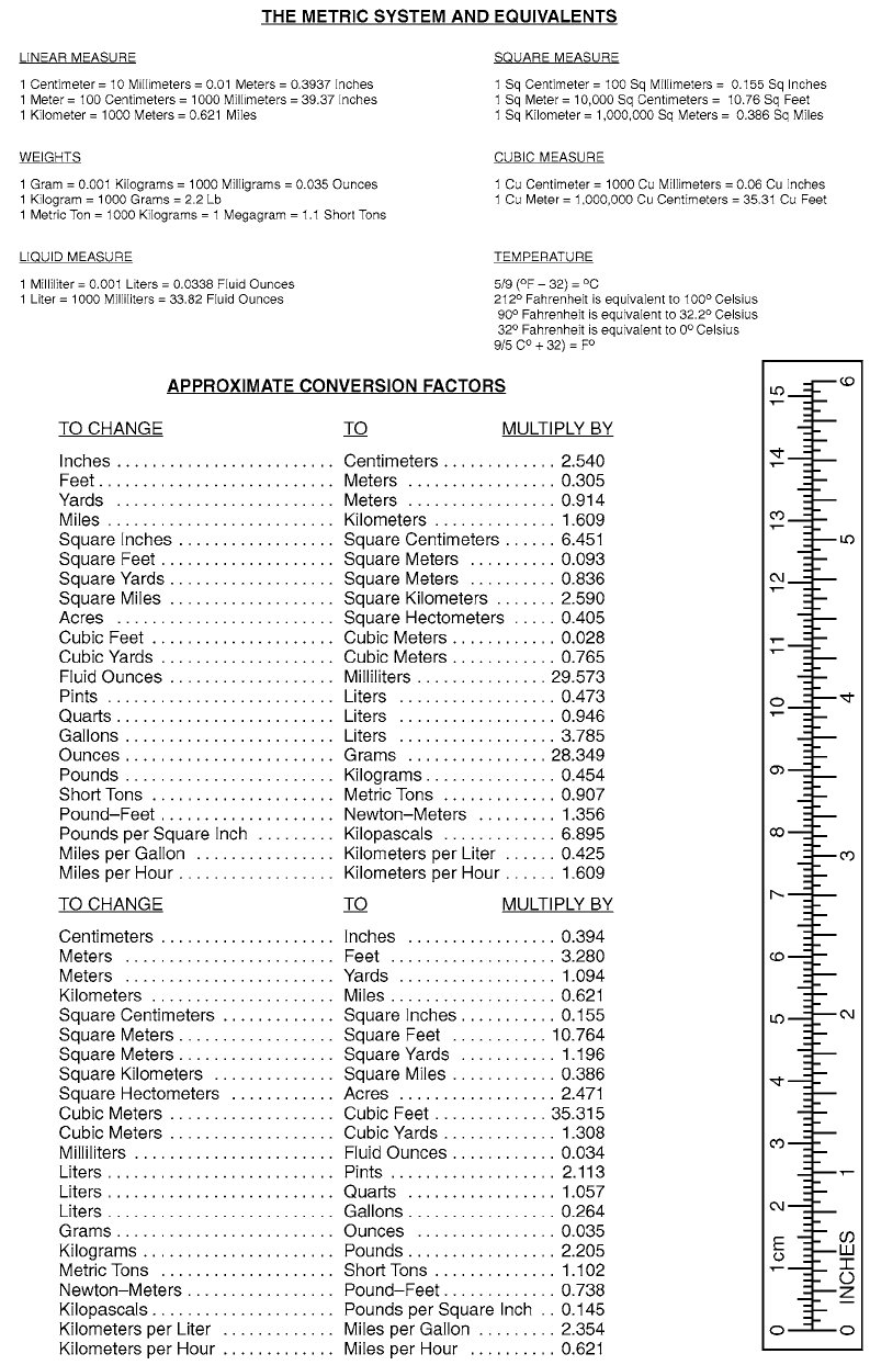
PIN: 082544-000

This fine document...
Was brought to you by me:
Liberated Manuals -- free army and government manuals
Why do I do it? I am tired of sleazy CD-ROM sellers, who take publicly
available information, slap “watermarks” and other junk on it, and sell it.
Those masters of search engine manipulation make sure that their sites that
sell free information, come up first in search engines. They did not create it...
They did not even scan it... Why should they get your money? Why are not
letting you give those free manuals to your friends?
I am setting this document FREE. This document was made by the US
Government and is NOT protected by Copyright. Feel free to share,
republish, sell and so on.
I am not asking you for donations, fees or handouts. If you can, please
provide a link to liberatedmanuals.com, so that free manuals come up first in
search engines:
<A HREF=http://www.liberatedmanuals.com/>Free Military and Government Manuals</A>
–Sincerely
Igor Chudov
http://igor.chudov.com/
–Chicago Machinery Movers
