TM78_Users Guide TM78 Users
TM78_UsersGuide TM78_UsersGuide
User Manual: TM78_UsersGuide
Open the PDF directly: View PDF ![]() .
.
Page Count: 60
E K-OTM78-UG-OO 1
Magnetic
Tape Formatter
User
Guide
digital
equipment
corporation
•
maynard,
massachusetts
1
st
Edition, September 1980
Copyright © 1980 by Digital Equipment Corporation
All rights reserved.
The
material in this
manual
is for informational purposes
and
is
subject to change without notice.
Digital Equipment
Corporation
assumes no responsibility for any
errors which may
appear
in this manual.
Printed in U.S.A.
This document was set on
DIGITAL's
DECset-8000 computerized
typesetting system.
The
following are
trademarks
of
Digital Equipment
Corporation,
Maynard,
Massachusetts:
DIGITAL
DEC
PDP
DEeUS
UNIBUS
D ECsystem-1 0
DECSYSTEM-20
DIBOL
EDUSYSTEM
VAX
VMS
MASSBUS
OMNIBUS
OS/8
RSTS
RSX
lAS
CHAPTER
1
1.1
1.2
1.2.1
1.2.2
1.3
1.3.1
1.3.1.1
1.3.1.2
1.3.1.3
1.3.1.4
1.3.1.5
1.3.1.6
1.3.1.7
1.3.1.8
1.3.1.9
1.3.1.10
1.3.1.11
1.4
1.5
CONTENTS
GENERAL
INFORMATION
Introduction
..
'........................................................
1-1
General Description . . . . . . . . . . . . . . . . . . . . . . . . . . . . . . . . . . . . . . . . . . . . . . . . .
..
1-1
Options
...........................................................
1-3
Physical Description
................................................
1-4
Functional Description
................................................
1-5
System Operation . . . . . . . . . . . . . . . . . . . . . . . . . . . . . . . . . . . . . . . . . . . . . . . . .
..
1-6
Common Address Space (M8957)
..................................
1-6
Data Bus Interface (M8956)
.......................................
1-7
Write Micro/Byte Assembly (M8959)
..............................
1-7
Write Translator (M8958)
.........................................
1-7
System Microcomputer (M8960)
...................................
1-8
Tape Unit Port (M8955)
..........................................
1-8
Read Channel Module (M8950) . . . .
..
. . .
.. ..
.
..
. .
..
. . . . .
..
. . . . .
.. ..
1-8
Read Path Controller (M8953)
.....................................
1-9
ECC
Controller (M8951)
........................................
1-10
Check Character Controller (M8952)
..............................
1-10
TM78 Maintenance Panel . . . . . . . . . . . . . . . . . . . . . . . . . . . . . . . . . . . . . .
..
1-10
Related Documents
..................................................
1-11
Specifications
.......................................................
1-11
CHAPTER
2
PROGRAMMING
INFORMATION
2.1
2.2
2.3
2.3.1
2.4
2.5
2.6
2.7
2.8
CHAPTER
3
3.1
3.2
3.3
3.4
3.4.1
3.4.2
Introduction
....................................
. . . . . . . . . . . . . . . . . . . .
..
2-1
Non-Data Transfers
...................................................
2-1
Data
Transfers
........................................................
2-2
Extended Sense (EXSNS) Command
.................................
2-6
TM78 Initiated Interrupts
.............................................
2-11
TM78 Hardware Control Registers
....................................
2-11
Dual Port . . . . . . . . . . . . . . . . . . . . . . . . . . . . . . . . . . . . . . . . . . . . . . . . . . . . . . . . .
..
2-13
Channel Address Summary
...........................................
2-13
Interrupt Code Failure Code Cross-Reference and Summary
..............
2-15
INSTALLATION
Site Planning and Considerations
.......................................
3-1
Unpacking
...........................................................
3-1
Inspection . . . . . . . . . . . . . . . . . . . . . . . . . . . . . . . . . . . . . . . . . . . . . . . . . . . . . . . . . .
..
3-1
Installation Procedures
................................................
3-3
MASSBUS Cabling. . . . . . . . . . . . . . . . . . . . . . . . . . . . . . . . . . . . . . . . . . . . . . .
..
3-3
TU
Bus Cabling
....................................................
3-4
iii
3.4.3
3.4.4
3.5
TM78-C Optional Dual Port Logic
...................................
3-4
Setting
MASSBUS
Drive Address
....................................
3-5
Acceptance Testing
...................................................
3-7
APPENDIX
A
EXTENDED
SENSE
COMMAND
(73)
DATA
BYTES
FIGURES
1-1
1-2
1-3
1-4
1-5
1-6
1-7
2-1
2-2
2-3
2-4
2-5
2-6
2-7
2-8
2-9
3-1
3-2
3-3
3-4
3-5
3-6
3-7
3-8
TABLES
2-1
2-2
2-3
2-4
2-5
2-6
2-7
2-8
2-9
2-10
2-11
2-12
TM78/TU78
Tape Transport System Configuration
.......................
1-2
TM78-AB Subsysteln Configuration
.....................................
1-3
TM78-BB Subsystem Configuration
.....................................
1-3
TM78 Mounted in Master
TU78
.......................................
1-4
TM78 Front View
....................................................
1-5
TM78
System Configuration
...........................................
1-5
TM78
Simplified Block Diagram
.......................................
1-6
Non-Data Transfer Fields
..............................................
2-1
Sense Information Fields
..............................................
2-4
Data
Transfer Fields
..................................................
2-5
Byte Assembly Modes and Associated Skip Counts
.......................
2-7
RHI0/20
EXSNS
Data
Byte Formatting
................................
2-8
TM78
Initiated Interrupt Fields
.......................................
2-11
TM78 Hardware Control Register Fields
...............................
2-12
RHII
and
RH70
Address Summary
...................................
2-14
RHI0,
RH20, and
RH780
Addresses
..................................
2-15
Releasing TM78 Logic
Gate
...........................................
3-1
Removing TM78 Logic Cover
..........................................
3-2
TM78 Module Layout . . . . . . . . . . . . . . . . . . . . . . . . . . . . . . . . . . . . . . . . . . . . . . .
..
3-2
MASSBUS Cable Terminator Connections
..............................
3-3
MASSBUS Cable Routing and Hardware
................................
3-4
Radial
TU
Bus Connections . . . . . . . . . . . . . . . . . . . . . . . . . . . . . . . . . . . . . . . . . .
..
3-5
TU
Bus Cable Routing and Hardware
...................................
3-6
MASSBUS Port
NB
Drive Address Selector Switch
.....................
3-6
Non-Data Transfer Function Codes
.....................................
2-3
Non~Data
Transfer Interrupt Codes
.....................................
2-4
Sense Information . . . . . . . . . . . . . . . . . . . . . . . . . . . . . . . . . . . . . . . . . . . . . . . . . . .
..
2-5
Data
Transfer Function
Codes.
. . . . . . . . . . . . . . . . . . . . . . . . . . . . . . . . . . . . . . .
..
2-8
Data
Transfer Interrupt Codes . . . . . . . . . . . . . . . . . . . . . . . . . . . . . . . . . . . . . . . .
..
2-9
TM78
Initiated Interrupt Codes
.......................................
2-11
TM78
Hardware Control Register Error Bits
............................
2-13
Interrupt Code to Failure Code
........................................
2-16
Non-Data Transfer
(NDT)
Interrupts to
NDT
Commands
................
2-24
Data
Transfer
(DT)
Interrupts to
DT
Commands
........................
2-25
TM78
Initiated Interrupts
.............................................
2-26
Host
Responses
.....................................................
2-26
tV
1.1 INTRODUCTION
CHAPTERl
GENERAL INFORMATION
The TM78 Magnetic Tape Formatter serves as an interface between a maximum of four TU78 Magnetic
Tape Transports and any MASSBUS controller.
It
provides control, data, status, and error information
between the MASSBUS controller and the standard 1.27 cm (0.50 in) TU78 Tape Transport, operating
at 318
cm/sec
(125 in/sec). The TM78 can read and write magnetic tape for information interchange at
1600 bits/in phase encoded (PE) or 6250 bits/in group-coded recording (GCR).
It
also has spacing and
reverse read capabilities. The TM78 formats data from
PDP-II
family, DECsystem-IO, DECSYSTEM-
20 and VAX processors into tape frame characters, and performs the reverse during a data read oper-
ation.
Aside from magnetic tape formatting, the TM78 offers the following features.
1.
Automatic two-track error correction when reading
GCR
data
2.
Resident on-line microdiagnostics
3.
Full wraparound maintenance diagnostics
4.
Dual MASSBUS port capability
5.
Automatic transport velocity monitoring
6.
Programmable self-diagnosing facility
7.
Full data path parity checking
8.
Automatic single-track error correction when reading
PE
data
9.
Automatic error repositioning for retries
1.2 GENERAL DESCRIPTION
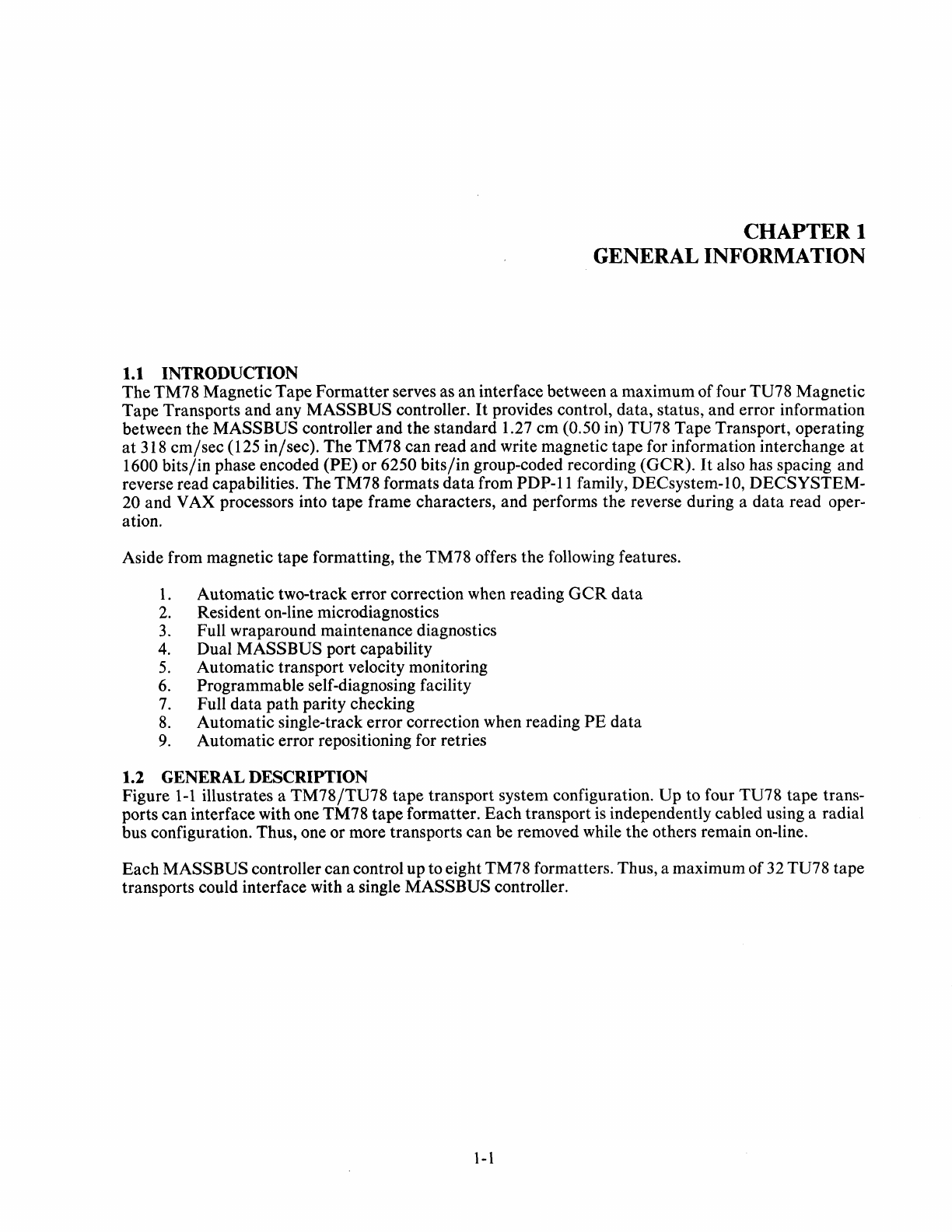
Figure
1-1
illustrates a
TM78/TU78
tape transport system configuration. Up to four TU78 tape trans-
ports can interface with one TM78 tape formatter. Each transport
is
independently cabled using a radial
bus configuration. Thus, one or more transports can be removed while the others remain on-line.
Each MASSBUS controller can control up to eight TM78 formatters. Thus, a maximum of 32 TU78 tape
transports could interface with a single MASSBUS controller.
1-1
MASSBUS
,...----,
...---
........
RADIAL
BUS
NETWORK
TRANSPORT
2
TRANSPORT
3
TRANSPORT
1
~
TRANSPORT
2
TRANSPORT
3
MA-6110
Figure
1-1
TM78/TU78
Tape Transport
System
Configuration
1-2
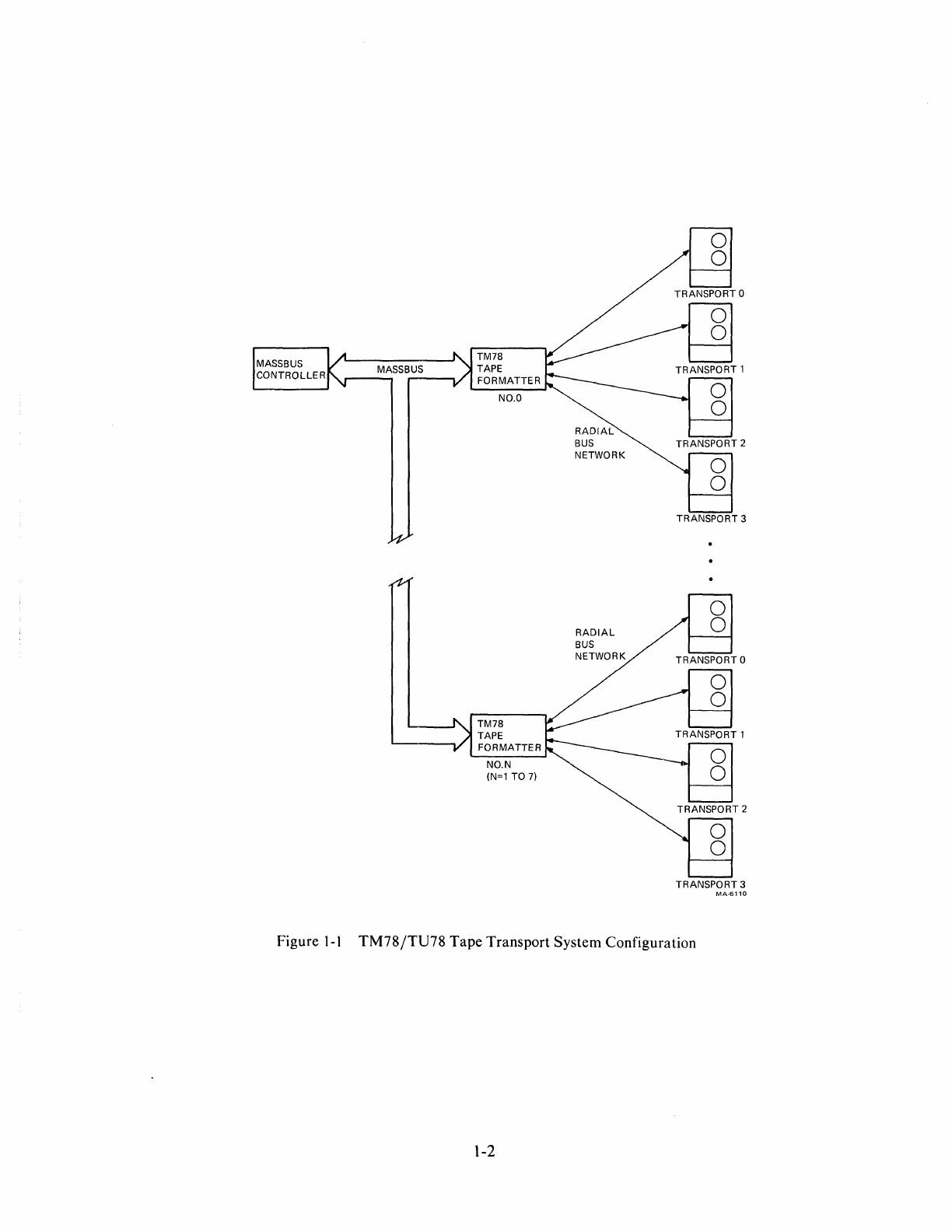
1.2.1 Options
TM78
FORMATTER
TU
PO
TU
P1
Figure
1-2
TM78-AB Subsystem Configuration
PORT
TU
A
PO
TM78
FORMATTER
PORT
TU
B
P1
Figure
1-3
TM78-BB Subsystem Configuration
MA-610e
MA-6109
The list below briefly describes all available TM78 options.
Option No
TM78-AB
TM78-BB
TM78-C
TM78
Configuration
Single
port
TM78 capable of interfacing
with
single MASSBUS
and
up
to
four
TU78s (Figure
1-2)
Dual
port
TM78 capable of interfacing
with
two
MASSBUSes
and
up
to
four
TU78s (Figure
1-3)
Dual
port
adapter
kit
for
TM78-AB
1-3
TU78
BASE ASSEMBLY
TM78 TAPE
FORMATTER
MA-6155
Figure
1-4
TM78
Mounted in
Master
TU78
1.2.2 Physical Description
Figure
1-4
shows the
TM78
mounted within the master TU78 tape transport cabinet. An H7422-AB pow-
er
supply provides power for the TM78, and
is
mounted in the rear of the master cabinet. Major sub-
assemblies of
the
TM78
are the H7422-AB plus regulators
(PN
70-17121) and TM78 tape formatter log-
ic
gate. Figure
1-5
shows the front view of the TM78.
1-4
MAINTENANCE
PANEL
MASSBUS
CONNECTORS
(4)
Figure
1-5
TM78
Front View
MASSBUS
CONTROLLER
TO 1-7
OTHER
DRIVES
TM78
PO
FORMATTER
P1
Figure
1-6
TM78
System
Configuration
1.3 FUNCTIONAL DESCRIPTION
LOGIC
BACKPLANE
MA-6156
MA-6107
The
TM78/TU78
tape transport system (Figure 1-6) interfaces with the central processor unit (CPU) via
the MASSBUS controller. However, the MASS BUS controller
is
almost transparent to the CPU; that is,
the
CPU
operates as though it controls the drive directly. (Throughout this manual, drive refers to a com-
plete tape subsystem, comprising a TM78 tape formatter and a TU78 tape transport.)
The
TM78 interfaces with the MASSBUS controller via the MASSBUS. The MASSBUS consists of an
asynchronous control bus and a synchronous data bus, both with associated control lines. Transactions on
the control bus control the drive and determine its status, while transactions on the data bus transfer data
to or from the drive. Because the data and control buses operate independently, the MASSBUS con-
troller can monitor drive status during a data transfer operation.
1-5
< CONTROL
BUS
~
WRITE
BUS
,.
READ
BUS
I'MS960
-MIC;;CO~E'R1
r----,
I 8085
J.lp
Figure
1-7
TM78
Simplified Block
Diagram
(5
TO
4)
MA-6106
The TM78 can control up to four tape transports through its dual port/radial bus scheme. Each tape unit
bus (radial bus) cable set
is
identical with one tape transport per cable set to the formatter. The bus con-
sists of write data, read data, control and various transport status lines.
1.3.1 System Operation
Figure
1-7
is
a block diagram of the TM78, showing the major functional groups, control lines, and data
paths. The following paragraphs describe these functional groups. While reading them, keep in mind
that
the word system implies the TM78 microcomputer system, and not some other portions (e.g., VAX,
11/70) or an overall computer system also run under microcode.
1.3.1.1 Common Address Space (M8957) -The common address space (CAS) interfaces the TM78
with the MASSBUS controller.
It
contains circuitry
that
decodes the drive select signals on the MASS-
BUS. Enabled by the proper drive select address code, the CAS module can
carryon
handshake oper-
ations with the MASSBUS controller, reading and writing TM78 registers.
Two TM78 registers provide a direct path from the MASSBUS to TM78 hardware. These registers are
used for initialization, loading and verification of diagnostic microcode, starting and stopping the micro-
processor, and diagnostic register access. The most important parts of the two registers are internal ad-
dress and internal data.
1-6
The
system microcoITlputer decodes
command
information in
CAS
registers and generates appropriate
control signals to
the
transport.
The
module/microcode
(that
is,
the
microcode within
the
module) also
determines when to
p(~rform
a
data
transfer operation.
When
this
is
the
case,
it
generates
OCC
(occupy)
on
the
MASSBUS
to notify
the
controller
that
it has occupied
the
data
bus.
1.3.1.2
Data
Bus Interface
(M8956)
-
The
data
bus interface module interfaces
the
TM78
data
paths
with
the
MASSBUS
c:ontroller.
The
data
bus interfac,e
is
enabled for operation when
the
MASSBUS
controller signal
OCC
is
asserted.
During a write operation,
the
MASSBUS
controller places a
data
word on
the
data
bus.
When
the
data
bus interface
is
ready to
accept
this
data
word,
it
asserts S
CLK
(sync clock) to
the
controller, which
then
replies with W
CLK
(write clock).
After
receiving W
CLK,
S
CLK
is
negated
and
the
data
bus interface strobes in
the
I8-bit word on
the
data
bus.
After
generating W
CLK,
the
MASSBUS
controller places
the
next
data
word on
the
data
bus.
When
the
data
bus interface module completes transferring
the
previous
data
word to
the
byte assembly
logic (M8959), it
issw~s
another
S
CLK,
receives another W
CLK,
and
strobes in
the
next
data
word for
transfer.
The
process continues until all
data
has been transferred (providing
there
are no
data
errors or
other
failures).
During a read operation,
the
data
bus interface module receives
an
I8-bit word from
the
byte assembly
logic.
It
is
placed on
the
data
bus, along with a
parity
bit
(D
PAR),
and
the
data
bus interface generates
an
S
CLK
pulse.
When
the
MASSBUS
controller receives S
CLK,
it strobes in
the
data
on
the
data
bus.
The
data
bus interface module continues to receive I8-bit
data
words, and notifies
the
controller
that
a
data
word
is
available by generating S
CLK.
As in a write operation,
the
method
of
word/character
as-
sembly
is
under
complete control
of
the
system microcode.
1.3.1.3
Write
Micro/Byte
Assembly
(M8959)
-
The
write
micro/byte
assembly module
is
a
ROM
mi-
crocontroller dispatched on various tasks
and
monitored by
the
system microcomputer (M8960).
In
addi-
tion to allowing diagnostic
data
injection to
the
write logic during diagnostic testing,
the
write micro por-
tion
of
the
module functions in
both
write
and
read
modes.
Write
Mode
1.
Receives
data
from
MASSBUS
data
module
2.
Disassembles
data
for translator in one
of
seven formats
3. Checks
data
parity from
MASSBUS
4.
Generates
data
parity to translator
5.
CRC
character
calculation
6.
ECC
character
calculation
(GCR)
7.
ACRC
character
calculation
(GCR)
8.
Formats
rel)idual
and
CRC
data
groups
(GCR)
Read
Mode
1.
Receives
data
from
read
logic
2. Assembles
data
for
MASSBUS
in one
of
seven formats
3.
Generates
data
parity
to
MASSBUS
4. Checks
data
parity from read logic
5.
Facilitates
data
byte skip count
1.3.1.4
Write
Translator
(M8958)
-
The
write translator is a
ROM
microcontroller initialized by
the
system
microcomput~~r
(M8960).
Once
initialized,
it
is controlled by
the
write micro portion
of
the
M8959
module.
The
write translator contains a microprogram
ROM,
subgroup buffers, translation
1-7
ROMs, and control logic required to translate 4-bit data bytes into the 5-bit characters required in
GCR
formatting. In general, during a
GCR
write operation, this module performs the following functions.
1.
Generates preamble and postamble
2.
Performs 4 to 5 translation
3.
Generates resync burst
4.
Generates end mark
5.
Controls flux reversal rate
6.
Provides track enable/disable functions
7.
Writes all ones
The module also performs the following functions during
PE
write operations.
1.
Generates preamble and postamble
2.
Controls flux reversal rate
3.
Provides track enable/disable functions
1.3.1.5 System Microcomputer (M8960) -The system microcomputer module uses an 8085 micro-
processor chip to act as the heart of the TM78 control bus (microbus).
PROM
space contains the oper-
ating system and diagnostic monitors. Specific diagnostic routines are loaded from the host computer
sys-
tem into 4K of additional RAM spaces before they are run.
The microcomputer directs TM78 operation over the TM78 microbus. it interfaces with the host
CPU
through the data bus interface and the CAS (common address space). The microcomputer's addressable
memory space extends to the CAS. In this context, they form a tightly coupled asymmetrical multi-
processor system.
1.3.1.6 Tape Unit
Port
(M8955) -The tape unit port module interfaces the TM78 formatter with the
tape transport. Two tape unit port modules may be used in each TM78 formatter, each module inter-
facing with two TU78 tape transports. During a TM78 write operation, the tape unit port module accepts
either
GCR
or
PE
formatted data from the M8958, and transmits it to the tape transport to be written
onto tape. Under complete microprogram control, bits in a
TU
command word inform the tape transport
as to what format the proceeding data
is
in.
During TM78 read or write operations, the tape unit port module accepts either
GCR
or
PE
data. This
time the data
is
to the TM78 from the tape transport. Again, the
TU
command word defines the data for-
mat.
This module also performs the following functions when the TM78
is
running
in
diagnostic mode.
1.
Loops translator to microcomputer
2.
Loops translator to read path
3.
Loops microcomputer to read path
4.
Loops transport command register to transport status register
5.
Loops microcomputer to
AMTIE
(amplitude track in error) lines
6.
Loops
AMTIE
lines to microcomputer
7.
Loops read data to microcomputer
1.3.1.7 Read Channel Module (M8950) -Nine read channel modules are used in the TM78 formatter,
one for each tape track. Read channels are
ROM
microcontrollers, dispatched and monitored by the read
path microcontroller (M8953). Read information feeds through the read channels, read data path, byte
assembly, and data bus interface to the MASSBUS, and on to the CPU. During the read-after-write por-
tion of the write cycle, information goes only as far as read data path logic, where
ECC
and
CRC/
ACRC
checking are performed.
1-8
Basically, functions
of
the
M8950
module during
PE
read/write
operation
are
as follows.
1.
Searches
for
preamble
2.
Passes
data
to
ECC
3.
Deskews
data
4.
Read
revers
Ie
correction
5.
Verifies
PE
flux reversal
The
main
function
of
1the
module during
GCR
read/write
operation is to
translate
the
5-bit
GCR
for-
matted
data
back
into the original 4-bit format. Additional functions
are
as follows.
1.
Searches
for
Mark
1
2.
Passes
data
to
ECC
3.
Deskews
data
4.
Read
revers~~
correction
5.
AMTIE
signal detection
6.
TIE
pointer generation
1.3.1.8 Read
Path
Controller
(M8953)
-
The
read
path
controller is a
ROM
microcontroller, dis-
patched
and
monitored by
the
system microcomputer.
The
read
path
dispatches
and
controls
the
nine
read
channel modules (M8950),
and
provides control information for
the
microcontrol portion
of
the
ECC
module. This module also serves as a
central
area
of
status
reporting for
the
entire
read
electronics
(read
channels,
ECC,
and
check
character
microcontroller parts).
The
basic module functions for
the
respective
formatter
operations
are
listed below.
Write
PE
1.
Tests
IRG
(iinter-record
gap)
2.
Tests
ID
Burst
3. Tests
Tape
~v1ark
4. Read-after-write
WriteGCR
1.
Tests
IRG
2.
Tests
ID
3.
Tests
Tape
~v1ark
4. Tests
ARA
][D
5.
Tests
ARA
Burst
6. Read-after-write
ReadGCR
1.
Reads
GCR
forward
2.
Reads
GCR
reverse
3.
Samples
density
at
BOT
4.
Detects
ARA
ID
5.
Detects
Tape
Mark
Read
PE
1.
Reads
PE
forward
2.
Reads
PE
reverse
3.
Samples
density
at
BOT
4.
Detects
Tap1e
Mark
1-9
Diagnostic Mode
1.
Self tests diagnostic
2.
Status register test
3.
Load/read
FIFO
data
1.3.1.9 ECC Controller (M8951) -The BCC (error correcting code) controller module
is
a
ROM
mi-
crocontroller initialized by the system microcomputer, and thereafter controlled by the read path
(M8953). This microcontroller implements the error-correction algorithms in both
GCR
and
PE
data for-
mats, and in both read and write modes.
Read
PE
1.
Single track error correction
Write/Read
GCR
1.
Single track error correction always
2.
Double track error correction with pointers
1.3.1.10 Check Character Controller (M8952) -The check character
(CRC
and ACRC) controller
module
is
a ROM microcontroller initialized by the system microcomputer, and thereafter controlled by
the ECC controller (M89 51). This microcontroller performs check character algorithms in both read and
write modes,
PE
and
GCR
data formats.
WriteGCR
1.
Verifies
CRC
and
ACRC
check characters
Read
GCR
1.
Verifies
CRC
and
ACRC
check characters
2.
Passes data to byte assembly logic (M8959)
Write
PE
1.
Generates
CRC
verification character
Read
PE
1.
Passes data to byte assembly logic (M8959)
1.3.1.11 TM78 Maintenance Panel -A maintenance panel, consisting of pushbuttons and LED
in-
dicators,
is
provided to enhance subsystem troubleshooting. The maintenance panel
is
tied to the resident
microcomputer and permits inspection of the formatter and transport without disabling the host CPU.
The panel keyboard/display
is
controlled exclusively by the TM78 microcode. The display remains blank
until the
ENA
key
is
pressed, and recognized by the microcode;
at
that time, the LEDs display HEL-
LO. The keyboard
is
enabled and all the keys may be used.
Subsystem failures and keypad operator errors generate a failure code (number) indicatd by the LEDs.
The failure codes and associated subcode listings define the particular error or problem. This aids mainte-
nance personnel, permitting them to work with one transport off-line, while the rest of the system remains
on-line. Refer to Paragraph 5.5 of the
TM78
Technical Manual for detailed information.
1-10
1.4 RELATED
DOCUMENTS
The
following list describes documents related to the
TM78
formatter.
Title
PDP-II
Peripherals
Handbook
RH
10
MASSBUS
Controller
Maintenance Manual
RH20
MASSBUS
Controller Unit
Description
RH780
MASSBUS
Adapter
Technical
Description
TM78
Field
Maintenance
Print
Set
H7422 Field
Maintenance
Print
Set
H7441 Field
Maintenance
Print
Set
H7476 Field
Maintenance
Print
Set
H7490 Field
Maintenance
Print
Set
1.5
SPECIFICATI()~NS
Data
Transfer Speed
Error
Detection
PE
GCR
Maximum record leng.:h
Doc No
EK-RH
IO-MM-002
EK-RH20-UD-00I
EK-RH780-TD-00I
MPOI061
Part
of
MPOI061
Part
of
MPOI061
Part
of
MPOI061
Part
of
MPOI061"
Contents
Register descriptions for
RH
MASSBUS
controllers
Theory and maintenance
of
RHI0
MASSBUS
controller
Description of
RH20
MASSBUS
controller
Programming and theory of
RH780
MASSBUS
adapter
Engineering drawings and
parts lists for
TM78
mechanics and logic
Engineering drawings and
parts lists for
TM78
power supply chassis
Engineering drawings and
parts lists for + 5 volt
regulator
Engineering drawings and
parts lists for ±
15
volt
regulator
Engineering drawings and
parts lists for - 5 volt
regulator
780,000
char
/ sec maximum
Single
track
error correction
Single
track
error correction always;
Double
track
error correction with
pointers;
CRC
/
ACRC
check
character
verification
65,536 characters
(PE
and
GCR)
1-11
Minimum record length
Environment
Operating
Nonoperating
Altitude
Operating
Nonoperating
Shock
Operating
Nonoperating
Vibration
Operating
Nonoperating
Power Requirements
DC
AC
TM78
Logic Assembly
Mechanical Specifications
Height
Width
Depth
Weight
1
character
(PE
and
GCR)
10° C (50
OF)
to 40° C (104
OF)
10 to 90 percent relative humidity
Wet
bulb: 28° C (82
OF)
maximum
Dew point:
2°
C (36
OF)
minimum
-40 ° C ( - 40 ° F) to 66 ° C (151 ° F)
o to 95 percent relative humidity
2.4 km (8000 ft)
maximum
9.1
km (30,000 ft)
maximum
Withstands half-sine shock pulse
of
10 G,
peak with 10 ± 3 ms duration
Withstands half-sine shock pulse
of
40 G,
peak
with 30 ± 10 ms duration
Withstands vibration
of
0.051
mm
(0.002
in) double amplitude (maximum) in
the
frequency range
of
5 to 50
Hz
Withstands
vibration
of
0.25 G, peak, in
the
frequency range
of
50 to 500
Hz
None
Input
voltage range
Single phase
Frequency
Power consumption
40 cnl (15.7 5 in)
48.25
cm
(19 in)
27.3
em
(10.75 in)
5.9 Kg (25Ibs)
1-12
184-256
Vac
47-63
Hz
525 VA typical
700 VA
maximum
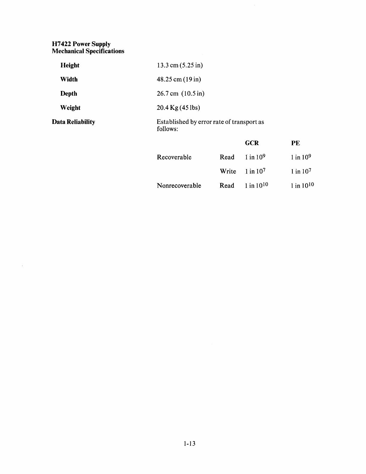
H7422
Power Supply
Mechanical Specifications
Height
Width
Depth
Weight
Data Reliability
13.3
em
(5.25 in)
48.25
em
(19 in)
26.7
em
(10.5 in)
20.4
Kg
(45 lbs)
Established
by
error
rate
of
transport
as
follows:
GCR
Recoverable
Read
1 in
10
9
Write
1 in 107
Nonrecoverable
Read
1 in 1010
1-13
PE
1 in 109
1 in
10
7
1 in 1010

CHAPTER 2
PROGRAMMING INFORMATION
2.1 INTRODUCTION
This chapter contains the programming information required by a user for a system containing the TM78
formatter. The information applies only to the TM78; programming information for other system units
can be found in the applicable documentation.
The TM78 common address space (CAS)is used by the host
CPU
and the internal microcomputer. The
CAS
is
located within the TM78, but
is
viewed as an extension to the memory address space of both the
host
CPU
(except for DECsystem-l0 and DECSYSTEM-20) and TM78 microcomputer. Within this
context, they form a tightly coupled, asymmetrical, multiprocessor system. This chapter defines the man-
ner in which the different processes cooperate.
This chapter also contains information about the use of the TM78 hardware control registers. These regis-
ters are used during subsystem initialization and diagnostic testing.
The TM78
GCR/PE
tape formatter
is
a MASSBUS device, and
is
subject to the same configuration
rules as other MASS BUS devices (i.e., up to eight TM78s per bus). Each TM78 may connect with as
many as four TU78 tape transports. The MASS BUS controller dictates
how
the TM78
is
accessed by the
program. Details of programming the MASS BUS controller and data channel (if any) are not provided.
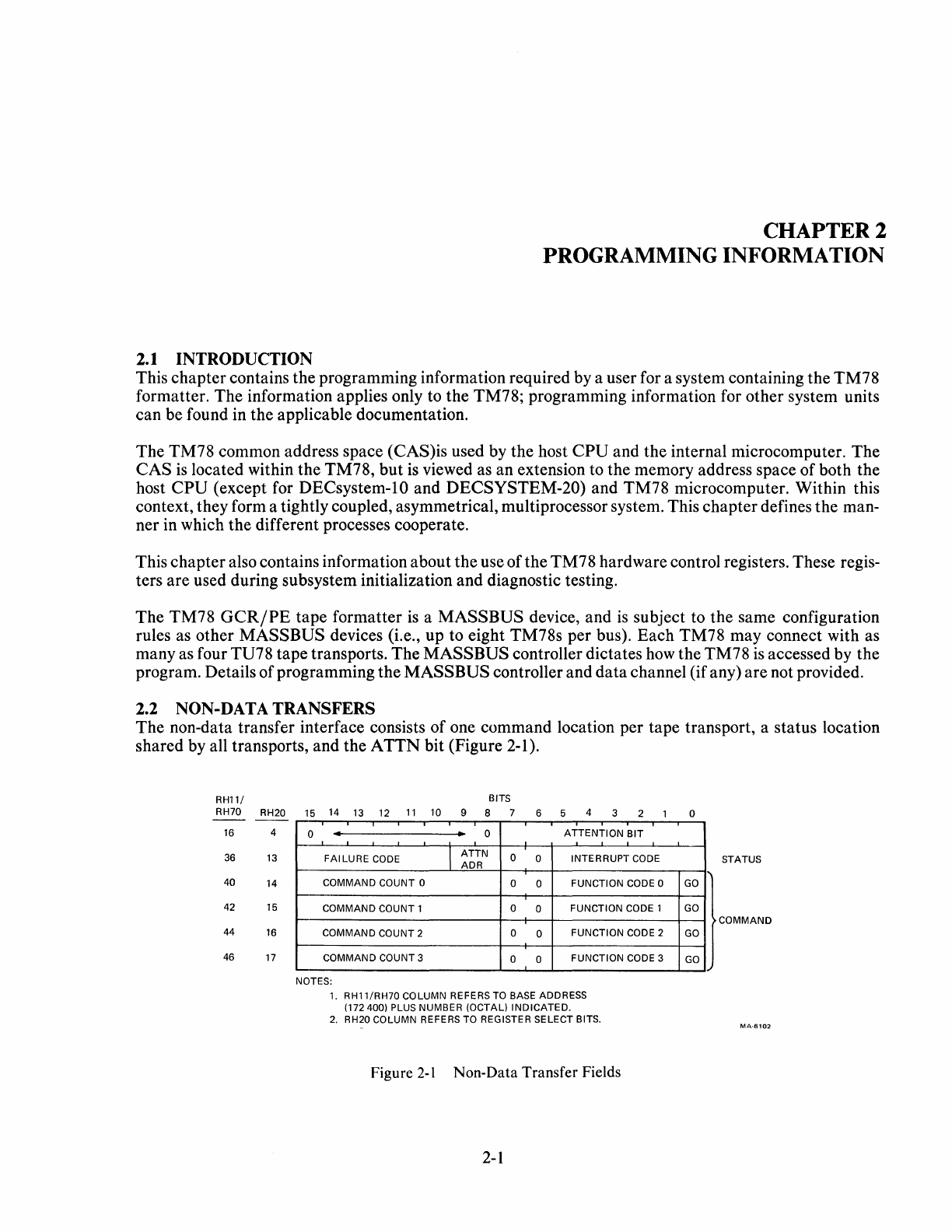
2.2 NON-DATA TRANSFERS
The non-data transfer interface consists of one command location per tape transport, a status location
shared by all transports, and the
ATTN
bit (Figure 2-1).
RH11/
RH70 RH20
16
4
36
13
40
14
42 15
44
16
46
17
BITS
15
14
13
12
11
10
9 8 7 6 5 4 3 2 0
0 •
..
0 ATTENTION BIT
FAI LURE
CODE
I ATTN 0 0 INTERRUPT
CODE
ADR
COMMAND COUNT 0 0 0 FUNCTION
CODE
0
COMMAND COUNT 1 0 0 FUNCTION
CODE
1
COMMAND COUNT 2 0 0 FUNCTION
CODE
2
COMMAND COUNT 3 0 0 FUNCTION
CODE
3
NOTES:
1. RH11/RH70 COLUMN REFERS
TO
BASE
ADDRESS
(172400) PLUS NUMBER (OCTAL) INDICATED.
2.
RH20 COLUMN REFERS TO REGISTER SELECT BITS.
Figure
2-1
Non-Data Transfer Fields
2-1
GO
GO
GO
GO
STATUS
COMMAND
MA-6102
The
host
CPU
may have up to four comnlands active
at
any time.
The
ATTN
bit corresponds to the
TM78
drive address and
is
set when a command
is
completed. Then, the host reads the
ATTN
ADR
to
determine the
tape
unit
that
has finished, and
the
Interrupt
Code corresponding to the interrupt-level ac-
tion to take.
If
the
Interrupt
Code indicates a hardware fault condition, then the Failure Code contains additional in-
formation for the system error log. To allow for further interrupts,
the
host
CPU
must write a logical one
into the
ATTN
Bit
after
reading the
Status
location. Command completion interrupts do not necessarily
occur in
the
same order as command initiations.
The Command Count specifies the number
of
times the command
is
to be repeated (octal 377 max-
imum).
If
the operation terminates prematurely, then the Command Count contains the number of op-
erations not completed successfully. A COlnmand Count
of
0 or 1 may be used to specify a single oper-
ation.
The
TM78
automatically performs all error recovery for non-data transfers. Unrecoverable errors and
hardware faults
are
reported.
The
GO
bits inform the
TM78
that
a new command has been loaded. They are not status bits because the
readability
is
undefined.
Non-data transfer function codes and interrupt codes
are
listed in Tables
2-1
and 2-2, respectively. Table
2-8
cross-references interrupt codes to failure codes.
The
Sense command may be used to obtain information about a specific tape transport. This information
is
available to the user during the time
the
ATTN
bit
is
set for this command (Figure 2-2).
Sense information
is
provided primarily for system initialization and error logging.
It
is
not necessary for
proper operation during non-error situations.
Table
2-3
lists all the Sense information mnemonics.
2.3
DATA
TRANSFERS
The
data
transfer interface
is
shared by all four tape transports; therefore, only one transfer may be active
at
a time.
The
data
transfer command
is
specified by the Function Code, Record Count, Format, Byte
Count, Command Address, and Skip Count.
Status
information for
read/write
operations
is
presented
through the
Interrupt
Code, Byte Count, Record Count, and Failure Code fields (Figure 2-3).
The
Function Code and
GO
bits
are
loaded
after
the
three locations
that
define a command.
It
is
not usu-
ally necessary to reload registers 2 and 5 in the
RH20
(addresses
14
and 6 in the
RH
11
/RH70)
in order to
repeat an operation (refer to Table 2-5). These locations must not be altered by the host
CPU
until the
operation has finished. Command completion is signaled by a
CMD
(command done) interrupt in the
RH20,
and an
RDY
interrupt in
the
RH
11
/RH70.
(The attention interrupt
is
not used for
data
trans-
fers).
The
host
CPU
reads the
Interrupt
Code to determine which interrupt-level action to take. All Inter-
rupt
Codes, except
DONE,
are accompanied by
the
DEE
bit (drive exception error) in the
RH20
and the
TRE
bit (transfer error) in
the
RHll/RH70.
The
CMD
ADR
specifies the
tape
unit to be used. This may
not be the address
of
a
tape
unit for which a non-data transfer command
is
active.
2-2
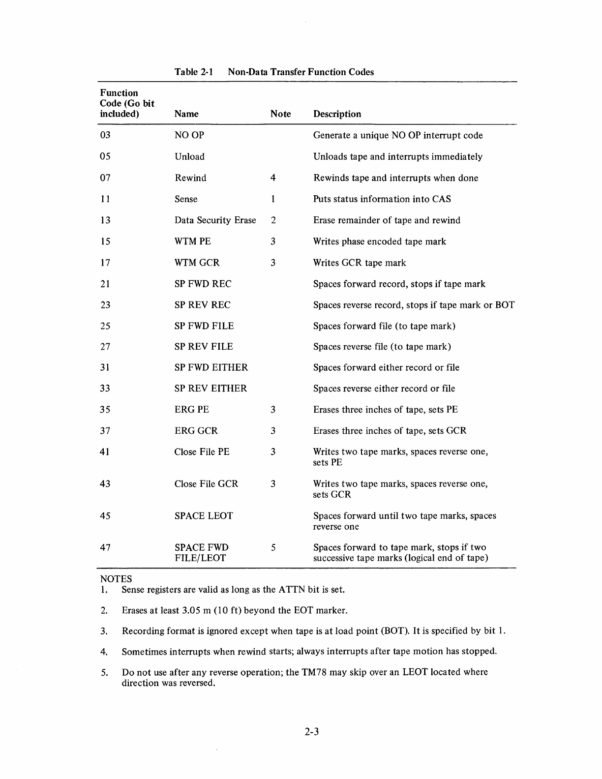
Function
Code (Go bit
included)
03
05
07
II
13
15
17
21
23
25
27
31
33
35
37
41
43
45
47
NOTES
Table
2-1
Non-Data Transfer Function Codes
Name
NOOP
Unload
Rewind
Sense
Data Security Erase
WTMPE
WTMGCR
SP
FWD
REC
SP
REV REC
SP
FWD
FILE
SP
REV FILE
SP
FWD
EITHER
SP
REV EITHER
ERGPE
ERGGCR
Close File PE
Close File GCR
SPACE LEOT
SPACE
FWD
FILE/LEOT
Note Description
Generate a unique
NO
OP interrupt code
Unloads tape and interrupts immediately
4 Rewinds tape and interrupts when done
Puts status information into
CAS
2 Erase remainder
of
tape and rewind
3 Writes phase encoded tape mark
3 Writes GCR tape mark
Spaces forward record, stops
if
tape mark
Spaces reverse record, stops
if
tape mark
or
BOT
Spaces forward file (to tape mark)
Spaces reverse file (to tape mark)
Spaces forward either record
or
file
Spaces reverse either record
or
file
3 Erases three inches
of
tape, sets PE
3 Erases three inches
of
tape, sets GCR
3 Writes two tape marks, spaces reverse one,
sets PE
3 Writes two tape marks, spaces reverse one,
sets GCR
Spaces forward until two tape marks, spaces
reverse one
5 Spaces forward
to
tape mark, stops
if
two
successive tape marks (logical end
of
tape)
I. Sense registers are valid as long
as
the ATTN bit
is
set.
2.
Erases
at
least 3.05 m (10 ft) beyond the EOT marker.
3.
Recording format
is
ignored except when tape
is
at load point (BOT).
It
is
specified by bit
1.
4.
Sometimes
intemlpts
when rewind starts; always interrupts after tape motion has stopped.
5.
Do
not
use after any reverse operation; the TM78 may skip over an LEOT located where
direction was
reve:rsed.
2-3
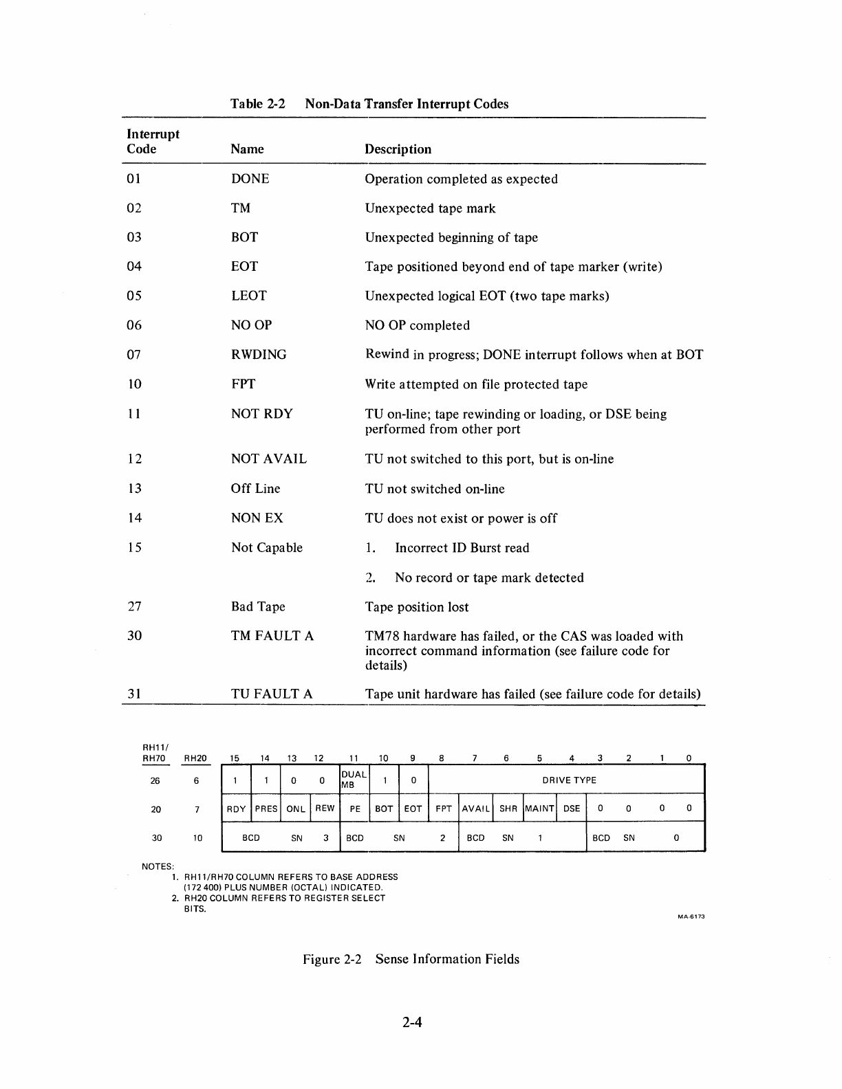
Table 2-2 Non-Data Transfer
Interrupt
Codes
Interrupt
Code Name Description
01
02
03
04
05
06
07
10
11
12
13
14
15
27
30
31
DONE
Operation
completed
as
expected
TM Unexpected tape
mark
BOT Unexpected beginning
of
tape
EaT
Tape positioned
beyond
end
of
tape
marker
(write)
LEOT Unexpected logical
EaT
(two
tape
marks)
NOOP
NO OP
completed
RWDING Rewind in progress; DONE
interrupt
follows when
at
BOT
FPT
NOT RDY
NOT AVAIL
Off
Line
NON EX
Not
Capable
Bad Tape
TM
FAULT
A
Write
attempted
on
file
protected
tape
TU
on-line; tape rewinding
or
loading,
or
DSE being
performed from
other
port
TU
not
switched
to
this
port,
but
is on-line
TU
not
switched on-line
TU does
not
exist
or
power
is
off
1.
Incorrect ID Burst read
2.
No record
or
tape
mark
detected
Tape position lost
TM78 hardware has failed,
or
the
CAS was loaded with
incorrect
command
information
(see failure code for
details)
TUFAULT
A Tape
unit
hardware has failed (see failure code for details)
RH11/
RH70 RH20 15 14 13 12
11
10
1 1 0 0
DUAL
1
MB
26 6
20 7 ROY
PRES
ONL
I
REW
PE
BOT
30
10
BCD
SN
3 BCD
SN
NOTES:
1.
RH11/RH70 COLUMN REFERS TO BASE ADDRESS
(172 400) PLUS NUMBER (OCTAL)
INDICATED.
2.
RH20 COLUMN REFERS TO REGISTER SELECT
BITS.
9 8 6 5 4 3
0
DRIVE
TYPE
EOT FPT
AVAILl
SHR
lMAINTI
DSE
0
2
BCD
SN
1
BCD
Figure 2-2 Sense Information Fields
2-4
2 o
0 0 0
SN
0
MA-6173
Name
DUALMB
DRIVE TYPE
RDY
PRES
ONL
REW
PE
BOT
EOT
FPT
AVAIL
SHR
MAINT
DSE
BCDSN
RH11/
RH70 RH20
o 0
14 2
6 5
12
Table 2-3 .Sense Information
Definition
When set, TM78 has dual MASSBUS
port
option
Octal
101
for TU78 tape drives
Tape unit has tape mounted,
is
on-line, and
is
not
rewinding or perfonning
DSE
Tape unit has power applied
Tape unit
is
on-line and tape is mounted
Tape unit
is
rewinding
When set, tape unit is set for PE recording format; when clear, tape unit
is
set for GCR recording format
Tape
is
positioned
at
load point
Tape
is
positioned beyond end-of-tape marker
Tape unit
is
write protected
Tape unit
is
available
to
this MASSBUS
Tape unit
is
available to
both
MASSBUS ports (shared)
Tape unit
is
in maintenance mode, and may
not
be used
Tape unit
is
performing erase portion
of
DSE command
Binary-coded-decimal serial number
of
the tape unit
BITS
15 14 13 12
11
10 9 8 7 6 5 4 3 2 o
0
+----+
0
DVAI
0
..
• o I FUNCTION CODE I
GO
SERI
FORMAT
SKIP COUNT 1 RECORD COUNT ICMD
ADR
BYTE COUNT
FAILURE
CODE I 0
1DP~
0 o I INTERRUPT CODE
NOTES:
1.
RH11/RH70
COLUMN REFERS TO BASE ADDRESS
(172 400) PLUS NUMBER (OCTAL)
INDICATED.
2.
RH20 COLUMN REFERS TO REGISTER SELECT
BITS.
Figure
2-3
Data Transfer Fields
2-5
MA-6103
The
Record Count specifies the number
of
records to read or write, and may be any value in the range of 0
to 778. When it
is
not zero, it
is
decremented after every record correctly transferred. When it
is
zero, the
TM78
transfers records until stopped by the
MASSBUS
controller.
The
RH20
has its own block counter
and may be operated with the Record Count set to zero. For the
RH
11
/RH70,
a block
of
memory may be
divided into multiple records by using the Record Count. Record Count
is
zero upon a normal termi-
nation, and after an error occurs indicates the number of records remaining to be transferred.
It
is
not
decremented during unsuccessful error retry operations,
so
that
it does not have to be reloaded after an
error, unless the
TM78
issues a
Read
Opposite interrupt code. In this case, the Record Count should be
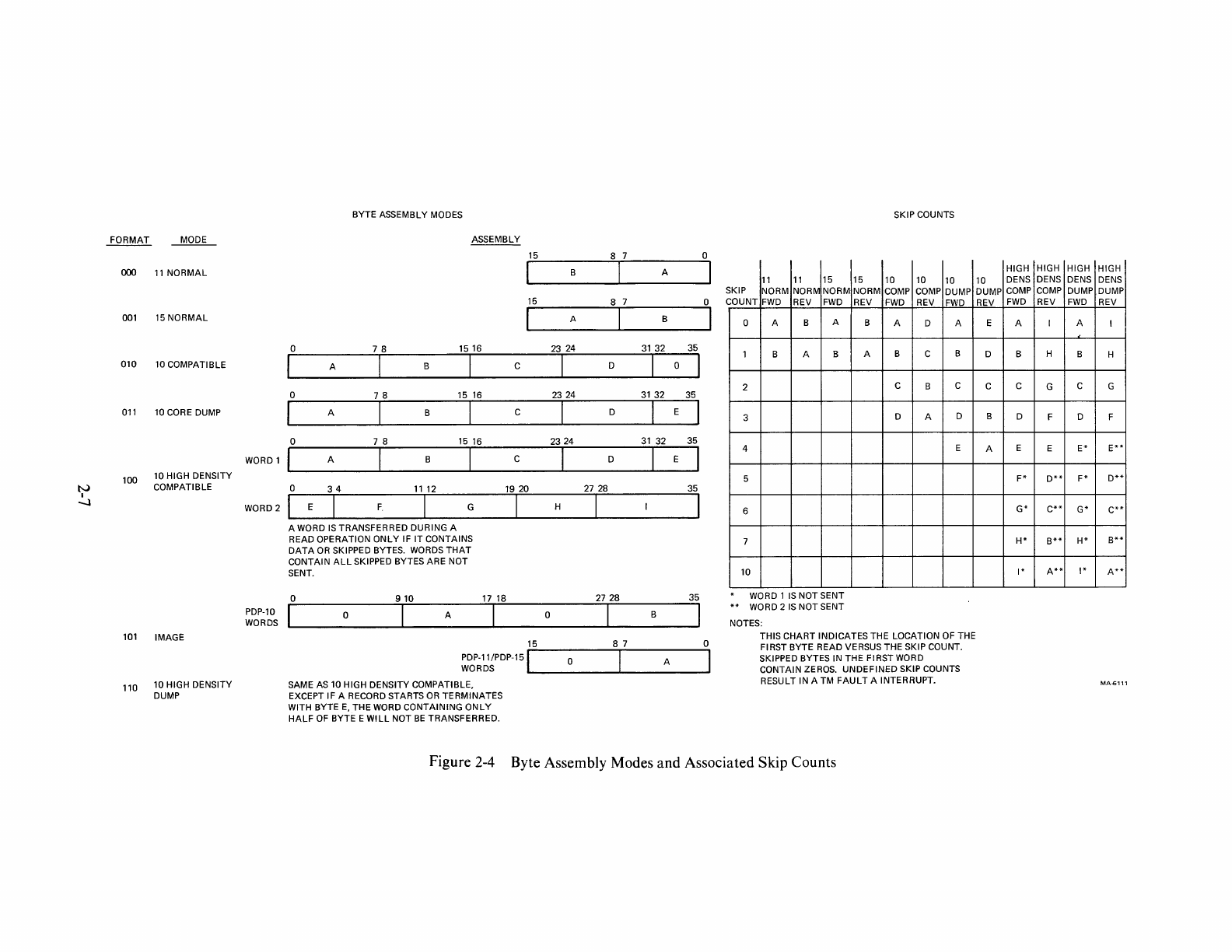
set to zero. When writing, records are always started with byte A (Figure 2-4). Any unwritten bytes in the
last word of a buffer are not written in the next record.
The
length of the record (or records) to be read or written is determined by the Byte Count. The entire
record
is
always sent to the
MASSBUS
controller, even if it
is
longer than Byte Count indicates.
If
the
record length differs from the Byte Count, the actual length
is
returned in Byte Count, unless the inter-
rupt code
is
Read Opposite (refer to Table 2-8). In addition, the
MASSBUS
controller can detect record
length errors when the
TM78
transfers an unexpected number of bytes to the
MASSBUS
controller (or
channel). A Byte Count
of
zero implies 2
16
bytes.
If
the
TM78
detects an error
that
requires a retry, it positions the tape for the retry operation unless
SER
(suppress error repositioning)
is
set.
If
SER
is
not set, error recovery algorithms
of
the TM78
inform the host
CPU
of the next operation to perform via the interrupt code. A record
is
declared un-
readable if repeated error recovery attempts fail.
If
a record cannot be written, the
TM78
responds with
BAD
TAPE
(Interrupt
Code 27).
The Format field (Figure 2-4) defines the manner in which tape bytes are assembled
to/from
the host
CPU
words. Skip Count
is
used during tape read operations to zero-fill the specified number of byte posi-
tions before reading the first
data
byte. These zero-filled bytes are transferred from the TM78 even if
no
data
bytes are read (because of an error).
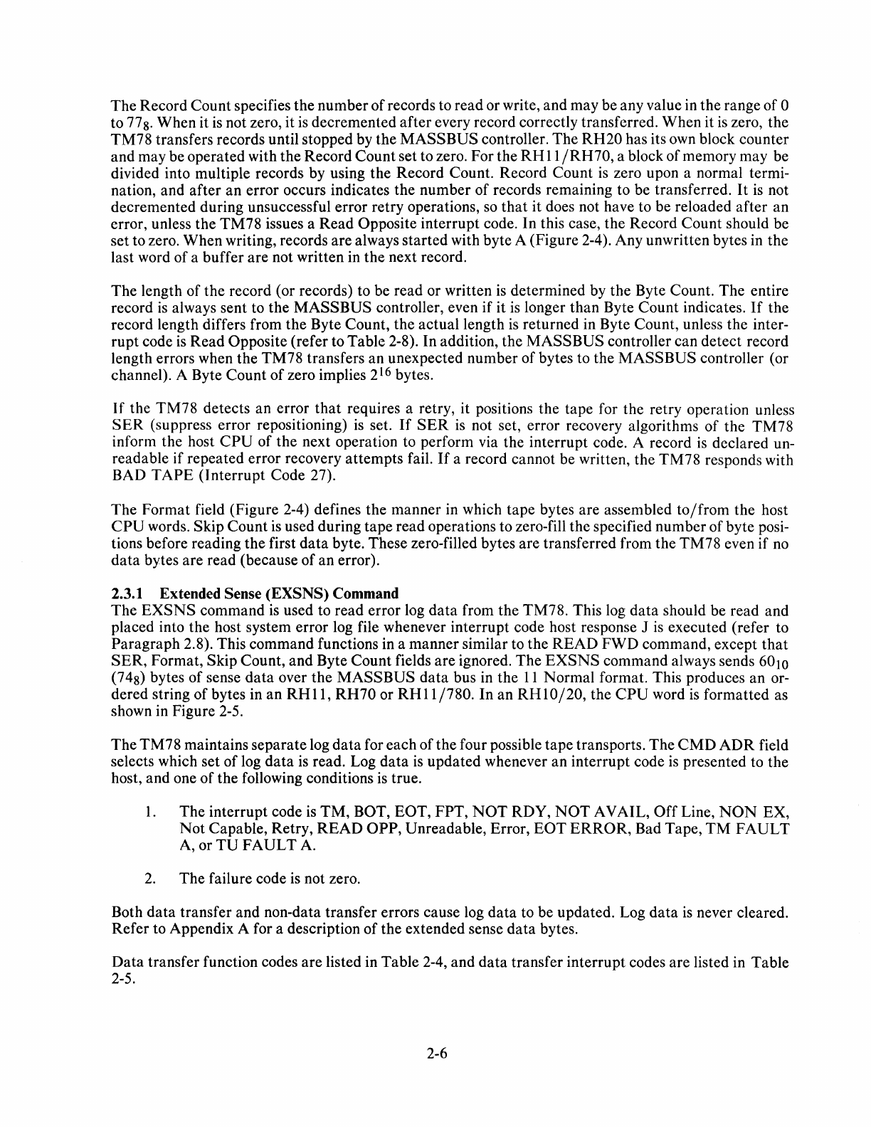
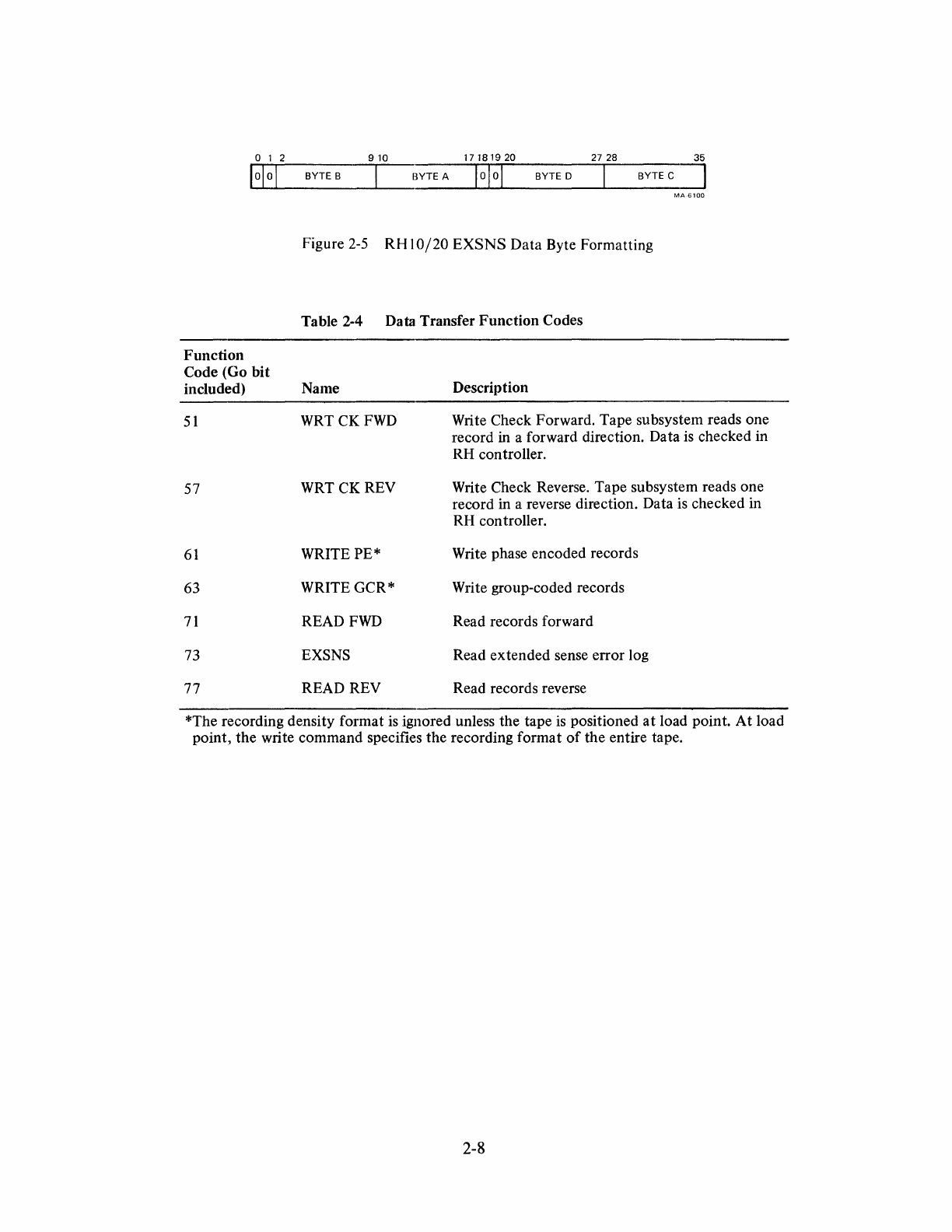
2.3.1 Extended Sense (EXSNS) Command
The
EXSNS
command
is
used to read error log
data
from the TM78. This log
data
should be read and
placed into the host system error log file whenever interrupt code host response J
is
executed (refer to
Paragraph 2.8). This command functions in a manner similar to the
READ
FWD
command, except
that
SER,
Format, Skip Count, and Byte Count fields are ignored.
The
EXSNS
command always sends
6010
(748) bytes of sense
data
over the
MASSBUS
data
bus in the
11
Normal format. This produces an or-
dered string of bytes in
an
RHll,
RH70
or
RHII/780.
In an
RHI0/20,
the
CPU
word
is
formatted as
shown in Figure 2-5.
The
TM78
maintains separate log
data
for each
of
the four possible tape transports. The
CMD
ADR
field
selects which set
of
log
data
is
read. Log
data
is
updated whenever an interrupt code
is
presented to the
host, and one
of
the following conditions
is
true.
1.
The interrupt code
is
TM,
BOT,
EaT,
FPT,
NOT
RDY,
NOT
AVAIL,
Off
Line,
NON
EX,
Not
Capable, Retry,
READ
OPP,
Unreadable, Error,
EaT
ERROR,
Bad Tape,
TM
FAULT
A,
orTU
FAULT
A.
2.
The failure code
is
not zero.
Both
data
transfer and non-data transfer errors cause log
data
to be updated. Log
data
is
never cleared.
Refer to Appendix A for a description
of
the extended sense
data
bytes.
Data
transfer function codes are listed in Table 2-4, and
data
transfer interrupt codes are listed in Table
2-5.
2-6
tv
I
-.J
FORMAT
~
000
11
NORMAL
001
15
NORMAL
010
10
COMPATIBLE
011
10
CORE
DUMP
100 10 HIGH DENSITY
COMPATIBLE
101
IMAGE
110 10 HIGH DENSITY
DUMP
WORD
1
WORD
2
BYTE ASSEMBLY MODES
ASSEMBLY
15
8 7 0
I B I A I
15
8 7 0
I A I B I
o 7 8
1516
23
24
31
32 35
I A I B I C I D 101
o 7 8
15
16
2324
31
32 35
I A I B I C I
DIE
I
o 7 8
15 16
2324
31
32 35
I A I B I C I D I I
o 3 4
11
12 19
20
27 28
35
I
ElF
I G I H I I
A WORD
IS
TRANSFERRED DURING A
READ OPERATION
ONLY
IF
IT
CONTAINS
DATA
OR
SKIPPED BYTES.
WORDS
THAT
CONTAIN
ALL
SKIPPED BYTES ARE NOT
SENT.
o
910
17 18
2728
35
~~~~S
I 0 I A I 0 I B I
15 8 7 0
PDP.ll/PDP.15 1 0 I A I
WORDS
SAME
AS
10 HIGH DENSITY COMPATIBLE,
EXCEPT IF A RECORD STARTS
OR
TERMINATES
WITH BYTE
E,
THE WORD CONTAINING
ONLY
HALF
OF
BYTE E
WILL
NOT
BE
TRANSFERRED.
SKIP COUNTS
11 11
15
15
10 10 10
;KIP NORM NORM NORM NORM
COMP COMP
DUMP
;OUNT
FWD
REV
FWD
REV
FWD
REV
FWD
0 A B A B A D A
1 B A B A B C B
2 C B C
3 D A D
4 E
5
6
7
10
WORD
1
IS
NOT SENT
WORD 2
IS
NOT SENT
NOTES:
THIS CHART INDICATES THE LOCATION OF THE
FIRST BYTE READ VERSUS THE SKIP COUNT.
SKIPPED BYTES IN THE FIRST WORD
CONTAIN ZEROS. UNDEFINED SKIP COUNTS
RESULT IN A TM
FAULT
A INTERRUPT.
Figure 2-4 Byte Assembly Modes
and
Associated Skip Counts
HIGH HIGH HIGH HIGH
10
DENS
DENS DENS
DENS
DUMP
COMP
COMP
DUMP DUMP
REV
FWD
REV
FWD
REV
E A I A I !
D B H B H
C C G C G
B D F D F
A E E
E*
E**
F*
D**
F*
D**
G*
C**
G*
C**
H*
B**
H*
B**
1*
A**
1*
A**
012
910
17 18 19 20 27 28
10101
BYTE B BYTE A 1
0 I a I BYTE D
35
BYTEC
~
Function
Code (Go
bit
included)
51
57
61
63
71
73
77
MA6100
Figure
2-5
RH
10/20
EXSNS
Data
Byte Formatting
Table 2-4 Data Transfer
Function
Codes
Name
WRTCKFWD
WRT CK REV
WRITE PE*
WRITE GCR*
READ
FWD
EXSNS
READ REV
Description
Write Check Forward. Tape subsystem reads one
record in a forward direction. Data
is
checked in
RH controller.
Write Check Reverse. Tape subsystem reads one
record in a reverse direction. Data is checked in
RH controller.
Write phase encoded records
Write group-coded records
Read records forward
Read extended sense error log
Read records reverse
*The recording density format
is
ignored unless the tape
is
positioned
at
load point.
At
load
point,
the
write command specifies the recording format
of
the
entire tape.
2-8
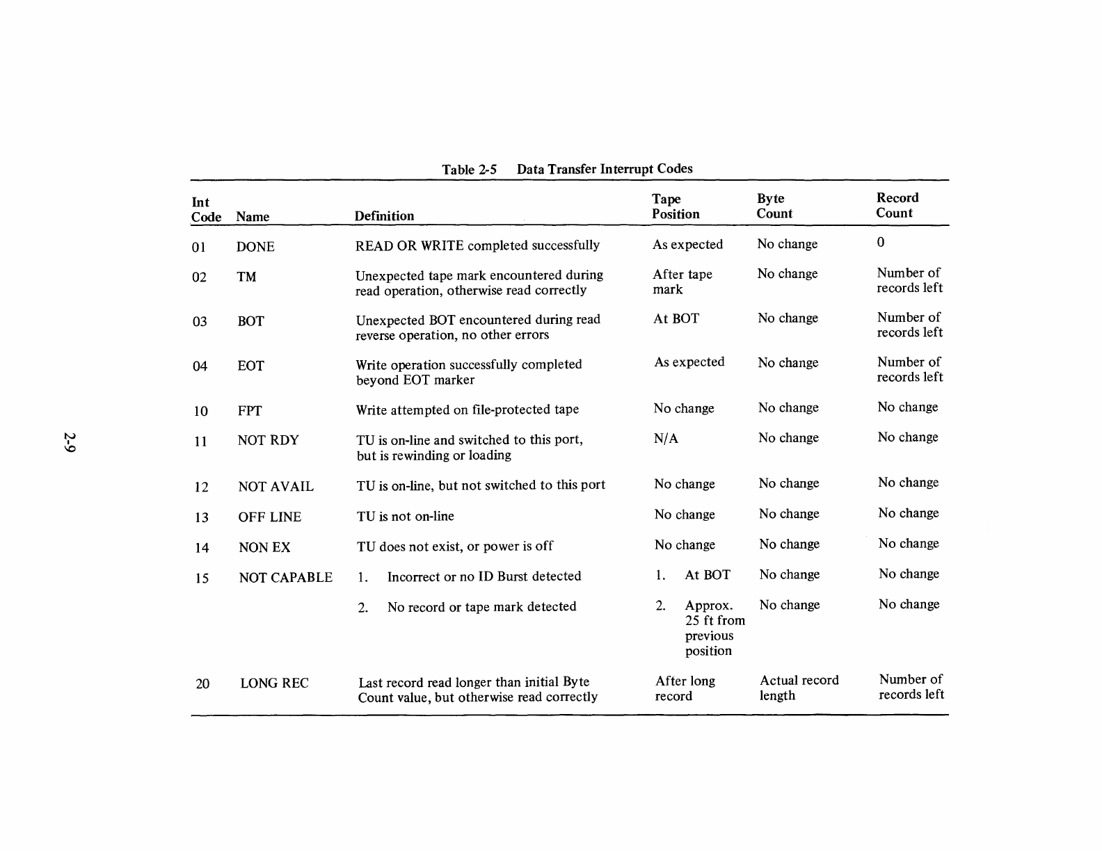
Table 2-5
Data
Transfer
Interrupt
Codes
Int
Tape
Byte
Record
Code
Name
DeImition
Position
Count
Count
01 DONE READ
OR
WRITE
completed
successfully As
expected
No change 0
02
TM Unexpected tape
mark
encountered
during
After
tape
No change
Number
of
read operation, otherwise read correctly
mark
records
left
03 BOT Unexpected BOT
encountered
during read
At
BOT No change
Number
of
reverse operation,
no
other
errors records
left
04
EOT Write
operation
successfully
completed
As
expected
No change
Number
of
beyond
EOT
marker
records
left
10 FPT Write
attempted
on
file-protected
tape
No
change No change No change
tv
11
NOTRDY
TU
is on-line
and
switched
to
this
port,
N/A
No change
No
change
I
\0
but
is rewinding
or
loading
12 NOT AVAIL
TU
is on-line,
but
not
switched
to
this
port
No
change No change No change
13
OFF
LINE
TU
is
not
on-line No change No change
No
change
14 NON EX
TU
does
not
exist,
or
power
is
off
No
change No change
No
change
15
NOT CAPABLE
1.
Incorrect
or
no
ID Burst
detected
1.
At
BOT No change No change
2. No record
or
tape
mark
detected
2.
Approx.
No change
No
change
25
ft
from
previous
position
20 LONG REC Last record read longer
than
initial Byte
After
long Actual record
Number
of
Count
value,
but
otherwise read correctly
record
length records left
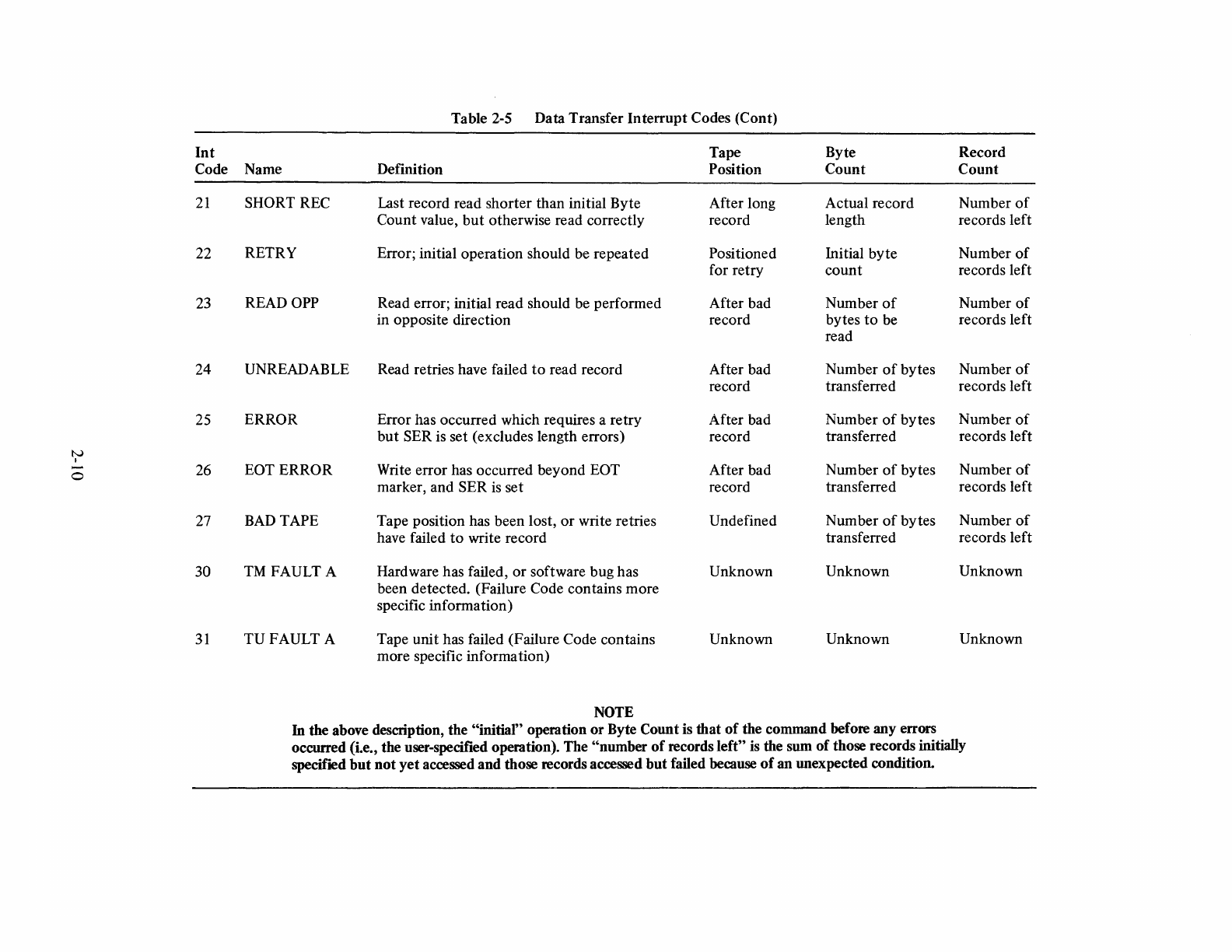
Table 2-5 Data Transfer Interrupt Codes (Cont)
Int
Tape Byte Record
Code Name Definition Position Count Count
21
SHORT REC Last record read shorter than initial Byte After long Actual record Number
of
Count value,
but
otherwise read correctly record length records left
22
RETRY Error; initial operation should be repeated Positioned Initial byte Number
of
for retry count records left
23
READ
OPP
Read error; initial read should be performed After bad Number
of
Number
of
in opposite direction record bytes
to
be records left
read
24
UNREADABLE Read retries have failed
to
read record After bad Number
of
bytes Number
of
record transferred records left
25
ERROR Error has occurred which requires a retry After bad Number
of
bytes Number
of
but SER is set (excludes length errors) record transferred records left
tv
I
0
26
EOTERROR
Write error has occurred beyond EOT After bad Number
of
bytes Number
of
marker, and SER
is
set record transferred records left
27
BAD
TAPE Tape position has been lost, or write retries Undefined Number
of
bytes Number
of
have failed
to
write record transferred records left
30
TM
FAULT A Hardware has failed, or software bug has Unknown Unknown Unknown
been detected. (Failure Code contains more
specific information)
31
TUFAULT
A Tape unit has failed (Failure Code contains Unknown Unknown Unknown
more specific information)
NOTE
In the above description, the "initial" operation or Byte Count is that of the command before any errors
occurred (i.e., the user-specified operation). The "number
of
records left"
is
the sum of those records initially
specified but not yet accessed and those records accessed but failed because
of
an unexpected condition.
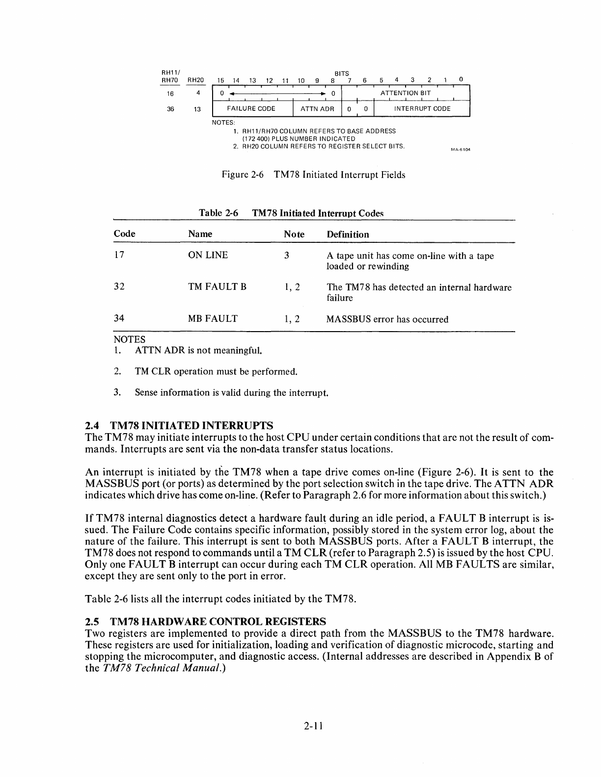
RH11/ BITS
RH70 RH20 15
14
13 12
11
10 9 8 7 6 5 4 3 2 0
Code
16
4
36 13
0 • • 0
ATTENTION
BIT
FAILURE
CODE I
ATTN
ADR
0 o I INTERRUPT CODE
NOTES:
1. RH11/RH70 COLUMN REFERS TO BASE ADDRESS
(172 400) PLUS NUMBER
INDICATED
2.
RH20 COLUMN REFERS TO REGISTER SELECT BITS.
Figure 2-6
TM78
Initiated
Interrupt
Fields
Table 2-6 TM78 Initiated
Interrupt
Codes
Name Note Definition
MA-6104
17
ON LINE 3 A
tape
unit
has come on-line with a tape
loaded
or
rewinding
32
TM
FAULTB
1,2
34
MB
FAULT
1,2
NOTES
1.
ATTN ADR
is
not
meaningful.
2.
TM
CLR
operation
must
be performed.
The TM78 has
detected
an
internal hardware
failure
MASSBUS error has
occurred
3. Sense
information
is valid during
the
interrupt.
2.4
TM78
INITIATED
INTERRUPTS
The TM78 may initiate interrupts to the host
CPU
under certain conditions
that
are not the result of com-
mands. Interrupts are sent via the non-data transfer status locations.
An interrupt
is
initiated by the TM78 when a tape drive comes on-line (Figure 2-6).
It
is
sent to the
MASS
BUS port (or ports) as determined by the port selection switch in the tape drive. The
ATTN
ADR
indicates which drive has come on-line. (Refer to Paragraph 2.6 for more information about this switch.)
If
TM78 internal diagnostics detect a hardware
faul~
during an idle period, a
FAULT
B interrupt
is
is-
sued. The Failure Code contains specific information, possibly stored in the system error log, about the
nature of the failure. This interrupt
is
sent to both MASSBUS ports. After a
FAULT
B interrupt, the
TM78 does not respond to commands until a
TM
CLR
(refer to Paragraph 2.5)
is
issued by the host CPU.
Only one
FAULT
B interrupt can occur during each
TM
CLR
operation. All MB FAULTS are similar,
except they are sent only to the port in error.
Table
2-6
lists all the interrupt codes initiated by the TM78.
2.5
TM78
HARDWARE CONTROL REGISTERS
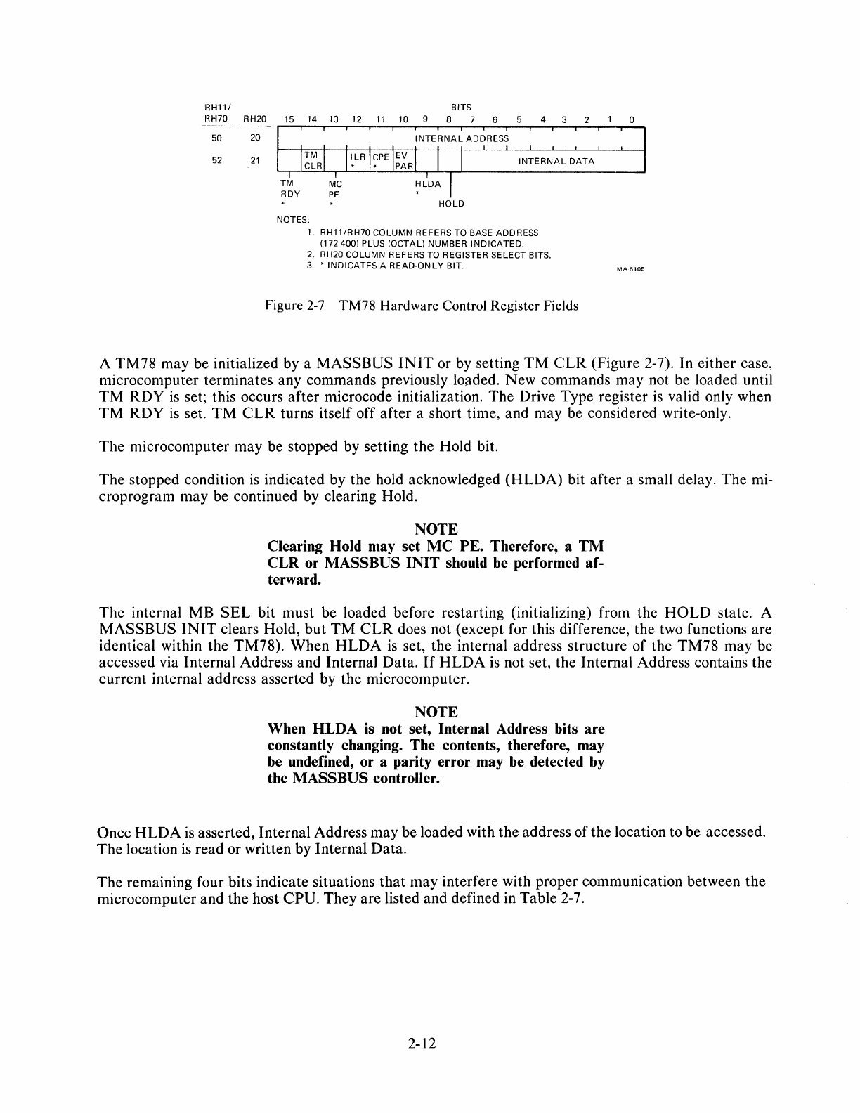
Two registers are implemented to provide a direct path from the MASSBUS to the TM78 hardware.
These registers are used for initialization, loading and verification of diagnostic microcode, starting and
stopping the microcomputer, and diagnostic access. (Internal addresses are described
in
Appendix B of
the TM78 Technical Manual.)
2-11
HH11/ BITS
HH70 RH20 15
14
13
12
11
10 9 8 6 5 4 3 2 0
50 20
52
21
INTERNAL
ADDRESS
INTERNAL
DATA
HOLD
NOTES:
1. RH11/RH70 COLUMN REFERS
TO
BASE ADDRESS
(172400)
PLUS (OCTAL) NUMBER INDICATED.
2.
RH20 COLUMN REFERS TO REGISTER SELECT BITS.
3.
* INDICATES A READ-ONLY BIT.
Figure
2-7
TM78
Hardware
Control Register Fields
MA
6105
A
TM78
may be initialized by a
MASSBUS
INIT
or by setting
TM
CLR
(Figure 2-7). In either case,
microcomputer terminates any commands previously loaded. New commands may not be loaded until
TM
RDY
is
set; this occurs
after
microcode initialization.
The
Drive Type register
is
valid only when
TM
RDY
is
set.
TM
CLR
turns itself off
after
a short time, and may be considered write-only.
The
microcomputer may be stopped by setting the Hold bit.
The
stopped condition
is
indicated by the hold acknowledged
(HLDA)
bit
after
a small delay. The mi-
croprogram may be continued by clearing Hold.
NOTE
Clearing Hold may set
MC
PE.
Therefore, a
TM
CLR or MASS BUS
INIT
should be performed af-
terward.
The
internal MB
SEL
bit must be loaded before restarting (initializing) from the
HOLD
state. A
MASSBUS
INIT
clears Hold,
but
TM
CLR
does not (except for this difference, the two functions are
identical within the TM78). When
HLDA
is
set, the internal address structure of the
TM78
may be
accessed via Internal Address and Internal Data.
If
HLDA
is
not set, the Internal Address contains the
current
internal address asserted by
the
microcomputer.
NOTE
When HLDA is not set, Internal Address bits are
constantly changing. The contents, therefore, may
be undefined, or a parity error may
be
detected
by
the MASSBUS controller.
Once
HLDA
is
asserted, Internal Address may be loaded with the address
of
the location to be accessed.
The
location
is
read or written by Internal Data.
The
remaining four bits indicate situations
that
may interfere with proper communication between the
microcomputer and
the
host
CPU.
They
are listed and defined in Table 2-7.
2-12

Name
MCPE
ILR
CPE
EVPAR
Table 2-7 TM78 Hardware Control Register Error Bits
Definition
Microcomputer
ROM
parity error has occurred
Reference has been made
to
nonexistent MASSBUS register address
Parity error detected
as
a result
of
write to some MASSBUS register address
Diagnostic bit causes even parity to be generated and checked for on
the
MASSBUS control bus
ILR
and
CPE
also cause
MB
FAULT
interrupt.
The
interrupt
occurs when
the
microcomputer
notices
the
error, which
may
be some
time
after
the
bit
actually sets.
2.6
DUAL
PORT
One
or
two
MASSBUSes
may
be connected to a
TM78.
The
DUAL
MB
sense
bit
indicates
dual
port
hardware.
Each
TU78
tape
transport
can
be
switched to
either
zero, one, or
both
ports. These conditions
are
indicated by
the
MAl
NT,
AVAIL
and
SHR
sense bits. A
tape
unit
is always available
(A
V
AIL)
if
DUAL
MB
hardware
is not installed.
NOTE
If
the dual
port
option is not present, the tape unit is
A VAIL when
the
TU78
port
select switch is in any
position except
MAINT.
All four bits
(DUAL
MB,
AVAIL,
SHR
and
MAl
NT)
are
intended for system configuration purposes
and
error
logging.
If
a port
attempts
to use a
tape
unit
not switched to it, a
NOT
A
VAIL
interrupt
is gen-
erated.
The
TM78
makes no
attempt
to synchronize a
shared
tape
unit between operations from two ports.
If
two
commands
are
active
at
one time,
they
are
executed
in
an
unpredictable
sequence.
Interrupts
are
re-
turned
to
the
MASSBUS
that
issued
the
command,
except
FAULT
B
and
On-Line, which
return
to
both
MASSBUSes
in a
shared
configuration.
It
is
expected
that
if
two
separate
processes
are
sharing a
tape
unit,
they
have
an
external
path
of
resource-sharing intercommunication. Synchronization is
performed
through
this external path.
Processes not synchronized should never
read
a
shared
tape.
Not
only will records be received in
random
order,
but
error
recovery operations
may
fail. Records
may
be
written in
an
unsynchronized fashion only
if
ordering
is
not important.
The
TM78
does not respond to
the
MASSBUS
port
request
sequence used by some
other
MASSBUS
devices.
2.7
CHANNEL
ADDRESS
SUMMARY
RHII
and
RH70
addresses, relative to
the
TM78,
are
summarized
in Figure 2-8.
RHI0,
RH20,
and
RH780
addresses, relative to
the
TM78,
are
summarized
in
Figure
2-9.
2-13
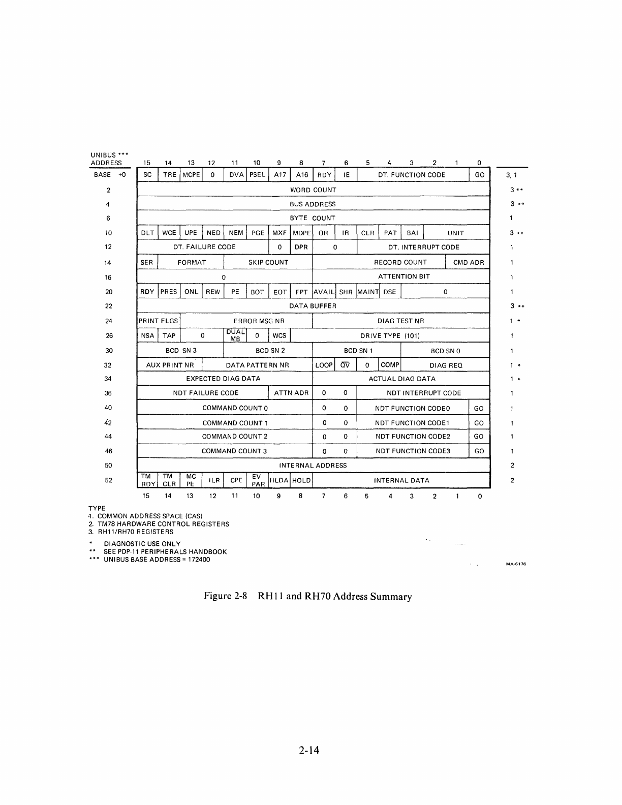
UNIBUS
***
ADDRESS 15
14 13 12
11
10 9 8 6 5 4 3 2 o
BASE +0 sc I TRE MCPEI 0
DVA
I PSEL A17
A16
RDY
I IE DT. FUNCTION CODE
GO
2 WORD COUNT
4 BUS ADDRESS
6 BYTE COUNT
10
DLT
I
WCE
UPE
I NED NEM I
PGE
MXF
MDPE
OR
I IR CLR I PAT BAI I
UNIT
12
DT.
FAILURE
CODE 0
DPR
0 DT. INTERRUPT CODE
14
SER
J
FORMAT
SKIP COUNT RECORD COUNT I CMD ADR
16
0
ATTENTION
BIT
20 RDY I
PRES
ONL
I
REW
PE
I BOT EOT FPT
AVAILI
SHR
MAINTI
DSE
0
22
DATA
BUFFER
24 PRINT FLGS ERROR
MSC;
NR DIAG TEST NR
26
NSA I TAP 0
DUALI
MB
0
WCS
DRIVE
TYPE (101)
30 BCD
SN
3
BCD
SN
2
BCD
SN
1 BCD
SN
0
32
AUX
PRINT NR I
DATA
PATTERN
NR
LOOpl
(J'i)
34 EXPECTED DIAG
DATA
36
NDT
FAILURE
CODE
40 COMMAND COUNT 0
42 COMMAND COUNT 1
44 COMMAND COUNT 2
46 COMMAND COUNT 3
50
52
TMI
™
RDY CLR MC I
ILR
PE
I EV
CPE
PAR
15
14
13
12
11
10
TYPE
-1.
COMMON ADDRESS
SPACE
(CAS)
2.
TM78 HARDWARE CONTROL REGISTERS
3.
RH11/RH70 REGISTERS
DIAGNOSTIC
USE
ONLY
SEE
PDP-l1 PERIPHERALS
HANDBOOK
UNIBUS BASE ADDRESS = 172400
ATTN
ADR
0 0
0 0
0 0
0 0
0 0
INTERNAL
ADDRESS
HLDA
HOLD
9 8 6
0 ICOMP DIAG REO
ACTUAL
DIAG
DATA
NDT
INTERRUPT
CODE
NDT
FUNCTION CODEO
NDT
FUNCTION
CODEl
NDT
FUNCTION CODE2
NDT
FUNCTION CODE3
INTERNAL
DATA
5 4 3 2
Figure
2-8
RH
11
and
RH70 Address Summary
2-14
GO
GO
GO
GO
o
3,1
3
**
3
**
3
**
1 *
1
..
1
..
2
2
MA.£176
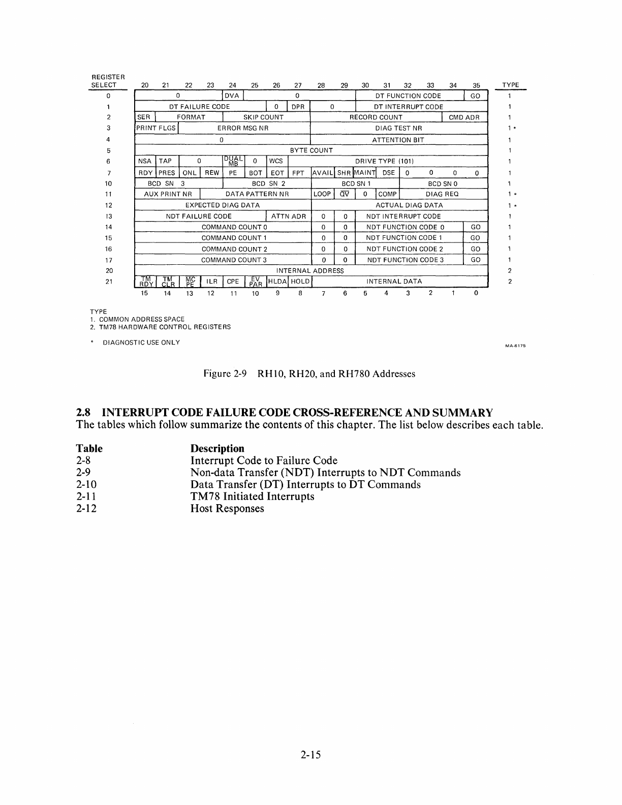
REGISTER
SELECT
o
1
20
21
22 23 24 25 26 27
0
OVA
I 0
DT
FAILURE
CODE I 0
IDPR
28 29 30
31
32
33 34 35
DT
FUNCTION
CODE GO
0
DT
INTERRUPT
CODE
2 SER I
FORMAT
SKIP
COUNT
RECORD
COUNT
I CMD
ADR
3
PRINT
FLGS I ERROR
MSG
NR
DIAG
TEST NR
4 0
ATTENTION
BIT
5
BYTE
COUNT
6
NSAITAP
l 0
ILJM~Ll
0
\wCS
\
DRIVE
TYPE (101)
7
RDY\
PRES \
ONL
\ REW
PE
\ BOT \ EOT \ FPT
AVAIL
SHR
MAINT\
DSE
0 0 0
10
11
12
13
14
15
16
17
20
21
BCD
SN
3 BCD
SN
2 BCD
SN
1 BCD
SN
0
AUX
PRINT
NR I
DATA
PATTERN
NR LOOP OV o I COMP
DIAG
REO
EXPECTED
DIAG
DATA
ACTUAL
DIAG
DATA
NOT
FAILURE
CODE 1
ATTN
ADR
0 0
NOT
INTERRUPT
CODE
COMMAND
COUNT
0 0 0
NOT
FUNCTION
CODE 0
COMMAND
COUNT
1 0 0
NOT
FUNCTION
CODE 1
COMMAND
COUNT
2 0 0
NOT
FUNCTION
CODE 2
COMMAND
COUNT
3 0 0
NOT
FUNCTION
CODE 3
INTERNAL
ADDRESS
TM
\
TM
\ MC I
ROY
CLR
PE
ILR
CPE
\
P~R
\HLDA\
HOLD
INTERNAL
DATA
15 14 13 12
11
10 9 8 6 5 4 3 2
TYPE
1.
COMMON ADDRESS SPACE
2.
TM78
HARDWARE
CONTROL
REGISTERS
*
DIAGNOSTIC
USE
ONLY
Figure
2-9
RH
10,
RH20, and
RH780
Addresses
0
GO
GO
GO
GO
o
2.8
INTERRUPT
CODE FAILURE CODE CROSS-REFERENCE AND SUMMARY
TYPE
1 •
1 •
1 •
2
2
MA·6175
The tables which follow summarize the contents of this chapter. The list below describes each table.
Table
2-8
2-9
2-10
2-11
2-12
Description
Interrupt Code to Failure Code
Non-data Transfer (NDT) Interrupts to
NDT
Commands
Data
Transfer (DT) Interrupts to
DT
Commands
TM78 Initiated Interrupts
Host Responses
2-15
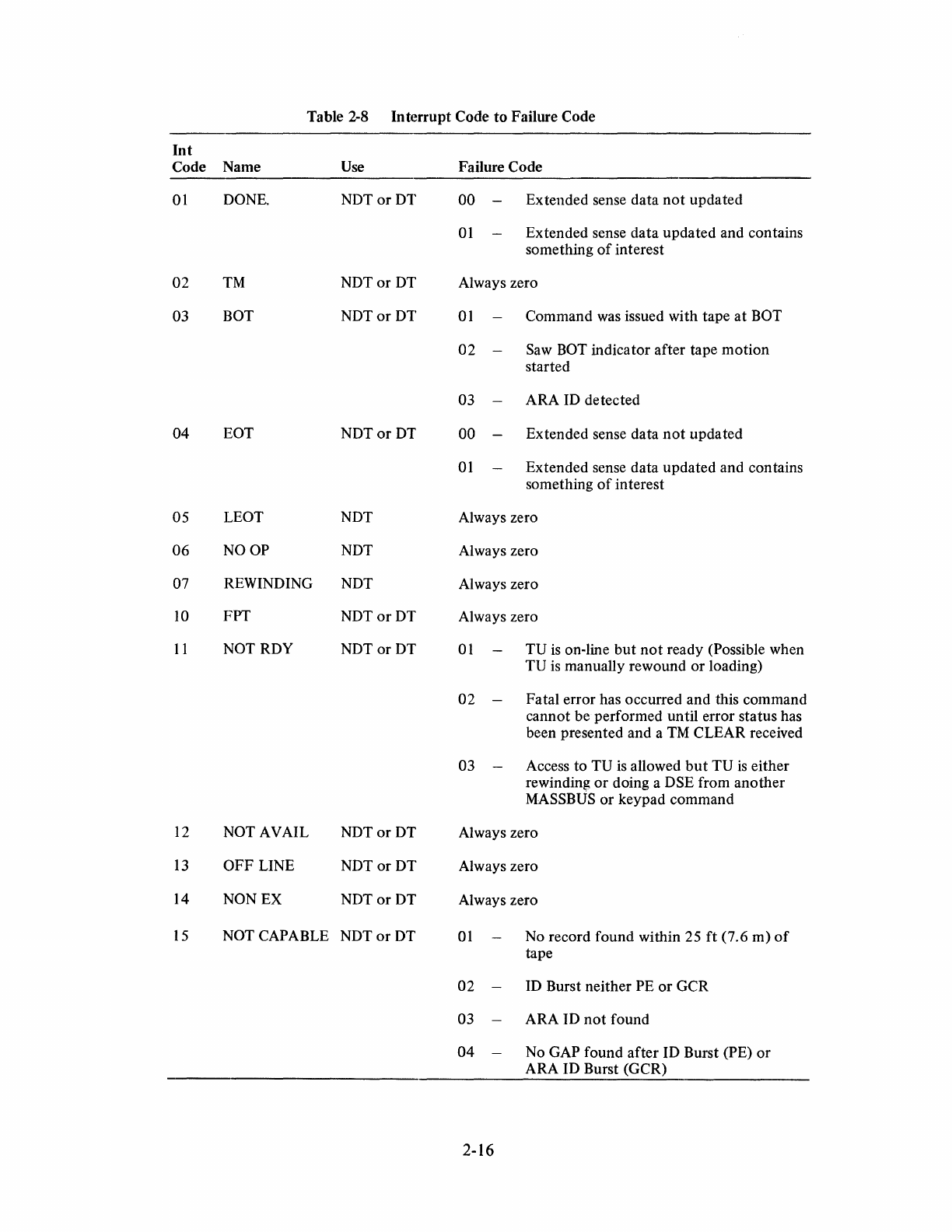
Table 2-8 Interrupt Code to Failure Code
Int
Code Name
Use
Failure Code
01
DONE.
NDTor
DT 00 Extended sense data
not
updated
01
Extended sense data updated and contains
something
of
interest
02
TM
NDTor
DT Always zero
03
BOT
NDTor
DT
01
Command
was
issued with tape
at
BOT
02 Saw BOT indicator after tape motion
started
03
ARA
ID
detected
04 EOT
NDTor
DT
00 Extended sense data
not
updated
01
Extended sense data updated and contains
something
of
interest
05 LEOT NDT Always zero
06
NOOP
NDT Always zero
07
REWINDING NDT Always zero
10
FPT
NDTorDT
Always zero
11
NOT RDY
NDTor
DT
01
TU
is
on-line
but
not
ready (Possible when
TV
is
manually rewound
or
loading)
02 Fatal error has occurred and this command
cannot be performed until error status has
been presented and a
TM
CLEAR received
03
Access to
TV
is allowed
but
TV
is
either
rewinding
or
doing a DSE from another
MASSBUS or keypad command
12
NOT AVAIL
NDTor
DT Always zero
13
OFF LINE
NDTorDT
Always zero
14
NON
EX
NDTor
DT Always zero
15
NOT CAPABLE
NDTor
DT
01
No record found within
25
ft
(7.6 m)
of
tape
02
ID
Burst neither PE
or
GCR
03
ARA ID
not
found
04 No GAP found after ID Burst (PE)
or
ARA ID Burst (GCR)
2-16
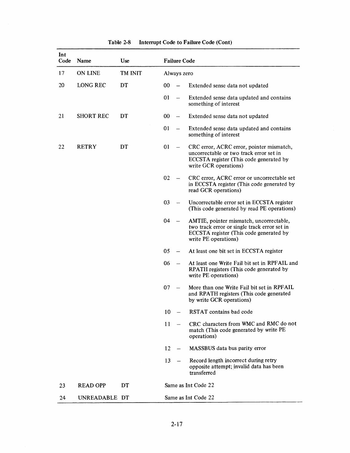
Table 2-8 Interrupt Code
to
Failure Code (Cont)
Int
Code Name
Use
Failure Code
17
ON
LINE
TM
INIT Always zero
20 LONGREC
DT
00 Extended sense data
not
updated
01
Extended sense data updated and contains
something
of
interest
21
SHORT REC DT 00 Extended sense data
not
updated
01
Extended sense data updated and contains
something
of
interest
22 RETRY DT
01
CRC error, ACRC error, pointer mismatch,
un correctable or two track error set in
ECCSTA register (This code generated by
write GCR operations)
02 CRC error, ACRC error
or
un correctable set
in
ECCSTA register (This code generated by
read GCR operations)
03 Un correctable error set in ECCSTA register
(This code generated by read PE operations)
04 AMTIE, pointer mismatch, uncorrectable,
two track error
or
single track error set in
ECCSTA register (This code generated by
write PE operations)
05 At least one bit set in ECCST A register
06 At least one Write Fail bit set in RPF AIL and
RP
ATH registers (This code generated by
write PE operations)
07 More than one Write Fail bit set in RPF AIL
and RPATH registers (This code generated
by write GCR operations)
10 RST AT contains bad code
11
CRC characters from
WMC
and
RMC
do
not
match (This code generated by write PE
operations)
12
MASSBUS
data bus parity error
13
Record length incorrect during retry
opposite attempt; invalid data has been
transferred
23 READ OPP DT Same
as
Int Code 22
24 UNREADABLE DT Same as Int Code 22
2-17
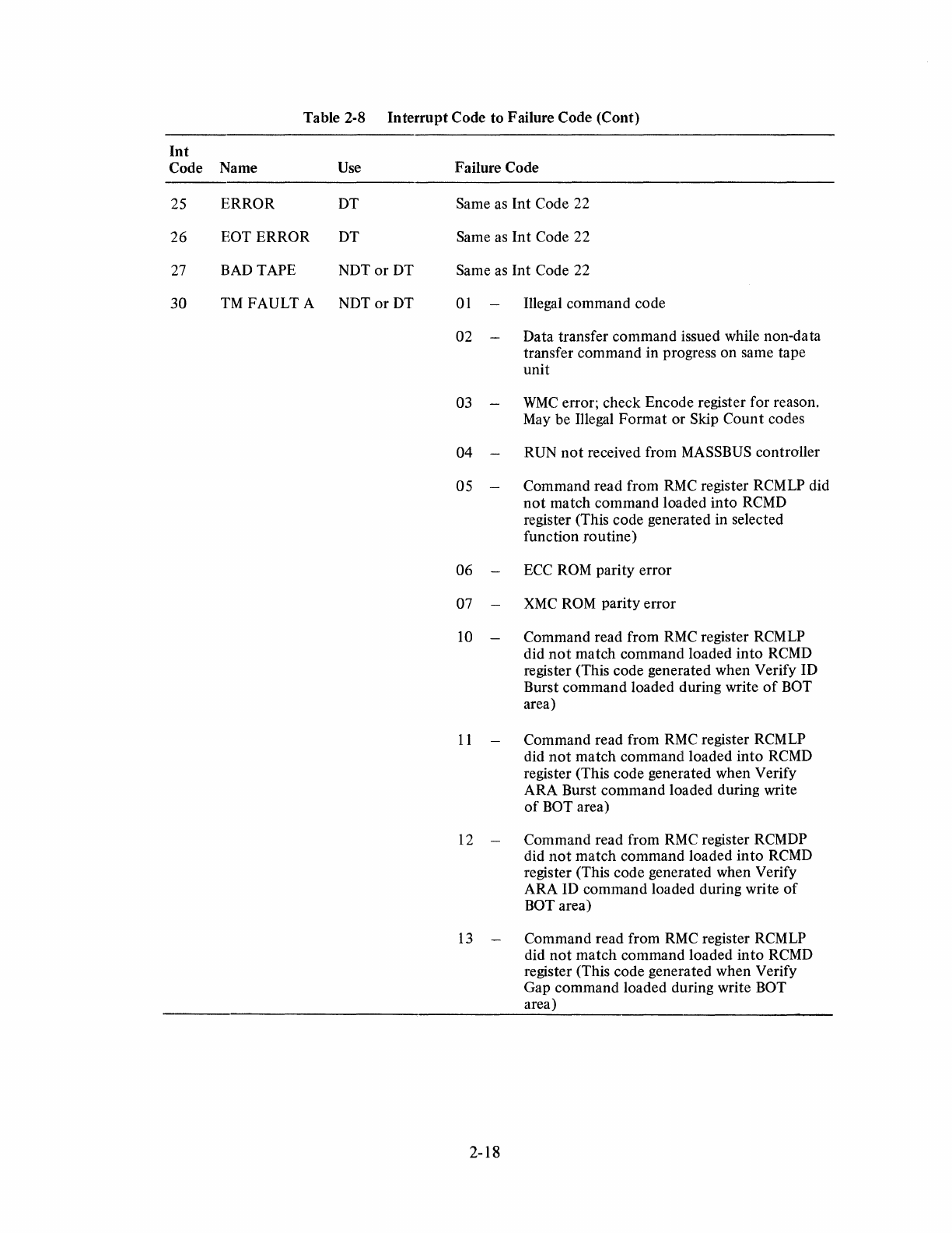
Table 2-8
Interrupt
Code to Failure Code (Cont)
Int
Code Name
Use
25
ERROR
DT
26 EOT ERROR DT
27
BAD
TAPE
NDTorDT
30
TM
FAULT A NDT
or
DT
Failure Code
Same as Int Code 22
Same
as
Int
Code 22
Same
as
Int Code 22
01
Illegal command code
02 Data transfer command issued while non-data
transfer command in progress on same tape
unit
03
WMC
error; check Encode register for reason.
May
be Illegal Format or Skip Count codes
04
RUN
not
received from MASSBUS controller
05 Command read from
RMC
register RCMLP did
not
match command loaded into
RCMD
register (This code generated in selected
function routine)
06
ECC
ROM
parity error
07
XMC
ROM
parity error
10
Command read from
RMC
register RCMLP
did
not
match command loaded
into
RCMD
register (This code generated when Verify ID
Burst command loaded during write
of
BOT
area)
II
Command read from
RMC
register RCMLP
did
not
match command loaded into
RCMD
register (This code generated when Verify
ARA Burst command loaded during write
of
BOT area)
12
Command read from
RMC
register RCMDP
did
not
match command loaded
into
RCMD
register (This code generated when Verify
ARA
ID
command loaded during write
of
BOT area)
13
Command read from
RMC
register RCMLP
did
not
match command loaded into
RCMD
register (This code generated when Verify
Gap command loaded during write BOT
area)
2-18
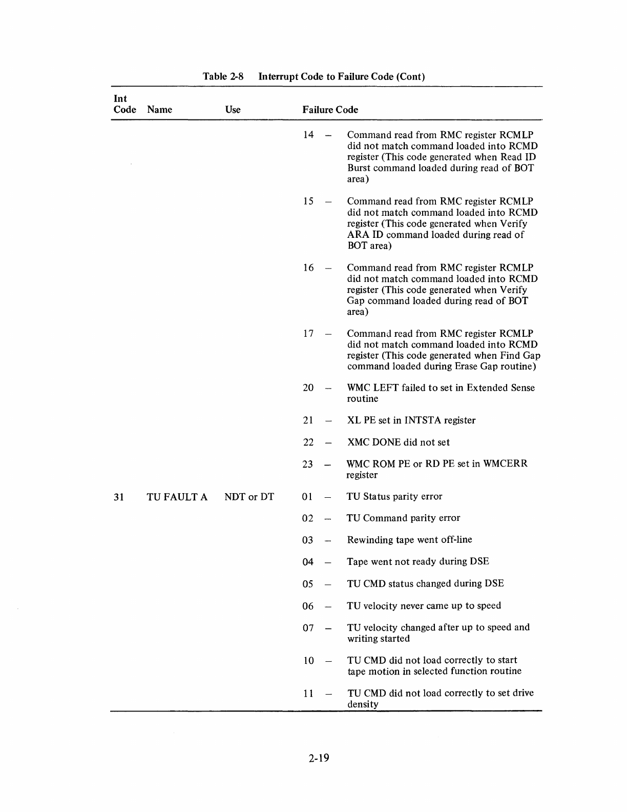
Table 2-8
Interrupt
Code to Failure Code (Cont)
Int
Code Name Vse Failure Code
14
-Command read from
RMC
register RCMLP
did
not
match command loaded
into
RCMD
register (This code generated when Read ID
Burst command loaded during read
of
BOT
area)
15
Command read from
RMC
register RCMLP
did
not
match command loaded into
RCMD
register (This code generated when Verify
ARA ID command loaded during read
of
BOT
area)
16
-Command read from
RMC
register RCMLP
did
not
match command loaded into
RCMD
register (This code generated when Verify
Gap command loaded during read
of
BOT
area)
17
Command read from
RMC
register RCMLP
did
not
match command loaded
into
RCMD
register (This code generated when Find Gap
command loaded during Erase Gap routine)
20
WMC
LEFT failed
to
set in Extended Sense
routine
21
XL PE set in INTST A register
22
XMC
DONE did
not
set
23
WMC
ROM
PE or RD PE set in WMCERR
register
31
TVFAVLTA
NDTor
DT
01
TV
Status parity error
02
TV
Command parity error
03
Rewinding tape went off-line
04 Tape went
not
ready during DSE
05
TV
CMD
status changed during DSE
06
TV
velocity never came up
to
speed
07
TV
velocity changed after up to speed and
writing started
10
-
TV
CMD
did
not
load correctly
to
start
tape motion in selected function routine
II
TV
CMD
did
not
load correctly
to
set drive
density
2-19
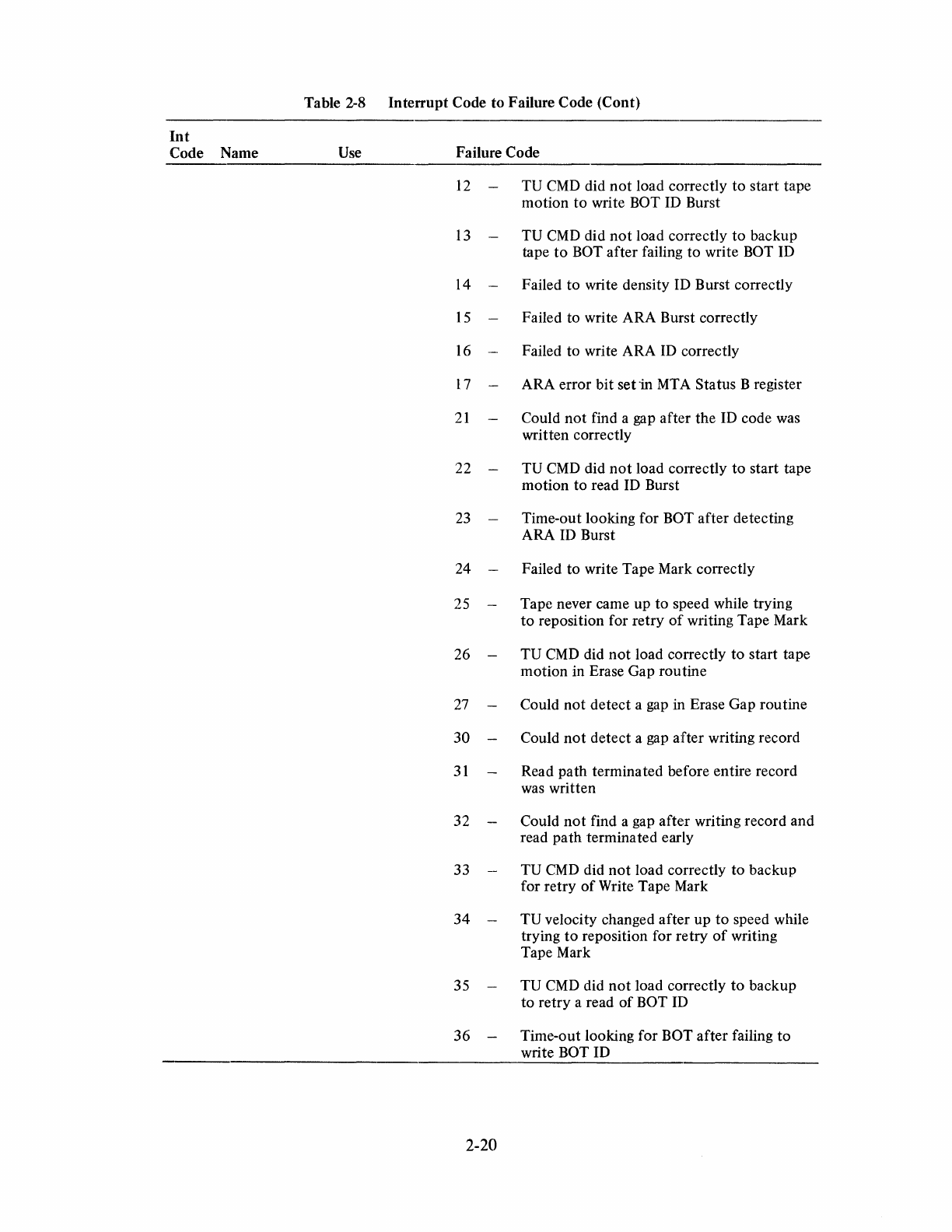
Int
Code Name
Table 2-8 Interrupt Code to Failure Code (Cont)
Use
Failure Code
12
TU
CMD
did
not
load correctly to start tape
motion
to
write BOT
ID
Burst
13
TU
CMD
did
not
load correctly to backup
tape
to
BOT after failing to write BOT ID
14 Failed to write density ID Burst correctly
15
Failed to write ARA Burst correctly
16
Failed to write ARA
ID
correctly
17
ARA error bit set
-in
MTA
Status B register
21
Could
not
find a gap after the
ID
code was
written correctly
22
TV
CMD
did
not
load correctly
to
start tape
motion to read
ID
Burst
23
Time-out looking for BOT after detecting
ARA
ID
Burst
24 Failed
to
write Tape Mark correctly
25
Tape never came up to speed while trying
to
reposition for retry
of
writing Tape Mark
26
TV
CMD
did
not
load correctly to start tape
motion in Erase Gap routine
27
Could
not
detect a gap in Erase Gap routine
30 Could
not
detect a gap after writing record
31
Read path terminated before entire record
was
written
32 Could
not
find a gap after writing record and
read path terminated early
33
TV
CMD
did
not
load correctly to backup
for retry
of
Write Tape Mark
34
TV
velocity changed after up
to
speed while
trying
to
reposition for retry
of
writing
Tape Mark
35
TV
CMD
did
not
load correctly
to
backup
to
retry a read
of
BOT
ID
36 Time-out looking for BOT after failing to
write BOT
ID
2-20
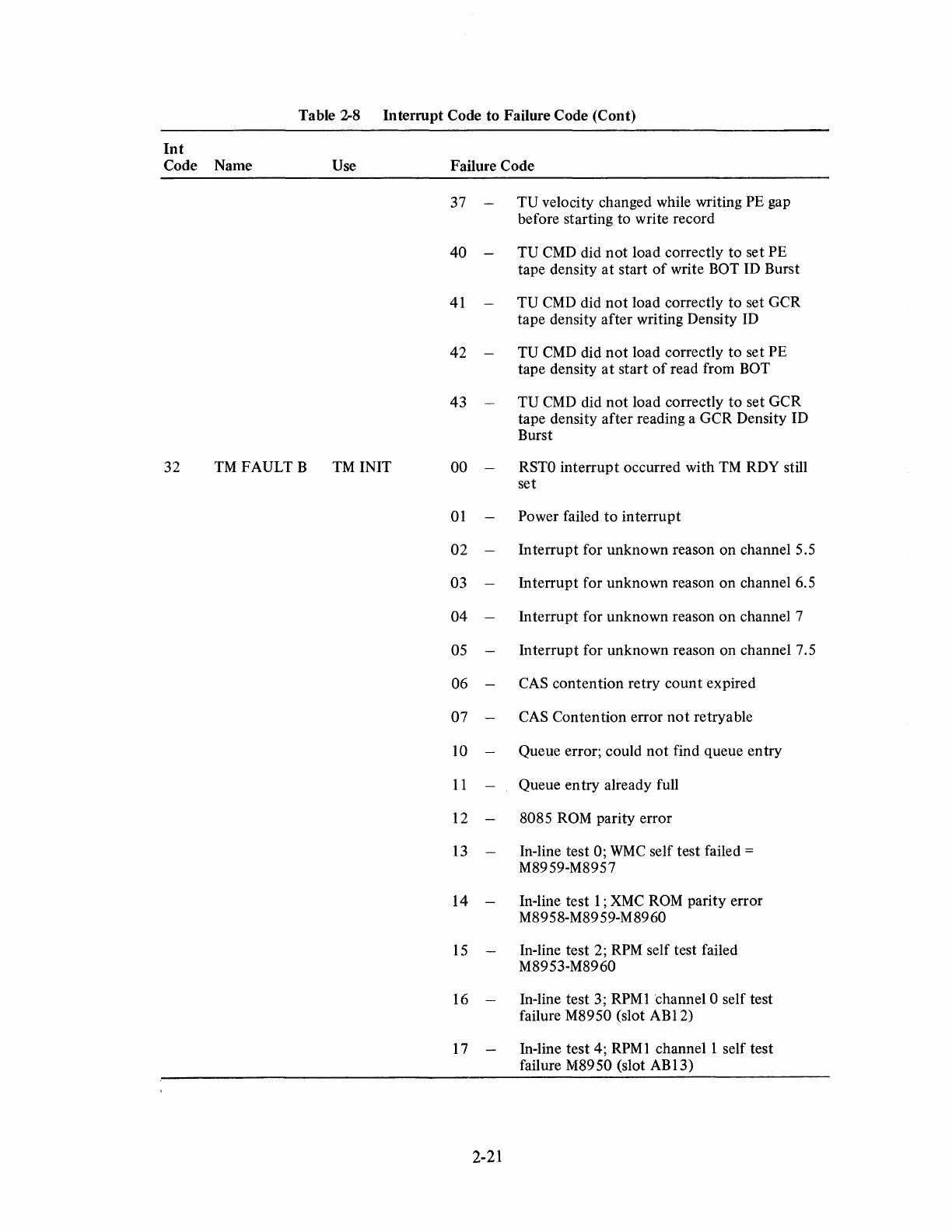
Table
2--8
Interrupt Code to Failure Code (Cont)
Int
Code Name Use
32
TM
FAULT B
TM
INIT
Failure Code
37 TU velocity changed while writing PE gap
before starting to write record
40 TU
CMD
did
not
load correctly to set PE
tape density
at
start
of
write BOT ID Burst
41
TU
CMD
did
not
load correctly to set GCR
tape density after writing Density
ID
42 TU
CMD
did
not
load correctly
to
set PE
tape density
at
start
of
read from BOT
43 TU
CMD
did
not
load correctly
to
set GCR
tape density after reading a GCR Density ID
Burst
00
RSTO
interrupt occurred with
TM
RDY still
set
01
Power failed
to
interrupt
02 Interrupt for unknown reason on channel 5.5
03 Interrupt for unknown reason on channel 6.5
04 Interrupt for unknown reason on channel 7
05 Interrupt for unknown reason on channel 7.5
06
CAS
contention retry count expired
07
CAS
Contention error
not
retryable
10
Queue error; could
not
find queue entry
11
Queue entry already full
12 8085
ROM
parity error
13
In-line test 0;
WMC
self test failed =
M8959-M8957
14 -In-line test 1 ;
XMC
ROM
parity error
M8958-M8959-M8960
15
In-line test 2;
RPM
self test failed
M8953-M8960
16 In-line test 3;
RPM
1 channel 0 self test
failure M8950 (slot
ABI2)
17 In-line test 4;
RPM
1
channell
self test
failure M8950 (slot ABI3)
2-21
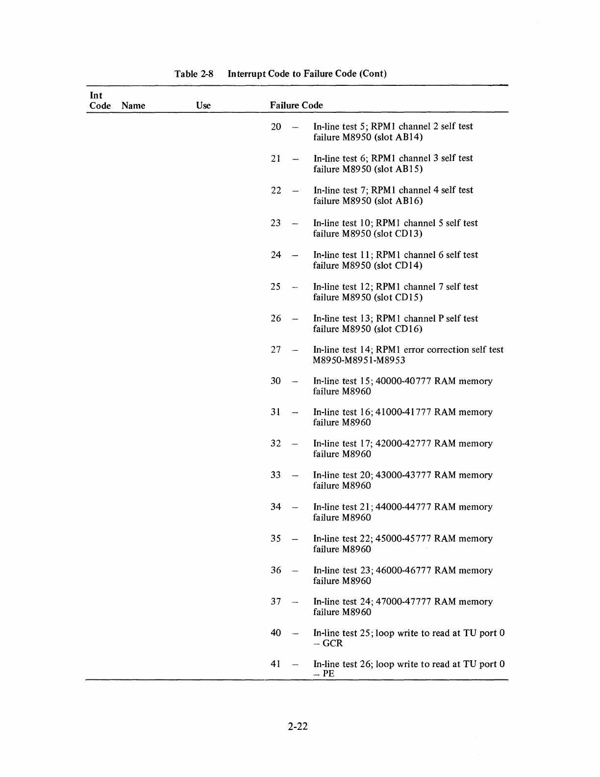
Int
Code Name
Table 2-8
Interrupt
Code to Failure Code (Cont)
Use
Failure Code
20 -In-line test 5; RPM 1 channel 2 self test
failure M8950 (slot
ABI4)
21
In-line test 6;
RPM
1 channel 3 self test
failure M8950 (slot
AB
15)
22 -In-line test 7;
RPM
1 channel 4 self test
failure M8950 (slot AB 16)
23 -In-line test 10; RPMl channel 5 self test
failure M8950 (slot
CDI3)
24 -In-line test 11;
RPM
1 channel 6 self test
failure M8950 (slot
CD
14)
25 -In-line test 12;
RPM
1 channel 7 self
test
failure M8950 (slot
CD
15)
26 -In-line test 13;
RPM
1 channel P self test
failure M8950 (slot
CD
16)
27 -In-line test 14; RPMl error correction self test
M89 50-M89 51-M89 53
30 -In-line test 15; 40000-40777 RAM memory
failure M8960
31
In-line test 16; 41000-41777 RAM memory
failure M8960
32
-In-line test 17; 42000-42777
RAM
memory
failure M8960
33 -In-line test 20; 43000-43777 RAM memory
failure M8960
34
-In-line
test
21
; 44000-44777 RAM memory
failure M8960
35 -In-line test 22; 45000-45777 RAM memory
failure M8960
36 -In-line test 23; 46000-46777 RAM memory
failure M8960
37 -In-line test 24; 47000-47777 RAM memory
failure M8960
40
-In-line test 25; loop write
to
read
at
TV
port
0
-GCR
41
In-line test 26; loop write
to
read
at
TV
port
0
-PE
2-22
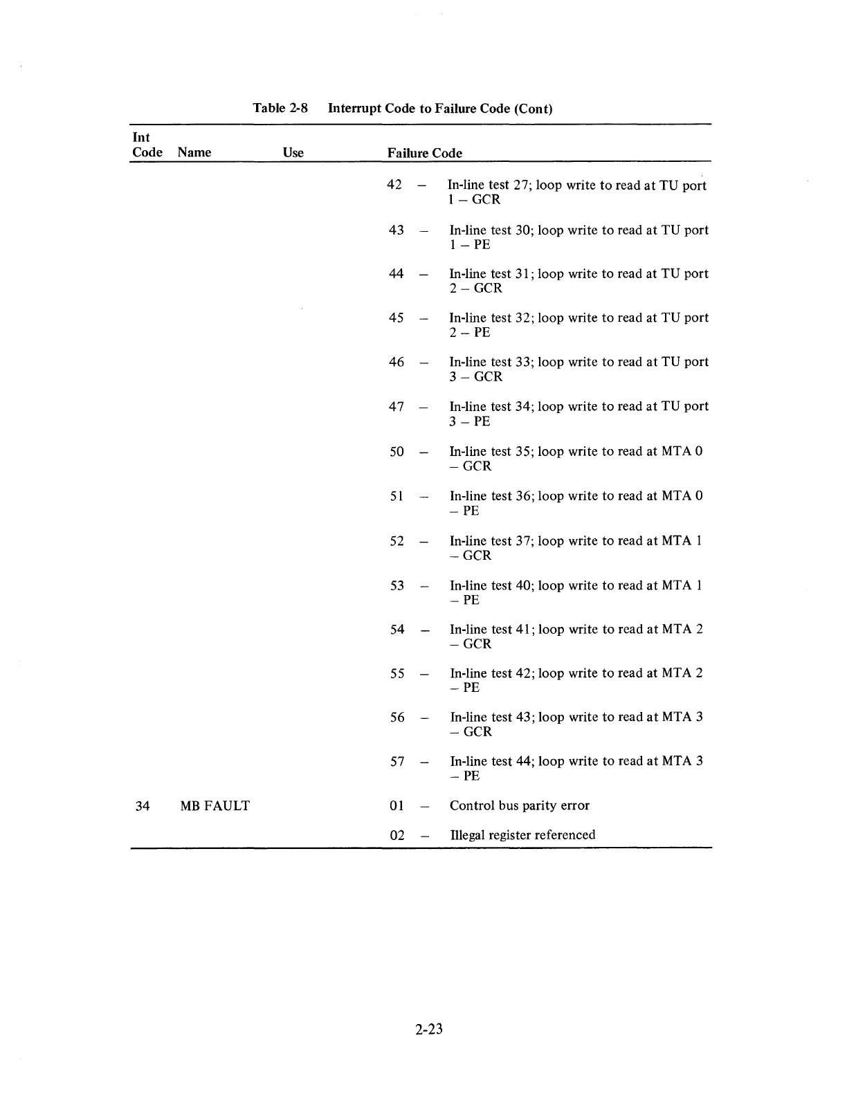
Table 2-8 Interrupt Code
to
Failure Code (Cont)
Int
Code Name
Use
Failure Code
42
-In-line test 27; loop write
to
read
at
TU port
1-
GCR
43
-In-line test 30; loop write
to
read
at
TU port
1 - PE
44 -In-line test
31
; loop write
to
read at TU
port
2-GCR
45 In-line test 32; loop write
to
read at
TV
port
2 - PE
46
-In-line test 33; loop write
to
read
at
TV
port
3-GCR
47
-In-line test 34; loop write
to
read
at
TV
port
3 - PE
50 -In-line test 35; loop write
to
read at
MT
A 0
-GCR
51
In-line test 36; loop write
to
read at MTA 0
-PE
52 -In-line test 37; loop write to read
at
MTA
I
-GCR
53
In-line test 40; loop write
to
read
at
MTA
I
-PE
54 In-line test
41
; loop write
to
read
at
MT
A 2
-GCR
55 -In-line test 42; loop write
to
read at
MTA
2
-PE
56 -In-line test 43; loop write
to
read
at
MT
A 3
-GCR
57 In-line test 44; loop write to read
at
MTA
3
-PE
34
MB
FAULT
01
Control bus parity error
02 Illegal register referenced
2-23
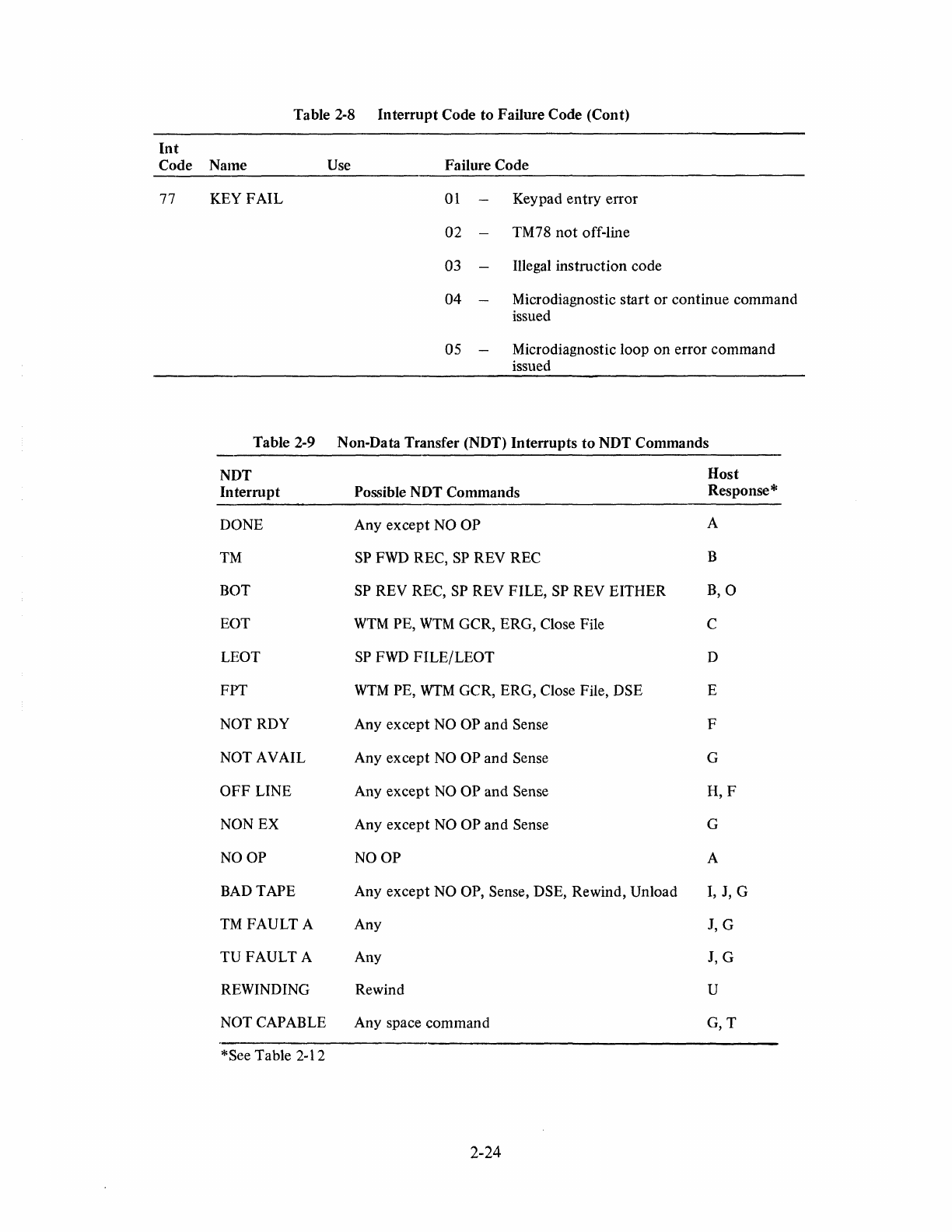
Table 2-8
Interrupt
Code
to
Failure Code (Cont)
Int
Code Name
77 KEY
FAIL
Table 2-9
NDT
Interrupt
DONE
TM
BOT
EaT
LEOT
FPT
NOT RDY
NOT AVAIL
OFF
LINE
NON EX
NOOP
BAD TAPE
TMFAULT
A
TUFAULT
A
REWINDING
NOT CAPABLE
*See Table 2-12
Use Failure Code
01
Keypad
entry
error
02 -TM78
not
off-line
03
Illegal instruction code
04
Microdiagnostic
start
or
continue command
issued
05
-Microdiagnostic loop
on
error
command
issued
Non-Data Transfer (NDT)
Interrupts
to
NDT
Commands
Host
Possible NDT Commands Response *
Any
except
NO OP A
SP FWD REC, SP REV REC B
SP
REV REC, SP REV FILE, SP REV EITHER
B,O
WTM
PE,
WTM
GCR, ERG, Close File C
SP
FWD
FILE/LEOT
D
WTM
PE,
WTM
GCR, ERG, Close File, DSE E
Any
except
NO OP
and
Sense F
Any
except
NO
OP
and
Sense G
Any
except
NO OP and Sense
H,F
Any
except
NO OP
and
Sense G
NOOP
A
Any
except
NO OP, Sense, DSE, Rewind, Unload I, J, G
Any J, G
Any J, G
Rewind U
Any space command
G,T
2-24
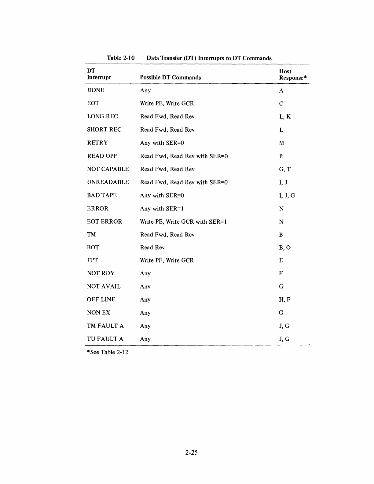
Table 2-10 Data Transfer (DT) In terrupts
to
DT
Commands
DT Host
Interrupt
Possible DT Commands Response
*
DONE Any A
EOT Write PE, Write GCR C
LONG REC Read Fwd, Read Rev
L,K
SHORT REC Read Fwd, Read Rev L
RETRY Any with
SER=O
M
READ OPP Read Fwd, Read Rev with SER=O P
NOT CAPABLE Read Fwd, Read Rev
G,T
UNREADABLE Read Fwd, Read Rev with SER=Q
I,
J
BAD TAPE Any with SER=O
I,
J, G
ERROR
Any with SER=l N
EOTERROR
Write PE, Write GCR with SER= 1 N
TM
Read Fwd, Read Rev B
BOT Read Rev
B,O
FPT Write PE, Write GCR E
NOT RDY Any F
NOT AVAIL Any G
OFF
LINE Any
H,F
NON EX Any G
TM
FAULT A Any J, G
TUFAULT
A Any J, G
* See Table 2-12
2-25
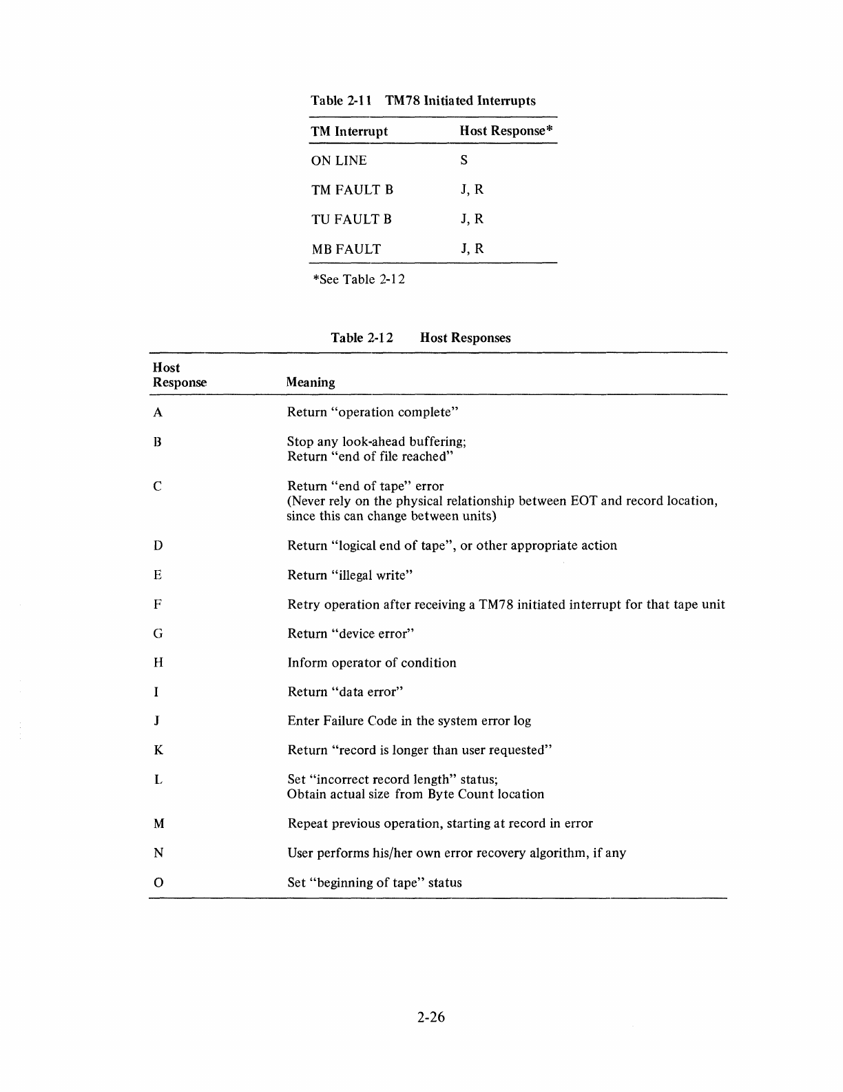
Host
Response
A
B
c
D
E
F
G
II
J
K
L
M
N
o
Table 2-11 TM78 Initiated Interrupts
TM
Interrupt
Host Response*
ON LINE S
TM
FAULT B J, R
TU FAULT B J, R
MB
FAULT
J,
R
*See Table
2-1
2
Table 2-12 Host Responses
Meaning
Return "operation complete"
Stop any look-ahead buffering;
Return
"end
of
file reached"
Return
"end
of
tape" error
(Never rely on the physical relationship between EOT and record location,
since this can change between units)
Return "logical end
of
tape",
or
other
appropriate action
Return "illegal write"
Retry operation after receiving a TM78 initiated interrupt for
that
tape unit
Return "device error"
Inform operator
of
condition
Return
"data
error"
Enter Failure Code in the system error log
Return "record
is
longer than user requested"
Set "incorrect record length" status;
Obtain actual size from Byte Count location
Repeat previous operation, starting
at
record in error
User performs his/her own error recovery algorithm,
if
any
Set "beginning
of
tape"
status
2-26
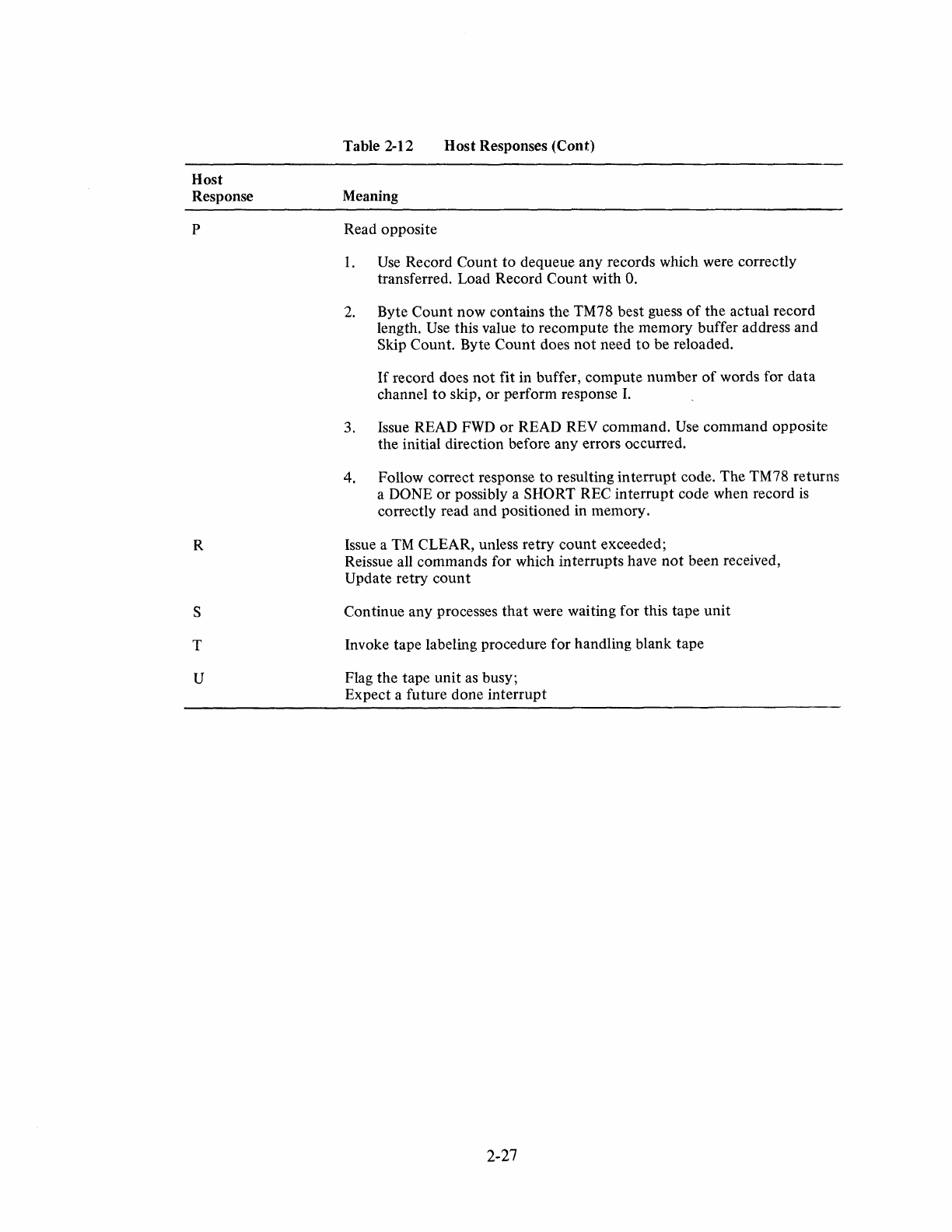
Host
Response
p
R
S
T
U
Table 2-12 Host Responses (Cont)
Meaning
Read opposite
1.
Use
Record Count to dequeue any records which were correctly
transferred. Load Record Count with
O.
2.
Byte Count now contains the TM78 best guess
of
the actual record
length.
Use
this value to recompute the memory buffer address and
Skip Count. Byte Count does
not
need
to
be reloaded.
If
record does
not
fit in buffer, compute number
of
words for data
channel
to
skip, or perform response I.
3. Issue READ
FWD
or READ REV command.
Use
command opposite
the initial direction before any errors occurred.
4. Follow correct response
to
resulting interrupt code. The TM78 returns
a DONE or possibly a SHORT REC interrupt code when record
is
correctly read and positioned in memory.
Issue a
TM
CLEAR, unless retry count exceeded;
Reissue all commands for which interrupts have
not
been received,
Update retry
count
Continue any processes
that
were waiting for this tape
unit
Invoke tape labeling procedure for handling blank tape
Flag the tape unit as busy;
Expect a future done interrupt
2-27

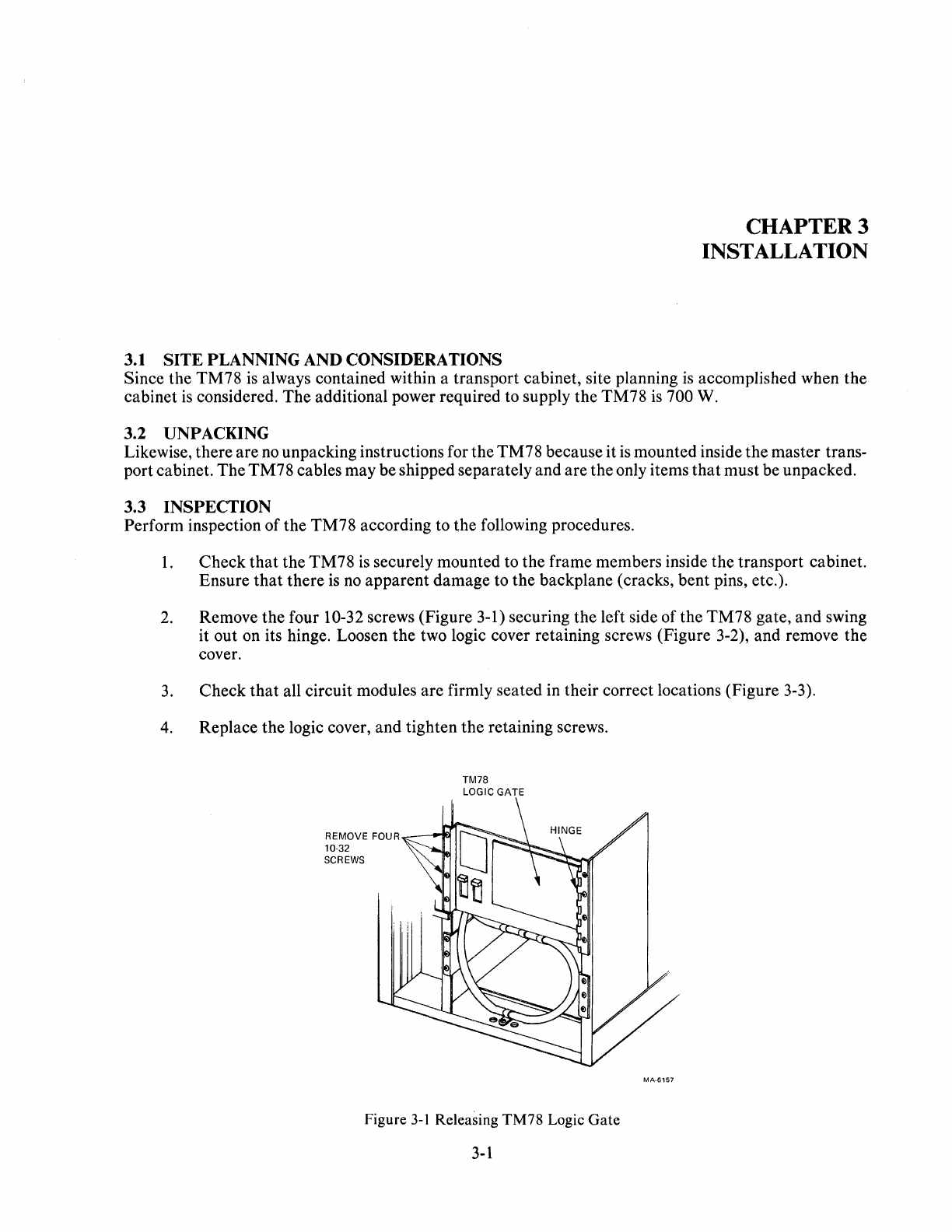
3.1 SITE PLANNING AND CONSIDERATIONS
CHAPTER 3
INSTALLATION
Since
the
TM78
is always
contained
within a
transport
cabinet,
site planning is accomplished when
the
cabinet
is considered.
The
additional power
required
to supply
the
TM78
is 700 W.
3.2 UNPACKING
Likewise,
there
are
no
unpacking
instructions for
the
TM78
because
it
is
mounted
inside
the
master
trans-
port
cabinet.
The
TM78
cables
may
be
shipped
separately
and
are
the
only items
that
must
be
unpacked.
3.3 INSPECTION
Perform
inspection
of
the
TM78
according to
the
following procedures.
1.
Check
that
the
TM78
is securely
mounted
to
the
frame
members
inside
the
transport
cabinet.
Ensure
that
there
is no
apparent
damage
to
the
backplane
(cracks,
bent
pins, etc.).
2.
Remove
the
four 10-32 screws
(Figure
3-1) securing
the
left side
of
the
TM78
gate,
and
swing
it
out
on its hinge. Loosen
the
two logic cover retaining screws
(Figure
3-2),
and
remove
the
cover.
3.
Check
that
all
circuit
modules
are
firmly
seated
in
their
correct
locations
(Figure
3-3).
4.
Replace
the
logic cover,
and
tighten
the
retaining screws.
REMOVE
FOUR----
10-32
SCREWS
TM78
LOGIC GATE
Figure
3-1
Releasing TM78 Logic
Gate
3-1
MA-6157
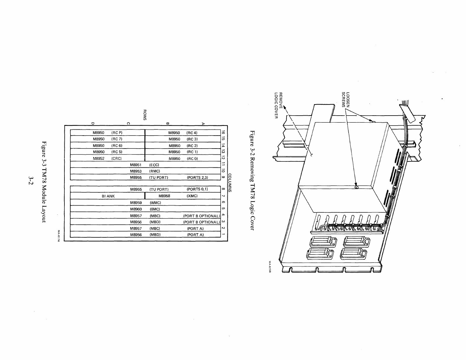
.."
60·
c::
..,
('D
'-f
w
...,
W
~
I
-..)
tv
00
~
0
0-
c::
~
l'
~
'"-<::
0
c::
.....
o
M8950 (RC
P)
M8950 (RC
7)
M8950
(RC6)
M8950 (RC
5)
MS952 (CRCi
BI
ANK
(")
M8951
M8953
M8955
M8955
M8959
M8960
M8957
M8956
M8957
M8956
:lJ
o
~
en
1
c:c
»
M8950
(RC4)
M8950
(RC3)
c;
.."
00·
(l'I
c::
M8950 (RC
2)
~
..,
('D
M8950 (RC
1)
w w
N
M8950 (RCO)
1\,)1
;;0
(ECC)
(RMC)
(TU PORT)
__
(PORTS 2,3)
('D
3
:
18
0
:s.
::s
r (JQ
C
...,
::;:
(TU PORT) (PORTS 0,1)
colZ
~
Ul
M8958 (XMC)
-..)
00
(WMC)
0)
l'
0
(8MC)
(MBC) (PORT B OPTIONAL)
(l'I
(JQ
.j>.
o·
(J
(MBD) (PORT B OPTIONAL) w 0
<:
(MBC) (PORT A)
I\,)
('D
..,
(MBD) (PORT A)
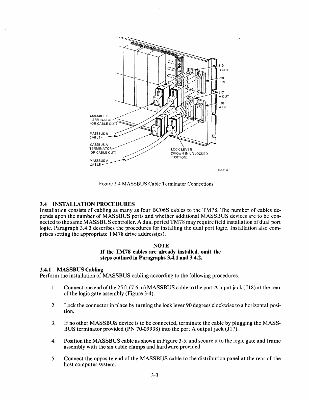
MASSBUS B
TERMINATOR
(OR CABLE OUT)
MASSBUS A
TERMINATOR
(OR
CABLE
OUT)
MASSBUSA
~
CABLE
-----
LOCK
LEVER
(SHOWN IN
UNLOCKED
POSITION)
Figure 3-4
MASS
BUS Cable Terminator Connections
3.4 INSTALLATION PROCEDURES
MA-6159
Installation consists of cabling as many as four BC06S cables to the TM78. The number of cables de-
pends upon the number of MASSBUS ports and whether additional MASSBUS devices are to be con-
nected to the same MASSBUS controller. A dual ported TM78 may require field installation of dual port
logic. Paragraph 3.4.3 describes the procedures for installing the dual port logic. Installation also com-
prises setting the appropriate TM78 drive address(es).
NOTE
If
the TM78 cables are already installed, omit the
steps outlined in Paragraphs 3.4.1 and 3.4.2.
3.4.1 MASS BUS Cabling
Perform the installation of MASSBUS cabling according to the following procedures.
1.
Connect one end of the
25
ft (7.6 m) MASSBUS cable to the port A input
jack
(118)
at
the rear
of the logic gate assembly (Figure 3-4).
2.
Lock the connector in place by turning the lock lever 90 degrees clockwise to a horizontal posi-
tion.
3.
If
no
other MASSBUS device
is
to be connected, terminate the cable by plugging the MASS-
BUS terminator provided
(PN
70-09938) into the port A output
jack
(117).
4.
Position the MASSBUS cable as shown in Figure 3-5, and secure it to the logic gate and frame
assembly with the six cable clamps and hardware provided.
5.
Connect the opposite end of the MASSBUS cable to the distribution panel
at
the rear of the
host computer system.
3-3
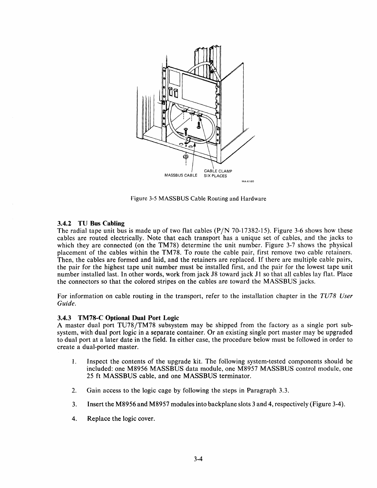
MASSBUS CABLE
MA-6160
Figure
3-5
MASSBUS
Cable Routing and Hardware
3.4.2
TU
Bus
Cabling
The
radial tape unit bus
is
made up of two flat cables
(PIN
70-17382-15). Figure
3-6
shows how these
cables are routed electrically.
Note
that
each transport has a unique set
of
cables, and the jacks to
which they are connected (on the
TM78)
determine the unit number. Figure
3-7
shows the physical
placement of the cables within the
T~178.
To route the cable pair, first remove two cable retainers.
Then, the cables are formed and laid, and the retainers are replaced.
If
there are multiple cable pairs,
the pair for the highest tape unit number must be installed first, and the pair for the lowest tape unit
number installed last. In other words, work from
jack
J8 toward
jack
Jl
so
that
all cables lay flat. Place
the connectors
so
that
the colored stripes on the cables are toward the
MASSBUS
jacks.
For information on cable routing in the transport, refer to the installation chapter in the TU78 User
Guide.
3.4.3 TM78-C Optional Dual Port Logic
A master dual port
TU78/TM78
subsystem may be shipped from the factory as a single port sub-
system, with dual port logic in a separate container.
Or
an existing single port master may be upgraded
to dual port
at
a later
date
in
the
field. In either case,
the
procedure below must be followed in order to
create a dual-ported master.
1.
Inspect the contents of the upgrade kit.
The
following system-tested components should be
included: one M8956
MASSBUS
data
module, one M8957
MASSBUS
control module, one
25
ft
MASSBUS
cable, and one
MASSBUS
terminator.
2.
Gain access to the logic cage by following the steps in Paragraph 3.3.
3.
Insert
the
M8956 and M8957 modules into backplane slots 3 and 4, respectively (Figure 3-4).
4. Replace the logic cover.
3-4
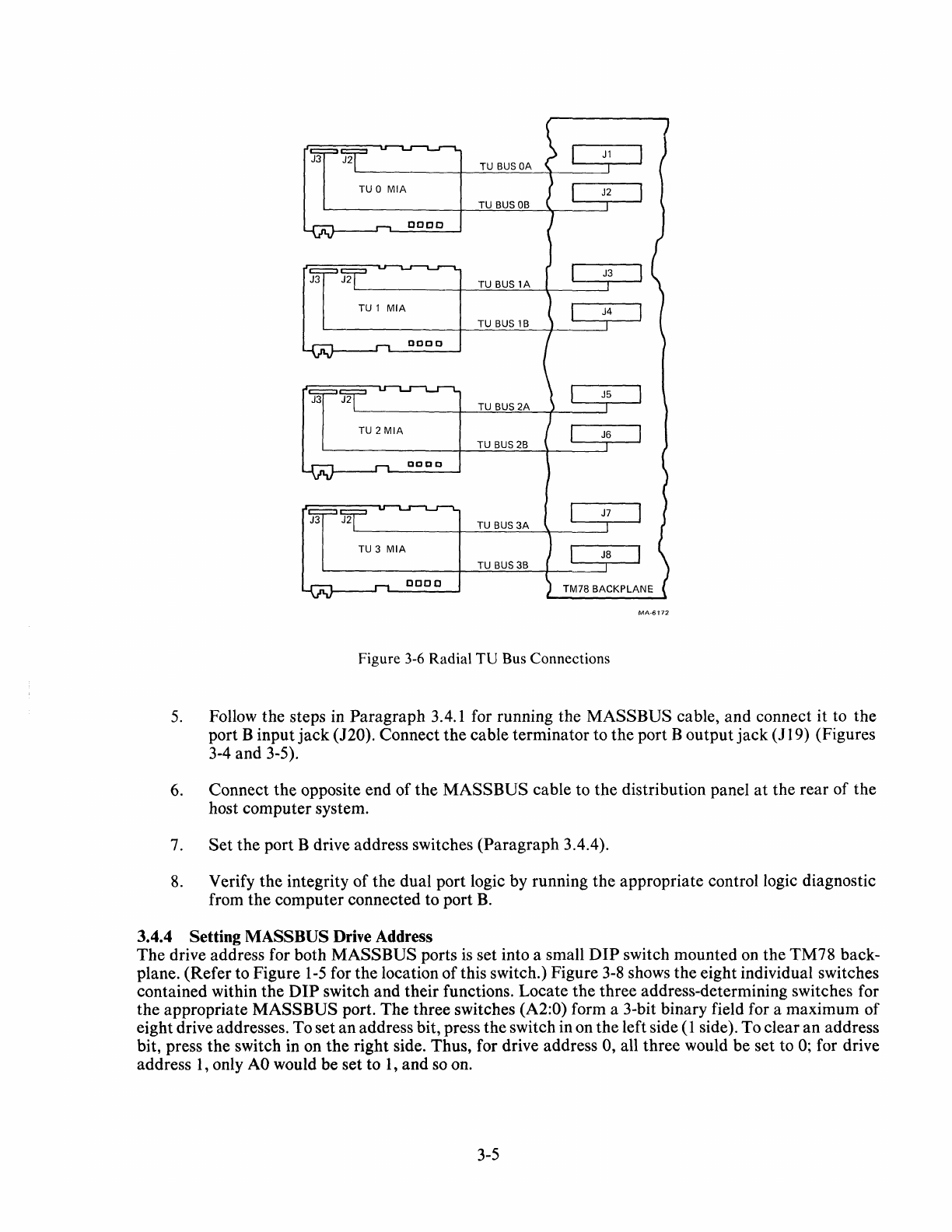
TU
BUS
OA
TU
BUS
OB
ooco
TU
BUS
lA
TUBUS1B
J3
J2 TU
BUS
2A
TU 2
MIA
TU
BUS
2B
DDDD
J3 J2 TU
BUS
3A
TU 3
MIA
TU
BUS
3B
0000
MA·6172
Figure 3-6 Radial
TU
Bus Connections
5.
Follow
the
steps in
Paragraph
3.4.1 for running the
MASS
BUS
cable,
and
connect it to
the
port B
input
jack
(J20). Connect
the
cable
terminator
to
the
port B
output
jack
(J
19) (Figures
3-4
and
3-5).
6. Connect
the
opposite end
of
the
MASSBUS
cable to
the
distribution panel
at
the rear
of
the
host
computer
system.
7.
Set
the
port B drive address switches
(Paragraph
3.4.4).
8.
Verify
the
integrity
of
the
dual
port logic by running
the
appropriate control logic diagnostic
from
the
computer
connected to port
B.
3.4.4 Setting
MASS
BUS
Drive Address
The
drive address for both
MASSBUS
ports is set into a small
DIP
switch mounted on
the
TM78
back-
plane.
(Refer
to Figure
1-5
for
the
location
of
this switch.) Figure
3-8
shows
the
eight individual switches
contained within
the
DIP
switch
and
their
functions.
Locate
the
three
address-determining switches for
the
appropriate
MASS
BUS
port.
The
three
switches (A2:0) form a 3-bit binary field for a
maximum
of
eight drive addresses. To
set
an
address bit, press
the
switch in on
the
left side ( 1 side). To clear
an
address
bit, press
the
switch in on
the
right
side. Thus, for drive address 0, all
three
would
be
set to 0; for drive
address 1, only
AO
would
be
set to
1,
and
so on.
3-5
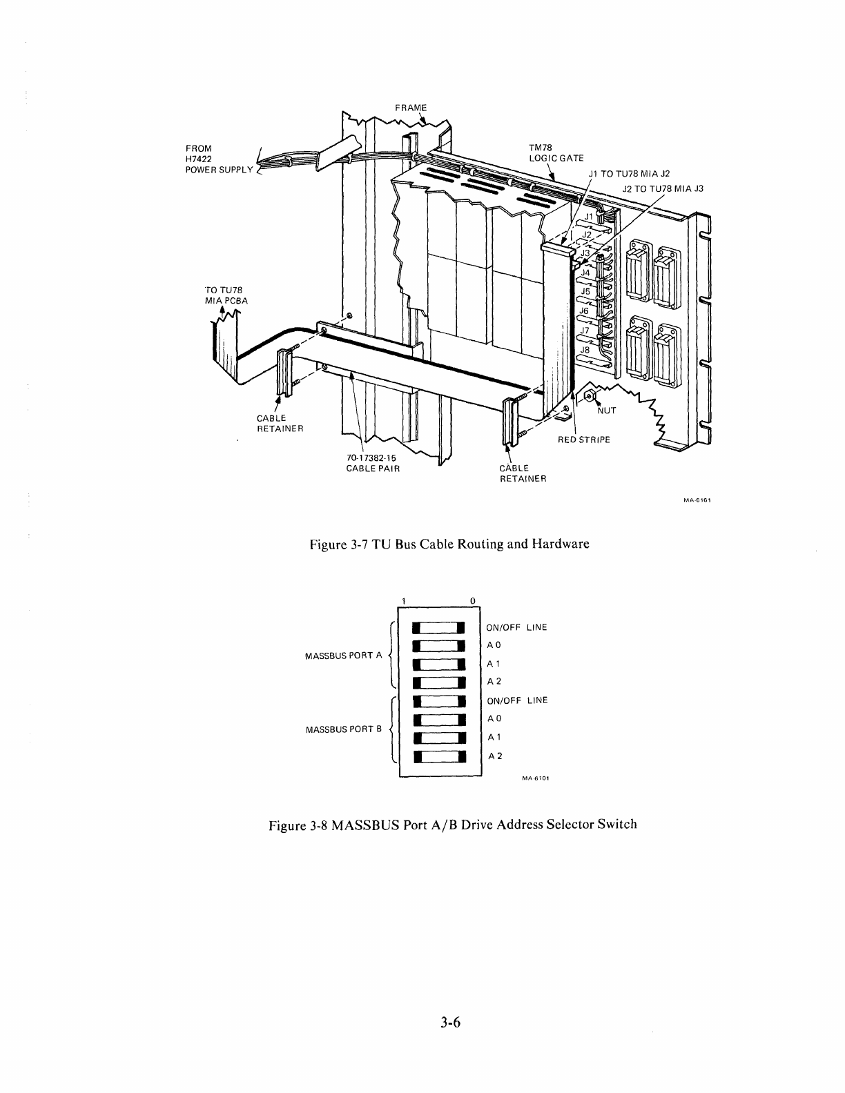
FROM
H7422
POWER SUPPLY
,
CABLE
RETAINER
CABLE
RETAINER
RED STRIPE
Figure 3-7
TU
Bus Cable Routing and Hardware
D
MASSBUS
PORT
A ( • •
ON/OFF
LINE
• •
AD
• •
Al
• •
A2
MASSBUS PORT B ( • •
ON/OFF
LINE
• •
AD
• • A 1
• •
A2
MA6101
Figure 3-8
MASSBUS
Port
AlB
Drive Address Selector Switch
3-6
MA-6161
The
on/off-line switches are used for maintenance purposes only. To electrically remove one or both ports
of
a drive from the host system(s), push the appropriate switch in on the right side. The normal position
for these switches
is
the on-line, or left position. Taking one of two ports off-line does not necessarily mean
that
a given transport
is
off-line; the transport may be switched to the opposite port through its control
panel port selector switch.
NOTE
If
the dual port option (port B) is not present in the
TM78,
the lower set
of
four switches has no effect.
3.5 ACCEPTANCE TESTING
The
TM78
acceptance tests are run concurrently with the master TU78 acceptance tests. Refer to the
subsystem acceptance procedures found in
Paragraph
3.5
of
the TU78 User Guide or TU78 Technical
Manual.
3-7

BYTE
1.
2.
3.
4.
5.
6.
7.
8.
9.
10.
11.
12.
13.
14.
15.
16.
17.
18.
19.
20.
APPENDIX
A
EXTENDED
SENSE
COMMAND (73) DATA BYTES
DESCRIPTION
Command
code
being
executed
on
last
error
Interrupt
code
from
last
error
Failure
code
from
last
error
Hardware register
0;
read
path
write fail bits
Hardware register 1;
read
path
diagnostic
bits
Hardware register 2; read
path
status
Hard ware register 3;
read
path
command
loop
Hardware register 20; AMTIE
Hardware register 21; RC DONE
Hardware register 22; illegal 5-4
Hardware register 23;
mark
2
Hardware register 24;
end
mark
Hardware register 25; RC
PAR
bits
Hardware register 26;
postamble
det
Hardware register 27;
data
Hardware register 30; CRC
Hardware register
31;
corrected
data
Hardware register 32; ECC
status
Hard ware register
40;
channel 0
TIE
bus
Hardware register 41 ;
channel
1
TIE
bus
A-I
BYTE
DESCRIPTION
21. Hardware register 42; channel 2 TIE bus
22. Hardware register 43; channel 3 TIE bus
23. Hardware register 44; channel 4 TIE bus
24. Hardware register 45; channel 5 TIE bus
25. Hardware register 46; channel 6 TIE bus
26. Hardware register 47; channel 7 TIE bus
27. Hardware register 50; channel P TIE bus
28. Hardware register 60; TIE bus
29. Hardware register 104; AMTIE
30. Hardware register 110; PORT status
31. Hardware register 114; read data
32. Hardware register 240;
CAS
status
33. Hardware register 241;
CBUS
status
34. Hardware register 300; DBUS status
35. Hardware register 320;
WMC
status
36. Hardware register 321; TU select 0
37. Hardware register 322; TU select I
38. Hardware register 323; write data
39. Hardware register 324; byte counter
<7:0>
40. Hardware register 324; byte counter
<15:8>
41. Hardware register 325; PAD counter
<7:0>
42. Hardware register 325; PAD counter
<15:8>
43. Hardware register 326; ECODE counter
<7:0>
44. Hardware register 326; ECODE counter
<15:
8>
45. Hardware register 330; DDR/MBD A
A-2
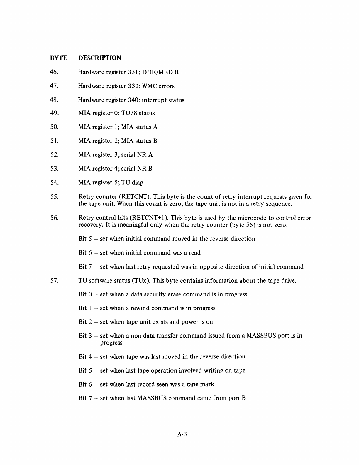
BYTE
46.
47.
48.
49.
50.
51.
52.
53.
54.
55.
56.
DESCRIPTION
Hardware register 331; DDR/MBD B
Hardware register
332;
WMC
errors
Hardware register 340;
interrupt
status
MIA register 0; TU78 status
MIA register
1;
MIA
status
A
MIA register 2; MIA status B
MIA register 3; serial
NR
A
MIA register 4; serial
NR
B
MIA register 5;
TU
diag
Retry
counter
(RETCNT). This
byte
is
the
count
of
retry
interrupt
requests given for
the
tape
unit. When this
count
is zero,
the
tape
unit
is
not
in a
retry
sequence.
Retry
control
bits (RETCNT+ I). This
byte
is
used
by
the
microcode
to
control
error
recovery.
It
is
meaningful only when
the
retry
counter
(byte
55)
is
not
zero.
Bit 5 - set when initial
command
moved in
the
reverse direction
Bit 6 - set when initial
command
was a read
Bit 7 - set when last
retry
requested was in opposite direction
of
initial
command
57.
TU
software status (TUx). This
byte
contains
information
about
the
tape drive.
Bit 0 - set when a
data
security erase
command
is in progress
Bit 1 -
set
when a rewind
command
is in progress
Bit 2 -
set
when tape
unit
exists
and
power
is
on
Bit 3 -
set
when a non-data transfer
command
issued from a MASSBUS
port
is
in
progress
Bit 4 - set when
tape
was last moved in
the
reverse direction
Bit 5 - set when last
tape
operation
involved writing
on
tape
Bit 6 - set when last record seen was a
tape
mark
Bit 7 -
set
when last MASSBUS
command
came from
port
B
A-3
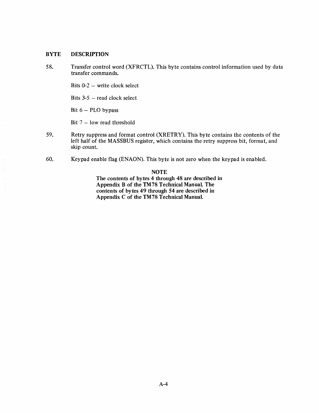
BYTE DESCRIPTION
58. Transfer control word (XFRCTL). This byte contains control information used by data
transfer commands.
Bits 0-2 -write clock select
Bits
3-5
-read clock select
Bit 6 - PLO bypass
Bit 7 - low read threshold
59. Retry suppress and format control (XRETRY). This byte contains the contents
of
the
left half
of
the MASSBUS register, which contains the retry suppress bit, format, and
skip count.
60. Keypad enable flag (ENAON). This byte
is
not
zero when the keypad
is
enabled.
NOTE
The contents
of
bytes 4 through 48 are described in
Appendix B
of
the TM78 Technical Manual. The
contents
of
bytes
49
through 54 are described in
Appendix C
of
the TM78 Technical Manual.
A-4
TM78
MAGNETIC
TAPE FORMATTER
USER
GUIDE
E K-OTM78-UG-001
Reader's
Comments
Your
comments
and
suggestions
will
help
us
in
our
continuous
effort
to
improve
the
quality
and
useful-
ness
of
our
publications.
What
is
your
general reaction
to
this manual? In your judgement is
it
complete, accurate, well organized,
w~lwritten,ett?
Isiteasytouse?~~~~~~~~~~~~~~~~~~~~~~~~~~~
What
features are most
useful?_~~
_____
~_~~
__
~~~~_~_~~~~~~~_
What
faults or errors have you found in the
manual?_~~_~
__
~
___
~~_",,---~~~~~~
Does this manual satisfy the need you think it was intended
to
satisfy?~~~~~~_~~~_~
__
Does
it
satisfy your needs?
__________
Why?
____
~
_________
~
__
_
o Please send me the current copy
of
the Technical
Documentation
Catalog, which contains information
on the remainder
of
DIGITAL's technical documentation.
Name
__
~_~
____
~
_______
___
Title
_~~
___
~~
____
~~
___
~_
Company
__
~~~~
___
~
____
~_~
___
Department
_~_~~~_~~
__
~_~~_
Additional copies
of
this document are available from:
Digital Equipment Corporation
Accessories and Supplies Group
Cotton Road
Nashua, N H
03060
Attention
Documentation
Products
Telephone
1-800-258-1710
Order No. E K·OTM78-UG·001
Street
___
~~~~~~~~~~~~~
__
City
________________
_
State/Country
_____________
_
Zip_~_~~~~~~~~~~~~~~
___
1
____________________
Fold
Here---------------------
--
______________
00
Not
Tear -Fold
Here
and Staple
----------------
momoomo
111111
~
__
~_R~_T_~_LA_~~~-E~S~PE~~~MI~TR~NO~~~3~~L=Y~M-AY-~-A.!
__
,I_M~_.
_____________________
].
POSTAGE
WILL
BE
PAID
BY
ADDRESSEE
Digital Equipment Corporation
Educational Services Development and Publishing
129 Parker Street, P K3-1
IT
12
Maynard,
MA
01754
No
Postage
Necessary
if
Mailed
in
the
United
States
