TM 9 2320 272 24 4 Maintenance Manual 1998
User Manual: TM-9-2320-272-24-4-Maintenance-Manual-1998 M939 Series Trucks
Open the PDF directly: View PDF ![]() .
.
Page Count: 842 [warning: Documents this large are best viewed by clicking the View PDF Link!]
ARMY TM 9-2320-272-24-4
AIR FORCE TO 36A12- 1 C- 1155-2-4
This publication supersedes TM 9-2320-272-20- 1, October 1985, and changes 1 through 4; TM 9-2320-272-20-2,
October 1985, and changes through 3; 9-2320-272-34-1, 1986, changes through
TM 9-2320-272-34-2, June 1986, and changes 1 and 2; and TM 9-2320-358-24&P, October 1992.
TECHNICAL MANUAL
VOLUME 4 OF 4
UNIT, DIRECT SUPPORT, AND GENERAL SUPPORT
MAINTENANCE MANUAL
FOR
TRUCK, 5-TON, 6X6, M939, M939A1, M939A2
SERIES TRUCKS (DIESEL)
TRUCK, CARGO: 5-TON, 6X6, DROPSIDE,
M923 (2320-01-050-2084) (EIC: BRY); M923A1 (2320-01-206-4087) (EIC: BSS); M923A2 (2320-01-230-0307) (EIC: B57);
M925 (2320-01-047-8769) (EIC: BRT); M925Al (2320-01-206-4088) (EIC: BST); M925A2 (2320-01-230-0308)(EIC: BS8);
TRUCK, CARGO: 5-TON, 6X6 XLWB,
M927 (2320-01-047-8771) (EIC: BRV); M927Al (2320-01-206-4089) (EIC: BSW); M927A2 (2320-01-230-0309) (EIC: BS9);
M928 (2320-01-047-8770) (UC: BRU); M928Al (2320-01-206-4090) (EIC: BSX); M928A2 (2320-01-230-0310) (EIC: BTM);
TRUCK, DUMP: 5-TON, 6X6,
M929 (2320-01-047-8756) (EIC: BTH); M929Al (2320-01-206-4079) (EIC: BSY); M929A2 (2320-01-230-0305) (EIC: BTN);
M930 (2320-01-047-8755) (EIC: BTG); M930Al (2320-01-206-4080) (EIC: BSZ); M930A2 (2320-0l-230-0306) (EIC: BTO);
TRUCK, TRACTOR: 5-TON, 6X6,
M931 (2320-01-047-8753) (EIC: BTE); M931A1 (2320-01-206-4077) (EK: BS2); M931A2 (2320-01-230-0302) (EIC: BTP);
M932 (2320-01-047-8752) (EIC: BTD); M932Al (2320-01-205-2684) (EIC: 855); M932A2 (2320-01-230-0303) (EIC: BTQ);
TRUCK, VAN, EXPANSIBLE: 5-TON, 6X6,
M934 (2320-01-047-8750) (EIC: BTB); M934A1 (2320-01-205-2682) (EIC: BS4); M934A2 (2320-0l-230-0300) (EIC: BTR);
TRUCK, MEDIUM WRECKER: 5-TON, 6X6,
M936 (2320-01-047-8754) (EIC: BTF); M936Al (2320-0l-206-4078) (EIC: BS6); M936A2 (2320-01-230-0304) (EIC: BTT).
DISTRIBUTION STATEMENT A - Approved for public release; distribution is unlimited.
DEPARTMENTS OF THE ARMY AND THE AIR FORCE
JUNE 1998

TM 9-2320-272-24-4
WARNING
EXHAUST GASES CAN KILL
1.
DO NOT operate vehicle engine in enclosed area.
2.
DO NOT idle vehicle engine with windows closed.
3.
DO NOT drive vehicle with inspection plates or cover plates removed.
4. BE ALERT at all times for odors.
5.
BE ALERT for exhaust poisoning symptoms. They are:
Headache
Dizziness
Sleepiness
Loss of muscular control
6.
IF YOU SEE another person with exhaust poisoning symptoms:
Remove person from area
Expose to open air
Keep person warm
Do not permit person to move
Administer artificial respiration or CPR, if necessary*
* For artificial respiration, refer to FM 21-11.
7.
BE AWARE: The field protective mask for Nuclear, Biological, or Chemical (NBC) protection will not
protect you from carbon monoxide poisoning.
THE BEST DEFENSE AGAINST EXHAUST POISONING IS ADEQUATE VENTILATION.
Warning a

TM 9-2320-272-24-4
WARNING SUMMARY
Hearing protection is required for the driver and passenger. Hearing protection is also required for
all personnel working in and around this vehicle while the engine is running (AR-40-5 and TB MED
501).
If required to remain inside vehicle during extreme heat, occupants should follow the water intake,
work/rest cycle, and other stress preventive measures (FM 21-10, Field Hygiene and Sanitation).
If NBC exposure is suspected, all air filter media should be handled by personnel wearing protective
equipment. Consult with your unit NBC officer or NBC NCO for appropriate handling or disposal
instructions.
This vehicle has been designed to operate safely and efficiently within the limits specified in this
TM. Operation beyond these limits is prohibited by IAW AR 70-1 without written approval from the
commander, U.S. Army Tank-automotive and Armaments Command, ATTN: AMCPEO-CM-S,
Warren, MI 48397-5000.
Never work under dump body unless safety braces are properly positioned. Failure to do this will
result in injury to personnel.
During winching operation, never stand between vehicles. Assistant must remain in secondary
vehicle to engage service brake if cable snaps or automatic brake fails while towing vehicle. Failure
to do this may result in injury to personnel.
Accidental or intentional introduction of liquid contaminants into the environment is in violation of
state, federal, and military regulations. Refer to Army POL (para. 1-7) for information concerning
storage, use, and disposal of these liquids. Failure to do so may result in injury or death.
Cleaning solvents are flammable and toxic. Do not. use near open flame and always have a fire
extinguisher nearby when solvents are used. Use only in well-ventilated places, wear protective
clothing, and dispose of cleaning rags in approved container. Failure to do this will result in injury
to personnel and/or damage to equipment.
Eyeshields must be worn when cleaning with compressed air. Compressed air source will not exceed
30 psi (207 kPa). Failure to do so may result in injury to personnel.
Extreme care should be taken when removing surge tank filler cap if temperature gauge reads
above 175°F (79°C). Steam or hot coolant under pressure will cause injury.
Alcohol used in the alcohol evaporator is flammable, poisonous, and explosive. Do not smoke when
removing alcohol evaporator or adding fluid, and do not drink fluid. Failure to do this will result in
injury or death.
Do not perform electrical circuit testing fuel tank with fill cap or sending unit removed. Fuel may
ignite, causing injury to personnel.
When performing battery maintenance, ensure batteries are seated and clamped down, all rubber
boots are installed, clamps are well down on battery posts, and all battery cables lie flat against the
top of the batteries. Failure to do this may result in injury to personnel and/or damage to
equipment.
Ensure companion seatbelts are not caught inside battery box. This will cause belts to rot which
may lead to injury of personnel.
On M936/Al/A2 model vehicles, remove spare tire prior to changing tire and install tire in spare tire
carrier after tire change is complete. Operation of crane and/or vehicle engine while vehicle is on
jacks may result in injury to personnel or damage to equipment.
Never assemble or disassemble tire and rim assembly while inflated, use inflation to seat lockring
on split rim or tire on two-piece rim, or inflate a tire without a tire inflation cage. Injury to
personnel may result.
Do not disconnect air lines or hoses, remove safety valves or CTIS components, or perform brake
chamber repairs before draining air reservoirs. Small parts under pressure may shoot out with high
velocity, causing injury to personnel.
Warning
b

TM 9-2320-272-24-4
WARNING SUMMARY (Contd)
Remove all jewelry when working on electrical circuits. Jewelry coming in contact with electrical
circuits may produce a short circuit, causing extreme heat, explosions, and fling particles of metal.
Failure to do so will result in injury or death and damage to equipment.
Use eyeshields and follow instructions carefully when performing assembling, disassembling, or
maintenance on this device. Components of this device are under spring tension and may shoot out
at a high velocity. Failure to do so will result in injury to personnel.
Do not remove hoses with engine running or start engine with hoses removed. High-pressure fluids
may cause hoses to whip violently and spray randomly. Failure to do so may result in injury to
personnel.
Keep hands out from between metal surfaces when removing heavy components. Failure to do so
may result in injury to personnel.
Keep personnel out from under equipment and components of equipment when supported by only a
lifting device. Sudden loss of lifting power or shift in load may result in injury or death.
Do not drain engine, transmission, or radiator fluids, or remove lines containing these fluids, when
hot. Doing so may result in injury to personnel.
Vehicle will become charged with electricity if it contacts or breaks high-voltage wires. Do not leave
vehicle while high-voltage lines are in contact with vehicle. Failure to do so may result in injury to
personnel.
Wear hand protection when handling lifting and winching cables, hot exhaust components, and
parts with sharp edges. Failure to do so may result in injury to personnel.
Do not perform fuel system procedures while smoking or within 50 ft (15.2 m) of sparks or open
flame. Diesel fuel is highly flammable and can explode easily, causing injury or death to personnel
and/or damage to equipment.
Ensure drainvalve on aftercooler is open when filling cooling system. Failure to do so may result in
injury to personnel.
Turbocharger intake fins are extremely sharp and turn at very high rpm. Keep hands and loose
items away from intake openings. Failure to do so may result in injury to personnel.
Do not place hands between frame and radiator when removing screws from trunnion or lifting
radiator. Sudden changes in support may cause the radiator to shift, causing injury to personnel.
Air pressure may create airborne debris. Use eye protection or injury to personnel may result.
Air system components are subject to high pressure. Always relieve pressure before loosening or
removing air system components.
Wear safety goggles when using a hammer.
Ether is extremely flammable. Do not perform ether start system procedures near fire. Injury to
personnel may result.
Warning c/(Warning d blank)

TECHNICAL MANUAL
NO.9-2320-272-24-4
TECHNICAL ORDER
NO. 36A12-1C-1155-2-4
ARMY TM 9-2320-272-24-4
AIR FORCE TO 36A12-1C-1155-2-4
HEADQUARTERS
DEPARTMENTS OF THE ARMY AND THE AIR FORCE
Washington, D.C., 30 JUNE 1998
TECHNICAL MANUAL
VOLUME 4 OF 4
UNIT, DIRECT SUPPORT, AND
GENERAL SUPPORT MAINTENANCE MANUAL
FOR
TRUCK, 5-TON, 6X6, M939, M939A1, M939A2 SERIES TRUCKS (DIESEL)
TRUCK MODEL
EIC
NSN WITHOUT WINCH NSN WITH WINCH
Cargo, Dropside
Cargo, Dropside
Cargo, Dropside
Cargo, Dropside
Cargo, Dropside
Cargo, Dropside
Cargo
Cargo
Cargo
Cargo
Cargo
Cargo
Dump
Dump
Dump
Dump
Dump
Dump
Tractor
Tractor
Tractor
Tractor
Tractor
Tractor
Van, Expansible
Van, Expansible
Van, Expansible
Medium Wrecker
Medium Wrecker
Medium Wrecker
M923
M923Al
M923A2
M925
M925Al
M925A2
M927
M927Al
M927A2
M928
M928Al
M92842
M929
M929Al
M929A2
M930
M930Al
M930A2
M931
M931Al
M931A2
M932
M932Al
M932A2
M934
M934Al
M934A2
M936
M936Al
M936A2
BRY
BSS
BS7
BRT
BST
BS8
BRV
BSW
BS9
BRU
BSX
BTM
BTH
BSY
BTN
BTG
BSZ
BTO
BTE
BS2
BTP
BTD
BS5
BTQ
BTB
BS4
BTR
BTF
BS6
BTT
2320-01-050-2084
2320-01-206-4087
2320-01-230-0307
2320-01-047-8771
2320-01-206-4089
2320-01-230-0309
2320-01-047-8769
2320-01-206-4088
2320-01-230-0308
2320-01-047-8756
2320-01-206-4079
2320-01-230-0305
2320-01-047-8770
2320-01-206-4090
2320-01-230-0310
2320-01-047-8753
2320-01-206-4077
2320-01-230-0302
2320-01-047-8755
2320-01-206-4080
2320-01-230-0306
2320-01-047-8750
2320-01-205-2682
2320-01-230-0300
2320-01-047-8752
2320-01-205-2684
2320-01-230-0303
2320-01-047-8754
2320-01-206-4078
2320-01-230-0304
REPORTING OF ERRORS AND RECOMMENDING IMPROVEMENTS
You can help improve this manual. If you find any mistakes or if you know of a way to improve the
procedures, please let us know. Mail your letter or DA Form 2028 (Recommended Changes to Publications
and Blank Forms), or DA Form 2028-2 located in back of this manual, directly to: Director, Armament and
Chemical Acquisition and Logistics Activity, ATTN: AMSTA-AC-NML, Rock Island, IL 61299-7630. A reply
will be furnished to you. You may also provide DA Form 2028-2 information via datafax or e-mail:
E-mail: amsta-ac-nml.@ria-emh2.army.mil
Fax: DSN 783-0726 or commercial (309) 782-0726
DISTRIBUTION STATEMENT A - Approved for public release; distribution is unlimited.
i

TM 9-2320-272-24-4
*This publication supersedes TM 9-2320-272-20-1,24 October 1985, and changes 1 through 4; TM 9-2320-272-20-2,25
October 1985, and changes 1 through 3; TM 9-2320-272-34-1, 10 June 1986, and changes 1 through 2; TM 9-2320-272-34-2,
10 June 1986, and changes 1 and 2; and TM 9-2320-358-24&P, 21 October 1992.
This publication is published in four volumes. TM 9-2320-272-24-1 contains chapters 1,2, and 3 (through
section IX). TM 9-2320-272-24-2 contains chapters 3 (sections X through XVI) and 4 (sections I through III).
TM 9-2320-272-24-3 contains chapter 4 (sections IV through XVI). TM 9-2320-272-24-4 contains chapters 5 and
6 and appendices A through H. Volume 1 contains a table of contents for the entire manual. Volumes 1,2, and 3
contain an alphabetical index covering tasks found in their respective volume. Volume 4 contains an
alphabetical index covering all tasks found in the entire manual.
CHAPTER 5
Section I.
Section II.
Section III.
Section IV
Section V
Section VI.
Section VII.
CHAPTER 6
Section I.
Section II.
Section III.
APPENDIX A
APPENDIX B
Section I.
Section II.
Section III.
Section IV.
APPENDIX C
Section I.
Section II.
APPENDIX D
APPENDIX E
APPENDIX F
APPENDIX G
APPENDIX H
ii
TABLE OF CONTENTS
VOLUME 4 OF 4
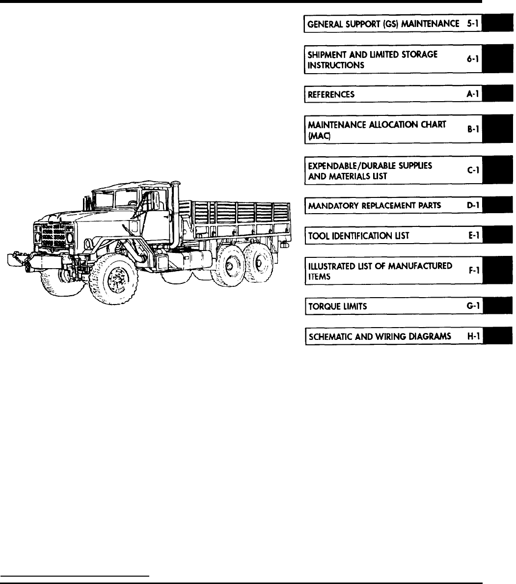
GENERAL SUPPORT (GS) MAINTENANCE INSTRUCTIONS
Page
.............
5-1
Engine (M939/Al) Maintenance ............................................. 5-l
Engine (M939A2) Maintenance ..............................................
5-157
TransmissionMaintenance .................................................
5-280
Transfer Case Maintenance .................................................
5-398
Front and Rear Axle Maintenance ............................................
5-432
Special Purpose Bodies Maintenance .........................................
5-463
Winch, Hoist, and Power Takeoff (PTO) Maintenance ............................
5-606
SHIPMENT AND LIMITED STORAGE INSTRUCTIONS ..................
6-1
General Preparation of Vehicle for Shipment ...................................
6-1
Loading and Movement ....................................................
6-2
LimitedStorage ..........................................................
6-2
REFERENCES .....................................................
A-1
MAINTENANCE ALLOCATION CHART (MAC) ......................... B-l
Introduction ............................................................. B-l
Maintenance Allocation Chart (MAC) .........................................
B-4
Tool and Test Equipment Requirements .......................................
B-25
Remarks ................................................................
B-26
EXPENDABLE/DURABLE SUPPLIES AND MATERIALS LIST ............
C-1
Introduction ............................................................. C-l
Expendable/Durable Supplies and Materials List. ...............................
C-3
MANDATORY REPLACEMENT PARTS ................................ D-l
COMMON AND SPECIAL TOOL IDENTIFICATION LIST ................ E-l
ILLUSTRATED LIST OF MANUFACTURED ITEMS ..................... F-l
TORQUE LIMITS ................................................... G-l
SCHEMATIC AND WIRING DIAGRAMS .............................. H-l

Section
I. ENGINE (M939/A1) MAINTENANCE
TM
9-2320-272-24-4
5-1. GENERAL
5-2. ENGINE (M939/A1) MAINTENANCE INDEX
PARA.
NO.
TITLE
PAGE
NO.
5-3.
5-4.
5-5.
5-6.
5-7.
5-8.
5-9.
5-10.
5-11
5-12.
5-13.
5-14.
5-15.
5-16.
5-17.
5-18.
5-19.
5-20.
5-21.
5-22.
5-23.
Cylinder Head Repair
Intake and Exhaust Valves Refacing
Valve Seat Inserts Maintenance
Fuel Injector Sleeve Maintenance
Cylinder Liners and Block Maintenance
Crankshaft and Main Bearings Maintenance
Camshaft and Gear Maintenance
Piston and Connecting Rod Maintenance
Engine Oil Pump Repair
Mounting Fuel Pump to Holding Fixture
Pressure Gear Pump Removal
Governor Spring Pack Maintenance
Fuel Pump Housing Maintenance
Throttle Cover and Shaft Maintenance
Governor Weight Maintenance
Fuel Pump Setup and Calibration
Fuel Injector Repair
Injector Leak Test
Injector Spray Pattern Test
Injector Test Stand Calibration
Injector Flow Test
5-2
5-18
5-22
5-26
5-34
5-48
5-58
5-64
5-78
5-92
5-93
5-94
5-96
5-98
5-102
5-104
5-122
5-136
5-140
5-142
5-148
5-1
TM 9-2320-272-24-4
5-3. CYLINDER HEAD REPAIR
THIS TASK COVERS:
a. Disassembly
b. Cleaning c. Inspection
d. Assembly
INITIAL SETUP:
APPLICABLE MODELS
PERSONNEL REQUIRED
M939/Al
TWO
SPECIAL TOOLS
Head holding future (Appendix E, Item 7)
Cleaning brush (Appendix E, Item 28)
Valve guide arbor (Appendix E, Item 153)
Gauge block (Appendix E, Item 52)
Crosshead guide puller (Appendix E, Item 106)
Crosshead guide spacer (Appendix E, Item 33)
REFERENCES (TM)
TM 9-2320-272-24P
TM 9-247
EQUIPMENT CONDlTlON
Cylinder head removed (para. 4-12).
TOOLS
General mechanic’s tool kit (Appendix E, Item 1)
Outside micrometer (Appendix E, Item 80)
Depth micrometer (Appendix E, Item 81)
Torque wrench (Appendix D, Item 145)
Soft-faced hammer
GENERAL SAFETY INSTRUCTIONS
When cleaning with compressed air, wear eyeshields
and ensure source pressure does not exceed 30 psi
(207 kPa).
MATERIALS/PARTS
Six freeze plugs (Appendix D, Item 133)
Sixteen half-keepers (Appendix D, Item 253)
Two O-rings (Appendix D, Item 438)
Two screw-assembled lockwashers (Appendix D,
Item 578)
Gasket (Appendix D, Item 94)
Freeze plug (Appendix D, Item 132)
Two freeze plugs (Appendix D, Item 134)
Lubricating oil (Appendix C, Item 50)
Prussian blue (Appendix C, Item 54)
Sealing compound (Appendix C, Item 61)
Antiseize tape (Appendix C, Item 72)
Crocus cloth (Appendix C, Item 20)
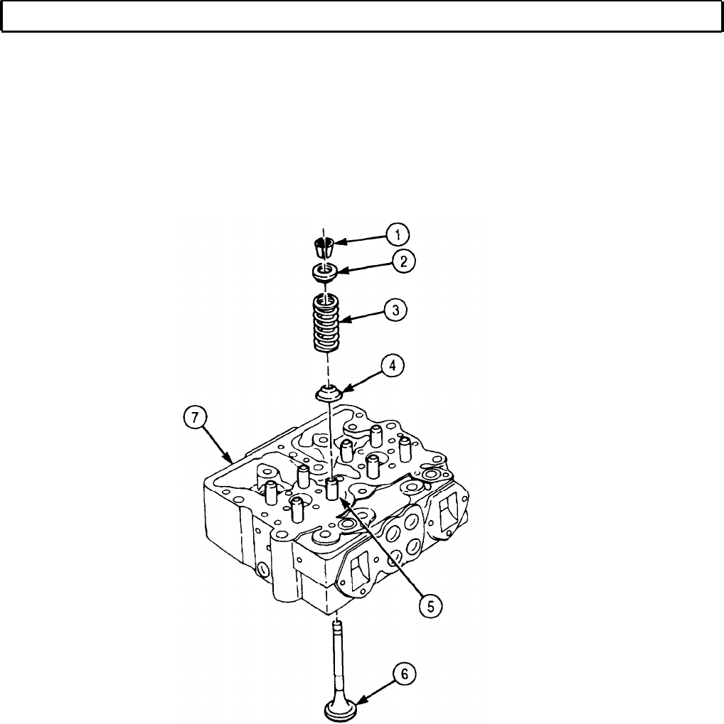
a. Disassembly
1.
Remove sixteen half-keepers (1) from valve springs (3) and cylinder head (7). Discard sixteen half-
keepers (1).
NOTE
Tag springs for installation
2.
Remove eight upper spring guides (2), valve springs (3), and lower spring guides (4) from valve
guide (5) and cylinder head (7).
3.
Tap eight valve (6) stems down lightly to loosen and remove from cylinder head (7). Place on
numbered valve board and hold for inspection.
5-2
TM 9-2320-272-24-4
5-3. CYLINDER HEAD REPAIR (Contd)
5-3

TM 9-2320-272-24-4
5-3. CYLINDER HEAD REPAIR (Contd)
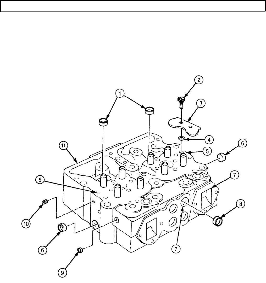
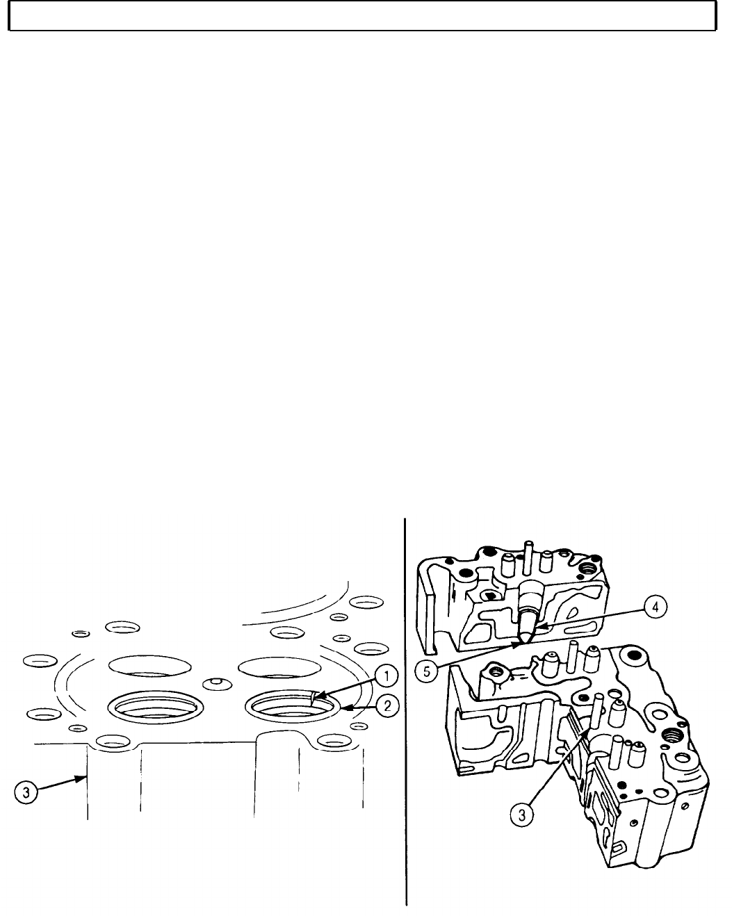
4.
5.
Remove two screw-assembled lockwashers (2), plate (3), and two O-rings (4) from cylinder head (11)
and fuel crossover connection (5). Discard O-rings (4) and screw-assembled lockwashers (2).
Remove pipe plugs (10) from front and rear face of cylinder head (11). Hold pipe plugs (10) for
installation.
6.
Remove four freeze plugs (8) from exhaust ports (17) on cylinder head (11). Discard freeze
plugs (8).
7.
Remove two freeze plugs (6) from front and rear face of cylinder head (11). Discard freeze plugs (6).
8.
Remove two freeze plugs (1) from cylinder head (11). Discard freeze plugs (1).
9.
Remove freeze plug (9) from front of cylinder head (11). Discard freeze plug (9).
5-4
TM 9-2320-272-24-4
5-3. CYLINDER HEAD REPAIR (Contd)
5-5

TM 9-2320-272-24-4
5-3. CYLINDER HEAD REPAIR (Contd)
b. Cleaning
Clean all cylinder head (1) components (TM 9-247).
c. Inspection
1.
2.
3.
4.
5.
6.
7.
8.
9.
10.
11.
12.
Install four pipe plugs (11) in front and rear face of cylinder head (1).
NOTE
Apply sealing compound to outer diameter of freeze plugs before
installation.
Install new freeze plug (10) in front face of cylinder head (1).
Install two new freeze plugs (2) in cylinder head (1).
Install two new freeze plugs (7) in front and rear face of cylinder head (1).
Install four new freeze plugs (9) in exhaust ports (8) on cylinder head (1).
Install two new O-rings (5), plate (4), and two new screw-assembled lockwashers (3) on fuel
crossover connection (6) in cylinder head (1).
CAUTION
Do not use sander to polish cylinder heads. Serious damage to
gasket sealing surfaces can result.
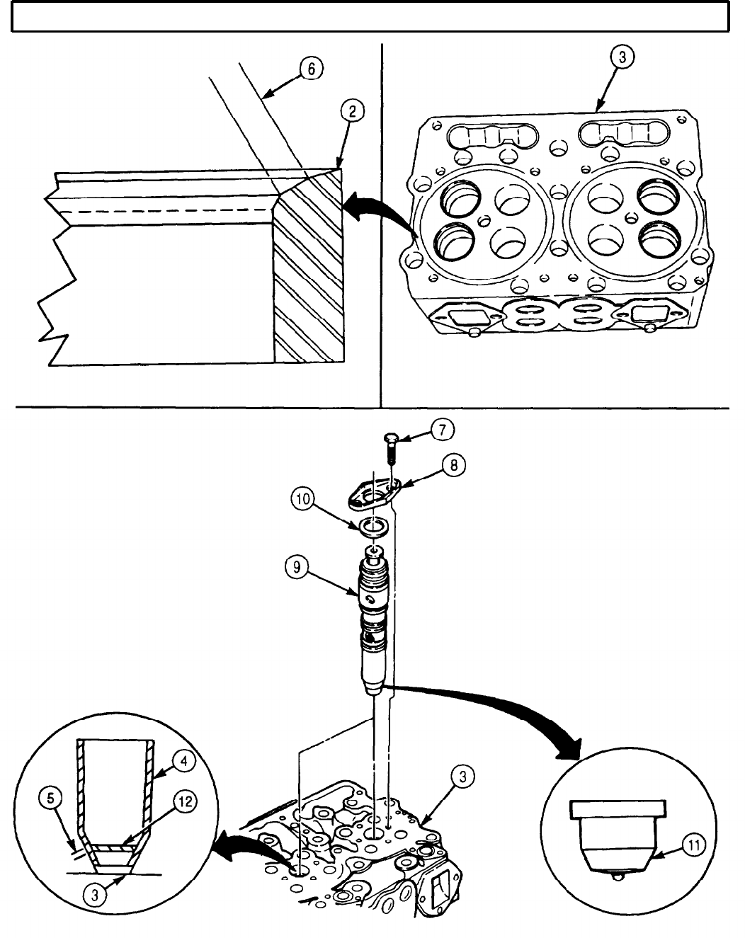
Clean cylinder head mating surfaces (12) lightly enough to remove all gasket remains and carbon
deposits. Inspect in accordance with instructions in para. 5-25.
NOTE
Instructions for use of portable magnetic tester are included with
the tester.
Inspect valve seats (13) and injector ports (14) on cylinder head (1) for cracks. If cracks are found,
replace cylinder head (1).
NOTE
The following examples of cylinder head defects are provided to
assist in determining causes of failures.
Check cylinder head valve seats (13) and injector ports (14) for hot spots and correct probable causes.
If this condition exists, probable causes are overheating, loss of coolant, coolant flow stoppage, over-
fueling, tight injector holddowns, incorrect injector sleeve installation, defective casting, hot
shutdowns, and incorrect insert fittings. If hot spots are found, replace cylinder head (1).
Check cylinder head (1) and water passage holes (15) for pits and scratches. If pits and scratches are
less than .003 in. (0.08 mm), remove with crocus cloth. If pits and scratches are more than 0.003 in.
(0.08 mm) deep in the area 0.-625-0.156 in. (1.59-3.97 mm) from edge of water passage hole (15),
replace cylinder head (1).
Check cylinder head surfaces (12) for warped surfaces. If warped surface exceeds 0.002 in. (0.05 mm),
replace cylinder head (1).
Check cylinder head (1) for required thickness. Cylinder head (1) must measure 4.340 in. (110.24
mm) thick. If less than 4.340 in. (110.24 mm) thick, replace cylinder head (1).
5-6

TM 9-2320-272-24-4
5-3. CYLINDER HEAD REPAIR (Contd)
5-7
TM 9-2320-272-24-4
5-3. HEAD REPAIR (Contd)
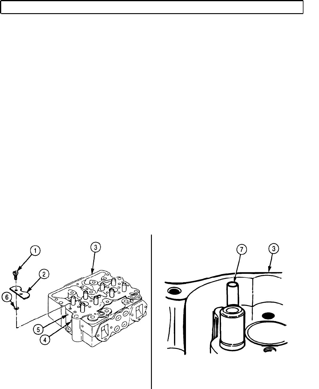
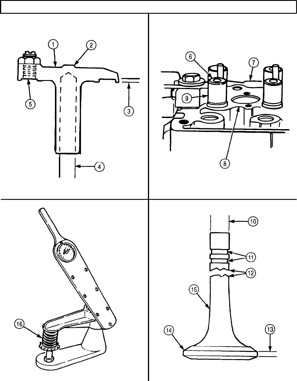
13.
14.
15.
16.
17.
18.
Check valve seat insert (2) and cylinder head (3) for looseness by tapping surface around valve seat
insert (2). Replace valve seat inserts (2) that bounce when tapped (para. 5-4).
Measure width (6) of valve seat insert (2). If width exceeds 0.125 in. (3.18 mm) at any one point
and cannot be narrowed during regrinding, mark valve seat inserts (2) for replacement (para. 5-4).
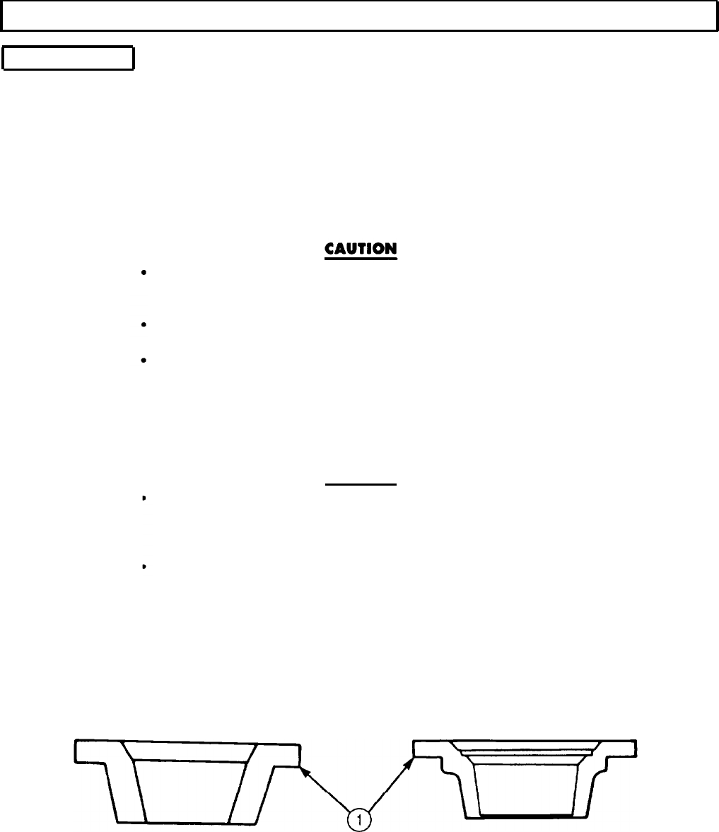
NOTE
The following examples of valve seat defects are provided to assist
in determining causes of failure.
Inspect valve seat insert (2) and cylinder (3) for cracks (1) and correct probable causes. If cracks
exist, probable causes are improperly machined insert bore, improper fitting of insert in bore,
foreign particle under insert, faulty installation, and overheating.
Inspect valve seat insert (2) and cylinder head (3) for bums and correct probable causes. If burned,
probable causes are carbon or foreign matter that prevents proper seating of valve. If burned,
resurface or replace (para. 5-4).
Inspect injector sleeves (4) and cylinder head (3) in accordance with instructions in para. 5-6. Check
injector sleeves (4) for scratches with bright light. If scratched, mark injector sleeve (4) for
replacement (para. 5-6).
Check injector cup seating area (5).
a. Lightly coat injector cup (11) with Prussian blue.
b. Install injector (9) into sleeve (4) with washer (10), clamp (8), and two screws (7). Tighten
alternately in 4 lb-ft (5.4 N.m) steps to 10-12 lb-ft (14-16 N-m).
c. Remove two screws (7), clamp (8), washer (10), and injector (9).
d. Check seat pattern in bottom of sleeve (4) and sleeve seating area (5).
e. Blued band (12) on sleeve (4) in sleeve seating area (5) must be 0.060 in. (1.52 mm) minimum
width and be located approximately 0.469 in. (11.91 mm) from bottom of cylinder head (3)
surface.
5-8
TM 9-2320-272-24-4
5-3. CYLINDER HEAD REPAIR (Contd)
5-9
TM 9-2320-272-24-4
5-3. CYLINDER HEAD REPAIR (Contd)
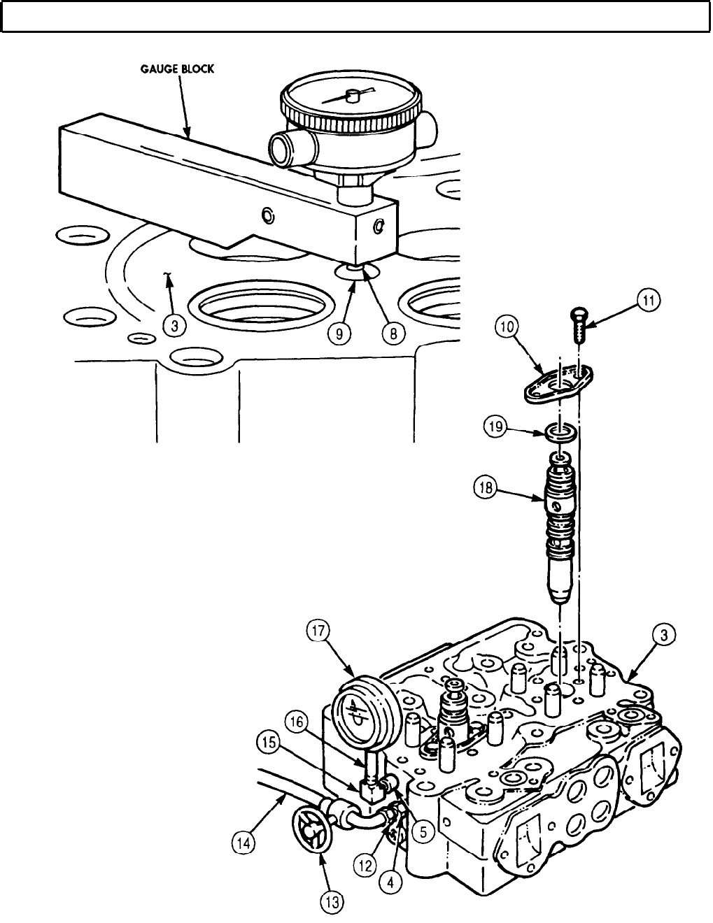
19.
Install injector (18) in cylinder head (3) with washer (19), clamp (10), and two
screws (11). Tighten alternately in 4 lb-ft (5.4 N-m) steps to 10-12 lb-ft (14-16 N-m).
20.
Measure protrusion of injector tip (8) with gauge block. Protrusion should be 0.060-0.070 in.
(1.52-1.78 mm). If not, mark sleeve (9) for replacement (para. 5-6).
21.
Air-test fuel inlet passage (4) and fuel outlet passage (5) for leakage and cracks.
a. Install two O-rings (6), plate (2), and two screw-assembled lockwashers (1).
b. Install pipe adapter (151, pipe extension (16), and air pressure gauge (17) into fuel outlet
passage (5).
c. Install air hose adapter (121, air pressure control valve (13), and air hose (141 into fuel inlet
passage (4).
d. Open air pressure control valve (13) and apply air pressure until air pressure gauge (17) reads
80-100 psi (550-690 pKa), then close valve (13).
e. Observe air pressure gauge (17). If pressure drops before fifteen seconds, replace cylinder head (3).
f. If air pressure holds for fifteen seconds, cylinder head (3) is serviceable.
NOTE
Replace pipe plugs in fuel passages of cylinder head after removal
of test adapters.
22.
Remove air pressure gauge (17). pipe extension (16), and pipe adapter (15).
23.
Remove air hose adapter (12), air pressure control valve (13), and air hose (14) from fuel inlet
passage (4)
24.
Inspect four crosshead guides (7) in accordance with instructions in para. 2-15.
25.
Check outside diameter of four crosshead guides (7) using micrometer or dial gauge. If outside
diameter is less than 0.432 in. (10.97 mm), mark guide (7) for replacement.
26.
Check four crosshead guides (7) for correct height. If height is not 1.860-1.880 in. (47.24-47.75 mm),
mark guide (7) for replacement.
27.
Check four crosshead guides (7) for straightness. If guide (7) is not straight, replace guide (7)
(subtask d, step 1).
5-10
TM 9-2320-272-24-4
5-3. CYLINDER HEAD REPAIR (Contd)
5-11

TM 9-2320-272-24-4
5-3. CYLINDER HEAD REPAIR (Contd)
28.
Inspect valve crossheads (1) in accordance with instructions in para. 2-15. Discard crossheads (1) if
defective.
a. Check valve crossheads (1) for damaged adjusting screw threads (5) and excessive wear on rocker
lever contact area (2).
b. Using micrometer, set small bore gauge at 0.4402 in. (11.181 mm).
c. Attempt to insert gauge into bore (4). Discard valve crosshead (1) if bore gauge goes into bore (4).
d. Check for out-of-round bore (4) by gauging at several points 90° apart. Discard valve crosshead (1)
if bore (4) is out of round.
e. Check valve stem counterbore depth (3). Discard crosshead (1) if depth (3) is not 0.1200-0.1400 in.
(3.048-3.556 mm).
29.
Inspect eight valve guides (9) in accordance with instructions in para. 2-15. If defective, mark valve
guides (9) for replacement.
a. Check eight valve guides (9) for chips, cracks, burrs, or broken out sections. If chipped, cracked,
broken, or burrs are found, mark for replacement.
b. Check valve guide (9) for protrusion (7). If protrusion (7) is not 1.270-1.280 in. (32.26-32.51 mm)
above cylinder head surface (8), mark valve guide (9) for replacement.
c. Set small bore gauge at 0.4552 in. (11.562 mm) and attempt to insert gauge into guide bore (6). If
gauge goes into bore (6), mark guide (9) for replacement.
30.
Check valve head (14) and intake and exhaust valves (15) for cracks, warping, pits, burns, or
cupping. Discard valve(s) (15) if cracked or warped, pitted, burned, or cupped.
a. Check rim thickness (13) on intake and exhaust valves (15). Discard valve (15) if rim thickness (13)
is less than 0.105 in. (2.67 mm).
b. Check intake and exhaust valve keeper grooves (11) for wear. Use new keeper to check grooves (11).
Discard valve(s) (15) if new keepers fit loosely in grooves (11).
c. Check valve stem (12) for cracks, scoring, and galling. If cracked, scored, or galled, discard valve (15).
d. Measure valve stem (10) outside diameter with micrometer. If stem (10) outside diameter is less
than 0.449 in. (11.41 mm), discard valve (15).
CAUTION
Use care when selecting replacement valve springs. Intermixing of
old and new valve guides in any one cylinder head is permissible
only if a specific crosshead has two of the same type or equivalent
guides and springs installed under it.
31.
Inspect valve springs (16) in accordance with instructions in para. 2-15. Discard valve springs (16) if
defective.
a. Check valve springs (16) for distortions, cracked, or collapsed coils. Discard valve spring (16) if
distorted, or if coils are cracked or collapsed.
b. Check valve spring (16) free length. No. 1 valve spring is 2.29 in. (58 mm) in length. No 2. valve
spring is 2.69 in. (68 mm) in length.
c. Using spring tester, inspect for serviceability by checking load when spring is compressed.
Discard spring No. 1 if spring does not give load of at least 150 lb (667 N) when compressed to
1.77 in (45 mm). Discard spring No. 2 if spring does not give load of at least 143 lb (636 N) when
compressed to 1.72 in. (44 mm).
5-12
TM 9-2320-272-24-4
5-3. CYLINDER HEAD REPAIR (Contd)
5-13
TM 9-2320-272-24-4
5-3. CYLINDER HEAD REPAIR (Contd)
d. Assembly
NOTE
Use repaired and inspection-approved cylinder heads only.
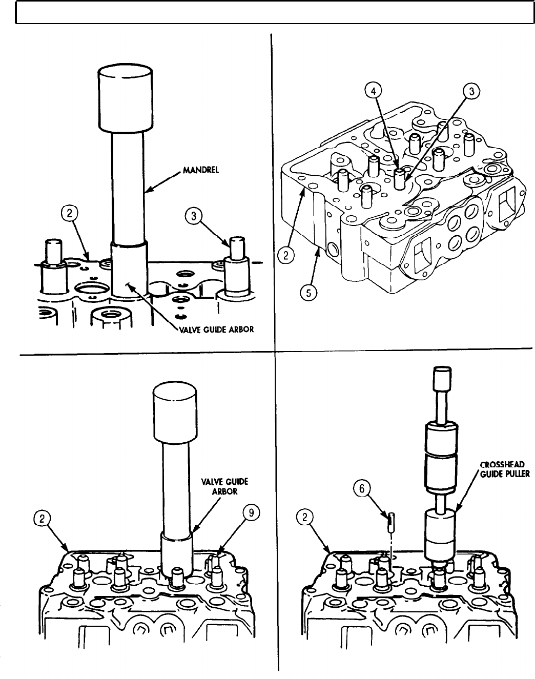
1.
Replace worn valve guides (3). Drive valve guides (3) from underside of cylinder head (2) with
hammer and punch.
2.
Using arbor press, mandrel, and valve guide arbor, install new valve guides (3).
3.
Using crosshead guide puller, remove defective crosshead guides (6) from cylinder head (2).
4.
Thoroughly clean crosshead guide (9) holes.
5.
Check crosshead guide (6) height. Assembled height must be 1.860-1.880 in. (47.24-47.75 mm).
To install intake and exhaust valves, position cylinder head on
intake port face. Use wooden surface, workbench, or protective
surface to prevent damage. Bench must be clean.
Be sure to install valves in original locations as numbered in
step 3.
Ensure cylinder head is clean
6.
Dip valve stem (4) in clean engine oil.
7.
Install valve stems (4) through valve guides (3) from face side (5) of cylinder head (2). Ensure valve
heads are correctly seated on valve seats (1).
8.
Carefully position cylinder head (2) face down on workbench after all valves are installed so valve
springs can be installed.
CAUTION
Two differently-designed valve spring guides have been used in
NHC-250 series engines. Part number 128879 spring guide
cannot be used with 211999 valve spring. Number 170296
spring guide can be used with either valve spring.
Reground valve heads seat deeper in cylinder head, causing
valve stem to protrude farther above valve guide. This allows
valve spring to extend beyond length limits of 2.250 in. (57.150
mm), and causes weak spring action. Use spacers up to 0.0625
in. (15.875 mm) to reduce valve spring to proper height.
5-14
TM 9-2320-272-24-4
5-3. CYLINDER HEAD REPAIR (Contd)
5-15

TM 9-2320-272-24-4
5-3. CYLINDER HEAD REPAIR (Contd)
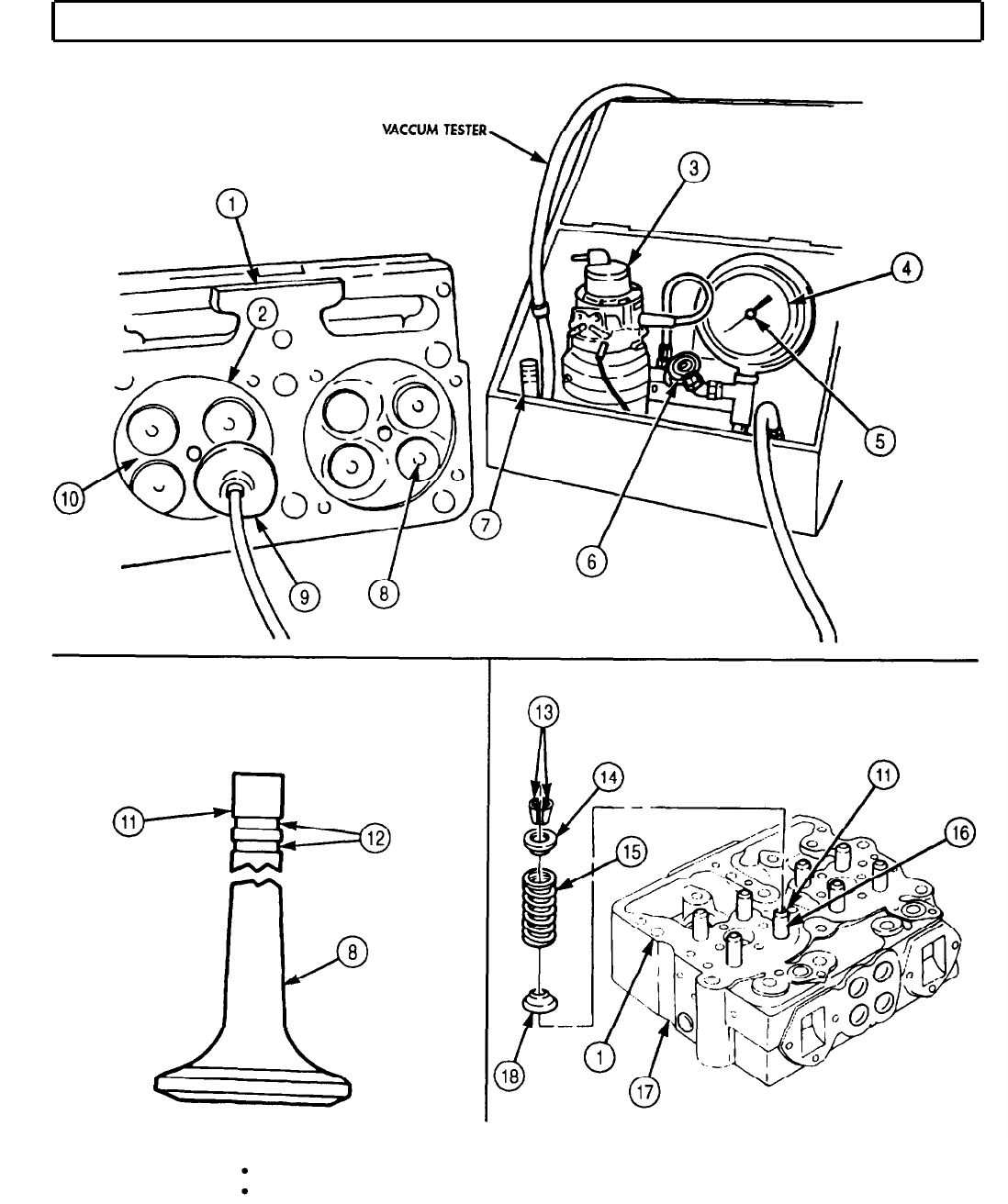
9.
10.
11.
12.
13.
NOTE
A maximum of two 0.03125 in. (0.794 mm) spacers may be used
under lower spring guide when cylinder head has been resurfaced
and valve seat insert has been refaced. Do not use spacers to
compensate for weak springs.
Place eight lower spring guides (18) over valve guides (16) and seat to cylinder head (1).
NOTE
Do not mix intake and exhaust springs. Intake springs are taller.
Place eight valve springs (15) on lower spring guides (18).
Place eight upper spring guides (14) on top of springs (15) and over stem end of valve (8). Compress
spring compressor until keeper grooves (12)on valve (8) are exposed.
Install new keepers (13) into valve grooves (12) and slowly release spring compressor. Repeat this
step until all valves (8) are locked by keepers (13).
Using vacuum tester, test intake and exhaust valves (8) for proper seating.
a.
b.
C.
d.
e.
f.
g.
h.
i.
j.
k.
l.
m.
n.
NOTE
Valves and valve seats must be dry.
Grease can be applied to O-ring on vacuum cup for better seal.
Select correct size vacuum cup (9) for size valves (8) being tested.
Hold vacuum cup (9) over head of valve (8) and seat flat on cylinder head surface (2)
surrounding valve (8).
Turn tester shutoff valve (6) to open position and hold pushbutton (7) down to operate vacuum
pump (4).
Operate tester shutoff valve (6) until indicator hand (5) on vacuum gauge (4) stops climbing
between 18-25 in. (457-635 mm) of mercury. Close tester shutoff valve (7) and release
pushbutton (8).
Begin timing as soon as hand (5) reaches 18 in. of mercury on gauge (4).
Stop timing as soon as indicator hand (5) reaches 8 in. (20.32 cm) of mercury. If time is less
than ten seconds, valve (8) seating is not satisfactory
Tap valve stem end with soft-faced hammer and retest by repeating steps a through f.
If valve seating is unsatisfactory, proceed to step i.
Check for loose connections on tester.
Operate vacuum pump (3) with suction cup (9) against a clear glass window.
Check indicator hand (5) for movement. If indicator hand (5) moves, there is leakage in the
tester.
Tighten connections and retest valves (8).
Repeat steps b through 1.
If test fails, regrind valves before retesting (para. 5-4).
5-16
TM 9-2320-272-24-4
5-3. CYLINDER HEAD REPAIR (Contd)
FOLLOW-ON TASK: Install injectors (para. 4-32)
Install cylinder head (para. 4-12).
5-17

TM 9-2320-272-24-4
5-4. INTAKE AND EXHAUST VALVES REFACING
THIS TASK COVERS:
a. Valve Specifications c. Cleaning after Refacing
b. Grinding or Refacing Valves
INITIAL SETUP:
APPLICABLE MODELS
EQUIPMENT CONDITION
M939/A1
Cylinder head disassembled (para. 5-3)
TOOLS SPECIAL ENVIRONMENTAL CONDlTlONS
General mechanic’s tool kit (Appendix E, Item 1) Well-ventilated work area.
Valve refacer
REFERENCES (TM)
TM 9-2320-272-24P
TM 9-4910-484-10
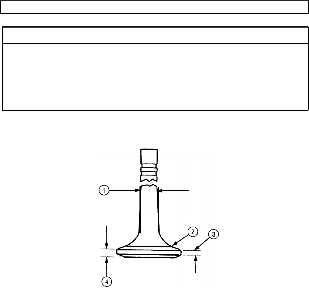
a. Valve Specifications
NOTE
Hard-faced exhaust valves are marked by letters “EX” or “HF”
in recessed area of valve head. Intake valves are not marked.
Use table 5-l for solid valves
Sodium-filled valves are not used in Cummins engines.
5-18
TM 9-2320-272-24-4
5-4. INTAKE AND EXHAUST VALVES REFACING
(Contd)
Table 5-1. Valve Specifications.
Ref.
Intake and
New
New
Exhaust Valves Minimum Maximum
1
Stem 0.4500 in. 0.4510 in.
(11.4300 mm) (11.4554 mm)
2
Seat angle
30° 30°
3
Refacing depth 0.0625 in.
(1.59 mm)
4
Valve head thickness 0.105 in.
(2.67 mm)
Worn
limits
0.4990 in.
(11.4046 mm)
0.0625 in
(1.59 mm)
0.105 in.
(2.67 mm)
5-19
TM 9-2320-272-24-4
5-4. INTAKE AND EXHAUST VALVES REFACING (Contd)
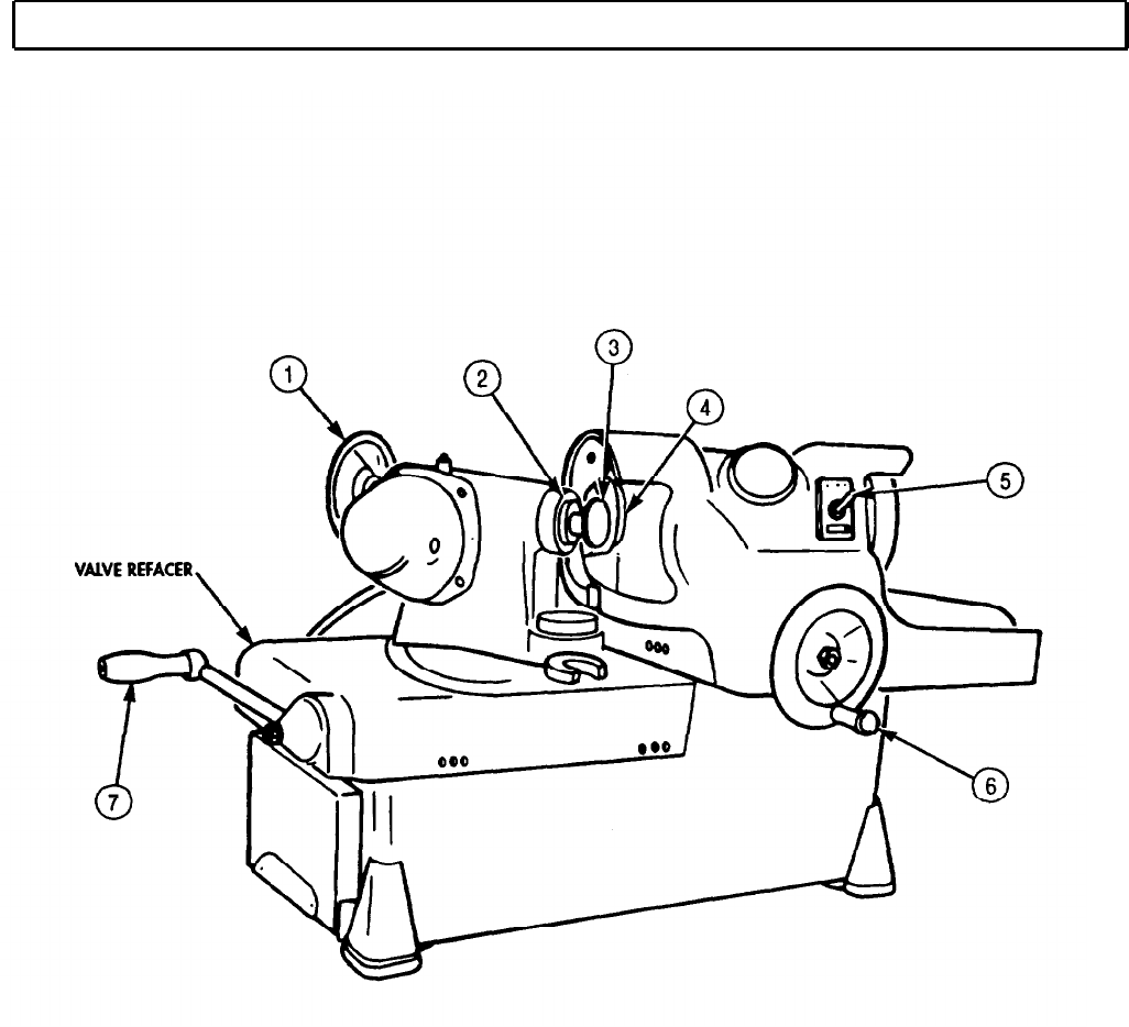
1.
2.
3.
4.
5.
6.
7.
8.
9.
10.
11.
12.
NOTE
Mark on ground face of valve. Mark is used to determine head
or stem warpage.
For operating instructions of valve refacer, refer to
TM 9-4910-484-10.
Install valve (3) stem in chuck (2).
Turn switch (5) of valve refacer to ON to start valve grinder electric motor.
NOTE
An out-of-round condition of valve will be marked by a small
bright spot on valve seating surface of valve head.
Turn grinder wheel handle (6) and very lightly touch valve (3) face with grinder wheel (4).
Move grinder wheel (4) away from valve head and switch valve grinder electric motor to OFF with
valve refacer switch (5).
Indicate location of small bright spot on ground face of valve (3).
Rechuck valve (3) 180° from first position and mark new position on valve (3).
Turn valve refacer switch (5) to ON to start valve refacer electric motor.
Turn grinder wheel (4) handle (6) and very lightly touch valve (3) face with grinder wheel (4).
Move grinder wheel (4) away from valve (3) head and switch grinder electric motor to OFF with
switch (5).
If bright spot is in the same position after both chucking operations, the valve (3) is warped. If valve (3)
is warped, replace valve (3).
If bright spots occur in different positions, the chuck (2) is out of alignment or the valve (3) is being
incorrectly chucked. Run-out should not exceed 0.0001 in. (0.0254 mm).
NOTE
Use valve refacer handle for left and right motion of valve.
Wet grind valves (3) to an exact 30° angle from horizontal and check valve (3) head rim thickness
with wheel handle (7) controlling depth of grind (table 5-l).
NOTE
Keep valves in order in a numbered valve stick or board.
NOTE
Do not use cloth to wipe valves clean.
1.
Clean refaced valves (3). For general cleaning instructions, refer to para. 2-14.
5-20
TM 9-2320-272-24-4
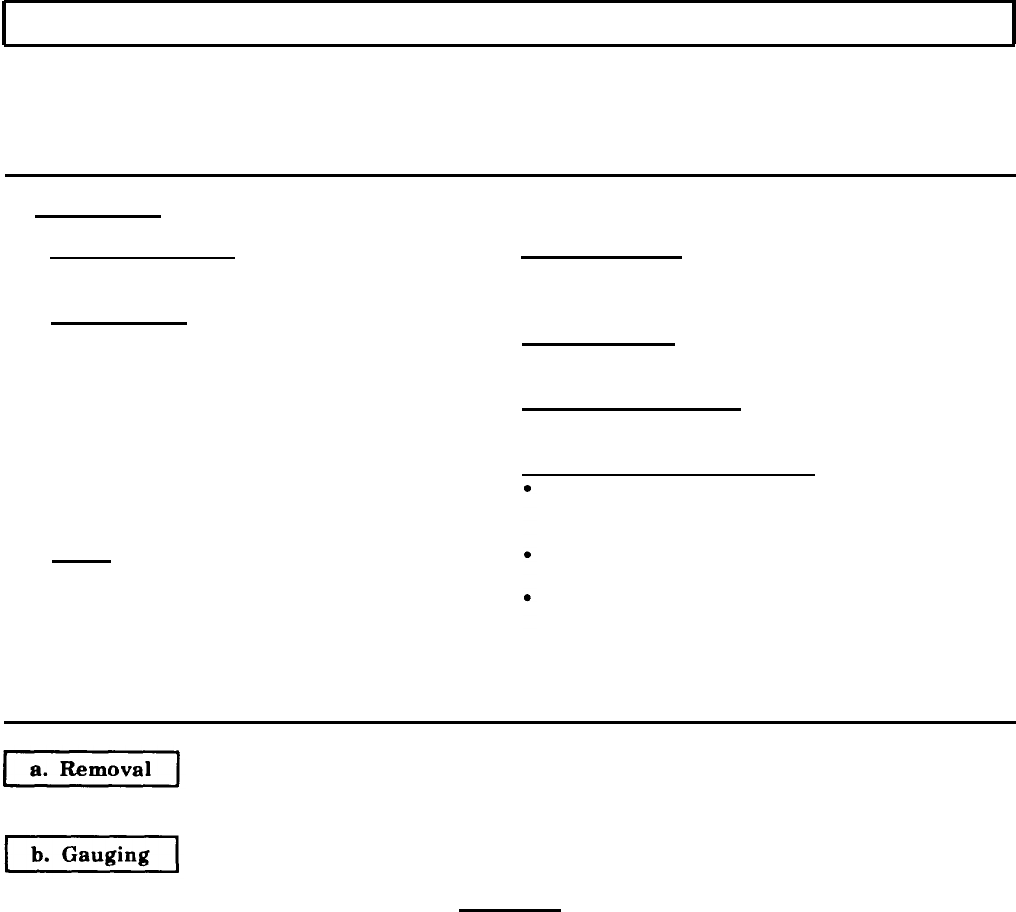
5-5. VALVE SEAT INSERTS MAINTENANCE
THIS TASK COVERS:
a. Removal
b. Gauging
c. Counterboring
d. Cleaning
e. Installation
INITIAL SETUP:
APPLIABLE MODELS
M939/Al
MATERIALS/PARTS
Valve seat inserts (Appendix D, Item 708)
SPECIAL TOOLS
Valve seat insert tool (Appendix E, Item 158)
Cutter seat (Appendix E Item 34)
Drycleaning solvent (Appendix C, Item 71)
REFERENCES (TM)
TM 9-2320-272-24P
Valve guide arbor (mandrel set) (Appendix E,
Item 154)
EQUIPMENT CONDlTlON
Tool driver (Appendix E, Item 140) Cylinder head disassembled (para. 5-3).
Valve seat insert staking tool (Appendix E,
Item 157)
GENERAL SAFETY INSTRUCTIONS
Valve seat insert extractor (Appendix E, When cleaning with compressed air, wear
Item 156) eyeshields and ensure source pressure does not
TOOLS
exceed 30 psi (207 kPa).
Keep fire extinguisher nearby when using
General mechanic’s tool kit (Appendix E, Item 1) drycleaning solvent.
Inside micrometer (Appendix E, Item 82) Drycleaning solvent is flammable and toxic. Do
Outside micrometer (Appendix E, Item 80) not use near an open flame.
Vernier calipers (Appendix E, Item 159)
Depth gauge (Appendix E, Item 81)
Brush
Electric drill
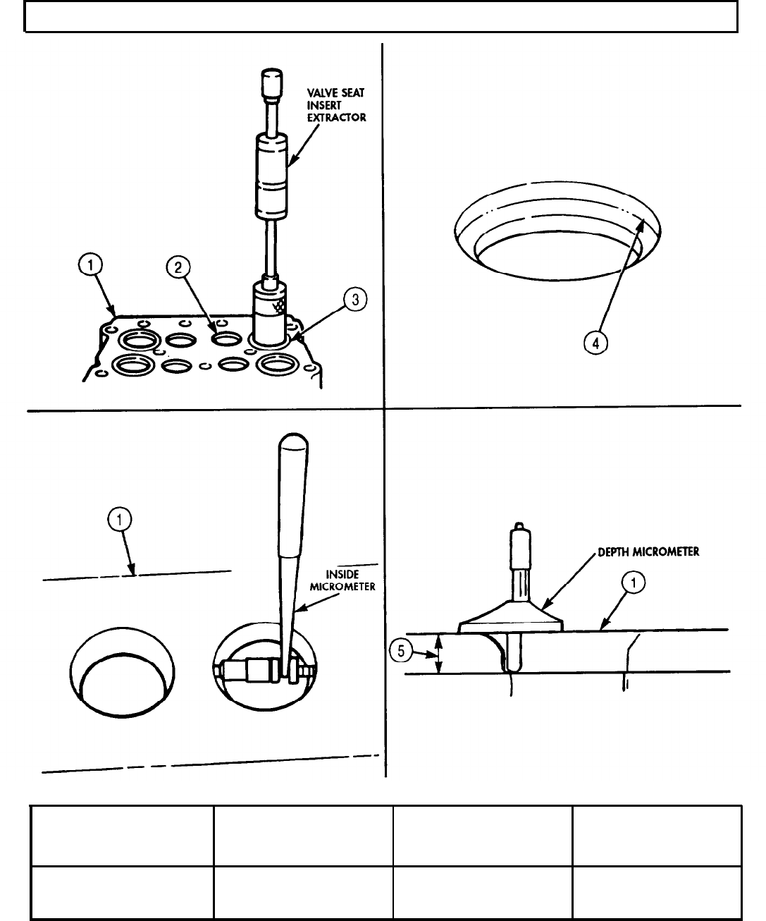
1.
Pull valve seat insert (3) from bore (2) on cylinder head (1) with valve seat insert extractor tool.
CAUTION
Each replacement valve seat insert outside diameter and
thickness must be measured and compared to relating valve seat
insert counterbore in the cylinder head before counterboring.
These measurements will prevent over-boring and damage to the
cylinder head.
1.
Measure outside diameter of valve seat insert (3) using micrometer. Record reading and compare
with specifications in table 5-2.
2.
Measure thickness of valve seat insert (3). Record reading and compare with specifications in table
5-2.
3.
Measure valve seat counterbore (4) depth (5) with depth micrometer. Record reading and compare to
specifications in table 5-2.
4.
Measure valve seat insert counterbore (4) inside diameter with inside micrometer. Record reading
and compare to specifications in table 5-2.
5-22
TM
9-2320-272-24-4
5-5. VALVE SEAT INSERTS MAINTENANCE
(Contd)
Table 5-2. Valve Seat Specifications.
CYLINDER HEAD
VALVE SEAT
COUNTERBORE DEPTH
Standard
CYLINDER HEAD
INSERT COUNTERBORE INSERT
OUTSIDE DIAMETER INSIDE DIAMETER THICKNESS
2.0025 - 2.0035 in. 1.9995 - 2.0005 in. 0.278 - 0.282 in.
(50.864 - 50.889 mm) (50.787 - 50.813 mm) (7.0612 - 7.1629 mm)
5-23
TM 9-2320-272-24-4
5-5. VALVE SEAT INSERTS MAINTENANCE (Contd)
c. Counterboring
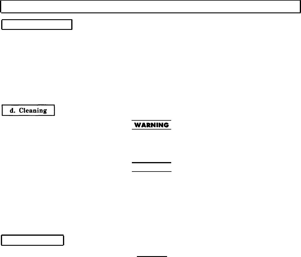
1.
Clamp base (2) of counterbore cutter (7) to cylinder head (3) near valve insert seat bore (4). Ensure
counterbore cutter (7) is securely clamped before starting electric drill motor (1).
NOTE
Allow cutter to turn several revolutions at exact moment the
proper depth in cylinder head is reached to ensure a perfectly flat
bottom of bore for valve seats to seat.
2.
Center counterbore cutter (7) in valve seat insert bore (4) and valve guide mandrel (6).
3.
Cut counterbore (5) 0.006-0.010 in. (0.1524-0.2540 mm) deeper than valve seat insert thickness to
allow staking (peening) of cylinder head (3) to secure valve seat insert.
Eyeshields must be worn when cleaning with compressed air.
Compressed air source will not exceed 30 psi (207 kPa). Failure to
do so may result in injury to personnel.
1.
Blow cylinder head (3) out with compressed air.
WARNING
Drycleaning solvent is flammable and toxic. Do not use near open
flame and always have a fire extinguisher nearby when solvents
are used. Use only in well-ventilated places, wear protective
clothing, and dispose of cleaning rags in approved container.
Failure to do this may result in injury or death to personnel and/or
damage to equipment.
2.
Clean opening and ports of cylinder head (3) with brush and drycleaning solvent.
3.
Dry cylinder head (3) with compressed air.
e. Installation
CAUTION
Valve seat inserts may be installed one time only. If valve seat
insert is not properly installed the first time, a new valve seat
insert must be installed.
NOTE
Keep valve seat inserts in cold storage until ready to install in
cylinder head. Install valve seat insert very quickly so room
temperature does not have a chance to expand insert and make it
difficult to install.
1.
Drive valve seat insert (9) into valve seat insert bore (4) with valve seat insert tool until fully seated.
2.
Stake (peen) valve seat insert (10) into cylinder head (3) with valve seat insert tool and valve seat
insert staking tool.
5-24
TM 9-2320-272-24-4
5-6. FUEL INJECTOR SLEEVE MAINTENANCE
THIS TASK COVERS:
a. Removal
b. Bead Cutting
c. Installation
d. Fitting and Forming
e. Check and Test
INITIAL SETUP:
APPLICABLE MODELS
M939lAl
SPECIAL TOOLS
Bead cutting tool (Appendix E, Item 9)
Injector sleeve expander tool (Appendix E,
Item 73)
Injector sleeve cutter (Appendix E, Item 72)
Injector protrusion gauge (Appendix E, Item 53)
Injector sleeve holding tool (Appendix E,
Item 74)
Injector sleeve installation mandrel (Appendix
E, Item 75)
Injection sleeve extractor (Appendix E,
Item 67)
TOOLS
General mechanic’s tool kit (Appendix E, Item 1)
Torque wrench (Appendix E, Item 146)
Dial indicator (Appendix E, Item 36)
Drill press
MATERIALS/PARTS
Injector sleeve (Appendix D, Item 257)
Injector sleeve O-ring (Appendix D, Item 478)
Cutting oil (Appendix C, Item 26)
Lubricating oil (Appendix C, Item 50)
Prussian blue (Appendix C, Item 54)
REFERENCES (TM)
TM 9-2320-272-24P
EQUIPMENT CONDITION
Cylinder head disassembled (para. 5-3).
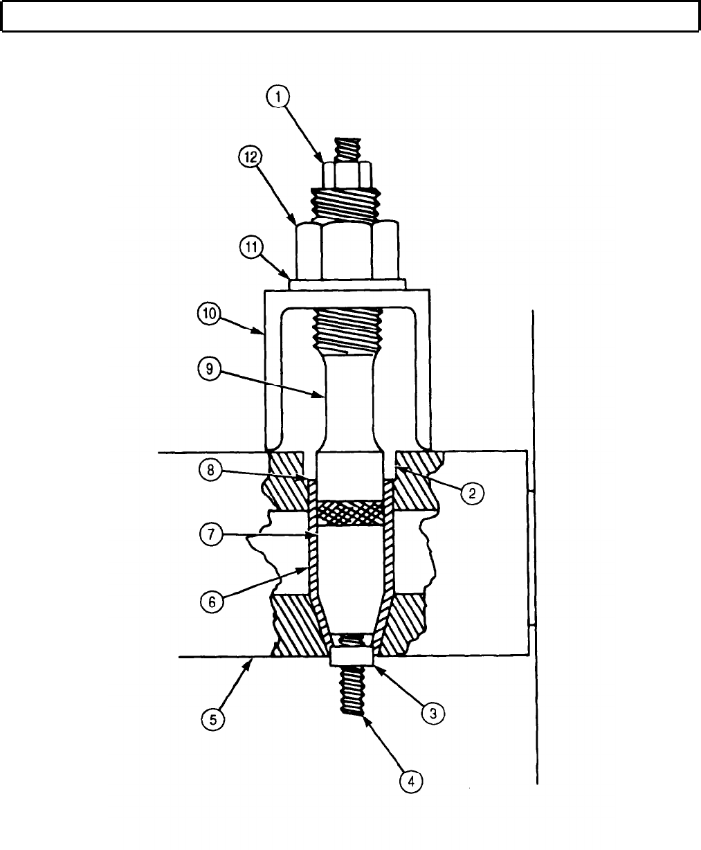
1.
2.
3.
4.
5.
6.
7.
8.
Place cylinder head (5) on workbench with exhaust manifold side down.
Insert tapered end of lower puller collar (7) into injector sleeve (6).
Insert upper puller collar (9) on top of collar (7) with threaded end out.
Position support bridge (10) over threaded end of collar (9) with one hand holding support
bridge (10) legs against cylinder head (5) and install washer (11) and nut (12). Tighten nut (12)
finger tight.
While holding support bridge (10) insert threaded rod (4) through holes in collars (7) and (9).
Install hex nut (1) and extractor tip (3) on threaded rod (4) and tighten. Ensure extractor tip (3) is
seated firmly against injector sleeve (6) bottom.
Tighten nut (1) to remove injector sleeve (6). Discard injector sleeve (6).
Remove O-ring (8) from injector sleeve bore (2). Discard O-ring (8).
5-26
TM 9-2320-272-24-4
5-6. FUEL INJECTOR SLEEVE MAINTENANCE (Contd)
5-27
TM 9-2320-272-24-4
5-6. FUEL INJECTOR SLEEVE MAINTENANCE (Contd)
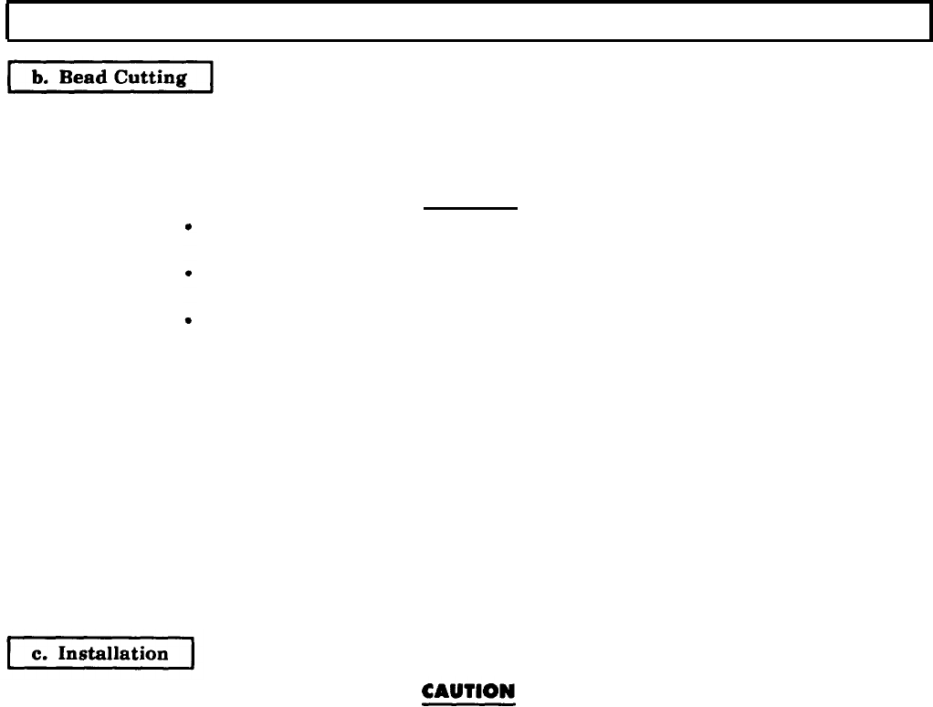
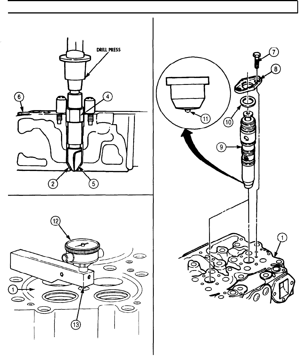
1.
Insert cylinder head (5) cutter (3) and cutter pilot (2) into injector sleeve bore (6).
2.
Position holder (1) to cutter (3).
3.
Set cylinder head (5) on table of drill press.
CAUTION
Tool chatter may occur if drill speed is higher than 75 rpm,
causing damage to cylinder head.
Do not cut more than 0.010 in. (0.254 mm) deep into cylinder
head.
Cutter must be sharp to prevent bead damage.
NOTE
Press may be turned by hand for light cuts or to prevent
accidental removal of too much material.
4.
Set drill press speed no higher than 75 rpm.
5.
Lift holder (1), pilot (2), and cutter (3) and apply cutting oil to lubricate cutter (3).
6.
Turn drill press motor on and take a very light cut. When the proper cut depth has been reached,
allow cutter (3) to dwell ten seconds to ensure a good seat and to clean the groove.
7.
Remove holder (1), pilot (2), and cutter (3) from injector sleeve bore (6).
8.
Apply Prussian blue to coat seat end of new injector sleeve (7) and insert new injector sleeve (7) in
injector sleeve bore (6) until fully seated.
9.
Remove new injector sleeve (7) from injector sleeve bore (6). Ensure blueing shows a complete 360°
band on both the injector sleeve (7) and seat (4).
Ensure sleeve seat at bottom of injector bore is free from oil,
carbon, or other foreign materials.
1.
Apply lubricating oil to coat new O-ring (10).
2.
Install new O-ring (10) into groove (11) of injector sleeve bore (6).
NOTE
Ensure mandrel is not struck with a hammer during this
operation.
3.
Use injector sleeve mandrel to push the new injector sleeve (7) into injector sleeve bore (6) until it
bottoms.
4.
Remove mandrel from injector sleeve bore (6).
5.
Install injector sleeve holding tool (8) in cylinder head (5). Tighten nut (9) 35-40 lb-ft
(48-54 N•m)
6.
Insert injector sleeve mandrel into injector sleeve bore (6) and drive injector sleeve (7) in with soft-
faced hammer until seated.
7.
Retighten nut (9) 35-40 lb-ft (48-54 N•m).
5-28
TM 9-2320-272-24-4
5-6. FUEL INJECTOR SLEEVE MAINTENANCE
(Contd)
5-29
TM 9-2320-272-24-4
5-6. FUEL INJECTOR SLEEVE MAINTENANCE
(Contd)
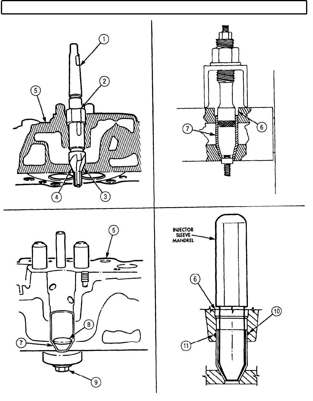
CAUTION
Do not roll lower area of injector sleeve which will cause
distortion of total sleeve.
Over-rolling of injector sleeve will cause deformation of sleeve
into O-ring groove.
1.
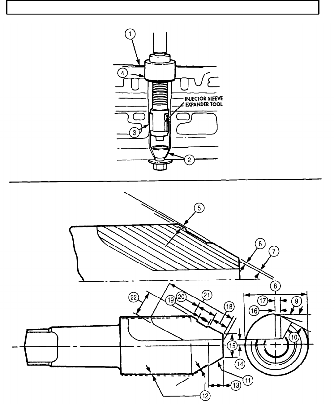
Position injector sleeve expander tool into injector sleeve (2) in cylinder head (1).
2.
Turn thrust nut (4) to adjust depth of expander tool so that roller (3) extends 0.5 in. (12.7 mm) into
sleeve (2).
3.
Lock thrust nut (4) in place using an Allen wrench.
4.
Push expander tool down, turn, and adjust until 75 lb-in. (8.5 N-m) maximum is reached.
NOTE
Form cutter per specifications in table 5-3.
Table 5-3. Cutter Specifications.
Item
5
6
7
8
9
10
11
12
13
14
15
16
17
18
19
20
21
22
In.
0.080
0.090
0.0015
0.0025
0.0077
0.0097
1.0615
1.0635
15° angle relief
15° angle relief
30° 9’ angle relief
0.375
0.312
0.125
0.375
0.010
0.0937
0.384
0.386
0.226
0.236
0.3425
1.250
0.375
(MM)
(2.0320)
(2.2860)
(0.0381)
(0.0635)
(0.1955)
(0.2463)
(26.9621)
(27.0129)
(9.5250)
(7.9375)
(3.1750)
(9.5250)
(0.2540)
(2.3812)
(9.7536)
(9.8044)
(5.7404)
(5.9944)
(8.6995)
(31.7500)
(9.5250)
5-30
TM 9-2320-272-24-4
5-6. FUEL INJECTOR SLEEVE MAINTENANCE
(Contd)
I
5-31
TM 9-2320-272-24-4
5-6. FUEL INJECTOR SLEEVE MAINTENANCE
(Contd)
5.
Size, grind, and inspect injector sleeve seat cutter (5) and ensure it is ground to exact contours
listed in table 5-3.
NOTE
Use a solid stream of clean cutting oil to allow injector sleeve
seat cutter to cut freely without grabbing.
Proper seating and protrusion of injector sleeve seat cutter are
checked in task e.
6.
Install injector sleeve seat cutter (5) on head (6) and use in drill press with pilot (4) to cut injector
sleeve (2) just enough to provide for proper seating of injector and to maintain correct injector tip
protrusion.
e. Check and Test
1.
2.
3.
4.
5.
6.
NOTE
Steps 1 through 4 check injector cup seating pattern in injector.
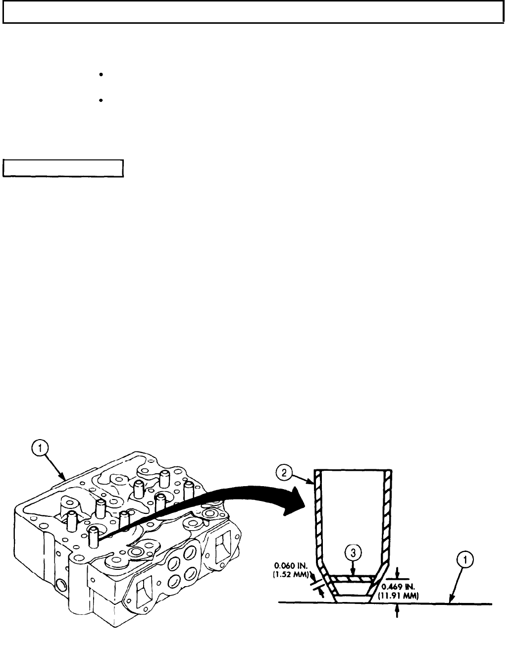
Apply light coat of Prussian blue to injector cup (11) and install injector assembly (9) into cylinder
head (1) with washer (10), clamp (8), and two screws (7). Tighten screws (7) alternately in
4lb-ft (5 N•m) steps to l0-12 lb-ft (14-16 N•m).
Remove two screws (7), clamp (8), washer (l0), and injector assembly (9) from cylinder head (1).
Check seat pattern in bottom of injector sleeve (2) cup seating area.
If blued band (3) on injector sleeve (2) seating area is not at least 0.060 in. (1.52 mm) wide and
located approximately 0.469 in. (11.91 mm) from bottom of cylinder head (1) surface, regrind
injector sleeve (2) seating area as described in steps 5 and 6 of task f.
Install injector assembly (9) in injector sleeve (2) in injector head (1) with clamp (8), washer (10),
and two screws (7). Tighten screws (7) alternately in 4 lb-ft (5 N•m) steps to 10-12 lb-ft. (14-16 N•m).
Check protrusion of injector tip (13) using dial indicator (12).
a. If injector tip (13) protrusion exceeds 0.070 in. (1.78 mm), install new injector sleeve (2).
b. If injector tip (13) protrusion is less than 0.060 in. (1.52 mm), regrind injector sleeve (2).
5-32
TM 9-2320-272-24-4
5-7. CYLINDER LINERS AND BLOCK MAINTENANCE
THIS TASK COVERS:
a. Removal c. Cleaning and Inspection
b. Disassembly d. Cylinder Liners Installation
INITIAL SETUP:
APPLICABLE MODELS
M939/A1
SPECIAL TOOLS
REFERENCES (TM)
TM 9-2320-272-24P
EQUIPMENT CONDITION
Crankshaft and main bearings removed (para. 5-8).
Liner clamp set (Appendix E, Item 78)
Liner driver (Appendix E, Item 79)
TOOLS
General mechanic’s tool kit (Appendix E, Item 1)
Cylinder liner puller (Appendix E, Item 107)
Outside micrometer (Appendix E, Item 80)
Vernier calipers (Appendix E, Item 159)
Depth gauge (Appendix E, Item 81)
Gauge block (Appendix E, Item 52)
Dial indicator (Appendix E, Item 36)
Telescoping gauge set (Appendix E, Item 136)
Torque wrench (Appendix E, Item 144)
Feeler gauge
Hold-down tool
MATERIAL PARTS
GENERAL SAFETY INSTRUCTIONS
Keep fire extinguisher nearby when using
drycleaning solvent.
Drycleaning solvent is flammable and toxic. Do
not use near an open flame.
When cleaning with compressed air, wear
eyeshields and ensure source pressure does not
exceed 30 psi (207 kPa).
SPECIAL ENVIRONMENTAL CONDITIONS
Work area clean and free from blowing dirt and
dust.
Two lockwashers (Appendix, Item 349)
Suction flange gasket (Appendix D, Item 680)
Two O-rings (Appendix D, Item 460)
Crevice seal (Appendix D, Item 88)
Drycleaning solvent (Appendix C, Item 71)
Antiseize tape (Appendix C, Item 72)
Lint-free cloth (Appendix C, Item 21)
Lubricating oil OE/HDO (Appendix C, Item 50)
Detergent (Appendix C, Item 27)
NOTE
Tag all cylinder liners for installation.
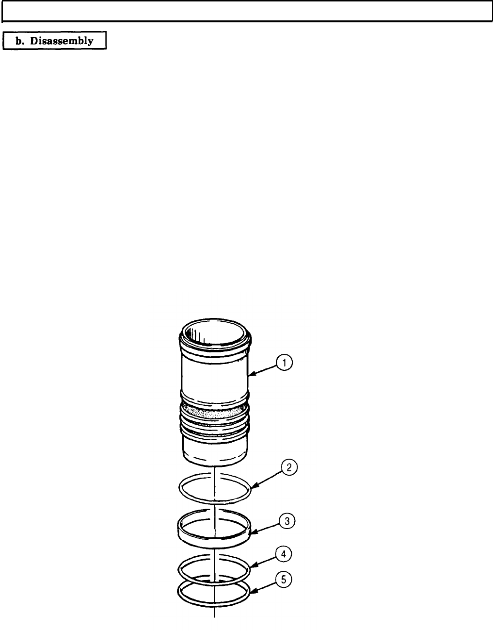
Remove six cylinder liners (1) from cylinder liner bores (2) with cylinder liner puller.
5-34

TM 9-2320-272-24-4
5-7. CYLINDER LINERS AND BLOCK MAINTENANCE (Contd)
5-35
TM 9-2320-272-24-4
5-7. CYLINDER LINERS AND BLOCK MAINTENANCE (Contd)
1.
2.
3.
4.
5.
6.
7.
8.
NOTE
All six cylinder liners are repaired the same way. This procedure
covers only one cylinder liner.
Remove upper and lower O-rings (4) and (5) and crevice seal (3) from cylinder liner (1). Discard O-
rings (4) and (5) and crevice seal (3).
Remove shim pack (2) from cylinder liner (1) and measure thickness with micrometer. Record
readings so same shim pack (2) thickness can be installed.
Tape shim pack (2) together and tag with corresponding cylinder liner (1) number. Hold shim
pack (2) for reassembly.
Place cylinder liner (1) on numbered rack and hold for cleaning and inspection.
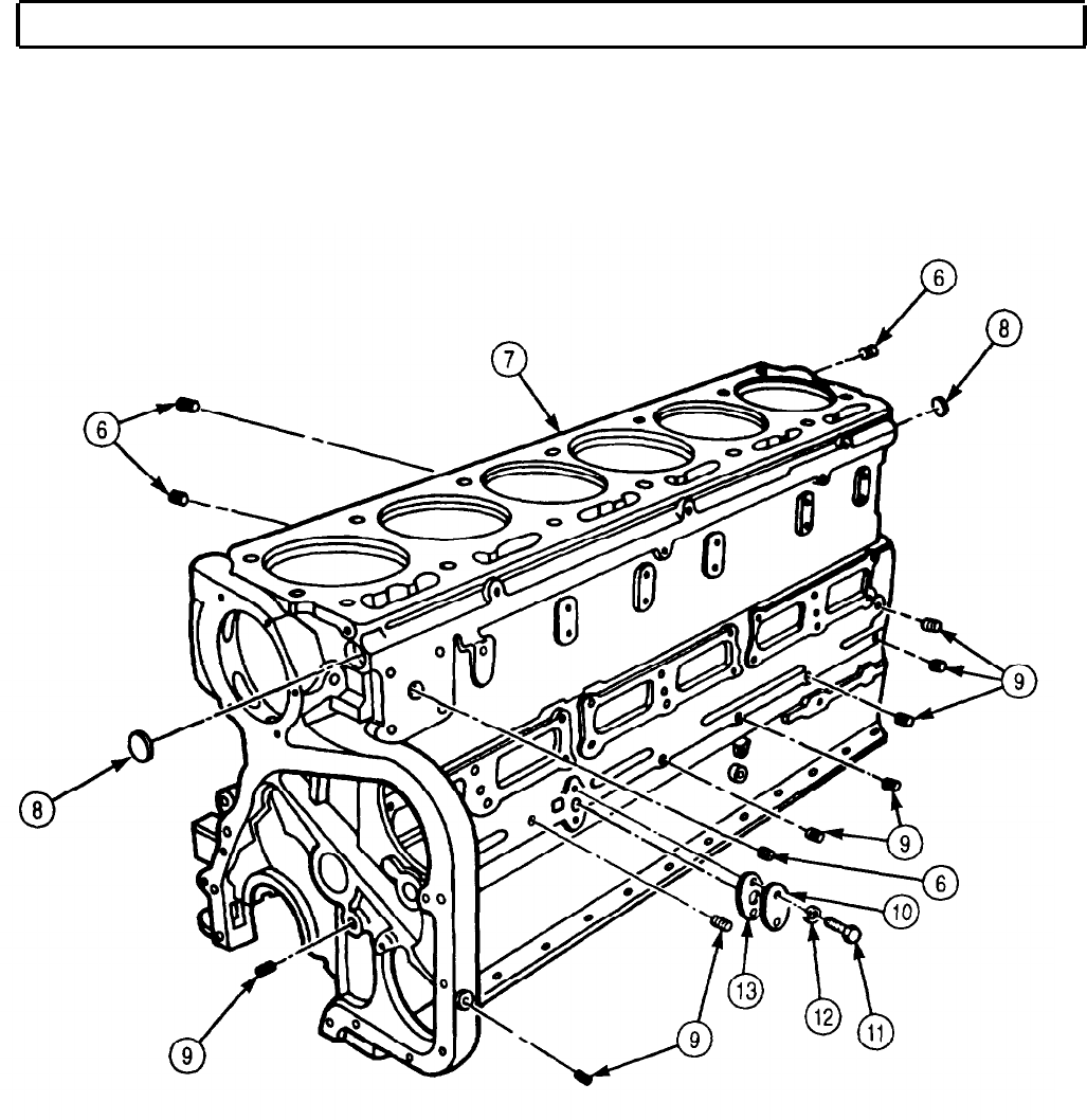
NOTE
Note location of plug removal for installation.
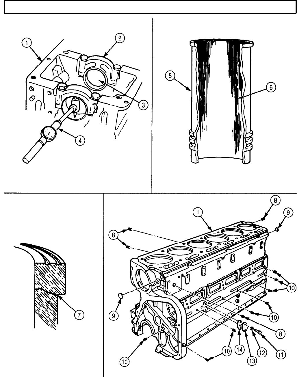
Remove four water passageway pipe plugs (6) from engine block (7).
Remove eight oil passageway pipe plugs (9) from engine block (7).
Remove two water passageway cup plugs (8) from engine block (7).
Remove two screws (11), lockwashers (12), suction flange plate (10), and gasket (13) from engine
block (7). Discard lockwashers (12) and gasket (13) and clean gasket remains from mating surfaces.
5-36
TM 9-2320-272-24-4
5-7. CYLINDER LINERS AND BLOCK MAINTENANCE (Contd)
5-37
TM 9-2320-272-24-4
5-7. CYLINDER LINERS AND BLOCK MAINTENANCE (Contd)
WARNING
Drycleaning solvent is flammable and toxic. Do not use near open
flame and always have a fire extinguisher nearby when solvents
are used. Use only in well-ventilated places, wear protective
clothing, and dispose of cleaning rags in approved container.
Failure to do this may result in injury or death to personnel and/or
damage to equipment.
1.
2.
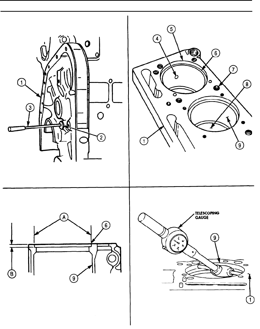
Clean engine block (1). Refer to para. 2-14 for general cleaning instructions.
Run rods (3) with brushes through all oil passages (2) in engine block (1).
3.
4.
5.
6.
7.
8.
9.
10.
11.
12.
13.
WARNING
Eyeshields must be worn when cleaning with compressed air.
Compressed air source will not exceed 30 psi (207 kPa). Failure to
do so may result in injury to personnel.
Blow oil passages (2) of engine block (1) clean with compressed air.
Clean water pump air bleed hole (4) in cylinder bore (5) with compressed air.
Blow all dirt and cleaning solvent from all engine block (1) screw holes (7).
Remove scale from liner counterbore ledge (6).
Clean carbon from lower liner bore (8) of engine block (1).
NOTE
Ensure engine block is on flat surface or workbench for inspection.
Refer to para. 2-15 for general engine block (1) inspection instructions.
Check engine block (1) for worn surfaces, pitting, corrosion, nicks, gouges, burrs, eroded waterholes,
damaged threads, distortion, and cracked areas.
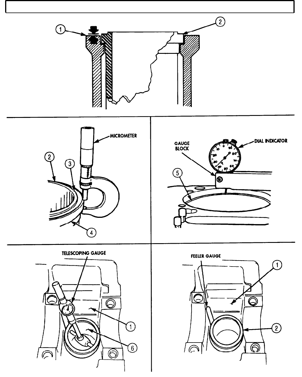
Inspect counterbore ledge (6) of cylinder liner counterbore (9) at points (A) and (B) to ensure
counterbore ledge (6) is 90° to liner bore.
Check counterbore diameter (A) and depth (B) to insure proper seating of cylinder liner and to
determine if machining of counterbore ledge (6) depth is necessary.
NOTE
If counterbore depth varies more than 0.001 in. (0.03 mm) at
several areas measured or counterbore slants downward toward
center of cylinder liner bore, counterbore ledge will need to be
refinished.
Steps 12 and 13 check engine block for possible counter-bore
distortion.
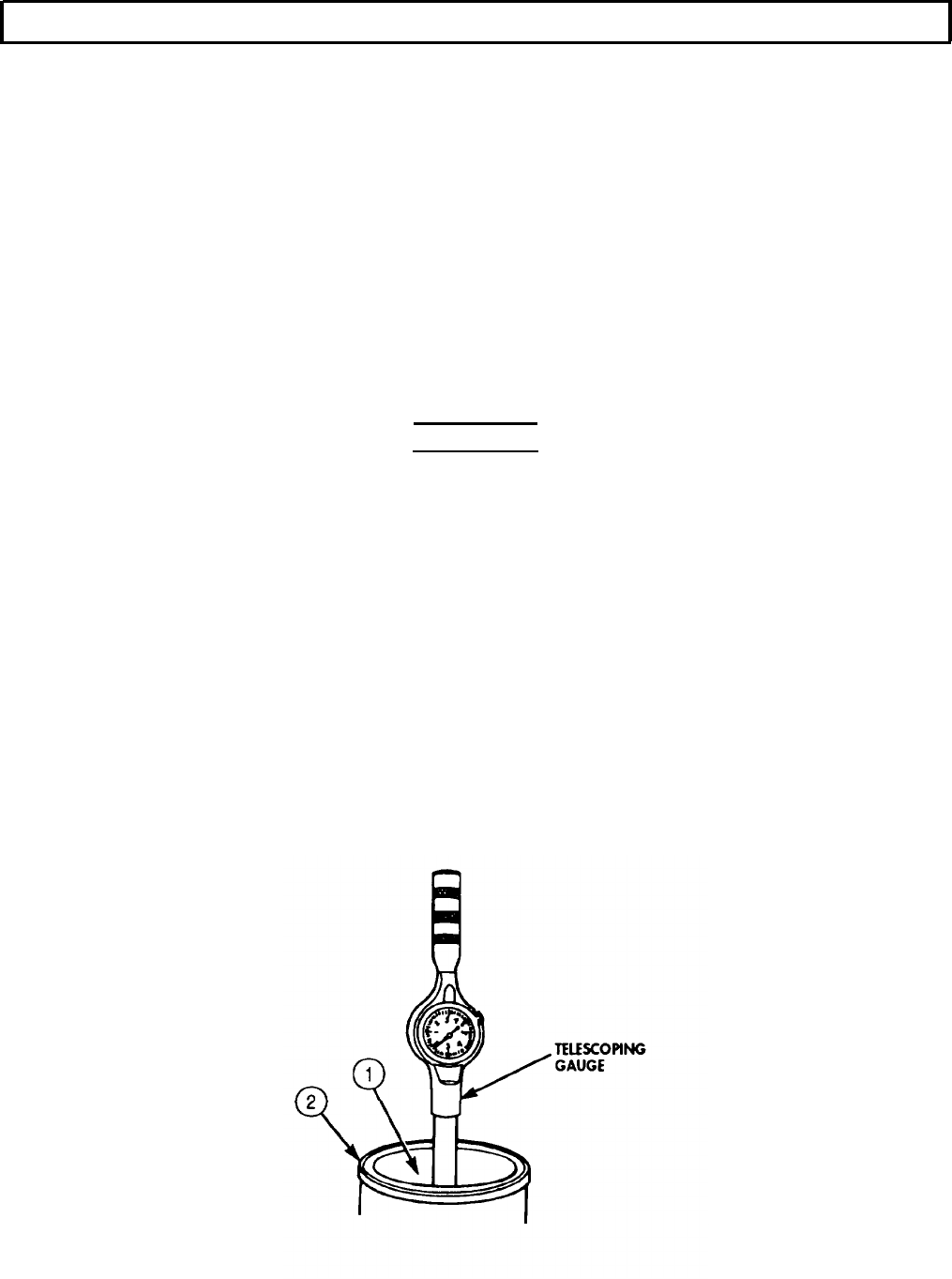
Position telescoping gauge in counterbore (9) and set dial to zero.
Move bore gauge around circumference of counterbore (9) and take readings at three intervals
of 120°. The difference in the readings will indicate amount of distortion. If specifications in
table 5-4 are exceeded, replace engine block (1).
5-38
TM 9-2320-272-24-4
5-7. CYLINDER LINERS AND BLOCK MAINTENANCE
(Contd)
5-39
TM 9-2320-272-24-4
5-7. CYLINDER LINERS AND BLOCK MAINTENANCE (Contd)
Table 5-4. Cylinder Liner Counterbore.
INSlDE DIAMETER DEPTH
New minimum . . . . . . . . . . . . . . . . . . . . . . . . 6.5615 in. 0.350 in.
(166.662 mm) (8.89 mm)
New maximum . . . . . . . . . . . . . . . . . . . . . . . . 6.5635 in. 0.352 in.
(166.713 mm) (8.94 mm)
Wear limit . . . . . . . . . . . . . . . . . . . . . . . . . . . . 0.412 in.
(10.56 mm)
14.
Ensure cylinder liners (2) protrude 0.003-0.006 in. (0.08-0.15 mm) above the engine block (1) when
they are properly installed.
NOTE
Shims are used to compensate for counterbore depth wear.
Steps 15 through 17 check cylinder liner for proper protrusion
without installing a cylinder liner.
15.
Measure cylinder liner (2) outside flange (4) with micrometer. Do not include bead (3) when taking
measurements.
16.
Measure counterbore ledge (5) depth with gauge block. Ensure counterbore ledge (5) is smooth and
not “cupped” more than 0.0014 in. (.036 mm). Depth must not vary more than 0.001 in. (0.254 mm).
17.
Subtract counterbore depth from cylinder liner (2) outside flange (4) depth to determine amount of
shims or depth of counterbore cut to be made to obtain 0.0036-0.006 in. (0.08-0.15 mm) liner
protrusion.
18.
Install cylinder liner (2) and clamps in engine block (1) without O-rings or crevice seal. Ensure
clamps are installed so there is equal pressure on liner. Tighten clamps 50 lb-ft (68 N•m).
19.
Use feeler gauge to check clearance between lower liner (2) and engine block (1). If clearance is not
within limits specified in table 5-5, check lower O-ring groove inside diameter in engine block (1).
20.
Remove cylinder liner (2) from engine block (1).
21.
Use telescoping gauge to check lower liner bore (6) in engine block (1). Bore (6) should be within
limits set in table 5-5.
Table 5-5. Lower Liner Bore Inside Diameter and Block Clearance.
MINIMUM
Lower liner bore inside diameter . . . . . . . . . . . . . . . 6.124 in.
(155.55 mm)
Lower liner to block clearance . . . . . . . . . . . . . . . . . 0.002 in.
(0.05 mm)
MAXIMUM
6.126 in.
(155.60 mm)
0.006 in.
(0.15 mm)
5-40
TM 9-2320-272-24-4
5-7. CYLINDER LINERS AND BLOCK MAINTENANCE
(Contd)
5-41
TM 9-2320-272-24-4
5-7. CYLINDER LINERS AND BLOCK MAINTENANCE (Contd)
22.
Install main bearing caps (2) in engine block (1) without crank or bearing shells.
23.
Measure main bearing bore diameter (3) horizontally, vertically, and diagonally with telescoping
gauge (4). Ensure bore diameter does not exceed 4.75 in. (120-663 mm).
NOTE
Pipe plugs, cup plugs, and suction flange plate are installed at this
time to keep passages clean. Wrap pipe plug threads with sealing
tape to prevent leakage.
24.
Install two cup plugs (9) in engine block (1).
25.
Install four pipe plugs (8) in block (1) and tighten according to table 5-6.
26.
Install eight pipe plugs (10) in block (1) and tighten according to table 5-6.
27.
Install new gasket (14) and suction flange plate (13) on engine block (1) with two new
lockwashers (12) and screws (11). Tighten screws (11) 10-15 lb-ft (14-20 N•m).
Table 5-6. Engine Block Pipe Plug Torque.
PIPE PLUG SIZE
1/8 in.
15
(20)
1/4 in.
30 (41)
3/8 in.
35 (47)
1/2 in.
45 (61)
3/4 in.
60 (81)
1-1/4 in.
75
(102)
1-1/2 in.
90
(122)
MINIMUM
LB-FT
(NM
MAXIMUM
LB-FT
(N•M)
20 (27)
35
(47)
45 (61)
55
(75)
70 (95)
85
(115)
100
(136)
NOTE
Most attempts to hone or deglaze cylinder liners provide worse
results than leaving them “as is”. Experience and laboratory
results indicate that liners do not need to be honed, rotated, or
deglazed to provide proper setting.
It is recommended that cylinder liners be inspected before
cleaning so defects can be clearly noted.
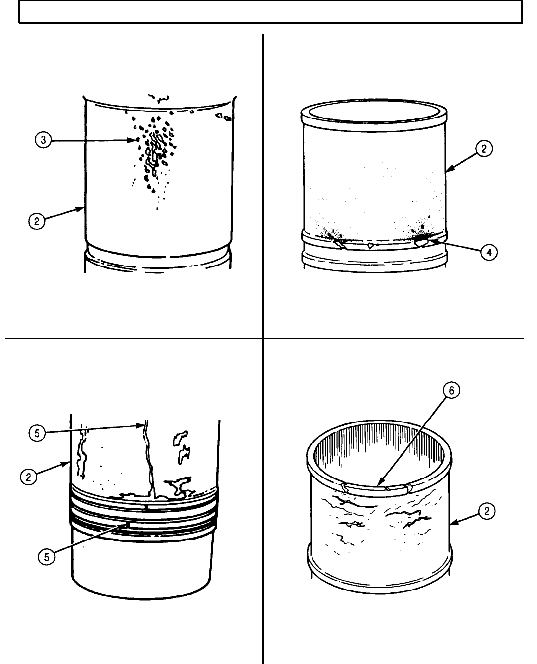
Inspect cylinder liners closely for any of the metal conditions
illustrated. If one liner has failed, then other liners in the same
engine are likely to have early signs of the same type of failure.
28.
Check cylinder liner (5) for scoring or vertical grooving (6) on the inside diameter indicating heavy
metal-to-metal contact of piston to cylinder liner (5). If scoring or vertical grooving (6) is present, tag
cylinder liner for replacement.
29.
Check cylinder liner (5) for cracks (7) indicated by magnetic detection. If cracks (7) are present, tag
cylinder liner (5) for replacement.
5-42
TM 9-2320-272-24-4
5-7. CYLINDER LINERS AND BLOCK MAINTENANCE (Contd)
5-43
TM 9-2320-272-24-4
5-7. CYLINDER LINERS AND BLOCK MAINTENANCE (Contd)
30.
31.
32.
33.
34.
35.
36.
37.
38.
39.
40.
41.
Check cylinder liner (2) for a series of pit erosions (3) on the thrust or antithrust side of the cylinder
liner (2) outside diameter. If pit erosions (3) are present, tag cylinder liner (2) for replacement.
Check cylinder liner (2) for visible cracks. As a rule, cylinder liners are highly resistant to vertical
cracks or breakage. If cracks are present, tag cylinder liner (2) for replacement.
Check cylinder liner (2) for eroded surface (4). Moving coolant contacting the cylinder liner (2)
outside diameter erodes the surface away and attacks the crevice seal. If surface is eroded (4),
tag cylinder liner (2) for replacement.
Check cylinder liner (2) for fretting of surfaces (6), and/or machined area. Top of cylinder liner
bead has worn away on illustrated cylinder liner (2). If surfaces (6) have fretted, tag cylinder
liner (2) for replacement.
NOTE
Do not use wire brush on cylinder liners.
Steam, clean, or wash cylinder liner (2) in hot water and detergent. Scrub with bristle brush.
Remove rust, scale, and corrosion from cylinder liner (2). If cylinder liner (2) is excessively rusted,
scaled, or corroded, replace.
WARNING
Eyeshields must be worn when cleaning with compressed air.
Compressed air source will not exceed 30 psi (207 kPa). Failure to
do so may result in injury to personnel.
Blow cylinder liner (2) dry with compressed air.
Apply generous coat of lubricating oil to cylinder liner (2) and let stand for five to ten minutes.
Wipe oil from cylinder liner bore (1) with heavy paper towel. Gray and black residue will appear on
towels.
Repeat steps 37 and 38 until black or gray residue no longer appears on towel.
Apply lubricating oil lightly to cylinder liners (2) and wrap cylinder liners (2). Store in clean, dry
location until installation.
NOTE
Cylinder liners must be checked at 60°-70°F (16°-21°C). New
cylinder liners with lubrite finish may be 0.0002-0.0006 in.
(0.005-0.015 mm) smaller than indicated due to lubrite coating.
Check liner bore (1) with telescoping gauge. If measurement exceeds 5.5050 in. (139.830 mm), tag
cylinder liner (2) for replacement.
5-44
TM 9-2320-272-24-4
5-7. CYLINDER LINERS AND BLOCK MAINTENANCE (Contd)
5-45
TM 9-2320-272-24-4
5-7. CYLINDER LINERS AND BLOCK MAINTENANCE (Contd)
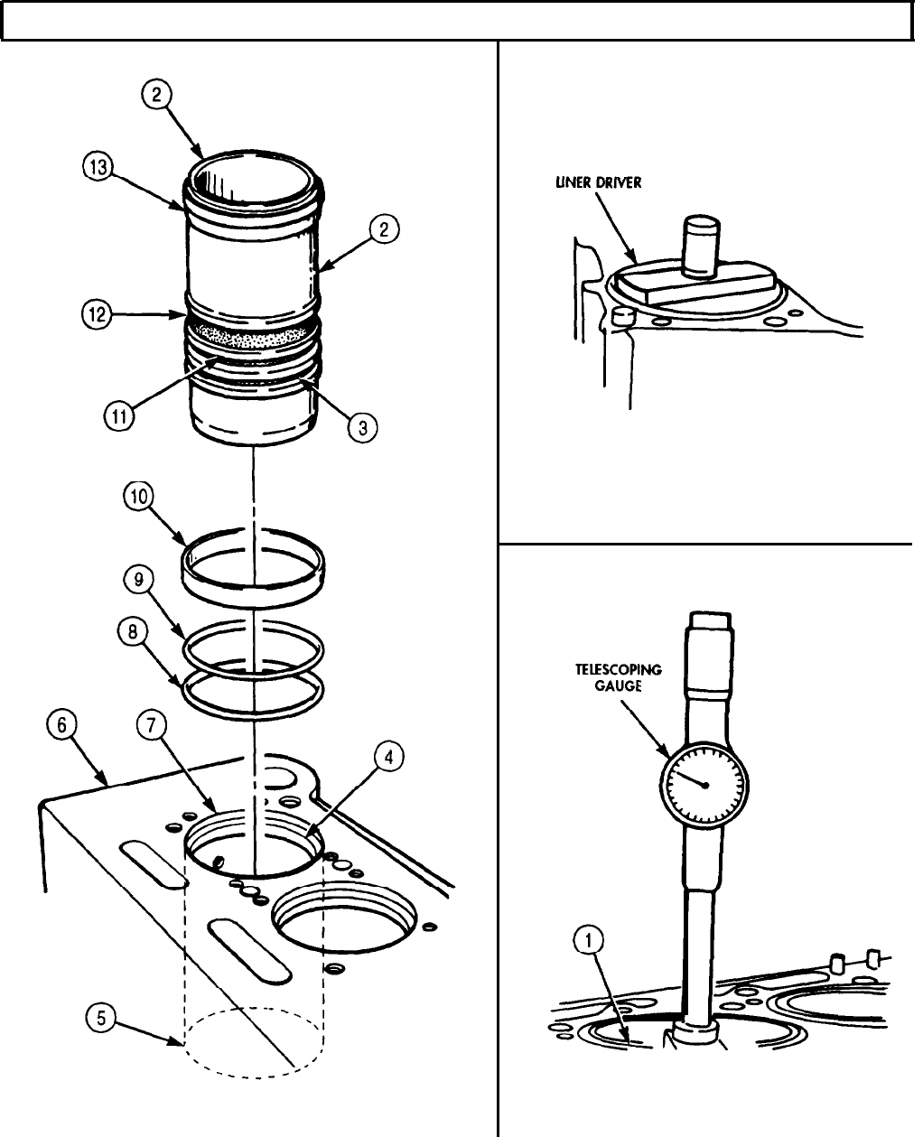
d. Cylinder Liners Installation
1.
Clean cylinder liner flange (2), crevice seal groove (12), and O-ring grooves (3) and (11) with lint-free
cloth.
2.
Install new crevice seal (10) in crevice seal groove (12). Ensure crevice seal (10) is straight and not
twisted.
3.
Install new black O-ring (9) in top O-ring groove (11) using molding mark as a guide. Ensure new
black O-ring (9) is straight and not twisted.
4.
Install new red O-ring (9) in bottom O-ring groove (3). Ensure new red O-ring (9) is straight and not
twisted.
5.
Clean cylinder bore (7), counterbore (4), and lower bore (5) and apply lubricating oil.
6.
Apply light coat of clean engine oil to crevice seal (11) and O-rings (8) and (9) and position cylinder
liner (1) in engine block (6) by hand. Take care not to dislodge O-rings (8) and (9) and crevice seal (10).
Press cylinder liner (1) in place using hand pressure.
NOTE
Install cylinder liner without shims until liner protrusion is
checked in step 8. It may be necessary to remove liners and add
shims.
7.
Drive cylinder liner (1) in with liner driver and liner clamp until cylinder liner flange (2) is seated.
Hold down with hold-down tool.
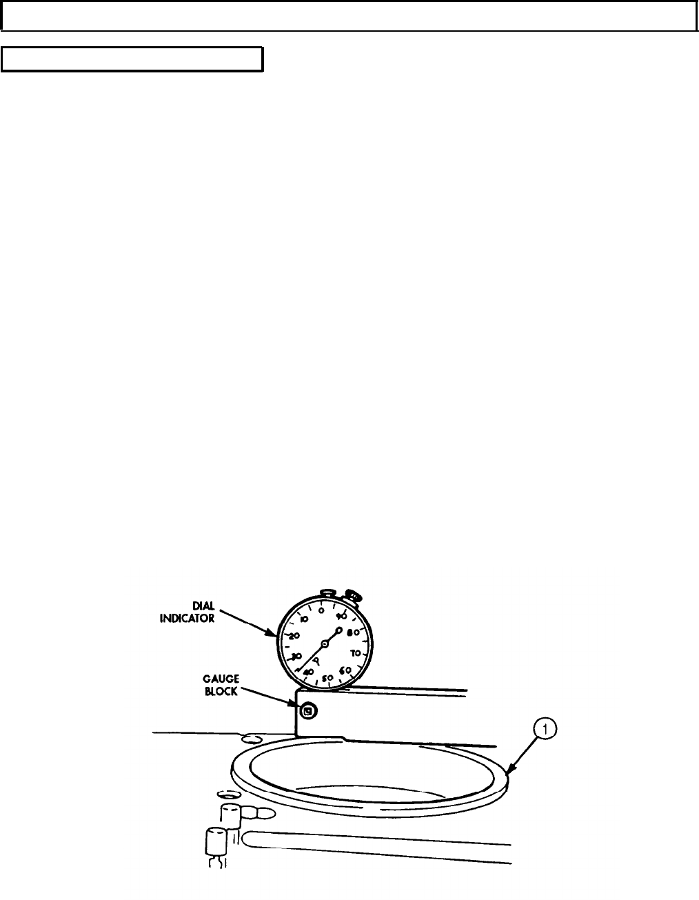
8.
Position dial indicator and gauge block on cylinder liner (1) and measure cylinder liner (1) protrusion.
If protrusion is not 0.003-0.006 in. (0.08-0.15 mm), add or remove shims and repeat task d.
NOTE
When performing step 9, if liner is more than 0.002 in. (0.05 mm)
out-of-round in lower bore O-ring area, remove liner and check for
cause of distortion. It is permissible to have 0.003 in. (0.08 mm)
out-of-round at the top 1 in. (25.4 mm) of liner bore.
9.
Position telescoping gauge in cylinder liner (1) and measure at several points within range
travel for out-of-round condition. If out-of-round, remove cylinder liner (1) and reinstall. of piston
5-46
TM 9-2320-272-24-4
5-8. CRANKSHAFT AND MAIN BEARINGS MAINTENANCE
THIS TASK COVERS:
a. Removal c. Installation
b. Cleaning and Inspection d. End Play Clearance
INITIAL SETUP:
APPLICABLE MODELS
M939/A1
TOOLS
General mechanic’s tool kit (Appendix E, Item 1)
Main bearing cap puller (Appendix E, Item 108)
Outside micrometer (Appendix E, Item 80)
Vernier caliper (Appendix E, Item 159)
Torque wrench (Appendix E, Item 144)
Dial indicator (Appendix E, Item 36)
Hoist
Rubber-protected hooks
MATERIALS/PARTS
Crankshaft main bearing set
(Appendix D, Item 87)
Thrust ring set (Appendix D, Item 682)
Fourteen lockplates (Appendix D, Item 341)
Woodruff Key (Appendix D, Item 738)
Fourteen dowel rings (Appendix D, Item 100)
Lint-free cloth (Appendix C, Item 21)
GAA grease (Appendix C, Item 28)
Lubricating oil (Appendix C, Item 50)
Drycleaning solvent (Appendix C, Item 71)
REFERENCES (TM)
TM 9-2320-272-24P
EQUIPMENT CONDITION
Connecting rod and pistons removed (para. 5-10).
GENERAL SAFETY INSTRUCTIONS
l Keep fire extinguisher nearby when using
drycleaning solvent.
l Drycleaning solvent is flammable and toxic. Do
not use near an open flame.
l When cleaning with compressed air, wear
eyeshields and ensure source pressure does not
exceed 30 psi (207 kPa).
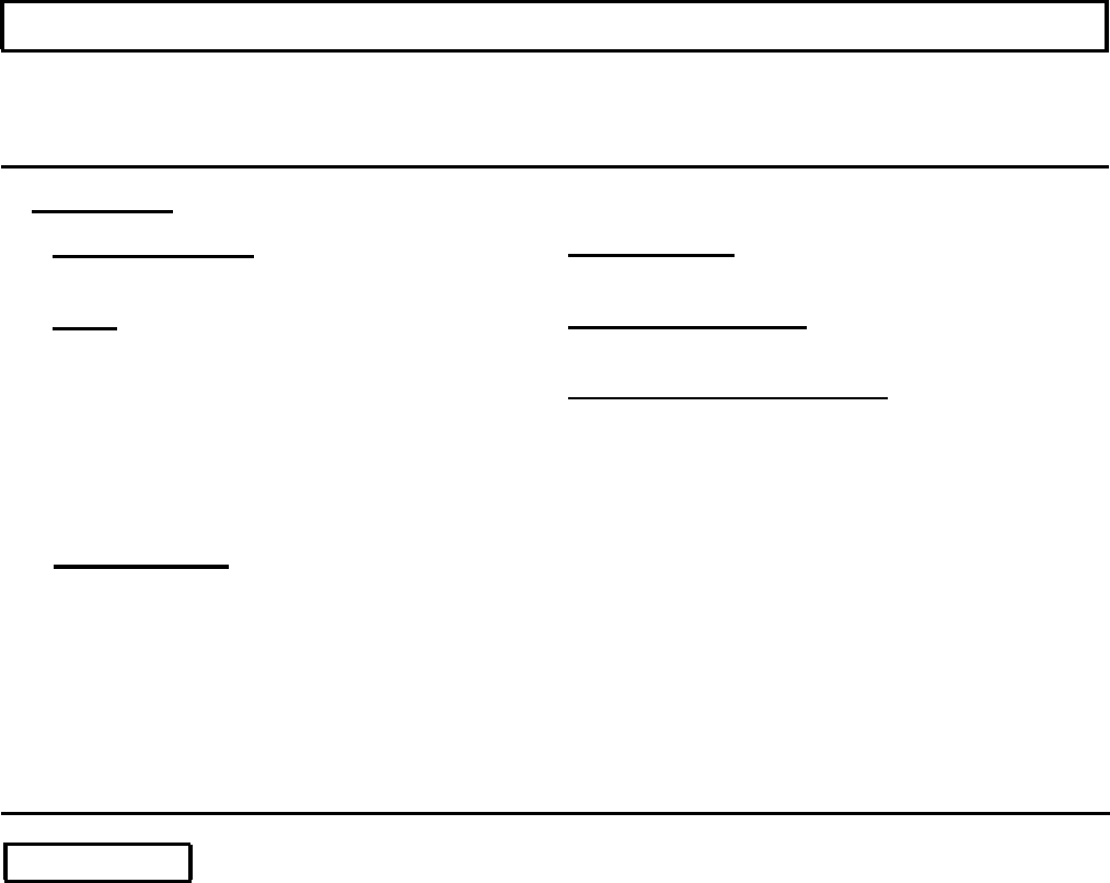
a. Removal
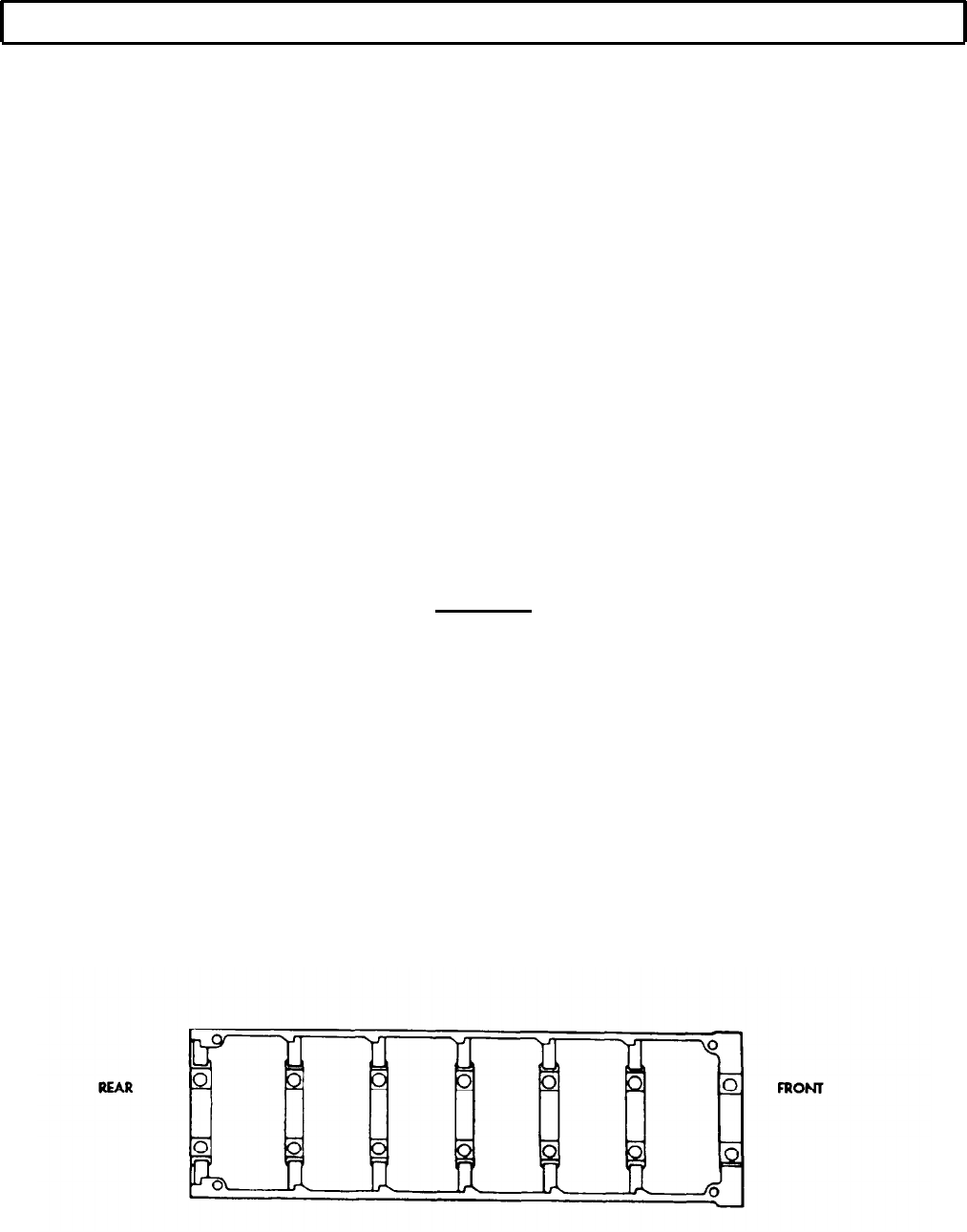
1.
Turn engine block (1) upside down.
2.
Bend down lockplate tab (8) and remove two screws (7) from seven main bearing caps (9). Discard
lockplates (8).
NOTE
Tag all bearing caps and bearing shells for installation.
3.
Remove main bearing caps (9) from engine block (1) with main bearing cap puller.
4.
Remove lower half bearing shell (10) from main bearing caps (9). Discard lower half bearing shell (10).
5.
Remove lower half of thrust ring (4) from crankshaft near journal (5). Discard thrust ring (4).
6.
Carefully remove crankshaft (6) from engine block (1) using hoist and rubber-protected hooks (11).
Place crankshaft (6) on clean, flat surface.
7.
Remove upper half bearing shells (2) from engine block (6). Discard upper half bearing shells (2).
8.
Remove fourteen dowel rings (3) from engine block (1). Discard dowel rings (3).
9.
Remove upper half of thrust ring (4) from engine block (1). Discard thrust ring (4).
5-48
TM 9-2320-272-24-4
5-8. CRANKSHAFT AND MAIN BEARINGS MAINTENANCE (Contd)
5-49

TM
9-2320-272-24-4
5-8. CRANKSHAFT AND MAIN BEARINGS MAINTENANCE (Contd)
b. Cleaning and Inspection
1.
2.
3.
4.
5.
6.
7.
8.
9.
10.
11.
12.
WARNING
Drycleaning solvent is flammable and toxic. Do not use near open
flame and always have a tire extinguisher nearby when solvents
are used. Use only in well-ventilated places, wear protective
clothing, and dispose of cleaning rags in approved container.
Failure to do this may result in injury or death to personnel and/or
damage to equipment.
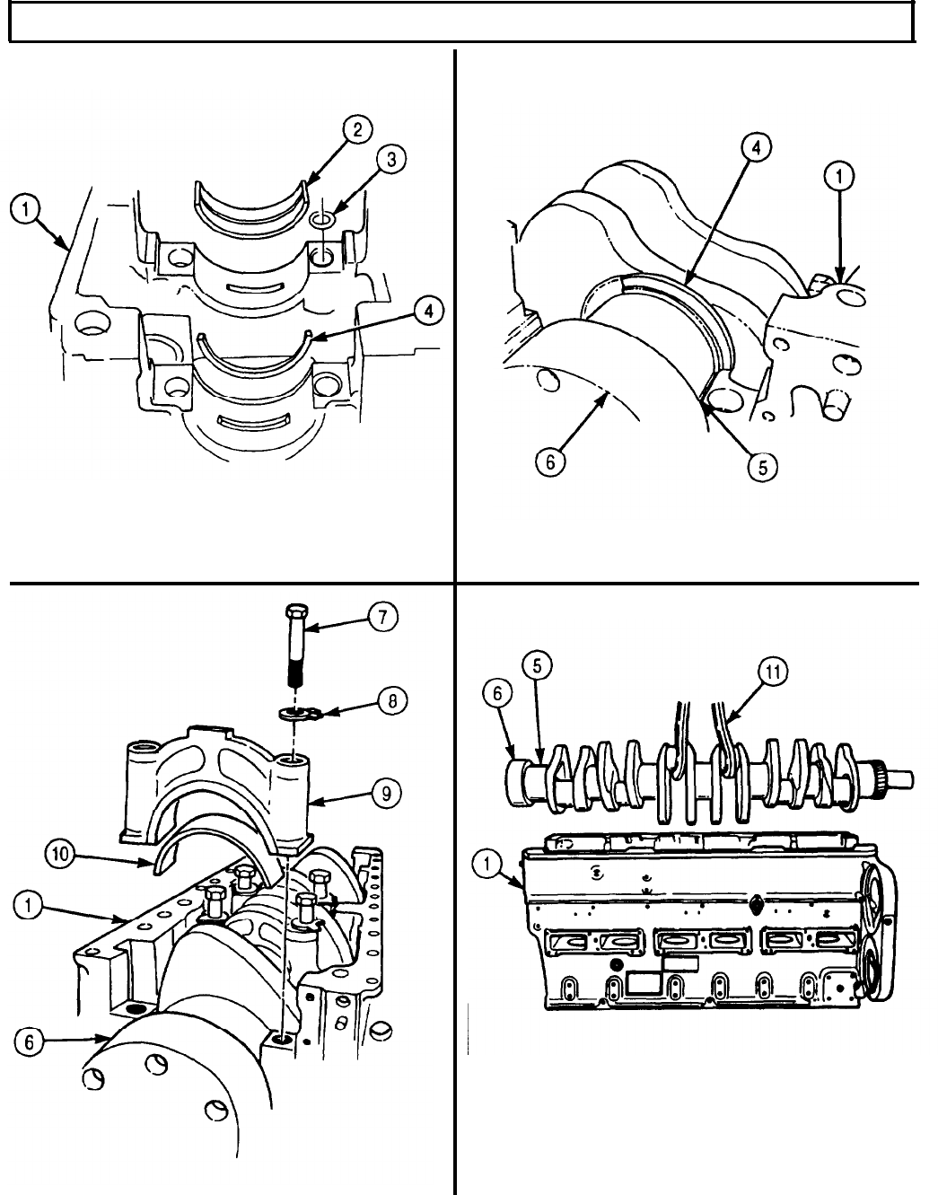
Clean crankshaft (2) and crankshaft gear (6) with drycleaning solvent. For cleaning instructions,
refer to para. 2-14.
Inspect crankshaft gear (6) for breaks, cracks, or chips. If broken, cracked, or chipped, replace
crankshaft (2) assembly.
Wipe rear No. 7 main bearing journal thrust flange (1) clean and check stamping (4) on
shaft web (5). Stamped numbers show standard or oversize thrust rings both front and rear.
Inspect rear No. 7 main bearing journal thrust flange (1) for scratches or scoring. If scratched or
scored, regrind and stamp shaft web (5) accordingly.
CAUTION
If any one bearing shell half is damaged, all bearing shells must
be discarded. Not doing so will vary oil clearance limits when
installed in engine and cause lubrication problems.
Wipe lower and upper half main bearing shell (7) clean and inspect for pits, chips, and scratches.
If pitted, chipped, or scratched, replace bearing set.
Measure thickness of lower and upper half main bearing shell (7). If thickness is less than 0.1215
in. (3.086 mm), replace bearing set.
Wipe crankshaft main bearing journals (3) clean with lint-free cloth and inspect for out-of-round
condition. Measure out-of-round condition with micrometer. If out-of-round more than 0.002 in.
(0.05 mm), replace crankshaft (2).
Measure outer diameter of crankshaft main bearing journals (3) with micrometer. If outer diameter
is less than 4.4975 in. (114.237 mm), repair and stamp on front counterweight (8) accordingly.
Wipe lower and upper half rod bearing shell (7) clean and inspect for pits, chips, and scratches. If
pitted, chipped, or scratched, replace bearing set.
Measure lower and upper half rod bearing shell (7) thickness with micrometer. If thickness is less
than 0.071 in. (1.80 mm), replace bearing set.
Wipe crankshaft rod journals (9) clean with lint-free cloth and measure outer diameter with
micrometer. If outer diameter is less than 3.122 in. (79.30 mm), repair and stamp on front
counterweight (8) accordingly.
Measure outer diameter of rear counterweight seal flange (10) with micrometer. If outer diameter is
under 5.997 in. (152.94 mm), replace crankshaft (2).
5-50
TM 9-2320-272-24-4
5-8. CRANKSHAFT AND MAIN BEARINGS MAINTENANCE (Contd)
5-51

TM 9-2320-272-24-4
5-8. CRANKSHAFT AND MAIN BEARINGS MAINTENANCE (Contd)
c. Installation
1.
2.
3.
4.
5.
6.
7.
8.
WARNING
Eyeshields must be worn when cleaning with compressed air.
Compressed air source will not exceed 30 psi (207 kPa). Failure to
do so may result in injury to personnel.
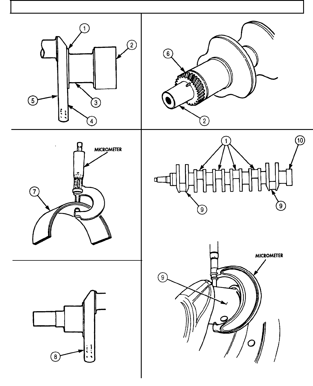
Ensure main bearing bores (3) of engine block (1) are facing up.
Clean all engine block screw holes (2) with compressed air.
Wipe all engine block bearing bores (3) clean with lint-free cloth.
CAUTION
Touching bearing shell wear surface after shells have been cleaned
will cause shell corrosion, resulting in engine damage.
NOTE
Count new bearing upper shells from front of engine block.
Wipe new bearing upper shells (4) Nos. 1, 2, 3, 4, 5, and 6 (4) clean with lint-free cloth.
Position new bearing upper shells (4) Nos. 1, 2, 3, 4, 5, and 6 (4) in bearing bores (3) with oil holes
(5) aligned and press in place. Apply coat of lubricating oil. Bearing shell (4) will project slightly
above bore (3).
NOTE
Wide portion of upper bearing shell is measured from oil groove to
edge.
Install new bearing upper shell No. 7 (7) in bore (10) with wide portion (8) toward flywheel end of
block (1).
Align new bearing upper shell No. 7 oil holes (9) and press in place. Apply coat of lubricating oil.
Bearing shell (7) will project slightly above bore (10).
Install fourteen new dowel rings (6) in engine block (1).
5-52
TM 9-2320-272-24-4
5-8. CRANKSHAFT AND MAIN BEARINGS MAINTENANCE (Contd)
5-53
TM 9-2320-272-24-4
5-8. CRANKSHAFT AND MAIN BEARINGS MAINTENANCE (Contd)
9.
10.
11.
12.
13.
14.
15.
16.
17.
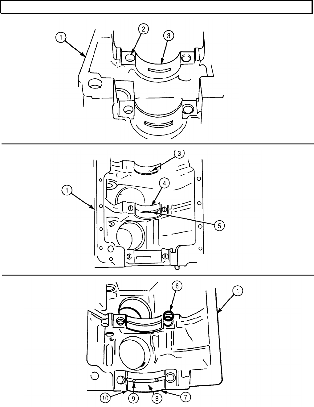
Wipe clear surfaces of crankshaft (1) clean with lint-free cloth, and apply lubricating oil.
Position crankshaft (1) in engine block (2) with hooks protected with rubber hose or rope sling at
two crank throws and rotate crankshaft (1) until rear crankshaft web is visible.
NOTE
Upper thrust rings are not doweled to block. Lower halves are
doweled to No. 7 bearing cap.
Check markings (12) on rear crankshaft web (10) to determine what size upper thrust rings (7) and (8)
are to be placed at front or rear of journal (9).
Apply lubricating oil to new upper thrust ring (8) and roll in place. Ensure babbit face or grooved
side of new upper thrust ring (8) is next to crankshaft flange (11).
Wipe new lower bearing shells (5) clean with lint-free cloth and apply lubricating oil.
Insert new lower bearing shells (5) over crankshaft (1).
NOTE
Lower thrust ring and No. 7 bearing cap are installed together.
Lower thrust ring must be located over dowel on bearing cap.
Apply lubricating oil to new lower thrust ring (8) and position on No. 7 main bearing cap. Ensure
babbit face or grooved side is next to crankshaft flange (11).
Wipe wear surfaces of main bearing caps (6) clean with lint-free cloth, and apply coat of lubricating
oil.
Position main bearing caps (6) in engine block (2) over new lower bearing shells (5). Ensure
numbers on caps (6) correspond with numbers on engine block (2) on camshaft side.
CAUTION
l Do not tap main bearing caps to seat. Hammering will jar
bearing shells out of position and cause engine damage.
l Main bearing screws must be tightened alternately and slowly
to ensure proper seating of bearing caps.
18.
Apply lubricating oil to screw (3) threads and new lockplates (4).
19.
Install new lockplates (4) and fourteen screws (3) through caps (6) in engine block (2).
20.
Tighten each screw (3) in three steps of 100 lb-ft (136 N•m) until 300-310 lb-ft (410-423 N•m) is
reached.
21.
Loosen all screws (3) three turns and repeat step 20.
NOTE
Do not bend up tabs on lockplates until after crankshaft end
clearance is checked.
5-54
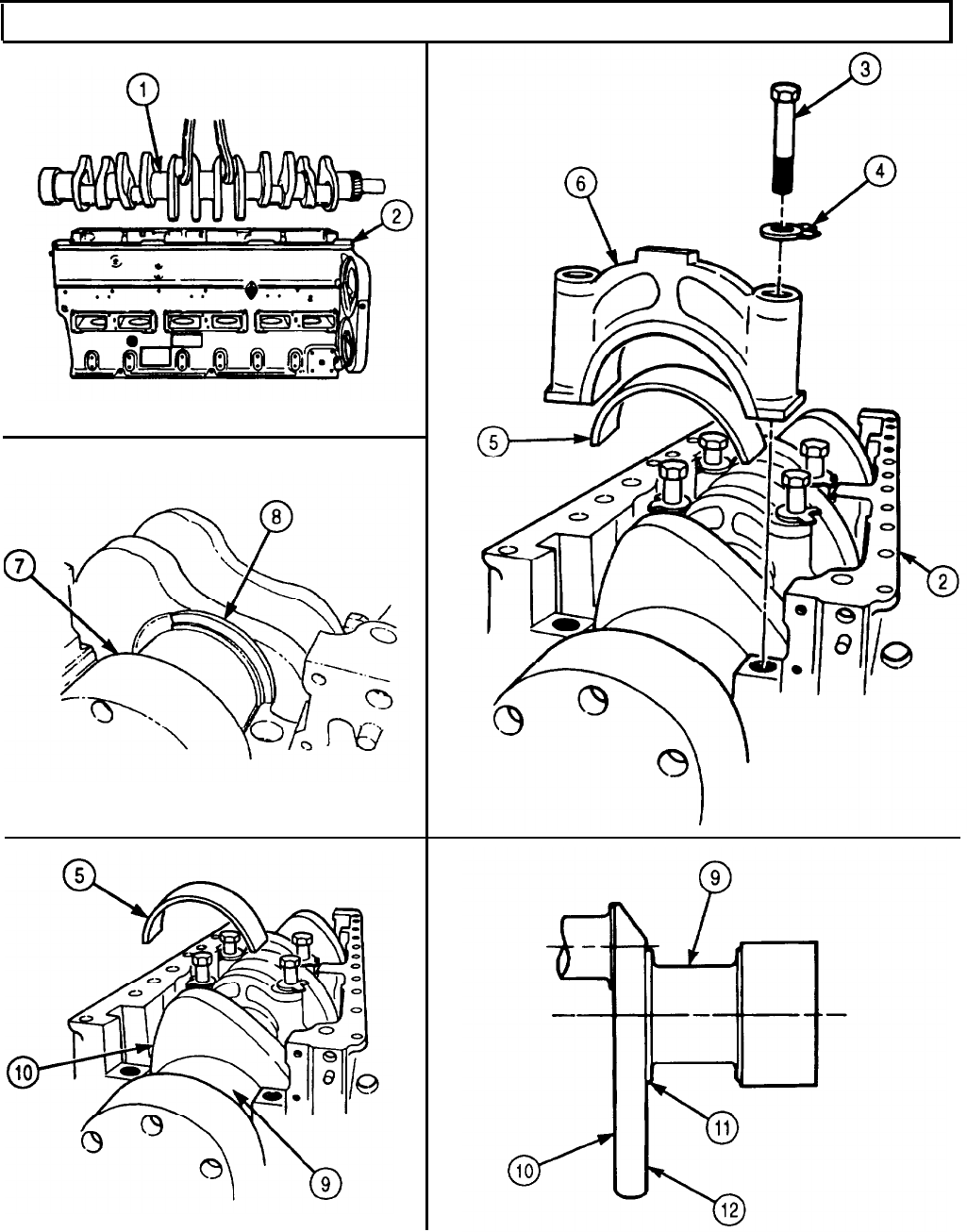
TM 9-2320-272-24-4
5-8. CRANKSHAFT AND MAIN BEARINGS MAINTENANCE (Contd)
5-55

TM 9-2320-272-24-4
5-8. CRANKSHAFT AND MAIN BEARINGS MAINTENANCE (Contd)
d. End Play Clearance
1.
Attach dial indicator to rear of engine block (6) with contact point (4) resting on crankshaft end
face (3).
2.
Push crankshaft end face (3) toward front of engine block (6) and set dial indicator to zero.
3.
Push crankshaft end face (3) back toward rear of engine block (6) and check dial indicator,
NOTE
Complete steps 4 through 6 only if end clearance of crankshaft is
less than 0.007 in. (0.18 mm).
4.
Loosen main bearing screws (1) one turn and push crankshaft (2) first toward front, then toward
rear of engine block (6).
5.
Tighten main bearings screws (1) as in task c, steps 18 through 21.
6.
Repeat steps 1 through 3.
NOTE
If end clearance is more than 0.22 in. (0.56 mm), crankshaft must
be replaced or oversize thrust rings installed. Ensure markings on
rear crankshaft counterbalance are correct. (Refer to task a, steps
11 and 12).
7.
Bend up tabs on fourteen lockplates (7) to hold screws (1).
5-56
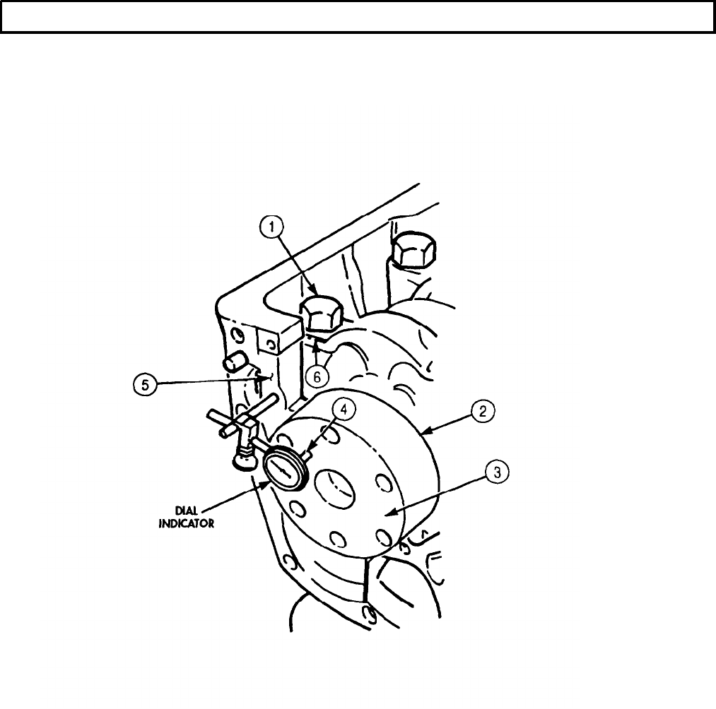
TM 9-2320-272-24-4
5-9. CAMSHAFT AND GEAR MAINTENANCE
THIS TASK COVERS:
a. Check Backlash
b.
Removal
c. Disassembly
d. Cleaning and Inspection
e. Assembly
f. Installation
INITIAL SETUP:
APPLICABLE MODELS
M939/A1
SPECIAL TOOLS
Telescoping gauge (Appendix E, Item 136)
Cam bushing replacement tool (Appendix E,
Item 26)
TOOLS
General mechanic’s tool kit (Appendix E, Item 1)
Dial indicator (Appendix E, Item 36)
Puller kit (Appendix E, Item 102)
Outside micrometer (Appendix E, Item 80)
Vernier caliper (Appendix E, Item 159)
Brass rod
a. Check Backlash
MATERIALS/PARTS
Seven cam bushings (Appendix D, Item 34)
Camshaft bushing (Appendix D, item 33)
Lubricating oil (Appendix C, Item 50)
Drycleaning solvent (Appendix C, Item 71)
REFERENCES (TM)
TM 9-2320-272-24P
EQUIPMENT CONDITION
l Engine oil pan removed (para. 4-22).
l Piston and connecting rod installed (para. 5-10).
GENERAL SAFETY INSTRUCTIONS
l Keep tire extinguisher nearby when using
drycleaning solvent.
l Drycleaning solvent is flammable and toxic. Do
not use near an open flame.
1.
Attach dial indicator to engine block (3) and rotate camshaft gear (2) as far as it will freely move
and hold it in place. Ensure crankshaft gear (1) does not move.
2.
Position dial indicator arm to camshaft gear (2) tooth and set dial indicator to zero.
3.
Rotate camshaft gear (2) in opposite direction and read backlash measurement as rotation stops. If
backlash is not 0.002-0.020 in. (0.05-0.51 mm), replace camshaft gear (2).
NOTE
Normal backlash is 0.0045-0.0105 in. (0.114-0.267 mm) on new
gear with a minimum of 0.002 in. (0.05 mm).
b. Removal
Rotate camshaft gear (2) and camshaft (4) slightly and remove from engine block (3).
CAUTION
Use care when removing camshaft to avoid damaging bearings.
5-58
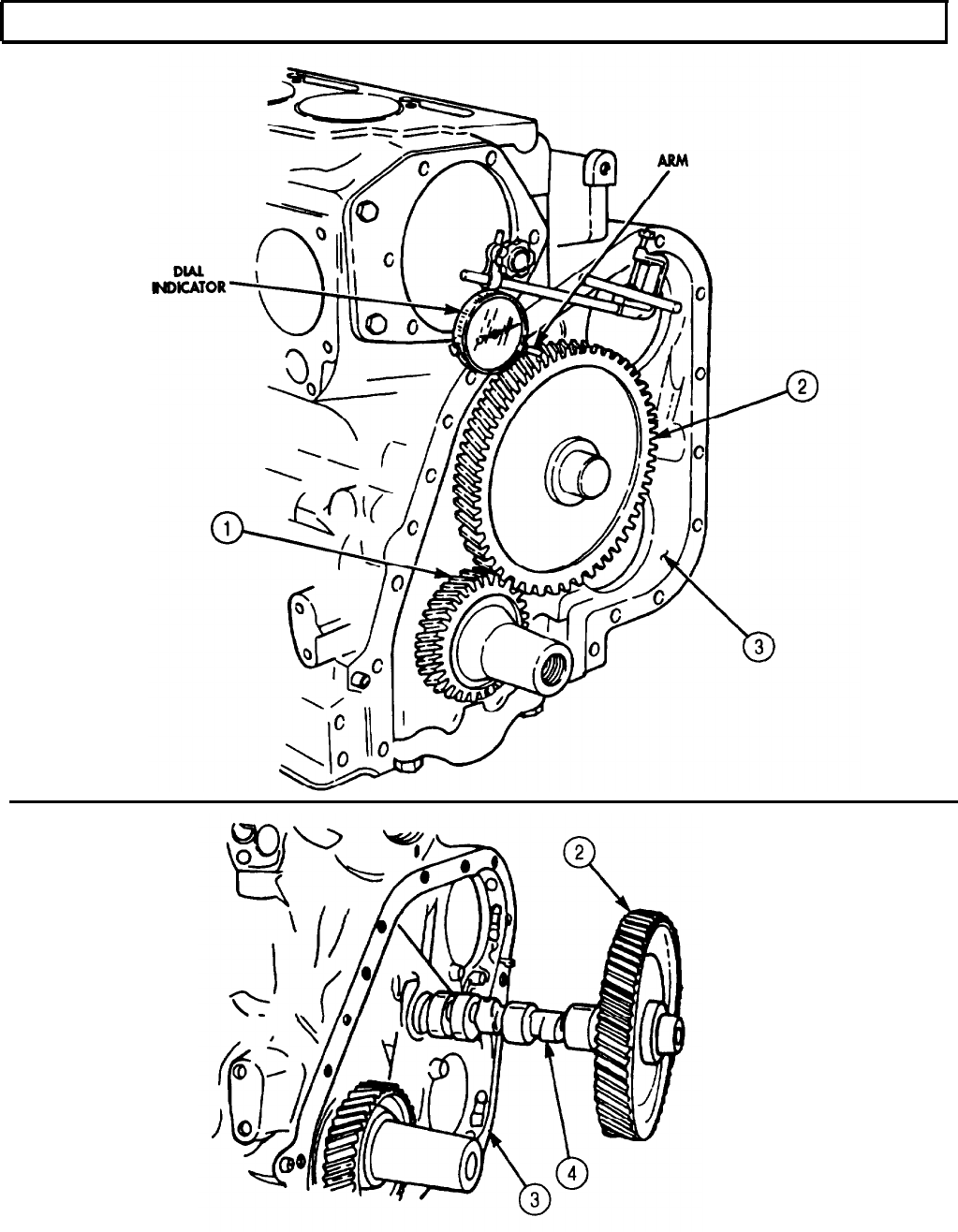
TM 9-2320-272-24-4
5-9. CAMSHAFT AND GEAR MAINTENANCE (Contd)
5-59
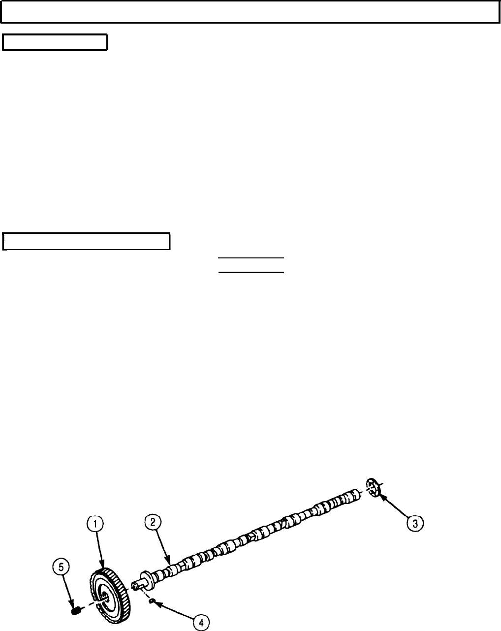
TM 9-2320-272-24-4
5-9. CAMSHAFT AND GEAR MAINTENANCE (Contd)
c. Disassembly
NOTE
Before disassembling camshaft gear from camshaft, perform task
d of this procedure. If, as a result of inspection, camshaft gear
must be disassembled from camshaft, perform stops 1 through 4.
1.
Place camshaft (2) between V-blocks. V-blocks should support camshaft (2).
2.
Remove pipe plug (5) from camshaft (2).
3.
Remove camshaft gear (1) from camshaft (2) with puller.
4.
Remove woodruff key (4) and thrust ring (3) from camshaft (2).
NOTE
Before removing camshaft bushings from engine block, perform
task d of this procedure. If, as a result of inspection, bushings
must be replaced, perform step 5.
5.
Remove seven camshaft bushings (6) from cylinder block (7) with cam bushing replacer.
d. Cleaning and Inspection
1.
2.
3.
4.
5.
WARNING
Drycleaning solvent is flammable and toxic. Do not use near open
flame and always have a fire extinguisher nearby when solvents
are used. Use only in well-ventilated places, wear protective
clothing, and dispose of cleaning rags in approved container.
Failure to do this may result in injury or death to personnel and/or
damage to equipment.
Clean camshaft (2), camshaft gear (1), and thrust washer (3) with drycleaning solvent and inspect
for cracks, breaks, or pits. If cracked, pitted, or broken, discard.
Measure outside diameter of camshaft journals (8) using micrometer. If outside diameter is less
than 1.996 in. (50.70 mm), replace camshaft (2).
Measure thickness of thrust ring (3). If thickness is less than 0.083 in. (2.11 mm), discard thrust
ring (3).
Clean seven camshaft bushings (6) with drycleaning solvent and inspect for breaks, cracks, or pits.
If broken, cracked, or pitted, discard.
Measure inner diameter of seven camshaft bushings (6) with telescoping gauge. If inner diameter
exceeds 2.001 in. (50.83 mm), discard.
5-60
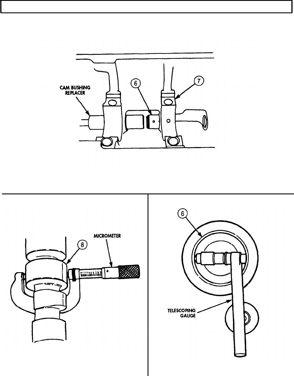
TM 9-2320-272-24-4
5-9. CAMSHAFT AND GEAR MAINTENANCE (Contd)
5-61
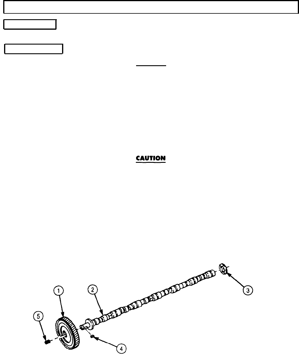
TM 9-2320-272-24-4
5-9. CAMSHAFT AND GEAR MAINTENANCE (Contd)
e. Assembly
Install thrust ring (3), woodruff key (4), camshaft gear (1), and pipe plug (5) in camshaft (2).
f. Installation
CAUTION
Positioning of new camshaft bushing in No. 7 bushing bore (rear of
cylinder block) is critical. The new bushing must be pressed in,
leaving clearance between bushing and rear face of cylinder block
to allow oil to drain from hole at rear of camshaft. Hydraulic lock
will occur if oil drain passage is blocked.
NOTE
No. 1 cam bushing (gear end) is wider; all others are the same.
1.
Position seven cam bushings (7) on cam bushing replacer (6), aligning oil hole (8) in cam bushing (7)
to oil hole in main bearing bore.
2.
Press seven cam bushings (7) into position in cam bore and check oil hole (8) alignment with a brass
rod through main bearing bore oil hole and cam bushing oil hole (8). If brass rod does not pass
through with ease, reposition cam bushings (7).
Use extreme care when installing camshaft to avoid damage to
bearings and camshaft lobes.
NOTE
Assistant will help with steps 3 through 5.
3.
Apply coat of lubricating oil to camshaft lobes (10) on camshaft (2) and camshaft gear (1).
4.
Position camshaft (2) and camshaft gear (1) in engine block (9) by grasping camshaft gear (1) with
both hands and gently sliding end into cam bore (11). With aid of assistant, carefully guide lobes (10)
through bore (11) as camshaft (2) is installed.
5.
Align index mark on camshaft gear (1) with index mark on crankshaft gear (12).
6.
Repeat task a. to check backlash.
5-62
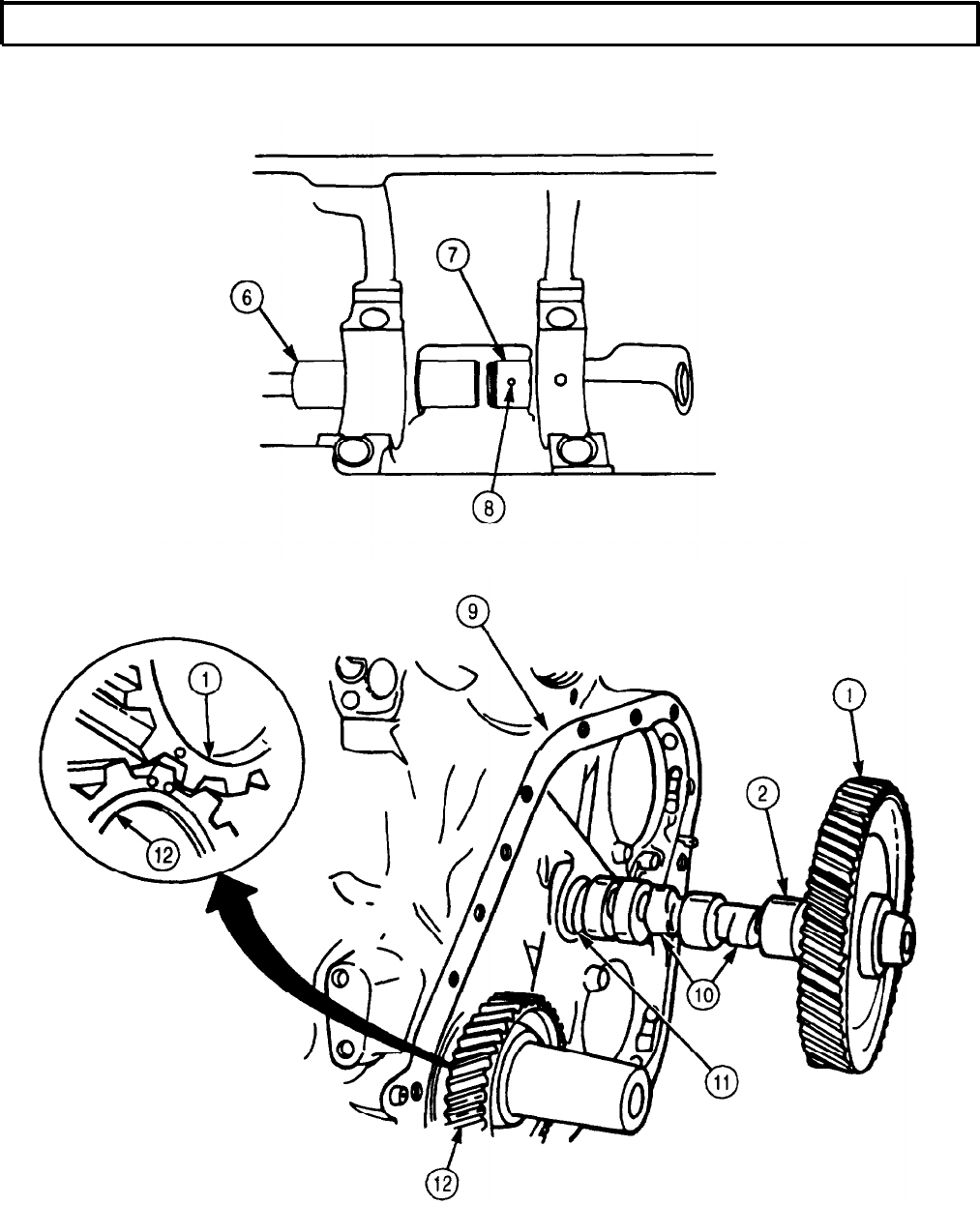
TM 9-2320-272-24-4
5-10. PISTON AND CONNECTING ROD MAINTENANCE
THIS TASK COVERS:
a. Connecting Rod Side Clearance Check
b. Removal
c. Disassembly
d. Cleaning and Inspection
e. Assembly
f. Installation
INITIAL SETUP:
APPLICABLE MODELS
M939/A1
SPECIAL TOOLS
Piston ring groove gauge (Appendix E, Item 97)
TOOLS
General mechanic’s tool kit (Appendix E, Item 1)
Torque wrench (Appendix E, Item 144)
Telescoping gauge (Appendix E, Item 136)
Outside micrometer (Appendix E, Item 80)
Inside micrometer (Appendix E, Item 82)
Piston ring expander (Appendix E, Item 96)
Arbor press
Feeler gauge
Soft-faced hammer
Vise
Tape-protected tool
a. Connecting Rod Side Clearance Check
1.
2.
3.
MATERIALS/PARTS
Twelve bearing shells (Appendix D, Item 14)
REFERENCES (TM)
TM 9-2320-272-24P
EQUIPMENT CONDITION
Camshaft and gear removed (para. 5-9).
GENERAL SAFETY INSTRUCTIONS
Gloves must be worn when handling hot pistons.
NOTE
Connecting rod should have free movement at crank journal.
Check with hand pressure first. Tap lightly with soft-faced
hammer only if necessary.
Move connecting rod (1) up and down on crank journal (3) and measure clearance with feeler gauge.
Clearance should be 0.0045-0.13 in. (0.11-0.33 mm). Record clearance of all six connecting rods for
reassembly.
NOTE
If clearance is not 0.0045-0.13 in. (0.11-0.33 mm) or rod will not
move, continue with steps 2 and 3.
Remove cap (2) and check for improper bearing size, dirt, or burrs.
Install cap (2) as outlined in task f.
5-64
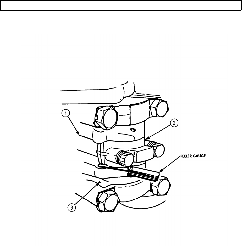
TM 9-2320-272-24-4
5-10. PISTON AND CONNECTING ROD MAINTENANCE (Contd)
5-65

TM 9-2320-272-24-4
5-10. PISTON AND CONNECTING ROD MAINTENANCE (Contd)
1.
Place cylinder block (1) in vertical position and remove all carbon from upper inside wall of each
cylinder liner. Use ridge reamer as necessary.
NOTE
All six connecting rod and bearing caps are removed the same way.
Steps 2 through 5 are for one connecting rod and bearing cap only.
2.
Rotate crankshaft (3) until connecting rod bearing caps (5) are above edge of cylinder block flange (2).
3.
Loosen two screws (6) on connecting rod bearing cap (5) 3/8 in. (9.5 mm) and tap with soft-faced
hammer to free connecting rod bearing cap (5) from connecting rod (7).
NOTE
l Tag and mark bearing cap for installation.
l Do not mix bearing caps.
4.
Remove two screws (6), bearing cap (5), and lower half bearing shell (4) from connecting rod (7).
Discard lower half bearing shell (4).
CAUTION
Use a tape-protected tool to push piston from block. Failure to do
this may result in damage to cylinder liners.
NOTE
l Assistant will help with steps 5 and 6.
l Mark location and position of all pistons before removal from
block. Discard upper half bearing shells.
5.
Push connecting rods (7), pistons (8), and upper bearing shells (9) out of cylinder block (1) with tape-
protected tool. Begin at crankshaft (3) side.
CAUTION
Bearing caps and connecting rods are stamped with same number
as the cylinder. Mixing piston assemblies may cause equipment
damage.
6.
After each piston (8) and connecting rod (7) is removed, assemble connecting rod bearing cap (5) to
connecting rod (7) with two screws (6).
5-66

TM 9-2320-272-24-4
5-10. PISTON AND CONNECTING ROD MAINTENANCE (Contd)
5-67
TM 9-2320-272-24-4
5-10. PISTON AND CONNECTING ROD MAINTENANCE (Contd)
c. Disassembly
1.
Remove four piston rings (1) from piston (6).
2.
Remove two snaprings (2) from piston pin bore (5).
WARNING
Pistons must be heated in hot water to remove piston pins. Do not
handle hot pistons with bare hands. Use protective gloves to avoid
burning hands.
NOTE
Mark piston and connecting rod so it can be reassembly in same
manner.
3.
Submerge pistons (6) and connecting rod (4) assemblies in container of hot water for fifteen minutes
to allow pistons to expand.
4.
Remove pistons (6) and connecting rod (4) assemblies from hot water with tongs or hook and place
in vise. Push piston pin (3) out of piston pin bore (5). Do not drive pins (3) out with hammer.
5.
Place pistons (6), piston pins (3), and connecting rods (4) on a numbered rack and hold for
inspection.
d. Cleaning and Inspection
NOTE
Ensure bearing caps remain assembled to mating connecting rods
at all times to avoid mixing.
1.
Clean connecting rod assemblies (7) (para. 2-14).
2.
Inspect connect rod assemblies (7) (para. 2-15).
3.
Visually check I-beam section (8) of connecting rod (4) for nicks, dents, and gouges. If nicks, dents,
or gouges are greater than 0.031 in. (0.787 mm), replace connecting rod (4).
4.
Inspect connecting rod assemblies (7) for cracks (para. 2-16).
NOTE
To accurately measure all connecting rod bearing cap bores, the screws
must be tightened to the operating torque specified in table 5-7.
5.
Install bearing caps (9) on connecting rod (4) with screws (10).
6.
Alternately tighten screws (10) with torque wrench in accordance with the sequence order in
table 5-7.
Table 5-7. Connecting Rod Screw Tightening Sequence.
TIGHTEN SEQUENCE
TORQUE VALUES
LB-FT
N•M
Step l-Tighten to
70-75
(95-102)
Step 2-Tighten to
140-150 (90-203)
Step 3-Loosen to
(0) (0)
Step 4-Tighten to
25-30 (34-41)
Step 5-Advance to
70-75 (95-102)
Step C--Advance to
140-150 (190-203)
5-68
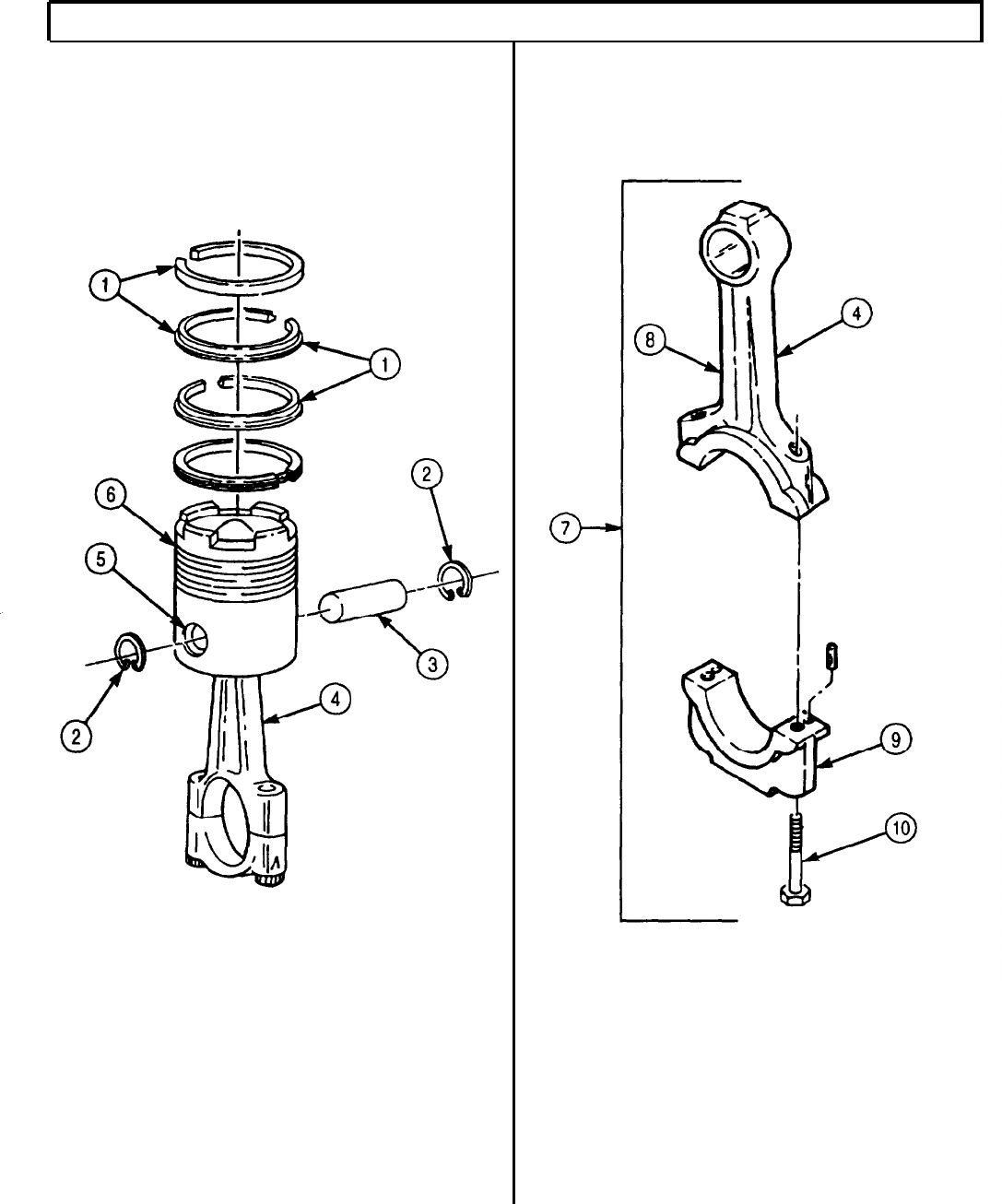
TM 9-2320-272-24-4
5-10. PISTON AND CONNECTING ROD MAINTENANCE (Contd)
5-69

TM 9-2320-272-24-4
5-10. PISTON AND CONNECTING ROD MAINTENANCE (Contd)
7.
Using telescoping gauge, measure inside diameter of crankshaft. journal bore (2) in connecting
rod (1) at points A-A and B-B, up to 30° either side of parting line C. Record readings. If crankshaft
journal bore (2) diameter is not 3.2725-3.2730 in. (83.122-83.134 mm), replace connecting rod (1).
8.
Using telescoping gauge, measure inside diameter of crankshaft journal bore (2) in connecting rod
at points D-D and E-E. Record readings. If crankshaft journal bore (2) diameter is not 3.2725-3.2730
in. (83.122-83.134 mm), replace connecting rod (1).
NOTE
Check pin bores with bushings installed.
9.
Check inside diameter of piston pin bushing bore (6) in connecting rod (1) with telescoping gauge. If
piston pin bushing bore (6) is worn beyond 2.0022 in. (50.856 mm), mark bushings for replacement.
NOTE
l Pistons must be cleaned before inspection.
l Conditions of the pistons and piston rings should be carefully
noted, as ‘they indicate borderline conditions leading to engine
failures.
l Pistons should be inspected at ambient temperatures of 70°-
90°F (21°-32°C).
10.
Check piston (5) wear surface for scoring, scuffing, and cracks. If scored, scuffed, or cracked, replace
piston (5).
NOTE
Vertical scratching and discoloration of piston ring sealing surface
is a major cause of oil consumption and piston and liner scoring.
11.
Check piston rings (3) for vertical scratching and discoloration of piston ring sealing surface. If ring
sealing surface is scratched or discolored, replace piston rings (3).
12.
Check for broken piston rings (3). If broken, replace piston ring (3).
13.
Check piston rings (3) for formation of deposits which prevent outward movement of piston rings (3) to
seal. If piston ring (3) sticks in piston grooves, replace piston ring (3).
14.
Check piston pin bore (4) on piston (5) for fractures. If piston ring bore (4) is fractured, replace
piston (5).
NOTE
l Pistons must be inspected at ambient temperatures of 70°-90°F
(21°-32°C) to obtain accurate measurement readings.
l First and second piston ring grooves are checked for depth wear
the same way. Step 15 checks for ring groove depth wear on the
top ring groove.
15.
Insert ring groove gauge into top ring groove (7) of pistons (5) and note whether shoulders (6) of
gauge touch ring groove (7). If shoulders (6) of gauge touch either ring groove (7), pistons (5) are not
serviceable and must be discarded.
16.
Repeat step 15 for second ring groove (8).
5-70
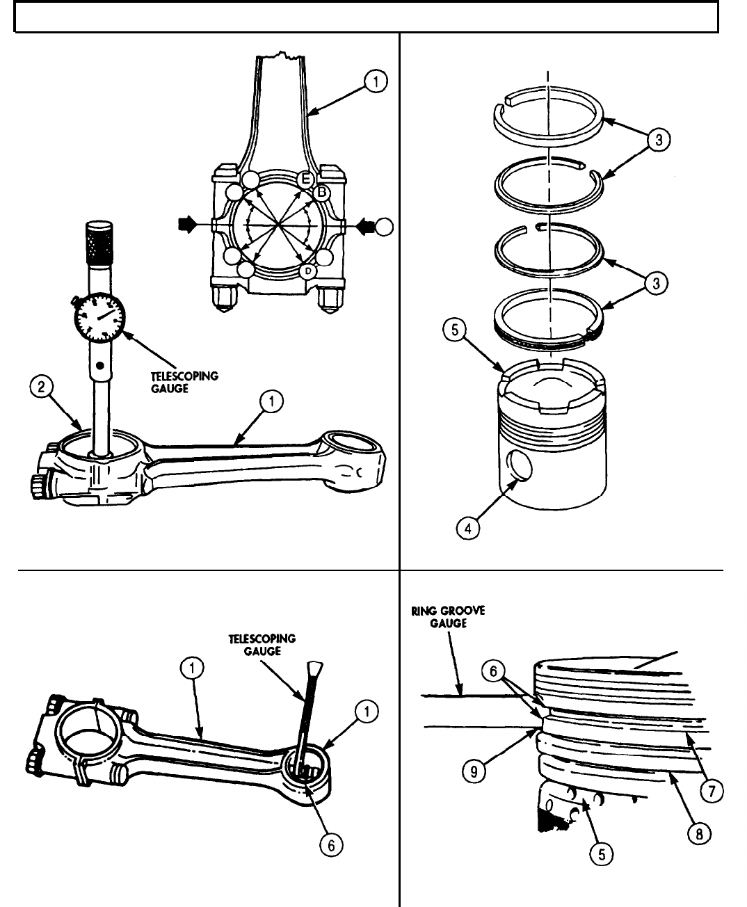
TM 9-2320-272-24-4
5-10. PISTON AND CONNECTING ROD MAINTENANCE (Contd)
5-71

TM 9-2320-272-24-4
5-10.
PISTON AND CONNECTING ROD MAINTENANCE (Contd)
NOTE
First and second piston ring groove widths are checked for wear
the same way. Step 17 checks top ring groove width for wear.
17.
Place and hold new piston ring (2) in top ring groove (3) and try to insert 0.006 in. (0.15 mm) feeler
gauge into ring groove (3) at top of piston ring (2). If feeler gauge enters either ring groove (3)
without force, piston (1) is not serviceable and must be discarded.
18.
Repeat step 17 for second ring groove (4).
NOTE
Measurements to check piston skirt outside diameters are taken
at right angle to piston bore.
19.
Measure piston (1) upper skirt outside diameter (6) approximately 1 in. (25.4 mm) below bottom
ring groove (4) with micrometer.
20.
Measure piston (1) bottom skirt outside diameter (7) approximately 1 in. (25.4 mm) above skirt bottom (8).
If outside diameters (6) and (7) measure less than 5.483 in. (139.27 mm), discard piston (1).
21.
Measure piston pin bore (5) inside diameter. If inside diameter exceeds 1.99 in. (50.775 mm) at 70°F
(21°C), discard piston (1). Add .0005 in. (0.13 mm) per each 10°F over 70°F (21°C) up to 90°F (32°C).
22.
Check outside diameter of piston pin (9) with micrometer. If outside diameter is worn out-of-round
more than 0.001 in. (0.03 mm), discard piston pin (9). If diameter is smaller than 1.99885 in.
(50.762 mm), discard piston pin (9).
23.
Check all piston (1) parts to be sure they are numbered the same. Number is generally located on
the inside of piston (1) skirt.
NOTE
New piston rings must be checked in the cylinder liner in which
they will be used to ensure ring gaps are correct.
24.
Insert piston rings (11), (13), (14), and (15) in each mating cylinder liner (10) bore, using head (top)
of piston (1) to position piston ring (11) so it seats squarely in piston ring (11) travel area.
25.
Measure ring gap (12) with feeler gauge. Ring gap (12) should meet specifications given in
table 5-8.
NOTE
Add 0.003 in. (0.08 mm) ring gap to new maximum for each 0.001
in. (0.03 mm) wear in cylinder liner wall. Measurement made in
ring travel area of liner.
Table 5-8. Ring Gap.
No. 1 compression ring (13) gap 0.023-0.033 in.
(0.58-0.85 mm)
No. 2 and 3 compression ring (11) and (14) gap 0.019-0.029 in.
(0.48-0.74 mm)
No. 4 oil ring (15) gap 0.010-0.025 in.
(0.25-0.64 mm)
26.
Install piston rings (13), (11), (14), and (15) in piston (1) with piston ring expander. Ensure the word
“top” faces toward top of piston (1).
27.
Check connecting rod journals (17) on crankshaft assembly (16) for scores and scratches. If scored or
scratched, replace crankshaft.
28.
Check connecting rod journals (17) for out-of round wear with micrometer. If worn more than 0.002
in. (0.05 mm), replace crankshaft.
5-72
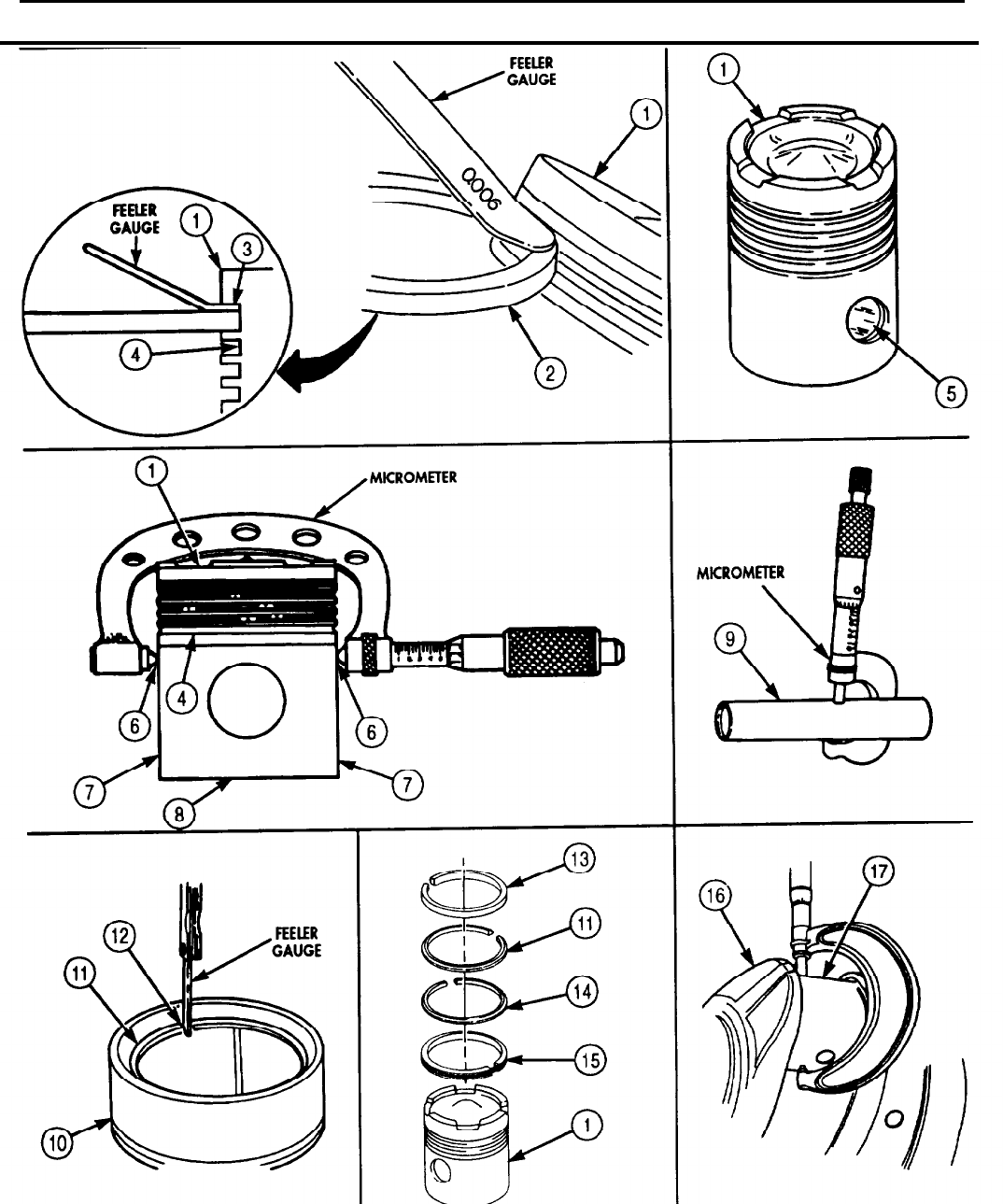
TM 9-2320-272-24-4
5-10. PISTON AND CONNECTING ROD MAINTENANCE (Contd)
5-73
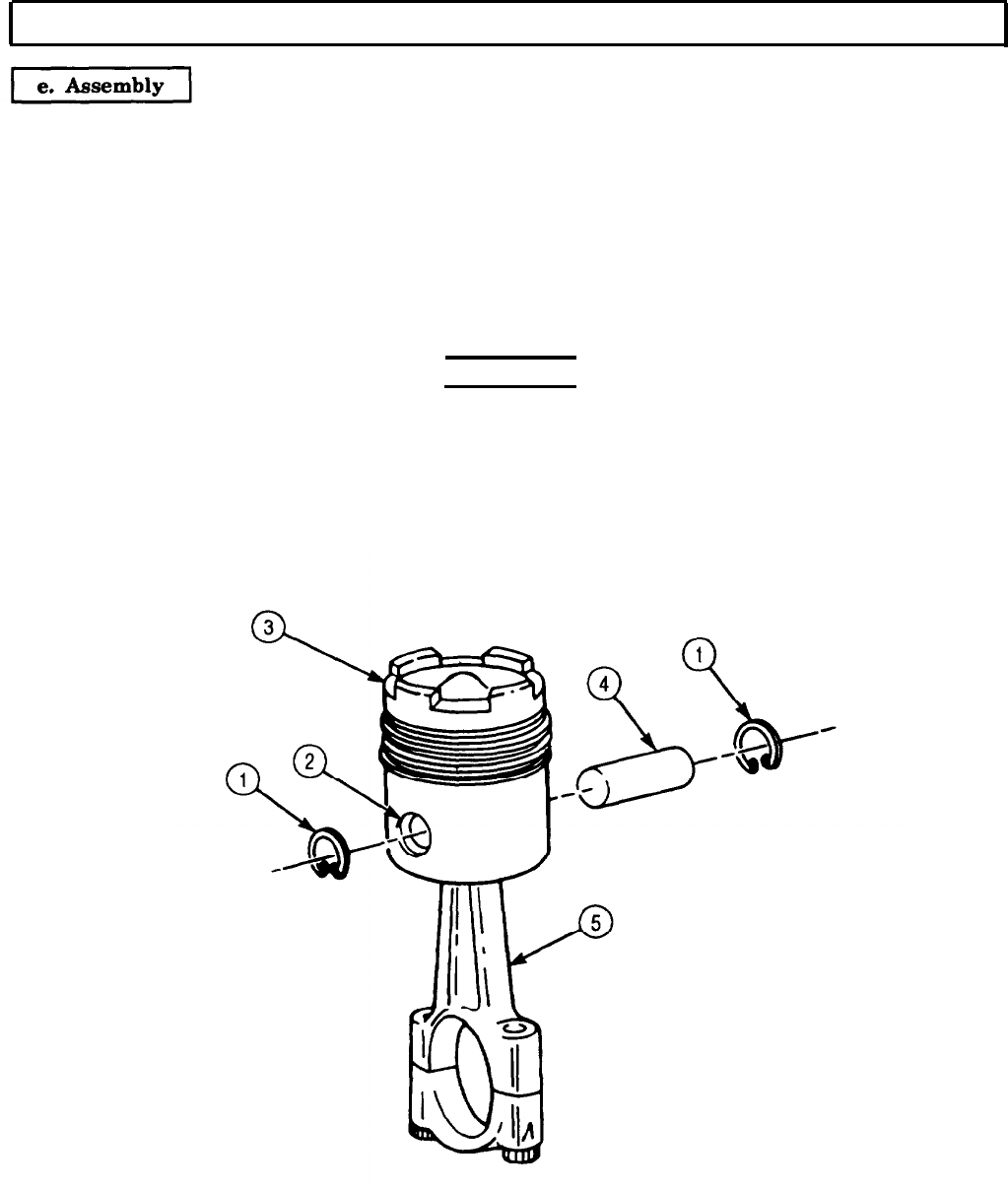
TM 9-2320-272-24-4
5-10. PISTON AND CONNECTING ROD MAINTENANCE (Contd)
1.
Remove piston pin bushing (10) from connecting rod (5) with mandrel, removal tool, and arbor press.
2.
Install sleeve (6), new standard size piston pin bushing (10), and guide sleeve (8) on mandrel.
3.
Place connecting rod (5) on block (7) and place in horizontal position.
4.
Line up mark on guide sleeve (8) with middle of boss on connecting rod (5). Ensure oil hole in new
piston pin bushing (10) and pin bore (9) are lined up.
5.
Press new piston pin bushing (10) into pin bore (9) with arbor press until guide sleeve (8) contacts
side of rod pin boss.
6.
Check inside diameter of new piston rod bushing (10). If inside diameter is not 2.001-2.0015 in.
(50.83-50.838 mm), replace piston pin bushing (10).
WARNING
Do not handle hot pistons with bare hands or injury to personnel
may result.
CAUTION
Never drive piston pins into pistons. Driving may cause distortion
of piston and cause piston seizure in cylinder liner.
5-74
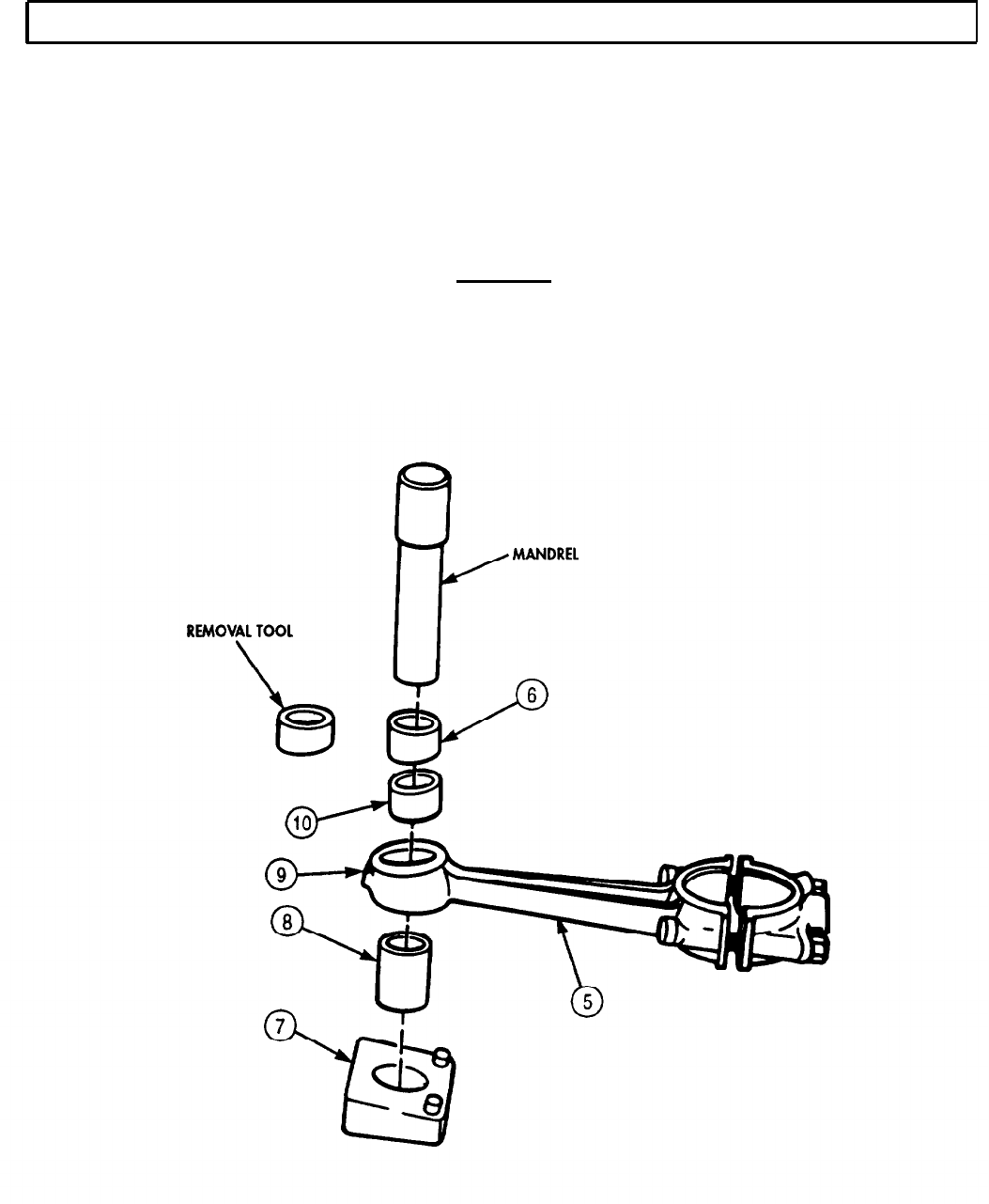
TM 9-2320-272-24-4
5-10. PISTON AND CONNECTING ROD MAINTENANCE (Contd)
NOTE
l Ensure rod and bearing cap are stamped with the numbers of
the cylinders they were removed from. All pistons must have
same part number.
l Ensure pistons and connecting rods are assembled with
orientation marks matching.
7.
Install one piston pin snapring (1) in groove of piston pin bore (2).
8.
Heat pistons (3) in hot water.
CAUTION
Do not attempt to install pin after piston has cooled. Pin will not fit.
9.
Install piston pin (4) through piston (3) and connecting rod (5) pin bores (9) before piston (3) cools.
10.
Install second snapring (1) in piston pin (4) groove at opposite end of pin bore (2).
5-75

TM 9-2320-272-24-4
5-10. PISTON AND CONNECTING ROD MAINTENANCE (Contd)
f. Installation
1.
2.
3.
4.
5.
6.
7.
8.
9.
10.
11.
NOTE
l Before installation, ensure all pistons have been properly
assembled and lubricated.
l If old pistons are being installed, ensure they are installed in
same location from which they were removed.
Remove two screws (5) and rod cap (4) from connecting rod (2).
Apply coat of lubricating oil to piston (1), connecting rod (2), and upper bearing shell (3).
Position tang (6) on new bearing (3) to groove (7) in connecting rod (2) and snap into place.
NOTE
Ensure piston ring gaps are staggered so they are not in line with
each other or piston pin.
Position ring compressor (10) over piston (1) and tighten with Allen wrench.
CAUTION
Assistant must guide connecting rod through cylinder from oil pan
side of block to avoid damaging liner.
NOTE
Ensure numbered side of connecting rod is toward the camshaft
side of engine block.
Carefully insert connecting rod (2) in cylinder liner (9) and hold ring compressor (10) right and
firmly seated against engine block (8). Ensure crankshaft journal (12) is at bottom dead center.
CAUTION
l Ring compressor must be held firmly against engine block to
prevent compressor from sipping and causing piston ring
breakage when pushing piston into cylinder liner.
l Do not force piston assembly into liner. If piston does not install
freely in liner, remove and check for broken rings.
NOTE
Assistant will guide rod onto crankshaft journal to prevent
damage to journal and liner.
Push piston (1) through ring compressor (10) until all piston rings are well into cylinder liner (9) in
engine block (8).
Drive piston (1) and rod (2) into cylinder liner (9) with rubber or wooden mallet handle until upper
rod bearing shell (3) seats on crankshaft journal (12).
Apply lubricating oil to lower connecting rod bearing shell (11).
Position new bearing shell (11) in rod cap (4) and install rod cap (4) so numbered side is matched to
numbered side of rod (2). Ensure tang (6) on bearing shell (11) is aligned with groove in rod cap (4).
Apply lubricating oil to screw (5) threads and install screws (5) through rod cap (4) and tighten
(table 5-7).
Check connecting rod clearance by following task a.
5-76
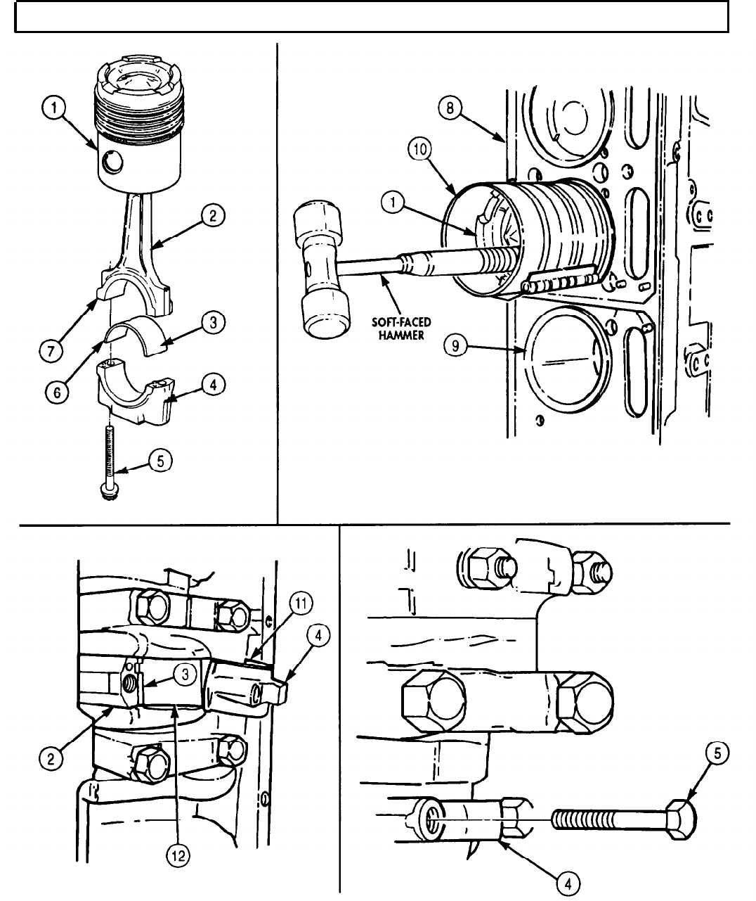
TM 9-2320-272-24-4
5-11. ENGINE OIL PUMP REPAIR
THIS TASK COVERS:
a. Disassembly
b.
Cleaning and Inspection c. Repair
d. Assembly
INITIAL SETUP:
APPLICABLE MODELS
M939/A1
TOOLS
General mechanic’s tool kit (Appendix E, Item 1)
Telescoping gauge (Appendix E, Item 136)
Snap gauge (Appendix E, Item 123)
Boring tool (Appendix E, Item 18)
Torque wrench (Appendix E, Item 144)
Soft-faced hammer
Arbor press
MATERIALS/PARTS
Bypass seat (Appendix D, Item 29)
Bypass spring (Appendix D, Item 30)
Bypass disc (Appendix D, Item 28)
Lockplate (Appendix D, Item 339)
Gasket (Appendix D, Item 176)
Two dowel pins (Appendix D, Item 96)
Two screw-assembled lockwashers
(Appendix D, Item 590)
Two gaskets (Appendix D, Item 174)
Seven lockwashers (Appendix D, Item 354)
Spring (Appendix D, Item 668)
Three lockwashers (Appendix D, Item 364)
Lubricating oil (Appendix C, Item 50)
Antiseize tape (Appendix C, Item 72)
Drycleaning solvent (Appendix C, Item 71)
a. Disassembly
REFERENCES (TM)
TM 9-2320-272-24P
EQUIPMENT CONDITION
l Engine oil filter removed (para. 3-5).
l Engine front gearcase cover removed (para. 4-18).
l Engine accessory drive removed (para. 4-26).
l Engine oil pump removed (para. 4-21).
GENERAL SAFETY INSTRUCTIONS
l Keep tire extinguisher nearby when using
drycleaning solvent.
l Drycleaning solvent is flammable and toxic. Do
not use near an open flame.
l When cleaning with compressed air, wear
eyeshields and ensure source pressure does not
exceed 30 psi (207 kPa).
1.
Remove adapter (7), elbow (8), and nipple (6) from oil pump body flange (1).
2.
Remove elbow (9) and nipple (10) from oil pump body flange (1).
3.
Remove pipe plugs (11) and (12) from oil pump body flange (1).
4.
Remove pipe plug (5) from inner body (2).
5.
Remove pipe plug (3) from filter head (4).
5-78
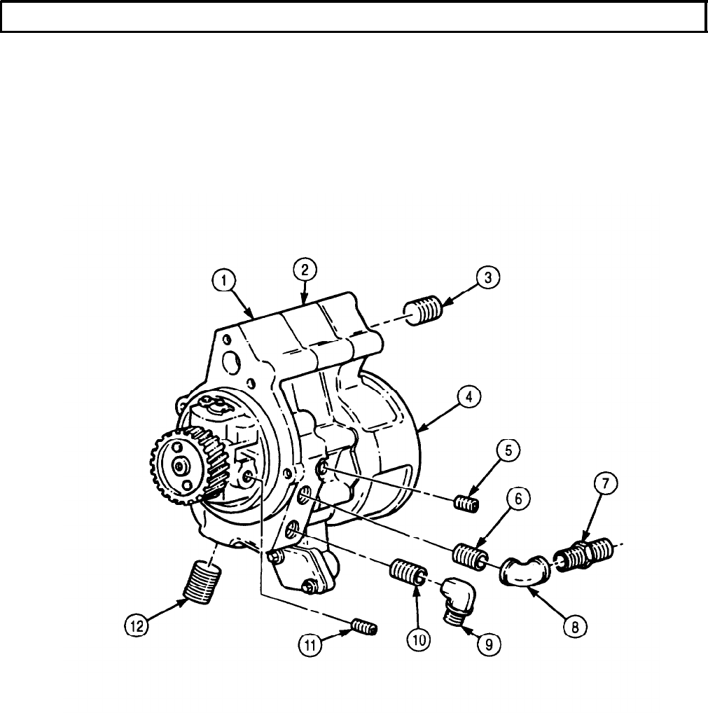
TM 9-2320-272-24-4
5-11. ENGINE OIL PUMP REPAIR (Contd)
5-79

TM 9-2320-272-24-4
5-11. ENGINE OIL PUMP REPAIR (Contd)
6.
Remove two screw-assembled lockwashers (12), flange plate (11), and gasket (10) from inner body (9).
Discard gasket (10) and screw-assembled lockwashers (12).
7.
Hold retainer (14) down and remove screw (1) from oil pump body (13).
8.
Slowly release retainer (14) and remove lockwasher (16), lockplate (15), retainer (14), retainer cap (2),
spring (3), and regulator plunger (4) from oil pump body (13). Discard lockwasher (16), lockplate (15),
and spring (3).
9.
Remove bypass seat (6), disc (7), and bypass spring (8) from filter head (5). Discard bypass seat (6)
and bypass spring (8).
5-80
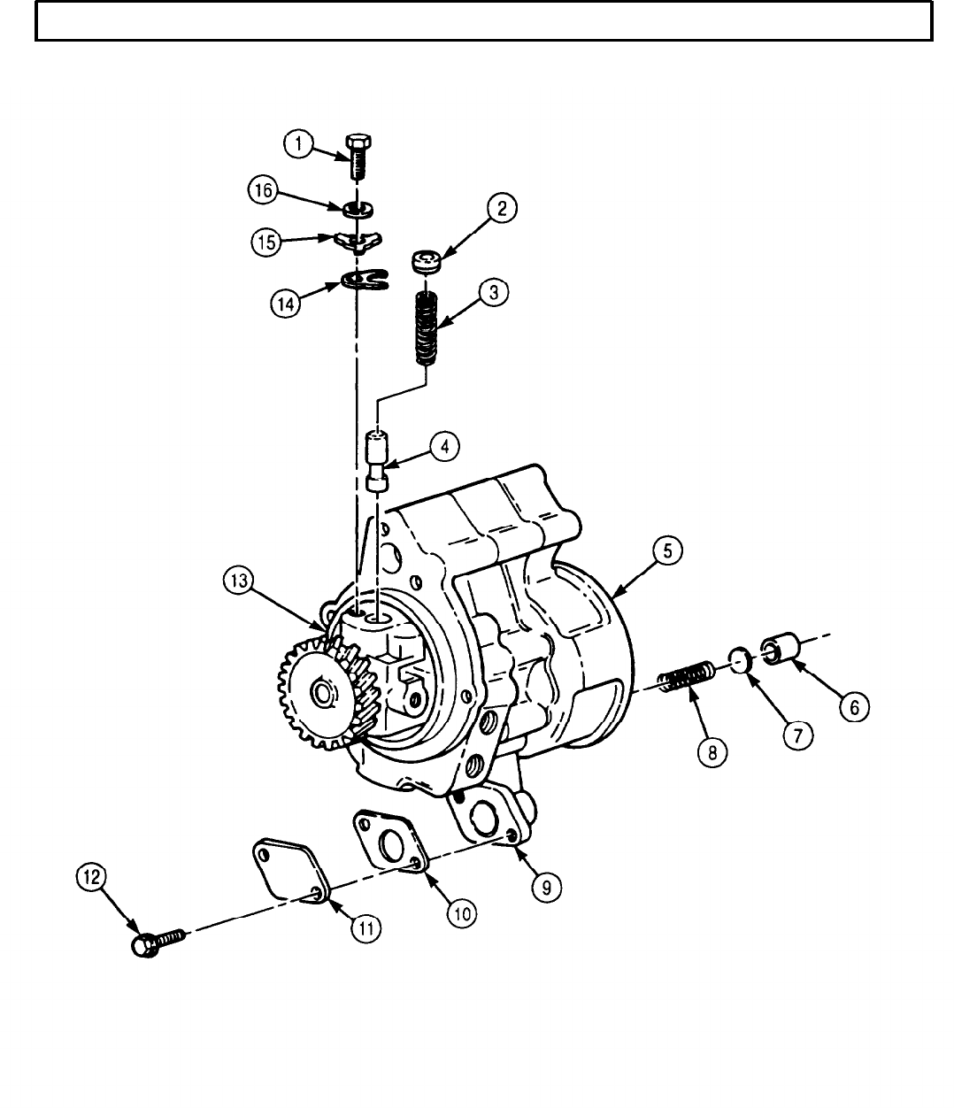
TM 9-2320-272-24-4
5-11. ENGINE OIL PUMP REPAIR (Contd)
5-81

TM 9-2320-272-24-4
5-11. ENGINE OIL PUMP REPAIR (Contd)
10.
11.
12.
13.
14.
15.
16.
17.
18.
19.
20.
21.
22.
23.
Remove two screws (6) and lockwashers (5) from filter head (1). Discard lockwashers (5).
Remove six screws (7) and lockwashers (8) from filter head (1). Discard lockwashers (8).
Tap filter head (1) with soft-faced hammer to separate from dowel pin (4) and inner body (3) and
remove filter head (1) and gasket (2) from inner body (3). Discard gasket (2).
Clean gasket remains from mating surfaces of filter head (1) and inner body (3).
Remove idler gear (14) from idler shaft (15) and inner body (3).
Press driveshaft (10) through driven gear (13) with arbor press and remove driven gear (13) from
driveshaft (10).
Tap inner body (3) and gasket (12) with soft-faced hammer to separate from dowel pin (11) and
remove inner body (3) and gasket (12) from oil pump body (9). Discard gasket (12).
Clean gasket remains from mating surfaces of oil pump body (9), inner body (3), and gasket (12).
Remove idler gear (17) from idler shaft (15).
Press driveshaft (10) through driven gear (15) with arbor press and remove driven gear (15) from
driveshaft (10).
Remove drive gear (18) from driveshaft (10) with arbor press.
Remove idler shaft (15) from oil pump body (9) with arbor press.
NOTE
Perform steps 22 and 23 only if dowel pins are damaged.
Remove dowel pin (4) from inner body (3). Discard dowel pin (4).
Remove dowel pin (11) from oil pump body (9). Discard dowel pin (11).
5-82
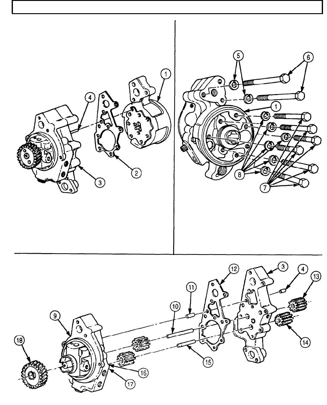
TM 9-2320-272-24-4
5-11. ENGINE OIL PUMP REPAIR (Contd)
5-83

TM 9-2320-272-24-4
5-11. ENGINE OIL PUMP REPAIR (Contd)
b. Cleaning and Inspection
1.
2.
3.
4.
5.
6.
7.
8.
9.
10.
11.
12.
13.
14.
15.
16.
17.
18.
WARNING
l Drycleaning solvent is flammable and toxic. Do not use near
open flame and always have a fire extinguisher nearby when
solvents are used. Use only in well-ventilated places, wear
protective clothing, and dispose of cleaning rags in approved
container. Failure to do this may result in injury or death to
personnel and/or damage to equipment.
l Eyeshields must be worn when cleaning with compressed air.
Compressed air source will not exceed 30 psi (207 kPa). Failure
to do so may result in injury to personnel.
Wipe pump body (2) clean with drycleaning solvent.
Blow out pump body (2) oil passages with compressed air.
Inspect pump body (2) for breaks and cracks. Replace if broken or cracked.
Check inside bore diameter of front and rear driveshaft bushings (1). Replace front and rear drive
shaft bushings (1) if inside diameter exceeds 0.6185 in. (15.710 mm).
Wipe filter head (5) clean with drycleaning solvent.
Blow out filter head (5) oil passages with compressed air.
Inspect filter head (5) for breaks and cracks. Replace filter head (5) if broken or cracked.
Check inside diameter of filter head bushing (4) for wear with dial bore gauge. Replace bushing (4) if
inner diameter exceeds 0.6185 in. (15.710 mm).
Wipe inner body (3) clean with drycleaning solvent.
Blow out inner body (3) oil passages with compressed air.
Inspect inner body (3) for breaks and cracks. Replace inner body (3) if broken or cracked.
Clean drive gear (11), two driven gears (9), and two idler gears (8) with drycleaning solvent, and
inspect for cracked, chipped, or broken teeth. Replace gears if gears (11), (8), and (9) teeth are
cracked, chipped, or broken. Replace gears (11), (8), and (9) if gear teeth show pitting over more
than 1/4 width of active tooth area.
Clean two idler gears (8) and four bushings (10) with drycleaning solvent.
Check inside diameter of two idler gears (8) and four bushings (10) with bore gauge. Replace idler
gears (8) and bushings (10) if inner diameter exceeds 0.6185 in. (15.71 mm).
Inspect pressure regulator plunger (6) to ensure it does not bind in bore (7) of oil pump body (2).
Replace pressure regulator plunger (6) if bent or binds.
Clean idler shaft (12) and driveshaft (13) with drycleaning solvent.
Inspect idler shaft (12) and driveshaft (13) for breaks, cracks, and galling. Replace if broken,
cracked, or galled.
Check idler shaft (12) and driveshaft (13) outside diameters using dial snap gauge. Replace shafts (12)
and (13) if outside diameters are less than 0.6145 in. (15.608 mm).
5-84

TM 9-2320-272-24-4
5-11. ENGINE OIL PUMP REPAIR (Contd)
5-85
TM 9-2320-272-24-4
5-11. ENGINE OIL PUMP REPAIR (Contd)
1.
2.
3.
4.
5.
6.
7.
8.
9.
NOTE
l Steps 1 through 9 are performed to replace parts found defective
during cleaning and inspection steps 3, 7, 12, and 13.
l Bushings must be replaced as a pair.
Using arbor press and mandrel, remove old front and rear driveshaft bushings (2) from oil pump
body (1).
Install new front and rear driveshaft bushings (2) in oil pump body (1), flush to 0.030 in. (0.78 mm)
below surfaces.
Bore new front and rear driveshaft bushings (2) inner diameter to 0.6165-0.6175 in. (15.659-15.684 mm).
Remove old bushing (3) from filter head (4).
Install new bushing (3) in filter head (4) to 0.020 in (0.51 mm) below front surface.
Bore new bushing (3) inner diameter to 0.6165-0.6175 in. (15.659-15.684 mm).
Using arbor press and mandrel, remove four old bushings (6) from two idler gears (5).
NOTE
Idler gear bushings must be replaced as a pair.
Press two new bushings (6) in each idler gear (5) flush to 0.20 in. (0.51 mm) below gear face.
Bore inner diameter of four bushings (6) to 0.6165-0.6175 in. (15.659-15.684 mm).
5-86

TM 9-2320-272-24-4
5-11. ENGINE OIL PUMP REPAIR (Contd)
5-87
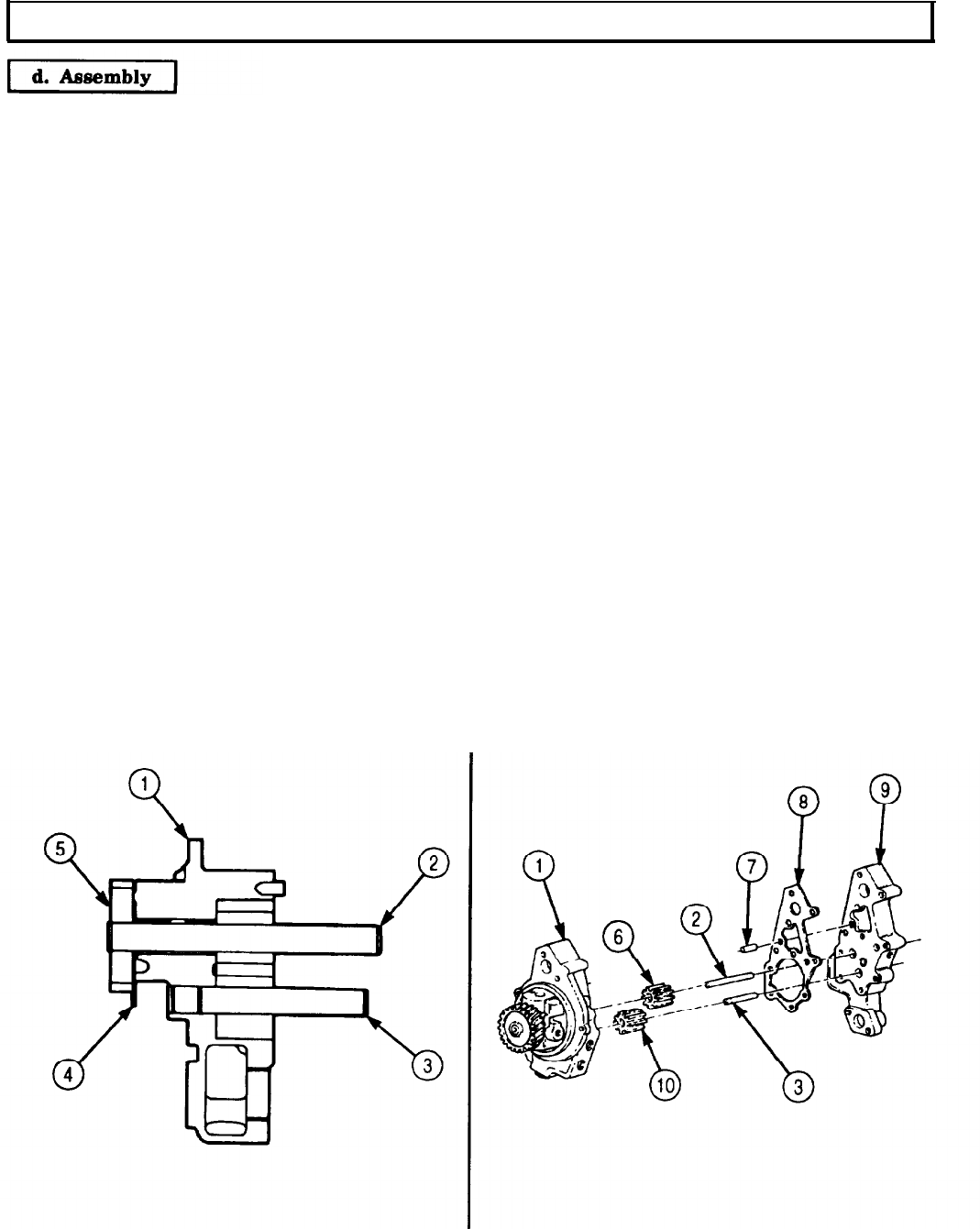
TM 9-2320-272-24-4
5-11. ENGINE OIL PUMP REPAIR (Contd)
1.
2.
3.
4.
5.
6.
7.
8.
9.
10.
11.
12.
13.
Press drilled end of idler shaft (3) into gear pocket side of oil pump body (1) with arbor press and
mandrel until idler shaft (3) protrudes 2.604-2.620 in. (66.04-66.55 mm) above back of body.
Press drive gear (5) over drilled end of driveshaft (2) with arbor press and mandrel until driveshaft. (2)
end protrudes 0.040-0.060 in. (1.02-1.52 mm) above drive gear (5) face.
Apply lubricating oil to driveshaft (2) and insert driveshaft (2) into oil pump body (1).
Position 0.012 in. (0.20 mm) shim (4) between back side of drive gear (5) and front of oil pump body (1)
and install drive gear (5) against shim (4) until snug. Remove shim (4).
NOTE
Perform step 5 only if dowel pin was removed during disassembly
procedure.
Install new dowel pin (7) in oil pump body (1) to 0.990-1.010 in. (22.15-25.65 mm) above face.
Install idler gear (10) on idler shaft (3).
Press driven gear (6) on driveshaft (2) with arbor press and mandrel.
Position 0.012 in. (0.30 mm) shim (4) on rear surface of driver gear (6) facing inner body (9) and
position inner body (9) over shafts (2) and (3) so it rests on the shim. Install inner body (9) to seat
driven gear (6) and remove inner body (9) and shim (4).
Apply lubricating oil to gears (6) and (10), shafts (3) and (2), and gear pockets.
Install new gasket (8) and inner body (9) on pump body (1), using soft-faced hammer to seat inner
body (9) on dowel pin (7). Ensure screw holes are open.
NOTE
Perform step 11 only if dowel pin was removed during disassembly
procedure.
Install new dowel pin (11) in inner body (9) to 0.990-1.010 in. (25.15 to 25.65 mm) above face.
Press driven gear (6) on driveshaft (2) with arbor press and mandrel. Leave 0.002-0.004 in.
(0.05-0.10 mm) clearance between bottom of gear pocket and driver gear (6) surface.
Install idler gear (10) on idler shaft (3).
5-88
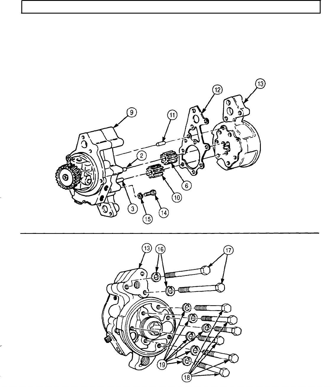
TM 9-2320-272-24-4
5-11. ENGINE OIL PUMP REPAIR (Contd)
14.
Apply lubricating oil to gears (6) and (10), shafts (2) and (3), and gear pockets.
NOTE
Screw is an installation screw and cannot be tightened at this
time.
15.
Position screw (14) and new lockwasher (15) in inner body (9).
16.
Install new gasket (12) and filter head (13) on inner body (9) with two screws (17), new lockwashers
(16), six screws (18), and new lockwashers (19). Use soft-faced hammer to seat filter head (13). Tighten
screws (17) and (18) 30-35 lb-ft (41-47 N•m).
5-89

TM 9-2320-272-24-4
5-11. ENGINE OIL PUMP REPAIR (Contd)
17.
18.
19.
20.
21.
22.
Rotate drive gear (17) back and forth to ensure inner gears are free.
Check driveshaft (18) end play. End play must be 0.004-0.007 in. (0.10-0.18 mm).
Install pressure regulator plunger (15), new spring (5), and retainer cap (4) in pump body (14) with
retainer clamp (16), new lockplate (3), new lockwasher (2), and screw (1). Tighten screw (1)
30-35 lb-ft (41-47 N•m).
Bend tabs of lockplate (3) with hammer and drift punch.
Install new bypass spring (7), disc (9), and new bypass seat (8) in filter head assembly (6).
Install new oil pump flange gasket (11) and flange (12) on pump flange (10) with two new
lockwashers (14) and screw-assembled washers (13).
5-90
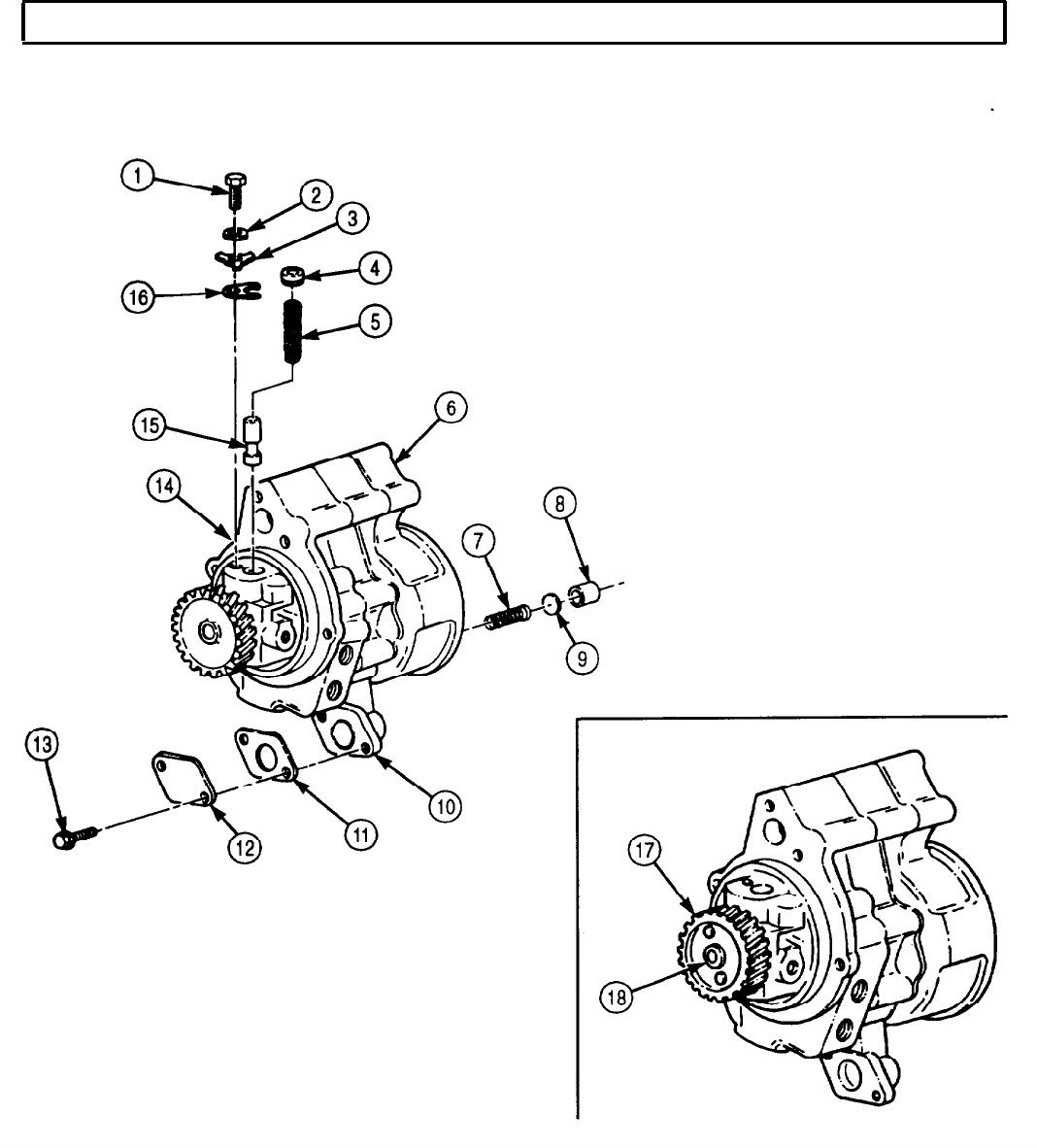
TM 9-2320-272-24-4
5-11. ENGINE OIL PUMP REPAIR (Contd)
FOLLOW-ON TASKS: l Replace engine oil filter (para. 3-5).
l Install engine accessory drive (para. 4-26).
l Install engine front gearcase cover (para. 4-18).
l Install engine oil pump (para. 4-21).
5-91
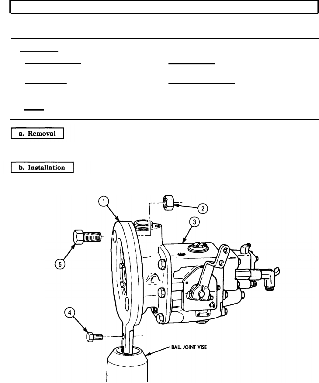
TM 9-2320-272-24-4
5-12. MOUNTING FUEL PUMP TO HOLDING FIXTURE
THIS TASK COVERS:
a. Removal b. Installation
INITIAL SETUP:
APPLICABLE MODELS REFERENCES (TM)
M939/A1
TM 9-2320-272-24P
SPECIAL TOOLS
Mounting plate (Appendix E, Item 84)
Ball joint vise (Appendix E, Item 7)
TOOLS
General mechanic’s tool kit (Appendix E. Item 1)
EQUIPMENT CONDITION
l Fuel pump removed from engine (para. 4-35).
l Fuel pump shutoff valve removed (para. 4-36 or
4-37).
1.
Remove two nuts (2), screws (5), and fuel pump (3) from mounting plate (1).
2.
Remove two screws (4) and mounting plate (1) from ball joint vise.
1.
Attach mounting plate (1) to ball joint vise and install two screws (4).
2.
Install fuel pump (3) to mounting plate (1) with two screws (5) and nuts (2).
FOLLOW-ON TASKS: lInstall fuel pump on engine (para. 4-35).
l Install fuel pump shutoff valve (para. 4-36 or 4-37).
5-92
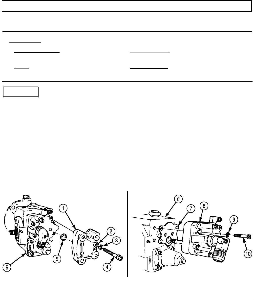
TM 9-2320-272-24-4
5-13. PRESSURE GEAR PUMP REMOVAL
THIS TASK COVERS:
Removal
INITIAL SETUP:
APPLICABLE MODELS MATERIALS/PARTS
M939/A1
Two lockwashers (Appendix D, Item 407)
TOOLS
REFERENCES (TM)
General mechanic’s tool kit (Appendix E, Item 1) TM 9-2320-272-24P
Soft-faced hammer
Removal
1.
2.
3.
4.
5.
6.
Remove two screws (4), lockwashers (3), washers (2), pulsation damper (1), and seal (5) from gear
pump (8). Discard lockwashers (3).
Remove four screws (10) and lockwashers (9) connecting gear pump (8) to fuel pump housing (6).
Discard lockwashers (9).
Tap gear pump (8) lightly with soft-faced hammer and remove from fuel pump housing (6).
Remove gasket (7) from gear pump (8). Discard gasket (7).
Clean gasket remains from gear pump (8) mating surfaces.
Install seal (5) and pulsation damper (1) on fuel pump housing (6) with two washers (2), new
lockwashers (3), and screws (4).
5-93
TM 9-2320-272-24-4
5-14. GOVERNOR SPRING PACK MAINTENANCE
THIS TASK COVERS:
a. Removal c. Installation
b. Inspection
INITIAL SETUP:
APPLICABLE MODELS REFERENCES (TM)
M939/A1
TM 9-2320-272-24P
TOOLS
EQUIPMENT CONDITION
General mechanic’s tool kit (Appendix E, Item 1)
Spring tester (Appendix E, Item 131) Fuel pump mounted on holding fixture (para. 5-12).
MATERIALS/PARTS
Retaining ring (Appendix D, Item 538)
Gasket (Appendix D, Item 223)
Seal (Appendix D, Item 612)
NOTE
Spring packs are maintained basically the same for AFC and
VS fuel pumps. This procedure covers the AFC fuel pump.
a. Removal
1.
Remove seal (12) from governor adjusting screw (13) and throttle leakage adjusting screw (18).
Discard seal (12).
2.
Remove four screws (14), spring pack cover (15), and gasket (16) from fuel pump (1). Discard
gasket (16).
3.
Remove retaining ring (11), spring retainer (10), shim(s) (9), spring (8), spring guide (5), washer (4),
spring (3), and plunger (2) from spring pack barrel (17). Discard retaining ring (11).
4.
Remove adjusting screw (7) and spring (6) from spring guide (5).
b. Inspection
1.
For general inspection instructions, refer to para. 2-15.
2.
Inspect spring pack cover (15) for cracks, breaks, and stripped threads. Replace spring pack cover (15)
if cracked, broken, or threads are stripped.
3.
Using spring tester, inspect tension of spring (8). Replace spring (8) if tension is not within 0.69-0.85 lb
(0.31-0.39 kg) when compressed to 1.0 in. (25.4 mm).
4.
Using spring tester, inspect tension of spring (3). Replace spring (3) if tension is not within 16.02-
17.78 lb (7.27-8.07 kg) when compressed to 1.025 in. (26.0 mm).
5-94
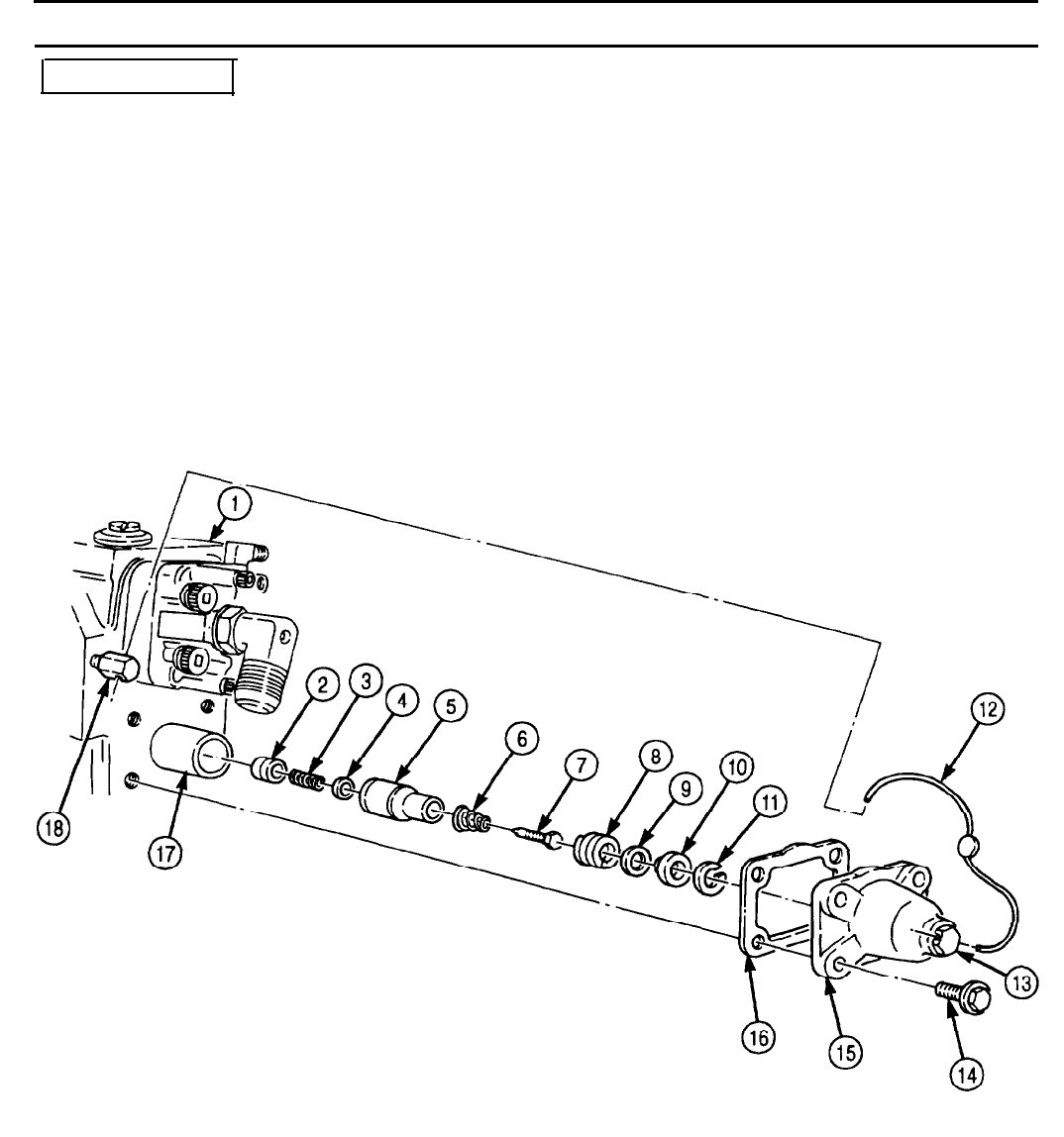
TM 9-2320-272-24-4
5-14. GOVERNOR SPRING PACK MAINTENANCE (Contd)
c. Installation
1.
Install spring (6) and adjusting screw (7) on spring guide (5).
2.
Install plunger (2), spring (3), washer (4), spring guide (5), spring (8), shim(s) (9), and spring
retainer (10) on spring pack barrel (17) with new retaining ring (11).
3.
Install new gasket (16) and spring pack cover (15) on fuel pump (1) with four screws (14).
NOTE
Seal is not installed until fuel pump calibration (para. 5-18).
FOLLOW-ON TASKS: l Remove fuel pump from holding fixture (para 5-12).
l Calibrate fuel pump (para. 5-18).
5-95
TM 9-2320-272-24-4
5-15. FUEL PUMP HOUSING MAINTENANCE
THIS TASK COVERS:
a. Disassembly
b. Inspection c. Assembly
INITIAL SETUP:
APPLICABLE MODELS REFERENCES (TM)
M939/A1
TM 9-2320-272-24P
TOOLS EQUIPMENT CONDITION
General mechanic’s tool kit (Appendix E, Item 1) l Governor spring pack removed (para. 5-14).
MATERIALS/PARTS
l Throttle shaft removed (para. 5-16).
Seven lockwashers (Appendix D, Item 412)
Gasket (Appendix D, Item 239)
Diesel fuel (Appendix C, Item 41)
a. Disassembly
NOTE
Tap edge of hardware lightly with soft-faced hammer to loosen,
1.
Remove screw (7), six screws (1), seven lockwashers (2), and washers (3) connecting front drive
cover (6) to fuel pump housing (4). Discard lockwashers (2).
2.
Pull fuel pump housing (4) straight out from front drive cover (6) to clear dowels.
3.
Remove gasket (5) from front drive cover (6). Discard gasket (5).
4.
Clean gasket remains from front drive cover (6) mating surfaces.
5.
Remove governor plunger (9) and torque spring (8) from fuel pump housing (4).
NOTE
Do not use straight pull on governor plunger torque spring. To
remove, twist spring off shoulder.
6.
Remove torque spring (8) from governor plunger (9).
b. Inspection
1.
Inspect governor plunger (9) for scoring, nicks, and scratches. If scored, nicked, or scratched, replace
governor plunger (9).
2.
Inspect torque spring (8) for broken coils. If coils are broken, replace torque spring (8).
c. Assembly
NOTE
Parts must submerged in diesel fuel and hands wet with diesel
fuel before steps 1 and 2 to prevent damage to close-tolerance
parts.
1.
Install torque spring (8) on governor plunger (9).
2.
Install torque spring (8) and governor plunger (9) in fuel pump housing (4).
3.
Install new gasket (5) and fuel pump housing (4) on front drive cover (6) with seven washers (3),
new lockwashers (2), six screws (1), and screw (7).
5-96
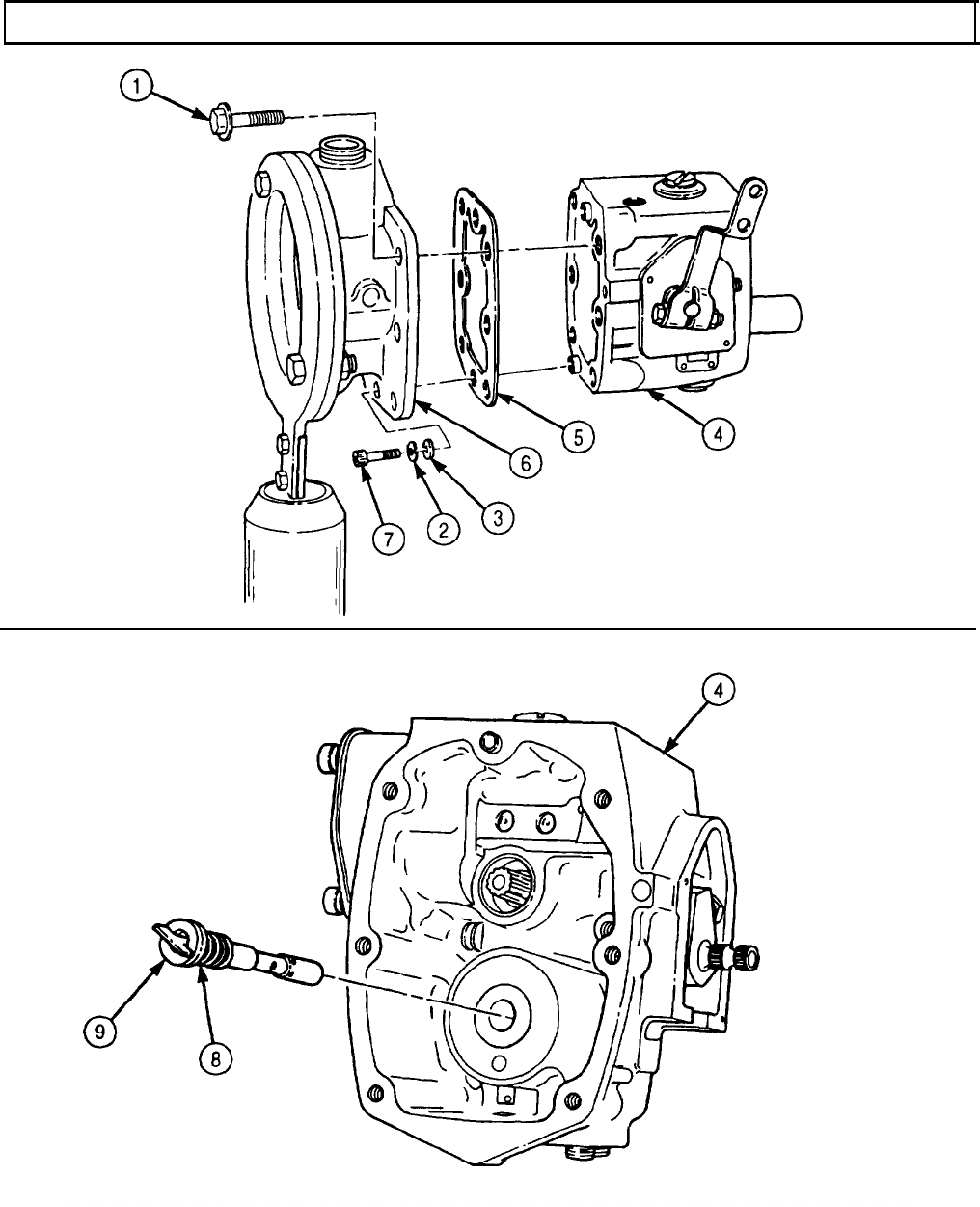

TM 9-2320-272-24-4
5-16. THROTTLE COVER AND SHAFT MAINTENANCE
THIS TASK COVERS:
a. Disassembly
b. Inspection c. Assembly
INITIAL SETUP:
APPLICABLE MODELS REFERENCES (TM)
M939/A1
TM 9-2320-272-24P
TOOLS EQUIPMENT CONDITION
General mechanic’s tool kit (Appendix E, Item 1) Fuel pump housing disassembled (para. 5-15).
MATERIALS/PARTS
Two drive pins (Appendix D, Item 101)
O-ring (Appendix D, Item 461)
O-ring (Appendix D, Item 462)
O-ring (Appendix D, Item 463)
Lockwasher (Appendix D, Item 400)
Throttle shaft soft ball bearing (Appendix D,
Item 666)
a. Disassembly
1.
Center punch and drill out the two drive pins (8) connecting the fuel pump housing (1) to throttle
shaft cover (2). Discard drive pins (8).
2.
Remove nut (4), lockwasher (5), washer (6), screw (7), throttle lever (3), and throttle shaft cover (2)
from fuel pump housing (1). Discard lockwasher (5).
3.
Remove retaining ring (10) and throttle shaft (9) from fuel pump housing (1).
4.
Drill and remove soft ball bearing (18) from throttle shaft (9). Discard soft ball bearing (18).
5.
Remove two set screws (15) and throttle stop control (14) from throttle shaft (9).
6.
Remove O-rings (13) and (16), fuel-adjust screw (17), valve plug (12), and O-ring (11) from throttle
shaft (9). Discard O-rings (13), (16), and (11).
b. Inspection
1.
Inspect throttle shaft (9) for scoring, nicks, and scratches. If scored, nicked, or scratched, replace
throttle shaft (9).
5-98

TM 9-2320-272-24-4
5-16. THROTTLE COVER AND SHAFT MAINTENANCE (Contd)
5-99

TM 9-2320-272-24-4
5-16. THROTTLE COVER AND SHAFT MAINTENANCE (Contd)
c. Assembly
1.
2.
3.
4.
5.
6.
7.
8.
9.
NOTE
Governor weight must be installed before assembling throttle
shaft cover (para. 5-17).
Install new O-ring (11) and valve plug (12) in fuel pump housing (1).
Install fuel-adjusting screw (17), new O-rings (13) and (16), throttle stop control (14) and two
setscrews (15) on throttle shaft (9).
Install new throttle shaft ball (18) in end of throttle shaft (9).
Install throttle shaft (9) in fuel pump housing (1) with retaining ring (10).
NOTE
l Do not install throttle shaft cover until fuel pump has been
calibrated (para. 5-18).
l Do not perform steps 5 through 7 unless pin holes are damaged
beyond use.
Position throttle shaft cover (2) on fuel pump housing (1).
CAUTION
Use care when drilling new holes for drive pins. The pump
housing is made of cast aluminum and is easily damaged. Do not
allow metal particles to enter pump housing.
Center punch location of new holes on throttle shaft cover (2). Ensure holes are opposite one
another.
Carefully drill through throttle shaft cover (2) and into throttle shaft cover flange with 1/15 in. drill
bit NO MORE than 1/4 in. (6 mm).
Install throttle shaft cover (2) on fuel pump housing (1) by gently tapping two new drive pins (8)
through throttle shaft cover (2) into holes.
Install throttle lever (3) on throttle shaft (9) with screw (7), washer (6), new lockwasher (5), and
nut (4).
5-100
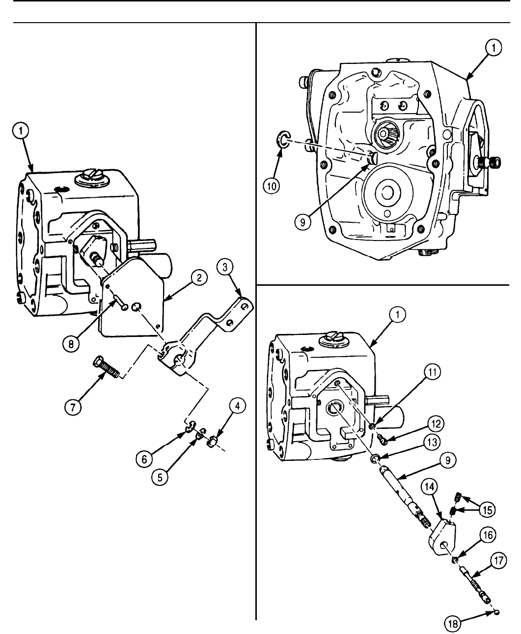
TM 9-2320-272-24-4
5-17. GOVERNOR WEIGHT MAINTENANCE
THIS TASK COVERS:
a. Removal c. Installation
b. Inspection
INITIAL SETUP:
APPLICABLE MODELS REFERENCES (TM)
M939/A1
TM 9-2320-272-24P
TOOLS EQUIPMENT CONDITION
General mechanic’s tool kit (Appendix E, Item 1) Throttle cover and shaft disassembled (para. 5-16).
a. Removal
1.
Remove governor weight (6) and gear (2) from front drive cover (1).
2.
Remove weight-assist plunger (5), spring (3), and shims (4) from governor weight (6).
b. Inspection
1.
Inspect spring (3) for bent or broken coils. If bent or broken, replace spring (3).
2.
Inspect governor weight gear (2) for cracked, broken, or pitted teeth. If cracked, broken, or pitted,
replace governor weight (6).
c. Installation
1.
Install shims (4), spring (3), and weight-assist plunger (5) in governor weight (6).
NOTE
Large end of weight-assist plunger is installed first.
2.
Install governor weight gear (2) and governor weight (6) on front drive cover (1).
5-102
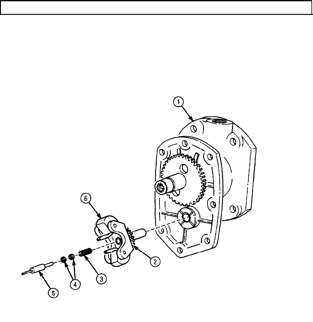
TM 9-2320-272-24-4
5-18. FUEL PUMP SETUP AND CALIBRATION
THIS TASK COVERS:
a. Throttle Shaft Cover Removal i. Testing and Adjusting Pump Main Pressure
b. Mounting Pump to Test Stand j. Testing and Adjusting Fuel Pressure
c. Fuel Pump Run-In k. Testing and Adjusting Governor Fuel
d. Testing Pump Seals for Leaks
Pressure
e. Testing Governor Cutoff RPM l. Checking and Adjusting Governor Weight
f. Testing and Adjusting Throttle Leakage
Pressure
g. Testing and Adjusting Idle Speed m. Testing and Adjusting Idle Speed
h. Checking and Adjusting Throttle Lever (VS Governor Only)
Travel
n. Shutdown and Removal from Test Stand
INITIAL SETUP:
APPLICABLE MODELS
M939/A1
SPECIAL TOOLS
Fuel injection tester (test stand) (Appendix E,
Item 49)
Spring pack adjusting tool (Appendix E,
Item 130)
Travel template (Appendix E, Item 150)
Level and angle indicator (Appendix E, Item 66)
Shaft installation tool (Appendix E, Item 120)
Gear pump block plate (Appendix E, Item 57)
TOOLS
General mechanic’s tool kit (Appendix E,
Item 1)
Straightedge
MATERIALS/PARTS
Two drive pins (Appendix D, Item 101)
Lockwasher (Appendix D, Item 400)
Throttle shaft soft ball bearing (Appendix D,
Item 666)
Grease, GAA (Appendix C, Item 28)
Lubricating oil OE/HDO 30 (Appendix C, Item 50)
45A calibrating fluid (Appendix C, Item 13)
Sealing tape (Appendix C, Item 72)
REFERENCES (TM)
TM 9-2320-272-24P
TM 9-4910-571-12
TM 9-4910-571-12P
EQUIPMENT CONDITION
l Fuel pump removed from vehicle (para. 4-35).
l Fuel pump shutoff valve removed (para. 4-36 or
4-37).
a. Throttle Shaft Cover Removal
NOTE
Perform task a. only if throttle shaft cover has not been removed.
1.
Center punch each of the two drive pins (8) connecting throttle shaft cover (2) to fuel pump housing (1).
2.
Drill drive pins (8) out of throttle shaft cover (2). Discard drive pins (8).
3.
Remove nut (4), lockwasher (5), washer (6), screw (7), and throttle lever (3) from throttle shaft cover (2).
Discard lockwasher (5).
4.
Remove throttle shaft cover (2) from fuel pump housing (1).
5.
Install throttle lever (3) on fuel pump housing (1) with washer (6), new lockwasher (5), and nut (4).
5-104
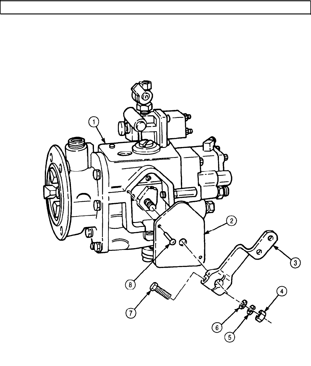
TM 9-2320-272-24-4
5-18. FUEL PUMP SETUP AND CALIBRATION (Contd)
5-105
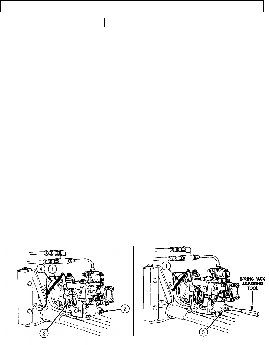
TM 9-2320-272-24-4
5-18. FUEL PUMP SETUP AND CALIBRATION (Contd)
b. Mounting Pump to Test Stand
1.
2.
3.
4.
5.
6.
7.
8.
9.
10.
11.
12.
13.
14.
15.
16.
17.
18.
Install adapter ring (7) on adapter bracket (8) with four washers (9) and screws (6). Ensure the
word TOP or part number on adapter ring (7) faces up.
Install ring and adapter bracket (4) on mounting rails (16) of test stand with clamp bar (14).
Tighten clamp bar (14) finger tight.
Mount fuel pump (11) to ring and adapter bracket (4) with four screws (12) and washers (13).
Place pump coupling insert (15) into test stand drive coupling (10).
Loosen clamp bar (14) and slide fuel pump (11) and ring and adapter bracket (4) forward to engage
drive coupling (10).
NOTE
Clean all male pipe threads and wrap with sealing tape before
installation.
Install inlet adapter (27) on pump elbow (26).
Connect 1/2 in. (12.7 mm) flexible hose (30) from test stand fuel pressure control valve (32) to
adapter (27).
Connect 1/4 in. (6.35 mm) manifold hose (24) from manifold vacuum adapter (28) to adapter (21).
Install pump discharge fitting (18) in fuel pump shutoff solenoid valve (19).
Install fuel pressure hose (17) from test stand pressure gauge outlet (38) to pump discharge fitting (18).
Install 1/2 in. (12.7 mm) flexible hose (25) from test stand lube pressure (31) to test stand lube
return (22).
Install fuel input hose (37) from test stand fuel input connector (36) to pump discharge fitting (18).
Install fuel outlet hose (33) from test stand fuel outlet connector (34) to test stand fuel return
connector (23).
Install leakage accumulator hose (40) to No. 1 accumulator can (41) from test stand leak test
connector (39).
Connect 1/4 in. (6.35 mm) flexible hose (29) to check valve fitting (20) on fuel pump (11) and to
auxiliary return connector (35).
Install throttle lever position holding spring (1) from top of throttle shaft lever (3) to ring and
adapter bracket (4). Spring (1) will hold throttle shaft lever (3) to full fuel position.
Remove governor spring pack housing pipe plug (2) from spring pack housing (5).
Install spring pack adjusting tool into spring pack housing (5).
5-106
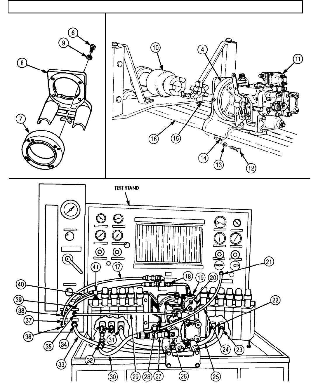
TM 9-2320-272-24-4
5-18. FUEL PUMP SETUP AND CALIBRATION (Contd)
5-107

TM 9-2320-272-24-4
5-18. FUEL PUMP SETUP AND CALIBRATION (Contd)
c. Fuel Pump Run-In
NOTE
Ensure all other test stand valves are in the CLOSED position to
prevent leakage. Seat all other test stand valves by opening one
quarter turn and reclosing.
1.
Place test stand (1), bypass valve (10), fuel pressure valve (9), and flow control valve (12) in open
position.
2.
Open fuel pump (3) by turning fuel shutoff valve manual override knob (13) until seated.
CAUTION
Check tachometer drive for clockwise rotation. If rotation is not
clockwise, reverse rotation of drive coupling.
3.
Apply lubricating oil to tachometer drive seal (2).
4.
Place test stand power switch (8) in ON position.
5.
Place test stand fuel heat switch (4) in ON position. Observe that fuel temperature gauge reads
between 90o-100°F (32o- 38°C) for diesel fuel.
6.
Place selector valve (11) in ROTAMETER position.
7.
Turn range crank (5) to HIGH range position.
NOTE
Perform steps 8 and 9 only on Variable Speed (VS) governor.
8.
Back high-adjusting screw (14), low-adjusting screw (15), and throttle lever (16) out of
VS governor (17) four turns.
9.
Fasten VS governor throttle lever (17) in full fuel position.
CAUTION
Pump must pick up fuel at 500 rpm without priming. If no fluid
pickup is indicated at ROTAMETER, check fuel filter for improper
installation, motor switch for correct rotation, open suction valve
and hose, and that gear pump connections are tight.
10.
Start test stand (1) by depressing start button (8) and run up to 500 rpm. To maintain 500 rpm,
depress and release FAST (7) rotate SLOW (6) button.
NOTE
l Check ROTAMETER for air in fuel flow. If air bubbles are
present, work pump throttle from fuel full-open to idle several
times to relieve entrapped air in pump.
l If air bubbling persists, it is an indication of an air leak in the
system. Turn test stand off and check the line for loose
connections between tank and test stand pump, mating of gear
pump housing, and full fuel supply tank (TM 9-4910-571-12).
l If pump is new or has been disassembled and reassembled, run
pump at 500 rpm for 5 minutes to allow bearings and seals to
seat and to purge air from system.
5-108
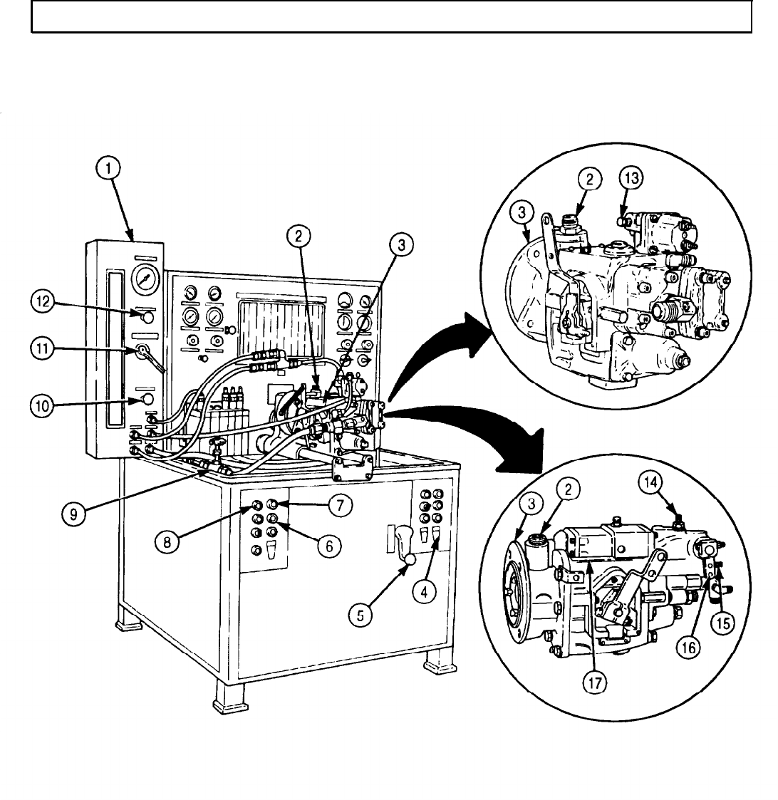
TM 9-2320-272-24-4
5-18. FUEL PUMP SETUP AND CALIBRATION (Contd)
5-109
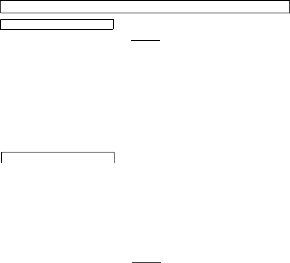
TM 9-2320-272-24-4
5-18. FUEL PUMP SETUP AND CALIBRATION (Contd)
d. Testing Pump Seals for Leaks
CAUTION
l Check tachometer drive for clockwise rotation. If rotation is not
clockwise, reverse rotation of drive coupling.
l Do not leave fuel pressure valve closed more than five minutes
because pump could overheat and be damaged.
NOTE
All steps must be completed before pump is considered calibrated.
1.
With test stand (2) operating at 500 rpm, close fuel pressure valve (7).
2.
Place test stand fuel flow control valve (1) to OPEN position. If 25 in. vacuum is not obtained, check
all hose connections.
3.
Place bypass valve (8) in closed position.
4.
Apply a small amount of GM grease over vent of weep hole (12). If grease is pulled into weep
hole (12) at 25 in. vacuum, fuel pump (10) oil seal is defective and fuel pump (10) must be replaced
(para. 4-35).
5.
Open fuel pressure valve (7).
e. Testing Governor Cutoff RPM
1.
Open test stand fuel flow control valve (1) completely.
2.
Increase fuel pump (10) speed to 2,100 rpm by depressing and releasing FAST (5) or SLOW (6)
button.
3.
Adjust test stand fuel flow control valve (1) to obtain 8 in. Mercury (HG) on vacuum gauge (4).
NOTE
Once 8 in. HG vacuum setting is obtained, do not change setting.
Readings will fluctuate during other tests. Just note the increases
or decreases as they occur.
4.
Open the fuel flow control valve (1) and place the selector valve (9) in ROTAMETER position.
5.
Increase pump (10) speed until the fuel pressure drops. Stand tachometer (3) reading should be
2,130-2,150 rpm. Depress and release FAST (5) or SLOW (6) button to increase or decrease rpm.
The VALVES governor automotive governor portion is set 100 rpm higher.
CAUTION
Test stand must be shut off to change shims in spring pack.
NOTE
l Perform steps 6 and 7 only if spring pack shims are changed.
l Each .001 in. (0.25 mm) shim thickness will change speed
approximately two rpm.
l Shims are available in 0.005, 0.010, and 0.020 in. (0.13, 0.25,
and 0.51 mm) thicknesses.
6.
If cutoff is too low, remove spring pack (11) and add shims. If cutoff is too high, remove shims
(para. 5-14).
7.
With fuel pump (10) at 500 rpm, move throttle lever (13) back and forth until ROTAMETER shows
no air and recheck governor cutoff rpm, steps 1 through 6.
5-110
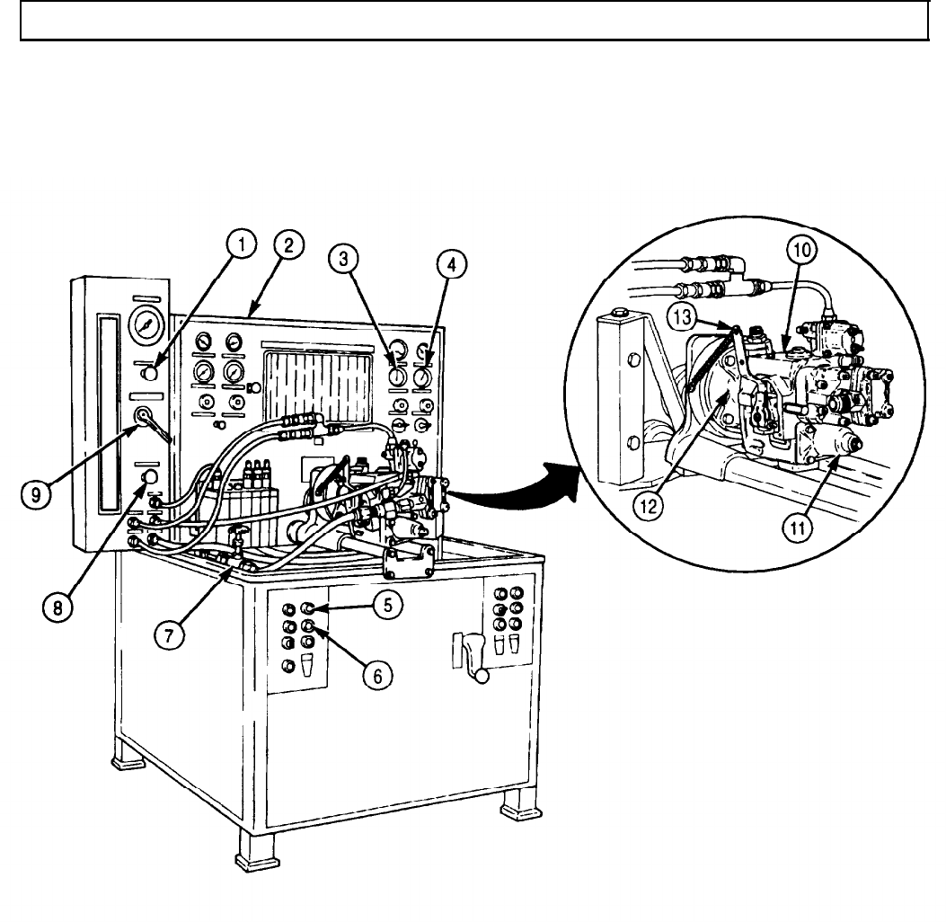
TM 9-2320-272-24-4
5-18. FUEL PUMP SETUP AND CALIBRATION (Contd)
5-111
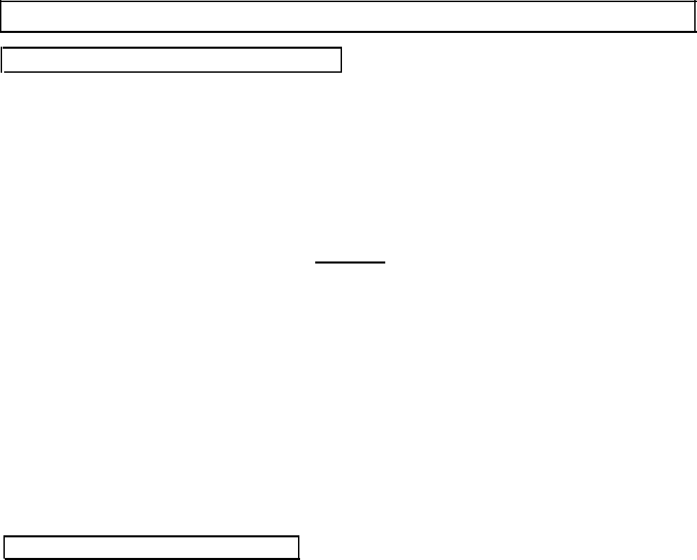
TM 9-2320-272-24-4
5-18. FUEL PUMP SETUP AND CALIBRATION (Contd)
f. Testing and Adjusting Throttle Leakage
1.
Increase fuel pump (9) speed to 2,100 rpm with fuel pump throttle lever (13) and place selector valve (7)
to ROTAMETER position to see if any air is in system.
NOTE
At 2,100 rpm fuel flow, ROTAMETER FLOAT should read 315 pph
on the scale.
2.
Set fuel flow control valve (8) for 315 pph reading.
3.
Place selector valve (7) to LEAKAGE TEST position and place count selector switch (6) to the 1,000
position.
4.
Pull out dumping lever (2) to retain fuel in No. 1 burette (3).
CAUTION
Do not hold throttle lever in idle position any longer than two
minutes to complete test. Pump may overheat, since fuel flow is
used to cool the pump.
5.
Remove throttle spring (4) and manually position throttle lever (14) to idle position.
6.
Depress pulse counter button (5) to fill No. 1 burette (3).
7.
Push dumping lever (2) inward.
NOTE
l Ensure burette is cleared of fuel in order to prevent overflow at
this time.
l A test cycle is one-half minute duration.
l For one half minute cycle, fuel delivery is 40-70 cc.
8.
At the end of a cycle, read the amount of fuel in number one burette (3) on the scale.
9.
If throttle leakage is not as specified, back rear throttle screw (12) out to decrease leakage and in to
increase leakage.
g. Testing and Adjusting Idle Speed
1.
Place selector valve (7) to IDLE position and increase fuel pump (9) rpm to 500.
2.
Pull fuel pump throttle lever (13) to idle position.
3.
If fuel pressure is not 26 psi (179.27 kPa), adjust idle screw (10) in governor spring pack housing (11)
using adjusting tool.
4.
If pressure is low and the adjusting screw bottoms, stop the test stand, add shims to the spring end
of the adjusting screw (para. 5-14), and retest cutoff rpm and throttle leakage, tasks e. and f.
NOTE
Each time governor spring pack housing or adjusting tool is
removed, run pump until purged of air.
5.
After proper adjustment is made, stop the test stand (1) and remove adjusting tool.
6.
Install 1/8 in. (3.17 mm) pipe plug (14) removed in steps 17 and 18, task b.
7.
Purge the fuel pump (9) of air.
5-112
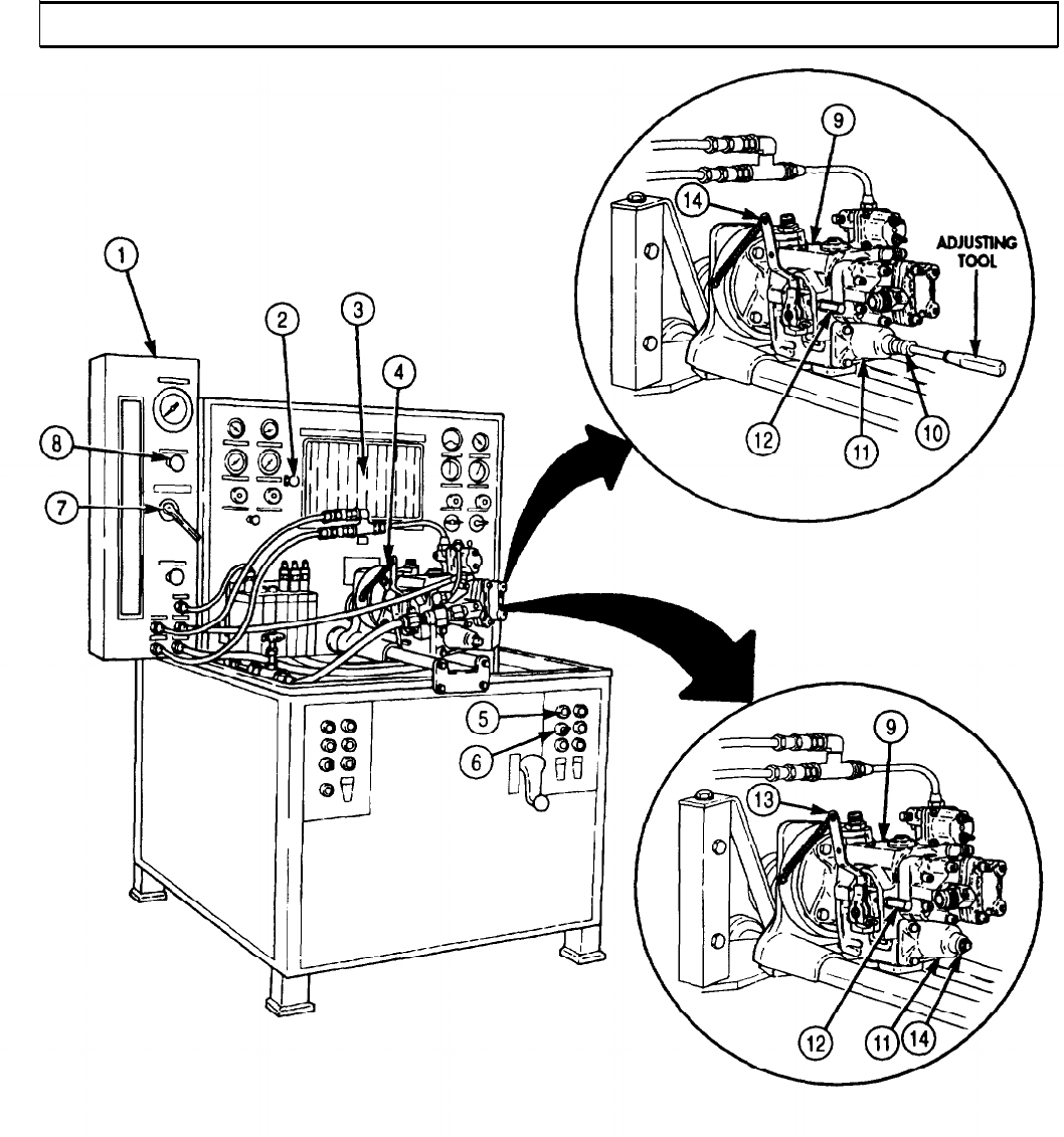
TM 9-2320-272-24-4
5-18. FUEL PUMP SETUP AND CALIBRATION (Contd)
5-113

TM 9-2320-272-24-4
5-18. FUEL PUMP SETUP AND CALIBRATION (Contd)
h. Checking and Adjusting Throttle Lever Travel
1.
2.
3.
4.
5.
6.
7.
8.
NOTE
Travel template or indicator, level, and angle will be used to set
pump throttle lever for travel adjustment. Ensure the combination
of the first and third or second and fourth holes on the template
are used. Any other combination will result in an inaccurate
reading. Correct travel is 27-79o.
Place template (7) against throttle housing (8) so inside flats are even on top and bottom.
CAUTION
DO NOT adjust rear throttle screw from valve set under throttle
linkage. The rear throttle screw has already been set to provide
the proper deceleration time for the engine, and any changes at
this point will require recalibration of throttle linkage.
Move the throttle lever (6) to idle position.
NOTE
The throttle lever may be repositioned on shaft as required to line
up the lever and template holes.
Line up template (7) idle hole and center of throttle lever (6) with straightedge.
Move the throttle lever (6) to full throttle position and align template (7) holes with hole in throttle
lever (6).
NOTE
Steps 5 through 8 check throttle lever travel adjustment.
Place level and angle indicator against the bottom of throttle lever (6) and move throttle lever (6) to
idle position. Note reading on scale of angle indicator.
Move throttle lever (6) to full throttle position. Note reading on scale of angle indicator.
Add readings taken in steps 5 and 6. If throttle lever (6) travel is not 27-29o, adjust front throttle
step screw (9) to obtain correct ravel.
After proper adjustment, the throttle lever (6) may be repositioned to accommodate throttle linkage.
i. Testing and Adjusting Pump Main Pressure
1.
With test stand (2) vacuum set at 8 in. HG on vacuum gauge (5) and throttle wide open, adjust
speed to 2,100 rpm.
2.
Place selector valve (4) to ROTAMETER position.
3.
Set fuel flow to 3.15 pph with fuel flow control valve (1).
4.
If fuel pressure reading on pressure gauge (3) is not 172-178 psi (1186-1227 kPa), adjust fuel
pressure.
5-114
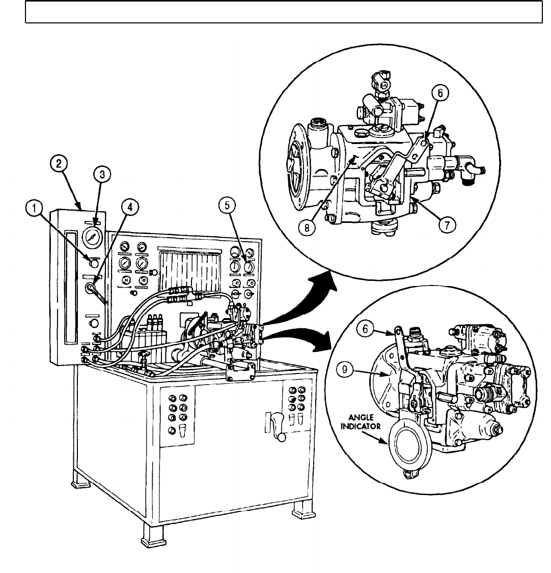
TM 9-2320-272-24-4
5-18. FUEL PUMP SETUP AND CALIBRATION (Contd)
5-115
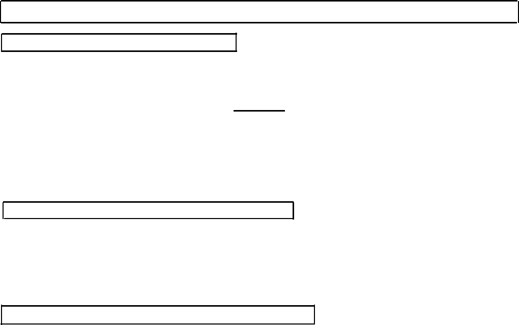
TM 9-2320-272-24-4
5-18. FUEL PUMP SETUP AND CALIBRATION (Contd)
j. Testing and Adjusting Fuel Pressure
NOTE
Throttle shaft internal adjusting screw is covered by a throttle
shaft ball in the end of throttle shaft.
CAUTION
Be careful not to damage bore of throttle shaft when drilling out
ball.
1.
Center punch and drill ball (6) out of fuel pump throttle shaft (7) with 1/4 in. drill bit.
2.
Screw internal fuel adjusting screw located in fuel pump throttle shaft (7) inward to increase fuel
pressure and outward to decrease fuel pressure until it is set to 172-178 psi (1186-1227 kPa).
3.
After fuel pressure is adjusted, insert new throttle shaft ball (6) with throttle shaft installation tool.
k. Testing and Adjusting Governor Fuel Pressure
1.
Adjust fuel pump (3) speed to 1,500 rpm.
2.
Place selector valve (4) on test stand (2) in ROTAMETER position.
3.
Place fuel throttle lever (5) to wide-open position.
4.
Set fuel flow to 2.30 pph with the fuel control valve (1).
5.
If fuel pressure is not 100-106 psi (689-730 kPa), check governor cutoff rpm (task e).
l. Checking and Adjusting Governor Weight Pressure
1.
Adjust fuel pump (3) speed to 1,000 rpm.
2.
Place throttle lever (5) to wide-open position.
3.
Place selector valve (4) in ROTAMETER position.
4.
Set fuel flow to 150 pph with fuel flow control valve (1).
NOTE
Shims are available in 0.005 and 0.010 in. (0.13 and 0.25 mm)
thickness. Do not change setting more than 0.020 in. (0.508 mm)
from specification.
5.
If fuel pressure is greater than 58 psi (399 kPa), decrease pressure by removing shims from behind
weight plunger.
6.
If fuel pressure is less than 50 psi (335 kPa), increase pressure by adding shims (para. 5-17).
5-116
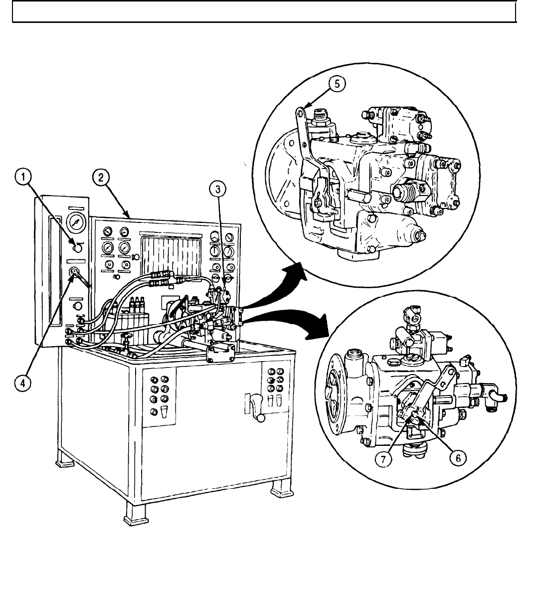
TM 9-2320-272-24-4
5-18. FUEL PUMP SETUP AND CALIBRATION (Contd)
5-117

TM 9-2320-272-24-4
5-18. FUEL PUMP SETUP AND CALIBRATION (Contd)
m. Testing and Adjusting Idle Speed (VS Governor Only)
NOTE
To calibrate fuel pump equipped with Variable Speed (VS)
governor, the preceding steps are followed. In addition, task c,
steps 8 and 9 are to adjust VS governor only.
1.
On test stand (2), place throttle lever (8) of fuel pump with VS governor (3) and VS governor lever (7)
to full-fuel position.
2.
Increase fuel pump (3) speed to 2,140 rpm.
3.
Loosen locknut (5), turn HI-IDLE (top) screw (4) in until fuel pressure starts to drop. Tighten
locknut (5).
4.
Decrease fuel pump (3) speed to 2,100 rpm, and gradually increase until pressure starts to drop.
5.
If fuel pump (3) speed is not 2,120-2,140 rpm, adjust VS governor HI-IDLE screw (4) until rpm is
2,120-2,140 rpm.
NOTE
The automotive governor cutoff must be set 100 rpm higher.
6.
Decrease fuel pump (3) speed to 500 rpm.
7.
Place VS governor lever (7) and stand selector valve (1) to IDLE position.
8.
Adjust governor LO-IDLE screw (bottom) (6) to obtain 26 psi (179 kPa).
5-118
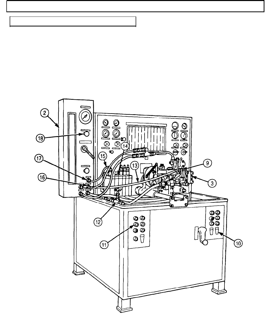
TM 9-2320-272-24-4
5-18. FUEL PUMP SETUP AND CALIBRATION (Contd)
n. Shutdown and Removal from Test Stand
1.
Depress test stand stop button (11).
2.
Place test stand fuel heat switch (10) in OFF position.
3.
Close test stand fuel pressure control valve (12) and fuel flow control valve (17).
4.
Remove 1/4 in. (6.35 mm) flexible hose (13) from small fitting (9) on fuel pump (3) and auxiliary
return fitting (16) on test stand (2).
5.
Remove leakage accumulator hose (15) from No. 1 accumulator can (14) and stand leak test
connector (17).
5-119
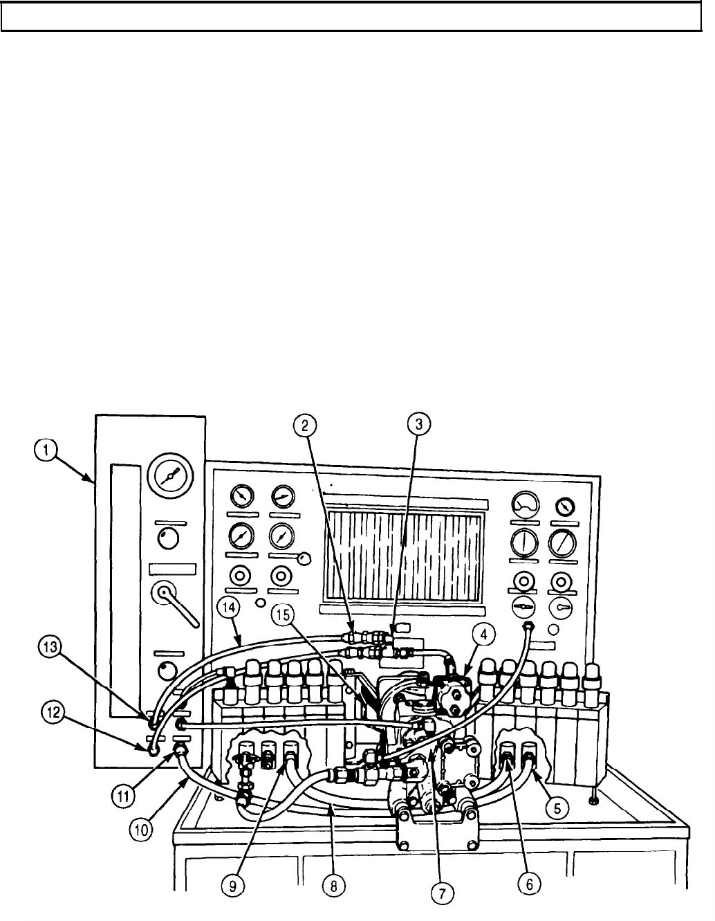
TM 9-2320-272-24-4
5-18. FUEL PUMP SETUP AND CALIBRATION (Contd)
6.
7.
8.
9.
10.
11.
12.
13.
14.
15.
16.
17.
Remove fuel outlet hose (10) from test stand fuel input connector (11) and fuel return connector (5).
Remove 1/2 in. (12.7 mm) flexible hose (8) from test stand lube pressure (9) and test stand lube
return (6).
Remove fuel pressure hose (14) from test stand pressure gauge outlet (13) and pump discharge
fitting (2).
Remove pump discharge fitting assembly (3) from pump fuel shutoff valve (4) and test stand fuel
input connector (12).
Remove throttle lever spring (15) from fuel pump (7).
Remove 1/4 in. (6.35 mm) manifold hose (17) from test stand manifold vacuum gauge (16) and
1/4 in. (6.35 mm) adapter on inlet adapter assembly (18).
Remove 1/2 in. (12.7 mm) inner diameter flexible hose (22) from fuel pressure control valve (23) and
adapter elbow on inlet adapter assembly (21).
Remove pump inlet adapter assembly (20) from pump inlet port (19).
Remove pump coupling insert (35) from test stand drive coupling (30).
Loosen bar clamp (34) and slide fuel pump (7) and ring and adapter bracket (31) back from test
stand drive coupling (30).
Remove fuel pump (7) from ring and adapter bracket (31) by removing four screws (32) and washers (33).
Remove nut (26), lockwasher (27), washer (28), screw (29), and throttle lever (25) from throttle lever
shaft (24).
5-120
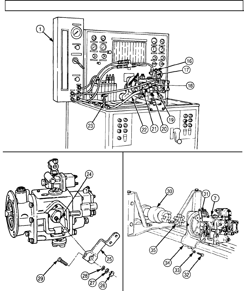
TM 9-2320-272-24-4
5-19. FUEL INJECTOR REPAIR
THIS TASK COVERS:
a. Non-Top Stop Injector Disassembly
b. Top Stop Injector Disassembly
c. Inspection
d. Non-Top Stop Injector Assembly
e. Top Stop Injector Assembly
INITIAL SETUP:
APPLICABLE MODELS
M939/A1
SPECIAL TOOLS
Cup retainer wrench (Appendix E, Item 162)
Crowfoot injector wrench-(Appendix E,
REFERENCES (TM)
Item 164) TM 9-2320-272-24P
Adjusting wrench (Appendix E, Item 3)
Locknut wrench (Appendix E, Item 165)
Injector body wrench (Appendix E, Item 70)
EQUIPMENT CONDITION
Fuel injectors removed (para. 4-32).
TOOLS GENERAL SAFETY INSTRUCTIONS
l Keep fire extinguisher nearby when using
drycleaning solvent.
MATERIALS/PARTS
Injector overhaul kit (Appendix D, Item 255)
Diesel fuel (Appendix C, Item 42)
Drycleaning solvent (Appendix C, Item 71)
General mechanic’s tool kit (Appendix E, Item 1)
Torque wrench (Appendix E, Item 144)
Magnifying glass l Drycleaning solvent is flammable and toxic. Do
not use near an open flame.
a. Non-Top Stop Injector Disassembly
1.
Remove injector link (1) from injector (8). Set injector link (1) aside to prevent damage.
WARNING
Drycleaning solvent is flammable and toxic. Do not use near open
flame and always have a fire extinguisher nearby when solvents
are used. Use only in well-ventilated places, wear protective
clothing, and dispose of cleaning rags in approved container.
Failure to do this may result in injury or death to personnel and/or
damage to equipment.
CAUTION
Improper cleaning methods and use of unauthorized cleaning
solvents can damage equipment.
2.
Clean exterior of injector (8) with drycleaning solvent (para. 2-14).
CAUTION
l Injector barrel and plunger are a matched pair (class fit). Do not
interchange.
l Do not touch internal parts unless hands are clean and
moistened with diesel fuel. Failure to do so may result in
damage to internal parts.
3.
Remove plunger (2) and spring (3) from injector (8). Store plunger (2) by standing on end.
4.
Remove small O-ring (4) and two large O-rings (5) from injector (8). Discard O-rings (4) and (5).
5.
Remove screen retaining ring (6) and screen (7) from injector (8). Discard retaining ring (6) and
screen (7).
5-122
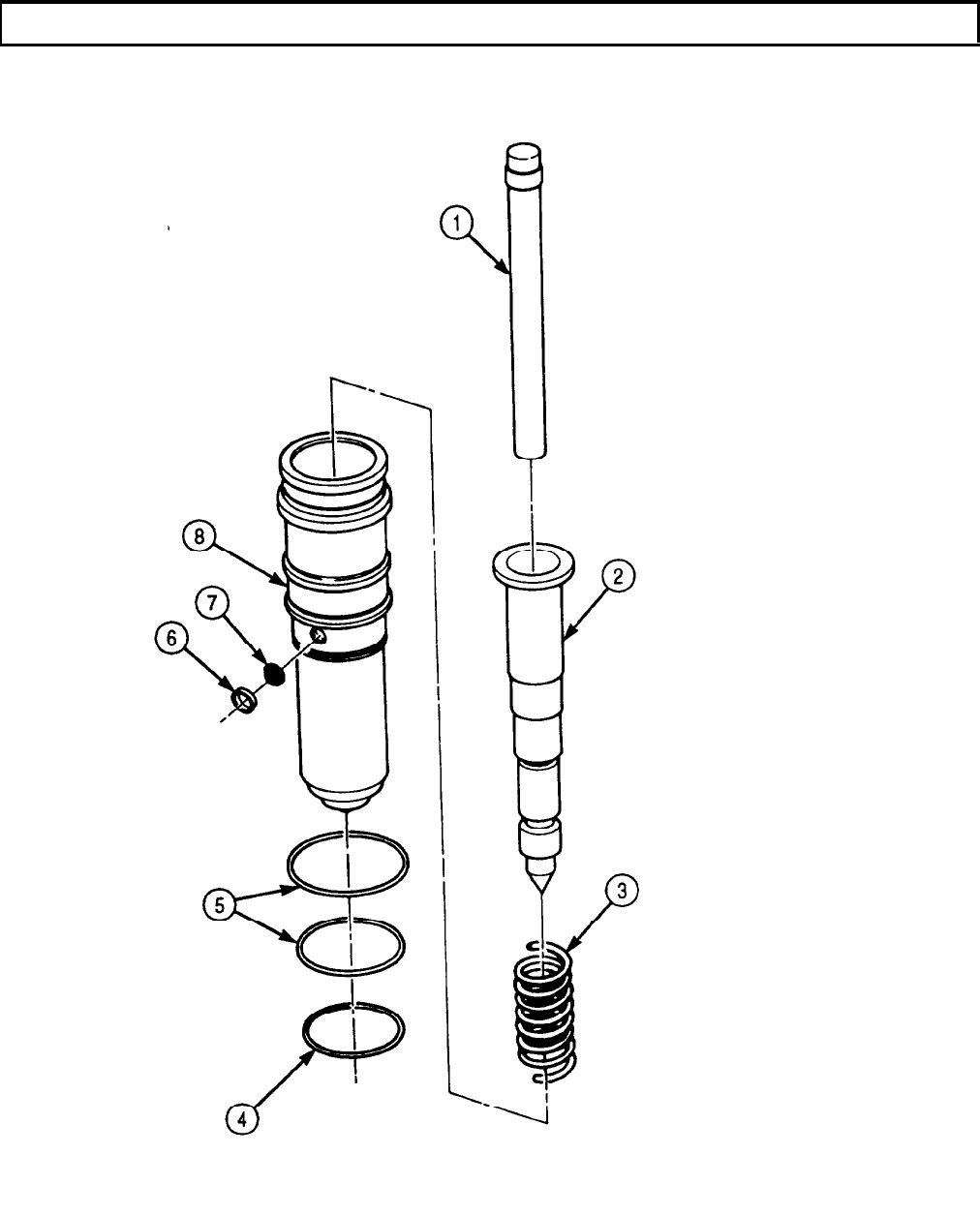
TM 9-2320-272-24-4
5-19. FUEL INJECTOR REPAIR (Contd)
5-123
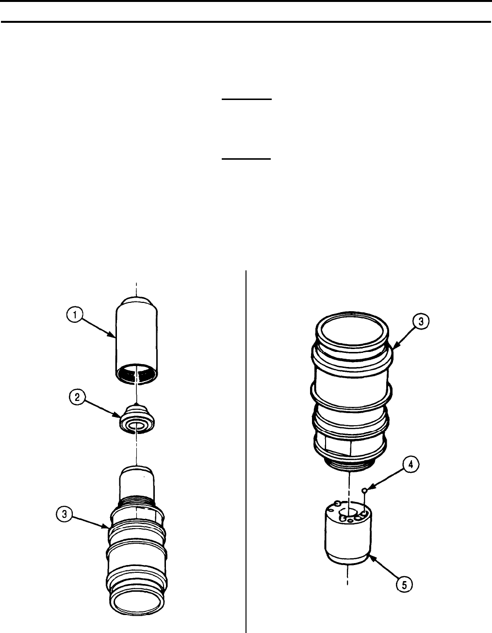
TM 9-2320-272-24-4
5-19. FUEL INJECTOR REPAIR (Contd)
6.
Install injector body wrench in vise.
7.
Slide flat machined areas of injector (6) into body wrench.
8.
Loosen cup retainer (1) with cup retainer wrench.
9.
Remove injector (6) and body wrench from vise.
CAUTION
When handling injector, use care not to drop or lose parts.
10.
Set injector adapter (3) upright on flat surface and remove cup retainer (1) by lifting straight up.
11.
Remove injector cup (2) from injector (6). Discard injector cup (2).
CAUTION
l
Injector barrel and plunger are a matched pair (class fit). Do not
interchange.
l
Do not touch internal parts unless hands are clean and
moistened with diesel fuel. Failure to do so may result in
damage to internal parts.
12.
Hold injector barrel (5) and adapter (3) together and set injector barrel (5) end upright on clean
cloth. Lift adaptor (3) straight out of injector barrel (5) while holding injector barrel (5).
13.
Lift injector barrel (5) up and tilt over hand until check ball (4) falls out.
5-124
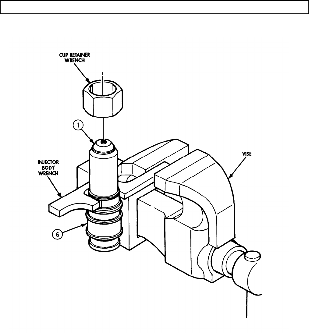
TM 9-2320-272-24-4
5-19. FUEL INJECTOR REPAIR (Contd)
5-125

TM 9-2320-272-24-4
5-19. FUEL INJECTOR REPAIR (Contd)
b. Top Stop Injector Disassembly
1.
2.
3.
4.
5.
6.
7.
8.
9.
10.
11.
12.
13.
14.
WARNING
Drycleaning solvent is flammable and toxic. Do not use near open
flame and always have a fire extinguisher nearby when solvents
are used. Use only in well-ventilated places, wear protective
clothing, and dispose of cleaning rags in approved container.
Failure to do this may result in injury or death to personnel and/or
damage to equipment.
CAUTION
l
When handling injector, use care not to drop or lose parts.
l
Improper cleaning methods and use of unauthorized cleaning
solvents can damage equipment.
Clean exterior of injector (6) with drycleaning solvent (para. 2-14).
Install injector body wrench in vise.
Slide flat machined areas of injector (6) into injector body wrench.
Loosen locknut (4) with locknut wrench.
Loosen adjusting screw (3) with adjusting wrench.
Remove adjusting screw (3), locknut (4), plunger (2), spring retainer (1), and plunger spring (7) from
injector (6).
Loosen cup retainer (5) using cup retainer wrench.
Remove injector (6) and body wrench from vise.
Set injector adapter (9) upright on flat surface and remove cup retainer (5) by lifting straight up.
Remove injector cup (8) from injector (6). Discard injector cup (8).
CAUTION
l
Injector barrel and plunger are a matched pair (class fit). Do not
interchange.
l
Do not touch internal parts unless hands are clean and
moistened with diesel fuel. Failure to do so may result in
damage to internal parts.
Hold injector barrel (11) and adapter (9) together and set injector barrel (11) end upright on clean
cloth. Lift adapter (9) straight up out of injector barrel (11) while holding injector barrel (11).
Lift injector barrel (11) up and tilt over hand until check ball (10) falls out. Discard check ball (10).
Remove small O-ring (13) and two large O-rings (12) from injector (6). Discard O-rings (13) and (12).
Remove screen retaining ring (14) and screen (15) from injector (6). Discard screen retaining ring (14)
and screen (15).
5-126
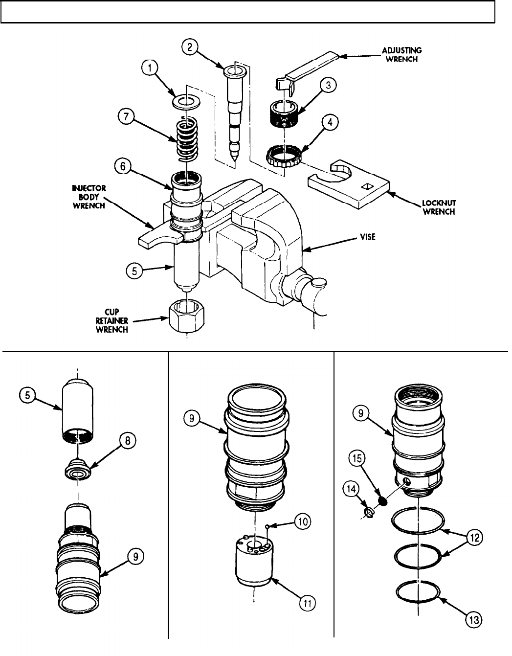
TM 9-2320-272-24-4
5-19. FUEL INJECTOR REPAIR (Contd)
5-127
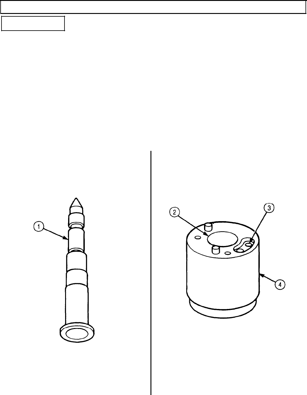
TM 9-2320-272-24-4
5-19. FUEL INJECTOR REPAIR (Contd)
c. Inspection
1.
2.
3.
4.
NOTE
l Bright spots or surface disruption at top of plunger-machined
area, on opposite side at bottom or midpoint, are normal results
of rocker lever action.
l This task pertains to the non-top stop and top stop injectors.
Inspect machined surfaces of plunger (1) for pitting, wear, cracks, and looseness. Narrow streaks
running length of plunger (1) are normal. Plunger (1) should be one solid part. If plunger (1) is
pitted or worn, or if cracks or looseness exist, replace plunger (1) and injector barrel (4).
Inspect injector barrel plunger bore (2) for scoring with strong magnifying glass. If scoring exists,
replace injector barrel (4) and plunger (1).
Inspect injector barrel (4) surface at each end for burrs or scratches. If burrs or scratches exist,
replace injector barrel (4) and plunger (1).
Inspect injector barrel check ball seat (3) for nicks or burrs. If nicks or burrs exists, replace injector
barrel (4) and plunger (1).
5-128
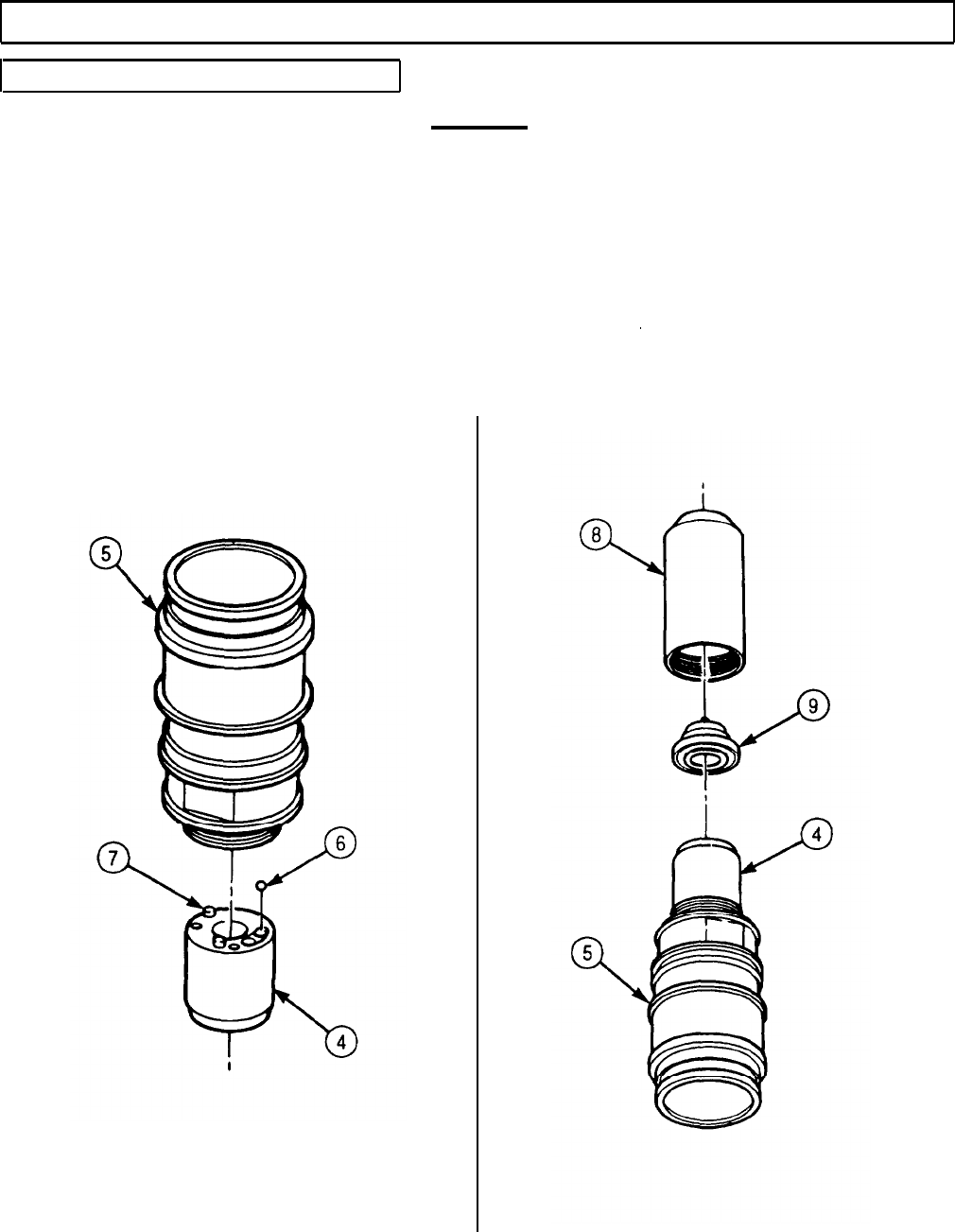
TM 9-2320-272-24-4
5-19. FUEL INJECTOR REPAIR (Contd)
d. Non-Top Stop Injector Assembly
CAUTION
l Injector barrel and plunger are a matched pair (class fit). Do not
interchange.
l Do not touch internal parts unless hands are clean and
moistened with diesel fuel. Failure to do so may result in
damage to internal parts.
1.
Place new check ball (6) in palm of hand and scoop up into injector barrel (4).
2.
Place injector barrel (4) flat on clean cloth so mating surface faces upward and align spiral pins (7)
with holes in adapter (5)
3.
Place adapter (5) on injector barrel (4) and hold together. Set adapter (5) upright on clean cloth.
4.
Position new injector cup (9) on top of injector barrel (4) and screw cup retainer (8) onto adapter (5).
Finger tighten cup retainer (8), and back off 1/4 turn.
5-129

TM 9-2320-272-24-4
5-19.
FUEL INJECTOR REPAIR (Contd)
5. Place injector cup retainer wrench over cup retainer (3).
CAUTION
l Injector barrel and plunger are a matched pair (class fit). Do not
interchange.
l Do not touch internal parts unless hands are clean and
moistened with diesel fuel. Failure to do so may result in
damage to internal parts.
6.
7.
8.
9.
10.
11.
12.
13.
14.
Apply clean diesel fuel to coat plunger (2) and insert plunger (2) into adapter (1).
Remove loading fixture stud (6) from loading fixture (4) and slide body wrench over injector (5) flats.
Position cup retainer wrench on cup retainer (3).
Install loading fixture stud (6) in loading fixture (4) and tighten 110 lb-in. (12 N
l
m).
Tighten cup retainer (3) 50 lb-ft (68 N
l
m) with torque wrench and crowfoot wrench.
Remove loading fixture stud (6) from loading fixture (4) and lift injector (5) out of loading fixture (4).
Remove plunger (2) from adapter (1).
Apply clean diesel fuel to coat plunger (2).
Insert plunger (2) into injector (5) barrel so plunger (2) remains 0.5 in. (12.7 mm) from edge of
adapter (1).
15.
Press plunger (2) into cup retainer (3) with palm of hand.
CAUTION
Do not allow plunger to fall out during step 16.
16.
17.
18.
19.
20.
21.
Turn cup retainer (3) and adapter (1) with one hand so cup retainer (3) faces upward. Plunger (2)
should slide out immediately. If plunger (2) does not slide out immediately, the injector (5) is not
aligned and must be reassembled as outlined in task b., steps 5 through 14.
Slide two new large O-rings (10) over end of injector (5) and into two upper grooves (15) on adapter.
Slide new small O-ring (9) over end of injector (5) onto lowest groove (13) on adapter (1).
Place new inlet fuel screen (11) over adapter orifice (14) and install with new retainer ring (12).
Place spring (8) on plunger (2) and slide plunger (2) into injector (5).
Install injector link (7) in plunger (2).
5-130

TM 9-2320-272-24-4
5-19. FUEL INJECTOR REPAIR (Contd)
5-131

TM 9-2320-272-24-4
5-19. FUEL INJECTOR REPAIR (Contd)
e. Top Stop Injector Assembly
1.
2.
3.
4.
5.
6.
Place new check ball (3) in injector barrel (4).
Place injector barrel (4) flat on clean lint-free cloth so mating surface faces upward.
Place adapter (2) on injector barrel (4).
Hold injector barrel (4) and adapter (2) together and set adapter (2) upright on clean lint-free cloth.
Position new injector cup (6) on top of injector barrel (4).
Screw cup retainer (5) onto adapter (2), finger tighten, and back off 1/4 turn.
CAUTION
l Injector barrel and plunger are a matched pair (class fit). Do not
interchange.
l Do not touch internal parts unless hands are clean and
moistened with diesel fuel. Failure to do so may result in
damage to internal parts.
7.
Apply clean diesel fuel to coat plunger (1).
8.
Insert plunger (1) into adapter (2).
9.
Remove loading fixture stud (7) from loading fixture (8) and insert injector (9) into loading fixture (8).
10.
Slide body wrench over flats on injector adapter (2).
11.
Position cup retainer wrench on cup retainer (5).
12.
Install loading fixture stud (7) in loading fixture (8) and tighten 75 lb-ft (8 N
l
m).
13.
Tighten cup retainer (5) 50 lb-ft (68 N
l
m) with torque wrench and crowfoot wrench.
CAUTION
l Lubricate parts only with clean diesel fuel before assembly. Do
not use lubricating oil. Oil can crystallize under excessive heat,
causing damage to injector components.
l Do not touch internal parts unless hands are clean and
moistened with diesel fuel. Failure to do so may result in
damage to internal parts.
5-132
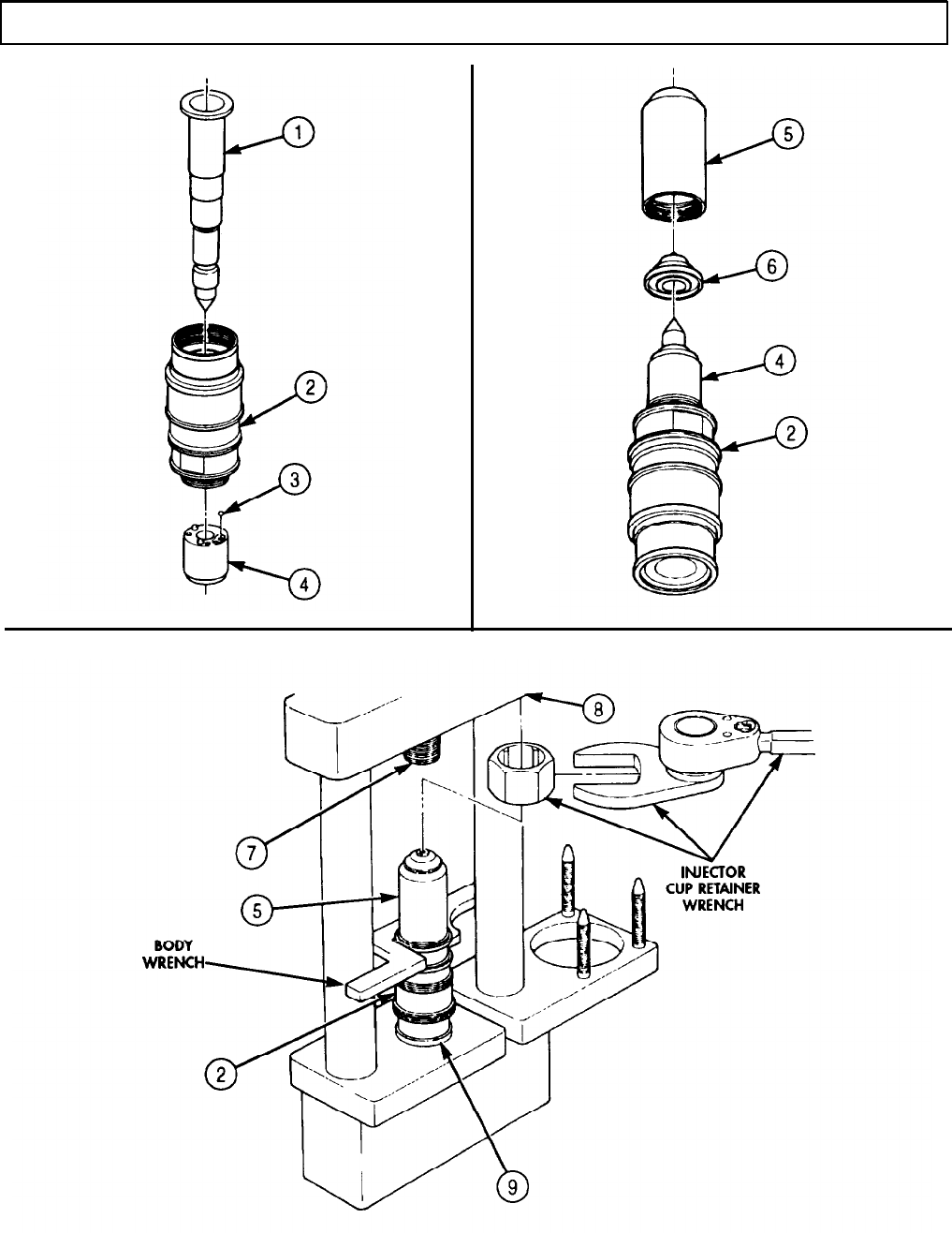
TM 9-2320-272-24-4
5-19. FUEL INJECTOR REPAIR (Contd)
5-133

TM 9-2320-272-24-4
5-19. FUEL INJECTOR REPAIR (Contd)
14.
15.
16.
17.
18.
Remove injector (4) and body wrench from loading fixture.
Remove plunger (2) from injector (4).
Apply clean diesel fuel to coat plunger (2).
Insert plunger (2) into injector (4) so plunger (2) remains 0.5 in. (12.7 mm) from edge of adapter (1).
Press plunger (2) into cup retainer (3) with palm of hand.
CAUTION
19.
20.
21.
22.
23.
24.
Do not allow plunger to fall out. Damage to plunger may result.
Turn cup retainer (3) and adapter (1) with one hand so cup retainer (3) faces upward. Plunger (2)
should slide out immediately. If plunger (2) does not slide out immediately, the injector (4) is not
aligned and must be reassembled as outlined in steps 1 through 18.
Install body wrench in vise.
Slide injector (4) into body wrench.
Place spring (9) and spring retainer (5) in injector (4).
Slide plunger (2) into injector (4).
25.
26.
Thread locknut (8) and adjusting screw (7) into injector (4) with locknut wrench and top-stop
adjusting wrench (6) until locknut (8) contacts adapter (10). Tighten locknut (8) 55 lb-ft
(75 N
l
m).
Remove injector (4) from body wrench.
Slide two new large O-rings (15) over end of injector (4) and into two upper grooves (11) and (12) of
adapter (10).
27.
Slide new small O-ring (14) over end of injector (4) into lowest groove (13) on adapter (10).
28.
Place new inlet fuel screen (17) over adapter orifice (18) and install with new retainer ring (16).
5-134
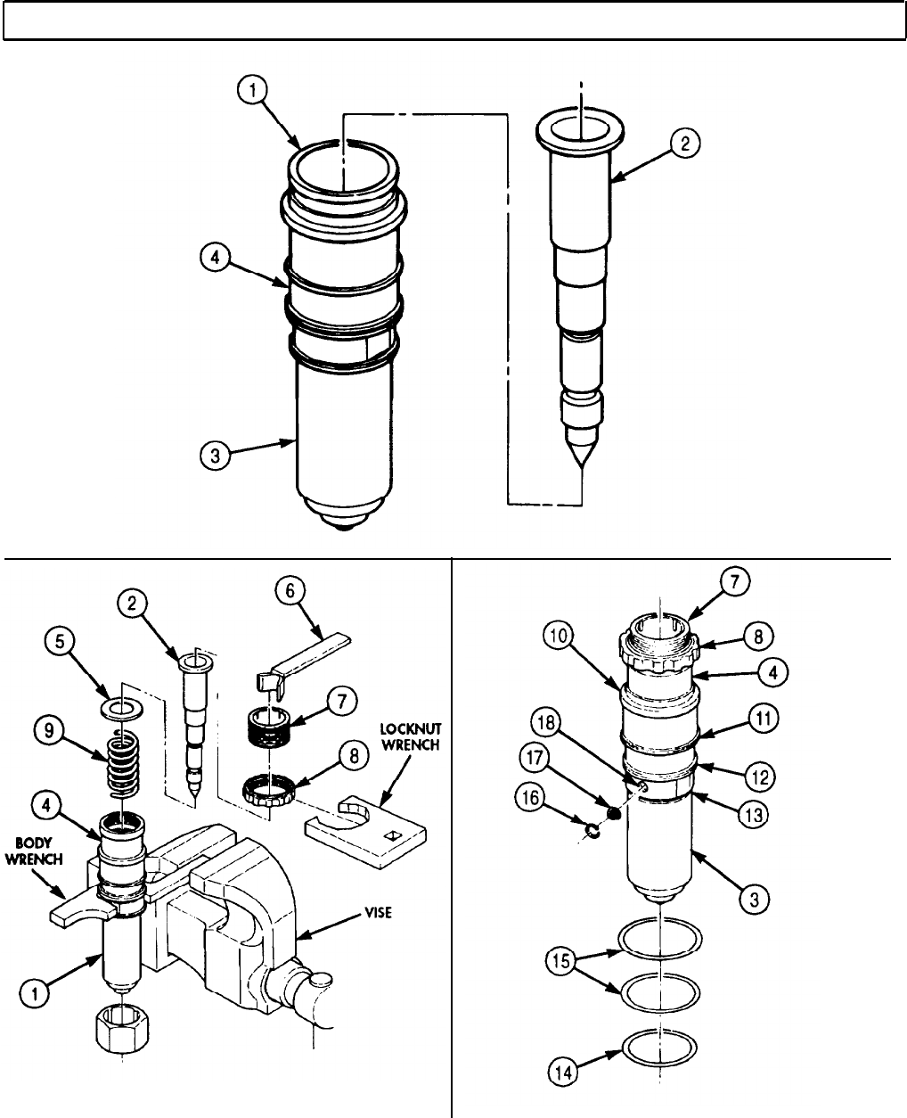
TM 9-2320-272-24-4
5-19. FUEL INJECTOR REPAIR (Contd)
FOLLOW-ON TASK: Install fuel injectors (para. 4-32).
5-135

TM 9-2320-272-24-4
5-20. INJECTOR LEAK TEST
THIS TASK COVERS:
a. Setting Up Injector Leakage Detector b. Testing Injector Plunger and Seat
INITIAL SETUP:
APPLICABLE MODELS
REFERENCES (TM)
M939/A1
TM 9-2320-272-24P
SPECIAL TOOLS
EQUIPMENT CONDITION
Injector leakage detector (Appendix E, Item 68) Fuel injectors removed (para. 4-32).
TOOLS
General mechanic’s tool kit (Appendix E, Item 1)
Feeler gauge
a. Setting Up Injector Leakage Detector
1.
2.
3.
4.
5.
6.
7.
Set pressure regulator on leakage tester at 60 psi (414 kPa). Read pressure setting on pressure
regulator gauge (1).
Operate retraction lever (3) on leakage tester three times, and reset pressure regulator gauge (1) at
60 psi (414 kPa).
NOTE
Air pressure must be held at 60 psi (414 kPa) during all tests.
Place leakage tester retraction lever (3) in position A.
Position load cell (2) on leakage tester.
Adjust knurled knob (4) on load cell (2) until load cell (2) reads 200 psi (1,379 kPa).
NOTE
Do not adjust locknut unless load cell is in use.
Place feeler gauge between knurled knob (4) and locknut (5) and adjust locknut (5).
Remove load cell (2) from leakage tester.
5-136
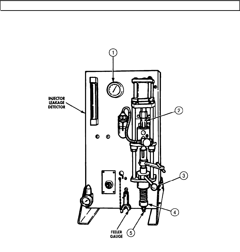
TM 9-2320-272-24-4
5-20. INJECTOR LEAK TEST (Contd)
5-137

TM 9-2320-272-24-4
5-20. INJECTOR LEAK TEST (Contd)
b. Testing Injector Plunger and Seat
1.
Remove plunger (2) and spring (3) from injector (4).
2.
Install injector link (1) in plunger (2) and place in injector (4).
3.
Remove screen retaining ring (6) and inlet fuel screen (7) from injector (4).
4.
Align injector delivery orifice (5) with burnishing tool hole (11) on burnishing tool adapter (10).
5.
Insert locating screw (8) in locating screw hole (9) on burnishing tool adapter (10) and tighten.
NOTE
Support plate may be tilted.
6.
7.
8.
9.
10.
11.
12.
13.
14.
15.
Position injector (4) on support plate (14) and install in leakage tester.
Place feeler gauge between knurled knob (17) and locknut (18). Do not adjust locknut (18).
Install transfer line (20) and tighten in injector adapter (13) drain port.
Tighten T-handle clamp (15).
Shift retraction lever (16) from position A to position B. Ensure plunger (2) retracts.
Rotate plunger (2) in clockwise direction a little at a time while reading air flow meter (12).
Stop rotating plunger (2) when highest reading is obtained.
If air flow meter (12) reading is over 4.5, overhaul injector (4) (para. 5-19).
Shift retraction lever (16) from position B to position A.
Loosen T-handle clamp (15). This will apply 200 lbs (91 kg) load to plunger (2).
While observing checker (21), see if any bubbles appear during the first ten seconds of testing.
No bubbles should appear.
16.
17.
18.
19.
20.
21.
22.
23.
24.
If a bubble does appear, observe the time it takes for the next one to appear. No more than
one bubble can appear every five seconds. If bubbling is too high, overhaul injector (4) (para. 5-19).
Remove transfer line (20) from injector adapter (13) drain port.
Release air pressure from pressure regulator (19).
Remove injector adapter (13) from leakage tester.
Remove locating screw (8) and transfer line (20) from burnishing tool adapter (10).
Remove injector (4) from burnishing tool adapter (10).
Place inlet fuel screen (7) over injector orifice (5), and install with retainer ring (6).
Remove plunger (2) and injector link (1) from injector (4).
Place plunger (2) and spring (3) in injector (4).
5-138
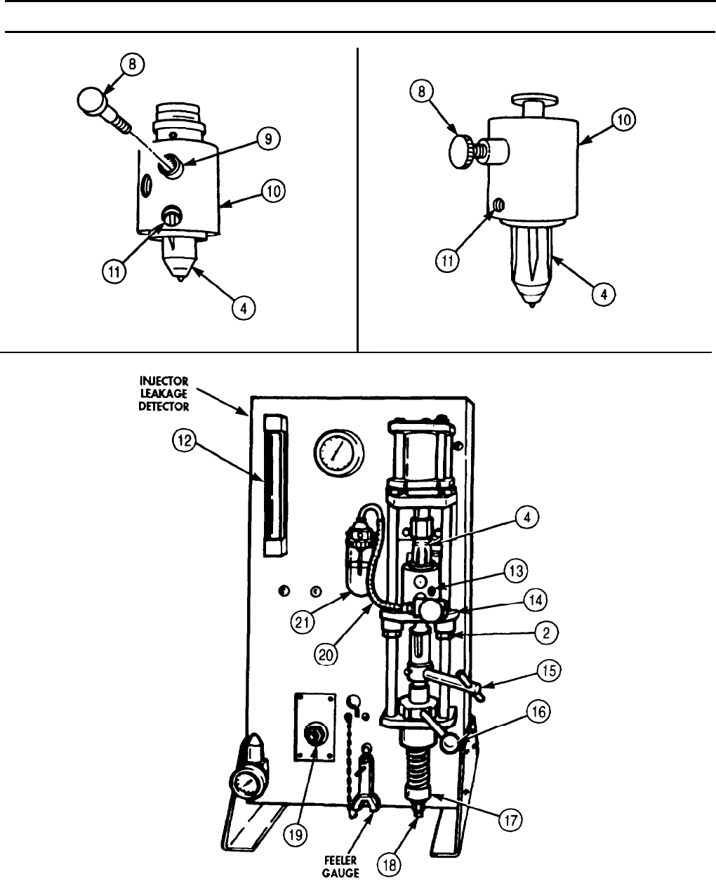
TM 9-2320-272-24-4
5-20. INJECTOR LEAK TEST (Contd)
FOLLOW-ON TASK: Install fuel injectors (para. 4-32).
5-139
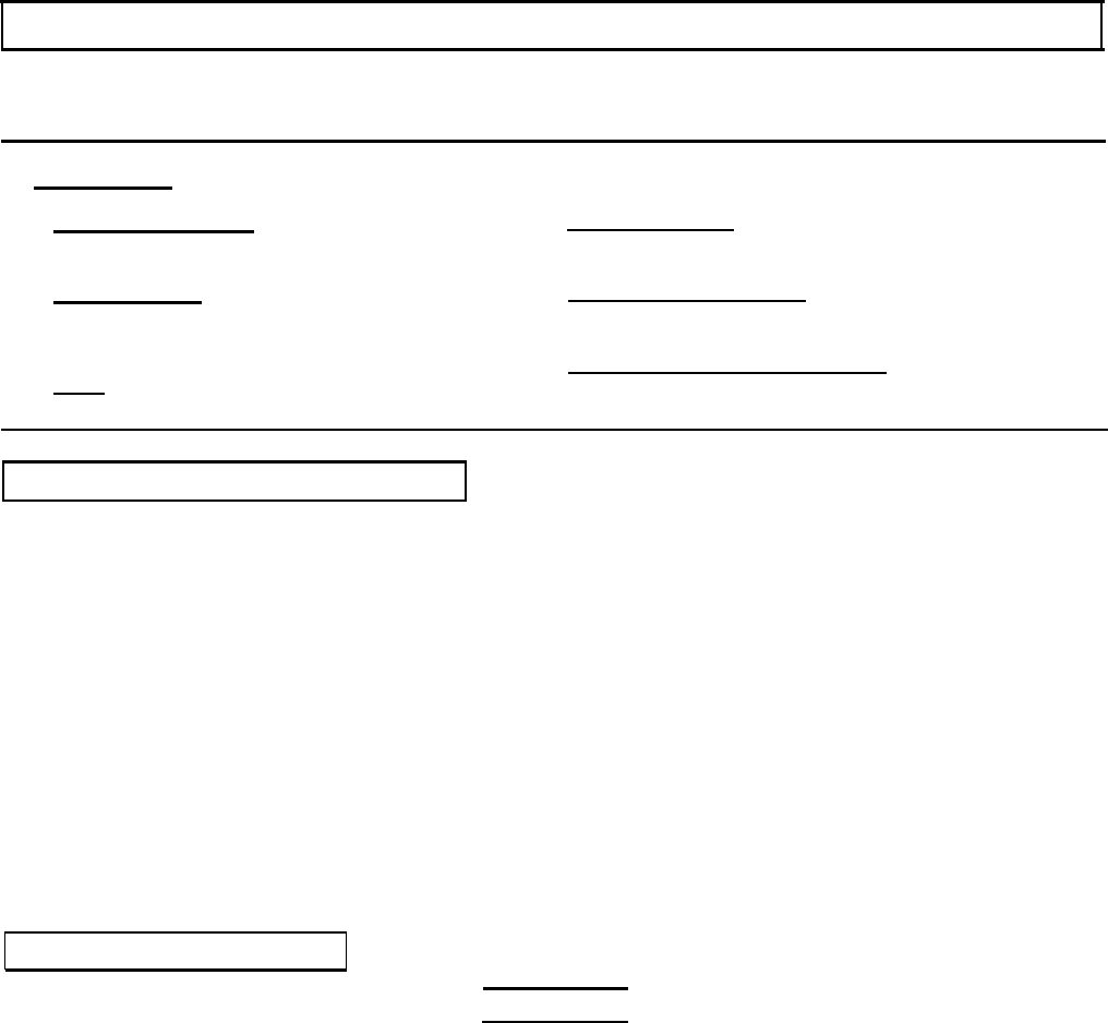
TM 9-2320-272-24-4
5-21. INJECTOR SPRAY PATTERN TEST
THIS TASK COVERS:
a. Setting Up Spray Pattern Tester b. Testing Spray Pattern
INITIAL SETUP:
APPLICABLE MODELS
M939/A1
SPECIAL TOOLS
Fuel injection tester (Appendix E, Item 49)
Spray angle tester (Appendix E, Item 138)
REFERENCES (TM)
TM 9-2320-272-24P
EQUIPMENT CONDITION
Fuel injectors removed (para. 4-32).
GENERAL SAFETY INSTRUCTIONS
TOOLS
General mechanic’s tool kit (Appendix E, Item 1) Whenever fuel is forced from injector spray holes,
keep hands away from spray stream.
a. Setting Up Spray Pattern Tester
NOTE
Any source of 22 psi (152 kPa) constant fuel pressure will operate
spray pattern tester.
1.
Locate spray pattern tester near or on injector test stand.
2.
Attach inlet hose (2) to adapter (8) from injector test stand.
3.
Attach drain hose (4) to adapter base (5) and place loose end in test stand drain area.
4.
Remove plunger (10) and spring (11) from injector (12) and store in safe place.
5.
Remove screen retaining ring (15) and inlet fuel screen (14) from injector test stand.
6.
Place injector (12) in adapter (8).
7.
Install knurled plug (6) in adapter (8) drain opening.
8.
Place injector (12) in spray pattern tester and tighten inlet hose connector (3).
9.
Install injector (12) in spray patter tester holddown bracket (9) with knurled knob (1).
10.
Install target ring (7) marked 8-.007 x 17o on spray pattern tester.
b. Testing Spray Pattern
WARNING
Keep hands away from spray stream when fuel is forced from injector
spray holes. Failure to do this may result in injury to personnel.
1.
Apply 22 psi (152 kPa) pressure to injector test stand.
NOTE
Each spray stream must hit a window in the target ring.
2.
Shift target ring (7) so one spray stream hits on No. 1 or index window. If spray stream is off 2o of
window, replace cup (para. 5-19).
3.
Loosen knurled knob (1) on holddown bracket (9).
4.
Remove injector (12) from spray pattern tester.
5.
Remove knurled plug (6) and injector (12) from adapter (8).
6.
Install spring (11) and plunger (10) in injector (12).
7.
Install inlet fuel screen (14) over injector orifice (13) with screen retaining ring (15).
5-140
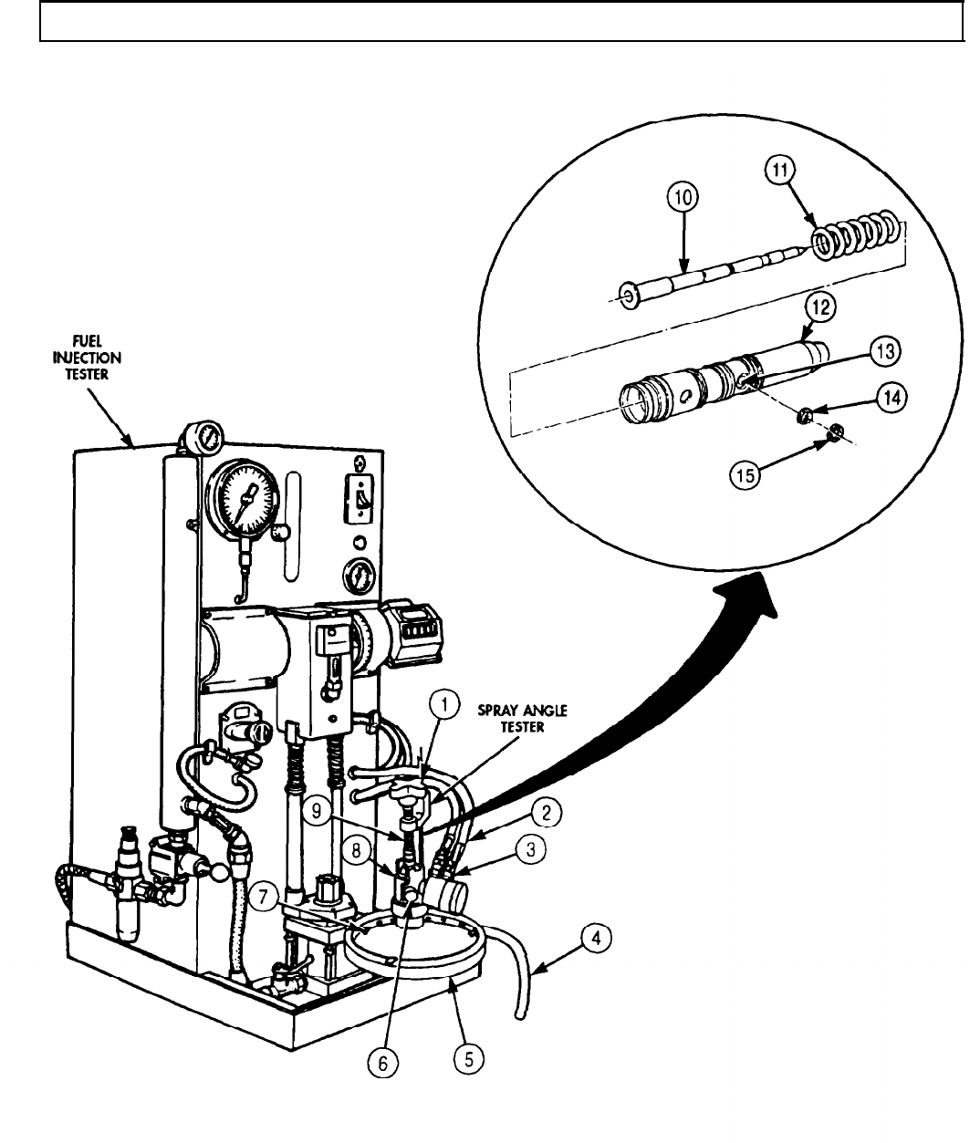
TM 9-2320-272-24-4
5-21. INJECTOR SPRAY PATTERN TEST (Contd)
FOLLOW-ON TASK: Install fuel injectors (para. 4-32).
5-141

TM 9-2320-272-24-4
5-22. INJECTOR TEST STAND CALIBRATION
THIS TASK COVERS:
a. Setting Up Injection Tester b. Test Stand Calibration
INITIAL SETUP:
APPLICABLE MODELS TOOLS
M939/A1
General mechanic’s tool kit (Appendix E, Item 1)
SPECIAL TOOLS REFERENCES (TM)
Fuel injection tester (Appendix E, Item 49) TM 9-2320-272-24P
a. Setting Up Injection Tester
1.
Rotate counter wheel (2) on injection tester until wheel marks and pointer are aligned.
2.
Open hydraulic valve (3).
CAUTION
3.
4.
5.
6.
Never operate test stand with load cell in position.
Position load cell tester on injection tester and secure by opening air valve (4).
Adjust air regulator (5) by turning knurled knob (7) until load cell tester registers within coded
range markings. Record air gauge (1) pressure reading.
Lock air regulator (5) in place with locknut (6).
Place air valve (4) to center position and remove load cell tester from injection tester.
5-142
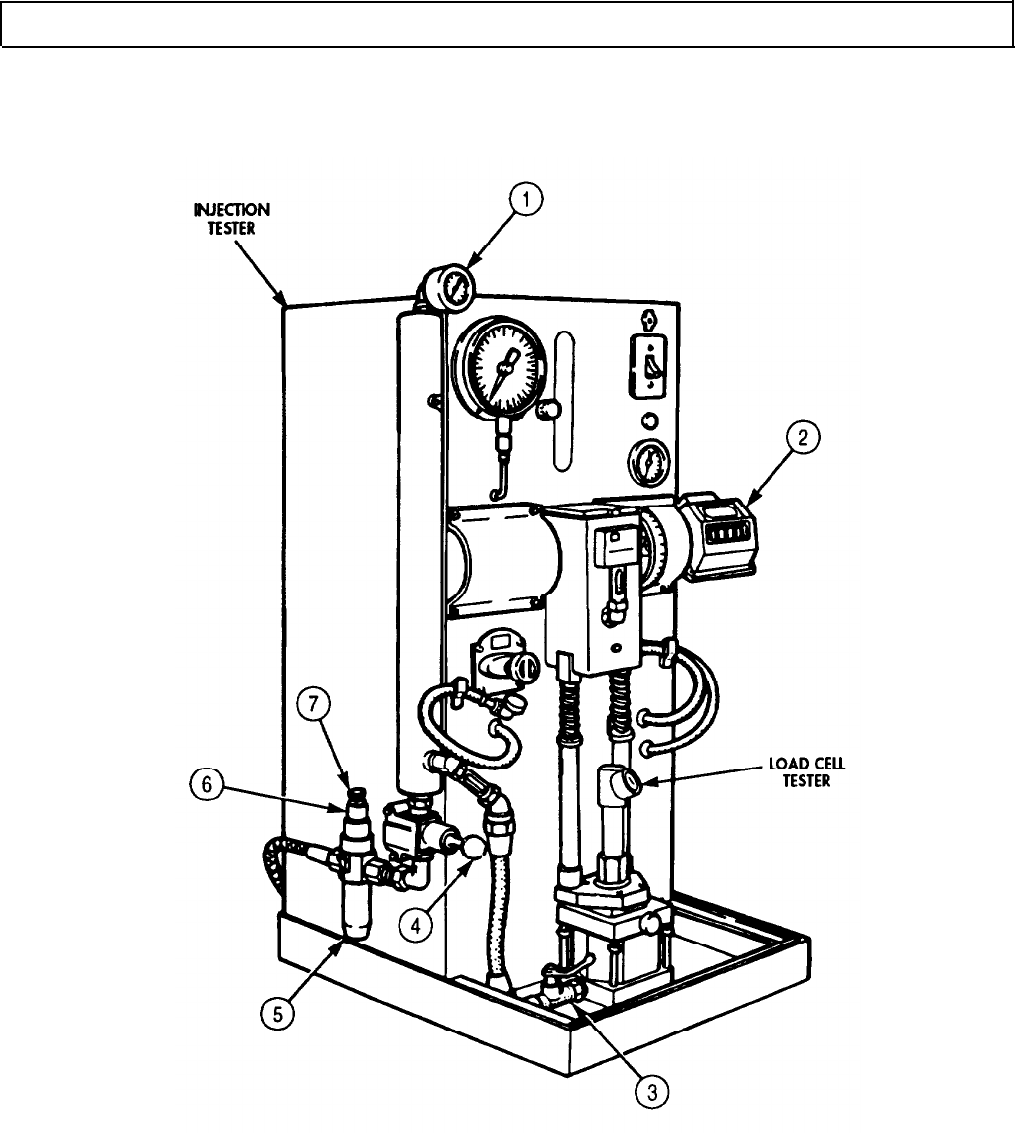
TM 9-2320-272-24-4
5-22. INJECTOR TEST STAND CALIBRATION (Contd)
5-143
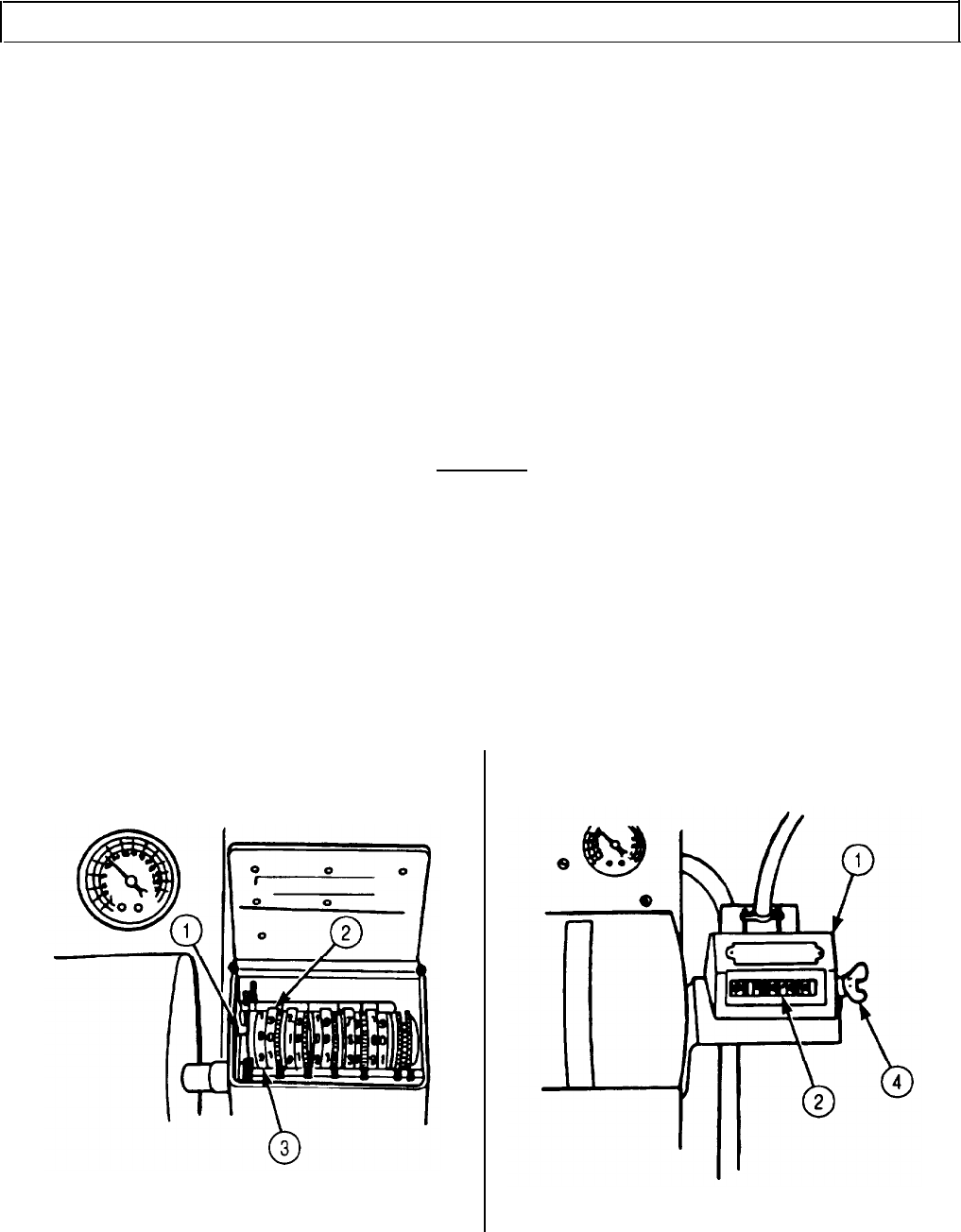
TM 9-2320-272-24-4
5-22. INJECTOR TEST STAND CALIBRATION (Contd)
7.
When cylinder (11) is down, hydraulic fluid should show in sight bulb. Open air valve (13) when
cylinder (11) is at the top of its travel; no air should show in sight glass (14). If air is indicated,
tighten all line connections.
NOTE
The master injector is precalibrated and must never be tampered
with.
8.
Place adapter (20) on master injector (17). Ensure wheel marks and pointer are aligned (step 1).
NOTE
Ensure injector seat contains 0.20 in. (0.51 mm) restrictor orifice.
9.
Position test stand link (15) over injector link (9) and place master injector (10) in injector seat (18).
10.
Tip back until test stand link (15) is below test stand push rod (8) and not rubbing.
11.
Open air valve (13) to clamp master injector (10) in place. Ensure test stand link (15) is aligned.
12.
Close hydraulic valve (12) to lock master injector (10) in place.
13.
Connect test stand fuel drain connector (19) to adapter (20).
14.
Connect test stand fuel inlet connector (16) to adapter (20).
CAUTION
If temperature exceeds 135°F (57°C), drain and replace with new
test oil.
15.
Place injector test stand motor switch (6) in START position. Ensure temperature gauge (7) reads
90°-95°F (32-35°C).
16.
Shift the silver colored counter (1) wheels (3) to the right, rotate counter (1) to indicate 1,020
strokes and release.
17.
Clear counter (1) by rotating thumbscrew (4) one complete revolution. Ensure all white-colored
counter wheels (2) read zero.
5-144
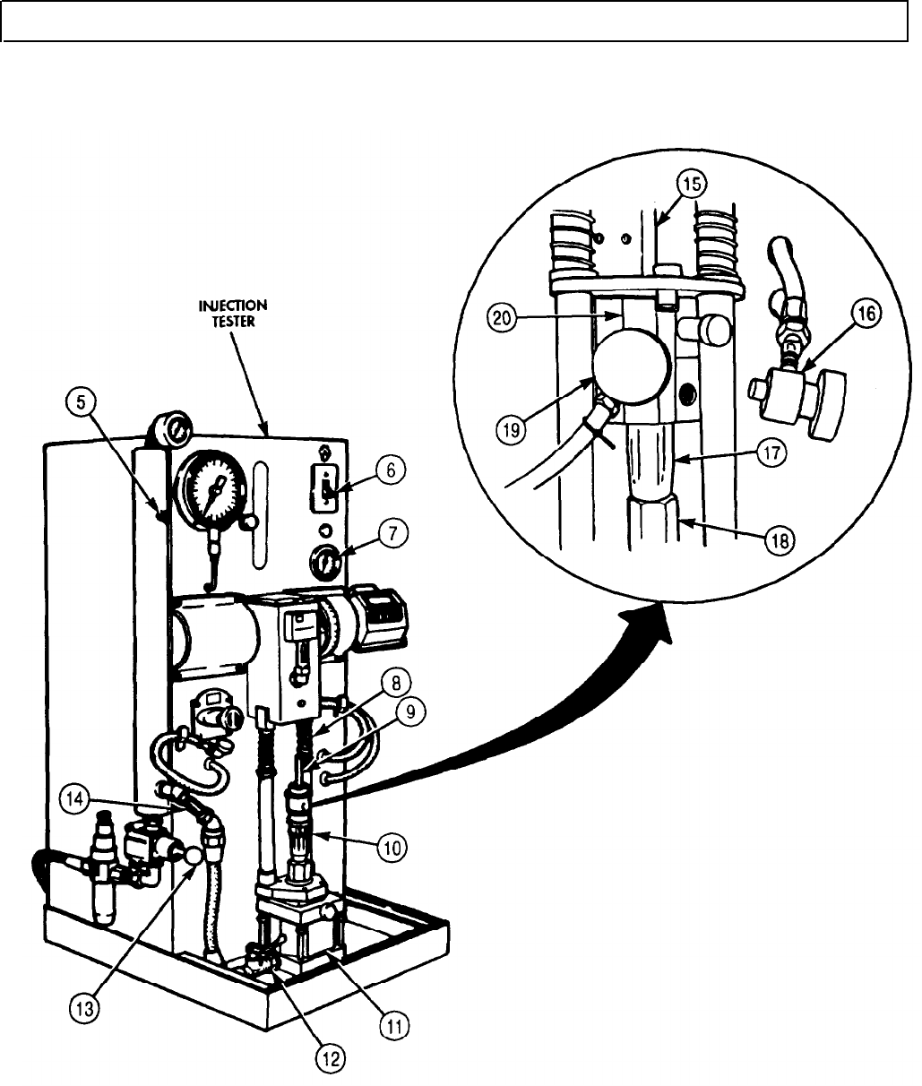
TM 9-2320-272-24-4
5-22. INJECTOR TEST STAND CALIBRATION (Contd)
5-145
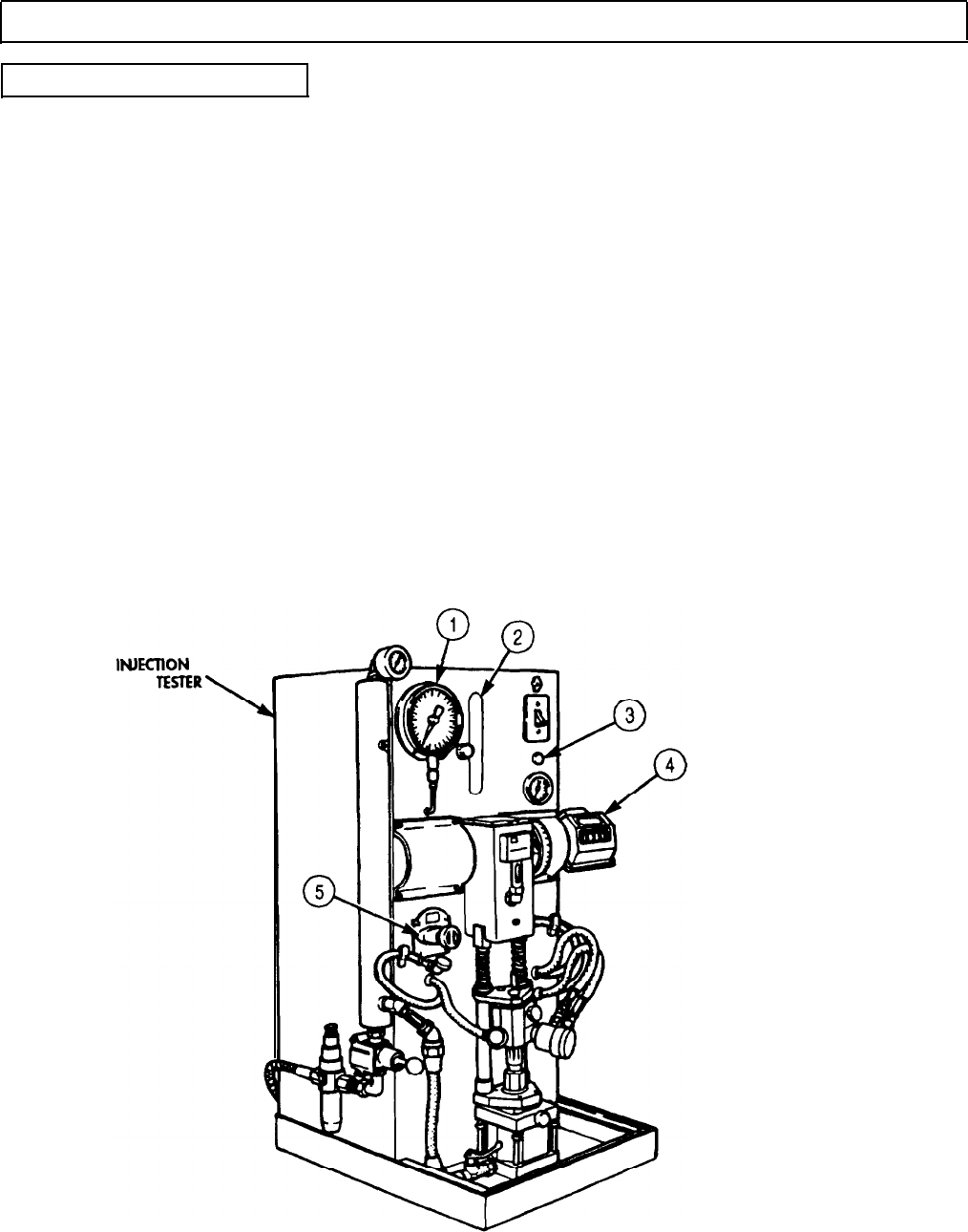
TM 9-2320-272-24-4
5-22. INJECTOR TEST STAND CALIBRATION (Contd)
b. Test Stand Calibration
1.
Adjust regulator knob (5) on injector test stand by turning until pressure gauge (1) reads 120 psi
(827 kPa). Ensure pressure is maintained at 120 psi (827 kPa) during calibration.
2.
Press red flow start switch (3) in and out until counter (4) reads 1,020 count strokes.
3.
Look directly into vial (2) and observe reading.
NOTE
Reading of 132 counterclockwise at 120 psi (827 kPa) indicates
test stand is in calibration. If reading is more than 132 cc, the test
stand is not set up properly. Repeat setup steps. If reading is
below 132 cc, continue.
4.
Reset counter (4) on injector test stand to zero (task a., steps 16 and 17).
5.
Set counter (4) up seven strokes for each cc less than 132 cc.
6.
Dump fuel from vial (2).
NOTE
If counter is set beyond 1,050 strokes to obtain 132 cc, the test
stand is not set up properly. Repeat setup steps. If counter reads
1,050 or below, the test stand is in calibration.
7.
Press red flow start switch (3) in and out until counter (4) sets strokes to obtain 132 cc.
8.
Place motor switch (6) in STOP position.
9.
Remove test stand fuel drain connector (14) from adapter (15).
5-146

TM 9-2320-272-24-4
5-22. INJECTOR TEST STAND CALIBRATION (Contd)
10.
Open hydraulic valve (9).
11.
Close air valve (10).
12.
Remove master injector (8) from injector seat (13).
13.
Slide test stand link (11) off injector plunger link (7).
14.
Remove test stand fuel inlet connector (12) from adapter (15).
15.
Remove adapter (15) from master injector (8).
5-147
TM 9-2320-272-24-4
5-23. INJECTOR FLOW TEST
THIS TASK COVERS:
a. Setting Up Test Stand
b. Testing Check Ball Seating c. Adjusting and Measuring Fuel Delivery
INlTIAL SETUP:
APPLICABLE MODELS
M939/Al
SPECIAL TOOLS
Injection tester (Appendix E, Item 49)
TOOLS
General mechanic’s tool kit (Appendix E, Item 1)
Burnishing tool adapter
Adjusting tool adapter
MATERIALS/PARTS
Gasket (Appendix D, Item 240)
Diesel fuel (Appendix C, Item 42)
REFERENCES (TM)
TM 9-2320-272-24P
EQUIPMENT CONDITION
• Fuel injector removed (para. 4-32).
• Injector test stand calibrated (para. 5-22).
SPECIAL ENVIRONMENTAL CONDITIONS
Work area clean and free from blowing dirt and dust.
a. Setting Up Test Stand
1.
Remove screen retainer ring (5) and inlet fuel screen (4) from injector (3).
2.
Remove plunger (1) and spring (2) from injector (3) and separate plunger (1) from spring (2).
3.
Place plunger (1) in injector (3) without spring (2).
4.
Apply diesel fuel to lubricate inside of burnishing tool adapter.
CAUTION
Injector inlet port and burnishing tool adapter inlet hole must be
aligned to prevent damage to the burnishing tool points when
installed later.
5.
Position injector (3) in burnishing tool adapter so injector (3) inlet port and burnishing adapter inlet
holes align. Tighten locating screw (12) on burnishing tool adapter to install injector (3).
6.
Connect test stand inlet pressure line adapter (11) to burnishing tool adapter.
b. Testing Check Ball Seating
NOTE
Hold injector in hand; do not place in test stand holding device,
1.
Hold plunger (1) down in injector (3).
2.
Place motor switch (7) on injection tester in START position. Ensure temperature gauge (9) reads
90-95°F (32-35°C).
CAUTION
If temperature exceeds 135°F (57°C), drain and replace with new
test oil.
3.
Adjust regulator knob (9) by turning until pressure gauge (6) reads 150 psi (1,034 kPa).
4.
Check burnishing tool adapter installation hole (10) for leaks. A slight seepage is not harmful. If
leakage is found, replace check ball (para. 5-19).
5.
Place motor switch (7) in STOP position.
6.
Disconnect test stand inlet pressure line adapter (11) from burnishing tool adapter.
5-148
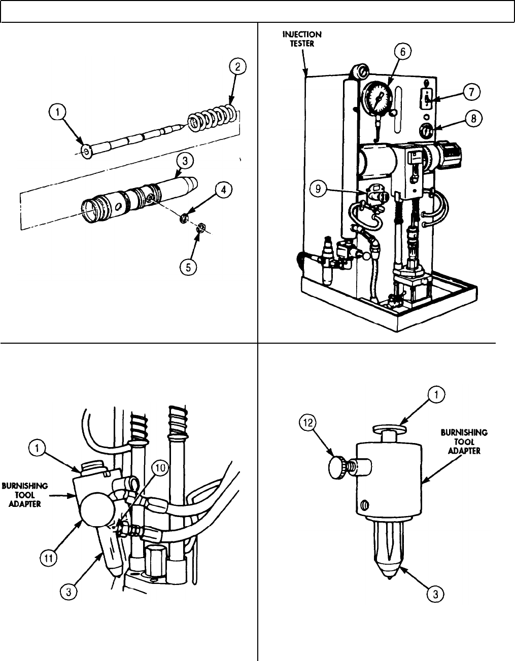
TM 9-2320-272-24-4
5-23. INJECTOR FLOW TEST (Contd)
5-149

TM 9-2320-272-24-4
5-23. INJECTOR FLOW TEST (Contd)
c. Adjusting and Measuring Fuel Delivery
1.
2.
3.
4.
5.
6.
7.
8.
9.
10.
11.
12.
Remove plunger (11) from injector (9).
Slide spring (12) on plunger (11) and place in injector (9).
Place retainer plate (14) on burnishing tool adapter and secure with pins (13).
Place test stand link (1) in burnishing tool adapter. Test stand link (1) should be 6.5 in. (17 cm)
long.
Place injector (9) in injector test stand (7) so injector (9) is in injector seat (8). Tip injector (9) back
until test stand link (1) is below test stand push rod (16) and is not rubbing.
Install burnishing tool (2) in test stand inlet pressure line adapter (9).
Retract burnishing tool needle (4) by pulling small knob (3) out.
NOTE
With needle retracted, burnishing tool may be left in adapter
during all test operations.
Connect test stand inlet pressure line adapter (6) to burnishing tool adapter inlet hole by screwing
in large knob (5).
Install drain connector (10) in burnishing tool adapter.
Clamp injector (9) in place by opening air valve (18). Ensure test stand link (1) is aligned.
Lock injector (9) in place by closing hydraulic valve (17).
Place motor switch (15) in START position. Ensure temperature reads 90°-95° F (32°-35°C).
CAUTION
If temperature exceeds 135 °F (57°C), drain and replace with new
test oil.
5-150
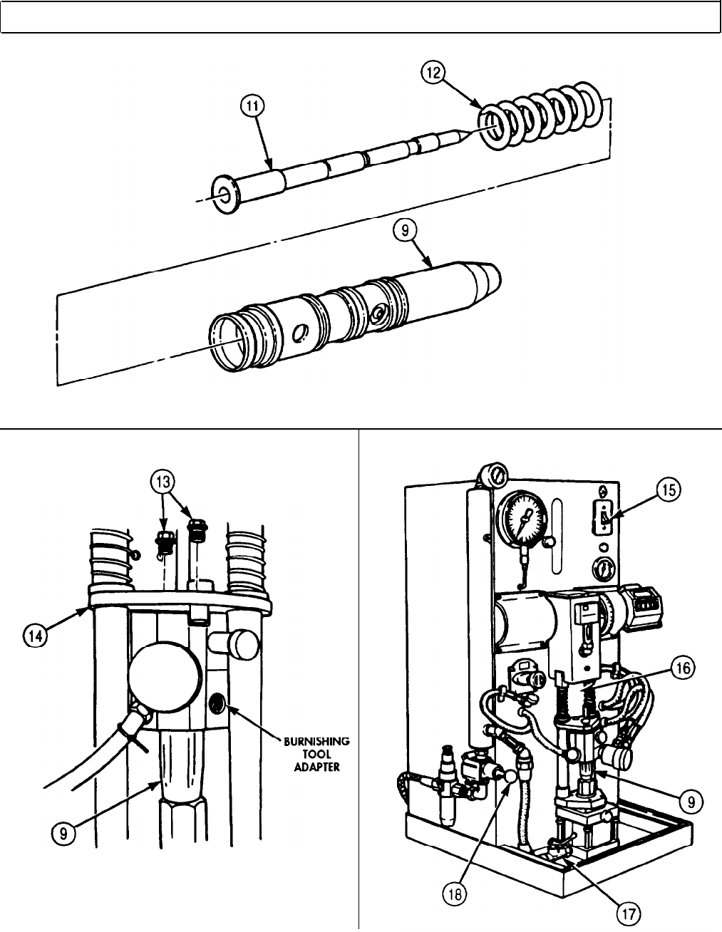
TM 9-2320-272-24-4
5-23. INJECTOR FLOW TEST (Contd)
5-151

TM 9-2320-272-24-4
5-23. INJECTOR FLOW TEST (Contd)
13.
Adjust injector test stand regulator knob (6) by turning until pressure gauge (1) reads 120 psi
(827 kPa).
14.
Press flow start switch (4) in until counter (5) reads the same as master injector counter strokes.
15.
Observe vial (2) reading, If reading is higher than 122 cc at 120 psi (827 kPa), perform steps 17
through 19 to install new orifice plug (16). If reading is lower than 121 cc at 120 psi (827 kPa),
perform steps 20 through 24 to set fuel flow.
16.
Remove test stand inlet pressure line adapter (11) and burnishing tool from burnishing tool
adapter (13) by turning large knob (9) out until assembly is free.
17.
Remove orifice plug (16) and gasket (15) from injector (10). Discard gasket (15).
NOTE
New orifice plug size .018-.019 in. (0.48-0.49 mm) is small enough
so burnishing will increase fuel efficiency.
18.
Install new gasket (15) and orifice plug (16) in injector orifice (14) and tighten orifice plug (16)
8-10 lb-in. (0.9-1.1N•
m).
19.
Install test stand inlet pressure line adapter (11) and burnishing tool on burnishing tool adapter (13)
by screwing large knob (9) into burnishing tool adapter (13) inlet hole until tight.
CAUTION
20.
21.
22.
23.
24.
25.
26.
27.
Place injector test stand motor switch (3) in STOP position.
Remove drain connector (12) from burnishing tool adapter (13).
Screw out large knob (9) on burnishing tool and remove test stand inlet pressure line adapter (11) from
burnishing tool adapter (13).
28.
Remove burnishing tool from burnishing tool adapter (13). Store burnishing tool in clean place.
When seating burnishing tool, use care not to push small knob in
too hard or overtighten indicator knob. When slight contact is
made, stop. Damage can be caused to injector. Test stand must be
running while burnishing.
Turn burnishing tool indicator knob (8) until spaced 3/8 in. (9.5 mm) from large knob (9).
Slowly push small burnishing tool knob (7) in until slight contact is made with injector (10).
Turn small burnishing tool knob (7) counterclockwise to lock large knob (9) and indicator knob (8).
Slowly turn indicator knob (8) in until slightly seated in injector (10). Index indicator knob (8) with
mark on large knob (9).
Advance indicator knob (8) one mark, and back off until spaced 3/8 in. (9.5 mm).
NOTE
Perform steps 12 through 15 and recheck fuel delivery. If delivery
is lower than 121-122 cc, repeat steps 20 through 24. If reading is
higher, install new orifice plug (steps 17 through 19), and recheck
fuel delivery.
5-152
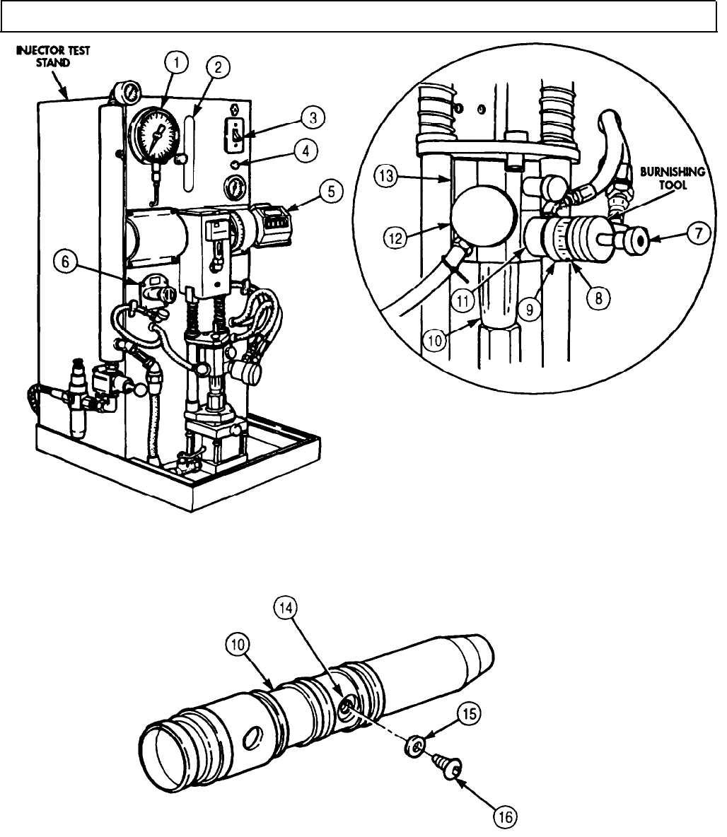
TM 9-2320-272-24-4
5-23. INJECTOR FLOW TEST (Contd)
5-153
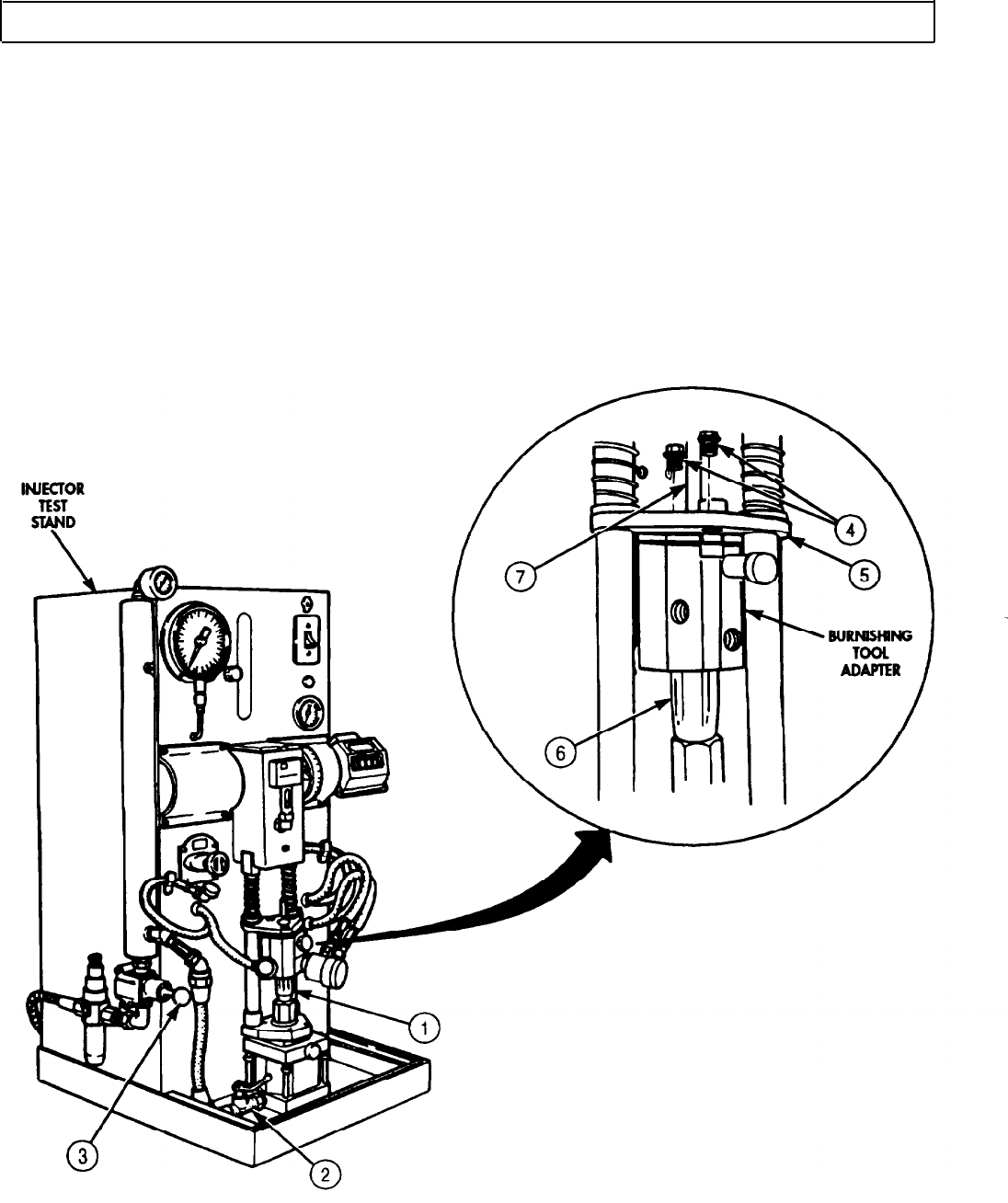
TM 9-2320-272-24-4
5-23. INJECTOR FLOW TEST (Contd)
29.
Open hydraulic valve (2) on injector test stand.
30.
Close air valve (3) on injector test stand.
31.
Remove injector (1) from injector test stand.
32.
Slide test stand link (7) out of burnishing tool adapter.
33.
Remove two pins (4) and retainer plate (5) from burnishing tool adapter.
34.
Remove burnishing tool adapter from injector (6).
35.
Remove plunger (8) and spring (9) from injector (1).
36.
Install screen (10) in injector orifice (12) with screen retainer (11).
37.
Place spring (9) in plunger (8) and slide in injector (1).
NOTE
Store injectors in a clean place.
5-154
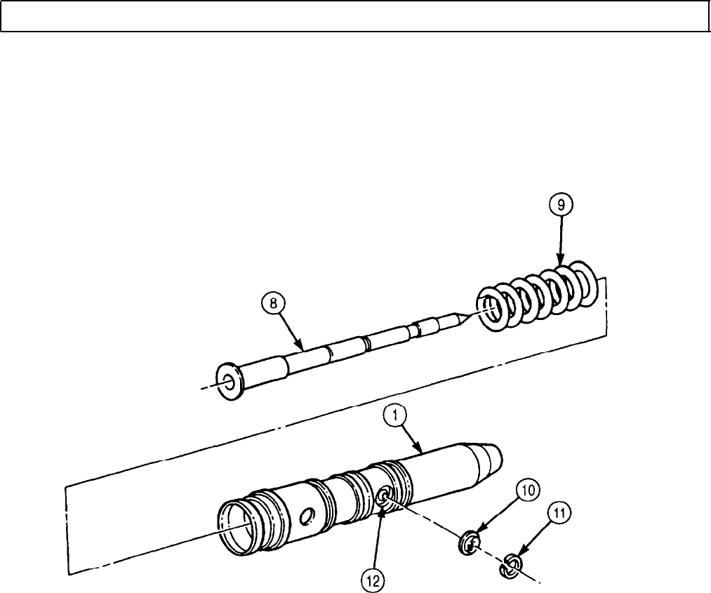
TM 9-2320-272-24-4
5-23. INJECTOR FLOW TEST (Contd)
FOLLOW-ON TASK: Install fuel injector (para. 4-32).
5-155 (5-156 blank)

TM 9-2320-272-24-4
Section II. ENGINE (M939A2) MAINTENANCE
5-24. ENGINE (M939A2) MAINTENANCE INDEX
PARA.
NO. TITLE PAGE
NO.
5-25.
Cylinder Head Repair
5-158
5-26.
Piston and Connecting Rod Maintenance
5-166
5-27.
Camshaft and Gear Maintenance
5-174
5-28.
Cylinder Liners and Block Maintenance
5-184
5-29.
Crankshaft and Gear Maintenance
5-196
5-30.
Rocker Levers and Push Rods Maintenance
5-206
5-31.
Mounting Fuel Injection Pump to Test Stand
5-210
5-32.
Fuel Injection Pump Pretest
5-214
5-33.
Manifold Pressure Compensator Maintenance
5-224
5-34.
R.Q.V. Governor Cover Maintenance
5-228
5-35.
R.Q.V. Governor Housing Maintenance
5-232
5-36.
Fuel Injection Pump Maintenance
5-240
5-37.
Fuel Injection Pump Calibration
5-262
5-157
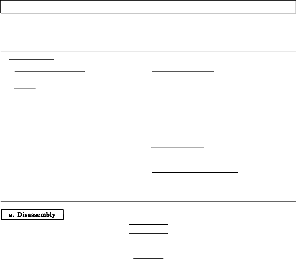
TM 9-2320-272-24-4
5-25. CYLINDER HEAD REPAIR
THIS TASK COVERS:
a. Disassembly
b. Cleaning
c. Inspection
d. Repair
e. Assembly
INITIAL SETUP:
APPLICABLE MODELS
M939A2
TOOLS
General mechanic’s tool kit (Appendix E, Item 1)
Spring compressor (Appendix E, Item 135)
Gauge block (Appendix E, Item 52)
Spring tester (Appendix E, Item 131))
Vernier caliper (Appendix E, Item 159)
Dial indicator (Appendix E, Item 36)
Feeler gauge
Valve refacing machine
MATERIALS/PARTS
Twenty-four collets (Appendix D, Item 253)
Twelve seals (Appendix D, Item 613)
Eight expansion plugs (Appendix D, Item 105)
Expansion plug (Appendix D, Item 106)
Two expansion plugs (Appendix D, Item 107)
Antiseize tape (Appendix C, Item 72)
Lapping compound (Appendix C, Item 37)
Lubricating oil (Appendix C, Item 50)
Pigment (Appendix C, Item 54)
Sealing compound (Appendix C, Item 64)
REFERENCES (TM)
TM 9-247
TM 9-2320-272-24P
EQUIPMENT CONDITION
Cylinder head removed (para. 4-41).
GENERAL SAFETY INSTRUCTIONS
Eyeshields must be worn when removing valves.
WARNING
Valve springs are under compression. Eyeshields must be worn when
removing valves. Failure to do so may cause injury to personnel.
CAUTION
To remove intake and exhaust valves, position cylinder head on
exhaust port face. Use wooden or protective surface work bench to
prevent damage to cylinder head.
NOTE
• Mark location and position of valves for installation.
• All intake and exhaust valves are removed the same.
1.
Using spring compressor, compress valve spring (3) and remove two collets (1) from valve (10) and
cylinder head (9). Discard collets (1).
2.
Release spring compressor and remove two spring retainers (2), valve spring (3), seal (4), and
valve (10) from cylinder head (9). Discard seal (4).
3.
Remove five expansion plugs (5) from top face of cylinder head (9). Discard expansion plugs (5).
4.
Remove expansion plug (6) from rear face of cylinder head (9). Discard expansion plug (6).
5.
Remove two expansion plugs (8) from front and rear faces of cylinder head (9). Discard expansion
plugs (8).
6.
Remove plug (7) from rear face of cylinder head (9).
5-158
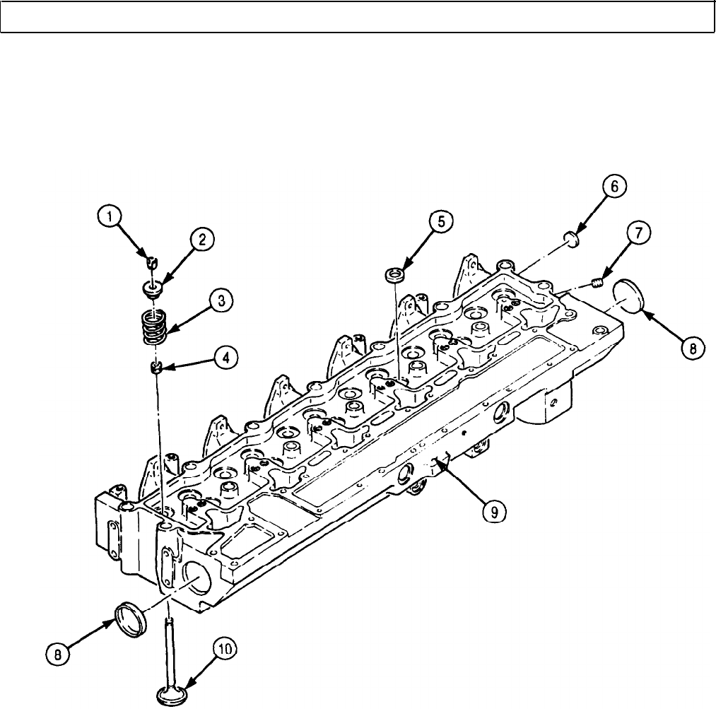
TM 9-2320-272-24-4
5-25. CYLINDER HEAD REPAIR (Contd)
5-159
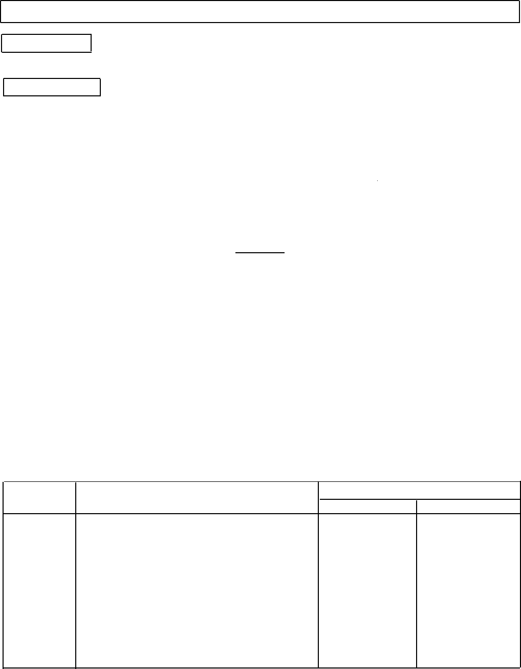
TM 9-2320-272-24-4
5-25. CYLINDER HEAD REPAIR (Contd)
b. Cleaning
Clean all cylinder head components (TM 9-247).
c. Inspection
1.
Inspect cylinder head (1) for cracks, pits, and scratches.
a. If pitted or scratched, remove with crocus cloth.
b. If cracked, excessively pitted or scratched, replace cylinder head (1).
2.
Inspect cylinder head (1) for warping.
a. Using straight edge and feeler gauge, inspect gasket surface of cylinder head (1) from front to
rear. Warping should not exceed 0.008 in. (0.20 mm).
b. Inspect gasket surface of cylinder head (1) from side to side. Warping should not exceed 0.003 in.
(0.076 mm).
c. Using 2-in. (51-mm) straight edge and feeler gauge, inspect for warping across valve ports (2) and
coolant passages (5). Warping should not exceed 0.001 in. (0.025 mm).
CAUTION
Machining of cylinder head surface is not to exceed 0.040 in.
(1.02 mm) or damage to equipment will result.
d. Replace or resurface cylinder head (1) if warping exceeds limits. Notify your supervisor.
NOTE
Perform steps 3 and 4 if cylinder head was resurfaced.
3.
Install valves (3) in their respective valve ports (2).
4.
Using gauge block, measure depth of valves (3). Mark valve seat(s) (6) for resurfacing if depth is less
than 0.043 in. (1.09 mm).
5.
Remove valves (3) from cylinder head (1).
6.
Inspect valve springs (4) for distortion, cracks, and collapsed coils. Refer to table 5-9, Cylinder Head
Wear Limits, for measurements. Replace valve springs (4) if damaged or worn.
7.
Using spring tester, compress valve springs (4) to 2 in. (51 mm). Load measured should be
101.2-115 lb (45.9-52.2 kg). Replace valve spring(s) (4) if not within limits.
8.
Inspect valve spring retainers (8) for wear and distortion. Replace valve spring retainer(s) (8) if
worn or distorted.
Table 5-9. Cylinder Head Wear Limits.
ITEM NO.
3
14
15
4
ITEM/POINT OF MEASUREMENT
Intake and exhaust valves
Rim thickness
Valve stem diameter
Exhaust valve guide
Valve guide length
Valve guide bore, inner
Intake valve guide
Valve guide length
Valve guide bore, inner
Valve springs
Free length
WEAR LIMITS/TOLERANCES
INCHES MILLIMETERS
0.060
1.52
0.373 9.47
0.896
22.76
0.376 9.55
0.893 22.68
0.376 9.55
2.585
65.66
5-160
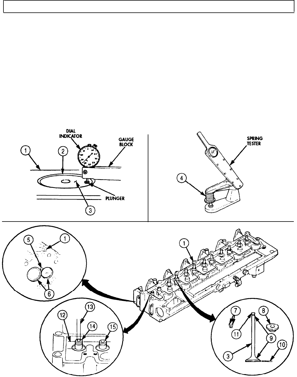
TM 9-2320-272-24-4
5-25. CYLINDER HEAD REPAIR (Contd)
9.
10.
11.
12.
13.
14.
15.
Inspect valve seats (6) for wear, burrs, pits, and cracks. Replace cylinder head (1) if worn, pitted,
cracked, or burred. Mark valve seat (6) for resurfacing.
Inspect exhaust (14) and intake (15) valve guides for chips, cracks, burrs, breaks, and wear. Replace
cylinder head (1) if chipped, cracked, burred, broken, or worn.
Measure valve guide length (12) and inside diameter of valve guide bore (13). Refer to table 5-9,
Cylinder Head Wear Limits, for measurements. Replace cylinder head (1) if not within limits.
Inspect valves (3) for cracks, bends, and wear. Replace valve(s) (3) if cracked, bent, or worn.
Measure outside diameter of valve stem (9). Refer to table 5-9, Cylinder Head Wear Limits, for
measurements. Replace valve(s) (3) if not within limits.
Measure rim (10) thickness of valves (3). Refer to table 5-9, Cylinder Head Wear Limits, for
measurement. Replace valve(s) (3) if not within limits.
Inspect collet grooves (11) for wear.
a. Install new collets (7) in collet grooves (11).
b. If collets (7) fit loosely, replace valve(s) (3).
5-161
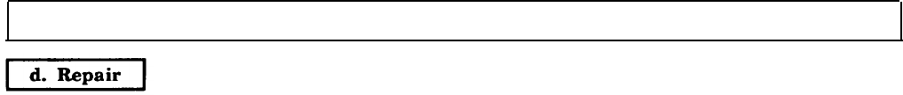
TM 9-2320-272-24-4
5-25. CYLINDER HEAD REPAIR (Contd)
1.
Apply light coat of lapping compound to valve (2) and lap valve (2) to valve seat insert (1).
2.
Clean lapping compound from valve (2) and valve seat insert (1).
3.
Measure width of valve seat insert (1). Limits are 0.060-0.080 in. (1.52-2.03 mm). If beyond limits,
replace cylinder head (4).
4.
Check contact surface between valve (2) and valve seat insert (1) as follows:
a. Apply light coat of pigment to valve face (3).
b. Lower valve (2) into valve guide (5) and let valve (2) drop against valve seat insert (1).
NOTE
Do not rotate valve when pushing valve against valve seat insert.
c. Push up on valve stem (6) until valve face (3) is about 1 in. (25.4 cm) above valve seat insert (1).
d. While releasing valve stem (6), apply pressure to valve (2) until valve face (3) makes contact with
valve seat insert (1). Repeat several times to get good imprint on pigment.
NOTE
Do not smear pigment from valve.
e. Remove valve (2).
f. Imprint on pigment should have an even contact surface all around center of valve face (3). If
pigment imprint is uneven, mark valve (2) and valve seat insert (1) for grinding.
NOTE
Repeat step 4 for all valves to check contact surface between valve
and valve seat insert.
5.
Grind valve (2) and valve seat insert (1) if valve (2) is new or has an uneven contact surface.
a. Use a 30° grinding wheel on valve seat insert (1) for intake port (7).
b. Use a 45° grinding wheel on valve seat insert (1) for exhaust port (8).
NOTE
If contact surface is at bottom of valve face, valve seat insert will
require more grinding with 15° wheel.
c. To center contact surface on valve face (3), grind area (11) of valve seat insert (1) with a 60°
wheel, and area (12) of valve seat insert (1) with a 15° wheel.
d. Using valve refacing machine, grind face of intake valve (2) to a 30° angle or a 45° angle for
exhaust valve.
6.
If valve stem tip (10) is not flat, dress tip for flatness on grinding wheel.
7.
Measure valve (2) depth from bottom of cylinder head (4) to surface when valve (2) is seated against
valve seat insert (1).
a. Position gauge block flat on surface of cylinder head (4) with plunger extended to cylinder head (4)
surface. Adjust dial indicator to zero.
b. Position gauge block flat on surface of cylinder head (4) with plunger extended to valve (2).
c. Valve (2) depth must measure 0.035-0.056 in. (0.89-1.42 mm) below bottom surface of cylinder
head (4).
d. If measurement is not within limits, use new valve (2) and repeat steps a through c.
e. If measure is beyond limit, replace cylinder head (4).
8.
Using pigment, check contact surface (9) between face of valve (2) and valve seat insert (1) (step 4d.).
9.
Clean cylinder head (4) and valves (2) after valves (2) and valve seat inserts (1) have been ground
(para. 2-14).
5-162
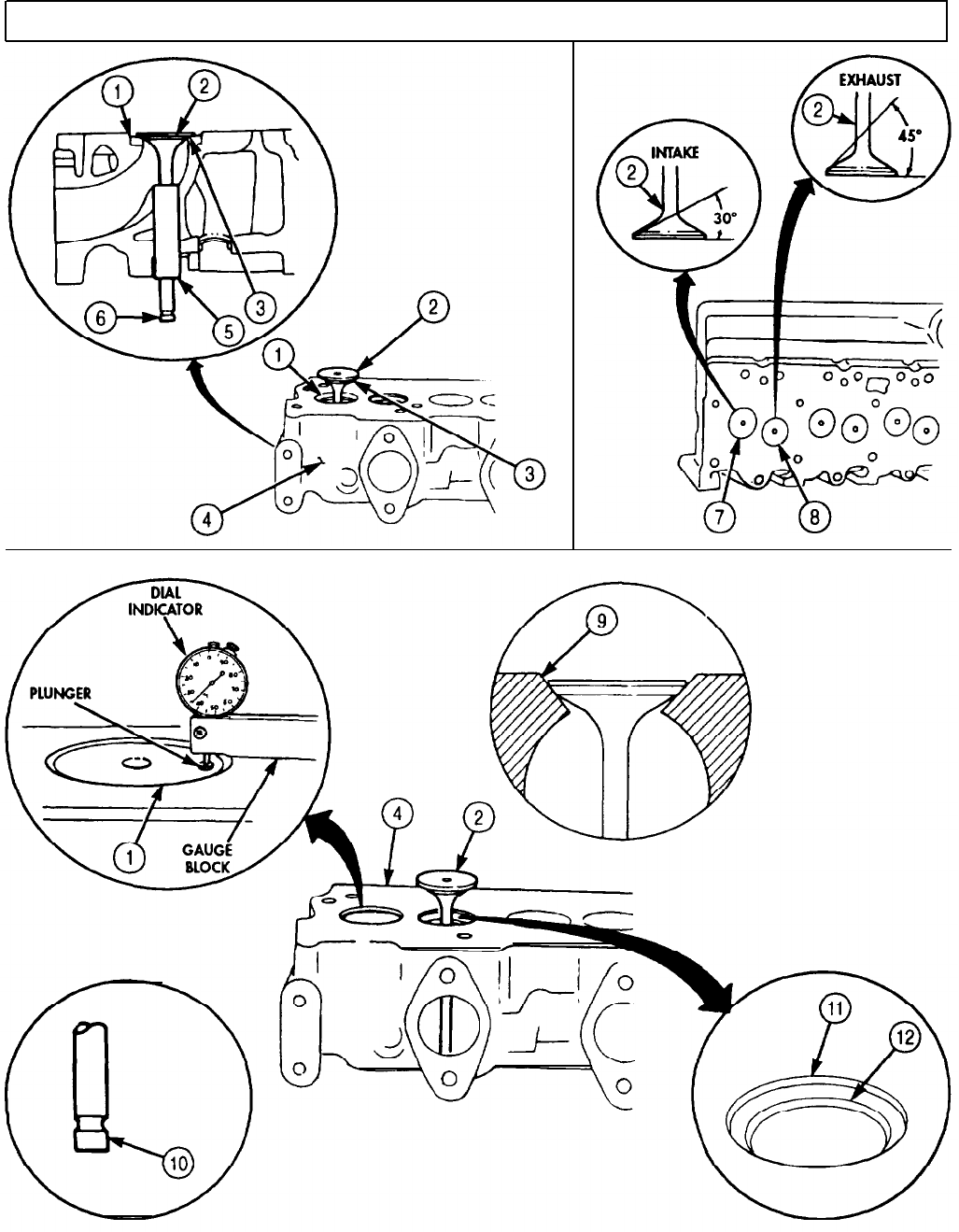
TM 9-2320-272-24-4
5-25. CYLINDER HEAD REPAIR (Contd)
5-163

TM 9-2320-272-24-4
5-25. CYLINDER HEAD REPAIR (Contd)
1.
2.
3.
4.
Install plug (8) on rear face of cylinder head (10).
Install two new expansion plugs (9) on front and rear faces of cylinder head (10).
Install new expansion plug (7) on rear face of cylinder head (10).
Install five new expansion plugs (6) on top face of cylinder head (10).
CAUTION
Position cylinder head on exhaust port face to install intake and
exhaust valves. Use wooden or protective surface work bench to
prevent damage to cylinder head. Bench must be clean.
NOTE
Ensure intake and exhaust valves are installed in original
locations as previously noted.
5.
6.
7.
8.
Dip valve (11) stems in clean engine oil and install in valve guides (5) from face side of cylinder
head (10).
Carefully position cylinder head (10) face down on bench.
Install twelve new seals (4), valve springs (3), and spring retainers (2) on valves (11).
Using spring compressor, compress valve springs (3) until collet grooves (12) on valves (11) are
exposed.
NOTE
Ensure all valves are locked by collets.
9.
Install twenty-four new collets (1) in collet grooves (12) and slowly release spring compressor.
NOTE
• Wrap male pipe threads with antiseize tape before installation.
• Apply sealing compound to mating surfaces of expansion plugs
before installation.
5-164
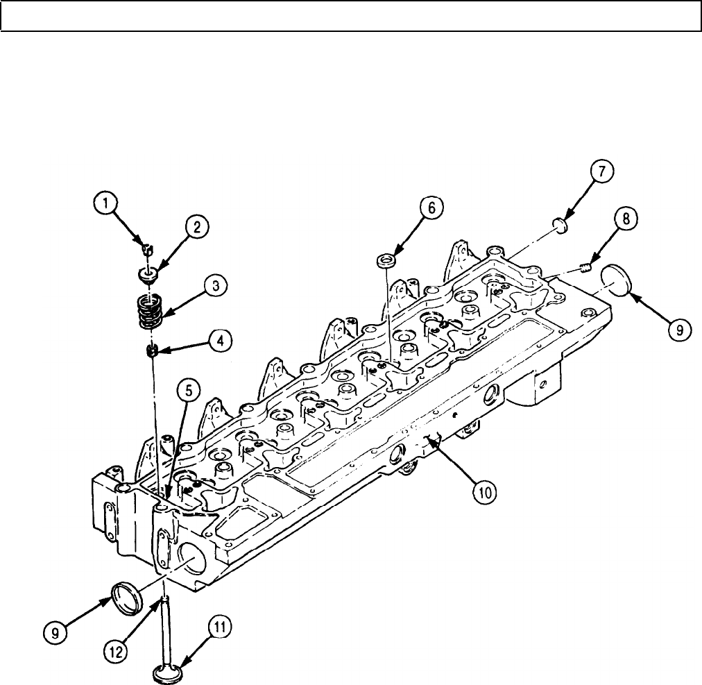
TM 9-2320-272-24-4
5-25. CYLINDER HEAD REPAIR (Contd)
FOLLOW-ON TASK: Install cylinder head (para. 4-41).
5-165
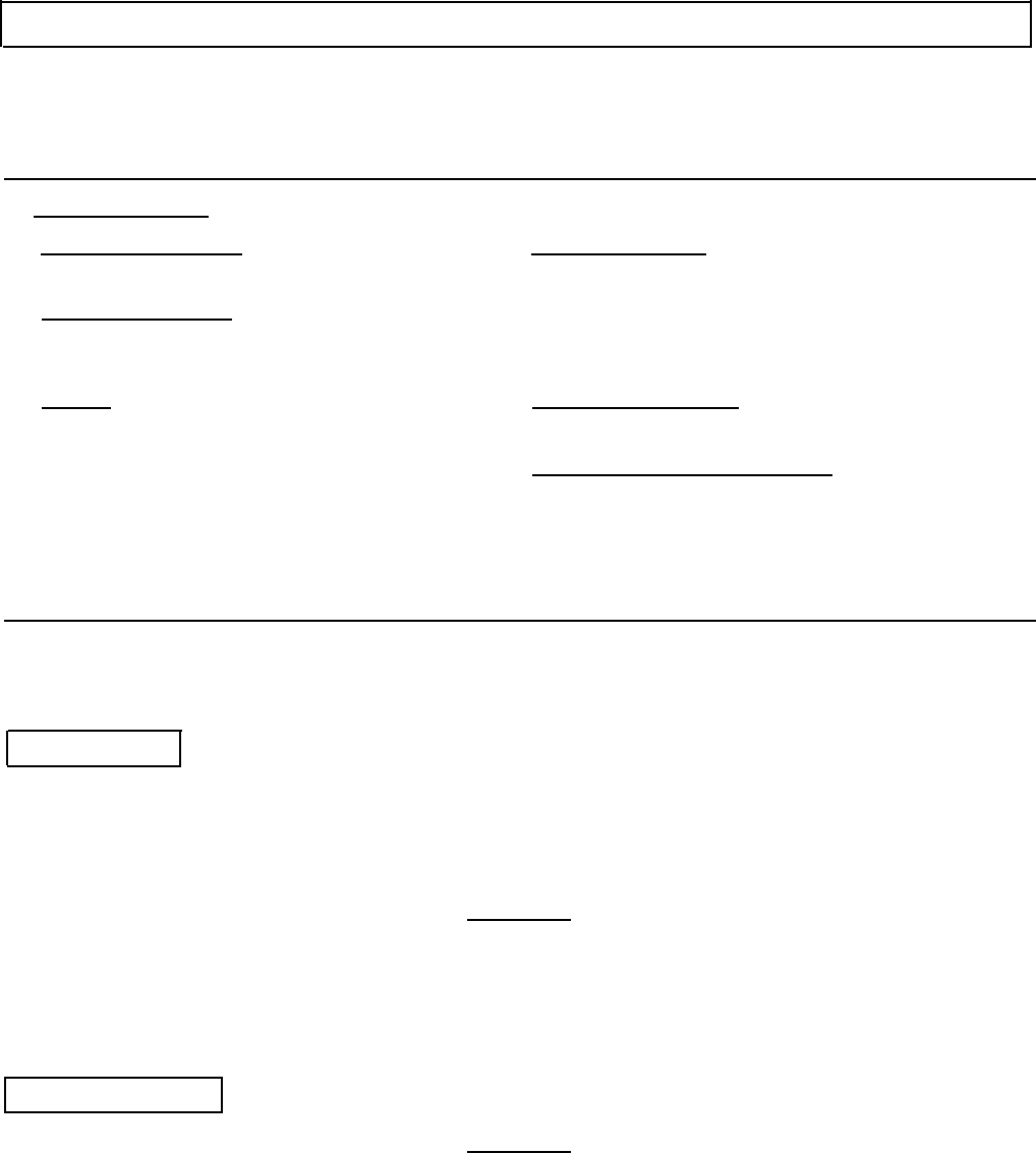
TM 9-2320-272-24-4
5-26. PISTON AND CONNECTING ROD MAINTENANCE
THIS TASK COVERS:
a. Removal
b. Disassembly
c. Cleaning and Inspection
d. Assembly
e. Installation
INITIAL SETUP:
APPLICABLE MODELS
M939A2
SPECIAL TOOLS
Engine barring tool (Appendix E, Item 43)
Ring compressor (Appendix E, Item 32)
TOOLS
General mechanic’s tool kit (Appendix E, Item 1)
Keystone gauge (Appendix E, Item 54)
Inside micrometer (Appendix E, Item 82)
Outside micrometer (Appendix E, Item 80)
Vernier calipers (Appendix E, Item 159)
Torque wrench (Appendix E, Item 144)
Depth gauge (Appendix E, Item 81)
Feeler gauge
Soft-headed hammer
MATERIALS/PARTS
Piston rings (Appendix D, Item 518)
Two retaining rings (Appendix D, Item 539)
Connecting rod bearing (Appendix D, Item 40)
Lubricating oil (Appendix C, Item 50)
Plastigage (Appendix C, Item 55)
REFERENCES (TM)
TM 9-2320-272-24P
EQUIPMENT CONDITlON
• Cylinder head removed (para. 4-41).
• Oil pan and suction tube removed (para. 4-47).
NOTE
All piston assemblies are replaced the same way. This procedure
covers replacement of one piston assembly.
a. Removal
1.
Using engine barring tool, rotate crankshaft (6) to lower pistons (1) enough to remove all carbon
from upper inside wall of each cylinder (3).
2.
Remove two nuts (8) from screws (5) and connecting rod cap (7).
3.
Using soft-headed hammer, tap screws (5) and remove connecting rod cap (7) from crankshaft (6).
CAUTION
Use a tape-protected tool to push piston from cylinder block.
Failure to do so may cause damage to cylinder liners.
NOTE
Assistant will help with step 4.
4.
Using tape-protected tool, push connecting rod (2) and piston (1) from engine block (4).
b. Disassembly
CAUTION
Pistons, connecting rods, and connecting rod caps must be kept together
as an assembly. Missing parts may cause damage to equipment.
1.
Remove two retaining rings (12) from bore of piston (1). Discard retaining rings (12).
2.
Remove piston pin (13) and connecting rod (2) from piston (1).
3.
Remove ring (9), compression ring (10), and oil ring (11) from piston (1). Discard rings (9), (10),
and (11).
5-166

TM 9-2320-272-24-4
5-26. PISTON AND CONNECTING ROD MAINTENANCE (Contd)
4.
Remove two screws (5) from connecting rod (2).
5.
Remove upper half bearing shell (14) from connecting rod (2). Discard upper half bearing shell (14).
6.
Remove lower half bearing shell (15) from connecting rod cap (7). Discard lower half bearing shell (15).
5-167

TM 9-2320-272-24-4
5-26. PISTON AND CONNECTING ROD MAINTENANCE (Contd)
c. Cleaning and Inspection
1.
For general cleaning instructions, refer to para. 2-14.
2.
For general inspection instructions, refer to para. 2-15.
3.
Replace all parts failing inspection.
NOTE
Measurements to check piston skirt outside diameters are taken
at right angle to piston pin bore.
4.
5.
Measure outside diameter of piston skirt (3) at several places. If diameter is less than 4.479 in.
(113.8 mm), replace piston (4).
Check piston ring groove (5) for wear.
6.
a. Insert keystone gauge into ring groove (5).
b. If shoulders of keystone gauge touch either end of ring groove (5), replace piston (4).
Check compression ring (6) and oil ring (7) grooves for wear.
a. Insert new compression ring (1) into compression ring groove (6).
b. Try to insert 0.006 in. (0.152 mm) feeler gauge between compression ring (1) and compression
ring groove (6).
c. If feeler gauge enters compression ring groove (6) without force, replace piston (4).
d. Repeat steps a through c using new oil ring (2) and 0.005 in. (0.127 mm) feeler gauge to check oil
ring groove (7) for wear.
7.
8.
9.
10.
11.
12.
13.
14.
15.
Measure inside diameter of piston pin bore (9). If inside diameter exceeds 1.773 in. (45.03 mm),
replace piston (4).
Measure outside diameter of piston pin (8). If outside diameter exceeds 1.771 in. (44.98 mm),
replace piston pin (8).
Inspect I-beam section (15) of connecting rod (11) for nicks, dents, and gouges. If nicked, dented, or
gouged, replace connecting rod (11).
Install two connecting rod screws (12) in connecting rod (11).
Install connecting rod cap (14) on connecting rod (11) with two nuts (13). Tighten nuts (13) to
73 lb-ft (99 N•m).
Check crankshaft journal bore (10) of connecting rod (11) for wear:
a. Measure inside diameter of crankshaft journal bore (10) at several points 30° from each other.
b. If inside diameter measurement exceeds 2.9926 in. (76.012 mm), replace connecting rod (11).
Measure inside diameter of piston pin bore (16). If inside diameter exceeds 1.773 in. (45.03 mm),
replace connecting rod (11).
Remove two nuts (13) and connecting rod cap (14) from connecting rod (11).
Check connecting rod journals (18) on crankshaft (17) for wear.
a. Measure outside diameter of six connecting rod journals (18) at A-A and B-B. If difference
exceeds 0.0005 in. (0.013), replace crankshaft (17) (para. 5-29).
b. Measure outside diameter of six connecting rod journals (18) at C-C and D-D. If difference
exceeds 0.002 in. (0.05 mm), replace crankshaft (17) (para. 5-29).
5-168

TM 9-2320-272-24-4
5-26. PISTON AND CONNECTING ROD MAINTENANCE (Contd)
5-169

TM 9-2320-272-24-4
5-26. PISTON AND CONNECTING ROD MAINTENANCE (Contd)
d. Assembly
1.
• Ensure numbers on pistons, connecting rods, and connecting rod
caps match numbers on the mating cylinders.
• Perform step 1 if assembling with new connecting rod.
Install two connecting rod screws (8) on connecting rod (2). Ensure heads of screws (8) are on flat of
connecting rod (2).
2.
3.
4.
5.
6.
Install retaining ring (13) in pin groove of piston (1).
Position connecting rod (2) in piston (1). Ensure connecting rod (2) matches FRONT mark on
piston (1).
Apply clean engine oil to lubricate piston pin (7) and piston pin bore (12).
Install piston pin (7) through piston (1) and connecting rod (2).
Install retaining ring (6) in pin groove of piston (1).
NOTE
7.
8.
Piston rings must be installed on piston with the word TOP or
supplier’s mark facing upward.
Install new oil ring (5) in oil ring groove (14).
Using piston ring expander, install new compression ring (4) and new ring (3) on piston (1).
NOTE
Align bearing shell tabs with connecting rod and connecting rod
cap slots when installing.
9.
Install new upper half bearing shell (9) in connecting rod (2).
10.
Install new lower half bearing shell (10) in connecting rod cap (11).
5-170

TM 9-2320-272-24-4
5-26. PISTON AND CONNECTING ROD MAINTENANCE (Contd)
5-171

TM 9-2320-272-24-4
5-26. PISTON AND CONNECTING ROD MAINTENANCE (Contd)
e. Installation
1.
Apply clean engine oil to lubricate piston (3) and cylinder bore (5).
NOTE
Ensure piston rings are staggered properly so they are not in line
with each other or piston pin.
2.
Lubricate ring compressor and install over piston rings (4) and piston (3).
3.
Using engine barring tool, rotate crankshaft (91 until connecting rod journal (11) is at bottom
dead center.
CAUTION
• Ensure piston assembly number matches that of mating
cylinder. Failure to do so will cause poor engine performance.
• Ring compressor must be held firmly against engine block to
prevent compressor from slipping and causing piston ring
breakage when pushing piston into cylinder liner.
• Do not force piston assembly into liner. If piston does not install
freely in liner, remove and check for broken rings.
NOTE
Ensure piston assemblies are installed with FRONT mark facing
front of engine.
4.
Insert connecting rod (7) in cylinder bore (5) and hold ring compressor tight and firmly seated
against engine block (6).
5.
Using rubber or wooden mallet handle, push piston (3) from ring compressor and into cylinder
bore (5) until upper half bearing (8) seats against connecting rod journal (11).
6.
Place a piece of plastic strip across lower half bearing shell (2).
7.
Install connecting rod cap (1) on connecting rod (7) with two nuts (10). Ensure numbers on
connecting rod cap (1) and connecting rod (7) are aligned.
8.
Tighten two nuts (10) as follows:
a. Tighten two nuts (10130 lb-ft (41 N•m).
b. Tighten two nuts (10) 60 lb-ft (81 N•m).
c. Tighten two nuts (10) 90 lb-ft (122 N•m).
9.
Remove two nuts (10) and connecting rod cap (1) from connecting rod (9).
10.
Using plastigage, measure width of plastic strip. Width should be 0.0013-0.0046 in. (0.033-0.117
mm). If width is not within limits, inspect connecting rod journal (11) (task c.).
11.
Clean connecting rod cap (1) and install on connecting rod (7) with two nuts (10). Ensure numbers
on connecting rod (7) and connecting rod cap (1) are aligned.
12.
Tighten nuts (10) as follows:
a. Tighten two nuts (10) 30 lb-ft (41 N•m).
b. Tighten two nuts (10) 60 lb-ft (81 N•m).
c. Tighten two nuts (10) 90 lb-ft (122 N•m).
13,
Check connecting rod side clearance.
a. Move connecting rod (7) back and forth on connecting rod journal (11).
b. Using feeler gauge, measure connecting rod (7) side clearance. Clearance should be 0.004-0.012 in.
(0.1-0.030 mm). If not within limits, remove connecting rod cap (1) and inspect for proper size
and seating of lower half bearing shell (2), and for dirt or burrs.
c. Repeat steps 12 and 13 to install connecting rod cap (1).
5-172
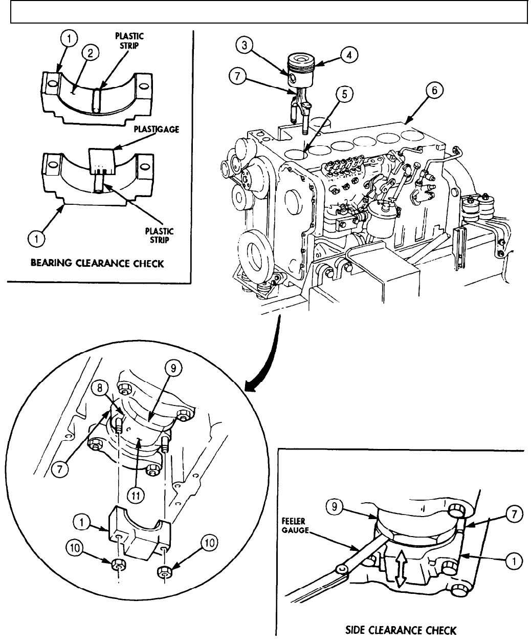
TM 9-2320-272-24-4
5-26. PISTON AND CONNECTING ROD MAINTENANCE (Contd)
FOLLOW-ON TASKS: • Install cylinder head (para. 4-41).
• Install oil pan and suction tube (para. 4-47).
5-173

TM 9-2320-272-24-4
5-27. CAMSHAFT AND GEAR MAINTENANCE
THIS TASK COVERS:
a. Check Backlash and End Play
b. Removal
c. Disassembly
d. Cleaning and Inspection
e. Assembly
f. Installation
INITIAL SETUP:
APPLICABLE MODELS
M939A2
SPECIAL TOOLS
Cam bushing replacement tool
(Appendix E, Item 26)
TOOLS
General mechanic’s tool kit (Appendix E, Item 1)
Gear puller (Appendix E, Item 102)
Dial indicator (Appendix E, Item 36)
Inside micrometer (Appendix E, Item 82)
Outside micrometer (Appendix E, Item 80)
Vernier caliper (Appendix E, Item 159)
Torque wrench (Appendix E, Item 144)
Arbor press
Prybar
MATERIALS/PARTS
Dowel pin (Appendix D, Item 98)
Lockwasher (Appendix D, Item 396)
GAA grease (Appendix C, Item 28)
Adhesive sealant (Appendix C, Item 4)
Rags (Appendix C, Item 58)
Drycleaning solvent (Appendix C, Item 71)
REFERENCES (TM)
TM 9-2320-272-24P
EQUIPMENT CONDITION
• Engine mounted on repair stand (para. 4-9).
• Rocker levers and push rods removed (para. 4-41).
• Flywheel housing removed (para. 4-43).
• Oil pan and suction tube removed (para. 4-47).
• Front gearcase cover removed (para. 4-48).
GENERAL SAFETY INSTRUCTIONS
• Keep fire extinguisher nearby when using
drycleaning solvent.
• Drycleaning solvent is flammable and toxic. Do
not use near open flame.
a. Check Backlash and End Play
1.
Rotate engine block (2) so bottom is facing upward.
2.
Install dial indicator on engine block (2) and crankshaft gear (1).
NOTE
Prevent crankshaft from rotating when checking backlash.
Reading will be the total of both gears.
3.
Rotate camshaft gear (3) clockwise until teeth contact teeth of crankshaft gear (1).
4.
Set dial indicator to zero.
5.
Rotate camshaft gear (3) counterclockwise until teeth contact crankshaft gear (1) teeth. Ensure
crankshaft gear (1) does not turn.
6.
Backlash of camshaft gear (3) should read 0.005-0.013 in. (0.13-0.33 mm). If reading is not within
limits, replace camshaft (tasks b through f.).
7.
Position dial indicator on face of camshaft gear (3). Press camshaft gear (3) towards rear of engine
block (1).
8.
Set dial indicator to zero.
9.
Pull camshaft gear (3) to front of engine block (1).
10.
End play of camshaft gear (3) should read 0.006-0.010 in. (0.152-0.254 mm). If reading is not within
limits, replace camshaft support (tasks b through f).
5-174
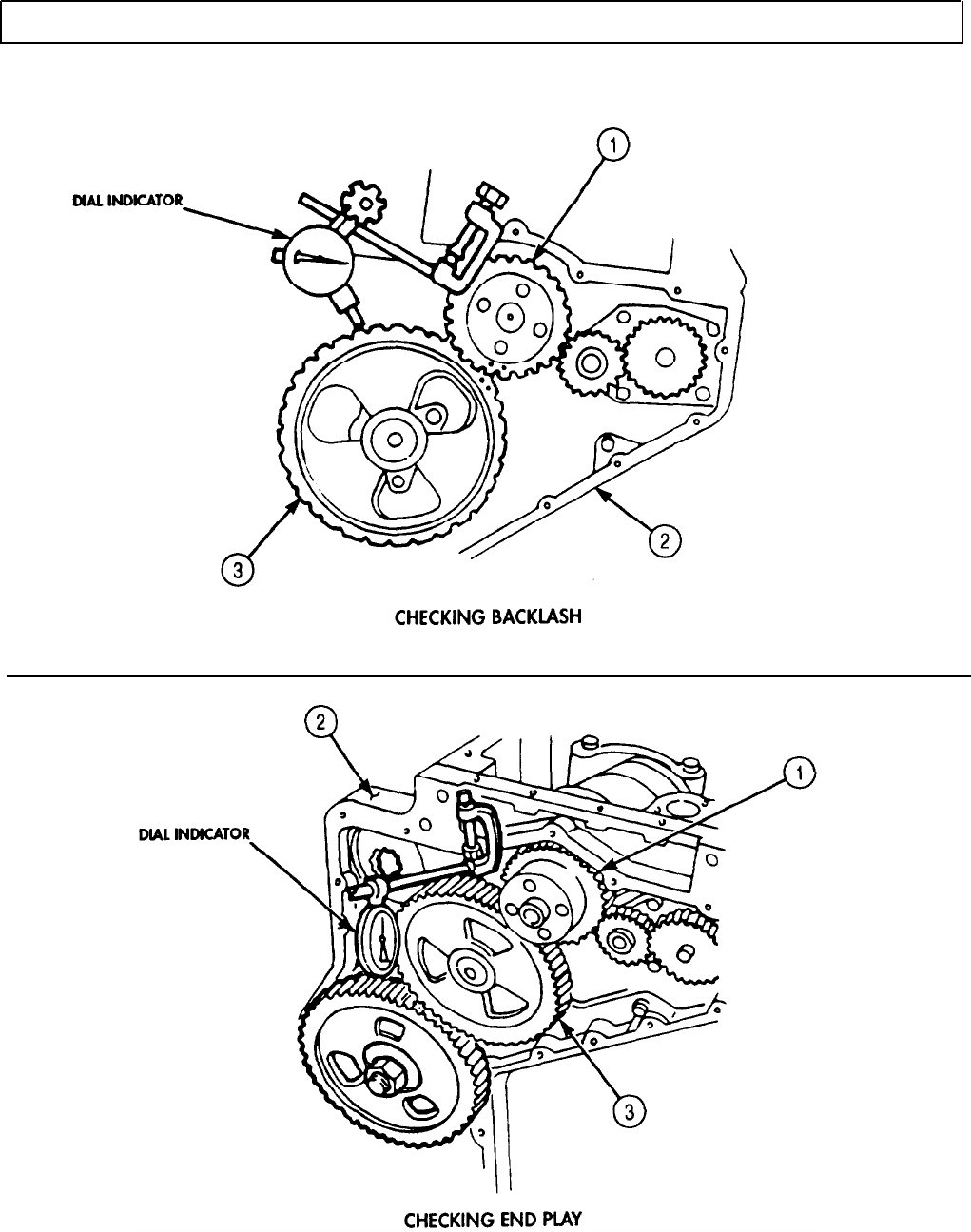
TM 9-2320-272-24-4
5-27. CAMSHAFT AND GEAR MAINTENANCE (Contd)
5-175

TM 9-2320-272-24-4
5-27. CAMSHAFT AND GEAR MAINTENANCE (Contd)
b. Removal
1.
Install two vibration damper screws (1) on crankshaft (3).
2.
Using prybar, prevent crankshaft (3) from rotating.
3.
Remove nut (6) and lockwasher (7) from drive gear (8). Discard lockwasher (7).
4.
Using gear puller, remove drive gear (8) from fuel injection pump shaft (5).
5.
Rotate crankshaft (3) and align timing marks (14) on crankshaft gear (2) and camshaft gear (4).
6.
Remove two screws (12) from camshaft support (11) and engine block (9).
CAUTION
Use care when removing camshaft. Damage to camshaft and
bushings may result.
7.
Remove camshaft (13) and camshaft support (11) from engine block (9).
NOTE
Tag all valve tappets for installation.
8.
Rotate crankshaft (3) as necessary to remove twelve valve tappets (10) from engine block (9).
c. Disassembly
NOTE
Before removing camshaft gear from camshaft, perform task d of
this procedure. If, as a result of inspection, the camshaft or
camshaft gear requires replacement, perform steps 1 and 2.
1.
Using arbor press, press camshaft gear (4) from camshaft (13).
2.
Remove dowel pin (15) from camshaft (13). Discard dowel pin (15).
5-176
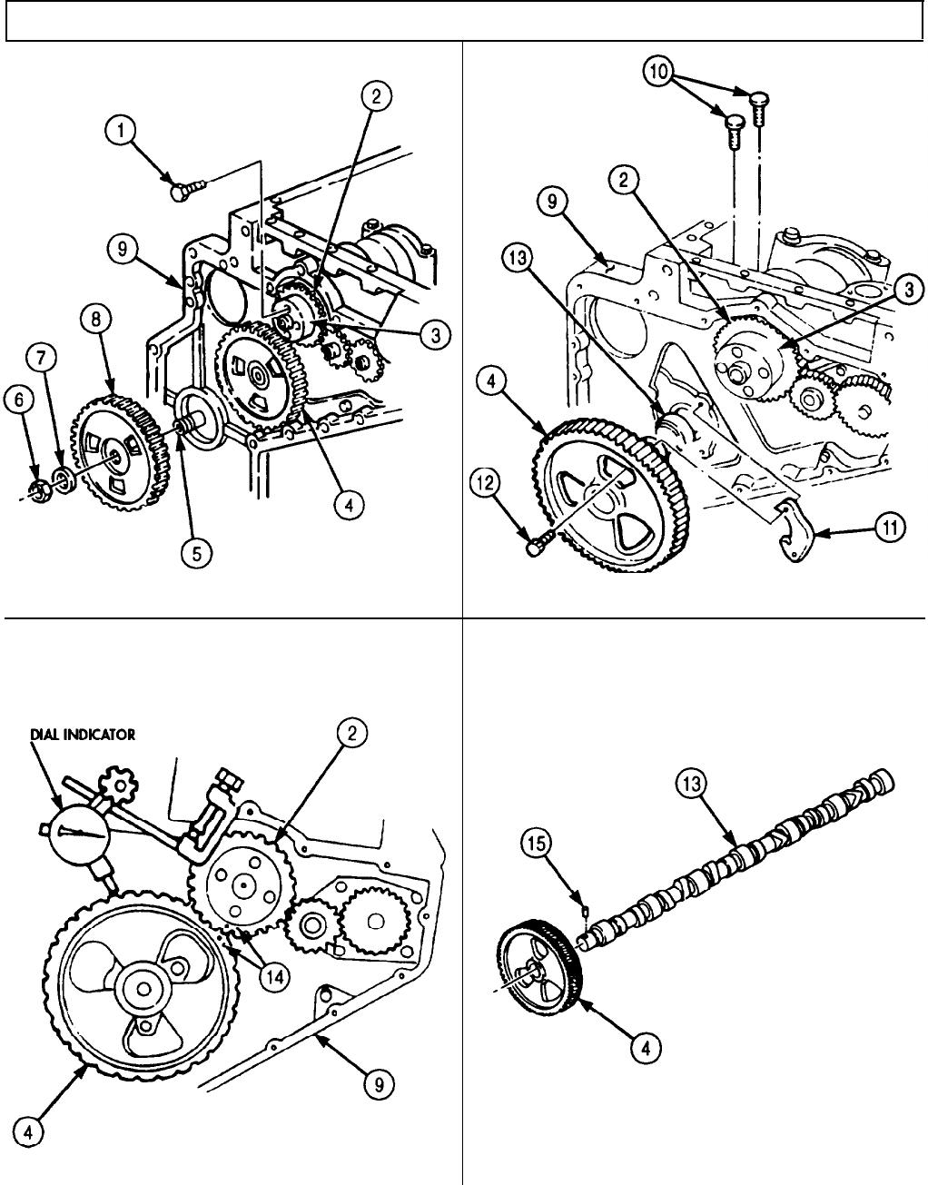
TM 9-2320-272-24-4
5-27. CAMSHAFT AND GEAR MAINTENANCE (Contd)
5-177
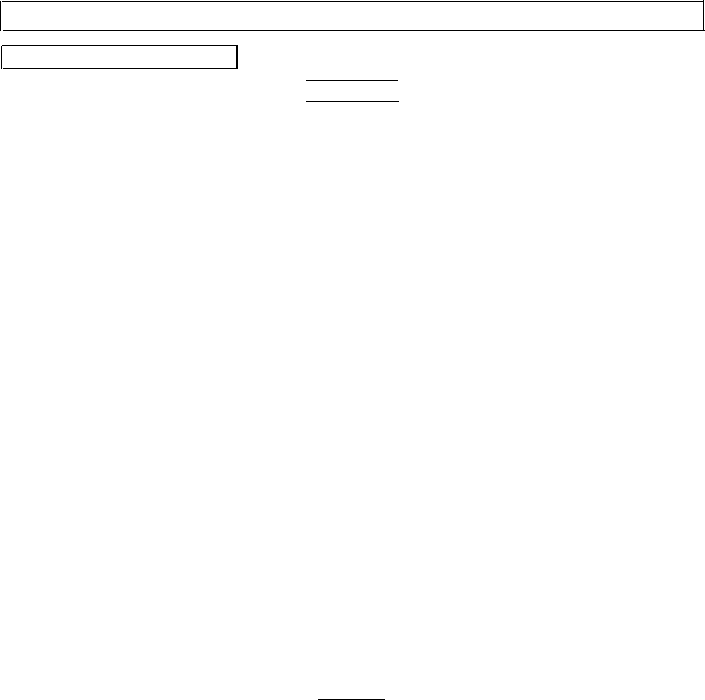
TM 9-2320-272-24-4
5-27. CAMSHAFT AND GEAR MAINTENANCE (Contd)
d. Cleaning and Inspection
1.
2.
3.
4.
5.
6.
7.
8.
9.
10.
11.
12.
13.
14.
WARNING
Drycleaning solvent is flammable and toxic. Do not use near open
flame and always have a fire extinguisher nearby when solvents
are used. Use only in well-ventilated places, wear protective
clothing, and dispose of cleaning rags in approved container.
Failure to do this may result in injury or death to personnel and/or
damage to equipment.
Clean all camshaft (6) components with drycleaning solvent and dry with clean rag.
Inspect camshaft support (1) for wear. Replace camshaft support (1) if excessively worn.
Inspect camshaft (6) for cracks, pits, and breaks. Replace camshaft (6) if cracked, pitted, or broken.
Inspect exhaust (4) and intake (2) camshaft lobes for wear.
a. Measure outside diameter of exhaust camshaft lobe (4) at several positions. Replace camshaft (6)
if outside diameter is less than 2.0313 in. (1.5950 mm).
b. Measure outside diameter of intake camshaft lobe (2) at several positions. Replace camshaft (6) if
outside diameter is less than 2.0383 in. (51.7728 mm).
c. Measure outside diameter of lift pump lobe (5) at several positions. Replace camshaft (6) if
outside diameter is less than 1.626 in. (59.9618 mm).
Inspect camshaft journals (3) for wear. Measure outside diameter of camshaft journals (3) at several
positions. Replace camshaft (6) if outside diameter is less than 2.3067 in. (59.9618 mm).
Inspect camshaft gear (7) for cracks, pits, and breaks. Replace camshaft gear (7) if cracked, pitted,
or broken.
Inspect camshaft gear teeth (8) for pitting and cracks at root of teeth (8). Replace camshaft gear (7)
if pitted or cracked.
Inspect camshaft bushings (9) for wear. Measure inside diameter of camshaft bushing (9) at several
positions. If inside diameter exceeds 2.367 in. (60.122 mm), mark camshaft bushing (9) for
replacement.
NOTE
Perform steps 9 through 14 for replacing camshaft bushings.
Remove expansion plug (11) from rear of engine block (10). Discard expansion plug (11).
Using cam bushing replacement tool, remove camshaft bushing (9) from bushing bore (14). Discard
camshaft bushing (9).
Measure inside diameter of camshaft bores (14). Replace engine block (10) if inside diameter
exceeds 2.520 in. (64.008 mm).
CAUTION
When installing camshaft bushing, ensure oil hole and oil hole
passages are aligned. Failure to do so will result in premature
failure and damage to engine.
Mark engine block (10) and new camshaft bushing (9) to ensure oil holes (12) and (13) are aligned.
Using cam bushing replacement tool, install new camshaft bushing (9) in camshaft bushing bore (14).
NOTE
Perform step 14 if rear camshaft bushing was removed.
Apply adhesive sealant to mating surfaces of new expansion plug (11) and install on engine block (10).
5-178
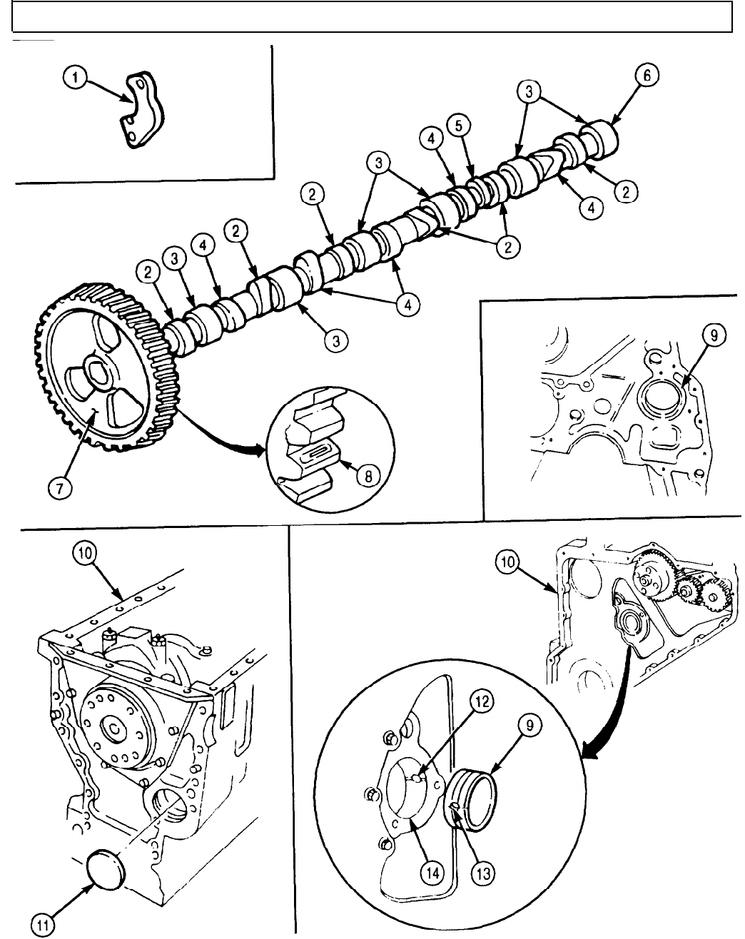
TM 9-2320-272-24-4
5-27. CAMSHAFT AND GEAR MAINTENANCE (Contd)
5-179

TM 9-2320-272-24-4
5-27. CAMSHAFT AND GEAR MAINTENANCE (Contd)
15. Inspect valve tappets (2) for nicks, burrs, and wear. Replace tappet(s) (2) if nicked, burred, or worn.
16. Measure outside diameter of tappet stem (1). Replace tappet(s) (2) if outside diameter is less than
0.628 in. (15.95 mm).
17. Inspect tappet bores (8) for scoring and wear. Replace engine block (7) if excessively scored or worn.
18. Measure inside diameter of tappet bore (8). Replace engine block (7) if inside diameter exceeds
0.632 in. (16.05 mm).
NOTE
Perform steps 1 through 3 if camshaft gear was removed.
1.
Install new dowel pin (3) in camshaft (4).
2.
Apply GM grease to coat camshaft lobe (5).
3.
Using arbor press, press camshaft gear (6) on camshaft (4).
5-180
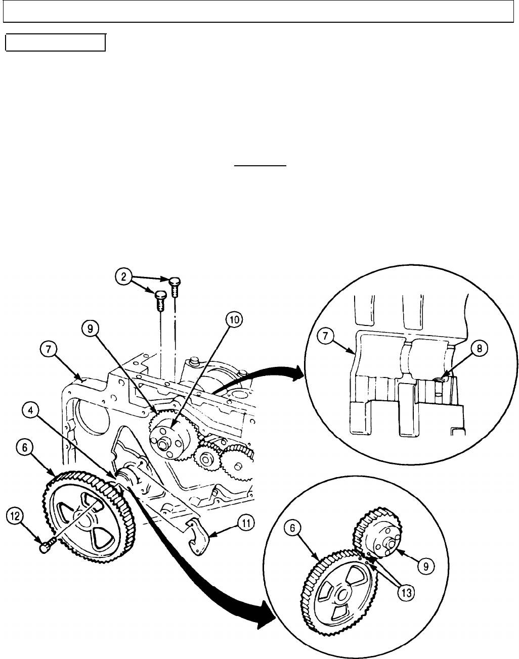
TM 9-2320-272-24-4
5-27. CAMSHAFT AND GEAR MAINTENANCE (Contd)
f. Installation
NOTE
• Used valve must be installed in mating tappet bores. If valve
tappet position was not noted during removal, replace all valve
tappets.
• Do not reuse old valve tappets if installing new camshaft.
1.
Rotate crankshaft (10) as necessary to access tappet bores (8).
2.
Coat twelve tappets (2) with GAA grease and install in tappet bores (8).
CAUTION
Use care when installing camshaft. Camshaft and bushings are
easily damaged.
3.
Apply coat of GM grease to camshaft (4) and install in engine block (7). Ensure timing marks (13)
of camshaft gear (6) and crankshaft gear (9) are aligned.
4.
Install camshaft support (11) on engine block (7) with two screws (12). Tighten screws (12) 18 lb-ft
(24 N•m).
5.
Check backlash and end play of camshaft (4) for proper seating (task a).
5-181
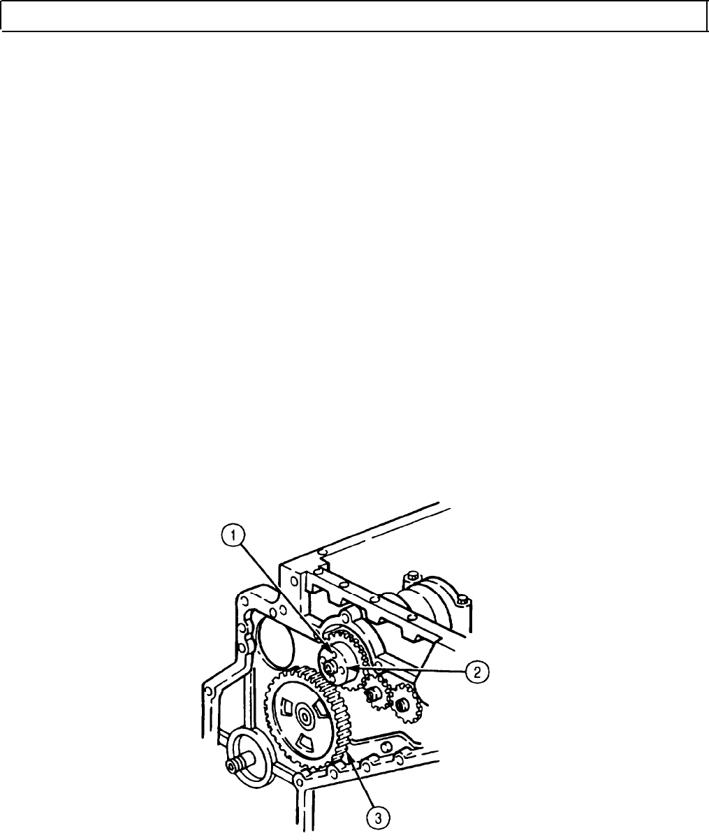
TM 9-2320-272-24-4
5-27. CAMSHAFT AND GEAR MAINTENANCE (Contd)
6.
7.
8.
Using prybar between two vibration damper screws (1), rotate crankshaft (2).
Press in timing pin (15), while rotating crankshaft (2), until timing pin (15) engages camshaft
gear (3).
Remove access plug (9), copper washer (8), and fuel injection pump timing pin (10) from fuel
injection pump (11).
9.
Install nut (4) on fuel injection pump shaft (12) and rotate until timing tooth (14) is visible in timing
pin hole (13).
10.
11.
12.
Install fuel injection pump timing pin (10) in hole (13). Ensure slot (7) of fuel injection pump timing
pin (10) is positioned over timing tooth (14).
Install copper washer (8) and access plug (9) on fuel injection pump (11).
Remove nut (4) from fuel injection pump shaft (12).
NOTE
Do not exceed torque limit for fuel injection pump drive gear nut.
Torque is not the final limit.
13.
Install drive gear (6) on fuel injection pump shaft (12) with new lockwasher (5) and nut (4). Tighten
nut (4) 7-11 lb-ft (10-15 N•m).
14.
15.
16.
Disengage timing pin (15) from camshaft gear (3).
Remove access plug (9), copper washer (8), and timing pin (10) from fuel injection pump (11).
Install timing pin (10) in fuel injection pump (11) with slot (7) facing outward from fuel injection
pump (11).
17.
Install copper washer (8) and access plug (9) on fuel injection pump (11).
18.
Using prybar between two vibration damper screws (1), tighten nut (4) 80 lb-ft (109 N•m).
5-182
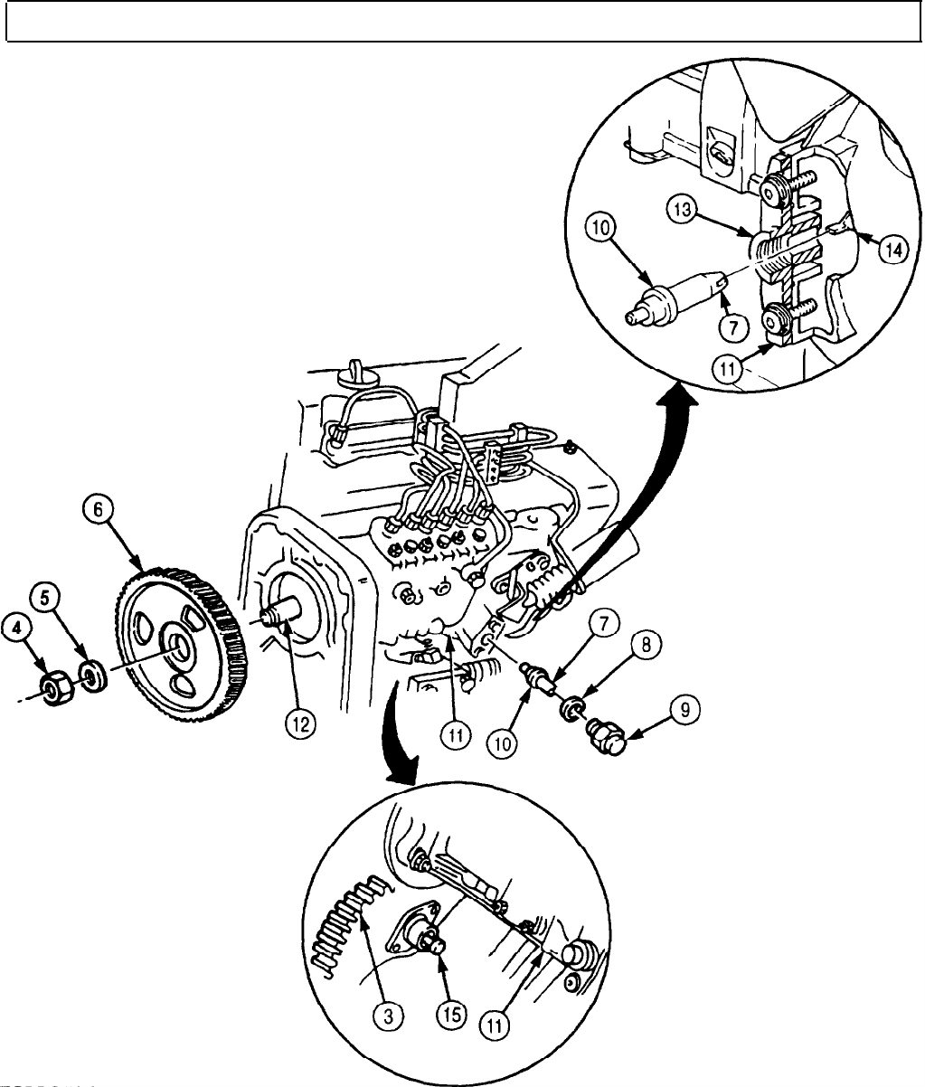
TM 9-2320-272-24-4
5-27. CAMSHAFT AND GEAR MAINTENANCE (Contd)
FOLLOW-ON TASKS:
• Install oil pan and suction tube (para. 4-47).
• Install front gearcase cover (para. 4-48).
• Install flywheel housing (para. 4-43)
• Install rocker levers and push rods tpara. 4-41)
• Remove engine from repair stand (para. 4-9).
5-183
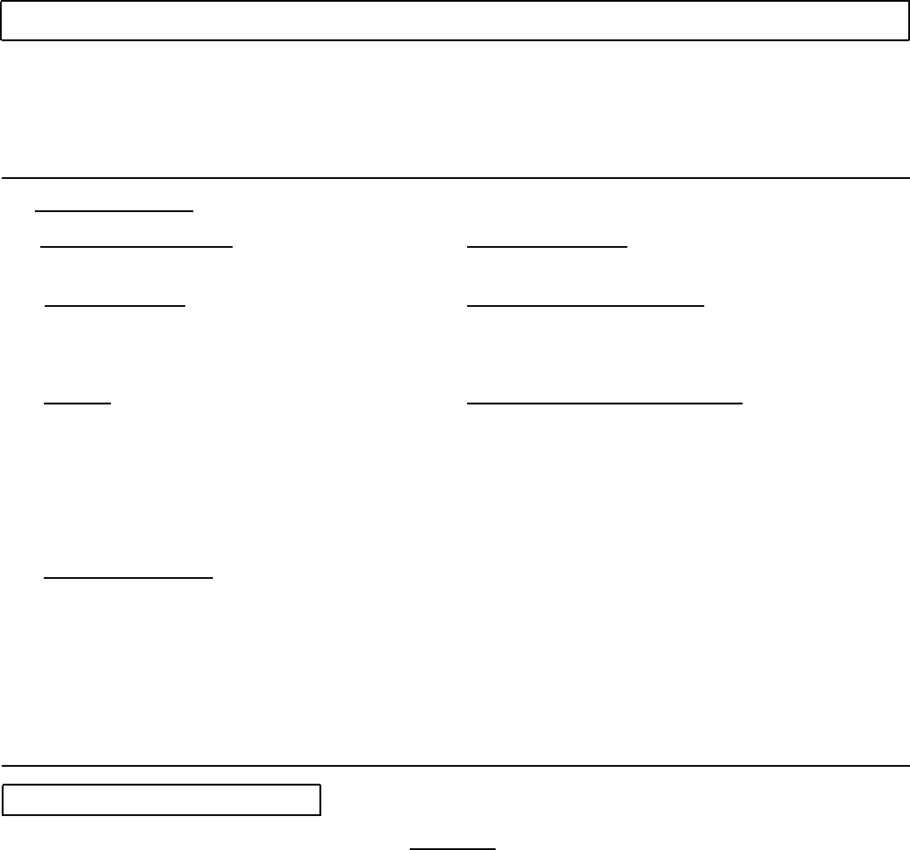
TM 9-2320-272-24-4
5-28. CYLINDER LINERS AND BLOCK MAINTENANCE
THIS TASK COVERS:
a. Cylinder Liner Inspection
b. Cylinder Liner Removal
c. Engine Block Disassembly
d. Cylinder Liner and Engine Block Cleaning
and Inspection
e. Engine Block Assembly
f. Cylinder Liner Installation
INITIAL SETUP:
APPLICABLE MODELS
M939A2
REFERENCES (TM)
TM 9-2320-272-24P
SPECIAL TOOLS
EQUIPMENT CONDITION
Cylinder liner puller (Appendix E, Item 107) • Connecting rods and pistons removed (para. 5-26).
Cylinder liner driver (Appendix E, Item 79) • Camshaft removed (para. 5-27).
Two cylinder liner clamps (Appendix E, Item 35) • Crankshaft removed (para. 5-29).
TOOLS
GENERAL SAFETY INSTRUCTIONS
General mechanic’s tool kit (Appendix E, Item 1) • Keep fire extinguisher nearby when using
Inside micrometer (Appendix E, Item 83) drycleaning solvent.
Gauge block (Appendix E, Item 52) • Drycleaning solvent is flammable and toxic.
Torque wrench (Appendix E, Item 144) • Eyeshields must be worn when cleaning with
Dial indicator (Appendix E, Item 36) compressed air. Compressed air source will not
Telescoping gauge (Appendix E, Item 136) exceed 30 psi (207 kPa).
Feeler gauge
MATERIALS/PARTS
Cylinder block kit (Appendix D, Item 93)
Cylinder liner seal (Appendix D, Item 95)
Drycleaning solvent (Appendix C, Item 71)
Rags (Appendix C, Item 58)
Crocus cloth (Appendix C, Item 20)
Detergent (Appendix C, Item 27)
Lubricating oil (Appendix C, Item 50)
Antiseize tape (Appendix C, Item 72)
Adhesive sealant (Appendix C, Item 4)
a. Cylinder Liner Inspection
CAUTION
Do not hone or deglaze cylinder liners. Honing or deglazing will
prevent oil ring from sealing properly.
NOTE
Inspect all cylinder liners to determine need for replacement.
1.
Inspect cylinder liner (1) for vertical scratches, grooves, pits, scuffing, scoring, and cracks. Tag
cylinder liner (1) for replacement if scratched, grooved, pitted, scuffed, scored, or cracked.
2.
Inspect for dirt or debris embedded in walls of cylinder liner (1). Tag cylinder liner (1) for
replacement if debris is present.
3. Inspect walls of cylinder liner (1) for heavy polishing and wear. Heavy polishing exists when wall
has a bright mirrored finish. Tag cylinder liner (1) for replacement if heavy polishing exists.
5-184
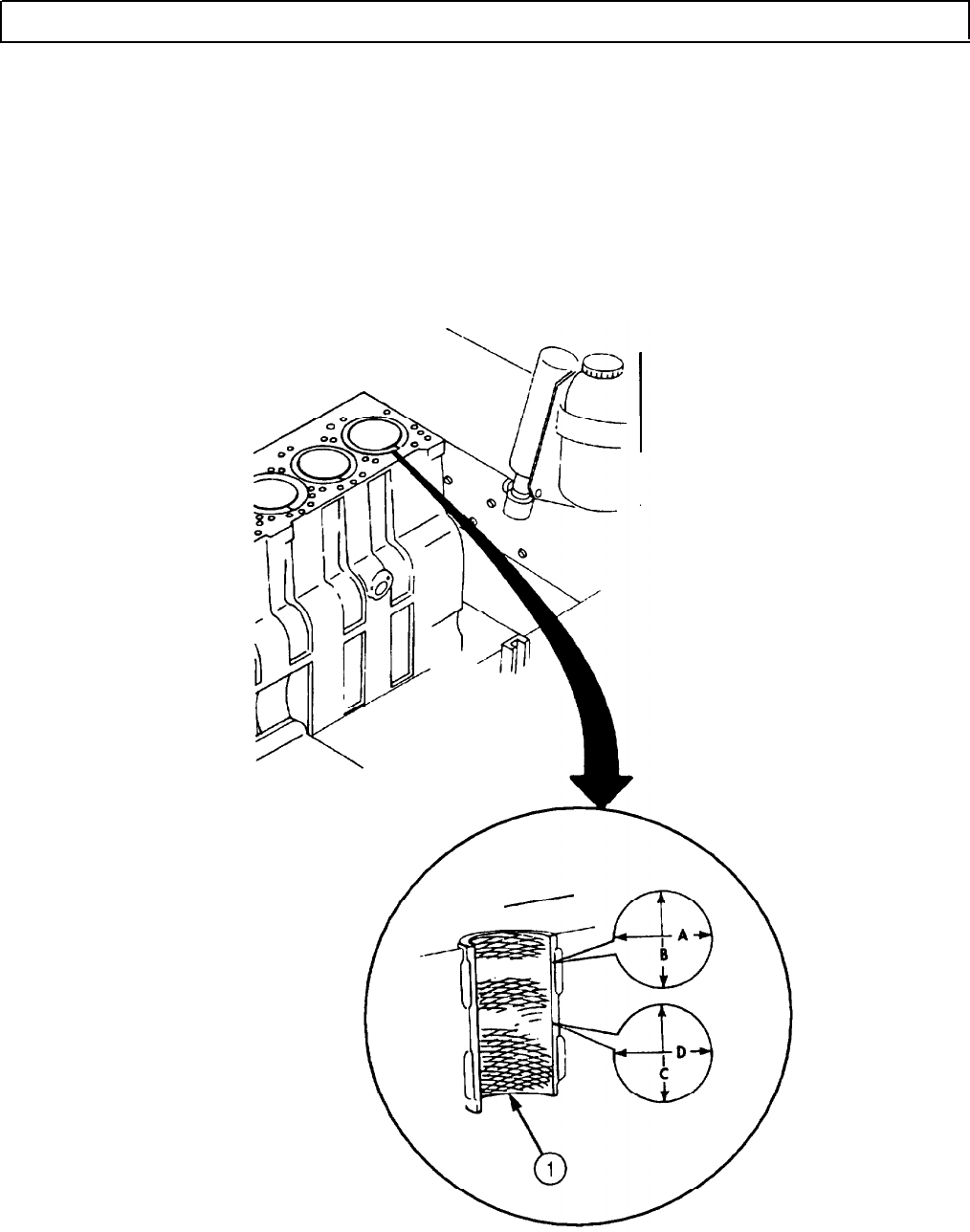
TM 9-2320-272-24-4
5-28. CYLINDER LINERS AND BLOCK MAINTENANCE (Contd)
4. Check cylinder liner (1) for wear:
a. Measure inside diameter of cylinder liner (1) in two places offset 90° at top of piston travel.
b. Record inside diameter measurements A and B.
c. Measure inside diameter of cylinder liner (1) in two places offset 90° at bottom of piston travel.
d. Record inside diameter measurements C and D.
e. Compare inside diameter measurements A with B and C with D. Tag cylinder liner (1) for
replacement if difference exceeds 0.0016 in. (0.041 mm).
f. Compare inside diameter measurements A with D and B with C. Tag cylinder liner (1) for
replacement if difference exceeds 0.0016 in. (0.041 mm).
5-185

TM 9-2320-272-24-4
5-28. CYLINDER LINERS AND BLOCK MAINTENANCE (Contd)
b. Cylinder Liner Removal
NOTE
All cylinder liners are removed the same way. This procedure
covers the removal of one cylinder liner.
1.
Scribe a mark (3) across cylinder liner (2) and engine block (4) for installation.
CAUTION
Do not install cylinder liner puller on lower block ledges. Failure
to comply may cause damage to engine block.
NOTE
Tag all cylinder liners with mating cylinder bore number for
installation.
2.
Install cylinder liner puller on engine block (4) and cylinder liner (2). Ensure cylinder liner puller
does not catch on lower block ledges (5).
3.
Remove cylinder liner (2) from engine block (4).
4.
Remove cylinder liner seal (1) from cylinder liner (2). Discard cylinder liner seal (1).
5-186
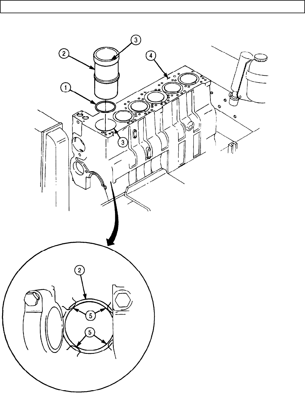
TM 9-2320-272-24-4
5-28. CYLINDER LINERS AND BLOCK MAINTENANCE (Contd)
5-187
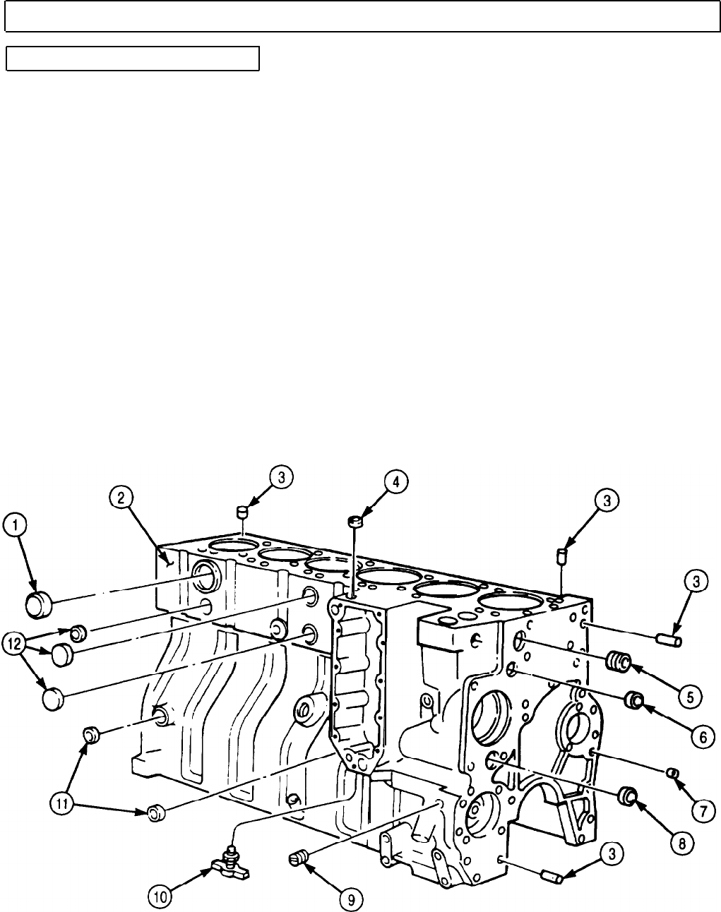
TM 9-2320-272-24-4
5-28. CYLINDER LINERS AND BLOCK MAINTENANCE (Contd)
c. Engine Block Disassembly
NOTE
Mark position and location of pipe and expansion plugs for
installation.
1.
Remove expansion plug (1) from engine block (2). Discard expansion plug (1).
2.
Remove three expansion plugs (12) from engine block (2). Discard expansion plugs (12).
3.
Remove two expansion plugs (11) from engine block (2). Discard expansion plugs (11).
4.
Remove drainvalve (10) from engine block (2).
5.
Remove expansion plug (4) from engine block (2). Discard expansion plug (4).
6.
Remove pipe plugs (5) and (9) from engine block (2).
7.
Remove expansion plug (6) from engine block (2). Discard expansion plug (6).
8.
Remove expansion plug (7) from engine block (2). Discard expansion plug (7).
9.
Remove expansion plug (8) from engine block (2). Discard expansion plug (8).
NOTE
Perform step 10 if dowel pins are damaged.
10.
Remove four dowel pins (3) from engine block (2). Discard dowel pins (3).
11.
Remove three pipe plugs (16) from engine block (2).
12.
Remove expansion plugs (13) and (17) from engine block (2). Discard expansion plugs (13) and (17).
13.
Remove expansion plug (15) from engine block (2). Discard expansion plug (15).
5-188
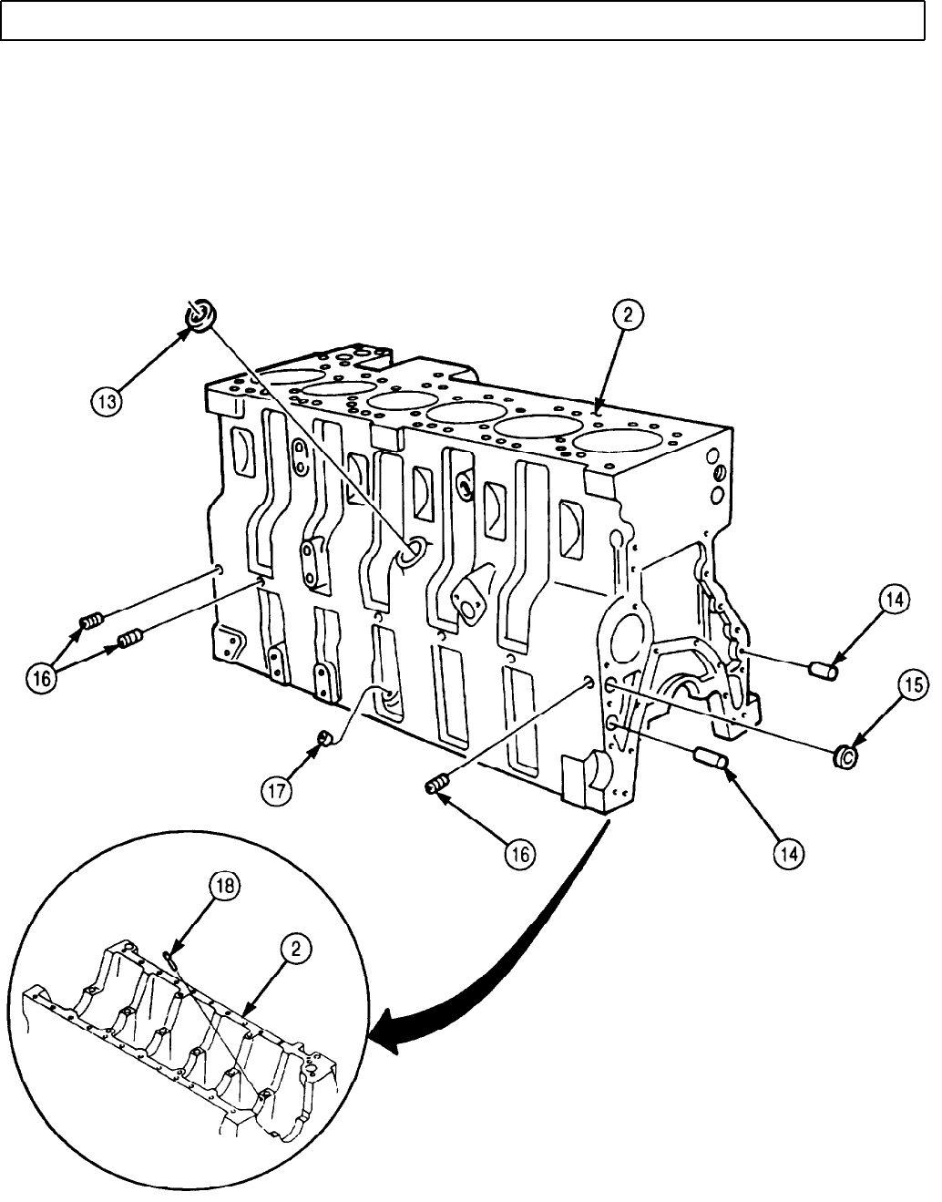
TM 9-2320-272-24-4
5-28. CYLINDER LINERS AND BLOCK MAINTENANCE (Contd)
NOTE
Perform step 14 if dowel pins are damaged.
14.
Remove two dowel pins (14) from engine block (2). Discard dowel pins (14).
15.
Remove six piston cooling nozzles (18) from engine block (2).
NOTE
Perform step 16 for late model engine.
16.
Remove twelve piston cooling nozzles (18) from engine block (2).
5-189

TM 9-2320-272-24-4
5-28. CYLINDER LINERS AND BLOCK MAINTENANCE (Contd)
d. Cylinder Liner and Engine Block Cleaning and Inspection
1.
2.
3.
4.
5.
6.
7.
8.
9.
10.
11.
12.
13.
5-190
WARNING
• Drycleaning solvent is flammable and toxic. Do not use near an
open flame and always have a fire extinguisher nearby when
solvents are used. Use only in well-ventilated places, wear
protective clothing, and dispose of cleaning rags in approved
container. Failure to do this may result in injury or death to
personnel and/or damage to equipment.
• Eyeshields must be worn when cleaning with compressed air.
Compressed air source will not exceed 30 psi (207 kPa). Failure
to do so may result in injury to personnel.
CAUTION
• Do not allow debris to fall into crankshaft oil holes. Damage to
crankshaft bearings could result.
• Do not remove stock material from cylinder liner seating
surface when cleaning. Machined tolerances are critical and
premature engine failure will result if material is removed.
Cover crankshaft oil holes (6) with clean rags.
Clean all expansion plug holes of engine block (2) with drycleaning solvent. Dry with compressed
air.
Clean sealing surfaces (3), (4), and (5) of engine block (2) with crocus cloth and drycleaning solvent.
Inspect sealing surfaces (3), (4), and (5) for cracks, pits, scores, and excessive wear. Replace engine
block (2) if cracked, pitted, scored, or excessively worn.
Measure inside diameter of sealing surface (4). Replace engine block (2) if inside diameter exceeds
5.2342 in. (132.949 mm).
Clean all oil draining and water cooling passage bores with brush and drycleaning solvent. Dry with
compressed air.
CAUTION
Engine block deck can be resurfaced twice in increments of
0.010 in. (0.254 mm). Do not exceed 0.020 in. (0.508 mm) when
resurfacing or damage to equipment will result.
Using straight edge and feeler gauge, inspect engine block (2) deck for warping. Replace engine
block (2) if warping exceeds 0.008 in. (0.203 mm). Notify your supervisor.
Install seven main bearing caps (8) on engine block (2) with fourteen screws (9). Tighten
screws (9) 130 lb-ft (176 N•m).
Using bore gauge, measure inside diameter of main bearing bore (10). Record measurement.
Replace main bearing (7) if inside diameter exceeds 3.8632 in. (98.125 mm).
Using bore gauge, measure inside diameter of camshaft bore (12). Replace bushing (13) if inside
diameter exceeds 2.367 in. (60.12 mm).
Measure inside diameter of tappet bore (11). Replace engine block (2) if inside diameter exceeds
0.632 in. (16.05 mm).
NOTE
Cylinder liners should be inspected before cleaning so defects can
be clearly noted.
Check cylinder liner (1) for cracks, scoring, or vertical grooves. Replace cylinder liner (1) if cracked,
scored, or vertical grooves are present.
Check cylinder liner (1) for pits and eroded surfaces. Replace cylinder liner (1) if pitted or eroded.
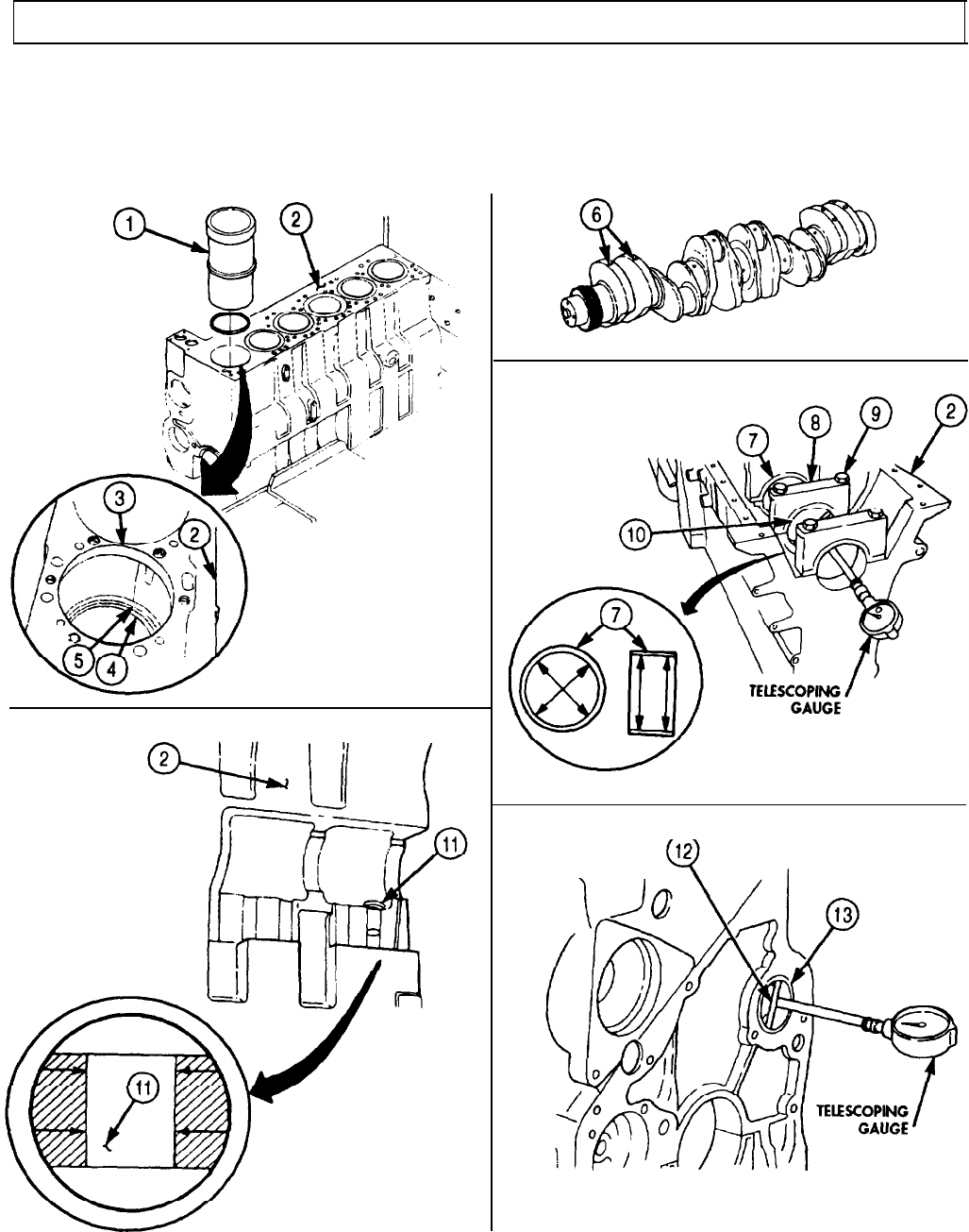
TM 9-2320-272-24-4
5-28. CYLINDER LINERS AND BLOCK MAINTENANCE (Contd)
14.
Check cylinder liner (1) for fretting and breaks in machined areas. Replace cylinder liner (1) if
fretted or broken.
15.
Check cylinder liner (1) for rust, scaling, and corrosion.
a. Clean with steam or hot water and detergent.
b. Replace if excessively rusted, scaled, or corroded.
5-191

TM 9-2320-272-24-4
5-28. CYLINDER LINERS AND BLOCK MAINTENANCE (Contd)
e. Engine Block Assembly
CAUTION
Ensure all engine block oil passages are free of obstructions.
Failure to do so may result in damage to engine.
NOTE
• Perform step 1 for late model engines, serial
number 44487830 and after.
• Perform step 2 if dowel pins were removed.
1.
Install twelve piston cooling nozzles (7) in engine block (2).
2.
Install two new dowel pins (3) in engine block (2).
3.
Install six piston cooling nozzles (7) in engine block (2).
NOTE
• Apply adhesive sealant to mating surfaces of all expansion
plugs before installation.
• Wrap male pipe threads with antiseize tape before installation.
4.
Install new expansion plug (4) in engine block (2).
5.
Install new expansion plugs (6) and (1) on engine block (2).
6.
Install three pipe plugs (5) on engine block (2). Tighten pipe plugs (5) 6 lb-ft (8 N•m).
NOTE
Perform step 7 if dowel pins were removed.
7.
Install four new dowel pins (8) on engine block (2).
8.
Install new expansion plug (13) on engine block (2).
9.
Install new expansion plug (12) on engine block (2).
10.
Install new expansion plug (11) on engine block (2).
11.
Install pipe plugs (10) and (14) on engine block (2). Tighten pipe plug (14) 6 lb-ft (8 N•m). Tighten
pipe plug (10) 27 lb-ft (37 N•m).
12.
Install new expansion plug (9) on engine block (2).
13.
Install new drainvalve (15) on engine block (2).
14.
Install two new expansion plugs (16) on engine block (2).
15.
Install three new expansion plugs (17) on engine block (2).
16.
Install new expansion plug (18) on engine block (2).
5-192
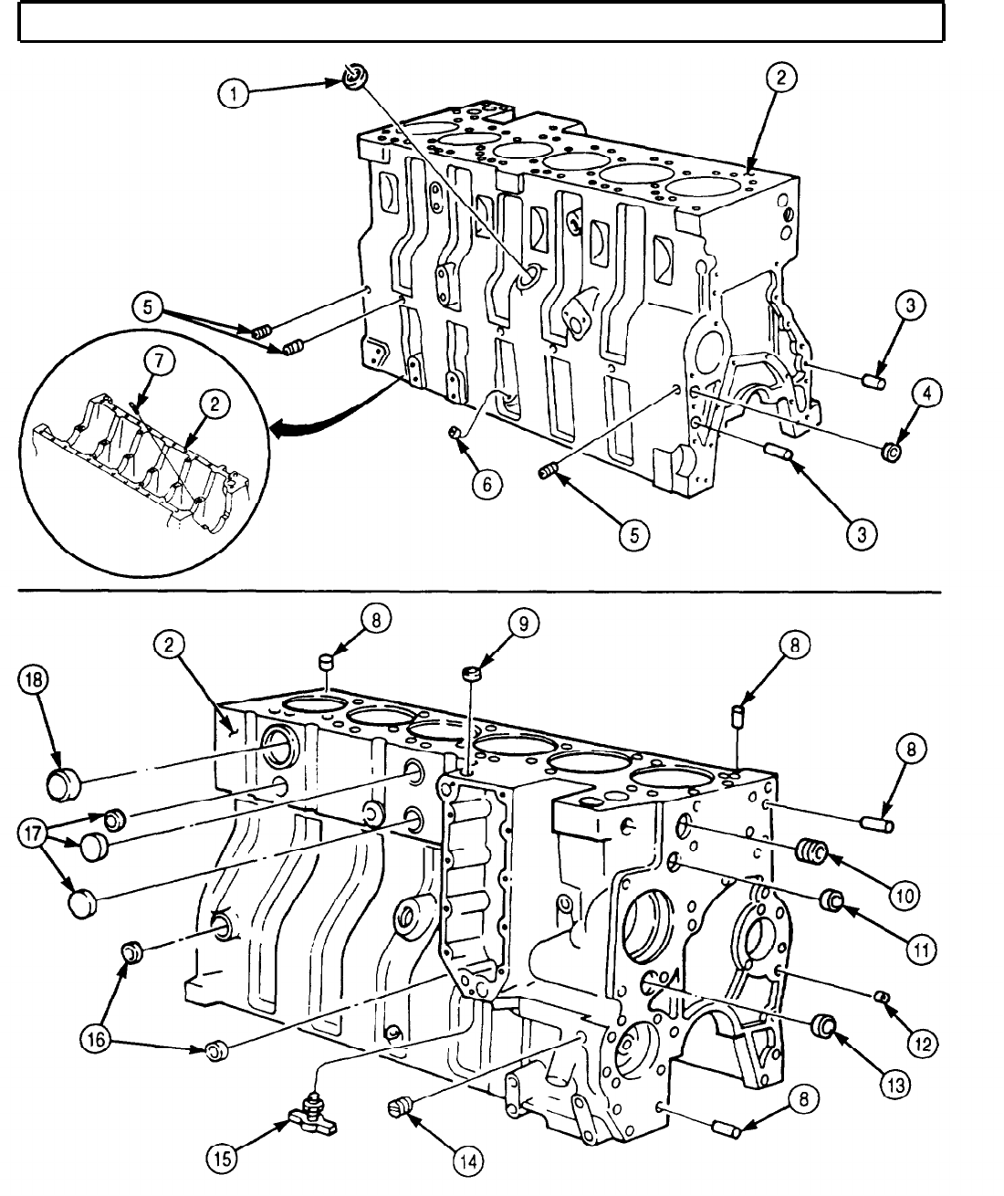
TM 9-2320-272-24-4
5-28. CYLINDER LINERS AND BLOCK MAINTENANCE (Contd)
5-193

TM 9-2320-272-24-4
5-28. CYLINDER LINERS AND BLOCK MAINTENANCE (Contd)
f. Cylinder Liner Installation
NOTE
All cylinder liners are installed the same. This procedure covers
installation of one cylinder liner.
1.
Apply clean engine oil to lubricate cylinder liner bore (4).
2.
Install new cylinder liner seal (2) on cylinder liner (1).
3.
Apply clean engine oil to lubricate sealing surfaces (5), (6), and (7), cylinder liner (1), and cylinder
liner seal (2).
4.
Install cylinder liner (1) in mating cylinder liner bore (4).
NOTE
Perform step 5 if installing old cylinder liner.
5.
Rotate cylinder liner (1) 1/8 turn from position noted in removal. Using cylinder liner driver, drive
cylinder liner (1) until it bottoms in cylinder liner bore (4).
6.
Install two cylinder liner clamps on engine block (3) with two washers and screws. Tighten screws
50 lb-ft (68 N·m).
7.
Remove two screws, washers, and cylinder liner clamps from engine block (3).
8.
Using gauge block, measure cylinder liner protrusion:
a. Position gauge block on engine block (3).
b. Place plunger on engine block (2) and set dial indicator to zero.
c. Position gauge block on engine block (3) and place plunger on cylinder liner (1).
d. Cylinder liner protrusion should be 0.005-0.0043 in. (0.0127-0.1092 mm).
e. Check cylinder liner (1) for proper installation if cylinder liner protrusion is not within limits.
f. If installed correctly, counterbore of engine block (3) will require cutting. Notify your supervisor.
9.
Check clearance between cylinder liner (1) and lower block ledges (8) using 0.009 in. (0.229 mm)
feeler gauge. If feeler gauge does not pass between cylinder liner (1) and lower bottom ledges (8),
remove cylinder liner (1) and reinstall.
5-194
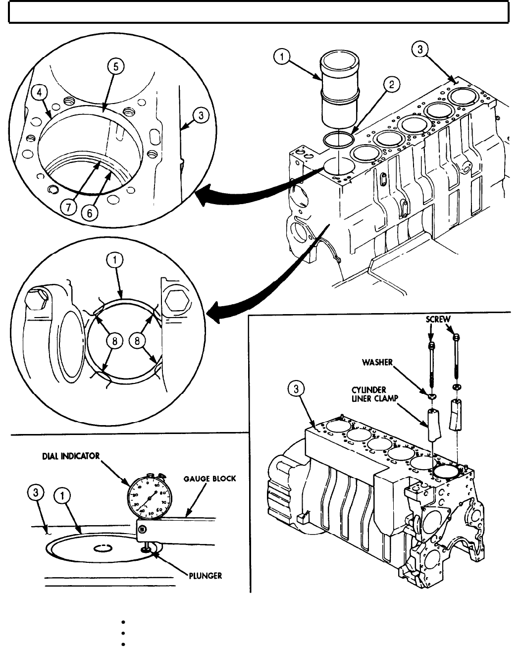
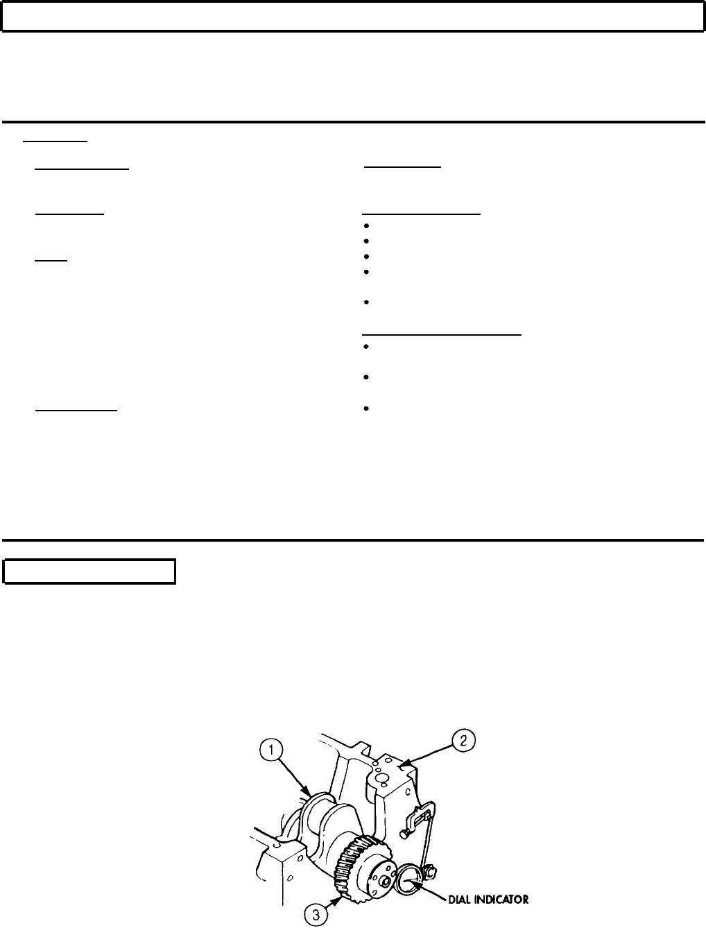
TM 9-2320-272-24-4
5-29. CRANKSHAFT AND GEAR MAINTENANCE
THIS TASK COVERS:
a.
Check End Play
d.
Cleaning and Inspection
b. Removal e. Assembly
c. Disassembly f. Installation
INITIAL SETUP:
APPLICABLE MODELS REFERENCES (TM)
M939A2
TM 9-2320-272-24P
SPECIAL TOOLS
EQUIPMENT CONDITION
Torque angle gauge (Appendix E, Item 141) Fuel injectors removed (para. 4-55).
TOOLS
Oil pan and suction tube removed (para. 4-47).
General mechanic’s tool kit (Appendix E, Item 1) Front gearcase housing removed (para. 4-46).
Flexplate and flywheel housing removed
Heavy duty gear puller (Appendix E, Item 102) (para. 4-43).
Dial indicator (Appendix E, Item 36) Rear cover and oil seal removed (para. 4-44).
Torque wrench (Appendix E, Item 144)
Feeler gauge
GENERAL SAFETY INSTRUCTIONS
Prybar Drycleaning solvent is flammable and toxic. Do
Soft-head hammer not use near open flame.
Nylon brush Keep fire extinguisher nearby when using
MATERIALS/PARTS
drycleaning solvent.
Eyeshields must be worn when cleaning with
Dowel pin (Appendix D, Item 99) compressed air. Compressed air source will not
Crankshaft main bearing set
(Appendix D, Item 87) exceed 30 psi (207 kPa).
Drycleaning solvent (Appendix C, Item 71)
GAA grease (Appendix C, Item 28)
Lubricating oil (Appendix C, Item 50)
Plastigage (Appendix C, Item 55)
Crocus cloth (Appendix C, Item 20)
a. Check End Play
1.
Position engine block (2) so crankshaft (1) is facing upward.
2.
Install dial indicator on engine block (2) with plunger on face of crankshaft gear (3).
3.
Move crankshaft (1) towards rear of engine block (2) using prybar.
4.
Set dial indicator to zero.
5.
Move crankshaft (1) toward front of engine block (2) using prybar. Record dial indicator reading.
6.
Replace thrust bearing in subtasks b and f if crankshaft (1) end play is not between 0.006-0.013 in.
(0.152-0.330 mm).
5-196
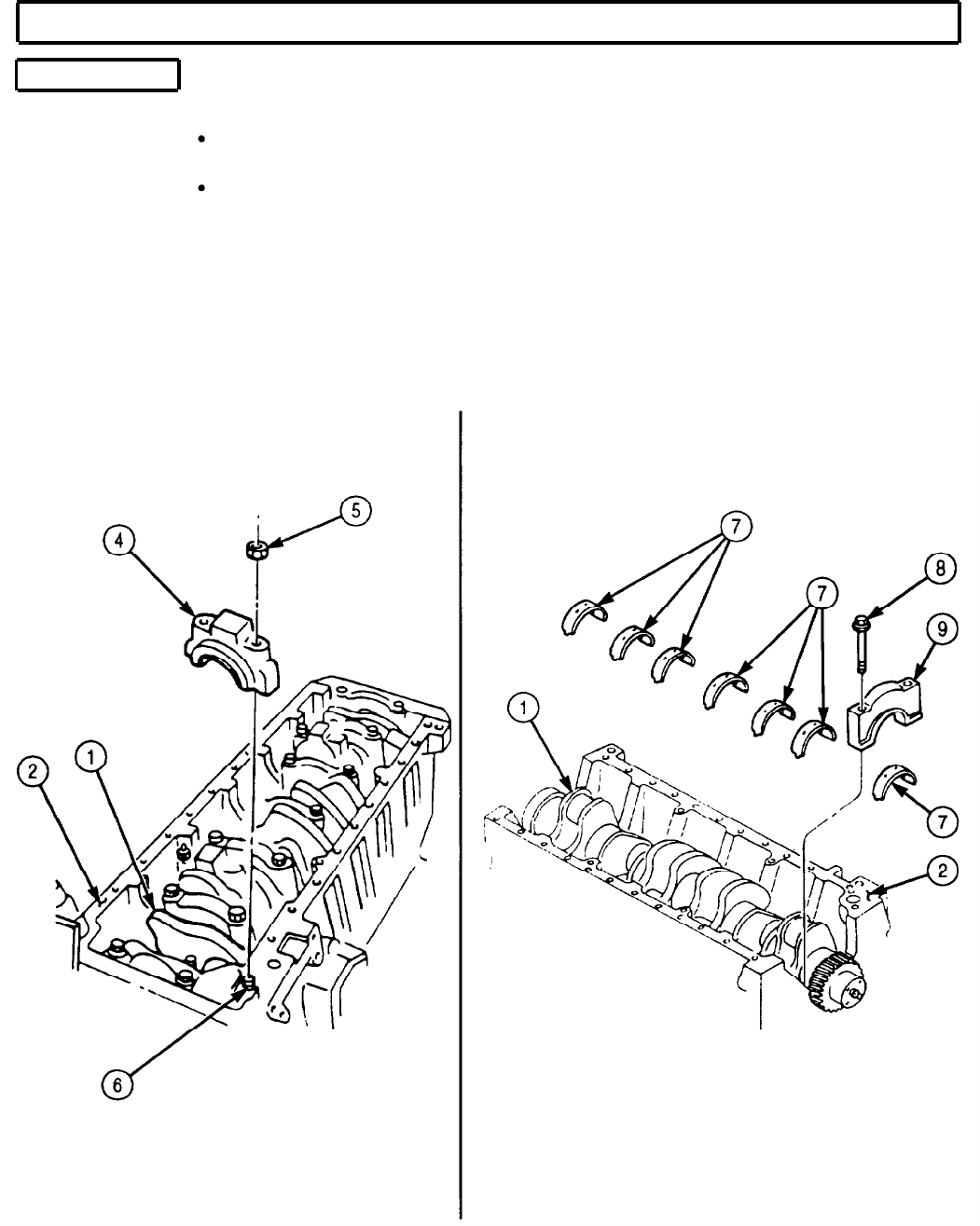
TM 9-2320-272-24-4
5-29. CRANKSHAFT AND GEAR MAINTENANCE (Contd)
b. Removal
NOTE
Tag all connecting rod caps, main bearing caps, mating
cylinders, and bearings for installation.
All connecting rod caps and main bearing caps are removed the
same.
1.
Remove twelve nuts (5) from six connecting rod caps (4).
2.
Using soft-head hammer, tap screws (6) and remove connecting rod caps (4) from crankshaft (1).
3.
Remove fourteen screws (8) from seven main bearing caps (9).
4.
Loosen main bearing caps (9) and remove from crankshaft (1) using screws (8).
5.
Remove seven lower main bearings (7) from main bearing caps (9). Discard bearings (7).
6.
Remove crankshaft (1) from engine block (2).
5-197
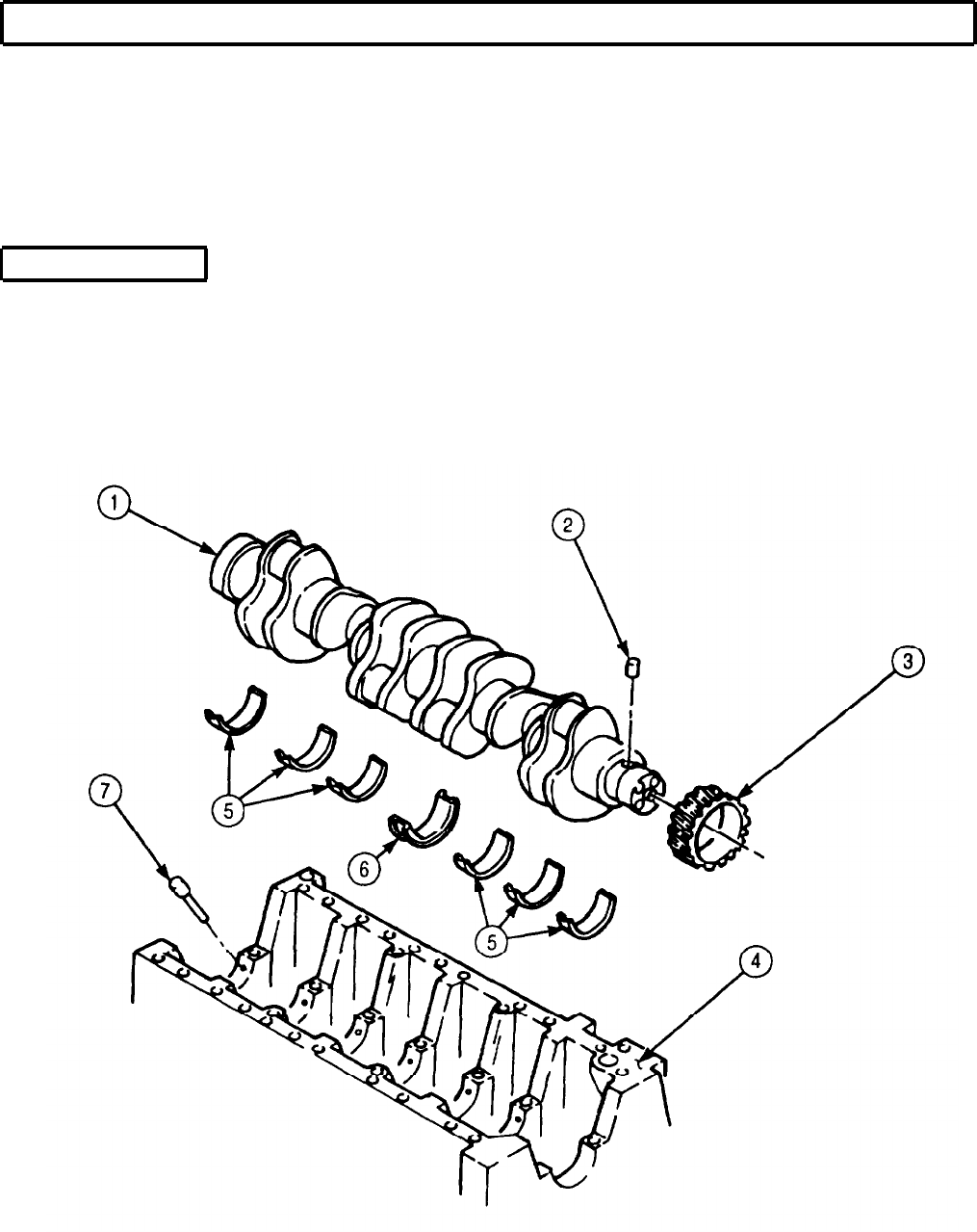
TM 9-2320-272-24-4
5-29. CRANKSHAFT AND GEAR MAINTENANCE (Contd)
7.
Remove six upper main bearings (5) and thrust bearing (6) from engine block (4). Discard
bearings (5) and (6).
NOTE
Perform step 8 for late model engines, serial number 44487830
and after.
8.
Remove twelve piston cooling nozzles (7) from engine block (4).
9.
Remove six piston cooling nozzles (7) from engine block (4).
c. Disassembly
NOTE
Before removing crankshaft gear from crankshaft, perform
subtask d of this procedure. If, as a result of inspection, the
crankshaft gear must be removed, perform steps 1 and 2.
1.
Using gear puller, remove crankshaft gear (3) from crankshaft (1).
2.
Remove dowel pin (2) from crankshaft (1). Discard dowel pin (2).
5-198
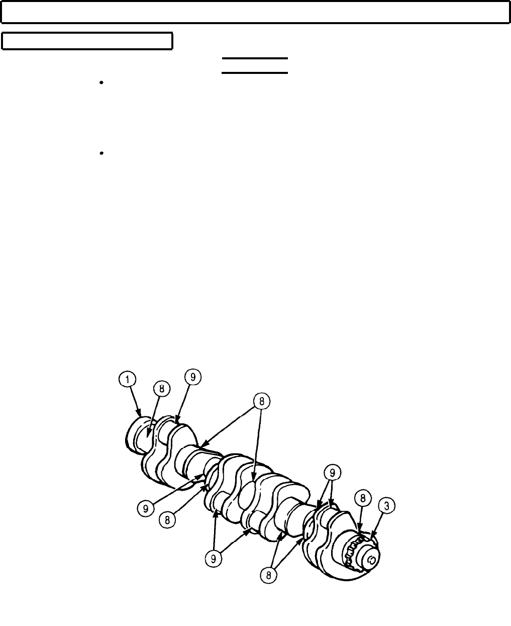
TM 9-2320-272-24-4
5-29. CRANKSHAFT AND GEAR MAINTENANCE (Contd)
d. Cleaning and Inspection
1.
2.
3.
4.
Drycleaning solvent is flammable and toxic. Do not use near
open flame and always have a fire extinguisher nearby when
solvents are used. Use only in well-ventilated places, wear
protective clothing, and dispose of cleaning rags in approved
container. Failure to do this may result in injury or death to
personnel and/or damage to equipment.
Eyeshields must be worn when cleaning with compressed air.
Compressed air source will not exceed 30 psi (207 kPa). Failure
to do so may result in injury to personnel.
Clean all parts with drycleaning solvent and dry with compressed air. Use nylon brush to clean all
oil passages.
Inspect crankshaft (1) for cracks, gouges, pits, burrs, nicks, and scratches. Remove minor damage
with fine mill file or crocus cloth. If excessively cracked, gouged, pitted, burred, nicked, or scratched,
replace crankshaft (1).
Inspect crankshaft gear (3) for cracks, breaks, and damaged teeth. If cracked, broken, or teeth are
damaged, replace crankshaft gear (3).
Inspect connecting rod journals (9) and main bearing journals (8) for scratches, grooves, excessive
wear, and discoloring caused by overheating. Replace crankshaft (1) if scratched, grooved, worn, or
discolored.
WARNING
5-199
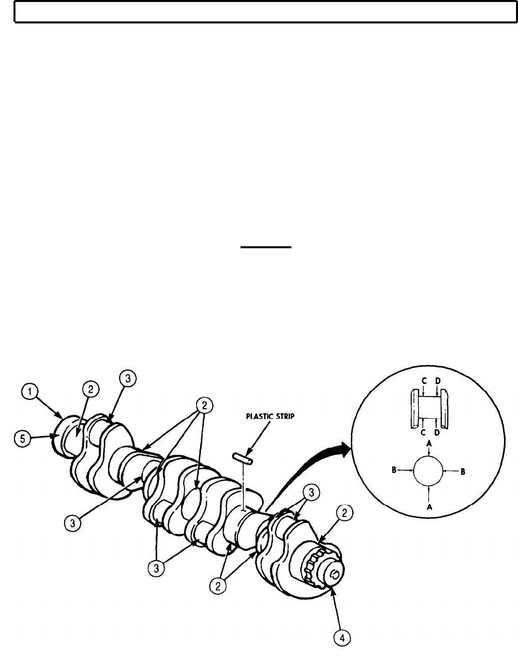
TM 9-2320-272-24-4
5-29. CRANKSHAFT AND GEAR MAINTENANCE (Contd)
5.
6.
7.
8.
9.
10.
11.
12.
13.
14.
15.
16.
17.
Inspect connecting rod caps (14) for cracks, breaks, and pits. Replace connecting rod caps (14) if
cracked, broken, or pitted.
Inspect main bearing caps (7) for cracks, breaks, and pits. Replace main bearing caps (7) if cracked,
broken, or pitted.
Inspect engine block (9) for scratches, grooves, wear, and stripped threads. Replace or repair if
engine block (9) is scratched, grooved, worn, or threads are stripped.
Measure outside diameter of main bearing journals (2) for out-of-roundness across points A and B.
Replace crankshaft (1) if difference of measurements exceeds 0.002 in. (0.0051 mm).
Measure outside diameter of main bearing journals (2) for taper at points C and D. Replace
crankshaft (1) if difference of measurements exceeds 0.0005 in. (0.013 mm).
Measure outside diameter of connecting rod journals (3) for out-of-roundness across points A and B.
Replace crankshaft (1) if difference of measurements exceeds 0.002 in. (0.0050 mm).
Measure outside diameter of connecting rod journals (3) for taper at points C and D. Replace
crankshaft (1) if difference of measurements exceeds 0.0005 in. (0.0127 mm).
Inspect front (4) and rear (5) crankshaft seal wear surfaces for scratches and grooves. Replace
crankshaft (1) if scratched or grooved.
CAUTION
Ensure main bearings are installed in proper mating seats.
Failure to do so will cause engine to fail.
Install new thrust bearing (8) in No. 4 main bearing seat (11).
Install six new upper main bearings (7) in main bearing seats (10). Ensure tangs (12) of upper main
bearings (7) are aligned with slots (13) of main bearings seats (10).
Install crankshaft (1) in engine block (9).
Install seven new lower main bearings (6) in main bearing caps (7).
Place plastic strips across width of seven main bearing journals (2).
5-200
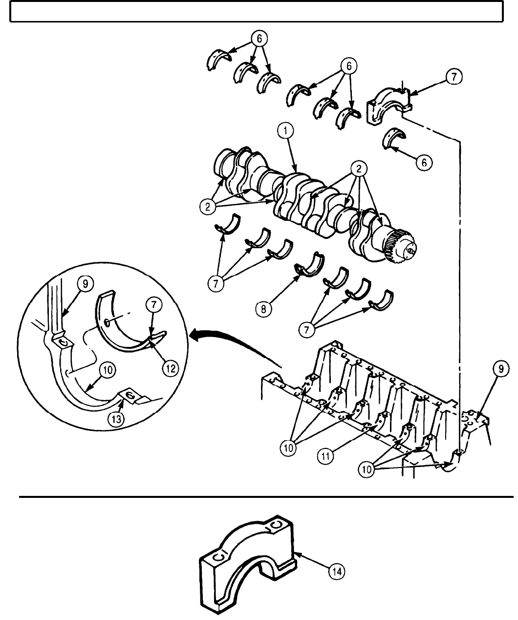
TM 9-2320-272-24-4
5-29. CRANKSHAFT AND GEAR MAINTENANCE (Contd)
5-201
TM 9-2320-272-24-4
5-29. CRANKSHAFT AND GEAR MAINTENANCE (Contd)
NOTE
Ensure main bearing caps are installed with mating cylinders.
Number on main bearing caps should face camshaft.
18.
Apply clean engine oil to coat threads of fourteen screws (2).
19.
Position seven main bearing caps (3) on engine block (14) and crankshaft (7) and tap main bearing
caps (3) using soft-head hammer until seated on main bearing journals (6).
20.
Install main bearing caps (3) on engine block (14) with fourteen screws (2). Tighten screws (2)
125 lb-ft (170 N·m) in sequence shown.
21.
Remove fourteen screws (2) and seven main bearing caps (3) from engine block (14).
22.
Measure width of plastic strip at widest point using plastigage. If plastic strip does not measure
0.0026-0.0053 in. (0.660-0.1346 mm), replace all upper (10), lower (1), and thrust (11) bearings.
e. Assembly
NOTE
Perform steps 1 through 3 if gear was removed.
1.
Install new dowel pin (5) in crankshaft (7).
2.
Apply GAA grease to lobe (8) of crankshaft (7).
3.
Press crankshaft gear (9) on crankshaft (7).
f. Installation
CAUTION
Late and early model engine main bearings and main bearing caps
and components are not interchangeable. Mixing components will
cause damage to engine.
NOTE
Perform step 1 if inspection did not require replacement of main
bearings.
Perform step 3 for late model engines, serial number 44487830
and after.
Piston cooling nozzles are located in all upper chain bearing
seats, except for No. 3 cylinder.
1.
Remove six upper main bearings (10) and thrust bearing (11) from engine block (14).
2.
Install six piston cooling nozzles (15) in upper main bearing seats (12). Ensure piston cooling
nozzles (15) seat below main bearing surface.
3.
Install twelve piston cooling nozzles (15) in upper main bearing seats (12). Ensure piston cooling
nozzles (15) seat below main bearing surface.
NOTE
Apply lubricating oil to all main bearings and bearing surfaces.
4.
Align tangs (16) of six upper main bearings (10) with slots (17) of main bearing seats (12) and
install on engine block (14).
5-202

TM 9-2320-272-24-4
5-29. CRANKSHAFT AND GEAR MAINTENANCE (Contd)
5. Install thrust bearing (11) in No. 4 main bearing seat (13).
6.
Install crankshaft (7) in engine block (14).
NOTE
Perform step 7 if inspection required replacement of lower main
bearings.
7.
8.
9.
10.
11.
12.
13.
Align tangs (4) of seven lower main bearings (1) with slots of main bearing caps (3) and install
seven lower main bearings (1) in main bearing caps (3).
Apply clean engine oil to main bearing journals (6) and install seven main bearing caps (3) on
engine block (14).
Using soft-head hammer, tap main bearing caps (3) until seated against main bearing journals (6).
Apply clean engine oil to threads of fourteen screws (2) and install on main bearing caps (3).
Tighten screws (2) as follows:
a.
Tighten screws (2) 125 lb-ft (170 N·m) in sequence shown. Loosen screws (2).
b.
Tighten screws (2) to 70 lb-ft (95 N·m) in sequence shown.
c.
Using torque angle gauge, tighten screws (2) an additional 45-75°.
Rotate crankshaft (7) and check for freedom of movement.
Check crankshaft (7) end play (task a).
5-203
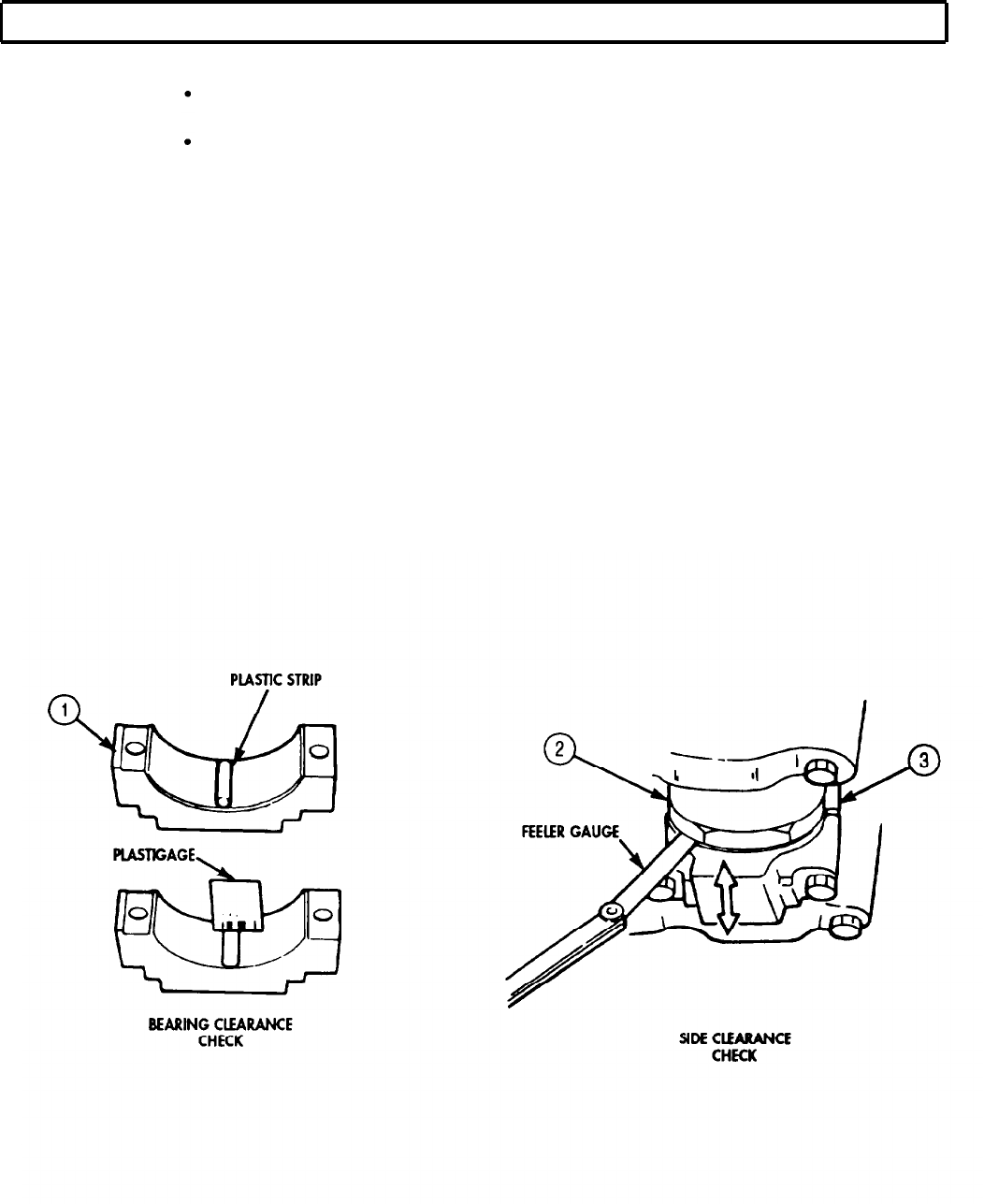
TM 9-2320-272-24-4
5-29. CRANKSHAFT AND GEAR MAINTENANCE (Contd)
14.
15.
16.
17.
18.
19.
20.
21.
22.
23.
Place a piece of plastic strip across width of connecting rod cap (1).
Install connecting rod cap (1) on crankshaft (2) and connecting rod (3) with two nuts (4).
Tighten nuts (4) 30 lb-ft (41 N·m), then 60 lb-ft (81 N·m), then 90 lb-ft (122 N·m).
Remove two nuts (4) and connecting rod cap (1) from connecting rod (3) and crankshaft (2).
Using plastigage, measure width of plastic strip. If width is not 0.0013-0.0046 in.
(0.033-0.117 mm), replace all connecting rod bearings (5) and (6).
Apply clean engine oil to lubricate connecting rod cap (1).
Install connecting rod cap (1) on crankshaft (2) and connecting rod (3) with two nuts (4).
Tighten nuts (4) 30 lb-ft (41 N·m), then 60 lb-ft (81 N·m), then 90 lb-ft (122 N·m).
Move connecting rod (3) back and forth on crankshaft (2).
Measure connecting rod (3) side clearance using feeler gauge. If clearance is not 0004-0.012 in.
(0.1-0.30 mm), remove connecting rod cap (1) and inspect for proper size and seating of
bearings (5) and (6).
NOTE
All connecting rod caps are installed the same. This procedure
covers the installation of one connecting rod cap.
Rotate crankshaft as necessary to access connecting rod
journals.
5-204
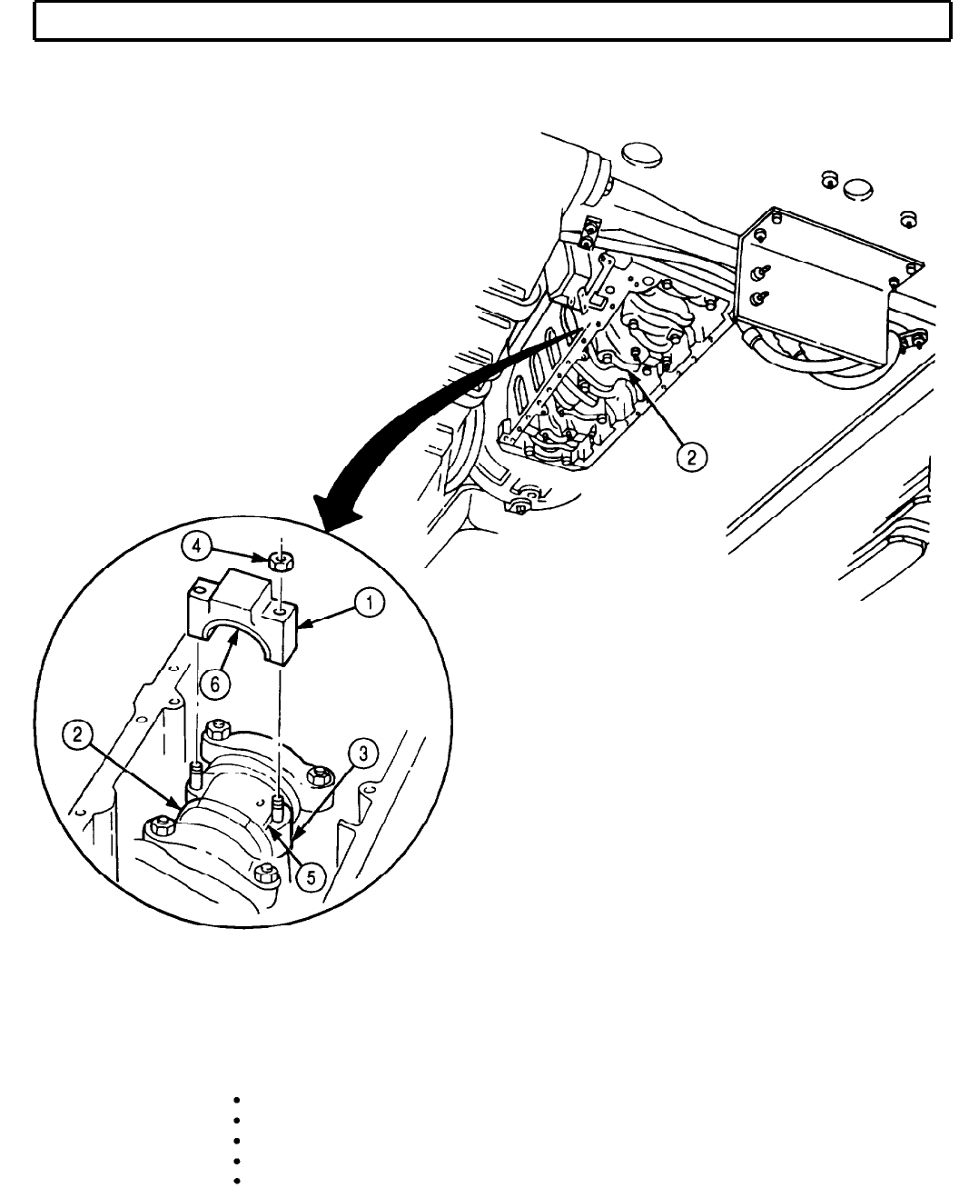
TM 9-2320-272-24-4
5-29. CRANKSHAFT AND GEAR MAINTENANCE (Contd)
FOLLOW-ON TASKS: Install rear cover and oil seal (para. 4-44).
Install flexplate and flywheel housing (para. 4-43).
Install front gearcase housing (para. 4-46).
Install oil pan and suction tube (para. 4-47).
Install fuel injectors (para. 4-55).
5-205
TM 9-2320-272-24-4
5-30. ROCKER LEVERS AND PUSH RODS MAINTENANCE
THIS TASK COVERS:
a. Disassembly c. Assembly
b.
Cleaning and Inspection
INITIAL SETUP:
APPLICABLE MODELS
M939A2
TOOLS
General mechanic’s tool kit (Appendix E, Item 1)
Inside micrometer (Appendix E, Item 82)
Outside micrometer (Appendix E, Item 80)
Torque wrench (Appendix E, Item 144)
MATERIALS/PARTS
Twelve locknuts (Appendix D, Item 326)
Drycleaning solvent (Appendix C, Item 71)
Lubricating oil (Appendix C, Item 50)
REFERENCES (TM)
TM 9-2320-272-10
TM 9-2320-272-24P
EQUIPMENT CONDITION
Parking brake set (TM 9-2320-272-10).
Rocker-levers and push rods removed (para. 4-41).
GENERAL SAFETY INSTRUCTIONS
Keep fire extinguisher nearby when using
drycleaning solvent.
Drycleaning solvent is flammable and toxic.
Eyeshields must be worn when cleaning with
compressed air. Compressed air source will not
exceed 30 psi (207 kPa).
a. Disassembly
NOTE
All rocker levers are disassembled the same way. This procedure
covers one rocker lever assembly.
1.
Remove two retaining rings (2), washers (3), spring washers (4), and rocker levers (1) from rocker
shaft (7).
2.
Remove locknut (5) and adjusting screw (6) from each rocker lever (1). Discard locknut (5).
b. Cleaning and Inspection
1.
For general cleaning instructions, refer to para. 2-14
2.
For general inspection instructions, refer to para. 2-15.
3.
Replace all parts failing inspection.
4.
Measure inside diameter of rocker lever bore (8) at several points, If inside diameter exceeds
0.878 in. (22.3 mm), replace rocker lever (1).
5.
Measure outside diameter of rocker shaft (7) at several points. If outside diameter is less than 0.874
in. (22.2 mm), replace rocker shaft (7).
5-206
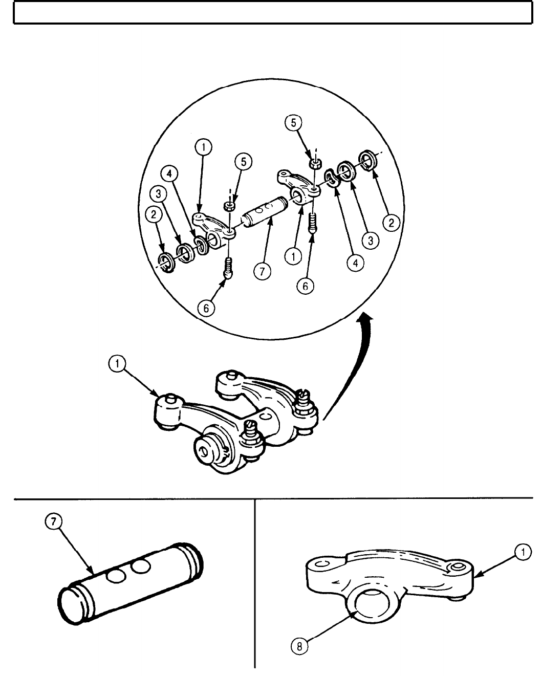
TM 9-2320-272-24-4
5-30. ROCKER LEVERS AND PUSH RODS MAINTENANCE (Contd)
5-207

TM 9-2320-272-24-4
5-30. ROCKER LEVERS AND PUSH RODS MAINTENANCE (Contd)
Drycleaning solvent is flammable and toxic. Do not use near
open flame and always have a fire extinguisher nearby when
solvents are used. Use only in well-ventilated places, wear
protective clothing, and dispose of cleaning rags in approved
container. Failure to do this may result in injury or death to
personnel and/or damage to equipment.
Eyeshields must be worn when cleaning with compressed air.
Compressed air source will not exceed 30 psi (207 kPa). Failure
to do so may result in injury to personnel.
6.
Inspect oil manifold (2) for bends, cracks, and breaks. If bent, cracked, or broken, replace oil
manifold (2).
CAUTION
Oil manifold screws are self-tapping and must be reinstalled in
their proper positions to ensure proper alignment of screw flats or
damage may occur to oil manifold.
7.
Inspect oil manifold (2) for clogged oil ports. If oil ports are clogged, remove two screws (1), flush oil
manifold (2) with drycleaning solvent. Dry with compressed air and replace two screws (1) in oil
manifold (2).
d. Assembly
All rocker levers are assembled the same way. This procedure is
for one rocker lever assembly.
Lightly oil all parts before assembling.
Perform step 1 if assembling with new rocker shaft.
1.
Install two plugs (8) on rocker shaft (13).
2.
Install adjusting screw (12) and new locknut (7) on each rocker lever (6).
3.
Install spring washer (5), washer (4), and retaining ring (3) on one side of rocker shaft (13).
4.
Install two rocker levers (6) on rocker shaft (13).
5.
Install spring washer (11), washer (10), and retaining ring (9) on rocker shaft (13).
5-208
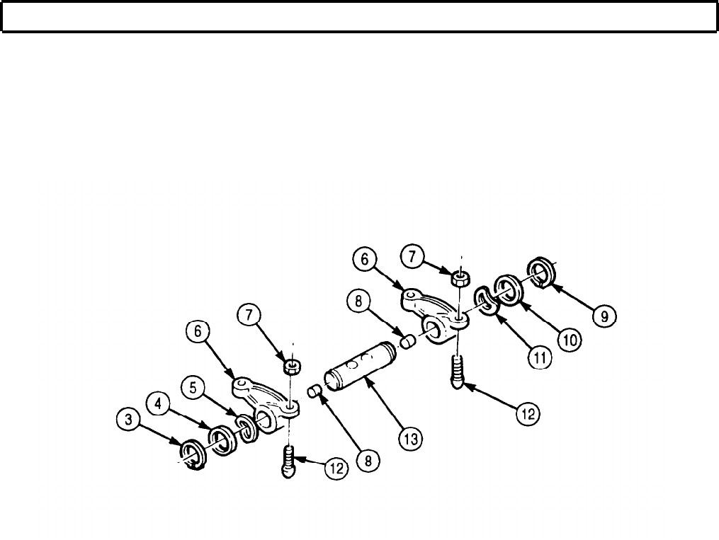
TM 9-2320-272-24-4
5-30. ROCKER LEVERS AND PUSH RODS MAINTENANCE (Contd)
FOLLOW-ON TASK: Install rocker levers and push rods (para. 4-41).
5-209
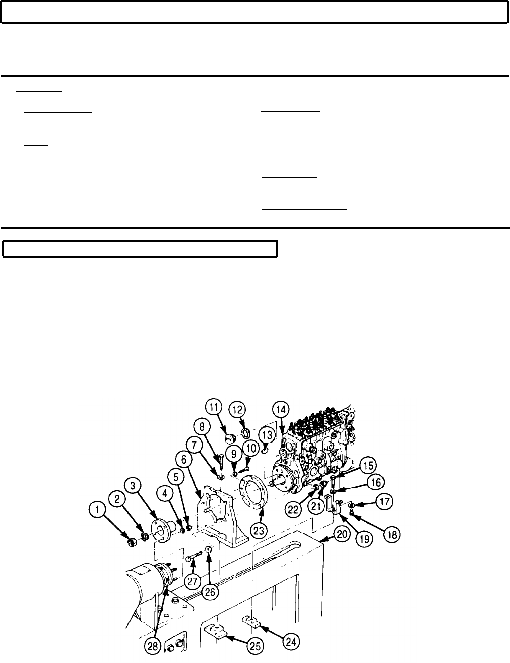
TM 9-2320-272-24-4
5-31. MOUNTING FUEL INJECTION PUMP TO TEST STAND
THIS TASK COVERS:
a. Mounting Fuel Injection Pump to b. Removing Fuel Injection Pump from
Test Stand Test Stand
INITIAL SETUP:
APPLICABLE MODELS MATERIALS/PARTS
M939A2
Lockwasher (Appendix D, Item 383)
TOOLS
Two copper washers (Appendix D, Item 42)
General mechanic’s tool kit (Appendix E, Item 1) Copper washer (Appendix D, Item 45)
Copper washer (Appendix D, Item 44)
Fuel injection pump test stand (Appendix E,
Item 50)
REFERENCES (TM)
TM 9-2320-272-24P
EQUIPMENT CONDITION
Fuel injection pump removed (para. 4-57).
a. Mounting Fuel Injection Pump to Test Stand
1.
Remove screw plug (11) and copper washer (12) from drive end of fuel pump (14). Discard copper
washer (12).
2.
Install adapter ring (23) on adapter bracket (6) with three washers (9) and screws (10).
3.
Install adapter bracket (6) on test stand (20) with washer (7), screw (8), and clamp bar (25).
4.
Install fuel pump (14) on adapter bracket (6) with four washers (26), screws (27), washers (22), and
nuts (21).
5.
Install woodruff key (13) and drive hub (3) on fuel pump (14) with lockwasher (2) and nut (1).
6.
Slide fuel pump (14) forward so drive hub (3) engages with drive coupling (28) and secure fuel
pump (14) in place with four lockwashers (4) and nuts (5).
7.
Install rear support bracket (19) on rear of fuel pump (14) with two washers (17) and screws (18).
5-210
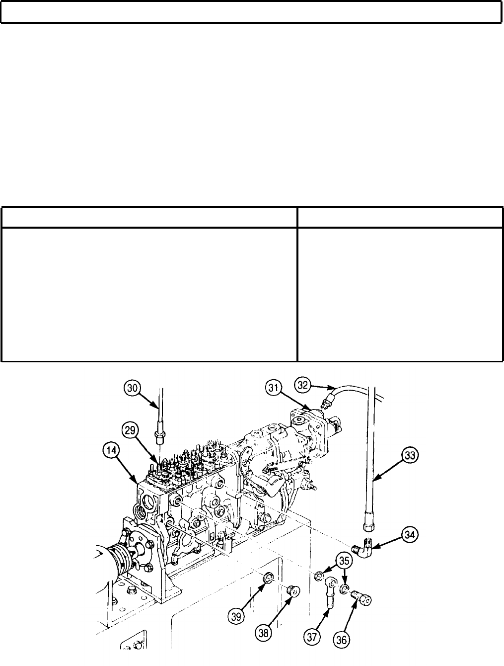
TM 9-2320-272-24-4
5-31. MOUNTING FUEL INJECTION PUMP TO TEST STAND (Contd)
8.
Install rear support bracket (19) and clamp bar (24) on test stand (20) with two washers (16) and
screws (15).
9.
Connect six test stand fuel lines (30) to delivery valve holders (29) and test stand injectors.
10.
Connect air line (32) to manifold pressure compensator (31).
11.
Remove plug (36), two copper washers (35), and adapter (37) from fuel pump (14). Discard copper
washers (35).
12.
Install outlet elbow (34) on fuel pump (14).
13.
Connect test stand supply line (33) to outlet elbow (34).
14.
Remove plug (38) and copper washer (39) from side of fuel pump (14) for access to number one
cylinder. Discard copper washer (39).
15.
Refer to table 5-10, Test Stand Requirements, for further preliminary requirements.
Table 5-10. Test Stand Requirements.
ITEM
REQUIREMENTS
Calibration Fluid Temperature
100°-108°F (38°-42°C)
Inlet Pressure 22 psi (152 kPa)
Opening Pressure 3,000-3,046 psi (20,684-21,001 kPa)
Firing Order
1-5-3-6-2-4
Select Drive Rotation
1:2
Direction of Drive Rotation Clockwise
Number of Injection Cylinders
Six
5-211

TM 9-2320-272-24-4
5-31. MOUNTING FUEL INJECTION PUMP TO TEST STAND (Contd)
b. Removing Fuel Injection Pump from Test Stand
1.
Install new copper washer (10) and plug (9) on fuel pump (11).
2.
Disconnect test stand supply line (4) from outlet elbow (5).
3.
Remove outlet elbow (5) from fuel pump (11).
4.
Install two new copper washers (6), adapter (8), and plug (7) on fuel pump (11).
5.
Disconnect air line (3) from manifold pressure compensator (2).
6.
Disconnect six test stand fuel lines (1) from delivery valve holders (12).
7.
Remove two screws (29) and washers (28) from rear support bracket (30).
8.
Remove four nuts (17) and lockwashers (16) from drive coupling (39). Discard lockwashers (16).
5-212
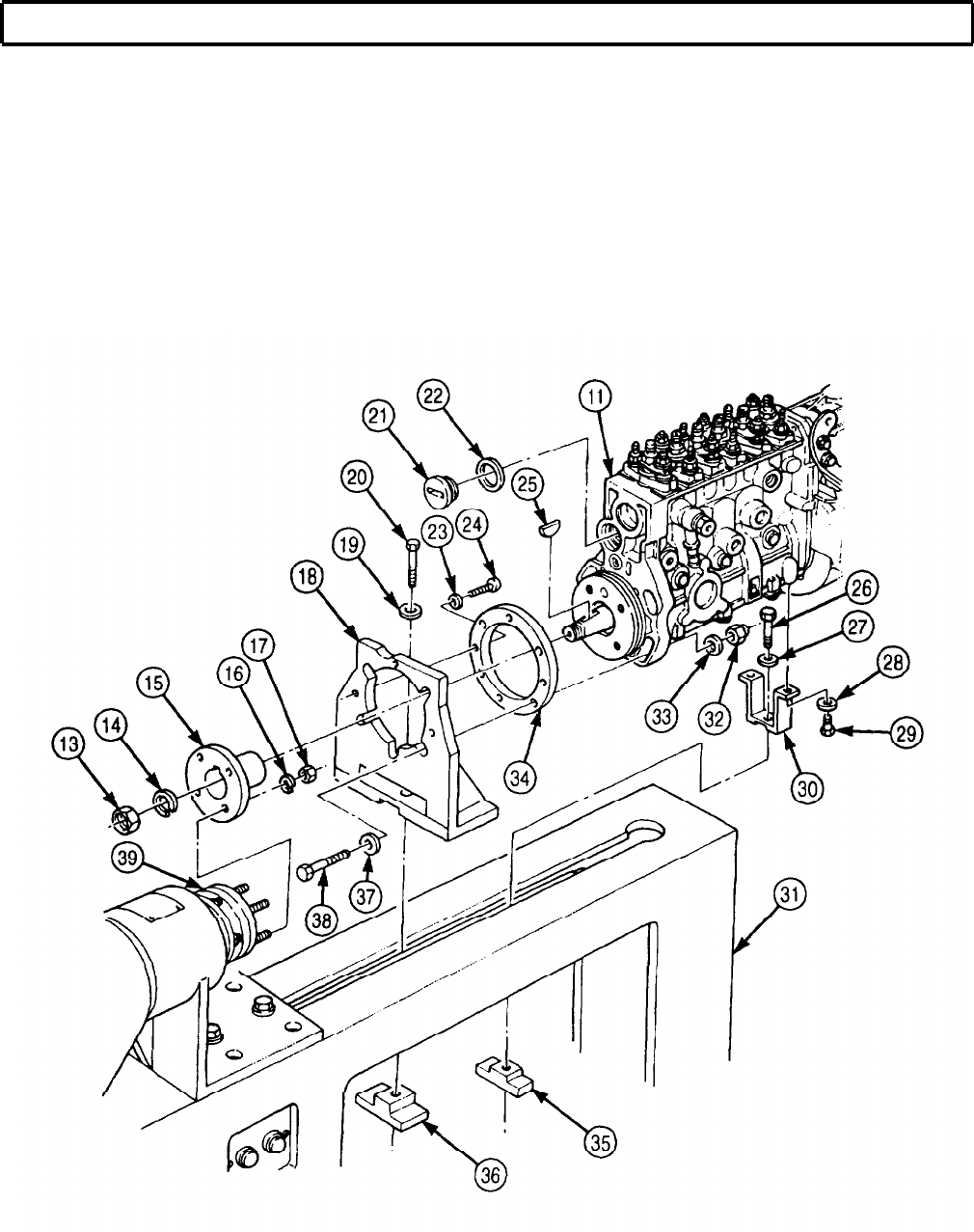
TM 9-2320-272-24-4
5-31. MOUNTING FUEL INJECTION PUMP TO TEST STAND (Contd)
9.
10.
11.
12.
13.
14.
15.
16.
Remove four nuts (32), washers (33), screws (38), and washers (37) from adapter bracket (18).
Loosen screw (20) and slide fuel pump (11) from drive coupling (39).
Remove nut (13), lockwasher (14), drive hub (15), and woodruff key (25) from fuel pump (11).
Discard lockwasher (14).
Remove fuel pump (11) from adapter bracket (18) and test stand (31).
Install new copper washer (22) and screw plug (21) on fuel pump (11).
Remove three screws (24), washers (23), and adapter ring (34) from adapter bracket (18).
Remove screw (20), washer (19), adapter bracket (18), and clamp bar (36) from test stand (31).
Remove two screws (26), washers (27), rear support bracket (30), and clamp bar (35) from test
stand (31).
FOLLOW-ON TASK: Install fuel injection pump (para. 4-57).
5-213
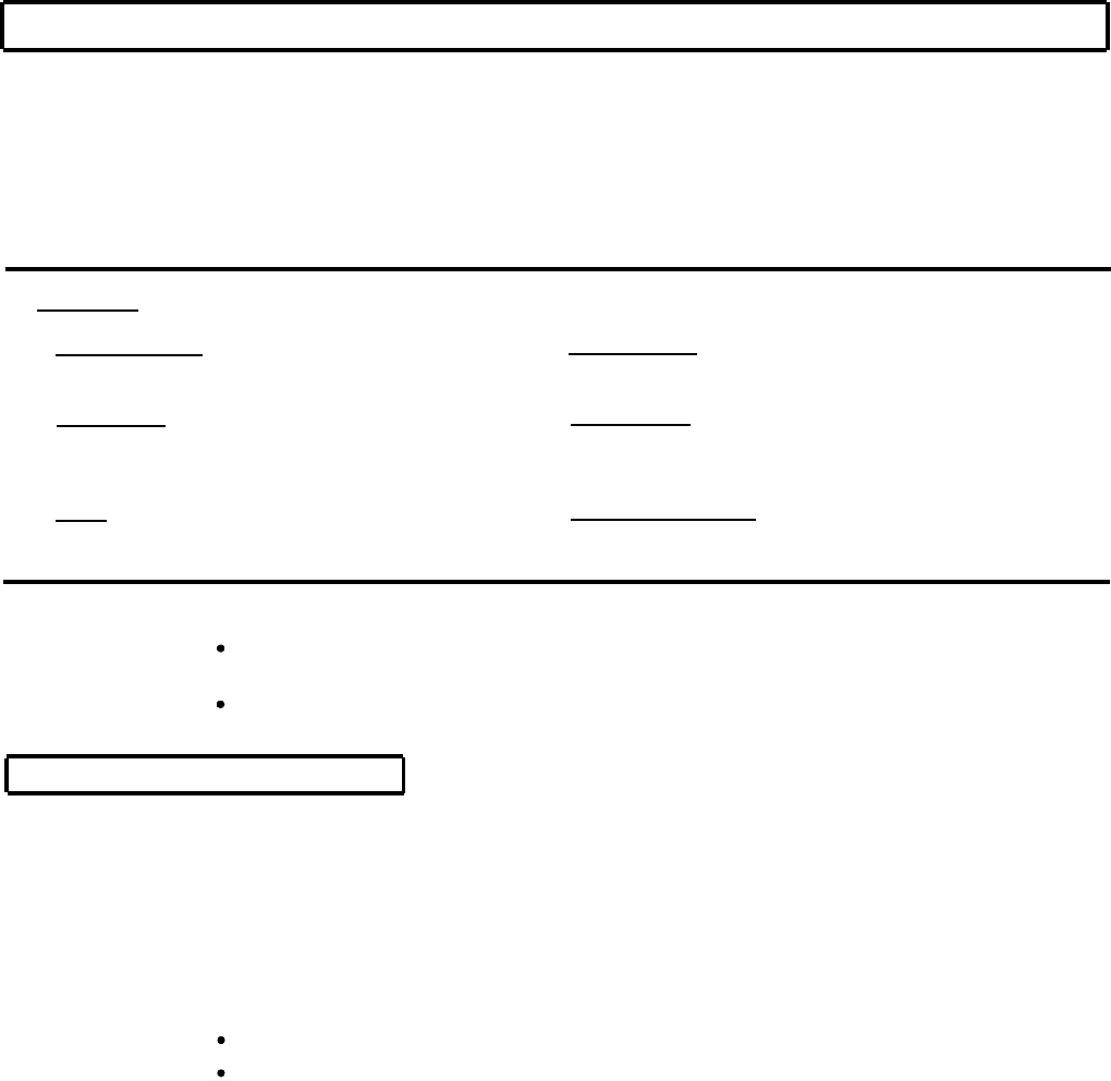
TM 9-2320-272-24-4
5-32. FUEL INJECTION PUMP PRETEST
THIS TASK COVERS:
a. Prestroke and Rack Travel
b. Cylinder Phasing (Timing)
c. High-speed Fuel Delivery Test
g. Manifold Pressure Compensator Test
h. Start Cut Out Test
I. Fuel Delivery Test
d. Low-speed Fuel Delivery Test j. Fuel Breakaway Test
e. Rated Speed Test k. Starting Fuel Delivery Test
f. Full Load Delivery l. Low Idle Fuel Delivery Test
INITIAL SETUP:
APPLICABLE MODELS MATERIALS/PARTS
M939A2
Two copper washers (Appendix D, Item 42)
SPECIAL TOOLS REFERENCES (TM)
Rack extension (Appendix E, Item 112) TM 9-2320-272-24P
Plunger lift device (Appendix E, Item 98) TM 9-4910-778-14&P
TOOLS EQUIPMENT CONDITION
General mechanic’s tool kit (Appendix E, Item 1)
Dial Indicator (Appendix E, Item 36) Fuel injection pump mounted to test stand (para. 5-31).
NOTE
Refer to TM 9-4910-778-14&P for operation of fuel injection
pump test stand, DFP 156.
If readings taken during pretest deviate from specifications
listed below, fuel pump must be repaired.
a. Prestroke and Rack Travel
1.
2.
3.
4.
5.
6.
7.
Mount dial indicator (4) on plunger lift device (5) and zero dial indicator (4).
8.
Manually rotate test stand driveshaft (8) until a reading is observed on dial indicator (4).
9.
Manually reverse rotation test stand driveshaft (8) until dial indicator (4) reads zero.
10.
Apply 435-464 psi (2,999-3,190 kPa) of calibration fluid pressure.
Mount dial indicator (10) and rack travel indicator holder (9) on drive end of fuel pump (13).
Install rack extension (11) on control rack (12).
Pull control lever (2) to full load position and, using rack extension (11), push control rack (12) all
the way back.
Preload dial indicator (10) giving control rack (12) 0.004 in. (0.1 mm) of preload travel.
Install plug (3) in return line access hole (14).
NOTE
Cylinder number one is located at drive end of fuel pump.
Rotate test stand driveshaft until tappet reaches bottom dead
center.
Install plunger lift device (5) on fuel pump (13) with finger of plunger lift device (5) resting on top of
tappet located in cylinder number one.
5-214
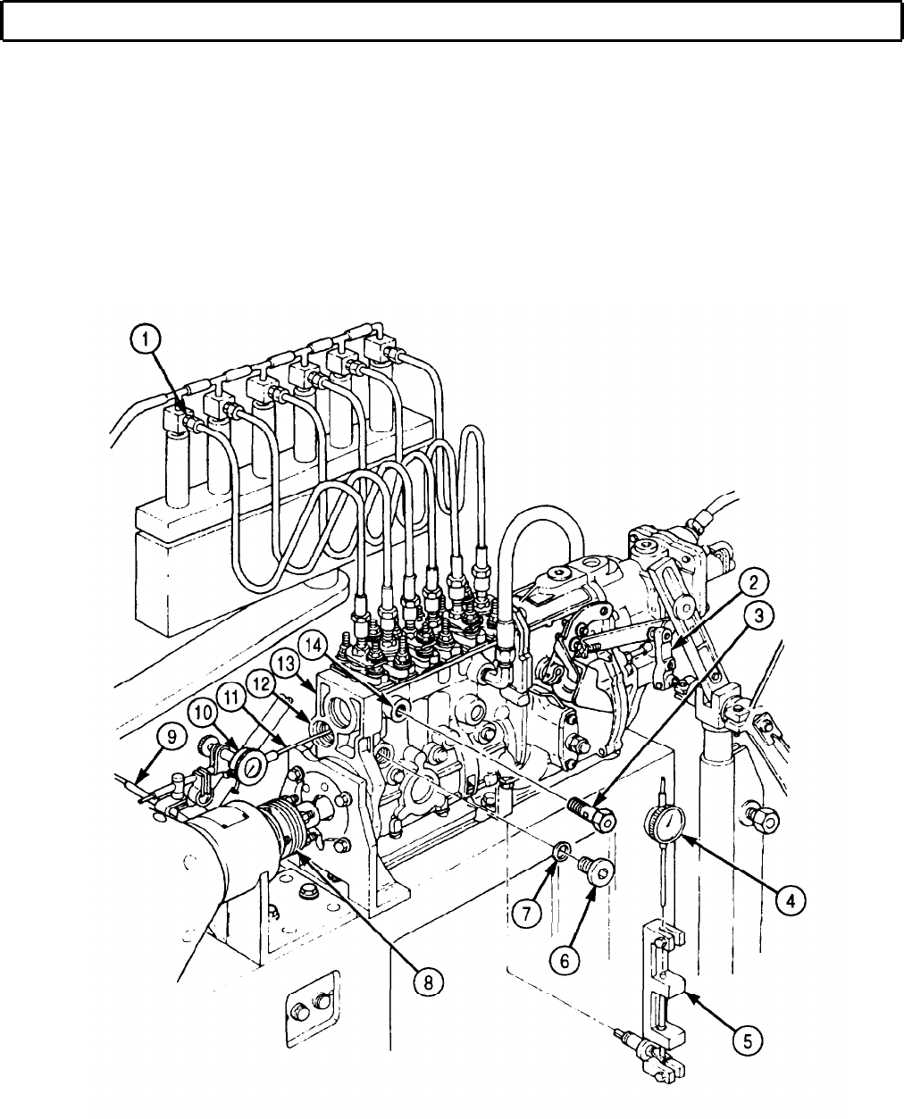
TM 9-2320-272-24-4
5-32. FUEL INJECTION PUMP PRETEST (Contd)
NOTE
Ensure a steady stream of calibration fluid flows from all bleed-off
valves. If not, increase calibration fluid pressure until a steady
stream of calibration fluid is obtained.
11.
Manually rotate test stand driveshaft (8) in correct fuel pump rotation until calibration fluid stops
flowing from bleed-off valve (1).
12.
Check prestroke measurement. Measurement should be 0.360-0.480 in. (9.14-12.19 mm).
13.
Remove plunger lift device (5) and dial indicator (4) from fuel pump (13).
14.
Install copper washer (7) and plug (6) on fuel pump (13).
5-215
TM 9-2320-272-24-4
5-32. FUEL INJECTION PUMP PRETEST (Contd)
b. Cylinder Phasing (Timing)
1.
2.
3.
4.
5.
6.
7.
In order to perform this task, correct prestroke measurement must
be obtained for cylinder number one (task a).
Set protractor (1) on drive end of test stand (6) to zero.
Remove plug (7) from fuel pump (4).
Install two new copper washers (5), plug (7), and adapter (8) on fuel pump (4).
Connect test stand return line (2) to fuel pump adapter (8).
Apply 435-464 psi (2,999-3,199 kPa) of calibration fluid pressure to fuel pump (4).
Manually rotate test stand driveshaft (3) in correct rotation of fuel pump (4) until calibration fluid
stops flowing from number five bleed-off valve.
Observe reading on protractor (1). Correct reading should be 60°.
NOTE
8.
9.
10.
11.
Following fuel pump firing order 1-5-3-6-2-4, repeat steps 6
and 7 until remaining cylinders are phased (timed).
For each cylinder phased, test stand protractor will increase in
60° intervals.
Perform steps 8 through 11 if 60° interval is not obtained.
Perform steps 8 through 11 to adjust one cylinder. Adjustment
of remaining five cylinders is performed basically the same way.
Remove fuel test line (9) from delivery valve holder (10).
Loosen three nuts (11) and remove two shims (12) between barrel (13) and fuel pump (4). Discard
shims (12).
CAUTION
Shims of the same thickness must be used on both sides of barrel.
Failure to do so will result in inaccurate prestroke measurement.
NOTE
Refer to TM 9-2320-272-24P to select shims.
Install two new shims (12) between barrel (13) and fuel pump (4).
Tighten three nuts (11) and install fuel test line (9) on delivery valve holder (10).
5-216

TM 9-2320-272-24-4
5-32. FUEL INJECTION PUMP PRETEST (Contd)
5-217

TM 9-2320-272-24-4
5-32. FUEL INJECTION PUMP PRETEST (Contd)
c. High-speed Fuel Delivery Test
NOTE
Maintain 21 psi (145 kPa) calibration fluid pressure throughout
this task.
1.
Set test stand (4) to measure fuel delivery at 1,000 strokes.
2.
Set fuel pump (1) to 1,050 rpm.
NOTE
If needed, increase aneroid air pressure to obtain correct rack
travel.
3.
Move control lever (3) to obtain rack travel of 0.360-0.480 in. (9.14-12.19 mm).
4.
Take fuel draw and check fuel delivery. Correct fuel delivery is 0.891-0.928 in.3 (14.6-15.2 cm3).
5.
Allowable reading spread is 0.037 in.3 (0.6 cm3).
d. Low-speed Fuel Delivery Test
NOTE
Maintain 21 psi (145 kPa) calibration fluid pressure throughout
this task.
1.
Reduce fuel pump (1) to 300 rpm.
2.
Set control rack travel between 0.308-0.316 in. (7.8-8.0 mm).
3.
Take fuel draw and check fuel delivery. Correct fuel delivery 0.079-0.134 in.3 (1.3-2.2 cm3)
4.
Allowable reading spread is 0.030 in3 (0.5 cm3).
e. Rated Speed Test
1.
Install protractor (2) on control lever (3).
2.
Position control lever (3) between 42-50°
3.
Increase rpm of fuel pump (1) until control rack travel of 0.464 in. (11.78 mm) is obtained.
4.
Fuel pump (1) rpm should be between 1,090-1,100.
5.
Increase rpm of fuel pump (1) to 1,185-1,215.
6.
Check control rack travel. Correct control rack travel should be 0.016 in (0.40 mm).
7.
Position control lever (3) between 10-18°.
8.
Adjust fuel pump (1) to 300 rpm.
9.
Check control rack travel. Correct control rack travel should be 0.312 in. (7.9 mm).
10.
Decrease fuel pump (1) to 100 rpm.
11.
Check control rack travel. Correct control rack travel should be 0.372 in. (9.45 mm).
12.
Increase rpm of fuel pump (1) to 300. Check control rack travel. Correct control rack travel should
be 0.308-0.316 in. (7.82-8.03 mm).
5-218
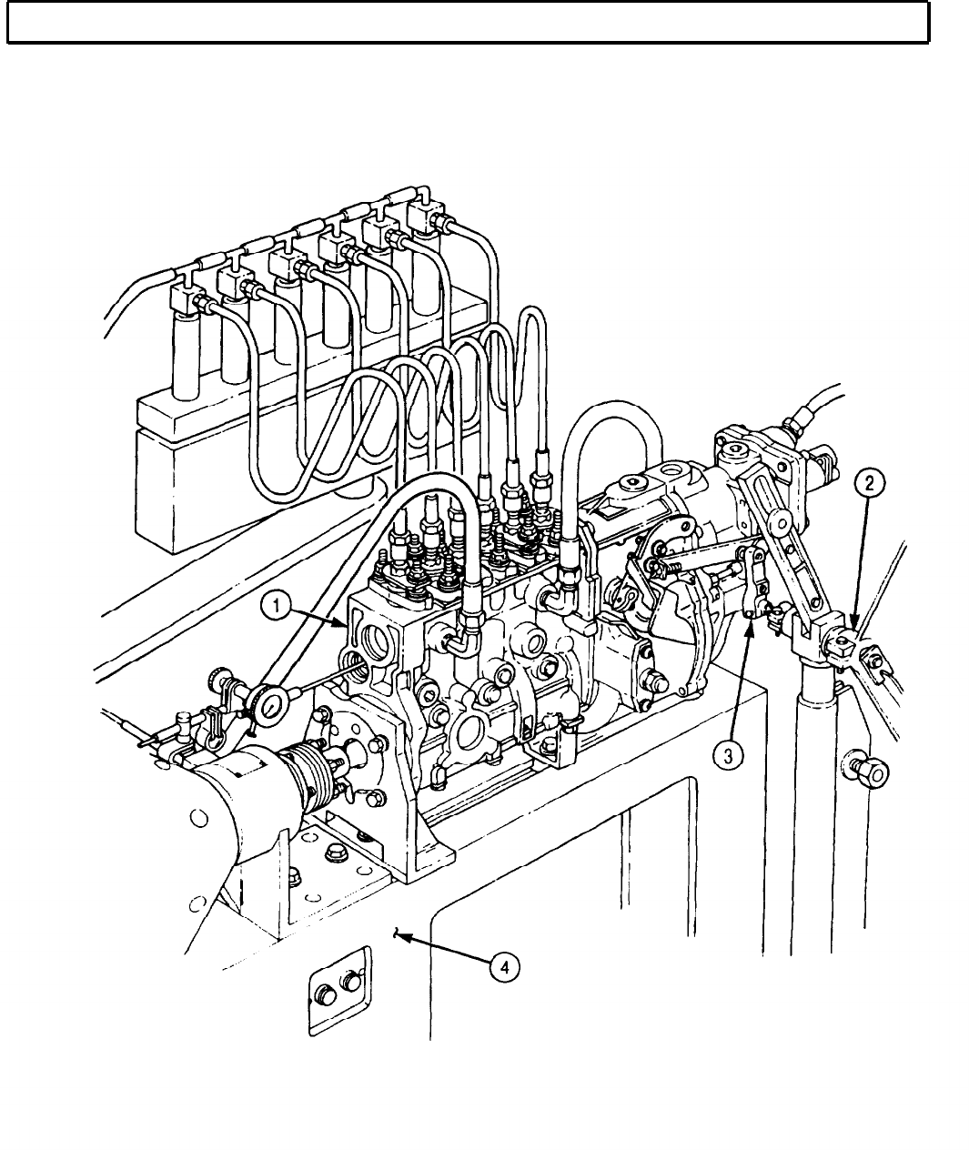
TM 9-2320-272-24-4
5-32. FUEL INJECTION PUMP PRETEST (Contd)
5-219

TM 9-2320-272-24-4
5-32. FUEL INJECTION PUMP PRETEST (Contd)
I
f. Full Load Delivery
1.
Apply 131 psi (903 kPa) of air pressure to manifold pressure compensator (2).
2.
Adjust fuel pump (1) to 1,050 rpm.
3.
Position control lever (3) in full load position.
4.
Take fuel draw and check delivery quantity. Correct fuel delivery quantity should be 8.90-9.28 in.3
(145.8-152.1 cm3).
5.
Allowable reading spread is 0.366 in.3 (5.998 cm3).
6.
Close air supply source to manifold pressure compensator (2).
g. Manifold Pressure Compensator Test
1.
Set fuel pump (1) to 500 rpm and position control rack (5) at 0.038-0.039 in. (0.97-0.99 mm) control
rack travel.
2.
Apply 44 psi (303 kPa) of air pressure to manifold pressure compensator (2) and observe control
rack travel. Correct control rack travel is 0.432-0.436 in. (10.97-11.07 mm).
3.
Increased air pressure to 75 psi (517 kPa) and observe control rack travel. Correct control rack
travel is 0.476-0.488 in. (12.09-12.39 mm).
4.
Increase air pressure to 131 psi (903 kPa) and observe control rack travel. Correct control rack
travel is 0.504-0.508 in. (12.80-12.90 mm).
5.
Close air supply source to manifold pressure compensator (2).
h. Start Cut Out Test
1.
Set fuel pump (1) to 240 rpm and run fuel pump (1) at this speed for approximately one minute.
2.
Move throttle lever (4) to full load position and measure control rack travel. Control rack travel
should be no more than 0.084 in. (2.13 mm).
i. Fuel Delivery Test
1.
2.
3.
4.
5.
6.
7.
8.
Apply 131 psi (903 kPa) of air pressure to manifold compensator (2).
Adjust fuel pump (1) to 700 rpm.
Set test stand to measure fuel delivery at 1,000 strokes.
Check fuel delivery quantity. Correct fuel delivery quantity should be 8.73-9.21 in.3 (143-150.9 cm3).
Check fuel spread. Correct fuel spread should be 0.427 in. (6.99 cm).
Decrease fuel pump rpm to 500.
Check fuel delivery quantity. Correct fuel delivery quantity is 4.64-5.00 in.3 (76.0-81.9 cm3).
Close air supply source to manifold pressure compensator (2).
5-220
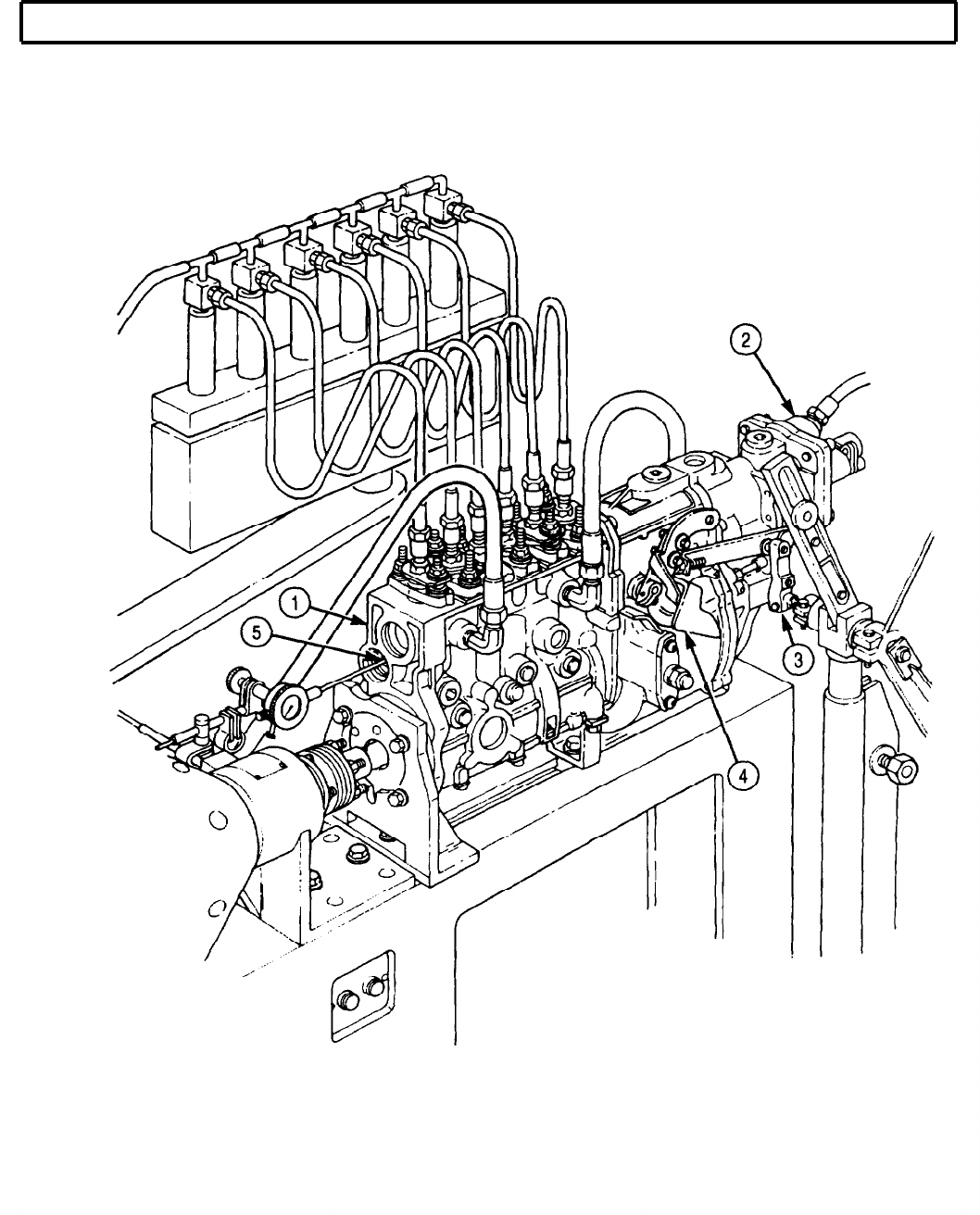
TM 9-2320-272-24-4
5-32. FUEL INJECTION PUMP PRETEST (Contd)
5-221

TM 9-2320-272-24-4
5-32. FUEL INJECTION PUMP PRETEST (Contd)
j. Fuel Breakaway Test
1.
Move control lever (3) to full load position.
2.
Gradually increase rpm of fuel pump (1) until control rack (6) moves 0.004 in. (0.1 mm) towards
shut off.
3.
Adjust fuel pump (1) to 1,090-1,100 rpm.
4.
Move control lever (3) to full load position and observe control rack travel. Correct control rack
travel should be 0.464 in. (11.79 mm).
k. Starting Fuel Delivery Test
1.
Set fuel pump (1) to 100 rpm.
2.
Set test stand (5) to measure calibration fluid at 1,000 strokes.
3.
Position throttle lever (4) to full load position and observe control rack (6) travel. Correct control
rack travel should be 0.076-0.084 in. (1.93-2.13 mm).
4.
Check fuel delivery quantity. Correct fuel delivery quantity is 12.94-13.91 in.3 (212-227.9 cm3).
l. Low Idle Fuel Delivery Test
1.
Set fuel pump (1) to 300 rpm.
2.
Position control lever (3) against low idle stopscrew (2) and take a fuel draw.
3.
Observe control rack travel. Correct control rack travel is 0.308-0.316 in. (7.82-8.03 mm).
4.
With test stand (5) set at 1,000 strokes, check fuel delivery quantity. Correct fuel delivery quantity
should be 0.824-1.373 in.3 (13.5-22.5 cm3).
5.
Check fuel spread. Correct fuel spread should be 0.305 in.3 (4.90 cm3).
5-222
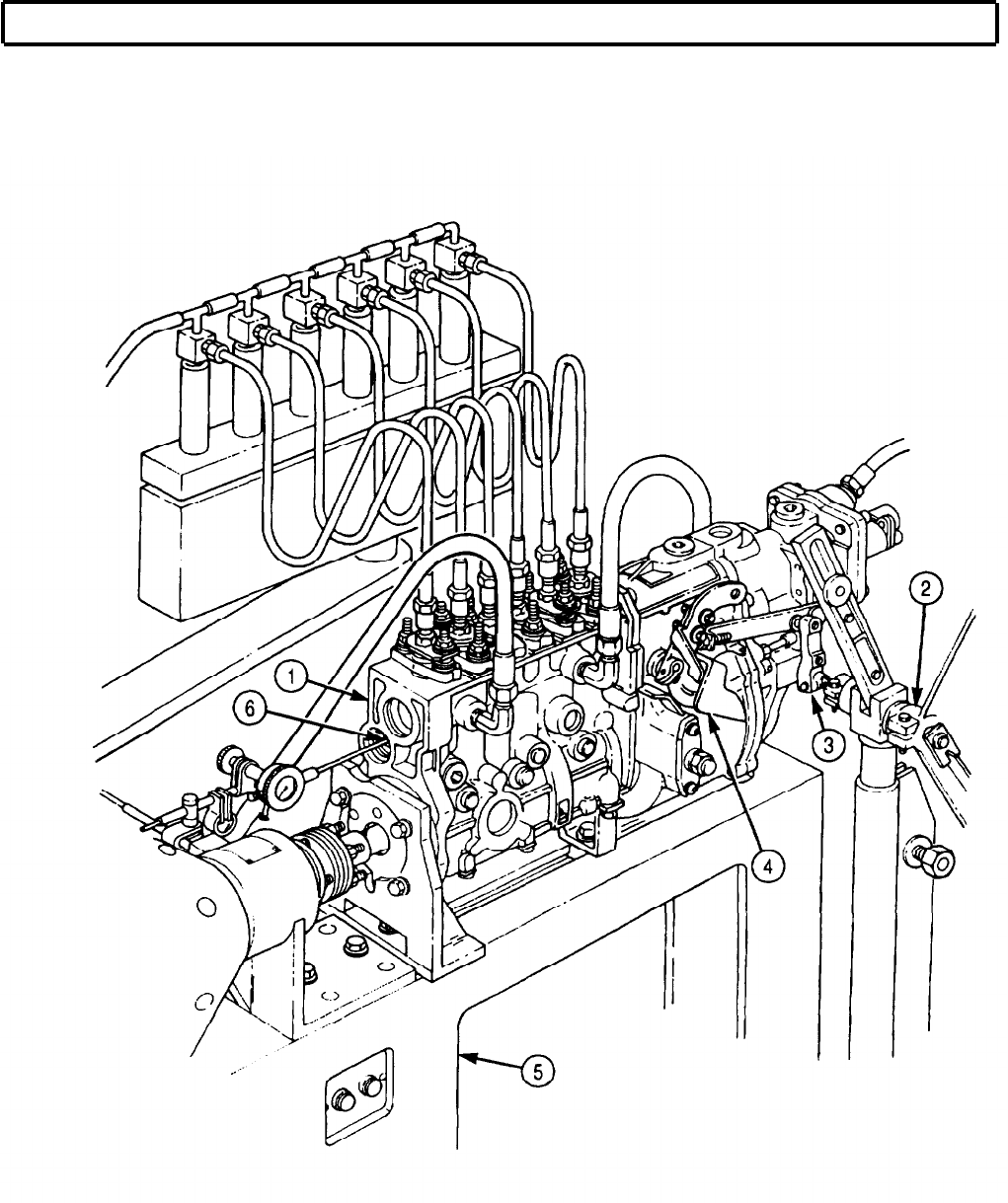

TM 9-2320-272-24-4
5-33. MANIFOLD PRESSURE COMPENSATOR MAINTENANCE
THIS TASK COVERS:
a. Removal d. Assembly
b. Disassembly e. Installation
c. Cleaning and Inspection
INITIAL SETUP:
APPLICABLE MODELS REFERENCES (TM)
M939A2
TM 9-2320-272-24P
TOOLS EQUIPMENT CONDITION
General mechanic’s tool kit (Appendix E, Item 1) Fuel injection pump pretest performed (para. 5-32).
MATERIALS/PARTS
Manifold pressure compensator maintenance
kit (Appendix D, Item 423)
Silicone adhesive (Appendix C, Item 3)
a. Removal
1.
Remove safety wire (1) from screw (24) and protective cap (2). Discard safety wire (1).
NOTE
2.
3.
4.
5.
6.
7.
8.
It may be necessary to cut a slot on breakoff screws for removal.
Remove breakoff screw (22), screw (24), lockwashers (21) and (23), protective cap (2), and pull-
stop (3) from pull-stop cover (16). Discard breakoff screw (22) and lockwashers (21) and (23).
Remove O-ring (4) from pull-stop (3). Discard O-ring (4).
Remove nuts (20) and (19) from stop bolt (12).
Remove three screws (18) and lockwashers (17) from pull-stop cover (16). Discard lockwashers (17).
Remove breakoff screw (5), lockwasher (6), and pull-stop cover (16) from manifold pressure
compensator (7). Discard breakoff screw (5) and lockwasher (6).
Remove three screws (8), lockwashers (9), and washers (10) from manifold pressure compensator (7).
Discard lockwashers (9).
Remove breakoff screw (15), lockwasher (14), washer (13), and manifold pressure compensator (7)
from governor cover (11). Discard breakoff screw (15) and lockwasher (14).
b. Disassembly
1.
Remove cotter pin (28), washer (27), and lever (26) from stop bolt (12). Discard cotter pin (28).
2.
Remove stop bolt (12) and spring (29) from manifold pressure compensator (7).
3.
Remove round nut (34), washer (33), washer plate (32), diaphragm (31), and washer plate (30) from
stop bolt (12). Discard diaphragm (31).
4.
Remove O-ring (25) from manifold pressure compensator (7). Discard O-ring (25).
5-224

TM 9-2320-272-24-4
5-33. MANIFOLD PRESSURE COMPENSATOR MAINTENANCE (Contd)
5-225
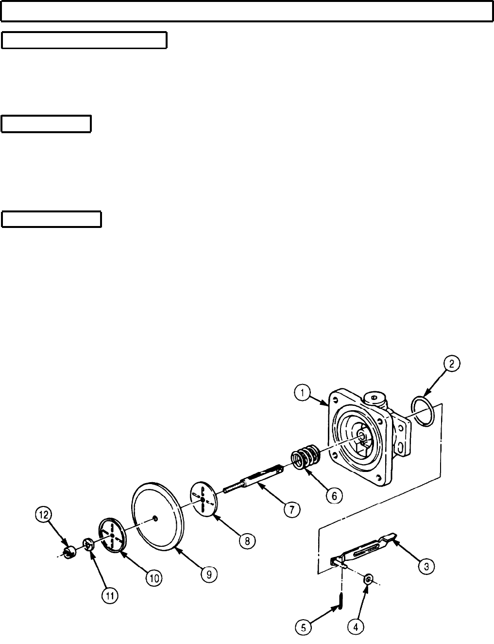
TM 9-2320-272-24-4
5-33. MANIFOLD PRESSURE COMPENSATOR MAINTENANCE (Contd)
c. Cleaning and Inspection
NOTE
Remove gasket sealant from mating surfaces.
1.
For general cleaning instructions, refer to para. 2-14.
2.
For general inspection instructions, refer to para. 2-15.
d. Assembly
1.
Install new O-ring (2) on manifold pressure compensator (1).
2.
Install washer plate (8), new diaphragm (9), washer plate (10), and washer (11) on stop bolt (7) with
round nut (12).
3.
Install spring (6) and stop bolt (7) in manifold pressure compensator (1).
4.
Install lever (3) on stop bolt (7) with washer (4) and new cotter pin (5).
e. Installation
NOTE
Perform step 1 to ensure manifold pressure compensator lever is
engaged to rocker arm in governor cover.
1.
Remove plug (24) from governor housing (23).
2.
Install manifold pressure compensator (1) on governor cover (22) with three washers (21), new
lockwashers (20), and screws (19).
3.
Install washer (25), new lockwasher (26), and new breakoff screw (27) on manifold pressure
compensator (1).
5-226
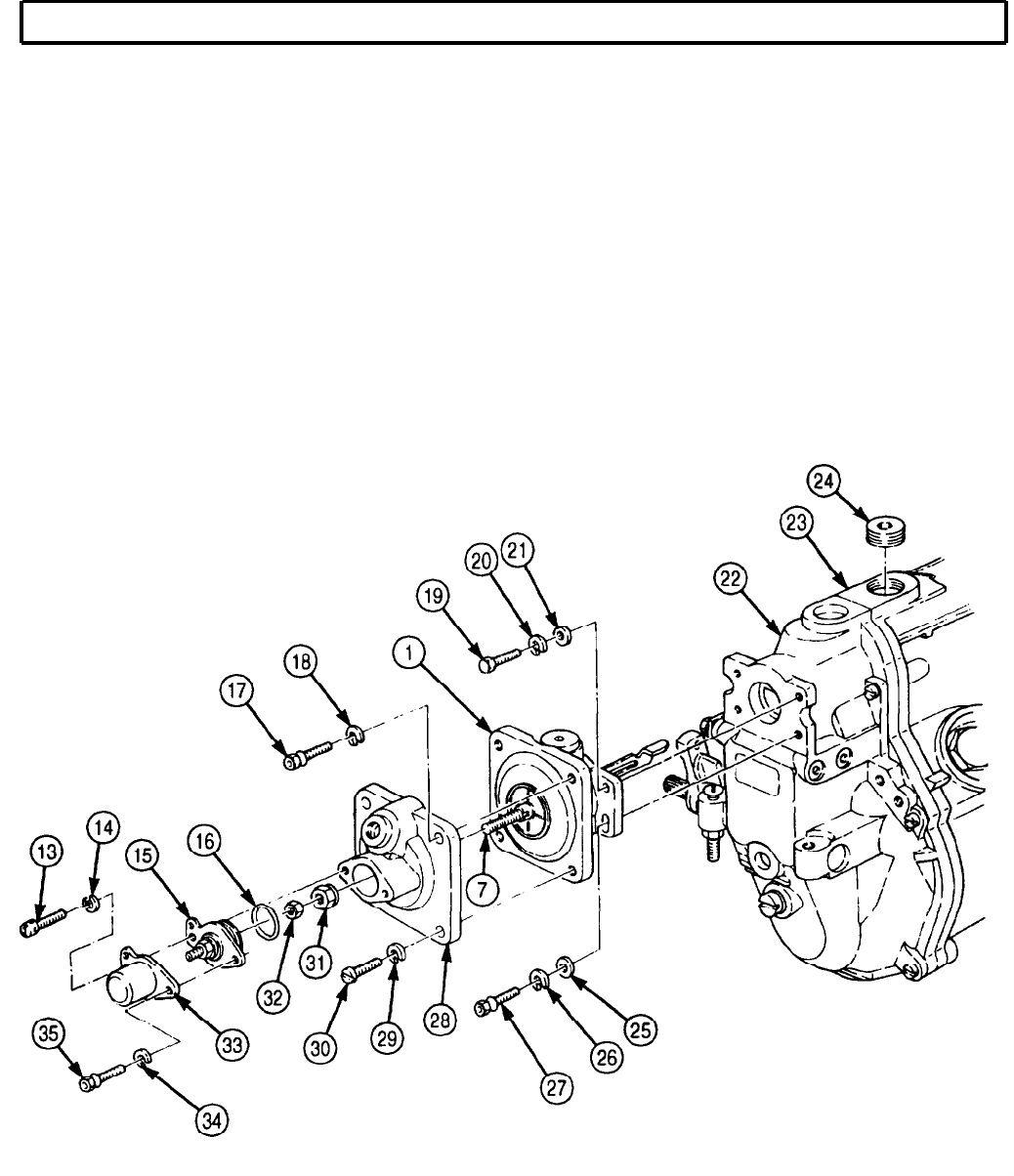
TM 9-2320-272-24-4
5-33. MANIFOLD PRESSURE COMPENSATOR MAINTENANCE (Contd)
NOTE
Apply silicone adhesive to mating surfaces of pull-stop cover and
manifold pressure compensator.
4.
Install pull-stop cover (28) on manifold pressure compensator (1) with three new lockwashers (29)
and screws (30).
5.
Install new lockwasher (18) and new breakoff screw (17) on pull-stop cover (28).
6.
Install nuts (31) and (32) on stop bolt (7).
7.
Install new O-ring (16) on pull-stop (15).
8.
Place pull-stop (15) in pull-stop cover (28).
9.
Install protective cap (33) on pull-stop cover (28) with new lockwashers (14) and (34), screw (13),
and new breakoff screw (35).
10.
Install plug (24) on governor housing (23).
NOTE
Safety wire will not be installed at this time. Safety wire will be
installed after fuel pump is calibrated (para. 5-37).
FOLLOW-ON TASK: Calibrate fuel injection pump (para. 5-37).
5-227
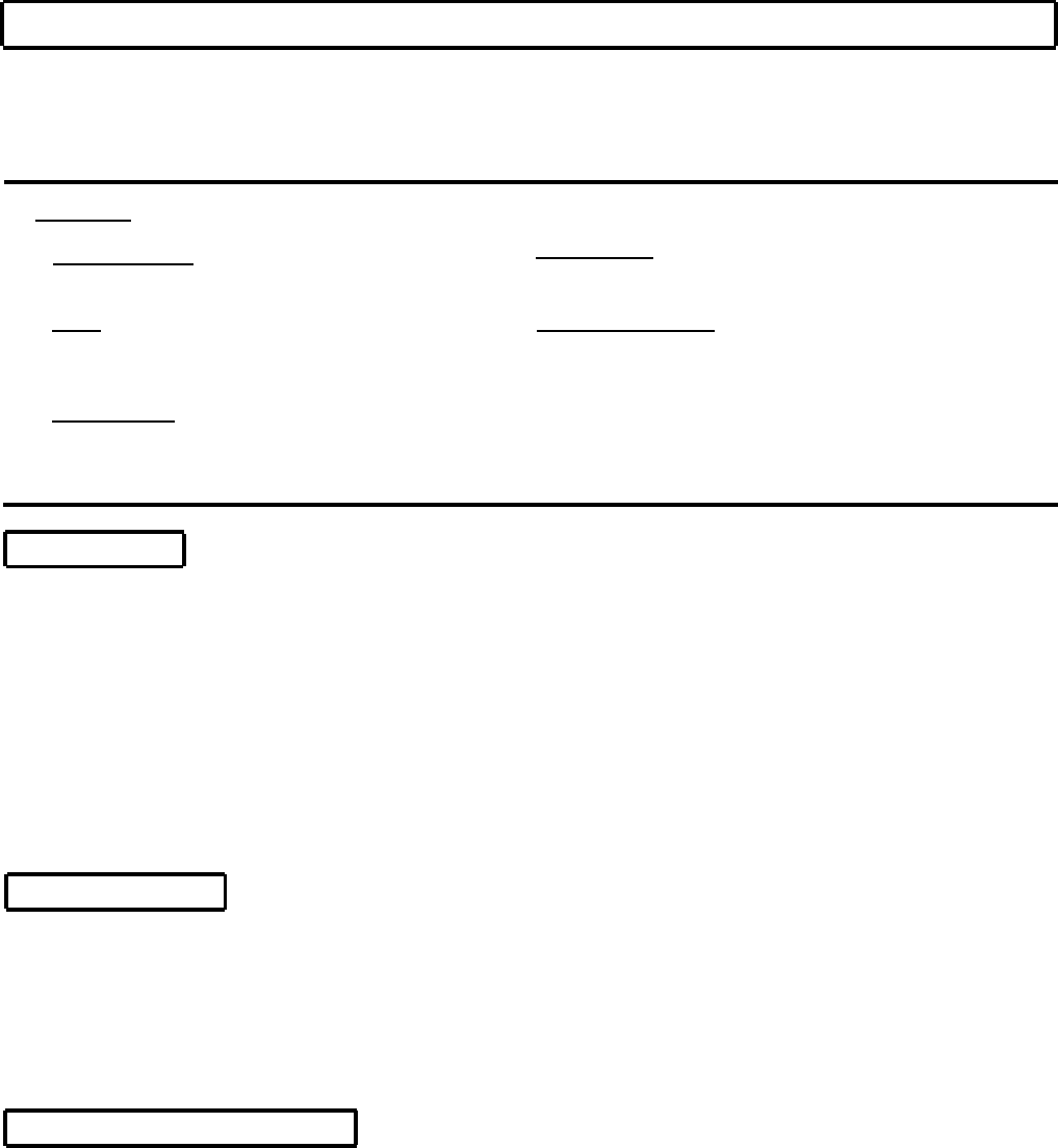
TM 9-2320-272-24-4
5-34. R.Q.V. GOVERNOR COVER MAINTENANCE
THIS TASK COVERS:
a. Removal d. Assembly
b. Disassembly e. Adjustment
c. Cleaning and Inspection f. Installation
INITIAL SETUP:
APPLICABLE MODELS REFERENCES (TM)
M939A2
TOOLS
General mechanic’s tool kit (Appendix E, Item 1)
Depth gauge (Appendix E, Item 81)
MATERIALS/PARTS
R.Q.V. governor cover maintenance kit
(Appendix D, Item 562)
Sealing compound (Appendix C, Item 61)
TM 9-2320-272-24P
EQUIPMENT CONDITION
Manifold pressure compensator removed (para. 5-33).
a. Removal
1.
Remove guide pin (8) and gasket (9) from governor cover (5). Discard gasket (9).
2.
Remove five screws (10) from governor cover (5).
3.
Remove two screws (12), lockwashers (13), governor stop (3), and two spacers (4) from governor
cover (5). Discard lockwashers (13).
NOTE
When removing governor cover, move governor lever back and
forth.
4.
Remove safety wire (6) from screws (7) and (11). Discard safety wire (6).
5.
Remove screw (7), governor cover (5), and gasket (2) from governor housing (1). Discard
gasket (2).
b. Disassembly
1.
Remove two drive pins (25) from linkage lever (23) and shaft (19). Discard drive pins (25).
2.
Remove shaft (19) from governor cover (5).
3.
Remove screw (14), lockwasher (15), shim (16), template (17), and shim (18) from governor cover (5).
Discard lockwasher (15).
4.
Remove linkage lever (23) and intermediate plates (22) and (24) from governor cover (5).
5.
Remove rocker arm (21) and spring (20) from governor cover (5).
c. Cleaning and Inspection
1.
For general cleaning instructions, refer to para. 2-14.
2.
For general inspection instructions, refer to para. 2-15.
5-228

TM 9-2320-272-24-4
5-34. R.Q.V. GOVERNOR COVER MAINTENANCE (Contd)
5-229

TM 9-2320-272-24-4
5-34. R.Q.V. GOVERNOR COVER MAINTENANCE (Contd)
d. Assembly
1.
Install spring (12)and rocker arm (13) in governor cover (3).
2.
Install intermediate plates (14) and (16) and linkage lever (15) in governor cover (3).
3.
Install shaft (11) in governor cover (3).
4.
Install shim (10), template (9), and shim (8) on governor cover (3) with new lockwasher (7) and
screw (6).
5.
Install two new drive pins (17) in linkage lever (15) and shaft (11).
e. Adjustment
1.
Position control lever (4) in full load position so pilot (5) contacts bottom end of template slot (1).
2.
Position new gasket (2) on governor cover (3).
3.
Place straightedge on governor cover (3). Using depth gauge, measure from straightedge to pilot (5).
Distance should be 0.098 in. (2.49 mm).
NOTE
Perform steps 4 through 7 if measurement is incorrect.
4.
Remove screw (6), lockwasher (7), shim (8), template (9), and shim (10) from governor cover (3).
5.
If distance is less than 0.098 in. (2.49 mm), use smaller shim (10).
6.
If distance is more than 0.098 in. (2.49 mm), use larger shim (10).
7.
Install shim (10), template (9), and shim (8) on governor cover (3) with lockwasher (7) and screw (6).
f. Installation
NOTE
Safety wire will not be installed at this time. Safety wire will be
installed after fuel pump is calibrated (para. 5-37).
Linkage lever piston must fit into cylinder on lever located in
governor housing.
1.
Install new gasket (2) and governor cover (3) on governor housing (18) with five screws (24) and
screw (21).
2.
Install governor stop (19) on governor cover (3) with two spacers (20), new lockwashers (25), and
screws (26).
NOTE
Apply sealing compound to male threads.
3.
Install new gasket (23) and guide pin (22) in governor cover (3).
5-230
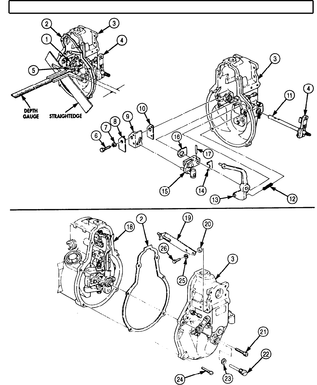
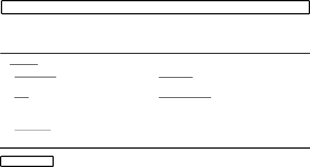
TM 9-2320-272-24-4
5-35. R.Q.V. GOVERNOR HOUSING MAINTENANCE
THIS TASK COVERS:
a. Removal
b. Disassembly
c. Cleaning and Inspection
d. Assembly
e. Installation
f. Adjustment
INITIAL SETUP:
APPLICABLE MODELS
M939A2
TOOLS
General mechanic’s tool kit (Appendix E, Item 1)
Depth gauge (Appendix E, Item 81)
Torque wrench (Appendix E, Item 144)
MATERIALS/PARTS
R.Q.V. governor housing maintenance kit
(Appendix D, Item 561)
REFERENCES (TM)
TM 9-2320-272-24P
EQUIPMENT CONDITION
R.Q.V. governor cover removed (para. 5-34).
GENERAL SAFETY INSTRUCTIONS
Wear eye protection when removing or installing
springs under tension.
a. Removal
1.
2.
3.
4.
5.
6.
7.
8.
9.
10.
11.
12.
13.
14.
15.
Remove retaining pin (12) from link pin (10). Discard retaining pin (12).
Remove link pin (10), slider (15), and lever (11) from link fork (9).
Remove retaining pin (5) and link fork (9) from connection plate (3). Discard retaining pin (5).
Bend tab washer (19) away from two nuts (20).
Remove nut (20). tab washer (19), nut (20), coupling pin (8), and washer (7) from flyweight
assembly (6). Discard tab washer (19).
Remove bearing pin (16) from guide bushing (17).
Bend two tab washers (13) away from screws (14).
Remove two screws (14), tab washers (13), and guide bushing (17) from flyweight assembly (6).
Discard tab washers (13).
Remove round nut (18) from camshaft (4) and governor flyweight assembly (6).
Remove governor flyweight assembly (6) from camshaft (4).
Remove capsule (21) and four rubber buffers (22) from driver (24). Discard rubber buffers (22).
Remove shim (23) and driver (24) from camshaft (4).
NOTE
Screws in steps 13 and 14 are torx head.
Remove four screws (28) and holding brackets (27) from governor housing (2).
Remove two screws (26) from governor housing (2).
Remove two screws (25), governor housing (2), and gasket (29) from fuel pump housing (1). Discard
gasket (29).
5-232
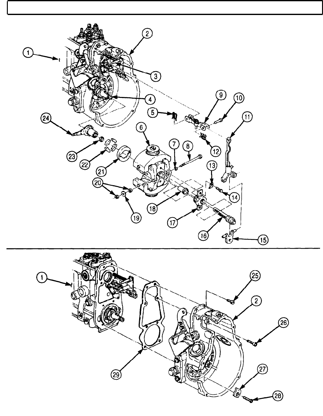
TM 9-2320-272-24-4
5-35. R.Q.V. GOVERNOR HOUSING MAINTENANCE (Contd)
5-233

TM 9-2320-272-24-4
5-35. R.Q.V. GOVERNOR HOUSING MAINTENANCE (Contd)
b. Disassembly
NOTE
Relieve governor flyweight spring tension when performing step 1.
1.
Press down on outer spring seat (3) and remove round nut (2) from threaded pin (9).
WARNING
Eye protection must be worn when removing springs under
tension. Failure to do so may result in injury to personnel.
2.
Remove outer spring seat (3), springs (4), (5), and (6), shim (7), and lower spring seat (8) from
governor flyweight assembly (12).
3.
Remove shims (1) and (13) from governor flyweight assembly (12).
c. Cleaning and Inspection
1.
For general cleaning instructions, refer to para. 2-14.
2.
For general inspection instructions, refer to para. 2-15.
3.
Inspect two governor flyweights (11) for nicks and scratches. If either flyweight (11) is nicked or
scratched, replace governor flyweight assembly (12).
4.
Inspect bell crank levers (10) for noticeable wear. Replace governor flyweight assembly (12) if either
bell crank lever (10) is worn.
5.
Inspect bearing pin (14) for scratches, scoring, nicks, and wear. Replace bearing pin (14) if
scratched, scored, nicked, or worn.
6.
Inspect guide bushing (15) for wear, scratches, or scores. Replace guide bushing (15) if worn,
scratched, or scored.
d. Assembly
1.
Install shims (13) and (1) in governor flyweight assembly (12).
WARNING
Eye protection must be worn when installing springs. Failure to
do so may result in injury to personnel.
2.
Install lower spring seat (8), shim (7), and springs (6), (5), and (4) in governor flyweight
assembly (12).
3.
Install outer spring seat (3) on spring (4).
4.
Install round nut (2) on threaded pin (9).
5-234
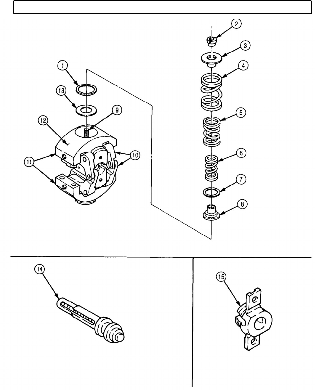
TM 9-2320-272-24-4
5-35. R.Q.V. GOVERNOR HOUSING MAINTENANCE (Contd)
5-235

TM 9-2320-272-24-4
5-35. R.Q.V. GOVERNOR HOUSING MAINTENANCE (Contd)
e. Installation
1.
2.
3.
4.
5.
6.
7.
8.
9.
10.
11.
12.
13.
14.
Install new gasket (6) and governor housing (5) on fuel pump housing (7) with two screws (1) and
screws (2).
Install four holding brackets (3) and screws (4) on governor housing (5).
Place shim (28) in driver (29) and install driver (29) on camshaft (9).
Install capsule (26) and four new rubber buffers (27) in back side of governor flyweight
assembly (11).
Install governor flyweight assembly (11) on driver (29).
Install round nut (23) on camshaft (9). Tighten round nut (23) 30-35 lb-ft (41-47 N·m).
CAUTION
Failure to obtain proper axial play may cause damage to fuel
pump.
Check governor flyweight assembly (11) for axial play:
a. Normal range is 0.002-0.004 in. (0.05-0.1 mm).
b. If axial play is less than 0.002 in. (0.05 mm), replace shim (28) with larger shim (28).
c. If axial play is more than 0.004 in. (0.1 mm), replace shim (28) with smaller shim (28).
d. When axial play is correctly adjusted, it is possible to turn governor flyweight assembly (11)
without governor flyweight assembly (11) sticking.
NOTE
Do not bend tab washer until fuel pump is calibrated (para. 5-37).
Install guide bushing (22) on flyweight assembly (11) with two new tab washers (18) and screws (19).
Tighten screws (19) 53-71 lb-in. (6-8 N·m).
Place bearing pin (21) in guide bushing (22).
NOTE
Adjust nuts to allow end play of 0.04-0.12 in. (1.0-3.0 mm).
Insert coupling pin (13) through washer (12), governor flyweight assembly (11), and bearing pin (21)
and install nut (25), new tab washer (24), and nut (25) on coupling pin (13). Tighten nuts (25)
53-71 lb-in. (6-8 N·m).
Install slider (20) on bearing pin (21).
Install lever (16) on slider (20).
Install link fork (14) on connection plate (8) with new retaining pin (10).
Install lever (16) on link fork (14) with link pin (15) and new retaining pin (17).
5-236
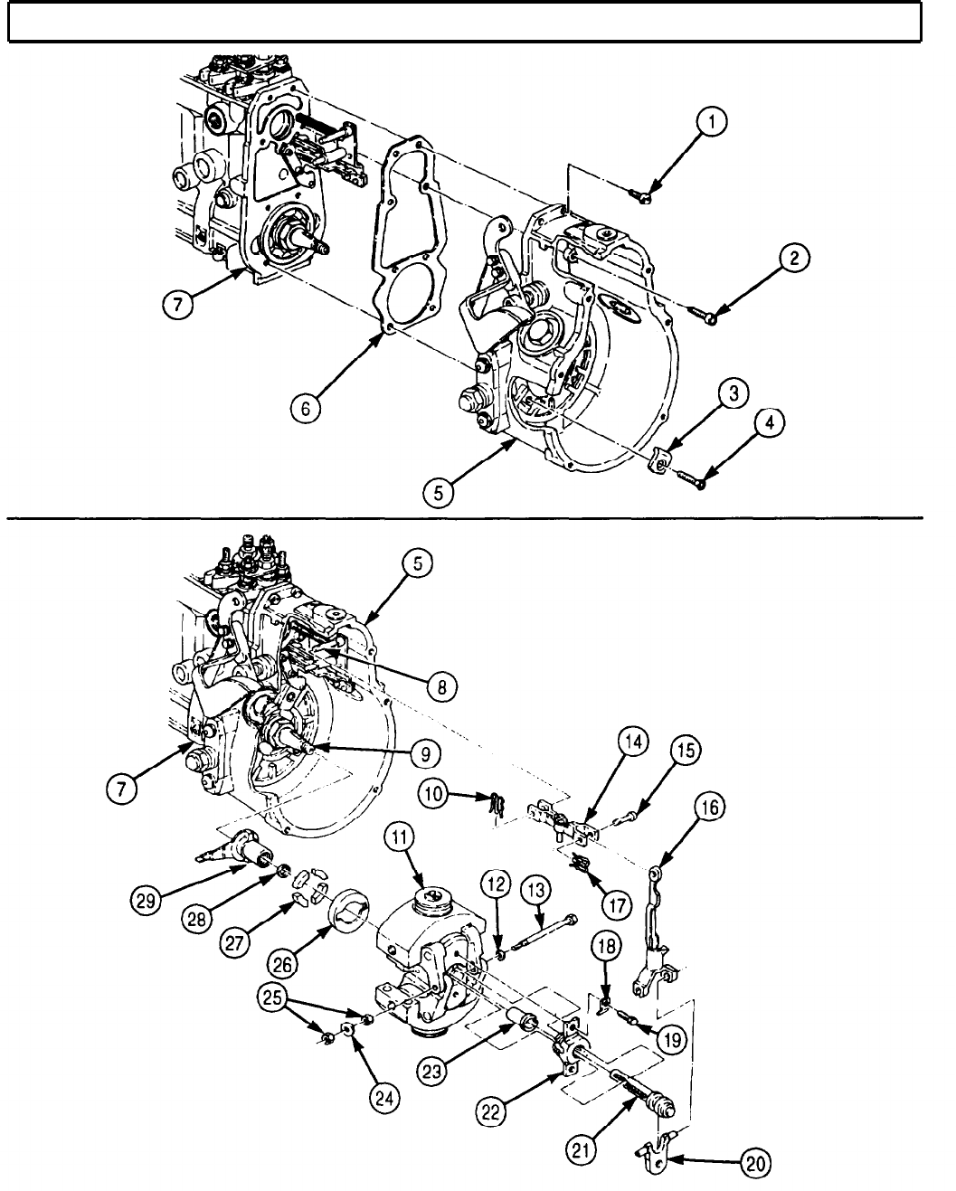
TM 9-2320-272-24-4
5-35. R.Q.V. GOVERNOR HOUSING MAINTENANCE (Contd)
5-237
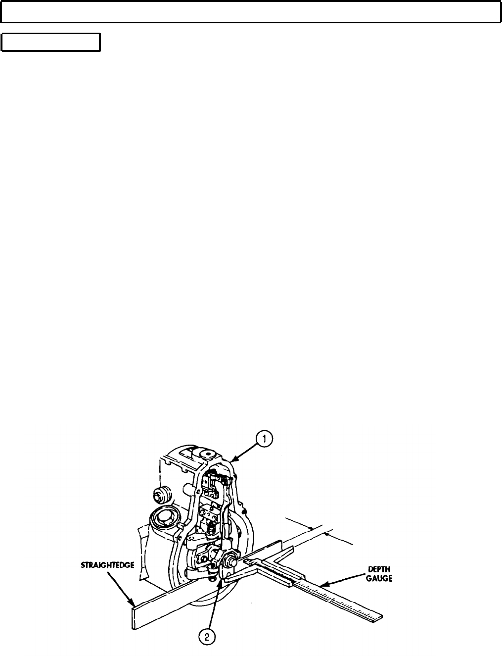
TM 9-2320-272-24-4
5-35. R.Q.V. GOVERNOR HOUSING MAINTENANCE (Contd)
f. Adjustment
1.
2.
3.
4.
5.
6.
7.
8.
9.
10.
11.
12.
13.
14.
15.
16.
NOTE
Distance is obtained by the measured distance plus the thickness
of straightedge minus half the thickness of slider.
Place straightedge on governor housing (1). Using depth gauge, measure distance between slider (2)
and straightedge. Distance should be 1.39-1.40 in. (35.3-35.6 mm).
NOTE
Perform steps 2 through 15 if measurement is incorrect.
Remove retaining pin (7) from link pin (6).
Remove link pin (6). slider (2), and lever (8) from link fork (5) and bearing pin (11).
Remove retaining pin (4) and link fork (5) from connection plate (3).
Remove nut (14), tab washer (15), nut (14), coupling pin (9), and washer (10) from governor
flyweight assembly (16).
Remove bearing pin (11) from guide bushing (13).
If slider measurement was less than 1.39 in. (35.3 mm), turn adjusting screw (12) in bearing pin (11)
clockwise.
If slider measurement was more than 1.40 in. (35.6 mm), turn adjusting screw (12) in bearing
pin (11) counterclockwise.
Place bearing pin (11) in guide bushing (13).
Install washer (10) on coupling pin (9) and insert coupling pin (9) through governor flyweight
assembly (16) and bearing pin (11) and secure with nut (14), tab washer (15), and nut (14) on
coupling pin (9). Tighten nuts (14) 53-71 lb-in. (6-8 N·m).
Bend tab washer (15) on nuts (14).
Install slider (2) on bearing pin (11).
Install lever (8) on slider (2).
Install link fork (5) on connection plate (3) with retaining pin (4).
Install lever (8) on link fork (5) with link pin (6) and retaining pin (7).
Check distance between slider (2) and straightedge (step 1).
5-238
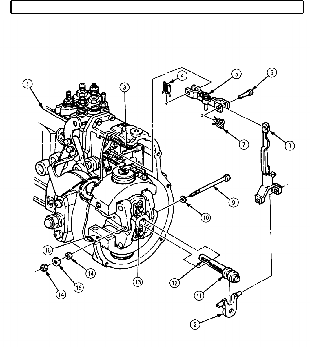
TM 9-2320-272-24-4
5-35. R.Q.V. GOVERNOR HOUSING MAINTENANCE (Contd)
FOLLOW-ON TASK: Install R.Q.V. governor cover (5-34).
5-239

TM 9-2320-272-24-4
5-36. FUEL INJECTION PUMP MAINTENANCE
THIS TASK COVERS:
a. Camshaft Removal
b. Tappet and Plunger Removal
c. Barrel and Control Rack Removal
d. Cleaning and Inspection
e. Leakage Test
f. Delivery Valve and Barrel Installation
g. Plunger and Control Rack Installation
h. Tappet and Spring Installation
i. Camshaft Installation
INITIAL SETUP:
APPLICABLE MODELS
M939A2
SPECIAL TOOLS
Two separation tubes (Appendix E, Item 119)
Side plug puller (Appendix E, Item 111)
Three tappet holders (Appendix E, Item 134)
Tappet spring compressor (Appendix E, Item 135)
TOOLS
General mechanic’s tool kit (Appendix E, Item 1)
Torque wrench (Appendix E, Item 144)
Arbor press
MATERIALS/PARTS
Fuel injection pump repair kit (Appendix D,
Item 137)
Fuel injection pump maintenance kit
(Appendix D, Item 136)
MATERIALS/PARTS (Contd)
Sealing compound (Appendix C, Item 61)
GAA grease (Appendix C, Item 28)
Drycleaning solvent (Appendix C, Item 71)
Lubricating oil (Appendix C, Item 50)
REFERENCES (TM)
TM 9-2320-272-24P
EQUIPMENT CONDITION
R.Q.V. governor housing removed (para. 5-35).
GENERAL SAFETY INSTRUCTIONS
Diesel fuel is flammable. Do not perform this task
near open flames.
Keep fire extinguisher nearby when using
drycleaning solvent.
Drycleaning solvent is flammable and toxic. Do
not use near open flame.
a. Camshaft Removal
WARNING
Diesel fuel is flammable. Do not perform fuel system procedure
near open flame. Injury to personnel may result.
Drycleaning solvent is flammable and toxic. Do not use near
open flame and always have a fire extinguisher nearby when
solvents are used. Use only in well-ventilated places, wear
protective clothing, and dispose of cleaning rags in approved
container. Failure to do this may result in injury or death to
personnel and/or damage to equipment.
CAUTION
Improper cleaning methods and use of unauthorized cleaning
solvents can damage equipment.
1.
Clean exterior of fuel pump housing (10) with drycleaning solvent.
2.
Using side plug puller, remove three side plugs (7) from fuel pump housing (10). Discard side plugs (7).
3.
Remove three spacer blocks (8) from side holes (9).
CAUTION
Keep cylinder parts together for replacement in their original
cylinder. Failure to do so may result in damage to fuel pump.
4.
Remove six nuts (4), lockwashers (3), spacer rings (2), and locking tabs (1) from studs (5) and delivery
valve holders (13). Discard lockwashers (3).
5-240
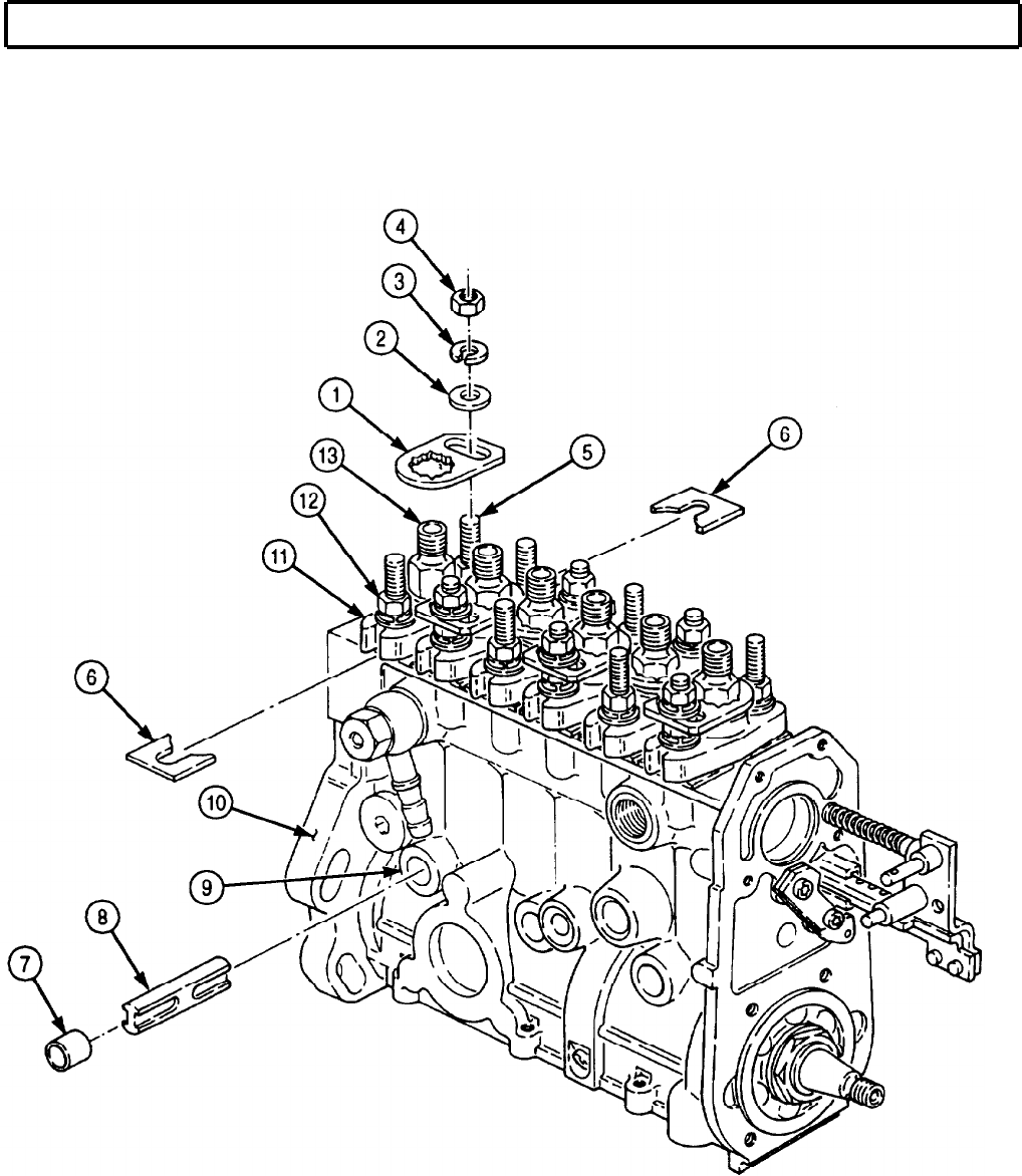
TM 9-2320-272-24-4
5-36. FUEL INJECTION PUMP MAINTENANCE (Contd)
NOTE
Perform step 5 to aid in insertion of tappet holder.
5.
Loosen twelve barrel flange nuts (12) and remove twelve shims (6) from between barrel (11) and
fuel pump housing (10).
5-241
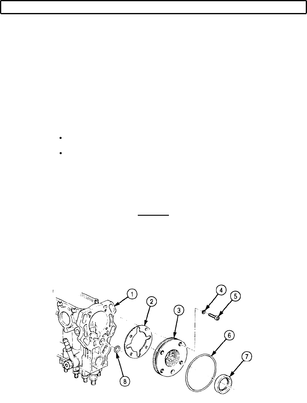
TM 9-2320-272-24-4
5-36. FUEL INJECTION PUMP MAINTENANCE (Contd)
6.
7.
8.
9.
10.
11.
12.
13.
14.
Remove camshaft (16), with bearing (23) and bearing shell (20), from governor end of fuel pump
housing (1).
15.
Remove four screws (5), lockwashers (4), end plate (3), and gasket (2) from fuel pump housing (1).
Discard gasket (2) and lockwashers (4).
16.
Remove O-ring (6) and oil seal (7) from end plate (3). Discard O-ring (6) and oil seal (7).
17.
Remove O-ring (8) from fuel pump housing (1). Discard O-ring (8).
Reverse position of fuel pump housing (1) and mount in vise.
Remove six screws (9), holding brackets (19), cover (18), and seal ring (17) from fuel pump
housing (1). Discard seal ring (17).
NOTE
Cylinder number one is located at drive end of fuel pump.
Rotate camshaft (16) until cylinder number one is at Top Dead Center (TDC).
Turn knurled handle (14) on tappet holder (15) fully counterclockwise.
Apply GM grease to ramp (12) and guide (11) on tappet holder (15).
NOTE
Tappet holder will insert only part way in when lifting tappet
number one off camshaft.
Hold tappet holder (15) with ramp (12) up and insert tappet holder (15) into side hole (10) of fuel
pump housing (1).
NOTE
Pressure must be maintained on handle of tappet holder to
prevent tappet holder from popping out.
When all six tappets are lifted off the camshaft, camshaft will
rotate with little resistance.
Rotate camshaft (16) until cylinder number two is at TDC and push tappet holder (15) until tapered
edge (13) on tappet holder (15) contacts fuel pump housing (1).
NOTE
Repeat steps 8 through 12 to install remaining two tappet holders.
Remove two screws (21) and seal rings (22) from fuel pump housing (1). Discard seal rings (22).
CAUTION
If arbor press is used, care should be taken to prevent damage to
control rack guide pin.
5-242
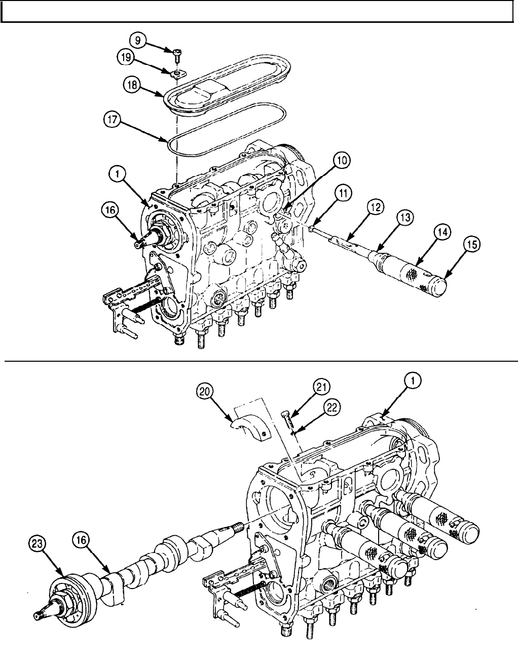
TM 9-2320-272-24-4
5-36. FUEL INJECTION PUMP MAINTENANCE (Contd)
5-243

TM 9-2320-272-24-4
5-36. FUEL INJECTION PUMP MAINTENANCE (Contd)
b. Tappet and Plunger Removal
1.
2.
3.
4.
5.
6.
7.
8.
9.
10.
11.
12.
NOTE
Camshaft must be removed to perform this task.
Position fuel pump housing (14) bottom side up in vise.
NOTE
l Cylinder number one is located at drive end of fuel pump.
l Step 2 covers the removal of tappet holder from cylinders one
and two. Remaining tappet holders are removed the same.
Install spring compressor clamp (1) on governor side of fuel pump hosing (14) with two washers (2)
and screws (3).
Place spring compressor adapter (6) on shaft (5).
Position shaft (5) and adapter (6) on the first two tappets (7).
Position lever (4) on spring compressor clamp (1) and shaft (5).
Depress lever (4), compressing both tappets (7).
Turn knurled knob (11) on tappet holder (10) fully clockwise and apply GAA grease to ramp (12) and
guide (9) on tappet holder (10).
While both tappets (7) are compressed, remove tappet holder (10) from side hole (8) of cylinders one
and two.
NOTE
Repeat steps 2 through 8 until all tappet holders are removed.
Remove two screws (3), washers (2), spring compressor clamp (1), lever (4), shaft (5), and adapter (6)
from fuel pump housing (14).
CAUTION
Keep cylinder parts together for replacement in their original
cylinder. Failure to do so may result in damage to fuel pump.
Remove six tappets (7), lower spring seats (15), plungers (16), and springs (20) from fuel pump
housing (14).
Position control rack (13) to align control sleeve ball (17) with notch (21) on fuel pump housing (14).
Remove six upper control sleeves (18) and upper spring seats (19) from fuel pump housing (14).
5-244
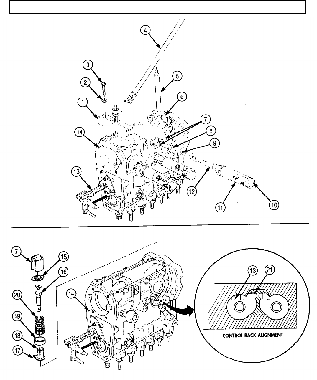
TM 9-2320-272-24-4
5-36. FUEL INJECTION PUMP MAINTENANCE (Contd)
5-245
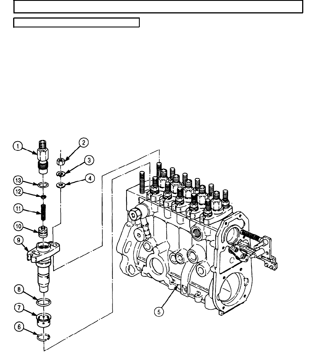
TM 9-2320-272-24-4
5-36. FUEL INJECTION PUMP MAINTENANCE (Contd)
c. Barrel and Control Rack Removal
1.
Position fuel pump housing (5) top side up in vise.
2.
Loosen six delivery valve holders (1) from barrels (9).
3.
Remove twelve barrel flange nuts (2), lockwashers (3), and spacer rings (4) from fuel pump
housing (5). Discard lockwashers (3).
4.
Remove six barrels (9) from fuel pump housing (5).
5.
Remove six O-rings (8) from barrels (9). Discard O-rings (8).
6.
Remove six retainers (6) and capsules (7) from barrels (9). Discard retainers (6).
7.
Remove six delivery valve holders (1), washers (12), springs (11), and delivery valves (10) from
barrels (9).
8.
Remove six O-rings (13) from delivery valve holders (1). Discard O-rings (13).
5-246

TM
9-2320-272-24-4
5-36. FUEL INJECTION PUMP MAINTENANCE (Contd)
9.
10.
11.
12.
Remove two screws (19) and retaining plate (20) from control rack (18) and fuel pump housing (5).
Remove control rack (18), spring retainer (17), spring (16), and washer (15) from fuel pump
housing (5).
NOTE
Perform step 11 if control rod is damaged.
Remove control rod (14) from fuel pump housing (5).
Remove fuel pump housing (5) from vise.
5-247
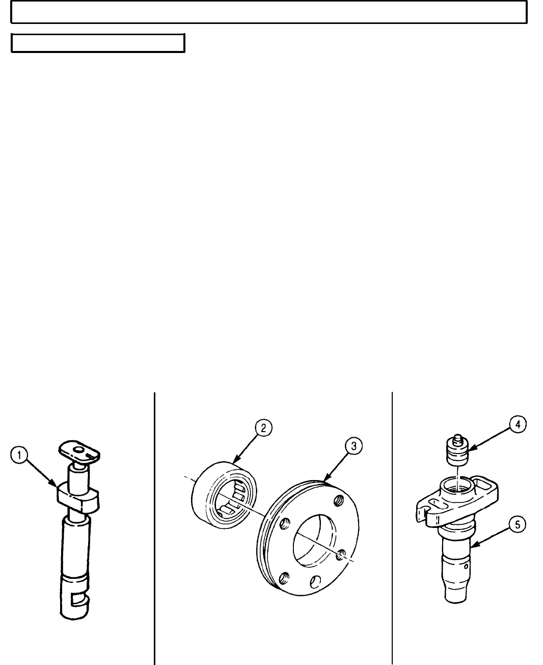
TM 9-2320-272-24-4
5-36. FUEL INJECTION PUMP MAINTENANCE (Contd)
d. Cleaning and Inspection
1.
2.
3.
4.
5.
6.
7.
8.
9.
10.
11.
12.
13.
For general cleaning instructions, refer to para. 2-14.
Inspect plunger (1) for scratches and scoring. Replace plunger (1) and barrel (5) if plunger (1) is
scratched or scored.
Inspect delivery valve (4) for wear and scoring. If worn or scored, replace delivery valve (4).
NOTE
Replace all camshaft bearings if camshaft requires replacement.
Inspect camshaft (7) for scratches and gouged lobes (6). If lobes (6) are scratched or gouged, replace
camshaft (7).
NOTE
Perform steps 5 through 7 if camshaft and endplate bearings
require replacement.
Press roller bearing (2) from end plate (3).
Remove nut (10) and lockwasher (9) from camshaft (7). Discard lockwasher (9).
Press bearing (8) from camshaft (7).
Inspect tappets (11) for wear or scratches. If worn or scratched, replace tappets (11).
Inspect six spacers (14) in fuel pump housing (13) for burrs, scratches, and nicks. If burred,
scratched or nicked, replace spacer (14).
NOTE
Perform steps 10 through 12 if spacer requires replacement.
Bend edges of spacers (14) in towards center of port (12).
Drive six spacers (14) out through top of fuel pump housing (13). Discard spacers (14).
Remove six O-rings (15) from fuel pump housing (13). Discard O-rings (15).
For general inspection instructions, refer to para. 2-15.
5-248
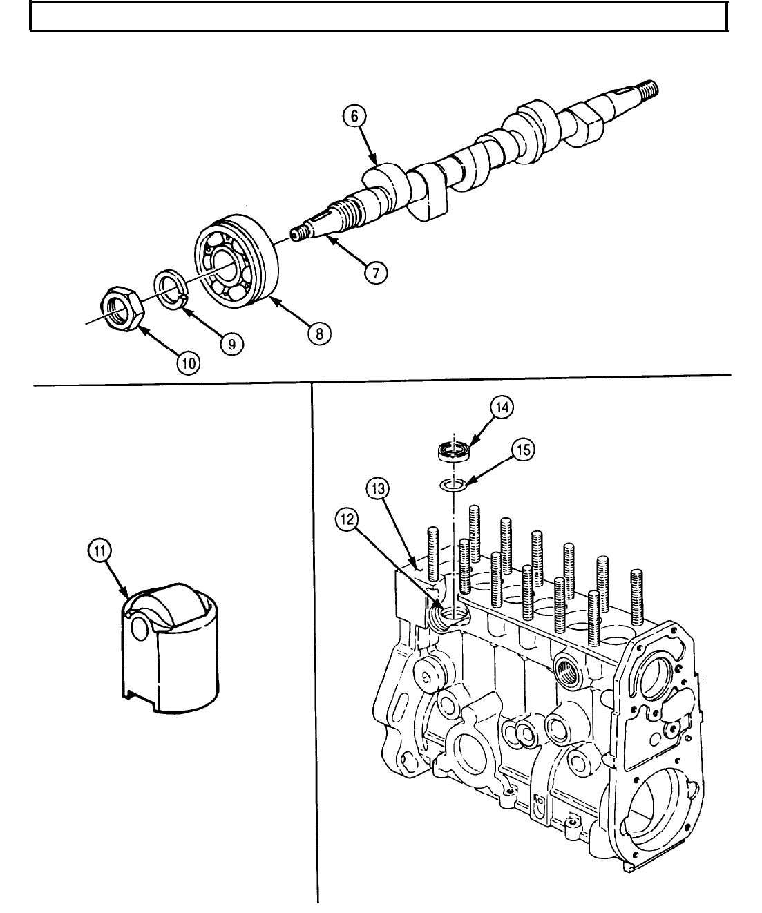
TM 9-2320-272-24-4
5-36. FUEL INJECTION PUMP MAINTENANCE (Contd)
5-249

TM 9-2320-272-24-4
5-36. FUEL INJECTION PUMP MAINTENANCE (Contd)
e. Leakage Test
1.
2.
3.
4.
5.
6.
7.
8.
9.
10.
11.
12.
13.
14.
CAUTION
Plungers and barrels are matched sets. Do not interchange parts
or damage to fuel pump may result.
NOTE
Barrels must be installed (subtask f) to perform this task.
Position fuel pump housing (1) bottom side up in vise.
Install six plungers (4) in mating barrels (7). Position plunger (4) so groove (5) on plunger (4) points
away from rack.
Install plunger retainer tubes (2) on fuel pump housing (1) with two bottom cover screws (3).
Remove fuel pump housing (1) from vise.
Install screw plug (8) in fuel gallery outlet (9).
Connect air hose to fuel gallery inlet (6).
Submerge fuel pump housing (1) in clean test oil bath and pressurize fuel pump housing (1) to
75 psi (517 kPa).
Check for bubbles at top and bottom of fuel pump housing (1). Any bubbles, other than small
bubbles from inside of plunger retainer tubes (2), indicate a leak.
If leaks are present, replace fuel pump housing (1).
Disconnect air hose from gallery inlet (6).
Remove screw plug (8) from gallery outlet (9).
Remove two bottom cover screws (3) and plunger retainer tubes (2) from fuel pump housing (1).
Remove six plungers (4) from barrels (7).
Remove fuel pump housing (1) from vise.
5-250
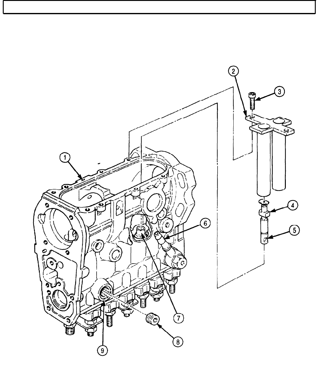
TM 9-2320-272-24-4
5-36. FUEL INJECTION PUMP MAINTENANCE (Contd)
5-251

TM 9-2320-272-24-4
5-36. FUEL INJECTION PUMP MAINTENANCE (Contd)
f. Delivery Valve and Barrel Installation
1.
2.
3.
4.
5.
6.
7.
8.
9.
10.
11.
12.
13.
NOTE
l The following subtask covers installation of one barrel. Remaining
barrels are installed the same.
l Coat all parts with oil before installation.
l Coat all O-rings with GAA grease.
NOTE
Perform steps 1 and 2 if spacer was removed.
Install new O-ring (13) in fuel pump housing (11).
Using arbor press, press new spacer (14) through top of fuel pump housing (11).
Position fuel pump housing (11) top side up in vise.
Install new O-ring (22) on delivery valve holder (1).
Install delivery valve (191, spring (20), washer (21), and delivery valve holder (1) in corresponding
barrel (18).
Install new O-ring (17) on barrel (18).
Install capsule (16) on barrel (18) with new retainer (15).
Position barrel (18) in corresponding cylinder (12) and install with two spacer rings (8), new
lockwashers (7), and barrel flange nuts (6). Tighten nuts (6) finger tight.
Place two shims (9) between barrel (18) and fuel pump housing (11).
Tighten nuts (6) 15-20 lb-ft (20-27 N•m).
Tighten delivery valve holder (1) 35-45 lb-ft (47-61 N•m).
Install locking tab (5), spacer ring (4), new lockwasher (2), and nut (3) on stud (10) and delivery
valve holder (1). Tighten nut (3) 15-20 lb-ft (20-27 N•m).
Remove fuel pump housing (11) from vise.
5-252
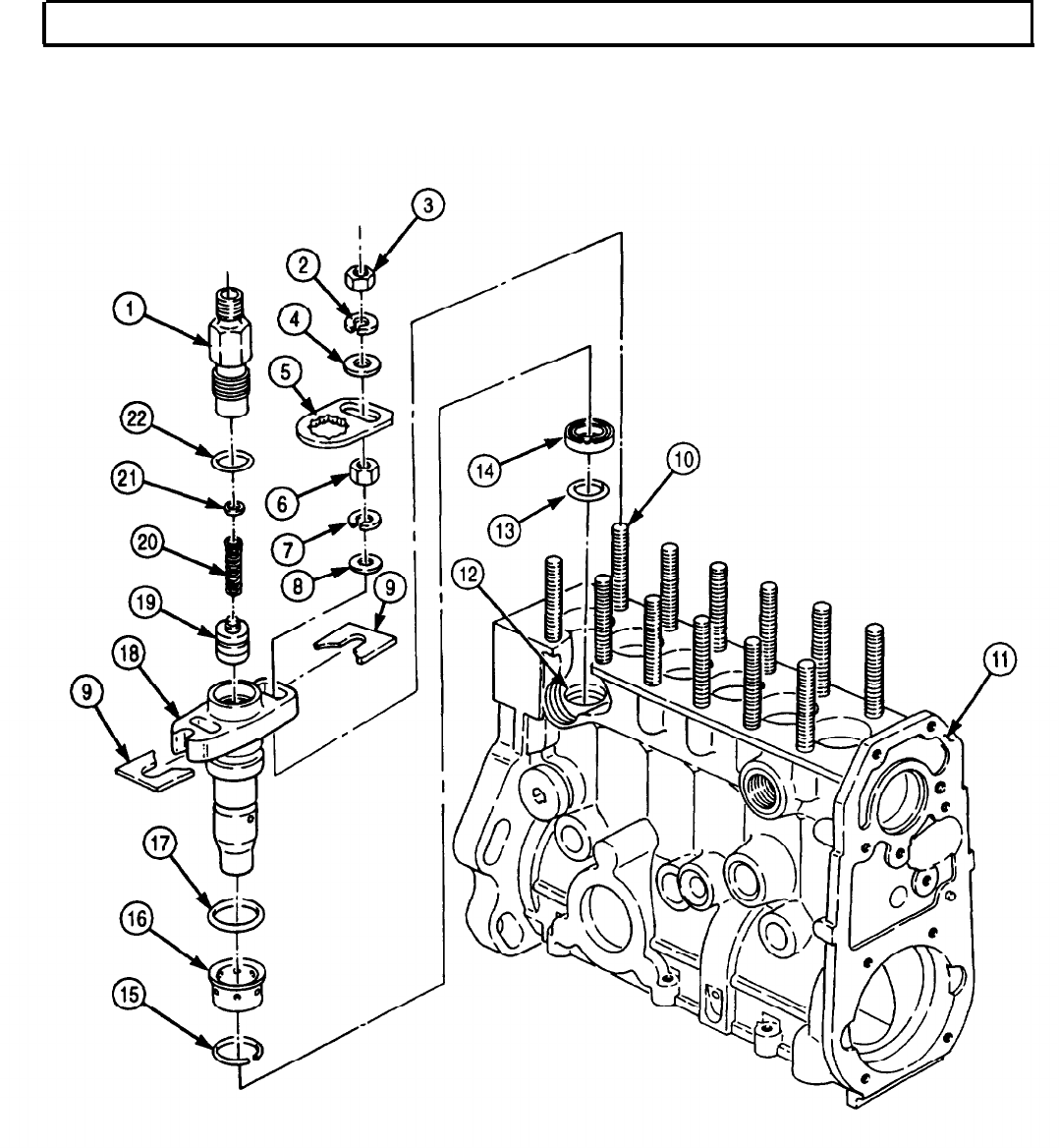
TM 9-2320-272-24-4
5-36. FUEL INJECTION PUMP MAINTENANCE (Contd)
5-253

TM 9-2320-272-24-4
5-36. FUEL INJECTION PUMP MAINTENANCE (Contd)
g. Plunger and Control Rack Installation
NOTE
Perform step 1 if control rod was removed.
1.
Install new control rod (1) on fuel pump housing (9).
2.
Install washer (2), spring (3), and cap (4) on control rod (1).
3.
Install control rack (5) and retaining plate (6) on fuel pump housing (9) with two screws (7).
4.
Mount fuel pump housing (9) bottom side up in vise.
5.
Position control rack (5) so guide slits (8) align with notch (18) on fuel pump housing (9).
NOTE
Control sleeve balls engage guide slit on control rack.
6.
Install six upper control sleeves (15) into mating barrels (16).
7.
After all control sleeves (15) are installed, move control rack (5) back and forth to ensure control
sleeves (14) move freely.
CAUTION
Once correct alignment is obtained, secure control rack in this
position until tappets are installed. Failure to do so may result in
damage to control sleeves.
8.
Position control rack (5) so guide slits (8) face adjusting groove (17) on barrel (16).
9.
Coat six upper spring seats (14) with GAA grease and position on control sleeves (15).
10.
Install six springs (13) on mating control sleeves (15).
CAUTION
Notch on plungers must align exactly with groove on barrel. If
alignment is not obtained, damage to fuel pump may result.
11.
Install six plungers (12) into mating barrels (16) so notched mark (11) on plunger base points
toward adjusting groove (17) on barrel (16).
12.
Install six lower spring seats (10) on plungers (12) and rotate lower spring seats (10) 90°.
5-254
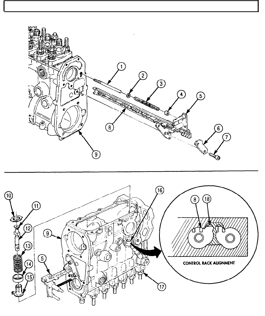
TM 9-2320-272-24-4
5-36. FUEL INJECTION PUMP MAINTENANCE (Contd)
5-255
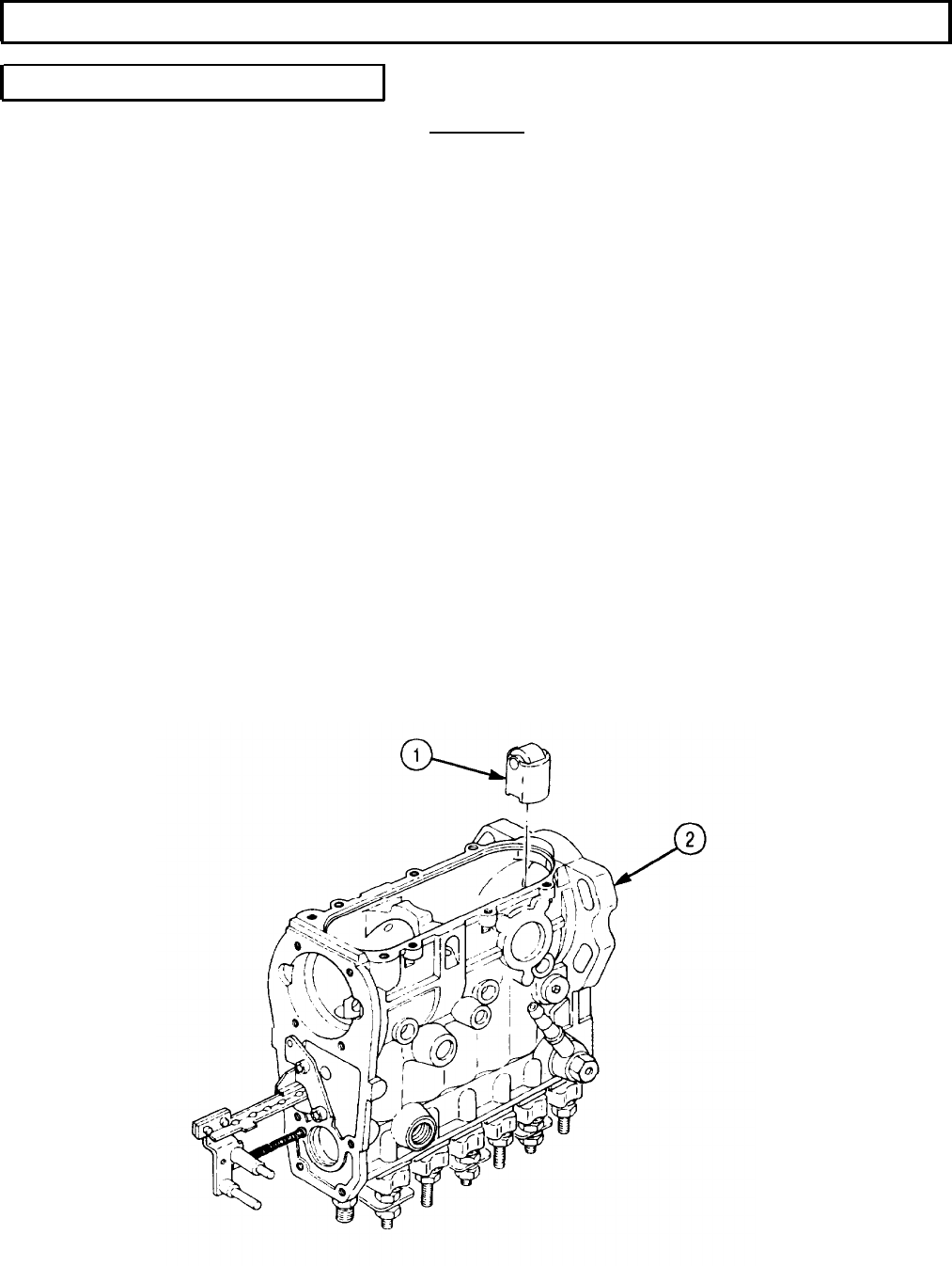
TM 9-2320-272-24-4
5-36. FUEL INJECTION PUMP MAINTENANCE (Contd)
h. Tappet and Spring Installation
1.
2.
3.
4.
5.
6.
7.
8.
9.
10.
CAUTION
When performing step 1, ensure flats on tappet align with recess
on the lower spring seat. Failure to do so may result in damage to
fuel pump housing.
NOTE
This task covers installation of two tappets for cylinders number
one and two. Remaining tappets are installed the same.
Install two tappets (1) in mating cylinders.
Install spring compressor clamp (3) on governor side of fuel pump housing (2) with two washers (4)
and screws (5).
Place spring compressor adapter (8) on shaft (7).
Position shaft (7) and adapter (8) on the first two tappets (1).
Position lever (6) on spring compressor clamp (3) and shaft (7).
Depress lever (6), compressing both tappets (1).
Turn knurled knob (12) on tappet holder (13) fully counterclockwise and apply GM grease to
ramp (11) and guide (10) on tappet holder (13).
While both tappets (1) are compressed, insert tappet holder (13) into side hole (9) of cylinders one
and two.
NOTE
Repeat steps 1 through 8 until all tappets and tappet holders are
installed.
Remove two screws (5), washers, (4), spring compressor clamp (3), lever (6), shaft (7), and
compressor adapter (8) from fuel pump housing (2).
Remove fuel pump housing (2) from vise.
5-256
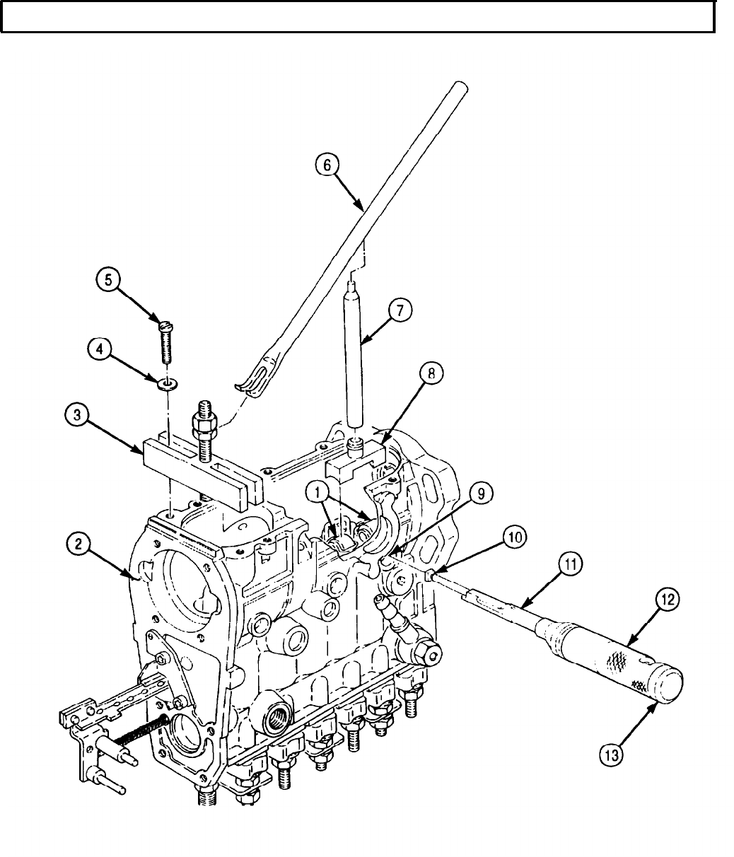
TM 9-2320-272-24-4
5-36. FUEL INJECTION PUMP MAINTENANCE (Contd)
5-257
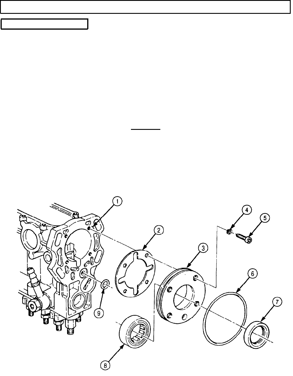
TM 9-2320-272-24-4
5-36. FUEL INJECTION PUMP MAINTENANCE (Contd)
i. Camshaft Installation
1.
2.
3.
4.
5.
6.
7.
8.
9.
Position fuel pump housing (1) bottom side up in vise.
NOTE
Perform step 2 if roller bearing was removed.
Press roller bearing (8) on end plate (3).
Install new O-ring (6) and oil seal (7) on end plate (3).
Position new gasket (2) and end plate (3) on fuel pump housing (1). Ensure oil return holes are
located at top of fuel pump housing (1).
Install end plate (3) on fuel pump housing (1) with four new lockwashers (4) and screws (5).
If bearing (16) was removed, press bearing (16) on camshaft (10) and secure bearing (16) on
camshaft (10) with new lockwasher (15) and nut (14).
Install new O-ring (9) on fuel pump housing (1).
CAUTION
When installing camshaft into fuel pump housing, tap only on
camshaft outer nut. Failure to do so may result in damage to fuel
pump.
Insert camshaft (10) and bearing shell (13) into fuel pump housing (1) through governor end of fuel
pump housing (1).
Install bearing shell (13) on fuel pump housing (1) with two new seal rings (12) and screws (11).
5-258

TM 9-2320-272-24-4
5-36. FUEL INJECTION PUMP MAINTENANCE (Contd)
5-259
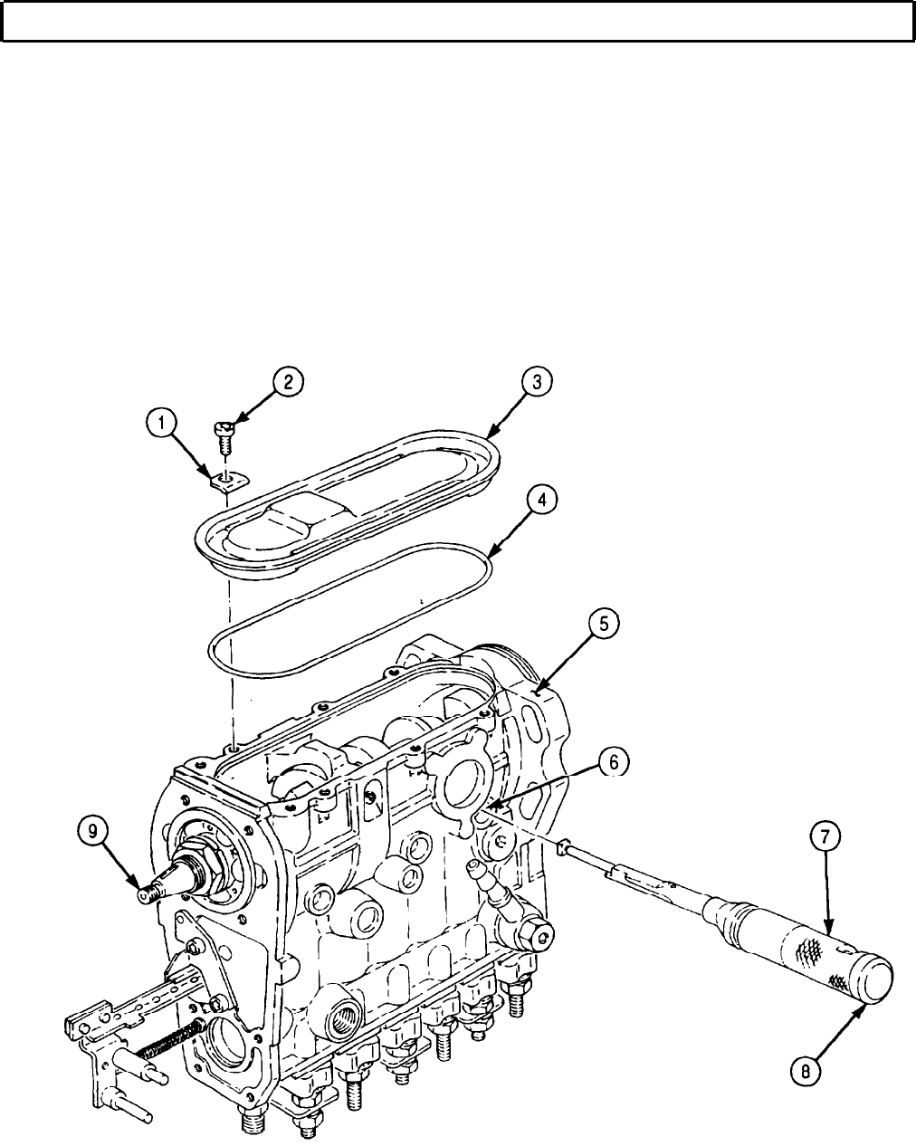
TM 9-2320-272-24-4
5-36. FUEL INJECTION PUMP MAINTENANCE (Contd)
NOTE
Steps 10 through 12 cover removal of one tappet holder. Remaining
tappet holders are removed the same.
10.
Turn knurled handle (7) on tappet holder (8) fully clockwise.
NOTE
Cylinder number one is located at drive end of fuel injection pump.
11.
Hold tappet holder (8) and rotate camshaft (9) until cylinder number one is at TDC and pull tappet
holder (8) from side hole (6).
12.
Rotate camshaft (9) until cylinder number two is at TDC and remove tappet holder (8) from side
hole (6).
13.
Install new seal ring (4) and bottom cover (3) on fuel pump housing (5) with six holding
brackets (1) and screws (2).
5-260
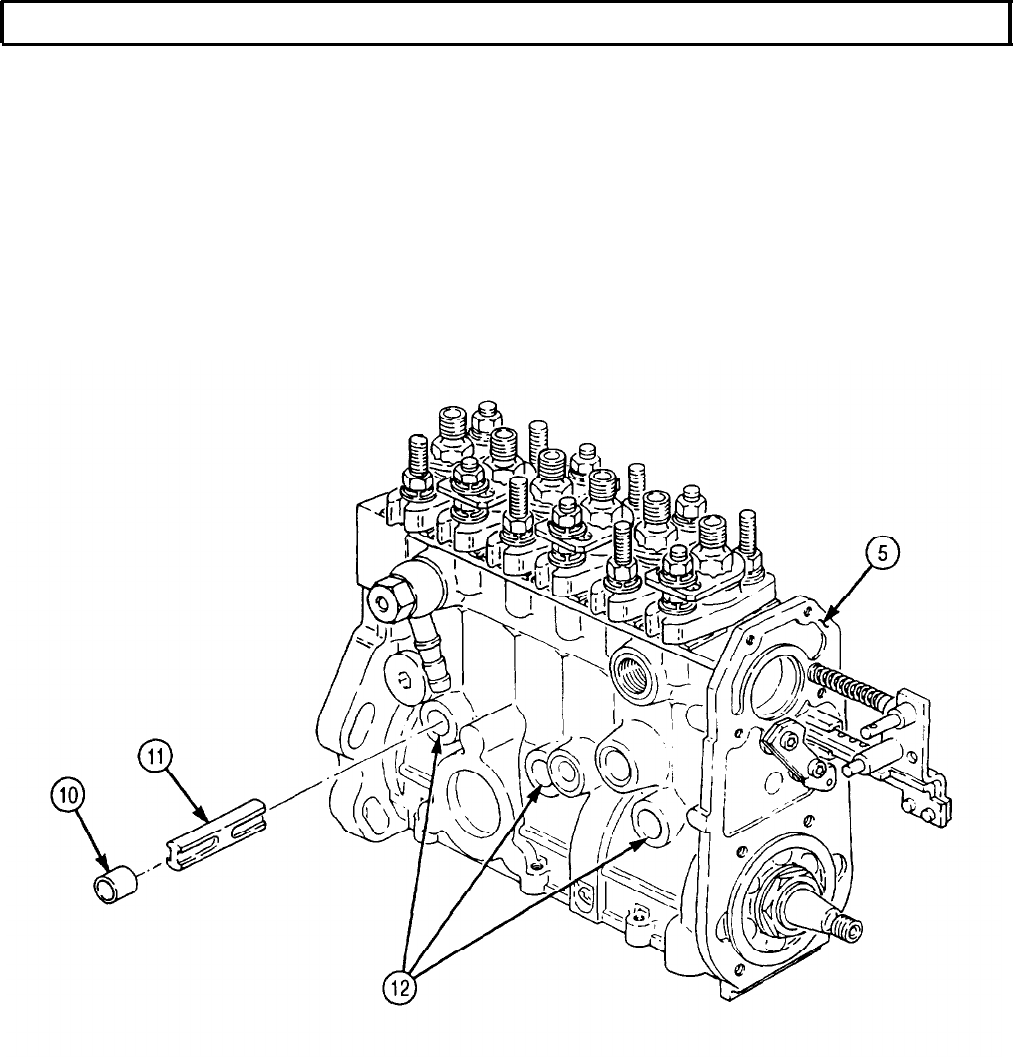
TM 9-2320-272-24-4
5-36. FUEL INJECTION PUMP MAINTENANCE (Contd)
14.
Install three spacer blocks (11) in fuel pump housing (5) through side holes (12).
15.
Apply sealing compound to new side plugs (10) and install side plugs (10) in fuel pump housing (5).
16.
Remove fuel pump housing (5) from vise.
FOLLOW-ON TASK: Install R.Q.V. governor housing (para. 5-35).
5-261

TM 9-2320-272-24-4
5-37. FUEL INJECTION PUMP CALIBRATION
THIS TASK COVERS:
a.
Prestroke and Back Travel
b. Cylinder Phasing (Timing)
c. Lock Timing
d. High-speed Fuel Delivery Test
e. Low-speed Fuel Delivery Test
f. Bated Speed Test
g.
Full Load Delivery
h. Manifold Pressure Compensator Test
i. Fuel Delivery Test
j.
Fuel Breakaway Test
k. Starting Fuel Delivery Test
l. Low Idle Fuel Delivery Test
m. External Stop Setting
INITIAL SETUP:
APPLICABLE MODELS
M939A2
SPECIAL TOOLS
Plunger lift device (Appendix E, Item 98)
Rack extension (Appendix E, Item 112)
TOOLS
General mechanic’s tool kit (Appendix E, Item 1)
Dial indicator (Appendix E, Item 36)
MATERIALS/PARTS
Two copper washers (Appendix D, Item 44)
Two break off screws (Appendix D, Item 19)
Two lockwashers (Appendix D, Item 397)
Copper washer (Appendix D, Item 42)
Two breakoff screws (Appendix D, Item 20)
Four lockwashers (Appendix D, Item 398)
Lubricating oil (Appendix C, Item 50)
Safety wire (Appendix C, Item 79)
REFERENCES (TM)
TM 9-2320-272-24P
TM 9-4910-778-14&P
EQUIPMENT CONDITION
l Fuel injection pump repaired (para. 5-36).
l Fuel injection pump mounted to test stand
(para. 5-31).
NOTE
Refer to TM 9-4910-778-14&P for operation of fuel injection pump
test stand, DFP 156.
1.
2.
3.
4.
5.
6.
7.
8.
9.
Mount dial indicator (2) and rack travel indicator holder (1) on drive end of fuel pump (5).
NOTE
Cylinder number one is located at drive end of fuel injection pump.
Install plunger lift device (8) on fuel pump (5) with finger of lifting device (8) resting on top of
tappet located in cylinder number one.
Mount dial indicator (7) on lifting device (8) and zero dial indicator (7).
Pull control lever (6) to full load position and using dial indicator shaft (3), push control rack (4) all
the way back.
Preload dial indicator (2) giving control rack (4) 0.004 in. (0.1 mm) of preload travel.
Manually rotate test stand driveshaft (9) until a reading is observed on dial indicator (7).
Manually reverse rotation test stand driveshaft (9) until dial indicator (7) reads zero.
Manually rotate test stand driveshaft (9) clockwise and take prestroke measurement from dial
indicator (7). Correct prestroke measurement should be 0.120-0.128 in. (3.05-3.25 mm).
If correct prestroke measurement is not obtained, perform steps 10 through 13.
5-262
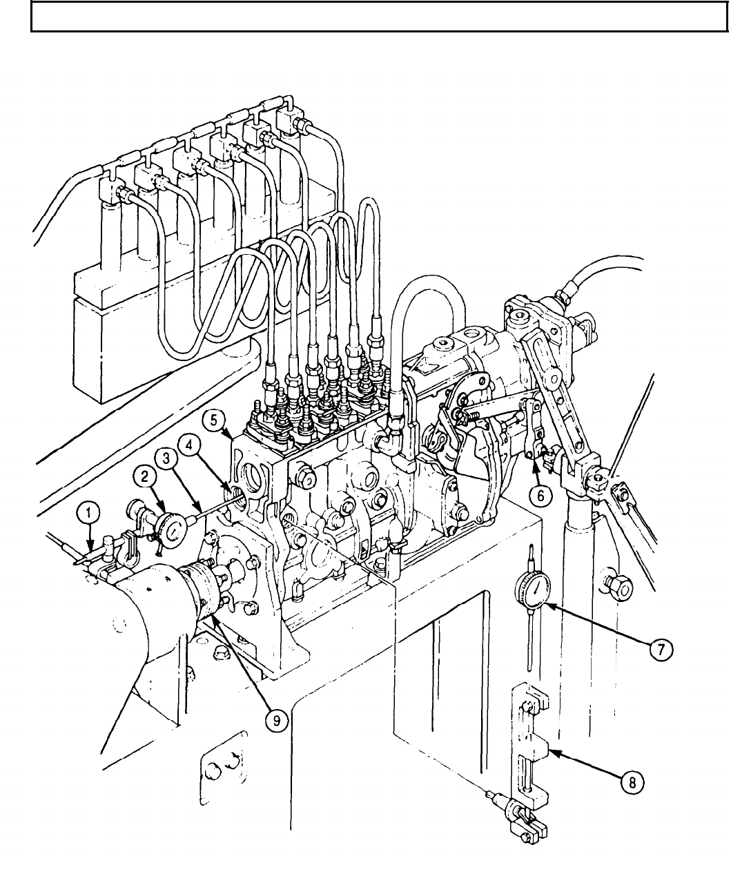
TM 9-2320-272-24-4
5-37. FUEL INJECTION PUMP CALIBRATION (Contd)
5-263

TM 9-2320-272-24-4
5-37. FUEL INJECTION PUMP CALIBRATION (Contd)
10.
11.
Steps 10 through 13 pertain to adjusting one cylinder. Remaining
five cylinders are adjusted the same.
Remove fuel test line (12) from delivery valve holder (11).
Loosen three nuts (10) and remove two shims (2) between barrel (9) and fuel pump (8). Discard
shims (2).
CAUTION
Adjusting shims of the same thickness must be used on both sides
of barrel. Failure to do so may result in inaccurate prestroke
measurement.
NOTE
12.
13.
Refer to TM 9-2320-272-24P to select shims.
Install two new shims (2) between barrel (9) and fuel pump (8).
Tighten three nuts (10) and install fuel test line (12) on delivery valve holder (11).
NOTE
14.
15.
Cylinder number one is located at drive end of fuel pump.
Close all bleedoff valves (1) except for cylinder number one.
Apply 435-464 psi (2,999-3,199 kPa) of calibration fluid pressure.
NOTE
16.
Ensure a steady stream of calibration fluid flows from number one
bleedoff valve. If not, increase calibration fluid pressure until a
steady stream of calibration fluid is obtained.
Manually rotate test stand driveshaft (7) in correct fuel pump (8) rotation, until calibration fluid
starts to drip from bleedoff valve (1).
17.
Check prestroke measurement. Correct measurement should be 0.360-0.480 in. (9.14-12.19 mm).
18.
Remove dial indicator (3) and plunger lift device (4) from fuel pump (8).
19.
Install new copper washer (6) and plug (5) on fuel pump (8).
NOTE
5-264
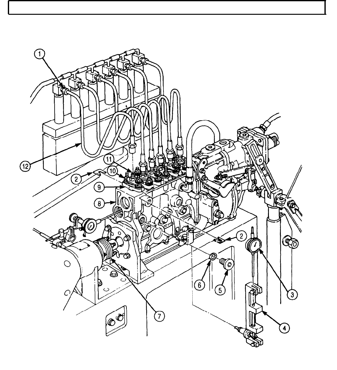
TM 9-2320-272-24-4
5-37. FUEL INJECTION PUMP CALIBRATION (Contd)
5-265

TM 9-2320-272-24-4
5-37. FUEL INJECTION PUMP CALIBRATION (Contd)
b. Cylinder Phasing (Timing)
NOTE
l When phasing (timing) cylinders, test stand calibration fluid
pressure must be set at 435-464 psi (2,999-3,199 kPa).
l When performing this task, correct prestroke measurement
must be obtained for cylinder number one. Refer to task a.
1.
Zero test stand protractor (6) on drive end of test stand (5).
2.
Close all bleedoff valves (2) except for cylinder number five.
NOTE
When bleedoff valve is opened, a stream of calibration fluid will
flow from bleedoff valve. If not, increase fluid pressure until a
stream of calibration fluid is obtained.
3.
Open bleedoff valve (2) on test nozzle (3) for cylinder number five.
4.
Manually rotate test stand driveshaft (7) in correct rotation of fuel pump (4) until calibration fluid
starts to drip from number five bleedoff valve (2).
5.
Observe reading on test stand protractor (6). Correct reading is 60°.
NOTE
l Following fuel pump firing order 1-5-3-6-2-4, repeat steps 2
through 5 until remaining cylinders are phased (timed).
l For each cylinder phased (timed), test stand protractor should
increase in 60° intervals.
6.
If 60° intervals are not obtained, adjust shims under barrel (1) (task a).
7.
If any adjustments are made to bring the remaining cylinders to specification, repeat steps 1
through 6 to ensure all cylinders are phased (timed) to specifications.
5-266
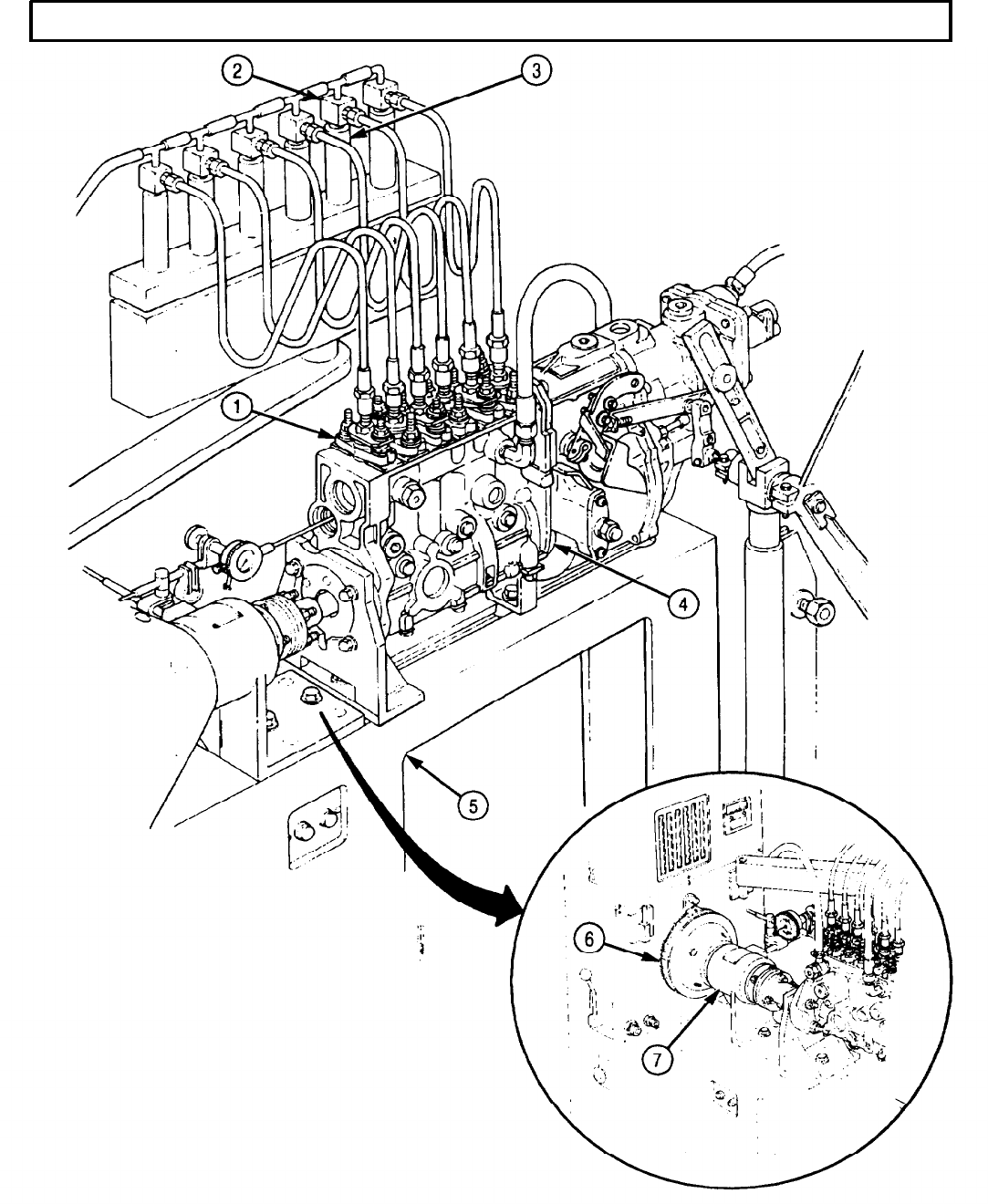
TM 9-2320-272-24-4
5-37. FUEL INJECTION PUMP CALIBRATION (Contd)
5-267

TM
9-2320-272-24-4
5-37. FUEL INJECTION PUMP CALIBRATION (Contd)
c. Lock Timing
NOTE
Fuel pump must be phased (timed) before performing this task.
Refer to task b.
1.
Remove access plug (7), washer (8), and timing pin (3) from timing plate (2).
2.
Rotate test stand drive (9) until number one cylinder is at port closure.
3.
Rotate test stand drive (9) in correct pump rotation 8° from cylinder one port closure.
4.
Timing tooth (11) should be aligned with timing pin access hole (10).
NOTE
Perform steps 5 through 11 if drive pointer is not aligned with
timing pin access hole.
5.
Remove governor cover from governor housing (para. 5-34).
6.
Remove two breakoff screws (6), lockwashers (5), washers (4), and timing plate (2) from governor
housing (1). Discard lockwashers (5) and breakoff screws (6).
7.
Remove governor flyweight and driver from fuel pump (para. 5-35).
8.
Install timing plate (2) on governor housing (1) with two washers (4), new lockwashers (5), and new
breakoff screws (6).
NOTE
l Align driver so timing tooth aligns with timing pin access hole.
l Timing plate can be adjusted up or down for final alignment.
9.
Install governor flyweight and driver on fuel pump (para. 5-35).
10.
Install timing pin (3) in timing plate (2) with slot of timing pin (3) facing timing tooth (11).
11.
Install washer (8) and access plug (7) on timing plate (2).
12.
Tighten breakoff screws (6).
13.
Install governor cover on governor housing (para. 5-34).
5-268
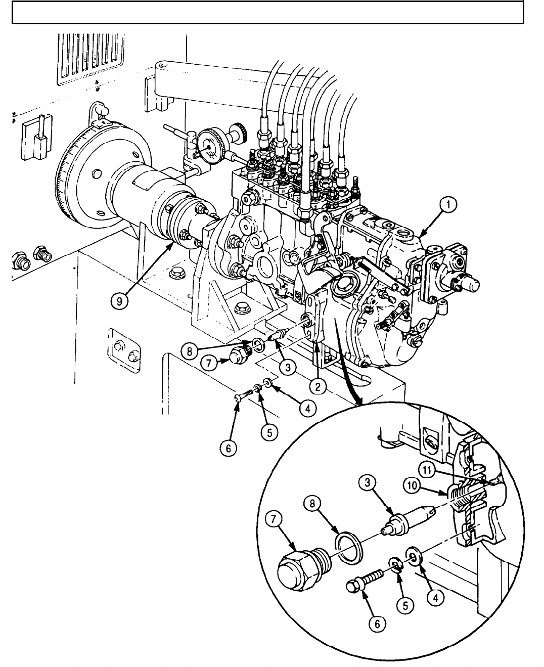
TM 9-2320-272-24-4
5-37. FUEL INJECTION PUMP CALIBRATION (Contd)
5-269
TM 9-2320-272-24-4
5-37. FUEL INJECTION PUMP CALIBRATION (Contd)
d. High-speed Fuel Delivery Test
1.
2.
3.
4.
5.
6.
7.
8.
9.
10.
11.
12.
13.
14.
15.
16.
NOTE
l Maintain 22 psi (152 kPa) calibration fluid pressure throughout
this task.
l Close all bleedoff valves.
Set test stand (12) to measure fuel delivery at 1,000 strokes.
Remove plug (4) from top of governor housing (5) and pour two pints of lubricating oil in governor
housing (5).
Remove plug (13) and washer (10) from fuel pump (9).
Install new copper washer (10), adapter (11), new copper washer (10), and plug (13) on fuel pump (9).
Connect return line (1) to adapter (11).
Adjust fuel pump (9) to 1,050 rpm.
NOTE
Adjust aneroid air pressure to help obtain correct rack travel.
Adjust control lever (8) to obtain rack travel of 0.360-0.480 in. (9.14-12.19 mm).
NOTE
Perform steps 8 and 9 if correct rack travel is not obtained.
Remove breakoff screw (19), screw (21), two lockwashers (18), protective cap (17), and stop (16) from
manifold pressure compensator (6). Discard breakoff screw (19) and two lockwashers (18).
Turn nuts (15) and (14) counterclockwise to increase rack travel; or clockwise to decrease rack
travel.
Position control lever (8) to full load and take fuel draw.
Check fuel delivery. Correct fuel delivery should be 0.891-0.928 in.3 (14.6-15.2 cm3).
Allowable spread reading is 0.037 in.3 (0.6 cm3).
NOTE
l Perform step 13 if fuel delivery deviates from specifications.
l Step 13 pertains to one cylinder only.
Loosen three nuts (2) and rotate barrel (3) clockwise to increase fuel delivery; counterclockwise to
decrease fuel delivery.
Repeat step 13 for remaining cylinders.
Install stop (16) and protective cap (17) on manifold pressure compensator (6) with two new
lockwashers (18), screw (21), and new breakoff screw (20).
Install new safety wire (22) on screw (21) and protective cap (17).
e. Low-speed Fuel Delivery Test
NOTE
Maintain 22 psi (152 kPa) calibration fluid pressure throughout
this task.
1.
Reduce fuel pump (9) to 300 rpm.
2.
Set control rack travel at 0.308-0.316 in. (7.8-8.0 mm).
3.
Check fuel delivery. Correct fuel delivery should be 0.079-0.134 in.3 (1.3-2.2 cm3).
4.
Allowable spread reading is 0.030 in.3 (0.5 cm3).
5.
If low-speed fuel delivery deviates from specifications given, adjust low idle stopscrew (7) until
correct fuel delivery is obtained.
5-270
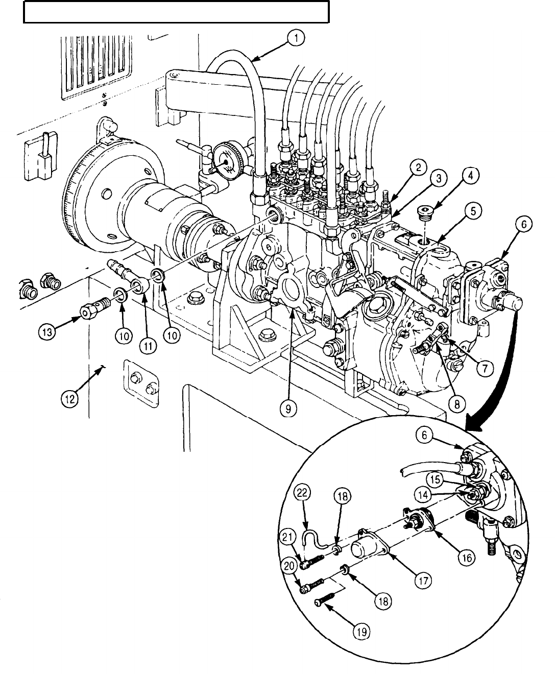
TM 9-2320-272-24-4
5-37 FUEL INJECTION PUMP CALIBRATION (Contd)
5-271
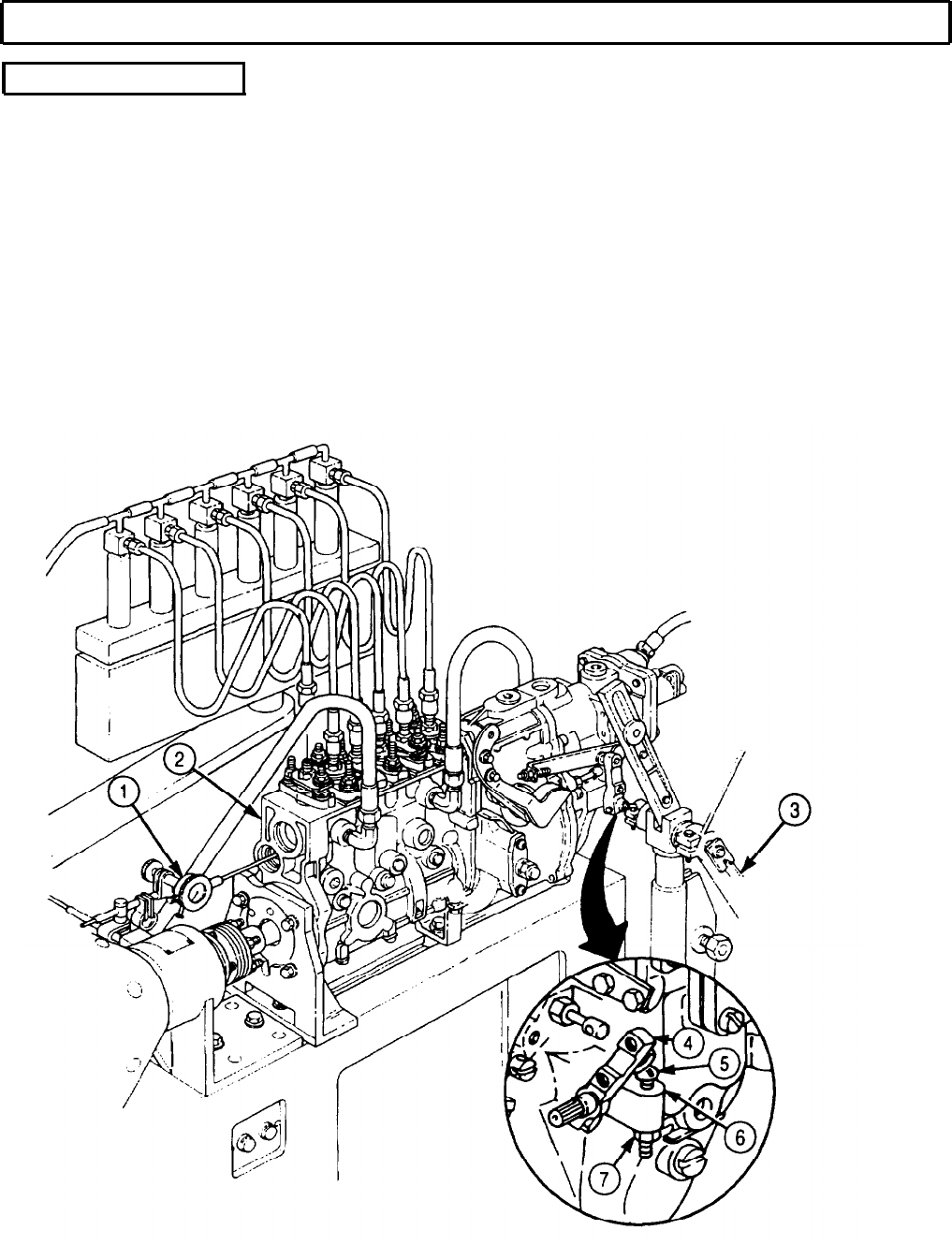
TM 9-2320-272-24-4
5-37. FUEL INJECTION PUMP CALIBRATION (Contd)
f. Rated Speed Test
1.
2.
3.
4.
5.
6.
Increase rpm of fuel pump (2) until a rack travel of 0.464 in. (11.79 mm) is obtained.
7.
Rpm of fuel pump (2) should be at 1,090-1,100 rpm.
8.
Adjust rpm of fuel pump (2) until rack travel of 0.312 in. (7.9 mm) is obtained.
9.
Rpm of fuel pump (2) should be at 300 rpm.
10.
Decrease rpm of fuel pump (2) to 100 rpm. Rack travel should be 0.372 in. (9.45 mm).
Loosen nut (7) on low idle stopscrew (5) and turn low idle stopscrew (5) until flush with governor
cover (6).
Position control level (4) until dial indicator (1) on drive end of fuel pump (2) reads zero.
Slowly move control lever (4) towards full load, until dial indicator (1) receives reading.
Set protractor (3) at zero.
Position control lever (4) to read 42-50° on protractor (3) by adjusting low idle stop-
screw (5).
5-272
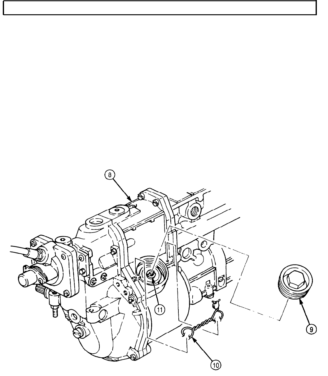
TM 9-2320-272-24-4
5-37. FUEL INJECTION PUMP CALIBRATION (Contd)
NOTE
Perform steps 11 through 17 if proper control rack travel was not
obtained.
11.
Remove safety wire (10) from governor housing (8).
12.
Remove plug (9) from governor housing (8), giving access to governor springs.
NOTE
Repeat steps 13 and 14 until both governor springs are adjusted.
13.
If control rack travel reading is too low at a given speed, increase flyweight spring tension by
turning round nut (11) clockwise.
14.
If control rack travel reading is too high at a given speed, decrease flyweight spring tension by
turning round nut (11) counterclockwise.
15.
Recheck control rack travel. If control rack travel is incorrect, repeat step 13 or 14. If rack travel is
correct, proceed to step 16.
16.
Install plug (9) on governor housing (5).
17.
Install new safety wire (10) on governor housing (8).
5-273
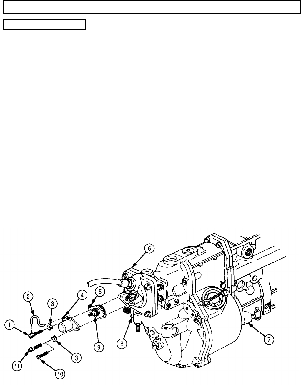
TM 9-2320-272-24-4
5-37. FUEL INJECTION PUMP CALIBRATION (Contd)
g. Full Load Delivery
1.
2.
3.
4.
5.
6.
7.
8.
9.
10.
11.
12.
13.
14.
15.
Apply 13.05 psi (90 kPa) of air to manifold pressure compensator (6).
Adjust fuel pump (7) to 1,050 rpm.
Set fuel test stand to measure fuel delivery at 1,000 strokes.
Reduce fuel pump (7) to 700 rpm.
Position control lever (8) to full load position.
Take fuel draw and observe delivery quantity. Correct delivery quantity should be 9.1-9.2 in.3
(149.1-150.8 cm3).
Check spread reading. Correct spread reading is 0.366 in.3 (6.00 cm3).
Close air supply source to manifold pressure compensator (6).
Reduce fuel pump (7) to 500 rpm.
Position control lever (8) to full load position.
Take fuel draw and observe delivery quantity. Correct delivery quantity is 4.8-4.9 in.3
(78.7-80.3 cm3).
NOTE
Perform steps 12 through 14 if fuel delivery quantity deviates
from specifications.
Remove breakoff screw (10), screw (1), two lockwashers (3), protective cap (4), and stop (5) from
manifold pressure compensator (6). Discard two lockwashers (3) and breakoff screw (10).
Turn nut (9) clockwise to increase fuel delivery; counterclockwise to decrease fuel delivery.
Install stop (5) and protective cap (4) on manifold pressure compensator (6) with two new lock-
washers (3), new breakoff screw (11), and screw (1).
Install new safety wire (2) on screw (1) and protective cap (4).
5-274
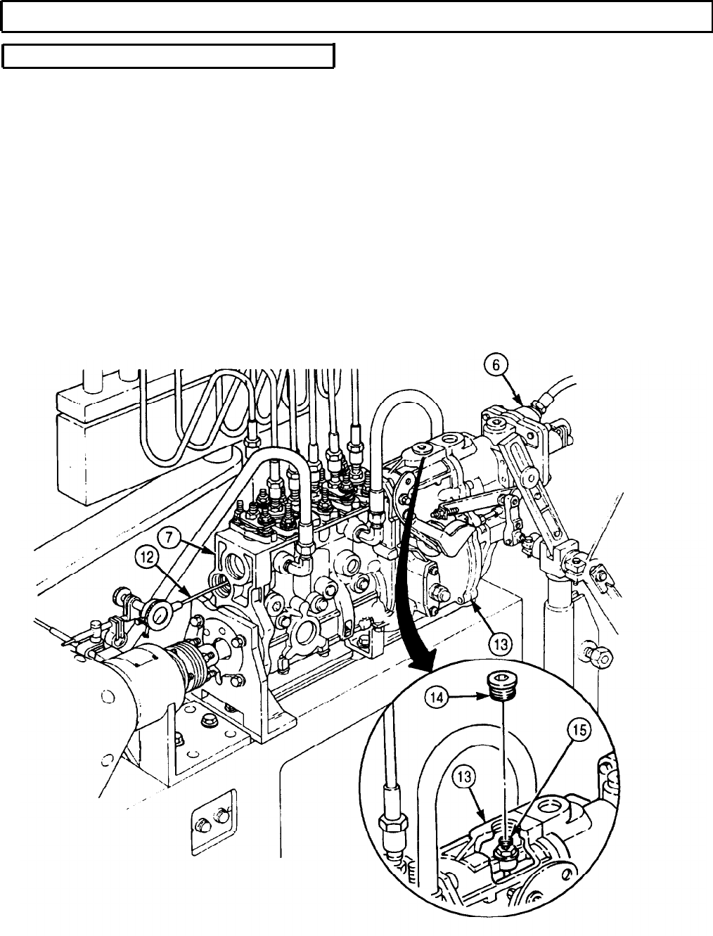
TM` 9-2320-272-24-4
5-37. FUEL INJECTION PUMP CALIBRATION (Contd)
h. Manifold Pressure Compensator Test
1.
Set fuel pump (7) to 500 rpm and position control rack (12) between 0.041-0.042 in.
(1.040-1.060 mm) rack travel.
2.
Apply 3.26 psi (22.5 kPa) of air pressure to manifold pressure compensator (6) and observe control
rack (12) travel. Correct control rack (12) travel is 0.429-04.36 in. (11.90-12.30 mm).
3.
Increase air pressure of manifold pressure compensator (6) to 6.53 psi (45.0 kPa) and observe
control rack (12) travel. Correct control rack (12) travel is 0.468-0.484 in. (11.90-12.30 mm).
NOTE
Perform steps 5 through 8 if control rack travel deviates from
specifications.
4.
Remove plug (14) from top of governor housing (13).
5.
If control rack (12) travel is less than required specifications, turn screw (15) clockwise.
6.
If control rack (12) travel is more than required specifications, turn screw (15) counterclockwise.
7. Recheck control rack (12) travel. If control rack (12) travel is incorrect, repeat step 6 or 7. If control
rack (12) travel is correct, proceed to step 9.
8. Install plug (14) on governor housing (13).
5-275
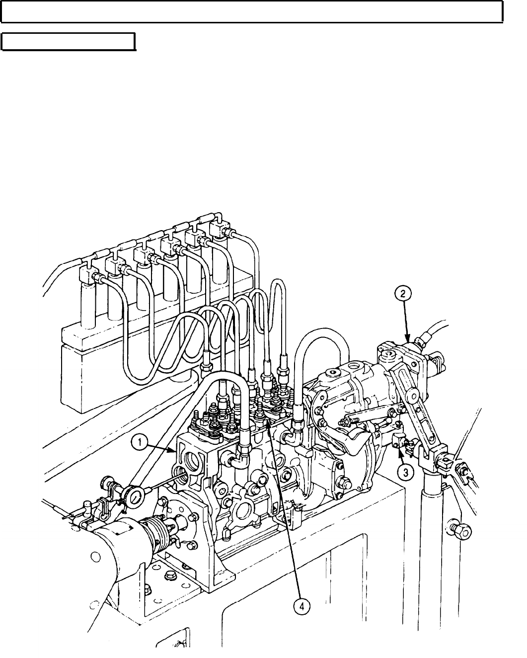
TM 9-2320-272-24-4
5-37. FUEL INJECTION PUMP CALIBRATION (Contd)
i. Fuel Delivery Test
1.
2.
3.
4.
5.
6.
7.
8.
9.
Apply 13.1 psi (90.3 kPa) to manifold pressure compensator (2).
Adjust fuel pump (1) to 700 rpm.
Set test stand to measure fuel delivery at 1,000 strokes.
Set control lever (3) to full load position.
Check fuel delivery quantity. Correct fuel delivery quantity should be 8.73-9.21 in.3
(143.0-151.0 cm3).
Check fuel spread. Fuel spread should be 0.427 in.3 (7.0 cm3).
Decrease fuel pump speed (1) to 500 rpm.
Check fuel delivery quantity. Correct fuel delivery quantity is 5.61-5.74 in.3 (92.0-94.0 cm3).
Adjust fuel delivery quantity by turning each barrel assembly (4) counterclockwise or clockwise
until correct fuel delivery quantity is obtained.
5-276
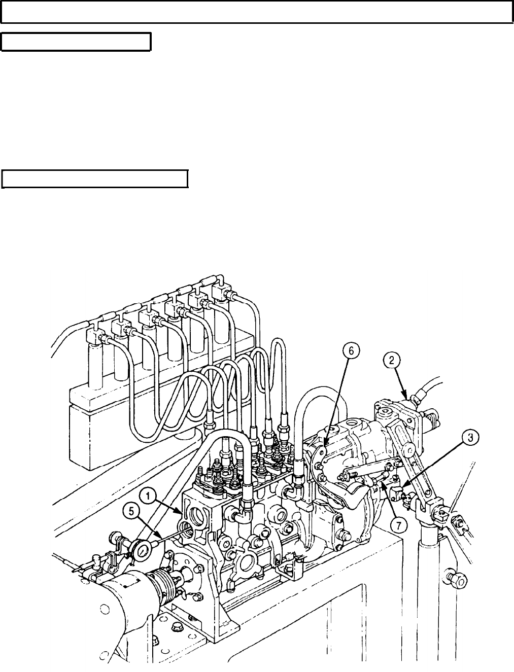
TM 9-2320-272-24-4
5-37. FUEL INJECTION PUMP CALIBRATION. (Contd)
j. Fuel Breakaway Test
1.
Move control lever (3) to full load position.
2.
Gradually increase rpm of fuel pump (1) rpm until control rack (5) moves 0.004 in. (0.1 mm)
towards shutoff.
3.
Rpm of fuel pump (1) should be 1,090-1,100 rpm. Perform step 5 if correct rpm is not obtained.
4.
Move control lever (3) to full load position and observe travel of control rack. Correct control rack
travel should be 0.464 in. (11.79 mm).
5.
If breakaway is not as specified rpm, adjust high-speed stopscrew (7) until correct breakaway is
obtained.
k. Starting Fuel Delivery Test
1.
Set fuel pump (1) to 100 rpm.
2.
Set test stand to measure calibration fluid at 1,000 strokes.
3.
Position throttle lever (6) so control rack (5) is at full load 0.827 in. (21 mm).
4.
Take fuel draw and check delivery quantity. Correct delivery quantity is 12.94-13.91 in.3
(212.0-228.0 cm3).
5-277
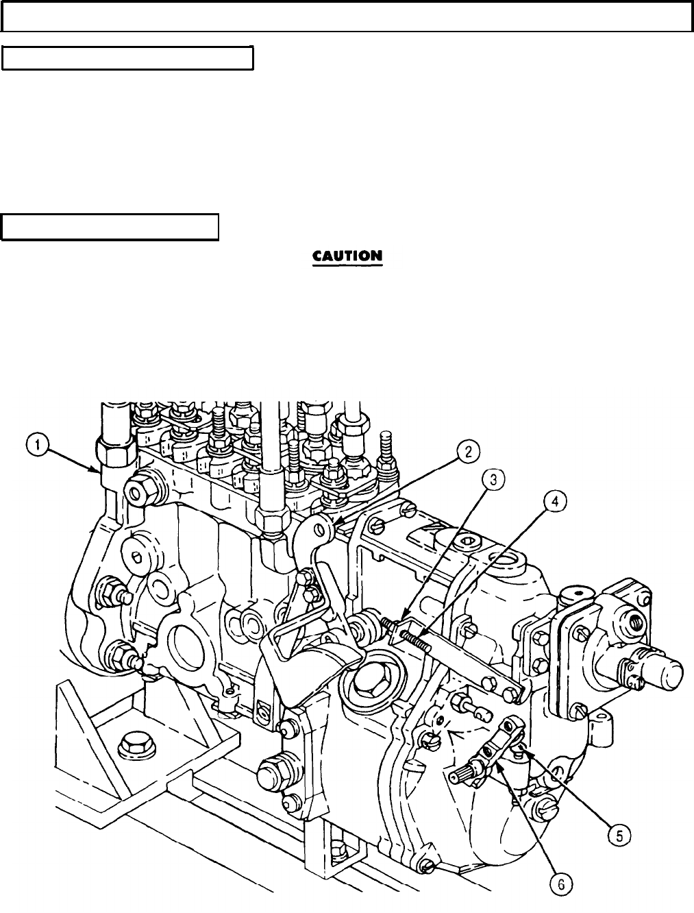
TM 9-2320-272-24-4
5-37. FUEL INJECTION PUMP CALIBRATION (Contd)
l. Low Idle Fuel Delivery Test
1.
Set fuel pump (1) to 300 rpm.
2.
Position control lever (6) against idle stopscrew (5) and take a fuel draw.
3.
Observe control rack travel. Correct control rack travel should be 0.308-0.316 in. (7.80-8.03 mm).
4.
With test stand set at 1,000 strokes, take fuel draw and check delivery quantity. Correct delivery
quantity is 0.824-1.373 in.3 (13.5-22.5 cm3).
5.
If fuel delivery deviates from specifications, adjust idle stopscrew (5) until correct fuel delivery is
obtained.
m. External Stop Setting
Perform this task so control rack has a 0.039 in. (1 mm) preload.
Failure to do so may result in damage to fuel pump.
1.
Loosen adjusting nut (3) on throttle stopscrew (4).
2.
Position throttle lever (2) against throttle stopscrew (4).
3.
Adjust throttle stopscrew (4) until 0.039 in. (1 mm) preload is observed on dial indicator (7) and
tighten adjusting nut (3).
5-278
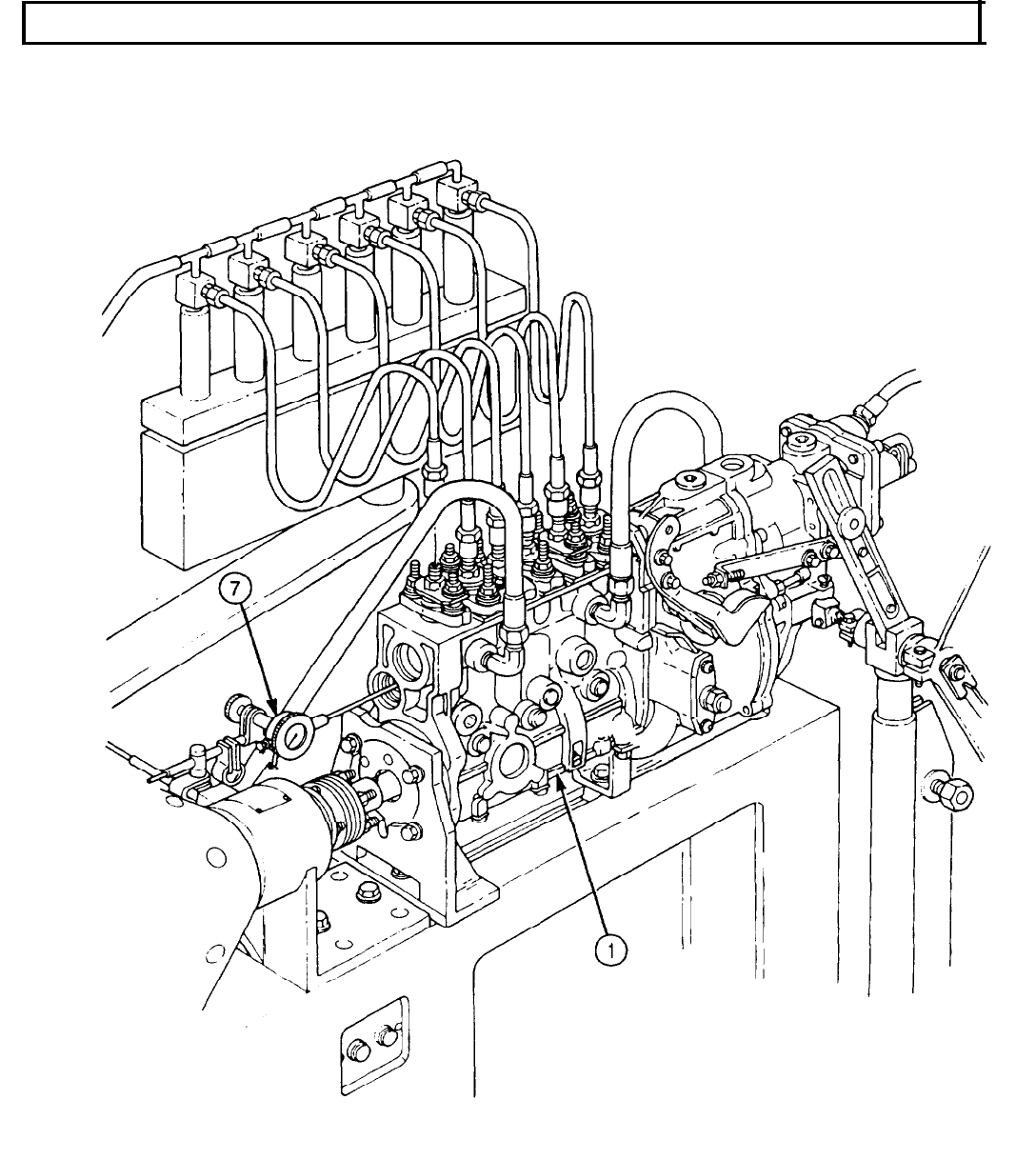

TM 9-2320-272-24-4
Section III. TRANSMISSION MAINTENANCE
5-38. TRANSMISSION MAINTENANCE INDEX
PARA.
TITLE
PAGE
NO.
NO.
5-39.
5-40.
5-41.
5-42.
5-43.
5-44.
5-45.
5-46.
5-47.
5-48.
5-49.
5-50.
5-51.
5-52.
5-53.
5-54.
5-55.
5-56.
5-57.
5-58.
5-59.
Transmission Housing Maintenance
5-60.
Transmission Oil Pressure Testing
5-61.
Transmission Modulator Maintenance
5-62.
Transmission Converter Stall Test
General Maintenance Instructions
Transmission Mounting to Holding Fixture
Transmission Torque Converter Maintenance
Transmission Oil Pan and Filter Maintenance
Modulate Lockup Valve, Low Trimmer Valve, and Low Shift
Valve Replacement
Transmission Control Valve Replacement
Transmission Manual Selector Shaft Replacement
Transmission Oil Pump and Front Support Maintenance
Forward Clutch Maintenance
Fourth Clutch Maintenance
Third Clutch Maintenance
Center Support Maintenance
Gear Unit and Main Shaft Maintenance
Second Clutch Maintenance
First Clutch Maintenance
Transmission Governor Replacement
Rear Cover and Low Planetary Carrier Maintenance
Low Clutch Removal and Clearance
Adapter Housing and First Clutch Piston Maintenance
Adapter Housing, Low Clutch, Low Planetary Carrier, and Rear
Cover Installation
5-281
5-282
5-286
5-300
5-304
5-306
5-308
5-310
5-322
5-332
5-338
5-340
5-348
5-354
5-358
5-362
5-364
5-374
5-378
5-382
5-384
5-386
5-394
5-396
5-280

TM 9-2320-272-24-4
5-39. GENERAL MAINTENANCE INSTRUCTIONS
WARNING
l Drycleaning solvent is flammable and will not be used near
open flame. Use only in well-ventilated places. Failure to do
so may result in injury to personnel.
l Compressed air source will not exceed 30 psi (20 kPa). When
cleaning with compressed air, eyeshields must be worn. Failure
to wear eyeshields may result in injury to personnel.
l When converter pump hub, front support (including ground
sleeve), or oil pump is defective, install wide oil pump kit. This
kit converts an early model transmission (P/N 6885292) into a
late model transmission (P/N 23040127). Failure to simultaneously
install all parts of kit may cause damage to transmission during
assembly or may cause transmission malfunction.
NOTE
l Refer to para. 2-14 for cleaning all transmission components.
l Make sure location markings are not removed when cleaning.
l All transmission parts must be lubricated with clean
OE/HDO-10 lubricating oil before assembly.
5-281
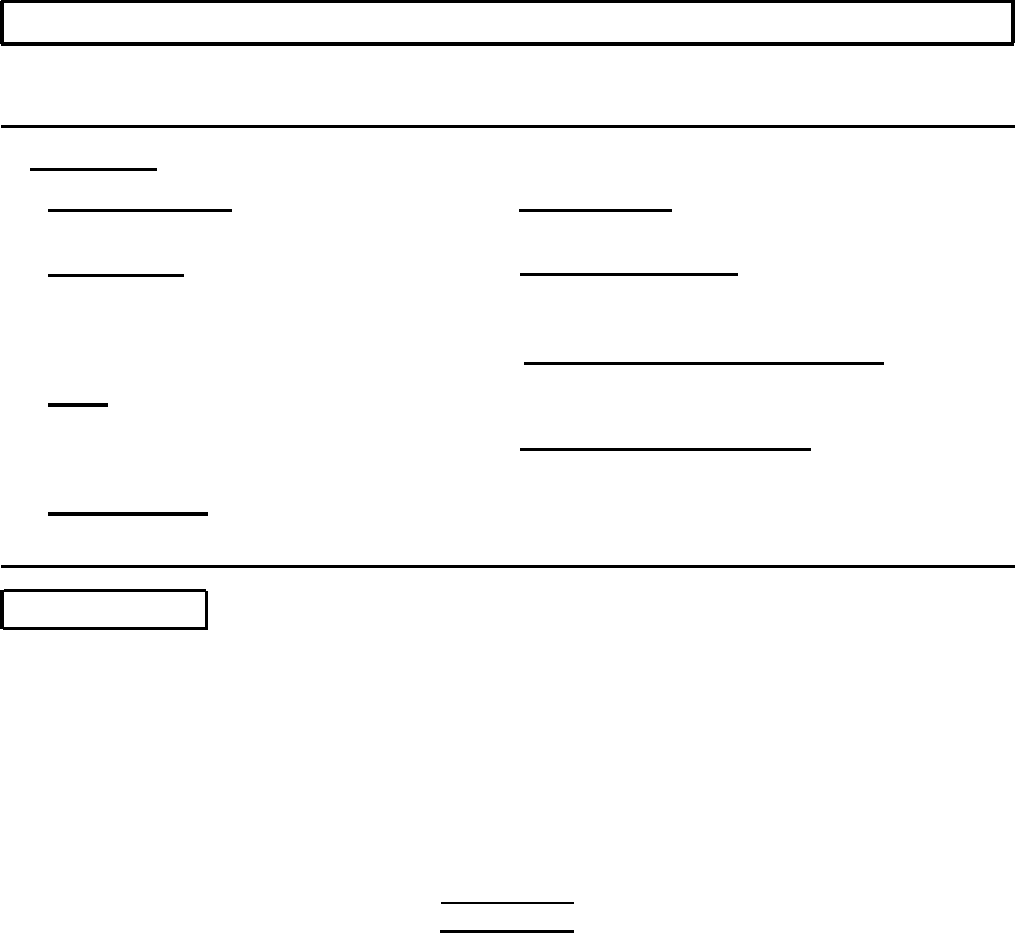
TM 9-2320-272-24-4
5-40. TRANSMISSION MOUNTING TO HOLDING FIXTURE
THIS TASK COVERS
a. Installation b. Removal
INITIAL SETUP:
APPLICABLE MODELS
All
SPECIAL TOOLS
Holding fixture adapter set (Appendix E,
Item 64)
Holding fixture (Appendix E, Item 63)
Holding fixture base (Appendix E, Item 65)
TOOLS
General mechanic’s tool kit (Appendix E, Item 1)
Lifting device
Chain
MATERIALS/PARTS
Gasket (Appendix D, Item 224)
REFERENCES (TM)
TM 9-2320-272-24P
EQUIPMENT CONDITION
Transmission removed from vehicle (para. 4-71) or
transmission removed from engine (para. 4-72).
SPECIAL ENVIRONMENTAL CONDITIONS
Work area clean and free from blowing dirt and
dust.
GENERAL SAFETY INSTRUCTIONS
l All personnel must stand clear during lifting
operations.
l Do not remove hoist chain from transmission until
transmission is stable. Injury to personnel may
result.
a. Installation
1.
Remove six screws (4), power takeoff cover (3), and gasket (2) from transmission (1). Discard
gasket (2).
2.
Install holding plate (6) and holding fixture (5) on right side of transmission (1) with six washers (7)
and screws (8).
NOTE
Transmission may be mounted on any overhaul stand or holding
fixture. However, the front, rear, and bottom of transmission must
be freely accessible for removal and installation of components.
3.
Install holding fixture base (10) on overhaul stand (11) with four screws (14), washers (13), and
nuts (12).
WARNING
l All personnel must stand clear during lifting operations.
A snapped cable, or swinging or shifting load, may cause
injury to personnel.
l Do not remove hoist chain from transmission until transmission
is stable on holding fixture base, or injury to personnel may
result.
4.
Using lifting device and chain, lift transmission (1) and holding fixture (5) into position and install
in holding fixture base (10) with pin (15) and setscrew (9).
5.
Remove chain and lifting device from transmission (1)
5-282
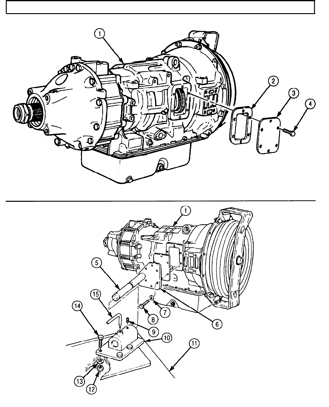
TM 9-2320-272-24-4
5-40. TRANSMISSION MOUNTING TO HOLDING FIXTURE (Contd)
5-283

TM 9-2320-272-24-4
5-40. TRANSMISSION MOUNTING TO HOLDING FIXTURE (Contd)
b. Removal
1.
2.
3.
4.
Attach lifting device and chain to transmission (1).
Remove pin (7) from holding fixture base (6) and loosen setscrew (5).
Support transmission (1) with chain and lifting device and remove transmission (1) and holding
fixture (8) from holding fixture base (6).
Remove six screws (4), washers (3), holding fixture (8), and holding plate (2) from transmission (1)
and holding fixture (8).
5.
Install new gasket (9) and power takeoff cover (10) on transmission (1) with six screws (11).
6.
Remove lifting device and chain from transmission (1).
WARNING
All personnel must stand clear during lifting operations.
A snapped cable, or swinging or shifting load, may cause
injury to personnel.
NOTE
Assistant will help with step 2.
5-284
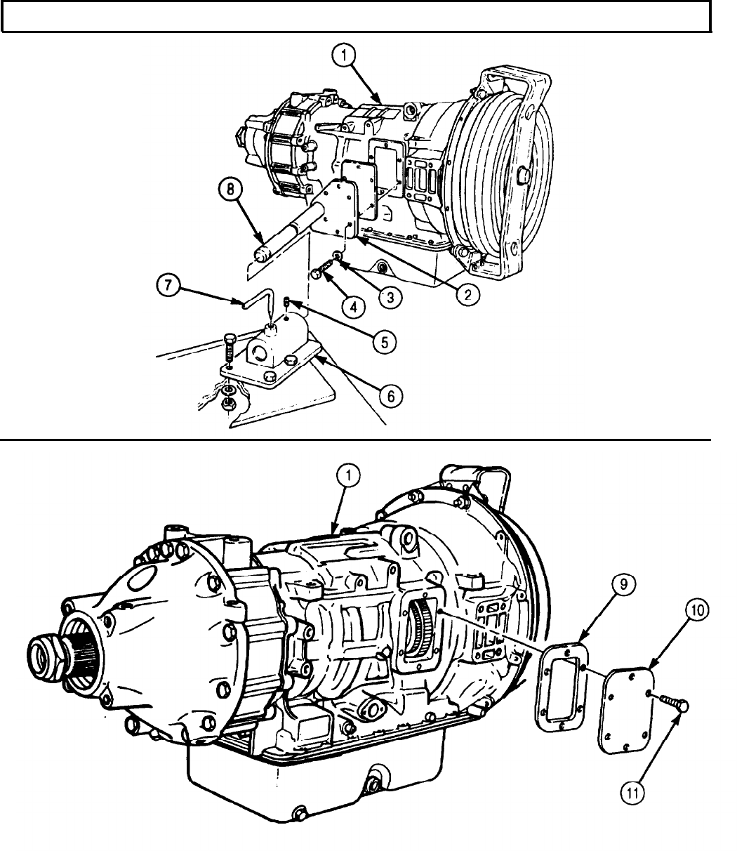
TM 9-2320-272-24-4
5-40. TRANSMISSION MOUNTING TO HOLDING FIXTURE (Contd)
FOLLOW-ON TASK: Install transmission on engine (para. 4-72) or install transmission in vehicle
(para. 4-71).
5-285
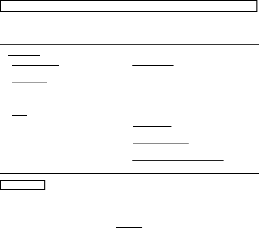
TM 9-2320-272-24-4
5-41. TRANSMISSION TORQUE CONVERTER MAINTENANCE
THIS TASK COVERS
a. Removal d. Assembly
b. Disassembly e. Installation
c. Cleaning and Inspection
INITIAL SETUP:
APPLICABLE MODELS
All
SPECIAL TOOLS
Bearing puller set (Appendix E. Item 105)
Drive handle (Appendix E, Item 38)
Bearing replacer (Appendix E, Item 15)
Bushing replacer (Appendix E, Item 25)
TOOLS
Arbor press
General mechanic’s tool kit (Appendix E, Item 1)
Vernier caliper (Appendix E, Item 159)
Torque wrench (Appendix E, Item 144)
MATERIALS/PARTS
Converter pump seal ring (Appendix D, Item 636)
Flywheel seal ring (Appendix D, Item 638)
Hook-type seal (Appendix D, Item 637)
Piston seal ring (Appendix D, Item 520)
Pump hub gasket (Appendix D, Item 225)
Six lockstraps (Appendix D, Item 342)
Thirty self-locking screws (Appendix D, Item 648)
Lubricating oil (Appendix C, Item 49)
Oil-soluble grease (Appendix C, Item 53)
REFERENCES (TM)
TM 9-2320-272-24P
EQUIPMENT CONDITION
Transmission mounted to holding fixture (para. 5-40).
SPECIAL ENVIRONMENTAL CONDITIONS
Work area clean and free from blowing dirt and
dust.
a. Removal
NOTE
Assistant will help with steps 1 and 2.
1.
Remove four nuts (1), washers (2), and screws (4) from converter retaining strap (3) and
transmission (7).
CAUTION
Torque converter must be pulled straight out of transmission and
not moved from side to side. Side movement will damage hook-
type seal ring on torque converter pump hub.
2.
Pull converter retaining strap (3) with torque converter (5) straight out of transmission (7).
3.
Remove two screws (6) and converter retaining strap (3) from torque converter (5).
5-286
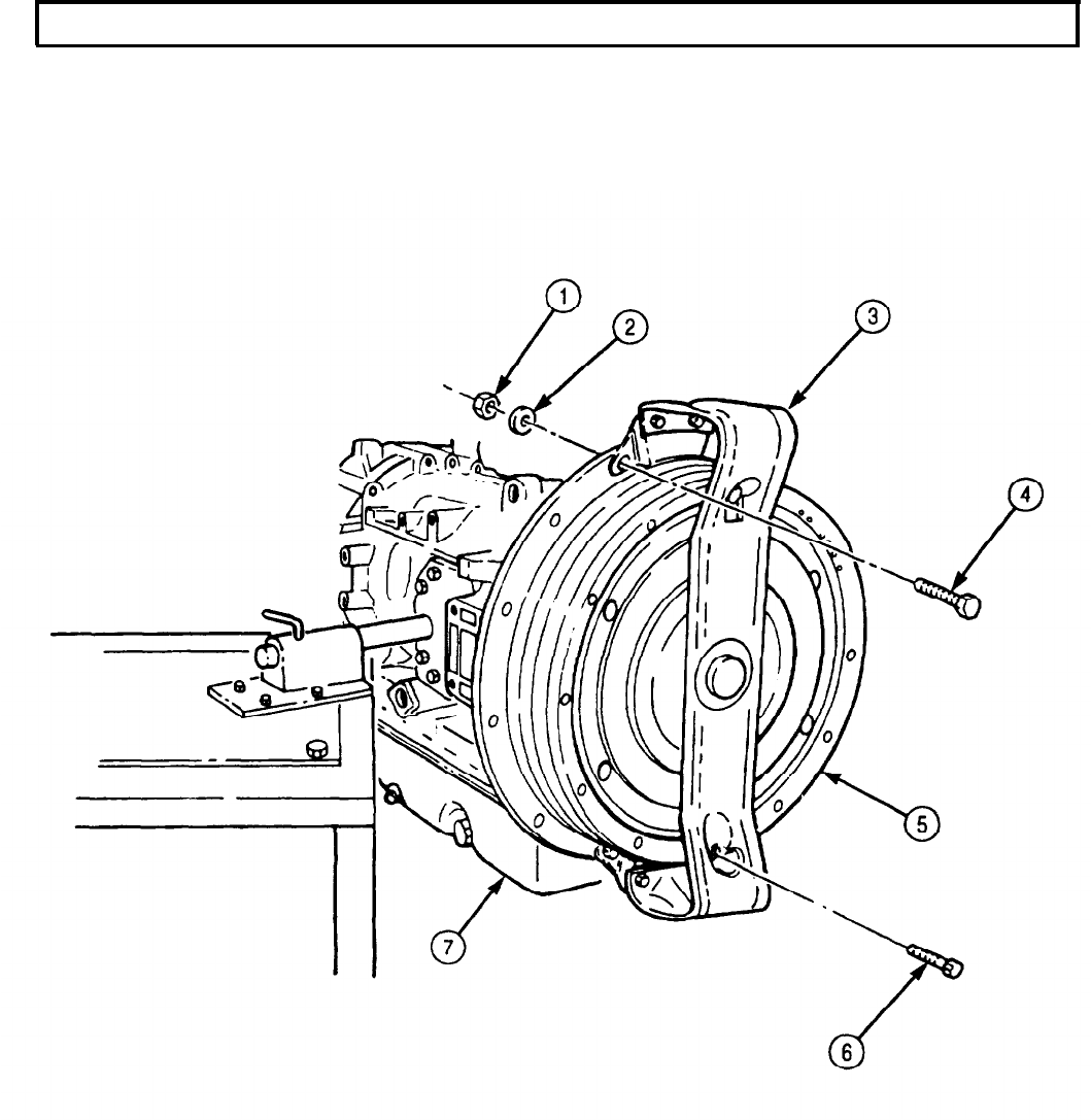
TM 9-2320-272-24-4
5-41. TRANSMISSION TORQUE CONVERTER MAINTENANCE (Contd)
5-287

TM 9-2320-272-24-4
5-41. TRANSMISSION TORQUE CONVERTER MAINTENANCE (Contd)
b. Disassembly
1.
2.
3.
4.
5.
6.
7.
8.
9.
10.
11.
12.
13.
14.
15.
16.
17.
18.
NOTE
Hook-type seal ring used on early models.
Remove hook-type seal ring (12) from torque converter pump hub (11). Discard hook-type
seal ring (12).
NOTE
l Have drainage container ready to catch transmission oil.
l Assistant will help with step 2.
Remove thirty self-locking screws (13) and washers (14) from converter pump (7) and converter
flywheel (1), and drain transmission oil. Discard self-locking screws (13).
Separate converter pump (7) from converter flywheel (1).
Remove seal ring (6) from converter pump (7). Discard seal ring (6).
Remove roller thrust bearing (2) and bearing race (3) from converter flywheel (1) or converter
pump (7).
Bend corners of six lockstraps (5) away from twelve screws (4) and remove twelve screws (4), six
lockstraps (5), and retainer (15) from converter pump (7). Discard lockstraps (5).
Remove torque converter pump hub (11) and gasket (10) from converter pump (7). Discard
gasket (10).
NOTE
l Early model transmission converter pump has a snapring and
roller bearing inside front bore. Late model converter pump hub
has no snapring or roller bearing, but does have a nose with
flats.
l Perform step 8 for early model transmission.
Using bearing puller set, remove snapring (8) and roller bearing (9) from torque converter pump
hub (11).
Remove stator (26) from converter turbine (25).
Turn roller race (31) clockwise and lift off stator (26).
Remove ten rollers (27) and springs (28) from stator (26).
Remove thrust bearing (30) and race (29) from stator (26).
NOTE
Converter turbine must be pulled straight off flywheel, or it will
bind.
Remove converter turbine (25) from converter flywheel (1).
Using bearing puller, remove ball bearing (22) and spacer (23) from turbine hub (24).
Remove lockup clutch plate (19), backplate (20), and two backplate keys (21) from converter
flywheel (1).
NOTE
Scribe mark on converter flywheel and lockup clutch piston for
installation.
Place converter flywheel (1) upright and remove lockup clutch piston (17). If lockup clutch
piston (17) sticks, tap flywheel (1) lightly with soft-faced hammer.
Remove piston seal ring (18) from piston (17). Discard piston seal ring (18).
Remove flywheel seal ring (16) from converter flywheel (1). Discard flywheel seal ring (16).
5-288
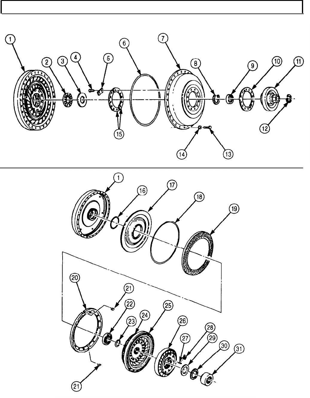
TM 9-2320-272-24-4
5-41. TRANSMISSION TORQUE CONVERTER MAINTENANCE (Contd)
5-289
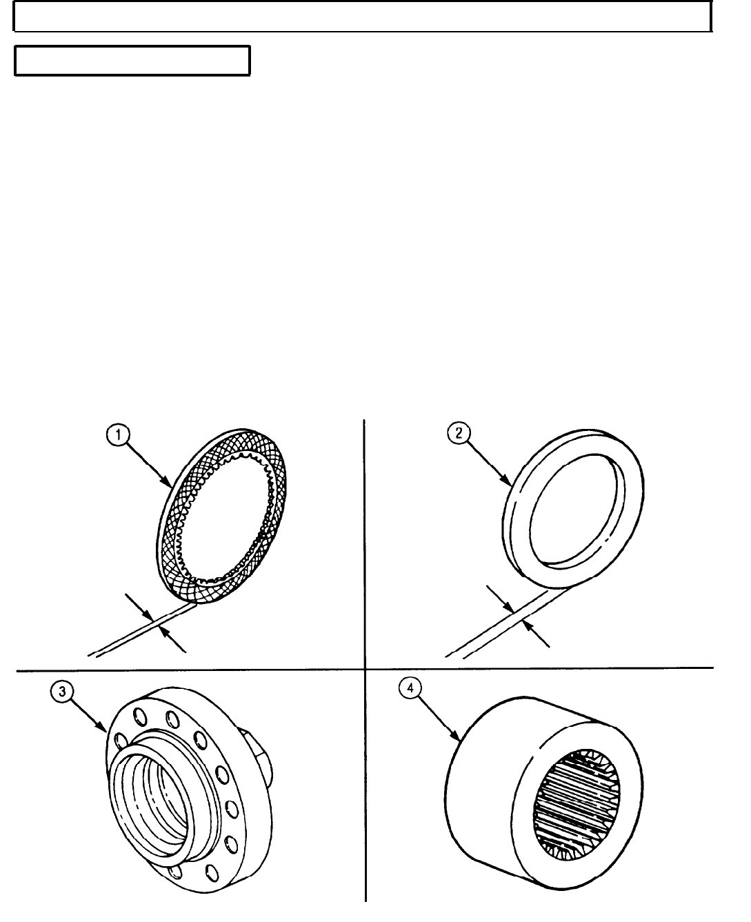
TM 9-2320-272-24-4
5-41. TRANSMISSION TORQUE CONVERTER MAINTENANCE (Contd)
c. Cleaning and Inspection
1.
For general cleaning instructions, refer to para. 2-14.
2.
For general inspection instructions, refer to para. 2-15.
3.
Inspect lockup clutch disc (1) for burned surfaces. If burned, discard lockup clutch disc (1).
4.
Measure thickness of lockup clutch disk (1). If thickness is less than 0.190 in. (4.32 mm), discard
lockup clutch disc (1).
5.
Measure thickness of thrust bearing race (2). If thickness is less than 0.029 in. (0.74 mm), discard
thrust bearing race (2).
6.
Inspect roller race (4) for scoring. If scored, discard roller race (4).
NOTE
Step 7 refers to early model pump hub.
7.
Inspect pump hub (3) for cracks, breaks, burred flats, and scored seal surface and bearing bore. If
damage is more than minor scoring, discard pump hub (3).
NOTE
Step 8 refers to late model pump hub.
8.
Inspect pump hub (3) for cracks, breaks, burred flats, and scored seal surface and bushing journal.
If damage is more than minor scoring, discard pump hub (3).
5-290
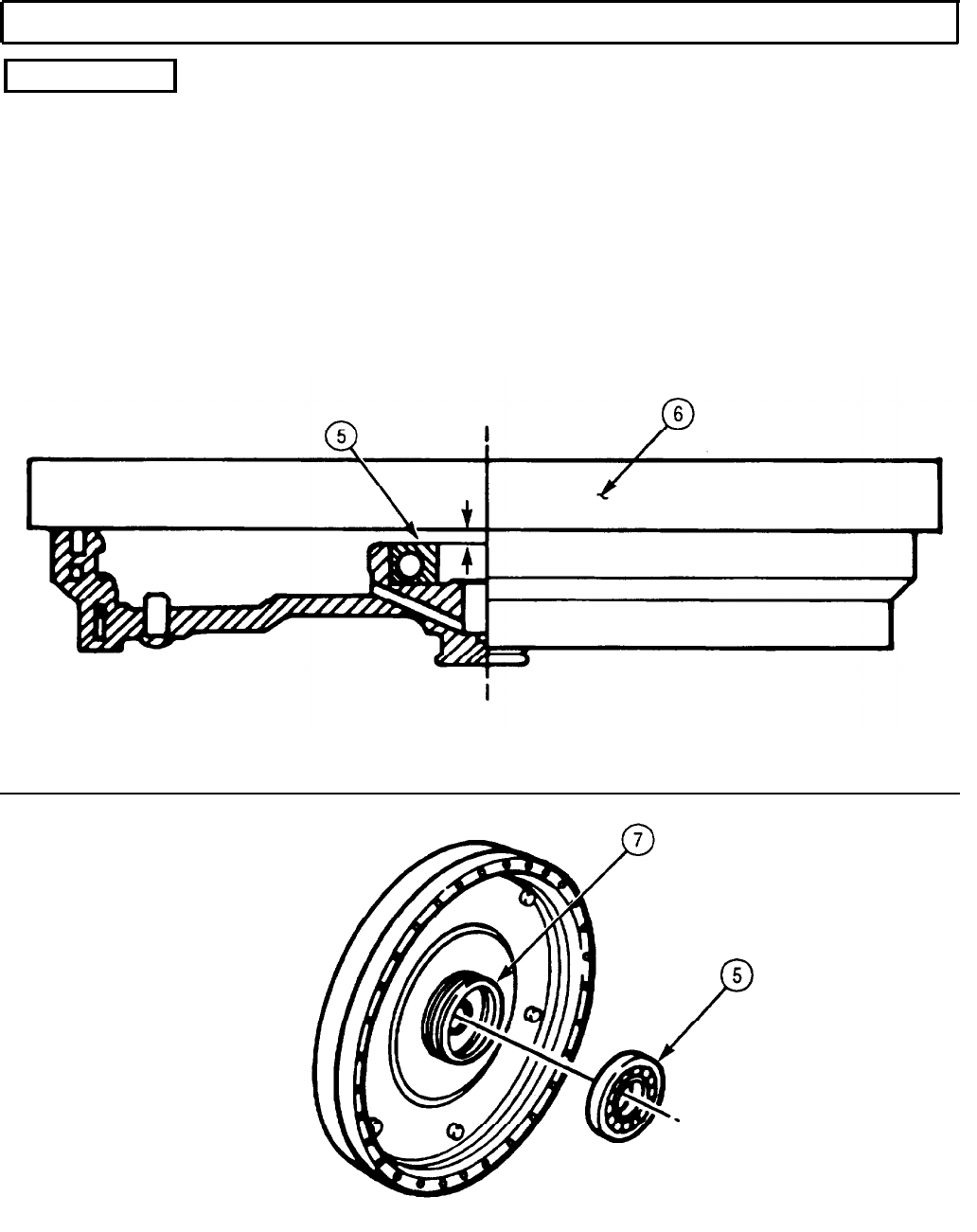
TM 9-2320-272-24-4
5-41. TRANSMISSION TORQUE CONVERTER MAINTENANCE (Contd)
d. Assembly
NOTE
l Steps 2 and 14 obtain measurements to select proper spacer
thickness. These measuring steps are treated as assembly steps.
l Steps 2 and 3 are performed only if new bearing is being
installed.
1.
Install ball bearing (5) in flywheel bore (7). Ensure ball bearing (5) seats against shoulder of
flywheel bore (7).
2.
Place straightedge (6) across flywheel bore (7) and measure the distance from inner race of ball
bearing (5) to straightedge (6). Record this measurement for use in step 14d.
5-291

TM 9-2320-272-24-4
5-41. TRANSMISSION TORQUE CONVERTER MAINTENANCE (Contd)
3.
4.
5.
6.
7.
8.
9.
Remove ball bearing (8) from flywheel (1).
Apply lubricating oil to new flywheel seal ring (2) and install on flywheel (1).
Apply lubricating oil to new piston seal ring (4) and install on lockup clutch piston (3).
Align previously scribed marks on lockup clutch piston (3) and install, cupped side first, on
flywheel (1).
Soak lockup clutch plate (5) in clean lubricating oil for at least two minutes. Install lockup clutch
plate (5) on clutch piston (3).
Position two backplate keys (7) in flywheel (1) recesses.
NOTE
Backplate and backplate keys must be level for the next step.
Install lockup clutch backplate (6).
a. Position lockup clutch backplate (6) in flywheel (1), engaging notch in lockup clutch backplate (6)
with two backplate keys (7).
CAUTION
If backplate is not approximately level with the key, the lockup
clutch piston is not properly engaged with the drive pins in the
flywheel. Rotate the piston until it drops into place on the pins.
Damage to backplate will result if piston is not engaged properly.
NOTE
Perform step b only if backplate is not level with the keys.
b. Rotate piston (3) until pin holes and flywheel (1) pins are aligned.
5-292
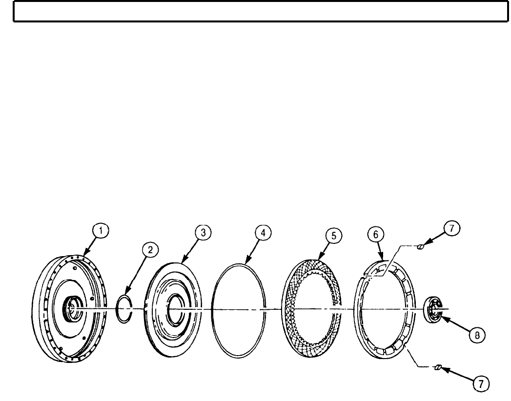
TM 9-2320-272-24-4
5-41. TRANSMISSION TORQUE CONVERTER MAINTENANCE (Contd)
5-293
TM 9-2320-272-24-4
5-41. TRANSMISSION TORQUE CONVERTER MAINTENANCE (Contd)
10.
11.
12.
13.
14.
15.
NOTE
Late model transmission does not have roller bearing or snap-
ring in front bore of torque converter pump hub.
Perform step 10 if bearing is to be installed in early model
transmission.
Using an arbor press and bearing remover/installer, press roller bearing (16) in torque converter
pump hub (18) and install with snapring (15).
CAUTION
Identify transmission model. Late model converter pump hub has
longer nose and has 1 in. (25.4 mm) long flats that fit into oil
pump (para. 5-39). Do not intermix parts from early and late
model transmissions. Damage to transmission will result.
Install new gasket (17) and torque converter pump hub (18) on converter pump (14) with
retainer (13), six new lockstraps (12), and twelve screws (11). Tighten screws (11) 33-40 lb-ft
(45-54 N•m). Bend comers of lockstraps (12) against head of each screw (11).
Install bearing race (10) and roller thrust bearing (9) in converter pump (14).
Install bearing race (25), thrust bearing (26), and freewheel roller race (27) in stator (24) and place
stator (24) and converter turbine (21) in converter pump (14). Center stator (24) and converter
turbine (21) carefully.
NOTE
Step 14 is performed only if new bearing was installed in step 1.
Select spacer (23) size:
a. Place gauge blocks (22) of equal height on edge of converter pump (14) as shown
b. Place straightedge (19) across gauge blocks (22) and measure distance from straightedge (19) to
shoulder (20) adjacent to hub of turbine (21). Record this measurement.
c. Subtract measurement obtained in step 14b. from gauge block height. Record this measurement.
d. Subtract measurement obtained in step 14c. from measurement obtained in step 2. Using this
measurement, refer to table 5-11 to select correct size spacer (23).
Table 5-11. Torque Converter Spacer Sizes.
Measurements Spacer
0.018-0.032 in. (0.457-0.813 mm)
Gold
0.032-0.044 in. (0.813-1.117 mm) Silver
0.044-0.062 in. (1.117-1.575 mm) Plain
0.062-0.077 in. (1.575-1.956 mm) Black
0.077-0.096 in. (1.956-2.438 mm) Copper
Remove converter turbine (21) from converter pump (14).
5-294
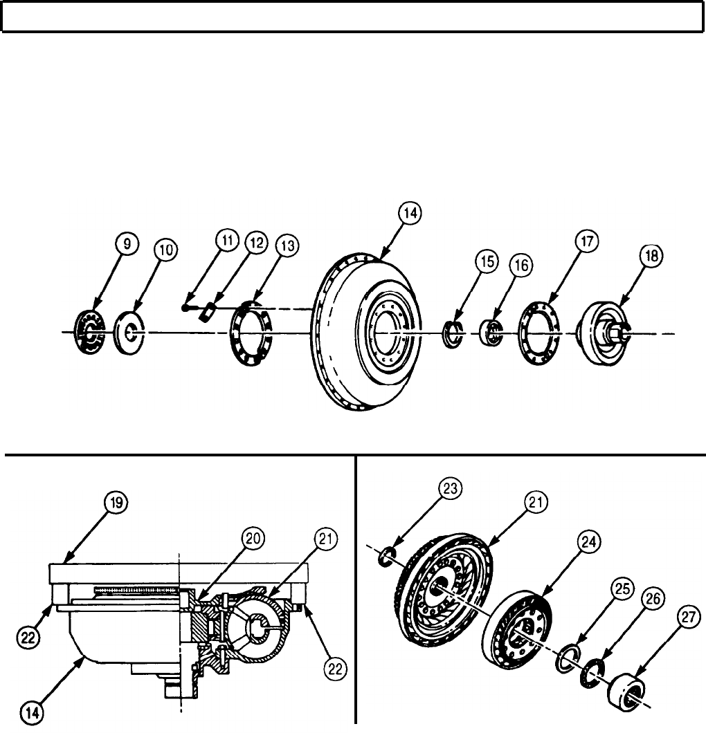
TM 9-2320-272-24-4
5-41. TRANSMISSION TORQUE CONVERTER MAINTENANCE (Contd)
5-295

TM 9-2320-272-24-4
5-41. TRANSMISSION TORQUE CONVERTER MAINTENANCE (Contd)
16.
17.
18.
19.
20.
21.
22.
23.
24.
25.
26.
27.
28.
Install spacer (3) on converter turbine hub (4).
Install ball bearing (2) on converter turbine hub (4) until seated against spacer (3).
Install converter turbine (5) in flywheel (1).
Remove stator (6) from converter pump (12).
Remove freewheel roller race (10) and thrust bearing (9) from stator (6).
NOTE
One of three different types of roller springs will be present in
early stators as shown. Either the later or latest type should
be used, but all springs must be of the same type.
The latest type roller springs are installed in a different
manner. The old tab may be either up or down.
Oil-soluble grease will hold springs and rollers in place.
Pack stator cam pockets (17) with oil-soluble grease and install springs (8) and rollers (7) in stator
cam pockets (17).
Apply a small amount of oil-soluble grease to thrust bearing (9) and position thrust bearing (9) to
freewheel roller race (10).
Position freewheel roller race (10) and thrust bearing (9) in stator (6) and turn clockwise until
seated in stator (6).
Position stator (6) on converter turbine (5).
Apply lubricating oil to new seal ring (11) and install on converter pump (12).
Install converter pump (12) on flywheel (1) with thirty new self-locking washers (16) and new self-
locking screws (15). Tighten screws (15) 41-49 lb-ft (56-66 N•m).
NOTE
Hook-type seal ring used on early models.
Install new hook-type seal ring (13) on torque converter pump hub (14).
Install converter retaining strap (19) on torque converter (18) with two screws (20).
5-296
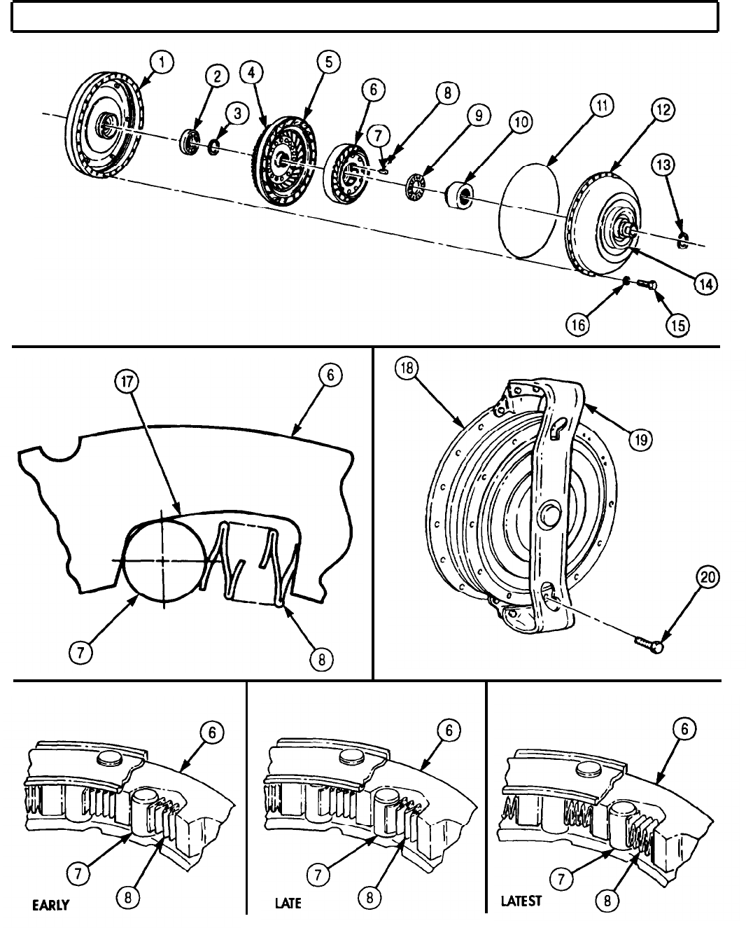
TM 9-2320-272-24-4
5-41. TRANSMISSION TORQUE CONVERTER MAINTENANCE (Contd)
5-297

TM 9-2320-272-24-4
5-41. TRANSMISSION TORQUE CONVERTER MAINTENANCE (Contd)
1.
Tilt transmission (7) to horizontal position, with oil pan (6) facing downward.
CAUTION
Torque converter must be installed straight on transmission and
not moved from side to side. Side movement will damage hook-
type seal ring on turbine shaft.
NOTE
Assistant will help with step 2.
2.
Install torque converter (5) in transmission (7). Ensure seal ring is properly positioned. Torque
converter (5) may be rotated until flat sides of pump hub engage flats in oil pump drive gear.
3.
Install converter retaining strap (3) on transmission (7) with four screws (4), washers (2), and nuts (1).
5-298
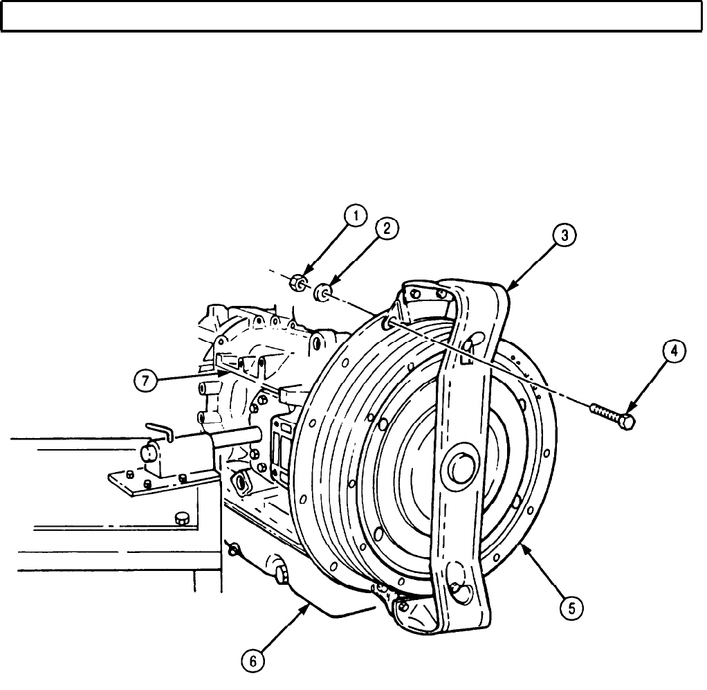
TM 9-2320-272-24-4
5-42. TRANSMISSION OIL PAN AND FILTER MAINTENANCE
THIS TASK COVERS:
a. Removal c. Installation
b. Cleaning and Inspection
INITIAL SETUP:
APPLICABLE MODELS REFERENCES (TM)
All
TM 9-2320-272-24P
TOOLS
General mechanic’s tool kit (Appendix E, Item 1)
Torque wrench (Appendix E, Item 146)
MATERIALS/PARTS
O-ring (Appendix D, Item 429)
Transmission oil filter (Appendix D, Item 699)
Gasket (Appendix D, Item 159)
EQUIPMENT CONDITION
Transmission torque converter removed (para. 5-41).
SPECIAL ENVIRONMENTAL CONDITIONS
Work area clean and free from blowing dirt and
dust.
1.
Remove twenty-one screws (l), oil pan (2), and gasket (3) from transmission (4). Discard
gasket (3).
2.
Rotate transmission (4) in stand until oil pan (2) mounting surface is horizontal and facing upward.
3.
Remove oil filter screw (6), oil filter (7), and filter suction tube (8) from transmission (4).
4.
Remove filter suction tube (8) from oil filter (7). Discard oil filter (7).
5.
Remove O-ring (9) from filter suction tube (8). Discard O-ring (9).
1.
For general cleaning instructions, refer to para. 2-14.
2.
For general inspection instructions, refer to para. 2-15.
3.
Inspect oil pan (2) for cracks. If cracked, replace oil pan (2).
NOTE
New oil pan has a plug in left side fill port.
If oil pan is defective, remove plug if present.
4.
Remove oil plug (5). Retain for installation in new oil pan (2).
5-300
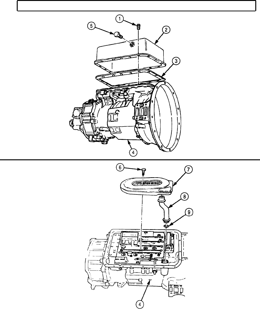
TM 9-2320-272-24-4
5-42. TRANSMISSION OIL PAN AND FILTER MAINTENANCE (Contd)
5-301
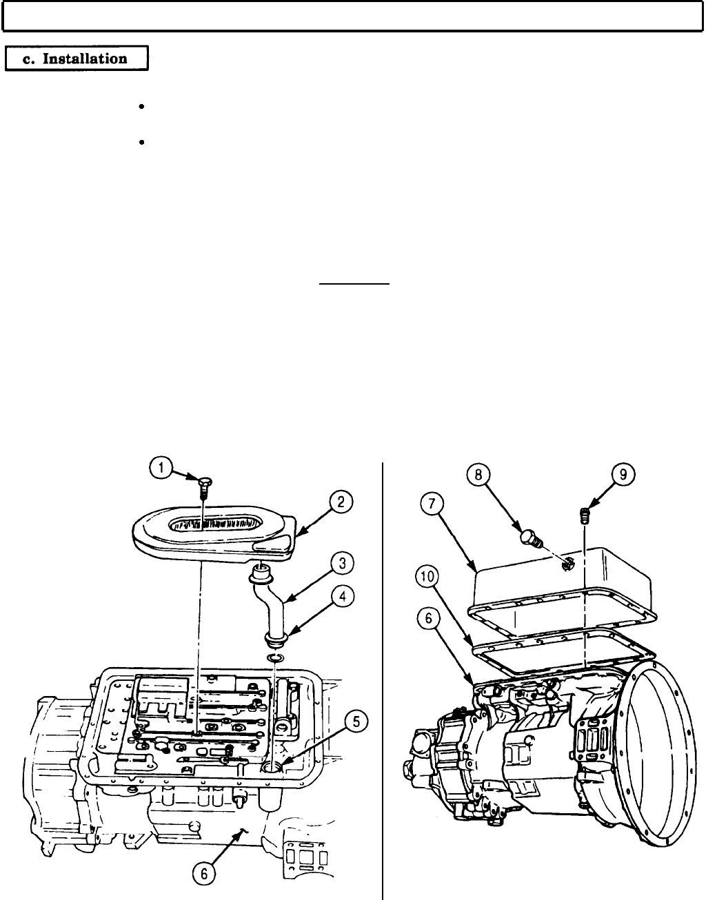
TM 9-2320-272-24-4
5-42. TRANSMISSION OIL PAN AND FILTER MAINTENANCE (Contd)
1.
2.
3.
4.
5.
6.
7.
NOTE
Keep oil pan mounting surface in horizontal position and facing
upward.
Filter suction tube ends are interchangeable.
Insert one end of filter suction tube (3) into new transmission oil filter assembly (2).
Install new O-ring (4) onto opposite end of filter suction tube (3).
Position new transmission oil filter assembly (2) on transmission (6). Ensure filter suction
tube (3) is inserted into oil input port (5).
Install new transmission oil filter assembly (2) on transmission (6) with screw (1). Tighten
screw (1) 10-15 lb-ft (14-20 N•m).
CAUTION
Do not use silicone-type gasket sealing compound when installing
gasket, because oil leakage may result. Oil or light grease coating
may be used to hold gasket in position during installation.
Position new oil pan gasket (10) against housing of transmission (6) and align with holes of
transmission (6).
Position transmission oil pan (7) against oil pan gasket (10) and install with twenty-one screws (9).
Tighten screws (9) finger-tight.
Tighten twenty-one screws (9) 10-15 lb-ft (14-20 N•m) following torque sequence shown.
5-302
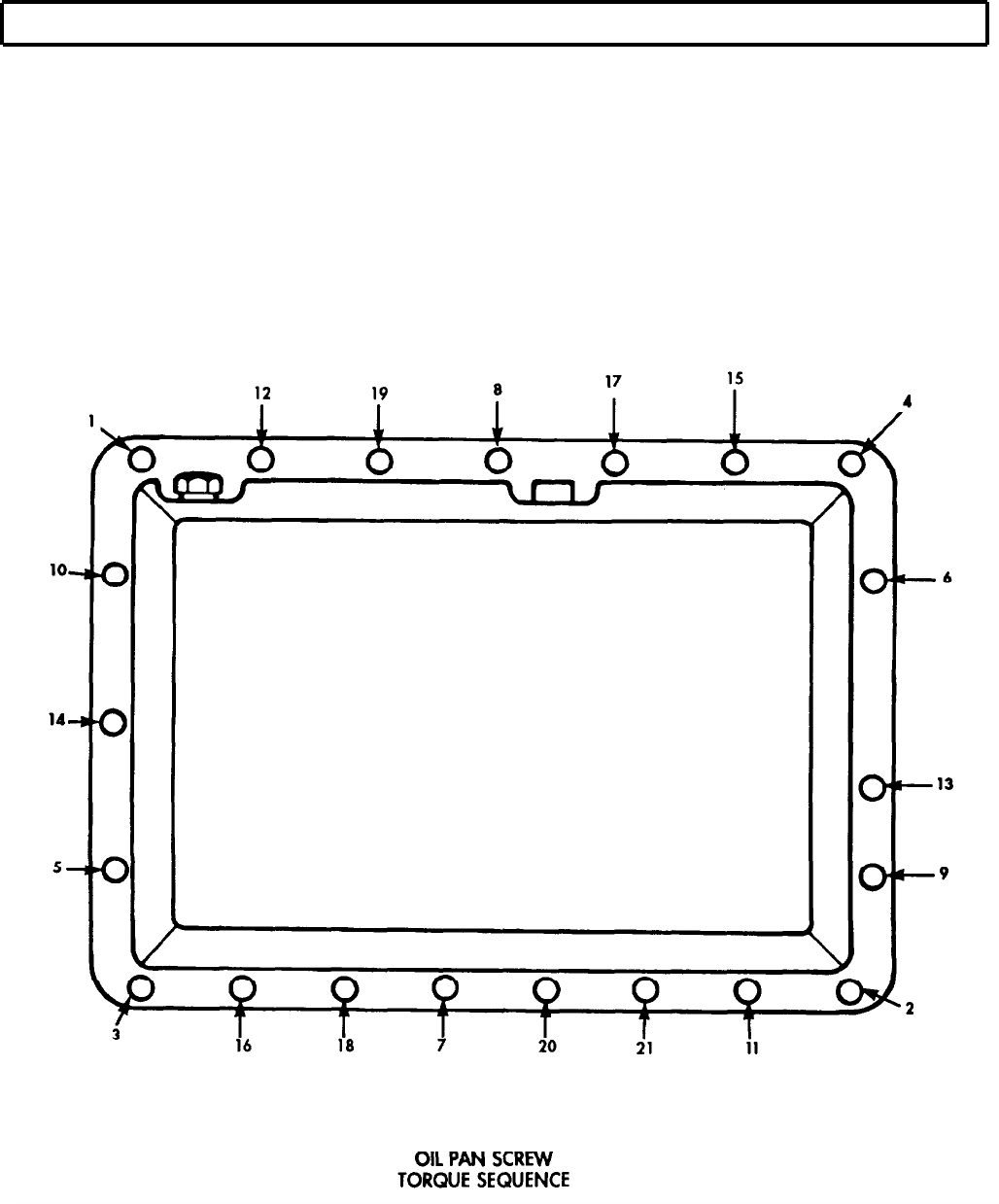
TM 9-2320-272-24-4
5-42. TRANSMISSION OIL PAN AND FILTER MAINTENANCE (Contd)
NOTE
Due to gasket compression, torque values will be lost and screws
must be retightened.
8.
Tighten twenty-one screws (9) 15-20 lb-ft (20-27 N•m) following torque sequence shown to achieve
final torque.
NOTE
Perform step 9 only if new oil pan was installed.
9.
Install plug (8) in oil pan (7). Ensure plug (8) is installed opposite hole for dipstick.
FOLLOW-ON TASK: Install transmission torque converter (para. 5-41).
5-303
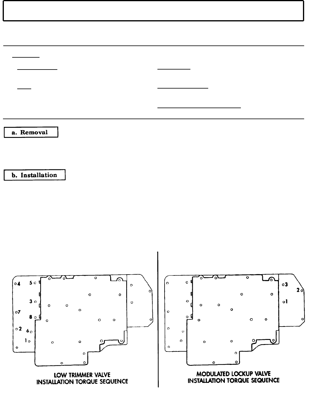
TM 9-2320-272-24-4
5-43. MODULATE LOCKUP VALVE, LOW TRIMMER VALVE, AND LOW SHIFT VALVE
REPLACEMENT
THIS TASK COVERS:
a. Removal b. Installation
INITIAL SETUP:
APPLICABLE MODELS
All
REFERENCES (TM)
TM 9-2320-272-24P
TOOLS EQUIPMENT CONDITION
General mechanic’s tool kit (Appendix E, Item 1) Transmission oil pan and filter removed (para. 5-42).
Torque wrench (Appendix E, Item 146)
SPECIAL ENVIRONMENTAL CONDITIONS
Work area clean and free from blowing dirt and dust.
1.
Remove three screws (5) and modulated lockup valve (6) from oil transfer plate (4).
2.
Remove six screws (1) and low trimmer valve (2) from low shift valve (3).
3.
Remove two screws (7) and low shift valve (3) from oil transfer plate (4).
NOTE
Keep oil pan mounting surface in horizontal position and facing
upward.
1.
Install low shift valve (3) on oil transfer plate (4) with two screws (7). Finger-tighten screws (7).
2.
Install low trimmer valve (2) on low shift valve (3) with six screws (1). Tighten screws (1) and (7)
9-11 lb-ft (12-15 N•m) in sequence shown.
3.
Install modulated lockup valve (6) on oil transfer plate (4) with three screws (5). Tighten screws (5)
9-11 lb-ft (12-15 N•m) in sequence shown.
5-304
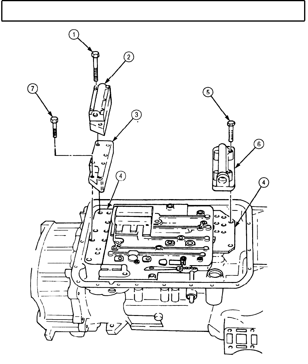
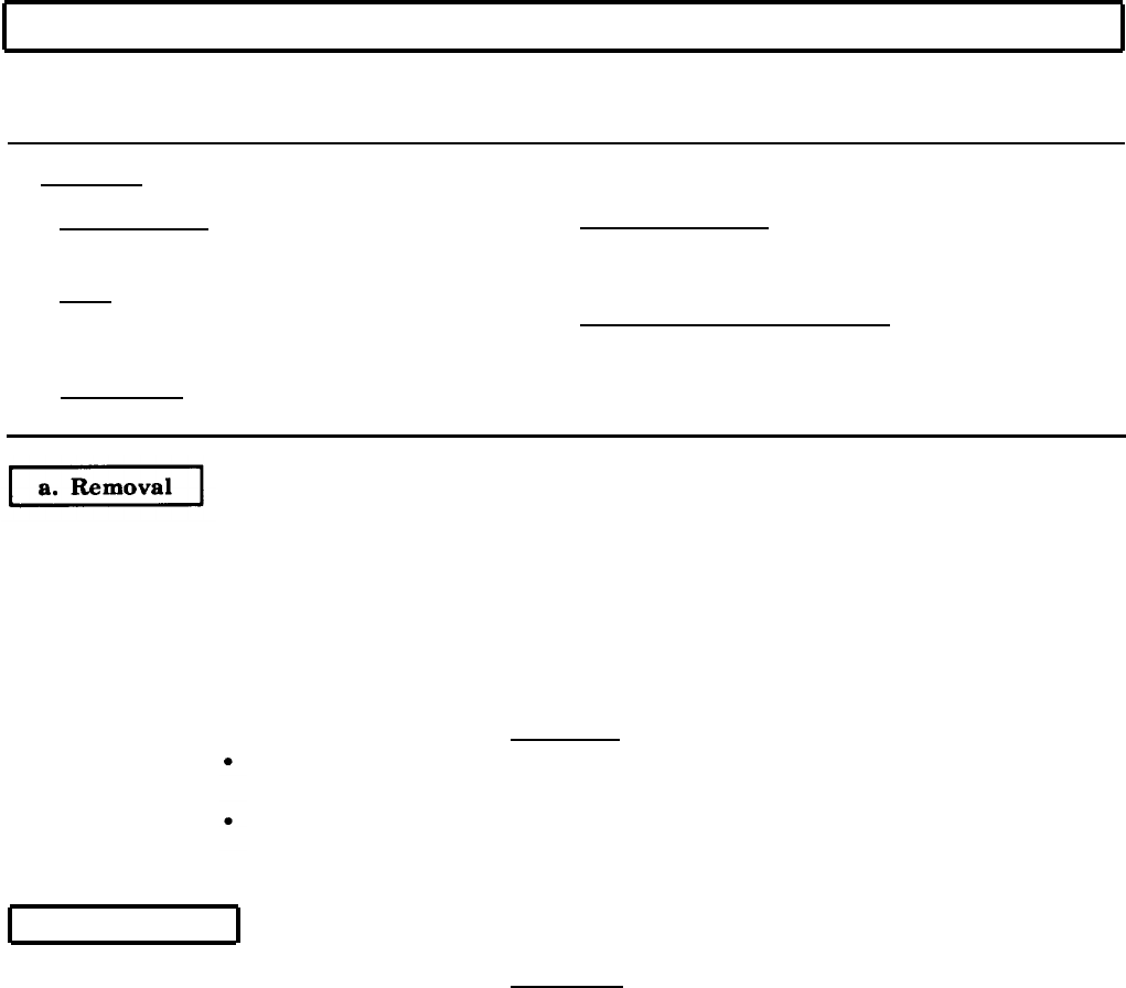
TM 9-2320-272-24-4
5-44. TRANSMISSION CONTROL VALVE REPLACEMENT
THIS TASK COVERS:
a. Removal b. Installation
INITIAL SETUP:
APPLICABLE MODELS
EQUIPMENT CONDITION
All
Low shift valve, low trimmer valve, and modulate
TOOLS
lockup valve removed (para. 5-43).
General mechanic’s tool kit (Appendix E, Item 1)
SPECIAL ENVIRONMENTAL CONDITIONS
Torque wrench (Appendix E, Item 146) Work area clean and free from blowing dirt and
REFERENCES (TM)
TM 9-2320-272-24P
dust.
NOTE
Separate and tag screws for installation.
1.
Remove screw (4) and detent spring and roller (5) from control valve (2).
2.
Remove three screws (3) from control valve (2).
3.
Remove screw (1) from control valve (2).
4.
Remove fifteen screws (6) from control valve (2).
CAUTION
Do not tilt control valve to allow selector valve to drop out.
Selector valve may be damaged.
Remove items as an assembly and do not separate. Loose parts
inside will fall free, resulting in damage to control valve.
5.
Remove control valve (2), separator plate (7), and oil transfer plate (8) from transmission (11).
b. Installation
CAUTION
Do not tilt control valve to allow selector valve to drop out.
Damage to selector valve may result.
1.
Position oil transfer plate (8), separator plate (7), and control valve (2) on transmission (11) so pin
on detent lever (10) aligns with slot on selector valve (9).
2.
Install control valve (2) on transmission (11) with fifteen screws (6). Finger-tighten screws (6).
3.
Install control valve (2) with three screws (3). Finger-tighten screws (3).
4.
Install control valve (2) with screw (1). Finger-tighten screw (1).
5.
Position detent spring and roller (5) on control valve (2) with roller in notch of detent lever (10), and
install with screw (4).
6.
Tighten twenty screws (1), (3), (4), and (6) 9-11 lb-ft (12-15 N•m) in sequence shown.
5-306
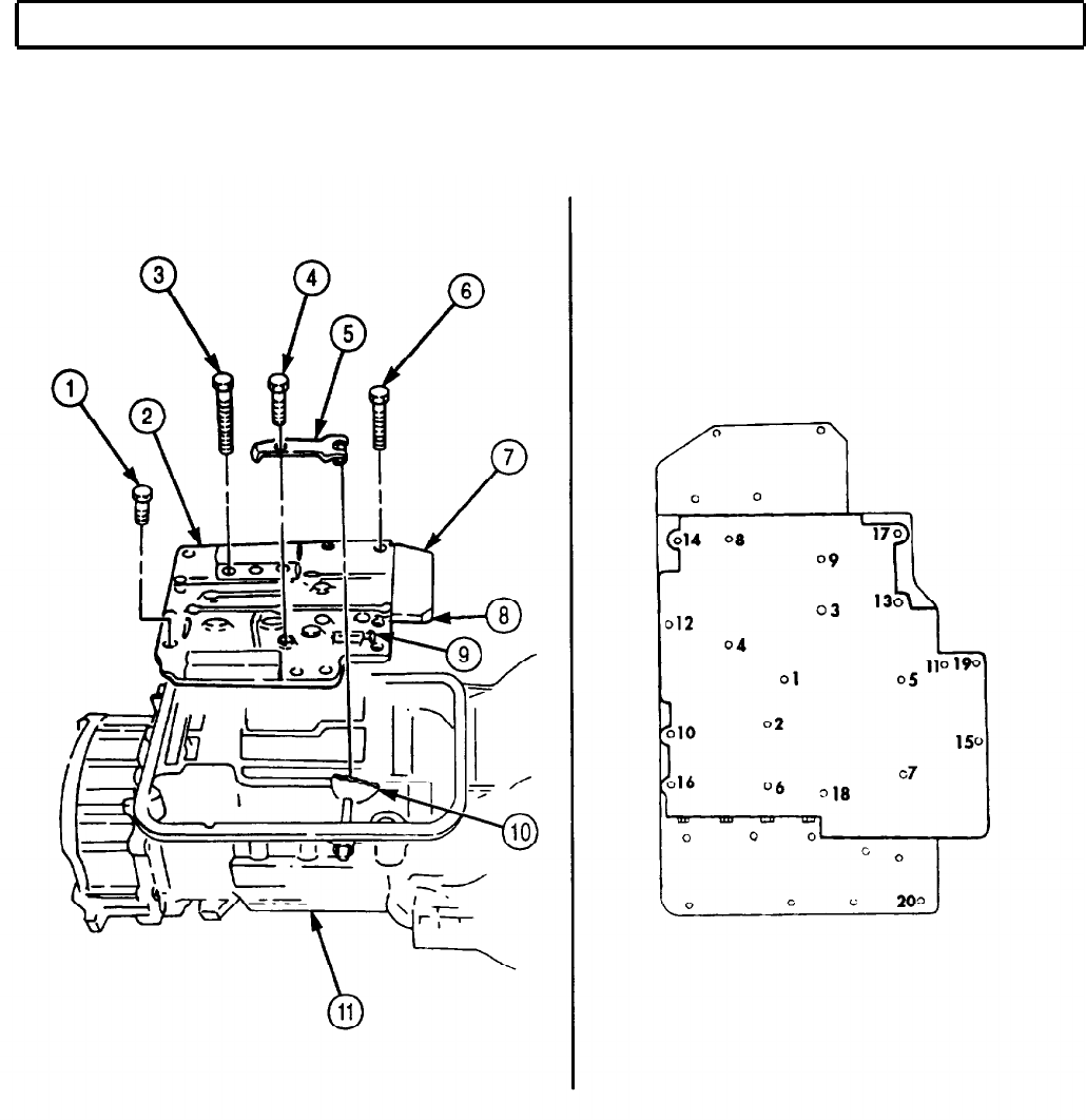

TM 9-2320-272-24-4
5-45. TRANSMISSION MANUAL SELECTOR SHAFT REPLACEMENT
THIS TASK COVERS:
a. Removal b. Installation
INITIAL SETUP:
APPLICABLE MODELS
All
TOOLS
EQUIPMENT CONDITION
Transmission selector shaft oil seal removed
(para. 4-76).
Transmission control valve removed (para. 5-44).
General mechanic’s tool kit (Appendix E, Item 1)
Torque wrench (Appendix E, Item 146)
SPECIAL ENVIRONMENTAL CONDITIONS
REFERENCES (TM)
Work area clean and free from blowing dirt and
dust.
TM 9-2320-272-24P
1.
Remove shaft retainer pin (3) from transmission housing (4).
2.
Remove nut (2) and detent lever (1) from transmission manual selector shaft (5).
3.
Remove transmission manual selector shaft (5) from transmission housing (4).
1.
Tilt transmission housing (4) to horizontal position with the bottom facing upward.
2.
Install manual selector shaft (5) and detent lever (1) on transmission housing (4) with nut (2).
Tighten nut 15-20 lb-ft (20-27 N•m).
3.
Secure manual selector shaft (5) in transmission housing (4) with shaft retainer pin (3).
5-308
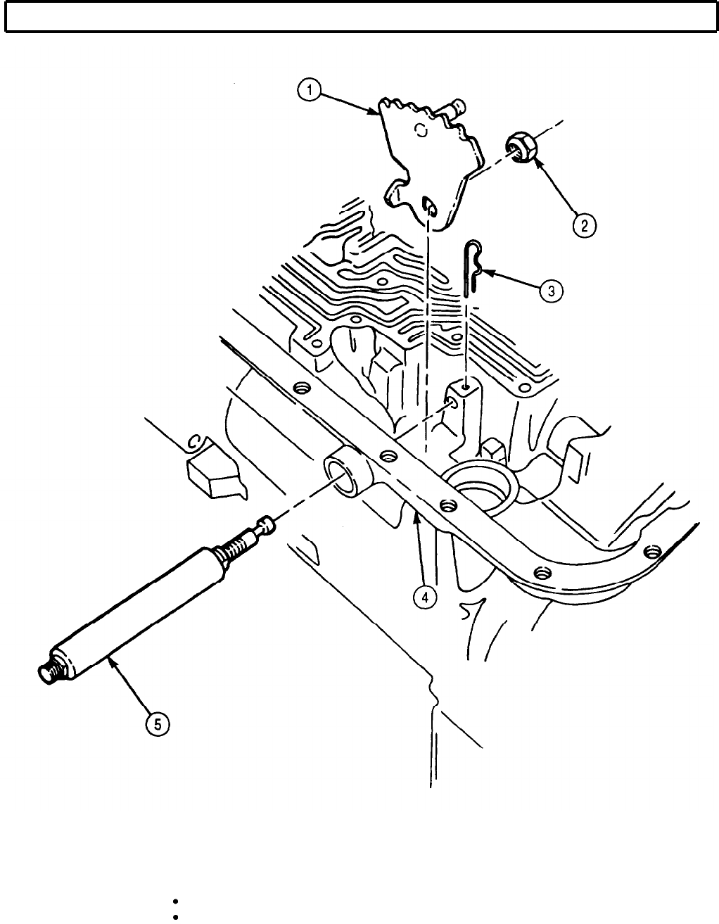

TM 9-2320-272-24-4
5-46. TRANSMISSION OIL PUMP AND FRONT SUPPORT MAINTENANCE
THIS TASK COVERS:
a. Removal d. Assembly
b. Disassembly e. Installation
c. Cleaning and Inspection
INITIAL SETUP:
APPLICABLE MODELS
All
SPECIAL TOOLS
Two guide pins (Appendix E, Item 60)
Front support lifter (Appendix E, Item 48)
Bearing installer (Appendix E, Item 11)
Driver handle (Appendix E, Item 38)
Valve pin remover (Appendix E, Item 155)
Slide hammer (Appendix E, Item 122)
Main regulator and lockup spring compressor
(Appendix E, Item 129)
Adapters (Appendix E, Item 2)
Centering band (Appendix E, Item 90)
Bushing replacer (Appendix E, Item 25)
TOOLS
General mechanic’s tool kit (Appendix E, Item 1)
Depth micrometer (Appendix E, Item 81)
Torque wrench (Appendix E, Item 146)
Arbor press
MATERIALS/PARTS
Oil seal (Appendix D, Item 502)
Two self-locking screws (Appendix D, Item 649)
Twelve self-locking screws (Appendix D, Item 650)
Two hook-type seal rings (Appendix D, Item 638)
Twelve washers (Appendix D, Item 713)
Oil pump seal ring (Appendix D, Item 226)
Oil pump gasket (Appendix D, Item 227)
Valve guide pin (Appendix D, Item 705)
Lubricating oil (Appendix C, Item 47)
Oil-soluble grease (Appendix C, Item 53)
Sealing compound (Appendix C, Item 62)
REFERENCES (TM)
TM 9-2320-272-24P
EQUIPMENT CONDITION
Transmission manual selector shaft removed
(para. 5-45).
SPECIAL ENVIRONMENTAL CONDITIONS
Work area clean and free from blowing dirt and dust.
GENERAL SAFETY INSTRUCTIONS
Use care when removing snaprings and retaining
rings.
1.
Position transmission (5) front upward.
2.
Remove twelve screws (2) and washers (1) connecting oil pump and front support (4) to
transmission (5). Discard washers (1).
3.
Attach front support lifter to converter ground sleeve (3) on oil pump and front support (4).
NOTE
Assistant will help with step 4.
4.
Remove oil pump and front support (4) from transmission (5) by lifting straight up. Assistant may
tap surface with a rubber hammer to ease removal.
5.
Remove oil pump gasket (6). Discard oil pump gasket (6).
5-310
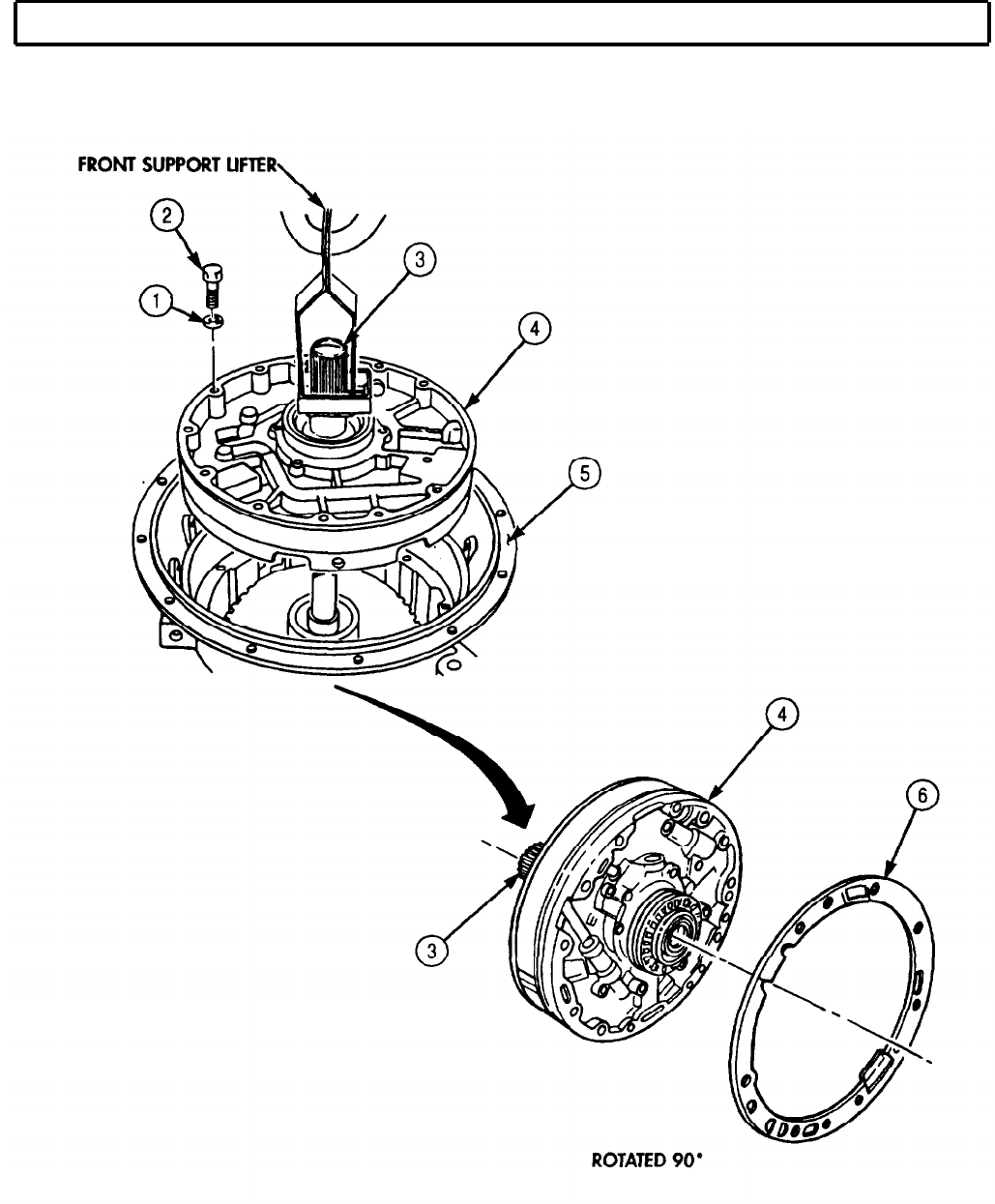
TM 9-2320-272-24-4
5-46. TRANSMISSION OIL PUMP AND FRONT SUPPORT MAINTENANCE (Contd)
5-311

1.
2.
3.
4.
5.
6.
7.
8.
9.
10.
11.
12.
13.
Remove two hook-type seal rings (8) from oil pump (19) and front support (5). Discard seal rings (8).
Remove bearing and race (7) from oil pump (19) and front support (5) or transmission.
Remove oil pump seal ring (1) from oil pump (19) and front support (5). Discard oil pump seal ring (1).
If replacement is necessary, remove needle bearing (6) from front support hub ground sleeve (9).
Install valve pin remover tool on slide hammer on oil pump (19) and front support (5).
Attach valve pin remover tool between coils of valve spring (3) and valve guide pin (2).
NOTE
Assistant will help with step 7.
Remove valve guide pin (2), valve spring (3), and converter pressure regulator valve (4). Discard
valve guide pin (2). Tag valve spring (3) for installation.
WARNING
Regulator valve spring is under approximately 65 lb (29 kg)
compression. Do not remove retaining snapring until compressor
is in place, or regulator valve spring may fly out causing injury.
NOTE
For transmissions with serial numbers 21628 and higher, use two
adapters with spring compressor.
Attach main regulator and lockup spring compressor to front support (5) and tighten two
screws (23) to relieve spring compression.
NOTE
Perform steps 9 and 10 for transmissions with serial numbers
21628 and higher.
Remove twelve self-locking screws (25) and two self-locking screws (24) and separate oil pump (19)
from front support (5). Mark location for installation. Discard self-locking screws (24) and (25).
Remove two cross pins (26) from front support (5).
NOTE
Perform step 11 for transmissions with serial numbers prior to
21628.
Remove snaprings (10) and (11) from oil pump (19) and front support (5).
Carefully remove and detach main regulator lockup spring compressor, valve stops (12) and (17),
valve springs (13) and (16), regulator valve (15), and lockup valve (14) from front support (5). Mark
locations for installation. Tag valve springs (13) and (16) for installation.
NOTE
Perform step 13 for transmissions with serial numbers prior to
21628.
Remove twelve self-locking screws (25) and two self-locking screws (24) connecting oil pump (19) to
front support (5). Separate oil pump (19) from front support (5). Mark location for installation and
discard self-locking screws (25) and (24).
5-46. TRANSMISSION OIL PUMP AND FRONT SUPPORT MAINTENANCE (Contd)
5-312
TM 9-2350-272-24-4
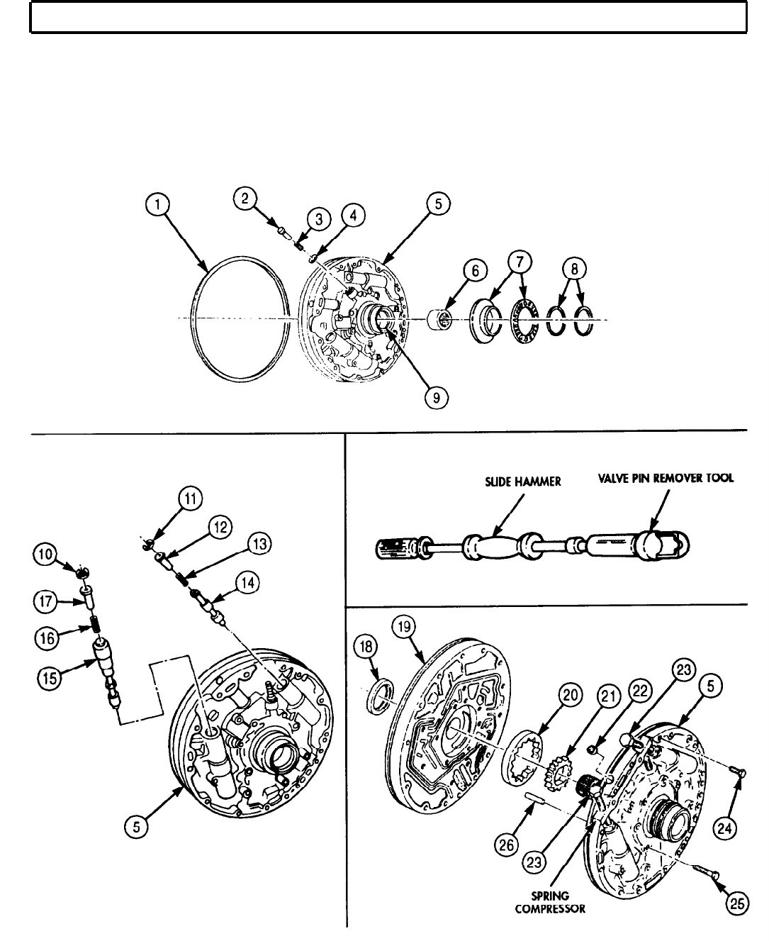
TM 9-2320-272-24-4
5-46. TRANSMISSION OIL PUMP AND FRONT SUPPORT MAINTENANCE (Contd)
NOTE
Do not perform steps 14 and 15 unless relative movement is
apparent between ground sleeve and front support.
14.
If plug (22) is loose or damaged, remove plug (22) from front support (5).
15.
Remove oil pump gears (20) and (21) and oil pump body oil seal (18) from oil pump (19).
Discard body oil seal (18).
5-313

TM 9-2320-272-24-4
5-46. TRANSMISSION OIL PUMP AND FRONT SUPPORT MAINTENANCE (Contd)
1.
2.
3.
4.
5.
6.
7.
8.
9.
10.
11.
12.
CAUTION
Early model and late model converter pump hub, Front support seals,
and oil pump are not interchangeable. Do not intermix parts from
early and late transmissions. Damage to transmission will result.
For general cleaning instructions, refer to para. 2-14.
For general inspection instructions, refer to para. 2-15.
Inspect oil pump gears (3) and (4) for broken teeth. Discard gears if broken.
Install oil pump gears (3) and (4) in pump body (2).
Place straightedge (1) across face of oil pump (2).
Measure clearance between straightedge (1) and gear (4). If clearance is more than 0.0020 in.
(0.051 mm), replace with thicker gear (4). Repeat steps 4 through 6.
NOTE
Perform step 7 for late model transmissions only. Early model
transmissions do not have bushing.
Measure inside diameter of bushing (5) on oil pump (2) at 5 o’clock position when viewed from the
front. Maximum wear limit is 2.257 in. (57.33 mm). Brass backing showing through is acceptable if
wear limit is not exceeded.
Inspect bushing (5) on oil pump (2) for scoring. Replace bushing (5) if scoring can be felt. Use
installer/remover tool and arbor press.
Inspect bushing (5) on oil pump (2) for discoloration due to overheating. Replace if discolored.
Inspect all springs for discoloration due to overheating. Discard if discolored.
Inspect all springs for broken coils or coils distorted due to wear. Discard if broken or distorted.
Using spring tester, inspect for serviceability by checking load when spring is compressed to the
correct length. Discard spring if spring does not give the correct load (table 5-12).
SPRING
Main pressure
regulator valve spring
Converter pressure
regulator valve spring
COLOR
Green
Blue
Table 5-12. Spring Data.
FREE LENGTH
COMPRESSED LENGTH
3.57 in. 2.01 in.
(90.7 mm) (51.0 mm)
1.24 in.
1.05 in.
(31.5 mm) (26.7 mm)
UNDER LOAD
70.6-76.6 lb
(314-341 N)
33.1-40.5 lb
(147-180 N)
Lockup valve spring
Yellow
2.84 in. 1.46 in. 26.1-28.9 lb
(72.1 mm) (37.1 mm)
(116-129 N)
5-314
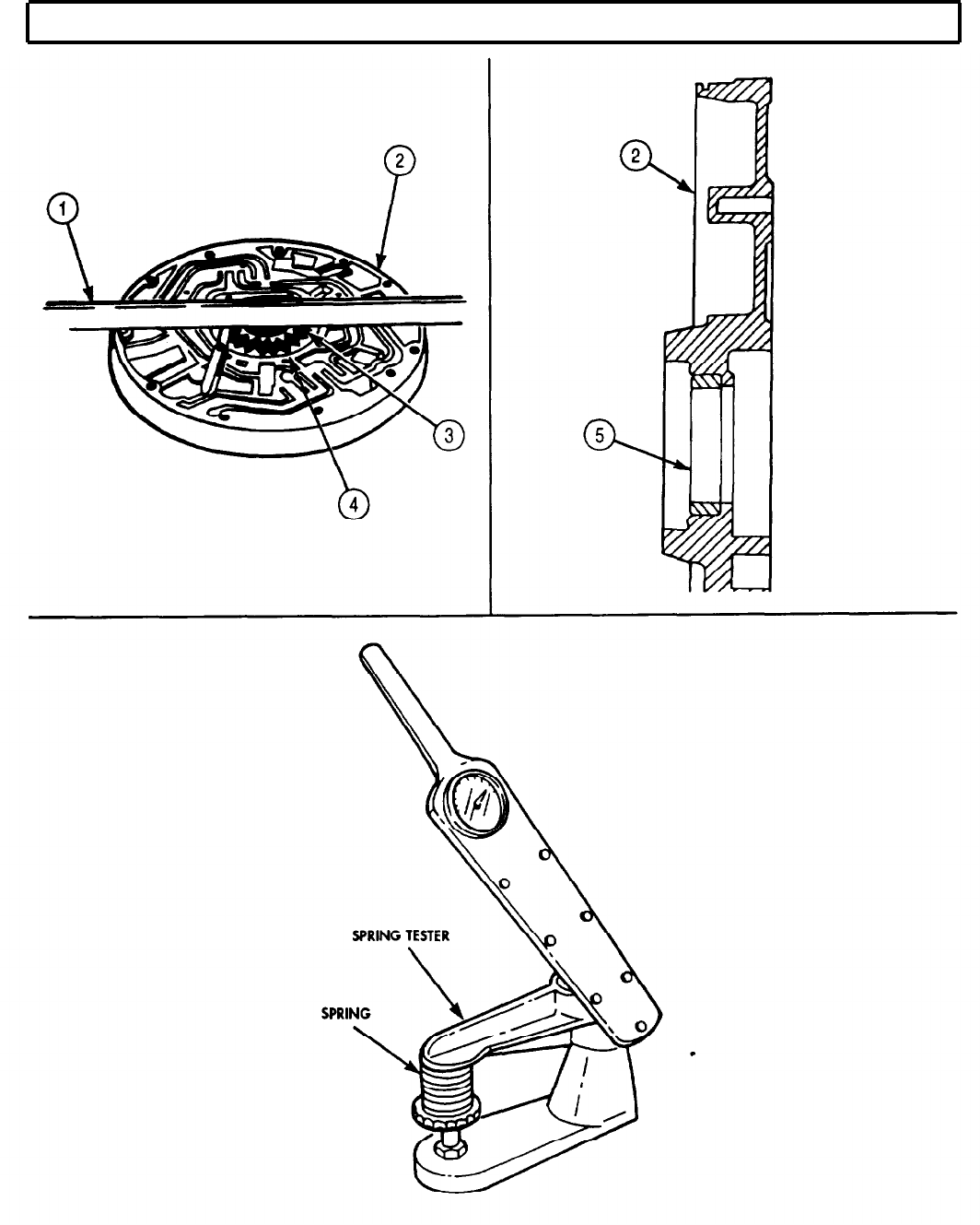
TM 9-2320-272-24-4
5-46. TRANSMISSION OIL PUMP AND FRONT SUPPORT MAINTENANCE (Contd)
5-315

TM 9-2320-272-24-4
5-46. TRANSMISSION OIL PUMP AND FRONT SUPPORT MAINTENANCE (Contd)
CAUTION
Oil seals for early and late model oil pumps are not
interchangeable (para. 5-39).
NOTE
Coat all internal parts, except oil pump, with lubricating oil
OE/HDO-10 prior to assembly.
Perform steps 1 through 3 only if gears and oil seal were
removed.
1.
Using oil-soluble grease, coat outside diameter of new oil pump seal ring (1)
2.
Install new oil pump seal ring (1) in oil pump body (2) 0.030-0.050 in. (1.76-1.27 mm) below outer
edge of bore. Install spring-loaded lip first. Use depth micrometer for measurement.
3.
Using oil-soluble grease, coat oil pump body seal (1) lip.
4.
Install oil pump gears (3) and (4).
NOTE
For transmissions with serial numbers 21628 and higher, use two
adapters with spring compressor.
5.
Install regulator valve (11), lockup valve (9), valve springs (12) and (8), and valve stops (13) and (7) in
front support (10) at location marked during disassembly.
6.
Attach main regulator and lockup spring compressor to front support (10) and tighten screws (14)
until snapring grooves or crosspin holes are visible in front of valve stops.
NOTE
Perform step 7 for transmissions with serial numbers prior to
21628.
7.
Install snaprings (5) and (6) over valve stops (13) and (7). Tighten screws (14) until snapring
grooves are visible in front of valve stops (7) and (13).
5-316
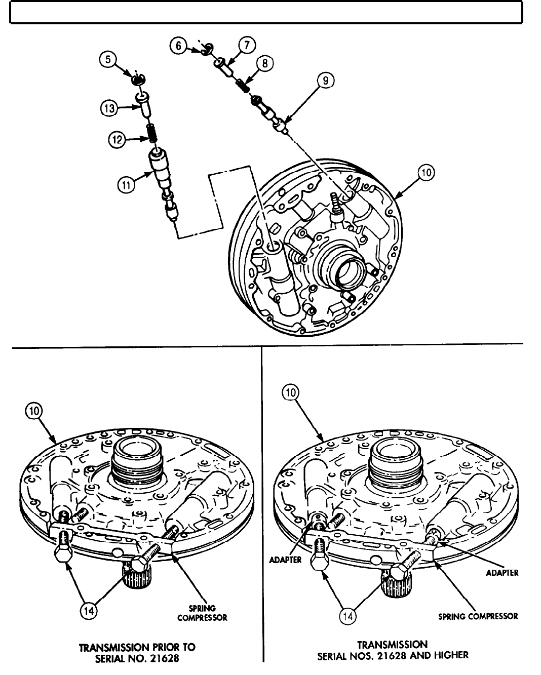
TM 9-2320-272-24-4
5-46. TRANSMISSION OIL PUMP AND FRONT SUPPORT MAINTENANCE (Contd)
5-317
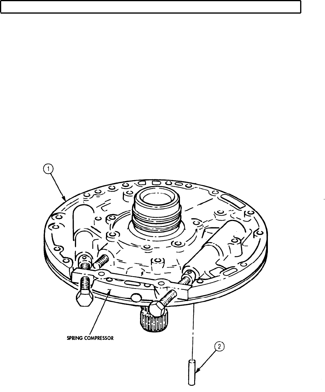
TM 9-2320-272-24-4
5-46. TRANSMISSION OIL PUMP AND FRONT SUPPORT MAINTENANCE (Contd)
8.
9.
10.
11.
12.
13.
14.
NOTE
Perform step 8 for transmissions with serial numbers 21628 and
higher.
Install two cross pins (2) in pin holes of front support (1).
Detach and remove main regulator and spring compressor from front support (1).
NOTE
Perform step 10 only if plug was previously removed.
Install plug (3) in front support (1).
Position oil pump (6) to front support (1) and align holes for screws (4) and (5). Install oil pump (6)
to front support (1) with two new self-locking screws (4) positioned 180° apart. Finger-tighten
screws (4).
Install centering band around oil pump (6).
Install oil pump (6) on front support (1) with remaining ten new self-locking screws (4) and two
new self-locking screws (5). Tighten screws (4) 17-20 lb-ft (23-27 N•m). Tighten screws (5) 36-42 lb-ft
(23-27 N•m).
Remove centering band from oil pump (6) to front support (1) and check separation line between oil
pump (6) and front support (1). If mating point between oil pump (6) and front support (1) is not
perfectly smooth by touch, loosen screws (4) and (5). Repeat steps 12 through 14.
5-318
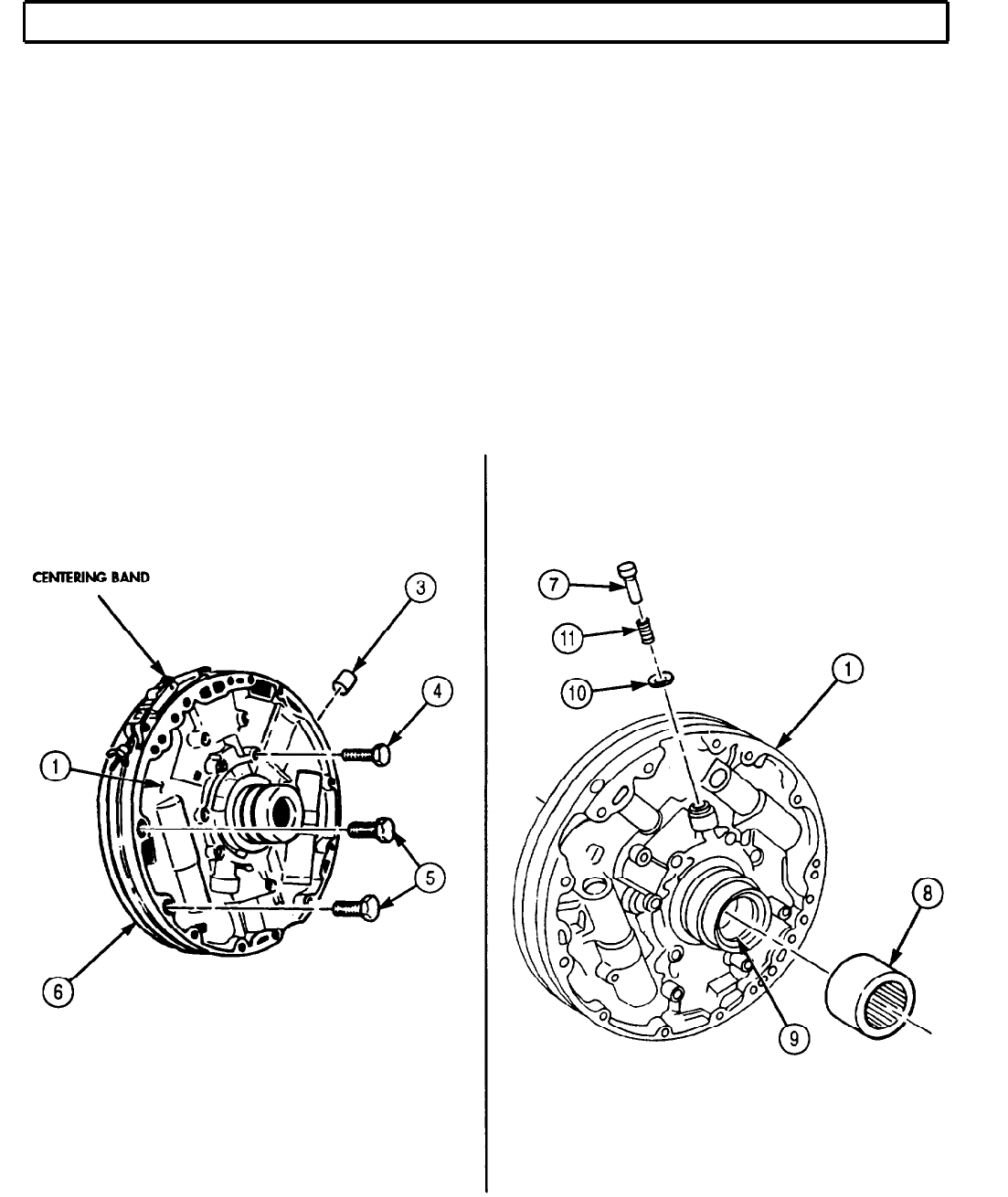
TM 9-2320-272-24-4
5-46. TRANSMISSION OIL PUMP AND FRONT SUPPORT MAINTENANCE (Contd)
NOTE
Perform step 15 only if needle bearing was previously removed.
15.
Position needle bearing (8) on converter ground sleeve (9). Ensure numbered end of needle
bearing (8) faces outward.
16.
Using bearing installer and driver handle, press needle bearing (8) into converter ground
sleeve (9) 1.240-1.260 in. (31.50-32.00 mm) below outer edge of bore.
NOTE
Perform steps 17 and 18 only if converter pressure regulator valve
was previously removed.
17.
Place valve spring (11) and converter pressure valve (10) on new valve guide pin (7).
18.
Press new valve guide pin (7) into front support (1) until new value guide pin (7) extends
1.16-1.20 in. (29.46-30.48 mm) above finished surface.
NOTE
Two seal rings for front support hub are installed when oil pump
and front support are installed in transmission.
5-319

TM 9-2320-272-24-4
5-46. TRANSMISSION OIL PUMP AND FRONT SUPPORT MAINTENANCE (Contd)
1.
2.
3.
4.
5.
6.
7.
8.
CAUTION
Identify transmission model before assembly of oil pump and front
support. If early model converter hub was replaced with late
model converter hub, a late model oil pump and front support
must be installed, or transmission may be damaged during
assembly (para. 5-39).
NOTE
Late model oil pump is thicker than early model oil pump.
Late model front support has a bushing and a thicker seal in oil
pump hub. Early model oil pump hub has a thin seal and the
torque converter hub has a roller bearing.
Install bearing and race (2) on turbine shaft (3).
NOTE
Guide pins maintain gasket alignment.
Install two guide pins (5) and new oil pump gasket (1) into transmission (4).
Apply oil-soluble grease sparingly to two new seal rings (10) to hold in place, and install seal
rings (10) on hub (9) of oil pump (7) and front support (8).
Apply oil-soluble grease to new oil pump and ring coil, and install new oil pump seal ring (6) on oil
pump (7) and front support (8).
Attach front support lifter to converter ground sleeve (12).
Align front support holes (13) with corresponding holes in transmission (4), and carefully install
front support (8) in transmission (4) over guide pins (5).
Remove two guide pins (5) and front support lifter from transmission (4).
Install front support (8) on transmission (4) with twelve new rubber-covered washers (14) and
screws (11). Tighten screws (11) as follows:
a.
Tighten alternately 180° apart. Tighten screws (11) 15 lb-ft (20 N•m).
b.
Repeat tightening sequence 180° apart to achieve final torque. Tighten screws (11) 24-32 lb-ft
(33-43 N•m).
5-320
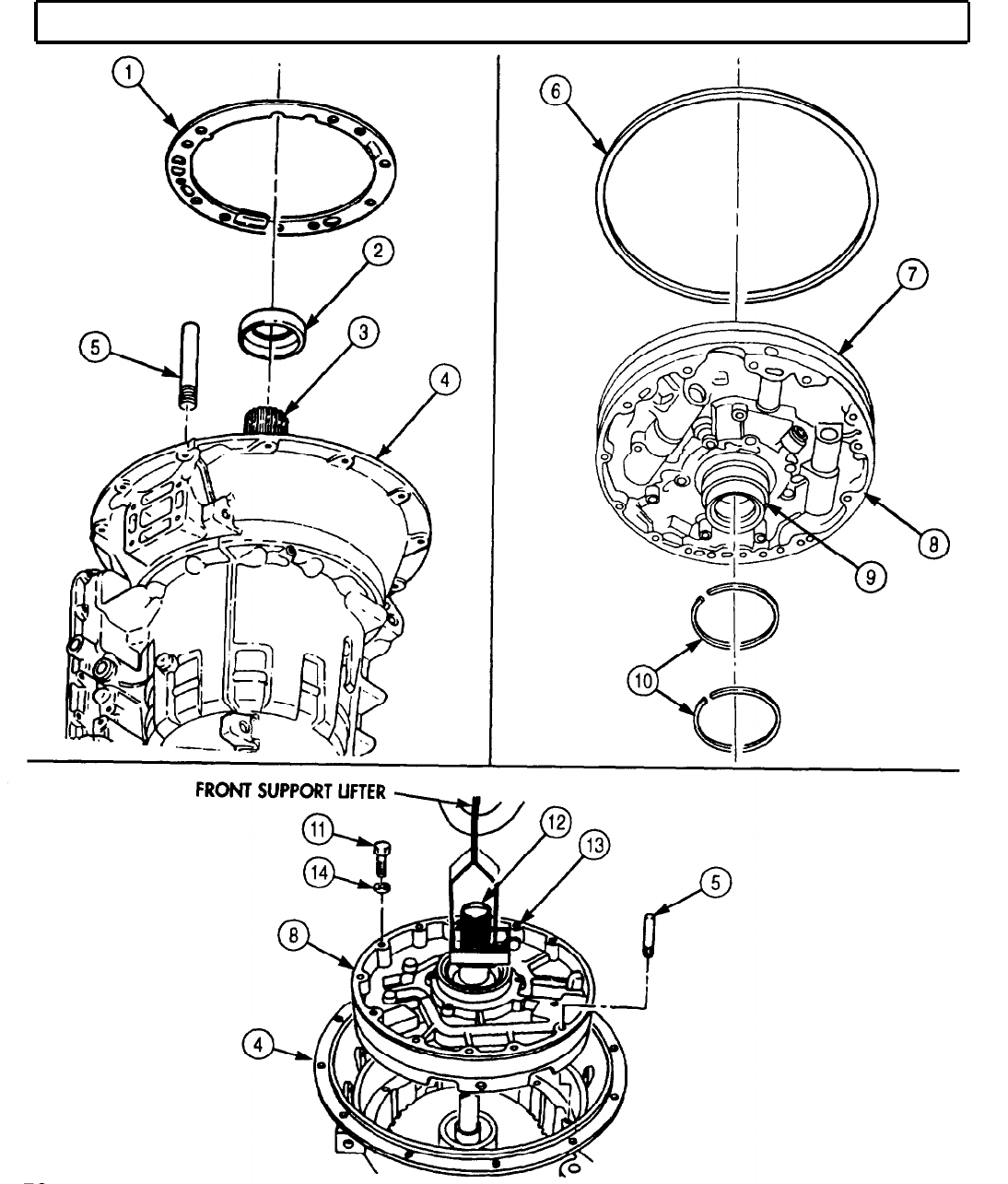
TM 9-2320-272-24-4
5-47. FORWARD CLUTCH MAINTENANCE
THIS TASK COVERS:
a. Removal d. Assembly
b. Disassembly e. Installation
c. Cleaning and Inspection
INITIAL SETUP:
APPLICABLE MODELS
All
SPECIAL TOOLS
Spring compressor (Appendix E, Item 95)
Forward clutch clearance gauge (Appendix E,
Item 46)
TOOLS
General mechanic’s tool kit (Appendix E, Item 1)
Spring tester (Appendix E, Item 131)
Outside micrometer (Appendix E, Item 80)
Vernier caliper (Appendix E, Item 159)
Depth gauge (Appendix E, Item 81)
Arbor press
MATERIALS/PARTS
Two turbine shaft seal rings (Appendix D,
Item 640)
Turbine shaft seal ring (Appendix D, Item 639)
Piston inner seal ring (Appendix D, Item 515)
Piston outer seal ring (Appendix D, Item 516)
Oil-soluble grease (Appendix C, Item 53)
Lubricating oil (Appendix C, Item 47)
REFERENCES (TM)
TM 9-2320-272-24P
EQUIPMENT CONDITION
Transmission oil pump and front support removed
(para. 5-46).
SPECIAL ENVIRONMENTAL CONDITIONS
Work area clean and free from blowing dirt and
dust.
1.
Lift forward clutch housing (9) and turbine shaft (1) straight out from transmission (5).
NOTE
Perform step 2 for transmissions with three-piece bearing.
2.
Remove bearing race (2), roller bearing (3), and bearing race (4) from turbine shaft (1).
NOTE
Perform step 3 for transmissions with single-piece bearing assembly.
3.
Remove bearing assembly (6) from turbine shaft (1).
1.
Remove seal ring (10) and two seal rings (11) from turbine shaft (1). Discard seal ring (10) and two
seal rings (11).
NOTE
Support Power Takeoff (PTO) drive gear on arbor press for steps 2
through 6.
5-322
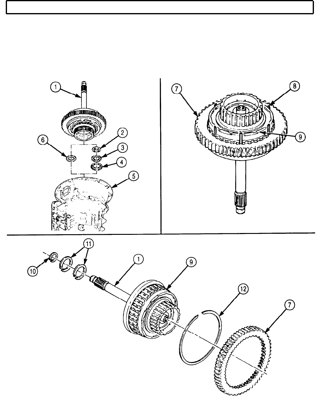
TM 9-2320-272-24-4
5-47. FORWARD CLUTCH MAINTENANCE (Contd)
2.
Locate opening (missing spline) in forward clutch housing (9) nearest snapring (12) gap.
3.
Press snapring (12) into groove in clutch housing (9) and insert one piece of shim stock (8) through
opening between snapring (12), Power Takeoff (PTO) gear (7), and teeth of clutch housing (9).
4.
Repeat step 3, inserting remaining pieces of shim stock (8) into PTO gear approximately 5 in.
(127 mm) apart.
5.
Lift PTO gear (7) off clutch housing (9).
6.
Remove snapring (12) and shim stock (8) from clutch housing (9).
5-323

TM 9-2320-272-24-4
5-47. FORWARD CLUTCH MAINTENANCE (Contd)
7.
8.
Remove snapring (6) from forward clutch housing (16).
Remove fourth clutch drive hub (5) and forward clutch hub (4) from forward clutch housing (16).
NOTE
9.
Perform step 9 for transmission with three-piece bearing.
Remove bearing race (7), bearing (8), and bearing race (9) from forward clutch housing (16) or
fourth clutch hub (5).
NOTE
Perform step 10 for transmissions with single-piece bearing
assembly.
10.
Remove bearing assembly (3) from forward clutch housing (16).
CAUTION
Keep all parts together. Intermixing forward clutch parts with any
other clutch pack will cause transmission damage.
NOTE
Tag all clutch parts for reassembly.
11.
Remove six clutch plates (1) and six clutch discs (2) from forward clutch housing (16).
NOTE
12.
13.
14.
15.
16.
17.
Use arbor press with compression tool for step 12.
Position compressor tool on spring retainer (11) and place on arbor press.
Apply pressure on spring retainer (11) and remove snapring (10) from forward clutch housing (16).
Remove compressor tool from spring retainer (11) and arbor press.
Remove spring retainer (11), piston return spring (12), piston (13), and piston inner seal ring (15)
from forward clutch housing (16). Discard piston inner seal ring (15).
Remove piston outer seal ring (14) from piston (13). Discard piston outer seal ring (14).
Remove retainer pin (20), valve plug (19), valve spring (18), and centrifugal valve (17) from forward
clutch housing (16).
5-324
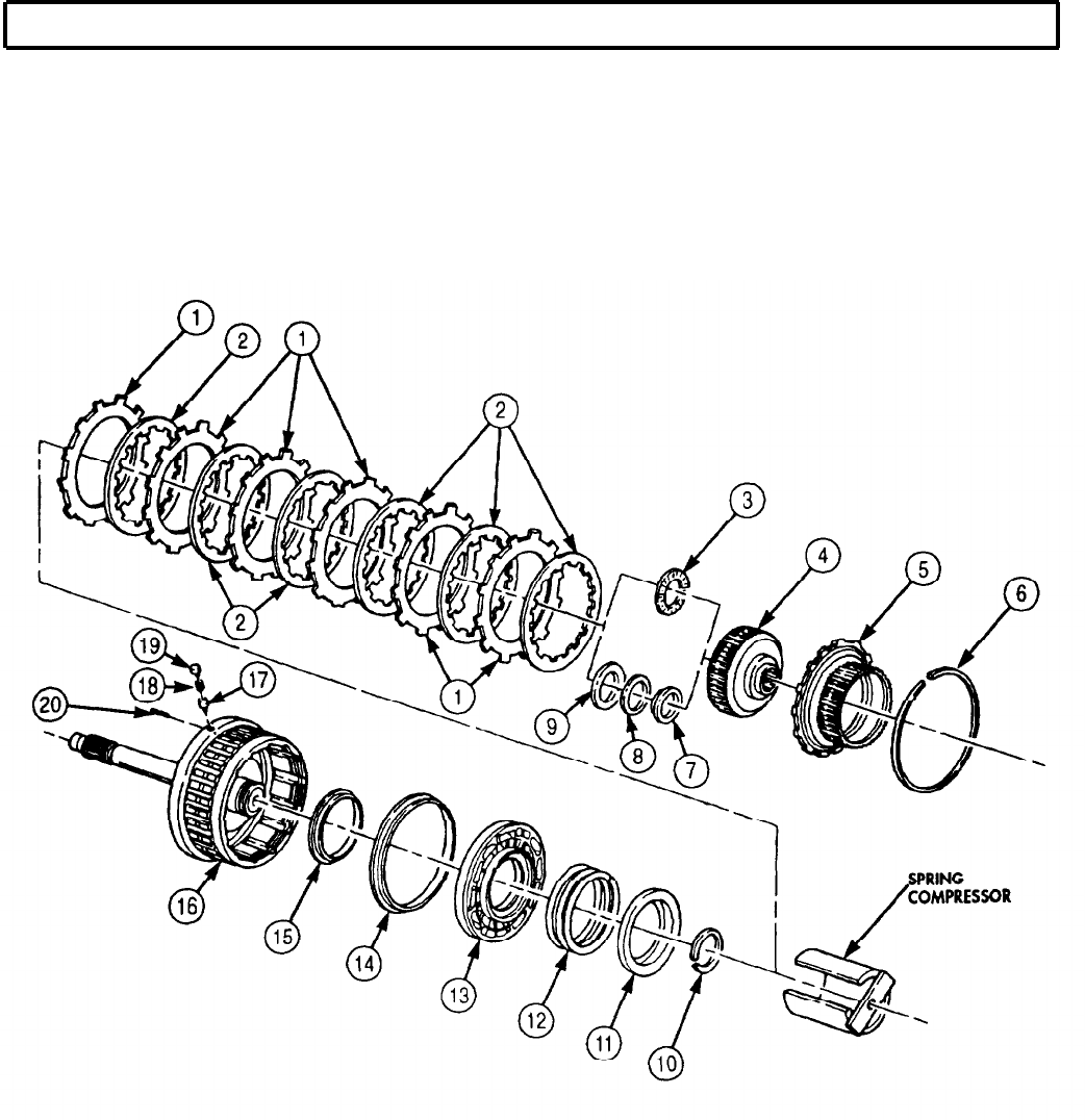
TM 9-2320-272-24-4
5-47. FORWARD CLUTCH MAINTENANCE (Contd)
5-325
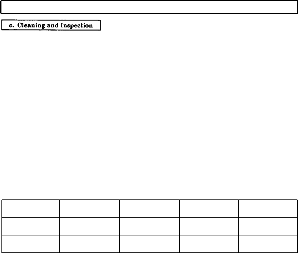
TM 9-2320-272-24-4
5-47. FORWARD CLUTCH MAINTENANCE (Contd)
1.
2.
3.
4.
5.
6.
7.
8.
9.
10.
For general cleaning instructions, refer to para. 2-14.
For general inspection instructions, refer to para. 2-15.
Inspect turbine shaft and forward clutch housing (1) for scoring in area where seals contact
turbine shaft (1). If scored, discard turbine shaft and forward clutch housing (1).
Inspect clutch plates (2) for burned surfaces. If burned, discard clutch plates (2).
Inspect clutch discs (3) for burned surfaces. If burned, discard clutch discs (3).
Measure thickness of fourth clutch drive hub (4) at clutch disc (3) contact area. If thickness is less
than 0.248 in. (6.30 mm), discard fourth clutch drive hub (4).
Inspect valve spring (5) and piston return spring (6) for discoloration due to overheating. If
discolored, discard.
Inspect valve spring (5) and piston return spring (6) for broken coils or coils distorted due to wear. If
broken or distorted, discard.
Using spring tester, inspect valve spring (5) for serviceability.
a. Compress valve spring (5) to 0.61 in. (15.5 mm) and check load (table 5-13).
b. If valve spring (5) does not give load of 5.7-6.3 lb (25.3-28 N), discard.
Using spring tester, inspect piston return spring (6) for serviceability.
a. Compress piston return spring (6) to 1.28 in. (32.5 mm) (table 5-13).
b. If piston return spring (6) does not give load of 158-178 lb (707-791 N), discard.
Table 5-13. Spring Data.
SPRING
COLOR FREE LENGTH
COMPRESSED
LENGTH
UNDER LOAD
Valve spring
Piston return
spring
Green
None
0.76 in. 0.61 in. 5.7-6.3 lb
(19.3 mm) (15.5 mm)
(25.3-28 N)
3.22 in. 1.28 in.
158-178 lb
(81.8 mm) (32.5 mm) (702-791 N)
5-326
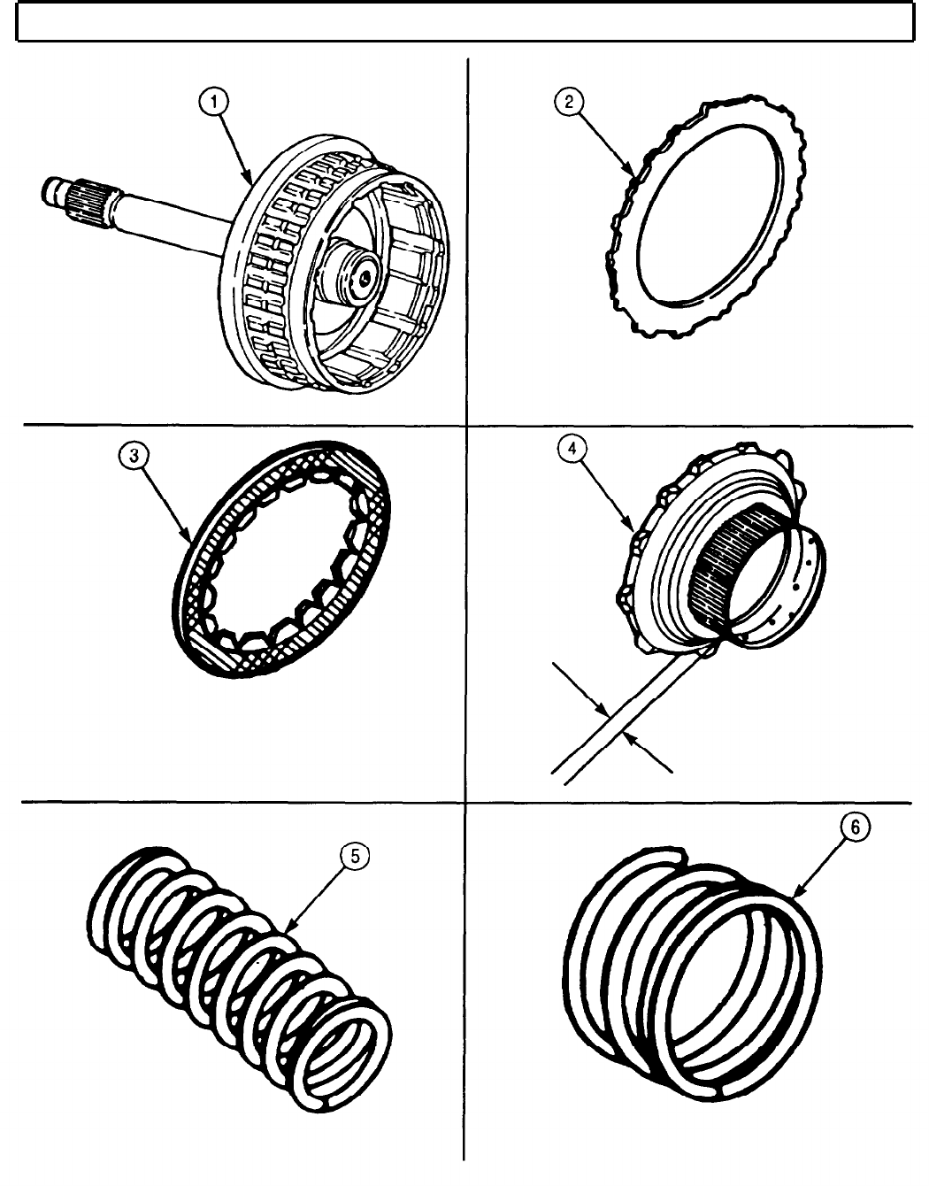
TM 9-2320-272-24-4
5-47. FORWARD CLUTCH MAINTENANCE (Contd)
5-327

TM 9-2320-272-24-4
5-47. FORWARD CLUTCH MAINTENANCE (Contd)
1.
2.
3.
4.
5.
6.
7.
8.
9.
10.
11.
12.
13.
14.
15.
16.
17.
18.
5-328
NOTE
If new centrifugal valve is being installed, all components must
have same color code as old valve.
Install centrifugal valve (3) and valve spring (2) in forward clutch housing (16). Ensure pointed end
of centrifugal valve (3) is installed first.
Push valve plug (1) into forward clutch housing (16) and install with retainer pin (17). Retainer pin (17)
must protrude 0.080-0.100 in. (2.03-2.54 mm) above front surface of forward clutch housing (16).
Apply oil-soluble grease to new piston outer seal ring (12) and install new piston outer seal ring (12)
on piston (10). Ensure piston outer seal ring (12) lips face toward oil pressure side of piston (10).
Apply oil-soluble grease to new piston inner seal ring (15) and install new piston inner seal ring (15)
on forward clutch housing (16) hub. Ensure piston inner seal ring (15) lips face toward oil pressure
side of piston (10).
Install piston (10) in forward clutch housing (16).
NOTE
Steps 6 through 12 obtain clutch running clearance.
Starting with clutch plate (5), alternately install six clutch plates (5) and six clutch discs (4) in
forward clutch housing (16).
Position fourth clutch drive hub (6) in forward clutch housing (16) and install with snapring (7).
Measure clearance between fourth clutch drive hub (6) and clutch disc (4) with forward clutch
clearance gauge.
Clutch running clearance should be 0.094-0.148 in. (2.387-3.759 mm).
NOTE
Perform steps 10 through 12 only if clutch running clearance is
incorrect.
If clearance exceeds 0.148 in. (3.759 mm), replace clutch plates (5) and clutch discs (4) with new,
thicker clutch plates (5) and clutch discs (4).
If clearance still exceeds 0.148 in. (3.759 mm) after completing step 10, replace piston (10) with new,
thicker piston (10).
If clearance is less than 0.094 in. (2.387 mm), replace piston (10) with a new, thinner piston (10).
Remove snapring (7), fourth clutch drive hub (6), six clutch discs (4), and six clutch plates (5) from
forward clutch housing (16).
Place piston return spring (14) and spring retainer (13) in forward clutch housing (16).
Place compressor tool on spring retainer (13) and arbor press.
Compress piston return spring (14) with compressor tool and arbor press and install spring
retainer (13) with snapring (11).
Remove compressor tool from spring retainer (13).
NOTE
Use oil-soluble grease to hold bearing race and bearing in place.
Soak six clutch discs in clean OE/HDO-10 lubricating
transmission oil for at least two minutes before installing in
forward clutch housing.
Perform step 18 for transmissions with single-piece bearing
assembly.
Install bearing assembly (9) in forward clutch housing (16). Ensure lube scallops of bearing
assembly (9) face down.
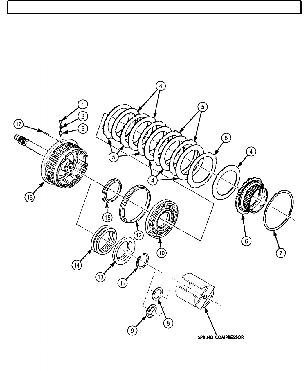
TM 9-2320-272-24-4
5-47. FORWARD CLUTCH MAINTENANCE (Contd)
NOTE
Perform steps 19 through 21 for transmission with three-piece
bearing.
19.
Install bearing race (8) in forward clutch housing (16). Ensure outer lip of bearing race (8) is
installed first.
5-329
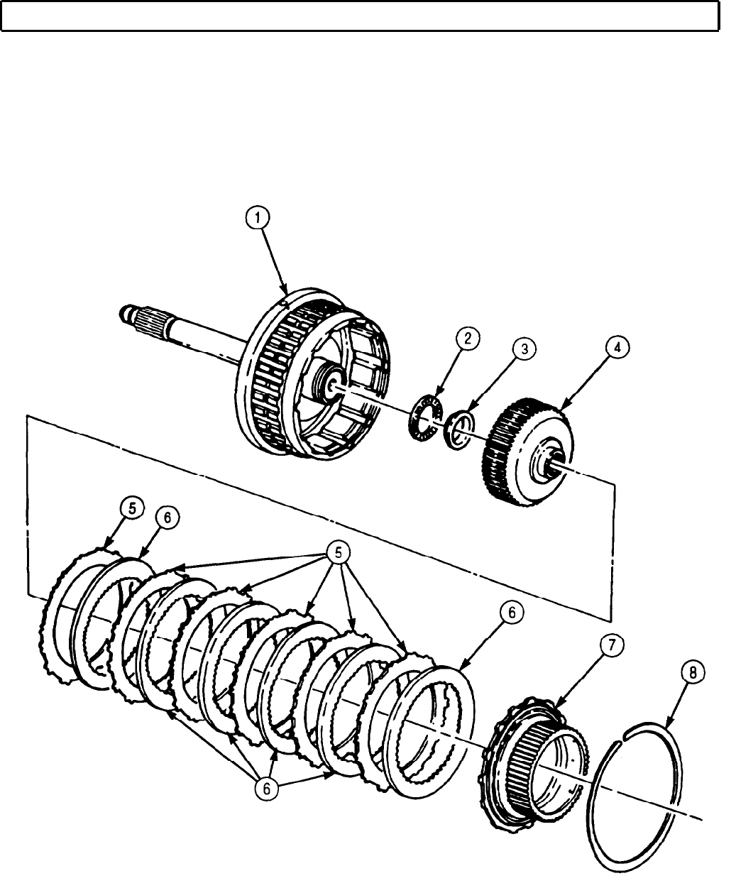
TM 9-2320-272-24-4
5-47. FORWARD CLUTCH MAINTENANCE (Contd)
20.
Install bearing race (3) on forward clutch hub (4). Ensure flat side of bearing race (3) is installed first.
21.
Apply liberal amount of oil-soluble grease on bearing (2) and install bearing (2) on forward clutch
hub (4).
22.
Install forward clutch hub (4) in forward clutch housing (1). Ensure splined edge is installed first.
23.
Starting with clutch plate (5), alternately install six clutch plates (5) and six clutch discs (6) in
forward clutch housing (1).
24.
Install fourth clutch drive hub (7) in forward clutch housing (1) with snapring (8).
5-330
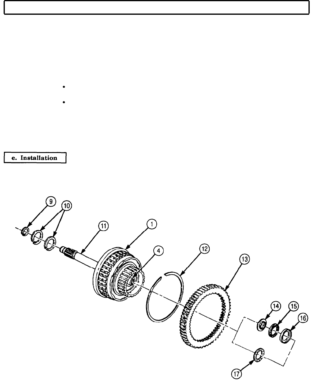
TM 9-2320-272-24-4
5-47. FORWARD CLUTCH MAINTENANCE (Contd)
25.
Install PTO gear snapring (12) on forward clutch housing (1).
26.
Slide PTO gear (13), chamfered end first, over PTO gear snapring (12) on forward clutch housing (1).
Ensure PTO gear snapring (12) springs outward into internal groove of PTO gear (13).
NOTE
Perform step 27 for transmissions with single-piece bearing
assembly.
27.
Install roller bearing (17) on forward clutch hub (4).
NOTE
Perform steps 28 and 29 for transmission with three-piece
bearing.
Use oil-soluble grease to hold bearing race, bearing, and seal
rings in place.
28.
Install bearing race (14), flat side first, on forward clutch hub (4).
29.
Install bearing (15) and bearing race (16) on forward clutch hub (4).
30.
Install two new seal rings (10) on turbine shaft (11).
31.
Install new seal ring (9) on turbine shaft (11).
Install forward clutch housing (1) and turbine shaft (11) in transmission housing while engaging fourth clutch
drive hub (7) with internal-splined clutch discs of fourth clutch. Ensure the fourth clutch housing (1) is
properly seated.
FOLLOW-ON TASK: Install transmission oil pump and front support (para. 5-46).
5-331
TM 9-2320-272-24-4
5-48. FOURTH CLUTCH MAINTENANCE
THIS TASK COVERS:
a. Removal
b. Disassembly
c. Cleaning and Inspection
d. Assembly
e. Installation
INITIAL SETUP:
APPLICABLE MODELS REFERENCES (TM)
All
TM 9-2320-272-24P
SPECIAL TOOLS
Spring compressor (Appendix E, Item 95)
Fourth clutch clearance gauge (Appendix E,
Item 47)
TOOLS
General mechanic’s tool kit (Appendix E, Item 1)
Vernier caliper (Appendix E, Item 159)
Depth gauge (Appendix E, Item 81)
Spring tester (Appendix E, Item 131)
Arbor press
EQUIPMENT CONDITION
Forward clutch removed (para. 5-47).
SPECIAL ENVIRONMENTAL CONDITIONS
Work area clean and free from blowing dirt and
dust.
GENERAL SAFETY INSTRUCTIONS
Use care when removing piston return spring.
Spring is under great compression.
MATERIALS/PARTS
Piston inner seal ring (Appendix D, Item 515)
Piston outer seal ring (Appendix D, Item 516)
Lubricating oil (Appendix C, Item 47)
Oil-soluble grease (Appendix C, Item 53)
1.
Lift fourth clutch (1) straight out of transmission (4).
NOTE
Perform step 2 for transmissions with two-piece bearing.
2.
Remove bearing race (2) and bearing assembly (3) from fourth clutch (1) or transmission (4).
NOTE
Perform step 3 for transmissions with single-piece bearing
assembly.
3.
Remove bearing assembly (3) from fourth clutch (1) or transmission (4).
1.
Position piston return spring compressor on spring retainer (5) and place on arbor press.
WARNING
Piston return spring is under great compression. Do not remove
snapring until pressure is applied to spring retainer. If not, piston
return spring may fly out, causing injury to personnel.
2.
Apply pressure to spring retainer (5) and remove snapring (6) from fourth clutch (1).
3.
Carefully remove piston return spring compressor.
4.
Remove spring retainer (5), piston return spring (7), and optional spacer (8) from fourth clutch
housing (1).
5-332
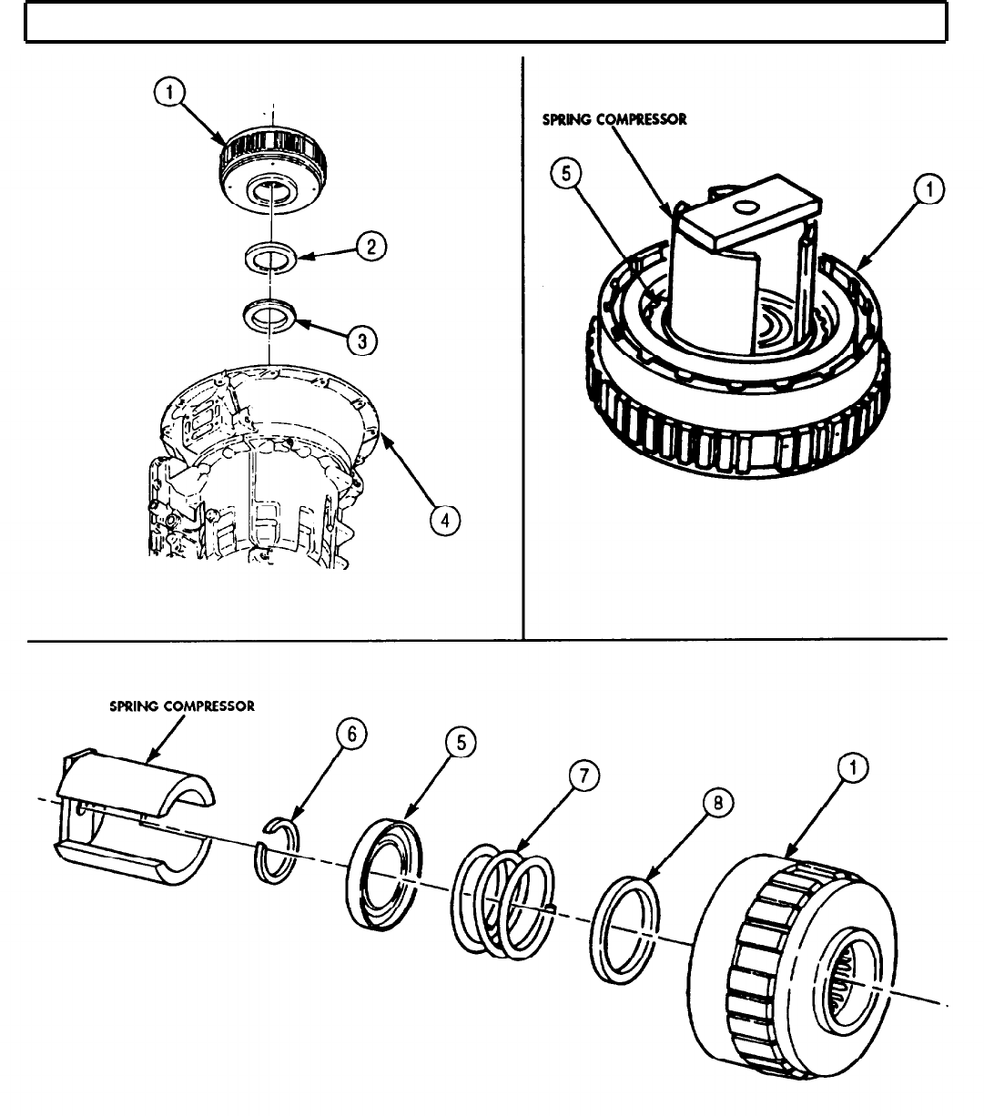
TM 9-2320-272-24-4
5-48. FOURTH CLUTCH MAINTENANCE (Contd)
5-333
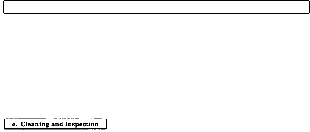
TM 9-2320-272-24-4
5-48. FOURTH CLUTCH MAINTENANCE (Contd)
5.
Remove backplate snapring (1) from fourth clutch housing (5).
CAUTION
The fourth clutch consists of a backplate, five clutch plates, and
five clutch discs. Keep all clutch parts together. Intermixing fourth
clutch parts with any other clutch part will cause transmission
damage.
NOTE
Tag all fourth clutch parts for reassembly.
6.
Remove backplate (2), five clutch plates (4), five clutch discs (3), and piston (8) from fourth clutch
housing (5).
7.
Remove piston outer seal ring (7) from piston (8). Discard seal ring (7).
8.
Remove piston inner seal ring (6) from fourth clutch housing (5). Discard seal ring (6).
1.
For general cleaning instructions, refer to para. 2-14.
2.
For general inspection instructions, refer to para. 2-15.
3.
Inspect five clutch plates (4) for burned surfaces. If burned, discard clutch plates (4).
4.
Inspect five clutch discs (3) for burned surfaces. If surface of clutch disc (3) is burned, discard clutch
disc (3).
5.
Inspect piston return spring (9) for discoloration due to overheating. If discolored, discard piston
return spring (9).
6.
Inspect piston return spring (9) for broken coils or coils distorted due to wear. If coils are broken or
distorted, discard piston return spring (9).
NOTE
Free length of piston return spring is 3.22 in. (81.8 mm).
7.
Using spring tester, inspect piston return spring (9) for serviceability.
a. Compress piston return spring (9) to 1.28 in. (32.5 mm).
b. If piston return spring (9) does not give load of 158-178 lb (703-791 N), discard.
8.
Measure backplate (2) thickness. If backplate (2) thickness is less than .248 in. (6.30 mm), discard.
5-334
TM 9-2320-272-24-4
5-48. FOURTH CLUTCH MAINTENANCE (Contd)
5-335
TM 9-2320-272-24-4
5-48. FOURTH CLUTCH MAINTENANCE (Contd)
NOTE
Ensure new seal ring lips face toward oil pressure side of piston.
1.
Apply oil-soluble grease to new piston outer seal ring (11) and install new piston outer seal ring (12)
on piston (10).
2.
Apply oil-soluble grease to new piston inner seal ring (12) and install new piston inner seal ring (12)
in fourth clutch housing (5).
3.
Install piston (10) in fourth clutch housing (5).
NOTE
Steps 4 through 9 obtain clutch running clearance.
4.
Starting with clutch plate (9), alternately install five clutch plates (9) and five clutch discs (8) in
fourth clutch housing (5).
5.
Position backplate (7) in fourth clutch housing (5) and install with snapring (6).
6.
Measure clearance between backplate (7) and clutch disc (8). Clearance should be 0.68-0.127 in.
(17.27-3.226 mm).
7.
If clearance exceeds 0.127 in. (3.226 mm), replace clutch discs (8) and clutch plates (9) with new,
thicker clutch discs (8) and plates (9).
8.
If clearance still exceeds 0.127 in. (3.226 mm) after completing step 7, replace piston (10) with new,
thicker piston (10).
9.
If clearance is less than 0.68 in. (17.27 mm), replace piston (10) with new, thinner piston (10).
10.
Remove snapring (6), backplate (7), five clutch discs (8), and five clutch plates (9) from fourth clutch
housing (5).
NOTE
Soak five clutch discs in clean OE/HDO-10 lubricating oil for at least
two minutes before installing in fourth clutch housing.
11.
Starting with clutch plate (9), alternately install five clutch plates (9) and clutch discs (8) in fourth
clutch housing (5).
12.
Place optional spacer (4), piston return spring (3), and spring retainer (2) in fourth clutch housing (5).
13.
Position piston return spring compressor on spring retainer (2) and arbor press, and compress piston
return spring (3).
14.
Install spring retainer (2) in fourth clutch housing (5) with snapring (1).
15.
Remove piston return spring compressor from spring retainer (2).
NOTE
Perform step 1 for transmission with single-piece bearing
assembly.
1.
Placing race section of bearing assembly (14) into transmission housing (15) first, install bearing
assembly (14) in transmission housing (15).
NOTE
Perform step 2 for transmission with two-piece bearing.
Use oil-soluble grease to hold bearing race in place.
2.
Install bearing race (13) and bearing assembly (14) on fourth clutch housing (5). Ensure bearing
race (13) is installed outer lip first.
3.
Install fourth clutch housing (5) in transmission housing (15).
5-336
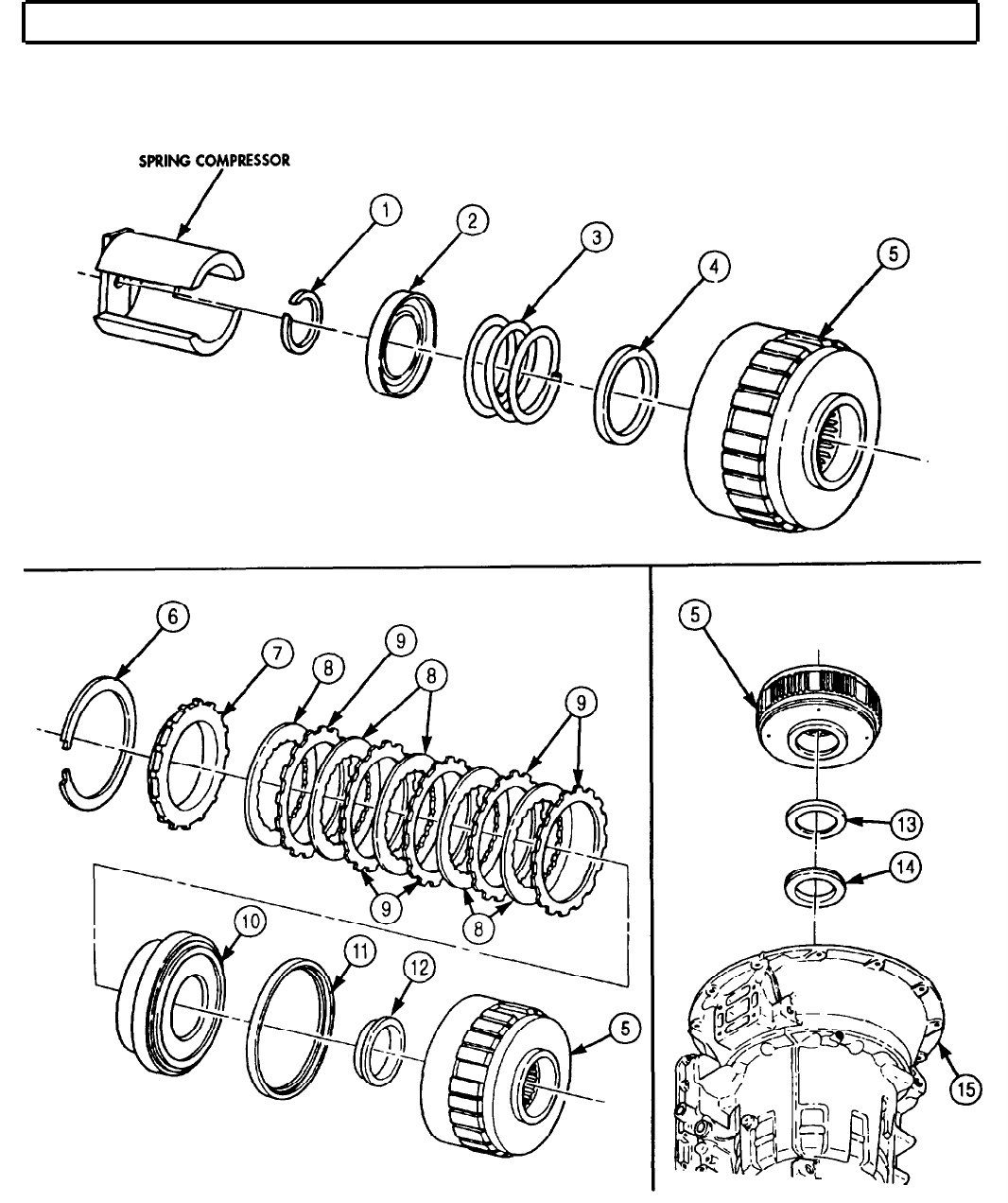
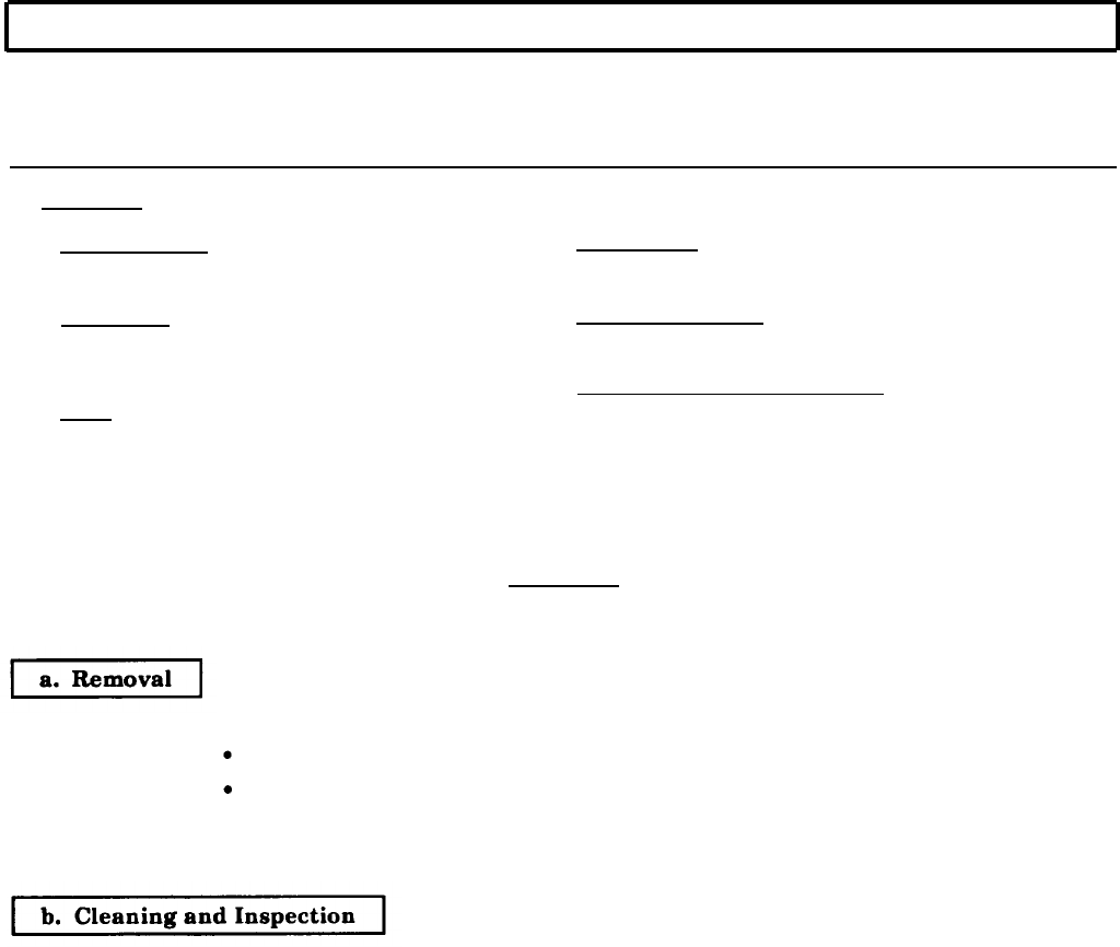
TM 9-2320-272-24-4
5-49. THIRD CLUTCH MAINTENANCE
THIS TASK COVERS:
a. Removal
b. Cleaning and Inspection c. Installation
INITIAL SETUP:
APPLICABLE MODELS REFERENCES (TM)
All
TM 9-2320-272-24P
SPECIAL TOOLS
Third clutch clearance gauge (Appendix E,
Item 139)
TOOLS
General mechanic’s tool kit (Appendix E, Item 1)
Outside micrometer (Appendix E, Item 80)
Spring tester (Appendix E, Item 131)
EQUIPMENT CONDITION
Fourth clutch removed (para. 5-48).
SPECIAL ENVIRONMENTAL CONDITIONS
Work area clean and free from blowing dirt and
dust.
CAUTION
Keep all clutch parts together. Intermixing third clutch parts with
any other clutch pack will cause transmission damage.
NOTE
Tag all clutch parts for reassembly.
Mark position of all clutch plates in transmission housing for
reassembly.
1.
Remove snapring (1), backplate (2), three clutch discs (3), and clutch plates (5) from transmission
housing (4).
1.
For general cleaning instructions, refer to para. 2-14.
2.
For general inspection instructions, refer to para. 2-15.
3.
Inspect clutch discs (3) for burned surfaces. If burned, discard clutch discs (3).
4.
Inspect clutch plates (5) for burned surfaces. If burned, discard clutch plates (5).
5.
Measure backplate (2) thickness.
a. If thickness of backplate (2) marked No. 7 is less than 0.476 in. (12.09 mm), discard backplate (2).
b. If thickness of backplate (2) marked No. 8 is less than 0.450 in. (11.43 mm), discard backplate (2).
c. If thickness of backplate (2) marked No. 9 is less than 0.463 in. (11.76 mm), discard backplate (2).
5-338
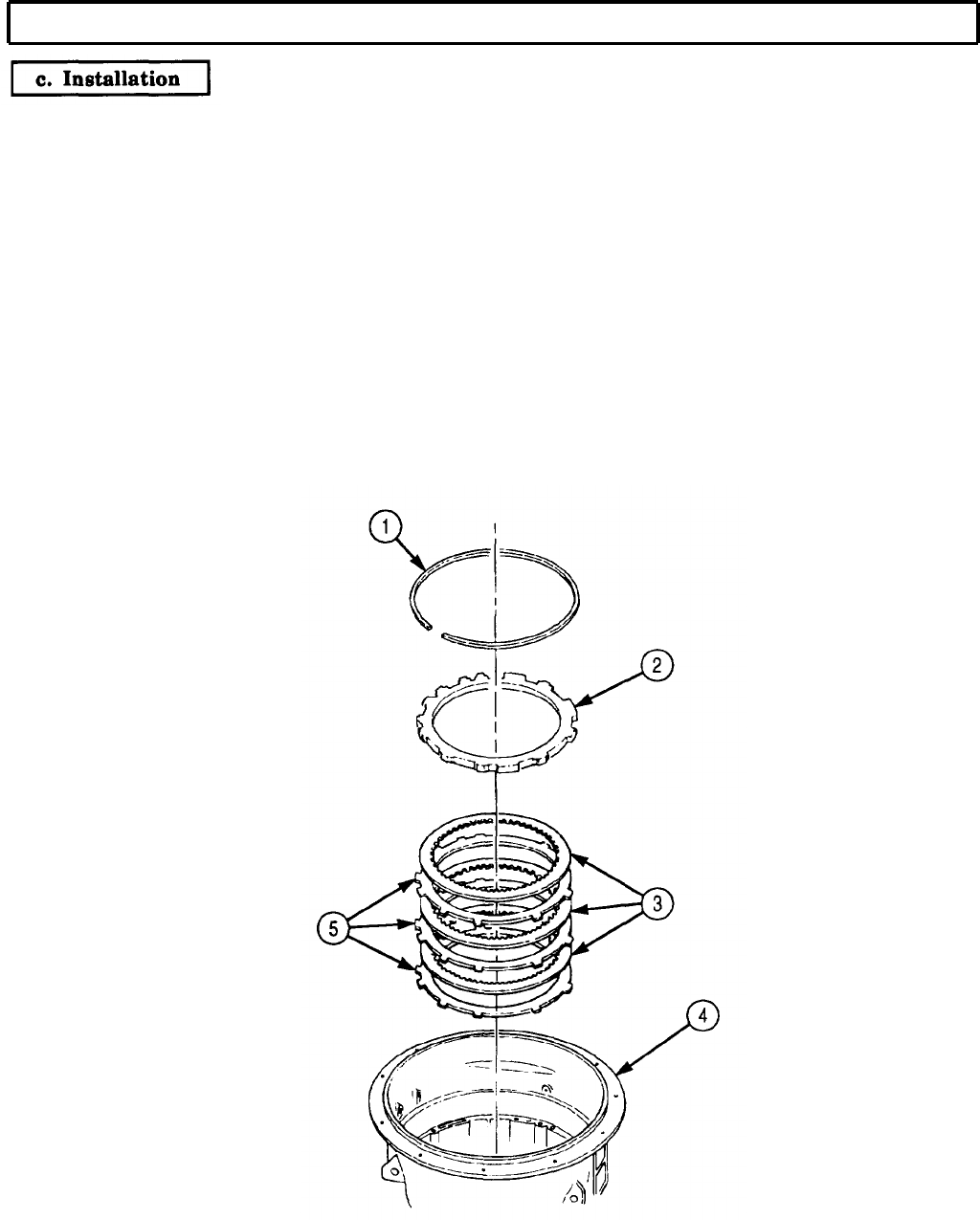
TM 9-2320-272-24-4
5-49. THIRD CLUTCH MAINTENANCE (Contd)
1.
Starting with clutch plate (5), alternately install three clutch plates (5) and three clutch discs (3) in
transmission housing (4).
2.
Install backplate (2) and snapring (1) in transmission housing (4).
3.
Measure clearance between backplate (2) and snapring (1) with third clutch clearance gauge. Third
clutch clearance should be 0.050-0.114 in. (1.270-2.896 mm).
4.
If third clutch clearance exceeds 0.114 in. (2.896 mm), replace clutch discs (3) with new, thicker
discs (3).
5.
If third clutch clearance still exceeds 0.114 in. (2.896 mm) after completing step 4, replace back-
plate (2) with new, thicker backplate (2).
6.
If third clutch clearance is less than 0.050 in. (1.270 mm), replace backplate (2) with new, thinner
backplate (2).
FOLLOW-ON TASK: Install fourth clutch (para. 5-48).
5-339
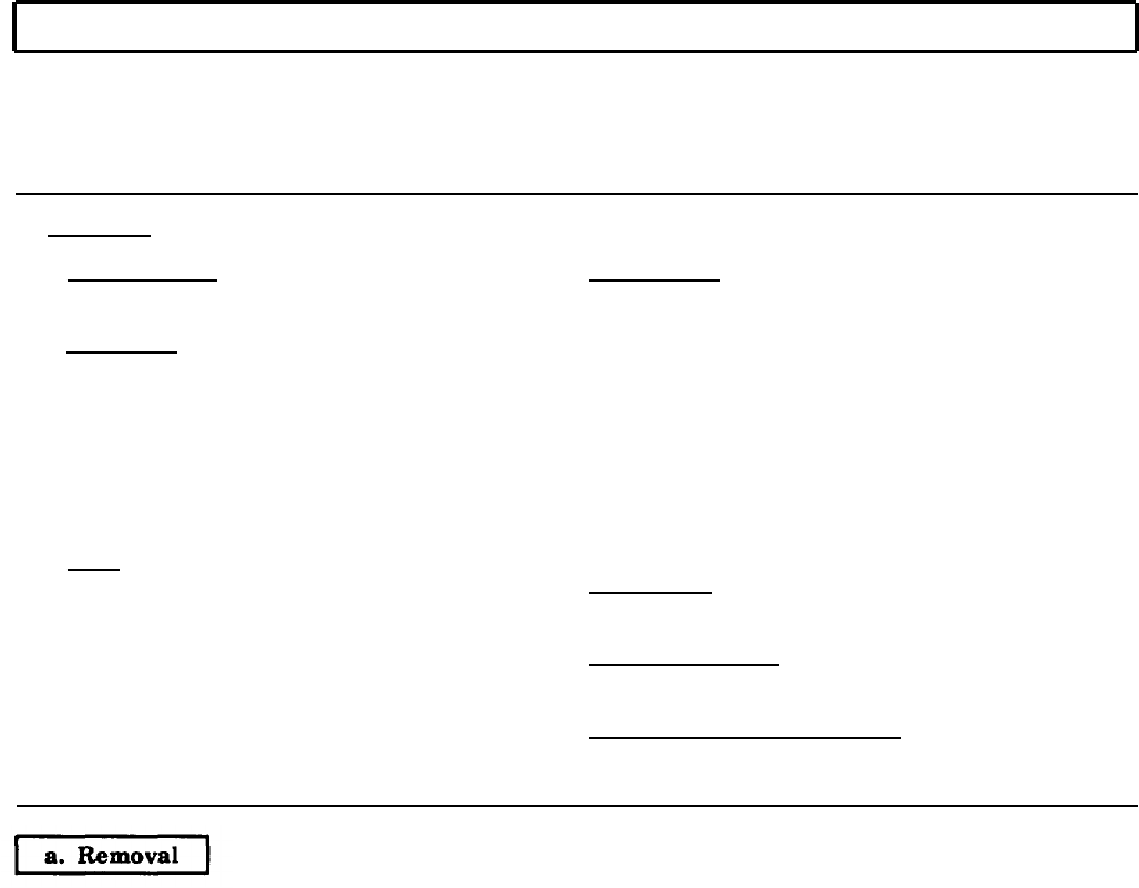
TM 9-2320-272-24-4
5-50. CENTER SUPPORT MAINTENANCE
THIS TASK COVERS:
a. Removal
b. Disassembly
c. Cleaning and Inspection
d. Assembly
e. Installation
INITIAL SETUP:
APPLICABLE MODELS MATERIALS/PARTS
All
SPECIAL TOOLS
Bushing installer (Appendix E, Item 24)
Retainer ring depth tool (Appendix E, Item 114)
Center support lifter (Appendix E, Item 27)
Compressor bar and screw (Appendix E,
Item 29)
Compressor base (Appendix E, Item 30)
Snapring gauge (Appendix E, Item 124)
TOOLS
General mechanic’s tool kit (Appendix E,
Item 1)
Spring tester (Appendix E, Item 131)
Depth gauge (Appendix E, Item 81)
Torque wrench (Appendix D, Item 144)
Arbor press
Hoist
Seal ring (Appendix D, Item 641)
Bushing (Appendix D, Item 27)
Eight self-locking retainers (Appendix D, Item 647)
Filter screen (Appendix D, Item 126)
Two piston inner seal rings (Appendix D, Item 258)
Two piston outer seal rings (Appendix D, Item 509)
Checkball (Appendix D, Item 37)
Two step-joint seal rings (Appendix D, Item 638)
Chamfered washer (Appendix D, Item 35)
Anchor bolt (Appendix D, Item 5)
Oil-soluble grease (Appendix C, Item 53)
REFERENCES (TM)
TM 9-2320-272-24P
1.
Remove center support anchor bolt (3) or (4) and washer (5) or (2) from transmission
housing (1). Discard anchor bolt (3) or (4) and washer (5) or (2).
NOTE
If old style hex-head bolt and washer were present, center support
must be rethreaded. Refer to task c.
2.
Remove snapring (6) from transmission housing (1).
3.
Attach center support lifter to center support (7) and remove center support (7) from transmission
housing (1).
NOTE
Record location of any shims present.
EQUIPMENT CONDITION
Third clutch removed (para. 5-49).
SPECIAL ENVIRONMENTAL CONDITIONS
Work area clean and free from blowing dirt and
dust.
5-340
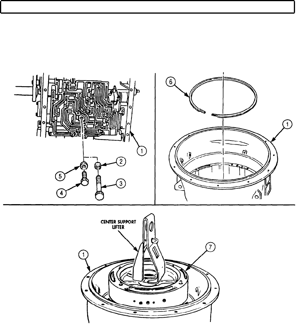
TM 9-2320-272-24-4
5-50. CENTER SUPPORT MAINTENANCE (Contd)
5-341

TM 9-2320-272-24-4
5-50. CENTER SUPPORT MAINTENANCE (Contd)
1.
2.
3.
4.
5.
6.
7.
8.
Remove filter screen (14) and seal ring (13) from center support (10). Discard filter screen (14) and
seal ring (13).
NOTE
The second and third clutch pistons are disassembled the
same way. This procedure covers the second clutch piston.
Remove second clutch piston (11) from center support (10).
Remove inner seal ring (5) and outer seal ring (6) from second clutch piston (11). Discard seal
rings (5) and (6).
Remove four self-locking retainers (1) from pins (12) on second clutch piston (11). Discard self-locking
retainers (1).
Remove retainer (2) and twenty springs (3) from second clutch piston (11).
Remove two step-joint seal rings (7) from center support (10). Discard step-joint seal rings (7).
NOTE
Bushing is removed only if it fails inspection (task c).
Mark location of bushing notch on center support for
reassembly.
Replace checkball if bushing is replaced.
Press bushing (8) out of center support (10) with arbor press and mandrel. Discard bushing (8).
Remove checkball (9) from center support (10). Discard checkball (9).
1.
2.
3.
4.
5.
6.
For general cleaning instructions, refer to para. 2-14.
For general inspection instructions, refer to para. 2-15.
Inspect center support (10) cavities for obstruction or foreign material. Remove obstruction or
foreign material.
Measure depth of anchor bolt hole in center support (10). If hole is not 1.610 in. (40.89 mm) deep,
rework center support (10) as follows:
a. Drill 1.610 in. (40.89 mm) hole in center support (10).
b. Counterbore 0.469 in. (11.91 mm) diameter 0.66-0.70 in. (16.8-17.8 mm) deep.
c. Tap hole using 3/8 in. (9.53 mm) tap UNC2B min. Full thread to depth of dim. A.
Inspect four pins (12) on each piston (4) and (11) for bends and breaks. If any pin (12) is damaged,
replace piston (4) or (11).
Inspect all springs (3) for discoloration due to overheating. If discoloration is present, discard
springs (3).
5-342
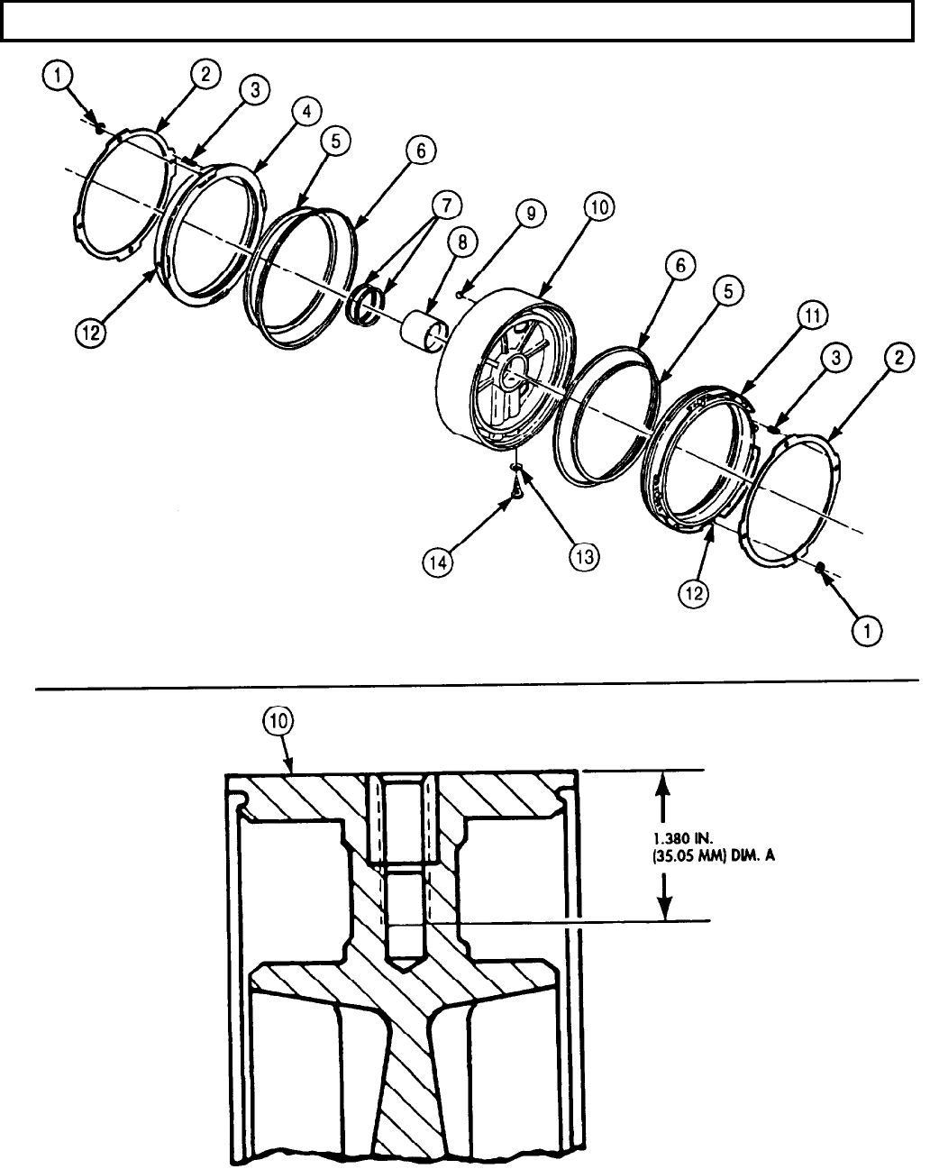
TM 9-2320-272-24-4
5-50. CENTER SUPPORT MAINTENANCE (Contd)
5-343

TM 9-2320-272-24-4
5-50. CENTER SUPPORT MAINTENANCE (Contd)
7.
Inspect all springs (6) for broken coils or coils distorted due to wear. If spring (6) is broken or
distorted, discard.
8.
Using spring tester, inspect all springs (6) for serviceability.
a. Compress spring (6) to 0.81 in. (20.7 mm) and check load.
b. If spring (6) does not give load of 4.30-5.70 lb (19.1.-25.4 N), discard.
d. Assembly
1.
2.
3.
4.
5.
6.
7.
8.
9.
10.
11.
NOTE
Perform steps 1 and 2 only if bushing was removed.
Checkball will be installed when new bushing is pressed in.
Position checkball (2) in center support (3) and align notch on new bushing (1) with marked location
on center support (3).
Press new bushing (1) in center support (3) with bushing installer and arbor press until flush.
NOTE
The second and third clutch pistons are assembled the same way.
This procedure covers the second clutch piston.
Place second clutch piston (10) in center support (3).
Place twenty springs (6) in pockets on piston (11).
Align spring retainer (5) with pins (11) on piston (10) with retainer ring depth tool and install four
new self-locking retainer rings (4)
Remove second clutch piston (10) from center support (3).
Apply oil-soluble grease to new inner seal ring (8) and new outer seal ring (9).
Install new inner seal ring (8) and new outer seal ring (9) on second clutch piston (10). Ensure lips
of seal rings (8) and (9) face toward center support (3) when second clutch piston (10) is installed.
Repeat steps 3 through 8 to assemble third clutch piston (7).
NOTE
Do not install third clutch piston in center support at this time.
Install second clutch piston (11) in center support (3).
NOTE
Install new filter screen (13) and new seal ring (12) on center support (3).
5-344
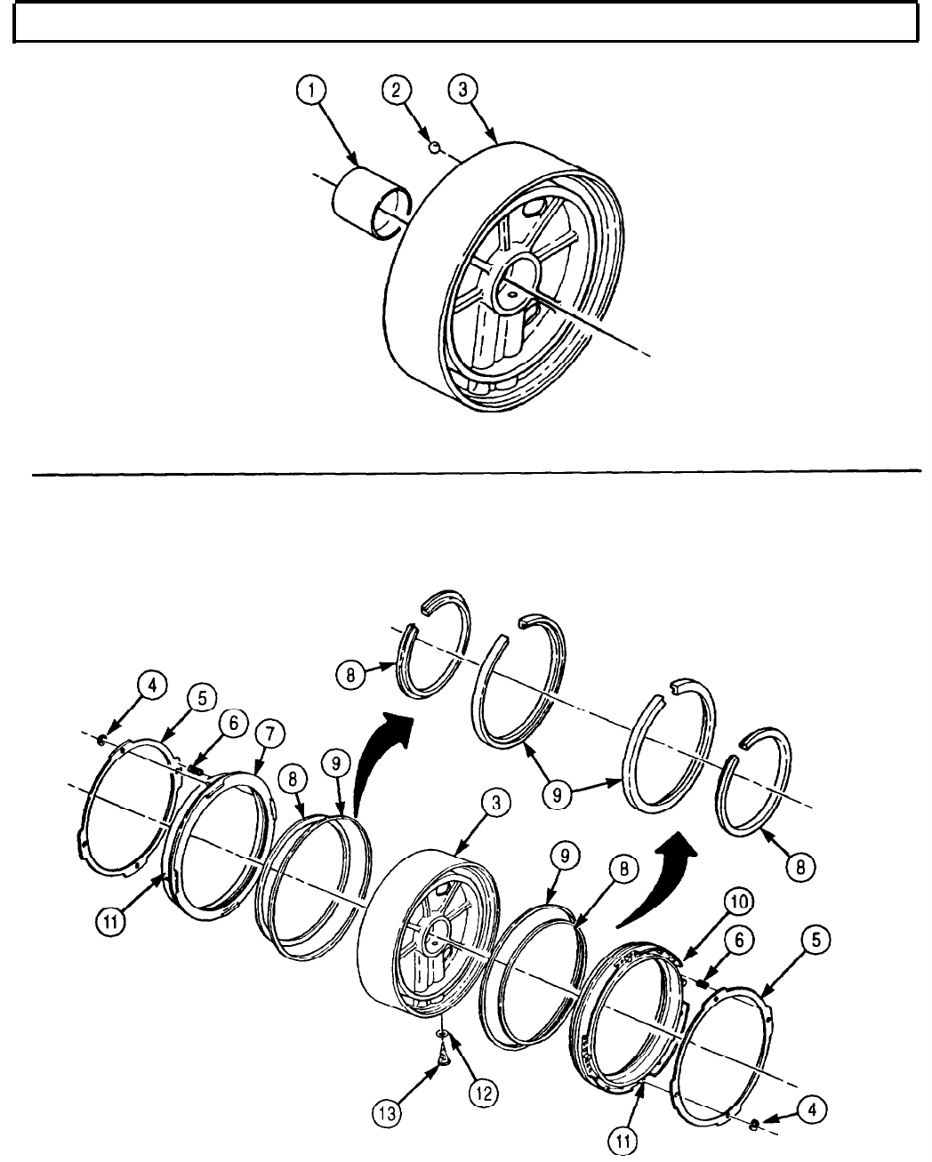
TM 9-2320-272-24-4
5-50. CENTER SUPPORT MAINTENANCE (Contd)
5-345
TM 9-2320-272-24-4
5-50. CENTER SUPPORT MAINTENANCE (Contd)
e. Installation
NOTE
Tilt front end of transmission housing upward before beginning
installation.
1.
Attach center support lifter to center support (4).
NOTE
Ensure center support is seated firmly against second clutch
snapring.
Do not use old-style washer or hex-head anchor bolt.
2.
Carefully position center support (4) in transmission housing (5) with the anchor bolt hole (6) on
center support (4) and transmission housing center support hole (14) aligned.
3.
Install center support (4) in transmission housing (5) with new chamfered washer (13) and anchor
bolt (12). Tighten anchor bolt (13) finger-tight.
4.
Remove center support lifter from center support (4).
5.
Position compressor base (9) on center support (4).
6.
Install compressor bar (10) and screw (8) on transmission housing (5) with two screws (11).
7.
Tighten compressor screw (8) 5 lb-ft (7 N•m).
8.
Measure clearance between top edge of center support (4) and top of center support snapring
groove (7) in transmission housing (5) with snapring gauge.
NOTE
Refer to table 5-14 to select. correct size snapring to be installed in
step 12.
9.
Release pressure from center support (4) by loosening compressor screw (8).
10.
Remove compressor bar screws (11), compressor bar (10) and screw (8), and compressor base (9)
from center support (4).
11.
Install third clutch piston (2) in center support (4).
12.
Install center support snapring (1) in transmission housing (5). Ensure snapring (1) is fully seated.
13.
Tighten anchor bolt (12) 39-46 lb-ft (53-62 N•m)
14.
Apply liberal amount of oil-soluble grease on two new step-joint seal rings (3), and install two new
step-joint seal rings (3) on hub of center support (4).
Table 5-14. Center Support Snapring.
MEASURED
SNAPRING
CLEARANCE THICKNESS
0.150-0.154 in. 0.148-0.150 in.
(3.81-3.91 mm) (3.76-3.81 mm)
0.154-0.157 in. 0.152-0.154 in.
(3.91-3.99 mm) (3.86-3.91 mm)
0.157-0.160 in. 0.155-0.157 in.
(3.99-4.06 mm) (3.94-3.99 mm)
0.160-0.164 in. 0.158-0.160 in.
(4.06-4.17 mm) (4.01-4.06 mm)
SNAPRING
COLOR
White
Yellow
Green
Red
5-346
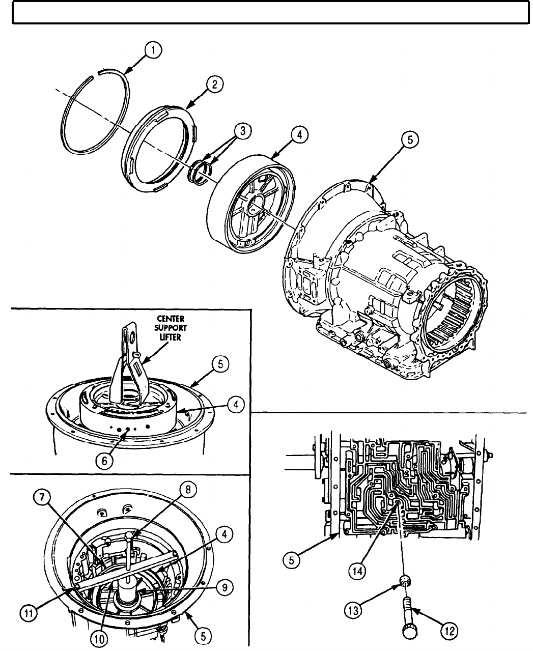

TM 9-2320-272-24-4
5-51. GEAR UNIT AND MAIN SHAFT MAINTENANCE
THIS TASK COVERS:
a. Removal d. Assembly
b. Disassembly e. Installation
c. Cleaning and Inspection
INITIAL SETUP:
APPLICABLE MODELS
All
SPECIAL TOOLS
Gear unit lifter (Appendix E, Item 58)
Tools
General mechanic’s tool kit (Appendix E, Item 1)
Outside micrometer (Appendix E, Item 80)
Vernier caliper (Appendix E, Item 159)
Snapring pliers (Appendix E, Item 125)
MATERIALS/PARTS
Oil-soluble grease (Appendix C, Item 53)
REFERENCES (TM)
TM 9-2320-272-24P
EQUIPMENT CONDITION
Center support removed (para. 5-50).
SPECIAL ENVIRONMENTAL CONDITIONS
Work area clean and free from blowing dirt and
dust.
a. Removal
Attach gear unit lifter to gear unit main shaft (1) and remove gear unit (2) from transmission housing (3).
b. Disassembly
1.
Remove thrust washer (4), front sun gear (5), sun gear shaft (7), and thrust washer (6) from front
planetary carrier (8).
2.
Remove front planetary carrier (8) and thrust washer (9) from planetary carrier drum (10).
3.
Remove snapring (12) from ring gear (13) and lift ring gear (13) out of planetary carrier drum (10).
4.
Remove center planetary carrier (11) from planetary carrier drum (10).
5.
Remove roller bearing (14) and bearing race (15) from main shaft (18).
6.
Remove snapring (19) from main shaft (18) and slide lower planetary sun gear (20) off main shaft (18).
7.
Remove main shaft (18) from rear planetary sun gear (23).
8.
Remove center ring gear (17) and rear planetary sun gear (23) from rear planetary carrier (22).
9.
Remove snapring (16) from center ring gear (17) and slide rear planetary sun gear (23) out of center
ring gear (17).
10.
Remove snapring (21) from rear planetary carrier (22) and lift rear planetary carrier (22) out of
planetary carrier drum (10).
5-348
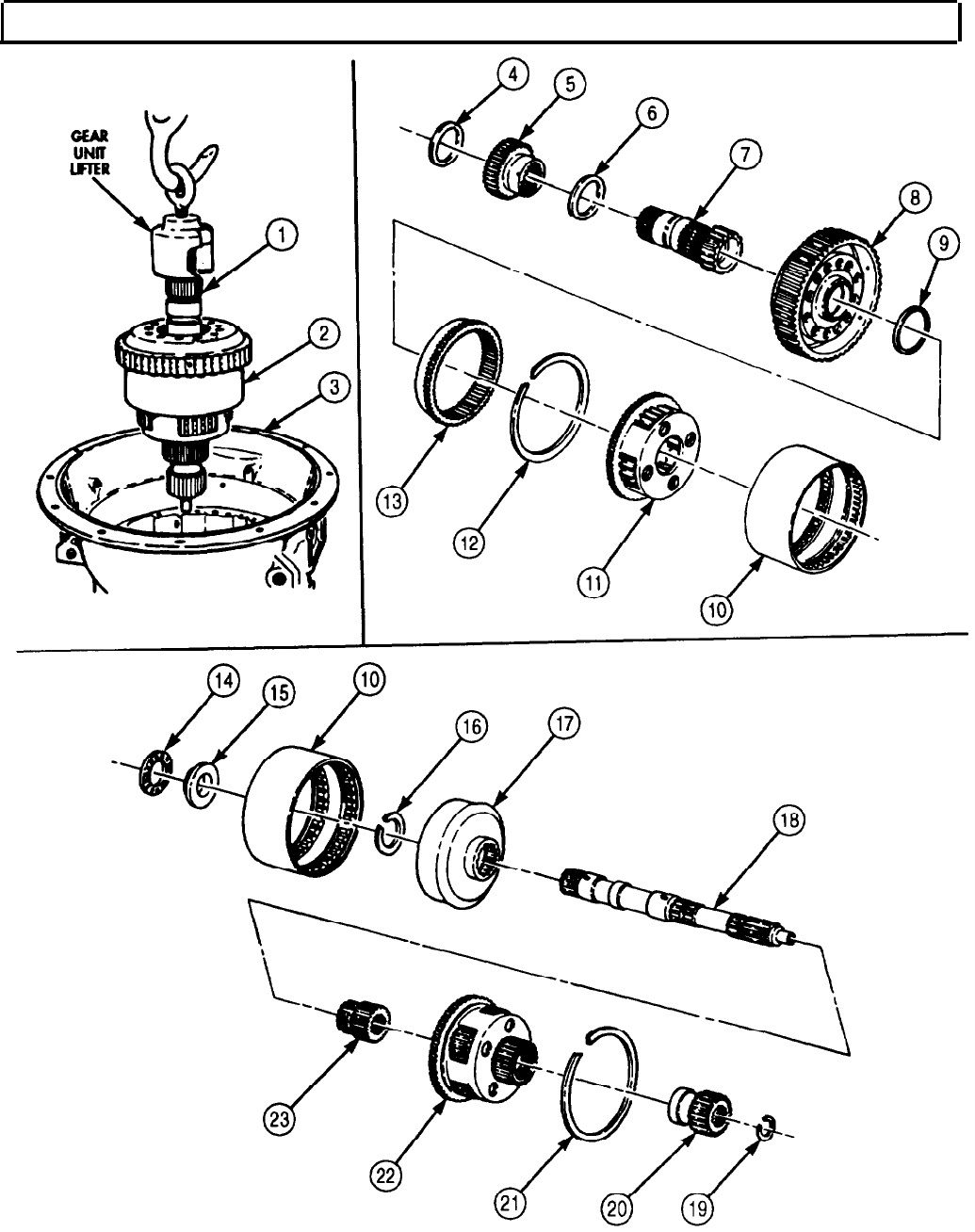
TM 9-2320-272-24-4
5-51. GEAR UNIT AND MAIN SHAFT MAINTENANCE (Contd)
5-349
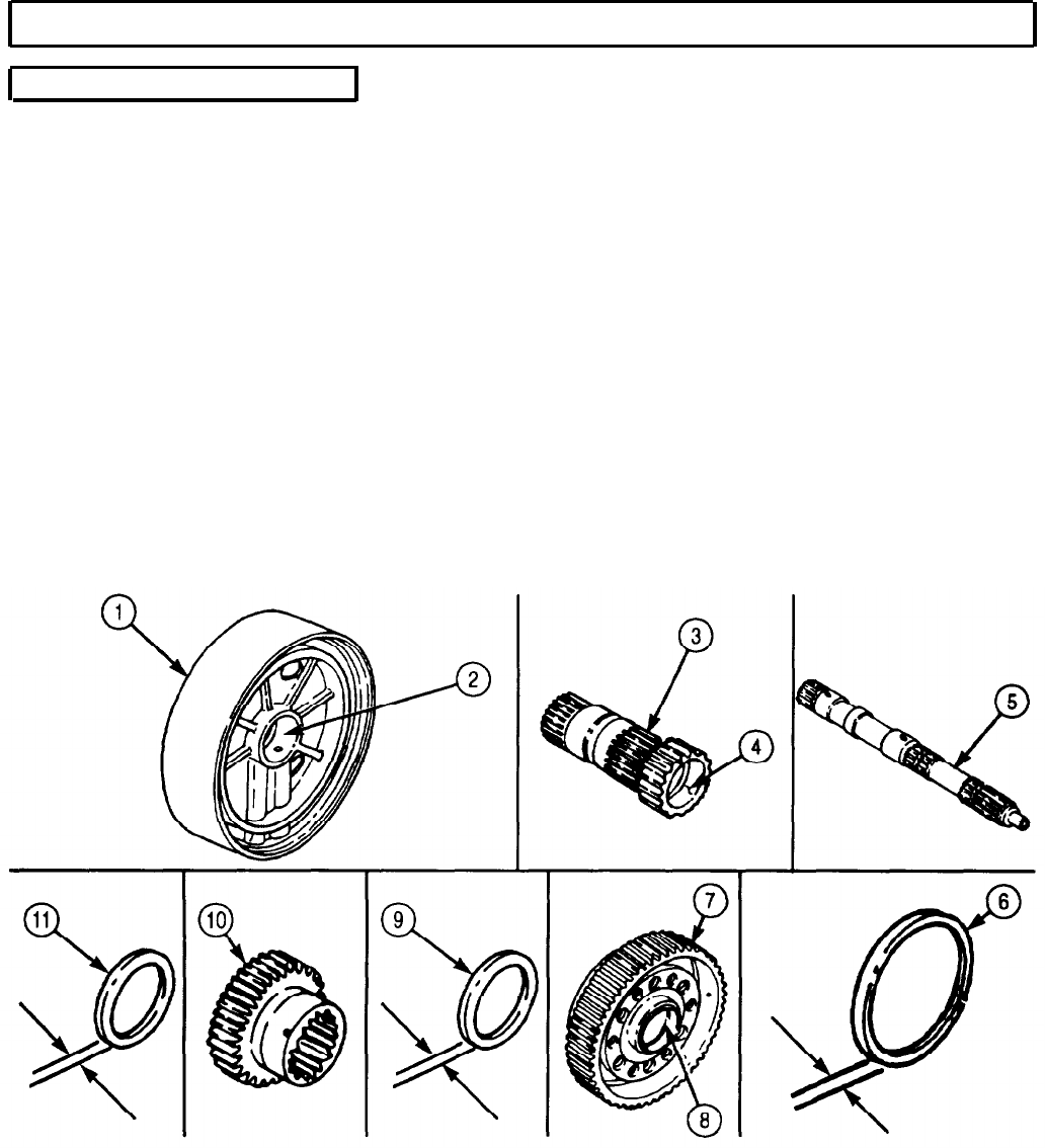
TM 9-2320-272-24-4
5-51. GEAR UNIT AND MAIN SHAFT MAINTENANCE (Contd)
c. Cleaning and Inspection
1.
2.
3.
4.
5.
6.
7.
8.
9.
For general cleaning instructions, refer to para. 2-14.
For general inspection instructions, refer to para. 2-15.
Measure thickness of thrust washer (11). If thrust washer (11) thickness is less than 0.092 in.
(2.354 mm), discard thrust washer (11).
Measure clearance from thrust washer (11) to front sun gear (10). If clearance from thrust
washer (11) to front sun gear (10) exceeds 0.005 in. (0.127 mm), discard thrust washer (11).
Measure thickness of thrust washers (6) and (9). If thickness is less than 0.091 in. (2.31mm),
discard thrust washers (6) and (9).
Inspect thrust washers (6) and (9) for scoring. If scored, discard thrust washers (6) and (9).
Measure clearance of two sun gear shaft bushings (4) on main shaft (5). If clearance exceeds
0.006 in. (0.152 mm), discard two sun gear shaft bushings (4).
Measure clearance of front planetary carrier (7) bushing (8) on front sun gear (10). If clearance
exceeds 0.005 in. (0.127 mm), discard front planetary carrier (7) bushing (8).
Measure clearance of sun gear shaft (3) on center support bushing. (2). If clearance exceeds 0.006 in.
(0.152 mm), discard sun gear shaft (3), or replace bushing (2) in center support (1) (para. 5-50).
5-350
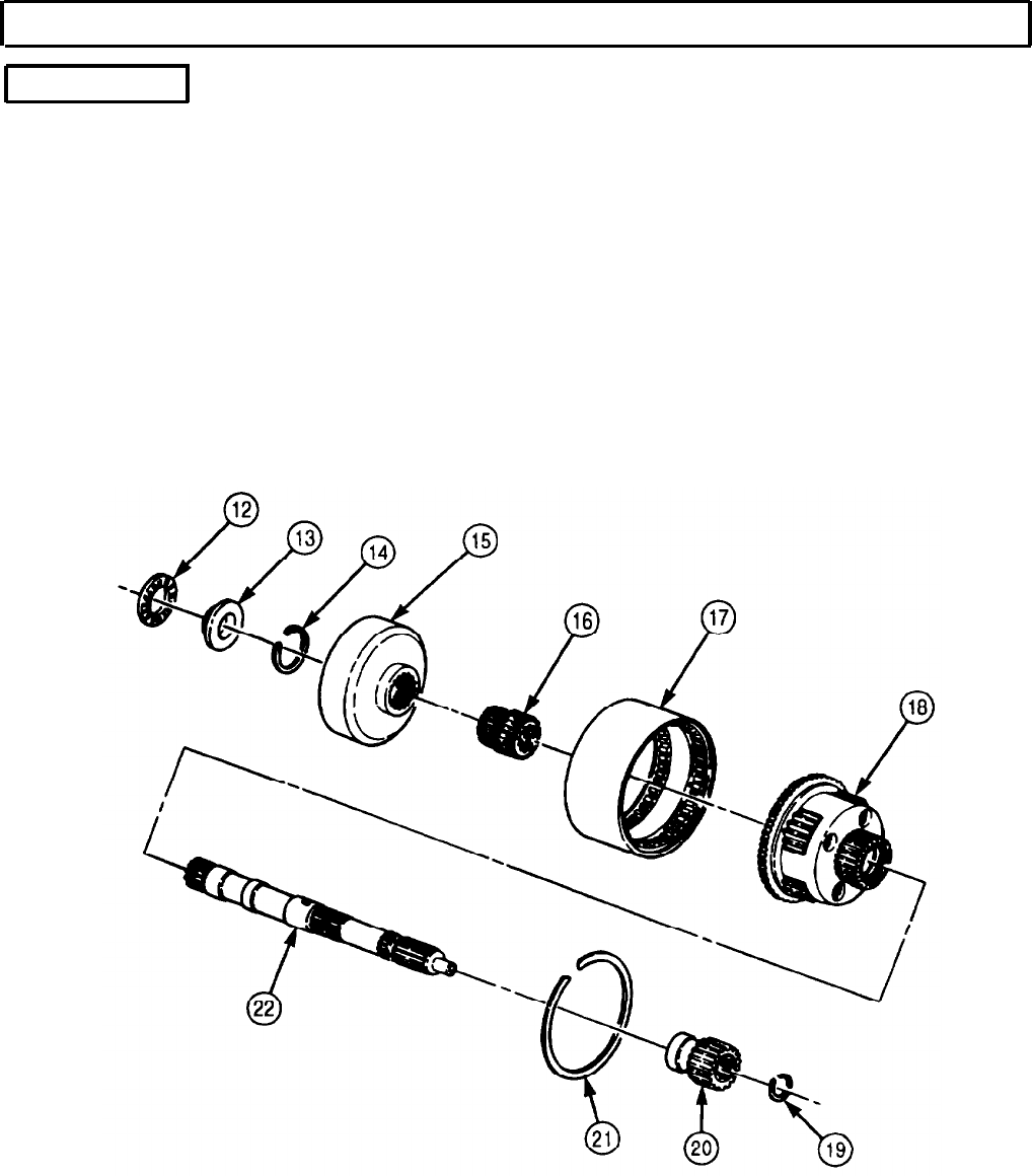
TM 9-2320-272-24-4
5-51. GEAR UNIT AND MAIN SHAFT MAINTENANCE (Contd)
d. Assembly
1.
2.
3.
4.
5.
6.
Position rear planetary carrier (18) in short splined end of planetary carrier drum (17) and install
with snapring (21).
Position rear planetary sun gear (16) in center ring gear (15) until seated and install with
snapring (14).
Install center ring gear (15) in planetary carrier drum (17), until seated against rear planetary
carrier (18).
Install main shaft (22) into rear planetary sun gear (16), ensuring smaller end is installed first.
Install lower planetary sun gear (20) on rear of main shaft (22) with snapring (19).
NOTE
Use oil-soluble grease to hold bearing race and bearing in place.
Install bearing race (13) and bearing (12) on main shaft (22). Ensure lip of bearing race (13) faces
away from center ring gear (15).
5-351
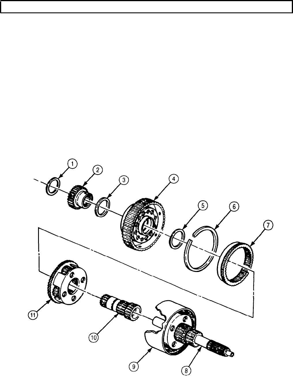
TM 9-2320-272-24-4
5-51. GEAR UNIT AND MAIN SHAFT MAINTENANCE (Contd)
7.
8.
9.
10.
11.
12.
13. Install sun gear shaft (10) over main shaft (8) in planetary carrier (9) until seated against bearing.
14. Install thrust washer (1) on sun gear (2) and over the gear shaft (10).
Install center planetary carrier (11) in long splined end of planetary carrier drum (9).
Place front planetary ring gear (7) in planetary carrier drum (9) over center planetary carrier (11)
and install with snapring (6).
NOTE
Use oil-soluble grease to hold thrust washers in place.
Install thrust washer (5) on front planetary carrier (4).
Install front planetary carrier (4) in planetary carrier drum (9).
Install thrust washer (3) on sun gear (2).
Install front sun gear (2) on sun gear shaft (10). Ensure spring pin on sun gear shaft (10) is aligned
with wide spline on front sun gear (2).
NOTE
Ensure sun gear teeth and front planetary pinion teeth are flush
and the front of the sun gear shaft is past groove between double
splines on the main shaft.
5-352
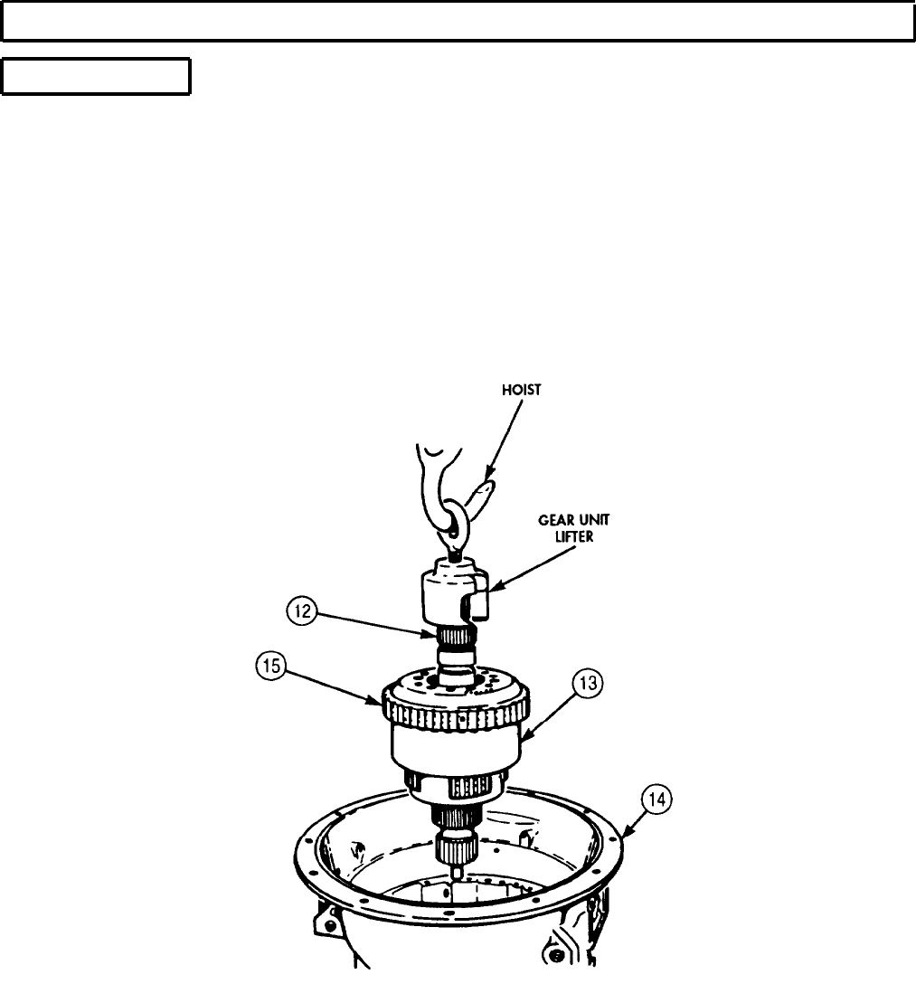
TM 9-2320-272-24-4
5-51. GEAR UNIT AND MAIN SHAFT MAINTENANCE (Contd)
e. Installation
1.
Attach gear unit lifter to gear unit main shaft (12).
2.
Carefully lower gear unit (13) into transmission housing (14) with hoist. Ensure all gear teeth (15)
mesh.
3.
Remove gear unit lifter from gear unit main shaft (12).
FOLLOW-ON TASK: Install center support (para. 5-50).
5-353
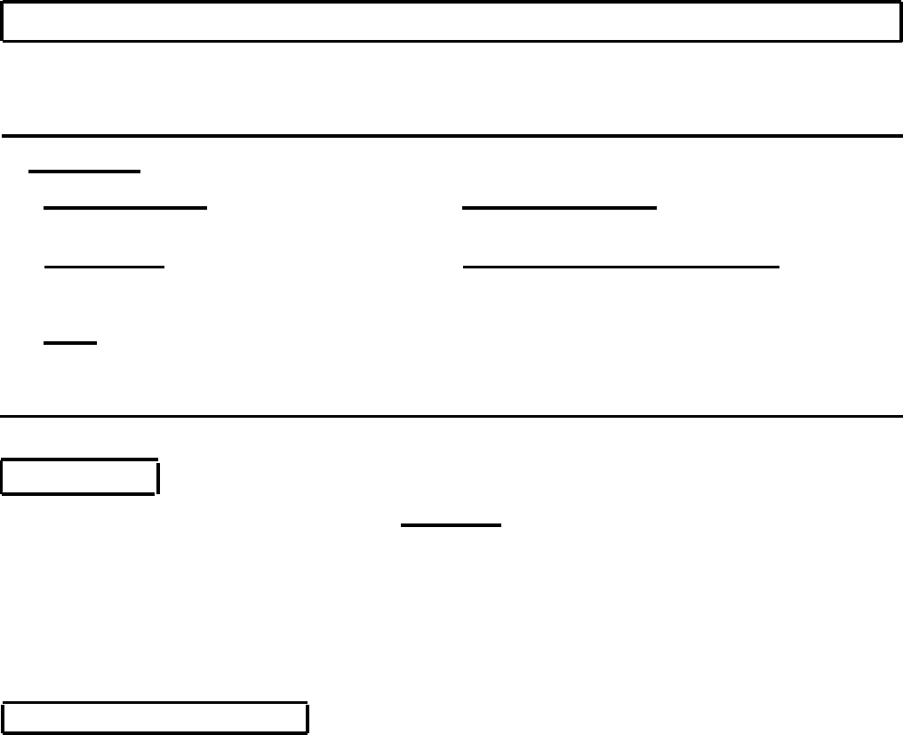
TM 9-2320-272-24-4
5-52. SECOND CLUTCH MAINTENANCE
THIS TASK COVERS:
a. Removal c. Installation
b. Cleaning and Inspection d. Establishing Clearance
INITIAL SETUP:
APPLICABLE MODELS
All
SPECIAL TOOLS
Second clutch clearance gauge (Appendix E,
Item 118)
EQUIPMENT CONDITION
Gear unit and main shaft removed (para. 5-51).
SPECIAL ENVIRONMENTAL CONDITIONS
Work area clean and free from blowing dirt and dust.
TOOLS
General mechanic’s tool kit (Appendix E, Item 1)
Outside micrometer (Appendix E, Item 80)
Vernier caliper (Appendix E, Item 159)
a. Removal
CAUTION
Second clutch consists of a backplate, four clutch plates, and four
clutch discs. Keep all clutch parts together. Intermixing second
clutch parts with any other clutch pack will cause transmission
damage.
NOTE
Tag all second clutch parts for reassembly.
Remove snapring (l), four clutch discs (5), clutch plates (2), and backplate (4) from transmission housing (3).
b. Cleaning and Inspection
Flying rust and metal particles may cause injury to personnel.
1.
For general cleaning instructions, refer to para. 2-14.
2.
For general inspection instructions, refer to para. 2-15.
3.
Inspect clutch plate (2) for burned surfaces. If burned, discard clutch plate (2).
4.
Inspect clutch discs (5) for burned surfaces. If burned, discard clutch disc (5).
5.
Measure backplate (4) thickness.
a. If thickness of backplate (4) marked No. 10 is less than 0.234 in. (5.94 mm), discard backplate (4).
b. If thickness of backplate (4) marked No. 11 is less than 0.208 in. (5.28 mm), discard backplate (4).
b. If thickness of backplate (4) marked No. 12 is less than 0.221 in. (5.61 mm), discard backplate (4).
5-354
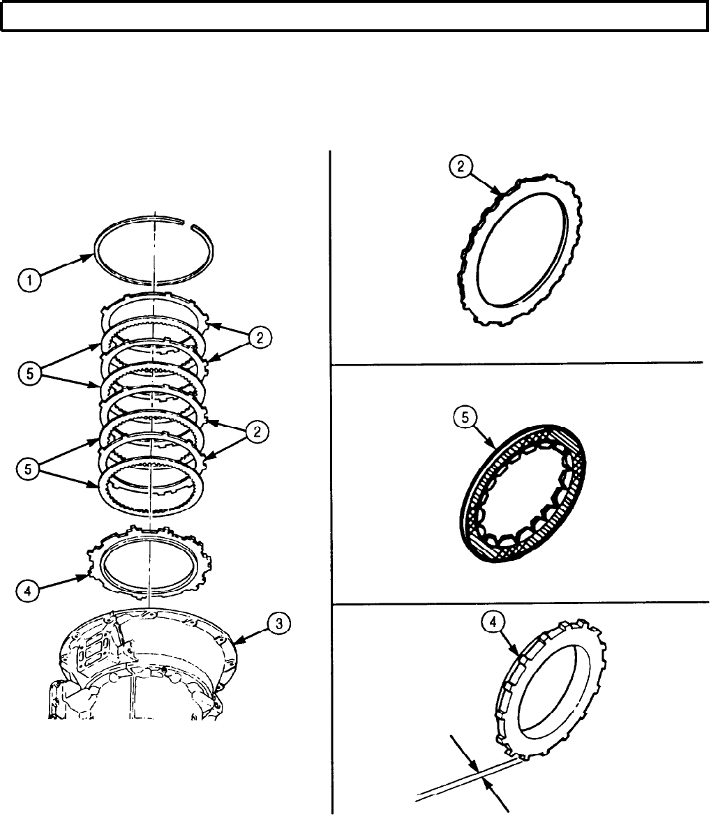
TM 9-2320-272-24-4
5-52. SECOND CLUTCH MAINTENANCE (Contd)
5-355
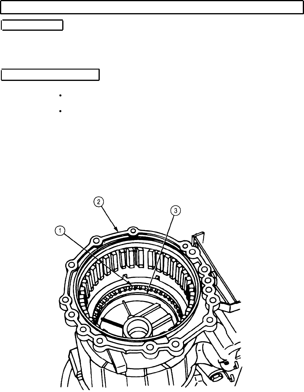
TM 9-2320-272-24-4
5-52. SECOND CLUTCH MAINTENANCE (Contd)
c. Installation
1.
Install backplate (3) in transmission housing (2). Ensure that flat side of backplate (3) is up.
2.
Starting with clutch disc (1), alternately install four clutch discs (1) and four clutch plates (5) in
transmission housing (2).
3.
Install snapring (4) on top of clutch plates (5).
d. Establishing Clearance
NOTE
Adapter housing and first clutch must be removed to establish
second clutch clearance. Refer to paras. 5-57 and 5-53.
Tilt rear end of transmission housing upward in order to
establish clearance.
1.
Measure clearance between backplate (3) and transmission housing (2). Clearance should be
0.059-0.129 in. (1.49-3.28 mm).
2.
If second clutch clearance exceeds 0.059-0.129 in. (1.49-3.28 mm), replace clutch discs (1) with new,
thicker clutch discs (1).
3.
If clutch clearance still exceeds 0.129 in. (3.28 mm) after completing step 1, replace backplate (3)
with new, thicker backplate.
4.
If clearance is less than 0.059 in. (1.49 mm), replace backplate (3) with new, thinner backplate (3).
5.
If first clutch and adapter housing were removed to establish second clutch clearance, install them
(paras. 5-57 and 5-53).
5-356
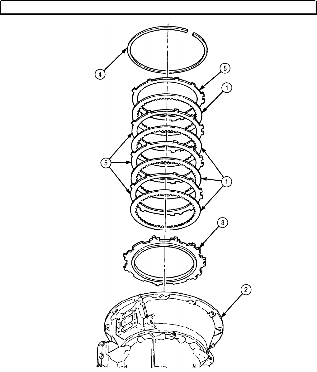
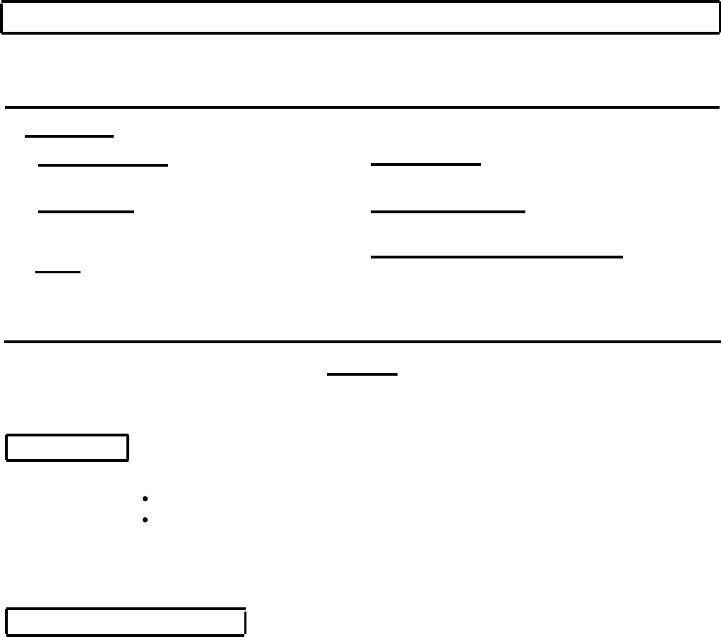
TM 9-2320-272-24-4
5-53. FIRST CLUTCH MAINTENANCE
THIS TASK COVERS:
a. Removal
b. Cleaning and Inspection c. Installation
d. Establishing Clearance
INITIAL SETUP:
APPLICABLE MODELS
All
SPECIAL TOOLS
First clutch clearance gauge (Appendix E,
Item 45)
TOOLS
General mechanic’s tool kit (Appendix E, Item 1)
Outside micrometer (Appendix E, Item 80)
Vernier caliper (Appendix E, Item 159)
Snapring pliers (Appendix C, Item 125)
REFERENCES (TM)
TM 9-2320-272-24P
EQUIPMENT CONDITION
Second clutch removed (para. 5-52).
SPECIAL ENVIRONMENTAL CONDITIONS
Work area clean and free from blowing dirt and
dust.
CAUTION
First clutch consists of a backplate, six clutch plates, and six clutch
discs. Keep all clutch parts together. Intermixing first clutch parts
with any other clutch pack will cause transmission damage.
a. Removal
NOTE
Tag all first clutch parts for reassembly.
Backplate, five clutch discs, four clutch plates, and
rear planetary ring gear are removed as one unit.
1.
Remove snapring (5), backplate (6), five clutch discs (3), four clutch plates (2), and rear planetary
ring gear (1) from transmission housing (4).
2.
Remove remaining two clutch plates (2) and clutch disc (3) from transmission housing (4).
b. Cleaning and Inspection
1.
For general cleaning instructions, refer to para. 2-14.
2.
For general inspection instructions, refer to para. 2-15.
3.
Inspect clutch discs (3) for burned surfaces. If surfaces are burned, discard clutch discs (3).
4.
Inspect clutch plate (2) for burned surfaces. If surfaces are burned, discard clutch plate (2).
NOTE
Cast iron backplates marked number 1, 2, and 3 must have same
thickness as corresponding new malleable iron backplates 4,5, and 6.
5.
Measure backplate (6) thickness.
a. If thickness of backplate (6) marked No. 4 is less than 0.702 in. (17.83 mm), discard backplate (6).
b. If thickness of backplate (6) marked No. 5 is less than 0.671 in. (17.04 mm), discard backplate (6).
c. If thickness of backplate (6) marked No. 6 is less than 0.640 in. (16.26 mm), discard backplate (6).
5-358
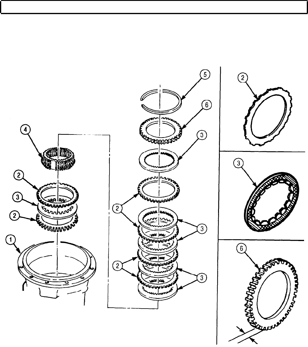
TM 9-2320-272-24-4
5-53. FIRST CLUTCH MAINTENANCE (Contd)
5-359

TM 9-2320-272-24-4
5-53. FIRST CLUTCH MAINTENANCE (Contd)
c. Installation
1.
Starting with clutch plate (2), alternately install two clutch plates (2) and one clutch disc (3) in
transmission housing (1).
2.
Install rear planetary ring gear (4) in transmission housing (1). Ensure all clutch plate (2) tangs
and clutch disc (3) splines mesh.
3.
Starting with clutch disc (3), alternately install five clutch discs (3) and four clutch plates (2) on rear
planetary ring gear (4).
4.
Install backplate (6) and snapring (5) in transmission housing (1). Ensure flat side of backplate (6) is
installed first.
d. Establishing Clearance
1.
Measure clearance between snapring (5) and backplate (6) with first clutch clearance gauge. Clutch
running clearance should be 0.074-0.147 in. (1.880-3.374 mm).
2.
If clutch running clearance exceeds 0.147 in. (3.734 mm), replace clutch plates (2) and discs (3) with
new, thicker plates (2) and discs (3).
3.
If clutch running clearance still exceeds 0.147 in. (3.374 mm) after completing step 2, replace
backplate (6) with new, thicker backplate (6).
4.
If clutch running clearance is less than 0.074 in. (3.374 mm), replace backplate (6) with new,
thinner backplate (6).
5-360
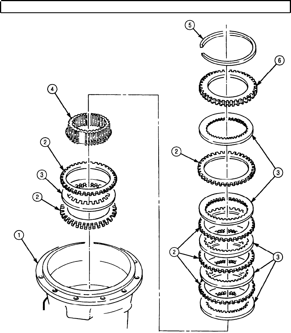

TM 9-2320-272-24-4
5-54. TRANSMISSION GOVERNOR REPLACEMENT
THIS TASK COVERS
a. Removal b. Installation
INITIAL SETUP:
APPLICABLE MODELS REFERENCES (TM)
All TM 9-2320-272-24P
TOOLS EQUIPMENT CONDITION
General mechanic’s tool kit (Appendix E, Item 1) First clutch removed (para. 5-53)
Torque wrench (Appendix E, Item 146)
MATERIALS/PARTS
Governor cover gasket (Appendix D, Item 241)
SPECIAL ENVIRONMENTAL CONDITIONS
Work area clean and free from blowing dirt and
dust.
a. Removal
1.
Remove four screws (3), governor cover (4), and gasket (5) from transmission rear cover (2). Discard
gasket (5).
2.
Rotate transmission governor (6) clockwise to disengage, and remove transmission governor (6) from
transmission rear cover (2).
b. Installation
NOTE
Governor is properly seated only after counterclockwise rotation of
governor gear is felt during installation.
1.
Insert plastic gear (7) end of transmission governor (6) into transmission governor bore (1) and push
inward. Ensure governor (6) is properly seated.
2.
Install new gasket (5) and governor cover (4) on transmission rear cover (2) with four screws (3).
Tighten screws (3) 15-20 lb-R (20-27 N•m).
5-362
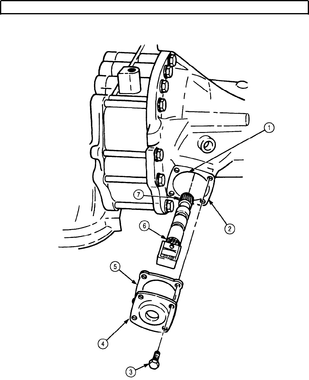
TM 9-2320-272-24-4
5-55. REAR COVER AND LOW PLANETARY CARRIER MAINTENANCE
THIS TASK COVERS:
a. Removal
b. Disassembly c. Cleaning and Inspection
d. Assembly
INITIAL SETUP:
APPLICABLE MODELS MATERIALS/PARTS
All
SPECIAL TOOLS
Driver handle (Appendix E, Item 38)
Spring compressor (Appendix E, Item 31)
Rear bearing installer (Appendix E, Item 115)
Driver handle (Appendix E, Item 37)
Seal remover (Appendix E, Item 92)
Converter turbine bearing puller
(Appendix E, Item 105)
Pin remover (Appendix E, Item 94)
Bearing installer (Appendix E, Item 10)
‘Iwo guide pliers (Appendix E, Item 59)
Tools
General mechanic’s tool kit (Appendix E, Item 1)
Outside micrometer (Appendix-E, Item 80)
Vernier calipers (Appendix E, Item 159)
Spring tester (Appendix E, Item 131)
Torque wrench (Appendix E, Item 144)
Arbor press
Low clutch piston inner seal ring
(Appendix D, Item 259)
Low clutch piston outer seal ring
(Appendix D, Item 509)
Gasket (Appendix D, Item 228)
Crocus cloth (Appendix C, Item 20)
Oil-soluble grease (Appendix C, Item 53)
REFERENCES (TM)
TM 9-2320-272-24P
EQUIPMENT CONDITION
Transmission governor removed (para. 5-54).
Transmission output shaft oil seal removed
(para. 4-78).
SPECIAL ENVIRONMENTAL CONDITIONS
Work area clean and free from blowing dirt and
dust.
a. Removal
NOTE
Turn transmission housing with rear cover facing upward.
1.
Remove fourteen screws (1) and washers (5) from rear cover (2).
NOTE
Clean gasket remains from mating surfaces.
2.
Remove rear cover (2), low planetary carrier (9), gasket (4), and thrust washer (10) from
transmission housing (3). Discard gasket (4).
3.
Remove sleeve spacer (6), speedometer drive gear (7), and governor drive gear (8) from low
planetary carrier (9).
5-364
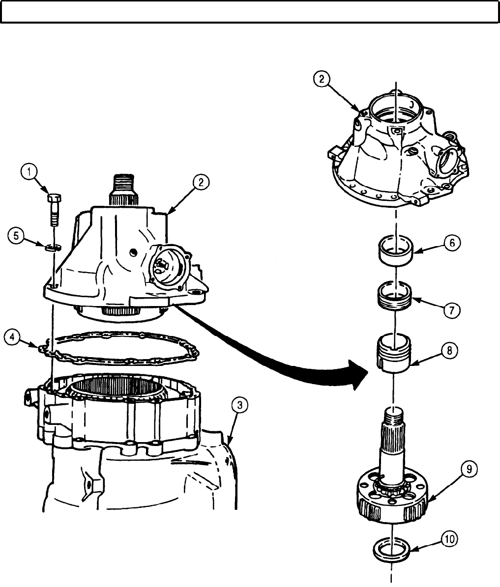
TM 9-2320-272-24-4
5-55. REAR COVER AND LOW PLANETARY CARRIER MAINTENANCE (Contd)
5-365
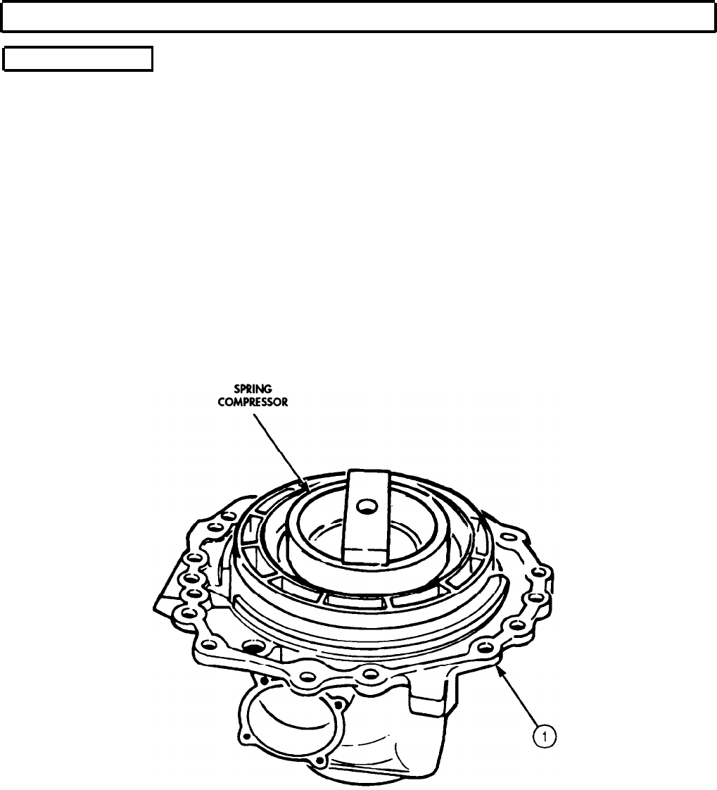
TM 9-2320-272-24-4
5-55. REAR COVER AND LOW PLANETARY CARRIER MAINTENANCE (Contd)
b. Disassembly
1.
Remove dust cover (11) and oil seal (10) from rear cover (1) with seal puller and hook.
2. Remove beveled snapring (9) and rear output shaft bearing (8) from rear cover (1) with converter
turbine bearing puller.
3.
Position spring compressor and arbor press on low clutch spring retainer (3) and apply pressure to
spring retainer (3).
4.
Remove snapring (2) and spring compressor from low clutch spring retainer (3).
5.
Remove low clutch spring retainer (3) and twenty-six piston return springs (4) from low clutch
piston (5).
6.
Remove low clutch piston (5) from rear cover (1).
7.
Remove outer seal ring (6) and inner seal ring (7) from low clutch piston (5). Discard seal rings (6)
and (7).
8.
Remove plug (13), drain tube (12), and plug (17) from rear cover (1).
9.
Remove filter plug (14), O-ring (15), and governor filter (16) from rear cover (1).
5-366
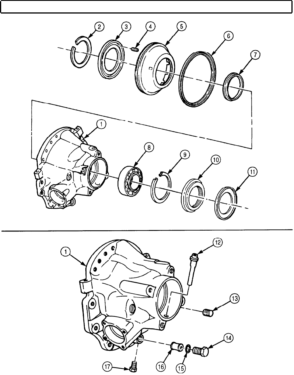
TM 9-2320-272-24-4
5-55. REAR COVER AND LOW PLANETARY CARRIER MAINTENANCE (Contd)
5-367
TM 9-2320-272-24-4
5-55. REAR COVER AND LOW PLANETARY CARRIER MAINTENANCE (Contd)
c. Cleaning and Inspection
1.
2.
3.
4.
5.
6.
7.
8.
9.
10.
11.
12.
13.
14.
15.
For general cleaning instructions, refer to para. 2-14.
For general cleaning instructions, refer to para. 2-15.
Inspect rear cover (1) for breaks and cracks. Replace rear cover (1) if broken or cracked.
Measure governor clearance in bore (2) of rear cover (1). Replace rear cover (1) if clearance exceeds
.0035 in. (.0089 mm).
Inspect governor support pin (9) for looseness, bends, and breaks. Replace governor support pin (9)
with pin remover if loose, bent, or broken.
Inspect low planetary carrier (5) for missing or twisted splines (6). Replace low planetary carrier (5)
if splines (6) are missing or twisted.
Inspect low planetary carrier (5) for burrs. If burrs are found, remove using crocus cloth.
Inspect roller bearing (7) on low planetary carrier (5) and race (8) in rear cover (1). Replace
bearing (7) and race (8) as a set if defective.
NOTE
Perform steps 9 and 10 only if bearing or race is defective.
Pin must be removed to remove bearing.
Remove pin (4) and roller bearing (7) from low planetary carrier (5). Discard pin (4).
Remove race (8) from rear cover (1) using bearing puller.
Measure thrust washer (3) thickness. Discard thrust washer (3) if thickness is less than 0.091 in.
(2.31mm).
Inspect thrust washer (3) for scoring. Discard if scored.
Inspect twenty-six piston return springs (10) for discoloration due to overheating. Discard piston
return springs (10) if discolored.
Inspect twenty-six piston return springs (10) for broken coils or coils distorted due to wear. Discard
piston return springs (10) if broken or distorted.
Inspect twenty-six piston return springs (10) for serviceability by checking load when compressed
with spring tester. Discard spring (10) if spring (10) does not give load according to table 5-15,
Spring Data.
Table 5-15. Spring Data.
SPRING
Piston return spring
COLOR
FREE LENGTH
COMPRESSED LENGTH UNDER LOAD
Solid orange, 1.28 in. 0.95 in. 13.6-16.4 lb
yellow stripe (32.5 mm) (24.1 mm) (60.5-72.9 N)
5-368
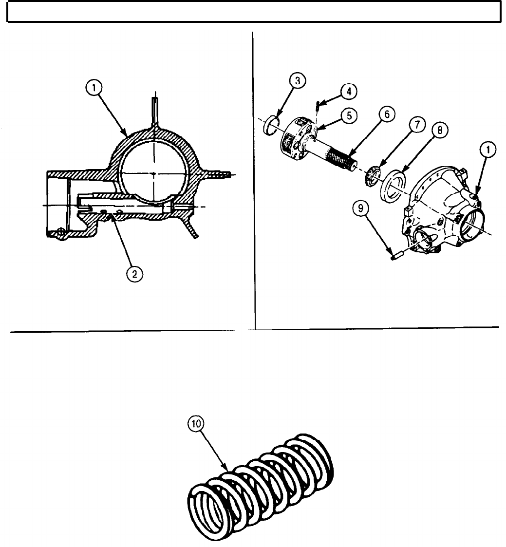
TM 9-2320-272-24-4
5-55. REAR COVER AND LOW PLANETARY CARRIER MAINTENANCE (Contd)
5-369
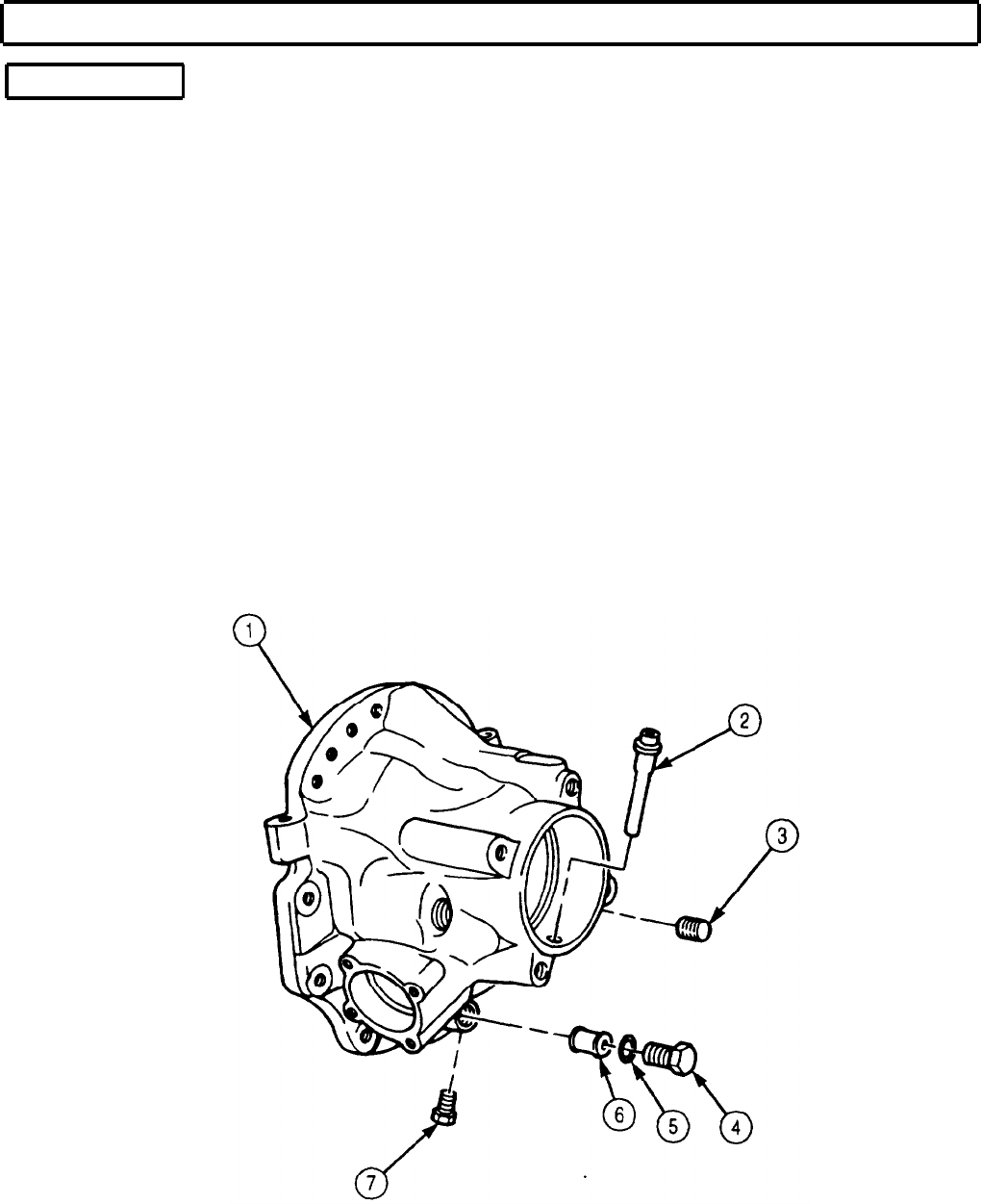
TM 9-2320-272-24-4
5-55. REAR COVER AND LOW PLANETARY CARRIER MAINTENANCE (Contd)
d. Assembly
1.
Install governor filter (6), O-ring (5), and filter plug (4) in rear cover (1). Tighten filter plug (4)
50-70 lb-ft (68-95 N•m).
2.
Install drain tube (2) and plug (3) in rear cover (1). Tighten plug (3) 12-16 lb-ft (16-22 N•m).
3.
Install plug (7) in rear cover (1). Tighten plug (7) 4-8 lb-ft (5-11 N•m).
NOTE
Perform step 4 only if support pin was previously removed.
4.
Using pin installer, press new governor support pin (11) into rear cover (1) until end of pin (11) is
5.886-5.896 in. (14.950-14.975 cm) from outside face (12) of rear cover (1).
NOTE
Perform steps 5 and 6 only if bearing and bearing race were
previously removed.
5.
Using bearing race installer, install bearing outer race (13) in rear cover (1).
NOTE
Install roller bearing before installing pin.
6.
Install roller bearing (10) and new pin (8) on low planetary carrier (14). Seat roller bearing (10) to
shoulder on shaft (9).
7.
Install new thrust washer (15) if discarded during inspection.
5-370
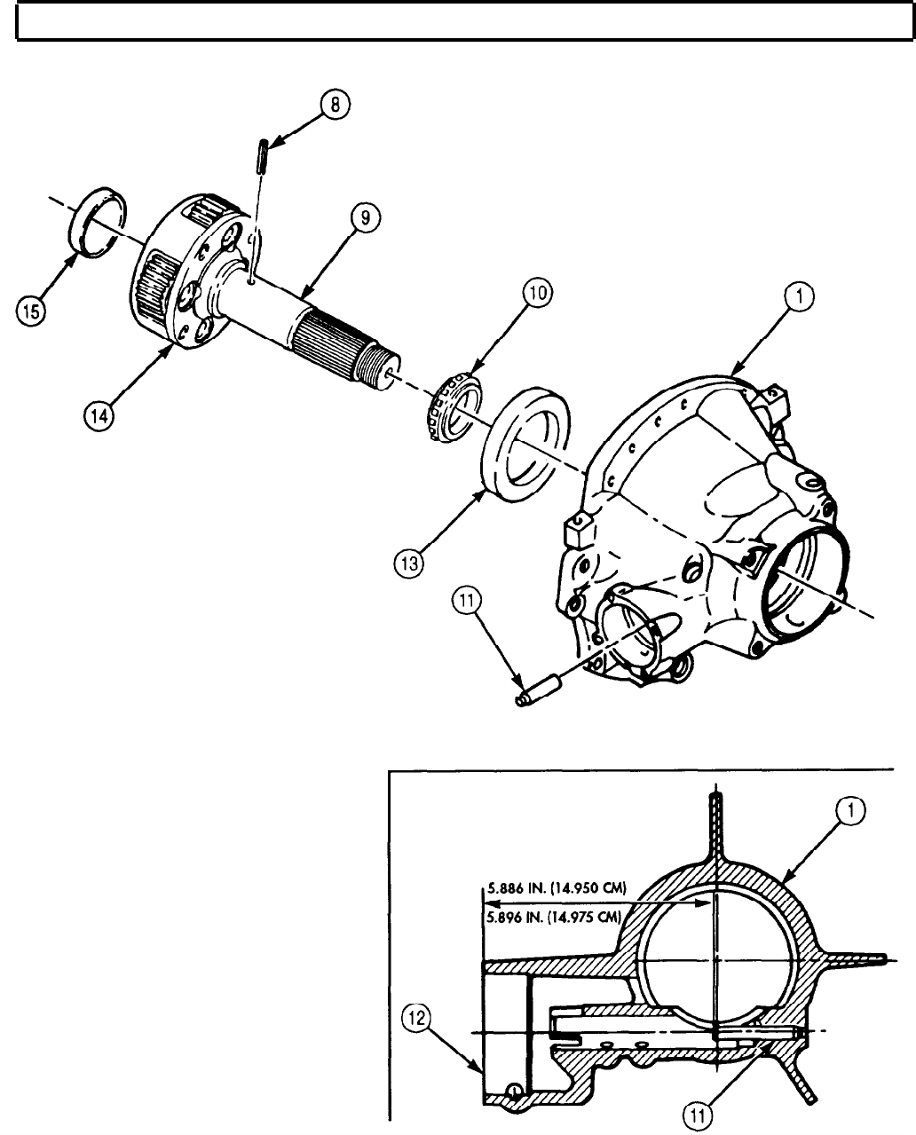
TM 9-2320-272-24-4
5-55. REAR COVER AND LOW PLANETARY CARRIER MAINTENANCE (Contd)
5-371

TM 9-2320-272-24-4
5-55. REAR COVER AND LOW PLANETARY CARRIER MAINTENANCE (Contd)
8.
9.
10.
11.
12.
Install new outer seal ring (6) and new inner seal ring (7) on low clutch piston (5).
Place low clutch piston (5) in rear cover (1).
Place twenty-six piston return springs (4) in low clutch piston (5).
Place cupped side of clutch spring retainer (3) over piston return springs (4).
Place spring compressor and snapring (2) on clutch spring retainer (3) and compress twenty-six piston
return springs (4).
13.
Install clutch spring retainer (3) with snapring (2).
14.
Remove spring compressor from clutch spring retainer (3).
15.
Install rear output shaft bearing (8) in rear cover (1) with bearing installer until seated.
16.
Install beveled snapring (9) in rear cover (1) with beveled side toward rear of transmission.
17.
Install oil seal (10) and dust shield (11) in rear cover (1).
18.
Install rear cover and low planetary carrier (para. 5-58).
NOTE
Ensure seal rings and lips face piston oil pressure side.
Use oil-soluble grease to hold in place.
5-372
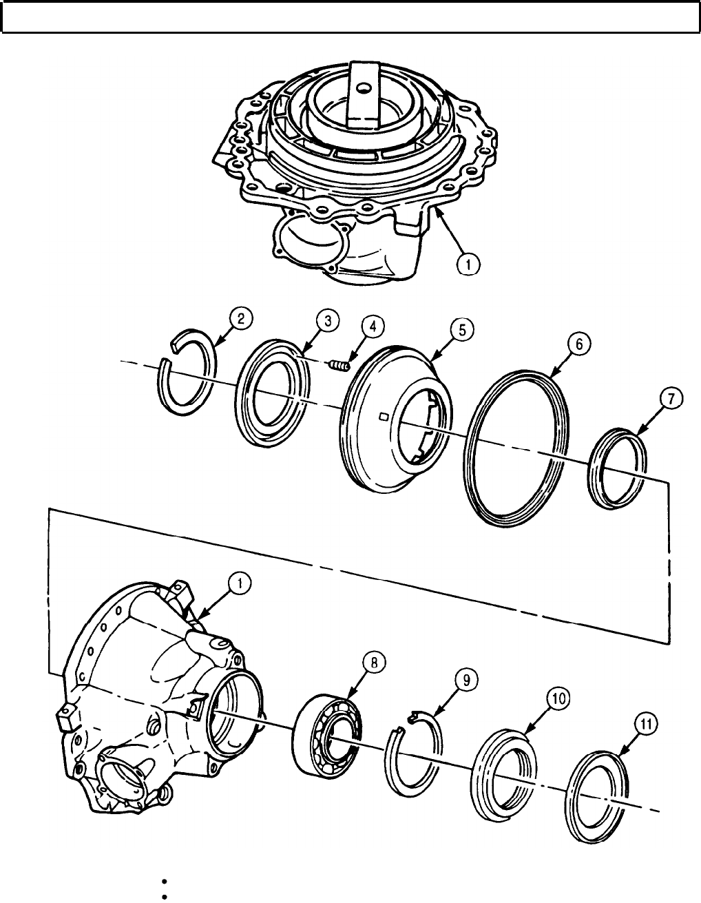
TM 9-2320-272-24-4
5-56. LOW CLUTCH REMOVAL AND CLEARANCE
THIS TASK COVERS:
a. Removal c. Establishing Clearance
b. Cleaning and Inspection
INITIAL SETUP:
APPLICABLE MODELS REFERENCES (TM)
All
TM 9-2320-272-24P
TOOLS EQUIPMENT CONDITION
General mechanic’s tool kit (Appendix E, Item 1)
Depth micrometer (Appendix E, Item 81) Rear cover and low planetary carrier removed
(para. 5-55).
MATERIALS/PARTS
Gasket (Appendix D, Item 228)
SPECIAL ENVIRONMENTAL CONDITIONS
Work area clean and free from blowing dirt and
dust.
a. Removal
1.
Remove low planetary ring gear (1), snapring (3), and low gear ring hub (2) from adapter
housing (6).
NOTE
Mark position of clutch plates in adapter housing for installation.
2.
Remove eight clutch plates (4) and seven clutch discs (5) from adapter housing (6).
b. Cleaning and Inspection
1.
For general cleaning instructions, refer to para. 2-14.
2.
For general inspection instructions, refer to para. 2-15.
3.
Inspect clutch discs (5) for burned surfaces. If burned, discard clutch discs (5).
4.
Inspect clutch plates (4) for burned surfaces. If burned, discard clutch plates (4).
5-374
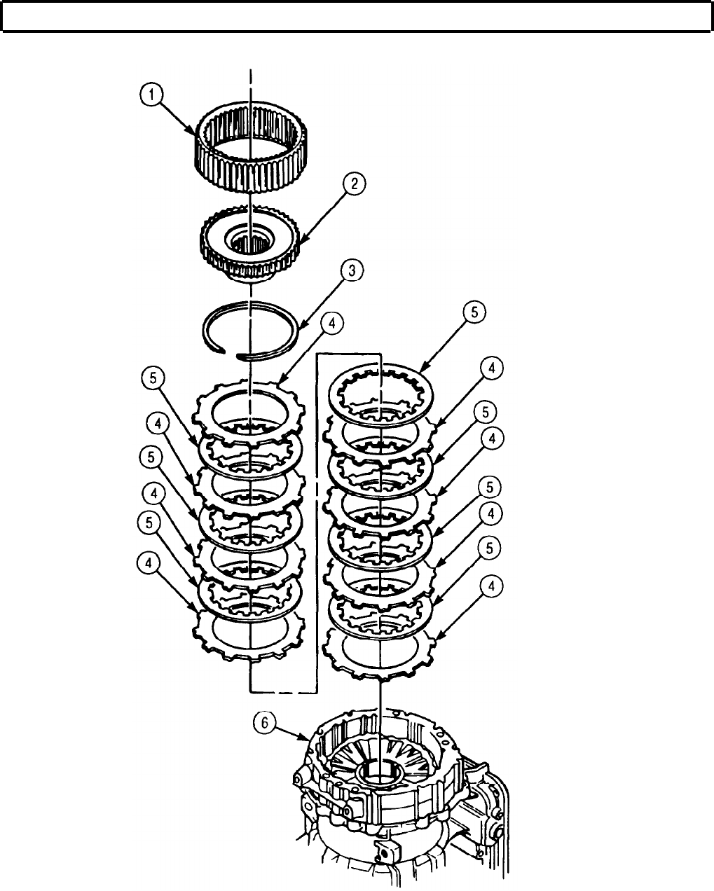
TM 9-2320-272-24-4
5-56. LOW CLUTCH REMOVAL AND CLEARANCE (Contd)
5-375

TM 9-2320-272-24-4
5-56. LOW CLUTCH REMOVAL AND CLEARANCE (Contd)
c. Establishing Clearance
1.
2.
3.
4.
5.
6.
Starting with clutch plate (2), alternately install eight clutch plates (2) and seven clutch discs (3) in
adapter housing (1).
Measure distance from top edge of adapter housing (1) to top of clutch plate (2) with depth
micrometer. Record measurement.
Position new rear cover gasket (4) on rear cover (5).
Measure distance from top of edge of piston (6) to gasket (4) with depth micrometer. Record
measurement.
Subtract step 4 measurement from step 2 measurement. Record the difference. This measurement is
low clutch clearance.
Low clutch clearance, as determined in step 5, should be 0.073-0.141 in. (1.85-3.58 mm). If clutch
clearance exceeds 0.141 in. (3.58 mm), replace clutch plates (2) and discs (3) with new, thicker
plates (2) and discs (3).
7.
Remove eight clutch plates (2) and seven clutch discs (3) from adapter housing (1).
5-376
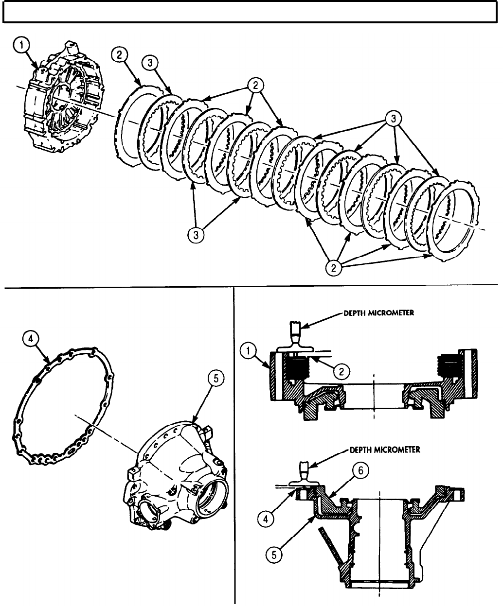

TM 9-2320-272-24-4
5-57. ADAPTER HOUSING AND FIRST CLUTCH PISTON MAINTENANCE
THIS TASK COVERS
a. Removal c. Cleaning and Inspection
b. Disassembly d. Assembly
INITIAL SETUP:
APPLICABLE MODELS
All
SPECIAL TOOLS
Spring compressor (Appendix E, Item 31)
TOOLS
General mechanic’s tool kit (Appendix E, Item 1)
Spring tester (Appendix E, Item 131)
Torque wrench (Appendix E, Item 146)
Arbor press
MATERIALS/PARTS
Basic overhaul kit (Appendix D. Item 10)
Adapter housing gasket (Appendix D, Item 228)
Oil-soluble grease (Appendix C, Item 53)
REFERENCES (TM)
TM 9-2320-272-24P
EQUIPMENT CONDITION
Low clutch removed (para. 5-56)
SPECIAL ENVIRONMENTAL CONDITIONS
Work area clean and free from blowing dirt and
dust.
a. Removal
Remove adapter housing (1) and gasket (2) from transmission housing (3). Discard gasket (2).
b. Disassembly
1.
Position compressor tool on first clutch spring retainer (5) and arbor press.
2.
Apply pressure to first clutch ring retainer (5), and remove snapring (4) from adapter housing (1).
3.
Remove compressor tool from first clutch spring retainer (5).
4.
Remove first clutch spring retainer (5) and twenty-six springs (6) from first clutch piston (7).
5.
Remove first clutch piston (7) from adapter housing (1).
6.
Remove outer seal ring (8) and inner seal ring (9) from first clutch piston (7). Discard inner seal
ring (9) and outer seal ring (8).
7.
Remove plug (10) from adapter housing (1).
5-378
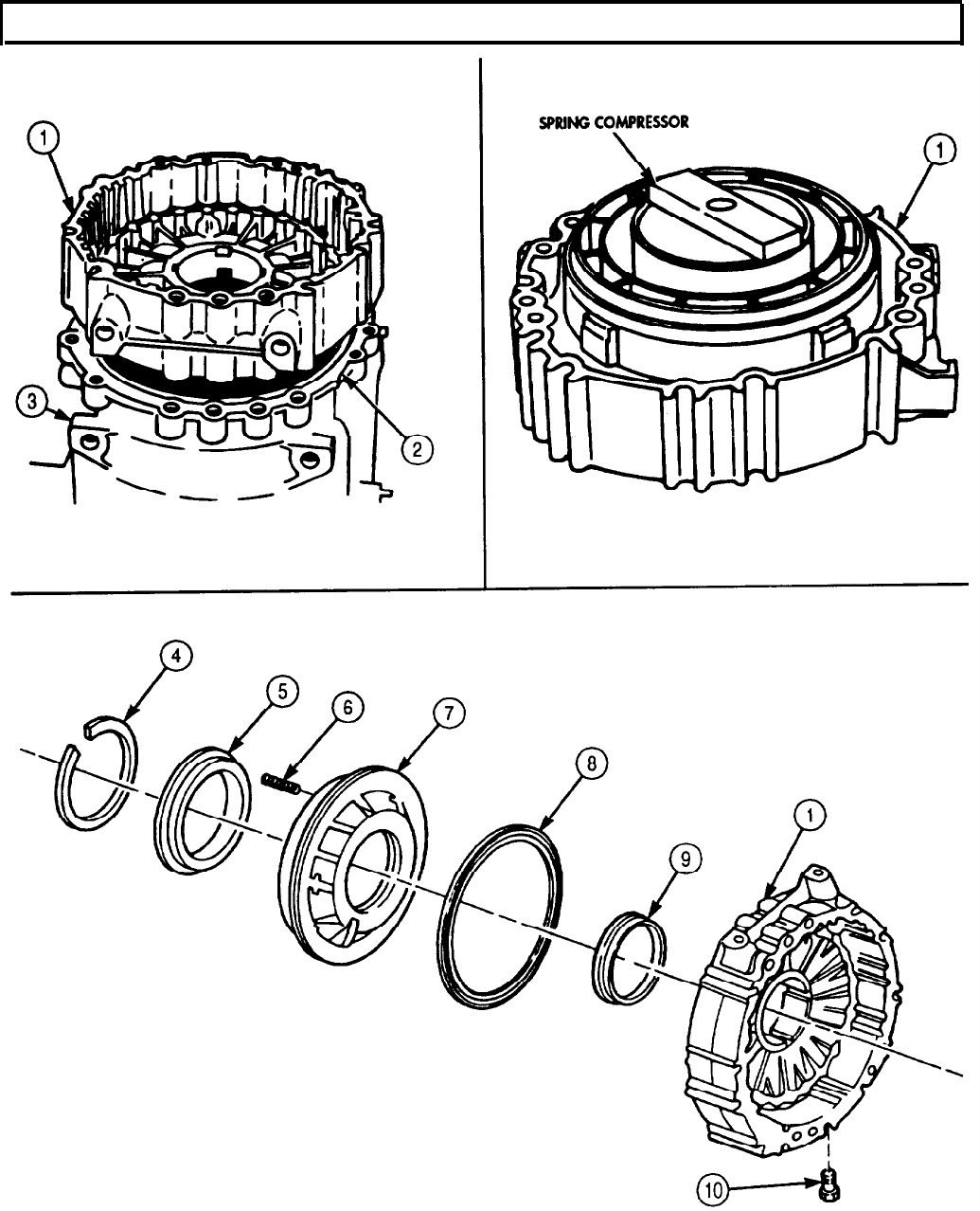
TM 9-2320-272-24-4
5-57. ADAPTER HOUSING AND FIRST CLUTCH PISTON MAINTENANCE (Contd)
5-379
TM 9-2320-272-24-4
5-57. ADAPTER HOUSING AND FIRST CLUTCH PISTON MAINTENANCE (Contd)
c. Cleaning and Inspection
1.
For general cleaning instructions, refer to para. 2-14.
2.
For general inspection instructions, refer to para. 2-15.
3.
Inspect twenty-six piston return springs (4) for discoloration due to overheating. If discolored,
discard piston return springs (4)
4.
Inspect twenty-six piston return springs (4) for broken coils or coils distorted due to wear. If broken
or distorted, discard piston return springs (4).
NOTE
Perform step 5 if springs pass visual inspection.
5.
Using spring tester, compress each of twenty-six piston return springs (4) to 0.95 in. (24.1 mm) and
check load. If piston return spring (4) does not give the correct load, discard piston return spring (4).
Refer to table 5-16, Spring Data.
Table 5-16. Spring Data.
SPRING COLOR
Piston return Solid orange,
spring yellow stripe
FREE LENGTH
1.28 in.
(32.5 mm)
COMPRESSED LENGTH
0.95 in.
(24.1 mm)
UNDER LOAD
13.6-16.4 lb.
(60.5-72.9 N)
d. Assembly
NOTE
Ensure seal rings and lips face piston oil pressure side.
Use oil-soluble grease to hold seal rings in place.
1.
Install new outer seal ring (6) and new inner seal ring (7) on first clutch piston (5).
2.
Place first clutch piston (5) in adapter housing (1).
3.
Place twenty-six piston return springs (4) in first clutch piston (5).
4.
Place cupped side of spring retainer (3) over piston return springs (4).
5.
Place compressor tool on spring retainer (3) and arbor press, and compress twenty-six piston return
springs (4).
6.
Install spring retainer (3) with snapring (2).
7.
Remove compressor tool from spring retainer (3).
8.
Install plug (8) in adapter housing (1). Tighten plug (8) 4-8 lb-ft (5-11 N•m).
5-380


TM 9-2320-272-24-4
5-58. ADAPTER HOUSING, LOW CLUTCH, LOW PLANETARY CARRIER, AND REAR
COVER INSTALLATION
THIS TASK COVERS:
Installation
INITIAL SETUP:
APPLICABLE MODELS
All
SPECIAL TOOLS
Two guide pins (Appendix E, Item 59)
TOOLS
General mechanic’s tool kit (Appendix E, Item 1)
Torque wrench (Appendix E, Item 144)
MATERIALS/PARTS
Two gaskets (Appendix D, Item 228)
Oil-soluble grease (Appendix C, Item 53)
REFERENCES (TM)
TM 9-2320-272-24P
SPECIAL ENVIRONMENTAL CONDITIONS
Work area clean and free from blowing dirt and
dust.
Installation
1.
Install new adapter housing gasket (8) on transmission housing (6).
NOTE
Guide pins maintain gasket alignment.
2.
3.
4.
5.
6.
Install two guide pins (7) in transmission housing (6).
Install adapter housing (9) over guide pins (7).
Install low ring gear hub (11) and snapring (10) on low planetary ring gear (1).
Install low planetary ring gear (1) into adapter housing (9).
Starting with clutch plate (4), alternately install eight clutch plates (4) and seven clutch discs (5) in
adapter housing (9).
NOTE
7.
8.
9.
10.
11.
12.
13.
Use oil-soluble grease to hold thrust washer in place.
Install thrust washer (3) on low planetary carrier (2) hub.
Install low planetary carrier (2) into adapter housing (9).
Install governor drive gear (17), speedometer drive gear (16), and sleeve spacer (15) on low
planetary carrier (2). Ensure governor drive gear (17) is seated over pin (19).
Install new rear cover gasket (18) and rear cover (14) over guide pins (7) with twelve washers (12)
and screws (13). Finger-tighten screws (13).
Remove two guide pins (7) and install remaining two washers (12) and screws (13).
Alternately tighten fourteen screws (13) 180° apart. Tighten screws (13) 30 lb-ft (41 N•m).
Repeat tightening sequence on fourteen screws (13) 180° apart to achieve final torque. Tighten
screws (13) 81-97 lb-ft (110-132 N•m).
5-382
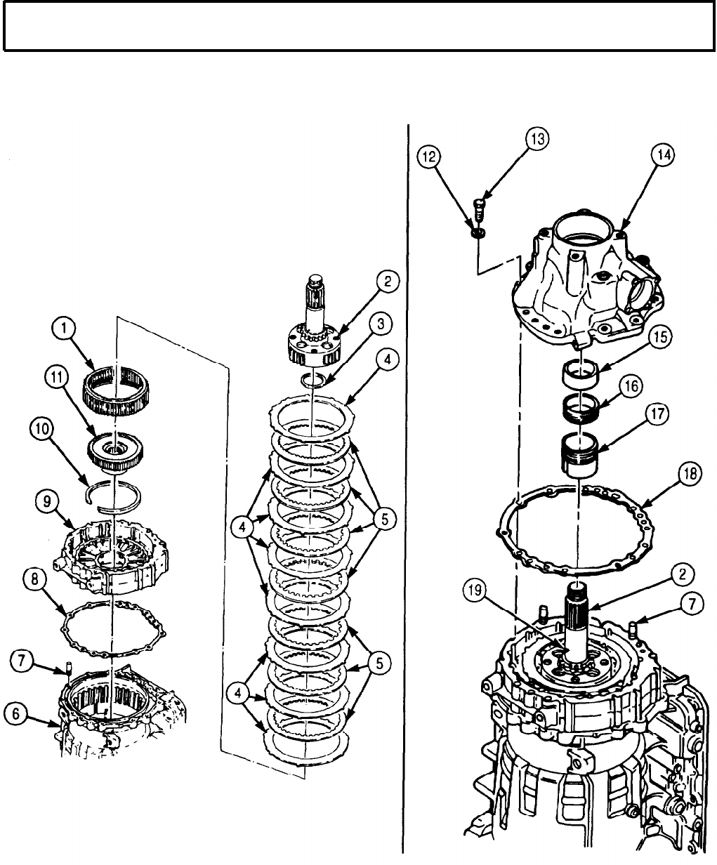
TM 9-2320-272-24-4
5-58. ADAPTER HOUSING, LOW CLUTCH, LOW PLANETARY CARRIER, AND REAR
COVER INSTALLATION (Contd)
5-383

TM 9-2320-272-24-4
5-59. TRANSMISSION HOUSING MAINTENANCE
THIS TASK COVERS:
a. Disassembly
b. Cleaning and Inspection c. Assembly
INITIAL SETUP:
APPLICABLE MODELS REFERENCES (TM)
All
TM 9-2320-272-24P
TOOLS
SPECIAL ENVIRONMENTAL CONDITIONS
General mechanic’s tool kit (Appendix E, Item 1)
Torque wrench (Appendix E, Item 146) Work area clean and free from blowing dirt and
dust.
a. Disassembly
Remove four plugs (3) from transmission housing (1).
b. Cleaning and Inspection
1.
For general cleaning instructions, refer to para. 2-14.
2.
For general inspection instructions, refer to para. 2-15.
3.
If adapter (2) is defective, replace adapter (2).
c. Assembly
1.
Install four plugs (3) in transmission housing (1). Tighten 4-5 lb-ft (5-7 N-m).
NOTE
Perform step 2 if early model transmission is to have wide oil
pump installed (para. 5-39).
2.
Change data plate (4) part number to 23040127.
5-384
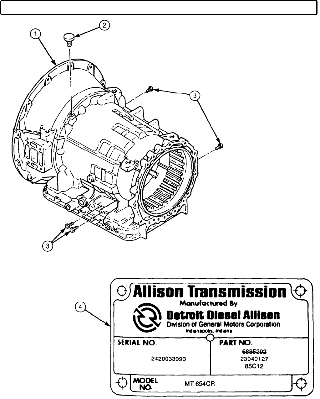
TM 9-2320-272-24-4
5-59. TRANSMISSION HOUSING MAINTENANCE (Contd)
5-385
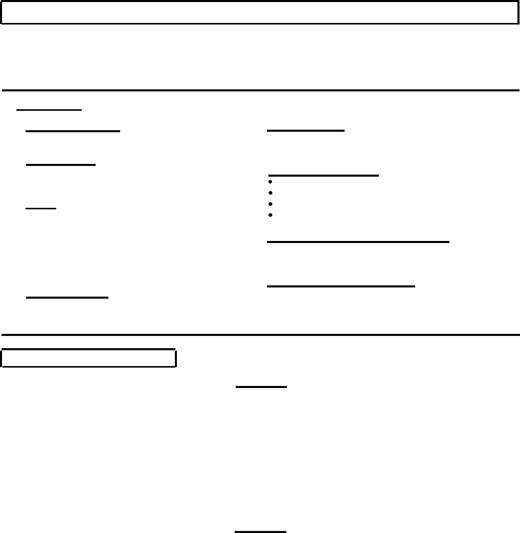
TM 9-2320-272-24-4
5-60. TRANSMISSION OIL PRESSURE TESTING
THIS TASK COVERS:
a. Oil Cooler Pressure Test
b. Main Pressure and Governor
Pressure Test
c. Automatic Shift Speed Test
INITIAL SETUP:
APPLICABLE MODELS
All
REFERENCES (TM)
TM 9-2320-272-10
TM 9-2320-272-24P
SPECIAL TOOLS
Pressure gauge set (300 psi) (Appendix E,
Item 51)
TOOLS
EQUIPMENT CONDITION
Parking brake set (TM 9-2320-272-10).
Transmission oil at proper level (TM 9-2320-272-10).
Vehicle at curb weight (empty) (TM 9-2320-272-10).
General mechanic’s tool kit (Appendix E, Item 1) Wheels blocked (chocked) (TM 9-2320-272-10).
Drill press
21/64 drill bit
SPECIAL ENVIRONMENTAL CONDITIONS
1/4-18 NPTF tap Work area clean and free from blowing dirt and
Pipe plug dust.
Two pipe plugs
MATERIALS/PARTS
O-ring (Appendix D, Item 430)
GENERAL SAFETY INSTRUCTIONS
Personnel must be clear from underside and front of
vehicle when engine is running.
Cap and plug set (Appendix C,
Item 14)
a. Oil Cooler Pressure Test
CAUTION
Before disconnecting transmission pressure lines, clean surrounding
surfaces and plug all openings to prevent entry of dirt or debris into
transmission. Damage will occur if dirt or debris enters transmission.
1.
Disconnect oil cooler supply hose (1) from elbow (2) on top of oil cooler (7).
NOTE
Note elbow alignment for connection.
2.
Loosen nut (3) and remove elbow (2) and O-ring (4) from oil cooler (7). Discard O-ring (4).
3.
Using drill press and 21/64 drill bit, drill hole in side of elbow (2) opposite hose port.
4.
Tap hole in elbow (2) with 1/4-18 NPTF tap.
CAUTION
After tapping, elbow must be thoroughly cleaned and all burrs
and shavings removed. Any shavings entering system will damage
transmission.
5.
Remove elbow (2) from drill press and thoroughly clean.
6.
Install new O-ring (4) and elbow (2) in oil cooler (7) until aligned as noted in step 2.
7.
Tighten nut (3) until O-ring (4) is seated.
8.
Install pipe plug (8) on elbow (2).
9.
Connect oil cooler supply hose (1) to elbow (2).
5-386

TM 9-2320-272-24-4
5-60. TRANSMISSION OIL PRESSURE TESTING (Contd)
10.
Remove oil sampling valve (6) from elbow (5).
11.
Install pressure gauge and gauge hose (9) on elbow (5).
5-387

TM 9-2320-272-24-4
5-60. TRANSMISSION OIL PRESSURE TESTING (Contd)
NOTE
Refer to TM 9-2320-272-10 when performing steps 12 through 20.
12. Set parking brake.
WARNING
Ensure all personnel are clear from underside and front of vehicle
before starting engine. Transmission slipping into gear may cause
injury to personnel.
13.
Start engine and check oil cooler connections for leaks.
CAUTION
Do not maintain stalled condition for longer than 30-second
intervals. Transmission oil may overheat and cause transmission
damage.
14.
Place transmission shift lever in 1-5 (drive) and operate engine at 1,200 rpm.
15.
Place transmission shift lever in N (neutral) and operate engine at normal operating temperature.
16.
Check transmission oil level.
17.
Operate engine at 1,650 rpm with transmission shift lever in N (neutral) and parking brake set.
Check pressure gauge and note reading.
18.
If pressure is less than 26 psi (179.2 kPa), check for hose or internal oil cooler leakage.
19.
If pressure exceeds 26 psi (179.2 kPa), check for cooler, cooler filter, or cooler hose restriction.
20.
Stop engine and disconnect gauge and hose (2) from elbow (1).
21.
Install oil sampling valve (3) in elbow (1).
22.
Remove pipe plug (5) from supply hose elbow (4).
23.
Install pressure gauge and hose (2) in supply hose elbow (4).
WARNING
Ensure all personnel are clear from underside and front of vehicle
before starting engine. Transmission slipping into gear may cause
injury to personnel.
NOTE
Refer to TM 9-2320-272-10 when performing steps 24 through 29.
24.
Set parking brake.
25.
Start engine and check oil cooler connections for leaks.
26.
Operate engine at 1,650 rpm with transmission shift lever in N (neutral) and parking brake set.
Check pressure gauge and note reading.
27.
If pressure is below 30 psi (207 kPa), check for hose or internal oil cooler leakage.
28.
If pressure exceeds 50 psi (345 kPa), check for cooler or cooler hose restriction.
29.
Stop engine and disconnect gauge and hose (2) from supply hose elbow (4).
30.
Install pipe plug (5) in elbow (4).
5-388
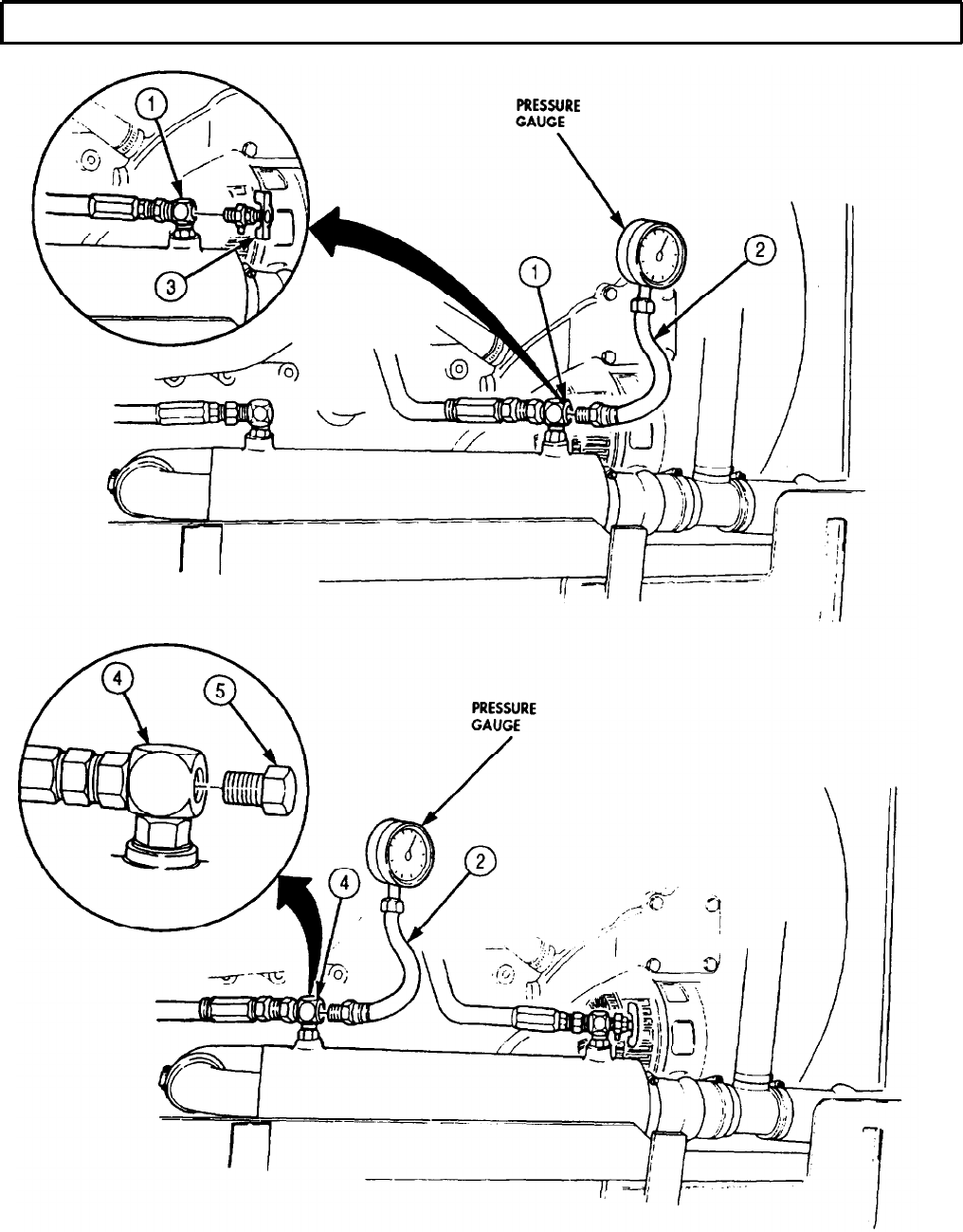
TM 9-2320-272-24-4
5-60. TRANSMISSION OIL PRESSURE TESTING (Contd)
5-389

TM 9-2320-272-24-4
5-60. TRANSMISSION OIL PRESSURE TESTING (Contd)
b. Main Pressure and Governor Pressure Test
1.
2.
3.
4.
5.
6.
7.
8.
9.
10.
11.
12.
13.
14.
WARNING
Ensure transmission-to-transfer case propeller shaft has been
removed before performing this test. If test is performed with
propeller shaft installed, wheel blocks (chocks) will not prevent
vehicle from rolling and causing injury to personnel.
Remove transmission-to-transfer case propeller shaft (para. 3-148).
CAUTION
Before disconnecting transmission pressure lines, clean surrounding
surfaces and plug all openings to prevent entry of dirt or debris into
transmission. Damage will occur if dirt or debris enters transmission.
NOTE
Transmission-to-transfer case propeller shaft removal allows
transmission output shaft to rotate to build up governor oil
pressure. Upshift will not occur without governor pressure.
Have drainage container ready to catch oil.
Disconnect main pressure line (1) from adapters (2) and (5) and remove main pressure line (1).
Remove adapter (5) from main pressure port (6).
Disconnect governor pressure line (4) from adapters (3) and (9) and remove governor pressure line (4).
NOTE
Only M936/A1/A2 vehicles are equipped with check valve.
Remove adapter (9) and check valve (8) from transmission auxiliary governor pressure port (7).
Install 1/8-27 NPTF Thd pipe plug (13) in auxiliary governor pressure port (7).
Connect pressure gauge and hose (12) to main pressure port (6) with 1/8-27 NPTF Thd hose
fitting (11).
NOTE
Refer to TM 9-2320-272-10 for steps 8 through 28.
Start engine, check pressure port connections for leaks, and check oil.
Operate engine at 625 ± 25 rpm with transmission (10) shift lever in N (neutral) and parking brake
set.
Note pressure reading on pressure gauge. If pressure is not 125 psi (802 kPa), repair trans-
mission (10) as necessary.
NOTE
Do not maintain stalled condition for longer than 30-second
intervals. Transmission oil may overheat and cause transmission
damage.
Place transmission shift lever in 1-5 (drive) position.
Operate engine at 1,200 ± 25 rpm and note pressure reading on pressure gauge. If pressure is not
180-205 psi (1,241-1,413 kPa), repair transmission (10) as necessary.
Stop engine and place transmission shift lever in N (neutral).
Disconnect pressure gauge and hose (12) from main pressure port (6) on left side of
transmission (10).
5-390
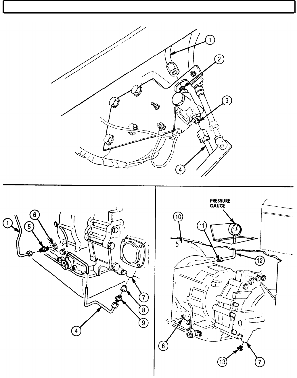
TM 9-2320-272-24-4
5-60. TRANSMISSION OIL PRESSURE TESTING (Contd)
5-391

TM 9-2320-272-24-4
5-60. TRANSMISSION OIL PRESSURE TESTING (Contd)
15.
Remove pipe plug (4) from auxiliary governor pressure port (3) and install in main pressure port (5).
16.
Install pressure gauge and hose (2) in auxiliary governor pressure port (3).
17.
Start engine and check pressure port connection for leaks.
18.
Check transmission oil level.
19.
Place transmission shift lever in 1-5 (drive) position and operate engine at 1,650 rpm. Note reading
on pressure gauge.
20.
If pressure is not 82-91 psi (565-627 kPa), repair transmission (1) as necessary
21.
Stop engine and disconnect pressure gauge and hose (2) from auxiliary governor pressure port (3).
22.
Remove pipe plug (4) from main pressure port (5).
NOTE
Only M936/A1/A2 vehicles are equipped with check valve.
23.
Install check valve (8) and adapter (9) in auxiliary governor pressure port (3). Ensure bleed hole end
of check valve (8) is inserted into pressure port (3) first.
24.
Install governor pressure line (10) on adapters (9) and (12).
25.
Install adapter (7) in main pressure port (5).
26.
Install main pressure line (6) on adapters (7) and (11).
27.
Start engine and check pressure port connections for leaks.
28.
Check transmission oil level.
29.
Install transmission-to-transfer case propeller shaft (para. 3-148).
c. Automatic Shift Speed Test
1.
Road test vehicle and record engine rpm at shift points (TM 9-2320-272-10).
2.
With vehicle in operation, shift transmission through the range sequence. See table 5-17 for lever
range sequence.
3.
Check recorded engine shift point rpm with table 5-17.
4.
If shift points are incorrect, check modulator adjustment (para. 5-61). If modulator adjustment does
not correct shift speed, repair transmission (1) as necessary.
Table 5-17. Transmission Shift Point Check.
SELECTOR
LEVER RANGE
1-2
1-3
1-4
1-5 (drive)
THROTTLE
Fully open
AUTOMATIC
ENGINE
SHIFTING (RPM)
1-2
1,900-2,050
2-2
1,900-2,050 (before converter lock-in)
2-2
1,600-1,825 (after converter lock-in)
2-3
2,000-2,150
3-4
2,030-2,140
4-5
2,015-2,130
5-392
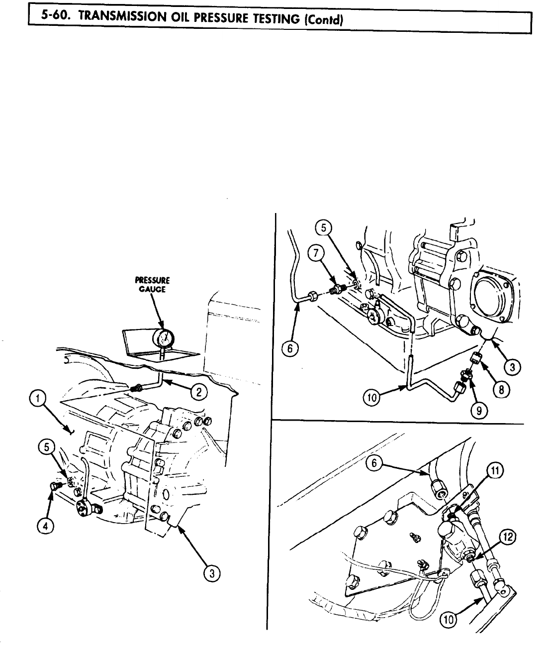
5-60. TRANSMISSION
TM 9-2320-272-24-4
5-393
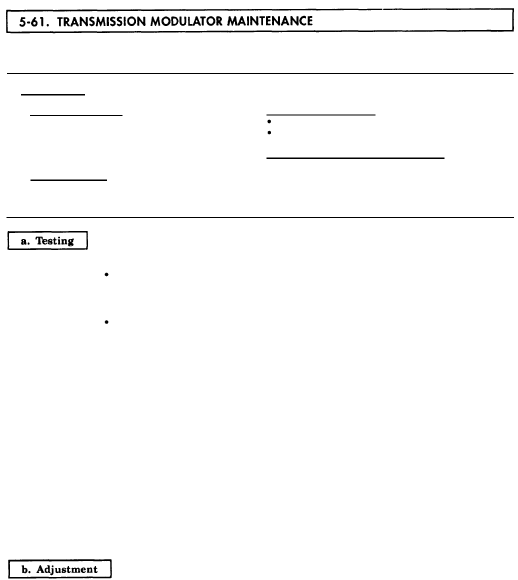
5-61. TRANSMISSION
TM 9-2320-272-24-4
THIS TASK COVERS:
a. Testing b. Adjustment
INITIAL SETUP:
APPLICABLE MODELS
All
TOOLS
EQUIPMENT CONDITION
Parking brake set (TM 9-2320-272-10).
Vehicle at curb weight (empty) (TM 9-2320-272-10).
General mechanic’s tool kit (Appendix E, Item 1)
SPECIAL ENVIRONMENTAL CONDITIONS
REFERENCES (TM)
Dry conditions, open roads, and easy grades.
LO 9-2320-272-12
TM 9-2320-272-10
TM 9-2320-272-24P
NOTE
Vehicle engine must be at normal operating temperature of 175-
195°F (79-90°C) as indicated by temperature gauge. Transmission
oil temperature must be at normal operating temperature of 120-
220°F (49-104°C) as indicated by temperature gauge.
Refer to TM 9-2320-272-10 for steps 1 through 7.
1.
Allow vehicle engine and transmission to reach normal operating temperatures with transmission
shift lever in N (neutral) and parking brake set.
2.
After warmup, depress accelerator pedal until engine reaches 2,100 rpm. If engine does not reach
2,100 r-pm, see table 4-1, fuel system malfunction 15. Proceed with testing if engine reaches
2,100 rpm.
NOTE
Assistant will operate vehicle as directed by mechanic. Mechanic
will observe and record engine rpm indicated by tachometer
during shift changes.
3.
Place transmission shift lever in 1-2 (second) and road test vehicle.
4.
Accelerate at full throttle, 1,900-2,050 rpm, and note shift change. Record engine rpm at moment of
shift change.
5.
Stop vehicle and repeat steps 3 and 4 in 1-3 (third).
6.
Stop vehicle and repeat steps 3 and 4 in 1-4 (fourth).
7.
Stop vehicle and repeat steps 3 and 4 in 1-5 (drive).
8.
Compare recorded engine rpm at shift points with correct shift point ranges given in table 5-17. If
all shift points are too high or too low by approximately same amount, adjust modulator (4).
1.
Inspect modulator (4) and cable (3) for looseness and improper installation.
5-394
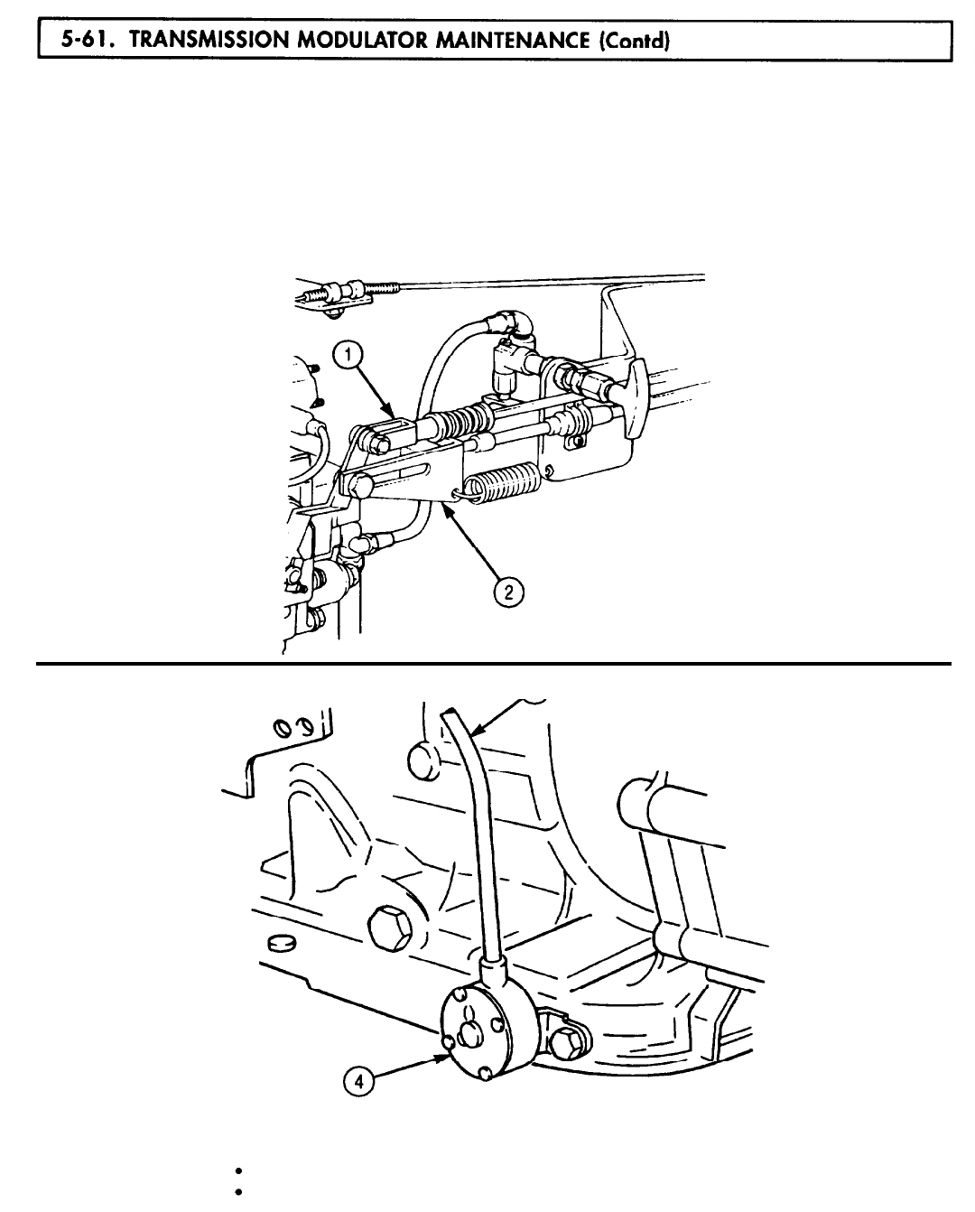
5-61. TRANSMISSION
TM 9-2320-272-24-4
NOTE
Modulator will be adjusted if properly installed. Refer to
para. 3-145 for correct modulator and cable installation and
adjustment instructions.
2.
If looseness and/or improper installation are found, correct and retest modulator (4) and cable (3).
3.
Remove modulator link (2) from throttle lever (1) and reinstall modulator link (2).
4.
Retest modulator (4). If retest indicates defective modulation, replace modulator (4).
FOLLOW-ON TASKS:
Fill transmission to proper oil level (LO 9-2320-272-12).
Start engine (TM 9-2320-272-10) and road test vehicle.
5-395

5-62. TRANSMISSION
TM 9-2320-272-24-4
THIS TASK COVERS:
Forward Stall Test
INITIAL SETUP:
APPLICABLE MODELS
All
TOOLS
General mechanic’s tool kit (Appendix E, Item 1)
REFERENCES (TM)
LO 9-2320-272-12
TM 9-2320-272-10
TM 9-2320-272-24P
EQUIPMENT CONDITION
• Parking brake set (TM 9-2320-272-10).
• Wheels blocked (chocked) (TM 9-2320-272-10).
SPECIAL ENVIRONMENTAL CONDITIONS
Work area clean and free from blowing dirt and
dust.
GENERAL SAFETY INSTRUCTIONS
Do not allow anyone to stand in front of vehicle
when conducting a stall test.
WARNING
Do not allow anyone to stand in front of vehicle when conducting
stall test. Vehicle movement may cause injury to personnel.
CAUTION
• Do not maintain the stalled condition longer than 30-second
intervals due to rapid heating of transmission oil. Observe
transmission oil temperature gauge. Normal operating range
is 120-220°F (49-104°C).
• Observe engine coolant temperature gauge. Operating tempera-
ture is 175-195°F (79-90°C).
• If oil temperature reaches 300°F (148°C), or if thirty seconds is
insufficient time to complete needed tests, transmission oil
temperature must be lowered or damage to transmission may
result.
• Run engine at 1,200-1,500 rpm with transmission in neutral for
two minutes to cool oil between tests.
NOTE
• The stall test is conducted when engine and/or transmission are
not performing satisfactorily The purpose of the stall test is to
determine if transmission or engine is the malfunctioning unit.
• The vehicle’s transmission will stay in first speed during the
stall tests regardless of transmission 5-4-3-2 and 1 quadrant
position. Transmission does not and cannot upshift because the
internal mechanism, output shaft, and governor are not
turning. The stall test checks the engine performance, converter
clutch operation or installation, and holding ability of the
converter one-way clutch.
• Refer to TM 9-2320-272-10 for the following steps.
5-396
5-62. TRANSMISSION
TM 9-2320-272-24-4
1.
2.
3.
4.
5.
Apply service brakes and place transmission shift lever in any forward drive position 5-4-3-2-1.
Accelerate engine to full throttle (1,900-2,050 rpm).
NOTE
Perform step 3 only if engine speed exceeds 1,700 rpm.
If engine speed exceeds 1,700 rpm, check transmission oil level.
a. If oil level is low, fill to proper level.
b. If oil level is correct, repair transmission as necessary.
NOTE
Perform steps 4 and 5 only if engine speed is less than
1,900 rpm.
Refer to table 4-1, Mechanical Troubleshooting.
If engine speed is less than 1,400 rpm, troubleshoot engine for loss of power.
If engine is performing satisfactorily, repair transmission torque converter (para. 5-41).
FOLLOW-ON TASK: Start engine (TM 9-2320-272-10) and road test vehicle.
TM 9-2320-272-24-4
Section IV. TRANSFER CASE MAINTENANCE
THIS TASK COVERS:
a. Disassembly
b. Cleaning and Inspection c. Assembly and Adjustment
INITIAL SETUP:
APPLICABLE MODELS
All
SPECIAL TOOLS
Crowfoot wrench (Appendix E, Item 163)
Two flange puller standoffs
(Appendix F, Item 1)
TOOLS
General mechanic’s tool kit (Appendix E. Item 1)
Mechanical puller (Appendix E, Item 102)
Torque wrench (Appendix E, Item 144)
Outside micrometer (Appendix E, Item 80)
Dial indicator (Appendix E, Item 36)
Arbor press
Feeler gauge
Prybar
Soft-faced hammer
Torque multiplier
MATERIALS/PARTS
Cylinder assembly (Appendix D, Item 92)
Seal (Appendix D, Item 254)
Three seals (Appendix D, Item 500)
Three locknuts Appendix D, Item 320)
Snapring Appendix D, Item 663)
Woodruff key (Appendix D, Item 727)
Two seals (Appendix D, Item 627)
Adhesive sealant (Appendix C, Item 4)
GAA grease (Appendix C, Item 28)
Gasket sealant (Appendix C, Item 30)
Lubricating oil (Appendix C, Item 47)
Sealing compound (Appendix C, Item 62)
PERSONNEL REQUIRED
TWO
REFERENCES (TM)
TM 9-2320-272-24P
TM 9-214
EQUIPMENT CONDITION
Transfer case removed (para. 4-94 or para. 4-95).
GENERAL SAFETY INSTRUCTIONS
Support transfer case with wood blocks before
performing disassembly.
WARNING
Transfer case is heavy. Use wood blocks to prevent transfer case
from tipping over and causing injury to personnel.
NOTE
Clean exterior of transfer case thoroughly before performing
procedure.
1.
Using crowfoot wrench, remove interlock air cylinder (1) and push rod (2) from transfer case (3).
2.
Remove eight screws (5) and inspection cover (4) from transfer case (3).
3.
Remove locknut (6) and washer (7) from output shaft (14). Discard locknut (6).
4.
Using mechanical puller, remove output flange (8) and parking brake drum (9) from output
shaft (14).
5-398
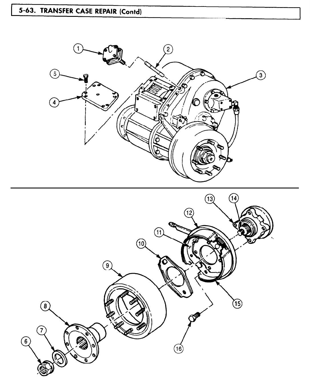
5-63. TRANSFER
TM 9-2320-272-24-4
5.
Remove actuating plate (10) from brakeshoe backing plate (11).
6.
Remove four screws (16), dustcover (12), and brakeshoe assembly (15) from companion flange (13).
5-399
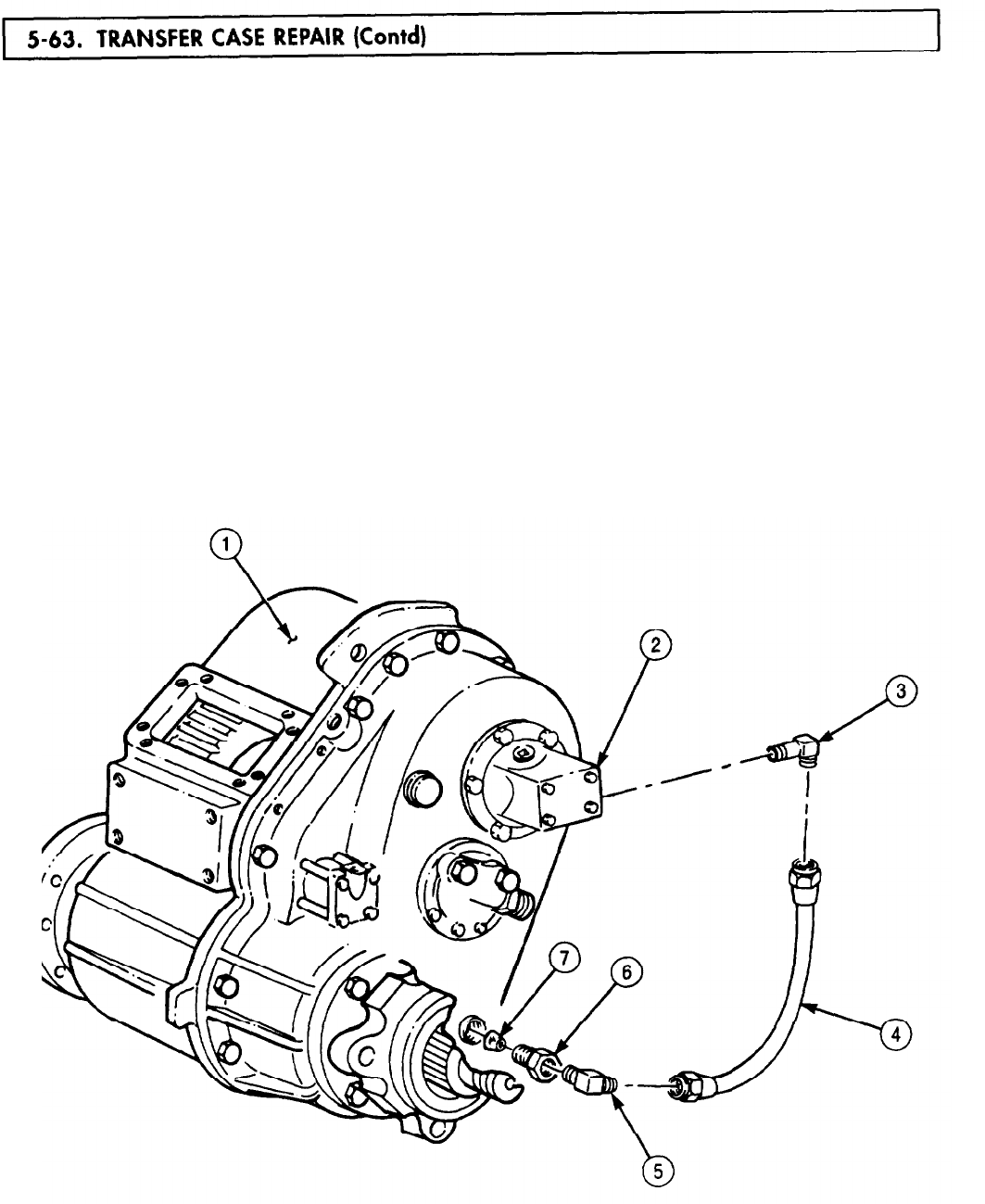
5-63. TRANSFER
TM 9-2320-272-24-4
7.
Disconnect oil line (4) from elbows (3) and (5).
8.
Remove elbow (3) from oil pump (2).
NOTE
Perform steps 9 and 10 for vehicles equipped with transfer case
power takeoff (PTO).
9.
Disconnect oil line (9) from elbows (5) and (8).
10.
Remove elbow (8) from PTO (10).
11.
Remove elbow (5), adapter (6), and filter screen (7) from transfer case (1). Clean filter screen (7).
NOTE
Mark position of oil pump for installation.
12.
Remove six screws (13), washers (12), and oil pump (11) from transfer case (1).
13.
Bend tabs of locking plates (15) away from screws (16).
14.
Remove four screws (16), locking plates (15), cover (14), cylinder (18), piston (19), and gasket (21)
from transfer case (1) and declutch shaft (22). Discard gasket (21), piston (19), cylinder (18), and
locking plates (15).
15.
Remove seals (17) and (20) from cover (14) and piston (19). Discard seals (17) and (20).
WITHOUT TRANSFER CASE PTO
5-400
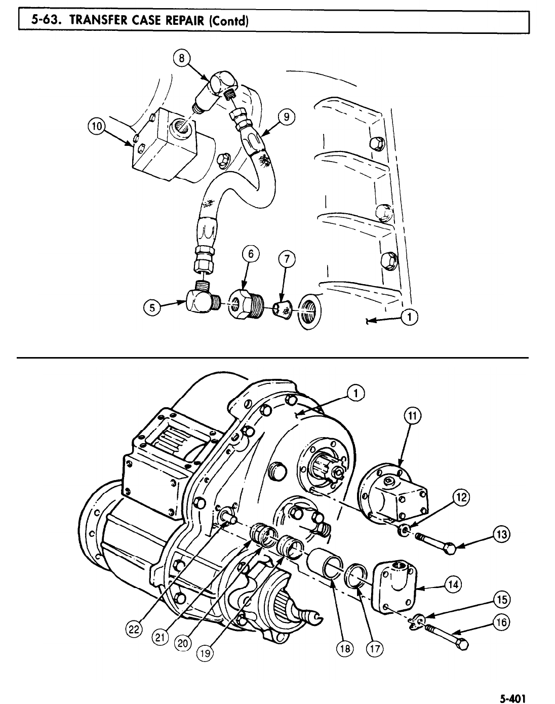
5-63. TRANSFER
TM 9-2320-272-24-4
WITH TRANSFER CASE PTO

TM 9-2320-272-24-4
NOTE
Chain is necessary to prevent main and output flanges from
rotating when removing hardware.
Tag main and front output flanges for installation.
16.
Install chain on main flange (5) and output flange (11) with two washers (9), screw (10), two
washers (3), screw (2), and nut (4).
17.
Remove locknut (8) and washer (7) from main input shaft (6). Discard locknut (8).
18.
Remove locknut (1) and washer (13) from front output shaft (12). Discard locknut (1).
19.
Remove screw (10), two washers (9), nut (4), washer (3), screw (2), washer (3), and chain from main
flange (5) and output flange (11).
20.
Using puller, remove main flange (5) and output flange (11) from main input shaft (6) and front
output shaft (12).
NOTE
Perform steps 21 and 22 for vehicles equipped with PTO.
21.
Remove six screws (15), washers (16), and PTO (14) from transfer case (17).
22.
Remove setscrew (19), PTO drive gear (18). and seal (20) from main input shaft (6). Discard
seal (20).
5-402
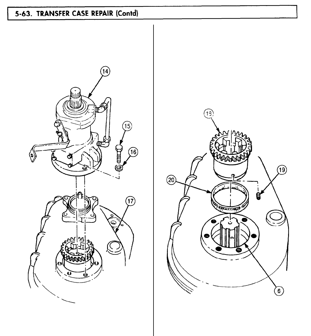
5-63. TRANSFER
TM 9-2320-272-24-4
WITH TRANSFER CASE PTO
5-403
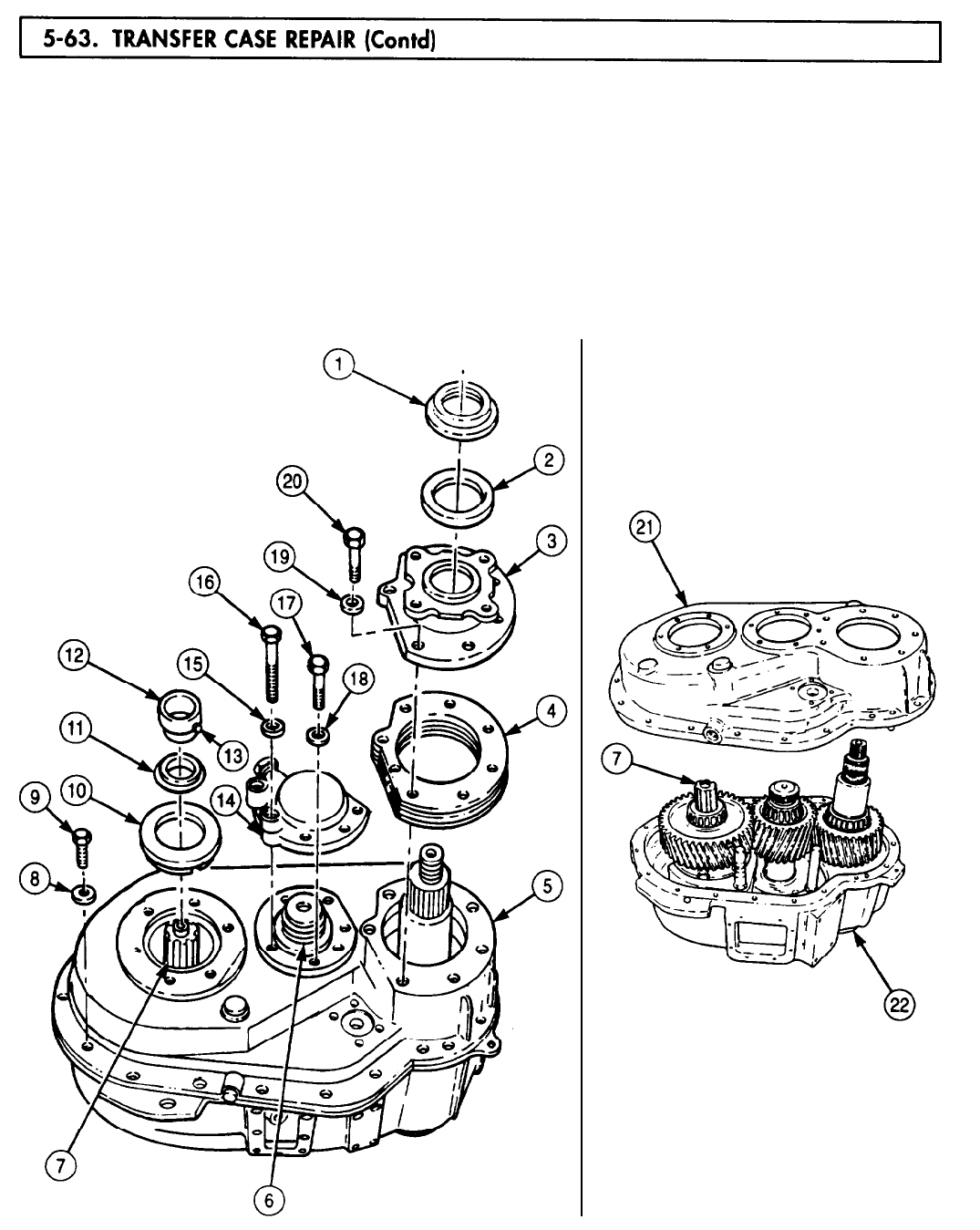
5-63. TRANSFER
TM 9-2320-272-24-4
23.
Loosen setscrew (13) and remove collar (12), seal (ll), and baffle (10) from main input shaft (7).
Discard seal (11).
24.
Remove seven screws (20), washers (19), flange (3), and shim pack (4) from transfer case (5).
25.
Remove slinger (1) and seal (2) from flange (3). Discard seal (2).
26.
Remove four screws (17), washers (18), two screws (16), washers (15), and gear cover (14) from
transfer case (5).
27.
Remove nineteen screws (9) and washers (8) from transfer case cover (21).
28.
Position puller on transfer case cover (21) with drive screw of puller over intermediate shaft (7) and
two long screws through puller and into transfer case cover (21).
29.
Remove transfer case cover (21) from transfer case housing (22).
5-404
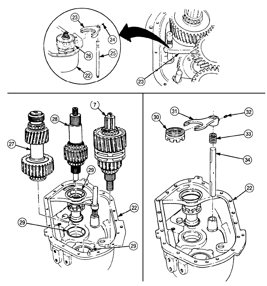
TM 9-2320-272-24-4
30.
Remove setscrew (24), hi-lo shift fork (23), and hi-lo shift shaft (25) from synchronizer gear (26) and
transfer case housing (22).
31.
Remove main input shaft (7), rear output shaft (28), and intermediate shaft (27) from bearing
races (29) and transfer case housing (22).
32.
Remove setscrew (32), declutch shaft (34), declutch fork (31), sliding clutch (30), and spring (33)
from transfer case housing (22). Discard spring (33) if broken or distorted.
5-405
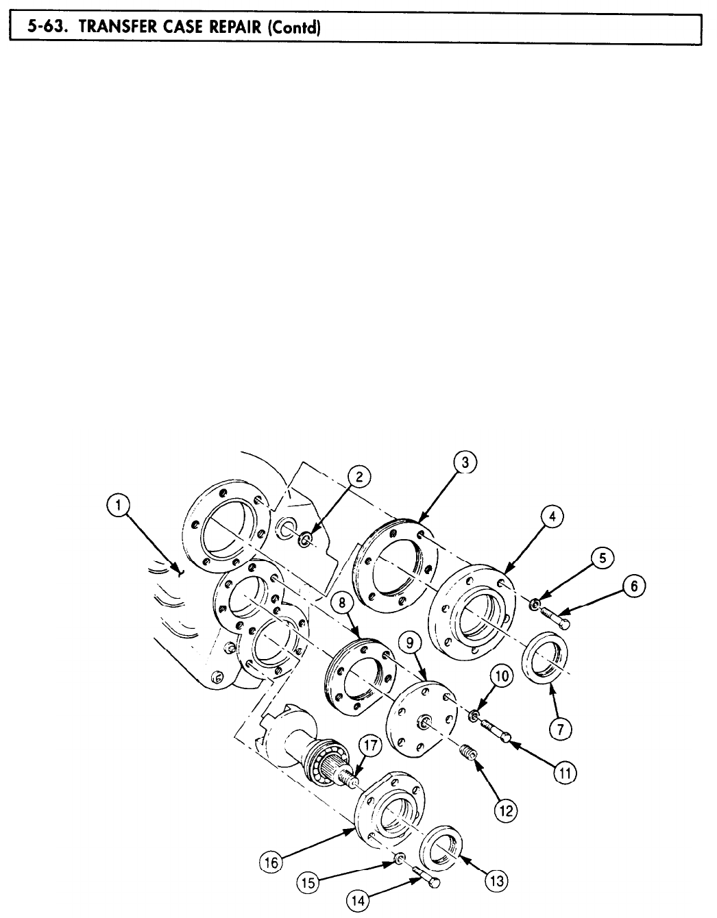
5-63. TRANSFER
TM 9-2320-272-24-4
33.
Remove hi-lo shaft seal (2) from transfer case housing (1). Discard seal (2).
34.
Remove six screws (6), washers (5), main input shaft cover (4), and shim pack (3) from transfer
case housing (1).
35.
Remove seal (7) from main input shaft cover (4). Discard seal (7).
36.
Remove plug (12) from intermediate shaft cover (9).
37.
Remove six screws (11), washers (10), intermediate shaft cover (9), and shim pack (8) from transfer
case housing (1).
38.
Remove six screws (14), washers (15), and front output shaft cover (16) from transfer case
housing (1).
39.
Remove seal (13) from front output shaft cover (16). Discard seal (13).
40.
Remove front output shaft (17) from transfer case housing (1).
NOTE
When disassembling front output, rear output, and intermediate
shafts, tag all bearings, spacers, and gears for installation.
41.
Using flat-axle type bearing puller, remove front output shaft bearing (18) from front output
shaft (17).
42.
Remove snapring (19) from front output shaft bearing (18).
43.
Remove spacer (24) from rear output shaft (21).
44.
Using arbor press, remove rear output shaft bearings (20) and (23), and gear (22) from rear output
shaft (21).
5-406
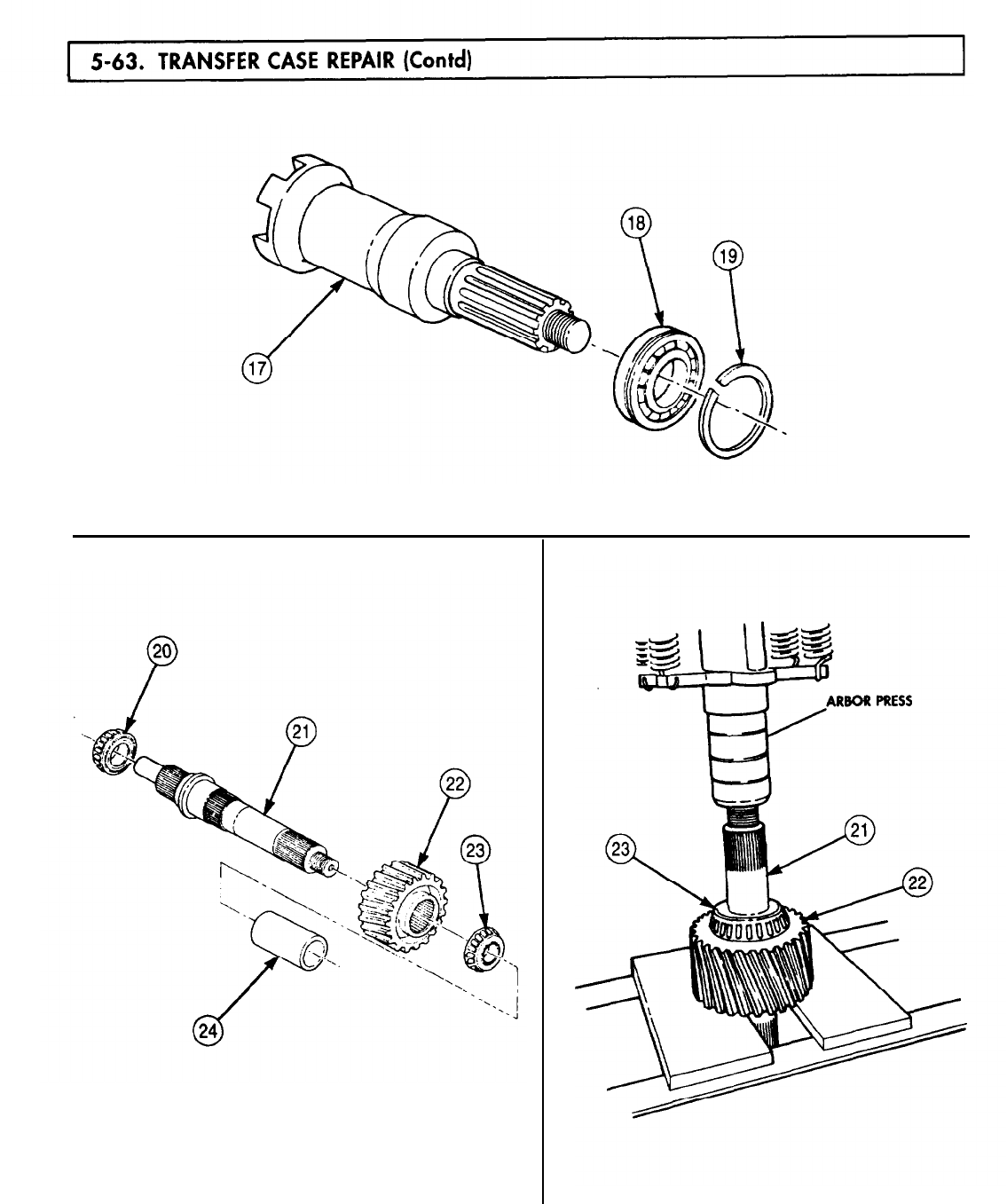
5-63. TRANSFER
TM 9-2320-272-24-4
5-407
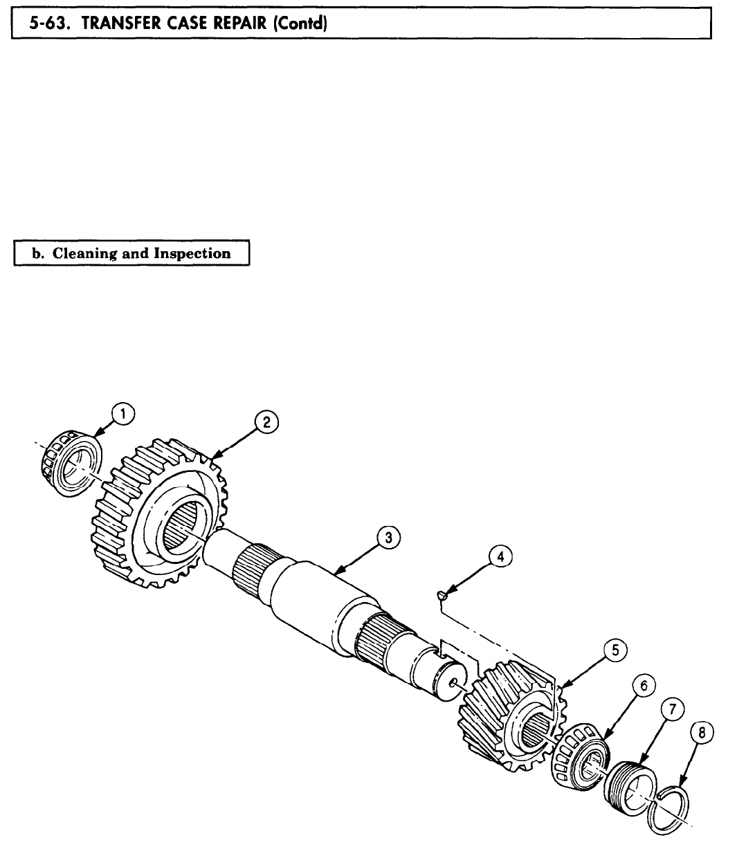
5-63. TRANSFER
TM 9-2320-272-24-4
45.
46.
47.
48.
49.
50.
Remove snapring (8), speedometer drive gear (7), and woodruff key (4) from intermediate shaft (3).
Discard woodruff key (4) and snapring (8).
Using arbor press, remove intermediate bearing (6), intermediate high-speed gear (5), intermediate
bearing (1), and intermediate low-speed gear (2) from intermediate shaft (3).
Remove companion flange spacer (9) from main input shaft (14).
Using arbor press, remove main input shaft bearing (16), bearing spacer (17), and high-speed
gear (18) from main input shaft (14).
Remove high-speed gear spacer (19) and synchronizer gear (20) from main input shaft (14).
Using arbor press, remove main input shaft bearing (10), bearing spacer (11), low-speed gear (12),
and low-speed gear spacer (13) from main input shaft (14).
1.
For general cleaning instructions, refer to para. 2-14.
2.
For general inspection instructions, refer to para. 2-15.
3.
Inspect two dowel pins (15) of main input shaft (14) for breaks. If broken, replace dowel pins (15).
5-408
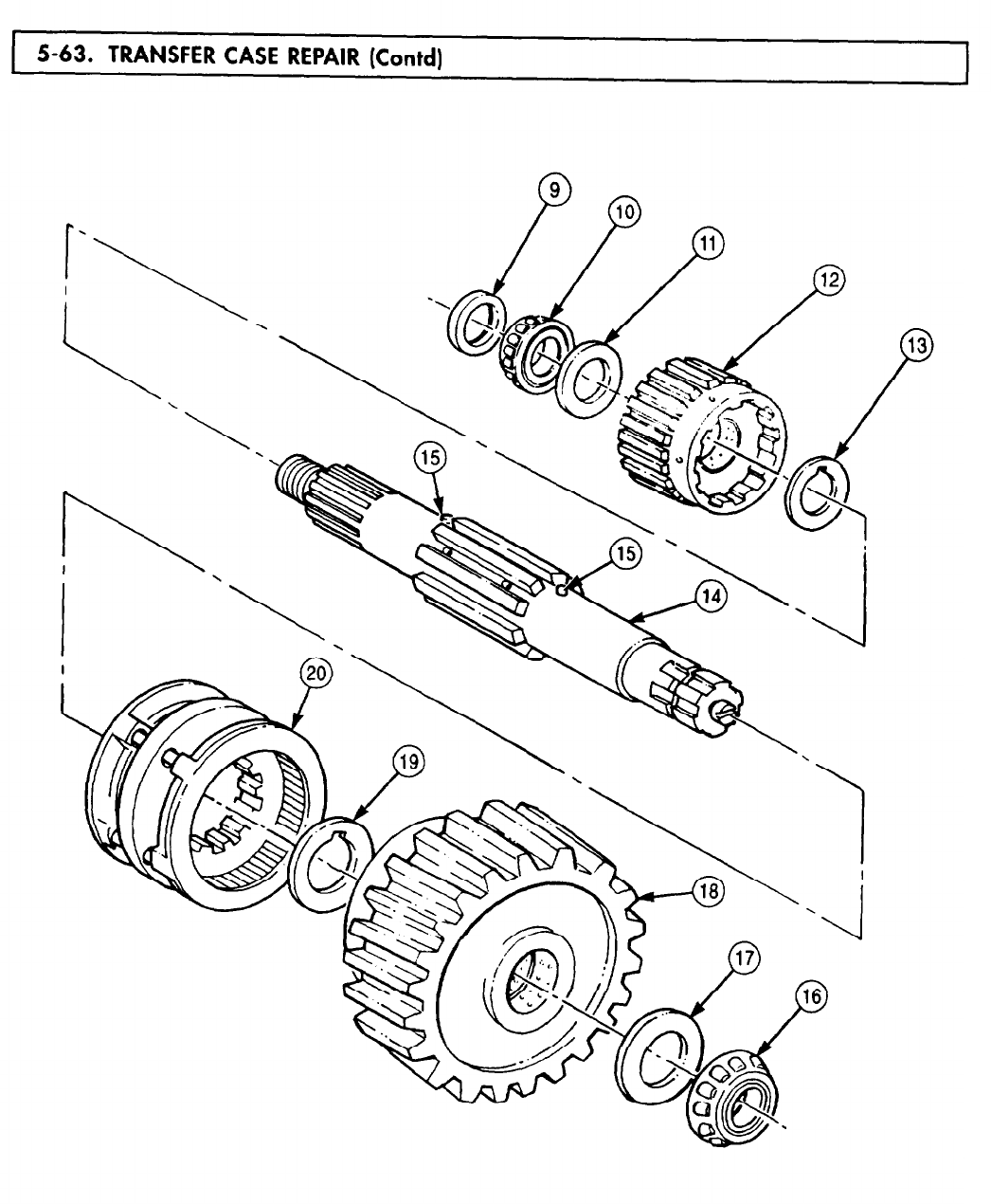
5-63. TRANSFER 5-63. TRANSFER
TM 9-2320-272-24-4
5-409

TM 9-2320-272-24-4
4.
Inspect three dowel pins (2) for bends and breaks. Replace dowel pins (2) if bent or broken.
5.
Remove filler plug (5) and drainplug (6) from transfer case housing (8) and inspect for stripped
threads. Replace plugs (5) or (6) if threads are stripped.
6.
Inspect freeze plugs (7) and (9) for looseness. Replace freeze plugs (7) or (9) if loose.
7.
Inspect transfer case cover (3) and housing (8) for breaks, cracks, and stripped threads. Replace
transfer case cover (3) or housing (8) if broken, cracked, or threads are not repairable (para. 2-5).
NOTE
Transfer case housing and cover bearings and bearing races are
matched parts and must be replaced as a set.
Perform steps 9 and 10 if bearings or bearing races fail
inspection.
8.
Inspect bearings (4) and bearing races (1) in accordance with TM 9-214. If damaged, replace
bearing (4) and matched bearing race (1).
9.
Remove bearing race (1) from transfer case housing (8) or cover (3) by tapping alternately around
outer edge of bearing race (1). Discard bearing race (1).
10.
Using arbor press, install new bearing race (1) on transfer case housing (8) or cover (3).
5-410
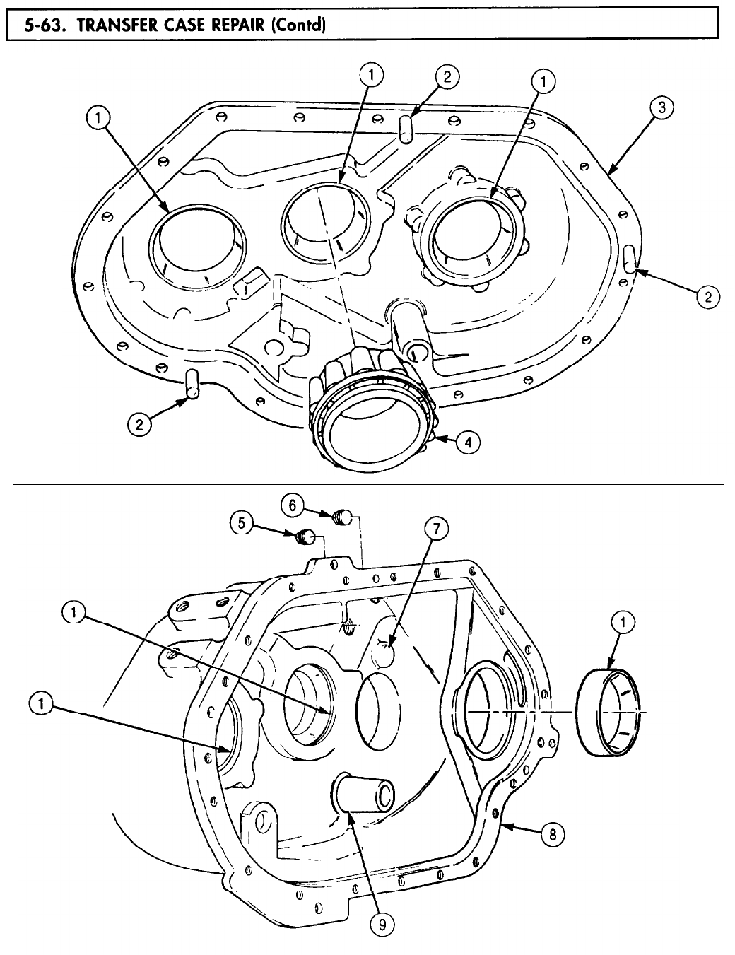
5-63. TRANSFER
TM 9-2320-272-24-4
5-411
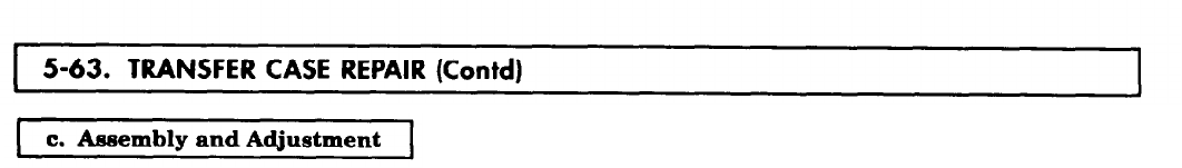
TM 9-2320-272-24-4
1.
2.
3.
4.
5.
6.
7.
8.
9.
10.
11.
12.
13.
14.
NOTE
Prior to assembly, apply coat of oil to lubricate all gears, bearings,
and shafts.
Measure thickness of bearing spacer (3). Replace bearing spacer (3) if thickness is less than
0.265 in. (6.73 mm).
Install low-speed gear spacer (5), low-speed gear (4), and bearing spacer (3) on main input shaft (6).
Ensure low-speed gear spacer (5) is aligned on dowel pin (8).
Using arbor press, install main input shaft bearing (2) on main input shaft (6).
Measure thickness of bearing spacer (10). Replace bearing spacer (10) if thickness is less than
0.143 in. (3.63 mm).
Install synchronizer gear (13), high-speed gear spacer (12), high-speed gear (11), and bearing
spacer (10) on main input shaft (6). Ensure gear spacer (12) is aligned with dowel pin (7).
Using arbor press, install main input shaft bearing (9) on main input shaft (6).
Install companion flange spacer (1) on main input shaft (6).
Using arbor press, install intermediate low-speed gear (15) and intermediate hearing (14) on
intermediate shaft (16).
Install intermediate high-speed gear (18) and roller bearing (21) on intermediate shaft (16).
Install new woodruff key (17) and speedometer gear (20) on intermediate shaft (16) with new
snapring (19).
Using arbor press, install rear output shaft driven gear (24) and rear output shaft bearings (25)
and (22) on rear output shaft (23).
Install rear output shaft spacer (26) on rear output shaft (23).
Using arbor press, install front output shaft bearing (28) on front output shaft (27).
Install snapring (29) on front output shaft bearing (27).
5-412
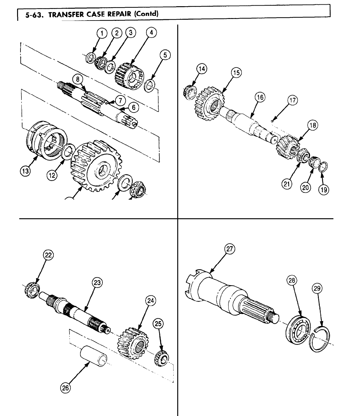
5-63. TRANSFER
TM 9-2320-272-24-4
5-413
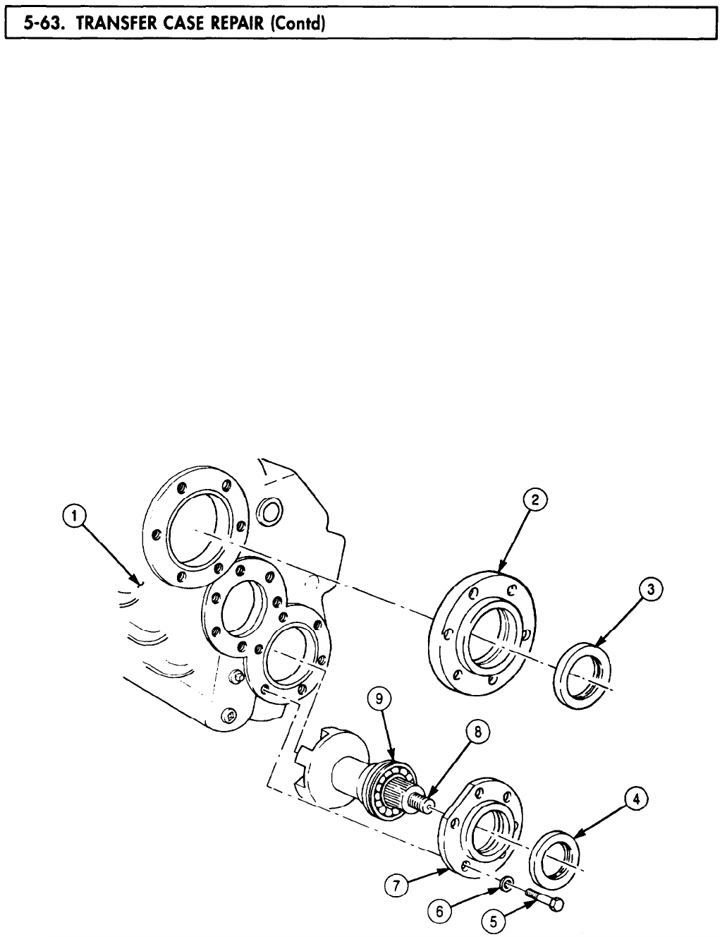
5-63. TRANSFER
TM 9-2320-272-24-4
15.
16.
17.
Apply GAA grease to inside diameter of all seals.
Install front output shaft (8) in transfer case housing (1) until snapring (9) is flush with transfer
case housing (1).
Install new front output shaft seal (4) in front output shaft cover (7).
Apply a thin coating of gasket sealer to mating surfaces of front output shaft cover (7) and transfer
case housing (1).
18.
19.
20.
21.
22.
23.
24.
Install front output shaft cover (7) on transfer case housing (1) with six washers (6) and screws (5).
Tighten screws (5) 40-65 lb-R (54-88 N•m).
Install new input shaft seal (3) on main input shaft cover (2).
Install sliding clutch (10) on front output shaft (8).
Position declutch fork (11) on sliding clutch (10).
Position declutch spring (13) under declutch fork (11) and insert declutch shaft (14) through
declutch fork (11), declutch spring (13), and into transfer case housing (1).
Install declutch fork (11) on declutch shaft (14) with setscrew (12).
Install intermediate shaft (15), rear output shaft (16), and main input shaft (18) in three bearing
races (17) on transfer case housing (1).
25.
Position hi-lo shift fork (19) on synchronizer gear (22).
26.
Insert hi-lo shift shaft (21) through hi-lo shift fork (19) and into transfer case housing (1).
27.
Install hi-lo shift fork (19) on hi-lo shift shaft (21) with setscrew (20).
NOTE
5-414
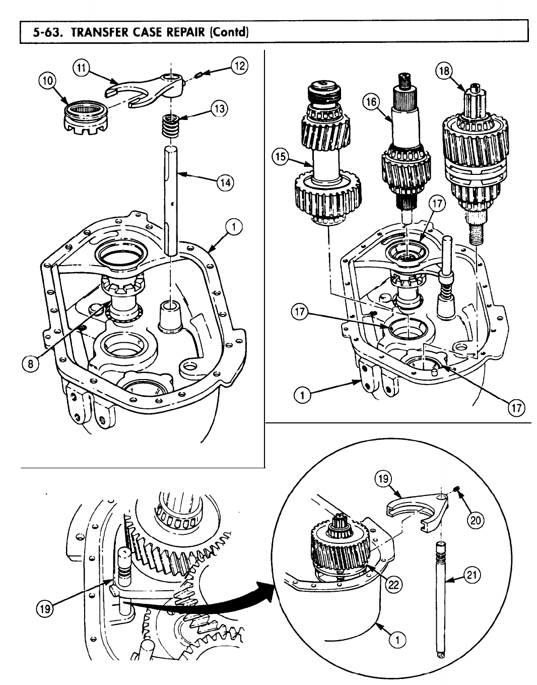
5-63. TRANSFER
TM 9-2320-272-24-4
5-415
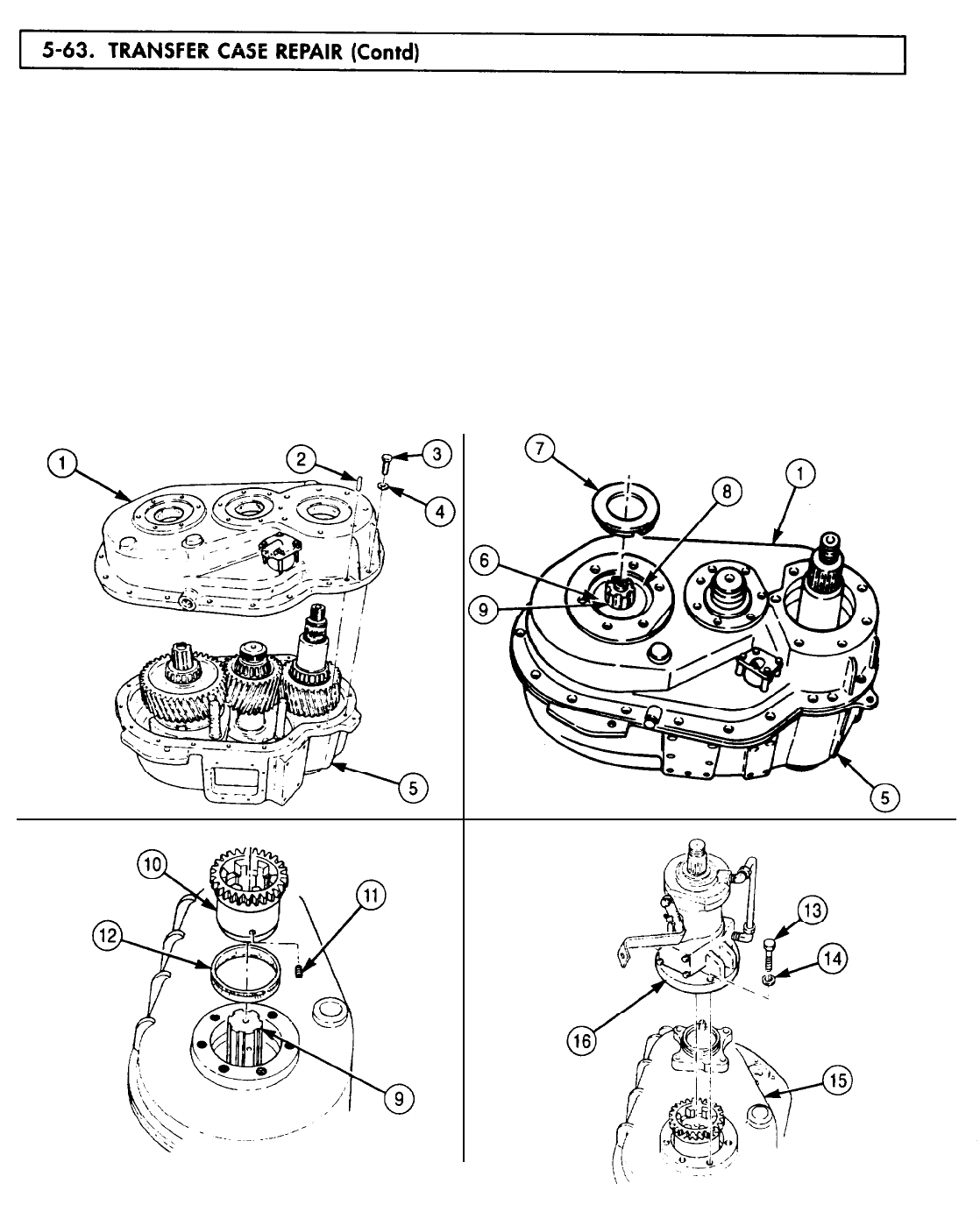
5-63. TRANSFER
TM 9-2320-272-24-4
28.
Apply gasket sealant to mating surfaces of transfer case cover (1) and housing (5).
29.
Install three dowel pins (2) on transfer case cover (1).
30.
Align dowel pins (2) on transfer case cover (1) with holes in transfer case housing (5) and install
transfer case cover (1) on transfer case housing (5) with nineteen washers (4) and screws (3).
Tighten screws (3) 40-65 lb-ft (54-88 N•m).
31.
Tap around outer edge of bearing race (8) to seat against main input shaft bearing (9).
32.
Install baffle (7) on main input shaft (6).
NOTE
Perform steps 32 through 34 for vehicles equipped with PTO.
33.
Apply adhesive sealant to setscrew (11).
34.
Install new seal (12) and PTO drive gear (10) on recess of main input shaft (9) with setscrew (11).
Tighten setscrew (11) 12-16 lb-ft (16-22 N•m).
35.
Apply sealing compound to PTO (16) and transfer case (15) and install PTO (16) on transfer
case (15) with six washers (14) and screws (13). Tighten screws (13) 140-65 lb-ft (54-36 N•m).
5-416
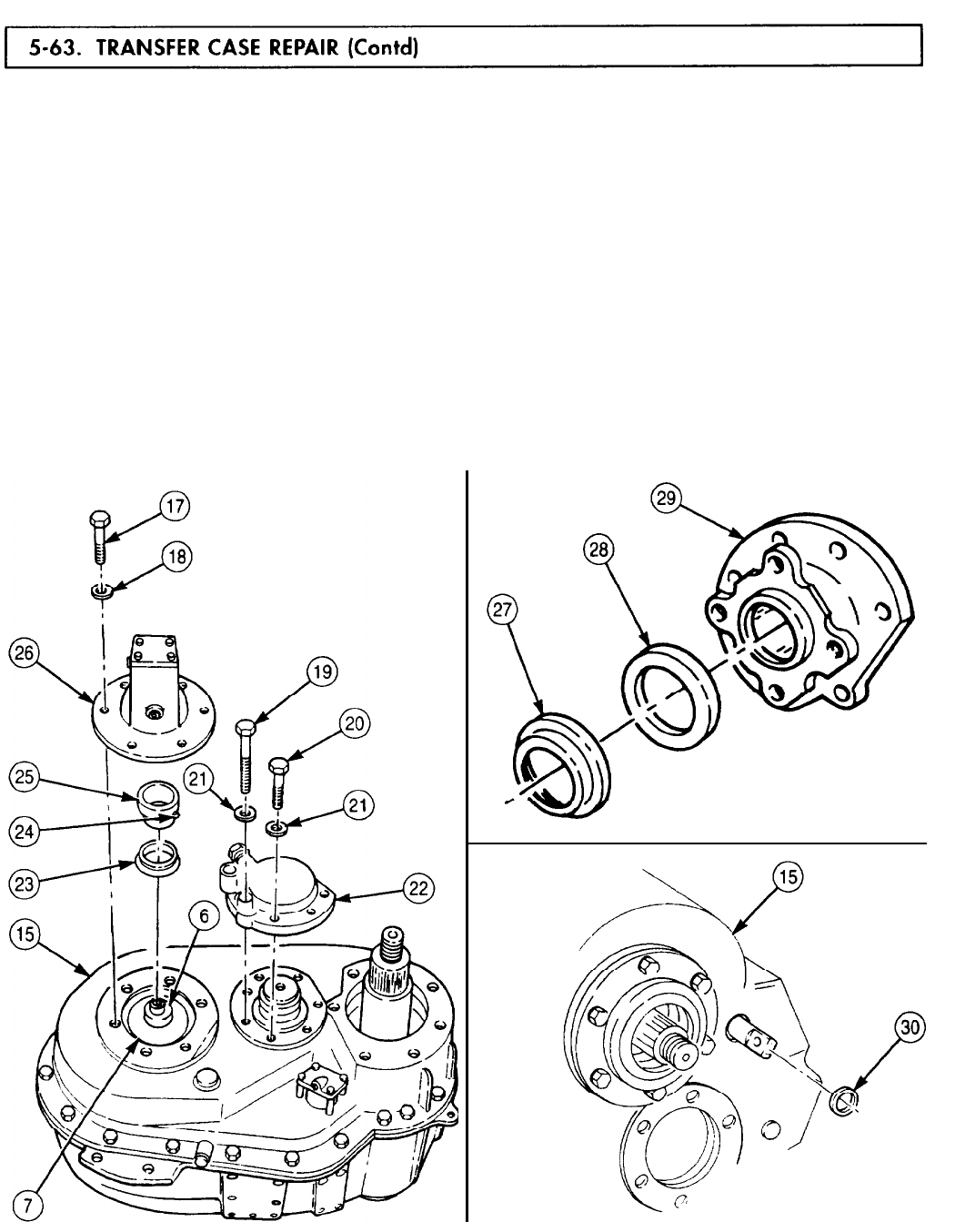
5-63. TRANSFER
TM 9-2320-272-24-4
36.
37.
38.
Apply adhesive sealant to setscrew (24).
Install new seal (23) on retaining collar (25) with large lip toward baffle (7).
Install retaining collar (25) on recess of main input shaft (6) with setscrew (24). Tighten
setscrew (24) 12-16 lb-ft (16-22 N•m).
39.
Apply a light coating of gasket sealant to mating surfaces of oil pump (26) and transfer case (15).
40.
41.
42.
43.
44.
NOTE
Ensure to align pump drive with slot on main input shaft.
Install oil pump (26) on transfer case (15) with six washers (18) and screws (17). Tighten
screws (17) 40-65 lb-ft (54-88 N-m).
Apply a light coating of gasket sealant to mating surfaces of speedometer drive cover (22) and
transfer case (15).
Install speedometer drive cover (32) on transfer case (15) with six washers (21), four screws (20),
and two screws (19). Tighten screws (19) and (20) 40-65 lb-ft (54-88) N•m).
Install new seal (28) and slinger (27) on flange (29).
Apply gasket sealant to new hi-lo shift shaft seal (30) and install on transfer case (15).
5-417

5-63. TRANSFER
TM 9-2320-272-24-4
NOTE
Step 45 establishes initial shim pack thickness for intermediate
shaft.
45.
Install intermediate shaft cover (2) on transfer case (1) and tap alternately around outer edge with
soft-faced hammer.
46.
Using feeler gauge, measure and record clearance between intermediate shaft cover (2) and
transfer case (1).
47.
Remove intermediate shaft cover (2) from transfer case (1).
NOTE
Use measurement from step 46 plus a .003 in. (.7692 mm) shim for
initial shim pack thickness.
48.
Install shim pack (3) and intermediate shaft cover (2) on transfer case (1) with six washers (4) and
screws (5). Tighten screws (5) 40-65 lb-ft (54-88 N•m).
49.
Mount dial indicator on transfer case (1) with tip of plunger positioned through hole in intermediate
shaft cover (2) on intermediate shaft (6).
NOTE
Perform step 50 to ensure intermediate shaft will rotate freely
without end play.
50.
Check intermediate shaft end play as follows:
a. Insert prybar through inspection hole (7) and force intermediate shaft (6) to rear of transfer
case (1).
b. Set dial indicator to zero.
c. Using prybar, force intermediate shaft (6) to front of transfer case (1).
d. Record reading from dial indicator and add 0.003-0.006 in. (0.076-0.152 mm) to reading. This
reading will be used for number of shims (3) to be removed.
51.
Remove dial indicator from transfer case (1).
5-418
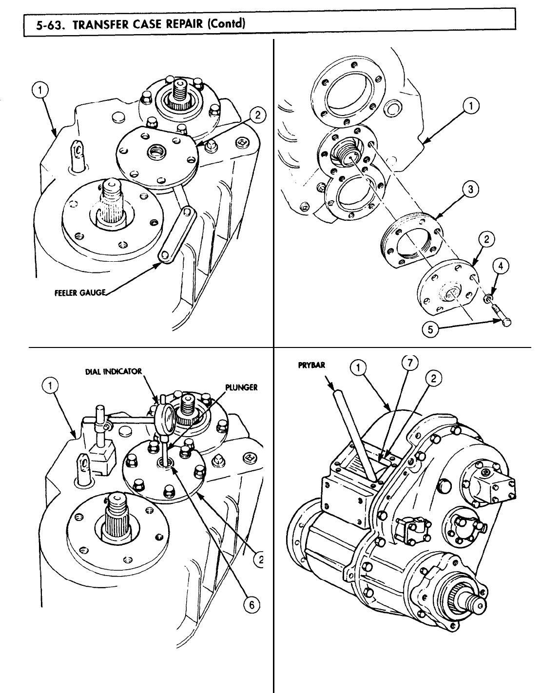
5-63. TRANSFER
TM 9-2320-272-24-4
5-419
5-63. TRANSFER
TM 9-2320-272-24-4
52.
53.
54.
55.
56.
57.
58.
59.
60.
Remove six screws (5), washers (4), intermediate shaft cover (3), and shim pack (2) from
transfer case (1).
NOTE
Use reading obtained in step 50d for number or thickness of shims
to be removed or added for intermediate shaft adjustment.
Remove or add amount of shims (2) as recorded.
CAUTION
Do not apply sealing compound to shims.
Apply a sealing compound to lightly coat mating surfaces of transfer case (1) and intermediate
shaft cover (3).
Install shim pack (2) and intermediate shaft cover (3) on transfer case (1) with six washers (4) and
screws (5). Tighten screws (5) 40-65 lb-ft (54-88 N•m).
Install plug (6) on intermediate shaft cover (3). Tighten plug (6) 35 lb-ft 48 N•m)
NOTE
Step 57 establishes initial shim pack thickness for main input
shaft.
Install main input shaft cover (7) on transfer case (1) and tap alternately around outer edge with
soft-faced hammer.
Using feeler gauge, measure and record clearance between main input shaft cover (7) and transfer
case (1).
Remove main input shaft cover (7) from transfer case (1).
NOTE
Use measurement from step 58 plus a .003 in. .0762 mm) shim for
initial shim pack thickness.
Install shim pack (8) and main input shaft cover (7) on transfer case (1) with six washers (10) and
screws (9). Tighten screws (9) 40-65 lb-ft (54-88 N•m).
5-420
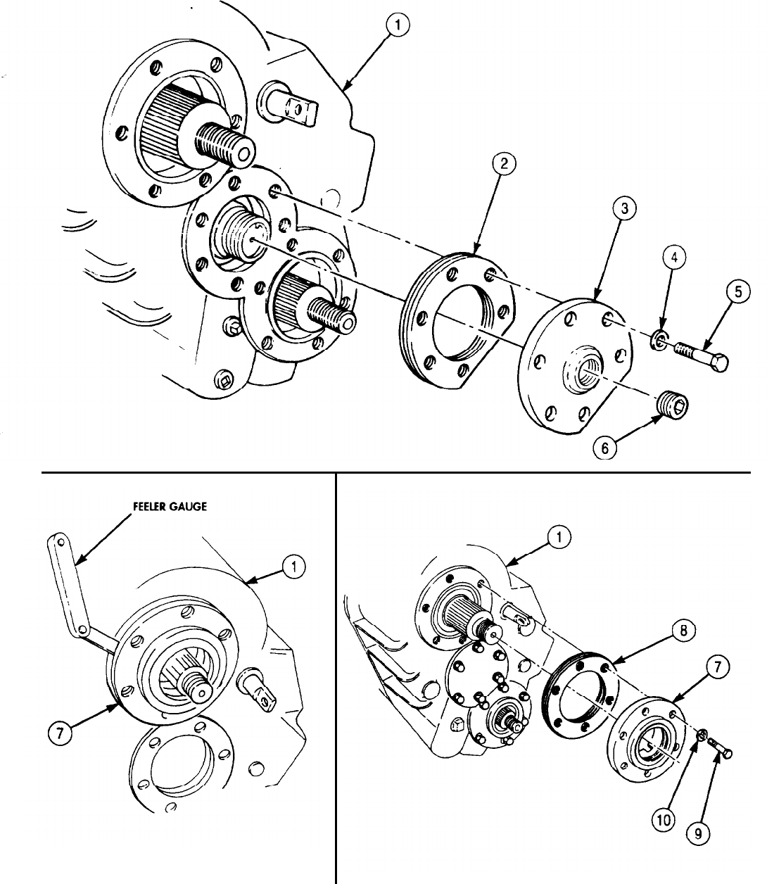
TM 9-2320-272-24-4
5-421
TM 9-2320-272-24-4
61.
Mount dial indicator on transfer case (1) with tip of plunger on main input shaft (2).
NOTE
Perform steps 62 through 64 to ensure main shaft rotates freely
without end play.
62.
Check main input shaft end play as follows:
a. Using prybar through inspection hole (3), force main input shaft (2) to rear of transfer
case (1) and hold.
b. Set dial indicator to zero.
c. Using prybar through inspection hole (3), force main input shaft (2) to front of transfer
case (1).
d. Record reading on dial indicator. End play should be 0.0001-0.005 in. (0.00254-0.127 mm).
63.
Remove dial indicator from transfer case (1).
64.
Remove six screws (7), washers (6), main input shaft cover (5), and shim pack (4) from transfer
case (1).
NOTE
Use reading obtained in step 62d for number or thickness of shims
to be removed or added for main input shaft adjustment.
65.
Remove or add amount of shims (4) as recorded.
CAUTION
Do not apply sealing compound to shims.
66.
Apply a light coating of sealing compound to mating surfaces of transfer case (1) and main input
shaft cover (5).
67.
Install shim pack (4) and main input shaft cover (5) on transfer case (1) with six washers (6) and
screws (7). Tighten screws (7) 40-65 lb-ft (54-88 N•m).
5-422
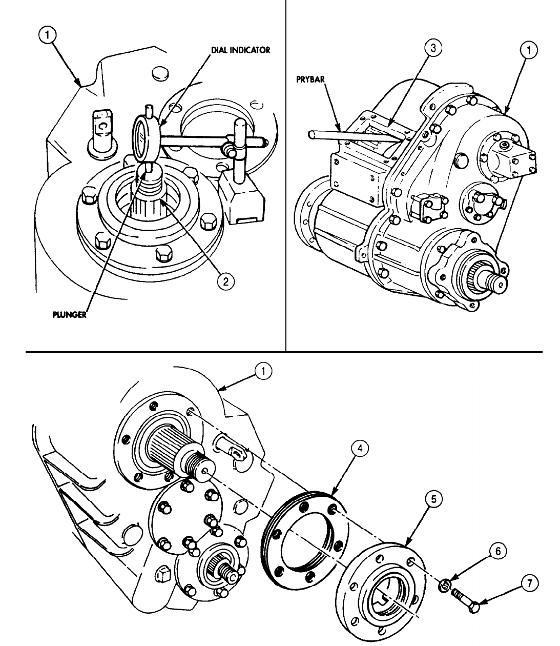
TM 9-2320-272-24-4
5-423
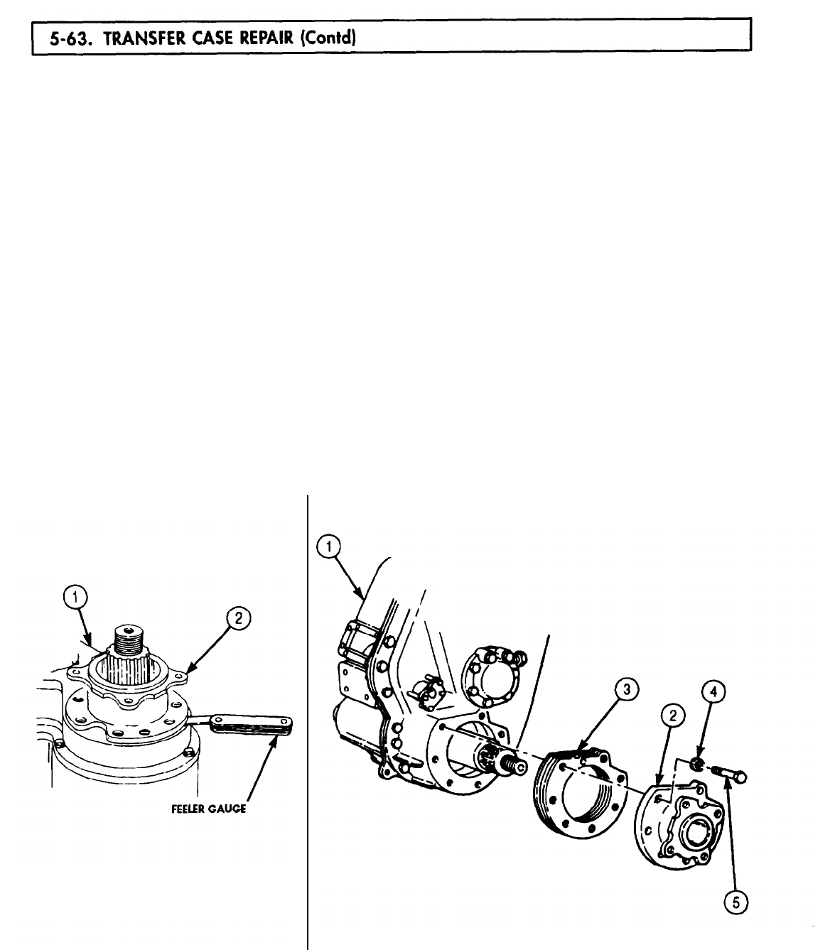
5-63. TRANSFER
TM 9-2320-272-24-4
NOTE
Steps 68 and 69 establish initial shim pack thickness for rear
output shaft.
68.
Install companion flange (2) on transfer case (1) and tap alternately around outer edge with soft-
faced hammer.
69.
Using feeler gauge, measure and record clearance between companion flange (2) and transfer
case (1).
70.
Remove companion flange (2) from transfer case (1).
NOTE
Use measurement from step 69 plus a 0.003 in. (0.0762 mm) shim
for initial shim pack thickness.
71.
Install shim pack (3) and companion flange (2) on transfer case (1) with seven washers (4) and
screws (5). Tighten screws (5) 60-100 lb-ft (81-136 N-m).
72.
Mount dial indicator on transfer case (1) with tip of plunger positioned on rear output shaft (6).
73.
Check rear output shaft (6) end play as follows:
a. Using prybar through inspection hole (7), force rear output shaft (6) to front of transfer
case (1) and hold.
b. Set dial indicator to zero.
c. Using prybar through inspection hole (7), force rear output shaft (6) to rear of transfer
case (1).
d. Record reading on dial indicator. End play should be 0.0001-0.005 in. (0.00254-0.127 mm).
74.
Remove dial indicator from transfer case (1).
5-424
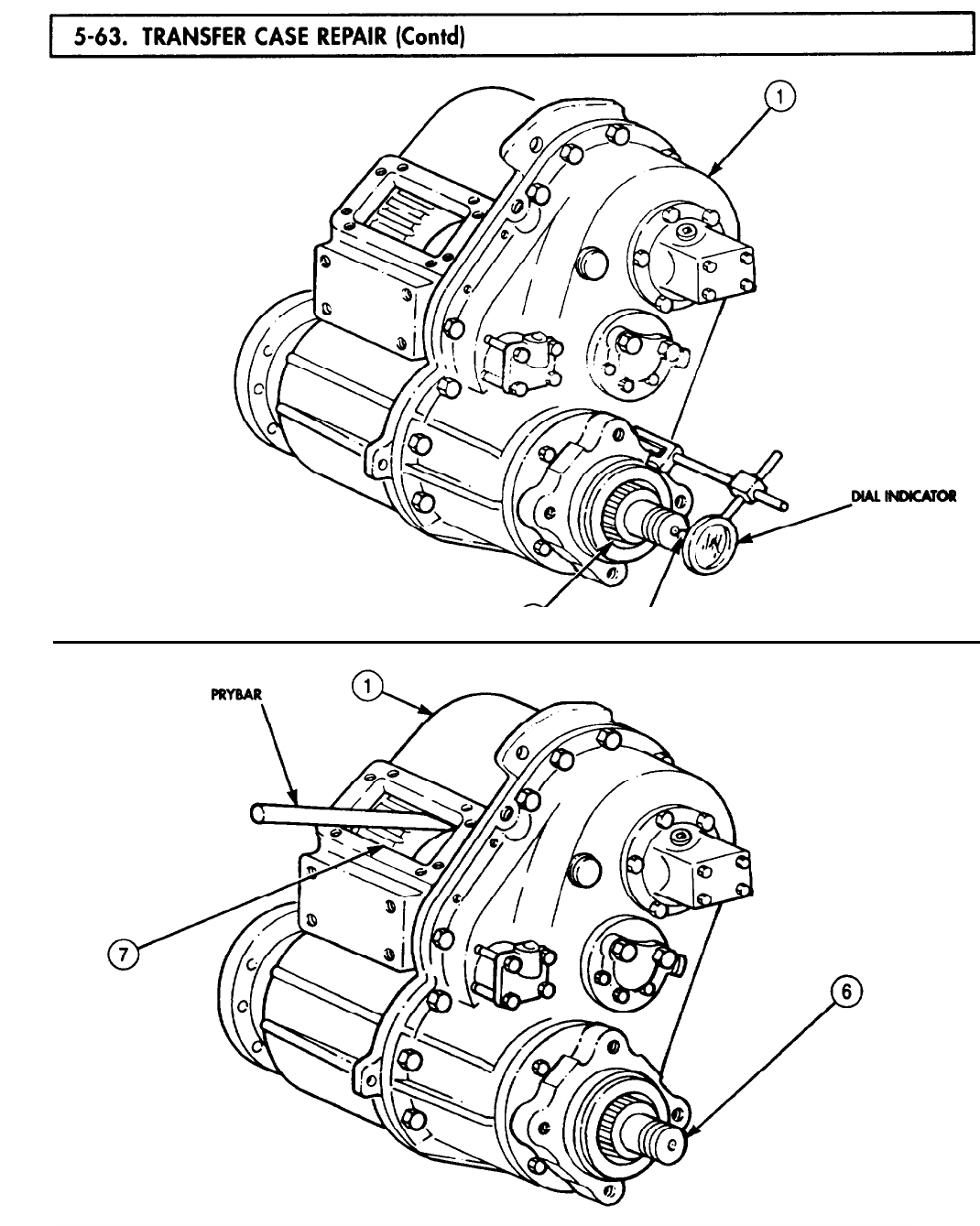
5-63. TRANSFER
TM 9-2320-272-24-4
5-425
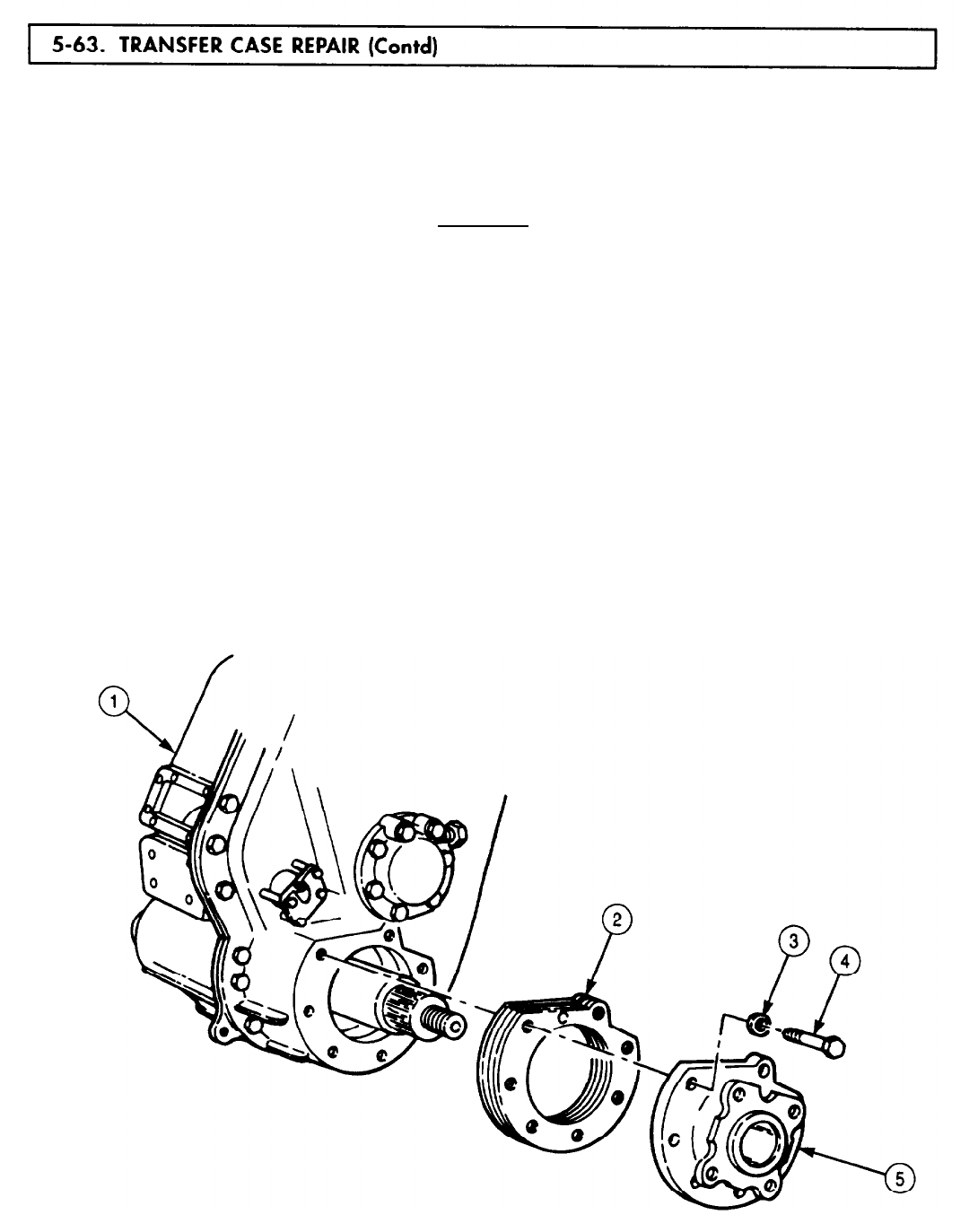
5-63. TRANSFER
TM 9-2320-272-24-4
75.
Remove seven screws (4), washers (3), and companion flange (5) from transfer case (1).
NOTE
Use reading obtained in step 73d for number or thickness of shims
to be removed or added for rear output shaft adjustment.
76.
Remove or add amount of shims (2) as recorded.
CAUTION
Do not apply sealing compound to shims.
77.
Apply a light coating of sealing compound to mating surfaces of transfer case (1) and companion
flange (5).
78.
Install shim pack (2) and companion flange (5) on transfer case (1) with seven washers (3) and
screws (4). Tighten screws (4) 110-145 lb-ft (149-197 N•m).
NOTE
Apply GAA grease to inside diameter of all seals.
79.
Install main input flange (6) on main input shaft (9).
80.
Install front output flange (7) on front output shaft (8).
NOTE
Chain is necessary to prevent main and output flanges from
rotating when removing hardware.
81.
Install chain on main input flange (6) with two washers (16) and screw (17).
82.
Install chain on front output flange (7) with washer (12), screw (11), washer (12), and nut (13).
83.
Apply a thin coating of gasket sealant to mating surfaces of washers (18) and (14), and install
washers (18) and (14) and new locknuts (10) and (15) on front output shaft (8) and main input
shaft (9). Tighten locknuts (10) and (15) 450-600 lb-ft (610-814 N•m).
5-426
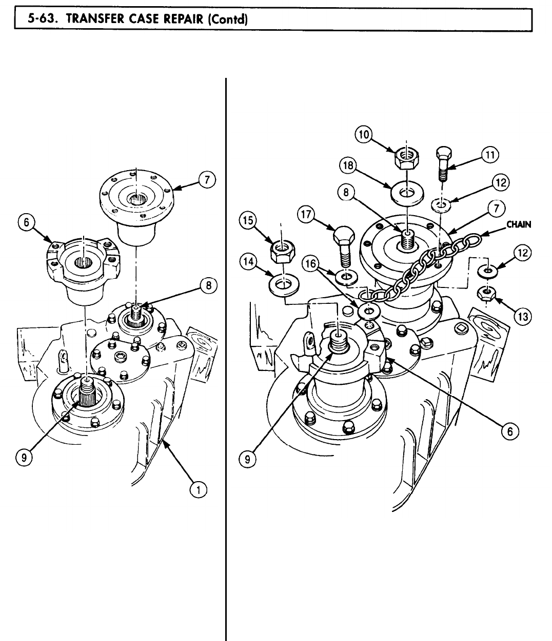
5-63. TRANSFER
TM 9-2320-272-24-4
5-427

5-63. TRANSFER
TM 9-2320-272-24-4
84.
85.
86.
87.
88.
89.
90.
91.
92.
Install filter screen (3), adapter fitting (4), and elbow (5) on transfer case (2). Tighten elbow (5)
15 lb-ft (20 N•m).
NOTE
Perform steps 85 and 86 for vehicles equipped with PTO.
Install elbow (1) on PTO (7). Tighten elbow (1) 26 lb-ft (35 N•m).
Connect oil line (6) to elbows (5) and (1).
Install nipple end of elbow (13) on oil pump (8). Tighten elbow (13) 20 lb-ft (27 N•m).
Connect oil line (14) to elbows (5) and (13).
Install new seal (9) on cover (12).
Install new seal (17) on piston (16).
Install new gasket (18). new piston (16), new cylinder (15), and cover (12) on transfer case (2) with
four new locking plates (11) and screws (10). Tighten screws (10) 5-10 lb-ft (8-13 N•m).
Bend tabs of locking plates (11) over heads of screws (10).
5-428
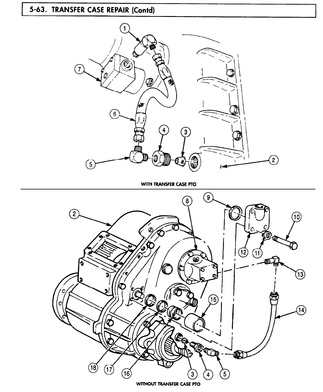
5-63.TRANSFER
TM 9-2320-272-24-4
5-429
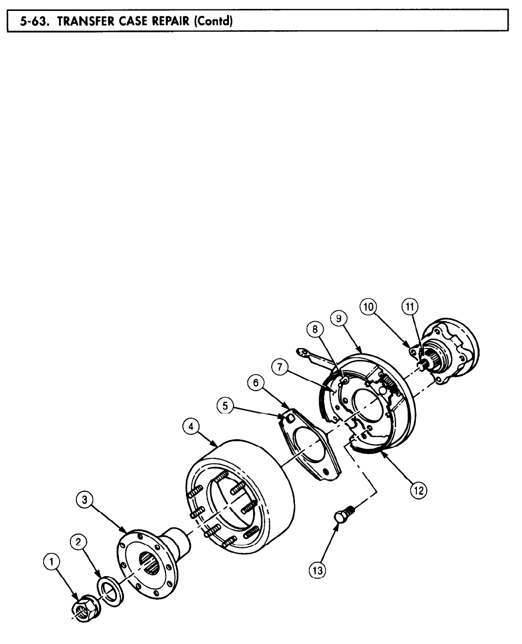
5-63.
TM 9-2320-272-24-4
93.
94.
95.
96.
97.
98.
99.
Install brakeshoe assembly (12) and dust cover (9) on companion flange (10) with four
screws (13). Tighten screws (13) 180-230 lb-ft (244-312 N•m).
Position actuating plate (6) against backing plate (7) so retainer opening (5) fits over brake lever
stud (8) of backing plate (7).
NOTE
Apply GAA grease to inside diameter of all seals.
Install parking brake drum (4) and output flange (3) on output shaft (11).
Apply a thin coating of gasket sealant to mating surfaces of washer (2) and install washer (2) and
new locknut (1) on output shaft (11). Tighten locknut (1) 450-600 lb-ft (610-814 N•m).
Remove nut (18), washer (17), screw (16), washer (17), screw (14), washer (19), and chain from main
input flange (20) and front output flange (15).
Apply a thin coating of gasket sealant to mating surfaces of inspection plate (24) and transfer
case (23) and install inspection plate (24) on transfer case (23) with eight screws (25). Do not tighten
screws (25).
Using crowfoot wrench, install pushrod (22) and interlock air cylinder (21) on transfer case (23).
Tighten interlock air cylinder (21) 30-40 lb-ft (41-54 N•m).
5-430
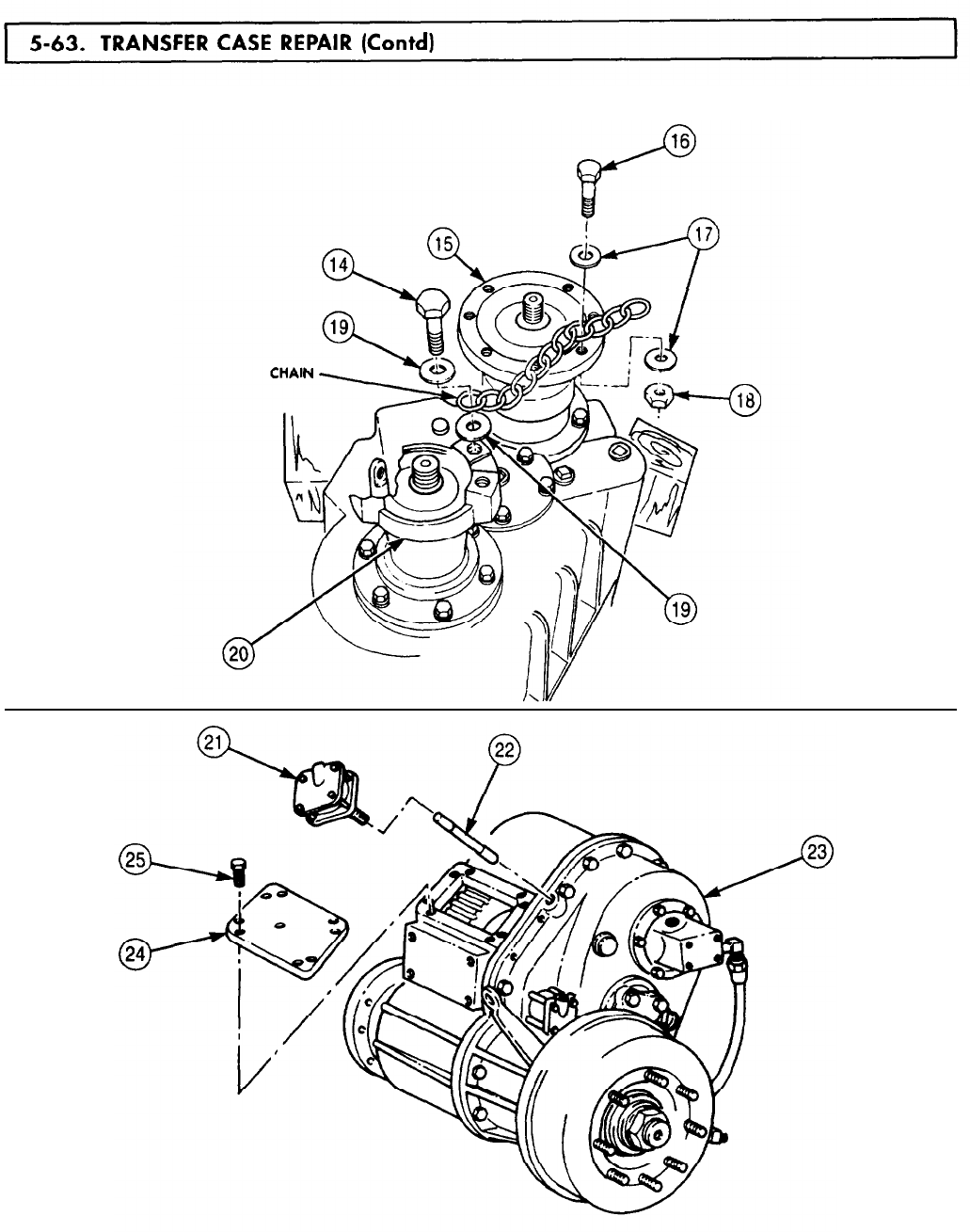
5-63. TRANSFER
TM 9-2320-272-24-4
FOLLOW-ON TASK: Install transfer case (para. 4-94 or para. 4-95).
5-431
5-64. DIFFERENTIAL
TM 9-2320-272-24-4
Section V. FRONT AND REAR AXLE MAINTENANCE
THIS TASK COVERS:
a.
Disassembly c. Assembly and Adjustment
b.
Cleaning, Inspection, and Repair
INITIAL SETUP:
APPLICABLE MODELS
All
SPECIAL TOOLS
Bearing replacer (Appendix E, Item 14)
Two puller screws (Appendix E, Item 104)
TOOLS
General mechanic’s tool kit
(Appendix E, Item 1)
Mechanical puller kit (Appendix E, Item 102)
Inside micrometer
(Appendix E, Item 83)
Torque wrench (Appendix E, Item 146)
Torque wrench (Appendix E, Item 145)
Dial indicator (Appendix E, Item 36)
Outside micrometer (Appendix E, Item 80)
Arbor press
Torque multiplier
Vise
Soft-head hammer
Chain
Lifting device
Bearing preload tester
MATERIALS/PARTS
Gasket (Appendix D, Item 206)
Gasket (Appendix D, Item 207)
Gasket (Appendix D, Item 208)
Three safety wires, 12 in. (Appendix D, Item 568)
Wear sleeve kit (Appendix D, Item 717)
Gasket and shim set (Appendix D, Item 248)
Six lockwashers (Appendix D, Item 350)
Locktab washer (Appendix D, Item 344)
Two cotter pins (Appendix D, Item 61)
Two oil seals (Appendix D, Item 500)
Gasket (Appendix D, Item 653)
Six lockwashers (Appendix D, Item 354)
Safety wire, 36 in. (Appendix D, Item 568)
Crocus cloth (Appendix C, Item 20)
GAA grease (Appendix C, Item 28)
Lubricating oil (Appendix C, Item 47)
Blue oil-base pigment (Appendix C, Item 54)
Sealing compound (Appendix C, Item 61)
Sealing compound (Appendix C, Item 62)
Twine (Appendix C, Item 77)
White carbonate pigment (Appendix C, Item 78)
REFERENCES (TM)
LO 9-2320-272-12
TM 9-214
TM 9-2320-272-24P
EQUIPMENT CONDITION
Differential and carrier assembly removed
(para. 4-100).
NOTE
Front and rear differentials are repaired the same way.
1.
Remove safety wires (1) from two screws (2) and four screws (4). Discard safety wires (1).
5-432
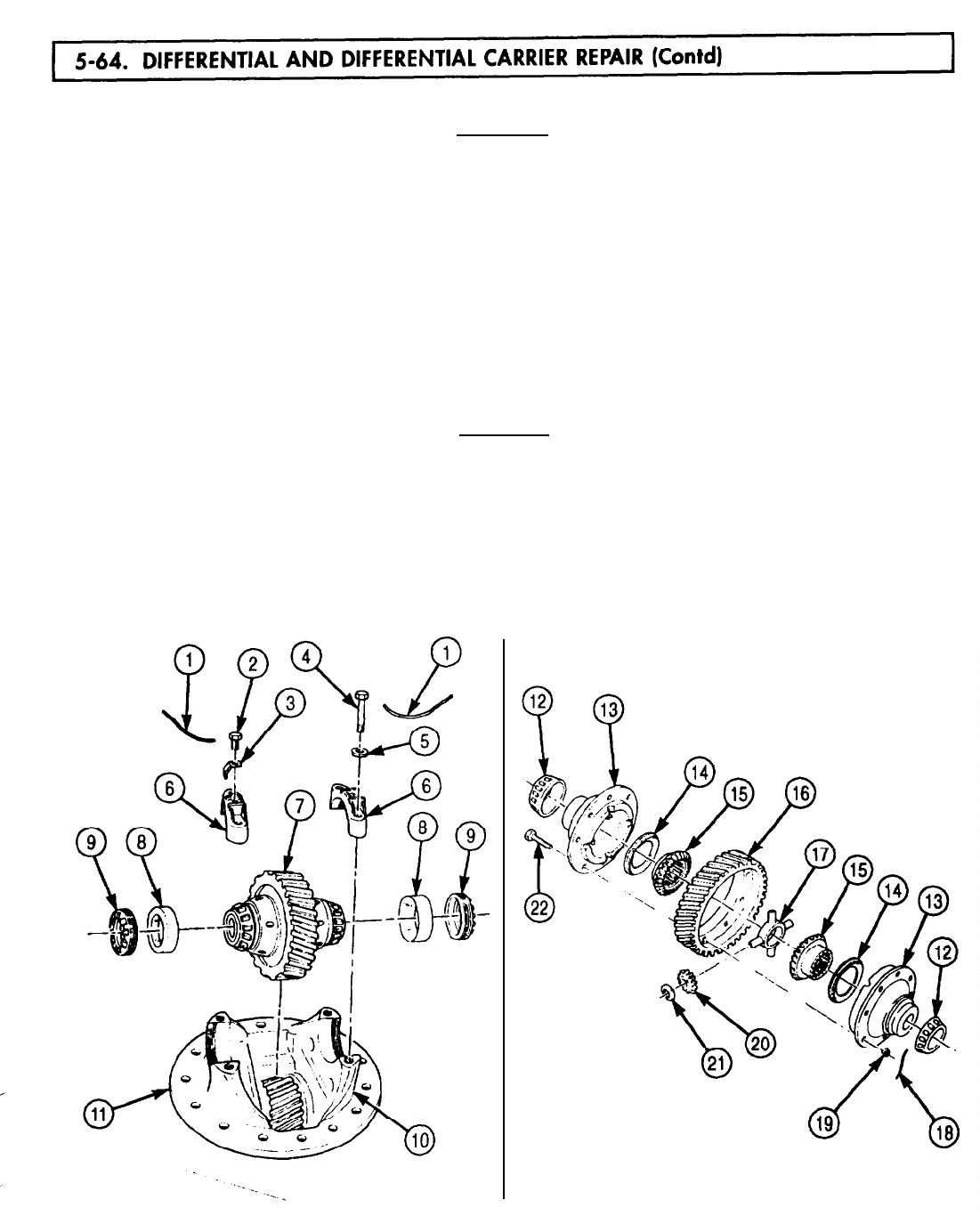
5-64. DIFFERENTIAL
TM 9-2320-272-24-4
2.
Remove two screws (2) and adjusting nut locks (3) from bearing caps (6).
CAUTION
Scribe bearing caps and saddles for installation. These items are
machine-matched and damage will result if they are intermixed.
3.
Remove four screws (4), washers (5), and two bearing caps (6) from differential carrier housing (11).
NOTE
Tag bearings and races as matched parts for inspection and
installation.
4.
Remove two adjusting nuts (9) and bearing races (8) from bearing saddles (10) and caps (6).
5.
Remove differential gear assembly (7) from differential carrier housing (11) and bearing
saddles (10).
6.
Using puller, remove two tapered roller bearings (12) from differential housings (13).
7.
Remove safety wire (18) from eight slotted nuts (19). Discard safety wire (18).
CAUTION
Two gear housings and helical drive gear must be scribed for
installation. These items are machine-matched and damage may
result if they are intermixed.
8.
Remove eight slotted nuts (19) and screws (22) from two differential housings (13). Mark two
differential housings (13) and helical ring gear (16) for installation.
9.
Remove four bevel spider gears (20), thrust washers (21), and spider (17) from differential
housing (13).
10.
Remove two bevel side gears (15) and thrust washers (14) from differential housings (13).
5-433
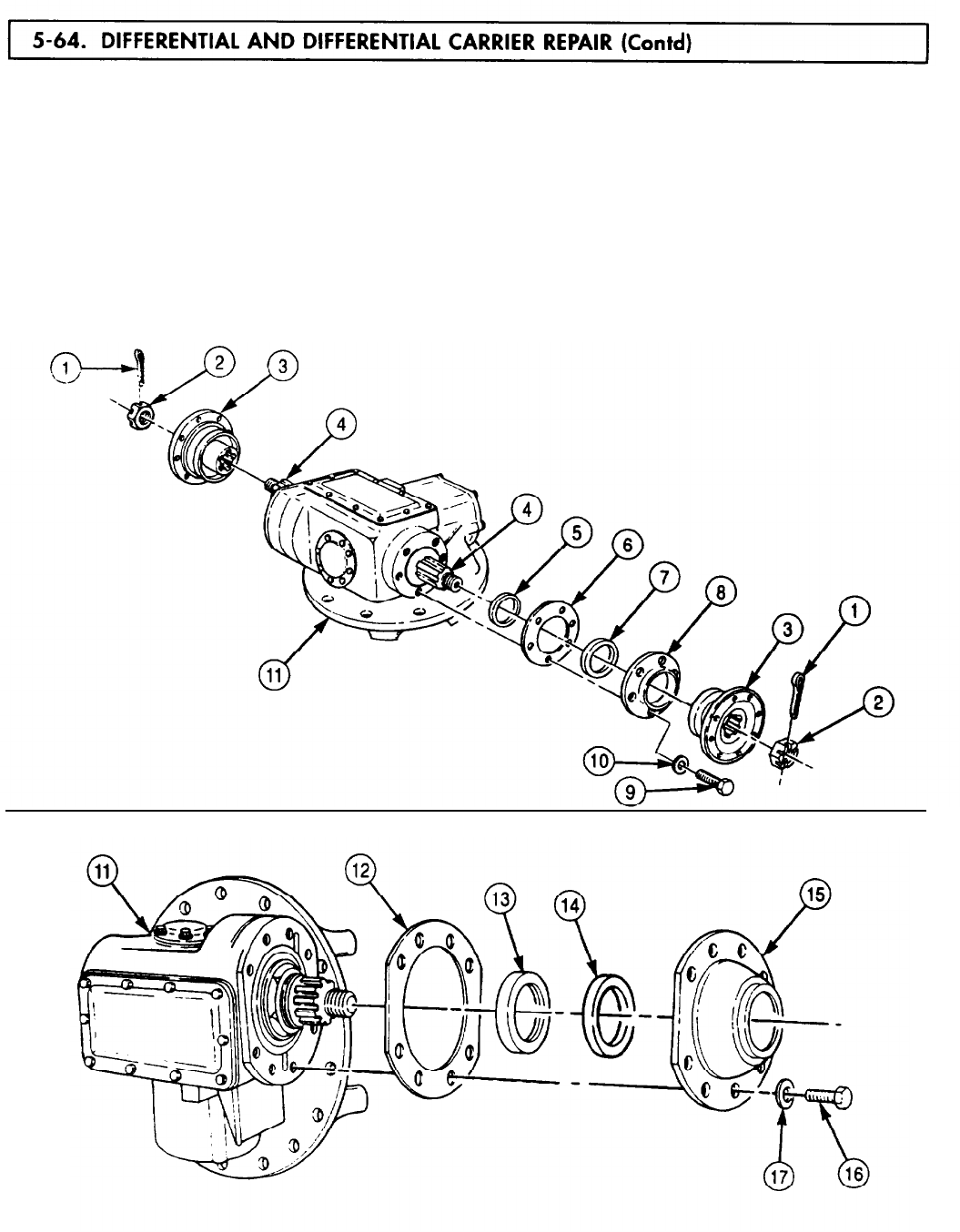
5-64. DIFFERENTIAL
TM 9-2320-272-24-4
11.
12.
13.
14.
15.
16.
17.
Remove two cotter pins (l), nuts (2), and companion flanges (3) from mainshaft (4). Discard cotter
pins (1).
Remove six screws (9) and lockwashers (10) from rear bearing cover (8). Discard lockwashers (10).
Remove rear bearing cover (8), gasket (6), and thrust washer (5) from differential carrier
housing (11). Discard gasket (6).
Remove oil seal (7) from rear bearing cover (8). Discard oil seal (7).
Remove eight screws (16) and washers (17) from front bearing cover (13).
Remove front bearing cover (15) and gasket (12) from differential carrier housing (11). Discard
gasket (12).
Using puller, remove oil seal (13) and gasket (14) from front bearing cover (15). Discard oil seal (13)
and gasket (14).
5-434
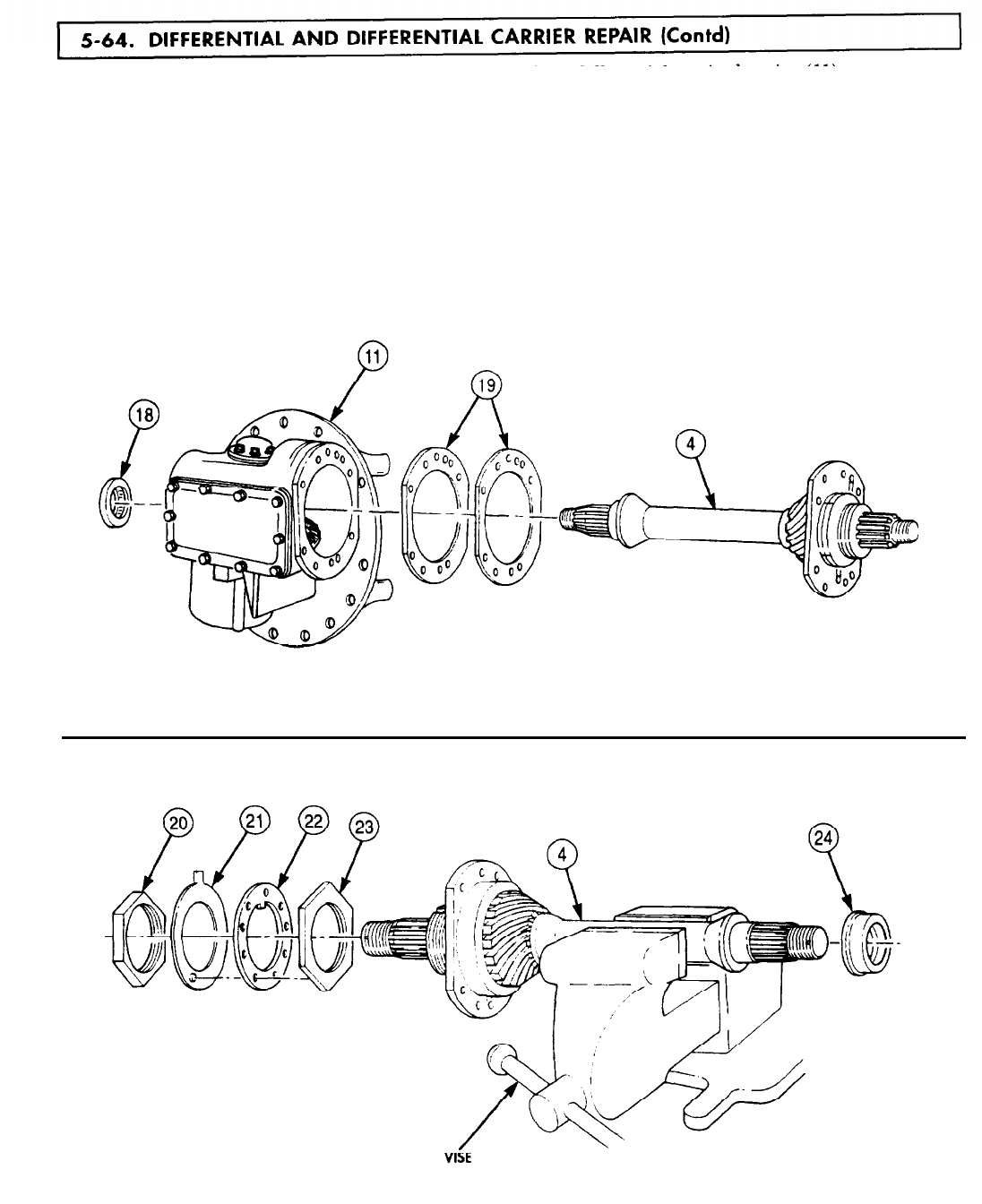
5-64. DIFFERENTIAL
TM 9-2320-272-24-4
18.
Remove mainshaft and pinion gear assembly (4) from differential carrier housing (11).
NOTE
19.
20.
21.
22.
23.
Tag and retain shims for measurement and installation.
Using bearing remover, remove shims (19) from front of differential carrier housing (11).
Remove bearing (18) from rear of differential carrier housing (11).
Place mainshaft (4) in soft-jawed vise.
Using puller, remove rear bearing race (24) from rear of mainshaft (4).
Open tab(s) on locktab washer (21) and remove outer nut (20), locktab washer (21), keywasher (22),
and inner nut (23) from mainshaft (4). Discard locktab washer (21).
5-435
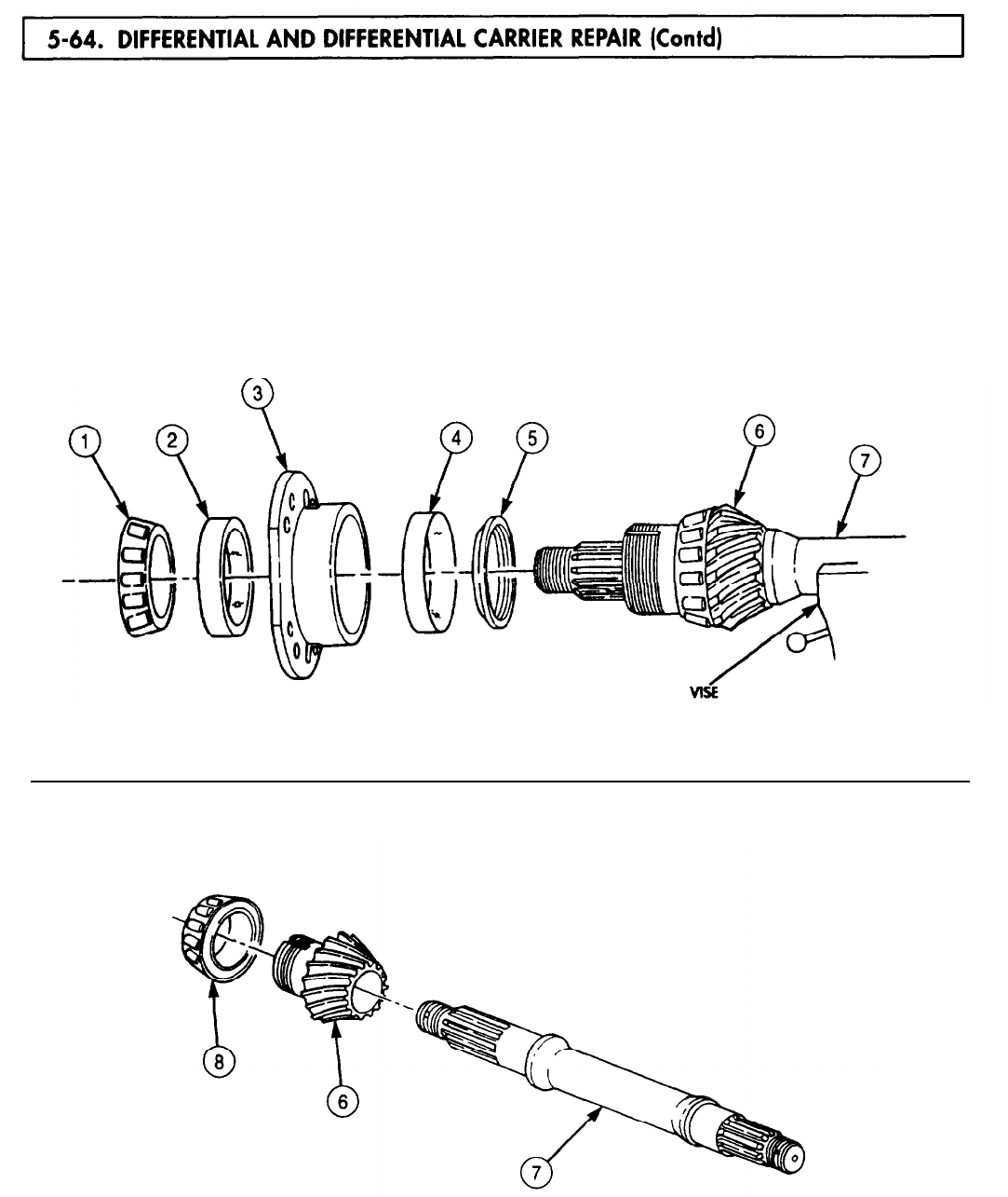
5-64. DIFFERENTIAL
TM 9-2320-272-24-4
24.
25.
26.
27.
28.
NOTE
Bearings and races are matched sets and must be kept together
for inspection and installation.
Using arbor press, remove outer bearing (1), retainer (3), and spacer (5) from pinion gear (6) and
mainshaft (7).
NOTE
Races may require light tapping to remove from retainer.
Using bearing replacer, remove races (2) and (4) from retainer (3).
Remove mainshaft (7) from vise.
Using arbor press, remove pinion gear (6) with bearing (8) from mainshaft (7).
Using puller, remove bearing (8) from pinion gear (6).
5-436
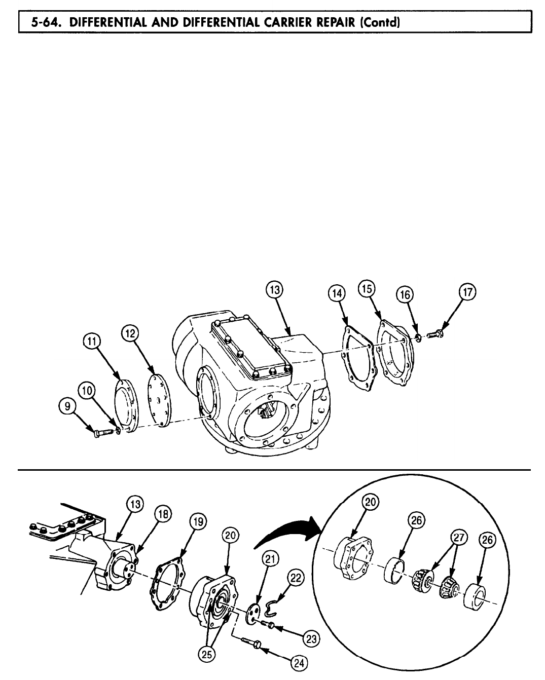
5-64. DIFFERENTIAL
TM 9-2320-272-24-4
29.
30.
31.
32.
33.
34.
35.
36.
37.
Remove eight screws (9) and washers (10) from side cover (11).
Remove side cover (11) and gasket (12) from differential carrier housing (13). Discard gasket (12).
Remove six screws (17) and lockwashers (16) from bearing retaining plate (15). Discard
lockwashers (16).
NOTE
Record number and thickness of shims for installation.
Remove bearing retaining plate (15) and shims (14) from differential carrier housing (13). Discard
shims (14).
Remove safety wire (22) from three screws (23) on retaining plate (21). Discard safety wire (22).
Remove three screws (23) and retaining plate (21) from shaft (18).
Install two puller screws (24) in tapped jacking holes (25) in bearing cap (20) and remove bearing
cap (20). Tighten screws (24) evenly while removing bearing cap (20). Remove puller
screws (24) from bearing cap (20).
NOTE
Tag and retain shims for measurement and installation.
Remove shims (19) from differential carrier housing (13).
Using arbor press, remove two bearings (27) and races (26) from bearing cap (20).
5-437
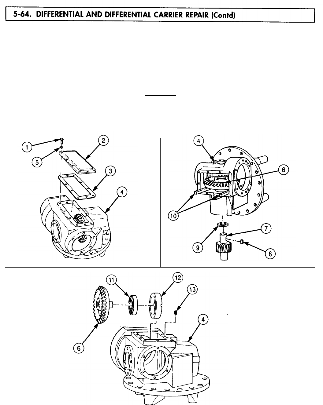
5-64. DIFFERENTIAL
TM 9-2320-272-24-4
38.
Remove ten screws (1), washers (5), access cover (2), and gasket (3) from differential carrier
housing (4). Discard gasket (3).
39.
Place two soft-iron spacers (10) between bevel ring gear (6) and differential carrier housing (4).
40.
Using arbor press, remove helical pinion gear (7) from bevel ring gear (6).
41.
Remove spacer (9) and machine key (8) from shaft of helical pinion gear (7).
42.
Remove bevel ring gear (6) with bearing (11) from differential carrier housing (4).
43.
Remove setscrew (13) from differential carrier housing (4).
CAUTION
Drive bearing sleeve out by tapping evenly. Scoring will occur if
sleeve tilts in housing.
44.
Using puller, remove bearing sleeve (12) from differential carrier housing (4).
45.
Using puller, remove bearing (11) from bevel ring gear (6).
5-438
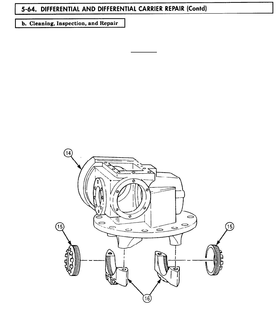
5-64. DIFFERENTIAL
TM 9-2320-272-24-4
1.
2.
3.
4.
For general cleaning instructions, refer to para. 2-14.
For general inspection instructions, refer to para. 2-15.
CAUTION
Differential carrier housing and cap, bearings, and bearing races
are machined or matched parts. Damage may result if they are
intermixed. Replace all matched parts as sets if damaged.
Inspect differential carrier housing (14) and bearing caps (16) for scores, cracks, distortion, breaks,
burrs, and wear. For repair of minor damage, refer to para. 2-16. Replace housing (14) and caps (16)
if either part is damaged.
Inspect two adjusting nuts (15) for cracks, breaks, missing locking lugs, and damaged threads.
Replace adjusting nut(s) (15) if cracked, broken, locking lugs are missing, or threads are damaged.
5-439
TM 9-2320-272-24-4
5.
6.
7.
8.
9.
10.
11.
12.
13.
14.
15.
16.
NOTE
Replace entire differential gear assembly if helical ring gear,
spider, spider gears, bevel gears, or thrust washer fails inspection.
Inspect two bearings (2) and races (1) (TM 9-214). Replace bearing (2) and race (1) as a set
if either part fails inspection.
Inspect two differential gear housings (4) for chips, burrs, cracks, pitting, scoring, and breaks. For
repair of minor damage, refer to para. 2-16. Replace entire differential gear assembly if differential
gear housings (4) are damaged.
Measure inside diameter of bearing races (5) and outside diameter of differential gear housing
hubs (3). The difference between measurements (press fit) must be within 0.0015-0.0035 in.
(0.0381-0.0889 mm). Replace entire differential gear assembly if press fit is not within limits.
Inspect four thrust washers (12), bevel spider gears (ll), two thrust washers (6), bevel side gears (7),
spider (9), and helical ring gear (8) for cracks, breaks, chips, burrs, scoring, and pitting. For repair of
minor damage, refer to para. 2-16. Replace entire differential gear assembly if any part fails
inspection.
Measure outside diameter of four spider arms (10). Measurement should be 1.122-1.123 in.
(28.50-28.52 mm). Replace entire differential gear assembly if spider arm(s) (10) are not within
limits.
Measure inside diameter of four bevel spider gears (11). Measurement should be 1.128-1.130 in.
(28.65-28.70 mm). Replace entire differential gear assembly if bevel spider gear(s) (11) are not
within limits.
Inspect two bearings (19) and races (18) (TM 9-214). Replace bearing (19) and race (18) as
a set if either part fails inspection.
Inspect bevel ring gear (13), sleeve (15), spacer (16), and helical pinion gear (17) for chips, breaks,
cracks, burrs, nicks, and scores. For repair of minor damage, refer to para. 2-16. Replace bevel ring
gear (13), sleeve (15), spacer (16), and helical pinion gear (17) if damaged.
Measure inside diameter of bearing races (20) and outside diameter of pinion gear shaft (21). The
difference between measurements (press fit) must be within 0.0000-0.0015 in. (0.0000-0.0381 mm).
Replace helical pinion gear (17) and bearings(s) (19) if press fit is not within limits.
Inspect bearing (14) (TM 9-214). Replace bearing (14) if damaged.
Measure outside diameter of bevel ring gear (13) and inside diameter of race on bearing (14). The
difference between measurements (press fit) must be within 0.0006-0.0011 in. (0.015-0.028 mm).
Replace bevel ring gear (13) and bearing (14) if press fit is not within limits.
Measure outside diameter of bearing (14) and inside diameter of spacer (15). The difference between
measurements (press fit) must be within 0.0030-0.0058 in. (0.076-0.147 mm). Replace bearing (14)
and sleeve (15) if press fit is not within limits.
5-440
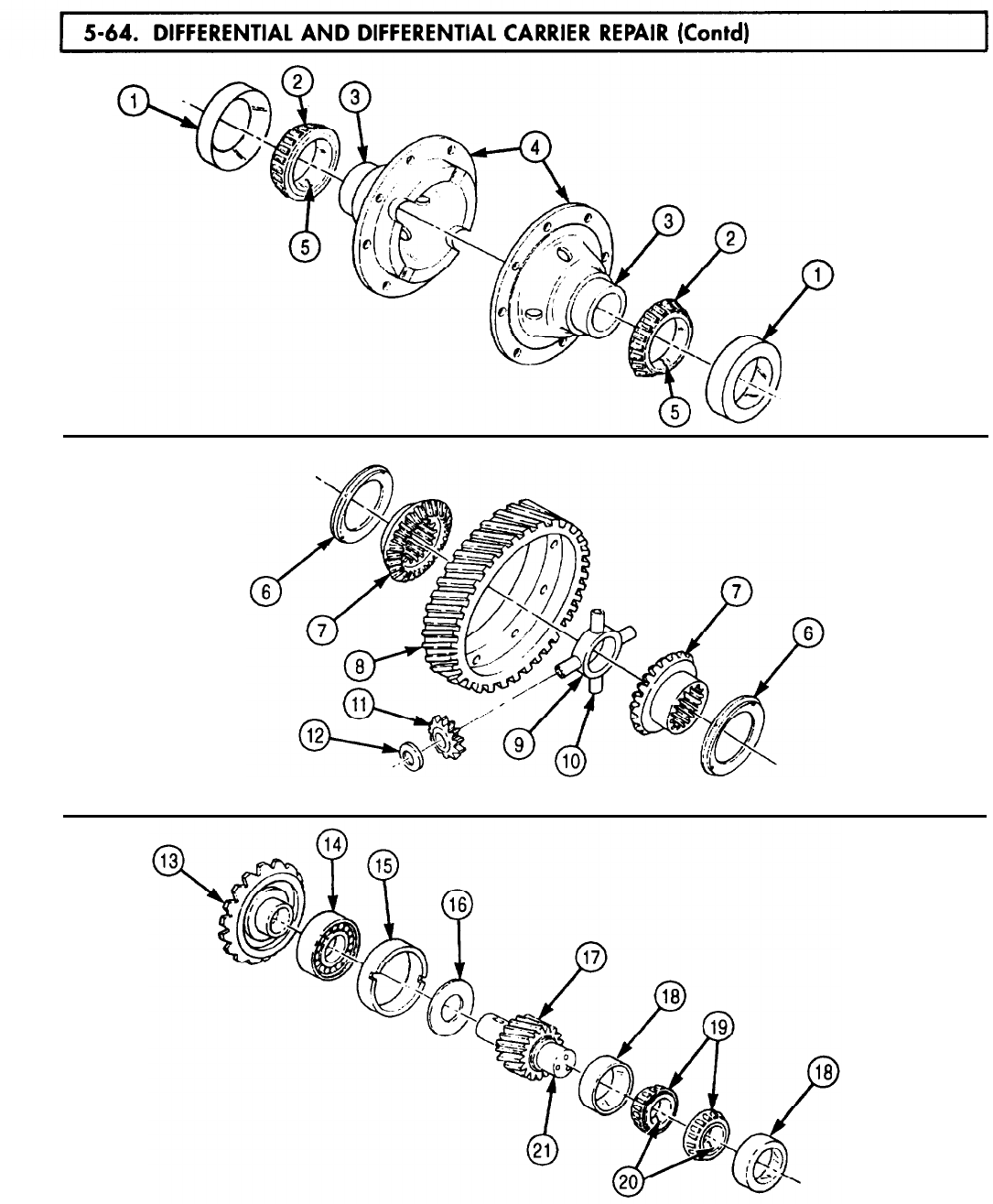
5-64. DIFFERENTIAL
TM 9-2320-272-24-4
5-441

5-64. DIFFERENTIAL
TM 9-2320-272-24-4
17.
18.
19.
20.
21.
22.
23.
Inspect two bearings (1) and races (2), bearing (7), and race (6) (TM 9-214). Replace
bearings (1) or (7) and appropriate races (2) or (6) if damaged.
Inspect bevel pinion gear (3) and mainshaft (4) for chips, burrs, breaks, bends, and scoring. For
repair of minor damage, refer to para. 2-16. Replace bevel pinion gear (3) or mainshaft (4) if
damaged.
Measure inside diameter of bearing race (2) and outside diameter of middle step (8) of bevel
pinion gear (3). The difference between measurements (press fit) must be within 0.0000-0.0020 in.
(0.000-0.051 mm). Replace bearing race (2) and bevel pinion gear (3) if press fit is not within limits.
Measure inside diameter of bearing race (10) and outside diameter of front step (9) of bevel
pinion gear (3). The difference between measurements (press fit) must be within 0.0010-0.0025 in.
(0.025-0.064 mm). Replace bearing (1) and bevel pinion gear (3) if press fit is not within limits.
Measure inside diameter of bearing race (6) and outside diameter of mainshaft shoulder (5). The
difference between measurements (press fit) must be within 0.0006-0.0019 in. (0.015-0.048 mm).
Replace bearing race (6) and mainshaft (40) if press fit is nut within limits.
Measure outside diameter of bearing (6) and inside diameter of rear bore (12) of differential carrier
housing (11). The difference between measurements (press fit) must be +0.0009 to -0.0007 in.
(+0.023 to -0.018 mm). Replace bearing (6) and differential carrier housing (11) if press tit is not
within limits.
Inspect companion flange (13), deflector (14), and wear sleeve (15) for cracks, breaks, bends, scoring,
and wear. Replace companion flange (13), deflector (14), or wear sleeve (15) if cracked, broken, bent,
scored, or worn. Follow instructions in wear sleeve kit, P/N 12375353, for replacement of wear
sleeve (15).
5-442
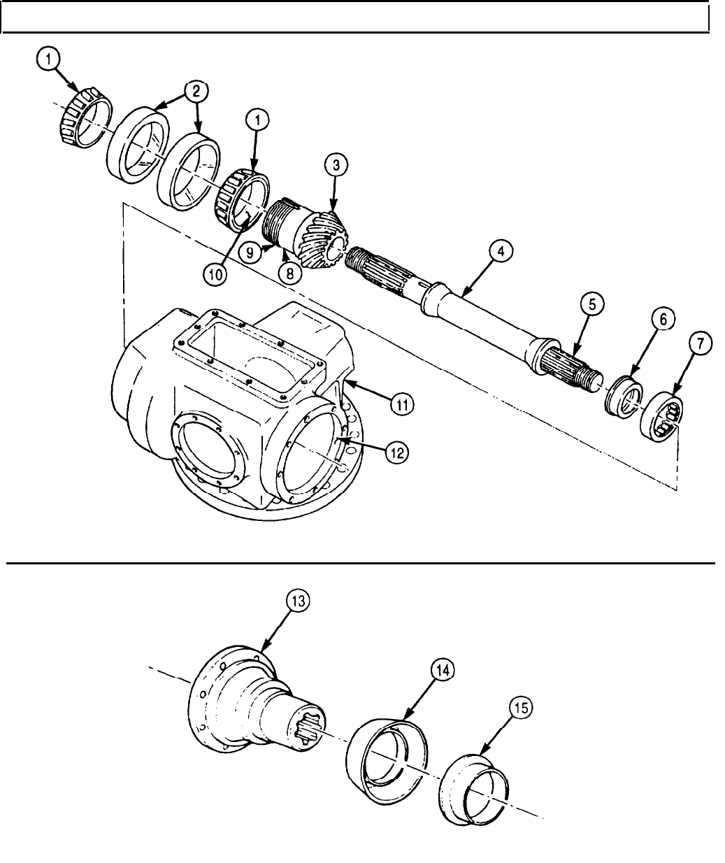
TM 9-2320-272-24-4
5-64. DIFFERENTIAL AND DIFFERENTIAL CARRIER REPAIR (Contd)
5-443
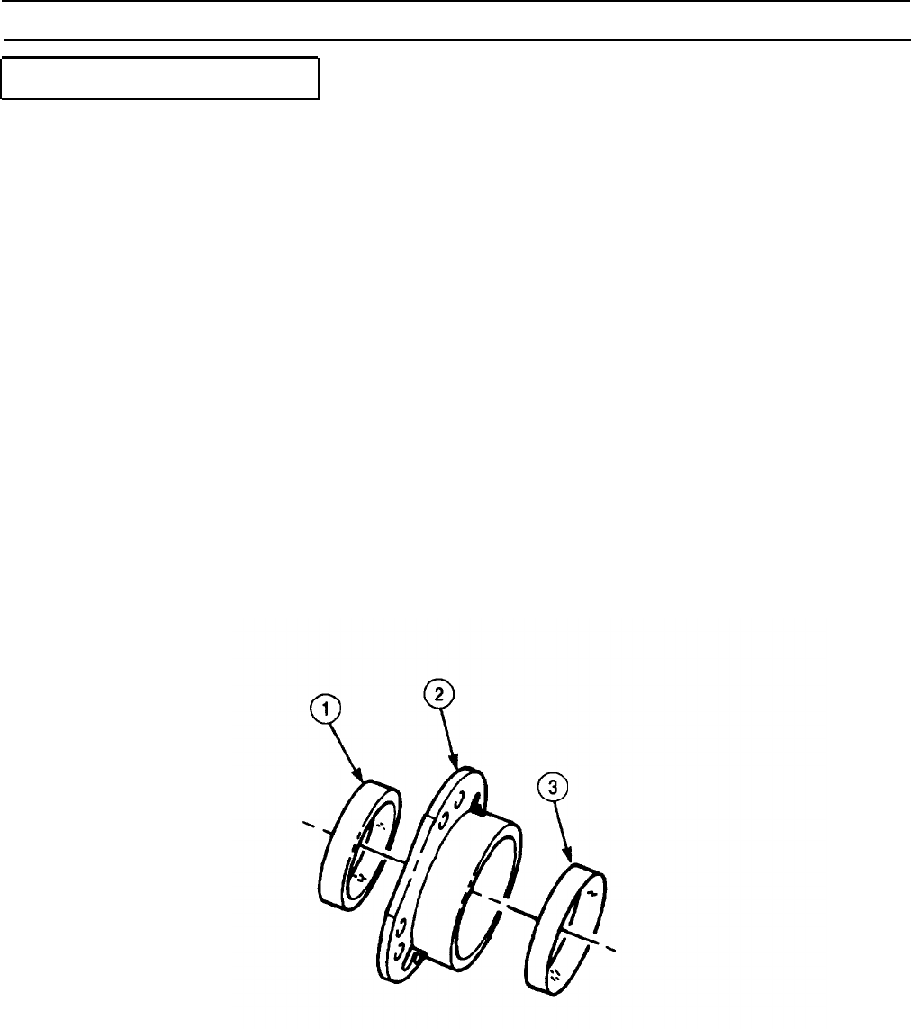
TM 9-2320-272-24-4
5-64. DIFFERENTIAL AND DIFFERENTIAL CARRIER REPAIR (Contd)
c. Assembly and Adjustment
1.
2.
3.
4.
5.
6.
7.
NOTE
Coat all bearings and gears with lubricating oil during reassembly.
Using bearing replacer, install inner bearing race (3) and outer bearing race (1) in retainer (2).
Ensure thick edges of races (1) and (3) are toward center of retainer (2).
Install bearing (4) on hub of bevel pinion gear (6). Thick inner race (10) must be seated against back
edge of teeth (5) on bevel pinion gear (6).
NOTE
White carbonate pigment is used as a high-pressure lubricant.
Coat long splined end (7) of mainshaft (9) with white carbonate pigment.
Position bevel pinion gear (6) over mainshaft (9), ensuring internal splines in bevel pinion gear (6)
align with splined end (7), and press bevel pinion gear (6) and bearing (4) onto mainshaft (9). Nose
of bevel pinion gear (6) must seat against shoulder (8).
Place mainshaft (7) in soft-jawed vise.
NOTE
Collar is used to set preload on bevel pinion gear bearings. Ensure
collar removed in disassembly is installed for preload test.
Install spacer (14) on hub (15) of bevel pinion gear (6) next to bearing (16).
Position small end (13) of retainer (12) over hub (15) and bearing (161 and place bearing (11) in
retainer (12) over hub (15).
5-444
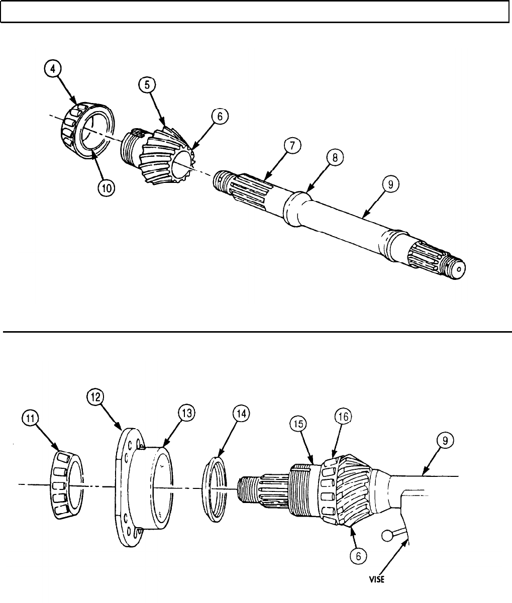
TM 9-2320-272-24-4
5-64. DIFFERENTIAL AND DIFFERENTIAL CARRIER REPAIR (Contd)
5-445

TM 9-2320-272-24-4
5-64. DIFFERENTIAL AND DIFFERENTIAL CARRIER REPAIR (Contd)
8.
9.
10.
11.
12.
13.
14.
15.
16.
17.
18.
19.
20.
Install inner nut (4) on threaded portion of hub (5) of bevel pinion gear (7). Ensure stud (9) on
inner nut (4) is facing away from retainer (6) and bevel pinion gear (7). Tighten inner nut (4)
800-1,000 lb-ft (1,085-1,356 N-m).
Install keywasher (3) on hub (5). Ensure hole in keywasher (3) aligns over stud (9) of inner nut (4).
Install new locktab washer (2) on hub (5). Ensure stud (9) sets into a hole in keywasher (3).
Install outer nut (1) on hub (5). Tighten nut (1) 1,OOO-1,200 lb-ft (1,356-1,627 N•m).
NOTE
Pinion bearings must be preloaded for proper operation of
differential assembly.
Wrap twine around retainer (6) and attach to bearing preload tester to determine bearing preload.
Observe pointer and pull on bearing preload tester until retainer (6) starts to rotate. Record
reading.
If original bearings are installed, bearing preload pull must be 1.2-2.4 lb (0.54-1.09 kg). If torque
method is used to measure bearing preload, torque must be 4-8 lb-in. (0.5-0.9 N•m).
If new bearings are installed, bearing preload pull must be 3.6-5.5 lb (1.63-2.50 kg). If torque
method is used to measure bearing preload, torque must be 5-25 lb-in. (0.41-0.62 N•m).
NOTE
If preload is not within given limits, perform steps 16
through 19.
If preload is within given limits, go to step 21.
Remove outer nut (1), locktab washer (2), keywasher (3), and inner nut (4) from hub (5) of bevel
pinion gear (7).
Using arbor press, remove outer bearing (10), retainer (6), and spacer (11) from hub (5).
If preload valve (steps 13, 14, and 15) exceeds limits, use a thicker spacer (11) from bevel pinion
gear spacer kit. If preload value is less than limits, use a thinner spacer (11).
Install parts on hub (5) following steps 5 through 11. Measure bearing preload using either twine
and bearing preload tester or torque method. Repeat steps 16 through 19 until bearing preload is
within limits of either step 14 or 15.
Remove mainshaft (8) from soft-jawed vise.
5-446
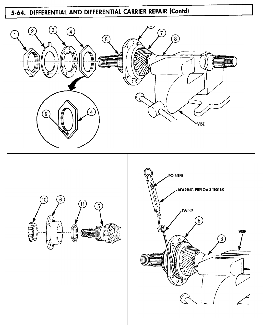
5-64. DIFFERENTIAL
TM 9-2320-272-24-4
5-447
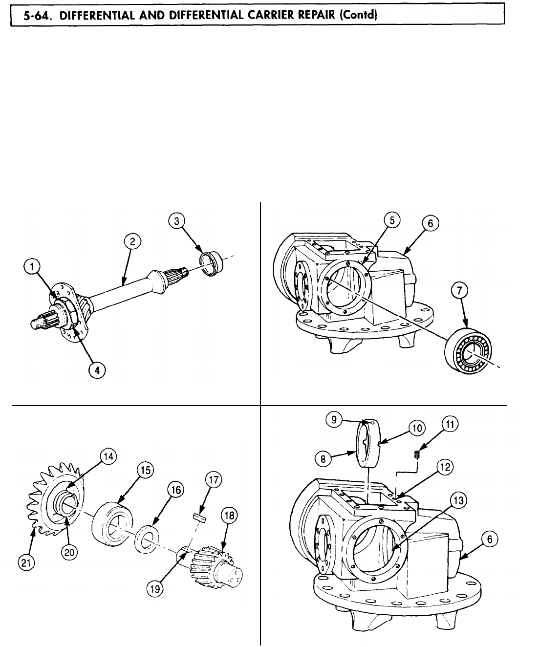
5-64. DIFFERENTIAL
TM 9-2320-272-24-4
21.
Bend tab(s) (4) on locktab washer over flats on outer nut (1).
22.
Using arbor press, install rear bearing inner race (3) on short splined end of mainshaft (2).
23.
Using arbor press, install bearing (7) in rear bore (5) of differential carrier housing (6).
24.
Install sleeve (8) in bore (13) with notches (10) toward shoulder of bore (13). Ensure hole (9) in
sleeve (8) aligns with hole (12) in differential carrier housing (6).
25.
Install setscrew (11) through hole (12) until seated in sleeve (8).
26.
Press bearing (15) on hub (20) of bevel ring gear (21). Bearing (15) must rest against shoulder (14)
on hub (20).
27.
Install spacer washer (16) on keyed end (19) of helical pinion gear (18).
28.
Install machine key (17) in keyed end (19) of helical pinion gear (18). Ensure exposed edges of
machine key (17) are not burred after installation. Remove any burrs with fine mill file.
5-448
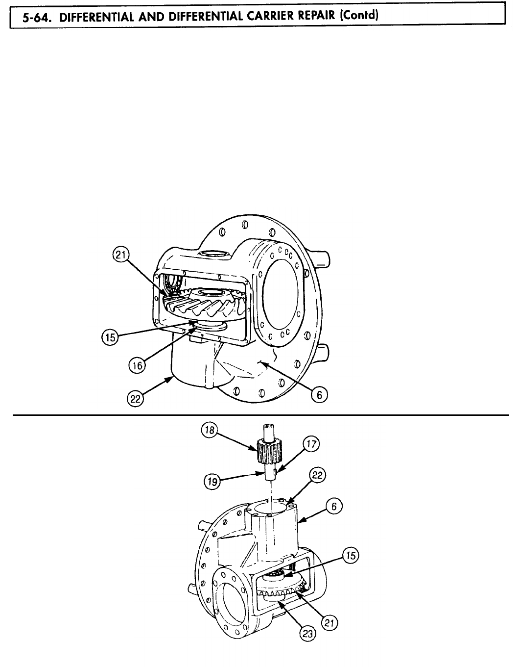
5-64. DIFFERENTIAL
TM 9-2320-272-24-4
29.
30.
Place bevel ring gear (21) in differential carrier housing (6) with hub and bearing (15) pointing
toward bore (22).
Support bevel ring gear (21) with two soft-iron semicircular blocks. Use support adapter (23) as an
alternate method.
NOTE
31.
32.
White carbonate pigment is used as high-pressure lubricant.
Coat keyed end (19) of helical pinion gear (18) with pigment lubricant and align over bore in bevel
ring gear (21). Ensure machine key (17) is aligned with keyway in bevel ring gear (21).
Using arbor press, install keyed end (19) of helical pinion gear (18) in bore of bevel ring gear (21).
NOTE
Light tapping with soft-head hammer or use of arbor press may be
needed to install bearing.
33. Remove blocks, turn differential carrier housing (6) over, and push bearing (15) into sleeve (16).
5-449

5-64. DIFFERENTIAL
TM 9-2320-272-24-4
34.
35.
36.
37.
38.
39.
40.
41.
42.
43.
44.
45.
46.
NOTE
Coat bearings and races with clean gear oil before installation.
Using bearing replacer, install race (2) in bearing cap (1). Thick edge of race (2) must be toward
small end (6) of bearing cap (1).
Install bearings (3) and (4) and race (5) in bearing cap (1). Use replacer to seat race (5) in bearing
cap (1). Wide edge of race (5) must face away from face of cap (1).
Starting with same thickness of shims (9) as removed, place shims (9) over shaft (8) and on
differential carrier housing (7). Carefully align holes in shims (9) to holes in carrier housing (7).
Place bearing cap (1) over shaft (8) and press bearing cap (1) into position on shaft (8) to differential
carrier housing (7).
Install retaining plate (10) on shaft (8) with three screws (12). Tighten screws (12) 42-54 lb-ft
(57-73 N-m) and install new safety wire (11) in screws (12).
Install new shims (13) and bearing cover (14) on differential carrier housing (7) with six new
lockwashers (15) and screws (16). Select shims (13) of same thickness as removed. Tighten
screws (16) 60.100 lb-ft (81-136 N-m).
To measure helical pinion gear (17) bearing preload, wrap twine around helical pinion gear (17) and
attach to bearing preload tester. Observe pointer and pull on bearing preload tester until helical
pinion gear (17) starts to rotate. Record value.
If original bearings are installed, bearing preload must be 4-8 lb-in. (.5-.9 N-m) If new bearings are
installed, bearing preload must be 12-18 lb-in. (1.36-2.03 N-m).
NOTE
If preload is not within given limits, perform steps 42
through 45.
If preload is within given limits, go to step 47.
Remove six screws (16), lockwashers (15), bearing cover (14), and shims (13) from differential
carrier housing (7). Remove shims (13) carefully to avoid creasing or damaging shims (13).
If preload scale (or torque) reading exceeds limits, add shims (13).
If preload scale (or torque) reading is less than lower limit, remove shims (13).
Install shims (13) and bearing cover (14) on differential carrier housing (7) with six lockwashers (15)
and screws (16). Carefully align shims (13) with holes in differential carrier housing (7). Tighten
screws (16) 60-100 lb-ft (81-136 N-m).
Repeat steps 40 through 45 as necessary.
5-450
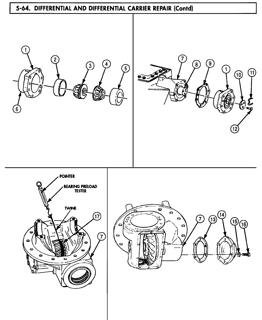
5-64. DIFFERENTIAL
TM 9-2320-272-24-4
5-451
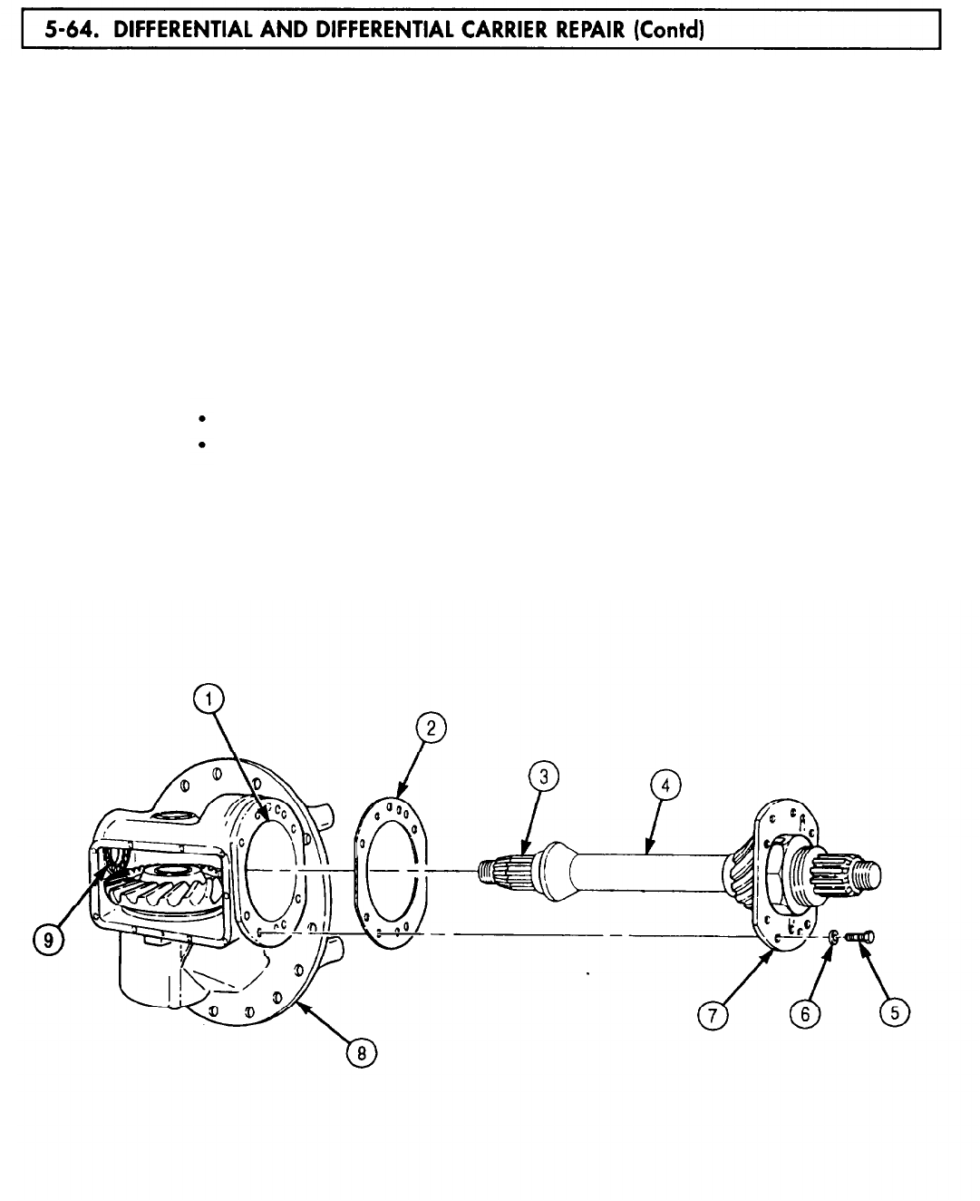
5-64. DIFFERENTIAL
TM 9-2320-272-24-4
47.
48.
49.
50.
51.
If contact pattern resembles pattern (14), perform steps 55-59 and 63-69.
52.
If contact pattern resembles pattern (15), perform steps 55-58, 60, and 63-69.
53.
If contact pattern resembles pattern (16), perform steps 55-58, 61, and 63-69.
54.
If contact pattern resembles pattern (17), perform steps 55-58, 62, and 63-69.
Position shims (2), same thickness pack as removed, on retainer (7) and slide mainshaft (4) into
differential carrier housing (8). Align inner race (3) with rear roller bearing (9).
Align holes in shims (2), differential carrier housing (8), bore (1), and retainer (7) and install with
eight washers (6) and screws (5). Tighten screws (5) 93-120 lb-ft (126-163 N•m).
CAUTION
Correct bevel ring gear and pinion gear contact pattern is critical
to correct operation of differential and differential carrier
assembly. Incorrect contact pattern can result in noisy operation or
premature failure of these two gears.
Check bevel ring gear (10) and pinion gear (11) tooth contact pattern by applying blue oil-base
pigment to at least three teeth of clean bevel ring gear (10). Turn mainshaft (4) for three full
rotations of bevel ring gear (10).
Examine teeth contact pattern (13) of bevel ring gear (10) with pinion gear (11). Pattern should be
centered both ways on teeth (12) and cover over two-thirds of tooth (12) contact surface.
NOTE
If pattern is not correct, perform steps 51 through 69.
If pattern is correct, go to step 71.
5-452
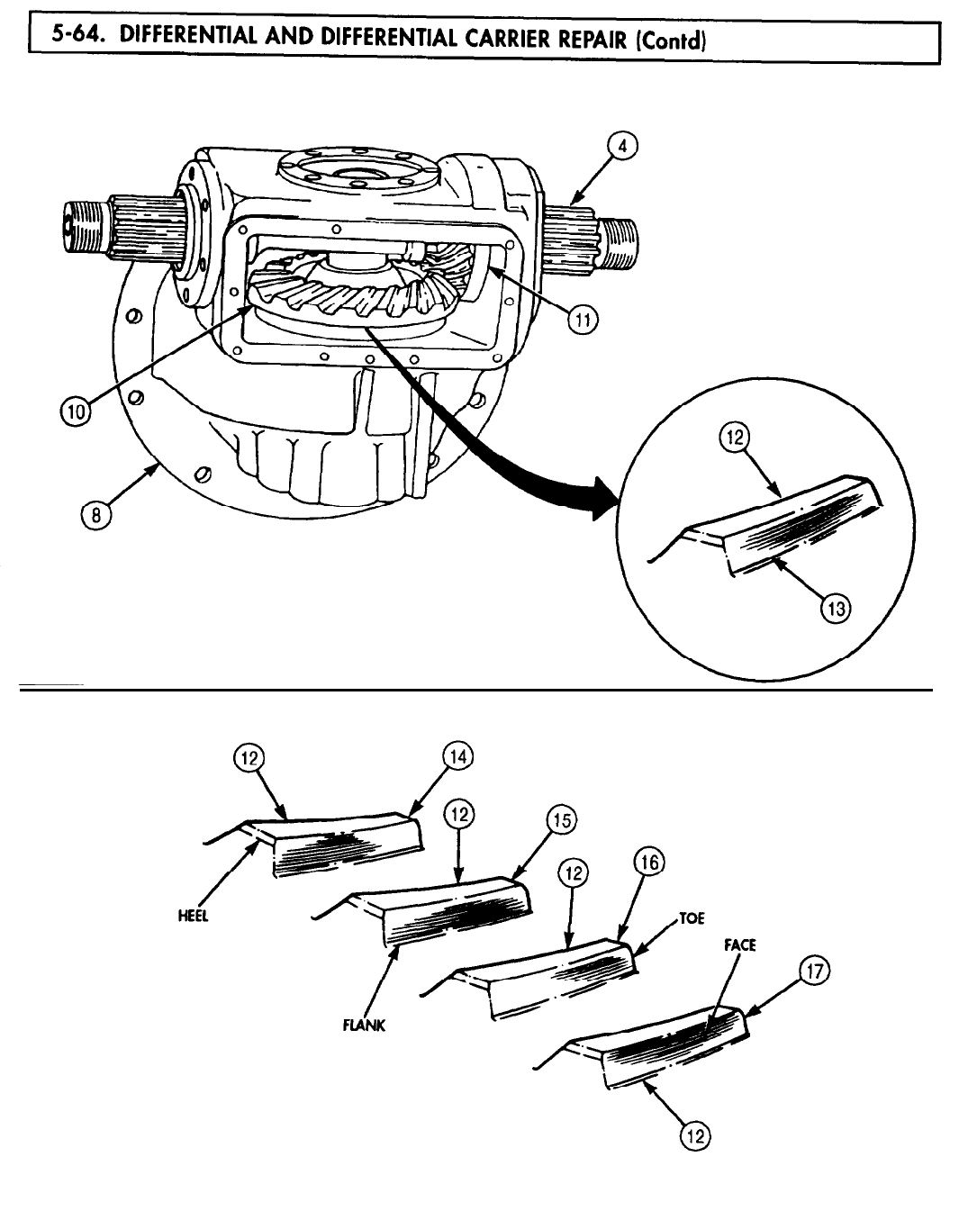
5-64. DIFFERENTIAL
TM 9-2320-272-24-4
5-453
5-64. DIFFERENTIAL
TM 9-2320-272-24-4
55.
56.
57.
58.
59.
60.
61.
62.
63.
64.
65.
66.
67.
68.
69.
70.
Remove six screws (6), lockwashers (7), cover (8), and shims (9) from differential carrier housing (1).
Remove safety wire (15), three screws (16), and retaining plate (14). Discard safety wire (15).
Using two jacking screws (17), remove bearing retainer (13) and shim pack (12) from shaft (11)
and shaft housing shoulder (10).
Remove eight screws (4), washers (5), mainshaft (3), and shim pack (2) from differential carrier
housing (1).
NOTE
If adjustment is needed to correct bevel ring gear and pinion gear
contact pattern, make initial shim changes of at least 0.010 in.
(0.25 mm).
For contact pattern of type in step 51, add shims to shim pack (2) and remove shims from shim
pack (12).
For contact pattern of type in step 52, add shims to shim pack (12) and remove shims from shim
pack (2).
For contact pattern of type in step 53, remove shims from pack (2) and add shims to shim pack (12).
For contact pattern of type in step 54, remove shims from shim pack (12) and add shims to shim
pack (2).
Using dial indicator, check backlash (20) of bevel ring gear (18) and pinion gear (19).
Backlash (20) should be 0.005-0.015 in. (0.127-0.381 mm).
NOTE
If backlash needs correction, perform steps 55, 56, 57, and 58.
If bevel ring gear and pinion gear backlash are within limits, go
to step 71.
If bevel ring gear and pinion gear backlash are not within
limits, perform steps 65 and 66.
If backlash (20) is less than limits, add equal amounts of shims to shim packs (2) and (12).
If backlash (20) is greater than limits, remove equal amounts of shims from shim packs (2) and (12).
Carefully place mainshaft (3) and shim pack (2) in differential carrier housing (1) and install with
eight washers (5) and screws (4). Tighten screws (4) 93-120 lb-ft (126-163 N•m).
Carefully align shim pack (12) to shaft housing shoulder (10) and press on bearing retainer (13)
over shaft (11).
Install retaining plate (14) on sheet (11) with three screws (16). Tighten screws (16) 42-54 lb-ft (57-
73 N•m). Fasten new safety wire (15) to all three screws (16).
Carefully align shims (9) to bearing retainer (13) and install cover (8), shims (9), retainer (13),
and shims (12) on shoulder (10) of carrier housing (1) with six new lockwashers (7) and screws (6).
Tighten screws (6) 60-100 lb-ft (81-136 N•m).
5-454

5-64. DIFFERENTIAL
TM 9-2320-272-24-4
5-455
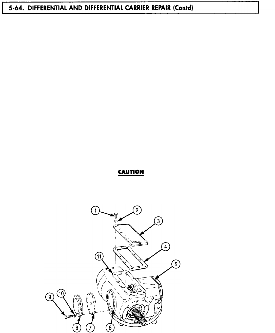
TM 9-2320-272-24-4
71.
72.
73.
74.
75.
76.
77.
78.
79.
80.
81.
82.
Coat top of new gasket (4) and gasket surface (11) with light coat of sealing compound and position
gasket (4) on differential carrier housing (5).
Install access cover (3) on gasket (4) and differential carrier housing (5) with ten washers (2) and
screws (1). Tighten screws (1) 27-40 lb-ft (37-54 N•m).
Coat gasket surface (6) with light coat of sealing compound.
Install new gasket (7) and side cover (8) on differential carrier housing (5) with eight washers (10)
and screws (9). Tighten screws (9) 27-40 lb-ft (37-54 N•m).
Lubricate sealing surface of new oil seal (13) with GM grease, coat metal contact outer diameter
with sealing compound, and install new gasket (14) and seal (13) in front bearing cover (15) with
seal installer tool and arbor press.
NOTE
Ensure oil slots on retainer are not blocked with sealing compound
or covered by new gasket.
Coat both sides of new gasket (12) with light coat of sealing compound and position on retainer (18).
Remove eight screws (16) and washers (17) from retainer (18).
Install front bearing cover (15), seal (13), gasket (12), and retainer (18) on carrier
housing (5) with eight washers (17) and screws (16). Tighten screws (16) 93-120 lb-ft (126-163 N•m).
Lubricate sealing surface of new seal (25) with GAA grease, coat outside metal contact outer
diameter with sealing compound, and install in bearing cover (26).
Coat new gasket (24) with light coat of sealing compound and position on differential carrier
housing (5).
Place thrust washer (23) over mainshaft (22) and install rear bearing cover (26) with six new lock-
washers (28) and screws (27). Tighten screws (27) 24-40 lb-ft (33-54 N•m).
Do not tap or hammer companion flanges on driveshaft assembly.
Damage to bearings will result.
Install two companion flanges (21) on mainshaft (22) with two nuts (20). Tighten nuts (20)
300-400 lb-ft (407-542 N•m) and install two new cotter pins (19).
5-456
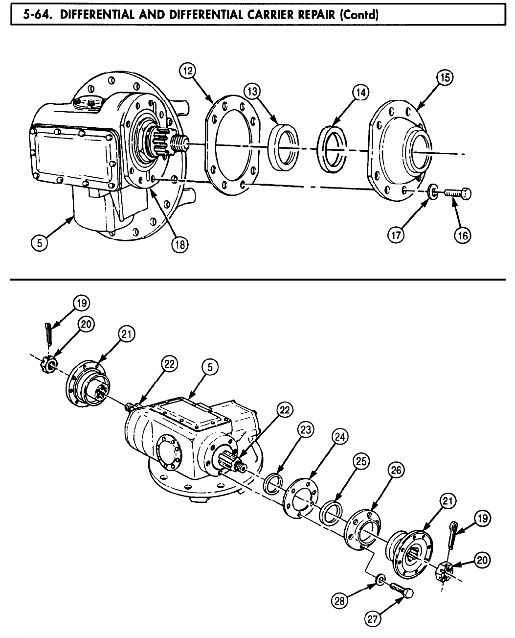
5-64. DIFFERENTIAL
TM 9-2320-272-24-4
5-457
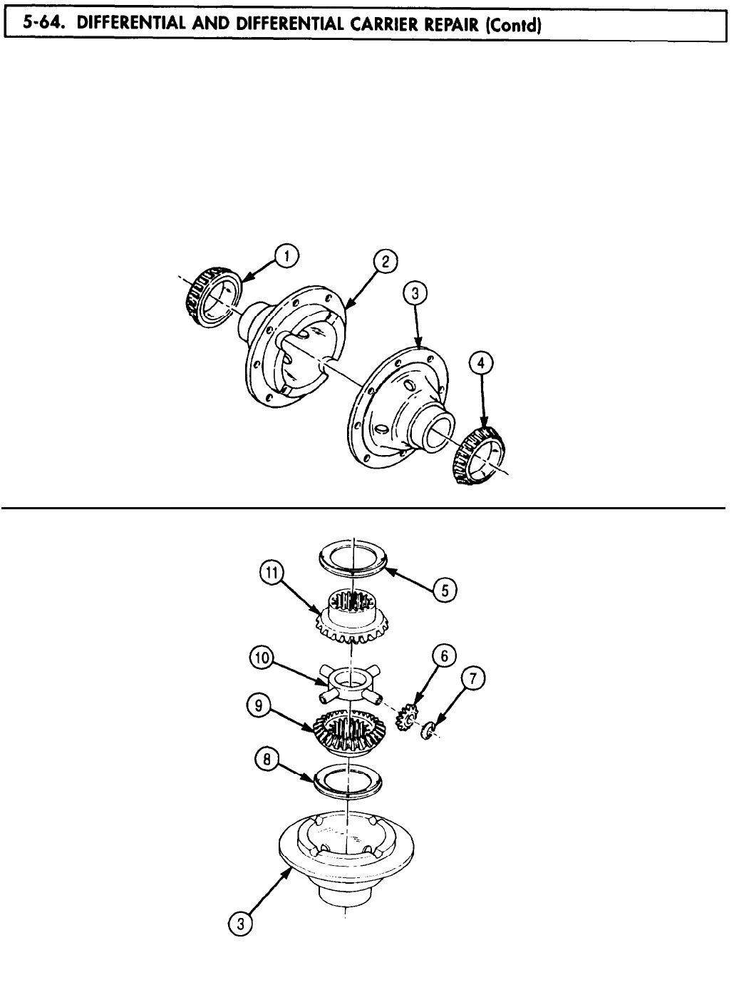
TM 9-2320-272-24-4
NOTE
Coat all bearings, races, gears, and thrust washers with clean gear
oil before assembly.
83.
Install two bearings (1) and (4) on hubs of differential gear housings (2) and (3).
84.
Lay one differential gear housing (3), bearing side down, on work surface and install one thrust
washer (8) and side gear (9) in differential gear housing (3).
85.
Place four bevel spider gears (6) and thrust washers (7) on spider (10) and place over bevel side
gear (9) in housing (3).
86.
Place thrust washer (5) over hub of bevel side gear (11) and position bevel side gear (11) over spider
gear assembly in differential gear housing (3).
5-458
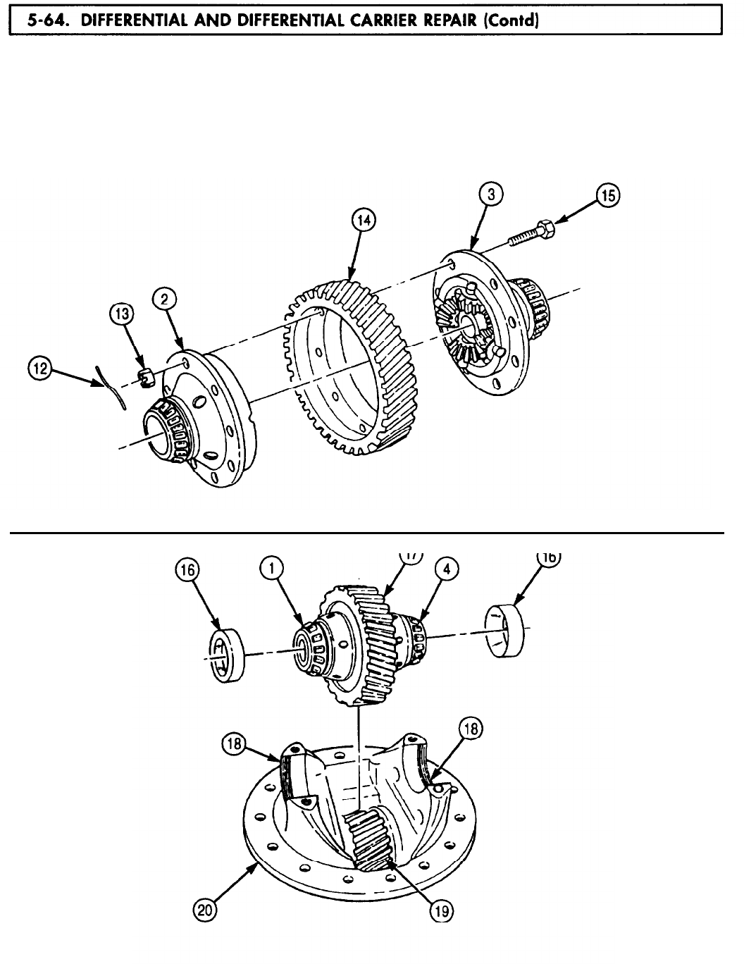
TM 9-2320-272-24-4
87.
88.
89.
Carefully align index marks made during disassembly and position two differential gear housings (2)
and (3) on helical ring gear (14) and install with eight screws (15) and slotted nuts (13). Tighten
nuts (13) 130-170 lb-ft (176-231 N•m). Secure with new safety wire (12). Twist ends of safety
wire (12) together until wire is tight. Remove and discard excess safety wire (12).
Place two races (16) over bearings (1) and (4) on differential gear (17) and set assembly in
saddles (18) of differential carrier housing (20). Ensure races (16) seat inside threads of saddles (18).
If races (16) do not fully seat in saddles (18), check that helical ring gear (14) is in mesh with helical
pinion gear (19).
5-459
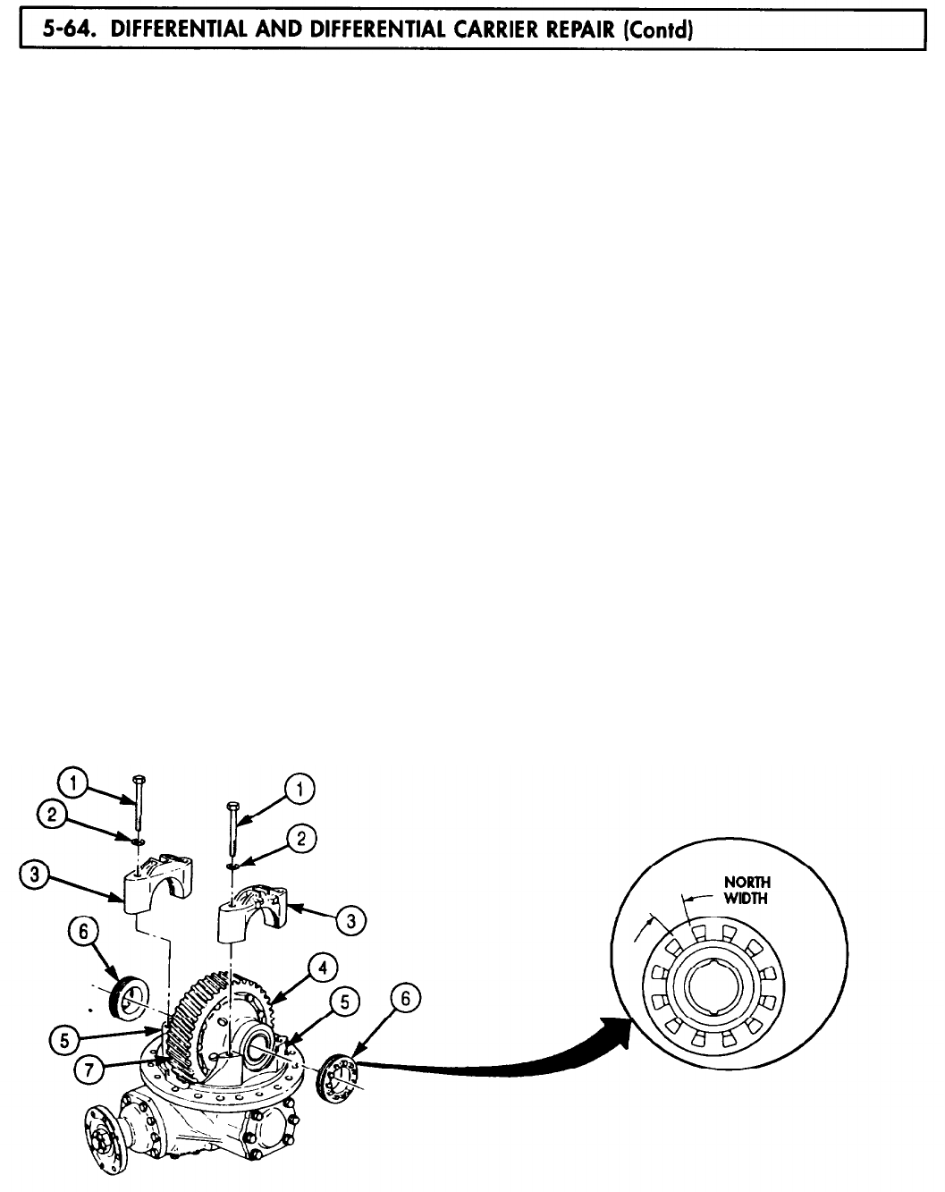
TM 9-2320-272-24-4
90.
Position two caps (3) on saddles (5) and install with four washers (2) and screws (1). Finger-tighten
screws (1).
91.
Start two adjusting nuts (6) in threads of saddles (5) and caps (3). Move caps (3) as necessary to
align threads to adjusting nuts (6).
92.
Turn adjusting nuts (6) by hand until contact is made with races (4).
93.
Ensure helical ring gear (7) aligns with mating helical pinion gear (9). If necessary, loosen and
tighten adjusting nuts (6) to align gears.
94.
Tighten screws (1) 7-12 lb-ft (9-16 N•m).
NOTE
Ensure a notch of each adjusting nut aligns with top center of cap.
95.
To establish helical bearing preload, perform step a. or b.
a.
Alternately tighten adjusting nuts (6) a total 1.5 to 2.75 notch widths.
b.
Tighten each adjusting nut (6) 15-35 lb-in. (1.7-4.0 N•m).
96.
Install dial indicator on differential carrier housing (8) with indicator plunger perpendicular to edge
of helical ring gear (7).
97.
Turn helical ring gear (7) one revolution in each direction. Runout reading on dial indicator must
not exceed 0.008 in. (0.20 mm). If runout exceeds this value, loosen adjusting nuts (6) and screws (1)
and repeat steps 90 through 95.
98.
Reposition dial indicator so plunger contacts tooth (10) and detects motion in plane of rotation of
helical ring gear (7) as the gear rotates.
99.
Hold helical pinion gear (9) still and rock helical ring gear (7) back and forth. Observe backlash
reading on dial indicator.
106.
Backlash should be 0.005-0.015 in. (0.127-0.381 mm). If reading is outside of these limits, replace
helical ring gear (7) and helical pinion gear (9).
101.
Tighten four screws (1) 290-370 lb-ft (393-502 N•m).
102.
Install two locks (12) of adjusting nut (6) on caps (3) with screws (13). Tighten screws (13)
66-85 lb-ft (90-115 N•m).
103.
Install new safety wire (11) through four screws (1) and two screws (13). Twist safety wire (11) ends
together, cut off and discard excess safety wire (11), and bend twisted ends of safety wire (11) out
of way.
5-460
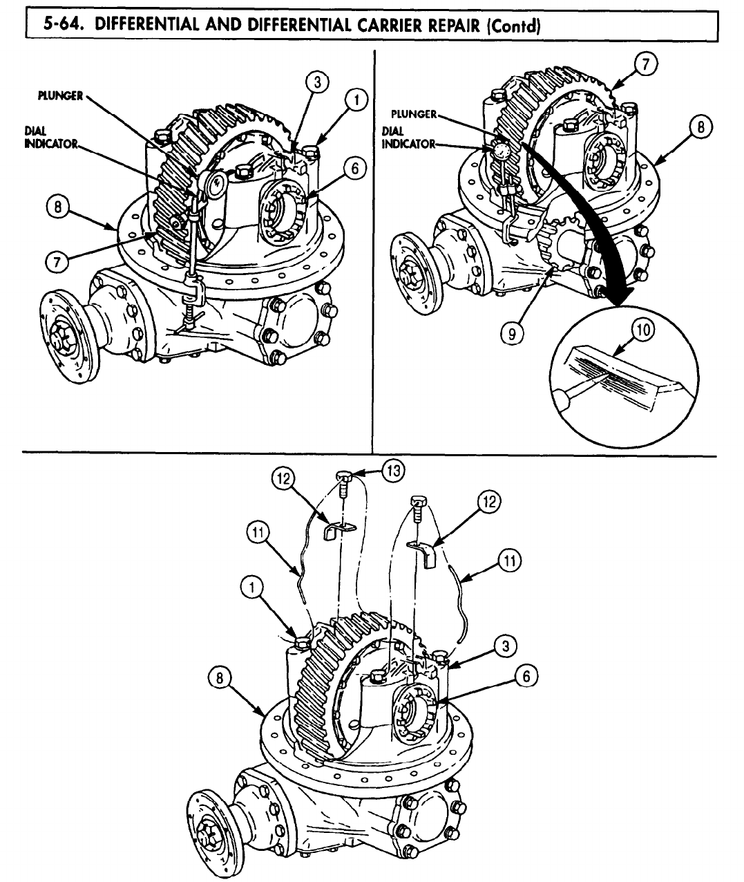
5-64. DIFFERENTIAL
TM 9-2320-272-24-4
FOLLOW-ON TASK: Install differential and carrier assembly (para. 4-100).
5-461 (5-462 blank)
5-65. SPECIAL
TM 9-2320-272-24-4
Section VI. SPECIAL PURPOSE BODIES MAINTENANCE
5-66.
5-67.
5-68.
5-69.
5-70.
5-71.
5-72.
5-73.
5-74.
5-75.
5-76.
5-77.
5-78.
5-79.
5-80.
5-81.
5-82.
5-83.
5-84.
5-85.
5-86.
5-87.
5-88.
5-89.
5-90.
5-91.
5-92.
5-93.
5-94.
5-95.
5-96.
5-97.
5-98.
5-99.
5-100.
Van Body Replacement
Retraceable Beam Replacement
Retractable Beam Drive Shaft and Lock Maintenance
Retractable Beam Rollers Replacement
Side Doors Maintenance
Underframe Parts Replacement
Hinged Floor Maintenance
Exterior Side Panel Maintenance
Rear Wall Interior Panels Replacement
Interior Side Panels and Latches Replacement
Ceiling and Frame Maintenance
Hinged Roof Maintenance
Front Wall Registers Replacement
Ceiling Filler and Side Panels Replacement
Ceiling Rear Cover Replacement
Ceiling Air Ducts Replacement
Ceiling Transition Maintenance
Ceiling Deflector and Registers Replacement
Rear Splice Plate Replacement
Bonnet Frame Parts Replacement
Bonnet Access Door Maintenance
Bonnet Door Maintenance
Air Conditioner Replacement
Main Wiring Harness Replacement
Van Air Conditioner Wiring Harness Replacement
Van Heater Wiring Harness Replacement
Electric Heater (10 kW) Wiring Harness Replacement
Blackout Bypass Wiring Harness Maintenance
Emergency Lamp Wiring Harness Replacement
Blackout and Clearance Lights Wiring Harness Replacement
400 hz Supply Wiring Harness Replacement
Branched 400 hz Receptacle Wiring Harness Replacement
Right and Left Side Blackout Harness Maintenance
Telephone Post Wiring Harness Replacement
3 Phase Receptacle Wiring Harness Replacement
5-464
5-468
5-470
5-474
5-478
5-484
5-486
5-490
5-498
5-500
5-508
5-518
5-531
5-532
5-534
5-536
5-538
5-542
5-543
5-544
5-549
5-554
5-563
5-568
5-570
5-572
5-578
5-580
5-582
5-588
5-590
5-596
5-598
5-602
5-604
5-463
5-66. VAN
TM 9-2320-272-24-4
THIS TASK COVERS:
a. Removal b. Installation
APPLICABLE MODELS
M934/A1/A2
TOOLS
General mechanic’s tool kit (Appendix E, Item 1)
MATERIALS/PARTS
Ten locknuts (Appendix D, Item 291)
Twelve locknuts (Appendix D, Item 321)
PERSONNEL REQUIRED
Two
REFERENCES (TM)
TM 9-2320-272-10
TM 9-2320-272-24P
EQUIPMENT CONDlTlON
l Parking brake set (TM 9-2320-272-10).
l Ladders removed (TM 9-2320-272-10).
GENERAL SAFETY INSTRUCTIONS
All personnel must stand clear during lifting
operations.
1.
Remove four locknuts (18), screws (13), washers (14), springs (15), and springs (16) from van
body (1) and two frame brackets (8). Discard locknuts (18).
2.
Remove eight locknuts (12) and screws (9) from van body (1) and four frame brackets (8). Discard
locknuts (12).
3.
Attach chain to four lifting brackets (2) and lifting device.
WARNING
All personnel must stand clear during lifting operations. A
snapped cable, or swinging or shifting load, may result in injury to
personnel.
NOTE
Second assistant will help with steps 4 and 5.
4.
Raise van body (1) clear of frame (7), release parking brake, and remove vehicle from under van
body (1).
5.
Lower van body (1) onto jack stands positioned evenly under van body (1).
6.
Remove four blocks (5) from frame brackets (8).
NOTE
Sills and hardware will be in position for removal after van body
has been removed.
7.
Remove ten locknuts (3), bevel washers (4), screws (10, washers (11), and two sills (6) and (17) from
van body (1). Discard locknuts (3).
8.
Remove chain from lifting device and four lifting brackets (2).
5-464
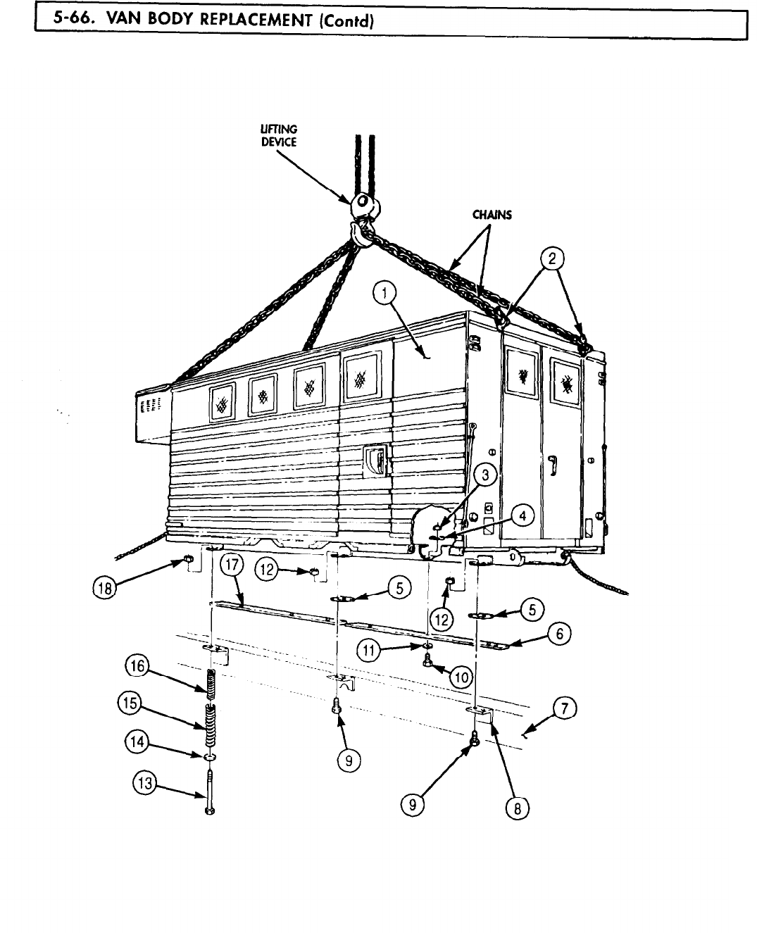
TM 9-2320-272-24-4
5-465

5-66. VAN
TM 9-2320-272-24-4
1.
2.
3.
Install two sills (6) and (17) on van body (1) with ten washers (11), screws (10), bevel
washers (4), and new locknuts (3).
Position four blocks (5) on frame brackets (8).
Attach chain to four lifting brackets (2) and lifting device.
WARNING
All personnel must stand clear during lifting operations. A
snapped cable, or swinging or shifting load, may result in injury to
personnel.
NOTE
4.
5.
6.
7.
8.
Second assistant will help with steps 4 and 5.
Raise van body (1) from jack stands, and remove jack stands from under van body (1).
Position vehicle under van body (1) and set parking brake.
Lower van body (1) onto frame (7) and align holes of frame brackets (8) and van body (1).
Install van body (1) on four frame brackets (8) with eight screws (9) and new locknuts (12).
Install van body (1) on two frame brackets (8) with four springs (15), springs (16), washers (14),
screws (13), and new locknuts (18).
9.
Remove chains from lifting device and four lifting brackets (2).
5-466
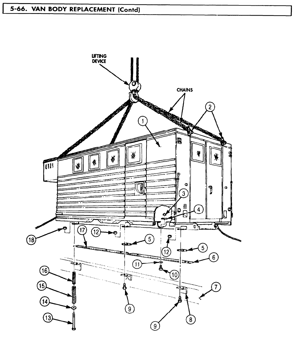
TM 9-2320-272-24-4
FOLLOW-ON TASK: Install ladders (TM 9-2320-272-10).
5-467
TM 9-2320-272-24-4
THIS TASK COVERS:
a. Removal b. Installation
APPLICABLE MODELS
M9341/A1/A2
TOOLS
General mechanic’s tool kit (Appendix E, Item 1)
MATERIALS/PARTS
Two locknuts (Appendix D, Item 274)
Seal (Appendix D, Item 614)
Seal (Appendix D, Item 615)
Seal (Appendix D, Item 616)
REFERENCES (TM)
TM 9-237
TM 9-2320-272-10
TM 9-2320-272-24P
EQUIPMENT CONDITION
Parking brake set (TM 9-2320-272-10).
Van body sides fully expanded and secured
(TM 9-2320-272- 10).
Retractable beam rollers removed (para. 5-69).
Retractable beam drive shaft and lock removed
(para. 5-68).
SPECIAL ENVIRONMENTAL CONDlTlONS
Vehicle must be on level surface.
NOTE
All ten retractable beams are replaced the same way. This
procedure is for the left-rear retractable beam.
1.
Break welds between side panel (1) and side panel support (13) and remove retractable beam (12)
(TM 9-237).
CAUTION
Remove retractable beam slowly from underframe. Failure to do so
may result in damage to equipment.
2.
Slide retractable beam (12) under side panel (1) and remove from underframe (4) and channel (5).
3.
Remove two locknuts (7), washers (8), screws (11), seven screws (10), retainer (9), and seals (2), (3),
and (6) from underframe (4). Discard locknuts (7) and seals (2), (3), and (6).
1.
Install new seals (6), (3), and (2), and retainer (9) on underframe (4) with seven screws (10), two
screws (11), washers (8), and new locknuts (7).
CAUTION
Install retractable beam slowly into underframe. Failure to do so
may result in damage to equipment .
2.
Slide retractable beam (12) under side panel (1) and install in under-frame (4) at channel (5).
3.
Install retractable beam (12) by welding retractable beam (12) to side panel (1) and side panel
support (13) (TM 9-237).
5-468
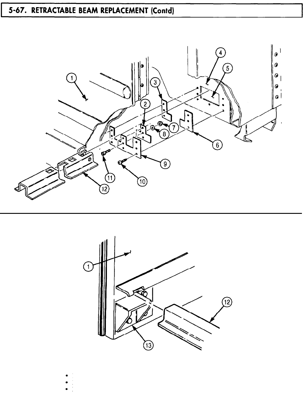
TM 9-2320-272-24-4
THIS TASK COVERS:
a. Removal
b. Cleaning, Inspection, and Repair c. Installation
APPLICABLE MODELS
M934/A1/A2
TOOLS
General mechanic’s tool kit (Appendix E, Item 1)
MATERIALS/PARTS
Five keys (Appendix D, Item 266)
Locknut (Appendix D, Item 297)
GAA grease (Appendix C, Item 28)
REFERENCES (TM)
LO 9-2320-272-12
TM 9-2320-272-10
TM 9-2320-272-24P
EQUIPMENT CONDITION
Parking brake set (TM 9-2320-272-10).
SPECIAL ENVIRONMENTAL CONDITIONS
Vehicle must be on level surface.
PERSONNEL REQUIRED
Two
NOTE
Left and right retractable beam drive shafts and locks are
replaced the same. This procedure is for the left retractable beam
drive shaft and lock.
1.
Remove locknut (1) and lock (2) from under-frame stud (8). Discard locknut (1).
2.
Remove screw (4), paw1 (3), and lock (2) from underframe (5).
3.
Remove thirty screws (7) and five covers (6) from underframe (5).
4.
Remove four setscrews (15) from bushings (14).
CAUTION
Do not bend or strain ratchet shaft during removal. Doing so may
result in damage to equipment.
NOTE
Remove all nicks, burrs, and corrosion from ratchet shaft and
lubricate before removal.
Direct assistant to catch ratchet shaft components under van
body during removal.
5.
Slowly pull ratchet shaft (9) and remove four bushings (14), nine bushings (13), spacers (12),
sprockets (11), and five spacers (10) from under-frame (5).
5-470
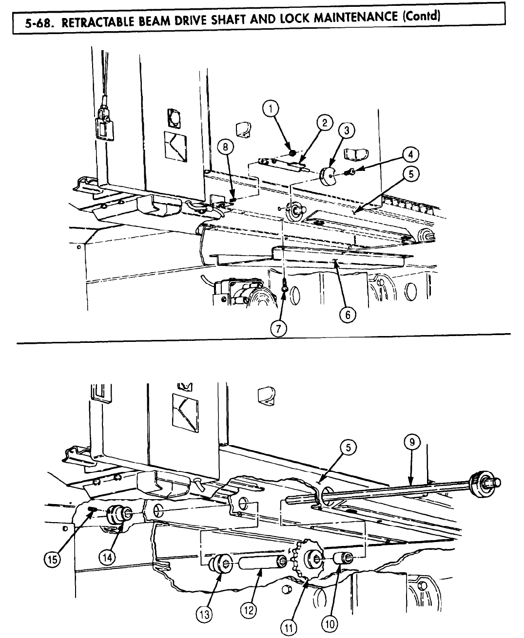
5-68. RETRACTABLE
TM 9-2320-272-24-4
5-471
TM 9-2320-272-24-4
1.
For general cleaning instructions, refer to para. 2-14.
2.
For general inspection instructions, refer to para. 2-15.
3.
Remove five keys (11) and bushings (10) from sprockets (4). Discard keys (11).
4.
Inspect bushings (10), (6), and (8) for wear and damage. If worn or damaged replace bushings (10), (6),
or (8).
5.
Inspect ratchet shaft (2) for burrs, nicks, and corrosion. If damaged, repair with file or emery cloth.
If damage is excessive, replace.
6.
Test spring action of lock plunger (14). If spring action is weak, replace lock (14).
7.
Install five new keys (11) and bushings (10) on sprockets (4).
Do not bend or strain ratchet shaft during installation. Doing so
may result in damage to equipment.
NOTE
Bevel forward end of ratchet shaft for installation.
Apply GAA grease on two feet of forward end of ratchet shaft for
installation.
Direct assistant to install ratchet shaft components under van
body when installing ratchet shaft.
1.
Slowly insert ratchet shaft (2) into underframe (1) and install five spacers (3), sprockets (4), spacers (5),
nine bushings (6), and four bushings (8).
2.
Install four setscrews (9) in bushings (8) in underframe channels (7).
3.
Lubricate ratchet shaft (2) with GAA grease (LO 9-2320-272-12).
4.
Install five covers (17) on underframe (1) with thirty screws (18).
5.
Install lock (14) and paw1 (15) on underframe stud (12) and underframe (1) with new
locknut (13) and screw (16).
5-472
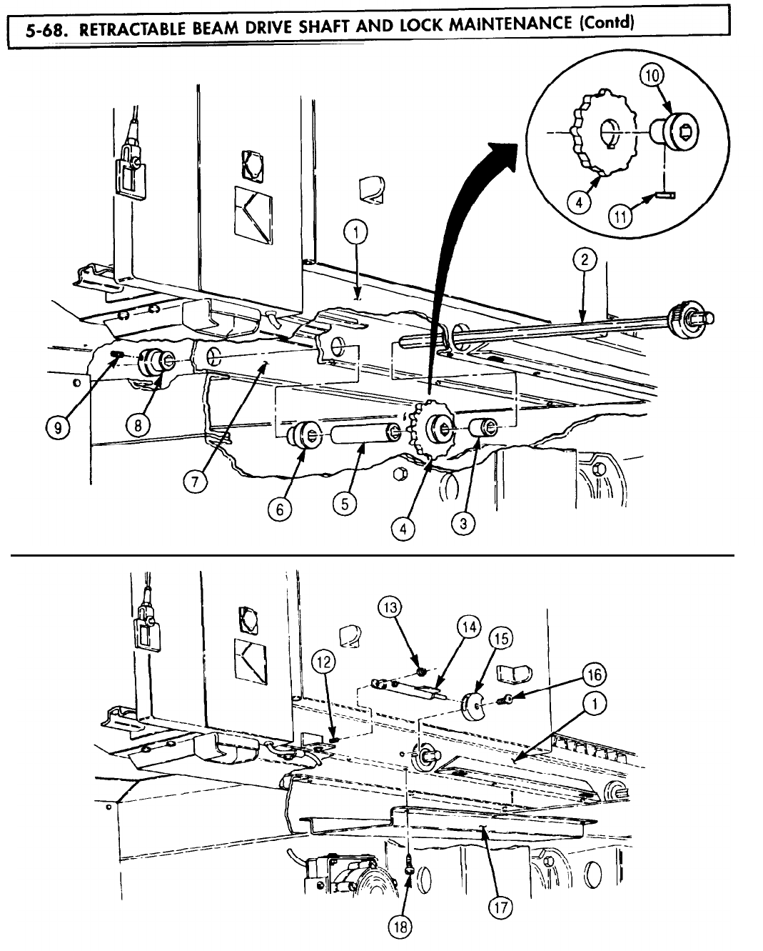
5-68. RETRACTABLE
TM 9-2320-272-24-4
5-473
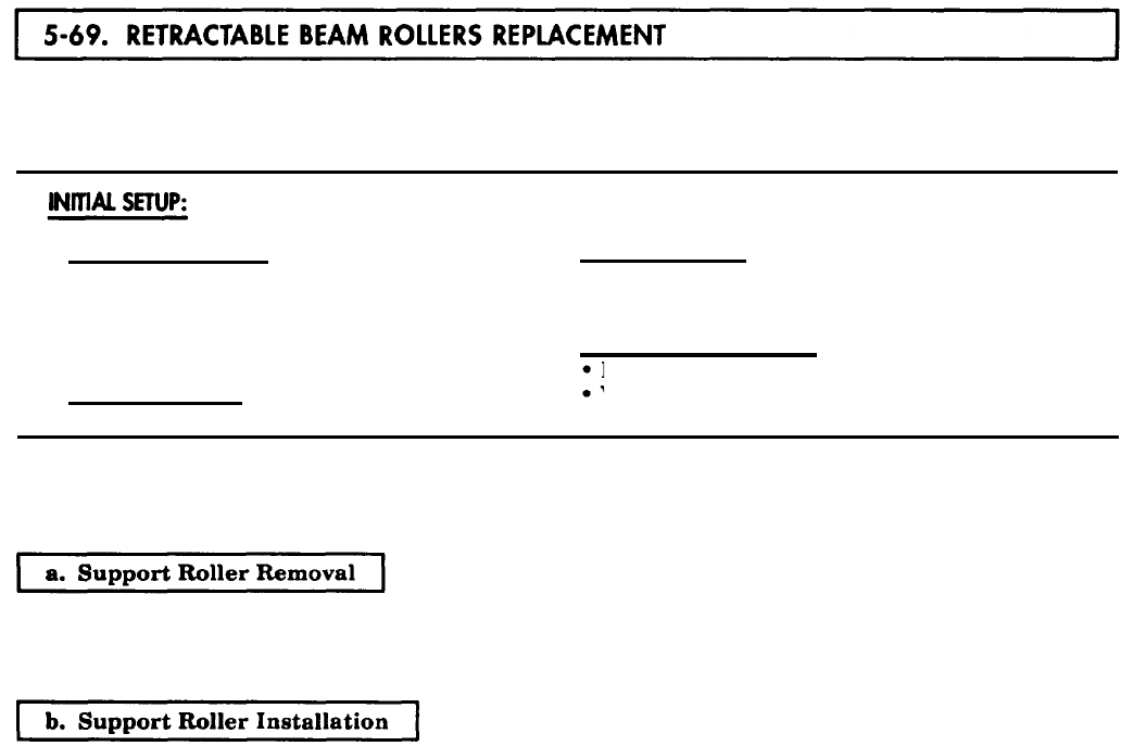
TM 9-2320-272-24-4
THIS TASK COVERS:
a. Support Roller Removal c. End Roller Removal
b. Support Roller Installation d. End Roller Installation
APPLICABLE MODELS REFERENCES (TM)
M934/A1/A2
TM 9-2320-272-10
TOOLS
TM 9-2320-272-24P
General mechanic’s tool kit (Appendix E, Item 1)
EQUIPMENT CONDITION
MATERIALS/PARTS
Four cotter pins (Appendix D, Item 72)
Parking brake (TM 9-2320-272-10).
Van body sides fully expanded and secured
(TM 9-2320-272-10).
NOTE
All support rollers are removed basically the same way, This
procedure is for left-rear support rollers.
1.
Remove seven screws (2), clamps (3), and cover (4) from underframe (1)
2.
Remove two cotter pins (5), support roller shaft (7), and support roller (6) from underframe (1).
Discard cotter pins (5).
1.
Install support roller (6) on underframe (1) with support roller shaft (7) and two new cotter pins (5).
2.
Install cover (4) on underframe (1) with seven clamps (3) and screws (2).
5-474
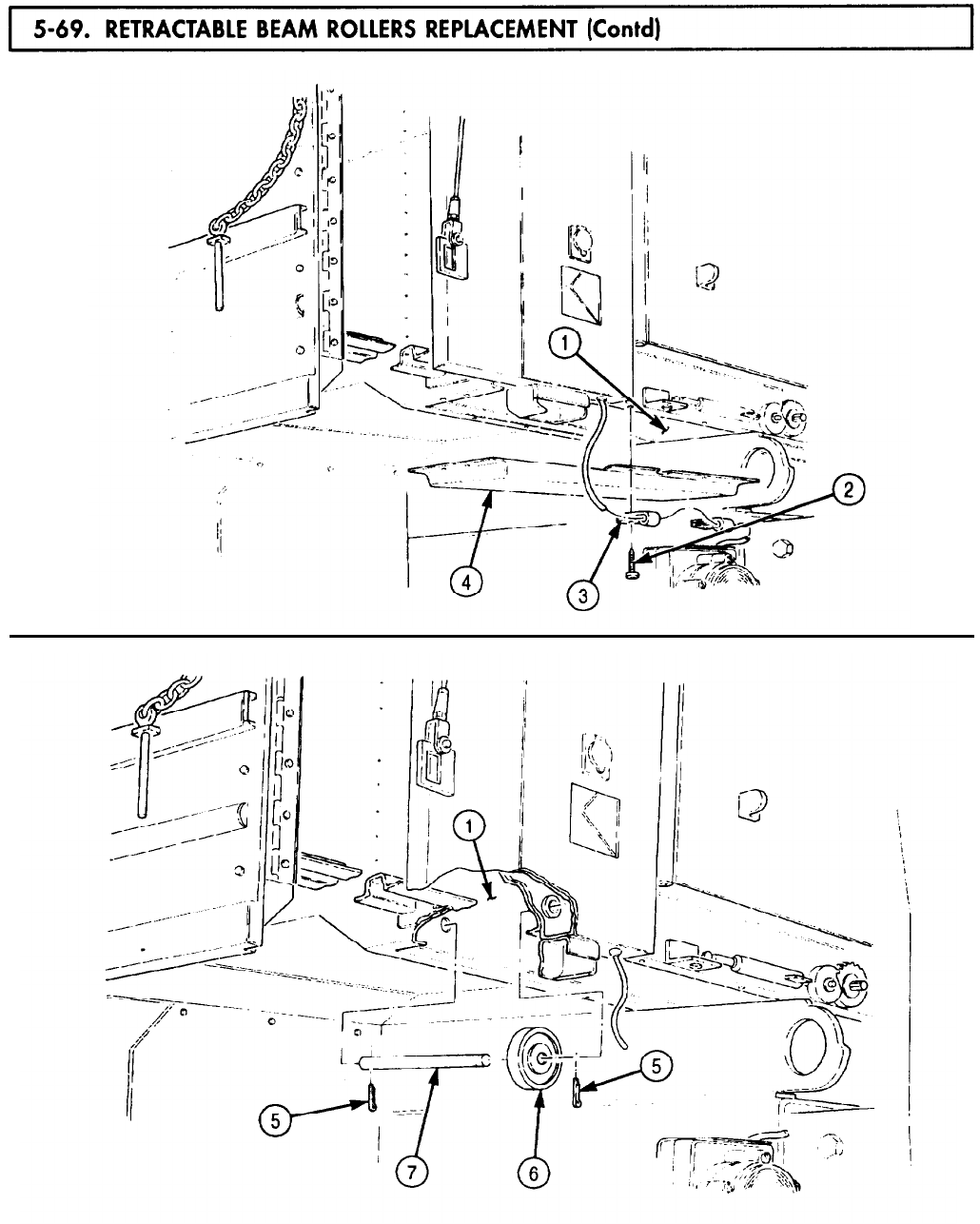
TM 9-2320-272-24-4
5-475
TM 9-2320-272-24-4
NOTE
All end rollers are replaced basically the same way. This
procedure is for left-rear end rollers.
1.
Remove support roller (task a.).
2.
Remove two cotter pins (2), end roller shaft (3), and end roller (4) from underframe (1). Discard
cotter pins (2).
1.
Install end roller (4) on underframe (1) with end roller shaft (3) and two new cotter pins (2).
2.
Install support roller (task b.).
5-476
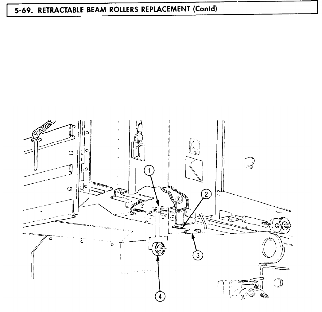
TM 9-2320-272-24-4
FOLLOW-ON TASK: Retract van body sides (TM 9-2320-272-10).
5-477
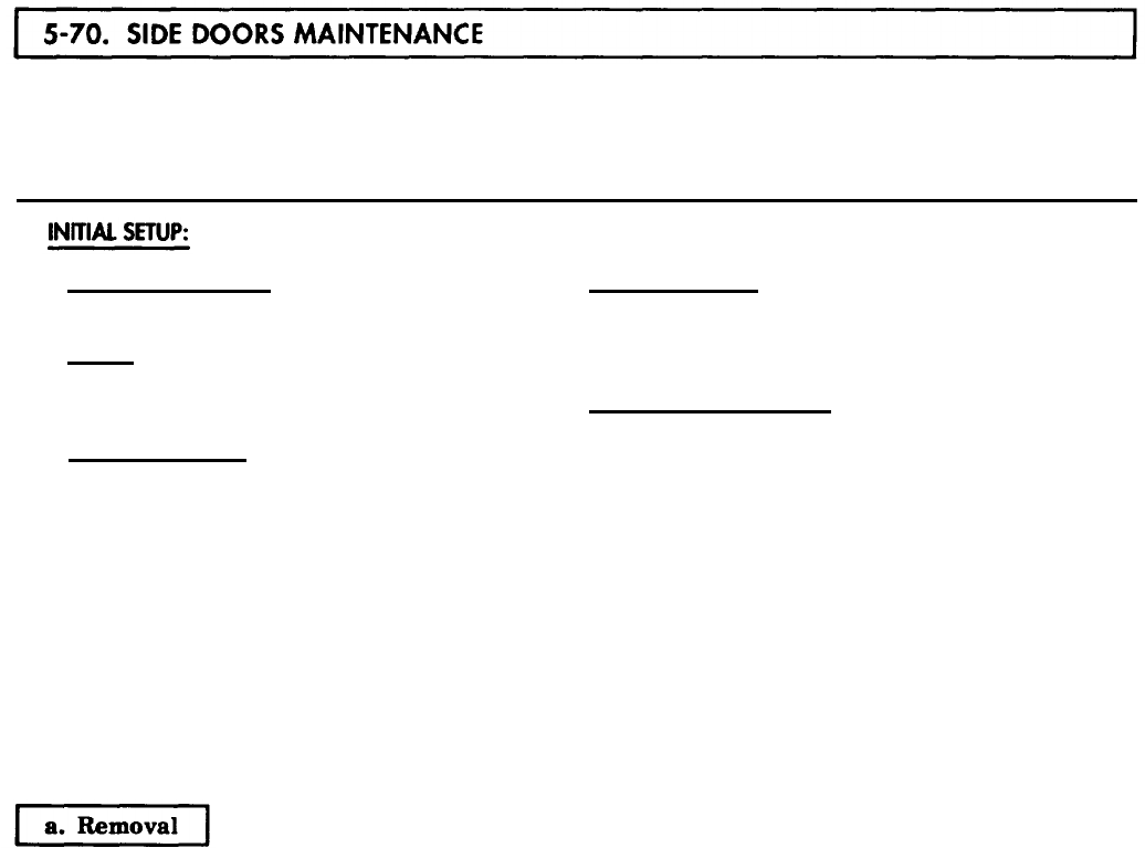
TM 9-2320-272-24-4
THIS TASK COVERS:
a. Removal
b. Disassembly
c. Cleaning and Inspection
d. Assembly
e. Installation
APPLICABLE MODELS
M934/A1/A2
TOOLS
General mechanic’s tool kit (Appendix E, Item 1)
Rivet gun
MATERIALS/PARTS
Two cotter pins (Appendix D, Item 51)
Two lockwashers (Appendix D, Item 364)
Three rivets (Appendix D, Item 548)
Sixteen rivets (Appendix D, Item 547)
Gasket (Appendix D, Item 229)
Seal (Appendix D, Item 605)
Seal (Appendix D, Item 633)
Adhesive sealant (Appendix C, Item 7)
Sealing compound (Appendix C, Item 67)
REFERENCES (TM)
TM 43-0213
TM 9-2320-272-10
TM 9-2320-272-24P
EQUIPMENT CONDITION
Parking brake set (TM 9-2320-272-10).
Van body sides fully expanded and secured
(TM 9-2320-272-10).
Side door window removed (para. 3-350).
NOTE
Left and right side doors are replaced the same way. This
procedure is for the left side door.
1.
Remove two screws (1), lockwashers (2), bracket (3), and door check lever (4) from door (5). Discard
lockwashers (2).
NOTE
Assistant will help with step 2.
2.
Remove fifteen screws (6) and door (5) from side panel of van body (7).
5-478
5-70. SIDE
TM 9-2320-272-24-4
5-479
TM 9-2320-272-24-4
1.
Remove three rivets (13), handle (12), and gasket (11) from pocket (10). Discard rivets (13) and
gasket (11).
2.
Remove sixteen rivets (14) and pocket (10) from outer panel (9). Discard rivets (14).
3.
Remove two cotter pins (23), screws (19), washers (20), and rods (21) from upper case (2), lower
case (18), and center case (22). Discard cotter pins (23).
4.
Remove pin (26) and handle (25) from center case (22).
5.
Remove four screws (27) and center case (22) from inner panel (24).
6.
Remove eight screws (1), upper case (2), and lower case (18) from inner panel (24).
7.
Remove fourteen screws (8), molding (7), seal (6), hinge (5), and seal (4) from door frame (17).
Discard seals (4) and (6).
8.
Break adhesive seal and remove two moldings (3) from inner panel (24).
9.
Remove two screws (16) and moldings (15) from inner panel (24).
1.
For general cleaning instructions, refer to para. 2-14.
2.
For general inspection instructions, refer to para. 2-15.
3.
Inspect all movable components of center case (22) and lower and upper cases (2) and (18) for proper
operation. Replace center case (22), lower case (18), or upper case (2) if damaged or defective.
4.
Inspect rods (21) for breaks and bends. Replace rods (21) if broken or bent.
5.
Inspect moldings (3) and (15) and pocket (10) for cracks and bends. Replace moldings (3), (15), or
pocket (10) if cracked or bent.
6.
Inspect outer panel (9), door frame (17), and inner panel (24) for damage. Replace entire side door if
either is damaged.
NOTE
Apply rustproofing compound to all inside surfaces and boxed-in
areas (TM 43-0213).
Apply sealing compound to all exterior joints for installation.
1.
Install two moldings (15) on inner panel (24) with two screws (16).
2.
Apply adhesive to two moldings (3) and install on inner panel (24).
3.
Install new seal (4), hinge (5), new seal (6), and molding (7) on door frame (17) with fourteen
screws (18).
4.
Install upper case (2) and lower case (18) on inner panel (24) with eight screws (1).
5.
Install center case (22) on inner panel (24) with four screws (27).
6.
Install handle (25) on center case (22) with pin (26).
7.
Install two rods (21) on center (22), upper case (2), and lower case (18) with two new cotter pins (23),
washers (20), and screws (19).
8.
Install pocket (10) on outer panel (9) with sixteen new rivets (14).
9.
Install new gasket (11) and handle (12) on pocket (10) with three new rivets (13).
5-480
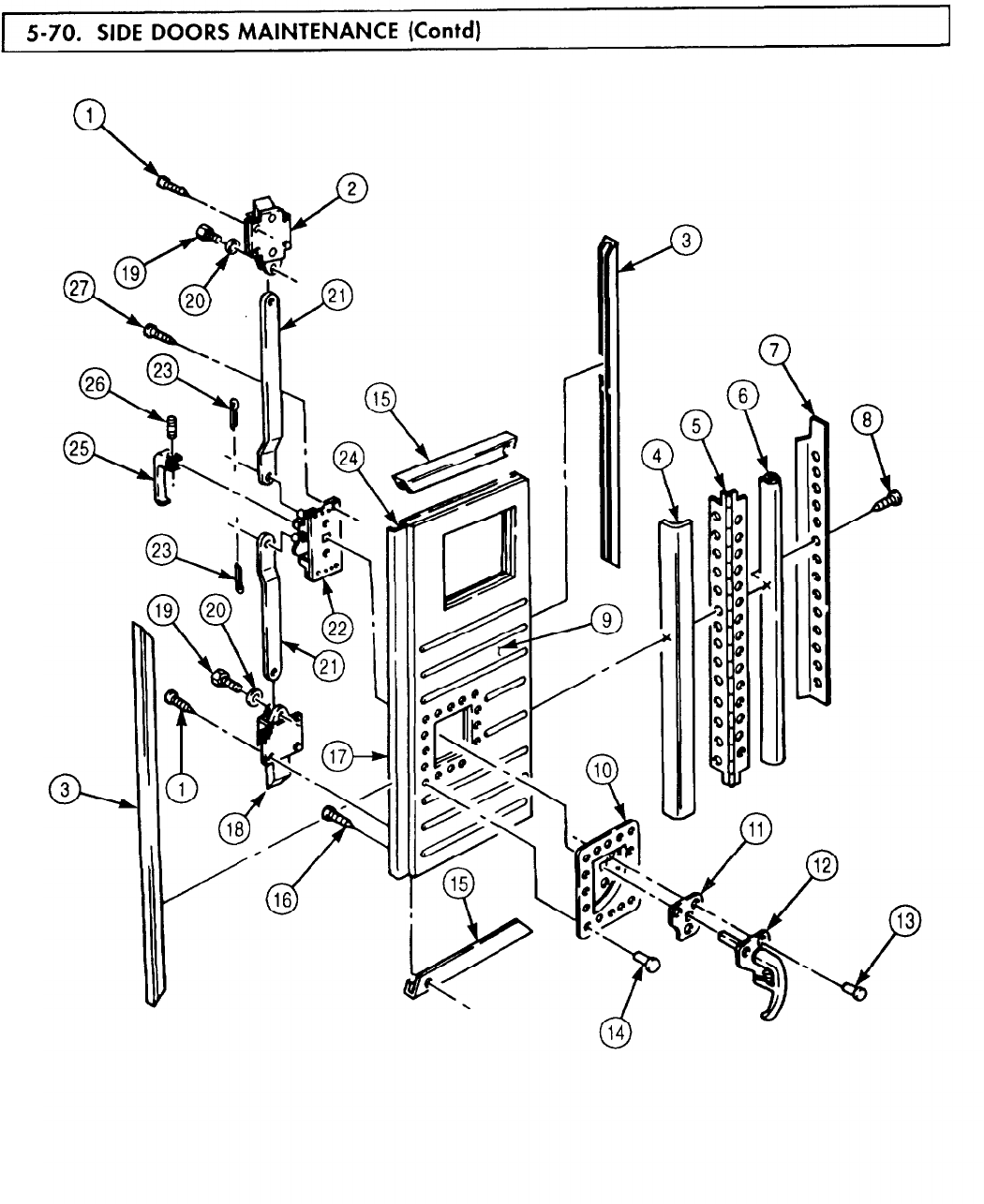
5-70.. SIDE
TM 9-2320-272-24-4
5-481

TM 9-2320-272-24-4
NOTE
Assistant will help with step 1.
1.
Install door (5) on side panel of van body (7) with fifteen screws (6).
2.
Install door check lever (4) and bracket (3) on door (5) with two new lockwashers (2) and screws (1).
5-482
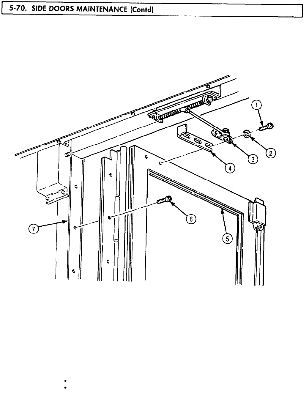
5-70. SIDE
TM 9-2320-272-24-4
FOLLOW-ON TASKS: Install side door window (para. 3-350).
Retract van body sides (TM 9-2320-272-10).
5-483
5-71. UNDERFRAME
TM 9-2320-272-24-4
THIS TASK COVERS:
a. Removal b. Installation
APPLICABLE MODELS REFERENCES (TM)
M934/A1/A2
TM 9-2320-272-10
TOOLS
TM 9-2320-272-24P
General mechanic’s tool kit (Appendix E, Item 1)
EQUIPMENT CONDITION
Rivet gun Parking brake set (TM 9-2320-272-10).
MATERIALS/PARTS
SPECIAL ENVIRONMENTAL CONDITIONS
Eight lockwashers (Appendix D, Item 400) Vehicle must be on level surface.
Two seals, 206 in. (Appendix D, Item 617)
Thirty-two rivets (Appendix D, Item 558)
Sealing compound (Appendix C, Item 67)
NOTE
Assistant will help with step 1.
1.
Remove one hundred thirty-eight screws (14), two retainers (15), channels (12), and seals (13) from
underframe (1). Discard seals (13).
2.
Remove thirty-two screws (4) and four covers (5) from under-frame (1).
3.
Remove eight nuts (3), lockwashers (2), screws (7), and four plates (6) from under-frame (1). Discard
lockwashers (2).
4.
Remove thirty-two rivets (8) and eight tiedowns (9) from underframe (1). Discard rivets (8).
5.
Remove four screws (11) and angle bracket (10) from underframe (1).
1.
Install angle bracket (10) on underframe (1) with four screws (11).
2.
Install eight tiedowns (9) on underframe (1) with thirty-two new rivets (8).
3.
Install four plates (6) on underframe (1) with eight screws (7), new lockwashers (2), and nuts (3).
4.
Install four covers (5) on underframe (1) with thirty-two screws (4).
NOTE
Apply sealing compound to exterior joints for installation.
5.
Install two new seals (13), channels (12), and retainers (15) on underframe (1) with one hundred
thirty-eight screws (14).
5-484
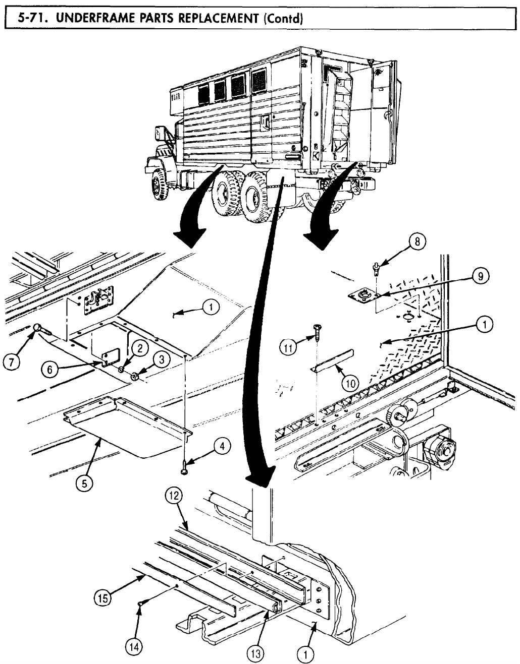
5-71. UNDERFRAME
TM 9-2320-272-24-4
5-485
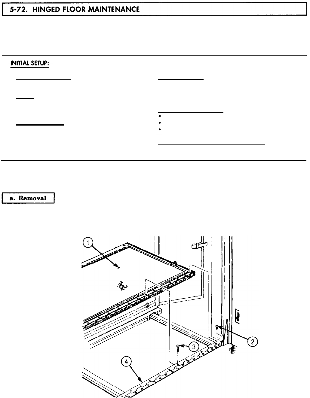
5-72. HINGED
TM 9-2320-272-24-4
THIS TASK COVERS:
a. Removal
b. Disassembly
c. Cleaning and Inspection
d. Assembly
e. Installation
APPLICABLE MODELS REFERENCES (TM)
M934/A1/A2 TM 9-237
TOOLS
TM 9-2320-272-10
TM 9-2320-272-24P
General mechanic’s tool kit (Appendix E, Item 1)
Rivet gun
EQUIPMENT CONDITION
MATERIALS/PARTS
Hinged end panel open (TM 9-2320-272-10)
Van body sides extended (TM 9-2320-272-10).
Fifty-six rivets (Appendix D Item 549) Counterbalance removed (para. 3-356).
Four seals, 39 in. (Appendix D, Item 617)
Seal, 203 in. (Appendix D, Item 631)
SPECIAL ENVIRONMENTAL CONDITIONS
Adhesive (Appendix C, Item 3) Vehicle must be on level surface.
Sealing compound (Appendix C, Item 67)
NOTE
Left and right hinged floors are maintained the same way. This
procedure is for left hinged floor.
NOTE
Assistant will help with step.
Remove fifty-five screws (3), four screws (2), and hinged floor (1) from hinge (4).
5-486
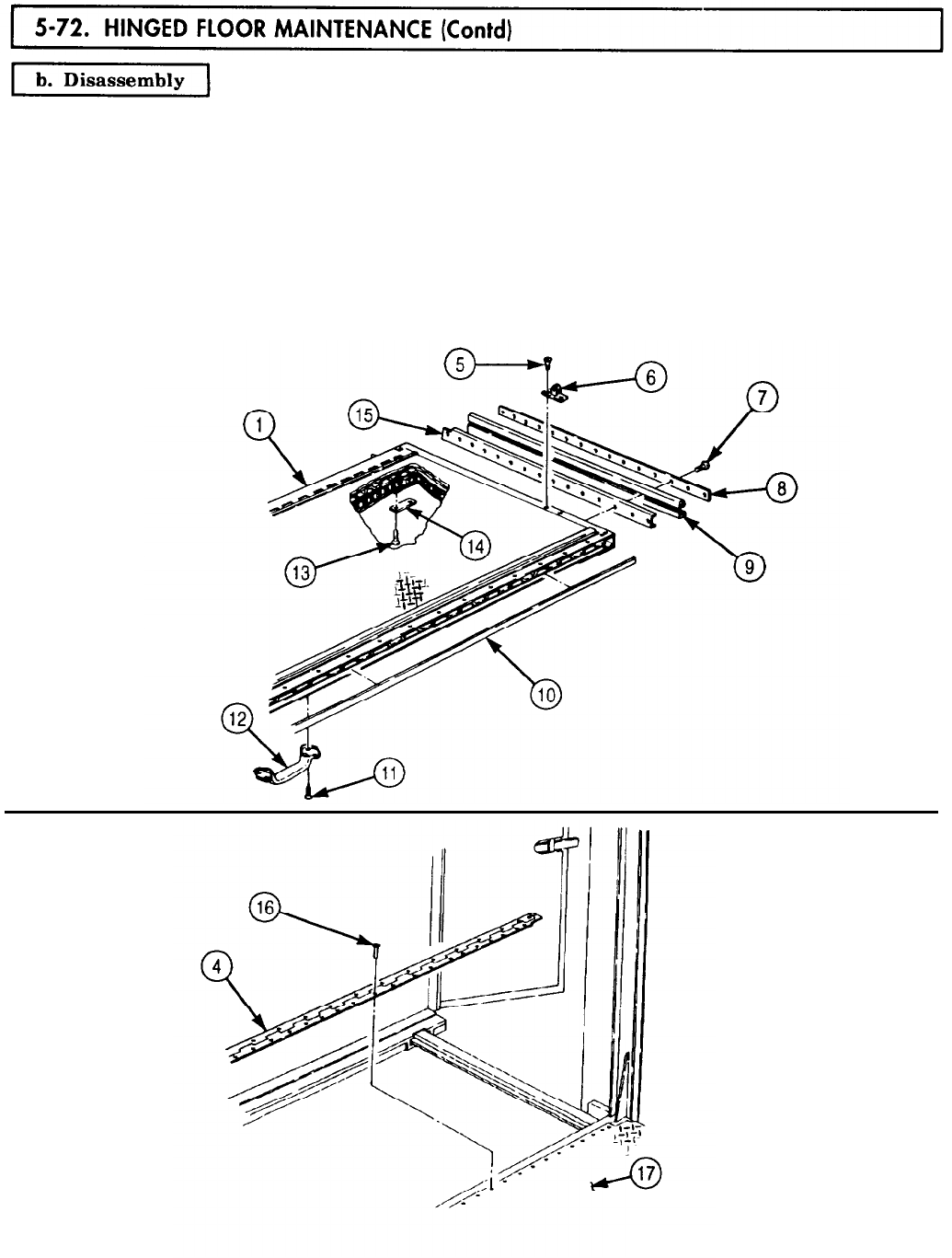
TM 9-2320-272-24-4
1.
Remove four screws (5) and two pivots (6) from hinged floor (1).
2.
Remove thirty screws (7), two retainers (8), four seals (9), and two channels (15) from hinged
floor (1). Discard seals (9).
3.
Remove ten screws (13) and five pads (14) from hinged floor (1).
4.
Remove four screws (11) and handle (12) from hinged floor (1).
5.
Remove seal (10) from hinged floor (1). Discard seal (10).
NOTE
Perform step 6 only if inspection requires replacement of hinge.
6.
Remove fifty-six rivets (16) and hinge (4) from under-frame (17). Discard rivets (16).
5-487
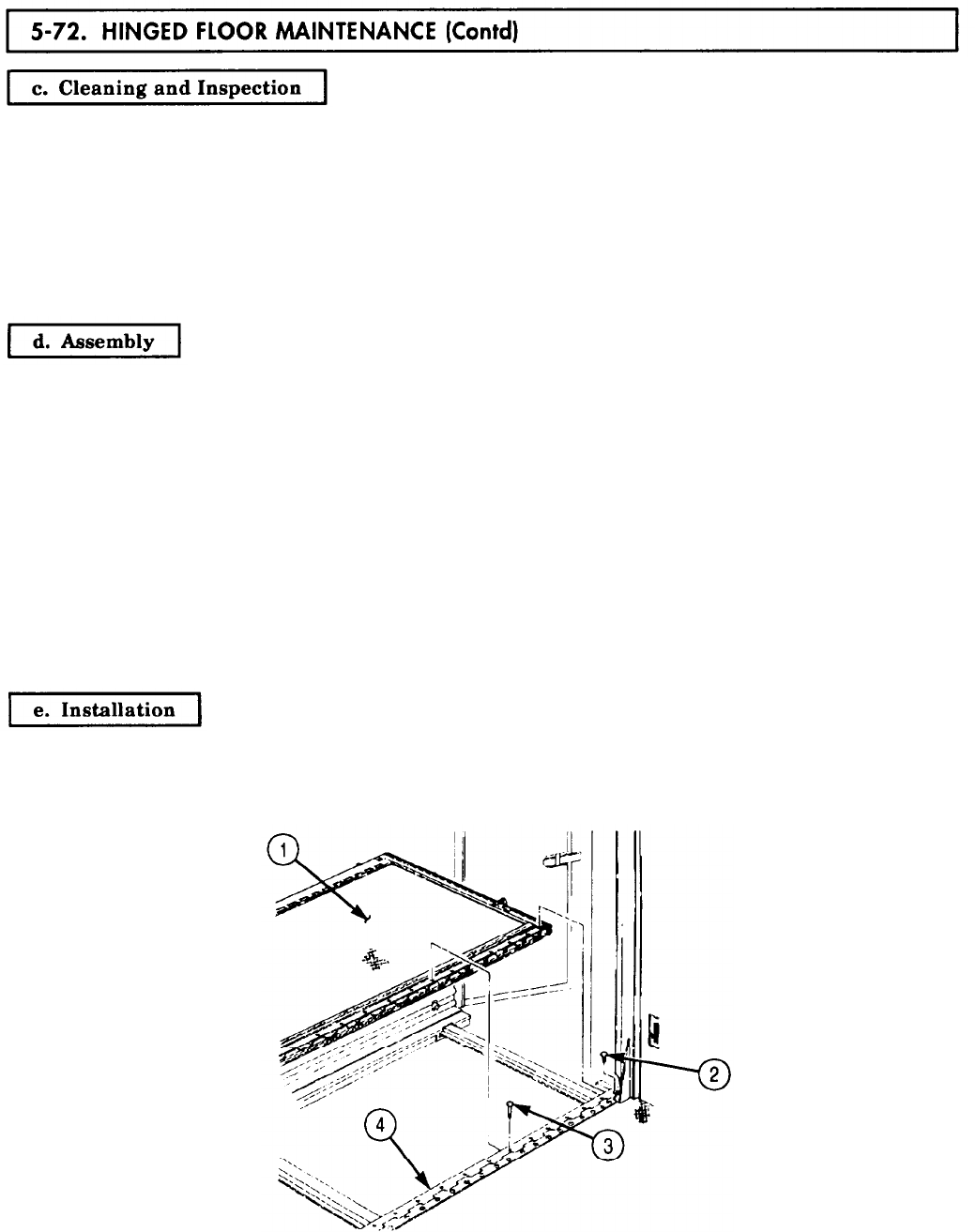
5-72. HINGED
TM 9-2320-272-24-4
1.
For general cleaning instructions, refer to para. 2-14.
2.
For general inspection instructions, refer to para. 2-15.
3.
Inspect hinged floor (1) for cracked, broken, and tom floor plates. If cracked, broken, or torn, replace
hinged floor (1) (TM 9-237).
4.
Inspect retainers (8) and channels (15) for bends and breaks. If bent or broken, replace retainers (8) or
channels (15).
5.
Inspect hinge (4) for breaks, cracks, and smooth operation. If cracked, broken, or not operating
properly, replace hinge (4).
NOTE
Apply sealing compound to exterior joints prior to installation.
Insulate exterior joints and areas of metal-to metal contact with
adhesive.
Perform step 1 only if hinge is to be replaced .
1.
Install hinge (4) on under-frame (17) with fifty-six new rivets (16).
2.
Install new seal (10) on hinged floor (1).
3.
Install handle (12) on hinged floor (1) with four screws (11).
4.
Install five pads (14) on hinged floor (1) with ten screws (13).
5.
Install two channels (15), four new seals (9), and two retainers (8) on hinged floor (1) with thirty
screws (7).
6.
Install two pivots (6) on hinged floor (1) with four screws (5).
NOTE
Assistant will help with step.
Install hinged floor (1) on hinge (4) with fifty-five screws (3) and four screws (2).
5-488
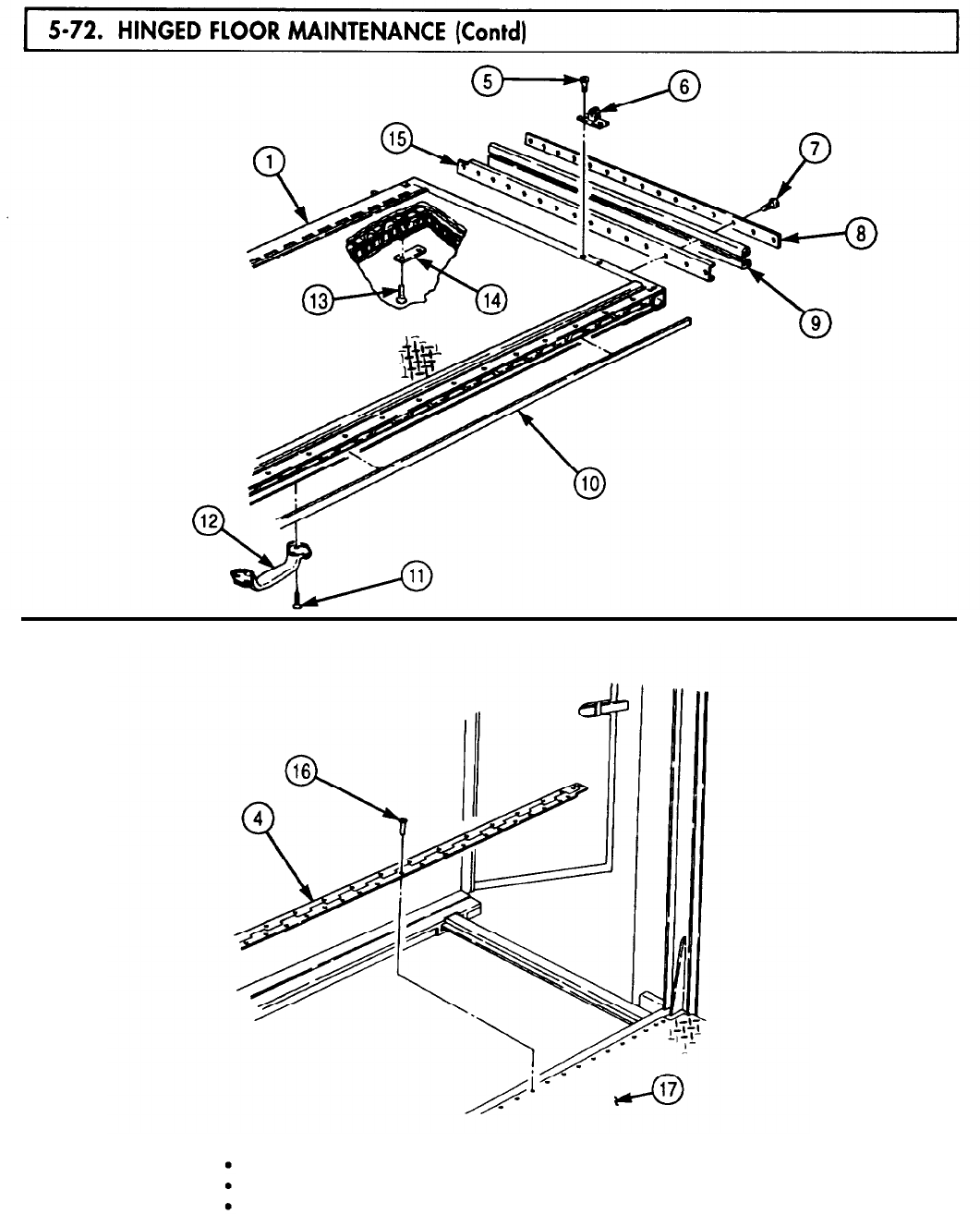
5-72. HINGED
TM 9-2320-272-24-4
FOLLOW-ON TASKS: Install counterbalance (para. 3-356).
Close hinged end panel (TM 9-2320-272-10).
Retract van body sides (TM 9-2320-272-10).
5-489
5-73. EXTERIOR
TM 9-2320-272-24-4
THIS TASK COVERS:
a. Disassembly
b. Cleaning and inspection c. Assembly
APPLICABLE MODELS REFERENCES (TM)
M934/A1/A2
TM 9-2320-272-10
TM 9-2320-272-24P
TOOLS
General mechanic’s tool kit (Appendix E, Item 1)
Rivet gun
MATERIALS/PARTS
Two hundred forty-eight rivets (Appendix D,
Item 547)
Twenty-four rivets (Appendix D, Item 551)
One hundred eighty-nine rivets (Appendix D,
Item 550)
Two seals, 86 in. (Appendix D, Item 617)
Two seals, 206 in. (Appendix D, item 617)
Two seals, 6 in. (Appendix D, Item 617)
Seal, 242 in. (Appendix D, Item 617)
Seal, 204 in. (Appendix D, Item 618)
Channel seal (Appendix D, Item 36)
Adhesive (Appendix C, Item 7)
Sealing compound (Appendix C, Item 67)
EQUIPMENT CONDlTlON
Parking brake set (TM 9-2320-272-10).
Van body fully expanded and secured
(TM 9-2320-272-10).
Side panel front lock removed (para. 3-369).
Side panel rear lock removed (para. 3-368).
Side door removed (para. 5-70).
Retractable window removed (para. 3-351).
SPECIAL ENVIRONMENTAL CONDITIONS
Vehicle must be on level surface.
NOTE
Left and right exterior side panels are disassembled the same.
This procedure covers the right exterior side panel.
1.
Remove twenty-five screws (5) and retainers (3) and (15) from side panel frame (14).
2.
Remove seals (2) and (4) and channel (1) from side panel frame (14). Discard seals (2) and (4).
3.
Remove thirty screws (12) and five retainers (13) from seal (10) at side panel frame (14).
4.
Remove sixty-two screws (11), six retainers (9), and seal (10) from side panel frame (14). Discard
seal (10).
5.
Remove six screws (8), two retainers (7), and seals (6) from side panel frame (14). Discard seals (6).
5-490
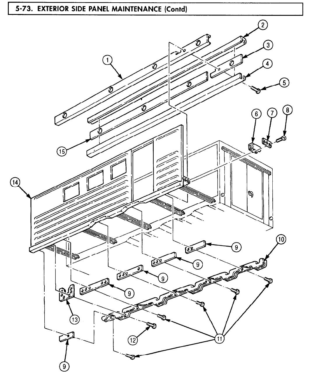
TM 9-2320-272-24-4
5-491
5-73. EXTERIOR
TM 9-2320-272-24-4
6.
7.
8.
9.
10.
11.
12.
Remove one hundred eighty-nine rivets (19), bracket (17), and seal (18) from skins (2) and (11) and
side panel frame (8). Discard rivets (19) and seal (18).
Remove eighty-two nuts (5), screws (1), four screws (10), two retainers (4), and seals (3) from side
panel frame (8). Discard seals (3).
Remove channel seal (9) from doorway of side panel frame (8). Discard channel seal (9).
Remove nine screws (6) and molding (7) from doorway of side panel frame (8).
NOTE
Perform steps 10 through 12 if skin is to be replaced.
Assistant will help with steps 10 through 12.
Remove two hundred forty-eight rivets (12) and skins (2) and (11) from side panel frame (8). Discard
rivets (12).
Remove eight screws (15) and two ladder hangers (14) from side panel frame (8).
Remove twenty-four rivets (16) and lower skin (13) from side panel frame (8). Discard rivets (16).
5-492
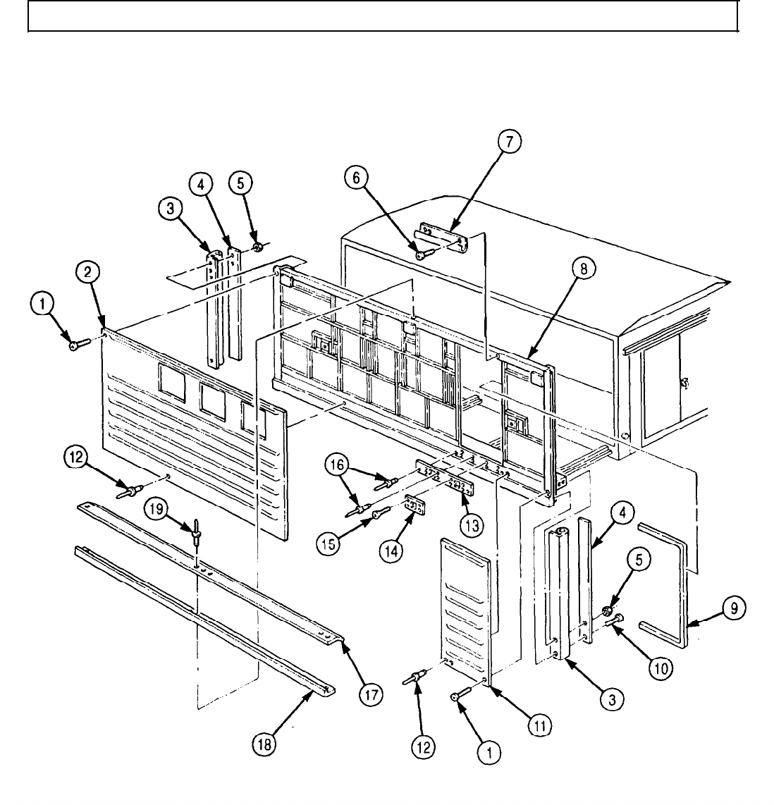
TM 9-2320-272-24-4
5-73. EXTERIOR SIDE PANEL MAINTENANCE (Contd)
5-493
TM 9-2320-272-24-4
5-73. EXTERIOR SIDE PANEL MAINTENANCE (Contd)
b. Cleaning and Inspection
1.
For general cleaning instructions, refer to para. 2-14.
2.
For general inspection instructions, refer to para. 2-15.
3.
Inspect five retainers (12), retainers (13), (5), and (6) for cracks and bends. If cracked or broken,
replace.
4.
Inspect bracket (3), retainers (9) and (10), and channel (11) for rust corrosion and breaks. If rusted
corroded, or broken, replace.
5.
Inspect molding (4), two ladder hangers (8), and side panel frame (2) for cracks, breaks, and
warpage. If cracked, broken, or warped, replace.
6.
Inspect skins (1) and (14) and lower skin (7) for tears and punctures. If torn or punctured, replace.
NOTE
l Perform steps 1 through 3 if skin was removed.
l Assistant will help with steps 1 through 3.
1.
Install lower skin (7) on side panel frame (2) with twenty-four new rivets (23).
2.
Install two ladder hangers (8) on side panel frame (2) with eight screws (22).
3.
Install skins (1) and (14) on side panel frame (2) with two hundred forty-eight new rivets (21).
NOTE
l Apply sealing compound to exterior joints for installation.
l Apply adhesive to rubber and metal surfaces for installation.
4.
Install molding (4) on doorway of side panel frame (2) with nine screws (18).
5.
Install new channel seal (19) on doorway of side panel frame (2).
6.
Install two new seals (16) and retainers (5) on side panel frame (2) with eighty-two screws (15),
nuts (17), and four screws (20).
7.
Install new seal (25) and bracket (24) on skins (1) and (14) and side panel frame (2) with one
hundred eighty-nine new rivets (26).
5-494
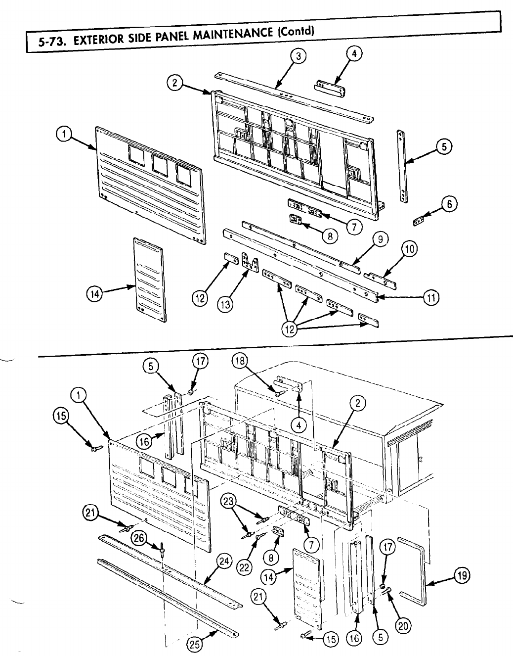
5-73. EXTERIOR
TM 9-2320-272-24-4
5-495

TM 9-2320-272-24-4
5-73. EXTERIOR SIDE PANEL MAINTENANCE (Contd)
8.
Install two new seals (6) and retainers (7) on side panel frame (14) with six screws (8).
9.
Install new seal (10) and six retainers (9) on side panel frame (14) with sixty-two screws (11).
10.
Install five retainers (13) on side panel frame (14) and seal (10) with thirty screws (12).
NOTE
New seals may need to be formed to fit on side panel frame.
11.
Install channel (1), new seals (2) and (4), retainer (3), and retainer (15) on side panel frame (14)
with twenty-five screws (5).
5-496
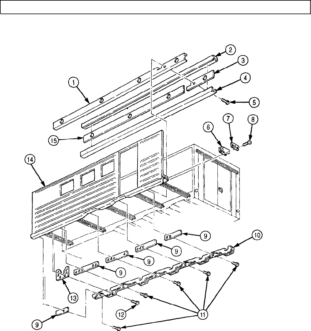
TM 9-2320-272-24-4
5-74. REAR WALL INTERIOR PANELS REPLACEMENT
THIS TASK COVERS:
a. Removal b. Installation
INITIAL SETUP:
APPLICABLE MODELS
EQUIPMENT CONDlTlON
M934/A1/A2
l
l
TOOLS
ll
General mechanic’s tool kit (Appendix E, Item 1)
l
MATERIALS/PARTS
ll
Sealing compound (Appendix C, Item 67)
l
.
REFERENCES (TM)
ll
TM 9-2320-272-10
l
TM 9-2320-272-24P
l
Parking brake set (TM 9-2320-272-10).
Rear doors opened (TM 9-2320-272-10).
Van body sides fully expanded and secured
(TM 9-2320-272-10).
Inside telephone jack post removed (para. 3-374).
Blackout light switch removed (para. 3-373).
Fire extinguisher bracket removed (para. 3-416).
Electrical load center removed (para. 4-161).
Electrical junction box removed (para. 4-163).
Converter outlet box removed (para. 4-169).
Heater thermostat removed (para. 4-165).
SPECIAL ENVIRONMENTAL CONDlTlONS
Vehicle must be on a level surface.
NOTE
l Rear wall exterior panels are not serviceable and if damaged
are replaced as a unit with rear wall assembly.
l Left and right rear wall interior panels are replaced the same
way. This procedure is for the left rear wall interior panel.
NOTE
Assistant will help with step 2.
1.
Remove thirteen screws (4) and molding (1) from panel (2) and header (3).
2.
Remove twenty-two screws (5) and panel (2) from header (3).
3.
Remove eight screws (9) and two gussets (8) from skin (7) and underframe (6).
NOTE
l Apply sealing compound to exterior joints prior to installation.
l
Assistant will help with step 2.
1.
Install two gussets (8) on skin (7) and underframe (6) with eight screws (9).
2.
Install panel (2) on header (3) with twenty-two screws (5).
3.
Install molding (1) on panel (2) and header (3) with thirteen screws (4).
5-498
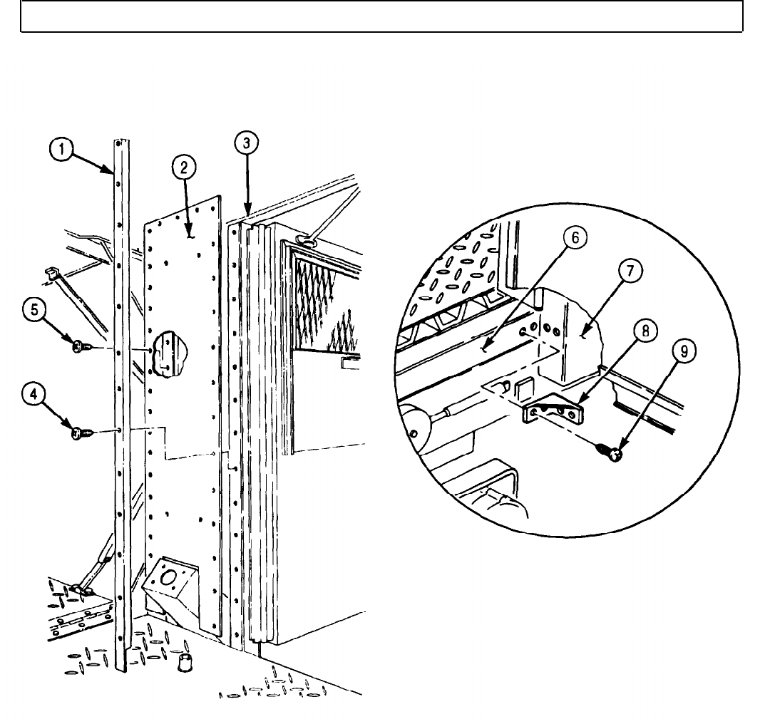
TM 9-2320-272-24-4
5-74. REAR WALL INTERIOR PANELS REPLACEMENT (Contd)
FOLLOW-ON TASKS: l Install heater thermostat (para. 4-165).
l Install converter outlet box (para. 4-169).
l Install electrical junction box (para. 4-163).
l Install electrical load center (para. 4-161).
l Install fire extinguisher bracket (para. 3-416).
l Install blackout light switch (para. 3-373).
l Install inside telephone jack post (para. 3-374).
l Retract van body sides (TM 9-2320-272-10).
l Close rear doors (TM 9-2320-272-10).
5-499

TM 9-2320-272-24-4
5-75. INTERIOR SIDE PANELS AND LATCHES REPLACEMENT
THIS TASK COVERS:
a. Removal b. Installation
INITIAL SETUP:
APPLICABLE MODELS
M934/A1/A2
TOOLS
REFERENCES (TM)
TM 9-2320-272-10
TM 9-2320-272-24P
General mechanic’s tool kit (Appendix E, Item 1)
EQUIPMENT CONDITION
MATERIALS/PARTS
l Parking brake set (TM 9-2320-272-10).
l Van body sides fully expanded and secured
Two cotter pins (Appendix D, Item 51)
Gasket (Appendix D, Item 231)
Three grommets (Appendix D, Item 251)
Six lockwashers (Appendix D, Item 364)
O-ring (Appendix D, Item 479)
Four rubber bumpers (Appendix D, Item 563)
Primer (Appendix C, Item 57)
Sealing compound (Appendix C, Item 67)
Adhesive (Appendix C, Item 7)
(TM 9-2320-272-10).
l Hinged end panels removed (para. 4-155).
l Hinged floor removed (para. 5-72).
l Hinged roof removed (para. 5-77).
l Side doors removed (para. 5-70).
SPECIAL ENVIRONMENTAL CONDITIONS
Vehicle must be on a level surface.
NOTE
Left and right interior side panels are replaced the same way. This
procedure is for right interior side panel.
1.
Remove six screws (1) and three hooks (2) from side panel frame (3).
2.
Remove six screws (5) and three clips (6) from side panel frame (3).
3.
Remove two screws (8) and striker (7) from side panel frame (3).
4.
Remove two nuts (4), screws (10), lockwashers (11), and door check assembly (9) from door
angle (15). Discard lockwashers (11).
5.
Remove two screws (12), striker (13), and two spacer plates (14) from side panel frame (3).
5-500
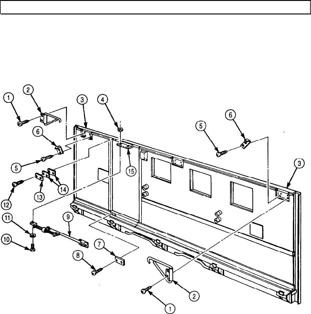
TM 9-2320-272-24-4
5-75. INTERIOR SIDE PANELS AND LATCHES REPLACEMENT (Contd)
5-501

TM 9-2320-272-24-4
5-75. INTERIOR SIDE PANELS AND LATCHES REPLACEMENT
(Contd)
6.
Remove two screws (2) and grommets (3) from side panel frame (1). Discard grommets (3).
7.
Remove four screws (11) and two clips (12) from panel (13) and side panel frame (1).
8.
Remove four screws (16), washers (17), and rubber bumpers (18) from panel (5). Discard rubber
bumpers (18).
9.
Remove eight screws (15) and four wood spacers (19) from panel (5).
10.
Remove eight screws (21) and four hangers (20) from panel (5).
11.
Remove four screws (23) and junction box (24) from panel (5).
12.
Remove eight screws (7) and plate (8) from panel (5).
13.
Remove eleven screws (22) and molding (25) from panel (5).
NOTE
Assistants will help with steps 14 and 15.
14.
Remove thirty-three screws (10) and panel (13) from side panel frame (1).
15.
Remove fifty-eight screws (9), molding (14), and panel (5) from side panel frame (1).
16.
Remove moldings (26), (4), and (6) from panel (5).
17.
Remove two moldings (27), moldings (28), and moldings (29) from panel (5).
5-502
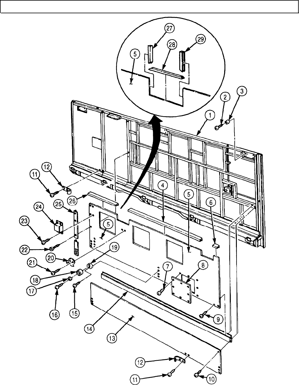
TM 9-2320-272-24-4
5-75. INTERIOR SIDE PANELS AND LATCHES REPLACEMENT (Contd)
5-503
TM 9-2320-272-24-4
5-75. INTERIOR SIDE PANELS AND LATCHES REPLACEMENT (Contd)
18.
Remove eight screws (15) and plate (14) from panel (16).
NOTE
19.
20.
21.
22.
23.
24.
25.
26.
27.
Assistant will help with step 19.
Remove thirty-three screws (13), moldings (27), (28), (29), (12), (17), and (18), and panel (16) from
side panel frame (4).
Remove nut (25) and washer (24) from latch (23).
Remove two screws (7), plate (8), gasket (9), shank (5), and O-ring (6) from latch (23). Discard
O-ring (6) and gasket (9).
Remove two cotter pins (22), pins (20), clevis (26), and clevis (21) from latch (23). Discard cotter pins (22).
Remove four nuts (11), lockwashers (10), and latch (23) from side panel frame (4). Discard
lockwashers (10).
Remove two screws (31) and retainer (30) from side panel frame (4).
Remove clevis (21) from flush bolt (3).
Remove clevis (26) from horizontal bar (19).
Remove horizontal bar (19) and flush bolt (3) from side panel frame (4).
NOTE
Repeat steps 18 through 27 for removal of each front latch
assembly.
28.
Remove screw (1) and grommet (2) from side panel frame (4). Discard grommet (2).
NOTE
l Insulate areas of dissimilar metal-to-metal contact with zinc
chromate primer.
l Apply sealing compound to exterior joints prior to installation.
l Apply adhesive to rubber and metal surfaces.
1.
Install new grommet (2) on side panel frame (4) with screw (1).
2.
Position horizontal bar (19) and flush bolt (3) in side panel frame (4).
3.
Install clevis (26) on horizontal bar (19).
4.
Install clevis (21) on flush bolt (3).
5.
Install retainer (30) on side panel frame (4) with two screws (31).
6.
Install latch (23) on side panel frame (4) with four new lockwashers (10) and nuts (11).
7.
Install clevises (26) and (21) on latch (23) with two pins (20) and new cotter pins (22).
8.
Install new O-ring (6), shank (5), new gasket (9), and plate (8) on latch (23) with two screws (7).
9.
Install washer (24) and nut (25) on shank (5) and latch (23).
NOTE
l Insulate entire structure with fibrous glass felt insulation.
l Assistant will help with step 10.
10.
Install panel (16) and moldings (27), (28), (29), (12), (17), and (18) on side panel frame (4) with
thirty-three screws (13).
11.
Install plate (14) on panel (16) with eight screws (15).
NOTE
Repeat steps 2 through 11 for installation of each front latch
assembly.
5-504

TM 9-2320-272-24-4
5-75. INTERIOR SIDE PANELS AND LATCHES REPLACEMENT (Contd)
5-505
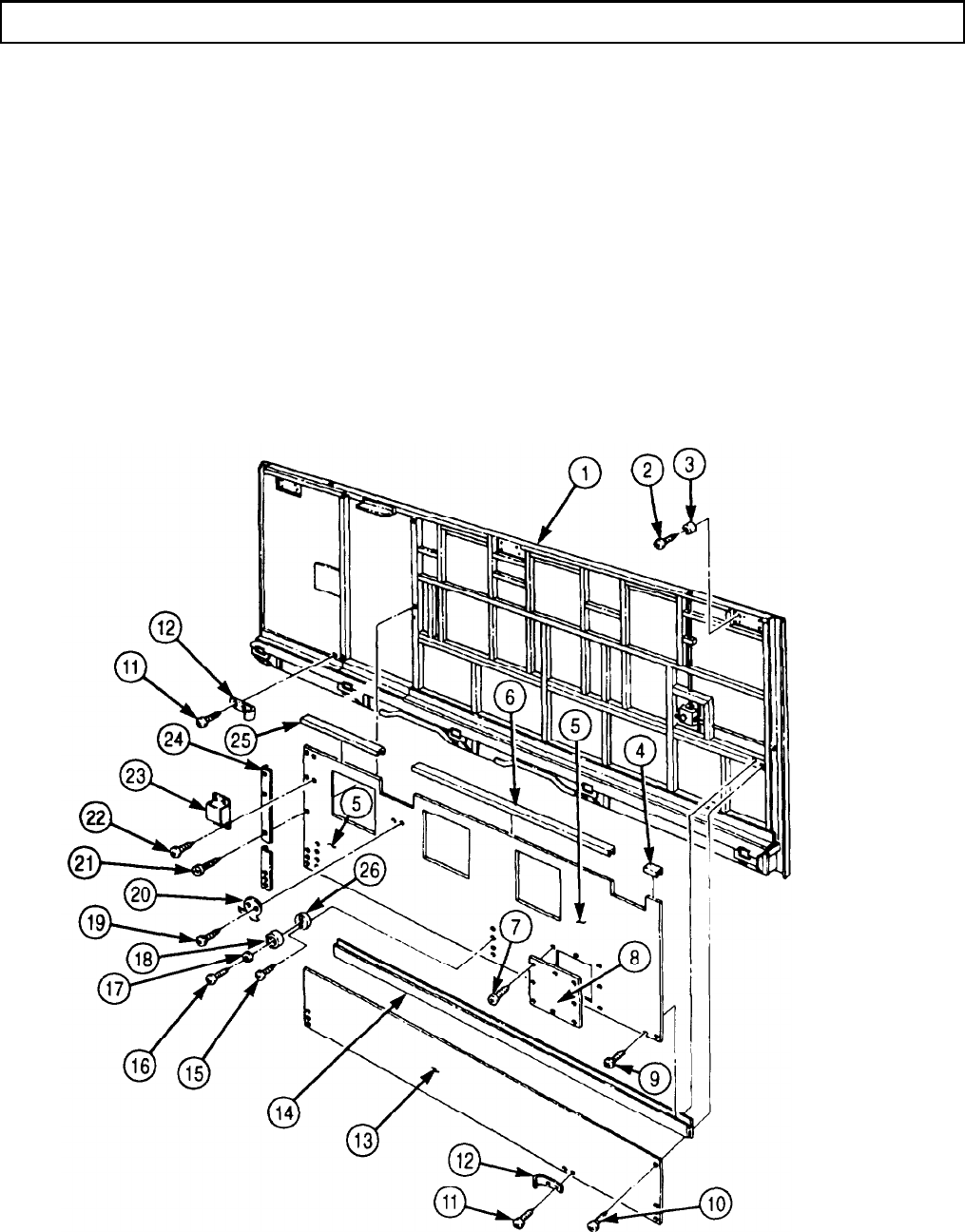
TM 9-2320-272-24-4
5-75. INTERIOR SIDE PANELS AND LATCHES REPLACEMENT (Contd)
12.
13.
14.
15.
16.
17.
18.
19.
20.
21.
22.
Install moldings (6), (4), and (25) on panel (5).
NOTE
l Assistants will help with steps 13 and 14.
l Insulate entire structure with fibrous glass felt insulation.
Install panel (5) and molding (14) on side panel frame (1) with fifty-eight screws (9).
Install panel (13) on side panel frame (1) with thirty-three screws (10).
Install molding (24) on panels (5) and (13) with eleven screws (21).
Install plate (8) on panel (5) with eight screws (7).
Install junction box (23) on panel (5) with four screws (22).
Install four hangers (20) on panel (5) with eight screws (19).
Install four wood spacers (26) on panel (5) with eight screws (15).
Install four new rubber bumpers (18) on panel (5) with four washers (17) and screws (16).
Install two clips (12) on panel (13) with four screws (11).
Install two new grommets (3) on side panel frame (1) with two screws (2).
5-506
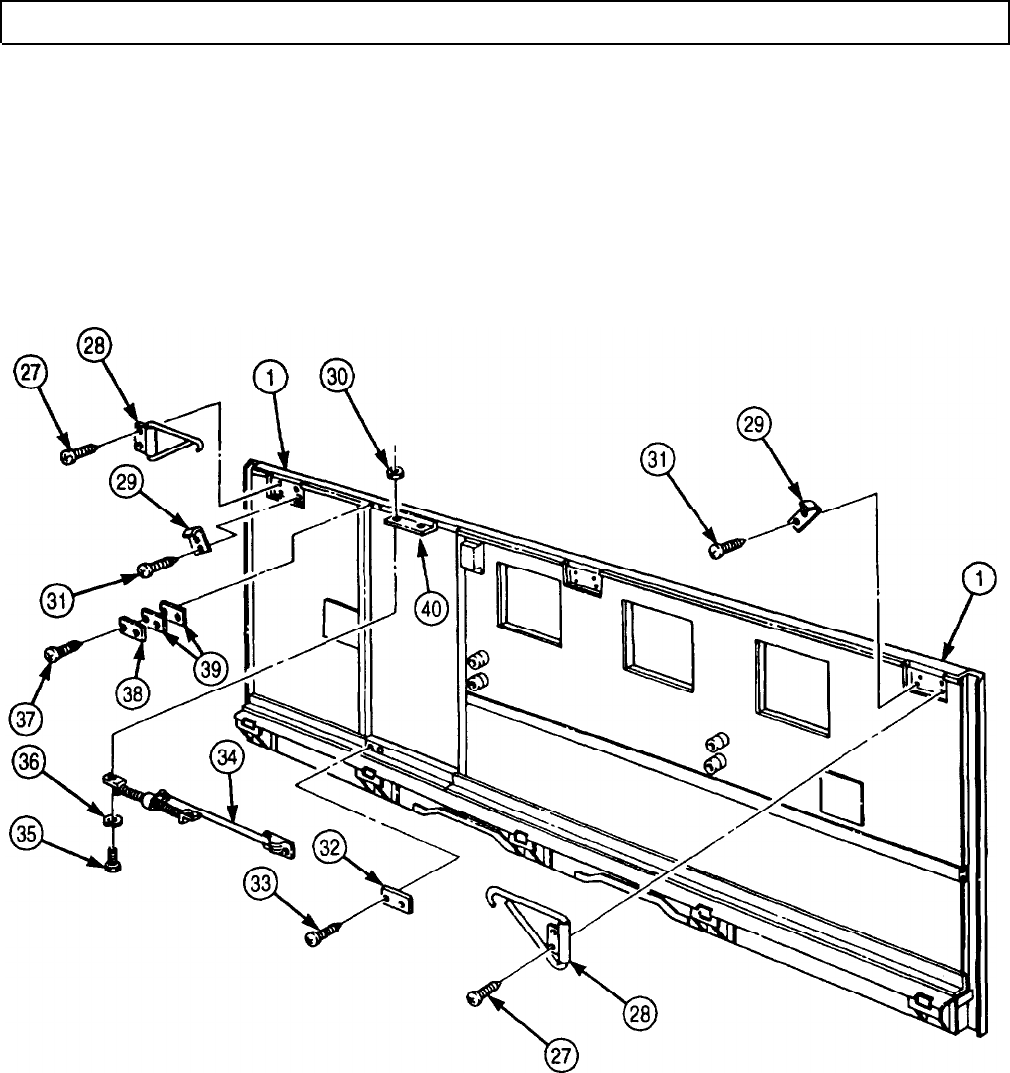
TM 9-2320-272-24-4
5-75. INTERIOR SIDE PANELS AND LATCHES REPLACEMENT (Contd)
23.
Install two spacer plates (39) and striker (38) on side panel frame (1) with two screws (37).
24.
Install door check assembly (34) on door angle (40) with two new lockwashers (36), screws (35), and
nuts (30).
25.
Install striker (32) on side panel frame (1) with two screws (33).
26.
Install three clips (29) on side panel frame (1) with six screws (31).
27.
Install three hooks (28) on side panel frame (1) with six screws (27).
FOLLOW-ON TASKS:
l Install side doors (para. 5-70).
l Install hinged roof (para. 5-77).
l Install hinged floor (para. 5-72).
l Install hinged end panels (para. 4-155).
l Retract van body sides (TM 9-2320-272-10).
5-507
TM 9-2320-272-24-4
5-76. CEILING AND FRAME MAINTENANCE
THIS TASK COVERS:
a. Removal c. Installation
b. Cleaning and Inspection
INITIAL SETUP:
APPLICABLE MODELS REFERENCES (TM)
M934/A1/A2
TM 9-2320-272-10
TOOLS
General mechanic’s tool kit (Appendix E, Item 1)
Rivet gun
MATERlALS/PARTS
Six lockwashers (Appendix D, Item 392)
One-hundred sixteen rivets (Appendix D,
Item 552)
One-hundred forty-four rivets (Appendix D,
Item 553)
Eighty-eight rivets (Appendix D, Item 551)
Two-hundred eight rivets (Appendix D,
Item 542)
Seal (Appendix D, Item 619)
Seal (Appendix D, Item 620)
Adhesive (Appendix C, Item 3)
Primer (Appendix C, Item 57)
TM 9-2320-272-24P
EQUIPMENT CONDITION
l Parking brake set (TM 9-2320-272-10).
l Van body sides fully expanded and secured
(TM 9-2320-272-10).
l Ceiling air ducts removed (para. 5-81).
l Ceiling filler and side panels removed (para. 5-79).
l Ceiling rear cover removed (para. 5-80).
l Rear doors removed (para. 4-154).
l Ceiling transition removed (para. 5-82).
NOTE
Assistant will help with steps 1 through 4.
1.
Remove one-hundred two rivets (6), ceiling panel (5), and two liner strips (1) from roof frame (2).
Discard rivets (6).
2.
Remove ninety-three rivets (4), ceiling panel (3), and two liner strips (1) from roof frame (2). Discard
rivets (4).
5-508
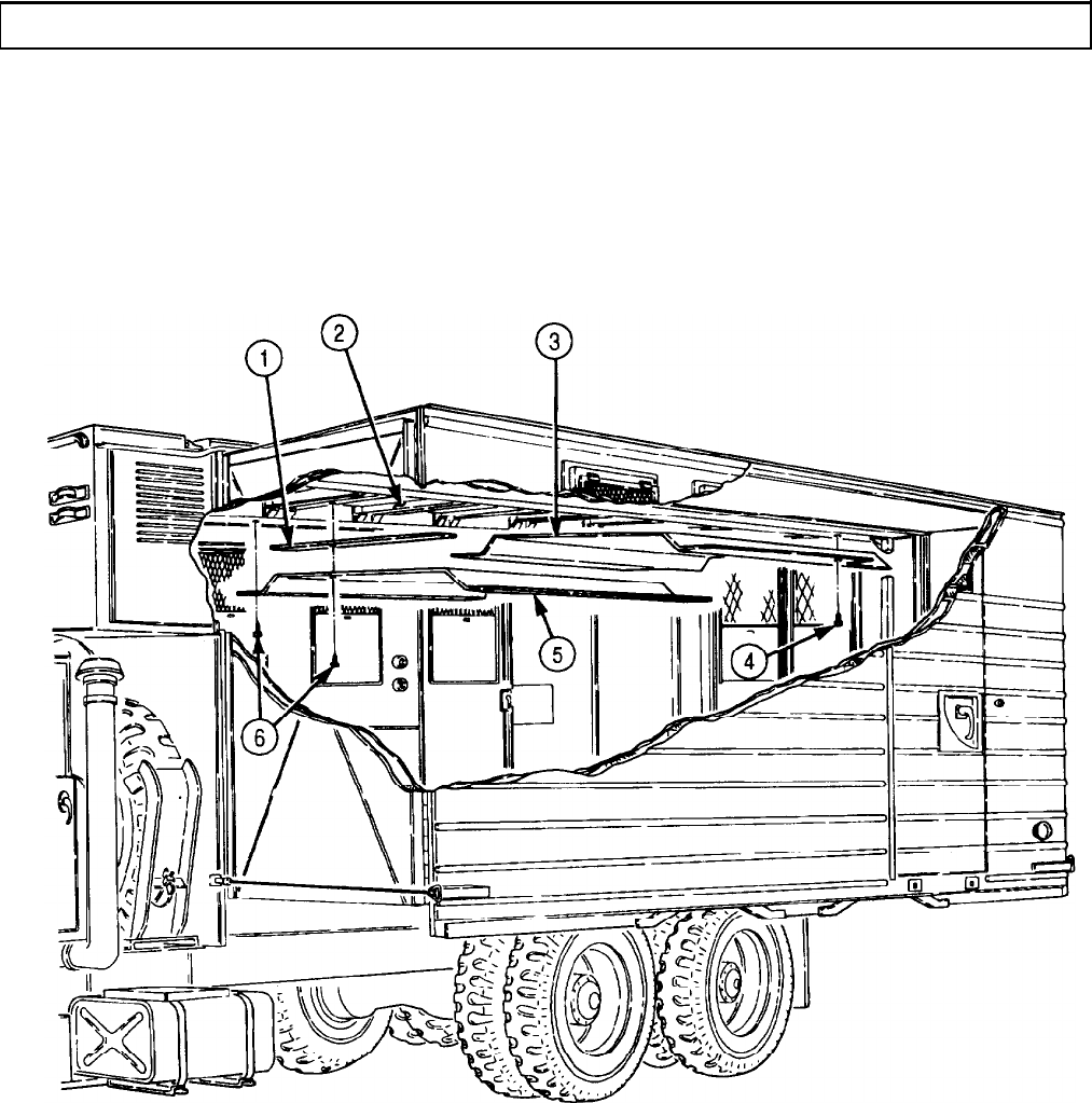
TM 9-2320-272-24-4
5-76. CEILING AND FRAME MAINTENANCE (Contd)
5-509
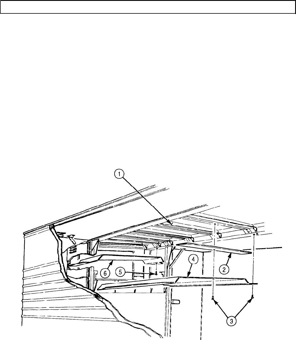
TM 9-2320-272-24-4
5-76. CEILING AND FRAME MAINTENANCE (Contd)
3.
Remove ninety-two rivets (3), ceiling panel (4), and two liner strips (2) from roof frame (1). Discard
rivets (3).
4.
Remove seventy-six rivets (5), ceiling panel (6), and three liner strips (2) from roof frame (1).
Discard rivets (5).
NOTE
Left and right side moldings are removed the same way. This
procedure covers the right side.
5.
Remove fifty-nine screws (11), molding (10), molding (12), and seal (9) from roof frame (1). Discard
seal (9).
6.
Remove six nuts (13), screws (7), lockwashers (18), and two lifting brackets (17) from roof frame (1).
Discard lockwashers (18).
NOTE
l Perform steps 7 and 8 only if roof is damaged and is to be
removed (task b).
l Assistant will help with steps 7 and 8.
7.
Remove one-hundred twenty-six rivets (15), eighteen rivets (14), and one-hundred sixteen rivets (8)
connecting roof panel (16) to roof frame (1). Discard rivets (8), (14), and (15).
8.
Remove roof panel (16) from roof frame (1) by lifting roof panel (16) and placing on supports.
5-510

TM 9-2320-272-24-4
5-76. CEILING AND FRAME MAINTENANCE (Contd)
5-511
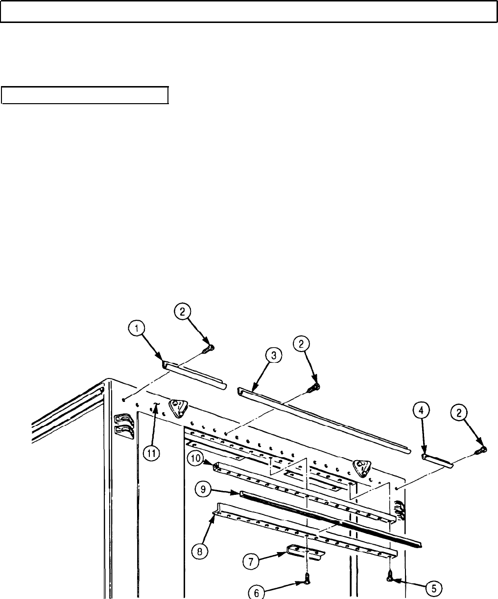
TM 9-2320-272-24-4
5-76. CEILING AND FRAME MAINTENANCE (Contd)
9.
Remove twenty-three screws (2) and moldings (1), (3), and (4) from van body (11).
10.
Remove three screws (6) and angle bracket (7) from retainer (8)
11.
Remove fifteen screws (5), seal (9), retainer (8), and woodblock (10) from van body (11). Discard
seal (9).
b. Cleaning and Inspection
1.
For general cleaning instructions, refer to para. 2-14.
2.
Inspect moldings (1), (3), and (4) for bends and breaks. If bent or broken, replace molding (l),
(3), or (4).
3.
Inspect angle bracket (7) and retainer (8) for cracks and breaks. If cracked or broken, replace.
4.
Inspect woodblock (10) for breaks. If broken, replace woodblock (10).
5.
Inspect moldings (13) and (14) for bends, breaks, and warpage. If bent, broken, or warped, replace
molding (13) or (14).
6.
Inspect lifting bracket (12) for breaks and cracks. If broken or cracked, replace lifting bracket (12).
7.
Inspect roof panel (16) for tears and punctures. If torn or punctured, replace roof panel (16).
8.
Inspect roof frame (15) for breaks, warpage, and broken bows. If roof frame (15) is damaged, replace
entire roof assembly.
9.
Inspect ceiling panels (17), (18), (19), and (20) for cracks and punctures. If cracked or punctured,
replace.
5-512
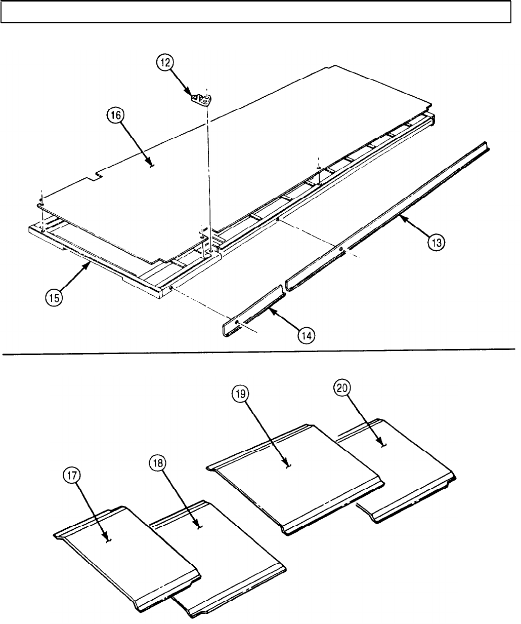
TM 9-2320-272-24-4
5-76. CEILING AND FRAME MAINTENANCE (Contd)
5-513

TM 9-2320-272-24-4
5-76. CEILING AND FRAME MAINTENANCE (Contd)
l Apply adhesive prior to installation.
l Insulate areas of dissimilar metal-to-metal contact with zinc
chromate primer.
1.
Install woodblock (10), new seal (9), and retainer (8) on van body (11) with fifteen screws (5). Leave
three center holes of retainer open for angle bracket (7) installation.
2.
Install angle bracket (7) on retainer (8) with three screws (6).
3.
Install moldings (3), (4), and (1) on van body (11) with twenty-three screws (2).
NOTE
l Perform steps 4 and 5 only if roof panel was removed.
l Insulate entire structure with fibrous glass felt insulation.
l Assistant will help with steps 4 and 5.
4.
Lift roof panel (22) from supports and position on roof frame (20).
5.
Install roof panel (22) on roof frame (20) with one-hundred sixteen new rivets (13), eighteen new
rivets (19), and one-hundred twenty-six new rivets (21).
6.
Install two lifting brackets (23) on roof frame (20) with six new lockwashers (24), screws (12), and
nuts (18).
NOTE
Left and right side moldings are installed the same way. This
procedure covers the right side.
7.
Install new seal (14), molding (15), and molding (17) on roof frame (20) with fifty-nine screws (16).
5-514

TM 9-2320-272-24-4
5-76. CEILING AND FRAME MAINTENANCE (Contd)
5-515
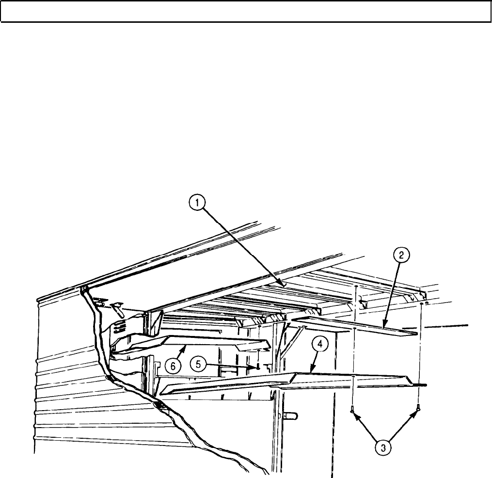
TM 9-2320-272-24-4
5-76. CEILING AND FRAME MAINTENANCE (Contd)
NOTE
Assistant will help with steps 8 through 11.
8.
Install ceiling panel (6) and three liner strips (2) on roof frame (1) with seventy-six new rivets (5).
9.
Install ceiling panel (4) and two liner strips (2) on roof frame (1) with ninety-two new rivets (3).
10.
Install ceiling panel (7) and two liner strips (2) on roof frame (1) with ninety-three new rivets (8).
11.
Install ceiling panel (9) and two liner strips (2) on roof frame (1) with one-hundred two new
rivets (10).
5-516
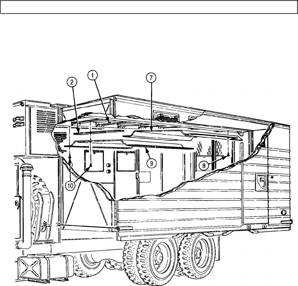
TM 9-2320-272-24-4
5-76. CEILING AND FRAME MAINTENANCE (Contd)
FOLLOW-ON TASKS: lInstall rear doors (para. 4-154).
lInstall ceiling transition (para. 5-82).
l
Install ceiling rear cover (para. 5-80).
l
Install ceiling filler and side panels (para. 5-79).
lInstall ceiling air ducts (para. 5-81).
lRetract van body sides (TM 9-2320-272-10).
5-517
TM 9-2320-272-24-4
5-77. HINGED ROOF MAINTENANCE
THIS TASK COVERS:
a. Removal
b. Disassembly
c. Cleaning and Inspection
d. Assembly
e. Installation
INITIAL SETUP:
APPLICABLE MODELS REFERENCES (TM)
M93/A1/A2 TM 9-2320-272-10
TOOLS
TM 9-2320-272-24P
General mechanic’s tool kit (Appendix E, Item 1)
EQUlPMENT CONDITION
Lifting device l Parking brake set (TM 9-2320-272-10).
Rivet gun l Van body sides fully expanded and secured
Four chains
(TM 9-2320-272-10).
MATERIALS/PARTS
Three cotter pins (Appendix D, Item 56)
Fifty-two rivets (Appendix D, Item 555)
One-hundred fifty-seven rivets (Appendix D,
Item 553)
Seal, 206 in. (Appendix D, Item 633)
Seal, 206 in. (Appendix D, Item 618)
Seal, 35 in. (Appendix D, Item 621)
Seal, 206 in. (Appendix D, Item 622)
Seal, 35 in. (Appendix D, Item 606)
Two cushion pads (left side) (Appendix D,
Item 90)
Two cushion pads (Right side) (Appendix D,
Item 91)
Gasket (Appendix D, Item 232)
O-ring (Appendix D, Item 464)
Twenty-four rivets (Appendix D, Item 554)
Four grommets (Appendix D, Item 251)
Primer (Appendix C, Item 57)
Sealing compound (Appendix C, Item 67)
Adhesive (Appendix C, Item 7)
l Hinged roof-operated blackout circuit plungers
removed (para. 3-377).
l Ceiling rear cover removed (para. 5-80).
l Ceiling filler and side panels removed (para. 5-79).
l Left and right side blackout harness removed
(para. 5-98).
SPECIAL ENVIRONMENTAL CONDITIONS
Vehicle must be on a level surface.
GENERAL SAFETY INSTRUCTIONS
All personnel must stand clear during lifting
operations.
NOTE
Left and right hinged roofs are maintained the same way. This
procedure covers right side.
1.
Attach four chains to lifting device and hinged roof (1). Remove slack from chains.
2.
Remove four screws (3), two angle brackets (2), and holding rods (4) from hinged roof (1).
5-518

TM 9-2320-272-24-4
5-77. HINGED ROOF MAINTENANCE (Contd)
WARNING
All personnel must stand clear during lifting operations. A
swinging or shifting load may cause injury to personnel.
NOTE
Assistant will help with step 3.
3.
Remove sixty-nine screws (5) from van body (6) and hinged roof (1). Lift hinged roof (1) and position
on supports.
4.
Remove chains from lifting device and hinged roof (1).
5-519

TM 9-2320-272-24-4
5-77. HINGED ROOF MAINTENANCE (Contd)
b. Disassembly
1.
Remove twelve screws (27) and three clamps (28) from hinged roof frame (1).
2.
Remove six screws (25) and three holder assemblies (26) from hinged roof frame (1).
3.
Remove thirty screws (5) and moldings (4), (6), and (7) from panels (2) and (18).
4.
Remove four screws (11) and handle (12) from panel (2).
5.
Remove ten screws (13) and cover (14) from panel (2).
6.
Remove six screws (9) and plate (8) from panel (2).
7.
Remove six screws (19) and three bars (20) from fillers (22).
8.
Remove six screws (21) and three fillers (22) from panels (2) and (8).
9.
Remove two screws (16) and molding (15) from panels (2) and (18).
10.
Remove moldings (3), (23), and (24) from panels (2) and (18).
11.
12.
NOTE
Assistant will help with steps 11 and 12.
Remove fifty-five screws (10) and panel (2) from hinged roof frame (1).
Remove forty-one screws (17) and panel (18) from hinged roof frame (1).
5-520

TM 9-2320-272-24-4
5-77. HINGED ROOF MAINTENANCE (Contd)
5-521

TM 9-2320-272-24-4
5-77. HINGED ROOF MAINTENANCE (Contd)
13.
14.
15.
16.
17.
18.
19.
20.
21.
22.
23.
24.
25.
26.
27.
Remove sixty-eight screws (26), hinge (14), and seal (13) from hinged roof frame (11). Discard seal (13).
Remove twenty-four rivets (29), retainer (30), and seal (28) from hinged roof frame (11). Discard
seal (28) and rivets (29).
Remove cushion pads (12) and (27) from hinged roof frame (11). Discard cushion pads (12) and (27).
Remove fifty-two rivets (32), retainer (34), and seal (35) from hinged roof frame (11). Discard
rivets (32) and seal (35).
Remove seals (31) and (33) from hinged roof frame (11). Discard seals (31) and (33).
Remove padlock and chain (2) and chain hook (1) from angle bracket (37).
Remove three screws (38) and angle bracket (37) from skin (7).
Remove cotter pin (24), nut (23), and washer (22) from handle (3). Discard cotter pin (24).
Remove two screws (4), handle (3), plate (5), gasket (6), and O-ring (36) from skin (7). Discard
O-ring (36) and gasket (6).
Remove two cotter pins (19), pins (16), and clevises (18) from latch (17). Discard cotter pins (19).
Remove four nuts (21), washers (20), and latch (17) from hinged roof frame (11).
Remove clevises (18) from bars (15) and (25).
Remove bars (15) and (25) from hinged roof frame (11).
Remove four screws (9) and grommets (10) from hinged roof frame (11). Discard grommets (10).
NOTE
l Perform step 27 only if skin is to be removed (task c).
l Assistant will help with step 27.
Remove one-hundred fifty-seven rivets (8) and skin (7) from hinged roof frame (11). Discard
rivets (8).
5-522
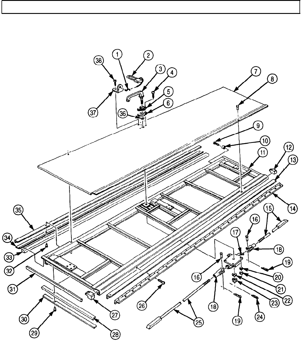
TM 9-2320-272-24-4
5-77. HINGED ROOF MAINTENANCE (Contd)
5-523
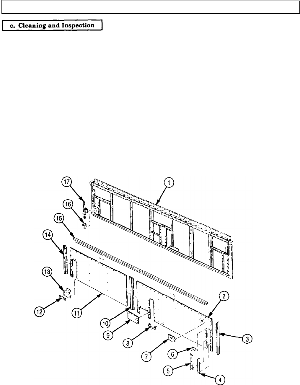
TM 9-2320-272-24-4
5-77. HINGED ROOF MAINTENANCE (Contd)
1.
2.
3.
4.
5.
6.
7.
8.
9.
10.
11.
12.
For general cleaning instructions, refer to para. 2-14.
Inspect panels (2) and (11) for cracks and breaks. Replace panels (2) and (11) if cracked or broken.
Inspect moldings (3), (4), (5), (6), (10), (14), and (15) for warpage and breaks. Replace moldings (3),
(4), (5), (6), (10), (14), and (15) if moldings are warped or broken.
Inspect plate (7), handle (8), cover (9), three bars (12), and fillers (13) for bends and breaks. Replace
plate (7), handle (8), cover (9), bars (12), and fillers (13) if bent or broken.
Inspect three clamps (17) and holder assemblies (16) for breaks and proper operation. Replace
clamps (17) and holder assemblies (16) if damaged.
Inspect hinge (23) for breaks and proper operation. Replace hinge (23) if damaged.
Inspect retainers (28) and (29) for cracks and breaks. Replace retainer (28) or (29) if cracked or broken.
Inspect angle bracket (18), padlock and chain (19), chain hook (20), and handle (21) for breaks.
Replace angle bracket (18), padlock and chain (19), chain hook (20), and handle (21) if broken.
Inspect bars (24) and (27), and two clevises (25) for bends and breaks. Replace bars (24), (27) and
clevises (25) if bent or broken.
Inspect latch (26) for proper operation. Replace latch (26) if damaged.
Inspect skin (22) for tears and punctures. Replace skin (22) if torn or punctured.
Inspect frame (1) for breaks. Replace entire hinged roof if damaged.
5-524
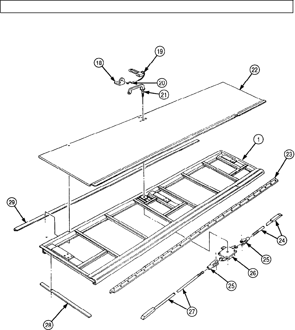
TM 9-2320-272-24-4
5-77. HINGED ROOF MAINTENANCE (Contd)
5-525
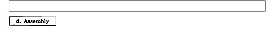
TM 9-2320-272-24-4
5-77. HINGED ROOF MAINTENANCE (Contd)
NOTE
l Insulate areas of dissimilar metal-to-metal contact with zinc
chromate primer.
l Apply sealing compound to exterior joints prior to installation.
l Apply adhesive to both rubber and metal surfaces.
l Perform step 1 only if skin was removed.
l Assistant will help with step 1.
1.
Install skin (7) on hinged roof frame (11) with one-hundred fifty-seven new rivets (8).
2.
Install four new grommets (10) on hinged roof frame (11) with four screws (9).
3.
Install clevises (18) on bars (15) and (25) and position in slots of hinged roof frame (11).
4.
Install latch (17) on hinged roof frame (11) with four washers (20) and nuts (21).
5.
Install two clevises (18) on latch (17) with two pins (16) and new cotter pins (19).
6.
Install new O-ring (36), new gasket (6), plate (5), and handle (3) on skin (7) with two screws (4).
7.
Install handle (3) on latch (17) with washer (22), nut (23), and new cotter pin (24).
8.
Install angle bracket (37) on skin (7) with three screws (38).
9.
Install chain hook (1) and padlock and chain (2) on angle bracket (37).
10.
Install new seals (31) and (33) on hinged roof frame (11).
11.
Install new seal (35) and retainer (34) on hinged roof frame (11) with fifty-two new rivets (32).
12.
Install new cushion pads (12) and (27) on hinged roof frame (11).
13.
Install new seal (28) and retainer (30) on hinged roof frame (11) with twenty-four new rivets (29).
14.
Install new seal (13) and hinge (14) on hinged roof frame (11) with sixty-eight screws (26).
5-526
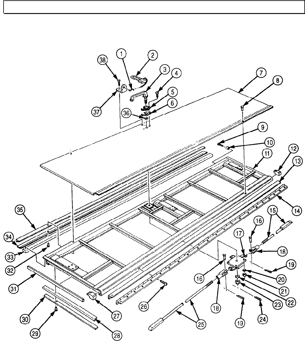
TM 9-2320-272-24-4
5-77. HINGED ROOF MAINTENANCE (Contd)
5-527

TM 9-2320-272-24-4
5-77. HINGED ROOF MAINTENANCE (Contd)
15.
Install panel (18) on hinged roof frame (1) with forty-one screws (17).
16.
Install panel (2) on hinged roof frame (1) with fifty-five screws (10).
17.
Install molding (15) on panels (2) and (18) with two screws (16).
18.
Install moldings (3), (23), and (24) on panels (2) and (18).
19.
Install three fillers (22) on panels (2) and (18) with six screws (21).
20.
Install three bars (20) on fillers (22) with six screws (19).
21.
Install plate (8) on panel (2) with six screws (9).
22.
Install cover (14) on panel (2) with ten screws (13).
23.
Install handle (12) on panel (2) with four screws (11).
24.
Install moldings (4), (6), and (7) on panels (2) and (18) with thirty screws (5).
25.
Install three holder assemblies (26) on hinged roof frame (1) with six screws (25).
26.
Install three clamps (28) on hinged roof frame (1) with twelve screws (27).
NOTE
l Insulate entire structure with fibrous glass felt insulation.
l Assistant will help with steps 15 and 16.
5-528
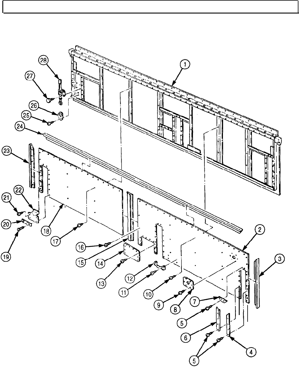
TM 9-2320-272-24-4
5-77. HINGED ROOF MAINTENANCE (Contd)
5-529

TM 9-2320-272-24-4
5-77. HINGED ROOF MAINTENANCE (Contd)
1.
Attach four chains to lifting device and hinged roof (1).
All personnel must stand clear during lifting operations. A
swinging or shifting load may cause injury to personnel.
NOTE
Assistant will help with step 2.
2.
Lift hinged roof (1) from supports and install on van body (6) with sixty-nine screws (5).
3.
Install two holding rods (4) and angle brackets (2) on hinged roof (1) with four screws (3).
4.
Remove chains from lifting device and hinged roof (1).
NOTE
Hinged roof-operated blackout circuit plungers must be installed
before side blackout harnesses are installed in load center.
5.
Install hinged roof-operated blackout circuit plungers (para. 3-377).
FOLLOW-ON TASKS: lInstall ceiling filler and side panels (para. 5-79).
l Install ceiling rear cover (para. 5-80).
l Install left and right side blackout harness (para. 5-98).
l Retract van body sides (TM 9-2320-272-10).
5-530
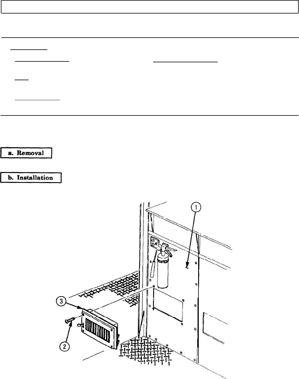
TM 9-2320-272-24-4
5-78. FRONT WALL REGISTERS REPLACEMENT
THIS TASK COVERS:
a. Removal b. Installation
INITIAL SETUP:
APPLICABLE MODELS
M934/A1/A2
TOOLS
EQUIPMENT CONDITION
Parking brake set (TM 9-2320-272-10).
General mechanic’s tool kit (Appendix E, Item 1)
REFERENCES (TM)
TM 9-2320-272-10
TM 9-2320-272-24P
NOTE
All four front wall registers are replaced the same way. This
procedure covers one register.
Remove four screws (2) and register (3) from front wall (1).
Install register (3) on front wall (1) with four screws (2).
5-531
TM 9-2320-272-24-4
5-79. CEILING FILLER AND SIDE PANELS REPLACEMENT
THIS TASK COVERS:
a. Removal b. Installation
INITIAL SETUP:
APPLICABLE MODELS
M934/A1/A2
TOOLS
General mechanic’s tool kit (Appendix E, Item 1)
MATERIALS/PARTS
Adhesive (Appendix C, Item 7)
Primer (Appendix C, Item 57)
PERSONNEL REQUIRED
TWO
REFERENCES (TM)
TM 9-2320-272-10
TM 9-2320-272-24P
EQUIPMENT CONDITION
l Parking brake set (TM 9-2320-272-10).
l Inside telephone jacks (ceiling) removed
(para. 3-374).
l Blackout light switches and receptacles removed
(para. 3-373).
l Ceiling deflectors and registers removed
(para. 5-83).
l Blackout and emergency light fixtures removed
(para. 3-372).
l Fluorescent light fixtures removed (para. 4-168).
l Rear splice plate removed (para. 5-84).
SPECIAL ENVIRONMENTAL CONDITIONS
Vehicle must be on a level surface.
NOTE
Left and right ceiling filler and side panels are replaced the same
way. This procedure covers the left side.
a. Removal
1.
Remove thirty screws (9) and side panel (8) from lintel (6), air ducts (5) and (7), and filler panel (1).
2.
Remove seven screws (10) and filler panel (1) from filler angles (2) and (3) and transition (4).
3.
Remove forty-four screws (14) and side panel (15) from lintel (6), rear header (13), and air ducts (11)
and (12).
NOTE
l Insulate areas of dissimilar metal-to-metal contact with zinc
chromate primer.
l Apply adhesive to both rubber and metal surfaces.
l Insulate entire structure with fibrous glass felt insulation.
1.
Install side panel (15) on lintel (6), rear header (13), and air ducts (12) and (11) with forty-four
screws (14).
2.
Install tiller panel (1) on filler angles (3) and (2) and transition (4) with seven screws (10).
3.
Install side panel (8) on lintel (6), air ducts (7) and (5), and filler panel (1) with thirty screws (9).
5-532

TM 9-2320-272-24-4
5-79. CEILING FILLER AND SIDE PANELS REPLACEMENT (Contd)
FOLLOW-ON TASKS: l Install rear splice plate (para. 5-84).
l Install fluorescent light fixtures (para. 4-168).
l Install blackout and emergency light fixtures (para. 3-372).
l Install blackout light switches and receptacles (para. 3-373).
l Install ceiling deflectors and registers (para. 5-83).
l Install inside telephone jacks (ceiling) (para. 3-374).
5-533
TM 9-2320-272-24-4
5-80. CEILING REAR COVER REPLACEMENT
THIS TASK COVERS:
a. Removal b. Installation
INlTlAL SETUP:
APPLICABLE MODELS
M934/A1/A2
TOOLS
General mechanic’s tool kit (Appendix E, Item 1)
MATERIALS/PARTS
Adhesive (Appendix C, Item 7)
Primer (Appendix C, Item 57)
PERSONNEL REQUIRED
TWO
REFERENCES (TM)
TM 9-2320-272-10
TM 9-2320-272-24P
EQUIPMENT CONDlTlON
l Parking brake set (TM 9-2320-272-10).
l Rear splice plate removed (par. 5-84).
SPECIAL ENVIRONMENTAL CONDITIONS
Vehicle must be on a level surface.
Remove eight screws (4), thirteen screws (5), and rear cover (3) from rear head (2) and air
duct (1).
NOTE
l Insulate areas of dissimilar metal-to-metal contact with zinc
chromate primer.
l Apply adhesive to metal surfaces.
l Insulate entire structure with fibrous glass felt insulation.
1.
Install rear cover (3) on rear header (2) with eight screws (4).
2.
Install rear cover (3) on air duct (1) with thirteen screws (5).
5-534
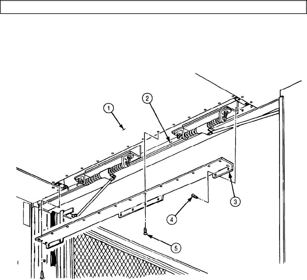
TM 9-2320-272-24-4
5-81. CEILING AIR DUCTS REPLACEMENT
THIS TASK COVERS:
a. Removal b. Installation
INITlAL SETUP:
APPLICABLE MODELS REFERENCES (TM)
M934/A1/A2
TM 9-2320-272-10
TOOLS
TM 9-2320-272-24P
General mechanic’s tool kit (Appendix E, Item 1)
EQUIPMENT CONDITION
MATERIALS/PARTS
l Parking brake set (TM 9-2320-272-10).
Primer (Appendix C, Item 57)
l Van sides fully expanded and secured
(TM 9-2320-272-10).
PERSONNEL REQUIRED
l Ceiling rear cover removed (para. 5-80).
TWO
l Ceiling filler and side panels removed (para. 5-79).
SPECIAL ENVIRONMENTAL CONDITIONS
Vehicle must be on a level surface.
1.
Remove fifty-two screws (6) and two enclosures (7) from air ducts (3) and (5).
2.
Remove fourteen screws (4) from air ducts (3) and (5) and support (1).
3.
Remove forty-two screws (2) and air duct (3) from ceiling (9).
4.
Remove eighteen screws (8) and air duct (5) from ceiling (9).
5.
Remove nine screws (10) and support (1) from ceiling (9).
6.
Remove fifty-two screws (20) and two enclosures (19) from air ducts (17) and (21).
7.
Remove four screws (16) from air duct (17) and support (13).
8.
Remove six screws (18) from air duct (21) and support (13).
9.
Remove twenty-six screws (15) and air ducts (17) and (21) from ceiling (9).
10.
Remove ten screws (14) and support (13) from ceiling (9).
11.
Remove seven screws (12) and support (11) from ceiling (9).
b. Installation
1.
Install support (11) on ceiling (9) with seven screws (12).
2.
Install support (13) on ceiling (9) with ten screws (14).
3.
Install air ducts (17) and (21) on ceiling (9) with twenty-six screws (15).
4.
Install air duct (21) on support (13) with six screws (18).
5.
Install air duct (17) on support (13) with four screws (16).
6.
Install two enclosures (19) on air ducts (21) and (17) with fifty-two screws (20).
7.
Position support (1) over bow of roof frame and install on ceiling (9) with nine screws (10).
8.
Install air duct (5) on ceiling (9) with eighteen screws (8).
9.
Install air duct (3) on ceiling (9) with forty-two screws (2).
10.
Install air ducts (3) and (5) on support (1) with fourteen screws (4).
11.
Install two enclosures (7) on air ducts (5) and (3) with fifty-two screws (6).
5-536
NOTE
Insulate areas of dissimilar metal-to-metal contact with zinc
chromate primer.
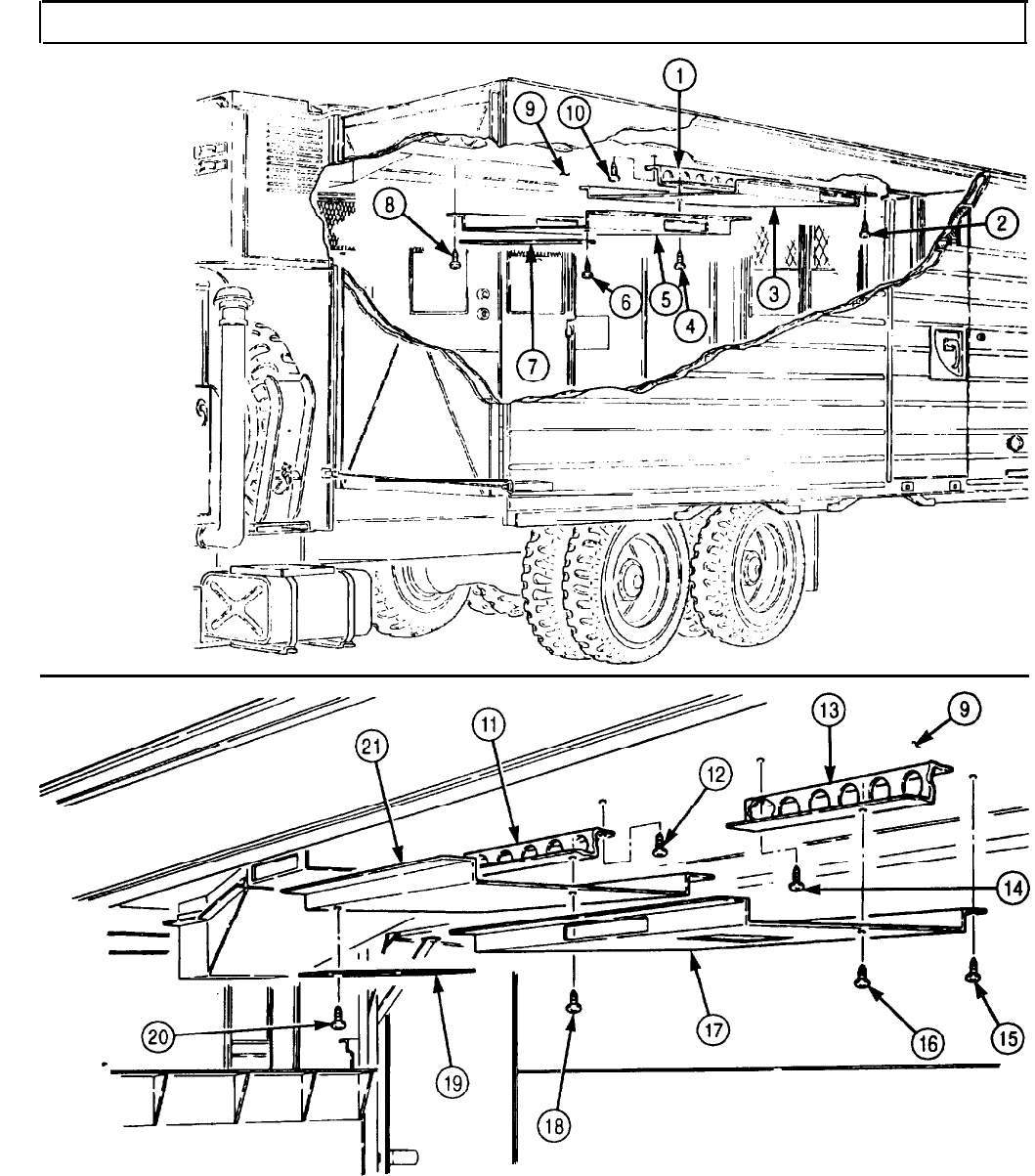
TM 9-2320-272-24-4
5-82. CEILING TRANSITION MAINTENANCE
THIS TASK COVERS:
a. Removal
b. Disassembly c. Assembly
d. Installation
INITIAL SETUP:
APPLICABLE MODELS REFERENCES (TM)
M934/A1/A2
TM 9-2320-272-10
TOOLS
TM 9-2320-272-24P
General mechanic’s tool kit (Appendix E, Item 1)
EQUIPMENT CONDITION
Rivet gun l Parking brake set (TM 9-2320-272-10).
MATERIALS/PARTS
l Van sides fully expanded and secured
(TM 9-2320-272-10).
Two seals, 15 in. (Appendix D, Item 617)
Twenty-four rivets (Appendix D, Item 542)
Two seals, 28 in. (Appendix D, Item 617)
Adhesive (Appendix C, Item 7)
l Ceiling filler and side panels removed (para. 5-79).
l Ceiling air ducts removed (para. 5-81).
SPECIAL ENVIRONMENTAL CONDITIONS
Vehicle must be on a level surface.
a. Removal
1.
Remove seven screws (4) from support (8).
NOTE
Assistants will help with step 2.
2.
Remove thirty screws (2) and transition (3) from ceiling (1).
1.
Remove seven rivets (6), retainer (7), seal (5), and support (8) from transition (3). Discard rivets (6)
and seal (5).
2.
Remove ten rivets (18), two retainers (9), and seals (10) from transition (3). Discard seals (10) and
rivets (18).
3.
Remove seven rivets (16), retainer (17), and seal (15) from transition (3). Discard seal (15) and
rivets (16).
4.
Remove four screws (11) and filler angle (12) from transition (3).
5.
Remove three screws (13) and filler angle (14) from transition (3).
5-538
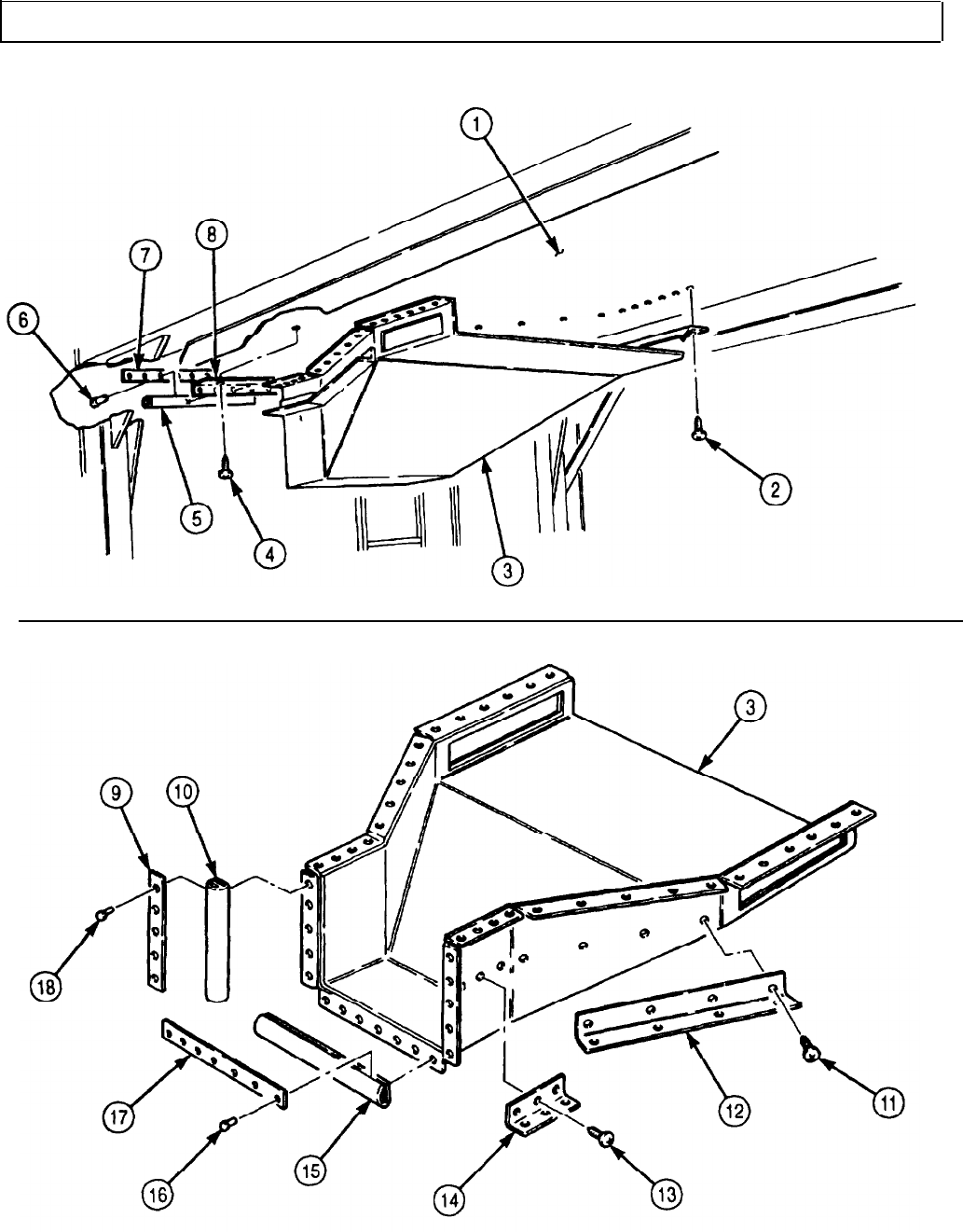
TM 9-2320-272-24-4
5-82. CEILING TRANSITION MAINTENANCE (Contd)
5-539
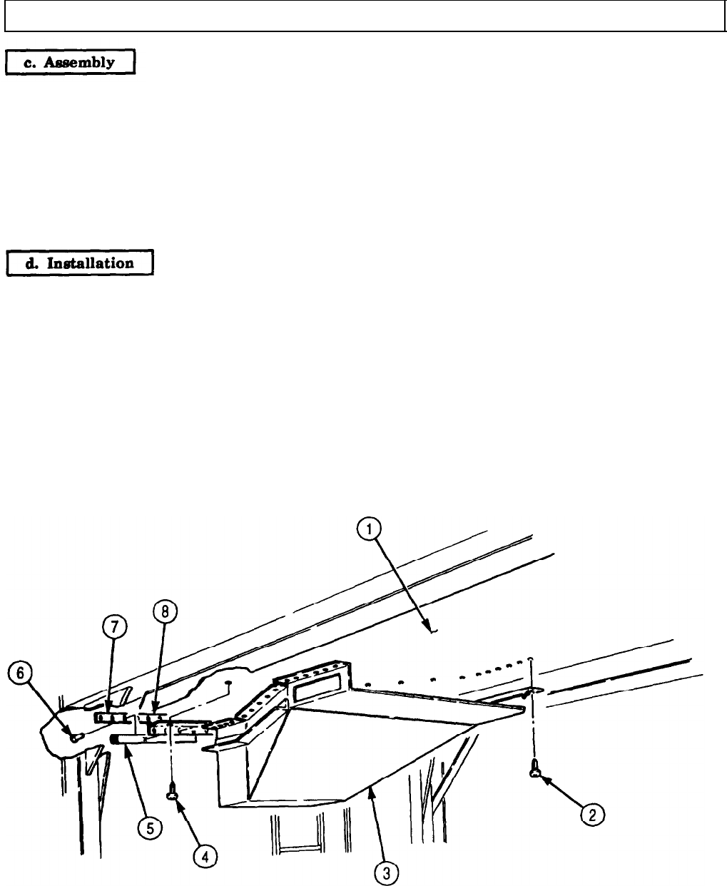
TM 9-2320-272-24-4
5-82. CEILING TRANSITION MAINTENANCE (Contd)
1.
Install filler angle (14) on transition (3) with three screws (13).
2.
Install tiller angle (12) on transition (3) with four screws (11).
NOTE
Apply adhesive to both rubber and metal surfaces.
3.
Install new seal (15) and retainer (17) on transition (3) with seven new rivets (16).
4.
Install two new seals (10) and retainers (9) on transition (3) with ten new rivets (18).
5.
Align support (8) with flanges on transition (3) and install support (8), new seal (5), and retainer (7)
on transition (3) with seven new rivets (6).
NOTE
l Insulate inside of transition with duct lining insulation.
l Assistants will help with steps 1 and 2.
1.
Install transition (3) on ceiling (1) with thirty screws (2).
2.
Install support (8) on ceiling (1) with seven screws (4).
5-540
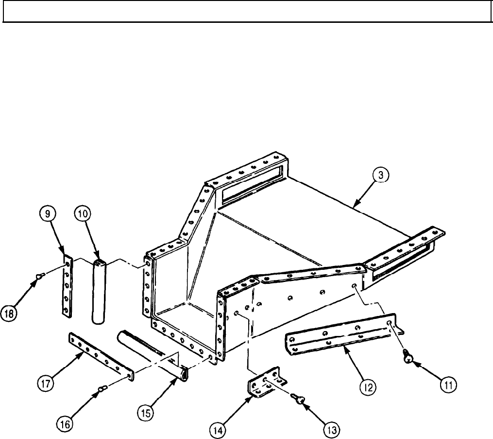
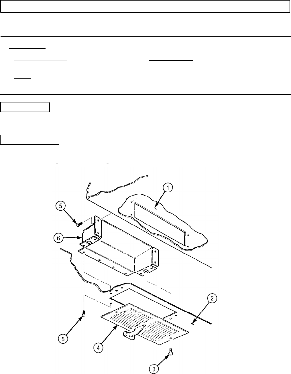
TM 9-2320-272-24-4
5-83. CEILING DEFLECTOR AND REGISTERS REPLACEMENT
THIS TASK COVERS:
a. Removal b. Installation
INITIAL SETUP:
APPLICABLE MODELS
M934/A1/A2
REFERENCES (TM)
TM 9-2320-272-10
TOOLS
TM 9-2320-272-24P
General mechanic’s tool kit (Appendix E, Item 1)
EQUIPMENT CONDITION
Parking brake set (TM 9-2320-272-10).
a. Removal
1.
Remove twenty screws (3) and ten registers (4) from ceiling side panels (2) and deflectors (6).
2.
Remove one hundred screws (5) and ten deflectors (6) from air ducts (1) and ceiling side panels (2).
b. Installation
1.
Install ten deflectors (6) on air ducts (1) and ceiling side panels (2) with one hundred screws (5).
2.
Install ten registers (4) on ceiling side panels (2) and ten deflectors (6) with twenty screws (3).
5-542
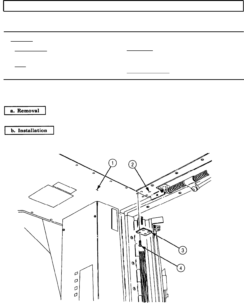
b. Installation
a. Removal
TM 9-2320-272-24-4
5-84. REAR SPLICE PLATE REPLACEMENT
THIS TASK COVERS:
a. Removal b. Installation
INITIAL SETUP:
APPLICABLE MODELS
M934/A1/A2
TOOLS
REFERENCES (TM)
TM 9-2320-272-10
TM 9-2320-272-24P
General mechanic’s tool kit (Appendix E, Item 1)
EQUIPMENT CONDITION
Parking brake set (TM 9-2320-272-10).
NOTE
Left and rear splice plates are replaced the same way. This
procedure covers the right side.
Remove four screws (4) and splice plate (3) from side panel (1) and rear cover (2).
Install splice plate (3) on side panel (1) and rear cover (2) with four screws (4).
5-543

a. Removal
TM 9-2320-272-24-4
5-85. BONNET FRAME PARTS REPLACEMENT
THIS TASK COVERS:
a. Removal b. Installation
INITIAL SETUP:
APPLICABLE MODELS REFERENCES (TM)
M934/A1/A2
TM 9-2320-272-10
TOOLS
TM 9-2320-272-24P
General mechanic’s tool kit (Appendix E, Item 1)
Rivet gun
EQUIPMENT CONDITION
MATERIALS/PARTS
Insulation (Appendix D, Item 260)
Two speed nuts (Appendix D, Item 667)
Eight rivets (Appendix D, Item 557)
Thirty-five rivets (Appendix D, Item 556)
One-hundred sixteen rivets (Appendix D,
l Parking brake set (TM 9-2320-272-10).
l Bonnet control rod removed (para. 3-361).
l Van heater removed (para. 3-379).
l Air conditioner (if equipped) removed (para. 5-88).
l Bonnet access door removed (para. 5-86).
l Bonnet door removed (para. 5-87).
Item 547)
One-hundred seventy-six rivets (Appendix D,
Item 542)
Sixteen rivets (Appendix D, Item 559)
Adhesive (Appendix C, Item 7)
Primer (Appendix C, Item 57)
Sealing compound (Appendix C, Item 67)
1.
Remove twenty-seven screws (5) and drip molding (4) from bonnet frame (14).
2.
Remove seventeen screws (13) and door panel (12) from bonnet frame (14).
3.
Remove four screws (15) and plate (1) from outer panel (2) and bonnet frame (14).
4.
Remove thirty-eight rivets (3), twenty-four rivets (7), and outer panels (6) and (2) from bonnet
frame (14) and bonnet lower panel (11). Discard rivets (3) and (7).
NOTE
l Left and right fillers are removed the same way. This procedure
is for the left filler.
l Assistant will help with step 5.
5.
Remove sixty-four rivets (9), thirty-one rivets (10), bonnet lower panel (11), and two tillers (8) from
bonnet frame (14). Discard rivets (9) and (10).
5-544
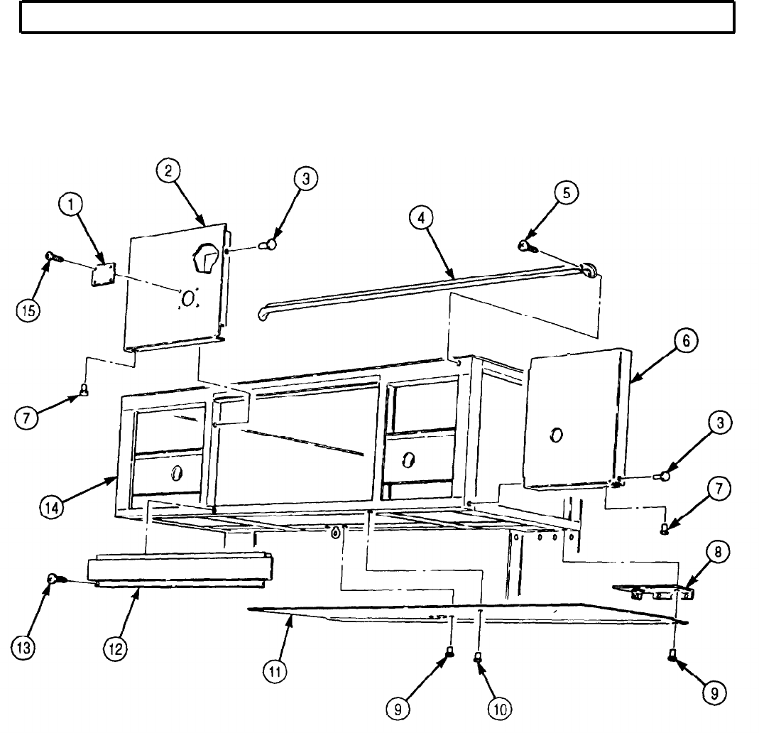
TM 9-2320-272-24-4
5-85. BONNET FRAME PARTS REPLACEMENT (Contd)
5-545
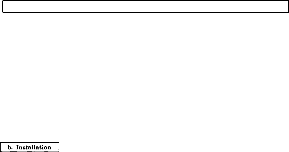
b. Installation
TM 9-2320-272-24-4
5-85. BONNET FRAME PARTS REPLACEMENT (Contd)
6.
7.
8.
9.
10.
11.
12.
NOTE
Left and right heater duct assemblies are removed the same way.
This procedure covers the right side.
Remove two fasteners (5) from support (14) and heater duct (2).
Remove four rivets (12) and two speed nuts (13) from support (14). Discard rivets (12) and speed
nuts (13).
Remove three screws (11) and support (14) from front wall (15).
Remove thirty-six rivets (3), heater duct (2), and insulation (4) from bonnet floor (19). Discard
rivets (3) and insulation (4).
Remove sixteen rivets (7), twenty-four rivets (8), thirty-six rivets (10), and inner panels (9) and (16)
from bonnet frame (6) and bonnet floor (19). Discard rivets (7), (8), and (10).
Remove three screws (20) and post (1) from bonnet floor (19).
NOTE
Assistant will help with step 12.
Remove forty-three rivets (17), thirty-five rivets (18), and bonnet floor (19) from bonnet frame (6)
and front wall (15). Discard rivets (17) and (18).
NOTE
l Insulate areas of dissimilar metal-to-metal contact with zinc
chromate primer.
l Apply sealing compound to exterior joints prior to installation.
l Insulate all enclosed structure with fibrous glass felt insulation.
l Assistant will help with step 1.
1.
Install bonnet floor (19) on bonnet frame (6) and front wall (15) with forty-three new rivets (17) and
thirty-five new rivets (18).
2.
Install post (1) on bonnet floor (19) with three screws (20).
3.
Install inner panels (9) and (16) on bonnet frame (6) and bonnet floor (19) with thirty-six new
rivets (10), twenty-four new rivets (8), and sixteen new rivets (7).
NOTE
Left and right heater duct assemblies are installed the same way.
This procedure covers the right side.
4.
Install new insulation (4) and heater duct (2) on bonnet floor (19) with thirty-six new rivets (3).
5.
Install support (14) on front wall (15) with three screws (11).
6.
Install two new speed nuts (13) on support (14) with four new rivets (12).
7.
Install heater duct (2) on support (14) with two fasteners (5).
5-546

TM 9-2320-272-24-4
5-85. BONNET FRAME PARTS REPLACEMENT (Contd)
5-547
TM 9-2320-272-24-4
5-85. BONNET FRAME PARTS REPLACEMENT (Contd)
8.
9.
10.
11.
12.
NOTE
l Left and right fillers are installed the same way. The left filler
is shown.
l Assistant will help with step 8.
Install two fillers (8) and bonnet lower panel (11) on bonnet frame (14) with sixty-four new
rivets (9) and thirty-one new rivets (10).
Install outer panels (6) and (2) on bonnet frame (14) and bonnet lower panel (11) with twenty-four
new rivets (7) and thirty-eight new rivets (3).
Install plate (1) on outer panel (2) and bonnet frame (14) with four screws (15).
Install door panel (12) on bonnet frame (14) with seventeen screws (13).
Install drip molding (4) on bonnet frame (14) with twenty-seven screws (5).
FOLLOW-ON TASKS: lInstall bonnet door (para. 5-87).
l Install bonnet access door (para. 5-86).
l Install van heater (para. 3-379).
l Install air conditioner (if equipped) (para. 5-88)
l Install bonnet control rod (para. 3-361).
5-548
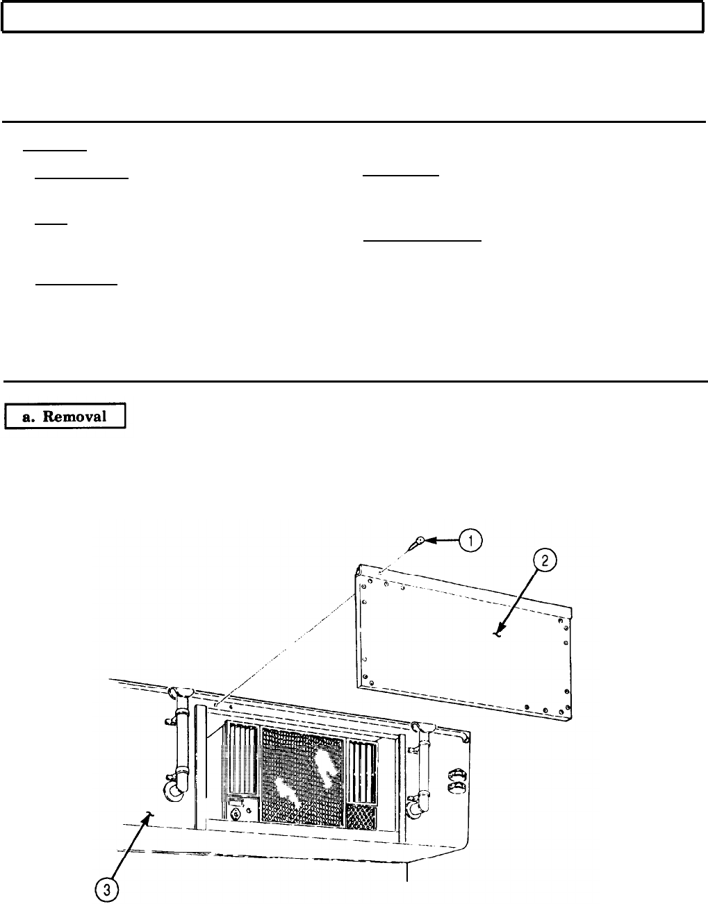
a. Removal
TM 9-2320-272-24-4
5-86. BONNET ACCESS DOOR MAINTENANCE
THIS TASK COVERS:
a. Removal d. Assembly
b. Disassembly e. Installation
c. Cleaning and Inspection
INITIAL SETUP:
APPLICABLE MODELS
M934/A1/A2
REFERENCES (TM)
TM 9-2320-272-10
TM 9-2320-272-24P
TOOLS
General mechanic’s tool kit (Appendix E, Item 1)
EQUIPMENT CONDITION
Rivet gun l Parking brake set (TM 9-2320-272-10).
MATERIALS/PARTS
l Bonnet control rod removed (para. 3-361).
One hundred forty-eight rivets (Appendix D,
Item 551)
Seal, 51 in. (Appendix D, Item 633)
Seal (Appendix D, Item 623)
Primer (Appendix C, Item 57)
Sealing compound (Appendix C, Item 67)
NOTE
Assistant will help with step.
Remove twelve screws (1) and access door assembly (2) from bonnet frame (3).
5-549

b. Disassembly
c. Cleaning
d. Assembly
TM 9-2320-272-24-4
5-86. BONNET ACCESS DOOR MAINTENANCE (Contd)
1.
Remove twelve screws (1), hinge (2), and seal (21) from door frame (17). Discard seal (21).
2.
Remove four screws (5) and two angle brackets (4) from inner panel (3).
3.
Remove four screws (7), rod (8), and holder bracket (6) from inner panel (3).
4.
Remove screw (11), two nuts (9), screws (12), and bracket (10) from inner panel (3).
NOTE
Assistant will help with step 5.
5.
Remove thirty-three nuts (13), screws (18), seventy-four rivets (19), outer panel (20), three
retainers (14), and seal (16) from door frame (17). Discard seal (16) and rivets (19).
NOTE
Perform step 6 if inner panel is to be replaced (subtask c.).
6.
Remove seventy-four rivets (15) and inner panel (3) from door frame (17). Discard rivets (15).
1.
For general cleaning instructions, refer to para. 2-14.
2.
Inspect hinge (2) for breaks and proper operation. Replace hinge (2) if damaged.
3.
Inspect three retainers (14) for bends and breaks. Replace if bent or broken.
4.
Inspect angle brackets (4), holder bracket (6), and rod (8) for cracks and breaks. Replace if cracked
or broken.
5.
Inspect outer panel (20) for tears and punctures. Replace outer panel (20) if tom or punctured.
6.
Inspect inner panel (3) for tears and punctures. Replace inner panel (3) if torn or punctured.
7.
Inspect door frame (17) for bend, cracks, and breaks. Replace door frame (17) if bent, cracked, or
broken.
NOTE
l Insulate areas of dissimilar metal-to-metal contact with zinc
chromate primer.
l Apply sealing compound to exterior joints prior to installation.
l Insulate all enclosed structure with fibrous glass felt insulation.
l Perform step 1 only if inner panel was removed.
l Assistant will help with steps 1 and 2.
1.
Install inner panel (3) on door frame (17) with seventy-four new rivets (15).
2.
Install new seal (16), three retainers (14), and outer panel (20) on door frame (17) with thirty-three
screws (18), nuts (13), and seventy-four new rivets (19).
3.
Install holder bracket (6) and rod (8) on inner panel (3) with four screws (7).
4.
Install screw (11) and two nuts (9) on bracket (10).
NOTE
Angle bracket can be installed on either side of door.
5.
Install bracket (10) on inner panel (3) with two screws (12).
6.
Install two angle brackets (4) on inner panel (3) with four screws (5).
7.
Install new seal (21) and hinge (2) on door frame (17) with twelve screws (1).
5-550
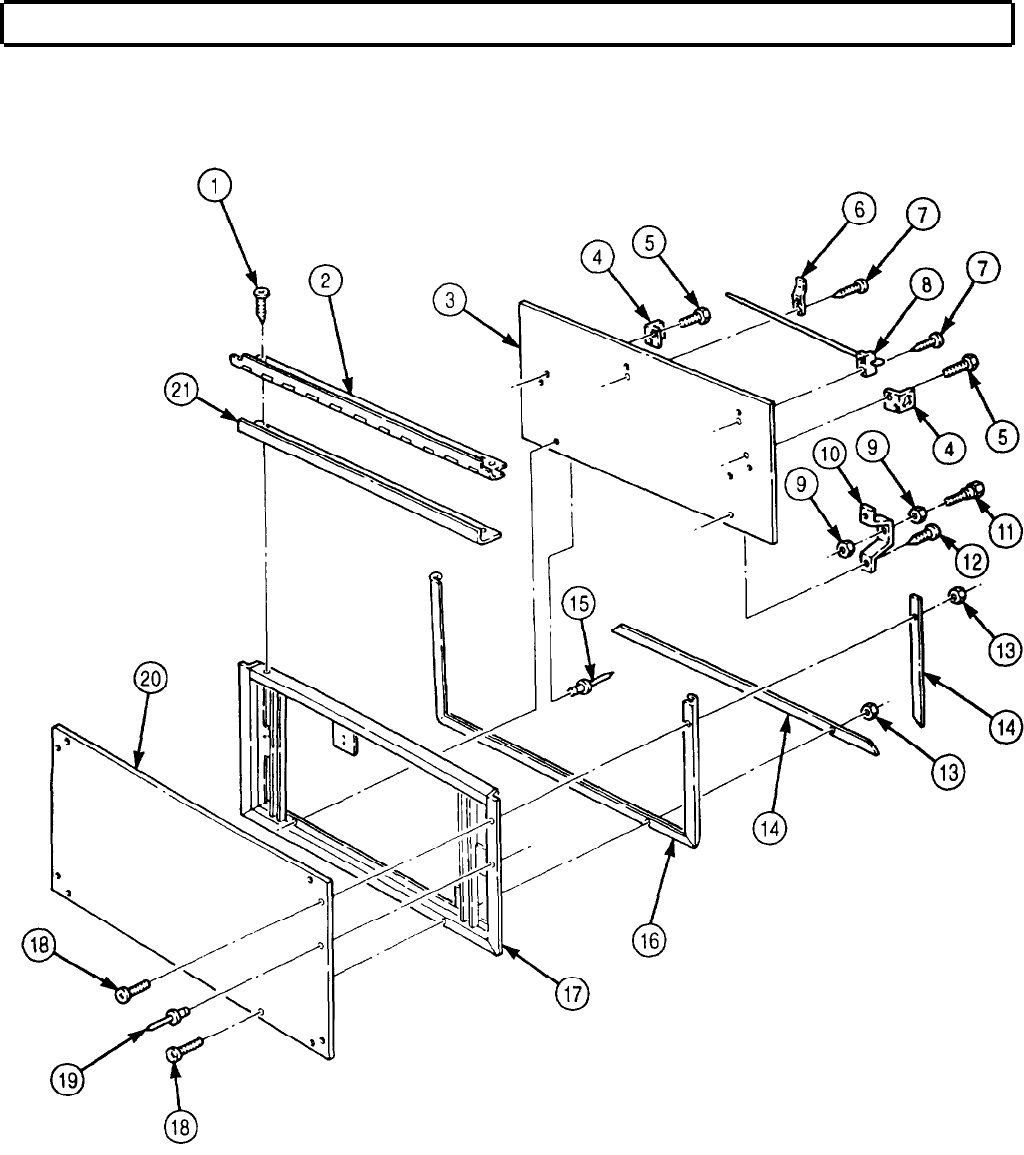
TM 9-2320-272-24-4
5-86. BONNET ACCESS DOOR MAINTENANCE (Contd)
5-551

e. Installation
TM 9-2320-272-24-4
5-86. BONNET ACCESS DOOR MAINTENANCE (Contd)
NOTE
Assistant will help with step.
Install access door assembly (2) on bonnet frame (3) with twelve screws (1).
5-552
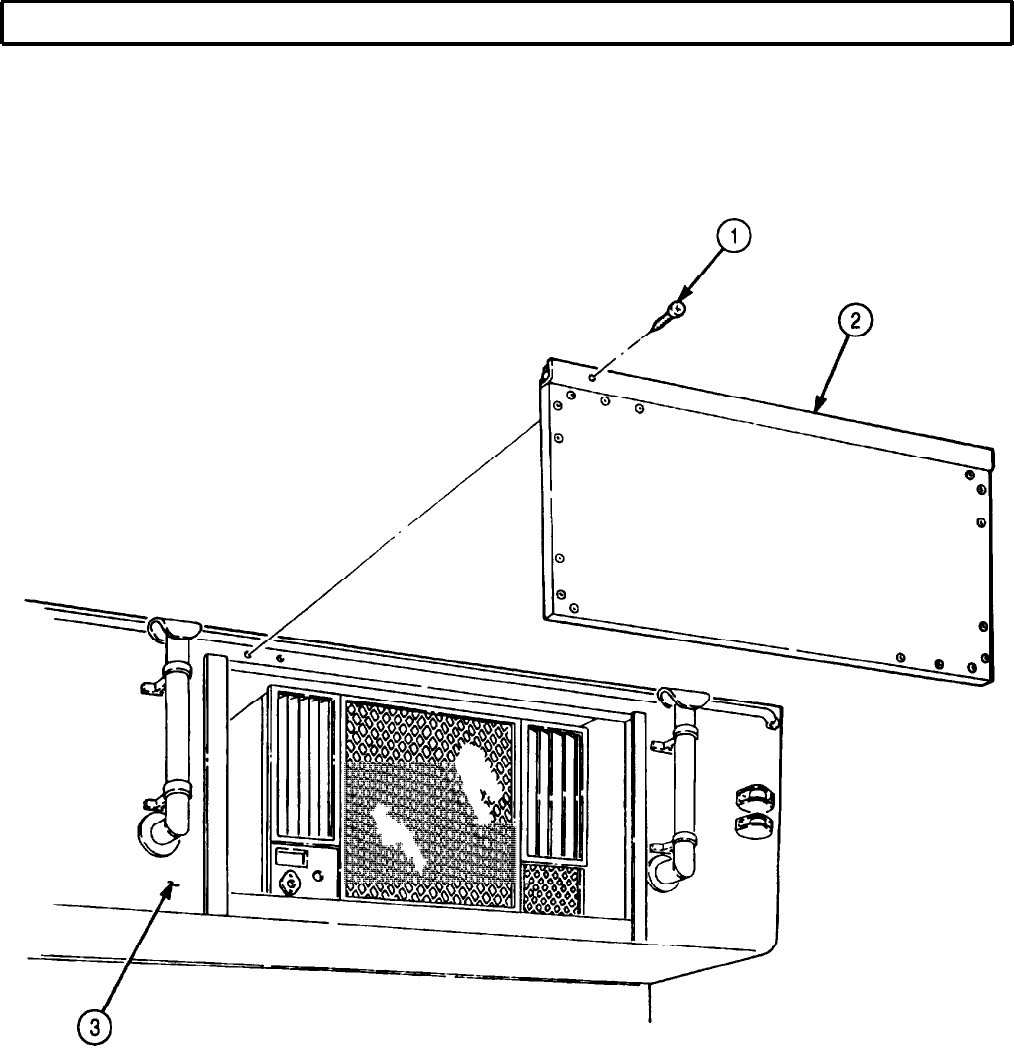
TM 9-2320-272-24-4
5-86. BONNET ACCESS DOOR MAINTENANCE (Contd)
FOLLOW-ON TASK: Install bonnet control rod (para. 3-361).
5-553
a. Removal
TM 9-2320-272-24-4
5-87. BONNET DOOR MAINTENANCE
THIS TASK COVERS:
a. Removal
b. Disassembly
c. Cleaning and Inspection
d. Assembly
e. Installation
INITIAL SETUP:
APPLICABLE MODELS
M934/A1/A2
TOOLS
General mechanic’s tool kit (Appendix E, Item 1)
Rivet gun
MATERIALS/PARTS
Channel seals (as required) (Appendix D,
Item 623)
Forty-eight rivets (Appendix D, Item 547)
Fifty-two rivets (Appendix D, Item 551)
Seal, 78 in. (Appendix D, Item 605)
Seal, 24 in. (Appendix D, Item 605)
Seal, 27 in. (Appendix D, Item 633)
Cork (Appendix C, Item 24)
Primer (Appendix C, Item 57)
Sealing compound (Appendix C, Item 67)
REFERENCES (TM)
TM 9-2320-272-10
TM 9-2320-273-24P
EQUIPMENT CONDITION
Parking brake set (TM 9-2320-272-10).
NOTE
Left and right bonnet doors are replaced the same way. This
procedure covers the left side.
1.
Remove two screws (4) and washers (5) from bonnet door (3) and bonnet (1).
NOTE
Assistant will help with step 2.
2.
Remove seven screws (2) and bonnet door (3) from bonnet (1).
3.
Position bonnet door (3) squarely on four jack stands with outer panel facing upwards.
5-554
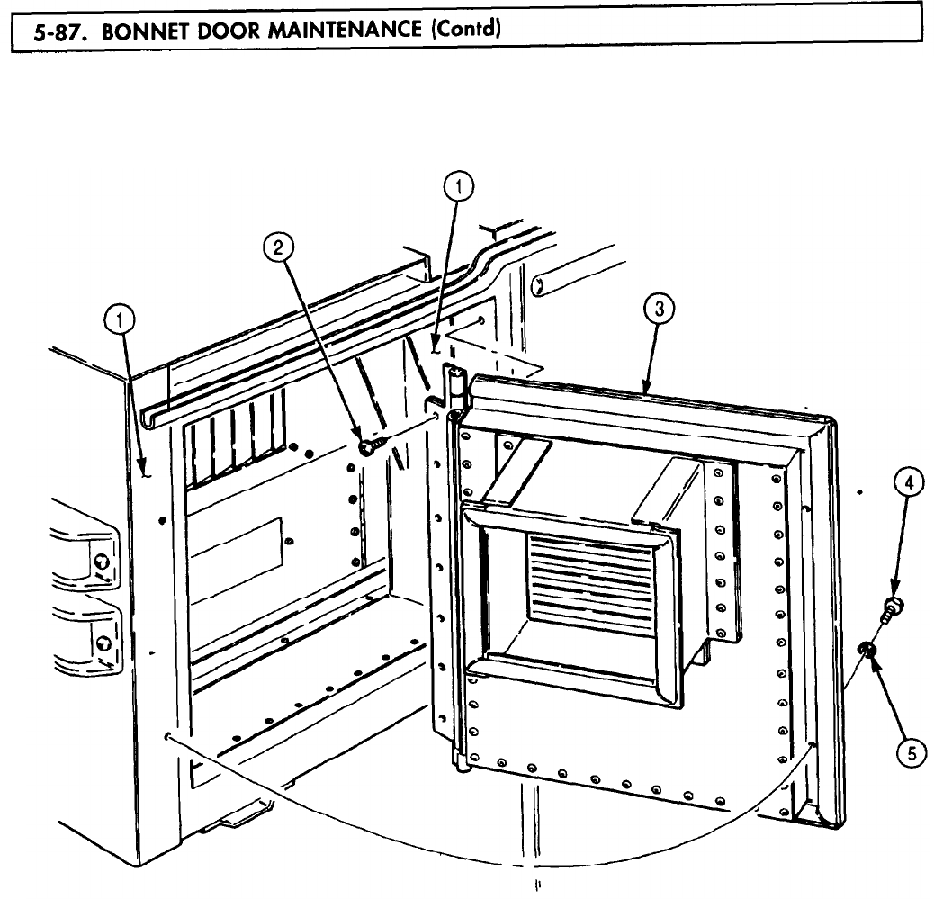
5-87. BONNET
TM 9-2320-272-24-4
5-555

5-87. BONNET
TM 9-2320-272-24-4
1.
2.
3.
4.
5.
6.
7.
8.
Remove six screws (16), spacer plate (15), seal (14), hinge (13), and seal (12) from frame (7). Discard
seals (12) and (14).
Remove eighteen nuts (28), screws (11), and two retainers (4) from outer panel (10), frame (7). and
seal (3).
NOTE
Assistant will help with step 3.
Remove seventeen rivets (9) and outer panel (10) from frame (7). Discard rivets (9).
Remove twenty-four rivets (27), intake assembly (17), intake panel (26) (if present), and preformed
cork (1) from inner panel (2). Discard rivets (27) and cork (1).
Remove fourteen rivets (21), two channels (20), channel seals (19), and channels (18) from intake
assembly (17). Discard rivets (21) and channel seals (19).
Remove ten rivets (22), two channels (23), channel seals (24), and channels (25) from intake
assembly (17). Discard rivets (22) and channel seals (24).
Remove seven nuts (5), screws (8), retainer (6), and seal (3) from frame (7). Discard seal (3).
NOTE
Assistant will help with step 9.
Remove thirty-three rivets (29), two rivets (30), and inner panel (2) from frame (7). Discard
rivets (29) and (30).
5-556

5-87. BONNET
TM 9-2320-272-24-4
5-557
5.87. BONNET
TM 9-2320-272-24-4
1.
2.
3.
4.
5.
6.
7.
8.
For general cleaning instructions, refer to para. 2-14.
Inspect hinge (9) for breaks, corrosion, and proper operation. Replace hinge (9) if damaged.
Inspect retainers (8) and (5) and spacer plate (10) for bends and breaks. Replace retainers (8)
and (5) and space plate (10) if bent or broken.
Inspect outer panel (4) and inner panel (7) for tears, cracks, and punctures. Replace outer panel (4)
and inner panel (7) if torn, cracked, or punctured.
Inspect intake assembly (11) for cracks and bends. Replace intake assembly (11) if cracked or bent.
Inspect intake panel (3) for bends and breaks. Replace intake panel (3) if bent or broken.
Inspect channels (12), (13), (1), and (2) for bends and breaks. Replace if bent or broken.
Inspect frame (6) for bends, breaks, cracks, and warpage. Replace entire bonnet door assembly if
frame (6) is damaged.
5-558

5-87. BONNET
TM 9-2320-272-24-4
5-559
5-87. BONNET
TM 9-2320-272-24-4
NOTE
l Insulate areas of dissimilar metal-to-metal contact with zinc
chromate primer.
l Apply sealing compound to exterior joints prior to installation.
l Insulate all enclosed structure with fibrous glass felt insulation.
l Assistant will help with step 1.
1.
Install inner panel (2) on frame (7) with thirty-three new rivets (29) and two new rivets (30).
2.
Install new seal (3) and retainer (6) on frame (7) with seven screws (8) and nuts (5).
3.
Install two new channel seals (24), channels (23), and channels (25) on intake assembly (17) with
ten new rivets (22).
4.
Install two new channel seals (19), channels (18), and channels (20) on intake assembly (17) with
fourteen new rivets (21).
NOTE
Assistant will help with steps 6 and 7.
5.
Install new preformed cork (1), intake panel (26) (if present), and intake assembly (17) on inner
panel (2) with twenty-four new rivets (27).
6.
Install outer panel (10) on frame (7) with seventeen new rivets (9).
7.
Install two retainers (4) in seal (3) with eighteen screws (11) and nuts (28).
8.
Install new seal (12), hinge (13), spacer plate (15), and new seal (14) on frame (7) with six screws (16).
Ensure hinge is flush with top of door.
5-560
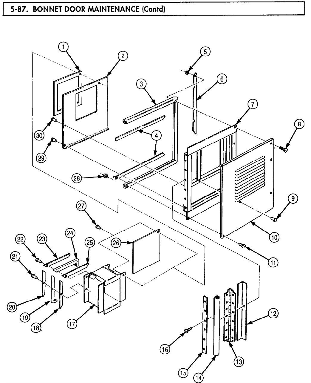
5-87. BONNET
TM 9-2320-272-24-4
5-561
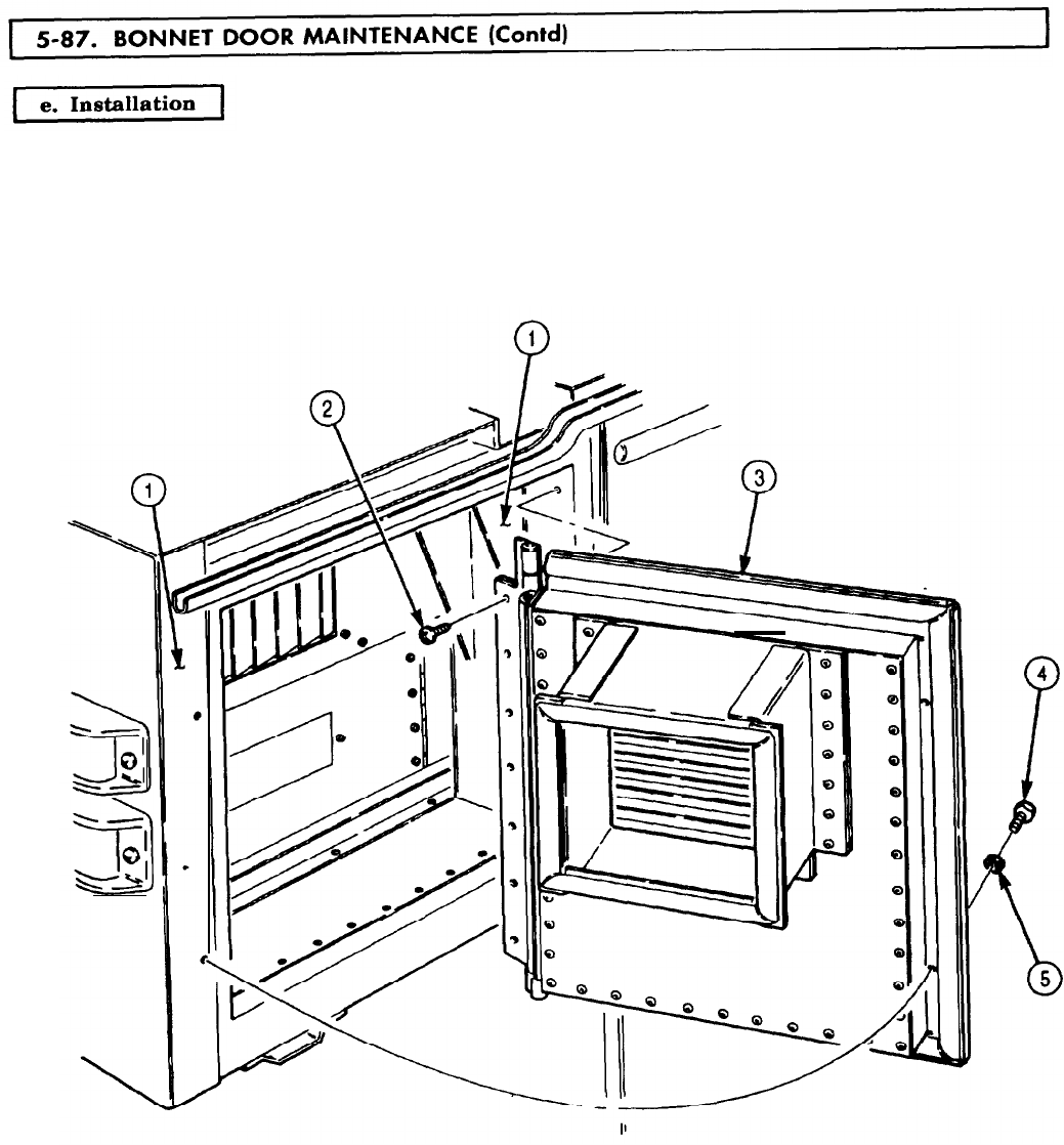
5-87. BONNET
TM 9-2320-272-24-4
NOTE
Assistant will help with step.
Install bonnet door (3) on bonnet (1) with seven screws (2), two screws (4), and washers (5).
5-562

5-88. AIR
TM 9-2320-272-24-4
THIS TASK COVERS:
a. Removal b. Installation
APPLICATION MODELS
EQUIPMENT CONDITION
M934/A1/A2
l Parking brake set (TM 9-2320-272-10).
l Cab tarpaulin and bows removed
TOOLS
(TM 9-2320-272-10).
General mechanic’s tool kit (Appendix E, Item 1)
Chain
Lifting device
l Windshield lowered (TM 9-2320-272-10).
l Companion seat lowered (TM 9-2320-272-10).
l External power source disconnected
MATERIALS/PARTS
(TM 9-2320-272-10).
Cotter pin (Appendix D, Item 57)
Two lockwashers (Appendix D, Item 418)
l Battery ground cables disconnected (para. 3-126).
l Air conditioner drain tube removed (para. 3-382).
l Bonnet door removed (para. 5-87).
REFERENCES (TM)
TM 9-2320-272-10
GENERAL SAFETY INSTRUCTIONS
All personnel must stand clear during lifting
TM 9-2320-272-24P operations.
NOTE
Screw quantity for steps 1, 2, and 4 may differ from vehicle to
vehicle. Record quantity removed for installation.
1.
Remove sixteen screws (6) and lower angle bracket (5) from lower panel mounting angle (7).
2.
Remove twelve screws (9) and lower panel mounting angle (7) from bonnet (11).
3.
Remove four screws (8) and two mounting angles (4) from bonnet (11).
4.
Remove fourteen screws (3), snap (2), and condenser guard (1) from air conditioner (10).
5-563
5-88. AIR
TM 9-2320-272-24-4
5.
Remove sixteen screws (1) and top enclosure (2) from bonnet (8) and air conditioner (7).
6.
Remove twelve screws (4) and right enclosure (3) from bonnet (8) and air conditioner (7).
7.
Remove four screws (14), plate (13), and bellows (12) from left enclosure (11).
8.
Remove ten screws (9) and left enclosure (11) from bonnet (8) and air conditioner (7).
9.
Remove cotter pin (16) and door rod (10) from swing arm (15). Discard cotter pin (16).
10.
Remove seven screws (6) and bottom enclosure (5) from bonnet (8) and air conditioner (7).
11.
Disconnect power cable (24) from air conditioner (7).
12.
Remove screw (26), ground cable (27), and lockwasher (25) from air conditioner (7). Discard
lockwasher (25).
13.
Remove screw (23), ground cable (27), and lockwasher (28) from mounting plate (18) and bonnet
floor (29). Discard lockwasher (28).
14.
Remove five screws (22) from mounting plate (18) and bonnet floor (29).
15.
Remove six screws (21) from mounting plate (17) and bonnet floor (29).
WARNING
All personnel must stand clear during lifting operations.
A snapped cable, or swinging or shifting load may result
in injury or death to personnel.
NOTE
Two assistants will help with step 16.
16.
Attach chains to lifting device and four lifting brackets (20) on air conditioner (7) and remove air
conditioner (7) from bonnet (8). Position air conditioner (7) for access to bottom of unit.
17.
Remove six screws (19) and mounting plates (17) and (18) from air conditioner (7).
1.
2.
3.
4.
5.
Two assistants will help with step 2.
Attach chains to lifting device and four lifting brackets (20).
Position air conditioner (7) in bonnet (8).
Install mounting plate (17) on bonnet floor (29) with six screws (21).
Install ground cable (27) on mounting plate (18) and bonnet floor (29) with new lockwasher (28),
and screw (23).
6.
Install ground cable (27) on air conditioner (7) with new lockwasher (25), and screw (26).
7.
Install mounting plate (18) on bonnet floor (29) with five screws (22).
8.
Connect power cable (24) to air conditioner (7).
9.
Remove lifting device and chains from air conditioner (7).
Install mounting plates (17) and (18) on air conditioner (7) with six screws (19).
WARNING
All personnel must stand clear during lifting operations.
A snapped cable, or swinging or shifting load may result
in injury or death to personnel.
NOTE
5-564

5-88. AIR
TM 9-2320-272-24-4
5-565
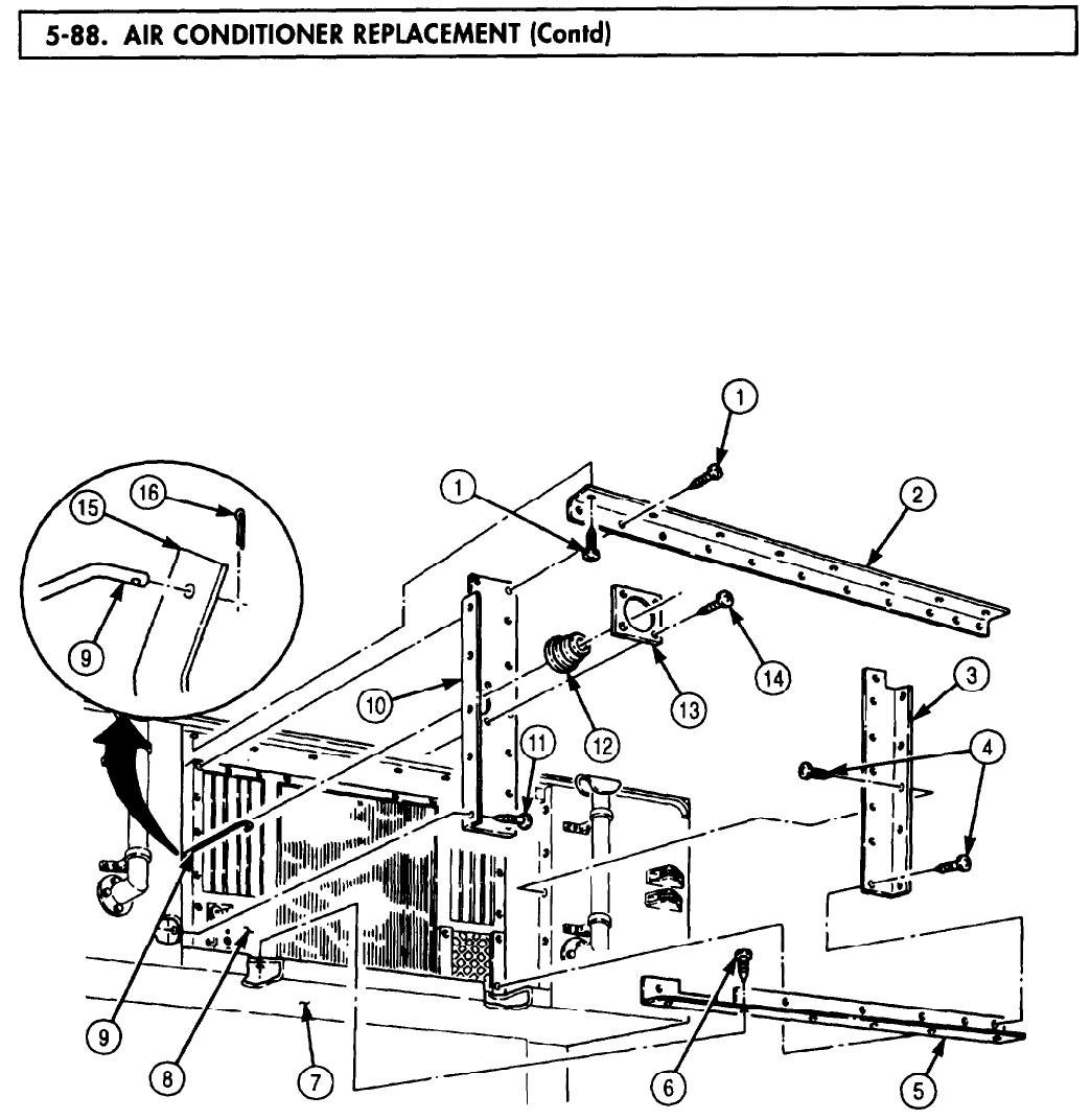
5-88. AIR
TM 9-2320-272-24-4
10.
Install bottom enclosure (5) on bonnet (7) and air conditioner (8) with seven screws (6).
11.
Install door rod (9) on swing arm (15) with new cotter pin (16).
12.
Install left enclosure (10) on bonnet (7) and air conditioner (8) with ten screws (11). Ensure door
rod (9) is positioned through bellows (12).
13.
Install bellows (12) on left enclosure (10) with plate (13) and four screws (14).
14.
Install right enclosure (3) on bonnet (7) and air conditioner (8) with twelve screws (4).
15.
Install top enclosure (2) on bonnet (7) and air conditioner (8) with sixteen screws (1).
5-566
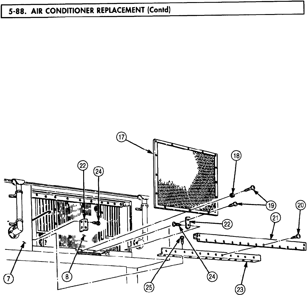
5-88. AIR
TM 9-2320-272-24-4
NOTE
Screw quantity for steps 16, 18, and 19 may differ from vehicle to
vehicle. Install screws as recorded.
16.
Install condenser guard (17) on air conditioner (8) with snap (18) and fourteen screws (19).
17.
Install two mounting angles (22) on bonnet (7) with four screws (24).
18.
Install lower panel mounting angle (23) on bonnet (7) with twelve screws (25).
19.
Install lower angle bracket (21) on bonnet (7) and two mounting angles (22) with sixteen screws (20).
FOLLOW-ON TASKS: l Install bonnet door (para. 5-87).
l Install air conditioner drain tube (para. 3-382).
l Connect battery ground cables (para. 3-126).
l Connect external power source (TM 9-2320-272-10).
l Raise companion seat (TM 9-2320-272-10).
l Raise windshield (TM 9-2320-272-10).
l Install cab tarpaulin and bows (TM 9-2320-272-10).
5-567
5-89. MAIN
TM 9-2320-272-24-4
THIS TASK COVERS:
a. Removal b. Installation
INITIAL SETUP:
APPLICABLE MODELS
M934/A1/A2
EQUIPMENT CONDITION
TOOLS
General mechanic’s tool kit (Appendix E, Item 1)
REFERENCES (TM)
TM 9-2320-272-10
TM 9-2320-272-24P
l Parking brake set (TM 9-2320-272-10).
l Battery ground cables disconnected (para 3-126).
l Fluorescent light tubes removed (para 3-371).
l Emergency/blackout lamp and light removed
(para 3-372).
l Blackout light switch and 110-volt receptacle
removed (para 3-373).
NOTE
l The left and right main wiring harnesses are replaced the same
way. This procedure covers the right main wiring harness.
l Tag wires for installation.
1.
Remove six screws (1) and cover (2) from load center (8).
2.
Remove three setscrews (9) and wires (3) from relay (10).
3.
Remove setscrew (15) and wire (16) from neutral bus (11).
4.
Remove three screws (13) and five wires (14) from 20 amp circuit breakers (12).
5.
Remove screw (4) and clamp (5) from plate (7) and wiring harnesses (6).
6.
Remove twelve screws (22) and clamps (21) from van ceiling (18) and main wiring harness (20).
7.
Remove grommet (23) from van side panel (17).
8.
Remove three screws (25) and wire clip (24) from van side panel (17).
9.
Remove main wiring harness (20) from van body (19).
1.
Position main wiring harness (20) on van body (19).
2.
Install wire clip (24) on side panel (17) of van body (19) with three screws (25).
3.
Install grommet (23) on side panel (17).
4.
Install twelve clamps (21) on main wiring harness (20) and van ceiling (18) with twelve screws (22).
5.
Install clamp (5) on harnesses (6) and plate (7) with screw (4).
6.
Install five wires (14) on 20 amp circuit breakers (12) with three screws (13).
7.
Install wire (16) on neutral bus (11) with setscrew (15).
8.
Install three wires (3) on relay (10) with three setscrews (9).
9.
Install cover (2) on load center (8) with six screws (1).
5-568
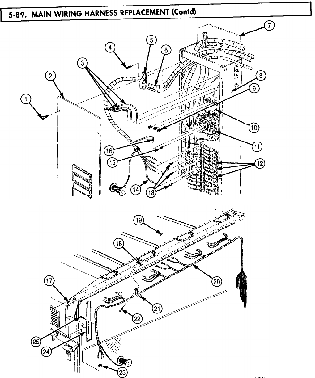
TM 9-2320-272-24-4
FOLLOW-ON TASKS: lInstall blackout light switch and 110-volt receptacle (para. 3-373
l
Install emergency/blackout lamp and light (para. 3-372).
l
Install fluorescent light tubes (para. 3-371).
l
Connect battery ground cables (para. 3-126).
5-569
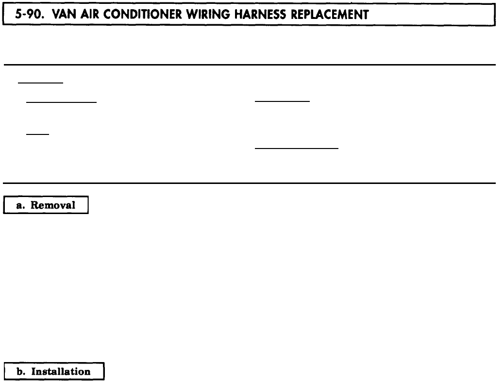
5-90. VAN
TM 9-2320-272-24-4
THIS TASK COVERS:
a. Removal b. Installation
INITIAL SETUP:
APPLICABLE MODEL
M934/A1/A2
REFERENCES (TM)
TM 9-2320-272-24P
TOOLS
TM 9-2320-272-24P
General mechanic’s tool kit (Appendix E, Item 1)
EQUIPMENT CONDITION
l Parking brake set (TM 9-2320-272-10)
l Battery ground cables disconnected (para. 3-126).
l Ceiling filler and side panels removed (para. 5-79).
NOTE
Tag cables for installation.
1.
Remove twelve screws (4) and clamps (5) from wiring harness (6) and van ceiling (1).
2.
Disconnect plug (2) from air conditioner (3).
3.
Remove six screws (22) and cover (21) from load center (16).
4.
Remove screw (7) and clamp (8) from wiring harnesses (20) and (23) and plate (12).
5.
Remove nut (9), screw (15), two washers (10), cable assembly (14), ground cable (13), and wiring
harness cable (11) from load center (16).
6.
Remove three screws (19) and wiring harness cables (18) from 30 amp circuit breaker (17).
7.
Remove wiring harness (20) from load center (16).
1.
Position wiring harness (20) on load center (16).
2.
Install three wiring harness cables (18) on 30 amp circuit breaker (17) with three screws (19).
3.
Install wiring harness cable (11), ground cable (13), and cable assembly (14) on load center (16) with
screw (15), two washers (10), and nut (9).
4.
Install clamp (8) on wiring harnesses (23) and (20) and plate (12) with screw (7).
5.
Install cover (21) on load center (16) with six screws (22).
6.
Connect plug (2) to air conditioner (3).
7.
Install twelve clamps (5) on wiring harness (6) and van ceiling (1) with twelve screws (4).
5-570
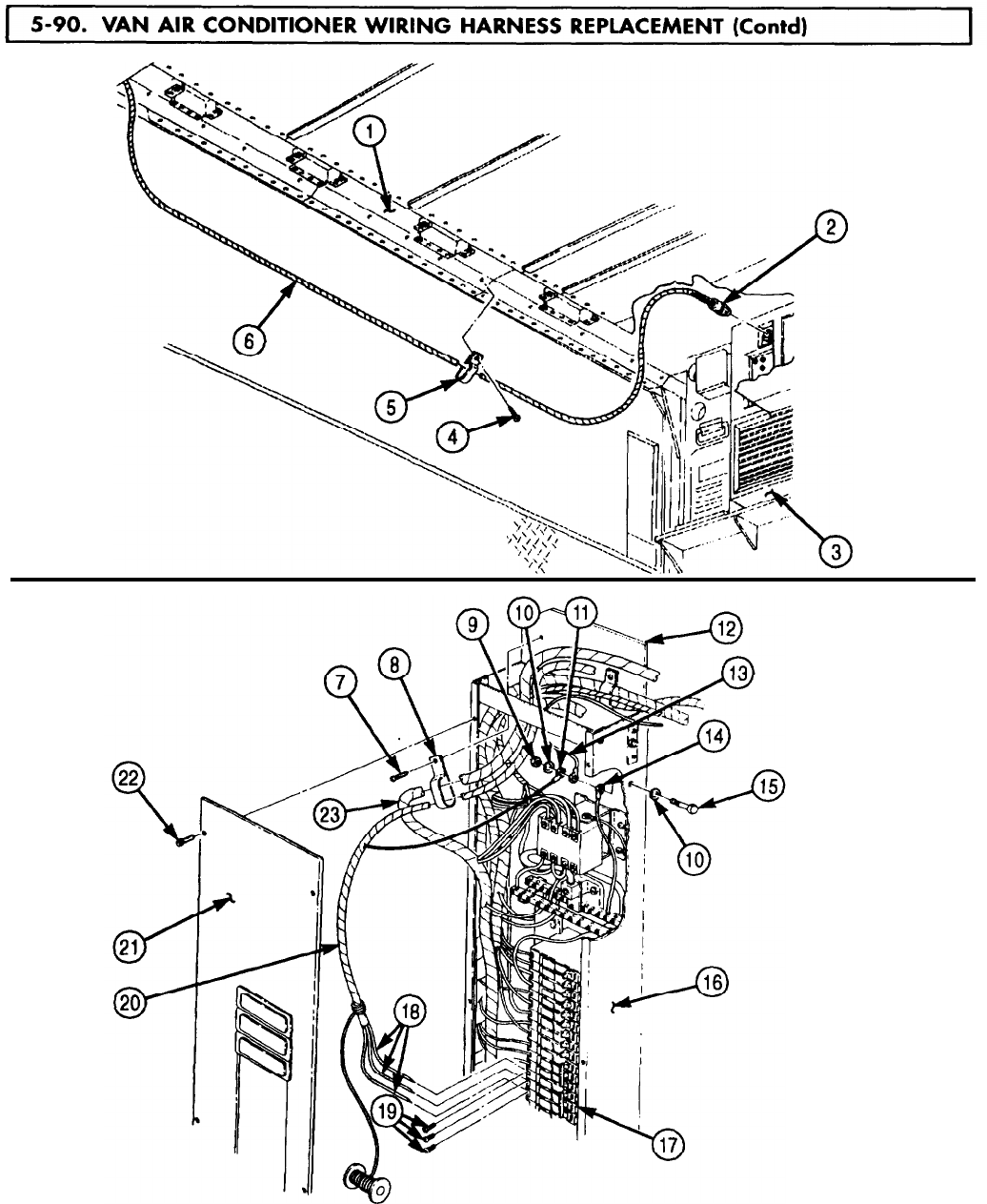
5-91. VAN
TM 9-2320-272-24-4
THIS TASK COVERS:
a. Removal b. Installation
INITIAL SETUP:
APPLICABLE MODELS
EQUIPMENT CONDITION
M934/A1/A2
TOOLS
General mechanic’s tool kit (Appendix E, Item 1)
REFERENCES (TM)
TM 9-2320-272-10
TM 9-2320-272-24P
l Parking brake set (TM 9-2320-272-10)
l Battery ground cables disconnected (para. 3-126).
l Ceiling filler and side panels removed (para. 5-79).
NOTE
Tag wires for installation.
1.
Remove twelve screws (6) and clamps (7) from van ceiling (1) and wiring harness (5).
2.
Remove two grommets (3) from van ceiling (1) and wiring harness (5).
3.
Disconnect two plugs (2) from heater (4).
5-572
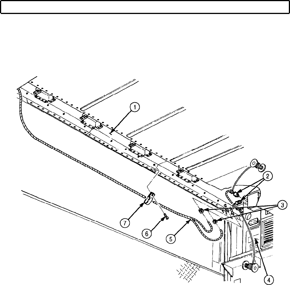
TM 9-2320-272-24-4
5-91. VAN HEATER WIRING HARNESS REPLACEMENT (Contd)
5-573

TM 9-2320-272-24-4
5-91. VAN HEATER WIRING HARNESS REPLACEMENT (Contd)
4.
Remove thermostat cover (5) from thermostat (6).
5.
Remove four screws (4) and thermostat (6) from control center box (9).
6.
Remove two screws (2) and wires (3) from control center box (9).
7.
Remove four screws (7) and upper cover (1) from control center box (9).
8.
Remove six screws (17) and cover (16) from load center (12).
9.
Remove screw (10) and clamp (11) from wiring harnesses (18).
10.
Remove setscrew (14), screw (13), and two wires (15) from load center (12).
11.
Remove wiring harnesses (18) from van body (8).
b. Installation
1.
Position wiring harness (18) on van body (8) and install two wires (15) on load center (12) with
screw (13) and setscrew (14).
2.
Place clamp (11) on wiring harnesses (18) and install on load center (12) with screw (10).
3.
Install cover (16) on load center (12) with six screws (17).
4.
Install upper cover (1) on center control box (9) with four screws (7).
5.
Install two wires (3) on thermostat (6) with two screws (2).
6.
Install thermostat (6) on upper cover (1) with two screws (4).
7.
Install thermostat cover (5) on thermostat (6).
5-574
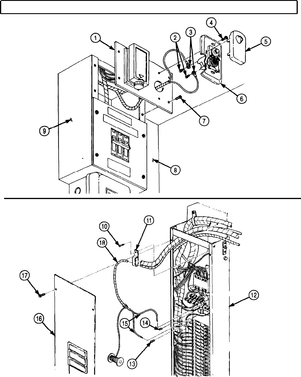
TM 9-2320-272-24-4
5-91. VAN HEATER WIRING HARNESS REPLACEMENT (Contd)
5-575

TM 9-2320-272-24-4
5-91. VAN HEATER WIRING HARNESS REPLACEMENT (Contd)
8.
Connect two plugs (2) to heater (4).
9.
Install two grommets (3) on wiring harness (5) and van ceiling (1).
10.
Install twelve clamps (7) on wiring harness (5) and van ceiling (1) with twelve screws (6).
5-576
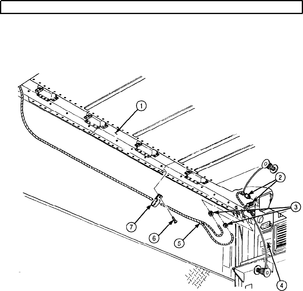

TM 9-2320-272-24-4
5-92. ELECTRIC HEATER (10 KW) WIRING HARNESS REPLACEMENT
THIS TASK COVERS:
a. Removal b. Installation
INITIAL SETUP:
APPLICABLE MODELS REFERENCES (TM)
M934/A1/A2
TM 9-2320-272-10
TOOLS
TM 9-2320-272-24P
General mechanic’s tool kit (Appendix E, Item 1)
EQUIPMENT CONDITION
Electrical tool kit (Appendix E, Item 40) l Parking brake set (TM 9-2320-272-10).
l Battery ground cables disconnected (para. 3-126).
l Ceiling filter and side panels removed (para. 5-79).
a. Removal
NOTE
Tag wires for installation.
1.
Remove twelve screws (28) and clamps (27) from van ceiling (25) and wiring harness (26).
2.
Remove grommet (24) from van ceiling (25) and wiring harness (26).
3.
Remove wires (29) and (23) from heater (30).
4.
Remove thermostat cover (4) from thermostat (5).
5.
Remove two screws (3) and thermostat (5) from upper cover (7).
6.
Remove three insulated wire splicers (6) from wiring harness (8) and thermostat leads (2). Discard
insulated wire splicers (6).
7.
Remove four screws (1) and upper cover (7) from control center box (10).
8.
Remove six screws (22) and cover (11) from load center (15).
9.
Remove screw (12), clamp (13), and wiring harnesses (21) and (8) from load center (15).
10.
Remove screw (20) and wire (19) from neutral bus (14).
11.
Remove three screws (17) and wires (18) from 20 amp circuit breakers (16).
12.
Remove wiring harness (8) from van body (9).
b. Installation
1.
Position wiring harness (8) on van body (9).
2.
Install three wires (18) on 20 amp circuit breakers (16) with three screws (17).
3.
Install wire (19) on neutral bus (14) with screw (20).
4.
Install clamp (13) on wiring harnesses (8) and (21) and load center (15) with screw (12).
5.
Install cover (11) on load center (15) with six screws (22).
6.
Install upper cover (7) on control center box (10) with four screws (1).
7.
Connect thermostat leads (2) to wiring harness (8) with three new insulated wire splicers (6).
8.
Install thermostat (5) on upper cover (7) with two screws (3).
9.
Install thermostat cover (4) on thermostat (5).
10.
Install wires (23) and (29) on heater (30).
5-578

TM 9-2320-272-24-4
5-92. ELECTRIC HEATER (10 KW) WIRING HARNESS REPLACEMENT (Contd)
11.
Install grommet (24) on wiring harness (26) and van ceiling (25).
12.
Install twelve clamps (27) on wiring harness (26) and van ceiling (25) with twelve screws (28).
FOLLOW-ON TASKS: l Install ceiling filler and side panels (para. 5-79).
l Connect battery ground cables (para. 3-126).
5-579
TM 9-2320-272-24-4
5-93. BLACKOUT BYPASS WIRING HARNESS MAINTENANCE
THIS TASK COVERS:
a. Removal
b. Repair c. Installation
INITIAL SETUP:
APPLICABLE MODELS REFERENCES (TM)
M934/A1/A2
TM 9-2320-272-10
TOOLS
TM 9-2320-272-24P
General mechanic’s tool kit (Appendix E, Item 1)
EQUIPMENT CONDITION
l Parking brake set (TM 9-2320-272-10).
l Battery ground cabled disconnected (para. 3-126)
a. Removal
NOTE
Tag wires for installation
1.
Remove six screws (1) and cover (2) from load center (6).
2.
Remove two setscrews (10) and wires (3) from 3-pole circuit breaker (5).
3.
Remove screw (8) and wire (9) from 30 amp circuit breaker (7).
4.
Remove two screws (13) and cover (14) from switch (11).
5.
Remove two screws (12) and switch (11) from van body (16).
6.
Loosen three screws (15) and remove wires (3) from switch (11).
7.
Remove wiring harness (4) from van body (16).
b. Repair
For wiring harness repair, refer to para. 3-131.
c. Installation
1.
Position wiring harness (4) on van body (16).
2.
Install three wires (3) on switch (11) and tighten three screws (15).
3.
Install switch (11) on van body (16) with two screws (12).
4.
Install cover (14) on switch (11) with two screws (13).
5.
Install wire (9) on 30 amp circuit breaker (7) with screw (8).
6.
Install two wires (3) on 3-pole circuit breaker (5) with two setscrews (10).
7.
Install cover (2) on load center (6) with six screws (1).
5-580
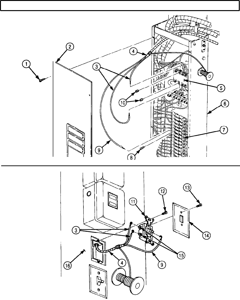
TM 9-2320-272-24-4
5-93. BLACKOUT BYPASS WIRING HARNESS MAINTENANCE (Contd)
FOLLOW-ON TASK: Connect battery ground cables (para. 3-126).
5-581
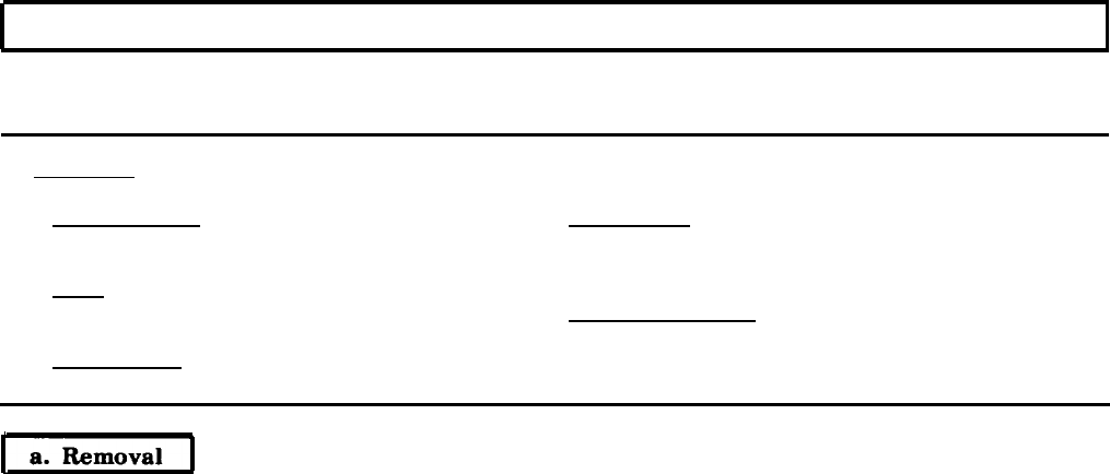
TM 9-2320-272-24-4
5-94. EMERGENCY LAMP WIRING HARNESS REPLACEMENT
THIS TASK COVERS:
a. Removal b. Installation
INITIAL SETUP:
APPLICABLE MODELS
M934/A1/A2
TOOLS
General mechanic’s tool kit (Appendix E, Item 1)
MATERIALS/PARTS
REFERENCES (TM)
TM 9-2320-272-10
TM 9-2320-272-24P
EQUIPMENT CONDITION
l Parking brake set (TM 9-2320-272-10).
l Battery ground cables disconnected (para. 3-126).
l Ceiling filter and side panels removed (para. 5-79).Locknut (Appendix D, Item 294)
1.
Remove twelve screws (16) and clamps (15) from van ceiling (13) and wiring harness (14).
2.
Remove two screws (6) and cover (5) from switch (8).
3.
Remove two screws (7) and switch (8) from switch box (10).
4.
Disconnect two wires (4) and wire (9) from switch (8).
5.
Remove four screws (3) and box (10) from van wall (2).
6.
Remove grommet (1) from switch box (10).
7.
Disconnect emergency lamp wiring harness lead (11) from emergency lamp wiring harness lead (12).
8.
Remove twelve screws (16) and clamps (15) from wiring harness (17) in van ceiling (13).
9.
Remove grommet (18) and wiring harness (17) from van ceiling (13).
NOTE
Tag wires for installation.
5-582
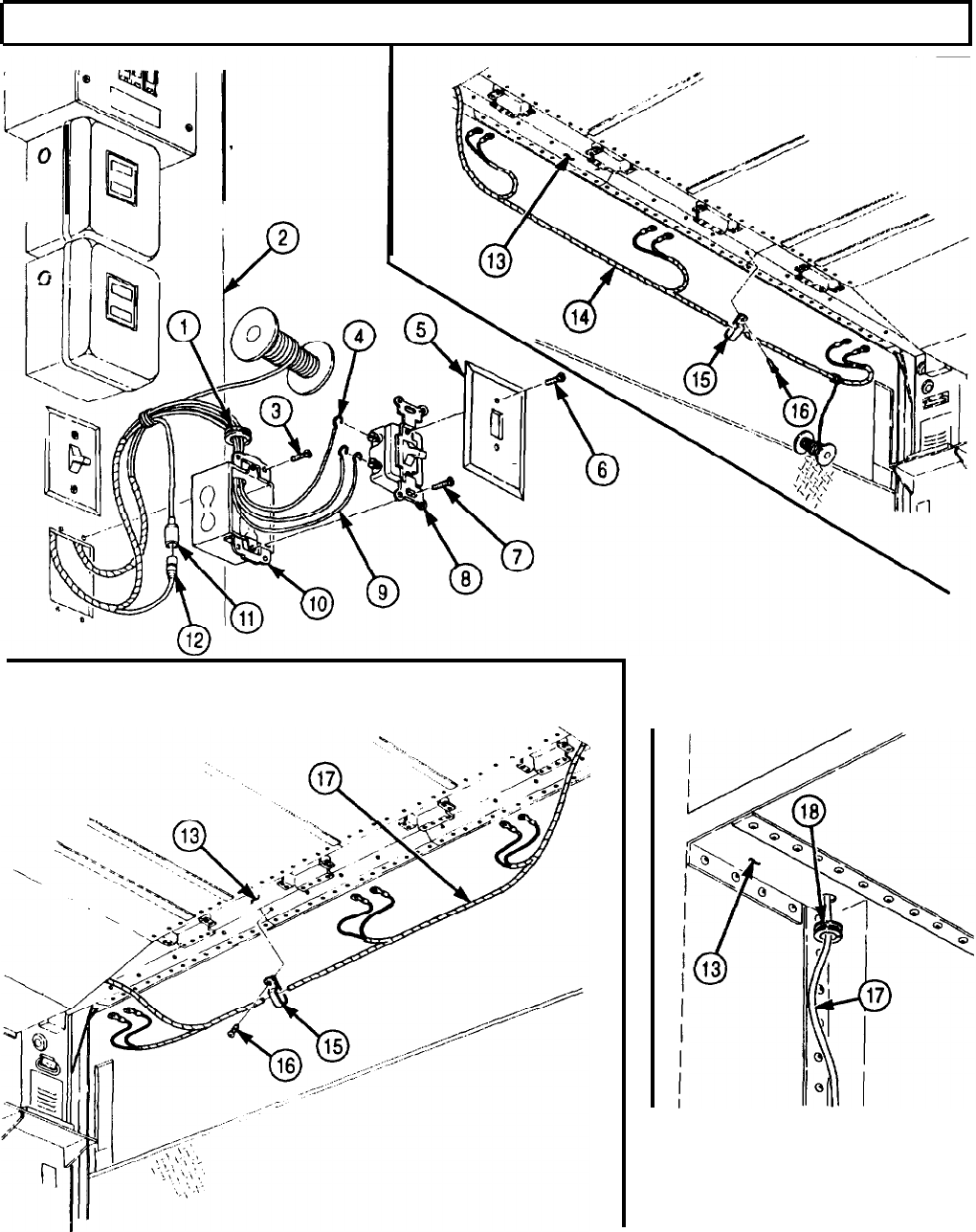
TM 9-2320-272-24-4
5-94. EMERGENCY LAMP WIRING HARNESS REPLACEMENT (Contd)
5-583

TM 9-2320-272-24-4
5-94. EMERGENCY LAMP WIRING HARNESS REPLACEMENT (Contd)
10.
Disconnect lead (2) from circuit breaker (1).
11.
Remove two screws (5) and clamps (4) from wiring harness (3) and van body (12).
12.
Remove two screws (11) and clamps (6) from wiring harness (3) and van body (12).
13.
Remove locknut (8), screw (10), clamp (9), and wiring harness (3) from spare tire carrier bracket (7).
Discard locknut (8).
14.
Remove nut (13) and wire (15) from positive battery terminal (14).
b. Installation
1.
Install wire (15) on positive battery terminal (14) with nut (13).
2.
Install wiring harness (3) on spare tire carrier bracket (7) with clamp (9), screw (10), and new
locknut (8).
3.
Install two clamps (6) on wiring harness (3) and van body (12) with two screws (11).
4.
Install two clamps (4) on wiring harness (3) and van body (12) with two screws (5).
5.
Connect lead (2) to circuit breaker (1).
5-584
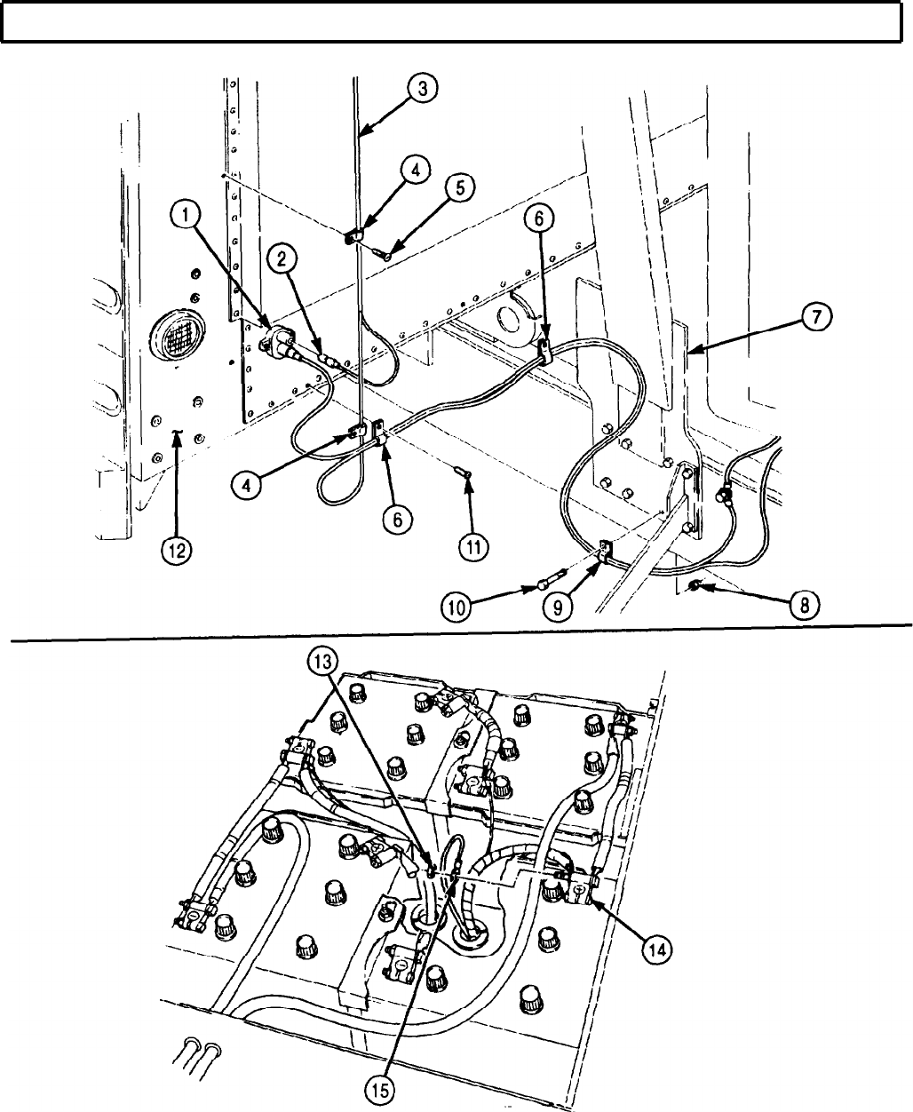
TM 9-2320-272-24-4
5-94. EMERGENCY LAMP WIRING HARNESS REPLACEMENT (Contd)
5-585
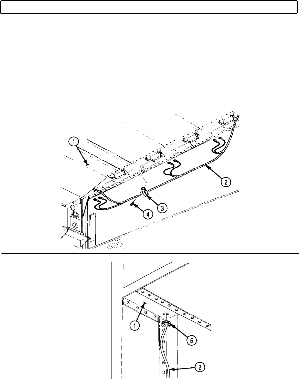
TM 9-2320-272-24-4
5-94. EMERGENCY LAMP WIRING HARNESS REPLACEMENT (Contd)
6.
7.
8.
9.
10.
11.
12.
13.
14.
Install grommet (5) on van ceiling (1) and wiring harness (2).
Install twelve clamps (3) on van ceiling (1) and wiring harness (2) with twelve screws (4).
Connect emergency lamp wiring harness (14) to emergency lamp wiring harness lead (15).
Install grommet (17) on switch box (13).
Install two cables (7) and cable (12) on switch (11).
Install switch box (13) on van wall (6) with four screws (16).
Install switch (11) on switch box (13) with two screws (10).
Install cover (9) on switch (11) with two screws (8).
Install emergency lamp wiring harness (18) on van ceiling (1) with twelve clamps (19) and screws (20).
5-586
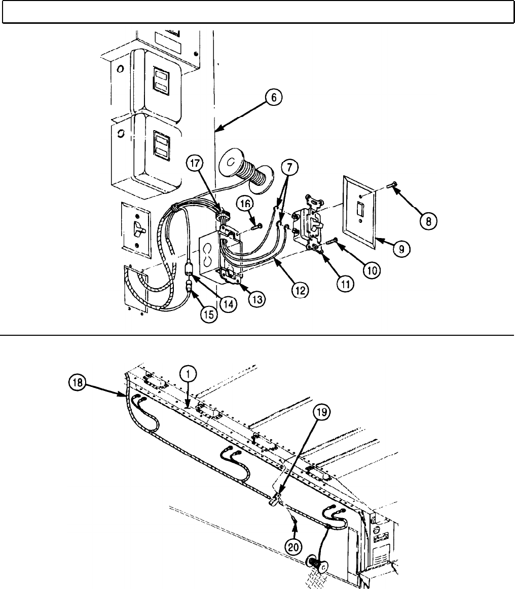
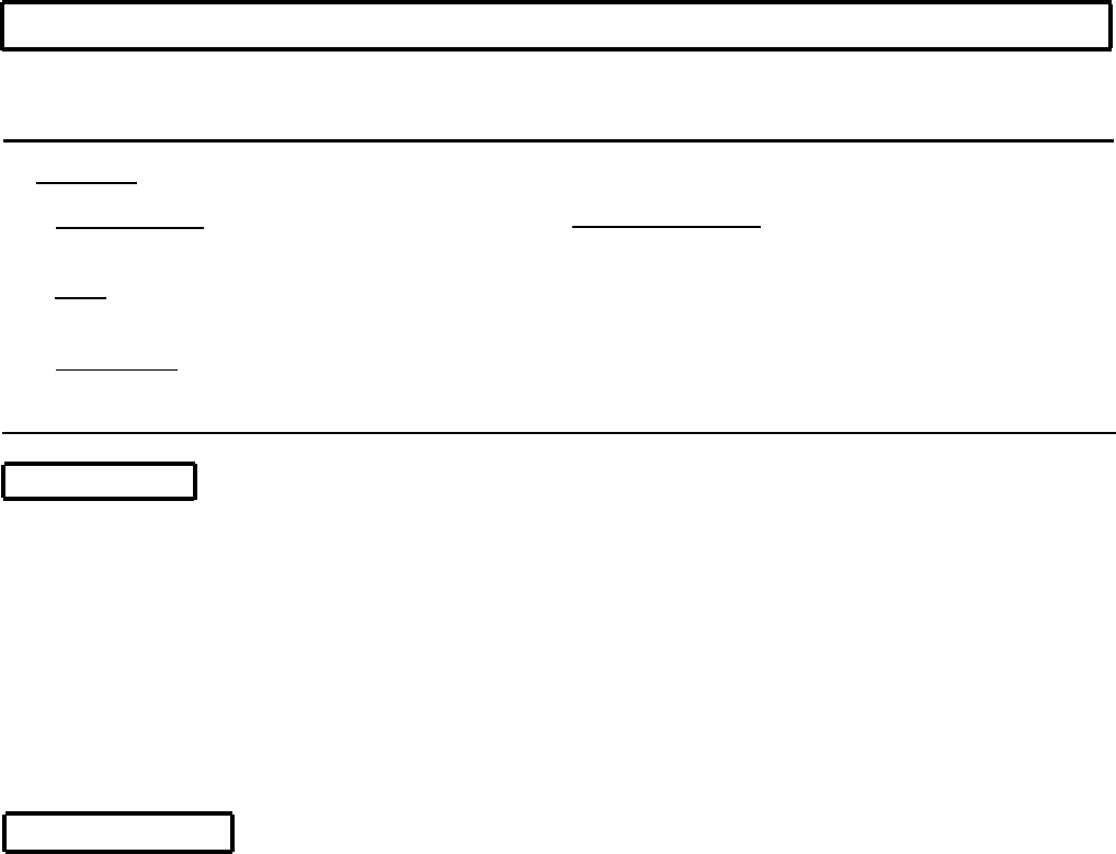
TM 9-2320-272-24-4
5-95. BLACKOUT AND CLEARANCE LIGHTS WIRING HARNESS REPLACEMENT
THIS TASK COVERS:
a. Removal b. Installation
INITIAL SETUP:
APPLICABLE MODELS
M934/A1/A2
TOOLS
EQUIPMENT CONDITION
l Parking brake set (TM 9-2320-272-10X
l Main power switch off (TM 9-2320-272-10).
l Clearance and blackout marker lights removed
General mechanic’s tool kit (Appendix E, Item 1) (para. 4-166).
REFERENCES (TM)
l Rear wall interior panels removed (para. 5-74).
l Ceiling filler and side panels removed (para. 5-79).
l Ceiling air ducts removed (para. 5-81).
l Battery ground cables disconnected (para. 3-126).
TM 9-2320-272- 10
TM 9-2320-272-24P
a. Removal
NOTE
Tag wires for installation.
1.
Remove grommet (2) from van body (3) and wiring harness (1).
2.
Remove two screws (6) and clamps (7) from van body (3) and wiring harness (1).
3.
Disconnect two wiring harness connectors (4) from rear wiring harness connectors (5).
4.
Remove twelve screws (11) and clamps (12) from van ceiling (13) and wiring harness (1).
5.
Remove five screws (10) and clamps (9) from van ceiling (13) and wiring harness (1).
6.
Remove four grommets (8) from van ceiling (13) and wiring harness (1).
7.
Remove wiring harness (1) from van body (14).
b. Installation
1.
Position wiring harness (1) on van body (14) and install four grommets (8) on van ceiling (13) and
wiring harness (1).
2.
Install five clamps (9) on van ceiling (13) and wiring harness (1) with five screws (10).
3.
Install twelve clamps (12) on van ceiling (13) and wiring harness (1) with twelve screws (11).
4.
Connect two wiring harness connectors (4) to rear wiring harness connectors (5).
5.
Install two clamps (7) on wiring harness (1) and van body (3) with two screws (6).
6.
Install grommet (2) on wiring harness (1) and van body (3).
5-588
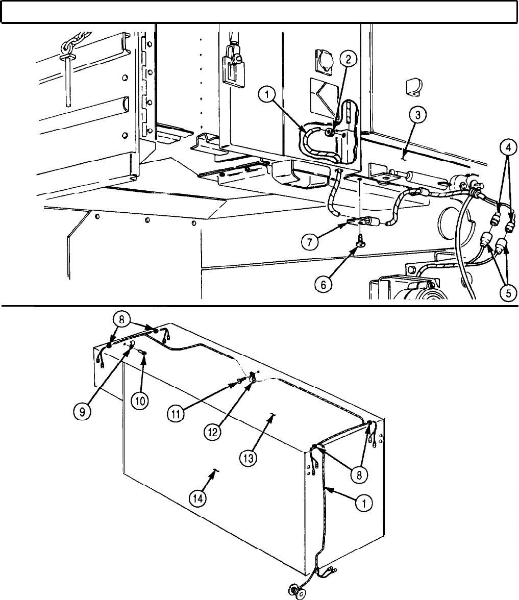
TM 9-2320-272-24-4
5-95. BLACKOUT AND CLEARANCE LIGHTS WIRING HARNESS REPLACEMENT (Contd)
FOLLOW-ON TASKS: l Install ceiling air ducts (para. 5-81).
l Install ceiling filler and side panels (para. 5-79).
l Install clearance and blackout marker lights (para. 4-166).
l Install rear wall interior panels (para. 5-74).
l Connect battery ground cables (para. 3-126).
l Main power switch on (TM 9-2320-272-10).
5-589

TM 9-2320-272-24-4
5-96. 400 HZ SUPPLY WIRING HARNESS REPLACEMENT
THIS TASK COVERS:
a. Removal b. Installation
INITIAL SETUP:
APPLICABLE MODELS REFERENCES (TM)
M934/A1/A2
TM 9-2320-272-10
TOOLS
TM 9-2320-272-24P
General mechanic’s tool kit (Appendix E, Item 1)
EQUIPMENT CONDITION
MATERIALS/PARTS
l Parking brake set (TM 9-2320-272-10).
Sealing compound (Appendix C, Item 62)
l Battery ground cables disconnected (para. 3-126).
l Ceiling filter and side panels removed (para. 5-79).
a. Removal
NOTE
Tag wires for installation.
1.
Remove four screws (1) and upper cover (2) from control center box (10).
2.
Remove four screws (5) and lower cover (4) from control center box (10).
3.
Remove screw (11) and wire (8) from terminal (9).
4.
Remove three screws (3) and wires (7) from circuit breaker (6).
5-590
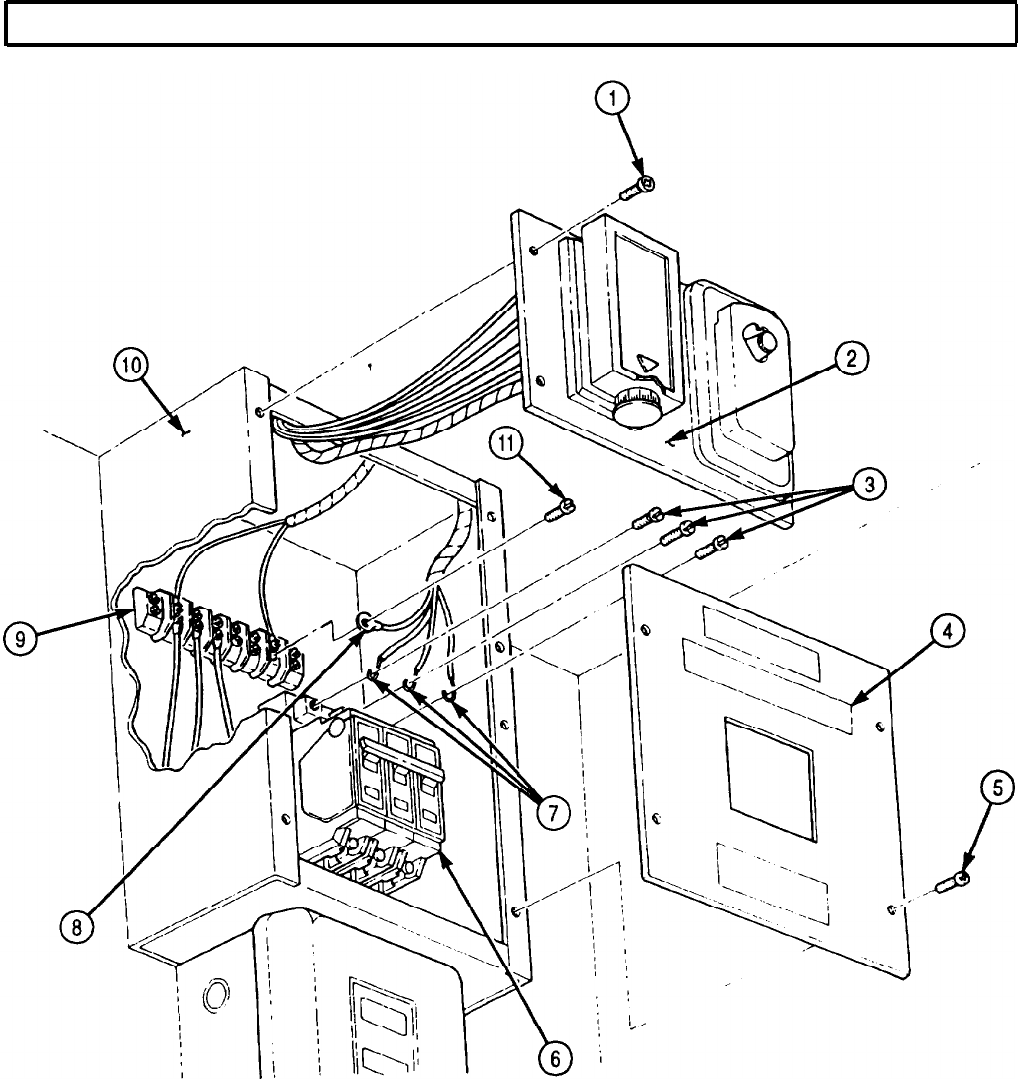
TM 9-2320-272-24-4
5-96. 400 HZ SUPPLY WIRING HARNESS REPLACEMENT (Contd)
5-591

TM 9-2320-272-24-4
5-96. 400 HZ SUPPLY WIRING HARNESS REPLACEMENT (Contd)
5.
Disconnect cables (13) and (12) from connectors (14) and (10).
6.
Remove eight screws (11) and electrical connector box cover (15) from electrical connector box (16).
7.
Disconnect four wires (7) from connector (14).
8.
Remove six screws (9) and cover (1) from load center (5).
9.
Remove screw (2) and clamp (3) from harnesses (4) and (8) and load center (5).
10.
Pull wiring harness (8) out of coupling (6) and remove from load center (5) and electrical connector
box (16).
b. Installation
6.
Connect cables (13) and (12) to connectors (10) and (14).
1.
Push wiring harness (8) through coupling (6), electrical connector box (16), and load center (5).
2.
Connect four wires (7) to connector (14).
3.
Install clamp (3) on harnesses (4) and (8) and load center (5) with screw (2).
4.
Install cover (1) on load center (5) with six screws (9).
5.
Apply sealing compound to screws (11) and install electrical connector box cover (15) on electrical
connector box (16) with eight screws (11).
5-592
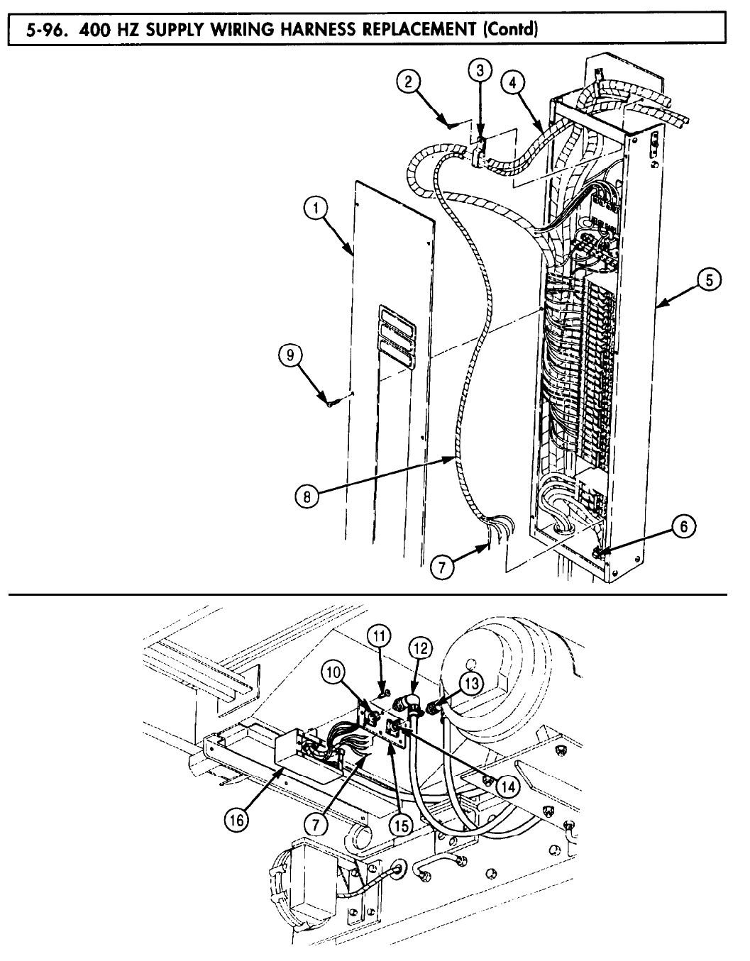
5-96. 400 HZ
TM 9-2320-272-24-4
5-593

TM 9-2320-272-24-4
7.
Install three wires (7) on circuit breaker (6) with three screws (3).
8.
Install wire (8) on terminal (9) with screw (11).
9.
Install lower cover (4) on control center box (10) with four screws (5).
10.
Install upper cover (2) on control center box (10) with four screws (1).
5-594
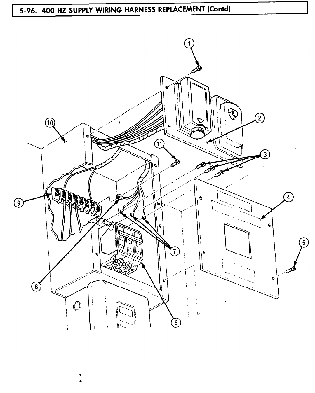
5-97. BRANCHED
TM 9-2320-272-24-4
THIS TASK COVERS:
a. Removal b. Installation
INITIAL SETUP:
APPLICABLE MODELS
EQUIPMENT CONDITION
M934/A1/A2
TOOLS
Parking brake set (TM 9-2320-272-10).
Battery ground cables disconnected (para. 3-126).
Ceiling filter and side panels removed (para. 5-79).
General mechanic’s tool kit (Appendix E, Item 1)
REFERENCES (TM)
TM 9-2320-272-10
TM 9-2320-272-24P
NOTE
Tag wires for installation.
1.
Remove four screws (1) and upper cover (2) from control center box (6).
2.
Remove two screws (3) and wires (4) from terminal (5).
3.
Remove six screws (10) and clamps (9) from branched 400 Hz receptacle harness (8) and van
ceiling (7).
1.
Install 400 Hz branched receptacle harness (8) on van ceiling (7) with six clamps (9) and screws (10).
2.
Install two wires (4) on terminal (5) with two screws (3).
3.
Install upper cover (2) on control center box (6) with four screws (1).
5-596
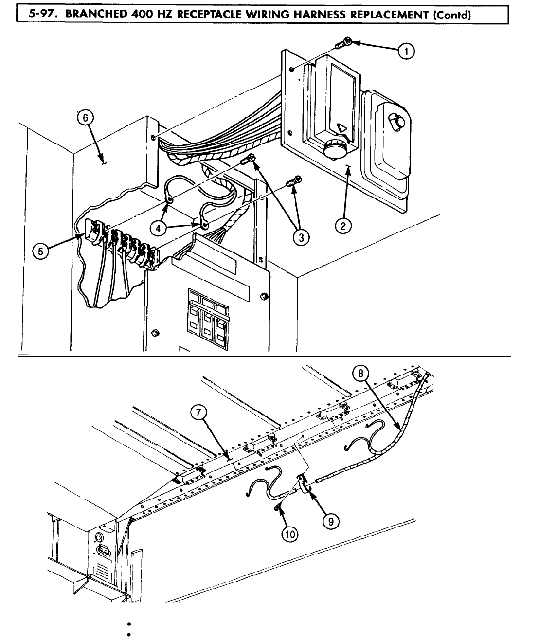
5-98. RIGHT
TM 9-2320-272-24-4
THIS TASK COVERS:
a.
Removal c. Installation
b. Repair
INITIAL SETUP:
APPLICABLE MODELS
M934/A1/A2
TOOLS
EQUIPMENT CONDITION
Parking brake set (TM 9-2320-272-10).
Van body sides fully expanded and secured
(TM 9-2320-272-10).
General mechanic’s tool kit (Appendix E, Item 1) Hinged roof-operated blackout circuit plungers
REFERENCES (TM)
removed (para. 3-377).
TM 9-2320-272-10
TM 9-2320-272-24P
NOTE
Tag wires for installation.
1.
Remove six screws (20) and cover (19) from load center (16).
2.
Remove screw (14) and wire (13) from neutral bus (15).
3.
Remove screw (10) and wire (11) from relay (12).
4.
Remove screws (5) and (9) and wires (7) and (8) from rear door blackout switch (6).
NOTE
Perform steps 5 through 7 for left and right side of van body.
5.
Remove six screws (24), cover (22), and grommet (4) from van body (26).
6.
Remove nut (21), two screws (17), and two connector halves (18) from harness (23) and cover (22).
7.
Remove nut (3), two screws (25), and two connector halves (1) from harness (23) and ceiling
truss (2) and pull harness (23) through hole in ceiling truss (2).
5-598
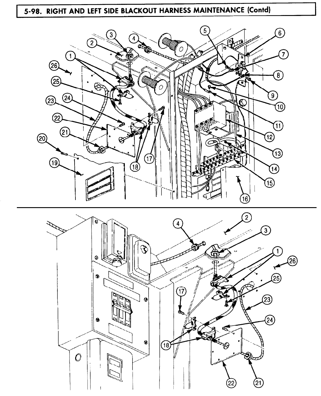
5-98. RIGHT
TM 9-2320-272-24-4
5-599
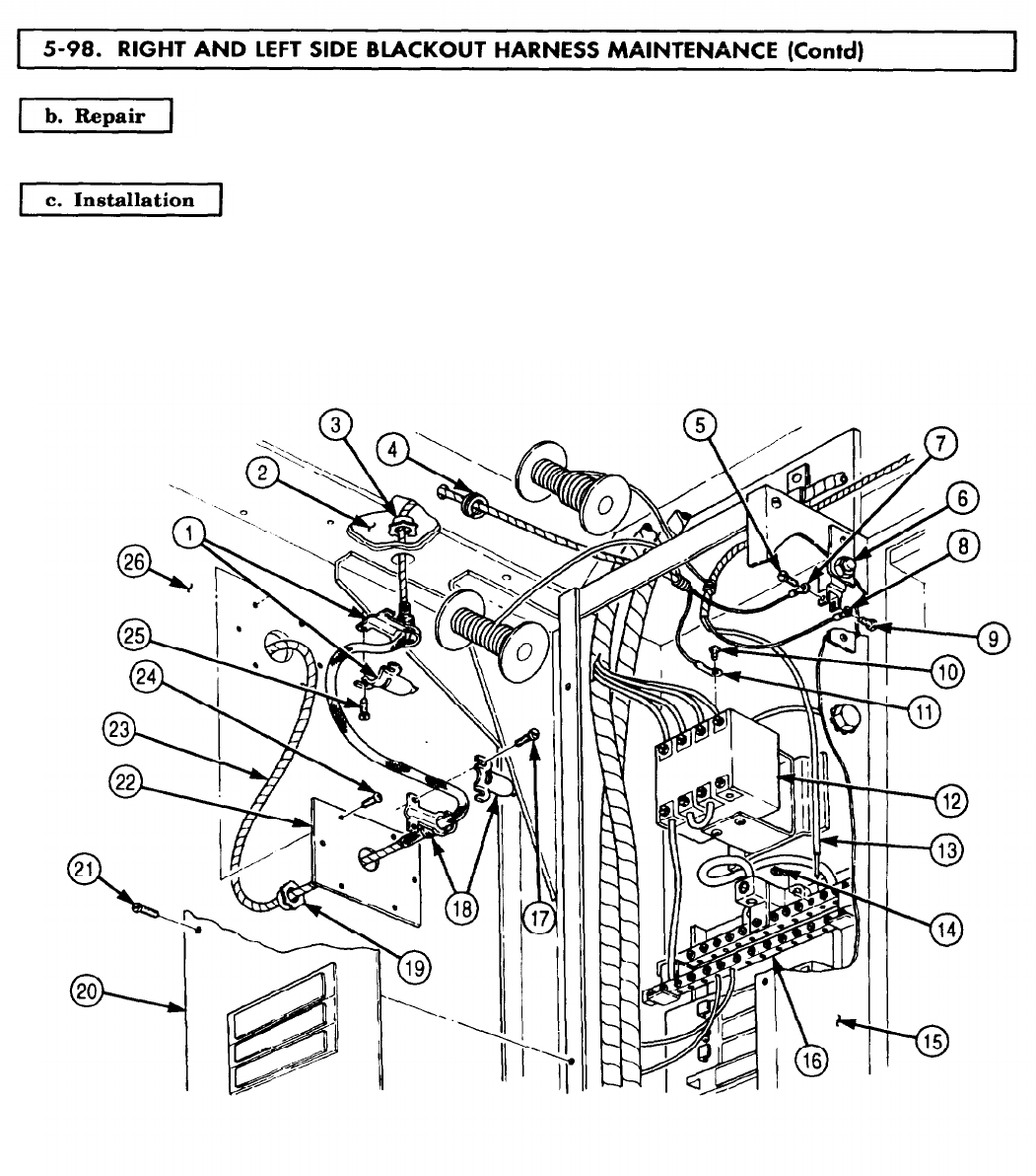
5-98. RIGHT
TM 9-2320-272-24-4
For wiring harness repair, refer to para. 3-131.
1.
Push harness (23) in through hole in ceiling truss (2) and position on load center (15).
5-600
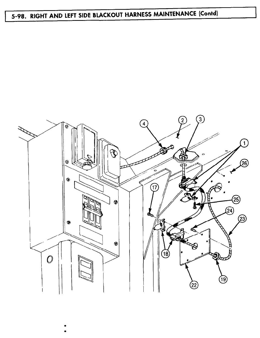
5-98. RIGHT
TM 9-2320-272-24-4
NOTE
Perform steps 2 through 5 for left and right side of van body.
2.
Install two connector halves (1) on harness (23) and ceiling truss (2) with nut (3) and two
screws (25).
3.
Install cover (22) on van body (26) with six screws (241.
4.
Install two connector halves (18) on harness (23) and cover (22) with nut (19) and two screws (17).
5.
Install grommet (4) on van body (26).
6.
Install wires (7) and (8) on rear door blackout switch (6) with screws (5) and (9).
7.
Install wire (11) on relay (12) with screw (10).
8.
Install wire (13) on neutral bus (16) with screw (14).
9.
Install cover (20) on load center (15) with six screws (21).
FOLLOW-ON TASKS:
Install hinged roof-operated blackout circuit plungers (para. 3-377).
Retract van body sides (TM 9-2320-272-10).
5-601
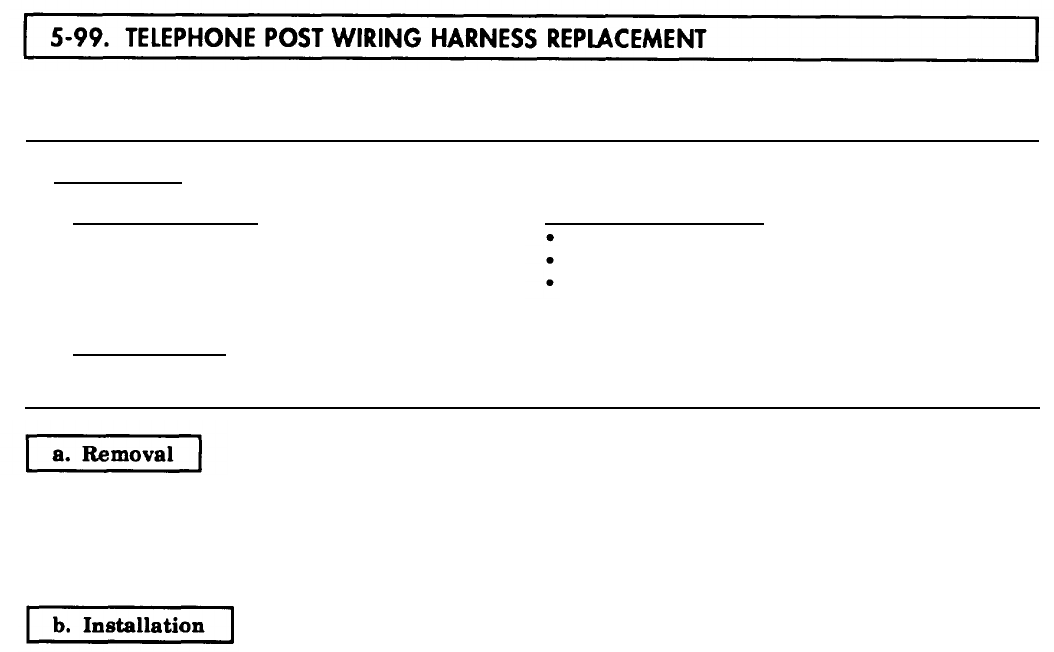
5.99 TELEPHONE
TM 9-2320-272-24-4
THIS TASK COVERS:
a. Removal b. Installation
INITIAL SETUP:
APPLICABLE MODELS EQUIPMENT CONDITIONS
M934/A1/A2
Parking brake set (TM 9-2320-272-10).
TOOLS
Inside telephone jacks removed (para. 3-374).
Gal mechanic’s tool kit (Appendix E, Item 1) Ceiling filler and side panels removed (para. 5-79).
REFERENCES (TM)
TM 9-2320-272-10
TM 9-2320-272-24P
NOTE
Tag wires for installation.
1.
Remove six screws (4) and clamps (3) from wiring harness (2) and van ceiling (1).
2.
Remove wiring harness (2) from van body (5).
1.
Install wiring harness (2) on van body (5).
2.
Install wiring harness (2) on van ceiling (1) with six clamps (3) and screws (4).
5-602
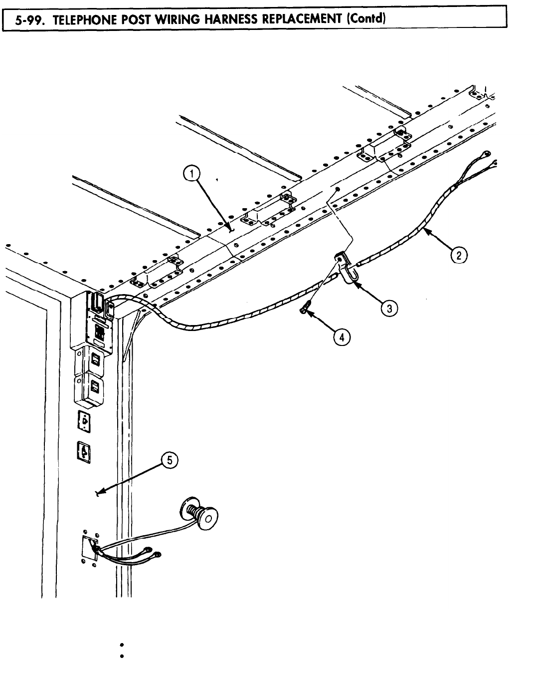
5-100. 3 PHASE
TM 9-2320-272-24-4
THIS TASK COVERS:
a. Removal b. Installation
INITIAL SETUP:
APPLICABLE MODELS
EQUIPMENT CONDITION
M934/A1/A2
Parking brake set (TM 9-2320-272-10).
TOOLS
Battery ground cables disconnected (para. 3-126).
General mechanic’s tool kit (Appendix E, Item 1) Ceiling filter and side panels removed (para. 5-79).
REFERENCES (TM)
TM 9-2320-272-10
TM 9-2320272-24P
NOTE
Tag wires for installation.
1.
Remove six screws (1) and cover (12) from load center (5).
2.
Remove screw (3) and clamp (13) from wiring harness (2) and van body (4).
3.
Remove screw (8) and wire (6) from neutral bus (7).
4.
Remove three screws (10) and wires (11) from circuit breakers (9).
5.
Remove twelve screws (16) and clamps (15) from van ceiling (14) and wiring harness (2).
6.
Remove wiring harness (2) from van body (4).
1.
Position wiring harness (2) on van body (4).
2.
Install wiring harness (2) on van ceiling (14) with twelve clamps (15) and screws (16).
3.
Install three wires (11) on circuit breakers (9) with three screws (10).
4.
Install wire (6) on neutral bus (7) with screw (8).
5.
Install clamp (13) on wiring harness (2) and van body (4) with screw (3).
6.
Install cover (12) on load center (5) with six screws (1).
5-604
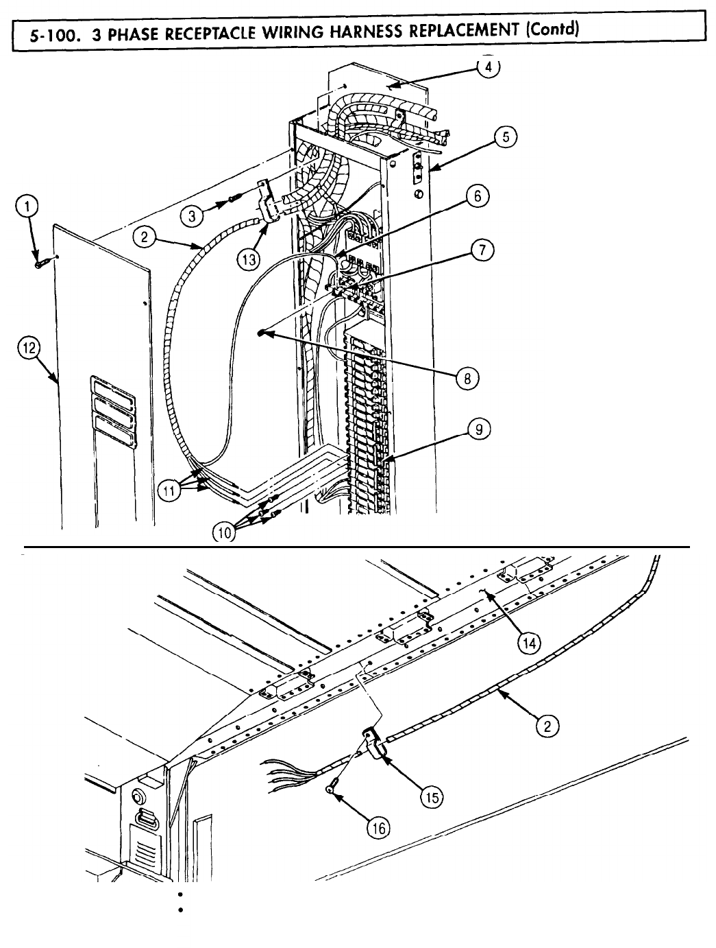
5-101. WINCH,
5-102. BOOM
TM 9-2320-272-24-4
Section VII. WINCH, HOIST, AND POWER TAKEOFF MAINTENANCE
PARA.
NO.
TITLE
PAGE
NO.
5-102.
Boom Elevating Cylinder Repair
5-606
5-103.
Boom Elevating Cylinder Packing Replacement
5-610
5-104.
Dump Roller Arm Maintenance
5-612
5-105.
Dump Hoist Cylinder Maintenance
5-614
5-106.
Boom Extension Cylinder Repair
5-626
5-107.
Crane Swinger Gearcase Repair
5-630
5-108.
Crane Control Valve Repair
5-636
THIS TASK COVERS:
a.
Disassembly c. Assembly
b.
Cleaning, Inspection, and Repair
INITIAL SETUP:
APPLICABLE MODELS
M936/A1/A2
SPECIAL TOOLS
Bushing installer (Appendix E, Item 23)
Handle (Appendix E, Item 61)
TOOLS
General mechanic’s tool kit (Appendix E, Item 1)
Spanner wrench (Appendix E, Item 166)
MATERIALS/PARTS
Piston seal (Appendix D, Item 519)
Rod seal (Appendix D, Item 560)
O-ring (Appendix D, Item 465)
Lockwire (Appendix D, Item 420)
Wiper strip (Appendix D, Item 720)
Packing (Appendix D, Item 510)
MATERIALS/PARTS (CONTD)
Crocus cloth (Appendix C, Item 20)
Lint-free cloth (Appendix C, Item 21)
Drycleaning solvent (Appendix C, Item 71)
REFERENCES (TM)
LO 9-2320-272-12
TM 9-2320-272-10
TM 9-2320-272-24P
EQUIPMENT CONDITION
• Parking brake set (TM 9-2320-272-10).
• Boom elevating cylinder removed (para. 4-193)
GENERAL SAFETY INSTRUCTIONS
Keep fire extinguisher nearby when using
drycleaning solvent.
Drycleaning solvent is flammable. Do not use
near open flame.
1.
Using spanner wrench, remove cylinder head (2) from elevating cylinder body (3).
2.
Remove piston rod (1) from elevating cylinder body (3).
3.
Remove lockwire (17), nut (18), washer (16), retainer (15), seal (14), piston (13), rod seal (5), cylinder
head (2), and wiper strip (8) from piston rod (1). Discard lockwire (17), piston seal (14), rod seal (5),
and wiper strip (8).
5-606
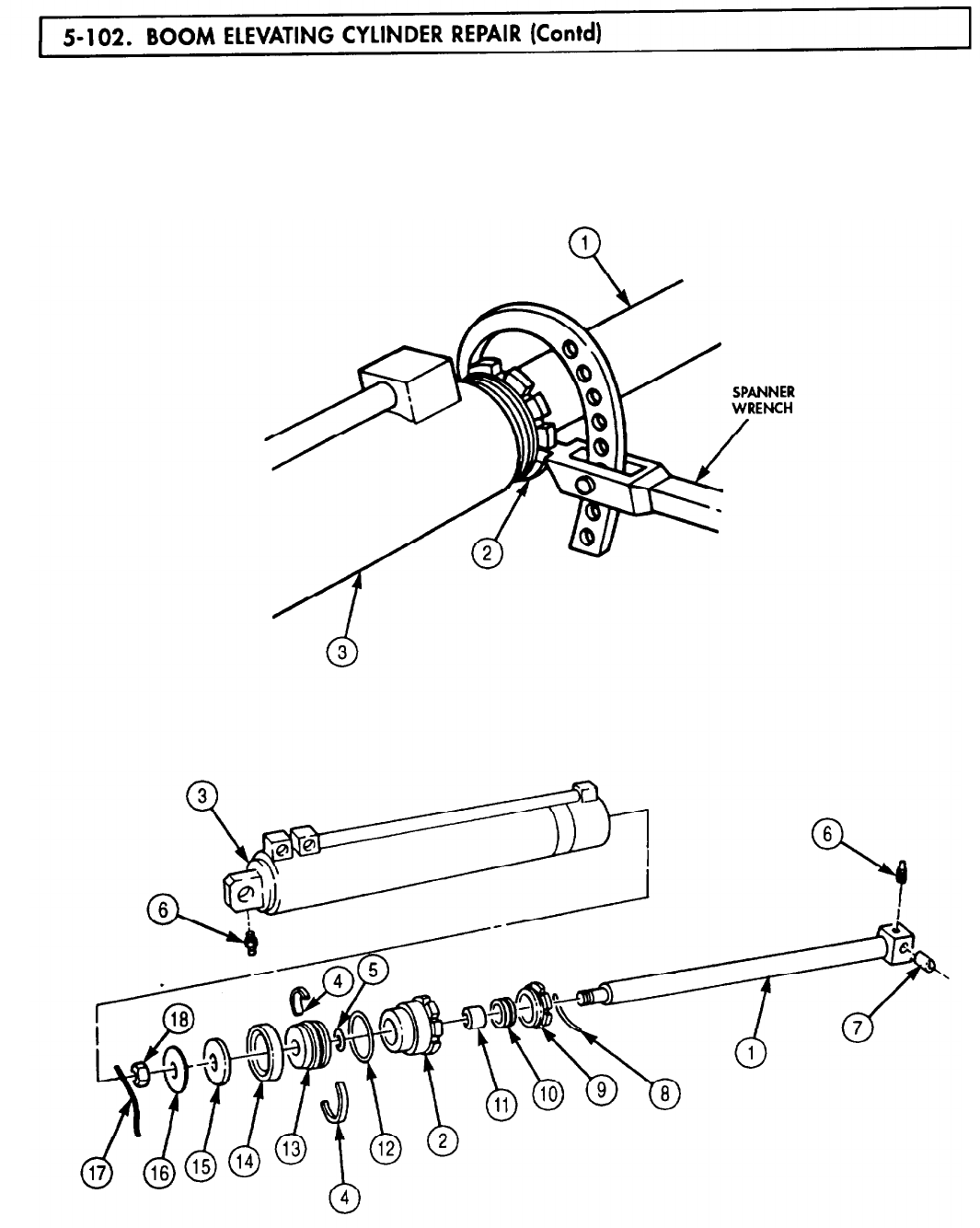
5-102. BOOM
TM 9-2320-272-24-4
4.
Remove packing nut (9), packing (10), bushing (11), and O-ring (12) from cylinder head (2). Discard
O-ring (12) and packing (10).
5.
Remove two half rings (4) from piston (13).
6.
Remove sleeve (7) from piston rod (1).
7.
Remove two lubrication fittings (6) from cylinder body (3) and piston rod (1).
5-607
5-102. BOOM
TM 9-2320-272-24-4
WARNING
Drycleaning solvent is flammable and will not be used near open
flame. Use only in well-ventilated places. Failure to do this may
result in injury to personnel.
1.
Clean all parts of elevating cylinder with drycleaning solvent and dry with lint-free cloth.
2.
Inspect piston rod (9) for burrs, scoring, scratches, and stripped threads. If minor scratches and
burrs are present, remove with crocus cloth.
3.
If piston rod (9) is scored, scratched, or if stripped threads are evident, replace piston rod (9).
4.
Inspect piston (13) and cylinder body (1) for scoring. If piston (13) is scored, replace. If cylinder
body (1) is scored, replace elevating cylinder.
1.
Install two lubrication fittings (2) in cylinder body (1) and piston rod (9).
2.
Install sleeve (10) in piston rod (9).
3.
Install two half rings (3) on piston (13).
4.
Install piston rod bushing (6) in cylinder head (5) with bushing installer and handle.
5.
Install new O-ring (4), new packing (7), packing nut (8), and new wiper strip (11) on cylinder head (5).
CAUTION
Be careful not to damage wiper strip when passing over threads
on piston rod.
6.
Install cylinder head (5) on piston rod (9).
7.
Install new rod seal (12), piston (13), new seal (14), retainer (15), and washer (16) on piston rod (9).
8.
Install nut (18) on piston rod (9) and secure nut (18) with lockwire (17).
9.
Slide piston rod (9) into cylinder body (1) and install cylinder head (5) on cylinder body (1).
10.
Using spanner wrench, tighten cylinder head (5).
5-608
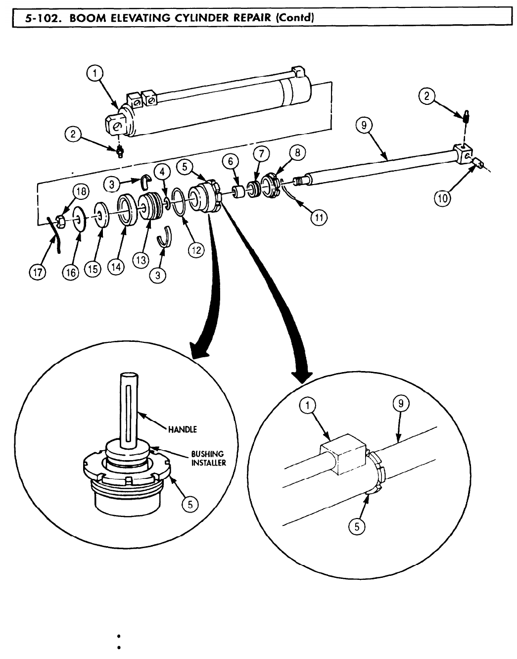
5-102. BOOM
TM 9-2320-272-24-4
FOLLOW-ON TASKS:
Install boom elevating cylinder (para. 4-193).
Lubricate elevating cylinder (LO 9-2320-272-12).
5-609

5-103. BOOM
TM 9-2320-272-24-4
THIS TASK COVERS:
a. Removal b. Installation
INITIAL SETUP:
APPLICABLE MODELS
M936/A1/A2
REFERENCES (TM)
LO 9-2320-272-12
TM 9-2320-272-10
TM 9-2320-272-24P
SPECIAL TOOLS
Spanner wrench (Appendix E, Item 167)
TOOLS
General mechanic’s tool kit (Appendix E, Item 1)
Boom lifting device
MATERIALS/PARTS
Packing (Appendix D, Item 510)
GAA grease (Appendix C, Item 28)
EQUIPMENT CONDITION
Parking brake set (TM 9-2320-272-10).
Boom lowered (TM 9-2320-272-10).
GENERAL SAFETY INSTRUCTIONS
All personnel must stand clear during lifting
operations.
WARNING
All personnel must stand clear during lifting operations. A
snapped cable, or shifting or swinging load ,may cause injury to
personnel.
1.
Place wrecker boom (2) cylinder control lever (7) in UP position.
2.
Raise wrecker boom (2) with lifting device and install shipper braces (TM 9-2320-272-10).
3.
Place boom cylinder control lever (7) in LOWER position to release pressure from elevating cylinder (6).
4.
Using spanner wrench, loosen packing nut (3) from cylinder head (5).
5.
Slide nut (3) up on piston rod (1) to expose packing (4).
CAUTION
Use care not to scratch piston rod surface when removing packing.
6.
Slide packing (4) up piston rod (1) and remove. Discard packing (4).
1.
Coat packing (4) with GAA grease and position around piston rod (1).
2.
Install packing (4) into cylinder head (5) and slide nut (3) onto cylinder head (5).
3.
Using spanner wrench, tighten nut (3).
4.
Remove lifting device from wrecker boom (2).
5-610

5-103. BOOM
TM 9-2320-272-24-4
FOLLOW-ON TASK: Operate crane through full range (TM 9-2320-272-10) and check for leaks at cylinder.
5-611
5-104. DUMP
TM 9-2320-272-24-4
THIS TASK COVERS:
a.
Removal
d.
Assembly
b.
Disassembly
e.
Installation
c. Inspection and Repair
INITIAL SETUP:
APPLICABLE MODELS
M929/A1/A2, M930/A1/A2
TOOLS
General mechanic’s tool kit (Appendix E, Item 1)
Brass drift
Soft-faced hammer
MATERIALS/PARTS
GAA grease (Appendix C, Item 28)
REFERENCES (TM)
LO 9-2320-272-12
TM 9-2320-272-10
TM 9-2320-272-24P
EQUIPMENT CONDITION
• Parking brake set (TM 9-2320-272-10).
• Dump body removed (para. 4-144).
GENERAL SAFETY INSTRUCTIONS
Do not operate dump controls when dump body is
removed.
WARNING
Ensure dump control lever is in neutral and not moved. Injury to
personnel may result if lift cylinder is operated when not secured.
NOTE
Left and right roller arms are replaced basically the same way.
This procedure covers right roller arm.
NOTE
Use soft-faced hammer to tap roller arm if necessary to complete
step 1.
Remove roller arm (3) from hoist cylinder crosshead shaft (1).
1.
Using punch and hammer, remove two pins (2) from roller arm (3).
2.
Using brass drift and hammer, drive roller pin (5) out of roller arm (3) and roller (6).
3.
Remove roller (6) from roller arm (3).
1.
Inspect roller (6) and roller pin (5). If cracked or deeply grooved, replace roller (6) and roller pin (5).
2.
Inspect roller arm (3). If broken or cracked, replace.
3.
Inspect two bushings (4) in roller arm (3). If broken, cracked, or out-of-round, replace bushings (4).
NOTE
Perform steps 4 and 5 only if bushings need to be replaced.
4.
Using brass drift and hammer, drive two bushings (4) out of roller arm (3).
5.
Using wood block and hammer, drive one new bushing (4) in from each side of roller arm (3) until
bushings (4) are flush with roller arm (3).
5-612
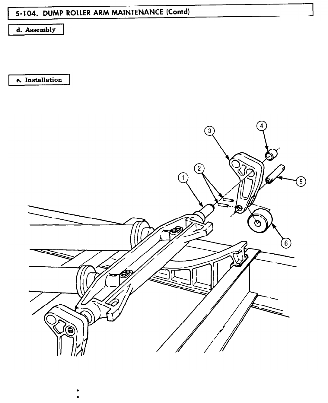
5-104. DUMP
TM 9-2320-272-24-4
1.
Position roller (6) in roller arm (3).
2.
Coat roller pin (5) with light film of GAA grease and insert through roller arm (3) and roller (6). Tap
pins (5) into place with soft-faced hammer.
3.
Install roller (6) on roller arm (3) with two pins (2)
Install roller arm (3) on hoist cylinder crosshead shaft
(1).
FOLLOW-ON TASKS:
Install dump body (para. 4-144).
Lubricate roller arms (LO 9-2320-272-12).
5-613

5-105. DUMP
TM 9-2320-272-24-4
THIS TASK COVERS:
a.
Removal d. Assembly
b.
Disassembly e. Installation
c. Cleaning and Inspection
INITIAL SETUP:
APPLICABLE MODELS
M929/A1/A2, M930/A1/A2
TOOLS
General mechanic’s tool kit (Appendix E, Item 1)
Spring tester (Appendix E, Item 131)
Soft-faced hammer
Outside micrometer (Appendix E, Item 80)
Inside micrometer (Appendix E, Item 83)
Torque wrench (Appendix E, Item 146)
MATERIALS/PARTS
Eight lockwashers (Appendix D, Item 393)
Preformed packing (Appendix D, Item 511)
O-ring (Appendix D, Item 466)
Cotter pin (Appendix D, Item 75)
Cap and plug set (Appendix C, Item 14)
Lint-free cloth (Appendix C, Item 21)
Clean hydraulic oil (Appendix C, Item 35)
WARNING
Ensure dump control is in neutral and not moved. Injury to
personnel may result if lift cylinder is operated when not secured.
REFERENCES (TM]
LO 9-2320-272-12
TM 9-2320-272-10
TM 9-2320-272-24P
EQUIPMENT CONDITION
Dump body removed (para. 4-144).
Dump roller arms removed (para. 5-104).
GENERAL SAFETY INSTRUCTIONS
Do not operate dump controls when dump body is
removed.
NOTE
A 4x4 block of wood is recommended for use as support.
1.
Raise hoist cylinders (3) and (9) from subframe (4) and place wood support between sub-
frame (4) and cylinders (3) and (9).
2.
Remove four screws (2), lockwashers (1), two upper crosshead retainers (5), lower crosshead
retainers (7), and crosshead (8) from two piston rods (6). Discard lockwashers (1).
CAUTION
Plug all hydraulic lines or openings to prevent dirt from entering
and damaging components.
NOTE
Cross fitting to hoist cylinder hoses must be disconnected from
cross fittings first. Then hoses can be removed from hoist
cylinders.
Have drainage containers ready to catch oil.
Tag all parts for installation.
3.
Disconnect hydraulic hoses (18) and (14) from right cross fitting (17).
5-614
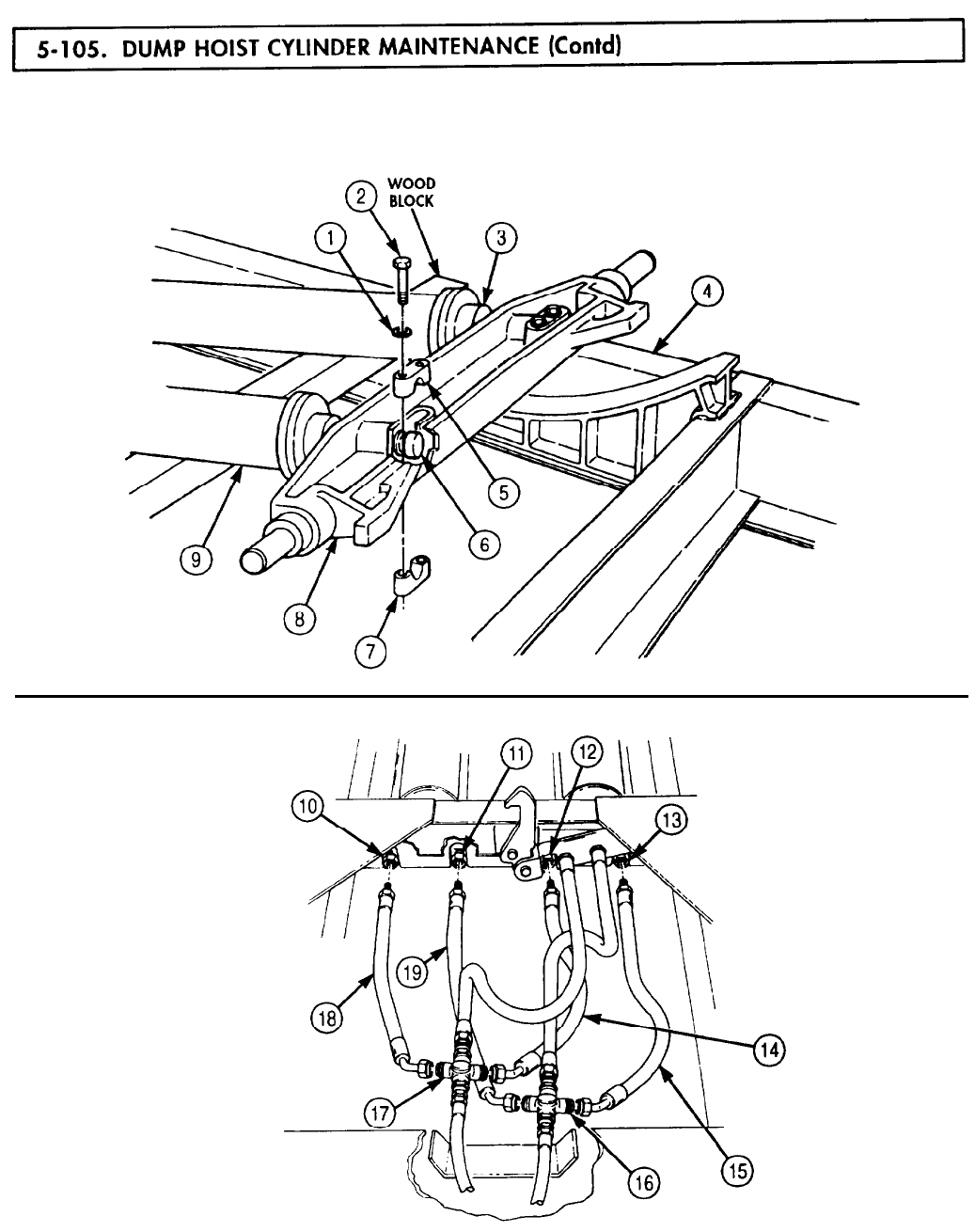
5-105. DUMP
TM 9-2320-272-24-4
4.
Disconnect hydraulic hoses (19) and (15) from left cross fitting (16).
5.
Disconnect hydraulic hoses (18) and (14) from right and left cylinder ports A (10) and (12).
6.
Disconnect hydraulic hoses (19) and (15) from right and left cylinder ports B (11) and (13).
5-615
5-105. DUMP
TM 9-2320-272-24-4
7.
Remove eight screws (3), lockwashers (4), four bearing caps (2), and hoist cylinders (5) and (1) from
subframe (6). Discard lockwashers (4).
1.
Both hoist cylinders are disassembled the same way. Steps 1
through 12 cover the left hoist cylinder.
Remove two square-head screws (18) from cylinder base (7) and slide hinge pin (19) out of cylinder
base (7).
2.
3.
4.
Remove three screws (11) from gland (12) and cylinder head (14).
Tap gland (12) free of cylinder head (14) and slide off piston rod (16).
Remove ten screws (10) and lockwashers (9) from cylinder head (14) and hoist cylinder housing (8).
Discard lockwashers (9).
5.
6.
Tap cylinder head (14) free of hoist cylinder housing (8) and slide cylinder head (14) off piston
rod (16).
Remove packing (13) and O-ring (15) from cylinder head (14). Discard packing (13) and O-ring (15).
CAUTION
Use care when performing step 7 to prevent damage to cylinder
bore or piston.
7.
Pull piston rod (16) and piston (17) straight out of hoist cylinder housing (8).
NOTE
5-616
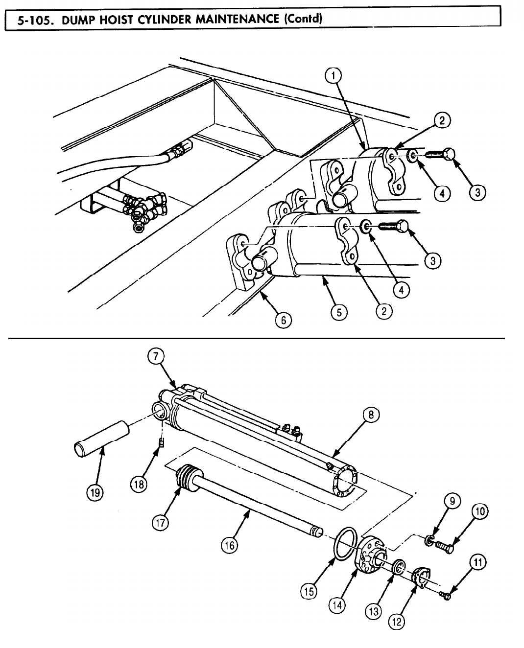
5-105. DUMP
TM 9-2320-272-24-4
5-617

5-105. DUMP
TM 9-2320-272-24-4
8.
Remove cotter pin (12) and slotted nut (13) from piston rod (8) and piston (9). Discard cotter pin (12).
9.
Slide piston (9) off piston rod (8).
10.
Remove three piston rings (11) from piston grooves (10).
NOTE
Tag bypass plugs, springs, and check balls for installation.
11.
Remove three bypass plugs (6), springs (5), and check balls (4) from hoist cylinder housing (7).
12.
Remove orifice plug cover (1) and orifice plug (2) from cylinder base (3).
NOTE
Use clean lint-free cloth to wipe parts clean. After parts are
cleaned and inspected, coat them with a light film of clean
hydraulic oil.
1.
Wipe check balls (4) clean and inspect. Replace if scratched, chipped, or marked.
2.
Wipe piston (9) clean and inspect. Replace if cracked or broken.
3.
Measure outside diameter of piston (9). If outside diameter is less than 5.236 in. (132.994 mm),
replace piston (9).
4.
Wipe piston rod (8) clean and inspect. Replace if scratched, chipped, or scored.
5.
Measure outside diameter of piston rod (8). If outside diameter is less than 1.994 in. (50.648 mm),
replace piston rod (8).
5-618
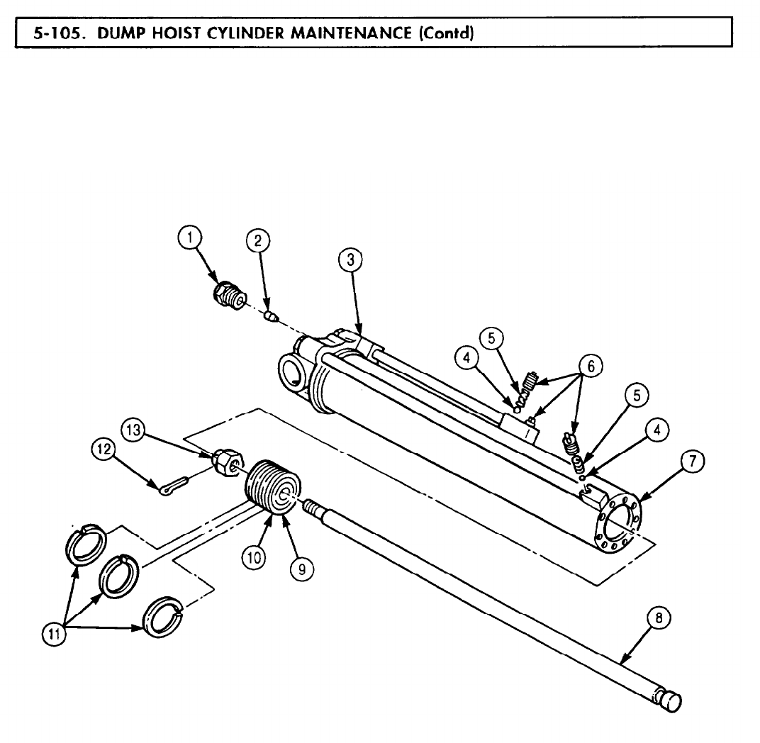
5-105. DUMP
TM 9-2320-272-24-4
5-619
5-105. DUMP
TM 9-2320-272-24-4
6.
Wipe head (5) and gland (6) clean and inspect. If cracked or broken, replace head (5) or gland (6).
7.
Measure inside diameter of head (5) and gland (6). If inside diameter is not 2.010 in. (51.05 mm),
replace head (5) or gland (6).
8.
Measure free length of three bypass springs (1). If length is not 1.25 in. (31.75 mm), replace bypass
spring (1).
9.
Compress each bypass spring (1) to 0.938 in. (23.8 mm) length. If torque reading is not 10 lb&
(14 N•m), replace bypass spring (1).
10.
Inspect three piston rings (11) for breaks. If any ring (11) is broken, replace all three rings (11).
11.
Wipe orifice plug (2) and hoist cylinder walls (4) clean and inspect. If scratched or chipped, replace
orifice plug (2) or hoist cylinder walls (4).
NOTE
Both hoist cylinders are assembled in the same way. Steps 1
through 12 cover the left hoist cylinder.
1.
Install three piston rings (11) on piston grooves (10).
2.
Slide piston (9) on piston rod (8) until seated and install with slotted nut (13) and new cotter pin (12).
CAUTION
Use care when performing step 3 to prevent damage to cylinder
bore or piston.
3.
Slide piston (9) and piston rod (8) in cylinder housing (3).
4.
Install new O-ring (7) on cylinder head (5).
5-620
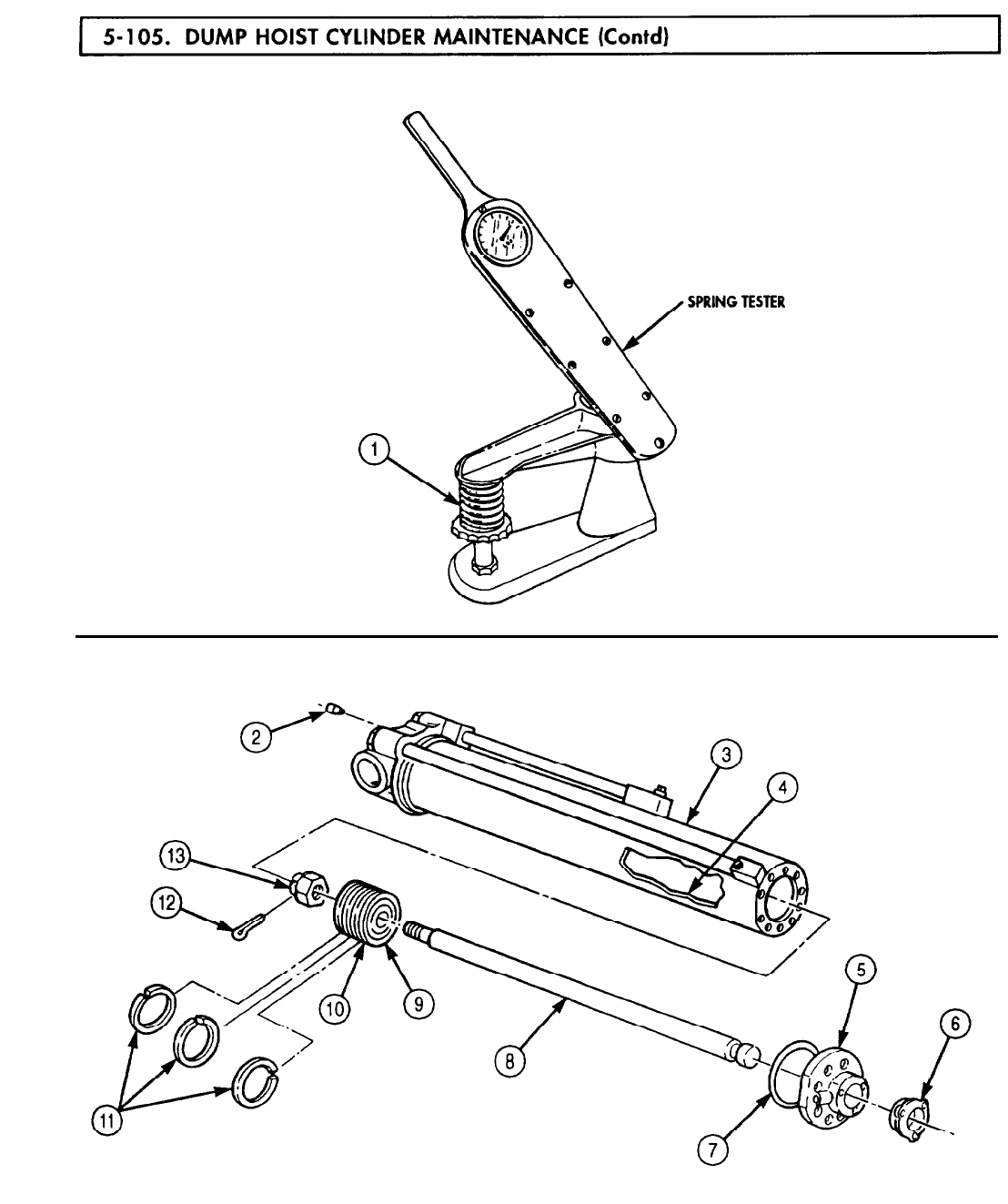
5-105. DUMP
TM 9-2320-272-24-4
5-621

5-105. DUMP
TM 9-2320-272-24-4
5.
6.
7.
8.
9.
10.
11.
12.
Slide cylinder head (17) over piston rod (18) and position on cylinder housing (19).
Install cylinder head (17) on cylinder housing (19) with ten new lockwashers (12) and screws (13).
Tighten screws (13) 8-10 lb-ft (11-14 N-m).
Install packing (16) around piston rod (18) in cylinder head (17). Use fingers to position new
packing (16).
Slide gland (15) over piston rod (18) until seated against packing (16) and install on cylinder head (17)
with three screws (14).
Install orifice plug (2) and orifice plug cover (1) in cylinder base (3).
NOTE
Short bypass tube connector block is located in middle of cylinder.
Install two bypass check balls (7), springs (6), and plugs (5) in short bypass tube connector
block (4).
NOTE
Long bypass tube connector block is located at head end of
cylinder.
Install one bypass check ball (10), spring (9), and plug (8) in long bypass tube connector block (11).
Position hinge pin (21) in cylinder base (3) until aligned with holes for screws (20) and install two
square-head screws (20).
5-622
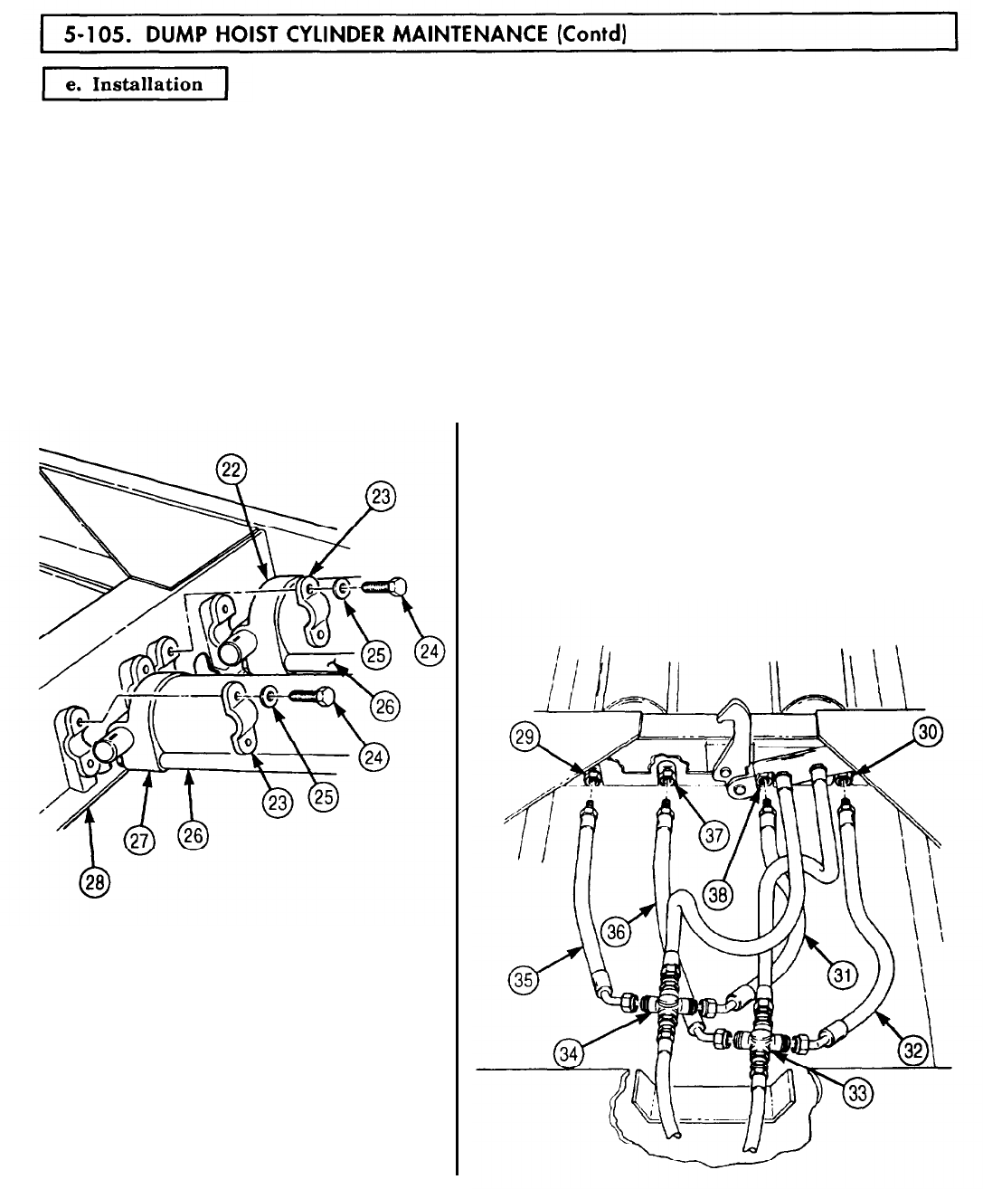
5-105. DUMP
TM 9-2320-272-24-4
1.
Position hoist cylinders (27) and (22) on subframe (28) with bypass tubes (26) facing down.
2.
Install each hoist cylinder (27) and (22) with two bearing caps (23), four new lockwashers (25), and
screws (24).
NOTE
To properly identify hose connection points, the cylinder port with
bypass tube extending to the middle of the cylinder will be
identified as port B. The cylinder port with bypass tube extending
full length of the cylinder will be identified as port A.
3.
Connect hydraulic hoses (31) and (35) to left cylinder port A (38), right cylinder port A (29), and
right cross fitting (34).
4.
Connect hydraulic hoses (32) and (36) to left cylinder port B (30), right cylinder port B (37), and left
cross fitting (33).
5-623
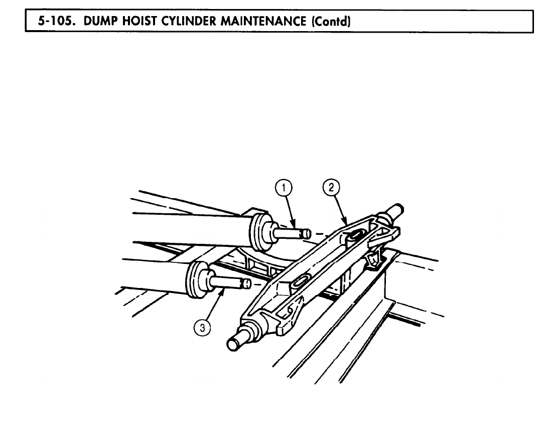
5-105. DUMP
TM 9-2320-272-24-4
5.
Position crosshead (2) on piston rods (1) and (3) and install with two upper crosshead retainers (7),
lower crosshead retainers (8), four new lockwashers (4), and screws (5).
6.
Raise hoist cylinders (6) and (9) and remove wood block.
5-624
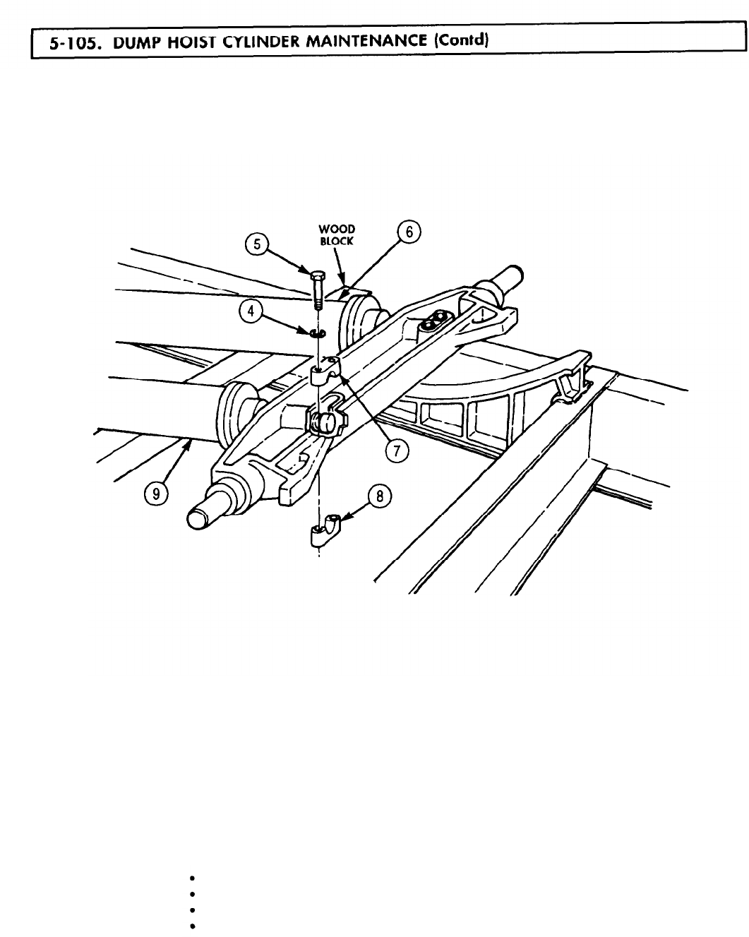

5-106. BOOM
TM 9-2320-272-24-4
THIS TASK COVERS:
a.
Disassembly c. Assembly
b.
Cleaning, Inspection, and Repair
INITIAL SETUP:
APPLICABLE MODELS
M936/A1/A2
SPECIAL TOOLS
Bushing installer (Appendix E, Item 23)
EQUIPMENT CONDITION
Handle (Appendix E, Item 61) Extension cylinder removed (para. 4-196)
TOOLS
General mechanic’s tool kit (Appendix E, Item 1)
Spanner wrench (Appendix E, Item 166)
GENERAL SAFETY INSTRUCTIONS
Keep fire extinguisher nearby when using
drycleaning solvent.
MATERIALS/PARTS
Drycleaning solvent is flammable and toxic. Do
not use near an open flame.
Wiper strip (Appendix D, Item 720)
Lockwire (Appendix D, Item 421)
O-ring (Appendix D, Item 467)
Packing (Appendix D, Item 510)
Crocus cloth (Appendix C, Item 20)
Drycleaning solvent (Appendix C, Item 71)
Lint-free cloth (Appendix C, Item 21)
REFERENCES (TM)
LO 9-2320-272-12
TM 9-2320-272-24P
1.
Using spanner wrench, remove cylinder head (21 from cylinder body (3).
2.
Remove piston rod (11 from cylinder body (3).
3.
Remove lockwire (14) and piston rod nut (15) from piston rod (1). Discard lockwire (14).
4.
Remove washer (13), two U-cup retainers (9), U-cups (10), piston (11), cylinder head (2), and wiper
strip (5) from piston rod (1). Discard wiper strip (5).
5.
Remove packing nut (4), packing (6), O-ring (8), and piston rod bushing (7) from cylinder head (2).
Discard O-ring (8) and packing (6).
6.
Remove two half rings (12) from piston (11).
5-626
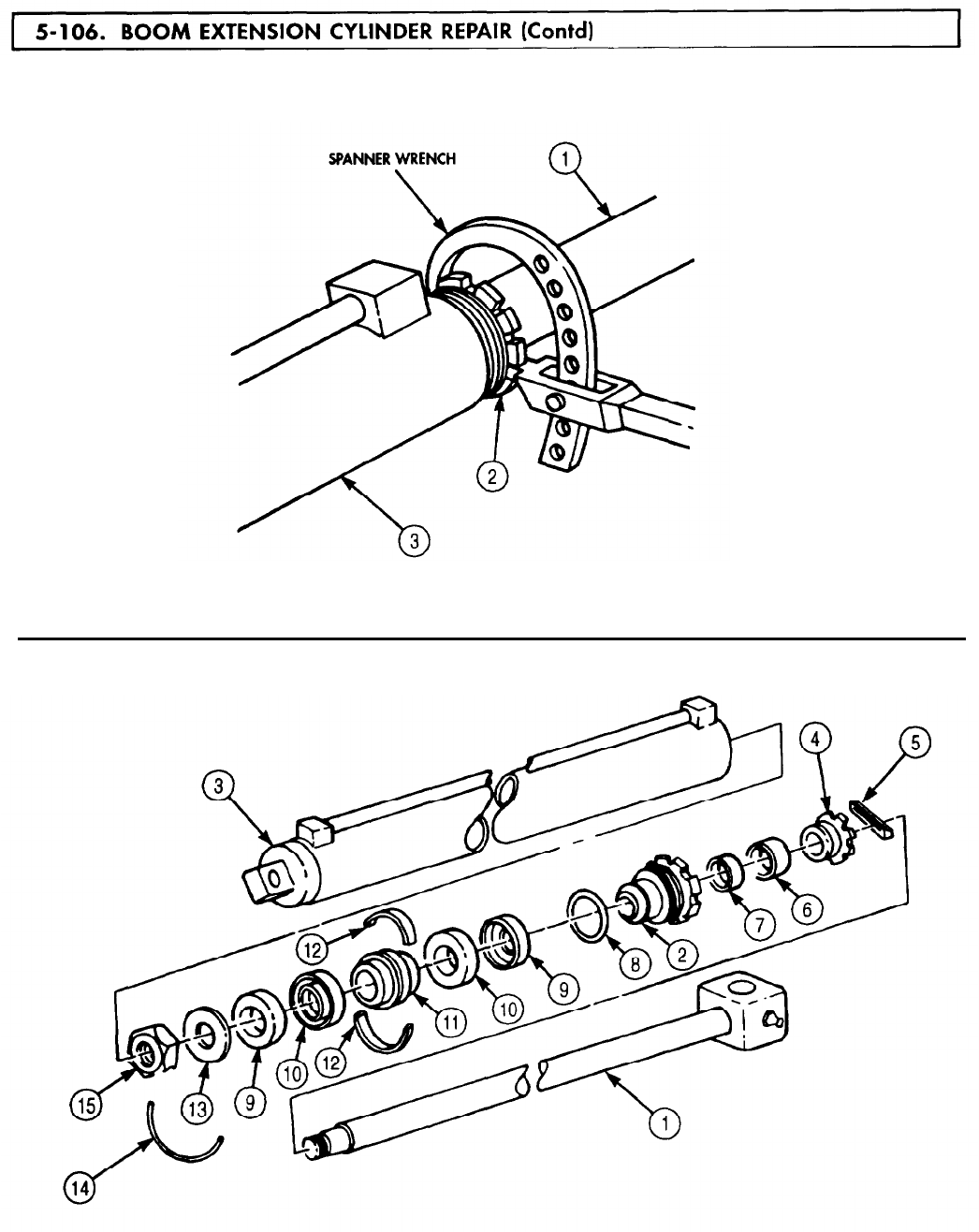
5-106. BOOM
TM 9-2320-272-24-4
5-627
5-106. BOOM
TM 9-2320-272-24-4
WARNING
Drycleaning solvent is flammable and toxic. Do not use near open
flame and always have a fire extinguisher nearby when solvents
are used. Use only in well-ventilated places, wear protective
clothing, and dispose of cleaning rags in approved container.
Failure to do this may result in injury or death to personnel and/or
damage to equipment.
1.
Clean all boom extension cylinder components with drycleaning solvent and dry with lint-free cloth
(para. 2-14).
2.
Inspect piston rod (6). Remove scratches and burrs with crocus cloth. Replace if scored or threads
are stripped.
3.
Inspect piston (11) and cylinder body (1). Replace piston (11) or cylinder body (1) if scored.
1.
Install two half rings (12) on piston (11).
2.
Using bushing installer and handle, install piston rod bushing (5) in cylinder head (7).
3.
Install new O-ring (8), new packing (4), packing nut (2), and new wiper strip (3) on cylinder head (7).
NOTE
Use care not to damage wiper strip when passing over threads on
piston rod.
4.
Install cylinder head (7) on piston rod (6).
5.
Install two U-cup retainers (9), U-cups (10), piston (11), and washer (13) on piston rod (6) with
piston rod nut (15) and new lockwire (14).
6.
Slide piston rod (6) into cylinder body (1) and install cylinder head (7) on cylinder body (1). Using
spanner wrench, tighten cylinder head (7).
5-628
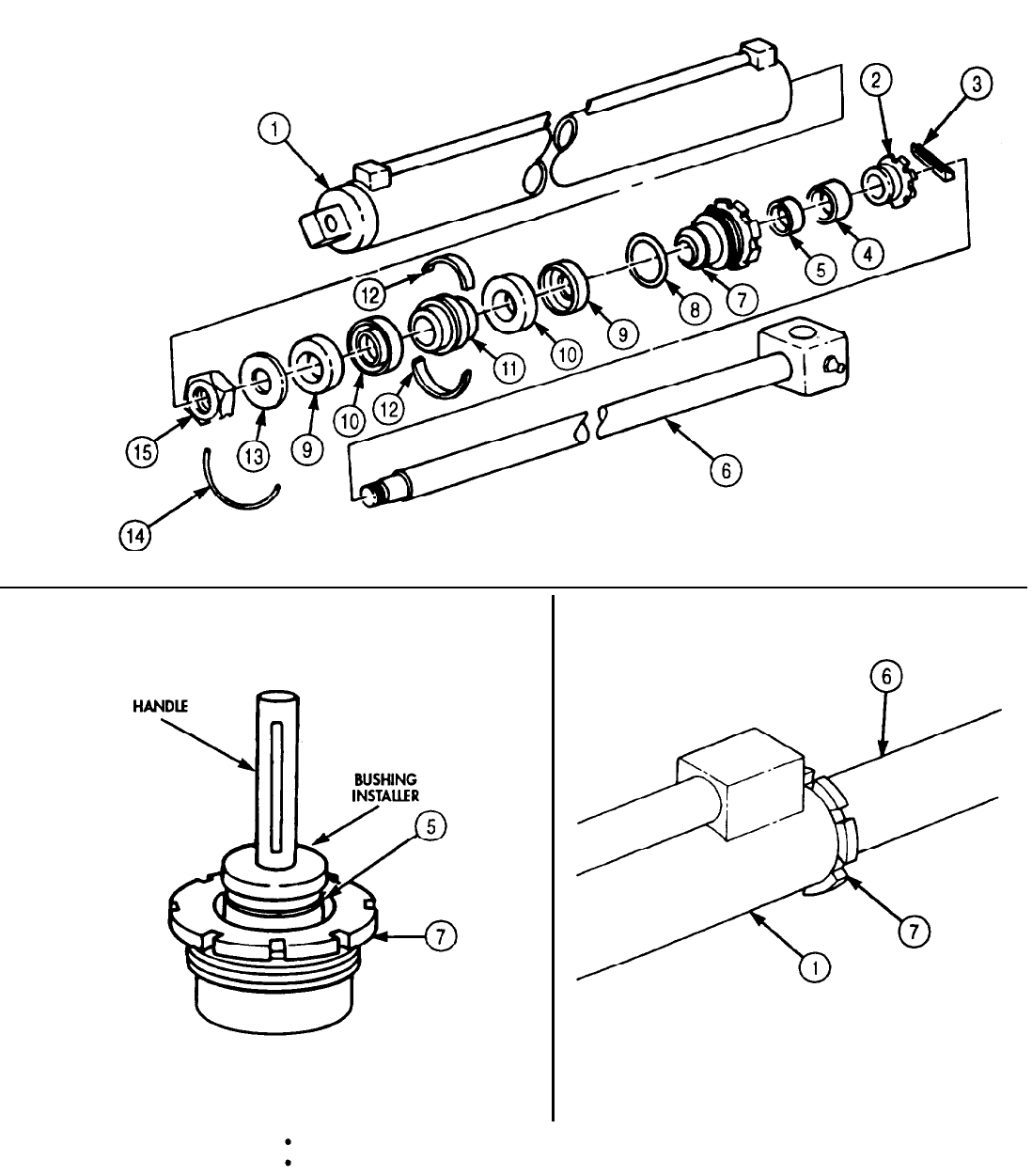
TM 9-2320-272-24-4
FOLLOW-ON TASKS:
Lubricate extension cylinder (LO 9-2320-272-12).
Install extension cylinder (para. 4-196).
5-629

6-107. CRANE
TM 9-2320-272-24-4
THIS TASK COVERS:
a.
Disassembly c. Assembly
b.
Cleaning, Inspection, and Repair
INITIAL SETUP:
APPUCABLE MODELS
M936/A1/A2
TOOLS
General mechanic’s tool kit (Appendix E, Item 1)
Torque wrench (Appendix E, Item 144)
Arbor press
Mandrel
MATERIALS/PARTS
Two gearcase gaskets (Appendix D, Item 233)
Gearcase seal (Appendix D, Item 6241
Fifteen lockwashers (Appendix D, Item 350)
Two woodruff keys (Appendix D, Item 734)
Gasket (Appendix D, Item 234)
Two woodruff keys (Appendix D, Item 736)
Woodruff key (Appendix D, Item 735)
Drycleaning solvent (Appendix C, Item 71)
REFERENCES (TM)
LO 9-2320-272-12
TM 9-2320-272-24P
EQUIPMENT CONDITION
Crane swinger gearcase removed (para. 4-200).
GENERAL SAFETY INSTRUCTIONS
Keep fire extinguisher nearby when using
drycleaning solvent.
Drycleaning solvent is flammable and toxic. Do
not use near an open flame.
1.
Thoroughly clean exterior with drycleaning solvent (para. 2-14).
NOTE
2.
Have drainage container ready to catch oil.
Remove two drainplugs (8) from crane swinger gearcase (13) and drain lubricant from crane swinger
gearcase (13).
3.
4.
5.
6.
7.
8.
Reinstall two drainplugs (8) in crane swinger gearcase (13).
Remove four screws (11), lockwashers (12), shaft bearing cap (10), and gasket (9) from crane swinger
gearcase (13). Discard lockwashers (12) and gasket (9).
Remove four screws (5), lockwashers (4), gearcase motor mounting cap (6), and gasket (7) from
crane swinger gearcase (13). Discard lockwashers (4) and gasket (7).
Remove six screws (l), lockwashers (14), cover (2), and gasket (3) from crane swinger gearcase (13).
Discard lockwashers (14) and gasket (3).
Using arbor press and mandrel, remove gear shaft assembly (20) from crane swinger gearcase (13).
Remove screw (15), lockwasher (25), and retaining washer (24) from gear shaft assembly (20).
Discard lockwasher (25).
5-630
WARNING
Drycleaning solvent is flammable and toxic. Do not use near open
flame and always have a fire extinguisher nearby when solvents
are used. Use only in well-ventilated places, wear protective
clothing, and dispose of cleaning rags in approved container.
Failure to do this may result in injury or death to personnel and/or
damage to equipment.
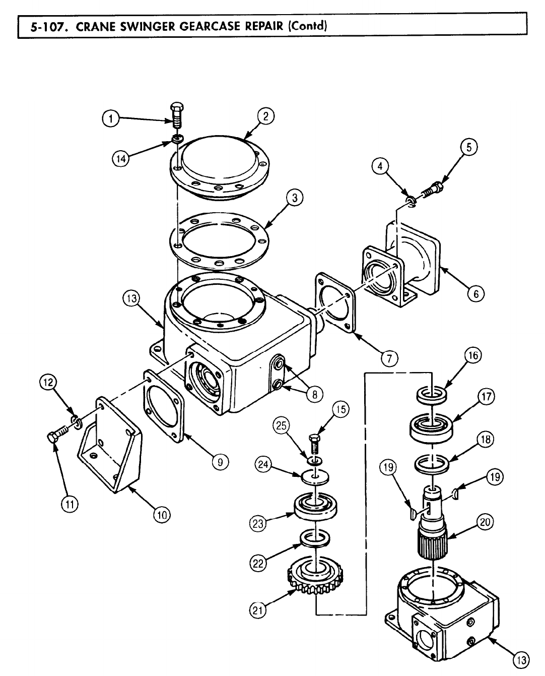
TM 9-2320-272-24-4
NOTE
Use puller to remove bearing and gear.
9.
Remove upper bearing (23), thrust washer (22), gear (21), gear washer (16), lower bearing (17), seal (18),
and two woodruff keys (19) from gear shaft assembly (20). Discard woodruff keys (19) and seal (18).
5-631
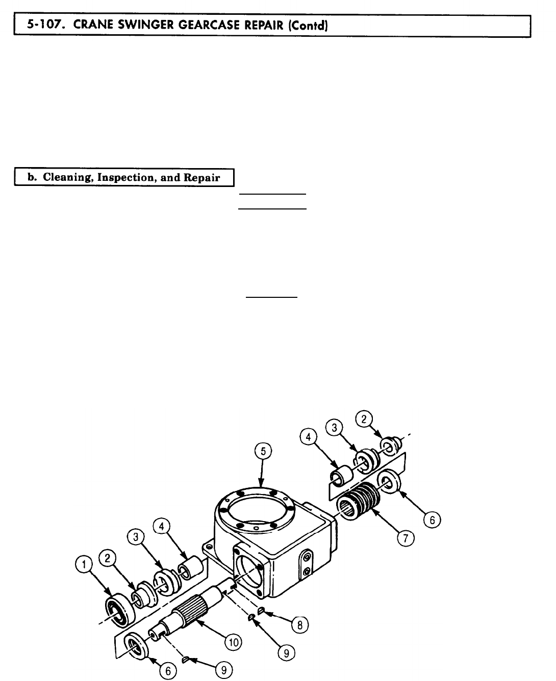
5-107. CRANE
TM 9-2320-272-24-4
10.
Using arbor press and mandrel, remove coupling (11) and woodruff key (8) from shoulder shaft (10).
Discard woodruff key (8).
11.
Using arbor press and mandrel, press crane swinger gearcase (5) shoulder shaft (10) down until
bearing (1) is removed.
12.
Turn crane swinger gearcase (5) over and press bearing (1) and shoulder shaft (10) assembly from
crane swinger gearcase (5).
13.
Remove two bushings (2), springs (3), spacers (4), washers (6), and woodruff keys (9) from shoulder
shaft (10). Discard woodruff keys (9).
14.
Remove worm gear (7) from shoulder shaft (10).
WARNING
Drycleaning solvent is flammable and toxic. Do not use near open
flame and always have a fire extinguisher nearby when solvents
are used. Use only in well-ventilated places, wear protective
clothing, and dispose of cleaning rags in approved container.
Failure to do this may result in injury or death to personnel and/or
damage to equipment.
CAUTION
Do not spin-dry bearings with compressed air.
1.
Clean all crane swinger gearcase (5) components with drycleaning solvent.
2.
Inspect four bearings (1). Replace if scored, pitted, or broken.
3.
Inspect crane swinger gearcase (5), gearcase motor mounting cap (14), shaft bearing cap (15), and
gearcase cover (12) for cracks and breaks. Replace if cracked or broken.
4.
Inspect shoulder shaft (10), worm gear (7), and gearshaft (13). Replace if broken, cracked, chipped,
or out-of-round.
5-632
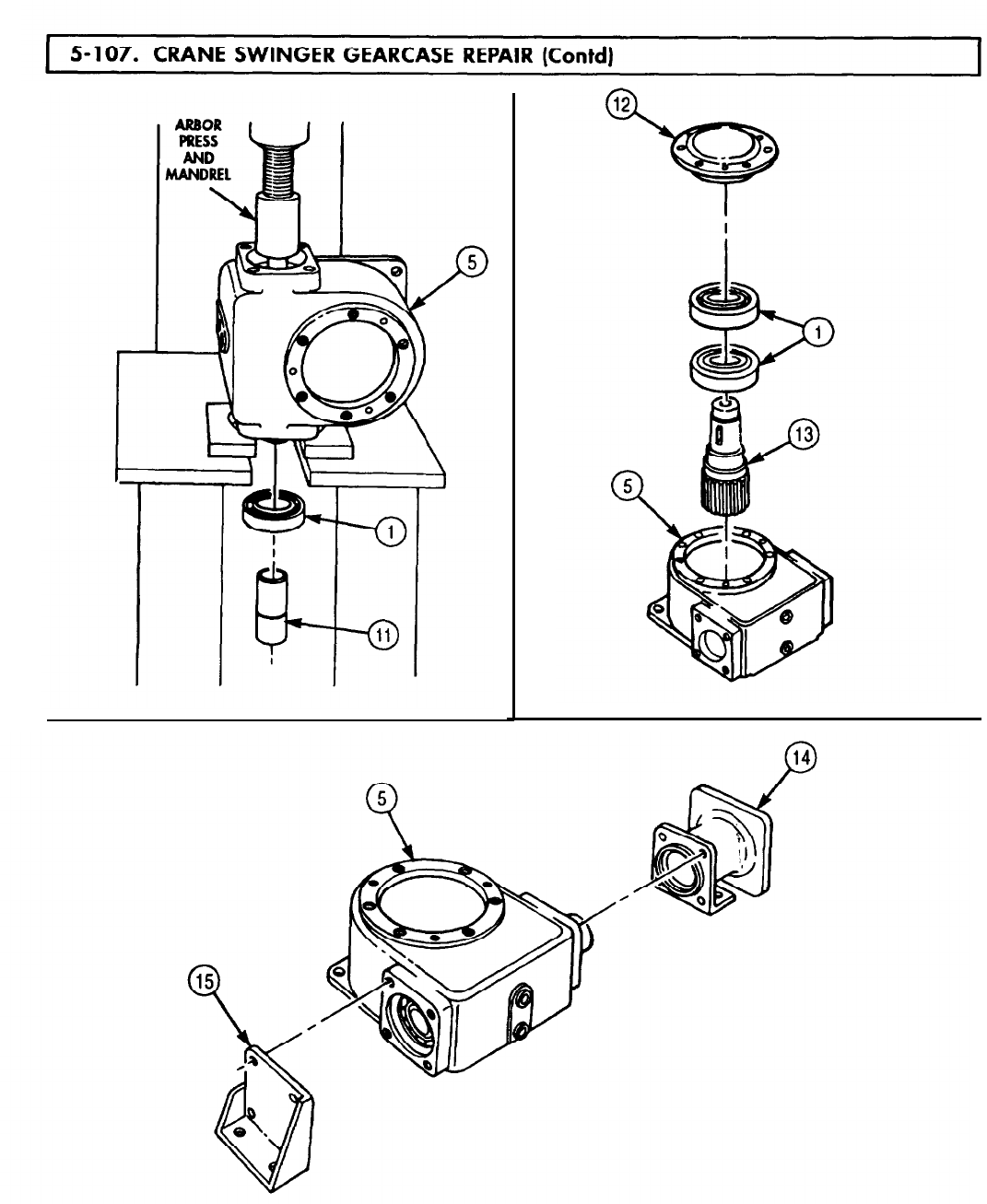
TM 9-2320-272-24-4
5-633
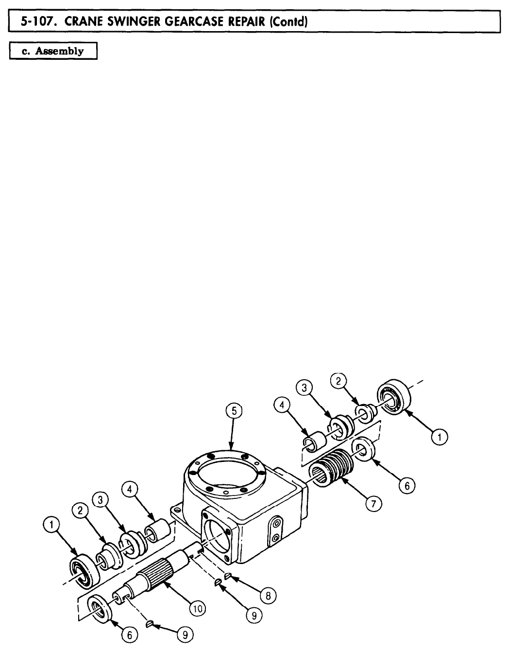
5-107. CRANE
TM 9-2320-272-24-4
1.
2.
3.
4.
5.
6.
7.
8.
9.
10.
11.
12.
13.
14.
Install two new woodruff keys (9), washers (6), spacers (4), springs (3), and bushings (2) on shoulder
shaft (10).
Install worm gear (7) on shoulder shaft (10).
Using arbor press and mandrel, install shoulder shaft bearings (1) on shoulder shaft (10) and press
shoulder shaft (10) into crane swinger gearcase (5) until bearing (1) is flush with end of crane
swinger gearcase (5).
Turn crane swinger gearcase (5) over and, using arbor press and mandrel, press second shoulder shaft
bearing (1) into crane swinger gearcase (5). Ensure bearing (1) is flush with crane swinger gearcase (5).
Install new woodruff key (8) on shoulder shaft (10).
Install new seal (14) on gear shaft (16).
Using arbor press and mandrel, press bearing (13) onto gear shaft (16).
Position lower thrust washer (12) and two new woodruff keys (15) on gear shaft (16) and, using
arbor press and mandrel, press gear (17) onto gear shaft (16) over woodruff keys (15).
Position upper thrust washer (18) on gear shaft (16) and, using arbor press and mandrel, press
bearing (19) onto gear shaft (16).
Install retaining washer (20), new lockwasher (21), and screw (22) on gear shaft (16). Tighten
screw (22) 44-61 lb-ft (60-83 N•m).
Install new gasket (23) and gearcase cover (24) on crane swinger gearcase (5) with six new lockwashers
(25) and screws (11). Tighten screws (11) 44-61 lb-ft (60-83 N•m).
Install new gasket (28) and shaft bearing cap (27) on crane swinger gearcase (5) with four new
lockwashers (26) and screws (34). Tighten screws (34) 44-61 lb-ft (60-83 N•m).
Install coupling (29) in crane swinger gearcase (5).
Install new gasket (30) and mounting cap (31) on crane swinger gearcase (5) with four new lockwashers
(32) and screws (33). Tighten screws (33) 44-61 lb-ft (60-83 N•m).
5-634
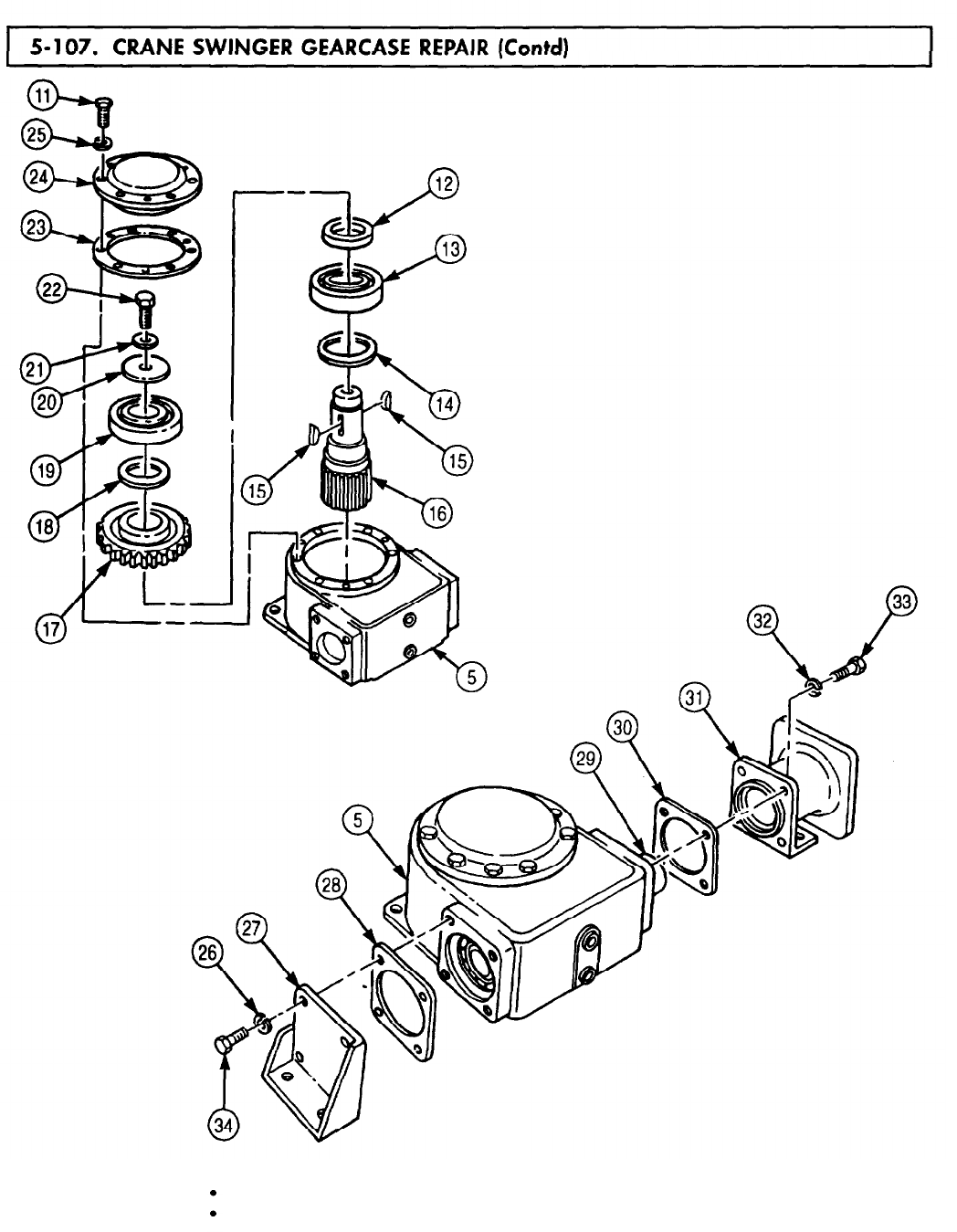
5-107. CRANE
TM 9-2320-272-24-4
FOLLOW-ON TASKS:
Fill crane swinger gearcase with lubricant (LO 9-2320-272-12).
Install crane swinger gearcase (para. 4-200).
5-635
5-108. CRANE
TM 9-2320-272-24-4
THIS TASK COVERS:
a. Disassembly c. Assembly
b. Cleaning, Inspection, and Repair
INITIAL SETUP:
APPLICABLE MODELS
M936/A1/A2
SPECIAL TOOLS
Seal retainer remover and replacer
(Appendix E, Item 117)
TOOLS
General mechanic’s tool kit (Appendix E, Item 1)
Soft-jawed vise
MATERIALS/PARTS
Relief valve kit (Appendix D, Item 533)
REFERENCES (TM)
TM 9-2320-272-24P
EQUIPMENT CONDITION
Crane control valve removed (para. 4-201).
GENERAL SAFETY INSTRUCT IONS
Keep fire extinguisher nearby when using
drycleaning solvent.
Drycleaning solvent is flammable and toxic. Do
not use near an open flame.
Load check valve kit (Appendix D, Item 270)
Eight snaprings (Appendix D, Item 665)
O-ring (Appendix D, Item 469)
O-ring (Appendix D, Item 468)
Four O-rings (Appendix D, Item 489)
Four lockwashers (Appendix D, Item 350)
Drycleaning solvent (Appendix C, Item 71)
Lint-free cloth (Appendix C, Item 21)
NOTE
Do not perform this procedure unless relief valve kit and load
check valve kit are available.
WARNING
Drycleaning solvent is flammable and toxic. Do not use near open
flame and always have a fire extinguisher nearby when solvents are
used. Use only in well-ventilated places, wear protective clothing, and
dispose of cleaning rags in approved container. Failure to do this may
result in injury or death to personnel and/or damage to equipment.
1.
Thoroughly clean exterior of crane control valve (3) with drycleaning solvent (para. 2-14).
2.
Remove eight snaprings (21), pins (20), and four handles (19) from base (2) and crane control
valve (3). Discard snaprings (21).
3.
Remove four nuts (13), lockwashers (14), screws (1), control brackets (15) and (7), and base (2) from
crane control valve (3). Discard lockwashers (14).
4.
Remove nipple adapter (17) and O-ring (16) from crane control valve (3). Discard O-ring (16).
5.
Remove nipple (18) from nipple adapter (17).
NOTE
Mark position and angle of tube and all elbows for assembly.
6.
Remove tube (6), connector (5), and O-ring (4) from crane control valve (3). Discard O-ring (4)
7.
Remove two elbows (10), three adapters (11), and two O-rings (12) from crane control valve (3).
Discard O-rings (12).
8.
Remove four elbows (9) and O-rings (8) from crane control valve (3). Discard O-rings (8).
5-636
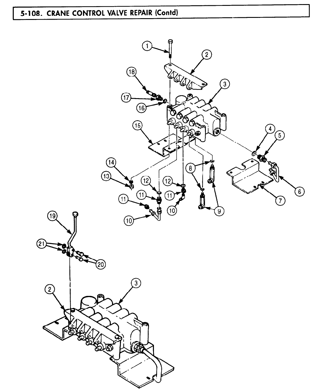
5-108. CRANE
TM 9-2320-272-24-4
5-637
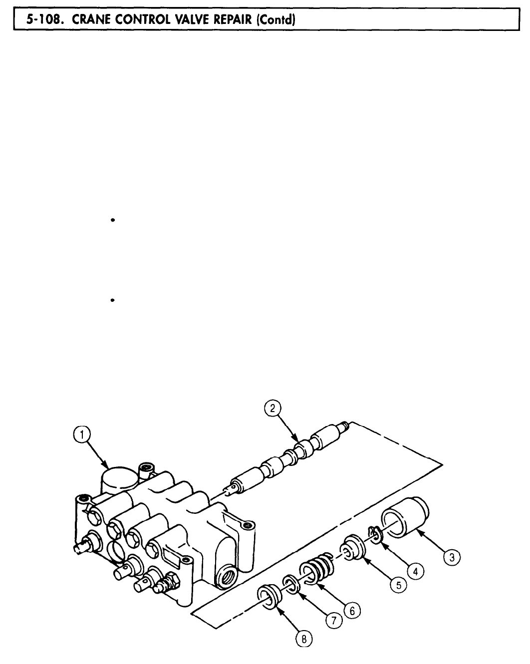
5-108. CRANE
TM 9-2320-272-24-4
NOTE
All spring-centered spool valves in the control valve are removed
and disassembled the same way. Three spool valves are stamped
with a D (double action) on the shank of the spool valve. The
fourth is stamped with an S (single action) and is located next to
the oil outlet port in the control valve. Steps 9 through 12 will
cover a double-action valve only.
9.
Remove spool valve cap (3) and spool valve (2) from crane control valve (1).
10.
Clamp spool valve (2) in soft-jawed vise.
11.
Using improvised compression tool, compress spring (6) and remove snapring (4), outer spacer (5),
spring (6), travel limit washer (7), and inner spacer (8) from spool valve (2).
12.
Using seal retainer remover and replacer, remove retainer (24), seal (25), and O-ring (26) from crane
control valve (1). Discard seal (25) and O-ring (26).
NOTE
All check valves in the control valve are removed and assembled
the same way. Check valves located adjacent to valve spools
marked with a D (double action) are identical. The check valve
located by the valve spool marked S (single action) contains only
one spring and poppet. All other components are the same as
the D-type spools. Steps 13 and 14 cover a check valve adjacent
to a D-type spool.
Do not remove check seat sleeve from control valve. Check valve
parts should be identified so they may be returned to their
original position during assembly.
13.
Remove two check valve caps (9), springs (17), and poppets (14) from crane control valve (1).
14.
Remove backup ring (16), O-ring (15), backup ring (13), backup ring (12), O-ring (11), and
O-ring (10) from each check valve cap (9). Discard backup ring (16), O-ring (15), backup ring (13),
backup ring (12), O-ring (11), and O-ring (10).
5-638

5-108. CRANE
TM 9-2320-272-24-4
15.
Remove relief valve (23) from crane control valve (1). Discard relief valve (23).
16.
Remove seat retainer plug (18), drain sleeve (20), and seat retainer (19) from crane control
valve (1). Discard seat retainer (19).
17.
Remove poppet spring (22) and poppet assembly (21) from crane control valve (1). Discard poppet
assembly (21) and poppet spring (22).
5-639
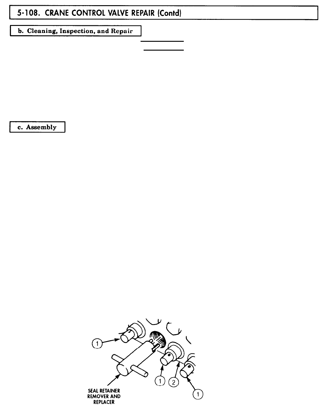
5-108. CRANE
TM 9-2320-272-24-4
WARNING
Drycleaning solvent is flammable and toxic. Do not use near open
flame and always have a tire extinguisher nearby when solvents
are used. Use only in well-ventilated places, wear protective
clothing, and dispose of cleaning rags in approved container.
Failure to do this may result in injury or death to personnel and/or
damage to equipment.
1.
Clean all control valve components with drycleaning solvent and dry with lint-free cloth (para. 2-14).
2.
Inspect spool valve (1) and crane control valve (2). Replace crane control valve (2) if grooved,
scratched, cracked, or broken.
1.
2.
3.
4.
5.
6.
7.
8.
9.
10.
NOTE
Drain sleeve should go into control valve far enough to leave two
or three full threads exposed. Installing seat retainer plug at this
point sets the seat retainer to the proper depth.
Install new seat retainer (13) and drain sleeve (14) in crane control valve (2).
Install seat retainer plug (12) in crane control valve (2).
Install new poppet assembly (15) and poppet spring (16) in crane control valve (2) so poppet
assembly (15) points toward seat retainer (13).
Install new relief valve (17) on crane control valve (2).
Install new O-rings (4) and (5), new backup rings (6) and (7), new O-ring (9), and new backup ring (10)
on each check valve cap (3).
Install two poppets (8), springs (ll), and check valve caps (3) into crane control valve (2).
NOTE
The remaining check valve caps are assembled the same way.
Clamp spool valve (1) in soft-jawed vise.
Using improvised compression tool, compress spring (21) and install inner spacer (23), travel limit
washer (22), spring (21), and outer spacer (20) on spool valve (1) with new snapring (19).
Install spool valve (1) and spool valve cap (18) in crane control valve (2).
Using seal retainer remover and replacer, install new O-ring (26), new seal (25), and retainer (24)
on crane control valve (2).
5-640
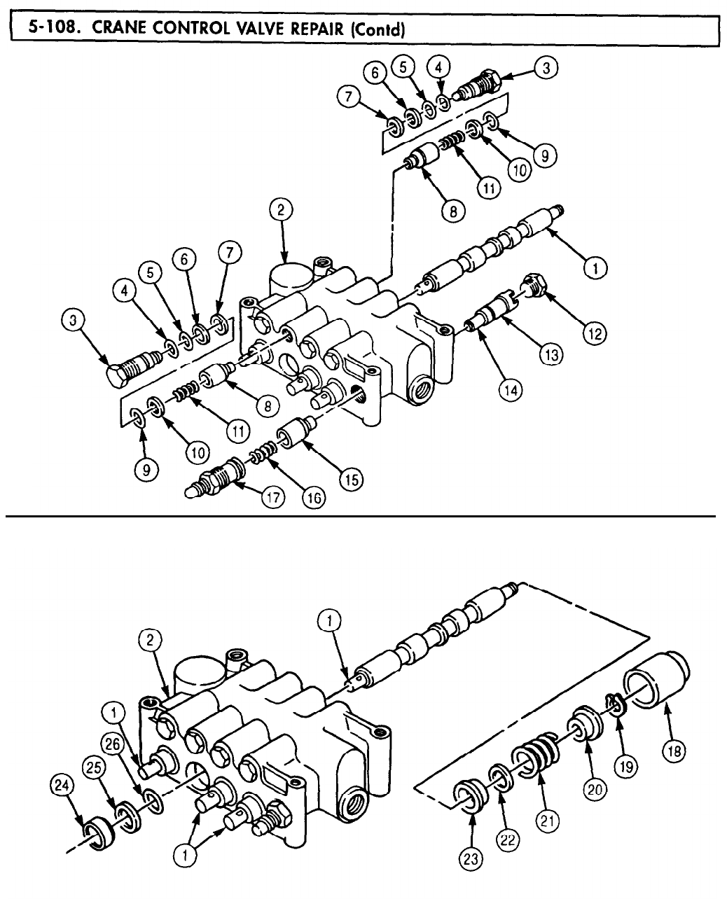
5-108. CRANE
TM 9-2320-272-24-4
5-641

5-108. CRANE
TM 9-2320-272-24-4
NOTE
Install all parts in steps 11 through 13 in their marked location
and angle on control valve.
The three remaining spool valves are assembled into the control
valve in the same way.
11.
Install four new O-rings (8), elbows (9), two new O-rings (12), three adapters (ll), two elbows (10),
new O-ring (4), connector (5), and tube (6) on crane control valve (3).
12.
Install nipple adapter (17) on nipple (18).
13.
Install new O-ring (16) and nipple adapter (17) on crane control valve (3).
14.
Install right control bracket (7), left control bracket (15),
four screws (1), new lockwashers (14), and nuts (13). and base (2) on crane control valve (3) with
15.
Align four operating handles (19) with holes in base (2) and control spool valves (21), and install
four operating handles (19) with eight pins (20) and new snaprings (22).
5-642
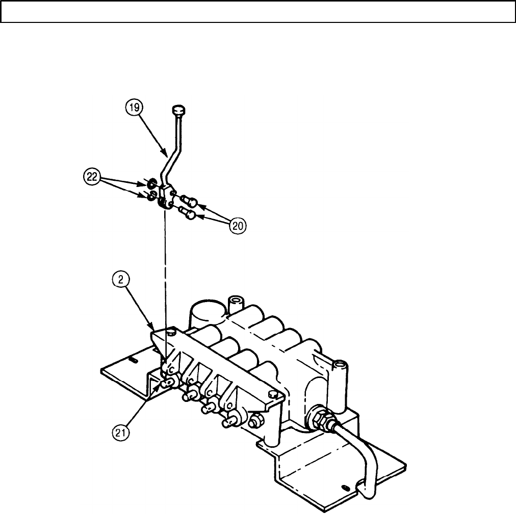
TM 9-2320-272-24-4
5-108. CRANE CONTROL VALVE REPAIR (Contd)
FOLLOW-ON TASK: Install crane control valve (para. 4-201).
5-643/(5-644 blank)
TM 9-2320-272-24-4
CHAPTER 6
SHIPMENT AND LIMITED STORAGE
Section I. General Preparation of Vehicle for Shipment (page 6-1)
Section II. Loading and Movement (page 6-2)
Section III. Limited Storage (page 6-2)
Section I. GENERAL PREPARATION OF VEHICLE FOR SHIPMENT
6-1. SCOPE
a. This section provides instructions on preserving and protecting vehicles for shipment.
b. Protection for vehicles and accompanying equipment must be sufficient to protect the material
against deterioration and physical damage.
6-2. CLEANING
WARNING
Drycleaning solvent is flammable and will not be used near open
flame. Use only in well-ventilated places. Failure to do so may
result in injury to personnel.
Cleaning materials or paints containing chlorinated hydrocarbon
class solvents are not to be used on composite taillights and
parking lights. Damage to taillight and parking light lenses may
result.
Prior to application of preservatives, surfaces must be cleaned to ensure removal of corrosion, soil, grease,
or vehicle acid and alkali residues.
a. Interior of Vehicle. Remove all dirt and other foreign matter from all painted metal surfaces of
vehicle by scrubbing with cloths soaked in drycleaning solvent (appendix C, item 71). DO NOT apply
solvent to electrical equipment or rubber parts of any nature. Use trichloroethylene (appendix C, item 76) to
clean electrical parts and electrical contact points. Use warm water for cleaning rubber parts. Apply
preservative compounds to rubber parts as required (TM 9-247).
b. Exterior of Vehicle. Clean exterior surfaces of vehicle to ensure removal of all dirt and foreign
matter. After cleaning, immediately dry parts to remove excess cleaning solutions or residual moisture.
Allow parts to air-dry or wipe with clean, dry, lint-free cloth (appendix C, item 21).
6-3. LUBRICATION
WARNING
Drycleaning solvent is flammable and will not be used near open
flame. Use only in well-ventilated places. Failure to do so may
result in injury to personnel.
After cleaning has been accomplished, wipe all grease fittings clean with drycleaning solvent (appendix C,
item 71) and lubricate vehicle in accordance with LO 9-2320-272-12. Remove excess grease after lubrication
and before processing.
6-1

TM 9-2320-272-24-4
6-4. PRESERVATION
All critical unpainted metal surfaces must be protected during shipment. Use procedures and materials
listed in steps a. and b. below. If the preservatives listed below are not available, oil or grease listed in
LO 9-2320-272-12 may be used for this purpose, but is effective for only a few days; therefore, equipment
protected must be closely watched for signs of corrosion. When selecting preservatives, use only those that
will not damage the surface to which they are applied.
a. Battery Leads. Disconnect both batteries (para. 3-126). Each battery lead terminal, including the
jumper lead ends, must be wrapped with tape (appendix C, item 73).
b. Miscellaneous Preservation. Coat all unpainted, exposed, or machined metal surfaces on the
exterior of the vehicle with corrosion-preventive compound (appendix C, item 25).
6-5. PACKAGING
Electrical Openings. Cover all electrical receptacles with tape (appendix C, item 73) or with plastic caps
which will afford the same degree of protection.
6-6. PACKING
Pack all Basic Issue Items (BII) and Additional Authorization List (AAL) items to prevent mechanical
damage.
6-7. SHIPMENT OF ARMY DOCUMENTS
Prepare all Army shipping documents accompanying vehicle in accordance with DA Pam 738-750.
Section II. LOADING AND MOVEMENT
6-8. LOADING AND MOVEMENT
For transportability guidance handling and movement of vehicles, refer to TM 55-2320-272-15-1.
Section III. LIMITED STORAGE
6-9. SCOPE
Commanders are responsible for ensuring that all vehicles issued or assigned to their command are
maintained in a serviceable condition and properly cared for and that personnel under their command
comply with technical instructions. Lack of time, trained personnel, or proper tools may result in a unit
being incapable of performing maintenance for which it is responsible. In such cases, unit commanders may,
with the approval of major commanders, place a vehicle that is beyond the maintenance capability of the
unit in administrative storage. For detailed maintenance information, refer to AB 750-1.
6-10. LIMITED STORAGE INSTRUCTIONS
a. Time Limitations. Administrative storage is restricted to a period of 90 days and must not be
extended unless the vehicle is reprocessed in accordance with step b.
6-2

TM 9-2320-272-24-4
6-10. LIMITED STORAGE INSTRUCTIONS (Contd)
b.
Storage Procedure. Perform disassembly only as required to clean and preserve exposed surfaces.
Except as otherwise noted, and to the maximum extent consistent with safe storage, place the vehicle in
administrative storage in as nearly a completely assembled condition as possible. Install and adjust
equipment so that the vehicle may be placed in service and operated with minimum delay.
(1) The vehicle should be stored on level ground in the most favorable location available, preferably
one which affords protection from exposure to the elements and from pilferage.
(2) Perform semiannual Preventive Maintenance Checks and Services (PMCS) (para. 2-12) on
vehicle intended for administrative storage. This maintenance consists of inspecting, cleaning, servicing,
preserving, lubricating, adjusting, and replacing minor repair parts as required.
(3) Remove both batteries (para. 3-125), place in covered storage, and maintain a charged condition.
(4) Provide access to the vehicle to permit inspection, servicing, and subsequent removal from
storage.
6-11. INSPECTION IN LIMITED STORAGE
a. Conduct visual inspection of vehicles in limited storage at least once a month and immediately
following hard rains, heavy snowstorms, windstorms, or other severe weather conditions. Perform
disassembly as required to fully ascertain the extent of any discovered deterioration or damage. Maintain a
record of these inspections for each vehicle. Attach record to vehicle so it is protected from the weather,
b. Perform necessary reprocessing for limited storage when rust or deterioration is found on any
unpainted area. Immediately repair damage caused to vehicle by severe weather conditions. Repair damage
to On-Equipment Materiel (OEM) as necessary. Thoroughly clean, dry, and repaint painted surfaces
showing evidence of wear.
6-12. REMOVAL FROM LIMITED STORAGE
Materiel removed from administrative storage will be:
(1)
Restored to normal operating conditions.
(2) Repaired as required.
(3)
Returned to normal PMCS schedule using last type service completed as a starting point.
(4)
Calibrate equipment as required (TM 43-180).
6-3 (6-4 blank)

TM 9-2320-272-24-4
APPENDIX A
REFERENCES
A-1. SCOPE
This appendix lists all forms, field manuals, and technical manuals for use with this manual.
A-2. PUBLICATIONS INDEX
The following indexes should be consulted frequently for latest changes or revisions and for new publications
relating to material covered in this manual.
Consolidated Index of Army Publications and Blank Forms . . . . . . . . . . . . . . . . . . . . . . . . . . . DA Pam 25-30
Functional User’s Manual for The Army Maintenance Management System (TAMMS) . . . . DA Pam 738-750
A-3. FORMS
The following forms pertain to this manual. See DA Pam 25-30, Consolidated Index of Army Publications
and Blank Forms, for index of blank forms. See DA Pam 738-750, The Army Maintenance Management
System (TAMMS), for instructions on the use of maintenance forms pertaining to this manual.
Unit Status Reporting .......................................................... AR 220-1
U.S. Army Accident Report. ..................................................... DA Form 285
Equipment Operator’s Qualification Record (Except Aircraft). .......................... DA Form 348
Recommended Changes to Publications and Blank Forms. ............. ..............DA Form 2028
Recommended Changes to Equipment Technical Publications ........................ DA Form 2028-2
Organizational Control Record for Equipment. ...................... ..............DA Form 2401
Exchange Tag ................................................ ............ DA Form 2402
Equipment Inspection and Maintenance Worksheet .................. ..............DA Form 2404
Maintenance Request Register. .................................. ..............DA Form 2405
Materiel Condition Status Report. ................................ ..............DA Form 2406
Maintenance Request .......................................... ............ DA Form 2407
Maintenance Request - Continuation Sheet ...................................... DA Form 2407-1
Equipment Log Assembly (Records) .............................................. DA Form 2408
Equipment Control Record ................................................... DA Form 2408-9
Equipment Maintenance Log (Consolidated) ....................................... DA Form 2409
Packaging and Improvement Report ............................................... DD Form 6
Preventive Maintenance Schedule and Record .....................................DD Form 314
Accident Identification Card ................................................... DD Form 518
Processing and Deprocessing Record for Shipment, Storage, and
Issue of Vehicles and Spare Engines ........................................... DD Form 1397
U.S. Government Motor Vehicle Operator’s Identity Card. ............................. OF Form 346
Operator Report on Motor Vehicle Accidents ......................................... SF Form 91
Report of Discrepancy (ROD) ................................................... SF Form 364
Product Quality Deficiency Report ................................................ SF Form 368
A-l

TM 9-2320-272-24-4
A-4. FIELD MANUALS
NBC Protection .................................................................... FM 3-4
NBC Decontamination .............................................................. FM 3-5
Camouflage..
FM 5-20
...................................................................
Operation and Maintenance of Army Materiel in Extreme Cold Weather (0°F to -65°F). ......... FM 9-207
General Fabric Repair .......................................................... FM 10-16
Petroleum Supply Point Equipment and Operations. .................................... FM 10-69
First Aid for Soldiers. .............................................................
FM 21-11
Manual for the Wheeled Vehicle Driver. ............................................. FM 21-305
Basic Cold Weather Manual ........................................................ FM 31-70
Northern Operations. .............................................................
FM 31-71
Metal Body Repair and Related Operations. ............................................
FM 43-2
A-5. TECHNICAL MANUALS
Chemical, Biological, and Radiological (CBR) Decontamination . . . . . . . . . . . . . . . . . . . . . . . . . . . TM 3-220
Operator’s and Unit Maintenance Manual (Including Repair Parts and Special Tool List)
for Decontaminating Apparatus, Portable, DST, 1 1/2 Quart, ABC-M11) . . . . . . . . . . TM 3-4230-204-12&P
Operator’s and Organizational Maintenance Manual:
For Alarm, Chemical Agent, Automatic: Portable, Manpack, M8. .................. TM 3-6665-225-12
Rigging .......................................................................
TM 5-725
Inspection, Care, and Maintenance of Antifriction Bearings ............................... TM 9-214
Operator’s Manual for Welding Theory and Application ..................................
TM 9-237
Deep-Water Fording of Ordnance Materiel. ............................................
TM 9-238
Use and Care of Hand Tools and Measuring Tools. ......................................
TM 9-243
Materials Used for Cleaning, Preserving, Abrading and Cementing Ordnance Materiel,
and Related Materials Including Chemicals . . . . . . . . . . . . . . . . . . . . . . . . . . . . . . . . . . . . . . TM 9-247
Operator, Organizational, Direct Support and General Support Maintenance Manual
Including Repair Parts and Special Tool Lists (Including Depot
Maintenance Repair Parts and Special Tools) Various Machine Gun Mounts
and Combinations Used on Tactical and Armored Vehicles Mounts. . . . . . . . . . . . . . . . . TM 9-1005-245-14
Operator’s Manual for Truck, 5-Ton, 6x6, M939 and M939A1 Series (Diesel), Truck,
Cargo: 5-Ton, 6x6, Dropside, M923, M923A1, M925, M925A1. . . . . . . . . . . . . . . . . . . . . TM 9-2320-272-10
Unit, Direct, and General Support Maintenance Rear Parts, Special Tools List for
Truck, 5-Ton, 6x6, M939 and M939A1 Series (Diesel),
Truck, Cargo, 5-Ton, 6x6, Dropside, M923, M923A1, M925, and M925A1. . . . . . . . . . . TM 9-2320-272-24P
Operator’s, Unit, Direct Support, and General Support Maintenance Manual for
Care, Maintenance, Repair, and Inspection of Pneumatic Tires and Inner Tubes . . . . . TM 9-2610-200-14
Maintenance, Direct and General Support Level Generator Assembly
(Prestolite Model AMA-5102UT) (Leece-Neville Models) . . . . . . . . . . . . . . . . .
Direct Support, General Support, and Depot Maintenance Manual
(Including Repair Parts) for Starter, Engine, Electrical, Assembly
(Delco-Remy Model 1113943) . . . . . . . . . . . . . . . . . . . . . . . . . . . . . . .
Direct Support and General Support Maintenance Manual
(Including Repair Parts and Special Tools List) for Starter, Engine, Electrical
(Leece-Neville Model M001707 2MB). . . . . . . . . . . . . . . . . . . . . . . . . . . . . . .
......
TM 9-2920-225-34
......
TM 9-2920-242-35
......TM 9-2920-243-34
A-2

TM 9-2320-272-24-4
A-5. TECHNICAL MANUALS (Contd)
Operator’s Manual for Lathe, Brake Drum, Floor Mounted, 60-Inch Rated Swing;
25 Inch Maximum Drum Diameter, 115 Volt, 60 Cycle, Single Phase ...............TM 9-4910-482-10
Operator’s Manual: Grinding Machine, Valve Face, Bench Mounting,
9/32 Inch to 11/16 Inch Chuck, 0 to 45 Degree Valve Face Angle Adjustment, 115-Volt,
AC/DC, 60-Cycle, Single Phase. ............................................ TM 9-4910-484-10
Operator’s and Organizational Maintenance Manual Including Repair Parts and
Special Tools List for Simplified Test Equipment for Internal Combustion Engines. .. TM 9-4910-571-12&P
Operator’s, Unit, Intermediate Direct Support, and Intermediate General Support
Maintenance Manual for Lead-Acid Storage Batteries; 4HN, 24-Volt; 2HN, 12-Volt. ...
TM 9-6140-200-14
Principles of Automotive Vehicles. .................................................. TM 9-8000
Packaging of Materiel: Preservation Vol. I ..........................................
TM 38-230-1
Packaging of Materiel: Packing Vol. II .............................................
TM 38-230-2
Painting Instructions for Army Materiel ............................................
TM 43-0139
Transportability Guidance (Trucks, 5-Ton, 6x6, M809 series)
Truck, Cargo, WWN, M813; Truck Cargo, Dropside, WWN, M813A1. ............
TM 55-2320-260-15-1
Administrative Storage of Equipment .............................................
TM 740-90-1
Storage and Materials Handling ................................................
TM 743-200-1
General Packing Instructions for Field Units ......................................... TM 746-10
Procedures for Destruction of Tank-Automotive Equipment to Prevent Enemy Use
(U.S. Army Tank-Automotive Command) ........................................
TM 750-244-6
Cooling Systems: Tactical Vehicles (Reprinted W/Basic Including Cl and C2) ...............TM 750-254
A-6. TECHNICAL BULLETINS
Load-Testing Vehicles Used to Handle Missiles and Rockets: Medium Wrecker: M62;
Medium Wrecker, Truck: M543 Series and M816 and Wrecker, Truck Tractor,
M246 Series and M819 .......................................................... TB 9-352
Tactical Wheeled Vehicles: Repair of Frames .................................... TB 9-2300-247-40
Standards for Oversea Shipment or Domestic Issue of Special Purpose Vehicles,
Combat, Tactical, Construction, and Selected Industrial and Troop Support,
US Army Tank-Automotive Materiel Readiness Command .......................
TB 9-2300-281-35
Truck, 5-Ton, 6x6 M939 Series Truck, Warranty Procedures for Cummins Engine,
Model NHC 250 (NSN 2815-01-111-2262) and Allison Transmission
Model MT654CR (2520-01-117-30101
......................................
TB 9-2300-295-15/21
Warranty Program for Truck, 5-Ton, 6x6 M939A2 Series Truck, Cargo:
5-Ton, 6x6, Dropside, M923A2, M925A2 Truck, Cargo: 5-Ton, 6x6, XLWB, M927A2 .... TB 9-2300-358-24
Mandatory Brake Hose Inspection and Replacement-Tactical Vehicles. ...............TB 9-2300-405-14
Security of Tactical Wheeled Vehicles .......................................... TB 9-2300-422-20
Calibration and Repair Requirements for the Maintenance of Army Materiel. ................TB 43-180
Equipment Improvement Report and Maintenance Digest
(US Army Tank-Automotive Command) Tank and Automotive Equipment ............TB 43-0001-39-1
Safety, Inspection, and Testing of Lifting Devices ..................................... TB 43-0142
Color, Marking, and Camouflage Painting of Military Vehicles, Construction Equipment,
and Materials Handling Equipment. ............................................. TB 43-0209
Non-Aeronautical Equipment, Army Oil Analysis Program (AOAP) ....................... TB 43-0210
A-3

TM 9-2320-272-24-4
A-6. TECHNICAL BULLETINS (Contd)
Purging, Cleaning, and Coating Interior Ferrous and Term Sheet Vehicle Fuel Tanks . . . . . . . . TB 43-0212
Corrosion Prevention and Control Including Rustproofing Procedures for
Tactical Vehicles and Trailers . . . . . . . . . . . . . . . . . . . . . . . . . . . . . . . . . . . . . . . . . . . . . . . . . . . TB 43-0213
Functional Grouping Codes; Combat, Tactical, and Support Vehicles and
Special Purpose Equipment. . . . . . . . . . . . . . . . . . . . . . . . . . . . . . . . . . . . . . . . . . . . . . . . TB 750-93-1
Maintenance Expenditure Limits for FSC Group 23, FSC Classes 2310, 2320, 2340,
and 2350 .................................................................. TB 750-98-23
Use of Antifreeze Solutions, Antifreeze Extender, Cleaning Compounds, and
Test Kit in Engine Cooling Systems . . . . . . . . . . . . . . . . . . . . . . . . . . . . . . . . . . . . . . . . . . TB 750-651
Occupational and Environmental Health: Hearing Conservation . . . . . . . . . . . . . . . . . . . . . . TB MED 501
Description, Use, Bonding Techniques, and Properties of Adhesives . . . . . . . . . . . . . . . . . . . . TB ORD 1032
Solder and Soldering ............................................................ TB SIG 222
A-7. OTHER PUBLICATIONS
Preventive Medicine ...............................................................
AR 40-5
Army Acquisition Policy ............................................................
AR 70-1
Identification and Distribution of DA Publications and Issue of Agency and
Command Administrative Publications .............................................
AR 310-2
Dictionary of United States Army Terms .............................................
AR 310-25
Authorized Abbreviations and Brevity Codes ..........................................
AR 310-50
Accident Reporting and Records .................................................... AR 385-40
Prevention of Motor Vehicle Accidents ...............................................
AR 385-55
The Army Driver and Operator Standardization Program (Selection, Training, Testing, and
Licensing). ................................................................ AR 600-55
Packing of Materiel .............................................................. AR 700-15
Army Medical Department Expendable/Durable Items ..................................
CTA 8-100
Expendable/Durable Items (Except Medical, Class V, Repair Parts, and Heraldic Items) .......
CTA 50-970
Methods of Preservation. .........................................................
MIL-P-116
Marking for Shipment and Storage. .............................................. MIL-STD-129
Magnetic Particles Inspection .................................................. MIL-STD-1949
Inspection, Liquid Penetrant ...................................................
MIL-STD-6866
Vehicles, Wheeled, Preparation for Shipment and Storage. .............................
MIL-V-62038
Softwood Lumber ............................................................. MM-L-751
Winterization Kits for Army Tank-Automotive Materiel. ...................................
SB 9-16
A-4
TM 9-2320-272-24-4
APPENDIX B
MAINTENANCE ALLOCATION CHART
Section I. INTRODUCTION
a. This section provides a general explanation of all maintenance and repair functions authorized at
various maintenance categories.
b. The Maintenance Allocation Chart (MAC) in section II designates overall authority and responsibility
for the performance of maintenance functions on the identified end item or component. The application of
the maintenance functions to the end item or component will be consistent with the capacities and
capabilities of the designated maintenance categories.
c. Section III lists the tools and test equipment (both special tools and common tool sets) required for
each maintenance function as referenced from section II.
d. Section IV contains supplemental instructions and explanatory notes for a particular maintenance
function.
B-2. MAINTENANCE FUNCTIONS
Maintenance functions will be limited to and defined as follows:
a. Inspect. To determine the serviceability of an item by comparing its physical, mechanical, and/or
electrical characteristics with established standards through examination (e.g., by sight, sound, or feel).
b. Test. To verify serviceability by measuring the mechanical, pneumatic, hydraulic, or electrical
characteristics of an item and comparing those characteristics with prescribed standards.
c. Service. Operations required periodically to keep an item in proper operating condition; i.e., to clean
(includes decontaminate, when required), to preserve, to drain, to paint, or to replenish fuel, lubricants,
chemical fluids, or gasses.
d. Adjust. To maintain or regulate, within prescribed limits, by bringing into proper or exact position,
or by setting the operating characteristics to specified parameters.
e. Align. To adjust specified variable elements of an item to bring about optimum or desired
performance.
f. Calibrate. To determine and cause corrections to be made or to be adjusted on instruments or test,
measuring, and diagnostic equipment used in precision measurement. Consists of comparisons of two
instruments, one of which is a certified standard of known accuracy, to detect and adjust any discrepancy in
the accuracy of the instrument being compared.
g. Remove/Install. To remove and install the same item when required to perform service or other
maintenance functions. Install may be the act of emplacing, seating, or fixing into position a spare, repair
part, or module (component or assembly) in a manner to allow the proper functioning of an equipment or
system.
h. Replace. To remove an unserviceable item and install a serviceable counterpart in its place.
“Replace” is authorized by the MAC and is shown as the 3d position code of the SMR code.
i. Repair. The application of maintenance services, including fault location/troubleshooting,
removal/installation, and disassembly/assembly procedures, and maintenance actions to identify troubles
and restore serviceability to an item by correcting specific damage, fault, malfunction, or failure in a part,
subassembly, modules (component or assembly), end item, or system.
B-l

TM 9-2320-272-24-4
B-2. MAINTENANCE FUNCTIONS (Contd)
j. Overhaul. That maintenance effort (service/action) prescribed to restore an item to a completely
serviceable/operational condition as required by maintenance standards in appropriate technical
publications. Overhaul is normally the highest degree of maintenance performed by the Army. Overhaul
does not normally return an item to like-new condition.
k. Rebuild. Consists of those services/actions necessary for the restoration of unserviceable equipment
to a like-new condition in accordance with original manufacturing standards. Rebuild is the highest degree
of materiel maintenance applied to Army equipment. The rebuild operation includes the act of returning to
zero those age measurement (hours/miles, etc.) considered in classifying Army equipment/components.
B-3. EXPLANATION OF COLUMNS IN THE MAC, SECTION II
a. Column (1) - Group Number. Column 1 lists functional group code numbers, the purpose of which
is to identity maintenance significant components, assemblies, subassemblies, and modules with the next
higher assembly. End item group number shall be “00.”
b. Column (2) - Component/Assembly. Column 2 contains the names of components, assemblies,
subassemblies, and modules for which maintenance is authorized.
NOTE
Those components that are unique to M939A2 series vehicles are
identified in column 2 by an asterisk (*).
c. Column (3) - Maintenance Function. Column 3 lists the functions to be performed on the item
listed in column 2. (For detailed explanation of these functions, see para. B-2.)
d. Column (4) - Maintenance Category. Column 4 specifies, by the listing of a work-time figure in
the appropriate subcolumn(s), the category of maintenance authorized to perform the function listed in
column 3. This figure represents the active time required to perform that maintenance function at the
indicated category of maintenance. If the number or complexity of the tasks within the listed maintenance
function varies at different maintenance categories, appropriate work-time figures will be shown for each
category. The work-time figure represents the average time required to restore an item (assembly,
subassembly, component, module, end item, or system) to a serviceable condition under typical field
operating conditions. This time includes preparation time (including any necessary disassembly/assembly
time), troubleshooting/fault location time, and quality assurance/quality control time in addition to the time
required to perform the specific tasks identified for the maintenance functions authorized in the MAC. The
symbol designations for the various maintenance categories are as follows:
C
. . . . . . . . . . . . . . . . . . . . . . . . . . . . . . . . . . . . . . . Operator or Crew
0. . . . . . . . . . . . . . . . . . . . . . . . . . . . . . . . . . . . . . . Unit Maintenance
F. . . . . . . . . . . . . . . . . . . . . . . . . . . . . . . . . . . . . . . Direct Support Maintenance
H . . . . . . . . . . . . . . . . . . . . . . . . . . . . . . . . . . . . . . . General Support Maintenance
e. Column (5) - Tools and Equipment. Column 5 specifies, by code, those common tool sets (not
individual tools) and special tools, TMDE, and support equipment required to perform the designated
function.
f. Column (6) - Remarks. This column shall, when applicable, contain a letter code, in alphabetic
order, which shall be keyed to the remarks contained in section IV
B-2

TM 9-2320-272-24-4
B-4. EXPLANATION OF COLUMNS IN TOOL AND TEST EQUIPMENT REQUIREMENTS,
SECTION III
a. Column (1) - Reference Code. The tool and test equipment reference code correlates with a code
used in the MAC, section II, column 5.
b. Column (2) - Maintenance Category. The lowest category of maintenance authorized to use the
tool or test equipment.
c. Column (3) - Nomenclature. Name or identification of the tool or test equipment.
d. Column (4) - National/NATO Stock Number. The National Stock Number (NSN) of the tool or
test equipment.
e. Column (5) - Tool Number. The manufacturer’s part number.
B-5. EXPLANATION OF COLUMNS IN REMARKS, SECTION IV
a. Column (1) - Reference Code. The code recorded in column 6, section II.
b. Column (2) - Remarks. This column lists information pertinent to the maintenance function being
performed as indicated in the MAC, section II.
B-3
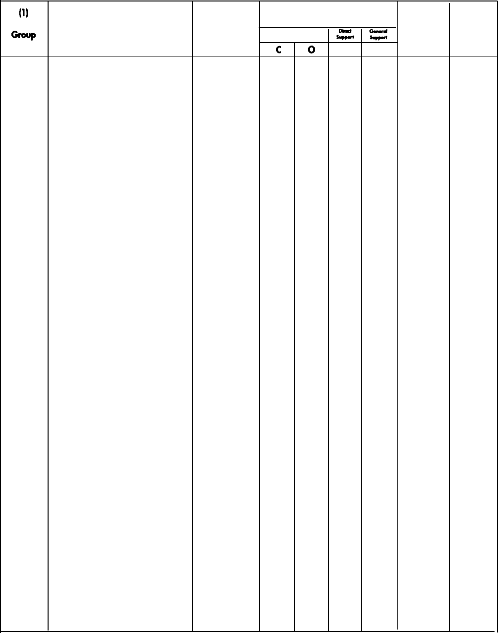
TM 9-2320-272-24-4
Section II. MAINTENANCE ALLOCATION CHART
(2) (3)
(4)
Maintenance Category
(5) (6)
Number
01
0100
component/Assembly
ENGINE
Engine Assembly
Maintenance
Function
Unit
Tools and
F
H
Equipment
Remarks
Inspect
Test
Service
Replace
Repair
0.1
1.5
2.0
0.1
1.5
2.0
0.2
0.2
2 thru 5
2 thru 5
7 thru 9
7, 11 thru
13
A
A
B
A
V
0101
0.3
2.0
0102 Crankshaft
0.2
0.5
0103
Engine Assembly*
Mount, Engine Lifting
Bracket, Engine Mounting
Head, Cylinder Assembly
Sleeve, Cylinder
Liner, Cylinder*
Damper, Vibration
Flange, Crankshaft
Flywheel, Ring Gear
Housing, Flywheel Gear
Ring Gear, Flexplate*
8.0
16.0
Overhaul
Inspect
Test
Service
Replace
Repair
Overhaul
Inspect
Replace
Inspect
Replace
Inspect
Replace
Repair
Inspect
Replace
40.0
8.0
14.0
40.0
0.2
2.0
0.2
4.0 5.0
0.3
2.0
Inspect
Replace
Inspect
Replace
1.5
5.0
Repair
6.0
Inspect
Replace
Inspect
Adjust
Replace
Inspect
Replace
Inspect
Replace
Inspect
Replace
thru 9,
23
1.0
0.2
0.5
0.4
1.0
1.0
4.0
1.0
1.0
2 thru 5
2 thru 5
7 thru 9
12, 13,
34 thru 37
6 thru 9
6 thru 9
6 thru 9
6 thru 9
7, 11 thru
13
7, 11, 13
23,34 thru
36
7, 11 thru
13
7, 11 thru
13
6 thru 9
6 thru 9
6 thru 9
6 thru 9
6 thru 9
6
*(M939A2 only)
B-4

TM 9-2320-272-24-4
Section II. MAINTENANCE ALLOCATION CHART (Contd)
(1) (2) (3)
(4)
Maintenance Category
(5)
(6)
Group Maintenance
Unit
Tools and
Number Component/Assembly Function C O F
H
Equipment Remarks
ENGINE (Contd)
0103
Housing, Flywheel* Inspect
0.5
(Contd)
Replace 4.0 6 thru 9,
23
Cover, Rear* Inspect
0.1 0.2
Replace
1.0
6 thru 9,
23
Seal, Rear Oil* Inspect
0.1
A
Replace
6.0
6 thru 9,
23
0104
Piston Assembly Inspect
0.3
Replace
5.0
9 thru 11
Repair
2.0
9 thru 11
Piston Assembly* Inspect
0.3
Replace
5.0
9 thru 11,
23
Repair
2.0
9 thru 11
Rod, Connecting Inspect
0.3
Replace
2.0
7, 11 thru
13
0105
Valve Cover Inspect
0.1
A
Replace
1.0
9 thru 11
Valve Cover* Inspect
0.1 A
Replace
1.0
2 thru 5
Assembly, Rocker Lever* Inspect
0.5
Adjust
0.5
6 thru 9
Replace
1.5
6 thru 9
Rod, Push, Intake/Exhaust* Inspect
0.1
Replace
0.5
6 thru 9
Shaft, Rocker Lever* Inspect
0.3
Replace 2.0 6 thru 9
Tube, Oil Manifold* Inspect
0.1
Replace 2.0 6 thru 9
Spring, Valve Inspect
0.3
Replace
0.5
6 thru 9
Valves, Intake and Exhaust Inspect
0.2
Replace
1.5
7, 11 thru
13
Repair
0.5
9 thru 13
Cover, Front Gear Inspect 0.2
Replace 2.0 6 thru 9
Seal, Front Oil Inspect
A
Replace 2.0 6 thru 9
* (M939A2 only)
B-5

TM 9-2320-272-24-4
Section II. MAINTENANCE ALLOCATION CHART (Contd)
(1) (2) (3)
(4)
Maintenance Category
(5) (6)
Maintenance Unit Tools and
Number Component/Assembly Function C O F
H
Equipment Remarks
ENGINE (Contd)
0105
Housing, Front Gear* Inspect
0.1 0.2 A
(Contd)
Replace 4.0 6 thru 9
Shaft Assembly, Rocker Arm Inspect
0.3
Replace 2.0 6 thru 9
Bearing, Camshaft Inspect
0.5
Replace
2.0
7, 11 thru
13
Camshaft Inspect
0.2
Replace
1.0
7, 11 thru
13
Camshaft, Gear Inspect
0.2
Replace
2.0
7, 11 thru
13
Camshaft* Inspect
0.5
Replace
1.5
7, 11 thru
13, 20
Camshaft, Gear* Inspect
0.2
Replace
2.0
7, 11 thru
13, 20
Bushings, Camshaft* Inspect
0.2
Replace
6.5
7, 11 thru
13, 20
Tappets* Inspect
0.1
Replace 4.0 7, 11 thru
13, 20
0106
Crankcase Breather Inspect
0.5
Replace
1.0
2 thru 5
Pump, Oil* Inspect
0.5
Replace 4.0 2 thru 5
Oil (Dipstick) Tube Inspect
0.2
A
Replace
0.3
2 thru 5
Cooler, Engine Oil* Replace
1.0
Repair
1.5
2 thru 5
Head, Filter* Inspect
0.1
Replace
0.5
2 thru 5
Oil Pan* Inspect
0.1
A
Replace
4.2
6 thru 9
Tube, Oil Suction* Inspect 0.1
Replace
0.5
6 thru 9
Pump, Oil Inspect
0.5
Replace
2.0
6 thru 9
Repair
4.0
7, 10 thru
13
* (M939A2 only)
B-6

TM 9-2320-272-24-4
Section II. MAINTENANCE ALLOCATION CHART (Contd)
(1)
12)
(3)
(4)
Maintenance Category
(5)
(6)
Maintenance Unit Tools and
Number Component/Assembly Function C O F
H
Equipment Remarks
ENGINE (Contd)
0106
Oil Pan Inspect
0.2
(Contd)
Replace
1.0
6 thru 9
Oil Filter Inspect
0.1
Replace
0.5
2 thru 5
Oil Cooler, Engine Inspect
0.5
Replace
0.7
6 thru 9
Repair
1.0
6 thru 9
0108
Manifold, Intake Inspect
0.5
Replace
3.0
6 thru 9
Manifold, Exhaust Inspect
0.5
Replace
2.0
6 thru 9
03
FUEL SYSTEM
0301
Injectors, Fuel Inspect
0.5
Test
0.5
7, 11 thru
13
Adjust
0.5
7, 11 thru
13
Replace
1.5
6 thru 9
Repair
1.0
7, 11 thru
13
Calibrate
2.0
7, 11 thru
13
Overhaul
1.0
7, 11 thru
13
Injectors, Fuel* Inspect
Test
Replace
Repair
0.5
1.5
7, 11 thru
13, 22, 38
2.0
6 thru 9
1.0
7, 11 thru
13, 22, 25
0302 Pump, Fuel Supply Inspect
0.5
Replace
2.0
6 thru 9
Adjust 2.0 7, 11 thru
13
Repair
4.0
7, 11 thru
13
Calibrate
2.0
7, 11 thru
13
Overhaul
4.0
7, 11 thru
13
Lines and Fittings, Injection Inspect
0.1
A
Pump* Replace
0.5
2 thru 5
D
Tubes, Fuel Injector* Inspect
0.1
Replace
1.0
2 thru 5
* (M939A2 only)
B-7

TM 9-2320-272-24-4
Section II. MAINTENANCE ALLOCATION CHART (Contd)
(1) (2) (3)
(4)
Maintenance Category
(5)
(6)
Maintenance
Unit
Tools and
Number Component/Assembly Function C O F
H
Equipment Remarks
FUEL SYSTEM (Contd)
0302
Fuel Injection Pump* Inspect
0.5
(Contd) Test
5.0
7, 11 thru
13, 33
Adjust
1.0
7, 11 thru
13, 33
Calibrate
6.0
7, 11 thru U
13, 33
Replace 2.0 2 thru 5,
23, 39
Repair 4.0 7, 11 thru
13, 27 thru
32
Fuel Transfer Pump* Inspect
0.2
Replace
0.3
2 thru 5
0304
Cleaner, Air Inspect
0.2
A
Replace
0.5
2 thru 5
Element Service
0.5 A
Replace
0.5
Lines and Connections, Vent Inspect
0.5
Replace
1.0
2 thru 5
D
Indicator, Air Cleaner Inspect
0.2 A
Test
0.2
Replace
0.5
2 thru 5
Hoses and Clamps Inspect
0.1
A
Replace
0.5
2 thru 5
0305
Hoses and Clamps, Inspect
0.2 A
Turbocharger* Replace
1.0
2 thru 5
Tube, Oil Drain* Inspect
0.2 A
Replace
1.0
2 thru 5
Turbocharger Assembly* Inspect
0.6
Replace
1.0
2 thru 5
Repair
1.5
6 thru 9
0306
Tank, Fuel Inspect
0.1
A
Replace
1.0
2 thru 5
Repair
1.0
6 thru 9
C
Bracket, Fuel Tank Inspect
0.1
A
Mounting Replace
1.0
2 thru 5
Lines and Fittings, Fuel Inspect
0.1
A
Replace
1.5
2 thru 5
D
Valve, Fuel Selector Inspect
0.1
A
Replace
1.0
2 thru 5
Lines and Fittings, Fuel Inspect
0.1
A
Pump to Engine Replace
1.0
2 thru 5
D
*(M939A2 only)
B-8
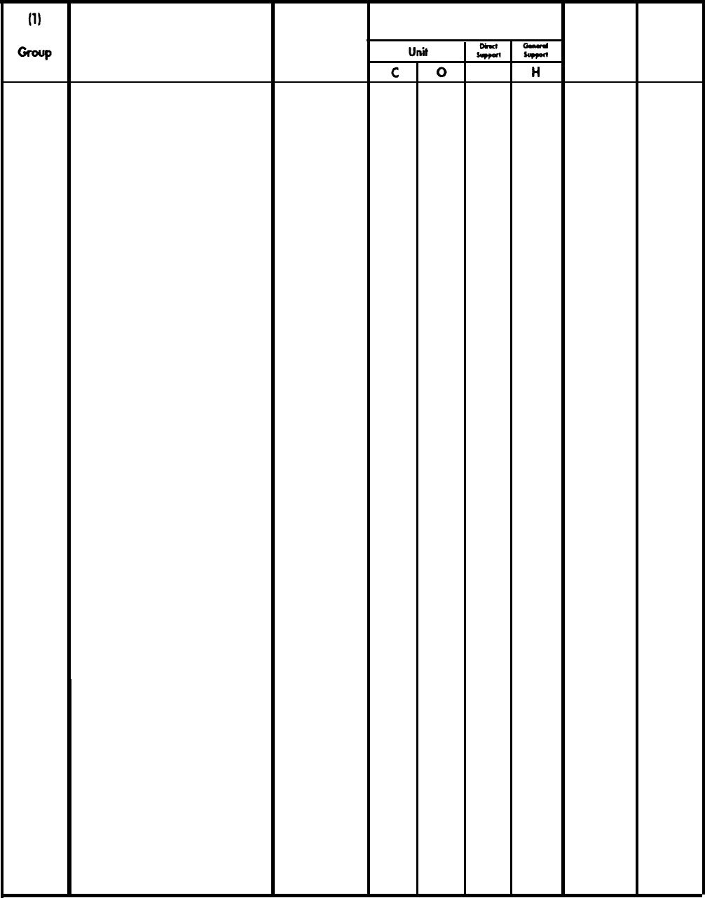
TM 9-2320-272-24-4
Section II. MAINTENANCE ALLOCATION CHART (Contd)
Number
0308 0.5
1.2
2.5
0.5
1.0
2.0
0.5
1.0
2.0
0.5
1.0
2.0
0.5
1.0
2.0
0.2
0.1
0.5
0309
0311
0.1
0.5
0.1
0.5
0.5
1.0
0.1
1.0
0.1
0.2
1.0
0.2
0.5
1.0
0312
(2)
Component/Assembly
FUEL SYSTEM (Cod)
Governor, Fuel Pump (AFC)
Spring Pack, Fuel Pump
Governor, Fuel Pump (VS)
Lower Spring Pack,
Fuel Pump
Upper Spring Pack,
Fuel Pump
Governor, Fuel Injection
Pump*
Fuel Filter
Filter, Fuel Water Separator
Aids, Engine Starting
Lines and Fittings
Pump, Hand Primer
Harness and Switch
Control, Accelerator and
Throttle Linkage
(3)
(4)
Maintenance Category
(5) (6)
Maintenance
Function
F
Tools and
Equipment Remarks
Inspect
Test
Replace
Inspect
Test
Replace
Inspect
Test
Replace
Inspect
Test
Replace
Inspect
Test
Replace
Inspect
Replace
Repair
Service
Replace
Service
Replace
Inspect
Replace
Inspect
Replace
Inspect
Test
Replace
Inspect
Adjust
Replace
7, 11 thru
13
7, 11 thru
13
7, 11 thru
13
7, 11 thru
13
7, 11 thru
13
7, 11 thru
13
7, 11 thru
13
7, 11 thru
13
7, 11 thru
13
7, 11 thru
13
7, 11 thru
13
7, 11 thru
13
2 thru 5
2 thru 5
2 thru 5
2 thru 5
2 thru 5
2 thru 15
2 thru 5
2 thru 5
A
A
D
* (M939A2 only)
B-9

TM 9-2320-272-24-4
Section II. MAINTENANCE ALLOCATION CHART (Contd)
Number
04
0401
05
0501
0502
0503
0504
0505
(3)
Maintenance Unit
Component/Assembly Function cO
EXHAUST SYSTEM
Pipe, Exhaust and Tail Inspect
0.2
Replace 2.0 2 thru 5
Muffler Inspect
0.2
Replace 2.0 2 thru 5
Shield, Vertical Exhaust Inspect
0.1
Replace
1.0
2 thru 5
COOLING SYSTEM
Radiator Inspect
0.2 0.2
Service
0.3
Replace
2.0
2 thru 5
Repair
3.0
6 thru 9
Tank, Surge Inspect 0.2
Service
0.1
02
Replace
1.0
2 thru 5
Radiator Hoses Inspect
0.2
Replace
0.5
2 thru 5
Canister, Thermostat* Inspect
0.1
Replace
0.5
Shroud, Radiator Fan Inspect
0.1
Replace
1.0
2 thru 5
Water Manifold and Headers Inspect
0.5
Replace
1.0
6 thru 9
Coolant Lines, Air Inspect
0.5
Compressor Replace
1.0
6 thru 9
Actuator, Fan Clutch Inspect
0.2
Replace
0.4
2 thru 9
Thermostats and Housing Inspect
0.1
0.2
Replace
1.0
2 thru 5
Pump, Water* Inspect
0.1
Replace
1.5
2 thru 5
Pump, Water Inspect
0.5
Replace
1.0
6 thru 9
Repair
1.5
6 thru 9
Belt, Water Pump Inspect
0.1
0.1
Adjust
0.3
2 thru 5
Replace
0.5
2 thru 5
Fan Assembly Inspect
0.1
0.1
Replace
1.0
2 thru 5
Clutch, Fan Drive Inspect
0.2
Replace
0.5
2 thru 5
Repair
1.0
6 thru 9
Pulley, Belt Tensioner* Inspect
0.1
Replace
0.5
2 thru 5
(4)
Maintenance Category
(5) (6)
Tools and
Equipment Remarks
A
E
A
A
A
A
A
A
A
*(M939A2 only)
B-10

TM 9-2320-272-24-4
Section II. MAINTENANCE ALLOCATION CHART (Contd)
(1)
(2) (3)
(4)
Maintenance Category
(5) (6)
Group
Maintenance Unit
Tools and
Number
Component/Assembly
Function
C O F
H
Equipment
Remarks
COOLING SYSTEM (Contd)
0505
Drivebelt, Fan Inspect
0.1 A
(Contd) Replace
0.3
2 thru 5
Fan Actuator* Inspect
0.1
A
Replace
0.8
2 thru 5
0507
Aftercooler, Engine* Inspect
0.3
Replace
1.0
2 thru 5
06
ELECTRICAL SYSTEM
0601
Alternator Inspect
0.1
Adjust
0.6
6 thru 9
Test
0.5
2 thru 5
Replace
1.0
2 thru 5
Repair
1.0
6 thru 9
Belt, Alternator Inspect
0.1
A
Adjust
0.2
2 thru 5
Replace
0.3
2 thru 5
0603
Starter Inspect
0.1
Test
0.5
2 thru 5
Replace
1.5
2 thru 5
Repair
1.0
6 thru 9
G
0606
Valve, Fuel Shutoff Electrical Inspect
1.0
Replace
0.7
6 thru 9
0607
Switches and Circuit Inspect
0.2 A
Breakers Test
0.7
2 thru 5
Replace
1.0
2 thru 5
Instruments and Gauges Inspect
0.1 A
Test
0.2
2 thru 5
Replace
1.0
2 thru 5
0608
Control, Directional Turn Inspect
0.1
A
Indicator Test
0.2
2 thru 5
Replace
0.5
2 thru 5
Repair
0.2
2 thru 5
Flasher Inspect
0.1 A
Replace
0.5
2 thru 5
Box, Protective Control Test
0.3
2 thru 5
Replace
0.7
2 thru 5
0609
Lights Inspect
0.1
2 thru 5
A
Adjust
0.2
2 thru 5
Replace
0.5
2 thru 5
0610
Unit, Sending Inspect
0.1
Replace
0.3
2 thru 5
Switch, Stoplight Inspect
0.1
Replace
0.5
2 thru 5
Buzzer, Warning Control Inspect
0.1
A
Replace
0.3
2 thru 5
* (M939A2 only)
B-11

TM 9-2320-272-24-4
Section II. MAINTENANCE ALLOCATION CHART (Contd)
(1)
(2)
(3)
(4)
Maintenance Category
(5)
(6)
Maintenance
Unit
Tools and
Number
Component/Assembly
Function
C O
F
H
Equipment
Remarks
ELECTRICAL SYSTEM (Contd)
0610 Transponder, Fuel Pump Inspect
0.2
(Contd) Replace
0.3
2 thru 5
0611
Horn Inspect
0.1 A
Replace
0.5
2 thru 5
Switch, Horn Inspect 0.1
Replace 0.5 2 thru 5
0612
Battery Inspect
0.1
A
Test
0.5
2 thru 5
Service
0.5
A
Replace
0.5
2 thru 5
Repair
1.0
2 thru 5
H
Cables, Battery Inspect
0.1 A
Replace
0.8
2 thru 5
Repair
0.5
2 thru 5
Box, Battery Inspect
0.1
A
Replace
1.8
2 thru 5
Repair
1.5
2 thru 5
0613
Harness, Chassis Wiring Inspect
0.1
A
Test
0.5
2 thru 5
Replace
4.5
6 thru 9
Repair
1.0
2 thru 5
07
TRANSMISSION
0705
Modulator Control Cable Adjust
0.5
2 thru 5
Replace
0.7
2 thru 5
0708
Torque Converter/Flywheel Replace 8.0 6 thru 9
Assembly Repair
5.0
7, 11 thru
14
0710
Transmission Assembly Inspect
0.2 A
Test
1.0
6 thru 9
Service
0.5 1.0
2 thru 5
Adjust
2.5
6 thru 9
Replace
6.0
6 thru 9
Repair
8.0
10.0
6 thru 9,
11 thru 14
Overhaul
20.0
I
Linkage, Shift Cable Inspect
0.1
Adjust
1.0
6 thru 9
Replace
1.0
6 thru 9
0721
Transmission Oil Cooler Inspect
0.1 A
Replace
2.0
6 thru 9
Lines and Fittings Inspect
0.2
A
Replace
1.0
6 thru 9
D
Transmission Oil Cooler* Inspect
0.2
Replace
1.5
2 thru 5
* (M939A2 only)
B-12

TM 9-2320-272-24-4
Section II. MAINTENANCE ALLOCATION CHART (Contd)
(1) (2)
(3)
(4)
Maintenance Category
(5)
(6)
Maintenance Unit
General
Support
Tools and
Number Component/Assembly Function C O F
H
Equipment Remarks
TRANSMISSION (Contd)
0721
Lines and Fittings* Inspect
0.1
A
(Contd) Replace
1.0
2 thru 5
08
TRANSFER CASE ASSEMBLY
0801
Transfer Case Assembly Inspect
0.3
Service
0.5
2 thru 5 A
Replace
5.0
6 thru 9
Repair
3.0 4.0
6 thru 14
Overhaul
9.5
J
Coupling, Yoke Input and Inspect
0.3
output Replace
1.0
6 thru 9
Flange, Output Inspect
0.3
Replace
1.0
6 thru 9
Cushion, Mounting Inspect 0.2
Replace
1.0
6 thru 9
Gear, Speedometer Inspect 0.2
Replace
0.5
6 thru 9
Seals, Input and Output Inspect
0.5
Shaft Replace 2.0 6 thru 9
Bearings, Gears, and Inspect
0.5
Shafts Replace
2.0
7, 11 thru
14
Repair
3.0
7, 11 thru
14
0803
Controls and Linkage Inspect
0.5
Adjust
0.3
6 thru 9
Replace
1.5
6 thru 9
Repair
1.0
6 thru 9
Cylinder, Air Shift Inspect
0.5
Replace
2.0
6 thru 9
Repair
0.7
6 thru 9
09
PROPELLER SHAFTS
0900 Shaft Assembly, Propeller Inspect
0.3
Service
0.5
2 thru 5
A
Replace
1.5
2 thru 5
Repair
1.0
Joint, Universal Inspect
0.2
A
Service
0.3
2 thru 5
Replace
1.5
2 thru 5
Dampener, Vibration Service
0.1
Replace
0.7
2 thru 5
Bearing, Center Inspect
0.2
Replace
1.5
2 thru 5
* (M939A2 only)
B-13

TM 9-2320-272-24-4
Section II. MAINTENANCE ALLOCATION CHART (Contd)
(1)
(2) (3)
(4)
Maintenance Category
(5)
(6)
Maintenance
Unit
General
Number Component/ Assembly
Support
Tools and
Function
C O F
H
Equipment
Remark
10
FRONT AXLE
1000
Front Axle Assembly Inspect
0.5
Service
1.0
2 thru 5 A
Replace
5.0
6 thru 9
Overhaul
10.0
K
1002
Carrier Assembly, Inspect
0.5
Differential Service
0.5
2 thru 5
A
Replace 7.0 6 thru 9
Repair 4.0 7, 11 thru
13
Seal, Pinion Inspect
0.2
Replace
2.0
6 thru 9
Flange, Companion Inspect
0.3
Replace
2.0
6 thru 9
Repair
1.6
6 thru 9
1004
Arms, Steering Inspect
0.2
Replace
2.5
6 thru 9
Boot, Dust (CV) Inspect
0.3
Replace
0.7
2 thru 5
Knuckle, Steering Inspect 0.1
Service
0.2
2 thru 5
A
Replace
2.5
6 thru 9
Axle Shaft and Inspect
0.2
2 thru 5
Universal Joint Service
0.3
2 thru 5
Replace
1.5
11 REAR AXLE
1100
Rear Axle Inspect
0.1 0.5 A
Service
1.0
2
Replace 4.0 2 thru 5
Repair 4.0 7, 11 thru
13
Overhaul
14.0 I
Rear Axle Assembly Inspect
0.3
Service
0.5
2 thru 5
Replace 4.0 6 thru 9
Repair 4.0 6 thru 9
Overhaul
14.0
K
1102
Carrier Assembly, Inspect
0.5
Differential Service
0.5
2 thru 5
Replace
7.0
6 thru 9
Repair 4.0 6, 11 thru
13
Seal, Pinion Inspect 0.2
Replace 1.0 6 thru 9
Flange, Companion Inspect
0.2
Replace
1.0
6 thru 9
Repair
1.6
6 thru 9
B-14

TM 9-2320-272-24-4
Section II. MAINTENANCE ALLOCATION CHART (Contd)
(2)
(3)
(4)
Maintenance Category
Component/Assembly
Maintenance
Function
(5)
Tools and
Equipment
Number
12
1201
1202
1206
1208
BRAKES
Drum, Handbrake
Shoes, Handbrake
Linkage, Handbrake
Brakeshoes, Parking
Brakeshoes, Service
Air Manifold*
Valve, Treadle
Chamber, Service Brake
Chamber, Spring Brake
Valve, Safety Air Pressure
Valve, Front Airbrake
Chamber (Limiting Valve)
Reservoir, Air Primary/
Secondary
Reservoir, Air Wet Tank
Pressure and Spring Brake
Valve, Hand Control
Valves, Brake Air Control
Miscellaneous
Inspect
Replace
Inspect
Adjust
Replace
Repair
Inspect
Adjust
Replace
Inspect
Adjust
Replace
Repair
Inspect
Adjust
Replace
Repair
Inspect
Replace
Inspect
Test
Replace
Repair
Inspect
Replace
Repair
Inspect
Replace
Repair
Inspect
Replace
Inspect
Replace
Repair
Inspect
Replace
Inspect
Replace
Test
Replace
Inspect
Replace
0.1
0.1
0.1
0.3
1.5
0.3
0.5
2.0
0.3
0.5
1.0
0.5
1.0
3.0
0.5
1.0
1.5
0.1
0.5
0.5
1.0
0.7
1.0
0.1
0.5
0.1
0.5
0.1
1.0
0.2
1.5
0.5
1.0
0.5
1.0
1.0
0.5
1.0
1.5
1.0
1.0
0.3
2 thru 5
2 thru 5
2 thru 5
6 thru 9
2 thru 5
2 thru 5
2 thru 5
19
2 thru 5,
22
6 thru 9
2 thru 5,
18
2 thru 5,
21
6 thru 8
2 thru 5
2 thru 5
2 thru 5
6 thru 9
2 thru 5
6 thru 9
2 thru 5
6 thru 9
2 thru 5
2 thru 5
6 thru 9
2 thru 5
2 thru 5
2 thru 5
2 thru 5
2 thru 5
(6)
Remarks
A
A
A
* (M939A2 only)
B-15
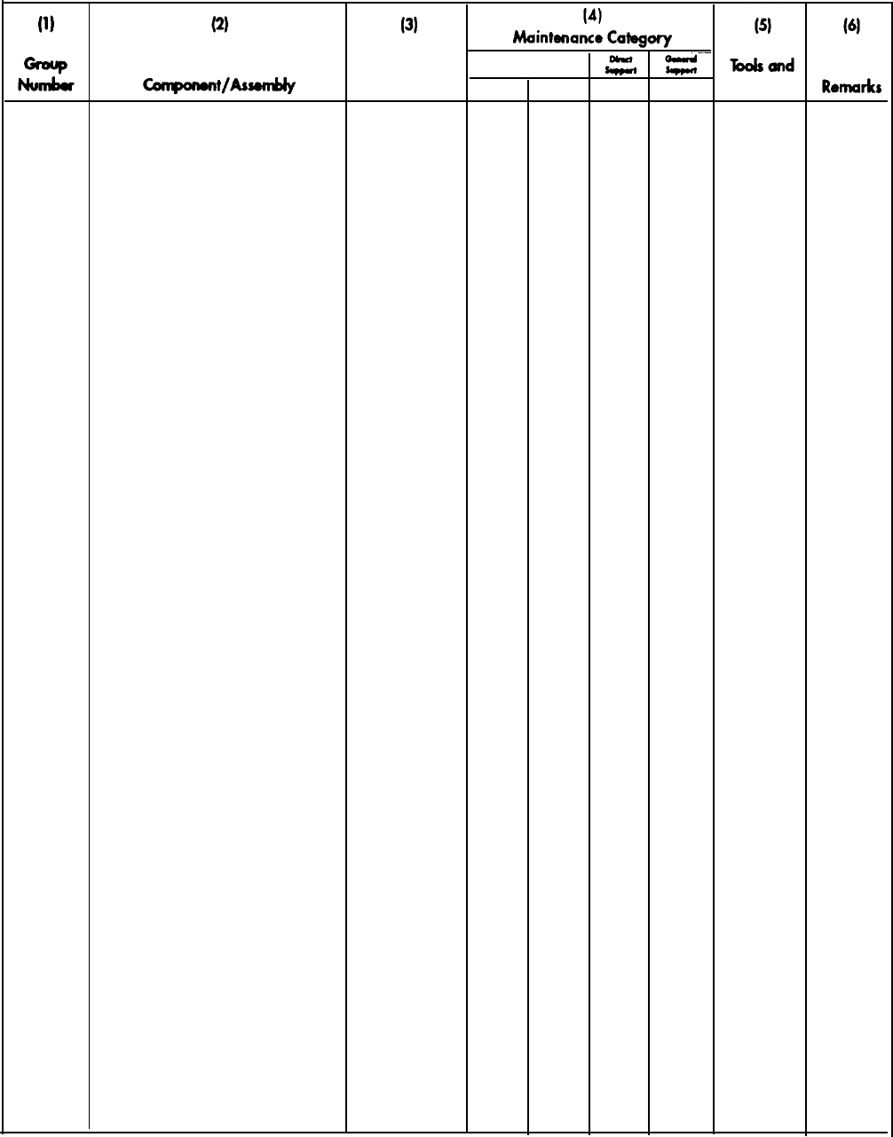
TM 9-2320-272-24-4
Section II. MAINTENANCE ALLOCATION CHART (Contd)
1208
(Contd)
1209
1211
13
WHEELS AND HUBS
1311
Hub. Wheel*
BRAKES (Contd)
Valve, Brake Lock Control
Lines and Fittings,
Airbrake System
Compressor, Air
Governor, Air
Evaporator, Alcohol
Mounting and Lines,
Air Compressor*
Compressor, Air*
Trailer Airbrake Connections
and Controls
Hose, Trailer Airbrake
Bearings, Wheel Hub
Wheel (M939A1/A2)
Drum, Brake
Seals, Inner and Outer Hub*
Valve Assembly, Wheel*
W/Filter
Maintenance
Function
Test
Replace
Inspect
Replace
Inspect
Test
Replace
Repair
Inspect
Test
Adjust
Replace
Inspect
Service
Replace
Inspect
Replace
Inspect
Replace
Repair
Inspect
Replace
Inspect
Replace
Inspect
Replace
Repair
Inspect
Service
Adjust
Replace
Inspect
Replace
Inspect
Replace
Repair
Inspect
Replace
Inspect
Service
Replace
Repair
Unit
C O F
H
Equipment
0.5
2 thru 5
0.5
2 thru 5
0.1 0.5
1.0
2 thru 5
0.1
0.5 2 thru 5
1.5
2.5 6 thru 9
6 thru 9
0.1
0.5
2 thru 5
0.3
2 thru 5
0.5
2 thru 5
0.1
0.2
0.5 2 thru 5
0.1 0.1
1.0
2 thru 5
0.1
3.0
2 thru 5
3.0
6 thru 9
0.1
0.3
2 thru 5
0.1 0.5
2 thru 5
0.1
1.5
2 thru 5
2.0
2 thru 5
0.5
1.0 2
0.5
2.5
2 thru 5
2 thru 5,
15
0.1
1.0
2 thru 5,
19, 20
0.2
1.5
2 thru 5
2.0
6 thru 9
0.5
2 thru 5
2.5
2 thru 5
0.1
0.5
1.0
2 thru 5
2 thru 5
1.5
2 thru 5
A, Q
A
A
A
G
A
A
A
A
A
*(M939A2 only)
B-16

TM 9-2320-272-24-4
Section II. MAINTENANCE ALLOCATION CHART (Contd)
(1) (2)
(3)
(4)
Maintenance Category
(5) (6)
Maintenance
Unit
GENERAL
Support
Tools and
Number Component/Assembly
Function
C O F
H
Equipment Remarks
WHEELS AND HUBS (Contd)
1311
Wheel (M939) Inspect
0.1 A
(Contd) Replace
1.0
2 thru 5
Hub, Wheel Inspect
0.2
Replace
1.5
2 thru 5
1313
Tires Inspect
0.2
0.2
A
Service
0.2 A,L
Replace
1.0
2 thru 5
20, 21
L
Repair
1.0
2 thru 5
L
Rebuild
2.0
L
Tubes Replace
0.5
2 thru 5
Repair
1.0
2 thru 5
L
14
STEERING
1401
Link, Front Drag Inspect
0.2
Service
0.2
Replace
1.0
2 thru 5
2 thru 5
Tie Rod Assembly Inspect
0.2
Service
0.2
2 thru 5
Replace
1.5
2 thru 5
Repair
1.5
2 thru 5
Arm, Pitman Steering Inspect
0.1
Replace
1.0
1 thru 5
Column, Steering (Lower) Inspect
0.2
Replace
2.5
6 thru 9
Repair 2.0 6 thru 9
Column, Steering (Upper) Replace
2.5
6 thru 9
Repair 2.0 6 thru 9
Wheel, Steering Inspect
0.2
Replace
1.0
2 thru 5
1407
Gear, Steering Assembly Inspect
0.2
Service
0.5
1 thru 5
Adjust 0.5 6 thru 9
Replace 3.0 6 thru 9
Repair
2.5
6 thru 9
1410
Pump, Hydraulic and Inspect
0.2
Reservoir Service
0.1
A
Replace
1.5
6 thru 9
Repair
1.0
6 thru 9
Power Steering Pump Inspect
0.1 A
Assembly Replace
1.0
2 thru 5
Repair
1.5
6 thru 9
1411
Lines and Fittings, Inspect
0.1
A
Power Steering Replace
1.0
2 thru 5
D
* (M939A2 only)
B-17

TM 9-2320-272-24-4
Section II. MAINTENANCE ALLOCATION CHART (Contd)
(1)
(2) (3)
(4)
Maintenance Category
(5)
(6)
Maintenance
Unit
General
Number
Support
Tools and
Component/Assembly
Function
C O F H Equipment Remarks
STEERING (Contd)
1412
Cylinder, Steering Assist Inspect 0.2
Adjust
0.5
2 thru 5
Replace
1.5
2 thru 5
Repair 2.0 6 thru 9
15
FRAME AND TOWING
ATTACHMENTS
1501
Frame Inspect
0.5
Repair
1.0
2.5
6 thru 14
M
Bumper, Front Inspect 0.2
Replace
2.0
2 thru 5
Brackets, Frame Inspect
0.1
A
Replace
1.0
2 thru 5
1503
Pintle Inspect
0.1
A
Service
0.1
0.5
2 thru 5
Replace 2 thru 5
1504
Carrier, Spare Wheel Inspect
0.1 A
Replace
1.0
2 thru 5
1506
Wheel, 5th Inspect
0.2
A
Service
0.5 A
Replace
2.5
2 thru 5
Repair
2.0
6 thru 9
16
SPRlNGS AND SHOCK
ABSORBERS
1601
Front Spring Inspect
0.2
A
Replace 3.0
Repair 2.0 1 thru 5
2 thru 5
Shackles Inspect
0.2
A
Replace 1.0 1 thru 5
Repair 0.4 2 thru 5
Springs, Rear and Seat Inspect
0.1
A
Replace
4.0
1 thru 5
Repair 2.0 2 thru 5
1604
Absorber, Front Shock Inspect
0.1 A
Replace
0.5
2 thru 5
1605
Rod, Rear Torque Inspect
0.1
Replace
1.5
6 thru 9
Repair 2.0 6 thru 9
18 BODY, HOOD, AND CAB
1801
Doors Inspect
0.1 A
Service
0.1
2 thru 5
Adjust
0.5
2 thru 5
Replace
1.0
2 thru 5
Repair
1.0
6 thru 10,
26
Cab Inspect
0.1
A
Replace
6.0
6 thru 9 P
B-18

TM 9-2320-272-24-4
Section II. MAINTENANCE ALLOCATION CHART (Contd)
(1) (2)
(3)
(4)
Maintenance Category
(5) (6)
Maintenance
Unit
General
Support
Tools and
Number Component/Assembly
Function
C 0 F HEquipment Remarks
BODY, HOOD, AND CAB (Contd)
1801
Hood Inspect
0.1 A
(Contd)
Adjust
0.5
2 thru 5
Replace 2.0 6 thru 9
Repair
1.0
6 thru 10 N
Cab Engine Cover Inspect
0.1 A
Replace
0.5
6 thru 9
1802
Fenders Inspect
0.1
A
Replace 2.0 6 thru 9
Repair
1.0
6 thru 10 N
Boards, Running Inspect
0.5 A
Replace
2.0
2 thru 5
1806
Cab Insulation Inspect
0.1
A
Replace 2.0 2 thru 5
Seats Inspect
0.1
A
Replace
1.0
2 thru 5
Repair
1.0
6 thru 9 T
1810
Body, Cargo Inspect
0.2
A
Replace
3.0
6 thru 9
Repair
10.0
6 thru 10
C, N
Troop Seat and Racks Inspect
0.2 A
Replace
1.0
2 thru 5
Repair
1.0
2 thru 5
Tailgate Inspect
0.2
Replace
1.0
2 thru 5
Repair 2.0 6 thru 9
C, N
1812
Doors Replace
2.5
2 thru 5
Repair 5.0 6 thru 10, N
26
Roof, Ceiling, Sides, Floors Replace
8.0
7, 11 thru
and Underframe
13
Repair
16.0
7, 10 thru
N
13
Mount, Front Cab Inspect
0.1
Replace
2.0
2 thru 5
Mount, Rear Cab Inspect
0.1
Replace
2.0
2 thru 5
Counterbalance Service
1.0
2 thru 5
Replace
8.0
2 thru 5
Electrical Wiring Replace 4.0 6 thru 9
Repair 4.0 6 thru 9
Heater Replace
4.0
2 thru 5
Repair
1.0
6 thru 9
S
Air Conditioner Inspect
0.2
6 thru 9
Replace 4.0 6 thru 9
B-19

TM 9-2320-272-24-4
Section II. MAINTENANCE ALLOCATION CHART (Contd)
(1)
(2)
(3)
(4)
Maintenance Category
(5)
(6)
Maintenance
Unit
Number Component/Assembly
Tools and
Function
C 0FH
Equipment
Remarks
BODY, HOOD, AND CAB (Contd)
1812
Boarding Ladders and Inspect
0.1
(Contd) Hardware A
Replace
0.3
20
HOIST, WINCH, AND
POWER TAKEOFF (PTO)
2001
Winch, Front and Rear Inspect
0.1
Service
A, R
0.5
2 thru 5 R
Adjust
0.5
2 thru 5
Replace
3.0
2 thru 5
Repair 4.0 6 thru 9
Overhaul
11.0 O
Band, Automatic Adjust
0.5
2 thru 5
Replace 2.0 6 thru 9
Cable, Winch Inspect
0.5 A
Service
0.5
R
Replace
1.0
2 thru 5 R
Repair 0.5 2 thru 5 R
Drum, Brake (Front Only) Adjust
1.0
2 thru 5
Replace 2.0 6 thru 9
Shaft, Hydraulic Pump Inspect
0.3
Drive Assembly Replace
1.0
2 thru 5
Repair 2.0 2 thru 5
Lines and Fittings, Hydraulic Inspect
0.2
Replace
0.5
6 thru 9
D
Boom, Assembly Inspect
0.2
Test
0.5
6 thru 9
Service
0.3
2 thru 5
Replace
15.0
6 thru 9
Repair
8.0
6 thru 9
Hoist Cylinders and Power Replace
8.0
Controls Hoist Cylinder 6 thru 9
Repair
6.0
7,
11 thru
13
Valve, Control Replace 2.0 6 thru 9
Repair
4.0
7,
11 thru
13
Cylinder, Boom Elevating Inspect
0.2 A
Replace 2.0 6 thru 9
Repair
3.0
7,
11 thru
13
Motor, Winch, Front Inspect
0.2
Repair
2.0
2 thru 5
Cylinder, Extension Replace
3.5
6 thru 9
Repair
4.0
7,
11 thru
13
Motor and Gearbox, Replace
2.0
Hydraulic Swing 6 thru 9
Repair
5.0
7,
11 thru
13
B-20

TM 9-2320-272-24-4
Section II. MAINTENANCE ALLOCATION CHART (Contd)
(1) (2)
(3)
(4)
Maintenance Category
(5)
(6)
Maintenance
Unit General
Support
Tools and
Number Component/Assembly
Function
C O F
H
Equipment
Remarks
HOIST, WINCH, AND
PTO (Contd)
2001
Winch Hoist Assembly Inspect
0.2
(Contd) Service
0.5
2 thru 5
A, R
Adjust
0.5
2 thru 5
Replace
4.5
6 thru 9
Repair
4.0
6 thru 9
Cable, Winch Hoist Inspect
0.5
A, R
Service
0.5
A, R
Replace 2.0
Repair
0.5
Valve, Control Assembly Replace
2.5
6 thru 9
Repair 4.0 6 thru 9
Motor, Hydraulic Inspect 0.2
Replace
2.0
6 thru 9
Reservoir, Hydraulic Oil Inspect
0.1
A
Service
0.1
A
Replace
2.0
6 thru 9
PTO and Winch Control Inspect
0.1 A
Cables* Replace
1.0
6 thru 8
Hydraulic Tubing, Winch Inspect
0.1
0.2
Pump* Replace
0.5
6 thru 8
Propeller Shaft, Front Inspect
0.1 A
Winch Dump Controls* Replace
0.8
2 thru 5
Repair
1.4
6 thru 8
2004
PTO, Transfer Inspect
0.1
A
Case Replace
5.0
2 thru 5
Repair 2.5 6 thru 8
PTO, Transmission Inspect
0.2
Replace
1.0
6 thru 9
Repair
3.0
6 thru 9
PTO, Shift Linkage Adjust
0.3
2 thru 5
Replace
1.0
6 thru 9
22
BODY CHASSIS AND
ACCESSORY ITEMS
2201 Bows
Inspect
0.1 A
Replace
1.0
2 thru 5
Cover, Cab Top Inspect
0.1 A
Replace
0.5
2 thru 5
Repair
1.5
6 thru 9
T
Curtains, Body Cover Inspect
0.1
A
Replace
1.0
2 thru 5
Repair
1.0
6 thru 9 T
2202
Motor, Windshield Wiper Inspect
0.1
A
Replace
0.7
2 thru 5
* (M939A2 only)
B-21

TM 9-2320-272-24-4
Section II. MAINTENANCE ALLOCATION CHART (Contd)
(1) (2)
(3)
(4)
Maintenance Category
(5) (6)
Maintenance
Unit
General
Support
Tools and
Number Component/Assembly
Function
C O
F
H
Equipment Remarks
BODY CHASSIS AND
ACCESSORY ITEMS (Contd)
2202
Arm and Blade, Windshield Inspect
0.1
A
(Contd)
Wiper Adjust
0.1
2 thru 5
Replace
0.2
2 thru 5
Washer Bottle and Controls Service
0.1
A
Replace
1.0
2 thru 5
Mirror, Rearview Inspect
0.1
A
Replace
0.5
2 thru 5
Spotlight Replace 0.5 2 thru 5
Repair
0.5
2 thru 5
Windshield Inspect
0.1
A
Replace
0.5
2 thru 5
Heater Valves Inspect
0.1
A
Replace
1.0
2 thru 5
2207
Heater, Personnel Inspect
0.2
A
Replace 3.0 2 thru 5
33
SPECIAL PURPOSE KITS
3303
Winterization Kits
Kit, Engine Coolant Heater Inspect
0.2
A
Install
10.0
6 thru 9 P
Kit, Radiator Cover Inspect
0.1
A
Install
1.2
6 thru 9 P
Kit, Hardtop Cab Inspect
0.1 A
Install
3.5
2 thru 5 P
Kit, Fuel Burning Personnel Inspect
0.2 A
Heater Install
6.0
6 thru 9
P
Kit, Pioneer Tool Bracket Inspect
1.0
2 thru 5 P
Kit, Swingfire Heater Inspect
0.2 A
Install
3.6
6 thru 9 P
3305
Kit, Deepwater Fording Inspect
0.2
A
Install
3.0
6 thru 9 P
3307
Special Purpose Kits
Kit, Troop Seat and Rack Inspect
0.1 A
Install
1.0
6 thru 9 P
Kit, Air Dryer Inspect
0.2 A
Install 8.0 6 thru 9 P
Kit, A-Frame Inspect
0.2 A
Install
1.0
2 thru 5 P
Kit, Fire Extinguisher Install
1.0
2 thru 5 P
Mounting
Kit, Chemical Agent Alarm Install 4.0 2 thru 5 P
Mounting
B-22

TM 9-2320-272-24-4
Section II. MAINTENANCE ALLOCATION CHART (Contd)
(1)
(2)
(3)
(4)
Maintenance Category
(5)
(6)
Kit, 100-Amp Alternator
Kit, Convoy Warning Light
Kit, European Mini-Lighting
Kit, Automatic Throttle
Kit, Atmospheric Fuel Tank
Vent System
Kit, Vehicle Tiedown
Kit, Hydraulic Hose
Chafe Guard
43
CTIS SYSTEM
4316
Lines and Fittings, Air*
Dryer, Air W/Filter*
4317
Group
Number Component/Assembly
SPECIAL PURPOSE KITS (Contd)
3307
Kit, Machine Gun Mounting
(Contd)
Kit, Decontamination (M13)
Apparatus Mounting
Kit, Mud Guard
Kit, Rifle Mounting
Kit, Hand Airbrake
Control Unit (ECU),*
Electronic
Valve, Relief Safety*
Controller, Pneumatic*
Wiring Harness, Electrical*
Switch, Pressure*
Warning Light, Amber*
Seals, Air (Front and Rear)*
Maintenance
Unit
Function
C O
Install
3.5
Install
3.0
Install
Inspect
Install
Inspect
Install
Install
Ins tall
Install
Install
Install
0.5
0.1
2.0
0.1
4.0
2.0
4.0
1.4
2.5
5.0
Install
Install
Inspect
Replace
Inspect
Service
Replace
Repair
Inspect
Replace
Inspect
Replace
Inspect
Replace
Repair
Inspect
Replace
Repair
Inspect
Replace
Inspect
Replace
Test
Replace
2.0
2.0
0.1 0.5
0.1 0.2
0.5
0.5
1.5
0.1
0.5
0.1 0.5
0.1 0.1
1.0
1.5
0.1
1.5
1.5
0.1
0.1
0.1 0.1
0.5
1.0
2 thru 15
P
2 thru 5 P
2 thru 5 P
A
6 thru 9 P
A
2 thru 5 P
2 thru 5 P
2 thru 5 P
2 thru 5 P
2 thru 5 P
2 thru 5 P
2 thru 5 P
2 thru 5 P
A
2 thru 5
D
2 thru 5
2 thru 5
2 thru 5
A
2 thru 5
A
2 thru 5
2 thru 5
2 thru 5
2 thru 5
2 thru 5
D
A
2 thru 5
A
2 thru 5
2 thru 5
2 thru 5
15
thru
17
* (M939A2 only)
B-23

TM 9-2320-272-24-4
Section II. MAINTENANCE ALLOCATION CHART (Contd)
(1) (2)
(3)
(4)
Maintenance Category
(5) (6)
Maintenance Unit
General
Support
Tools and
Number Component/Assembly
Function
C O F H Equipment Remarks
CTIS SYSTEM (Contd)
4317
Filter, Compressed Air* Inspect
0.8
A
(Contd) Replace
1.0
2 thru 5
Repair
1.0
2 thru 5
47
GAUGES (NON-ELECTRICAL)
4701
Drive, Tachometer* Inspect
0.1 A
Replace
0.6
2 thru 5
Speedometer Inspect
0.1 A
Replace
1.0
2 thru 5
Tachometer Inspect
0.1 A
Replace
1.0
2 thru 5
4702
Gauge, Air Pressure Inspect
0.1 A
Replace
0.5
2 thru 5
*(M939A2 only)
B-24

TM 9-2320-272-24-4
Section III. TOOL AND TEST EQUIPMENT REQUIREMENTS
REFERENCE
MAINTENANCE
(3)
(4) (5)
NATIONAL/NATO
TOOL
CODE
CATEGORY NOMENCLATURE
STOCK NUMBER NUMBER
1
O
Organizational Maintenance
5180-00-762-1737 5704499
Tool Kit
2
O
No. 1 Common Organizational
4910-00-754-0654 SC4910-95-CL-A74
Maintenance Tool Kit
3
O
No. 1 Supplemental Organiza-
4910-00-754-0643 SC4910-95-CL-A73
tional Maintenance Tool Kit
4O
No. 2 Common Organizational 4910-00-754-0650
SC4910-95-CL-A72
Maintenance Tool Kit
5
O
General Mechanic’s Tool Kit
5180-00-177-7033
SC5180-90-CL-N26
6
FTool Kit, Direct Support
5180-00-762-1740
5704500
7
FAutomotive Maintenance and
4910-00-754-0705 SC4910-95-CL-A31
Repair Tool Kit
8
FAutomotive Maintenance Shop
4910-00-348-7696 SC4910-95-CL-A02
Equipment, Wheeled Vehicles,
Set A
9
FTool Kit, General Mechanic’s
5180-00-699-5273
SC5180-90-CL-N05
10
FShop Equipment, Field
3470-00-357-7268 SC3470-95-CL-A08
Maintenance Welding
11
HGeneral Support Tool Kit
5180-00-762-1741 5704501
12
HNo. 1 Supplemental Automotive
4910-00-754-0706 SC4910-95-CL-A62
Maintenance and Repair Tool Set
13
HNo. 2 Supplemental Automotive
4910-00-754-0707 SC4910-95-CL-A63
Maintenance and Repair Tool Set
14
HTool Kit, General Support
5180-01-147-5824 5704171
15
O
Bearing Punch
5120-01-285-5192 20511262
16
O
Air Seal Installer
5120-01-285-7620 20511263
17
O
Air Gauge Assembly
5220-01-298-5730 20511320
18 O
Adjusting Tool, Brakeshoe
5120-01-154-3029
J34061
19
O
Tool, Wheel Assembly
4910-01-218-4490
J35193
20
O
Bolt, Inserter Tool
4910-01-220-1512
J35198
21
O
Pliers, Brake Repair
5120-01-152-2318
J33111
22 FTube Reducer
4730-01-284-9086 23622
23
FEngine Barring Tool
5120-01-285-5193 3377371
24
FWrench Box
5120-01-178-5351 CXM 1519
25
FNozzle Cleaning Kit
2915-01-285-2527 3376947
26 FTool Kit, Glass Cutting
5180-00-357-7737 SC4940-95-CL-A18
27
HTube, Separation
4910-01-336-8204
KDEP-1052
28
HPuller, Side Plug
5120-01-343-2585
KDEP-1056
B-25

TM 9-2320-272-24-4
Section Ill. TOOL AND TEST EQUIPMENT REQUIREMENTS (Contd)
(1) (2) (3)
(4) (5)
REFERENCE MAINTENANCE NATIONAL/NATO
TOOL
CODE
CATEGORY
NOMENCLATURE STOCK NUMBER NUMBER
29
HTappet Holder
5120-01-345-2586
KDEP-1068
30
HSpring Compressor
5120-01-341-6000
KDEP-1505
31
HPlunger Lift Device
4910-01-338-6241 1-688-130-135
32
HRack Extension
5340-01-341-6572 9-681-233-100
33
HFuel Pump Test Stand
4910-01-194-7667
DFP 156
34
HCylinder Liner Clamps
5120-01-262-7309
3822503
35
HMechanical Puller
5120-01-291-5769
3822786
36
HCylinder Liner Puller
5120-01-143-2032
3376015
37
HTorque Angle Gauge
5120-01-386-5992
3823878
38
HTester, Injector Nozzle
4910-00-255-8641 7551255
39
HPuller Kit
5180-00-999-4053
J24420C
Section IV. REMARKS
REFERENCE
CODE
REMARKS
A
Perform PMCS as shown in TM 9-2320-272-10.
B
Engine overhaul will be in accordance with DMWR 9-2815-500.
C
Welding will be in accordance with TM 9-237.
D
Repair of lines and fittings will be in accordance with TM 9-243.
E
Test and repair of radiator will be in accordance with TM 750-254.
FRepair of alternator will be in accordance with TM 9-2920-225-34.
G
Repair of starter will be in accordance with TM 9-2920-243-34.
H
Repair of batteries will be in accordance with TM 9-6140-200-14.
I
Transmission overhaul will be in accordance with DMWR 9-2520-522.
JTransfer overhaul will be in accordance with DMWR 9-2520-530.
KOverhaul of front and rear axle will be in accordance with DMWR 9-2520-508.
L
Tires/Tubes: Repair and Inspection TM 9-2610-200-14
Storage
TM 743-200-1
M
Repair of frames will be in accordance with TB 2300-247-40.
NMetal body repair will be in accordance with FM 43-2.
O
Overhaul of front and rear winches will be in accordance with DMWR 9-3830-501.
PRefer to kit installation instructions for kit installation.
Q
Inspection of brake lines will be in accordance with TB 9-2300-405-14.
R
Service/inspection of winch/hoist wire rope/cables will be in accordance with
TB 43-0142 and TB 9-0352.
S
Repair of heaters will be in accordance with TM 9-2540-205-24&P.
T
Repair of canvas will be in accordance with FM 10-16.
U
Operation of fuel pump test stand, P/N DFP 156, will be in accordance with
TM 9-4910-778-14&P.
VEngine overhaul will be in accordance with DMWR 9-2815-358.
B-26
TM 9-2320-272-24-4
APPENDIX C
EXPENDABLE/DURABLE SUPPLIES AND MATERIALS LIST
Section I. Introduction (page C-l).
Section II. Expendable/Durable Supplies and Materials List (page C-2).
Section I. INTRODUCTION
This appendix lists expendable/durable supplies and materials you will need to maintain M939 series
vehicles. This listing is for informational purpose only and is not authority to requisition listed items.
C-2. EXPLANATION OF COLUMNS
Column (1) - Item Number. This number is assigned to the entry in the listing and is referenced in
the INITIAL SETUP of applicable tasks under the heading of MATERIALS/PARTS.
b.
Column (2) - Level. This column identifies the lowest level of maintenance that requires the listed
item.
C - Operator/Crew
O - Organizational Maintenance
F - Direct Support Maintenance
C. Column (3) - National Stock Number. This is the National Stock Number assigned to the item;
use it to request or requisition the item.
d. Column (4) - Description, CAGEC, and Part Number. Indicates the federal item name and, if
required, a description to identify the item. The last line for each item indicates the Commercial and
Government Entity Code (CAGEC) (in parentheses) followed by a part number. These codes are identified as:
CAGEC
MANUFACTURER
05972
19200
19207
Loctite Corporation
U.S. Army Research and Development Command
U.S. Army Tank-automotive and Armaments Command,
AMSTA-IM-MM
58536 Federal Commercial Item Promulgated by General
Services Administration
62377
Permatex Industrial
71984
Dow Corning Corp.
72932
Gulf Oil Corp.
75037
Minnesota Mining and Manufacturing Company
77220
Dana Corp.
78500
Rockwell Heavy Vehicle Systems Inc.
79819
BT Office Products Intl. Inc.
80064
Naval Ship Systems Command
80244
General Services Administration
81348
Federal Specifications
C-l

TM 9-2320-272-24-4
C-2. EXPLANATION OF COLUMNS (Contd)
81349 Military Specification Promulgated by Military
81755
Lockheed Martin Company
96599
Fischbein-Dave Company
96906
Military Standards
96980 American Grease Stick Company
97403
U.S. Army Communications - Electronic Command Center
98308
Castrol Industrial North America
e. Column (5) - Unit of Issue. This column indicates the size of container issued for each NSN. This
measure is expressed by an abbreviation [such as ea (each), oz (ounce), gal. (gallon)]. If the unit of measure
differs from the unit of issue, requisition the lowest unit of issue that will satisfy your requirements.
C-2

TM 9-2320-272-24-4
EXPENDABLE/DURABLES SUPPLIES AND MATERIALS LIST
(1)
REFERENCE
CODE NO.
LEVEL
NATlONAL STOCK
NUMBER
O
6830-00-264-6751
(4)
DESCRIPITON
(5)
UNIT OF
ISSUE
ACETYLENE, TECHNICAL:
gas filled acetylene,
(81348) BB-A-106
225 cubic feet CU-FT
2
F
3
O
4
F
5
O
6
O
7
O
8C
9C
10 O
ADHESIVE, LIQUID: ethyl
cyanacrylic resin, type II
(81349) MILA-46050
0040-00-142-9193
10 1 ounce bottles per box
BX
ADHESIVE, LIQUID: silicone,
rubber, Silastic 732RTV (clear)
non-hardening type I
(81348) MMM-A-139
8040-00-262-9062
1 pint PT
ADHESIVE SEALANT: anaerobic
threadlock, medium strength,
MIL-S-46163, type II, grade N,
Loctite 242,
(05972) 24231
8030-01-014-5869
50 milliliter
ML
ADHESIVE: silicone rubber,
MIL-A-46106, type I,
(97403)
8040-00-833-9563
1 kit
KT
ADHESIVE: synthetic
rubber, class II,
(80244) MMM-A-189 CL2
8040-00-543-7170
1 pint can
PT
ADHESIVE: synthetic rubber,
MMM-A-1617, type II,
(79819) 1357
8040-00-262-9005
1 gallon can
GAL.
ANTIFREEZE: arctic grade,
permanent type, fluorescent
yellow,
(81349) MILA-11755
6850-00-174-1806
55 gallon drum
GAL.
ANTIFREEZE: ethylene glycol,
permanent type, inhibited {-60°F
(-51°C)} blue-green in color,
(81349) MILA-46153
6850-00-181-7929
1 gallon container
GAL.
6850-00-181-7933
5 gallon container
GAL.
6850-00-181-7940
55 gallon drum
GAL.
ANTISEIZE COMPOUND:
temperature resistant
lubricant, MIL-A-907,
Loctite, antiseize, 1050°F (566°C),
(05972) 76764
8030-00-251-3980
1 pound can with brush top
LB
C-3

TM
9-2320-272-24-4
EXPENDABLE/DURABLES SUPPLIES AND MATERIALS LIST (Contd)
(1) (2)
REFERENCE
LEVEL
CODE NO.
11
O
12
O
13
F
14 O
15
F
16 0
17 0
18 0
19 0
20
O
21
O
22
O
23 O
(3)
(4)
(5)
NATlONAL STOCK DESCRIPITON UNIT OF
NUMBER ISSUE
BAG: plastic, polyethylene,
(58536) A-A-1799
8105-00-837-7754
500 bags per box
BX
BOTTLES: oil sample,
(81996) PD 8125-1
8125-01-082-9697
120 bottles box
per
BX
CALIBRATING OIL: gulf 45A,
(72932) 45A
6850-00-974-3738
55 gallon drum
GAL.
CAP AND PLUG SET:
(19207) 10935405
5340-00-450-5718
1 set SET
CAULKING COMPOUND:
rubber, synthetic
(81349) MIL-C-18255
8030-00-682-6745
1 kit KT
CHALK LINE AND REEL: self-
chalking, hand crank rewind,
(81349) GGG-C-291
5120-00-273-9793
50 feet EA
CHALK: marking, white,
(81348) SS-C-266
7510-00-164-8893
1 gross CR
CLEANING COMPOUND:
windshield, concentrated
(81348)
6850-00-926-2275
16 ounce bottle
OZ
CLEANING COMPOUND KIT
engine cooling system
(81349) MIL-C-10597
6850-00-598-7328
1 kit
KT
CLOTH, ABRASIVE (crocus):
9 inch x 11 inch sheets,
(58536) A-A-1206
5350-00-221-0872
50 sheets/package PG
CLOTH, CLEANING: lint-free,
general purpose, white,
(81349) MIL-C-85043
7920-00-044-9281
10 pound box
LB
COATING: polyurethane,
chemical agent resistant, green 383,
MIL-C-46168C, type II,
(19207) 5584154
8010-01-160-6741
1 gallon can
GAL.
COATING: battery box, non-
drying epoxy,
(81349) MIL-C-22750
8010-00-959-4661
1 kit KT
C-4

TM 9-2320-272-24-4
EXPENDABLE/DURABLES SUPPLIES AND MATERIALS LIST (Contd)
(1)
REFERENCE
CODE NO.
24
25
26
27
28
29
30
31
(2)
LEVEL
F
O
F
O
O
O
O
C
(3)
NATIONAL STOCK
NUMBER
5330-00-069-3321
8030-00-244-1297
9150-00-265-9406
7930-00-282-9699
9150-00-935-1017
8040-01-378-0235
8040-00-664-4134
8040-00-728-3088
9620-00-233-6712
9150-01-197-7698
9150-01-197-7690
9150-01-197-7689
9150-01-197-7692
9150-00-530-7369
9150-00-027-2954
4720-00-845-0630
(4)
DESCRIPITON
CORK Type IB, Class 2
(81348) Spec HH-C-576
36 inch x 36 inch
CORROSION PREVENTIVE
COMPOUND: grade II, soft film
(81349) MIL-C-16173
1 gallon can
CUTTING FLUID:
(81348) C-O-376
1 gallon can
DETERGENT: nonsudsing,
general purpose, liquid,
(80244) MIL-D-16791 type I
1 gallon
GAA GREASE: automotive and
artillery, MIL-G-10924,
(98308) BRAYCOTE610
14 ounce can
GASKET COMPOUND: shellac,
heavy-bodied, hard setting,
(62377)
2 ounce bottle
1 pint bottle
GASKET SEALANT: silicone rubber,
MIL-A-46106, type 1,
(78500) 1199-T-3842
1 kit
GRAPHITE, POWDERED:
MIL-SS-G-659
(81348) SSG659
1 pound kit
GREASE, AUTOMOTIVE AND
ARTILLERY (MIL-G-10924)
(81349)
2-1/4 ounce tube
1-3/4 pound can
6-1/2 pound can
35 pound can
120 pound drum
GREASE, SILICONE INSULATED:
electric motor,
(71984) Molykote DC44
5.3 ounce tube
HOSE: nonmetallic, rubber
synthetic, black, fuel/oil resistant
(23040) C2AZ9324C
3/8 inch ID, 5/8 inch OD
(5)
UNIT OF
ISSUE
EA
GAL.
GAL.
GAL.
OZ
OZ
PT
KT
KT
32
C
33
C
34
O
OZ
LB
LB
LB
LB
OZ
FT
C-5

TM 9-2320-272-24-4
EXPENDABLE/DURABLES SUPPLIES AND MATERIALS LIST (Contd)
(1) (2) (3) (4)
(5)
REFERENCE
LEVEL
NATIONAL STOCK DESCRIPITON UNIT OF
CODE NO.
NUMBER
ISSUE
35 C
36
0
37 F
38
F
9150-00-402-2372
6850-01-160-3868
6850-01-287-8067
5350-00-193-1341
5350-00-271-5966
39 O
40
0
41 C
42
C
43
C
2640-00-256-5527
6810-00-597-3608
6810-00-275-6010
9140-00-286-5289
9140-00-286-5286
9140-00-286-5297
9140-00-286-5294
9140-00-286-5284
9140-00-286-5285
9140-00-286-5283
HYDRAULIC FLUID:
SAE 15W40 (O-1236)
(81349) MIL-L-46167
5 gallon can
INHIBITOR, CORROSION:
liquid cooling system; powder
(81348) MIL-A-54009
1 quart bottle
1 gallon bottle
LAPPING AND GRINDING
COMPOUND: valve-grinding
compound, grease-mixed,
grit 220 fine,
(58536) A-A-1203 type I
1 pound can
LAPPING AND GRINDING
COMPOUND: valve-grinding
compound, grease-mixed,
grit 120 coarse,
(58536) A-A-1203 type I
1 pound can
LUBRICANT, TIRE AND RIM:
liquid,
(96980) AA18
1 gallon
METHYL ALCOHOL, METHANOL:
(81348) O-M-232
1 gallon can
5 gallon can
OIL, FUEL, DIESEL DF-1: Winter
(81349) (W-F-800) gauge
55 gallon drum, 18 gauge
bulk
OIL, FUEL, DIESEL DF-2: Regular
(81348) (W-F-800) gauge
55 gallon drum, 18 gauge
bulk
OIL, FUEL, DIESEL DF-A: Arctic
(81348) (VV-F-800)
55 gallon drum, 16 gauge
55 gallon drum, 18 gauge
bulk
GAL.
QT
GAL.
LB
LB
GAL.
GAL.
GAL.
GAL.
GAL.
GAL:
GAL.
GAL.
GAL:
GAL.
GAL.
GAL.
C-6

TM 9-2320-272-24-4
EXPENDABLE/DURABLES SUPPLIES AND MATERIALS LIST (Contd)
(1) (2) (3) (4)
(5)
REFERENCE
LEVEL
NATIONAL STOCK DESCRIPITON UNIT OF
CODE NO.
NUMBER
ISSUE
44 C
45
C
46
C
47
C
48
C
49
C
50
C
51
C
52
O
9150-00-402-4478
9150-00-49 1-7197
9150-00-234-5197
9150-01-035-5390
9150-01-422-9342
9150-00-183-7807
9150-01-035-5393
9150-01-035-5394
9150-00-188-9858
9150-00-191-2772
9150-00-186-6668
9150-00-189-6729
9150-00-183-7808
9130-01-031-5816
6830-00-292-0129
OIL, LUBRICATING, ENGINE:
arctic (ice, sub-zero) OEA
(SEA OW-20)
(19200) (9377757)
1 quart can
55 gallon drum, 16 gauge
OIL, LUBRICATING, GEAR,
EXPOSED: CW
(81348) (W-L-751)
5 pound can
OIL, LUBRICATING, GEAR,
MULTI-PURPOSE: GO 75
(81349) (MIL-L-2105)
1 quart can
55 gallon drum, 16 gauge
bulk
OIL, LUBRICATING, GEAR,
MULTI-PURPOSE: GO 80/90
(81349) (MIL-L-2105)
5 gallon can
55 gallon drum, 16 gauge
OIL, LUBRICATING, OE/HDO: 1OW
(81349) (MIL-L-2104)
5 gallon drum
55 gallon drum, 16 gauge
OIL, LUBRICATING: internal
combustion engine, tactical
service, OE/HDO 10,
(81349) MIL-L-2104
5 gallon drum
OIL, LUBRICATING, OE/HDO: 30W
(81349) (MIL-L-2104)
55 gallon drum, 16 gauge
bulk
OIL, TURBINE FUEL,
AVIATION: grade JP-8
(81349)
bulk
OXYGEN, TECHNICAL: gas
filled oxygen,
(81348) BB-A-925
240 cubic feet (to be filled/refilled
locally)
QT
GAL.
GAL.
LB
QT
GAL.
GAL.
GAL:
QT
GAL.
GAL:
QT
GAL.
GAL:
GAL.
GAL.
GAL.
GAL.
CU-FT
C-7

TM 9-2320-272-24-4
EXPENDABLE/DURABLES SUPPLIES AND MATERIALS LIST (Contd)
(1) (2)
(3)
(4) (5)
REFERENCE
LEVEL
NATlONAL STOCK DESCRIPITON UNIT OF
CODE NO.
NUMBER
ISSUE
53
F
9150-00-250-0933
PETROLATUM: technical, oil-soluble
grease (Vaseline)
(81348) W-P-236
7-1/2 pound can
LB
54
F
8010-00-247-4334
PIGMENT: iron, blue, oil base
(substitute for Prussian blue),
(81348) TT-P-381
1/2 pint can PT
55
F
56
O
57
F
5210-00-640-6177
9620-00-233-6712
0010-00-145-0312
PLASTIGAGE: clearance range
green
(77220) PG-1
12 each box
POWDERED GRAPHITE:
MIL-SS-G-659
(81348) SSG659
1 pound can
PRIMER: zinc chromate
(81348) Spec TT-P-1757
1 pint can
BX
LB
P-r
58
O
7920-00-205-1711
RAG: wiping, unbleached cotton
and cotton-synthetic, mixed colors
(58536) A-A-531
50 pound bale
LB
59
O
60
O
61
O
4020-00-23 1-2581
8105-00-290-0340
8030-00-111-6404
ROPE, FIBROUS: 3 strand,
3/8 inch diameter, 1-1/8 inch
circumference, 1,350 pound capacity
(81348) TR605
406.667 yards, minimum
SACK: shipping, water resistant,
ten pound load capacity,
(58536) A-A-160
250 each box
SEALING COMPOUND: plastic
epoxy, resin, MIL-R-46082,
type II, Loctite RC/640,
(05972) 64031
50 cubic centimeters
YD
BX
CC
62
O
8030-00-204-9149
SEALING COMPOUND: plastic,
tetrafluoroethylene, Loctite 277,
(05972) 59241
250 cubic centimeters
CC
63
C
8030-01-054-0740
SEALING COMPOUND;
polyester and plastic,
tetrafluoroethylene,
Loctite 592-31,
(05972)
50 cubic centimeters
CC
C-8

TM 9-2320-272-24-4
EXPENDABLE/DURABLES SUPPLIES AND MATERIALS LIST (Contd)
(1)
REFERENCE
CODE NO.
(2)
LEVEL
(3)
NATIONAL STOCK
NUMBER
(4)
DESCRIPITON
(5)
UNIT OF
ISSUE
65 O
66
O
8030-00-247-2525
8030-00-252-3391
8030-00-180-6222
11 ounce tube
SEALING COMPOUND: non-
hardening, MIL-S-45180, type II,
Permatex no. 2,
(80064) 1756371
11 ounce tube
SEALING COMPOUND: resin,
synthetic, MIL-R-46082, type I,
Loctite 75,
(05972) 669-31
50 cubic centimeters
OZ
OZ
cc
67
F
68 F
69
O
70
O
71
C
72
O
73
O
8030-00-503-0316
8030-00-656-1426
6810-00-264-6618
3439-00-224-3567
6850-01-277-0595
6850-01-244-3207
8030-00-889-3535
5970-00-4 19-4291
SEALING COMPOUND: non-
hardening, Permatex no. 51H
(pipe joint compound),
(77247) 51H
4 ounce can
SEALING COMPOUND: liquid
resin, nonhardening, type III,
(77247) MIL-S-45180
1 pint can
SODIUM BICARBONATE:
technical
(81348) 0-5-576
1 pound box
SOLDER: rosin core, 60/40,
0.094 inch diagnostic,
(81348) QQ-S-571
5 pound spool
SOLVENT, DRYCLEANING:
type III, biodegradable
(81348) 134 Hi-Solv
5 gallon
55 gallon drum
TAPE, ANTISEIZING: white,
MIL-T-27730,
(81755) P5025-2R
1/2 inch wide x 260 inches long
x 0.0035 inch thick with snap-on shell
TAPE, INSULATION: electrical
MIL-I-24391, 3/4 inch wide, black
(75037)
108 feet roll
OZ
PT
LB
LB
GAL.
GAL.
EA
FT
C-9

TM 9-2320-272-24-4
EXPENDABLE/DURABLES SUPPLIES AND MATERIALS LIST (Contd)
(1)
(2) (3) (4)
(5)
REFERENCE
LEVEL
NATIONAL STOCK DESCRIPITON
UNIT OF
CODE NO.
NUMBER
ISSUE
74
75
76
77
78
O
F
O
O
F
5970-01-189-6927
7510-00-290-2023
6810-00-678-4418
4020-00-291-5901
TAPE, INSULATION: electrical
(81349) MIL-I-24391
3/4 inch wide x 10 yards long x
0.0085 inch thick
TAPE, PRESSURE SENSITIVE:
masking, 1/2 inch wide, tan,
A-A-883 type II
(81348) PPP-T-42
60 yards per roll
TRICHLOROETHYLENE: liquid
(81349) O-T-634
1 gallon can
TWINE: cotton (string), 16 ply
(81348) A-A-1451
375 yard ball
WHITE LEAD: basic carbonate,
paste in oil,
(96906) MS35599-1 type B
EA
EA
GAL.
YD
79
O
80
F
81
F
82 F
8010-00-239-5736
9525-00-990-7799
9505-00-198-9125
8030-00-222-0503
5510-00-270-6031
1 pound can
WIRE, NON-ELECTRICAL:
safety wire
(96906) QQ-N-281, Class A
1 pound roll
WIRE: non-electric, iron,
(80244) 22-W-1642-125-36
1 pound roll
WOOD PRESERVATIVE:
(81349) MIL-S-13518
1 gallon can
WOOD, LAMINATED
DECKING: red or white oak,
ungraded, MIL-W-3912, treated
with preservative TT-W-572,
(97403) 12319E0079
228 inches X 11.5 inches X 1.12
inches
LB
LB
LB
GAL.
EA
C-10

TM 9-2320-272-24-4
APPENDIX D
MANDATORY REPLACEMENT PARTS
Section I. Introduction (page D-l).
Section II. Mandatory Replacement Parts (page D-2).
Section I. INTRODUCTION
This appendix list mandatory replacement parts you will need to maintain M939, M939A1, and M939A2
series vehicles.
D-2. EXPLANATION OF COLUMNS
a. Column (1) - Item Number. This number is assigned to each entry in the listing and is referenced
in the Initial Setup of applicable task under the heading of MATERIALS/PARTS.
b. Column (2) - Nomenclature. Name or identification of part.
c. Column (3) - Part Number. The manufacturer’s part number.
d. Column (4) - National/NATO Stock Number. The national stock number of the part.
D-l

TM 9-2320-272-24-4
Section II. MANDATORY REPLACEMENT PARTS
D-2
(1)
ITEM
NO
(2)
NOMENCLATURE
(3)
PART
NUMBER
(6)
NATIONAL/NATO
STOCK NUMBER
1Adapter 3903845 5307-01-196-4246
2Adapter ER22663 4730-01-127-6697
3Adjuster Parts Kit 1164 2530-01-278-7364
4Air Compressor Repair Kit 3801808 4910-01-272-5374
5Anchor Bolt 231013398 5360-01-145-6923
6Anchor Plunger Kit (Left) 1173
7Anchor Plunger Kit (Right) 1174
8Backing Ring 032590 5330-01-135-4069
9Banjo Seal 3903380 5330-01-195-5268
10 Basic Overhaul Kit 6884259 2520-01-140-2376
11 Bearing 6071-2RS 3110-01-126-1287
12 Bearing 69867 3110-00-100-2368
13 Bearing Retainer 2411521 5365-01-235-2580
14 Bearing Shell 214950
214951
214952
214953
3120-01-087-3004
3120-01-155-4442
3120-01-157-3316
3120-01-155-8707
15 Brake Band 7409663 2530-00-740-9663
16 Brakeshoe Lining 2740-D-1122 2530-01-135-0187
17 Brakeshoe Lining and
Assembly Kit 2000-P-1446 2530-01-326-6127
18 Breakoff Screw 2 423 450 005 5305-01-336-0006
19 Breakoff Screw 1 423 450 056 5305-01-301-5112
20 Breakoff Screw 2 910 172 197 5305-01-335-9965
21 Bushing S1003A 5326-00-598-5255
22 Bushing 55602H 3120-00-740-9344
23 Bushing S1077 5365-00-362-1880
24 Bushing 7411156 3120-00-741-1156
25 Bushing 7409666 3120-00-740-9666
26 Bushing 7954534 3120-01-120-8450
27 Bushing 23011924 4730-01-078-2732
28 Bypass Disc 200819 4820-00-400-5189
29 Bypass Seat 153526 2815-00-131-1700
30 Bypass Spring 251152 5360-00-932-7452
31 Bypass Valve 3902338 2815-01-211-5270

TM 9-2320-272-24-4
Section II. MANDATORY REPLACEMENT PARTS (Contd)
D-3
(1)
ITEM
NO
(2)
NOMENCLATURE
(3)
PART
NUMBER
(6)
NATIONAL/NATO
STOCK NUMBER
32 Camshaft Bore Cork Gasket 9333-1 5330-00-729-4427
33 Camshaft Bushing 100670 3120-00-573-0391
34 Camshaft Bushing 157870 3120-00-906-6657
35 Chamfered Washer 23014094 5310-01-145-6923
36 Channel Seal 7373291-2 5330-01-026-7512
37 Checkball 8622757 2520-00-008-7306
38 Compression Ring 187350 4310-01-197-1882
39 Compression Ring 650330 4310-01-079-5245
40 Connecting Rod Bearing 3901434 3120-01-275-7665
41 Connector MS27144-1 5935-00-167-7775
42 Copper Washer 007603014106 5330-12-156-4523
43 Cooper Washer 3912889 5310-01-271-5706
44 Copper Washer 2916710613 5325-01-276-8488
45 Copper Washer 2916710619 5330-01-301-1763
46 Cotter Pin MS24665-283 5310-00-842-3044
47 Cotter Pin MS24665-500 5310-00-187-9567
48 Cotter Pin 210492 5310-01-246-4339
49 Cotter Pin MS24665-362 5310-00-298-1498
50 Cotter Pin MS24665-134 5315-00-839-5820
51 Cotter Pin IF316 5315-00-816-1794
52 Cotter Pin MS2466-172 5315-00-187-9370
53 Cotter Pin AN415-4 5315-01-057-8371
54 Cotter Pin MS24655-490 5315-00-059-0205
55 Cotter Pin MS24665-214 5315-00-080-3503
56 Cotter Pin MS24665-353 5315-00-839-5822
57 Cotter Pin MS24665-351 5315-00-893-5821
58 Cotter Pin MS24665-369 5315-00-059-0187
59 Cotter Pin MS24665-498 5315-00-849-9854
60 Cotter Pin MS24665-335 5315-00-012-0123
61 Cotter Pin MS24665-361 5315-00-059-0184
62 Cotter Pin MS24665-300 5315-00-234-1863
63 Cotter Pin MS24665-655 5315-00-187-9414
64 Cotter Pin MS24665-493 5315-00-018-7988
65 Cotter Pin AN415-6 5315-01-018-9991

TM 9-2320-272-24-4
Section II. MANDATORY REPLACEMENT PARTS (Contd)
D-4
(1)
ITEM
NO
(2)
NOMENCLATURE
(3)
PART
NUMBER
(6)
NATIONAL/NATO
STOCK NUMBER
66 Cotter Pin MS24665-132,
A82-1 5315-00-839-2325
67 Cotter Pin MS34665-627 5315-00-013-7308
68 Cotter Pin MS24665-502 5315-00-849-5582
69 Cotter Pin MS24665-423 5315-00-013-7228
70 Cotter Pin MS24665-381 5315-00-839-2326
71 Cotter Pin MS24665-427 5315-00-879-2910
72 Cotter Pin MS24665-491 5315-00-059-0206
73 Cotter Pin L6451-101 5315-00-187-9591
74 Cotter Pin MS24665-631 5315-00-597-7399
75 Cotter Pin MS24665-49 5315-01-136-4542
76 Cotter Pin MS24665-359 5315-00-013-7214
77 Cotter Pin MS24665-628 5315-00-846-0126
78 Cotter Pin MS24665-238 5315-00-239-8027
79 Cotter Pin 137159 5315-00-013-7159
80 Cotter Pin CO2-40-4 5315-01-135-9506
81 Cotter Pin MS24665-5 5315-00-236-8345
82 Cotter Pin MS24665-285 5315-01-359-1451
83 Cotter Pin MS24665-153 5315-00-185-0037
84 Cotter Pin MS24665-151 5315-00-815-1405
85 Cotter Pin MS24665-357 5315-00-298-1481
86 Cotter Pin 20511322Z 2530-01-272-2912
87 Cotter Pin 3801260 3120-01-132-9339
88 Cotter Pin 215090 5330-00-064-4399
89 Cotter Pin 175831 5340-00-485-0945
90 Cotter Pin 7084738 2590-00-471-5343
91 Cotter Pin 8380498 2590-00-471-5344
92 Cotter Pin A-3261-S-253 3040-01-149-1111
93 Cotter Pin 390415
94 Cotter Pin 3076189 5330-01-080-5021
95 Cotter Pin 3917737 5330-01-272-1282
96 Cotter Pin 69519 5315-00-475-2514
97 Cotter Pin 70550 2815-01-124-0232
98 Cotter Pin 3917883 5315-01-270-8286

TM 9-2320-272-24-4
Section II. MANDATORY REPLACEMENT PARTS (Contd)
(1)
(2)
(3)
(4)
ITEM
NOMENCLATURE PART
NATIONAL/NATO
NO.
NUMBER STOCK NUMBER
99 Dowel Pin 3904483 5315-01-270-8285
100 Dowel Ring
60575
5365-00-428-6201
101
Drive Pin S-2286 5305-00-804-6318
102 Drivebelt 3912004 3030-01-217-3754
103
Dustcap Assy
DCL6N-3
104
Dustcap Assy SERUR14-16
2530-01-286-0108
105
Expansion Plug 3032693
5340-01-271-2420
106 Expansion Plug 156075
5340-01-271-2419
107
Expansion Plug
3900965 5340-01-194-8936
108 Fan Drive Repair Kit F212028
109 Fastener 7529309 2540-00-562-0422
110 Felt Seal 7411160 5330-00-741-1160
111 Felt Washer
5X625
5330-00-740-9312
112 Felt Washer 7409928 5310-00-740-9928
113
Felt Washer 7417093 5330-00-741-7093
114
Felt Washer
7409929 5330-00-740-9929
115
Felt Washer 7411154 5330-00-741-1154
116 Felt Washer 7411159
5330-00-741-1159
117 Felt Washer 7417094
5330-00-741-7094
118 Ferrule 2297-N-5630 4730-01-272-0582
119 Fiber Washer 14079550
5330-00-107-3925
120 Filter
3313281
2940-01-157-6309
121 Filter 146483 2910-00-790-8736
122
Filter 599791
4460-01-284-2344
123
Filter Element Kit ERS-28001
4330-01-272-2937
124
Filter Element Kit
12503
4330-01-284-6203
125 Filter Kit AR 51480 2940-00-404-3057
126 Filter Screen 23010654
2940-01-140-8227
127 Filter Strip 12277066 9320-01-109-5696
128
Fluid Pressure Kit
3652-11 4330-01-243-0055
129 Fluid Pressure Kit 256476
2910-00-152-2033
130 Flywheel Seal Ring 6770492 5330-00-999-3760
131 Frame Seal 7373300 9390-00-737-3300
132 Freeze Plug 213394 5310-01-087-0682
D-5

TM 9-2320-272-24-4
Section II. MANDATORY REPLACEMENT PARTS (Contd)
165
Gasket 1227128
5330-01-115-0604
(1) (2) (3)
(4)
ITEM
PART
NO.
133 Freeze Plug 213395
5340-01-087-0681
134 Freeze Plug 216524
5340-012-086-6193
135 Fuel Filter 33472
2910-01-201-7719
136 Fuel Injection Pump 57k0144
2910-01-339-0423
Maintenance Kit
137 Fuel Injection Pump Repair Kit 1417010008
2910-01-339-7912
138 Gasket
3048341
5330-01-262-5118
139 Gasket 3923054 5330-01-190-9555
140 Gasket
3911941 5330-01-272-1146
141 Gasket 3914388 5330-01-190-1905
142 Gasket 1235675 5330-01-299-6616
143 Gasket
7539072
5330-00-753-9072
144 Gasket A5711 5310-01-133-5847
145 Gasket 153518 5330-01-044-2096
146 Gasket 154088 5330-00-961-9470
147 Gasket 70441
5330-00-508-0411
148 Gasket 3060912
5330-01-272-1142
149 Gasket 3914310
5330-01-287-8656
150
GASKET
3913032
5330-01-901-1828
151
GASKET
3913025 5330-01-302-0780
152 GASKET 35913027
5330-01-301-1829
153
GASKET
130226
5330-00-106-6370
154
GASKET
3914391 5330-01-272-1138
155
GASKET
1164431
5330-00-143-7797
156
GASKET
11664480
5330-00-252-3274
NOMENCLATURE
NATIONAL/NATO
NUMBER
STOCK NUMBER
157
Gasket 33069823
5330-01-137-4487
158
Gasket
3031007
5330-01-165-2314
159
Gasket
29501160 5330-01-120-8090
160
Gasket
3905449
5330-01-271-8307
161
Gasket
7979274
5330-00-740-9600
162
Gasket
3910642
5330-01-271-8306
163
Gasket
154916
5330-01-071-5727
164
Gasket
7979275 5330-00-734-6993
D-6

TM 9-2320-272-24-4
Section II. MANDATORY REPLACEMENT PARTS (Contd)
(1) (2)
(3)
(4)
NOMENCLATURE
PART
NUMBER NATIONAL/NATO
STOCK NUMBER
ITEM
NO.
166
Gasket
I
1089995
I
5330-00-182-3489
167
Gasket
I
65274 5330-00-246-0309
5330-00-659-3178
5330-00-193-7652
5330-01-379-4345
5330-01-267-0399
5330-00-861-8592
5330-01-147-4071
Gasket
142234
Gasket
134276
Gasket
12255817
Gasket
3011273
Gasket
3017750
Gasket
307613
168
169
170
171
172
173
174
Gasket
151911
5330-00-961-6314
5330-01-374-0400
5330-00-465-5818
5330-00-143-8371
5330-00-143-8376
Gasket
12256082-1
Gasket
134285
Gasket
110453
Gasket
157551
Gasket
68210
175
176
177
178
179
180
5330-00-328-8656
Gasket
3008017 5330-01-079-6514
I
Gasket
3008591 5330-01-086-3523
Gasket
3012972 5330-01-131-2967
181
182
183
184
185
Gasket
3069101 5330-00-026-2931
Gasket 70089-l
5330-00-537-2382
Gasket
320-1850 5330-01-181-0631
Gasket
154018 5330-00-852-7347
Gasket
3054841 5330-01-285-4827
Gasket
3921852 5330-01-272-1145
186
187
188
189
Gasket
3908096
I
5330-01-266-3294
190
Gasket
3914301
I
5330-01-271-4308
191
Gasket
3929253
I
5330-01-317-3213
192
Gasket
3915772 5330-01-263-6179
Gasket
3914017 5330-01-289-3135
Gasket
3914302 5330-01-272-1143
Gasket
3917780 5330-01-321-2053
Gasket
3911942 5330-01-281-9013
Gasket
3915800 5330-01-270-8144
Gasket
3201386 5330-01-181-0630
193
194
195
196
197
198
199
Gasket 176027
5330-00-129-9389
D-7

TM 9-2320-272-24-4
Section II. MANDATORY REPLACEMENT PARTS (Contd)
(1)
ITEM
NO.
(2)
NOMENCLATURE
(3)
PART
NUMBER
(4)
NATIONAL/NATO
STOCK NUMBER
200
Gasket
3047159 5330-00-131-7072
201
Gasket
12302621 5330-01-232-1487
202
Gasket
7376584 5330-00-737-6584
203
Gasket
3021735 5330-01-082-6985
204
Gasket
50161-2 5330-01-285-1601
205
Gasket
6884872 5330-01-111-9291
206
Gasket
10900396 5330-00-419-5872
207
Gasket
7346886 5330-00-734-6886
208
Gasket
7346896 5330-00-641-2466
209
Gasket
291882 5330-01-123-6409
210
Gasket
20510093-4Z 5330-01-271-9407
211
Gasket
11663365 5330-01-054-4011
212
Gasket
7973339 5330-00-895-3424
213
Gasket
7409821 5330-00-740-9821
214
Gasket
7409822 5330-00-057-3823
215
Gasket
3914308 5330-01-271-6404
216
Gasket
7409933 5330-00-740-9933
217
Gasket
7409931 5330-00-166-4333
218
Gasket
7409932 5330-00-740-9932
219
Gasket
20511420 5330-01-361-5600
220
Gasket
2208-U-697 5330-00-549-7694
221
Gasket
35-P-8 5330-00-485-0895
222
Gasket
22-P-24-2 5330-00-485-0865
223
Gasket
70705 5330-00-562-1176
224
Gasket
12288013 5330-00-781-7774
225
Gasket
6771366 5330-00-911-9411
226
Gasket
23016347 2840-01-068-1713
227
Gasket
23014221 5330-00-557-6518
228
Gasket
23045099 5330-01-219-2555
229
Gasket
11592566 5330-00-414-6695
230
Gasket
3918174 5330-01-271-5791
231
Gasket
7535583 5330-00-415-1484
232
Gasket
830431 5330-00-415-1488
233
Gasket
10876133 5330-00-826-5202
D-8

TM 9-2320-272-24-4
NOMENCLATURE
PART NATIONAL/NATO
NUMBER
(1)
(2)
(3)
(4)
ITEM
NO.
234
Gasket 10876132
5330-00-826-5203
235
Gasket
7529300
5365-01-129-0399
236
Gasket MS51071-7
6680-00-882-0965
237
Gasket
981072
5220-00-982-4259
238
Gasket 35-P-41
5330-01-133-0205
239 Gasket
100764 5330-00-506-4866
240
Gasket
173086 5330-00-132-0247
23011670
241 Gasket
5330-00-001-1984
242
Gasket
118394
243
Gasket
3008947
5330-01-129-6541
244 Gasket
HFB642010-A1
245 Gasket 3780-Q-381
5330-01-292-9575
246
Gasket 2208-S-1033
5330-01-272-1148
247
Gasket and Seal Set 5518441
5330-01-341-6583
248 Gasket and Shim Set
7346807 5330-00-513-1443
249 Governor Filter 6882687
4330-01-074-9642
250 Governor Filter O-ring
6882689 5330-01-080-3254
251 Grommet 7035447, 5340-00-264-7182
747R
252
Grommet MS35489-135
5325-00-263-6648
253 Half-Keeper 127554 5340-01-143-6048
254 Hi-Lo Shaft Seal A-1205-P-1758
5330-01-132-8346
255 Injector Overhaul Kit AR-51522
2910-00-117-3689
256 3909886 2910-01-271-9826
Injector Sleeve
257 Injector Sleeve
3011934
2910-01-146-0048
258 Inner Seal Ring 23011471 4310-01-006-4952
259 Inner Seal Ring
6883031 5330-01-083-3065
260
Insulation 12302774
261 Insulator 11669319-1
5970-01-114-3753
262
Insulator 12256707 5340-01-104-7843
263 Isolator 11669109
5340-01-101-0005
264 Jamnut MS51967-18 5310-00-763-8919
51967-18
265 Key 8327444
5315-00-281-7652
Section II. MANDATORY REPLACEMENT PARTS (Contd)
STOCK NUMBER
D-9

TM 9-2320-272-24-4
Section II. MANDATORY REPLACEMENT PARTS (Contd)
(1)
ITEM
NO.
266
267
268
269
270
271
272
273
274
275
(2)
NOMENCLATURE
Key
Key Washer
Keyway Insert
Leather Washer
Load Check Valve Kit
Lock Pin
Locknut
Locknut
Locknut
Locknut
(3)
(4)
PART
NATIONAL/NATO
NUMBER STOCK NUMBER
7535631 5315-01-217-2269
114638 5310-00-887-8325
5-X-663 5330-01-133-7262
77121-l
5310-00-760-7493
5704273 4820-01-093-5785
10166 5315-01-284-9812
MS21045-4 5310-00-061-7325
MS51943-46 5310-00-935-3569
MS21045-3 5310-00-061-7326
MS51922-5 5310-00-959-7600
276
Locknut MS21044N4 5310-00-877-5796
277
Locknut MS51922-13
5310-00-984-3807
278
Locknut 5590560
5310-01-126-9404
279
Locknut 942279
5310-01-193-6884
280
Locknut MS51922-9
5310-00-984-3806
281
Locknut
MS21045-7 5310-00-274-9364
282
Locknut MS21245-L10
5310-00-449-2381
283 Locknut
MS21044-N3 5310-00-877-5797
284 Locknut MS51922-17
5310-00-087-4652
285
Locknut MS21045-8
5310-00-062-4952
286 Locknut MS51922-61 5310-00-832-9719
287 Locknut
1779-Z-260
5310-00-949-6280
288
Locknut MS51922-21 5310-00-959-1488
289 Locknut 3913371
5310-01-287-5742
290 Locknut 12301125
5310-01-210-0199
291
Locknut
MS51943-36
5310-00-814-0672
292
Locknut
MS21045-C3 5310-00-263-2862
293
Locknut MS17830-06C 5310-00-176-6341
294
Locknut MS51943-40
5310-00-488-3888
295
Locknut MS51943-39
5310-00-488-3889
296
Locknut MS51922-53 5310-00-225-6408
297
Locknut MS51922-1 5310-00-088-1251
298
Locknut MS51968-8 5310-00-732-0559
299 Locknut MS51943-34 5310-00-241-6658
D-10

TM 9-2320-272-24-4
Section II. MANDATORY REPLACEMENT PARTS (Contd)
(2)
NOMENCLATURE
(3)
(4)
PART
NATIONAL/NATO
NUMBER STOCK NUMBER
MS51922-6 5310-00-143-6102
9422305 5310-01-130-4274
8712289-5 5310-00-044-3342
3906216
5310-01-270-8251
MS51943-33
5310-00-814-0673
FCO30005
5310-01-270-8342
MS51943-35
5310-00-935-9021
AN365-1024A
5310-00-208-1918
7373244 5310-00-269-7044
MS21044-N8
5310-00-877-5795
MS21045-10 5310-00-982-5009
MS21045-12
5310-00-982-5012
MS51922-37 5310-00-067-9507
MS51943-32
5310-00-935-9022
MS21083C12
5310-00-923-4219
MS51943-38
5310-00-994-1006
MS21045-14
5310-00-982-5014
11609727-2 5310-00-176-6690
MS21045-5 5310-00-982-4912
9422301 5310-01-149-4407
1227-K-1051 5310-01-099-0397
MS51943-44
5310-00-241-6664
MS51943-2 5310-01-374-0508
NAS1021-N17
5310-00-325-1900
3311501033 5310-01-143-0512
2304890
5310-00-748-0548
S-212 5310-00-011-7051
MS21045-6,
5310-00-982-4908
456702
9419479
5310-01-409-1642
MS51943-5 5310-01-249-0904
9422298 5310-01-150-5914
MS21045-18 5310-00-057-7153
G-9415992 5310-00-421-3991
(1)
ITEM
NO.
Locknut
Locknut
Locknut
300
301
302
303
304
Locknut
Locknut
Locknut
Locknut
305
306
Locknut
Locknut
Locknut
307
308
309
310
Locknut
311
Locknut
312
Locknut
313
Locknut
314
Locknut
315
Locknut
316
Locknut
Locknut
Locknut
Locknut
317
318
319
320
Locknut
321
Locknut
322
Locknut
323
Locknut
324
Locknut
325
Locknut
326
Locknut
327
Locknut
328
329
330
331
332
Locknut
Locknut
Locknut
Locknut
Locknut
D-11

TM 9-2320-272-24-4
Section II. MANDATORY REPLACEMENT PARTS (Contd)
NOMENCLATURE
PART NATIONAL/NATO
NUMBER
STOCK NUMBER
(1)
(2) (3) (4)
ITEM
NO.
333 Locknut MS519221-1
5315-00-088-1251
334 Locknut 131245
5310-00-013-1245
335 Locknut MS21042-8
5310-00-807-1468
336 Locknut MS51943-4
5310-00-935-3750
337
Locknut MS51943-6
5310-01-344-8250
338 Locknut MS51943-10
5310-00-455-9967
339
Locknut 109319
2518-00-406-8936
340 Lockplate 3914708
5310-01-330-8313
341 Lockplate 3039305
342 Lockstrap 6880899
5340-01-056-0037
343 Locktab 028426
5310-01-135-6758
344 Locktab Washer 8758258
5310-00-147-3274
345 Lockwasher MS35335-33
5310-00-209-0786
346 Lockwasher MS35338-62
5310-00-274-8710
347 Lockwasher MS35338-63
5310-00-274-8715
348 Lockwasher MS12203-2
5310-00-159-6209
349 Lockwasher
MS35338-8,
5310-00-261-7340
S-604
350 Lockwasher 210104-8S 5310-00-003-4094
351 Lockwasher MS35338-42
5310-00-045-3299
352 Lockwasher
MS35338-43
5310-00-045-3296
353 Lockwasher MS45904-73
354 Lockwasher MS35338-46
5310-00-130-9065
355
Lockwasher
MS35333-44 5310-00-194-1483
356 Lockwasher MS35335-42
5310-00-595-7237
357 Lockwasher
MS35335-32 5310-00-596-7691
358 Lockwasher
MS27183-14 5310-00-080-6004
359 Lockwasher 138485
360 Lockwasher
MS353335-35, 5310-00-627-6128
138489
361
Lockwasher WA-LH8-3
5310-00-031-2673
362
Lockwasher MS35338-52
5310-00-754-2005
363
Lockwasher
MS35043-53 5310-00-926-5885
364
Lockwasher
7410218, 5310-00-407-9566
MS35338-45
D-12

TM 9-2320-272-24-4
Section II. MANDATORY REPLACEMENT PARTS (Contd)
NOMENCLATURE
NATIONAL/NATO
NUMBER
STOCK NUMBER
(1)
(2) (3) (4)
ITEM
PART
NO.
365 Lockwasher 1229-S-513-C
5310-01-062-3384
366
Lockwasher MS35333-49
5310-00-582-6714
367 Lockwasher MS35333-41
5310-00-167-0721
368
Lockwasher MS35340-48
5310-00-834-7606
369 Lockwasher MS35335-31
5310-00-596-7693
370 Lockwasher 2379-10ZF
5310-01-135-4828
371
Lockwasher MS35333-40
5310-00-550-1130
372
Lockwasher MS45904-84
5310-00-935-8984
373
Lockwasher MS35335-30
5310-00-209-0788
374
Lockwasher MS35338-41 5310-00-045-4007
375 Lockwasher MS35333-47
5310-00-550-3714
376 Lockwasher MS35340-43
5310-00-721-7809
377 Lockwasher MS35338-50
5310-00-820-6653
378 Lockwasher MS35333-78
5310-00-261-7156
379 Lockwasher MS45904-76 5310-00-061-1258
380 Lockwasher 3910266 5310-01-270-8423
381 Lockwasher MS35338-49
5310-00-167-0680
382 Lockwasher MS35338-47
5310-00-209-0965
383 Lockwasher 3912897
5310-01-270-8405
384 Lockwasher MS35336-9 5310-00-550-0248
385 Lockwasher MS35335-34 5310-00-510-6674
386 Lockwasher 96906 5310-00-959-4679
387 Lockwasher 06853
5310-00-119-4864
388 Lockwasher MS35335-40 5310-00-275-3683
389 Lockwasher MS35333-39
5310-00-576-5752
390 Lockwasher AN3066-12 5975-00-793-5550
391 Lockwasher MS35233-38
5310-00-559-0070
392 Lockwasher MS35338-50
5310-00-004-5034
393 Lockwasher MS35338-51
5310-00-584-7888
394 Lockwaasher 378003
5310-00-838-1490
395 Lockwasher 9411417
5310-00-799-4910
396 Lockwasher 2 916 699 092
5310-01-300-7037
397 Lockwasher 2 916 699 085 5310-01-301-1875
398 Lockwasher 2 916 699 083
5310-01-301-7811
D-13

TM 9-2320-272-24-4
(1)
ITEM
NO.
399
Lockwasher
400
Lockwasher
401
Lockwasher
402
Lockwasher
403
Lockwasher
404
Lockwasher
405
Lockwasher
406
Lockwasher
407
Lockwasher
408
Lockwasher
409
Lockwasher
410
Lockwasher
411
Lockwasher
412
Lockwasher
413
Lockwasher
414
Lockwasher
415
Lockwasher
416
Lockwasher
417
418
419
420
421
422
423
424
425
426
427
428
429
430
Lockwasher
Lockwasher
Lockwire
Lockwire
Lockwire
Lubrication Valve
Manifold Pressure
Compensator Maintenance Kit
O-ring
O-ring
O-ring
O-ring
O-ring
O-ring
O-ring
D-14
Section II. MANDATORY REPLACEMENT PARTS (Contd)
(2)
NOMENCLATURE
(3)
PART
NUMBER
MS35335-39
MS35338-44
26X-3074
MS45904-68
20X-0196
MS45904-72
MS35335-36
MS35335-60
181466
S-622
WA-LM7-2
MS35336-39
S-610
S-606
178556
120380
11500207
1613,
MS35338-48
MS51848-14
MS45904-74
22-W-1642-100
MS20995F9H2
MS20995F91
6834624
57K0143
(4)
NATIONAL/NATO
STOCK NUMBER
5310-00-800-0695
5310-00-582-5965
5310-00-889-2528
5310-00-889-2527
5310-00-550-3503
5310-00-209-1239
5310-00-484-1718
5310-00-562-6557
5310-00-486-5355
5310-00-194-9213
5310-01-300-8400
5310-00-410-6756
5310-00-017-8556
5310-00-209-2946
5310-01-206-7306
5310-00-584-5272
5310-00-171-1735
9505-00-554-0098
9505-00-846-0941
2520-00-557-5900
2910-01-339-0422
145504 5330-01-051-4243
130240 5330-00-106-6969
15434 5330-01-272-1123
3910824
5330-01-281-8997
MS28775-032 5330-01-049-7374
6762127
5330-01-010-9693
MS28778-10 5330-00-285-9842

TM 9-2320-272-24-4
Section II. MANDATORY REPLACEMENT PARTS (Contd)
D-15
(1)
ITEM
NO
(2)
NOMENCLATURE
(3)
PART
NUMBER
(6)
NATIONAL/NATO
STOCK NUMBER
431 O-ring 3909397 5330-01-272-1120
432 O-ring 12301126 5330-01-210-2155
433 O-ring MS35489-6 5325-00-263-6632
434 O-ring N72259 5330-00-152-1759
435 O-ring N72260 5330-01-166-3662
436 O-ring MS28775-238 5330-00-579-75745
437 O-ring AN6290-6 5330-00-804-5695
438 O-ring 131026 5330-00-143-8485
439 O-ring 137075 5330-00-420-9624
440 O-ring 67270 5330-00-171-3879
441 O-ring 3019116 5330-01-160-7458
442 O-ring 70624 5330-00-506-4874
443 O-ring 3024789 5330-01-145-5381
444 O-ring 3910260 5330-01-272-1124
445 O-ring 3913994
TS33-016 70 5330-01-291-6537
446 O-ring 3910503 5330-01-272-1121
447 O-ring 3916284 5330-01-272-1122
448 O-ring FCO30020 5330-01-271-9372
449 O-ring FD76A 5330-01-123-2832
450 O-ring FD145A 5330-01-271-9374
451 O-ring FD0077 5330-01-079-6513
452 O-ring 233955 5330-00-074-2692
453 O-ring ER-82141 5330-01-129-0384
454 O-ring MS29513-115 5330-00-248-3847
455 O-ring MS28775-219 5330-00-579-7925
456 O-ring MS28775-225 5330-00-579-7927
457 O-ring MS28778-12 5330-00-251-8839
458 O-ring 154129 5330-00-948-6482
459 O-ring MS28775-113 5330-00-582-2855
460 O-ring 3032874 5330-01-220-2389
461 O-ring 68061-A 5330-00-970-3461
462 O-ring 100478 5330-00-081-9289
463 O-ring 213768 5330-01-072-8983

TM 9-2320-272-24-4
Section II. MANDATORY REPLACEMENT PARTS (Contd)
D-16
(1)
ITEM
NO
(2)
NOMENCLATURE
(3)
PART
NUMBER
(6)
NATIONAL/NATO
STOCK NUMBER
464 O-ring 582826 5330-00-522-8544
465 O-ring MS28775-249 5330-01-019-2448
466 O-ring M83461/1-427 5330-01-183-0985
467 O-ring MS28775-243 5330-00-579-7544
468 O-ring MS28778-20 5330-00-816-3546
469 O-ring MA28775-128 5330-00-702-5643
470 O-ring AS3551-12 5330-00-776-2830
471 O-ring MS28775-232 5330-00-585-8247
472 O-ring MS27183 5310-01-317-1812
473 O-ring 7374401 5330-00-984-3756
474 O-ring 20510736 4730-01-279-1519
475 O-ring 154087 5330-00-772-7657
476 O-ring 3037236 5330-01-331-9293
477 O-ring MS28778-8 5330-00-808-0794
478 O-ring 3007759 5330-01-072-4436
479 O-ring 282818 5330-01-217-0734
480 O-ring 18048 5330-01-280-6503
481 O-ring 028466 5310-01-135-6754
482 O-ring 032586 5330-01-143-2780
483 O-ring 032616 5330-01-149-7229
484 O-ring 032571 5330-01-135-4809
485 O-ring 032615 5330-01-135-4068
486 O-ring M83461/1-012 5330-01-046-3300
487 O-ring MS28775-206 5330-01-133-5858
488 O-ring M832484/1-324 5330-01-005-3704
489 O-ring MS28778-16 5330-00-804-5694
490 O-ring M83461/1-219 5330-01-128-3954
491 Oil Filter PH3519 2940-01-110-2489
492 Oil Filter Element PF297 2940-00-950-8410
493 Oil Pan Gasket 3032861 5330-01-147-0748
494 Oil Pump Kit 3802278 2815-01-268-8753
495 Oil Seal A-1205-E2137 5330-01-271-9362
496 Oil Seal 10938292 5330-00-145-8355

TM 9-2320-272-24-4
Section II. MANDATORY REPLACEMENT PARTS (Contd)
D-17
(1)
ITEM
NO
(2)
NOMENCLATURE
(3)
PART
NUMBER
(6)
NATIONAL/NATO
STOCK NUMBER
497 Oil Seal 4591SCR,
A-1205-Z-2132 5330-01-271-9410
498 Oil Seal 211255 5330-00-135-6382
499 Oil Seal 208069 5300-00-006-2529
500 Oil Seal A-1205-U-1737 5330-01-023-0269
501 Oil Seal 28-P-52 5330-00-237-7828
502 Oil Seal 23016643 5330-01-219-2375
503 Oil Seal 6773311 5330-00-999-3752
504 Oil Seal A-1205-U-1633 5330-01-126-0565
505 Oil Seal Kit 3802387
506 Oil Seal Kit 3802389 5330-01-344-0567
507 Oil Sleeve 1844-J-634 2520-01-132-6841
508 Outer Bearing Oil Seal 7431447 5330-00-961-3596
509 Outer Seal Ring 6883035 5330-01-104-8934
510 Packing 10900300 5330-00-523-4235
511 Packing 11609215 5330-00-269-4953
512 Packing 032634-A1 5330-01-135-0682
513 Packing Ring 032361 5330-01-195-5757
514 Pin 7412376 2510-00-741-2376
515 Piston Inner Seal Ring 23015880 5330-01-146-6053
516 Piston Outer Seal Ring 6833981 5365-01-010-9689
517 Piston Ring 180810 2815-01-079-3290
518 Piston Rings 3802110 2815-01-271-9792
519 Piston Seal 10900304 5340-00-523-4305
520 Piston Seal Ring 6758740 5330-00-582-0456
521 Plastic Backup Washer 028435 5310-01-161-6131
522 Power Steering Filter Kit ERS27788 2530-01-137-5921
523 Power Steering Parts Kit 20510093-26Z 2530-01-272-2910
524 Pressure Regulator Plunger 391852 5340-01-331-9625
525 Pumping Element Kit 20510093-25Z 5330-01-271-9544
526 Rear Cover Plate Gasket 151623 5330-01-082-1906
527 Rear Cover Plate Seal M39807 5330-00-005-0858
528 Regulator Channel Filler 10906350 2510-00-179-5708
529 Regulator Channel Seal 7373301 9390-00-737-3301

TM 9-2320-272-24-4
Section II. MANDATORY REPLACEMENT PARTS (Contd)
D-18
(1)
ITEM
NO
(2)
NOMENCLATURE
(3)
PART
NUMBER
(6)
NATIONAL/NATO
STOCK NUMBER
530 Relay Valve Kit 599913 2530-01-284-4287
531 Relay Valve Kit 599911 2530-01-284-4288
532 Relief Fitting 70295 4730-00-011-3175
533 Relief Valve Kit 5704274 2590-00-606-2383
534 Repair Kit 3011472 5330-00-480-6133
535 Repair Kit AR73350 2815-00-913-2074
536 Resilient Mount 7521436 5340-00-040-2073
537 Retaining Ring 110827 5330-00-785-7894
538 Retaining Ring MS16625-1100 5365-00-807-2636
539 Retaining Ring 3901996 5325-01-280-5592
540 Retaining Ring 401309 5325-00-613-7796
541 Ring Seal 900877 2590-01-119-4103
542 Rivet MS20600AD6W4 5320-00-528-3276
543 Rivet 7B5049 5320-00-262-6492
544 Rivet RV876 5320-01-146-9582
545 Rivet MS20600-MP8W/4 5320-01-068-2340
546 Rivet MS20600AD5W2 5320-00-582-3302
547 Rivet RV200-6-3 5320-00-582-3268
548 Rivet MS20600AD8W7 5320-00-721-5384
549 Rivet MS24662-234 5320-00-930-7865
550 Rivet RV200-6-4 5320-00-582-3276
551 Rivet RV200-6-2 5320-00-584-1285
552 Rivet MS20470A6-6 5320-00-242-1580
553 Rivet ADJUST644 5320-00-956-7355
554 Rivet MS20470A5-8 5320-00-234-8557
555 Rivet MS20473A6-9 5320-00-264-3266
556 Rivet CR9163-6-6 5320-00-582-3499
557 Rivet RV200-6-1 5320-00-616-4350
558 Rivet MS24661-226 5320-00-231-3663
559 Rivet RV200-6-5 5320-00-582-3301
560 Rod Seal MS28775-222 5330-00-338-4460
561 RQV Governor Cover Housing
Maintenance Kit 57K0141 2910-01-338-4460
562 RQV Governor Cover Maintenance Kit 57K0142 2910-01-338-6473

TM 9-2320-272-24-4
Section II. MANDATORY REPLACEMENT PARTS (Contd)
D-19
(1)
ITEM
NO
(2)
NOMENCLATURE
(3)
PART
NUMBER
(6)
NATIONAL/NATO
STOCK NUMBER
563 Rubber Bumper 7535643 5340-00-766-3330
564 Rubber Bushing 7409618 5365-00-740-9618
565 Rubber Grommet MS35489-19 5325-00-276-6091
566 Rubber Seal 12256106 5330-01-120-8454
567 Safety Wire ASTM AS41 9505-00-248-9842
568 Safety Wire 22W1642125 9505-00-198-9125
569 Screw MS90726-97 5305-00-225-9092
570 Screw MS51106-421 5305-00-940-9517
571 Screw 522875
572 Screw-Assembled Lockwasher 425841 5306-00-042-5841
573 Screw-Assembled Lockwasher 187995,
7373271 5305-00-696-5285
574 Screw-Assembled Lockwasher 455176 5305-01-225-2106
575 Screw-Assembled Lockwasher 425648 5305-00-042-5648
576 Screw-Assembled Lockwasher 9414109 5305-01-229-9587
577 Screw-Assembled Lockwasher 423569 5306-01-226-0798
578 Screw Assembled Lockwasher 70772 5305-00-477-6769
579 Screw-Assembled Lockwasher 3021470 5305-01-144-6233
580 Screw-Assembled Lockwasher 3012472 5305-01-112-4312
581 Screw-Assembled Lockwasher 7372083-1 5305-01-090-7626
582 Screw Assembled Lockwasher MS90726-59 5305-00-912-5113
583 Screw Assembled Lockwasher 423568 5305-00-042-3568
584 Screw Assembled Lockwasher 11663070 5305-01-104-9018
585 Screw Assembled Lockwasher 11664479-1 5306-01-106-3850
586 Screw Assembled Lockwasher 3010593 5305-01-197-3449
587 Screw Assembled Lockwasher 423518 5305-00-638-0714
588 Screw Assembled Lockwasher 30105494 5305-01-130-6100
589 Screw Assembled Lockwasher 3010590 5305-01-119-8621
590 Screw Assembled Lockwasher 3010596 5305-01-088-6019
591 Screw Assembled Lockwasher 3010592 5305-01-176-8018
592 Screw Assembled Lockwasher 3010597 5305-01-086-7036
593 Screw Assembled Washer 425567 5305-00-042-5597
594 Seal 67946 5365-00-197-9327
595 Seal 3900216 5310-01-188-0997

TM 9-2320-272-24-4
Section II. MANDATORY REPLACEMENT PARTS (Contd)
D-20
(1)
ITEM
NO
(2)
NOMENCLATURE
(3)
PART
NUMBER
(6)
NATIONAL/NATO
STOCK NUMBER
596 Seal 8265 5310-00-246-0221
597 Seal 186780 5330-00-864-5422
598 Seal 188318 5330-01-301-1761
599 Seal 145530 5330-01-201-3623
600 Seal 3902466 5330-01-272-1246
601 Seal 7059240 5330-00-414-3754
602 Seal 3909410 5330-01-192-2037
603 Seal 3903475 5330-01-791-8047
604 Seal 032579 5330-01-143-4186
605 Seal 11607302-7 5330-00-340-3637
606 Seal 10937693-3 2510-01-197-4200
607 Seal 17657/55-542465 5330-01-150-9691
608 Seal 10875107-7 5330-01-119-5801
609 Seal 7409940 5330-00-292-1600
610 Seal 500207 5330-00-585-3210
611 Seal E-450121VG 5330-01-131-5416
612 Seal 3003156 5330-01-072-8830
613 Seal 3915707 5340-01-281-7792
614 Seal 8735035 5330-00-470-2115
615 Seal 8735034 5330-00-419-9468
616 Seal 87350536 5330-00-419-9469
617 Seal 10608E44S 5330-00-020-5375
618 Seal 10937640 5330-00-338-0774
619 Seal 10915159 9390-00-405-0215
620 Seal 7373291-3 5330-00-152-3217
621 Seal 10937691 5330-01-098-6555
622 Seal 10937727 5330-01-016-1245
623 Seal 12302744 5330-01-209-7354
624 Seal 500163 5330-00-178-2191
625 Seal S-1003-A 5365-00-598-5255
626 Seal 23010610 2840-01-141-9503
627 Seal 1205-Y-1633 5330-01-137-4799
628 Seal C-366005 2590-01-134-9834
629 Seal A-1205-D-2162 5330-01-308-0175

TM 9-2320-272-24-4
Section II. MANDATORY REPLACEMENT PARTS (Contd)
D-21
(1)
ITEM
NO
(2)
NOMENCLATURE
(3)
PART
NUMBER
(6)
NATIONAL/NATO
STOCK NUMBER
630 Seal A-1205-N-2120 5330-01-272-1147
631 Seal 11607267-2 9320-00-421-7230
632 Seal 10937683-2 9390-00-158-2408
633 Seal 8380420 9320-00-451-8080
634 Seal Assembly 12375801 5330-00-740-9550
635 Seal Assembly 3033677,
3071085 5330-00-005-0407
636 Seal Ring 6880389 5330-01-141-9579
637 Seal Ring 6830187 2520-00-405-1842
638 Seal Ring 23014632 2520-00-557-6211
639 Seal Ring 6839163 5330-00-374-4873
640 Seal Ring 23017696 2520-01-130-5770
641 Seal Ring MS28775-111 5330-00-579-8108
642 Seal Ring 032570 5330-01-135-4067
643 Seal Ring 035552 5330-01-135-4808
644 Seal Washer 3918191 5310-01-340-8469
645 Seal Washer 3903037 5310-01-195-1441
646 Seal Washer 3914896 5310-01-331-9411
647 Seal-Locking Retainer 3909063 5310-01-143-0542
648 Self-Locking Screw 940937 5305-00-292-4594
649 Self-Locking Screw MS35764-1297 5306-01-052-2402
650 Self-Locking Screw 9409225 5305-00-638-2362
651 Shim 68192 5365-00-378-2885
652 Shim 12256738-1 5365-01-110-8183
653 Side Cover Gasket 7346899 5330-00-734-6899
654 Sleeve C5165X4 4730-00-969-6941
655 Sleeve 8120115B,
120115B 4730-00-054-2571
656 Sleeve 8 12011B
657 Sleeve Bearing 7346983 3120-00-537-0614
658 Slotted Nut 7979183 5310-00-740-9621
659 Snapring N5002-500MD 5325-00-914-5837
660 Snapring S-16255 2815-00-815-0355
661 Snapring 1229-H-2816 5325-01-162-7624

TM 9-2320-272-24-4
Section II. MANDATORY REPLACEMENT PARTS (Contd)
D-22
(1)
ITEM
NO
(2)
NOMENCLATURE
(3)
PART
NUMBER
(6)
NATIONAL/NATO
STOCK NUMBER
662 Snapring 112302 5325-00-420-9696
663 Snapring 1229-U-2829 5325-01-129-6849
664 Snapring 378391 5325-00-477-0304
665 Snapring MS90707-1050 5325-00-419-3322
666 Soft Ball Bearing 213769 3110-01-079-8190
667 Speed Nut 17-10015-13 5310-00-885-7734
668 Spring 68274 5360-00-664-5343
669 Spring Center Nut MS51968-14 5310-00-732-0560
670 Spring Center Nut 10883157 5305-00-139-7074
671 Spring Guide 23045085 4710-00-557-5885
672 Spring Nut 7951891 5310-01-122-2060
673 Spring Nut 5305-18 5310-01-122-2060
674 Spring Nut MS13532-35 5315-00-814-3530
675 Springtite Assembly 1164243 5306-00-238-5661
676 Steering Knuckle Boot
Replacement Kit 5704510 2530-01-25-9272
677 Steering Parts Kit 1790522K 2530-01-339-7913
678 Steering Parts Kits 5223281 2530-01-340-0365
679 Stop Screw 5225875 5306-00-281-1651
680 Suction Flange Gasket 67963 5330-00-171-7267
681 Terminal MS20659-127 5940-00-113-3147
682 Thrust Ring Set 157280
683 Thrust Washer 31P-27 5310-00-469-4039
684 Tiedown Strap MS3367-1-0 5975-00-984-6582
685 Tiedown Strap MS3367-3-9 5975-00-451-5001
686 Tiedown Strap MS3367-2-0 5975-00-899-4606
687 Tiedown Strap MS3367-1-9,
SST2SC 5975-00-074-2072
688 Tiedown Strap MS3367-6-9 5975-00-133-8696
689 Tiedown Strap 12256372 5340-01-104-9012
690 Tiedown Strap MS3367-7-9 5975-00-570-9598
691 Tiedown Strap MS3367-1-9 5975-01-013-2742
692 Tiedown Strap MS3367-4 5975-00-727-5153
693 Tiedown Strap 11669079-5 4730-01-331-6630

TM 9-2320-272-24-4
Section II. MANDATORY REPLACEMENT PARTS (Contd)
D-23
(1)
ITEM
NO
(2)
NOMENCLATURE
(3)
PART
NUMBER
(6)
NATIONAL/NATO
STOCK NUMBER
694 Tiedown Strap MS3367-5-9 5975-00-111-3208
695 Tiedown Strap MS2367-202
696 Tiedown Strap MS3367-2-9 5975-00-156-3253
697 Tiedown Strap MS3367-3-0 5975-00-985-6630
698 Top Cover Gasket 7535079 5330-00-138-8388
699 Transmission Oil Filter 6883044 2520-01-124-6469
700 Turbocharger Repair Kit 3802149 2950-01-271-2345
701 Two-Piece Seal 032791A1 2530-01-131-7445
702 Universal Joint Kit CP85WB62 2520-01-280-4129
703 Universal Joint Parts Kit 5704528 2520-00-460-6477
704 Universal Plate 7335053 5340-01-119-5682
705 Valve Guide Pin 6834410 2520-01-011-1068
706 Valve Repair Kit 289352 2530-01-134-1834
707 Valve Repair Kit 17BV361 4820-01-034-0971
708 Valve Seat Inseat 170296 5340-00-933-3009
709 Valve Spring 6836928 5360-01-123-5483
710 Vent Door Weatherseal 7373317 9390-00-737-3317
711 Washer 3902425 5310-01-209-0508
712 Washer 3906659 5310-01-270-8417
713 Washer 6834908 5310-00-557-5942
714 Washer 11511514 5310-01-286-5452
715 Washer 65003-S 5310-01-099-2550
716 Washer 3901798 5310-01-270-8388
717 Wear Sleeve Kit 99293 4910-01-313-4621
718 Weatherseal 12368265 9390-01-285-9623
719 Wiper 7409553 2590-00-740-9553
720 Wiper Strip 2012993-4 5330-00-972-2635
721 Wood 11682324-1
722 Wood 11682324-2
723 Wood 11682323-1
724 Wood 11682323-2
725 Wood 11665738 2510-01-180-6164
726 Woodruff Key MS35756-8 5315-00-616-5526
727 Woodruff Key MS35756-6 5315-00-616-5514-

TM 9-2320-272-24-4
Section II. MANDATORY REPLACEMENT PARTS (Contd)
D-24
(1)
ITEM
NO
(2)
NOMENCLATURE
(3)
PART
NUMBER
(6)
NATIONAL/NATO
STOCK NUMBER
728 Woodruff Key MS35756-14 5315-00-616-5520
729 Woodruff Key MS35756-17 5315-00-012-4553
730 Woodruff Key MS20067-270 5315-00-042-3293
731 Woodruff Key MS35756-13 5315-00-616-5521
732 Woodruff Key MS35756-1 5315-00-616-5519
733 Woodruff Key MS35756-38 5315-00-043-1789
734 Woodruff Key 8328341 5315-00-281-7651
735 Woodruff Key MS35756-21 5315-00-616-5500
736 Woodruff Key MS35156-20 5315-00-616-5501
737 Woodruff Key M20067-493 5315-01-119-5239
738 Woodruff Key 9300-1 5315-00-276-4438

TM 9-2320-272-24-4
APPENDIX E
COMMON AND SPECIAL TOOL IDENTIFICATION LIST
E-l. SCOPE
This appendix list common and special tools outside of the general mechanic’s toolkit which you will need
when servicing M939 series vehicles.
E-2. EXPLANATION OF COLUMNS
a.
Column (1) - Item Number. This number is assigned to each entry in the listing and is referenced
in the Initial Setup of applicable task under the heading of special tools, test equipment, or tools.
b. Column (2) - Item Name. Name or identification of special or common tool.
c. Column (3) - National Stock Number. This identifies the manufacturer’s part number or catalog
number assigned to each tool or kit.
d. Column (4) - Part Number. This is the National Stock Number assigned to each tool or kit; use it
to request or requisition the tool or kit.
e. Column (5) - Reference. This is the supply catalog number in which the common tool can be found.
Special tools are not found in supply catalogs and are referenced individually in the reference column.
E-1

TM 9-2320-272-24-4
COMMON AND SPECIAL TOOL IDENTIFICATION LIST (Contd)
E-2
(1)
REFERENCE
CODE NO.
(2)
NOMENCLATURE
(3)
PART
NUMBER
(4)
NATIONAL/NATO
STOCK NUMBER
(5)
REFERENCE
1General's Mechanic Tool Kit SC5180-90CL-N26 5180-00-177-7033
2Adapters J-24459 5120-01-054-4045
3Adjusting Wrench 3375165 4910-01-097-6927
4Air Gauge Assembly 20511320 5220-01-298-5730
5Air Seal Installer 20511263 5120-01-285-7620
6Angle Cutter, 60 GGG-C-613 5133-00-228-2323 4940-95-CL-BO2
7Ball Joint Vise 1160002854 4910-00-999-1506 Special Tool
8Barring Tool ST-747 4910-00-150-5798 Special Tool
9Bead Cutting Tool ST-788 5110-00-932-2089 Special Tool
10 Bearing Installer J-25393A 5120-01-132-5448 Special Tool
11 Bearing Installer, Front Support J-24457 5120-01-141-9459 Special Tool
12 Bearing Punch 20511262 5120-01-285-5192
13 Bearing Replacer 7950082 5120-00-795-0082 Special Tool
14 Bearing Replacer 7950159 5120-00-795-0159 Special Tool
15 Bearing Replacer J-28435 5120-01-134-8449
16 Belt Tension Gauge ST-1136 5220-01-141-5776
17 Bolt Inserter Tool J-35198 4910-01-220-1512
18 Boring Tool, Oil Pump 3375206 4910-01-085-7824
19 Brake Reliner MILR 13495TYCR1 4910-00-173-5310 4910-95-CL-A31
20 Brake Repair Pliers J-33111 5120-01-152-2318
21 Brakeshoe Adjusting Tool J-34061 5120-01-154-3029
22 Burnishing Tool ST-708 4910-00-999-1503 Special Tool
23 Bushing Installer 3005319 5120-00-792-1612
24 Bushing Installer, Center
Support J-24794 5120-01-132-5470 Special Tool
25 Bushing Replacer J-36376 5120-01-132-5469
26 Cam Busing Replacement Tool ST-782 5120-00-953-9664
27 Center Support Lifter J-24455 5120-01-054-4001 Special Tool
28 Cleaning Brush ST-876 7920-00-168-3244 Special Tool
29 Compressor Bar and Screw J-24475 5120-01-132-5449 Special Tool
30 Compressor Base J-24475-A 5120-01-132-5449 Special Tool
31 Compressor, Low and First
Spring J-24452 5120-01-054-7221 Special Tool
32 Compressor, Piston Ring ST-755 5120-00-116-7676 Special Tool
33 Crosshead Guide Spacer ST-633 4910-00-150-5797

TM 9-2320-272-24-4
COMMON AND SPECIAL TOOL IDENTIFICATION LIST (Contd)
E-3
(1)
REFERENCE
CODE NO.
(2)
NOMENCLATURE
(3)
PART
NUMBER
(4)
NATIONAL/NATO
STOCK NUMBER
(5)
REFERENCE
34 Cutter Seat ST-662 4910-00-999-1208
35 Cylinder Liner Clamps 3822503 5120-01-262-7309
36 Dial Indicator 196A 5120-00-277-8840 4910-95-CL-A63
37 Driver Handle J-24202-4 5120-01-054-4042 Special Tool
38 Driver Handle J-8092 5120-00-677-2259 Special Tool
39 Dust Shield Installer J-24198 5120-01-054-4052 Special Tool
40 Electrical Tool Kit 7550526 5180-00-876-9336 4910-95-CL-A31
41 Engine and Transmission Sling J-36130-812 4910-01-353-2519 Special Tool
42 Engine Barring Tool 3377321 5120-01-262-7307
43 Engine Barring Tool 3377371 5120-02-285-5193
44 Engine Repair Stand 3375193 4910-00-977-7506
45 First Clutch Clearance Gauge J-26914 5210-01-065-9030 Special Tool
46 Forward Clutch Clearance
Gauge J-29146 5210-01-134-8224
47 Fourth Clutch Clearance Gauge J-29156 5120-01-134-8225 Special Tool
48 Front Support Lifter J-24473 5120-01-054-4056 Special Tool
49 Fuel Injecion Tester
(Test Stand) 11020200 4910-00-817-7431
50 Fuel Pump Test Stand DFP 156 4910-01-194-7667
51 Gauge, Hydraulic Pressure 3005456 4910-00-792-8304 Special Tool
52 Gauge Block ST-547 5210-01-157-3091
53 Gauge, Injector Protrusion 3376220 5210-00-690-7949 Special Tool
54 Gauge, Keystone J-24599 5220-01-028-1109
55 Gauge, Mechanical Force 5210-01-018-2832 4910-95-CL-A31
56 Gauge, Wheel Alignment
Toe-In/Out WA361 5210-00-529-1205 4910-95-CL-A74
57 Gear Pump Block Plate ST-844 5365-00-904-2159
58 Gear Unit Lifter J-24454 5120-01-054-4057 Special Tool
59 Guide Pin J-1927-1 5120-01-144-4483 Special Tool
60 Guide Pin J-24315-1 5315-01-141-9458
61 Handle 7010321 5120-00-601-2234 Special Tool
62 Heat Gun 500A 4940-00-561-1002
63 Holding Fixture J-23642 5120-01-132-5468
64 Holding Fixture Adapter Set J-24462 5120-01-054-4043 Special Tool
65 Holding Fixture Base J-3289-20 5120-01-144-4484

TM 9-2320-272-24-4
COMMON AND SPECIAL TOOL IDENTIFICATION LIST (Contd)
E-4
(1)
REFERENCE
CODE NO.
(2)
NOMENCLATURE
(3)
PART
NUMBER
(4)
NATIONAL/NATO
STOCK NUMBER
(5)
REFERENCE
66 Indicator, Level and Angle 3375855 4910-00-074-0020
67 Injection Sleeve Extractor ST-1140 4910-00-150-5858 Special Tool
68 Injector Leakage Detector 3375375 5120-01-029-6861 Special Tool
69 Injector and Valve Adjustment
Kit 3375842 4910-00-548-7984 Special Tool
70 Injector Body Wrench ST-1298 5120-00-033-2738
71 Injector Nozzle Tester 7551255 4910-00-255-8641
72 Injector Sleeve Cutter ST-884 4910-00-981-3105 Special Tool
73 Injector Sleeve Expander
Tool/Cutter ST-880 3441-00-922-6699 Special Tool
74 Injector Sleeve Holding Tool ST-1179 5120-00-104-1795
75 Injector Sleeve Installation
Mandrel/Driver ST-1227 5120-00-981-3108 Special Tool
76 Injector Timing Fixture 3375522 4910-01-394-0391
77 Inner Wheel Socket 5120-00-378-4411 5120-00-378-4411 Special Tool
78 Liner Clamp Set 3376669 5120-00-104-1816
79 Liner Driver, Engine
Cylinder Sleeve ST-1229 5120-00-999-1206 Special Tool
80 Micrometer Set, Outside, 0-6 in. GGG-C-105
TYICLISTA 5210-00-554-7134 4910-95-CL-A63
81 Micrometer, Depth 445BS-6RL 5120-00-619-4045 4910-95-CL-A63
82 Micrometer, Inside, 0-1 In. GGG-C-105 5210-00-221-1918
83 Micrometer, Inside, 2-12 In. 124B 5120-00-221-1921 4910-95-CL-A63
84 Mounting Plate 11600040 4910-00-977-7505
85 Mounting Plate 3375133 4910-01-128-2685 Special Tool
86 Multimeter AN/PSM-45 6625-01-139-2512 4910-95-CL-A72
87 Nozzle Cleaning Kit 3376947 2915-01-285-2527
88 Oil Filter Wrench J-29927 5120-01-037-1595
89 Oil Primer Pump 1P0540 5120-01-217-9642 Special Tool
90 Oil Pump Body Centering Band J-24461 5120-01-054-4044 Special Tool
91 Output Shaft Oil Seal Installer J-24620 5120-01-132-5466 Special Tool
92 Output Shaft Seal and
Dust Shield Remover J-24171 5120-01-048-2153 Special Tool
93 Output Shaft Seal and
Dust Shield Remover J-29355 5120-01-135-1978 Special Tool

TM 9-2320-272-24-4
COMMON AND SPECIAL TOOL IDENTIFICATION LIST (Contd)
E-5
(1)
REFERENCE
CODE NO.
(2)
NOMENCLATURE
(3)
PART
NUMBER
(4)
NATIONAL/NATO
STOCK NUMBER
(5)
REFERENCE
94 Pin Remover J-28708 5120-01-176-3893 Special Tool
95 Piston Return Spring
Compressor J-6438-01 5120-01-132-5465
96 Piston Ring Expander ST-763 5120-00-150-7486 Special Tool
97 Piston Ring Groove Gauge ST-560 5210-00-999-1209
98 Plunger Lift Device 1-688-130-135 4910-01-338-6241
99 Portable Magnetic Tester ST-1166 6635-01-128-2676
100 Power Steering Pressure
Gauge Kit 7010267 4910-00-627-7043 Special Tool
101 Puller Kit 1178 5120-00-313-9496 4910-95-CL-A72
102 Puller Kit, Mechanical GGG-P 781 5180-00-423-1596 4910-95-CL-A31
103 Puller Kit, Universal J-24420 5180-00-999-4053 Special Tool
104 Puller Screw 8366689 5120-00-836-6689 Special Tool
105 Puller Set, Bearing
Converter Turbine J-26956 5120-01-134-2338
106 Puller, Crosshead Guide ST-1134 4910-00-150-5848
107 Puller, Cylinder Liner 3376015 5120-01-143-2032
108 Puller, Main Bearing Cap ST-1178 5120-01-141-5777
109 Puller, Mechanical 3822786 5120-01-291-5769
110 Puller, Mechanical CG60DB 5120-00-620-0020
111 Puller, Side Plug KDEP-1056 5120-01-343-2585
112 Rack Extension 9-681-233-100 5340-01-341-6572
113 Rear Axle Oil Seal Wiper
Replacer 7950136 5120-00-795-0136 Special Tool
114 Retainer Ring Depth Tool J-24453 5120-01-054-4050
115 Ring Bearing Installer J-24447 5120-01-054-4054 Special Tool
116 Rocker Lever Bushing Block
And Mandrel ST-691 3460-00-999-1210 Special Tool
117 Seal Retainer Remover and
Replacer Y-56205
118 Second Clutch Clearance Gauge J-26918 5210-01-132-5467 Special Tool
119 Separation Tube KDEP-1052 4910-10-336-8204
120 Shaft Installation Tool 3375204 4910-01-118-3747 Special Tool
121 Slide Hammer 3376617 5120-01-187-3626
122 Slide Hammer J-6125-1 5120-01-112-2165 Special Tool
123 Snap Gauge A210605 5220-00-449-7013 4910-95-CL-A63

TM 9-2320-272-24-4
COMMON AND SPECIAL TOOL IDENTIFICATION LIST (Contd)
E-6
(1)
REFERENCE
CODE NO.
(2)
NOMENCLATURE
(3)
PART
NUMBER
(4)
NATIONAL/NATO
STOCK NUMBER
(5)
REFERENCE
124 Snapring Gauge J-24208-4 5120-01-116-5016 Special Tool
125 Snapring Gauge J-6843-01 5120-00-293-0186 4910-95-CL-A62
126 Soldering Torch Kit LP-999 3439-00-542-0531 4910-95-CL-A74
127 Spindle Bearing Sleeve Remover 7950127 5120-00-378-4301 Special Tool
128 Spindle Bearing Sleeve Replacer
(Front Axle Oil Seal) 7950129 5120-00-795-0129 Special Tool
129 Spring Compressor
Main Regulator and Lockup J-24459 5120-01-054-4045 Special Tool
130 Spring Pack Adjusting Tool ST-984 4910-00-150-5805
131 Spring Tester J-22738-02 4940-01-138-8259
132 Spring Tester SPT 6635-00-641-7346 4910-95-CL-A63
133 Spring Tester 3375182 4910-01-142-4929
134 Tappet Holder KDEP-1068 5120-01-345-2586
135 Tappet Spring Compressor KDEP-1505 5120-01-341-6000
136 Telescoping Gauge Set GGG-G-17 5210-00-473-9350 4910-95-CL-A63
137 Test Kit MILT 13011B 4910-00-250-2423 Special Tool
138 Tester, Injector Spray Angle 11600056 4910-00-999-1501 Special Tool
139 Third Cluth Clearance Gauge J-26916 5210-01-141-9457 Special Tool
140 Tool Driver ST-1122 4910-00-150-5843 Special Tool
141 Torque Angle Gauge 3823878 5120-01-386-5992
142 Torque Wrench ST-753-1 2815-00-972-9661 Special Tool
143 Torque Wrench Adapter ST-669 5120-00-103-4987 Special Tool
144 Torque Wrench, 1/2-In. Drive A-A-2411 5120-00-640-6364 4910-95-CL-A31
145 Torque Wrench, 3/4 In. Drive TES18000A 5120-01-118-3679 4910-95-CL-A31
146 Torque Wrench, 3/8-In Drive TE-12A 5120-00-230-6380 4910-95-CL-A31
147 Transmission Jack 9037-20BM 4910-00-585-3622 4910-95-CL-A62
148 Transmission Shift Lever
Seal Installer J-26282 5120-01-115-1161 Special Tool
149 Transmission Shift Lever
Seal Remover J-26401 5120-01-118-6264 Special Tool
150 Travel Template 3375355 4910-01-074-0020
151 Tube Reducer 23622 4730-01-284-9086
152 Vacuum Tester ST-1257 4910-01-144-3837
153 Valve Guide Arbor ST-954 4910-00-150-5804
154 Valve Guide Arbor (Mandrel Set) ST-663 3460-00-999-1173

TM 9-2320-272-24-4
COMMON AND SPECIAL TOOL IDENTIFICATION LIST (Contd)
E-7/(E-8 blank)
(1)
REFERENCE
CODE NO.
(2)
NOMENCLATURE
(3)
PART
NUMBER
(4)
NATIONAL/NATO
STOCK NUMBER
(5)
REFERENCE
155 Valve Pin Remover J-24412-2 5120-01-048-3128 Special Tool
156 Valve Seat Insert Extractor ST-1279 5120-01-128-2679
157 Valve Seat Insert Staking Tool ST-1124 4910-00-150-5844 Special Tool
158 Valve Seat Insert Tool ST-257 4910-00-345-3708
159 Vernier Caliper, 0-6 In. GGG-C-111 5210-00-113-1548 4910-95-CL-A31
160 Wheel Assembly Tool J-35193 4910-01-218-4490 Special Tool
161 Wrench Box CXM 1519 5120-01-178-5351
162 Wrench, Cup Retainer ST-995 5120-00-155-7492 Special Tool
163 Wrench, Crowfoot GGG-C-1507 5120-00-184-8390 Special Tool
164 Wrench, Crowfoot Injector ST-1072 4910-00-185-8511 Special Tool
165 Wrench, Locknut 3375166 4910-01-097-6928
166 Wrench, Spanner 4C4734 5120-01-440-1710 1U6680
167 Wrench, Spanner 8747917 Special Tool
168 Gauge, Pressure PDSS-1P-210A-004
169 Flowmeter, 2-30 GPM 701-030 6680-01-188-0289
170 Flowmeter, 10-100 GPM 801-100

-
-
-
-
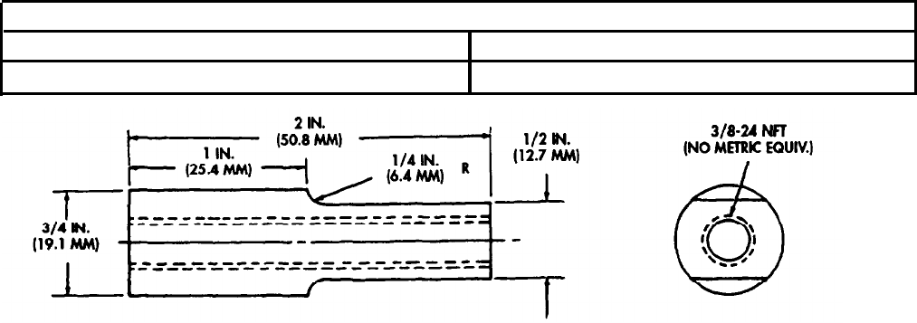
TM 9-2320-272-24-4
APPENDIX F
ILLUSTRATED LIST OF MANUFACTURED ITEMS
Section I. INTRODUCTION
This appendix includes complete instructions for making items authorized to be manufactured or
fabricated at Unit, Direct Support and General Support Maintenance levels.
All bulk materials needed to manufacture the item are listed by part number or specification number in
a tabular list on the illustration.
Section II. MANUFACTURED ITEMS PART NUMBER INDEX
MATERIALS
NSN
9510-00-042-1493
DESCRIPTION
Mild Tool Steel Bar
Figure F-l. Flange Puller Standoff.
NOTE:
1.
Dimensions shown are in inches with metric equivalent.
2.
All dimensions are +/- 0.30 in. (0.76 mm).
INSTRUCTIONS:
Fabricate and finish per diagram above.
F-1
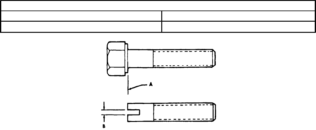
TM 9-2320-272-24-4
Section II. MANUFACTURED ITEMS PART NUMBER INDEX (Contd)
DESCRIPTION
Screw
MATERIALS
NSN
5305-01-072-4270
Figure F-2. Guide Screw.
NOTES:
1.
Two guide screws are required.
2.
Fabricate from screw part number 177734 (NSN 5305-01-072-4270) or equivalent.
PROCEDURE:
1.
Remove head of screw at A.
2.
Cut slot in screw at B. Slot shall be large enough to accommodate screwdriver tip.
F-2
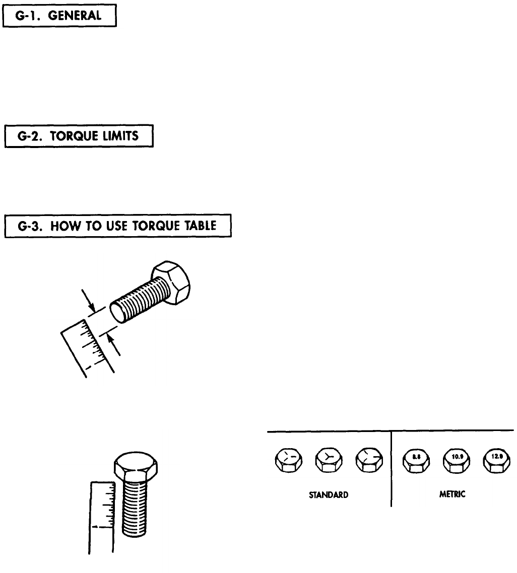
TM 9-2320-272-24-4
APPENDIX G
TORQUE LIMITS
This appendix provides general torque limits for screws used on M939, M939A1, and M939A2 vehicles.
Special torque limits are indicated in the maintenance procedures for applicable components. The general
torque limits given in this appendix shall be used when specific torque limits are not indicated in the
maintenance procedure. These general torque limits cannot be applied to screws that retain rubber
components. The rubber components will be damaged before the correct torque limit is reached. If a special
torque limit is not given in the maintenance instructions, tighten the screw or nut until it touches the
metal bracket, then tighten it one more turn.
Table G-l lists dry torque limits. Dry torque limits are used on screws that do not have lubricants
applied to the threads. Table G-2 lists wet torque limits. Wet torque limits are used on screws that have
high-pressure lubricants applied to the threads. For metric fasteners, refer to table G-3 for torque limit
requirements.
a. Measure the diameter of the screw you are
installing.
b.
Count the number of threads per inch.
c..
d.
Under the heading SIZE, look down the left-
hand column until you find the diameter
of the screw you are installing (there will
usually be two lines beginning with the
same size).
In the second column under SIZE, find the
number of threads per inch that matches the
number of threads you counted in step b.
CAPSCREW HEAD MARKINGS
Manufacturer's marks may
vary. These are all SAE
Grade 5 (3-line).
Metric screws are of three
grades: 8.8, 10.9, and 12.9.
Grades & Manufacturer’s marks
appear on the screw head.
e.
To find the grade screw you are installing,
match the markings on the head to the
correct picture of CAPSCREW HEAD
MARKINGS on the torque table.
f.
Look down the column under the picture you
found in step e. until you find the torque
limit (in lb-ft or N°m) for the diameter and
threads per inch of the screw.
G-1

TM 9-2320-272-24-4
Table G-1. Torque Limits for Dry Fasteners.
CAPSCREW HEAD MARKINGS
TORQUE
SIZE
SAE GRADE SAE GRADE SAE GRADE SAE GRADE
N0.1or2
N0. 5
NO.
6
or 7
N0. 8
DIA. THREADS
DIA.
INCHES PER INCH
MILLIMETERS
POUND NEWTON POUND NEWTON
POUND NEWTON POUND NEWTON
FEET
METERS
FEET
METERS
FEET
METERS
FEET
METERS
1/4
20 6.35
1/4
28
6.35
5/16
18
7.94
5/16
24 7.94
3/8
16 9.53
3/8
24 9.53
7/16
14 11.11
7/16
20
11.11
1/2
13
12.70
1/2
20 12.70
9/16
12
14.29
9/16
18
14.29
5/8
11
15.88
5/8
18
15.88
3/4
10
19.05
3/4
16
19.05
7/8
9
22.23
7/8
14
22.23
1
825.40
1
14
25.40
1-1/8
_____
28.58
1-1/4
_______
31.75
1-3/8
_______
34.93
1-1/2
_______
38.10
5 6.78
6 8.14
11 14.92
13 17.63
18 24.41
20 27.12
28 37.97
30 40.68
39 52.88
41 55.60
51 69.16
55 74.58
63 85.43
95 128.82
105 142.38
115 155.94
160 216.96
175 237.30
235 318.66
250 339.00
________
_____
_____
______
_____
_____
____ ____
8
10.85
10
13.56
17
23.05
19
25.76
31
42.04
35 47.46
49
66.44
55
74.58
75 101.70
85 115.26
110
149.16
120
162.72
150 203.40
170 230.52
270 366.12
295 400.02
395 535.62
435 589.86
590 800.04
660
894.96
800. 1,084.8-
880 1,193.3
______
_____
1,460- 1,979.8.
1,680
2,278.l
1,940- 2,630.6-
2,200 2,983.2
10
13.56
12
16.27
____ ____
14
18.98
19
25.76 24 32.54
____ ___
27
36.61
34
46.10
44 59.66
____ ____
49
66.44
55
74.58
70 94.92
____ ____
78 105.77
85 115.26 105 142.38
___ ____
120 162.72
120
162.72 155 210.18
___ ____
170 230.52
167 226.45 210 284.76
___ ____
240 325.44
280
379.68
375 508.50
____ ____
420 569.52
440
596.64 605
820.38
____ ___
675 915.30
660 894.96 910 1,233.96
____ ____
990 1,342.44
____ ____
1,280- 1,735.68
1,440 1,952.64
____ ____
1,820
2467.92
2,000 2,712.00
____ ____
2,380- 3,227.28
2,720 3.688.32
____ ____
3,160- 4,284.96
3,560 4,827.36
G-2

TM 9-2320-272-24-4
Table G-2. Torque Limits for Wet Fasteners.
CAPSCREW HEAD MARKINGS
TORQUE
SIZE
SAE GRADE SAE GRADE SAE GRADE SAE GRADE
No.1 or 2
No .5
N0.6 or 7
No.8
DIA.
THREADS
DIA.
POUND NEWTON POUND NEWTON POUND NEWTON POUND NEWTON
INCHES
PER INCH
MILLIMETERS
F
EET METERS
FEET
METERS
FEET
METERS
FEET
METERS
1/4
20
6.35
4.5
6.1
7.2
9.76
9.0 12.20 10.8 14.64
1/4
28
6.35 5.4 7.32
9.0 12.20
_____
_____
12.6 17.09
5/16
18
7.94
9.9 13.42
15.3
20.75
17.1
23.19 21.6 29.29
5/16
24 7.94 11.7 15.87
17.1
23.19
____ ____
24.3 32.95
3/8
16
9.53 16.2 21.97 27.9 37.83 30.6 41.49 39.6 53.70
3/8
24 9.53 18.0
24.41
31.5
42.71
___ ____
44.1
59.80
7/16
14
11.11
25.2 34.17
44.1
59.80 49.5
67.12 63.0
85.43
7/16
20
11.11
27.0
36.61
49.5 67.12
___ ___
70.2 95.19
1/2
13
12.70
35.1
47.60
67.5
91.53 76.5 103.73 94.5 128.14
1/2
20 12.70 36.9 50.04 76.5 103.73
_____ _____
108.0 146.45
9/16
12
14.29 45.9
62.24
99.0 134.24 108.0 146.45 139.5 189.16
9/16
18
14.29 49.5
67.12
108.0 146.45
____ _____
153.0 207.47
5/8
11
15.88
56.7
76.89 135.0 183.06 150.3 203.81 189.0 256.28
5/8
18
15.88 85.5 115.94 153.0 207.47
_____ _____
216.0 292.90
3/4
10
19.05
94.5
128.14 243.0 329.51 252.0 341.71
337.5
457.65
3/4
16
19.05 103.5 140.35 265.5 360.02
_____ ______
378.0
512.57
7/8
922.23 144.0 195.26 355.5 482.06 396.0
536.98 544.5
738.34
7/8
14
22.23 157.5 213.57 391.5 530.87
_____ _____
607.5
823.77
1
8
25.40 211.5 286.79
531.0
720.04 594.0 805.46
819.0
1,110.56
1
14 25.40 225.0 305.10
594.0
805.46
_____ _____
891.0
1,208.20
1-1/8
____
28.58
_____ _____
720.0- 976.32-
_____ _____
1,152.0- 1,562.11-
792.0 1,073.95 1,296.0 1,757.38
1-1/4
____
31.75
____ ______
_____
_____ _____ ____
1,637.99- 2,221.11-
1,800.00 2,440.80
1-3/8
____
34.93
_____
_____
1,314.0- 1,781.78-
____ ____
2,142.0.
2,904.55-
1,512.0 2,050.27
2,448.0
3,319.49
1-1/2
____
38.10
_____ _____
1,746.0. 2,367.58-
____ ____
2,844.0.
3,856.46
1,980.0 2,684.88
3,204.0
4,344.62
G-3
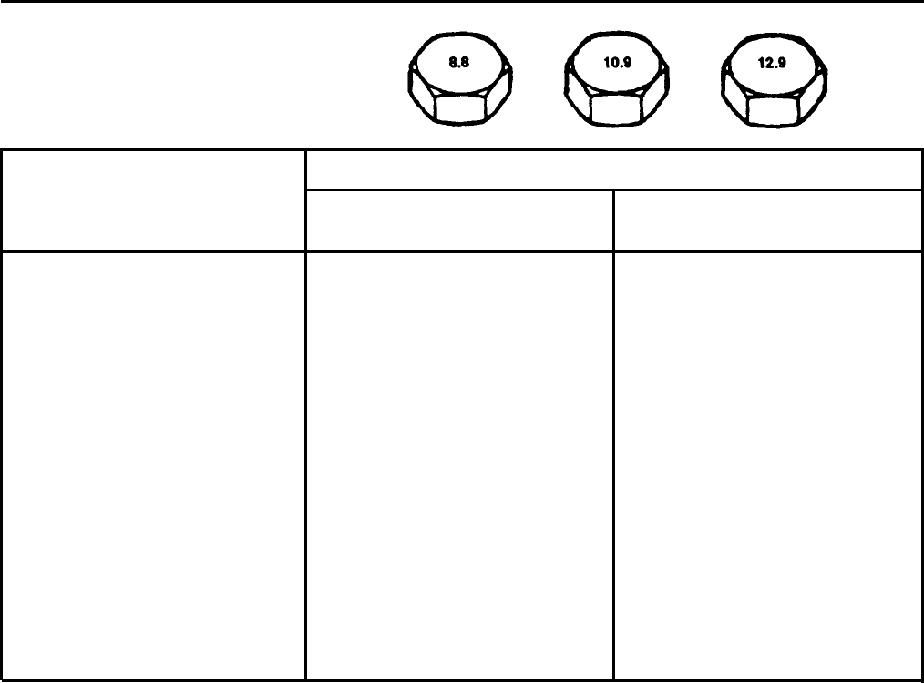
TM 9-2320-272-24-4
Table G-3.. Torque Limits for Metric Fasteners.
CAPSCREW HEAD MARKINGS
SIZE
M6
M8
M10
M12
M14
M16
M20
M24
M30
M36
POUND
FEET
7-11
21 - 35
45 - 65
80-120
130-190
200-280
400-520
700-900
1,400 - 1,800
2,400 - 3,000
TORQUE
NEWTON
METERS
9.49 - 14.92
28.48-47.46
61.02 - 88.14
108.48 - 162.72
176.28 - 257.64
271.20 - 379.68
542.40 - 705.12
949.20 - 1,220.40
1,898.40 - 2,440.80
3.254.40 - 4,068.OO
G-4
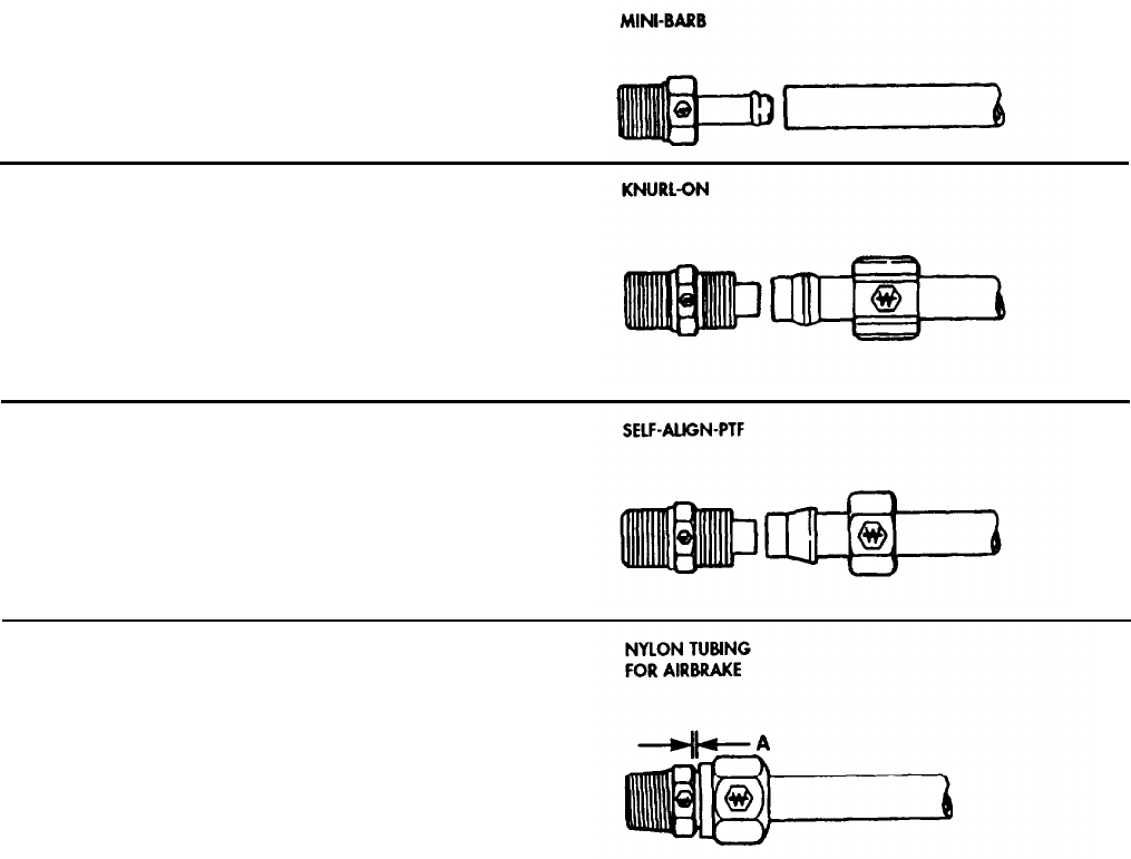
TM 9-2320-272-24-4
APPENDIX G (Contd)
Tubing Application Tightening Assembly Instructions.
Slide tubing over barbed insert until it bottoms on
fitting.
1. Slide nut and sleeve on tubing.
2.
Slide I.D. of tubing onto fitting insert until it
bottoms.
3. Assemble nut to fitting body.
4.
Tighten assembly finger-tight to cover body
threads.
1.
2.
3.
4.
Slide nut and sleeve on tubing.
Slide I.D. of tubing onto fitting insert until it
bottoms.
Assemble nut to fitting body.
Finger-tighten nut. From that point, tighten
with a wrench two complete turns.
1.
Cut tubing to desired length. Ensure ends are
cut reasonably square.
2.
Slide tubing into preassembled fitting and
push until tube bottoms.
3.
Tighten nut as indicated in chart. Another
check on proper assembly is dimension A,
when nut is fully tightened.
DISASSEMBLY - Remove nut and pull tubing
out of fitting body. Insert will remain on tubing.
REASSEMBLY - Push tubing and insert into
fitting body until it bottoms. Thread nut onto
fitting body and tighten as in step 3.
TUBE O.D. TIGHTEN NUT TO:
A
1/4
85 - 115 lb-in. (9.6 - 13.0 N°m) .085/.105
3/8
12 - 17 lb-ft (16.3 - 23.1 N°m)
.125/.145
1/2
25 - 33 lb-ft (33.9 - 44.7 N°m)
.100/.120
5/8 26 - 35 lb-ft (35.3 - 47.5 N°m)
.115/.135
3/4
38 - 50 lb-ft (51.5 - 67.8 N°m)
.180/.200
G-5
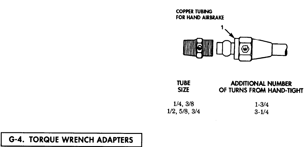
TM 9-2320-272-24-4
APPENDIX G (Contd)
Tubing Application Tightening Assembly Instructions (Contd).
1. Slide nut and sleeve on tubing. Threaded end
of nut (1) must face out.
2. Insert tubing into fitting. Ensure tubing is
bottomed on fitting shoulder.
3. Thread nut onto fitting body until it is hand
tight.
4. From that point, tighten with a wrench the
number of turns indicated at right.
Some tasks require the use of a torque wrench adapter when the nut or screw cannot be reached with
a regular socket on the end of the torque wrench. These adapters add to the overall length of the torque
wrench and make the dial or scale reading less than the actual torque applied to the nut or screw. To
prevent overtorquing and damage to equipment, calculate correct dial or scale reading using Conversion
Formula (para. G-5).
G-6
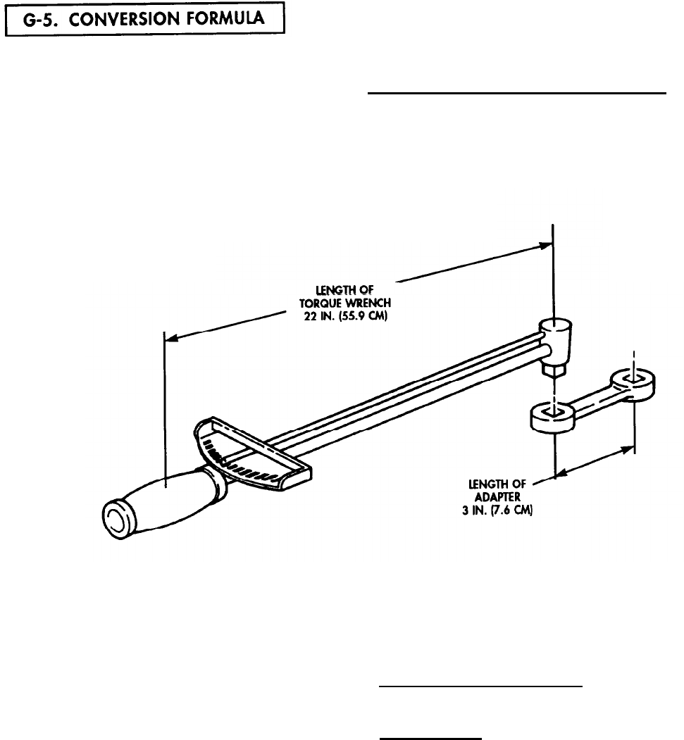
TM 9-2320-272-24-4
APPENDIX G (Contd)
Corrected dial or scale readings are determined by the use of the following formula:
Corrected =
reading
Required
torque value +
Length of torque wrench + Length of adapter
Length of torque wrench
NOTE
The length of the torque wrench is
measured from the center of the handle
to the center of the drive. The length of
the adapter is measured from the center
of the drive to the center of the wrench.
In this example, the torque wrench measures 22 in. (55.9 cm) and the adapter is 3 in. (7.6 cm). The
required torque is 19 lb-ft (25.8 N°m).
Corrected = 19 lb-ft (25.8 N•m) + 22 in. (55.9 cm) + 3 in. (7.6 cm)
reading 22 in. (55.9 cm)
Corrected = 19 lb-ft (25.8 N•m) + 25 in. (63.5 cm)
reading 22 in. (55.9 cm)
Corrected =
reading 19 lb-ft (25.8 N•m) +
1.14
Corrected =
reading 17 lb-ft (23.1 N•m)
G-7/(G-8 blank)

TM 9-2320-272-24-4
APPENDIX H
SCHEMATIC AND WIRING DIAGRAMS
Foldout 1.
Foldout 2.
Foldout 3.
Foldout 4.
Foldout 5.
Foldout 6.
Foldout 7.
Foldout 8.
Foldout 9.
Foldout 10.
M939/A1 Electrical System Wiring Diagram
M939A2 Electrical System Wiring Diagram (1 of 2)
M939A2 Electrical System Wiring Diagram (2 of 2)
M939/A1 Cab Air System Diagram
M939/A1 Air Supply Line Diagram
M939/A1 Air Control Line Diagram
M939/A1 Air Vent Line Diagram
M939A2 Schematic Diagram for M939 Expansible Van
M939A2 CTIS Electrical/Pneumatic Diagram
M939A2 Air Supply Line to CTIS Diagram
H-3
H-5
H-7
H-9
H-11
H-13
H-15
H-17
H-19
H-21
H-1 /(H-2 blank)
TM 9-2320-272-24-4
Para
Page
INDEX
Para
Page
A
100-amp alternator harness
replacement:
Installation.. ....................... 3-427b
3- 1098
Removal.. ............................ 3-427a
3- 1096
100-amp alternator
replacement:
Installation.. ....................... 3-426b 3-1094
Removal.............................. 3-426a 3-1094
100-amp voltage regulator
replacement:
Installation ......................... 3.428b 3-1100
Removal.............................. 3-428a 3-1100
3-phase receptacle wiring
harness replacement:
Installation.. ....................... 5-100b 5-604
Removal.............................. 5-100a 5-604
400 Hz converter harness
conduit replacement:
Installation.. ....................... 4-164b 4-794
Removal.............................. 4-164a 4-794
400 Hz converter replacement:
Installation.. ....................... 4-169b 4-804
Removal.. ............................ 4-169a 4-804
400 Hz supply wiring harness
replacement:
Installation.. ....................... 5-96b 5-592
Removal.............................. 5-96a 5-590
A-frame kit maintenance:
Inspection.. ......................... 3-414b 3-1048
Installation.. ....................... 3-414c 3-1048
Removal.............................. 3-414a 3-1046
Accelerator linkage (M939/A1)
maintenance:
Adjustment.........................
3-42c
3-124
Installation......................... 3-42b 3-124
Removal.. ............................ 3-42a 3-124
Accelerator linkage (M939A2)
maintenance:
Adjustment.. ....................... 3-43f
3- 128
Assembly ............................ 3-43d 3-128
Cleaning and inspection...... 3-43c 3-128
Disassembly.. ..................... 3-43b 3-126
Installation.. ....................... 3-43e 3-128
Removal.. ............................ 3-43a 3-126
Accelerator pedal, bracket, rod,
and stopscrew replacement:
Installation......................... 3-41b 3-123
Removal.. ............................ 3-41a 3-123
Access door, bonnet,
maintenance:
Assembly ............................ 5-86d 5-550
Cleaning and inspection...... 5-86c 5-550
Disassembly.. ..................... 5-86b 5-550
Installation.. ....................... 5-86e 5-552
Removal.............................. 5-86a 5-549
Access step, spare tire carrier,
cargo, replacement:
Installation.. ....................... 3-260b 3-720
Removal.............................. 3-260a 3-720
Access step, spare tire carrier,
dump and tractor,
replacement:
Installation......................... 3-255b 3-711
Removal.............................. 3-255a 3-710
Accessory drive and pulley,
engine, maintenance:
Accessory drive assembly .... 4-26e 4-190
Accessory drive cleaning and
inspection ......................... 4-26d 4-188
Accessory drive
disassembly.. .................... 4-26c 4-188
Accessory drive installation. 4-27f 4-190
Accessory drive pulley
installation.. ..................... 4-26g 4-192
Accessory drive pulley
removal.................... ......... 4-26a 4-186
Accessory drive removal.. .... 4-26b 4-186
Actuator, front brake, repair:
Adjustable actuator
assembly .......................... 4-112e 4-598
Adjustable actuator
disassembly.. ..................... 4-112a 4-596
Cleaning and inspection...... 4-112c 4-596
Stationary actuator
assembly .......................... 4-112d 4-598
Stationary actuator
disassembly.. .................... 4-112b 4-596
Actuator, rear brake, repair:
Assembly ............................ 4-113c 4-602
Cleaning and inspection...... 4-113b 4-600
Disassembly.. ..................... 4-113a 4-600
Adapter housing and first
clutch piston maintenance:
Assembly.. .......................... 5-57d 5-380
Cleaning and inspection...... 5-57c 5-380
Disassembly.. ..................... 5-57b 5-378
Removal.. ............................ 5-57a 5-378
Adapter housing, low clutch,
low planetary carrier, and
rear cover installation:
Installation......................... 5-58 5-382
Index 1
TM 9-2320-272-24-4
INDEX (Contd)
Para
Page
Para
Page
Adjustment, bearing, wheel:
Front wheel bearing
adjustment......................... 3-225a 3-648
Rear wheel bearing
adjustment......................... 3-225b 3-650
Air Fuel Control (AFC) fuel
pump filter replacement:
Installation.. ....................... 3-31b 3-108
Removal.............................. 3-31a 3-108
Aftercooler and tubes
(M939A2) replacement:
Installation.. ....................... 3-76b 3-218
Removal.. ............................ 3-76a 3-216
Air cleaner assembly and
mounting bracket
maintenance:
Inspection.. ......................... 3-15b 3-52
Installation......................... 3-15c 3-54
Removal.. ............................. ..3-15a 3-52
Air cleaner hose (M939A2)
maintenance:
Assembly.. .......................... 3-13d 3-48
Disassembly.. ..................... 3-13b 3-48
Inspection.. ......................... 3-13c 3-48
Installation.. ....................... 3-13e 3-49
Removal.............................. 3-13a 3-48
Air cleaner indicator and tube
maintenance:
Cleaning and inspection...... 3-12c 3-44
Installation......................... 3-12d 3-46
Removal.. ............................ 3-12b 3-44
Testing.. ............................. 3-12a 3-42
Air cleaner intake pipe
(M939/A1) maintenance:
Inspection.. ......................... 3-14b 3-50
Installation.. ....................... 3-14c 3-50
Removal.. ............................ 3-14a 3-50
Air compressor (M939/A1)
maintenance:
Assembly ............................ 4-31e 4-226
Cleaning............................. 4-31c 4-220
Disassembly.. ..................... 4-31b 4-218
Inspection and repair.. ........ 4-31d 4-220
Installation and timing....... 4.31f 4-232
Removal.. ............................ 4-31a 4-214
Air compressor (M939A2)
maintenance:
Assembly.. .......................... 4-52c 4-322
Cleaning and inspection...... 4-52b 4-318
Disassembly.. ..................... 4-52a 4-314
Air compressor and lines
(M939A2) replacement:
Installation......................... 3-206b 3-576
Removal.. ............................ 3-206a 3-574
Air compressor coolant lines
(M939A2) replacement:
Cleaning and inspection...... 3-57b 3-168
Installation . . . . . . . . . . . . . . . . . . . . . . . . .
3-57c 3-168
Removal . . . . . . . . . . . . . . . . . . . . . . . . . . . . . .
3-57a 3-168
Air compressor coolant supply
and return tubes (M939/A1)
maintenance:
Inspection . . . . . . . . . . . . . . . . . . . . . . . . . . .
3-55c 3-161
Return tube installation . . . . . 3-55e 3-163
Return tube removal . . . . . . . . . . .
3-55b
3- 161
Supply tube installation . . . . . 3-55d 3-162
Supply tube removal . . . . . . . . . . .
3-55a 3-160
Air conditioner drain tube
replacement:
Installation . . . . . . . . . . . . . . . . . . . . . . . . .
3-382b 3-938
Removal . . . . . . . . . . . . . . . . . . . . . . . . . . . . . .
3-382a 3-938
Air conditioner manual starter
switches replacement:
Installation . . . . . . . . . . . . . . . . . . . . . . . . .
4-167b 4-800
Removal . . . . . . . . . . . . . . . . . . . . . . . . . . . . . .
4-167a 4-799
Air conditioner replacement:
Installation . . . . . . . . . . . . . . . . . . . . . . . . .
5-88b 5-564
Removal . . . . . . . . . . . . . . . . . . . . . . . . . . . . . .
5-88a 5-563
Air couplings replacement:
Front air couplings
Installation . . . . . . . . . . . . . . . . . . . . . . .
3-208d 3-590
Front air couplings removal 3-208a 3-584
Rear air couplings
installation (M923/A1/A21 3-208e 3-592
Rear air couplings removal
(M923/A1/A2)
. . . . . . . . . . . . . . . . . . .
3-208b 3-586
Rear air couplings
installation (M929/A1/A2,
M931/A1A2, M934/A1/A2,
M936/A1/A2) . . . . . . . . . . . . . . . . . . . .
3-208f 3-594
Rear air couplings removal
(M929/A1/A2,
M931/A1/A2,
M9341/A1/A2,
M936/A1/A2) . . . . . . . . . . . . . . . . . . . .
3-208c 3-588
Air cylinder, transfer case
interlock, replacement:
Installation . . . . . . . . . . . . . . . . . . . . . . . . .
4-83b 4-506
Removal . . . . . . . . . . . . . . . . . . . . . . . . . . . . . .
4-83a 4-506
Air dryer and check valve
maintenance:
Assembly . . . . . . . . . . . . . . . . . . . . . . . . . . . .
3-464d 3-1272
Cleaning and inspection...... 3-464c 3-1272
Disassembly . . . . . . . . . . . . . . . . . . . . . . .
3-464b 3-1272
Installation . . . . . . . . . . . . . . . . . . . . . . . . .
3-464e 3-1274
Removal . . . . . . . . . . . . . . . . . . . . . . . . . . . . . .
3-464a 3-1270
Air dryer filter replacement:
Installation . . . . . . . . . . . . . . . . . . . . . . . . .
3-465b 3-1276
Removal . . . . . . . . . . . . . . . . . . . . . . . . . . . . . .
3-465a 3-1276
Index 2
TM 9-2320-272-24-4
INDEX
Para
Page
Air dryer kit (M923/A1/A2,
M9251/A1/A2, M927/A1/A2,
M928/A1/A2, M934/A1/A2)
replacement:
Installation . . . . . . . . . . . . . . . . . . . . . . . . .
3-412b 3-1026
Removal . . . . . . . . . . . . . . . . . . . . . . . . . . . . . .
3-412a 3-1022
Air dryer kit (M929/A1/A2,
M930/A1/A2, M931/A1/A2,
M932/A1/A2, M936/A1/A2)
replacement:
Installation . . . . . . . . . . . . . . . . . . . . . . . . .
3-413b 3-1039
Removal . . . . . . . . . . . . . . . . . . . . . . . . . . . . . .
3-413a 3-1032
Air Fuel Control (AFC) tube
(M939A2) maintenance:
Inspection . . . . . . . . . . . . . . . . . . . . . . . . . . .
3-18b 3-61
Installation . . . . . . . . . . . . . . . . . . . . . . . . .
3-18c
3-61
Removal . . . . . . . . . . . . . . . . . . . . . . . . . . . . . .
3-18a 3-61
Air gauge replacement:
Installation . . . . . . . . . . . . . . . . . . . . . . . . .
3-87b 3-252
Removal . . . . . . . . . . . . . . . . . . . . . . . . . . . . . .
3-87a 3-252
Air governor maintenance:
Adjustment . . . . . . . . . . . . . . . . . . . . . . . . .
3-207d 3-582
Installation . . . . . . . . . . . . . . . . . . . . . . . . .
3-207b 3-580
Removal . . . . . . . . . . . . . . . . . . . . . . . . . . . . . .
3-207a 3-580
Testing . . . . . . . . . . . . . . . . . . . . . . . . . . . . . . .
3-207c 3-582
Air lines, fabrication . . . . . . . . . . . . . . .
3-452 3-1232
Air manifold tee, brake
chamber, replacement:
Installation . . . . . . . . . . . . . . . . . . . . . . . . .
3-189b 3-520
Removal . . . . . . . . . . . . . . . . . . . . . . . . . . . . . .
3-189a 3-520
Air manifold, rear axle,
maintenance:
Cleaning and inspection...... 3-463b 3-1268
Installation . . . . . . . . . . . . . . . . . . . . . . . . .
3-463c 3-1268
Removal . . . . . . . . . . . . . . . . . . . . . . . . . . . . . .
3-463a 3-1268
Air reservoir (supply tank),
primary, replacement:
Installation . . . . . . . . . . . . . . . . . . . . . . . . .
3-202b 3-564
Removal . . . . . . . . . . . . . . . . . . . . . . . . . . . . . .
3-202a 3-562
Air reservoir (supply tank),
secondary, replacement:
Installation . . . . . . . . . . . . . . . . . . . . . . . . .
3-203b 3-568
Removal . . . . . . . . . . . . . . . . . . . . . . . . . . . . . .
3-203a 3-566
Air reservoir drainvalves
replacement:
Installation . . . . . . . . . . . . . . . . . . . . . . . . .
3-205b 3-572
Removal . . . . . . . . . . . . . . . . . . . . . . . . . . . . . .
3-205a 3-572
Air reservoir one-way check
valve replacement:
Installation . . . . . . . . . . . . . . . . . . . . . . . . .
3-186b 3-514
Removal . . . . . . . . . . . . . . . . . . . . . . . . . . . . . .
3-186a 3-514
Air reservoir, emergency spring
brake (supply tank),
replacement:
Installation . . . . . . . . . . . . . . . . . . . . . . . . .
3-204b 3-570
Removal .............................. 3-204a 3-570
(Contd)
Para
Page
Air seals, hub, leak test:
Front hub leak test . . . . . . . . . . . . .
3-462a 3-1264
Rear hub leak test . . . . . . . . . . . . . .
3-462b 3-1266
Air vent control assembly,
fresh, replacement:
Installation . . . . . . . . . . . . . . . . . . . . . . . . .
3-293b 3-784
Removal . . . . . . . . . . . . . . . . . . . . . . . . . . . . . .
3-293a 3-784
Airbrake hand control valve
(M931/A1/A2, M932/A1/A2)
trailer, replacement:
Installation . . . . . . . . . . . . . . . . . . . . . . . . .
3-210b 3-598
Removal
. . . . . . . . . . . . . . . . . . . . . . . . . . . . . .
3-210a 3-598
Alcohol evaporator
replacement:
Installation ,........................ 3-211b 3-600
Removal . . . . . . . . . . . . . . . . . . . . . . . . . . . . . .
3-211a 3-600
Alternator and mounting
bracket (M939/A1)
replacement:
Installation . . . . . . . . . . . . . . . . . . . . . . . . .
3-79b 3-226
Removal . . . . . . . . . . . . . . . . . . . . . . . . . . . . . .
3-79a 3-224
Alternator drivebelts
(M939/A1) maintenance:
Inspection . . . . . . . . . . . . . . . . . . . . . . . . . . .
3-78b 3-222
Installation and
adjustment . . . . . . . . . . . . . . .........
3-78c 3-222
Removal . . . . . . . . . . . . . . . . . . . . . . . . . . . . . .
3-78a 3-222
Alternator pulley (M939/A1)
replacement:
Installation . . . . . . . . . . . . . . . . . . . . . . . . .
3-81b 3-232
Removal . . . . . . . . . . . . . . . . . . . . . . . . . . . . . .
3-81a 3-232
Alternator, 100-amp,
replacement:
Installation . . . . . . . . . . . . . . . . . . . . . . . . .
3-426b 3-1094
Removal . . . ........................... 3-426a 3-1094
Alternator, mounting bracket,
and pulley (M939A2)
maintenance:
Adjustment . . . . . . . . . . . . . . . . . . . . . . . . .
3-80e 3-230
Alternator and mounting
bracket installation . . . . . . . . . . 3-80d
3-230
Alternator and mounting
bracket removal . . . . . . . . . . . . . . . .
3-80a 3-228
Pulley installation . . . . . . . . . . . . . .
3-80c
3-230
Pulley removal . . . . . . . . . . . . . . . . . . . .
3-80b 3-229
Amber warning light
replacement:
Installation . . . . . . . . . . . . . . . . . . . . . . . . .
3-469b 3-1283
Removal . . . . . . . . . . . . . . . . . . . . . . . . . . . . . .
3-469a 3-1283
Anchor post, toggle clamp,
replacement:
Installation . . . . . . . . . . . . . . . . . . . . . . . . .
3-358b 3-897
Removal
. . . . . . . . . . . . . . . . . . . . . . . . . . . . . .
3-358a 3-897
Index 3
TM 9-2320-272-24-4
Para
Appendix A, references:
Field
manuals . . . . . . . . . . . . . . . . . . . .
A-4
Forms . . . . . . . . . . . . . . . . . . . . . . . . . . . . . . . . .
A-3
Other publications . . . . . . . . . . . . . .
A-7
Publications index . . . . . . . . . . . . ..
A-2
Scope . . . . . . . . . . . . . . . . . . . . . . . . . . . . . . . . . .
A-1
Technical bulletins . . . . . . . . . . . . . .
A-6
Technical manuals . . . . . . . . . . . . . .
A-5
Appendix B, Maintenance
Allocation Chart (MAC):
Explanation of columns
in remarks, section IV . . . . . . .
B-5
Explanation of columns
in the MAC, section II . . . . . . . B-3
Explanation of columns
in tool and test equipment
requirements,
section III . . . . . . . . . . . . . . . . . . . . . . . . .
B-4
General. . . . . . . . . . . . . . . . . . . . . . . . . . . . .
B-1
Maintenance functions . . . . . . . . B-2
Appendix C,
expendable/durable supplies
and materials list:
Explanation of columns . . . . . . . C-1
Scope . . . . . . . . . . . . . . . . . . . . . . . . . .. . . . . . . .
C-1
Appendix D, mandatory
replacement parts:
Explanation of columns . . . . . . .
D-2
Scope . . . . . . . . . . . . . . . . . . . . . . . . . . . . . . . . . .
D-l
Appendix E, common and
special tool identification list:
Explanation of columns... . . . . E-2
Scope . . . . . . . . . . . . . . . . . . . . . . . . . . . . . . . . . .
E-1
Appendix F, illustrated list of
manufactured items . . . . . . . . . . . . . . F- 1
Appendix G, torque limits:
General. . . . . . . . . . . . . . . . . . . . . . . . . . . . . . .
G-1
How to use torque table......
G-3
Torque limits . . . . . . . . . . . . . . . . . . . . . .
G-2
Appendix H, schematic and
wiring diagrams . . . . . . . . . . . . . . . . . . . .
H1
Approach plates, fifth wheel,
replacement:
INDEX
Page
A-2
A-1
A-4
A-1
A-1
A-3
A-2
B-3
B-2
B-3
B-1
B-1
C-1
C-1
D-l
D-l
E-1
E-1
F-1
G-1
G-1
G-1
H-1
Installation . . . . . . . . . . . . . . . . . . . . . . . . .
3-249b 3-698
Removal . . . . . . . . . . . . . . . . . . . . . . . . . . . . . .
3-249a 3-698
Arm, pitman, replacement
(Ross):
Installation . . . . . . . . . . . . . . . . . . . . . . . . .
3-227b 3-653
Removal . . . . . . . . . . . . . . . . . . . . . . . . . . . . . .
3-227a 3-653
Arm, pitman, replacement
(Sheppard):
Installation . . . . . . . . . . . . . . . . . . . . . . . . .
3-228b 3-654
Removal . . . . . . . . . . . . . . . . . . . . . . . . . . . . . .
3-228a 3-654
(Contd)
Para
Page
Arm, roller, dump,
maintenance:
Assembly.. ..........................
5- 104d
5-613
Disassembly ....................... 5-104b 5-612
Inspection and repair.. ........ 5-104c 5-612
Installation......................... 5-104e 5-613
Removal.. ............................ 5-104a 5-612
Army documents,
shipment of.. .........................
6-7
6-2
Army Petroleum, Oils, and
Lubricants (POL). .................
1-8 1-2
Assembly, PMCS .................... 2-18 2-58
Assist cylinder, steering,
replacement:
Assembly.. .......................... 3-233c 3-664
Disassembly ....................... 3-233b 3-664
Installation......................... 3-233d 3-666
Removal.. ............................ 3-233a 3-662
Travel adjustment.. ............ 3-233e 3-666
Atmospheric fuel tank vent
system kit replacement:
Installation.. ....................... 3-44lb
3- 1141
Removal.. ............................ 3-441a 3-1140
Atomizer (M939/A1), ether,
replacement:
Installation......................... 3-37b 3-117
Removal.. ............................ 3-37a 3-117
Atomizer and temperature
sensor (M939A2), ether,
replacement:
Installation......................... 3-38b
3- 118
Removal.. ............................ 3-38a
3- 118
Automatic brake (hoist winch)
adjustment:
Adjustment......................... 3-383 3-940
Automatic throttle kit
(M936/A1) replacement:
Installation......................... 3-440b 3-1136
Removal.. ............................ 3-440a 3-1134
Auxiliary outlet socket and
receptacle (M936/A1/A2)
replacement:
Installation......................... 3-110b 3-298
Removal.. ............................ 3-110a 3-298
Axle breather, front and rear,
replacement:
Installation.. ....................... 3-159b 3-438
Removal.. ............................ 3-159a 3-438
Axle carrier differential, front
and rear, maintenance:
Cleaning and inspection ...... 4-100b 4-564
Installation.. ....................... 4-100c 4-565
Removal.. ............................ 4-100a 4-564
Index 4
Axle engagement air cylinder,
transfer case, front,
replacement:
Installation.........................
Removal..............................
Axle leakage test:
Corrective action .................
Test.. ..................................
Axle seal, front, replacement:
Installation.. .......................
Removal..............................
Axle shaft, rear, maintenance:
Inspection ...........................
Installation.. .......................
Removal..............................
Axle, forward-rear and rear-
rear, replacement:
Installation.. .......................
Removal..............................
Axle, front, replacement:
Installation.. .......................
Removal ..............................
INDEX (Contd)
Para
Page
TM 9-2320-272-24-4
Para
Page
4-84b 4-508
4-84a 4-508
4-106b 4-582
4-106a 4-582
3-160b 3-439
3-160a 3-439
3-157b 3-433
3-157c 3-433
3-157a 3-433
4-101b 4-570
4-101a 4-566
4-99b 4-560
4-99a 4-558
B
Backrest cushion, companion
seat cushion, frame, and,
replacement:
Installation . . . . . . . . . . . . . . . . . . . . . . . . .
3-286b 3-770
Removal . . . . . . . . . . . . . . . . . . . . . . . . . . . . . .
3-286a 3-770
Backrest cushion, driver’s seat
cushion, frame and,
replacement:
Installation . . . . . . . . . . . . . . . . . . . . . . . . .
3-285b 3-768
Removal . . . . . . . . . . . . . . . . . . . . . . . . . . . . . .
3-285a 3-768
Baffles, seals, and plates,
radiator, replacement:
Installation . . . . . . . . . . . . . . . . . . . . . . . . .
3-272b 3-738
Removal . . . . . . . . . . . . . . . . . . . . . . . . . . . . . .
3-272a 3-738
Battery box cover replacement:
Installation . . . . . . . . . . . . . . . . . . . . . . . . .
3-123b 3-332
Removal . . . . . . . . . . . . . . . . . . . . . . . . . . . . . .
3-123a 3-332
Battery box heater pad, engine
coolant, replacement:
Installation . . . . . . . . . . . . . . . . . . . . . . . . .
3-404b 3-994
Removal . . . . . . . . . . . . . . . . . . . . . . . . . . . . . .
3-404a 3-994
Battery box replacement:
Installation . . . . . . . . . . . . . . . . . . . . . . . . .
3-128b 3-342
Removal . . . . . . . . . . . . . . . . . . . . . . . . . . . . . .
3-128a 3-342
Battery cable and terminal
adapter replacement:
Installation . . . . . . . . . . . . . . . . . . . . . . . . .
3-124b 3-334
Removal . . . . . . . . . . . . . . . . . . . . . . . . . . . . . .
3-124a 3-334
Battery ground cable
maintenance:
Connection.. ........................ 3-126b 3-338
Disconnection ...................... 3-126a 3-338
Battery maintenance:
Inspection and cleaning..
....
3-125b 3-336
Installation......................... 3-125c 3-337
Removal.. ............................ 3-125a 3-336
Beam rollers, retractable,
replacement:
End roller installation.......
..
5-69d 5-476
End roller removal ..............
5-69c
5-476
Support roller installation
...
5-69b 5-474
Support roller removal.. ...... 5-69a 5-474
Beam, retractable beam drive
shaft and lock, maintenance:
Cleaning, inspection,
and repair......................... 5-68b 5-472
Installation.. ....................... 5-68c 5-472
Removal.. ............................ 5-68a 5-470
Beam, retractable,
replacement:
Installation.. ....................... 5-67b 5-468
Removal.. ............................ 5-67a 5-468
Bearing adjustment, wheel:
Front wheel bearing
adjustment......................... 3-225a 3-648
Rear wheel bearing
adjustment......................... 3-225b 3-650
Bearing sleeve, spindle,
replacement:
Installation.. ....................... 4-97b 4-549
Removal.. ............................ 4-97a 4-548
Bearings, crankshaft and main,
maintenance:
Cleaning and inspection...... 5-8b 5-50
End play clearance.. ............ 5-8d 5-56
Installation.. .......................
5-8c
5-52
Removal.. ............................ 5-8a 5-48
Blackout and clearance lights
wiring harness replacement:
Installation......................... 5-95b 5-588
Removal.. ............................ 5-95a 5-588
Blackout and emergency light
fixtures replacement:
Installation......................... 4-166b 4-798
Removal.. ............................ 4-166a 4-798
Blackout bypass wiring
harness maintenance:
Installation......................... 5-93c 5-580
Removal.. ............................ 5-93a 5-580
Repair................................. 5-93b 5-580
Index 5
TM 9-2320-272-24-4
Blackout circuit plungers,
hinged roof-operated,
replacement:
Para
INDEX
Page
Installation . . . . . . . . . . . . . . . . . . . . . . . . .
3-377b 3-924
Removal . . . . . . . . . . . . . . . . . . . . . . . . . . . . . .
3-377a 3-924
Blackout light maintenance:
Assembly . . . . . . . . . . . . . . . . . . . . . . . . . . . .
3-117c 3-308
Disassembly . . . . . . . . . . . . . . . . . . . . . . .
3-117b 3-308
Installation. . . . . . . . . . . . . . . . . . . . . . . . .
3-117d 3-308
Removal . . . . . . . . . . . . . . . . . . . . . . . . . . . . . .
3-117a 3-308
Blackout light switch and
110-volt receptacle
replacement:
Installation . . . . . . . . . . . . . . . . . . . . . . . . .
3-373b 3-916
Removal . . . . . . . . . . . . . . . . . . . . . . . . . . . . . .
3-373a 3-916
Blackout light switch, side and
rear door maintenance:
Installation . . . . . . . . . . . . . . . . . . . . . . . . .
3-376b 3-922
Removal . . . . . . . . . . . . . . . . . . . . . . . . . . . . . .
3-376a 3-922
Blackout panel, window
replacement:
Installation . . . . . . . . . . . . . . . . . . . . . . . . . 3-352b 3-890
Removal . . . . . . . . . . . . . . . . . . . . . . . . . . . . . .
3-352a
3-890
Block, cylinder liners and,
maintenance:
Cleaning and inspection...... 5-7c
Cylinder liners installation. 5-7d
Disassembly . . . . . . . . . . . . . . . . . . . . . . .
5-7b
Removal . . . . . . . . . . . . . . . . . . . . . . . . . . . . . .
5-7a
Block, cylinder liners and,
maintenance:
5-38
5-46
5-36
5-34
Cylinder liner and engine
block cleaning and
inspection . . . . . . . . . . . . . . . . . . . . . . . . .
5-28d 5-190
Cylinder liner inspection . . . . .
5-28a 5-184
Cylinder liner installation... 5-28f 5-194
Cylinder liner removal . . . . . . . . .
5-28b 5-186
Engine block assembly . . . . . . . .
5-28e 5-192
Engine block disassembly.. . 5-28c 5-188
Body assembly, cargo,
maintenance:
Cleaning and inspection...... 4-142b 4-718
Installation . . . . . . . . . . . . . . . . . . . . . . . . .
4-142d 4-718
Removal . . . . . . . . . . . . . . . . . . . . . . . . . . . . . .
4-142a 4-716
Repair . . . . . . . . . . . . . . . . . . . . . . . . . . . . . . . . .
4-142c 4-718
Body, dump, maintenance:
Installation . . . . . . . . . . . . . . . . . . . . . . . . .
4-144c 4-728
Inspection and repair . . . . . . . . . .
4-144b 4-727
Removal . . . . . . . . . . . . . . . . . . . . . . . . . . . . . .
4-144a 4-726
Body, van, replacement:
Installation . . . . . . . . . . . . . . . . . . . . . . . . .
5-66b 5-466
Removal . . . . . . . . . . . . . . . . . . . . . . . . . . . . . .
5-66a 5-464
Body, wrecker, replacement:
Installation . . . . . . . . . . . . . . . . . . . . . . . . .
4-152b 4-750
Removal . . . . . . . . . . . . . . . . . . . . . . . . . . . . . .
4-152a 4-748
Index 6
(Contd)
Para
Page
Bonnet access door
maintenance:
Assembly.. .......................... 5-86d 5-550
Cleaning and inspection...... 5-86c 5-550
Disassembly.. ..................... 5-86b 5-550
Installation......................... 5-86e 5-552
Removal.. ............................ 5-86a 5-549
Bonnet door maintenance:
Assembly.. .......................... 5-87d 5-560
Cleaning and inspection...... 5-87c 5-558
Disassembly.. ..................... 5-87b 5-556
Installation......................... 5-87e 5-562
Removal.. ............................ 5-87a 5-554
Bonnet frame parts
replacement:
Installation.. ....................... 5-85b 5-546
Removal.. ............................ 5-85a 5-544
Bonnet handle and control rod
replacement:
Installation.. ....................... 3-361b 3-900
Removal.. ............................ 3-361a 3-900
Boom elevating cylinder
packing replacement:
Installation. ........................ 5-103b 5-610
Removal.. ............................ 5-103a 5-610
Boom elevating cylinder repair:
Assembly.. .......................... 5-102c 5-608
Cleaning, inspection,
and repair......................... 5-102b 5-608
Disassembly.. ..................... 5-102a 5-606
Boom elevating cylinder
replacement:
Installation.. ....................... 4-193b 4-911
Removal.. ............................ 4-193a 4-910
Boom extension cylinder repair:
Assembly. ........................... 5-106c 5-628
Cleaning, inspection,
and repair......................... 5-10b 5-628
Disassembly ....................... 5-106a 5-626
Boom extension cylinder
replacement:
Installation......................... 4-196b 4-920
Removal.. ............................ 4-196a 4-920
Boom floodlight wire
replacement:
Installation......................... 3-385b 3-946
Removal.. ............................ 3-385a 3-946
Boom repair and adjustment:
Assembly.. .......................... 4-204c 4-952
Cleaning, inspection,
and repair......................... 4-204b 4-950
Disassembly.. ..................... 4-204a 4-950
Vertical adjustment.. .......... 4-204d 4-953
Boom replacement:
Installation.. ....................... 4-194b 4-914
Removal.. ............................ 4-194a 4-912
TM 9-2320-272-24-4
INDEX (Contd)
Para
Page
Boom roller maintenance:
Assembly ............................ 4-197d 4-924
Cleaning and inspection...... 4-197c 4-924
Disassembly.. ..................... 4-197b 4-922
Installation.. ....................... 4-197e 4-924
Removal.............................. 4-197a 4-922
Boom, inner, replacement:
Installation......................... 4-195b 4-918
Removal.............................. 4-195a 4-916
Boot, steering knuckle,
maintenance:
Cleaning and inspection...... 3-155b 3-430
Installation......................... 3-155c 3-430
Removal.. ............................ 3-155a 3-430
Bows, cargo body cover,
replacement:
Installation......................... 3-341b 3-872
Removal.............................. 3-341a 3-872
Box, battery, replacement:
Installation......................... 3-128b 3-342
Removal.............................. 3-128a 3-342
Box, electrical junction,
replacement:
Installation......................... 4-163b 4-792
Removal.............................. 4-163a 4-792
Box, electrical load center,
maintenance:
Assembly ............................ 4-161c 4-782
Disassembly.. ..................... 4-161b 4-782
Installation......................... 4-161d 4-784
Removal.. ............................ 4-161a 4-776
Box, electrical, maintenance:
Inspection ........................... 4-162b 4-790
Installation.. ....................... 4-162c 4-790
Removal.............................. 4-162a 4-790
Brace, dump safety,
installation:
Installation......................... 4-145b 4-730
Removal.. ............................ 4-145a 4-730
Bracket (M939/A1), personnel
fuel burning heater mounting,
replacement:
Installation......................... 4-216b
4- 1006
Removal .............................. 4-216a 4-1006
Bracket (M939A2), personnel
fuel burning heater and
mounting, replacement:
Installation......................... 4-217b 4-1008
Removal.............................. 4-217a 4-1008
Bracket (M939A2), surge tank
and, replacement:
Installation.. ....................... 3-62b 3-184
Removal .............................. 3-62a 3-184
Bracket, fuel can, replacement:
Installation......................... 4-187b 4-896
Removal.. ............................ 4-187a 4-896
Para
Page
Bracket, hood crossmember,
maintenance:
Cleaning and inspection...... 4-132b 4-692
Installation . . . . . . . . . . . . . . . . . . . . . . . . .
4-132c 4-692
Removal . . . . . . . . . . . . . . . . . . . . . . . . . . . . . .
4-132a 4-692
Bracket, parking brake cable
and, replacement:
Installation . . . . . . . . . . . . . . . . . . . . . . . . .
3-175b 3-488
Removal . . . . . . . . . . . . . . . . . . . . . . . . . . . . . .
3-175a 3-486
Bracket, rod, and stopscrew,
accelerator pedal,
replacement:
Installation . . . . . . . . . . . . . . . . . . . . . . . . .
3-41b 3-123
Removal.............................. 3-41a 3-123
Bracket, steering gear (Ross),
and, replacement:
Installation . . . . . . . . . . . . . . . . . . . . . . . . .
4-117b 4-616
Removal . . . . . . . . . . . . . . . . . . . . . . . . . . . . . .
4-117a 4-614
Bracket, steering gear
(Sheppard), and, replacement:
Installation . . . . . . . . . . . . . . . . . . . . . . . . .
4-118b 4-620
Removala............................. 4-118a 4-618
Bracket, wet air reservoir
(supply tank) and,
replacement:
Installation . . . . . . . . . . . . . . . . . . . . . . . . .
3-200b 3-552
Removal . . . . . . . . . . . . . . . . . . . . . . . . . . . . . .
3-200a 3-548
Brackets (M939A2), upper
radiator hoses and,
replacement:
Installation . . . . . . . . . . . . . . . . . . . . . . . . .
3-58b 3-170
Removal . . . . . . . . . . . . . . . . . . . . . . . . . . . . . .
3-58a 3-170
Brackets, engine lifting,
replacement:
Installation . . . . . . . . . . . . . . . . . . . . . . . . .
4-40b 4-278
Removal . . . . . . . . . . . . . . . . . . . . . . . . . . . . . .
4-40a 4-278
Brake chamber, air manifold
tee, replacement:
Installation . . . . . . . . . . . . . . . . . . . . . . . . .
3-189b 3-520
Removal . . . . . . . . . . . . . . . . . . . . . . . . . . . . . .
3-189a 3-520
Brake chamber, combination
spring (emergency) and
service, replacement:
Installation . . . . . . . . . . . . . . . . . . . . . . . . .
3-182b 3-506
Removal
. . . . . . . . . . . . . . ...............
3-182a 3-506
Brake chamber, service,
replacement:
Installation . . . . . . . . . . . . . . . . . . . . . . . . .
3-181b 3-504
Removal . . . . . . . . . . . . . . . . . . . . . . . . . . . . . .
3-181a 3-504
Brake chamber, spring
(emergency), maintenance:
Assembly . . . . . . . . . . . . . . . . . . . . . . . . . . . .
3-193c 3-528
Disassembly . . . . . . . . . . . . . . . . . . . . . . .
3-193a 3-528
Inspection . . . . . . . . . . . . . . . . . . . . . . . . . . .
3-193b 3-528
Index 7
TM 9-2320-272-24-4
INDEX (Contd)
Para
Page
Para
Page
Brake lever and switch,
parking, replacement:
Installation . . . . . . . . . . . . . . . . . . . . . . . . .
3-174b 3-484
Removal.............................. 3-174a 3-484
Brake mechanism checks and
adjustments (front and rear):
Brakeshoe check and
adjustment . . . . . . . . . . . . . . . . . . . . . . .
3-179a
3-498
Checking brakeshoe wear ... 3-179b 3-500
Mechanism inspection . . . . . . . . .
3-179c 3-500
Brake modification kit
(M939A2), engine exhaust
brake, replacement:
Installation . . . . . . . . . . . . . . . . . . . . . . . . .
3-447b 3-1194
Removal
. . . . . . . . . . . . . . . . . . . . . . . . . . . . . .
3-447a 3-1186
Brake modification kit
(M939A2), engine exhaust
brake, replacement:
Installation . . . . . . . . . . . . . . . . . . . . . . . . .
3-448b 3-1214
Removal
. . . . . . . . . . . . . . . . . . . . . . . . . . . . . .
3-448a 3-1204
Brake pedal (treadle) valve
(M936/A1/A2) replacement:
Installation . . . . . . . . . . . . . . . . . . . . . . . . .
3-198b 3-542
Removal . . . . . . . . . . . . . . . . . . . . . . . . . . . . . .
3-198a 3-540
Brake pedal (treadle) valve
repair:
Assembly
. . . . . . . . . . . . . . . . . . . . . . . . . . . .
4-108c 4-586
Cleaning and inspection...... 4-108b 4-586
Disassembly . . . . . . . . . . . . . . . . . . . . . . .
4-108a 4-584
Brake pedal (treadle) valve
replacement:
Installation . . . . . . . . . . . . . . . . . . . . . . . . .
3-197b 3-538
Removal
. . . . . . . . . . . . . . . . . . . . . . . . . . . . .
3-197a 3-536
Brake pedal maintenance:
Adjustment . . . . . . . . . . . . . . . . . . . . . . . . .
3-196c 3-534
Installation . . . . . . . . . . . . . . . . . . . . . . . . .
3-196b 3-534
Removal . . . . . . . . . . . . . . . . . . . . . . . . . . . . . .
3-196a 3-534
Brake proportioning valve
replacement:
Installation . . . . . . . . . . . . . . . . . . . . . . . . .
3-199b 3-546
Removal
. . . . . . . . . . . . . . . . . . .. . . . . . . . . . .
3-199a 3-546
Brake spider, front,
replacement:
Installation . . . . . . . . . . . . . . . . . . . . . . . . .
3-183b 3-508
Removal
. . . . . . . . . . . . . . . . . . . . . . . . . . . . . .
3-183a 3-508
Brake spider, rear,
replacement:
Installation . . . . . . . . . . . . . . . . . . . . . . . . .
3-184b 3-510
Removal
. . . . . . . . . . . . . . . . . . . . . . . . . . . . . .
3-184a 3-510
Brake valve, spring parking,
replacement:
Installation . . . . . . . . . . . . . . . . . . . . . . . . .
3-194b 3-530
Removal . . . . . . . . . . . . . . . . . . . . . . . . . . . . . .
3-194a 3-530
Brake valve, spring,
maintenance:
Adjustment.........................
Installation.. .......................
Removal..............................
Brake, (hoist winch),
automatic, adjustment:
Adjustment.........................
Brake, parking, adjustment:
Lever arm adjustment.. ......
Major adjustment.. .............
Minor adjustment...............
Test....................................
Brakedrum dustcover, parking,
replacement:
Installation.. .......................
Removal..............................
Brakedrum, parking and
service, repair:
Cleaning .............................
Inspection.. .........................
Brakeshoe replacement:
Installation.. .......................
Removal..............................
Brakeshoe, parking and
service, repair:
Inspection.. .........................
Parking brakeshoe
assembly ..........................
Parking brakeshoe
disassembly.. ....................
Service brakeshoe
assembly ..........................
Service brakeshoe
disassembly.. ....................
Brakeshoes, parking,
replacement:
Installation.........................
Removal ..............................
Branched 400 hz receptacle
wiring harness replacement:
Installation.........................
Removal..............................
Breather, axle, front and rear,
replacement:
Installation.. .......................
Removal ..............................
Breather, transmission
replacement:
Installation.........................
Removal ..............................
Brushguard, radiator,
maintenance:
Inspection and repair..........
Installation.. .......................
Removal ..............................
3-173b 3-482
3-173c 3-482
3-173a 3-482
3-383 3-940
3-172d 3-480
3-172c 3-480
3-172b 3-478
3-172a 3-478
3-177b 3-494
3-177a 3-494
4-110a 4-592
4-110b 4-592
3-180b 3-502
3-180a 3-501
4-111c 4-595
4-111e 4-595
4-111a 4-594
4-llld 4-595
4-lllb 4-594
3-176b 3-492
3-176a 3-490
5-97b 5-596
5-97a 5-596
3-159b 3-438
3-159a 3-438
3-136b 3-372
3-136a 3-372
4-136b 4-702
4-136c 4-704
4-136a 4-700
Index 8
TM 9-2320-272-24-4
INDEX (Contd)
Para
Page
Para
Page
Brushguard, window,
replacement:
Installation.........................
Removal..............................
Bumper, front spring,
replacement:
Installation.........................
Removal ..............................
Bumper, hood, replacement:
Installation.........................
Removal ..............................
Bumper, rear spring,
replacement:
Installation.........................
Removal ..............................
Bumperette replacement:
Installation.........................
Removal..............................
Bumpers, ladder rack,
replacement:
Installation.........................
Removal..............................
Bumpers, rubber, side panel,
replacement:
Installation.. .......................
Removal..............................
Bumpers, tailgate,
replacement:
Installation.........................
Removal..............................
Bushing, ether thermal close
valve and, replacement:
Installation.. .......................
Removal..............................
Bushing, front spring,
maintenance:
Inspection ...........................
Installation.. .......................
Removal..............................
Bushing, transmission mount,
replacement:
Installation.. .......................
Removal..............................
Bypass tubing, fuel drain
(M939/A1) and, replacement:
Installation.. .......................
Removal..............................
3-355b 3-893
3-355a 3-893
3-164b 3-450
3-164a 3-450
3-274b 3-741
3-274a 3-741
3-165b 3-451
3-165a 3-451
3-246b 3-694
3-246a 3-694
3-366b 3-907
3-366a 3-907
3-367b 3-908
3-367a 3-908
3-261b 3-721
3-261a 3-721
3-36b 3-116
3-36a 3-116
3-163a 3-448
3-163c 3-448
3-163b 3-448
4-77b 4-492
4-77a 4-492
3-17b 3-58
3-17a 3-56
C
Cab cowl vent screen and door
replacement:
Installation.. ....................... 3-299b 3-793
Removal.. ............................ 3-299a 3-793
Cab door catch replacement:
Installation.. ....................... 3-321b 3-821
Removal.............................. 3-321a 3-821
Cab door check rod
replacement:
Installation ......................... 3-318b 3-817
Removal.. ............................ 3-318a 3-817
Cab door dovetail replacement:
Installation.. ....................... 3-310b 3-809
Removal.. ............................ 3-310a 3-809
Cab door dovetail wedge
replacement:
Installation.. ....................... 3-309b 3-808
Removal.............................. 3-309a 3-808
Cab door glass maintenance:
Adjustment......................... 3-314c 3-813
Installation.. ....................... 3-314b 3-813
Removal.............................. 3-314a 3-813
Cab door glass repair:
Assembly ............................ 4-137b 4-706
Disassembly.. ..................... 4-137a 4-706
Cab door hinge replacement:
Installation.. ....................... 3-320b 3-820
Removal.............................. 3-320a 3-820
Cab door inspection hole cover
replacement:
Installation.. ....................... 3-312b 3-811
Removal.............................. 3-312a 3-811
Cab door lock replacement:
Installation.. ....................... 3-313b 3-812
Removal.. ............................ 3-313a 3-812
Cab door regulator assembly
replacement:
Installation.. ....................... 3-317b 3-816
Removal.. ............................ 3-317a 3-816
Cab door replacement:
Installation.. ....................... 3-319b 3-318
Removal.. ............................ 3-319a 3-818
Cab door weatherseal
replacement:
Installation......................... 3-311b 3-810
Removal.. ............................ 3-311a 3-810
Cab grab handle replacement:
Installation ......................... 3-288b 3-773
Removal.............................. 3-288a 3-773
Cab heat and defrost air
ducting replacement:
Installation......................... 3-297b 3-791
Removal.. ............................ 3-297a 3-791
Index 9
TM 9-2320-272-24-4
INDEX (Contd)
Para
Page
Cab heat shield, rear exhaust
pipe, support bracket and,
maintenance:
Inspection.. ......................... 3-49b 3-142
Installation.. ....................... 3-49c 3-142
Removal.............................. 3-49a 3-142
Cab hood stop bracket
replacement:
Installation ......................... 3-273b 3-740
Removal.............................. 3-273a 3-740
Cab insulation replacement:
Installation.. ....................... 3-306b 3-804
Removal.............................. 3-306a 3-804
Cab mount, rear, replacement:
Installation.. ....................... 3-305b 3-802
Removal.............................. 3-305a 3-802
Cab protector shield, dump,
maintenance:
Inspection and repair.. ........ 4-146b 4-732
Installation.. ....................... 4-146c 4-732
Removal.. ............................ 4-146a 4-731
Cab top seal and retainer
replacement:
Installation.. ....................... 3-316b 3-815
Removal.. ............................ 3-316a 3-815
Cab turnbuttons and lashing
hooks replacement:
Installation......................... 3-303b 3-798
Removal.. ............................ 3-303a 3-798
Cab windshield hinge
assembly replacement:
Installation.. ....................... 3-280b 3-756
Removal.............................. 3-280a 3-756
Cab windshield repair:
Assembly.. .......................... 4-138b 4-708
Disassembly.. ..................... 4-138a 4-708
Cab, mount, front,
replacement:
Installation.. ....................... 3-304b 3-800
Removal.. ............................ 3-304a 3-800
Cable and bracket, parking
brake, replacement:
Installation......................... 3-175b 3-488
Removal.. ............................ 3-175a 3-486
Cable assembly (M939/A2),
front lights, replacement:
Installation......................... 4-65b 4-390
Removal.............................. 4-65a 4-388
Cable, hinged roof and floor
counterbalance, maintenance:
Cable adjustment............... 3-356c 3-895
Installation......................... 3-356b 3-894
Removal.. ............................ 3-356a 3-894
Cable, hoist, winch,
replacement:
Para
Page
Installation . . . . . . . . . . . . . . . . . . . . . . . . .
3-384b 3-944
Removal . . . . . . . . . . . . . . . . . . . . . . . . . . . . . .
3-384a 3-942
Cable, transfer case Power
Takeoff (PTO) control,
replacement:
Installation . . . . . . . . . . . . . . . . . . . . . . . . .
4-205b 4-954
Removal . . . . . . . . . . . . . . . . . . . . . . . . . . . . . .
4-205a 4-954
Cable, transmission
modulator, maintenance:
Adjustment . . . . . . . . . . . . . . . . . . . . . . . . .
3-145c 3-400
Installation . . . . . . . . . . . . . . . . . . . . . . . . .
3-145b 3-400
Removal . . . . . . . . . . . . . . . . . . . . . . . . . . . . . .
3-145a 3-398
Calibration, fuel pump set up
Checking and adjusting
governor weight pressure . . 5-181 5-116
Checking and adjusting
throttle lever travel . . . . . . . . . . . 5- 18h 5- 114
Fuel pump run-in . . . . . . . . . . . . . . . .
5-18c 5-108
Mounting pump to
test stand . . . . . . . . . . . . . . . . . . . . . . . . .
5-18b 5-106
Shutdown and removal
from test stand . . . . . . . . . . . . . . . . .
5-18n 5-119
Testing and adjusting
fuel pressure . . . . . . . . . . . . . . . . . . . . .
5-18j 5-116
Testing and adjusting
governor fuel pressure....... 5-18k 5-116
Testing and adjusting
idle speed (VS governor
only) . . . . . . . . . . . . . . . . . . . . . . . . . . . . . . . . . .
5-18m 5-118
Testing and adjusting
idle speed . . . . . . . . . . . . . . . . . . . . . . . . .
5-18g 5-112
Testing and adjusting
pump main pressure . . . . . . . . .
5-18i 5-114
Testing and adjusting
throttle leakage . . . . . . . . . . . . . . . .
5-18f
5- 112
Testing governor cutoff........ 5-18e 5-110
Testing pump seals for
leaks . . . . . . . . . . . . . . . . . . . . . . . . . . . . . . . . .
5-18d 5-110
Throttle shaft cover
removal . . . . . . . . . . . . . . . . . . . . . . . . . . . . .
5-18a 5-104
Cam follower housing
maintenance:
Assembly . . . . . . . . . . . . . . . . . . . . . . . . . . . .
4-19d 4-150
Cleaning and inspection...... 4-19c 4-148
Disassembly . . . . . . . . . . . . . . . . . . . . . . .
4-19b 4-146
Installation . . . . . . . . . . . . . . . . . . . . . . . . .
4-19e 4-152
Removal . . . . . . . . . . . . . . . . . . . . . . . . . . . . . .
4-19a 4-144
Index 10
TM 9-2320-272-24-4
INDEX (Contd)
Para
Page
Para
Page
Camshaft and gear
maintenance:
Assembly ............................
Check backlash.. .................
Cleaning and inspection......
Disassembly.. .....................
Installation.........................
Removal ..............................
Camshaft and gear
maintenance:
Assembly.. ..........................
Cleaning and inspection......
Check backlash and
end play.. ..........................
Disassembly.......................
Installation.. .......................
Removal ..............................
Capacitor, governor piping
maintenance:
Inspection.. .........................
Installation .........................
Removal ..............................
Capacitor, transfer case,
replacement:
Installation.........................
Removal..............................
Cargo body assembly
maintenance:
Cleaning and inspection......
Installation.........................
Removal ..............................
Repair.................................
Cargo body frame rail sill
maintenance:
Fabrication.. .......................
Inspection.. .........................
Installation.........................
Removal..............................
Cargo spare tire carrier (M923,
M925, M927, M928)
replacement:
Installation.. .......................
Removal..............................
Cargo spare tire carrier
(M923A1/A2,M925A1/A2,
M927A1/A2, M928A1/A2)
replacement:
Installation.........................
Removal ..............................
Cargo spare tire carrier access
step replacement:
Installation.. .......................
Removal.. ............................
5-9e 5-62
5-9a 5-58
5-9d 5-60
5-9c
5-60
5-9f 5-62
5-9b 5-58
5-27e
5-180
5-27d
5-178
5-27a 5-174
5-27c
5-176
5-27f 5-181
5-27b 5-176
3-135b
3-366
3-135c
3-368
3-135a
3-364
4-91b
4-522
4-91a
4-522
4-142b
4-718
4-142d
4-718
4-142a
4-716
4-142c
4-718
4-143c
4-723
4-143b
4-722
4-143d
4-725
4-143a
4-722
3-258b
3-716
3-258a
3-716
3-259b
3-718
3-259a
3-718
3-260b
3-720
3-260a 3-720
Cargo stowage box
replacement:
Installation.. ....................... 3-346b 3-880
Removal.. ............................ 3-346a 3-880
Cargo tailgate replacement:
Installation......................... 3-343b 3-876
Removal.. ............................ 3-343a 3-876
Cargo troop seat replacement:
Installation......................... 3-340b 3-870
Removal.. ............................ 3-340a 3-870
Cargo upper and lower wheel
splash guard replacement:
Installation.. ....................... 3-342b 3-874
Removal.. ............................ 3-342a 3-874
Carrier differential top cover
gasket and side cover gasket
replacement:
Side cover gasket
installation.. ..................... 3-158d 3-437
Side cover gasket removal.. 3-158c 3-437
Top cover gasket
installation.. .....................
3-158b
3-436
Top cover gasket removal
.... 3-158a 3-434
Ceiling air ducts replacement:
Installation.. ....................... 5-81b 5-536
Removal.. ............................ 5-81a 5-536
Ceiling and frame
maintenance:
Cleaning and inspection......
5-76b
5-512
Installation.. .......................
5-76c
5-514
Removal.. ............................ 5-76a 5-508
Ceiling deflector and registers
replacement:
Installation.. ....................... 5-83b 5-542
Removal.. ............................ 5-83a 5-542
Ceiling filler and side panels
replacement:
Installation.. .......................
5-79b
5-532
Removal.. ............................ 5-79a 5-532
Ceiling rear cover replacement:
Installation......................... 5-80b 5-534
Removal.. ............................ 5-80a 5-534
Ceiling transition maintenance:
Assembly.. .......................... 5-82c 5-540
Disassembly....................... 5-82b 5-538
Installation......................... 5-82d 5-540
Removal.. ............................ 5-82a 5-538
Center support maintenance:
Assembly.. .......................... 5-50d 5-344
Cleaning and inspection...... 5-50c 5-342
Disassembly....................... 5-50b 5-342
Installation.. ....................... 5-50e 5-346
Removal.. ............................ 5-50a 5-340
Central Tire Inflation System
(CTIS) operation ...................
1-25 1-78
Index 11
TM 9-2320-272-24-4
Para
INDEX
Page
Central Tire Inflation System
(CTIS) troubleshooting . . . . . . . . . .
2-25 2-267
Characteristics, capabilities,
and features, equipment . . . . . . . 1-13
1-5
Check valve, air dryer and,
maintenance:
Assembly . . . . . . . . . . . . . . . . . . . . . . . . . . . .
3-464d 3-1272
Cleaning and inspection...... 3-464c 3-1272
Disassembly . . . . . . . . . . . . . . . . . . . . . . .
3-464b 3-1272
Installation . . . . . . . . . . . . . . . . . . . . . . . . .
3-464e 3-1274
Removal . . . . . . . . . . . . . . . . . . . . . . . . . . . . . .
3-464a 3-1270
Check valve, air reservoir one-
way, replacement:
Installation . . . . . . . . . . . . . . . . . . . . . . . . .
3-186b 3-514
Removal . . . . . . . . . . . . . . . . . . . . . . . . . . . . . .
3-186a 3-514
Checks, door, replacement:
Installation . . . . . . . . . . . . . . . . . . . . . . . . .
3-365b 3-906
Removal . . . . . . . . . . . . . . . . . . . . . . . . . . . . . .
3-365a 3-906
Chemical agent alarm
mounting bracket kit
replacement:
Chemical alarm wiring
harness installation . . . . . . . . . .
3-417d 3-1064
Chemical alarm wiring
harness removal .............. 3-417a
3-1058
Detector and alarm bracket
installation.. ..................... 3-417c 3-1062
Detector and alarm bracket
removal.. ........................... 3-417b 3-1060
Chock anchors, front and rear
field (M936/A1), replacement:
Installation.. ....................... 3-244b 3-690
Removal.. ............................ 3-244a 3-690
Circuit breaker harness and
circuit breaker maintenance:
Circuit breaker harness
installation.. ..................... 4-158e 4-770
Circuit breaker harness
removal.. ........................... 4-158a 4-770
Circuit breaker
installation.. ..................... 4-158d 4-770
Circuit breaker removal..
....
4-158b 4-770
Repair.. ............................... 4-158c 4-770
Circuit breaker replacement:
Installation......................... 3-105b 3-288
Removal.. ............................ 3-105a 3-288
Clamp, ladder locking,
replacement:
Installation......................... 3-360b 3-899
Removal.. ............................ 3-360a 3-899
Cleaning, general.. .................. 2-14 2-54
Cleaning, general preparation
of vehicle for shipment ..........
6-2 6-1
(Contd)
Para
Page
Clevis, winch cable,
replacement:
Installation......................... 3-326b 3-832
Removal.. ............................ 3-326a 3-831
Clip, side locking pin retaining,
replacement:
Installation.. ....................... 3-344b 3-878
Removal.. ............................ 3-344a 3-878
Cluster, instrument,
maintenance:
Assembly.. .......................... 3-83c 3-242
Disassembly.. ..................... 3-83b 3-242
Installation.. ....................... 3-83d 3-244
Removal.. ............................ 3-83a 3-238
Clutch (M939/A1), fan drive,
maintenance:
Assembly.. .......................... 4-61c 4-364
Cleaning and inspection...... 4-61b 4-363
Disassembly.. ..................... 4-61a 4-356
Fan drive clutch
operation check. ................ 4-61d 4-368
Clutch (M939/A1), fan drive,
replacement:
Installation.. ....................... 3-75b 3-214
Removal.. ............................ 3-75a 3-214
Clutch (M939A2), fan drive,
maintenance:
Assembly.. .......................... 4-62c 4-374
Cleaning and inspection...... 4-62b 4-372
Disassembly.. ..................... 4-62a 4-370
Clutch actuator (M939/A1), fan
drive, maintenance:
Inspection.. ......................... 3-73b 3-210
Installation......................... 3-73c 3-210
Removal.. ............................ 3-73a 3-210
Clutch, first, maintenance:
Cleaning and inspection......
5-53b
5-358
Establishing clearance ........
5-53d
5-360
Installation......................... 5-53c 5-360
Removal.. ............................ 5-53a 5-358
Clutch, forward, maintenance:
Assembly ............................ 5-47d
5-328
Cleaning and inspection...... 5-47c 5-326
Disassembly ....................... 5-47b 5-322
Installation.. ....................... 5-47e 5-331
Removal.. ............................ 5-47a 5-322
Clutch, fourth, maintenance:
Assembly.. .......................... 5-48d 5-336
Cleaning and inspection...... 5-48c 5-334
Disassembly.. ..................... 5-48b 5-332
Installation.. ....................... 5-48e 5-336
Removal.. ............................ 5-48a 5-332
Clutch, low planetary carrier,
adapter housing, and rear
cover, low, installation:
Installation.........................
5-58
5-382
Index 12
TM 9-2320-272-24-4
INDEX (Contd)
Para
Page
Para
Page
Clutch, low, removal and,
clearance:
Cleaning and inspection...... 5-56b 5-374
Establishing clearance ........ 5-56c 5-376
Removal.. ............................ 5-56a 5-374
Clutch, second, maintenance:
Cleaning and inspection...... 5-52b 5-354
Establishing clearance ........ 5-52d 5-356
Installation......................... 5-52c 5-356
Removal.. ............................ 5-52a 5-354
Clutch, third, maintenance:
Cleaning and inspection...... 5-49b 5-338
Installation......................... 5-49c 5-339
Removal.. ............................ 5-49a 5-338
Combination spring
(emergency) and service brake
chamber replacement:
Installation.. ....................... 3-182b 3-506
Removal.. ............................ 3-182a 3-506
Companion seat cushion,
backrest cushion, and frame
replacement:
Installation.. ....................... 3-286b 3-770
Removal.. ............................ 3-286a 3-770
Compartment, map,
replacement:
Installation......................... 3-287b 3-772
Removal.. ............................ 3-287a 3-772
Compensator, manifold
pressure, maintenance:
Assembly.. .......................... 5-33d 5-226
Cleaning and inspection...... 5-33c 5-226
Installation.. ....................... 5-33e 5-226
Disassembly ....................... 5-33b 5-224
Removal.. ............................ 5-33a 5-224
Composite light and bracket,
front and rear, replacement:
Composite light lamp
installation.. ..................... 3-118n 3-320
Composite light lamp
removal.. ........................... 3-118m 3-320
Front composite light
installation.. ..................... 3-118b 3-311
Front composite light
removal.. ........................... 3-118a 3-310
Installation (M923/A1/A2)... 3-118d 3-312
Installation (M929/A1/A2)... 3-118h 3-314
Installation (M931/A1/A2)... 3-118j 3-316
Installation (M934/A1/A2)... 3-1181 3-318
Installation (M936/A1/A2)... 3-118f 3-313
Removal (M923/A1/A21....... 3-118c 3-312
Removal (M929/A1/A2) ....... 3-118g 3-314
Removal (M931/A1/A2) ....... 3-118i 3-316
Removal (M934/A1/A2) ....... 3-118k 3-318
Removal (M936/A1/A2) ....... 3-118e 3-313
Compressed air and brake
system operation ..................
1-23 1-55
Compressed air and brake
system troubleshooting......... 2-23 2-177
Compressor, air, (M939/A1),
maintenance:
Assembly.. .......................... 4-31e 4-226
Cleaning............................. 4-31c 4-220
Disassembly.. ..................... 4-31b 4-218
Inspection and repair.......... 4-31d 4-220
Installation and timing....... 4-31f
4-232
Removal.. ............................ 4-31a 4-214
Compressor, air, (M939A2),
maintenance:
Assembly.. .......................... 4-52c 4-322
Cleaning and inspection...... 4-52b 4-318
Disassembly.. ..................... 4-52a 4-314
Conduit, electrical load center,
replacement:
Installation.. ....................... 4-170b 4-806
Removal.. ............................ 4-170a 4-806
Contact, brush, horn,
replacement:
Installation.. ....................... 3-102b 3-282
Removal.............................. 3-102a 3-282
Control box, personnel fuel
burning heater, replacement:
Installation......................... 4-214b 4-1003
Removal.. ............................ 4-214a 4-1002
Control box, protective,
replacement:
Installation......................... 3-115b 3-304
Removal.. ............................ 3-115a 3-304
Control cable, throttle,
maintenance:
Inspection.. ......................... 3-45b 3-136
Installation......................... 3-45c 3-136
Removal.. ............................ 3-45a 3-134
Control switch, floodlight,
maintenance:
Assembly.. .......................... 3-120d 3-324
Disassembly.. ..................... 3-120b 3-324
Inspection.. ......................... 3-120c 3-324
Installation......................... 3-120e 3-325
Removal.............................. 3-120a 3-324
Control system operation.. ......
1-20 1-25
Control Unit, Electronic (ECU),
replacement:
Installation......................... 3-468b 3-1282
Removal.. ............................ 3-468a 3-1282
Control valve, front axle
engagement, transfer case,
replacement:
Installation......................... 3-144b 3-396
Removal.. ............................ 3-144a 3-396
Index 13
TM 9-2320-272-24-4
INDEX (Contd)
Control valve, lock-in, transfer
case front axle, replacement:
Installation. . . . . . . . . . . . . . . . . . . . .. .
Removal.. . . . . . . . . . . . . . . . . . . . . . . . .
Control valve, transmission,
replacement:
Installation... . . . . . . . . . . . . . . . . .
Removal.. . . . . . . . . .. . . . . . . . . . . . . . . .
Control valve, washer,
replacement:
Installation . . . . . . . . . . . . . . . . . . . . . .
Removal.. . . . . . . .. . . . . . . . . . . . . . . . . .
Control valve, windshield
wiper, replacement:
Installation . . . . . . . .. . . . . . . . . . . .
Removal.. . . . . . . . . . . . . . . . . . . . . . . . .
Controls, defrost and heat,
replacement:
Installation . . . . . . . . . . . . . . . . . . . . .
Removal.. . . . . . . . . . . . . . . . . . . . . . . . .
Converter, 400 Hz,
replacement:
Installation . . . .. . . . . . . . . . . . . . . . . .
Removal.. . . . . . . . . . . . . . . . . . . . . . . .
Convoy warning light harness
(M929/A1/A2, M930/A1/A2)
replacement:
Installation . . . .. . . . . . . . . . . . . . . . . . .
Removal.. . . . . . . . . . . . . . . . . . . . . . . . .
Convoy warning light harness
(M934/A1/A2) replacement:
Installation . . . . . . . . . . . . . . . . . . . . .
Removal.. . . . . . . . . . . . . . . . . . . . . . . . .
Convoy warning light mount
(M929/A1/A2, M930/A1/A2)
replacement:
Installation . . . . . . . . . . . . . . . . . . . . . .
Removal.. . . . . . . . . . . . . . . . . . . . . . . . .
Convoy warning light mount
(M934/A1/A2) replacement:
Installation . . . . . . . . . . . . . . . . . . . . . .
Removal.. . . . . . . . . . . . . . . . . . . . . . . . .
Convoy warning light mount
replacement:
Installation ............ . . . . . . .
Removal.. . . . . . . . . . . . . . . . . . . . . . . . .
Convoy warning light
replacement:
Installation . . . . . . . . . . . . . . . . . . . . .
Removal.. . . . . . . . . . . . . . . . . . . . . . .
Convoy warning light resistor
and leads replacement:
Installation... . . . . . . . . . . .... . . . .
Removal. . . . . . . . . . . . . . .. . . . . . . .
3-147b 3-404
3-147a 3-404
5-44b 5-306
5-44a 5-306
3-191b 3-524
3-191a 3-524
3-192b 3-526
3-192a 3-526
3-294b 3-786
3-294a 3-786
4-169b 4-804
4-169a 4-804
3-434b 3-1118
3-434a 3-1116
3-435b 3-1122
3-435a 3-1120
3-432b 3-1112
3-432a 3-1112
3-431b 3-1110
3-431a 3-1108
3-430b 3-1106
3-430a 3-1104
3-437b 3-1128
3-437a 3-1128
3-436b 3-1126
3-436a 3-1124
Para
Page
Para
Page
Convoy warning light switch
replacement:
Installation . . . . . . . . . . . . . . . . . . . . . .
3-438b 3-1130
Removal . . . . . . . . .. . . . . . . . . . . . . . . . .
3-438a 3-1130
Coolant hoses and lines
(M939A2) replacement:
Installation . . . . .. . . . . . . . . . . . . . . . .
3-56b 3-166
Removal . . . . . . . . . . . . . . . . . . . . . . . . . .
3-56a 3-164
Coolant hoses and tubes
(M939/A1) replacement:
Radiator inlet hoses and
tube installation . . . . . . . . . . . . . . .
3-54j 3-158
Radiator inlet hoses and
tube removal... . . . . . . . . . . . . . . .
3-54a 3-154
Radiator outlet hoses and
tee installation . . . . . . . . . . . . . . . . .
3-54g 3-156
Radiator outlet hoses and
tee removal . . . . . . . . . . . . . . . . . . .
3-54d 3-156
Surge tank hose installation 3-54h 3-156
Surge tank hose removal..... 3-54c 3-156
Thermostat housing hose,
radiator bypass tube, and
hose installation . . . . . . . . . . . . . . .
3-54i 3-158
Thermostat housing hose,
radiator bypass tube, and
hose removal . . . . . . . . . . . . . . . . . . . . .
3-54b 3-154
Transmission oil cooler
hoses and tube installation 3-54f 3-156
Transmission oil cooler
hoses and tube removal.... 3-54e 3-156
Coolant lines (M939A2), air
compressor, replacement:
Cleaning and inspection...... 3-57b 3-168
Installation . . . . . . . . . . . . . . . . . . . . .
3-57c 3-168
Removal . . . . . . . . . . . . . . . . . . . . . . . . .
3-57a 3-168
Coolant lines (M939A2),
turbocharger and,
replacement:
Installation . . . . . . .. . . . . . . . . . . . . . .
3-2 lb 3-70
Removal . . . . . . . . . . . . . . . . . . . . . . . . .
3-21a 3-68
Coolant supply and return
tubes (M939/A1), air
compressor, maintenance:
Inspection . . . . . . . . . .. . . . . . . . . . . . .
3-55c 3-161
Return tube installation . . . . . 3-55e 3-163
Return tube removal . . . . . . . . . . .
3-55b 3-161
Supply tube installation . . . . . 3-55d 3-162
Supply tube removal . . . . . . . . . . .
3-55a 3-160
Coolant, heater engine,
replacement:
Installation . . . . . . . . . . . . . . . . . . . . . .
3-397b 3-974
Removal . . . . . . . . . . . . . . . . . . . . . . . . . .
3-397a 3-974
Cooling system maintenance. . . 4-59 4-352
Index 14
INDEX (Contd)
Para
Page
Cooling system servicing:
Cleaning and flushing
system . . . . . . . . . . . . . . . . . . . . . . . .
3-53c 3-150
Depressurizing system........ 3-53a 3-150
Draining system . . . . .. . . . . . . . . . . .
3-53b 3-150
Filling system . . . . . . . . . . . . . . . . . . .
3-53d 3-152
Coupling hoses (M931/A1/A2,
M932/A1/A2), emergency and
trailer, replacement:
Installation . . . . . . . . . . . . . . . . . . . . . .
3-209b 3-596
Removal
. . . . . . . . . . . . . . . . . . . . . . . . . . . . . .
3-209a 3-596
Couplings, air, replacement:
Front air couplings
installation . . . . . . . . . . . . . . . . . .
3-208d 3-590
Front air couplings removal 3-208a 3-584
Rear air couplings
installation (M923/A1/A2) 3-208e 3-592
Rear air couplings removal
(M923/A1/A2) . . . . . . . . . . . . . . . . . . .
3-208b 3-586
Rear air couplings
installation (M929/A1/A2,
M931/A1/A2, M934/A1/A2,
M936/A1/A2)................... 3-208f 3-594
Rear air couplings removal
(M929/A1/A2,
M931/A1/A2,
M934/A1/A2,
M936/A1/A2) . . . . . . . . . . . . . . . . .
3-208c 3-588
Cover (in-cab), engine access,
replacement:
Installation . . . . . . . . . . . . . . . . . . .
4-140b 4-712
Removal. . . . . . . . . . . . . . . . . . . . . . .
4-140a 4-712
Cover, battery box,
replacement:
Installation . . . . . . . . . . . . . . . . . . . .
3-123b 3-332
Removal . . . . . . . . . . . . . . . . . . . . . .
3-123a 3-332
Cover, cab door inspection hole,
replacement:
Installation . . . . . . . . . . . . . . . . . . .
3-312b 3-811
Removal . . . . . . . . . . . . . . . . . . . . . . . .
3-312a 3-811
Cover, ceiling rear,
replacement:
Installation . . . . . . . . . . . . . . . . . . . . .
5-80b 5-534
Removal
. . . . . . . . . . . . . . . . . . . . . . . . . . . . .
5-80a 5-534
Cover, crankshaft rear, seal
and, replacement:
Installation . . . . . . . . . . . . . . . . . . .
4-17b 4-136
Removal . . . . . . . . . . . . . . . . . . . . . . .
4-17a 4-136
Cover, engine access,
replacement:
Installation . . . . . . . . . . . . . . . . . . . .
4-13b 4-124
Removal.......................... 4-13a 4-124
TM 9-2320-272-24-4
Para
Page
Cover, fuel filter and,
maintenance:
Cleaning and inspection......
Installation (M939/A1) ......
Installation (M939A2)........
Removal (M939/A1) ............
Removal (M939A2).............
Cover, housing assembly,
replacement:
Installation.........................
Removal ..............................
Cover, kit, radiator,
replacement:
Installation.........................
Removal ..............................
Cover, R.Q.V. governor,
maintenance:
Adjustment.........................
Assembly.. ..........................
Cleaning and
inspection .........................
Disassembly.. .....................
Installation.........................
Removal., ............................
Cover, R.Q.V. governor,
maintenance:
Adjustment.........................
Assembly.. ..........................
Cleaning and
inspection .........................
Disassembly.. .....................
Installation.........................
Removal ..............................
Crane control valve repair:
Assembly.. ..........................
Cleaning, inspection,
and repair.. .......................
Disassembly.. .....................
Crane control valve
replacement:
Installation.........................
Removal.. ............................
Crane hydraulic filter
maintenance:
Assembly.. ..........................
Cleaning and inspection......
Disassembly.. .....................
Installation.........................
Removal..............................
Crane hydraulic swinger motor
replacement:
Installation.........................
Removal ..............................
3-30c 3-106
3-30d 3-106
3-30e 3-107
3-30b 3-105
3-30a 3-104
3-333b 3-852
3-333a 3-852
3-395b 3-970
3-395a 3-970
5-34e 5-230
5-34d 5-230
5-34c 5-228
5-34b 5-228
5-34f 5-230
5-34a 5-228
5-35f 5-238
5-35d 5-234
5-35c 5-234
5-35b 5-234
5-35e 5-236
5-35a 5-232
5-108c 5-640
5-108b 5-640
5-108a 5-636
4-201b 4-940
4-201a 4-938
3-391d 3-962
3-391c 3-962
3-391b 3-960
3-391e 3-962
3-39 la 3-960
4-199b 4-934
4-199a 4-934
Index 15
TM 9-2320-272-24-4
INDEX
Para
Page
Crane swinger gearcase repair:
Assembly . . . . . . . . . . . . . . . . . . . . . . . . . . . .
5-107c 5-634
Cleaning, inspection,
and
repair . . . . . . . . . . . . . . . . . . . . . .
5-107b 5-632
Disassembly . . . . . . . .. . . . . . . . . . . . . .
5-107a 5-630
Crane swinger gearcase
replacement:
Installation . . . . . . . . . . . . . . . . . . . . . . .
4-200b 4-936
Removal . . . . . . . . . . . .. . . . . . . . . . . . . . .
4-200a 4-936
Crane swivel valve
maintenance:
Installation . . . . . . . . . . . . . . . . . . . . . . .
4-198c 4-930
Removal . . . . . . . . . . . . . . . . . . . . . . . . .
4-198b 4-928
Wiring harness
connection . . . . . . . . . . .. . . . . . . . . . .
4-198d 4-932
Wiring harness
disconnection . . . . . . . . . . . . . . . . .
4-198a 4-926
Crane wiring harness
replacement:
Installation . . . . . . . . . . . . . . . . . . . . . . .
3-386b 3-950
Removal . . . . . . . . . . . . . . . . . . . . . . . . . . .
3-386a 3-948
Crankcase breather and tube
maintenance:
Breather and tube
installation (M939/A1)...... 3-2e
Breather and tube removal
(M939/A1)
......................... 3-2a
Breather tuba
installation (M939A2)....... 3-2d
Breather tube removal
(M939A2) ......................... 3-2b
Cleaning and inspection......
3-2c
Crankshaft and gear
maintenance:
Assembly.. .......................... 5-29e
Check end play ................... 5-29a
Cleaning and inspection...... 5-29d
Disassembly.. ..................... 5-29c
Installation.. ....................... 5-29f
Removal.. ............................ 5-29b
Crankshaft and main bearings
maintenance:
Cleaning and inspection...... 5-8b
End play clearance.. ............ 5-8d
Installation.. ....................... 5-8c
Removal.............................. 5-8a
Crankshaft rear cover and seal
replacement:
Installation. ........................ 4-17b
Removal.. ............................ 4-17a
Crankshaft vibration and
damper replacement:
Inspection.. .........................
4-14c
Installation......................... 4-14d
Removal.. ............................ 4-14b
Runout and wobble check... 4-14a
Index 16
3-6
3-2
3-4
3-4
3-4
5-202
5-196
5-199
5-198
5-202
5-197
5-50
5-56
5-52
5-48
4-136
4-136
4-128
4-128
4-126
4-126
(Contd)
Para
Page
Cross tube replacement:
Installation.. ....................... 4-104b 4-578
Removal.. ............................ 4-104a 4-578
Cross-shaft, transfer case,
replacement:
Installation......................... 4-87b 4-514
Removal.. ............................ 4-87a 4-514
Crossheads, fuel crossover
connectors and, replacement:
Inspection.. ......................... 4-30b 4-210
Installation and
adjustment.. ..................... 4-30c 4-212
Removal.. ............................ 4-30a 4-210
Crossmembers, torsion bars
and, replacement:
Installation.. ....................... 4-134b 4-696
Removal.. ............................ 4-134a 4-696
CTIS wiring harness
replacement:
Installation......................... 3-470b 3-1286
Removal.. ............................ 3-470a 3-1284
Cylinder head repair
(M939/A1):
Assembly.. .......................... 5-3d 5-14
Cleaning............................. 5-3b 5-6
Disassembly.. ..................... 5-3a
5-2
Inspection.. ......................... 5-3c
5-6
Cylinder head repair
(M939A2):
Assembly.. .......................... 5-25e 5-164
Cleaning............................. 5-25b 5-160
Disassembly.. ..................... 5-25a 5-158
Inspection.. ......................... 5-25c 5-160
Repair.. ............................... 5-25d 5-162
Cylinder head replacement:
Installation.. ....................... 4-12b 4-122
Removal .............................. 4-12a 4-120
Cylinder head, rocker levers,
push rods, and, replacement:
Cylinder head installation.. 4-41c 4-286
Cylinder head removal.. ...... 4-4 lb 4-282
Rocker levers and push
rods installation............... 4-41d 4-289
Rocker levers and push
rods removal.. ................... 4-41a 4-280
Cylinder liners and block
maintenance:
Cleaning and inspection......
5-7c
5-38
Cylinder liners installation. 5-7d 5-46
Disassembly.. ..................... 5-7b 5-36
Removal.. ............................ 5-7a 5-34
INDEX (Contd)
Para
Page
Cylinder liners and block
maintenance:
Cylinder liner and engine
block cleaning and
inspection ......................... 5-28d 5-190
Cylinder liner inspection..
...
5-28a 5-184
Cylinder liner installation
...
5-28f 5-194
Cylinder liner removal......... 5-28b 5-186
Engine block assembly.. ...... 5-288 5-192
Engine block disassembly ... 5-28c 5-188
Cylinder packing, boom
elevating, replacement:
Installation.. ....................... 5-103b 5-610
Removal.............................. 5-103a 5-610
Cylinder, boom elevating,
repair:
Assembly.. .......................... 5-102c 5-608
Cleaning, inspection,
and repair......................... 5-102b 5-608
Disassembly.. ..................... 5-102a 5-606
Cylinder, boom elevating,
replacement:
Installation.. ....................... 4-193b 4-911
Removal.. ............................ 4-193a 4-910
Cylinder, boom extension,
repair:
Assembly ............................ 5-106c 5-628
Cleaning, inspection,
and repair......................... 5-10b 5-628
Disassembly.. ..................... 5-106a 5-626
Cylinder, boom extension,
replacement:
Installation......................... 4-196b 4-920
Removal.............................. 4-196a 4-920
Cylinder, dump hoist,
maintenance:
Assembly.. .......................... 5-105d 5-620
Cleaning and inspection...... 5-105c 5-618
Disassembly.. ..................... 5-105b 5-616
Installation.. ....................... 5-105e 5-623
Removal.. ............................ 5-105a 5-614
Cylinder, power steering assist,
repair:
Assembly.. .......................... 4-121c 4-656
Cleaning, inspection,
and repair......................... 4-121b 4-656
Disassembly.. ..................... 4-121a 4-654
Cylinder, steering assist,
replacement:
Assembly.. .......................... 3-233c 3-664
Disassembly.. ..................... 3-233b 3-664
Installation.. ....................... 3-233d 3-666
Removal.............................. 3-233a 3-662
Travel adjustment.............. 3-233e 3-666
TM 9-2320-272-24-4
Para
Page
D
Damper, crankshaft vibration
and, replacement:
Inspection ....................... 4-14c 4-128
Installation . . . . .. . . . . . . . . . . . . ..
4-14d 4-128
Removal
. . . . . . . . . . . . . . . . . . . . . .
4-14b 4-126
Runout and wobble check... 4-14a 4-126
Damper, vibration,
maintenance:
Inspection . . . . . . . . . . . . . . . . . . . . .
4-42b 4-290
Installation . . . . . . . . . . . . . . . . . . . .
4-42c 4-290
Removal . . . . . . . . . . . . . . . . . . . . . . .
4-42a 4-290
Dash control valve, spring
brake, replacement:
Installation . . . . . . . . . . . . . . . . . . . .
3-195b 3-532
Removal . . . . . . . . . . . . . . . . . . . . . . .
3-195a 3-532
Data plates, description of . . . . . . 1-17 1-24
Data,
equipment . . . . . . . . . . . . . . . . .
1-16 1-22
Davit and pulley, swing, van,
replacement:
Installation . . . . . . . . . . . . . . . . . . . .
3-265b 3-726
Removal . . . . . . . . . . . . . . . . . . . . . . .
3-265a 3-726
Davit chain and wire rope, van,
replacement:
Installation . . . . . . . . . . . . . . . . . . . .
3-264b 3-724
Removal . . . . . . . . . . . . . . . . . . . . . . .
3-264a 3-724
Davit winch (M934A1/A21, van,
replacement:
Installation . . . . . . . . . . . . . . . . . . .
3-266b 3-728
Removal . . . . . . . . . . . . . . . . . . . . . . .
3-266a 3-728
Deck plate, fifth wheel,
replacement:
Installation . . . . . . . . . . . . . . . . . . . . .
3-251b 3-700
Removal . . . . . . . . . . . . . . . . . . . . . . .
3-251a 3-700
Deck plate, forward,
replacement:
Installation . . . . . . . . . . . . . . . . . . . .
3-392b 3-964
Removal . . . . . . . . . . . . . . . . . . . . . . .
3-392a 3-964
Decontamination (M13)
apparatus mounting bracket
kit replacement:
Installation (M923/A1/A2,
M925/A1/A2, M927/A1/A2,
M928/A1/A2).................... 3-419h 3-1076
Installation (M929/A1/A2,
M930/A1/A2, M931/A1/A2,
M932/A1/A2) . . . . . . . . . . . . . . .
3-419b 3-1074
Installation (M934/A1/A2).. 3-419d 3-1074
Installation (M936/A1/A2).. 3-419f 3-1076
Removal (M923/A1/A2,
M925/A1/A2, M9271A1/A2,
M928/A1/A2)................. 3-419g 3-1076
Index 17
TM 9-2320-272-24-4
INDEX (Contd)
Para
Page
Removal (M929/A1/A2,
M930/A1/A2, M931/A1/A2,
M932/A1/A2). ................... 3-419a 3-1074
Removal (M934/A1/A2)....... 3-419c 3-1074
Removal (M936/A1/A2)....... 3-419e 3-1076
Deepwater fording air pressure
hose replacement:
Installation (M939/A1). ...... 4-227d 4-1038
Installation (M939A2)........ 4-227c 4-1034
Removal (M939/A1)............ 4-227a 4-1034
Removal (M939A2)............. 4-227b 4-1036
Deepwater fording control
replacement:
Installation......................... 4-225b 4-1026
Removal.. ............................ 4-225a 4-1026
Deepwater fording
pressurization valve
replacement:
Installation (M939/A1)....... 4-226b 4-1032
Installation (M939A2)........ 4-226c 4-1030
Removal (M939/A1)............ 4-226a 4-1028
Removal (M939A2)............. 4-226b 4-1030
Deepwater fording regulator
valve replacement:
Installation......................... 4-228b 4-1040
Removal.. ............................ 4-228a 4-1040
Deflector, ceiling and registers,
replacement:
Installation......................... 5-83b 5-542
Removal.. ............................ 5-83a 5-542
Defrost and heat controls
replacement:
Installation.. ....................... 3-294b 3-786
Removal.. ............................ 3-294a 3-786
Description and data index,
equipment.. ..........................
1-12
1-5
Description of data plates.. .....
1-17 1-24
Description of major
components, location and..
.... 1-14 1-16
Destruction of Army materiel to
prevent enemy use.. ..............
1-3 1-2
Differences between models ....
1-15 1-20
Differential and differential
carrier repair:
Assembly and
adjustment.. ..................... 5-64c 5-44
Cleaning, inspection, and
repair.. .............................. 5-64b 5-439
Disassembly.. ..................... 5-64a 5-432
Differential oil seal, front,
replacement:
Installation......................... 4-102b 4-574
Removal.. ............................ 4-102a 4-574
Differential oil seal, rear,
replacement:
Installation.. .......................
Removal ..............................
Differential, front and rear axle
carrier, maintenance:
Cleaning and inspection......
Installation.........................
Removal.. ............................
Diode, transfer case transorb,
replacement:
Installation.. .......................
Removal..............................
Dipstick, dipstick tube,
transmission, maintenance:
Installation.. .......................
Inspection.. .........................
Removal ..............................
Direct and general support
mechanical troubleshooting
symptom index ...................
Direct and general support
mechanical troubleshooting
...
Disassembly, general.. ............
Diverter assembly
replacement:
Installation.........................
Removal ..............................
Door catch, cab, replacement:
Installation.. .......................
Removal ..............................
Door checks replacement:
Installation.. .......................
Removal ..............................
Door handle and lock
replacement:
Installation.........................
Removal.. ............................
Door handle, outside,
replacement:
Installation.........................
Removal ..............................
Door hinge and seal
replacement:
Installation.. .......................
Removal ..............................
Door hinge, cab, replacement:
Installation.. .......................
Removal ..............................
Door regulator assembly, cab,
replacement:
Installation.........................
Removal.. ............................
Para
Page
4-103b 4-576
4-103a 4-576
4-100b 4-564
4-100c 4-565
4-100a 4-564
4-92b 4-524
4-92a 4-524
3-134c 3-362
3-134b 3-362
3-134a 3-362
4-2 4-2
4-1 4-1
2-17 2-58
3-295b 3-788
3-295a 3-788
3-321b 3-821
3-321a 3-821
3-365b 3-906
3-365a 3-906
3-364b 3-905
3-364a 3-905
3-307b 3-806
3-307a 3-806
3-362b 3-902
3-362a 3-902
3-320b 3-820
3-320a 3-820
3-317b 3-816
3-317a 3-816
Index 18
TM 9-2320-272-24-4
INDEX (Contd)
Para
Page
Para
Page
Door, bonnet, maintenance:
Assembly.. .......................... 5-87d 5-560
Cleaning and inspection...... 5-87c 5-558
Disassembly.. ..................... 5-87b 5-556
Installation.. ....................... 5-87e 5-562
Removal.. ............................ 5-87a 5-554
Door, cab, replacement:
Installation.. ....................... 3-319b 3-318
Removal.. ............................ 3-319a 3-818
Door, check rod, cab,
replacement:
Installation......................... 3-318b 3-817
Removal.. ............................ 3-318a 3-817
Door, rear, maintenance:
Assembly.. .......................... 4-154d 4-758
Cleaning and inspection...... 4-154c 4-758
Disassembly.. ..................... 4-154b 4-756
Installation.. ....................... 4-154e 4-760
Removal.............................. 4-154a 4-756
Doors, side, maintenance:
Assembly.. .......................... 5-70d 5-480
Cleaning and inspection...... 5-70c 5-480
Disassembly.. ..................... 5-70b 5-480
Installation.. ....................... 5-70e 5-482
Removal.. ............................ 5-70a 5-478
Doublecheck valve No. 1
replacement:
Installation.. ....................... 3-212b 3-602
Removal.. ............................ 3-212a 3-602
Doublecheck valve No. 2
(M931/A1/A2, M932/A1/A2)
replacement:
Installation.........................
3-214b,
3-606
Removal.. ............................ 3-214a 3-606
Doublecheck valve No. 2
replacement:
Installation......................... 3-213b 3-604
Removal.. ............................ 3-213a 3-604
Doublecheck valve No. 5
(M931/A1/A2,M932/A1/A2)
replacement:
Installation......................... 3-215b 3-608
Removal.. ............................ 3-215a 3-608
Doublecheck valves No. 3,
No. 4, and quick-release valve
replacement:
Installation.. ....................... 3-216b 3-612
.Removal.. ............................ 3-216a 3-610
Dovetail wedge, cab door,
replacement:
Installation.. ....................... 3-309b 3-808
Removal.. ............................ 3-309a 3-808
Dovetail, cab door,
replacement:
Installation......................... 3-310b 3-809
Removal.. ............................ 3-310a 3-809
Drag link replacement:
Installation ......................... 3-229b 3-655
Removal.. ............................ 3-229a 3-655
Drain kit, hydraulic reservoir,
replacement:
Installation.. ....................... 3-444b 3-1152
Removal.. ............................ 3-444a 3-1152
Drain tube, air conditioner,
replacement:
Installation......................... 3-382b 3-938
Removal.. ............................ 3-382a 3-938
Drainvalves, air reservoir,
replacement:
Installation......................... 3-205b 3-572
Removal.. ............................ 3-205a 3-572
Drive flange, front axle,
maintenance:
Inspection.. ......................... 3-156b 4-432
Installation......................... 3-156c 4-432
Removal.. ............................ 3-156a 3-432
Drive gear and driven shaft,
transfer case speedometer,
replacement:
Installation......................... 4-89b 4-518
Removal.. ............................ 4-89a 4-518
Drive, tachometer,
maintenance:
Cleaning and inspection...... 4-51b 4-313
Installation......................... 4-51c 4-313
Removal.. ............................ 4-51a 4-313
Drivebelt (M939/A1), water
pump, maintenance:
Adjustment.. ....................... 3-67a 3-196
Inspection.. .........................
3-67c
3-198
Installation......................... 3-67d 3-198
Removal.. ............................ 3-67b 3-198
Drivebelt and drivebelt
tensioner (M939A2), fan,
replacement:
Installation......................... 3-71b 3-206
Removal.. ............................ 3-71a 3-206
Drivebelt tensioner (M939A2),
fan drivebelt and,
replacement:
Installation......................... 3-7 lb 3-206
Removal.. ............................ 3-71a 3-206
Drivebelts (M939A1), fan,
maintenance:
Adjustment......................... 3-70a 3-204
Inspection.. .........................
3-70c
3-205
Installation.. ....................... 3-70d 3-205
Removal.. ............................ 3-70b 3-204
Index 19
TM 9-2320-272-24-4
INDEX (Contd)
Para
Page
Drivebelts, alternator
(M939/A1), maintenance:
Inspection.. ......................... 3-78b 3-222
Installation and
adjustment.. .....................
3-78c
3-222
Removal.. ............................ 3-78a 3-222
Drivebelts, steering pump,
maintenance (M939/A1):
Adjustment......................... 3-230a 3-656
Inspection.. ......................... 3-230c 3-656
Installation.. ....................... 3-230d 3-657
Removal.. ............................ 3-230a 3-656
Driver’s seat cushion, backrest
cushion, and frame
replacement:
Installation.. ....................... 3-285b 3-768
Removal .............................. 3-285a 3-768
Driver’s seat frame and base
maintenance:
Inspection and repair.. ........ 3-284b 3-766
Installation......................... 3-284c 3-766
Removal.. ............................ 3-284a 3-764
Driver’s seat replacement:
Installation......................... 3-283b 3-762
Removal.. ............................ 3-283a 3-762
Driveshaft (M939/A1),
tachometer maintenance:
Installation......................... 3-89b 3-256
Removal.. ............................ 3-89a 3-256
Driveshaft, speedometer
maintenance:
Inspection.. ......................... 3-90b 3-260
Installation.. .......................
3-90c
3-260
Removal.. ............................ 3-90a 3-258
Drum (M939/A1), front hub
and, maintenance:
Cleaning and inspection...... 3-223b 3-640
Installation......................... 3-223d 3-640
Lubrication.. ....................... 3-223c 3-640
Removal.. ............................ 3-223a 3-638
Drum (M939/A1), rear hub
and, maintenance:
Cleaning and inspection...... 3-224b 3-644
Installation......................... 3-224d 3-646
Lubrication.. ....................... 3-224c 3-644
Removal.. ............................ 3-224a 3-642
Ducting, cab heat and defrost,
air, replacement:
Installation......................... 3-297b 3-791
Removal.. ............................ 3-297a 3-791
Ducting, fresh air inlet,
replacement:
Installation......................... 3-296b 3-790
Removal.. ............................ 3-296a 3-790
Index 20
Para
Page
Ducts, ceiling air, replacement:
Installation......................... 5-81b 5-536
Removal.. ............................ 5-81a 5-536
Dump and tractor spare tire
carrier access step
replacement:
Installation ......................... 3-255b 3-711
Removal.. ............................ 3-255a 3-710
Dump body hydraulic hose
replacement:
Installation......................... 4-147b 4-736
Removal.. ............................ 4-147a 4-734
Dump body maintenance:
Installation......................... 4-144c 4-728
Inspection and repair.. ........ 4-144b 4-727
Removal.. ............................ 4-144a 4-726
Dump cab protector shield
maintenance:
Inspection and repair.. ........ 4-146b 4-732
Installation......................... 4-146c 4-732
Removal.. ............................ 4-146a 4-731
Dump hoist cylinder
maintenance:
Assembly.. .......................... 5-105d 5-620
Cleaning and inspection...... 5-105c 5-618
Disassembly.. ..................... 5-105b 5-616
Installation......................... 5-105e 5-623
Removal.. ............................ 5-105a 5-614
Dump hydraulic pump
replacement.......................... 4-150 4-748
Dump roller arm maintenance:
Assembly.. .......................... 5-104d 5-613
Disassembly ....................... 5-104b 5-612
Inspection and repair.. ........ 5-104c 5-612
Installation......................... 5-104e 5-613
Removal.. ............................ 5-104a 5-612
Dump safety brace
installation:
Installation.. ....................... 4-145b 4-730
Removal.. ............................ 4-145a 4-730
Dump spare tire carrier (M929,
M930) replacement:
Installation......................... 3-256b 3-712
Removal.. ............................ 3-256a 3-712
Dump spare tire carrier
(M929A1/A2, M930A1/A2)
replacement:
Installation.. ....................... 3-257b 3-714
Removal.. ............................ 3-257a 3-713
Dump subframe replacement:
Installation......................... 4-149b 4-746
Removal. ............................. 4-149a 4-742
Dump tailgate assembly
replacement:
Installation......................... 3-348b 3-882
Removal.. ............................ 3-348a 3-882
TM 9-2320-272-24-4
INDEX (Contd)
Para
Page
Dump tailgate control linkage
replacement:
Installation . . . . . .. . . . . . . . . . . . . .
3-349b 3-886
Removal . . . . . . . . . . . . . . . . . . . . .
3-349a 3-884
Dustcover, parking brakedrum,
replacement:
Installation . . . . . . . . . . . . . . . . . . .
3-177b 3-494
Removal . . . . . . . . . .. . . . . . . . . . .
3-177a 3-494
Dustcovers, wheel brakedrum,
replacement:
Front wheel dustcovers
installation . . . . . . . . . . . . . . . . .
3-178c 3-496
Front wheel dustcovers
removal . . . . . . . . . . . . . . . . . . .
3-178a 3-496
Rear wheel dustcovers
installation................. 3-178d 3-496
Rear wheel dustcovers
removal . . . . . . . .. . . . . . . . . . .
3-178b 3-496
E
Electric heater (10 kw) wiring
harness replacement:
Installation . . . . . . . . . . . . . . . . .
5-92b 5-578
Removal . . . . . .. . . . . . . . . . . . .
5-92a 5-578
Electrical box maintenance:
Inspection . . . . . . . . . . . . . . . 4-162b 4-790
Installation . . . . . . . . . . . . . . . . . .
4-162c 4-790
Removal . . . . . . . . . . . . . . . . . . .
4-162a 4-790
Electrical gauges replacement:
Installation . . . . . . .. . . . . . . . . . .
3-86b 3-250
Removal . . . . . . . . . . . . . . . . . . . .
3-86a 3-250
Electrical junction box
replacement:
Installation . . . . . . . . . . . . . . . . . .
4-163b 4-792
Removal . . . . . . . . . . . . . . . . . . . .
4-163a 4-792
Electrical load center box
maintenance:
Assembly . . . . . . . . . . . . . . . . . .
4-161c 4-782
Disassembly . . . . . . . . . . . . . . . .
4-161b 4-782
Installation . . . . . . .. . . . . . . . . . .
4-161d 4-784
Removal . . . . . . . . . . . . . . . . . . . .
4-161a 4-776
Electrical load center conduit
replacement:
Installation . . . . . . . . . . . . . . .
4-170b 4-806
Removal
. . . . . . . . . . .. . . . . . .
4-170a 4-806
Electrical switches
replacement:
Accessory switches
installation . . . . . . . . . . . . . . .
3-107b 3-292
Accessory switches
removal . . . . . . . . . . . . . . . . . .
3-107a 3-292
Battery and starter
switch installation . . . . . . . . 3-107d 3-293
Battery and starter
switch removal . . . . . . . . . . . .
3-107c 3-292
Electrical system
Para
Page
troubleshooting . . . . . . . . . . . . . .
2-22 2-92
Electrical systems operation . . .
1-22 1-45
Electronic Control Unit (ECU)
replacement:
Installation . . . . . . . . . . . . .. . . 3-468b 3-1282
Removal . . . . . . . . . . . .. . . . . . .
3-468a 3-1282
Emergency and trailer coupling
hoses (M931/A1/A2,
M932/A1/A2) replacement:
Installation . . . . . . . . . . . . . . . 3-209b 3-596
Removal . . . . . . . . . . . . . . . . . .
3-209a 3-596
Emergency lamp wiring
harness replacement:
Installation . . . . . . . . . . . . . . 5-94b 5-584
Removal . . . . . . . . .. . . . . . . 5-94a 5-582
Emergency spring brake
(supply tank) air reservoir
replacement:
Installation . . . . . . . . . . . . . 3-204b 3-570
Removal . . . . . . . . . .. . . . . . 3-204a 3-570
Emergency stop control cable
maintenance:
Inspection . . . . . . . . . . . . 3-44b 3-132
Installation . . . . . . . . . . . . . 3-44c 3-132
Removal . . . . . . . .. . . . . . . . . 3-44a 3-130
Emergency/blackout light lamp
and lens replacement:
Installation . . . . . . . . . . . . . . 3-372b 3-915
Removal . . . . . . . . . . .. . . . . 3-372a 3-915
End panel, hinged,
maintenance:
Assembly . . . . . . . . . . . . . . . 4-155d 4-764
Cleaning and inspection...... 4-155c 4-763
Disassembly . . . . . . . . . . . . . 4-155b 4-762
Installation . . . . . . . . . . . . . . . .
4-155e 4-764
Removal . . . . . . . . . . . . . . . . . .
4-155a 4-762
Engine access cover (in-cab)
replacement:
Installation . . . . . . . . . . . . . . 4-140b 4-712
Removal . . . . . . . . . . . . . . . . .
4-140a 4-712
Engine accessory drive and
pulley maintenance:
Accessory drive assembly . . . .
4-26e 4-190
Accessory drive cleaning and
inspection ... . . . . . . . .. . . . . .
4-26d 4-188
Accessory drive
disassembly.. . . . . . . . . .. . . .
4-26c 4-188
Accessory drive installation. 4-27f 4-190
Accessory drive pulley
installation . . . . . . . . . . . . .. . . .
4-26g 4-192
Accessory drive pulley
removal . . . . . . . . . . . . . . . . . . . .
4-26a 4-186
Accessory drive removal . . . . .
4-26b 4-186
Index 21
TM 9-2320-272-24-4
INDEX (Contd)
Para
Page
Para
Page
Engine air intake manifold
maintenance:
Assembly.. .......................... 4-24d 4-180
Cleaning and inspection...... 4-24c 4-180
Disassembly.. ..................... 4-24b 4-180
Installation.. ....................... 4-24e 4-182
Removal.............................. 4-24a 4-178
Engine and container
replacement:
Installation.. ....................... 4-6b 4-88
Removal.............................. 4-6a 4-86
Engine AOAP valve
maintenance:
Installation.. ....................... 3-10c 3-40
Removal
Oil sampling....................... 3-10a 3-38
................................. 3-10b 3-40
Engine coolant battery box
heater pad replacement:
Installation.. ....................... 3-404b 3-994
Removal.. ............................ 3-404a 3-994
Engine coolant heater control
box replacement:
Installation.. ....................... 3-399b 3-978
Removal.. ............................ 3-399a 3-978
Engine coolant heater harness
(M939/A1) replacement:
Installation.. ....................... 3-400b 3-980
Removal.. ............................ 3-400a 3-980
Engine coolant heater harness
(M939A2) replacement:
Installation.. ....................... 3-401b 3-982
Removal.. ............................ 3-401a 3-982
Engine coolant heater hose
replacement:
Installation.. ....................... 3-403b 3-990
Removal.............................. 3-403a 3-986
Engine coolant heater pump
replacement:
Installation.. ....................... 3-398b 3-976
Removal.. ............................ 3-398a 3-976
Engine coolant heater
replacement:
Installation.. ....................... 3-397b 3-974
Removal.. ............................ 3-397a 3-974
Engine coolant oil pan shroud
and exhaust tube
replacement:
Installation......................... 4-402b 3-984
Removal.. ............................ 4-402a 3-984
Engine exhaust brake
modification kit (M939/A1)
replacement:
Installation......................... 3-447b 3-1194
Removal.. ............................ 3-447a 3-1186
Engine exhaust brake
modification kit (M939A2)
replacement:
Installation.. ....................... 3-448b 3-1214
Removal .............................. 3-448a 3-1204
Engine exhaust manifold
maintenance:
Installation.. ....................... 4-25b 4-184
Removal.. ............................ 4-25a 4-184
Engine hood maintenance:
Adjustment......................... 3-275c 3-746
Installation......................... 3-275b 3-744
Removal.. ............................ 3-275a 3-742
Engine injector timing
instructions:
Fuel injectors installation
...
4-32h 4-242
Fuel injectors removal.. ....... 4-32d 4-238
General instructions........... 4-32e 4-238
Injector timing.. .................. 4-32g 4-240
Rocker lever housing covers
installation.. ..................... 4-32k 4-246
Rocker lever housing covers
removal.. ........................... 4-32a 4-236
Rocker lever housing and
push tubes removal .......... 4-32b 4-236
Rocker lever housing and
push tubes installation..... 4-32j 4-244
Timing tool setup.. .............. 4-32f 4-240
Valve crossheads
installation and
adjustment.. .....................
4-323
4-244
Valve crossheads removal
...
4-32c 4-238
Engine lift eyes replacement:
Installation.. ....................... 4-llb 4-118
Removal.. ............................ 4-lla 4-118
Engine lifting brackets
replacement:
Installation......................... 4-40b 4-278
Removal.. ............................ 4-40a 4-278
Engine mounting brackets and
isolators replacement:
Installation......................... 4-39b 4-274
Removal.. ............................ 4-39a 4-272
Engine mounting on repair
stand:
Installation (M939/A1). ...... 4-9a 4-100
Installation (M939A2). ....... 4-9b 4-106
Removal (M9391A1). ........... 4-9d 4-110
Removal (M939A2) ............. 4-9c 4-108
Engine oil cooler (M939A2)
maintenance:
Assembly.. .......................... 3-4d 3-14
Cleaning and inspection...... 3-4c 3-14
Disassembly.. ..................... 3-4b 3-14
Installation......................... 3-4e 3-16
Removal.. ............................ 3-4a 3-12
Index 22
TM 9-2320-272-24-4
INDEX (Contd)
Para
Page
Para
Page
Engine oil cooler maintenance:
Assembly ............................ 4-23d
Cleaning and inspection...... 4-23c
Disassembly.. ..................... 4-23b
Installation ......................... 4-23e
Removal.. ............................ 4-23a
Engine oil filter maintenance:
Cleaning and inspection...... 3-5d
Draining oil......................... 3-5a
Filter shell and bolt
assembly (M939/A1). ........ 3-5e
Filter shell and bolt
disassembly (M939/A1).
...
3-5c
Oil filter installation.. ......... 3-5f
Oil filter removal................. 3-5b
Engine oil pan maintenance:
Assembly.. .......................... 4-22d
Cleaning and inspection......
4-22c
Disassembly.. ..................... 4-22b
Installation.. ....................... 4-22e
Removal.. ............................ 4-22a
Engine oil pump repair:
Assembly.. .......................... 5-11d
Cleaning and inspection...... 5-11b
Disassembly.. ..................... 5-11a
Repair.. ...............................
5-11c
Engine oil pump replacement:
Gear backlash test............. 4-21a
Installation.. ....................... 4-21c
Removal.. ............................ 4-2 lb
Engine run-in test and idle
speed adjustment:
Engine run-in test.. ............. 4-54a
Idle speed adjustment.. ...... 4-54b
Engine water manifold
maintenance:
Assembly.. .......................... 4-27d
Cleaning and inspection...... 4-27c
Disassembly.. ..................... 4-27b
Installation......................... 4-27e
Removal.. ............................ 4-27a
Entrance receptacle 220V
3-phase wiring harness
maintenance:
Installation......................... 4-159c
Removal.. ............................ 4-159a
Repair.. ............................... 4-159b
Equipment characteristics,
capabilities, and features..
...
1-13
Equipment data.....................
1-16
Equipment description and
data index ............................
1-12
Ether atomizer (M939/A1)
replacement:
Installation......................... 3-37b
Removal.. ............................ 3-37a
4-176
4-176
4-174
4-176
4-174
3-20
3-18
3-20
3-20
3-21
3-20
4-170
4-170
4-170
4-172
4-168
5-88
5-84
5-78
5-86
4-164
4-166
4-164
4-328
4-328
4-196
4-196
4-194
4-196
4-194
4-772
4-772
4-772
1-5
1-22
1-5
3-117
3-117
Ether atomizer and
temperature sensor (M939A2)
replacement:
Installation . . . . . . . . . . . . . . . .
3-38b 3-118
Removal . . . . . . . . . . . . . . . . . .
3-38a 3-118
Ether cylinder and valve
replacement:
Ether cylinder installation... 3-35d 3-115
Ether cylinder removal . . .. . . 3-35a 3-114
Ether valve installation . . . . 3-35c 3-115
Ether valve removal . . . . . . . .
3-35b 3-114
Ether start fuel pressure
switch (M939/A1)
replacement:
Installation . . . . . . . . . . . . . . . . . .
3-34b 3-113
Removal . . . . . . . . . . . . . . . . . . . .
3-34a 3-113
Ether start switch
replacement:
Installation . . . . . . . .. . . . . . . . . .
3-33b 3-112
Removal . . . . . .. . . . . . . . . . . . .
3-33a 3-112
Ether thermal close valve and
bushing replacement:
Installation . . . . . . . . . . . . . . . . . .
3-36b 3-116
Removal . . . . . . . . . . . . . . . . . . .
3-36a 3-116
Ether tubing replacement:
Installation. . . . . . . . . . . . . . . 3-39b 3-120
Removal........................ 3-39a 3-120
Ether, atomizer (M939/A1),
replacement:
Installation . . . . . . . . . . . . . . . . . . . .
3-37b 3-117
Removal . . . . . . . . . . . . . . . . . . . . . . .
3-37a 3-117
Ether, atomizer and
temperature sensor
(M939A2), replacement:
Installation . . . . . . . . . . . . . . . . . . . . .
3-38b 3-118
Removal . . . . . . . . . . . . . . . . . . . . . . .
3-38a 3-118
European mini-lighting kit
replacement:
Installation . . . . . . . . . . . . . . . . . . . .
3-439b 3-1132
Removal . . . . . . . . . . . . . . . . . . . . . .
3-439a 3-1132
Evaporator, alcohol,
replacement:
Installation . . . . . . . . . . . . . . . . . . . . .
3-211b 3-600
Removal . . . . . . . . . . . . . . . . . . . . . . .
3-211a 3-600
Exhaust heat shield accessory
kit replacement:
Installation . . . . . . . . . . . . . . . . . . . . .
3-449b 3-1224
Removal......................... 3-449a 3-1224
Exhaust manifold replacement:
Installation . . . . . . . . . . . . . . . . . . . . .
4-50b 4-312
Removal.......................... 4-50a 4-312
Exhaust manifold, engine,
maintenance:
Installation........................ 4-25b 4-184
Removal . . . . . . . . . . . . . . . . . . . . . . .
4-25a 4-184
Index 23
TM 9-2320-272-24-4
INDEX (Contd)
Para
Page
Para
Page
Exhaust stack replacement:
Installation . . . . . . . . . . . . . . . 3-48b 3-140
Removal . . . . . . . . . . . . . . . . . .
3-48a 3-140
Expanding and retracting
mechanism locks
replacement:
Installation . . . . . . . . . . . . . . . . .
3-378b 3-926
Removal
. . . . . . . . . . . . . . . . .
3-378a 3-926
Exterior side panel
maintenance:
Assembly . . . . . . . . . . . . . . . . . .
5-73c 5-494
Cleaning and inspection...... 5-73b 5-494
Disassembly . . . . . . . . . . . . . . 5-73a 5-490
F
Fabrication of air lines.. ....... 3-452 3-1232
Failsafe warning module
replacement:
Installation......................... 3-106b 3-290
Removal.. ............................ 3-106a 3-290
Fan actuator (M939A2), fan
clutch and, maintenance:
Cleaning and inspection...... 3-74b 3-212
Installation......................... 3-74c 3-213
Removal.............................. 3-74a 3-212
Fan and fan shroud (M939A2)
maintenance:
Inspection.. ......................... 3-64b 3-188
Installation.. .......................
3-64c
3-188
Removal.. ............................ 3-64a 3-188
Fan blade, radiator,
(M939/A1) replacement:
Installation.. ....................... 3-72b 3-208
Removal.. ............................ 3-72a 3-208
Fan clutch and fan actuator
(M939A2) maintenance:
Cleaning and inspection...... 3-74b 3-212
Installation.. ....................... 3-74c 3-213
Removal.............................. 3-74a 3-212
Fan drive clutch (M939/A1)
maintenance:
Assembly.. .......................... 4-61c 4-364
Cleaning and inspection...... 4-61b 4-363
Disassembly.. ..................... 4-61a 4-356
Fan drive clutch
operation check ................. 4-61d 4-368
Fan drive clutch (M939/A1)
replacement:
Installation......................... 3-75b 3-214
Removal.. ............................ 3-75a 3-214
Fan drive clutch actuator
(M939/A1) maintenance:
Inspection.. ......................... 3-73b 3-210
Installation.. .......................
3-73c
3-210
Removal.............................. 3-73a 3-210
Fan drive clutch maintenance
(M939A2):
Assembly.. .......................... 4-62c 4-374
Cleaning and inspection...... 4-62b 4-372
Disassembly.. ..................... 4-62a 4-370
Fan drivebelt and drivebelt
tensioner (M939A2)
replacement:
Installation......................... 3-7 lb 3-206
Removal.. ............................ 3-71a 3-206
Fan drivebelts (M939A1)
maintenance:
Adjustment......................... 3-70a 3-204
Inspection.. ......................... 3-70c 3-205
Installation.. ....................... 3-70d 3-205
Removal.. ............................ 3-70b 3-204
Fan shroud (M939/A1),
radiator, replacement:
Installation......................... 3-63b 3-186
Removal.. ............................ 3-63a 3-186
Fan shroud (M939A2), fan
and, maintenance:
Inspection.. ......................... 3-64b 3-188
Installation......................... 3-64c 3-188
Removal.. ............................ 3-64a 3-188
Fender extension, front,
replacement:
Installation......................... 3-300b 3-794
Removal.. ............................ 3-300a 3-794
Fender, front, replacement:
Installation......................... 4-135b 4-698
Removal.. ............................ 4-135a 4-698
Fifth wheel approach plates
replacement:
Installation......................... 3-249b 3-698
Removal.. ............................ 3-249a 3-698
Fifth wheel deck plate
replacement:
Installation......................... 3-251b 3-700
Removal.. ............................ 3-25 la 3-700
Fifth wheel maintenance:
Assembly ............................ 4-130c 4-688
Cleaning and inspection...... 4-130b 4-686
Disassembly.. ..................... 4-130a 4-682
Fifth wheel spacers
replacement:
Installation.. ....................... 3-252b 3-701
Removal.. ............................ 3-252a 3-701
Fifth wheel, tractor,
replacement:
Installation......................... 3-248b 3-696
Removal.. ............................ 3-248a 3-696
Filer, air dryer, replacement:
Installation......................... 3-465b 3-1276
Removal.. ............................ 3-465a 3-1276
Index 24
Para
Page
Filler cap and spout, fuel tank,
replacement:
Installation......................... 3-25b 3-78
Removal.. ............................ 3-25a 3-78
Filter, AFC fuel pump,
replacement:
Installation.. ....................... 3-31b 3-108
Removal.. ............................ 3-31a 3-108
Filter, crane hydraulic,
maintenance:
Assembly.. .......................... 3-391d 3-962
Cleaning and inspection...... 3-391c 3-962
Disassembly....................... 3-391b 3-960
Installation......................... 3-391e 3-962
Removal.. ............................ 3-391a 3-960
Filter, power steering pump
(M939A2), maintenance:
Cleaning............................. 3-237c 3-674
Filter installation............... 3-237e 3-674
Filter removal..................... 3-237a 3-674
Reservoir installation.. ........ 3-237d 3-674
Reservoir removal ............... 3-237b 3-674
Filter, wheel valve,
replacement:
Installation.. ....................... 3-458b 3-1248
Removal.. ............................ 3-458a 3-1248
Filter, winch hydraulic oil
reservoir, replacement:
Installation.. ....................... 3-336b 3-858
Removal.. ............................ 3-336a 3-858
Fire extinguisher mounting
bracket kit replacement:
Installation.. ....................... 3-416b 3-1056
Removal.. ............................ 3-416a 3-1056
First clutch maintenance:
Cleaning and inspection...... 5-53b 5-358
Establishing clearance ........ 5-53d 5-360
Installation.. ....................... 5-53c 5-360
Removal.. ............................ 5-53a 5-358
Flasher, turn signal,
replacement:
Installation.. ....................... 3-114b 3-303
Removal.. ............................ 3-114a 3-303
Flex hose, fuel selector valve,
replacement:
Installation......................... 3-23b 3-74
Removal.. ............................ 3-23a 3-74
Flexible converter wiring
harness maintenance:
Installation.. ....................... 4-160c 4-774
Removal.. ............................ 4-160a 4-774
Repair.. ............................... 4-160b 4-774
TM 9-2320-272-24-4
INDEX (Contd)
Para
Page
Flexplate and flywheel housing
maintenance:
Assembly.. .......................... 4-43d 4-294
Cleaning and inspection...... 4-43c 4-293
Disassembly ....................... 4-43b 4-292
Installation ......................... 4-43e 4-294
Removal.. ............................ 4-43a 4-292
Floodlight control switch
maintenance:
Assembly.. .......................... 3-120d 3-324
Disassembly.. ..................... 3-120b 3-324
Inspection.. ......................... 3-120c 3-324
Installation.. ....................... 3-120e 3-325
Removal.. ............................ 3-120a 3-324
Floodlight maintenance:
Assembly.. .......................... 3-121c 3-328
Disassembly.. ..................... 3-121b 3-326
Installation.. ....................... 3-121d 3-328
Removal.. ............................ 3-121a 3-326
Floodlight sealed beam lamp
and door (M936/A1/A2)
replacement:
Installation.. ....................... 3-119b 3-322
Removal.. ............................ 3-119a 3-322
Floor, hinged, maintenance:
Assembly.. .......................... 5-72d 5-488
Cleaning and inspection...... 5-72c 5-488
Disassembly.. ..................... 5-72b 5-487
Installation......................... 5-72e 5-488
Removal .............................. 5-72a 5-486
Flow test, injector:
Adjusting and measuring
fuel delivery ...................... 5-23c 5-150
Setting up test stand .......... 5-23a 5-148
Testing check ball seating
...
5-23b 5-148
Fluorescent light fixtures
maintenance:
Assembly.. .......................... 4-168d 4-802
Disassembly.. ..................... 4-168b 4-802
Inspection.. ......................... 4-168c 4-802
Installation......................... 4-168e 4-803
Removal.. ............................ 4-168a 4-802
Fluorescent light tube
replacement:
Installation......................... 3-371b 3-914
Removal.. ............................ 3-37 la 3-914
Flywheel housing maintenance:
Cleaning and inspection...... 4-16b 4-130
Installation.. ....................... 4-16c 4-132
Removal.. ............................ 4-16a 4-130
Index 25
TM 9-2320-272-24-4
INDEX
Para
Page
Flywheel housing, flexplate
and, maintenance:
Assembly.. .......................... 4-43d 4-294
Cleaning and inspection...... 4-43c 4-293
Disassembly.. ..................... 4-43b 4-292
Installation.. ....................... 4-43e 4-294
Removal.. ............................ 4-43a 4-292
Flywheel ring gear
maintenance:
Installation.. ....................... 4-15b 4-129
Removal.. ............................ 4-15a 4-129
Fording control, deepwater,
replacement:
Installation.. ....................... 4-225b 4-1026
Removal.. ............................ 4-225a 4-1026
Forward clutch maintenance:
Assembly ............................ 5-47d 5-328
Cleaning and inspection...... 5-47c 5-326
Disassembly.. ..................... 5-47b 5-322
Installation.. ....................... 5-47e 5-331
Removal.. ............................ 5-47a 5-322
Forward deck plate
replacement:
Installation.. ....................... 3-392b 3-964
Removal.. ............................ 3-392a 3-964
Forward-rear and rear-rear
axle replacement:
Installation......................... 4-101b 4-570
Removal.. ............................ 4-101a 4-566
Forward-rear to rear-rear
propeller shaft replacement:
Installation.. ....................... 3-151b 3-420
Removal.. ............................ 3-151a 3-420
Fourth clutch maintenance:
Assembly ............................
5-48d
5-336
Cleaning and inspection......
5-48c
5-334
Disassembly.. ..................... 5-48b 5-332
Installation......................... 5-48e 5-336
Removal.. ............................ 5-48a 5-332
Frame assembly, outer,
windshield and, replacement:
Installation......................... 3-278b 3-752
Removal.. ............................ 3-278a 3-752
Frame assembly, windshield,
replacement:
Installation......................... 3-279b 3-754
Removal.. ............................ 3-279a 3-754
Frame extension, winch,
replacement:
Installation......................... 3-245b 3-692
Removal.. ............................ 3-245a 3-692
Frame parts, bonnet,
replacement:
Installation......................... 5-85b 5-546
Removal.. ............................ 5-85a 5-544
Frame repair .......................... 4-129 4-681
Index 26
Para
Page
(Contd)
Frame, ceiling and,
maintenance:
Cleaning and inspection......
5-76b 5-512
Installation . . . . . . . . . . . . . . . . . . . . .
5-76c 5-514
Removal . . . . . . . . . . . . . . . . . . . . . . .
5-76a 5-508
Frame, under-, parts,
replacement:
Installation . . . . . . . . . . . . . . . . . . . . .
5-71b 5-484
Removal . . . . . . . . . . . . . . . . . . . . . . .
5-71a 5-484
Fresh air inlet ducting
replacement:
Installation . . . . . . . . . . . . . . . . . . .
3-296b 3-790
Removal . . . . . . . . . . . . . . . . . . . . . . .
3-296a 3-790
Fresh air vent control assembly
replacement:
Installation . . . . . . . . . . . . . . . . . . . .
3-293b 3-784
Removal . . . . . . . . . . . . . . . . . . . . . . .
3-293a 3-784
Front and rear axle breather
replacement:
Installation . . . . . . . . . . . . . . . . . . . . .
3-159b 3-438
Removal . . . . . . . . . . . . . . . . . . . . . . .
3-159a 3-438
Front and rear axle carrier
differential maintenance:
Cleaning and inspection...... 4-100b 4-564
Installation....................... 4-100c 4-565
Removal . . . . . . . . . . . . . . . . . . . . . . .
4-100a 4-564
Front and rear composite light
and bracket replacement:
Composite light lamp
installation . . . . . . . . . . . . . . . . . . .
3-118n 3-320
Composite light lamp
removal . . . . . . . . . . . . . . . . . . . . . .
3-118m 3-320
Front composite light
installation . . . . . . . . . . . . . . . . . . .
3-118b 3-311
Front composite light
removal . . . . . . . . . . . . . . . . . . . . . . .
3-118a 3-310
Installation (M923/A1/A2).. 3-118d 3-312
Installation (M929/A1/A2).. 3-118h 3-314
Installation (M931/A1/A2).. 3-118j 3-316
Installation (M934/A1/A2).. 3-1181 3-318
Installation (M936/A1/A2).. 3-118f 3-313
Removal (M923/A1/A2)....... 3-118c 3-312
Removal (M929/A1/A2)....... 3-118g 3-314
Removal (M931/A1/A2)....... 3-118i 3-316
Removal (M934/A1/A2)....... 3-118k 3-318
Removal (M936/A1/A2)....... 3-118e 3-313
Front and rear field chock
anchors (M936/A1)
replacement:
Installation . . . . . . . . . . . . . . . . . . . . .
3-244b 3-690
Removal . . . . . . . . . . . . . . . . . . . . . . .
3-244a 3-690
Front and rear lifting shackle
and bracket replacement:
Installation . . . . . . . . . . . . . . . . . . . . .
3-24 lb 3-684
Removal . . . . . . . . . . . . . . . . . . . . . .
3-24 la 3-684
TM 9-2320-272-24-4
INDEX (Contd)
Para
Page
Para
Page
Front and rear winch control
valve (M930/A1/A2)
replacement:
Installation......................... 4-179b 4-856
Removal.. ............................ 4-179a 4-856
Front and rear winch control
valve replacement:
Installation......................... 4-178b 4-854
Removal.. ............................ 4-178a 4-854
Front and rear winch level
wind maintenance:
Assembly.. .......................... 4-174d 4-839
Cleaning, inspection,
and repair......................... 4-174c 4-836
Disassembly.. ..................... 4-174b 4-832
Installation......................... 4-174e 4-841
Removal.. ............................ 4-174a 4-832
Front axle drive flange
maintenance:
Inspection.. ......................... 3-156b 4-432
Installation.. ....................... 3-156c 4-432
Removal.............................. 3-156a 3-432
Front axle replacement:
Installation.. ....................... 4-99b 4-560
Removal.. ............................ 4-99a 4-558
Front axle seal replacement:
Installation.. ....................... 3-160b 3-439
Removal.. ............................ 3-160a 3-439
Front axle shaft and universal
joint maintenance:
Cleaning and inspection...... 3-154b 3-426
Installation.. ....................... 3-154e 3-429
Removal.. ............................ 3-154a 3-426
Universal joint assembly.... 3-154d 3-428
Universal joint disassembly 3-154c 3-428
Front brake actuator repair:
Adjustable actuator
assembly .......................... 4-112e 4-598
Adjustable actuator
disassembly.. ..................... 4-112a 4-596
Cleaning and inspection...... 4-112c 4-596
Stationary actuator
assembly.. ........................ 4-112d 4-598
Stationary actuator
disassembly.. .................... 4-112b 4-596
Front brake spider
replacement:
Installation.. ....................... 3-183b 3-508
Removal.. ............................ 3-183a 3-508
Front bumper and plates
replacement:
Installation.. ....................... 3-243b 3-688
Removal.. ............................ 3-243a 3-688
Front cab mount replacement:
Installation......................... 3-304b 3-800
Removal.. ............................ 3-304a 3-800
Front differential oil seal
replacement:
Installation.........................
Removal..............................
Front exhaust pipe
replacement:
Installation.........................
Removal..............................
Front fender extension
replacement:
Installation.. .......................
Removal..............................
Front fender replacement:
Installation.. .......................
Removal..............................
Front gearcase cover and oil
seal maintenance:
Cleaning and inspection......
Installation.........................
Removal.. ............................
Front gearcase cover
maintenance:
Assembly.. ..........................
Cleaning and inspection......
Disassembly.. .....................
Installation.........................
Removal ..............................
Front gearcase housing and
timing pin maintenance:
Cleaning and inspection......
Front gearcase housing
installation.. .....................
Front gearcase housing
removal .............................
Timing pin installation.......
Timing pin removal.............
Front hub and drum
(M939/A1) maintenance:
Cleaning and inspection......
Installation.........................
Lubrication.. .......................
Removal..............................
Front hub and drum
(M939/A1) maintenance:
Cleaning and inspection......
Installation.........................
Lubrication.. .......................
Removal.. ............................
Front hubs repair:
Cleaning and inspection......
Installation.........................
Removal ..............................
Repair.. ...............................
4-102b 4-574
4-102a 4-574
3-50b 3-144
3-50a 3-144
3-300b 3-794
3-300a 3-794
4-135b 4-698
4-135a 4-698
4-48b 4-306
4-48c 4-306
4-48a 4-306
4-18d 4-140
4-18c 4-140
4-18b 4-138
4-18e 4-142
4-18a 4-138
4-46c 4-300
4-46e 4-302
4-46a 4-300
4-46d 4-302
4-46b 4-300
3-223b 3-640
3-223d 3-640
3-223c 3-640
3-223a 3-638
3-223b 3-640
3-223d 3-640
3-223c 3-640
3-223a 3-638
3-460b 3-1253
3-460d 3-1256
3-460a 3-1252
3-460c 3-1254
Index 27
TM 9-2320-272-24-4
INDEX (Contd)
Para
Page
Para
Page
Front lights cable assembly
(M939/A1) replacement:
Installation.. ....................... 4-65b 4-390
Removal.. ............................ 4-65a 4-388
Front limiting valve
replacement:
Installation......................... 3-190b 3-522
Removal.............................. 3-190a 3-522
Front relay valve replacement:
Installation......................... 3-187b 3-516
Removal.............................. 3-187a 3-516
Front spring and main leaf
replacement:
Front spring main leaf
installation ....................... 3-161c 3-443
Front spring main leaf
removal ............................. 3-161b 3-443
Front spring installation..... 3-161d 3-444
Front spring removal .......... 3-161a 3-440
Front spring bumper
replacement:
Installation.. ....................... 3-164b 3-450
Removal.. ............................ 3-164a 3-450
Front spring bushing
maintenance:
Inspection.. ......................... 3-163a 3-448
Installation......................... 3-163c 3-448
Removal.. ............................ 3-163b 3-448
Front spring shackle
replacement:
Installation.. ....................... 3-162b 3-446
Removal.. ............................ 3-162a 3-446
Front sump tube maintenance:
Inspection.. ......................... 3-9b 3-36
Installation.. ....................... 3-9c 3-36
Removal.............................. 3-9a 3-36
Front wall registers
replacement:
Installation......................... 5-78b 5-531
Removal .............................. 5-78a 5-531
Front wheel valve
maintenance:
Cleaning and inspection...... 3-456b 3-1244
Installation.. ....................... 3-456c 3-1245
Removal.. ............................ 3-456a 3-1244
Front winch automatic brake
adjustment:
Adjustment......................... 3-323b 3-826
Testing.. ............................. 3-323a 3-824
Front winch cable chain and
hook replacement:
Installation.. ....................... 3-325b 3-830
Removal .............................. 3-325a 3-830
Front winch cable replacement:
Installation......................... 3-327b 3-834
Removal.. ............................ 3-327a 3-834
Front winch cable tensioner
maintenance:
Assembly.. .......................... 4-173d 4-829
Cleaning and inspection...... 4-173c 4-827
Disassembly.. ..................... 4-173b 4-825
Installation......................... 4-173e 4-830
Removal.. ............................ 4-173a 4-825
Front winch control valve cable
replacement:
Installation......................... 4-177b 4-851
Removal.. ............................ 4-177a 4-850
Front winch drag brake
adjustment:
Adjustment......................... 3-324b 3-828
Testing.. ............................. 3-324a 3-828
Front winch hydraulic hose and
tube replacement:
Installation.. ....................... 4-180b 4-861
Removal.............................. 4-180a 4-858
Front winch hydraulic pump
replacement:
Installation......................... 4-176b 4-848
Removal.. ............................ 4-176a 4-848
Front winch motor
replacement:
Installation......................... 3-328b 3-838
Removal.. ............................ 3-328a 3-836
Front winch repair:
Assembly of
subassemblies.. .................. 4-172d 4-819
Assembly of winch.. ............ 4-172e 4-823
Cleaning, inspection,
and repair......................... 4-172c 4-816
Disassembly into
subassemblies.................. 4-172a 4-810
Disassembly of
subassemblies.................. 4-172b 4-812
Front winch replacement:
Installation......................... 3-329b 3-842
Removal.. ............................ 3-329a 3-840
Front winch roller assembly
maintenance:
Assembly.. .......................... 4-175d 4-845
Cleaning, inspection,
and repair......................... 4-175c 4-844
Disassembly.. ..................... 4-175b 4-843
Installation......................... 4-175e 4-847
Removal.. ............................ 4-175a 4-842
Front wiring harness
(M939/A1) replacement:
Installation.. ....................... 4-66b 4-408
Removal.. ............................ 4-66a 4-394
Front wiring harness (M939A2)
replacement:
Installation.. ....................... 4-67b 4-434
Removal .............................. 4-67a 4-422
Index 28
Para
Page
Front, axle, seal, replacement:
Installation.. ....................... 3-160b 3-439
Removal.............................. 3-160a 3-439
Front-wheel drive lock-in
switch replacement:
Installation.. ....................... 3-101b 3-280
Removal.. ............................ 3-101a 3-280
Fuel can bracket replacement:
Installation.. ....................... 4-187b 4-896
Removal.. ............................ 4-187a 4-896
Fuel crossover connectors and
crossheads replacement:
Inspection.. ......................... 4-30b 4-210
Installation and
adjustment.. ..................... 4-30c 4-212
Removal.. ............................ 4-30a 4-210
Fuel drain and bypass tubing
(M939/A1) replacement:
Installation.. ....................... 3-17b 3-58
Removal.. ............................ 3-17a 3-56
Fuel filter and cover
maintenance:
Cleaning and inspection ......
3-30c
3-106
Installation (M939/A1)........ 3-30d 3-106
Installation (M939A2). ........ 3-30e 3-107
Removal (M939/A1)............. 3-30b 3-105
Removal (M939A2). ............. 3-30a 3-104
Fuel injection pump
calibration:
Cylinder phasing (timing)
....
5-37b 5-266
External stop setting.. ........ 5-37m 5-278
Fuel breakaway test........... 5-37j 5-277
Fuel delivery test.. .............. 5-37i 5-276
Full load delivery.. .............. 5-37g 5-274
High-speed fuel delivery
test................................... 5-37d 5-270
Lock timing.. .......................
5-37c
5-268
Low idle fuel delivery test
... 5-371
5-278
Low-speed fuel delivery
test................................... 5-37e 5-270
Manifold pressure
compensator test.. ............ 5-37h 5-275
Prestroke and rack
travel ................................ 5-37a 5-262
Rated speed test................. 5-37f 5-272
Starting fuel delivery test.... 5-37k 5-277
Fuel injection pump
maintenance:
Adjustment.. ....................... 4-57c 4-345
Installation.. ....................... 4-57b 4-342
Removal.. ............................ 4-57a 4-338
TM 9-2320-272-24-4
INDEX (Contd)
Para
Fuel injection pump
maintenance:
Barrel and control rack
removal.. ...........................
5-36c
Camshaft installation......... 5-36i
Camshaft removal .............. 5-36a
Cleaning and inspection...... 5-36d
Delivery valve and
barrel installation.. ........... 5-36f
Leakage test.. ..................... 5-36e
Plunger and control rack
installation.. ..................... 5-36g
Tappet and plunger
removal.. ........................... 5-36b
Tappet and spring
installation.. ..................... 5-36h
Fuel injection pump pretest:
Cylinder phasing (timing)
....
5-32b
Fuel breakaway test........... 5-32j
Fuel delivery test.. .............. 5-32i
Full load delivery.. .............. 5-32f
High-speed fuel delivery
test.. ................................. 5-32c
Low idle fuel delivery test
... 5-321
Low speed fuel delivery
test.. ................................. 5-32d
Manifold pressure
compensator test .............. 5-32g
Prestroke and rack
travel.. .............................. 5-32a
Rated speed test................. 5-32e
Starting cut out test.. .......... 5-32h
Starting fuel delivery test
....
5-32k
Fuel injection pump, mounting
to test stand:
Mounting fuel injection
pump to test stand.. ......... 5-31a
Removing fuel injection
pump from test stand.. ..... 5-31b
Fuel injector calibration:
Leakage test.. ..................... 4-56b
Opening pressure test.. ....... 4-56a
Spray pattern test.............. 4-56c
Fuel injector maintenance:
Assembly.. .......................... 4-55d
Cleaning and inspection...... 4-55c
Disassembly.. ..................... 4-55b
Installation......................... 4-55e
Removal.. ............................ 4-55a
Fuel injector repair:
Inspection.. .........................
5-19c
Non-top stop injector
assembly .......................... 5-19d
Page
5-246
5-258
5-240
5-248
5-252
5-250
5-254
5-244
5-256
5-216
5-222
5-220
5-220
5-218
5-222
5-218
5-220
5-214
5-218
5-220
5-222
5-210
5-212
4-336
4-336
4-337
4-334
4-332
4-330
4-334
4-330
5-19c
5-19d
Index 29
TM 9-2320-272-24-4
INDEX (Contd)
Para
Non-top stop injector
disassembly.. .................... 5-19a
Top stop injector assembly. 5-19e
Top stop injector
disassembly.. .................... 5-19b
Fuel injector sleeve
maintenance:
Bead cutting....................... 5-6b
Check and test.................... 5-6e
Fitting and forming............. 5-6d
Installation......................... 5-6c
Removal.............................. 5-6a
Fuel injector tube (M939A2)
maintenance:
Cleaning and inspection...... 3-19b
Installation.........................
3-19c
Removal.............................. 3-19a
Fuel level sending unit
replacement:
Installation......................... 3-92b
Removal.. ............................ 3-92a
Fuel pressure switch, ether
start, (M939/A1)
replacement: 3-34b
Installation......................... 3-34a
Removal..............................
Fuel pressure transducer
(M939/A1) replacement:
Installation......................... 3-96b
Removal.. ............................ 3-96a
Fuel primer pump (M939/A1)
replacement:
Installation.. ....................... 3-40b
Removal .............................. 3-40a
Fuel pump filter, AFC,
replacement:
Installation......................... 3-3 lb
Removal.. ............................ 3-3 la
Fuel pump housing
maintenance:
Assembly ............................ 5-15c
Disassembly.. ..................... 5-15a
Inspection.. ......................... 5-15b
Fuel pump replacement:
Installation......................... 4-35b
On-engine adjustments....... 4-35c
Removal.. ............................ 4-35a
Fuel pump setup and
calibration:
Checking and adjusting
governor weight pressure..
5-181
Checking and adjusting
throttle lever travel.. ......... 5-18h
Fuel pump run-in.. ..............
5-18c
Page
Para
5-122
5-132
5-126
5-28
5-32
5-30
5-28
5-26
3-64
3-64
3-62
3-264
3-264
3-113
3-113
3-271
3-271
3-122
3-122
3-108
3-108
5-96
5-96
5-96
4-262
4-264
4-260
5-116
5-114
5-108
Mounting pump to
test
stand . . . . . . . . . . . . . . . . . . . .
Shutdown and removal
from test stand . . . . . . . . . . . . . . . . .
Testing and adjusting
fuel
pressure . . . . . . . . . . . . . . . .
Testing and adjusting
governor fuel pressure . . . . . . .
Testing and adjusting
idle speed (VS governor
only).. . . . . . . . . . . . . . . . . . . . . . . . .
Testing and adjusting
idle
speed . . . . . . . . . . . . . . . . . . . .
Testing and adjusting
pump main pressure . . . . . . . . .
Testing and adjusting
throttle
leakage . . . . . . . . . . . . .
Testing governor cutoff . . . . . . . .
Testing pump seals for
leaks . . . . . . . . . . . . . . . . . . . . . . . . .
Throttle shaft cover
removal. . . . . . . . . . . . . . . . . . . . . .
Fuel pump shutoff valve
(M936) replacement:
Installation . . . . . . . . . . . . . . . . . . . . .
Removal.. . . . . . . . . . . . . . . . . . . . . . .
Fuel pump shutoff valve
replacement:
Fuel pump shutoff valve
installation . . . . . . . . . . . . . . . . . . .
Fuel pump shutoff valve
removal... . . . . . . . . . . . . . . . . . . . .
Manual shutoff valve
installation . . . . . . . . . . . . . . . . . . .
Manual shutoff valve
removal... . . . . . . . . . . . . . . . . . . . . .
Fuel pump with VS governor
filter replacement:
Installation . . . . . . . . . . . . . . . . . . . . .
Removal.. . . . . . . . . . . . . . . . . . . . . . .
Fuel selector valve flex hose
replacement:
Installation . . . . . . . . . . . . . . . . . . . .
Removal.. . . . . . . . . . . . . . . . . . . . . . .
Fuel selector valve switch
replacement:
Installation . . . . . . . . . . . . . . . . . . . . .
Removal.. . . . . . . . . . . . . . . . . . . . . . .
Fuel selector valve, mounting
bracket, and indicator plate
maintenance:
Inspection . . . . . . . . . . . . . . . . . . . . . .
Installation . . . . . . . . . . . . . . . . . . . . .
Removal . . . . . . . . . . . . . . . . . . . . . . .
5-18b 5-106
5-18n 5-119
5-18j 5-116
5-18k 5-116
5-18m 5-118
5-18g 5-112
5-18i 5-114
5-18f 5-112
5-18e 5-110
5-18d 5-110
5-18a 5-104
4-37b 4-268
4-37a 4-268
4-36c 4-266
4-36b 4-266
4-36d 4-266
4-36a 4-266
3-32b 3-110
3-32a 3-110
3-23b 3-74
3-23a 3-74
3-109b 3-296
3-109a 3-296
3-24b 3-76
3-24c 3-77
3-24a 3-76
Page
Index 30
TM 9-2320-272-24-4
INDEX (Contd)
Para
Page
Para
Page
Fuel system (M939A2),
priming:
Priming.. ............................. 3-22 3-72
Fuel tank (M936/A1/A2)
maintenance:
Draining.. ........................... 3-27a 3-84
Inspection.. .........................
3-27c
3-88
Installation.. ....................... 3-27d 3-88
Removal.. ............................ 3-27a 3-84
Fuel tank filler cap and spout
replacement:
Installation.. ....................... 3-25b 3-78
Removal.. ............................ 3-25a 3-78
Fuel tank hangers and
retaining straps
maintenance:
Inspection.. ......................... 3-28b 3-94
Installation.. .......................
3-28c
3-94
Removal.............................. 3-28a 3-92
Fuel tank lines (M939A2)
replacement:
Installation.. ....................... 3-29b 3-100
Removal.. ............................ 3-29a 3-96
Fuel tank maintenance:
Draining.. ........................... 3-26a 3-80
Inspection.. .........................
3-26c
3-82
Installation......................... 3-26d 3-82
Removal.. ............................ 3-26b 3-80
Fuel tank vent system kit,
atmospheric, replacement:
Installation ......................... 3-441b 3-1141
Removal.. ............................ 3-441a 3-1140
Fuel transfer pump and supply
lines (M939A2) maintenance:
Cleaning and inspection...... 3-20b 3-66
Installation.. .......................
3-20c
3-67
Removal.. ............................ 3-20a 3-66
G
Gauge, air, replacement:
Installation . . . . . . . . . . . . . . . .
3-87b 3-252
Removal . . . . . . . . . . . . . . . . . . .
3-87a 3-252
Gauges, electlrical
replacement:
Installation . . . . . . . . . . . . . . . . .
3-86b 3-250
Removal . . . . . . . . . . . . . . . . . . . .
3-86a 3-250
Gear (on-vehicle), power
steering, adjustment:
Sector shaft adjustment...... 4-125a 4-668
Wormshaft adjustment....... 4-125b 4-668
Gear (Ross), steering, repair:
Assembly.. ..........................
Cleaning, inspection
and repair.. .......................
Disassembly.. .....................
Final adjustment.. ..............
Gear (Sheppard), steering,
repair:
Assembly.. ..........................
Cleaning, inspection,
and repair.. .......................
Disassembly.. .....................
Gear unit and main shaft
maintenance:
Assembly ............................
Cleaning and inspection......
Disassembly.. .....................
Installation.. .......................
Removal..............................
Gear, camshaft and,
maintenance:
Assembly.. ..........................
Check backlash.. .................
Cleaning and inspection......
Disassembly.. .....................
Installation.. .......................
Removal.. ............................
Gear, camshaft and,
maintenance:
Assembly.. ..........................
Cleaning and inspection......
Check backlash and
end play.. ..........................
Disassembly.. .....................
Installation.........................
Removal ..............................
Gear, crankshaft and,
maintenance:
Assembly.. ..........................
Check end play ...................
Cleaning and inspection......
Disassembly.. .....................
Installation.. .......................
Removal ..............................
Gearcase cover, front,
maintenance:
Assembly.. ..........................
Cleaning and inspection......
Disassembly.. .....................
Installation.........................
Removal ..............................
4-119c 4-631
4-119b 4-630
4-119a 4-624
4-119d 4-638
4-120c 4-648
4-120b 4-645
4-120a 4-640
5-51d 5-351
5-51c
5-350
5-51b 5-348
5-51e 5-353
5-51a 5-348
5-9e 5-62
5-9a 5-58
5-9d 5-60
5-9c 5-60
5-9f 5-62
5-9b 5-58
5-27e 5-180
5-27d 5-178
5-27a 5-174
5-27c 5-176
5-27f 5-181
5-27b 5-176
5-29e 5-202
5-29a 5-196
5-29d 5-199
5-29c
5-198
5-29f 5-202
5-29b 5-197
4-18d 4-140
4-18c 4-140
4-18b 4-138
4-18e 4-142
4-18a 4-138
Index 31
TM 9-2320-272-24-4
INDEX (Contd)
Gearcase, crane swinger,
repair:
Assembly.. ..........................
Cleaning, inspection,
and repair.........................
Disassembly.. .....................
Gearcase, crane swinger,
replacement:
Installation.........................
Removal.. ............................
General ...................................
General assembly...................
General cleaning.....................
General disassembly ..............
General information................
General inspection.. ................
General inspection and
servicing instructions ............
General maintenance
instructions.. .........................
General repair ........................
General service upon receipt
...
Generator, speed signal,
replacement:
Installation.........................
Removal..............................
Glass, cab door, maintenance:
Adjustment.........................
Installation.........................
Removal..............................
Glass, cab door, repair:
Assembly.. ..........................
Disassembly.. .....................
Glossary .................................
Gondola replacement:
Installation.........................
Removal..............................
Governor piping and capacitor
maintenance:
Inspection.. .........................
Installation.........................
Removal..............................
Governor spring pack
maintenance:
Inspection.. .........................
Installation .........................
Removal..............................
Governor weight maintenance:
Inspection.. .........................
Installation.........................
Removal..............................
Governor, air, maintenance:
Adjustment.. .......................
Installation.........................
Removal..............................
Testing ...............................
Para
Page
5-107c
5-634
5-107b
5-632
5-107a
5-630
4-200b
4-936
4-200a
4-936
4-70 4-465
2-18 2-58
2-14 2-54
2-17 2-58
4-115
4-605
2-15 2-56
2-6 2-2
5-39 5-281
2-16 2-57
2-5 2-1
3-47 lb
3-1288
3-47 la
3-1288
3-314c
3-813
3-314b
3-813
3-314a
3-813
4-137b
4-706
4-137a
4-706
1-11
1-3
4-202b
4-944
4-202a
4-942
3-135b
3-366
3-135c
3-368
3-135a
3-364
5-14b
5-94
5-14c
5-95
5-14a
5-94
5-17b
5-102
5-17c
5-102
5-17a
5-102
3-207d
3-582
3-207b
3-580
3-207a
3-580
3-207c
3-582
Para
Page
Governor, air, maintenance:
Adjustment . . . . . . . . . . . . . . . . .
3-207d 3-582
Installation . . . . . . . .. . . . . . . . .
3-207b 3-580
Removal . . . . . . . . . . . . . . . . . . . .
3-207a 3-580
Testing . . . . . . . . .. . . . . . . . . . . .
3-207c 3-582
Governor, transmission,
replacement:
Installation . . . . . . . . . . . . . . . . . . 5-54b
5-362
Removal . . . . . . . . . . . . . . . . . . .
5-54a 5-362
Grab handle, cab, replacement:
Installation . . . . . . . . . . . . . . . .
3-288b 3-773
Removal . . . . . . . . . . . . . . . . . . .
3-288a 3-773
Grab handle, hood,
replacement:
Installation . . . . . . . . . . . . . . . . .
3-271b 3-737
Removal . . . . . . .. . . . . . . . . . . . . .
3-271a 3-737
Ground cable, battery,
maintenance:
Connection . . . . . . . . . . . . . . . . .
3-126b 3-338
Disconnection . . . . . . . . . . . . . .
3-126a 3-338
Ground strap replacement:
Ground strap (M939/A1)
installation . . . . . . . . . . . .. . . . .
3-129b 3-344
Ground strap (M939A2)
installation . . . . . . . . . . . . . . . .
3-129d 3-346
Ground strap (M939/A1)
removal . . . . . . . . . . . . . . . . . . .
3-129a 3-344
Ground strap (M939A2)
removal . . . . . . . . . . . . . . . . . . .
3-129c 3-346
H
Hand airbrake air supply valve
replacement:
Installation . . . . . . . . . . . . . . . . .
3-422b 3-1084
Removal . . . . . . .. . . . . . . . . . . . .
3-422a 3-1084
Hand airbrake controller valve
replacement:
Installation . . . . . . . . . . . . . . . . .
3-423b 3-1086
Removal . . . . . .. . . . . . . . . . . . . .
3-423a 3-1086
Hand airbrake doublecheck
valves replacement:
Installation (forward-rear
axle doublecheck valve)..... 3-424b 3-1088
Installation (rear-rear
axle doublecheck valve)..... 3-424d 3-1090
Removal (forward-rear
axle doublecheck valve)..... 3-424a 3-1088
Removal (rear-rear axle
doublecheck valve) . . . . . . . . . .
3-424c 3-1090
Hand airbrake tractor
protection valve replacement:
Installation . . . . . . . . . . . . . . . .
3-425b 3-1092
Removal . . . . . . . . . . . . . . . . . .
3-425a 3-1092
Index 32
TM 9-2320-272-24-4
INDEX (Contd)
Para
Page
Para
Page
Hand control valve
(M931/A1/A2, M932/A1/A2),
trailer airbrake, replacement:
Installation . . . . . . . .. . . . . . . . . .
3-210b 3-598
Removal . . . . . . . . . . . . . . . . . . .
3-210a 3-598
Handle, and control rod,
bonnet, replacement:
Installation . . . . . . . . . . . . . . . .
3-36 lb 3-900
Removal . . . . . . . . .. . . . . . . . . .
3-36 la 3-900
Handle, and lock, door,
replacement:
Installation . . . . . . . . . . . . . . . .
3-364b 3-905
Removal . . . . . . . . . . . . . . . . . .
3-364a 3-905
Handle, inside door, window
regulator and, replacement:
Installation . . . . . . . . . . . . . . . 3-308b 3-807
Removal . . . . . . . . . . . . . . . . .
3-308a 3-807
Handrail modification kit,
(M934/A1/A2), van,
replacement:
Door check spacer
installation . . . . . . . . . . . . .. . .
3-450h 3-1229
Door check spacer
removal................ 3-450g 3-1229
Ladder handrail guide
installation . . . . . . . . . . . . . . 3-450b 3-1225
Ladder handrail guide
removal . . . . . . . . . . . . . . . . . .
3-450a 3-1225
Ladder handrail hangers
installation . . . . . . . . . . . . . .
3-450d 3-1226
Ladder handrail hangers
removal . . . . . . . . . .. . . . . . . . .
3-450c 3-1226
Van door grab handles
installation . . . . . . . . . . . . . . 3-450f 3-1228
Van door grab handles
removal . . . . . . . . . . . . . . . 3-450e 3-1228
Hangers and retaining straps,
fuel tank, maintenance:
Inspection . . . . . . .. . . . . . . . . .
3-28b 3-94
Installation . . . . . . . .. . . . . . . .
3-28c
3-94
Removal . . . . . . . . . . . . . . . . . .
3-28a 3-92
Hard top kit replacement:
Installation . . . . . . . . . . . . . . . .
3-396b 3-972
Removal . . . . . . . . . . . . . . . . . . .
3-396a 3-972
Harness (M939/A1), engine
coolant heater, replacement:
Installation . . . . . . . . . .. . . . . . .
3-400b 3-980
Removal . . . . . . . . . . . . . . . . .
3-400a 3-980
Harness (M939A2), engine
coolant heater, replacement:
Installation . . . . . . . . . . . . . . . 3-401b 3-982
Removal . . . . . . . . . . . . . . . . . .
3-401a 3-982
Harness conduit, 400 Hz
converter, replacement:
Installation................ 4-164b 4-794
Removal . . . . . . . . . . . . . . . . . .
4-164a 4-794
Harness, 100-amp alternator,
replacement:
Installation.. .......................
Removal..............................
Harness, circuit breaker and,
circuit breaker maintenance:
Circuit breaker harness
installation.. .....................
Circuit breaker harness
removal.. ...........................
Circuit breaker
installation.. .....................
Circuit breaker removal......
Repair.................................
Harness, convoy warning light
(M929/A1/A2, M930/A1/A2),
replacement:
Installation.. .......................
Removal..............................
Harness, convoy warning light,
replacement:
Installation.. .......................
Removal.. ............................
Harness, instrument cluster,
replacement:
Installation.........................
Removal.. ............................
Harness, right and left side
blackout, maintenance:
Installation.. .......................
Removal.. ............................
Repair.................................
Harness, right and left side
blackout, maintenance:
Installation.........................
Removal ..............................
Repair.................................
Harness, swingfire heater,
replacement:
Installation.........................
Removal..............................
Harness, wiring, repair:
Female cable connector
(with sleeve). .....................
Male cable connector.. .........
Plug assembly ....................
Receptacle assembly...........
Terminal-type cable
connector.. .........................
Head, cylinder, replacement:
Installation.........................
Removal ..............................
3-427b 3-1098
3-427a 3-1096
4-158e 4-770
4-158a 4-770
4-158d 4-770
4-158b 4-770
4-158c 4-770
3-434b 3-1118
3-434a 3-1116
3-433b 3-1114
3-433a 3-1114
3-130b 3-348
3-130a 3-348
4-157c 4-768
4-157a 4-768
4-157b 4-768
5-98c 5-600
5-98a 5-598
5-98b 5-600
3-408b 3-1012
3-408a 3-1010
3-131c 3-350
3-131b 3-350
3-131d 3-350
3-131e 3-350
3-131a 3-349
4-12b 4-122
4-12a 4-120
Index 33
TM 9-2320-272-24-4
INDEX
Para
Page
Head, oil cooler filter,
transmission, replacement:
Oil cooler filter
installation . . . . . . . . . . . . . .
3-139d 3-377
Oil cooler filter head
installation . . . . . . . . . . . . . . 3-139c 3-377
Oil cooler filter head
removal . . . . . . . . . . . . . . . . .
3-139b 3-376
Oil cooler filter removal....... 3-139a 3-376
Header plates, water,
replacement:
Installation . . . . . . . . . . . . . . . .
4-28b 4-198
Removal . . . . . . . . . . . . . . . . .
4-28a 4-198
Headlight maintenance:
Alignment . . . . . . . . . . . . . . 3-116c 3-306
Installation . . . . . .. . . . . . . 3-116b 3-306
Removal . . . . . . . . .. . . . . . . . 3-116a 3-306
Heat shield accessroy, exhaust,
replacement:
Installation............... 3-449b 3-1224
Removal . . . . . . . . . . . . . . . .. . . .
3-449a 3-1224
Heater (M933/A1), personnel
fuel burning, replacement:
Installation . . . . . . . . . . . . . . . 4-215b 4-1004
Removal . . . . . . . . . . . . . . . 4-215a 4-1004
Heater and exhaust, van,
replacement:
Installation...............
3-379b
3-930
Removal . . . . . . . . . . . . . . . 3-379a 3-928
Heater control box, engine
coolant, replacement:
Installation . . . . . . . . . . . . . . . .
3-399b 3-978
Removal . . . . . . . . . . . . . . . . .
3-399a 3-978
Heater exhaust tube
(M939/A1), personnel fuel
burning, replacement:
Installation . . . . .. . . . . . . . . . 4-222b 4-1020
Removal . . . . . . . . . . . . . . . . .
4-222a 4-1020
Heater exhaust tube (M939A21,
personnel fuel burning,
replacement:
Installation . . . . . . . . . . 4-223b 4-1022
Removal . . . . . . . . . . . . . . . . . .
4-223a 4-1022
Heater fuel pump
(M934A1/A2), van,
replacement:
Installation (M934) . . . . . . . . 3-381d 3-936
Installation (M934A1/A2)... 3-381b 3-934
Removal (M934). . . . . . . . . .. .
3-381c 3-936
Removal (M934A1/A2)...... 3-381a
3-934
Heater fuel pump wiring
harness maintenance:
Installation . . . . . . . . . . .. . . . .
4-156c 4-766
Removal . . . . . . . . . . . . . . . . 4-156a 4-766
Repair . . . . . . . . . . . . . . . . . . . . .
4-156b 4-766
Index 34
(Contd)
Para
Page
Heater pad, swingfire heater
battery box, replacement:
Installation . . . . . . . . . . . . .
Removal.. . . . . . . . . . . . . .
Heater pump, engine coolant,
replacement:
Installation.............
Removal.. . . . . . .. . . . . . . . .
Heater thermostat and 10 kW
heater thermostat
replacement:
10 kW heater thermostat
installation . . . . . . . . . . . . .
10 kW heater thermostat
removal . . . . . . . . . . . . . . . . .
Heater thermostat
installation . . . . . . . . . . . . . . .
Heater thermostat
removal. . . . . . . . . . .
Heater, circuit breaker,
personnel fuel burning,
replacement:
3-410b 3-1018
3-410a 3-1018
3-398b 3-976
3-398a 3-976
4-165d 4-796
4-165b 4-796
4-165c 4-796
4-165a 4-796
Installation . . . . . . . . .. .
Removal . . . . . . . . . . . . . . . .
Heater, electric fuel pump
(M939A1), personnel fuel
burning, replacement:
Installation . . . . . . . . . . . . .. . .
Removal.. . . . . . . . . . . . . . . . .
Heater, electric fuel pump
(M939A2), personnel fuel
burning, replacement:
Installation.............
Removal. . . . . . . . . . . . . . . . .
Heater, electrical components,
swingtire, replacement:
Circuit breaker
installation . . . . . . . . . . . . . .
Circuit breaker removal . . . .
Electrical connecter
installation . . . . . . . . . . . . .
Electrical connector
removal . . . . . . . . . . . . . . . . .
Relay installation . . . . . .. . .
Relay removal . . . . . . . . . . . .
Thermal switch
installation . . . . . . . . . . . . .. .
Thermal switch removal . . . .
Heater, fuel shutoff valve,
personnel fuel burning,
replacement:
4-224b 4-1024
4-224a 4-1024
4-218b 4-1010
4-218a 4-1010
4-219b 4-1012
4-219a 4-1012
3-407f 3-1006
3-407c 3-1006
3-407h 3-1008
3-407a 3-1004
3-407g 3-1008
3-407b 3-1004
3-407e 3-1006
3-407d 3-1006
Installation . . . . . . . . . . . . . . 4-220b 4-1014
Removal.. . . . . . . . . . . . . . . . . .
4-220a 4-1014
TM 9-2320-272-24-4
INDEX (Contd)
Para
Page
Heater, mounting bracket and
swingtire, replacement:
Installation.. ....................... 3-406b 3-1002
Removal.............................. 3-406a 3-1000
Heater, personnel, hot water,
replacement:
Installation.. ....................... 3-292b 3-782
Removal.. ............................ 3-292a 3-782
Heater, wiring harness,
personnel fuel burning,
replacement:
Installation......................... 4-221b 4-1018
Removal.. ............................ 4-221a 4-1016
High-beam selector switch
replacement:
Installation......................... 3-112b 3-301
Removal.. ............................ 3-112a 3-301
Hinge, and seal, door,
replacement:
Installation.. ....................... 3-362b 3-902
Removal.. ............................ 3-362a 3-902
Hinge, hood, replacement:
Installation.. ....................... 4-133b 4-694
Removal.. ............................ 4-133a 4-694
Hinged end panel maintenance:
Assembly.. .......................... 4-155d 4-764
Cleaning and inspection...... 4-155c 4-763
Disassembly.. ..................... 4-155b 4-762
Installation.. ....................... 4-155e 4-764
Removal.. ............................ 4-155a 4-762
Hinged floor maintenance:
Assembly.. .......................... 5-72d 5-488
Cleaning and inspection...... 5-72c 5-488
Disassembly.. ..................... 5-72b 5-487
Installation.. ....................... 5-72e 5-488
Removal.............................. 5-72a 5-486
Hinged roof and floor
counterbalance cable
maintenance:
Cable adjustment............... 3-356c 3-895
Installation.. ....................... 3-356b 3-894
Removal.. ............................ 3-356a 3-894
Hinged roof maintenance:
Assembly.. .......................... 5-77d 5-526
Cleaning and inspection...... 5-77c 5-524
Disassembly.. ..................... 5-77b 5-520
Installation......................... 5-77e 5-530
Removal.............................. 5-77a 5-518
Hinged roof-operated blackout
circuit plungers replacement:
Installation.. ....................... 3-377b 3-924
Removal.. ............................ 3-377a 3-924
Para
Page
Hoist level wind maintenance:
Assembly.. .......................... 4-191c 4-906
Disassembly.. ..................... 4-191b 4-906
Installation.. ....................... 4-191d 4-906
Removal.. ............................ 4-191a 4-906
Hoist winch cable replacement:
Installation......................... 3-384b 3-944
Removal.. ............................ 3-384a 3-942
Hoist winch replacement:
Installation......................... 4-192b 4-908
Removal.. ............................ 4-192a 4-908
Holding future, mounting fuel
pump to:
Installation.. ....................... 5-12b 5-92
Removal.. ............................ 5-12a 5-92
Holding fixture, transmission
mounting to:
Installation.. ....................... 5-40a 5-284
Removal.. ............................ 5-40b 5-282
Hood bumper replacement:
Installation.. ....................... 3-274b 3-741
Removal.............................. 3-274a 3-741
Hood crossmember bracket
maintenance:
Cleaning and inspection...... 4-132b 4-692
Installation......................... 4-132c 4-692
Removal.. ............................ 4-132a 4-692
Hood grab handle replacement:
Installation......................... 3-27 lb 3-737
Removal.. ............................ 3-271a 3-737
Hood hinge replacement:
Installation.. ....................... 4-133b 4-694
Removal.. ............................ 4-133a 4-694
Hood latch and bracket
replacement:
Installation.. ....................... 3-268b 3-732
Removal.. ............................ 3-268a 3-732
Hood retaining bracket
replacement:
Installation.. ....................... 3-247b 3-695
Removal.. ............................ 3-247a 3-695
Hood stop bracket, cab,
replacement:
Installation.. ....................... 3-273b 3-740
Removal.. ............................ 3-273a 3-740
Hood stop cables replacement:
Installation......................... 3-270b 3-736
Removal.. ............................ 3-270a 3-736
Hood support bar and bracket
replacement:
Installation......................... 3-269b 3-734
Removal.. ............................ 3-269a 3-734
Hood, engine, maintenance:
Adjustment......................... 3-275c 3-746
Installation......................... 3-275b 3-744
Removal .............................. 3-275a 3-742
Index 35
TM 9-2320-272-24-4
INDEX (Contd)
Para
Page
Hook, pintle, maintenance:
Assembly.. .......................... 3-242d 3-687
Cleaning and inspection...... 3-242c 3-686
Disassembly.. ..................... 3-242b 3-686
Installation.. ....................... 3-242e 3-687
Removal.. ............................ 3-242a 3-686
Hook, side panel roof swivel,
replacement:
Installation.. ....................... 3-359b 3-898
Removal.. ............................ 3-359a 3-898
Horn contact brush
replacement:
Installation.. ....................... 3-102b 3-282
Removal.. ............................ 3-102a 3-282
Horn switch replacement:
Installation.. ....................... 3-104b 3-286
Removal.. ............................ 3-104a 3-286
Horn, solenoid, and bracket
replacement:
Installation.. ....................... 3-103b 3-285
Removal.. ............................ 3-103a 3-284
Hose (M939A2), air cleaner,
maintenance:
Assembly.. .......................... 3-13d 3-48
Disassembly.. ..................... 3-13b 3-48
Inspection.. .........................
3-13c
3-48
Installation.. ....................... 3-13e 3-49
Removal.. ............................ 3-13a 3-48
Hose chafe guard kit, hydraulic,
replacement:
Installation.. ....................... 3-443b 3-1150
Removal.. ............................ 3-443a 3-1148
Hose, deepwater fording air
pressure, replacement:
Installation (M939/A1)....... 4-227d 4-1038
Installation (M939A2)........ 4-227c 4-1034
Removal (M9391A1)............ 4-227a 4-1034
Removal (M939A2). ............ 4-227b 4-1036
Hose, heater inlet and outlet,
personnel, replacement:
Installation......................... 3-291b 3-780
Removal.. ............................ 3-291a 3-780
Hose, heater, engine coolant,
replacement:
Installation.. ....................... 3-403b 3-990
Removal.. ............................ 3-403a 3-986
Hoses and brackets (M939A2),
upper radiator, replacement:
Installation......................... 3-58b 3-170
Removal.. ............................ 3-58a 3-170
Hoses and lines (M939A2),
coolant, replacement:
Installation......................... 3-56b 3-166
Removal.. ............................ 3-56a 3-164
Para
Page
Hoses and tubes (M939/A1),
coolant, replacement:
Radiator inlet hoses and
tube installation . . . . . . . . . . .
3-54j 3-158
Radiator inlet hoses and
tube removal . . . . . . . . . . . . . .
3-54a 3-154
Radiator outlet hoses and
tee installation . .. . . . . . . . . 3-54g 3-156
Radiator outlet hoses and
tee removal . . . . . . . . . . . . . . .
3-54d 3-156
Surge tank hose installation 3-54h 3-156
Surge tank hose removal..... 3-54c 3-156
Thermostat housing hose,
radiator bypass tube, and
hose installation . . . . . . . . . .
3-54i 3-158
Thermostat housing hose,
radiator bypass tube, and
hose removal . . . . . . . . . . . . .
3-54b 3-154
Transmission oil cooler
hoses and tube installation 3-54f 3-156
Transmission oil cooler
hoses and tube removal.... 3-54e 3-156
Hoses, oil cooler, transmission,
replacement:
Installation . . . . . . . . . . . . . . . .
3-142b 3-388
Removal . . . . . . . . . . . . . . . . . . .
3-142a 3-384
Hoses, power steering pump
pressure and return,
replacement (Ross):
Installation . . . . . . . . . . . . . . . . .
3-234b 3-668
Removal . . . . . .. . . . . . . . . . . . . .
3-234a 3-668
Hoses, power steering pump
pressure and return,
replacement (Sheppard):
Installation . . . . . . . . . . . . . . . . . .
3-235b 3-670
Removal . . . . . . . . . . . . . . . . . .
3-235a 3-670
Hoses, steering assist cylinder,
replacement:
Installation . . . . . . . . . . . . . . . . .
3-232b 3-660
Removal . . . . . . . . . . . . . . . . . . . .
3-232a 3-660
Housing (M939A2),
thermostats and,
maintenance:
Cleaning and inspection...... 3-66b 3-193
Installation (external
bypass) . . . . . . . . . . . . . . . . . . .
3-66e 3-194
Installation (internal
bypass) . . . . . . . . . . . . . . . . . . . . . . .
3-66c
3-193
Removal (external bypass).. 3-66d 3-194
Removal (internal bypass).. 3-66a 3-192
Housing assembly cover
replacement:
Installation . . . . . . . . . . . . . . . . . .
3-333b 3-852
Removal . . . . . . . . . . . . . . . . . . .
3-333a 3-852
Index 36
INDEX
Para
Page
Housing, adapter and first
cluth piston, maintenance:
Assembly ............................ 5-57d
5-380
Cleaning and inspection...... 5-57c
5-380
Disassembly.. ..................... 5-57b 5-378
Removal.............................. 5-57a 5-378
Housing, cam follower,
maintenance:
Assembly.. .......................... 4-19d 4-150
Cleaning and inspection...... 4-19c 4-148
Disassembly.. ..................... 4-19b 4-146
Installation.. ....................... 4-19e 4-152
Removal.. ............................ 4-19a 4-144
Housing, flywheel,
maintenance:
Cleaning and inspection...... 4-16b 4-130
Installation.. ....................... 4-16c 4-132
Removal.. ............................ 4-16a 4-130
Housing, fuel pump,
maintenance:
Assembly.. ..........................
5-15c
5-96
Disassembly.. ..................... 5-15a 5-96
Inspection.. ......................... 5-15b 5-96
Housing, hydraulicoil filter,
replacement:
Installation.. ....................... 4-186b 4-894
Removal.. ............................ 4-186a 4-894
Housing, transmission,
maintenance:
Assembly.. ..........................
5-59c
5-384
Cleaning and inspection......
5-59b
5-384
Disassembly.. ..................... 5-59a 5-384
Hub air seal leak test:
Front hub leak test.. ........... 3-462a 3-1264
Rear hub leak test.. ............ 3-462b 3-1266
Hub and drum (M939/A1),
front, maintenance:
Cleaning and inspection...... 3-223b
3-640
Installation......................... 3-223d 3-640
Lubrication.. ....................... 3-223c 3-640
Removal.. ............................ 3-223a 3-638
Hub and drum (M939/A1),
rear, maintenance:
Cleaning and inspection...... 3-224b 3-644
Installation.. ....................... 3-224d 3-646
Lubrication ......................... 3-224c 3-644
Removal.. ............................ 3-224a 3-642
Hubs, front, repair:
Cleaning and inspection...... 3-460b 3-1253
Installation.. ....................... 3-460d
3-1256
Removal .............................. 3-460a 3-1252
Repair................................. 3-460c 3-1254
TM 9-2320-272-24-4
(Contd)
Hubs, rear, repair:
Para
Page
Cleaning and inspection. . . . . .
3-461b 3-1260
Installation . . . . . . . . . . . . . . . .
3-461d 3-1262
Removal . . . . . . . . . . . . . . . . . . .
3-461a 3-1258
Repair. . . . . . . . . . . . . . . . . . . 3-461c 3-1260
Hydraulic hoist winch motor
and lines replacement:
Installation . . . . . . . . . . . . . . . . . .
4-190b 4-904
Removal . . . . . . . . . . . . . . . . . . . .
4-190a 4-904
Hydraulic hose chafe guard kit
replacement:
Installation . . . . . . . . . . . . . . . . .
3-443b 3-1150
Removal ..................... 3-443a 3-1148
Hydraulic oil filter housing
replacement:
Installation . . . . . . . . . . . . . . . .
4-186b 4-894
Removal . . . . . . . . . .. . . . . . . . . .
4-186a 4-894
Hydraulic oil reservoir brackets
and straps replacement:
Installation . . . . . . . . . . . . . . . . . .
4-189b 4-902
Removal . . . . . . . . . . . . .. . . . . . .
4-189a 4-902
Hydraulic oil reservoir
maintenance:
Assembly . . . . . . . . . . . . . . . . . . .
4-188d 4-900
Cleaning, inspection,
and repair . . . . . .. . . . . . . . . . . .
4-188c 4-900
Disassembly . . . . . . . . . . . . . . . .
4-188b 4-898
Installation . . . . . . . . . . . . . . . . . .
4-188e 4-900
Removal . . . . . . . . . . . . . . . . . . . .
4-188a 4-898
Hydraulic reservoir drain kit
replacement:
Installation . . . . . . . . . . . . . . . .
3-444b 3-1152
Removal . . . . . . . . . . . . . . . . . .
3-444a 3-1152
Hydraulic reservoir shutoff
modification kit replacement:
Installation . . . . . . . . . . . . . . . 3-445b 3-1156
Removal . . . . . . . . . . . . . . . . . . .
3-445a 3-1154
Hydraulic system operation..... 1-24 1-71
I
Idle speed, engine run-in test
and, adjustment:
Engine run-in test . . . . . . . . . . .
4-54a 4-328
Idle speed adjustment . .. . . . . 4-54b 4-328
Indicator lamp, turn signal
control and, replacement:
Installation . . . . . . . . . . . . . . . . .
3-113b 3-302
Removal . . . . . . . . . . . . . . . . . . . .
3-113a 3-302
Indicator panel light and lamp
replacement:
Lamp installation . . . . . . . . . . . .
3-84d 3-246
Lamp removal . . . . . . . . . . . . . .
3-84c 3-246
Light assembly installation. 3-84b 3-246
Light assembly removal...... 3-84a 3-246
Index 37
TM 9-2320-272-24-4
INDEX (Contd)
Para
Page
Para
Page
Indicator plate, fuel selector
valve, mounting bracket, and,
maintenance:
Inspection.. ......................... 3-24b
Installation.. ....................... 3-24c
Removal.. ............................ 3-24a
Information, general ............... 4-115
Injection pump, fuel,
maintenance:
Adjustment......................... 4-57c
Installation.. ....................... 4-57b
Removal.. ............................ 4-57a
Injector (dial indicator method),
valve and, adjustment:
Checking plunger free
travel.. .............................. 4-33a
Injector and valve
adjustments..................... 4-33b
Injector flow test:
Adjusting and measuring
fuel delivery ...................... 5-23c
Setting up test stand.. ........ 5-23a
Testing check ball seating... 5-23b
Injector leak test:
Setting up injector leakage
detector.. ........................... 5-20a
Testing injector plunger
and seat........................... 5-20b
Injector plunger and valve
adjustments (torque method):
Injector and valve
adjustment.. ..................... 4-34b
Pre-adjustment setup ......... 4-34a
Injector spray pattern test:
Setting up spray
pattern tester................... 5-21a
Testing spray pattern ......... 5-21b
Injector test stand calibration:
Setting up injector tester..... 5-22a
Test stand calibration ........ 5-22b
Injector, fuel, calibration:
Leakage test.. ..................... 4-56b
Opening pressure test.. ....... 4-56a
Spray pattern test.. ............ 4-56c
Injector, fuel, maintenance:
Assembly.. .......................... 4-55d
Cleaning and inspection...... 4-55c
Disassembly.. ..................... 4-55b
Installation......................... 4-55e
Removal.. ............................ 4-55a
Injector, fuel, repair:
Inspection.. .........................
5-19c
Non-top stop injector
assembly .......................... 5-19d
3-76
3-77
3-76
4-605
4-345
4-342
4-338
4-248
4-248
5-150
5-148
5-148
5-136
5-138
4-256
4-254
5-140
5-140
5-142
5-146
4-336
4-336
4-337
4-334
4-332
4-330
4-334
4-330
5-128
5-129
Non-top stop injector
disassembly.. .................... 5-19a 5-122
Top stop injector assembly. 5-19e
5-132
Top stop injector
disassembly.. .................... 5-19b 5-126
Inner boom replacement:
Installation.. ....................... 4-195b 4-918
Removal.. ............................ 4-195a 4-916
Inserts, valve seat,
maintenance:
Cleaning ............................. 5-5d 5-24
Counterboring.. ................... 5-5c 5-24
Gauging.. ............................ 5-5b 5-22
Installation.. ....................... 5-5e 5-24
Removal.. ............................ 5-5a 5-22
Inside telephone jack post
replacement:
Installation......................... 3-374b 3-918
Removal.. ............................ 3-374a 3-918
Inspection and servicing
instructions, general .............
2-6 2-2
Inspection and servicing
instructions, specific..............
2-7
2-2
Inspection in limited storage... 6-11
6-3
Inspection, general.................. 2-15 2-56
Instrument cluster harness
replacement:
Installation......................... 3-130b 3-348
Removal.. ............................ 3-130a 3-348
Instrument cluster
maintenance:
Assembly.. .......................... 3-83c 3-242
Disassembly.. ..................... 3-83b 3-242
Installation......................... 3-83d 3-244
Removal.. ............................ 3-83a 3-238
Instrument panel replacement:
Installation.. ....................... 3-85b 3-248
Removal.. ............................ 3-85a 3-248
Insulation, cab, replacement:
Installation......................... 3-306b 3-804
Removal.. ............................ 3-306a 3-804
Intake and exhaust valves
refacing:
Cleaning after refacing.. ...... 5-4c 5-20
Grinding or refacing
valves ............................... 5-4b 5-20
Valve specifications.. ........... 5-4a 5-18
Intake pipe (M939/A1), air
cleaner, maintenance:
Inspection.. ......................... 3-14b 3-50
Installation.. ....................... 3-14c 3-50
Removal.. ............................ 3-14a 3-50
Interior side panels and
latches replacement:
Installation......................... 5-75b 5-504
Removal.. ............................ 5-75a 5-500
Index 38
TM 9-2320-272-24-4
INDEX (Contd)
Isolator (M939A2),
transmission mounting
bracket replacement:
Installation . . . . . . . . . . . . . . . . . . . . .
Removal.. . . . . . . . . . . . . . . . . . . . . . .
K
Kit, A-frame, maintenance:
Inspection.. .........................
Installation.. .......................
Removal..............................
Kit, air dryer (M923/A1/A2,
M925/A1/A2, M927/A1/A2,
M928/A1/A2, M934/A1/A2)
replacement:
Installation.. .......................
Removal..............................
Kit, air dryer (M929/A1/A2,
M930/A1/A2, M931/A1/A2,
M932/A1/A2, M936/A1/A2)
replacement:
Installation.. .......................
Removal..............................
Kit, hardtop, replacement:
Installation.. .......................
Removal ..............................
Kit, mud guard (M931/A1/A2,
M932/A1/A2), replacement:
Installation.. .......................
Removal..............................
Kit, troop seat and siderack
(M929/A1/A2, M930/A1/A2)
maintenance:
Siderack assembly..............
Siderack disassembly.. .......
Troop seat assembly...........
Troop seat disassembly ......
Knuckle, steering,
maintenance:
Cleaning and inspection......
End play test......................
Installation.. .......................
Removal ..............................
L
Ladder locking clamp
replacement:
Installation . . . . . . . . . . . . . . . . . . . . .
Removal.. . . . . . . . . . . . . . . . . . . . . . .
Ladder rack bumpers
replacement:
Installation . . . . . . . . . . . . . . . . . . . . .
Removal.. . . . . . . . . . . . . . . . . . . . . .
Para
Page
3-137b 3-373
3-137a 3-373
3-414b 3-1048
3-414c 3-1048
3-414a 3-1046
3-412b 3-1026
3-412a 3-1022
3-413b 3-1039
3-413a 3-1032
3-396b 3-972
3-396a 3-972
3-420b 3-1078
3-420a 3-1078
3-429c 3-1102
3-429b 3-1102
3-429d 3-1102
3-429a 3-1102
4-98b 4-552
4-98d 4-556
4-98c 4-554
4-98a 4-550
3-360b 3-899
3-360a 3-899
3-366b 3-907
3-366a 3-907
Para
Page
Lamp and door (M936/A1/A2),
floodlight, sealed beam,
replacement:
Installation......................... 3-119b 3-322
Removal.. ............................ 3-119a 3-322
Lamp and lens, emergency/
blackout light, replacement:
Installation......................... 3-372b 3-915
Removal.. ............................ 3-372a 3-915
Latch and bracket, hood,
replacement:
Installation.. ....................... 3-268b 3-732
Removal.. ............................ 3-268a 3-732
Leak test, injector:
Setting up injector leakage
detector.. ........................... 5-20a 5-136
Testing injector plunger
and seat........................... 5-20b 5-138
Leakage, axle, test:
Corrective action ................. 4-106b 4-582
Test.. .................................. 4-106a 4-582
Level wind, hoist,
maintenance:
Assembly.. .......................... 4-191c 4-906
Disassembly.. ..................... 4-191b 4-906
Installation.. ....................... 4-191d 4-906
Removal.. ............................ 4-191a 4-906
Lift eyes, engine, replacement:
Installation.. ....................... 4-11b 4-118
Removal.. ............................ 4-11a 4-118
Lifting shackle and bracket,
front and rear, replacement:
Installation ......................... 3-24 lb 3-684
Removal.. ............................ 3-24 la 3-684
Light fixtures, blackout and
emergency, replacement:
Installation.. ....................... 4-166b 4-798
Removal.. ............................ 4-166a 4-798
Light fixtures, flourescent,
maintenance:
Assembly.. .......................... 4-168d 4-802
Disassembly.. ..................... 4-168b 4-802
Inspection.. ......................... 4-168c 4-802
Installation.. ....................... 4-168e 4-803
Removal.. ............................ 4-168a 4-802
Light switch, main,
replacement:
Installation......................... 3-108b 3-294
Removal.. ............................ 3-108a 3-294
Light tube, fluorescent,
replacement:
Installation......................... 3-371b 3-914
Removal.. ............................ 3-371a 3-914
Index 39
TM 9-2320-272-24-4
INDEX (Contd)
Para
Page
Light, blackout, maintenance:
Assembly.. .......................... 3-117c 3-308
Disassembly.. ..................... 3-117b 3-308
Installation.. ....................... 3-117d 3-308
Removal.. ............................ 3-117a 3-308
Light, head-, maintenance:
Alignment.. ......................... 3-116c 3-306
Installation.. ....................... 3-116b 3-306
Removal.. ............................ 3-116a 3-306
Lights, bracket and side
marker, replacement:
Lamp installation............... 3-122d 3-330
Lamp removal.. .................. 3-122a 3-330
Light installation.. .............. 3-122c 3-330
Light removal..................... 3-122b 3-330
Lightweight weapon station
modification kit maintenance:
Assembly.. .......................... 3-446c 3-1170
Disassembly.. ..................... 3-446b 3-1168
Installation......................... 3-446d 3-1174
Removal.............................. 3-446a 3-1160
Limited storage instructions
...
6-10
6-2
Limited storage, inspection in. 6-11
6-3
Limited storage, removal from 6-12
6-3
Limiting valve, front,
replacement:
Installation ......................... 3-190b
3-522
Removal.. ............................ 3-190a 3-522
Lines (M939A2), air
compressor and, replacement:
Installation.. ....................... 3-206b 3-576
Removal.. ............................ 3-206a 3-574
Lines (M939A2), fuel tank,
replacement:
Installation.. ....................... 3-29b 3-100
Removal.. ............................ 3-29a 3-96
Link, drag, replacement:
Installation.. ....................... 3-229b 3-655
Removal.. ............................ 3-229a 3-655
Linkage (M939/A1),
accelerator, maintenance:
Adjustment.........................
3-42c
3-124
Installation......................... 3-42b 3-124
Removal.. ............................ 3-42a 3-124
Linkage (M939A2), accelerator,
maintenance:
Adjustment......................... 3-43f 3-128
Assembly.. .......................... 3-43d 3-128
Cleaning and inspection...... 3-43c 3-128
Disassembly.. ..................... 3-43b 3-126
Installation ......................... 3-43e 3-128
Removal.. ............................ 3-43a 3-126
List of abbreviations.. ............. l-10
1-3
Loading and movement .......... 6-8
6-2
Location and description of
major components................. 1-14 1-16
Index 40
Para
Page
Lock, cab door, replacement:
Installation . . . . .. . . . . . . . . . . . .
3-313b 3-812
Removal . . . . . . . . . .. . . . . . . . . .
3-313a 3-812
Lock, rear, side panel,
replacement:
Installation . . . . . . . . .. . . . . . . . .
3-368b 3-910
Removal . . . . . . . .. . . . . . . . . . .
3-368a 3-909
Lock, side panel exterior,
replacement:
Installation . . . . . .. . . . . . . . . . .
3-370b 3-912
Removal . . . . . . . . . . . . . . . . . . .
3-370a 3-912
Lock, side panel front and
hinged-type roof, replacement:
Installation . . . . . . . . . . . . . . . . . .
3-369b 3-911
Removal..................... 3-369a 3-911
Lock-in control valve, transfer
case front axle, replacement:
Installation . . . . . . . . . . . . . . . . . . . . .
3-147b 3-404
Removal . . . . . . . . . . . . . . . . . . . . . . .
3-147a 3-404
Lock-in switch, front wheel,
replacement:
Installation . . . . . . . . . . . . . . . .
3-101b 3-280
Removal . . . . . . . . . . .. . . . . . . .
3-101a 3-280
Locks, expanding and
retracting mechanism,
replacement:
Installation . . . . . . . . . . . . . . 3-378b 3-926
Removal . . . . . . . . . . . . . . . . . .
3-378a 3-926
Low clutch removal and
clearance:
Cleaning and inspection...... 5-56b 5-374
Establishing clearance........ 5-56c 5-376
Removal . . . . . . . . . . . . . . .. . . . . .
5-56a 5-374
Lower torque rod, upper and,
maintenance:
Assembly . . . . . . . . . . . . . . . . . .
3-170e 3-472
Cleaning and inspection...... 3-170c 3-470
Diassembly. . . . . . . . . . . . . .. . . . .
3-170d 3-470
Lower torque rod
installation. . . . . . . . . . . . . . . .
3-170h 3-474
Lower torque rod removal...
3-170b
3-470
Setting preload for upper
torque rod . . . . . . . . . . . . . . . . .
3-170f 3-472
Upper torque rod
installation . . . . .. . . . . . . . . . .
3-170g 3-474
Upper torque rod removal... 3-170a 3-468
Lubrication, general
preparation of vehicle for
shipment . . . . . . . . . . . . . . . . . . .
6-3 6-1
TM 9-2320-272-24-4
INDEX (Contd)
Para
Page
Para
Page
M
Machine gun mounting kit
maintenance:
Assembly ............................
Disassembly.......................
Installation.........................
Removal ..............................
Main leaf, front spring and,
replacement:
Front spring main leaf
installation.. .....................
Front spring main leaf
removal.. ...........................
Front spring installation.....
Front spring removal ..........
Main light switch replacement:
Installation.........................
Removal ..............................
Main shaft, gear unit and,
maintenance:
Assembly.. ..........................
Cleaning and inspection......
Disassembly.. .....................
Installation.. .......................
Removal ..............................
Main wiring harness
replacement:
Installation.. .......................
Removal ..............................
Maintenance forms, records,
and reports...........................
Maintenance instructions,
general ..................................
Manifold pressure compensator
maintenance:
Assembly.. ..........................
Cleaning and inspection......
Installation. ........................
Disassembly .......................
Removal ..............................
Manifold return hose
(M939/A1), surge tank,
radiator vent hose and,
replacement:
Radiator vent and manifold
return hoses installation
...
Radiator vent and manifold
return hoses removal ........
Surge tank installation.......
Surge tank removal.............
3-418c 3-1070
3-418b 3-1068
3-418d 3-1072
3-418a 3-1066
3-161c
3-443
3-161b 3-443
3-161d 3-444
3-161a 3-440
3-108b 3-294
3-108a 3-294
5-51d 5-351
5-51c
5-350
5-51b 5-348
5-51e 5-353
5-51a 5-348
5-89b
5-568
5-89a
5-568
1-2
1-1
5-39
5-281
5-33d 5-226
5-33c 5-226
5-33e 5-226
5-33b 5-224
5-33a 5-224
3-61d
3-182
3-61a
3-180
3-61c
3-182
3-61b
3-180
Manifold, engine air intake,
maintenance:
Assembly.. .......................... 4-24d 4-180
Cleaning and inspection...... 4-24c
4-180
Disassembly.. ..................... 4-24b 4-180
Installation.. ....................... 4-24e 4-182
Removal.............................. 4-24a
4-178
Manifold, engine water,
maintenance:
Assembly.. .......................... 4-27d 4-196
Cleaning and inspection...... 4-27c
4-196
Disassembly.. ..................... 4-27b 4-194
Installation......................... 4-27e 4-196
Removal.. ............................ 4-27a 4-194
Manifold, exhaust,
replacement:
Installation.. ....................... 4-50b 4-312
Removal.. ............................ 4-50a 4-312
Manual selector shaft,
transmission, replacement:
Installation.. ....................... 5-45b 5-308
Removal.. ............................ 5-45a 5-308
Map compartment
replacement:
Installation......................... 3-287b 3-772
Removal.. ............................ 3-287a 3-772
Mechanical troubleshooting,
direct and general support
symptom index ...................
4-2
4-2
Mechanical troubleshooting,
unit level.. ............................. 2-21 2-61
Mini-lighting kit, European,
replacement:
Installation......................... 3-439b 3-1132
Removal.. ............................ 3-439a 3-1132
Mirror, brace and, rearview,
replacement:
Installation......................... 3-290b 3-779
Removal.. ............................ 3-290a 3-778
Models, differences between
....
1-15 1-20
Modulate lockup valve, low
trimmer valve, and low shift
valve replacement:
Installation......................... 5-43b 5-304
Removal.. ............................ 5-43a 5-304
Modulator, transmission,
maintenance:
Adjustment......................... 5-61b 5-394
Testing.. ............................. 5-61a 5-394
Motor, crane hydraulic swinger,
replacement:
Installation......................... 4-199b 4-934
Removal.. ............................ 4-199a 4-934
Index 41
TM 9-2320-272-24-4
INDEX (Contd)
Para
Page
Para
Page
Mount (M939/A1), oil cooler,
transmission, replacement:
Oil cooler installation . . . . . . . . . .
3-140d 3-379
Oil cooler mount
installation . . . . . . . . . . . . . . . . .
3-140c 3-378
Oil cooler mount removal . . . .
3-140b 3-378
Oil cooler removal . . . . . . . . . . . . .
3-140a 3-378
Mount (M939A2), oil cooler,
transmission, replacement:
Installation . . . . . .. . . . . . . . . . .
3-14 lb 3-382
Removal . . . . . . . . . . . . . . . . . . .
3-14 la 3-380
Mount, convoy warning light
(M929/A1/A2, M930/A1/A2),
replacement:
Installation . . . . . . . . . . . . . . . . .
3-432b 3-1112
Removal . . . . . .. . . . . . . . . . . . . .
3-432a 3-1112
Mount, convoy warning light
(M934/A1/A2), replacement:
Installation . . . . . . . . . . . . . . . .
3-431b 3-1110
Removal . . . . . .. . . . . . . . . . . . . .
3-431a 3-1108
Mount, convoy warning light,
replacement:
Installation . . . . . . . . . . . . . . . .
3-430b 3-1106
Removal . . . . . . . . . . . . . . . . . . .
3-430a 3-1104
Mounting bracket kit, chemical
agent alarm, replacement:
Chemical alarm wiring
harness installation . . . . . . . .
3-417d 3-1064
Chemical alarm wiring
harness removal . . . . . . . . . . .
3-417a 3-1058
Detector and alarm bracket
installation . . . . . . . . . . . . . . . .
3-417c 3-1062
Detector and alarm bracket
removal . . . . . . . . . . . . . . . . . . .
3-417b 3-1060
Mounting bracket kit,
decontamination (M13)
apparatus, replacement:
Installation (M923/A1/A2,
M925/A1/A2, M9271A1/A2,
M928/A1/A2) . . . . . . . . . . . .
3-419h 3-1076
Installation (M929/A1/A2,
M930/A1/A2, M931/A1/A2,
M932/A1/A2) . . . . . . . . . . . .
3-419b 3-1074
Installation (M934/A1/A2).. 3-419d 3-1074
Installation (M936/A1/A2).. 3-419f 3-1076
Removal (M923/A1/A2,
M925/A1/A2, M927/A1/A2,
M928/A1/A2).............. 3-419g 3-1076
Removal (M929/A1/A2,
M930/A1/A2, M931/A1/A2,
M932/A1/A2) . . . . . . . . . . . .
3-419a 3-1074
Removal (M934/A1/A2)....... 3-419c 3-1074
Removal (M936/A1/A2)....... 3-419e 3-1076
Mounting bracket kit, fire
extinguisher, replacement:
Installation . . . . . . . . . . . . . . . . . .
3-416b 3-1056
Removal . . . . . . . . . . . . . . . . . . . . .
3-416a 3-1056
Mounting bracket, air cleaner
assembly and, maintenance:
Inspection . . . . . . . . . . . . . . . . . . .
3-15b 3-52
Installation . . . . . . . . . . . . . . . . .
3-15c 3-54
Removal . . . . . . . . . . . . . . . . . . . . . .3-15a
3-52
Mounting bracket, alernator,
pulley (M939A2)
maintenance:
Adjustment . . . . . . . . . . . . . . . . . .
3-80e 3-230
Alternator and mounting
bracket installation . . . . . . . . . .
3-80d 3-230
Alternator and mounting
bracket removal . . . . . . . . . . . . . .
3-80a 3-228
Pulley installation . . . . . . . . . . . . . .
3-80c 3-230
Pulley removal . . . . . . . . . . . . . . . . .
3-80b 3-229
Mounting bracket, alternator
(M939/A1) and, replacement:
Installation . . . . . . . . . . . . . . . . . . . . .
3-79b 3-226
Removal . . . . . . . . . . . . . . . . . . . . . . .
3-79a 3-224
Mounting bracket, fuel selector
valve, and indicator plate
maintenance:
Inspection . . . . . . . . . . . . . . . . . . . . . .
3-24b 3-76
Installation . . . . . . . . . . . . . . . . . . . . .
3-24e 3-77
Removal . . . . . . . . . . . . . . . . . . . . . . .
3-24a 3-76
Mounting bracket, pioneer tool
kit, replacement:
Bracket installation (M923,
M925, M927, M928) . . . . . . . . .
3-415b 3-1052
Bracket installation (M929,
M930)........................... 3-415f 3-1054
Bracket installation
(M929A1, M930A1) . . . . . . . . .
3-415h 3-1054
Bracket installation (M931,
M932) . . . . . . . . . . . . . . . . . 3-415d 3-1052
Bracket removal (M923,
M925, M927, M928) . . . . . . . .
3-415a 3-1052
Bracket removal (M929,
M930). . . . . . . . . . . . . . . . . . . .
3-415e 3-1054
Bracket removal (M929A1,
M930A1). . . . . . . . .. . . . . . . . .
3-415g 3-1054
Bracket removal (M931,
M932) . . . . . . . . . . . .. . . . . . . . .
3-415c 3-1052
Mounting brackets and
isolators, engine,
replacement:
Installation . . . . . . .. . . . . . . . . . .
4-39b 4-274
Removal . . . . . . . . . . . . . . . . . . .
4-39a 4-272
Index 42
TM 9-2320-272-24-4
INDEX (Contd)
Para
Page
Para
Page
Mounting fuel injection pump
to test stand:
Mounting fuel injection
pump to test stand.. ......... 5-31a 5-210
Removing fuel injection
pump from test stand.. ..... 5-31b 5-212
Mounting fuel pump to holding
fixture:
Installation.. ....................... 5-12b 5-92
Removal.............................. 5-12a 5-92
Mounting kit, machine gun,
maintenance:
Assembly.. .......................... 3-418c 3-1070
Disassembly.. ..................... 3-418b 3-1068
Installation.. ....................... 3-418d 3-1072
Removal.............................. 3-418a 3-1066
Mounting kit, rifle,
replacement:
Installation on left door.. .... 3-421c 3-1082
Installation on dash
and floor........................... 3-42ld 3-1083
Removal from dash
and floor ........................... 3-421b 3-1081
Removal from left door ........ 3-421a 3-1080
Mounting pins, shock absorber
and, replacement:
Installation......................... 3-166b 3-452
Removal.............................. 3-166a 3-452
Mounting plate (M936/Al/A2),
wet air reservoir (supply
tank) and, replacement:
Installation.. ....................... 3-201b 3-558
Removal.. ............................ 3-201a 3-556
Movement, loading and...........
6-8 6-2
Mud guard kit (M931/A1/A2,
M932/A1/A2) replacement:
Installation.. ....................... 3-420b 3-1078
Removal.............................. 3-420a 3-1078
Muffler and shield
maintenance:
Inspection ........................... 3-51b 3-146
Installation......................... 3-51c 3-146
.Removal.. ............................ 3-51a 3-146
N
Neutral start switch,
transmission, replacement:
Installation . . . . . . . . . . . . . . . . . . . . .
3-98b 3-273
Removal. . . . . . . . . . . . . . . . . . . . . . . .
3-98a
3-273
O
Official nomenclature.. ............ 1-5
1-2
Oil cooler, engine,
maintenance:
Assembly.. .......................... 4-23d 4-176
Cleaning and inspection...... 4-23c 4-176
Disassembly.. ..................... 4-23b 4-174
Installation......................... 4-23e 4-176
Removal.. ............................ 4-23a 4-174
Oil dipstick tube maintenance:
Inspection ........................... 3-3c 3-8
Installation (M939/A1). ...... 3-3d 3-10
Installation (M939A2)........ 3-3e 3-10
Removal (M939/A1).. .......... 3-3a 3-8
Removal (M939A2). ............ 3-3b
3-8
Oil pan and filter,
transmission, maintenance:
Cleaning and inspection...... 5-42b 5-300
Installation.. ....................... 5-42c 5-302
Removal.. ............................ 5-42a 5-300
Oil pan and oil suction tube
maintenance:
Cleaning and inspection...... 4-47c 4-304
Oil pan installation ............ 4-47e 4-305
Oil pan removal.. ................ 4-47a 4-304
Oil suction tube 4-47d 4-304
installation.. .....................
Oil suction tube removal ..... 4-47b 4-304
Oil pan shroud and exhaust
tube, engine coolant
replacement:
Installation......................... 4-402b 3-984
Removal.. ............................ 4-402a 3-984
Oil pan shroud and exhaust
tube, swingfire heater,
replacement:
Installation......................... 3-409b 3-1016
Removal.............................. 3-409a 3-1016
Oil pan, engine, maintenance:
Assembly ............................ 4-22d 4-170
Cleaning and inspection...... 4-22c 4-170
Disassembly.. ..................... 4-22b 4-170
Installation......................... 4-22e 4-172
Removal.. ............................ 4-22a 4-168
Oil pressure sending unit
replacement:
Installation.. ....................... 3-91b 3-262
Removal.. ............................ 3-91a 3-262
Oil pressure, transmission,
testing:
Automatic shift speed test.. 5-60c 5-392
Main pressure and
governor pressure test....... 5-60b 5-390
Oil cooler pressure test.. ..... 5-60a 5-386
Index 43
TM 9-2320-272-24-4
INDEX (Contd)
Para
Page
Para
Page
Oil pump and front support,
transmission, maintenance:
Assembly.. .......................... 5-46d 5-316
Cleaning and inspection...... 5-46c
5-314
Disassembly.. ..................... 5-46b 5-312
Installation.. ....................... 5-46e 5-320
Removal.. ............................ 5-46a 5-310
Oil pump maintenance:
Cleaning and inspection...... 4-49c
4-310
Gear backlash test............. 4-49a 4-308
Installation.. ....................... 4-49d 4-310
Removal.. ............................ 4-49b 4-308
Oil pump pickup hose
maintenance:
Inspection.. ......................... 3-7b 3-32
Installation.. ....................... 3-7c 3-32
Removal.. ............................ 3-7a 3-32
Oil pump return hose
maintenance:
Inspection.. ......................... 3-8b 3-34
Installation.. ....................... 3-8c 3-34
Removal................................ 3-8a 3-34
Oil pump, engine, replacement:
Gear backlash test............. 4-21a 4-164
Installation.. ....................... 4-21c 4-166
Removal.. ............................ 4-21b 4-164
Oil reservoir (M932/A1/A2),
tractor winch hydraulic,
replacement:
Installation......................... 3-338b 3-866
Removal.. ............................ 3-338a 3-864
Oil reservoir brackets and
straps, hydraulic,
replacement:
Installation......................... 4-189b 4-902
Removal.. ............................ 4-189a 4-902
Oil reservoir, hydraulic,
maintenance:
Assembly.. .......................... 4-188d 4-900
Cleaning, inspection,
and repair......................... 4-188c 4-900
Disassembly.. ..................... 4-188b 4-898
Installation.. ....................... 4-188e 4-900
Removal.. ............................ 4-188a 4-898
Oil reservoir, winch hydraulic,
replacement:
Installation......................... 3-337b 3-862
Removal.. ............................ 3-337a 3-860
Oil seal (in vehicle), rear,
maintenance:
Cleaning and inspection...... 4-45b 4-298
Installation ......................... 4-45c 4-298
Removal.. ............................ 4-45a 4-298
Oil seal, front gearcase cover
and, maintenance:
Cleaning and inspection...... 4-48b 4-306
Installation......................... 4-48c 4-306
Removal .............................. 4-48a 4-306
Oil seal, rear cover and,
maintenance:
Cleaning and inspection...... 4-44b 4-296
Installation.. ....................... 4-44c 4-296
Removal .............................. 4-44a 4-296
Oil seal, transmission output
shaft yoke and, replacement:
Installation.. ....................... 4-78b 4-494
Removal.. ............................ 4-78a 4-494
Oil section tube, oil pan and,
maintenance:
Cleaning and inspection...... 4-47c 4-304
Oil pan installation ............ 4-47e 4-305
Oil pan removal .................. 4-47a 4-304
Oil suction tube 4-47d 4-304
installation.. .....................
Oil suction tube removal ..... 4-47b 4-304
Oil service, transmission,
instructions:
Draining oil.. ....................... 3-133a 3-354
Governor filter
installation.. ..................... 3-133e 3-358
Governor filter removal.. ..... 3-133d 3-358
Oil filter installation.. ......... 3-133c 3-356
Oil filter removal.. ............... 3-133b 3-356
Replenishing oil .................. 3-133f 3-360
One-way check valve, air
reservoir, replacement:
Installation......................... 3-186b 3-514
Removal.. ............................ 3-186a 3-514
Operation reference index,
principles of.. ........................ 1-19
1-25
Operation, general, principles
of
.......................................... 1-18 1-25
Operation:
Central tire inflation system
(CTIS) operation ............... 1-25 1-78
Compressed air and brake
system.............................. 1-23 1-25
Control system.. .................... 1-20 1-25
Electrical systems................. 1-22 1-45
Hydraulic system .................. 1-24 1-71
Power system....................... 1-21 1-34
Outside door handle
replacement:
Installation......................... 3-307b 3-806
Removal.. ............................ 3-307a 3-806
Outside telephone jack post
replacement:
Installation.. ....................... 3-375b 3-920
Removal.. ............................ 3-375a 3-920
Index 44
TM 9-2320-272-24-4
INDEX (Contd)
Para
Page
Para
Page
P
Packaging, general preparation
of vehicle for shipment . . . . . . . . . .
6-5
6-2
Packing, general preparation of
vehicle for shipment.. ............ 6-6
6-2
Panel light and lamp, indicator
replacement:
Lamp installation............... 3-84d 3-246
Lamp removal .................... 3-84c 3-246
Light assembly installation. 3-84b 3-246
Light assembly removal...... 3-84a 3-246
Panel seals replacement:
Installation.. ....................... 3-363b 3-904
Removal.. ............................ 3-363a 3-904
Panel, exterior side,
maintenance:
Assembly.. .......................... 5-73c 5-494
Cleaning and inspection...... 5-73b 5-494
Disassembly.. ..................... 5-73a 5-490
Panel, instrument
replacement:
Installation.. ....................... 3-85b 3-248
Removal.. ............................ 3-85a 3-248
Panels, ceiling filler and side,
replacement:
Installation ......................... 5-79b 5-532
Removal.. ............................ 5-79a 5-532
Panels, latches, side panels
and, replacement:
Installation.. .......................
5-7513
5-504
Removal.. ............................ 5-75a 5-500
Panels, rear wall interior
replacement:
Installation......................... 5-74b 5-498
Removal.. ............................ 5-74a 5-498
Parking and service brakedrum
repair:
Cleaning ............................. 4-110a 4-592
Inspection ........................... 4-110b 4-592
Parking and service brakeshoe
repair:
Inspection.. ......................... 4-111c 4-595
Parking brakeshoe
assembly .......................... 4-111e 4-595
Parking brakeshoe
disassembly ...................... 4-111a
4-594
Service brakeshoe
assembly .......................... 4-111d 4-595
Service brakeshoe
disassembly.. .................... 4-11 lb 4-594
Parking brake adjustment:
Lever arm adjustment........ 3-172d 3-480
Major adjustment . . . . . . . . . . . . . . .
3-172c 3-480
Minor adjustment . . . . . . . . . . . . . . .
3-172b 3-478
Test
. . . . . . . . . . . . . . . . . . . . . . . . . .
3-172a
3-478
Parking brake cable and
bracket replacement:
Installation . . . . . . . . . . . . . . . . . . . .
3-175b 3-488
Removal . . . . . . . . . . . . . . . . . . . . . . .
3-175a 3-486
Parking brake lever and switch
replacement:
Installation . . . . . . . . . . . . . . . . . . . .
3-174b 3-484
Removal
. . . . . . . . . . . . . . . . . . . . .
3-174a 3-484
Parking brakedrum dustcover
replacement:
Installation . . . . . . . . . . . . . . . . . . . .
3-177b 3-494
Removal
. . . . . . . . . . . . . . . . . . . . .
3-177a 3-494
Parking brakeshoes
replacement:
Installation . . . . . . . . . . . . . . . . .
3-176b 3-492
Removal . . . . . . . . . . . . . . . . . . . . . .
3-176a 3-490
Pedal, brake, maintenance:
Adjustment . . . . . . . . . . . . . . . . . . .
3-196c 3-534
Installation . . . . . . . . . . . . . . . . . . . .
3-196b 3-534
Removal . . . . . . . . . . . . . . . . . . . . . .
3-196a 3-534
Personnel fuel burning heater
(M939/A1) replacement:
Installation... . . . . . . . . . . . . . . . . . . .
4-215b 4-1004
Removal ............................ 4-215a 4-1004
Personnel fuel burning heater
and mounting bracket
(M939A2) replacement:
Installation . . . . . . . . . . . . . . . . . . . . .
4-217b 4-1008
Removal . . . . . . . . . . . . . . . . . . . . .
4-217a 4-1008
Personnel fuel burning heater
circuit breaker replacement:
Installation........................ 4-224b 4-1024
Removal . . . . . . . . . . . . . . . . . . . . . . .
4-224a 4-1024
Personnel fuel burning heater
control box replacement:
Installation . . . . . . . . . . . . . . . . . . . .
4-214b 4-1003
Removal.. . . . . . . . . . . . . . . . . . . . . .
4-214a 4-1002
Personnel fuel burning heater
electric fuel pump (M939A2)
replacement:
Installation . . . . . . . . . . . . . . . . . . . .
4-219b 4-1012
Removal . . . . . . . . . . . . . . . . . . . . . . .
4-219a 4-1012
Personnel fuel burning heater
exhaust tube (M939/A1)
replacement:
Installation . . . . . . . . . . . . . . . . . . . .
4-222b 4-1020
Removal . . . . . . . . . . . . . . . . . . . . . . .
4-222a 4-1020
Index 45
TM 9-2320-272-24-4
INDEX (Contd)
Para
Page
Personnel fuel burning heater
exhaust tube (M939A2)
replacement:
Installation . . . . . . . . . . . . . . . . . . . .
4-223b 4-1022
Removal
. . . . . . . . . . . . . . . . . . . . . .
4-223a 4-1022
Personnel fuel burning heater
fuel pump (M939/A1)
replacement:
Installation . . . . . . . . . . . . . . . . . . . . .
4-218b 4-1010
Removal . . . . . . . . . . . . . . . . . . . . . . .
4-218a 4-1010
Personnel fuel burning heater
fuel shutoff valve
replacement:
Installation . . . . . . . . . . . . . . . . . . . .
4-220b 4-1014
Removal . . . . . . . . . . . . . . . . . . . . . . .
4-220a 4-1014
Personnel fuel burning heater
mounting bracket (M939/A1)
replacement:
Installation . . . . . . . . . . . . . . . . . . . . .
4-216b 4-1006
Removal . . . . . . . . . . . . . . . . . . . . . . .
4-216a 4-1006
Personnel fuel burning heater
wiring harness replacement:
Installation . . . . . . . . . . . . . . . . . . . . .
4-221b 4-1018
Removal . . . . . . . . . . . . . . . . . . . . . . .
4-221a 4-1016
Personnel heater inlet and
outlet hose replacement:
Installation . . . . . . . . . . . . . . . . . . . .
3-291b 3-780
Removal . . . . . . . . . . . . . . . . . . . . . .
3-291a 3-780
Personnel hot water heater
replacement:
Installation . . . . . . . . . . . . . . . . . . . .
3-292b 3-782
Removal . . . . . . . . . . . . . . . . . . . . . .
3-292a 3-782
Pintle hook maintenance:
Assembly . . . . . . . . . . . . . . . . . . . . .
3-242d 3-687
Cleaning and inspection...... 3-242c 3-686
Disassembly . . . . . . . . . . . . . . . . . .
3-242b 3-686
Installation . . . . . . . . . . . . . . . . . . . .
3-242e 3-687
Removal . . . . . . . . . . . . . . . . . . . . . . .
3-242a 3-686
Pioneer tool kit mounting
bracket replacement:
Bracket installation (M923,
M925, M927, M928) . . . . . . . . .
3-415b 3-1052
Bracket installation (M929,
M930) . . . . . . . . . . . . . . . . . . . . . .
3-415f 3-1054
Bracket installation
(M929A1, M930A1)
. . . . . . .
3-415h 3-1054
Bracket installation (M931,
M932). . . . . . . . . . . . . . . . . . . . . . . . .
3-415d 3-1052
Bracket removal (M923,
M925, M927, M928) . . . . . . . . .
3-415a 3-1052
Bracket removal (M929,
M930). . . . . . . . . . . . . . . . . . . . . . . .
3-415e 3-1054
Bracket removal (M929A1,
M930A1) . . . . . . . . . . . . . . . . . . . . .
3-415g 3-1054
Bracket removal (M931,
M932) . . . . . . . . . . . . . . . . . . . . . . .
3-415c 3-1052
Index 46
Pipe, front exhaust,
replacement:
Installation.........................
Removal...............................
Piston and connecting rod
maintenance:
Assembly.. ..........................
Cleaning and inspection......
Connecting rod side
clearance check .................
Disassembly.. .....................
Installation.........................
Removal..............................
Piston and connecting rod
maintenance:
Assembly ............................
Cleaning and inspection......
Disassembly.. .....................
Installation.........................
Removal..............................
Piston, first clutch, adapter
housing, maintenance:
Assembly ............................
Cleaning and inspection......
Disassembly.. .....................
Removal..............................
Pitman arm replacement
(Ross):
Installation.. .......................
Removal..............................
Pitman arm replacement
(Sheppard):
Installation.. .......................
Removal ..............................
Pitman, arm, replacement
(Ross):
Installation .........................
Removal..............................
Pitman, arm, replacement
(Sheppard):
Installation.. .......................
Removal..............................
Planetary carrier, adapter
housing, low clutch, and rear
cover, low, installation:
Installation.. .......................
Planetary carrier, rear cover
and, maintenance:
Assembly.. ..........................
Cleaning and inspection......
Disassembly.. .....................
Removal ..............................
Platel, rear splice,
replacement:
Installation.........................
Removal..............................
Para
Page
3-50b 3-144
.3-50a 3-144
5-10e 5-74
5-10d 5-68
5-10a 5-64
5-10c 5-68
5-10f 5-76
5-10b 5-66
5-26d 5-170
5-26c 5-168
5-26b 5-166
5-26e 5-172
5-26a 5-166
5-57d 5-380
5-57c 5-380
5-57b 5-378
5-57a 5-378
3-227b
3-653
3-227a
3-653
3-228b 3-654
3-228a
3-654
3-227b
3-653
3-227a 3-653
3-228b 3-654
3-228a 3-654
5-58 5-382
5-55d
5-370
5-55c
5-368
5-55b
5-366
5-55a
5-364
5-84b 5-543
5-84a 5-543
TM 9-2320-272-24-4
Plates, front bumper and,
replacement:
Para
INDEX
Page
Installation......................... 3-243b 3-688
Removal.. ............................ 3-243a 3-688
Pneumatic controller and relief
valve maintenance:
Assembly.. .......................... 3-454d 3-1238
Cleaning and inspection...... 3-454c 3-1238
Disassembly....................... 3-454b 3-1236
Installation.. ....................... 3-454e 3-1239
Removal.. ............................ 3-454a 3-1236
Power cable reel (M934A1/A2),
van, replacement:
Installation.. ....................... 3-380b 3-932
Removal.. ............................ 3-380a 3-932
Power plant (M939/A1)
replacement:
Installation......................... 4-4c 4-53
Preliminary disconnections. 4-4a 4-36
Removal.. ............................ 4-4b 4-49
Power plant (M939A2)
replacement:
Installation......................... 4-5c 4-76
Preliminary disconnections. 4-5a 4-67
Removal.. ............................ 4-5b 4-75
Power steering gear
adjustment (on-vehicle):
Sector shaft adjustment...... 4-125a 4-668
Wormshaft adjustment....... 4-125b 4-668
Power steering pump
(M939/A1) maintenance:
Assembly.. .......................... 3-236c 3-672
Disassembly ....................... 3-236b 3-672
Installation......................... 3-236d 3-673
Removal.. ............................ 3-236a 3-672
Power steering pump
(M939A2) repair:
Assembly.. .......................... 4-127c 4-676
Cleaning and inspection...... 4-127b 4-676
Disassembly.. ..................... 4-127a 4-674
Power steering pump and
reservoir (M939/A1) repair:
Assembly.. .......................... 4-126d 4-672
Cleaning and inspection...... 4-126c 4-672
Disassembly.. ..................... 4-126b 4-670
Installation.. ....................... 4-126e 4-672
Removal.............................. 4-126a 4-670
Power steering pump filter
(M939A2) maintenance:
Cleaning.. ........................... 3-237c 3-674
Filter installation............... 3-237e 3-674
Filter removal..................... 3-237a 3-674
Reservoir installation.. ........ 3-237d 3-674
Reservoir removal ............... 3-237b 3-674
(Contd)
Para
Page
Power steering pump filter and
reservoir (M939A2)
maintenance:
Cleaning . . . . . . . . . . . . . . . . . . . . . . .
3-237c 3-674
Filter installation . . . . . . . . . . . . . . .
3-237e 3-674
Filter removal . . . . . . . . . . . . . .
3-237a
3-674
Reservoir installation . . . . . . . . . .
3-237d 3-674
Reservoir removal . . . . . . . . . . . . .
3-237b 3-674
Power steering pump
maintenance:
Assembly . . . . . . . . . . . . . . . . . .
3-236c 3-673
Disassembly . . . . . . . . . . . . . . . . . . .
3-236b 3-672
Installation . . . . . . . . . . . . . . . . . . . . .
3-236d 3-673
Removal . . . . . . . . . . . . . . . . . . . . . . .
3-236a 3-672
Power steering pump pressure
and return hoses replacement
(Ross):
Installation . . . . . . . . . . . . . . . . . . . . .
3-234b 3-668
Removal . . . . . . . . . . . . . . . . . . . . . . .
3-234a 3-668
Power steering pump pressure
and return hoses replacement
(Sheppard):
Installation . . . . . . . . . . . . . . . . . . . . .
3-235b 3-670
Removal . . . . . . . . . . . . . . . . . . . . . . .
3-235a 3-670
Power steering pump test
equipment setup:
Installation . . . . . . . . . . . . . . . . . . . . .
4-122a 4-658
Removal . . . . . . . . . . . . . . . . . . . . . . .
4-122b 4-658
Power steering tests and
adjustment (Ross):
Poppet adjustment . . . . . . . . . . . . .
4-123d 4-662
Steering gear internal
leakage test . . . . . . . . . . . . . . . . . .
4-123c 4-662
Steering pump flow test...... 4-123b
4-661
Steering pump pressure
test.............................. 4-123a 4-660
Power steering tests and
adjustment (Sheppard):
Plunger adjustment . . . . . . . . . . . .
4-124d 4-666
Steering gear internal
leakage test . . . . . . . . . . . . . . . . . . .
4-124c 4-664
Steering pump flow test . . . . . .
4-124b 4-664
Steering pump pressure
test
. . . . . . . . . . . . . . . . . . . . . . . .
4-124a 4-664
Power system operation . . . . . . . . . .
1-21
1-34
Power Takeoff (PTO) control
cable (M939A2),
transmission, replacement:
Installation . . . . . . . . . . . . . . . . . . . .
4-210b 4-980
Removal . . . . . . . . . . . . . . . . . . . . . . .
4-210a 4-978
Power Takeoff (PTO) control
cable, transmission,
replacement:
Installation . . . . . . . . . . . . . . . . . . . . .
4-209b 4-976
Removal . . . . . . . . . . . . . . . . . . . . . .
4-209a 4-976
Index 47
TM 9-2320-272-24-4
INDEX
Para
Page
Power Takeoff (PTO) cross-
shaft (control lever), transfer
case, replacement:
Installation . . . . . . . . . . . . . . . . . . . . .
4-206b 4-956
Removal . . . . . . . . . . . . . . . . . . . . . . .
4-206a 4-956
Power Takeoff (PTO), transfer
case, maintenance:
Assembly . . . . . . . . . . . . . . . . . . . . . .
4-208c 4-970
Cleaning and inspection...... 4-208b 4-968
Disassembly . . . . . . . . . . . . . . . . . . .
4-208a 4-962
Power Takeoff (PTO), transfer
case, replacement:
Installation .. . . . . . . . . . . . . . . . . . . .
4-207b 4-960
Removal . . . . . . . . . . . . . . . . . . . . . . .
4-207a 4-958
Power Takeoff (PTO),
transmission, maintenance:
Assembly . . . . . . . . . . . . . . . . . . . . . .
4-212c 4-996
Cleaning and inspection...... 4-212b 4-994
Disassembly . . . . . . . . . . . . . . . . . .
4-212a 4-988
Power Takeoff (PTO),
transmission, replacement:
Installation . . . . . . . . . . . . . . . . . . . . .
4-211b 4-986
Removal . . . . . . . . . . . . . . . . . . . . . . .
4-211a 4-982
Preparation for storage or
shipment . . . . . . . . . . . . . . . . . . . . . . . . .
1-4
1-2
Preparing replacement engine
for installation in vehicle:
Installation . . . . . . . . . . . . . . . . . .
4-7b 4-92
Removal . . . . . . . . . . . . . . . . . . . . . . .
4-7a
4-91
Preservation, general
preparation of vehicle for
shipment . . . . . . . . . . . . . . . . . . . . . . . .
6-4
6-2
Pressure gear pump removal:
Removal . . . . . . . . . . . . . . . . . . . . . .
5-13
5-93
Pressure lines, steering gear-
to-assist cylinder
replacement:
Installation. . . . . . . . . . . . . . . . . . . . .
3-239b 3-680
Removal . . . . . . . . . . . . . . . . . . . . . . .
3-239a 3-678
Pressure relief valve
maintenance:
Adjustment . . . . . . . . . . . . . . . . . . . . .
3-389b 3-956
Testing . . . . . . . . . . . . . . . . . . . . . . . . .
3-389a 3-956
Pressure switch replacement:
Installation . . . . . . . . . . . . . . . . . . . .
3-467b 3-1280
Removal . . . . . . . . . . . . . . . . . . . . . . .
3-467a 3-1280
Pressure switch, 5th gear lock-
up, transmission
replacement:
Installation . . . . . . . . . . . . . . . . . . . . .
3-138b 3-374
Removal . . . . . . . . . . . . . . . . . . . . . . .
3-138a 3-374
Pressure switch, spring brake,
replacement:
Installation . . . . . . . . . . . . . . . . . . . .
3-100b 3-278
Removal . . . . . . . . . . . . . . . . . . . . . . .
3-100a 3-278
Index 48
(Contd)
Para
Page
Pressure transducer
replacement:
Installation . . . . . . . . . . . . . . . . . . . . .
3-453b 3-1234
Removal . . . . . . . . . . . . . . . . . . . . . . .
3-453a 3-1232
Preventive Maintenance
Checks and Services (PMCS),
unit:
General . . . . . . . . . . . . . . . . . . . . . . . .
2-8 2-2
Intervals . . . . . . . . . . . . . . . . . . . . . . . .
2-9 2-2
Reporting repairs . . . . . . . . . . . . . .
2-10
2-3
General service and
inspection procedures.. . . . . . .
2-11 2-3
Specific PMCS procedures. . . 2-12
2-3
Primary air reservoir (supply
tank) replacement:
Installation . . . . . . . . . . . . . . . . . . . .
3-202b 3-564
Removal . . . . . . . . . . . . . . . . . . . . . . .
3-202a 3-562
Primary and secondary low air
pressure switch replacement:
Primary switch
installation . . . . . . . . . . . . . . . . . .
3-99b 3-274
Primary switch
removal . . . . . . . . . . . . . . . . . . . . . .
3-99a 3-274
Secondary switch
installation . . . . . . . . . . . . . . . . . . .
3-99d 3-276
Secondary switch
removal . . . . . . . . . . . . . . . . . . . . . .
3-99c 3-276
Primary, air reservoir (supply
tank), replacement:
Installation . . . . . . . . . . . . . . . . . . . .
3-202b 3-564
Removal........................... 3-202a
3-562
Primer pump (M939/A1), fuel,
replacement:
Installation . . . . . . . . . . . . . . . . . . .
3-40b 3-122
Removal . . . . . . . . . . . . . . . . . . . . . .
3-40a 3-122
Priming fuel system (M939A2):
Priming............................... 3-22 3-72
Principles of operation
reference index . . . . . . . . . . . . . . . . .
1-19
1-25
Principles of operation, general 1-18
1-25
Propeller shaft, forward-rear to
rear-rear, replacement:
Installation . . . . . . . . . . . . . . . . . . . .
3-151b 3-420
Removal . . . . . . . . . . . . . . . . . . . . . .
3-151a 3-420
Propeller shaft, PTO-to-
hydraulic pump,
transmission, replacement:
Installation . . . . . . . . . . . . . . . . . . .
3-334b 3-853
Removal . . . . . . . . . . . . . . . . . . . . . . .
3-334a 3-853
Propeller shaft, transfer case
to forward-rear axle,
maintenance:
Assembly . . . . . . . . . . . . . . . . . . . . . .
3-150d 3-416
INDEX
Para
Page
Cleaning and inspection...... 3-150c 3-414
Disassembly.. ..................... 3-150b 3-414
Installation.. ....................... 3-150e 3-416
Removal.. ............................ 3-150a 3-412
Propeller shaft, transfer case-
to-front axle, replacement:
Installation.. ....................... 3-149b 3-410
Removal.. ............................ 3-149a 3-410
Propeller shaft, transmission-
to-transfer case,
maintenance:
Assembly ............................ 3-148c 3-408
Disassembly.. ..................... 3-148b 3-408
Installation.. ....................... 3-148d 3-408
Removal.. ............................ 3-148a 3-406
Proportioning valve, brake,
replacement:
Installation.. ....................... 3-199b 3-546
Removal.............................. 3-199a 3-546
Protective control box
replacement:
Installation.. ....................... 3-115b 3-304
Removal.. ............................ 3-115a 3-304
PTO-to-hydraulic pump
propeller shaft, transfer,
replacement:
Installation.. ....................... 3-393b 3-966
Removal.. ............................ 3-393a 3-966
Pulley (M939/A1), alternator,
replacement:
Installation......................... 3-81b 3-232
Removal.. ............................ 3-81a 3-232
Pulse sensor (M939/A1),
tachometer replacement:
Installation.. ....................... 3-94b 3-268
Removal.. ............................ 3-94a 3-268
Pulse sensor (M939A2),
tachometer replacement:
Installation......................... 3-95b 3-270
Removal.. ............................ 3-95a 3-270
Pump (M939/A1), power
steering, maintenance:
Assembly.. .......................... 3-236c 3-672
Disassembly....................... 3-236b 3-672
Installation......................... 3-236d 3-673
Removal.............................. 3-236a
3-672
Pump (M939/A1), water
maintenance:
Assembly ............................ 4-63c 4-384
Cleaning and inspection...... 4-63b 4-381
Disassembly.. ..................... 4-63a 4-378
Pump (M939/A1), water,
replacement:
Installation......................... 3-68b 3-200
Removal.. ............................ 3-68a 3-200
TM 9-2320-272-24-4
(Contd)
Para
Page
Pump (M939A2), power
steering, repair:
Assembly.. .......................... 4-127c 4-676
Cleaning and inspection...... 4-127b 4-676
Disassembly.. ..................... 4-127a 4-674
Pump (M939A2), water,
maintenance:
Cleaning and inspection...... 3-69b 3-202
Installation.. ....................... 3-69c 3-202
Removal.. ............................ 3-69a 3-202
Pump, engine oil, repair:
Assembly.. .......................... 5-11d 5-88
Cleaning and inspection...... 5-11b
5-84
Disassembly.. ..................... 5-11a 5-78
Repair.. ............................... 5-11c 5-86
Pump, fuel injection,
calibration:
Cylinder phasing (timing)....
5-37b
5-266
External stop setting.......... 5-37m
Fuel breakaway test.. 5-37j 5-278
5-277
.........
Fuel delivery test.. .............. 5-37i 5-276
Full load delivery.. .............. 5-37g 5-274
High-speed fuel delivery
test................................... 5-37d
5-270
Lock timing.. .......................
5-37c
5-268
Low idle fuel delivery test
... 5-371
5-278
Low-speed fuel delivery
test.. ................................. 5-37e 5-270
Manifold pressure
compensator test.. ............ 5-37h 5-275
Prestroke and rack
travel.. .............................. 5-37a 5-262
Rated speed test................. 5-37f 5-272
Starting fuel delivery test.... 5-37k 5-277
Pump, fuel injection,
maintenance:
Barrel and control rack
removal.. ........................... 5-36c 5-246
Camshaft installation......... 5-36i 5-258
Camshaft removal .............. 5-36a 5-240
Cleaning and inspection...... 5-36d 5-248
Delivery valve and
barrel installation............. 5-36f 5-252
Leakage test....................... 5-36e 5-250
Plunger and control rack
installation.. ..................... 5-36g 5-254
Tappet and plunger
removal.. ........................... 5-36b 5-244
Tappet and spring
installation.. ..................... 5-36h 5-256
Pump, fuel injection, pretest:
Cylinder phasing (timing)....
5-32b
5-216
Fuel breakaway test........... 5-32j 5-222
Fuel delivery test.. ..............
5-323
5-220
Full load delivery.. .............. 5-32f 5-220
Index 49
TM 9-2320-272-24-4
INDEX (Contd)
Para
Page
Para
Page
High-speed fuel delivery
test...................................
5-32c
5-218
Low idle fuel delivery test
...
5-321
5-222
Low speed fuel delivery
test................................... 5-32d 5-218
Manifold pressure
compensator test.. ............ 5-32g 5-220
Prestroke and rack
travel................................ 5-32a 5-214
Rated speed test................. 5-32e 5-218
Starting cut out test.. .......... 5-32h 5-220
Starting fuel delivery test.... 5-32k 5-222
Pump, fuel, replacement:
Installation......................... 4-35b 4-262
On-engine adjustments....... 4-35c
4-264
Removal.. ............................ 4-35a 4-260
Pump, oil, maintenance:
Cleaning and inspection...... 4-49c 4-310
Gear backlash test............. 4-49a 4-308
Installation......................... 4-49d 4-310
Removal.. ............................ 4-49b 4-308
Pump, pressure gear, removal:
Removal..............................
5-13
5-93
Pump, steering, drivebelts,
maintenance (M939/A1):
Adjustment......................... 3-230b 3-656
Inspection.. ......................... 3-230c 3-656
Installation.. ....................... 3-230d 3-657
Removal.............................. 3-230a 3-656
Pump, swingtire heater,
replacement:
Installation......................... 3-405b 3-998
Removal.. ............................ 3-405a 3-996
Pump, transfer case oil,
replacement:
Installation.. ....................... 4-93b 4-526
Removal.. ............................ 4-93a 4-526
Pump, water, maintenance:
Assembly.. .......................... 4-29d 4-206
Cleaning and inspection...... 4-29c 4-204
Disassembly.. ..................... 4-29b 4-202
Installation.. ....................... 4-29e 4-208
Removal.. ............................ 4-29a 4-200
Pump, wrecker crane hydraulic,
replacement:
Installation......................... 3-388b 3-954
Removal.. ............................ 3-388a 3-954
Push rods, rocker levers and,
maintenance:
Assembly.. ..........................
5-30c
5-208
Cleaning and inspection...... 5-30b 5-206
Disassembly....................... 5-30a 5-206
Push tubes, rocker lever
housing and, maintenance:
Assembly.... . . . . . . . . . . . . . . . . .
Cleaning and inspection......
Disassembly . . . . . . . . . . . . . . . . . .
Installation . . . . . . . . . . . . . . . . . . . . .
Removal.. . . . . . . . . . . . . . . . . . . .
Pushrods, rocker levers,
cylinder head and,
replacement:
Cylinder head installation ..
Cylinder head removal . . . . . .
Rocker levers and push
rods installation . . . . . . . . . . . . .
Rocker levers and push
rods
removal . . . . . . . . . . . . . . . . . . . . .
4-20d 4-160
4-20c 4-156
4-20b 4-156
4-20e 4-160
4-20a 4-154
4-41c 4-286
4-41b 4-282
4-41d 4-289
4-41a 4-280
R
R.Q.V. governor cover
maintenance:
Adjustment.........................
Assembly.. ..........................
Cleaning and
inspection .........................
Disassembly.. .....................
Installation.. .......................
Removal ..............................
R.Q.V. governor housing
maintenance:
Adjustment.........................
Assembly.. ..........................
Cleaning and
inspection .........................
Disassembly.. .....................
Installation.........................
Removal ..............................
Radiator (M9391A1)
replacement:
Installation.........................
Removal ..............................
Radiator (M939A2)
maintenance:
Cleaning and inspection......
Installation.. .......................
Removal.. ............................
Radiator baffles, seals, and
plates replacement:
Installation .........................
Removal ..............................
Radiator brushguard
maintenance:
Inspection and repair.. ........
Installation.........................
Removal ..............................
5-34e 5-230
5-34d 5-230
5-34c 5-228
5-34b 5-228
5-34f 5-230
5-34a 5-228
5-35f 5-238
5-35d 5-234
5-35c 5-234
5-35b 5-234
5-35c 5-236
5-35a 5-232
3-59b 3-174
3-59a 3-172
3-60b 3-177
3-60c
3-178
3-60a 3-176
3-272b 3-738
3-272a 3-738
4-136b 4-702
4-136c 4-704
4-136a 4-700
Index 50
TM 9-2320-272-24-4
INDEX (Contd)
Para
Page
Radiator cover kit replacement:
Installation.. ....................... 3-395b 3-970
Removal.. ............................ 3-395a 3-970
Radiator fan blade (M939/A1)
replacement:
Installation.. ....................... 3-72b 3-208
Removal.. ............................ 3-72a 3-208
Radiator fan shroud (M939/A1)
replacement:
Installation.. ....................... 3-63b 3-186
Removal.. ............................ 3-63a 3-186
Radiator hoses and brackets
(M939A2), upper,
replacement:
Installation.. ....................... 3-58b 3-170
Removal.. ............................ 3-58a 3-170
Radiator maintenance:
Assembly.. ..........................
4-60c
4-354
Cleaning, inspection, and
repair.. .............................. 4-60b 4-354
Disassembly.. ..................... 4-60a 4-352
Radiator vent hose, manifold
return hose, and surge tank,
(M939/A1) replacement:
Radiator vent and manifold
return hoses installation
... 3-61d
3-182
Radiator vent and manifold
return hoses removal ........ 3-61a 3-180
Surge tank installation .......
3-61c
3-182
Surge tank removal.. ........... 3-6 lb 3-180
Rail sill, cargo body frame,
maintenance:
Fabrication.. ....................... 4-143c 4-723
Inspection.. ......................... 4-143b 4-722
Installation.. ....................... 4-143d 4-725
Removal.. ............................ 4-143a 4-722
Rear axle air manifold
maintenance:
Cleaning and inspection...... 3-463b 3-1268
Installation.. ....................... 3-463c 3-1268
Removal.. ............................ 3-463a 3-1268
Rear axle shaft maintenance:
Inspection.. ......................... 3-157b 3-433
Installation......................... 3-157c 3-433
Removal.. ............................ 3-157a 3-433
Rear axles spring seat wear
pads and upper bracket
maintenance:
Inspection.. ......................... 3-168b 3-462
Installation.. ....................... 3-168c 3-462
Removal.. ............................ 3-168a 3-460
Rear brake actuator repair:
Assembly.. .......................... 4-113c 4-602
Cleaning and inspection...... 4-113b 4-600
Disassembly....................... 4-113a 4-600
Rear brake spider
replacement:
Installation.. .......................
Removal..............................
Rear cab mount replacement:
Installation.........................
Removal.. ............................
Rear cover and low planetary
carrier maintenance:
Assembly.. ..........................
Cleaning and inspection......
Disassembly.. .....................
Removal ..............................
Rear cover and oil seal
maintenance:
Cleaning and inspection......
Installation.........................
Removal ..............................
Rear differential oil seal
replacement:
Installation.........................
Removal ..............................
Rear door maintenance:
Assembly ............................
Cleaning and inspection ......
Disassembly.. .....................
Installation.........................
Removal ..............................
Rear exhaust pipe, support
bracket, and cab heat shield
maintenance:
Inspection.. .........................
Installation.........................
Removal ..............................
Rear hub and drum (M939/A1)
maintenance:
Cleaning and inspection......
Installation.........................
Lubrication.. .......................
Removal.. ............................
Rear hubs repair:
Cleaning and inspection......
Installation.........................
Removal ..............................
Repair.. ...............................
Rear oil seal (in vehicle)
maintenance:
Cleaning and inspection......
Installation.. .......................
Removal., ............................
Rear relay valve replacement:
Installation.........................
Removal ..............................
Rear splice plate replacement:
Installation.........................
Removal ..............................
Para
Page
3-184b
3-510
3-184a
3-510
3-305b
3-802
3-305a
3-802
5-55d
5-370
5-55c
5-368
5-55b
5-366
5-55a
5-364
4-44b
4-296
4-44c
4-296
4-44a
4-296
4-103b
4-576
4-103a
4-576
4-154d 4-758
4-154c 4-758
4-154b 4-756
4-154e 4-760
4-154a 4-756
3-49b
3-142
3-49c
3-142
3-49a
3-142
3-224b
3-644
3-224d
3-646
3-224c
3-644
3-224a
3-642
3-461b
3-1260
3-461d
3-1262
3-461a
3-1258
3-461c
3-1260
4-45b
4-298
4-45c
4-298
4-45a
4-298
3-188b
3-518
3-188a
3-518
5-84b
5-543
5-84a
5-543
Index 51
TM 9-2320-272-24-4
INDEX (Contd)
Para
Page
Rear spring bumper
replacement:
Installation.. ....................... 3-165b 3-451
Removal.. ............................ 3-165a 3-451
Rear spring replacement:
Installation.. ....................... 3-167b 3-458
Removal.............................. 3-167a 3-454
Rear spring seat maintenance:
Adjustment......................... 3-169e 3-466
Cleaning and inspection...... 3-169b 3-464
Installation.. ....................... 3-169d 3-466
Lubrication.. ....................... 3-169c 3-466
Removal.. ............................ 3-169a 3-464
Rear wall interior panels
replacement:
Installation......................... 5-74b 5-498
Removal.. ............................ 5-74a 5-498
Rear wheel valve maintenance:
Cleaning and inspection......
3-457b
3-1246
Installation.........................
3-457c
3-1247
Removal.. ............................
3-457a
3-1246
Rear winch adjustment:
Cable tensioner
adjustment.. ..................... 3-330b 3-844
Cable tensioner
check.. ............................... 3-330a 3-844
Rear winch cable replacement:
Installation.. ....................... 3-331b 3-846
Removal.. ............................ 3-331a 3-846
Rear winch cable tensioner
repair:
Assembly.. .......................... 4-182c 4-882
Cleaning, inspection,
and repair......................... 4-182b 4-880
Disassembly.. ..................... 4-182a 4-878
Rear winch hydraulic motor
replacement:
Installation.. ....................... 4-185b 4-890
Removal.. ............................ 4-185a 4-888
Rear winch repair:
Assembly.. .......................... 4-181c 4-872
Cleaning and inspection......
4-181b
4-870
Disassembly.. ..................... 4-181a 4-864
Rear winch replacement:
Installation......................... 3-332b 3-848
Removal.. ............................ 3-332a 3-847
Rear winch roller repair:
Cleaning and inspection...... 4-153c
5-754
Side roller assembly.. .......... 4-153e 4-754
Side roller disassembly .......
4-153a
4-752
Top and bottom roller
assembly.. ........................ 4-153d 4-754
Top and bottom roller
disassembly.. .................... 4-153b 4-752
Para
Page
Rear winch side roller repair:
Assembly.. ..........................
4-183c
4-885
Cleaning and inspection......
4-183b
4-884
Disassembly.. .....................
4-183a
4-884
Rear winch top and bottom
roller repair:
Assembly.. .......................... 4-184c 4-887
Cleaning and inspection......
4-184b
4-886
Disassembly.. .....................
4-184a
4-886
Rear wiring harness
replacement:
Installation.. ....................... 4-68b 4-454
Removal.. ............................ 4-68a 4-446
Rear, axle, shaft, maintenance:
Inspection.. .........................
3-157b
3-433
Installation.. ....................... 3-157c 3-433
Removal.. ............................ 3-157a 3-433
Rearview mirror and brace
replacement:
Installation.. ....................... 3-290b 3-779
Removal.. ............................ 3-290a 3-778
Receptacle (M936/A1/A2),
auxiliary outlet socket and,
replacement:
Installation.. ....................... 3-110b 3-298
Removal.. ............................ 3-110a 3-298
Receptacle 220v 3-phase wiring
harness, entrance,
maintenance:
Installation......................... 4-159c 4-772
Removal.. ............................ 4-159a 4-772
Repair.. ............................... 4-159b 4-772
Receptacle 220v 3-phase wiring
harness, entrance,
maintenance:
Installation......................... 4-159c 4-772
Removal.. ............................ 4-159a 4-772
Repair................................. 4-159b
4-772
Receptacle, slave, replacement:
Installation.. ....................... 3-127b 3-340
Removal.. ............................ 3-127a 3-340
Reflectors replacement:
Installation......................... 3-345b 3-879
Removal.. ............................ 3-345a 3-879
Registers, front wall,
replacement:
Installation.. ....................... 5-78b 5-531
Removal.. ............................ 5-78a 5-531
Relay valve repair:
Assembly.. .......................... 4-109c 4-590
Cleaning and inspection......
4-109b
4-590
Disassembly.. ..................... 4-109a 4-590
Relay valve, front,
replacement:
Installation.. ....................... 3-187b 3-516
Removal.. ............................ 3-187a 3-516
Index 52
TM 9-2320-272-24-4
INDEX (Contd)
Para
Page
Para
Page
Relay valve, rear, replacement:
Installation.. ....................... 3-188b 3-518
Removal.. ............................ 3-188a 3-518
Relief safety valve
maintenance:
Assembly.. .......................... 3-455d 3-1242
Cleaning and inspection...... 3-455c 3-1242
Disassembly....................... 3-455b 3-1241
Installation.. ....................... 3-455e 3-1242
Removal.. ............................ 3-455a 3-1240
Removal from limited storage. 6-12
6-3
Repair, general....................... 2-16 2-57
Reporting Equipment
Improvement
Recommendations (EIRs);
reporting of errors and
recommending
improvements.......................
1-6 1-2
Reservoif shutoff modification
kit, hydraulic, replacement:
Installation.. ....................... 3-445b 3-1156
Removal.. ............................ 3-4453 3-1154
Reservoir (M939/A1), power
steering pump and, repair:
Assembly ............................ 4-126d 4-672
...... 4-126c 4-672Cleaning and inspection
Disassembly.. ..................... 4-126b 4-670
Installation.. ....................... 4-126e 4-672
Removal.............................. 4-126a 4-670
Reservoir (supply tank) and
bracket, wet air, replacement:
Installation.. ....................... 3-200b 3-552
Removal.. ............................ 3-200a 3-548
Reservoir (supply tank) and
mounting plate, wet air,
(M936/A1/A2) replacement:
Installation......................... 3-201b 3-558
Removal.. ............................ 3-201a 3-556
Reservoir, jet, and control,
windshield wiper,
replacement:
Installation.. ....................... 3-28 lb 3-758
Removal.. ............................ 3-281a 3-758
Resistor, convoy warning light,
leads and, replacement:
Installation.. ....................... 3-436b 3-1126
Removal.. ............................ 3-436a 3-1124
Retaining bracket, hood,
replacement:
Installation.. ....................... 3-247b 3-695
Removal.. ............................ 3-247a 3-695
Retaining straps, fuel tank
hangers and, maintenance:
Inspection.. ......................... 3-28b
3-94
Installation.........................
3-28c 3-94
Removal.. ............................ 3-28a 3-92
Retractable beam drive shaft
and lock maintenance:
Cleaning, inspection,
and repair......................... 5-68b 5-472
Installation.. ....................... 5-68c 5-472
Removal.. ............................ 5-68a 5-470
Retractable beam replacement:
Installation.. ....................... 5-67b 5-468
Removal.. ............................ 5-67a 5-468
Retractable beam rollers
replacement:
End roller installation.. ....... 5-69d 5-476
End roller removal ..............
5-69c
5-476
Support roller installation
...
5-69b 5-474
Support roller removal ........ 5-69a 5-474
Retractable window glass and
van door window glass
replacement:
Installation.. ....................... 4-139b 4-710
Removal.. ............................ 4-139a 4-710
Retractable window regulator
replacement:
Installation.. ....................... 3-354b 3-892
Removal.. ............................ 3-354a 3-892
Retractable window
replacement:
Installation......................... 3-351b 3-889
Removal.. ............................ 3-35 la 3-889
Return tubes (M939/A1), air
compressor coolant supply
and, maintenance:
Inspection.. .........................
3-55c
3-161
Return tube installation ..... 3-55e 3-163
Return tube removal.. ......... 3-55b 3-161
Supply tube installation..
...
3-55d 3-162
Supply tube removal.. ......... 3-55a 3-160
Rifle mounting kit replacement:
Installation on left door.. .... 3-421c 3-1082
Installation on dash
and floor.. ......................... 3-421d 3-1083
Removal from dash
and floor.. ......................... 3-421b 3-1081
Removal from left door ........ 3-421a 3-1080
Right and left side blackout
harness maintenance:
Installation......................... 4-157c 4-768
Removal.. ............................ 4-157a 4-768
Repair.. ............................... 4-157b 4-768
Right and left side blackout
harness maintenance:
Installation.. .......................
5-98c
5-600
Removal.. ............................ 5-98a 5-598
Repair.. ............................... 5-98b 5-600
Index 53
TM 9-2320-272-24-4
INDEX (Contd)
Para
Page
Ring gear, flywheel,
maintenance:
Installation.. ....................... 4-15b 4-129
Removal.. ............................ 4-15a 4-129
Rocker lever housing and push
tubes maintenance:
Assembly.. .......................... 4-20d 4-160
Cleaning and inspection...... 4-20c 4-156
Disassembly.. ..................... 4-20b 4-156
Installation......................... 4-20e 4-160
Removal.. ............................ 4-20a 4-154
Rocker levers and push rods
maintenance:
Assembly.. ..........................
5-30c
5-208
Cleaning and inspection......
5-30b
5-206
Disassembly.. ..................... 5-30a 5-206
Rocker levers, push rods, and
cylinder head replacement:
Cylinder head installation.. 4-41c 4-286
Cylinder head removal ........
4-41b
4-282
Rocker levers and push
rods installation............... 4-41d 4-289
Rocker levers and push
rods removal.. ................... 4-41a 4-280
Rod, connecting, piston, and,
maintenance:
Assembly.. .......................... 5-26d 5-170
Cleaning and inspection...... 5-26c 5-168
Disassembly.. ..................... 5-26b 5-166
Installation......................... 5-26e 5-172
Removal.. ............................ 5-26a 5-166
Rod, piston and connecting,
maintenance:
Assembly.. .......................... 5-10e 5-74
Cleaning and inspection...... 5-10d 5-68
Connecting rod side
clearance check ................. 5-10a 5-64
Disassembly.. .....................
5-10c
5-68
Installation.. ....................... 5-10f 5-76
Removal.. ............................ 5-10b 5-66
Rod, stopscrew, accelerator
pedal, bracket and,
replacement:
Installation......................... 3-41b 3-123
Removal.. ............................ 3-41a 3-123
Rod, tie, maintenance:
Inspection.. ......................... 3-153b 3-424
Installation......................... 3-153c 3-424
Removal.. ............................ 3-153a 3-424
Roller, boom, maintenance:
Assembly.. .......................... 4-197d 4-924
Cleaning and inspection...... 4-197c
4-924
Disassembly....................... 4-197b 4-922
Installation......................... 4-197e 4-924
Removal.. ............................ 4-197a 4-922
Index 54
Para
Page
Roof, hinged, maintenance:
Assembly.. .......................... 5-77d 5-526
Cleaning and inspection...... 5-77c 5-524
Disassembly.. ..................... 5-77b 5-520
Installation......................... 5-77e 5-530
Removal.. ............................ 5-77a 5-518
Rotation, wheel and, tire
(M939):
Front wheel installation..
...
3-218f
3-621
Inner rear wheel
installation.. .....................
3-218d
3-619
Wheel and tire removal .......
3-218b
3-616
Inspection.. ......................... 3-218e 3-620
Outer rear wheel
installation.. ..................... 3-218a 3-616
Wheel and tire rotation....... 3-218c 3-618
Rotation, wheel and, tire
(M939A1/A2):
Front wheel installation..
...
3-219e 3-625
Inspection.. ......................... 3-219b 3-622
Rear wheel installation....... 3-219d 3-624
Wheel and tire removal....... 3-219a 3-622
Wheel and tire rotation....... 3-219c 3-624
S
Safety valve, wet reservoir
(supply tank), replacement:
Installation......................... 3-185b 3-512
Removal.. ............................ 3-185a 3-512
Scope.. ....................................
1-1
1-1
Scope, general preparation of
vehicle for shipment.. ............
6-1
6-1
Scope, limited storage.. ...........
6-9 6-2
Screen, window, replacement:
Installation......................... 3-353b 3-891
Removal.. ............................ 3-353a 3-891
Seal and retainer, cab top,
replacement:
Installation .........................
3-316b
3-815
Removal.. ............................ 3-316a 3-815
Seal, front, axle, replacement:
Installation......................... 3-160b 3-439
Removal.. ............................ 3-160a 3-439
Seals, panel, replacement:
Installation.. ....................... 3-363b 3-904
Removal.. ............................ 3-363a 3-904
Seat frame and base, driver’s,
maintenance:
Inspection and repair.. ........ 3-284b 3-766
Installation......................... 3-284c 3-766
Removal.. ............................ 3-284a 3-764
Seat, driver’s, replacement:
Installation.. ....................... 3-283b 3-762
Removal.. ............................ 3-283a 3-762
INDEX
Para
Page
Seatbelt replacement:
Companion seatbelts
installation . . . . . . . . . . . . . . . . . .
3-289d 3-776
Companion seatbelts
removal
. . . . . . . . . . . . . . . . . . . .
3-289c
3-776
Driver’s seatbelt
installation . . . . . . . . . . . . . . . . . .
3-289b 3-774
Driver’s seatbelt
removal . . . . . . . . . . . . . . . . . . . . . . .
3-289a 3-774
Second clutch maintenance:
Cleaning and inspection...... 5-52b 5-354
Establishing clearance........
5-52d
5-356
Installation . . . . . . . . . . . . . . . . . . . .
5-52c
5-356
Removal . . . . . . . . . . . . . . . . . . . . . . .
5-52a 5-354
Secondary air reservoir (supply
tank) replacement:
Installation . . . . . . . . . . . . . . . . . . . . .
3-203b 3-568
Removal . . . . . . . . . . . . . . . . . . . . . . .
3-203a 3-566
Secondary low air pressure
switch, primary and,
replacement:
Primary switch
installation . . . . . . . . . . . . . . . . . . .
3-99b 3-274
Primary switch
removal . . . . . . . . . . . . . . . . . . . . . . .
3-99a 3-274
Secondary switch
installation . . . . . . . . . . . . . . . . . . .
3-99d 3-276
Secondary switch
removal
. . . . . . . . . . . . . . . . . . . .
3-99c
3-276
Secondary, air reservoir (supply
tank), replacement:
Installation . . . . . . . . . . . . . . . . . . . .
3-203b 3-568
Removal . . . . . . . . . . . . . . . . . . . . . . .
3-203a 3-566
Select lever, transmission,
replacement:
Installation . . . . . . . . . . . . . . . . . . . . .
4-73b 4-482
Removal . . . . . . . . . . . . . . . . . . . . . . .
4-73a 4-482
Selector switch, high-beam,
replacement:
Installation . . . . . . . . . . . . . . . . . . . . .
3-112b 3-301
Removal
. . . . . . . . . . . . . . . . . . . . . .
3-112a 3-301
Sending unit, fuel level,
replacement:
Installation . . . . . . . . . . . . . . . . . . . . .
3-92b 3-264
Removal
. . . . . . . . . . . . . . . . . . . . .
3-92a 3-264
Sending unit, oil pressure,
replacement:
Installation . . . . . . . . . . . . . . . . . . . .
3-91b 3-262
Removal . . . . . . . . . . . . . . . . . . . . . . .
3-91a 3-262
Sending unit, water
temperature, replacement:
Installation . . . . . . . . . . . . . . . . . . . .
3-93b 3-266
Removal . . . . . . . . . . . . . . . . . . . . . . .
3-93a 3-266
TM 9-2320-272-24-4
(Contd)
Para
Page
Separator, water,
maintenance:
Assembly.. .......................... 3-466d 3-1278
Cleaning and inspection...... 3-466c 3-1278
Disassembly.. ..................... 3-466b 3-1278
Installation.. ....................... 3-466e 3-1279
Removal.............................. 3-466a 3-1278
Service brake chamber
replacement:
Installation.. ....................... 3-181b 3-504
Removal.. ............................ 3-181a 3-504
Service brake chamber,
combination spring
(emergency) and,
replacement:
Installation. ........................ 3-182b 3-506
Removal.. ............................ 3-182a 3-506
Service upon receipt, general
...
2-5 2-1
Shackle, front spring,
replacement:
Installation......................... 3-162b 3-446
Removal.............................. 3-162a 3-446
Shaft oil seal, transmission
selector, replacement:
Installation ......................... 4-76b 4-490
Removal.. ............................ 4-76a 4-489
Shaft, rear, axle, maintenance:
Inspection.. ......................... 3-157b 3-433
Installation.. ....................... 3-157c 3-433
Removal.. ............................ 3-157a 3-433
Shaft, throttle cover and,
maintenance:
Assembly.. .......................... 5-16c 5-100
Disassembly.. ..................... 5-16a 5-98
Inspection.. ......................... 5-16b 5-98
Shield, muffler and,
maintenance:
Inspection ...........................
3-51b
3-146
Installation......................... 3-51c 3-146
Removal.. ............................ 3-51a 3-146
Shift cable, transmission,
maintenance:
Adjustment......................... 4-75c 4-488
Installation......................... 4-75b 4-486
Removal.. ............................ 4-75a 4-486
Shift lever shift rod, transfer
case, maintenance:
Adjustment......................... 4-86b 4-512
Installation......................... 4-86c 4-512
Removal.. ............................ 4-86a 4-512
Shift lever, dump valve cable
and, replacement:
Installation and
adjustment.. ..................... 4-148b 4-740
Removal .............................. 4-148a 4-738
Index 55
TM 9-2320-272-24-4
INDEX (Contd)
Shift lever, transfer case,
maintenance:
Para
Page
Cleaning, inspection, and
repair
. . . . . . . . . . . . . . . . . . . . . . .
4-85b
4-510
Installation . . . . . . . . . . . . . . . . . . . .
4-85c 4-510
Removal . . . . . . . . . . . . . . . . . . . . . . .
4-85a 4-510
Shift rod, transfer case,
maintenance:
Adjustment . . . . . . . . . . . . . . . . . . . . .
4-88c 4-517
Cleaning, inspection, and
repaira...............................
4-88b
4-516
Installation . . . . . . . . . . . . . . . . . . . . .
4-88d 4-517
Removal . . . . . . . . . . . . . . . . . . . . . . .
4-88a 4-516
Shift tower, transmission,
replacement:
Installation . . . . . . . . . . . . . . . . . . . . .
4-74b 4-484
Removal . . . . . . . . . . . . . . . . . . . . . . .
4-74a 4-484
Shipment of Army
documents . . . . . . . . . . . . . . . . . . . . . .
6-7
6-2
Shock absorber and mounting
pins replacement:
Installation . . . . . . . . . . . . . . . . . . . . .
3-166b 3-452
Removal . . . . . . . . . . . . . . . . . . . . . . .
3-166a 3-452
Shroud (M939/A1), radiator
fan, replacement:
Installation......................
3-63b 3-186
Removal . . . . . . . . . . . . . . . . . . . . . . .
3-63a 3-186
Shutoff valve (M936), fuel
pump, replacement:
Installation . . . . . . . . . . . . . . . . . . . . .
4-37b 4-268
Removal . . . . . . . . . . . . . . . . . . . . . . .
4-37a 4-268
Shutoff valve, fuel pump,
replacement:
Fuel pump shutoff valve
installation . . . . . . . . . . . . . . . . . . .
4-36c 4-266
Fuel pump shutoff valve
removal . . . . . . . . . . . . . . . . . . . . . . .
4-36b 4-266
Manual shutoff valve
installation . . . . . . . . . . . . . . . . . . .
4-36d 4-266
Manual shutoff valve
removal . . . . . . . . . . . . . . . . . . . . . . .
4-36a 4-266
Side and rear door blackout
light switch maintenance:
Installation . . . . . . . . . . . . . . . . . . . . .
3-376b 3-922
Removal . . . . . . . . . . . . . . . . . . . . . . .
3-376a 3-922
Side cover gasket, carrier
differential top cover gasket
and, replacement:
Side cover gasket
installation . . . . . . . . . . . . . . . . . . .
3-158d 3-437
Side cover gasket removal... 3-158c 3-437
Top cover gasket
installation . . . . . . . . . . . . . . . . . . .
3-158b 3-436
Top cover gasket removal.... 3-158a 3-434
Index 56
Para
Page
Side doors maintenance:
Assembly ............................
5-70d
5-480
Cleaning and inspection...... 5-70c 5-480
Disassembly.. ..................... 5-70b 5-480
Installation......................... 5-70e 5-482
Removal.............................. 5-70a 5-478
Side locking pin retaining clip
replacement:
Installation......................... 3-344b 3-878
Removal.. ............................ 3-344a 3-878
Side marker lights and bracket
replacement:
Lamp installation............... 3-122d 3-330
Lamp removal .................... 3-122a 3-330
Light installation.. .............. 3-122c 3-330
Light removal ..................... 3-122b 3-330
Side panel exterior lock
replacement:
Installation.. ....................... 3-370b 3-912
Removal.. ............................ 3-370a 3-912
Side panel front lock and
hinged-type roof lock
replacement:
Installation.. ....................... 3-369b 3-911
Removal.. ............................ 3-369a 3-911
Side panel rear lock
replacement:
Installation......................... 3-368b 3-910
Removal.. ............................ 3-368a 3-909
Side panel roof swivel hook
replacement:
Installation......................... 3-359b 3-898
Removal .............................. 3-359a 3-898
Side panel rubber bumpers
replacement:
Installation......................... 3-367b 3-908
Removal.. ............................ 3-367a 3-908
Side panel-to-roof toggle clamp
replacement:
Installation.. ....................... 3-357b 3-896
Removal.. ............................ 3-357a 3-896
Slave receptacle replacement:
Installation......................... 3-127b 3-340
Removal.. ............................ 3-127a 3-340
Sleeve, fuel injector,
maintenance:
Bead cutting ....................... 5-6b 5-28
Check and test.. .................. 5-6e 5-32
Fitting and forming.. ........... 5-6d 5-30
Installation.........................
5-6c
5-28
Removal.. ............................ 5-6a 5-26
Snubber valve assembly
replacement:
Installation.. ....................... 3-390b 3-958
Removal .............................. 3-390a 3-958
INDEX
Para
Page
Solenoid (M939A2), throttle
control, replacement:
Installation . . . . . . . . . . . . . . . . . . . .
3-46b 3-138
Removal . . . . . . . . . . . . . . . . . . . . . . .
3-46a 3-138
Solenoid, bracket, horn and,
replacement:
Installation . . . . . . . . . . . . . . . . . . . .
3-103b 3-285
Removal
. . . . . . . . . . . . . . . . . . . . . . .
3-103a 3-284
Solenoid, transmission fifth
gear lock-in, replacement:
Installation.....................
4-80b
4-502
Removal
. . . . . . . . . . . . . . . . . . . . . .
4-80a
4-500
Spacers, fifth wheel,
replacement:
Installation . . . . . . . . . . . . . . . . . . . .
3-252b 3-701
Removal . . . . . . . . . . . . . . . . . . . . . . .
3-252a 3-701
Spare tire carrier (M923,
M925, M927, M928), cargo,
replacement:
Installation . . . . . . . . . . . . . . . . . . . .
3-258b 3-716
Removal . . . . . . . . . . . . . . . . . . . . . . .
3-258a 3-716
Spare tire carrier
(M923A1/A2,M925A1/A2,
M927A1/A2, M928A1/A2),
cargo, replacement:
Installation . . . . . . . . . . . . . . . . . . . . .
3-259b 3-718
Removal . . . . . . . . . . . . . . . . . . . . . . .
3-259a 3-718
Spare tire carrier (M929,
M930), dump, replacement:
Installation . . . . . . . . . . . . . . . . . . . .
3-256b 3-712
Removal . . . . . . . . . . . . . . . . . . . . . . .
3-256a 3-712
Spare tire carrier (M929A1/A2,
M930A1/A2), dump,
replacement:
Installation . . . . . . . . . . . . . . . . . . . .
3-257b 3-714
Removal . . . . . . . . . . . . . . . . . . . . . . .
3-257a 3-713
Spare tire carrier (M931,
M932), tractor, replacement:
Installation . . . . . . . . . . . . . . . . . . . . .
3-253b 3-702
Removal . . . . . . . . . . . . . . . . . . . . . . .
3-253a 3-702
Spare tire carrier (M931A1/A2,
M932A1/A2), tractor,
replacement:
Installation . . . . . . . . . . . . . . . . . . . . .
3-254b 3-706
Removal . . . . . . . . . . . . . . . . . . . . . . .
3-254a 3-704
Spare tire carrier (M934), van,
replacement
. . . . . . . . . . . . . . . . . . .
3-262
3-722
Spare tire carrier (M934A1/A2),
van, replacement:
Installation . . . . . . . . . . . . . . . . . . . .
3-263b 3-722
Removal . . . . . . . . . . . . . . . . . . . . . . .
3-263a 3-722
Specific inspection and
servicing instructions . . . . . . . . . . . .
2-7 2-2
TM 9-2320-272-24-4
(Contd)
Speed signal generator
replacement:
Para
Page
Installation . . . . . . . . . . . . . . . . . . . . .
3-471b 3-1288
Removal . . . . . . . . . . . . . . . . . . . . . . .
3-471a 3-1288
Speedometer and tachometer
replacement:
Installation . . . . . . . . . . . . . . . . . . . .
3-88b 3-254
Removal . . . . . . . . . . . . . . . . . . . . . . .
3-88a 3-254
Speedometer driveshaft
maintenance:
Inspection . . . . . . . . . . . . . . . . . . . . .
3-90b 3-260
Installation. . . . . . . . . . . . . . . . . . . . .
3-90c
3-260
Removal . . . . . . . . . . . . . . . . . . . . . . .
3-90a 3-258
Spindle bearing sleeve
replacement:
Installation . . . . . . . . . . . . . . . . . . . . .
4-97b 4-549
Removal . . . . . . . . . . . . . . . . . . . . . . .
4-97a 4-548
Splash guard, cargo upper and
lower wheel, replacement:
Installation . . . . . . . . . . . . . . . . . . . . .
3-342b 3-874
Removal........................... 3-342a 3-874
Splash shield, fender,
replacement:
Installation........................ 3-301b 3-795
Removal . . . . . . . . . . . . . . . . . . . . . . .
3-301a 3-795
Spout, fuel tank, filler cap and,
replacement:
Installation........................
3-25b
3-78
Removal . . . . . . . . . . . . . . . . . . . . . . .
3-25a 3-78
Spray pattern test, injector:
Setting up spray
pattern tester . . . . . . . . . . . . . . . . .
5-21a 5-140
Testing spray pattern . . . . . . . . .
5-21b 5-140
Spring (emergency) and service
brake chamber, combination,
replacement:
Installation . . . . . . . . . . . . . . . . . . . . .
3-182b 3-506
Removal . . . . . . . . . . . . . . . . . . . . . . .
3-182a 3-506
Spring (emergency) brake
chamber maintenance:
Assembly . . . . . . . . . . . . . . . . . . . . .
3-193c 3-528
Disassembly . . . . . . . . . . . . . . . . . . .
3-193a 3-528
Inspection . . . . . . . . . . . . . . . . . . . . . .
3-193b 3-528
Spring and main leaf, front,
replacement:
Front spring main leaf
installation . . . . . . . . . . . . . . . . . . . .
3-161c 3-443
Front spring main leaf
removal . . . . . . . . . . . . . . . . . . . . . .
3-161b 3-443
Front spring installation..... 3-161d 3-444
Front spring removal . . . . . . . . . .
3-161a 3-440
Spring brake (supply tank),
emergency, air reservoir,
replacement:
Installation . . . . . . . . . . . . . . . . . . . . .
3-204b 3-570
Removal............................ 3-204a 3-570
Index 57
TM 9-2320-272-24-4
INDEX
Para
Page
Spring brake dash control
valve replacement:
Installation.. ....................... 3-195b 3-532
Removal.. ............................ 3-195a 3-532
Spring brake pressure switch
replacement:
Installation.. ....................... 3-100b 3-278
Removal.. ............................ 3-100a 3-278
Spring brake valve
maintenance:
Adjustment......................... 3-173b 3-482
Installation.. ....................... 3-173c 3-482
Removal.............................. 3-173a 3-482
Spring bumper, front,
replacement:
Installation.. ....................... 3-164b 3-450
Removal.. ............................ 3-164a 3-450
Spring bumper, rear,
replacement:
Installation.. ....................... 3-165b 3-451
Removal.. ............................ 3-165a 3-451
Spring bushing, front,
maintenance:
Inspection.. ......................... 3-163a 3-448
Installation.. ....................... 3-163c 3-448
Removal.. ............................ 3-163b 3-448
Spring pack, governor,
maintenance:
Inspection.. ......................... 5-14b 5-94
Installation.. ....................... 5-14c 5-95
Removal.. ............................ 5-14a 5-94
Spring parking brake valve
replacement:
Installation......................... 3-194b 3-530
Removal.. ............................ 3-194a 3-530
Spring seat wear pads and
upper bracket, rear axles,
maintenance:
Inspection.. ......................... 3-168b 3-462
Installation......................... 3-168c 3-462
Removal.. ............................ 3-168a 3-460
Spring seat, rear,
maintenance:
Adjustment......................... 3-169e 3-466
Cleaning and inspection...... 3-169b 3-464
Installation.. .......................
3-169d
3-466
Lubrication.. ....................... 3-169c 3-466
Removal.. ............................ 3-169a 3-464
Spring shackle, front,
replacement:
Installation......................... 3-162b 3-446
Removal.. ............................ 3-162a 3-446
Spring, rear, replacement:
Installation......................... 3-167b 3-458
Removal.. ............................ 3-167a 3-454
Index 58
(Contd)
Para
Page
Stack, exhaust, replacement:
Installation.. ....................... 3-48b 3-140
Removal.. ............................ 3-48a 3-140
Stall test, transmission
converter:
Forward stall test............... 5-62 5-396
Start switch, ether,
replacement:
Installation ......................... 3-33b 3-112
Removal.. ............................ 3-33a 3-112
Starter replacement:
Installation......................... 3-82b 3-236
Removal.. ............................ 3-82a 3-234
Starting repaired or
replacement engine:
In-chassis run-in.. ............... 4-8c 4-96
Out-of-chassis run-in
(M939/A1) ........................ 4-8b 4-96
Priming lubrication
system (M939/A1). ............ 4-8a 4-95
STE/ICE troubleshooting.. ...... 2-24 2-219
Steering assist cylinder hoses
replacement:
Installation.. ....................... 3-232b 3-660
Removal.. ............................ 3-232a 3-660
Steering assist cylinder
replacement:
Assembly.. .......................... 3-233c 3-664
Disassembly.. ..................... 3-233b 3-664
Installation......................... 3-233d 3-666
Removal.. ............................ 3-233a 3-662
Travel adjustment.............. 3-233e 3-666
Steering assist cylinder stone
shield replacement:
Installation.. ....................... 3-231b 3-658
Removal.. ............................ 3-231a 3-658
Steering column, upper and
lower, maintenance:
Cleaning, inspection,
and repair.. ....................... 4-116c 4-608
Disassembly.. ..................... 4-116b 4-608
Installation......................... 4-116e 4-612
Reassembly.. ...................... 4-116d 4-610
Removal.. ............................ 4-116a 4-606
Steering gear (Ross) and
mounting bracket
replacement:
Installation......................... 4-117b 4-616
Removal.. ............................ 4-117a 4-614
Steering gear (Ross) repair:
Assembly.. .......................... 4-119c 4-631
Cleaning, inspection
and repair.. ....................... 4-119b 4-630
Disassembly.. ..................... 4-119a 4-624
Final adjustment................ 4-119d 4-638
INDEX
Para
Page
Steering gear (Sheppard) and
mounting bracket
replacement:
Installation......................... 4-118b 4-620
Removal.............................. 4-118a 4-618
Steering gear (Sheppard)
repair:
Assembly.. .......................... 4-120c 4-648
Cleaning, inspection,
and repair.. ....................... 4-120b 4-645
Disassembly....................... 4-120a 4-640
Steering gear stone shield
replacement:
Installation.. ....................... 3-238b 3-676
Removal.. ............................ 3-238a 3-676
Steering gear-to-assist cylinder
pressure lines replacement:
Installation.. ....................... 3-239b 3-680
Removal.. ............................ 3-239a 3-678
Steering knuckle boot
maintenance:
Cleaning and inspection...... 3-155b 3-430
Installation......................... 3-155c 3-430
Removal.. ............................ 3-155a 3-430
Steering knuckle maintenance:
Cleaning and inspection...... 4-98b 4-552
End play test...................... 4-98d 4-556
Installation.. ....................... 4-98c 4-554
Removal.. ............................ 4-98a 4-550
Steering pump drivebelts
maintenance (M939/Al):
Adjustment.. ....................... 3-230b 3-656
Inspection.. ......................... 3-230c 3-656
Installation......................... 3-230d 3-657
Removal.. ............................ 3-230a 3-656
Steering stop adjustment:
Check.. ................................ 4-105a 4-580
Turning angle adjustment.. 4-105b 4-580
Steering wheel replacement:
Installation.. ....................... 3-226b 3-652
Removal .............................. 3-226a 3-651
Steering, assist cylinder,
replacement:
Assembly.. .......................... 3-233c 3-664
Disassembly....................... 3-233b 3-664
Installation.. ....................... 3-233d 3-666
Removal.. ............................ 3-233a 3-662
Travel adjustment.............. 3-233e 3-666
Step, tailgate personnel,
replacement:
Installation.. ....................... 3-347b 3-881
Removal.. ............................ 3-347a 3-881
Steps, toolbox and,
replacement:
Installation.. ....................... 3-302b 3-796
Removal.. ............................ 3-302n 3-796
TM 9-2320-272-24-4
(Contd)
Para
Page
Stone shield, steering assist
cylinder, replacement:
Installation . . . . . . . . . . . . . . . . . . . . .
3-231b 3-658
Removal . . . . . . . . . . . . . . . . . . . . . . .
3-231a 3-658
Stone shield, steering gear,
replacement:
Installation . . . . . . . . . . . . . . . . . . . .
3-238b 3-676
Removal . . . . . . . . . . . . . . . . . . . . . . .
3-238a 3-676
Stop bracket and latch,
windshield, replacement:
Installation . . . . . . . . . . . . . . . . . . . . .
3-276b 3-747
Removal . . . . . . . . . . . . . . . . . . . . . . .
3-276a 3-747
Stop cables, hood, replacement:
Installation . . . . . . . . . . . . . . . . . . . . .
3-270b 3-736
Removal......................... 3-270a
3-736
Stop control cable, emergency,
maintenance:
Inspection . . . . . . . . . . . . . . . . . . . . . .
3-44b 3-132
Installation . . . . . . . . . . . . . . . . . . . . .
3-44c 3-132
Removal . . . . . . . . . . . . . . . . . . . . . . .
3-44a 3-130
Stop, steering, adjustment::
Check . . . . . . . . . . . . . . . . . . . . . . . . . .
4-105a 4-580
Turning angle adjustment.. 4-105b
4-580
Stoplight switch replacement:
Installation . . . . . . . . . . . . . . . . . . . .
3-111b 3-300
Removal . . . . . . . . . . . . . . . . . . . . . . .
3-111a 3-300
Stopscrew, accelerator pedal,
bracket, rod and,
replacement:
Installation . . . . . . . . . . . . . . . . . . . . .
3-41b 3-123
Removal . . . . . . . . . . . . . . . . . . . . . . .
3-41a 3-123
Stowage, box cargo,
replacement:
Installation . . . . . . . . . . . . . . . . . . . .
3-346b 3-880
Removal . . . . . . . . . . . . . . . . . . . . . . .
3-346a 3-880
Strap, ground, replacement:
Ground strap (M939/A1)
installation . . . . . . . . . . . . . . . . . . .
3-129b 3-344
Ground strap (M939A2)
installation . . . . . . . . . . . . . . . . . . .
3-129d 3-346
Ground strap (M939/A1)
removal . . . . . . . . . . . . . . . . . . . . . . .
3-129a 3-344
Ground strap (M939A2)
removal . . . . . . . . . . . . . . . . . . . . . . .
3-129c 3-346
Stud, wheel rim, replacement:
Installation . . . . . . . . . . . . . . . . . . . . .
3-222b 3-636
Removal............................. 3-222a 3-636
Subframe, dump, replacement:
Installation . . . . . . . . . . . . . . . . . . . . .
4-149b 4-746
Removal . . . . . . . . . . . . . . . . . . . . . . .
4-149a 4-742
Supply and return tubes
(M939/A1), air compressor
coolant, maintenance:
Inspection. . . . . . . . . . . . . . . . . . . . . .
3-55c 3-161
Return tube installation . . . . . 3-55e 3-163
Index 59
TM 9-2320-272-24-4
INDEX (Contd)
Para
Page
Return tube removal . . . . . . . . . . .
3-55b 3-161
Supply tube installation . . . . . 3-55d 3-162
Supply tube removal . . . . . . . . . . .
3-55a 3-160
Supply lines (M939A2), fuel
transfer pump and,
maintenance:
Cleaning and inspection...... 3-20b 3-66
Installation . . . . . . . . . . . . . . . . . . . .
3-20c 3-67
Removal . . . . . . . . . . . . . . . . . . . . . . .
3-20a 3-66
Support bar and bracket, hood,
replacement:
Installation . . . . . . . . . . . . . . . . . . . .
3-269b 3-734
Removal . . . . . . . . . . . . . . . . . . . . . . .
3-269a 3-734
Support, center, maintenance:
Assembly . . . . . . . . . . . . . . . . . . . . . .
5-50d 5-344
Cleaning and inspection...... 5-50c
5-342
Disassembly . . . . . . . . . . . . . . . . . .
5-50b 5-342
Installation . . . . . . . . . . . . . . . . . . . .
5-50e 5-346
Removal . . . . . . . . . . . . . . . . . . . . . . .
5-50a 5-340
Surge tank and bracket
(M939A2) replacement:
Installation . . . . . . . . . . . . . . . . . . . .
3-62b 3-184
Removal . . . . . . . . . . . . . . . . . . . . . . .
3-62a 3-184
Surge tank, radiator vent hose,
and manifold return hose
(M939/A1) replacement:
Radiator vent and manifold
return hoses installation... 3-61d 3-182
Radiator vent and manifold
return hoses removal . . . . . . . .
3-61a 3-180
Surge tank installation....... 3-61c 3-182
Surge tank removal . . . . . . . . . . . . .
3-61b 3-180
Swingfire heater and mounting
bracket replacement:
Installation . . . . . . . . . . . . . . . . . . . .
3-406b 3-1002
Removal . . . . . . . . . . . . . . . . . . . . . . .
3-406a 3-1000
Swingfire heater battery box
heater pad replacement:
Installation . . . . . . . . . . . . . . . . . . . .
3-410b 3-1018
Removal . . . . . . . . . . . . . . . . . . . . . . .
3-410a 3-1018
Swing-fire heater electrical
components replacement:
Circuit breaker
installation . . . . . . . . . . . . . . . . . . .
3-407f 3-1006
Circuit breaker removal . . . . . .
3-407c 3-1006
Electrical connector
installation . . . . . . . . . . . . . . . . . . .
3-407h 3-1008
Electrical connector
removal . . . . . . . . . . . . . . . . . . . . . .
3-407a 3-1004
Relay installation . . . . . . . . . . . . .
3-407g 3-1008
Relay removal . . . . . . . . . . . . . . . . .
3-406b 3-1004
Thermal switch
installation . . . . . . . . . . . . . . . . . . .
3-407e 3-1006
Thermal switch removal . . . . .
3-407d
3-1006
Index 60
Swingfire heater harness
replacement:
Para
Page
Installation . . . . . . . . . . . . . . . . . . . . .
3-408b 3-1012
Removal . . . . . . . . . . . . . . . . . . . . . . .
3-408a 3-1010
Swingfire heater oil pan shroud
and exhaust tube
replacement:
Installation . . . . . . . . . . . . . . . . . . . .
3-409b 3-1016
Removal . . . . . . . . . . . . . . . . . . . . . . .
3-409a 3-1016
Swingfire heater pump
replacement:
Installation . . . . . . . . . . . . . . . . . . . .
3-405b 3-998
Removal . . . . . . . . . . . . . . . . . . . . . . .
3-405a 3-996
Swingfire heater water jacket
replacement:
Installation . . . . . . . . . . . . . . . . . . . .
3-411b 3-1020
Removal . . . . . . . . . . . . . . . . . . . . . . .
3-411a 3-1020
Switch, blackout light,
100-volt, receptacle, and,
replacement:
Installation . . . . . . . . . . . . . . . . . . . . .
3-373b 3-916
Removal . . . . . . . . . . . . . . . . . . . . . . .
3-373a 3-916
Switch, convoy warning light,
replacement:
Installation . . . . . . . . . . . . . . . . . . . . .
3-438b 3-1130
Removal . . . . . . . . . . . . . . . . . . . . . . .
3-438a 3-1130
Switch, horn, replacement:
Installation . . . . . . . . . . . . . . . . . . . . .
3-104b 3-286
Removal . . . . . . . . . . . . . . . . . . . . . . .
3-104a 3-286
Switch, parking brake lever
and, replacement:
Installation . . . . . . . . . . . . . . . . . . . . .
3-174b 3-484
Removal . . . . . . . . . . . . . . . . . . . . . . .
3-174a 3-484
Switch, pressure, replacement:
Installation . . . . . . . . . . . . . . . . . . . . .
3-467b 3-1280
Removal . . . . . . . . . . . . . . . . . . . . . . .
3-467a 3-1280
Switch, stoplight, replacement:
Installation . . . . . . . . . . . . . . . . . . .
3-111b 3-300
Removal . . . . . . . . . . . . . . . . . . . . . . .
3-111a 3-300
Switch, transfer case,
replacement:
Installation........................ 4-90b 4-520
Removal . . . . . . . . . . . . . . . . . . . . . .
4-90a 4-520
Switches, air conditioner
manual starter, replacement:
Installation . . . . . . . . . . . . . . . . . . . . .
4-167b 4-800
Removal . . . . . . . . . . . . . . . . . . . . . . .
4-167a 4-799
Switches, electrical,
replacement:
Accessory switches
installation . . . . . . . . . . . . . . . . . .
3-107b 3-292
Accessory switches
removal . . . . . . . . . . . . . . . . . . . . . .
3-107a 3-292
TM 9-2320-272-24-4
Installation . . . . . . . . . . . . . . . . . . . . . . . . .
3-347b 3-881
Removal . . . . . . . . . . . . . . . . . . . . . . . . . . . . . .
3-347a 3-881
Tailgate, cargo, replacement:
Installation . . . . . . . . . . . . . . . . . . . . . . . . .
3-343b 3-876
Removal . . . . . . . . . . . . . . . . . . . . . . . . . . . . . .
3-343a 3-876
Tank and bracket (M939A2),
surge, replacement:
Installation . . . . . . . . . . . . . . . . . . . . . . . . .
3-62b 3-184
Removal . . . . . . . . . . . . . . . . . . . . . . . . . . . . . .
3-62a 3-184
Telephone jack post, inside,
vreplacement:
Installation . . . . . . . . . . . . . . . . . . . . . . . . .
3-374b 3-918
Removal . . . . . . . . . . . . . . . . . . . . . . . . . . . . . .
3-374a 3-918
INDEX (Contd)
Para
Page
Battery and starter
switch installation . . . . . . . . . . . .
3-107d
3-293
Battery and starter
switch removal . . . . . . . . . . . . . . . . . .
3-107c
3-292
T
Telephone jack post, outside,
replacement:
Para
Page
Installation . . . . . . . . . . . . . . . . . . . . . . . . .
3-375b 3-920
Removal . . . . . . . . . . . . . . . . . . . . . . . . . . . . . .
3-375a 3-920
Telephone post wiring harness
replacement:
Installation . . . . . . . . . . . . . . . . . . . . . . . . .
5-99b 5-602
Removal
............................... 5-99a 5-602
Temperature sensor (M939A2),
ether atomizer and,
replacement:
Installation . . . . . . . . . . . . . . . . . . . . . . . . .
3-38b 3-118
Removal . . . . . . . . . . . . . . . . . . . . . . . . . . . . . .
3-38a 3-118
Tensioner, front winch cable,
maintenance:
Assembly
............................ 4-173d 4-829
Cleaning and inspection...... 4-173c 4-827
Disassembly . . . . . . . . . . . . . . . . . . . . . . .
4-173b 4-825
Installation
........................ 4-173e 4-830
Removal
.............................. 4-173a 4-825
Terminal adapter, battery
cable and, replacement:
Installation . . . . . . . . . . . . . . . . . . . . . . . . .
3-124b 3-334
Removal
.............................. 3-124a 3-334
Test equipment setup, power
steering setup:
Installation
........................ 4-122a 4-658
Removal . . . . . . . . . . . . . . . . . . . . . . . . . . . . . .
4-122b 4-658
Test stand, injector,
calibration:
Setting up injector tester..... 5-22a 5-142
Test stand calibration ............ 5-22b 5-146
Tests, and adjustment (Ross),
power steering:
Poppet adjustment . . . . . . . . . . . . .
4-123d 4-662
Steering gear internal
leakage test . . . . . . . . . . . . . . . . . . . . . .
4-123c 4-662
Steering pump flow test...... 4-123b 4-661
Steering pump pressure
test . . . . . . . . . . . . . . . . . . . . . . . . . . . . . . . . . . .
4-123a
4-660
Tests, and adjustment
(Sheppard), power steering:
Plunger adjustment . . . . . . . . . . . .
4-124d 4-666
Steering gear internal
leakage test . . . . . . . . . . . . . . . . . . . . . .
4-124c 4-664
Steering pump flow test...... 4-124b 4-664
Steering pump pressure
test . . . . . . . . . . . . . . . . . . . . . . . . . . . . . . . . . . .
4-124a 4-664
Thermal close valve and
bushing, ether, replacement:
Installation . . . . . . . . . . . . . . . . . . . . . . . . .
3-36b 3-116
Removal . . . . . . . . . . . . . . . . . . . . . . . . . . . . . .
3-36a 3-116
Tachometer drive maintenance:
Cleaning and inspection......
4-51b
4-313
Installation . . . . . . . . . . . . . . . . . . . . . . . . .
4-51c
4-313
Removal . . . . . . . . . . . . . . . . . . . . . . . . . . . . . .
4-51a
4-313
Tachometer driveshaft
(M939/A1) maintenance:
Installation
........................... 3-89b 3-256
Removal . . . . . . . . . . . . . . . . . . . . . . . . . . . . . .
3-89a 3-256
Tachometer pulse sensor
(M939/A1) replacement:
Installation . . . . . . . . . . . . . . . . . . . . . . . . .
3-94b 3-268
Removal . . . . . . . . . . . . . . . . . . . . . . . . . . . . . .
3-94a 3-268
Tachometer pulse sensor
(M939A2) replacement:
Installation.... . . . . . . . . . . . . . . . . . . . . . .
3-95b 3-270
Removal . . . . . . . . . . . . . . . . . . . . . . . . . . . . . .
3-95a 3-270
Tachometer, speedometer and,
replacement:
Installation . . . . . . . . . . . . . . . . . . . . . . . . .
3-88b 3-254
Removal . . . . . . . . . . . . . . . . . . . . . . . . . . . . . .
3-88a 3-254
Tailgate assembly, dump
replacement:
Installation . . . . . . . . . . . . . . . . . . . . . . . . .
3-348b 3-882
Removal . . . . . . . . . . . . . . . . . . . . . . . . . . . . . .
3-348a 3-882
Tailgate bumpers replacement:
Installation . . . . . . . . . . . . . . . . . . . . . . . . .
3-261b 3-721
Removal . . . . . . . . . . . . . . . . . . . . . . . . . . . . . .
3-261a 3-721
Tailgate control linkage, dump,
replacement:
Installation . . . . . . . . . . . . . . . . . . . . . . . . .
3-349b 3-886
Removal . . . . . . . . . . . . . . . . . . . . . . . . . . . . . .
3-349a 3-884
Tailgate personnel step
replacement:
Index 61
TM 9-2320-272-24-4
Thermostat (M939/A1)
maintenance:
Para
INDEX (Contd)
Page
Installation . . . . . . . . . . . . . . . . . . . . . . . . .
3-65c
3-190
Removal . . . . . . . . . . . . . . . . . . . . . . . . . . . . . .
3-65a 3-190
Testing . . . . . . . . . . . . . . . . . . . . . . . . . . . . . . .
3-65b 3-190
Thermostat, heater and 10 kW
thermostat heater,
replacement:
10 kW heater thermostat
installation . . . . . . . . . . . . . . . . . . . . . . .
4-165d
4-796
10 kW heater thermostat
removal . . . . . . . . . . . . . . . . . . . . . . . . . . . . .
4-165b
4-796
Heater thermostat
installation . . . . . . . . . . . . . . . . . . . . . . .
4-165c
4-796
Heater thermostat
removal . . . . . . . . . . . . . . . . . . . . . . . . . . . . .
4-165a
4-796
Thermostats and housing
(M939A2) maintenance:
Cleaning and inspection...... 3-66b 3-193
Installation (external
bypass) . . . . . . . . . . . . . . . . . . . . . . . . . . . . .
3-66e
3-194
Installation (internal
bypass) . . . . . . . . . . . . . . . . . . . . . . . . . . . . .
3-66c
3-193
Removal (external bypass). . 3-66d 3-194
Removal (internal bypass) . . 3-66a 3-192
Third clutch maintenance:
Cleaning and inspection...... 5-49b 5-338
Installation
......................... 5-49c 5-339
Removal . . . . . . . . . . . . . . . . . . . . . . . . . . . . . .
5-49a
5-338
Throttle control cable
maintenance:
Inspection . . . . . . . . . . . . . . . . . . . . . . . . . .
3-45b 3-136
Installation . . . . . . . . . . . . . . . . . . . . . . . .
3-45c
3-136
Removal . . . . . . . . . . . . . . . . . . . . . . . . . . . . .
3-45a 3-134
Throttle control solenoid
(M939A2) replacement:
Installation . . . . . . . . . . . . . . . . . . . . . . . . .
3-46b
3-138
Removal . . . . . . . . . . . . . . . . . . . . . . . . . . . . . .
3-46a
3-138
Throttle cover and shaft
maintenance:
Assembly . . . . . . . . . . . . . . . . . . . . . . . . . . . .
5-16c
5-100
Disassembly . . . . . . . . . . . . . . . . . . . . . . .
5-16a 5-98
Inspection . . . . . . . . . . . . . . . . . . . . . . . . . . .
5-16b 5-98
Throttle kit (M936/A1),
automatic, replacement:
Installation
........................
3-440b
3-1136
Removal . . . . . . . . . . . . . . . . . . . . . . . . . . . . . .
3-440a
3-1134
Tie rod maintenance:
Inspection . . . . . . . . . . . . . . . . . . . . . . . . . . .
3-153b
3-424
Installation
......................
3-153c
3-424
Removal . . . . . . . . . . . . . . . . . . . . . . . . . . . . . .
3-153a
3-424
Tiedown kit, vehicle,
replacement:
Installation . . . . . . . . . . . . . . . . . . . . . . . . .
3-442b
3-1146
Removal . . . . . . . . . . . . . . . . . . . . . . . . . . . . . .
3-442a
3-1146
Index 62
Para
Page
Timing pin, front gearcase
cover and, maintenance:
Cleaning and inspection...... 4-46c 4-300
Front gearcase housing
installation . . . . . . . . . . . . . . . . . . . . . . .
4-46e 4-302
Front gearcase housing
removal . . . . . . . . . . . . . . . . . . . . . . . . . . . . .
4-46a 4-300
Timing pin installation....... 4-46d 4-302
Timing pin removal . . . . . . . . . . . . .
4-46b 4-300
Timing, engine injector,
instructions:
Fuel injectors installation . . . 4-32h 4-242
Fuel injectors removal . . . . . . . . .
4-32d 4-238
General instructions . . . . . . . . . . .
4-32e 4-238
Injector timing . . . . . . . . . . . . . . . . . . . .
4-32g 4-240
Rocker lever housing covers
installation . . . . . . . . . . . . . . . . . . . . . . .
4-32k 4-246
Rocker lever housing covers
removal . . . . . . . . . . . . . . . . . . . . . . . . . . . . .
4-32a 4-236
Rocker lever housing and
push tubes removal . . . . . . . . . .
4-32b 4-236
Rocker lever housing and
push tubes installation..... 4-32j 4-244
Timing tool setup . . . . . . . . . . . . . . . .
4-32f 4-240
Valve crossheads
installation and
adjustment . . . . . . . . . . . . . . . . . . . . . . .
4-32i
4-244
Valve crossheads removal...
4-32c 4-238
Tire and tube (M939)
maintenance:
Inspection . . . . . . . . . . . . . . . . . . . . . . . . . .
3-220b 3-628
Installation . . . . . . . . . . . . . . . . . . . . . . . . .
3-220c 3-628
Removal . . . . . . . . . . . . . . . . . . . . . . . . . . . . . .
3-220a 3-626
Tire and wheel (M939A1/A2)
maintenance:
Assembly . . . . . . . . . . . . . . . . . . . . . . . . . . . .
3-221b 3-634
Disassembly . . . . . . . . . . . . . . . . . . . . . . .
3-221a 3-630
Tire, wheel and, rotation
(M939):
Front wheel installation . . . . . 3-218f 3-621
Inner rear wheel
installation . . . . . . . . . . . . . . . . . . . . . .
3-218d 3-619
Wheel and tire removal....... 3-218b 3-616
Inspection . . . . . . . . . . . . . . . . . . . . . . . . . . .
3-218e 3-620
Outer rear wheel
installation . . . . . . . . . . . . . . . . . . . . . .
3-218a 3-616
Wheel and tire rotation....... 3-218c 3-618
Tire, wheel and, rotation
(M939A1/A2):
Front wheel installation . . . . .
3-219e
3-625
Inspection . . . . . . . . . . . . . . . . . . . . . . . . . . .
3-219b
3-622
Rear wheel installation....... 3-219d 3-624
Wheel and tire removal....... 3-219a 3-622
Wheel and tire rotation....... 3-219c 3-624
TM 9-2320-272-24-4
INDEX (Contd)
Para
Page
Toe-in check and adjustment:
Toe-in adjustment . . . . . . . . . . . . . .
3-152b 3-422
Toe-in check . . . . . . . . . . . . . . . . . . . . . . . .
3-152a 3-422
Toggle clamp anchor post
replacement:
Installation . . . . . . . . . . . . . . . . . . . . . . . . .
3-358b 3-897
Removal
. . . . . . . . . . . . . . . . . . . . . . . . . . . . .
3-358a 3-897
Toggle clamp, side panel-to-
roof, replacement:
Installation . . . . . . . . . . . . . . . . . . . . . . . . .
3-357b 3-896
Removal
. . . . . . . . . . . . . . . . . . . . . . . . . . . . . .
3-357a 3-896
Toolbox and steps
replacement: 3-302b 3-796
Installation . . . . . . . . . . . . . . . . . . . . . . . . .
3-302a 3-796
Removal.. . . . . . . . . . . . . . . . . . . . . . . . . . . . .
Toolbox, spare tire carrier,
tractor, replacement:
Installation . . . . . . . . . . . . . . . . . . . . . . . . .
3-250b 3-699
Removal . . . . . . . . . . . . . . . . . . . . . . . . . . . . . .
3-250a 3-699
Top cover gasket and side
cover gasket, carrier
differential, replacement:
Side cover gasket
installation . . . . . . . . . . . . . . . . . . . . . . .
3-158d 3-437
Side cover gasket removal... 3-158c 3-437
Top cover gasket
installation .............................
3-158b 3-436
Top cover gasket removal.... 3-158a 3-434
Torque converter,
transmission, maintenance:
Assembly . . . . . . . . . . . . . . . . . . . . . . . . . . . .
5-41d 5-291
Cleaning and inspection......
5-41c
5-290
Disassembly . . . . . . . . . . . . . . . . . . . . .
5-41b 5-288
Installation . . . . . . . . . . . . . . . . . . . . . . . . .
5-41e 5-298
Removal . . . . . . . . . . . . . . . . . . . . . . . . . . . . . .
5-41a 5-286
Torque rod, upper and lower,
maintenance:
Assembly
. . . . . . . . . . . . . . . . . . . . . . . . . . . .
3-170e 3-472
Cleaning and inspection...... 3-170c 3-470
Diassembly . . . . . . . . . . . . . . . . . . . . . . . . .
3-170d 3-470
Lower torque rod
installation . . . . . . . . . . . . . . . . . . . . . . .
3-170h 3-474
Lower torque rod removal.......
3-170b 3-470
Setting preload for upper
torque rod . . . . . . . . . . . . . . . . . . . . . . . . .
3-170f 3-472
Upper torque rod
installation . . . . . . . . . . . . . . . . . . . . . . .
3-170g 3-474
Upper torque rod removal 3-170a 3-468
Torsion bars and
crossmembers replacement:
Installation . . . . . . . . . . . . . . . . . . . . . . . . .
4-134b 4-696
Removal . . . . . . . . . . . . . . . . . . . . . . . . . . . . . .
4-134a 4-696
Tractor fifth wheel
replacement:
Installation . . . . . . . . . . . . . . . . . . . . . . . . .
3-248b 3-696
Removal . . . . . . . . . . . . . . . . . . . . . . .
3-248a 3-696
Tractor spare tire carrier
(M931, M932) replacement:
Installation . . . . . . . . . . . . . . . . . . . . . . . . .
Removal.. . . . . . . . . . . . . . . . . . . . . . . . . . . . .
Tractor spare tire carrier
(M931A1/A2, M932A1/A2)
replacement:
Installation . . . . . . . . . . . . . . . . . . . . . . . . .
Removal.. . . . . . . . . . . . . . . . . . . . . . . . . . . . .
Tractor spare tire carrier
toolbox replacement:
Installation . . . . . . . . . . . . . . . . . . . . . . . . .
Removal.. . . . . . . . . . . . . . . . . . . . . . . . . . .
Tractor winch hydraulic oil
reservoir (M932/A1/A2)
replacement:
Installation
..........................
Removal.. . . . . . . . . . . . . . . . . . . . . . . . . . . . .
Trailer airbrake hand control
valve (M931/A1/A2,
M932/A1/A2) replacement:
Installation . . . . . . . . . . . . . . . . . . . . . . . . .
Removal . . . . . . . . . . . . . . . . . . . . . . .
. . . . . . . .
Trailer coupling hoses
(M931/A1/A2, M932/A1/A2),
emergency and, replacement:
Installation . . . . . . . . . . . . . . . . . . . . . . . . .
Removal.. . . . . . . . . . . . . . . . . . . . . . . . . . . . .
Transducer (M939/A1), fuel
pressure, replacement:
Installation . . . . . . . . . . . . . . . . . . . . . . . . .
Removal.. . . . . . . . . . . . . . . . . . . . . . . . . . . . .
Transducer, pressure,
replacement:
Installation . . . . . . . . . . . . . . . . . . . . . . . . .
Removal.. . . . . . . . . . . . . . . . . . . . . . . . . . . . .
Transfer case (M936/A1/A2)
replacement:
Installation . . . . . . . . . . . . . . . . . . . . . . . . .
Removal.. . . . . . . . . . . . . . . . . . . . . . . . . . . . .
Transfer case capacitor
replacement:
Installation . . . . . . . . . . . . . . . . . . . . . . . . .
Removal.. . . . . . . . . . . . . . . . . . . . . . . . . . . . .
Transfer case cross shaft
replacement:
3-253b 3-702
3-253a 3-702
3-254b 3-706
3-254a 3-704
3-250b 3-699
3-250a 3-699
3-338b 3-866
3-338a 3-864
3-210b 3-598
3-210a 3-598
3-209b 3-596
3-209a 3-596
3-96b 3-271
3-96a 3-271
3-453b 3-1234
3-453a 3-1232
4-95b 4-542
4-95a 4-537
4-91b 4-522
4-91a 4-522
Installation . . . . . . . . . . . . . . . . . . . . . . . . .
Removal.. . . . . . . . . . . . . . . . . . . . . . . . . . . . .
Transfer case front axle
engagement air cylinder
replacement:
4-87b 4-514
4-87a 4-514
Installation . . . . . . . . . . . . . . . . . . . . . . . . .
4-84b 4-508
Removal . . . . . . . . . . . . . . . . . . . . . . .
4-84a 4-508
Para
Page
Index 63
TM 9-2320-272-24-4
INDEX (Contd)
Transfer case front axle
engagement control valve
replacement:
Para
Page
Installation . . . . . . . . . . . . . . . . . . . . . . . . .
3-144b 3-396
Removal . . . . . . . . . . . . . . . . . . . . . . . . . . . . . .
3-144a 3-396
Transfer case front axle lock-in
control valve replacement:
Installation . . . . . . . . . . . . . . . . . . . . . . . . .
3-147b 3-404
Removal
. . . . . . . . . . . . . . . . . . . .
3-147a 3-404
Transfer case interlock air
cylinder replacement:
Installation
......................... 4-83b 4-506
Removal
. . . . . . . . . . . . . . . . . . . . . . .
4-83a 4-506
Transfer case interlock valve
(M936/A1/A2) replacement:
Installation . . . . . . . . . . . . . . . . . . . . . . . . .
4-82b 4-504
Removal . . . . . . . . . . . . . . . . . . . . . .
4-82a 4-504
Transfer case interlock valve
replacement:
Installation . . . . . . . . . . . . . . . . . . . . . . . . .
3-143b 3-394
Removal . . . . . . . . . . . . . . .. . . . . . .
3-143a 3-392
Transfer case oil pump
replacement:
Installation . . . . . . . . . . . . . . . . . . . . . . . . .
4-93b
4-526
Removal
. . . . . . . . . . . . . . . . . . . . . .
4-93a
4-526
Transfer case Power Takeoff
(PTO) control cable
replacement:
Installation . . . . . . . . . . . . . . . . . . . . . . . . .
4-205b 4-954
Removal . . . . . . . . . . . . . .. . . . . . . . .
4-205a 4-954
Transfer case Power Takeoff
(PTO) cross shaft (control
lever) replacement:
Installation . . . . . . . . . . . . . . . . . . . . . . . . .
4-206b 4-956
Removal . . . . . . . . . . . . . . . . . . . . . .
4-206a 4-956
Transfer case Power Takeoff
(PTO) maintenance:
Assembly . . . . . . . . . . . . . . . . . . . .
4-208c 4-970
Cleaning and inspection...... 4-208b 4-968
Disassembly . . . . . . . . . . . . . . . . . . . . . . .
4-208a 4-962
Transfer case Power Takeoff
(PTO) replacement:
Installation . . . . . . . . . . . . . . . . . . . . . . . . .
4-207b 4-960
Removal . . . . . . . . . . . . . . . . . . . . . .
4-207a 4-958
Transfer case repair:
Assembly and
adjustment . . . . . . . . . . . . . . . . . . . . . . .
5-63c
5-412
Cleaning and inspection...... 5-63b 5-408
Disassembly . . . . . . . . . . . . . . . . . . . . . . .
5-63a 5-398
Transfer case replacement:
Installation . . . . . . . . . . . . . . . . . . . . . . . . .
4-94b 4-532
Removal . . . . . . . . . . . . . . . . . . . . . .
4-94a 4-528
Para
Page
Transfer case shift lever
maintenance:
Cleaning, inspection, and
repair.. .............................. 4-85b 4-510
Installation......................... 4-85c 4-510
Removal.. ............................ 4-85a 4-510
Transfer case shift lever shift
rod maintenance:
Adjustment......................... 4-86b 4-512
Installation......................... 4-86c 4-512
Removal.. ............................ 4-86a 4-512
Transfer case shift rod
maintenance:
Adjustment......................... 4-88c 4-517
Cleaning, inspection, and
repair.. .............................. 4-88b 4-516
Installation......................... 4-88d 4-517
Removal.............................. 4-88a 4-516
Transfer case speedometer
drive gear and driven shaft
replacement:
Installation......................... 4-89b 4-518
Removal.............................. 4-89a 4-518
Transfer case switch
replacement:
Installation......................... 4-90b 4-520
Removal.............................. 4-90a 4-520
Transfer case to forward-rear
axle propeller shaft
maintenance:
Assembly............................ 3-150d 3-416
Cleaning and inspection...... 3-150c 3-414
Disassembly....................... 3-150b 3-414
Installation......................... 3-150e 3-416
Removal.............................. 3-150a 3-412
Transfer case transorb diode
replacement:
Installation.. ....................... 4-92b 4-524
Removal.. ............................ 4-92a 4-524
Transfer case-to-front axle
propeller shaft replacement:
Installation......................... 3-149b 3-410
Removal.. ............................ 3-149a 3-410
Transfer PTO-to-hydraulic
pump propeller shaft
replacement:
Installation......................... 3-393b 3-966
Removal.. ............................ 3-393a 3-966
Transition, ceiling,
maintenance:
Assembly.. .......................... 5-82c 5-540
Disassembly.. ..................... 5-82b 5-538
Installation.. ....................... 5-82d 5-540
Removal.. ............................ 5-82a 5-538
Index 64
INDEX (Contd)
Para
Page
Transmission 5th gear lock-up
pressure switch replacement:
Installation . . . . . . . . . . . . . . . . . . . . . . . . .
3-138b 3-374
Removal . . . . . . . . . . . . . . . . . . . . . . . . . . . . . .
3-138a 3-374
Transmission breather
replacement:
Installation . . . . . . . . . . . . . . . . . . . . . . . . .
3-136b 3-372
Removal . . . . . . . . . . . . . . . . . . . . . . . . . . . . . .
3-136a 3-372
Transmission control valve
replacement:
Installation . . . . . . . . . . . . . . . . . . . . . . . . .
5-44b 5-306
Removal . . . . . . . . . . . . . . . . . . . . . . . . . . . . . .
5-44a 5-306
Transmission converter stall
test:
Forward stall test . . . . . . . . . . . . . . .
5-62 5-397
Transmission converter stall
test:
Forward stall test . . . . . . . . . . . . . . .
5-62 5-396
Transmission dipstick tube
and dipstick maintenance:
Installation . . . . . . . . . . . . . . . . . . . . . . . . .
3-134c 3-362
Inspection . . . . . . . . . . . . . . . . . . . . . . . . . . .
3-134b 3-362
Removal . . . . . . . . . . . . . . . . . . . . . . . . . . . . . .
3-134a 3-362
Transmission fifth gear lock-in
solenoid replacement:
Installation . . . . . . . . . . . . . . . . . . . . . . . . .
4-80b 4-502
Removal . . . . . . . . . . . . . . . . . . . . . . . . . . . . . .
4-80a 4-500
Transmission governor
replacement:
Installation . . . . . . . . . . . . . . . . . . . . . . . . .
5-54b 5-362
Removal . . . . . . . . . . . . . . . . . . . . . . . . . . . . . .
5-54a 5-362
Transmission housing
maintenance:
Assembly . . . . . . . . . . . . . . . . . . . . . . . . . . . .
5-59c 5-384
Cleaning and inspection...... 5-59b 5-384
Disassembly . . . . . . . . . . . . . . . . . . . . . . .
5-59a 5-384
Transmission lubrication valve
replacement:
Installation . . . . . . . . . . . . . . . . . . . . . . . . .
4-79b 4-498
Removal . . . . . . . . . . . . . . . . . . . . . . . . . . . . . .
4-79a 4-496
Transmission manual selector
shaft replacement:
Installation . . . . . . . . . . . . . . . . . . . . . . . . .
5-45b 5-308
Removal . . . . . . . . . . . . . . . . . . . . . . . . . . . . . .
5-45a 5-308
Transmission modulator and
cable maintenance:
Adjustment . . . . . . . . . . . . . . . . . . . . . . . . .
3-145c 3-400
Installation . . . . . . . . . . . . . . . . . . . . . . . . .
3-145b 3-400
Removal . . . . . . . . . . . . . . . . . . . . . . . . . . . . . .
3-145a 3-398
Transmission modulator
maintenance:
Adjustment
............................ 5-6lb 5-394
Testing
. . . . . . . . . . . . . . . . . . . . . . . .. . . . . .
5-61a 5-394
TM 9-2320-272-24-4
Para
Page
Transmission mount bushing
replacement:
Installation . . . . . . . . . . . . . . . . . . . . . . . . .
4-77b 4-492
Removal
. . . . . . . . . . . . . . . . . . . . . . . . . . . .
4-77a 4-492
Transmission mounting
bracket and isolator
(M939A2) replacement:
Installation . . . . . . . . . . . . . . . . . . . . . . . . .
3-137b 3-373
Removal . . . . . . . . . . . . . . . . . . . . . . . . . . . . . .
3-137a 3-373
Transmission mounting to
holding fixture:
Installation . . . . . . . . . . . . . . . . . . . . . . . . .
5-40a 5-284
Removal
. . . . . . . . . . . . . . . . . . . . . . . . . . . . . .
5-40b 5-282
Transmission neutral start
switch replacement:
Installation . . . . . . . . . . . . . . . . . . . . . . . . .
3-98b 3-273
Removal . . . . . . . . . . . . . . . . . . . . . . . . . . . . . .
3-98a 3-273
Transmission oil cooler and
mount (M939/A1)
replacement:
Oil cooler installation . . . . . . . . . .
3-140d 3-379
Oil cooler mount
installation . . . . . . . . . . . . . . . . . . . . . . .
3-140c 3-378
Oil cooler mount removal . . . .
3-140b 3-378
Oil cooler removal . . . . . . . . . . . . . . .
3-140a 3-378
Transmission oil cooler and
mount (M939A2)
replacement:
Installation . . . . . . . . . . . . . . . . . . . . . . . . .
3-14lb 3-382
Removal . . . . . . . . . . . . . . . . . . . . . . . . . . . . . .
3-14la 3-380
Transmission oil cooler filter
and head replacement:
Oil cooler filter
installation . . . . . . . . . . . . . . . . . . . . . . .
3-139d 3-377
Oil cooler filter head
installation . . . . . . . . . . . . . . . . . . . . . . .
3-139c 3-377
Oil cooler filter head
removal . . . . . . . . . . . . . . . . . . . . . . . . . . . . .
3-139b 3-376
Oil cooler filter removal....... 3-139a 3-376
Transmission oil cooler hoses
replacement:
Installation . . . . . . . . . . . . . . . . . . . . . . . . .
3-142b 3-388
Removal . . . . . . . . . . . . . . . . . . . . . . . . . . . . . .
3-142a 3-384
Transmission oil pan and filter
maintenance:
Cleaning and inspection...... 5-42b 5-300
Installation . . . . . . . . . . . . . . . . . . . . . . . . .
5-42c 5-302
Removal . . . . . . . . . . . . . . . . . . . . . . . . . . . . . .
5-42a 5-300
Transmission oil pressure
testing:
Automatic shift speed test......
5-60c
5-392
Main pressure and
governor pressure test....... 5-60b 5-390
Oil cooler pressure test . . . . . . . 5-60a
5-386
Index 65
TM 9-2320-272-24-4
INDEX (Contd)
Para
Page
Para
Page
Transmission oil pump and
front support maintenance:
Assembly ............................ 5-46d 5-316
Cleaning and inspection...... 5-46c 5-314
Disassembly.. ..................... 5-46b 5-312
Installation.. ....................... 5-46e 5-320
Removal.. ............................ 5-46a 5-310
Transmission oil service
instructions:
Draining oil......................... 3-133a 3-354
Governor filter
installation.. ..................... 3-133e 3-358
Governor filter removal....... 3-133d 3-358
Oil filter installation........... 3-133c 3-356
Oil filter removal................. 3-133b 3-356
Replenishing oil .................. 3-133f 3-360
Transmission output shaft
yoke and oil seal replacement:
Installation.. ....................... 4-78b 4-494
Removal.. ............................ 4-78a 4-494
Transmission Power Takeoff
(PTO) control cable (M939A2)
replacement:
Installation......................... 4-210b 4-980
Removal.. ............................ 4-210a 4-978
Transmission Power Takeoff
(PTO) control cable
replacement:
Installation......................... 4-209b 4-976
Removal.. ............................ 4-209a 4-976
Transmission Power Takeoff
(PTO) maintenance:
Assembly ............................ 4-212c 4-996
Cleaning and inspection...... 4-212b 4-994
Disassembly.. ..................... 4-212a 4-988
Transmission Power Takeoff
(PTO) replacement:
Installation......................... 4-211b 4-986
Removal.. ............................ 4-211a 4-982
Transmission PTO-to-hydraulic
pump propeller shaft
replacement:
Installation......................... 3-334b 3-853
Removal.. ............................ 3-334a 3-853
Transmission PTO-to-hydraulic
pump propeller shaft
universal joint maintenance:
Assembly.. .......................... 3-335c 3-856
Disassembly.. ..................... 3-335a 3-854
Inspection.. ......................... 3-335b 3-854
Transmission replacement (in-
vehicle):
Installation......................... 4-71b 4-470
Removal.. ............................ 4-71a 4-466
Transmission replacement
(out-of-vehicle):
Installation......................... 4-72b 4-478
Removal.. ............................ 4-72a 4-476
Transmission select lever
replacement:
Installation.. ....................... 4-73b 4-482
Removal.. ............................ 4-73a 4-482
Transmission selector shaft oil
seal replacement:
Installation.. ....................... 4-76b 4-490
Removal.. ............................ 4-76a 4-489
Transmission shift cable
maintenance:
Adjustment......................... 4-75c 4-488
Installation......................... 4-75b 4-486
Removal.. ............................ 4-75a 4-486
Transmission shift tower
replacement:
Installation......................... 4-74b 4-484
Removal.. ............................ 4-74a 4-484
Transmission temperature
transmitter replacement:
Installation......................... 3-97b 3-272
Removal.. ............................ 3-97a 3-272
Transmission torque converter
maintenance:
Assembly.. ..........................
5-41d
5-291
Cleaning and inspection...... 5-41c 5-290
Disassembly.. ..................... 5-41b 5-288
Installation.. ....................... 5-41e 5-298
Removal.. ............................ 5-41a 5-286
Transmission-to-transfer case
propeller shaft maintenance:
Assembly.. .......................... 3-148c 3-408
Disassembly.. ..................... 3-148b 3-408
Installation......................... 3-148d 3-408
Removal.. ............................ 3-148a 3-406
Transmitter, transmission
temperature, replacement:
Installation......................... 3-97b 3-272
Removal.. ............................ 3-97a 3-272
Troop seat and siderack kit
(M929/A1/A2, M930/A1/A2)
maintenance:
Siderack assembly.............. 3-429c 3-1102
Siderack disassembly......... 3-429b 3-1102
Troop seat assembly.. ......... 3-429d 3-1102
Troop seat disassembly ...... 3-429a 3-1102
Troop seat, cargo, replacement:
Installation......................... 3-340b 3-870
Removal.. ............................ 3-340a 3-870
Troubleshooting, Central Tire
Inflation System (CTIS) ........ 2-25 2-267
Troubleshooting, compressed
air and brake system.. .......... 2-23 2-177
Index 66
TM 9-2320-272-24-4
INDEX (Contd)
Para
Page
Troubleshooting, direct and
general support, mechanical
symptom index . . . . . . . . . . . . . . . . . . .
4-2
4-2
Troubleshooting, electrical
system . . . . . . . . . . . . . . . . . . . . . . . . .
2-22 2-92
Troubleshooting, mechanical,
unit level . . . . . . . . . . . . . . . . . . . . . . .
2-21
2-61
Troubleshooting, STE/ICE
symptom index . . . . . . . . . . . . . . . . . . .
2-24 2-219
Tube (M939), tire and,
maintenance:
Inspection . . . . . . . . . . . . . . . . . . . . . . . . . . .
3-220b 3-628
Installation . . . . . . . . . . . . . . . . . . . . . . . . .
3-220c 3-628
Removal . . . . . . . . . . . . . . . . . . . . . . .
3-220a 3-626
Tube (M939A2) Air Fuel
Control (AFC), maintenance:
Inspection . . . . . . . . . . . . . . . . . . . . . .
3-18b 3-61
Installation . . . . . . . . . . . . . . . . . . . . . . . . .
3-18c
3-61
Removal . . . . . . . . . . . . . . . . . . . . . . . .
3-18a
3-61
Tube, air cleaner indicator and,
maintenance:
Cleaning and inspection......
3-12c 3-44
Installation . . . . . . . . . . . . . . . . . . . . .
3-12d 3-46
Removal . . . . . . . . . . . . . . . . . . . . . . . .
3-12b 3-44
Testing . . . . . . . . . . . . . . . . . . . . . . . . .
3-12a 3-42
Tube, cross, replacement:
Installation . . . . . . . . . . . . . . . . . . . . . . . . .
4-104b 4-578
Removal . . . . . . . . . . . . . . . . . . . . . . . . .
4-104a 4-578
Tubes (M939/A1), coolant
hoses and, replacement:
Radiator inlet hoses and
tube installation . . . . . . . . . . . . . . .
3-54j 3-158
Radiator inlet hoses and
tube removal . . . . . . . . . . . . . . . . . . . . .
3-54a 3-154
Radiator outlet hoses and
tee installation . . . . . . . . . . . . . . . .
3-54g 3-156
Radiator outlet hoses and
tee removal . . . . . . . . . . . . . . . . . .
3-54d 3-156
Surge tank hose installation 3-54h 3-156
Surge tank hose removal..... 3-54c 3-156
Thermostat housing hose,
radiator bypass tube, and
hose installation . . . . . . . . . . . . . . .
3-54i 3-158
Thermostat housing hose,
radiator bypass tube, and
hose removal.................. 3-54b 3-154
Transmission oil cooler
hoses and tube installation 3-54f 3-156
Transmission oil cooler
hoses and tube removal . . . . 3-54e 3-156
Tubes (M939A2), aftercooler
and, replacement:
Installation . . . . . . . . . . . . . . . . . . . . . . .
3-76b 3-218
Removal . . . . . . . . . . . . . . . . . . . . . . . . . . . . . .
3-76a 3-216
Para
Page
Tubes (M939A2), aftercooler
and, replacement:
Installation.. ....................... 3-76b 3-218
Removal.............................. 3-76a 3-216
Tubing, ether, replacement:
Installation.. ....................... 3-39b 3-120
Removal.............................. 3-39a 3-120
Turbocharger and coolant lines
(M939A2) replacement:
Installation.. ....................... 3-21b 3-70
Removal.. ............................ 3-21a 3-68
Turbocharger maintenance:
Assembly.. .......................... 4-58c 4-348
Cleaning and inspection...... 4-58b 4-348
Disassembly.. ..................... 4-58a 4-346
Turn signal control and
indicator lamp replacement:
Installation......................... 3-113b 3-302
Removal.. ............................ 3-113a 3-302
Turn signal flasher
replacement:
Installation......................... 3-114b 3-303
Removal.. ............................ 3-114a 3-303
Turnbuttons and lashing
hooks, cab, replacement:
Installation.. ....................... 3-303b 3-798
Removal.. ............................ 3-303a 3-798
Turntable repair:
Assembly.. .......................... 4-203d 4-948
Cleaning, inspection,
and repair......................... 4-203c 4-948
Disassembly.. ..................... 4-203b 4-946
Installation.. ....................... 4-203e 4-948
Removal.. ............................ 4-203a 4-946
Underframe parts replacement:
Installation......................... 5-71b 5-484
Removal.. ............................ 5-71a 5-484
U
Unit Preventive Maintenence
Checks and Services (PMCS):
General.. .............................
2-8 2-2
Intervals.. ...........................
2-9 2-2
Reporting repairs ................ 2-10
2-3
General service and
inspection procedures........
2-11 2-3
Specific PMCS procedures
...
2-12 2-3
Universal joint, front axle shaft
and, maintenance:
Cleaning and inspection...... 3-154b 3-426
Installation......................... 3-154e 3-429
Removal.. ............................ 3-154a 3-426
Universal joint assembly.... 3-154d 3-428
Universal joint disassembly 3-154c 3-428
Index 67
TM 9-2320-272-24-4
INDEX (Contd)
Universal joint, PTO-to-
hydraulic pump propeller
shaft, transmission,
maintenance:
Para
Page
Assembly . . . . . . . . . . . . . . . . . . . . . . . . . . . .
3-335c 3-856
Disassembly . . . . . . . . . . . . . . . . . . . . . . .
3-335a 3-854
Inspection . . . . . . . . . . . . . . . . . . . . . . . . . . .
3-335b 3-854
Upper and lower steering
column maintenance:
Cleaning, inspection,
and repair . . . . . . . . . . . . . . . . . . . . . . . . .
4-116c 4-608
Disassembly . . . . . . . . . . . . . . . . . . . . . . .
4-116b 4-608
Installation . . . . . . . . . . . . . . . . . . . . . . . . .
4-116e 4-612
Reassembly . . . . . . . . . . . . . . . . . . . . . . . .
4-116d 4-610
Removal . . . . . . . . . . . . . . .. . . . . . . .
4-116a 4-606
Upper and lower torque rod
maintenance:
Assembly . . . . . . . . . . . . . . . . . . . . . . . . . . . .
3-170e 3-472
Cleaning and inspection...... 3-170c 3-470
Diassembly . . . . . . . . . . . . . . . . . . . . . . . . .
3-170d 3-470
Lower torque rod
installation . . . . . . . . . . . . . . . . . . . . . . .
3-170h 3-474
Lower torque rod removal... 3-170b 3-470
Setting preload for upper
torque rod . . . . . . . . . . . . . . . . . . . . .
3-170f 3-472
Upper torque rod
installation . . . . . . . . . . . . . . . . . . . . . . .
3-170g 3-474
Upper torque rod removal... 3-170a 3-468
Upper bracket, rear axles
spring seat wear pads and,
maintenance:
Inspection . . . . . . . . . . . . . . . . . . . . . . . . . . .
3-168b 3-462
Installation . . . . . . . . . . . . . . . . . . . . . . . . .
3-168c 3-462
Removal . . . . . . . . . . . . . . . . .. . . . . .
3-168a 3-460
Upper radiator hoses and
brackets (M939A2)
replacement:
Installation . . . . . . . . . . . . . . . . . . . . . . . . .
3-58b 3-170
Removal . . . . . . . . . . . . . . . . . . . . .
3-58a 3-170
Use of metric system . . . . . . . . . . . . . . .
1-9 1-3
V
Valve (M936/A1/A2), brake
pedal (treadle), replacement:
Installation . . . . . . . . . . . . . . . . . . . . . . . . .
3-198b 3-542
Removal . . . . . . . . . . . . . . . . . . . . . . . . . . . . . .
3-198a 3-540
Valve (M936/A1/A2), transfer
case interlock, replacement:
Installation . . . . . . . . . . . . . . . . . . . . . . . . .
4-82b 4-504
Removal . . . . . . . . . . . . . . . . . . . . . . . . .
4-82a 4-504
Valve adjustment:
Adjustment . . . . . . . . . . . . . . . . . . . . . . . .
4-53a 4-326
Para
Page
Valve and injector adjustment
(dial indicator method):
Checking plunger free
travel . . . . . . . . . . . . . . . . . . . . . . . . .
4-33a 4-248
Injector and valve
adjustments . . . . . . . . . . . . . . . . . . . . .
4-33b 4-248
Valve cover (M939A2)
maintenance:
Cleaning and inspection...... 3-6b 3-26
Installation . . . . . . . . . . . . . . . . . . . . . . . . .
3-6c
3-26
Removal . . . . . . . . . . . . . . . . . . . . . . . .
3-6a 3-22
Valve No. 1, doublecheck,
replacement:
Installation . . . . . . . . . . . . . . . . . . . . . . . . .
3-212b 3-602
Removal . . . . . . . . . . . . . . . . . . . . .
3-212a 3-602
Valve No. 2 (M931/A1/A2,
M932/A1/A2), doublecheck,
replacement:
Installation . . . . . . . . . . . . . . . . . . . . . . . . .
3-214b 3-606
Removal . . . . . . . . . . . . . . . . . . . . . . .
3-214a 3-606
Valve No. 2 (M931/A1/A2,
M932/A1/A2), doublecheck,
replacement:
Installation . . . . . . . . . . . . . . . . . . . . . . . . .
3-214b 3-606
Removal . . . . . . . . . . . . . . . . . . . . . . . . .
3-214a 3-606
Valve No. 2, doublecheck,
(M93/A1/A2, M9321/A1/A2)
replacement:
Installation . . . . . . . . . . . . . . . . . . . . . . . . .
3-214b 3-606
Removal . . . . . . . . . . . . . . . . . . . . . . . . . . . . . .
3-214a 3-606
Valve No. 2, doublecheck,
replacement:
Installation . . . . . . . . . . . . . . . . . . . . . . . . .
3-213b 3-604
Removal . . . . . . . . . . . . . . . . . . . . . . . .
3-213a 3-604
Valve No. 5, doublecheck,
(M931/A1/A2,M932/A1/A2)
replacement:
Installation . . . . . . . . . . . . . . . . . . . . . . . . .
3-215b 3-608
Removal . . . . . . . . . . . . . . . . . . . . . .
3-215a 3-608
Valve seat inserts
maintenance:
Cleaning . . . . . . . . . . . . . . . . . . . . . .
5-5d 5-24
Counterboring . . . . . . . . . . . . . . . . . . . . .
5-5c
5-24
Gauging . . . . . . . . . . . . . . . . . . . . . .
5-5b 5-22
Installation . . . . . . . . . . . . . . . . . . . . . . . . .
5-5e 5-24
Removal . . . . . . . .. . . . . . . . . . . . . .
5-5a 5-22
Valve switch, fuel selector,
replacement:
Installation . . . . . . . . . . . . . . . . . . . . .
3-109b 3-296
Removal . . . . . . . . .. . . . . . . . . . . . . .
3-109a 3-296
Valve, air supply, hand
airbrake, replacement:
Installation
........................ 3-422b 3-1084
Removal . . . . . . . . .. . . . . . . . . . . . .
3-422a 3-1084
Index 68
Valve, assembly, snubber,
replacement:
Installation . . . . . . . . . . . . . . . . . . . . . . . . .
Removal.. . . . . . . . . . . . . . . . . . . . . . . . . . .
Valve, brake pedal (treadle)
repair:
Assembly . . . . . . . . . . . . . . . . . . . . . . . . . . . .
Cleaning and inspection......
Disassembly . . . . . . . . . . . . . . . . . . . . . . .
Valve, brake pedal (treadle),
replacement:
Installation . . . . . . . . . . . . . . . . . . . . . . . . .
Removal.. . . . . . . . . . . . . . . . . . . . . . . . . . . .
Valve, Check, air reservoir one-
way, replacement:
Installation . . . . . . . . . . . . . . . . . . . . . . . . .
Removal.. . . . . . . . . . . . . . . . . . . . . . . . . . . . .
Valve, crane control, repair:
Assembly . . . . . . . . . . . . . . . . . . . . . .
Cleaning, inspection,
and
repair . . . . . . . . . . . . . . . . . . . . .
Disassembly . . . . . . . . . . . . . . . . . . . . . . .
Valve, crane swivel,
maintenance:
Installation . . . . . . . . . . . . . . . . . . . . . . . . .
Removal.. . . . . . . . . . . . . . . . . . . . . . . . . . . . .
Wiring harness
connection.. . . . . . . . . . . . . . . . . . . . . . . .
Wiring harness
disconnection . . . . . . . . . . . . . . . . . .
Valve, deepwater fording
pressurization, replacement:
Installation (M939/A1) . . . . . . .
Installation (M939A2) . . . . . . . .
Removal (M939/A1) . . . . . . . . . . .
Removal (M939A2) . . . . . . . . . . . . .
Valve, deepwater fording
regulator, replacement:
Installation . . . . . . . . . . . . . . . . . . . . . . . . .
Removal.. . . . . . . . . . . . . . . . . . . . . . .
Valve, doublecheck,hand
airbrake, replacement:
Installation (forward-rear
axle doublecheck valve). . . . .
Installation (rear-rear
axle doublecheck valve). . . .
Removal (forward-rear
axle doublecheck valve). . . . .
Removal (rear-rear axle
doublecheck valve) . . . . . . . . . . . .
Valve, ether cylinder and,
replacement:
Ether cylinder installation . .
Ether cylinder removal . . . . . . . .
Ether valve installation . . . . . .
Ether valve removal . . . . . . . . . . . .
Para
Page
TM 9-2320-272-24-4
INDEX (Contd)
3-390b 3-958
3-390a 3-958
4-108c 4-586
4-108b 4-586
4-108a 4-584
3-197b 3-538
3-197a 3-536
3-186b 3-514
3-186a 3-514
5-108c 5-640
5-108b 5-640
5-108a 5-636
4-198c 4-930
4-198b 4-928
4-198d 4-932
4-198a 4-926
4-226b 4-1032
4-226c 4-1030
4-226a 4-1028
4-226b 4-1030
4-228b 4-1040
4-228a 4-1040
3-424b 3-1088
3-424d 3-1090
3-424a 3-1088
3-424c 3-1090
3-35d 3-115
3-35a 3-114
3-35c 3-115
3-35b 3-114
Para
Page
Valve, front wheel,
maintenance:
Cleaning and inspection...... 3-456b 3-1244
Installation......................... 3-456c 3-1245
Removal.. ............................ 3-456a 3-1244
Valve, hand airbrake
controller, replacement:
Installation......................... 3-423b 3-1086
Removal.............................. 3-423a 3-1086
Valve, hand air-brake tractor
protection, valve replacement:
Installation.. ....................... 3-425b 3-1092
Removal.. ............................ 3-425a 3-1092
Valve, injector plunger (torque
method) and, adjustments:
Injector and valve
adjustment.. ..................... 4-34b 4-256
Pre-adjustment setup......... 4-34a 4-254
Valve, interlock, transfer case,
replacement:
Installation.. ....................... 3-143b 3-394
Removal.. ............................ 3-143a 3-392
Valve, modulator lockup, low
trimmer valve, and low shift
valve, replacement:
Installation......................... 5-43b 5-304
Removal.. ............................ 5-43a 5-304
Valve, pneumatic controller
and relief, maintenance:
Assembly.. .......................... 3-454d 3-1238
Cleaning and inspection...... 3-454c 3-1238
Disassembly.. ..................... 3-454b 3-1236
Installation......................... 3-454e 3-1239
Removal.. ............................ 3-454a 3-1236
Valve, pressure relief,
maintenance:
Adjustment......................... 3-389b 3-956
Testing.. ............................. 3-389a 3-956
Valve, rear wheel,
maintenance:
Cleaning and inspection ...... 3-457b 3-1246
Installation.. ....................... 3-457c 3-1247
Removal.. ............................ 3-457a 3-1246
Valve, relay, repair:
Assembly.. .......................... 4-109c 4-590
Cleaning and inspection ...... 4-109b 4-590
Disassembly.. ..................... 4-109a 4-590
Valve, relief safety,
maintenance:
Assembly.. .......................... 3-455d 3-1242
Cleaning and inspection...... 3-455c 3-1242
Disassembly.. ..................... 3-455b 3-1241
Installation......................... 3-455e 3-1242
Removal .............................. 3-455a 3-1240
Index 69
TM 9-2320-272-24-4
Valve, spring brake,
maintenance:
Adjustment . . . . . . . . . . . . . . . . . . . . . . . . .
Installation . . . . . . . . . . . . . . . . . . . . . . . . .
Removal.. . . . . . . . . . . . . . . . . . . . .
Valve, transmission
lubrication, replacement:
Installation. . . . . . . . . . . . . . . . . . . . . . . . .
Removal.. . . . . . . . . . . . . . . . . . . . .
Valve, wheel, maintenance:
Assembly . . . . . . . . . . . . . . . . . . . . . .
Cleaning and inspection. . . . . .
Disassembly . . . . . . . . . . . . . . . . . . . . . . .
Valves No. 3, No. 4,
doublecheck and quick-
release valve replacement:
Installation . . . . . . . . . . . . . . . . . . . . . . . . .
Removal . . . . . . . . . . . . . . . . . . . . . .
Valves, intake and exhaust,
refacing:
Cleaning after refacing.. . . . . . .
Grinding or refacing
. . . . . . . . . . . . . . . . . . . . . . . . . . . . . . .
Valve specifications . . . . . . . . . . . . .
Van air conditioner wiring
harness replacement:
Installation . . . . . . . . . . . . . . . . . . . . . . . . .
Removal.. . . . . . . . . . . . . . . . . . . . .
Van body replacement:
Installation . . . . . . . . . . . . . . . . . . . . . . . . .
Removal.. . . . . . . . . . . . . . . . . . . . . . . . . . . .
Van davit chain and wire rope
replacement:
Installation . . . . . . . . . . . . . . . . . . . . . . . . .
Removal.. . . . . . . . . . . . . . . . . . . . . . . . . . .
Van davit chain and wire rope
replacement:
Installation. . . . . . . . . . . . . . . . . . . . . . .
Removal.. . . . . . . . . . . . . . . . . . . . . . . . . . . .
Van davit winch (M934A1/A2)
replacement:
Installation . . . . . . . . . . . . . . . . . . . . . . . . .
Removal.. . . . . . . . . . . . . . . . . . . . . . . . . . . . .
Van handrail modification kit
(M9341/A1/A2) replacement:
Door check spacer
installation . . . . . . . . . . . . . . . . . . . . . . .
Door check spacer
removal. . . . . . . . . . . . . . . . .. . . .
Ladder handrail guide
installation . . . . . . . . . . . . . . . . .
Ladder handrail guide
removal . . . . . . . . . . . . . . . . . . . . .
Index 70
Para
Page
Para
Page
INDEX (Contd)
3-173b 3-482
3-173c 3-482
3-173a 3-482
4-79b 4-498
4-79a 4-496
3-459c 3-1250
3-459b 3-1250
3-459a 3-1250
3-216b 3-612
3-216a 3-610
5-4c
5-20
5-4b 5-20
5-4a 5-18
5-90b 5-570
5-90a 5-570
5-66b 5-466
5-66a 5-464
3-264b 3-724
3-264a 3-724
3-264b 3-724
3-264a 3-724
3-266b 3-728
3-266a 3-728
3-450h 3-1229
3-450g 3-1229
3-450b 3-1225
3-450a 3-1225
Ladder handrail hangers
installation . . . . . . . . . . . . . . . . . . .
3-450d 3-1226
Ladder handrail hangers
removal . . . . . . . . . . . . . . . . . . . . . .
3-450c 3-1226
Van door grab handles
installation . . . . . . . . . . . . . . . . . .
3-450f 3-1228
Van door grab handles
removal . . . . . . . . . . . . . . . . . . . . .
3-450e 3-1228
Van heater and exhaust
replacement:
Installation . . . . . . . . . . . . . . . . . . . .
3-379b 3-930
Removal . . . . . . . . . . . . . . . . . . . . . . . . . .
3-379a 3-928
Van heater fuel pump
(M934A1/A2) replacement:
Installation (M934) . . . . . . . . . . . . .
3-381d
3-936
Installation (M934A1/A2)... 3-381b 3-934
Removal (M934) . . . . . . . . . . . . . . . . . .
3-381c 3-936
Removal (M934A1/A2)........ 3-381a 3-934
Van heater wiring harness
replacement:
Installation . . . . . . . . . . . . . . . . . . . .
5-91b 5-574
Removal . . . . . . . . . . . . . . . . . . . . . . . . .
5-91a 5-572
Van power cable reel
(M934A1/A2) replacement:
Installation . . . . . . . . . . . . . . . . . . . . .
3-380b 3-932
Removal . . . . . . . . . . . . . . . . . . . . . . . . .
3-380a 3-932
Van rear door and side door
window replacement:
Installation
........................ 3-350b 3-888
Removal . . . . . . . . . . . . . . . . . . . . . . . .
3-350a 3-888
Van spare tire carrier (M934)
replacement . . . . . . . . . . . . . . . . . . . . .
3-262 3-722
Van spare tire carrier
(M934A1/A2) replacement:
Installation . . . . . . . . . . . . . . . . . . . . .
3-263b 3-722
Removal . . . . . . . . . . . . . . . . . . . . . . . .
3-263a 3-722
Van swing davit and pulley
replacement:
Installation . . . . . . . . . . . . . . . . . . . . .
3-265b 3-726
Removal . . . . . . . . . . . . . . . . . . . . . . . .
3-265a 3-726
Vavle, crane control,
replacement:
Installation . . . . . . . . . . . . . . . . . . . .
4-201b 4-940
Removal . . . . . . . . . . . . . . . . . . . . . .
4-201a 4-938
Vehicle tiedown kit
replacement:
Installation . . . . . . . . . . . . . . . . . . . . . . . . .
3-442b 3-1146
Removal . . . . . . . . . . . . . . . . . . . . . . .
3-442a 3-1146
Vent door weatherseal
replacement:
Installation . . . . . . . . . . . . . . . . . . . . . . . . .
3-298b 3-792
Removal . . . . . . . . . . . . . . . . . . . . . . . .
3-298a 3-792
Vent, screen and door, cab
cowl, replacement:
Installation . . . . . . . . . . . . . . . . . . . . . . . . .
3-299b 3-793
Removal . . . . . . . . . . . . . . . . . . . . . . .
3-299a 3-793
INDEX
Para
Page
Vibration damper
maintenance:
Inspection
. . . . . . . . . . . . . . . . . . . . . . . . . . .
4-42b 4-290
Installation . . . . . . . . . . . . . . . . . . . . . . . . .
4-42c 4-290
Removal . . . . . . . . . . . . . . . . . . . . . . . .
4-42a 4-290
Voltage regulator, 100-amp,
replacement:
Installation . . . . . . . . . . . . . . . . . . . . . . . . .
3-428b 3-1100
Removal
. . . . . . . . . . . . . . . . . . . . . . . . . . . . . .
3-428a 3-1100
VS governor filter, fuel pump
with, replacement:
Installation . . . . . . . . . . . . . . . . . . . . . . . . .
3-32b 3-110
Removal . . . . . . . . . . . . . . . . . . . . . . .
3-32a 3-110
W
Warning light, amber,
replacement:
Installation . . . . . . . . . . . . . . . . . . . . . . . . .
3-469b 3-1283
Removal
. . . . . . . . . . . . . . . . . . . . . . . . . . . . . .
3-469a 3-1283
Warning light, convoy,
replacement:
Installation . . . . . . . . . . . . . . . . . . . . . . . . .
3-437b 3-1128
Removal . . . . . . . . . . . . . . . . . . . .. . . .
3-437a 3-1128
Warning module, failsafe,
replacement:
Installation . . . . . . . . . . . . . . . . . . . . . . . . .
3-106b 3-290
Removal
. . . . . . . . . . . . . . . . . . . . . . . . . . . . . .
3-106a 3-290
Warranty information . . . . . . . . . . . . .
1-7 1-2
Washer control valve
replacement:
Installation . . . . . . . . . . . . . . . . . . . . . . . . .
3-191b 3-524
Removal . . . . . . . . . . . . . . . . . . . .. . . . .
3-191a 3-524
Washer hoses, windshield,
replacement:
Installation . . . . . . . . . . . . . . . . . . . . . . . . .
3-282b 3-760
Removal . . . . . . . . . . . . . . . . . . . . . .
3-282a 3-760
Water header plates
replacement:
Installation . . . . . . . . . . . . . . . . . . . . . . . . .
4-28b 4-198
Removal
. . . . . . . . . . . . . . . . . . . . . . . . . . . . .
4-28a 4-198
Water jacket, swingfire heater,
replacement:
Installation
....................... 3-411b 3-1020
Removal . . . . . . . . . . . . . . . . . . . . . . .
3-411a
3-1020
Water pump (M939/A1)
maintenance:
Assembly . . . . . . . . . . . . .. . . . . . . . . .
4-63c 4-384
Cleaning and inspection...... 4-63b 4-381
Disassembly . . . . . . . . . . . . . . . . . . . . . . .
4-63a 4-378
Water pump (M939/A1)
replacement:
Installation . . . . . . . . . . . . . . . . . . . . . . . . .
3-68b 3-200
Removal . . . . . . . . . . . . . . . . . . . . . . .
3-68a 3-200
TM 9-2320-272-24-4
(Contd)
Para
Page
Water pump (M939A2)
maintenance:
Cleaning and inspection...... 3-69b 3-202
Installation.. ....................... 3-69c 3-202
Removal.. ............................ 3-69a 3-202
Water pump drivebelt
(M939/A1) maintenance:
Adjustment......................... 3-67a 3-196
Inspection.. ......................... 3-67c 3-198
Installation.. ....................... 3-67d 3-198
Removal.. ............................ 3-67b 3-198
Water pump maintenance:
Assembly.. .......................... 4-29d 4-206
Cleaning and inspection...... 4-29c 4-204
Disassembly.. ..................... 4-29b 4-202
Installation......................... 4-29e 4-208
Removal.. ............................ 4-29a 4-200
Water separator maintenance:
Assembly.. .......................... 3-466d 3-1278
Cleaning and inspection...... 3-466c 3-1278
Disassembly.. ..................... 3-466b 3-1278
Installation.. ....................... 3-466e 3-1279
Removal.. ............................ 3-466a 3-1278
Water temperature sending
unit replacement:
Installation......................... 3-93b 3-266
Removal.. ............................ 3-93a 3-266
Weapon station modification
kit, lightweight, maintenance:
Assembly.. .......................... 3-446c 3-1170
Disassembly.. ..................... 3-446b 3-1168
Installation......................... 3-446d 3-1174
Removal.. ............................ 3-446a 3-1160
Weatherseal, cab door,
replacement:
Installation......................... 3-311b 3-810
Removal.. ............................ 3-311a 3-810
Weatherseal, vent door,
replacement:
Installation.. ....................... 3-298b 3-792
Removal.. ............................ 3-298a 3-792
Weatherstripping (cab door),
window, replacement:
Installation......................... 3-315b 3-814
Removal.. ............................ 3-315a 3-814
Weight, governor, maintenance:
Inspection.. ......................... 5-17b 5-102
Installation.. ....................... 5-17c 5-102
Removal.............................. 5-17a 5-102
Wet air reservoir (supply tank)
and bracket replacement:
Installation.. ....................... 3-200b 3-552
Removal.. ............................ 3-200a 3-548
Index 71
TM 9-2320-272-24-4
INDEX
Para
Page
Wet air reservoir (supply tank)
and mounting plate
(M936/A1/A2) replacement:
Installation . . . . . . . . . . . . . . . . . . . . . . . . .
3-201b 3-558
Removal . . . . . . . . . . . . . . . . . . . . . . . . . . . . . .
3-201a 3-556
Wet reservoir (supply tank)
safety valve replacement:
Installation . . . . . . . . . . . . . . . . . . . . . . . . .
3-185b 3-512
Removal . . . . . . . . . . . . . . . . . . . . . . . . . . . . . .
3-185a 3-512
Wheel (M939A1/A2), tire and,
maintenance:
Assembly . . . . . . . . . . . . . . . . . . . . . . . . . . . .
3-221b 3-634
Disassembly . . . . . . . . . . . . . . . . . . . . . . .
3-221a 3-630
Wheel and tire rotation
(M939):
Front wheel installation . . . . . 3-218f 3-621
Inner rear wheel
installation . . . . . . . . . . . . . . . . .
3-218d 3-619
Wheel and tire removal....... 3-218a 3-616
Inspection . . . . . . . . . . . . . . . . . . . . . . . . . .
3-218b 3-616
Outer rear wheel
installation . . . . . . . . . . . . . . . . . . . . . . .
3-218e 3-620
Wheel and tire rotation....... 3-218c 3-618
Wheel and tire rotation
(M939A1/A2):
Front wheel installation . . . . . 3-219e 3-625
Inspection . . . . . . . . . . . . . . . . . . . . . . . . . . .
3-219b 3-622
Rear wheel installation....... 3-219d 3-624
Wheel and tire removal....... 3-219a 3-622
Wheel and tire rotation....... 3-219c 3-624
Wheel bearing adjustment:
Front wheel bearing
adjustment . . . . . . . . . . . . . . . . . . . . . . . . .
3-225a 3-648
Rear wheel bearing
adjustment . . . . . . . . . . . . . . . . . . . . . . . . .
3-225b 3-650
Wheel brakedrum dustcovers
replacement:
Front wheel dustcovers
installation . . . . . . . . . . . . . . . . . . . . . . .
3-178c 3-496
Front wheel dustcovers
removal . . . . . . . . . . . . . . . . . . . . . . . . . . . . .
3-178a 3-496
Rear wheel dustcovers
installation . . . . . . . . . . . . . . . . . . . . . . .
3-178d 3-496
Rear wheel dustcovers
removal . . . . . . . . . . . . . . . . . . . . . . . . . . . . .
3-178b 3-496
Wheel rim stud replacement:
Installation . . . . . . . . . . . . . . . . . . . . . . . . .
3-222b 3-636
Removal . . . . . . . . . . . . . . . . . . . . . . . . . . . . . .
3-222a 3-636
Wheel valve filter replacement:
Installation . . . . . . . . . . . . . . . . . . . . . . . . .
3-458b 3-1248
Removal . . . . . . . . . . . . . . . . . . . . . . . . . . . . . .
3-458a 3-1248
Wheel valve maintenance:
Assembly . . . . . . . . . . . . . . . . . . . . . . . . . . . .
3-459c 3-1250
Cleaning and inspection...... 3-459b 3-1250
Disassembly . . . . . . . . . . . . . . . . . . . . . . .
3-459a
3-1250
Index 72
(Contd)
Para
Page
Wheel, steering, replacement:
Installation . . . . . . . . . . . . . . . . . . . . . . . . .
3-226b 3-652
Removal . . . . . . . . . . . . . . . . . . . . . . . . . . . . . .
3-226a 3-651
Winch automatic brake, front,
adjustment:
Adjustment . . . . . . . . . . . . . . . . . . . . . . . . .
3-323b 3-826
Testing
............................ 3-323a 3-824
Winch cable chain and hook,
front, replacement:
Installation . . . . . . . . . . . . . . . . . . . . . . . . .
3-325b 3-830
Removal . . . . . . . . . . . . . . . . . . . . . . . . . . . . . .
3-325a 3-830
Winch cable clevis replacement:
Installation . . . . . . . . . . . . . . . . . . . . . . . . .
3-326b 3-832
Removal . . . . . . . . . . . . . . . . . . . .. . . . . . . . .
3-326a 3-831
Winch cable tensioner, rear,
repair:
Assembly . . . . . . . . . . . . . . . . . . . . . . . . . . . .
4-182c 4-882
Cleaning, inspection,
and repair . . . . . . . . . . . . . . . . . . . . . . . . .
4-182b 4-880
Disassembly . . . . . . . . . . . . . . . . . . . . . . .
4-182a 4-878
Winch cable, front,
replacement:
Installation . . . . . . . . . . . . . . . . . . . . . . . . .
3-327b 3-834
Removal . . . . . . . . . . . . . . . . . . . . . . . . . . . . . .
3-327a 3-834
Winch cable, rear, replacement:
Installation . . . . . . . . . . . . . . . . . . . . . . . . .
3-33 lb 3-846
Removal . . . . . . . . . . . . . . . . . . . . . . . . . . . . . .
3-33 la 3-846
Winch control valve
(M930/A1/A2), front,
replacement:
Installation . . . . . . . . . . . . . . . . . . . . . . . . .
4-179b 4-856
Removal . . . . . . . . . . . . . . . . . . . . . . . . . . . . . .
4-179a 4-856
Winch control valve cable,
front, replacement:
Installation . . . . . . . . . . . . . . . . . . . . . . . . .
4-177b 4-851
Removal . . . . . . . . . . . . . . . . . . . . . . . . . . . . . .
4-177a 4-850
Winch control valve, front and
rear, replacement:
Installation . . . . . . . . . . . . . . . . . . . . . . . . .
4-178b 4-854
Removal . . . . . . . . . . . . . . . . . . . . . . . . . . . . . .
4-178a 4-854
Winch drag brake, front,
adjustment:
Adjustment . . . . . . . . . . . . . . . . . . . . . . . . .
3-324b 3-828
Testing . . . . . . . . . . . . . . . . . . . . . . . . . . . . . . .
3-324a 3-828
Winch frame extension
replacement:
Installation . . . . . . . . . . . . . . . . . . . . . . . . .
3-245b 3-692
Removal . . . . . . . . . . . . . . . . . . . . . . . . . . . . . .
3-245a 3-692
Winch hydraulic hose and tube,
front, replacement:
Installation . . . . . . . . . . . . . . . . . . . . . . . . .
4-180b 4-861
Removal . . . . . . . . . . . . . . . . . . . . . . . . . . . . . .
4-180a 4-858
Winch hydraulic motor, rear,
replacement:
Installation . . . . . . . . . . . . . . . . . . . . . . . . .
4-185b 4-890
Removal . . . . . . . . . . . . . . . . . . . . . . . . . . . . . .
4-185a 4-888
INDEX
Para
Page
Winch hydraulic oil reservoir
replacement:
Installation.. ....................... 3-337b 3-862
Removal.............................. 3-337a 3-860
Winch level wind, front and
rear, maintenance:
Assembly ............................ 4-174d 4-839
Cleaning, inspection,
and repair......................... 4-174c 4-836
Disassembly.. ..................... 4-174b 4-832
Installation.. ....................... 4-174e 4-841
Removal.............................. 4-174a 4-832
Winch motor and lines,
hydraulic hoist, replacement:
Installation......................... 4-190b 4-904
Removal.. ............................ 4-190a 4-904
Winch motor, front,
replacement:
Installation......................... 3-328b 3-838
Removal.. ............................ 3-328a 3-836
Winch roller, rear, repair:
Cleaning and inspection...... 4-153c 5-754
Side roller assembly............ 4-153e 4-754
Side roller disassembly ....... 4-153a 4-752
Top and bottom roller
assembly.. ........................ 4-153d 4-754
Top and bottom roller
disassembly.. .................... 4-153b 4-752
Winch side roller, repair:
Assembly ............................ 4-183c 4-885
Cleaning and inspection...... 4-183b 4-884
Disassembly....................... 4-183a 4-884
Winch top and bottom roller,
rear, repair:
Assembly ............................ 4-184c 4-887
Cleaning and inspection...... 4-184b 4-886
Disassembly....................... 4-184a 4-886
Winch, front, repair:
Assembly of
subassemblies.. .................. 4-172d 4-819
Assembly of winch.. ............ 4-172e 4-823
Cleaning, inspection,
and repair......................... 4-172c 4-816
Disassembly into
subassemblies.................. 4-172a 4-810
Disassembly of
subassemblies.. ................ 4-172b 4-812
Winch, front, replacement:
Installation.. ....................... 3-329b 3-842
Removal.. ............................ 3-329a 3-840
Winch, hoist replacement:
Installation.. ....................... 4-192b 4-908
Removal .............................. 4-192a
4-908
Winch, hoist, PTO
maintenance.. ....................... 5-101 5-606
TM 9-2320-272-24-4
(Contd)
Para
Page
Winch, hydraulic pump, front,
replacement:
Installation.. .......................
4-176b
4-848
Removal.............................. 4-176a 4-848
Winch, rear, adjustment:
Cable tensioner
adjustment.. ..................... 3-330b 3-844
Cable tensioner
check.. ............................... 3-330a 3-844
Winch, rear, repair:
Assembly.. .......................... 4-181c 4-872
Cleaning and inspection...... 4-181b 4-870
Disassembly.. ..................... 4-181a 4-864
Winch, rear, replacement:
Installation......................... 3-332b 3-848
Removal.. ............................ 3-332a 3-847
Winch, roller assembly, front,
maintenance:
Assembly.. .......................... 4-175d 4-845
Cleaning, inspection,
and repair......................... 4-175c 4-844
Disassembly.. ..................... 4-175b 4-843
Installation......................... 4-175e 4-847
Removal.. ............................ 4-175a 4-842
Window blackout panel
replacement:
Installation......................... 3-352b 3-890
Removal.. ............................ 3-352a 3-890
Window brushguard
replacement:
Installation.. ....................... 3-355b 3-893
Removal.. ............................ 3-355a 3-893
Window glass, retractable and
van door, replacement:
Installation......................... 4-139b 4-710
Removal.. ............................ 4-139a 4-710
Window regulator and inside
door handle replacement:
Installation......................... 3-308b 3-807
Removal.. ............................ 3-308a 3-807
Window regulator, retractable,
replacement:
Installation.. ....................... 3-354b 3-892
Removal.. ............................ 3-354a 3-892
Window screen replacement:
Installation......................... 3-353b 3-891
Removal.. ............................ 3-353a 3-891
Window weatherstripping (cab
door) replacement:
Installation......................... 3-315b 3-814
Removal.. ............................ 3-315a 3-814
Window, retractable,
replacement:
Installation......................... 3-351b 3-889
Removal.. ............................
3-351a 3-889
Index 73
TM 9-2320-272-24-4
INDEX (Contd)
Para
Page
Window, van rear door and
side door, replacement:
Installation . . . . . . . . . . . . . . . . . . . . . . . . .
3-350b 3-888
Removal . . . . . . . . . . . . . . . . . . . . . . . .
3-350a 3-888
Windshield and outer frame
assembly replacement:
Installation . . . . . . . . . . . . . . . . . . . . . . . . .
3-278b 3-752
Removal . . . . . . . . . . . . . . . . . . . . . .. .
3-278a 3-752
Windshield frame assembly
replacement:
Installation . . . . . . . . . . . . . . . . . . . . . . . . .
3-279b 3-754
Removal . . . . . . . . . . . . . . . . . . . . . . . .
3-279a 3-754
Windshield hinge, cab
assembly, replacement:
Installation . . . . . . . . . . . . . . . . . . . . . . . . .
3-280b 3-756
Removal . . . . . . . . . . . . . . . . . . . . . .
3-280a 3-756
Windshield stop bracket and
latch replacement:
Installation . . . . . . . . . . . . . . . . . . . . . . . . .
3-276b 3-747
Removal . . . . . . . . . . . . . . . . . . . . . . .
3-276a 3-747
Windshield washer hoses
replacement:
Installation . . . . . . . . . . . . . . . . . . . . . . . . .
3-282b 3-760
Removal . . . . . . . . . . . . . . . . . . . . . . .
3-282a 3-760
Windshield wiper control valve
replacement:
Installation . . . . . . . . . . . . . . . . . . . . . . . . .
3-192b 3-526
Removal . . . . . . . . . . . . . . . . . . . . . . .
3-192a 3-526
Windshield wiper reservoir, jet,
and control replacement:
Installation . . . . . . . . . . . . . . . . . . . . . . . . .
3-281b 3-758
Removal . . . . . . . . . . . . . . . . . . . . . . .
3-281a 3-758
Windshield, cab, repair:
Assembly . . . . . . . . . . . . . . . . . . . .
4-138b 4-708
Disassembly . . . . . . . . . . . . . . . . . . . . . . .
4-138a 4-708
Wiper motor, windshield wiper
blade, wiper arm, and,
replacement:
Installation . . . . . . . . . . . . . . . . . . . . . . . . .
3-277b 3-750
Removal . . . . . . . . . . . . . . . . . . . . . .
3-277a 3-748
Wire, boom, floodlight,
replacement:
Installation . . . . . . . . . . . . . . . . . . . . . . . . .
3-385b 3-946
Removal . . . . . . . . . . . . . . . . .. . . . . . .
3-385a 3-946
Wiring harness (M939/A2),
front, replacement:
Installation . . . . . . . . . . . . . . . . . . . . . . . . .
4-66b 4-408
Removal . . . . . . . . . . . . . . . . . . . . . .
4-66a 4-394
Wiring harness (M939A2),
front, replacement:
Installation . . . . . . . . . . . . . . . . . . . . . . . . .
4-67b 4-434
Removal . . . . . . . . . . . . . . . . . .. . . . . .
4-67a 4-422
Para
Page
Wiring harness repair:
Female cable connector
(with sleeve)...................... 3-131c 3-350
Male cable connector.. ......... 3-131b 3-350
Plug assembly.. .................. 3-131d 3-350
Receptacle assembly.. ......... 3-131e 3-350
Terminal-type cable
connector.. ......................... 3-131a 3-349
Wiring harness, 3-phase
receptacle, replacement:
Installation......................... 5-100b 5-604
Removal.. ............................ 5-100a 5-604
Wiring harness, 400 Hz supply,
replacement:
Installation.. ....................... 5-96b 5-592
Removal.. ............................ 5-96a 5-590
Wiring harness, air conditioner,
van, replacement:
Installation......................... 5-90b 5-570
Removal.. ............................ 5-90a 5-570
Wiring harness, blackout and
clearance lights, replacement:
Installation......................... 5-95b 5-588
Removal.. ............................ 5-95a 5-588
Wiring harness, blackout
bypass, maintenance:
Installation.. ....................... 5-93c 5-580
Removal.. ............................ 5-93a 5-580
Repair.. ............................... 5-93b 5-580
Wiring harness, brached 400
Hz receptacle, replacement:
Installation......................... 5-97b 5-596
Removal.. ............................ 5-97a 5-596
Wiring harness, crane,
replacement:
Installation......................... 3-386b 3-950
Removal.. ............................ 3-386a 3-948
Wiring harness, CTIS,
replacement:
Installation.. ....................... 3-470b 3-1286
Removal.. ............................ 3-470a 3-1284
Wiring harness, electric heater
(10 kw), replacement:
Installation......................... 5-92b 5-578
Removal.. ............................ 5-92a 5-578
Wiring harness, emergency
lamp, replacement:
Installation.. ....................... 5-94b 5-584
Removal.. ............................ 5-94a 5-582
Index 74
TM 9-2320-272-24-4
INDEX (Contd)
Para
Page
Wiring harness, flexible
converter, maintenance:
Installation.. .......................
Removal..............................
Repair.. ...............................
Wiring harness, heater fuel
pump, maintenance:
Installation.........................
Removal..............................
Repair.. ...............................
Wiring harness, main,
replacement:
Installation.........................
Removal ..............................
Wiring harness, rear,
replacement:
Installation.. .......................
Removal..............................
Wiring harness, telephone
post, replacement:
Installation.........................
Removal ..............................
Wiring harness, van heater,
replacement:
Installation.........................
Removal ..............................
Wrecker body replacement:
Installation .........................
Removal.. ............................
Wrecker crane hydraulic hose
and tube replacement:
Installation.........................
Removal ..............................
Wrecker crane hydraulic pump
replacement:
Installation.........................
Removal.. ............................
4-160c 4-774
4-160a 4-774
4-160b 4-774
4-156c 4-766
4-156a 4-766
4-156b 4-766
5-89b 5-568
5-89a 5-568
4-68b 4-454
4-68a 4-446
5-99b 5-602
5-99a 5-602
5-91b 5-574
5-91a 5-572
4-152b 4-750
4-152a 4-748
3-387b 3-952
3-387a 3-952
3-388b 3-954
3-388a 3-954
Index 75/(Index 76 blank)

By Order of the Secretary of the Army:
DENNIS J. REIMER
General, United States Army
Chief of Staff
Administrative Assistant to the
Secretary of the Army
04876
DISTRIBUTION:
To be distributed in accordance with the initial distribution
number (IDN) 381074 requirements for TM 9-2320-272-24-4.
*U.S. GOVERNMENT PRNITING OFFICE:1998-646-.039/80045
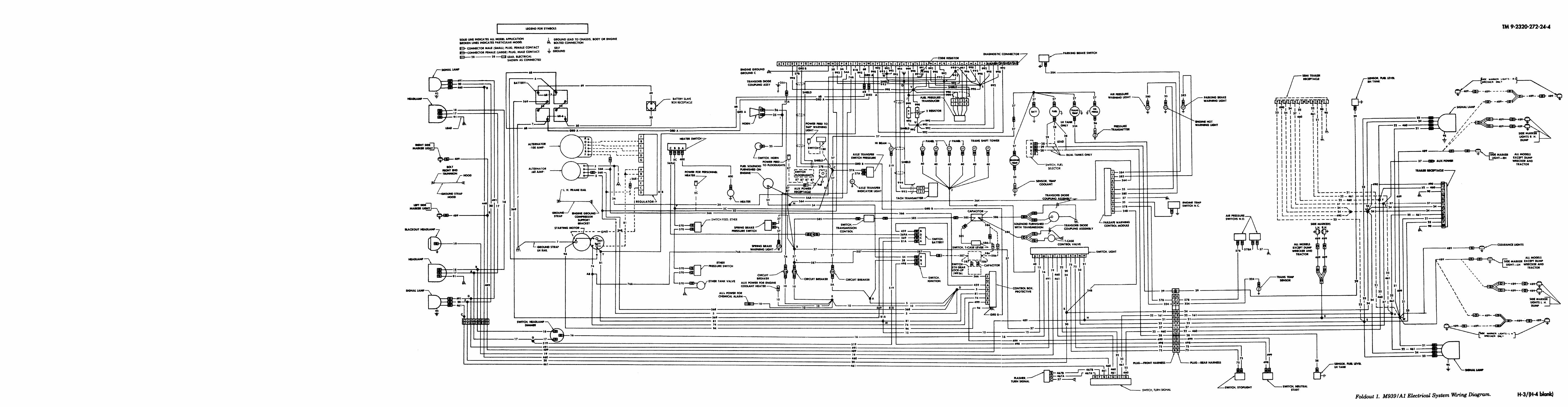
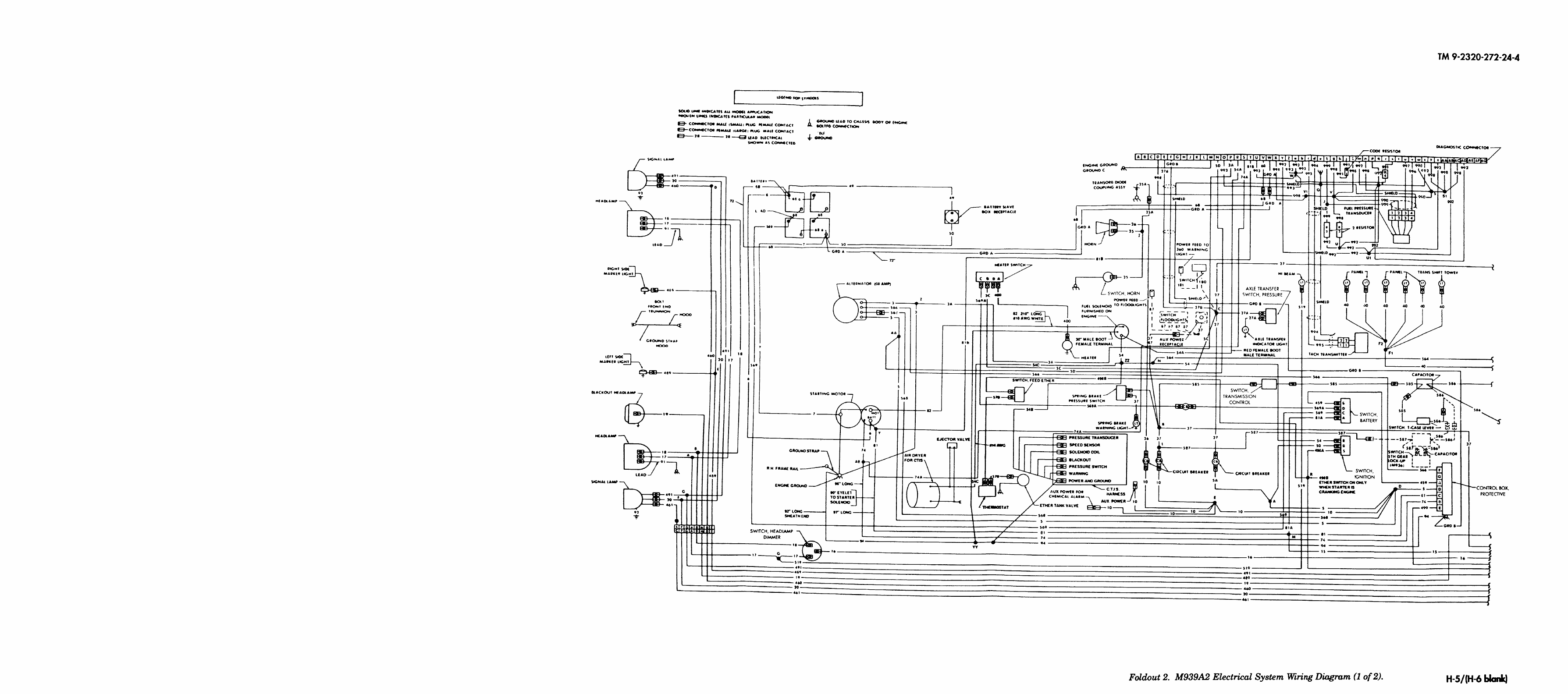
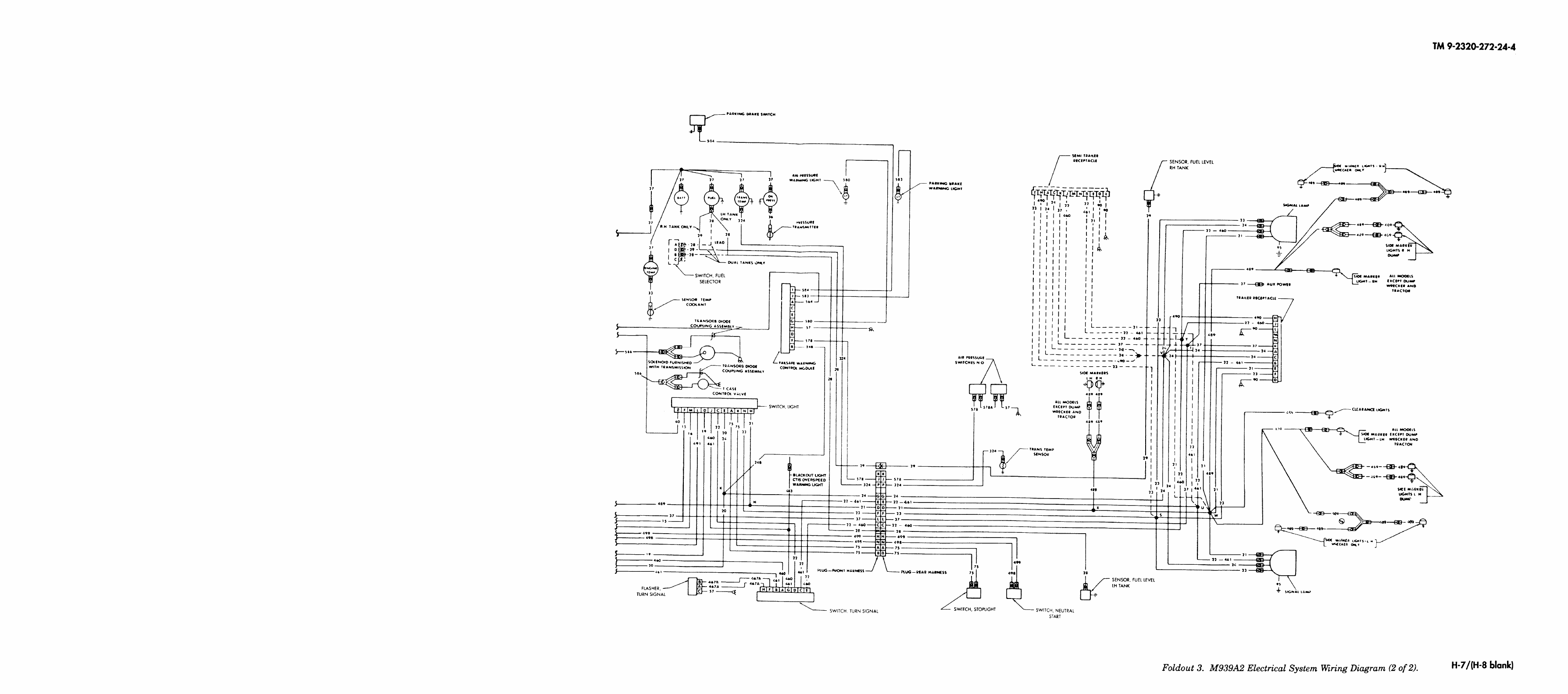
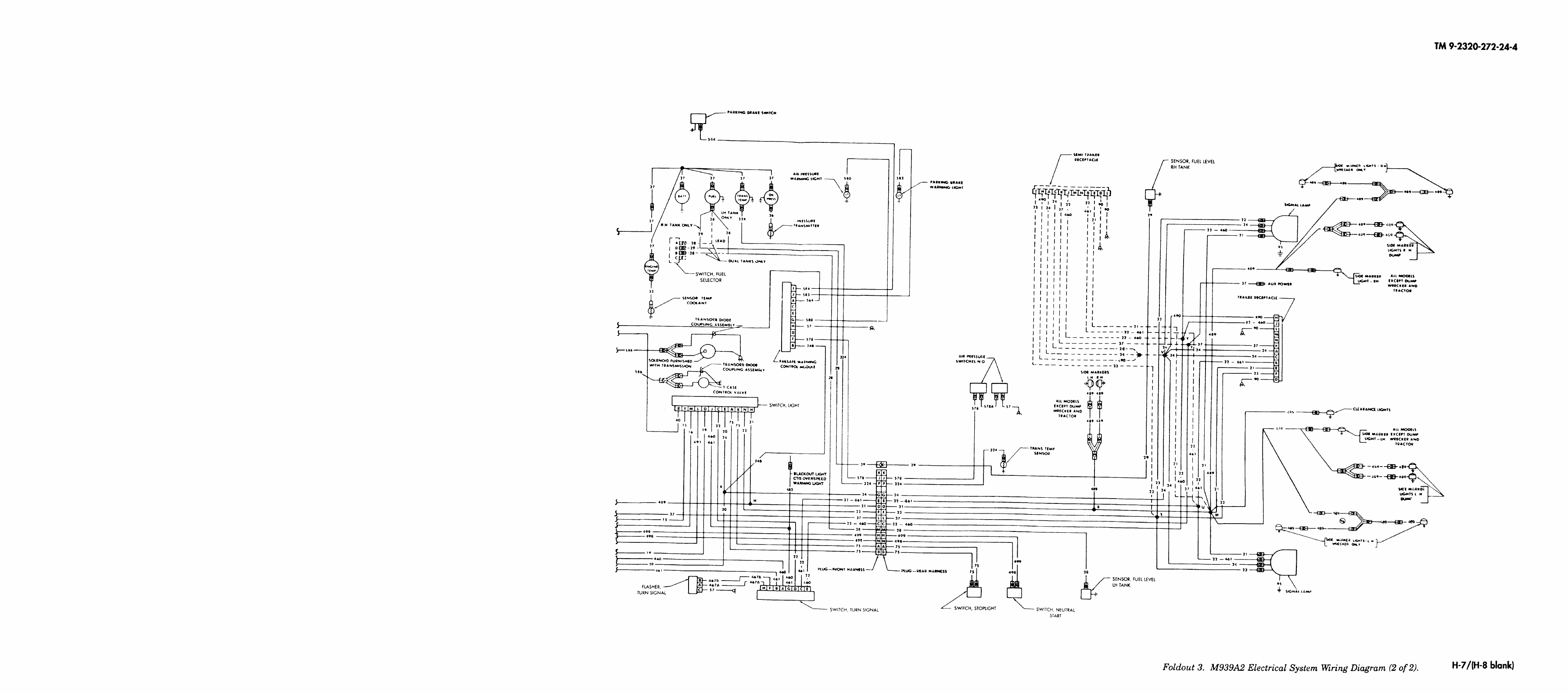
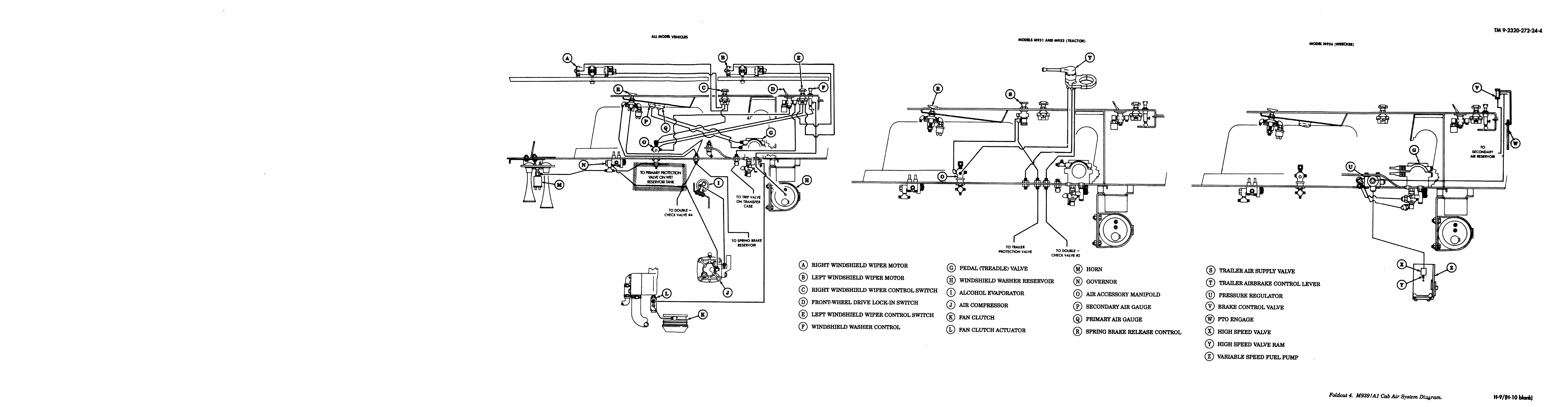
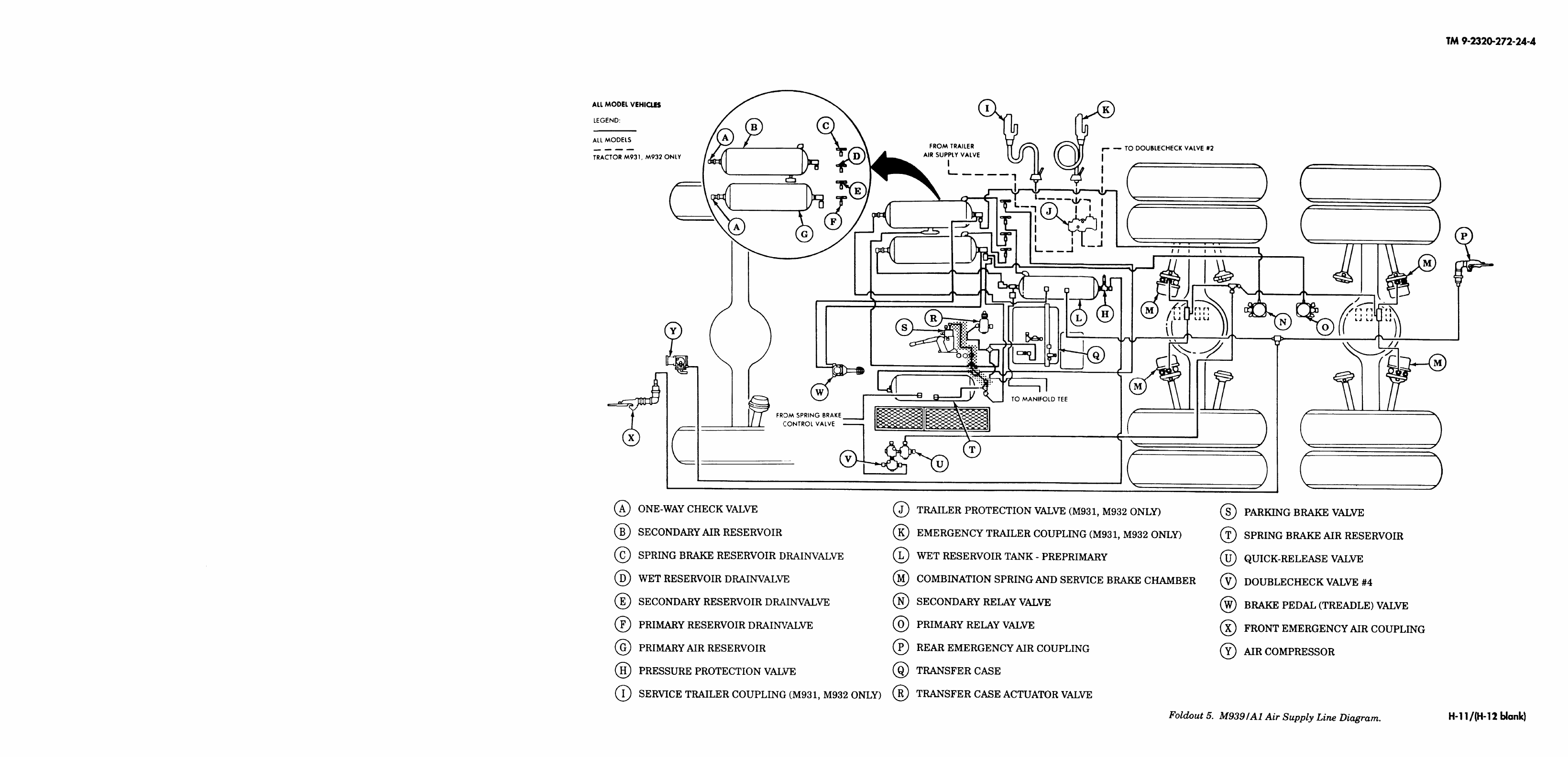
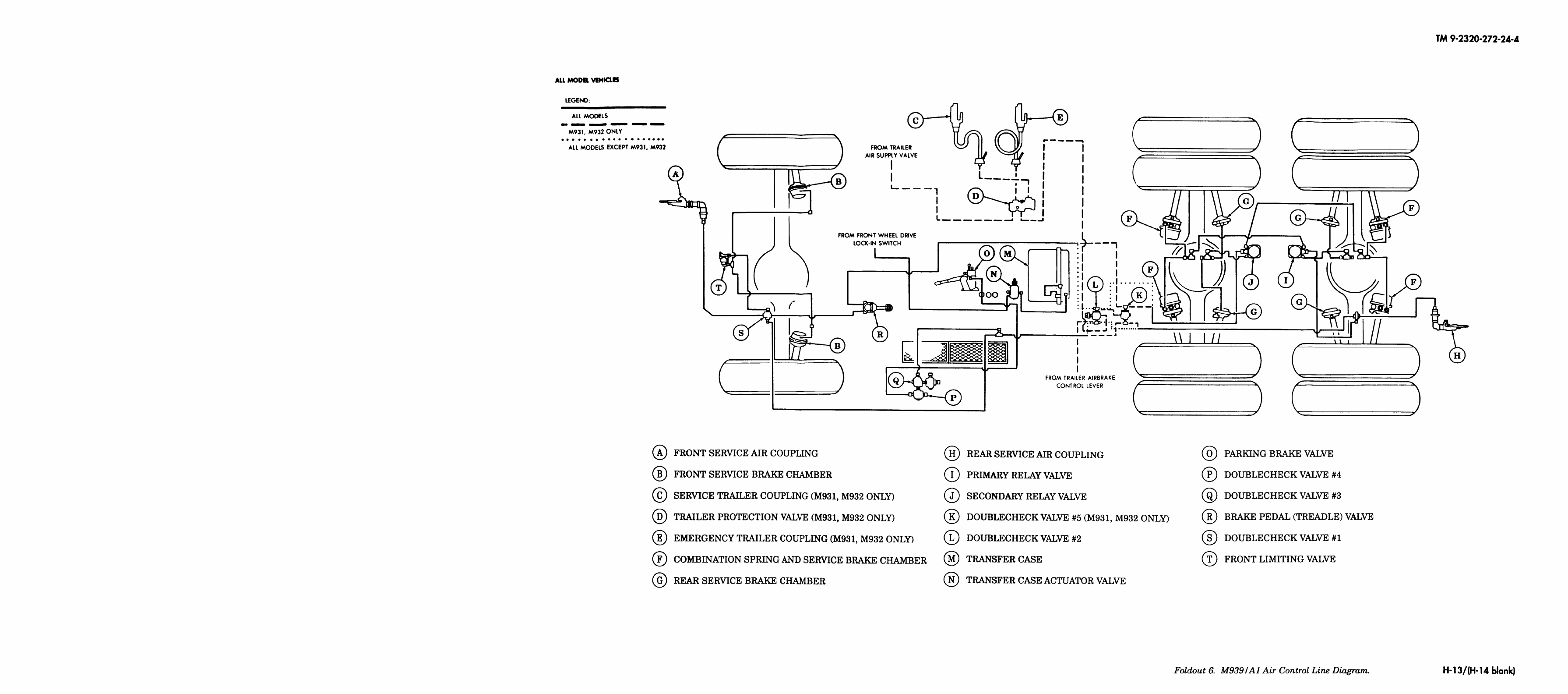
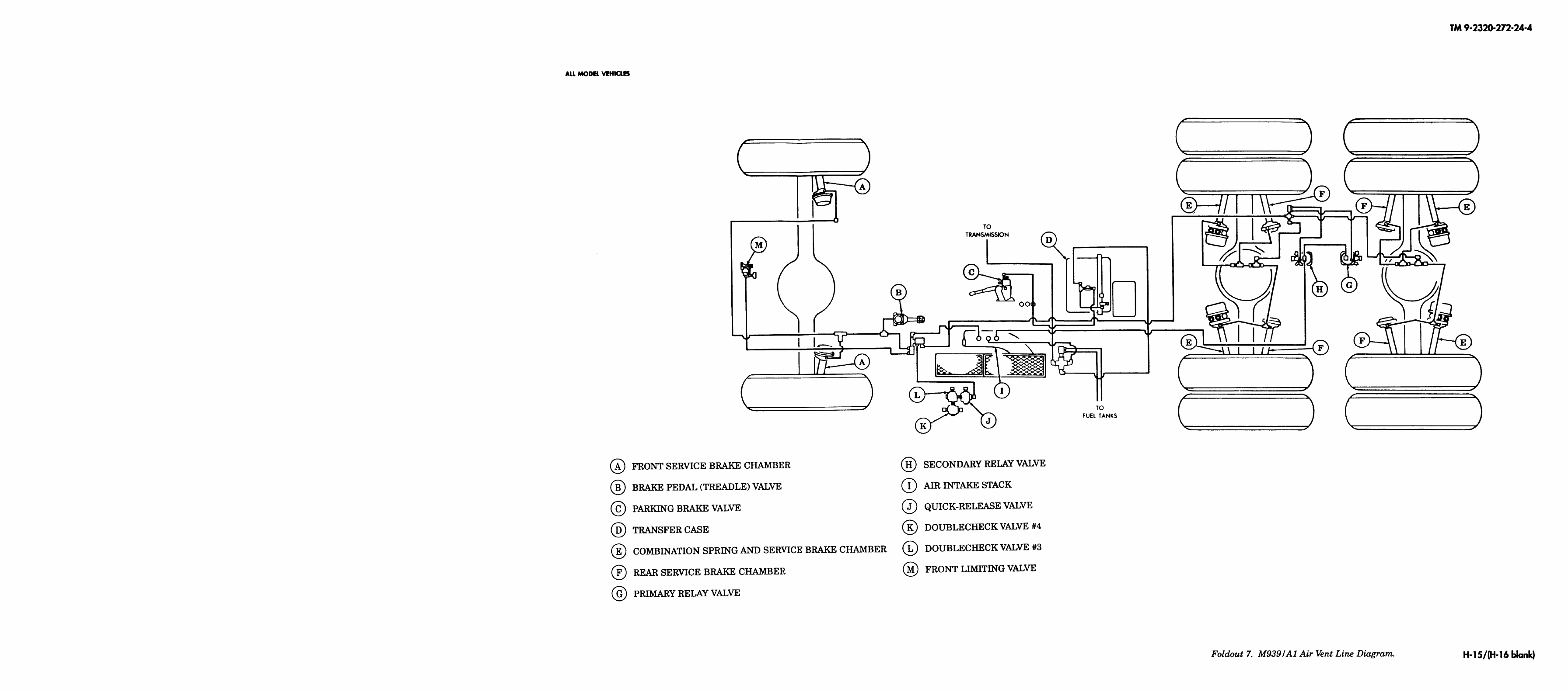
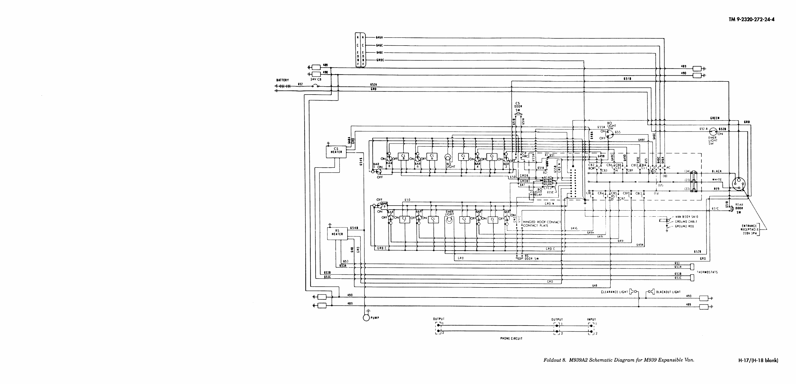
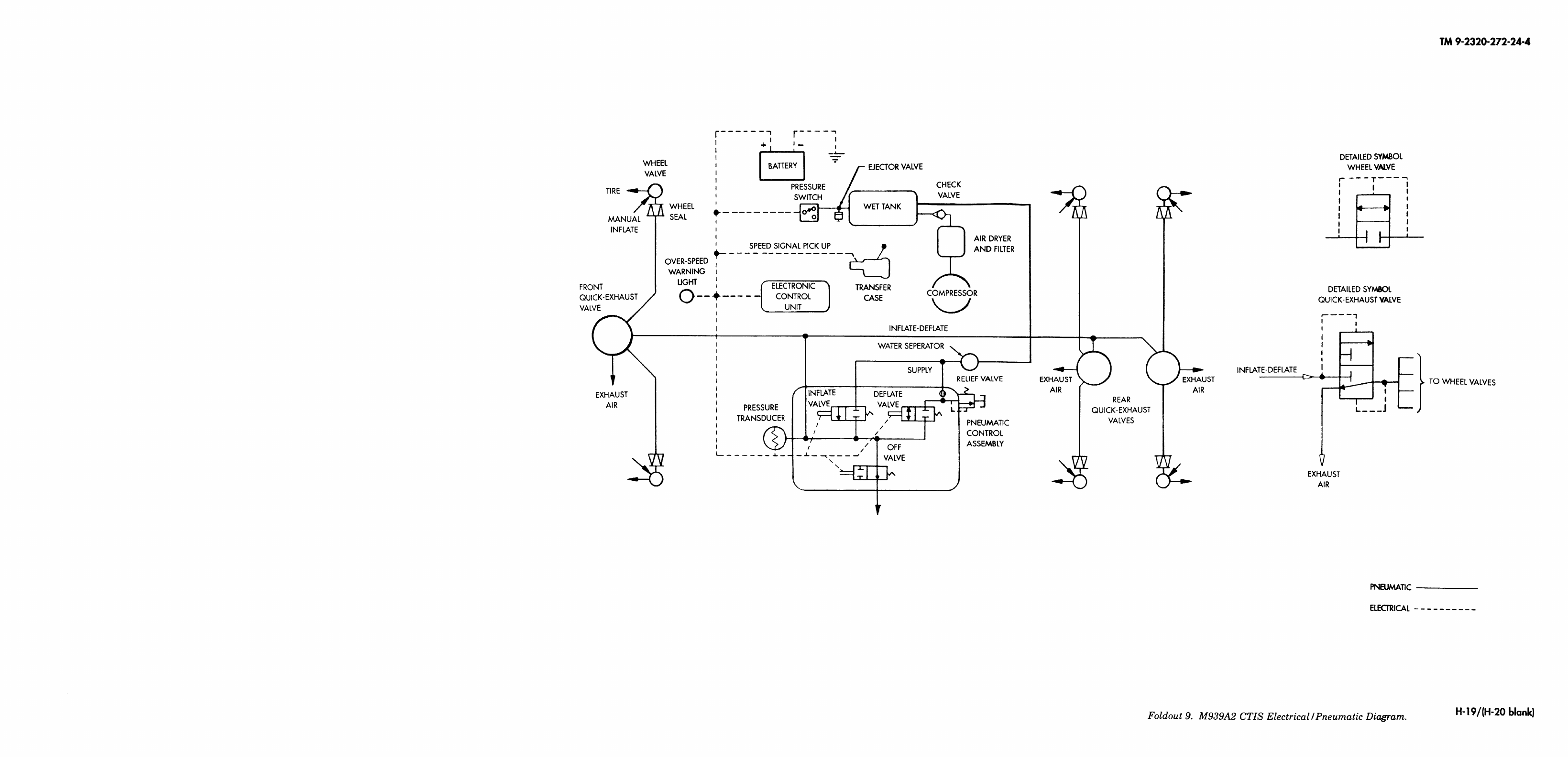
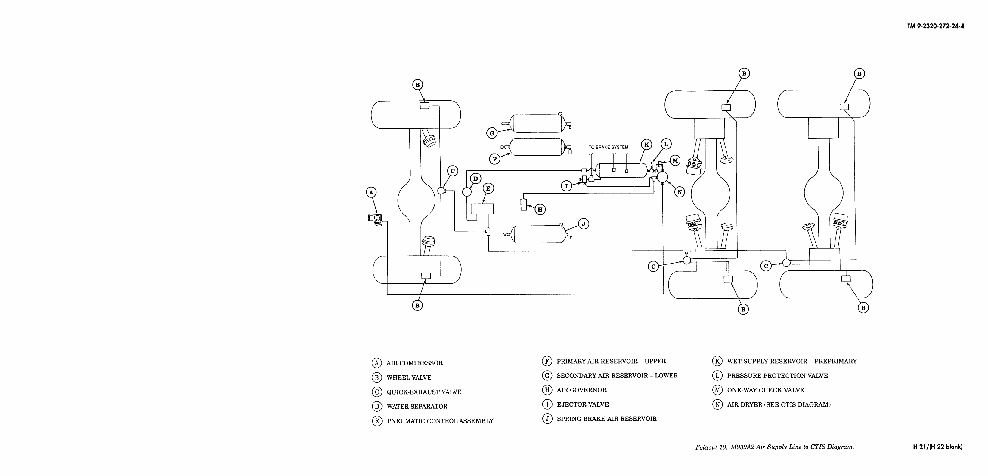
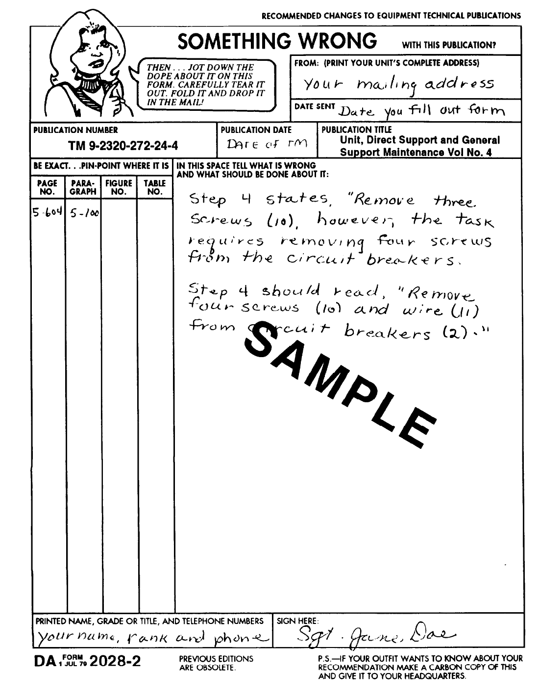
THE METRIC
SYSTEM
AND EQUIVALENTS
LINEAR MEASURE
1
Centimeter = 10 Millimeters = 0.01 Meters =
0.3937 Inches
1
Meter = 100 Centimeters = 1,000 Millimeters
=
39.37 Inches
1
Kilometer = 1,000 Meters = 0.621 Miles
SQUARE MEASURE
LIQUID MEASURE
1 Milliliter = 0.001 Liters = 0.0338 Fluid Ounces
1 Liter = 1,000 Milliliters = 33.82 Fluid Ounces
TEMPERATURE
5/9 (oF -32) - oC
212o Fahrenheit is equivalent to 100o Celsius
90o Fahrenheit is equivalent to 32.2o Celsius
32o Fahrenheit is equivalent to 0o Celsius
9/5 oC +32 = oF
1 Sq Centimeter = 100 Sq Millimeters = 0.155 Sq Inches
1 Sq Meter = 10,000 Sq Centimeters = 10.76 Sq Feet
1 Sq Kilometer = 1,000,000 Sq Meters = 0.386 Sq Miles
CUBIC MEASURE
1 Cu Centimeter = 1,000 Cu Millimeters = 0.06 Cu Inches
1 Cu Meter = 1,000,000 Cu Centimeters = 35.31 Cu Feet
WEIGHTS
1 Gram = 0.001 Kilograms = 1,000 Milligrams = 0.035 Ounces
1 Kilogram = 1,000 Grams = 2.2 Lb
1 Metric Ton = 1,000 Kilograms = 1 Megagram = 1.1 Short Tons
APPROXIMATE CONVERSION FACTORS
TO CHANGE TO
MULTIPLY BY
Inches ......................... Centimeters.. ............... 2.540
Feet .......................... Meters ..................... 0.305
Yards ......................... Meters ..................... 0.914
Miles .......................... Kilometers .................. 1.609
Square Inches .................. Square Centimeters ........... 6.451
Square Feet .................... Square Meters ............... 0.093
Square Yards ................... Square Meters ............... 0.836
Square Miles ................... Square Kilometers ............ 2.590
Acres .......................... Square Hectometers .......... 0.405
Cubic Feet ..................... Cubic Meters ................ 0.028
Cubic Yards .................... Cubic Meters ................ 0.765
Fluid Ounces ................... Milliliters ................... 29.573
Pints.. ........................ Liters ...................... 0.473
Quarts ........................ Liters ...................... 0.946
Gallons.. ...................... Liters ...................... 3.735
Ounces ........................ Grams ...................... 28.349
Pounds ........................ Kilograms ................... 0.454
Short Tons ..................... Metric Tons ................. 0.907
Pound-Feet ..................... Newton-Meters ..............
1.356
Pounds Per Square Inch .......... Kilopascals .................. 6.895
Miles Per Gallon ................ Kilometers Per Liter .......... 0.425
Miles Per Hour ................. Kilometers Per Hour ..........
1.609
TO CHANGE TO
MULTIPLY BY
Centimeters .................... Inches ...................... 0.394
Meters ........................ Feet ........................ 3.280
Meters ........................ Yards ......................
1.094
Kilometers ..................... Miles ....................... 0.621
Square Centimeters ............. Square Inches ............... 0.155
Square Meters .................. Square Feet .................
10.764
Square Meters .................. Square Yards ................
1.196
Square Kilometers ............... Square Miles ................ 0.386
Square Hectometers ............. Acres .......................
2.471
Cubic Meters ................... Cubic Feet .................. 35.315
Cubic Meters ................... Cubic Yards .................
1.308
Milliliters ...................... Fluid Ounces ................ 0.034
Liters ......................... Pints ....................... 2.113
Liters ......................... Quarts .....................
1.057
Liters ......................... Gallons ..................... 0.264
Grams. ........................ Ounces ..................... 0.035
Kilograms. ..................... Pounds ..................... 2.205
Metric Tons .................... Short Tons ..................
1.102
Newton-Meters ................. Pound-Feet .................. 0.738
Kilopascals ..................... Pounds Per Square Inch ....... 0.145
Kilometers Per Liter ............. Miles Per Gallon ............. 2.354
Kilometers Per Hour ............. Miles Per Hour .............. 0.621
PIN: 076652-000

This fine document...
Was brought to you by me:
Liberated Manuals -- free army and government manuals
Why do I do it? I am tired of sleazy CD-ROM sellers, who take publicly
available information, slap “watermarks” and other junk on it, and sell it.
Those masters of search engine manipulation make sure that their sites that
sell free information, come up first in search engines. They did not create it...
They did not even scan it... Why should they get your money? Why are not
letting you give those free manuals to your friends?
I am setting this document FREE. This document was made by the US
Government and is NOT protected by Copyright. Feel free to share,
republish, sell and so on.
I am not asking you for donations, fees or handouts. If you can, please
provide a link to liberatedmanuals.com, so that free manuals come up first in
search engines:
<A HREF=http://www.liberatedmanuals.com/>Free Military and Government Manuals</A>
–Sincerely
Igor Chudov
http://igor.chudov.com/
