TM 9 2320 366 10 1 M1085
User Manual: M1085
Open the PDF directly: View PDF ![]() .
.
Page Count: 25
- TOC
- LOI
- LAST CHANGE
- WARNING
- CHAPTERS
- CHAPTER 1
- CHAPTER 2
- PARA 2-1
- PARA 2-2
- PARA 2-3
- PARA 2-4
- PARA 2-5
- PARA 2-6
- PARA 2-7
- PARA 2-8
- PARA 2-9
- PARA 2-10
- PARA 2-11
- PARA 2-12
- PARA 2-13
- PARA 2-14
- PARA 2-15
- PARA 2-16
- PARA 2-17
- PARA 2-18
- PARA 2-19
- PARA 2-20
- PARA 2-21
- PARA 2-22
- PARA 2-23
- PARA 2-24
- PARA 2-25
- PARA 2-26
- PARA 2-27
- PARA 2-28
- PARA 2-29
- PARA 2-30
- PARA 2-31
- PARA 2-32
- PARA 2-33
- PARA 2-34
- PARA 2-35
- PARA 2-36
- PARA 2-37
- PARA 2-38
- PARA 2-39
- PARA 2-40
- FIGURES
- FIGURE 1-1
- FIGURE 1-2
- FIGURE 1-3
- FIGURE 1-4
- FIGURE 1-5
- FIGURE 1-6
- FIGURE 1-7
- FIGURE 1-8
- FIGURE 1-9
- FIGURE 1-10
- FIGURE 1-11
- FIGURE 1-12
- FIGURE 1-13
- FIGURE 1-14
- FIGURE 1-15
- FIGURE 1-16
- FIGURE 1-17
- FIGURE 1-18
- FIGURE 1-19
- FIGURE 1-20
- FIGURE 1-21
- FIGURE 1-22
- FIGURE 1-23
- FIGURE 1-24
- FIGURE 1-25
- FIGURE 1-26
- FIGURE 1-27
- FIGURE 1-28
- FIGURE 2-1
- FIGURE 2-2
- FIGURE 2-3
- FIGURE 2-4
- FIGURE 2-5
- FIGURE 2-6
- FIGURE 2-7
- FIGURE 2-8
- FIGURE 2-9
- FIGURE 2-10
- FIGURE 2-11
- FIGURE 2-12
- FIGURE 2-13
- FIGURE 2-14
- FIGURE 2-15
- FIGURE 2-16
- FIGURE 2-17
- FIGURE 2-18
- FIGURE 2-19
- FIGURE 2-20
- FIGURE 2-21
- FIGURE 2-22
- FIGURE 2-23
- FIGURE 2-24
- FIGURE 2-25
- FIGURE 2-26
- FIGURE 2-27
- FIGURE 2-28
- FIGURE 2-29
- FIGURE 2-30
- TABLES
- APPENDICES
- INDEX
- PAGES
- PAGE 1-1
- PAGE 1-3
- PAGE 1-4
- PAGE 1-5
- PAGE 1-6
- PAGE 1-7
- PAGE 1-8
- PAGE 1-9
- PAGE 1-10
- PAGE 1-11
- PAGE 1-12
- PAGE 1-13
- PAGE 1-14
- PAGE 1-15
- PAGE 1-17
- PAGE 1-18
- PAGE 1-19
- PAGE 1-23
- PAGE 1-24
- PAGE 1-26
- PAGE 1-27
- PAGE 1-28
- PAGE 1-30
- PAGE 1-31
- PAGE 1-35
- PAGE 1-36
- PAGE 1-36.1
- PAGE 1-37
- PAGE 1-38
- PAGE 1-39
- PAGE 1-41
- PAGE 1-42
- PAGE 1-45
- PAGE 1-49
- PAGE 1-50
- PAGE 1-53
- PAGE 1-54
- PAGE 1-56
- PAGE 1-57
- PAGE 1-59
- PAGE 1-62
- PAGE 1-63
- PAGE 1-65
- PAGE 1-66
- PAGE 1-68
- PAGE 1-71
- PAGE 1-72
- PAGE 1-75
- PAGE 2-1
- PAGE 2-3
- PAGE 2-7
- PAGE 2-10
- PAGE 2-11
- PAGE 2-12
- PAGE 2-13
- PAGE 2-14
- PAGE 2-15
- PAGE 2-16
- PAGE 2-17
- PAGE 2-18
- PAGE 2-19
- PAGE 2-20
- PAGE 2-21
- PAGE 2-22
- PAGE 2-23
- PAGE 2-24
- PAGE 2-25
- PAGE 2-26
- PAGE 2-28
- PAGE 2-29
- PAGE 2-31
- PAGE 2-32
- PAGE 2-36
- PAGE 2-39
- PAGE 2-42
- PAGE 2-43
- PAGE 2-46
- PAGE 2-47
- PAGE 2-50
- PAGE 2-51
- PAGE 2-52
- PAGE 2-53
- PAGE 2-54
- PAGE 2-55
- PAGE 2-56
- PAGE 2-59
- PAGE 2-60
- PAGE 2-60.2
- PAGE 2-61
- PAGE 2-72
- PAGE 2-75
- PAGE 2-80
- PAGE 2-80.1
- PAGE 2-83
- PAGE 2-88
- PAGE 2-89
- PAGE 2-90
- PAGE 2-91
- PAGE 2-94
- PAGE 2-94.1
- PAGE 2-95
- PAGE 2-96
- PAGE 2-99
- PAGE 2-100
- PAGE 2-105
- PAGE 2-112
- PAGE 2-113
- PAGE 2-114
- PAGE 2-115
- PAGE 2-122
- PAGE 2-125
- PAGE 2-128
- PAGE 2-130
- PAGE 2-131
- PAGE 2-135
- PAGE 2-136
- PAGE 2-141
- PAGE 2-144
- PAGE 2-146
- PAGE 2-147
- PAGE 2-153
- PAGE 2-154
- PAGE 2-173
- PAGE 2-178
- PAGE 2-181
- PAGE 2-186
- PAGE 2-188
- PAGE 2-189
- PAGE 2-194
- PAGE 2-195
- PAGE 2-197
- PAGE 2-200
- PAGE 2-201
- PAGE 2-202
- PAGE 2-203
- PAGE 2-206
- PAGE 2-207
- PAGE 2-211
- PAGE 2-212
- PAGE 2-212.1
- PAGE 2-213
- PAGE 2-214
- PAGE 2-226
- PAGE 2-231
- PAGE 2-232
- PAGE 2-237
- PAGE 2-242
- PAGE 2-247
- PAGE 2-250
- PAGE 2-261
- PAGE 2-264
- PAGE 2-269
- PAGE 2-270
- PAGE 2-273
- PAGE 2-275
- PAGE 2-276
- PAGE 2-277
- PAGE 2-278
- PAGE 2-282
- PAGE 2-293
- PAGE 2-294
- PAGE 2-295
- PAGE 2-297
- PAGE 2-298.1
- PAGE 2-298.3
- PAGE 2-299
- PAGE 2-300
- PAGE 2-300.1
- PAGE 2-300.63
- PAGE 2-301
- PAGE 2-322
- PAGE 2-330
- PAGE 2-333
- PAGE 2-334
- PAGE 2-351
- PAGE 2-355
- PAGE 2-356
- PAGE 2-357
- PAGE 2-378
- PAGE 2-379
- PAGE 2-380
- PAGE 2-391
- PAGE 2-392
- PAGE 2-395
- PAGE 2-396
- PAGE 2-401
- PAGE 2-402
- PAGE 2-408
- PAGE 2-411
- PAGE 2-416
- PAGE 2-421
- PAGE 2-425
- PAGE 2-426
- PAGE 2-427
- PAGE 2-428
- PAGE 2-430
- PAGE A-1
- PAGE A-3
- PAGE B-1
- PAGE B-3
- PAGE B-25
- PAGE C-1
- PAGE C-4
- PAGE D-1
- PAGE D-4
- PAGE E-1
- PAGE E-2
- PAGE E-7
- PAGE E-8
- PAGE F-1
- PAGE F-4
- PAGE F-7
- PAGE F-8
- PAGE F-11
- PAGE F-16

ARMY TM 9-2320-366-10-1
AIR FORCE T.0. 36A12-1C-1091-1
TECHNICAL MANUAL
OPERATOR’S INSTRUCTIONS
M1083 SERIES, 5 TON, 6x6,
MEDIUM TACTICAL VEHICLES (MTV)
VOLUME NO. 1 OF 2
MODEL NSN EIC
TRK, CAR., MTV, M1083
W/WN 2320-01-360-1895 BT3 TABLE OF
CONTENTS ii
W/O WN 2320-01-354-3386 BR2
TRK, CAR., MTV, W/MATL
HDLG EQPT (MHE) M1084 2320-01-354-3387 BR3 HOW TO USE
THIS MANUAL vi
TRK, CAR., MTV, LWB,
M1085
W/WN 2320-01-360-1897 BT5 EQUIPMENT
DESCRIPTION 1-17
W/O WN 2320-01-354-4530 BR7
TRK, CAR., MTV, LWB, W/MATL
HDLG EQPT (MHE) M1086 2320-01-354-4531 BR8 DESCRIPTION AND USE OF
OPERATOR’S CONTROLS
AND INDICATORS 2-3
TRK, TRACTOR, MTV, M1088
W/WN 2320-01-360-1892 BTY
W/O WN 2320-01-355-4332 BTJ
PREVENTIVE
MAINTENANCE CHECKS
AND SERVICES
(PMCS) 2-50
TRK, WKR, MTV, M1089 2320-01-354-4528 BR4
TRK, DUMP, MTV, M1090
W/WN 2320-01-360-1893 BTZ
W/O WN 2320-01-354-4529 BR5
VEHICLE OPERATION 2-214
TRK, CHAS, MTV, M1092 2320-01-354-3382 BRZ
TRK, CAR., MTV, AIR DROP,
M1093
W/WN 2320-01-360-1896 BT4
W/O WN 2320-01-355-3063 BR9
TRK, DUMP, MTV, AIR DROP,
M1094
W/WN 2320-01-360-1894 BT2
W/O WN 2320-01-355-3062 BTK
TRK, CHAS, MTV, LWB,
M1096 2320-01-354-4527 BR6
DISTRIBUTION STATEMENT A. Approved for public release; distribution is unlimited.
HEADQUARTERS, DEPARTMENTS OF THE
ARMY AND THE AIR FORCE
15 September 1998

ARMY TM 9-2320-366-10-1
AIR FORCE T.O. 36A12-1C-1091-1
TECHNICAL MANUAL HEADQUARTERS
NO. 9-2320-366-10-1 DEPARTMENTS OF THE ARMY
AND THE AIR FORCE
TECHNICAL ORDER
NO. 36A12-1C-1091-1 Washington, D.C., 15 September 1998
Operator’s Instructions Manual
M1083 SERIES, 5-TON, 6x6,
MEDIUM TACTICAL VEHICLES (MTV)
VOLUME NO. 1 OF 2
MODEL NSN EIC
TRK, CAR., MTV, M1083
W/WN 2320-01-360-1895 BT3
W/O WN 2320-01-354-3386 BR2
TRK, CAR., MTV, W/MATL
HDLG EQPT (MHE) M1084 2320-01-354-3387 BR3
TRK, CAR., MTV, LWB, M1085
W/WN 2320-01-360-1897 BT5
W/O WN 2320-01-354-4530 BR7
TRK, CAR., MTV, LWB, W/MATL
HDLG EQPT (MHE) M1086 2320-01-354-4531 BR8
TRK, TRACTOR, MTV, M1088
W/WN 2320-01-360-1892 BTY
W/O WN 2320-01-355-4332 BTJ
TRK, WKR, MTV, M1089 2320-01-354-4528 BR4
TRK, DUMP, MTV, M1090
W/WN 2320-01-360-1893 BTZ
W/O WN 2320-01-354-4529 BR5
TRK, CHAS, MTV, M1092 2320-01-354-3382 BRZ
TRK, CAR., MTV, AIR DROP, M1093
W/WN 2320-01-360-1896 BT4
W/O WN 2320-01-355-3063 BR9
TRK, DUMP, MTV, AIR DROP, M1094
W/WN 2320-01-360-1894 BT2
W/O WN 2320-01-355-3062 BTK
TRK, CHAS, MTV, LWB, M1096 2320-01-354-4527 BR6
Change 1 i
TM 9-2320-366-10-1
REPORTING ERRORS AND RECOMMENDING IMPROVEMENTS
You can help improve this publication. If you find any mistakes or if you know of a
way to improve the procedures, please let us know. Submit your DA Form 2028
(Recommended Changes to Equipment Technical Publications), through the
Internet, on the Army Electronic Product Support (AEPS) website. The Internet
address is http://aeps.ria.army.mil. If you need a password, scroll down and click
on "ACCESS REQUEST FORM". The DA Form 2028 is located in the ONLINE
FORMS PROCESSING section of the AEPS. Fill out the form and click on
SUBMIT. Using this form on the AEPS will enable us to respond quicker to your
comments and better manage the DA Form 2028 program. You may also mail, fax
or Email your letter or DA Form 2028 direct to: AMSTA-LC-CI/TECH PUBS,
TACOM-RI, 1 Rock Island Arsenal, Rock Island, IL 61299-7630. The email address
is TACOM-TECH-PUBS@ria.army.mil. The fax number is DSN 793-0726 or
Commercial (309) 782-0726.
DISTRIBUTION STATEMENT A. Approved for public release; distribution is
unlimited.
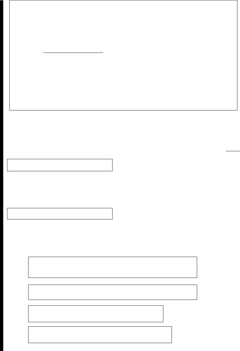
TABLE OF CONTENTS Page
HOW TO USE THIS MANUAL ..................................vi
CHAPTER 1. INTRODUCTION ......................................1-1
Section I. General Information ...............................1-1
Section II Equipment Description ...............................1-17
Section III. Principles of Operation ..........................1-50
CHAPTER 2. OPERATING INSTRUCTIONS ............................2-1
Section I. Description and Use of Operator’s Controls and
Indicators .......2-3
Section II. Preventive Maintenance Checks and Services ......2-50
Section III. Operation Under Usual Conditions ............... 2-207
Section IV. Operation Under Unusual Conditions ............ 2-720
ii Change 1
TM 9-2320-366-10-1
Page
CHAPTER 3. MAINTENANCE INSTRUCTIONS .........................3-1
Section I. Lubrication Instructions ..........................3-1
Section II. Troubleshooting Procedures ................. 3-2
Section III. Maintenance Procedures ................. 3-87
APPENDIX A. REFERENCES ..................................... A-1
APPENDIX B. COMPONENTS OF END ITEM (COEI) AND BASIC
ISSUE ITEMS (BII) .................................. B-1
APPENDIX C. ADDITIONAL AUTHORIZATION LIST (AAL) ............... C-1
APPENDIX D. EXPENDABLE AND DURABLE ITEMS LIST ............... D-1
APPENDIX E. STOWAGE LOCATION/DECAL/STENCIL GUIDE ............ E-1
APPENDIX F. LUBRICATION ORDER .................... F-1
ALPHABETICAL (SUBJECT) INDEX ......................... INDEX-1
LIST OF ILLUSTRATIONS
Figure Title Page
1-1 M1083 Truck, Cargo: 5-Ton, 6x6, Dropside ........................1-3
1-2 M1084 Truck, Cargo: 5-Ton, 6x6, Dropside, W/MHC .................1-4
1-3 M1085 Truck, Cargo: 5-Ton, 6x6, Dropside, LWB ...................1-5
1-4 M1086 Truck, Cargo: 5-Ton, 6x6, Dropside, LWB, W/MHC ............1-6
1-5 M1088 Truck, Tractor: 5-Ton, 6x6 ..............................1-7
1-6 M1089 Truck, Wrecker: 5-Ton, 6x6 ..............................1-8
1-7 M1090 Truck, Dump: 5-Ton, 6x6 ...............................1-9
1-8 M1092 Truck, Chassis: 5-Ton, 6x6 .............................1-10
1-9 M1093 Truck, Cargo 5-Ton, 6x6, Dropside, Air Drop ................1-11
1-10 M1094 Truck, Dump: 5-Ton, 6x6, Air Drop .......................1-12
Change 1 iii

TM 9-2320-366-10-1
LIST OF ILLUSTRATIONS (CONT)
Figure Title Page
1-11 M1096 Truck, Chassis: 5-Ton, 6x6, LWB ........................1-13
1-12 Common Vehicle Components Location ......................... 1-19
1-13 M1083 and M1085 Cargo Vehicles and M1093 Air Drop
Cargo Vehicles Components Location ..........................1-26
1-14 M1084 and M1086 Cargo Vehicles With Material Handling
Crane (MHC) Components Location ............................ 1-27
1-15 M1088 Tractor Components Location ...........................1-28
1-16 M1090 and M1094 Dump Truck Components Location .............. 1-30
1-17 M1089 Wrecker Components Location ..........................1-31
1-18 M1093 and M1094 Air Drop Vehicle Components Location ...........1-35
1-19 Powertrain ..............................................1-50
1-20 Engine Air Intake System .................................... 1-53
1-21 Fuel System ............................................. 1-54
1-22 Cooling System ........................................... 1-56
1-23 Electrical System ..........................................1-59
1-24 Brake System ............................................1-63
1-25 15K Self-Recovery Winch (SRW) ..............................1-65
1-26 Material Handling Crane (MHC) ............................... 1-68
1-27 Material Handling Crane (MHC), 30K Winches, and Underlift
Assembly ...............................................1-71
1-28 Air System .............................................. 1-75
2-1 Instrument Panel Controls and Indicators .........................2-3
2-2 Lighted Indicator Display .....................................2-7
2-3 Main Light Switch .........................................2-10
2-4 WTEC II Transmission ECU Pushbutton Shift Selector (TEPSS) ........2-11
2-5 WTEC III Transmission Pushbutton Shift Selector (TPSS) ............ 2-12
2-6 Auxiliary Panel Controls and Indicators
for M1083, M1084, M1085, M1086, M1088,
M1089, and M1093 ........................................2-13
2-7 Auxiliary Panel Controls and Indicators
for M1090 and M1094 ...................................... 2-15
2-8 Air System Controls ........................................ 2-16
2-9 Heater/Defrost Controls ..................................... 2-17
2-10 Central Tire Inflation System (CTIS) Electronic Control Unit (ECU)
Controls and Indicators ..................................... 2-18
2-11 Steering Column Controls ................................... 2-19
2-12 Floor-Mounted Controls ..................................... 2-20
2-13 Door-Mounted Controls ..................................... 2-21
2-14 Driver’s Seat Controls ...................................... 2-22
2-15 Right Passenger Seat Controls ............................... 2-22
2-16 Passenger Side Exterior Controls ..............................2-23
2-17 Hydraulic Manifold Controls .................................. 2-24
2-18 Driver’s Side Exterior Controls and Indicators ..................... 2-25
iv Change 1

TM 9-2320-366-10-1
LIST OF ILLUSTRATIONS (CONT)
Figure Title Page
2-19 Material Handling Crane (MHC) Controls ........................2-26
2-20 Material Handling Crane (MHC) Remote Control ................... 2-28
2-21 Cargo Truck with Material Handling Crane (MHC) Boom Angle and
Extension Indicators ....................................... 2-29
2-22 Exterior Dump Body Controls .................................2-30
2-23 Tractor Fifth Wheel Controls ................................. 2-31
2-24 Wrecker Control Panel Fixed Operators Station .................... 2-32
2-25 Wrecker Remote Control ....................................2-36
2-26 Wrecker Material Handling Crane (MHC) Controls ..................2-39
2-27 Wrecker Material Handling Crane (MHC) REMOTE CONTROL UNIT ....2-42
2-28 Other Wrecker and Material Handling Crane (MHC) Controls
and Indicators ............................................2-43
2-29 Troop Transport Alarm Switch ................................ 2-46
2-30 Light Material Handling Crane (LMHC) ..........................2-47
2-31 Deleted
2-32 Deleted
2-33 Area Definition Chart ...................................... 2-661
LIST OF TABLES
Number Title Page
1-1 Differences Between Models ................................. 1-36
1-2 Vehicle Dimensions ........................................ 1-38
1-3 Vehicle Weights and Payloads ................................1-39
1-4 Vehicle Performance Data ................................... 1-41
1-5 Fluid Capacities ..........................................1-42
1-6 System Data ............................................. 1-42
1-7 Vehicle Classification .......................................1-49
2-1 Preventive Maintenance Checks and Services
(all Models) .............................................. 2-54
2-2 Preventive Maintenance Checks and Services
(M1083, M1084, M1085, M1086, and M1093) .................... 2-114
2-3 Preventive Maintenance Checks and Services
(M1084 and M1086) ...................................... 2-131
2-4 Preventive Maintenance Checks and Services
(M1088) ............................................... 2-147
2-5 Preventive Maintenance Checks and Services
(M1089) ............................................... 2-154
2-6 Preventive Maintenance Checks and Services
(M1090 and M1094) ...................................... 2-189
2-7 Preventive Maintenance Checks and Services
(M1093) ............................................... 2-195
Change 1 v

TM 9-2320-366-10-1
LIST OF TABLES (CONT)
Number Title Page
2-8 Preventive Maintenance Checks and Services
(M1094) ............................................... 2-202
2-9 Capacity Chart for Light Material Handling Crane (LMHC) ........... 2-247
2-10 Central Tire Inflation System (CTIS) Tire Pressures and Restrictions
for M1083, M1084, M1085, M1086, M1090, M1093,
and M1094 Models ....................................... 2-275
2-11 Central Tire Inflation System (CTIS) Tire Pressure and Restrictions
for M1088 and M1089 Models ............................... 2-276
2-12 Cargo Bed Side Panel Stowage Information ..................... 2-295
2-13 Cargo Bed Side Panel Stowage Information ..................... 2-297
2-14 Material Handling Crane (MHC) (M1084/M1086)
Range Diagram Summary .................................. 2-357
2-15 Material Weight by Volume ................................. 2-380
2-16 M1088 Speed and Tire Pressure on Highways ................... 2-425
2-17 M1088 Speed and Tire Pressure on Gravel/Dirt .................. 2-426
2-18 M1088 Speed and Tire Pressure for Cross Country ................ 2-427
2-19 M1088 Speed and Tire Pressure for Sand/Mud/Snow .............. 2-428
2-20 30K Winch Pull Capacity ................................... 2-442
2-21 Load Chart ............................................. 2-662
2-22 Wrecker Material Handling Crane (MHC) Range Diagram Summary .... 2-664
2-23 Wrecker Material Handling Crane (MHC) Range Diagram Summary .... 2-681
2-24 15K Self-Recovery Winch (SRW) Pull Capacity ................... 2-770
2-25 Deleted
3-1 Malfunction Index ..........................................3-2
3-2 Troubleshooting ..........................................3-18
3-3 Cold Tire Inflation Pressures and Restrictions
for M1083, M1084, M1085, M1086, M1090, M1092,
M1093, M1094, and M1096 Models ........................... 3-103
3-4 Cold Tire Inflation Pressures and Restrictions
for M1088 and M1089 Models ............................... 3-104
3-5 General Cleaning Instructions ............................... 3-112
HOW TO USE THIS MANUAL
OVERVIEW
This Technical Manual (TM) is provided to help you operate and maintain the Medium
Tactical Vehicles (MTV). This volume, volume 1, contains general information, equipment
description, and operating instructions. Volume 2 contains the remainder of chapter 2,
lubrication, troubleshooting, and maintenance procedures. Volume 1 is divided into the
following major sections in order of appearance.
vi Change 1

TM 9-2320-366-10-1
• FRONT COVER INDEX. The front cover index contains a list of the most
important topics contained in the volume. It features a black box at the
right edge of the cover which corresponds with a black box on the page
containing the topic. The topics listed on the front cover are highlighted
in the table of contents with a box.
• WARNING SUMMARY. Provides a summary of the most important
warnings that apply throughout the manual. Read all warnings and
cautions before performing any operation, troubleshooting or maintenance
procedures.
• TABLE OF CONTENTS. Lists the chapters, sections, appendixes, and
alphabetical index with page number in order of appearance.
• CHAPTER 1, INTRODUCTION. Describes the MTV and provides
equipment data.
• CHAPTER 2, OPERATING INSTRUCTIONS (PARAGRAPH 2-1
THROUGH 2-40). Describes operator’s controls and indicators, preventive
maintenance checks and services (PMCS), and operating instructions.
• APPENDIX A, REFERENCES. Lists publications used with the MTV and
reference publications which contain information regarding the equipment.
• APPENDIX B, COMPONENTS OF END ITEM (COEI) AND BASIC ISSUE
ITEMS (BII) LISTS. Lists and illustrates COEI and BII items issued with
the MTV.
• APPENDIX C, ADDITIONAL AUTHORIZATION LIST (AAL). Lists
additional items you are authorized for support of the MTV.
• APPENDIX D, EXPENDABLE AND DURABLE ITEMS LIST. Lists
expendable and durable items used in the performance of maintenance
procedures.
• APPENDIX E, STOWAGE AND DECAL/DATA PLATE GUIDE. Shows
the location of signs and details the location of COEI, BII, and AAL items.
• APPENDIX F, LUBRICATION INSTRUCTIONS. Gives operator
lubrication instructions and the time interval at which lubrication is
conducted. Lubrication points are also illustrated.
• SUBJECT INDEX. Lists important subjects contained in Volume
1 and Volume 2 in alphabetical order and gives the paragraph
number where they are located.
Change 1 vii

TM 9-2320-366-10-1
OVERVIEW (CONT)
Volume 2 contains the following major sections in order of appearance:
• WARNING SUMMARY. Provides a summary of the warnings that appear
throughout the manual. Read all WARNINGS and CAUTIONS before
performing any operation, troubleshooting or maintenance procedures.
• TABLE OF CONTENTS. Lists the chapters, sections, appendixes, and
alphabetical index with page number in order of appearance.
• CHAPTER 2, OPERATING INSTRUCTIONS (PARAGRAPH 2-41
THROUGH 2-80). Describes the remaining operating instructions.
• CHAPTER 3, MAINTENANCE INSTRUCTIONS. Provides instructions for
lubrication, troubleshooting, and operator maintenance.
• APPENDIX A, REFERENCES. Lists publications used with the MTV and
reference publications which contain information regarding the equipment.
• APPENDIX B, COMPONENTS OF END ITEM (COEI) AND BASIC ISSUE
ITEMS (BII) LISTS. Lists and illustrates COEI and BII items issued with
the MTV.
• APPENDIX C, ADDITIONAL AUTHORIZATION LIST (AAL). Lists
additional items you are authorized for support of the MTV.
• APPENDIX D, EXPENDABLE AND DURABLE ITEMS LIST. Lists
expendable and durable items used in the performance of maintenance.
• APPENDIX E, STOWAGE AND DECAL/DATA PLATE GUIDE. Shows
the location of signs and details the location of COEI, BII, and AAL items.
• APPENDIX F, LUBRICATION INSTRUCTIONS. Gives operator
lubrication instructions and the time interval at which lubrication is
conducted. Lubrication points are also illustrated.
• SUBJECT INDEX. Lists important subjects contained in Volume
2 in alphabetical order and gives the paragraph number where
they are located.
viii Change 1

TM 9-2320-366-10-1
FINDING INFORMATION
There are several ways to find the information you need in this manual. They are as
follows:
• TABLE OF CONTENTS. Lists chapters, sections, appendixes, and
indexes with page numbers in order of appearance.
• CHAPTER INDEXES. List paragraphs contained in the individual
chapters with paragraph and page numbers in order of appearance.
• MALFUNCTION INDEX. Lists malfunctions contained in the
troubleshooting table with page numbers in order of appearance.
• ALPHABETICAL (SUBJECT) INDEX. Lists all important topics with page
numbers in alphabetical order.
TROUBLESHOOTING
Troubleshooting is contained in Volume 2, Chapter 3. When you have a problem with the
operation of your equipment, look at Table 3-1, Malfunction Index on page 3-2. Find the
malfunction in the index. Turn to the page number listed for the malfunction in Table 3-2,
Troubleshooting. Perform the steps required to correct the malfunction. If you can not find
the malfunction, or the malfunction is not corrected, notify Unit Maintenance.
OPERATION AND MAINTENANCE
• OPERATION. Before you operate the MTV, familiarize yourself with the
controls and indicators (Chapter 2, Section I). Perform your BEFORE
preventive maintenance (Chapter 2, Section II). Read the operating
instructions contained in Chapter 2, Sections III and IV. Always follow the
WARNINGS and CAUTIONS. During operation, perform your DURING
preventive maintenance, and after operation perform your AFTER
preventive maintenance (Chapter 2, Section II).
• MAINTENANCE. When you perform maintenance, look over the entire
procedure before starting. Make sure you have the necessary tools and
materials at hand. Always observe WARNINGS and CAUTIONS.
Change 1 ix/(x Blank)

TM 9-2320-366-10-1
CHAPTER 1
INTRODUCTION
Section I. GENERAL INFORMATION ................................1-1
1-1. SCOPE .................................................1-1
1-2. MAINTENANCE FORMS AND PROCEDURES ...................1-14
1-3. CORROSION PREVENTION AND CONTROL (CPC) ............... 1-14
1-4. DESTRUCTION OF ARMY MATERIEL TO PREVENT ENEMY USE .... 1-14
1-5. REPORTING EQUIPMENT IMPROVEMENT RECOMMENDATIONS
(EIR) .................................................1-14
1-6. WARRANTY INFORMATION ................................1-15
1-7. NOMENCLATURE CROSS-REFERENCE LIST ...................1-15
1-8. LIST OF ABBREVIATIONS .................................. 1-15
1-9. GLOSSARY ............................................. 1-17
Section II. EQUIPMENT DESCRIPTION .............................. 1-17
1-10. EQUIPMENT CHARACTERISTICS, CAPABILITIES, AND FEATURES . . . 1-17
1-11. LOCATION AND DESCRIPTION OF MAJOR COMPONENTS ........ 1-19
1-12. DIFFERENCES BETWEEN MODELS .......................... 1-36
1-13. EQUIPMENT DATA ....................................... 1-38
Section III. PRINCIPLES OF OPERATION ............................ 1-50
1-14. POWERTRAIN ...........................................1-50
1-15. ENGINE AIR INTAKE SYSTEM ............................... 1-53
1-16. FUEL SYSTEM ..........................................1-54
1-17. COOLING SYSTEM ....................................... 1-56
1-18. ELECTRICAL SYSTEM .................................... 1-59
1-19. BRAKE SYSTEM .........................................1-63
1-20. 15K SELF-RECOVERY WINCH (SRW) ......................... 1-65
1-21. M1084/M1086 MATERIAL HANDLING CRANE (MHC) ..............1-68
1-22. M1089 MATERIAL HANDLING CRANE (MHC), 30K WINCHES,
AND UNDERLIFT ASSEMBLY ..............................1-71
1-23. AIR SYSTEM ............................................ 1-75
Section I. GENERAL INFORMATION
1-1. SCOPE
This chapter provides general information, equipment description, and principles of
operation for the M1083 series Medium Tactical Vehicle (MTV). The MTV will herein be
referred to as the vehicle.
a. Type of Manual. This manual provides instructions for operation and Operator
maintenance of the vehicle.
1-1

TM 9-2320-366-10-1
1-1. SCOPE (CONT)
b. Name and Model. The vehicle model numbers and names are listed below:
M1083 Truck, Cargo: 5-Ton, 6x6, Dropside (Figure 1-1).
M1084 Truck, Cargo: 5-Ton, 6x6, Dropside, W/MHC (Figure 1-2).
M1085 Truck, Cargo: 5-Ton, 6x6, Dropside, LWB (Figure 1-3).
M1086 Truck, Cargo: 5-Ton, 6x6, Dropside, LWB, W/MHC (Figure 1-4).
M1088 Truck, Tractor: 5-Ton, 6x6 (Figure 1-5).
M1089 Truck, Wrecker: 5-Ton, 6x6 (Figure 1-6).
M1090 Truck, Dump: 5-Ton, 6x6 (Figure 1-7).
M1092 Truck, Chassis: 5-Ton, 6x6 (Figure 1-8).
M1093 Truck, Cargo 5-Ton, 6x6, Dropside, Air Drop (Figure 1-9).
M1094 Truck, Dump: 5-Ton, 6x6, Air Drop (Figure 1-10).
M1096 Truck, Chassis: 5-Ton, 6x6, LWB (Figure 1-11).
c. Purpose of Equipment. The MTV series is a family of 6x6 wheeled vehicles. The
purpose of these vehicles is as follows:
(1) M1083 - Cargo hauling vehicle; can be outfitted for troop transport when equipped
with a troopseat kit.
(2) M1084 - Cargo hauling vehicle; it is equipped with a Material Handling Crane (MHC).
(3) M1085 - Long Wheelbase (LWB) cargo hauling vehicle; can be outfitted for troop
transport when equipped with a troopseat kit.
(4) M1086 - Long wheelbase (LWB) cargo hauling vehicle; it is equipped with a Material
Handling Crane (MHC).
(5) M1088 - Tractor with fifth wheel; used to pull various types of fifth wheel trailers.
(6) M1089 - Wrecker with two winches, an underlift assembly, and Material Handling
Crane (MHC); used for recovering disabled vehicles.
(7) M1090 - Dump truck; can be outfitted for troop transport when equipped with a
troopseat kit.
(8) M1092 - Standard wheelbase vehicle chassis; this chassis will accept a standard
cargo bed or may be modified for special missions.
(9) M1093 - Cargo hauling vehicle; can be airdropped and outfitted for troop transport
when equipped with a troopseat kit.
(10) M1094 - Dump truck; can be airdropped and outfitted for troop transport when
equipped with a troopseat kit.
(11) M1096 - Long Wheelbase (LWB) vehicle chassis; this chassis will accept a long cargo
bed or may be modified for special missions.
1-2

TM 9-2320-366-10-1
1-2. MAINTENANCE FORMS AND PROCEDURES
Department of the Army forms and procedures used for equipment maintenance will be
those prescribed by DA Pam 738-750 as contained in the Maintenance Management
Update.
1-3. CORROSION PREVENTION AND CONTROL (CPC)
The vehicle has a total service life of 20 years which allows for extended periods of
operation in a corrosive environment. A corrosive environment includes exposure to high
humidity, salt spray, road de-icing chemicals, gravel damage, and atmospheric
contamination. No action beyond normal washing and repair of damaged areas is needed
to control corrosion. To prevent moisture accumulation, drain holes are provided on
structural and sheet metal areas where needed, and stowage boxes are provided with
seals and baffled drains.
Corrosion Prevention and Control (CPC) of Army material is a continuing concern. It is
important that any corrosion problems with the vehicle be reported so that the problem can
be corrected and improvements made to prevent the problem in the future.
While corrosion is typically associated with rusting of metals, it can also include
deterioration of other materials, such as rubber and plastic. Unusual cracking, softening,
swelling, or breaking of these materials may be a corrosion problem.
If a corrosion problem is identified, it can be reported using form SF 368 (Product Quality
Deficiency Report). Using keywords such as "corrosion", "rust", "cracking", or
"deterioration" will ensure that the information is identified as a CPC problem.
Form SF 368 should be submitted to the address specified in DA PAM 738-750.
1-4. DESTRUCTION OF ARMY MATERIEL TO PREVENT ENEMY
USE
Command decision, according to the tactical situation, will determine when the using
organization is to destroy a vehicle. A destruction plan will be prepared by the using
organization, unless one was prepared by a higher authority. For general vehicle
destruction procedures, refer to TM 750-244-6, Procedures for Destruction of Tank-
Automotive Equipment to Prevent Enemy Use (U.S. Army Tank-automotive and
Armaments Command).
1-5. REPORTING EQUIPMENT IMPROVEMENT
RECOMMENDATIONS (EIR)
If your vehicle needs improvement, let us know. Send us an EIR. You, the user, are the
only one who can tell us what you don’t like about your equipment. Let us know why you
don’t like the design or performance. Put it on an SF 368. Mail it to us at: Commander,
U.S. Army Tank-automotive and Armaments Command, ATTN: AMSTA-TR-E/MPA,
Warren, MI 48397-5000. We’ll send you a reply.
1-14

TM 9-2320-366-10-1
1-6. WARRANTY INFORMATION
The vehicle is warranted by Stewart & Stevenson Services, Inc., Tactical Vehicle Systems
Division for 18 months or 12,000 miles (19,308 km), whichever comes first. For complete
information covering this warranty, refer to TB 9-2300-366-15, Warranty Program for
M1083 Series, 5 Ton, 6x6, Medium Tactical Vehicles (MTV).
1-7. NOMENCLATURE CROSS-REFERENCE LIST
COMMON NAME OFFICIAL NOMENCLATURE
Cold Start System Ether quick-start system
Engine Coolant Antifreeze, ethylene glycol mixture
Gladhand Quick-disconnect coupling
Parking Brake SYSTEM PARK Control
Throttle Pedal Accelerator pedal
1-8. LIST OF ABBREVIATIONS
ABBREVIATION NAME
AAL Additional Authorization List
amp Amperes
AOAP Army Oil Analysis Program
ATAAC Air to Air Aftercooler
BII Basic Issue Item
°C Degrees Celsius
CAC Charge Air Cooler
CBR Chemical, Biological, and Radiological
CCW Counterclockwise
cid Cubic Inch Displacement
cm Centimeter
COEI Component of End Item
CPC Corrosion Prevention and Control
CTIS Central Tire Inflation System
CW Clockwise
DA Department of the Army
ECU Electronic Control Unit
EIR Equipment Improvement Recommendation
°F Degrees Fahrenheit
FMVSS Federal Motor Vehicle Safety Standard
1-15

TM 9-2320-366-10-1
1-8. LIST OF ABBREVIATIONS (CONT)
ABBREVIATION NAME
ft Foot
gal Gallon, U.S.
GCWR Gross Combination Weight Rating
GPFU Gas Particulate Filter Unit
GVW Gross Vehicle Weight
HI High
hp Horse Power
in. Inch
kg Kilogram
km/h Kilometer Per Hour
kPa Kilopascal
kw Kilowatt
L Liter
lb Pound
LED Light Emitting Diode
LH Left Hand
m Meter
MGVW Maximum Gross Vehicle Weight
MHC Material Handling Crane
mi Mile
mm Millimeter
mph Miles Per Hour
MTOE Modified Table of Organization and Equipment
MTV Medium Tactical Vehicle
NBC Nuclear, Biological, Chemical
PMCS Preventive Maintenance Checks and Services
psi Pounds Per Square Inch
PTO Power Take-Off
PDP Power Distribution Panel
qt Quart
RH Right Hand
RPM Revolutions Per Minute
SAE Society of Automotive Engineers
SRW 15K Self-Recovery Winch
TAMMS The Army Maintenance Management System
TM Technical Manual
vac Volts Alternating Current
vdc Volts Direct Current
WTEC II World Transmission Electronic Control II
WTEC II TEPSS WTEC II Transmission ECU Pushbutton Shift Selector
WTEC III World Transmission Electronic Control III
WTEC II TPSS WTEC III Transmission Pushbutton Shift Selector
XMSN Transmission
1-16

TM 9-2320-366-10-1
1-9. GLOSSARY
NOMENCLATURE DEFINITION
Alternator Engine-driven generator used to charge batteries.
Fuel Injection Method that fuel enters engine cylinders; through specially
designed nozzles (injectors).
Parallel Connection More than one battery connected together from positive to
positive and from negative to negative.
Power Take-Off (PTO) Gear-driven device used to power hydraulic equipment (e.g.,
15K Self-Recovery Winch [SRW]).
Rigging Cable, chains and straps used to secure loads.
Series Connection More than one battery connected together from positive to
negative.
Turbocharger Air compressor driven by exhaust gases. Used to increase
engine power.
Section II. EQUIPMENT DESCRIPTION
1-10. EQUIPMENT CHARACTERISTICS, CAPABILITIES, AND
FEATURES
a. Characteristics. The MTVs are a series of 6x6 tactical vehicles designed for use over
all types of roads, cross-country terrain, and in all weather conditions. The cab and
chassis for all vehicle models are similar. Each vehicle model is equipped with a unique
body and may be equipped with other auxiliary equipment depending on vehicle mission.
b. Capabilities.
(1) The vehicle operates in temperatures from -25°Fto120°F (-32°Cto49°C).
(2) The vehicle can ford water up to 30 in. (76 cm) deep for 15 minutes without damage
or requiring maintenance before operation can continue.
Change 1 1-17

TM 9-2320-366-10-1
1-10. EQUIPMENT CHARACTERISTICS, CAPABILITIES, AND
FEATURES (CONT)
(3) The normal operating range for the vehicle is 300 mi (483 km), based on 54 gal (204
L) of fuel and vehicle at maximum gross combination weight (wrecker at Maximum Gross
Vehicle Weight (MGVW)) when operated at an average speed of 25 mph (40 km/h).
Varying loads, prolonged idle, use of Power Take-Off (PTO), off-road driving, and climatic
conditions will affect operating range.
(4) Tiedown points are located so that the vehicle can be restrained in all directions
during air transport in C-130 and C-141 aircraft. The vehicles are capable of being
transported by highway, rail, and sea.
c. Features.
(1) An in-line, six-cylinder, 403 cid (6.6 L), turbocharged diesel engine, producing 290 hp
(216 kW).
(2) An automatic transmission with seven forward speeds and one reverse speed. The
transmission incorporates an integral transfer case. Normal mode is used when operating
the vehicle under usual conditions. Off-road mode is used when operating on unimproved
road surfaces. When operating in the normal mode, 70 percent of the power is distributed
to the rear axles and 30 percent to the front axle. When operating in the off-road mode,
power is evenly distributed between the front and rear axles.
(3) A power steering system consisting of a recirculating ball type steering gear box with
hydraulic boost. Mechanical linkage provides the Operator with control in the event of
steering oil pressure loss.
(4) A fuel system that includes; a 56 gal (212 L) capacity, 54 gal (204 L) usable fuel tank,
fuel/water separator with fuel priming pump, fuel transfer pump, secondary fuel filter, and
fuel injectors.
(5) Two front and two rear towing eyes with shackles.
(6) A manually operated pintle hook for towing a trailer or a disabled vehicle.
(7) A Central Tire Inflation System (CTIS) that allows the Operator to adjust tire pressure,
with the touch of a button, to suit terrain conditions.
(8) A cab with accommodations for three personnel, or two personnel if a radio is
installed.
(9) Service and emergency gladhands at the rear and front of the vehicle for towing a
trailer or disabled vehicle, or for being towed.
1-18 Change 1
TM 9-2320-366-10-1
(10) An air powered hydraulically operated system that allows the Operator to raise and
lower the cab and spare tire quickly and easily. This system also provides the Operator
with the means to safely and easily lower and raise the vehicle suspension for internal air
transport. In addition, a back-up hydraulic pump is provided in the event that there is not
enough air pressure available to operate the primary system.
1-11. LOCATION AND DESCRIPTION OF MAJOR COMPONENTS
a. Major External Components Common to All Vehicle Variants.
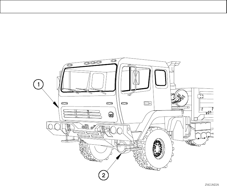
Figure 1-12. Common Vehicle Components Location
(1) CAB. The cab provides the crew with protection from the weather and contains the
controls, gages, and indicators needed to operate the vehicle. The cab
accommodates three fully-equipped personnel if no radio is installed, and two fully-
equipped personnel if a radio is installed. The cab can be raised and lowered from
the hydraulic manifold located on the passenger side of the vehicle.
(2) FRONT DRIVING AXLE. Supports the weight of the vehicle and transmits power to
drive the front wheels.
1-19
TM 9-2320-366-10-1
1-11. LOCATION AND DESCRIPTION OF MAJOR COMPONENTS
(CONT)
Figure 1-12. Common Vehicle Components Location (Cont)
(3) FRONT TOW EYES/SHACKLES. Provides attachment points for towing.
(4) FRONT GLADHANDS. Allows connection of brake air supply between vehicles
during towing operations.
(5) FRONT ELECTRICAL CONNECTOR. A connector that receives 12 vdc power from
a towing vehicle through an intervehicular cable.
(6) WINDSHIELD WASHER RESERVOIR. A three quart (3 L) reservoir that stores fluid
used to clean the windshield.
1-20
TM 9-2320-366-10-1
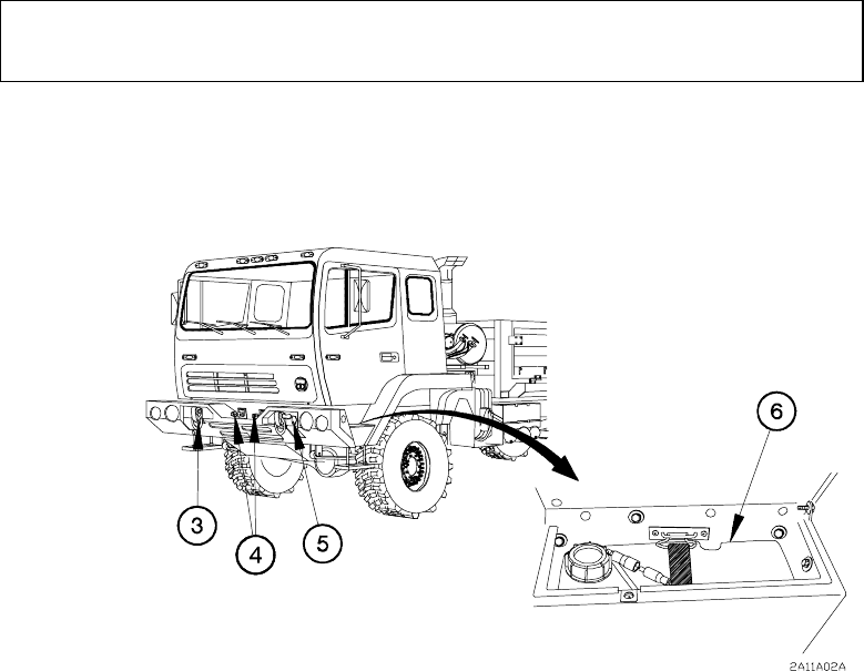
Figure 1-12. Common Vehicle Components Location (Cont)
(7) RADIATOR OVERFLOW TANK. A reservoir that can store up to eight quarts (7 L)
of engine coolant.
(8) INTAKE AIR CLEANER ASSEMBLY. A cartridge-type filter that removes particles
from the air before it enters the turbocharger.
(9) BATTERY BOX. The battery box contains four 12 vdc batteries connected in series
and parallel.
(10) AIR TANKS. The primary and secondary air tanks and the wet tank store
compressed air for operation of the brakes, CTIS, and the air/hydraulic power unit.
1-21
TM 9-2320-366-10-1
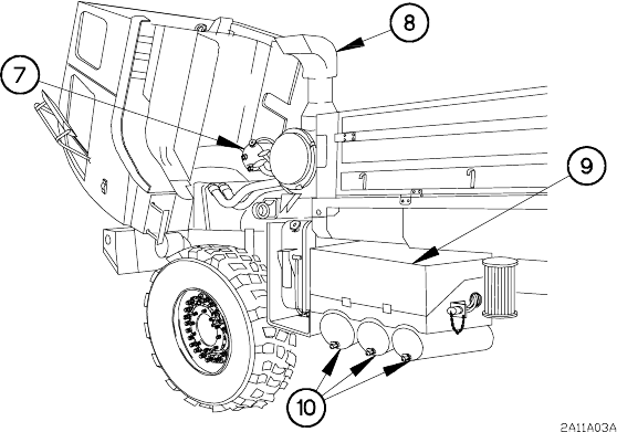
1-11. LOCATION AND DESCRIPTION OF MAJOR COMPONENTS
(CONT)
Figure 1-12. Common Vehicle Components Location (Cont)
(11) HYDRAULIC RESERVOIR. A 27 gal (102 L) reservoir that stores the oil needed to
operate the 15K Self-Recovery Winch (SRW) and/or the Material Handling Crane
(MHC). May be installed on any vehicle model except M1089.
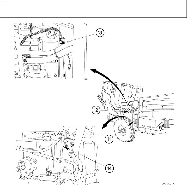
(12) FRONT LIFT BEAM. Provides attachment points for lifting/loading operations.
(13) FUEL/WATER SEPARATOR. Removes moisture and contaminants from the fuel
before it enters the fuel pump. The fuel/water separator incorporates a fuel priming
pump and an electric heater to prevent gelling of the fuel in cold weather.
(14) SUSPENSION CYLINDER. Provides a means of compressing the vehicle
suspension in preparation for internal air transport.
1-22
TM 9-2320-366-10-1
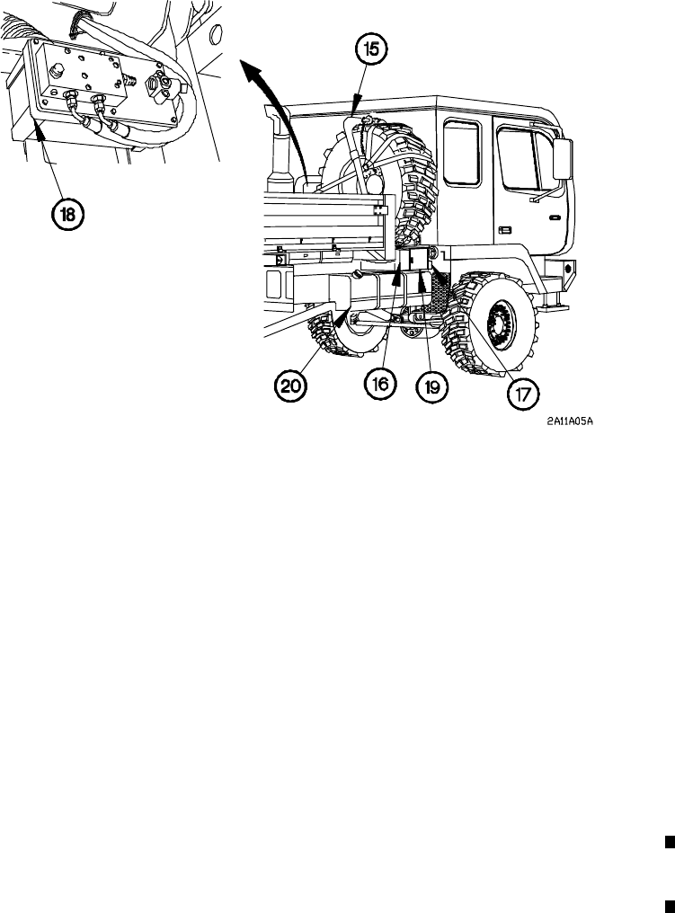
Figure 1-12. Common Vehicle Components Location (Cont)
(15) SPARE TIRE RETAINER. Provides a stowage location for the spare tire. The
operation of the spare tire retainer is controlled from the hydraulic manifold.
(16) HYDRAULIC MANIFOLD. The hydraulic manifold contains the valves and controls
used to raise and lower the cab, spare tire, and vehicle suspension.
(17) BACK-UP HYDRAULIC PUMP. This manual pump serves as a backup for the
hydraulic manifold. This pump is used in the event that there is not enough air
pressure in the air tanks to operate the air/hydraulic power unit.
(18) AIR/HYDRAULIC POWER UNIT. Converts air pressure into hydraulic pressure to
operate the cylinders used to raise and lower the cab, spare tire, and vehicle
suspension.
(19) TOOL BOX. Used to stow Basic Issue Items (BII), Components of End Item (COEI),
and Additional Authorization List (AAL) items.
(20) FUEL TANK. A 56 gal (212 L) capacity, 54 gal (204 L) usable tank stores fuel used
to operate the engine.
Change 1 1-23
TM 9-2320-366-10-1
1-11. LOCATION AND DESCRIPTION OF MAJOR COMPONENTS
(CONT)
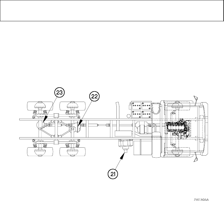
Figure 1-12. Common Vehicle Components Location (Cont)
(21) 15K SELF-RECOVERY WINCH (SRW) (if equipped). Provides the Operator with
the ability to recover the vehicle from a stranded condition. It also allows the
Operator to attempt retrieval of a medium or light vehicle not equipped with a 15K
SRW.
(22) INTERMEDIATE DRIVING AXLE. Supports the weight of the vehicle and transmits
power to drive the intermediate wheels.
(23) REAR DRIVING AXLE. Supports the weight of the vehicle and transmits power to
drive the rear wheels.
1-24
TM 9-2320-366-10-1
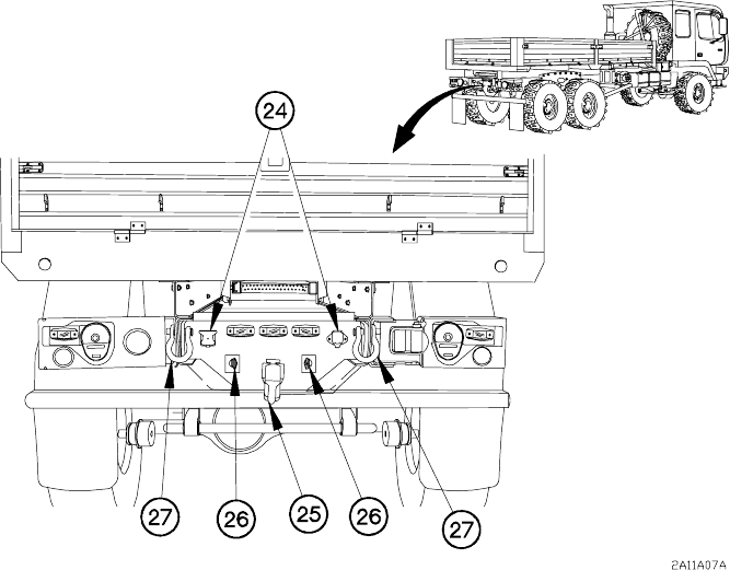
Figure 1-12. Common Vehicle Components Location (Cont)
(24) REAR ELECTRICAL CONNECTORS. Two connectors (24 vdc/12-pin and 12-vdc/7-
pin) that supply electrical power to a trailer or a towed vehicle through an
intervehicular cable.
(25) PINTLE HOOK. Hook used for towing a trailer. Model M1089 is equipped with
towing pintle assembly that is attached to the underlift assembly when required by the
mission. The towing pintle assembly on model M1089 is stowed in a tool box when
not in use.
(26) REAR GLADHANDS. Allows connection of brake air supply between vehicles or
between the towing vehicle and the trailer during towing operations.
(27) REAR TOW EYES/SHACKLES. Provides attachment points for towing.
1-25
TM 9-2320-366-10-1
1-11. LOCATION AND DESCRIPTION OF MAJOR COMPONENTS
(CONT)
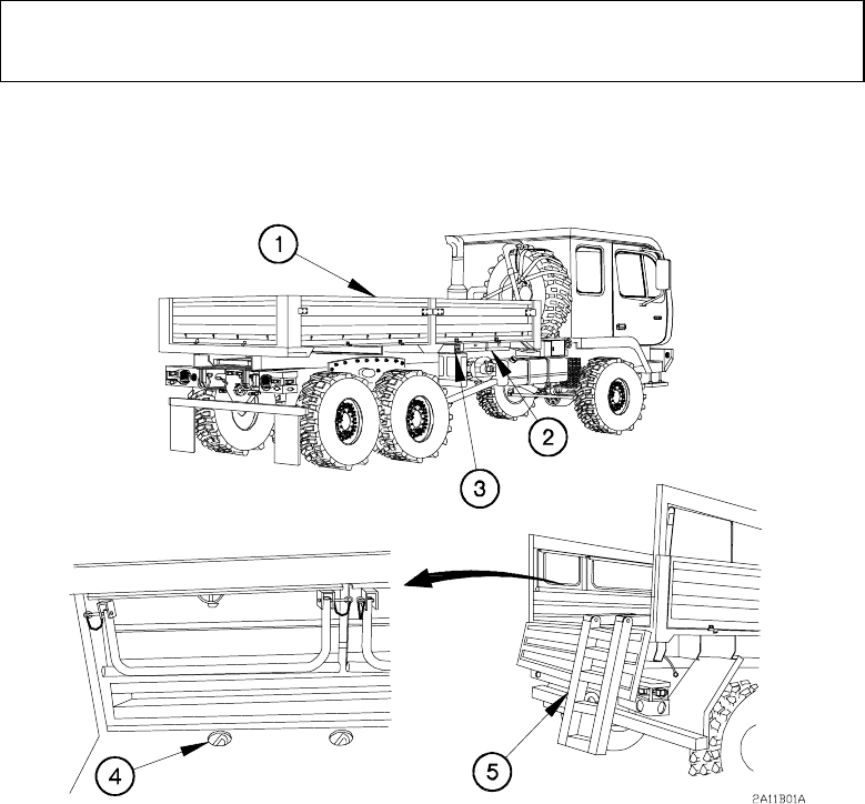
b. Major External Components Common to M1083 and M1085 Cargo Vehicles and
M1093 Air Drop Cargo Vehicles.
Figure 1-13. M1083 and M1085 Cargo Vehicles and M1093
Air Drop Cargo Vehicles Components Location
(1) CARGO BED SIDE PANELS. Aluminum panels used to keep cargo from falling out
of cargo bed. They may be raised or lowered, or removed and stowed under the
cargo bed.
(2) CARGO BED SIDE STOWAGE BOXES. Two boxes used to stow cargo bed side
panels when removed.
(3) LIFT BEAM ASSEMBLIES. Two extendable beams that act as sling spreaders,
when deployed, to prevent damage to cargo bed side panels during external air
transport.
(4) CARGO BED TIE DOWNS. Anchor points for securing cargo.
(5) ACCESS LADDER. Used to assist personnel when climbing into or out of cargo bed.
The access ladder is stored underneath the cargo bed when not in use.
1-26
