Kcda261.tmp TM 9 6115 651 14 And P POWER UNIT 707A/M (NSN 00 394 9573) MEP 115A, 60 KW, 400 HZ GENERATOR M200A1, 2 WHEEL, 4 TIRE, MODIFIED TRAILER
User Manual: TM-9-6115-651-14-and-P POWER UNIT 707A/M (NSN 6115-00-394-9573) MEP-115A, 60 KW, 400 HZ GENERATOR M200A1, 2-WHEEL, 4-TIRE, MODIFIED TRAILER Military Generators == MEP 115A
Open the PDF directly: View PDF ![]() .
.
Page Count: 116 [warning: Documents this large are best viewed by clicking the View PDF Link!]
- TABLE OF CONTENTS
- LOI
- LOT
- WARNINGS
- CHAPTERS
- FIGURES
- TABLES
- APPENDICES
- PAGES
- PAGE 1-1
- PAGE 1-2
- PAGE 1-3
- PAGE 2-1
- PAGE 2-2
- PAGE 3-1
- PAGE 3-4
- PAGE 3-21
- PAGE 4-1
- PAGE 4-2
- PAGE 4-4
- PAGE 4-6
- PAGE 4-7
- PAGE 4-8
- PAGE 4-9
- PAGE 4-12
- PAGE 4-13
- PAGE 4-14
- PAGE 4-15
- PAGE 4-17
- PAGE 4-19
- PAGE 4-21
- PAGE 4-23
- PAGE 5-1
- PAGE 5-2
- PAGE 5-3
- PAGE 5-4
- PAGE 6-1
- PAGE A-1
- PAGE B-1
- PAGE B-2
- PAGE B-3
- PAGE C-1
- PAGE D-1
- PAGE D-8
- PAGE D-10
- PAGE D-14
- PAGE D-16
- PAGE D-18
- PAGE D-20
- PAGE D-22
- PAGE D-24

TM 9-6115-651-14&P
TECHNICAL MANUAL
OPERATOR, UNIT, DIRECT SUPPORT AND
GENERAL SUPPORT MAINTENANCE MANUAL
(INCLUDING REPAIR PARTS AND
SPECIAL TOOLS LISTS)
POWER UNIT
PU-707A/M (NSN 6115-00-394-9573)
MEP-115A 60 KW 400 HZ GENERATOR SET
M200A1 2-WHEEL, 4-TIRE, MODIFIED
TRAILER
Approved for public release. Distribution is unlimited.
*This manual supersedes Chapter 6 of TM 5-6115-594-14&P dated 25 September 1984.
HEADQUARTERS, DEPARTMENT OF THE ARMY
10 MAY 1990

TM 9-6115-651-14&P
SAFETY STEPS TO FOLLOW IF SOMEONE
IS THE VICTIM OF ELECTRICAL SHOCK
DO NOT TRY TO PULL OR GRAB THE INDIVIDUAL
IF POSSIBLE, TURN OFF THE ELECTRICAL POWER
IF YOU CANNOT TURN OFF THE ELECTRICAL
POWER, PULL, PUSH, OR LIFT THE PERSON TO
SAFETY USING A DRY WOODEN POLE OR A DRY
ROPE OR SOME OTHER INSULATING MATERIAL
SEND FOR HELP AS SOON AS POSSIBLE
AFTER THE INJURED PERSON IS FREE OF
CONTACT WITH THE SOURCE OF ELECTRICAL
SHOCK, MOVE THE PERSON A SHORT DISTANCE
AWAY AND IMMEDIATELY START ARTIFICIAL
RESUSCITATION
a

TM 9-6115-651-14&P
b
All specific cautions and warnings contained in this manual shall be strictly adhered to.
Otherwise, severe injury, death and/or damage to the equipment may result.
HIGH VOLTAGE
is produced when this power unit is in operation.
DEATH
or severe burns may
result if
personnel fail to observe safety precautions. Do not operate this
power unit until the ground terminal stud has been connected to a suitable ground. Disconnect
the battery ground cable on the generator set before removing and installing components on the
engine or in the electrical control panel system. Remove all rings, watches, and other jewelry
when performing maintenance on this equipment. Loose fitting clothing should be secured to
prevent it catching moving parts. Do not attempt to service or otherwise make any adjustments,
connections or reconnections of wires or cables until generator set is shut down and completely
de-energized.
DANGEROUS GASES
Batteries generate explosive gas during charging: therefore, utilize extreme caution. Do not
smoke, or use open flame in the vicinity of the generator set when servicing batteries.
Exhaust discharge contains noxious and deadly fumes. Do not operate power unit generator set
in enclosed areas unless exhaust discharge is properly vented to the outside.
To avoid sparking between filler nozzle and fuel tank, always maintain metal to metal contact
between filler nozzle and fuel tank when filling generator set fuel tank.
Do not smoke or use open flame in the vicinity of the power unit while refueling generator set.
LIQUIDS UNDER HIGH PRESSURE
are generated as a result of operation of the power unit generator set. Do not expose any part of
the body to a high pressure leak in the fuel injection system.
NOISE
Operating noise level of the generator set can cause hearing damage. Ear protectors, as
recommended by the medical or safety officer, must be worn when working near this power unit.
Clean parts in a well-ventilated area. Avoid inhalation of solvent fumes and prolonged exposure
of skin to cleaning solvent. Wash exposed skin thoroughly. Dry cleaning solvent (P D-680) used
to clean parts is potentially dangerous to personnel and property. Do not use near open flame or
excessive heat. Flash point of solvent is 100
O
F to 138°F (38°C to 59
O
C).

*
TM
9-6115-651-14&P
TECHNICAL MANUAL HEADQUARTERS
DEPARTMENT OF THE ARMY
NO. 9-6115-651-14&P
Washington, D.C., 10 May 1990
Operator, Unit, Direct Support and General Support Maintenance Manual
(Including Repair Parts and Special Tools Lists)
POWER UNIT, PU-707A/M
(NSN 6115-00-394-9573)
MEP-115A 60 KW 400 HZ GENERATOR SET
M200A1 2-WHEEL, 4-TIRE, MODIFIED TRAILER
Approved for public release. Distribution is unlimited.
REPORTING ERRORS AND RECOMMENDING IMPROVEMENTS
You
can help improve this manual. If you find any mistake or if you know of a way to improve the pro-
cedures, please let us know. Mail your letter, DA Form 2028 (Recommended Changes to Publications and
Blank Forms), or DA Form 2028-2 located in the back of this manual direct to: Commander, U.S. Army
Troop Support Command, ATTN: AMSTR-MCTS, 4300 Goodfellow Boulevard, St. Louis, MO 63120-1798.
A reply will be furnished directly to you.
CHAPTER 1.
Section I.
Section Il.
CHAPTER 2.
Section I.
Section II.
Section III.
CHAPTER 3.
Section I.
Section Il.
Section Ill.
Section IV.
Section V.
*This manual
TABLE OF CONTENTS
Page
INTRODUCTION
General . . . . . . . . . . . . . . . . . . . . . . . . . . . . . . . . . . . . . . . . . . . . . . . . . . . . . . . . 1-1
Description and Data . . . . . . . . . . . . . . . . . . . . . . . . . . . . . . . . . . . . . . . . .
. . . . .
1-2
OPERATING INSTRUCTIONS
Operating Procedures . . . . . . . . . . . . . . . . . . . . . . . . . . . . . . . . . . . . . . . . . . . . . 2-1
Operation of Auxiliary Equipment . . . . . . . . . . . . . . . . . . . . . . . . . . . . . . . . . . . . . 2-2
Operation Under Unusual Conditions . . . . . . . . . . . . . . . . . . . . . . . . . . . . . . . . 2-2
OPERATOR/CREW MAINTENANCE INSTRUCTIONS
Consumable Operating and Maintenance SuppIies . . . . . . . . . . . . . . . . . . . . . . . . . 3-1
Lubrication lnstructions . . . . . . . . . . . . . . . . . . . . . . . . . . . . . . . . . . . . . . . . . . . . 3-1
Preventive Maintenance Checks and Services (PMCS) . . . . . . . . . . . . . . . . . . . . . . 3-1
Troubleshooting. . . . . . . . . . . . . . . . . . . . . . . . . . . . . . . . . . . . . . . . . . . . . . . . . . 3-21
Operator/Crew Maintenance . . . . . . . . . . . . . . . . . . . . . . . . . . . . . . . . . . . . . . . . . 3-21
supersedes Chapter 6 of TM 5-6115-594-14&P dated 25 September 1984.
i
TM 9-6115-651-14&P
TABLE OF CONTENTS (continued)
CHAPTER 4.
Section l.
Section Il.
Section III.
Section IV.
Section V.
Section VI.
Section VII.
Section Vlll.
CHAPTER 5.
Section I.
Section Il.
Section Ill.
CHAPTER 6.
Section I.
Section Il.
Section Ill.
APPENDIX A.
APPENDIX B.
APPENDIX C.
APPENDIX D.
ii
UNIT MAINTENANCE
Service Upon Receipt of Equipment. . . . . . . . . . . . . . . . . . . . . . . . . . . . . . . . . 4-1
Movement to a New Worksite . . . . . . . . . . . . . . . . . . . . . . . . . . . . . . . . . . . . . . . 4-6
Repair Parts, Special Tools, Special Test, Measurement and
Diagnostic Equipment (TMDE) . . . . . . . . . . . . . . . . . . . . . . . . . . . . . . . . . . . . . 4-7
Lubrication Instructions . . . . . . . . . . . . . . . . . . . . . . . . . . . . . . . . . . . . . . . . . . . . .4-7
Preventive Maintenance Checks and Services . . . . . . . . . . . . . . . . . . . . . . . . . . . . .4-8
Troubleshooting . . . . . . . . . . . . . . . . . . . . . . . . . . . . . . . . . . . . . . . . . . . . . . . . . . 4-12
Radio Interference Suppression. . . . . . . . . . . . . . . . . . . . . . . . . . . . . . . . . . . . . 4-12
Maintenance of Power Unit Trailer . . . . . . . . . . . . . . . . . . . . . . . . . . . . . . . . . . . 4-13
DIRECT SUPPORT AND GENERAL SUPPORT MAINTENANCE INSTRUCTIONS
Introduction . . . . . . . . . . . . . . . . . . . . . . . . . . . . . . . . . . . . . . . . . . . . . . . . . . . . . 5-1
Maintenance of Power Unit Trailer . . . . . . . . . . . . . . . . . . . . . . . . . . . . . . . . . . . 5-1
Generator Set . . . . . . . . . . . . . . . . . . . . . . . . . . . . . . . . . . . . . . . . . . . . . . . . . . . 5-2
TEST AND INSPECTION AFTER REPAIR
General Requirements . . . . . . . . . . . . . . . . . . . . . . . . . . . . . . . . . . . . . . . . . . . . 6-1
Inspection . . . . . . . . . . . . . . . . . . . . . . . . . . . . . . . . . . . . . . . . . . . . . . . . . . . . . . 6-1
Operational Tests . . . . . . . . . . . . . . . . . . . . . . . . . . . . . . . . . . . . . . . . . . . . . . . . 6-1
REFERENCES . . . . . . . . . . . . . . . . . . . . . . . . . . . . . . . . . . . . . . . . . . . . . . . . . . . A-1
COMPONENTS OF END ITEM AND BASIC ISSUE ITEMS LISTS . . . . . . . . . . B-1
MAINTENANCE ALLOCATION CHART . . . . . . . . . . . . . . . . . . . . . . . . . . . . . . . . C-1
UNIT, DIRECT SUPPORT AND GENERAL SUPPORT AND DEPOT
MAINTENANCE REPAIR PARTS AND SPECIAL TOOLS LIST . . . . . . . . . . . . . . D-1
TM 9-6115-651-14&P
Figure
1-1
1-2
4-1
4-2
4-3
4-4
4-5
4-6
4-7
4-8
4-9
4-10
4-11
5-1
5-2
5-3
5-4
D-1
D-2
D-3
D-4
D-5
D-6
D-7
D-8
Number
3-1
3-2
4-1
LIST OF ILLUSTRATIONS
Title Page
Power Unit, Curbside Front, Three-Quarter View . . . . . . . . . . . . . . . . . . . . . . . . . . . . . . . . 1-3
Power Unit, Roadside Rear, Three-Quarter View . . . . . . . . . . . . . . . . . . . . . . . . . . . . . . . .1-3
Power Unit Packed for Shipment . . . . . . . . . . . . . . . . . . . . . . . . . . . . . . . . . . . . . . . . . . 4-1
Unpacking Power Unit . . . . . . . . . . . . . . . . . . . . . . . . . . . . . . . . . . . . . . . . . . . . . . . . . . 4-2
Installing Power Unit . . . . . . . . . . . . . . . . . . . . . . . . . . . . . . . . . . . . . . . . . . . . . . . . . . . . 4-4
External Fuel Line Connection. . . . . . . . . . . . . . . . . . . . . . . . . . . . . . . . . . . . . . . . . . . . 4-6
Fuel Can Bracket Replacement. . . . . . . . . . . . . . . . . . . . . . . . . . . . . . . . . . . . . . . . . . 4-13
Accessory Box Replacement . . . . . . . . . . . . . . . . . . . . . . . . . . . . . . . . . . . . . . . . . . . . . 4-14
Fire Extinguisher Bracket Replacement . . . . . . . . . . . . . . . . . . . . . . . . . . . . . . . . . . . . . 4-15
Front Step Replacement . . . . . . . . . . . . . . . . . . . . . . . . . . . . . . . . . . . . . . . . . . . . . . . . . 4-17
Rear Step and Bracket Replacement . . . . . . . . . . . . . . . . . . . . . . . . . . . . . . . . . . . . . . . 4-19
Fender Replacement . . . . . . . . . . . . . . . . . . . . . . . . . . . . . . . . . . . . . . . . . . . . . . . . . . . . 4-21
Personnel Platform Replacement. . . . . . . . . . . . . . . . . . . . . . . . . . . . . . . . . . . . . . . . . . 4-23
Accessory Box Repair . . . . . . . . . . . . . . . . . . . . . . . . . . . . . . . . . . . . . . . . . . . . . . . . . . . 5-1
Power Unit Markings . . . . . . . . . . . . . . . . . . . . . . . . . . . . . . . . . . . . . . . . . . . . . . . . . . . . 5-2
Detaching Generator Set From Trailer . . . . . . . . . . . . . . . . . . . . . . . . . . . . . . . . . . . . . . 5-3
Lifting Generator Set . . . . . . . . . . . . . . . . . . . . . . . . . . . . . . . . . . . .
. . . . . . . . . . . . . . . 5-4
Components of End ltem . . . . . . . . . . . . . . . . . . . . . . . . . . . . . . . . . . . . . . . . . . . . . . . . B-2
Basic lssue ltems . . . . . . . . . . . . . . . . . . . . . . . . . . . . . . . . . . . . . . . . . . . . . . . . . . . . . . . B-3
Generator Set . . . . . . . . . . . . . . . . . . . . . . . . . . . . . . . . . . . . . . . . . . . . . . . . . . . . . . . . . . D-8
Trailer Body . . . . . . . . . . . . . . . . . . . . . . . . . . . . . . . . . . . . . . . . . . . . . . . . . . . . . . . . . . . . D-10
Accessory Box . . . . . . . . . . . . . . . . . . . . . . . . . . . . . . . . . . . . . . . . . . . . . . . . . . . . . . . . . D-14
Front Steps . . . . . . . . . . . . . . . . . . . . . . . . . . . . . . . . . . . . . . . . . . . . . . . . . . . . . . . . . . . D-16
Rear Steps . . . . . . . . . . . . . . . . . . . . . . . . . . . . . . . . . . . . . . . . . . . . . . . . . . . . . . . . . . . . D-18
Fenders . . . . . . . . . . . . . . . . . . . . . . . . . . . . . . . . . . . . . . . . . . . . . . . . . . . . . . . . . . . . . . . D-20
Personnel Platform . . . . . . . . . . . . . . . . . . . . . . . . . . . . . . . . . . . . . . . . . . . . . . . . . . . . . . D-22
Handbrakes . . . . . . . . . . . . . . . . . . . . . . . . . . . . . . . . . . . . . . . . . . . . . . . . . . . . . . . . . . . . D-24
LIST OF TABLES
Title
Page
Consumable Operating and Maintenance Supplies . . . . . . . . . . . . . . . . . . . . . . . . . . . . . .3-1
Operator/Crew Preventive Maintenance Checks and Services(PMCS) . . . . . . . . . . . . . .3-4
Unit Preventive Maintenance Checks and Services (PMCS) . . . . . . . . . . . . . . . . . . . . . 4-9
iii/(iv blank)
TM 9-6115-651-14&P
CHAPTER 1
INTRODUCTION
Section I. GENERAL
1-1.
Scope.
This manual is for your use in operating and maintaining the Power Unit, PU-707A/M. The
PU-707A/M is a mobile power unit used to supply power to any system or equipment requiring up to 60 KW of
400 Hz input operating power. In addition to operating instructions and operator, unit, and direct support and
general support maintenance procedures, this manual contains a Repair Parts and Special Tools List for the
power unit.
1-2.
Maintenance Forms and Records.
Maintenance forms and records used by Army personnel are
prescribed by DA Pam 738-750.
1-3.
Reporting of Errors.
Reporting of errors and omissions and recommendations for improvement of this
publication by the individual user is encouraged. Reports should be submitted on a DA Form 2028 directly to:
Commander, US Army Troop Support Command, ATTN: AMSTR-MCTS, 4300 Goodfellow Boulevard, St. Louis,
MO, 63120-1798.
1-4.
Reporting Equipment Improvement Recommendations (EIR).
ElR’s will be prepared using
SF 368 Product Quality Deficiency Report. Instructions for preparing ElR’s are provided in DA Pam 738-750, The
Army Maintenance Management System. ElR’s should be mailed directly to: Commander, US Army Troop
Support Command, ATTN: AMSTR-QX, 4300 Goodfellow Boulevard, St. Louis, MO, 63120-1798.
1-5.
Levels of Maintenance Accomplishment.
Army users shall refer to the Maintenance Allocation
Chart (MAC) for tasks and levels of maintenance to be performed.
1-6.
Destruction of Army Materiel.
Destruction of Army materiel to prevent enemy use shall be in
accordance with TM 750-244-3.
1-7. Administrative Storage.
a.
Placement of equipment in administrative storage should be for short periods of time when a shortage of
maintenance effort exists. Items should be in mission readiness within 24 hours or within the time factors as
determined by the directing authority. During the storage period appropriate maintenance records will be kept.
b. Army equipment placed in administrative storage will have preventive maintenance performed in
accordance with PMCS tables before storage. When equipment is removed from storage, PMCS will be
performed to ensure operational readiness.
c. Storage site selection. Inside storage is preferred for items selected for administrative storage. If inside
storage is not available, trucks, vans, conex containers and other containers may be used.
1-8.
Preparation for Shipment and Storage.
Refer to TB 740-97-2.
1-1

TM 9-6115-651-14&P
Section II. DESCRIPTION AND DATA
1-9.
Description.
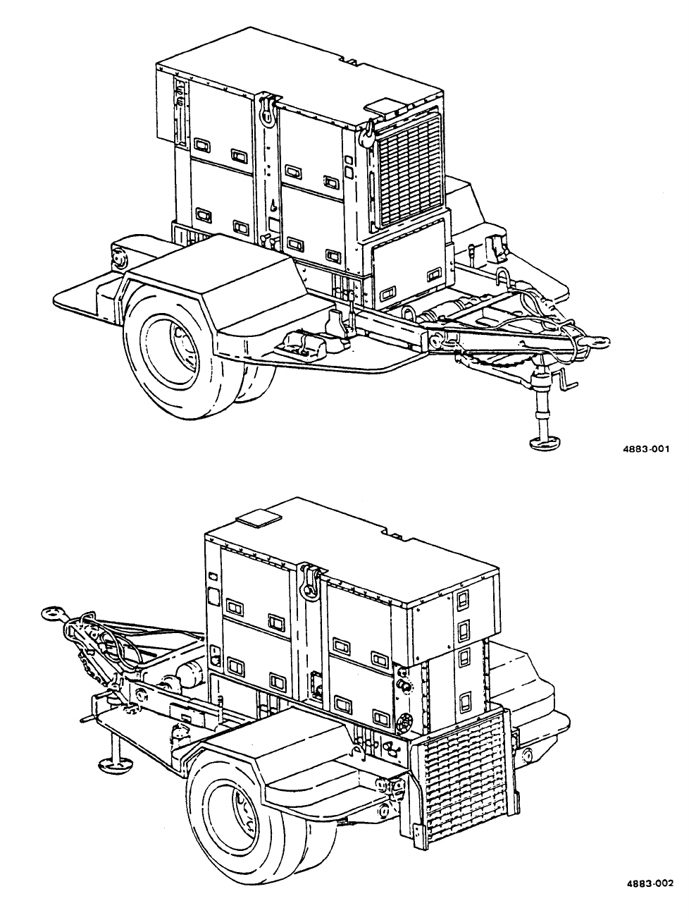
Power Unit PU-707A/M (figures 1-1 and 1-2) is made up of one Precise Power Generator
Set, DOD Model MEP-115A, mounted on a modified M200A1 trailer. The generator set is a liquid-cooled diesel
engine-driven unit with a load capacity of 60 KW at 400 Hz. The trailer is a two-wheeled unit with dual tires
mounted. The trailer has a 2-1/2-ton carrying capacity. The modifications to the basic trailer provide stowage for
the accessories and all equipment necessary for mobile operation as well as providing a work platform for the
operator and maintenance personnel.
1-10.
Tabulated Data.
The tabulated data provides operator and unit level personnel with the dimensions
and weights for Power Unit, PU-707A/M. These specifications are computed from the combined dimensions and
weights of the generator set and trailer as modified for use with the power unit. Specifications of the individual
components can be found in their respective technical publications. For additional information concerning
Generator Set DOD Model MEP-115A, refer to TM 5-6115-545-12 and -34. For additional information on the
M200A1 trailer, refer to TM 9-2330-205-14&P. The tabulated data also includes the location and content of all
data plates unique to the power unit.
a.
Identification
and Instruction Plates.
(1)
Identification plate.
(a) Location. This plate is located on the front roadside frame between the trailer body and the Iunette.
(b) Content.
US
POWER UNIT
PU 707A/M
KW 60
HERTZ 400
NSN 6115-00-394-9573
(2) Instruction plate.
(a)
(b)
1-2
Location. This plate is located near the ground stud on the front, roadside corner of the trailer body.
Content.
GROUND TERMINAL
TM 9-6115-651-14&P
Figure 1-1. Power Unit, Curbside Front, Three-Quarter View.
Figure 1-2. Power Unit, Roadside Rear, Three-Quarter View.
1-3

TM 9-6115-651-14&P
b. Tabulated Data for Power Unit.
Overall Length
Overall Width
Overall Height
Net Weight (empty)
Net Weight (filled)
166 3/8 inches (423.6 centimeters)
95 1/2 inches (242.6 centimeters)
85 inches (216 centimeters)
4400 lb. (199.57 Kg.)
T.B.S.
Shipping Weight
7800 lb. (353.8 Kg.)
Cubage
836.76 cubic feet (23.6 cubic meters)
1-11.
Differences Between Models.
There are no differences between models.
1-4

TM 9-6115-651-14&P
CHAPTER 2
OPERATING INSTRUCTIONS
Section I. OPERATING PROCEDURES
2-1. Power Unit Operating Procedures. The typical mission for any mobile power generating
equipment can be described in three steps or phases. In the first phase, the power unit is towed to the worksite
and installed by unit level technicians (paragraph 4-2). In the second phase of the mission, the operator starts the
generator set, runs it to power a system or equipment, and eventually shuts it down. In the final phase, the power
unit is dismantled, packed up and either moved to a new worksite or returned to standby status (paragraph 4-3).
This final phase is also accomplished by unit level technicians.
a.
Generator Set Operating Procedures
Do not operate power unit generator set until properly grounded (paragraph 4-2, b.)
Serious injury or death by electrocution can result from operating an ungrounded
generator set.
Operating noise level of generator set can cause hearing damage. Ear protectors, as
recommended by medical or safety officer, must be worn when working near power unit.
CAUTION
To avoid damage to equipment, make certain of voltage, frequency, and phase
requirements of load connected to power unit.
NOTE
Before starting generator set, do your Before PMCS as described in table 3-2.
Detailed procedures for prestarting, starting, operating
}
and shutting down the power unit generator set is found in
TM 5-6115-545-12 and on the Operating Instruction data plate found on the equipment. Refer to the data plate,
located inside the right hand control panel door, to start and run the generator set. Monitor and adjust power
output as required during operation. At the end of the mission, shut down generator set in accordance with
operating instructions on the data plate.
b. Trailer Operating Procedures
M200A1 trailer.
Section Il.
Refer to TM 9-2330-205-14&P for specific operating procedures for the
OPERATION OF AUXILIARY EQUIPMENT
2-2.
Operation Of Auxiliary Equipment.
There is no auxiliary equipment supplied with the power unit.
2-1
TM 9-6115-651-14&P
Section Ill. OPERATION UNDER UNUSUAL CONDITIONS
2-3.
Operation Under Unusual Conditions.
When operating the power unit under unusual conditions
such as extremes in temperature or difficult terrain, there are steps that must be taken to protect the equipment.
a. Refer to TM 5-6115-545-12 for special procedures when operating the generator set under unusual
conditions.
b. Refer to TM 9-2330-205-14&P for special procedures when operating the trailer under unusual conditions.
2-2

TM 9-6115-651-14&P
CHAPTER 3
OPERATOR/CREW MAINTENANCE INSTRUCTIONS
Section I. CONSUMABLE OPERATING AND MAINTENANCE SUPPLIES
3-1.
Consumable Supplies.
Consumable supplies used in the maintenance and operation of the power
unit are listed in Table 3-1.
Table 3-1. Consumable Operating and Maintenance Supplies.
(1)
(2) (3) (4) (5) (6)
Qty
Qty
required required
Component National for initial 8 hours
application stock number Description operation
operation
Notes
General
6850-00-664-5685 Solvent, Drycleaning, PD-680
1 quart As required
Cleaning
Personnel 9150-00-186-6681 Oil, Lubricating, OE/HDO-30 1 quart As required
Platform
9150-00-402-4478
Oil, Lubricating, OEA 1 quart As required
Section Il. LUBRICATION INSTRUCTIONS
3-2.
General.
Detailed instructions for the lubrication of the major components of the power unit are contained
in the applicable Lubrication Orders (LO’s). Refer to DA Pam 25-30 to ensure the latest editions of the LO’s are
used.
3-3.
Generator Lubrication.
Refer to TM 5-6115-545-12 for generator set Lubrication Order.
3-4.
Trailer Lubrication.
There are no operator/crew lubrication requirernents for the power unit trailer.
Section Ill. PREVENTIVE MAINTENANCE CHECKS AND SERVICES (PMCS)
NOTE
The PMCS chart in this section contains all necessary Operator/Crew preventive
maintenance checks and services for this equipment.
3-5.
General.
The preventive maintenance checks and services listed in Table 3-2 are grouped according to
stages of equipment operation or time intervals. Using the following as a guide, do the checks and services at the
intervals shown.
a. Before you operate, perform your before (B) PMCS. Observe all CAUTIONS and WARNINGS.
3-1

TM 9-6115-651-14&P
b.
c.
d.
e.
f.
While you operate, perform your during (D) PMCS. Observe all CAUTIONS and WARNINGS.
After you operate, be sure to perform your after (A) PMCS.
Do (W) PMCS weekly.
Do (M) PMCS monthly.
If equipment fails to operate, refer to Section IV Troubleshooting. If the problem cannot be corrected, see
paragraph 3-8, Reporting Deficiencies.
3-6.
Purpose Of PMCS Table.
The purpose of the PMCS table is to provide a systematic method of
inspecting and servicing the equipment. In this way, small defects can be detected early before they become a
major problem causing the equipment to fail to complete its mission. The PMCS table is arranged with the
individual PMCS procedures listed in sequence under assigned intervals. The most logical time (before, during, or
after operation) to perform each procedure determines the interval to which it is assigned. Make a habit of doing
the checks and services in the same order each time and anything wrong will be seen quickly. See paragraph 3-7
for an explanation of the columns in table 3-2.
3-7.
Explanation Of Columns.
The following is a list of the PMCS table column headings with a description
of the information found in each column.
a. Item No. This column shows the sequence in which the checks and services are to be performed, and is
used to identify the equipment area on the Equipment Inspection and Maintenance Worksheet, DA Form 2404.
b. Interval. This column shows when each check is to be done.
c. Item to be Inspected. This column identifies the general area or specific part where the check or service is
to be done.
d. Procedures. This column lists the checks or services to be done and explains how to do them.
e. Equipment is Not Ready/Available If.
This column lists conditions that make the equipment unavailable for
use because it is unable to perform its mission or because it would represent a safety hazard. Do not accept or
operate equipment with a condition in the “Equipment is Not Ready/Available If” column.
3-8.
Reporting Deficiencies.
If you discover any problem with the equipment during PMCS or while
operating it that you are unable to correct, it must be reported. Refer to DA Pam 738-750 and report the
deficiency using the proper forms.
3-9.
Special Instructions.
Preventive maintenance is not limited to performing the checks and services
listed in the PMCS table. Covering unused receptacles, stowing unused equipment and other routine procedures
such as equipment inventory, cleaning components, and touch-up painting are not listed in the PMCS table.
These are things you should do any time you see they need to be done. If a routine check is listed in the PMCS
table it is because other operators have reported problems with this item. Take along tools and cleaning cloths
needed to perform the required checks and services. Use the information in the following paragraphs to help you
identify problems at anytime.
3-2

TM 9-6115-651-14&P
a. Routine Inspection.
Use the following information to help identify potential problems before and during
checks and services.
(1)
(2)
(3)
(4)
(5)
Drycleaning solvent PD-680 is both toxic and flammable. Wear safety goggles and
gloves and use in a well-ventilated area. Avoid prolonged breathing of vapors and avoid
skin contact. Do not use near open flame or excessive heat. Flash point of solvent is
100
O
F to 138°F (38°C to 59°C). If you become dizzy while using PD-680, get fresh air
immediately and get medical aid. If PD-680 contacts eyes, flush with water and get
medical aid immediately.
Keep it clean. Dirt, grease, and oil get in the way and may cover up a serious problem. Use drycleaning
solvent PD-680, to clean metal surfaces. Use soap and water to clean rubber or plastic parts and
material.
Bolts, nuts, and screws. Check them all to make sure they’re not loose, missing, bent, or broken. Don’t
try to check them all with a tool, but look for chipped paint, bare metal, or rust around bolt heads. If you
find one loose, tighten it or report it to unit maintenance.
Welds. Look for loose or chipped paint, rust, or gaps where parts are welded together. If a broken weld
is found, report it to higher level of maintenance.
Electrical wires connectors, terminals and receptacles. Look for cracked or broken insulation, bare
wires, and loose or broken connectors. Tighten loose connectors and make sure the wires are in good
condition. Examine terminals and receptacles for serviceability.
Hoses and fluid lines. Look for wear, damage, and leaks. Make sure clamps and fittings are tight. Wet
spots and stains around a fitting or connector can mean a leak. If a leak comes from a loose connector,
tighten it. If something is broken or worn out, report it to unit maintenance.
b.
Leakage Definitions. It is necessary for you to know how fluid leakage affects the status of your equipment.
The following are definitions of the types/classes of leakage you need to know to be able to determine the status
of your equipment. Learn and be familiar with them. When in doubt, NOTIFY YOUR SUPERVISOR!
Leakage Definitions:
Class I Seepage of fluid (as indicated by wetness or discoloration) not great
enough to form drops.
Class II Leakage of fluid great enough to form drops but not enough to cause
drops to drip from item being checked/inspected.
Class Ill
Leakage of fluid great enough to form drops that fall from the item being
checked/inspected.
3-3
TM 9-6115-651-14&P
CAUTION
Equipment operation is allowable with minor leakage (Class I or II) of any fluid except
fuel. Of course, consideration must be given to the fluid capacity in the item being
checked/inspected. When in doubt, notify your supervisor.
When operating with Class I or II leaks, continue to check fluid level more often than
required in the PMCS. Parts without fluid will stop working and/or cause equipment
damage.
Class Ill leaks should be reported to your supervisor or unit maintenance.
NOTE
If the equipment must be kept in continuous operation, check and service only those
items that can be checked and serviced without disturbing operation. Make the complete
checks and services when the equipment can be shut down.
Within designated interval, these checks are to be performed in the order listed.
Table 3-2. Operator/Crew Preventive Maintenance Checks and Services (PMCS).
B – Before D – During A – After W – Weekly
M - Monthly
WARNING
Before performing any maintenance that
requires climbing on or under trailer, set
trailer handbrakes, chock wheels, and lower
rear leveling jacks. Injury to personnel could
result from trailer suddenly rolling or tipping.
NOTE
Perform weekly as well as before PMCS if
you are the assigned operator but have not
operated the equipment since the last weekly
inspection, or if you are operating the
equipment for the first time.
3-4
1
2
TM 9-6115-651-14&P
Table 3-2. Operator/Crew Preventive Maintenance Checks and Services (PMCS) (cont).
B - Before D - During A - After W - Weekly
●
●
GENERATOR SET EXTERIOR
a.
b.
c.
Check on, around, and beneath generator set
for fuel or oil and coolant leaks.
Check that generator set ground is properly
installed and grounding connections are
tight.
Manually open and close radiator louvers to
check for proper operation
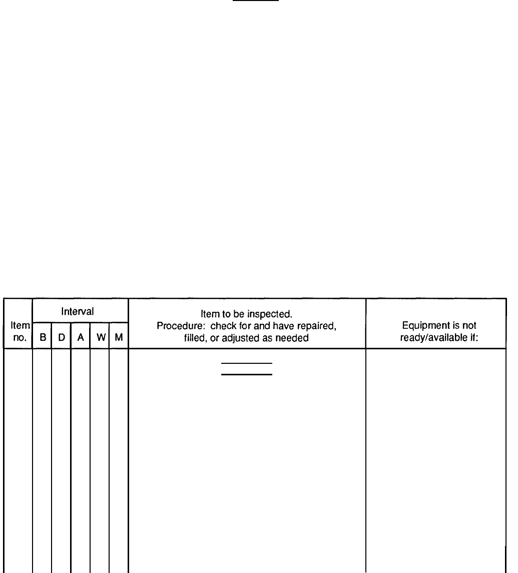
FUEL GAGE
Check fuel gage (1) for sufficient fuel for
continuous operation.
4883-003
M - Monthly
A Class Ill coolant or lubrica-
tion oil leak or any class fuel
leak is detected.
Not properly grounded.
Louver does not operate
correctly.
3-5
TM 9-6115-651-14&P
3
4
Table 3-2. Operator/Crew Preventive Maintenance Checks and Services (PMCS) (cont).
B – Before D – During
A- After
W – Weekly
M - Monthly
●
●
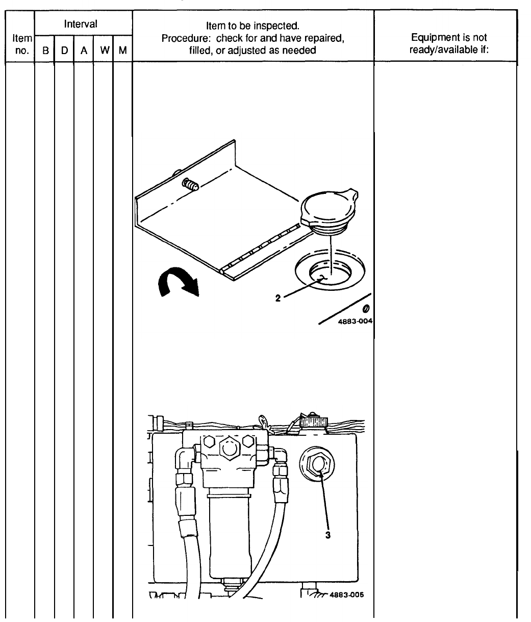
COOLANT LEVEL
Check coolant level (2). Proper level is two inches
below the overflow pipe. Add coolant as required.
HYDRAULIC FLUID LEVEL
Check level of fluid in hydraulic sump (3).
Coolant is below proper
coolant level.
Hydraulic fluid level is below
the full mark.
3-6
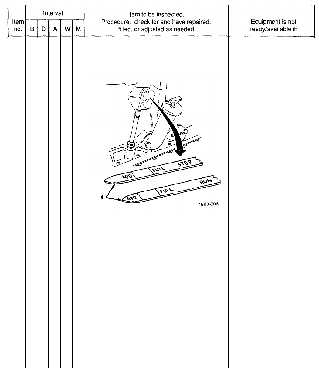
5
6
7
TM 9-6115-651-14&P
Table 3-2. Operator/Crew Preventive Maintenance Checks and Services (PMCS) (cont).
B – Before
●
●
●
D - During
A – After W – Weekly
ENGINE OIL LEVEL
Check oil filler dipstick (4) for proper oil level. Add
oil as required.
ACCESSORIES
Check that the following accessories are
not missing.
a. Sledge hammer
b. Fire extinguisher
c. Slide hammer
d. Ground rods
e. Fuel drum adapter
BRACKETS
Check fire extinguisher and fuel can mounting
brackets for loose hardware and broken fittings.
M – Monthly
Engine oil is at or below the
add mark.
Fire extinguisher is missing.
Ground rods are missing.
3-7
TM 9-6115-651-14&P
8
9
10
11
3-8
Table 3-2. Operator/Crew Preventive Maintenance Checks and Services (PMCS) (cont).
B – Before D – During A – After W – Weekly
●
●
●
•
TIRES
a.
b.
Check for cuts, foreign objects, or unusual tread
wear. Remove any stones from between the
treads.
Check that tire pressure is 35 psi (241.22 kPa)
when tires are cool.
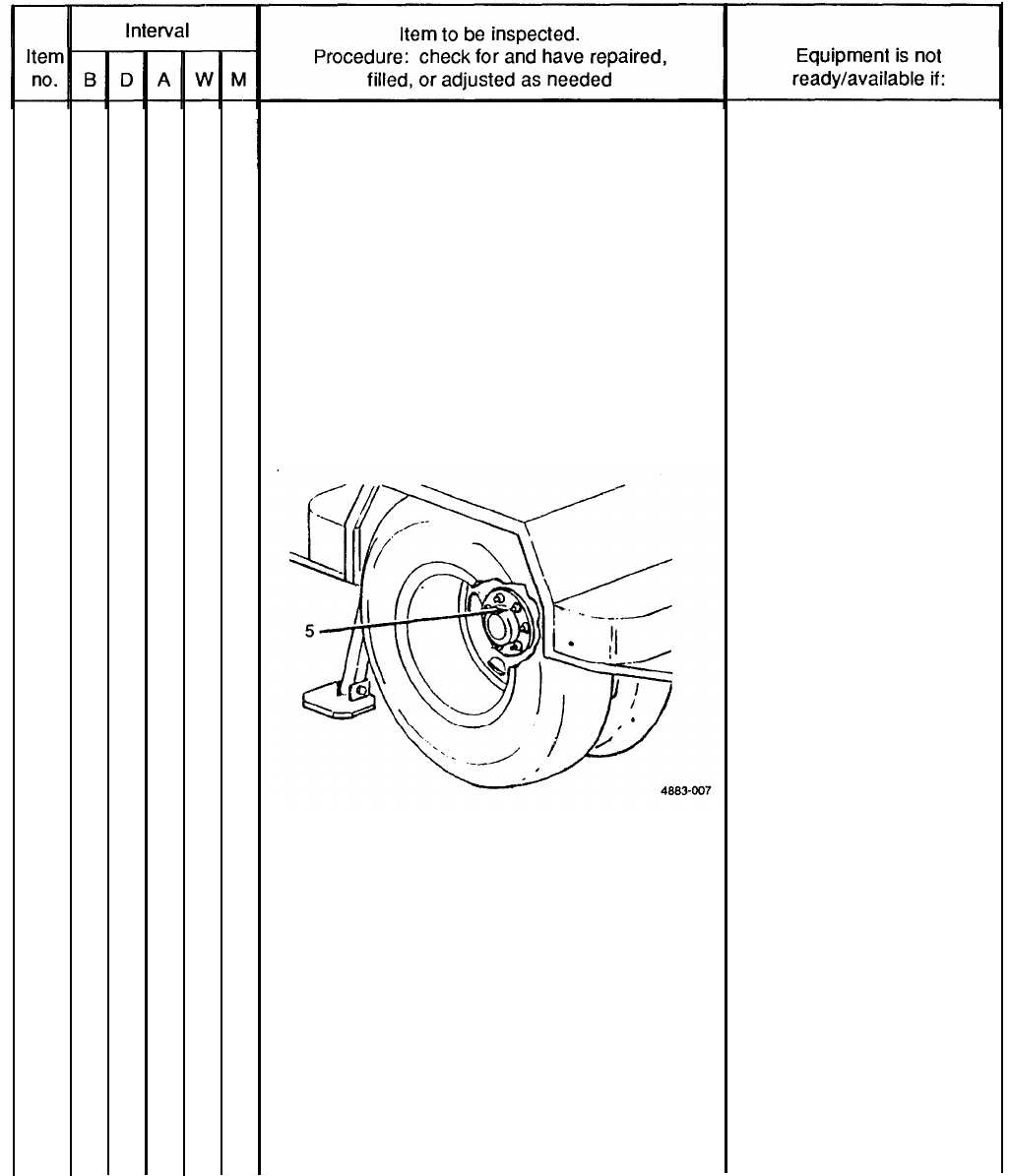
WHEELS
Check for wheel damage and loose or missing
stud nuts (5).
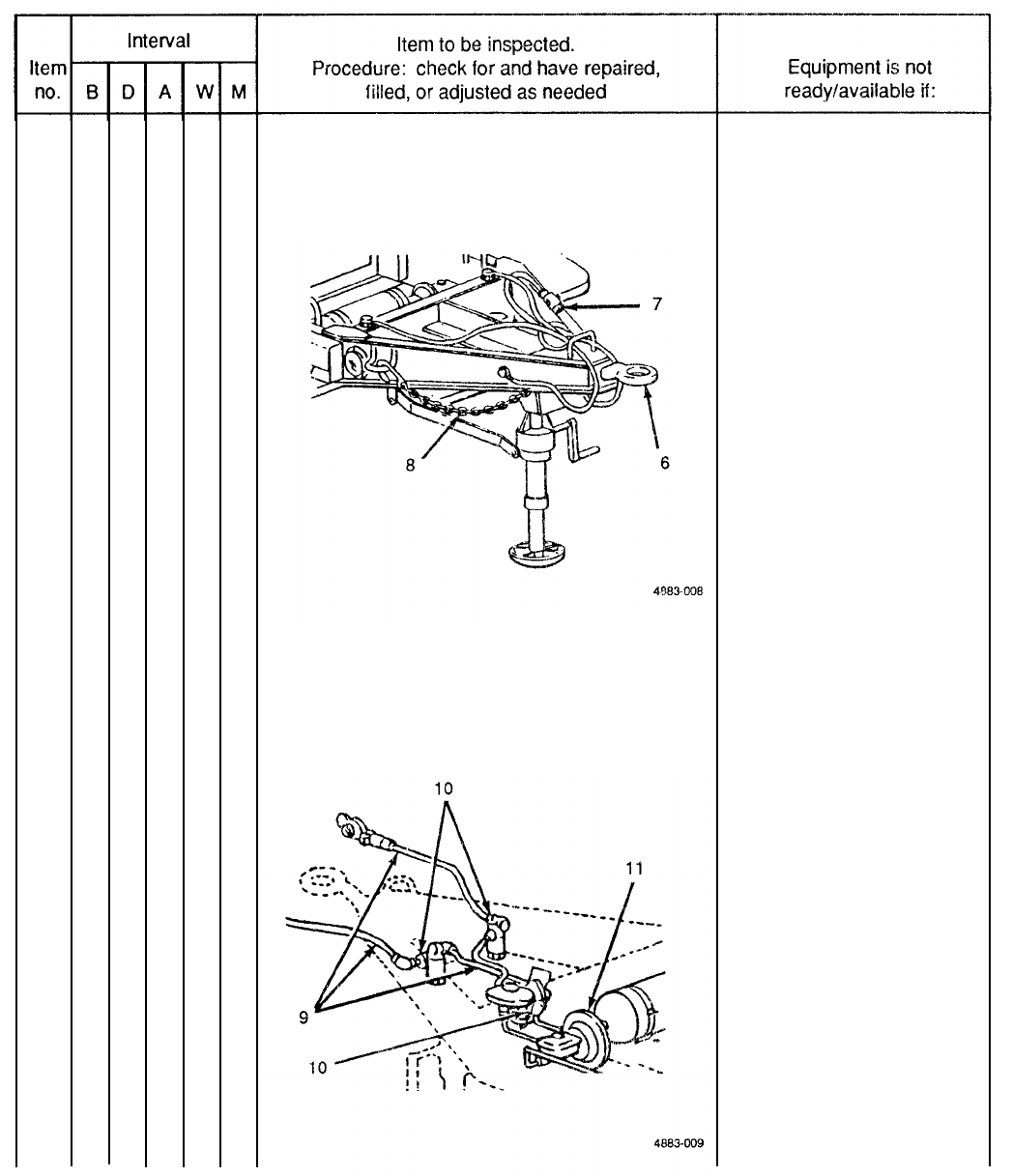
LUNETTE
Check Iunette (6) for insecure mounting and
obvious damage.
INTERVEHICULAR CABLE
Check cable (7) and connector for cuts and breaks.
M – Monthly
One tire is flat, missing, or
unserviceable.
One wheel is damaged.
One stud nut is loose or
missing.
Lunette is loose or bent.
Intervehicular cable is
broken or missing.
M – Monthly
12
13
TM 9-6115-651-14&P
Table 3-2. Operator/Crew Preventive Maintenance Checks and Services (PMCS) (cont).
B – Before D – During A – After
W – Weekly
●
●
SAFETY CHAINS
Check safety chains (8) for insecure mounting
and obvious damage.
AIR HOSES, FITTINGS AND BRAKE AIR
CHAMBER
Check air hoses (9) , fittings (10) and brake air
chamber (11) for signs of damage or leaks.
Safety chains are missing or
unsecured.
Damage or leaks are
detected.
3-9
TM 9-6115-651-14&P
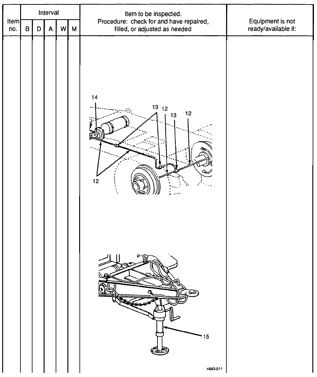
14
15
Table 3-2. Operator/Crew Preventive Maintenance Checks and Services (PMCS) (cont).
B - Before
D – During
A-After
W – Weekly M – Monthly
●
●
HYDRAULIC HOSES, FITTINGS AND MASTER
CYLINDER
Check brake system hoses (12) and fittings (13)
and master cylinder (14), and check under vehicle
for signs of brake fluid leaks.
4683410
LANDING LEG
Check
condition of landing leg (15).
A class Ill brake fluid leak is
detected. Hoses are broken
or worn.
Landing leg is bent or
broken.
3-10
16
17
TM 9-6115-651-14&P
Table 3-2. Operator/Crew Preventive Maintenance Checks and Services (PMCS) (cont).
B - Before
D – During A – After
W – Weekly
●
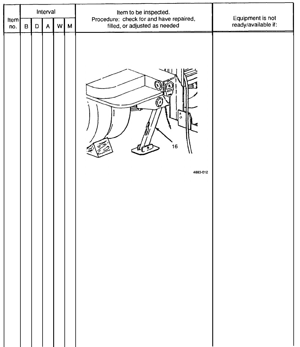
●
LEVELING JACK
Check condition of leveling jack (16).
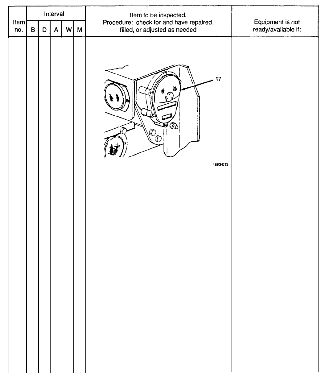
LIGHTS
a. With intervehicular cable connected to towing
vehicle, operate vehicle light switch through
all settings and check lights (17).
NOTE
An assistant is required while checking brake
lights.
Step on brake pedal and check brake
lights (17).
M - Monthly
There is indication that a jack
might collapse.
Taillights fail to operate
properly.
Brake lights fail to operate
properly.
3-11
TM 9-6115-651-14&P
17
18
19
20
Table 3-2. Operator/Crew Preventive Maintenance Checks and Services (PMCS) (cont).
B - Before D - During
A- After
W – Weekly
●
●
●
●
LIGHTS (cont)
BRAKE SYSTEM
Test brake system by hooking trailer to towing
vehicle and applying brakes.
TRAILER OPERATION
a. Be alert for any unusual noises while towing
trailer. Stop and investigate any unusual noises.
b. Ensure that trailer is tracking/following correct-
ly behind towing vehicle with no side pull.
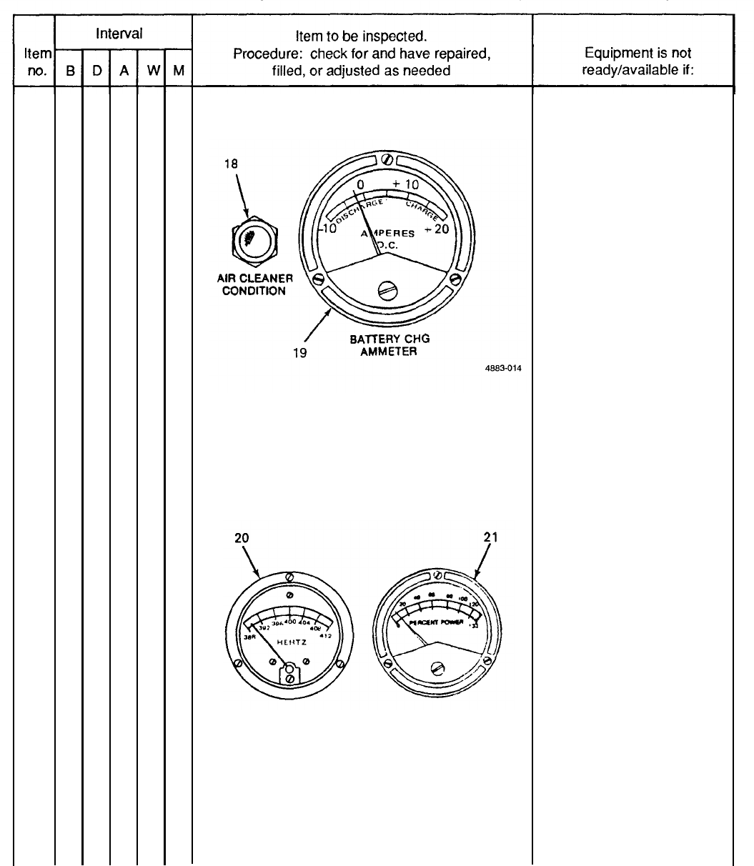
GENERATOR SET GAGES AND INSTRUMENTS
a.
b.
Check that air cleaner condition indicator (18)
does not indicate a clogged air cleaner. Press-
to-test.
Check that battery charging ammeter (19) is
in green area during normal operation.
M - Monthly
Service brakes fail to
operate.
Trailer is not tracking/
following properly.
Light remains on during
operation.
Battery indicator not in
green area.
3-12
20
TM 9-6115-651-14&P
Table 3-2. Operator/Crew Preventive Maintenance Checks and Services (PMCS) (cont).
B - Before
D – During A – After
W- Weekly
M – Monthly
●
GENERATOR SET GAGES AND INSTRUMENTS
(cont)
c.
d.
e.
Check that frequency meter (20) indicates
400 Hz (red line) when generator is operating
under load.
Check that kilowatt meter (21) reading does
not exceed 100%.
4883-015
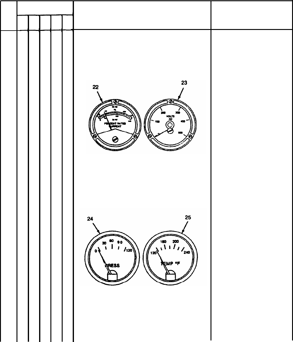
Check that A.C. ammeter (22) reading does not
exceed 100% of rated current or more than 5%.
load difference between phases.
Correct frequency cannot be
maintained.
No indication when load
is applied.
3-13
TM 9-6115-651-14&P
Table 3-2. Operator/Crew Preventive Maintenance Checks and Services (PMCS) (cont).
B - Before
D - During
A - After
W - Weekly M - Monthly
Item
no.
20
B
Interval
D
●
A
W
M
Item to be inspected.
Procedure: check for and have repaired,
filled, or adjusted as needed
GENERATOR SET GAGES AND INSTRUMENTS
(cont)
f.
g.
h.
Check that A.C voltmeter (23) indicates desired
output voltage as determined by load connec-
tions and amps-volts selector switch.
4883-016
Check engine oil pressure gage (24) for
20 to 55 psig indication.
Check coolant temperature gage (25) for
170° to 200°F (76.7° to 93.3°C) indication.
OIL PRESSURE COOLANT TEMPERATURE
4883-017
Equipment is not
ready/available if:
Desired voltage cannot be
obtained and maintained.
Oil pressure drops below
20 psig.
Temperature exceeds 200°F
(93.3°C).
3-14
20
21
TM 9-6115-651-14&P
Table 3-2. Operator/Crew Preventive Maintenance Checks and Services (PMCS) (cont).
B - Before D - During
A - After
W - Weekly
●
●
GENERATOR SET GAGES AND INSTRUMENTS
(cont)
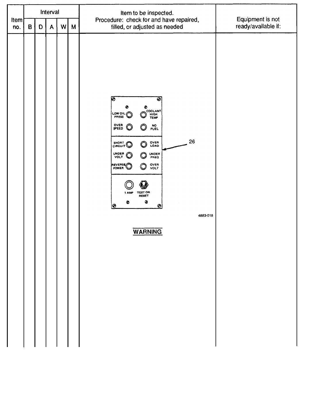
i.
Check that all lights on FAULT INDICATOR
panel (26) are out during operation. Check
bulb operation with TEST or RESET switch
on panel.
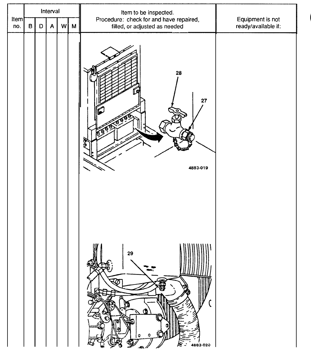
FUEL TANK
Do not smoke or use open flame in the
vicinity of the power unit while refueling
generator set.
a. Fill set tank upon completion of operation.
NOTE
Fuel system temperature must be above
freezing when draining water and sediment.
b. Remove cap (27), open drain (28) and drain
water and sediment from fuel tank into a suitable
container. Allow to drain until fuel runs clean.
M – Monthly
Fault light will not go out
when switch is set to TEST
or RESET position, then
released. All bulbs should
be lit when switch is in TEST
or RESET position.
3-15
TM 9-6115-651-14&P
21
22
Table 3-2. Operator/Crew Preventive Maintenance Checks and Services (PMCS) (cont).
B - Before
D – During A – After
W - Weekly
M – Monthly
●
FUEL TANK (cont)
DAY TANK
NOTE
Fuel system temperature must be above
freezing when draining water and sediment.
Open drain (29) and drain water and sediment from
day tank into a suitable container. Allow to drain
until fuel runs clean.
3-16
23
24
25
TM 9-6115-651-14&P
Table 3-2. Operator/Crew Preventive Maintenance Checks and Services (PMCS) (cont).
B – Before D – During
A - After
W – Weekly
●
●
●
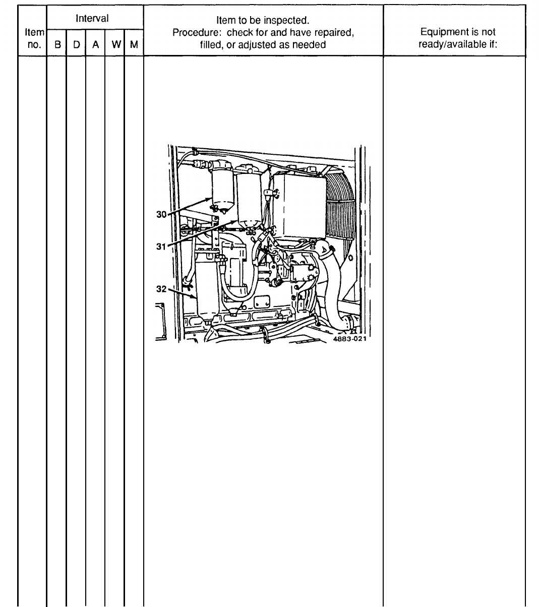
FUEL STRAINER AND FILTERS
Drain water and sediment from strainer (30),
primary (31) and secondary (32) filters into a suit-
able container. Allow to drain until fuel runs clean.
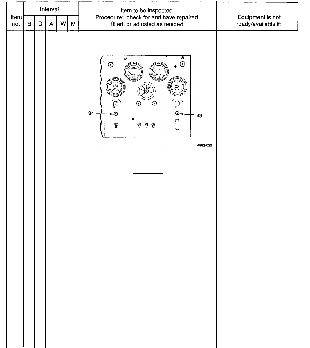
BATTLE SHORT lNDICATOR LIGHT
Push in on lens housing. Light (33) should
illuminate. If not, replace bulb.
CIRCUIT BREAKER INDICATOR LIGHT
Push in on lens housing. Light (34) should
illuminate. If not, replace bulb.
M – Monthly
3-17
TM 9-6115-651-14&P
25
26
27
Table 3-2. Operator/Crew Preventive Maintenance Checks and Services (PMCS) (cont).
B – Before
D - During
A - After
W - Weekly
●
●
●
CIRCUIT BREAKER INDICATOR LIGHT (cont)
BRAKE DRUMS AND HUBS
WARNING
A defect in the operation of the brakes or hub
can cause these parts to get hot enough to
cause serious burns. Use extreme caution
when attempting to detect heat in this area.
Feel drums and hubs for overheating.
AIR RESERVOIR
Open draincock (35) to drain moisture from air
reservoir (36) and close when finished.
M - Monthly
Brakes or hub are dragging
or binding.
3-18
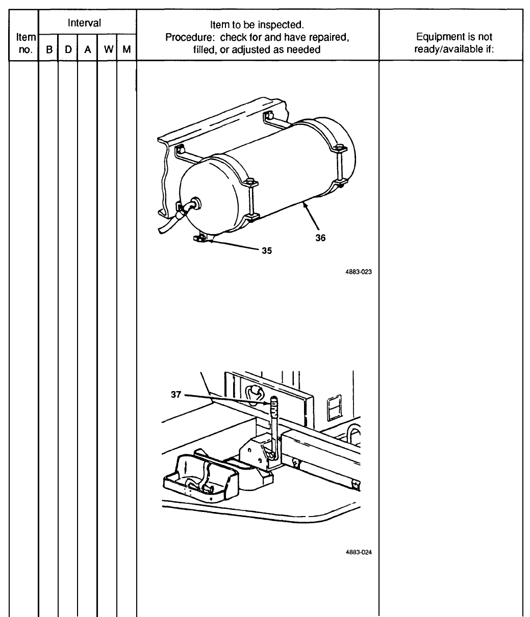
27
28
TM 9-6115-651-14&P
Table 3-2. Operator/Crew Preventive Maintenance Checks and Services (PMCS) (cont).
B - Before
D – During A – After
W - Weekly
●
AIR RESERVOIR (cont)
HANDBRAKES
With trailer hooked to towing vehicle, set hand-
brakes (37). Move trailer slightly to see if hand-
brakes hold wheels. Adjust as required.
M – Monthly
Handbrakes cannot
be adjusted.
3-19

TM 9-6115-651-14&P
Section IV. TROUBLESHOOTING
3-10. Power Unit Troubleshooting. There are no troubleshooting procedures authorized at operator level
for the power unit end item. Troubleshooting procedures for the generator set and trailer are contained in their
respective technical manuals referenced below.
a. Generator Set Troubleshootinq Refer to TM 5-6115-545-12 for troubleshooting procedures applicable to
the generator set.
b. Trailer Troubleshooting. Refer to TM 9-2330-205-14&P for troubleshooting procedures applicable to the
trailer.
Section V. OPERATOR/CREW MAINTENANCE
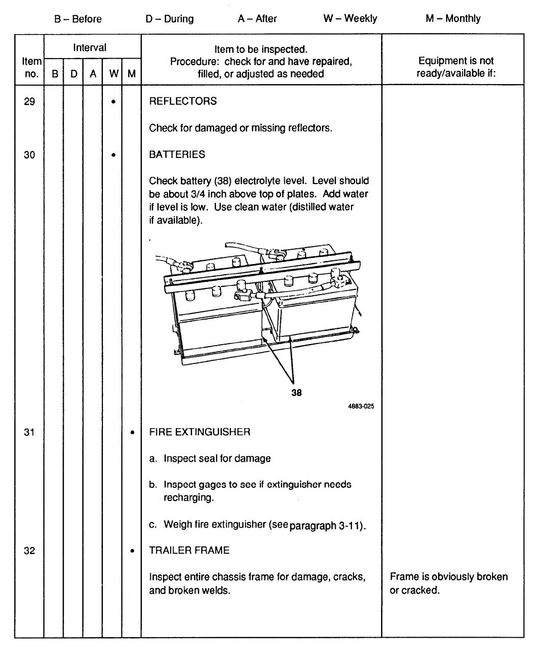
3-11. Fire Extinguisher Maintenance. The PU-707A/M Power Unit is equipped with a 5 lb CO2 fire
extinguisher. Maintenance is limited to weighing the fire extinguisher monthly to insure that it is sufficiently
charged. Fully charged, the fire extinguisher weighs 13 lb. Send the unit to specialized activity for recharging if it
weighs 12.5 lb or less.
Caution
Do not attempt to verify readiness of a fire extinguisher by partially discharging unit. Any
discharge of contents will require refilling.
3-21/(3-22 blank)
TM 9-6115-651-14&P
CHAPTER 4
UNIT MAINTENANCE
Section I. SERVICE UPON RECEIPT OF EQUIPMENT
4-1.
Inspecting and
Servicing
Equipment.
The power unit is unpacked, inspected, and serviced as
described in the following paragraphs. Unpacked equipment must be checked against the Equipment Packing List
to insure completeness. Discrepancies must be reported in accordance with instructions in DA Pam 738-750.
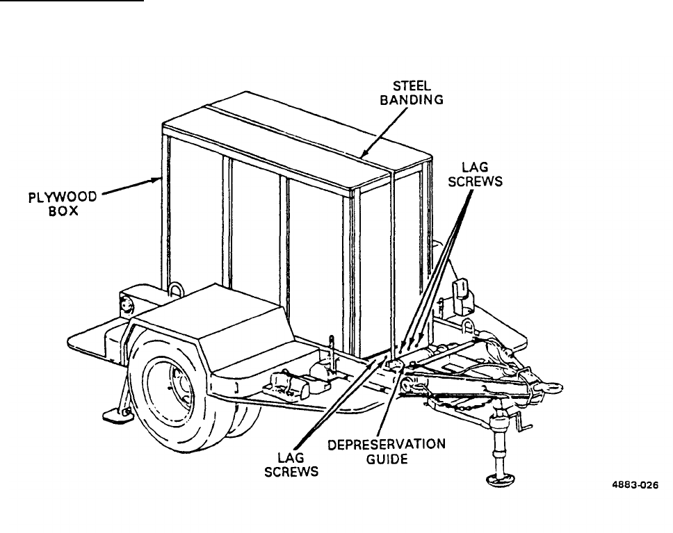
a. Unpacking
Power Unit
(See figures 4-1 and 4-2.) The generator set is packed in place on the trailer
frame. Before beginning the unpacking procedure, locate, remove, and save the waterproof envelopes marked
Depreservation Guide.
4-1
Figure 4-1. Power Unit Packed for Shipment.
TM 9-6115-651-14&P
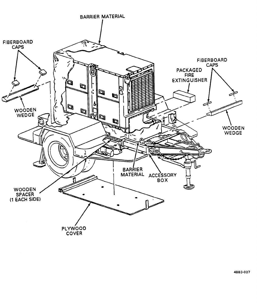
Figure
4-2.
Unpacking Power Unit.
4-2

(1)
(2)
(3)
(4)
(5)
(6)
(7)
(8)
(9)
(10)
(11)
TM 9-6115-651-14&P
WARNING
The steel banding used in packaging of power unit has sharp edges. Care should be
taken when cutting and handling banding to avoid injury to personnel.
Remove steel banding around plywood box covering generator set.
Remove lag screws securing plywood box cover over generator set and lift cover off generator.
Remove wooden wedges and spacers from around generator set base.
Remove and save package of technical manuals secured to barrier material covering generator.
Remove four sets of attaching hardware and drop plywood cover from beneath generator set.
Remove barrier material and fiberboard caps from generator set.
Remove packaged fire extinguisher from within generator set enclosure. Unpack and secure fire
extinguisher in bracket on front roadside step.
Remove steel banding around accessory box, unpack and inventory contents.
Refer to DA Form 2258, Depreservation Guide for Vehicles and Equipment, packed with power unit and
follow instructions given for putting unit into service.
Stow technical manuals in box on inside of generator set enclosure rear curbside door.
Stow all authorized accessories in the accessory box.
Refer to Service Upon Receipt of Materiel in TM 5-6115-545-12
for initial inspection and servicing procedures.
c. Inspection and Servicing of Trailer. Refer to Service Upon Receipt of Materiel in TM 9-2330-205-14&P for
initial inspection and servicing procedures.
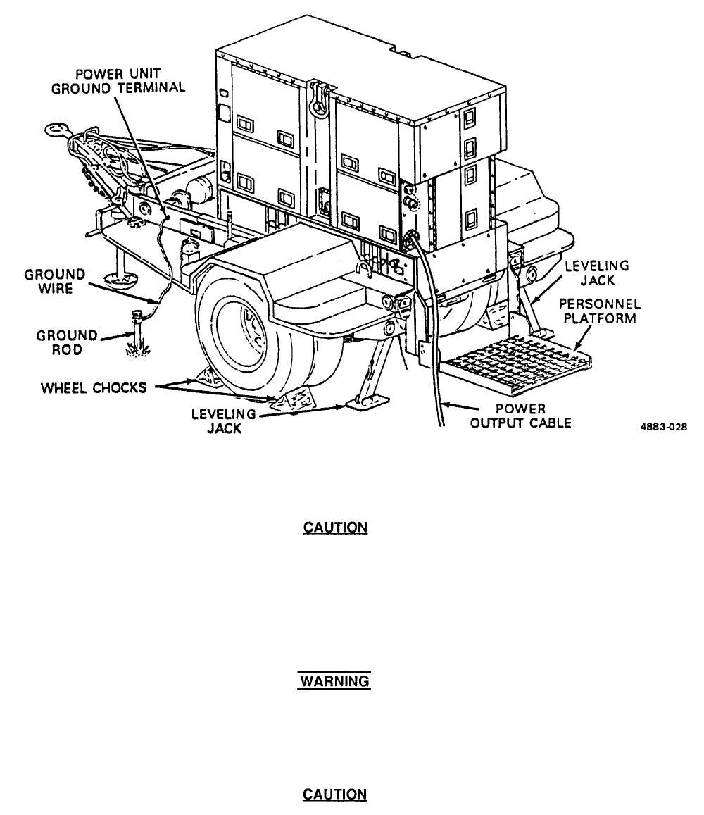
4-2. Installation. (See figure 4-3.) Installation of the power unit at a worksite involves positioning the trailer
and grounding the power unit.
a. Positioning Power Unit. Position the power unit on the worksite as follows:
b. Inspection and Servicing of Generator Set.
(1)
(2)
(3)
(4)
Select an area as level as possible to install power unit and position trailer.
Set trailer handbrakes and lower landing leg.
Chock both sets of wheels.
Lower both rear leveling jacks, secure leveling jacks with Iockpins, and extend lower tubes by stepping
on hinged pads.
4-3
TM 9-6115-651-14&P
(5)
(6)
4-4
Figure 4-3. Installing Power Unit.
Remove fire extinguishers and fuel cans from power unit when generator set is in
operation. This will insure that in the event of fire, extra fuel will not be involved and
extinguisher will remain accessible.
Locate fuel cans and fire extinguisher on ground away from power unit.
Do not operate generator set until power unit is properly grounded (paragraph 4-2, b.).
Serious injury or death by electrocution can result from operating an ungrounded power
unit.
To avoid damage to equipment, make certain of voltage, frequency, and phase
requirements of load being connected to generator set.
Connect power unit to system or equipment to be powered. Refer to TM 5-6115-545-12 and generator
set load terminal board data plate.

(7)
(8)
TM 9-6115-651-14&P
Remove two platform anchor quick-release pins and lower personnel platform.
Close all doors on generator set enclosure except control panel doors and the two doors immediately
below the control panel.
b. Grounding. Check that generator set is grounded to GROUND TERMINAL stud on trailer frame. Using
ground wire supplied with power unit, connect power unit GROUND TERMINAL to a suitable ground as described
below. The following sources of good ground are listed in order of preference.
(1)
(2)
(3)
NOTE
As a substitute for the supplied ground wire, any copper wire of a least No. 6 AWG may
be used.
Underground water system. Ground power unit to one of the accessible pipes in an underground water
system. Make certain underground pipe is made of metal and there is no insulation, such as a water
meter, between ground wire and the earth.
Ground rod. Drive ground rod a minimum of eight feet into earth. A ground rod must have a minimum
diameter of 5/8-inch, if solid, or 3/4-inch if pipe.
NOTE
It maybe necessary to saturate the area around ground rod with water if soil conditions
are dry.
Ground plate. Ground power unit to a metal plate buried four feet deep. Ground plate should cover a
minimum area of nine square feet.
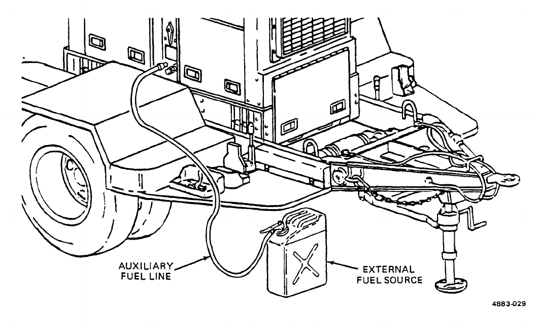
c. External Fuel Line Connection.
(See figure 4-4.) The power unit generator set can be fueled from an
external source such as a five-gallon fuel can or 55 gallon drum. This eliminates the need for frequent refilling of
the generator’s fuel tank during long intervals of operation.
(1)
(2)
(3)
(4)
(5)
Remove fuel can adapter and fuel pickup tube from storage locations on power unit and assemble by
threading pickup tube into adapter.
Thread one end of auxiliary fuel line onto fuel can adapter fitting and tighten.
Connect free end of auxiliary fuel line to AUXILIARY FUEL CONNECTION. This connection is located
on the side of the generator set above the trailer curbside fender.
Insert fuel can adapter in external fuel source and secure by pressing down on lever.
Set FUEL SELECTOR VALVE beneath fuel filler to AUXILIARY position.
4-5
TM 9-6115-651-14&P
Figure 4-4. External Fuel Line Connection.
Section Il. MOVEMENT TO A NEW WORKSITE
4-3.
Dismantling for Movement.
Because the power unit is designed to be mobile, a minimum amount of
effort is required to relocate to a new worksite. Procedures are as follows:
a.
b.
c.
d.
e.
f.
g.
h.
4-6
Disconnect power unit from system or equipment being powered.
Disconnect ground cable from source of ground and from power unit GROUND TERMINAL. Roll up cable
and store in accessory box.
Using slide hammer, remove ground rod. Disassemble, clean, and stow ground rod in accessory box.
Disconnect power unit from external fuel source, if applicable.
Stow any remaining authorized equipment in accessory box.
Secure fire extinguisher and fuel cans in their respective mounting brackets.
Close all doors on the generator set enclosure.
Swing personnel platform into traveling position and secure with two platform anchor quick-release pins.

TM 9-6115-14&P
i.
j.
k.
/.
4-4.
Use care when releasing spring-loaded lower tube of leveling jacks. The lower tube will
return to retracted position with considerable force and can cause injury.
Retract lower tubes of leveling jacks. Swing leveling jacks up into traveling position and secure with
Iockpins.
Remove wheel chocks.
Attach power unit to towing vehicle. Refer to TM 9-2330-205-14&P.
Release trailer handbrakes.
Reinstallation After Movement.
After movement to a new worksite, install power unit in accordance
with paragraph 4-2.
Section Ill. REPAIR PARTS, SPECIAL TOOLS, SPECIAL TEST, MEASUREMENT AND
DIAGNOSTIC EQUIPMENT (TMDE)
4-5.
Tools and Equipment.
There are no special tools or equipment required to maintain the PU-707A/M
power unit.
4-6.
Maintenance Repair Parts.
Repair parts and equipment for maintenance of this power unit are listed
and illustrated in the repair parts and special tools list in Appendix D of this manual.
Section IV. LUBRICATION INSTRUCTIONS
4-7.
General.
Detailed instructions for the lubrication of the major components of the power unit are contained
in the applicable Lubrication Orders (LO’s). Refer to DA Pam 25-30 to ensure that the latest editions of the L.O.’S
are used. This section contains lubrication instructions that are not included in the Lubrication Orders.
4-8.
Generator Lubrication.
Refer to TM 5-6115-545-12 for generator set Lubrication Order.
4-9. Trailer Assembly Lubrication.
a. Trailer Lubrication.
Refer to TM 9-2330-205-14&P for trailer Lubrication Order.
b. Personnel Platform Lubrication. The personnel platform is a modification to the standard M200A1 trailer
and, as such, does not appear in the associated L.O. Lubricate the personnel platform semiannually as follows:
4-7

TM 9-6115-651-14&P
WARNING
Clean parts in a well-ventilated area. Avoid inhalation of solvent fumes and prolonged
exposure of skin to cleaning solvent. Wash exposed skin thoroughly. Dry cleaning
solvent (PD-680) used to clean parts is potentially dangerous to personnel and property.
Do not smoke or use near open flame or excessive heat. Flash point of solvent is 100
O
F
to 138°F (38°C to 59
O
C).
(1) Using PD-680, or equivalent, clean area to be lubricated.
(2) Apply OE lubricating oil to personnel platform pivot points and to platform anchor quick-release pins.
Section V. PREVENTIVE MAINTENANCE CHECKS AND SERVICES
NOTE
The PMCS chart in this section contains all necessary unit preventive maintenance
checks and services for this equipment.
4-10.
General.
The trailer assembly and generator set must be inspected and serviced systematically to insure
that the power unit is ready for operation at all times. Inspection will allow defects to be discovered and corrected
before they result in serious damage or failure. Table 4-1 contains a tabulated list of preventive maintenance
checks and services to be performed by unit maintenance personnel. All of the unit PMCS on the trailer is
scheduled to be performed semiannually or annually. Unit PMCS on the generator set is scheduled monthly or on
a per-hours-of-operation basis. The running time meter on the control panel is used to determine the operating
time of the generator set. Using the following as a guide, do the checks and services at the intervals shown.
Observe all CAUTIONS and WARNINGS.
a. For PMCS performed on an operating time basis, perform your hourly (H) PMCS as close as possible to the
time intervals indicated.
NOTE
For units in continuous operation, perform PMCS before starting operation if continuous
operation will extend service interval past that which is shown.
b. Perform your monthly (M) PMCS every month or 100 hours of generator set operating time.
c. Do your semiannual (S) PMCS once every six months or 500 hours of Generator Set operating time.
d. If you discover a problem with the equipment, refer to Section Vl, Troubleshooting. If you cannot correct the
problem, refer to paragraph 4-12, Reporting Deficiencies.
4-11.
Explanation Of Columns.
The following is a list of the PMCS table column headings with a
description of the information found in each column.
a. Item No. This column shows the sequence in which to do the checks and services, and is used to identify
the equipment area on the Equipment Inspection and Maintenance Worksheet, DA Form 2404.
4-8
b.
c.
d.
TM 9-6115-651-14&P
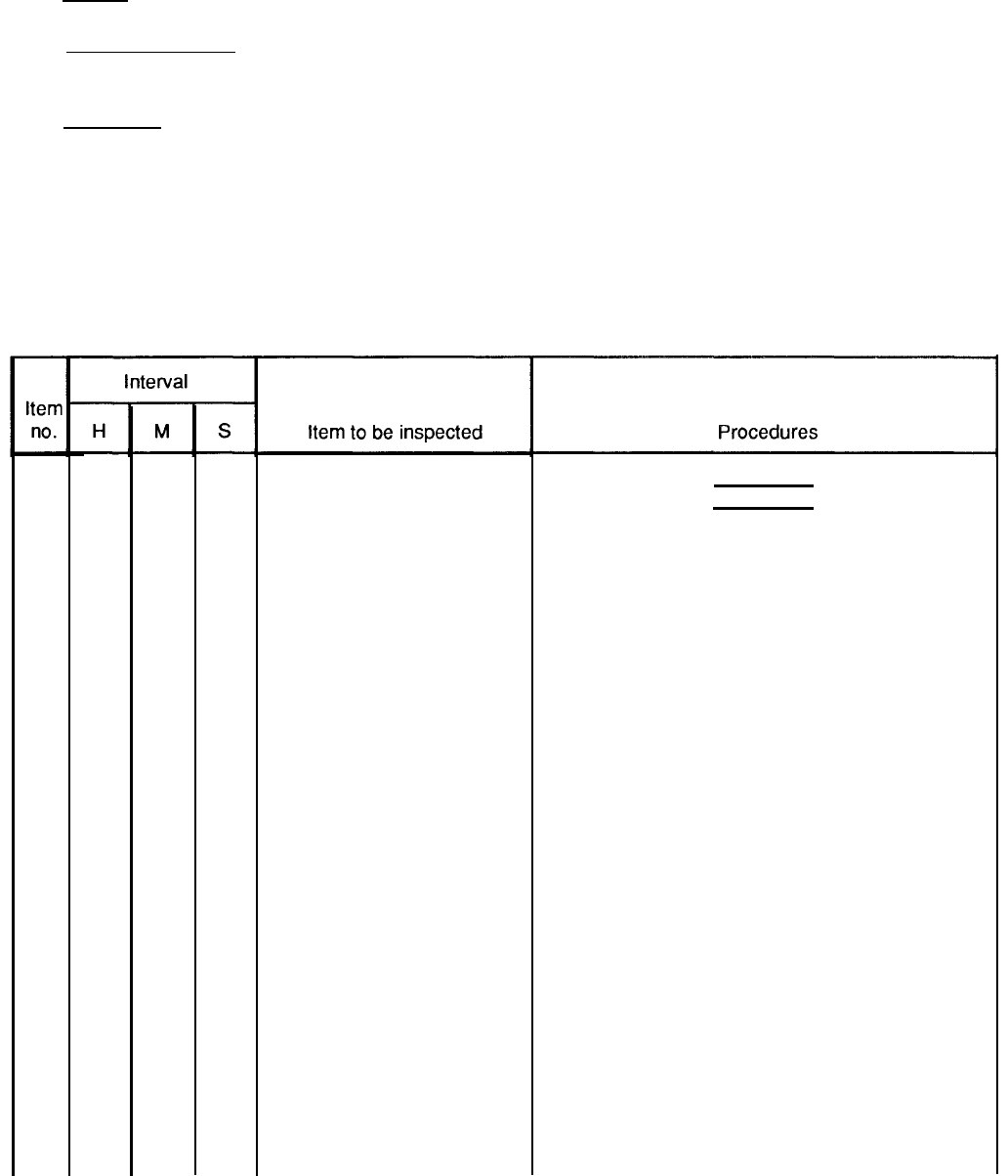
Interval. This column shows when each check is to be done.
Item to be Inspected.
This column identifies the general area or specific part where the check or service is
to be done.
Procedures. This column lists the checks or service you have to do and explains how to do them.
4-12.
Reporting Deficiencies.
If you discover any problem with the equipment during PMCS that you are
unable to correct, it must be reported. Refer to DA Pam 738-750 and report the deficiency using the proper forms.
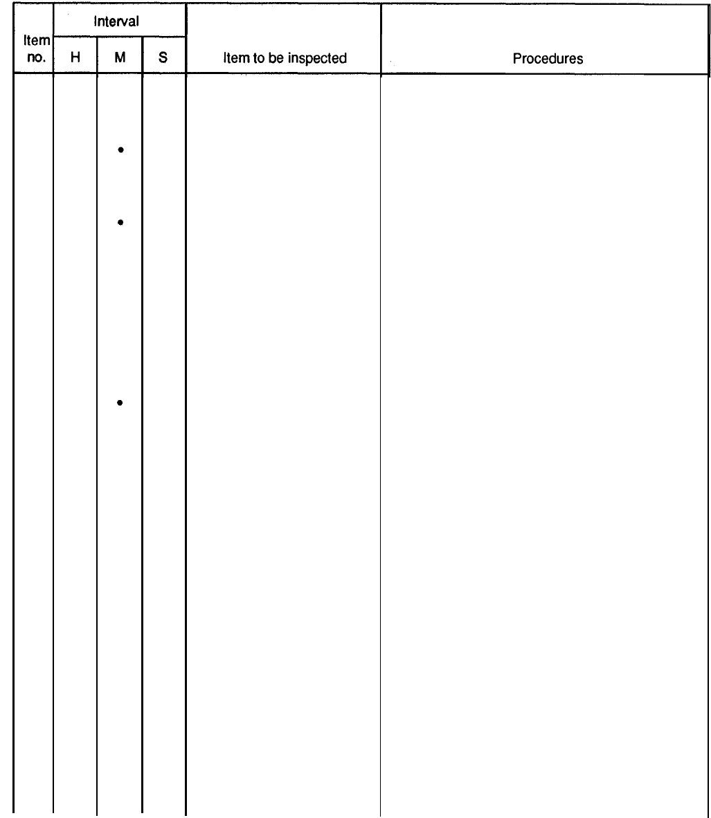
Table 4-1. Unit Preventive Maintenance Checks and Services (PMCS).
H – Hours of operation M – Monthly
S – Semiannually
1
2
3
(As indicated)
●
●
●
(100 hours) (500 hours)
Generator Set Exterior
Fuel Strainer and Filters
Fuel Tanks
WARNING
Before performing any maintenance that
requires climbing on or under trailer, set
trailer handbrakes, chock wheels, and lower
rear leveling jacks. Injury to personnel
could result from trailer suddenly rolling or
tipping.
Inspect generator set for fuel and oil leaks, loose
or missing components and hardware, and un-
usual wear or deterioration. Clean generator set.
NOTE
Fuel system must be above freezing
temperature when draining water and
sediment from strainer, filters, and tank.
Open drains on fuel strainer, and primary and
secondary fuel filters. Drain water and sediment
into a suitable container. Allow to drain until fuel
runs clean.
Open drains on main fuel tank and day tank. Drain
water and sediment into a suitable container.
Allow to drain until fuel runs clean.
4-9
TM 9-6115-651-14&P
4
5
6
7
8
9
10
11
12
13
14
15
16
Table 4-1. Unit Preventive Maintenance Checks and Services (PMCS) (cont).
H - Hours of operation M - Monthly S - Semiannually
(As indicated)
300
300
300
AR
●
●
●
●
●
●
(100 hours) (500 hours)
Fuel Pumps
Batteries
V-Belts
Fuel Filters
Fuel Strainer
Lubricating Oil and Filter
Hydraulic Sump
Hydraulic Filter
Hydraulic Actuator Screen
Breather and Breather Tube
Air Cleaner
Taillights
Intervehicular Cable
Clean or replace, as necessary, fuel strainer in
bottom of fuel pump.
Perform a hydrometer test on batteries every
100 hours. Refer to TM 9-6115-549-12 for
test procedures.
Inspect for worn, frayed, oil soaked, or cracked
belts. Check adjustment. Proper adjustment for
fan belt is a deflection of 9/32 inch with application
of 12-14 lb pressure midway between fan and
accessory drive pulley. The alternator drive belt
is adjusted properly when there is 9/64 inch
deflection with application of 3–5 lb pressure
midway between alternator and accessory drive
pulley.
Replace filter elements.
Clean fuel strainer.
Change lubricating oil and filter. (Refer to LO.)
Drain and refill.
Replace filter.
Clean filter.
Inspect for damage. Clean breather and tube at oil
change interval.
Clean air cleaner element whenever necessary as
indicated by air filter condition indicator light.
Replace any broken or cracked lenses or defective
bulbs.
Check for cuts, breaks, frayed wires, or damaged
plug.
4-10
TM
9-6115-651-14&P
17
18
19
20
21
22
23
24
25
26
Table 4-1. Unit Preventive Maintenance Checks and Services (PMCS) (cont).
H – Hours of operation
M - Monthly S – Semiannually
(As indicated) (100 hours) (500 hours)
●
●
●
●
●
●
●
●
●
●
Lunette
Safety Chains
RefIectors
Data Plates and Markings
Landing Leg
Leveling Jacks
Suspension Assemblies
Axle
Wheels and Tires
Brakes
Check security of mounting. Inspect ring for
excessive wear.
Inspect for broken links or missing chain(s).
Replace any cracked, broken, or missing
refIectors.
Make sure data plates are legible and securely
mounted. Replace illegible data plates.
Inspect landing leg and brace for bent or broken
parts.
Inspect leveling jacks for bent or broken parts.
a.
b.
a.
b.
a.
b.
a.
b.
Inspect shackles, bearings, pins, leaf springs
and spring eyes for damage or broken parts.
Inspect mounting brackets for cracks or loose
or missing hardware.
Check for damaged axle tube.
Check for loose or missing U-bolts or nuts.
Check serviceability of tires as indicated in
TM 9-2610-200-24.
Tighten wheel stud nuts to 450 to 500 ft-lb
(611 to 678 N*m).
Inspect brake linings for wear. Replace if brake
shoe lining is less than 1/8-inch (3.2 mm) thick.
Inspect brake adjusting screw, retaining screw,
retaining pins, springs, and clips for corrosion
and wear.
4-11
TM 9-6115-651-14&P
Table 4-1. Unit Preventive Maintenance Checks and Services (PMCS) (cont).
H – Hours of operation M – Monthly S – Semiannually
(As indicated) (100 hours) (500 hours)
26 Brakes (cont)
c. Inspect hydraulic wheel cylinders for leaks.
d. Adjust brakes.
27
●
Wheel Bearings Clean and repack wheel bearings.
28
●
Hydraulic Brake Hoses and Inspect for dents, cracks, loose connections and
Fittings
leaks.
29
●
Air Hoses and Fittings Inspect for dents, cracks, loose connections and
leaks.
30
●
Brake Master Cylinder
Check fluid level. Fill to 1/2 inch from top.
31
●
Trailer - Road Test Perform road test paying special attention to items
that were repaired or adjusted, in accordance with
TM 9-2330-205-14&P.
Section VI. TROUBLESHOOTING
4-13. Power Unit
Troubleshooting.
There are no troubleshooting procedures authorized at unit level for
the power unit end item. Troubleshooting procedures for the individual generator set and trailer are contained in
their respective technical manuals referenced below.
a.
Generator Set Troubleshooting. Refer to TM 5-6115-545-12 for troubleshooting procedures applicable to
the generator set.
b. Trailer Troubl
eshooting. Refer to TM 9-2330-205-14&P for troubleshooting procedures applicable to the
trailer.
Section VII. RADIO INTERFERENCE SUPPRESSION
4-14. General Methods Used to Attain Proper Suppression.
Essentially, suppression is attained
by providing a low resistance path to ground for stray currents. The methods used include shielding ignition and
high-frequency wires, grounding the frame with bonding straps, and using filtering systems.
4-15.
Radio Interference Suppression Components.
All component parts on the power unit end
item, whose primary or secondary function is radio interference suppression, are on the generator set. Refer to
TM 5-6115-545-12 for location of radio interference suppression components.
4-12
TM 9-6115-651-14&P
Section Vlll. MAINTENANCE OF POWER UNIT TRAILER
4-16.
General.
This section of the manual contains unit level maintenance procedures for components of the
M200A1 trailer added when the trailer is used as part of the PU-707A/M power unit. These components are not
covered in the overall trailer maintenance manual. For all other unit maintenance procedures on the trailer, refer
to TM 9-2330-205-14&P. When power unit has been painted in camouflage, replacement parts must be painted
to match authorized patterns and colors as specified in TB 43-0147. Application of camouflage paint shall be
done in accordance with MIL-C-53072.
WARNING
Before performing any maintenance that requires climbing on or under trailer, set trailer
handbrakes, chock both wheels, and lower rear leveling jacks. Injury to personnel could
result from trailer suddenly rolling or tipping.
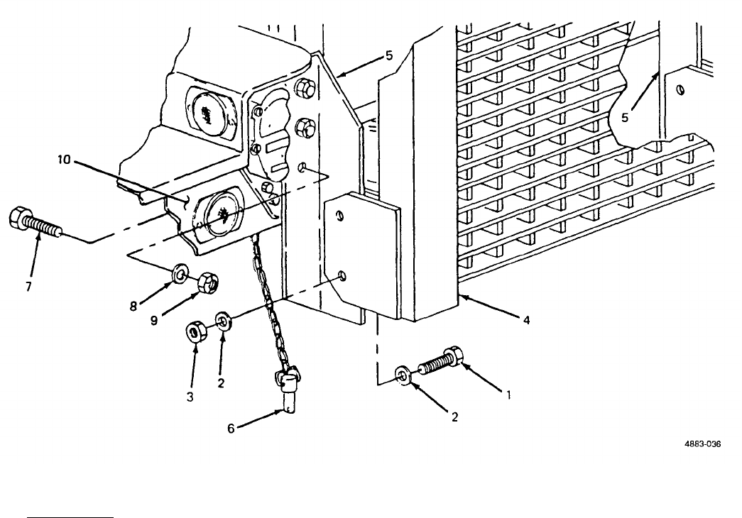
4-17.
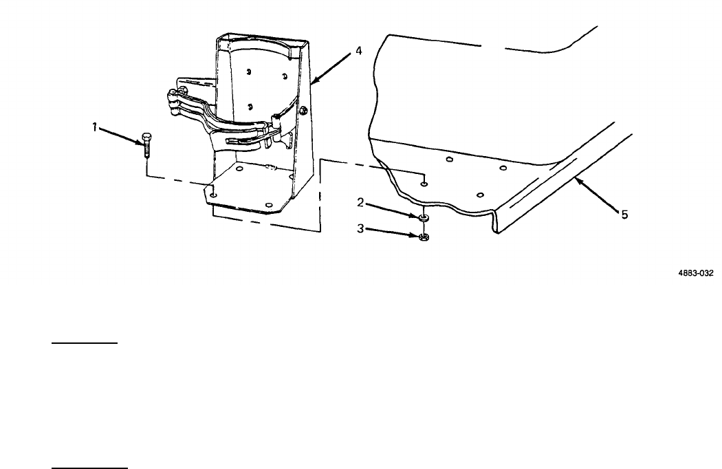
Fuel Can Bracket Replacement.
(See figure 4-5.) There are two fuel can brackets supplied with
the PU-707A/M. The brackets are mounted on top of the curbside front step. Replacement procedures described
below are the same for both.
Figure 4-5. Fuel Can Bracket Replacement.
a. Removal.
(1)
(2)
Remove four screws (1, figure 4-5), four self-locking nuts (2) and four flat washers (3) securing bracket
(4) to step (5).
Remove bracket (4) from step (5).
4-13
TM 9-6115-651-14&P
b. Installation.
(1) Position fuel can bracket (4) on step (5).
(2) Insert four screws (1) down through bracket (4) and through step (5).
(3) Install one washer (3) and one self-locking nut (2) on each screw(1). Tighten hardware to secure
bracket (4).
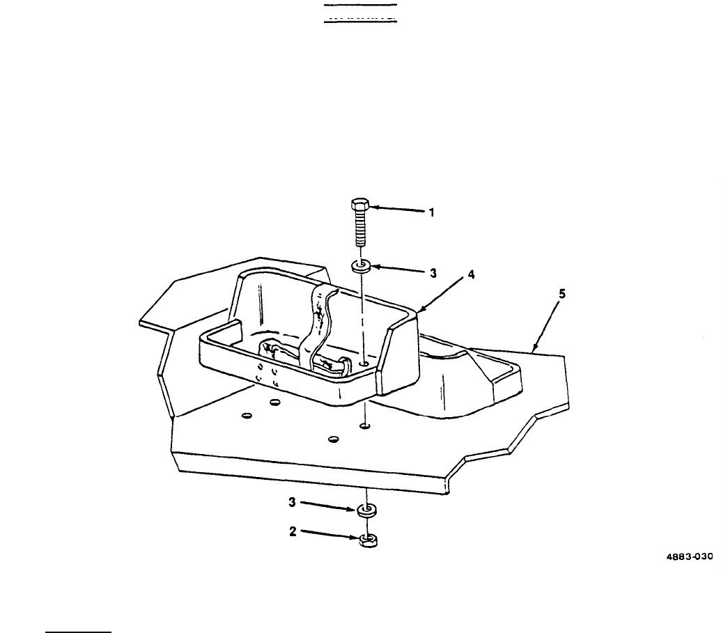
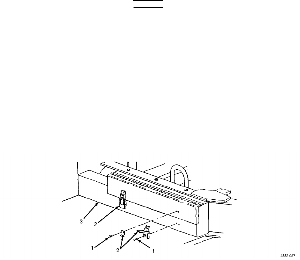
4-18.
Accessory Box Replacement.
(See figure 4-6.) The accessory box is mounted to the trailer frame
at the curbside front step.
Figure 4-6. Accessory Box Replacement.
a. Removal.
(1) Remove three screws (1, figure 4-6), three flat washers (2), and three nuts (3) securing accessory box
(4) to trailer frame (5).
(2) Slide accessory box (4) forward and off front step (6).
b. Installation.
(1) Position accessory box (4) on front trailer step (6) with narrow end between handbrake lever (7) and
trailer frame (5).
4-14
TM 9-6115-651-14&P
(2)
Lift accessory box (4) so that top of box contacts lip of trailer frame (5).
(3) Insert three screws (1) down through trailer frame (5) into accessory box (4).
(4) Install one nut (3) and one washer (2) on each screw (1) and tighten.
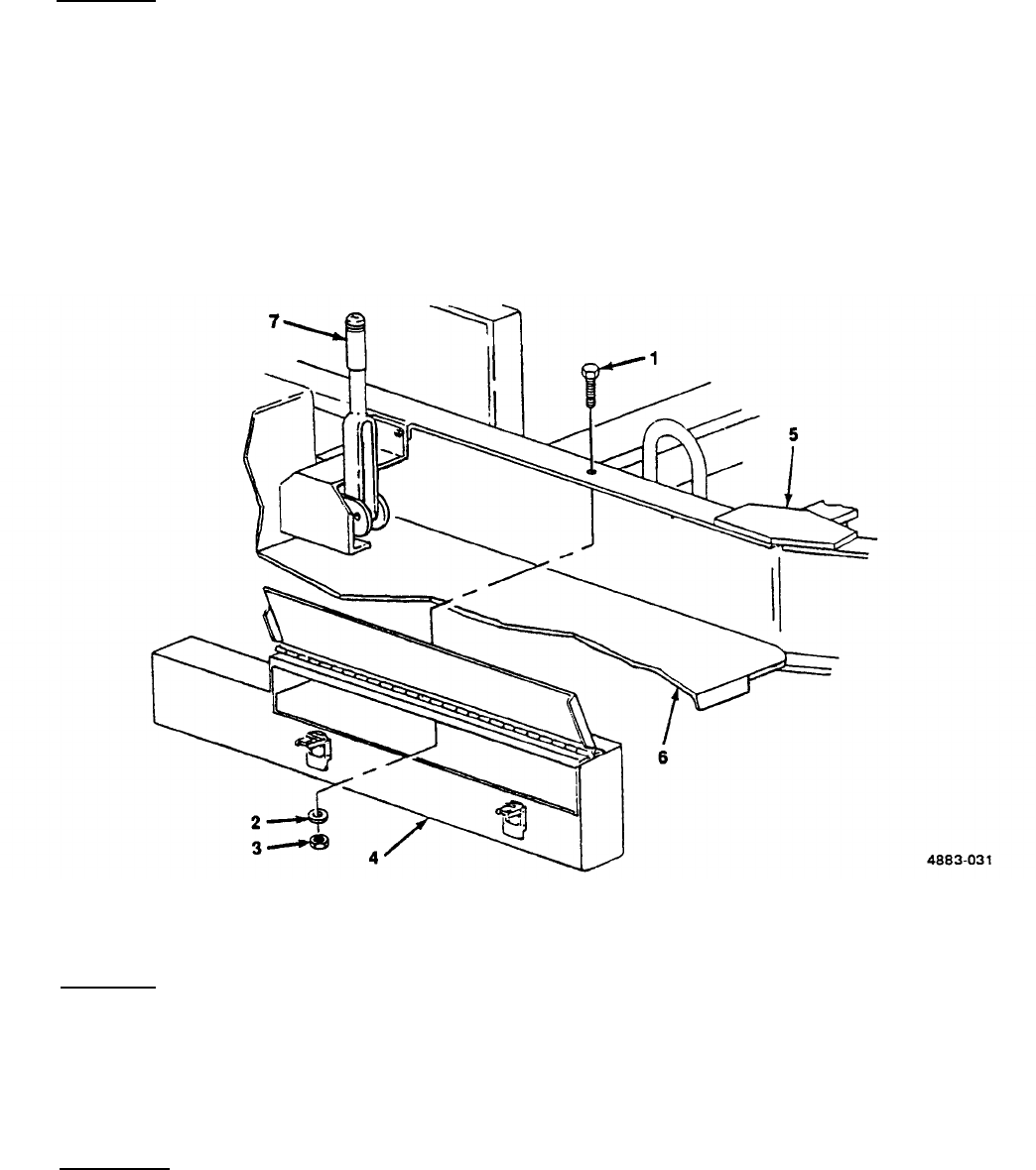
4-19.
Fire Extinguisher Bracket Replacement.
(See figure 4-7.) The fire extinguisher supplied with
the power unit is carried in a bracket mounted on the front roadside step.
Figure 4-7. Fire Extinguisher Bracket Replacement.
a. Removal.
(1) Remove four screws (1, figure 4-7), four flat washers (2), and four nuts (3) securing bracket (4) to
step (5).
(2) Remove bracket (4) from step (5).
b. Installation.
(1)
(2)
(3)
Position fire extinguisher bracket (4) on step (5).
Insert four screws (1) down through bracket (4) and through step (5).
Install one flat washer (2) and one nut (3) on each screw (1). Tighten hardware to secure bracket (4).
4-15

TM 9-6115-651-14&P
4-20.
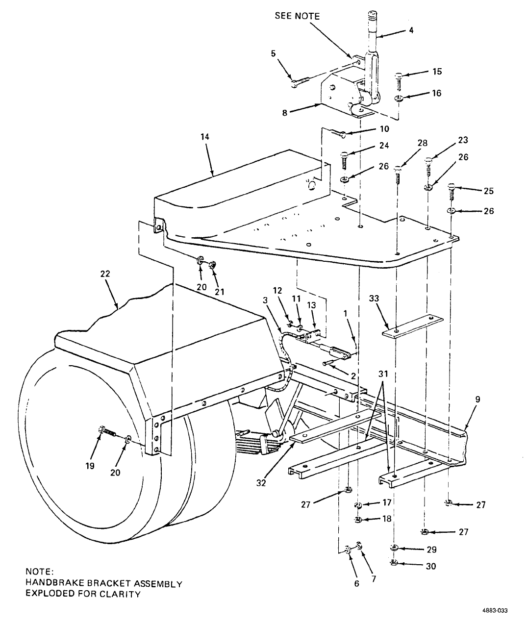
Front Step Replacement.
(See figure 4-8.) The roadside and curbside front steps are symmetrical,
and replacement procedures are the same except where noted in the steps below.
a. Removal.
(1)
(2)
(3)
(4)
(5)
(6)
(7)
(8)
(9)
NOTE
When removing roadside front step, omit steps (1)
Remove fuel can brackets (paragraph 4-17, a).
Remove accessory box (paragraph 4-18, a).
and (2).
Remove cotter pin (1, figure 4-8) and clevis pin (2) securing handbrake cable (3) to handbrake lever
mechanism (4).
Remove two screws (5), two flat washers (6) and two nuts (7) securing handbrake (8) to trailer frame (9).
Remove two screws (10), two flat washers (11) and two nuts (12) securing handbrake cable bracket (13)
to front step (14).
NOTE
There are two screws, flat washers, and nuts securing handbrake bracket to front step. It
is only necessary to remove one set of attaching hardware to remove front step from
trailer frame.
Remove screw (15), flat washer (16), Iockwasher (17) and nut (18) directly beneath pivot point of
handbrake Iever (4).
Remove seven screws (19),
edge of fender (22).
Remove four screws (23, 24
to edge of trailer frame (9).
14 flat washers (20) and seven nuts (21) securing front step (14) to front
and 25), eight flat washers (26) and four nuts (27) securing front step (14)
Remove three screws (28), three flat washers (29) and three nuts (30) securing front step (14) to trailer
cross brace channel (31) and remove front step (14) and spacers (32) and (33).
b. Installation.
NOTE
Three different length screws are used to mount the front step. Screws with index
numbers (5), (10), (19) and (23) in figure 4-8 are one inch long. Screw with index number
(24) is 1-1/4 inch long. Screws with index numbers (15), (25) and (28) are 1-3/4 inch
long. Observe lengths and locations when installing hardware.
4-16
TM 9-6115-651-14&P
Figure 4-8. Front Step Replacement.
4-17

TM 9-6115-651-14&P
(1)
(2)
(3)
(4)
(5)
(6)
(7)
(8)
(9)
(10)
(11)
Position front step (14) and spacers (32) and (33) on cross brace channels (31) and trailer frame (9).
Insert clevis on handbrake cable (3) through hole in front step (14).
Insert four screws (23, 24 and 25) eight flat washers (26) through front step (14) and trailer frame (9).
Insert three screws (28) with fIat washers (29) through front step (14) and trailer cross brace
channel (31).
Working under step, install one nut (30) on each screw (28) securing front step (14) to cross brace
channel (31) and install one flat washer (26) and one nut (27) on each screw (23, 24 and 25) securing
step to trailer frame (9). Tighten seven sets of hardware.
Secure front step (14) to fender (22) with seven screws (19), 14 flat washers (20) and seven nuts (21).
Insert screw (15) with flat washer (16) through handbrake bracket (8), front step (14) and cross brace
channel (31). Install Iockwasher (17) and nut (18) on screw from underneath and tighten.
Insert two screws (5) with flat washers (6) through handbrake bracket (8) and trailer frame (9). Install
one nut (7) on each screw and tighten.
Insert two screws (10) through front step (14) and handbrake cable bracket (13). Install one flat washer
(11) and one nut (12) on each screw and tighten.
Position clevis on handbrake cable (3) on handbrake lever mechanism (4). Insert clevis pin (2) and
secure with cotter pin (1).
NOTE
When installing roadside front step, omit steps (10) and (11).
Install accessory box (paragraph 4-18, b).
Install fuel can brackets (paragraph 4-17, b).
4-21.
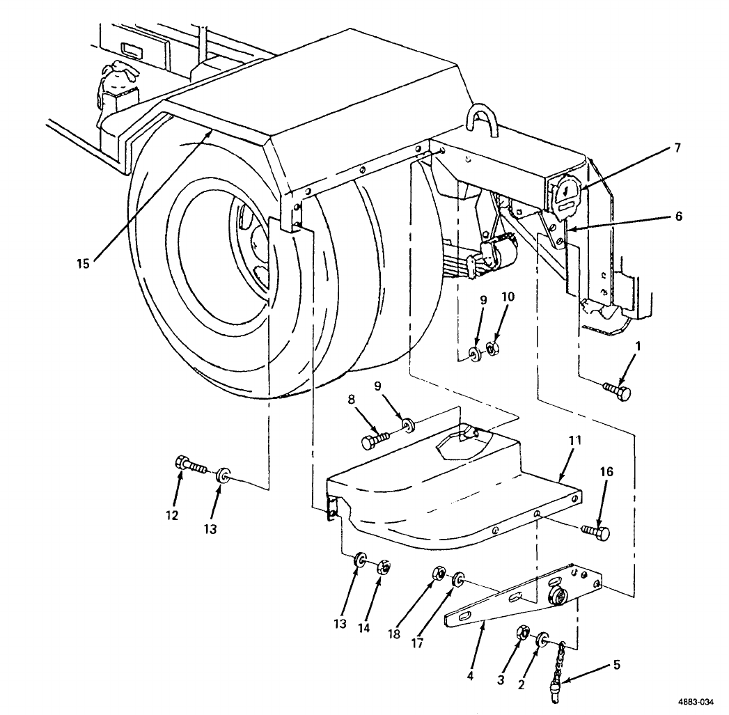
Rear Step and Bracket Replacement.
(See figure 4-9.) The roadside and curbside rear steps are
symmetrical, and replacement procedures are the same for both.
a. Removal
(1) Remove two screws (1, figure 4-9), two flat washers (2) and two nuts (3) securing rear step bracket (4)
and platform anchor (5) to trailer frame (6) under taillight (7).
(2) Remove two screws (8), four flat washers (9) and two nuts (10) securing rear step (11) to trailer
frame (6).
(3) Remove five screws (12), ten flat washers (13) and five nuts (14) securing rear step (11) to fender (15).
Remove rear step from trailer.
4-18
TM 9-6115-651-14&P
Figure 4-9. Rear
Step and Bracket Replacement.
NOTE
If rear step bracket (4) must be straightened or replaced, do step 4. Remove and retain
reflector for installation on new or repaired rear step bracket.
(16), three flat washers (17), and three nuts (18). Separate rear step bracket (4)
(4)
Remove three screws
from step (11).
4-19

TM 9-6115-651-14&P
b. Installation.
(1) If rear step bracket (4) and step (11) were separated during removal, aline bracket and step and install
three screws (16), three flat washers (17), three nuts (18) and tighten.
(2)
(3)
(4)
(5)
(6)
(7)
Position rear step (11) on trailer frame (6).
Secure rear step (11) to trailer frame (6) with two screws (8), four flat washers (9) and two nuts (10).
Secure rear step (11) to fender (15) with five screws (12), ten flat washers (13) and five nuts (14).
Aline two mounting holes in rear step bracket (4) with holes in trailer frame (6) under taillight (7) and
insert two screws (1).
Slide S-hook at chain end of platform anchor (5) onto threaded end of lower screw (1) inside trailer
frame (6).
Install one flat washer (2) and one nut (3) on each screw (1) and tighten.
4-22.
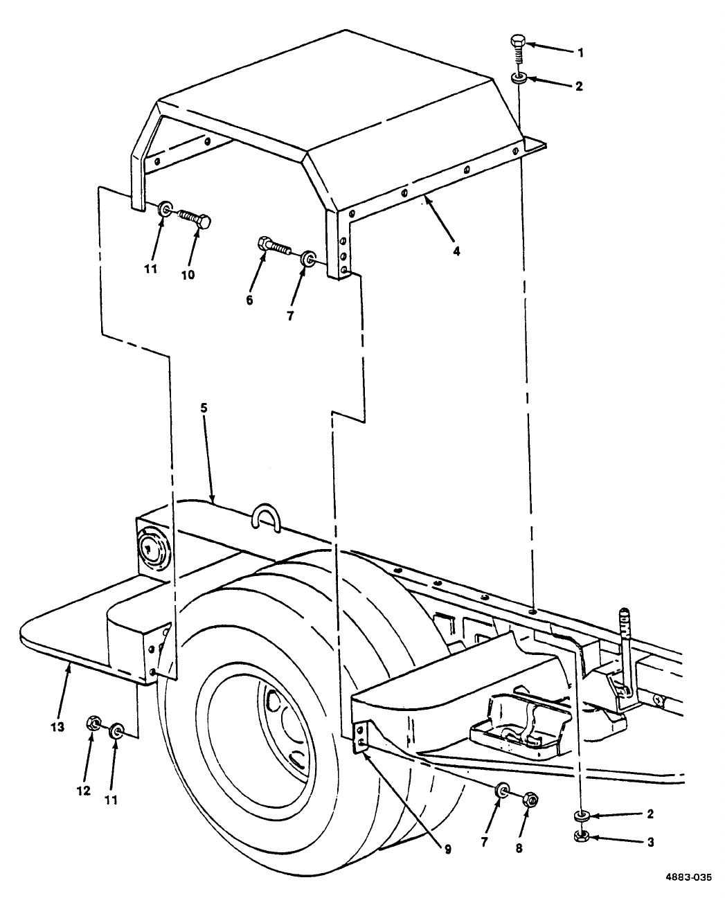
Fender Replacement.
(See figure 4-10.) The fenders on the trailer are symmetrical, and
replacement procedures are the same for both.
a.
Removal.
(1) Remove five screws (1, figure 4-10), ten flat washers (2) and five nuts (3) securing fender (4) to trailer
frame (5).
WARNING
There are five sets of hardware securing fender to rear step and seven sets of hardware
securing fender to front step. This hardware should be removed in sequence from trailer
frame outward. In this way, last two screws on front and rear lower fender edge will
support fender until you are out from underneath.
(2) Remove six screws (6), 12 flat washers (7) and six nuts (8) securing fender (4) to front step (9).
(3) Remove four screws (10), eight flat washers (11) and four nuts (12) securing fender (4) to rear step (13).
WARNING
Support fender while removing remaining two screws. When screws are removed, fender
will drop, causing injury to personnel.
(4) Remove one screw (6), two flat washers (7) and one nut (8) securing fender (4) to front step (9).
(5) Remove one screw (10), two flat washers (11) and one nut (12) securing fender (4) to rear step (13).
(6) Remove fender (4).
4-20
TM 9-6115-651-14&P
Figure 4-10. Fender Replacement.
4-21

TM 9-6115-651-14&P
b. Installation.
(1) Position fender (4) on trailer.
(2)
(3)
(4)
(5)
(6)
(7)
Insert one screw (10) with flat washer (11) through lower outside edge of fender (4) into rear step (13),
and insert one screw (6) with flat washer (7) through lower outside edge of fender (4) into front step (9).
Install one washer (11) and one nut (12) on screw (10), and one washer (7) and one nut (8) on screw
(6). Tighten hardware.
Insert five screws (1) with flat washers (2) down through fender (4) into trailer frame (5).
Working under fender, install one flat washer (2) and one nut (3) on each screw (1) and tighten.
Insert six screws (6) with flat washers (7) through fender (4) into front step (9). Install one washer (7)
and one nut (8) on each screw (6) and tighten.
Insert four screws (10) with flat washers (11) through fender (4) into rear step (13). Install one washer
(11) and one nut (12) on each screw (10) and tighten.
4-23.
Personnel Platform Replacement.
(See figure 4-11). This platform is mounted on the rear of the
trailer to facilitate access to generator set controls and indicators.
a. Removal.
(1) Remove two screws (1, figure 4-11), four flat washers (2) and two self-locking nuts (3) securing platform
(4) to mounting brackets (5).
WARNING
Support platform while removing anchors. When anchors are removed, platform will
drop, causing injury to personnel.
(2) Remove two platform anchors (6) by pushing in on button on head of pin while pulling pin out of
mounting hole.
NOTE
Mounting brackets are fastened with self-locking nuts. Removal may damage locking
capability when reinstalled. Do not remove mounting brackets unless they are damaged.
(3) Remove three screws (7) three flat washers (8) and three self-locking
nuts (9) from each mounting bracket (5) and take mounting brackets off of
trailer frame (10) .
4-22
TM 9-6115-651-14&P
b. Installation
(1)
(2)
(3)
Figure 4-11. Personnel Platform Replacement.
NOTE
If mounting brackets have not been removed, omit step (1).
Position each mounting bracket (5) on trailer frame (10). Insert three screws (7) through frame into each
bracket. Install one washer (8) and one self-locking nut (9) on each screw and tighten.
Holding platform (4) in vertical position, position platform on mounting brackets (5) so that holes in
platform line up with holes in brackets and install platform anchors (6) in upper mounting hole on each
side of platform.
Secure platform (4) to brackets (5) with two screws (1), four flat washers (2) and two self-locking
nuts (3).
4-23/(4-24 blank)
TM 9-6115-651-14&P
CHAPTER 5
DIRECT SUPPORT AND GENERAL SUPPORT
MAINTENANCE INSTRUCTIONS
Section I. INTRODUCTION
5-1.
General.
This chapter contains Direct Support and General Support level maintenance procedures for
components of the M200A1 trailer added when the trailer is used as part of the PU-707A/M power unit. These
components are not covered in the overall trailer maintenance manual. For all other direct and general support
maintenance procedures on the trailer, refer to TM 9-2330-205-14&P. For direct and general support
maintenance procedures on the generator set, refer to TM 5-6115-545-34.
WARNING
Before performing any maintenance that requires climbing on or under trailer, set trailer
handbrakes, chock wheels and lower rear leveling jacks. Injury to personnel could result
from trailer suddenly rolling or tipping.
Section Il. MAINTENANCE OF POWER UNIT TRAILER
5-2.
Step and Fender Repair.
Repair of the front and rear steps and the fenders is limited to straightening,
welding and repainting. If required, repaint in accordance with MIL-T-704, Type F, Color Green, No. 383 of
MIL-C-46168. If power unit is painted in camouflage, refer to paragraph 5-4, Marking.
5-3.
Accessory Box Repair.
(See figure 5-1.) The accessory box is repaired by replacing the latch and
strike assemblies. The box itself may be straightened, welded and repainted. If required, repaint in accordance
with MIL-T-704, Type F, Color Green, No. 383 of MIL-C-46168. If power unit is painted in camouflage, refer to
paragraph 5-4, Marking. Replace latch and strike assemblies as follows:
a.
Grind off or drill out solid rivets (1, figure 5-1) securing latch and strike assembly (2) to accessory box (3).
b. Position new latch and strike assembly (2) on accessory box (3) and secure with solid rivets (1).
c. Touch up with paint as required.
Figure 5-1. Accessory Box Repair.
5-1
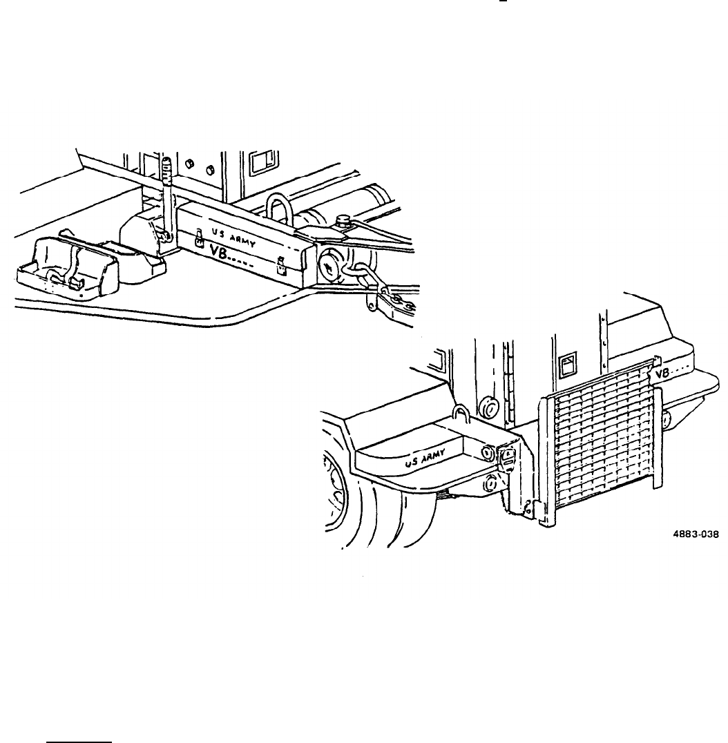
TM 9-6115-651-14&P
5-4.
Marking.
(See
figure 5-2.) The power unit four-digit registration number, preceded by the prefix "VB" and
the words "U.S. ARMY", is marked in three places on power unit trailer. Marking is done in accordance with
MIL-STD-642. On the fender, over each wheel, “T.P. 35 PSI” is marked in 1.00 + .12 inch high characters in
accordance with MIL-STD-130. Figure 5-2 shows the approximate location of markings on power unit. If
required, touch-up painting of the base color shall be done in accordance with MIL-T-704, Type F, Color Green,
No. 383 of MIL-C-46168. When power unit has been previously painted in camouflage, any touch-up painting
following repairs must match authorized patterns and colors as specified in TB 43-0147. Application of
camouflage paint shall be done in accordance with MIL-C-53072.
Figure 5-2.
Section Ill.
Power Unit Markings.
GENERATOR SET
5-5.
Generator Set Replacement.
(See figures 5-3 and 5-4).
a. Removal.
(1) Disconnect ground wire (1, figure 5-3) from generator set (2) to GROUND TERMINAL stud (3) on trailer.
5-2
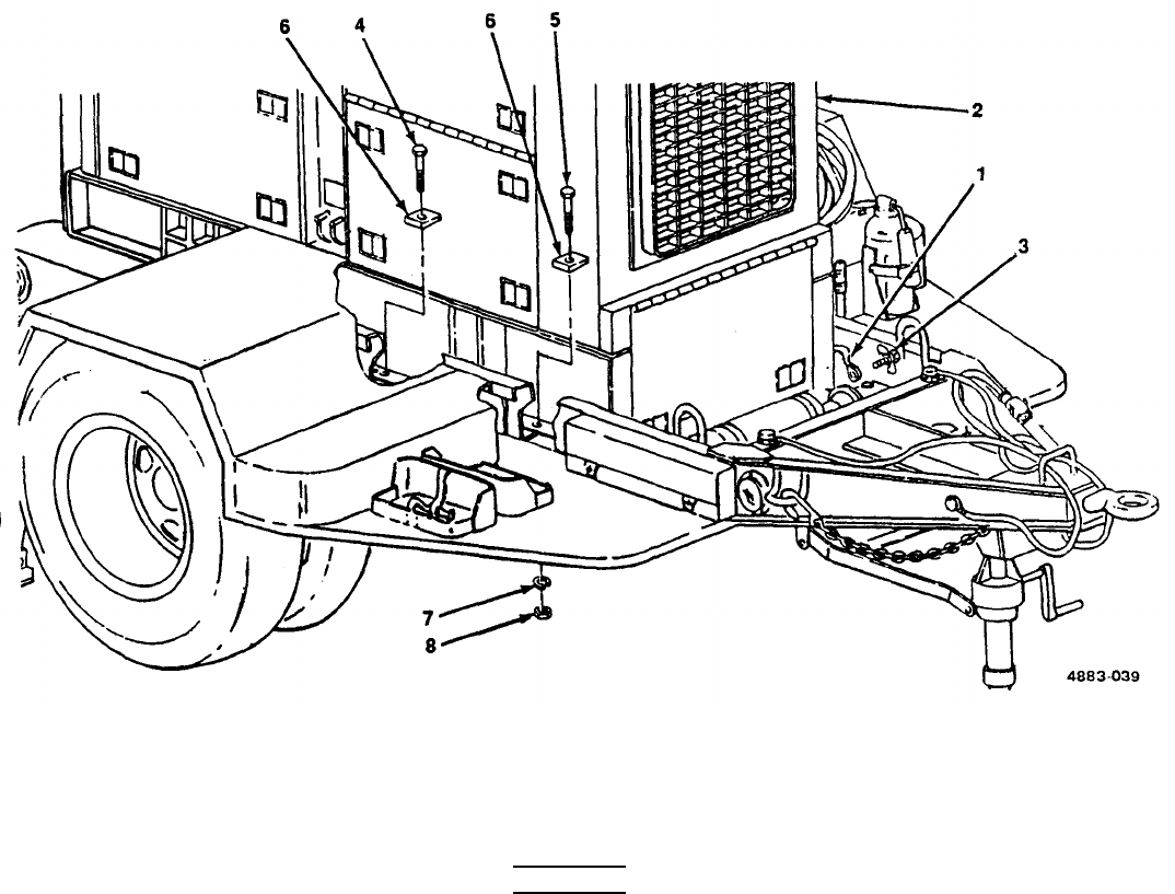
TM 9-6115-651-14&P
NOTE
Two center mounting screws on each side can be reached through cutouts in trailer frame
under each fender. Observe that two mounting screws (5) at front corners of generator
set are shorter than remaining six mounting screws (4). The beveled washers (6) may
have been welded in place.
(2)
(3)
(4)
Figure 5-3. Detaching Generator Set from Trailer.
Remove six screws (4), two screws (5), eight beveled washers (6), eight flat washers (7) and eight nuts
(8) securing generator set (2) to trailer.
WARNING
When lifting generator set, use lifting equipment with a minimum lifting capacity of 5000
lb. Do not stand under generator while it is being lifted. Do not permit generator set to
swing. Failure to observe these precautions can cause injury to personnel or damage to
equipment.
Attach lifting equipment with a minimum lifting capacity of 5000 lb (1, figure 5-4) to both lifting eyes (2)
on top edges of generator set (3). Insert a rope (4) through each of four tiedown cleats (5) on generator
set.
With one person at each rope to steady and guide generator set (3), lift generator set off of trailer.
5-3
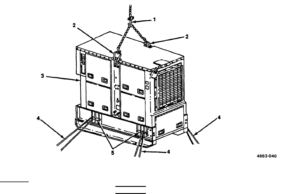
TM 9-6115-651-14&P
b.
Figure 5-4. Lifting Generator Set.
Installation.
(1)
(2)
(3)
(4)
(5)
(6)
5-4
WARNING
When lifting generator set, use lifting equipment with a minimum lifting capacity of 5000
lb. Do not stand under generator. Do not permit generator set to swing. Failure to
observe these precautions can cause injury to personnel or damage to equipment.
Attach lifting equipment with a minimum lifting capacity of 5000 lb (1, figure 5-4) to lifting eyes (2) on top
edges of generator set (3). Insert a rope (4) through each of four tiedown cleats (5) on generator set.
With one person at each rope to steady and guide generator set (3), lift generator set and carefully lower
it onto trailer.
NOTE
Two center mounting screws on each side can be reached through cutouts in trailer frame
under each fender. The two shorter mounting screws (5, figure 5-3) are installed at the
front corner positions.
Insert six screws (4, figure 5-3) and two screws (5) with beveled washers (6) down through generator set
skids into trailer.
Working under trailer install one Iockwasher (7) and one nut (8) on each screw (4) and (5).
Position beveled washers (6) so that screw heads are parallel to tops of washers. While holding beveled
washers in position, tighten hardware.
Connect generator set ground wire (1) to trailer GROUND TERMINAL stud (3).
TM 9-6115-651-14&P
CHAPTER 6
TEST AND INSPECTION AFTER REPAIR
Section I. GENERAL REQUIREMENTS
6-1.
General Requirements.
The activity performing the repair is responsible for the performance of all
applicable tests and inspections specified in the technical manuals referenced below. Activities performing
maintenance on any component of the power unit must perform those tests and inspections required by the
applicable component or system repair instruction.
Section II. INSPECTION
6-2.
Generator Set Inspections.
Refer to TM5-6115-545-12 and -34 for inspections required following
repair of the generator set.
6-3.
Trailer Inspections.
Refer to TM 9-2330-205-14&P for inspections required following repair of the
trailer.
Section Ill. OPERATIONAL TESTS
6-4.
Generator Set Operational Tests.
Refer to TM 5-6115-545-12 and -34 for operational tests required
to verify satisfactory performance of the generator set.
6-5.
Trailer Operational Tests.
Refer to TM 9-2330-205-14&P for operational tests required to verify
satisfactory performance of the trailer.
6-1/(6-2 blank)
TM 9-6115-651-14&P
APPENDIX A
REFERENCES
A-1.
Scope.
This appendix lists all pamphlets, forms, technical manuals, specifications and miscellaneous
publications referenced in this manual.
A-2. Forms and Records.
Supply Policy Below the Wholesale Level . . . . . . . . . . . . . . . . . . . . . . . . . . . . . . . . . . . . . .. AR710-2
Recommended Changes to Publications and Blank Forms . . . . . . . . . . . . . . . . . . . . . . . . . DA Form 2028
Depreservation Guide for Vehicles and Equipment . . . . . . . . . . . . . . . . . . . . . . . . . . . . . . . DA Form 2258
Equipment Inspection and Maintenance Worksheet . . . . . . . . . . . . . . . . . . . . . . . . . . . . . . . DA Form 2404
Maintenance Request . . . . . . . . . . . . . . . . . . . . . . . . . . . . . . . . . . . . . . . . . . . . . . . . . . . . .. DA Form 2407
Consolidated lndex of Army Publications . . . . . . . . . . . . . . . . . . . . . . . . . . . . . . . . . . . . . .. DA PAM 25-30
The Army Maintenance Management System (TAMMS) . . . . . . . . . . . . . . . . . . . . . . . . . . . DA PAM 738-750
Product Quality Deficiency Report . . . . . . . . . . . . . . . . . . . . . . . . . . . . . . . . . . . . . . . . . . . SF 368
A-3. Military Specifications.
Chemical Agent Resistant Aliphatic Polyurethane Coating . . . . . . . . . . . . . . . . . . . . . . . . . . MIL-C-46168
Chemical Agent Resistant Coating (CARC) System Application Procedure and
Q/C lnspection . . . . . . . . . . . . . . . . . . . . . . . . . . . . . . . . . . . . . . . . . . . . . . . . . . . . . . . . .. MIL-C-53072
Identification Marking of U.S. Military Property . . . . . . . . . . . . . . . . . . . . . . . . . . . . . . . . . .. MIL-STD-130
Identification Marking of Combat and Tactical Transport . . . . . . . . . . . . . . . . . . . . . . . . . . . MIL-STD-642
Treatment and Painting of Materiel . . . . . . . . . . . . . . . . . . . . . . . . . . . . . . . . . . . . . . . . . . .. MIL-T-704
A-4. Technical Manuals.
Operator’s and Organizational Maintenance Manual: Generator Set,
Diesel Engine Driven, Tactical Skid Mtd., 60 KW, 3 Phase 4,
Wire, 120/208 and 240/416V (DOD Models MEP-006A) Utility Class,
50/60 Hz (NSN 6115-00-118-1243), (Model MEP-105A) Precise Class,
50/60 Hz (6115-00-118-1252) and (Model MEP-115A) Precise Class,
400 Hz (6115-00-118-1253) . . . . . . . . . . . . . . . . . . . . . . . . . . . . . . . . . . . . . . . . . . . . . . .. TM 5-6115-545-12
Organizational, Intermediate (Field), (Direct and General Support)
and Depot Maintenance Repair Parts and Special Tools List for
Generator Set, Diesel Engine Driven, Tactical Skid Mtd., 60 KW,
3 Phase, 4 Wire, 120/208 ad 240/416 Volts, DOD Models MEP-006A,
Utility Class, 50/60 Hz (6115-00-118-152), MEP-115A, Precise Class,
400 Hz (6115-00-118-1253) . . . . . . . . . . . . . . . . . . . . . . . . . . . . . . . . . . . . . . . . . . . . . . .. TM 5-6115-545-24P
Direct and General Support) and Depot Maintenance Manual: Generator Set,
Diesel Engine Driven, Tactical Skid Mtd., 60 KW, 3 Phase, 4 Wire, 120/208
and 240/416V; DOD Models MEP-006A, Utility Class, 50/60 Hz (6115-118-1252)
(FSN 6115-118-1243 ), MEP-105A, Precise Class, 50/60 Hz and MEP-115A,
Precise Class, 400 Hz (6115 -118-1253) . . . . . . . . . . . . . . . . . . . . . . . . . . . . . . . . . . . . . . TM 5-6115-545-34
Procedures for Destruction of Equipment to Prevent Enemy Use
(Mobility Equipment Command) . . . . . . . . . . . . . . . . . . . . . . . . . . . . . . . . . . . . . . . . . . . . TM 750-244-3
A-1
TM 9-6115-651-14&P
Operator’s, Organizational, Direct Support and General Support Maintenance
Manual Including Repair Parts and Special Tools List for Chassis, Trailer,
Generator, 2-1/2 Ton, 2-Wheel M200A1 (NSN 2330-00-331-2307) . . . . . . . . . . . . . . . . . . TM 9-2330-205-14&P
Organizational, Direct Support, and General Support Care Maintenance
and Repair of Pneumatic Tires and Inner Tubes . . . . . . . . . . . . . . . . . . . . . . . . . . . . . . . . . TM 9-2610-200-24
A-5.
Technical Bulletins.
Color, Marking and Camouflage Patterns Used on Military Equipment Managed
by USATROSCOM . . . . . . . . . . . . . . . . . . . . . . . . . . . . . . . . . . . . . . . . . . . . . . . . . . . . . . TB 43-0147
Preservation of USAMECOM Mechanical Equipment for
Shipment and Storage . . . . . . . . . . . . . . . . . . . . . . . . . . . . . . . . . . . . . . . . . . . . . . . . . . . .
TB 740-97-2
A-2

TM 9-6115-651-14&P
APPENDIX B
COMPONENTS OF END ITEM AND BASIC ISSUE ITEMS LISTS
Section I. INTRODUCTION
B-1. Scope. This appendix lists components of end item and basic issue items for the power unit to help you
inventory items required for safe and efficient operation.
B-2. General. The Components of End Item and Basic Issue Items lists are divided into the following sections:
a. Section II. Components of End Item. This listing is for informational purposes only, and is not authority to
requisition replacements. These items are part of the end item, but are removed and separately packaged for
transportation or shipment. As part of the end item, these items must be with the end item whenever it is issued
or transferred between property accounts. Illustrations are furnished to assist you in identifying the items.
b.
Section Ill. Basic IssueItems. These are the minimum essential items required to place the power unit in
operation, to operate it, and to perform emergency repairs. Although shipped separately packaged, Bll must be
with the power unit during operation and whenever it is transferred between property accounts. The illustrations
will assist you with hard-to-identify items. This manual is your authority to request/requisition Bll, based on
TOE/MTOE authorization of the end item.
B-3. Explanation Of Columns. The following provides an explanation of columns found in the tabular
listings:
a.
Column (1). Illustration Number (Illus No.).
This column indicates the number assigned to the item.
b. Column (2). National Stock Number.
Indicates the National Stock Number assigned to the item.
c.
Column (3).
Description. Indicates the federal item name and, if required, a minimum description to identify
and locate the item. The last line for each item indicates the FSCM (in parentheses) followed by the part number.
If item needed differed for different models of this equipment, the model would be shown under the “Usable on
Code” heading in this column. The Usable on Code is not applicable for this equipment.
d. Column (4). Unit of Measure (U/M). Indicates the measure used in performing the actual operational/
maintenance function. This measure is expressed by a two-character alphabetical abbreviation (eg, ea, in, pr).
e.
Column (5). Qua
ntity Required (Qty
Req’d). Indicates the quantity of the item authorized to be used with/on
the equipment.
B-1
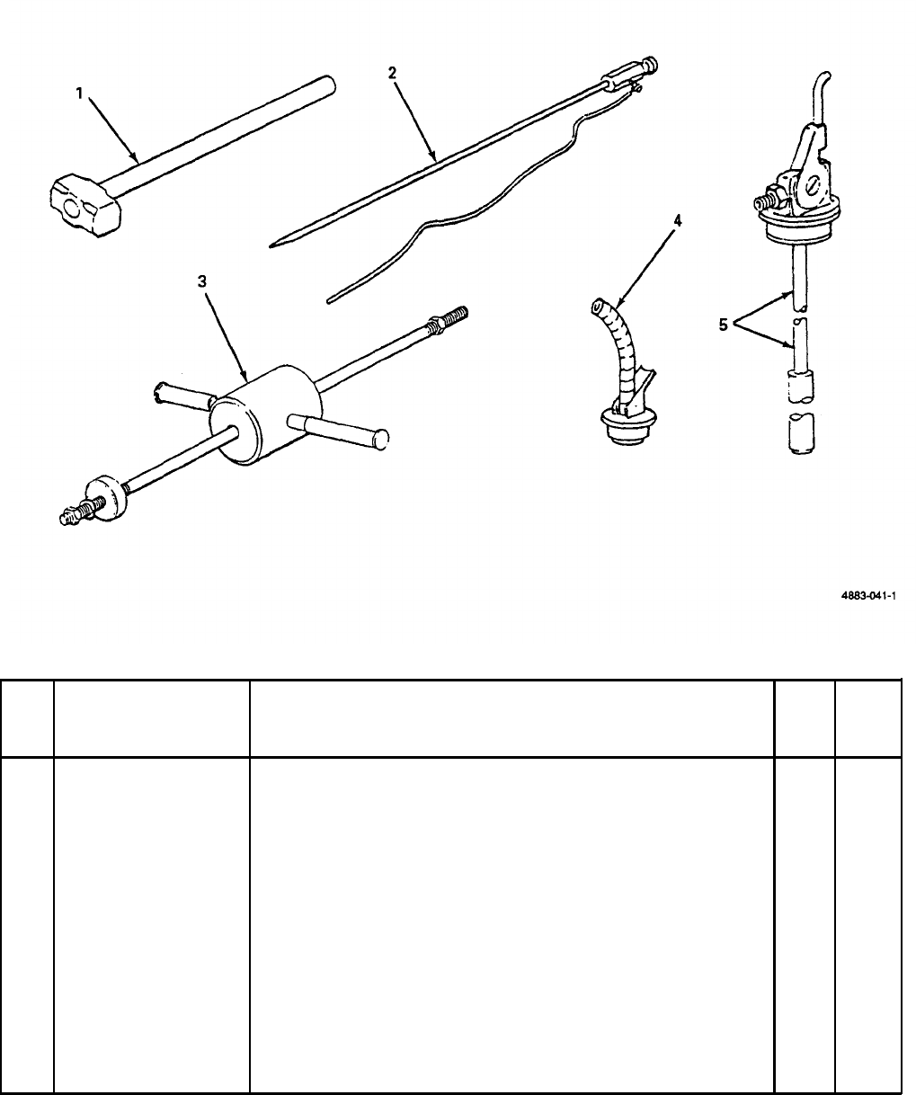
Section Il. COMPONENTS OF END ITEM
TM 9-6115-651-14&P
(1)
(2)
(3)
(4)
(5)
IIlus
National Description Usable Qty
no.
stock number FSCM and part number on code
U/M
req’d
1
5120-00-243-2957
Hammer, Hand, Engineers 8 lb. ea
1
(3.6 kg) (81348) GGG-H-86
2
5975-00-878-3791 Rod, Ground, Driven, Sectional
ea
2
9 ft (2.7 m) (81349) MlL-R-11461
3
5120-01-013-1676
Hammer, Slide (97403) 13226E7741 ea
1
4
7240-00-177-6154
Spout, Can, Flexible (81349)
ea
1
MlL-S-1285
5
2910-00-066-1235
Adapter Assy, Fuel Drum (97403)
ea
1
13214E7541
B-2
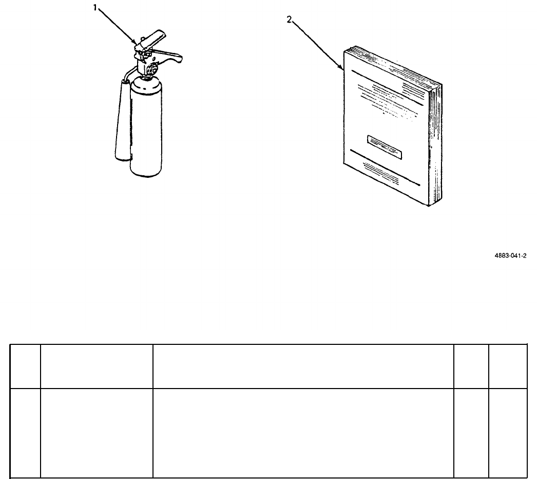
TM 9-6115-651-14&P
Section Ill. BASIC ISSUE ITEMS
(1)
(2)
(3) (4) (5)
Illus
National Description Usable
Qty
no.
stock number FSCM and part number on code
U/M
req’d
1
4210-00-270-4512
Extinguisher, Fire, Hand, 5 lb. ea
1
(2.3 kg) (81348) O-E-910
2
Manual, Technical ea
1
TM 9-6115-651-14&P
B-3/(B-4 blank)

TM 9-6115-651-14&P
APPENDIX C
MAINTENANCE ALLOCATION CHART
Section I. INTRODUCTION
C-1.
General.
a. This section provides a general explanation of all maintenance and repair functions authorized at various
maintenance levels.
b. Section II designates overall responsibility for the performance of maintenance functions on the identified
end item or component. The implementation of the maintenance functions upon the end item or component will
be consistent with the assigned maintenance functions.
c. Section Ill lists the tools and test equipment required for each maintenance function as referenced from
Section Il.
d. Section IV contains supplemental instructions, explanatory notes and/or illustrations required for a particular
maintenance function.
C-2.
Explanation of Columns in Section Il.
a. Group Number. Column 1. The assembly group is a numerical group assigned to each assembly in a top
down breakdown sequence. The applicable assembly groups are listed on the MAC in disassembly sequence
beginning with the first assembly removed in a top down disassembly sequence.
b. Assembly Group. Column 2. This column contains a brief description of the components of each assembly
group.
c. Maintenance Functions. Column 3.
This column lists the various maintenance functions (A through K) and
indicates the lowest maintenance category authorized to perform these functions. The symbol designations for
the various maintenance categories are as follows:
C-
O-
F-
H-
D-
Operator or crew
Unit maintenance
Direct support maintenance
General support maintenance
Depot maintenance
The maintenance functions are defined as follows:
A
- Inspect. To determine serviceability of an item by comparing its physical, mechanical, and electrical
characteristics with established standards.
B
- Test. To verify serviceability and to detect electrical or mechanical failure by use of test equipment.
C-1

TM 9-6115-651-14&P
C - Service.
To clean, to
preserve, to charge, and to add fuel, lubricants, cooling agents, and air.
If
it is
desired that elements,
such as painting and lubricating, be defined separately, they maybe so listed.
D - Adjust. To rectify to the extent necessary to bring into proper operating range.
E - Aline. To adjust specified variable elements of an item to bring to optimum performance.
F - Calibrate. To determine the corrections to be made in the readings of instruments or test equipment used
in precise measurement. Consists of the comparison of two instruments, one of which is a certified standard of
known accuracy, to detect and adjust any discrepancy in the accuracy of the instrument being compared with the
certified standard,
G - Install. To setup for use in an operational environment such as emplacement, site, or vehicle.
H - Replace. To replace unserviceable items with serviceable like items.
I
- Repair. Those maintenance operations necessary to restore an item to serviceable condition through
correction of material damage to a specific failure. Repair may be accomplished at each category of
maintenance.
J - Overhaul. Normally, the highest degree of maintenance performed by the Army in order to minimize time
work in process is consistent with quality and economy of operation. It consists of that maintenance necessary to
restore an item to completely serviceable condition as prescribed by maintenance standard in technical
publications for each item of equipment. Overhaul normally does not return an item to like new, zero mileage, or
zero hour condition.
K - Rebuild. The highest degree of material maintenance. It consists of restoring equipment as nearly as
possible to new conditions in accordance with original manufacturing standards. Rebuild is performed only when
required by operational considerations or other paramount factors and then only at the depot maintenance
category. Rebuild reduces to zero the hours or miles of the equipment, or component thereof, has been in use.
d. Symbols. The uppercase letter placed in the appropriate column indicates the
lowest level at
which that
particular maintenance function is to be performed.
e.
Tools and Equipment. Column 4.
This column is provided for referencing by code, the special tools and
test equipment, (Section III) required to perform the maintenance functions (Section II).
f. Remarks. Column 5. This column is provided for referencing by code, the remarks (Section IV) pertinent to
the maintenance functions.
C-3.
Explanation of Columns in Section III.
Section III, Tools, Test, and Support Equipment
Requirements is not applicable.
C-4.
Explanation Of Columns in Section
IV.
Section IV, Remarks, is not applicable.
C-2
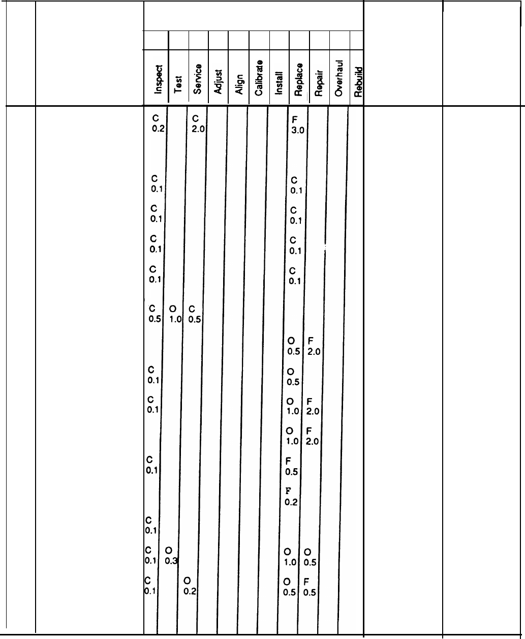
(1)
Group
no.
01
02
03
TM 9-6115-651-14&P
Section II. MAINTENANCE ALLOCATION CHART
(2)
A B C D EFGHIJK
Assembly
group
GENERATOR SET
ACCESSORIES
Sledge Hammer
Fire
Extinguisher
Slide Hammer
Ground Rods
TRAILER ASSEMBLY
Accessory Box
Fuel Can/Fire
Extinguisher Brackets
Steps/Platforms
Fenders
Reflectors
Data Plates
Leveling Jacks
Lighting
Handbrake Bracket
(3)
Maintenance functions (4)
Tools and
equipment
(5)
Remarks
See TM 5-
6115-545-12, -34
for generator set
maintenance.
See TM 9-
2330-205-14&P
for trailer
maintenance.
C-3/(C-4 blank)

TM 9-6115-651-14&P
APPENDIX D
UNIT, DIRECT SUPPORT AND GENERAL SUPPORT
AND DEPOT MAINTENANCE REPAIR PARTS
AND SPECIAL TOOLS LIST
Section I. lNTRODUCTION
D-1. Scope. This manual lists repair parts and special tools required for the performance of unit, intermediate
(field) (direct and general support) and depot maintenance of the power unit.
D-2. General. The Repair Parts and Special Tools List is divided into the following sections:
a.
Repair Parts - Section II.
A list of repair parts authorized for the performance of maintenance at the unit,
intermediate (field) (direct and general support) and depot level in figure and item number sequence.
b.
Sp
ecial Tools. Test a
nd Support
Equipment - Section ///.
A list of special tools, test and support equipment
authorized for the performance of maintenance at the unit, direct support, general
support and depot level.
c.
National Stock Number and Reference Number Index - Section IV.
A list of National stock numbers in
numerical sequence, followed by a list of reference numbers appearing in all the listings, in alphanumeric
sequence, cross-referenced to the illustration figure number and item number.
d.
Reference Desingsator Index - Sect
ion V. The reference Designator Column includes all assigned reference
designators arranged first in alphabetical order, second in numerical order. Opposite each symbol is listed the
figure and item number of the part in Section II and the reference number.
D-3. Explanation Of Columns. The following provides an explanation of columns in the tabular lists in
Sections II and Ill.
a. Illustrations. (Column 1.)
This column is divided as follows:
(1) Figure number. Indicates the figure number of the illustration on which the item is shown.
(2) Item number. Indicates the number used to identify the item on the illustration.
D-1

TM 9-6115-651-14&P
b. Source.
Maintenance, a
nd Recoverability Codes (SMR). (
Column 2).
(1) Source codes.
GENERAL: Source Codes are assigned to support items to indicate the manner of acquiring support items for
maintenance, repair, or overhaul of end items. Source codes are entered in the first and second positions of the
Uniform SMR Code format as follows:
Code Definition
PA
Item procured and stocked for anticipated or known usage.
PB
Item procured and stocked for insurance purposes because essentially
dictates that a minimum quantity be available in the supply systems.
PC
Item procured and stocked and which otherwise would be coded PA
except that it is deteriorative in nature.
PD
Support item, excluding support equipment, procured for initial issue or
outfitting and stocked only for subsequent or additional initial issues or
outfitting. Not subject to automatic replenishment.
D-2
PE
Support equipment procured and stocked for initial issue or outfitting to
specified maintenance repair activities.
PF
Support equipment which will not be stocked but which will be centrally
procured on demand.
PG
Item procured and stocked to provide for sustained support for the life
of the equipment. It is applied to an item peculiar to the equipment which
because of probable discontinuance or shutdown of production facilities
would prove uneconomical to reproduce at a later time.
KD
KF
KB
MO
An item of depot overhaul/repair kit and not purchased separately. Depot
kit defined as a kit that provides items required at the time of overhaul or
repair.
An item of maintenance kit and not purchased separate-
ly. Maintenance kit defined as a kit that provides an
item that can be replaced at unit, direct support or
general support levels of maintenance.
Item included in both a depot overhaul/repair kit and a maintenance kit.
Item to be manufactured or fabricated at unit level.
TM 9-6115-651-14&P
Code
MF
MD
AO
Definition
Item to be manufactured or fabricated at general support maintenance levels.
Item to be manufactured or fabricated at depot maintenance level.
Item to be assembled at unit level.
AF Item to be assembled at direct support maintenance level.
AH Item to be assembled at general support maintenance level.
AD Item to be assembled at depot maintenance level.
XA Item is not procured or stocked because the requirements for the item will
result in the replacement of the next higher assembly.
XB
Item is not procured or stocked. If not available through salvage, requisition.
xc
Installation drawing, diagram, instruction sheet, field service drawing, that is
identified by manufacturer’s part number.
XD
A support item that is not stocked. When required, item will be procured through
normal supply channels.
(2) Maintenance codes: GENERAL: Maintenance Codes are assigned to indicate the levels of maintenance
authorized to USE and REPAIR support items. The Maintenance Codes are in the third and fourth position of the
Uniform SMR Code Format.
(a) Use (third position): The Maintenance Code entered in the third position indicates the lowest level
maintenance level authorized to remove, replace, and use the support item. The Maintenance Code entered in
the third position indicates one of the following levels of maintenance.
Code
Application/Explanation
O
Support item is removed, replaced, used at the unit level of maintenance.
F
Support item is removed, replaced, used at direct support level.
H
Support item is removed, replaced, used general support level.
Code Definition
D
Support items that are removed, replaced, used at depot only: Depot, Mobile
Depot and Specialized Repair Activity.
D-3
TM 9-6115-651-14&P
(b) Repair (fourth position): The maintenance code entered in the fourth position indicates whether the
item is to be repaired and identifies the lowest maintenance level with the capability to perform complete repair
(i.e., all authorized maintenance functions).
Code
o
F
H
D
Code
L
Z
B
Application/Explanation
The lowest maintenance level capable of complete repair of the support item is
the unit level.
The lowest maintenance level capable of complete repair of the support item is
direct support level.
The lowest maintenance level capable of complete repair of the support item is
general support level.
Definition
The lowest maintenance level capable of complete repair of the support item is
the depot level: Depot, Mobile Depot, and Specialized Repair Activity.
Application/Explanation
Repair restricted to designated Specialized Repair Activity.
Nonreparable. No repair is authorized.
No repair is authorized. The item maybe reconditioned by adjusting, lubricating,
etc., at the user level. No parts or special tools are procured for the maintenance
of this item.
(3) Recoverability codes: GENERAL: Recoverability Codes are assigned to support items to indicate the
disposition action on unserviceable items. The recoverability code is entered in the fifth position of the uniform
SMR Code Format as follows:
Recoverability
Codes Definition
Z
Nonreparable item. When unserviceable, condemn and dispose at the level
indicated in column 3.
O
Reparable item. When uneconomically reparable, condemn and dispose at
unit level.
F
Reparable item. When uneconomically reparable, condemn and dispose at
direct support level.
H
Reparable item. When uneconomically reparable, condemn and dispose at
general support level.
D-4

Recoverability
Codes
D
L
A
TM 9-6115-651-14&P
Definition
Reparable item. When beyond lower level repair capability, return to
depot. Condemnation and disposal not authorized below depot level.
Reparable item. Repair, condemnation and disposal not authorized below
depot/Specialized Repair Activity level.
Item requires special handling or condemnation procedure because of
specific reasons (i.e., precious metal content, high-dollar value, critical
material or hazardous material). Refer to appropriate manuals/directives
for specific instructions.
c. National Stock
Number (Column 4).
Indicates the National Stock Number assigned to the item and will be
used for requisitioning purposes.
d. Description (Column 5).
Indicates the Federal item name and any additional descriptions of the item
required. The abbreviation "w/e" when used as a part of the nomenclature, indicates that the National Stock
Number includes all armament, equipment, accessories and repair parts issued with the item. A part number or
other reference number is followed by the applicable five digit Federal Supply Code for Manufacturer in
parentheses. If two reference numbers and Federal Supply Codes for Manufacturer are listed, the first listing
refers to the Department of Defense Drawing Number, the second listing refers to the actual part manufacturer.
Items that are included in kits and sets are listed below the name of the kit or set with the quantity of each item in
the kit or set indicated in the quantity incorporated in unit column.
e.
Unit of Measure (U/M) (Co
Iumn 6).
Indicates the standard of the basic quantity of the listed item as used in
performing the actual maintenance function. This measure is expressed by a two-character alphabetical
abbreviation (e.g., ea, in, pr. etc.). When the unit of measure differs from the unit of issue, the lowest unit of issue
that will satisfy the required units of measure will be requisitioned.
f. Quanity Incorpoated in Unit (Column 7).
Indicates the quantity of the item used in the assembly group. A
“V” appearing in this column in lieu of a quantity indicates that a definite quantity cannot be indicated (e.g., shims,
spacers, etc.).
D-4. Special Information.
a. Identification of Usable On Codes for this manual is not applicable.
b. Army unit maintenance personnel will extract the items which they require from Section II, 3rd or 4th
position of column 2 of the direct and general
support
RPSTL. Parts which are manufactured or assembled at a
higher level than that authorized to install the part are indicated by the use of higher level code in the source
column.
c.
Stockage In
formation.
Army stockage is demand based in accordance with AR 710-2. Repair parts listed
in this publication represent those authorized for use at indicated maintenance levels and will be requisitioned on
an as-required basis until stockage is justified in accordance with AR 710-2.
D-5

TM 9-6115-651-14&P
d. In the parts list, some items are indented to show that they area component of the item under which they
are indented.
D-5.
How to Locate Repair Parts.
a.
When National Stock Number or Refe ence Number is Unknown:
r
(1)
(2)
(3)
(4)
Using the table of contents, determine the functional group; i.e., batteries and related parts, exhaust and
breather pipes, within which the repair part belongs. This is necessary since illustrations are prepared
for functional groups.
Find the illustration covering the functional group to which the repair part belongs.
Identify the repair part on the illustration and note the illustration figure and item number of the repair
part.
Using the Repair Parts Listing, find the figure and item number noted on the illustration.
b. When National St
ock Number or Reference Number is Known:
(1)
(2)
Using the Index of National Stock Numbers and Reference Numbers, find the pertinent national stock
number or reference number. This index is in ascending NSN sequence followed by a list of reference
numbers in alphanumeric sequence, cross-referenced to the illustration figure number and item number.
After finding the figure and item number, locate the figure and item number in the repair parts list.
D-6.
Use of the Reference Designator Index Section.
This Section (Section V) is used when the
reference designator is known or identified by other technical manuals supporting this equipment. The reference
number is given in this section. If description or location is desired, note the figure and item number. Turn to
Section II to the noted figure and item number. The location of the part and description is given in this listing.
D-7.
Abbreviations.
Abbreviations
D-8.
Federal Supply Codes for
Code
Explanation
Not Applicable
Manufacturers.
Manufacturer
Not Applicable
D-9.
Recommendation for Maintenance Publication Improvements.
Report of errors,
omissions, and recommendations for improving this publication by the individual user is encouraged. Reports
should be submitted directly to: Commander, US Army Troop Support Command, ATTN: AMSTR-MCTS, 4300
Goodfellow Boulevard, St. Louis, MO 63120-1798.
D-6
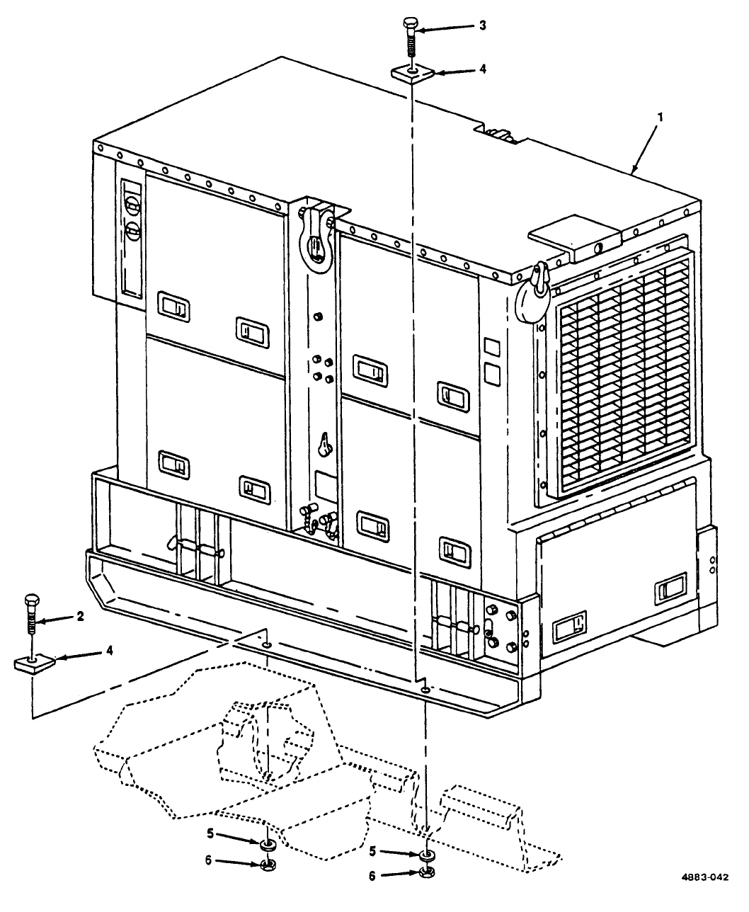
TM 9-6115-651-14&P
Figure D-1. Generator Set.
(D-7
blank)/D-8
TM9-6115-651-14&P
(1) (2) (3) (4) (5) (6) (7) (8)
ILLUS- SMR CODE USMC DESCRIPTION
TRATION QTY USMC
ABAB C D A BNATIONAL USABLE INC QTY
FIG ITEM AIR REPL STOCK REF NUMBER ON IN PER
NO. NO. ARMY FORCE NAVY USMC SSI FACTOR NUMBER & MFR CODE CODE U/M UNIT EQUIP
GROUP 01 - GENERATOR
D-1 16115-00-118-1253 GENERATOR SET,DIESEL EA 1
MEP-115A 97403
D-1 2PAFZZ 5305-00-724-7224 SCREW,CAP,HEX EA 6
MS90728-166 96906
D-1 3PAFZZ 5305-00-724-7222 SCREW,CAP,HEX EA 2
MS90728-164 97403
D-1 4PAFZZ 5310-01-185-0586 WASHER,BEVELED EA 8
13206E4482-3 97403
D-1 5PAFZZ 5310-00-823-8803 WASHER,FLAT EA 8
MS27183-21 96906
D-1 6PAFZZ 5310-00-269-4040 NUT,SELF-LOCKING EA 8
MS51922-49 96906
D-9
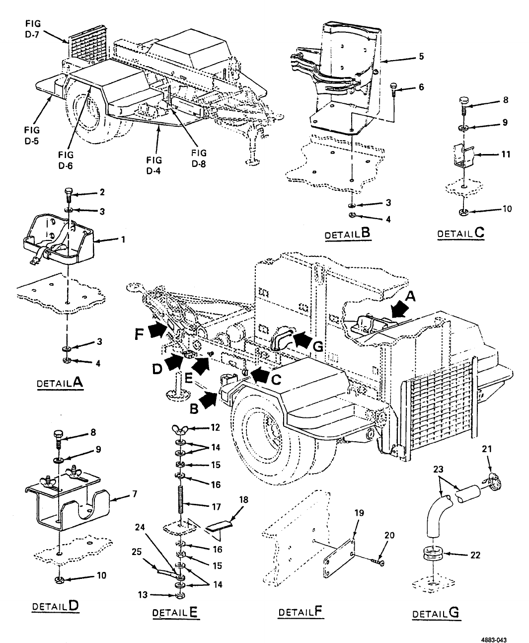
TM 9-6115-651-14&P
Figure D-2. Trailer Body.
D-10
TM9-6115-651-14&P
(1) (2) (3) (4) (5) (6) (7) (8)
ILLUS- SMR CODE USMC DESCRIPTION
TRATION QTY USMC
A B A B C D A B NATIONAL USABLE INC QTY
FIG ITEM AIR REPL STOCK REF NUMBER ON IN PER
NO. NO. ARMY FORCE NAVY USMC SSI FACTOR NUMBER & MFR CODE CODE U/M UNIT EQUIP
GROUP 03 - TRAILER
03-BODY
D-2 1 XBOZZ BRACKET ASSEMBLY,LIQUID CONTAINER EA 2
MS53052-1 96906
D-2 2 PAOZZ 5305-00-269-3210 SCREW,CAP,HEZ EA 8
MS90725-62 96906
D-2 3 PAOZZ 5310-00-080-6004 WASHER,FLAT EA 20
MS27183-14 96906
D-2 4 PAOZZ 5310-00-087-4652 NUT,SELF-LOCKING EA 12
MS51922-17 96906
D-2 5 PAOZZ 4210-00-223-4857 BRACKET,FIRE EXTINGUISHER EA 1
13214E1235 97403
D-2 6 PAOZZ 5305-00-984-5691 SCREW,MACHINE EA 4
MS35206-311 96906
D-2 7 PAOZZ 5340-00-999-6277 BRACKET ASSEMBLY EA 1
13214E1214 97403
D-2 8 PAOZZ 5305-00-068-0502 SCREW,CAP,HEX EA 3
MS90725-6 96906
D-2 9 PAOZZ 5310-00-809-4058 WASHER,FLAT EA 3
MS27183-10 96906
D-2 10 PAOZZ 5310-00-088-1251 NUT,SELF-LOCKING EA 3
MS51922-1 96906
D-2 11 PAOZZ 5304-00-914-2578 CLIP,SPRING EA 1
13214E1213-1 97403
D-2 12 PAOZZ 5310-00-543-4717 NUT,PLAIN,WING EA 1
MS35435-28 96906
D-2 13 PAOZZ 5310-00-584-7995 NUT,PLAIN,HEX EA 1
MS16203-27 96906
D-2 14 PAOZZ 5310-00-004-9129 WASHER,FLAT EA 4
AN961-616S 81352
PAOZZ 5310-00-187-2413 WASHER,FLAT EA 4
AN961-616T 81352
D-2 15 PAOZZ 5310-00-026-5824 NUT,PLAIN,HEX EA 2
MS16203-39 96906
D-2 16 PAOZZ 5310-00-022-8847 LOCKWASHER EA 2
MS35333-110 96906
D-2 17 PAOZZ 5307-00-227-1741 STUD EA 1
13214E1223 97403
D-2 18 MDFZZ 9905-01-085-7703 PLATE,IDENTIFICATION EA 1
13205E4918 97403
D-2 19 MDFZZ PLATE,IDENTIFICATION EA 1
13216E7604-39 97403
D-2 20 PAOZZ 5305-00-253-5616 SCREW,DRIVE EA 4
MS21318-21 96906
D-11
TM9-6115-651-14&P
(1) (2) (3) (4) (5) (6) (7) (8)
ILLUS- SMR CODE USMC DESCRIPTION
TRATION QTY USMC
ABAB C D A BNATIONAL USABLE INC QTY
FIG ITEM AIR REPL STOCK REF NUMBER ON IN PER
NO. NO. ARMY FORCE NAVY USMC SSI FACTOR NUMBER & MFR CODE CODE U/M UNIT EQUIP
GROUP 03- TRAILER
03-BODY (CONT)
D-2 21 PAOZZ 4730-00-908-3193 CLAMP,HOSE EA 1
MS35842-12 96906
D-2 22 PAOZZ 5325-00-290-1960 GROMMET EA 1
MS35489-27 96906
D-2 23 MHOZZ HOSE EA 1
ZZ-H-428 81348
D-2 24 PAOZZ 5940-00-115-4992 TERMINAL,LUG EA 2
MS20659-110 96906
D-2 25 PAOZZ 6145-00-395-8799 WIRE,NO.6AWG FT AR
QQ-W-343 81348
D-12
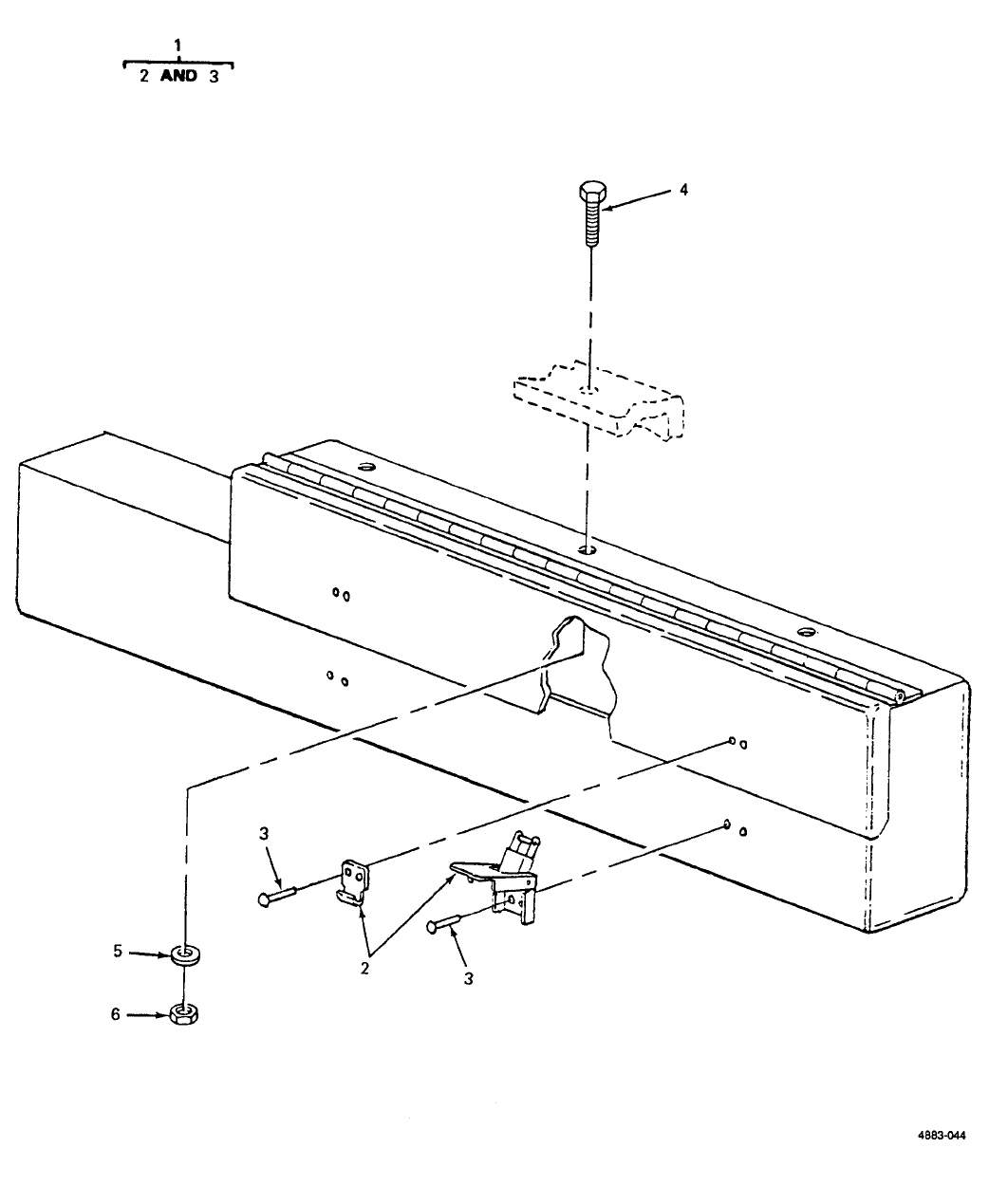
TM 9-6115-651-14&P
Figure D-3. Accessory Box.
(D-13 blank)/D-14
TM9-6115-651-14&P
(1) (2) (3) (4) (5) (6) (7) (8)
ILLUS- SMR CODE USMC DESCRIPTION
TRATION QTY USMC
ABAB C D A BNATIONAL USABLE INC QTY
FIG ITEM AIR REPL STOCK REF NUMBER ON IN PER
NO. NO. ARMY FORCE NAVY USMC SSI FACTOR NUMBER & MFR CODE CODE U/M UNIT EQUIP
D-3 1XBOFF 2450-00-903-3503 ACCESSORY BOX EA 1
13214E1256 97403
D-3 2PAFZZ 5340-00-975-2126 CATCH,CLAMPING AND STRIKE EA 2
ASSEMBLY
MS18015-1 96906
D-3 3PAFZZ 5320-00-753-3830 RIVET EA 8
MS20613-4P5 96906
D-3 4PAOZZ 5306-00-225-8498 SCREW,CAP,HEX EA 3
MS90725-33 96906
D-3 5PAOZZ 5310-00-087-7493 WASHER,FLAT EA 3
MS27183-13 96906
D-3 6PAOZZ 5310-00-985-3806 NUT,SELF-LOCKING EA 3
MS51922-9 96906
D-15
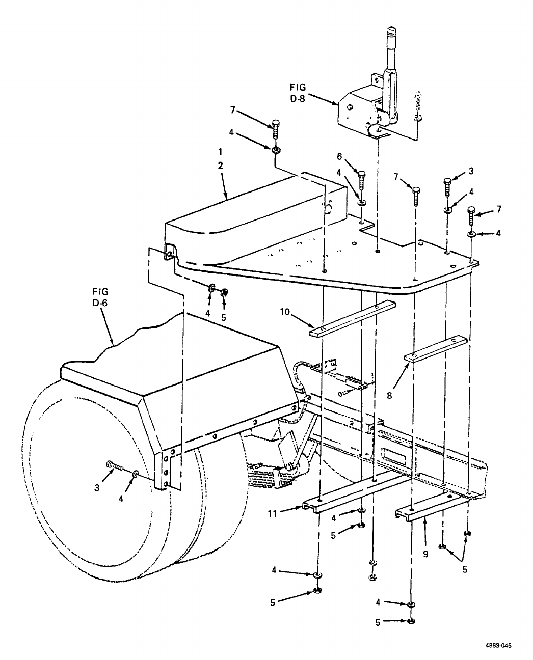
FIG D-6
FIG D-8
TM 9-6115-651-14&P
Figure D-4. Front Steps.
D-16
TM9-6115-651-14&P
(1) (2) (3) (4) (5) (6) (7) (8)
ILLUS- SMR CODE USMC DESCRIPTION
TRATION QTY USMC
ABAB C D A BNATIONAL USABLE INC QTY
FIG ITEM AIR REPL STOCK REF NUMBER ON IN PER
NO. NO. ARMY FORCE NAVY USMC SSI FACTOR NUMBER & MFR CODE CODE U/M UNIT EQUIP
03-FRONT STEPS
D-4 1XBOFF 2330-01-150-9864 STEP,FRONT,CURBSIDE EA 1
13214E1461 97403
D-4 2XBOFF 2510-00-196-4682 STEP,FRONT,ROADSIDE EA 1
13214E1462 97403
D-4 3PAOZZ 5306-00-225-8499 SCREW,CAP,HEX EA 18
MS90725-34 96906
D-4 4PAOZZ 5310-00-081-4219 WASHER,FLAT EA 60
MS27183-12 96906
D-4 5PAOZZ 5310-00-984-3806 NUT,SELF-LOCKING EA 30
MS51922-9 96906
D-4 6PAOZZ 5305-00-225-9081 SCREW,CAP,HEX EA 2
MS90725-36 96906
D-4 7PAOZZ 5306-00-225-8503 SCREW,CAP,HEX EA 10
MS90725-39 96906
D-4 8XBOZZ 5365-00-944-2692 SPACER EA 2
13214E1267-1 97403
D-4 9XBOZZ CHANNEL EA 1
13214E1268 97403
D-4 10 XBOZZ 5365-00-945-5998 SPACER EA 2
13214E1267-2 97403
D-4 11 XBOZZ CHANNEL EA 1
13214E1463 97403
D-17
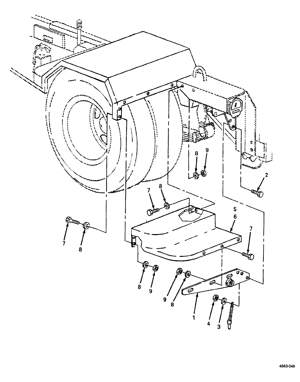
TM 9-6115-651-14&P
Figure D-5. Rear Steps.
D-18
TM9-6115-651-14&P
(1) (2) (3) (4) (5) (6) (7) (8)
ILLUS- SMR CODE USMC DESCRIPTION
TRATION QTY USMC
ABAB C D A BNATIONAL USABLE INC QTY
FIG ITEM AIR REPL STOCK REF NUMBER ON IN PER
NO. NO. ARMY FORCE NAVY USMC SSI FACTOR NUMBER & MFR CODE CODE U/M UNIT EQUIP
03-REAR STEPS
D-5 1XBOFF 5340-01-875-8820 BRACKET,STEP,REAR EA 2
13214E1309-1 97403
D-5 2PAOZZ 5305-00-269-3213 SCREW,CAP,HEX EA 6
MS90725-62 96906
D-5 3PAOZZ 5310-00-080-6004 WASHER,FLAT EA 6
MS27183-14 96906
D-5 4PAOZZ 5310-00-087-4652 NUT,SELF-LOCKING EA 6
MS51922-17 96906
D-5 5XBOFF 2510-01-N73-0729 STEP,REAR,ROADSIDE EA 1
13214E1261 97403
D-5 6XBOFF 2510-01-N73-0794 STEP,REAR,CURBSIDE EA 1
13214E1259 97403
D-5 7PAOZZ 5306-00-225-8499 SCREW,CAP,HEX EA 20
MS90725-34 96906
D-5 8PAOZZ 5310-00-081-4219 WASHER,FLAT EA 40
MS27183-12 96906
D-5 9PAOZZ 5310-00-984-3806 NUT,SELF-LOCKING EA 20
MS51922-9 96906
D-19
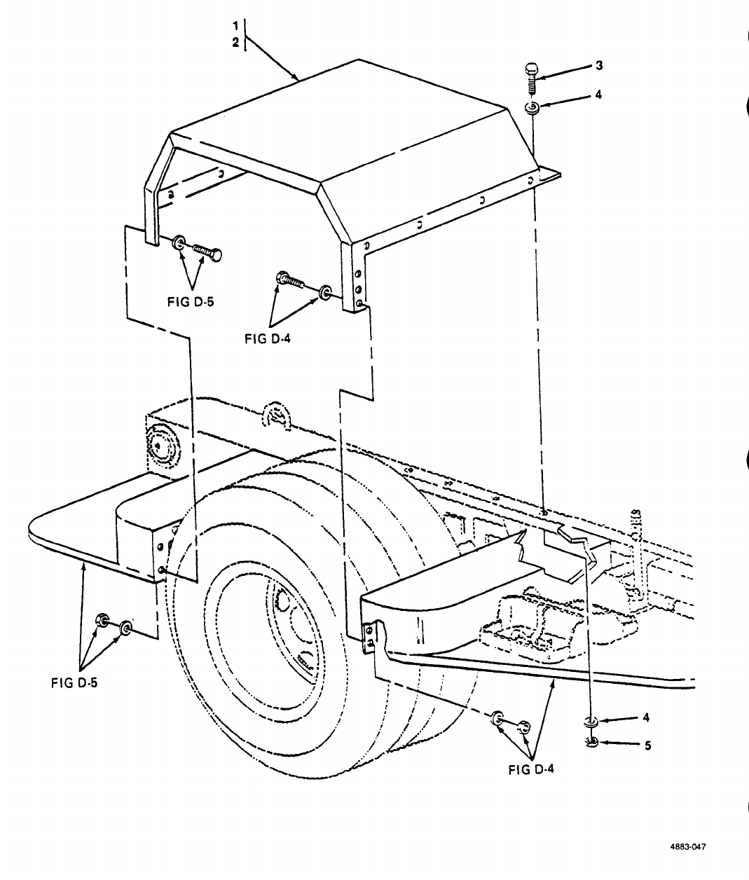
FIG D-5
FIG D-4
FIG D-5
FIG D-4
TM 9-6115-651-14&P
Figure D-6. Fenders.
D-20
TM9-6115-651-14&P
(1) (2) (3) (4) (5) (6) (7) (8)
ILLUS- SMR CODE USMC DESCRIPTION
TRATION QTY USMC
ABAB C D A BNATIONAL USABLE INC QTY
FIG ITEM AIR REPL STOCK REF NUMBER ON IN PER
NO. NO. ARMY FORCE NAVY USMC SSI FACTOR NUMBER & MFR CODE CODE U/M UNIT EQUIP
GROUP 03-FENDERS
D-6 1XBOFF 2510-01-213-3242 FENDER,ROADSIDE EA 1
13214E1264 97403
D-6 2XBOZZ 2510-01-195-4273 FENDER,CURBSIDE EA 1
13214E1263 97403
D-6 3PAOZZ 5306-00-225-8500 SCREW,CAP,HEX EA 10
MS90725-35 96906
D-6 4PAOZZ 5310-00-081-4219 WASHER,FLAT EA 20
MS27183-12 96906
D-6 5PAOZZ 5310-00-984-3806 NUT,SELF-LOCKING EA 10
MS51922-9 96906
D-21
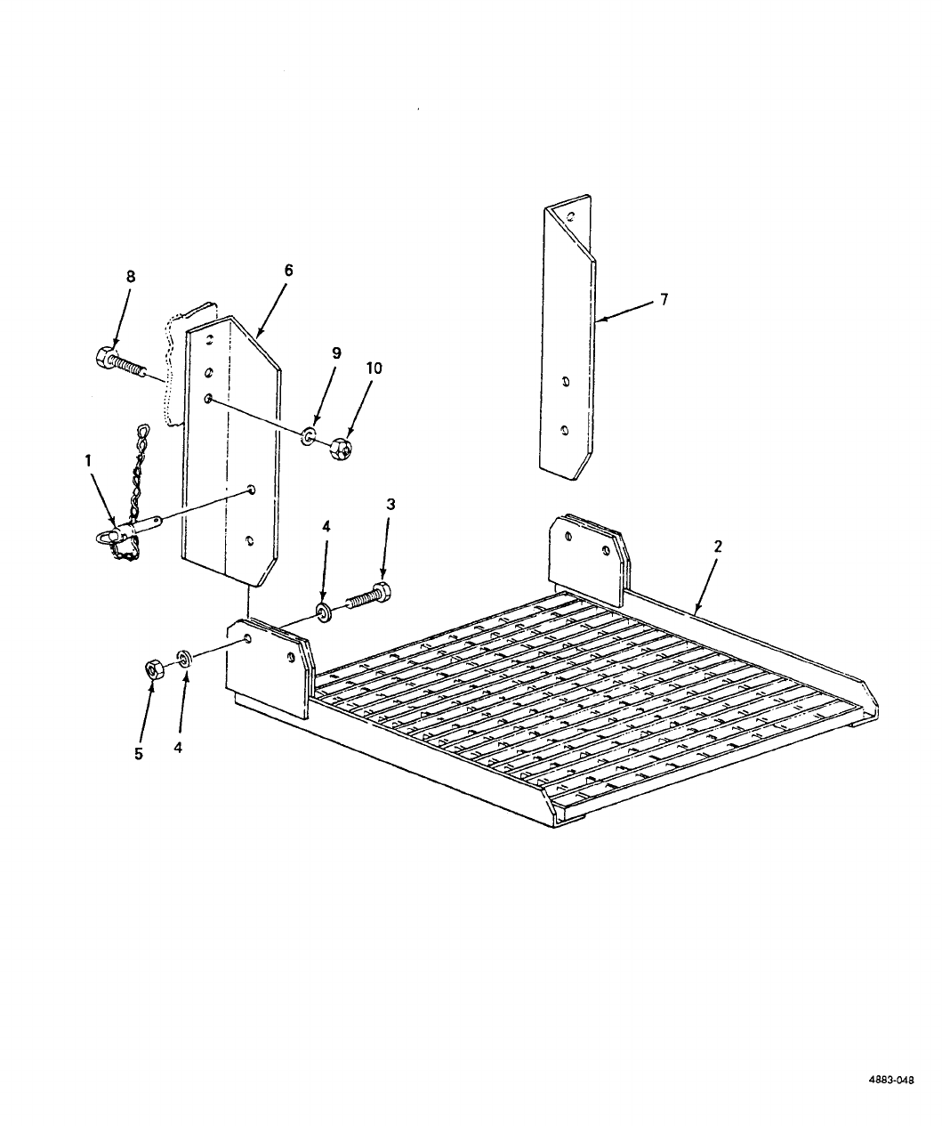
TM 9-6115-651-14&P
Figure D-7. Personnel Platform.
D-22
TM9-6115-651-14&P
(1) (2) (3) (4) (5) (6) (7) (8)
ILLUS- SMR CODE USMC DESCRIPTION
TRATION QTY USMC
ABAB C D A BNATIONAL USABLE INC QTY
FIG ITEM AIR REPL STOCK REF NUMBER ON IN PER
NO. NO. ARMY FORCE NAVY USMC SSI FACTOR NUMBER & MFR CODE CODE U/M UNIT EQUIP
03-PERSONNEL PLATFORM
D-7 1PAOZZ 5340-01-156-6142 ANCHOR,PLATFORM EA 2
13214E1303 97403
D-7 2XBOFF 2510-00-926-3517 PLATFORM,PERSONNEL EA 1
13214E1298 97403
D-7 3PAOZZ 5305-00-939-9204 SCREW,CAP,HEX EA 2
MS90725-187 96906
D-7 4PAOZZ 5310-00-809-8533 WASHER,FLAT EA 4
MS27183-23 96906
D-7 5PAOZZ 5310-00-067-6356 NUT,SELF-LOCKING EA 2
MS51922-57 96906
D-7 6XBOFF 5340-00-087-7676 BRACKET,LEFT EA 1
13214E1299 97403
D-7 7XBOFF 5340-00-999-6441 BRACKET,RIGHT EA 1
13214E1300 97403
D-7 8PAOZZ 5305-00-042-6417 SCREW,CAP,HEX EA 6
MS90725-113 96906
D-7 9PAOZZ 5310-00-809-5998 WASHER,FLAT EA 6
MS27183-18 96906
D-7 10 PAOZZ 5310-00-225-6993 NUT,SELF-LOCKING EA 6
MS51922-33 96906
D-23
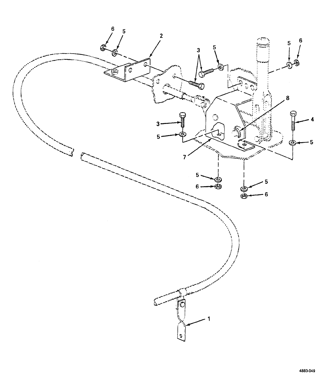
TM 9-6115-651-14&P
Figure D-8. Handbrakes.
D-24
TM9-6115-651-14&P
(1) (2) (3) (4) (5) (6) (7) (8)
ILLUS- SMR CODE USMC DESCRIPTION
TRATION QTY USMC
ABAB C D A BNATIONAL USABLE INC QTY
FIG ITEM AIR REPL STOCK REF NUMBER ON IN PER
NO. NO. ARMY FORCE NAVY USMC SSI FACTOR NUMBER & MFR CODE CODE U/M UNIT EQUIP
03-HANDBRAKES
D-8 1XBOZZ 6115-01-876-2084 STRAP,BRAKE CABLE EA 2
13214E1271 97403
D-8 2PAOZZ BRACKET,BRAKE CABLE EA 2
13214E1270 97403
D-8 3PAOZZ 5306-00-225-8499 SCREW,CAP,HEX EA 10
MS90725-34 96906
D-8 4PAOZZ SCREW,CAP,HEX EA 2
MS90725-39 96906
D-8 5PAOZZ 5310-00-081-4219 WASHER,FLAT EA 20
MS27183-12 96906
D-8 6PAOZZ 5310-00-984-3806 NUT,SELF-LOCKING EA 12
MS51922-9 96906
D-8 7XBOZZ 5340-01-226-5766 BRACKET,BRAKE EA 2
13214E1269 97403
D-8 8XDOZZ 5365-00-989-3304 SPACER EA 4
13214E1272 97403
D-25
TM9-6115-651-14&P
SECTION III. SPECIAL TOOLS, TEST AND SUPPORT EQUIPMENT
SECTION IV NATIONAL STOCK NUMBER AND PART NUMBER INDEX
NSN FIG ITEM NSN FIG ITEM
NO NO NO NO
2330-01-150-9864 D-4 1 5310-00-081-4219 D-8 5
2510-00-196-4682 D-4 2 5310-00-087-4652 D-2 4
2510-00-926-3517 D-7 2 D-5 4
2510-01-N73-0729 D-5 5 5310-00-087-7493 D-3 5
2510-01-N73-0794 D-5 6 5310-00-088-1251 D-2 10
2510-01-195-4273 D-6 2 5310-00-187-2413 D-2 14
2510-01-213-3242 D-6 1 5310-00-225-6993 D-7 10
4210-00-223-4857 D-2 5 5310-00-269-4040 D-1 6
4730-00-908-3193 D-2 21 5310-00-543-4717 D-2 12
5304-00-914-2578 D-2 11 5310-00-584-7995 D-2 13
5305-00-042-6417 D-7 8 5310-00-809-4058 D-2 9
5305-00-068-0502 D-2 8 5310-00-809-5998 D-7 9
5305-00-225-9081 D-4 6 5310-00-809-8533 D-7 4
5350-00-253-5616 D-2 20 5310-00-823-8803 D-1 5
5305-00-269-3210 D-2 2 5310-00-985-3806 D-3 6
D-5 2 D-4 5
5305-00-724-7222 D-1 3 D-5 9
5305-00-724-7224 D-1 2 D-6 5
5305-00-939-9204 D-7 3 D-8 6
5305-00-984-5691 D-2 6 5310-01-185-0586 D-1 4
5306-00-225-8498 D-3 4 5320-00-753-3830 D-3 3
5306-00-225-8499 D-4 3 5325-00-290-1960 D-2 22
D-5 7 5340-00-087-7676 D-7 6
D-8 3 5340-00-975-2126 D-3 2
5306-00-225-8500 D-6 3 5340-00-999-6277 D-2 7
5306-00-225-8503 D-4 7 5340-00-999-6441 D-7 7
D-8 4 5340-01-156-6142 D-7 1
5307-00-227-1741 D-2 17 5340-01-226-5766 D-8 7
5310-00-004-9129 D-2 14 5340-01-875-8820 D-5 1
5310-00-022-8847 D-2 16 5365-00-944-2692 D-4 8
5310-00-026-5824 D-2 15 5365-00-945-5998 D-4 10
5310-00-067-6356 D-7 5 5365-00-989-3304 D-8 8
5310-00-080-6004 D-2 3 5940-00-115-4992 D-2 24
D-5 3 6115-00-118-1253 D-1 1
5310-00-081-4219 D-4 4 6115-01-876-2084 D-8 1
D-5 8 6145-00-395-8799 D-2 25
D-6 4 9905-01-085-7703 D-2 18
D-26

TM9-6115-651-14&P
SECTION IV. NATIONAL STOCK NUMBER AND REFERENCE NUMBER INDEX (CONT)
REFERENCE FIG. ITEM REFERENCE FIG. ITEM
NUMBER FSCM NO. NO. NUMBER FSCM NO. NO.
AN961-616S 81352 D-2 14 MS90725-34 96906 D-4 3
AN961-616T 81352 D-2 14 D-5 7
MEP-115A 97403 D-1 1 D-8 3
QQ-W-343 81348 D-2 25 MS90725-35 96906 D-6 3
ZZ-H-428 81348 D-2 23 MS90725-36 96906 D-4 6
MS16203-27 96906 D-2 13 MS90725-39 96906 D-4 7
MS16203-39 96906 D-2 15 D-8 4
MS20613-4P5 96906 D-3 3 MS90725-6 96906 D-2 8
MS20659-110 96906 D-2 24 MS90725-62 96906 D-2 2
MS21318-21 96906 D-2 20 D-5 2
MS27183-10 96906 D-2 9 MS90728-164 96906 D-1 3
MS27183-12 96906 D-4 4 MS90728-166 96906 D-1 2
D-5 8 MA8015-1 96906 D-3 2
D-6 4 13206E4482-3 97403 D-1 4
D-8 5 13214E1213-1 97403 D-2 11
MS27183-13 96906 D-3 5 13214E1214 97403 D-2 7
MS27183-14 96906 D-2 3 13214E1223 97403 D-2 17
D-5 3 13214E1235 97403 D-2 5
MS27183-18 96906 D-7 13214E1256 97403 D-3 1
MS27183-21 96906 D-1 5 13214E1259 97403 D-5 6
MS27183-23 96906 D-7 4 13214E1261 97403 D-5 5
MS35206-311 96906 D-2 6 13214E1263 97403 D-6 2
MS35333-110 96906 D-2 16 13214E1264 97403 D-6 1
MS35435-28 96906 D-2 12 13214E1267-1 97403 D-4 8
MS35489-27 96906 D-2 22 13214E1267-2 97403 D-4 10
MS35842-12 96906 D-2 21 13214E1268 97403 D-4 9
MS51922-1 96906 D-2 10 13214E1269 97403 D-8 7
MS51922-17 96906 D-2 4 13214E1270 97403 D-8 2
D-5 4 13214E1271 97403 D-8 1
MS51922-33 96906 D-7 10 13214E1272 97403 D-8 8
MS51922-49 96906 D-1 6 13214E1298 97403 D-7 2
MS51922-57 96906 D-7 5 13214E1299 97403 D-7 6
MS51922-9 96906 D-3 6 13214E1300 97403 D-7 7
D-4 5 13214E1303 97403 D-7 1
D-5 9 13214E1309-1 97403 D-5 1
D-6 5 13214E1461 97403 D-4 1
D-8 6 13214E1462 97403 D-4 2
MS53052-1 96906 D-2 1 13214E1463 97403 D-4 11
MS90725-113 96906 D-7 8 13216E7604-39 97403 D-2 19
MS90725-187 96906 D-7 3 13205E4913 97403 D-2 18
MS90725-33 96906 D-3 4
D-27
TM9-6115-651-14&P
SECTION V. REFERENCE DESIGNATOR INDEX
NOT APPLICABLE
D-28
TM 9-6115-651-14&P
CARL E. VUONO
General, United States Army
Chief of Staff
By Order of the Secretary of the Army:
Official:
WILLIAM J. MEEHAN, II
Brigadier General, United States Army
The Adjutant General
DISTRIBUTION:
To be distributed in accordance with DA Form 12-25A, Operator, Unit, Direct Sup-
port and General Support Maintenance requirements for Generator Set, Diesel Engine
Driven, Trailer Mounted.
* U.S. GOVERNMENT PRINTING OFFICE: 1990 – 754 - 029/ 20108
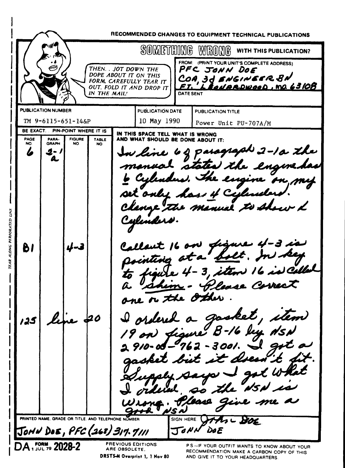
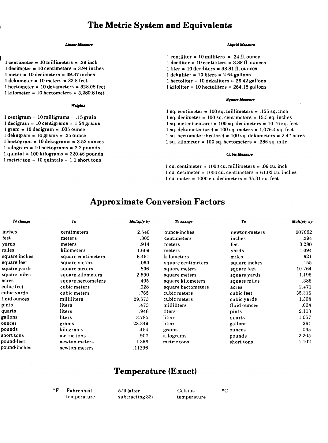
PIN 067746-000
