TMS320C28x Extended Instruction Sets (Rev. A) Technical Reference Manual
User Manual:
Open the PDF directly: View PDF ![]() .
.
Page Count: 404 [warning: Documents this large are best viewed by clicking the View PDF Link!]
- Table of Contents
- Preface
- 1 Floating Point Unit (FPU)
- 2 C28 Viterbi, Complex Math and CRC Unit-II (VCU-II)
- 3 Trigonometric Math Unit (TMU)
- Revision History
- Important Notice

TMS320C28x Extended Instruction Sets
Technical Reference Manual
Literature Number: SPRUHS1A
March 2014–Revised December 2015

Contents
Preface ........................................................................................................................................ 5
1 Floating Point Unit (FPU) ...................................................................................................... 9
1.1 Overview..................................................................................................................... 10
1.1.1 Compatibility with the C28x Fixed-Point CPU ................................................................. 10
1.2 Components of the C28x plus Floating-Point CPU .................................................................... 11
1.2.1 Emulation Logic.................................................................................................... 12
1.2.2 Memory Map ....................................................................................................... 12
1.2.3 On-Chip Program and Data...................................................................................... 12
1.2.4 CPU Interrupt Vectors ............................................................................................ 12
1.2.5 Memory Interface.................................................................................................. 12
1.3 CPU Register Set .......................................................................................................... 13
1.3.1 CPU Registers..................................................................................................... 13
1.4 Pipeline ...................................................................................................................... 19
1.4.1 Pipeline Overview ................................................................................................. 19
1.4.2 General Guidelines for Floating-Point Pipeline Alignment .................................................. 20
1.4.3 Moves from FPU Registers to C28x Registers................................................................ 20
1.4.4 Moves from C28x Registers to FPU Registers................................................................ 21
1.4.5 Parallel Instructions ............................................................................................... 21
1.4.6 Invalid Delay Instructions......................................................................................... 22
1.4.7 Optimizing the Pipeline ........................................................................................... 25
1.5 Floating Point Unit Instruction Set ....................................................................................... 26
1.5.1 Instruction Descriptions........................................................................................... 26
1.5.2 Instructions ......................................................................................................... 29
2 C28 Viterbi, Complex Math and CRC Unit-II (VCU-II) ............................................................. 140
2.1 Overview ................................................................................................................... 141
2.2 Components of the C28x Plus VCU.................................................................................... 142
2.2.1 Emulation Logic .................................................................................................. 144
2.2.2 Memory Map ..................................................................................................... 144
2.2.3 CPU Interrupt Vectors........................................................................................... 144
2.2.4 Memory Interface ................................................................................................ 144
2.2.5 Address and Data Buses ....................................................................................... 144
2.2.6 Alignment of 32-Bit Accesses to Even Addresses .......................................................... 145
2.3 Register Set ............................................................................................................... 146
2.3.1 VCU Register Set................................................................................................ 147
2.3.2 VCU Status Register (VSTATUS) ............................................................................. 149
2.3.3 Repeat Block Register (RB) .................................................................................... 152
2.4 Pipeline..................................................................................................................... 154
2.4.1 Pipeline Overview................................................................................................ 154
2.4.2 General Guidelines for VCU Pipeline Alignment ............................................................ 154
2.4.3 Parallel Instructions.............................................................................................. 155
2.4.4 Invalid Delay Instructions ....................................................................................... 156
2.5 Instruction Set ............................................................................................................. 159
2.5.1 Instruction Descriptions ......................................................................................... 159
2.5.2 General Instructions ............................................................................................. 161
2.5.3 Arithmetic Math Instructions.................................................................................... 205
2Contents SPRUHS1A–March 2014–Revised December 2015
Submit Documentation Feedback
Copyright © 2014–2015, Texas Instruments Incorporated

www.ti.com
2.5.4 Complex Math Instructions ..................................................................................... 212
2.5.5 Cyclic Redundancy Check (CRC) Instructions............................................................... 271
2.5.6 Deinterleaver Instructions....................................................................................... 287
2.5.7 FFT Instructions.................................................................................................. 303
2.5.8 Galois Instructions ............................................................................................... 331
2.5.9 Viterbi Instructions ............................................................................................... 344
2.6 Rounding Mode ........................................................................................................... 379
3 Trigonometric Math Unit (TMU)........................................................................................... 381
3.1 Overview ................................................................................................................... 382
3.2 Components of the C28x+FPU Plus TMU............................................................................. 382
3.2.1 Interrupt Context Save and Restore........................................................................... 382
3.3 Data Format ............................................................................................................... 382
3.4 Pipeline..................................................................................................................... 383
3.4.1 Pipeline and Register Conflicts ................................................................................ 383
3.4.2 Delay Slot Requirements ....................................................................................... 385
3.4.3 Effect of Delay Slot Operations on the Flags ................................................................ 386
3.4.4 Multi-Cycle Operations in Delay Slots......................................................................... 386
3.4.5 Moves From FPU Registers to C28x Registers ............................................................. 386
3.5 TMU Instruction Set ...................................................................................................... 388
3.5.1 Instruction Descriptions ......................................................................................... 388
3.5.2 Common Restrictions ........................................................................................... 389
3.5.3 Instructions ....................................................................................................... 389
Revision History ........................................................................................................................ 403
3
SPRUHS1A–March 2014–Revised December 2015 Contents
Submit Documentation Feedback Copyright © 2014–2015, Texas Instruments Incorporated

www.ti.com
List of Figures
1-1. FPU Functional Block Diagram........................................................................................... 10
1-2. C28x With Floating-Point Registers...................................................................................... 14
1-3. Floating-point Unit Status Register (STF)............................................................................... 16
1-4. Repeat Block Register (RB) .............................................................................................. 18
1-5. FPU Pipeline ................................................................................................................ 19
2-1. C28x + VCU Block Diagram............................................................................................. 142
2-2. C28x + FPU + VCU Registers .......................................................................................... 146
2-3. VCU Status Register (VSTATUS) ...................................................................................... 149
2-4. Repeat Block Register (RB) ............................................................................................. 152
2-5. C28x + FCU + VCU Pipeline ............................................................................................ 154
List of Tables
1-1. 28x Plus Floating-Point CPU Register Summary ...................................................................... 15
1-2. Floating-point Unit Status (STF) Register Field Descriptions ........................................................ 16
1-3. Repeat Block (RB) Register Field Descriptions ........................................................................ 18
1-4. Operand Nomenclature.................................................................................................... 27
1-5. Summary of Instructions................................................................................................... 29
2-1. Viterbi Decode Performance ............................................................................................ 141
2-2. Complex Math Performance............................................................................................. 141
2-3. VCU Register Set......................................................................................................... 147
2-4. 28x CPU Register Summary ............................................................................................ 148
2-5. VCU Status (VSTATUS) Register Field Descriptions................................................................ 149
2-6. Operation Interaction With VSTATUS Bits ............................................................................ 150
2-7. Repeat Block (RB) Register Field Descriptions....................................................................... 152
2-8. Operations Requiring a Delay Slot(s) .................................................................................. 155
2-9. Operand Nomenclature .................................................................................................. 159
2-10. INSTRUCTION dest, source1, source2 Short Description .......................................................... 160
2-11. General Instructions ...................................................................................................... 161
2-12. Arithmetic Math Instructions............................................................................................. 205
2-13. Complex Math Instructions .............................................................................................. 212
2-14. CRC Instructions.......................................................................................................... 271
2-15. Deinterleaver Instructions................................................................................................ 287
2-16. FFT Instructions........................................................................................................... 303
2-17. Galois Field Instructions ................................................................................................. 331
2-18. Viterbi Instructions ........................................................................................................ 344
2-19. Example: Values Before Shift Right.................................................................................... 379
2-20. Example: Values after Shift Right ...................................................................................... 379
2-21. Example: Addition with Right Shift and Rounding.................................................................... 379
2-22. Example: Addition with Rounding After Shift Right................................................................... 379
2-23. Shift Right Operation With and Without Rounding ................................................................... 380
3-1. TMU Supported Instructions............................................................................................. 382
3-2. IEEE 32-Bit Single Precision Floating-Point Format ................................................................. 382
3-3. Delay Slot Requirements for TMU Instructions ....................................................................... 385
3-4. Operand Nomenclature .................................................................................................. 388
3-5. Summary of Instructions ................................................................................................. 389
4List of Figures SPRUHS1A–March 2014–Revised December 2015
Submit Documentation Feedback
Copyright © 2014–2015, Texas Instruments Incorporated

Preface
SPRUHS1A–March 2014–Revised December 2015
Read This First
This document describes the architecture, pipeline, and instruction sets of the TMU, VCU-II, and FPU
accelerators.
About This Manual
The TMS320C2000™ digital signal processor (DSP) platform is part of the TMS320™ DSP family.
Notational Conventions
This document uses the following conventions.
• Hexadecimal numbers are shown with the suffix h or with a leading 0x. For example, the following
number is 40 hexadecimal (decimal 64): 40h or 0x40.
• Registers in this document are shown as figures and described in tables.
– Each register figure shows a rectangle divided into fields that represent the fields of the register.
Each field is labeled with its bit name, its beginning and ending bit numbers above, and its
read/write properties below. A legend explains the notation used for the properties
– Reserved bits in a register figure designate a bit that is used for future device expansion.
Related Documentation
The following books describe the TMS320x28x and related support tools that are available on the TI
website:
Data Manual and Errata—
SPRS439— TMS320F28335, TMS320F28334, TMS320F28332, TMS320F28235, TMS320F28234,
TMS320F28232 Digital Signal Controllers (DSCs) Data Manual contains the pinout, signal
descriptions, as well as electrical and timing specifications for the F2833x/2823x devices.
SPRZ272— TMS320F28335, F28334, F28332, TMS320F28235, F28234, F28232 Digital Signal
Controllers (DSCs) Silicon Errata describes the advisories and usage notes for different versions of
silicon.
CPU User's Guides—
SPRU430 — TMS320C28x CPU and Instruction Set Reference Guide describes the central processing
unit (CPU) and the assembly language instructions of the TMS320C28x fixed-point digital signal
processors (DSPs). It also describes emulation features available on these DSPs.
SPRUEO2 — TMS320C28x Floating Point Unit and Instruction Set Reference Guide describes the
floating-point unit and includes the instructions for the FPU.
Peripheral Guides—
SPRU566 — TMS320x28xx, 28xxx DSP Peripheral Reference Guide describes the peripheral
reference guides of the 28x digital signal processors (DSPs).
SPRUFB0 — TMS320x2833x, 2823x System Control and Interrupts Reference Guide describes the
various interrupts and system control features of the 2833x and 2823x digital signal controllers
(DSCs).
SPRU812 — TMS320x2833x, 2823x Analog-to-Digital Converter (ADC) Reference Guide describes
how to configure and use the on-chip ADC module, which is a 12-bit pipelined ADC.
SPRU949 — TMS320x2833x, 2823x DSC External Interface (XINTF) Reference Guide describes the
XINTF, which is a nonmultiplexed asynchronous bus, as it is used on the 2833x and 2823x devices.
5
SPRUHS1A–March 2014–Revised December 2015 Read This First
Submit Documentation Feedback Copyright © 2014–2015, Texas Instruments Incorporated

Related Documentation
www.ti.com
SPRU963 — TMS320x2833x, 2823x Boot ROM Reference Guide describes the purpose and features of
the bootloader (factory-programmed boot-loading software) and provides examples of code. It also
describes other contents of the device on-chip boot ROM and identifies where all of the information
is located within that memory.
SPRUFB7 — TMS320x2833x, 2823x Multichannel Buffered Serial Port (McBSP) Reference Guide
describes the McBSP available on the 2833x and 2823x devices. The McBSPs allow direct
interface between a DSP and other devices in a system.
SPRUFB8 — TMS320x2833x, 2823x Direct Memory Access (DMA) Module Reference Guide
describes the DMA on the 2833x and 2823x devices.
SPRUG04 — TMS320x2833x, 2823x Enhanced Pulse Width Modulator (ePWM) Module Reference
Guide describes the main areas of the enhanced pulse width modulator that include digital motor
control, switch mode power supply control, UPS (uninterruptible power supplies), and other forms of
power conversion.
SPRUG02 — TMS320x2833x, 2823x High-Resolution Pulse Width Modulator (HRPWM) Reference
Guide describes the operation of the high-resolution extension to the pulse width modulator
(HRPWM).
SPRUFG4 — TMS320x2833x, 2823x Enhanced Capture (eCAP) Module Reference Guide describes
the enhanced capture module. It includes the module description and registers.
SPRUG05 — TMS320x2833x, 2823x Enhanced Quadrature Encoder Pulse (eQEP) Module
Reference Guide describes the eQEP module, which is used for interfacing with a linear or rotary
incremental encoder to get position, direction, and speed information from a rotating machine in
high-performance motion and position control systems. It includes the module description and
registers.
SPRUEU1 — TMS320x2833x, 2823x Enhanced Controller Area Network (eCAN) Reference Guide
describes the eCAN that uses established protocol to communicate serially with other controllers in
electrically noisy environments.
SPRUFZ5 — TMS320x2833x, 2823x Serial Communications Interface (SCI) Reference Guide
describes the SCI, which is a two-wire asynchronous serial port, commonly known as a UART. The
SCI modules support digital communications between the CPU and other asynchronous peripherals
that use the standard non-return-to-zero (NRZ) format.
SPRUEU3 — TMS320x2833x, 2823x DSC Serial Peripheral Interface (SPI) Reference Guide
describes the SPI - a high-speed synchronous serial input/output (I/O) port - that allows a serial bit
stream of programmed length (one to sixteen bits) to be shifted into and out of the device at a
programmed bit-transfer rate.
SPRUG03 — TMS320x2833x, 2823x Inter-Integrated Circuit (I2C) Module Reference Guide describes
the features and operation of the inter-integrated circuit (I2C) module.
Tools Guides—
SPRU513 — TMS320C28x Assembly Language Tools v5.0.0 User's Guide describes the assembly
language tools (assembler and other tools used to develop assembly language code), assembler
directives, macros, common object file format, and symbolic debugging directives for the
TMS320C28x device.
SPRU514 — TMS320C28x Optimizing C/C++ Compiler v5.0.0 User's Guide describes the
TMS320C28x™ C/C++ compiler. This compiler accepts ANSI standard C/C++ source code and
produces TMS320 DSP assembly language source code for the TMS320C28x device.
SPRU608 — TMS320C28x Instruction Set Simulator Technical Overview describes the simulator,
available within the Code Composer Studio for TMS320C2000 IDE, that simulates the instruction
set of the C28x™ core.
SPRU625 — TMS320C28x DSP/BIOS 5.32 Application Programming Interface (API) Reference
Guide describes development using DSP/BIOS.
6Read This First SPRUHS1A–March 2014–Revised December 2015
Submit Documentation Feedback
Copyright © 2014–2015, Texas Instruments Incorporated


Chapter 1
SPRUHS1A–March 2014–Revised December 2015
Floating Point Unit (FPU)
The TMS320C2000™ DSP family consists of fixed-point and floating-point digital signal controllers
(DSCs). TMS320C2000™ Digital Signal Controllers combine control peripheral integration and ease of
use of a microcontroller (MCU) with the processing power and C efficiency of TI’s leading DSP
technology. This chapter provides an overview of the architectural structure and components of the C28x
plus floating-point unit CPU.
Topic ........................................................................................................................... Page
1.1 Overview........................................................................................................... 10
1.2 Components of the C28x plus Floating-Point CPU ................................................. 11
1.3 CPU Register Set ............................................................................................... 13
1.4 Pipeline............................................................................................................. 19
1.5 Floating Point Unit Instruction Set........................................................................ 26
9
SPRUHS1A–March 2014–Revised December 2015 Floating Point Unit (FPU)
Submit Documentation Feedback Copyright © 2014–2015, Texas Instruments Incorporated
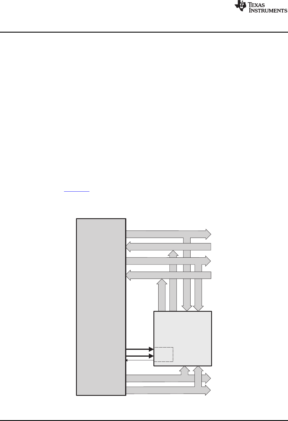
Programaddressbus(22)
Programdatabus(32)
Readaddressbus(32)
Readdatabus(32)
Writedatabus(32)
Existing
memory,
peripherals,
interfaces
PIE
Writeaddressbus(32)
LVF
LUF
C28x
+
FPU
Memory
bus
Memory
bus
Overview
www.ti.com
1.1 Overview
The C28x plus floating-point (C28x+FPU) processor extends the capabilities of the C28x fixed-point CPU
by adding registers and instructions to support IEEE single-precision floating point operations. This device
draws from the best features of digital signal processing; reduced instruction set computing (RISC); and
microcontroller architectures, firmware, and tool sets. The DSC features include a modified Harvard
architecture and circular addressing. The RISC features are single-cycle instruction execution, register-to-
register operations, and modified Harvard architecture (usable in Von Neumann mode). The
microcontroller features include ease of use through an intuitive instruction set, byte packing and
unpacking, and bit manipulation. The modified Harvard architecture of the CPU enables instruction and
data fetches to be performed in parallel. The CPU can read instructions and data while it writes data
simultaneously to maintain the single-cycle instruction operation across the pipeline. The CPU does this
over six separate address/data buses.
Throughout this document the following notations are used:
• C28x refers to the C28x fixed-point CPU.
• C28x plus Floating-Point and C28x+FPU both refer to the C28x CPU with enhancements to support
IEEE single-precision floating-point operations.
1.1.1 Compatibility with the C28x Fixed-Point CPU
No changes have been made to the C28x base set of instructions, pipeline, or memory bus architecture.
Therefore, programs written for the C28x CPU are completely compatible with the C28x+FPU and all of
the features of the C28x documented in TMS320C28x DSP CPU and Instruction Set Reference Guide
(literature number SPRU430) apply to the C28x+FPU.
Figure 1-1 shows basic functions of the FPU.
Figure 1-1. FPU Functional Block Diagram
10 Floating Point Unit (FPU) SPRUHS1A–March 2014–Revised December 2015
Submit Documentation Feedback
Copyright © 2014–2015, Texas Instruments Incorporated

www.ti.com
Components of the C28x plus Floating-Point CPU
1.1.1.1 Floating-Point Code Development
When developing C28x floating-point code use Code Composer Studio 3.3, or later, with at least service
release 8. The C28x compiler V5.0, or later, is also required to generate C28x native floating-point
opcodes. This compiler is available via Code Composer Studio update advisor as a seperate download.
V5.0 can generate both fixed-point as well as floating-point code. To build floating-point code use the
compiler switches:-v28 and - -float_support = fpu32. In Code Composer Studio 3.3 the float_support
option is in the build options under compiler-> advanced: floating point support. Without the float_support
flag, or with float_support = none, the compiler will generate fixed-point code.
When building for C28x floating-point make sure all associated libraries have also been built for floating-
point. The standard run-time support (RTS) libaries built for floating-point included with the compiler have
fpu32 in their name. For example rts2800_fpu32.lib and rts2800_fpu_eh.lib have been built for the floating-
point unit. The "eh" version has exception handling for C++ code. Using the fixed-point RTS libraries in a
floating-point project will result in the linker issuing an error for incompatible object files.
To improve performance of native floating-point projects, consider using the C28x FPU Fast RTS Library
(SPRC664). This library contains hand-coded optimized math routines such as division, square root,
atan2, sin and cos. This library can be linked into your project before the standard runtime support library
to give your application a performance boost. As an example, the standard RTS library uses a polynomial
expansion to calculate the sin function. The Fast RTS library, however, uses a math look-up table in the
boot ROM of the device. Using this look-up table method results in approximately a 20 cycle savings over
the standard RTS calculation.
1.2 Components of the C28x plus Floating-Point CPU
The C28x+FPU contains:
• A central processing unit for generating data and program-memory addresses; decoding and executing
instructions; performing arithmetic, logical, and shift operations; and controlling data transfers among
CPU registers, data memory, and program memory
• A floating-point unit for IEEE single-precision floating point operations.
• Emulation logic for monitoring and controlling various parts and functions of the device and for testing
device operation. This logic is identical to that on the C28x fixed-point CPU.
• Signals for interfacing with memory and peripherals, clocking and controlling the CPU and the
emulation logic, showing the status of the CPU and the emulation logic, and using interrupts. This logic
is identical to the C28x fixed-point CPU.
Some features of the C28x+FPU central processing unit are:
• Fixed-Point instructions are pipeline protected. This pipeline for fixed-point instructions is identical to
that on the C28x fixed-point CPU. The CPU implements an 8-phase pipeline that prevents a write to
and a read from the same location from occurring out of order. See Figure 1-5.
• Some floating-point instructions require pipeline alignment. This alignment is done through software to
allow the user to improve performance by taking advantage of required delay slots.
• Independent register space. These registers function as system-control registers, math registers, and
data pointers. The system-control registers are accessed by special instructions.
• Arithmetic logic unit (ALU). The 32-bit ALU performs 2s-complement arithmetic and Boolean logic
operations.
• Floating point unit (FPU). The 32-bit FPU performs IEEE single-precision floating-point operations.
• Address register arithmetic unit (ARAU). The ARAU generates data memory addresses and
increments or decrements pointers in parallel with ALU operations.
• Barrel shifter. This shifter performs all left and right shifts of fixed-point data. It can shift data to the left
by up to 16 bits and to the right by up to 16 bits.
• Fixed-Point Multiplier. The multiplier performs 32-bit × 32-bit 2s-complement multiplication with a 64-bit
result. The multiplication can be performed with two signed numbers, two unsigned numbers, or one
signed number and one unsigned number.
11
SPRUHS1A–March 2014–Revised December 2015 Floating Point Unit (FPU)
Submit Documentation Feedback Copyright © 2014–2015, Texas Instruments Incorporated

Components of the C28x plus Floating-Point CPU
www.ti.com
1.2.1 Emulation Logic
The emulation logic is identical to that on the C28x fixed-point CPU. This logic includes the following
features:
• Debug-and-test direct memory access (DT-DMA). A debug host can gain direct access to the content
of registers and memory by taking control of the memory interface during unused cycles of the
instruction pipeline.
• A counter for performance benchmarking.
• Multiple debug events. Any of the following debug events can cause a break in program execution:
– A breakpoint initiated by the ESTOP0 or ESTOP1 instruction.
– An access to a specified program-space or data-space location.
When a debug event causes the C28x to enter the debug-halt state, the event is called a break event.
• Real-time mode of operation.
For more details about these features, refer to the TMS320C28x DSP CPU and Instruction Set Reference
Guide (literature number SPRU430.
1.2.2 Memory Map
Like the C28x, the C28x+FPU uses 32-bit data addresses and 22-bit program addresses. This allows for a
total address reach of 4G words (1 word = 16 bits) in data space and 4M words in program space.
Memory blocks on all C28x+FPU designs are uniformly mapped to both program and data space. For
specific details about each of the map segments, see the data sheet for your device.
1.2.3 On-Chip Program and Data
All C28x+FPU based devices contain at least two blocks of single access on-chip memory referred to as
M0 and M1. Each of these blocks is 1K words in size. M0 is mapped at addresses 0x0000 −0x03FF and
M1 is mapped at addresses 0x0400 −0x07FF. Like all other memory blocks on the C28x+FPU devices,
M0 and M1 are mapped to both program and data space. Therefore, you can use M0 and M1 to execute
code or for data variables. At reset, the stack pointer is set to the top of block M1. Depending on the
device, it may also have additional random-access memory (RAM), read-only memory (ROM), external
interface zones, or flash memory.
1.2.4 CPU Interrupt Vectors
The C28x+FPU interrupt vectors are identical to those on the C28x CPU. Sixty-four addresses in program
space are set aside for a table of 32 CPU interrupt vectors. The CPU vectors can be mapped to the top or
bottom of program space by way of the VMAP bit. For more information about the CPU vectors, see
TMS320C28x DSP CPU and Instruction Set Reference Guide (literature number SPRU430). For devices
with a peripheral interrupt expansion (PIE) block, the interrupt vectors will reside in the PIE vector table
and this memory can be used as program memory.
1.2.5 Memory Interface
The C28x+FPU memory interface is identical to that on the C28x. The C28x+FPU memory map is
accessible outside the CPU by the memory interface, which connects the CPU logic to memories,
peripherals, or other interfaces. The memory interface includes separate buses for program space and
data space. This means an instruction can be fetched from program memory while data memory is being
accessed. The interface also includes signals that indicate the type of read or write being requested by the
CPU. These signals can select a specified memory block or peripheral for a given bus transaction. In
addition to 16-bit and 32-bit accesses, the C28x+FPU supports special byte-access instructions that can
access the least significant byte (LSByte) or most significant byte (MSByte) of an addressed word. Strobe
signals indicate when such an access is occurring on a data bus.
1.2.5.1 Address and Data Buses
Like the C28x, the memory interface has three address buses:
•PAB: Program address bus
12 Floating Point Unit (FPU) SPRUHS1A–March 2014–Revised December 2015
Submit Documentation Feedback
Copyright © 2014–2015, Texas Instruments Incorporated

www.ti.com
CPU Register Set
The PAB carries addresses for reads and writes from program space. PAB is a 22-bit bus.
•DRAB: Data-read address bus
The 32-bit DRAB carries addresses for reads from data space.
•DWAB: Data-write address bus
The 32-bit DWAB carries addresses for writes to data space.
The memory interface also has three data buses:
•PRDB: Program-read data bus
The PRDB carries instructions during reads from program space. PRDB is a 32-bit bus.
•DRDB: Data-read data bus
The DRDB carries data during reads from data space. DRDB is a 32-bit bus.
•DWDB: Data-/Program-write data bus
The 32-bit DWDB carries data during writes to data space or program space.
A program-space read and a program-space write cannot happen simultaneously because both use the
PAB. Similarly, a program-space write and a data-space write cannot happen simultaneously because
both use the DWDB. Transactions that use different buses can happen simultaneously. For example, the
CPU can read from program space (using PAB and PRDB), read from data space (using DRAB and
DRDB), and write to data space (using DWAB and DWDB) at the same time. This behavior is identical to
the C28x CPU.
1.2.5.2 Alignment of 32-Bit Accesses to Even Addresses
The C28x+FPU CPU expects memory wrappers or peripheral-interface logic to align any 32-bit read or
write to an even address. If the address-generation logic generates an odd address, the CPU will begin
reading or writing at the previous even address. This alignment does not affect the address values
generated by the address-generation logic.
Most instruction fetches from program space are performed as 32-bit read operations and are aligned
accordingly. However, alignment of instruction fetches are effectively invisible to a programmer. When
instructions are stored to program space, they do not have to be aligned to even addresses. Instruction
boundaries are decoded within the CPU.
You need to be concerned with alignment when using instructions that perform 32-bit reads from or writes
to data space.
1.3 CPU Register Set
The C28x+FPU architecture is the same as the C28x CPU with an extended register and instruction set to
support IEEE single-precision floating point operations. This section describes the extensions to the C28x
architecture
1.3.1 CPU Registers
Devices with the C28x+FPU include the standard C28x register set plus an additional set of floating-point
unit registers. The additional floating-point unit registers are the following:
• Eight floating-point result registers, RnH (where n = 0 - 7)
• Floating-point Status Register (STF)
• Repeat Block Register (RB)
All of the floating-point registers except the repeat block register are shadowed. This shadowing can be
used in high priority interrupts for fast context save and restore of the floating-point registers.
Figure 1-2 shows a diagram of both register sets and Table 1-1 shows a register summary. For
information on the standard C28x register set, see the TMS320C28x DSP CPU and Instruction Set
Reference Guide (literature number SPRU430).
13
SPRUHS1A–March 2014–Revised December 2015 Floating Point Unit (FPU)
Submit Documentation Feedback Copyright © 2014–2015, Texas Instruments Incorporated
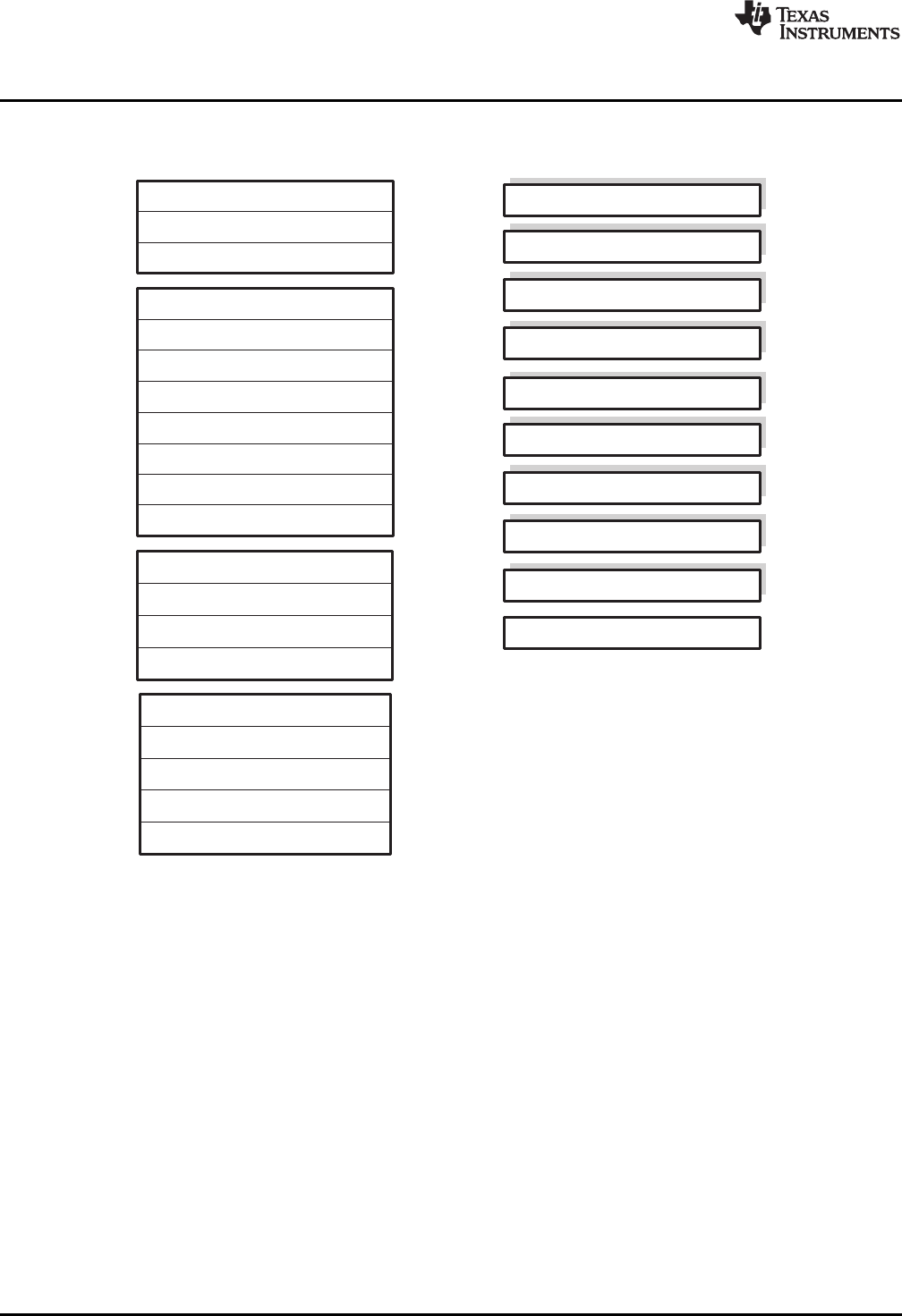
ACC(32-bit)
R1H(32-bit)
R2H(32-bit)
R3H(32-bit)
R4H(32-bit)
R5H(32-bit)
R6H(32-bit)
R7H(32-bit)
R0H(32-bit)
FPUStatusRegister(STF)
RepeatBlockRegister(RB)
P (32-bit)
XT (32-bit)
XAR0(32-bit)
XAR1(32-bit)
XAR2(32-bit)
XAR3(32-bit)
XAR4(32-bit)
XAR5(32-bit)
XAR6(32-bit)
XAR7(32-bit)
PC(22-bit)
RPC(22-bit)
DP (16-bit)
SP (16-bit)
ST0(16-bit)
ST1(16-bit)
IER(16-bit)
IFR(16-bit)
DBGIER(16-bit)
StandardC28xRegisterSet Additional32-bitFPURegisters
FPUregistersR0H-R7HandSTF
areshadowedforfastcontext
saveandrestore
CPU Register Set
www.ti.com
Figure 1-2. C28x With Floating-Point Registers
14 Floating Point Unit (FPU) SPRUHS1A–March 2014–Revised December 2015
Submit Documentation Feedback
Copyright © 2014–2015, Texas Instruments Incorporated

www.ti.com
CPU Register Set
Table 1-1. 28x Plus Floating-Point CPU Register Summary
Register C28x CPU C28x+FPU Size Description Value After Reset
ACC Yes Yes 32 bits Accumulator 0x00000000
AH Yes Yes 16 bits High half of ACC 0x0000
AL Yes Yes 16 bits Low half of ACC 0x0000
XAR0 Yes Yes 32 bits Auxiliary register 0 0x00000000
XAR1 Yes Yes 32 bits Auxiliary register 1 0x00000000
XAR2 Yes Yes 32 bits Auxiliary register 2 0x00000000
XAR3 Yes Yes 32 bits Auxiliary register 3 0x00000000
XAR4 Yes Yes 32 bits Auxiliary register 4 0x00000000
XAR5 Yes Yes 32 bits Auxiliary register 5 0x00000000
XAR6 Yes Yes 32 bits Auxiliary register 6 0x00000000
XAR7 Yes Yes 32 bits Auxiliary register 7 0x00000000
AR0 Yes Yes 16 bits Low half of XAR0 0x0000
AR1 Yes Yes 16 bits Low half of XAR1 0x0000
AR2 Yes Yes 16 bits Low half of XAR2 0x0000
AR3 Yes Yes 16 bits Low half of XAR3 0x0000
AR4 Yes Yes 16 bits Low half of XAR4 0x0000
AR5 Yes Yes 16 bits Low half of XAR5 0x0000
AR6 Yes Yes 16 bits Low half of XAR6 0x0000
AR7 Yes Yes 16 bits Low half of XAR7 0x0000
DP Yes Yes 16 bits Data-page pointer 0x0000
IFR Yes Yes 16 bits Interrupt flag register 0x0000
IER Yes Yes 16 bits Interrupt enable register 0x0000
DBGIER Yes Yes 16 bits Debug interrupt enable register 0x0000
P Yes Yes 32 bits Product register 0x00000000
PH Yes Yes 16 bits High half of P 0x0000
PL Yes Yes 16 bits Low half of P 0x0000
PC Yes Yes 22 bits Program counter 0x3FFFC0
RPC Yes Yes 22 bits Return program counter 0x00000000
SP Yes Yes 16 bits Stack pointer 0x0400
ST0 Yes Yes 16 bits Status register 0 0x0000
ST1 Yes Yes 16 bits Status register 1 0x080B(1)
XT Yes Yes 32 bits Multiplicand register 0x00000000
T Yes Yes 16 bits High half of XT 0x0000
TL Yes Yes 16 bits Low half of XT 0x0000
ROH No Yes 32 bits Floating-point result register 0 0.0
R1H No Yes 32 bits Floating-point result register 1 0.0
R2H No Yes 32 bits Floating-point result register 2 0.0
R3H No Yes 32 bits Floating-point result register 3 0.0
R4H No Yes 32 bits Floating-point result register 4 0.0
R5H No Yes 32 bits Floating-point result register 5 0.0
R6H No Yes 32 bits Floating-point result register 6 0.0
R7H No Yes 32 bits Floating-point result register 7 0.0
STF No Yes 32 bits Floating-point status register 0x00000000
RB No Yes 32 bits Repeat block register 0x00000000
(1) Reset value shown is for devices without the VMAP signal and MOM1MAP signal pinned out. On these devices both of these signals are
tied high internal to the device.
15
SPRUHS1A–March 2014–Revised December 2015 Floating Point Unit (FPU)
Submit Documentation Feedback Copyright © 2014–2015, Texas Instruments Incorporated
CPU Register Set
www.ti.com
1.3.1.1 Floating-Point Status Register (STF)
The floating-point status register (STF) reflects the results of floating-point operations. There are three
basic rules for floating point operation flags:
1. Zero and negative flags are set based on moves to registers.
2. Zero and negative flags are set based on the result of compare, minimum, maximum, negative and
absolute value operations.
3. Overflow and underflow flags are set by math instructions such as multiply, add, subtract and 1/x.
These flags may also be connected to the peripheral interrupt expansion (PIE) block on your device.
This can be useful for debugging underflow and overflow conditions within an application.
As on the C28x, program flow is controlled by C28x instructions that read status flags in the status register
0 (ST0) . If a decision needs to be made based on a floating-point operation, the information in the STF
register needs to be loaded into ST0 flags (Z,N,OV,TC,C) so that the appropriate branch conditional
instruction can be executed. The MOVST0 FLAGinstruction is used to load the current value of specified
STF flags into the respective bits of ST0. When this instruction executes, it will also clear the latched
overflow and underflow flags if those flags are specified.
Example 1-1. Moving STF Flags to the ST0 Register
Loop:
MOV32 R0H,*XAR4++
MOV32 R1H,*XAR3++
CMPF32 R1H, R0H
MOVST0 ZF, NF ; Move ZF and NF to ST0
BF Loop, GT ; Loop if (R1H > R0H)
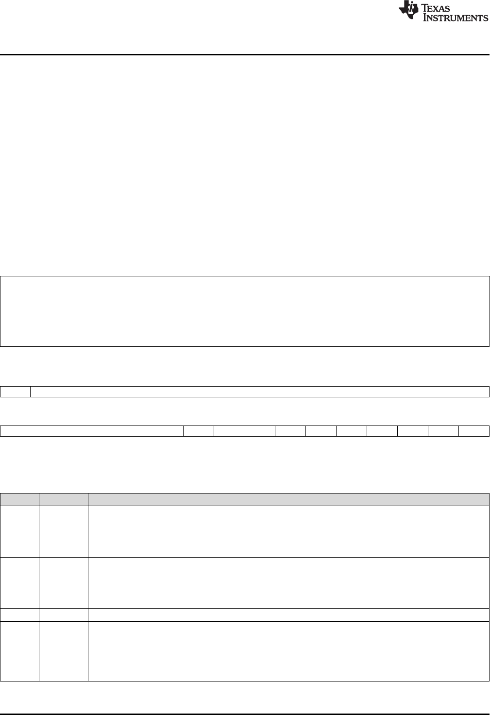
Figure 1-3. Floating-point Unit Status Register (STF)
31 30 16
SHDWS Reserved
R/W-0 R-0
15 109876543210
Reserved RND32 Reserved TF ZI NI ZF NF LUF LVF
R-0 R/W-0 R-0 R/W-0 R/W-0 R/W-0 R/W-0 R/W-0 R/W-0 R/W-0
LEGEND: R/W = Read/Write; R = Read only; -n= value after reset
Table 1-2. Floating-point Unit Status (STF) Register Field Descriptions
Bits Field Value Description
31 SHDWS Shadow Mode Status Bit
0 This bit is forced to 0 by the RESTORE instruction.
1 This bit is set to 1 by the SAVE instruction.
This bit is not affected by loading the status register either from memory or from the shadow values.
30 - 10 Reserved 0 Reserved for future use
9 RND32 Round 32-bit Floating-Point Mode
0 If this bit is zero, the MPYF32, ADDF32 and SUBF32 instructions will round to zero (truncate).
1 If this bit is one, the MPYF32, ADDF32 and SUBF32 instructions will round to the nearest even value.
8 - 7 Reserved 0 Reserved for future use
6 TF Test Flag
The TESTTF instruction can modify this flag based on the condition tested. The SETFLG and SAVE
instructions can also be used to modify this flag.
0 The condition tested with the TESTTF instruction is false.
1 The condition tested with the TESTTF instruction is true.
16 Floating Point Unit (FPU) SPRUHS1A–March 2014–Revised December 2015
Submit Documentation Feedback
Copyright © 2014–2015, Texas Instruments Incorporated

www.ti.com
CPU Register Set
Table 1-2. Floating-point Unit Status (STF) Register Field Descriptions (continued)
Bits Field Value Description
5 ZI Zero Integer Flag
The following instructions modify this flag based on the integer value stored in the destination register:
MOV32, MOVD32, MOVDD32
The SETFLG and SAVE instructions can also be used to modify this flag.
0 The integer value is not zero.
1 The integer value is zero.
4 NI Negative Integer Flag
The following instructions modify this flag based on the integer value stored in the destination register:
MOV32, MOVD32, MOVDD32
The SETFLG and SAVE instructions can also be used to modify this flag.
0 The integer value is not negative.
1 The integer value is negative.
3 ZF Zero Floating-Point Flag (1) (2)
The following instructions modify this flag based on the floating-point value stored in the destination
register:
MOV32, MOVD32, MOVDD32, ABSF32, NEGF32
The CMPF32, MAXF32, and MINF32 instructions modify this flag based on the result of the operation.
The SETFLG and SAVE instructions can also be used to modify this flag
0 The floating-point value is not zero.
1 The floating-point value is zero.
2 NF Negative Floating-Point Flag (1) (2)
The following instructions modify this flag based on the floating-point value stored in the destination
register:
MOV32, MOVD32, MOVDD32, ABSF32, NEGF32
The CMPF32, MAXF32, and MINF32 instructions modify this flag based on the result of the operation.
The SETFLG and SAVE instructions can also be used to modify this flag.
0 The floating-point value is not negative.
1 The floating-point value is negative.
1 LUF Latched Underflow Floating-Point Flag
The following instructions will set this flag to 1 if an underflow occurs:
MPYF32, ADDF32, SUBF32, MACF32, EINVF32, EISQRTF32
0 An underflow condition has not been latched. If the MOVST0 instruction is used to copy this bit to ST0,
then LUF will be cleared.
1 An underflow condition has been latched.
0 LVF Latched Overflow Floating-Point Flag
The following instructions will set this flag to 1 if an overflow occurs:
MPYF32, ADDF32, SUBF32, MACF32, EINVF32, EISQRTF32
0 An overflow condition has not been latched. If the MOVST0 instruction is used to copy this bit to ST0,
then LVF will be cleared.
1 An overflow condition has been latched.
(1) A negative zero floating-point value is treated as a positive zero value when configuring the ZF and NF flags.
(2) A DeNorm floating-point value is treated as a positive zero value when configuring the ZF and NF flags.
17
SPRUHS1A–March 2014–Revised December 2015 Floating Point Unit (FPU)
Submit Documentation Feedback Copyright © 2014–2015, Texas Instruments Incorporated
CPU Register Set
www.ti.com
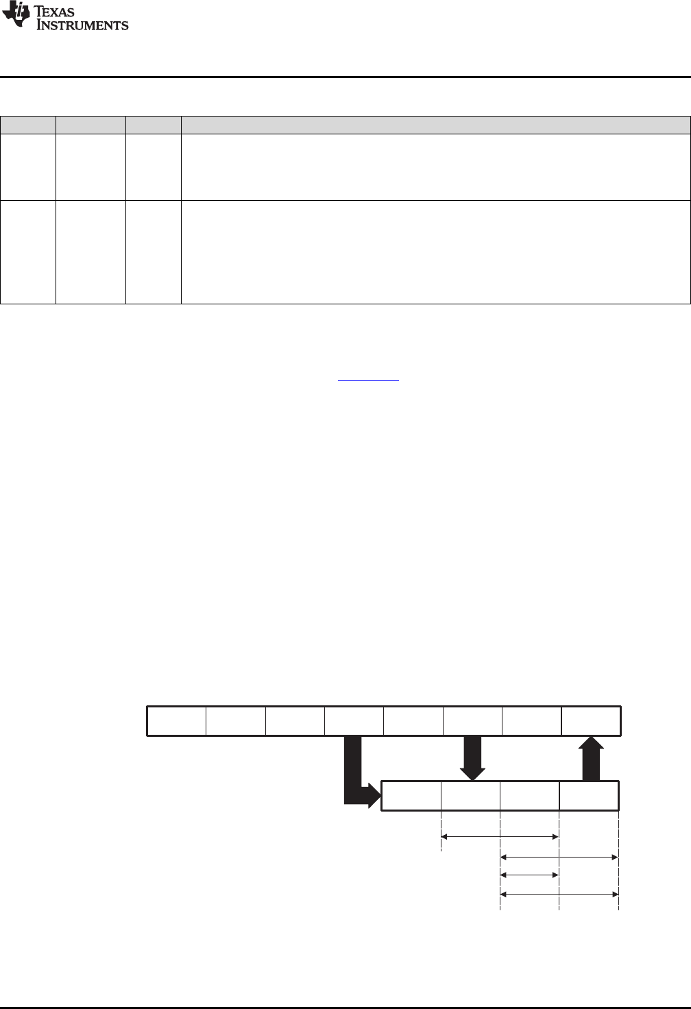
1.3.1.2 Repeat Block Register (RB)
The repeat block instruction (RPTB) is a new instruction for C28x+FPU. This instruction allows you to
repeat a block of code as shown in Example 1-2.
Example 1-2. The Repeat Block (RPTB) Instruction uses the RB Register
; find the largest element and put its address in XAR6
MOV32 R0H, *XAR0++;
.align 2 ; Aligns the next instruction to an even address
NOP ; Makes RPTB odd aligned - required for a block size of 8
RPTB VECTOR_MAX_END, AR7 ; RA is set to 1
MOVL ACC,XAR0
MOV32 R1H,*XAR0++ ; RSIZE reflects the size of the RPTB block
MAXF32 R0H,R1H ; in this case the block size is 8
MOVST0 NF,ZF
MOVL XAR6,ACC,LT
VECTOR_MAX_END: ; RE indicates the end address. RA is cleared
The C28x_FPU hardware automatically populates the RB register based on the execution of a RPTB
instruction. This register is not normally read by the application and does not accept debugger writes.
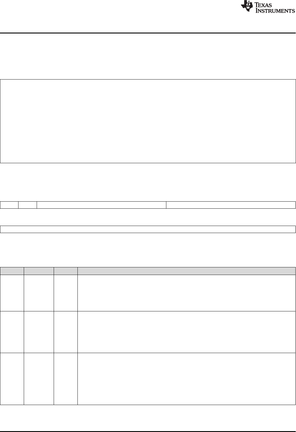
Figure 1-4. Repeat Block Register (RB)
31 30 29 23 22 16
RAS RA RSIZE RE
R-0 R-0 R-0 R-0
15 0
RC
R-0
LEGEND: R = Read only; -n= value after reset
Table 1-3. Repeat Block (RB) Register Field Descriptions
Bits Field Value Description
31 RAS Repeat Block Active Shadow Bit
When an interrupt occurs the repeat active, RA, bit is copied to the RAS bit and the RA bit is cleared.
When an interrupt return instruction occurs, the RAS bit is copied to the RA bit and RAS is cleared.
0 A repeat block was not active when the interrupt was taken.
1 A repeat block was active when the interrupt was taken.
30 RA Repeat Block Active Bit
0 This bit is cleared when the repeat counter, RC, reaches zero.
When an interrupt occurs the RA bit is copied to the repeat active shadow, RAS, bit and RA is cleared.
When an interrupt return, IRET, instruction is executed, the RAS bit is copied to the RA bit and RAS is
cleared.
1 This bit is set when the RPTB instruction is executed to indicate that a RPTB is currently active.
29-23 RSIZE Repeat Block Size
This 7-bit value specifies the number of 16-bit words within the repeat block. This field is initialized
when the RPTB instruction is executed. The value is calculated by the assembler and inserted into the
RPTB instruction's RSIZE opcode field.
0-7 Illegal block size.
8/9-0x7F A RPTB block that starts at an even address must include at least 9 16-bit words and a block that
starts at an odd address must include at least 8 16-bit words. The maximum block size is 127 16-bit
words. The codegen assembler will check for proper block size and alignment.
18 Floating Point Unit (FPU) SPRUHS1A–March 2014–Revised December 2015
Submit Documentation Feedback
Copyright © 2014–2015, Texas Instruments Incorporated
Fetch
C28xpipeline
Decode Read Exe
W
Write
FPUinstruction
Store
Load
CMP/MIN/MAX/NEG/ABS
MPY/ADD/SUB/MACF32
ER2R1D2D1F2F1
E2
W
E1RD
www.ti.com
Pipeline
Table 1-3. Repeat Block (RB) Register Field Descriptions (continued)
Bits Field Value Description
22-16 RE Repeat Block End Address
This 7-bit value specifies the end address location of the repeat block. The RE value is calculated by
hardware based on the RSIZE field and the PC value when the RPTB instruction is executed.
RE = lower 7 bits of (PC + 1 + RSIZE)
15-0 RC Repeat Count
0 The block will not be repeated; it will be executed only once. In this case the repeat active, RA, bit will
not be set.
1- This 16-bit value determines how many times the block will repeat. The counter is initialized when the
0xFFFF RPTB instruction is executed and is decremented when the PC reaches the end of the block. When
the counter reaches zero, the repeat active bit is cleared and the block will be executed one more
time. Therefore the total number of times the block is executed is RC+1.
1.4 Pipeline
The pipeline flow for C28x instructions is identical to that of the C28x CPU described in TMS320C28x
DSP CPU and Instruction Set Reference Guide (SPRU430). Some floating-point instructions, however,
use additional execution phases and thus require a delay to allow the operation to complete. This pipeline
alignment is achieved by inserting NOPs or non-conflicting instructions when required. Software control of
delay slots allows you to improve performance of an application by taking advantage of the delay slots and
filling them with non-conflicting instructions. This section describes the key characteristics of the pipeline
with regards to floating-point instructions. The rules for avoiding pipeline conflicts are small in number and
simple to follow and the C28x+FPU assembler will help you by issuing errors for conflicts.
1.4.1 Pipeline Overview
The C28x FPU pipeline is identical to the C28x pipeline for all standard C28x instructions. In the decode2
stage (D2), it is determined if an instruction is a C28x instruction or a floating-point unit instruction. The
pipeline flow is shown in Figure 1-5. Notice that stalls due to normal C28x pipeline stalls (D2) and memory
waitstates (R2 and W) will also stall any C28x FPU instruction. Most C28x FPU instructions are single
cycle and will complete in the FPU E1 or W stage which aligns to the C28x pipeline. Some instructions will
take an additional execute cycle (E2). For these instructions you must wait a cycle for the result from the
instruction to be available. The rest of this section will describe when delay cycles are required. Keep in
mind that the assembly tools for the C28x+FPU will issue an error if a delay slot has not been handled
correctly.
Figure 1-5. FPU Pipeline
19
SPRUHS1A–March 2014–Revised December 2015 Floating Point Unit (FPU)
Submit Documentation Feedback Copyright © 2014–2015, Texas Instruments Incorporated

Pipeline
www.ti.com
1.4.2 General Guidelines for Floating-Point Pipeline Alignment
While the C28x+FPU assembler will issue errors for pipeline conflicts, you may still find it useful to
understand when software delays are required. This section describes three guidelines you can follow
when writing C28x+FPU assembly code.
Floating-point instructions that require delay slots have a 'p' after their cycle count. For example '2p'
stands for 2 pipelined cycles. This means that an instruction can be started every cycle, but the result of
the instruction will only be valid one instruction later.
There are three general guidelines to determine if an instruction needs a delay slot:
1. Floating-point math operations (multiply, addition, subtraction, 1/x and MAC) require 1 delay slot.
2. Conversion instructions between integer and floating-point formats require 1 delay slot.
3. Everything else does not require a delay slot. This includes minimum, maximum, compare, load, store,
negative and absolute value instructions.
There are two exceptions to these rules. First, moves between the CPU and FPU registers require special
pipeline alignment that is described later in this section. These operations are typically infrequent. Second,
the MACF32 R7H, R3H, mem32, *XAR7 instruction has special requirements that make it easier to use.
Refer to the MACF32 instruction description for details.
An example of the 32-bit ADDF32 instruction is shown in Example 1-3. ADDF32 is a 2p instruction and
therefore requires one delay slot. The destination register for the operation, R0H, will be updated one
cycle after the instruction for a total of 2 cycles. Therefore, a NOP or instruction that does not use R0H
must follow this instruction.
Any memory stall or pipeline stall will also stall the floating-point unit. This keeps the floating-point unit
aligned with the C28x pipeline and there is no need to change the code based on the waitstates of a
memory block.
Please note that on certain devices instructions make take additional cycles to complete under specific
conditions. These exceptions will be documented in the device errata.
Example 1-3. 2p Instruction Pipeline Alignment
ADDF32 R0H, #1.5, R1H ; 2 pipeline cycles (2p)
NOP ; 1 cycle delay or non-conflicting instruction
; <-- ADDF32 completes, R0H updated
NOP ; Any instruction
1.4.3 Moves from FPU Registers to C28x Registers
When transferring from the floating-point unit registers to the C28x CPU registers, additional pipeline
alignment is required as shown in Example 1-4 and Example 1-5.
Example 1-4. Floating-Point to C28x Register Software Pipeline Alignment
; MINF32: 32-bit floating-point minimum: single-cycle operation
; An alignment cycle is required before copying R0H to ACC
MINF32 R0H, R1H ; Single-cycle instruction
; <-- R0H is valid
NOP ; Alignment cycle
MOV32 @ACC, R0H ; Copy R0H to ACC
For 1-cycle FPU instructions, one delay slot is required between a write to the floating-point register and
the transfer instruction as shown in Example 1-4. For 2p FPU instructions, two delay slots are required
between a write to the floating-point register and the transfer instruction as shown in Example 1-5.
20 Floating Point Unit (FPU) SPRUHS1A–March 2014–Revised December 2015
Submit Documentation Feedback
Copyright © 2014–2015, Texas Instruments Incorporated

www.ti.com
Pipeline
Example 1-5. Floating-Point to C28x Register Software Pipeline Alignment
; ADDF32: 32-bit floating-point addition: 2p operation
; An alignment cycle is required before copying R0H to ACC
ADDF32 R0H, R1H, #2 ; R0H = R1H + 2, 2 pipeline cycle instruction
NOP ; 1 delay cycle or non-conflicting instruction
; <-- R0H is valid
NOP ; Alignment cycle
MOV32 @ACC, R0H ; Copy R0H to ACC
1.4.4 Moves from C28x Registers to FPU Registers
Transfers from the standard C28x CPU registers to the floating-point registers require four alignment
cycles. For the 2833x, 2834x, 2806x, 28M35xx and 28M26xx, the four alignment cycles can be filled with
NOPs or any non-conflicting instruction except for FRACF32, UI16TOF32, I16TOF32, F32TOUI32, and
F32TOI32. These instructions cannot replace any of the four alignment NOPs. On newer devices any non-
conflicting instruction can go into the four alignment cycles. Please refer to the device errata for specific
exceptions to these rules.
Example 1-6. C28x Register to Floating-Point Register Software Pipeline Alignment
; Four alignment cycles are required after copying a standard 28x CPU
; register to a floating-point register.
;
MOV32 R0H,@ACC ; Copy ACC to R0H
NOP
NOP
NOP
NOP ; Wait 4 cycles
ADDF32 R2H,R1H,R0H ; R0H is valid
1.4.5 Parallel Instructions
Parallel instructions are single opcodes that perform two operations in parallel. This can be a math
operation in parallel with a move operation, or two math operations in parallel. Math operations with a
parallel move are referred to as 2p/1 instructions. The math portion of the operation takes two pipelined
cycles while the move portion of the operation is single cycle. This means that NOPs or other non
conflicting instructions must be inserted to align the math portion of the operation. An example of an add
with parallel move instruction is shown in Example 1-7.
Example 1-7. 2p/1 Parallel Instruction Software Pipeline Alignment
; ADDF32 || MOV32 instruction: 32-bit floating-point add with parallel move
; ADDF32 is a 2p operation
; MOV32 is a 1 cycle operation
;
ADDF32 R0H, R1H, #2 ; R0H = R1H + 2, 2 pipeline cycle operation
|| MOV32 R1H, @Val ; R1H gets the contents of Val, single cycle operation
; <-- MOV32 completes here (R1H is valid)
NOP ; 1 cycle delay or non-conflicting instruction
; <-- ADDF32 completes here (R0H is valid)
NOP ; Any instruction
Parallel math instructions are referred to as 2p/2p instructions. Both math operations take 2 cycles to
complete. This means that NOPs or other non conflicting instructions must be inserted to align the both
math operations. An example of a multiply with parallel add instruction is shown in Example 1-8.
21
SPRUHS1A–March 2014–Revised December 2015 Floating Point Unit (FPU)
Submit Documentation Feedback Copyright © 2014–2015, Texas Instruments Incorporated

Pipeline
www.ti.com
Example 1-8. 2p/2p Parallel Instruction Software Pipeline Alignment
; MPYF32 || ADDF32 instruction: 32-bit floating-point multiply with parallel add
; MPYF32 is a 2p operation
; ADDF32 is a 2p cycle operation
;
MPYF32 R0H, R1H, R3H ; R0H = R1H * R3H, 2 pipeline cycle operation
|| ADDF32 R1H, R2H, R4H ; R1H = R2H + R4H, 2 pipeline cycle operation
NOP ; 1 cycle delay or non-conflicting instruction
; <-- MPYF32 and ADDF32 complete here (R0H and R1H are valid)
NOP ; Any instruction
1.4.6 Invalid Delay Instructions
Most instructions can be used in delay slots as long as source and destination register conflicts are
avoided. The C28x+FPU assembler will issue an error anytime you use an conflicting instruction within a
delay slot. The following guidelines can be used to avoid these conflicts.
NOTE: Destination register conflicts in delay slots:
Any operation used for pipeline alignment delay must not use the same destination register
as the instruction requiring the delay. See Example 1-9.
In Example 1-9 the MPYF32 instruction uses R2H as its destination register. The next instruction should
not use R2H as its destination. Since the MOV32 instruction uses the R2H register a pipeline conflict will
be issued by the assembler. This conflict can be resolved by using a register other than R2H for the
MOV32 instruction as shown in Example 1-10.
22 Floating Point Unit (FPU) SPRUHS1A–March 2014–Revised December 2015
Submit Documentation Feedback
Copyright © 2014–2015, Texas Instruments Incorporated

www.ti.com
Pipeline
Example 1-9. Destination Register Conflict
; Invalid delay instruction. Both instructions use the same destination register
MPYF32 R2H, R1H, R0H ; 2p instruction
MOV32 R2H, mem32 ; Invalid delay instruction
Example 1-10. Destination Register Conflict Resolved
; Valid delay instruction
MPYF32 R2H, R1H, R0H ; 2p instruction MOV32 R1H, mem32
; Valid delay
; <-- MPYF32 completes, R2H valid
NOTE: Instructions in delay slots cannot use the instruction's destination register as a source
register.
Any operation used for pipeline alignment delay must not use the destination register of the
instruction requiring the delay as a source register as shown in Example 1-11. For parallel
instructions, the current value of a register can be used in the parallel operation before it is
overwritten as shown in Example 1-13.
In Example 1-11 the MPYF32 instruction again uses R2H as its destination register. The next instruction
should not use R2H as its source since the MPYF32 will take an additional cycle to complete. Since the
ADDF32 instruction uses the R2H register a pipeline conflict will be issued by the assembler. This conflict
can be resolved by using a register other than R2H or by inserting a non-conflicting instruction between
the MPYF32 and ADDF32 instructions. Since the SUBF32 does not use R2H this instruction can be
moved before the ADDF32 as shown in Example 1-12.
Example 1-11. Destination/Source Register Conflict
; Invalid delay instruction. ADDF32 should not use R2H as a source operand
MPYF32 R2H, R1H, R0H ; 2p instruction
ADDF32 R3H, R3H, R2H ; Invalid delay instruction
SUBF32 R4H, R1H, R0H
Example 1-12. Destination/Source Register Conflict Resolved
; Valid delay instruction.
MPYF32 R2H, R1H, R0H ; 2p instruction
SUBF32 R4H, R1H, R0H ; Valid delay for MPYF32
ADDF32 R3H, R3H, R2H ; <-- MPYF32 completes, R2H valid
NOP ; <-- SUBF32 completes, R4H valid
It should be noted that a source register for the 2nd operation within a parallel instruction can be the same
as the destination register of the first operation. This is because the two operations are started at the
same time. The 2nd operation is not in the delay slot of the first operation. Consider Example 1-13 where
the MPYF32 uses R2H as its destination register. The MOV32 is the 2nd operation in the instruction and
can freely use R2H as a source register. The contents of R2H before the multiply will be used by MOV32.
23
SPRUHS1A–March 2014–Revised December 2015 Floating Point Unit (FPU)
Submit Documentation Feedback Copyright © 2014–2015, Texas Instruments Incorporated

Pipeline
www.ti.com
Example 1-13. Parallel Instruction Destination/Source Exception
; Valid parallel operation.
MPYF32 R2H, R1H, R0H ; 2p/1 instruction
|| MOV32 mem32, R2H ; <-- Uses R2H before the MPYF32
; <-- mem32 updated
NOP ; <-- Delay for MPYF32
; <-- R2H updated
Likewise, the source register for the 2nd operation within a parallel instruction can be the same as one of
the source registers of the first operation. The MPYF32 operation in Example 1-14 uses the R1H register
as one of its sources. This register is also updated by the MOV32 register. The multiplication operation will
use the value in R1H before the MOV32 updates it.
Example 1-14. Parallel Instruction Destination/Source Exception
; Valid parallel instruction
MPYF32 R2H, R1H, R0H ; 2p/1 instruction
|| MOV32 R1H, mem32 ; Valid
NOP ; <-- MOV32 completes, R1H valid
; <-- MPYF32, R2H valid
NOTE: Operations within parallel instructions cannot use the same destination register.
When two parallel operations have the same destination register, the result is invalid.
For example, see Example 1-15.
If both operations within a parallel instruction try to update the same destination register as shown in
Example 1-15 the assembler will issue an error.
Example 1-15. Invalid Destination Within a Parallel Instruction
; Invalid parallel instruction. Both operations use the same destination register
MPYF32 R2H, R1H, R0H ; 2p/1 instruction
|| MOV32 R2H, mem32 ; Invalid
Some instructions access or modify the STF flags. Because the instruction requiring a delay slot will also
be accessing the STF flags, these instructions should not be used in delay slots. These instructions are
SAVE, SETFLG, RESTORE and MOVST0.
NOTE: Do not use SAVE, SETFLG, RESTORE, or the MOVST0 instruction in a delay slot.
24 Floating Point Unit (FPU) SPRUHS1A–March 2014–Revised December 2015
Submit Documentation Feedback
Copyright © 2014–2015, Texas Instruments Incorporated

www.ti.com
Pipeline
1.4.7 Optimizing the Pipeline
The following example shows how delay slots can be used to improve the performance of an algorithm.
The example performs two Y = MX+B operations. In Example 1-16, no optimization has been done. The Y
= MX+B calculations are sequential and each takes 7 cycles to complete. Notice there are NOPs in the
delay slots that could be filled with non-conflicting instructions. The only requirement is these instructions
must not cause a register conflict or access the STF register flags.
Example 1-16. Floating-Point Code Without Pipeline Optimization
; Using NOPs for alignment cycles, calculate the following:
;
; Y1 = M1*X1 + B1
; Y2 = M2*X2 + B2
;
; Calculate Y1
;
MOV32 R0H,@M1 ; Load R0H with M1 - single cycle
MOV32 R1H,@X1 ; Load R1H with X1 - single cycle
MPYF32 R1H,R1H,R0H ; R1H = M1 * X1 - 2p operation
|| MOV32 R0H,@B1 ; Load R0H with B1 - single cycle
NOP ; Wait for MPYF32 to complete
; <-- MPYF32 completes, R1H is valid
ADDF32 R1H,R1H,R0H ; R1H = R1H + R0H - 2p operation
NOP ; Wait for ADDF32 to complete
; <-- ADDF32 completes, R1H is valid
MOV32 @Y1,R1H ; Save R1H in Y1 - single cycle
; Calculate Y2
MOV32 R0H,@M2 ; Load R0H with M2 - single cycle
MOV32 R1H,@X2 ; Load R1H with X2 - single cycle
MPYF32 R1H,R1H,R0H ; R1H = M2 * X2 - 2p operation
|| MOV32 R0H,@B2 ; Load R0H with B2 - single cycle
NOP ; Wait for MPYF32 to complete
; <-- MPYF32 completes, R1H is valid
ADDF32 R1H,R1H,R0H ; R1H = R1H + R0H
NOP ; Wait for ADDF32 to complete
; <-- ADDF32 completes, R1H is valid
MOV32 @Y2,R1H ; Save R1H in Y2
; 14 cycles
; 48 bytes
The code shown in Example 1-17 was generated by the C28x+FPU compiler with optimization enabled.
Notice that the NOPs in the first example have now been filled with other instructions. The code for the
two Y = MX+B calculations are now interleaved and both calculations complete in only nine cycles.
25
SPRUHS1A–March 2014–Revised December 2015 Floating Point Unit (FPU)
Submit Documentation Feedback Copyright © 2014–2015, Texas Instruments Incorporated

Floating Point Unit Instruction Set
www.ti.com
Example 1-17. Floating-Point Code With Pipeline Optimization
; Using non-conflicting instructions for alignment cycles,
; calculate the following:
;
; Y1 = M1*X1 + B1
; Y2 = M2*X2 + B2
;
MOV32 R2H,@X1 ; Load R2H with X1 - single cycle
MOV32 R1H,@M1 ; Load R1H with M1 - single cycle
MPYF32 R3H,R2H,R1H ; R3H = M1 * X1 - 2p operation
|| MOV32 R0H,@M2 ; Load R0H with M2 - single cycle
MOV32 R1H,@X2 ; Load R1H with X2 - single cycle
; <-- MPYF32 completes, R3H is valid
MPYF32 R0H,R1H,R0H ; R0H = M2 * X2 - 2p operation
|| MOV32 R4H,@B1 ; Load R4H with B1 - single cycle
; <-- MOV32 completes, R4H is valid
ADDF32 R1H,R4H,R3H ; R1H = B1 + M1*X1 - 2p operation
|| MOV32 R2H,@B2 ; Load R2H with B2 - single cycle
; <-- MPYF32 completes, R0H is valid
ADDF32 R0H,R2H,R0H ; R0H = B2 + M2*X2 - 2p operation
; <-- ADDF32 completes, R1H is valid
MOV32 @Y1,R1H ; Store Y1
; <-- ADDF32 completes, R0H is valid
MOV32 @Y2,R0H ; Store Y2
; 9 cycles
; 36 bytes
1.5 Floating Point Unit Instruction Set
This chapter describes the assembly language instructions of the TMS320C28x plus floating-point
processor. Also described are parallel operations, conditional operations, resource constraints, and
addressing modes. The instructions listed here are an extension to the standard C28x instruction set. For
information on standard C28x instructions, see the TMS320C28x DSP CPU and Instruction Set Reference
Guide (literature number SPRU430).
1.5.1 Instruction Descriptions
This section gives detailed information on the instruction set. Each instruction may present the following
information:
• Operands
• Opcode
• Description
• Exceptions
• Pipeline
• Examples
• See also
The example INSTRUCTION is shown to familiarize you with the way each instruction is described. The
example describes the kind of information you will find in each part of the individual instruction description
and where to obtain more information. On the C28x+FPU instructions, follow the same format as the
C28x. The source operand(s) are always on the right and the destination operand(s) are on the left.
The explanations for the syntax of the operands used in the instruction descriptions for the TMS320C28x
plus floating-point processor are given in Table 1-4. For information on the operands of standard C28x
instructions, see the TMS320C28x DSP CPU and Instruction Set Reference Guide (SPRU430).
26 Floating Point Unit (FPU) SPRUHS1A–March 2014–Revised December 2015
Submit Documentation Feedback
Copyright © 2014–2015, Texas Instruments Incorporated

www.ti.com
Floating Point Unit Instruction Set
Table 1-4. Operand Nomenclature
Symbol Description
#16FHi 16-bit immediate (hex or float) value that represents the upper 16-bits of an IEEE 32-bit floating-point value.
Lower 16-bits of the mantissa are assumed to be zero.
#16FHiHex 16-bit immediate hex value that represents the upper 16-bits of an IEEE 32-bit floating-point value.
Lower 16-bits of the mantissa are assumed to be zero.
#16FLoHex A 16-bit immediate hex value that represents the lower 16-bits of an IEEE 32-bit floating-point value
#32Fhex 32-bit immediate value that represents an IEEE 32-bit floating-point value
#32F Immediate float value represented in floating-point representation
#0.0 Immediate zero
#RC 16-bit immediate value for the repeat count
*(0:16bitAddr) 16-bit immediate address, zero extended
CNDF Condition to test the flags in the STF register
FLAG Selected flags from STF register (OR) 11 bit mask indicating which floating-point status flags to change
label Label representing the end of the repeat block
mem16 Pointer (using any of the direct or indirect addressing modes) to a 16-bit memory location
mem32 Pointer (using any of the direct or indirect addressing modes) to a 32-bit memory location
RaH R0H to R7H registers
RbH R0H to R7H registers
RcH R0H to R7H registers
RdH R0H to R7H registers
ReH R0H to R7H registers
RfH R0H to R7H registers
RB Repeat Block Register
STF FPU Status Register
VALUE Flag value of 0 or 1 for selected flag (OR) 11 bit mask indicating the flag value; 0 or 1
27
SPRUHS1A–March 2014–Revised December 2015 Floating Point Unit (FPU)
Submit Documentation Feedback Copyright © 2014–2015, Texas Instruments Incorporated

INSTRUCTION dest1, source1, source2 — Short Description
www.ti.com
INSTRUCTION dest1, source1, source2 Short Description
Operands
dest1 description for the 1st operand for the instruction
source1 description for the 2nd operand for the instruction
source2 description for the 3rd operand for the instruction
Each instruction has a table that gives a list of the operands and a short description.
Instructions always have their destination operand(s) first followed by the source
operand(s).
Opcode This section shows the opcode for the instruction.
Description Detailed description of the instruction execution is described. Any constraints on the
operands imposed by the processor or the assembler are discussed.
Restrictions Any constraints on the operands or use of the instruction imposed by the processor are
discussed.
Pipeline This section describes the instruction in terms of pipeline cycles as described in
Section 1.4.
Example Examples of instruction execution. If applicable, register and memory values are given
before and after instruction execution. All examples assume the device is running with
the OBJMODE set to 1. Normally the boot ROM or the c-code initialization will set this
bit.
See Also Lists related instructions.
28 Floating Point Unit (FPU) SPRUHS1A–March 2014–Revised December 2015
Submit Documentation Feedback
Copyright © 2014–2015, Texas Instruments Incorporated

www.ti.com
Floating Point Unit Instruction Set
1.5.2 Instructions
The instructions are listed alphabetically, preceded by a summary.
Table 1-5. Summary of Instructions
Title ...................................................................................................................................... Page
ABSF32 RaH, RbH —32-bit Floating-Point Absolute Value........................................................................ 31
ADDF32 RaH, #16FHi, RbH —32-bit Floating-Point Addition..................................................................... 32
ADDF32 RaH, RbH, #16FHi —32-bit Floating-Point Addition..................................................................... 34
ADDF32 RaH, RbH, RcH —32-bit Floating-Point Addition......................................................................... 36
ADDF32 RdH, ReH, RfH ∥∥MOV32 mem32, RaH —32-bit Floating-Point Addition with Parallel Move...................... 38
ADDF32 RdH, ReH, RfH ∥∥MOV32 RaH, mem32 —32-bit Floating-Point Addition with Parallel Move....................... 40
CMPF32 RaH, RbH —32-bit Floating-Point Compare for Equal, Less Than or Greater Than ................................ 42
CMPF32 RaH, #16FHi —32-bit Floating-Point Compare for Equal, Less Than or Greater Than ............................. 43
CMPF32 RaH, #0.0 —32-bit Floating-Point Compare for Equal, Less Than or Greater Than................................. 45
EINVF32 RaH, RbH —32-bit Floating-Point Reciprocal Approximation .......................................................... 46
EISQRTF32 RaH, RbH —32-bit Floating-Point Square-Root Reciprocal Approximation ...................................... 48
F32TOI16 RaH, RbH —Convert 32-bit Floating-Point Value to 16-bit Integer ................................................... 50
F32TOI16R RaH, RbH —Convert 32-bit Floating-Point Value to 16-bit Integer and Round ................................... 51
F32TOI32 RaH, RbH —Convert 32-bit Floating-Point Value to 32-bit Integer ................................................... 52
F32TOUI16 RaH, RbH —Convert 32-bit Floating-Point Value to 16-bit Unsigned Integer .................................... 53
F32TOUI16R RaH, RbH —Convert 32-bit Floating-Point Value to 16-bit Unsigned Integer and Round..................... 54
F32TOUI32 RaH, RbH —Convert 32-bit Floating-Point Value to 16-bit Unsigned Integer .................................... 55
FRACF32 RaH, RbH —Fractional Portion of a 32-bit Floating-Point Value...................................................... 56
I16TOF32 RaH, RbH —Convert 16-bit Integer to 32-bit Floating-Point Value .................................................. 57
I16TOF32 RaH, mem16 —Convert 16-bit Integer to 32-bit Floating-Point Value .............................................. 58
I32TOF32 RaH, mem32 —Convert 32-bit Integer to 32-bit Floating-Point Value .............................................. 59
I32TOF32 RaH, RbH —Convert 32-bit Integer to 32-bit Floating-Point Value .................................................. 60
MACF32 R3H, R2H, RdH, ReH, RfH —32-bit Floating-Point Multiply with Parallel Add ..................................... 61
MACF32 R3H, R2H, RdH, ReH, RfH ∥∥MOV32 RaH, mem32 —32-bit Floating-Point Multiply and Accumulate with
Parallel Move ................................................................................................................... 63
MACF32 R7H, R3H, mem32, *XAR7++ —32-bit Floating-Point Multiply and Accumulate ................................... 65
MACF32 R7H, R6H, RdH, ReH, RfH —32-bit Floating-Point Multiply with Parallel Add ...................................... 67
MACF32 R7H, R6H, RdH, ReH, RfH ∥∥MOV32 RaH, mem32 —32-bit Floating-Point Multiply and Accumulate with
Parallel Move ................................................................................................................... 69
MAXF32 RaH, RbH —32-bit Floating-Point Maximum.............................................................................. 71
MAXF32 RaH, #16FHi —32-bit Floating-Point Maximum .......................................................................... 72
MAXF32 RaH, RbH ∥∥MOV32 RcH, RdH —32-bit Floating-Point Maximum with Parallel Move.............................. 73
MINF32 RaH, RbH —32-bit Floating-Point Minimum................................................................................ 74
MINF32 RaH, #16FHi —32-bit Floating-Point Minimum ............................................................................ 75
MINF32 RaH, RbH ∥∥MOV32 RcH, RdH —32-bit Floating-Point Minimum with Parallel Move ................................ 76
MOV16 mem16, RaH —Move 16-bit Floating-Point Register Contents to Memory............................................. 77
MOV32 *(0:16bitAddr), loc32 —Move the Contents of loc32 to Memory ....................................................... 78
MOV32 ACC, RaH —Move 32-bit Floating-Point Register Contents to ACC .................................................... 79
MOV32 loc32, *(0:16bitAddr) —Move 32-bit Value from Memory to loc32 ..................................................... 80
MOV32 mem32, RaH —Move 32-bit Floating-Point Register Contents to Memory ............................................ 81
MOV32 mem32, STF —Move 32-bit STF Register to Memory .................................................................... 83
MOV32 P, RaH —Move 32-bit Floating-Point Register Contents to P ............................................................ 84
MOV32 RaH, ACC —Move the Contents of ACC to a 32-bit Floating-Point Register ......................................... 85
MOV32 RaH, mem32 {, CNDF} —Conditional 32-bit Move........................................................................ 86
MOV32 RaH, P —Move the Contents of P to a 32-bit Floating-Point Register ................................................. 88
29
SPRUHS1A–March 2014–Revised December 2015 Floating Point Unit (FPU)
Submit Documentation Feedback Copyright © 2014–2015, Texas Instruments Incorporated

Floating Point Unit Instruction Set
www.ti.com
Table 1-5. Summary of Instructions (continued)
MOV32 RaH, RbH {, CNDF} —Conditional 32-bit Move............................................................................ 89
MOV32 RaH, XARn —Move the Contents of XARn to a 32-bit Floating-Point Register ...................................... 90
MOV32 RaH, XT —Move the Contents of XT to a 32-bit Floating-Point Register .............................................. 91
MOV32 STF, mem32 —Move 32-bit Value from Memory to the STF Register ................................................. 92
MOV32 XARn, RaH —Move 32-bit Floating-Point Register Contents to XARn ................................................. 93
MOV32 XT, RaH —Move 32-bit Floating-Point Register Contents to XT......................................................... 94
MOVD32 RaH, mem32 —Move 32-bit Value from Memory with Data Copy .................................................... 95
MOVF32 RaH, #32F —Load the 32-bits of a 32-bit Floating-Point Register ..................................................... 96
MOVI32 RaH, #32FHex —Load the 32-bits of a 32-bit Floating-Point Register with the immediate.......................... 97
MOVIZ RaH, #16FHiHex —Load the Upper 16-bits of a 32-bit Floating-Point Register ....................................... 98
MOVIZF32 RaH, #16FHi —Load the Upper 16-bits of a 32-bit Floating-Point Register........................................ 99
MOVST0 FLAG —Load Selected STF Flags into ST0 ............................................................................ 100
MOVXI RaH, #16FLoHex —Move Immediate to the Low 16-bits of a Floating-Point Register .............................. 101
MPYF32 RaH, RbH, RcH —32-bit Floating-Point Multiply ........................................................................ 102
MPYF32 RaH, #16FHi, RbH —32-bit Floating-Point Multiply .................................................................... 103
MPYF32 RaH, RbH, #16FHi —32-bit Floating-Point Multiply .................................................................... 105
MPYF32 RaH, RbH, RcH ∥∥ADDF32 RdH, ReH, RfH —32-bit Floating-Point Multiply with Parallel Add................... 107
MPYF32 RdH, ReH, RfH ∥∥MOV32 RaH, mem32 —32-bit Floating-Point Multiply with Parallel Move...................... 109
MPYF32 RdH, ReH, RfH ∥∥MOV32 mem32, RaH —32-bit Floating-Point Multiply with Parallel Move...................... 111
MPYF32 RaH, RbH, RcH ∥∥SUBF32 RdH, ReH, RfH —32-bit Floating-Point Multiply with Parallel Subtract.............. 112
NEGF32 RaH, RbH{, CNDF} —Conditional Negation............................................................................. 113
POP RB —Pop the RB Register from the Stack ................................................................................... 114
PUSH RB —Push the RB Register onto the Stack ................................................................................ 116
RESTORE —Restore the Floating-Point Registers ............................................................................... 117
RPTB label, loc16 —Repeat A Block of Code ..................................................................................... 119
RPTB label, #RC —Repeat a Block of Code ....................................................................................... 121
SAVE FLAG, VALUE —Save Register Set to Shadow Registers and Execute SETFLG ................................... 123
SETFLG FLAG, VALUE —Set or clear selected floating-point status flags ................................................... 125
SUBF32 RaH, RbH, RcH —32-bit Floating-Point Subtraction................................................................... 126
SUBF32 RaH, #16FHi, RbH —32-bit Floating Point Subtraction ................................................................ 127
SUBF32 RdH, ReH, RfH ∥∥MOV32 RaH, mem32 —32-bit Floating-Point Subtraction with Parallel Move ................ 128
SUBF32 RdH, ReH, RfH ∥∥MOV32 mem32, RaH —32-bit Floating-Point Subtraction with Parallel Move ................ 130
SWAPF RaH, RbH{, CNDF} —Conditional Swap................................................................................. 132
TESTTF CNDF —Test STF Register Flag Condition .............................................................................. 133
UI16TOF32 RaH, mem16 —Convert unsigned 16-bit integer to 32-bit floating-point value.................................. 134
UI16TOF32 RaH, RbH —Convert unsigned 16-bit integer to 32-bit floating-point value...................................... 135
UI32TOF32 RaH, mem32 —Convert Unsigned 32-bit Integer to 32-bit Floating-Point Value................................ 136
UI32TOF32 RaH, RbH —Convert Unsigned 32-bit Integer to 32-bit Floating-Point Value ................................... 137
ZERO RaH —Zero the Floating-Point Register RaH ............................................................................. 138
ZEROA —Zero All Floating-Point Registers........................................................................................ 139
30 Floating Point Unit (FPU) SPRUHS1A–March 2014–Revised December 2015
Submit Documentation Feedback
Copyright © 2014–2015, Texas Instruments Incorporated

www.ti.com
ABSF32 RaH, RbH — 32-bit Floating-Point Absolute Value
ABSF32 RaH, RbH 32-bit Floating-Point Absolute Value
Operands
RaH floating-point destination register (R0H to R7H)
RbH floating-point source register (R0H to R7H)
Opcode
LSW: 1110 0110 1001 0101
MSW: 0000 0000 00bb baaa
Description The absolute value of RbH is loaded into RaH. Only the sign bit of the operand is
modified by the ABSF32 instruction.
if (RbH < 0) {RaH = -RbH}
else {RaH = RbH}
Flags This instruction modifies the following flags in the STF register:
Flag TF ZI NI ZF NF LUF LVF
Modified No No No Yes Yes No No
The STF register flags are modified as follows:
NF = 0;
ZF = 0;
if ( RaH[30:23] == 0) ZF = 1;
Pipeline This is a single-cycle instruction.
Example MOVIZF32 R1H, #-2.0 ; R1H = -2.0 (0xC0000000)
ABSF32 R1H, R1H ; R1H = 2.0 (0x40000000), ZF = NF = 0
MOVIZF32 R0H, #5.0 ; R0H = 5.0 (0x40A00000)
ABSF32 R0H, R0H ; R0H = 5.0 (0x40A00000), ZF = NF = 0
MOVIZF32 R0H, #0.0 ; R0H = 0.0
ABSF32 R1H, R0H ; R1H = 0.0 ZF = 1, NF = 0
See also NEGF32 RaH, RbH{, CNDF}
31
SPRUHS1A–March 2014–Revised December 2015 Floating Point Unit (FPU)
Submit Documentation Feedback Copyright © 2014–2015, Texas Instruments Incorporated

ADDF32 RaH, #16FHi, RbH — 32-bit Floating-Point Addition
www.ti.com
ADDF32 RaH, #16FHi, RbH 32-bit Floating-Point Addition
Operands
RaH floating-point destination register (R0H to R7H)
#16FHi A 16-bit immediate value that represents the upper 16-bits of an IEEE 32-bit floating-point value. The
low 16-bits of the mantissa are assumed to be all 0.
RbH floating-point source register (R0H to R7H)
Opcode
LSW: 1110 1000 10II IIII
MSW: IIII IIII IIbb baaa
Description Add RbH to the floating-point value represented by the immediate operand. Store the
result of the addition in RaH.
#16FHi is a 16-bit immediate value that represents the upper 16-bits of an IEEE 32-bit
floating-point value. The low 16-bits of the mantissa are assumed to be all 0. #16FHi is
most useful for representing constants where the lowest 16-bits of the mantissa are 0.
Some examples are 2.0 (0x40000000), 4.0 (0x40800000), 0.5 (0x3F000000), and -1.5
(0xBFC00000). The assembler will accept either a hex or float as the immediate value.
That is, the value -1.5 can be represented as #-1.5 or #0xBFC0.
RaH = RbH + #16FHi:0
This instruction can also be written as ADDF32 RaH, RbH, #16FHi.
Flags This instruction modifies the following flags in the STF register:
Flag TF ZI NI ZF NF LUF LVF
Modified No No No No No Yes Yes
The STF register flags are modified as follows:
• LUF = 1 if ADDF32 generates an underflow condition.
• LVF = 1 if ADDF32 generates an overflow condition.
Pipeline This is a 2 pipeline-cycle instruction (2p). That is:
ADDF32 RaH, #16FHi, RbH ; 2 pipeline cycles (2p)
NOP ; 1 cycle delay or non-conflicting instruction
; <-- ADDF32 completes, RaH updated
NOP
Any instruction in the delay slot must not use RaH as a destination register or use RaH
as a source operand.
Example ; Add to R1H the value 2.0 in 32-bit floating-point format
ADDF32 R0H, #2.0, R1H ; R0H = 2.0 + R1H
NOP ; Delay for ADDF32 to complete
; <-- ADDF32 completes, R0H updated
NOP ;
; Add to R3H the value -2.5 in 32-bit floating-point format
ADDF32 R2H, #-2.5, R3H ; R2H = -2.5 + R3H
NOP ; Delay for ADDF32 to complete
; <-- ADDF32 completes, R2H updated
NOP ;
; Add to R5H the value 0x3FC00000 (1.5)
ADDF32 R5H, #0x3FC0, R5H ; R5H = 1.5 + R5H
NOP ; Delay for ADDF32 to complete
; <-- ADDF32 completes, R5H updated
32 Floating Point Unit (FPU) SPRUHS1A–March 2014–Revised December 2015
Submit Documentation Feedback
Copyright © 2014–2015, Texas Instruments Incorporated

www.ti.com
ADDF32 RaH, #16FHi, RbH — 32-bit Floating-Point Addition
NOP ;
See also ADDF32 RaH, RbH, #16FHi
ADDF32 RaH, RbH, RcH
ADDF32 RdH, ReH, RfH || MOV32 RaH, mem32
ADDF32 RdH, ReH, RfH || MOV32 mem32, RaH
MACF32 R3H, R2H, RdH, ReH, RfH
MPYF32 RaH, RbH, RcH || ADDF32 RdH, ReH, RfH
33
SPRUHS1A–March 2014–Revised December 2015 Floating Point Unit (FPU)
Submit Documentation Feedback Copyright © 2014–2015, Texas Instruments Incorporated

ADDF32 RaH, RbH, #16FHi — 32-bit Floating-Point Addition
www.ti.com
ADDF32 RaH, RbH, #16FHi 32-bit Floating-Point Addition
Operands
RaH floating-point destination register (R0H to R7H)
RbH floating-point source register (R0H to R7H)
#16FHi A 16-bit immediate value that represents the upper 16-bits of an IEEE 32-bit floating-point value. The
low 16-bits of the mantissa are assumed to be all 0.
Opcode
LSW: 1110 1000 10II IIII
MSW: IIII IIII IIbb baaa
Description Add RbH to the floating-point value represented by the immediate operand. Store the
result of the addition in RaH.
#16FHi is a 16-bit immediate value that represents the upper 16-bits of an IEEE 32-bit
floating-point value. The low 16-bits of the mantissa are assumed to be all 0. #16FHi is
most useful for representing constants where the lowest 16-bits of the mantissa are 0.
Some examples are 2.0 (0x40000000), 4.0 (0x40800000), 0.5 (0x3F000000), and -1.5
(0xBFC00000). The assembler will accept either a hex or float as the immediate value.
That is, the value -1.5 can be represented as #-1.5 or #0xBFC0.
RaH = RbH + #16FHi:0
This instruction can also be written as ADDF32 RaH, #16FHi, RbH.
Flags This instruction modifies the following flags in the STF register:
Flag TF ZI NI ZF NF LUF LVF
Modified No No No No No Yes Yes
The STF register flags are modified as follows:
• LUF = 1 if ADDF32 generates an underflow condition.
• LVF = 1 if ADDF32 generates an overflow condition.
Pipeline This is a 2 pipeline-cycle instruction (2p). That is:
ADDF32 RaH, #16FHi, RbH ; 2 pipeline cycles (2p)
NOP ; 1 cycle delay or non-conflicting instruction
; <-- ADDF32 completes, RaH updated
NOP
Any instruction in the delay slot must not use RaH as a destination register or use RaH
as a source operand.
Example
; Add to R1H the value 2.0 in 32-bit floating-point format
ADDF32 R0H, R1H, #2.0 ; R0H = R1H + 2.0
NOP ; Delay for ADDF32 to complete
; <-- ADDF32 completes, R0H updated
NOP ;
; Add to R3H the value -2.5 in 32-bit floating-point format
ADDF32 R2H, R3H, #-2.5 ; R2H = R3H + (-2.5)
NOP ; Delay for ADDF32 to complete
; <-- ADDF32 completes, R2H updated
NOP ;
; Add to R5H the value 0x3FC00000 (1.5)
ADDF32 R5H, R5H, #0x3FC0 ; R5H = R5H + 1.5
NOP ; Delay for ADDF32 to complete
; <-- ADDF32 completes, R5H updated
34 Floating Point Unit (FPU) SPRUHS1A–March 2014–Revised December 2015
Submit Documentation Feedback
Copyright © 2014–2015, Texas Instruments Incorporated

www.ti.com
ADDF32 RaH, RbH, #16FHi — 32-bit Floating-Point Addition
NOP ;
See also ADDF32 RaH, RbH, #16FHi
ADDF32 RaH, RbH, RcH
ADDF32 RdH, ReH, RfH || MOV32 RaH, mem32
ADDF32 RdH, ReH, RfH || MOV32 mem32, RaH
MACF32 R3H, R2H, RdH, ReH, RfH
MPYF32 RaH, RbH, RcH || ADDF32 RdH, ReH, RfH
35
SPRUHS1A–March 2014–Revised December 2015 Floating Point Unit (FPU)
Submit Documentation Feedback Copyright © 2014–2015, Texas Instruments Incorporated

ADDF32 RaH, RbH, RcH — 32-bit Floating-Point Addition
www.ti.com
ADDF32 RaH, RbH, RcH 32-bit Floating-Point Addition
Operands
RaH floating-point destination register (R0H to R7H)
RbH floating-point source register (R0H to R7H)
RcH floating-point source register (R0H to R7H)
Opcode
LSW: 1110 0111 0001 0000
MSW: 0000 000c ccbb baaa
Description Add the contents of RcH to the contents of RbH and load the result into RaH.
RaH = RbH + RcH
Flags This instruction modifies the following flags in the STF register:
Flag TF ZI NI ZF NF LUF LVF
Modified No No No No No Yes Yes
The STF register flags are modified as follows:
• LUF = 1 if ADDF32 generates an underflow condition.
• LVF = 1 if ADDF32 generates an overflow condition.
Pipeline This is a 2 pipeline-cycle instruction (2p). That is:
ADDF32 RaH, RbH, RcH ; 2 pipeline cycles (2p)
NOP ; 1 cycle delay or non-conflicting instruction
; <-- ADDF32 completes, RaH updated
NOP
Any instruction in the delay slot must not use RaH as a destination register or use RaH
as a source operand.
Example Calculate Y = M1*X1 + B1. This example assumes that M1, X1, B1 and Y are all on the
same data page.
MOVW DP, #M1 ; Load the data page
MOV32 R0H,@M1 ; Load R0H with M1
MOV32 R1H,@X1 ; Load R1H with X1
MPYF32 R1H,R1H,R0H ; Multiply M1*X1
|| MOV32 R0H,@B1 ; and in parallel load R0H with B1
NOP ; <-- MOV32 complete
; <-- MPYF32 complete
ADDF32 R1H,R1H,R0H ; Add M*X1 to B1 and store in R1H
NOP
; <-- ADDF32 complete
MOV32 @Y1,R1H ; Store the result
Calculate Y = A + B
MOVL XAR4, #A
MOV32 R0H, *XAR4 ; Load R0H with A
MOVL XAR4, #B
MOV32 R1H, *XAR4 ; Load R1H with B
ADDF32 R0H,R1H,R0H ; Add A + B R0H=R0H+R1H
MOVL XAR4, #Y
; < -- ADDF32 complete
MOV32 *XAR4,R0H ; Store the result
See also ADDF32 RaH, RbH, #16FHi
ADDF32 RaH, #16F, RbH
ADDF32 RdH, ReH, RfH || MOV32 RaH, mem32
36 Floating Point Unit (FPU) SPRUHS1A–March 2014–Revised December 2015
Submit Documentation Feedback
Copyright © 2014–2015, Texas Instruments Incorporated

www.ti.com
ADDF32 RaH, RbH, RcH — 32-bit Floating-Point Addition
ADDF32 RdH, ReH, RfH || MOV32 mem32, RaH
MACF32 R3H, R2H, RdH, ReH, RfH
MPYF32 RaH, RbH, RcH || ADDF32 RdH, ReH, RfH
37
SPRUHS1A–March 2014–Revised December 2015 Floating Point Unit (FPU)
Submit Documentation Feedback Copyright © 2014–2015, Texas Instruments Incorporated

ADDF32 RdH, ReH, RfH ∥∥MOV32 mem32, RaH — 32-bit Floating-Point Addition with Parallel Move
www.ti.com
ADDF32 RdH, ReH, RfH ∥∥MOV32 mem32, RaH 32-bit Floating-Point Addition with Parallel Move
Operands
RdH floating-point destination register for the ADDF32 (R0H to R7H)
ReH floating-point source register for the ADDF32 (R0H to R7H)
RfH floating-point source register for the ADDF32 (R0H to R7H)
mem32 pointer to a 32-bit memory location. This will be the destination of the MOV32.
RaH floating-point source register for the MOV32 (R0H to R7H)
Opcode
LSW: 1110 0000 0001 fffe
MSW: eedd daaa mem32
Description Perform an ADDF32 and a MOV32 in parallel. Add RfH to the contents of ReH and store
the result in RdH. In parallel move the contents of RaH to the 32-bit location pointed to
by mem32. mem32 addresses memory using any of the direct or indirect addressing
modes supported by the C28x CPU.
RdH = ReH + RfH,
[mem32] = RaH
Flags This instruction modifies the following flags in the STF register:
Flag TF ZI NI ZF NF LUF LVF
Modified No No No No No Yes Yes
The STF register flags are modified as follows:
• LUF = 1 if ADDF32 generates an underflow condition.
• LVF = 1 if ADDF32 generates an overflow condition.
Pipeline ADDF32 is a 2 pipeline-cycle instruction (2p) and MOV32 takes a single cycle. That is:
ADDF32 RdH, ReH, RfH ; 2 pipeline cycles (2p)
|| MOV32 mem32, RaH ; 1 cycle
; <-- MOV32 completes, mem32 updated
NOP ; 1 cycle delay or non-conflicting instruction
; <-- ADDF32 completes, RdH updated
NOP
Any instruction in the delay slot must not use RdH as a destination register or use RdH
as a source operand.
Example
ADDF32 R3H, R6H, R4H ; (A) R3H = R6H + R4H and R7H = I3
|| MOV32 R7H, *-SP[2] ;
; <-- R7H vali
SUBF32 R6H, R6H, R4H ; (B) R6H = R6H - R4H
; <-- ADDF32 (A) completes, R3H valid
SUBF32 R3H, R1H, R7H ; (C) R3H = R1H - R7H and store R3H (A)
|| MOV32 *+XAR5[2], R3H ;
; <-- SUBF32 (B) completes, R6H valid
; <-- MOV32 completes, (A) stored
ADDF32 R4H, R7H, R1H ; R4H = D = R7H + R1H and store R6H (B)
|| MOV32 *+XAR5[6], R6H ;
; <-- SUBF32 (C) completes, R3H valid
; <-- MOV32 completes, (B) stored
MOV32 *+XAR5[0], R3H ; store R3H (C)
; <-- MOV32 completes, (C) stored
; <-- ADDF32 (D) completes, R4H valid
MOV32 *+XAR5[4], R4H ; store R4H (D) ;
38 Floating Point Unit (FPU) SPRUHS1A–March 2014–Revised December 2015
Submit Documentation Feedback
Copyright © 2014–2015, Texas Instruments Incorporated

www.ti.com
ADDF32 RdH, ReH, RfH ∥∥MOV32 mem32, RaH — 32-bit Floating-Point Addition with Parallel Move
; <-- MOV32 completes, (D) stored
See also ADDF32 RaH, #16FHi, RbH
ADDF32 RaH, RbH, #16FHi
ADDF32 RaH, RbH, RcH
MACF32 R3H, R2H, RdH, ReH, RfH
MPYF32 RaH, RbH, RcH || ADDF32 RdH, ReH, RfH
ADDF32 RdH, ReH, RfH || MOV32 RaH, mem32
39
SPRUHS1A–March 2014–Revised December 2015 Floating Point Unit (FPU)
Submit Documentation Feedback Copyright © 2014–2015, Texas Instruments Incorporated

ADDF32 RdH, ReH, RfH ∥∥MOV32 RaH, mem32 — 32-bit Floating-Point Addition with Parallel Move
www.ti.com
ADDF32 RdH, ReH, RfH ∥∥MOV32 RaH, mem32 32-bit Floating-Point Addition with Parallel Move
Operands
RdH floating-point destination register for the ADDF32 (R0H to R7H).
RdH cannot be the same register as RaH.
ReH floating-point source register for the ADDF32 (R0H to R7H)
RfH floating-point source register for the ADDF32 (R0H to R7H)
RaH floating-point destination register for the MOV32 (R0H to R7H).
RaH cannot be the same register as RdH.
mem32 pointer to a 32-bit memory location. This is the source for the MOV32.
Opcode
LSW: 1110 0011 0001 fffe
MSW: eedd daaa mem32
Description Perform an ADDF32 and a MOV32 operation in parallel. Add RfH to the contents of ReH
and store the result in RdH. In parallel move the contents of the 32-bit location pointed to
by mem32 to RaH. mem32 addresses memory using any of the direct or indirect
addressing modes supported by the C28x CPU.
RdH = ReH + RfH,
RaH = [mem32]
Restrictions The destination register for the ADDF32 and the MOV32 must be unique. That is, RaH
and RdH cannot be the same register.
Any instruction in the delay slot must not use RdH as a destination register or use RdH
as a source operand.
Flags This instruction modifies the following flags in the STF register:
Flag TF ZI NI ZF NF LUF LVF
Modified No Yes Yes Yes Yes Yes Yes
The STF register flags are modified as follows:
• LUF = 1 if ADDF32 generates an underflow condition.
• LVF = 1 if ADDF32 generates an overflow condition.
The MOV32 Instruction will set the NF, ZF, NI and ZI flags as follows:
NF = RaH(31);
ZF = 0;
if(RaH(30:23) == 0) { ZF = 1; NF = 0; }
NI = RaH(31);
ZI = 0;
if(RaH(31:0) == 0) ZI = 1;
Pipeline The ADDF32 takes 2 pipeline cycles (2p) and the MOV32 takes a single cycle. That is:
ADDF32 RdH, ReH, RfH ; 2 pipeline cycles (2p)
|| MOV32 RaH, mem32 ; 1 cycle
; <-- MOV32 completes, RaH updated NOP
; 1 cycle delay or non-conflicting instruction
; <-- ADDF32 completes, RdH updated
NOP
40 Floating Point Unit (FPU) SPRUHS1A–March 2014–Revised December 2015
Submit Documentation Feedback
Copyright © 2014–2015, Texas Instruments Incorporated

www.ti.com
ADDF32 RdH, ReH, RfH ∥∥MOV32 RaH, mem32 — 32-bit Floating-Point Addition with Parallel Move
Example Calculate Y = A + B - C:
MOVL XAR4, #A
MOV32 R0H, *XAR4 ; Load R0H with A
MOVL XAR4, #B
MOV32 R1H, *XAR4 ; Load R1H with B
MOVL XAR4, #C
ADDF32 R0H,R1H,R0H ; Add A + B and in parallel
|| MOV32 R2H, *XAR4 ; Load R2H with C
; <-- MOV32 complete
MOVL XAR4,#Y
; ADDF32 complete
SUBF32 R0H,R0H,R2H ; Subtract C from (A + B)
NOP ;
<-- SUBF32 completes
MOV32 *XAR4,R0H ; Store the result
See also ADDF32 RaH, #16FHi, RbH
ADDF32 RaH, RbH, #16FHi
ADDF32 RaH, RbH, RcH
ADDF32 RdH, ReH, RfH || MOV32 mem32, RaH
MACF32 R3H, R2H, RdH, ReH, RfH
MPYF32 RaH, RbH, RcH || ADDF32 RdH, ReH, RfH
41
SPRUHS1A–March 2014–Revised December 2015 Floating Point Unit (FPU)
Submit Documentation Feedback Copyright © 2014–2015, Texas Instruments Incorporated

CMPF32 RaH, RbH — 32-bit Floating-Point Compare for Equal, Less Than or Greater Than
www.ti.com
CMPF32 RaH, RbH 32-bit Floating-Point Compare for Equal, Less Than or Greater Than
Operands
RaH floating-point source register (R0H to R7H)
RbH floating-point source register (R0H to R7H)
Opcode
LSW: 1110 0110 1001 0100
MSW: 0000 0000 00bb baaa
Description Set ZF and NF flags on the result of RaH - RbH. The CMPF32 instruction is performed
as a logical compare operation. This is possible because of the IEEE format offsetting
the exponent. Basically the bigger the binary number, the bigger the floating-point value.
Special cases for inputs:
• Negative zero will be treated as positive zero.
• A denormalized value will be treated as positive zero.
• Not-a-Number (NaN) will be treated as infinity.
Flags This instruction modifies the following flags in the STF register:
Flag TF ZI NI ZF NF LUF LVF
Modified No No No Yes Yes No No
The STF register flags are modified as follows:
If(RaH == RbH) {ZF=1, NF=0}
If(RaH > RbH) {ZF=0, NF=0}
If(RaH < RbH) {ZF=0, NF=1}
Pipeline This is a single-cycle instruction.
Example
; Behavior of ZF and NF flags for different comparisons
MOVIZF32 R0H, #5.0 ; R0H = 5.0 (0x40A00000)
CMPF32 R1H, R0H ; ZF = 0, NF = 1
CMPF32 R0H, R1H ; ZF = 0, NF = 0
CMPF32 R0H, R0H ; ZF = 1, NF = 0
; Using the result of a compare for loop control
Loop:
MOV32 R0H,*XAR4++ ; Load R0H
MOV32 R1H,*XAR3++ ; Load R1H
CMPF32 R1H, R0H ; Set/clear ZF and NF
MOVST0 ZF, NF ; Copy ZF and NF to ST0 Z and N bits
BF Loop, GT ; Loop if R1H > R0H
See also CMPF32 RaH, #16FHi
CMPF32 RaH, #0.0
MAXF32 RaH, #16FHi
MAXF32 RaH, RbH
MINF32 RaH, #16FHi
MINF32 RaH, RbH
42 Floating Point Unit (FPU) SPRUHS1A–March 2014–Revised December 2015
Submit Documentation Feedback
Copyright © 2014–2015, Texas Instruments Incorporated

www.ti.com
CMPF32 RaH, #16FHi — 32-bit Floating-Point Compare for Equal, Less Than or Greater Than
CMPF32 RaH, #16FHi 32-bit Floating-Point Compare for Equal, Less Than or Greater Than
Operands
RaH floating-point source register (R0H to R7H)
#16FHi A 16-bit immediate value that represents the upper 16-bits of an IEEE 32-bit floating-point value. The
low 16-bits of the mantissa are assumed to be all 0.
Opcode
LSW: 1110 1000 0001 0III
MSW: IIII IIII IIII Iaaa
Description Compare the value in RaH with the floating-point value represented by the immediate
operand. Set the ZF and NF flags on (RaH - #16FHi:0).
#16FHi is a 16-bit immediate value that represents the upper 16-bits of an IEEE 32-bit
floating-point value. The low 16-bits of the mantissa are assumed to be all 0. This
addressing mode is most useful for constants where the lowest 16-bits of the mantissa
are 0. Some examples are 2.0 (0x40000000), 4.0 (0x40800000), 0.5 (0x3F000000), and
-1.5 (0xBFC00000). The assembler will accept either a hex or float as the immediate
value. That is, -1.5 can be represented as #-1.5 or #0xBFC0.
The CMPF32 instruction is performed as a logical compare operation. This is possible
because of the IEEE floating-point format offsets the exponent. Basically the bigger the
binary number, the bigger the floating-point value.
Special cases for inputs:
• Negative zero will be treated as positive zero.
• Denormalized value will be treated as positive zero.
• Not-a-Number (NaN) will be treated as infinity.
Flags This instruction modifies the following flags in the STF register:
Flag TF ZI NI ZF NF LUF LVF
Modified No No No Yes Yes No No
The STF register flags are modified as follows:
If(RaH == #16FHi:0) {ZF=1, NF=0}
If(RaH > #16FHi:0) {ZF=0, NF=0}
If(RaH < #16FHi:0) {ZF=0, NF=1}
Pipeline This is a single-cycle instruction
Example ; Behavior of ZF and NF flags for different comparisons
MOVIZF32 R1H, #-2.0 ; R1H = -2.0 (0xC0000000)
MOVIZF32 R0H, #5.0 ; R0H = 5.0 (0x40A00000)
CMPF32 R1H, #-2.2 ; ZF = 0, NF = 0
CMPF32 R0H, #6.5 ; ZF = 0, NF = 1
CMPF32 R0H, #5.0 ; ZF = 1, NF = 0
; Using the result of a compare for loop control
Loop:
MOV32 R1H,*XAR3++ ; Load R1H
CMPF32 R1H, #2.0 ; Set/clear ZF and NF
MOVST0 ZF, NF ; Copy ZF and NF to ST0 Z and N bits
BF Loop, GT ; Loop if R1H > #2.0
See also CMPF32 RaH, #0.0
CMPF32 RaH, RbH
MAXF32 RaH, #16FHi
43
SPRUHS1A–March 2014–Revised December 2015 Floating Point Unit (FPU)
Submit Documentation Feedback Copyright © 2014–2015, Texas Instruments Incorporated


www.ti.com
CMPF32 RaH, #0.0 — 32-bit Floating-Point Compare for Equal, Less Than or Greater Than
CMPF32 RaH, #0.0 32-bit Floating-Point Compare for Equal, Less Than or Greater Than
Operands
RaH floating-point source register (R0H to R7H)
#0.0 zero
Opcode LSW: 1110 0101 1010 0aaa
Description Set the ZF and NF flags on (RaH - #0.0). The CMPF32 instruction is performed as a
logical compare operation. This is possible because of the IEEE floating-point format
offsets the exponent. Basically the bigger the binary number, the bigger the floating-point
value.
Special cases for inputs:
• Negative zero will be treated as positive zero.
• Denormalized value will be treated as positive zero.
• Not-a-Number (NaN) will be treated as infinity.
Flags This instruction modifies the following flags in the STF register:
Flag TF ZI NI ZF NF LUF LVF
Modified No No No Yes Yes No No
The STF register flags are modified as follows:
If(RaH == #0.0) {ZF=1, NF=0}
If(RaH > #0.0) {ZF=0, NF=0}
If(RaH < #0.0) {ZF=0, NF=1}
Pipeline This is a single-cycle instruction.
Example ; Behavior of ZF and NF flags for different comparisons
MOVIZF32 R0H, #5.0 ; R0H = 5.0 (0x40A00000)
MOVIZF32 R1H, #-2.0 ; R1H = -2.0 (0xC0000000)
MOVIZF32 R2H, #0.0 ; R2H = 0.0 (0x00000000)
CMPF32 R0H, #0.0 ; ZF = 0, NF = 0
CMPF32 R1H, #0.0 ; ZF = 0, NF = 1
CMPF32 R2H, #0.0 ; ZF = 1, NF = 0
; Using the result of a compare for loop control
Loop:
MOV32 R1H,*XAR3++ ; Load R1H
CMPF32 R1H, #0.0 ; Set/clear ZF and NF
MOVST0 ZF, NF ; Copy ZF and NF to ST0 Z and N bits
BF Loop, GT ; Loop if R1H > #0.0
See also CMPF32 RaH, #0.0
CMPF32 RaH, #16FHi
MAXF32 RaH, #16FHi
MAXF32 RaH, RbH
MINF32 RaH, #16FHi
MINF32 RaH, RbH
45
SPRUHS1A–March 2014–Revised December 2015 Floating Point Unit (FPU)
Submit Documentation Feedback Copyright © 2014–2015, Texas Instruments Incorporated

EINVF32 RaH, RbH — 32-bit Floating-Point Reciprocal Approximation
www.ti.com
EINVF32 RaH, RbH 32-bit Floating-Point Reciprocal Approximation
Operands
RaH floating-point destination register (R0H to R7H)
RbH floating-point source register (R0H to R7H)
Opcode
LSW: 1110 0110 1001 0011
MSW: 0000 0000 00bb baaa
Description This operation generates an estimate of 1/X in 32-bit floating-point format accurate to
approximately 8 bits. This value can be used in a Newton-Raphson algorithm to get a
more accurate answer. That is:
Ye = Estimate(1/X);
Ye = Ye*(2.0 - Ye*X)
Ye = Ye*(2.0 - Ye*X)
After two iterations of the Newton-Raphson algorithm, you will get an exact answer
accurate to the 32-bit floating-point format. On each iteration the mantissa bit accuracy
approximately doubles. The EINVF32 operation will not generate a negative zero,
DeNorm or NaN value.
RaH = Estimate of 1/RbH
Flags This instruction modifies the following flags in the STF register:
Flag TF ZI NI ZF NF LUF LVF
Modified No No No No No Yes Yes
The STF register flags are modified as follows:
• LUF = 1 if EINVF32 generates an underflow condition.
• LVF = 1 if EINVF32 generates an overflow condition.
Pipeline This is a 2 pipeline cycle (2p) instruction. That is:
EINVF32 RaH, RbH ; 2p
NOP ; 1 cycle delay or non-conflicting instruction
; <-- EINVF32 completes, RaH updated
NOP
Any instruction in the delay slot must not use RaH as a destination register or use RaH
as a source operand.
46 Floating Point Unit (FPU) SPRUHS1A–March 2014–Revised December 2015
Submit Documentation Feedback
Copyright © 2014–2015, Texas Instruments Incorporated

www.ti.com
EINVF32 RaH, RbH — 32-bit Floating-Point Reciprocal Approximation
Example Calculate Y = A/B. A fast division routine similar to that shown below can be found in the
C28x FPU Fast RTS Library (SPRC664).
MOVL XAR4, #A
MOV32 R0H, *XAR4 ; Load R0H with A
MOVL XAR4, #B
MOV32 R1H, *XAR4 ; Load R1H with B
LCR DIV ; Calculate R0H = R0H / R1H
MOV32 *XAR4, R0H ;
....
DIV:
EINVF32 R2H, R1H ; R2H = Ye = Estimate(1/B)
CMPF32 R0H, #0.0 ; Check if A == 0
MPYF32 R3H, R2H, R1H ; R3H = Ye*B
NOP
SUBF32 R3H, #2.0, R3H ; R3H = 2.0 - Ye*B
NOP
MPYF32 R2H, R2H, R3H ; R2H = Ye = Ye*(2.0 - Ye*B)
NOP
MPYF32 R3H, R2H, R1H ; R3H = Ye*B
CMPF32 R1H, #0.0 ; Check if B == 0.0
SUBF32 R3H, #2.0, R3H ; R3H = 2.0 - Ye*B
NEGF32 R0H, R0H, EQ ; Fixes sign for A/0.0
MPYF32 R2H, R2H, R3H ; R2H = Ye = Ye*(2.0 - Ye*B)
NOP
MPYF32 R0H, R0H, R2H ; R0H = Y = A*Ye = A/B
LRETR
See also EISQRTF32 RaH, RbH
47
SPRUHS1A–March 2014–Revised December 2015 Floating Point Unit (FPU)
Submit Documentation Feedback Copyright © 2014–2015, Texas Instruments Incorporated

EISQRTF32 RaH, RbH — 32-bit Floating-Point Square-Root Reciprocal Approximation
www.ti.com
EISQRTF32 RaH, RbH 32-bit Floating-Point Square-Root Reciprocal Approximation
Operands
RaH floating-point destination register (R0H to R7H)
RbH floating-point source register (R0H to R7H)
Opcode
LSW: 1110 0110 1001 0010
MSW: 0000 0000 00bb baaa
Description This operation generates an estimate of 1/sqrt(X) in 32-bit floating-point format accurate
to approximately 8 bits. This value can be used in a Newton-Raphson algorithm to get a
more accurate answer. That is:
Ye = Estimate(1/sqrt(X));
Ye = Ye*(1.5 - Ye*Ye*X/2.0)
Ye = Ye*(1.5 - Ye*Ye*X/2.0)
After 2 iterations of the Newton-Raphson algorithm, you will get an exact answer
accurate to the 32-bit floating-point format. On each iteration the mantissa bit accuracy
approximately doubles. The EISQRTF32 operation will not generate a negative zero,
DeNorm or NaN value.
RaH = Estimate of 1/sqrt (RbH)
Flags This instruction modifies the following flags in the STF register:
Flag TF ZI NI ZF NF LUF LVF
Modified No No No No No Yes Yes
The STF register flags are modified as follows:
• LUF = 1 if EISQRTF32 generates an underflow condition.
• LVF = 1 if EISQRTF32 generates an overflow condition.
Pipeline This is a 2 pipeline cycle (2p) instruction. That is:
EINVF32 RaH, RbH ; 2 pipeline cycles (2p)
NOP ; 1 cycle delay or non-conflicting instruction
; <-- EISQRTF32 completes, RaH updated
NOP
Any instruction in the delay slot must not use RaH as a destination register or use RaH
as a source operand.
48 Floating Point Unit (FPU) SPRUHS1A–March 2014–Revised December 2015
Submit Documentation Feedback
Copyright © 2014–2015, Texas Instruments Incorporated

www.ti.com
EISQRTF32 RaH, RbH — 32-bit Floating-Point Square-Root Reciprocal Approximation
Example Calculate the square root of X. A square-root routine similar to that shown below can be
found in the C28x FPU Fast RTS Library (SPRC664).
; Y = sqrt(X)
; Ye = Estimate(1/sqrt(X));
; Ye = Ye*(1.5 - Ye*Ye*X*0.5)
; Ye = Ye*(1.5 - Ye*Ye*X*0.5)
; Y = X*Ye
_sqrt:
; R0H = X on entry
EISQRTF32 R1H, R0H ; R1H = Ye = Estimate(1/sqrt(X))
MPYF32 R2H, R0H, #0.5 ; R2H = X*0.5
MPYF32 R3H, R1H, R1H ; R3H = Ye*Ye
NOP
MPYF32 R3H, R3H, R2H ; R3H = Ye*Ye*X*0.5
NOP
SUBF32 R3H, #1.5, R3H ; R3H = 1.5 - Ye*Ye*X*0.5
NOP
MPYF32 R1H, R1H, R3H ; R2H = Ye = Ye*(1.5 - Ye*Ye*X*0.5)
NOP
MPYF32 R3H, R1H, R2H ; R3H = Ye*X*0.5
NOP
MPYF32 R3H, R1H, R3H ; R3H = Ye*Ye*X*0.5
NOP
SUBF32 R3H, #1.5, R3H ; R3H = 1.5 - Ye*Ye*X*0.5
CMPF32 R0H, #0.0 ; Check if X == 0
MPYF32 R1H, R1H, R3H ; R2H = Ye = Ye*(1.5 - Ye*Ye*X*0.5)
NOP
MOV32 R1H, R0H, EQ ; If X is zero, change the Ye estimate to 0
MPYF32 R0H, R0H, R1H ; R0H = Y = X*Ye = sqrt(X)
LRETR
See also EINVF32 RaH, RbH
49
SPRUHS1A–March 2014–Revised December 2015 Floating Point Unit (FPU)
Submit Documentation Feedback Copyright © 2014–2015, Texas Instruments Incorporated

F32TOI16 RaH, RbH — Convert 32-bit Floating-Point Value to 16-bit Integer
www.ti.com
F32TOI16 RaH, RbH Convert 32-bit Floating-Point Value to 16-bit Integer
Operands
RaH floating-point destination register (R0H to R7H)
RbH floating-point source register (R0H to R7H)
Opcode LSW: 1110 0110 1000 1100
MSW: 0000 0000 00bb baaa
Description Convert a 32-bit floating point value in RbH to a 16-bit integer and truncate. The result
will be stored in RaH.
RaH(15:0) = F32TOI16(RbH)
RaH(31:16) = sign extension of RaH(15)
Flags This instruction does not affect any flags:
Flag TF ZI NI ZF NF LUF LVF
Modified No No No No No No No
Pipeline This is a 2 pipeline cycle (2p) instruction. That is:
F32TOI16 RaH, RbH ; 2 pipeline cycles (2p)
NOP ; 1 cycle delay or non-conflicting instruction
; <-- F32TOI16 completes, RaH updated
NOP
Any instruction in the delay slot must not use RaH as a destination register or use RaH
as a source operand.
Example MOVIZF32 R0H, #5.0 ; R0H = 5.0 (0x40A00000)
F32TOI16 R1H, R0H ; R1H(15:0) = F32TOI16(R0H)
; R1H(31:16) = Sign extension of R1H(15)
MOVIZF32 R2H, #-5.0 ; R2H = -5.0 (0xC0A00000)
; <-- F32TOI16 complete, R1H(15:0) = 5 (0x0005)
; R1H(31:16) = 0 (0x0000)
F32TOI16 R3H, R2H ; R3H(15:0) = F32TOI16(R2H)
; R3H(31:16) = Sign extension of R3H(15)
NOP ; 1 Cycle delay for F32TOI16 to complete
; <-- F32TOI16 complete, R3H(15:0) = -5 (0xFFFB)
; R3H(31:16) = (0xFFFF)
See also F32TOI16R RaH, RbH
F32TOUI16 RaH, RbH
F32TOUI16R RaH, RbH
I16TOF32 RaH, RbH
I16TOF32 RaH, mem16
UI16TOF32 RaH, mem16
UI16TOF32 RaH, RbH
50 Floating Point Unit (FPU) SPRUHS1A–March 2014–Revised December 2015
Submit Documentation Feedback
Copyright © 2014–2015, Texas Instruments Incorporated

www.ti.com
F32TOI16R RaH, RbH — Convert 32-bit Floating-Point Value to 16-bit Integer and Round
F32TOI16R RaH, RbH Convert 32-bit Floating-Point Value to 16-bit Integer and Round
Operands
RaH floating-point destination register (R0H to R7H)
RbH floating-point source register (R0H to R7H)
Opcode LSW: 1110 0110 1000 1100
MSW: 1000 0000 00bb baaa
Description Convert the 32-bit floating point value in RbH to a 16-bit integer and round to the nearest
even value. The result is stored in RaH.
RaH(15:0) = F32ToI16round(RbH)
RaH(31:16) = sign extension of RaH(15)
Flags This instruction does not affect any flags:
Flag TF ZI NI ZF NF LUF LVF
Modified No No No No No No No
Pipeline This is a 2 pipeline cycle (2p) instruction. That is:
F32TOI16R RaH, RbH ; 2 pipeline cycles (2p)
NOP ; 1 cycle delay or non-conflicting instruction
; <-- F32TOI16R completes, RaH updated
NOP
Any instruction in the delay slot must not use RaH as a destination register or use RaH
as a source operand.
Example
MOVIZ R0H, #0x3FD9 ; R0H [31:16] = 0x3FD9
MOVXI R0H, #0x999A ; R0H [15:0] = 0x999A
; R0H = 1.7 (0x3FD9999A)
F32TOI16R R1H, R0H ; R1H(15:0) = F32TOI16round (R0H)
; R1H(31:16) = Sign extension of R1H(15)
MOVF32 R2H, #-1.7 ; R2H = -1.7 (0xBFD9999A)
; <- F32TOI16R complete, R1H(15:0) = 2 (0x0002)
; R1H(31:16) = 0 (0x0000)
F32TOI16R R3H, R2H ; R3H(15:0) = F32TOI16round (R2H)
; R3H(31:16) = Sign extension of R2H(15)
NOP ; 1 Cycle delay for F32TOI16R to complete
; <-- F32TOI16R complete, R1H(15:0) = -2 (0xFFFE)
; R1H(31:16) = (0xFFFF)
See also F32TOI16 RaH, RbH
F32TOUI16 RaH, RbH
F32TOUI16R RaH, RbH
I16TOF32 RaH, RbH
I16TOF32 RaH, mem16
UI16TOF32 RaH, mem16
UI16TOF32 RaH, RbH
51
SPRUHS1A–March 2014–Revised December 2015 Floating Point Unit (FPU)
Submit Documentation Feedback Copyright © 2014–2015, Texas Instruments Incorporated

F32TOI32 RaH, RbH — Convert 32-bit Floating-Point Value to 32-bit Integer
www.ti.com
F32TOI32 RaH, RbH Convert 32-bit Floating-Point Value to 32-bit Integer
Operands
RaH floating-point destination register (R0H to R7H)
RbH floating-point source register (R0H to R7H)
Opcode LSW: 1110 0110 1000 1000
MSW: 0000 0000 00bb baaa
Description Convert the 32-bit floating-point value in RbH to a 32-bit integer value and truncate.
Store the result in RaH.
RaH = F32TOI32(RbH)
Flags This instruction does not affect any flags:
Flag TF ZI NI ZF NF LUF LVF
Modified No No No No No No No
Pipeline This is a 2 pipeline cycle (2p) instruction. That is:
F32TOI32 RaH, RbH ; 2 pipeline cycles (2p)
NOP ; 1 cycle delay or non-conflicting instruction
; <-- F32TOI32 completes, RaH updated
NOP
Any instruction in the delay slot must not use RaH as a destination register or use RaH
as a source operand.
Example
MOVF32 R2H, #11204005.0 ; R2H = 11204005.0 (0x4B2AF5A5)
F32TOI32 R3H, R2H ; R3H = F32TOI32 (R2H)
MOVF32 R4H, #-11204005.0 ; R4H = -11204005.0 (0xCB2AF5A5)
; <-- F32TOI32 complete,
; R3H = 11204005 (0x00AAF5A5)
F32TOI32 R5H, R4H ; R5H = F32TOI32 (R4H)
NOP ; 1 Cycle delay for F32TOI32 to complete
; <-- F32TOI32 complete,
; R5H = -11204005 (0xFF550A5B)
See also F32TOUI32 RaH, RbH
I32TOF32 RaH, RbH
I32TOF32 RaH, mem32
UI32TOF32 RaH, RbH
UI32TOF32 RaH, mem32
52 Floating Point Unit (FPU) SPRUHS1A–March 2014–Revised December 2015
Submit Documentation Feedback
Copyright © 2014–2015, Texas Instruments Incorporated

www.ti.com
F32TOUI16 RaH, RbH — Convert 32-bit Floating-Point Value to 16-bit Unsigned Integer
F32TOUI16 RaH, RbH Convert 32-bit Floating-Point Value to 16-bit Unsigned Integer
Operands
RaH floating-point destination register (R0H to R7H)
RbH floating-point source register (R0H to R7H)
Opcode LSW: 1110 0110 1000 1110
MSW: 0000 0000 00bb baaa
Description Convert the 32-bit floating point value in RbH to an unsigned 16-bit integer value and
truncate to zero. The result will be stored in RaH. To instead round the integer to the
nearest even value use the F32TOUI16R instruction.
RaH(15:0) = F32ToUI16(RbH) RaH(31:16) = 0x0000
Flags This instruction does not affect any flags:
Flag TF ZI NI ZF NF LUF LVF
Modified No No No No No No No
Pipeline This is a 2 pipeline cycle (2p) instruction. That is:
F32TOUI16 RaH, RbH ; 2 pipeline cycles (2p)
NOP ; 1 cycle delay or non-conflicting instruction
; <-- F32TOUI16 completes, RaH updated
NOP
Any instruction in the delay slot must not use RaH as a destination register or use RaH
as a source operand.
Example
MOVIZF32 R4H, #9.0 ; R4H = 9.0 (0x41100000)
F32TOUI16 R5H, R4H ; R5H (15:0) = F32TOUI16 (R4H)
; R5H (31:16) = 0x0000
MOVIZF32 R6H, #-9.0 ; R6H = -9.0 (0xC1100000)
; <-- F32TOUI16 complete, R5H (15:0) = 9.0 (0x0009)
; R5H (31:16) = 0.0 (0x0000)
F32TOUI16 R7H, R6H ; R7H (15:0) = F32TOUI16 (R6H)
; R7H (31:16) = 0x0000
NOP ; 1 Cycle delay for F32TOUI16 to complete
; <-- F32TOUI16 complete, R7H (15:0) = 0.0 (0x0000)
; R7H (31:16) = 0.0 (0x0000)
See also F32TOI16 RaH, RbH
F32TOUI16R RaH, RbH
F32TOUI16R RaH, RbH
I16TOF32 RaH, RbH
I16TOF32 RaH, mem16
UI16TOF32 RaH, mem16
UI16TOF32 RaH, RbH
53
SPRUHS1A–March 2014–Revised December 2015 Floating Point Unit (FPU)
Submit Documentation Feedback Copyright © 2014–2015, Texas Instruments Incorporated

F32TOUI16R RaH, RbH — Convert 32-bit Floating-Point Value to 16-bit Unsigned Integer and Round
www.ti.com
F32TOUI16R RaH, RbH Convert 32-bit Floating-Point Value to 16-bit Unsigned Integer and Round
Operands
RaH floating-point destination register (R0H to R7H)
RbH floating-point source register (R0H to R7H)
Opcode LSW: 1110 0110 1000 1110
MSW: 1000 0000 00bb baaa
Description Convert the 32-bit floating-point value in RbH to an unsigned 16-bit integer and round to
the closest even value. The result will be stored in RaH. To instead truncate the
converted value, use the F32TOUI16 instruction.
RaH(15:0) = F32ToUI16round(RbH)
RaH(31:16) = 0x0000
Flags This instruction does not affect any flags:
Flag TF ZI NI ZF NF LUF LVF
Modified No No No No No No No
Pipeline This is a 2 pipeline cycle (2p) instruction. That is:
F32TOUI16R RaH, RbH ; 2 pipeline cycles (2p)
NOP ; 1 cycle delay or non-conflicting instruction
; <-- F32TOUI16R completes, RaH updated
NOP
Any instruction in the delay slot must not use RaH as a destination register or use RaH
as a source operand.
Example MOVIZ R5H, #0x412C ; R5H = 0x412C
MOVXI R5H, #0xCCCD ; R5H = 0xCCCD
; R5H = 10.8 (0x412CCCCD)
F32TOUI16R R6H, R5H ; R6H (15:0) = F32TOUI16round (R5H)
; R6H (31:16) = 0x0000
MOVF32 R7H, #-10.8 ; R7H = -10.8 (0x0xC12CCCCD)
; <-- F32TOUI16R complete,
; R6H (15:0) = 11.0 (0x000B)
; R6H (31:16) = 0.0 (0x0000)
F32TOUI16R R0H, R7H ; R0H (15:0) = F32TOUI16round (R7H)
; R0H (31:16) = 0x0000
NOP ; 1 Cycle delay for F32TOUI16R to complete
; <-- F32TOUI16R complete,
; R0H (15:0) = 0.0 (0x0000)
; R0H (31:16) = 0.0 (0x0000)
See also F32TOI16 RaH, RbH
F32TOI16R RaH, RbH
F32TOUI16 RaH, RbH
I16TOF32 RaH, RbH
I16TOF32 RaH, mem16
UI16TOF32 RaH, mem16
UI16TOF32 RaH, RbH
54 Floating Point Unit (FPU) SPRUHS1A–March 2014–Revised December 2015
Submit Documentation Feedback
Copyright © 2014–2015, Texas Instruments Incorporated

www.ti.com
F32TOUI32 RaH, RbH — Convert 32-bit Floating-Point Value to 16-bit Unsigned Integer
F32TOUI32 RaH, RbH Convert 32-bit Floating-Point Value to 16-bit Unsigned Integer
Operands
RaH floating-point destination register (R0H to R7H)
RbH floating-point source register (R0H to R7H)
Opcode LSW: 1110 0110 1000 1010
MSW: 0000 0000 00bb baaa
Description Convert the 32-bit floating-point value in RbH to an unsigned 32-bit integer and store the
result in RaH.
RaH = F32ToUI32(RbH)
Flags This instruction does not affect any flags:
Flag TF ZI NI ZF NF LUF LVF
Modified No No No No No No No
Pipeline This is a 2 pipeline cycle (2p) instruction. That is:
F32TOUI32 RaH, RbH ; 2 pipeline cycles (2p)
NOP ; 1 cycle delay or non-conflicting instruction
; <-- F32TOUI32 completes, RaH updated
NOP
Any instruction in the delay slot must not use RaH as a destination register or use RaH
as a source operand.
Example MOVIZF32 R6H, #12.5 ; R6H = 12.5 (0x41480000)
F32TOUI32 R7H, R6H ; R7H = F32TOUI32 (R6H)
MOVIZF32 R1H, #-6.5 ; R1H = -6.5 (0xC0D00000)
; <-- F32TOUI32 complete, R7H = 12.0 (0x0000000C)
F32TOUI32 R2H, R1H ; R2H = F32TOUI32 (R1H)
NOP ; 1 Cycle delay for F32TOUI32 to complete
; <-- F32TOUI32 complete, R2H = 0.0 (0x00000000)
See also F32TOI32 RaH, RbH
I32TOF32 RaH, RbH
I32TOF32 RaH, mem32
UI32TOF32 RaH, RbH
UI32TOF32 RaH, mem32
55
SPRUHS1A–March 2014–Revised December 2015 Floating Point Unit (FPU)
Submit Documentation Feedback Copyright © 2014–2015, Texas Instruments Incorporated

FRACF32 RaH, RbH — Fractional Portion of a 32-bit Floating-Point Value
www.ti.com
FRACF32 RaH, RbH Fractional Portion of a 32-bit Floating-Point Value
Operands
RaH floating-point destination register (R0H to R7H)
RbH floating-point source register (R0H to R7H)
Opcode LSW: 1110 0110 1111 0001
MSW: 0000 0000 00bb baaa
Description Returns in RaH the fractional portion of the 32-bit floating-point value in RbH
Flags This instruction does not affect any flags:
Flag TF ZI NI ZF NF LUF LVF
Modified No No No No No No No
Pipeline This is a 2 pipeline cycle (2p) instruction. That is:
FRACF32 RaH, RbH ; 2 pipeline cycles (2p)
NOP ; 1 cycle delay or non-conflicting instruction
; <-- FRACF32 completes, RaH updated
NOP
Any instruction in the delay slot must not use RaH as a destination register or use RaH
as a source operand.
Example MOVIZF32 R2H, #19.625 ; R2H = 19.625 (0x419D0000)
FRACF32 R3H, R2H ; R3H = FRACF32 (R2H)
NOP ; 1 Cycle delay for FRACF32 to complete
; <-- FRACF32 complete, R3H = 0.625 (0x3F200000)
See also
56 Floating Point Unit (FPU) SPRUHS1A–March 2014–Revised December 2015
Submit Documentation Feedback
Copyright © 2014–2015, Texas Instruments Incorporated

www.ti.com
I16TOF32 RaH, RbH — Convert 16-bit Integer to 32-bit Floating-Point Value
I16TOF32 RaH, RbH Convert 16-bit Integer to 32-bit Floating-Point Value
Operands
RaH floating-point destination register (R0H to R7H)
RbH floating-point source register (R0H to R7H)
Opcode LSW: 1110 0110 1000 1101
MSW: 0000 0000 00bb baaa
Description Convert the 16-bit signed integer in RbH to a 32-bit floating point value and store the
result in RaH.
RaH = I16ToF32 RbH
Flags This instruction does not affect any flags:
Flag TF ZI NI ZF NF LUF LVF
Modified No No No No No No No
Pipeline This is a 2 pipeline cycle (2p) instruction. That is:
I16TOF32 RaH, RbH ; 2 pipeline cycles (2p)
NOP ; 1 cycle delay or non-conflicting instruction
; <-- I16TOF32 completes, RaH updated
NOP
Any instruction in the delay slot must not use RaH as a destination register or use RaH
as a source operand.
Example MOVIZ R0H, #0x0000 ; R0H[31:16] = 0.0 (0x0000)
MOVXI R0H, #0x0004 ; R0H[15:0] = 4.0 (0x0004)
I16TOF32 R1H, R0H ; R1H = I16TOF32 (R0H)
MOVIZ R2H, #0x0000 ; R2H[31:16] = 0.0 (0x0000)
; <--I16TOF32 complete, R1H = 4.0 (0x40800000)
MOVXI R2H, #0xFFFC ; R2H[15:0] = -
4.0 (0xFFFC) I16TOF32 R3H, R2H ; R3H = I16TOF32 (R2H)
NOP ; 1 Cycle delay for I16TOF32 to complete
; <-- I16TOF32 complete, R3H = -4.0 (0xC0800000)
See also F32TOI16 RaH, RbH
F32TOI16R RaH, RbH
F32TOUI16 RaH, RbH
F32TOUI16R RaH, RbH
I16TOF32 RaH, mem16
UI16TOF32 RaH, mem16
UI16TOF32 RaH, RbH
57
SPRUHS1A–March 2014–Revised December 2015 Floating Point Unit (FPU)
Submit Documentation Feedback Copyright © 2014–2015, Texas Instruments Incorporated

I16TOF32 RaH, mem16 — Convert 16-bit Integer to 32-bit Floating-Point Value
www.ti.com
I16TOF32 RaH, mem16 Convert 16-bit Integer to 32-bit Floating-Point Value
Operands
RaH floating-point destination register (R0H to R7H)
mem316 16-bit source memory location to be converted
Opcode LSW: 1110 0010 1100 1000
MSW: 0000 0aaa mem16
Description Convert the 16-bit signed integer indicated by the mem16 pointer to a 32-bit floating-
point value and store the result in RaH.
RaH = I16ToF32[mem16]
Flags This instruction does not affect any flags:
Flag TF ZI NI ZF NF LUF LVF
Modified No No No No No No No
Pipeline This is a 2 pipeline cycle (2p) instruction. That is:
I16TOF32 RaH, mem16 ; 2 pipeline cycles (2p)
NOP ; 1 cycle delay or non-conflicting instruction
; <-- I16TOF32 completes, RaH updated
NOP
Any instruction in the delay slot must not use RaH as a destination register or use RaH
as a source operand.
Example MOVW DP, #0x0280 ; DP = 0x0280
MOV @0, #0x0004 ; [0x00A000] = 4.0 (0x0004)
I16TOF32 R0H, @0 ; R0H = I16TOF32 [0x00A000]
MOV @1, #0xFFFC ; [0x00A001] = -4.0 (0xFFFC)
; <--I16TOF32 complete, R0H = 4.0 (0x40800000)
I16TOF32 R1H, @1 ; R1H = I16TOF32 [0x00A001]
NOP ; 1 Cycle delay for I16TOF32 to complete
; <-- I16TOF32 complete, R1H = -4.0 (0xC0800000)
See also F32TOI16 RaH, RbH
F32TOI16R RaH, RbH
F32TOUI16 RaH, RbH
F32TOUI16R RaH, RbH
I16TOF32 RaH, RbH
UI16TOF32 RaH, mem16
UI16TOF32 RaH, RbH
58 Floating Point Unit (FPU) SPRUHS1A–March 2014–Revised December 2015
Submit Documentation Feedback
Copyright © 2014–2015, Texas Instruments Incorporated

www.ti.com
I32TOF32 RaH, mem32 — Convert 32-bit Integer to 32-bit Floating-Point Value
I32TOF32 RaH, mem32 Convert 32-bit Integer to 32-bit Floating-Point Value
Operands
RaH floating-point destination register (R0H to R7H)
mem32 32-bit source for the MOV32 operation. mem32 means that the operation can only address memory
using any of the direct or indirect addressing modes supported by the C28x CPU
Opcode LSW: 1110 0010 1000 1000
MSW: 0000 0aaa mem32
Description Convert the 32-bit signed integer indicated by the mem32 pointer to a 32-bit floating
point value and store the result in RaH.
RaH = I32ToF32[mem32]
Flags This instruction does not affect any flags:
Flag TF ZI NI ZF NF LUF LVF
Modified No No No No No No No
Pipeline This is a 2 pipeline cycle (2p) instruction. That is:
I32TOF32 RaH, mem32 ; 2 pipeline cycles (2p)
NOP ; 1 cycle delay or non-conflicting instruction
; <-- I32TOF32 completes, RaH updated
NOP
Any instruction in the delay slot must not use RaH as a destination register or use RaH
as a source operand.
Example MOVW DP, #0x0280 ; DP = 0x0280
MOV @0, #0x1111 ; [0x00A000] = 4369 (0x1111)
MOV @1, #0x1111 ; [0x00A001] = 4369 (0x1111)
; Value of the 32 bit signed integer present in
; 0x00A001 and 0x00A000 is +286331153 (0x11111111)
I32TOF32 R1H, @0 ; R1H = I32TOF32 (0x11111111)
NOP ; 1 Cycle delay for I32TOF32 to complete
; <-- I32TOF32 complete, R1H = 286331153 (0x4D888888)
See also F32TOI32 RaH, RbH
F32TOUI32 RaH, RbH
I32TOF32 RaH, RbH
UI32TOF32 RaH, RbH
UI32TOF32 RaH, mem32
59
SPRUHS1A–March 2014–Revised December 2015 Floating Point Unit (FPU)
Submit Documentation Feedback Copyright © 2014–2015, Texas Instruments Incorporated

I32TOF32 RaH, RbH — Convert 32-bit Integer to 32-bit Floating-Point Value
www.ti.com
I32TOF32 RaH, RbH Convert 32-bit Integer to 32-bit Floating-Point Value
Operands
RaH floating-point destination register (R0H to R7H)
RbH floating-point source register (R0H to R7H)
Opcode LSW: 1110 0110 1000 1001
MSW: 0000 0000 00bb baaa
Description Convert the signed 32-bit integer in RbH to a 32-bit floating-point value and store the
result in RaH.
RaH = I32ToF32(RbH)
Flags This instruction does not affect any flags:
Flag TF ZI NI ZF NF LUF LVF
Modified No No No No No No No
Pipeline This is a 2 pipeline cycle (2p) instruction. That is:
I32TOF32 RaH, RbH ; 2 pipeline cycles (2p)
NOP ; 1 cycle delay or non-conflicting instruction
; <-- I32TOF32 completes, RaH updated
NOP
Any instruction in the delay slot must not use RaH as a destination register or use RaH
as a source operand.
Example MOVIZ R2H, #0x1111 ; R2H[31:16] = 4369 (0x1111)
MOVXI R2H, #0x1111 ; R2H[15:0] = 4369 (0x1111)
; Value of the 32 bit signed integer present
; in R2H is +286331153 (0x11111111)
I32TOF32 R3H, R2H ; R3H = I32TOF32 (R2H)
NOP ; 1 Cycle delay for I32TOF32 to complete
; <-- I32TOF32 complete, R3H = 286331153 (0x4D888888)
See also F32TOI32 RaH, RbH
F32TOUI32 RaH, RbH
I32TOF32 RaH, mem32
UI32TOF32 RaH, RbH
UI32TOF32 RaH, mem32
60 Floating Point Unit (FPU) SPRUHS1A–March 2014–Revised December 2015
Submit Documentation Feedback
Copyright © 2014–2015, Texas Instruments Incorporated

www.ti.com
MACF32 R3H, R2H, RdH, ReH, RfH — 32-bit Floating-Point Multiply with Parallel Add
MACF32 R3H, R2H, RdH, ReH, RfH 32-bit Floating-Point Multiply with Parallel Add
Operands This instruction is an alias for the parallel multiply and add instruction. The operands are
translated by the assembler such that the instruction becomes:
MPYF32 RdH, RaH, RbH
|| ADDF32 R3H, R3H, R2H
R3H floating-point destination and source register for the ADDF32
R2H floating-point source register for the ADDF32 operation (R0H to R7H)
RdH floating-point destination register for MPYF32 operation (R0H to R7H)
RdH cannot be R3H
ReH floating-point source register for MPYF32 operation (R0H to R7H)
RfH floating-point source register for MPYF32 operation (R0H to R7H)
Opcode LSW: 1110 0111 0100 00ff
MSW: feee dddc ccbb baaa
Description This instruction is an alias for the parallel multiply and add, MACF32 || ADDF32,
instruction.
RdH = ReH * RfH
R3H = R3H + R2H
Restrictions The destination register for the MPYF32 and the ADDF32 must be unique. That is, RdH
cannot be R3H.
Flags This instruction modifies the following flags in the STF register:.
Flag TF ZI NI ZF NF LUF LVF
Modified No No No No No Yes Yes
The STF register flags are modified as follows:
• LUF = 1 if MPYF32 or ADDF32 generates an underflow condition.
• LVF = 1 if MPYF32 or ADDF32 generates an overflow condition.
Pipeline Both MPYF32 and ADDF32 take 2 pipeline cycles (2p) That is:
MPYF32 RaH, RbH, RcH ; 2 pipeline cycles (2p)
|| ADDF32 RdH, ReH, RfH ; 2 pipeline cycles (2p)
NOP ; 1 cycle delay or non-conflicting instruction
; <-- MPYF32, ADDF32 complete, RaH, RdH updated
NOP
Any instruction in the delay slot must not use RaH or RdH as a destination register or as
a source operand.
61
SPRUHS1A–March 2014–Revised December 2015 Floating Point Unit (FPU)
Submit Documentation Feedback Copyright © 2014–2015, Texas Instruments Incorporated

MACF32 R3H, R2H, RdH, ReH, RfH — 32-bit Floating-Point Multiply with Parallel Add
www.ti.com
Example ; Perform 5 multiply and accumulate operations:
;
; 1st multiply: A = X0 * Y0
; 2nd multiply: B = X1 * Y1
; 3rd multiply: C = X2 * Y2
; 4th multiply: D = X3 * Y3
; 5th multiply: E = X3 * Y3
;
; Result=A+B+C+D+E
MOV32 R0H, *XAR4++ ; R0H = X0
MOV32 R1H, *XAR5++ ; R1H = Y0
;R2H=A=X0*Y0
MPYF32 R2H, R0H, R1H ; In parallel R0H = X1
|| MOV32 R0H, *XAR4++
MOV32 R1H, *XAR5++ ; R1H = Y1
;R3H=B=X1*Y1
MPYF32 R3H, R0H, R1H ; In parallel R0H = X2
|| MOV32 R0H, *XAR4++
MOV32 R1H, *XAR5++ ; R1H = Y2
;R3H=A+B
;R2H=C=X2*Y2
MACF32 R3H, R2H, R2H, R0H, R1H ; In parallel R0H = X3
|| MOV32 R0H, *XAR4++
MOV32 R1H, *XAR5++ ; R1H = Y3
;R3H=(A+B)+C
;R2H=D=X3*Y3
MACF32 R3H, R2H, R2H, R0H, R1H ; In parallel R0H = X4
|| MOV32 R0H, *XAR4
MOV32 R1H, *XAR5 ; R1H = Y4
; The next MACF32 is an alias for
; MPYF32 || ADDF32
;R2H=E=X4*Y4
MACF32 R3H, R2H, R2H, R0H, R1H ; in parallel R3H = (A + B + C) + D
NOP ; Wait for MPYF32 || ADDF32 to complete
ADDF32 R3H, R3H, R2H ; R3H = (A + B + C + D) + E
NOP ; Wait for ADDF32 to complete
MOV32 @Result, R3H ; Store the result
See also MACF32 R3H, R2H, RdH, ReH, RfH || MOV32 RaH, mem32
MACF32 R7H, R3H, mem32, *XAR7++
MACF32 R7H, R6H, RdH, ReH, RfH
MACF32 R7H, R6H, RdH, ReH, RfH || MOV32 RaH, mem32
MPYF32 RaH, RbH, RcH || ADDF32 RdH, ReH, RfH
62 Floating Point Unit (FPU) SPRUHS1A–March 2014–Revised December 2015
Submit Documentation Feedback
Copyright © 2014–2015, Texas Instruments Incorporated

www.ti.com
MACF32 R3H, R2H, RdH, ReH, RfH ∥∥MOV32 RaH, mem32 — 32-bit Floating-Point Multiply and Accumulate
with Parallel Move
MACF32 R3H, R2H, RdH, ReH, RfH ∥∥MOV32 RaH, mem32 32-bit Floating-Point Multiply and
Accumulate with Parallel Move
Operands
R3H floating-point destination/source register R3H for the add operation
R2H floating-point source register R2H for the add operation
RdH floating-point destination register (R0H to R7H) for the multiply operation
RdH cannot be the same register as RaH
ReH floating-point source register (R0H to R7H) for the multiply operation
RfH floating-point source register (R0H to R7H) for the multiply operation
RaH floating-point destination register for the MOV32 operation (R0H to R7H).
RaH cannot be R3H or the same register as RdH.
mem32 32-bit source for the MOV32 operation
Opcode LSW: 1110 0011 0011 fffe
MSW: eedd daaa mem32
Description Multiply and accumulate the contents of floating-point registers and move from register
to memory. The destination register for the MOV32 cannot be the same as the
destination registers for the MACF32.
R3H = R3H + R2H,
RdH = ReH * RfH,
RaH = [mem32]
Restrictions The destination registers for the MACF32 and the MOV32 must be unique. That is, RaH
cannot be R3H and RaH cannot be the same register as RdH.
Flags This instruction modifies the following flags in the STF register:
Flag TF ZI NI ZF NF LUF LVF
Modified No Yes Yes Yes Yes Yes Yes
The STF register flags are modified as follows:
• LUF = 1 if MACF32 (add or multiply) generates an underflow condition.
• LVF = 1 if MACF32 (add or multiply) generates an overflow condition.
MOV32 sets the NF, ZF, NI and ZI flags as follows:
NF = RaH(31);
ZF = 0;
if(RaH(30:23) == 0) { ZF = 1; NF = 0; }
NI = RaH(31);
ZI = 0;
if(RaH(31:0) == 0) ZI = 1;
Pipeline The MACF32 takes 2 pipeline cycles (2p) and the MOV32 takes a single cycle. That is:
MACF32 R3H, R2H, RdH, ReH, RfH ; 2 pipeline cycles (2p)
|| MOV32 RaH, mem32 ; 1 cycle
; <-- MOV32 completes, RaH updated
NOP ; 1 cycle delay for MACF32
; <-- MACF32 completes, R3H, RdH updated
NOP
Any instruction in the delay slot for this version of MACF32 must not use R3H or RdH as
a destination register or R3H or RdH as a source operand.
63
SPRUHS1A–March 2014–Revised December 2015 Floating Point Unit (FPU)
Submit Documentation Feedback Copyright © 2014–2015, Texas Instruments Incorporated

MACF32 R3H, R2H, RdH, ReH, RfH ∥∥MOV32 RaH, mem32 — 32-bit Floating-Point Multiply and Accumulate with Parallel
Move
www.ti.com
Example ; Perform 5 multiply and accumulate operations:
;
; 1ST multiply: A = X0 * Y0
; 2nd multiply: B = X1 * Y1
; 3rd multiply: C = X2 * Y2
; 4TH multiply: D = X3 * Y3
; 5th multiply: E = X3 * Y3
;
; Result=A+B+C+D+E
MOV32 R0H, *XAR4++ ; R0H = X0
MOV32 R1H, *XAR5++ ; R1H = Y0
;R2H=A=X0*Y0
MPYF32 R2H, R0H, R1H ; In parallel R0H = X1
|| MOV32 R0H, *XAR4++
MOV32 R1H, *XAR5++ ; R1H = Y1
;R3H=B=X1*Y1
MPYF32 R3H, R0H, R1H ; In parallel R0H = X2
|| MOV32 R0H, *XAR4++
MOV32 R1H, *XAR5++ ; R1H = Y2
;R3H=A+B
;R2H=C=X2*Y2
MACF32 R3H, R2H, R2H, R0H, R1H ; In parallel R0H = X3
|| MOV32 R0H, *XAR4++
MOV32 R1H, *XAR5++ ; R1H = Y3
;R3H=(A+B)+C
;R2H=D=X3*Y3
MACF32 R3H, R2H, R2H, R0H, R1H ; In parallel R0H = X4
|| MOV32 R0H, *XAR4
MOV32 R1H, *XAR5 ; R1H = Y4
;R2H=E=X4*Y4
MPYF32 R2H, R0H, R1H ; in parallel R3H = (A + B + C) + D
|| ADDF32 R3H, R3H, R2H
NOP ; Wait for MPYF32 || ADDF32 to complete
ADDF32 R3H, R3H, R2H ; R3H = (A + B + C + D) + E
NOP ; Wait for ADDF32 to complete
MOV32 @Result, R3H ; Store the result
See also MACF32 R3H, R2H, RdH, ReH, RfH
MACF32 R7H, R3H, mem32, *XAR7++
MACF32 R7H, R6H, RdH, ReH, RfH
MACF32 R7H, R6H, RdH, ReH, RfH || MOV32 RaH, mem32
MPYF32 RaH, RbH, RcH || ADDF32 RdH, ReH, RfH
64 Floating Point Unit (FPU) SPRUHS1A–March 2014–Revised December 2015
Submit Documentation Feedback
Copyright © 2014–2015, Texas Instruments Incorporated

www.ti.com
MACF32 R7H, R3H, mem32, *XAR7++ — 32-bit Floating-Point Multiply and Accumulate
MACF32 R7H, R3H, mem32, *XAR7++ 32-bit Floating-Point Multiply and Accumulate
Operands
R7H floating-point destination register
R3H floating-point destination register
mem32 pointer to a 32-bit source location
*XAR7++ 32-bit location pointed to by auxiliary register 7, XAR7 is post incremented.
Opcode LSW: 1110 0010 0101 0000
MSW: 0001 1111 mem32
Description Perform a multiply and accumulate operation. When used as a standalone operation, the
MACF32 will perform a single multiply as shown below:
Cycle 1: R3H = R3H + R2H, R2H = [mem32] * [XAR7++]
This instruction is the only floating-point instruction that can be repeated using the single
repeat instruction (RPT ||). When repeated, the destination of the accumulate will
alternate between R3H and R7H on each cycle and R2H and R6H are used as
temporary storage for each multiply.
Cycle 1: R3H = R3H + R2H, R2H = [mem32] * [XAR7++]
Cycle 2: R7H = R7H + R6H, R6H = [mem32] * [XAR7++]
Cycle 3: R3H = R3H + R2H, R2H = [mem32] * [XAR7++]
Cycle 4: R7H = R7H + R6H, R6H = [mem32] * [XAR7++]
etc...
Restrictions R2H and R6H will be used as temporary storage by this instruction.
Flags This instruction modifies the following flags in the STF register:
Flag TF ZI NI ZF NF LUF LVF
Modified No No No No No Yes Yes
The STF register flags are modified as follows:
• LUF = 1 if MACF32 generates an underflow condition.
• LVF = 1 if MACF32 generates an overflow condition.
Pipeline When repeated the MACF32 takes 3 + N cycles where N is the number of times the
instruction is repeated. When repeated, this instruction has the following pipeline
restrictions:
<instruction1> ; No restriction
<instruction2> ; Cannot be a 2p instruction that writes
; to R2H, R3H, R6H or R7H
RPT #(N-1) ; Execute N times, where N is even
|| MACF32 R7H, R3H, *XAR6++, *XAR7++
<instruction3> ; No restrictions.
; Can read R2H, R3H, R6H and R7H
65
SPRUHS1A–March 2014–Revised December 2015 Floating Point Unit (FPU)
Submit Documentation Feedback Copyright © 2014–2015, Texas Instruments Incorporated

MACF32 R7H, R3H, mem32, *XAR7++ — 32-bit Floating-Point Multiply and Accumulate
www.ti.com
MACF32 can also be used standalone. In this case, the instruction takes 2 cycles and
the following pipeline restrictions apply:
<instruction1> ; No restriction
<instruction2> ; Cannot be a 2p instruction that writes
; to R2H, R3H, R6H or R7H
MACF32 R7H, R3H, *XAR6, *XAR7 ; R3H = R3H + R2H, R2H = [mem32] * [XAR7++]
; <--
R2H and R3H are valid (note: no delay required)
NOP
Example
ZERO R2H ; Zero the accumulation registers
ZERO R3H ; and temporary multiply storage
registers
ZERO R6H
ZERO R7H
RPT #3 ; Repeat MACF32 N+1 (4) times
|| MACF32 R7H, R3H, *XAR6++, *XAR7++
ADDF32 R7H, R7H, R3H ; Final accumulate
NOP ; <-- ADDF32 completes, R7H valid
NOP
Cascading of RPT || MACF32 is allowed as long as the first and subsequent counts are
even. Cascading is useful for creating interruptible windows so that interrupts are not
delayed too long by the RPT instruction. For example:
ZERO R2H ; Zero the accumulation registers
ZERO R3H ; and temporary multiply storage
registers
ZERO R6H
ZERO R7H
RPT #3 ; Execute MACF32 N+1 (4) times
|| MACF32 R7H, R3H, *XAR6++, *XAR7++ RPT #5 ; Execute MACF32 N+1 (6) times
|| MACF32 R7H, R3H, *XAR6++, *XAR7++ RPT #N ; Repeat MACF32 N+1 times where N+1
is even
|| MACF32 R7H, R3H, *XAR6++, *XAR7++
ADDF32 R7H, R7H, R3H ; Final accumulate
NOP
; <-- ADDF32 completes, R7H valid
See also MACF32 R3H, R2H, RdH, ReH, RfH || MOV32 RaH, mem32
MACF32 R7H, R6H, RdH, ReH, RfH || MOV32 RaH, mem32
MPYF32 RaH, RbH, RcH || ADDF32 RdH, ReH, RfH
66 Floating Point Unit (FPU) SPRUHS1A–March 2014–Revised December 2015
Submit Documentation Feedback
Copyright © 2014–2015, Texas Instruments Incorporated

www.ti.com
MACF32 R7H, R6H, RdH, ReH, RfH — 32-bit Floating-Point Multiply with Parallel Add
MACF32 R7H, R6H, RdH, ReH, RfH 32-bit Floating-Point Multiply with Parallel Add
Operands This instruction is an alias for the parallel multiply and add instruction. The operands are
translated by the assembler such that the instruction becomes:
MPYF32 RdH, RaH, RbH || ADDF32 R7H, R7H, R6H
R7H floating-point destination and source register for the ADDF32
R6H floating-point source register for the ADDF32 operation (R0H to R7H)
RdH floating-point destination register for MPYF32 operation (R0H to R7H)
RdH cannot be R3H
ReH floating-point source register for MPYF32 operation (R0H to R7H)
RfH floating-point source register for MPYF32 operation (R0H to R7H)
Opcode LSW: 1110 0111 0100 00ff
MSW: feee dddc ccbb baaa
Description This instruction is an alias for the parallel multiply and add, MACF32 || ADDF32,
instruction.
RdH = RaH * RbH
R7H = R6H + R6H
Restrictions The destination register for the MPYF32 and the ADDF32 must be unique. That is, RdH
cannot be R7H.
Flags This instruction modifies the following flags in the STF register:.
Flag TF ZI NI ZF NF LUF LVF
Modified No No No No No Yes Yes
The STF register flags are modified as follows:
• LUF = 1 if MPYF32 or ADDF32 generates an underflow condition.
• LVF = 1 if MPYF32 or ADDF32 generates an overflow condition.
Pipeline Both MPYF32 and ADDF32 take 2 pipeline cycles (2p) That is:
MPYF32 RaH, RbH, RcH ; 2 pipeline cycles (2p)
|| ADDF32 RdH, ReH, RfH ; 2 pipeline cycles (2p)
NOP ; 1 cycle delay or non-conflicting instruction
; <-- MPYF32, ADDF32 complete, RaH, RdH updated
NOP
Any instruction in the delay slot must not use RaH or RdH as a destination register or as
a source operand.
67
SPRUHS1A–March 2014–Revised December 2015 Floating Point Unit (FPU)
Submit Documentation Feedback Copyright © 2014–2015, Texas Instruments Incorporated

MACF32 R7H, R6H, RdH, ReH, RfH — 32-bit Floating-Point Multiply with Parallel Add
www.ti.com
Example ; Perform 5 multiply and accumulate operations:
;
; 1st multiply: A = X0 * Y0
; 2nd multiply: B = X1 * Y1
; 3rd multiply: C = X2 * Y2
; 4th multiply: D = X3 * Y3
; 5th multiply: E = X3 * Y3
;
; Result=A+B+C+D+E
MOV32 R0H, *XAR4++ ; R0H = X0
MOV32 R1H, *XAR5++ ; R1H = Y0
;R6H=A=X0*Y0
MPYF32 R6H, R0H, R1H ; In parallel R0H = X1
|| MOV32 R0H, *XAR4++
MOV32 R1H, *XAR5++ ; R1H = Y1
;R7H=B=X1*Y1
MPYF32 R7H, R0H, R1H ; In parallel R0H = X2
|| MOV32 R0H, *XAR4++
MOV32 R1H, *XAR5++ ; R1H = Y2
;R7H=A+B
;R6H=C=X2*Y2
MACF32 R7H, R6H, R6H, R0H, R1H ; In parallel R0H = X3
|| MOV32 R0H, *XAR4++
MOV32 R1H, *XAR5++ ; R1H = Y3
;R7H=(A+B)+C
;R6H=D=X3*Y3
MACF32 R7H, R6H, R6H, R0H, R1H ; In parallel R0H = X4
|| MOV32 R0H, *XAR4
MOV32 R1H, *XAR5 ; R1H = Y4
; Next MACF32 is an alias for
; MPYF32 || ADDF32
MACF32 R7H, R6H, R6H, R0H, R1H ; R6H = E = X4 * Y4
; in parallel R7H = (A + B + C) + D
NOP ; Wait for MPYF32 || ADDF32 to complete
ADDF32 R7H, R7H, R6H ; R7H = (A + B + C + D) + E
NOP ; Wait for ADDF32 to complete
MOV32 @Result, R7H ; Store the result
See also MACF32 R3H, R2H, RdH, ReH, RfH
MACF32 R3H, R2H, RdH, ReH, RfH || MOV32 RaH, mem32
MACF32 R7H, R3H, mem32, *XAR7++
MACF32 R7H, R6H, RdH, ReH, RfH || MOV32 RaH, mem32
MPYF32 RaH, RbH, RcH || ADDF32 RdH, ReH, RfH
68 Floating Point Unit (FPU) SPRUHS1A–March 2014–Revised December 2015
Submit Documentation Feedback
Copyright © 2014–2015, Texas Instruments Incorporated

www.ti.com
MACF32 R7H, R6H, RdH, ReH, RfH ∥∥MOV32 RaH, mem32 — 32-bit Floating-Point Multiply and Accumulate
with Parallel Move
MACF32 R7H, R6H, RdH, ReH, RfH ∥∥MOV32 RaH, mem32 32-bit Floating-Point Multiply and
Accumulate with Parallel Move
Operands
R7H floating-point destination/source register R7H for the add operation
R6H floating-point source register R6H for the add operation
RdH floating-point destination register (R0H to R7H) for the multiply operation.
RdH cannot be the same register as RaH.
ReH floating-point source register (R0H to R7H) for the multiply operation
RfH floating-point source register (R0H to R7H) for the multiply operation
RaH floating-point destination register for the MOV32 operation (R0H to R7H).
RaH cannot be R3H or the same as RdH.
mem32 32-bit source for the MOV32 operation
Opcode LSW: 1110 0011 1100 fffe
MSW: eedd daaa mem32
Description Multiply/accumulate the contents of floating-point registers and move from register to
memory. The destination register for the MOV32 cannot be the same as the destination
registers for the MACF32.
R7H = R7H + R6H
RdH = ReH * RfH,
RaH = [mem32]
Restrictions The destination registers for the MACF32 and the MOV32 must be unique. That is, RaH
cannot be R7H and RaH cannot be the same register as RdH.
Flags This instruction modifies the following flags in the STF register:
Flag TF ZI NI ZF NF LUF LVF
Modified No Yes Yes Yes Yes Yes Yes
The STF register flags are modified as follows:
• LUF = 1 if MACF32 (add or multiply) generates an underflow condition.
• LVF = 1 if MACF32 (add or multiply) generates an overflow condition.
The MOV32 Instruction will set the NF, ZF, NI and ZI flags as follows:
NF = RaH(31);
ZF = 0;
if(RaH(30:23) == 0) {ZF = 1;
NF = 0;} NI = RaH(31);
ZI = 0;
if(RaH(31:0) == 0) ZI = 1;
Pipeline The MACF32 takes 2 pipeline cycles (2p) and the MOV32 takes a single cycle. That is:
MACF32 R7H, R6H, RdH, ReH, RfH ; 2 pipeline cycles (2p)
|| MOV32 RaH, mem32 ; 1 cycle
; <-- MOV32 completes, RaH updated
NOP ; 1 cycle delay
; <-- MACF32 completes, R7H, RdH updated
NOP
69
SPRUHS1A–March 2014–Revised December 2015 Floating Point Unit (FPU)
Submit Documentation Feedback Copyright © 2014–2015, Texas Instruments Incorporated

MACF32 R7H, R6H, RdH, ReH, RfH ∥∥MOV32 RaH, mem32 — 32-bit Floating-Point Multiply and Accumulate with Parallel
Move
www.ti.com
Example Perform 5 multiply and accumulate operations:
;
; 1st multiply: A = X0 * Y0
; 2nd multiply: B = X1 * Y1
; 3rd multiply: C = X2 * Y2
; 4th multiply: D = X3 * Y3
; 5th multiply: E = X3 * Y3
;
; Result=A+B+C+D+E
MOV32 R0H, *XAR4++ ; R0H = X0
MOV32 R1H, *XAR5++ ; R1H = Y0
;R6H=A=X0*Y0
MPYF32 R6H, R0H, R1H ; In parallel R0H = X1
|| MOV32 R0H, *XAR4++
MOV32 R1H, *XAR5++ ; R1H = Y1
;R7H=B=X1*Y1
MPYF32 R7H, R0H, R1H ; In parallel R0H = X2
|| MOV32 R0H, *XAR4++
MOV32 R1H, *XAR5++ ; R1H = Y2
;R7H=A+B
;R6H=C=X2*Y2
MACF32 R7H, R6H, R6H, R0H, R1H ; In parallel R0H = X3
|| MOV32 R0H, *XAR4++
MOV32 R1H, *XAR5++ ; R1H = Y3
;R7H=(A+B)+C
;R6H=D=X3*Y3
MACF32 R7H, R6H, R6H, R0H, R1H ; In parallel R0H = X4
|| MOV32 R0H, *XAR4
MOV32 R1H, *XAR5 ; R1H = Y4
;R6H=E=X4*Y4
MPYF32 R6H, R0H, R1H ; in parallel R7H = (A + B + C) + D
|| ADDF32 R7H, R7H, R6H
NOP ; Wait for MPYF32 || ADDF32 to complete
ADDF32 R7H, R7H, R6H ; R7H = (A + B + C + D) + E
NOP ; Wait for ADDF32 to complete
MOV32 @Result, R7H ; Store the result
See also MACF32 R7H, R3H, mem32, *XAR7++
MACF32 R3H, R2H, RdH, ReH, RfH || MOV32 RaH, mem32
MPYF32 RaH, RbH, RcH || ADDF32 RdH, ReH, RfH
70 Floating Point Unit (FPU) SPRUHS1A–March 2014–Revised December 2015
Submit Documentation Feedback
Copyright © 2014–2015, Texas Instruments Incorporated

www.ti.com
MAXF32 RaH, RbH — 32-bit Floating-Point Maximum
MAXF32 RaH, RbH 32-bit Floating-Point Maximum
Operands
RaH floating-point source/destination register (R0H to R7H)
RbH floating-point source register (R0H to R7H)
Opcode LSW: 1110 0110 1001 0110
MSW: 0000 0000 00bb baaa
Description if(RaH < RbH) RaH = RbH
Special cases for the output from the MAXF32 operation:
• NaN output will be converted to infinity
• A denormalized output will be converted to positive zero.
Flags This instruction modifies the following flags in the STF register:
Flag TF ZI NI ZF NF LUF LVF
Modified No No No Yes Yes No No
The ZF and NF flags are configured on the result of the operation, not the result stored
in the destination register.
if(RaH == RbH){ZF=1, NF=0}
if(RaH > RbH) {ZF=0, NF=0}
if(RaH < RbH) {ZF=0, NF=1}
Pipeline This is a single-cycle instruction.
Example
MOVIZF32 R0H, #5.0 ; R0H = 5.0 (0x40A00000)
MOVIZF32 R1H, #-2.0 ; R1H = -2.0 (0xC0000000)
MOVIZF32 R2H, #-1.5 ; R2H = -1.5 (0xBFC00000)
MAXF32 R2H, R1H ; R2H = -1.5, ZF = NF = 0
MAXF32 R1H, R2H ; R1H = -1.5, ZF = 0, NF = 1
MAXF32 R2H, R0H ; R2H = 5.0, ZF = 0, NF = 1
MAXF32 R0H, R2H ; R2H = 5.0, ZF = 1, NF = 0
See also CMPF32 RaH, RbH
CMPF32 RaH, #16FHi
CMPF32 RaH, #0.0
MAXF32 RaH, RbH || MOV32 RcH, RdH
MAXF32 RaH, #16FHi
MINF32 RaH, RbH
MINF32 RaH, #16FHi
71
SPRUHS1A–March 2014–Revised December 2015 Floating Point Unit (FPU)
Submit Documentation Feedback Copyright © 2014–2015, Texas Instruments Incorporated

MAXF32 RaH, #16FHi — 32-bit Floating-Point Maximum
www.ti.com
MAXF32 RaH, #16FHi 32-bit Floating-Point Maximum
Operands
RaH floating-point source/destination register (R0H to R7H)
#16FHi A 16-bit immediate value that represents the upper 16-bits of an IEEE 32-bit floating-point value. The
low 16-bits of the mantissa are assumed to be all 0.
Opcode LSW: 1110 1000 0010 0III
MSW: IIII IIII IIII Iaaa
Description Compare RaH with the floating-point value represented by the immediate operand. If the
immediate value is larger, then load it into RaH.
if(RaH < #16FHi:0) RaH = #16FHi:0
#16FHi is a 16-bit immediate value that represents the upper 16-bits of an IEEE 32-bit
floating-point value. The low 16-bits of the mantissa are assumed to be all 0. This
addressing mode is most useful for constants where the lowest 16-bits of the mantissa
are 0. Some examples are 2.0 (0x40000000), 4.0 (0x40800000), 0.5 (0x3F000000), and
-1.5 (0xBFC00000). The assembler will accept either a hex or float as the immediate
value. That is, -1.5 can be represented as #-1.5 or #0xBFC0.
Special cases for the output from the MAXF32 operation:
• NaN output will be converted to infinity
• A denormalized output will be converted to positive zero.
Flags This instruction modifies the following flags in the STF register:
Flag TF ZI NI ZF NF LUF LVF
Modified No No No Yes Yes No No
The ZF and NF flags are configured on the result of the operation, not the result stored
in the destination register.
if(RaH == #16FHi:0){ZF=1, NF=0}
if(RaH > #16FHi:0) {ZF=0, NF=0}
if(RaH < #16FHi:0) {ZF=0, NF=1}
Pipeline This is a single-cycle instruction.
Example MOVIZF32 R0H, #5.0 ; R0H = 5.0 (0x40A00000)
MOVIZF32 R1H, #4.0 ; R1H = 4.0 (0x40800000)
MOVIZF32 R2H, #-1.5 ; R2H = -1.5 (0xBFC00000)
MAXF32 R0H, #5.5 ; R0H = 5.5, ZF = 0, NF = 1
MAXF32 R1H, #2.5 ; R1H = 4.0, ZF = 0, NF = 0
MAXF32 R2H, #-1.0 ; R2H = -1.0, ZF = 0, NF = 1
MAXF32 R2H, #-1.0 ; R2H = -1.5, ZF = 1, NF = 0
See also MAXF32 RaH, RbH
MAXF32 RaH, RbH || MOV32 RcH, RdH
MINF32 RaH, RbH
MINF32 RaH, #16FHi
72 Floating Point Unit (FPU) SPRUHS1A–March 2014–Revised December 2015
Submit Documentation Feedback
Copyright © 2014–2015, Texas Instruments Incorporated

www.ti.com
MAXF32 RaH, RbH ∥∥MOV32 RcH, RdH — 32-bit Floating-Point Maximum with Parallel Move
MAXF32 RaH, RbH ∥∥MOV32 RcH, RdH 32-bit Floating-Point Maximum with Parallel Move
Operands
RaH floating-point source/destination register for the MAXF32 operation (R0H to R7H)
RaH cannot be the same register as RcH
RbH floating-point source register for the MAXF32 operation (R0H to R7H)
RcH floating-point destination register for the MOV32 operation (R0H to R7H)
RcH cannot be the same register as RaH
RdH floating-point source register for the MOV32 operation (R0H to R7H)
Opcode LSW: 1110 0110 1001 1100
MSW: 0000 dddc ccbb baaa
Description If RaH is less than RbH, then load RaH with RbH. Thus RaH will always have the
maximum value. If RaH is less than RbH, then, in parallel, also load RcH with the
contents of RdH.
if(RaH < RbH) { RaH = RbH; RcH = RdH; }
The MAXF32 instruction is performed as a logical compare operation. This is possible
because of the IEEE floating-point format offsets the exponent. Basically the bigger the
binary number, the bigger the floating-point value.
Special cases for the output from the MAXF32 operation:
• NaN output will be converted to infinity
• A denormalized output will be converted to positive zero.
Restrictions The destination register for the MAXF32 and the MOV32 must be unique. That is, RaH
cannot be the same register as RcH.
Flags This instruction modifies the following flags in the STF register:
Flag TF ZI NI ZF NF LUF LVF
Modified No No No Yes Yes No No
The ZF and NF flags are configured on the result of the operation, not the result stored
in the destination register.
if(RaH == RbH){ZF=1, NF=0}
if(RaH > RbH) {ZF=0, NF=0}
if(RaH < RbH) {ZF=0, NF=1}
Pipeline This is a single-cycle instruction.
Example MOVIZF32 R0H, #5.0 ; R0H = 5.0 (0x40A00000)
MOVIZF32 R1H, #4.0 ; R1H = 4.0 (0x40800000)
MOVIZF32 R2H, #-1.5 ; R2H = -1.5 (0xBFC00000)
MOVIZF32 R3H, #-2.0 ; R3H =-2.0 (0xC0000000)
MAXF32 R0H, R1H ; R0H = 5.0, R3H = -1.5, ZF = 0, NF = 0
|| MOV32 R3H, R2H
MAXF32 R1H, R0H ; R1H = 5.0, R3H = -1.5, ZF = 0, NF = 1
|| MOV32 R3H, R2H
MAXF32 R0H, R1H ; R0H = 5.0, R2H = -1.5, ZF = 1, NF = 0
|| MOV32 R2H, R1H
See also MAXF32 RaH, RbH
MAXF32 RaH, #16FHi
73
SPRUHS1A–March 2014–Revised December 2015 Floating Point Unit (FPU)
Submit Documentation Feedback Copyright © 2014–2015, Texas Instruments Incorporated

MINF32 RaH, RbH — 32-bit Floating-Point Minimum
www.ti.com
MINF32 RaH, RbH 32-bit Floating-Point Minimum
Operands
RaH floating-point source/destination register (R0H to R7H)
RbH floating-point source register (R0H to R7H)
Opcode LSW: 1110 0110 1001 0111
MSW: 0000 0000 00bb baaa
Description if(RaH > RbH) RaH = RbH
Special cases for the output from the MINF32 operation:
• NaN output will be converted to infinity
• A denormalized output will be converted to positive zero.
Flags This instruction modifies the following flags in the STF register:
Flag TF ZI NI ZF NF LUF LVF
Modified No No No Yes Yes No No
The ZF and NF flags are configured on the result of the operation, not the result stored
in the destination register.
if(RaH == RbH){ZF=1, NF=0}
if(RaH > RbH) {ZF=0, NF=0}
if(RaH < RbH) {ZF=0, NF=1}
Pipeline This is a single-cycle instruction.
Example MOVIZF32 R0H, #5.0 ; R0H = 5.0 (0x40A00000)
MOVIZF32 R1H, #4.0 ; R1H = 4.0 (0x40800000)
MOVIZF32 R2H, #-1.5 ; R2H = -1.5 (0xBFC00000)
MINF32 R0H, R1H ; R0H = 4.0, ZF = 0, NF = 0
MINF32 R1H, R2H ; R1H = -1.5, ZF = 0, NF = 0
MINF32 R2H, R1H ; R2H = -1.5, ZF = 1, NF = 0
MINF32 R1H, R0H ; R2H = -1.5, ZF = 0, NF = 1
See also MAXF32 RaH, RbH
MAXF32 RaH, #16FHi
MINF32 RaH, #16FHi
MINF32 RaH, RbH || MOV32 RcH, RdH
74 Floating Point Unit (FPU) SPRUHS1A–March 2014–Revised December 2015
Submit Documentation Feedback
Copyright © 2014–2015, Texas Instruments Incorporated

www.ti.com
MINF32 RaH, #16FHi — 32-bit Floating-Point Minimum
MINF32 RaH, #16FHi 32-bit Floating-Point Minimum
Operands
RaH floating-point source/destination register (R0H to R7H)
#16FHi A 16-bit immediate value that represents the upper 16-bits of an IEEE 32-bit floating-point value. The
low 16-bits of the mantissa are assumed to be all 0.
Opcode LSW: 1110 1000 0011 0III
MSW: IIII IIII IIII Iaaa
Description Compare RaH with the floating-point value represented by the immediate operand. If the
immidate value is smaller, then load it into RaH.
if(RaH > #16FHi:0) RaH = #16FHi:0
#16FHi is a 16-bit immediate value that represents the upper 16-bits of an IEEE 32-bit
floating-point value. The low 16-bits of the mantissa are assumed to be all 0. This
addressing mode is most useful for constants where the lowest 16-bits of the mantissa
are 0. Some examples are 2.0 (0x40000000), 4.0 (0x40800000), 0.5 (0x3F000000), and
-1.5 (0xBFC00000). The assembler will accept either a hex or float as the immediate
value. That is, -1.5 can be represented as #-1.5 or #0xBFC0.
Special cases for the output from the MINF32 operation:
• NaN output will be converted to infinity
• A denormalized output will be converted to positive zero.
Flags This instruction modifies the following flags in the STF register:
Flag TF ZI NI ZF NF LUF LVF
Modified No No No Yes Yes No No
The ZF and NF flags are configured on the result of the operation, not the result stored
in the destination register.
if(RaH == #16FHi:0){ZF=1, NF=0}
if(RaH > #16FHi:0) {ZF=0, NF=0}
if(RaH < #16FHi:0) {ZF=0, NF=1}
Pipeline This is a single-cycle instruction.
Example MOVIZF32 R0H, #5.0 ; R0H = 5.0 (0x40A00000)
MOVIZF32 R1H, #4.0 ; R1H = 4.0 (0x40800000)
MOVIZF32 R2H, #-1.5 ; R2H = -1.5 (0xBFC00000)
MINF32 R0H, #5.5 ; R0H = 5.0, ZF = 0, NF = 1
MINF32 R1H, #2.5 ; R1H = 2.5, ZF = 0, NF = 0
MINF32 R2H, #-1.0 ; R2H = -1.5, ZF = 0, NF = 1
MINF32 R2H, #-1.5 ; R2H = -1.5, ZF = 1, NF = 0
See also MAXF32 RaH, #16FHi
MAXF32 RaH, RbH
MINF32 RaH, RbH
MINF32 RaH, RbH || MOV32 RcH, RdH
75
SPRUHS1A–March 2014–Revised December 2015 Floating Point Unit (FPU)
Submit Documentation Feedback Copyright © 2014–2015, Texas Instruments Incorporated

MINF32 RaH, RbH ∥∥MOV32 RcH, RdH — 32-bit Floating-Point Minimum with Parallel Move
www.ti.com
MINF32 RaH, RbH ∥∥MOV32 RcH, RdH 32-bit Floating-Point Minimum with Parallel Move
Operands
RaH floating-point source/destination register for the MIN32 operation (R0H to R7H)
RaH cannot be the same register as RcH
RbH floating-point source register for the MIN32 operation (R0H to R7H)
RcH floating-point destination register for the MOV32 operation (R0H to R7H)
RcH cannot be the same register as RaH
RdH floating-point source register for the MOV32 operation (R0H to R7H)
Opcode LSW: 1110 0110 1001 1101
MSW: 0000 dddc ccbb baaa
Description if(RaH > RbH) { RaH = RbH; RcH = RdH; }
Special cases for the output from the MINF32 operation:
• NaN output will be converted to infinity
• A denormalized output will be converted to positive zero.
Restrictions The destination register for the MINF32 and the MOV32 must be unique. That is, RaH
cannot be the same register as RcH.
Flags This instruction modifies the following flags in the STF register:
Flag TF ZI NI ZF NF LUF LVF
Modified No No No Yes Yes No No
The ZF and NF flags are configured on the result of the operation, not the result stored
in the destination register.
if(RaH == RbH){ZF=1, NF=0}
if(RaH > RbH) {ZF=0, NF=0}
if(RaH < RbH) {ZF=0, NF=1}
Pipeline This is a single-cycle instruction.
Example
MOVIZF32 R0H, #5.0 ; R0H = 5.0 (0x40A00000)
MOVIZF32 R1H, #4.0 ; R1H = 4.0 (0x40800000)
MOVIZF32 R2H, #-1.5 ; R2H = -1.5 (0xBFC00000)
MOVIZF32 R3H, #-2.0 ; R3H = -2.0 (0xC0000000)
MINF32 R0H, R1H ; R0H = 4.0, R3H = -1.5, ZF = 0, NF = 0
|| MOV32 R3H, R2H
MINF32 R1H, R0H ; R1H = 4.0, R3H = -1.5, ZF = 1, NF = 0
|| MOV32 R3H, R2H
MINF32 R2H, R1H ; R2H = -1.5, R1H = 4.0, ZF = 1, NF = 1
|| MOV32 R1H, R3H
See also MINF32 RaH, RbH
MINF32 RaH, #16FHi
76 Floating Point Unit (FPU) SPRUHS1A–March 2014–Revised December 2015
Submit Documentation Feedback
Copyright © 2014–2015, Texas Instruments Incorporated

www.ti.com
MOV16 mem16, RaH — Move 16-bit Floating-Point Register Contents to Memory
MOV16 mem16, RaH Move 16-bit Floating-Point Register Contents to Memory
Operands
mem16 points to the 16-bit destination memory
RaH floating-point source register (R0H to R7H)
Opcode LSW: 1110 0010 0001 0011
MSW: 0000 0aaa mem16
Description Move 16-bit value from the lower 16-bits of the floating-point register (RaH[15:0]) to the
location pointed to by mem16.
[mem16] = RaH[15:0]
Flags No flags STF flags are affected.
Flag TF ZI NI ZF NF LUF LVF
Modified No No No No No No No
Pipeline This is a single-cycle instruction.
Example MOVW DP, #0x02C0 ; DP = 0x02C0
MOVXI R4H, #0x0003 ; R4H = 3.0 (0x0003)
MOV16 @0, R4H ; [0x00B000] = 3.0 (0x0003
See also MOVIZ RaH, #16FHiHex
MOVIZF32 RaH, #16FHi
MOVXI RaH, #16FLoHex
77
SPRUHS1A–March 2014–Revised December 2015 Floating Point Unit (FPU)
Submit Documentation Feedback Copyright © 2014–2015, Texas Instruments Incorporated

MOV32 *(0:16bitAddr), loc32 — Move the Contents of loc32 to Memory
www.ti.com
MOV32 *(0:16bitAddr), loc32 Move the Contents of loc32 to Memory
Operands
0:16bitAddr 16-bit immediate address, zero extended
loc32 32- bit source location
Opcode LSW: 1011 1101 loc32
MSW: IIII IIII IIII IIII
Description Move the 32-bit value in loc32 to the memory location addressed by 0:16bitAddr. The
EALLOW bit in the ST1 register is ignored by this operation.
[0:16bitAddr] = [loc32]
Flags This instruction does not modify any STF register flags.
Flag TF ZI NI ZF NF LUF LVF
Modified No No No No No No No
Pipeline This is a two-cycle instruction.
Example MOVIZ R5H, #0x1234 ; R5H[31:16] = 0x1234
MOVXI R5H, #0xABCD ; R5H[15:0] = 0xABCD
NOP ; 1 Alignment Cycle
MOV32 ACC, R5H ; ACC = 0x1234ABCD
MOV32 *(0xA000), @ACC ; [0x00A000] = ACC NOP
; 1 Cycle delay for MOV32 to complete
; <-- MOV32 *(0:16bitAddr), loc32 complete,
; [0x00A000] = 0xABCD, [0x00A001] = 0x1234
See also MOV32 mem32, RaH
MOV32 mem32, STF
MOV32 loc32, *(0:16bitAddr)
78 Floating Point Unit (FPU) SPRUHS1A–March 2014–Revised December 2015
Submit Documentation Feedback
Copyright © 2014–2015, Texas Instruments Incorporated

www.ti.com
MOV32 ACC, RaH — Move 32-bit Floating-Point Register Contents to ACC
MOV32 ACC, RaH Move 32-bit Floating-Point Register Contents to ACC
Operands
ACC 28x accumulator
RaH floating-point source register (R0H to R7H)
Opcode LSW: 1011 1111 loc32
MSW: IIII IIII IIII IIII
Description If the condition is true, then move the 32-bit value referenced by mem32 to the floating-
point register indicated by RaH.
ACC = RaH
Flags No STF flags are affected.
Flag TF ZI NI ZF NF LUF LVF
Modified No No No No No No No
Z and N flag in status register zero (ST0) of the 28x CPU are affected.
Pipeline While this is a single-cycle instruction, additional pipeline alignment is required when
copying a floating-point register to a C28x register. If the move follows a single cycle
floating point instruction, a single alignment cycle must be added. For example:
MINF32 R0H,R1H ; Single-cycle instruction
NOP ; 1 alignment cycle
MOV32 @ACC,R0H ; Copy R0H to ACC
NOP ; Any instruction
If the move follows a 2 pipeline-cycle floating point instruction, then two alignment cycles
must be used. For example:
ADDF32 R2H, R1H, R0H ; 2 pipeline instruction (2p)
NOP ; 1 cycle delay for ADDF32 to complete
; <-- ADDF32 completes, R2H is valid
NOP ; 1 alignment cycle MOV32 ACC, R2H
; copy R2H into ACC, takes 2 cycles
; <-- MOV32 completes, ACC is valid
NOP ; Any instruction
Example
ADDF32 R2H, R1H, R0H ; 2 pipeline instruction (2p)
NOP ; 1 cycle delay for ADDF32 to complete
; < -- ADDF32 completes, R2H is valid
NOP ; 1 alignment cycle
MOV32 ACC, R2H ; copy R2H into ACC, takes 2 cycles
; <-- MOV32 completes, ACC is valid
NOP ; Any instruction
MOVIZF32 R0H, #2.5 ; R0H = 2.5 = 0x40200000
F32TOUI32 R0H, R0H
NOP ; Delay for conversion instruction
; < -- Conversion complete, R0H valid
NOP ; Alignment cycle
MOV32 P, R0H ; P = 2 = 0x00000002
See also MOV32 P, RaH
MOV32 XARn, RaH
MOV32 XT, RaH
79
SPRUHS1A–March 2014–Revised December 2015 Floating Point Unit (FPU)
Submit Documentation Feedback Copyright © 2014–2015, Texas Instruments Incorporated

MOV32 loc32, *(0:16bitAddr) — Move 32-bit Value from Memory to loc32
www.ti.com
MOV32 loc32, *(0:16bitAddr) Move 32-bit Value from Memory to loc32
Operands
loc32 destination location
0:16bitAddr 16-bit address of the 32-bit source value
Opcode LSW: 1011 1111 loc32
MSW: IIII IIII IIII IIII
Description Copy the 32-bit value referenced by 0:16bitAddr to the location indicated by loc32.
[loc32] = [0:16bitAddr]
Flags No STF flags are affected. If loc32 is the ACC register, then the Z and N flag in status
register zero (ST0) of the 28x CPU are affected.
Flag TF ZI NI ZF NF LUF LVF
Modified No No No No No No No
Pipeline This is a 2 cycle instruction.
Example MOVW DP, #0x0300 ; DP = 0x0300
MOV @0, #0xFFFF ; [0x00C000] = 0xFFFF;
MOV @1, #0x1111 ; [0x00C001] = 0x1111;
MOV32 @ACC, *(0xC000) ; AL = [0x00C000], AH = [0x00C001]
NOP ; 1 Cycle delay for MOV32 to complete
; <-- MOV32 complete, AL = 0xFFFF, AH = 0x1111
See also MOV32 RaH, mem32{, CNDF}
MOV32 *(0:16bitAddr), loc32
MOV32 STF, mem32
MOVD32 RaH, mem32
80 Floating Point Unit (FPU) SPRUHS1A–March 2014–Revised December 2015
Submit Documentation Feedback
Copyright © 2014–2015, Texas Instruments Incorporated

www.ti.com
MOV32 mem32, RaH — Move 32-bit Floating-Point Register Contents to Memory
MOV32 mem32, RaH Move 32-bit Floating-Point Register Contents to Memory
Operands
RaH floating-point register (R0H to R7H)
mem32 points to the 32-bit destination memory
Opcode LSW: 1110 0010 0000 0011
MSW: 0000 0aaa mem32
Description Move from memory to STF.
[mem32] = RaH
Flags This instruction modifies the following flags in the STF register:
Flag TF ZI NI ZF NF LUF LVF
Modified No No No No No No No
No flags affected.
Pipeline This is a single-cycle instruction.
Example ; Perform 5 multiply and accumulate operations:
;
; 1st multiply: A = X0 * Y0
; 2nd multiply: B = X1 * Y1
; 3rd multiply: C = X2 * Y2
; 4th multiply: D = X3 * Y3
; 5th multiply: E = X3 * Y3
;
; Result=A+B+C+D+E
MOV32 R0H, *XAR4++ ; R0H = X0
MOV32 R1H, *XAR5++ ; R1H = Y0
;R6H=A=X0*Y0
MPYF32 R6H, R0H, R1H ; In parallel R0H = X1
|| MOV32 R0H, *XAR4++
MOV32 R1H, *XAR5++ ; R1H = Y1
;R7H=B=X1*Y1
MPYF32 R7H, R0H, R1H ; In parallel R0H = X2
|| MOV32 R0H, *XAR4++
MOV32 R1H, *XAR5++ ; R1H = Y2
;R7H=A+B
;R6H=C=X2*Y2
MACF32 R7H, R6H, R6H, R0H, R1H ; In parallel R0H = X3
|| MOV32 R0H, *XAR4++
MOV32 R1H, *XAR5++ ; R1H = Y3
;R3H=(A+B)+C
;R6H=D=X3*Y3
MACF32 R7H, R6H, R6H, R0H, R1H ; In parallel R0H = X4
|| MOV32 R0H, *XAR4
MOV32 R1H, *XAR5 ; R1H = Y4
;R6H=E=X4*Y4
MPYF32 R6H, R0H, R1H ; in parallel R7H = (A + B + C) + D
|| ADDF32 R7H, R7H, R2H
NOP ; Wait for MPYF32 || ADDF32 to complete
81
SPRUHS1A–March 2014–Revised December 2015 Floating Point Unit (FPU)
Submit Documentation Feedback Copyright © 2014–2015, Texas Instruments Incorporated

MOV32 mem32, RaH — Move 32-bit Floating-Point Register Contents to Memory
www.ti.com
ADDF32 R7H, R7H, R6H ; R7H = (A + B + C + D) + E NOP
; Wait for ADDF32 to complete
MOV32 @Result, R7H ; Store the result
See also MOV32 *(0:16bitAddr), loc32
MOV32 mem32, STF
82 Floating Point Unit (FPU) SPRUHS1A–March 2014–Revised December 2015
Submit Documentation Feedback
Copyright © 2014–2015, Texas Instruments Incorporated

www.ti.com
MOV32 mem32, STF — Move 32-bit STF Register to Memory
MOV32 mem32, STF Move 32-bit STF Register to Memory
Operands
STF floating-point status register
mem32 points to the 32-bit destination memory
Opcode LSW: 1110 0010 0000 0000
MSW: 0000 0000 mem32
Description Copy the floating-point status register, STF, to memory.
[mem32] = STF
Flags This instruction modifies the following flags in the STF register:
Flag TF ZI NI ZF NF LUF LVF
Modified No No No No No No No
No flags affected.
Pipeline This is a single-cycle instruction.
Example 1 MOVW DP, #0x0280 ; DP = 0x0280
MOVIZF32 R0H, #2.0 ; R0H = 2.0 (0x40000000)
MOVIZF32 R1H, #3.0 ; R1H = 3.0 (0x40400000)
CMPF32 R0H, R1H ; ZF = 0, NF = 1, STF = 0x00000004
MOV32 @0, STF ; [0x00A000] = 0x00000004
Example 2
MOV32 *SP++, STF ; Store STF in stack
MOVF32 R2H, #3.0 ; R2H = 3.0 (0x40400000)
MOVF32 R3H, #5.0 ; R3H = 5.0 (0x40A00000)
CMPF32 R2H, R3H ; ZF = 0, NF = 1, STF = 0x00000004
MOV32 R3H, R2H, LT ; R3H = 3.0 (0x40400000)
MOV32 STF, *--SP ; Restore STF from stack
See also MOV32 mem32, RaH
MOV32 *(0:16bitAddr), loc32
MOVST0 FLAG
83
SPRUHS1A–March 2014–Revised December 2015 Floating Point Unit (FPU)
Submit Documentation Feedback Copyright © 2014–2015, Texas Instruments Incorporated

MOV32 P, RaH — Move 32-bit Floating-Point Register Contents to P
www.ti.com
MOV32 P, RaH Move 32-bit Floating-Point Register Contents to P
Operands
P 28x product register P
RaH floating-point source register (R0H to R7H)
Opcode LSW: 1011 1111 loc32
MSW: IIII IIII IIII IIII
Description Move the 32-bit value in RaH to the 28x product register P.
P = RaH
Flags No flags affected in floating-point unit.
Flag TF ZI NI ZF NF LUF LVF
Modified No No No No No No No
Pipeline While this is a single-cycle instruction, additional pipeline alignment is required when
copying a floating-point register to a C28x register. If the move follows a single cycle
floating point instruction, a single alignment cycle must be added. For example:
MINF32 R0H,R1H ; Single-cycle instruction
NOP ; 1 alignment cycle
MOV32 @ACC,R0H ; Copy R0H to ACC
NOP ; Any instruction
If the move follows a 2 pipeline-cycle floating point instruction, then two alignment cycles
must be used. For example:
ADDF32 R2H, R1H, R0H ; 2 pipeline instruction (2p)
NOP ; 1 cycle delay for ADDF32 to complete
; <-- ADDF32 completes, R2H is valid
NOP ; 1 alignment cycle
MOV32 ACC, R2H ; copy R2H into ACC, takes 1 cycle
; <-- MOV32 completes, ACC is valid NOP ; Any instruction
Example MOVIZF32 R0H, #2.5 ; R0H = 2.5 = 0x40200000
F32TOUI32 R0H, R0H
NOP ; Delay for conversion instruction
; <-- Conversion complete, R0H valid
NOP ; Alignment cycle
MOV32 P, R0H ; P = 2 = 0x00000002
See also MOV32 ACC, RaH
MOV32 XARn, RaH
MOV32 XT, RaH
84 Floating Point Unit (FPU) SPRUHS1A–March 2014–Revised December 2015
Submit Documentation Feedback
Copyright © 2014–2015, Texas Instruments Incorporated

www.ti.com
MOV32 RaH, ACC — Move the Contents of ACC to a 32-bit Floating-Point Register
MOV32 RaH, ACC Move the Contents of ACC to a 32-bit Floating-Point Register
Operands
RaH floating-point destination register (R0H to R7H)
ACC accumulator
Opcode LSW: 1011 1101 loc32
MSW: IIII IIII IIII IIII
Description Move the 32-bit value in ACC to the floating-point register RaH.
RaH = ACC
Flags This instruction does not modify any STF register flags.
Flag TF ZI NI ZF NF LUF LVF
Modified No No No No No No No
Pipeline While this is a single-cycle instruction, additional pipeline alignment is required. Four
alignment cycles are required after any copy from a standard 28x CPU register to a
floating-point register. The four alignment cycles can be filled with any non-conflicting
instructions except for the following: FRACF32, UI16TOF32, I16TOF32, F32TOUI32,
and F32TOI32.
MOV32 R0H,@ACC ; Copy ACC to R0H
NOP ; Wait 4 cycles
NOP ; Do not use FRACF32, UI16TOF32
NOP ; I16TOF32, F32TOUI32 or F32TOI32
NOP ;
; <-- ROH is valid
Example MOV AH, #0x0000
MOV AL, #0x0200 ; ACC = 512
MOV32 R0H, ACC
NOP
NOP
NOP
NOP UI32TOF32 R0H, R0H ; R0H = 512.0 (0x44000000)
See also MOV32 RaH, P
MOV32 RaH, XARn
MOV32 RaH, XT
85
SPRUHS1A–March 2014–Revised December 2015 Floating Point Unit (FPU)
Submit Documentation Feedback Copyright © 2014–2015, Texas Instruments Incorporated

MOV32 RaH, mem32 {, CNDF} — Conditional 32-bit Move
www.ti.com
MOV32 RaH, mem32 {, CNDF} Conditional 32-bit Move
Operands
RaH floating-point destination register (R0H to R7H)
mem32 pointer to the 32-bit source memory location
CNDF optional condition.
Opcode LSW: 1110 0010 1010 CNDF
MSW: 0000 0aaa mem32
Description If the condition is true, then move the 32-bit value referenced by mem32 to the floating-
point register indicated by RaH.
if (CNDF == TRUE) RaH = [mem32]
CNDF is one of the following conditions:
Encode (1) CNDF Description STF Flags Tested
0000 NEQ Not equal to zero ZF == 0
0001 EQ Equal to zero ZF == 1
0010 GT Greater than zero ZF == 0 AND NF == 0
0011 GEQ Greater than or equal to zero NF == 0
0100 LT Less than zero NF == 1
0101 LEQ Less than or equal to zero ZF == 1 AND NF == 1
1010 TF Test flag set TF == 1
1011 NTF Test flag not set TF == 0
1100 LU Latched underflow LUF == 1
1101 LV Latched overflow LVF == 1
1110 UNC Unconditional None
1111 UNCF (2) Unconditional with flag modification None
(1) Values not shown are reserved.
(2) This is the default operation if no CNDF field is specified. This condition will allow the ZF, NF, ZI, and NI flags to be modified
when a conditional operation is executed. All other conditions will not modify these flags.
Flags This instruction modifies the following flags in the STF register:
Flag TF ZI NI ZF NF LUF LVF
Modified No Yes Yes Yes Yes No No
if(CNDF == UNCF)
{
NF = RaH(31); ZF = 0;
if(RaH[30:23] == 0) { ZF = 1; NF = 0; } NI = RaH[31]; ZI = 0;
if(RaH[31:0] == 0) ZI = 1;
}
else No flags modified;
Pipeline This is a single-cycle instruction.
86 Floating Point Unit (FPU) SPRUHS1A–March 2014–Revised December 2015
Submit Documentation Feedback
Copyright © 2014–2015, Texas Instruments Incorporated

www.ti.com
MOV32 RaH, mem32 {, CNDF} — Conditional 32-bit Move
Example MOVW DP, #0x0300 ; DP = 0x0300
MOV @0, #0x5555 ; [0x00C000] = 0x5555
MOV @1, #0x5555 ; [0x00C001] = 0x5555
MOVIZF32 R3H, #7.0 ; R3H = 7.0 (0x40E00000)
MOVIZF32 R4H, #7.0 ; R4H = 7.0 (0x40E00000)
MAXF32 R3H, R4H ; ZF = 1, NF = 0
MOV32 R1H, @0, EQ ; R1H = 0x55555555
See also MOV32 RaH, RbH{, CNDF}
MOVD32 RaH, mem32
87
SPRUHS1A–March 2014–Revised December 2015 Floating Point Unit (FPU)
Submit Documentation Feedback Copyright © 2014–2015, Texas Instruments Incorporated

MOV32 RaH, P — Move the Contents of P to a 32-bit Floating-Point Register
www.ti.com
MOV32 RaH, P Move the Contents of P to a 32-bit Floating-Point Register
Operands
RaH floating-point register (R0H to R7H)
P product register
Opcode
LSW: 1011 1101 loc32
MSW: IIII IIII IIII IIII
Description Move the 32-bit value in the product register, P, to the floating-point register RaH.
RaH = P
Flags This instruction does not modify any STF register flags.
Flag TF ZI NI ZF NF LUF LVF
Modified No No No No No No No
Pipeline While this is a single-cycle instruction, additional pipeline alignment is required. Four
alignment cycles are required after any copy from a standard 28x CPU register to a
floating-point register. The four alignment cycles can be filled with any non-conflicting
instructions except for the following: FRACF32, UI16TOF32, I16TOF32, F32TOUI32,
and F32TOI32.
MOV32 R0H,@P ; Copy P to R0H
NOP ; Wait 4 alignment cycles
NOP ; Do not use FRACF32, UI16TOF32
NOP ; I16TOF32, F32TOUI32 or F32TOI32
NOP ;
; <-- R0H is valid
; Instruction can use R0H as a source
Example MOV PH, #0x0000
MOV PL, #0x0200 ; P = 512
MOV32 R0H, P
NOP
NOP
NOP
NOP
UI32TOF32 R0H, R0H ; R0H = 512.0 (0x44000000)
See also MOV32 RaH, ACC
MOV32 RaH, XARn
MOV32 RaH, XT
88 Floating Point Unit (FPU) SPRUHS1A–March 2014–Revised December 2015
Submit Documentation Feedback
Copyright © 2014–2015, Texas Instruments Incorporated

www.ti.com
MOV32 RaH, RbH {, CNDF} — Conditional 32-bit Move
MOV32 RaH, RbH {, CNDF} Conditional 32-bit Move
Operands
RaH floating-point destination register (R0H to R7H)
RbH floating-point source register (R0H to R7H)
CNDF optional condition.
Opcode LSW: 1110 0110 1100 CNDF
MSW: 0000 0000 00bb baaa
Description If the condition is true, then move the 32-bit value referenced by mem32 to the floating-
point register indicated by RaH.
if (CNDF == TRUE) RaH = RbH
CNDF is one of the following conditions:
Encode (1) CNDF Description STF Flags Tested
0000 NEQ Not equal to zero ZF == 0
0001 EQ Equal to zero ZF == 1
0010 GT Greater than zero ZF == 0 AND NF == 0
0011 GEQ Greater than or equal to zero NF == 0
0100 LT Less than zero NF == 1
0101 LEQ Less than or equal to zero ZF == 1 AND NF == 1
1010 TF Test flag set TF == 1
1011 NTF Test flag not set TF == 0
1100 LU Latched underflow LUF == 1
1101 LV Latched overflow LVF == 1
1110 UNC Unconditional None
1111 UNCF (2) Unconditional with flag modification None
(1) Values not shown are reserved.
(2) This is the default operation if no CNDF field is specified. This condition will allow the ZF, NF, ZI, and NI flags to be modified
when a conditional operation is executed. All other conditions will not modify these flags.
Flags This instruction modifies the following flags in the STF register:
Flag TF ZI NI ZF NF LUF LVF
Modified No Yes Yes Yes Yes No No
if(CNDF == UNCF) { NF = RaH(31); ZF = 0;
if(RaH[30:23] == 0) {ZF = 1; NF = 0;} NI = RaH(31); ZI = 0;
if(RaH[31:0] == 0) ZI = 1; } else No flags modified;
Pipeline This is a single-cycle instruction.
Example MOVIZF32 R3H, #8.0 ; R3H = 8.0 (0x41000000)
MOVIZF32 R4H, #7.0 ; R4H = 7.0 (0x40E00000)
MAXF32 R3H, R4H ; ZF = 0, NF = 0
MOV32 R1H, R3H, GT ; R1H = 8.0 (0x41000000)
See also MOV32 RaH, mem32{, CNDF}
89
SPRUHS1A–March 2014–Revised December 2015 Floating Point Unit (FPU)
Submit Documentation Feedback Copyright © 2014–2015, Texas Instruments Incorporated

MOV32 RaH, XARn — Move the Contents of XARn to a 32-bit Floating-Point Register
www.ti.com
MOV32 RaH, XARn Move the Contents of XARn to a 32-bit Floating-Point Register
Operands
RaH floating-point register (R0H to R7H)
XARn auxiliary register (XAR0 - XAR7)
Opcode LSW: 1011 1101 loc32
MSW: IIII IIII IIII IIII
Description Move the 32-bit value in the auxiliary register XARn to the floating point register RaH.
RaH = XARn
Flags This instruction does not modify any STF register flags.
Flag TF ZI NI ZF NF LUF LVF
Modified No No No No No No No
Pipeline While this is a single-cycle instruction, additional pipeline alignment is required. Four
alignment cycles are required after any copy from a standard 28x CPU register to a
floating-point register. The four alignment cycles can be filled with any non-conflicting
instructions except for the following: FRACF32, UI16TOF32, I16TOF32, F32TOUI32,
and F32TOI32.
MOV32 R0H,@XAR7 ; Copy XAR7 to R0H
NOP ; Wait 4 alignment cycles
NOP ; Do not use FRACF32, UI16TOF32
NOP ; I16TOF32, F32TOUI32 or F32TOI32
NOP ;
; <-- R0H is valid
ADDF32 R2H,R1H ,R0H ; Instruction can use R0H as a source
Example MOVL XAR1, #0x0200 ; XAR1 = 512
MOV32 R0H, XAR1
NOP
NOP
NOP
NOP
UI32TOF32 R0H, R0H ; R0H = 512.0 (0x44000000)
See also MOV32 RaH, ACC
MOV32 RaH, P
MOV32 RaH, XT
90 Floating Point Unit (FPU) SPRUHS1A–March 2014–Revised December 2015
Submit Documentation Feedback
Copyright © 2014–2015, Texas Instruments Incorporated

www.ti.com
MOV32 RaH, XT — Move the Contents of XT to a 32-bit Floating-Point Register
MOV32 RaH, XT Move the Contents of XT to a 32-bit Floating-Point Register
Operands
RaH floating-point register (R0H to R7H)
XT auxiliary register (XAR0 - XAR7)
Opcode LSW: 1011 1101 loc32
MSW: IIII IIII IIII IIII
Description Move the 32-bit value in temporary register, XT, to the floating-point register RaH.
RaH = XT
Flags This instruction does not modify any STF register flags.
Flag TF ZI NI ZF NF LUF LVF
Modified No No No No No No No
Pipeline While this is a single-cycle instruction, additional pipeline alignment is required. Four
alignment cycles are required after any copy from a standard 28x CPU register to a
floating-point register. The four alignment cycles can be filled with any non-conflicting
instructions except for the following: FRACF32, UI16TOF32, I16TOF32, F32TOUI32,
and F32TOI32.
MOV32 R0H, XT ; Copy XT to R0H
NOP ; Wait 4 alignment cycles
NOP ; Do not use FRACF32, UI16TOF32
NOP ; I16TOF32, F32TOUI32 or F32TOI32
NOP ;
; <-- R0H is valid
ADDF32 R2H,R1H,R0H ; Instruction can use R0H as a sourc
Example MOVIZF32 R6H, #5.0 ; R6H = 5.0 (0x40A00000)
NOP ; 1 Alignment cycle
MOV32 XT, R6H ; XT = 5.0 (0x40A00000)
MOV32 R1H, XT ; R1H = 5.0 (0x40A00000)
See also MOV32 RaH, ACC
MOV32 RaH, P
MOV32 RaH, XARn
91
SPRUHS1A–March 2014–Revised December 2015 Floating Point Unit (FPU)
Submit Documentation Feedback Copyright © 2014–2015, Texas Instruments Incorporated

MOV32 STF, mem32 — Move 32-bit Value from Memory to the STF Register
www.ti.com
MOV32 STF, mem32 Move 32-bit Value from Memory to the STF Register
Operands
STF floating-point unit status register
mem32 pointer to the 32-bit source memory location
Opcode
LSW: 1110 0010 1000 0000
MSW: 0000 0000 mem32
Description Move from memory to the floating-point unit's status register STF.
STF = [mem32]
Flags This instruction modifies the following flags in the STF register:
Flag TF ZI NI ZF NF LUF LVF
Modified Yes Yes Yes Yes Yes Yes Yes
Restoring status register will overwrite all flags.
Pipeline This is a single-cycle instruction.
Example 1 MOVW DP, #0x0300 ; DP = 0x0300
MOV @2, #0x020C ; [0x00C002] = 0x020C
MOV @3, #0x0000 ; [0x00C003] = 0x0000
MOV32 STF, @2 ; STF = 0x0000020C
Example 2 MOV32 *SP++, STF ; Store STF in stack
MOVF32 R2H, #3.0 ; R2H = 3.0 (0x40400000)
MOVF32 R3H, #5.0 ; R3H = 5.0 (0x40A00000)
CMPF32 R2H, R3H ; ZF = 0, NF = 1, STF = 0x00000004
MOV32 R3H, R2H, LT ; R3H = 3.0 (0x40400000)
MOV32 STF, *--SP ; Restore STF from stack
See also MOV32 mem32, STF
MOVST0 FLAG
92 Floating Point Unit (FPU) SPRUHS1A–March 2014–Revised December 2015
Submit Documentation Feedback
Copyright © 2014–2015, Texas Instruments Incorporated

www.ti.com
MOV32 XARn, RaH — Move 32-bit Floating-Point Register Contents to XARn
MOV32 XARn, RaH Move 32-bit Floating-Point Register Contents to XARn
Operands
XARn 28x auxiliary register (XAR0 - XAR7)
RaH floating-point source register (R0H to R7H)
Opcode LSW: 1011 1111 loc32
MSW: IIII IIII IIII IIII
Description Move the 32-bit value from the floating-point register RaH to the auxiliary register XARn.
XARn = RaH
Flags No flags affected in floating-point unit.
Flag TF ZI NI ZF NF LUF LVF
Modified No No No No No No No
Pipeline While this is a single-cycle instruction, additional pipeline alignment is required when
copying a floating-point register to a C28x register. If the move follows a single cycle
floating point instruction, a single alignment cycle must be added. For example:
MINF32 R0H,R1H ; Single-cycle instruction
NOP ; 1 alignment cycle
MOV32 @ACC,R0H ; Copy R0H to ACC
NOP ; Any instruction
If the move follows a 2 pipeline-cycle floating point instruction, then two alignment cycles
must be used. For example:
ADDF32 R2H, R1H, R0H ; 2 pipeline instruction (2p)
NOP ; 1 cycle delay for ADDF32 to complete
; <-- ADDF32 completes, R2H is valid
NOP ; 1 alignment cycle
MOV32 ACC, R2H ; copy R2H into ACC, takes 1 cycle
; <-- MOV32 completes, ACC is valid
NOP ; Any instruction
Example MOVIZF32 R0H, #2.5 ; R0H = 2.5 = 0x40200000
F32TOUI32 R0H, R0H
NOP ; Delay for conversion instruction
; <-- Conversion complete, R0H valid
NOP ; Alignment cycle
MOV32 XAR0, R0H ; XAR0 = 2 = 0x00000002
See also MOV32 ACC, RaH
MOV32 P, RaH
MOV32 XT, RaH
93
SPRUHS1A–March 2014–Revised December 2015 Floating Point Unit (FPU)
Submit Documentation Feedback Copyright © 2014–2015, Texas Instruments Incorporated

MOV32 XT, RaH — Move 32-bit Floating-Point Register Contents to XT
www.ti.com
MOV32 XT, RaH Move 32-bit Floating-Point Register Contents to XT
Operands
XT temporary register
RaH floating-point source register (R0H to R7H)
Opcode
LSW: 1011 1111 loc32
MSW: IIII IIII IIII IIII
Description Move the 32-bit value in RaH to the temporary register XT.
XT = RaH
Flags No flags affected in floating-point unit.
Flag TF ZI NI ZF NF LUF LVF
Modified No No No No No No No
Pipeline While this is a single-cycle instruction, additional pipeline alignment is required when
copying a floating-point register to a C28x register. If the move follows a single cycle
floating point instruction, a single alignment cycle must be added. For example:
MINF32 R0H,R1H ; Single-cycle instruction
NOP ; 1 alignment cycle
MOV32 @XT,R0H ; Copy R0H to ACC NOP
; Any instruction
If the move follows a 2 pipeline-cycle floating point instruction, then two alignment cycles
must be used. For example:
ADDF32 R2H, R1H, R0H ; 2 pipeline instruction (2p)
NOP ; 1 cycle delay for ADDF32 to complete
; <-- ADDF32 completes, R2H is valid
NOP ; 1 alignment cycle
MOV32 XT, R2H ; copy R2H into ACC, takes 1 cycle
; <-- MOV32 completes, ACC is valid
NOP ; Any instruction
Example
MOVIZF32 R0H, #2.5 ; R0H = 2.5 = 0x40200000
F32TOUI32 R0H, R0H
NOP ; Delay for conversion instruction
; <-- Conversion complete, R0H valid
NOP ; Alignment cycle
MOV32 XT, R0H ; XT = 2 = 0x00000002
See also MOV32 ACC, RaH
MOV32 P, RaH
MOV32 XARn, RaH
94 Floating Point Unit (FPU) SPRUHS1A–March 2014–Revised December 2015
Submit Documentation Feedback
Copyright © 2014–2015, Texas Instruments Incorporated

www.ti.com
MOVD32 RaH, mem32 — Move 32-bit Value from Memory with Data Copy
MOVD32 RaH, mem32 Move 32-bit Value from Memory with Data Copy
Operands
RaH floating-point register (R0H to R7H)
mem32 pointer to the 32-bit source memory location
Opcode LSW: 1110 0010 0010 0011
MSW: 0000 0aaa mem32
Description Move the 32-bit value referenced by mem32 to the floating-point register indicated by
RaH.
RaH = [mem32] [mem32+2] = [mem32]
Flags This instruction modifies the following flags in the STF register:
Flag TF ZI NI ZF NF LUF LVF
Modified No Yes Yes Yes Yes No No
NF = RaH[31];
ZF = 0;
if(RaH[30:23] == 0){ ZF = 1; NF = 0; }
NI = RaH[31];
ZI = 0;
if(RaH[31:0] == 0) ZI = 1;
Pipeline This is a single-cycle instruction.
Example MOVW DP, #0x02C0 ; DP = 0x02C0
MOV @2, #0x0000 ; [0x00B002] = 0x0000
MOV @3, #0x4110 ; [0x00B003] = 0x4110
MOVD32 R7H, @2 ; R7H = 0x41100000,
; [0x00B004] = 0x0000, [0x00B005] = 0x4110
See also MOV32 RaH, mem32 {,CNDF}
95
SPRUHS1A–March 2014–Revised December 2015 Floating Point Unit (FPU)
Submit Documentation Feedback Copyright © 2014–2015, Texas Instruments Incorporated

MOVF32 RaH, #32F — Load the 32-bits of a 32-bit Floating-Point Register
www.ti.com
MOVF32 RaH, #32F Load the 32-bits of a 32-bit Floating-Point Register
Operands This instruction is an alias for MOVIZ and MOVXI instructions. The second operand is
translated by the assembler such that the instruction becomes:
MOVIZ RaH, #16FHiHex
MOVXI RaH, #16FLoHex
RaH floating-point destination register (R0H to R7H)
#32F immediate float value represented in floating-point representation
Opcode
LSW: 1110 1000 0000 0III (opcode of MOVIZ RaH, #16FHiHex)
MSW: IIII IIII IIII Iaaa
LSW: 1110 1000 0000 1III (opcode of MOVXI RaH, #16FLoHex)
MSW: IIII IIII IIII Iaaa
Description Note: This instruction accepts the immediate operand only in floating-point
representation. To specify the immediate value as a hex value (IEEE 32-bit floating-
point format) use the MOVI32 RaH, #32FHex instruction.
Load the 32-bits of RaH with the immediate float value represented by #32F.
#32F is a float value represented in floating-point representation. The assembler will only
accept a float value represented in floating-point representation. That is, 3.0 can only be
represented as #3.0. #0x40400000 will result in an error.
RaH = #32F
Flags This instruction modifies the following flags in the STF register:
Flag TF ZI NI ZF NF LUF LVF
Modified No No No No No No No
Pipeline Depending on #32FH, this instruction takes one or two cycles. If all of the lower 16-bits
of the IEEE 32-bit floating-point format of #32F are zeros, then the assembler will
convert MOVF32 into only MOVIZ instruction. If the lower 16-bits of the IEEE 32-bit
floating-point format of #32F are not zeros, then the assembler will convert MOVF32 into
MOVIZ and MOVXI instructions.
Example MOVF32 R1H, #3.0 ; R1H = 3.0 (0x40400000)
; Assembler converts this instruction as
; MOVIZ R1H, #0x4040
MOVF32 R2H, #0.0 ; R2H = 0.0 (0x00000000)
; Assembler converts this instruction as
; MOVIZ R2H, #0x0
MOVF32 R3H, #12.265 ; R3H = 12.625 (0x41443D71)
; Assembler converts this instruction as
; MOVIZ R3H, #0x4144
; MOVXI R3H, #0x3D71
See also MOVIZ RaH, #16FHiHex
MOVXI RaH, #16FLoHex
MOVI32 RaH, #32FHex
MOVIZF32 RaH, #16FHi
96 Floating Point Unit (FPU) SPRUHS1A–March 2014–Revised December 2015
Submit Documentation Feedback
Copyright © 2014–2015, Texas Instruments Incorporated

www.ti.com
MOVI32 RaH, #32FHex — Load the 32-bits of a 32-bit Floating-Point Register with the immediate
MOVI32 RaH, #32FHex Load the 32-bits of a 32-bit Floating-Point Register with the immediate
Operands This instruction is an alias for MOVIZ and MOVXI instructions. The second operand is
translated by the assembler such that the instruction becomes:
MOVIZ RaH, #16FHiHex
MOVXI RaH, #16FLoHex
RaH floating-point register (R0H to R7H)
#32FHex A 32-bit immediate value that represents an IEEE 32-bit floating-point value.
Opcode
LSW: 1110 1000 0000 0III (opcode of MOVIZ RaH, #16FHiHex)
MSW: IIII IIII IIII Iaaa
LSW: 1110 1000 0000 1III (opcode of MOVXI RaH, #16FLoHex)
MSW: IIII IIII IIII Iaaa
Description Note: This instruction only accepts a hex value as the immediate operand. To specify the
immediate value with a floating-point representation use the MOVF32 RaH, #32F
instruction.
Load the 32-bits of RaH with the immediate 32-bit hex value represented by #32Fhex.
#32Fhex is a 32-bit immediate hex value that represents the IEEE 32-bit floating-point
value of a floating-point number. The assembler will only accept a hex immediate value.
That is, 3.0 can only be represented as #0x40400000. #3.0 will result in an error.
RaH = #32FHex
Flags This instruction modifies the following flags in the STF register:
Flag TF ZI NI ZF NF LUF LVF
Modified No No No No No No No
Pipeline Depending on #32FHex, this instruction takes one or two cycles. If all of the lower 16-
bits of #32FHex are zeros, then assembler will convert MOVI32 to the MOVIZ
instruction. If the lower 16-bits of #32FHex are not zeros, then assembler will convert
MOVI32 to a MOVIZ and a MOVXI instruction.
Example MOVI32 R1H, #0x40400000 ; R1H = 0x40400000
; Assembler converts this instruction as
; MOVIZ R1H, #0x4040
MOVI32 R2H, #0x00000000 ; R2H = 0x00000000
; Assembler converts this instruction as
; MOVIZ R2H, #0x0
MOVI32 R3H, #0x40004001 ; R3H = 0x40004001
; Assembler converts this instruction as
; MOVIZ R3H, #0x4000 ; MOVXI R3H, #0x4001
MOVI32 R4H, #0x00004040 ; R4H = 0x00004040
; Assembler converts this instruction as
; MOVIZ R4H, #0x0000 ; MOVXI R4H, #0x4040
See also MOVIZ RaH, #16FHiHex
MOVXI RaH, #16FLoHex
MOVF32 RaH, #32F
MOVIZF32 RaH, #16FHi
97
SPRUHS1A–March 2014–Revised December 2015 Floating Point Unit (FPU)
Submit Documentation Feedback Copyright © 2014–2015, Texas Instruments Incorporated

MOVIZ RaH, #16FHiHex — Load the Upper 16-bits of a 32-bit Floating-Point Register
www.ti.com
MOVIZ RaH, #16FHiHex Load the Upper 16-bits of a 32-bit Floating-Point Register
Operands
RaH floating-point register (R0H to R7H)
#16FHiHex A 16-bit immediate hex value that represents the upper 16-bits of an IEEE 32-bit floating-point value.
The low 16-bits of the mantissa are assumed to be all 0.
Opcode
LSW: 1110 1000 0000 0III
MSW: IIII IIII IIII Iaaa
Description Note: This instruction only accepts a hex value as the immediate operand. To specify the
immediate value with a floating-point representation use the MOVIZF32 pseudo
instruction.
Load the upper 16-bits of RaH with the immediate value #16FHiHex and clear the low
16-bits of RaH.
#16FHiHex is a 16-bit immediate value that represents the upper 16-bits of an IEEE 32-
bit floating-point value. The low 16-bits of the mantissa are assumed to be all 0. The
assembler will only accept a hex immediate value. That is, -1.5 can only be represented
as #0xBFC0. #-1.5 will result in an error.
By itself, MOVIZ is useful for loading a floating-point register with a constant in which the
lowest 16-bits of the mantissa are 0. Some examples are 2.0 (0x40000000), 4.0
(0x40800000), 0.5 (0x3F000000), and -1.5 (0xBFC00000). If a constant requires all 32-
bits of a floating-point register to be initialized, then use MOVIZ along with the MOVXI
instruction.
RaH[31:16] = #16FHiHex
RaH[15:0] = 0
Flags This instruction modifies the following flags in the STF register:
Flag TF ZI NI ZF NF LUF LVF
Modified No No No No No No No
Pipeline This is a single-cycle instruction.
Example
; Load R0H with -1.5 (0xBFC00000)
MOVIZ R0H, #0xBFC0 ; R0H = 0xBFC00000
; Load R0H with pi = 3.141593 (0x40490FDB)
MOVIZ R0H, #0x4049 ; R0H = 0x40490000
MOVXI R0H, #0x0FDB ; R0H = 0x40490FDB
See also MOVIZF32 RaH, #16FHi
MOVXI RaH, #16FLoHex
98 Floating Point Unit (FPU) SPRUHS1A–March 2014–Revised December 2015
Submit Documentation Feedback
Copyright © 2014–2015, Texas Instruments Incorporated

www.ti.com
MOVIZF32 RaH, #16FHi — Load the Upper 16-bits of a 32-bit Floating-Point Register
MOVIZF32 RaH, #16FHi Load the Upper 16-bits of a 32-bit Floating-Point Register
Operands
RaH floating-point register (R0H to R7H)
#16FHi A 16-bit immediate value that represents the upper 16-bits of an IEEE 32-bit floating-point value. The
low 16-bits of the mantissa are assumed to be all 0.
Opcode
LSW: 1110 1000 0000 0III
MSW: IIII IIII IIII Iaaa
Description Load the upper 16-bits of RaH with the value represented by #16FHi and clear the low
16-bits of RaH.
#16FHi is a 16-bit immediate value that represents the upper 16-bits of an IEEE 32-bit
floating-point value. The low 16-bits of the mantissa are assumed to be all 0. This
addressing mode is most useful for constants where the lowest 16-bits of the mantissa
are 0. Some examples are 2.0 (0x40000000), 4.0 (0x40800000), 0.5 (0x3F000000), and
-1.5 (0xBFC00000). #16FHi can be specified in hex or float. That is, -1.5 can be
represented as #-1.5 or #0xBFC0.
MOVIZF32 is an alias for the MOVIZ RaH, #16FHiHex instruction. In the case of
MOVIZF32 the assembler will accept either a hex or float as the immediate value and
encodes it into a MOVIZ instruction. For example, MOVIZF32 RaH, #-1.5 will be
encoded as MOVIZ RaH, 0xBFC0.
RaH[31:16] = #16FHi
RaH[15:0] = 0
Flags This instruction modifies the following flags in the STF register:
Flag TF ZI NI ZF NF LUF LVF
Modified No No No No No No No
Pipeline This is a single-cycle instruction.
Example
MOVIZF32 R0H, #3.0 ; R0H = 3.0 = 0x40400000
MOVIZF32 R1H, #1.0 ; R1H = 1.0 = 0x3F800000
MOVIZF32 R2H, #2.5 ; R2H = 2.5 = 0x40200000
MOVIZF32 R3H, #-5.5 ; R3H = -5.5 = 0xC0B00000
MOVIZF32 R4H, #0xC0B0 ; R4H = -5.5 = 0xC0B00000
;
; Load R5H with pi = 3.141593 (0x40490000)
;
MOVIZF32 R5H, #3.141593 ; R5H = 3.140625 (0x40490000)
;
; Load R0H with a more accurate pi = 3.141593 (0x40490FDB)
;
MOVIZF32 R0H,#0x4049 ; R0H = 0x40490000
MOVXI R0H,#0x0FDB ; R0H = 0x40490FDB
See also MOVIZ RaH, #16FHiHex
MOVXI RaH, #16FLoHex
99
SPRUHS1A–March 2014–Revised December 2015 Floating Point Unit (FPU)
Submit Documentation Feedback Copyright © 2014–2015, Texas Instruments Incorporated

MOVST0 FLAG — Load Selected STF Flags into ST0
www.ti.com
MOVST0 FLAG Load Selected STF Flags into ST0
Operands
FLAG Selected flag
Opcode LSW: 1010 1101 FFFF FFFF
Description Load selected flags from the STF register into the ST0 register of the 28x CPU where
FLAG is one or more of TF, CI, ZI, ZF, NI, NF, LUF or LVF. The specified flag maps to
the ST0 register as follows:
• Set OV = 1 if LVF or LUF is set. Otherwise clear OV.
• Set N = 1 if NF or NI is set. Otherwise clear N.
• Set Z = 1 if ZF or ZI is set. Otherwise clear Z.
• Set C = 1 if TF is set. Otherwise clear C.
• Set TC = 1 if TF is set. Otherwise clear TF.
If any STF flag is not specified, then the corresponding ST0 register bit is not modified.
Restrictions Do not use the MOVST0 instruction in the delay slots for pipelined operations. Doing so
can yield invalid results. To avoid this, the proper number of NOPs or non-pipelined
instructions must be inserted before the MOVST0 operation.
; The following is INVALID
MPYF32 R2H, R1H, R0H ; 2 pipeline-cycle instruction (2p)
MOVST0 TF ; INVALID, do not use MOVST0 in a delay slot
; The following is VALID
MPYF32 R2H, R1H, R0H ; 2 pipeline-cycle instruction (2p)
NOP ; 1 delay cycle, R2H updated after this instruction
MOVST0 TF ; VALID
Flags This instruction modifies the following flags in the STF register:
Flag TF ZI NI ZF NF LUF LVF
Modified No No No No No Yes Yes
When the flags are moved to the C28x ST0 register, the LUF or LVF flags are
automatically cleared if selected.
Pipeline This is a single-cycle instruction.
Example Program flow is controlled by C28x instructions that read status flags in the status
register 0 (ST0) . If a decision needs to be made based on a floating-point operation, the
information in the STF register needs to be loaded into ST0 flags (Z,N,OV,TC,C) so that
the appropriate branch conditional instruction can be executed. The MOVST0 FLAG
instruction is used to load the current value of specified STF flags into the respective bits
of ST0. When this instruction executes, it will also clear the latched overflow and
underflow flags if those flags are specified.
Loop:
MOV32 R0H,*XAR4++
MOV32 R1H,*XAR3++
CMPF32 R1H, R0H
MOVST0 ZF, NF
BF Loop, GT ; Loop if (R1H > R0H)
See also MOV32 mem32, STF
MOV32 STF, mem32
100 Floating Point Unit (FPU) SPRUHS1A–March 2014–Revised December 2015
Submit Documentation Feedback
Copyright © 2014–2015, Texas Instruments Incorporated

www.ti.com
MOVXI RaH, #16FLoHex — Move Immediate to the Low 16-bits of a Floating-Point Register
MOVXI RaH, #16FLoHex Move Immediate to the Low 16-bits of a Floating-Point Register
Operands
Ra floating-point register (R0H to R7H)
#16FLoHex A 16-bit immediate hex value that represents the lower 16-bits of an IEEE 32-bit floating-point value. The
upper 16-bits will not be modified.
Opcode LSW: 1110 1000 0000 1III MSW: IIII IIII IIII Iaaa
Description Load the low 16-bits of RaH with the immediate value #16FLoHex. #16FLoHex
represents the lower 16-bits of an IEEE 32-bit floating-point value. The upper 16-bits of
RaH will not be modified. MOVXI can be combined with the MOVIZ or MOVIZF32
instruction to initialize all 32-bits of a RaH register.
RaH[15:0] = #16FLoHex
RaH[31:16] = Unchanged
Flags
Flag TF ZI NI ZF NF LUF LVF
Modified No No No No No No No
Pipeline This is a single-cycle instruction.
Example ; Load R0H with pi = 3.141593 (0x40490FDB)
MOVIZ R0H,#0x4049 ; R0H = 0x40490000
MOVXI R0H,#0x0FDB ; R0H = 0x40490FDB
See also MOVIZ RaH, #16FHiHex
MOVIZF32 RaH, #16FHi
101
SPRUHS1A–March 2014–Revised December 2015 Floating Point Unit (FPU)
Submit Documentation Feedback Copyright © 2014–2015, Texas Instruments Incorporated

MPYF32 RaH, RbH, RcH — 32-bit Floating-Point Multiply
www.ti.com
MPYF32 RaH, RbH, RcH 32-bit Floating-Point Multiply
Operands
RaH floating-point destination register (R0H to R7H)
RbH floating-point source register (R0H to R7H)
RcH floating-point source register (R0H to R7H)
Opcode
LSW: 1110 0111 0000 0000
MSW: 0000 000c ccbb baaa
Description Multiply the contents of two floating-point registers.
RaH = RbH * RcH
Flags This instruction modifies the following flags in the STF register:.
Flag TF ZI NI ZF NF LUF LVF
Modified No No No No No Yes Yes
The STF register flags are modified as follows:
• LUF = 1 if MPYF32 generates an underflow condition.
• LVF = 1 if MPYF32 generates an overflow condition.
Pipeline This is a 2 pipeline cycle (2p) instruction. That is:
MPYF32 RaH, RbH, RcH ; 2 pipeline cycles (2p)
NOP ; 1 cycle delay or non-conflicting instruction
; <-- MPYF32 completes, RaH updated
NOP
Any instruction in the delay slot must not use RaH as a destination register or use RaH
as a source operand.
Example Calculate Y = A * B:
MOVL XAR4, #A
MOV32 R0H, *XAR4 ; Load R0H with A
MOVL XAR4, # B
MOV32 R1H, *XAR4 ; Load R1H with B
MPYF32 R0H,R1H,R0H ; Multiply A * B
MOVL XAR4, #Y
; <--MPYF32 complete
MOV32 *XAR4,R0H ; Save the result
See also MPYF32 RaH, #16FHi, RbH
MPYF32 RaH, RbH, RcH || ADDF32 RdH, ReH, RfH
MPYF32 RdH, ReH, RfH || MOV32 RaH, mem32
MPYF32 RdH, ReH, RfH || MOV32 mem32, RaH
MPYF32 RaH, RbH, RcH || SUBF32 RdH, ReH, RfH
MACF32 R3H, R2H, RdH, ReH, RfH || MOV32 RaH, mem32
102 Floating Point Unit (FPU) SPRUHS1A–March 2014–Revised December 2015
Submit Documentation Feedback
Copyright © 2014–2015, Texas Instruments Incorporated

www.ti.com
MPYF32 RaH, #16FHi, RbH — 32-bit Floating-Point Multiply
MPYF32 RaH, #16FHi, RbH 32-bit Floating-Point Multiply
Operands
RaH floating-point destination register (R0H to R7H)
#16FHi A 16-bit immediate value that represents the upper 16-bits of an IEEE 32-bit floating-point value. The
low 16-bits of the mantissa are assumed to be all 0.
RcH floating-point source register (R0H to R7H)
Opcode LSW: 1110 1000 01II IIII
MSW: IIII IIII IIbb baaa
Description Multiply RbH with the floating-point value represented by the immediate operand. Store
the result of the addition in RaH.
#16FHi is a 16-bit immediate value that represents the upper 16-bits of an IEEE 32-bit
floating-point value. The low 16-bits of the mantissa are assumed to be all 0. #16FHi is
most useful for representing constants where the lowest 16-bits of the mantissa are 0.
Some examples are 2.0 (0x40000000), 4.0 (0x40800000), 0.5 (0x3F000000), and -1.5
(0xBFC00000). The assembler will accept either a hex or float as the immediate value.
That is, the value -1.5 can be represented as #-1.5 or #0xBFC0.
RaH = RbH * #16FHi:0
This instruction can also be written as MPYF32 RaH, RbH, #16FHi.
Flags This instruction modifies the following flags in the STF register:.
Flag TF ZI NI ZF NF LUF LVF
Modified No No No No No Yes Yes
The STF register flags are modified as follows:
• LUF = 1 if MPYF32 generates an underflow condition.
• LVF = 1 if MPYF32 generates an overflow condition.
Pipeline This is a 2 pipeline cycle (2p) instruction. That is:
MPYF32 RaH, #16FHi, RbH ; 2 pipeline cycles (2p)
NOP ; 1 cycle delay or non-conflicting instruction
; <-- MPYF32 completes, RaH updated
NOP
Any instruction in the delay slot must not use RaH as a destination register or use RaH
as a source operand.
Example 1
MOVIZF32 R3H, #2.0 ; R3H = 2.0 (0x40000000)
MPYF32 R4H, #3.0, R3H ; R4H = 3.0 * R3H
MOVL XAR1, #0xB006 ; <-- Non conflicting instruction
; <-- MPYF32 complete, R4H = 6.0 (0x40C00000)
MOV32 *XAR1, R4H ; Save the result in memory location 0xB006
Example 2 ;Same as above example but #16FHi is represented in Hex
MOVIZF32 R3H, #2.0 ; R3H = 2.0 (0x40000000)
MPYF32 R4H, #0x4040, R3H ; R4H = 0x4040 * R3H
; 3.0 is represented as 0x40400000 in
; IEEE 754 32-bit format
MOVL XAR1, #0xB006 ; <-- Non conflicting instruction
; <-- MPYF32 complete, R4H = 6.0 (0x40C00000)
MOV32 *XAR1, R4H ; Save the result in memory location 0xB006
103
SPRUHS1A–March 2014–Revised December 2015 Floating Point Unit (FPU)
Submit Documentation Feedback Copyright © 2014–2015, Texas Instruments Incorporated

MPYF32 RaH, #16FHi, RbH — 32-bit Floating-Point Multiply
www.ti.com
See also MPYF32 RaH, RbH, #16FHi
MPYF32 RaH, RbH, RcH
MPYF32 RaH, RbH, RcH || ADDF32 RdH, ReH, RfH
104 Floating Point Unit (FPU) SPRUHS1A–March 2014–Revised December 2015
Submit Documentation Feedback
Copyright © 2014–2015, Texas Instruments Incorporated

www.ti.com
MPYF32 RaH, RbH, #16FHi — 32-bit Floating-Point Multiply
MPYF32 RaH, RbH, #16FHi 32-bit Floating-Point Multiply
Operands
RaH floating-point destination register (R0H to R7H)
RbH floating-point source register (R0H to R7H)
#16FHi A 16-bit immediate value that represents the upper 16-bits of an IEEE 32-bit floating-point value. The
low 16-bits of the mantissa are assumed to be all 0.
Opcode LSW: 1110 1000 01II IIII
MSW: IIII IIII IIbb baaa
Description Multiply RbH with the floating-point value represented by the immediate operand. Store
the result of the addition in RaH.
#16FHi is a 16-bit immediate value that represents the upper 16-bits of an IEEE 32-bit
floating-point value. The low 16-bits of the mantissa are assumed to be all 0. #16FHi is
most useful for representing constants where the lowest 16-bits of the mantissa are 0.
Some examples are 2.0 (0x40000000), 4.0 (0x40800000), 0.5 (0x3F000000), and -1.5
(0xBFC00000). The assembler will accept either a hex or float as the immediate value.
That is, the value -1.5 can be represented as #-1.5 or #0xBFC0.
RaH = RbH * #16FHi:0
This instruction can also be writen as MPYF32 RaH, #16FHi, RbH.
Flags This instruction modifies the following flags in the STF register:.
Flag TF ZI NI ZF NF LUF LVF
Modified No No No No No Yes Yes
The STF register flags are modified as follows:
• LUF = 1 if MPYF32 generates an underflow condition.
• LVF = 1 if MPYF32 generates an overflow condition.
Pipeline This is a 2 pipeline cycle (2p) instruction. That is:
MPYF32 RaH, RbH, #16FHi ; 2 pipeline cycles (2p)
NOP ; 1 cycle delay or non-conflicting instruction
; <-- MPYF32 completes, RaH updated
NOP
Any instruction in the delay slot must not use RaH as a destination register or use RaH
as a source operand.
Example 1
MOVIZF32 R3H, #2.0 ; R3H = 2.0 (0x40000000)
MPYF32 R4H, R3H, #3.0 ; R4H = R3H * 3.0
MOVL XAR1, #0xB008 ; <-- Non conflicting instruction
; <-- MPYF32 complete, R4H = 6.0 (0x40C00000)
MOV32 *XAR1, R4H ; Save the result in memory location 0xB008
Example 2 ;Same as above example but #16FHi is represented in Hex
MOVIZF32 R3H, #2.0 ; R3H = 2.0 (0x40000000)
MPYF32 R4H, R3H, #0x4040 ; R4H = R3H * 0x4040
; 3.0 is represented as 0x40400000 in
; IEEE 754 32-bit format
MOVL XAR1, #0xB008 ; <-- Non conflicting instruction
; <-- MPYF32 complete, R4H = 6.0 (0x40C00000)
MOV32 *XAR1, R4H ; Save the result in memory location 0xB008
105
SPRUHS1A–March 2014–Revised December 2015 Floating Point Unit (FPU)
Submit Documentation Feedback Copyright © 2014–2015, Texas Instruments Incorporated


www.ti.com
MPYF32 RaH, RbH, RcH ∥∥ADDF32 RdH, ReH, RfH — 32-bit Floating-Point Multiply with Parallel Add
MPYF32 RaH, RbH, RcH ∥∥ADDF32 RdH, ReH, RfH 32-bit Floating-Point Multiply with Parallel Add
Operands
RaH floating-point destination register for MPYF32 (R0H to R7H)
RaH cannot be the same register as RdH
RbH floating-point source register for MPYF32 (R0H to R7H)
RcH floating-point source register for MPYF32 (R0H to R7H)
RdH floating-point destination register for ADDF32 (R0H to R7H)
RdH cannot be the same register as RaH
ReH floating-point source register for ADDF32 (R0H to R7H)
RfH floating-point source register for ADDF32 (R0H to R7H)
Opcode LSW: 1110 0111 0100 00ff
MSW: feee dddc ccbb baaa
Description Multiply the contents of two floating-point registers with parallel addition of two registers.
RaH = RbH * RcH
RdH = ReH + RfH
This instruction can also be written as:
MACF32 RaH, RbH, RcH, RdH, ReH, RfH
Restrictions The destination register for the MPYF32 and the ADDF32 must be unique. That is, RaH
cannot be the same register as RdH.
Flags This instruction modifies the following flags in the STF register:.
Flag TF ZI NI ZF NF LUF LVF
Modified No No No No No Yes Yes
The STF register flags are modified as follows:
• LUF = 1 if MPYF32 or ADDF32 generates an underflow condition.
• LVF = 1 if MPYF32 or ADDF32 generates an overflow condition.
Pipeline Both MPYF32 and ADDF32 take 2 pipeline cycles (2p) That is:
MPYF32 RaH, RbH, RcH ; 2 pipeline cycles (2p)
|| ADDF32 RdH, ReH, RfH ; 2 pipeline cycles (2p)
NOP ; 1 cycle delay or non-conflicting instruction
; <-- MPYF32, ADDF32 complete, RaH, RdH updated
NOP
Any instruction in the delay slot must not use RaH or RdH as a destination register or as
a source operand.
107
SPRUHS1A–March 2014–Revised December 2015 Floating Point Unit (FPU)
Submit Documentation Feedback Copyright © 2014–2015, Texas Instruments Incorporated

MPYF32 RaH, RbH, RcH ∥∥ADDF32 RdH, ReH, RfH — 32-bit Floating-Point Multiply with Parallel Add
www.ti.com
Example ; Perform 5 multiply and accumulate operations:
;
; 1st multiply: A = X0 * Y0
; 2nd multiply: B = X1 * Y1
; 3rd multiply: C = X2 * Y2
; 4th multiply: D = X3 * Y3
; 5th multiply: E = X3 * Y3
;
; Result=A+B+C+D+E
MOV32 R0H, *XAR4++ ; R0H = X0
MOV32 R1H, *XAR5++ ; R1H = Y0
;R2H=A=X0*Y0
MPYF32 R2H, R0H, R1H ; In parallel R0H = X1
|| MOV32 R0H, *XAR4++
MOV32 R1H, *XAR5++ ; R1H = Y1
;R3H=B=X1*Y1
MPYF32 R3H, R0H, R1H ; In parallel R0H = X2
|| MOV32 R0H, *XAR4++
MOV32 R1H, *XAR5++ ; R1H = Y2
;R3H=A+B
;R2H=C=X2*Y2
MACF32 R3H, R2H, R2H, R0H, R1H ; In parallel R0H = X3
|| MOV32 R0H, *XAR4++
MOV32 R1H, *XAR5++ ; R1H = Y3
;R3H=(A+B)+C
;R2H=D=X3*Y3
MACF32 R3H, R2H, R2H, R0H, R1H ; In parallel R0H = X4
|| MOV32 R0H, *XAR4
MOV32 R1H, *XAR5 ; R1H = Y4
;R2H=E=X4*Y4
MPYF32 R2H, R0H, R1H ; in parallel R3H = (A + B + C) + D
|| ADDF32 R3H, R3H, R2H
NOP ; Wait for MPYF32 || ADDF32 to complete
ADDF32 R3H, R3H, R2H ; R3H = (A + B + C + D) + E NOP
; Wait for ADDF32 to complete
MOV32 @Result, R3H ; Store the result
See also MACF32 R3H, R2H, RdH, ReH, RfH
MACF32 R3H, R2H, RdH, ReH, RfH || MOV32 RaH, mem32
MACF32 R7H, R3H, mem32, *XAR7++
MACF32 R7H, R6H, RdH, ReH, RfH
MACF32 R7H, R6H, RdH, ReH, RfH || MOV32 RaH, mem32
108 Floating Point Unit (FPU) SPRUHS1A–March 2014–Revised December 2015
Submit Documentation Feedback
Copyright © 2014–2015, Texas Instruments Incorporated

www.ti.com
MPYF32 RdH, ReH, RfH ∥∥MOV32 RaH, mem32 — 32-bit Floating-Point Multiply with Parallel Move
MPYF32 RdH, ReH, RfH ∥∥MOV32 RaH, mem32 32-bit Floating-Point Multiply with Parallel Move
Operands
RdH floating-point destination register for the MPYF32 (R0H to R7H)
RdH cannot be the same register as RaH
ReH floating-point source register for the MPYF32 (R0H to R7H)
RfH floating-point source register for the MPYF32 (R0H to R7H)
RaH floating-point destination register for the MOV32 (R0H to R7H)
RaH cannot be the same register as RdH
mem32 pointer to a 32-bit memory location. This will be the source of the MOV32.
Opcode LSW: 1110 0011 0000 fffe
MSW: eedd daaa mem32
Description Multiply the contents of two floating-point registers and load another.
RdH = ReH * RfH
RaH = [mem32]
Restrictions The destination register for the MPYF32 and the MOV32 must be unique. That is, RaH
cannot be the same register as RdH.
Flags This instruction modifies the following flags in the STF register:.
Flag TF ZI NI ZF NF LUF LVF
Modified No Yes Yes Yes Yes Yes Yes
The STF register flags are modified as follows:
• LUF = 1 if MPYF32 generates an underflow condition.
• LVF = 1 if MPYF32 generates an overflow condition.
The MOV32 Instruction will set the NF, ZF, NI and ZI flags as follows:
NF = RaH(31);
ZF = 0;
if(RaH(30:23) == 0) { ZF = 1; NF = 0; }
NI = RaH(31);
ZI = 0;
if(RaH(31:0) == 0) ZI = 1;
Pipeline MPYF32 takes 2 pipeline-cycles (2p) and MOV32 takes a single cycle. That is:
MPYF32 RdH, ReH, RfH ; 2 pipeline cycles (2p)
|| MOV32 RaH, mem32 ; 1 cycle
; <-- MOV32 completes, RaH updated
NOP ; 1 cycle delay or non-conflicting instruction
; <-- MPYF32 completes, RdH updated
NOP
Any instruction in the delay slot must not use RdH as a destination register or as a
source operand.
109
SPRUHS1A–March 2014–Revised December 2015 Floating Point Unit (FPU)
Submit Documentation Feedback Copyright © 2014–2015, Texas Instruments Incorporated

MPYF32 RdH, ReH, RfH ∥∥MOV32 RaH, mem32 — 32-bit Floating-Point Multiply with Parallel Move
www.ti.com
Example Calculate Y = M1*X1 + B1. This example assumes that M1, X1, B1 and Y1 are all on the
same data page.
MOVW DP, #M1 ; Load the data page
MOV32 R0H,@M1 ; Load R0H with M1
MOV32 R1H,@X1 ; Load R1H with X1
MPYF32 R1H,R1H,R0H ; Multiply M1*X1
|| MOV32 R0H,@B1 ; and in parallel load R0H with B1
; <-- MOV32 complete
NOP ; Wait 1 cycle for MPYF32 to complete
; <-- MPYF32 complete
ADDF32 R1H,R1H,R0H ; Add M*X1 to B1 and store in R1H
NOP ; Wait 1 cycle for ADDF32 to complete
; <-- ADDF32 complete
MOV32 @Y1,R1H ; Store the result
Calculate Y = (A * B) * C:
MOVL XAR4, #A
MOV32 R0H, *XAR4 ; Load ROH with A
MOVL XAR4, #B
MOV32 R1H, *XAR4 ; Load R1H with B
MOVL XAR4, #C
MPYF32 R1H,R1H,R0H ; Calculate R1H = A * B
|| MOV32 R0H, *XAR4 ; and in parallel load R2H with C
; <-- MOV32 complete
MOVL XAR4, #Y
; <-- MPYF32 complete
MPYF32 R2H,R1H,R0H ; Calculate Y = (A * B) * C
NOP ; Wait 1 cycle for MPYF32 to complete
; MPYF32 complete
MOV32 *XAR4,R2H
See also MPYF32 RdH, ReH, RfH || MOV32 mem32, RaH
MACF32 R3H, R2H, RdH, ReH, RfH || MOV32 RaH, mem32
MACF32 R7H, R6H, RdH, ReH, RfH || MOV32 RaH, mem32
MACF32 R7H, R3H, mem32, *XAR7++
110 Floating Point Unit (FPU) SPRUHS1A–March 2014–Revised December 2015
Submit Documentation Feedback
Copyright © 2014–2015, Texas Instruments Incorporated

www.ti.com
MPYF32 RdH, ReH, RfH ∥∥MOV32 mem32, RaH — 32-bit Floating-Point Multiply with Parallel Move
MPYF32 RdH, ReH, RfH ∥∥MOV32 mem32, RaH 32-bit Floating-Point Multiply with Parallel Move
Operands
RdH floating-point destination register for the MPYF32 (R0H to R7H)
ReH floating-point source register for the MPYF32 (R0H to R7H)
RfH floating-point source register for the MPYF32 (R0H to R7H)
mem32 pointer to a 32-bit memory location. This will be the destination of the MOV32.
RaH floating-point source register for the MOV32 (R0H to R7H)
Opcode LSW: 1110 0000 0000 fffe
MSW: eedd daaa mem32
Description Multiply the contents of two floating-point registers and move from memory to register.
RdH = ReH * RfH, [mem32] = RaH
Flags This instruction modifies the following flags in the STF register:
Flag TF ZI NI ZF NF LUF LVF
Modified No No No No No Yes Yes
The STF register flags are modified as follows:
• LUF = 1 if MPYF32 generates an underflow condition.
• LVF = 1 if MPYF32 generates an overflow condition.
Pipeline MPYF32 takes 2 pipeline-cycles (2p) and MOV32 takes a single cycle. That is:
MPYF32 RdH, ReH, RfH ; 2 pipeline cycles (2p)
|| MOV32 mem32, RaH ; 1 cycle
; <-- MOV32 completes, mem32 updated
NOP ; 1 cycle delay or non-conflicting instruction
; <-- MPYF32 completes, RdH updated
NOP
Any instruction in the delay slot must not use RdH as a destination register or as a
source operand.
Example
MOVL XAR1, #0xC003 ; XAR1 = 0xC003
MOVIZF32 R3H, #2.0 ; R3H = 2.0 (0x40000000)
MPYF32 R3H, R3H, #5.0 ; R3H = R3H * 5.0
MOVIZF32 R1H, #5.0 ; R1H = 5.0 (0x40A00000)
; <-- MPYF32 complete, R3H = 10.0 (0x41200000)
MPYF32 R3H, R1H, R3H ; R3H = R1H * R3H
|| MOV32 *XAR1, R3H ; and in parallel store previous R3 value
; MOV32 complete, [0xC003] = 0x4120,
; [0xC002] = 0x0000
NOP ; 1 cycle delay for MPYF32 to complete
; <-- MPYF32 , R3H = 50.0 (0x42480000)
See also MPYF32 RdH, ReH, RfH || MOV32 RaH, mem32
MACF32 R3H, R2H, RdH, ReH, RfH || MOV32 RaH, mem32
MACF32 R7H, R6H, RdH, ReH, RfH || MOV32 RaH, mem32
MACF32 R7H, R3H, mem32, *XAR7++
111
SPRUHS1A–March 2014–Revised December 2015 Floating Point Unit (FPU)
Submit Documentation Feedback Copyright © 2014–2015, Texas Instruments Incorporated

MPYF32 RaH, RbH, RcH ∥∥SUBF32 RdH, ReH, RfH — 32-bit Floating-Point Multiply with Parallel Subtract
www.ti.com
MPYF32 RaH, RbH, RcH ∥∥SUBF32 RdH, ReH, RfH 32-bit Floating-Point Multiply with Parallel
Subtract
Operands
RaH floating-point destination register for MPYF32 (R0H to R7H)
RaH cannot be the same register as RdH
RbH floating-point source register for MPYF32 (R0H to R7H)
RcH floating-point source register for MPYF32 (R0H to R7H)
RdH floating-point destination register for SUBF32 (R0H to R7H)
RdH cannot be the same register as RaH
ReH floating-point source register for SUBF32 (R0H to R7H)
RfH floating-point source register for SUBF32 (R0H to R7H)
Opcode LSW: 1110 0111 0101 00ff MSW: feee dddc ccbb baaa
Description Multiply the contents of two floating-point registers with parallel subtraction of two
registers.
RaH = RbH * RcH,
RdH = ReH - RfH
Restrictions The destination register for the MPYF32 and the SUBF32 must be unique. That is, RaH
cannot be the same register as RdH.
Flags This instruction modifies the following flags in the STF register:.
Flag TF ZI NI ZF NF LUF LVF
Modified No No No No No Yes Yes
The STF register flags are modified as follows:
• LUF = 1 if MPYF32 or SUBF32 generates an underflow condition.
• LVF = 1 if MPYF32 or SUBF32 generates an overflow condition.
Pipeline MPYF32 and SUBF32 both take 2 pipeline-cycles (2p). That is:
MPYF32 RaH, RbH, RcH ; 2 pipeline cycles (2p)
|| SUBF32 RdH, ReH, RfH ; 2 pipeline cycles (2p)
NOP ; 1 cycle delay or non-conflicting instruction
; <-- MPYF32, SUBF32 complete. RaH, RdH updated
NOP
Any instruction in the delay slot must not use RaH or RdH as a destination register or as
a source operand.
Example
MOVIZF32 R4H, #5.0 ; R4H = 5.0 (0x40A00000)
MOVIZF32 R5H, #3.0 ; R5H = 3.0 (0x40400000)
MPYF32 R6H, R4H, R5H ; R6H = R4H * R5H
|| SUBF32 R7H, R4H, R5H ; R7H = R4H - R5H NOP
; 1 cycle delay for MPYF32 || SUBF32 to complete
; <-- MPYF32 || SUBF32 complete,
; R6H = 15.0 (0x41700000), R7H = 2.0 (0x40000000)
See also SUBF32 RaH, RbH, RcH
SUBF32 RdH, ReH, RfH || MOV32 RaH, mem32
SUBF32 RdH, ReH, RfH || MOV32 mem32, RaH
112 Floating Point Unit (FPU) SPRUHS1A–March 2014–Revised December 2015
Submit Documentation Feedback
Copyright © 2014–2015, Texas Instruments Incorporated

www.ti.com
NEGF32 RaH, RbH{, CNDF} — Conditional Negation
NEGF32 RaH, RbH{, CNDF} Conditional Negation
Operands
RaH floating-point destination register (R0H to R7H)
RbH floating-point source register (R0H to R7H)
CNDF condition tested
Opcode LSW: 1110 0110 1010 CNDF
MSW: 0000 0000 00bb baaa
Description if (CNDF == true) {RaH = - RbH }
else {RaH = RbH }
CNDF is one of the following conditions:
Encode (1) CNDF Description STF Flags Tested
0000 NEQ Not equal to zero ZF == 0
0001 EQ Equal to zero ZF == 1
0010 GT Greater than zero ZF == 0 AND NF == 0
0011 GEQ Greater than or equal to zero NF == 0
0100 LT Less than zero NF == 1
0101 LEQ Less than or equal to zero ZF == 1 AND NF == 1
1010 TF Test flag set TF == 1
1011 NTF Test flag not set TF == 0
1100 LU Latched underflow LUF == 1
1101 LV Latched overflow LVF == 1
1110 UNC Unconditional None
1111 UNCF (2) Unconditional with flag modification None
(1) Values not shown are reserved.
(2) This is the default operation if no CNDF field is specified. This condition will allow the ZF, NF, ZI, and NI flags to be modified
when a conditional operation is executed. All other conditions will not modify these flags.
Flags This instruction modifies the following flags in the STF register:
Flag TF ZI NI ZF NF LUF LVF
Modified No No No Yes Yes No No
Pipeline This is a single-cycle instruction.
Example MOVIZF32 R0H, #5.0 ; R0H = 5.0 (0x40A00000)
MOVIZF32 R1H, #4.0 ; R1H = 4.0 (0x40800000)
MOVIZF32 R2H, #-1.5 ; R2H = -1.5 (0xBFC00000)
MPYF32 R4H, R1H, R2H ; R4H = -6.0
MPYF32 R5H, R0H, R1H ; R5H = 20.0
; <-- R4H valid
CMPF32 R4H, #0.0 ; NF = 1
; <-- R5H valid
NEGF32 R4H, R4H, LT ; if NF = 1, R4H = 6.0
CMPF32 R5H, #0.0 ; NF = 0
NEGF32 R5H, R5H, GEQ ; if NF = 0, R4H = -20.0
See also ABSF32 RaH, RbH
113
SPRUHS1A–March 2014–Revised December 2015 Floating Point Unit (FPU)
Submit Documentation Feedback Copyright © 2014–2015, Texas Instruments Incorporated

POP RB — Pop the RB Register from the Stack
www.ti.com
POP RB Pop the RB Register from the Stack
Operands
RB repeat block register
Opcode LSW: 1111 1111 1111 0001
Description Restore the RB register from stack. If a high-priority interrupt contains a RPTB
instruction, then the RB register must be stored on the stack before the RPTB block and
restored after the RTPB block. In a low-priority interrupt RB must always be saved and
restored. This save and restore must occur when interrupts are disabled.
Flags This instruction does not affect any flags floating-point Unit:
Flag TF ZI NI ZF NF LUF LVF
Modified No No No No No No No
Pipeline This is a single-cycle instruction.
Example A high priority interrupt is defined as an interrupt that cannot itself be interrupted. In a
high priority interrupt, the RB register must be saved if a RPTB block is used within the
interrupt. If the interrupt service routine does not include a RPTB block, then you do not
have to save the RB register.
; Repeat Block within a High-Priority Interrupt (Non-Interruptible)
_Interrupt: ; RAS = RA, RA = 0
...
PUSH RB ; Save RB register only if a RPTB block is used in the
ISR
...
...
RPTB #BlockEnd, AL ; Execute the block AL+1 times
...
...
BlockEnd ; End of block to be repeated
...
...
POP RB ; Restore RB register
...
IRET ; RA = RAS, RAS = 0
A low-priority interrupt is defined as an interrupt that allows itself to be interrupted. The
RB register must always be saved and restored in a low-priority interrupt. The RB
register must stored before interrupts are enabled. Likewise before restoring the RB
register interrupts must first be disabled.
; Repeat Block within a Low-Priority Interrupt (Interruptible)
_Interrupt: ; RAS = RA, RA = 0
...
PUSH RB ; Always save RB register
...
CLRC INTM ; Enable interrupts only after saving RB
...
... ; ISR may or may not include a RPTB block
...
SETC INTM ; Disable interrupts before restoring RB
...
POP RB ; Always restore RB register
...
IRET ; RA = RAS, RAS = 0
114 Floating Point Unit (FPU) SPRUHS1A–March 2014–Revised December 2015
Submit Documentation Feedback
Copyright © 2014–2015, Texas Instruments Incorporated


PUSH RB — Push the RB Register onto the Stack
www.ti.com
PUSH RB Push the RB Register onto the Stack
Operands
RB repeat block register
Opcode LSW: 1111 1111 1111 0000
Description Save the RB register on the stack. If a high-priority interrupt contains a RPTB instruction,
then the RB register must be stored on the stack before the RPTB block and restored
after the RTPB block. In a low-priority interrupt RB must always be saved and restored.
This save and restore must occur when interrupts are disabled.
Flags This instruction does not affect any flags floating-point Unit:
Flag TF ZI NI ZF NF LUF LVF
Modified No No No No No No No
Pipeline This is a single-cycle instruction for the first iteration, and zero cycles thereafter.
Example A high priority interrupt is defined as an interrupt that cannot itself be interrupted. In a
high priority interrupt, the RB register must be saved if a RPTB block is used within the
interrupt. If the interrupt service routine does not include a RPTB block, then you do not
have to save the RB register.
; Repeat Block within a High-Priority Interrupt (Non-Interruptible)
_Interrupt: ; RAS = RA, RA = 0
...
PUSH RB ; Save RB register only if a RPTB block is used in the
ISR
...
RPTB #BlockEnd, AL ; Execute the block AL+1 times
...
...
BlockEnd ; End of block to be repeated
...
POP RB ; Restore RB register
...
IRET ; RA = RAS, RAS = 0
A low-priority interrupt is defined as an interrupt that allows itself to be interrupted. The
RB register must always be saved and restored in a low-priority interrupt. The RB
register must stored before interrupts are enabled. Likewise before restoring the RB
register interrupts must first be disabled.
; Repeat Block within a Low-Priority Interrupt (Interruptible)
_Interrupt: ; RAS = RA, RA = 0
...
PUSH RB ; Always save RB register
...
CLRC INTM ; Enable interrupts only after saving RB
...
... ; ISR may or may not include a RPTB block
...
SETC INTM ; Disable interrupts before restoring RB
...
POP RB ; Always restore RB register
...
IRET ; RA = RAS, RAS = 0
See also POP RB
RPTB #RSIZE, RC
RPTB #RSIZE, loc16
116 Floating Point Unit (FPU) SPRUHS1A–March 2014–Revised December 2015
Submit Documentation Feedback
Copyright © 2014–2015, Texas Instruments Incorporated

www.ti.com
RESTORE — Restore the Floating-Point Registers
RESTORE Restore the Floating-Point Registers
Operands
none This instruction does not have any operands
Opcode LSW: 1110 0101 0110 0010
Description Restore the floating-point register set (R0H - R7H and STF) from their shadow registers.
The SAVE and RESTORE instructions should be used in high-priority interrupts. That is
interrupts that cannot themselves be interrupted. In low-priority interrupt routines the
floating-point registers should be pushed onto the stack.
Restrictions The RESTORE instruction cannot be used in any delay slots for pipelined operations.
Doing so will yield invalid results. To avoid this, the proper number of NOPs or non-
pipelined instructions must be inserted before the RESTORE operation.
; The following is INVALID
MPYF32 R2H, R1H, R0H ; 2 pipeline-cycle instruction (2p)
RESTORE ; INVALID, do not use RESTORE in a delay slot
; The following is VALID
MPYF32 R2H, R1H, R0H ; 2 pipeline-cycle instruction (2p)
NOP ; 1 delay cycle, R2H updated after this instruction
RESTORE ; VALID
Flags Restoring the status register will overwrite all flags:
Flag TF ZI NI ZF NF LUF LVF
Modified Yes Yes Yes Yes Yes Yes Yes
Pipeline This is a single-cycle instruction.
117
SPRUHS1A–March 2014–Revised December 2015 Floating Point Unit (FPU)
Submit Documentation Feedback Copyright © 2014–2015, Texas Instruments Incorporated

RESTORE — Restore the Floating-Point Registers
www.ti.com
Example The following example shows a complete context save and restore for a high-priority
interrupt. Note that the CPU automatically stores the following registers: ACC, P, XT,
ST0, ST1, IER, DP, AR0, AR1 and PC. If an interrupt is low priority (that is it can be
interrupted), then push the floating point registers onto the stack instead of using the
SAVE and RESTORE operations.
; Interrupt Save
_HighestPriorityISR: ; Uninterruptable
ASP ; Align stack
PUSH RB ; Save RB register if used in the ISR
PUSH AR1H:AR0H ; Save other registers if used
PUSH XAR2
PUSH XAR3
PUSH XAR4
PUSH XAR5
PUSH XAR6
PUSH XAR7
PUSH XT
SPM 0 ; Set default C28 modes
CLRC AMODE
CLRC PAGE0,OVM
SAVE RNDF32=1 ; Save all FPU registers
... ; set default FPU modes
...
; Interrupt Restore
...
RESTORE ; Restore all FPU registers
POP XT ; restore other registers
POP XAR7
POP XAR6
POP XAR5
POP XAR4
POP XAR3
POP XAR2
POP AR1H:AR0H
POP RB ; restore RB register
NASP ; un-align stack
IRET ; return from interrupt
See also SAVE FLAG, VALUE
118 Floating Point Unit (FPU) SPRUHS1A–March 2014–Revised December 2015
Submit Documentation Feedback
Copyright © 2014–2015, Texas Instruments Incorporated

www.ti.com
RPTB label, loc16 — Repeat A Block of Code
RPTB label, loc16 Repeat A Block of Code
Operands
label This label is used by the assembler to determine the end of the repeat block and to calculate RSIZE.
This label should be placed immediately after the last instruction included in the repeat block.
loc16 16-bit location for the repeat count value.
Opcode LSW: 1011 0101 0bbb bbbb
MSW: 0000 0000 loc16
Description Initialize repeat block loop, repeat count from [loc16]
Restrictions
• The maximum block size is ≤127 16-bit words.
• An even aligned block must be ≥9 16-bit words.
• An odd aligned block must be ≥8 16-bit words.
• Interrupts must be disabled when saving or restoring the RB register.
• Repeat blocks cannot be nested.
• Any discontinuity type operation is not allowed inside a repeat block. This includes all
call, branch, or TRAP instructions. Interrupts are allowed.
• Conditional execution operations are allowed.
Flags This instruction does not affect any flags in the floating-point unit:
Flag TF ZI NI ZF NF LUF LVF
Modified No No No No No No No
Pipeline This instruction takes four cycles on the first iteration and zero cycles thereafter. No
special pipeline alignment is required.
Example The minimum size for the repeat block is 9 words if the block is even-aligned and 8
words if the block is odd-aligned. If you have a block of 8 words, as in the following
example, you can make sure the block is odd aligned by proceeding it by a .align 2
directive and a NOP instruction. The .align 2 directive will make sure the NOP is even-
aligned. Since a NOP is a 16-bit instruction the RPTB will be odd-aligned. For blocks of
9 or more words, this is not required.
; Repeat Block of 8 Words (Interruptible)
;
; find the largest element and put its address in XAR6
.align 2
NOP
RPTB VECTOR_MAX_END, AR7 ; Execute the block AR7+1 times
MOVL ACC,XAR0
MOV32 R1H,*XAR0++ ; min size = 8, 9 words
MAXF32 R0H,R1H ; max size = 127 words
MOVST0 NF,ZF
MOVL XAR6,ACC,LT
VECTOR_MAX_END: ; label indicates the end
; RA is cleared
When an interrupt is taken the repeat active (RA) bit in the RB register is automatically
copied to the repeat active shadow (RAS) bit. When the interrupt exits, the RAS bit is
automatically copied back to the RA bit. This allows the hardware to keep track if a
repeat loop was active whenever an interrupt is taken and restore that state
automatically.
119
SPRUHS1A–March 2014–Revised December 2015 Floating Point Unit (FPU)
Submit Documentation Feedback Copyright © 2014–2015, Texas Instruments Incorporated

RPTB label, loc16 — Repeat A Block of Code
www.ti.com
A high priority interrupt is defined as an interrupt that cannot itself be interrupted. In a
high priority interrupt, the RB register must be saved if a RPTB block is used within the
interrupt. If the interrupt service routine does not include a RPTB block, then you do not
have to save the RB register.
; Repeat Block within a High-Priority Interrupt (Non-Interruptible)
;
; Interrupt: ; RAS = RA, RA = 0
...
PUSH RB ; Save RB register only if a RPTB block is used in the
ISR
...
...
RPTB #BlockEnd, AL ; Execute the block AL+1 times
...
...
...
BlockEnd ; End of block to be repeated
...
...
POP RB ; Restore RB register
...
IRET ; RA = RAS, RAS = 0
A low-priority interrupt is defined as an interrupt that allows itself to be interrupted. The
RB register must always be saved and restored in a low-priority interrupt. The RB
register must stored before interrupts are enabled. Likewise before restoring the RB
register interrupts must first be disabled.
; Repeat Block within a Low-Priority Interrupt (Interruptible)
;
; Interrupt: ; RAS = RA, RA = 0
...
PUSH RB ; Always save RB register
...
CLRC INTM ; Enable interrupts only after saving RB
...
...
... ; ISR may or may not include a RPTB block
...
...
SETC INTM ; Disable interrupts before restoring RB
...
POP RB ; Always restore RB register
...
IRET ; RA = RAS, RAS = 0
See also POP RB
PUSH RB
RPTB label, RC
120 Floating Point Unit (FPU) SPRUHS1A–March 2014–Revised December 2015
Submit Documentation Feedback
Copyright © 2014–2015, Texas Instruments Incorporated

www.ti.com
RPTB label, #RC — Repeat a Block of Code
RPTB label, #RC Repeat a Block of Code
Operands
label This label is used by the assembler to determine the end of the repeat block and to calculate RSIZE.
This label should be placed immediately after the last instruction included in the repeat block.
#RC 16-bit location
Opcode LSW: 1011 0101 1bbb bbbb
MSW: cccc cccc cccc cccc
Description Repeat a block of code. The repeat count is specified as a immediate value.
Restrictions
• The maximum block size is ≤127 16-bit words.
• An even aligned block must be ≥9 16-bit words.
• An odd aligned block must be ≥8 16-bit words.
• Interrupts must be disabled when saving or restoring the RB register.
• Repeat blocks cannot be nested.
• Any discontinuity type operation is not allowed inside a repeat block. This includes all
call, branch or TRAP instructions. Interrupts are allowed.
• Conditional execution operations are allowed.
Flags This instruction does not affect any flags int the floating-point unit:
Flag TF ZI NI ZF NF LUF LVF
Modified No No No No No No No
Pipeline This instruction takes one cycle on the first iteration and zero cycles thereafter. No
special pipeline alignment is required.
Example The minimum size for the repeat block is 8 words if the block is even aligned and 9
words if the block is odd aligned. If you have a block of 8 words, as in the following
example, you can make sure the block is odd aligned by proceeding it by a .align 2
directive and a NOP instruction. The .align 2 directive will make sure the NOP is even
aligned. Since a NOP is a 16-bit instruction the RPTB will be odd aligned. For blocks of
9 or more words, this is not required.
; Repeat Block (Interruptible)
;
; find the largest element and put its address in XAR6
.align 2
NOP
RPTB VECTOR_MAX_END, #(4-1) ; Execute the block 4 times
MOVL ACC,XAR0
MOV32 R1H,*XAR0++ ; 8 or 9 words block size 127 words
MAXF32 R0H,R1H
MOVST0 NF,ZF
MOVL XAR6,ACC,LT
VECTOR_MAX_END: ; RE indicates the end address
; RA is cleared
When an interrupt is taken the repeat active (RA) bit in the RB register is automatically
copied to the repeat active shadow (RAS) bit. When the interrupt exits, the RAS bit is
automatically copied back to the RA bit. This allows the hardware to keep track if a
repeat loop was active whenever an interrupt is taken and restore that state
automatically.
121
SPRUHS1A–March 2014–Revised December 2015 Floating Point Unit (FPU)
Submit Documentation Feedback Copyright © 2014–2015, Texas Instruments Incorporated

RPTB label, #RC — Repeat a Block of Code
www.ti.com
A high priority interrupt is defined as an interrupt that cannot itself be interrupted. In a
high priority interrupt, the RB register must be saved if a RPTB block is used within the
interrupt. If the interrupt service routine does not include a RPTB block, then you do not
have to save the RB register.
; Repeat Block within a High-Priority Interrupt (Non-Interruptible)
;
; Interrupt: ; RAS = RA, RA = 0
...
PUSH RB ; Save RB register only if a RPTB block is used in the
ISR
...
...
RPTB #BlockEnd, #5 ; Execute the block 5+1 times
...
...
...
BlockEnd ; End of block to be repeated
...
...
POP RB ; Restore RB register
...
IRET ; RA = RAS, RAS = 0
A low-priority interrupt is defined as an interrupt that allows itself to be interrupted. The
RB register must always be saved and restored in a low-priority interrupt. The RB
register must stored before interrupts are enabled. Likewise before restoring the RB
register interrupts must first be disabled.
; Repeat Block within a Low-Priority Interrupt (Interruptible)
;
; Interrupt: ; RAS = RA, RA = 0
...
PUSH RB ; Always save RB register
...
CLRC INTM ; Enable interrupts only after saving RB
...
...
... ; ISR may or may not include a RPTB block
...
...
SETC INTM ; Disable interrupts before restoring RB
...
POP RB ; Always restore RB register
...
IRET ; RA = RAS, RAS = 0
See also POP RB
PUSH RB
RPTB #RSIZE, loc16
122 Floating Point Unit (FPU) SPRUHS1A–March 2014–Revised December 2015
Submit Documentation Feedback
Copyright © 2014–2015, Texas Instruments Incorporated

www.ti.com
SAVE FLAG, VALUE — Save Register Set to Shadow Registers and Execute SETFLG
SAVE FLAG, VALUE Save Register Set to Shadow Registers and Execute SETFLG
Operands
FLAG 11 bit mask indicating which floating-point status flags to change.
VALUE 11 bit mask indicating the flag value; 0 or 1.
Opcode LSW: 1110 0110 01FF FFFF
MSW: FFFF FVVV VVVV VVVV
Description This operation copies the current working floating-point register set (R0H to R7H and
STF) to the shadow register set and combines the SETFLG FLAG, VALUE operation in
a single cycle. The status register is copied to the shadow register before the flag values
are changed. The STF[SHDWM] flag is set to 1 when the SAVE command has been
executed. The SAVE and RESTORE instructions should be used in high-priority
interrupts. That is interrupts that cannot themselves be interrupted. In low-priority
interrupt routines the floating-point registers should be pushed onto the stack.
Restrictions Do not use the SAVE instruction in the delay slots for pipelined operations. Doing so can
yield invalid results. To avoid this, the proper number of NOPs or non-pipelined
instructions must be inserted before the SAVE operation.
; The following is INVALID
MPYF32 R2H, R1H, R0H ; 2 pipeline-cycle instruction (2p)
SAVE RNDF32=1 ; INVALID, do not use SAVE in a delay slot
; The following is VALID
MPYF32 R2H, R1H, R0H ; 2 pipeline-cycle instruction (2p)
NOP ; 1 delay cycle, R2H updated after this instruction
SAVE RNDF32=1 ; VALID
Flags This instruction modifies the following flags in the STF register:
Flag TF ZI NI ZF NF LUF LVF
Modified Yes Yes Yes Yes Yes Yes Yes
Any flag can be modified by this instruction.
Pipeline This is a single-cycle instruction.
Example To make it easier and more legible, the assembler will accept a FLAG=VALUE syntax for
the STFLG operation as shown below:
SAVE RNDF32=0, TF=1, ZF=0 ; FLAG = 01001000100, VALUE = X0XX0XXX1XX
MOVST0 TF, ZF, LUF ; Copy the indicated flags to ST0
; Note: X means this flag will not be modified.
; The assembler will set these X values to 0.
The following example shows a complete context save and restore for a high priority
interrupt. Note that the CPU automatically stores the following registers: ACC, P, XT,
ST0, ST1, IER, DP, AR0, AR1 and PC.
123
SPRUHS1A–March 2014–Revised December 2015 Floating Point Unit (FPU)
Submit Documentation Feedback Copyright © 2014–2015, Texas Instruments Incorporated

SAVE FLAG, VALUE — Save Register Set to Shadow Registers and Execute SETFLG
www.ti.com
_HighestPriorityISR:
ASP ;Align stack
PUSH RB ; Save RB register if used in the ISR
PUSH AR1H:AR0H ; Save other registers if used
PUSH XAR2
PUSH XAR3
PUSH XAR4
PUSH XAR5
PUSH XAR6
PUSH XAR7
PUSH XT
SPM 0 ; Set default C28 modes
CLRC AMODE
CLRC PAGE0,OVM
SAVE RNDF32=0 ; Save all FPU registers
... ; set default FPU modes
...
...
...
RESTORE ; Restore all FPU registers
POP XT ; restore other registers
POP XAR7
POP XAR6
POP XAR5
POP XAR4
POP XAR3
POP XAR2
POP AR1H:AR0H
POP RB ; restore RB register
NASP ; un-align stack IRET
; return from interrupt
See also RESTORE
SETFLG FLAG, VALUE
124 Floating Point Unit (FPU) SPRUHS1A–March 2014–Revised December 2015
Submit Documentation Feedback
Copyright © 2014–2015, Texas Instruments Incorporated

www.ti.com
SETFLG FLAG, VALUE — Set or clear selected floating-point status flags
SETFLG FLAG, VALUE Set or clear selected floating-point status flags
Operands
FLAG 11 bit mask indicating which floating-point status flags to change.
VALUE 11 bit mask indicating the flag value; 0 or 1.
Opcode LSW: 1110 0110 00FF FFFF
MSW: FFFF FVVV VVVV VVVV
Description The SETFLG instruction is used to set or clear selected floating-point status flags in the
STF register. The FLAG field is an 11-bit value that indicates which flags will be
changed. That is, if a FLAG bit is set to 1 it indicates that flag will be changed; all other
flags will not be modified. The bit mapping of the FLAG field is shown below:
10 9 8 7 6 5 4 3 2 1 0
reserved RNDF32 reserved reserved TF ZI NI ZF NF LUF LVF
The VALUE field indicates the value the flag should be set to; 0 or 1.
Restrictions Do not use the SETFLG instruction in the delay slots for pipelined operations. Doing so
can yield invalid results. To avoid this, the proper number of NOPs or non-pipelined
instructions must be inserted before the SETFLG operation.
; The following is INVALID
MPYF32 R2H, R1H, R0H ; 2 pipeline-cycle instruction (2p)
SETFLG RNDF32=1 ; INVALID, do not use SETFLG in a delay slot
; The following is VALID
MPYF32 R2H, R1H, R0H ; 2 pipeline-cycle instruction (2p)
NOP ; 1 delay cycle, R2H updated after this instruction
SETFLG RNDF32=1 ; VALID
Flags This instruction modifies the following flags in the STF register:
Flag TF ZI NI ZF NF LUF LVF
Modified Yes Yes Yes Yes Yes Yes Yes
Any flag can be modified by this instruction.
Pipeline This is a single-cycle instruction.
Example To make it easier and legible, the assembler will accept a FLAG=VALUE syntax for the
STFLG operation as shown below:
SETFLG RNDF32=0, TF=1, ZF=0 ; FLAG = 01001001000, VALUE = X0XX1XX0XXX
MOVST0 TF, ZF, LUF ; Copy the indicated flags to ST0
; X means this flag is not modified.
; The assembler will set X values to 0
See also SAVE FLAG, VALUE
125
SPRUHS1A–March 2014–Revised December 2015 Floating Point Unit (FPU)
Submit Documentation Feedback Copyright © 2014–2015, Texas Instruments Incorporated

SUBF32 RaH, RbH, RcH — 32-bit Floating-Point Subtraction
www.ti.com
SUBF32 RaH, RbH, RcH 32-bit Floating-Point Subtraction
Operands
RaH floating-point destination register (R0H to R1)
RbH floating-point source register (R0H to R1)
RcH floating-point source register (R0H to R1)
Opcode LSW: 1110 0111 0010 0000
MSW: 0000 000c ccbb baaa
Description Subtract the contents of two floating-point registers
RaH = RbH - RcH
Flags This instruction modifies the following flags in the STF register:
Flag TF ZI NI ZF NF LUF LVF
Modified No No No No No Yes Yes
The STF register flags are modified as follows:
• LUF = 1 if MPYF32 generates an underflow condition.
• LVF = 1 if MPYF32 generates an overflow condition.
Pipeline This is a 2 pipeline cycle (2p) instruction. That is:
SUBF32 RaH, RbH, RcH ; 2 pipeline cycles (2p)
NOP ; 1 cycle delay or non-conflicting instruction
; <-- SUBF32 completes, RaH updated
NOP
Any instruction in the delay slot must not use RaH as a destination register or as a
source operand.
Example Calculate Y - A + B - C:
MOVL XAR4, #A
MOV32 R0H, *XAR4 ; Load R0H with A
MOVL XAR4, #B
MOV32 R1H, *XAR4 ; Load R1H with B
MOVL XAR4, #C
ADDF32 R0H,R1H,R0H ; Add A + B and in parallel
|| MOV32 R2H,*XAR4 ; Load R2H with C
; <-- ADDF32 complete
SUBF32 R0H,R0H,R2H ; Subtract C from (A + B)
NOP
; <-- SUBF32 completes
MOV32 *XAR4,R0H ; Store the result
See also SUBF32 RaH, #16FHi, RbH
SUBF32 RdH, ReH, RfH || MOV32 RaH, mem32
SUBF32 RdH, ReH, RfH || MOV32 mem32, RaH
MPYF32 RaH, RbH, RcH || SUBF32 RdH, ReH, RfH
126 Floating Point Unit (FPU) SPRUHS1A–March 2014–Revised December 2015
Submit Documentation Feedback
Copyright © 2014–2015, Texas Instruments Incorporated

www.ti.com
SUBF32 RaH, #16FHi, RbH — 32-bit Floating Point Subtraction
SUBF32 RaH, #16FHi, RbH 32-bit Floating Point Subtraction
Operands
RaH floating-point destination register (R0H to R1)
#16FHi A 16-bit immediate value that represents the upper 16-bits of an IEEE 32-bit floating-point value. The
low 16-bits of the mantissa are assumed to be all 0.
RbH floating-point source register (R0H to R1)
Opcode LSW: 1110 1000 11II IIII
MSW: IIII IIII IIbb baaa
Description Subtract RbH from the floating-point value represented by the immediate operand. Store
the result of the addition in RaH.
#16FHi is a 16-bit immediate value that represents the upper 16-bits of an IEEE 32-bit
floating-point value. The low 16-bits of the mantissa are assumed to be all 0. #16FHi is
most useful for representing constants where the lowest 16-bits of the mantissa are 0.
Some examples are 2.0 (0x40000000), 4.0 (0x40800000), 0.5 (0x3F000000), and -1.5
(0xBFC00000). The assembler will accept either a hex or float as the immediate value.
That is, the value -1.5 can be represented as #-1.5 or #0xBFC0.
RaH = #16FHi:0 - RbH
Flags This instruction modifies the following flags in the STF register:
Flag TF ZI NI ZF NF LUF LVF
Modified No No No No No Yes Yes
The STF register flags are modified as follows:
• LUF = 1 if MPYF32 generates an underflow condition.
• LVF = 1 if MPYF32 generates an overflow condition.
Pipeline This is a 2 pipeline cycle (2p) instruction. That is:
SUBF32 RaH, #16FHi, RbH ; 2 pipeline cycles (2p)
NOP ; 1 cycle delay or non-conflicting instruction
; <-- SUBF32 completes, RaH updated
NOP
Any instruction in the delay slot must not use RaH as a destination register or as a
source operand.
Example Calculate Y = 2.0 - (A + B):
MOVL XAR4, #A
MOV32 R0H, *XAR4 ; Load R0H with A
MOVL XAR4, #B
MOV32 R1H, *XAR4 ; Load R1H with B
ADDF32 R0H,R1H,R0H ; Add A + B and in parallel
NOP
; <-- ADDF32 complete
SUBF32 R0H,#2.0,R2H ; Subtract (A + B) from 2.0
NOP
; <-- SUBF32 completes
MOV32 *XAR4,R0H ; Store the result
See also SUBF32 RaH, RbH, RcH
SUBF32 RdH, ReH, RfH || MOV32 RaH, mem32
SUBF32 RdH, ReH, RfH || MOV32 mem32, RaH
MPYF32 RaH, RbH, RcH || SUBF32 RdH, ReH, RfH
127
SPRUHS1A–March 2014–Revised December 2015 Floating Point Unit (FPU)
Submit Documentation Feedback Copyright © 2014–2015, Texas Instruments Incorporated

SUBF32 RdH, ReH, RfH ∥∥MOV32 RaH, mem32 — 32-bit Floating-Point Subtraction with Parallel Move
www.ti.com
SUBF32 RdH, ReH, RfH ∥∥MOV32 RaH, mem32 32-bit Floating-Point Subtraction with Parallel Move
Operands
RdH floating-point destination register (R0H to R7H) for the SUBF32 operation
RdH cannot be the same register as RaH
ReH floating-point source register (R0H to R7H) for the SUBF32 operation
RfH floating-point source register (R0H to R7H) for the SUBF32 operation
RaH floating-point destination register (R0H to R7H) for the MOV32 operation
RaH cannot be the same register as RdH
mem32 pointer to 32-bit source memory location for the MOV32 operation
Opcode LSW: 1110 0011 0010 fffe
MSW: eedd daaa mem32
Description Subtract the contents of two floating-point registers and move from memory to a floating-
point register.
RdH = ReH - RfH, RaH = [mem32]
Restrictions The destination register for the SUBF32 and the MOV32 must be unique. That is, RaH
cannot be the same register as RdH.
Flags This instruction modifies the following flags in the STF register:
Flag TF ZI NI ZF NF LUF LVF
Modified No Yes Yes Yes Yes Yes Yes
The STF register flags are modified as follows:
• LUF = 1 if SUBF32 generates an underflow condition.
• LVF = 1 if SUBF32 generates an overflow condition.
The MOV32 Instruction will set the NF, ZF, NI and ZI flags as follows:
NF = RaH(31);
ZF = 0;
if(RaH(30:23) == 0) { ZF = 1; NF = 0; }
NI = RaH(31);
ZI = 0;
if(RaH(31:0) == 0) ZI = 1;
Pipeline SUBF32 is a 2 pipeline-cycle instruction (2p) and MOV32 takes a single cycle. That is:
SUBF32 RdH, ReH, RfH ; 2 pipeline cycles (2p)
|| MOV32 RaH, mem32 ; 1 cycle
; <-- MOV32 completes, RaH updated
NOP ; 1 cycle delay or non-conflicting instruction
; <-- SUBF32 completes, RdH updated
NOP
Any instruction in the delay slot must not use RdH as a destination register or as a
source operand.
128 Floating Point Unit (FPU) SPRUHS1A–March 2014–Revised December 2015
Submit Documentation Feedback
Copyright © 2014–2015, Texas Instruments Incorporated

www.ti.com
SUBF32 RdH, ReH, RfH ∥∥MOV32 RaH, mem32 — 32-bit Floating-Point Subtraction with Parallel Move
Example
MOVL XAR1, #0xC000 ; XAR1 = 0xC000
SUBF32 R0H, R1H, R2H ; (A) R0H = R1H - R2H
|| MOV32 R3H, *XAR1 ;
; <-- R3H valid
MOV32 R4H, *+XAR1[2] ;
; <-- (A) completes, R0H valid, R4H valid
ADDF32 R5H, R4H, R3H ; (B) R5H = R4H + R3H
|| MOV32 *+XAR1[4], R0H ;
; <-- R0H stored
MOVL XAR2, #0xE000 ;
; <-- (B) completes, R5H valid
MOV32 *XAR2, R5H ;
; <-- R5H stored
See also SUBF32 RaH, RbH, RcH
SUBF32 RaH, #16FHi, RbH
MPYF32 RaH, RbH, RcH || SUBF32 RdH, ReH, RfH
129
SPRUHS1A–March 2014–Revised December 2015 Floating Point Unit (FPU)
Submit Documentation Feedback Copyright © 2014–2015, Texas Instruments Incorporated

SUBF32 RdH, ReH, RfH ∥∥MOV32 mem32, RaH — 32-bit Floating-Point Subtraction with Parallel Move
www.ti.com
SUBF32 RdH, ReH, RfH ∥∥MOV32 mem32, RaH 32-bit Floating-Point Subtraction with Parallel Move
Operands
RdH floating-point destination register (R0H to R7H) for the SUBF32 operation
ReH floating-point source register (R0H to R7H) for the SUBF32 operation
RfH floating-point source register (R0H to R7H) for the SUBF32 operation
mem32 pointer to 32-bit destination memory location for the MOV32 operation
RaH floating-point source register (R0H to R7H) for the MOV32 operation
Opcode LSW: 1110 0000 0010 fffe
MSW: eedd daaa mem32
Description Subtract the contents of two floating-point registers and move from a floating-point
register to memory.
RdH = ReH - RfH,
[mem32] = RaH
Flags This instruction modifies the following flags in the STF register: SUBF32 RdH, ReH, RfH
|| MOV32 RaH, mem32
Flag TF ZI NI ZF NF LUF LVF
Modified No No No No No Yes Yes
The STF register flags are modified as follows:
• LUF = 1 if SUBF32 generates an underflow condition.
• LVF = 1 if SUBF32 generates an overflow condition.
Pipeline SUBF32 is a 2 pipeline-cycle instruction (2p) and MOV32 takes a single cycle. That is:
SUBF32 RdH, ReH, RfH ; 2 pipeline cycles (2p)
|| MOV32 mem32, RaH ; 1 cycle
; <-- MOV32 completes, mem32 updated
NOP ; 1 cycle delay or non-conflicting instruction
; <-- ADDF32 completes, RdH updated
NOP
Any instruction in the delay slot must not use RdH as a destination register or as a
source operand.
Example ADDF32 R3H, R6H, R4H ; (A) R3H = R6H + R4H and R7H = I3
|| MOV32 R7H, *-SP[2] ;
; <-- R7H valid
SUBF32 R6H, R6H, R4H ; (B) R6H = R6H - R4H
; <-- ADDF32 (A) completes, R3H valid
SUBF32 R3H, R1H, R7H ; (C) R3H = R1H - R7H and store R3H (A)
|| MOV32 *+XAR5[2], R3H ;
; <-- SUBF32 (B) completes, R6H valid
; <-- MOV32 completes, (A) stored
ADDF32 R4H, R7H, R1H ; R4H = D = R7H + R1H and store R6H (B)
|| MOV32 *+XAR5[6], R6H ;
; <-- SUBF32 (C) completes, R3H valid
; <-- MOV32 completes, (B) stored
MOV32 *+XAR5[0], R3H ; store R3H (C)
; <-- MOV32 completes, (C) stored
; <-- ADDF32 (D) completes, R4H valid
MOV32 *+XAR5[4], R4H ; store R4H (D)
; <-- MOV32 completes, (D) stored
130 Floating Point Unit (FPU) SPRUHS1A–March 2014–Revised December 2015
Submit Documentation Feedback
Copyright © 2014–2015, Texas Instruments Incorporated

www.ti.com
SUBF32 RdH, ReH, RfH ∥∥MOV32 mem32, RaH — 32-bit Floating-Point Subtraction with Parallel Move
See also SUBF32 RaH, RbH, RcH
SUBF32 RaH, #16FHi, RbH
SUBF32 RdH, ReH, RfH || MOV32 RaH, mem32
MPYF32 RaH, RbH, RcH || SUBF32 RdH, ReH, RfH
131
SPRUHS1A–March 2014–Revised December 2015 Floating Point Unit (FPU)
Submit Documentation Feedback Copyright © 2014–2015, Texas Instruments Incorporated

SWAPF RaH, RbH{, CNDF} — Conditional Swap
www.ti.com
SWAPF RaH, RbH{, CNDF} Conditional Swap
Operands
RaH floating-point register (R0H to R7H)
RbH floating-point register (R0H to R7H)
CNDF condition tested
Opcode LSW: 1110 0110 1110 CNDF
MSW: 0000 0000 00bb baaa
Description Conditional swap of RaH and RbH.
if (CNDF == true) swap RaH and RbH
CNDF is one of the following conditions:
Encode (1) CNDF Description STF Flags Tested
0000 NEQ Not equal to zero ZF == 0
0001 EQ Equal to zero ZF == 1
0010 GT Greater than zero ZF == 0 AND NF == 0
0011 GEQ Greater than or equal to zero NF == 0
0100 LT Less than zero NF == 1
0101 LEQ Less than or equal to zero ZF == 1 AND NF == 1
1010 TF Test flag set TF == 1
1011 NTF Test flag not set TF == 0
1100 LU Latched underflow LUF == 1
1101 LV Latched overflow LVF == 1
1110 UNC Unconditional None
1111 UNCF (2) Unconditional with flag modification None
(1) Values not shown are reserved.
(2) This is the default operation if no CNDF field is specified. This condition will allow the ZF, NF, ZI, and NI flags to be modified
when a conditional operation is executed. All other conditions will not modify these flags.
Flags This instruction modifies the following flags in the STF register:
Flag TF ZI NI ZF NF LUF LVF
Modified No No No No No No No
No flags affected
Pipeline This is a single-cycle instruction.
Example ;find the largest element and put it in R1H
MOVL XAR1, #0xB000 ;
MOV32 R1H, *XAR1 ; Initialize R1H
.align 2
NOP
RPTB LOOP_END, #(10-1); Execute the block 10 times
MOV32 R2H, *XAR1++ ; Update R2H with next element
CMPF32 R2H, R1H ; Compare R2H with R1H
SWAPF R1H, R2H, GT ; Swap R1H and R2H if R2 > R1
NOP ; For minimum repeat block size
NOP ; For minimum repeat block size
LOOP_END:
132 Floating Point Unit (FPU) SPRUHS1A–March 2014–Revised December 2015
Submit Documentation Feedback
Copyright © 2014–2015, Texas Instruments Incorporated

www.ti.com
TESTTF CNDF — Test STF Register Flag Condition
TESTTF CNDF Test STF Register Flag Condition
Operands
CNDF condition to test
Opcode LSW: 1110 0101 1000 CNDF
Description Test the floating-point condition and if true, set the TF flag. If the condition is false, clear
the TF flag. This is useful for temporarily storing a condition for later use.
if (CNDF == true) TF = 1; else TF = 0;
CNDF is one of the following conditions:
Encode (1) CNDF Description STF Flags Tested
0000 NEQ Not equal to zero ZF == 0
0001 EQ Equal to zero ZF == 1
0010 GT Greater than zero ZF == 0 AND NF == 0
0011 GEQ Greater than or equal to zero NF == 0
0100 LT Less than zero NF == 1
0101 LEQ Less than or equal to zero ZF == 1 AND NF == 1
1010 TF Test flag set TF == 1
1011 NTF Test flag not set TF == 0
1100 LU Latched underflow LUF == 1
1101 LV Latched overflow LVF == 1
1110 UNC Unconditional None
1111 UNCF (2) Unconditional with flag modification None
(1) Values not shown are reserved.
(2) This is the default operation if no CNDF field is specified. This condition will allow the ZF, NF, ZI, and NI flags to be modified
when a conditional operation is executed. All other conditions will not modify these flags.
Flags This instruction modifies the following flags in the STF register:
Flag TF ZI NI ZF NF LUF LVF
Modified Yes No No No No No No
TF = 0; if (CNDF == true) TF = 1;
Note: If (CNDF == UNC or UNCF), the TF flag will be set to 1.
Pipeline This is a single-cycle instruction.
Example CMPF32 R0H, #0.0 ; Compare R0H against 0
TESTTF LT ; Set TF if R0H less than 0 (NF == 0)
ABS R0H, R0H ; Get the absolute value of R0H
; Perform calculations based on ABS R0H
MOVST0 TF ; Copy TF to TC in ST0
SBF End, NTC ; Branch to end if TF was not set
NEGF32 R0H, R0H
End
See also
133
SPRUHS1A–March 2014–Revised December 2015 Floating Point Unit (FPU)
Submit Documentation Feedback Copyright © 2014–2015, Texas Instruments Incorporated

UI16TOF32 RaH, mem16 — Convert unsigned 16-bit integer to 32-bit floating-point value
www.ti.com
UI16TOF32 RaH, mem16 Convert unsigned 16-bit integer to 32-bit floating-point value
Operands
RaH floating-point destination register (R0H to R7H)
mem16 pointer to 16-bit source memory location
Opcode LSW: 1110 0010 1100 0100
MSW: 0000 0aaa mem16
Description RaH = UI16ToF32[mem16]
Flags This instruction does not affect any flags:
Flag TF ZI NI ZF NF LUF LVF
Modified No No No No No No No
Pipeline This is a 2 pipeline cycle (2p) instruction. That is:
UI16TOF32 RaH, mem16 ; 2 pipeline cycles (2p)
NOP ; 1 cycle delay or non-conflicting instruction
; <-- UI16TOF32 completes, RaH updated
NOP
Any instruction in the delay slot must not use RaH as a destination register or as a
source operand.
Example ; float32 y,m,b;
; AdcRegs.RESULT0 is an unsigned int
; Calculate: y = (float)AdcRegs.ADCRESULT0 * m + b;
;
MOVW DP @0x01C4
UI16TOF32 R0H, @8 ; R0H = (float)AdcRegs.RESULT0
MOV32 R1H, *-SP[6] ; R1H = M
; <-- Conversion complete, R0H valid
MPYF32 R0H, R1H, R0H ; R0H = (float)X * M
MOV32 R1H, *-SP[8] ; R1H = B
; <-- MPYF32 complete, R0H valid
ADDF32 R0H, R0H, R1H ; R0H = Y = (float)X * M + B
NOP
; <-- ADDF32 complete, R0H valid
MOV32 *-[SP], R0H ; Store Y
See also F32TOI16 RaH, RbH
F32TOI16R RaH, RbH
F32TOUI16 RaH, RbH
F32TOUI16R RaH, RbH
I16TOF32 RaH, RbH
I16TOF32 RaH, mem16
UI16TOF32 RaH, RbH
134 Floating Point Unit (FPU) SPRUHS1A–March 2014–Revised December 2015
Submit Documentation Feedback
Copyright © 2014–2015, Texas Instruments Incorporated

www.ti.com
UI16TOF32 RaH, RbH — Convert unsigned 16-bit integer to 32-bit floating-point value
UI16TOF32 RaH, RbH Convert unsigned 16-bit integer to 32-bit floating-point value
Operands
RaH floating-point destination register (R0H to R7H)
RbH floating-point source register (R0H to R7H)
Opcode LSW: 1110 0110 1000 1111
MSW: 0000 0000 00bb baaa
Description RaH = UI16ToF32[RbH]
Flags This instruction does not affect any flags:
Flag TF ZI NI ZF NF LUF LVF
Modified No No No No No No No
Pipeline This is a 2 pipeline cycle (2p) instruction. That is:
UI16TOF32 RaH, RbH ; 2 pipeline cycles (2p)
NOP ; 1 cycle delay or non-conflicting instruction
; <-- UI16TOF32 completes, RaH updated
NOP
Any instruction in the delay slot must not use RaH as a destination register or as a
source operand.
Example MOVXI R5H, #0x800F ; R5H[15:0] = 32783 (0x800F)
UI16TOF32 R6H, R5H ; R6H = UI16TOF32 (R5H[15:0])
NOP ; 1 cycle delay for UI16TOF32 to complete
; R6H = 32783.0 (0x47000F00)
See also F32TOI16 RaH, RbH
F32TOI16R RaH, RbH
F32TOUI16 RaH, RbH
F32TOUI16R RaH, RbH
I16TOF32 RaH, RbH
I16TOF32 RaH, mem16
UI16TOF32 RaH, mem16
135
SPRUHS1A–March 2014–Revised December 2015 Floating Point Unit (FPU)
Submit Documentation Feedback Copyright © 2014–2015, Texas Instruments Incorporated

UI32TOF32 RaH, mem32 — Convert Unsigned 32-bit Integer to 32-bit Floating-Point Value
www.ti.com
UI32TOF32 RaH, mem32 Convert Unsigned 32-bit Integer to 32-bit Floating-Point Value
Operands
RaH floating-point destination register (R0H to R7H)
mem32 pointer to 32-bit source memory location
Opcode LSW: 1110 0010 1000 0100
MSW: 0000 0aaa mem32
Description RaH = UI32ToF32[mem32]
Flags This instruction does not affect any flags:
Flag TF ZI NI ZF NF LUF LVF
Modified No No No No No No No
Pipeline This is a 2 pipeline cycle (2p) instruction. That is:
UI32TOF32 RaH, mem32 ; 2 pipeline cycles (2p)
NOP ; 1 cycle delay non-conflicting instruction
; <-- UI32TOF32 completes, RaH updated
NOP
Any instruction in the delay slot must not use RaH as a destination register or as a
source operand.
Example ; unsigned long X
; float Y, M, B
; ...
; Calculate Y = (float)X * M + B
;
UI32TOF32 R0H, *-SP[2] ; R0H = (float)X
MOV32 R1H, *-SP[6] ; R1H = M
; <-- Conversion complete, R0H valid
MPYF32 R0H, R1H, R0H ; R0H = (float)X * M
MOV32 R1H, *-SP[8] ; R1H = B
; <-- MPYF32 complete, R0H valid
ADDF32 R0H, R0H, R1H ; R0H = Y = (float)X * M + B
NOP
; <-- ADDF32 complete, R0H valid
MOV32 *-[SP], R0H ; Store Y
See also F32TOI32 RaH, RbH
F32TOUI32 RaH, RbH
I32TOF32 RaH, mem32
I32TOF32 RaH, RbH
UI32TOF32 RaH, RbH
136 Floating Point Unit (FPU) SPRUHS1A–March 2014–Revised December 2015
Submit Documentation Feedback
Copyright © 2014–2015, Texas Instruments Incorporated

www.ti.com
UI32TOF32 RaH, RbH — Convert Unsigned 32-bit Integer to 32-bit Floating-Point Value
UI32TOF32 RaH, RbH Convert Unsigned 32-bit Integer to 32-bit Floating-Point Value
Operands
RaH floating-point destination register (R0H to R7H)
RbH floating-point source register (R0H to R7H)
Opcode LSW: 1110 0110 1000 1011
MSW: 0000 0000 00bb baaa
Description RaH = UI32ToF32[RbH]
Flags This instruction does not affect any flags:
Flag TF ZI NI ZF NF LUF LVF
Modified No No No No No No No
Pipeline This is a 2 pipeline cycle (2p) instruction. That is:
UI32TOF32 RaH, RbH ; 2 pipeline cycles (2p)
NOP ; 1 cycle delay or non-conflicting instruction
; <-- UI32TOF32 completes, RaH updated
NOP
Any instruction in the delay slot must not use RaH as a destination register or as a
source operand.
Example MOVIZ R3H, #0x8000 ; R3H[31:16] = 0x8000
MOVXI R3H, #0x1111 ; R3H[15:0] = 0x1111
; R3H = 2147488017
UI32TOF32 R4H, R3H ; R4H = UI32TOF32 (R3H)
NOP ; 1 cycle delay for UI32TOF32 to complete
; R4H = 2147488017.0 (0x4F000011)
See also F32TOI32 RaH, RbH
F32TOUI32 RaH, RbH
I32TOF32 RaH, mem32
I32TOF32 RaH, RbH
UI32TOF32 RaH, mem32
137
SPRUHS1A–March 2014–Revised December 2015 Floating Point Unit (FPU)
Submit Documentation Feedback Copyright © 2014–2015, Texas Instruments Incorporated

ZERO RaH — Zero the Floating-Point Register RaH
www.ti.com
ZERO RaH Zero the Floating-Point Register RaH
Operands
RaH floating-point register (R0H to R7H)
Opcode LSW: 1110 0101 1001 0aaa
Description Zero the indicated floating-point register:
RaH = 0
Flags This instruction modifies the following flags in the STF register:
Flag TF ZI NI ZF NF LUF LVF
Modified No No No No No No No
No flags affected.
Pipeline This is a single-cycle instruction.
Example ;for(i = 0; i < n; i++)
;{
; real += (x[2*i] * y[2*i]) - (x[2*i+1] * y[2*i+1]);
; imag += (x[2*i] * y[2*i+1]) + (x[2*i+1] * y[2*i]);
;}
;Assume AR7 = n-1
ZERO R4H ; R4H = real = 0
ZERO R5H ; R5H = imag = 0
LOOP
MOV AL, AR7
MOV ACC, AL << 2
MOV AR0, ACC
MOV32 R0H, *+XAR4[AR0] ; R0H = x[2*i]
MOV32 R1H, *+XAR5[AR0] ; R1H = y[2*i]
ADD AR0, #2
MPYF32 R6H, R0H, R1H; ; R6H = x[2*i] * y[2*i]
|| MOV32 R2H, *+XAR4[AR0] ; R2H = x[2*i+1]
MPYF32 R1H, R1H, R2H ; R1H = y[2*i] * x[2*i+2]
|| MOV32 R3H, *+XAR5[AR0] ; R3H = y[2*i+1]
MPYF32 R2H, R2H, R3H ; R2H = x[2*i+1] * y[2*i+1]
|| ADDF32 R4H, R4H, R6H ; R4H += x[2*i] * y[2*i]
MPYF32 R0H, R0H, R3H ; R0H = x[2*i] * y[2*i+1]
|| ADDF32 R5H, R5H, R1H ; R5H += y[2*i] * x[2*i+2]
SUBF32 R4H, R4H, R2H ; R4H -= x[2*i+1] * y[2*i+1]
ADDF32 R5H, R5H,R0H ; R5H += x[2*i] * y[2*i+1]
BANZ LOOP , AR7--
See also ZEROA
138 Floating Point Unit (FPU) SPRUHS1A–March 2014–Revised December 2015
Submit Documentation Feedback
Copyright © 2014–2015, Texas Instruments Incorporated

www.ti.com
ZEROA — Zero All Floating-Point Registers
ZEROA Zero All Floating-Point Registers
Operands
none
Opcode LSW: 1110 0101 0110 0011
Description Zero all floating-point registers:
R0H = 0
R1H = 0
R2H = 0
R3H = 0
R4H = 0
R5H = 0
R6H = 0
R7H = 0
Flags This instruction modifies the following flags in the STF register:
Flag TF ZI NI ZF NF LUF LVF
Modified No No No No No No No
No flags affected.
Pipeline This is a single-cycle instruction.
Example ;for(i = 0; i < n; i++)
;{
; real += (x[2*i] * y[2*i]) - (x[2*i+1] * y[2*i+1]);
; imag += (x[2*i] * y[2*i+1]) + (x[2*i+1] * y[2*i]);
;}
;Assume AR7 = n-1
ZER0A ; Clear all RaH registers
LOOP
MOV AL, AR7
MOV ACC, AL << 2
MOV AR0, ACC
MOV32 R0H, *+XAR4[AR0] ; R0H = x[2*i]
MOV32 R1H, *+XAR5[AR0] ; R1H = y[2*i]
ADD AR0,#2
MPYF32 R6H, R0H, R1H; ; R6H = x[2*i] * y[2*i]
|| MOV32 R2H, *+XAR4[AR0] ; R2H = x[2*i+1]
MPYF32 R1H, R1H, R2H ; R1H = y[2*i] * x[2*i+2]
|| MOV32 R3H, *+XAR5[AR0] ; R3H = y[2*i+1]
MPYF32 R2H, R2H, R3H ; R2H = x[2*i+1] * y[2*i+1]
|| ADDF32 R4H, R4H, R6H ; R4H += x[2*i] * y[2*i]
MPYF32 R0H, R0H, R3H ; R0H = x[2*i] * y[2*i+1]
|| ADDF32 R5H, R5H, R1H ; R5H += y[2*i] * x[2*i+2]
SUBF32 R4H, R4H, R2H ; R4H -= x[2*i+1] * y[2*i+1]
ADDF32 R5H, R5H,R0H ; R5H += x[2*i] * y[2*i+1]
BANZ LOOP , AR7--
See also ZERO RaH
139
SPRUHS1A–March 2014–Revised December 2015 Floating Point Unit (FPU)
Submit Documentation Feedback Copyright © 2014–2015, Texas Instruments Incorporated

Chapter 2
SPRUHS1A–March 2014–Revised December 2015
C28 Viterbi, Complex Math and CRC Unit-II (VCU-II)
This chapter provides an overview of the architectural structure and instruction set of the Viterbi, Complex
Math and CRC Unit (VCU-II) and describes the architecture, pipeline, instruction set, and interrupts. The
VCU is a fully-programmable block which accelerates the performance of communications-based
algorithms. In addition to eliminating the need for a second processor to manage the communications link,
the performance gains of the VCU provides headroom for future system growth and higher bit rates or,
conversely, enables devices to operate at a lower MHz to reduce system cost and power consumption.
Any references to VCU or VCU-II in this chapter relate to Type 2 specifically. Information pertaining to an
older VCU will have the module type listed explicitly. See the TMS320x28xx, 28xxx DSP Peripheral
Reference Guide (SPRU566) for a list of all devices with a VCU module of the same type, to determine
the differences between the types, and for a list of device-specific differences within a type.
Topic ........................................................................................................................... Page
2.1 Overview ......................................................................................................... 141
2.2 Components of the C28x Plus VCU..................................................................... 142
2.3 Register Set ..................................................................................................... 146
2.4 Pipeline ........................................................................................................... 154
2.5 Instruction Set.................................................................................................. 159
2.6 Rounding Mode................................................................................................ 379
140 C28 Viterbi, Complex Math and CRC Unit-II (VCU-II) SPRUHS1A–March 2014–Revised December 2015
Submit Documentation Feedback
Copyright © 2014–2015, Texas Instruments Incorporated
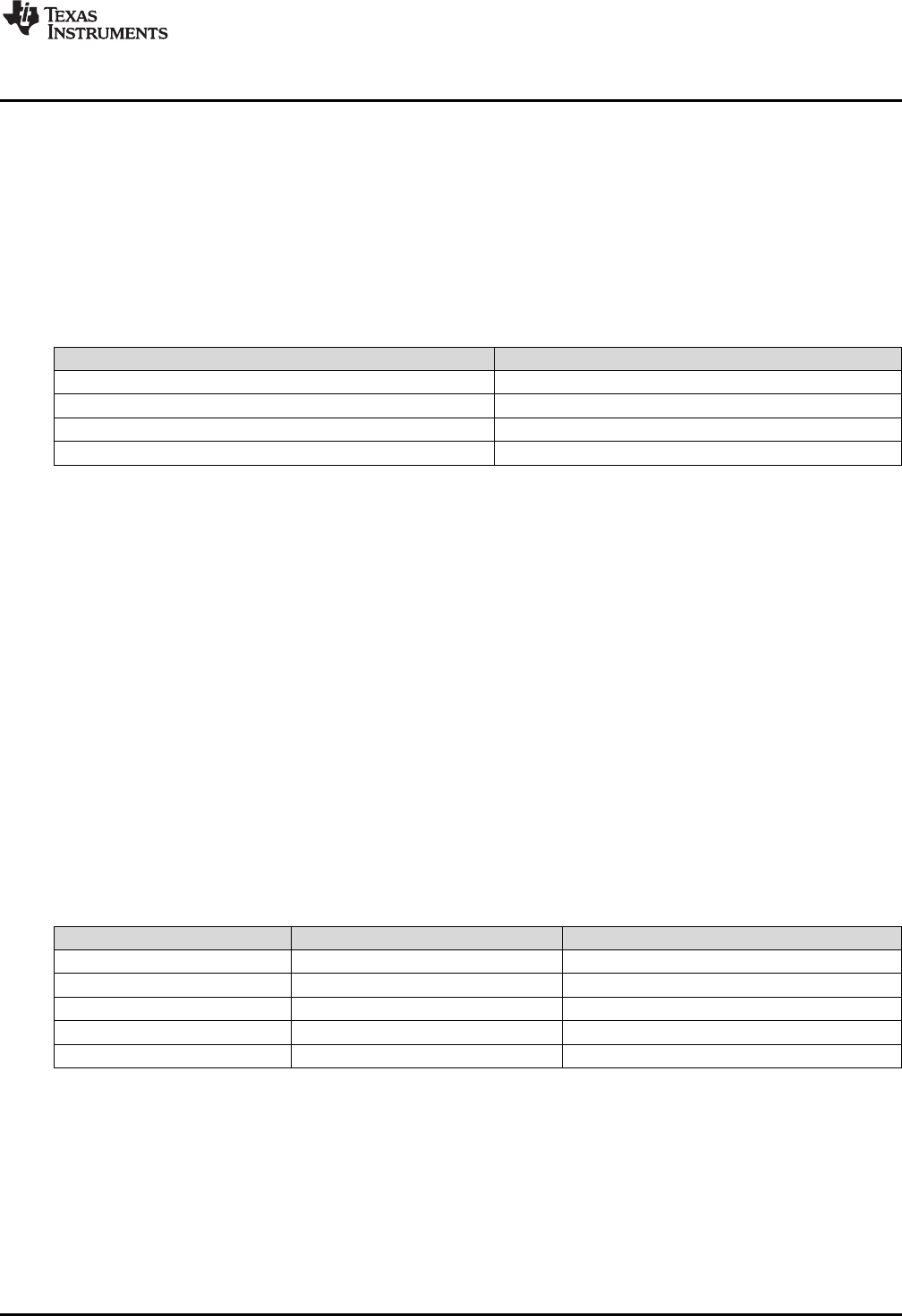
www.ti.com
Overview
2.1 Overview
The C28x with VCU (C28x+VCU) processor extends the capabilities of the C28x fixed-point or floating-
point CPU by adding registers and instructions to support the following algorithm types:
•Viterbi decoding
Viterbi decoding is commonly used in baseband communications applications. The viterbi decode
algorithm consists of three main parts: branch metric calculations, compare-select (viterbi butterfly) and
a traceback operation. Table 2-1 shows a summary of the VCU performance for each of these
operations.
Table 2-1. Viterbi Decode Performance
Viterbi Operation VCU Cycles
Branch Metric Calculation (code rate = 1/2) 1
Branch Metric Calculation (code rate = 1/3) 2p
Viterbi Butterfly (add-compare-select) 2 (1)
Traceback per Stage 3 (2)
(1) C28x CPU takes 15 cycles per butterfly.
(2) C28x CPU takes 22 cycles per stage.
•Cyclic redundancy check (CRC)
CRC algorithms provide a straightforward method for verifying data integrity over large data blocks,
communication packets, or code sections. The C28x+VCU can perform 8-, 16-, 24-, and 32-bit CRCs.
For example, the VCU can compute the CRC for a block length of 10 bytes in 10 cycles. A CRC result
register contains the current CRC which is updated whenever a CRC instruction is executed.
•Complex math
Complex math is used in many applications. The VCU A few of which are:
– Fast fourier transform (FFT)
The complex FFT is used in spread spectrum communications, as well in many signal processing
algorithms.
– Complex filters
Complex filters improve data reliability, transmission distance, and power efficiency. The
C28x+VCU can perform a complex I and Q multiply with coefficients (four multiplies) in a single
cycle. In addition, the C28x+VCU can read/write the real and imaginary parts of 16-bit complex data
to memory in a single cycle.
Table 2-2 shows a summary of the VCU operations enabled by the VCU:
Table 2-2. Complex Math Performance
Complex Math Operation VCU Cycles Notes
Add Or Subtract 1 32 +/- 32 = 32-bit (Useful for filters)
Add or Subtract 1 16 +/- 32 = 15-bit (Useful for FFT)
Multiply 2p 16 x 16 = 32-bit
Multiply & Accumulate (MAC) 2p 32 + 32 = 32-bit, 16 x 16 = 32-bit
RPT MAC 2p+N Repeat MAC. Single cycle after the first operation.
This C28x+VCU draws from the best features of digital signal processing; reduced instruction set
computing (RISC); and microcontroller architectures, firmware, and tool sets. The C2000 features include
a modified Harvard architecture and circular addressing. The RISC features are single-cycle instruction
execution, register-to-register operations, and modified Harvard architecture (usable in Von Neumann
mode). The microcontroller features include ease of use through an intuitive instruction set, byte packing
and unpacking, and bit manipulation. The modified Harvard architecture of the CPU enables instruction
and data fetches to be performed in parallel. The CPU can read instructions and data while it writes data
simultaneously to maintain the single-cycle instruction operation across the pipeline. The CPU does this
over six separate address/data buses.
Throughout this document the following notations are used:
141
SPRUHS1A–March 2014–Revised December 2015 C28 Viterbi, Complex Math and CRC Unit-II (VCU-II)
Submit Documentation Feedback Copyright © 2014–2015, Texas Instruments Incorporated
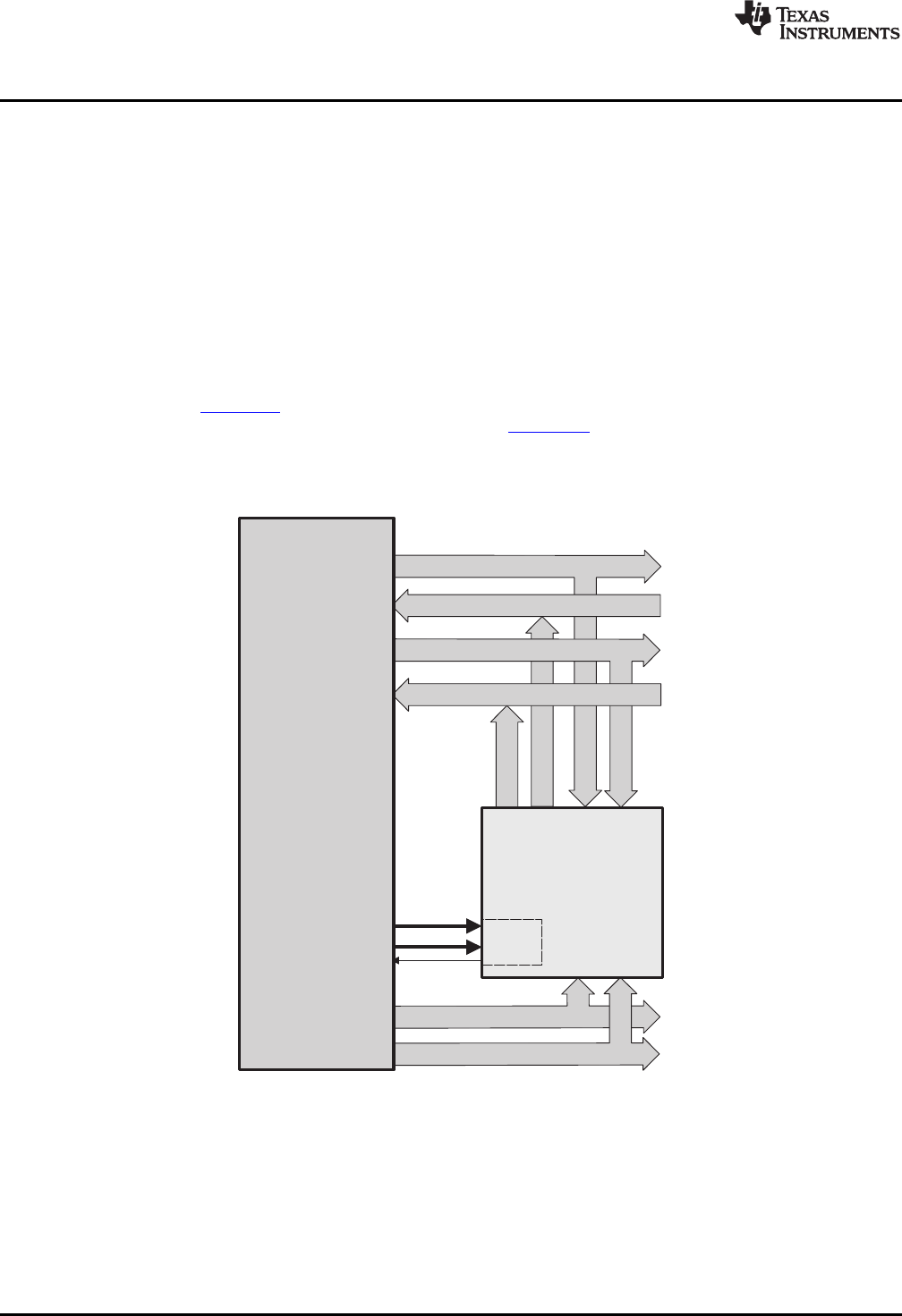
Program address bus (22)
Program data bus (32)
Read address bus (32)
Read data bus (32)
Write data bus (32)
Existing
memory,
peripherals,
interfaces
PIE
Write address bus (32)
LVF
LUF
C28x
+
FPU
+
Vcu
Memory
bus
Memory
bus
Components of the C28x Plus VCU
www.ti.com
• C28x refers to the C28x fixed-point CPU.
• C28x plus Floating-Point and C28x+FPU both refer to the C28x CPU with enhancements to support
IEEE single-precision floating-point operations.
• C28x plus VCU and C28x+VCU both refer to the C28x CPU with enhancements to support viterbi
decode, complex math, forward error correcting algorithms, and CRC.
• Some devices have both the FPU and the VCU. These are referred to as C28x+FPU+VCU.
2.2 Components of the C28x Plus VCU
The VCU extends the capabilities of the C28x CPU and C28x+FPU processors by adding additional
instructions. No changes have been made to existing instructions, pipeline, or memory bus architecture.
Therefore, programs written for the C28x are completely compatible with the C28x+VCU. All of the
features of the C28x documented in TMS320C28x DSP CPU and Instruction Set Reference Guide
(literature number SPRU430) apply to the C28x+VCU. All features documented in the TMS320C28x
Floating Point Unit and Instruction Set Reference Guide (SPRUE02) apply to the C28x+FPU+VCU.
Figure 2-1 shows the block diagram of the VCU.
Figure 2-1. C28x + VCU Block Diagram
142 C28 Viterbi, Complex Math and CRC Unit-II (VCU-II) SPRUHS1A–March 2014–Revised December 2015
Submit Documentation Feedback
Copyright © 2014–2015, Texas Instruments Incorporated

www.ti.com
Components of the C28x Plus VCU
The C28x+VCU contains the same features as the C28x fixed-point CPU:
• A central processing unit for generating data and program-memory addresses; decoding and executing
instructions; performing arithmetic, logical, and shift operations; and controlling data transfers among
CPU registers, data memory, and program memory.
• Emulation logic for monitoring and controlling various parts and functions of the device and for testing
device operation. This logic is identical to that on the C28x fixed-point CPU.
• Signals for interfacing with memory and peripherals, clocking and controlling the CPU and the
emulation logic, showing the status of the CPU and the emulation logic, and using interrupts. This logic
is identical to the C28x fixed-point CPU.
• Arithmetic logic unit (ALU). The 32-bit ALU performs 2s-complement arithmetic and Boolean logic
operations.
• Address register arithmetic unit (ARAU). The ARAU generates data memory addresses and
increments or decrements pointers in parallel with ALU operations.
• Fixed-Point instructions are pipeline protected. This pipeline for fixed-point instructions is identical to
that on the C28x fixed-point CPU. The CPU implements an 8-phase pipeline that prevents a write to
and a read from the same location from occurring out of order.
• Barrel shifter. This shifter performs all left and right shifts of fixed-point data. It can shift data to the left
by up to 16 bits and to the right by up to 16 bits.
• Fixed-Point Multiplier. The multiplier performs 32-bit × 32-bit 2s-complement multiplication with a 64-bit
result. The multiplication can be performed with two signed numbers, two unsigned numbers, or one
signed number and one unsigned number.
The VCU adds the following features:
• Instructions to support Cyclic Redundancy Check (CRC) or a polynomial code checksum
– CRC8
– CRC16
– CRC32
– CRC24
• Clocked at the same rate as the main CPU (SYSCLKOUT).
• Instructions to support a software implementation of a Viterbi Decoder of constraint length 4 - 7 and
code rates of 1/2 and 1/3
– Branch metrics calculations
– Add-Compare Select or Viterbi Butterfly
– Traceback
• Complex Math Arithmetic Unit
– Add or Subtract
– Multiply
– Multiply and Accumulate (MAC)
– Repeat MAC (RPT || MAC).
• Independent register space. These registers function as source and destination registers for VCU
instructions.
• Some VCU instructions require pipeline alignment. This alignment is done through software to allow
the user to improve performance by taking advantage of required delay slots. See Section 2.4 for more
information.
Devices with the floating-point unit also include:
• Floating point unit (FPU). The 32-bit FPU performs IEEE single-precision floating-point operations.
• Dedicated floating-point registers.
143
SPRUHS1A–March 2014–Revised December 2015 C28 Viterbi, Complex Math and CRC Unit-II (VCU-II)
Submit Documentation Feedback Copyright © 2014–2015, Texas Instruments Incorporated

Components of the C28x Plus VCU
www.ti.com
2.2.1 Emulation Logic
The emulation logic is identical to that on the C28x fixed-point CPU. This logic includes the following
features. For more details about these features, refer to the TMS320C28x DSP CPU and Instruction Set
Reference Guide (literature number SPRU430):
• Debug-and-test direct memory access (DT-DMA). A debug host can gain direct access to the content
of registers and memory by taking control of the memory interface during unused cycles of the
instruction pipeline
• A counter for performance benchmarking.
• Multiple debug events. Any of the following debug events can cause a break in program execution:
– A breakpoint initiated by the ESTOP0 or ESTOP1 instruction.
– An access to a specified program-space or data-space location. When a debug event causes the
C28x to enter the debug-halt state, the event is called a break event.
• Real-time mode of operation.
2.2.2 Memory Map
Like the C28x, the C28x+VCU uses 32-bit data addresses and 22-bit program addresses. This allows for a
total address reach of 4G words (1 word = 16 bits) in data space and 4M words in program space.
Memory blocks on all C28x+VCU designs are uniformly mapped to both program and data space. For
specific details about each of the map segments, see the device-specific data manual.
2.2.3 CPU Interrupt Vectors
The C28x+VCU interrupt vectors are identical to those on the C28x CPU. Sixty-four addresses in program
space are set aside for a table of 32 CPU interrupt vectors. For more information about the CPU vectors,
see TMS320C28x CPU and Instruction Set Reference Guide (literature number SPRU430). Typically the
CPU interrupt vectors are only used during the boot up of the device by the boot ROM. Once an
application has taken control it should initialize and enable the peripheral interrupt expansion block (PIE).
2.2.4 Memory Interface
The C28x+VCU memory interface is identical to that on the C28x. The C28x+VCU memory map is
accessible outside the CPU by the memory interface, which connects the CPU logic to memories,
peripherals, or other interfaces. The memory interface includes separate buses for program space and
data space. This means an instruction can be fetched from program memory while data memory is being
accessed. The interface also includes signals that indicate the type of read or write being requested by the
CPU. These signals can select a specified memory block or peripheral for a given bus transaction. In
addition to 16-bit and 32-bit accesses, the CPU supports special byte-access instructions that can access
the least significant byte (LSByte) or most significant byte (MSByte) of an addressed word. Strobe signals
indicate when such an access is occurring on a data bus.
2.2.5 Address and Data Buses
Like the C28x, the memory interface has three address buses:
• PAB: Program address bus: The 22-bit PAB carries addresses for reads and writes from program
space.
• DRAB: Data-read address bus: The 32-bit DRAB carries addresses for reads from data space.
• DWAB: Data-write address bus: The 32-bit DWAB carries addresses for writes to data space.
The memory interface also has three data buses:
• PRDB: Program-read data bus: The 32-bit PRDB carries instructions during reads from program
space.
• DRDB: Data-read data bus: The 32-bit DRDB carries data during reads from data space.
• DWDB: Data-/Program-write data bus: The 32-bit DWDB carries data during writes to data space or
program space.
144 C28 Viterbi, Complex Math and CRC Unit-II (VCU-II) SPRUHS1A–March 2014–Revised December 2015
Submit Documentation Feedback
Copyright © 2014–2015, Texas Instruments Incorporated

www.ti.com
Components of the C28x Plus VCU
A program-space read and a program-space write cannot happen simultaneously because both use the
PAB. Similarly, a program-space write and a data-space write cannot happen simultaneously because
both use the DWDB. Transactions that use different buses can happen simultaneously. For example, the
CPU can read from program space (using PAB and PRDB), read from data space (using DRAB and
DRDB), and write to data space (using DWAB and DWDB) at the same time. This behavior is identical to
the C28x CPU.
2.2.6 Alignment of 32-Bit Accesses to Even Addresses
The C28x+VPU expects memory wrappers or peripheral-interface logic to align any 32-bit read or write to
an even address. If the address-generation logic generates an odd address, the CPU will begin reading or
writing at the previous even address. This alignment does not affect the address values generated by the
address-generation logic.
Most instruction fetches from program space are performed as 32-bit read operations and are aligned
accordingly. However, alignment of instruction fetches are effectively invisible to a programmer. When
instructions are stored to program space, they do not have to be aligned to even addresses. Instruction
boundaries are decoded within the CPU.
You need to be concerned with alignment when using instructions that perform 32-bit reads from or writes
to data space.
145
SPRUHS1A–March 2014–Revised December 2015 C28 Viterbi, Complex Math and CRC Unit-II (VCU-II)
Submit Documentation Feedback Copyright © 2014–2015, Texas Instruments Incorporated
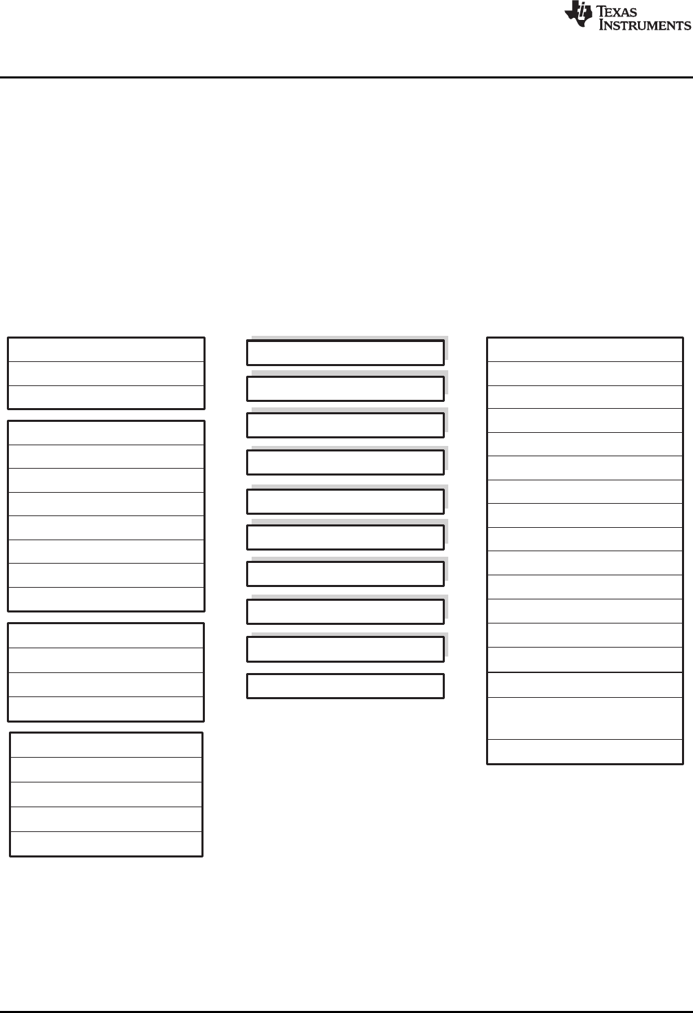
ACC (32-bit)
R1H (32-bit)
R2H (32-bit)
R3H (32-bit)
R4H (32-bit)
R5H (32-bit)
R6H (32-bit)
R7H (32-bit)
R0H (32-bit)
FPU Status Register (STF)
Repeat Block Register (RB)
P (32-bit)
XT (32-bit)
XAR0 (32-bit)
XAR1 (32-bit)
XAR2 (32-bit)
XAR3 (32-bit)
XAR4 (32-bit)
XAR5 (32-bit)
XAR6 (32-bit)
XAR7 (32-bit)
PC (22-bit)
RPC (22-bit)
DP (16-bit)
SP (16-bit)
ST0 (16-bit)
ST1 (16-bit)
IER (16-bit)
IFR (16-bit)
DBGIER (16-bit)
Standard C28x Register Set Additional 32-bit FPU Registers
FPU registers R0H - R7H and STF
are shadowed for fast context
save and restore
VR0
VR1
VR2
VR3
VR4
VR5
VR6
VR7
VR8
VT0
VT1
VSTATUS
VCRC
VSM0
VSM1
VSM63
Standard VCU Register Set
.
.
.
.
.
.
Register Set
www.ti.com
2.3 Register Set
Devices with the C28x+VCU include the standard C28x register set plus an additional set of VCU specific
registers. The additional VCU registers are the following:
• Result registers: VR0, VR1... VR8
• Traceback registers: VT0, VT1
• Configuration and status register: VSTATUS
• CRC result register: VCRC
• Repeat block register: RB
Figure 2-2 shows the register sets for the 28x CPU, the FPU and the VCU. The following section
discusses the VCU register set in detail.
Figure 2-2. C28x + FPU + VCU Registers
146 C28 Viterbi, Complex Math and CRC Unit-II (VCU-II) SPRUHS1A–March 2014–Revised December 2015
Submit Documentation Feedback
Copyright © 2014–2015, Texas Instruments Incorporated

www.ti.com
Register Set
2.3.1 VCU Register Set
Table 2-3 describes the VCU module register set. The last three columns indicate whether the particular
module within the VCU can make use of the register.
Table 2-3. VCU Register Set
Register Complex
Name Size Description Viterbi Math CRC
VR0 32 bits General purpose register 0 Yes Yes No
VR1 32 bits General purpose register 1 Yes Yes No
VR2 32 bits General purpose register 2 Yes Yes No
VR3 32 bits General purpose register 3 Yes Yes No
VR4 32 bits General purpose register 4 Yes Yes No
VR5 32 bits General purpose register 5 Yes Yes No
VR6 32 bits General purpose register 6 Yes Yes No
VR7 32 bits General purpose register 7 Yes Yes No
VR8 32 bits General purpose register 8 Yes No No
VT0 32 bits 32-bit transition bit register 0 Yes No No
VT1 32 bits 32-bit transition bit register 1 Yes No No
VSTATUS 32 bits VCU status and configuration register (1) Yes Yes No
VCRC 32 bits Cyclic redundancy check (CRC) result register No No Yes
VSM0- 32 bits Viterbi Decoding State Metric registers Yes No No
VSM63
VRx.By 32 bits Aliased address space for each byte of the VRx registers, left- No No No
x = 0 – 7 shifted by one
y = 0 - 3
(1) Debugger writes are not allowed to the VSTATUS register.
Table 2-4 lists the CPU registers available on devices with the C28x, the C28x+FPU, the C28x+VCU and
the C28x+FPU+VCU.
147
SPRUHS1A–March 2014–Revised December 2015 C28 Viterbi, Complex Math and CRC Unit-II (VCU-II)
Submit Documentation Feedback
Copyright © 2014–2015, Texas Instruments Incorporated

Register Set
www.ti.com
Table 2-4. 28x CPU Register Summary
Register C28x CPU C28x+FPU C28x+VCU C28x+FPU+VCU Description
ACC Yes Yes Yes Yes Fixed-point accumulator
AH Yes Yes Yes Yes High half of ACC
AL Yes Yes Yes Yes Low half of ACC
XAR0 - XAR7 Yes Yes Yes Yes Auxiliary register 0 - 7
AR0 - AR7 Yes Yes Yes Yes Low half of XAR0 - XAR7
DP Yes Yes Yes Yes Data-page pointer
IFR Yes Yes Yes Yes Interrupt flag register
IER Yes Yes Yes Yes Interrupt enable register
DBGIER Yes Yes Yes Yes Debug interrupt enable register
P Yes Yes Yes Yes Fixed-point product register
PH Yes Yes Yes Yes High half of P
PL Yes Yes Yes Yes Low half of P
PC Yes Yes Yes Yes Program counter
RPC Yes Yes Yes Yes Return program counter
SP Yes Yes Yes Yes Stack pointer
ST0 Yes Yes Yes Yes Status register 0
ST1 Yes Yes Yes Yes Status register 1
XT Yes Yes Yes Yes Fixed-point multiplicand register
T Yes Yes Yes Yes High half of XT
TL Yes Yes Yes Yes Low half of XT
ROH - R7H No Yes No Yes Floating-point Unit result registers
STF No Yes No Yes Floating-point Uint status register
RB No Yes Yes Yes Repeat block register
VR0 - VR8 No No Yes Yes VCU general purpose registers
VT0, VT1 No No Yes Yes VCU transition bit register 0 and 1
VSTATUS No No Yes Yes VCU status and configuration
VCRC No No Yes Yes CRC result register
VSM0-VSM63 No No Yes(1) Yes(1) Viterbi State Metric Registers
VRx.By No No Yes(1) Yes(1) Aliased address space for each byte of the
x = 0 – 7 VRx registers, left-shifted by one
y = 0 – 3
(1) Present on Type-2 VCU only
148 C28 Viterbi, Complex Math and CRC Unit-II (VCU-II) SPRUHS1A–March 2014–Revised December 2015
Submit Documentation Feedback
Copyright © 2014–2015, Texas Instruments Incorporated

www.ti.com
Register Set
2.3.2 VCU Status Register (VSTATUS)
The VCU status register (VSTATUS) register is described in Figure 2-3. There is no single instruction to
directly transfer the VSTATUS register to a C28x register. To transfer the contents:
1. Store VSTATUS into memory using VMOV32 mem32, VSTATUS instruction
2. Load the value from memory into a main C28x CPU register.
Configuration bits within the VSTATUS registers are set or cleared using VCU instructions.
Figure 2-3. VCU Status Register (VSTATUS)
31 30 29 27 26 24 23 16
CRCMSGFLIP DIVE K GFORDER GFPOLY
R/W-0 R/W-0 R/W-7 R/W-7
15 14 13 12 11 10 9 5 4 0
OPACK CPACK OVRI OVFR RND SAT SHIFTL SHIFTR
R/W-0 R/W-0 R/W-0 R/W-0 R/W-0 R/W-0 R/W-0 R/W-0
LEGEND: R/W = Read/Write; R = Read only; -n= value after reset
Table 2-5. VCU Status (VSTATUS) Register Field Descriptions
Bits Field Value Description
31 CRCMSGF CRC Message Flip
LIP(1) This bit affects the order in which the bits in the message are taken for CRC calculation by all the
CRC instructions.
0 Message bits are taken starting from most-significant to least-significant for CRC computation. In this
case, bytes loaded from memory are fed directly for CRC computation.
1 Message bits are taken starting from least-significant to most-significant for CRC computation. In this
case, bytes loaded from memory are “flipped” and then fed for CRC computation.
30 DIVE(1) Divide-by-zero Error
0 Indicates whether a “divide by zero” occurred during a VMOD32 computation. This bit is cleared by
executing the VCLRDIVE instruction
1
29-27 K(1) Constraint Length for Viterbi Decoding
0x7 This field sets the constraint length for the Viterbi decoding algorithm. It accepts values of 4 to 7.
Values outside this range will be treated as 7 by the hardware.
1
26-24 GFORDER(Galois Field Polynomial Order
1) 0x7 This field holds the Order of the polynomial for all the Galois Field instructions. This field is initialized
by the VGFINIT mem16 instruction. The actual order of the polynomial is GFORDER+1
23-16 GFPOLY(1) Galois Field Polynomial
0 This field holds the Polynomial for all the Galois Field instructions. This field is initialized by the
VGFINIT mem16 instruction.
1
15 OPACK(1) Viterbi Traceback Packing Order
This bit affects the packing order of the traceback output bits (using the VTRACE instructions)
0 Big-endian (compatible with VCU Type-0 output packing order)
1 Little-endian (VCU Type-2 mode)
14 CPACK(1) Complex Packing Order
This bit affects the packing order of the 16-bit real and 16-bit imaginary part of a complex numbers
inside the 32-bit general purpose VRx register.
0 VRx[31:16] holds Real part, VRx[15:0] holds Imaginary part (VCU-I compatible mode)
1 VRx[31:16] holds Imaginary part; VRx[15:0] holds Real part
(1) Present on Type-2 VCU only.
149
SPRUHS1A–March 2014–Revised December 2015 C28 Viterbi, Complex Math and CRC Unit-II (VCU-II)
Submit Documentation Feedback Copyright © 2014–2015, Texas Instruments Incorporated

Register Set
www.ti.com
Table 2-5. VCU Status (VSTATUS) Register Field Descriptions (continued)
Bits Field Value Description
13 OVRI Overflow or Underflow Flag: Imaginary Part
0 No overflow or underflow has been detected.
1 Indicates an overflow or underflow has occurred during the computation of the imaginary part of
operations shown in Table 10-6 . This bit will be set regardless of the value of the VSTATUS[SAT]
bit.OVRI bit will remain set until it is cleared by executing the VCLROVFI instruction.
12 OVFR Overflow or Underflow Flag: Real Part
0 No overflow or underflow has been detected.
1 Indicates overflow or underflow has occurred during a real number calculation for operations shown
in Table 2-6. This bit will be set regardless of the value of the VSTATUS[SAT] bit. This bit will remain
set until it is cleared by executing the VCLROVFR instruction.
11 RND Rounding
When a right-shift operation is performed the lower bits of the value will be lost. The RND bit
determines if the shifted value is rounded or if the shifted-out bits are simply truncated. This is
described in Section 2.3.2. Operations which use right-shift and rounding are shown in Table 2-6.
The RND bit is set by the VRNDON instruction and cleared by the VRNDOFF instruction.
0 Rounding is not performed. Bits shifted out right are truncated.
1 Rounding is performed. Refer to the instruction descriptions for information on how the operation is
affected by the RND bit.
10 SAT Saturation
This bit determines whether saturation will be performed for operations shown in Table 2-6.
The SAT bit is set by the VSATON instruction and is cleared by the VSATOFF instruction.
0 No saturation is performed.
1 Saturation is performed.
9-5 SHIFTL Left Shift
Operations which use left-shift are shown in Table 2-6
The shift SHIFTL field can be set or cleared by the VSETSHL instruction.
0 No left shift.
0x01 - Refer to the instruction description for information on how the operation is affected by the shift value.
0x1F During the left-shift, the lower bits are filled with 0's.
4-0 SHIFTR Right Shift
Operations which use right-shift and rounding are shown in Table 2-6.
The shift SHIFTR field can be set or cleared by the VSETSHR instruction.
0 No right shift.
0x01 - Refer to the instruction descriptions for information on how the operation is affected by the shift value.
0x1F During the right-shift, the lower bits are lost, and the shifted value is sign extended. If rounding is
enabled (VSTATUS[RND] == 1) , then the value will be rounded instead of truncated.
Table 2-6 shows a summary of the operations that are affected by or modify bits in the VSTATUS register.
Table 2-6. Operation Interaction With VSTATUS Bits
Operation(1) Description OVFI OVFR RND SAT SHIFTL SHIFTR CPACK OPACK DIVE
VITDLADDSUB Viterbi Add and Subtract - Y - Y - - - - -
Low
VITDHADDSUB Viterbi Add and Subtract - Y - Y - - - - -
High
VITDLSUBADD Viterbi Subtract and Add - Y - Y - - - - -
Low
VITDHSUBADD Viterbi Subtract and Add - Y - Y - - - - -
High
VITBM2 Viterbi Branch Metric CR - Y - Y - - - - -
1/2
VITBM3 Viterbi Branch Metric CR - Y - Y - - - - -
1/3
VTRACE(2) Viterbi Trace-back - - - - - - - Y -
(1) Some parallel instructions also include these operations. In this case, the operation will also modify, or be affected by, VSTATUS bits as
when used as part of a parallel instruction.
(2) Present on Type-2 VCU only.
150 C28 Viterbi, Complex Math and CRC Unit-II (VCU-II) SPRUHS1A–March 2014–Revised December 2015
Submit Documentation Feedback
Copyright © 2014–2015, Texas Instruments Incorporated
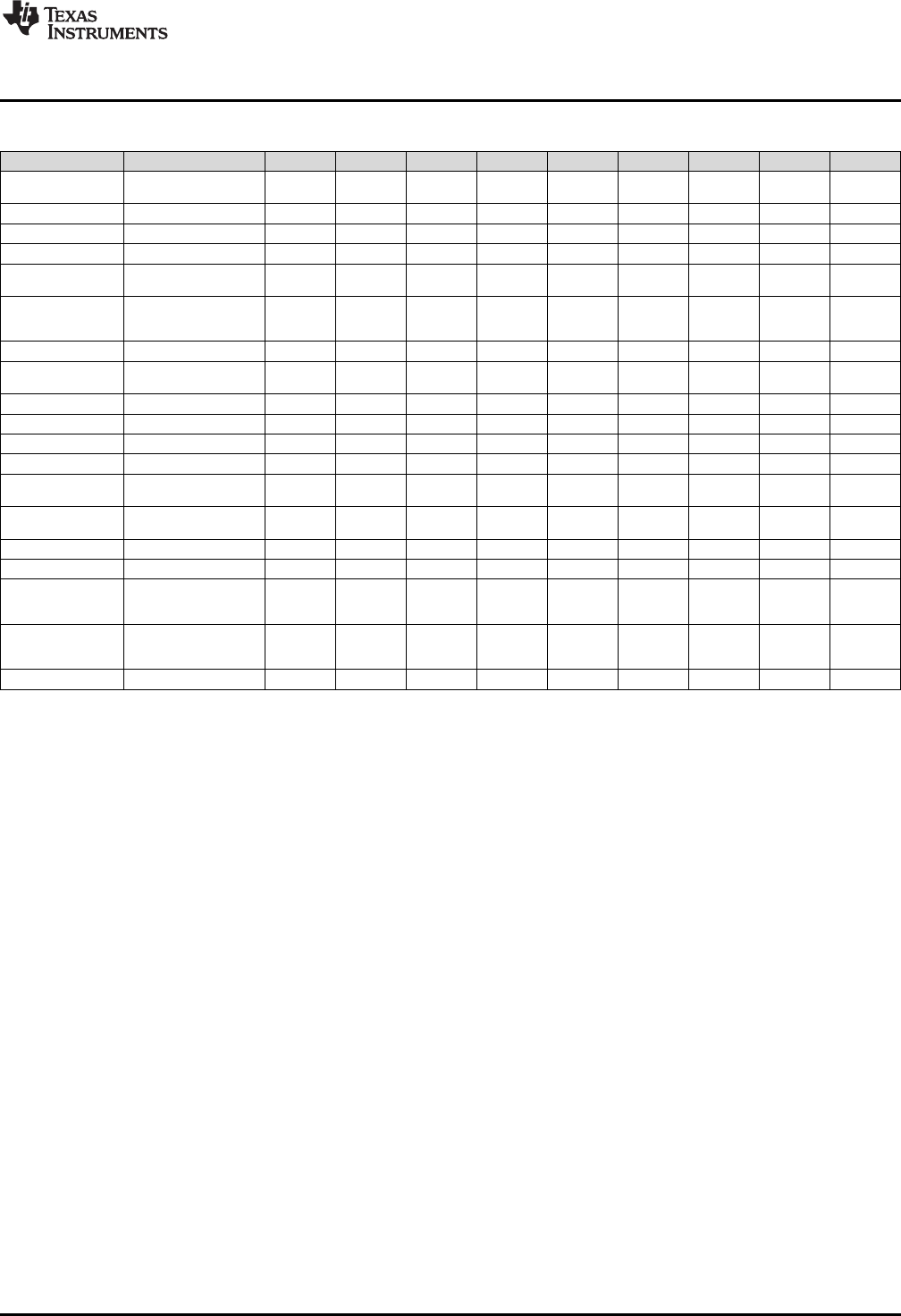
www.ti.com
Register Set
Table 2-6. Operation Interaction With VSTATUS Bits (continued)
Operation(1) Description OVFI OVFR RND SAT SHIFTL SHIFTR CPACK OPACK DIVE
VITSTAGE(2) Viterbi Compute 32 - Y - Y - - - - -
Butterfly
VCADD Complex 32 + 32 = 32 Y Y Y Y - Y - - -
VCDADD16 Complex 16 + 32 = 32 Y Y Y Y Y Y - - -
VCDSUB16 Complex 16 - 32 = 32 Y Y Y Y Y Y - - -
VCMAC Complex 32 + 32 = 32, Y Y Y Y - Y - - -
16 x 16 = 32
VCCMAC(2) Complex Conjugate 32 + Y Y Y Y - Y Y - -
32 = 32,
16 x 16 = 32
VCMPY Complex 16 x 16 = 32 Y Y - Y - - Y - -
VCCMPY(2) Complex Conjugate 16 x Y Y - Y - - Y - -
16 = 32
VCSUB Complex 32 - 32 = 32 Y Y Y Y - Y - - -
VCCON(2) Complex Conjugate Y - - Y - - Y - -
VCSHL16(2) Complex Shift Left Y Y - Y - - Y - -
VCHR16(2) Complex Shift Right - - Y - - - - - -
VCMAG(2) Complex Number - Y Y Y - - - - -
Magnitude
VNEG Two’s Complement - Y - Y - - - - -
Negation
VASHR32(2) Arithmetic Shift Right - - Y - - - - - -
VASHL32(2) Arithmetic Shift Left - Y - Y - - - - -
VMPYADD(2) Arithmetic Multiply Add - Y Y Y - Y - - -
16 + ((16 x 16) >> SHR) =
16
VCFFTx(2) Complex FFT calculation Y Y Y Y - Y - - -
step
(x = 1 – 10)
VMOD32 Modulo 32 % 16 = 16 - - - - - - - - Y
151
SPRUHS1A–March 2014–Revised December 2015 C28 Viterbi, Complex Math and CRC Unit-II (VCU-II)
Submit Documentation Feedback Copyright © 2014–2015, Texas Instruments Incorporated
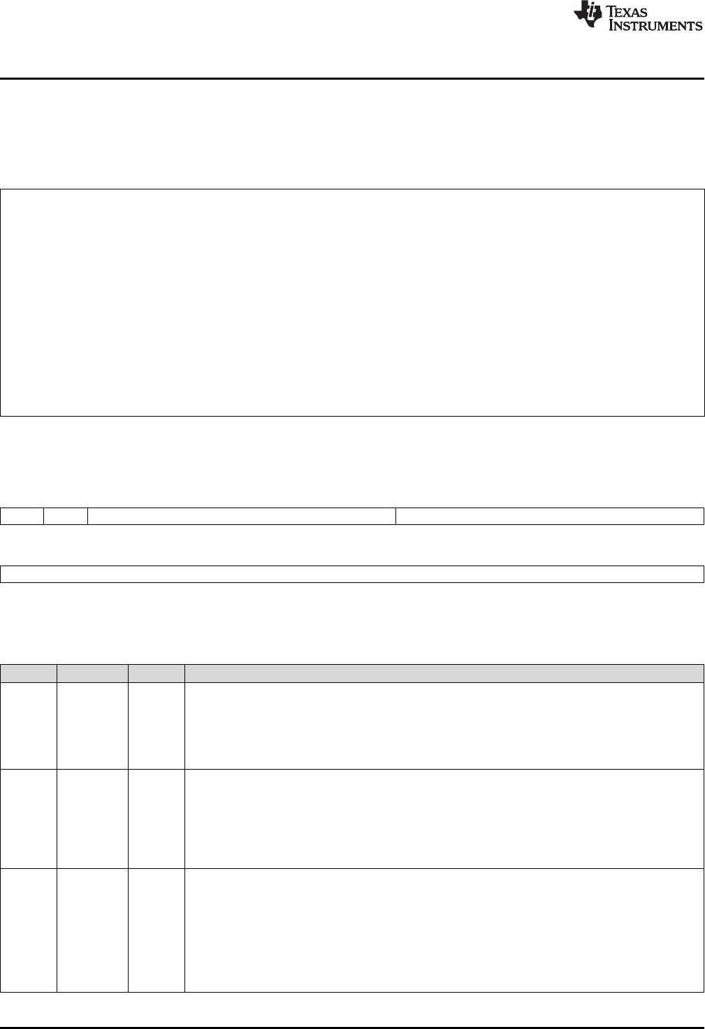
Register Set
www.ti.com
2.3.3 Repeat Block Register (RB)
The repeat block instruction (RPTB) applies to devices with the C28x+FPU and the C28x+VCU. This
instruction allows you to repeat a block of code as shown in Example 2-1.
Example 2-1. The Repeat Block (RPTB) Instruction uses the RB Register
; find the largest element and put its address in XAR6
;
; This example makes use of floating-point (C28x + FPU) instructions
;
;
MOV32 R0H, *XAR0++;
.align 2 ; Aligns the next instruction to an even address
NOP ; Makes RPTB odd aligned - required for a block size of 8
RPTB VECTOR_MAX_END, AR7 ; RA is set to 1
MOVL ACC,XAR0
MOV32 R1H,*XAR0++ ; RSIZE reflects the size of the RPTB block
MAXF32 R0H,R1H ; in this case the block size is 8
MOVST0 NF,ZF
MOVL XAR6,ACC,LT
VECTOR_MAX_END: ; RE indicates the end address. RA is cleared
The C28x FPU or VCU automatically populates the RB register based on the execution of a RPTB
instruction. This register is not normally read by the application and does not accept debugger writes.
Figure 2-4. Repeat Block Register (RB)
31 30 29 23 22 16
RAS RA RSIZE RE
R-0 R-0 R-0 R-0
15 0
RC
R-0
LEGEND: R = Read only; -n= value after reset
Table 2-7. Repeat Block (RB) Register Field Descriptions
Bits Field Value Description
31 RAS Repeat Block Active Shadow Bit
When an interrupt occurs the repeat active, RA, bit is copied to the RAS bit and the RA bit is cleared.
When an interrupt return instruction occurs, the RAS bit is copied to the RA bit and RAS is cleared.
0 A repeat block was not active when the interrupt was taken.
1 A repeat block was active when the interrupt was taken.
30 RA Repeat Block Active Bit
0 This bit is cleared when the repeat counter, RC, reaches zero.
When an interrupt occurs the RA bit is copied to the repeat active shadow, RAS, bit and RA is cleared.
When an interrupt return, IRET, instruction is executed, the RAS bit is copied to the RA bit and RAS is
cleared.
1 This bit is set when the RPTB instruction is executed to indicate that a RPTB is currently active.
29-23 RSIZE Repeat Block Size
This 7-bit value specifies the number of 16-bit words within the repeat block. This field is initialized
when the RPTB instruction is executed. The value is calculated by the assembler and inserted into the
RPTB instruction's RSIZE opcode field.
0-7 Illegal block size.
8/9-0x7F A RPTB block that starts at an even address must include at least 9 16-bit words and a block that
starts at an odd address must include at least 8 16-bit words. The maximum block size is 127 16-bit
words. The codegen assembler will check for proper block size and alignment.
152 C28 Viterbi, Complex Math and CRC Unit-II (VCU-II) SPRUHS1A–March 2014–Revised December 2015
Submit Documentation Feedback
Copyright © 2014–2015, Texas Instruments Incorporated

www.ti.com
Register Set
Table 2-7. Repeat Block (RB) Register Field Descriptions (continued)
Bits Field Value Description
22-16 RE Repeat Block End Address
This 7-bit value specifies the end address location of the repeat block. The RE value is calculated by
hardware based on the RSIZE field and the PC value when the RPTB instruction is executed.
RE = lower 7 bits of (PC + 1 + RSIZE)
15-0 RC Repeat Count
0 The block will not be repeated; it will be executed only once. In this case the repeat active, RA, bit will
not be set.
1- This 16-bit value determines how many times the block will repeat. The counter is initialized when the
0xFFFF RPTB instruction is executed and is decremented when the PC reaches the end of the block. When
the counter reaches zero, the repeat active bit is cleared and the block will be executed one more
time. Therefore the total number of times the block is executed is RC+1.
153
SPRUHS1A–March 2014–Revised December 2015 C28 Viterbi, Complex Math and CRC Unit-II (VCU-II)
Submit Documentation Feedback Copyright © 2014–2015, Texas Instruments Incorporated
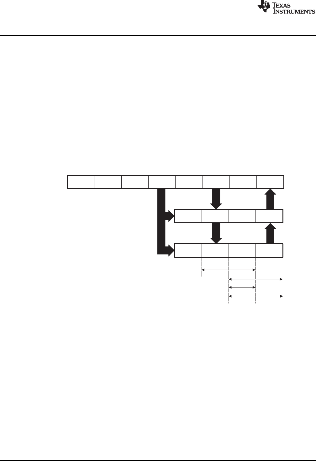
Fetch
C28x pipeline
Decode Read Exe
W
Write
FPU instruction
Store
Load
Complex ADD/SUB Viterbi ADDSUB/SUBADD
FPU ADD/SUB/MPY, Complex MPY
ER2R1D2D1F2F1
E2
W
E1RD
VCU instruction E2
W
E1RD
Pipeline
www.ti.com
2.4 Pipeline
This section describes the VCU pipeline stages and presents cases where pipeline alignment must be
considered.
2.4.1 Pipeline Overview
The C28x VCU pipeline is identical to the C28x pipeline for all standard C28x instructions. In the decode2
stage (D2), it is determined if an instruction is a C28x instruction, a FPU instruction, or a VCU instruction.
The pipeline flow is shown in Figure 2-5.
Notice that stalls due to normal C28x pipeline stalls (D2) and memory waitstates (R2 and W) will also stall
any C28x VCU instruction. Most C28x VCU instructions are single cycle and will complete in the VCU E1
or W stage which aligns to the C28x pipeline. Some instructions will take an additional execute cycle (E2).
For these instructions you must wait a cycle for the result from the instruction to be available. The rest of
this section will describe when delay cycles are required. Keep in mind that the assembly tools for the
C28x+VCU will issue an error if a delay slot has not been handled correctly.
Figure 2-5. C28x + FCU + VCU Pipeline
2.4.2 General Guidelines for VCU Pipeline Alignment
The majority of the VCU instructions do not require any special pipeline considerations. This section lists
the few operations that do require special consideration.
While the C28x+VCU assembler will issue errors for pipeline conflicts, you may still find it useful to
understand when software delays are required. This section describes three guidelines you can follow
when writing C28x+VCU assembly code.
VCU instructions that require delay slots have a 'p' after their cycle count. For example '2p' stands for 2
pipelined cycles. This means that an instruction can be started every cycle, but the result of the instruction
will only be valid one instruction later.
Table 2-8 outlines the instructions that need delay slots.
154 C28 Viterbi, Complex Math and CRC Unit-II (VCU-II) SPRUHS1A–March 2014–Revised December 2015
Submit Documentation Feedback
Copyright © 2014–2015, Texas Instruments Incorporated

www.ti.com
Pipeline
Table 2-8. Operations Requiring a Delay Slot(s)
Operation(1) Description Cycles
VITBM3 Viterbi Branch Metric CR 1/3 2p/2(2)
VCMAC Complex 32 + 32 = 32, 2p
16 x 16 = 32
VCCMAC(3) Complex Conjugate 32 + 32 = 32, 2p
16 x 16 = 32
VCMPY Complex 16 x 16 = 32 2p
VCCMPY(3) Complex Conjugate 16 x 16 = 32 2p
VCMAG(3) Complex Number Magnitude 2
VCFFTx(3) Complex FFT calculation step (x = 1 – 10) 2p/2(2)
VMOD32 Modulo 32 % 16 = 16 9p
VMPYADD(3) Arithmetic Multiply Add 2p
16 + ((16 x 16) >> SHR) = 16
(1) Some parallel instructions also include these operations. In this case, the operation will also modify, or be affected by, VSTATUS
bits as when used as part of a parallel instruction.
(2) Variations of the instruction execute differently. In these cases, the user is referred to the description Example 2-2 of the
instruction(s) in Section 2.5.
(3) Present on Type-2 VCU only.
An example of the complex multiply instruction is shown in Example 2-2. VCMPY is a 2p instruction and
therefore requires one delay slot. The destination registers for the operation, VR2 and VR3, will be
updated one cycle after the instruction for a total of two cycles. Therefore, a NOP or instruction that does
not use VR2 or VR3 must follow this instruction.
Any memory stall or pipeline stall will also stall the VCU. This keeps the VCU aligned with the C28x
pipeline and there is no need to change the code based on the waitstates of a memory block.
Example 2-2. 2p Instruction Pipeline Alignment
VCMPY VR3, VR2, VR1, VR0 ; 2 pipeline cycles (2p)
NOP ; 1 cycle delay or non-conflicting instruction
; <-- VCMPY completes, VR2 and VR3 updated
NOP ; Any instruction
2.4.3 Parallel Instructions
Parallel instructions are single opcodes that perform two operations in parallel. The guidelines provided in
Section 2.4.2 apply to parallel instructions as well. In this case the cycle count will be given for both
operations. For example, a branch metric calculation for code rate of 1/3 with a parallel load takes 2p/1
cycles. This means the branch metric portion of the operation takes two pipelined cycles while the move
portion of the operation is single cycle. NOPs or other non conflicting instructions must be inserted to align
the branch metric calculation portion of the operation as shown in Example 2-4.
Example 2-3. Branch Metric CR 1/2 Calculation with Parallel Load
; VITBM2 || VMOV32 instruction: branch metrics calculation with parallel load
; VBITM2 is a 1 cycle operation (code rate = 1/2)
; VMOV32 is a 1 cycle operation
;
VITBM2 VR0 ; Load VR0 with the 2 branch metrics
|| VMOV32 VR2, @Val ; VR2 gets the contents of Val
; <-- VMOV32 completes here (VR2 is valid)
; <-- VITBM2 completes here (VR0 is valid)
<instruction 2> ; Any instruction, can use VR2 and/or VR0
155
SPRUHS1A–March 2014–Revised December 2015 C28 Viterbi, Complex Math and CRC Unit-II (VCU-II)
Submit Documentation Feedback Copyright © 2014–2015, Texas Instruments Incorporated

Pipeline
www.ti.com
Example 2-4. Branch Metric CR 1/3 Calculation with Parallel Load
; VITBM3 || VMOV32 instruction: branch metrics calculation with parallel load
; VBITM3 is a 2p cycle operation (code rate = 1/3)
; VMOV32 is a 1 cycle operation
;
VITBM3 VR0, VR1, VR2 ; Load VR0 and VR1 with the 4 branch metrics
|| VMOV32 VR2, @Val ; VR2 gets the contents of Val
; <-- VMOV32 completes here (VR2 is valid)
<instruciton 2> ; Must not use VR0 or VR1. Can use VR2.
; <-- VITBM3 completes here (VR0, VR1 are valid)
<instruction 3> ; Any instruction, can use VR2 and/or VR0
2.4.4 Invalid Delay Instructions
All VCU, FPU and fixed-point instructions can be used in VCU instruction delay slots as long as source
and destination register conflicts are avoided. The C28x+VCU assembler will issue an error anytime you
use an conflicting instruction within a delay slot. The following guidelines can be used to avoid these
conflicts.
NOTE: Destination register conflicts in delay slots:
Any operation used for pipeline alignment delay must not use the same destination register
as the instruction requiring the delay. See Example 2-5.
In Example 2-5 the VCMPY instruction uses VR2 and VR3 as its destination registers. The next instruction
should not use VR2 or VR3 as a destination. Since the VMOV32 instruction uses the VR3 register a
pipeline conflict will be issued by the assembler. This conflict can be resolved by using a register other
than VR2 for the VMOV32 instruction as shown in Example 2-6.
156 C28 Viterbi, Complex Math and CRC Unit-II (VCU-II) SPRUHS1A–March 2014–Revised December 2015
Submit Documentation Feedback
Copyright © 2014–2015, Texas Instruments Incorporated

www.ti.com
Pipeline
Example 2-5. Destination Register Conflict
; Invalid delay instruction.
; Both instructions use the same destination register (VR3)
;
VCMPY VR3, VR2, VR1, VR0 ; 2p instruction
VMOV32 VR3, mem32 ; Invalid delay instruction
; <-- VCMPY completes, VR3, VR2 are valid
Example 2-6. Destination Register Conflict Resolved
; Valid delay instruction
;
VCMPY VR3, VR2, VR1, VR0 ; 2p instruction
VMOV32 VR7, mem32 ; Valid delay instruction
NOTE: Instructions in delay slots cannot use the instruction's destination register as a
source register.
Any operation used for pipeline alignment delay must not use the destination register of the
instruction requiring the delay as a source register as shown in Example 2-7. For parallel
instructions, the current value of a register can be used in the parallel operation before it is
overwritten as shown in Example 2-9.
In Example 2-7 the VCMPY instruction again uses VR3 and VR2 as its destination registers. The next
instruction should not use VR3 or VR2 as its source since the VCMPY will take an additional cycle to
complete. Since the VCADD instruction uses the VR2 as a source register a pipeline conflict will be issued
by the assembler. The use of VR3 will also cause a pipeline conflict. This conflict can be resolved by using
a register other than VR2 or VR3 or by inserting a non-conflicting instruction between the VCMPY and
VCADD instructions. Since the VNEG does not use VR2 or VR3 this instruction can be moved before the
VCADD as shown in Example 2-8.
Example 2-7. Destination/Source Register Conflict
; Invalid delay instruction.
; VCADD should not use VR2 or VR3 as a source operand
;
VCMPY VR3, VR2, VR1, VR0 ; 2p instruction
VCADD VR5, VR4, VR3, VR2 ; Invalid delay instruction
VNEG VR0 ; <- VCMPY completes, VR3, VR2 valid
Example 2-8. Destination/Source Register Conflict Resolved
; Valid delay instruction.
;
VCMPY VR3, VR2, VR1, VR0 ; 2p instruction
VNEG VR0 ; Non conflicting instruction or NOP
VCADD VR5, VR4, VR3, VR2 ; <- VCMPY completes, VR3, VR2 valid
It should be noted that a source register for the second operation within a parallel instruction can be the
same as the destination register of the first operation. This is because the two operations are started at
the same time. The second operation is not in the delay slot of the first operation. Consider Example 2-9
where the VCMPY uses VR3 and VR2 as its destination registers. The VMOV32 is the second operation
in the instruction and can freely use VR3 or VR2 as a source register. In the example, the contents of VR3
before the multiply will be used by MOV32.
157
SPRUHS1A–March 2014–Revised December 2015 C28 Viterbi, Complex Math and CRC Unit-II (VCU-II)
Submit Documentation Feedback Copyright © 2014–2015, Texas Instruments Incorporated

Pipeline
www.ti.com
Example 2-9. Parallel Instruction Destination/Source Exception
; Valid parallel operation.
;
VCMPY VR3, VR2, VR1, VR0 ; 2p/1 instruction
|| VMOV32 mem32, VR3 ; <-- Uses VR3 before the VCMPY update
; <-- mem32 updated
NOP ; <-- Delay for VCMPY
; <-- VR2, VR3 updated
Likewise, the source register for the second operation within a parallel instruction can be the same as one
of the source registers of the first operation. The VCMPY operation in Example 2-10 uses the VR0 register
as one of its sources. This register is also updated by the VMOV32 instruction. The multiplication
operation will use the value in VR0 before the VMOV32 updates it.
Example 2-10. Parallel Instruction Destination/Source Exception
; Valid parallel operation.
VCMPY VR3, VR2, VR1, VR0 ; 2p/1 instruction
|| VMOV32 VR0, mem32 ; <-- Uses VR3 before the VCMPY update
; <-- mem32 updated
NOP ; <-- Delay for VCMPY
; <-- VR2, VR3 updated
NOTE: Operations within parallel instructions cannot use the same destination register.
When two parallel operations have the same destination register, the result is invalid.
For example, see Example 2-11.
If both operations within a parallel instruction try to update the same destination register as shown in
Example 2-11 the assembler will issue an error.
Example 2-11. Invalid Destination Within a Parallel Instruction
; Invalid parallel instruction. Both operations use VR3 as a destination register
;
VCMPY VR3, VR2, VR1, VR0 ; 2p/1 instruction
|| VMOV32 VR3, mem32 ; <-- Invalid
158 C28 Viterbi, Complex Math and CRC Unit-II (VCU-II) SPRUHS1A–March 2014–Revised December 2015
Submit Documentation Feedback
Copyright © 2014–2015, Texas Instruments Incorporated

www.ti.com
Instruction Set
2.5 Instruction Set
This section describes the assembly language instructions of the VCU. Also described are parallel
operations, conditional operations, resource constraints, and addressing modes. The instructions listed
here are independent from C28x and C28x+FPU instruction sets.
2.5.1 Instruction Descriptions
This section gives detailed information on the instruction set. Each instruction may present the following
information:
• Operands
• Opcode
• Description
• Exceptions
• Pipeline
• Examples
• See also
The example INSTRUCTION is shown to familiarize you with the way each instruction is described. The
example describes the kind of information you will find in each part of the individual instruction description
and where to obtain more information. VCU instructions follow the same format as the C28x; the source
operand(s) are always on the right and the destination operand(s) are on the left.
The explanations for the syntax of the operands used in the instruction descriptions for the C28x VCU are
given in Table 2-9.
Table 2-9. Operand Nomenclature
Symbol Description
#16FHi 16-bit immediate (hex or float) value that represents the upper 16-bits of an IEEE 32-bit floating-point value.
Lower 16-bits of the mantissa are assumed to be zero.
#16FHiHex 16-bit immediate hex value that represents the upper 16-bits of an IEEE 32-bit floating-point value.
Lower 16-bits of the mantissa are assumed to be zero.
#16FLoHex A 16-bit immediate hex value that represents the lower 16-bits of an IEEE 32-bit floating-point value
#32Fhex 32-bit immediate value that represents an IEEE 32-bit floating-point value
#32F Immediate float value represented in floating-point representation
#0.0 Immediate zero
#5-bit 5-bit immediate unsigned value
addr Opcode field indicating the addressing mode
Im(X), Im(Y) Imaginary part of the input X or input Y
Im(Z) Imaginary part of the output Z
Re(X), Re(Y) Real part of the input X or input Y
Re(Z) Real part of the output Z
mem16 Pointer (using any of the direct or indirect addressing modes) to a 16-bit memory location
mem32 Pointer (using any of the direct or indirect addressing modes) to a 32-bit memory location
VRa VR0 - VR8 registers. Some instructions exclude VR8. Refer to the instruction description for details.
VR0H, VR0 - VR7 registers, high half.
VR1H...VR7H
VR0L, VR1L....VR7L VR0 - VR7 registers, low half.
VT0, VT1 Transition bit register VT0 or VT1.
VSMn+1: VSMn Pair of State Metric Registers (n = 0 : 62, n is even)
VRx.By 32 bit Aliased address space foe each byte of the VRx registers (x=0:7,y =0:3)
Each instruction has a table that gives a list of the operands and a short description. Instructions always
have their destination operand(s) first followed by the source operand(s).
159
SPRUHS1A–March 2014–Revised December 2015 C28 Viterbi, Complex Math and CRC Unit-II (VCU-II)
Submit Documentation Feedback Copyright © 2014–2015, Texas Instruments Incorporated

Instruction Set
www.ti.com
Table 2-10. INSTRUCTION dest, source1, source2 Short Description
Description
dest1 Description for the 1st operand for the instruction
source1 Description for the 2nd operand for the instruction
source2 Description for the 3rd operand for the instruction
Opcode This section shows the opcode for the instruction
Description Detailed description of the instruction execution is described. Any constraints on the operands imposed by
the processor or the assembler are discussed.
Restrictions Any constraints on the operands or use of the instruction imposed by the processor are discussed.
Pipeline This section describes the instruction in terms of pipeline cycles as described in Section 2.4.
Example Examples of instruction execution. If applicable, register and memory values are given before and after
instruction execution. Some examples are code fragments while other examples are full tasks that assume
the VCU is correctly configured and the main CPU has passed it data.
Operands Each instruction has a table that gives a list of the operands and a short description. Instructions always
have their destination operand(s) first followed by the source operand(s).
160 C28 Viterbi, Complex Math and CRC Unit-II (VCU-II) SPRUHS1A–March 2014–Revised December 2015
Submit Documentation Feedback
Copyright © 2014–2015, Texas Instruments Incorporated

www.ti.com
Instruction Set
2.5.2 General Instructions
The instructions are listed alphabetically, preceded by a summary.
Table 2-11. General Instructions
Title ...................................................................................................................................... Page
POP RB —Pop the RB Register from the Stack ................................................................................... 162
PUSH RB —Push the RB Register onto the Stack ................................................................................ 164
RPTB label, loc16 —Repeat A Block of Code ..................................................................................... 166
RPTB label, #RC —Repeat a Block of Code ....................................................................................... 168
VCLEAR VRa —Clear General Purpose Register ................................................................................. 170
VCLEARALL —Clear All General Purpose and Transition Bit Registers ...................................................... 171
VCLRCPACK —Clears CPACK bit in the VSTATUS Register .................................................................. 172
VCLRCRCMSGFLIP —Clears CRCMSGFLIP bit in the VSTATUS Register ................................................. 173
VCLROPACK —Clears OPACK bit in the VSTATUS Register.................................................................. 174
VCLROVFI —Clear Imaginary Overflow Flag...................................................................................... 175
VCLROVFR —Clear Real Overflow Flag ........................................................................................... 176
VMOV16 mem16, VRaH —Store General Purpose Register, High Half........................................................ 177
VMOV16 mem16, VRaL —Store General Purpose Register, Low Half......................................................... 178
VMOV16 VRaH, mem16 —Load General Purpose Register, High Half ........................................................ 179
VMOV16 VRaL, mem16 —Load General Purpose Register, Low Half ......................................................... 180
VMOV32 *(0:16bitAddr), loc32 —Move the contents of loc32 to Memory..................................................... 181
VMOV32 loc32, *(0:16bitAddr) —Move 32-bit Value from Memory to loc32 .................................................. 182
VMOV32 mem32, VRa —Store General Purpose Register ...................................................................... 183
VMOV32 mem32, VSTATUS —Store VCU Status Register ..................................................................... 184
VMOV32 mem32, VTa —Store Transition Bit Register ........................................................................... 185
VMOV32 VRa, mem32 —Load 32-bit General Purpose Register ............................................................... 186
VMOV32 VRb, VRa —Move 32-bit Register to Register .......................................................................... 187
VMOV32 VSTATUS, mem32 —Load VCU Status Register...................................................................... 188
VMOV32 VTa, mem32 —Load 32-bit Transition Bit Register .................................................................... 189
VMOVD32 VRa, mem32 —Load Register with Data Move....................................................................... 190
VMOVIX VRa, #16I —Load Upper Half of a General Purpose Register with I6-bit Immediate .............................. 191
VMOVZI VRa, #16I —Load General Purpose Register with Immediate......................................................... 192
VMOVXI VRa, #16I —Load Low Half of a General Purpose Register with Immediate........................................ 193
VRNDOFF —Disable Rounding...................................................................................................... 194
VRNDON —Enable Rounding........................................................................................................ 195
VSATOFF —Disable Saturation ..................................................................................................... 196
VSATON —Enable Saturation ....................................................................................................... 197
VSETCPACK —Set CPACK bit in the VSTATUS Register ...................................................................... 198
VSETCRCMSGFLIP —Set CRCMSGFLIP bit in the VSTATUS Register ..................................................... 199
VSETOPACK —Set OPACK bit in the VSTATUS Register...................................................................... 200
VSETSHL #5-bit —Initialize the Left Shift Value .................................................................................. 201
VSETSHR #5-bit —Initialize the Left Shift Value.................................................................................. 202
VSWAP32 VRb, VRa —32-bit Register Swap...................................................................................... 203
VXORMOV32 VRa, mem32 —32-bit Load and XOR From Memory ............................................................ 204
161
SPRUHS1A–March 2014–Revised December 2015 C28 Viterbi, Complex Math and CRC Unit-II (VCU-II)
Submit Documentation Feedback Copyright © 2014–2015, Texas Instruments Incorporated

POP RB — Pop the RB Register from the Stack
www.ti.com
POP RB Pop the RB Register from the Stack
Operands
RB repeat block register
Opcode LSW: 1111 1111 1111 0001
Description Restore the RB register from stack. If a high-priority interrupt contains a RPTB
instruction, then the RB register must be stored on the stack before the RPTB block and
restored after the RTPB block. In a low-priority interrupt RB must always be saved and
restored. This save and restore must occur when interrupts are disabled.
Flags This instruction does not affect any flags in the VSTATUS register.
Pipeline This is a single-cycle instruction.
Example A high priority interrupt is defined as an interrupt that cannot itself be interrupted. In a
high priority interrupt, the RB register must be saved if a RPTB block is used within the
interrupt. If the interrupt service routine does not include a RPTB block, then you do not
have to save the RB register.
; Repeat Block within a High-Priority Interrupt (Non-Interruptible)
;
; Interrupt: ; RAS = RA, RA = 0
...
PUSH RB ; Save RB register only if a RPTB block is used in the ISR
...
...
RPTB _BlockEnd, AL ; Execute the block AL+1 times
...
...
...
_BlockEnd ; End of block to be repeated
...
...
POP RB ; Restore RB register ...
IRET ; RA = RAS, RAS = 0
A low-priority interrupt is defined as an interrupt that allows itself to be interrupted. The
RB register must always be saved and restored in a low-priority interrupt. The RB
register must stored before interrupts are enabled. Likewise before restoring the RB
register interrupts must first be disabled.
; Repeat Block within a Low-Priority Interrupt (Interruptible)
;
; Interrupt:
; RAS = RA, RA = 0
...
PUSH RB ; Always save RB register
...
CLRC INTM ; Enable interrupts only after saving RB
...
...
...
; ISR may or may not include a RPTB block
...
...
SETC INTM ; Disable interrupts before restoring RB
...
POP RB ; Always restore RB register
...
IRET ; RA = RAS, RAS = 0
See also PUSH RB
162 C28 Viterbi, Complex Math and CRC Unit-II (VCU-II) SPRUHS1A–March 2014–Revised December 2015
Submit Documentation Feedback
Copyright © 2014–2015, Texas Instruments Incorporated


PUSH RB — Push the RB Register onto the Stack
www.ti.com
PUSH RB Push the RB Register onto the Stack
Operands
RB repeat block register
Opcode LSW: 1111 1111 1111 0000
Description Save the RB register on the stack. If a high-priority interrupt contains a RPTB instruction,
then the RB register must be stored on the stack before the RPTB block and restored
after the RTPB block. In a low-priority interrupt RB must always be saved and restored.
This save and restore must occur when interrupts are disabled.
Flags This instruction does not affect any flags in the VSTATUS register.
Pipeline This is a single-cycle instruction.
Example A high priority interrupt is defined as an interrupt that cannot itself be interrupted. In a
high priority interrupt, the RB register must be saved if a RPTB block is used within the
interrupt. If the interrupt service routine does not include a RPTB block, then you do not
have to save the RB register.
; Repeat Block within a High-Priority Interrupt (Non-Interruptible)
;
; Interrupt: ; RAS = RA, RA = 0
...
PUSH RB ; Save RB register only if a RPTB block is used in the ISR
...
...
RPTB _BlockEnd, AL ; Execute the block AL+1 times
...
...
...
_BlockEnd ; End of block to be repeated
...
...
POP RB ; Restore RB register ...
IRET ; RA = RAS, RAS = 0
A low-priority interrupt is defined as an interrupt that allows itself to be interrupted. The
RB register must always be saved and restored in a low-priority interrupt. The RB
register must stored before interrupts are enabled. Likewise before restoring the RB
register interrupts must first be disabled.
; Repeat Block within a Low-Priority Interrupt (Interruptible)
;
; Interrupt:
; RAS = RA, RA = 0
...
PUSH RB ; Always save RB register
...
CLRC INTM ; Enable interrupts only after saving RB
...
...
...
; ISR may or may not include a RPTB block
...
...
SETC INTM ; Disable interrupts before restoring RB
...
POP RB ; Always restore RB register
...
IRET ; RA = RAS, RAS = 0
See also POP RB
164 C28 Viterbi, Complex Math and CRC Unit-II (VCU-II) SPRUHS1A–March 2014–Revised December 2015
Submit Documentation Feedback
Copyright © 2014–2015, Texas Instruments Incorporated


RPTB label, loc16 — Repeat A Block of Code
www.ti.com
RPTB label, loc16 Repeat A Block of Code
Operands
label This label is used by the assembler to determine the end of the repeat block and to calculate RSIZE.
This label should be placed immediately after the last instruction included in the repeat block.
loc16 16-bit location for the repeat count value.
Opcode LSW: 1011 0101 0bbb bbbb
MSW: 0000 0000 loc16
Description Initialize repeat block loop, repeat count from [loc16]
Restrictions
• The maximum block size is ≤127 16-bit words.
• An even aligned block must be ≥9 16-bit words.
• An odd aligned block must be ≥8 16-bit words.
• Interrupts must be disabled when saving or restoring the RB register.
• Repeat blocks cannot be nested.
• Any discontinuity type operation is not allowed inside a repeat block. This includes all
call, branch or TRAP instructions. Interrupts are allowed.
• Conditional execution operations are allowed.
Flags This instruction does not affect any flags in the VSTATUS register.
Pipeline This instruction takes four cycles on the first iteration and zero cycles thereafter. No
special pipeline alignment is required.
Example The minimum size for the repeat block is 8 words if the block is even aligned and 9
words if the block is odd aligned. If you have a block of 8 words, as in the following
example, you can make sure the block is odd aligned by proceeding it by a .align 2
directive and a NOP instruction. The .align 2 directive will make sure the NOP is even
aligned. Since a NOP is a 16-bit instruction the RPTB will be odd aligned. For blocks of
9 or more words, this is not required.
; Repeat Block of 8 Words (Interruptible)
;
; Note: This example makes use of floating-point (C28x+FPU) instructions
;
;
; find the largest element and put its address in XAR6
.align 2
NOP
RPTB _VECTOR_MAX_END, AR7
; Execute the block AR7+1 times
MOVL ACC,XAR0 MOV32 R1H,*XAR0++ ; min size = 8, 9 words
MAXF32 R0H,R1H ; max size = 127 words
MOVST0 NF,ZF
MOVL XAR6,ACC,LT
_VECTOR_MAX_END: ; label indicates the end
; RA is cleared
When an interrupt is taken the repeat active (RA) bit in the RB register is automatically
copied to the repeat active shadow (RAS) bit. When the interrupt exits, the RAS bit is
automatically copied back to the RA bit. This allows the hardware to keep track if a
repeat loop was active whenever an interrupt is taken and restore that state
automatically.
A high priority interrupt is defined as an interrupt that cannot itself be interrupted. In a
high priority interrupt, the RB register must be saved if a RPTB block is used within the
166 C28 Viterbi, Complex Math and CRC Unit-II (VCU-II) SPRUHS1A–March 2014–Revised December 2015
Submit Documentation Feedback
Copyright © 2014–2015, Texas Instruments Incorporated

www.ti.com
RPTB label, loc16 — Repeat A Block of Code
interrupt. If the interrupt service routine does not include a RPTB block, then you do not
have to save the RB register.
; Repeat Block within a High-Priority Interrupt (Non-Interruptible)
;
; Interrupt: ; RAS = RA, RA = 0
...
PUSH RB ; Save RB register only if a RPTB block is used in the ISR
...
...
RPTB _BlockEnd, AL ; Execute the block AL+1 times
...
...
...
_BlockEnd ; End of block to be repeated
...
...
POP RB ; Restore RB register ...
IRET ; RA = RAS, RAS = 0
A low-priority interrupt is defined as an interrupt that allows itself to be interrupted. The
RB register must always be saved and restored in a low-priority interrupt. The RB
register must stored before interrupts are enabled. Likewise before restoring the RB
register interrupts must first be disabled.
; Repeat Block within a Low-Priority Interrupt (Interruptible)
;
; Interrupt:
; RAS = RA, RA = 0
...
PUSH RB ; Always save RB register
...
CLRC INTM ; Enable interrupts only after saving RB
...
...
...
; ISR may or may not include a RPTB block
...
...
SETC INTM ; Disable interrupts before restoring RB
...
POP RB ; Always restore RB register
...
IRET ; RA = RAS, RAS = 0
See also POP RB
PUSH RB
RPTB label, #RC
167
SPRUHS1A–March 2014–Revised December 2015 C28 Viterbi, Complex Math and CRC Unit-II (VCU-II)
Submit Documentation Feedback Copyright © 2014–2015, Texas Instruments Incorporated

RPTB label, #RC — Repeat a Block of Code
www.ti.com
RPTB label, #RC Repeat a Block of Code
Operands
label This label is used by the assembler to determine the end of the repeat block and to calculate RSIZE.
This label should be placed immediately after the last instruction included in the repeat block.
#RC 16-bit immediate value for the repeat count.
Opcode LSW: 1011 0101 1bbb bbbb
MSW: cccc cccc cccc cccc
Description Repeat a block of code. The repeat count is specified as a immediate value.
Restrictions
• The maximum block size is ≤127 16-bit words.
• An even aligned block must be ≥9 16-bit words.
• An odd aligned block must be ≥8 16-bit words.
• Interrupts must be disabled when saving or restoring the RB register.
• Repeat blocks cannot be nested.
• Any discontinuity type operation is not allowed inside a repeat block. This includes all
call, branch or TRAP instructions. Interrupts are allowed.
• Conditional execution operations are allowed.
Flags This instruction does not affect any flags in the VSTATUS register.
Pipeline This instruction takes one cycle on the first iteration and zero cycles thereafter. No
special pipeline alignment is required.
Example The minimum size for the repeat block is 8 words if the block is even aligned and 9
words if the block is odd aligned. If you have a block of 8 words, as in the following
example, you can make sure the block is odd aligned by proceeding it by a .align 2
directive and a NOP instruction. The .align 2 directive will make sure the NOP is even
aligned. Since a NOP is a 16-bit instruction the RPTB will be odd aligned. For blocks of
9 or more words, this is not required.
; Repeat Block of 8 Words (Interruptible)
;
; Note: This example makes use of floating-point (C28x+FPU) instructions
;
; find the largest element and put its address in XAR6
;
.align 2
NOP
RPTB _VECTOR_MAX_END, AR7
; Execute the block AR7+1 times
MOVL ACC,XAR0 MOV32 R1H,*XAR0++ ; min size = 8, 9 words
MAXF32 R0H,R1H ; max size = 127 words
MOVST0 NF,ZF
MOVL XAR6,ACC,LT
_VECTOR_MAX_END: ; label indicates the end
; RA is cleared
When an interrupt is taken the repeat active (RA) bit in the RB register is automatically
copied to the repeat active shadow (RAS) bit. When the interrupt exits, the RAS bit is
automatically copied back to the RA bit. This allows the hardware to keep track if a
repeat loop was active whenever an interrupt is taken and restore that state
automatically.
A high priority interrupt is defined as an interrupt that cannot itself be interrupted. In a
high priority interrupt, the RB register must be saved if a RPTB block is used within the
168 C28 Viterbi, Complex Math and CRC Unit-II (VCU-II) SPRUHS1A–March 2014–Revised December 2015
Submit Documentation Feedback
Copyright © 2014–2015, Texas Instruments Incorporated

www.ti.com
RPTB label, #RC — Repeat a Block of Code
interrupt. If the interrupt service routine does not include a RPTB block, then you do not
have to save the RB register.
; Repeat Block within a High-Priority Interrupt (Non-Interruptible)
;
; Interrupt: ; RAS = RA, RA = 0
...
PUSH RB ; Save RB register only if a RPTB block is used in the ISR
...
...
RPTB #_BlockEnd, #5 ; Execute the block AL+1 times
...
...
...
_BlockEnd ; End of block to be repeated
...
...
POP RB ; Restore RB register ...
IRET ; RA = RAS, RAS = 0
A low-priority interrupt is defined as an interrupt that allows itself to be interrupted. The
RB register must always be saved and restored in a low-priority interrupt. The RB
register must stored before interrupts are enabled. Likewise before restoring the RB
register interrupts must first be disabled.
; Repeat Block within a Low-Priority Interrupt (Interruptible)
;
; Interrupt:
; RAS = RA, RA = 0
...
PUSH RB ; Always save RB register
...
CLRC INTM ; Enable interrupts only after saving RB
...
...
...
; ISR may or may not include a RPTB block
...
...
SETC INTM ; Disable interrupts before restoring RB
...
POP RB ; Always restore RB register
...
IRET ; RA = RAS, RAS = 0
See also POP RB
PUSH RB
RPTB label, loc16
169
SPRUHS1A–March 2014–Revised December 2015 C28 Viterbi, Complex Math and CRC Unit-II (VCU-II)
Submit Documentation Feedback Copyright © 2014–2015, Texas Instruments Incorporated

VCLEAR VRa — Clear General Purpose Register
www.ti.com
VCLEAR VRa Clear General Purpose Register
Operands VRa General purpose register: VR0, VR1... VR8
Opcode LSW: 1110 0110 1111 1000
MSW: 0000 0000 0000 aaaa
Description Clear the specified general purpose register.
VRa = 0x00000000;
Flags This instruction does not modify any flags in the VSTATUS register.
Pipeline This is a single-cycle instruction.
Example ;
; Code fragment from a viterbi traceback
; For the first iteration the previous state metric must be
; initalized to zero (VR0).
;
VCLEAR VR0 ; Clear the VR0 register
MOVL XAR5,*+XAR4[0] ; Point XAR5 to an array
;
; For first stage
;
VMOV32 VT0, *--XAR3
VMOV32 VT1, *--XAR3
VTRACE *XAR5++,VR0,VT0,VT1 ; Uses VR0 (which is zero)
;
; etc...
;
See also VCLEARALL
VTCLEAR
170 C28 Viterbi, Complex Math and CRC Unit-II (VCU-II) SPRUHS1A–March 2014–Revised December 2015
Submit Documentation Feedback
Copyright © 2014–2015, Texas Instruments Incorporated

www.ti.com
VCLEARALL — Clear All General Purpose and Transition Bit Registers
VCLEARALL Clear All General Purpose and Transition Bit Registers
Operands none
Opcode LSW: 1110 0110 1111 1001
MSW: 0000 0000 0000 0000
Description Clear all of the general purpose registers (VR0, VR1... VR8) and the transition bit
registers (VT0 and VT1).
VR0 = 0x00000000;
VR0 = 0x00000000;
VR2 = 0x00000000;
VR3 = 0x00000000;
VR4 = 0x00000000;
VR5 = 0x00000000;
VR6 = 0x00000000;
VR7 = 0x00000000;
VR8 = 0x00000000;
VT0 = 0x00000000;
VT1 = 0x00000000;
VSM0 = 0x00000000
VSM1 = 0x00000000
...
VSM63 = 0x00000000
Flags This instruction does not modify any flags in the VSTATUS register.
Pipeline This is a single-cycle instruction.
Example ;
; Context save all VCU VRa and VTa registers
;
VMOV32 *SP++, VR0
VMOV32 *SP++, VR1
VMOV32 *SP++, VR2
VMOV32 *SP++, VR3
VMOV32 *SP++, VR4
VMOV32 *SP++, VR5
VMOV32 *SP++, VR6
VMOV32 *SP++, VR7
VMOV32 *SP++, VR8
VMOV32 *SP++, VT0
VMOV32 *SP++, VT1
;
; Clear VR0 - VR8, VT0 and VT1, VSM0 - VSM63
;
VCLEARALL
;
; etc...
See also VCLEAR VRa
VTCLEAR
171
SPRUHS1A–March 2014–Revised December 2015 C28 Viterbi, Complex Math and CRC Unit-II (VCU-II)
Submit Documentation Feedback Copyright © 2014–2015, Texas Instruments Incorporated

VCLRCPACK — Clears CPACK bit in the VSTATUS Register
www.ti.com
VCLRCPACK Clears CPACK bit in the VSTATUS Register
Operands none
Opcode LSW: 1110 0101 0010 0010
MSW: 0000 0000 0000 0000
Description Clears the CPACK bit in the VSTATUS register. This causes the VCU to process
complex data, in complex math operations, in the VRx registers as follows:
VRx[31:16] holds Real part, VRx[15:0] holds Imaginary part
Flags This instruction clears the CPACK bit in the VSTATUS register.
Pipeline This is a single-cycle instruction.
Example ; complex conjugate multiply| (jb + a)*(jd + c)=(ac+bd)+j(bc-ad)
VCLRCPACK ; cpack = 0 real part in high word
VMOV32 VR0, *XAR4++ ; load 1st complex input | jb + a
VMOV32 VR1, *XAR4++ ; load second complex input | jd + c
VCCMPY VR3, VR2, VR1, VR0
See also VSETCPACK
172 C28 Viterbi, Complex Math and CRC Unit-II (VCU-II) SPRUHS1A–March 2014–Revised December 2015
Submit Documentation Feedback
Copyright © 2014–2015, Texas Instruments Incorporated

www.ti.com
VCLRCRCMSGFLIP — Clears CRCMSGFLIP bit in the VSTATUS Register
VCLRCRCMSGFLIP Clears CRCMSGFLIP bit in the VSTATUS Register
Operands none
Opcode LSW: 1110 0101 0010 1101
MSW: 0000 0000 0000 0000
Description Clear the CRCMSGFLIP bit in the VSTATUS register. This causes the VCU to process
message bits starting from most-significant to least-significant for CRC computation. In
this case, bytes loaded from memory are fed directly for CRC computation.
Flags This instruction clears the CRCMSGFLIP bit in the VSTATUS register.
Pipeline This is a single-cycle instruction.
Example ; Clear the CRCMSGFLIP bit to have the CRC routine process the
; input message in big-endian format. The CRCMSGFLIP bit is
; cleared on reset
;
VCLRCRCMSGFLIP
LCR _CRC_run8Bit
See also VSETCRCMSGFLIP
173
SPRUHS1A–March 2014–Revised December 2015 C28 Viterbi, Complex Math and CRC Unit-II (VCU-II)
Submit Documentation Feedback Copyright © 2014–2015, Texas Instruments Incorporated

VCLROPACK — Clears OPACK bit in the VSTATUS Register
www.ti.com
VCLROPACK Clears OPACK bit in the VSTATUS Register
Operands none
Opcode LSW: 1110 0101 0010 0101
MSW: 0000 0000 0000 0000
Description Clear the OPACK bit in the VSTATUS register. This bit affects the packing order of the
traceback output bits (using the VTRACE instructions). When the bit is set to 0 it forces
the bits generated from the traceback operation to be loaded through the LSb of the
destination register (or memory location) with the older bits being left shifted.
Flags This instruction clears the OPACK bit in the VSTATUS register.
Pipeline This is a single-cycle instruction.
Example
See also VSETOPACK
174 C28 Viterbi, Complex Math and CRC Unit-II (VCU-II) SPRUHS1A–March 2014–Revised December 2015
Submit Documentation Feedback
Copyright © 2014–2015, Texas Instruments Incorporated

www.ti.com
VCLROVFI — Clear Imaginary Overflow Flag
VCLROVFI Clear Imaginary Overflow Flag
Operands none
Opcode LSW: 1110 0101 0000 1011
Description Clear the real overflow flag in the VSTATUS register. To clear the real flag, use the
VCLROVFR instruction. The imaginary flag bit can be set by instructions shown in
Table 2-6. Refer to individual instruction descriptions for details.
VSTATUS[OVFR] = 0;
Flags This instruction clears the OVFI flag.
Pipeline This is a single-cycle instruction.
Example
See also VCLROVFR
VRNDON
VSATFOFF
VSATON
175
SPRUHS1A–March 2014–Revised December 2015 C28 Viterbi, Complex Math and CRC Unit-II (VCU-II)
Submit Documentation Feedback Copyright © 2014–2015, Texas Instruments Incorporated

VCLROVFR — Clear Real Overflow Flag
www.ti.com
VCLROVFR Clear Real Overflow Flag
Operands none
Opcode LSW: 1110 0101 0000 1010
Description Clear the real overflow flag in the VSTATUS register. To clear the imaginary flag, use
the VCLROVFI instruction. The imaginary flag bit can be set by instructions shown in
Table 2-6. Refer to individual instruction descriptions for details.
VSTATUS[OVFR] = 0;
Flags This instruction clears the OVFR flag.
Pipeline This is a single-cycle instruction.
Example
See also VCLROVFI
VRNDON
VSATFOFF
VSATON
176 C28 Viterbi, Complex Math and CRC Unit-II (VCU-II) SPRUHS1A–March 2014–Revised December 2015
Submit Documentation Feedback
Copyright © 2014–2015, Texas Instruments Incorporated

www.ti.com
VMOV16 mem16, VRaH — Store General Purpose Register, High Half
VMOV16 mem16, VRaH Store General Purpose Register, High Half
Operands mem16 Pointer to a 16-bit memory location. This will be the source for the VMOV16.
VRaH High word of a general purpose register: VR0H, VR1H...VR8H.
Opcode
LSW: 1110 0010 0001 1000
MSW: 0001 aaaa mem16
Description Store the upper 16-bits of the specified general purpose register into the 16-bit memory
location.
[mem16] = VRa[31:6];
Flags This instruction does not affect any flags in the VSTATUS register.
Pipeline This is a single-cycle instruction.
Example
See also VMOV16 VRaH, mem16
177
SPRUHS1A–March 2014–Revised December 2015 C28 Viterbi, Complex Math and CRC Unit-II (VCU-II)
Submit Documentation Feedback Copyright © 2014–2015, Texas Instruments Incorporated

VMOV16 mem16, VRaL — Store General Purpose Register, Low Half
www.ti.com
VMOV16 mem16, VRaL Store General Purpose Register, Low Half
Operands mem16 Pointer to a 16-bit memory location. This will be the destination of the VMOV16.
VRaL Low word of a general purpose register: VR0L, VR1L...VR8L.
Opcode
LSW: 1110 0010 0001 1000
MSW: 0000 aaaa mem16
Description Store the low 16-bits of the specified general purpose register into the 16-bit memory
location.
[mem16] = VRa[15:0];
Flags This instruction does not modify any flags in the VSTATUS register.
Pipeline This is a single-cycle instruction.
Example
See also VMOV16 VRaL, mem16
178 C28 Viterbi, Complex Math and CRC Unit-II (VCU-II) SPRUHS1A–March 2014–Revised December 2015
Submit Documentation Feedback
Copyright © 2014–2015, Texas Instruments Incorporated

www.ti.com
VMOV16 VRaH, mem16 — Load General Purpose Register, High Half
VMOV16 VRaH, mem16 Load General Purpose Register, High Half
Operands VRHL High word of a general purpose register: VR0H, VR1H....VR8H
mem16 Pointer to a 16-bit memory location. This will be the source for the VMOV16.
Opcode
LSW: 1110 0010 1100 1001
MSW: 0001 aaaa mem16
Description Load the upper 16 bits of the specified general purpose register with the contents of
memory pointed to by mem16.
VRa[31:16] = [mem16];
Flags This instruction does not affect any flags in the VSTATUS register.
Pipeline This is a single-cycle instruction.
Example
;1st Iteration
VMOV32 VR4, *+XAR3[0] ; VR4H = m, VR4L=n Load m,n
VMOV16 VR0H, *+XAR5[0] ; VR0H = J, VR0L = I Init I, J
VMOV32 VR1, *+XAR3[4] ; VR1H = u, VR1L = a load u, a
VMOV32 VR6, VR0 ; Save current {J,I} in VR6
; etc.
See also VMOV16 mem16, VRaH
179
SPRUHS1A–March 2014–Revised December 2015 C28 Viterbi, Complex Math and CRC Unit-II (VCU-II)
Submit Documentation Feedback Copyright © 2014–2015, Texas Instruments Incorporated

VMOV16 VRaL, mem16 — Load General Purpose Register, Low Half
www.ti.com
VMOV16 VRaL, mem16 Load General Purpose Register, Low Half
Operands VRaL Low word of a general purpose register: VR0L, VR1L....VR8L
mem16 Pointer to a 16-bit memory location. This will be the source for the VMOV16.
Opcode LSW: 1110 0010 1100 1001
MSW: 0000 aaaa mem16
Description Load the lower 16 bits of the specified general purpose register with the contents of
memory pointed to by mem16.
VRa[15:0] = [mem16];
Flags This instruction does not modify any flags in the VSTATUS register.
Pipeline This is a single-cycle instruction.
Example
;
; Loop will run 106 times for 212 inputs to decoder
;
; Code fragment from viterbi decoder
;
_LOOP:
;
;
; Calculate the branch metrics for code rate = 1/3
; Load VR0L, VR1L and VR2L with inputs
; to the decoder from the array pointed to by XAR5
;
;
VMOV16 VR0L, *XAR5++
VMOV16 VR1L, *XAR5++
VMOV16 VR2L, *XAR5++
;
; VR0L = BM0
; VR0H = BM1
; VR1L = BM2
; VR1H = BM3
; VR2L = pt_old[0]
; VR2H = pt_old[1]
;
VITBM3 VR0, VR1, VR2
VMOV32 VR2, *XAR1++
; etc...
See also VMOV16 mem16, VRaL
180 C28 Viterbi, Complex Math and CRC Unit-II (VCU-II) SPRUHS1A–March 2014–Revised December 2015
Submit Documentation Feedback
Copyright © 2014–2015, Texas Instruments Incorporated

www.ti.com
VMOV32 *(0:16bitAddr), loc32 — Move the contents of loc32 to Memory
VMOV32 *(0:16bitAddr), loc32 Move the contents of loc32 to Memory
Operands l*(0:16bitAddr) Address of 32-bit Destination Location (VCU register)
loc32 Source Location (CPU register)
Opcode LSW: 1011 1101 loc32
MSW: IIII IIII IIII IIII
Description Move the 32-bit value in loc32 to the memory location addressed by 0:16bitAddr. The
EALLOW bit in the ST1 register is ignored by this operation.
[0:16bitAddr] = [loc32]
Flags This instruction does not affect any flags in the VSTATUS register.
Pipeline This is a two-cycle instruction.
Example ; EALLOW ignored on write
; Four NOPs are needed after the operation so that the write to
; the VCU register takes effect before it is used in
; subsequent operations, for example
VMOV32 VRa,@ACC ; VRa = ACC
NOP ; Pipeline alignment
NOP ; Pipeline alignment
NOP ; Pipeline alignment
NOP ; Pipeline alignment
VMOV32 *XAR7++, VRa ; [*XAR] = VRa
See also VMOV32 VRa, mem32
VMOV32 VRb, VRa
VMOV32 loc32, *(0:16bitAddr)
181
SPRUHS1A–March 2014–Revised December 2015 C28 Viterbi, Complex Math and CRC Unit-II (VCU-II)
Submit Documentation Feedback Copyright © 2014–2015, Texas Instruments Incorporated

VMOV32 loc32, *(0:16bitAddr) — Move 32-bit Value from Memory to loc32
www.ti.com
VMOV32 loc32, *(0:16bitAddr) Move 32-bit Value from Memory to loc32
Operands loc32 Destination Location (CPU register)
*(0:16bitAddr) Address of 32-bit Source Value (VCU register)
Opcode LSW: 1011 1111 loc32
MSW: IIII IIII IIII IIII
Description Copy the 32-bit value referenced by 0:16bitAddr to the location indicated by loc32
[loc32] = [0:16bitAddr]
Flags This instruction does not affect any flags in the VSTATUS register.
Pipeline This is two-cycle instruction.
Example ; A single NOP is needed before the operation so as to read the
; correct VCU's VRx register value
VMOV32 VRa,*XAR7++ ; VRa = [*XAR7]
NOP ; Pipeline alignment
VMOV32 @ACC, VRa ; ACC = VRa
; Two NOPs are needed before the operation so as to read the
; correct VCU's VSMx or VRx.By register value.
VMOV32 VSM1: VSM0, *XAR7 ; VSM1:VSM0 = [*XAR7]
NOP ; Pipeline alignment
NOP ; Pipeline alignment
VMOV32 @ACC, VSM0 ; AH:AL = VSM1:VSM0
See also VMOV32 VRa, mem32
VMOV32 VRb, VRa
VMOV32 *(0:16bitAddr), loc32
182 C28 Viterbi, Complex Math and CRC Unit-II (VCU-II) SPRUHS1A–March 2014–Revised December 2015
Submit Documentation Feedback
Copyright © 2014–2015, Texas Instruments Incorporated

www.ti.com
VMOV32 mem32, VRa — Store General Purpose Register
VMOV32 mem32, VRa Store General Purpose Register
Operands mem32 Pointer to a 32-bit memory location. This will be the destination of the VMOV32.
VRa General purpose register VR0, VR1... VR8
Opcode LSW: 1110 0010 0000 0100
MSW: 0000 aaaa mem32
Description Store the 32-bit contents of the specified general purpose register into the memory
location pointed to by mem32.
[mem32] = VRa;
Flags This instruction does not modify any flags in the VSTATUS register.
Pipeline This is a single-cycle instruction.
Example
See also VMOV32 mem32, VSTATUS
VMOV32 mem32, VTa
VMOV32 VRa, mem32
VMOV32 VTa, mem32
183
SPRUHS1A–March 2014–Revised December 2015 C28 Viterbi, Complex Math and CRC Unit-II (VCU-II)
Submit Documentation Feedback Copyright © 2014–2015, Texas Instruments Incorporated

VMOV32 mem32, VSTATUS — Store VCU Status Register
www.ti.com
VMOV32 mem32, VSTATUS Store VCU Status Register
Operands mem32 Pointer to a 32-bit memory location. This will be the destination of the VMOV32.
VSTATUS VCU status register.
Opcode LSW: 1110 0010 0000 1101
MSW: 0000 0000 mem32
Description Store the VSTATUS register into the memory location pointed to by mem32.
[mem32] = VSTATUS;
Flags This instruction does not modify any flags in the VSTATUS register.
Pipeline This is a single-cycle instruction.
Example
See also VMOV32 mem32, VRa
VMOV32 mem32, VTa
VMOV32 VRa, mem32
VMOV32 VSTATUS, mem32
VMOV32 VTa, mem32
184 C28 Viterbi, Complex Math and CRC Unit-II (VCU-II) SPRUHS1A–March 2014–Revised December 2015
Submit Documentation Feedback
Copyright © 2014–2015, Texas Instruments Incorporated

www.ti.com
VMOV32 mem32, VTa — Store Transition Bit Register
VMOV32 mem32, VTa Store Transition Bit Register
Operands mem32 pointer to a 32-bit memory location. This will be the destination of the VMOV32.
VTa Transition bits register VT0 or VT1
Opcode LSW: 1110 0010 0000 0101
MSW: 0000 00tt mem32
Description Store the 32-bits of the specified transition bits register into the memory location pointed
to by mem32.
[mem32] = VTa;
Flags This instruction does not modify any flags in the VSTATUS register.
Pipeline This is a single-cycle instruction.
Example
See also VMOV32 mem32, VRa
VMOV32 mem32, VSTATUS
VMOV32 VRa, mem32
VMOV32 VSTATUS, mem32
VMOV32 VTa, mem32
185
SPRUHS1A–March 2014–Revised December 2015 C28 Viterbi, Complex Math and CRC Unit-II (VCU-II)
Submit Documentation Feedback Copyright © 2014–2015, Texas Instruments Incorporated

VMOV32 VRa, mem32 — Load 32-bit General Purpose Register
www.ti.com
VMOV32 VRa, mem32 Load 32-bit General Purpose Register
Operands VRa General purpose register VR0, VR1....VR8
mem32 Pointer to a 32-bit memory location. This will be the source of the VMOV32.
Opcode LSW: 1110 0011 1111 0000
MSW: 0000 aaaa mem32
Description Load the specified general purpose register with the 32-bit value in memory pointed to
by mem32.
VRa = [mem32];
Flags This instruction does not modify any flags in the VSTATUS register.
Pipeline This is a single-cycle instruction.
Example
See also VMOV32 mem32, VRa
VMOV32 mem32, VSTATUS
VMOV32 mem32, VTa
VMOV32 VSTATUS, mem32
VMOV32 VTa, mem32
186 C28 Viterbi, Complex Math and CRC Unit-II (VCU-II) SPRUHS1A–March 2014–Revised December 2015
Submit Documentation Feedback
Copyright © 2014–2015, Texas Instruments Incorporated

www.ti.com
VMOV32 VRb, VRa — Move 32-bit Register to Register
VMOV32 VRb, VRa Move 32-bit Register to Register
Operands VRa General purpose destination register VR0....VR8
VRb General purpose source register VR0...VR8
Opcode LSW: 1110 0110 1111 0010
MSW: 0000 0010 bbbb aaaa
Description Move a 32-bit value from one general purpose VCU register to another.
VRa = [mem32];
Flags This instruction does not affect any flags in the VSTATUS register.
Pipeline This is a single-cycle instruction.
Example ; Swap VR0 and VR1 using VR2 as temporary storage
;
VMOV32 VR2, VR1
VMOV32 VR1, VR0
VMOV32 VR0, VR2
See also VMOV32 mem32, VRa
VMOV32 mem32, VSTATUS
VMOV32 mem32, VTa
VMOV32 VTa, mem32
187
SPRUHS1A–March 2014–Revised December 2015 C28 Viterbi, Complex Math and CRC Unit-II (VCU-II)
Submit Documentation Feedback Copyright © 2014–2015, Texas Instruments Incorporated

VMOV32 VSTATUS, mem32 — Load VCU Status Register
www.ti.com
VMOV32 VSTATUS, mem32 Load VCU Status Register
Operands VSTATUS VCU status register
mem32 Pointer to a 32-bit memory location. This will be the source of the VMOV32.
Opcode LSW: 1110 0010 1011 0000
MSW: 0000 0000 mem32
Description Load the VSTATUS register with the 32-bit value in memory pointed to by mem32.
VSTATUS = [mem32];
Flags This instruction modifies all bits within the VSTATUS register.
Pipeline This is a single-cycle instruction.
Example
See also VMOV32 mem32, VSTATUS
VMOV32 mem32, VTa
VMOV32 VRa, mem32
VMOV32 VTa, mem32
188 C28 Viterbi, Complex Math and CRC Unit-II (VCU-II) SPRUHS1A–March 2014–Revised December 2015
Submit Documentation Feedback
Copyright © 2014–2015, Texas Instruments Incorporated

www.ti.com
VMOV32 VTa, mem32 — Load 32-bit Transition Bit Register
VMOV32 VTa, mem32 Load 32-bit Transition Bit Register
Operands VTa Transition bit register: VT0, VT1
mem32 Pointer to a 32-bit memory location. This will be the source of the VMOV32.
Opcode LSW: 1110 0011 1111 0001
MSW: 0000 00tt mem32
Description Load the specified transition bit register with the 32-bit value in memory pointed to by
mem32 .
VTa = [mem32];
Flags This instruction does not modify any flags in the VSTATUS register.
Pipeline This is a single-cycle instruction.
Example
See also VMOV32 mem32, VSTATUS
VMOV32 mem32, VTa
VMOV32 VRa, mem32
VMOV32 VSTATUS, mem32
189
SPRUHS1A–March 2014–Revised December 2015 C28 Viterbi, Complex Math and CRC Unit-II (VCU-II)
Submit Documentation Feedback Copyright © 2014–2015, Texas Instruments Incorporated

VMOVD32 VRa, mem32 — Load Register with Data Move
www.ti.com
VMOVD32 VRa, mem32 Load Register with Data Move
Operands VRa General purpose registger, VR0, VR1.... VR8
mem32 Pointer to a 32-bit memory location. This will be the source of the VMOV32.
Opcode LSW: 1110 0010 0010 0100
MSW: 0000 aaaa mem32
Description Load the specified general purpose register with the 32-bit value in memory pointed to
by mem32. In addition, copy the next 32-bit value in memory to the location pointed to by
mem32.
VRa = [mem32];
[mem32 + 2] = [mem32];
Flags This instruction does not modify any flags in the VSTATUS register.
Pipeline This is a single-cycle instruction.
Example
See also
190 C28 Viterbi, Complex Math and CRC Unit-II (VCU-II) SPRUHS1A–March 2014–Revised December 2015
Submit Documentation Feedback
Copyright © 2014–2015, Texas Instruments Incorporated

www.ti.com
VMOVIX VRa, #16I — Load Upper Half of a General Purpose Register with I6-bit Immediate
VMOVIX VRa, #16I Load Upper Half of a General Purpose Register with I6-bit Immediate
Operands VRa General purpose registger, VR0, VR1... VR8
#16I 16-bit immediate value
Opcode LSW: 1110 0111 1110 IIII
MSW: IIII IIII IIII aaaa
Description Load the upper 16-bits of the specified general purpose register with an immediate
value. Leave the upper 16-bits of the register unchanged.
VRa[15:0] = unchanged;
VRa[31:16] = #16I;
Flags This instruction does not modify any flags in the VSTATUS register.
Pipeline This is a single-cycle instruction.
Example
See also VMOVZI VRa, #16I
VMOVXI VRa, #16I
191
SPRUHS1A–March 2014–Revised December 2015 C28 Viterbi, Complex Math and CRC Unit-II (VCU-II)
Submit Documentation Feedback Copyright © 2014–2015, Texas Instruments Incorporated

VMOVZI VRa, #16I — Load General Purpose Register with Immediate
www.ti.com
VMOVZI VRa, #16I Load General Purpose Register with Immediate
Operands VRa General purpose registger, VR0, VR1...VR8
#16I 16-bit immediate value
Opcode LSW: 1110 0111 1111 IIII
MSW: IIII IIII IIII aaaa
Description Load the lower 16-bits of the specified general purpose register with an immediate value.
Clear the upper 16-bits of the register.
VRa[15:0] = #16I;
VRa[31:16] = 0x0000;
Flags This instruction does not modify any flags in the VSTATUS register.
Pipeline This is a single-cycle instruction.
Example
See also VMOVIX VRa, #16I
VMOVXI VRa, #16I
192 C28 Viterbi, Complex Math and CRC Unit-II (VCU-II) SPRUHS1A–March 2014–Revised December 2015
Submit Documentation Feedback
Copyright © 2014–2015, Texas Instruments Incorporated

www.ti.com
VMOVXI VRa, #16I — Load Low Half of a General Purpose Register with Immediate
VMOVXI VRa, #16I Load Low Half of a General Purpose Register with Immediate
Operands VRa General purpose register, VR0 - VR8
#16I 16-bit immediate value
Opcode LSW: 1110 0111 0111 IIII
MSW: IIII IIII IIII aaaa
Description Load the lower 16-bits of the specified general purpose register with an immediate value.
Leave the upper 16 bits unchanged.
VRa[15:0] = #16I;
VRa[31:16] = unchanged;
Flags This instruction does not modify any flags in the VSTATUS register.
Pipeline This is a single-cycle instruction.
Example
See also VMOVIX VRa, #16I
VMOVZI VRa, #16I
193
SPRUHS1A–March 2014–Revised December 2015 C28 Viterbi, Complex Math and CRC Unit-II (VCU-II)
Submit Documentation Feedback Copyright © 2014–2015, Texas Instruments Incorporated

VRNDOFF — Disable Rounding
www.ti.com
VRNDOFF Disable Rounding
Operands none
Opcode LSW: 1110 0101 0000 1001
Description This instruction disables the rounding mode by clearing the RND bit in the VSTATUS
register. When rounding is disabled, the result of the shift right operation for addition and
subtraction operations will be truncated instead of rounded. The operations affected by
rounding are shown in Table 2-6. Refer to the individual instruction descriptions for
information on how rounding effects the operation. To enable rounding use the VRNDON
instruction.
For more information on rounding, refer to Section 2.3.2.
VSTATUS[RND] = 0;
Flags This instruction clears the RND bit in the VSTATUS register. It does not change any
flags.
Pipeline This is a single-cycle instruction.
Example
See also VCLROVFI
VCLROVFR
VRNDON
VSATFOFF
VSATON
194 C28 Viterbi, Complex Math and CRC Unit-II (VCU-II) SPRUHS1A–March 2014–Revised December 2015
Submit Documentation Feedback
Copyright © 2014–2015, Texas Instruments Incorporated

www.ti.com
VRNDON — Enable Rounding
VRNDON Enable Rounding
Operands none
Opcode LSW: 1110 0101 0000 1000
Description This instruction enables the rounding mode by setting the RND bit in the VSTATUS
register. When rounding is enabled, the result of the shift right operation for addition and
subtraction operations will be rounded instead of being truncated. The operations
affected by rounding are shown in Table 2-6. Refer to the individual instruction
descriptions for information on how rounding effects the operation. To disable rounding
use the VRNDOFF instruction.
For more information on rounding, refer to Section 2.3.2.
VSTATUS[RND] = 1;
Flags This instruction sets the RND bit in the VSTATUS register. It does not change any flags.
Pipeline This is a single-cycle instruction.
Example
See also VCLROVFI
VCLROVFR
VRNDOFF
VSATFOFF
VSATON
195
SPRUHS1A–March 2014–Revised December 2015 C28 Viterbi, Complex Math and CRC Unit-II (VCU-II)
Submit Documentation Feedback Copyright © 2014–2015, Texas Instruments Incorporated

VSATOFF — Disable Saturation
www.ti.com
VSATOFF Disable Saturation
Operands none
Opcode LSW: 1110 0101 0000 0111
Description This instruction disables the saturation mode by clearing the SAT bit in the VSTATUS
register. When saturation is disabled, results of addition and subtraction are allowed to
overflow or underflow. When saturation is enabled, results will instead be set to a
maximum or minimum value instead of being allowed to overflow or underflow. To
enable saturation use the VSATON instruction.
VSTATUS[SAT] = 0
Flags This instruction clears the the SAT bit in the VSTATUS register. It does not change any
flags.
Pipeline This is a single-cycle instruction.
Example
See also VCLROVFI
VCLROVFR
VRNDOFF
VRNDON
VSATON
196 C28 Viterbi, Complex Math and CRC Unit-II (VCU-II) SPRUHS1A–March 2014–Revised December 2015
Submit Documentation Feedback
Copyright © 2014–2015, Texas Instruments Incorporated

www.ti.com
VSATON — Enable Saturation
VSATON Enable Saturation
Operands none
Opcode LSW: 1110 0101 0000 0110
Description This instruction enables the saturation mode by setting the SAT bit in the VSTATUS
register. When saturation is enables, results of addition and subtraction are not allowed
to overflow or underflow. Results will, instead, be set to a maximum or minimum value.
To disable saturation use the VSATOFF instruction..
VSTATUS[SAT] = 1
Flags This instruction sets the SAT bit in the VSTATUS register. It does not change any flags.
Pipeline This is a single-cycle instruction.
Example
See also VCLROVFI
VCLROVFR
VRNDOFF
VRNDON
VSATOFF
197
SPRUHS1A–March 2014–Revised December 2015 C28 Viterbi, Complex Math and CRC Unit-II (VCU-II)
Submit Documentation Feedback Copyright © 2014–2015, Texas Instruments Incorporated

VSETCPACK — Set CPACK bit in the VSTATUS Register
www.ti.com
VSETCPACK Set CPACK bit in the VSTATUS Register
Operands none
Opcode LSW: 1110 0101 0010 0001
Description Set the CPACK bit in the VSTATUS register. This causes the VCU to process complex
data, in complex math operations, in the VRx registers as follows:
VRx[31:16] holds the Imaginary part, VRx[15:0] holds the Real part
Flags This instruction sets the CPACK bit in the VSTATUS register.
Pipeline This is a single-cycle instruction.
Example ; complex conjugate multiply| (a + jb)*(c + jd)=(ac+bd)+j(bc-ad)
VSETCPACK ; cpack = 1 imag part in low word
VMOV32 VR0, *XAR4++ ; load 1st complex input | a + jb
VMOV32 VR1, *XAR4++ ; load second complex input | c + jd
VCCMPY VR3, VR2, VR1, VR0
See also VCLRCPACK
198 C28 Viterbi, Complex Math and CRC Unit-II (VCU-II) SPRUHS1A–March 2014–Revised December 2015
Submit Documentation Feedback
Copyright © 2014–2015, Texas Instruments Incorporated

www.ti.com
VSETCRCMSGFLIP — Set CRCMSGFLIP bit in the VSTATUS Register
VSETCRCMSGFLIP Set CRCMSGFLIP bit in the VSTATUS Register
Operands none
Opcode LSW: 1110 0101 0010 1100
Description Set the CRCMSGFLIP bit in the VSTATUS register. This causes the VCU to process
message bits starting from least-significant to most-significant for CRC computation. In
this case, bytes loaded from memory are “flipped” and then fed for CRC computation.
Flags This instruction sets the CRCMSGFLIP bit in the VSTATUS register.
Pipeline This is a single-cycle instruction.
Example ; Set the CRCMSGFLIP bit, each word has all its bits reversed
; prior to the CRC being calculated
;
VSETCRCMSGFLIP
LCR _CRC_run8Bit
VCLRCRCMSGFLIP
See also VCLRCRCMSGFLIP
199
SPRUHS1A–March 2014–Revised December 2015 C28 Viterbi, Complex Math and CRC Unit-II (VCU-II)
Submit Documentation Feedback Copyright © 2014–2015, Texas Instruments Incorporated

VSETOPACK — Set OPACK bit in the VSTATUS Register
www.ti.com
VSETOPACK Set OPACK bit in the VSTATUS Register
Operands none
Opcode LSW: 1110 0101 0010 0011
Description Set the OPACK bit in the VSTATUS register. This bit affects the packing order of the
traceback output bits (using the instructions). When the bit is set to 1 it forces the bits
generated from the traceback operation to be loaded through the MSb of the destination
register (or memory location) with the older bits being right-shifted. This instruction sets
the OPACK bit in the VSTATUS register.
Flags This instruction sets the OPACK bit in the VSTATUS register.
Pipeline This is a single-cycle instruction.
Example VSETOPACK ; VSTATUS.OPACK = 1, start packing the decoded
; bits from trace back into VT1 starting from the
; MSb, this obviates the need to manually flip the
; result each time
; etc…
See also VCLROPACK
200 C28 Viterbi, Complex Math and CRC Unit-II (VCU-II) SPRUHS1A–March 2014–Revised December 2015
Submit Documentation Feedback
Copyright © 2014–2015, Texas Instruments Incorporated

www.ti.com
VSETSHL #5-bit — Initialize the Left Shift Value
VSETSHL #5-bit Initialize the Left Shift Value
Operands #5-bit 5-bit, unsigned, immediate value
Opcode LSW: 1110 0101 110s ssss
Description Load VSTATUS[SHIFTL] with an unsigned, 5-bit, immediate value. The left shift value
specifies the number of bits an operand is shifted by. A value of zero indicates no shift
will be performed. The left shift is used by the and VCDSUB16 and VCDADD16
operations. Refer to the description of these instructions for more information. To load
the right shift value use the VSETSHR #5-bit instruction.
VSTATUS[VSHIFTL] = #5-bit
Flags This instruction changes the VSHIFTL value in the VSTATUS register. It does not
change any flags.
Pipeline This is a single-cycle instruction.
Example
See also VSETSHR #5-bit
201
SPRUHS1A–March 2014–Revised December 2015 C28 Viterbi, Complex Math and CRC Unit-II (VCU-II)
Submit Documentation Feedback Copyright © 2014–2015, Texas Instruments Incorporated

VSETSHR #5-bit — Initialize the Left Shift Value
www.ti.com
VSETSHR #5-bit Initialize the Left Shift Value
Operands #5-bit 5-bit, unsigned, immediate value
Opcode LSW: 1110 0101 010s ssss
Description Load VSTATUS[SHIFTR] with an unsigned, 5-bit, immediate value. The right shift value
specifies the number of bits an operand is shifted by. A value of zero indicates no shift
will be performed. The right shift is used by the VCADD, VCSUB, VCDADD16 and
VCDSUB16 operations. It is also used by the addition portion of the VCMAC. Refer to
the description of these instructions for more information.
VSTATUS[VSHIFTR] = #5-bit
Flags This instruction changes the VSHIFTR value in the VSTATUS register. It does not
change any flags.
Pipeline This is a single-cycle instruction.
Example
See also VSETSHL #5-bit
202 C28 Viterbi, Complex Math and CRC Unit-II (VCU-II) SPRUHS1A–March 2014–Revised December 2015
Submit Documentation Feedback
Copyright © 2014–2015, Texas Instruments Incorporated

www.ti.com
VSWAP32 VRb, VRa — 32-bit Register Swap
VSWAP32 VRb, VRa 32-bit Register Swap
Operands VRb General purpose register VR0…VR8
VRab General purpose register VR0…VR8
Opcode LSW: 1110 0110 1111 0010
MSW: 0000 0011 bbbb aaaa
Description Swap the contents of the 32-bit general purpose VCU registers VRa and VRb.
Flags This instruction does not affect any flags in the VSTATUS register
Pipeline This is a single-cycle instruction.
Example ; Swap VR0 and VR1 using VSWAP32 instruction
;
See also VMOV32 mem32, VSTATUS
VMOV32 mem32, VTa
VMOV32 VRa, mem32
VMOV32VRbVRa
VMOV32VTamem32
203
SPRUHS1A–March 2014–Revised December 2015 C28 Viterbi, Complex Math and CRC Unit-II (VCU-II)
Submit Documentation Feedback Copyright © 2014–2015, Texas Instruments Incorporated

VXORMOV32 VRa, mem32 — 32-bit Load and XOR From Memory
www.ti.com
VXORMOV32 VRa, mem32 32-bit Load and XOR From Memory
Operands Input Register Value
VRa General purpose register VR0...VR8
mem32 Pointer to 32-bit memory location
Opcode
LSW: 1110 0011 1111 0000
MSW: 0000 aaaa MMMM MMMM
Description XOR the contents of the VRa register with a long word from memory and store the result
back into VRa
VRa = VRa ^ mem32
Flags This instruction does not affect any flags in the VSTATUS register.
Pipeline This is a single-cycle instruction.
Example VXORMOV32 VR0, *+XAR4[0] ;VR0=VR0 ^ *XAR4[0]
See also
204 C28 Viterbi, Complex Math and CRC Unit-II (VCU-II) SPRUHS1A–March 2014–Revised December 2015
Submit Documentation Feedback
Copyright © 2014–2015, Texas Instruments Incorporated

www.ti.com
Instruction Set
2.5.3 Arithmetic Math Instructions
The instructions are listed alphabetically, preceded by a summary.
Table 2-12. Arithmetic Math Instructions
Title ...................................................................................................................................... Page
VASHL32 VRa << #5-bit —Arithmetic Shift Left .................................................................................. 206
VASHR32 VRa >> #5-bit —Arithmetic Shift Right ................................................................................ 207
VBITFLIP VRa —Bit Flip............................................................................................................... 208
VLSHL32 VRa << #5-bit —Logical Shift Left ...................................................................................... 209
VLSHR32 VRa >> #5-bit —Logical Shift Right .................................................................................... 210
VNEG VRa —Two's Complement Negate........................................................................................... 211
205
SPRUHS1A–March 2014–Revised December 2015 C28 Viterbi, Complex Math and CRC Unit-II (VCU-II)
Submit Documentation Feedback Copyright © 2014–2015, Texas Instruments Incorporated

VASHL32 VRa << #5-bit — Arithmetic Shift Left
www.ti.com
VASHL32 VRa << #5-bit Arithmetic Shift Left
Operands
VRa VRa can be VR0 - VR7. VRa can not be VR8.
#5-bit 5-bit unsigned immediate value
Opcode LSW: 1110 0110 1111 0010
MSW: 0000 0111 IIII Iaaa
Description Arithmetic left shift of VRa
If(VSTATUS[SAT] == 1){
VRa = sat(VRa << #5-bit Immediate)
}else {
VRa = VRa << #5-bit Immediate
}
Flags This instruction modifies the following bits in the VSTATUS register:
• OVFR is set if the 32-bit signed result after the shift left operation overflows
Pipeline This is a single-cycle instruction
Example VASHL32 VR4 << #16 ; VR4 := VR4 << 16
See also VASHR32 VRa>> #5-bit
206 C28 Viterbi, Complex Math and CRC Unit-II (VCU-II) SPRUHS1A–March 2014–Revised December 2015
Submit Documentation Feedback
Copyright © 2014–2015, Texas Instruments Incorporated

www.ti.com
VASHR32 VRa >> #5-bit — Arithmetic Shift Right
VASHR32 VRa >> #5-bit Arithmetic Shift Right
Operands
VRa VRa can be VR0 - VR7. VRa can not be VR8.
#5-bit 5-bit unsigned immediate value
Opcode LSW: 1110 0110 1111 0010
MSW: 0000 1000 IIII Iaaa
Description Arithmetic right shift of VRa
If(VSTATUS[RND] == 1){
VRa = rnd(VRa >> #5-bit Immediate)
}else {
VRa = VRa >> #5-bit Immediate
}
Flags This instruction does not affect any flags in the VSTATUS register
Pipeline This is a single-cycle instruction
Example VASHR32 VR1 >> #16 ; VR1 := VR1 >> 16 (sign extended)
See also VASHL32 VRa#5-bit
207
SPRUHS1A–March 2014–Revised December 2015 C28 Viterbi, Complex Math and CRC Unit-II (VCU-II)
Submit Documentation Feedback Copyright © 2014–2015, Texas Instruments Incorporated

VBITFLIP VRa — Bit Flip
www.ti.com
VBITFLIP VRa Bit Flip
Operands
VRa General purpose register VR0...VR8
Opcode LSW: 1010 0001 0010 aaaa
Description Reverse the bit order of VRa register
VRa[31:0] = VRa[0:31]
Flags This instruction does not affect any flags in the VSTATUS register
Pipeline This is a single-cycle instruction
Example VBITFLIP VR1 ; VR1(31:0) := VR1(0:31)
See also
208 C28 Viterbi, Complex Math and CRC Unit-II (VCU-II) SPRUHS1A–March 2014–Revised December 2015
Submit Documentation Feedback
Copyright © 2014–2015, Texas Instruments Incorporated

www.ti.com
VLSHL32 VRa << #5-bit — Logical Shift Left
VLSHL32 VRa << #5-bit Logical Shift Left
Operands
VRa VRa can be VR0 - VR7. VRa can not be VR8.
#5-bit 5-bit unsigned immediate value
Opcode LSW: 1110 0110 1111 0010
MSW: 0000 0101 IIII Iaaa
Description Logical right shift of VRa
VRa = VRa << #5-bit Immediate
Flags This instruction does not affect any flags in the VSTATUS register
Pipeline This is a single-cycle instruction
Example VLSHL32 VR0 << #16 ; VR0 := VR0 << 16
See also VLSHL32 VRa>> #5-bit
209
SPRUHS1A–March 2014–Revised December 2015 C28 Viterbi, Complex Math and CRC Unit-II (VCU-II)
Submit Documentation Feedback Copyright © 2014–2015, Texas Instruments Incorporated

VLSHR32 VRa >> #5-bit — Logical Shift Right
www.ti.com
VLSHR32 VRa >> #5-bit Logical Shift Right
Operands
VRa VRa can be VR0 - VR7. VRa can not be VR8.
#5-bit 5-bit unsigned immediate value
Opcode LSW: 1110 0110 1111 0010
MSW: 0000 0110 IIII Iaaa
Description Logical right shift of VRa
VRa = VRa >> #5-bit Immediate
Flags This instruction does not affect any flags in the VSTATUS register
Pipeline This is a single-cycle instruction
Example VLSHR32 VR0 >> #16 ; VR0 := VR0 >> 16 (no sign extension)
See also VLSHL32 VRa#5-bit
210 C28 Viterbi, Complex Math and CRC Unit-II (VCU-II) SPRUHS1A–March 2014–Revised December 2015
Submit Documentation Feedback
Copyright © 2014–2015, Texas Instruments Incorporated

www.ti.com
VNEG VRa — Two's Complement Negate
VNEG VRa Two's Complement Negate
Operands VRa VRa can be VR0 - VR7. VRa can not be VR8.
Opcode LSW: 1110 0101 0001 aaaa
Description Complex add operation.
// SAT is VSTATUS[SAT]
//
if (VRa == 0x800000000)
{
if(SAT == 1)
{
VRa = 0x7FFFFFFF;
}
else
{
VRa = 0x80000000;
}
}
else
{
VRa = - VRa
}
Flags This instruction modifies the following bits in the VSTATUS register:
• OVFR is set if the input to the operation is 0x80000000.
Pipeline This is a single-cycle instruction.
Example
See also VCLROVFR
VSATON
VSATOFF
211
SPRUHS1A–March 2014–Revised December 2015 C28 Viterbi, Complex Math and CRC Unit-II (VCU-II)
Submit Documentation Feedback Copyright © 2014–2015, Texas Instruments Incorporated

Instruction Set
www.ti.com
2.5.4 Complex Math Instructions
The instructions are listed alphabetically, preceded by a summary.
Table 2-13. Complex Math Instructions
Title ...................................................................................................................................... Page
VCADD VR5, VR4, VR3, VR2 —Complex 32 + 32 = 32 Addition ............................................................... 213
VCADD VR5, VR4, VR3, VR2 || VMOV32 VRa, mem32 —Complex 32+32 = 32 Add with Parallel Load................. 215
VCADD VR7, VR6, VR5, VR4 —Complex 32 + 32 = 32- Addition............................................................... 217
VCCMAC VR5, VR4, VR3, VR2, VR1, VR0 —Complex Conjugate Multiply and Accumulate .............................. 219
VCCMAC VR5, VR4, VR3, VR2, VR1, VR0 || VMOV32 VRa, mem32 —: Complex Conjugate Multiply and
Accumulate with Parallel Load ............................................................................................. 221
VCCMAC VR7, VR6, VR5, VR4, mem32, *XAR7++ —Complex Conjugate Multiply and Accumulate .................... 223
VCCMPY VR3, VR2, VR1, VR0 —Complex Conjugate Multiply ................................................................. 226
VCCMPY VR3, VR2, VR1, VR0 || VMOV32 mem32, VRa —Complex Conjugate Multiply with Parallel Store............ 228
VCCMPY VR3, VR2, VR1, VR0 || VMOV32 VRa, mem32 —Complex Conjugate Multiply with Parallel Load ............ 230
VCCMAC VR5, VR4, VR3, VR2, VR1, VR0 —Complex Conjugate Multiply with Parallel Load ............................. 232
VCCON VRa —Complex Conjugate ................................................................................................. 234
VCDADD16 VR5, VR4, VR3, VR2 —Complex 16 + 32 = 16 Addition .......................................................... 235
VCDADD16 VR5, VR4, VR3, VR2 || VMOV32 VRa, mem32 —Complex Double Add with Parallel Load ................. 239
VCDSUB16 VR6, VR4, VR3, VR2 —Complex 16-32 = 16 Subtract............................................................. 242
VCDSUB16 VR6, VR4, VR3, VR2 || VMOV32 VRa, mem32 —Complex 16-32 = 16 Subtract with Parallel Load ....... 246
VCFLIP VRa —Swap Upper and Lower Half of VCU Register .................................................................. 249
VCMAC VR5, VR4, VR3, VR2, VR1, VR0 —Complex Multiply and Accumulate .............................................. 250
VCMAC VR7, VR6, VR5, VR4, mem32, *XAR7++ —Complex Multiply and Accumulate ................................... 252
VCMAC VR5, VR4, VR3, VR2, VR1, VR0 || VMOV32 VRa, mem32 —Complex Multiply and Accumulate with Parallel
Load............................................................................................................................ 256
VCMAG VRb, VRa —Magnitude of a Complex Number .......................................................................... 258
VCMPY VR3, VR2, VR1, VR0 —Complex Multiply ................................................................................ 259
VCMPY VR3, VR2, VR1, VR0 || VMOV32 mem32, VRa —Complex Multiply with Parallel Store........................... 261
VCMPY VR3, VR2, VR1, VR0 || VMOV32 VRa, mem32 —Complex Multiply with Parallel Load ........................... 263
VCSHL16 VRa << #4-bit —Complex Shift Left.................................................................................... 265
VCSHR16 VRa >> #4-bit —Complex Shift Right.................................................................................. 266
VCSUB VR5, VR4, VR3, VR2 —Complex 32 - 32 = 32 Subtraction ............................................................ 267
VCSUB VR5, VR4, VR3, VR2 || VMOV32 VRa, mem32 —Complex Subtraction............................................. 269
212 C28 Viterbi, Complex Math and CRC Unit-II (VCU-II) SPRUHS1A–March 2014–Revised December 2015
Submit Documentation Feedback
Copyright © 2014–2015, Texas Instruments Incorporated

www.ti.com
VCADD VR5, VR4, VR3, VR2 — Complex 32 + 32 = 32 Addition
VCADD VR5, VR4, VR3, VR2 Complex 32 + 32 = 32 Addition
Operands Before the operation, the inputs should be loaded into registers as shown below. Each
operand for this instruction includes a 32-bit real and a 32-bit imaginary part.
Input Register Value
VR5 32-bit integer representing the real part of the first input: Re(X)
VR4 32-bit integer representing the imaginary part of the first input: Im(X)
VR3 32-bit integer representing the real part of the 2nd input: Re(Y)
VR2 32-bit integer representing the imaginary part of the 2nd input: Im(Y)
The result is also a complex number with a 32-bit real and a 32-bit imaginary part. The
result is stored in VR5 and VR4 as shown below:
Output Register Value
VR5 32-bit integer representing the real part of the result:
Re(Z) = Re(X) + (Re(Y) >> SHIFTR)
VR4 32-bit integer representing the imaginary part of the result:
Im(Z) = Im(X) + (Im(Y) >> SHIFTR)
Opcode LSW: 1110 0101 0000 0010
Description Complex 32 + 32 = 32-bit addition operation.
The second input operand (stored in VR3 and VR2) is shifted right by VSTATUS[SHIFR]
bits before the addition. If VSTATUS[RND] is set, then bits shifted out to the right are
rounded, otherwise these bits are truncated. The rounding operation is described in
Section 2.3.2. If the VSTATUS[SAT] bit is set, then the result will be saturated in the
event of an overflow or underflow.
// RND is VSTATUS[RND]
// SAT is VSTATUS[SAT]
// SHIFTR is VSTATUS[SHIFTR]
//
// X: VR5 = Re(X) VR4 = Im(X)
// Y: VR3 = Re(Y) VR2 = Im(Y)
//
// Calculate Z = X + Y
//
if (RND == 1)
{
VR5 = VR5 + round(VR3 >> SHIFTR); // Re(Z)
VR4 = VR4 + round(VR2 >> SHIFTR); // Im(Z)
}
else
{
VR5 = VR5 + (VR3 >> SHIFTR); // Re(Z)
VR4 = VR4 + (VR2 >> SHIFTR); // Im(Z)
}
if (SAT == 1)
{
sat32(VR5);
sat32(VR4);
}
Flags This instruction modifies the following bits in the VSTATUS register:
• OVFR is set if the VR5 computation (real part) overflows or underflows.
• OVFI is set if the VR4 computation (imaginary part) overflows or underflows.
Pipeline This is a single-cycle instruction.
213
SPRUHS1A–March 2014–Revised December 2015 C28 Viterbi, Complex Math and CRC Unit-II (VCU-II)
Submit Documentation Feedback Copyright © 2014–2015, Texas Instruments Incorporated

VCADD VR5, VR4, VR3, VR2 — Complex 32 + 32 = 32 Addition
www.ti.com
Example
See also VCADD VR5, VR4, VR3, VR2 || VMOV32 VRa, mem32
VCADD VR7, VR6, VR5, VR4
VCLROVFI
VCLROVFR
VRNDOFF
VRNDON
VSATON
VSATOFF
VSETSHR #5-bit
214 C28 Viterbi, Complex Math and CRC Unit-II (VCU-II) SPRUHS1A–March 2014–Revised December 2015
Submit Documentation Feedback
Copyright © 2014–2015, Texas Instruments Incorporated

www.ti.com
VCADD VR5, VR4, VR3, VR2 || VMOV32 VRa, mem32 — Complex 32+32 = 32 Add with Parallel Load
VCADD VR5, VR4, VR3, VR2 || VMOV32 VRa, mem32 Complex 32+32 = 32 Add with Parallel Load
Operands Before the operation, the inputs should be loaded into registers as shown below. Each
complex number includes a 32-bit real and a 32-bit imaginary part.
Input Register Value
VR5 32-bit integer representing the real part of the first input: Re(X)
VR4 32-bit integer representing the imaginary part of the first input: Im(X)
VR3 32-bit integer representing the real part of the 2nd input: Re(Y)
VR2 32-bit integer representing the imaginary part of the 2nd input: Im(Y)
mem32 pointer to a 32-bit memory location
The result is also a complex number with a 32-bit real and a 32-bit imaginary part. The
result is stored in VR5 and VR4 as shown below:
Output Register Value
VR5 32-bit integer representing the real part of the result:
Re(Z) = Re(X) + (Re(Y) >> SHIFTR)
VR4 32-bit integer representing the imaginary part of the result:
Im(Z) = Im(X) + (Im(Y) >> SHIFTR)
VRa contents of the memory pointed to by [mem32]. VRa can not be VR5, VR4 or VR8.
Opcode LSW: 1110 0011 1111 1000
MSW: 0000 aaaa mem32
Description Complex 32 + 32 = 32-bit addition operation with parallel register load.
The second input operand (stored in VR3 and VR2) is shifted right by VSTATUS[SHIFR]
bits before the addition. If VSTATUS[RND] is set, then bits shifted out to the right are
rounded, otherwise these bits are truncated. The rounding operation is described in
Section 2.3.2. If the VSTATUS[SAT] bit is set, then the result will be saturated in the
event of an overflow or underflow.
In parallel with the addition, VRa is loaded with the contents of memory pointed to by
mem32.
// RND is VSTATUS[RND]
// SAT is VSTATUS[SAT]
// SHIFTR is VSTATUS[SHIFTR]
//
// VR5 = Re(X) VR4 = Im(X)
// VR3 = Re(Y) VR2 = Im(Y)
//
//Z=X+Y
//
if (RND == 1)
{
VR5 = VR5 + round(VR3 >> SHIFTR); // Re(Z)
VR4 = VR4 + round(VR2 >> SHIFTR); // Im(Z)
}
else
{
VR5 = VR5 + (VR3 >> SHIFTR); // Re(Z)
VR4 = VR4 + (VR2 >> SHIFTR); // Im(Z)
}
if (SAT == 1)
{
sat32(VR5);
sat32(VR4);
}
VRa = [mem32];
215
SPRUHS1A–March 2014–Revised December 2015 C28 Viterbi, Complex Math and CRC Unit-II (VCU-II)
Submit Documentation Feedback Copyright © 2014–2015, Texas Instruments Incorporated

VCADD VR5, VR4, VR3, VR2 || VMOV32 VRa, mem32 — Complex 32+32 = 32 Add with Parallel Load
www.ti.com
Flags This instruction modifies the following bits in the VSTATUS register:
• OVFR is set if the VR5 computation (real part) overflows.
• OVFI is set if the VR4 computation (imaginary part) overflows.
Pipeline Both operations complete in a single cycle (1/1 cycles).
Example
See also VCADD VR7, VR6, VR5, VR4
VCLROVFI
VCLROVFR
VRNDOFF
VRNDON
VSATON
VSATOFF
VSETSHR #5-bit
216 C28 Viterbi, Complex Math and CRC Unit-II (VCU-II) SPRUHS1A–March 2014–Revised December 2015
Submit Documentation Feedback
Copyright © 2014–2015, Texas Instruments Incorporated

www.ti.com
VCADD VR7, VR6, VR5, VR4 — Complex 32 + 32 = 32- Addition
VCADD VR7, VR6, VR5, VR4 Complex 32 + 32 = 32- Addition
Operands Before the operation, the inputs should be loaded into registers as shown below. Each
complex number includes a 32-bit real and a 32-bit imaginary part.
Input Register Value
VR7 32-bit integer representing the real part of the first input: Re(X)
VR6 32-bit integer representing the imaginary part of the first input: Im(X)
VR5 32-bit integer representing the real part of the 2nd input: Re(Y)
VR4 32-bit integer representing the imaginary part of the 2nd input: Im(Y)
The result is also a complex number with a 32-bit real and a 32-bit imaginary part. The
result is stored in VR7 and VR6 as shown below:
Output Register Value
VR6 32-bit integer representing the real part of the result:
Re(Z) = Re(X) + (Re(Y) >> SHIFTR)
VR7 32-bit integer representing the imaginary part of the result:
Im(Z) = Im(X) + (Im(Y) >> SHIFTR)
Opcode LSW: 1110 0101 0010 1010
Description Complex 32 + 32 = 32-bit addition operation.
The second input operand (stored in VR5 and VR4) is shifted right by VSTATUS[SHIFR]
bits before the addition. If VSTATUS[RND] is set, then bits shifted out to the right are
rounded, otherwise these bits are truncated. The rounding operation is described in
Section 2.3.2. If the VSTATUS[SAT] bit is set, then the result will be saturated in the
event of an overflow or underflow.
// RND is VSTATUS[RND]
// SAT is VSTATUS[SAT]
// SHIFTR is VSTATUS[SHIFTR]
//
// VR5 = Re(X) VR4 = Im(X)
// VR3 = Re(Y) VR2 = Im(Y)
//
//Z=X+Y
//
if (RND == 1)
{
VR7 = VR7 + round(VR5 >> SHIFTR); // Re(Z)
VR6 = VR6 + round(VR4 >> SHIFTR); // Im(Z)
}
else
{
VR7 = VR5 + (VR5 >> SHIFTR); // Re(Z)
VR6 = VR4 + (VR4 >> SHIFTR); // Im(Z)
}
if (SAT == 1)
{
sat32(VR7);
sat32(VR6);
}
Flags This instruction modifies the following bits in the VSTATUS register:
• OVFR is set if the VR7 computation (real part) overflows.
• OVFI is set if the VR6 computation (imaginary part) overflows.
Pipeline This is a single-cycle instruction.
217
SPRUHS1A–March 2014–Revised December 2015 C28 Viterbi, Complex Math and CRC Unit-II (VCU-II)
Submit Documentation Feedback Copyright © 2014–2015, Texas Instruments Incorporated

VCADD VR7, VR6, VR5, VR4 — Complex 32 + 32 = 32- Addition
www.ti.com
Example
See also VCADD VR5, VR4, VR3, VR2
VCADD VR5, VR4, VR3, VR2 || VMOV32 VRa, mem32
VCLROVFI
VCLROVFR
VRNDOFF
VRNDON
VSATON
VSATOFF
VSETSHR #5-bit
218 C28 Viterbi, Complex Math and CRC Unit-II (VCU-II) SPRUHS1A–March 2014–Revised December 2015
Submit Documentation Feedback
Copyright © 2014–2015, Texas Instruments Incorporated

www.ti.com
VCCMAC VR5, VR4, VR3, VR2, VR1, VR0 — Complex Conjugate Multiply and Accumulate
VCCMAC VR5, VR4, VR3, VR2, VR1, VR0 Complex Conjugate Multiply and Accumulate
Operands Input Register (1) Value
VR0 First Complex Operand
VR1 Second Complex Operand
VR2 Imaginary part of the Result
VR3 Real part of the Result
VR4 Imaginary part of the accumulation
VR5 Real part of the accumulation
(1) The user will need to do one final addition to accumulate the final multiplications (Real-VR3 and Imaginary-
VR2) into the result registers.
Opcode
LSW: 1110 0101 0000 1111
Description Complex Conjugate Multiply Operation
// VR5 = Accumulation of the real part
// VR4 = Accumulation of the imaginary part
//
// VR0 = X + jX: VR0[31:16] = X, VR0[15:0] = jX
// VR1 = Y + jY: VR1[31:16] = Y, VR1[15:0] = jY
//
// Perform add
//
if (RND == 1)
{
VR5 = VR5 + round(VR3 >> SHIFTR);
VR4 = VR4 + round(VR2 >> SHIFTR);
}
else
{
VR5 = VR5 + (VR3 >> SHIFTR);
VR4 = VR4 + (VR2 >> SHIFTR);
}
//
// Perform multiply (X + jX) * (Y - jY)
//
If(VSTATUS[CPACK] == 0){
VR3 = VR0H * VR1H + VR0L * VR1L; Real result
VR2 = VR0H * VR1L - VR0L * VR1H; Imaginary result
}
else
{
VR3 = VR0L * VR1L + VR0H * VR1H; Real result
VR2 = VR0L * VR1H - VR0H * VR1L; Imaginary result
}
if(SAT == 1)
{
sat32(VR3);
sat32(VR2);
}
Flags This instruction modifies the following bits in the VSTATUS register:
• OVFR is set if the VR3 computation (real part) overflows or underflows.
• OVFI is set if the VR2 computation (imaginary part) overflows or underflows.
Pipeline This is a 2p-cycle instruction.
See also VCLROVFI
219
SPRUHS1A–March 2014–Revised December 2015 C28 Viterbi, Complex Math and CRC Unit-II (VCU-II)
Submit Documentation Feedback Copyright © 2014–2015, Texas Instruments Incorporated

VCCMAC VR5, VR4, VR3, VR2, VR1, VR0 — Complex Conjugate Multiply and Accumulate
www.ti.com
VCLROVFR
VCCMAC VR5, VR4, VR3, VR2, VR1, VR0
VSATON
VSATOFF
220 C28 Viterbi, Complex Math and CRC Unit-II (VCU-II) SPRUHS1A–March 2014–Revised December 2015
Submit Documentation Feedback
Copyright © 2014–2015, Texas Instruments Incorporated

www.ti.com
VCCMAC VR5, VR4, VR3, VR2, VR1, VR0 || VMOV32 VRa, mem32 — : Complex Conjugate Multiply and
Accumulate with Parallel Load
VCCMAC VR5, VR4, VR3, VR2, VR1, VR0 || VMOV32 VRa, mem32 : Complex Conjugate Multiply
and Accumulate with Parallel Load
Operands Input Register Value
VR0 First Complex Operand
VR1 Second Complex Operand
VR2 Imaginary part of the Result
VR3 Real part of the Result
VR4 Imaginary part of the accumulation
VR5 Real part of the accumulation
VRa Contents of the memory pointed to by mem32. VRa cannot be VR5, VR4 or VR8
mem32 Pointer to 32-bit memory location
Note: The user will need to do one final addition to accumulate the final multiplications (Real-VR3 and
Imaginary-VR2) into the result registers.
Opcode
LSW: 1110 0011 1111 0111
MSW: 0001 aaaa mem32
Description Complex Conjugate Multiply Operation with parallel load.
// VR5 = Accumulation of the real part
// VR4 = Accumulation of the imaginary part
//
// VR0 = X + jX: VR0[31:16] = X, VR0[15:0] = jX
// VR1 = Y + jY: VR1[31:16] = Y, VR1[15:0] = jY
//
// Perform add
//
if (RND == 1)
{
VR5 = VR5 + round(VR3 >> SHIFTR);
VR4 = VR4 + round(VR2 >> SHIFTR);
}
else
{
VR5 = VR5 + (VR3 >> SHIFTR);
VR4 = VR4 + (VR2 >> SHIFTR);
}
//
// Perform multiply (X + jX) * (Y - jY)
//
If(VSTATUS[CPACK] == 0){
VR3 = VR0H * VR1H + VR0L * VR1L; Real result
VR2 = VR0H * VR1L - VR0L * VR1H; Imaginary result
}
else
{
VR3 = VR0L * VR1L + VR0H * VR1H; Real result
VR2 = VR0L * VR1H - VR0H * VR1L; Imaginary result
}
if(SAT == 1)
{
sat32(VR3);
sat32(VR2);
}
VRa = [mem32];
221
SPRUHS1A–March 2014–Revised December 2015 C28 Viterbi, Complex Math and CRC Unit-II (VCU-II)
Submit Documentation Feedback Copyright © 2014–2015, Texas Instruments Incorporated

VCCMAC VR5, VR4, VR3, VR2, VR1, VR0 || VMOV32 VRa, mem32 — : Complex Conjugate Multiply and Accumulate with
Parallel Load
www.ti.com
Flags This instruction modifies the following bits in the VSTATUS register:
• OVFR is set if the VR3 computation (real part) overflows or underflows.
• OVFI is set if the VR2 computation (imaginary part) overflows or underflows.
Pipeline This is a 2p-cycle instruction.
See also VCLROVFI
VCLROVFR
VCCMAC VR5, VR4, VR3, VR2, VR1, VR0
VSATON
VSATOFF
222 C28 Viterbi, Complex Math and CRC Unit-II (VCU-II) SPRUHS1A–March 2014–Revised December 2015
Submit Documentation Feedback
Copyright © 2014–2015, Texas Instruments Incorporated

www.ti.com
VCCMAC VR7, VR6, VR5, VR4, mem32, *XAR7++ — Complex Conjugate Multiply and Accumulate
VCCMAC VR7, VR6, VR5, VR4, mem32, *XAR7++ Complex Conjugate Multiply and Accumulate
Operands The VMAC alternates which registers are used between each cycle. For odd cycles (1,
3, 5, and so on) the following registers are used:
Odd Cycle Input Value
VR5 Previous real-part total accumulation: Re(odd_sum)
VR4 Previous imaginary-part total accumulation: Im(odd-sum)
VR1 Previous real result from the multiply: Re(odd-mpy)
VR0 Previous imaginary result from the multiply Im(odd-mpy)
[mem32] Pointer to a 32-bit memory location representing the first input to the multiply
If(VSTATUS[CPACK] == 0)
[mem32][32:16] = Re(X)
[mem32][15:0] = Im(X)
If(VSTATUS[CPACK] == 1)
[mem32][32:16] = Im(X)
mem32][15:0] = Re(X)
XAR7 Pointer to a 32-bit memory location representing the second input to the multiply
If(VSTATUS[CPACK] == 0)
*XAR7[32:16] = Re(X)
*XAR7[15:0] = Im(X)
If(VSTATUS[CPACK] == 1)
*XAR7[32:16] = Im(X)
*XAR7 [15:0] = Re(X)
The result from the odd cycle is stored as shown below:
Odd Cycle Output Value
VR5 32-bit real part of the total accumulation
Re(odd_sum) = Re(odd_sum) + Re(odd_mpy)
VR4 32-bit imaginary part of the total accumulation
Im(odd_sum) = Im(odd_sum) + Im(odd_mpy)
VR1 32-bit real result from the multiplication:
Re(Z) = Re(X)*Re(Y) + Im(X)*Im(Y)
VR0 32-bit imaginary result from the multiplication:
Im(Z) = Re(X)*Im(Y) - Re(Y)*Im(X)
For even cycles (2, 4, 6, and so on) the following registers are used:
Even Cycle Input Value
VR7 Previous real-part total accumulation: Re(even_sum)
VR6 Previous imaginary-part total accumulation: Im(even-sum)
VR3 Previous real result from the multiply: Re(even-mpy)
VR2 Previous imaginary result from the multiply Im(even-mpy)
[mem32] Pointer to a 32-bit memory location representing the first input to the multiply
If(VSTATUS[CPACK] == 0)
[mem32][32:16] = Re(X)
[mem32][15:0] = Im(X)
If(VSTATUS[CPACK] == 1)
[mem32][32:16] = Im(X)
223
SPRUHS1A–March 2014–Revised December 2015 C28 Viterbi, Complex Math and CRC Unit-II (VCU-II)
Submit Documentation Feedback Copyright © 2014–2015, Texas Instruments Incorporated

VCCMAC VR7, VR6, VR5, VR4, mem32, *XAR7++ — Complex Conjugate Multiply and Accumulate
www.ti.com
Even Cycle Input Value
mem32][15:0] = Re(X)
XAR7 Pointer to a 32-bit memory location representing the second input to the multiply
If(VSTATUS[CPACK] == 0)
*XAR7[32:16] = Re(X)
*XAR7[15:0] = Im(X)
If(VSTATUS[CPACK] == 1)
*XAR7[32:16] = Im(X)
*XAR7 [15:0] = Re(X)
The result from even cycles is stored as shown below:
Even Cycle Output Value
VR7 32-bit real part of the total accumulation
Re(even_sum) = Re(even_sum) + Re(even_mpy)
VR6 32-bit imaginary part of the total accumulation
Im(even_sum) = Im(even_sum) + Im(even_mpy)
VR3 32-bit real result from the multiplication:
Re(Z) = Re(X)*Re(Y) + Im(X)*Im(Y)
VR2 32-bit imaginary result from the multiplication:
Im(Z) = Re(X)*Im(Y) - Re(Y)*Im(X)
Opcode
LSW: 1110 0010 0101 0001
MSW: 0010 1111 mem32
Description Perform a repeated complex conjugate multiply and accumulate operation. This
instruction must be used with the single repeat instruction (RPT ||). The destination of
the accumulate will alternate between VR7/VR6 and VR5/VR4 on each cycle.
// Cycle 1:
//
// Perform accumulate
//
if(RND == 1)
{
VR5 = VR5 + round(VR1 >> SHIFTR)
VR4 = VR4 + round(VR0 >> SHIFTR)
}
else
{
VR5 = VR5 + (VR1 >> SHIFTR)
VR4 = VR4 + (VR0 >> SHIFTR)
}
//
// X and Y array element 0
//
VR1 = Re(X)*Re(Y) + Im(X)*Im(Y)
VR0 = Re(X)*Im(Y) - Re(Y)*Im(X)
//
// Cycle 2:
//
// Perform accumulate
//
if(RND == 1)
{
VR7 = VR7 + round(VR3 >> SHIFTR)
VR6 = VR6 + round(VR2 >> SHIFTR)
}
224 C28 Viterbi, Complex Math and CRC Unit-II (VCU-II) SPRUHS1A–March 2014–Revised December 2015
Submit Documentation Feedback
Copyright © 2014–2015, Texas Instruments Incorporated

www.ti.com
VCCMAC VR7, VR6, VR5, VR4, mem32, *XAR7++ — Complex Conjugate Multiply and Accumulate
else
{
VR7 = VR7 + (VR3 >> SHIFTR)
VR6 = VR6 + (VR2 >> SHIFTR)
}
//
// X and Y array element 1
//
VR3 = Re(X)*Re(Y) + Im(X)*Im(Y)
VR2 = Re(X)*Im(Y) - Re(Y)*Im(X)
//
// Cycle 3:
//
// Perform accumulate
//
if(RND == 1)
{
VR5 = VR5 + round(VR1 >> SHIFTR)
VR4 = VR4 + round(VR0 >> SHIFTR)
}
else
{
VR5 = VR5 + (VR1 >> SHIFTR)
VR4 = VR4 + (VR0 >> SHIFTR)
}
//
// X and Y array element 2
//
VR1 = Re(X)*Re(Y) + Im(X)*Im(Y)
VR0 = Re(X)*Im(Y) - Re(Y)*Im(X)
etc...
Restrictions VR0, VR1, VR2, and VR3 will be used as temporary storage by this instruction.
Flags The VSTATUS register flags are modified as follows:
• OVFR is set in the case of an overflow or underflow of the addition or subtraction
operations.
• OVFI is set in the case an overflow or underflow of the imaginary part of the addition
or subtraction operations.
Pipeline
The VCCMAC takes 2p + N cycles where N is the number of times the instruction is
repeated. This instruction has the following pipeline restrictions:
<instruction1> ; No restriction
<instruction2 ; Cannot be a 2p instruction that writes
; to VR0, VR1...VR7 registers
RPT #(N-1) ; Execute N times, where N is even
|| VCMAC VR7, VR6, VR5, VR4, *XAR6++, *XAR7++
<instruction3> ; No restrictions.
; Can read VR0, VR1... VR8
See also VCMAC VR7, VR6, VR5, VR4, mem32, *XAR7++
225
SPRUHS1A–March 2014–Revised December 2015 C28 Viterbi, Complex Math and CRC Unit-II (VCU-II)
Submit Documentation Feedback Copyright © 2014–2015, Texas Instruments Incorporated

VCCMPY VR3, VR2, VR1, VR0 — Complex Conjugate Multiply
www.ti.com
VCCMPY VR3, VR2, VR1, VR0 Complex Conjugate Multiply
Operands Both inputs are complex numbers with a 16-bit real and 16-bit imaginary part. The result
is a complex number with a 32-bit real and a 32-bit imaginary part. The result is stored in
VR2 and VR3 as shown below:
Input Register Value
VR0 First Complex Operand
VR1 Second Complex Operand
VR2 Imaginary part of the Result
VR3 Real part of the Result
The result is a complex number with a 16-bit real and a 16-bit imaginary part. The result
is stored in VR5 as shown below:
Opcode LSW: 1110 0101 0000 1110
Description Complex Conjugate 16 x 16 = 32-bit multiply operation.
If the VSTATUS[CPACK] bit is set, the low word of the input is treated as the real part
while the upper word is treated as imaginary. If the VSTATUS[SAT] bit is set, then the
result will be saturated in the event of a 32-bit overflow or underflow. The following
operation is carried out:.
if(VSTATUS[CPACK] == 0){
VR3 = VR0H * VR1H + VR0L * VR1L; //Re(Z) = Re(X)*Re(Y) + Im(X)*Im(Y)
VR2 = VR0H * VR1L - VR0L * VR1H; // Im(Z) = Re(X)*Im(Y) - Im(X)*Re(Y)
}else{
VR3 = VR0L * VR1L + VR0H * VR1H; // Re(Z) = Re(X)*Re(Y) + Im(X)*Im(Y)
VR2 = VR0L * VR1H - VR0H * VR1L; // Im(Z) = Re(X)*Im(Y) - Im(X)*Re(Y)
}
Flags This instruction modifies the following bits in the VSTATUS register:
• OVFR is set if the VR3 computation (real part) overflows or underflows.
• OVFI is set if the VR2 computation (imaginary part) overflows or underflows.
Pipeline This is a 2p-cycle instruction. The instruction following this one should not use VR3 or
VR2.
VCLRCPACK ; cpack = 0 real part in high word
VMOV32 VR0, *XAR4++ ; load 1st complex input | jb + a
VMOV32 VR1, *XAR4++ ; load second complex input | jd + c
VCCMPY VR3, VR2, VR1, VR0 ; complex conjugate multiply|
; (jb + a)*(jd + c)=(ac+bd)+j(bc-ad)
NOP
VMOV32 *XAR5++, VR3 ; store real part first
VMOV32 *XAR5++, VR2 ; store imag part next
VSETCPACK ; cpack = 1 imag part in low word
VMOV32 VR0, *XAR4++ ; load 1st complex input | a + jb
VMOV32 VR1, *XAR4++ ; load second complex input | c + jd
VCCMPY VR3, VR2, VR1, VR0 ; complex conjugate multiply|
; (a + jb)*(c + jd)=(ac+bd)+j(bc-ad)
NOP
VMOV32 *XAR5++, VR3 ; store real part first
VMOV32 *XAR5++, VR2 ; store imag part next
Example
See also VCLROVFI
VCLROVFR
VCCMAC VR5, VR4, VR3, VR2, VR1, VR0
226 C28 Viterbi, Complex Math and CRC Unit-II (VCU-II) SPRUHS1A–March 2014–Revised December 2015
Submit Documentation Feedback
Copyright © 2014–2015, Texas Instruments Incorporated

www.ti.com
VCCMPY VR3, VR2, VR1, VR0 — Complex Conjugate Multiply
VCCMAC VR5, VR4, VR3, VR2, VR1, VR0 || VMOV32 VRa, mem32
VSETCPACK
VCLRCPACK
VSATON
VSATOFF
227
SPRUHS1A–March 2014–Revised December 2015 C28 Viterbi, Complex Math and CRC Unit-II (VCU-II)
Submit Documentation Feedback Copyright © 2014–2015, Texas Instruments Incorporated

VCCMPY VR3, VR2, VR1, VR0 || VMOV32 mem32, VRa — Complex Conjugate Multiply with Parallel Store
www.ti.com
VCCMPY VR3, VR2, VR1, VR0 || VMOV32 mem32, VRa Complex Conjugate Multiply with Parallel
Store
Operands Both inputs are complex numbers with a 16-bit real and 16-bit imaginary part. The result
is a complex number with a 32-bit real and a 32-bit imaginary part. The result is stored in
VR2 and VR3 as shown below:
Input Register Value
VR0 First Complex Operand
VR1 Second Complex Operand
VRa Value to be stored
VR2 Imaginary part of the Result
VR3 Real part of the Result
mem32 Pointer to 32-bit memory location
The result is a complex number with a 16-bit real and a 16-bit imaginary part. The result
is stored in VR5 as shown below:
Opcode LSW: 1110 0011 0000 0111
MSW: 0001 aaaa mem32
Description Complex Conjugate 16 x 16 = 32-bit multiply operation.
If the VSTATUS[CPACK] bit is set, the low word of the input is treated as the real part
while the upper word is treated as imaginary. If the VSTATUS[SAT] bit is set, then the
result will be saturated in the event of a 32-bit overflow or underflow. The following
operation is carried out:
if(VSTATUS[CPACK] == 0){
VR3 = VR0H * VR1H + VR0L * VR1L; //Re(Z) = Re(X)*Re(Y) + Im(X)*Im(Y)
VR2 = VR0H * VR1L - VR0L * VR1H; // Im(Z) = Re(X)*Im(Y) - Im(X)*Re(Y)
}else{
VR3 = VR0L * VR1L + VR0H * VR1H; // Re(Z) = Re(X)*Re(Y) + Im(X)*Im(Y)
VR2 = VR0L * VR1H - VR0H * VR1L; // Im(Z) = Re(X)*Im(Y) - Im(X)*Re(Y)
}
[mem32] = VRa;
Flags This instruction modifies the following bits in the VSTATUS register:
• OVFR is set if the VR3 computation (real part) overflows or underflows.
• OVFI is set if the VR2 computation (imaginary part) overflows or underflows.
Pipeline This is a 2p/1-cycle instruction. The multply operation takes 2p cycles and the VMOV
operation completes in a single cycle. The instruction following this one should not use
VR3 or VR2.
Example VCLRCPACK ; cpack = 0 real part in high word
VMOV32 VR0, *XAR4++ ; load 1st complex input | jb + a
VMOV32 VR1, *XAR4++ ; load second complex input | jd + c
VCCMPY VR3, VR2, VR1, VR0 ; complex conjugate multiply|
||VMOV32 VR0, *XAR4++ ; (jb + a)*(jd + c)=(ac+bd)+j(bc-ad)
; load 1st complex input | a + jb
NOP ; for next VCCMPY instr |
VMOV32 *XAR5++, VR3 ; store real part first
VSETCPACK ; cpack = 1 imag part in low word
VMOV32 VR1, *XAR4++ ; load second complex input | c + jd
VCCMPY VR3, VR2, VR1, VR0 ; complex conjugate multiply|
||VMOV32 *XAR5++, VR2 ; (a + jb)*(c + jd)=(ac+bd)+j(bc-ad)
; store imag part of first |
NOP ; VCCMPY instruction |
VMOV32 *XAR5++, VR3 ; store real part first
VMOV32 *XAR5++, VR2 ; store imag part next
VCLRCPACK
228 C28 Viterbi, Complex Math and CRC Unit-II (VCU-II) SPRUHS1A–March 2014–Revised December 2015
Submit Documentation Feedback
Copyright © 2014–2015, Texas Instruments Incorporated

www.ti.com
VCCMPY VR3, VR2, VR1, VR0 || VMOV32 mem32, VRa — Complex Conjugate Multiply with Parallel Store
See also VCLROVFI
VCLROVFR
VCCMAC VR5, VR4, VR3, VR2, VR1, VR0
VCCMAC VR3, VR2, VR1, VR0 || VMOV32 VRa, mem32
VSETCPACK
VCLRCPACK
VSATON
VSATOFF
229
SPRUHS1A–March 2014–Revised December 2015 C28 Viterbi, Complex Math and CRC Unit-II (VCU-II)
Submit Documentation Feedback Copyright © 2014–2015, Texas Instruments Incorporated

VCCMPY VR3, VR2, VR1, VR0 || VMOV32 VRa, mem32 — Complex Conjugate Multiply with Parallel Load
www.ti.com
VCCMPY VR3, VR2, VR1, VR0 || VMOV32 VRa, mem32 Complex Conjugate Multiply with Parallel
Load
Operands Both inputs are complex numbers with a 16-bit real and 16-bit imaginary part. The result
is a complex number with a 32-bit real and a 32-bit imaginary part. The result is stored in
VR2 and VR3 as shown below:
Input Register Value
VR0 First Complex Operand
VR1 Second Complex Operand
VRa 32-bit value pointed to by mem32. VRa can not be VR2, VR3 or VR8.
VR2 Imaginary part of the Result
VR3 Real part of the Result
mem32 Pointer to 32-bit memory location
The result is a complex number with a 16-bit real and a 16-bit imaginary part. The result
is stored in VR5 as shown below:
Opcode LSW: 1110 0011 1111 0110
MSW: 0001 aaaa mem32
Description Complex Conjugate 16 x 16 = 32-bit multiply operation.
If the VSTATUS[CPACK] bit is set, the low word of the input is treated as the real part
while the upper word is treated as imaginary. If the VSTATUS[SAT] bit is set, then the
result will be saturated in the event of a 32-bit overflow or underflow. The following
operation is carried out:
if(VSTATUS[CPACK] == 0){
VR3 = VR0H * VR1H + VR0L * VR1L; // Re(Z) = Re(X)*Re(Y) + Im(X)*Im(Y)
VR2 = VR0H * VR1L - VR0L * VR1H; // Im(Z) = Re(X)*Im(Y) - Im(X)*Re(Y)
}else{
VR3 = VR0L * VR1L + VR0H * VR1H; // Re(Z) = Re(X)*Re(Y) + Im(X)*Im(Y)
VR2 = VR0L * VR1H - VR0H * VR1L; // Im(Z) = Re(X)*Im(Y) - Im(X)*Re(Y)
}
VRa = [mem32];
Flags This instruction modifies the following bits in the VSTATUS register:
• OVFR is set if the VR3 computation (real part) overflows or underflows.
• OVFI is set if the VR2 computation (imaginary part) overflows or underflows.
Pipeline This is a 2p/1-cycle instruction. The multiply operation takes 2p cycles and the VMOV
operation completes in a single cycle. The instruction following this one should not use
VR3 or VR2.
Example
VCLRCPACK ; cpack = 0 real part in high word
VMOV32 VR0, *XAR4++ ; load 1st complex input | jb + a
VMOV32 VR1, *XAR4++ ; load second complex input | jd + c
VCCMPY VR3, VR2, VR1, VR0 ; complex conjugate multiply|
||VMOV32 VR0, *XAR4++ ; (jb + a)*(jd + c)=(ac+bd)+j(bc-ad)
; load 1st complex input | a + jb
NOP ; for next VCCMPY instr |
VMOV32 *XAR5++, VR3 ; store real part first
VSETCPACK ; cpack = 1 imag part in low word
VMOV32 VR1, *XAR4++ ; load second complex input | c + jd
VCCMPY VR3, VR2, VR1, VR0 ; complex conjugate multiply|
||VMOV32 *XAR5++, VR2 ; (a + jb)*(c + jd)=(ac+bd)+j(bc-ad)
; store imag part of first |
NOP ; VCCMPY instruction |
VMOV32 *XAR5++, VR3 ; store real part first
VMOV32 *XAR5++, VR2 ; store imag part next
VCLRCPACK
230 C28 Viterbi, Complex Math and CRC Unit-II (VCU-II) SPRUHS1A–March 2014–Revised December 2015
Submit Documentation Feedback
Copyright © 2014–2015, Texas Instruments Incorporated

www.ti.com
VCCMPY VR3, VR2, VR1, VR0 || VMOV32 VRa, mem32 — Complex Conjugate Multiply with Parallel Load
See also VCLROVFI
VCLROVFR
VCCMAC VR5, VR4, VR3, VR2, VR1, VR0 || VMOV32 VRa, mem32
VCCMAC VR5, VR4, VR3, VR2, VR1, VR0
VSETCPACK
VCLRCPACK
VSATON
VSATOFF
231
SPRUHS1A–March 2014–Revised December 2015 C28 Viterbi, Complex Math and CRC Unit-II (VCU-II)
Submit Documentation Feedback Copyright © 2014–2015, Texas Instruments Incorporated

VCCMAC VR5, VR4, VR3, VR2, VR1, VR0 — Complex Conjugate Multiply with Parallel Load
www.ti.com
VCCMAC VR5, VR4, VR3, VR2, VR1, VR0 Complex Conjugate Multiply with Parallel Load
Operands Both inputs are complex numbers with a 16-bit real and 16-bit imaginary part. The result
is a complex number with a 32-bit real and a 32-bit imaginary part. The result is stored in
VR2 and VR3 as shown below:
Input Register Value
VR0 First Complex Operand
VR1 Second Complex Operand
VRa 32-bit value pointed to by mem32. VRa can not be VR2, VR3 or VR8.
VR2 Imaginary part of the Result
VR3 Real part of the Result
mem32 Pointer to 32-bit memory location
The result is a complex number with a 16-bit real and a 16-bit imaginary part. The result
is stored in VR5 as shown below:
Opcode LSW: 1110 0101 0000 1111
Description Complex Conjugate 16 x 16 = 32-bit multiply operation.
If the VSTATUS[CPACK] bit is set, the low word of the input is treated as the real part
while the upper word is treated as imaginary. If the VSTATUS[SAT] bit is set, then the
result will be saturated in the event of a 32-bit overflow or underflow. The following
operation is carried out:
if(VSTATUS[CPACK] == 0){
VR3 = VR0H * VR1H + VR0L * VR1L; // Re(Z) = Re(X)*Re(Y) + Im(X)*Im(Y)
VR2 = VR0H * VR1L - VR0L * VR1H; // Im(Z) = Re(X)*Im(Y) - Im(X)*Re(Y)
}else{
VR3 = VR0L * VR1L + VR0H * VR1H; // Re(Z) = Re(X)*Re(Y) + Im(X)*Im(Y)
VR2 = VR0L * VR1H - VR0H * VR1L; // Im(Z) = Re(X)*Im(Y) - Im(X)*Re(Y)
}
VRa = [mem32];
Flags This instruction modifies the following bits in the VSTATUS register:
• OVFR is set if the VR3 computation (real part) overflows or underflows.
• OVFI is set if the VR2 computation (imaginary part) overflows or underflows.
Pipeline This is a 2p/1-cycle instruction. The multiply operation takes 2p cycles and the VMOV
operation completes in a single cycle. The instruction following this one should not use
VR3 or VR2.
Example
VCLRCPACK ; cpack = 0 real part in high word
VMOV32 VR0, *XAR4++ ; load 1st complex input | jb + a
VMOV32 VR1, *XAR4++ ; load second complex input | jd + c
VCCMPY VR3, VR2, VR1, VR0 ; complex conjugate multiply|
||VMOV32 VR0, *XAR4++ ; (jb + a)*(jd + c)=(ac+bd)+j(bc-ad)
; load 1st complex input | a + jb
NOP ; for next VCCMPY instr |
VMOV32 *XAR5++, VR3 ; store real part first
VSETCPACK ; cpack = 1 imag part in low word
VMOV32 VR1, *XAR4++ ; load second complex input | c + jd
VCCMPY VR3, VR2, VR1, VR0 ; complex conjugate multiply|
||VMOV32 *XAR5++, VR2 ; (a + jb)*(c + jd)=(ac+bd)+j(bc-ad)
; store imag part of first |
NOP ; VCCMPY instruction |
VMOV32 *XAR5++, VR3 ; store real part first
VMOV32 *XAR5++, VR2 ; store imag part next
VCLRCPACK
See also VCLROVFI
232 C28 Viterbi, Complex Math and CRC Unit-II (VCU-II) SPRUHS1A–March 2014–Revised December 2015
Submit Documentation Feedback
Copyright © 2014–2015, Texas Instruments Incorporated

www.ti.com
VCCMAC VR5, VR4, VR3, VR2, VR1, VR0 — Complex Conjugate Multiply with Parallel Load
VCLROVFR
VCCMAC VR5, VR4, VR3, VR2, VR1, VR0
VCCMAC VR5, VR4, VR3, VR2, VR1, VR0 || VMOV32 VRa, mem32
VSETCPACK
VCLRCPACK
VSATON
VSATOFF
233
SPRUHS1A–March 2014–Revised December 2015 C28 Viterbi, Complex Math and CRC Unit-II (VCU-II)
Submit Documentation Feedback Copyright © 2014–2015, Texas Instruments Incorporated

VCCON VRa — Complex Conjugate
www.ti.com
VCCON VRa Complex Conjugate
Operands
VRa General purpose register: VR0, VR1....VR7. Cannot be VR8.
Opcode LSW: 1110 0001 0001 aaaa
Description if(VSTATUS[CPACK] == 0){
if(VSTATUS[SAT] == 1){
VRaL = sat(- VraL)
}else {
VRaL = - VRaL
}
}else {
if(VSTATUS[SAT] == 1){
VRaH = sat(- VraH)
}else {
VRaH = - VRaH
}
}
Flags This instruction modifies the following bits in the VSTATUS register:
• OVFI is set in the case an overflow or underflow of the imaginary part of the
conjugate operation.
Pipeline This is a single-cycle instruction.
Example VCCON VR1 ; VR1 := VR1^*
See also
234 C28 Viterbi, Complex Math and CRC Unit-II (VCU-II) SPRUHS1A–March 2014–Revised December 2015
Submit Documentation Feedback
Copyright © 2014–2015, Texas Instruments Incorporated

www.ti.com
VCDADD16 VR5, VR4, VR3, VR2 — Complex 16 + 32 = 16 Addition
VCDADD16 VR5, VR4, VR3, VR2 Complex 16 + 32 = 16 Addition
Operands Before the operation, the inputs should be loaded into registers as shown below. The
first operand is a complex number with a 16-bit real and 16-bit imaginary part. The
second operand has a 32-bit real and a 32-bit imaginary part.
Input Register Value
VR4H 16-bit integer:
if(VSTATUS[CPACK]==0)
Re(X)
else
Im(X)
VR4L 16-bit integer:
if(VSTATUS[CPACK]==0)
Im(X)
else
Re(X)
VR3 32-bit integer representing the real part of the 2nd input: Re(Y)
VR2 32-bit integer representing the imaginary part of the 2nd input: Im(Y)
The result is a complex number with a 16-bit real and a 16-bit imaginary part. The result
is stored in VR5 as shown below:
Output Register Value
VR5H 16-bit integer:
if (VSTATUS[CPACK]==0){
Re(Z) = (Re(X) << SHIFTL) + (Re(Y)) >> SHIFTR
} else {
Im(Z) = (Im(X) << SHIFTL) + (Im(Y)) >> SHIFTR
}
VR5L 16-bit integer:
if (VSTATUS[CPACK]==0){
Im(Z) = (Im(X) << SHIFTL) + (Im(Y)) >> SHIFTR
} else {
Re(Z) = (Re(X) << SHIFTL) + (Re(Y)) >> SHIFTR
}
Opcode LSW: 1110 0101 0000 0100
Description Complex 16 + 32 = 16-bit operation. This operation is useful for algorithms similar to a
complex FFT. The first operand is a complex number with a 16-bit real and 16-bit
imaginary part. The second operand has a 32-bit real and a 32-bit imaginary part.
Before the addition, the first input is sign extended to 32-bits and shifted left by
VSTATUS[VSHIFTL] bits. The result of the addition is left shifted by
VSTATUS[VSHIFTR] before it is stored in VR5H and VR5L. If VSTATUS[RND] is set,
then bits shifted out to the right are rounded, otherwise these bits are truncated. The
rounding operation is described in Section 2.3.2. If the VSTATUS[SAT] bit is set, then
the result will be saturated in the event of a 16-bit overflow or underflow.
// RND is VSTATUS[RND]
// SAT is VSTATUS[SAT]
// SHIFTR is VSTATUS[SHIFTR]
// SHIFTL is VSTATUS[SHIFTL]
//
// VSTATUS[CPACK] = 0
// VR4H = Re(X) 16-bit
// VR4L = Im(X) 16-bit
// VR3 = Re(Y) 32-bit
// VR2 = Im(Y) 32-bit
235
SPRUHS1A–March 2014–Revised December 2015 C28 Viterbi, Complex Math and CRC Unit-II (VCU-II)
Submit Documentation Feedback Copyright © 2014–2015, Texas Instruments Incorporated

VCDADD16 VR5, VR4, VR3, VR2 — Complex 16 + 32 = 16 Addition
www.ti.com
//
// Calculate Z = X + Y
//
temp1 = sign_extend(VR4H); // 32-bit extended Re(X)
temp2 = sign_extend(VR4L); // 32-bit extended Im(X)
temp1 = (temp1 << SHIFTL) + VR3; // Re(Z) intermediate
temp2 = (temp2 << SHIFTL) + VR2; // Im(Z) intermediate
if (RND == 1)
{
temp1 = round(temp1 >> SHIFTR);
temp2 = round(temp2 >> SHIFTR);
}
else
{
temp1 = truncate(temp1 >> SHIFTR);
temp2 = truncate(temp2 >> SHIFTR);
}
if (SAT == 1)
{
VR5H = sat16(temp1);
VR5L = sat16(temp2);
}
else
{
VR5H = temp1[15:0];
VR5L = temp2[15:0];
}
Flags This instruction modifies the following bits in the VSTATUS register:
• OVFR is set if the real-part computation (VR5H) overflows or underflows.
• OVFI is set if the imaginary-part computation (VR5L) overflows or underflows.
Pipeline This is a single-cycle instruction.
Example ;
;Example: Z = X + Y
;
; X = 4 + 3j (16-bit real + 16-bit imaginary)
; Y = 13 + 12j (32-bit real + 32-bit imaginary)
;
; Real:
; temp1 = 0x00000004 + 0x0000000D = 0x00000011
; VR5H = temp1[15:0] = 0x0011 = 17
; Imaginary:
; temp2 = 0x00000003 + 0x0000000C = 0x0000000F
; VR5L = temp2[15:0] = 0x000F = 15
;
VSATOFF ; VSTATUS[SAT] = 0
VRNDOFF ; VSTATUS[RND] = 0
VSETSHR #0 ; VSTATUS[SHIFTR] = 0
VSETSHL #0 ; VSTATUS[SHIFTL] = 0
VCLEARALL ; VR0, VR1...VR8 == 0
VMOVXI VR3, #13 ; VR3 = Re(Y) = 13
VMOVXI VR2, #12 ; VR2 = Im(Y) = 12
VMOVXI VR4, #3
VMOVIX VR4, #4 ; VR4 = X = 0x00040003 = 4 + 3j
VCDADD16 VR5, VR4, VR3, VR2 ; VR5 = Z = 0x0011000F = 17 + 15j
The next example illustrates the operation with a right shift value defined.
;
; Example: Z = X + Y with Right Shift
236 C28 Viterbi, Complex Math and CRC Unit-II (VCU-II) SPRUHS1A–March 2014–Revised December 2015
Submit Documentation Feedback
Copyright © 2014–2015, Texas Instruments Incorporated

www.ti.com
VCDADD16 VR5, VR4, VR3, VR2 — Complex 16 + 32 = 16 Addition
;
; X = 4 + 3j (16-bit real + 16-bit imaginary)
; Y = 13 + 12j (32-bit real + 32-bit imaginary)
;
; Real:
; temp1 = (0x00000004 + 0x0000000D ) >> 1
; temp1 = (0x00000011) >> 1 = 0x0000008.8
; VR5H = temp1[15:0] = 0x0008 = 8
; Imaginary:
; temp2 = (0x00000003 + 0x0000000C ) >> 1
; temp2 = (0x0000000F) >> 1 = 0x0000007.8
; VR5L = temp2[15:0] = 0x0007 = 7
;
VSATOFF ; VSTATUS[SAT] = 0
VRNDOFF ; VSTATUS[RND] = 0
VSETSHR #1 ; VSTATUS[SHIFTR] = 1
VSETSHL #0 ; VSTATUS[SHIFTL] = 0
VCLEARALL ; VR0, VR1...VR8 == 0
VMOVXI VR3, #13 ; VR3 = Re(Y) = 13
VMOVXI VR2, #12 ; VR2 = Im(Y) = 12
VMOVXI VR4, #3
VMOVIX VR4, #4 ; VR4 = X = 0x00040003 = 4 + 3j
VCDADD16 VR5, VR4, VR3, VR2 ; VR5 = Z = 0x00080007 = 8 + 7j
The next example illustrates the operation with a right shift value defined as well as
rounding.
;
; Example: Z = X + Y with Right Shift and Rounding
;
; X = 4 + 3j (16-bit real + 16-bit imaginary)
; Y = 13 + 12j (32-bit real + 32-bit imaginary)
;
; Real:
; temp1 = round((0x00000004 + 0x0000000D ) >> 1)
; temp1 = round(0x00000011 >> 1)
; temp1 = round(0x0000008.8) = 0x00000009
; VR5H = temp1[15:0] = 0x0011 = 8
; Imaginary:
; temp2 = round(0x00000003 + 0x0000000C ) >> 1)
; temp2 = round(0x0000000F >> 1)
; temp2 = round(0x0000007.8) = 0x00000008
; VR5L = temp2[15:0] = 0x0008 = 8
;
VSATOFF ; VSTATUS[SAT] = 0
VRNDON ; VSTATUS[RND] = 1
VSETSHR #1 ; VSTATUS[SHIFTR] = 1
VSETSHL #0 ; VSTATUS[SHIFTL] = 0
VCLEARALL ; VR0, VR1...VR8 == 0
VMOVXI VR3, #13 ; VR3 = Re(Y) = 13
VMOVXI VR2, #12 ; VR2 = Im(Y) = 12
VMOVXI VR4, #3
VMOVIX VR4, #4 ; VR4 = X = 0x00040003 = 4 + 3j
VCDADD16 VR5, VR4, VR3, VR2 ; VR5 = Z = 0x00090008 = 9 + 8j
The next example illustrates the operation with both a right and left shift value defined
along with rounding.
;
; Example: Z = X + Y with Right Shift, Left Shift and Rounding
;
; X = -4 + 3j (16-bit real + 16-bit imaginary)
; Y = 13 - 9j (32-bit real + 32-bit imaginary)
;
; Real:
; temp1 = 0xFFFFFFFC << 2 + 0x0000000D
; temp1 = 0xFFFFFFF0 + 0x0000000D = 0xFFFFFFFD
; temp1 = 0xFFFFFFFD >> 1 = 0xFFFFFFFE.8
237
SPRUHS1A–March 2014–Revised December 2015 C28 Viterbi, Complex Math and CRC Unit-II (VCU-II)
Submit Documentation Feedback Copyright © 2014–2015, Texas Instruments Incorporated

VCDADD16 VR5, VR4, VR3, VR2 — Complex 16 + 32 = 16 Addition
www.ti.com
; temp1 = round(0xFFFFFFFFE.8) = 0xFFFFFFFF
; VR5H = temp1[15:0] 0xFFFF = -1;
; Imaginary:
; temp2 = 0x00000003 << 2 + 0xFFFFFFF7
; temp2 = 0x0000000C + 0xFFFFFFF7 = 0x00000003
; temp2 = 0x00000003 >> 1 = 0x00000001.8
; temp1 = round(0x000000001.8 = 0x000000002
; VR5L = temp2[15:0] 0x0002 = 2
;
VSATOFF ; VSTATUS[SAT] = 0
VRNDON ; VSTATUS[RND] = 1
VSETSHR #1 ; VSTATUS[SHIFTR] = 1
VSETSHL #2 ; VSTATUS[SHIFTL] = 2
VCLEARALL ; VR0, VR1...VR8 == 0
VMOVXI VR3, #13 ; VR3 = Re(Y) = 13 = 0x0000000D
VMOVXI VR2, #-9 ; VR2 = Im(Y) = -9
VMOVIX VR2, #0xFFFF ; sign extend VR2 = 0xFFFFFFF7
VMOVXI VR4, #3
VMOVIX VR4, #-4 ; VR4 = X = 0xFFFC0003 = -4 + 3j
VCDADD16 VR5, VR4, VR3, VR2 ; VR5 = Z = 0xFFFF0002 = -1 + 2j
See also VCADD VR5, VR4, VR3, VR2 || VMOV32 VRa, mem32
VCADD VR7, VR6, VR5, VR4
VCDADD16 VR5, VR4, VR3, VR2 || VMOV32 VRa, mem32
VRNDOFF
VRNDON
VSATON
VSATOFF
VSETSHL #5-bit
VSETSHR #5-bit
238 C28 Viterbi, Complex Math and CRC Unit-II (VCU-II) SPRUHS1A–March 2014–Revised December 2015
Submit Documentation Feedback
Copyright © 2014–2015, Texas Instruments Incorporated

www.ti.com
VCDADD16 VR5, VR4, VR3, VR2 || VMOV32 VRa, mem32 — Complex Double Add with Parallel Load
VCDADD16 VR5, VR4, VR3, VR2 || VMOV32 VRa, mem32 Complex Double Add with Parallel Load
Operands Before the operation, the inputs should be loaded into registers as shown below. The
first operand is a complex number with a 16-bit real and 16-bit imaginary part. The
second operand has a 32-bit real and a 32-bit imaginary part.
Input Register Value
VR4H 16-bit integer:
if (VSTATUS[CPACK]==0)
Re(X)
else
Im(X)
VR4L 16-bit integer:
if (VSTATUS[CPACK]==0)
Im(X)
else
Re(X)
VR3 32-bit integer representing the real part of the 2nd input: Re(Y)
VR2 32-bit integer representing the imaginary part of the 2nd input: Im(Y)
mem32 pointer to a 32-bit memory location.
The result is a complex number with a 16-bit real and a 16-bit imaginary part. The result
is stored in VR5 as shown below:
Output Register Value
VR5H 16-bit integer:
if (VSTATUS[CPACK]==0){
Re(Z) = (Re(X) << SHIFTL) + (Re(Y) ) >> SHIFTR
} else {
Im(Z) = (Im(X) << SHIFTL) + (Im(Y) ) >> SHIFTR
}
VR5L 16-bit integer:
if (VSTATUS[CPACK]==0){
Im(Z) = (Im(X) << SHIFTL) + (Im(Y) ) >> SHIFTR
} else {
Re(Z) = (Re(X) << SHIFTL) + (Re(Y) ) >> SHIFTR
}
VRa Contents of the memory pointed to by [mem32]. VRa can not be VR5 or VR8.
Opcode LSW: 1110 0011 1111 1010
MSW: 0000 aaaa mem32
Description Complex 16 + 32 = 16-bit operation with parallel register load. This operation is useful
for algorithms similar to a complex FFT.
The first operand is a complex number with a 16-bit real and 16-bit imaginary part. The
second operand has a 32-bit real and a 32-bit imaginary part.
Before the addition, the first input is sign extended to 32-bits and shifted left by
VSTATUS[VSHIFTL] bits. The result of the addition is left shifted by
VSTATUS[VSHIFTR] before it is stored in VR5H and VR5L. If VSTATUS[RND] is set,
then bits shifted out to the right are rounded, otherwise these bits are truncated. The
rounding operation is described in Section 2.3.2. If the VSTATUS[SAT] bit is set, then
the result will be saturated in the event of a 16-bit overflow or underflow.
// RND is VSTATUS[RND]
239
SPRUHS1A–March 2014–Revised December 2015 C28 Viterbi, Complex Math and CRC Unit-II (VCU-II)
Submit Documentation Feedback Copyright © 2014–2015, Texas Instruments Incorporated

VCDADD16 VR5, VR4, VR3, VR2 || VMOV32 VRa, mem32 — Complex Double Add with Parallel Load
www.ti.com
// SAT is VSTATUS[SAT]
// SHIFTR is VSTATUS[SHIFTR]
// SHIFTL is VSTATUS[SHIFTL]
//
// VSTATUS[CPACK] = 0
// VR4H = Re(X) 16-bit
// VR4L = Im(X) 16-bit
// VR3 = Re(Y) 32-bit
// VR2 = Im(Y) 32-bit
temp1 = sign_extend(VR4H); // 32-bit extended Re(X)
temp2 = sign_extend(VR4L); // 32-bit extended Im(X)
temp1 = (temp1 << SHIFTL) + VR3; // Re(Z) intermediate
temp2 = (temp2 << SHIFTL) + VR2; // Im(Z) intermediate
if (RND == 1)
{
temp1 = round(temp1 >> SHIFTR);
temp2 = round(temp2 >> SHIFTR);
}
else
{
temp1 = truncate(temp1 >> SHIFTR);
temp2 = truncate(temp2 >> SHIFTR);
}
if (SAT == 1)
{
VR5H = sat16(temp1);
VR5L = sat16(temp2);
}
else
{
VR5H = temp1[15:0];
VR5L = temp2[15:0];
}
VRa = [mem32];
Flags This instruction modifies the following bits in the VSTATUS register:
• OVFR is set if the real-part (VR5H) computation overflows or underflows.
• OVFI is set if the imaginary-part (VR5L) computation overflows or underflows.
Pipeline Both operations complete in a single cycle.
Example For more information regarding the addition operation, see the examples for the
VCDADD16 VR5, VR4, VR3, VR2 instruction.
;
;Example: Right Shift, Left Shift and Rounding
;
; X = -4 + 3j (16-bit real + 16-bit imaginary)
; Y = 13 - 9j (32-bit real + 32-bit imaginary)
;
;
; Real:
; temp1 = 0xFFFFFFFC << 2 + 0x0000000D
; temp1 = 0xFFFFFFF0 + 0x0000000D = 0xFFFFFFFD
; temp1 = 0xFFFFFFFD >> 1 = 0xFFFFFFFE.8
; temp1 = round(0xFFFFFFFFE.8) = 0xFFFFFFFF
; VR5H = temp1[15:0] 0xFFFF = -1;
; Imaginary:
; temp2 = 0x00000003 << 2 + 0xFFFFFFF7
; temp2 = 0x0000000C + 0xFFFFFFF7 = 0x00000003
; temp2 = 0x00000003 >> 1 = 0x00000001.8
; temp1 = round(0x000000001.8 = 0x000000002
; VR5L = temp2[15:0] 0x0002 = 2
240 C28 Viterbi, Complex Math and CRC Unit-II (VCU-II) SPRUHS1A–March 2014–Revised December 2015
Submit Documentation Feedback
Copyright © 2014–2015, Texas Instruments Incorporated

www.ti.com
VCDADD16 VR5, VR4, VR3, VR2 || VMOV32 VRa, mem32 — Complex Double Add with Parallel Load
;
VSATOFF ; VSTATUS[SAT] = 0
VRNDON ; VSTATUS[RND] = 1
VSETSHR #1 ; VSTATUS[SHIFTR] = 1
VSETSHL #2 ; VSTATUS[SHIFTL] = 2
VCLEARALL ; VR0, VR1...VR8 == 0
VMOVXI VR3, #13 ; VR3 = Re(Y) = 13 = 0x0000000D
VMOVXI VR2, #-9 ; VR2 = Im(Y) = -9
VMOVIX VR2, #0xFFFF ; sign extend VR2 = 0xFFFFFFF7
VMOVXI VR4, #3
VMOVIX VR4, #-4 ; VR4 = X = 0xFFFC0003 = -4 + 3j
VCDADD16 VR5, VR4, VR3, VR2 ; VR5 = Z = 0xFFFF0002 = -1 + 2j
|| VCMOV32 VR2, *XAR7 ; VR2 = value pointed to by XAR7
See also VCADD VR5, VR4, VR3, VR2 || VMOV32 VRa, mem32
VCADD VR7, VR6, VR5, VR4
VRNDOFF
VRNDON
VSATON
VSATOFF
VSETSHL #5-bit
VSETSHR #5-bit
241
SPRUHS1A–March 2014–Revised December 2015 C28 Viterbi, Complex Math and CRC Unit-II (VCU-II)
Submit Documentation Feedback Copyright © 2014–2015, Texas Instruments Incorporated

VCDSUB16 VR6, VR4, VR3, VR2 — Complex 16-32 = 16 Subtract
www.ti.com
VCDSUB16 VR6, VR4, VR3, VR2 Complex 16-32 = 16 Subtract
Operands Before the operation, the inputs should be loaded into registers as shown below. The
first operand is a complex number with a 16-bit real and 16-bit imaginary part. The
second operand has a 32-bit real and a 32-bit imaginary part.
Input Register Value
VR4H 16-bit integer:
if(VSTATUS[CPACK]==0)
Re(X)
else
Im(X)
VR4L 16-bit integer:
if VSTATUS[CPACK]==0)
Im(X)
else
Re(X)
VR3 32-bit integer representing the real part of the 2nd input: Re(Y)
VR2 32-bit integer representing the imaginary part of the 2nd input: Im(Y)
The result is a complex number with a 16-bit real and a 16-bit imaginary part. The result
is stored in VR6 as shown below:
Output Register Value
VR6H 16-bit integer:
if (VSTATUS[CPACK]==0){
Re(Z) = (Re(X) << SHIFTL) -(Re(Y) ) >> SHIFTR
} else {
Im(Z) = (Im(X) << SHIFTL) -(Im(Y) ) >> SHIFTR
}
VR6L 16-bit integer:
if(VSTATUS[CPACK]==0){
Im(Z) = (Im(X) << SHIFTL) -(Im(Y) ) >> SHIFTR
} else {
Re(Z) = (Re(X) << SHIFTL) -(Re(Y) ) >> SHIFTR
}
Opcode LSW: 1110 0101 0000 0101
Description Complex 16 - 32 = 16-bit operation. This operation is useful for algorithms similar to a
complex FFT.
The first operand is a complex number with a 16-bit real and 16-bit imaginary part. The
second operand has a 32-bit real and a 32-bit imaginary part.
Before the addition, the first input is sign extended to 32-bits and shifted left by
VSTATUS[VSHIFTL] bits. The result of the subtraction is left shifted by
VSTATUS[VSHIFTR] before it is stored in VR5H and VR5L. If VSTATUS[RND] is set,
then bits shifted out to the right are rounded, otherwise these bits are truncated. The
rounding operation is described in Section 2.3.2. If the VSTATUS[SAT] bit is set, then
the result will be saturated in the event of a 16-bit overflow or underflow.
// RND is VSTATUS[RND]
// SAT is VSTATUS[SAT]
// SHIFTR is VSTATUS[SHIFTR]
// SHIFTL is VSTATUS[SHIFTL]
//
// VSTATUS[CPACK] = 0
// VR4H = Re(X) 16-bit
// VR4L = Im(X) 16-bit
// VR3 = Re(Y) 32-bit
242 C28 Viterbi, Complex Math and CRC Unit-II (VCU-II) SPRUHS1A–March 2014–Revised December 2015
Submit Documentation Feedback
Copyright © 2014–2015, Texas Instruments Incorporated

www.ti.com
VCDSUB16 VR6, VR4, VR3, VR2 — Complex 16-32 = 16 Subtract
// VR2 = Im(Y) 32-bit
temp1 = sign_extend(VR4H); // 32-bit extended Re(X)
temp2 = sign_extend(VR4L); // 32-bit extended Im(X)
temp1 = (temp1 << SHIFTL) - VR3; // Re(Z) intermediate
temp2 = (temp2 << SHIFTL) - VR2; // Im(Z) intermediate
if (RND == 1)
{
temp1 = round(temp1 >> SHIFTR);
temp2 = round(temp2 >> SHIFTR);
}
else
{
temp1 = truncate(temp1 >> SHIFTR);
temp2 = truncate(temp2 >> SHIFTR);
}
if (SAT == 1)
{
VR5H = sat16(temp1);
VR5L = sat16(temp2);
}
else
{
VR5H = temp1[15:0];
VR5L = temp2[15:0];
}
Flags This instruction modifies the following bits in the VSTATUS register:
• OVFR is set if the real-part (VR6H) computation overflows or underflows.
• OVFI is set if the imaginary-part (VR6L) computation overflows or underflows.
Pipeline This is a single-cycle instruction.
Example ;
; Example: Z = X - Y
;
; X = 4 + 6j (16-bit real + 16-bit imaginary)
; Y = 13 + 22j (32-bit real + 32-bit imaginary)
;
;Z=(4-13)+(6-22)j=-9-16j
;
VSATOFF ; VSTATUS[SAT] = 0
VRNDOFF ; VSTATUS[RND] = 0
VSETSHR #0 ; VSTATUS[SHIFTR] = 0
VSETSHL #0 ; VSTATUS[SHIFTL] = 0
VCLEARALL ; VR0, VR1...VR8 = 0
VMOVXI VR3, #13 ; VR3 = Re(Y) = 13 = 0x0000000D
VMOVXI VR2, #22 ; VR2 = Im(Y) = 22j = 0x00000016
VMOVXI VR4, #6
VMOVIX VR4, #4 ; VR4 = X = 0x00040006 = 4 + 6j
VCDSUB16 VR6, VR4, VR3, VR2 ; VR5 = Z = 0xFFF7FFF0 = -9 + -16j
The next example illustrates the operation with a right shift value defined.
;
; Example: Z = X - Y with Right Shift
; Y = 4 + 6j (16-bit real + 16-bit imaginary)
; X = 13 + 22j (32-bit real + 32-bit imaginary)
;
; Real:
; temp1 = (0x00000004 - 0x0000000D) >> 1
; temp1 = (0xFFFFFFF7) >> 1
243
SPRUHS1A–March 2014–Revised December 2015 C28 Viterbi, Complex Math and CRC Unit-II (VCU-II)
Submit Documentation Feedback Copyright © 2014–2015, Texas Instruments Incorporated

VCDSUB16 VR6, VR4, VR3, VR2 — Complex 16-32 = 16 Subtract
www.ti.com
; temp1 = 0xFFFFFFFFB
; VR5H = temp1[15:0] = 0xFFFB = -5
; Imaginary:
; temp2 = (0x00000006 - 0x00000016) >> 1
; temp2 = (0xFFFFFFF0) >> 1
; temp2 = 0xFFFFFFF8
; VR5L = temp2[15:0] = 0xFFF8 = -8
;
VSATOFF ; VSTATUS[SAT] = 0
VRNDOFF ; VSTATUS[RND] = 0
VSETSHR #1 ; VSTATUS[SHIFTR] = 1
VSETSHL #0 ; VSTATUS[SHIFTL] = 0
VCLEARALL ; VR0, VR1...VR8 == 0
VMOVXI VR3, #13 ; VR3 = Re(Y) = 13 = 0x0000000D
VMOVXI VR2, #22 ; VR2 = Im(Y) = 22j = 0x00000016
VMOVXI VR4, #6
VMOVIX VR4, #4 ; VR4 = X = 0x00040006 = 4 + 6j
VCDSUB16 VR6, VR4, VR3, VR2 ; VR5 = Z = 0xFFFBFFF8 = -5 + -8j
The next example illustrates rounding with a right shift value defined.
;
; Example: Z = X-Y with Rounding and Right Shift
;
; X = 4 + 6j (16-bit real + 16-bit imaginary)
; Y = -13 + 22j (32-bit real + 32-bit imaginary)
;
; Real:
; temp1 = round((0x00000004 - 0xFFFFFFF3) >> 1)
; temp1 = round(0x00000011) >> 1)
; temp1 = round(0x000000008.8) = 0x000000009
; VR5H = temp1[15:0] = 0x0009 = 9
; Imaginary:
; temp2 = round((0x00000006 - 0x00000016) >> 1)
; temp2 = round(0xFFFFFFF0) >> 1)
; temp2 = round(0xFFFFFFF8.0) = 0xFFFFFFF8
; VR5L = temp2[15:0] = 0xFFF8 = -8
;
VSATOFF ; VSTATUS[SAT] = 0
VRNDON ; VSTATUS[RND] = 1
VSETSHR #1 ; VSTATUS[SHIFTR] = 1
VSETSHL #0 ; VSTATUS[SHIFTL] = 0
VCLEARALL ; VR0, VR1...VR8 == 0
VMOVXI VR3, #-13 ; VR3 = Re(Y)
VMOVIX VR3, #0xFFFF ; sign extend VR3 = -13 = 0xFFFFFFF3
VMOVXI VR2, #22 ; VR2 = Im(Y) = 22j = 0x00000016
VMOVXI VR4, #6
VMOVIX VR4, #4 ; VR4 = X = 0x00040006 = 4 + 6j
VCDSUB16 VR6, VR4, VR3, VR2 ; VR5 = Z = 0x0009FFF8 = 9 + -8j
The next example illustrates rounding with both a left and a right shift value defined.
;
; Example: Z = X-Y with Rounding and both Left and Right Shift
;
; X = 4 + 6j (16-bit real + 16-bit imaginary)
; Y = -13 + 22j (32-bit real + 32-bit imaginary)
;
; Real:
; temp1 = round((0x00000004 << 2 - 0xFFFFFFF3) >> 1)
; temp1 = round((0x00000010 - 0xFFFFFFF3) >> 1)
; temp1 = round( 0x0000001D >> 1)
; temp1 = round( 0x0000000E.8) = 0x0000000F
; VR5H = temp1[15:0] = 0x000F = 15
; Imaginary:
; temp2 = round((0x00000006 << 2 - 0x00000016) >> 1)
244 C28 Viterbi, Complex Math and CRC Unit-II (VCU-II) SPRUHS1A–March 2014–Revised December 2015
Submit Documentation Feedback
Copyright © 2014–2015, Texas Instruments Incorporated

www.ti.com
VCDSUB16 VR6, VR4, VR3, VR2 — Complex 16-32 = 16 Subtract
; temp2 = round((0x00000018 - 0x00000016) >> 1)
; temp2 = round( 0x00000002 >> 1)
; temp1 = round( 0x00000001.0) = 0x00000001
; VR5L = temp2[15:0] = 0x0001 = 1
;
VSATOFF ; VSTATUS[SAT] = 0
VRNDON ; VSTATUS[RND] = 1
VSETSHR #1 ; VSTATUS[SHIFTR] = 1
VSETSHL #2 ; VSTATUS[SHIFTL] = 2
VCLEARALL ; VR0, VR1...VR8 == 0
VMOVXI VR3, #-13 ; VR3 = Re(Y)
VMOVIX VR3, #0xFFFF ; sign extend VR3 = -13 = 0xFFFFFFF3
VMOVXI VR2, #22 ; VR2 = Im(Y) = 22j = 0x00000016
VMOVXI VR4, #6
VMOVIX VR4, #4 ; VR4 = X = 0x00040006 = 4 + 6j
VCDSUB16 VR6, VR4, VR3, VR2 ; VR5 = Z = 0x000F0001 = 15 + 1j
See also VCADD VR5, VR4, VR3, VR2 || VMOV32 VRa, mem32
VCADD VR7, VR6, VR5, VR4
VRNDOFF
VRNDON
VSATON
VSATOFF
VSETSHL #5-bit
VSETSHR #5-bit
245
SPRUHS1A–March 2014–Revised December 2015 C28 Viterbi, Complex Math and CRC Unit-II (VCU-II)
Submit Documentation Feedback Copyright © 2014–2015, Texas Instruments Incorporated

VCDSUB16 VR6, VR4, VR3, VR2 || VMOV32 VRa, mem32 — Complex 16-32 = 16 Subtract with Parallel Load
www.ti.com
VCDSUB16 VR6, VR4, VR3, VR2 || VMOV32 VRa, mem32 Complex 16-32 = 16 Subtract with Parallel
Load
Operands Before the operation, the inputs should be loaded into registers as shown below. The
first operand is a complex number with a 16-bit real and 16-bit imaginary part. The
second operand has a 32-bit real and a 32-bit imaginary part.
Input Register Value
VR4H 16-bit integer:
if(VSTATUS[CPACK]==0)
Re(X)
else
Im(X)
VR4L 16-bit integer:
if(VSTATUS[CPACK]==0)
Im(X)
else
Re(X)
VR3 32-bit integer representing the real part of the 2nd input: Re(Y)
VR2 32-bit integer representing the imaginary part of the 2nd input: Im(Y)
mem32 pointer to a 32-bit memory location.
The result is a complex number with a 16-bit real and a 16-bit imaginary part. The result
is stored in VR6 as shown below:
Output Register Value
VR6H 16-bit integer:
if (VSTATUS[CPACK]==0){
Re(Z) = (Re(X) << SHIFTL) - (Re(Y) ) >> SHIFTR
} else {
Im(Z) = (Im(X) << SHIFTL) - (Im(Y) ) >> SHIFTR
}
VR6L 16-bit integer:
if(VSTATUS[CPACK]==0){
Im(Z) = (Im(X) << SHIFTL) - (Im(Y)) >> SHIFTR
} else {
Re(Z) = (Re(X) << SHIFTL) - (Re(Y)) >> SHIFTR
}
VRa Contents of the memory pointed to by [mem32]. VRa cannot be VR6 or VR8.
Opcode
LSW: 1110 0011 1111 1011
MSW: 0000 aaaa mem32
Description Complex 16 - 32 = 16-bit operation with parallel load. This operation is useful for
algorithms similar to a complex FFT.
The first operand is a complex number with a 16-bit real and 16-bit imaginary part. The
second operand has a 32-bit real and a 32-bit imaginary part.
Before the addition, the first input is sign extended to 32-bits and shifted left by
VSTATUS[VSHIFTL] bits. The result of the subtraction is left shifted by
VSTATUS[VSHIFTR] before it is stored in VR5H and VR5L. If VSTATUS[RND] is set,
then bits shifted out to the right are rounded, otherwise these bits are truncated. The
rounding operation is described in Section 2.3.2. If the VSTATUS[SAT] bit is set, then
the result will be saturated in the event of a 16-bit overflow or underflow.
// RND is VSTATUS[RND]
// SAT is VSTATUS[SAT]
// SHIFTR is VSTATUS[SHIFTR]
246 C28 Viterbi, Complex Math and CRC Unit-II (VCU-II) SPRUHS1A–March 2014–Revised December 2015
Submit Documentation Feedback
Copyright © 2014–2015, Texas Instruments Incorporated

www.ti.com
VCDSUB16 VR6, VR4, VR3, VR2 || VMOV32 VRa, mem32 — Complex 16-32 = 16 Subtract with Parallel Load
// SHIFTL is VSTATUS[SHIFTL]
//
// VSTATUS[CPACK] = 0
// VR4H = Re(X) 16-bit
// VR4L = Im(X) 16-bit
// VR3 = Re(Y) 32-bit
// VR2 = Im(Y) 32-bit
temp1 = sign_extend(VR4H); // 32-bit extended Re(X)
temp2 = sign_extend(VR4L); // 32-bit extended Im(X)
if (RND == 1)
{
temp1 = round(temp1 >> SHIFTR);
temp2 = round(temp2 >> SHIFTR);
}
else
{
temp1 = truncate(temp1 >> SHIFTR);
temp2 = truncate(temp2 >> SHIFTR);
}
if (SAT == 1)
{
VR5H = sat16(temp1);
VR5L = sat16(temp2);
}
else
{
VR5H = temp1[15:0];
VR5L = temp2[15:0];
}
VRa = [mem32];
Flags This instruction modifies the following bits in the VSTATUS register:
• OVFR is set if the real-part (VR6H) computation overflows or underflows.
• OVFI is set if the imaginary-part (VR6l) computation overflows or underflows.
Pipeline Both operations complete in a single cycle.
Example For more information regarding the subtraction operation, please refer to VCDSUB16
VR6, VR4, VR3, VR2.
;
; Example: Z = X-Y with Rounding and both Left and Right Shift
;
; X = 4 + 6j (16-bit real + 16-bit imaginary)
; Y = -13 + 22j (32-bit real + 32-bit imaginary)
;
; Real:
; temp1 = round((0x00000004 << 2 - 0xFFFFFFF3) >> 1)
; temp1 = round((0x00000010 - 0xFFFFFFF3) >> 1)
; temp1 = round( 0x0000001D >> 1)
; temp1 = round( 0x0000000E.8) = 0x0000000F
; VR5H = temp1[15:0] = 0x000F = 15
; Imaginary:
; temp2 = round((0x00000006 << 2 - 0x00000016) >> 1)
; temp2 = round((0x00000018 - 0x00000016) >> 1)
; temp2 = round( 0x00000002 >> 1)
; temp1 = round( 0x00000001.0) = 0x00000001
; VR5L = temp2[15:0] = 0x0001 = 1
;
VSATOFF ; VSTATUS[SAT] = 0
VRNDON ; VSTATUS[RND] = 1
VSETSHR #1 ; VSTATUS[SHIFTR] = 1
VSETSHL #2 ; VSTATUS[SHIFTL] = 2
247
SPRUHS1A–March 2014–Revised December 2015 C28 Viterbi, Complex Math and CRC Unit-II (VCU-II)
Submit Documentation Feedback Copyright © 2014–2015, Texas Instruments Incorporated

VCDSUB16 VR6, VR4, VR3, VR2 || VMOV32 VRa, mem32 — Complex 16-32 = 16 Subtract with Parallel Load
www.ti.com
VCLEARALL ; VR0, VR1...VR8 == 0
VMOVXI VR3, #-13 ; VR3 = Re(Y)
VMOVIX VR3, #0xFFFF ; sign extend VR3 = -13 = 0xFFFFFFF3
VMOVXI VR2, #22 ; VR2 = Im(Y) = 22j = 0x00000016
VMOVXI VR4, #6
VMOVIX VR4, #4 ; VR4 = X = 0x00040006 = 4 + 6j
VCDSUB16 VR6, VR4, VR3, VR2 ; VR5 = Z = 0x000F0001 = 15 + 1j
|| VCMOV32 VR2, *XAR7 ; VR2 = contents pointed to by XAR7
See also VCADD VR5, VR4, VR3, VR2 || VMOV32 VRa, mem32
VCADD VR7, VR6, VR5, VR4
VRNDOFF
VRNDON
VSATON
VSATOFF
VSETSHL #5-bit
VSETSHR #5-bit
248 C28 Viterbi, Complex Math and CRC Unit-II (VCU-II) SPRUHS1A–March 2014–Revised December 2015
Submit Documentation Feedback
Copyright © 2014–2015, Texas Instruments Incorporated

www.ti.com
VCFLIP VRa — Swap Upper and Lower Half of VCU Register
VCFLIP VRa Swap Upper and Lower Half of VCU Register
Operands
VRa General purpose register: VR0, VR1....VR7. Cannot be VR8.
Opcode LSW: 1010 0001 0000 aaaa
Description Swap VRaL and VRaH
Flags This instruction does not affect any flags in the VSTATUS register
Pipeline This is a single-cycle instruction.
Example VCFLIP VR7 ; VR7H := VR7L | VR7L := VR7H
See also
249
SPRUHS1A–March 2014–Revised December 2015 C28 Viterbi, Complex Math and CRC Unit-II (VCU-II)
Submit Documentation Feedback Copyright © 2014–2015, Texas Instruments Incorporated

VCMAC VR5, VR4, VR3, VR2, VR1, VR0 — Complex Multiply and Accumulate
www.ti.com
VCMAC VR5, VR4, VR3, VR2, VR1, VR0 Complex Multiply and Accumulate
Operands Input Register Value
VR5 Real part of the accumulation
VR4 Imaginary part of the accumulation
VR3 Real part of the product
VR2 Imaginary part of the product
VR1 Second Complex Operand
VR0 First Complex Operand
NOTE: The user will need to do one final addition to accumulate the final
multiplications (Real-VR3 and Imaginary-VR2) into the result registers.
Opcode LSW: 1110 0101 0000 0001
Description Complex multiply operation.
// VR5 = Accumulation of the real part
// VR4 = Accumulation of the imaginary part
//
// VR0 = X + jX: VR0[31:16] = X, VR0[15:0] = jX
// VR1 = Y + jY: VR1[31:16] = Y, VR1[15:0] = jY
//
// Perform add
//
if (RND == 1)
{
VR5 = VR5 + round(VR3 >> SHIFTR);
VR4 = VR4 + round(VR2 >> SHIFTR);
}
else
{
VR5 = VR5 + (VR3 >> SHIFTR);
VR4 = VR4 + (VR2 >> SHIFTR);
}
//
// Perform multiply (X + jX) * (Y + jY)
//
if(VSTATUS[CPACK] == 0){
VR3 = VR0H * VR1H - VR0L * VR1L; // Re(Z) = Re(X)*Re(Y) - Im(X)*Im(Y)
VR2 = VR0H * VR1L + VR0L * VR1H; // Im(Z) = Re(X)*Im(Y) + Im(X)*Re(Y)
}else{
VR3 = VR0L * VR1L - VR0H * VR1H; // Re(Z) = Re(X)*Re(Y) - Im(X)*Im(Y)
VR2 = VR0L * VR1H + VR0H * VR1L; // Im(Z) = Re(X)*Im(Y) + Im(X)*Re(Y)
}
if(SAT == 1)
{
sat32(VR3);
sat32(VR2);
}
Flags This instruction modifies the following bits in the VSTATUS register:
• OVFR is set if the VR3 computation (real part) overflows or underflows.
• OVFI is set if the VR2 computation (imaginary part) overflows or underflows.
Pipeline This is a 2p-cycle instruction.
Example
250 C28 Viterbi, Complex Math and CRC Unit-II (VCU-II) SPRUHS1A–March 2014–Revised December 2015
Submit Documentation Feedback
Copyright © 2014–2015, Texas Instruments Incorporated

www.ti.com
VCMAC VR5, VR4, VR3, VR2, VR1, VR0 — Complex Multiply and Accumulate
See also VCLROVFI
VCLROVFR
VCMAC VR5, VR4, VR3, VR2, VR1, VR0 || VMOV32 VRa, mem32
VSATON
VSATOFF
251
SPRUHS1A–March 2014–Revised December 2015 C28 Viterbi, Complex Math and CRC Unit-II (VCU-II)
Submit Documentation Feedback Copyright © 2014–2015, Texas Instruments Incorporated

VCMAC VR7, VR6, VR5, VR4, mem32, *XAR7++ — Complex Multiply and Accumulate
www.ti.com
VCMAC VR7, VR6, VR5, VR4, mem32, *XAR7++ Complex Multiply and Accumulate
Operands The VMAC alternates which registers are used between each cycle. For odd cycles (1,
3, 5, and so on) the following registers are used:
Odd Cycle Input Value
VR5 Previous real-part total accumulation: Re(odd_sum)
VR4 Previous imaginary-part total accumulation: Im(odd-sum)
VR1 Previous real result from the multiply: Re(odd-mpy)
VR0 Previous imaginary result from the multiply Im(odd-mpy)
[mem32] Pointer to a 32-bit memory location representing the first input to the multiply
If(VSTATUS[CPACK] == 0)
[mem32][32:16] = Re(X)
[mem32][15:0] = Im(X)
If(VSTATUS[CPACK] == 1)
[mem32][32:16] = Im(X)
mem32][15:0] = Re(X)
XAR7 Pointer to a 32-bit memory location representing the second input to the multiply
If(VSTATUS[CPACK] == 0)
*XAR7[32:16] = Re(X)
*XAR7[15:0] = Im(X)
If(VSTATUS[CPACK] == 1)
*XAR7[32:16] = Im(X)
*XAR7 [15:0] = Re(X)
The result from odd cycle is stored as shown below:
Odd Cycle Output Value
VR5 32-bit real part of the total accumulation
Re(odd_sum) = Re(odd_sum) + Re(odd_mpy)
VR4 32-bit imaginary part of the total accumulation
Im(odd_sum) = Im(odd_sum) + Im(odd_mpy)
VR1 32-bit real result from the multiplication:
Re(Z) = Re(X)*Re(Y) - Im(X)*Im(Y)
VR0 32-bit imaginary result from the multiplication:
Im(Z) = Re(X)*Im(Y) + Re(Y)*Im(X)
For even cycles (2, 4, 6, and so on) the following registers are used:
Even Cycle Input Value
VR7 Previous real-part total accumulation: Re(even_sum)
VR6 Previous imaginary-part total accumulation: Im(even-sum)
VR3 Previous real result from the multiply: Re(even-mpy)
VR2 Previous imaginary result from the multiply Im(even-mpy)
[mem32] Pointer to a 32-bit memory location representing the first input to the multiply
If(VSTATUS[CPACK] == 0)
[mem32][32:16] = Re(X)
[mem32][15:0] = Im(X)
If(VSTATUS[CPACK] == 1)
[mem32][32:16] = Im(X)
252 C28 Viterbi, Complex Math and CRC Unit-II (VCU-II) SPRUHS1A–March 2014–Revised December 2015
Submit Documentation Feedback
Copyright © 2014–2015, Texas Instruments Incorporated

www.ti.com
VCMAC VR7, VR6, VR5, VR4, mem32, *XAR7++ — Complex Multiply and Accumulate
Even Cycle Input Value
mem32][15:0] = Re(X)
XAR7 Pointer to a 32-bit memory location representing the second input to the multiply
If(VSTATUS[CPACK] == 0)
*XAR7[32:16] = Re(X)
*XAR7[15:0] = Im(X)
If(VSTATUS[CPACK] == 1)
*XAR7[32:16] = Im(X)
*XAR7 [15:0] = Re(X)
The result from even cycles is stored as shown below:
Even Cycle Output Value
VR7 32-bit real part of the total accumulation
Re(even_sum) = Re(even_sum) + Re(even_mpy)
VR6 32-bit imaginary part of the total accumulation
Im(even_sum) = Im(even_sum) + Im(even_mpy)
VR3 32-bit real result from the multiplication:
Re(Z) = Re(X)*Re(Y) - Im(X)*Im(Y)
VR2 32-bit imaginary result from the multiplication:
Im(Z) = Re(X)*Im(Y) + Re(Y)*Im(X)
Opcode LSW: 1110 0010 0101 0001
MSW: 0000 0000 mem32
Description Perform a repeated multiply and accumulate operation. This instruction must be used
with the repeat instruction (RPT||). The destination of the accumulate will alternate
between VR7/VR6 and VR5/VR4 on each cycle.
// Cycle 1:
//
// Perform accumulate
//
if(RND == 1)
{
VR5 = VR5 + round(VR1 >> SHIFTR)
VR4 = VR4 + round(VR0 >> SHIFTR)
}
else
{
VR5 = VR5 + (VR1 >> SHIFTR)
VR4 = VR4 + (VR0 >> SHIFTR)
}
//
// X and Y array element 0
//
VR1 = Re(X)*Re(Y) - Im(X)*Im(Y)
VR0 = Re(X)*Im(Y) + Re(Y)*Im(X)
//
// Cycle 2:
//
// Perform accumulate
//
if(RND == 1)
{
VR7 = VR7 + round(VR3 >> SHIFTR)
VR6 = VR6 + round(VR2 >> SHIFTR)
}
else
{
253
SPRUHS1A–March 2014–Revised December 2015 C28 Viterbi, Complex Math and CRC Unit-II (VCU-II)
Submit Documentation Feedback Copyright © 2014–2015, Texas Instruments Incorporated

VCMAC VR7, VR6, VR5, VR4, mem32, *XAR7++ — Complex Multiply and Accumulate
www.ti.com
VR7 = VR7 + (VR3 >> SHIFTR)
VR6 = VR6 + (VR2 >> SHIFTR)
}
//
// X and Y array element 1
//
VR3 = Re(X)*Re(Y) - Im(X)*Im(Y)
VR2 = Re(X)*Im(Y) + Re(Y)*Im(X)
//
// Cycle 3:
//
// Perform accumulate
//
if(RND == 1)
{
VR5 = VR5 + round(VR1 >> SHIFTR)
VR4 = VR4 + round(VR0 >> SHIFTR)
}
else
{
VR5 = VR5 + (VR1 >> SHIFTR)
VR4 = VR4 + (VR0 >> SHIFTR)
}
//
// X and Y array element 2
//
VR1 = Re(X)*Re(Y) - Im(X)*Im(Y)
VR0 = Re(X)*Im(Y) + Re(Y)*Im(X)
etc...
Restrictions VR0, VR1, VR2, and VR3 will be used as temporary storage by this instruction.
Flags The VSTATUS register flags are modified as follows:
• OVFR is set in the case of an overflow or underflow of the addition or subtraction
operations.
• OVFI is set in the case an overflow or underflow of the imaginary part of the addition
or subtraction operations.
Pipeline The VCCMAC takes 2p + N cycles where N is the number of times the instruction is
repeated. This instruction has the following pipeline restrictions:
<<instruction1>> ; No restrictions
<<instruction2>> ; Cannot be a 2p instruction that writes
; to VR0, VR1...VR7 registers
RPT #(N-1) ; Execute N times, where N is even
|| VCMAC VR7, VR6, VR5, VR4, *XAR6++, *XAR7++
<<instruction3>> ; No restrictions
; Can read VR0, VR1...VR8
Example Cascading of RPT || VCMAC is allowed as long as the first and subsequent counts are
even. Cascading is useful for creating interruptible windows so that interrupts are not
delayed too long by the RPT instruction. For example:
;
; Example of cascaded VMAC instructions
;
VCLEARALL ; Zero the accumulation registers
;
; Execute MACF32 N+1 (4) times
;
RPT #3
|| VCMAC VR7, VR6, VR5, VR4, *XAR6++, *XAR7++
;
; Execute MACF32 N+1 (6) times
;
254 C28 Viterbi, Complex Math and CRC Unit-II (VCU-II) SPRUHS1A–March 2014–Revised December 2015
Submit Documentation Feedback
Copyright © 2014–2015, Texas Instruments Incorporated

www.ti.com
VCMAC VR7, VR6, VR5, VR4, mem32, *XAR7++ — Complex Multiply and Accumulate
RPT #5
|| VCMAC VR7, VR6, VR5, VR4, *XAR6++, *XAR7++
;
; Repeat MACF32 N+1 times where N+1 is even
;
RPT #N
|| MACF32 R7H, R3H, *XAR6++, *XAR7++
ADDF32 VR7, VR6, VR5, VR4
See also VCCMAC VR7, VR6, VR5, VR4, mem32, *XAR7++
255
SPRUHS1A–March 2014–Revised December 2015 C28 Viterbi, Complex Math and CRC Unit-II (VCU-II)
Submit Documentation Feedback Copyright © 2014–2015, Texas Instruments Incorporated

VCMAC VR5, VR4, VR3, VR2, VR1, VR0 || VMOV32 VRa, mem32 — Complex Multiply and Accumulate with Parallel Load
www.ti.com
VCMAC VR5, VR4, VR3, VR2, VR1, VR0 || VMOV32 VRa, mem32 Complex Multiply and Accumulate
with Parallel Load
Operands Input Register Value
VR0 First Complex Operand
VR1 Second Complex Operand
VR2 Imaginary part of the product
VR3 Real part of the product
VR4 Imaginary part of the accumulation
VR5 Real part of the accumulation
VRa Contents of the memory pointed to by mem32. VRa cannot be VR5, VR4, or VR8
mem32 Pointer to 32-bit memory location
NOTE: The user will need to do one final addition to accumulate the final
multiplications (Real-VR3 and Imaginary-VR2) into the result registers.
Opcode LSW: 1110 0011 1111 0111
MSW: 0000 aaaa mem32
Description Complex multiply operation.
// VR5 = Accumulation of the real part
// VR4 = Accumulation of the imaginary part
//
// VR0 = X + Xj: VR0[31:16] = Re(X), VR0[15:0] = Im(X)
// VR1 = Y + Yj: VR1[31:16] = Re(Y), VR1[15:0] = Im(Y)
//
// Perform add
//
if (RND == 1)
{
VR5 = VR5 + round(VR3 >> SHIFTR);
VR4 = VR4 + round(VR2 >> SHIFTR);
}
else
{
VR5 = VR5 + (VR3 >> SHIFTR);
VR4 = VR4 + (VR2 >> SHIFTR);
}
//
// Perform multiply Z = (X + Xj) * (Y + Yj)
//
if(VSTATUS[CPACK] == 0){
VR3 = VR0H * VR1H - VR0L * VR1L; // Re(Z) = Re(X)*Re(Y) - Im(X)*Im(Y)
VR2 = VR0H * VR1L + VR0L * VR1H; // Im(Z) = Re(X)*Im(Y) + Im(X)*Re(Y)
}else{
VR3 = VR0L * VR1L - VR0H * VR1H; // Re(Z) = Re(X)*Re(Y) - Im(X)*Im(Y)
VR2 = VR0L * VR1H + VR0H * VR1L; // Im(Z) = Re(X)*Im(Y) + Im(X)*Re(Y)
})
if(SAT == 1)
{
sat32(VR3);
sat32(VR2);
}
VRa = [mem32];
Flags This instruction modifies the following bits in the VSTATUS register:
• OVFR is set if the VR3 computation (real part) overflows or underflows.
256 C28 Viterbi, Complex Math and CRC Unit-II (VCU-II) SPRUHS1A–March 2014–Revised December 2015
Submit Documentation Feedback
Copyright © 2014–2015, Texas Instruments Incorporated

www.ti.com
VCMAC VR5, VR4, VR3, VR2, VR1, VR0 || VMOV32 VRa, mem32 — Complex Multiply and Accumulate with
Parallel Load
• OVFI is set if the VR2 computation (imaginary part) overflows or underflows.
Pipeline This is a 2p/1-cycle instruction. The multiply and accumulate is a 2p-cycle operation and
the VMOV32 is a single-cycle operation.
Example
See also VCLROVFI
VCLROVFR
VCMAC VR5, VR4, VR3, VR2, VR1, VR0
VSATON
VSATOFF
257
SPRUHS1A–March 2014–Revised December 2015 C28 Viterbi, Complex Math and CRC Unit-II (VCU-II)
Submit Documentation Feedback Copyright © 2014–2015, Texas Instruments Incorporated

VCMAG VRb, VRa — Magnitude of a Complex Number
www.ti.com
VCMAG VRb, VRa Magnitude of a Complex Number
Operands VRb General purpose register VR0…VR8
VRa General purpose register VR0…VR8
Opcode LSW: 1110 0110 1111 0010
MSW: 0000 0100 bbbb aaaa
Description Compute the magnitude of the Complex value in VRa
If the VSTATUS[SAT] bit is set, then the result will be saturated in the event of a 32-bit
overflow or underflow.
If(VSTATUS[SAT] == 1){
If(VSTATUS[RND] == 1){
VRb = rnd(sat(VRaH*VRaH + VRaL*VRaL)>>VSTATUS[SHIFTR])
}else {
VRb = sat(VRaH*VRaH + VRaL*VRaL)>>VSTATUS[SHIFTR]
}
}else { //VSTATUS[SAT] = 0
If(VSTATUS[RND] == 1){
VRb = rnd((VRaH*VRaH + VRaL*VRaL)>>VSTATUS[SHIFTR])
}else {
VRb = (VRaH*VRaH + VRaL*VRaL)>>VSTATUS[SHIFTR]
}
}
Sign-Extension is automatically done for the shift right operations
Flags This instruction modifies the following bits in the VSTATUS register:
• OVFR is set if overflow is detected in the complex magnitude operation of the real
32-bit result
Pipeline This is a 2 cycle instruction
Example VMOV32 VR1, VR0 ; VR1 := VR0
VCCON VR1 ; VR1 := VR1^*
VCMAG VR2 , VR0 ; VR2 := magnitude(VR0)
and so forth
See also
258 C28 Viterbi, Complex Math and CRC Unit-II (VCU-II) SPRUHS1A–March 2014–Revised December 2015
Submit Documentation Feedback
Copyright © 2014–2015, Texas Instruments Incorporated

www.ti.com
VCMPY VR3, VR2, VR1, VR0 — Complex Multiply
VCMPY VR3, VR2, VR1, VR0 Complex Multiply
Operands Both inputs are complex numbers with a 16-bit real and 16-bit imaginary part. The result
is a complex number with a 32-bit real and a 32-bit imaginary part. The result is stored in
VR2 and VR3 as shown below:
Input Register Value
VR3 Real part of the Result
VR2 Imaginary part of the Result
VR1 Second Complex Operand
VR0 First Complex Operand
Opcode LSW: 1110 0101 0000 0000
Description Complex 16 x 16 = 32-bit multiply operation.
If the VSTATUS[CPACK] bit is set, the low word of the input is treated as the real part
while the upper word is treated as imaginary. If the VSTATUS[SAT] bit is set, the result
will be saturated in the event of a 32-bit overflow or underflow.
// Calculate: Z = (X + jX) * (Y + jY)
//
if(VSTATUS[CPACK] == 0){
VR3 = VR0H * VR1H - VR0L * VR1L; // Re(Z) = Re(X)*Re(Y) - Im(X)*Im(Y)
VR2 = VR0H * VR1L + VR0L * VR1H; // Im(Z) = Re(X)*Im(Y) + Im(X)*Re(Y)
}else{
VR3 = VR0L * VR1L - VR0H * VR1H; // Re(Z) = Re(X)*Re(Y) - Im(X)*Im(Y)
VR2 = VR0L * VR1H + VR0H * VR1L; // Im(Z) = Re(X)*Im(Y) + Im(X)*Re(Y)
}
if(SAT == 1)
{
sat32(VR3);
sat32(VR2);
}
Flags This instruction modifies the following bits in the VSTATUS register:
• OVFR is set if the VR3 computation (real part) overflows or underflows.
• OVFI is set if the VR2 computation (imaginary part) overflows or underflows.
Pipeline This is a 2p-cycle instruction. The instruction following this one should not use VR3 or
VR2.
Example ; Example 1
;X= 4+6j
;Y=12+9j
;
;Z=X*Y
; Re(Z) = 4*12 - 6*9 = -6
; Im(Z) = 4*9 + 6*12 = 108
;
VSATOFF ; VSTATUS[SAT] = 0
VCLEARALL ; VR0, VR1...VR8 == 0
VMOVXI VR0, #6
VMOVIX VR0, #4 ; VR0 = X = 0x00040006 = 4 + 6j
VMOVXI VR1, #9
VMOVIX VR1, #12 ; VR1 = Y = 0x000C0009 = 12 + 9j
VCMPY VR3, VR2, VR1, VR0 ; VR3 = Re(Z) = 0xFFFFFFFA = -6
; VR2 = Im(Z) = 0x0000006C = 108
<instruction 1> ; <- Must not use VR2, VR3
; <- VCMPY completes, VR2, VR3 valid
<instruction 2> ; Can use VR2, VR3
259
SPRUHS1A–March 2014–Revised December 2015 C28 Viterbi, Complex Math and CRC Unit-II (VCU-II)
Submit Documentation Feedback Copyright © 2014–2015, Texas Instruments Incorporated

VCMPY VR3, VR2, VR1, VR0 — Complex Multiply
www.ti.com
See also VCLROVFI
VCLROVFR
VCMAC VR5, VR4, VR3, VR2, VR1, VR0
VCMAC VR5, VR4, VR3, VR2, VR1, VR0 || VMOV32 VRa, mem32
VSATON
VSATOFF
260 C28 Viterbi, Complex Math and CRC Unit-II (VCU-II) SPRUHS1A–March 2014–Revised December 2015
Submit Documentation Feedback
Copyright © 2014–2015, Texas Instruments Incorporated

www.ti.com
VCMPY VR3, VR2, VR1, VR0 || VMOV32 mem32, VRa — Complex Multiply with Parallel Store
VCMPY VR3, VR2, VR1, VR0 || VMOV32 mem32, VRa Complex Multiply with Parallel Store
Operands Both inputs are complex numbers with a 16-bit real and 16-bit imaginary part. The result
is a complex number with a 32-bit real and a 32-bit imaginary part. The result is stored in
VR2 and VR3 as shown below:
Input Register Value
VR3 Real part of the Result
VR2 Imaginary part of the Result
VR1 Second Complex Operand
VR0 First Complex Operand
VRa Value to be stored
mem32 Pointer to 32-bit memory location
Opcode LSW: 1110 0010 1100 1010
MSW: 0000 aaaa mem16
Description Complex 16 x 16 = 32-bit multiply operation with parallel register load.
If the VSTATUS[CPACK] bit is set, the low word of the input is treated as the real part
while the upper word is treated as imaginary. If the VSTATUS[SAT] bit is set, then the
result will be saturated in the event of a 32-bit overflow or underflow.
// Calculate: Z = (X + jX) * (Y + jY)
//
if(VSTATUS[CPACK] == 0){
VR3 = VR0H * VR1H - VR0L * VR1L; // Re(Z) = Re(X)*Re(Y) - Im(X)*Im(Y)
VR2 = VR0H * VR1L + VR0L * VR1H; // Im(Z) = Re(X)*Im(Y) + Im(X)*Re(Y)
}else{
VR3 = VR0L * VR1L - VR0H * VR1H; // Re(Z) = Re(X)*Re(Y) - Im(X)*Im(Y)
VR2 = VR0L * VR1H + VR0H * VR1L; // Im(Z) = Re(X)*Im(Y) + Im(X)*Re(Y)
}
if(SAT == 1)
{
sat32(VR3);
sat32(VR2);
}
VRa = [mem32];
Flags This instruction modifies the following bits in the VSTATUS register:
• OVFR is set if the VR3 computation (real part) overflows or underflows.
• OVFI is set if the VR2 computation (imaginary part) overflows or underflows.
Pipeline This is a 2p/1-cycle instruction. The multiply operation takes 2p cycles and the VMOV
operation completes in a single cycle. The instruction following this one must not use
VR2 or VR3.
Example ; Example 1
;X= 4+6j
;Y=12+9j
;
;Z=X*Y
; Re(Z) = 4*12 - 6*9 = -6
; Im(Z) = 4*9 + 6*12 = 108
;
VSATOFF ; VSTATUS[SAT] = 0
VCLEARALL ; VR0, VR1...VR8 == 0
VMOVXI VR0, #6
VMOVIX VR0, #4 ; VR0 = X = 0x00040006 = 4 + 6j
VMOVXI VR1, #9
VMOVIX VR1, #12 ; VR1 = Y = 0x000C0009 = 12 + 9j
; VR3 = Re(Z) = 0xFFFFFFFA = -6
261
SPRUHS1A–March 2014–Revised December 2015 C28 Viterbi, Complex Math and CRC Unit-II (VCU-II)
Submit Documentation Feedback Copyright © 2014–2015, Texas Instruments Incorporated

VCMPY VR3, VR2, VR1, VR0 || VMOV32 mem32, VRa — Complex Multiply with Parallel Store
www.ti.com
VCMPY VR3, VR2, VR1, VR0 ; VR2 = Im(Z) = 0x0000006C = 108
|| VMOV32 *XAR7, VR3 ; Location XAR7 points to = VR3 (before
multiply)
<instruction 1> ; <- Must not use VR2, VR3
; <- VCMPY completes, VR2, VR3 valid
<instruction 2> ; Can use VR2, VR3
See also VCLROVFI
VCLROVFR
VCMAC VR5, VR4, VR3, VR2, VR1, VR0
VCMAC VR5, VR4, VR3, VR2, VR1, VR0 || VMOV32 VRa, mem32
VSATON
VSATOFF
262 C28 Viterbi, Complex Math and CRC Unit-II (VCU-II) SPRUHS1A–March 2014–Revised December 2015
Submit Documentation Feedback
Copyright © 2014–2015, Texas Instruments Incorporated

www.ti.com
VCMPY VR3, VR2, VR1, VR0 || VMOV32 VRa, mem32 — Complex Multiply with Parallel Load
VCMPY VR3, VR2, VR1, VR0 || VMOV32 VRa, mem32 Complex Multiply with Parallel Load
Operands Both inputs are complex numbers with a 16-bit real and 16-bit imaginary part. The result
is a complex number with a 32-bit real and a 32-bit imaginary part. The result is stored in
VR2 and VR3 as shown below:
Input Register Value
VR3 Real part of the Result
VR2 Imaginary part of the Result
VR1 Second Complex Operand
VR0 First Complex Operand
VRa 32-bit value pointed to by mem32. VRa can not be VR2, VR3 or VR8.
mem32 Pointer to 32-bit memory location
Opcode LSW: 1110 0011 1111 0110
MSW: 0000 aaaa mem32
Description Complex 16 x 16 = 32-bit multiply operation with parallel register load.
If the VSTATUS[CPACK] bit is set, the low word of the input is treated as the real part
while the upper word is treated as imaginary. If the VSTATUS[SAT] bit is set, then the
result will be saturated in the event of a 32-bit overflow or underflow.
// Calculate: Z = (X + jX) * (Y + jY)
//
if(VSTATUS[CPACK] == 0){
VR3 = VR0H * VR1H - VR0L * VR1L; // Re(Z) = Re(X)*Re(Y) - Im(X)*Im(Y)
VR2 = VR0H * VR1L + VR0L * VR1H; // Im(Z) = Re(X)*Im(Y) + Im(X)*Re(Y)
}else{
VR3 = VR0L * VR1L - VR0H * VR1H; // Re(Z) = Re(X)*Re(Y) - Im(X)*Im(Y)
VR2 = VR0L * VR1H + VR0H * VR1L; // Im(Z) = Re(X)*Im(Y) + Im(X)*Re(Y)
}
if(SAT == 1)
{
sat32(VR3);
sat32(VR2);
}
VRa = [mem32];
Flags This instruction modifies the following bits in the VSTATUS register:
• OVFR is set if the VR3 computation (real part) overflows or underflows.
• OVFI is set if the VR2 computation (imaginary part) overflows or underflows.
Pipeline This is a 2p/1-cycle instruction. The multiply operation takes 2p cycles and the VMOV
operation completes in a single cycle. The instruction following this one must not use
VR2 or VR3.
Example ; Example 1
;X= 4+6j
;Y=12+9j
;
;Z=X*Y
; Re(Z) = 4*12 - 6*9 = -6
; Im(Z) = 4*9 + 6*12 = 108
;
VSATOFF ; VSTATUS[SAT] = 0
VCLEARALL ; VR0, VR1...VR8 == 0
VMOVXI VR0, #6
VMOVIX VR0, #4 ; VR0 = X = 0x00040006 = 4 + 6j
VMOVXI VR1, #9
VMOVIX VR1, #12 ; VR1 = Y = 0x000C0009 = 12 + 9j
; VR3 = Re(Z) = 0xFFFFFFFA = -6
263
SPRUHS1A–March 2014–Revised December 2015 C28 Viterbi, Complex Math and CRC Unit-II (VCU-II)
Submit Documentation Feedback Copyright © 2014–2015, Texas Instruments Incorporated

VCMPY VR3, VR2, VR1, VR0 || VMOV32 VRa, mem32 — Complex Multiply with Parallel Load
www.ti.com
VCMPY VR3, VR2, VR1, VR0 ; VR2 = Im(Z) = 0x0000006C = 108
|| VMOV32 VR0, *XAR7 ; VR0 = contents of location XAR7 points to
<instruction 1> ; <- Must not use VR2, VR3
; <- VCMPY completes, VR2, VR3 valid
<instruciton 2> ; Can use VR2, VR3
See also VCLROVFI
VCLROVFR
VCMAC VR5, VR4, VR3, VR2, VR1, VR0
VCMAC VR5, VR4, VR3, VR2, VR1, VR0 || VMOV32 VRa, mem32
VSATON
VSATOFF
264 C28 Viterbi, Complex Math and CRC Unit-II (VCU-II) SPRUHS1A–March 2014–Revised December 2015
Submit Documentation Feedback
Copyright © 2014–2015, Texas Instruments Incorporated

www.ti.com
VCSHL16 VRa << #4-bit — Complex Shift Left
VCSHL16 VRa << #4-bit Complex Shift Left
Operands VRa General purpose register VR0…VR8
#4-bit 4-bit unsigned immediate value
Opcode LSW: 1110 0110 1111 0010
MSW: 0000 0000 IIII aaaa
Description Left Shift the Real and Imaginary parts of the complex value in VRa.
if(VSTATUS[CPACK] == 0){
if(VSTATUS[SAT] == 1){
VRaL = sat(VRaL <<#4-bit Immediate) (imaginary result)
VRaH = sat(VRaH << #4-bit Immediate) (real result)
}else {
VRaL = VRaL << #4-bit Immediate (imaginary result)
VRaH = VRaH << #4-bit Immediate (real result)
}
}else {
If(VSTATUS[SAT] == 1){
VRaL = sat(VRaL << #4-bit Immediate) (real result)
VRaH = sat(VRaH << #4-bit Immediate) (imaginary result)
}else {
VRaL = VRaL << #4-bit Immediate (real result)
VRaH = VRaH << #4-bit Immediate (imaginary result)
}
}
Flags This instruction modifies the following bits in the VSTATUS register:
• OVFR is set if overflow is detected in the shift left operation of the real signed-16-bit
result.
• OVFI is set if overflow is detected in the shift left operation of the imaginary signed-
16-bit result.
Pipeline This is a single-cycle instruction.
Example VSATOFF ; turn off saturation
VCSHL16 VR5 << #8 ; VR5L := VR5L << 8 | VR5H := VR5H << 8
See also
265
SPRUHS1A–March 2014–Revised December 2015 C28 Viterbi, Complex Math and CRC Unit-II (VCU-II)
Submit Documentation Feedback Copyright © 2014–2015, Texas Instruments Incorporated

VCSHR16 VRa >> #4-bit — Complex Shift Right
www.ti.com
VCSHR16 VRa >> #4-bit Complex Shift Right
Operands VRa General purpose register VR0…VR8
#4-bit 4-bit unsigned immediate value
Opcode LSW: 1110 0110 1111 0010
MSW: 0000 0001 IIII aaaa
Description Right Shift the Real and Imaginary parts of the complex value in VRa.
if(VSTATUS[CPACK] == 0){
if(VSTATUS[RND] == 1){
VRaL = rnd(VRaL >> #4-bit Immediate) (imaginary result)
VRaH = rnd(VRaH >> #4-bit Immediate) (real result)
}else {
VRaL = VRaL >> #4-bit Immediate (imaginary result)
VRaH = VRaH >> #4-bit Immediate (real result)
}
}else {
If(VSTATUS[RND] == 1){
VRaL = rnd(VRaL >> #4-bit Immediate) (real result)
VRaH = rnd(VRaH >> #4-bit Immediate) (imaginary result)
}else {
VRaL = VRaL >> #4-bit Immediate (real result)
VRaH = VRaH >> #4-bit Immediate (imaginary result)
}
}
Sign-Extension is automatically done for the shift right operations
Flags This instruction does not affect any flags in the VSTATUS register.
Pipeline This is a single-cycle instruction.
Example VSATOFF ; turn off saturation
VCSHR16 VR6 >> #8 ; VR6L := VR6L >> 8 | VR6H := VR6H >> 8
See also
266 C28 Viterbi, Complex Math and CRC Unit-II (VCU-II) SPRUHS1A–March 2014–Revised December 2015
Submit Documentation Feedback
Copyright © 2014–2015, Texas Instruments Incorporated

www.ti.com
VCSUB VR5, VR4, VR3, VR2 — Complex 32 - 32 = 32 Subtraction
VCSUB VR5, VR4, VR3, VR2 Complex 32 - 32 = 32 Subtraction
Operands Before the operation, the inputs should be loaded into registers as shown below. Each
complex number includes a 32-bit real and a 32-bit imaginary part.
Input Register Value
VR5 32-bit integer representing the real part of the first input: Re(X)
VR4 32-bit integer representing the imaginary part of the first input: Im(X)
VR3 32-bit integer representing the real part of the 2nd input: Re(Y)
VR2 32-bit integer representing the imaginary part of the 2nd input: Im(Y)
The result is also a complex number with a 32-bit real and a 32-bit imaginary part. The
result is stored in VR5 and VR4 as shown below:
Output Register Value
VR5 32-bit integer representing the real part of the result:
Re(Z) = Re(X) - (Re(Y) >> SHIFTR)
VR4 32-bit integer representing the imaginary part of the result:
Im(Z) = Im(X) - (Im(Y) >> SHIFTR)
Opcode LSW: 1110 0101 0000 0011
Description Complex 32 - 32 = 32-bit subtraction operation.
The second input operand (stored in VR3 and VR2) is shifted right by VSTATUS[SHIFR]
bits before the subtraction. If VSTATUS[RND] is set, then bits shifted out to the right are
rounded, otherwise these bits are truncated. The rounding operation is described in
Section 2.3.2. If the VSTATUS[SAT] bit is set, then the result will be saturated in the
event of an overflow or underflow.
// RND is VSTATUS[RND]
// SAT is VSTATUS[SAT]
// SHIFTR is VSTATUS[SHIFTR]
//
if (RND == 1)
{
VR5 = VR5 - round(VR3 >> SHIFTR);
VR4 = VR4 - round(VR2 >> SHIFTR);
}
else
{
VR5 = VR5 - (VR3 >> SHIFTR);
VR4 = VR4 - (VR2 >> SHIFTR);
}
if (SAT == 1)
{
sat32(VR5);
sat32(VR4);
}
Flags This instruction modifies the following bits in the VSTATUS register:
• OVFR is set if the VR5 computation (real part) overflows or underflows.
• OVFI is set if the VR6 computation (imaginary part) overflows or underflows.
Pipeline This is a single-cycle instruction.
Example
See also VCADD VR5, VR4, VR3, VR2 || VMOV32 VRa, mem32
VCADD VR7, VR6, VR5, VR4
VCSUB VR5, VR4, VR3, VR2 || VMOV32 VRa, mem32
VCLROVFI
267
SPRUHS1A–March 2014–Revised December 2015 C28 Viterbi, Complex Math and CRC Unit-II (VCU-II)
Submit Documentation Feedback Copyright © 2014–2015, Texas Instruments Incorporated


www.ti.com
VCSUB VR5, VR4, VR3, VR2 || VMOV32 VRa, mem32 — Complex Subtraction
VCSUB VR5, VR4, VR3, VR2 || VMOV32 VRa, mem32 Complex Subtraction
Operands Before the operation, the inputs should be loaded into registers as shown below. Each
complex number includes a 32-bit real and a 32-bit imaginary part.
Input Register Value
VR5 32-bit integer representing the real part of the first input: Re(X)
VR4 32-bit integer representing the imaginary part of the first input: Im(X)
VR3 32-bit integer representing the real part of the 2nd input: Re(Y)
VR2 32-bit integer representing the imaginary part of the 2nd input: Im(Y)
mem32 pointer to a 32-bit memory location
The result is also a complex number with a 32-bit real and a 32-bit imaginary part. The
result is stored in VR5 and VR4 as shown below:
Output Register Value
VR5 32-bit integer representing the real part of the result:
Re(Z) = Re(X) - (Re(Y) >> SHIFTR)
VR4 32-bit integer representing the imaginary part of the result:
Im(Z) = Im(X) - (Im(Y) >> SHIFTR)
VRa contents of the memory pointed to by [mem32]. VRa can not be VR5, VR4 or VR8.
Opcode LSW: 1110 0011 1111 1001
MSW: 0000 aaaa mem32
Description Complex 32 - 32 = 32-bit subtraction operation with parallel load.
The second input operand (stored in VR3 and VR2) is shifted right by VSTATUS[SHIFR]
bits before the subtraction. If VSTATUS[RND] is set, then bits shifted out to the right are
rounded, otherwise these bits are truncated. The rounding operation is described in
Section 2.3.2. If the VSTATUS[SAT] bit is set, then the result will be saturated in the
event of an overflow or underflow.
// RND is VSTATUS[RND]
// SAT is VSTATUS[SAT]
// SHIFTR is VSTATUS[SHIFTR]
//
if (RND == 1)
{
VR5 = VR5 - round(VR3 >> SHIFTR);
VR4 = VR4 - round(VR2 >> SHIFTR);
}
else
{
VR5 = VR5 - (VR3 >> SHIFTR);
VR4 = VR4 - (VR2 >> SHIFTR);
}
if (SAT == 1)
{
sat32(VR5);
sat32(VR4);
}
VRa = [mem32];
Flags This instruction modifies the following bits in the VSTATUS register:
• OVFR is set if the VR5 computation (real part) overflows or underflows.
• OVFI is set if the VR6 computation (imaginary part) overflows or underflows.
Pipeline This is a single-cycle instruction.
Example
269
SPRUHS1A–March 2014–Revised December 2015 C28 Viterbi, Complex Math and CRC Unit-II (VCU-II)
Submit Documentation Feedback Copyright © 2014–2015, Texas Instruments Incorporated

VCSUB VR5, VR4, VR3, VR2 || VMOV32 VRa, mem32 — Complex Subtraction
www.ti.com
See also VCADD VR5, VR4, VR3, VR2 || VMOV32 VRa, mem32
VCADD VR7, VR6, VR5, VR4
VCSUB VR5, VR4, VR3, VR2
VCLROVFI
VCLROVFR
VRNDOFF
VRNDON
VSATON
VSATOFF
VSETSHR #5-bit
270 C28 Viterbi, Complex Math and CRC Unit-II (VCU-II) SPRUHS1A–March 2014–Revised December 2015
Submit Documentation Feedback
Copyright © 2014–2015, Texas Instruments Incorporated

www.ti.com
Instruction Set
2.5.5 Cyclic Redundancy Check (CRC) Instructions
The instructions are listed alphabetically, preceded by a summary.
Table 2-14. CRC Instructions
Title ...................................................................................................................................... Page
VCRC8H_1 mem16 —CRC8, High Byte ............................................................................................ 272
VCRC8L_1 mem16 —CRC8 , Low Byte ............................................................................................ 273
VCRC16P1H_1 mem16 —CRC16, Polynomial 1, High Byte..................................................................... 274
VCRC16P1L_1 mem16 —CRC16, Polynomial 1, Low Byte...................................................................... 275
VCRC16P2H_1 mem16 —CRC16, Polynomial 2, High Byte..................................................................... 276
VCRC16P2L_1 mem16 —CRC16, Polynomial 2, Low Byte...................................................................... 277
VCRC24H_1 mem16 —CRC24, High Byte ......................................................................................... 278
VCRC24L_1 mem16 —CRC24, Low Byte .......................................................................................... 279
VCRC32H_1 mem16 —CRC32, High Byte ......................................................................................... 280
VCRC32L_1 mem16 —CRC32, Low Byte .......................................................................................... 281
VCRC32P2H_1 mem16 —CRC32, Polynomial 2, High Byte..................................................................... 282
VCRC32P2L_1 mem16 —CRC32, Low Byte....................................................................................... 283
VCRCCLR —Clear CRC Result Register .......................................................................................... 284
VMOV32 mem32, VCRC —Store the CRC Result Register..................................................................... 285
VMOV32 VCRC, mem32 —Load the CRC Result Register ...................................................................... 286
271
SPRUHS1A–March 2014–Revised December 2015 C28 Viterbi, Complex Math and CRC Unit-II (VCU-II)
Submit Documentation Feedback Copyright © 2014–2015, Texas Instruments Incorporated

VCRC8H_1 mem16 — CRC8, High Byte
www.ti.com
VCRC8H_1 mem16 CRC8, High Byte
Operands mem16 16-bit memory location
Opcode LSW: 1110 0010 1100 1100
MSW: 0000 0000 mem16
Description This instruction uses CRC8 polynomial == 0x07.
Calculate the CRC8 of the most significant byte pointed to by mem16 and accumulate it
with the value in the VCRC register. Store the result in VCRC.
if (VSTATUS[CRCMSGFLIP == 0){
temp[7:0] = [mem16][15:8];
}else {
temp[7:0] = [mem16][8:15];
}
VCRC[7:0] = CRC8 (VCRC[7:0], temp[7:0])
Flags This instruction does not modify any flags in the VSTATUS register.
Pipeline This is a single-cycle instruction.
Example Refer to the example for VCRC8L_1 mem16
See also VCRC8L_1 mem16
272 C28 Viterbi, Complex Math and CRC Unit-II (VCU-II) SPRUHS1A–March 2014–Revised December 2015
Submit Documentation Feedback
Copyright © 2014–2015, Texas Instruments Incorporated

www.ti.com
VCRC8L_1 mem16 — CRC8 , Low Byte
VCRC8L_1 mem16 CRC8 , Low Byte
Operands mem16 16-bit memory location
Opcode LSW: 1110 0010 1100 1011
MSW: 0000 0000 mem16
Description This instruction uses CRC8 polynomial == 0x07.
Calculate the CRC8 of the least significant byte pointed to by mem16 and accumulate it
with the value in the VCRC register. Store the result in VCRC.
if (VSTATUS[CRCMSGFLIP] == 0){
temp[7:0] = [mem16][7:0];
}else{
temp[7:0] = [mem16][0:7];
}
VCRC[7:0] = CRC8 (VCRC[7:0], temp[7:0])
Flags This instruction does not modify any flags in the VSTATUS register.
Pipeline This is a single-cycle instruction.
Example
typedef struct {
uint32_t *CRCResult; // Address where result should be stored
uint16_t *CRCData; // Start of data
uint16_t CRCLen; // Length of data in bytes
}CRC_CALC;
CRC_CALC mycrc;
...
CRC8(&mycrc);
...
; -------------------
; Calculate the CRC of a block of data
; This function assumes the block is a multiple of 2 16-bit words
;
.global _CRC8
_CRC8
VCRCCLR ; Clear the result register
MOV AL, *+XAR4[4] ; AL = CRCLen
ASR AL, 2 ; AL = CRCLen/4
SUBB AL, #1 ; AL = CRCLen/4 - 1
MOVL XAR7, *+XAR4[2] ; XAR7 = &CRCData
.align 2
NOP ; Align RPTB to an odd address
RPTB _CRC8_done, AL ; Execute block of code AL + 1 times
VCRC8L_1 *XAR7 ; Calculate CRC for 4 bytes
VCRC8H_1 *XAR7++ ; ...
VCRC8L_1 *XAR7 ; ...
VCRC8H_1 *XAR7++ ; ...
_CRC8_done
MOVL XAR7, *_+XAR4[0] ; XAR7 = &CRCResult
MOV32 *+XAR7[0], VCRC ; Store the result
LRETR ; return to caller
See also VCRC8H_1 mem16
273
SPRUHS1A–March 2014–Revised December 2015 C28 Viterbi, Complex Math and CRC Unit-II (VCU-II)
Submit Documentation Feedback Copyright © 2014–2015, Texas Instruments Incorporated

VCRC16P1H_1 mem16 — CRC16, Polynomial 1, High Byte
www.ti.com
VCRC16P1H_1 mem16 CRC16, Polynomial 1, High Byte
Operands mem16 16-bit memory location
Opcode LSW: 1110 0010 1100 1111
MSW: 0000 0000 mem16
Description This instruction uses CRC16 polynomial 1 == 0x8005.
Calculate the CRC16 of the most significant byte pointed to by mem16 and accumulate it
with the value in the VCRC register. Store the result in VCRC.
if (VSTATUS[CRCMSGFLIP] == 0){
temp[7:0] = [mem16][15:8];
}else {
temp[7:0] = [mem16][8:15];
}
VCRC[15:0] = CRC16(VCRC[15:0], temp[7:0])
Flags This instruction does not modify any flags in the VSTATUS register.
Pipeline This is a single-cycle instruction.
Example Refer to the example for VCRC16P1L_1 mem16.
See also VCRC16P1L_1 mem16
VCRC16P2H_1 mem16
VCRC16P2L_1 mem16
274 C28 Viterbi, Complex Math and CRC Unit-II (VCU-II) SPRUHS1A–March 2014–Revised December 2015
Submit Documentation Feedback
Copyright © 2014–2015, Texas Instruments Incorporated

www.ti.com
VCRC16P1L_1 mem16 — CRC16, Polynomial 1, Low Byte
VCRC16P1L_1 mem16 CRC16, Polynomial 1, Low Byte
Operands mem16 16-bit memory location
Opcode LSW: 1110 0010 1100 1110
MSW: 0000 0000 mem16
Description This instruction uses CRC16 polynomial 1 == 0x8005.
Calculate the CRC16 of the least significant byte pointed to by mem16 and accumulate it
with the value in the VCRC register. Store the result in VCRC.
if (VSTATUS[CRCMSGFLIP] == 0){
temp[7:0] = [mem16][7:0];
}else {
temp[7:0] = [mem16][0:7];
}
VCRC[15:0] = CRC16 (VCRC[15:0], temp[7:0]))
Flags This instruction does not modify any flags in the VSTATUS register.
Pipeline This is a single-cycle instruction.
Example
typedef struct {
uint32_t *CRCResult; // Address where result should be stored
uint16_t *CRCData; // Start of data
uint16_t CRCLen; // Length of data in bytes
}CRC_CALC;
CRC_CALC mycrc;
...
CRC16P1(&mycrc);
...
; -------------------
; Calculate the CRC of a block of data
; This function assumes the block is a multiple of 2 16-bit words
;
.global _CRC16P1
_CRC16P1
VCRCCLR ; Clear the result register
MOV AL, *+XAR4[4] ; AL = CRCLen
ASR AL, 2 ; AL = CRCLen/4
SUBB AL, #1 ; AL = CRCLen/4 - 1
MOVL XAR7, *+XAR4[2] ; XAR7 = &CRCData
.align 2
NOP ; Align RPTB to an odd address
RPTB _CRC16P1_done, AL ; Execute block of code AL + 1 times
VCRC16P1L_1 *XAR7 ; Calculate CRC for 4 bytes
VCRC16P1H_1 *XAR7++ ; ...
VCRC16P1L_1 *XAR7 ; ...
VCRC16P1H_1 *XAR7++ ; ...
_CRC16P1_done
MOVL XAR7, *_+XAR4[0] ; XAR7 = &CRCResult
MOV32 *+XAR7[0], VCRC ; Store the result
LRETR ; return to caller
See also VCRC16P1H_1 mem16
VCRC16P2H_1 mem16
VCRC16P2L_1 mem16
275
SPRUHS1A–March 2014–Revised December 2015 C28 Viterbi, Complex Math and CRC Unit-II (VCU-II)
Submit Documentation Feedback Copyright © 2014–2015, Texas Instruments Incorporated

VCRC16P2H_1 mem16 — CRC16, Polynomial 2, High Byte
www.ti.com
VCRC16P2H_1 mem16 CRC16, Polynomial 2, High Byte
Operands mem16 16-bit memory location
Opcode LSW: 1110 0010 1100 1111
MSW: 0001 0000 mem16
Description This instruction uses CRC16 polynomial 2== 0x1021.
Calculate the CRC16 of the most significant byte pointed to by mem16 and accumulate it
with the value in the VCRC register. Store the result in VCRC.
if (VSTATUS[CRCMSGFLIP] == 0){
temp[7:0] = [mem16][15:8];
}else {
temp[7:0] = [mem16][8:15];
}
VCRC[15:0] = CRC16(VCRC[15:0], temp[7:0])
Flags This instruction does not modify any flags in the VSTATUS register.
Pipeline This is a single-cycle instruction.
Example Refer to the example for VCRC16P2L_1 mem16.
See also VCRC16P2L_1 mem16
VCRC16P1H_1 mem16
VCRC16P1L_1 mem16
276 C28 Viterbi, Complex Math and CRC Unit-II (VCU-II) SPRUHS1A–March 2014–Revised December 2015
Submit Documentation Feedback
Copyright © 2014–2015, Texas Instruments Incorporated

www.ti.com
VCRC16P2L_1 mem16 — CRC16, Polynomial 2, Low Byte
VCRC16P2L_1 mem16 CRC16, Polynomial 2, Low Byte
Operands mem16 16-bit memory location
Opcode LSW: 1110 0010 1100 1110
MSW: 0001 0000 mem16
Description This instruction uses CRC16 polynomial 2== 0x1021.
Calculate the CRC16 of the least significant byte pointed to by mem16 and accumulate it
with the value in the VCRC register. Store the result in VCRC.
if (VSTATUS[CRCMSGFLIP] == 0){
temp[7:0] = [mem16][7:0];
}else {
temp[7:0] = [mem16][0:7];
}
VCRC[15:0] = CRC16 (VCRC[15:0], temp[7:0]
Flags This instruction does not modify any flags in the VSTATUS register.
Pipeline This is a single-cycle instruction.
Example
typedef struct {
uint32_t *CRCResult; // Address where result should be stored
uint16_t *CRCData; // Start of data
uint16_t CRCLen; // Length of data in bytes
}CRC_CALC;
CRC_CALC mycrc;
...
CRC16P2(&mycrc);
...
; -------------------
; Calculate the CRC of a block of data
; This function assumes the block is a multiple of 2 16-bit words
;
.global _CRC16P2
_CRC16P2
VCRCCLR ; Clear the result register
MOV AL, *+XAR4[4] ; AL = CRCLen
ASR AL, 2 ; AL = CRCLen/4
SUBB AL, #1 ; AL = CRCLen/4 - 1
MOVL XAR7, *+XAR4[2] ; XAR7 = &CRCData
.align 2
NOP ; Align RPTB to an odd address
RPTB _CRC16P2_done, AL ; Execute block of code AL + 1 times
VCRC16P2L_1 *XAR7 ; Calculate CRC for 4 bytes
VCRC16P2H_1 *XAR7++ ; ...
VCRC16P2L_1 *XAR7 ; ...
VCRC16P2H_1 *XAR7++ ; ...
_CRC16P2_done
MOVL XAR7, *_+XAR4[0] ; XAR7 = &CRCResult
MOV32 *+XAR7[0], VCRC ; Store the result
LRETR ; return to caller
See also VCRC16P2H_1 mem16
VCRC16P1H_1 mem16
VCRC16P1L_1 mem16
277
SPRUHS1A–March 2014–Revised December 2015 C28 Viterbi, Complex Math and CRC Unit-II (VCU-II)
Submit Documentation Feedback Copyright © 2014–2015, Texas Instruments Incorporated

VCRC24H_1 mem16 — CRC24, High Byte
www.ti.com
VCRC24H_1 mem16 CRC24, High Byte
Operands mem16 16-bit memory location
Opcode LSW: 1110 0010 1100 1011
MSW: 0000 0010 mem16
Description This instruction uses CRC24 polynomial == 0x5D6DCB
Calculate the CRC24 of the most significant byte pointed to by mem16 and accumulate it
with the value in the VCRC register. Store the result in VCRC.
if (VSTATUS[CRCMSGFLIP] == 0){
temp[7:0] = [mem16][15:8];
}else {
temp[7:0] = [mem16][8:15];
}
VCRC[23:0] = CRC24 (VCRC[23:0], temp[7:0])
Flags This instruction does not modify any flags in the VSTATUS register.
Pipeline This is a single-cycle instruction.
Example Refer to the example for VCRC24L_1 mem16.
See also VCRC24L_1 mem16
278 C28 Viterbi, Complex Math and CRC Unit-II (VCU-II) SPRUHS1A–March 2014–Revised December 2015
Submit Documentation Feedback
Copyright © 2014–2015, Texas Instruments Incorporated

www.ti.com
VCRC24L_1 mem16 — CRC24, Low Byte
VCRC24L_1 mem16 CRC24, Low Byte
Operands mem16 16-bit memory location
Opcode LSW: 1110 0010 1100 1011
MSW: 0000 0001 mem16
Description This instruction uses CRC24 polynomial == 0x5D6DCB
Calculate the CRC24 of the most significant byte pointed to by mem16 and accumulate it
with the value in the VCRC register. Store the result in VCRC.
if (VSTATUS[CRCMSGFLIP] == 0){
temp[7:0] = [mem16][7:0];
}else {
temp[7:0] = [mem16][0:7];
}
VCRC[23:0] = CRC24 (VCRC[23:0], temp[7:0])
Flags This instruction does not modify any flags in the VSTATUS register.
Pipeline This is a single-cycle instruction.
Example typedef struct {
uint32_t *CRCResult; // Address where result should be stored
uint16_t *CRCData; // Start of data
uint16_t CRCLen; // Length of data in bytes
}CRC_CALC;
CRC_CALC mycrc;
...
CRC24(&mycrc);
...
; -------------------
; Calculate the CRC of a block of data
; This function assumes the block is a multiple of 2 16-bit words
;
.global _CRC24
_CRC24
VCRCCLR ; Clear the result register
MOV AL, *+XAR4[4] ; AL = CRCLen
ASR AL, 2 ; AL = CRCLen/4
SUBB AL, #1 ; AL = CRCLen/4 - 1
MOVL XAR7, *+XAR4[2] ; XAR7 = &CRCData
.align 2
NOP ; Align RPTB to an odd address
RPTB _CRC24_done, AL ; Execute block of code AL + 1 times
VCRC24L_1 *XAR7 ; Calculate CRC for 4 bytes
VCRC24H_1 *XAR7++ ; ...
VCRC24L_1 *XAR7 ; ...
VCRC24H_1 *XAR7++ ; ...
_CRC24_done
MOVL XAR7, *_+XAR4[0] ; XAR7 = &CRCResult
VMOV32 *+XAR7[0], VCRC ; Store the result
LRETR ; return to caller
See also VCRC24H_1 mem16
279
SPRUHS1A–March 2014–Revised December 2015 C28 Viterbi, Complex Math and CRC Unit-II (VCU-II)
Submit Documentation Feedback Copyright © 2014–2015, Texas Instruments Incorporated

VCRC32H_1 mem16 — CRC32, High Byte
www.ti.com
VCRC32H_1 mem16 CRC32, High Byte
Operands mem16 16-bit memory location
Opcode LSW: 1110 0010 1100 0010
MSW: 0000 0000 mem16
Description This instruction uses CRC32 polynomial 1 == 0x04C11DB7
Calculate the CRC32 of the most significant byte pointed to by mem16 and accumulate it
with the value in the VCRC register. Store the result in VCRC.
if (VSTATUS[CRCMSGFLIP] == 0){
temp[7:0] = [mem16][15:8];
}else {
temp[7:0] = [mem16][8:15];
}
VCRC[31:0] = CRC32 (VCRC[31:0], temp[7:0])
Flags This instruction does not modify any flags in the VSTATUS register.
Pipeline This is a single-cycle instruction.
Example Refer to the example for VCRC32L_1 mem16.
See also VCRC32L_1 mem16
280 C28 Viterbi, Complex Math and CRC Unit-II (VCU-II) SPRUHS1A–March 2014–Revised December 2015
Submit Documentation Feedback
Copyright © 2014–2015, Texas Instruments Incorporated

www.ti.com
VCRC32L_1 mem16 — CRC32, Low Byte
VCRC32L_1 mem16 CRC32, Low Byte
Operands mem16 16-bit memory location
Opcode LSW: 1110 0010 1100 0001
MSW: 0000 0000 mem16
Description This instruction uses CRC32 polynomial 1 == 0x04C11DB7
Calculate the CRC32 of the least significant byte pointed to by mem16 and accumulate it
with the value in the VCRC register. Store the result in VCRC.
if (VSTATUS[CRCMSGFLIP] == 0){
temp[7:0] = [mem16][7:0];
}else {
temp[7:0] = [mem16][0:7];
}
VCRC[31:0] = CRC32 (VCRC[31:0], temp[7:0])
Flags This instruction does not modify any flags in the VSTATUS register.
Pipeline This is a single-cycle instruction.
Example
typedef struct {
uint32_t *CRCResult; // Address where result should be stored
uint16_t *CRCData; // Start of data
uint16_t CRCLen; // Length of data in bytes
}CRC_CALC;
CRC_CALC mycrc;
...
CRC32(&mycrc);
...
; -------------------
; Calculate the CRC of a block of data
; This function assumes the block is a multiple of 2 16-bit words
;
.global _CRC32
_CRC32
VCRCCLR ; Clear the result register
MOV AL, *+XAR4[4] ; AL = CRCLen
ASR AL, 2 ; AL = CRCLen/4
SUBB AL, #1 ; AL = CRCLen/4 - 1
MOVL XAR7, *+XAR4[2] ; XAR7 = &CRCData
.align 2
NOP ; Align RPTB to an odd address
RPTB _CRC32_done, AL ; Execute block of code AL + 1 times
VCRC32L_1 *XAR7 ; Calculate CRC for 4 bytes
VCRC32H_1 *XAR7++ ; ...
VCRC32L_1 *XAR7 ; ...
VCRC32H_1 *XAR7++ ; ...
_CRC32_done
MOVL XAR7, *_+XAR4[0] ; XAR7 = &CRCResult
WMOV32 *+XAR7[0], VCRC ; Store the result
LRETR ; return to caller
See also VCRC32H_1 mem16
281
SPRUHS1A–March 2014–Revised December 2015 C28 Viterbi, Complex Math and CRC Unit-II (VCU-II)
Submit Documentation Feedback Copyright © 2014–2015, Texas Instruments Incorporated

VCRC32P2H_1 mem16 — CRC32, Polynomial 2, High Byte
www.ti.com
VCRC32P2H_1 mem16 CRC32, Polynomial 2, High Byte
Operands mem16 16-bit memory location
Opcode LSW: 1110 0010 1100 1011
MSW: 0000 0100 mem16
Description This instruction uses CRC32 polynomial == 0x1EDC6F41
Calculate the CRC32 of the most significant byte pointed to by mem16 and accumulate it
with the value in the VCRC register. Store the result in VCRC.
if (VSTATUS[CRCMSGFLIP] == 0){
temp[7:0] = [mem16][15:8];
}else {
temp[7:0] = [mem16][8:15];
}
VCRC[31:0] = CRC32 (VCRC[31:0], temp[7:0])
Flags This instruction does not modify any flags in the VSTATUS register.
Pipeline This is a single-cycle instruction.
Example Refer to the example for VCRC32P2L_1 mem16.
See also VCRC32L_1 mem16
282 C28 Viterbi, Complex Math and CRC Unit-II (VCU-II) SPRUHS1A–March 2014–Revised December 2015
Submit Documentation Feedback
Copyright © 2014–2015, Texas Instruments Incorporated

www.ti.com
VCRC32P2L_1 mem16 — CRC32, Low Byte
VCRC32P2L_1 mem16 CRC32, Low Byte
Operands mem16 16-bit memory location
Opcode LSW: 1110 0010 1100 1011
MSW: 0000 0011 mem16
Description This instruction uses CRC32 polynomial == 0x04C11DB7
Calculate the CRC32 of the least significant byte pointed to by mem16 and accumulate it
with the value in the VCRC register. Store the result in VCRC.
if (VSTATUS[CRCMSGFLIP] == 0){
temp[7:0] = [mem16][7:0];
}else {
temp[7:0] = [mem16][0:7];
}
VCRC[31:0] = CRC32 (VCRC[31:0], temp[7:0])
Flags This instruction does not modify any flags in the VSTATUS register.
Pipeline This is a single-cycle instruction.
Example typedef struct {
uint32_t *CRCResult; // Address where result should be stored
uint16_t *CRCData; // Start of data
uint16_t CRCLen; // Length of data in bytes
}CRC_CALC;
CRC_CALC mycrc;
...
CRC32P2(&mycrc);
...
; -------------------
; Calculate the CRC of a block of data
; This function assumes the block is a multiple of 2 16-bit words
;
.global _CRC32P2
_CRC32P2
VCRCCLR ; Clear the result register
MOV AL, *+XAR4[4] ; AL = CRCLen
ASR AL, 2 ; AL = CRCLen/4
SUBB AL, #1 ; AL = CRCLen/4 - 1
MOVL XAR7, *+XAR4[2] ; XAR7 = &CRCData
.align 2
NOP ; Align RPTB to an odd address
RPTB _CRC32P2_done, AL ; Execute block of code AL + 1 times
VCRC32P2L_1 *XAR7 ; Calculate CRC for 4 bytes
VCRC32P2H_1 *XAR7++ ; ...
VCRC32P2L_1 *XAR7 ; ...
VCRC32P2H_1 *XAR7++ ; ...
_CRC32P2_done
MOVL XAR7, *_+XAR4[0] ; XAR7 = &CRCResult
VMOV32 *+XAR7[0], VCRC ; Store the result
LRETR ; return to caller
See also VCRC32P2H_1 mem16
283
SPRUHS1A–March 2014–Revised December 2015 C28 Viterbi, Complex Math and CRC Unit-II (VCU-II)
Submit Documentation Feedback Copyright © 2014–2015, Texas Instruments Incorporated

VCRCCLR — Clear CRC Result Register
www.ti.com
VCRCCLR Clear CRC Result Register
Operands mem16 16-bit memory location
Opcode LSW: 1110 0101 0010 0100
Description Clear the VCRC register.
VCRC = 0x0000
Flags This instruction does not modify any flags in the VSTATUS register.
Pipeline This is a single-cycle instruction.
Example Refer to the example for VCRC32L_1 mem16.
See also VMOV32 mem32, VCRC
VMOV32 VCRC, mem32
284 C28 Viterbi, Complex Math and CRC Unit-II (VCU-II) SPRUHS1A–March 2014–Revised December 2015
Submit Documentation Feedback
Copyright © 2014–2015, Texas Instruments Incorporated

www.ti.com
VMOV32 mem32, VCRC — Store the CRC Result Register
VMOV32 mem32, VCRC Store the CRC Result Register
Operands mem32 32-bit memory destination
VCRC CRC result register
Opcode LSW: 1110 0010 0000 0110
MSW: 0000 0000 mem32
Description Store the VCRC register.
[mem32] = VCRC
Flags This instruction does not modify any flags in the VSTATUS register.
Pipeline This is a single-cycle instruction.
Example
See also VCRCCLR
VMOV32 VCRC, mem32
285
SPRUHS1A–March 2014–Revised December 2015 C28 Viterbi, Complex Math and CRC Unit-II (VCU-II)
Submit Documentation Feedback Copyright © 2014–2015, Texas Instruments Incorporated

VMOV32 VCRC, mem32 — Load the CRC Result Register
www.ti.com
VMOV32 VCRC, mem32 Load the CRC Result Register
Operands mem32 32-bit memory source
VCRC CRC result register
Opcode LSW: 1110 0011 1111 0110
MSW: 0000 0000 mem32
Description Load the VCRC register.
VCRC = [mem32]
Flags This instruction does not modify any flags in the VSTATUS register.
Pipeline This is a single-cycle instruction.
Example
See also VCRCCLR
VMOV32 mem32, VCRC
286 C28 Viterbi, Complex Math and CRC Unit-II (VCU-II) SPRUHS1A–March 2014–Revised December 2015
Submit Documentation Feedback
Copyright © 2014–2015, Texas Instruments Incorporated

www.ti.com
Instruction Set
2.5.6 Deinterleaver Instructions
The instructions are listed alphabetically, preceded by a summary.
Table 2-15. Deinterleaver Instructions
Title ...................................................................................................................................... Page
VCLRDIVE —Clear DIVE bit in the VSTATUS Register.......................................................................... 288
VDEC VRaL —16-bit Decrement ..................................................................................................... 289
VDEC VRaL || VMOV32 VRb, mem32 —16-bit Decrement with Parallel Load................................................ 290
VINC VRaL —16-bit Increment ....................................................................................................... 291
VINC VRaL || VMOV32 VRb, mem32 —16-bit Increment with Parallel Load.................................................. 292
VMOD32 VRaH, VRb, VRcH —Modulo Operation................................................................................. 293
VMOD32 VRaH, VRb, VRcH || VMOV32 VRd, VRe —Modulo Operation with Parallel Move.............................. 294
VMOD32 VRaH, VRb, VRcL —Modulo Operation................................................................................. 295
VMOD32 VRaH, VRb, VRcL || VMOV32 VRd, VRe —Modulo Operation with Parallel Move .............................. 296
VMOV16 VRaL, VRbH —16-bit Register Move.................................................................................... 297
VMOV16 VRaH, VRbL —16-Bit Register Move ................................................................................... 298
VMOV16 VRaH, VRbH —16-Bit Register Move ................................................................................... 299
VMOV16 VRaL, VRbL —16-Bit Register Move.................................................................................... 300
VMPYADD VRa, VRaL, VRaH, VRbH —Multiply Add 16-Bit..................................................................... 301
VMPYADD VRa, VRaL, VRaH, VRbL —Multiply Add 16-bit ..................................................................... 302
287
SPRUHS1A–March 2014–Revised December 2015 C28 Viterbi, Complex Math and CRC Unit-II (VCU-II)
Submit Documentation Feedback Copyright © 2014–2015, Texas Instruments Incorporated

VCLRDIVE — Clear DIVE bit in the VSTATUS Register
www.ti.com
VCLRDIVE Clear DIVE bit in the VSTATUS Register
Operands none
Opcode LSW: 1110 0101 0010 0000
Description Clear the DIVE (Divide by zero error) bit in the VSTATUS register.
Flags This instruction clears the DIVE bit in the VSTATUS register
Pipeline This is a single-cycle operation
Example
See also
288 C28 Viterbi, Complex Math and CRC Unit-II (VCU-II) SPRUHS1A–March 2014–Revised December 2015
Submit Documentation Feedback
Copyright © 2014–2015, Texas Instruments Incorporated

www.ti.com
VDEC VRaL — 16-bit Decrement
VDEC VRaL 16-bit Decrement
Operands
VRaL Low word of a general purpose register: VR0L, VR1L....VR7L. Cannot be VR8L
Opcode LSW: 1110 0110 1111 0010
MSW: 0000 1011 0000 1aaa
Description 16-bit Increment
VRaL = VRaL - 1
Flags This instruction does not affect any flags in the VSTATUS register
Pipeline This is a single-cycle instruction
Example VDEC VR0L ; VR0L = VR0L - 1
See also VINC VRaL || VMOV32 VRb, mem32
VINC VRaL
VDEC VRaL || VMOV32 VRb, mem32
289
SPRUHS1A–March 2014–Revised December 2015 C28 Viterbi, Complex Math and CRC Unit-II (VCU-II)
Submit Documentation Feedback Copyright © 2014–2015, Texas Instruments Incorporated

VDEC VRaL || VMOV32 VRb, mem32 — 16-bit Decrement with Parallel Load
www.ti.com
VDEC VRaL || VMOV32 VRb, mem32 16-bit Decrement with Parallel Load
Operands
VRaL Low word of a general purpose register: VR0L, VR1L....VR7L. Cannot be VR8L
VRb General purpose register: VR0, VR1....VR7. Cannot be VR8
mem32 Pointer to 32-bit memory location
Opcode LSW: 1110 0010 1000 0001
MSW: 01bb baaa mem32
Description 16-bit Decrement with Parallel Load
VRaL = VRaL - 1
VRb = [mem32]
Flags This instruction does not affect any flags in the VSTATUS register
Pipeline This is a single-cycle instruction
Example VDEC VR0L || VMOV32 VR1, *+XAR3[4]
See also VINC VRaL
VDEC VRaL
VINC VRaL || VMOV32 VRb, mem32
290 C28 Viterbi, Complex Math and CRC Unit-II (VCU-II) SPRUHS1A–March 2014–Revised December 2015
Submit Documentation Feedback
Copyright © 2014–2015, Texas Instruments Incorporated

www.ti.com
VINC VRaL — 16-bit Increment
VINC VRaL 16-bit Increment
Operands
VRaL Low word of a general purpose register: VR0L, VR1L....VR7L. Cannot be VR8L
Opcode LSW: 1110 0110 1111 0010
MSW: 0000 1011 0000 0aaa
Description 16-bit Increment
VRaL = VRaL + 1
Flags This instruction does not affect any flags in the VSTATUS register
Pipeline This is a single-cycle instruction
Example VINC VR0L ; VR0L = VR0L + 1
See also VINC VRaL || VMOV32 VRb, mem32
VDEC VRaL
VDEC VRaL || VMOV32 VRb, mem32
291
SPRUHS1A–March 2014–Revised December 2015 C28 Viterbi, Complex Math and CRC Unit-II (VCU-II)
Submit Documentation Feedback Copyright © 2014–2015, Texas Instruments Incorporated

VINC VRaL || VMOV32 VRb, mem32 — 16-bit Increment with Parallel Load
www.ti.com
VINC VRaL || VMOV32 VRb, mem32 16-bit Increment with Parallel Load
Operands
VRaL Low word of a general purpose register: VR0L, VR1L....VR7L. Cannot be VR8L
VRb General purpose register: VR0, VR1....VR7. Cannot be VR8
mem32 Pointer to 32-bit memory location
Opcode LSW: 1110 0010 1000 0001
MSW: 00bb baaa mem32
Description 16-bit Increment with parallel load
VRaL = VRaL +1
VRb = [mem32]
Flags This instruction does not affect any flags in the VSTATUS register
Pipeline This is a single-cycle instruction
Example VINC VR0L || VMOV32 VR1, *+XAR3[4]
See also VINC VRaL
VDEC VRaL
VDEC VRaL || VMOV32 VRb, mem32
292 C28 Viterbi, Complex Math and CRC Unit-II (VCU-II) SPRUHS1A–March 2014–Revised December 2015
Submit Documentation Feedback
Copyright © 2014–2015, Texas Instruments Incorporated

www.ti.com
VMOD32 VRaH, VRb, VRcH — Modulo Operation
VMOD32 VRaH, VRb, VRcH Modulo Operation
Operands
VRaH High word of a general purpose register: VR0H, VR1H....VR7H. Cannot be VR8H
VRb General purpose register: VR0, VR1....VR7. Cannot be VR8
VRcH High word of a general purpose register: VR0H, VR1H....VR7H. Cannot be VR8H
Opcode LSW: 1110 0110 1000 0000
MSW: 0010 100a aabb bccc
Description Modulo operation: 32-bit signed %16 bit unsigned
if(VRcH == 0x0){
VSTATUS[DIVE] = 1
}else{
VRaH = VRb % VRcH
}
Flags This instruction modifies the following bits in the VSTATUS register:
• DIVE is set if VRcH is 0 i.e. a divide by zero error.
Pipeline This is a 9p cycle instruction. No VMOD32 related instruction can be present in the delay
slot of this instruction.
Example
VMOD32 VR5H, VR3, VR4H ; VR5H = VR3%VR4H = j
; compute j = (b * J - v * i) % n;
NOP ; D1
MOV *+XAR1[AR0], AL ; D2 Save previous Y(i+j*m)
NOP ; D3
NOP ; D4
MOV AL, *XAR4++ ; D5 AL = X(I) load X(I)
NOP ; D6
NOP ; D7
NOP ; D8
VMPYADD VR5, VR5L, VR5H, VR4H
; VR5 = VR5L + VR5H*VR4H
; = i + j*m compute i + j*m
See also VMOD32 VRaH, VRb, VRcL
VMOD32 VRaH, VRb, VRcL || VMOV32 VRd, VRe
VMOD32 VRaH, VRb, VRcH || VMOV32 VRd, Vre
VCLRDIVE
293
SPRUHS1A–March 2014–Revised December 2015 C28 Viterbi, Complex Math and CRC Unit-II (VCU-II)
Submit Documentation Feedback Copyright © 2014–2015, Texas Instruments Incorporated

VMOD32 VRaH, VRb, VRcH || VMOV32 VRd, VRe — Modulo Operation with Parallel Move
www.ti.com
VMOD32 VRaH, VRb, VRcH || VMOV32 VRd, VRe Modulo Operation with Parallel Move
Operands
VRaH High word of a general purpose register: VR0H, VR1H....VR7H. Cannot be VR8H
VRb General purpose register: VR0, VR1....VR7. Cannot be VR8
VRcH Low word of a general purpose register: VR0H, VR1H....VR7H. Cannot be VR8H
VRd General purpose register: VR0, VR1....VR7. Cannot be VR8
VRe General purpose register: VR0, VR1....VR7. Cannot be VR8
Opcode LSW: 1110 0110 1111 0011
MSW: 1eee dddc ccbb baaa
Description Modulo operation: 32-bit signed %16 bit unsigned
if(VRcL == 0x0){
VSTATUS[DIVE] = 1
}else{
VRaH = VRb % VRcH
}
VRd = VRe
Flags This instruction modifies the following bits in the VSTATUS register:
• DIVE is set if VRcH is 0, that is, a divide by zero error.
Pipeline This is a 9p/1 cycle instruction. The VMOD32 instruction takes 9p cycles while the
VMOV32 operation completes in a single cycle. No VMOD32 related instruction can be
present in the delay slot of this instruction.
Example
VMOD32 VR5H, VR3, VR4H ; VR5H = VR3%VR4H = j; VR0 = {J,I}
|| VMOV32 VR0, VR6 ; compute j = (b * J - v * i) % n;
; load back saved J,I
VINC VR0L ; D1 VR1H = u, VR1L = a
|| VMOV32 VR1, *+XAR3[4] ; increment I; load u, a
MOV *+XAR1[AR0], AL ; D2 Save previous Y(i+j*m)
VCMPY VR3, VR2, VR1, VR0 ; D3 VR3 = a*I - u*J
;computea*I-u*J
VMOV32 VR1, *+XAR3[2] ; D4/D1 VR1H = v, VR1L = b load v,b
MOV AL, *XAR4++ ; D5 AL = X(I) load X(I)
NOP ; D6
VMOV32 VR6, VR0 ; D7 VR6 = {J,I} save current {J,I}
VMOV16 VR0L, *+XAR5[0] ; D8 VR0L = J load J
VMOD32 VR0H, VR3, VR4H ; VR0H = (VR3 % VR4H) = i
; compute i = (a * I - u * J) % m;
See also VMOD32 VRaH, VRb, VRcH
VMOD32 VRaH, VRb, VRcL
VMOD32 VRaH, VRb, VRcL || VMOV32 VRd, VRe
VCLRDIVE
294 C28 Viterbi, Complex Math and CRC Unit-II (VCU-II) SPRUHS1A–March 2014–Revised December 2015
Submit Documentation Feedback
Copyright © 2014–2015, Texas Instruments Incorporated

www.ti.com
VMOD32 VRaH, VRb, VRcL — Modulo Operation
VMOD32 VRaH, VRb, VRcL Modulo Operation
Operands
VRaH High word of a general purpose register: VR0H, VR1H....VR7H. Cannot be VR8H
VRb General purpose register: VR0, VR1....VR7. Cannot be VR8
VRcL Low word of a general purpose register: VR0L, VR1L....VR7L. Cannot be VR8L
Opcode LSW: 1110 0110 1000 0000
MSW: 0010 011a aabb bccc
Description Modulo operation: 32-bit signed %16 bit unsigned
if(VRcL == 0x0){
VSTATUS[DIVE] = 1
}else{
VRaH = VRb % VRcL
}
Flags This instruction modifies the following bits in the VSTATUS register:
• DIVE is set if VRcL is 0, that is, a divide by zero error.
Pipeline This is a 9p cycle instruction. No VMOD32 related instruction can be present in the delay
slot of this instruction.
Example
VMOD32 VR5H, VR3, VR4L ; VR5H = VR3%VR4L = j
; compute j = (b * J - v * i) % n;
NOP ; D1
MOV *+XAR1[AR0], AL ; D2 Save previous Y(i+j*m)
NOP ; D3
NOP ; D4
MOV AL, *XAR4++ ; D5 AL = X(I) load X(I)
NOP ; D6
NOP ; D7
NOP ; D8
VMPYADD VR5, VR5L, VR5H, VR4H
; VR5 = VR5L + VR5H*VR4H
; = i + j*m compute i + j*m
See also VMOD32 VRaH, VRb, VRcH
VMOD32 VRaH, VRb, VRcL || VMOV32 VRd, VRe
VMOD32 VRaH, VRb, VRcH || VMOV32 VRd, Vre
VCLRDIVE
295
SPRUHS1A–March 2014–Revised December 2015 C28 Viterbi, Complex Math and CRC Unit-II (VCU-II)
Submit Documentation Feedback Copyright © 2014–2015, Texas Instruments Incorporated

VMOD32 VRaH, VRb, VRcL || VMOV32 VRd, VRe — Modulo Operation with Parallel Move
www.ti.com
VMOD32 VRaH, VRb, VRcL || VMOV32 VRd, VRe Modulo Operation with Parallel Move
Operands
VRaH High word of a general purpose register: VR0H, VR1H....VR7H. Cannot be VR8H
VRb General purpose register: VR0, VR1....VR7. Cannot be VR8
VRcL Low word of a general purpose register: VR0L, VR1L....VR7L. Cannot be VR8L
VRd General purpose register: VR0, VR1....VR7. Cannot be VR8
VRe General purpose register: VR0, VR1....VR7. Cannot be VR8
Opcode LSW: 1110 0110 1111 0011
MSW: 0eee dddc ccbb baaa
Description Modulo operation: 32-bit signed %16 bit unsigned
if(VRcL == 0x0){
VSTATUS[DIVE] = 1
}else{
VRaH = VRb % VRcL
}
VRd = VRe
Flags This instruction modifies the following bits in the VSTATUS register:
• DIVE is set if VRcH is 0, that is, a divide by zero error.
Pipeline This is a 9p/1 cycle instruction. The VMOD32 instruction takes 9p cycles while the
VMOV32 operation completes in a single cycle. No VMOD32 related instruction can be
present in the delay slot of this instruction.
Example
VMOD32 VR5H, VR3, VR4L ; VR5H = VR3%VR4L = j; VR0 = {J,I}
|| VMOV32 VR0, VR6 ; compute j = (b * J - v * i) % n;
; load back saved J,I
VINC VR0L ; D1 VR1H = u, VR1L = a
|| VMOV32 VR1, *+XAR3[4] ; increment I; load u, a
MOV *+XAR1[AR0], AL ; D2 Save previous Y(i+j*m)
VCMPY VR3, VR2, VR1, VR0 ; D3 VR3 = a*I - u*J
;computea*I-u*J
VMOV32 VR1, *+XAR3[2] ; D4/D1 VR1H = v, VR1L = b load v,b
MOV AL, *XAR4++ ; D5 AL = X(I) load X(I)
NOP ; D6
VMOV32 VR6, VR0 ; D7 VR6 = {J,I} save current {J,I}
VMOV16 VR0L, *+XAR5[0] ; D8 VR0L = J load J
VMOD32 VR0H, VR3, VR4H ; VR0H = (VR3 % VR4H) = i
; compute i = (a * I - u * J) % m;
See also VMOD32 VRaH, VRb, VRcH
VMOD32 VRaH, VRb, VRcL
VMOD32 VRaH, VRb, VRcH || VMOV32 VRd, Vre
VCLRDIVE
296 C28 Viterbi, Complex Math and CRC Unit-II (VCU-II) SPRUHS1A–March 2014–Revised December 2015
Submit Documentation Feedback
Copyright © 2014–2015, Texas Instruments Incorporated

www.ti.com
VMOV16 VRaL, VRbH — 16-bit Register Move
VMOV16 VRaL, VRbH 16-bit Register Move
Operands
VRbH High word of a general purpose register: VR0H, VR1H....VR7H. Cannot be VR8H
VRaL Low word of a general purpose register: VR0L, VR1L....VR7L. Cannot be VR8L
Opcode LSW: 1110 0110 1111 0010
MSW: 0000 1010 00bb baaa
Description 16-bit Register Move
VRaL = VRbH
Flags This instruction does not affect any flags in the VSTATUS register
Pipeline This is a single-cycle instruction
Example VMOV16 VR5L, VR0H ; VR5L = VR0H
See also VMOV16 VRaH, VRbL
VMOV16 VRaH, VRbH
VMOV16 VRaL, VRbL
297
SPRUHS1A–March 2014–Revised December 2015 C28 Viterbi, Complex Math and CRC Unit-II (VCU-II)
Submit Documentation Feedback Copyright © 2014–2015, Texas Instruments Incorporated

VMOV16 VRaH, VRbL — 16-Bit Register Move
www.ti.com
VMOV16 VRaH, VRbL 16-Bit Register Move
Operands
VRbL Low word of a general purpose register: VR0L, VR1L....VR7L. Cannot be VR8L
VRaH High word of a general purpose register: VR0H, VR1H....VR7H. Cannot be VR8H
Opcode LSW: 1110 0110 1111 0010
MSW: 0000 1010 01bb baaa
Description 16-bit Register Move
VRaH = VRbL
Flags This instruction does not affect any flags in the VSTATUS register
Pipeline This is a single-cycle instruction
Example VMOV16 VR5H, VR0L ; VR5H = VR0L
See also VMOV16 VRaL, VRbH
VMOV16 VRaH, VRbH
VMOV16 VRaL, VRbL
298 C28 Viterbi, Complex Math and CRC Unit-II (VCU-II) SPRUHS1A–March 2014–Revised December 2015
Submit Documentation Feedback
Copyright © 2014–2015, Texas Instruments Incorporated

www.ti.com
VMOV16 VRaH, VRbH — 16-Bit Register Move
VMOV16 VRaH, VRbH 16-Bit Register Move
Operands
VRbH High word of a general purpose register: VR0H, VR1H....VR7H. Cannot be VR8H
VRaH High word of a general purpose register: VR0H, VR1H....VR7H. Cannot be VR8H
Opcode LSW: 1110 0110 1111 0010
MSW: 0000 1010 10bb baaa
Description 16-bit Register Move
VRaH = VRbH
Flags This instruction does not affect any flags in the VSTATUS register
Pipeline This is a single-cycle instruction
Example VMOV16 VR5H, VR0H ; VR5H = VR0H
See also VMOV16 VRaL, VRbH
VMOV16 VRaH, VRbL
VMOV16 VRaL, VRbL
299
SPRUHS1A–March 2014–Revised December 2015 C28 Viterbi, Complex Math and CRC Unit-II (VCU-II)
Submit Documentation Feedback Copyright © 2014–2015, Texas Instruments Incorporated

VMOV16 VRaL, VRbL — 16-Bit Register Move
www.ti.com
VMOV16 VRaL, VRbL 16-Bit Register Move
Operands
VRbL Low word of a general purpose register: VR0L, VR1L....VR7L. Cannot be VR8L
VRaL Low word of a general purpose register: VR0L, VR1L....VR7L. Cannot be VR8L
Opcode LSW: 1110 0110 1111 0010
MSW: 0000 1010 11bb baaa
Description 16-bit Register Move
VRaL = VRbL
Flags This instruction does not affect any flags in the VSTATUS register
Pipeline This is a single-cycle instruction
Example VMOV16 VR5L, VR0L ; VR5L = VR0L
See also VMOV16 VRaL, VRbH
VMOV16 VRaH, VRbL
VMOV16 VRaH, VRbH
300 C28 Viterbi, Complex Math and CRC Unit-II (VCU-II) SPRUHS1A–March 2014–Revised December 2015
Submit Documentation Feedback
Copyright © 2014–2015, Texas Instruments Incorporated

www.ti.com
VMPYADD VRa, VRaL, VRaH, VRbH — Multiply Add 16-Bit
VMPYADD VRa, VRaL, VRaH, VRbH Multiply Add 16-Bit
Operands
VRbH High word of a general purpose register: VR0H, VR1H....VR7H. Cannot be VR8H
VRaH Low word of a general purpose register: VR0H, VR1H....VR7H. Cannot be VR8H
VRaL Low word of a general purpose register: VR0L, VR1L....VR7L. Cannot be VR8L
VRa General purpose register: VR0, VR1....VR7. Cannot be VR8
Opcode LSW: 1110 0110 1111 0010
MSW: 0000 1100 00bb baaa
Description Performs p + q*r, where p,q, and r are 16-bit values
If(VSTATUS[SAT] == 1){
If(VSTATUS[RND] == 1){
VRa = rnd(sat(VRaL + VRaH * VRbH)>>VSTATUS[SHIFTR]);
}else {
VRa = sat(VRaL + VRaH * VRbH)>>VSTATUS[SHIFTR];
}
}else { //VSTATUS[SAT] = 0
If(VSTATUS[RND] == 1){
VRa = rnd((VRaL + VRaH * VRbH)>>VSTATUS[SHIFTR]);
}else {
VRa = (VRaL + VRaH * VRbH)>>VSTATUS[SHIFTR];
}
}
It should be noted that:
• VRaH*VRbH is represented as 32-bit temp value
• VRaL should be sign extended to 32-bit before performing add
• The add operation is a 32-bit operation
Flags This instruction modifies the following bits in the VSTATUS register:
• • OVFR is set if signed overflow if 32-bit signed overflow is detected in the add
operation.
Pipeline This is a 2p cycle operation
Example
VMPYADD VR5, VR5L, VR5H, VR4H ; VR5 = VR5L + VR5H*VR4H
; = i + j*m compute i + j*m
NOP ; D1
See also VMPYADD VRa, VRaL, VRaH, VRbL
301
SPRUHS1A–March 2014–Revised December 2015 C28 Viterbi, Complex Math and CRC Unit-II (VCU-II)
Submit Documentation Feedback Copyright © 2014–2015, Texas Instruments Incorporated

VMPYADD VRa, VRaL, VRaH, VRbL — Multiply Add 16-bit
www.ti.com
VMPYADD VRa, VRaL, VRaH, VRbL Multiply Add 16-bit
Operands
VRbL High word of a general purpose register: VR0H, VR1H....VR7H. Cannot be VR8H
VRaH Low word of a general purpose register: VR0H, VR1H....VR7H. Cannot be VR8H
VRaL Low word of a general purpose register: VR0L, VR1L....VR7L. Cannot be VR8L
VRa General purpose register: VR0, VR1....VR7. Cannot be VR8
Opcode
LSW: 1110 0110 1111 0010
MSW: 0000 1100 01bb baaa
Description Performs p + q*r, where p,q, and r are 16-bit values
If(VSTATUS[SAT] == 1){
If(VSTATUS[RND] == 1){
VRa = rnd(sat(VRaL + VRaH * VRbL)>>VSTATUS[SHIFTR]);
}else {
VRa = sat(VRaL + VRaH * VRbL)>>VSTATUS[SHIFTR];
}
}else { //VSTATUS[SAT] = 0
If(VSTATUS[RND] == 1){
VRa = rnd((VRaL + VRaH * VRbL)>>VSTATUS[SHIFTR]);
}else {
VRa = (VRaL + VRaH * VRbL)>>VSTATUS[SHIFTR];
}
}
It should be noted that:
• VRaH* VRbL is represented as 32-bit temp value
• VRaL should be sign extended to 32-bit before performing add
• The add operation is a 32-bit operation
Flags This instruction modifies the following bits in the VSTATUS register:
• • OVFR is set if signed overflow if 32-bit signed overflow is detected in the add
operation.
Pipeline This is a 2p cycle operation
Example
VMPYADD VR5, VR5L, VR5H, VR4L ; VR5 = VR5L + VR5H*VR4L
; = i + j*m compute i + j*m
NOP ; D1
See also VMPYADD VRa, VRaL, VRaH, VRbH
302 C28 Viterbi, Complex Math and CRC Unit-II (VCU-II) SPRUHS1A–March 2014–Revised December 2015
Submit Documentation Feedback
Copyright © 2014–2015, Texas Instruments Incorporated

www.ti.com
Instruction Set
2.5.7 FFT Instructions
The instructions are listed alphabetically, preceded by a summary.
Table 2-16. FFT Instructions
Title ...................................................................................................................................... Page
VCFFT1 VR2, VR5, VR4 —Complex FFT calculation instruction ................................................................ 304
VCFFT2 VR7, VR6, VR4, VR2, VR1, VR0, #1-bit —Complex FFT calculation instruction .................................. 305
VCFFT2 VR7, VR6, VR4, VR2, VR1, VR0, #1-bit || VMOV32 mem32, VR1 —Complex FFT calculation instruction
with Parallel Store ............................................................................................................ 307
VCFFT3 VR5, VR4, VR3, VR2, VR0, #1-bit —Complex FFT calculation instruction......................................... 309
VCFFT3 VR5, VR4, VR3, VR2, VR0, #1-bit || VMOV32 VR5, mem32 —Complex FFT calculation instruction with
Parallel Load .................................................................................................................. 311
VCFFT4 VR4, VR2, VR1, VR0, #1-bit —Complex FFT calculation instruction................................................ 313
VCFFT4 VR4, VR2, VR1, VR0, #1-bit || VMOV32 VR7, mem32 —Complex FFT calculation instruction with Parallel
Load............................................................................................................................ 315
VCFFT5 VR5, VR4, VR3, VR2, VR1, VR0, #1-bit || VMOV32 mem32, VR1 —Complex FFT calculation instruction
with Parallel Load ............................................................................................................ 317
VCFFT6 VR3, VR2, VR1, VR0, #1-bit || VMOV32 mem32, VR1 —Complex FFT calculation instruction with Parallel
Load............................................................................................................................ 319
VCFFT7 VR1, VR0, #1-bit || VMOV32 VR2, mem32 —Complex FFT calculation instruction with Parallel Load......... 320
VCFFT8 VR3, VR2, #1-bit —Complex FFT calculation instruction ............................................................. 321
VCFFT8 VR3, VR2, #1-bit || VOMV32 mem32, VR4 —Complex FFT calculation instruction with Parallel Store ........ 322
VCFFT9 VR5, VR4, VR3, VR2, VR1, VR0 #1-bit —Complex FFT calculation instruction................................... 323
VCFFT9 VR5, VR4, VR3, VR2, VR1, VR0 #1-bit || VMOVE32 mem32, VR5 —Complex FFT calculation instruction
with Parallel Store ............................................................................................................ 324
VCFFT10 VR7, VR6, VR3, VR2, VR1, VR0 #1-bit —Complex FFT calculation instruction ................................. 326
VCFFT10 VR7, VR6, VR3, VR2, VR1, VR0 #1-bit || VMOV32 VR0, mem32 —Complex FFT calculation instruction
with Parallel Load ............................................................................................................ 330
303
SPRUHS1A–March 2014–Revised December 2015 C28 Viterbi, Complex Math and CRC Unit-II (VCU-II)
Submit Documentation Feedback Copyright © 2014–2015, Texas Instruments Incorporated

VCFFT1 VR2, VR5, VR4 — Complex FFT calculation instruction
www.ti.com
VCFFT1 VR2, VR5, VR4 Complex FFT calculation instruction
Operands This operation assumes the following complex packing order for complex operands:
VRa[31:16] = Imaginary Part
VRa[15:0] = Real Part
It ignores the VSTATUS[CPACK] bit.
VR4 First Complex Input
VR5 Second Complex Input
VR2 Complex Output
Opcode LSW: 1110 0101 0010 1011
Description This operation is used in the butterfly operation of the FFT:
If(VSTATUS[SAT] == 1){
If(VSTATUS[RND] == 1){
VR2H = rnd(sat(VR5H*VR4L - VR5L*VR4H)>>VSTATUS[SHIFTR])
VR2L = rnd(sat(VR5L*VR4L + VR5H*VR4H)>>VSTATUS[SHIFTR])
}else {
VR2H = sat(VR5H*VR4L - VR5L*VR4H)>>VSTATUS[SHIFTR]
VR2H = sat(VR5L*VR4L + VR5H*VR4H)>>VSTATUS[SHIFTR]
}
}else { //VSTATUS[SAT] = 0
If(VSTATUS[RND] == 1){
VR2H = rnd((VR5H*VR4L - VR5L*VR4H)>>VSTATUS[SHIFTR])
VR2H = rnd((VR5L*VR4L + VR5H*VR4H)>>VSTATUS[SHIFTR])
}else {
VR2H = (VR5H*VR4L - VR5L*VR4H)>>VSTATUS[SHIFTR]
VR2L = (VR5L*VR4L + VR5H*VR4H)>>VSTATUS[SHIFTR]
}
}
Sign-Extension is automatically done for the shift right operations
Flags This instruction modifies the following bits in the VSTATUS register:
• OVFR is set if signed overflow is detected for add/sub calculation in which destination
is VRxL
• OVFI is set if signed overflow is detected for add/sub calculation in which destination
is VRxH
• The OVFR and OVFI flags are also set if, after shift right operation, the 32-bit
temporary result can't fit in 16-bit destination
Pipeline This is a two cycle instruction
Example See the example for VCFFT10 VR7, VR6, VR3, VR2, VR1, VR0, #1-bit
See also
304 C28 Viterbi, Complex Math and CRC Unit-II (VCU-II) SPRUHS1A–March 2014–Revised December 2015
Submit Documentation Feedback
Copyright © 2014–2015, Texas Instruments Incorporated

www.ti.com
VCFFT2 VR7, VR6, VR4, VR2, VR1, VR0, #1-bit — Complex FFT calculation instruction
VCFFT2 VR7, VR6, VR4, VR2, VR1, VR0, #1-bit Complex FFT calculation instruction
Operands This operation assumes the following complex packing order for complex operands:
VRa[31:16] = Imaginary Part
VRa[15:0] = Real Part
It ignores the VSTATUS[CPACK] bit.
VR7 Complex Input
VR6 Complex Input
VR4 Complex Input
VR2 Complex Output
VR1 Complex Output
VR0 Complex Output
#1-bit 1-bit immediate value
Opcode LSW: 1010 0001 0011 000I
Description This operation is used in the butterfly operation of the FFT:
If(VSTATUS[SAT] == 1){
If(VSTATUS[RND] == 1){
VR0H = rnd(sat(VR7H + VR2H)>>#1-bit);
VR0L = rnd(sat(VR7L + VR2L)>>#1-bit);
VR1L = rnd(sat(VR7L - VR2L)>>#1-bit);
VR1H = rnd(sat(VR7H - VR2H)>>#1-bit);
VR2H = rnd(sat(VR6H * VR4L - VR6L * VR4H)>> VSTATUS[SHIFTR]);
VR2L = rnd(sat(VR6L * VR4L + VR6H * VR4H)>> VSTATUS[SHIFTR]);
}else {
VR0H = sat(VR7H + VR2H)>>#1-bit;
VR0L = sat(VR7L + VR2L)>>#1-bit;
VR1L = sat(VR7L - VR2L)>>#1-bit;
VR1H = sat(VR7H - VR2H)>>#1-bit;
VR2H = sat(VR6H * VR4L - VR6L * VR4H)>> VSTATUS[SHIFTR];
VR2L = sat(VR6L * VR4L + VR6H * VR4H)>> VSTATUS[SHIFTR];
}
}else { //VSTATUS[SAT] = 0
If(VSTATUS[RND] == 1){
VR0H = rnd((VR7H + VR2H)>>#1-bit);
VR0L = rnd((VR7L + VR2L)>>#1-bit);
VR1L = rnd((VR7L - VR2L)>>#1-bit);
VR1H = rnd((VR7H - VR2H)>>#1-bit);
VR2H = rnd((VR6H * VR4L - VR6L * VR4H)>> VSTATUS[SHIFTR]);
VR2L = rnd((VR6L * VR4L + VR6H * VR4H)>> VSTATUS[SHIFTR]);
}else {
VR0H = (VR7H + VR2H)>>#1-bit;
VR0L = (VR7L + VR2L)>>#1-bit;
VR1L = (VR7L - VR2L)>>#1-bit;
VR1H = (VR7H - VR2H)>>#1-bit;
VR2H = (VR6H * VR4L - VR6L * VR4H)>> VSTATUS[SHIFTR];
VR2L = (VR6L * VR4L + VR6H * VR4H)>> VSTATUS[SHIFTR];
}
}
Sign-Extension is automatically done for the shift right operations
Flags This instruction modifies the following bits in the VSTATUS register:
• OVFR is set if signed overflow is detected for add/sub calculation in which destination
is VRxL
• OVFI is set if signed overflow is detected for add/sub calculation in which destination
is VRxH
• The OVFR and OVFI flags are also set if, after shift right operation, the 32-bit
305
SPRUHS1A–March 2014–Revised December 2015 C28 Viterbi, Complex Math and CRC Unit-II (VCU-II)
Submit Documentation Feedback Copyright © 2014–2015, Texas Instruments Incorporated

VCFFT2 VR7, VR6, VR4, VR2, VR1, VR0, #1-bit — Complex FFT calculation instruction
www.ti.com
temporary result can't fit in 16-bit destination
Pipeline This is a two cycle instruction
Example See the example for VCFFT10 VR7, VR6, VR3, VR2, VR1, VR0, #1-bit
See also
306 C28 Viterbi, Complex Math and CRC Unit-II (VCU-II) SPRUHS1A–March 2014–Revised December 2015
Submit Documentation Feedback
Copyright © 2014–2015, Texas Instruments Incorporated

www.ti.com
VCFFT2 VR7, VR6, VR4, VR2, VR1, VR0, #1-bit || VMOV32 mem32, VR1 — Complex FFT calculation
instruction with Parallel Store
VCFFT2 VR7, VR6, VR4, VR2, VR1, VR0, #1-bit || VMOV32 mem32, VR1 Complex FFT calculation
instruction with Parallel Store
Operands This operation assumes the following complex packing order for complex operands:
VRa[31:16] = Imaginary Part
VRa[15:0] = Real Part
It ignores the VSTATUS[CPACK] bit.
VR7 Complex Input
VR6 Complex Input
VR4 Complex Input
VR2 Complex Output
VR1 Complex Output
VR0 Complex Output
#1-bit 1-bit immediate value
mem32 Pointer to 32-bit memory location
Opcode LSW: 1110 0010 0000 0111
MSW: 0010 000I mem32
Description This operation is used in the butterfly operation of the FFT:
If(VSTATUS[SAT] == 1){
If(VSTATUS[RND] == 1){
VR0H = rnd(sat(VR7H + VR2H)>>#1-bit);
VR0L = rnd(sat(VR7L + VR2L)>>#1-bit);
VR1L = rnd(sat(VR7L - VR2L)>>#1-bit);
VR1H = rnd(sat(VR7H - VR2H)>>#1-bit);
VR2H = rnd(sat(VR6H * VR4L - VR6L * VR4H)>> VSTATUS[SHIFTR]);
VR2L = rnd(sat(VR6L * VR4L + VR6H * VR4H)>> VSTATUS[SHIFTR]);
}else {
VR0H = sat(VR7H + VR2H)>>#1-bit;
VR0L = sat(VR7L + VR2L)>>#1-bit;
VR1L = sat(VR7L - VR2L)>>#1-bit;
VR1H = sat(VR7H - VR2H)>>#1-bit;
VR2H = sat(VR6H * VR4L - VR6L * VR4H)>> VSTATUS[SHIFTR];
VR2L = sat(VR6L * VR4L + VR6H * VR4H)>> VSTATUS[SHIFTR];
}
}else { //VSTATUS[SAT] = 0
If(VSTATUS[RND] == 1){
VR0H = rnd((VR7H + VR2H)>>#1-bit);
VR0L = rnd((VR7L + VR2L)>>#1-bit);
VR1L = rnd((VR7L - VR2L)>>#1-bit);
VR1H = rnd((VR7H - VR2H)>>#1-bit);
VR2H = rnd((VR6H * VR4L - VR6L * VR4H)>> VSTATUS[SHIFTR]);
VR2L = rnd((VR6L * VR4L + VR6H * VR4H)>> VSTATUS[SHIFTR]);
}else {
VR0H = (VR7H + VR2H)>>#1-bit;
VR0L = (VR7L + VR2L)>>#1-bit;
VR1L = (VR7L - VR2L)>>#1-bit;
VR1H = (VR7H - VR2H)>>#1-bit;
VR2H = (VR6H * VR4L - VR6L * VR4H)>> VSTATUS[SHIFTR];
VR2L = (VR6L * VR4L + VR6H * VR4H)>> VSTATUS[SHIFTR];
}
}
[mem32] = VR1;
Sign-Extension is automatically done for the shift right operations
307
SPRUHS1A–March 2014–Revised December 2015 C28 Viterbi, Complex Math and CRC Unit-II (VCU-II)
Submit Documentation Feedback Copyright © 2014–2015, Texas Instruments Incorporated

VCFFT2 VR7, VR6, VR4, VR2, VR1, VR0, #1-bit || VMOV32 mem32, VR1 — Complex FFT calculation instruction with
Parallel Store
www.ti.com
Flags This instruction modifies the following bits in the VSTATUS register:
• OVFR is set if signed overflow is detected for add/sub calculation in which destination
is VRxL
• OVFI is set if signed overflow is detected for add/sub calculation in which destination
is VRxH
• The OVFR and OVFI flags are also set if, after shift right operation, the 32-bit
temporary result can't fit in 16-bit destination
Pipeline This is a 2p/1-cycle instruction. The VCFFT operation takes 2p cycles and the VMOV
operation completes in a single cycle.
Example See the example for VCFFT10 VR7, VR6, VR3, VR2, VR1, VR0, #1-bit
See also
308 C28 Viterbi, Complex Math and CRC Unit-II (VCU-II) SPRUHS1A–March 2014–Revised December 2015
Submit Documentation Feedback
Copyright © 2014–2015, Texas Instruments Incorporated

www.ti.com
VCFFT3 VR5, VR4, VR3, VR2, VR0, #1-bit — Complex FFT calculation instruction
VCFFT3 VR5, VR4, VR3, VR2, VR0, #1-bit Complex FFT calculation instruction
Operands This operation assumes the following complex packing order for complex operands:
VRa[31:16] = Imaginary Part
VRa[15:0] = Real Part
It ignores the VSTATUS[CPACK] bit.
VR5 Complex Input
VR4 Complex Input
VR3 Complex Output
VR2 Complex Output/Complex Input from previous operation
VR0 Complex Output/Complex Input from previous operation
#1-bit 1-bit immediate value
Opcode LSW: 1010 0001 0011 001I
Description This operation is used in the butterfly operation of the FFT:
If(VSTATUS[SAT] == 1){
If(VSTATUS[RND] == 1){
VR0H = rnd(sat(VR5H + VR2H)>>#1-bit);
VR0L = rnd(sat(VR5L + VR2L)>>#1-bit);
VR3H = rnd(sat(VR5H - VR2H)>>#1-bit);
VR3L = rnd(sat(VR5L - VR2L)>>#1-bit);
VR2H = rnd(sat(VR0H * VR4L - VR0L * VR4H)>>VSTATUS[SHIFTR]);
VR2L = rnd(sat(VR0L * VR4L + VR0H * VR4H)>>VSTATUS[SHIFTR]);
}else {
VR0H = sat(VR5H + VR2H)>>#1-bit;
VR0L = sat(VR5L + VR2L)>>#1-bit;
VR3H = sat(VR5H - VR2H)>>#1-bit;
VR3L = sat(VR5L - VR2L)>>#1-bit;
VR2H = sat(VR0H * VR4L - VR0L * VR4H)>>VSTATUS[SHIFTR];
VR2L = sat(VR0L * VR4L + VR0H * VR4H)>>VSTATUS[SHIFTR];
}
}else { //VSTATUS[SAT] = 0
If(VSTATUS[RND] == 1){
VR0H = rnd((VR5H + VR2H)>>#1-bit);
VR0L = rnd((VR5L + VR2L)>>#1-bit);
VR3H = rnd((VR5H - VR2H)>>#1-bit);
VR3L = rnd((VR5L - VR2L)>>#1-bit);
VR2H = rnd((VR0H * VR4L - VR0L * VR4H)>>VSTATUS[SHIFTR]);
VR2L = rnd((VR0L * VR4L + VR0H * VR4H)>>VSTATUS[SHIFTR]);
}else {
VR0H = (VR5H + VR2H)>>#1-bit;
VR0L = (VR5L + VR2L)>>#1-bit;
VR3H = (VR5H - VR2H)>>#1-bit;
VR3L = (VR5L - VR2L)>>#1-bit;
VR2H = (VR0H * VR4L - VR0L * VR4H)>>VSTATUS[SHIFTR];
VR2L = (VR0L * VR4L + VR0H * VR4H)>>VSTATUS[SHIFTR];
}
}
Sign-Extension is automatically done for the shift right operations
309
SPRUHS1A–March 2014–Revised December 2015 C28 Viterbi, Complex Math and CRC Unit-II (VCU-II)
Submit Documentation Feedback Copyright © 2014–2015, Texas Instruments Incorporated

VCFFT3 VR5, VR4, VR3, VR2, VR0, #1-bit — Complex FFT calculation instruction
www.ti.com
Flags This instruction modifies the following bits in the VSTATUS register:
• OVFR is set if signed overflow is detected for add/sub calculation in which destination
is VRxL
• OVFI is set if signed overflow is detected for add/sub calculation in which destination
is VRxH
• The OVFR and OVFI flags are also set if, after shift right operation, the 32-bit
temporary result can't fit in 16-bit destination
Pipeline This is a 2p/1-cycle instruction. The VCFFT operation takes 2p cycles and the VMOV
operation completes in a single cycle.
Example See the example for VCFFT10 VR7, VR6, VR3, VR2, VR1, VR0, #1-bit
See also
310 C28 Viterbi, Complex Math and CRC Unit-II (VCU-II) SPRUHS1A–March 2014–Revised December 2015
Submit Documentation Feedback
Copyright © 2014–2015, Texas Instruments Incorporated

www.ti.com
VCFFT3 VR5, VR4, VR3, VR2, VR0, #1-bit || VMOV32 VR5, mem32 — Complex FFT calculation instruction
with Parallel Load
VCFFT3 VR5, VR4, VR3, VR2, VR0, #1-bit || VMOV32 VR5, mem32 Complex FFT calculation
instruction with Parallel Load
Operands This operation assumes the following complex packing order for complex operands:
VRa[31:16] = Imaginary Part
VRa[15:0] = Real Part
It ignores the VSTATUS[CPACK] bit.
VR5 Complex Input
VR4 Complex Input
VR3 Complex Output
VR2 Complex Output/Complex Input from previous operation
VR0 Complex Output/Complex Input from previous operation
#1-bit 1-bit immediate value
mem32 Pointer to 32-bit memory location
Opcode LSW: 1110 0010 1011 0000
MSW: 0000 001I mem32
Description This operation is used in the butterfly operation of the FFT:
If(VSTATUS[SAT] == 1){
If(VSTATUS[RND] == 1){
VR0H = rnd(sat(VR5H + VR2H)>>#1-bit);
VR0L = rnd(sat(VR5L + VR2L)>>#1-bit);
VR3H = rnd(sat(VR5H - VR2H)>>#1-bit);
VR3L = rnd(sat(VR5L - VR2L)>>#1-bit);
VR2H = rnd(sat(VR0H * VR4L - VR0L * VR4H)>>VSTATUS[SHIFTR]);
VR2L = rnd(sat(VR0L * VR4L + VR0H * VR4H)>>VSTATUS[SHIFTR]);
}else {
VR0H = sat(VR5H + VR2H)>>#1-bit;
VR0L = sat(VR5L + VR2L)>>#1-bit;
VR3H = sat(VR5H - VR2H)>>#1-bit;
VR3L = sat(VR5L - VR2L)>>#1-bit;
VR2H = sat(VR0H * VR4L - VR0L * VR4H)>>VSTATUS[SHIFTR];
VR2L = sat(VR0L * VR4L + VR0H * VR4H)>>VSTATUS[SHIFTR];
}
}else { //VSTATUS[SAT] = 0
If(VSTATUS[RND] == 1){
VR0H = rnd((VR5H + VR2H)>>#1-bit);
VR0L = rnd((VR5L + VR2L)>>#1-bit);
VR3H = rnd((VR5H - VR2H)>>#1-bit);
VR3L = rnd((VR5L - VR2L)>>#1-bit);
VR2H = rnd((VR0H * VR4L - VR0L * VR4H)>>VSTATUS[SHIFTR]);
VR2L = rnd((VR0L * VR4L + VR0H * VR4H)>>VSTATUS[SHIFTR]);
}else {
VR0H = (VR5H + VR2H)>>#1-bit;
VR0L = (VR5L + VR2L)>>#1-bit;
VR3H = (VR5H - VR2H)>>#1-bit;
VR3L = (VR5L - VR2L)>>#1-bit;
VR2H = (VR0H * VR4L - VR0L * VR4H)>>VSTATUS[SHIFTR];
VR2L = (VR0L * VR4L + VR0H * VR4H)>>VSTATUS[SHIFTR];
}
}
VR5 = [mem32];
Sign-Extension is automatically done for the shift right operations
311
SPRUHS1A–March 2014–Revised December 2015 C28 Viterbi, Complex Math and CRC Unit-II (VCU-II)
Submit Documentation Feedback Copyright © 2014–2015, Texas Instruments Incorporated

VCFFT3 VR5, VR4, VR3, VR2, VR0, #1-bit || VMOV32 VR5, mem32 — Complex FFT calculation instruction with Parallel
Load
www.ti.com
Flags This instruction modifies the following bits in the VSTATUS register:
• OVFR is set if signed overflow is detected for add/sub calculation in which destination
is VRxL
• OVFI is set if signed overflow is detected for add/sub calculation in which destination
is VRxH
• The OVFR and OVFI flags are also set if, after shift right operation, the 32-bit
temporary result can't fit in 16-bit destination
Pipeline This is a 2p cycle instruction.
Example See the example for VCFFT10 VR7, VR6, VR3, VR2, VR1, VR0, #1-bit
See also
312 C28 Viterbi, Complex Math and CRC Unit-II (VCU-II) SPRUHS1A–March 2014–Revised December 2015
Submit Documentation Feedback
Copyright © 2014–2015, Texas Instruments Incorporated

www.ti.com
VCFFT4 VR4, VR2, VR1, VR0, #1-bit — Complex FFT calculation instruction
VCFFT4 VR4, VR2, VR1, VR0, #1-bit Complex FFT calculation instruction
Operands This operation assumes the following complex packing order for complex operands:
VRa[31:16] = Imaginary Part
VRa[15:0] = Real Part
It ignores the VSTATUS[CPACK] bit.
VR4 Complex Input
VR2 Complex Output/Complex Input from previous operation
VR1 Complex Output/Complex Input from previous operation
VR0 Complex Output/Complex Input from previous operation
#1-bit 1-bit immediate value
Opcode LSW: 1010 0001 0011 010I
Description This operation is used in the butterfly operation of the FFT:
If(VSTATUS[SAT] == 1){
If(VSTATUS[RND] == 1){
VR0H = rnd(sat(VR0H + VR2H)>>#1-bit);
VR0L = rnd(sat(VR0L + VR2L)>>#1-bit);
VR1H = rnd(sat(VR0H - VR2H)>>#1-bit);
VR1L = rnd(sat(VR0L - VR2L)>>#1-bit);
VR2H = rnd(sat(VR1L * VR4L + VR1H * VR4H)>>VSTATUS[SHIFTR]);
VR2L = rnd(sat(VR1H * VR4L - VR1L * VR4H)>>VSTATUS[SHIFTR]);
}else {
VR0H = sat(VR0H + VR2H)>>#1-bit;
VR0L = sat(VR0L + VR2L)>>#1-bit;
VR1H = sat(VR0H - VR2H)>>#1-bit;
VR1L = sat(VR0L - VR2L)>>#1-bit;
VR2H = sat(VR1L * VR4L + VR1H * VR4H)>>VSTATUS[SHIFTR];
VR2L = sat(VR1H * VR4L - VR1L * VR4H)>>VSTATUS[SHIFTR];
}
}else { //VSTATUS[SAT] = 0
If(VSTATUS[RND] == 1){
VR0H = rnd((VR0H + VR2H)>>#1-bit);
VR0L = rnd((VR0L + VR2L)>>#1-bit);
VR1H = rnd((VR0H - VR2H)>>#1-bit);
VR1L = rnd((VR0L - VR2L)>>#1-bit);
VR2H = rnd((VR1L * VR4L + VR1H * VR4H)>>VSTATUS[SHIFTR]);
VR2L = rnd((VR1H * VR4L - VR1L * VR4H)>>VSTATUS[SHIFTR]);
}else {
VR0H = (VR0H + VR2H)>>#1-bit;
VR0L = (VR0L + VR2L)>>#1-bit;
VR1H = (VR0H - VR2H)>>#1-bit;
VR1L = (VR0L - VR2L)>>#1-bit;
VR2H = (VR1L * VR4L + VR1H * VR4H)>>VSTATUS[SHIFTR];
VR2L = (VR1H * VR4L - VR1L * VR4H)>>VSTATUS[SHIFTR];
}
}
Sign-Extension is automatically done for the shift right operations
313
SPRUHS1A–March 2014–Revised December 2015 C28 Viterbi, Complex Math and CRC Unit-II (VCU-II)
Submit Documentation Feedback Copyright © 2014–2015, Texas Instruments Incorporated

VCFFT4 VR4, VR2, VR1, VR0, #1-bit — Complex FFT calculation instruction
www.ti.com
Flags This instruction modifies the following bits in the VSTATUS register:
• OVFR is set if signed overflow is detected for add/sub calculation in which destination
is VRxL
• OVFI is set if signed overflow is detected for add/sub calculation in which destination
is VRxH
• The OVFR and OVFI flags are also set if, after shift right operation, the 32-bit
temporary result can't fit in 16-bit destination
Pipeline This is a 2p cycle instruction.
Example See the example for VCFFT10 VR7, VR6, VR3, VR2, VR1, VR0, #1-bit
See also
314 C28 Viterbi, Complex Math and CRC Unit-II (VCU-II) SPRUHS1A–March 2014–Revised December 2015
Submit Documentation Feedback
Copyright © 2014–2015, Texas Instruments Incorporated

www.ti.com
VCFFT4 VR4, VR2, VR1, VR0, #1-bit || VMOV32 VR7, mem32 — Complex FFT calculation instruction with
Parallel Load
VCFFT4 VR4, VR2, VR1, VR0, #1-bit || VMOV32 VR7, mem32 Complex FFT calculation instruction
with Parallel Load
Operands This operation assumes the following complex packing order for complex operands:
VRa[31:16] = Imaginary Part
VRa[15:0] = Real Part
It ignores the VSTATUS[CPACK] bit.
VR4 Complex Input
VR2 Complex Output/Complex Input from previous operation
VR1 Complex Output/Complex Input from previous operation
VR0 Complex Output/Complex Input from previous operation
#1-bit 1-bit immediate value
mem32 Pointer to 32-bit memory location
Opcode LSW: 1110 0010 1011 0000
MSW: 0000 010I mem32
Description This operation is used in the butterfly operation of the FFT:
If(VSTATUS[SAT] == 1){
If(VSTATUS[RND] == 1){
VR0H = rnd(sat(VR0H + VR2H)>>#1-bit);
VR0L = rnd(sat(VR0L + VR2L)>>#1-bit);
VR1H = rnd(sat(VR0H - VR2H)>>#1-bit);
VR1L = rnd(sat(VR0L - VR2L)>>#1-bit);
VR2H = rnd(sat(VR1L * VR4L + VR1H * VR4H)>>VSTATUS[SHIFTR]);
VR2L = rnd(sat(VR1H * VR4L - VR1L * VR4H)>>VSTATUS[SHIFTR]);
}else {
VR0H = sat(VR0H + VR2H)>>#1-bit;
VR0L = sat(VR0L + VR2L)>>#1-bit;
VR1H = sat(VR0H - VR2H)>>#1-bit;
VR1L = sat(VR0L - VR2L)>>#1-bit;
VR2H = sat(VR1L * VR4L + VR1H * VR4H)>>VSTATUS[SHIFTR];
VR2L = sat(VR1H * VR4L - VR1L * VR4H)>>VSTATUS[SHIFTR];
}
}else { //VSTATUS[SAT] = 0
If(VSTATUS[RND] == 1){
VR0H = rnd((VR0H + VR2H)>>#1-bit);
VR0L = rnd((VR0L + VR2L)>>#1-bit);
VR1H = rnd((VR0H - VR2H)>>#1-bit);
VR1L = rnd((VR0L - VR2L)>>#1-bit);
VR2H = rnd((VR1L * VR4L + VR1H * VR4H)>>VSTATUS[SHIFTR]);
VR2L = rnd((VR1H * VR4L - VR1L * VR4H)>>VSTATUS[SHIFTR]);
}else {
VR0H = (VR0H + VR2H)>>#1-bit;
VR0L = (VR0L + VR2L)>>#1-bit;
VR1H = (VR0H - VR2H)>>#1-bit;
VR1L = (VR0L - VR2L)>>#1-bit;
VR2H = (VR1L * VR4L + VR1H * VR4H)>>VSTATUS[SHIFTR];
VR2L = (VR1H * VR4L - VR1L * VR4H)>>VSTATUS[SHIFTR];
}
}
VR7 = [mem32];
Sign-Extension is automatically done for the shift right operations
315
SPRUHS1A–March 2014–Revised December 2015 C28 Viterbi, Complex Math and CRC Unit-II (VCU-II)
Submit Documentation Feedback Copyright © 2014–2015, Texas Instruments Incorporated

VCFFT4 VR4, VR2, VR1, VR0, #1-bit || VMOV32 VR7, mem32 — Complex FFT calculation instruction with Parallel Load
www.ti.com
Flags This instruction modifies the following bits in the VSTATUS register:
• OVFR is set if signed overflow is detected for add/sub calculation in which destination
is VRxL
• OVFI is set if signed overflow is detected for add/sub calculation in which destination
is VRxH
• The OVFR and OVFI flags are also set if, after shift right operation, the 32-bit
temporary result can't fit in 16-bit destination
Pipeline This is a 2p cycle instruction.
Example See the example for VCFFT10 VR7, VR6, VR3, VR2, VR1, VR0, #1-bit
See also
316 C28 Viterbi, Complex Math and CRC Unit-II (VCU-II) SPRUHS1A–March 2014–Revised December 2015
Submit Documentation Feedback
Copyright © 2014–2015, Texas Instruments Incorporated

www.ti.com
VCFFT5 VR5, VR4, VR3, VR2, VR1, VR0, #1-bit || VMOV32 mem32, VR1 — Complex FFT calculation
instruction with Parallel Load
VCFFT5 VR5, VR4, VR3, VR2, VR1, VR0, #1-bit || VMOV32 mem32, VR1 Complex FFT calculation
instruction with Parallel Load
Operands This operation assumes the following complex packing order for complex operands:
VRa[31:16] = Imaginary Part
VRa[15:0] = Real Part
It ignores the VSTATUS[CPACK] bit.
VR5 Complex Input
VR4 Complex Input
VR3 Complex Input
VR2 Complex Output/Complex Input from previous operation
VR1 Complex Output/Complex Input from previous operation
VR0 Complex Output/Complex Input from previous operation
#1-bit 1-bit immediate value
mem32 Pointer to 32-bit memory location
Opcode LSW: 1110 0010 0000 0111
MSW: 0010 001I mem32
Description This operation is used in the butterfly operation of the FFT:
If(VSTATUS[SAT] == 1){
If(VSTATUS[RND] == 1){
VR0H = rnd(sat(VR3H - VR2H)>>#1-bit);
VR0L = rnd(sat(VR3L + VR2L)>>#1-bit);
VR1H = rnd(sat(VR3H + VR2H)>>#1-bit);
VR1L = rnd(sat(VR3L - VR2L)>>#1-bit);
VR2H = rnd(sat(VR5H * VR4L - VR5L * VR4H)>>VSTATUS[SHIFTR]);
VR2L = rnd(sat(VR5L * VR4L + VR5H * VR4H)>>VSTATUS[SHIFTR]);
}else {
VR0H = sat(VR3H - VR2H)>>#1-bit;
VR0L = sat(VR3L + VR2L)>>#1-bit;
VR1H = sat(VR3H + VR2H)>>#1-bit;
VR1L = sat(VR3L - VR2L)>>#1-bit;
VR2H = sat(VR5H * VR4L - VR5L * VR4H)>>VSTATUS[SHIFTR];
VR2L = sat(VR5L * VR4L + VR5H * VR4H)>>VSTATUS[SHIFTR];
}
}else { //VSTATUS[SAT] = 0
If(VSTATUS[RND] == 1){
VR0H = rnd((VR3H - VR2H)>>#1-bit);
VR0L = rnd((VR3L + VR2L)>>#1-bit);
VR1H = rnd((VR3H + VR2H)>>#1-bit);
VR1L = rnd((VR3L - VR2L)>>#1-bit);
VR2H = rnd((VR5H * VR4L - VR5L * VR4H)>>VSTATUS[SHIFTR]);
VR2L = rnd((VR5L * VR4L + VR5H * VR4H)>>VSTATUS[SHIFTR]);
}else {
VR0H = (VR3H - VR2H)>>#1-bit;
VR0L = (VR3L + VR2L)>>#1-bit;
VR1H = (VR3H + VR2H)>>#1-bit;
VR1L = (VR3L - VR2L)>>#1-bit;
VR2H = (VR5H * VR4L - VR5L * VR4H)>>VSTATUS[SHIFTR];
VR2L = (VR5L * VR4L + VR5H * VR4H)>>VSTATUS[SHIFTR];
}
}
[mem32] = VR1;
Sign-Extension is automatically done for the shift right operations
317
SPRUHS1A–March 2014–Revised December 2015 C28 Viterbi, Complex Math and CRC Unit-II (VCU-II)
Submit Documentation Feedback Copyright © 2014–2015, Texas Instruments Incorporated

VCFFT5 VR5, VR4, VR3, VR2, VR1, VR0, #1-bit || VMOV32 mem32, VR1 — Complex FFT calculation instruction with
Parallel Load
www.ti.com
Flags This instruction modifies the following bits in the VSTATUS register:
• OVFR is set if signed overflow is detected for add/sub calculation in which destination
is VRxL
• OVFI is set if signed overflow is detected for add/sub calculation in which destination
is VRxH
• The OVFR and OVFI flags are also set if, after shift right operation, the 32-bit
temporary result can't fit in 16-bit destination
Pipeline This is a 2p cycle instruction.
Example See the example for VCFFT10 VR7, VR6, VR3, VR2, VR1, VR0, #1-bit
See also
318 C28 Viterbi, Complex Math and CRC Unit-II (VCU-II) SPRUHS1A–March 2014–Revised December 2015
Submit Documentation Feedback
Copyright © 2014–2015, Texas Instruments Incorporated

www.ti.com
VCFFT6 VR3, VR2, VR1, VR0, #1-bit || VMOV32 mem32, VR1 — Complex FFT calculation instruction with
Parallel Load
VCFFT6 VR3, VR2, VR1, VR0, #1-bit || VMOV32 mem32, VR1 Complex FFT calculation instruction
with Parallel Load
Operands This operation assumes the following complex packing order for complex operands:
VRa[31:16] = Imaginary Part
VRa[15:0] = Real Part
It ignores the VSTATUS[CPACK] bit.
VR3 Complex Input
VR2 Complex Output/Complex Input from previous operation
VR1 Complex Output/Complex Input from previous operation
VR0 Complex Output/Complex Input from previous operation
#1-bit 1-bit immediate value
mem32 Pointer to 32-bit memory location
Opcode LSW: 1110 0010 0000 0111
MSW: 0010 010I mem32
Description This operation is used in the butterfly operation of the FFT:
If(VSTATUS[SAT] == 1){
If(VSTATUS[RND] == 1){
VR0H = rnd(sat(VR3H - VR2H)>>#1-bit);
VR0L = rnd(sat(VR3L + VR2L)>>#1-bit);
VR1H = rnd(sat(VR3H + VR2H)>>#1-bit);
VR1L = rnd(sat(VR3L - VR2L)>>#1-bit);
}else {
VR0H = sat(VR3H - VR2H)>>#1-bit;
VR0L = sat(VR3L + VR2L)>>#1-bit;
VR1H = sat(VR3H + VR2H)>>#1-bit;
VR1L = sat(VR3L - VR2L)>>#1-bit;
}
}else { //VSTATUS[SAT] = 0
If(VSTATUS[RND] == 1){
VR0H = rnd((VR3H - VR2H)>>#1-bit);
VR0L = rnd((VR3L + VR2L)>>#1-bit);
VR1H = rnd((VR3H + VR2H)>>#1-bit);
VR1L = rnd((VR3L - VR2L)>>#1-bit);
}else {
VR0H = (VR3H - VR2H)>>#1-bit;
VR0L = (VR3L + VR2L)>>#1-bit;
VR1H = (VR3H + VR2H)>>#1-bit;
VR1L = (VR3L - VR2L)>>#1-bit;
}
}
[mem32] = VR1;
Sign-Extension is automatically done for the shift right operations
Flags This instruction modifies the following bits in the VSTATUS register:
• OVFR is set if signed overflow is detected for add/sub calculation in which destination
is VRxL
• OVFI is set if signed overflow is detected for add/sub calculation in which destination
is VRxH
Pipeline This is a 1/1-cycle instruction. The VCFFT and VMOV operations are completed in one
cycle.
Example See the example for VCFFT10 VR7, VR6, VR3, VR2, VR1, VR0, #1-bit
See also
319
SPRUHS1A–March 2014–Revised December 2015 C28 Viterbi, Complex Math and CRC Unit-II (VCU-II)
Submit Documentation Feedback Copyright © 2014–2015, Texas Instruments Incorporated

VCFFT7 VR1, VR0, #1-bit || VMOV32 VR2, mem32 — Complex FFT calculation instruction with Parallel Load
www.ti.com
VCFFT7 VR1, VR0, #1-bit || VMOV32 VR2, mem32 Complex FFT calculation instruction with Parallel
Load
Operands This operation assumes the following complex packing order for complex operands:
VRa[31:16] = Imaginary Part
VRa[15:0] = Real Part
It ignores the VSTATUS[CPACK] bit.
VR3 Complex Input
VR2 Complex Output/Complex Input from previous operation
VR1 Complex Output/Complex Input from previous operation
VR0 Complex Output/Complex Input from previous operation
#1-bit 1-bit immediate value
mem32 Pointer to 32-bit memory location
Opcode LSW: 1110 0010 1011 0000
MSW: 0000 011I mem32
Description This operation is used in the butterfly operation of the FFT:
If(VSTATUS[SAT] == 1){
If(VSTATUS[RND] == 1){
VR0L = rnd(sat(VR0L + VR1L)>>#1-bit);
VR0H = rnd(sat(VR0L - VR1L)>>#1-bit);
VR1L = rnd(sat(VR0H + VR1H)>>#1-bit);
VR1H = rnd(sat(VR0H - VR1H)>>#1-bit);
}else {
VR0L = sat(VR0L + VR1L)>>#1-bit;
VR0H = sat(VR0L - VR1L)>>#1-bit;
VR1L = sat(VR0H + VR1H)>>#1-bit;
VR1H = sat(VR0H - VR1H)>>#1-bit;
}
}else { //VSTATUS[SAT] = 0
If(VSTATUS[RND] == 1){
VR0L = rnd((VR0L + VR1L)>>#1-bit);
VR0H = rnd((VR0L - VR1L)>>#1-bit);
VR1L = rnd((VR0H + VR1H)>>#1-bit);
VR1H = rnd((VR0H - VR1H)>>#1-bit);
}else {
VR0L = (VR0L + VR1L)>>#1-bit;
VR0H = (VR0L - VR1L)>>#1-bit;
VR1L = (VR0H + VR1H)>>#1-bit;
VR1H = (VR0H - VR1H)>>#1-bit;
}
}
VR2 = [mem32];
Sign-Extension is automatically done for the shift right operations
Flags This instruction modifies the following bits in the VSTATUS register:
• OVFR is set if signed overflow is detected for add/sub calculation in which destination
is VRxL
• OVFI is set if signed overflow is detected for add/sub calculation in which destination
is VRxH
Pipeline This is a 1/1-cycle instruction. The VCFFT and VMOV operations are completed in one
cycle.
Example See the example for VCFFT10 VR7, VR6, VR3, VR2, VR1, VR0, #1-bit
See also
320 C28 Viterbi, Complex Math and CRC Unit-II (VCU-II) SPRUHS1A–March 2014–Revised December 2015
Submit Documentation Feedback
Copyright © 2014–2015, Texas Instruments Incorporated

www.ti.com
VCFFT8 VR3, VR2, #1-bit — Complex FFT calculation instruction
VCFFT8 VR3, VR2, #1-bit Complex FFT calculation instruction
Operands This operation assumes the following complex packing order for complex operands:
VRa[31:16] = Imaginary Part
VRa[15:0] = Real Part
It ignores the VSTATUS[CPACK] bit.
VR2 Complex Output/Complex Input from previous operation
VR3 Complex Output/Complex Input from previous operation
#1-bit 1-bit immediate value
Opcode LSW: 1010 0001 0011 011I
Description This operation is used in the butterfly operation of the FFT:
If(VSTATUS[SAT] == 1){
If(VSTATUS[RND] == 1){
VR2L = rnd(sat(VR2L + VR3L)>>#1-bit);
VR2H = rnd(sat(VR2L - VR3L)>>#1-bit);
VR3L = rnd(sat(VR2H + VR3H)>>#1-bit);
VR3H = rnd(sat(VR2H - VR3H)>>#1-bit);
}else {
VR2L = sat(VR2L + VR3L)>>#1-bit;
VR2H = sat(VR2L - VR3L)>>#1-bit;
VR3L = sat(VR2H + VR3H)>>#1-bit;
VR3H = sat(VR2H - VR3H)>>#1-bit;
}
}else { //VSTATUS[SAT] = 0
If(VSTATUS[RND] == 1){
VR2L = rnd((VR2L + VR3L)>>#1-bit);
VR2H = rnd((VR2L - VR3L)>>#1-bit);
VR3L = rnd((VR2H + VR3H)>>#1-bit);
VR3H = rnd((VR2H - VR3H)>>#1-bit);
}else {
VR2L = (VR2L + VR3L)>>#1-bit;
VR2H = (VR2L - VR3L)>>#1-bit;
VR3L = (VR2H + VR3H)>>#1-bit;
VR3H = (VR2H - VR3H)>>#1-bit;
}
}
Sign-Extension is automatically done for the shift right operations
Flags This instruction modifies the following bits in the VSTATUS register:
• OVFR is set if signed overflow is detected for add/sub calculation in which destination
is VRxL
• OVFI is set if signed overflow is detected for add/sub calculation in which destination
is VRxH
Pipeline This is a single cycle instruction.
Example See the example for VCFFT10 VR7, VR6, VR3, VR2, VR1, VR0, #1-bit
See also
321
SPRUHS1A–March 2014–Revised December 2015 C28 Viterbi, Complex Math and CRC Unit-II (VCU-II)
Submit Documentation Feedback Copyright © 2014–2015, Texas Instruments Incorporated

VCFFT8 VR3, VR2, #1-bit || VOMV32 mem32, VR4 — Complex FFT calculation instruction with Parallel Store
www.ti.com
VCFFT8 VR3, VR2, #1-bit || VOMV32 mem32, VR4 Complex FFT calculation instruction with Parallel
Store
Operands This operation assumes the following complex packing order for complex operands:
VRa[31:16] = Imaginary Part
VRa[15:0] = Real Part
It ignores the VSTATUS[CPACK] bit.
VR4 Complex Input from previous operation
VR2 Complex Output/Complex Input from previous operation
VR3 Complex Output/Complex Input from previous operation
#1-bit 1-bit immediate value
mem32 Pointer to 32-bit memory location
Opcode LSW: 1110 0010 0000 0111
MSW: 0010 011I mem32
Description This operation is used in the butterfly operation of the FFT:
If(VSTATUS[SAT] == 1){
If(VSTATUS[RND] == 1){
VR2L = rnd(sat(VR2L + VR3L)>>#1-bit);
VR2H = rnd(sat(VR2L - VR3L)>>#1-bit);
VR3L = rnd(sat(VR2H + VR3H)>>#1-bit);
VR3H = rnd(sat(VR2H - VR3H)>>#1-bit);
}else {
VR2L = sat(VR2L + VR3L)>>#1-bit;
VR2H = sat(VR2L - VR3L)>>#1-bit;
VR3L = sat(VR2H + VR3H)>>#1-bit;
VR3H = sat(VR2H - VR3H)>>#1-bit;
}
}else { //VSTATUS[SAT] = 0
If(VSTATUS[RND] == 1){
VR2L = rnd((VR2L + VR3L)>>#1-bit);
VR2H = rnd((VR2L - VR3L)>>#1-bit);
VR3L = rnd((VR2H + VR3H)>>#1-bit);
VR3H = rnd((VR2H - VR3H)>>#1-bit);
}else {
VR2L = (VR2L + VR3L)>>#1-bit;
VR2H = (VR2L - VR3L)>>#1-bit;
VR3L = (VR2H + VR3H)>>#1-bit;
VR3H = (VR2H - VR3H)>>#1-bit;
}
}
[mem32] = VR4;
Sign-Extension is automatically done for the shift right operations
Flags This instruction modifies the following bits in the VSTATUS register:
• OVFR is set if signed overflow is detected for add/sub calculation in which destination
is VRxL
• OVFI is set if signed overflow is detected for add/sub calculation in which destination
is VRxH
Pipeline This is a single cycle instruction.
Example See the example for VCFFT10 VR7, VR6, VR3, VR2, VR1, VR0, #1-bit
See also
322 C28 Viterbi, Complex Math and CRC Unit-II (VCU-II) SPRUHS1A–March 2014–Revised December 2015
Submit Documentation Feedback
Copyright © 2014–2015, Texas Instruments Incorporated

www.ti.com
VCFFT9 VR5, VR4, VR3, VR2, VR1, VR0 #1-bit — Complex FFT calculation instruction
VCFFT9 VR5, VR4, VR3, VR2, VR1, VR0 #1-bit Complex FFT calculation instruction
Operands This operation assumes the following complex packing order for complex operands:
VRa[31:16] = Imaginary Part
VRa[15:0] = Real Part
It ignores the VSTATUS[CPACK] bit.
VR0 Complex Input
VR1 Complex Input
VR2 Complex Input
VR3 Complex Input
VR4 Complex Output
VR5 Complex Output
#1-bit 1-bit immediate value
Opcode LSW: 1010 0001 0011 100I
Description This operation is used in the butterfly operation of the FFT:
If(VSTATUS[SAT] == 1){
If(VSTATUS[RND] == 1){
VR4L = rnd(sat(VR0L + VR2L)>>#1-bit);
VR4H = rnd(sat(VR1L + VR3L)>>#1-bit);
VR5L = rnd(sat(VR0L - VR2L)>>#1-bit);
VR5H = rnd(sat(VR1L - VR3L)>>#1-bit);
}else {
VR4L = sat(VR0L + VR2L)>>#1-bit;
VR4H = sat(VR1L + VR3L)>>#1-bit;
VR5L = sat(VR0L - VR2L)>>#1-bit;
VR5H = sat(VR1L - VR3L)>>#1-bit;
}
}else { //VSTATUS[SAT] = 0
If(VSTATUS[RND] == 1){
VR4L = rnd((VR0L + VR2L)>>#1-bit);
VR4H = rnd((VR1L + VR3L)>>#1-bit);
VR5L = rnd((VR0L - VR2L)>>#1-bit);
VR5H = rnd((VR1L - VR3L)>>#1-bit);
}else {
VR4L = (VR0L + VR2L)>>#1-bit;
VR4H = (VR1L + VR3L)>>#1-bit;
VR5L = (VR0L - VR2L)>>#1-bit;
VR5H = (VR1L - VR3L)>>#1-bit;
}
}
Sign-Extension is automatically done for the shift right operations
Flags This instruction modifies the following bits in the VSTATUS register:
• OVFR is set if signed overflow is detected for add/sub calculation in which destination
is VRxL
• OVFI is set if signed overflow is detected for add/sub calculation in which destination
is VRxH
Pipeline This is a single cycle instruction.
Example See the example for VCFFT10 VR7, VR6, VR3, VR2, VR1, VR0, #1-bit
323
SPRUHS1A–March 2014–Revised December 2015 C28 Viterbi, Complex Math and CRC Unit-II (VCU-II)
Submit Documentation Feedback Copyright © 2014–2015, Texas Instruments Incorporated

VCFFT9 VR5, VR4, VR3, VR2, VR1, VR0 #1-bit || VMOVE32 mem32, VR5 — Complex FFT calculation instruction with
Parallel Store
www.ti.com
VCFFT9 VR5, VR4, VR3, VR2, VR1, VR0 #1-bit || VMOVE32 mem32, VR5 Complex FFT calculation
instruction with Parallel Store
Operands This operation assumes the following complex packing order for complex operands:
VRa[31:16] = Imaginary Part
VRa[15:0] = Real Part
It ignores the VSTATUS[CPACK] bit.
VR0 Complex Input
VR1 Complex Input
VR2 Complex Input
VR3 Complex Input
VR4 Complex Output
VR5 Complex Output
#1-bit 1-bit immediate value
mem32 Pointer to 32-bit memory location
Opcode
LSW: 1110 0010 0000 0111
MSW: 0010 100I mem32
Description This operation is used in the butterfly operation of the FFT:
If(VSTATUS[SAT] == 1){
If(VSTATUS[RND] == 1){
VR4L = rnd(sat(VR0L + VR2L)>>#1-bit);
VR4H = rnd(sat(VR1L + VR3L)>>#1-bit);
VR5L = rnd(sat(VR0L - VR2L)>>#1-bit);
VR5H = rnd(sat(VR1L - VR3L)>>#1-bit);
}else {
VR4L = sat(VR0L + VR2L)>>#1-bit;
VR4H = sat(VR1L + VR3L)>>#1-bit;
VR5L = sat(VR0L - VR2L)>>#1-bit;
VR5H = sat(VR1L - VR3L)>>#1-bit;
}
}else { //VSTATUS[SAT] = 0
If(VSTATUS[RND] == 1){
VR4L = rnd((VR0L + VR2L)>>#1-bit);
VR4H = rnd((VR1L + VR3L)>>#1-bit);
VR5L = rnd((VR0L - VR2L)>>#1-bit);
VR5H = rnd((VR1L - VR3L)>>#1-bit);
}else {
VR4L = (VR0L + VR2L)>>#1-bit;
VR4H = (VR1L + VR3L)>>#1-bit;
VR5L = (VR0L - VR2L)>>#1-bit;
VR5H = (VR1L - VR3L)>>#1-bit;
}
}
[mem32] = VR5;
Sign-Extension is automatically done for the shift right operations
324 C28 Viterbi, Complex Math and CRC Unit-II (VCU-II) SPRUHS1A–March 2014–Revised December 2015
Submit Documentation Feedback
Copyright © 2014–2015, Texas Instruments Incorporated

www.ti.com
VCFFT9 VR5, VR4, VR3, VR2, VR1, VR0 #1-bit || VMOVE32 mem32, VR5 — Complex FFT calculation
instruction with Parallel Store
Flags This instruction modifies the following bits in the VSTATUS register:
• OVFR is set if signed overflow is detected for add/sub calculation in which destination
is VRxL
• OVFI is set if signed overflow is detected for add/sub calculation in which destination
is VRxH
Pipeline This is a 1/1-cycle instruction. The VCFFT and VMOV operations are completed in one
cycle.
Example See the example for VCFFT10 VR7, VR6, VR3, VR2, VR1, VR0, #1-bit
See also
325
SPRUHS1A–March 2014–Revised December 2015 C28 Viterbi, Complex Math and CRC Unit-II (VCU-II)
Submit Documentation Feedback Copyright © 2014–2015, Texas Instruments Incorporated

VCFFT10 VR7, VR6, VR3, VR2, VR1, VR0 #1-bit — Complex FFT calculation instruction
www.ti.com
VCFFT10 VR7, VR6, VR3, VR2, VR1, VR0 #1-bit Complex FFT calculation instruction
Operands This operation assumes the following complex packing order for complex operands:
VRa[31:16] = Imaginary Part
VRa[15:0] = Real Part
It ignores the VSTATUS[CPACK] bit.
VR0 Complex Input
VR1 Complex Input
VR2 Complex Input
VR3 Complex Input
VR6 Complex Output
VR7 Complex Output
#1-bit 1-bit immediate value
Opcode LSW: 1010 0001 0011 101I
Description This operation is used in the butterfly operation of the FFT:
If(VSTATUS[SAT] == 1){
If(VSTATUS[RND] == 1){
VR6L = rnd(sat(VR0H + VR3H)>>#1-bit);
VR6H = rnd(sat(VR1H - VR2H)>>#1-bit);
VR7L = rnd(sat(VR0H - VR3H)>>#1-bit);
VR7H = rnd(sat(VR1H + VR2H)>>#1-bit);
}else {
VR6L = sat(VR0H + VR3H)>>#1-bit;
VR6H = sat(VR1H - VR2H)>>#1-bit;
VR7L = sat(VR0H - VR3H)>>#1-bit;
VR7H = sat(VR1H + VR2H)>>#1-bit;
}
}else { //VSTATUS[SAT] = 0
If(VSTATUS[RND] == 1){
VR6L = rnd((VR0H + VR3H)>>#1-bit);
VR6H = rnd((VR1H - VR2H)>>#1-bit);
VR7L = rnd((VR0H - VR3H)>>#1-bit);
VR7H = rnd((VR1H + VR2H)>>#1-bit);
}else {
VR6L = (VR0H + VR3H)>>#1-bit;
VR6H = (VR1H - VR2H)>>#1-bit;
VR7L = (VR0H - VR3H)>>#1-bit;
VR7H = (VR1H + VR2H)>>#1-bit;
}
}
Sign-Extension is automatically done for the shift right operations
Flags This instruction modifies the following bits in the VSTATUS register:
• OVFR is set if signed overflow is detected for add/sub calculation in which destination
is VRxL
• OVFI is set if signed overflow is detected for add/sub calculation in which destination
is VRxH
Pipeline This is a single cycle instruction.
Example _CFFT_run1024Pt:
...
etc ...
...
MOVL *-SP[ARG_OFFSET], XAR4
VSATON
326 C28 Viterbi, Complex Math and CRC Unit-II (VCU-II) SPRUHS1A–March 2014–Revised December 2015
Submit Documentation Feedback
Copyright © 2014–2015, Texas Instruments Incorporated

www.ti.com
VCFFT10 VR7, VR6, VR3, VR2, VR1, VR0 #1-bit — Complex FFT calculation instruction
_CFFT_run1024Pt_stages1and2Combined:
MOVZ AR0, *+XAR4[NSAMPLES_OFFSET]
MOVL XAR2, *+XAR4[INBUFFER_OFFSET]
MOVL XAR1, *+XAR4[OUTBUFFER_OFFSET]
.lp_amode
SETC AMODE
NOP *,ARP2
VMOV32 VR0, *BR0++
VMOV32 VR1, *BR0++
VCFFT7 VR1, VR0, #1
|| VMOV32 VR2, *BR0++
VMOV32 VR3, *BR0++
VCFFT8 VR3, VR2, #1
VCFFT9 VR5, VR4, VR3, VR2, VR1, VR0, #1
.align 2
RPTB _CFFT_run1024Pt_stages1and2CombinedLoop, #S12_LOOP_COUNT
VCFFT10 VR7, VR6, VR3, VR2, VR1, VR0, #1
|| VMOV32 VR0, *BR0++
VMOV32 VR1, *BR0++
VCFFT7 VR1, VR0, #1
|| VMOV32 VR2, *BR0++
VMOV32 VR3, *BR0++
VCFFT8 VR3, VR2, #1
|| VMOV32 *XAR1++, VR4
VMOV32 *XAR1++, VR6
VCFFT9 VR5, VR4, VR3, VR2, VR1, VR0, #1
|| VMOV32 *XAR1++, VR5
VMOV32 *++, VR7, ARP2
_CFFT_run1024Pt_stages1and2CombinedLoop:
VCFFT10 VR7, VR6, VR3, VR2, VR1, VR0, #1
VMOV32 *XAR1++, VR4
VMOV32 *XAR1++, VR6
VMOV32 *XAR1++, VR5
VMOV32 *XAR1++, VR7
_CFFT_run1024Pt_stages1and2CombinedEnd:
.c28_amode
CLRC AMODE
_CFFT_run1024Pt_stages3and4Combined:
...
etc ...
...
VSETSHR #15
VRNDON
MOVL XAR2, *+XAR4[S34_INPUT_OFFSET]
MOVL XAR1, #S34_INSEP
MOVL XAR0, #S34_OUTSEP
MOVL XAR6, *+XAR4[S34_OUTPUT_OFFSET]
MOVL XAR7, XAR6
ADDB XAR7, #S34_GROUPSEP
MOVL XAR3, #_vcu2_twiddleFactors
327
SPRUHS1A–March 2014–Revised December 2015 C28 Viterbi, Complex Math and CRC Unit-II (VCU-II)
Submit Documentation Feedback Copyright © 2014–2015, Texas Instruments Incorporated

VCFFT10 VR7, VR6, VR3, VR2, VR1, VR0 #1-bit — Complex FFT calculation instruction
www.ti.com
MOVL *-SP[TFPTR_OFFSET], XAR3
MOVL XAR4, XAR2
ADDB XAR4, #S34_GROUPSEP
MOVL XAR5, #S34_OUTER_LOOP_COUNT
_CFFT_run1024Pt_stages3and4OuterLoop:
MOVL XAR3, *-SP[TFPTR_OFFSET]
; Inner Butterfly Loop
VMOV32 VR5, *+XAR4[AR1]
VMOV32 VR6, *+XAR2[AR1]
VMOV32 VR7, *XAR4++
VMOV32 VR4, *XAR3++
VCFFT1 VR2, VR5, VR4
VMOV32 VR5, *XAR2++
VCFFT2 VR7, VR6, VR4, VR2, VR1, VR0, #1
.align 2
RPTB _CFFT_run1024Pt_stages3and4InnerLoop, #S34_INNER_LOOP_COUNT
VMOV32 VR4, *XAR3++
VCFFT3 VR5, VR4, VR3, VR2, VR0, #1
|| VMOV32 VR5, *+XAR4[AR1]
VMOV32 VR6, *+XAR2[AR1]
VCFFT4 VR4, VR2, VR1, VR0, #1
|| VMOV32 VR7, *XAR4++
VMOV32 VR4, *XAR3++
VMOV32 *XAR6++, VR0
VCFFT5 VR5, VR4, VR3, VR2, VR1, VR0, #1
|| VMOV32 *XAR7++, VR1
VMOV32 VR5, *XAR2++
VMOV32 *+XAR6[AR0], VR0
VCFFT2 VR7, VR6, VR4, VR2, VR1, VR0, #1
|| VMOV32 *+XAR7[AR0], VR1
_CFFT_run1024Pt_stages3and4InnerLoop:
VMOV32 VR4, *XAR3++
VCFFT3 VR5, VR4, VR3, VR2, VR0, #1
NOP
VCFFT4 VR4, VR2, VR1, VR0, #1
NOP
VMOV32 *XAR6++, VR0
VCFFT6 VR3, VR2, VR1, VR0, #1
|| VMOV32 *XAR7++, VR1
NOP
VMOV32 *+XAR6[AR0], VR0
VMOV32 *+XAR7[AR0], VR1
ADDB XAR2, #S34_POST_INCREMENT
ADDB XAR4, #S34_POST_INCREMENT
ADDB XAR6, #S34_POST_INCREMENT
ADDB XAR7, #S34_POST_INCREMENT
BANZ _CFFT_run1024Pt_stages3and4OuterLoop, AR5--
_CFFT_run1024Pt_stages3and4CombinedEnd:
328 C28 Viterbi, Complex Math and CRC Unit-II (VCU-II) SPRUHS1A–March 2014–Revised December 2015
Submit Documentation Feedback
Copyright © 2014–2015, Texas Instruments Incorporated

www.ti.com
VCFFT10 VR7, VR6, VR3, VR2, VR1, VR0 #1-bit — Complex FFT calculation instruction
See also The entire FFT implementation, with accompanying code comments, can be found in the
VCU Library in controlSUITE.
329
SPRUHS1A–March 2014–Revised December 2015 C28 Viterbi, Complex Math and CRC Unit-II (VCU-II)
Submit Documentation Feedback Copyright © 2014–2015, Texas Instruments Incorporated

VCFFT10 VR7, VR6, VR3, VR2, VR1, VR0 #1-bit || VMOV32 VR0, mem32 — Complex FFT calculation instruction with
Parallel Load
www.ti.com
VCFFT10 VR7, VR6, VR3, VR2, VR1, VR0 #1-bit || VMOV32 VR0, mem32 Complex FFT calculation
instruction with Parallel Load
Operands This operation assumes the following complex packing order for complex operands:
VRa[31:16] = Imaginary Part
VRa[15:0] = Real Part
It ignores the VSTATUS[CPACK] bit.
VR0 Complex Input
VR1 Complex Input
VR2 Complex Input
VR3 Complex Input
VR6 Complex Output
VR7 Complex Output
#1-bit 1-bit immediate value
mem32 pointer to 32-bit memory location
Opcode LSW: 1110 0010 1011 0000
MSW: 0000 100I mem32
Description This operation is used in the butterfly operation of the FFT:
If(VSTATUS[SAT] == 1){
If(VSTATUS[RND] == 1){
VR6L = rnd(sat(VR0H + VR3H)>>#1-bit);
VR6H = rnd(sat(VR1H - VR2H)>>#1-bit);
VR7L = rnd(sat(VR0H - VR3H)>>#1-bit);
VR7H = rnd(sat(VR1H + VR2H)>>#1-bit);
}else {
VR6L = sat(VR0H + VR3H)>>#1-bit;
VR6H = sat(VR1H - VR2H)>>#1-bit;
VR7L = sat(VR0H - VR3H)>>#1-bit;
VR7H = sat(VR1H + VR2H)>>#1-bit;
}
}else { //VSTATUS[SAT] = 0
If(VSTATUS[RND] == 1){
VR6L = rnd((VR0H + VR3H)>>#1-bit);
VR6H = rnd((VR1H - VR2H)>>#1-bit);
VR7L = rnd((VR0H - VR3H)>>#1-bit);
VR7H = rnd((VR1H + VR2H)>>#1-bit);
}else {
VR6L = (VR0H + VR3H)>>#1-bit;
VR6H = (VR1H - VR2H)>>#1-bit;
VR7L = (VR0H - VR3H)>>#1-bit;
VR7H = (VR1H + VR2H)>>#1-bit;
}
}
VR0 = [mem32];
Sign-Extension is automatically done for the shift right operations
Flags This instruction modifies the following bits in the VSTATUS register:
• OVFR is set if signed overflow is detected for add/sub calculation in which destination
is VRxL
• OVFI is set if signed overflow is detected for add/sub calculation in which destination
is VRxH
Pipeline This is a 1/1-cycle instruction. The VCFFT and VMOV operations are completed in one
cycle.
Example See the example for VCFFT10 VR7, VR6, VR3, VR2, VR1, VR0, #1-bit
330 C28 Viterbi, Complex Math and CRC Unit-II (VCU-II) SPRUHS1A–March 2014–Revised December 2015
Submit Documentation Feedback
Copyright © 2014–2015, Texas Instruments Incorporated

www.ti.com
Instruction Set
2.5.8 Galois Instructions
The instructions are listed alphabetically, preceded by a summary.
Table 2-17. Galois Field Instructions
Title ...................................................................................................................................... Page
VGFACC VRa, VRb, #4-bit —Galois Field Instruction ........................................................................... 332
VGFACC VRa, VRb, VR7 —Galois Field Instruction ............................................................................. 333
VGFACC VRa, VRb, VR7 || VMOV32 VRc, mem32 —Galois Field Instruction with Parallel Load ......................... 334
VGFADD4 VRa, VRb, VRc, #4-bit —Galois Field Four Parallel Byte X Byte Add............................................ 335
VGFINIT mem16 —Initialize Galois Field Polynomial and Order ............................................................... 336
VGFMAC4 VRa, VRb, VRc —Galois Field Four Parallel Byte X Byte Multiply and Accumulate ............................ 337
VGFMPY4 VRa, VRb, VRc —Galois Field Four Parallel Byte X Byte Multiply................................................. 338
VGFMPY4 VRa, VRb, VRc || VMOV32 VR0, mem32 —Galois Field Four Parallel Byte X Byte Multiply with Parallel
Load............................................................................................................................ 339
VGFMAC4 VRa, VRb, VRc || PACK4 VR0, mem32, #2-bit —Galois Field Four Parallel Byte X Byte Multiply and
Accumulate with Parallel Byte Packing.................................................................................... 340
VPACK4 VRa, mem32, #2-bit —Byte Packing.................................................................................... 341
VREVB VRa —Byte Reversal......................................................................................................... 342
VSHLMB VRa, VRb —Shift Left and Merge Right Bytes ......................................................................... 343
331
SPRUHS1A–March 2014–Revised December 2015 C28 Viterbi, Complex Math and CRC Unit-II (VCU-II)
Submit Documentation Feedback Copyright © 2014–2015, Texas Instruments Incorporated

VGFACC VRa, VRb, #4-bit — Galois Field Instruction
www.ti.com
VGFACC VRa, VRb, #4-bit Galois Field Instruction
Operands
VRb General purpose register: VR0, VR1....VR7. Cannot be VR8
VRa General purpose register: VR0, VR1....VR7. Cannot be VR8
#4-bit 4-bit Immediate Value
Opcode
LSW: 1110 0110 1000 0001
MSW: 0000 00aa abbb IIII
Description Performs the following sequence of operations
If (I[0:0] == 1 )
VRa[7:0] = VRa[7:0] ^ VRb[7:0]
If (I[1:1] == 1 )
VRa[7:0] = VRa[7:0] ^ VRb[15:8]
If (I[2:2] == 1 )
VRa[7:0] = VRa[7:0] ^ VRb[23:16]
If (I[3:3] == 1 )
VRa[7:0] = VRa[7:0] ^ VRb[31:24]
Flags This instruction does not affect any flags in the VSTATUS register
Pipeline This is a single-cycle instruction
Example See the Reed-Solomon algorithm implementation in the VCU library in controlSUITE
See also VGFACC VRa, VRb, VR7
VGFACC VRa, VRb, VR7 || VMOV32 VRc, mem32
332 C28 Viterbi, Complex Math and CRC Unit-II (VCU-II) SPRUHS1A–March 2014–Revised December 2015
Submit Documentation Feedback
Copyright © 2014–2015, Texas Instruments Incorporated

www.ti.com
VGFACC VRa, VRb, VR7 — Galois Field Instruction
VGFACC VRa, VRb, VR7 Galois Field Instruction
Operands
VRb General purpose register: VR0, VR1....VR7. Cannot be VR8
VRa General purpose register: VR0, VR1....VR7. Cannot be VR8
VR7 General purpose register: VR7
Opcode LSW: 1110 0110 1000 0001
MSW: 0000 0100 00aa abbb
Description Performs the following sequence of operations
If (VR7[0:0] == 1 )
VRa[7:0] = VRa[7:0] ^ VRb[7:0]
If (VR7[1:1] == 1 )
VRa[7:0] = VRa[7:0] ^ VRb[15:8]
If (VR7[2:2] == 1 )
VRa[7:0] = VRa[7:0] ^ VRb[23:16]
If (VR7[3:3] == 1 )
VRa[7:0] = VRa[7:0] ^ VRb[31:24]
Flags This instruction does not affect any flags in the VSTATUS register
Pipeline This is a single-cycle instruction
Example See the Reed-Solomon algorithm implementation in the VCU library in controlSUITE
See also VGFACC VRa, VRb, #4-bit
VGFACC VRa, VRb, VR7 || VMOV32 VRc, mem32
333
SPRUHS1A–March 2014–Revised December 2015 C28 Viterbi, Complex Math and CRC Unit-II (VCU-II)
Submit Documentation Feedback Copyright © 2014–2015, Texas Instruments Incorporated

VGFACC VRa, VRb, VR7 || VMOV32 VRc, mem32 — Galois Field Instruction with Parallel Load
www.ti.com
VGFACC VRa, VRb, VR7 || VMOV32 VRc, mem32 Galois Field Instruction with Parallel Load
Operands
VRb General purpose register: VR0, VR1....VR7. Cannot be VR8
VRa General purpose register: VR0, VR1....VR7. Cannot be VR8
VRc General purpose register: VR0, VR1....VR7. Cannot be VR8
VR7 General purpose register: VR7
mem32 Pointer to a 32-bit memory location
Opcode LSW: 1110 0010 1011 011a
MSW: aabb bccc mem32
Description Performs the following sequence of operations
If (VR7[0:0] == 1 )
VRa[7:0] = VRa[7:0] ^ VRb[7:0]
If (VR7[1:1] == 1 )
VRa[7:0] = VRa[7:0] ^ VRb[15:8]
If (VR7[2:2] == 1 )
VRa[7:0] = VRa[7:0] ^ VRb[23:16]
If (VR7[3:3] == 1 )
VRa[7:0] = VRa[7:0] ^ VRb[31:24]
VRc = [mem32]
Flags This instruction does not affect any flags in the VSTATUS register
Pipeline This is a 1/1-cycle instruction. Both the VGFACC and VMOV32 operation complete in a
single cycle.
Example See the Reed-Solomon algorithm implementation in the VCU library in controlSUITE
See also VGFACC VRa, VRb, #4-bit
VGFACC VRa, VRb, VR7
334 C28 Viterbi, Complex Math and CRC Unit-II (VCU-II) SPRUHS1A–March 2014–Revised December 2015
Submit Documentation Feedback
Copyright © 2014–2015, Texas Instruments Incorporated

www.ti.com
VGFADD4 VRa, VRb, VRc, #4-bit — Galois Field Four Parallel Byte X Byte Add
VGFADD4 VRa, VRb, VRc, #4-bit Galois Field Four Parallel Byte X Byte Add
Operands
VRb General purpose register: VR0, VR1....VR7. Cannot be VR8
VRa General purpose register: VR0, VR1....VR7. Cannot be VR8
VRc General purpose register: VR0, VR1....VR7. Cannot be VR8
#4-bit 4-bit Immediate Value
Opcode LSW: 1110 0110 1000 0000
MSW: 000a aabb bccc IIII
Description Performs the following sequence of operations
If (I[0:0] == 1 )
VRa[7:0] = VRb[7:0] ^ VRc[7:0]
else
VRa[7:0] = VRb[7:0]
If (I[1:1] == 1 )
VRa[15:8] = VRb[15:8] ^ VRc[15:8]
else
VRa[15:8] = VRb[15:8]
If (I[2:2] == 1 )
VRa[23:16] = VRb[23:16] ^ VRc[23:16]
else
VRa[23:16] = VRb[23:16]
If (I[3:3] == 1 )
VRa[31:24] = VRb[31:24] ^ VRc[31:24]
else
VRa[31:24] = VRb[31:24]
Flags This instruction does not affect any flags in the VSTATUS register
Pipeline This is a single cycle instruction
Example See the Reed-Solomon algorithm implementation in the VCU library in controlSUITE
See also
335
SPRUHS1A–March 2014–Revised December 2015 C28 Viterbi, Complex Math and CRC Unit-II (VCU-II)
Submit Documentation Feedback Copyright © 2014–2015, Texas Instruments Incorporated

VGFINIT mem16 — Initialize Galois Field Polynomial and Order
www.ti.com
VGFINIT mem16 Initialize Galois Field Polynomial and Order
Operands
mem16 Pointer to 16-bit memory location
Opcode LSW: 1110 0010 1100 0101
MSW: 0000 0000 mem16
Description Initialize GF Polynomial and Order
VSTATUS[GFPOLY] = [mem16][7:0]
VSTATUS[GFORDER] = [mem16][10:8]
Flags This instruction does not affect any flags in the VSTATUS register
Pipeline This is a single-cycle instruction
Example See the Reed-Solomon algorithm implementation in the VCU library in controlSUITE
See also
336 C28 Viterbi, Complex Math and CRC Unit-II (VCU-II) SPRUHS1A–March 2014–Revised December 2015
Submit Documentation Feedback
Copyright © 2014–2015, Texas Instruments Incorporated

www.ti.com
VGFMAC4 VRa, VRb, VRc — Galois Field Four Parallel Byte X Byte Multiply and Accumulate
VGFMAC4 VRa, VRb, VRc Galois Field Four Parallel Byte X Byte Multiply and Accumulate
Operands
VRb General purpose register: VR0, VR1....VR7. Cannot be VR8
VRa General purpose register: VR0, VR1....VR7. Cannot be VR8
VRc General purpose register: VR0, VR1....VR7. Cannot be VR8
Opcode LSW: 1110 0110 1000 0000
MSW: 0010 001a aabb bccc
Description Performs the follow sequence of operations:
VRa[7:0] = (VRa[7:0] * VRb[7:0]) ^ VRc[7:0]
VRa[15:8] = (VRa[15:8] * VRb[15:8]) ^ VRc[15:8]
VRa[23:16] = (VRa[23:16] * VRb[23:16]) ^ VRc[23:16]
VRa[31:24] = (VRa[31:24] * VRb[31:24]) ^ VRc[31:24]
The GF multiply operation is defined by VSTATUS[GFPOLY] and VSTATUS[GFORDER]
bits.
Flags This instruction does not affect any flags in the VSTATUS register
Pipeline This is a single-cycle instruction
Example See the Reed-Solomon algorithm implementation in the VCU library in controlSUITE
See also VGFMPY4 VRa, VRb, VRc || VMOV32 VR0, mem32
337
SPRUHS1A–March 2014–Revised December 2015 C28 Viterbi, Complex Math and CRC Unit-II (VCU-II)
Submit Documentation Feedback Copyright © 2014–2015, Texas Instruments Incorporated

VGFMPY4 VRa, VRb, VRc — Galois Field Four Parallel Byte X Byte Multiply
www.ti.com
VGFMPY4 VRa, VRb, VRc Galois Field Four Parallel Byte X Byte Multiply
Operands
VRb General purpose register: VR0, VR1....VR7. Cannot be VR8
VRa General purpose register: VR0, VR1....VR7. Cannot be VR8
VRc General purpose register: VR0, VR1....VR7. Cannot be VR8
Opcode LSW: 1110 0110 1000 0000
MSW: 0010 000a aabb bccc
Description Performs the following sequence of operations
VRa[7:0] = VRb[7:0] * VRc[7:0]
VRa[15:8] = VRb[15:8] * VRc[15:8]
VRa[23:16] = VRb[23:16] * VRc[23:16]
VRa[31:24] = VRb[31:24] * VRc[31:24]
The GF multiply operation is defined by VSTATUS[GFPOLY] and VSTATUS[GFORDER]
bits.
Flags This instruction does not affect any flags in the VSTATUS register
Pipeline This is a single cycle instruction
Example See the Reed-Solomon algorithm implementation in the VCU library in controlSUITE
See also VGFMPY4 VRa, VRb, VRc || VMOV32 VR0, mem32
338 C28 Viterbi, Complex Math and CRC Unit-II (VCU-II) SPRUHS1A–March 2014–Revised December 2015
Submit Documentation Feedback
Copyright © 2014–2015, Texas Instruments Incorporated

www.ti.com
VGFMPY4 VRa, VRb, VRc || VMOV32 VR0, mem32 — Galois Field Four Parallel Byte X Byte Multiply with
Parallel Load
VGFMPY4 VRa, VRb, VRc || VMOV32 VR0, mem32 Galois Field Four Parallel Byte X Byte Multiply
with Parallel Load
Operands
VRb General purpose register: VR0, VR1....VR7. Cannot be VR8
VRa General purpose register: VR0, VR1....VR7. Cannot be VR8
VRc General purpose register: VR0, VR1....VR7. Cannot be VR8
VR0 General purpose register: VR0
mem32 Pointer to a 32-bit memory location
Opcode LSW: 1110 0010 1011 010a
MSW: aabb bccc mem32
Description Performs the following sequence of operations
VRa[7:0] = VRb[7:0] * VRc[7:0]
VRa[15:8] = VRb[15:8] * VRc[15:8]
VRa[23:16] = VRb[23:16] * VRc[23:16]
VRa[31:24] = VRb[31:24] * VRc[31:24]
VR0 = [mem32]
The GF multiply operation is defined by VSTATUS[GFPOLY] and VSTATUS[GFORDER]
bits.
Flags This instruction does not affect any flags in the VSTATUS register
Pipeline This is a 1/1-cycle instruction. Both the VGFMPY4 and VMOV32 operation complete in a
single cycle.
Example See the Reed-Solomon algorithm implementation in the VCU library in controlSUITE
See also VGFMPY4 VRa, VRb, VRc
339
SPRUHS1A–March 2014–Revised December 2015 C28 Viterbi, Complex Math and CRC Unit-II (VCU-II)
Submit Documentation Feedback Copyright © 2014–2015, Texas Instruments Incorporated

VGFMAC4 VRa, VRb, VRc || PACK4 VR0, mem32, #2-bit — Galois Field Four Parallel Byte X Byte Multiply and
Accumulate with Parallel Byte Packing
www.ti.com
VGFMAC4 VRa, VRb, VRc || PACK4 VR0, mem32, #2-bit Galois Field Four Parallel Byte X Byte
Multiply and Accumulate with Parallel Byte Packing
Operands
VRb General purpose register: VR0, VR1....VR7. Cannot be VR8
VRa General purpose register: VR0, VR1....VR7. Cannot be VR8
VRc General purpose register: VR0, VR1....VR7. Cannot be VR8
VR0 General purpose register: VR0
mem32 Pointer to 32-bit memory location
#2-bit 2-bit Immediate Value
Opcode LSW: 1110 0010 1011 1IIa
MSW: aabb bccc mem32
Description Performs the follow sequence of operations:
VRa[7:0] = (VRa[7:0] * VRb[7:0]) ^ VRc[7:0]
VRa[15:8] = (VRa[15:8] * VRb[15:8]) ^ VRc[15:8]
VRa[23:16] = (VRa[23:16] * VRb[23:16]) ^ VRc[23:16]
VRa[31:24] = (VRa[31:24] * VRb[31:24]) ^ VRc[31:24]
If (I == 0)
VR0[7:0] = [mem32][7:0]
VR0[15:8] = [mem32][7:0]
VR0[23:16] = [mem32][7:0]
VR0[31:24] = [mem32][7:0]
Else If (I == 1)
VR0[7:0] = [mem32][15:8]
VR0[15:8] = [mem32][15:8]
VR0[23:16] = [mem32][15:8]
VR0[31:24] = [mem32][15:8]
Else If (I == 2)
VR0[7:0] = [mem32][23:16]
VR0[15:8] = [mem32][23:16]
VR0[23:16] = [mem32][23:16]
VR0[31:24] = [mem32][23:16]
Else If (I == 3)
VR0[7:0] = [mem32][31:24]
VR0[15:8] = [mem32][31:24]
VR0[23:16] = [mem32][31:24]
VR0[31:24] = [mem32][31:24]
The GF multiply operation is defined by VSTATUS[GFPOLY] and VSTATUS[GFORDER]
bits.
Flags This instruction does not affect any flags in the VSTATUS register
Pipeline This is a 1/1-cycle instruction. Both the VGFMAC4 and PACK4 operations complete in a
single cycle.
Example See the Reed-Solomon algorithm implementation in the VCU library in controlSUITE
See also
340 C28 Viterbi, Complex Math and CRC Unit-II (VCU-II) SPRUHS1A–March 2014–Revised December 2015
Submit Documentation Feedback
Copyright © 2014–2015, Texas Instruments Incorporated

www.ti.com
VPACK4 VRa, mem32, #2-bit — Byte Packing
VPACK4 VRa, mem32, #2-bit Byte Packing
Operands
VRa General purpose register: VR0, VR1....VR7. Cannot be VR8
mem32 Pointer to a 32-bit memory location
#2-bit 2-bit Immediate Value
Opcode LSW: 1110 0010 1011 0001
MSW: 000a aaII mem32
Description Pack Ith byte from a memory location 4 times in VRa
If (I == 0)
VRa[7:0] = [mem32][7:0]
VRa[15:8] = [mem32][7:0]
VRa[23:16] = [mem32][7:0]
VRa[31:24] = [mem32][7:0]
Else If (I == 1)
VRa[7:0] = [mem32][15:8]
VRa[15:8] = [mem32][15:8]
VRa[23:16] = [mem32][15:8]
VRa[31:24] = [mem32][15:8]
Else If (I == 2)
VRa[7:0] = [mem32][23:16]
VRa[15:8] = [mem32][23:16]
VRa[23:16] = [mem32][23:16]
VRa[31:24] = [mem32][23:16]
Else If (I == 3)
VRa[7:0] = [mem32][31:24]
VRa[15:8] = [mem32][31:24]
VRa[23:16] = [mem32][31:24]
VRa[31:24] = [mem32][31:24]
The GF multiply operation is defined by VSTATUS[GFPOLY] and VSTATUS[GFORDER]
bits.
Flags This instruction does not affect any flags in the VSTATUS register
Pipeline This is a single-cycle instruction
Example See the Reed-Solomon algorithm implementation in the VCU library in controlSUITE
See also
341
SPRUHS1A–March 2014–Revised December 2015 C28 Viterbi, Complex Math and CRC Unit-II (VCU-II)
Submit Documentation Feedback Copyright © 2014–2015, Texas Instruments Incorporated

VREVB VRa — Byte Reversal
www.ti.com
VREVB VRa Byte Reversal
Operands
VRa General purpose register: VR0, VR1....VR7. Cannot be VR8
Opcode LSW: 1110 0110 1000 0000
MSW: 0010 0100 0000 0aaa
Description Reverse Bytes
Input: VRa = {B3,B2,B1,B0}
Output: VRa = {B0,B1,B2,B3}
Flags This instruction does not affect any flags in the VSTATUS register
Pipeline This is a single-cycle instruction
Example See the Reed-Solomon algorithm implementation in the VCU library in controlSUITE
See also
342 C28 Viterbi, Complex Math and CRC Unit-II (VCU-II) SPRUHS1A–March 2014–Revised December 2015
Submit Documentation Feedback
Copyright © 2014–2015, Texas Instruments Incorporated

www.ti.com
VSHLMB VRa, VRb — Shift Left and Merge Right Bytes
VSHLMB VRa, VRb Shift Left and Merge Right Bytes
Operands
VRa General purpose register: VR0, VR1....VR7. Cannot be VR8
VRb General purpose register: VR0, VR1....VR7. Cannot be VR8
Opcode LSW: 1110 0110 1000 0000
MSW: 0010 0100 01aa abbb
Description Shift Left and Merge Bytes
Input: VRa = {B7,B6,B5,B4}
Input: VRb = {B3,B2,B1,B0}
Output: VRa = {B6,B5,B4,B3}
Output: VRb = {B2,B1,B0,8'b0}
Restrictions VRa != VRb. The source and destination registers must be different
Flags This instruction does not affect any flags in the VSTATUS register
Pipeline This is a single-cycle instruction
Example See the Reed-Solomon algorithm implementation in the VCU library in controlSUITE
See also
343
SPRUHS1A–March 2014–Revised December 2015 C28 Viterbi, Complex Math and CRC Unit-II (VCU-II)
Submit Documentation Feedback Copyright © 2014–2015, Texas Instruments Incorporated

Instruction Set
www.ti.com
2.5.9 Viterbi Instructions
The instructions are listed alphabetically, preceded by a summary.
Table 2-18. Viterbi Instructions
Title ...................................................................................................................................... Page
VITBM2 VR0 —Code Rate 1:2 Branch Metric Calculation........................................................................ 345
VITBM2 VR0, mem32 —Branch Metric Calculation CR=1/2 ..................................................................... 346
VITBM2 VR0 || VMOV32 VR2, mem32 — Code Rate 1:2 Branch Metric Calculation with Parallel Load.................. 347
VITBM3 VR0, VR1, VR2 —Code Rate 1:3 Branch Metric Calculation .......................................................... 348
VITBM3 VR0, VR1, VR2 || VMOV32 VR2, mem32 —Code Rate 1:3 Branch Metric Calculation with Parallel Load .... 349
VITBM3 VR0L, VR1L, mem16 —Branch Metric Calculation CR=1/3 ........................................................... 350
VITDHADDSUB VR4, VR3, VR2, VRa —Viterbi Double Add and Subtract, High ............................................. 351
VITDHADDSUB VR4, VR3, VR2, VRa || VMOV32 mem32, VRb —Viterbi Add and Subtract High with Parallel Store .353
VITDHSUBADD VR4, VR3, VR2, VRa —Viterbi Add and Subtract Low........................................................ 354
VITDHSUBADD VR4, VR3, VR2, VRa || VMOV32 mem32, VRb —Viterbi Subtract and Add, High with Parallel Store 355
VITDLADDSUB VR4, VR3, VR2, VRa —Viterbi Add and Subtract Low ....................................................... 356
VITDLADDSUB VR4, VR3, VR2, VRa || VMOV32 mem32, VRb —Viterbi Add and Subtract Low with Parallel Load... 357
VITDLSUBADD VR4, VR3, VR2, VRa —Viterbi Subtract and Add Low ....................................................... 358
VITDLSUBADD VR4, VR3, VR2, VRa || VMOV32 mem32, VRb —Viterbi Subtract and Add, Low with Parallel Store .359
VITHSEL VRa, VRb, VR4, VR3 —Viterbi Select High ............................................................................ 360
VITHSEL VRa, VRb, VR4, VR3 || VMOV32 VR2, mem32 —Viterbi Select High with Parallel Load ....................... 361
VITLSEL VRa, VRb, VR4, VR3 —Viterbi Select, Low Word ..................................................................... 362
VITLSEL VRa, VRb, VR4, VR3 || VMOV32 VR2, mem32 —Viterbi Select Low with Parallel Load ........................ 363
VITSTAGE —Parallel Butterfly Computation....................................................................................... 365
VITSTAGE || VITBM2 VR0, mem32 —Parallel Butterfly Computation with Parallel Branch Metric Calculation CR=1/2 366
VITSTAGE || VMOV16 VR0L, mem16 —Parallel Butterfly Computation with Parallel Load ................................ 368
VMOV32 VSM (k+1):VSM(k), mem32 —Load Consecutive State Metrics .................................................... 369
VMOV32 mem32, VSM (k+1):VSM(k) —Store Consecutive State Metrics ................................................... 370
VSETK #3-bit —Set Constraint Length for Viterbi Operation.................................................................... 371
VSMINIT mem16 —State Metrics Register initialization .......................................................................... 372
VTCLEAR —Clear Transition Bit Registers ........................................................................................ 373
VTRACE mem32, VR0, VT0, VT1 —Viterbi Traceback, Store to Memory ..................................................... 374
VTRACE VR1, VR0, VT0, VT1 —Viterbi Traceback, Store to Register ......................................................... 376
VTRACE VR1, VR0, VT0, VT1 || VMOV32 VT0, mem32 —Trace-back with Parallel Load.................................. 378
344 C28 Viterbi, Complex Math and CRC Unit-II (VCU-II) SPRUHS1A–March 2014–Revised December 2015
Submit Documentation Feedback
Copyright © 2014–2015, Texas Instruments Incorporated

www.ti.com
VITBM2 VR0 — Code Rate 1:2 Branch Metric Calculation
VITBM2 VR0 Code Rate 1:2 Branch Metric Calculation
Operands Before the operation, the inputs are loaded into the registers as shown below. Each
operand for the branch metric calculation is 16-bits.
Input Register Value
VR0L 16-bit decoder input 0
VR0H 16-bit decoder input 1
The result of the operation is also stored in VR0 as shown below:
Output Register Value
VR0L 16-bit branch metric 0 = VR0L + VR0H
VR0H 16-bit branch metric 1 = VR0L - VR0L
Opcode LSW: 1110 0101 0000 1100
Description Branch metric calculation for code rate = 1/2.
// SAT is VSTATUS[SAT]
// VR0L is decoder input 0
// VR0H is decoder input 1
//
// Calculate the branch metrics by performing 16-bit signed
// addition and subtraction
//
VR0L = VR0L + VR0H; // VR0L = branch metric 0
VR0H = VR0L - VR0L; // VR0H = branch metric 1
if (SAT == 1)
{
sat16(VR0L);
sat16(VR0H);
}
Flags This instruction sets the real overflow flag, VSTATUS[OVFR] in the event of an overflow
or underflow.
Pipeline This is a single-cycle instruction.
Example
See also VITBM2 VR0 || VMOV32 VR2, mem32
VITBM3 VR0, VR1, VR2
345
SPRUHS1A–March 2014–Revised December 2015 C28 Viterbi, Complex Math and CRC Unit-II (VCU-II)
Submit Documentation Feedback Copyright © 2014–2015, Texas Instruments Incorporated

VITBM2 VR0, mem32 — Branch Metric Calculation CR=1/2
www.ti.com
VITBM2 VR0, mem32 Branch Metric Calculation CR=1/2
Operands Before the operation, the inputs are loaded into the registers as shown below.
Opcode LSW: 1110 0010 1000 0000
MSW: 0000 0001 mem16
Description Calculates two Branch-Metrics (BMs) for CR = ½
If(VSTATUS[SAT] == 1){
VR0L = sat([mem32][15:0] + [mem32][31:16]);
VR0H = sat([mem32][15:0] - [mem32][31:16]);
}else {
VR0L = [mem32][15:0] + [mem32][31:16];
VR0H = [mem32][15:0] - [mem32][31:16];
}
Flags This instruction modifies the following bits in the VSTATUS register:
• OVFR is set if overflow is detected in the computation of 16-bit signed result
Pipeline This is a single-cycle instruction.
Example ;
; Viterbi K=4 CR = 1/2
;
;etc ...
;
VSETK #CONSTRAINT_LENGTH ; Set constraint length
MOV AR1, #SMETRICINIT_OFFSET
VSMINIT *+XAR4[AR1] ; Initialize the state metrics
MOV AR1, #NBITS_OFFSET
MOV AL, *+XAR4[AR1]
LSR AL, 2
SUBB AL, #2
MOV AR3, AL ; Initialize the BMSEL register
; for butterfly 0 to K-1
MOVL XAR6, *+XAR4[BMSELINIT_OFFSET]
VMOV32 VR2, *XAR6 ; Initialize BMSEL for
; butterfly 0 to 7
VITBM2 VR0, *XAR0++ ; Calculate and store BMs in
; VR0L and VR0H
;
;etc ...
See also VITBM2 VR0
VITBM2 VR0 || VMOV32 VR2, mem32
VITSTAGE_VITBM2_VR0_mem32
346 C28 Viterbi, Complex Math and CRC Unit-II (VCU-II) SPRUHS1A–March 2014–Revised December 2015
Submit Documentation Feedback
Copyright © 2014–2015, Texas Instruments Incorporated

www.ti.com
VITBM2 VR0 || VMOV32 VR2, mem32 — Code Rate 1:2 Branch Metric Calculation with Parallel Load
VITBM2 VR0 || VMOV32 VR2, mem32 Code Rate 1:2 Branch Metric Calculation with Parallel Load
Operands Before the operation, the inputs are loaded into the registers as shown below. Each
operand for the branch metric calculation is 16-bits.
Input Register Value
VR0L 16-bit decoder input 0
VR0H 16-bit decoder input 1
[mem32] pointer to 32-bit memory location.
The result of the operation is stored in VR0 as shown below:
Output Register Value
VR0L 16-bit branch metric 0 = VR0L + VR0H
VR0H 16-bit branch metric 1 = VR0L - VR0L
VR2 contents of memory pointed to by [mem32]
Opcode
LSW: 1110 0011 1111 1100
MSW: 0000 0000 mem32
Description Branch metric calculation for a code rate of 1/2 with parallel register load.
// SAT is VSTATUS[SAT]
// VR0L is decoder input 0
// VR0H is decoder input 1
//
// Calculate the branch metrics by performing 16-bit signed
// addition and subtraction
//
VR0L = VR0L + VR0H; // VR0L = branch metric 0
VR0H = VR0L - VR0L; // VR0H = branch metric 1
if (SAT == 1)
{
sat16(VR0L);
sat16(VR0H);
}
VR2 = [mem32] // Load VR2L and VR2H with the next state metrics
Flags This instruction sets the real overflow flag, VSTATUS[OVFR] in the event of an overflow
or underflow.
Pipeline Both operations complete in a single cycle.
Example
See also VITBM2 VR0
VITBM3 VR0, VR1, VR2
VITBM3 VR0, VR1, VR2 || VMOV32 VR2, mem32
347
SPRUHS1A–March 2014–Revised December 2015 C28 Viterbi, Complex Math and CRC Unit-II (VCU-II)
Submit Documentation Feedback Copyright © 2014–2015, Texas Instruments Incorporated

VITBM3 VR0, VR1, VR2 — Code Rate 1:3 Branch Metric Calculation
www.ti.com
VITBM3 VR0, VR1, VR2 Code Rate 1:3 Branch Metric Calculation
Operands Before the operation, the inputs are loaded into the registers as shown below. Each
operand for the branch metric calculation is 16-bits.
Input Register Value
VR0L 16-bit decoder input 0
VR1L 16-bit decoder input 1
VR2L 16-bit decoder input 2
The result of the operation is stored in VR0 and VR1 as shown below:
Output Register Value
VR0L 16-bit branch metric 0 = VR0L + VR1L + VR2L
VR0H 16-bit branch metric 1 = VR0L + VR1L - VR2L
VR1L 16-bit branch metric 2 = VR0L - VR1L + VR2L
VR1H 16-bit branch metric 3 = VR0L - VR1L - VR2L
Opcode LSW: 1110 0101 0000 1101
Description Calculate the four branch metrics for a code rate of 1/3.
// SAT is VSTATUS[SAT]
// VR0L is decoder input 0
// VR1L is decoder input 1
// VR2L is decoder input 2
//
// Calculate the branch metrics by performing 16-bit signed
// addition and subtraction
//
VR0L = VR0L + VR1L + VR2L; // VR0L = branch Metric 0
VR0H = VR0L + VR1L - VR2L; // VR0H = branch Metric 1
VR1L = VR0L - VR1L + VR2L; // VR1L = branch Metric 2
VR1H = VR0L - VR1L - VR2L; // VR1H = branch Metric 3
if(SAT == 1)
{
sat16(VR0L);
sat16(VR0H);
sat16(VR1L);
sat16(VR1H);
}
Flags This instruction sets the real overflow flag, VSTATUS[OVFR] in the event of an overflow
or underflow.
Pipeline This is a 2p-cycle instruction. The instruction following VITBM3 must not use VR0 or
VR1.
Example Refer to the example for VITDHADDSUB VR4, VR3, VR2, VRa.
See also VITBM2 VR0
VITBM3 VR0, VR1, VR2 || VMOV32 VR2, mem32
VITBM2 VR0 || VMOV32 VR2, mem32
348 C28 Viterbi, Complex Math and CRC Unit-II (VCU-II) SPRUHS1A–March 2014–Revised December 2015
Submit Documentation Feedback
Copyright © 2014–2015, Texas Instruments Incorporated

www.ti.com
VITBM3 VR0, VR1, VR2 || VMOV32 VR2, mem32 — Code Rate 1:3 Branch Metric Calculation with Parallel
Load
VITBM3 VR0, VR1, VR2 || VMOV32 VR2, mem32 Code Rate 1:3 Branch Metric Calculation with
Parallel Load
Operands Before the operation, the inputs are loaded into the registers as shown below. Each
operand for the branch metric calculation is 16-bits.
Input Register Value
VR0L 16-bit decoder input 0
VR1L 16-bit decoder input 1
[mem32] pointer to a 32-bit memory location
The result of the operation is stored in VR0 and VR1 and VR2 as shown below:
Output Register Value
VR0L 16-bit branch metric 0 = VR0L + VR1L + VR2L
VR0H 16-bit branch metric 1 = VR0L + VR1L - VR2L
VR1L 16-bit branch metric 2 = VR0L - VR1L + VR2
VR1H 16-bit branch metric 3 = VR0L - VR1L - VR2L
VR2 Contents of the memory pointed to by [mem32]
Opcode
LSW: 1110 0011 1111 1101
MSW: 0000 0000 mem32
Description Calculate the four branch metrics for a code rate of 1/3 with parallel register load.
// SAT is VSTATUS[SAT]
// VR0L is decoder input 0
// VR1L is decoder input 1
// VR2L is decoder input 2
//
// Calculate the branch metrics by performing 16-bit signed
// addition and subtraction
//
VR0L = VR0L + VR1L + VR2L; // VR0L = branch Metric 0
VR0H = VR0L + VR1L - VR2L; // VR0H = branch Metric 1
VR1L = VR0L - VR1L + VR2L; // VR1L = branch Metric 2
VR1H = VR0L - VR1L - VR2L; // VR1H = branch Metric 3
if(SAT == 1)
{
sat16(VR0L);
sat16(VR0H);
sat16(VR1L);
sat16(VR1H);
}
VR2 = [mem32];
Flags This instruction sets the real overflow flag, VSTATUS[OVFR] in the event of an overflow
or underflow.
Pipeline This is a 2p/1-cycle instruction. The VBITM3 operation takes 2p cycles and the VMOV32
completes in a single cycle. The next instruction must not use VR0 or VR1.
Example Refer to the example for VITDHADDSUB VR4, VR3, VR2, VRa.
See also VITBM2 VR0
VITBM2 VR0 || VMOV32 VR2, mem32
349
SPRUHS1A–March 2014–Revised December 2015 C28 Viterbi, Complex Math and CRC Unit-II (VCU-II)
Submit Documentation Feedback Copyright © 2014–2015, Texas Instruments Incorporated

VITBM3 VR0L, VR1L, mem16 — Branch Metric Calculation CR=1/3
www.ti.com
VITBM3 VR0L, VR1L, mem16 Branch Metric Calculation CR=1/3
Operands Input Output
VR0L Low word of the general purpose register VR0
VR1L Low word of the general purpose register VR1
mem16 Pointer to 16-bit memory location
Opcode
LSW: 1110 0010 1100 0101
MSW: 0000 0010 mem16
Description Calculates four Branch-Metrics (BMs) for CR = 1/3
If(VSTATUS[SAT] == 1){
VR0L = sat(VR0L + VR1L + [mem16]);
VR0H = sat(VR0L + VR1L – [mem16]);
VR1L = sat(VR0L – VR1L + [mem16]);
VR1H = sat(VR0L – VR1L – [mem16]);
}else {
VR0L = VR0L + VR1L + [mem16];
VR0H = VR0L + VR1L – [mem16];
VR1L = VR0L – VR1L + [mem16];
VR1H = VR0L – VR1L – [mem16];
}
Flags This instruction modifies the following bits in the VSTATUS register.
• OVFR is set if overflow is detected in the computation of a 16-bit signed result
Pipeline This is a single-cycle instruction.
Example See the example for VITSTAGE || VMOV16 VROL, mem16
See also VITBM3
VITBM3 VR0, VR1, VR2 || VMOV32 VR2, mem32
350 C28 Viterbi, Complex Math and CRC Unit-II (VCU-II) SPRUHS1A–March 2014–Revised December 2015
Submit Documentation Feedback
Copyright © 2014–2015, Texas Instruments Incorporated

www.ti.com
VITDHADDSUB VR4, VR3, VR2, VRa — Viterbi Double Add and Subtract, High
VITDHADDSUB VR4, VR3, VR2, VRa Viterbi Double Add and Subtract, High
Operands Before the operation, the inputs are loaded into the registers as shown below. This
operation uses the branch metric stored in VRaH.
Input Register Value
VR2L 16-bit state metric 0
VR2H 16-bit state metric 1
VRaH Branch metric 1. VRa must be VR0 or VR1.
The result of the operation is stored in VR3 and VR4 as shown below:
Output Register Value
VR3L 16-bit path metric 0 = VR2L + VRaH
VR3H 16-bit path metric 1 = VR2H - VRaH
VR4L 16-bit path metric 2 = VR2L - VRaH
VR4H 16-bit path metric 3 = VR2H +VRaH
Opcode LSW: 1110 0101 0111 aaaa
Description Viterbi high add and subtract. This instruction is used to calculate four path metrics.
//
// Calculate the four path metrics by performing 16-bit signed
// addition and subtraction
//
// Before this operation VR2L and VR2H are loaded with the state
// metrics and VRaH with the branch metric.
//
VR3L = VR2L + VRaH // Path metric 0
VR3H = VR2H - VRaH // Path metric 1
VR4L = VR2L - VRaH // Path metric 2
VR4H = VR2H + VRaH // Path metric 3
Flags This instruction does not modify any flags in the VSTATUS register.
Pipeline This is a single-cycle instruction.
Example
; Example Viterbi decoder code fragment
; Viterbi butterfly calculations
; Loop once for each decoder input pair
;
; Branch metrics = BM0 and BM1
; XAR5 points to the input stream to the decoder
...
...
_loop:
VMOV32 VR0, *XAR5++ ; Load two inputs into VR0L, VR0H
VITBM2 VR0 ; VR0L = BM0 VR0H = BM1
|| VMOV32 VR2, *XAR1++ ; Load previous state metrics
;
; 2 cycle Viterbi butterfly
;
VITDLADDSUB VR4,VR3,VR2,VR0 ; Perform add/sub
VITLSEL VR6,VR5,VR4,VR3 ; Perform compare/select
|| VMOV32 VR2, *XAR1++ ; Load previous state metrics
;
; 2 cycle Viterbi butterfly, next stage
;
VITDHADDSUB VR4,VR3,VR2,VR0
351
SPRUHS1A–March 2014–Revised December 2015 C28 Viterbi, Complex Math and CRC Unit-II (VCU-II)
Submit Documentation Feedback Copyright © 2014–2015, Texas Instruments Incorporated

VITDHADDSUB VR4, VR3, VR2, VRa — Viterbi Double Add and Subtract, High
www.ti.com
VITHSEL VR6,VR5,VR4,VR3
|| VMOV32 VR2, *XAR1++
;
; 2 cycle Viterbi butterfly, next stage
;
VITDLADDSUB VR4,VR3,VR2,VR0
|| VMOV32 *XAR2++, VR5
...
...
See also VITDHSUBADD VR4, VR3, VR2, VRa
VITDLADDSUB VR4, VR3, VR2, VRa
VITDLSUBADD VR4, VR3, VR2, VRa
352 C28 Viterbi, Complex Math and CRC Unit-II (VCU-II) SPRUHS1A–March 2014–Revised December 2015
Submit Documentation Feedback
Copyright © 2014–2015, Texas Instruments Incorporated

www.ti.com
VITDHADDSUB VR4, VR3, VR2, VRa || VMOV32 mem32, VRb — Viterbi Add and Subtract High with Parallel
Store
VITDHADDSUB VR4, VR3, VR2, VRa || VMOV32 mem32, VRb Viterbi Add and Subtract High with
Parallel Store
Operands Before the operation, the inputs are loaded into the registers as shown below. This
operation uses the branch metric stored in VRaH.
Input Register Value
VR2L 16-bit state metric 0
VR2H 16-bit state metric 1
VRaH Branch metric 1. VRa must be VR0 or VR1.
VRb Value to be stored. VRb can be VR5, VR6, VR7 or VR8.
The result of the operation is stored in VR3 and VR4 as shown below:
Output Register Value
VR3L 16-bit path metric 0 = VR2L + VRaH
VR3H 16-bit path metric 1 = VR2H - VRaH
VR4L 16-bit path metric 2 = VR2L - VRaH
VR4H 16-bit path metric 3 = VR2H +VRaH
[mem32] Contents of VRb. VRb can be VR5, VR6, VR7 or VR8.
Opcode LSW: 1110 0010 0000 1001
MSW: bbbb aaaa mem32
Description Viterbi high add and subtract. This instruction is used to calculate four path metrics.
//
// Calculate the four path metrics by performing 16-bit signed
// addition and subtraction
//
// Before this operation VR2L and VR2H are loaded with the state
// metrics and VRaH with the branch metric.
//
VR3L = VR2L + VRaH // Path metric 0
VR3H = VR2H - VRaH // Path metric 1
VR4L = VR2L - VRaH // Path metric 2
VR4H = VR2H + VRaH // Path metric 3
Flags This instruction does not modify any flags in the VSTATUS register.
Pipeline This is a single-cycle instruction.
Example
See also VITDHSUBADD VR4, VR3, VR2, VRa
VITDLADDSUB VR4, VR3, VR2, VRa
VITDLSUBADD VR4, VR3, VR2, VRa
353
SPRUHS1A–March 2014–Revised December 2015 C28 Viterbi, Complex Math and CRC Unit-II (VCU-II)
Submit Documentation Feedback Copyright © 2014–2015, Texas Instruments Incorporated

VITDHSUBADD VR4, VR3, VR2, VRa — Viterbi Add and Subtract Low
www.ti.com
VITDHSUBADD VR4, VR3, VR2, VRa Viterbi Add and Subtract Low
Operands Before the operation, the inputs are loaded into the registers as shown below. This
operation uses the branch metric stored in VRaL.
Input Register Value
VR2L 16-bit state metric 0
VR2H 16-bit state metric 1
VRaL Branch metric 0. VRa must be VR0 or VR1.
The result of the operation is 4 path metrics stored in VR3 and VR4 as shown below:
Output Register Value
VR3L 16-bit path metric 0 = VR2L - VRaH
VR3H 16-bit path metric 1 = VR2H + VRaH
VR4L 16-bit path metric 2 = VR2L + VRaH
VR4H 16-bit path metric 3 = VR2H - VRaL
Opcode LSW: 1110 0101 1111 aaaa
Description This instruction is used to calculate four path metrics in the Viterbi butterfly. This
operation uses the branch metric stored in VRaL.
//
// Calculate the four path metrics by performing 16-bit signed
// addition and subtraction
//
// Before this operation VR2L and VR2H are loaded with the state
// metrics and VRaL with the branch metric.
//
VR3L = VR2L - VRaL // Path metric 0
VR3H = VR2H + VRaL // Path metric 1
VR4L = VR2L + VRaL // Path metric 2
VR4H = VR2H - VRaL // Path metric 3
Flags This instruction does not modify any flags in the VSTATUS register.
Pipeline This is a single-cycle instruction.
Example Refer to the example for VITDHADDSUB VR4, VR3, VR2, VRa.
See also VITDHADDSUB VR4, VR3, VR2, VRa
VITDHSUBADD VR4, VR3, VR2, VRa
VITDLSUBADD VR4, VR3, VR2, VRa
354 C28 Viterbi, Complex Math and CRC Unit-II (VCU-II) SPRUHS1A–March 2014–Revised December 2015
Submit Documentation Feedback
Copyright © 2014–2015, Texas Instruments Incorporated

www.ti.com
VITDHSUBADD VR4, VR3, VR2, VRa || VMOV32 mem32, VRb — Viterbi Subtract and Add, High with Parallel
Store
VITDHSUBADD VR4, VR3, VR2, VRa || VMOV32 mem32, VRb Viterbi Subtract and Add, High with
Parallel Store
Operands Before the operation, the inputs are loaded into the registers as shown below. This
operation uses the branch metric stored in VRaH.
Input Register Value
VR2L 16-bit state metric 0
VR2H 16-bit state metric 1
VRaH Branch metric 1. VRa must be VR0 or VR1.
VRb Contents to be stored. VRb can be VR5, VR6, VR7 or VR8.
The result of the operation is stored in VR3 and VR4 as shown below:
Output Register Value
VR3L 16-bit path metric 0 = VR2L -VRaH
VR3H 16-bit path metric 1 = VR2H + VRaH
VR4L 16-bit path metric 2 = VR2L + VRaH
VR4H 16-bit path metric 3 = VR2H - VRaH
[mem32] Contents of VRb. VRb can be VR5, VR6, VR7 or VR8.
Opcode
LSW: 1110 0010 0000 1011
MSW: bbbb aaaa mem32
Description Viterbi high subtract and add. This instruction is used to calculate four path metrics.
//
// Calculate the four path metrics by performing 16-bit signed
// addition and subtraction
//
// Before this operation VR2L and VR2H are loaded with the state
// metrics and VRaH with the branch metric.
//
[mem32] = VRb // Store VRb to memory
VR3L = VR2L - VRaH // Path metric 0
VR3H = VR2H + VRaH // Path metric 1
VR4L = VR2L + VRaH // Path metric 2
VR4H = VR2H - VRaH // Path metric 3
Flags This instruction does not modify any flags in the VSTATUS register.
Pipeline This is a single-cycle instruction.
Example
See also VITDHADDSUB VR4, VR3, VR2, VRa
VITDLADDSUB VR4, VR3, VR2, VRa
VITDLSUBADD VR4, VR3, VR2, VRa
355
SPRUHS1A–March 2014–Revised December 2015 C28 Viterbi, Complex Math and CRC Unit-II (VCU-II)
Submit Documentation Feedback Copyright © 2014–2015, Texas Instruments Incorporated

VITDLADDSUB VR4, VR3, VR2, VRa — Viterbi Add and Subtract Low
www.ti.com
VITDLADDSUB VR4, VR3, VR2, VRa Viterbi Add and Subtract Low
Operands Before the operation, the inputs are loaded into the registers as shown below. This
operation uses the branch metric stored in VRaL.
Input Register Value
VR2L 16-bit state metric 0
VR2H 16-bit state metric 1
VRaL Branch metric 0. VRa must be VR0 or VR1.
The result of the operation is 4 path metrics stored in VR3 and VR4 as shown below:
Output Register Value
VR3L 16-bit path metric 0 = VR2L + VRaH
VR3H 16-bit path metric 1 = VR2H - VRaH
VR4L 16-bit path metric 2 = VR2L - VRaH
VR4H 16-bit path metric 3 = VR2H + VRaL
Opcode LSW: 1110 0101 0011 aaaa
Description This instruction is used to calculate four path metrics in the Viterbi butterfly. This
operation uses the branch metric stored in VRaL.
//
// Calculate the four path metrics by performing 16-bit signed
// addition and subtraction
//
// Before this operation VR2L and VR2H are loaded with the state
// metrics and VRaL with the branch metric.
//
VR3L = VR2L + VRaL // Path metric 0
VR3H = VR2H - VRaL // Path metric 1
VR4L = VR2L - VRaL // Path metric 2
VR4H = VR2H + VRaL // Path metric 3
Flags This instruction does not modify any flags in the VSTATUS register.
Pipeline This is a single-cycle instruction.
Example Refer to the example for VITDHADDSUB VR4, VR3, VR2, VRa.
See also VITDHADDSUB VR4, VR3, VR2, VRa
VITDHSUBADD VR4, VR3, VR2, VRa
VITDLSUBADD VR4, VR3, VR2, VRa
356 C28 Viterbi, Complex Math and CRC Unit-II (VCU-II) SPRUHS1A–March 2014–Revised December 2015
Submit Documentation Feedback
Copyright © 2014–2015, Texas Instruments Incorporated

www.ti.com
VITDLADDSUB VR4, VR3, VR2, VRa || VMOV32 mem32, VRb — Viterbi Add and Subtract Low with Parallel
Load
VITDLADDSUB VR4, VR3, VR2, VRa || VMOV32 mem32, VRb Viterbi Add and Subtract Low with
Parallel Load
Operands Before the operation, the inputs are loaded into the registers as shown below. This
operation uses the branch metric stored in VRaL.
Input Register Value
VR2L 16-bit state metric 0
VR2H 16-bit state metric 1
VRaL Branch metric 0. VRa can be VR0 or VR1.
VRb Contents to be stored to memory
The result of the operation is four path metrics stored in VR3 and VR4 as shown below:
Output Register Value
VR3L 16-bit path metric 0 = VR2L + VRaH
VR3H 16-bit path metric 1 = VR2H - VRaH
VR4L 16-bit path metric 2 = VR2L - VRaH
VR4H 16-bit path metric 3 = VR2H + VRaL
[mem32] Contents of VRb. VRb can be VR5, VR6, VR7 or VR8.
Opcode
LSW: 1110 0010 0000 1000
MSW: bbbb aaaa mem32
Description This instruction is used to calculate four path metrics in the Viterbi butterfly. This
operation uses the branch metric stored in VRaL.
//
// Calculate the four path metrics by performing 16-bit signed
// addition and subtraction
//
// Before this operation VR2L and VR2H are loaded with the state
// metrics and VRaL with the branch metric.
//
[mem32] = VRb // Store VRb
VR3L = VR2L + VRaL // Path metric 0
VR3H = VR2H - VRaL // Path metric 1
VR4L = VR2L - VRaL // Path metric 2
VR4H = VR2H + VRaL // Path metric 3
Flags This instruction does not modify any flags in the VSTATUS register.
Pipeline This is a single-cycle instruction.
Example Refer to the example for VITDHADDSUB VR4, VR3, VR2, VRa.
See also VITDHADDSUB VR4, VR3, VR2, VRa
VITDHSUBADD VR4, VR3, VR2, VRa
VITDLSUBADD VR4, VR3, VR2, VRa
357
SPRUHS1A–March 2014–Revised December 2015 C28 Viterbi, Complex Math and CRC Unit-II (VCU-II)
Submit Documentation Feedback Copyright © 2014–2015, Texas Instruments Incorporated

VITDLSUBADD VR4, VR3, VR2, VRa — Viterbi Subtract and Add Low
www.ti.com
VITDLSUBADD VR4, VR3, VR2, VRa Viterbi Subtract and Add Low
Operands Before the operation, the inputs are loaded into the registers as shown below. This
operation uses the branch metric stored in VRaL.
Input Register Value
VR2L 16-bit state metric 0
VR2H 16-bit state metric 1
VRaL Branch metric 0. VRa must be VR0 or VR1.
The result of the operation is four path metrics stored in VR3 and VR4 as shown below:
Output Register Value
VR3L 16-bit path metric 0= VR2L - VRaH
VR3H 16-bit path metric 1 = VR2H + VRaH
VR4L 16-bit path metric 2 = VR2L + VRaH
VR4H 16-bit path metric 3 = VR2H - VRaL
Opcode LSW: 1110 0101 1110 aaaa
Description This instruction is used to calculate four path metrics in the Viterbi butterfly. This
operation uses the branch metric stored in VRaL.
//
// Calculate the four path metrics by performing 16-bit signed
// addition and subtraction
//
// Before this operation VR2L and VR2H are loaded with the state
// metrics and VRaH with the branch metric.
//
VR3L = VR2L - VRaL // Path metric 0
VR3H = VR2H + VRaL // Path metric 1
VR4L = VR2L + VRaL // Path metric 2
VR4H = VR2H - VRaL // Path metric 3
Flags This instruction does not modify any flags in the VSTATUS register.
Pipeline This is a single-cycle instruction.
Example Refer to the example for VITDHADDSUB VR4, VR3, VR2, VRa.
See also VITDHADDSUB VR4, VR3, VR2, VRa
VITDHSUBADD VR4, VR3, VR2, VRa
VITDLADDSUB VR4, VR3, VR2, VRa
358 C28 Viterbi, Complex Math and CRC Unit-II (VCU-II) SPRUHS1A–March 2014–Revised December 2015
Submit Documentation Feedback
Copyright © 2014–2015, Texas Instruments Incorporated

www.ti.com
VITDLSUBADD VR4, VR3, VR2, VRa || VMOV32 mem32, VRb — Viterbi Subtract and Add, Low with Parallel
Store
VITDLSUBADD VR4, VR3, VR2, VRa || VMOV32 mem32, VRb Viterbi Subtract and Add, Low with
Parallel Store
Operands Before the operation, the inputs are loaded into the registers as shown below. This
operation uses the branch metric stored in VRaL.
Input Register Value
VR2L 16-bit state metric 0
VR2H 16-bit state metric 1
VRaL Branch metric 0. VRa must be VR0 or VR1.
VRb Value to be stored. VRb can be VR5, VR6, VR7 or VR8.
The result of the operation is 4 path metrics stored in VR3 and VR4 as shown below:
Output Register Value
VR3L 16-bit path metric 0= VR2L - VRaH
VR3H 16-bit path metric 1 = VR2H + VRaH
VR4L 16-bit path metric 2 = VR2L + VRaH
VR4H 16-bit path metric 3 = VR2H - VRaL
[mem32] Contents of VRb. VRb can be VR5, VR6, VR7 or VR8.
Opcode
LSW: 1110 0010 0000 1010
MSW: bbbb aaaa mem32
Description This instruction is used to calculate four path metrics in the Viterbi butterfly. This
operation uses the branch metric stored in VRaL.
//
// Calculate the four path metrics by performing 16-bit signed
// addition and subtraction
//
// Before this operation VR2L and VR2H are loaded with the state
// metrics and VRaH with the branch metric.
//
[mem32] = VRb // Store VRb into mem32
VR3L = VR2L - VRaL // Path metric 0
VR3H = VR2H + VRaL // Path metric 1
VR4L = VR2L + VRaL // Path metric 2
VR4H = VR2H - VRaL // Path metric 3
Flags This instruction does not modify any flags in the VSTATUS register.
Pipeline This is a single-cycle instruction.
Example Refer to the example for VITDHADDSUB VR4, VR3, VR2, VRa.
See also VITDHADDSUB VR4, VR3, VR2, VRa
VITDHSUBADD VR4, VR3, VR2, VRa
VITDLADDSUB VR4, VR3, VR2, VRa
359
SPRUHS1A–March 2014–Revised December 2015 C28 Viterbi, Complex Math and CRC Unit-II (VCU-II)
Submit Documentation Feedback Copyright © 2014–2015, Texas Instruments Incorporated

VITHSEL VRa, VRb, VR4, VR3 — Viterbi Select High
www.ti.com
VITHSEL VRa, VRb, VR4, VR3 Viterbi Select High
Operands Before the operation, the path metrics are loaded into the registers as shown below.
Typically this will have been done using a Viterbi AddSub or SubAdd instruction.
Input Register Value
VR3L 16-bit path metric 0
VR3H 16-bit path metric 1
VR4L 16-bit path metric 2
VR4H 16-bit path metric 3
The result of the operation is the new state metrics stored in VRa and VRb as shown
below:
Output Register Value
VRaH 16-bit state metric 0. VRa can be VR6 or VR8.
VRbH 16-bit state metric 1. VRb can be VR5 or VR7.
VT0 The transition bit is appended to the end of the register.
VT1 The transition bit is appended to the end of the register.
Opcode
LSW: 1110 0110 1111 0111
MSW: 0000 0000 bbbb aaaa
Description This instruction computes the new state metrics of a Viterbi butterfly operation and
stores them in the higher 16 bits of the VRa and VRb registers. To instead load the state
metrics into the low 16-bits use the VITLSEL instruction.
T0 = T0 << 1 // Shift previous transition bits left
if (VR3L > VR3H)
{
VRbH = VR3L; // New state metric 0
T0[0:0] = 0; // Store the transition bit
}
else
{
VRbH = VR3H; // New state metric 0
T0[0:0] = 1; // Store the transition bit
}
T1 = T1 << 1 // Shift previous transition bits left
if (VR4L > VR4H)
{
VRaH = VR4L; // New state metric 1
T1[0:0] = 0; // Store the transition bit
}
else
{
VRaH = VR4H; // New state metric 1
T1[0:0] = 1; // Store the transition bit
}
Flags This instruction does not modify any flags in the VSTATUS register.
Pipeline This is a single-cycle instruction.
Example Refer to the example for VITDHADDSUB VR4, VR3, VR2, VRa.
See also VITLSEL VRa, VRb, VR4, VR3
360 C28 Viterbi, Complex Math and CRC Unit-II (VCU-II) SPRUHS1A–March 2014–Revised December 2015
Submit Documentation Feedback
Copyright © 2014–2015, Texas Instruments Incorporated

www.ti.com
VITHSEL VRa, VRb, VR4, VR3 || VMOV32 VR2, mem32 — Viterbi Select High with Parallel Load
VITHSEL VRa, VRb, VR4, VR3 || VMOV32 VR2, mem32 Viterbi Select High with Parallel Load
Operands Before the operation, the path metrics are loaded into the registers as shown below.
Typically this will have been done using a Viterbi AddSub or SubAdd instruction.
Input Register Value
VR3L 16-bit path metric 0
VR3H 16-bit path metric 1
VR4L 16-bit path metric 2
VR4H 16-bit path metric 3
[mem32] pointer to 32-bit memory location.
The result of the operation is the new state metrics stored in VRa and VRb as shown
below:
Output Register Value
VRaH 16-bit state metric 0. VRa can be VR6 or VR8.
VRbH 16-bit state metric 1. VRb can be VR5 or VR7.
VT0 The transition bit is appended to the end of the register.
VT1 The transition bit is appended to the end of the register.
VR2 Contents of the memory pointed to by [mem32].
Opcode
LSW: 1110 0011 1111 1111
MSW: bbbb aaaa mem32
Description This instruction computes the new state metrics of a Viterbi butterfly operation and
stores them in the higher 16-bits of the VRa and VRb registers. To instead load the state
metrics into the low 16-bits use the VITLSEL instruction.
T0 = T0 << 1 // Shift previous transition bits left
if (VR3L > VR3H)
{
VRbH = VR3L; // New state metric 0
T0[0:0] = 0; // Store the transition bit
}
else
{
VRbH = VR3H; // New state metric 0
T0[0:0] = 1; // Store the transition bit
}
T1 = T1 << 1 // Shift previous transition bits left
if (VR4L > VR4H)
{
VRaH = VR4L; // New state metric 1
T1[0:0] = 0; // Store the transition bit
}
else
{
VRaH = VR4H; // New state metric 1
T1[0:0] = 1; // Store the transition bit
}
VR2 = [mem32]; // Load VR2
Flags This instruction does not modify any flags in the VSTATUS register.
Pipeline This is a single-cycle instruction.
Example Refer to the example for VITDHADDSUB VR4, VR3, VR2, VRa.
See also VITLSEL VRa, VRb, VR4, VR3
361
SPRUHS1A–March 2014–Revised December 2015 C28 Viterbi, Complex Math and CRC Unit-II (VCU-II)
Submit Documentation Feedback Copyright © 2014–2015, Texas Instruments Incorporated

VITLSEL VRa, VRb, VR4, VR3 — Viterbi Select, Low Word
www.ti.com
VITLSEL VRa, VRb, VR4, VR3 Viterbi Select, Low Word
Operands Before the operation, the path metrics are loaded into the registers as shown below.
Typically this will have been done using a Viterbi AddSub or SubAdd instruction.
Input Register Value
VR3L 16-bit path metric 0
VR3H 16-bit path metric 1
VR4L 16-bit path metric 2
VR4H 16-bit path metric 3
The result of the operation is the new state metrics stored in VRa and VRb as shown
below:
Output Register Value
VRaL 16-bit state metric 0. VRa can be VR6 or VR8.
VRbL 16-bit state metric 1. VRb can be VR5 or VR7.
VT0 The transition bit is appended to the end of the register.
VT1 The transition bit is appended to the end of the register.
Opcode
LSW: 1110 0110 1111 0110
MSW: 0000 0000 bbbb aaaa
Description This instruction computes the new state metrics of a Viterbi butterfly operation and
stores them in the higher 16-bits of the VRa and VRb registers. To instead load the state
metrics into the low 16-bits use the VITHSEL instruction.
T0 = T0 << 1 // Shift previous transition bits left
if (VR3L > VR3H)
{
VRbL = VR3L; // New state metric 0
T0[0:0] = 0; // Store the transition bit
}
else
{
VRbL = VR3H; // New state metric 0
T0[0:0] = 1; // Store the transition bit
}
T1 = T1 << 1 // Shift previous transition bits left
if (VR4L > VR4H)
{
VRaL = VR4L; // New state metric 1
T1[0:0] = 0; // Store the transition bit
}
else
{
VRaL = VR4H; // New state metric 1
T1[0:0] = 1; // Store the transition bit
}
Flags This instruction does not modify any flags in the VSTATUS register.
Pipeline This is a single-cycle instruction.
Example Refer to the example for VITDHADDSUB VR4, VR3, VR2, VRa.
See also VITHSEL VRa, VRb, VR4, VR3
362 C28 Viterbi, Complex Math and CRC Unit-II (VCU-II) SPRUHS1A–March 2014–Revised December 2015
Submit Documentation Feedback
Copyright © 2014–2015, Texas Instruments Incorporated

www.ti.com
VITLSEL VRa, VRb, VR4, VR3 || VMOV32 VR2, mem32 — Viterbi Select Low with Parallel Load
VITLSEL VRa, VRb, VR4, VR3 || VMOV32 VR2, mem32 Viterbi Select Low with Parallel Load
Operands Before the operation, the path metrics are loaded into the registers as shown below.
Typically this will have been done using a Viterbi AddSub or SubAdd instruction.
Input Register Value
VR3L 16-bit path metric 0
VR3H 16-bit path metric 1
VR4L 16-bit path metric 2
VR4H 16-bit path metric 3
mem32 Pointer to 32-bit memory location.
The result of the operation is the new state metrics stored in VRa and VRb as shown
below:
Output Register Value
VRaL 16-bit state metric 0. VRa can be VR6 or VR8.
VRbL 16-bit state metric 1. VRb can be VR5 or VR7.
VT0 The transition bit is appended to the end of the register.
VT1 The transition bit is appended to the end of the register.
VR2 Contents of 32-bit memory pointed to by mem32.
Opcode
LSW: 1110 0011 1111 1110
MSW: bbbb aaaa mem32
Description This instruction computes the new state metrics of a Viterbi butterfly operation and
stores them in the higher 16-bits of the VRa and VRb registers. To instead load the state
metrics into the low 16-bits use the VITHSEL instruction. In parallel the VR2 register is
loaded with the contents of memory pointed to by [mem32].
T0 = T0 << 1 // Shift previous transition bits left
if (VR3L > VR3H)
{
VRbL = VR3L; // New state metric 0
T0[0:0] = 0; // Store the transition bit
}
else
{
VRbL = VR3H; // New state metric 0
T0[0:0] = 1; // Store the transition bit
}
T1 = T1 << 1 // Shift previous transition bits left
if (VR4L > VR4H)
{
VRaL = VR4L; // New state metric 1
T1[0:0] = 0; // Store the transition bit
}
else
{
VRaL = VR4H; // New state metric 1
T1[0:0] = 1; // Store the transition bit
}
VR2 = [mem32]
Flags This instruction does not modify any flags in the VSTATUS register.
Pipeline This is a single-cycle instruction.
Example Refer to the example for VITDHADDSUB VR4, VR3, VR2, VRa.
363
SPRUHS1A–March 2014–Revised December 2015 C28 Viterbi, Complex Math and CRC Unit-II (VCU-II)
Submit Documentation Feedback Copyright © 2014–2015, Texas Instruments Incorporated

VITLSEL VRa, VRb, VR4, VR3 || VMOV32 VR2, mem32 — Viterbi Select Low with Parallel Load
www.ti.com
See also VITHSEL VRa, VRb, VR4, VR3
364 C28 Viterbi, Complex Math and CRC Unit-II (VCU-II) SPRUHS1A–March 2014–Revised December 2015
Submit Documentation Feedback
Copyright © 2014–2015, Texas Instruments Incorporated

www.ti.com
VITSTAGE — Parallel Butterfly Computation
VITSTAGE Parallel Butterfly Computation
Operands None
Opcode LSW: 1110 0101 0010 0110
Description VITSTAGE instruction performs 32 viterbi butterflies in a single cycle. This instructions
does the following:
• Depends on the Initial 64 State Metrics of the current stage stored in registers VSM0
to VSM63
• Depends on the Branch Metrics Select configuration stored in registers VR2 to VR5
• Depends on the Computed Branch Metrics of the current stage stored in registers
VR0 and VR1
• Computes the State Metrics for the next stage and updates registers VSM0 to
VSM63. The 16-bit signed result of the computation is saturated if VSTATUS[SAT]
== 1
• Computes transition bits for all 64 states and updates registers VT0 and VT1
Flags This instruction modifies the following bits in the VSTATUS register.
• OVFR is set if overflow is detected in the computation of a 16-bit signed result
Pipeline This is a single-cycle instruction.
Example ;
; Viterbi K=4 CR = 1/2
;
;etc ...
;
VSETK #CONSTRAINT_LENGTH ; Set constraint length
MOV AR1, #SMETRICINIT_OFFSET
VSMINIT *+XAR4[AR1] ; Initialize the state metrics
MOV AR1, #NBITS_OFFSET
MOV AL, *+XAR4[AR1]
LSR AL, 2
SUBB AL, #2
MOV AR3, AL ; Initialize the BMSEL register
; for butterfly 0 to K-1
MOVL XAR6, *+XAR4[BMSELINIT_OFFSET]
VMOV32 VR2, *XAR6 ; Initialize BMSEL for
; butterfly 0 to 7
VITBM2 VR0, *XAR0++ ; Calculate and store BMs in
; VR0L and VR0H
.align 2
RPTB _VITERBI_runK4CR12_stageAandB, AR3
_VITERBI_runK4CR12_stageA:
VITSTAGE ; Compute NSTATES/2 butterflies
; in parallel,
VITBM2 VR0, *XAR0++ ; compute branch metrics for
; next butterfly
VMOV32 *XAR2++, VT1 ; Store VT1
VMOV32 *XAR2++, VT0 ; Store VT0
;
;etc ...
;
See also VITSTAGE || VITBM2 VR0, mem32
VITSTAGE || VMOV16 VROL, mem16
365
SPRUHS1A–March 2014–Revised December 2015 C28 Viterbi, Complex Math and CRC Unit-II (VCU-II)
Submit Documentation Feedback Copyright © 2014–2015, Texas Instruments Incorporated

VITSTAGE || VITBM2 VR0, mem32 — Parallel Butterfly Computation with Parallel Branch Metric Calculation CR=1/2
www.ti.com
VITSTAGE || VITBM2 VR0, mem32 Parallel Butterfly Computation with Parallel Branch Metric
Calculation CR=1/2
Operands Input Output
VR0 Destination register
mem32 Pointer to 32-bit memory location
Opcode
LSW: 1110 0010 1000 0000
MSW: 0000 0010 mem32
Description VITSTAGE instruction performs 32 viterbi butterflies in a single cycle. This instructions
does the following:
• Depends on the Initial 64 State Metrics of the current stage stored in registers VSM0
to VSM63
• Depends on the Branch Metrics Select configuration stored in registers VR2 to VR5
• Depends on the Computed Branch Metrics of the current stage stored in registers
VR0 and VR1
• Computes the State Metrics for the next stage and updates registers VSM0 to
VSM63. The 16-bit signed result of the computation is saturated if VSTATUS[SAT]
== 1
• Computes transition bits for all 64 states and updates registers VT0 and VT1
VR0L = [mem32][15:0] + [mem32][31:16]
VR0H = [mem32][15:0] - [mem32][31:16]
Flags This instruction modifies the following bits in the VSTATUS register.
• OVFR is set if overflow is detected in the computation of a 16-bit signed result
Pipeline This is a single-cycle instruction.
Example ;
; Viterbi K=4 CR = 1/2
;
;etc ...
;
VSETK #CONSTRAINT_LENGTH ; Set constraint length
MOV AR1, #SMETRICINIT_OFFSET
VSMINIT *+XAR4[AR1] ; Initialize the state metrics
MOV AR1, #NBITS_OFFSET
MOV AL, *+XAR4[AR1]
LSR AL, 2
SUBB AL, #2
MOV AR3, AL ; Initialize the BMSEL register
; for butterfly 0 to K-1
MOVL XAR6, *+XAR4[BMSELINIT_OFFSET]
VMOV32 VR2, *XAR6 ; Initialize BMSEL for
; butterfly 0 to 7
VITBM2 VR0, *XAR0++ ; Calculate and store BMs in
; VR0L and VR0H
.align 2
RPTB _VITERBI_runK4CR12_stageAandB, AR3
_VITERBI_runK4CR12_stageA:
VITSTAGE ; Compute NSTATES/2 butterflies
; in parallel,
||VITBM2 VR0, *XAR0++ ; compute branch metrics for
; next butterfly
VMOV32 *XAR2++, VT1 ; Store VT1
VMOV32 *XAR2++, VT0 ; Store VT0
;
366 C28 Viterbi, Complex Math and CRC Unit-II (VCU-II) SPRUHS1A–March 2014–Revised December 2015
Submit Documentation Feedback
Copyright © 2014–2015, Texas Instruments Incorporated

www.ti.com
VITSTAGE || VITBM2 VR0, mem32 — Parallel Butterfly Computation with Parallel Branch Metric Calculation
CR=1/2
;etc ...
;
See also VITSTAGE
VITSTAGE || VMOV16 VROL, mem16
367
SPRUHS1A–March 2014–Revised December 2015 C28 Viterbi, Complex Math and CRC Unit-II (VCU-II)
Submit Documentation Feedback Copyright © 2014–2015, Texas Instruments Incorporated

VITSTAGE || VMOV16 VR0L, mem16 — Parallel Butterfly Computation with Parallel Load
www.ti.com
VITSTAGE || VMOV16 VR0L, mem16 Parallel Butterfly Computation with Parallel Load
Operands Input Output
VR0L Low word of the destination register
mem16 Pointer to 16-bit memory location
Opcode
LSW: 1110 0010 1100 0101
MSW: 0000 0011 mem16
Description VITSTAGE instruction performs 32 viterbi butterflies in a single cycle. This instructions
does the following:
• Depends on the Initial 64 State Metrics of the current stage stored in registers VSM0
to VSM63
• Depends on the Branch Metrics Select configuration stored in registers VR2 to VR5
• Depends on the Computed Branch Metrics of the current stage stored in registers
VR0 and VR1
• Computes the State Metrics for the next stage and updates registers VSM0 to
VSM63. The 16-bit signed result of the computation is saturated if VSTATUS[SAT]
== 1
• Computes transition bits for all 64 states and updates registers VT0 and VT1
VR0L = [mem16]
Flags This instruction modifies the following bits in the VSTATUS register.
• OVFR is set if overflow is detected in the computation of a 16-bit signed result
Pipeline This is a single-cycle instruction.
Example ;
; Viterbi K=7 CR = 1/3
;
;etc ...
;
_VITERBI_runK7CR13_stageA:
VITSTAGE ; Compute NSTATES/2 butterflies in
; parallel,
||VMOV16 VR0L, *XAR0++ ; Load LLR(A) for next butterfly
VMOV16 VR1L, *XAR0++ ; Load LLR(B) for next butterfly
VITBM3 VR0L, VR1L, *XAR0++ ; Load LLR(C) and compute branch
; metric for next butterfly
VMOV32 *XAR2++, VT1 ; Store VT1
VMOV32 *XAR2++, VT0 ; Store VT0
;
;etc ...
;
See also VITSTAGE
VITSTAGE || VITBM2 VR0, mem32
368 C28 Viterbi, Complex Math and CRC Unit-II (VCU-II) SPRUHS1A–March 2014–Revised December 2015
Submit Documentation Feedback
Copyright © 2014–2015, Texas Instruments Incorporated

www.ti.com
VMOV32 VSM (k+1):VSM(k), mem32 — Load Consecutive State Metrics
VMOV32 VSM (k+1):VSM(k), mem32 Load Consecutive State Metrics
Operands Input Output
VSM(k+1):VSM(k) Consecutive State Metric Registers (VSM1:VSM0 …. VSM63:VSM62)
mem32 Pointer to 32-bit memory location
Opcode LSW: 1110 0010 1000 0000
MSW: 001n nnnn mem32
Description Load a pair of Consecutive State Metrics from memory:
VSM(k+1) = [mem32][31:16];
VSM(k) = [mem32][15:0];
Note:
• n-k/2, used in opcode assignment
• k is always even
Flags This instruction does not affect any flags in the VSTATUS register.
Pipeline This is a single-cycle instruction.
Example VMOV32 VSM63: VSM62, *XAR7++
See also VMOV32 mem32, VSM (k+1):VSM(k)
369
SPRUHS1A–March 2014–Revised December 2015 C28 Viterbi, Complex Math and CRC Unit-II (VCU-II)
Submit Documentation Feedback Copyright © 2014–2015, Texas Instruments Incorporated

VMOV32 mem32, VSM (k+1):VSM(k) — Store Consecutive State Metrics
www.ti.com
VMOV32 mem32, VSM (k+1):VSM(k) Store Consecutive State Metrics
Operands Input Output
VSM(k+1):VSM(k) Consecutive State Metric Registers (VSM1:VSM0 …. VSM63:VSM62)
mem32 Pointer to 32-bit memory location
Opcode LSW: 1110 0010 0000 1110
MSW: 000n nnnn mem32
Description Store a pair of Consecutive State Metrics from memory:
[mem32] [31:16] = VSM(k+1);
[mem32] [15:0] = VSM(k);
NOTE:
• n-k/2, used in opcode assignment
• k is always even
Flags This instruction does not affect any flags in the VSTATUS register.
Pipeline This is a single-cycle instruction.
Example VMOV32 *XAR7++ VSM63: VSM62
See also VMOV32 VSM (k+1):VSM(k), mem32
370 C28 Viterbi, Complex Math and CRC Unit-II (VCU-II) SPRUHS1A–March 2014–Revised December 2015
Submit Documentation Feedback
Copyright © 2014–2015, Texas Instruments Incorporated

www.ti.com
VSETK #3-bit — Set Constraint Length for Viterbi Operation
VSETK #3-bit Set Constraint Length for Viterbi Operation
Operands Input Output
#3-bit 3-bit immediate value
Opcode
LSW: 1110 0110 1111 0010
MSW: 0000 1001 0000 0III
Description VSTATUS[K] = #3-bit Immediate
Flags This instruction does not affect any flags in the VSTATUS register.
Pipeline This is a single-cycle instruction.
Example
See also
371
SPRUHS1A–March 2014–Revised December 2015 C28 Viterbi, Complex Math and CRC Unit-II (VCU-II)
Submit Documentation Feedback Copyright © 2014–2015, Texas Instruments Incorporated

VSMINIT mem16 — State Metrics Register initialization
www.ti.com
VSMINIT mem16 State Metrics Register initialization
Operands Input Output
mem16 Pointer to 16-bit memory location
Opcode
LSW: 1111 0010 1100 0101
MSW: 0000 0001 mem16
Description Initializes the state metric registers.
VSM0 = 0
VSM1 to VSM63 = [mem16]
Flags This instruction does not affect any flags in the VSTATUS register.
Pipeline This is a single-cycle instruction.
Example VSMINIT *+XAR4[AR1] ; Initialize the state metrics
See also
372 C28 Viterbi, Complex Math and CRC Unit-II (VCU-II) SPRUHS1A–March 2014–Revised December 2015
Submit Documentation Feedback
Copyright © 2014–2015, Texas Instruments Incorporated

www.ti.com
VTCLEAR — Clear Transition Bit Registers
VTCLEAR Clear Transition Bit Registers
Operands none
Opcode LSW: 1110 0101 0010 1001
Description Clear the VT0 and VT1 registers.
VT0 = 0;
VT1 = 0;
Flags This instruction does not modify any flags in the VSTATUS register.
Pipeline This is a single-cycle instruction.
Example
See also VCLEARALL
VCLEAR VRa
373
SPRUHS1A–March 2014–Revised December 2015 C28 Viterbi, Complex Math and CRC Unit-II (VCU-II)
Submit Documentation Feedback Copyright © 2014–2015, Texas Instruments Incorporated

VTRACE mem32, VR0, VT0, VT1 — Viterbi Traceback, Store to Memory
www.ti.com
VTRACE mem32, VR0, VT0, VT1 Viterbi Traceback, Store to Memory
Operands Before the operation, the path metrics are loaded into the registers as shown below
using a Viterbi AddSub or SubAdd instruction.
Input Register Value
VT0 transition bit register 0
VT1 transition bit register 1
VR0 Initial value is zero. After the first VTRACE, this contains information from the
previous trace-back.
The result of the operation is the new state metrics stored in VRa and VRb as shown
below:
Output Register Value
[mem32] Traceback result from the transition bits.
Opcode
LSW: 1110 0010 0000 1100
MSW: 0000 0000 mem32
Description Trace-back from the transition bits stored in VT0 and VT1 registers. Write the result to
memory. The transition bits in the VT0 and VT1 registers are stored in the following
format by the VITLSEL and VITHSEL instructions:
VT0[31] Transition bit [State 0]
VT0[30] Transition bit [State 1]
VT0[29] Transition bit [State 2]
... ...
VT0[0] Transition bit [State 31]
VT1[31] Transition bit [State 32]
VT1[30] Transition bit [State 33]
VT1[29] Transition bit [State 34]
... ...
VT1[0] Transition bit [State 63]
//
// Calculate the decoder output bit by performing a
// traceback from the transition bits stored in the VT0 and VT1 registers
//
K = VSTATUS[K];
S = VR0[K-2:0];
VR0[31:K-1] = 0;
if (S < (1<<(K-2))){
temp[0] = VT0[(1 << (K-2))- 1 -S];
}else{
temp[0] = VT1[(1 << (K-1))- 1 -S];
}
[mem32][0] = temp;
[mem32][31:1] = 0;
VR0[K-2:0] = 2*VR0[K-2:0] + temp[0];
Flags This instruction does not modify any flags in the VSTATUS register.
Pipeline This is a single-cycle instruction.
Example
//
// Example traceback code fragment
374 C28 Viterbi, Complex Math and CRC Unit-II (VCU-II) SPRUHS1A–March 2014–Revised December 2015
Submit Documentation Feedback
Copyright © 2014–2015, Texas Instruments Incorporated

www.ti.com
VTRACE mem32, VR0, VT0, VT1 — Viterbi Traceback, Store to Memory
//
// XAR5 points to the beginning of Decoder Output array
//
VCLEAR VR0
MOVL XAR5,*+XAR4[0]
//
// To retrieve each original message:
// Load VT0/VT1 with the stored transition values
// and use VTRACE instruction
//
VMOV32 VT0, *--XAR3
VMOV32 VT1, *--XAR3
VTRACE *XAR5++, VR0, VT0, VT1
VMOV32 VT0, *--XAR3
VMOV32 VT1, *--XAR3
VTRACE *XAR5++, VR0, VT0, VT1
...
...etc for each VT0/VT1 pair
See also VTRACE VR1, VR0, VT0, VT1
375
SPRUHS1A–March 2014–Revised December 2015 C28 Viterbi, Complex Math and CRC Unit-II (VCU-II)
Submit Documentation Feedback Copyright © 2014–2015, Texas Instruments Incorporated

VTRACE VR1, VR0, VT0, VT1 — Viterbi Traceback, Store to Register
www.ti.com
VTRACE VR1, VR0, VT0, VT1 Viterbi Traceback, Store to Register
Operands Before the operation, the path metrics are loaded into the registers as shown below
using a Viterbi AddSub or SubAdd instruction.
Input Register Value
VT0 transition bit register 0
VT1 transiton bit register 1
VR0 Initial value is zero. After the first VTRACE, this contains information from the
previous trace-back.
The result of the operation is the output of the decoder stored in VR1:
Output Register Value
VR1 Traceback result from the transition bits.
Opcode LSW: 1110 0101 0010 1000
Description Trace-back from the transition bits stored in VT0 and VT1 registers. Write the result to
VR1. The transition bits in the VT0 and VT1 registers are stored in the following format
by the VITLSEL and VITHSEL instructions:
VT0[31] Transition bit [State 0]
VT0[30] Transition bit [State 1]
VT0[29] Transition bit [State 2]
... ...
VT0[0] Transition bit [State 31]
VT1[31] Transition bit [State 32]
VT1[30] Transition bit [State 33]
VT1[29] Transition bit [State 34]
... ...
VT1[0] Transition bit [State 63]
//
// Calculate the decoder output bit by performing a
// traceback from the transition bits stored in the VT0 and VT1 registers
//
K = VSTATUS[K];
S = VR0[K-2:0];
VR0[31:K-1] = 0;
if (S < (1<<(K-2))) {
temp[0] = VT0[(1<<(K-2))- 1 -S];
}else{
temp[0] = VT1[(1<<(K-1))- 1 -S];
}
if(VSTATUS[OPACK]==0){
VR1 = VR1<<1;
VR1[0:0] = temp[0] ;
VR0[K-2:0] = 2*VR0[K-2:0] + temp[0];
}else{
VR1 = VR1>>1
VR1[31:31] = temp[0] ;
VR0[K-2:0] = 2*VR0[K-2:0] + temp[0];
}
Flags This instruction does not modify any flags in the VSTATUS register.
Pipeline This is a single-cycle instruction.
376 C28 Viterbi, Complex Math and CRC Unit-II (VCU-II) SPRUHS1A–March 2014–Revised December 2015
Submit Documentation Feedback
Copyright © 2014–2015, Texas Instruments Incorporated


VTRACE VR1, VR0, VT0, VT1 || VMOV32 VT0, mem32 — Trace-back with Parallel Load
www.ti.com
VTRACE VR1, VR0, VT0, VT1 || VMOV32 VT0, mem32 Trace-back with Parallel Load
Operands Input Register Value
VT0 Traceback register
VT1 Traceback register
VR0 Decoded output bits register
VR1 Decoded output bits register
mem32 Pointer to 32-bit memory location
Opcode
LSW: 1110 0010 1011 0000
MSW: 0000 0001 mem32
Description Trace-back with Parallel Load
K = VSTATUS[K];
S = VR0[K-2:0]; VR0[31:K-1] = 0;
if (S < (1 << (K-2)))
temp[0] = VT0[(1<<(K-2))- 1 -S];
else
temp[0] = VT1[(1<<(K-1))- 1 -S];
if(VSTATUS[OPACK]==0){
VR1 = VR1<<1;
VR1[0:0] = temp[0] ;
VR0[K-2:0] = 2*VR0[K-2:0] + temp[0];
}else{
VR1 = VR1>>1;
VR1[31:31] = temp[0] ;
VR0[K-2:0] = 2*VR0[K-2:0] + temp[0];
}
VT0 = [mem32]
Flags This instruction does not affect any flags in the VSTATUS register.
Pipeline This is a 1/1 cycle instruction. The VTRACE and VMOV32 instruction complete in a
single cycle.
Example ;
; etc ...
;
.align 2
RPTB _tb_loop_ovlp2, #12
VMOV32 VT0, *--XAR3
VMOV32 VT1, *--XAR3
VTRACE VR1,VR0,VT0,VT1
||VMOV32 VT0, *--XAR3
VMOV32 VT1, *--XAR3
VTRACE VR1,VR0,VT0,VT1
_tb_loop_ovlp2
;
; etc ...
;
See also VTRACE mem32, VR0, VT0, VT1
378 C28 Viterbi, Complex Math and CRC Unit-II (VCU-II) SPRUHS1A–March 2014–Revised December 2015
Submit Documentation Feedback
Copyright © 2014–2015, Texas Instruments Incorporated
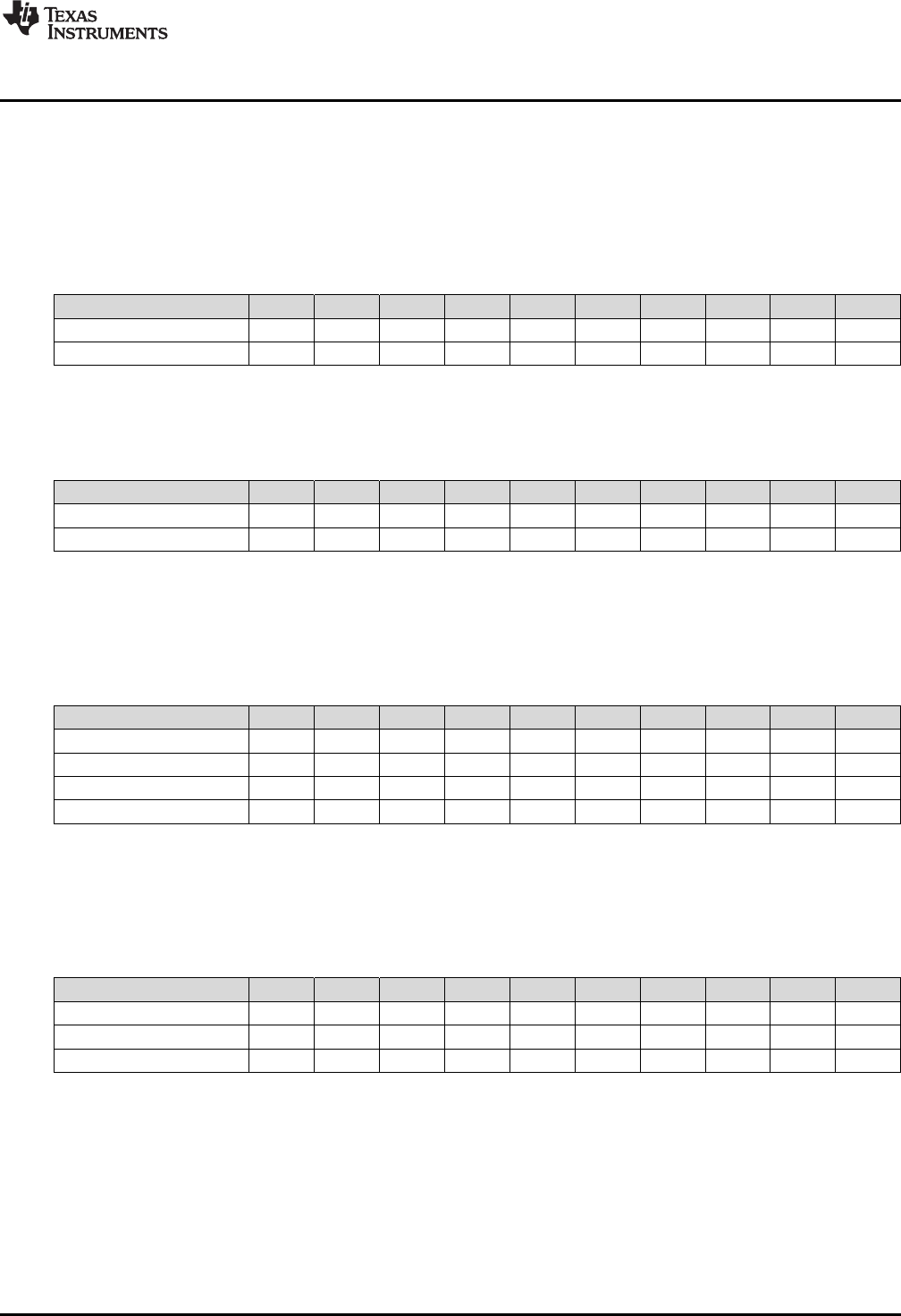
www.ti.com
Rounding Mode
2.6 Rounding Mode
This section details the rounding operation as applied to a right shift. When the rounding mode is enabled
in the VSTATUS register, .5 will be added to the right shifted intermediate value before truncation. If
rounding is disabled the right shifted value is only truncated. Table 2-19 shows the bit representation of
two values, 11.0 and 13.0. The columns marked Bit-1, Bit-2 and Bit-3 hold temporary bits resulting from
the right shift operation.
Table 2-19. Example: Values Before Shift Right
Bit5 Bit4 Bit3 Bit2 Bit1 Bit0 Bit-1 Bit-2 Bit -3 Value
Val A 0 0 1 0 1 1 0 0 0 11.000
Val B 0 0 0 0 0 1 0 0 0 13.000
Table 2-19 shows the intermediate values after the right shift has been applied to Val B. The columns
marked Bit-1, Bit-2 and Bit-3 hold temporary bits resulting from the right shift operation.
Table 2-20. Example: Values after Shift Right
Bit5 Bit4 Bit3 Bit2 Bit1 Bit0 Bit-1 Bit-2 Bit -3 Value
Val A 0 0 1 0 1 1 0 0 0 11.000
Val B >> 3 0 0 0 0 0 1 1 0 1 1.625
When the rounding mode is enabled, .5 will be added to the intermediate result before truncation. Table 2-
21 shows the bit representation of Val A + Val (B >> 3) operation with rounding. Notice .5 is added to the
intermediate shifted right value. After the addition, the bits in Bit-1, Bit-2 and Bit-3 are removed. In this
case the result of the operation will be 13 which is the truncated value after rounding.
Table 2-21. Example: Addition with Right Shift and Rounding
Bit5 Bit4 Bit3 Bit2 Bit1 Bit0 Bit-1 Bit-2 Bit -3 Value
Val A 0 0 1 0 1 1 0 0 0 11.000
Val B >> 3 0 0 0 0 0 1 1 0 1 1.625
.5 0 0 0 0 0 0 1 0 0 0 .500
Val A + Val B >> 3 + .5 0 0 1 1 0 1 0 0 1 13.125
When the rounding mode is disabled, the value is simply truncated. Table 2-22 shows the bit
representation of the operation Val A + (Val B >> 3) without rounding. After the addition, the bits in Bit-1,
Bit-2 and Bit-3 are removed. In this case the result of the operation will be 12 which is the truncated value
without rounding.
Table 2-22. Example: Addition with Rounding After Shift Right
Bit5 Bit4 Bit3 Bit2 Bit1 Bit0 Bit-1 Bit-2 Bit -3 Value
Val A 0 0 1 0 1 1 0 0 0 11.000
Val B >> 3 0 0 0 0 0 1 1 0 1 1.625
Val A + Val B >> 3 0 0 1 1 0 0 1 0 1 12.625
Table 2-23 shows more examples of the intermediate shifted value along with the result if rounding is
enabled or disabled. In each case, the truncated value is without .5 added and the rounded value is with
.5 added.
379
SPRUHS1A–March 2014–Revised December 2015 C28 Viterbi, Complex Math and CRC Unit-II (VCU-II)
Submit Documentation Feedback
Copyright © 2014–2015, Texas Instruments Incorporated
Rounding Mode
www.ti.com
Table 2-23. Shift Right Operation With and Without Rounding
Bit2 Bit1 Bit0 Bit -1 Bit -2 Value Result with RND = 0 Result with RND = 1
0 1 0 0 0 2.00 2 2
0 0 1 1 1 1.75 1 2
0 0 1 1 0 1.50 1 2
0 0 1 0 1 1.25 1 1
0 0 0 1 1 0.75 0 1
0 0 0 1 0 0.50 0 1
0 0 0 0 1 0.25 0 0
0 0 0 0 0 0.00 0 0
1 1 1 1 1 -0.25 0 0
1 1 1 1 0 -0.50 0 0
1 1 1 0 1 -0.75 0 -1
1 1 1 0 0 -1.00 -1 -1
1 1 0 1 1 -1.25 -1 -1
1 1 0 1 0 -1.50 -1 -1
1 1 0 0 1 -1.75 -1 -2
1 1 0 0 0 -2.00 -2 -2
380 C28 Viterbi, Complex Math and CRC Unit-II (VCU-II) SPRUHS1A–March 2014–Revised December 2015
Submit Documentation Feedback
Copyright © 2014–2015, Texas Instruments Incorporated

Chapter 3
SPRUHS1A–March 2014–Revised December 2015
Trigonometric Math Unit (TMU)
The Trigonometric Math Unit (TMU) is a fully programmable block that enhances the instruction set of the
C28-FPU to more efficiently execute common trigonometric and arithmetic operations.
The TMU module described in this reference guide is a Type 0 TMU. For a list of all devices with a TMU
module of the same type and to determine differences between the types, see the TMS320x28xx, 28xxx
DSP Peripheral Reference Guide (SPRU566). This document describes the architecture and instruction
set of the C28x+FPU+TMU.
Topic ........................................................................................................................... Page
3.1 Overview ......................................................................................................... 382
3.2 Components of the C28x+FPU Plus TMU............................................................. 382
3.3 Data Format ..................................................................................................... 382
3.4 Pipeline ........................................................................................................... 383
3.5 TMU Instruction Set .......................................................................................... 388
381
SPRUHS1A–March 2014–Revised December 2015 Trigonometric Math Unit (TMU)
Submit Documentation Feedback Copyright © 2014–2015, Texas Instruments Incorporated
Overview
www.ti.com
3.1 Overview
The TMU extends the capabilities of a C28x+FPU enabled processor by adding instructions to speed up
the execution of common trigonometric and arithmetic operations listed in Table 3-1.
Table 3-1. TMU Supported Instructions
Instructions C Equivalent Operation
MPY2PIF32 RaH,RbH a = b * 2pi
DIV2PIF32 RaH,RbH a = b / 2pi
DIVF32 RaH,RbH,RcH a = b/c
SQRTF32 RaH,RbH a = sqrt(b)
SINPUF32 RaH,RbH a = sin(b*2pi)
COSPUF32 RaH,RbH a = cos(b*2pi)
ATANPUF32 RaH,RbH a = atan(b)/2pi
QUADF32 RaH,RbH,RcH,RdH Operation to assist in calculating ATANPU2
3.2 Components of the C28x+FPU Plus TMU
The TMU extends the capabilities of the C28x+FPU processors by adding new instructions and, in some
cases, leveraging existing FPU instructions to carry out common arithmetic operations used in control
applications.
No changes have been made to existing instructions, pipeline or memory bus architecture. All TMU
instructions use the existing FPU register set (R0H to R7H) to carry out their operations. A detailed
explanation of the workings of the FPU can be found in the TMS320C28x Floating Point Unit and
Instruction Set Reference Guide (SPRUEO2).
3.2.1 Interrupt Context Save and Restore
Since the TMU uses the same register set and flags as the FPU, there are no special considerations with
regards to interrupt context save and restore.
If a TMU operation is executing when an interrupt occurs, the C28 can initiate an interrupt context switch
without affecting the TMU operation. The TMU will continue to process the operation to completion. Even
though most TMU operations are multi-cycle, the TMU operation will have completed by the time register
context save operations for the FPU are commenced. When restoring FPU registers, you must make sure
that all TMU operations are completed before restoring any register used by another TMU operation.
3.3 Data Format
The encoding of the floating-point formats is given in Table 3-2.
Table 3-2. IEEE 32-Bit Single Precision Floating-Point Format
S32 E32 (7:0) M32 (22:0) Value (V)
0 0 0 Zero (V = 0)
1 0 0 Negative Zero (V = -0)
0 +ve 0 non zero De-normalized (V=(-1)S* 2(-126)* (0.M))
1 -ve
0 +ve 1 to 254 0 to 0x7FFFFF Normal Range (V=(-1)S* 2(E-127) * (1.M))
1 -ve
0 254 0x7FFFFF Positive Max (V = +Max)
1 254 0x7FFFFF Negative Max (V = -Max)
0 max=255 0 Positive Infinity (V = +Infinity)
1 max=255 0 Negative Infinity (V = -Infinity)
x max=255 non zero Not A Number (V = NaN)
382 Trigonometric Math Unit (TMU) SPRUHS1A–March 2014–Revised December 2015
Submit Documentation Feedback
Copyright © 2014–2015, Texas Instruments Incorporated

www.ti.com
Pipeline
The treatment of the various IEEE floating-point numerical formats for this TMU is the same as the FPU
implementation given below:
Negative Zero: All TMU operations generate a positive (S==0, E==0, M==0) zero, never a negative zero if
the result of the operation is zero. All TMU operations treat negative zero operations as zero.
De-Normalized Numbers: A de-normalized operand (E==0, M!=0) input is treated as zero (E==0, M==0)
by all TMU operations. TMU operations never generate a de-normalized value.
Underflow: Underflow occurs when an operation generates a value that is too small to represent in the
given floating-point format. Under such cases, a zero value is returned. If a TMU operation generates an
underflow condition, then the latched underflow flag (LUF) is set to 1. The LUF flag will remain latched
until cleared by the user executing an instruction that clears the flag.
Overflow: Overflow occurs when an operation generates a value that is too large to represent in the given
floating-point format. Under such cases, a ± Infinity value is returned. If a TMU operation generates an
overflow condition, then the latched overflow flag (LVF) is set to 1. The LVF flag will remain latched until
cleared by the user executing an instruction that clears the flag.
Rounding: There are various rounding formats supported by the IEEE standard. Rounding has no
meaning for TMU operations (rounding is inherent in the implementation). Hence rounding mode is
ignored by TMU operations.
Infinity and Not a Number (NaN): An NaN operand (E==max, M!=0) input is treated as Infinity (E==max,
M==0) for all operations. TMU operations will never generate a NaN value but Infinity instead.
3.4 Pipeline
The TMU enhances the instruction set of the C28-FPU and, therefore, operates the C28x pipeline in the
same fashion as the FPU. For a detailed explanation on the working of the pipeline, see the TMS320C28x
Floating Point Unit and Instruction Set Reference Guide (SPRUEO2).
3.4.1 Pipeline and Register Conflicts
In addition to the restrictions mentioned in the TMS320C28x Floating Point Unit and Instruction Set
Reference Guide (SPRUEO2), the TMU places the following restrictions on its instructions:
Example 3
‑‑
1. SINPUF32 Operation (4p cycles)
SINPUF32 RaH,RbH ; Value in registers RbH read in this cycle.
Instruction1 ; Instructions 1-3 cannot operate on register RaH.
Instruction2 ; Instructions 1-3 can operate on register RbH.
Instruction3 ; Instructions 1-3 can be any TMU/FPU/VCU/CPU operation.
Instruction4 ; Result in RaH usable by Instruction 4.
Example 3
‑‑
2. COSPUF32 Operation (4p cycles)
COSPUF32 RaH,RbH ; Value in registers RbH read in this cycle.
Instruction1 ; Instructions 1-3 cannot operate on register RaH.
Instruction2 ; Instructions 1-3 can operate on register RbH.
Instruction3 ; Instructions 1-3 can be any TMU/FPU/VCU/CPU operation.
Instruction4 ; Result in RaH usable by Instruction4.
Example 3
‑‑
3. ATANPUF32 Operation (4p cycles)
ATANPUF32 RaH,RbH ; Value in registers RbH read in this cycle.
Instruction1 ; Instructions 1-3 cannot operate on register RaH.
Instruction2 ; Instructions 1-3 can operate on register RbH.
Instruction3 ; Instructions 1-3 can be any TMU/FPU/VCU/CPU operation.
; Result, LVF flag updated on Instruction3 (4th cycle).
Instruction4 ; Result in RaH usable by Instruction4.
383
SPRUHS1A–March 2014–Revised December 2015 Trigonometric Math Unit (TMU)
Submit Documentation Feedback Copyright © 2014–2015, Texas Instruments Incorporated

Pipeline
www.ti.com
Example 3
‑‑
4. DIVF32 Operation (5p cycles)
DIVF32 RaH,RbH,RcH ; Value in registers RbH & RcH read in this cycle.
Instruction1 ; Instructions 1-4 cannot operate on register RaH.
Instruction2 ; Instructions 1-4 can operate on register RbH & RcH.
Instruction3 ; Instructions 1-4 can be any TMU/FPU/VCU/CPU operation.
Instruction4 ; Result, LVF and LUF flags updated on Instruction4 (5th cycle).
Instruction5 ; Result in RaH usable by Instruction5.
Example 3
‑‑
5. SQRTF32 Operation (5p cycles)
SQRTF32 RaH,RbH ; Value in register RbH read in this cycle.
Instruction1 ; Instructions 1-4 cannot operate on register RaH.
Instruction2 ; Instructions 1-4 can operate on register RbH.
Instruction3 ; Instructions 1-4 can be any TMU/FPU/VCU/CPU operation.
Instruction4 ; Result, LVF flag updated on Instruction4 (5th cycle).
Instruction5 ; Result in register RaH usable by Instruction5.
Example 3
‑‑
6. QUADF32 Operations (5p cycles)
QUADF32 RaH,RbH,RcH,RdH
; Value in registers RcH & RdH read in this cycle.
Instruction1 ; Instructions 1-4 cannot operate on registers RaH & RbH.
Instruction2 ; Instructions 1-4 can operate on register RbH.
Instruction3 ; Instructions 1-4 can be any TMU/FPU/VCU/CPU operation.
Instruction4 ; Result, LVF and LUF flags updated on Instruction4 (5th cycle).
Instruction5 ; Result in registers RaH & RbH usable by Instruction5.
384 Trigonometric Math Unit (TMU) SPRUHS1A–March 2014–Revised December 2015
Submit Documentation Feedback
Copyright © 2014–2015, Texas Instruments Incorporated

www.ti.com
Pipeline
3.4.2 Delay Slot Requirements
The Delay slot requirements for the TMU instructions are presented in Table 3-3.
Table 3-3. Delay Slot Requirements for TMU Instructions
Case Description
1 Any Single Cycle FPU operation (including any memory load/store operation)
SINPUF32/COSPUF32/ATANPUF32/QUADF32/MPY2PIF32/DIV2PIF32/DIVF32/SQRTF32
2 All FPU 2p-cycle operations MPY/ADD/SUB/….
NOP
NOP
SINPUF32/COSPUF32/ATANPUF32/QUADF32/MPY2PIF32/DIV2PIF32/DIVF32/SQRTF32
3 SINPUF32/COSPUF32/ATANPUF32
NOP
NOP
NOP
All TMU or FPU operations
4 QUADF32/DIVF32/SQRTF32
NOP
NOP
NOP
NOP
All TMU or FPU operations
Special Cases Involving MPY2PIF32/DIV2PIF32
5 MPY2PIF32/DIV2PIF32
NOP
SINPUF32/COSPUF32
6 MPY2PIF32/DIV2PIF32
NOP
NOP
ATANPUF32/QUADF32/DIVF32/SQRTF32
7 MPY2PIF32/DIV2PIF32
NOP
NOP
All FPU operations
8 MPY2PIF32/DIV2PIF32
NOP
MOV32 mem,RxH; Special case: Store result of MPY2PIF32/DIV2PIF32 to memory (but does not include MOV32 operation
between CPU and FPU registers).
Notes:
The “NOPs” can be any other FPU, TMU, VCU or CPU operation that does not conflict with the current
active TMU operation (does not use same destination register). For example,
Example 3
‑‑
7. Use of Non-Conflicting Instructions in Delay Slots
SINPUF32 R0H,R1H
COSPUF32 R2H,R1H
MOV32 R4H,@VarA
MOV32 R5H,@VarB
ADDF32 R3H,R4H,R0H ; SINPUF32 value (R0H) used here
ADDF32 R7H,R5H,R2H ; COSPUF32 value (R2H) used here
The delay FPU slot requirements apply to the operation whereby the destination register value is
subsequently used by the TMU operation. For example, in the following case, a parallel MPY and MOV
operation precedes the TMU operation and the result from MPY operation is used, then two delay slots
are required (Case 2 of Table 3-3):
385
SPRUHS1A–March 2014–Revised December 2015 Trigonometric Math Unit (TMU)
Submit Documentation Feedback Copyright © 2014–2015, Texas Instruments Incorporated

Pipeline
www.ti.com
Example 3
‑‑
8. Delay Slot Requirement for TMU Instructions That Use Results of Prior FPU Instructions
MPYF32 R3H,R2H,R1H
||MOV32 R4H,@varA
NOP
NOP
SINPUF32 R6H,R3H
If however the result of the parallel MOV operation is used, then no delay slots are required since the
MOV will complete in a single cycle. (Case 1 of Table 3-3):
Example 3
‑‑
9. FPU Instruction Followed by a Non-Dependent TMU Instruction
MPYF32 R3H,R2H,R1H
||MOV32 R4H,@varA
SINPUF32 R6H,R4H
3.4.3 Effect of Delay Slot Operations on the Flags
The LVF and LUF flags can only be set. If multiple operations (from FPU or TMU) try to set the flags, the
operations on the flags are ORed together. Operations that set the LVF or LUF flags (either FPU or TMU)
are allowed in delay slots. For example, the following sequence of operations is valid:
Example 3
‑‑
10. Valid Back-to-Back Instructions That may Set the LVF, LUF Flag
MPY2PIF32 R0H,R0H
MPY2PIF32 R1H,R1H
If the SETFLG, SAVE, RESTORE, MOVST0, or loading and storing of the STF register, operations try to
modify the state of the LVF, LUF flags while a TMU or any other FPU operation is trying to set the flags,
the LUV, LVF flags are undefined. This can only occur if the SAVE, SETFLG, RESTORE, MOVST0, or
loading and storing of the STF register, operations are placed in the delay slots of the pipeline operations;
this should be avoided. This also applies to ZF and NF flags, which are not affected by TMU operations.
3.4.4 Multi-Cycle Operations in Delay Slots
A multi-cycle operation like RET, BRANCH, CALL is equivalent to a minimum four NOPs. For example,
the code shown in Example 3-11 returns the correct value because LRETR takes a minimum of four
cycles to execute (equivalent to four NOPs):
Example 3
‑‑
11. Multi-Cycle Operation in the Delay Slot of a TMU Instruction
DIVF32 R0H,R2H,R1H
LRETR
3.4.5 Moves From FPU Registers to C28x Registers
When transferring from floating-point unit registers (result of an FPU or TMU operation) to the C28x CPU
register, additional pipeline alignment is required as shown in Example 3-12.
386 Trigonometric Math Unit (TMU) SPRUHS1A–March 2014–Revised December 2015
Submit Documentation Feedback
Copyright © 2014–2015, Texas Instruments Incorporated

www.ti.com
Pipeline
Example 3
‑‑
12. Floating-Point to C28x Register Software Pipeline Alignment
; SINPUF32: Per unit sine: 4 pipeline cycle operation
; An alignment cycle is required before copying R0H to ACC
SINPUF32 R0H,R1H
NOP ; Delay Slot 1
NOP ; Delay Slot 2
NOP ; Delay Slot 3
NOP ; Alignment cycle
MOV32 @ACC,R0H
387
SPRUHS1A–March 2014–Revised December 2015 Trigonometric Math Unit (TMU)
Submit Documentation Feedback Copyright © 2014–2015, Texas Instruments Incorporated

TMU Instruction Set
www.ti.com
3.5 TMU Instruction Set
This section describes the assembly language instructions of the TMU.
3.5.1 Instruction Descriptions
This section provides detailed information on the instruction set. Each instruction may present the
following information:
• Operands
• Opcode
• Description
• Exceptions
• Pipeline
• Examples
• See also
The example INSTRUCTION is shown to familiarize you with the way each instruction is described. The
example describes the kind of information you will find in each part of the individual instruction description
and where to obtain more information. TMU instructions follow the same format as the C28x and the
C28x+FPU; the source operand(s) are always on the right and the destination operand(s) are on the left.
The explanations for the syntax of the operands used in the instruction descriptions for the C28x TMU are
given in Table 3-4. For information on the operands of standard C28x instructions, see the TMS320C28x
CPU and Instruction Set Reference Guide (SPRU430).
Table 3-4. Operand Nomenclature
Symbol Description
#16FHi 16-bit immediate (hex or float) value that represents the upper 16-bits of an IEEE 32-bit floating-point value. Lower
16-bits of the mantissa are assumed to be zero.
#16FHiHex 16-bit immediate hex value that represents the upper 16-bits of an IEEE 32-bit floating-point value. Lower 16-bits of
the mantissa are assumed to be zero.
#16FLoHex A 16-bit immediate hex value that represents the lower 16-bits of an IEEE 32-bit floating-point value
#32Fhex 32-bit immediate value that represents an IEEE 32-bit floating-point value
#32F Immediate float value represented in floating-point representation
#0.0 Immediate zero
#RC 16-bit immediate value for the repeat count
*(0:16bitAddr) 16-bit immediate address, zero extended
CNDF Condition to test the flags in the STF register
FLAG Selected flags from STF register (OR) 11 bit mask indicating which floating-point status flags to change
label Label representing the end of the repeat block
mem16 Pointer (using any of the direct or indirect addressing modes) to a 16-bit memory location
mem32 Pointer (using any of the direct or indirect addressing modes) to a 32-bit memory location
RaH R0H to R7H registers
RbH R0H to R7H registers
RcH R0H to R7H registers
RdH R0H to R7H registers
ReH R0H to R7H registers
RfH R0H to R7H registers
RB Repeat Block Register
STF FPU Status Register
VALUE Flag value of 0 or 1 for selected flag (OR) 11 bit mask indicating the flag value; 0 or 1
388 Trigonometric Math Unit (TMU) SPRUHS1A–March 2014–Revised December 2015
Submit Documentation Feedback
Copyright © 2014–2015, Texas Instruments Incorporated

www.ti.com
INSTRUCTION dest1, source1, source2 Short Description —
INSTRUCTION dest1, source1, source2 Short Description
Operands
dest1 Description for the 1st operand for the instruction
source1 Description for the 2nd operand for the instruction
source2 Description for the 3rd operand for the instruction
Each instruction has a table that gives a list of the operands and a short description.
Instructions always have their destination operand(s) first followed by the source
operand(s).
Opcode This section shows the opcode for the instruction.
Description Detailed description of the instruction execution is described. Any constraints on the
operands imposed by the processor or the assembler are discussed.
Restrictions Any constraints on the operands or use of the instruction imposed by the processor are
discussed.
Pipeline This section describes the instruction in terms of pipeline cycles.
Example Examples of instruction execution. If applicable, register and memory values are given
before and after instruction execution. All examples assume the device is running with
the OBJMODE set to 1. Normally the boot ROM or the c-code initialization will set this
bit.
See Also Lists related instructions.
3.5.2 Common Restrictions
For all the TMU instructions, the inputs are conditioned as follows (LVF, LUF are not affected):
• Negative zero is treated as positive zero
• Positive or negative denormalized numbers are treated as positive zero
• Positive and negative NaN are treated as positve and negative infinity respectively
3.5.3 Instructions
The instructions are listed alphabetically.
Table 3-5. Summary of Instructions
Title ...................................................................................................................................... Page
MPY2PIF32 RaH, RbH —32-Bit Floating-Point Multiply by Two Pi.............................................................. 391
389
SPRUHS1A–March 2014–Revised December 2015 Trigonometric Math Unit (TMU)
Submit Documentation Feedback Copyright © 2014–2015, Texas Instruments Incorporated

TMU Instruction Set
www.ti.com
Table 3-5. Summary of Instructions (continued)
DIV2PIF32 RaH, RbH —32-Bit Floating-Point Divide by Two Pi................................................................. 392
DIVF32 RaH, RbH, RcH —32-Bit Floating-Point Division......................................................................... 393
SQRTF32 RaH, RbH —32-Bit Floating-Point Square Root ....................................................................... 395
SINPUF32 RaH, RbH —32-Bit Floating-Point Sine (per unit) .................................................................... 396
COSPUF32 RaH, RbH —32-Bit Floating-Point Cosine (per unit) ................................................................ 398
ATANPUF32 RaH, RbH —32-Bit Floating-Point ArcTangent (per unit)......................................................... 400
QUADF32 RaH, RbH, RcH —Quadrant Determination Used in Conjunction With ATANPUF32().......................... 401
390 Trigonometric Math Unit (TMU) SPRUHS1A–March 2014–Revised December 2015
Submit Documentation Feedback
Copyright © 2014–2015, Texas Instruments Incorporated

www.ti.com
MPY2PIF32 RaH, RbH — 32-Bit Floating-Point Multiply by Two Pi
MPY2PIF32 RaH, RbH 32-Bit Floating-Point Multiply by Two Pi
Operands
RaH Floating-point destination register (R0H to R7H)
RbH Floating-point source register (R0H to R7H)
Opcode
LSW 1110 0010 0111 0000
MSW 0000 0000 00bb baaa
Description This operation is similar to the MPYF32 operation except that the second operand is the
constant value 2pi:
RaH = RbH * 2pi
This operation is used in converting Per Unit values to Radians. Per Unit values are
used in control applications to represent normalized radians:
Per Unit Radians
1.0 2pi
0.0 0
1.0 2pi
2pi = 6.28318530718 = 1.570796326795 * 2^2
In IEEE 32-bit Floating point format:
S = 0 << 31= 0x00000000
E = (2 + 127) << 23= 129 << 23= 0x40800000
M = (1.570796326795 * 2^23) & 0x007FFFFF= 0x00490FDB
2pi = S+E+M = 0x40C90FDB
Flags
Flag TF ZI NI ZF NF LUF LVF
Modified No No No No No No Yes
Restrictions If( RaH result is too big for floating-point number, Ea > 255 ){
RaH = ±Infinity
LVF = 1;
}
Pipeline Instruction takes 2 pipeline cycles to execute if followed by either SINPUF32,
COSPUF32 or MOV32 mem, Rx operations and 3 pipeline cycles for all other operations
(FPU or TMU).
Example ;; Convert Per Unit value to Radians:
MOV32 R0H,@PerUnit ; R0H = Per Unit value
MPY2PIF32 R0H,R0H ; R0H = R0H * 2pi
NOP ; pipeline delay
MOV32 @Radians,R0H ; store Radian result
; 4 cycles
391
SPRUHS1A–March 2014–Revised December 2015 Trigonometric Math Unit (TMU)
Submit Documentation Feedback Copyright © 2014–2015, Texas Instruments Incorporated

DIV2PIF32 RaH, RbH — 32-Bit Floating-Point Divide by Two Pi
www.ti.com
DIV2PIF32 RaH, RbH 32-Bit Floating-Point Divide by Two Pi
Operands
RaH Floating-point destination register (R0H to R7H)
RbH Floating-point source register (R0H to R7H)
Opcode
LSW 1110 0010 0111 0001
MSW 0000 0000 00bb baaa
Description This operation is similar to the MPYF32 operation except that the second operand is the
constant value 1/2pi:
RaH = RbH * 1/2pi
This operation is used in converting Radians to Per unit values. Per unit values are used
in control representing normalized Radians:
Per Unit Radians
1.0 2pi
0.0 0
-1.0 -2pi
In IEEE 32-bit Floating point format:
1/2pi = 0.1591549430919 = 1.273239544735 * 2^-3
S = 0 << 31= 0x00000000
E = (-3+127) << 23 = 124 << 23 = 0x3E000000
M = (1.273239544735 * 2^23) & 0x007FFFFF = 0x0022F983
1/2pi = S+E+M = 0x3E22F983
Flags
Flag TF ZI NI ZF NF LUF LVF
Modified No No No No No Yes No
Restrictions If( RaH result is too small for floating-point number, Ea < 0) {
RaH = 0.0
LUF = 1;
}
Pipeline Instruction takes 2 pipeline cycles to execute if followed by either SINPUF32,
COSPUF32 or MOV32 mem, Rx operations and 3 pipeline cycles for all other operations
(FPU or TMU).
Example ;; Convert Per Unit value to Radians:
MOV32 R0H,@Radians ; R0H = Radian value
DIV2PIF32 R0H,R0H ; R0H = R0H * 1/2pi
NOP ; pipeline delay
MOV32 @Per Unit ; store Per Unit result
; 4 cycles
392 Trigonometric Math Unit (TMU) SPRUHS1A–March 2014–Revised December 2015
Submit Documentation Feedback
Copyright © 2014–2015, Texas Instruments Incorporated

www.ti.com
DIVF32 RaH, RbH, RcH — 32-Bit Floating-Point Division
DIVF32 RaH, RbH, RcH 32-Bit Floating-Point Division
Operands
RaH Floating-point destination register (R0H to R7H)
RbH Floating-point source register (R0H to R7H)
RcH Floating-point source register (R0H to R7H)
Opcode
LSW 1110 0010 0111 0100
MSW 0000 000c ccbb baaa
Description RaH = RbH/RcH
The sequence of operations are as follows:
Sa = Sb ^ Sc; // Set sign of result
Ea = (Eb – Ec) + 127; // Calculate Exponent
Ma = Mb / Mc; // 0.5 < Ma < 2.0
if(Ma < 1.0){){ // Re-normalize mantissa range
Ea = Ea – 1;
Ma = Ma * 2.0;
}
if(Ea >= 255){ // Chek if result too big:
Ea = 255; // Return Inf
Ma = 0;
LVF = 1; // Set overflow flag
}
if((Ea == 0) & (Ma != 0)){ // Check if result Denorm value:
Sa = 0;
Ea = 0; // Return zero
Ma = 0;
LUF = 1; // Set underflow flag
}
if(Ea < 0){ // Check if result too small:
Sa = 0;
Ea = 0; // Return zero
Ma = 0;
LUF = 1; // Set underflow flag
}
Flags
Flag TF ZI NI ZF NF LUF LVF
Modified No No No No No Yes Yes
393
SPRUHS1A–March 2014–Revised December 2015 Trigonometric Math Unit (TMU)
Submit Documentation Feedback Copyright © 2014–2015, Texas Instruments Incorporated

DIVF32 RaH, RbH, RcH — 32-Bit Floating-Point Division
www.ti.com
Restrictions The following boundary conditions apply:
Division Result LVF LUF
0/0 0 1 -
0/Inf 0 - 1
Inf/Normal Inf 1 -
Inf/0 Inf 1 -
Inf/Inf Inf - 1
Normal/0 Inf 1 -
Normal/Inf 0 - 1
Pipeline Instruction takes 5 pipeline cycles to execute.
Example ;; Calculate Z = Y/X
MOV32 R0H,@X ; R0H = X
MOV32 R1H,@Y ; R1H = Y
DIVF32 R2H,R1H,R0H ; R2H = R1H/R0H = Y/X = Z
NOP ; pipeline delay
NOP ; pipeline delay
NOP ; pipeline delay
NOP ; pipeline delay
MOV32 @Z,R2H ; Z = Y/X
; 8 cycles
394 Trigonometric Math Unit (TMU) SPRUHS1A–March 2014–Revised December 2015
Submit Documentation Feedback
Copyright © 2014–2015, Texas Instruments Incorporated

Rah RbH=
www.ti.com
SQRTF32 RaH, RbH — 32-Bit Floating-Point Square Root
SQRTF32 RaH, RbH 32-Bit Floating-Point Square Root
Operands
RaH Floating-point destination register (R0H to R7H)
RbH Floating-point source register (R0H to R7H)
Opcode
LSW 1110 0010 0111 0111
MSW 0000 0000 00bb baaa
Description
Flags
Flag TF ZI NI ZF NF LUF LVF
Modified No No No No No No Yes
Restrictions If( RbH < 0.0 or -Inf ) { // Check if input is negative:
Sa = 0; // Return zero
Ea = 0;
Ma = 0;
LVF = 1; // Set overflow flag
}
If( RbH == +Inf ) {
Sa = 0; // Return Inf
Ea = 255;
Ma = 0;
LVF = 1; // Set overflow flag
}
Pipeline Instruction takes 5 pipeline cycles to execute.
Example ;; Calculate Y = sqrt(X)
MOV32 R0H,@X ; R0H = X
SQRTF32 R1H,R0H ; R1H = sqrt(X)
NOP ; pipeline delay
NOP ; pipeline delay
NOP ; pipeline delay
NOP ; pipeline delay
MOV32 @Y,R1H ; Y = sqrt(X)
; 7 cycles
395
SPRUHS1A–March 2014–Revised December 2015 Trigonometric Math Unit (TMU)
Submit Documentation Feedback Copyright © 2014–2015, Texas Instruments Incorporated
SINPUF32 RaH, RbH — 32-Bit Floating-Point Sine (per unit)
www.ti.com
SINPUF32 RaH, RbH 32-Bit Floating-Point Sine (per unit)
Operands
RaH Floating-point destination register (R0H to R7H)
RbH Floating-point source register (R0H to R7H)
Opcode
LSW 1110 0010 0111 1000
MSW 0000 0000 00bb baaa
Description This instruction performs the following equivalent operation:
PerUnit = fraction(RbH)
RaH = sin(PerUnit*2pi)
In control applications radians are usually normalized to the range of -1.0 to 1.0.
Per Unit Radians
1.0 2pi
0.0 0
-1.0 -2pi
The operation takes the fraction of the input value RbH. This equates to the cosine
waveform repeating itself every 2pi radians
RbH Per Unit Radians Sine Value
2.0 0.0 0 0.0
1.75 0.75 3pi/2 -1.0
1.5 0.5 pi 0.0
1.25 0.25 pi/2 1.0
1.0 0.0 0 0.0
0.75 0.75 3pi/2 -1.0
0.5 0.5 pi 0.0
0.25 0.25 pi/2 1.0
0.0 0.0 0 0.0
-0.25 -0.25 -pi/2 -1.0
-0.5 -0.5 -pi 0.0
-0.75 -0.75 -3pi/2 1.0
-1.0 0.0 0 0.0
-1.25 -0.25 -pi/2 -1.0
-1.5 -0.5 -pi 0.0
-1.75 -0.75 -3pi/2 1.0
-2.0 0.0 0 0.0
Flags
Flag TF ZI NI ZF NF LUF LVF
Modified No No No No No No No
396 Trigonometric Math Unit (TMU) SPRUHS1A–March 2014–Revised December 2015
Submit Documentation Feedback
Copyright © 2014–2015, Texas Instruments Incorporated

www.ti.com
SINPUF32 RaH, RbH — 32-Bit Floating-Point Sine (per unit)
Restrictions If the input value is too small (<= 2^-33) or too big (>= 2^22), then the output will be
returned as 0.0 (no flags affected).
Pipeline Instruction takes 4 pipeline cycles to execute.
Example ;; Convert Radian value to PerUnit value and
;; calculate Sin value:
MOV32 R0H,@RadianValue ; R0H = Radian value
DIV2PIF32 R1H,R0H
; R1H=R0H/2pi= Per Unit Value
NOP ; pipeline delay
SINPUF32 R2H,R1H ; R2H = SINPU(fraction(R1H))
NOP ; pipeline delay
NOP ; pipeline delay
NOP ; pipeline delay
MOV32 @SinValue,R2H ; Sin Value=sin(Radian Value)
; 8 cycles
397
SPRUHS1A–March 2014–Revised December 2015 Trigonometric Math Unit (TMU)
Submit Documentation Feedback Copyright © 2014–2015, Texas Instruments Incorporated

COSPUF32 RaH, RbH — 32-Bit Floating-Point Cosine (per unit)
www.ti.com
COSPUF32 RaH, RbH 32-Bit Floating-Point Cosine (per unit)
Operands
RaH Floating-point destination register (R0H to R7H)
RbH Floating-point source register (R0H to R7H)
Opcode
LSW 1110 0010 0111 1001
MSW 0000 0000 00bb baaa
Description This instruction performs the following equivalent operation:
PerUnit = fraction(RbH)
RaH = cos(PerUnit*2pi)
In control applications radians are usually normalized to the range of -1.0 to 1.0.
Per Unit Radians
1.0 2pi
0.0 0
-1.0 -2pi
The operation takes the fraction of the input value RbH. This equates to the cosine
waveform repeating itself every 2pi radians
RbH Per Unit Radians Cosine Value
2.0 0.0 0 1.0
1.75 0.75 3pi/2 0.0
1.5 0.5 pi -1.0
1.25 0.25 pi/2 0.0
1.0 0.0 0 1.0
0.75 0.75 3pi/2 0.0
0.5 0.5 pi -1.0
0.25 0.25 pi/2 0.0
0.0 0.0 0 1.0
-0.25 -0.25 -pi/2 0.0
-0.5 -0.5 -pi -1.0
-0.75 -0.75 -3pi/2 0.0
-1.0 0.0 0 1.0
-1.25 -0.25 -pi/2 0.0
-1.5 -0.5 -pi -1.0
-1.75 -0.75 -3pi/2 0.0
-2.0 0.0 0 1.0
Flags
Flag TF ZI NI ZF NF LUF LVF
Modified No No No No No No No
398 Trigonometric Math Unit (TMU) SPRUHS1A–March 2014–Revised December 2015
Submit Documentation Feedback
Copyright © 2014–2015, Texas Instruments Incorporated

www.ti.com
COSPUF32 RaH, RbH — 32-Bit Floating-Point Cosine (per unit)
Restrictions If the input value is too small (<= 2^-33) or too big (>= 2^22), then the output will be
returned as 1.0 (no flags affected).
Pipeline Instruction takes 4 pipeline cycles to execute.
Example ;; Convert Radian value to PerUnit value and
;; calculate Sin value:
MOV32 R0H,@RadianValue ; R0H = Radian value
DIV2PIF32 R1H,R0H
; R1H=R0H/2pi= Per Unit Value
NOP ; pipeline delay
COSPUF32 R2H,R1H ; R2H = COSPU(fraction(R1H))
NOP ; pipeline delay
NOP ; pipeline delay
NOP ; pipeline delay
MOV32 @CosValue,R2H ; Cos Value=cos(Radian Value)
; 8 cycles
399
SPRUHS1A–March 2014–Revised December 2015 Trigonometric Math Unit (TMU)
Submit Documentation Feedback Copyright © 2014–2015, Texas Instruments Incorporated
ATANPUF32 RaH, RbH — 32-Bit Floating-Point ArcTangent (per unit)
www.ti.com
ATANPUF32 RaH, RbH 32-Bit Floating-Point ArcTangent (per unit)
Operands
RaH Floating-point destination register (R0H to R7H)
RbH Floating-point source register (R0H to R7H)
Opcode
LSW 1110 0010 0111 1010
MSW 0000 0000 00bb baaa
Description This instruction computes the arc tangent of a given value and returns the result as a
per-unit value:
PerUnit = atan(RbH)/2pi
The operation limits the input ranget of the input value RbH to:
-1.0 < = RbH < = 1.0
Values outside this range return 0.125 as follows:
RbH Per Unit Radians ATANPU Value LVF Flag
>1.0 0.125 pi/4 0.125 1
1.0 0.125 pi/4 0.125
0.0 0.0 0 0.0
-1.0 -0.125 -pi/4 -0.125
<-1.0 -0.125 -pi/4 -0.125 1
Flags
Flag TF ZI NI ZF NF LUF LVF
Modified No No No No No No Yes
Pipeline Instruction takes 4 pipeline cycles to execute.
Example ;; Calculate ATAN and generate Per Unit value and
;; convert to Radians:
MOV32 R0H,@AtanValue ; R0H = Atan Value
ATANPUF32 R1H,R0H ; R1H = ATANPU(R0H)
NOP ; pipeline delay
NOP ; pipeline delay
NOP ; pipeline delay
MPY2PIF32 R2H,R1H ; R2H = R1H * 2pi
; = Radian value
NOP ; pipeline delay
MOV @RadianValue,R2H ; Store result
; 8 cycles
400 Trigonometric Math Unit (TMU) SPRUHS1A–March 2014–Revised December 2015
Submit Documentation Feedback
Copyright © 2014–2015, Texas Instruments Incorporated

www.ti.com
QUADF32 RaH, RbH, RcH — Quadrant Determination Used in Conjunction With ATANPUF32()
QUADF32 RaH, RbH, RcH Quadrant Determination Used in Conjunction With ATANPUF32()
Operands
RaH Floating-point destination register (R0H to R7H)
RbH Floating-point destination register (R0H to R7H)
RcH Floating-point source register (R0H to R7H)
RdH Floating-point source register (R0H to R7H)
Opcode
LSW 1110 0010 0111 1100
MSW 0000 dddc ccbb baaa
Description This operation, in conjunction with atanpu(), is used in calculating atanpu2() for a full
circle:
RdH = X value
RcH = Y value
RbH = Ratio of X & Y
RaH = Quadrant value (0.0, ±0.25, ±0.5)
Calculation of RaH (Quadrant) and RbH (Ratio) Based on RcH (Y) and RdH (X) Values
shows how the values RaH and RbH are generated based on the contents of RbH and
RcH.
The algorithm for this instruction is as follows:
if( (fabs(RcH(Y)) == 0.0) & (fabs(RdH(X)) == 0.0) ) {
RaH(Quadrant) = 0.0;
RbH(Ratio) = 0.0;
}else if( fabs(RcH(Y)) < = fabs(RdH(X)) ) {
RbH(Ratio) = RcH(Y) / RdH(X);
if( RdH(X) >= 0.0 )
RaH(Quadrant) = 0.0;
else {
if( RcH(Y) >= 0.0 )
RaH(Quadrant) = 0.5;
else
RaH(Quadrant) = -0.5;
}
}else {
if( RcH(Y) >= 0.0 )
RaH(Quadrant) = 0.25;
else
RaH(Quadrant) = -0.25;
RbH(Ratio) = - RdH(X) / RcH(Y);
}
Flags
Flag TF ZI NI ZF NF LUF LVF
Modified No No No No No Yes Yes
401
SPRUHS1A–March 2014–Revised December 2015 Trigonometric Math Unit (TMU)
Submit Documentation Feedback Copyright © 2014–2015, Texas Instruments Incorporated
If( (|Y| > |X|) & (Y >= 0) )
{ Quadrant = 0.25; Ratio = -X/Y; }
X
Y
If( (|Y| > |X|) & (Y < 0) )
{ Quadrant = -0.25; Ratio = -X/Y }
If( (|Y| <= |X|) & (X >=0) )
{ Ratio = Y/X;
Quadrant = 0.0; }
If( (|Y| <= |X|)
& (X < 0) & (Y >= 0) )
{ Quadrant = 0.5;
Ratio = Y/X }
If( (|Y| <= |X|)
& (X < 0) & (Y < 0) )
{ Quadrant = -0.5;
Ratio = Y/X }
Note: If( (Y==0) & (X ==0) )
{ Ratio = 0.0;
Quadrant = 0.0; }
0.125 (PU) = pi/4
0.25 (PU) = pi/2
0.375 (PU) = 3*pi/4
-0.375 (PU) = -3*pi/4 -0.125 (PU) = -pi/4
-0.25 (PU) = -pi/2
0.5 (PU) = pi
~0.5 (PU) = ~-pi
ATANPU2(Y,X) = Quadrant + ATANPU(Ratio)
QUADF32 RaH, RbH, RcH — Quadrant Determination Used in Conjunction With ATANPUF32()
www.ti.com
Restrictions
Division Result LVF LUF
0/0 0 1 -
0/Inf 0 - 1
Inf/Normal Inf 1 -
Inf/0 Inf 1 -
Inf/Inf Inf - 1
Normal/0 Inf 1 -
Normal/Inf 0 - 1
Pipeline Instruction takes 5 pipeline cycles to execute.
Example ;; Calculate Z = atan2(Y,X), where Z is in
;; radians:
MOV32 R0H,@X ; R0H = X
MOV32 R1H,@Y ; R1H = Y
;; if(Y <= X) R2H= R1H/R0H
;; else R2H= -R0H/R1H
;; R3H= 0.0, +/-0.25, +/-0.5
QUADF32 R3H,R2H,R1H,R0H
NOP ; pipeline delay
NOP ; pipeline delay
NOP ; pipeline delay
NOP ; pipeline delay
;; R4H = ATANPU(R2H)(Per Unit result)
ATANPUF32 R4H,R2H
NOP ; pipeline delay
NOP ; pipeline delay
NOP ; pipeline delay
;; R5H = R3H + ATANPU(R4H) = ATANPU2 value
ADDF32 R5H,R3H,R4H
NOP ; pipeline delay
;; R6H = ATANPU2 * 2pi = atan2 value(radians)
MPY2PIF32 R6H,R5H
NOP ; pipeline delay
MOV32 @Z,R6H ; store result
; 16 cycles
Calculation of RaH (Quadrant) and RbH (Ratio) Based on RcH (Y) and RdH (X) Values
402 Trigonometric Math Unit (TMU) SPRUHS1A–March 2014–Revised December 2015
Submit Documentation Feedback
Copyright © 2014–2015, Texas Instruments Incorporated

www.ti.com
Revision History
Revision History
Changes from March 15, 2014 to November 7, 2015 ...................................................................................................... Page
•Section 2.4.2: Added the last paragraph to this section ............................................................................ 20
•Section 1.4.4: Revised this paragraph. ............................................................................................... 21
•Chapter 2:C28 Viterbi, Complex Math and CRC Unit-II (VCU-II) : Made changes to the majority of the LSW and MSW
opcodes. ................................................................................................................................ 140
403
SPRUHS1A–March 2014–Revised December 2015 Revision History
Submit Documentation Feedback Copyright © 2014–2015, Texas Instruments Incorporated

IMPORTANT NOTICE
Texas Instruments Incorporated and its subsidiaries (TI) reserve the right to make corrections, enhancements, improvements and
other changes to its semiconductor products and services per JESD46, latest issue, and to discontinue any product or service
per JESD48, latest issue. Buyers should obtain the latest relevant information before placing orders and should verify that such
information is current and complete. All semiconductor products (also referred to herein as “components”) are sold subject to
TI’s terms and conditions of sale supplied at the time of order acknowledgment.
TI warrants performance of its components to the specifications applicable at the time of sale, in accordance with the warranty in
TI’s terms and conditions of sale of semiconductor products. Testing and other quality control techniques are used to the extent
TI deems necessary to support this warranty. Except where mandated by applicable law, testing of all parameters of each
component is not necessarily performed.
TI assumes no liability for applications assistance or the design of Buyers’ products. Buyers are responsible for their products
and applications using TI components. To minimize the risks associated with Buyers’ products and applications, Buyers should
provide adequate design and operating safeguards.
TI does not warrant or represent that any license, either express or implied, is granted under any patent right, copyright, mask
work right, or other intellectual property right relating to any combination, machine, or process in which TI components or
services are used. Information published by TI regarding third-party products or services does not constitute a license to use
such products or services or a warranty or endorsement thereof. Use of such information may require a license from a third party
under the patents or other intellectual property of the third party, or a license from TI under the patents or other intellectual
property of TI.
Reproduction of significant portions of TI information in TI data books or data sheets is permissible only if reproduction is
without alteration and is accompanied by all associated warranties, conditions, limitations, and notices. TI is not responsible or
liable for such altered documentation. Information of third parties may be subject to additional restrictions.
Resale of TI components or services with statements different from or beyond the parameters stated by TI for that component or
service voids all express and any implied warranties for the associated TI component or service and is an unfair and deceptive
business practice. TI is not responsible or liable for any such statements.
Buyer acknowledges and agrees that it is solely responsible for compliance with all legal, regulatory and safety-related
requirements concerning its products, and any use of TI components in its applications, notwithstanding any applications-related
information or support that may be provided by TI. Buyer represents and agrees that it has all the necessary expertise to create
and implement safeguards which anticipate dangerous consequences of failures, monitor failures and their consequences, lessen
the likelihood of failures that might cause harm and take appropriate remedial actions. Buyer will fully indemnify TI and its
representatives against any damages arising out of the use of any TI components in safety-critical applications.
In some cases, TI components may be promoted specifically to facilitate safety-related applications. With such components, TI’s
goal is to help enable customers to design and create their own end-product solutions that meet applicable functional safety
standards and requirements. Nonetheless, such components are subject to these terms.
No TI components are authorized for use in FDA Class III (or similar life-critical medical equipment) unless authorized officers of
the parties have executed a special agreement specifically governing such use.
Only those TI components which TI has specifically designated as military grade or “enhanced plastic” are designed and
intended for use in military/aerospace applications or environments. Buyer acknowledges and agrees that any military or
aerospace use of TI components which have not been so designated is solely at the Buyer's risk, and that Buyer is solely
responsible for compliance with all legal and regulatory requirements in connection with such use.
TI has specifically designated certain components as meeting ISO/TS16949 requirements, mainly for automotive use. In any case
of use of non-designated products, TI will not be responsible for any failure to meet ISO/TS16949.
Products Applications
Audio www.ti.com/audio Automotive and www.ti.com/automotive
Transportation
Amplifiers amplifier.ti.com Communications and www.ti.com/communications
Telecom
Data Converters dataconverter.ti.com Computers and Peripherals www.ti.com/computers
DLP® Products www.dlp.com Consumer Electronics www.ti.com/consumer-apps
DSP dsp.ti.com Energy and Lighting www.ti.com/energy
Clocks and Timers www.ti.com/clocks Industrial www.ti.com/industrial
Interface interface.ti.com Medical www.ti.com/medical
Logic logic.ti.com Security www.ti.com/security
Power Mgmt power.ti.com Space, Avionics and Defense www.ti.com/space-avionics-defense
Microcontrollers microcontroller.ti.com Video and Imaging www.ti.com/video
RFID www.ti-rfid.com
OMAP Applications Processors www.ti.com/omap TI E2E Community e2e.ti.com
Wireless Connectivity www.ti.com/wirelessconnectivity
Mailing Address: Texas Instruments, Post Office Box 655303, Dallas, Texas 75265
Copyright © 2015, Texas Instruments Incorporated
