TN857 1 Telex IP 224 CI ADAPTER (Vega) Ethernet 2242
User Manual: TN857 CI-IP-ADAPTER-1 Telex (Vega) IP-224 Ethernet Adapter 8. Other | LMR & HF Radio | Codan Radio
Open the PDF directly: View PDF ![]() .
.
Page Count: 4
TN857 Rev 1-0-0 Aug 16
TN857 CI-IP-ADAPTER-1 Telex (Vega) IP-224 Ethernet Adapter
MT-4 Radio Systems
TECHNICAL NOTES
Page 1 of 4
© 2016 Codan Limited All rights reserved.
43 Erie Street
Victoria, B.C.
Canada V8V 1P8
Toll Free Canada & U.S.A.
Phone: 1-800-664-4066
Fax: 1-877-750-0004
International
Phone: 250-382-8268
Fax: 250-382-6139
Internet
Email: LMRsales@codanradio.com
Web: www.codanradio.com
The Telex IP-224 Ethernet Adapter provides a reliable means of remotely controlling up to two Codan base stations
remotely. The adapter can be used in conjunction with Telex model C-6200, C-Soft, IP-1616, IP-2002 consoles. The
IP-223 is interconnected to the distant remote control console(s) by means of any available Wide Area Network
(WAN) or Local Area Network (LAN) connection.
The IP-224 can be confi gured to operate in modes that allow it to connect to both digital and analog radios, and
perform a variety of other tasks related to using radios on a digital network. The IP-224 can be rack mounted
providing easy installation and service. A sleek LCD display provides user feedback when programming. VU meters
are provided on the front of the display for alignment purposes. All other confi gurations are completed in the web
browser confi guration windows.
The Telex IP-224 Ethernet Adapter provides the following features:
Ethernet TX and LINK LEDs
PTT (Push To Talk) Monitor, F1 and F2 relays
Four (4) PTT Modes and Three (3) Monitor Modes
Nine (9) Selectable PTT Frequencies
Seven (7) Digital Outputs for Channel Selection
CTCSS (Continuous Tone Coded Squelch System) Generation(64 frequencies)
Software Gain Control
Direct Radio Control
Handset Port for Monitoring Activity and Transmission
Single Function Tone Recognition (16 Function Tones)
AGC (Automatic Gain Control)
RX (Receive) Audio Squelch
ANI (Automatic Number Identifi cation) Over-the-Air Protocol
Up to 1000 function tones supported
MDC1 and FleetSync1 Encode/Decode
SOIP (Serial Over Internet Protocol)
Dual Ethernet Interface for Backup Solution
Supports RS485, CAN Bus, RS232 and TTL
Backwards Compatible with Telex Radio Dispatch Products
Secure Remote Web Browser Programming and Confi guration
Single or Dual Function Tone Generation
Guard Tone User-Selectable for 2100Hz, 2175Hz, 2300Hz, 2325Hz,2400Hz, 2600Hz, 2800Hz, 2850Hz or 2900 Hz
Menu Driven Front Panel Control for TX, RX, Spare Audio, and CTCSS
TN857 CI-IP-ADAPTER-1 Telex (Vega) IP-224 Ethernet Adapter
MT-4 Radio Systems
TECHNICAL NOTES
TN857 Rev 1-0-0 Aug 16Page 2 of 4 © 2016 Codan Limited All rights reserved.
43 Erie Street
Victoria, B.C.
Canada V8V 1P8
Toll Free Canada & U.S.A.
Phone: 1-800-664-4066
Fax: 1-877-750-0004
International
Phone: 250-382-8268
Fax: 250-382-6139
Internet
Email: LMRsales@codanradio.com
Web: www.codanradio.com
Installation:
A female DB25 connector on the back of the subrack (J10) can be used for basic base connections to a Telex
IP-224, using a standard straight-through male-to-male DB25 cable and a female DB25 to male DB37 adapter as
follows:
CBLC40-04225092 straight-through male-to-male DB25 cable
CBLC46-TELEX-ADPTR female DB25 to male DB37 adapter
WARNING: JU108 must be confi gured correctly or damage can occur. JU108 B for Rx A COR / IP-224. The
IP-224 also requires that 2 pins on the DB25 (PTT COM - pin2 and MON COM - pin 16) are wired to ground for
proper operation. The A-PNL-AUX96-3 auxiliary connector can also be used to connect to the Telex board to a
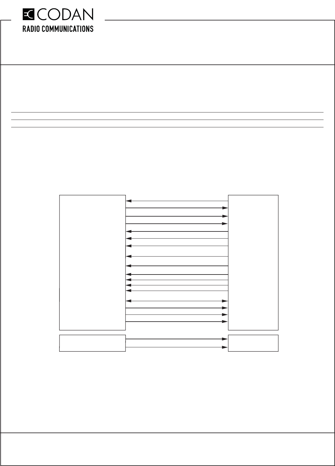
Codan Base Station with an AC-3E or CI-BC-4E, as shown in Figure 1. Ensure jumpers JU67A (or JU67X for CI-
BC-4E) and JU68 are installed on the AC-3E and CI-BC-4E. On Codan MT-4R and MT-4D P25 radio systems, the
CTCSS to Subtone connection is not connected.
Figure 1: Codan Radio System to Telex IP-224 connection
CODAN RADIO EQUIPMENT
P1 (A-PNL-AUX96-3 CONTROL CONNECTOR)
TXA SECURE / CLEAR (OPTIONAL)
RX A COR
(GPIO 5) AUX 1 AUDIO O/P1
(GPIO 6) AUX 1 AUDIO O/P2
(GPIO 1) AUX 1 AUDIO I/P1
F1 NO
COR (DIG 6)
RX+
RX-
TX+
TX-
GND
F1 COM
PTT COM
MON COM
TELEX IP-224
ETHERNET REMOTE ADAPTER
C24
B8
B11
A11
C19
C20
(GPIO 2) AUX 1 AUDIO I/P2
(J5-5)
(J1-7)
(J3-5)
(J3-6)
(J3-1)
(J3-2)
(GPIO 14) AUX 1 PTT K PTT NO
C13 (J3-14)
CTCSS
C22 (J1-4)
TXA SUBTONE I/P
TXA CSEL D0
TXA CSEL D1
C21 (J2-1)
B21 (J2-2) DIG0
TXA CSEL D2
TXA CSEL D3
A21 (J2-3)
C23 (J2-4) DIG2
DIG1
DIG3
Jumpers Required For TXA Channel Select:
SR-39-1: JU50A, JU51A, JU52A, JU53A, Remove JU48
On older motherboards (Serial # 123125 and earlier)
the jumpers were as follows:
SR-39-1: JU24B, JU25B, JU26B, JU27B, Remove JU41
RXA SQUELCH OVERRIDE MONITOR NO
C10 (J4-9)
GROUND
GROUND
GROUND
GROUND
A32, B32 (J4-1)
A32, B32 (J4-2)
A32, B32 (J4-3)
A32, B32 (J4-4)
(CONNECTOR J8) +13.8V
GND
+12V
GND
TN857 Rev 1-0-0 Aug 16
TN857 CI-IP-ADAPTER-1 Telex (Vega) IP-224 Ethernet Adapter
MT-4 Radio Systems
TECHNICAL NOTES
Page 3 of 4
© 2016 Codan Limited All rights reserved.
43 Erie Street
Victoria, B.C.
Canada V8V 1P8
Toll Free Canada & U.S.A.
Phone: 1-800-664-4066
Fax: 1-877-750-0004
International
Phone: 250-382-8268
Fax: 250-382-6139
Internet
Email: LMRsales@codanradio.com
Web: www.codanradio.com
Telex IP Alignment / Tuning Procedures:
Initial Setup
Step 1 - Program the Telex IP-224 for your system. Codan makes the following changes from default:
- Ethernet Setup: IP Address, Subnet Mask and Default Gateway
- Multicast Setup: Set RX Mcast, TX Mcast and Mcast address at 224.0.0.13
- Per Line Setup: CTCSS Setup Always On, Digital Outputs set from 0 up, COR Enable, Hi-Pass RX, and PTT
Notch Filter selected, Monitor Relay set to Timed 1000 ms.
AC-3E Audio Control Card and CI-BC-4E Base Control Card Tuning
Step 2 - Disconnect the Telex from the Codan radio system.
Step 3 - Apply a 1.0 KHz tone @ 0 dBm (775 mV) to the GPIO 1 (Aux1 I/P 1) and GPIO 2 (Aux1 I/P 2) balanced
auxiliary audio input on the Codan radio system.
Step 4 - Adjust R120 (Aux In 1 to TXA) for a transmitter deviation of ± 3 KHz (WB), ± 1.5 KHz (NB).
Step 5 - Inject a 1.0 KHz tone @ a deviation of ± 3 KHz (WB), ± 1.5 KHz (NB) into Receiver A.
Step 6 - Adjust R13 (RXA to Aux Out 1) for an audio level of 0 dBm (775 mV @ 600 ohms) across GPIO 5 (Aux 1
O/P 1) and GPIO 6 (Aux 1 O/P 2) on the Codan radio system. Note: MT-4R and MT-4D P25 Receiver modules
have a higher audio level output when receiving a digital signal (as opposed to analog). When using these receiver
modules in digital mode, adjust R13 for an audio level of -8.0 dBm (308 mV @ 600 ohms).
Step 7 - Connect the Telex to the Codan radio system.
Telex Line and Radio Level Tuning
Step 8 - Inject a 1.0 KHz tone @ a deviation of ± 3 KHz (WB), ± 1.5 KHz (NB) into Receiver A.
Step 9 - On the front of the Telex, go to Gain Adjustments - RX Inputs and adjust Line #1 (dB) until VU reads +0dB.
Step 10 - On the front of the Telex, go to Gain Adjustments - TX Outputs and select Tone as well as PTT. This will
key the Transmitter
Step 11 - Adjust Line #1 (dB) for a transmitter deviation of ± 3 KHz (WB), ± 1.5 KHz (NB).
Step 12 - Ensure the transmitter is de-keyed by unselecting the Tone and PTT.
Step 13 - On the front of the Telex, go to System Utilities - Reboot IP-224 and reboot the IP-224.
Step 14 - Connect a console and test the connection.
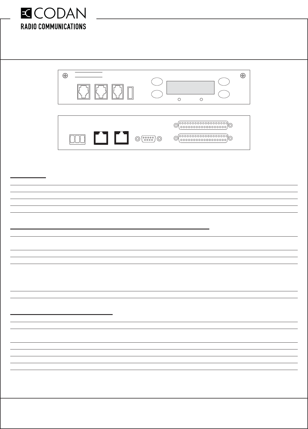
IP-224
TX LINK
HANDSET
RADIO 1 RADIO 2
TELEX
USB
IC
MENU
ETHERNET
POWER PRIM SECOND
+12V GND EGND ACCESORY
RADIO 1
RADIO 2
TN857 CI-IP-ADAPTER-1 Telex (Vega) IP-224 Ethernet Adapter
MT-4 Radio Systems
TECHNICAL NOTES
TN857 Rev 1-0-0 Aug 16Page 4 of 4 © 2016 Codan Limited All rights reserved.
43 Erie Street
Victoria, B.C.
Canada V8V 1P8
Toll Free Canada & U.S.A.
Phone: 1-800-664-4066
Fax: 1-877-750-0004
International
Phone: 250-382-8268
Fax: 250-382-6139
Internet
Email: LMRsales@codanradio.com
Web: www.codanradio.com
Bypassing the AC-3E Audio Control Card and CI-BC-4E Base Control Card:
The AC-3E Audio Control Card and CI-BC-4E Base Control Card can be bypassed and the MT-4E Receiver
and Transmitter can be connected directly to the Telex adapter. The control card needs to be removed from the
subrack, or unwanted loading could occur.
The following receiver and transmitter tuning changes would be required:
Transmitter Setup - Apply a 1.0 KHz tone @ 0 dBm (775 mV) to the Tx A Bal I/P1 (J1-1) and Tx A Bal I/P 2 (J1-2)
balanced audio input and adjust the RSS software Balanced Audio Deviation Level for a transmitter deviation of ±
3 KHz (WB), ± 1.5 KHz (NB).
Receiver Setup - Inject a 1.0 KHz tone @ a deviation of ± 3 KHz (WB), ± 1.5 KHz (NB) into the receiver and
adjust the RSS software Balanced Output Audio Level for an audio level of 0 dBm (775 mV @ 600 ohms) across
Rx A Bal O/P 1 (J1-5) and Rx A Bal O/P 2 (J1-6).
The DB25 (J10) can be jumpered for Balanced Audio direct to / from the receiver and transmitter as follows:
WARNING: JU108 must be confi gured correctly for IP-224 or damage can occur.
JU104 A = RX A Bal O/P2 JU107 A = RX A Bal O/P1
JU105 A = TX A Bal I/P2 JU108 B = IP-223 & IP-224 / RX A COR
JU106 A = TX A Bal I/P1
On the Wiring diagram for the A-PNLAUX96-3, the following connections change:
(GPIO 5) AUX 1 AUDIO O/P1(J3-5) Rx A Bal O/P 1 (J1-5)
(GPIO 6) AUX 1 AUDIO O/P2 (J3-6) Rx A Bal O/P 2 (J1-6)
(GPIO 1) AUX 1 AUDIO I/P1 (J3-1) Tx A Bal I/P1 (J1-1)
(GPIO 2) AUX 1 AUDIO I/P2 (J3-2) Tx A Bal I/P 2 (J1-2)
(GPIO 14) AUX 1 PTT K (J3-14) Tx A PTT (J1-3)
