TRAX 280 Data Sheet Brochure
User Manual: TRAX-280-Data-Sheet-Brochure
Open the PDF directly: View PDF ![]() .
.
Page Count: 7
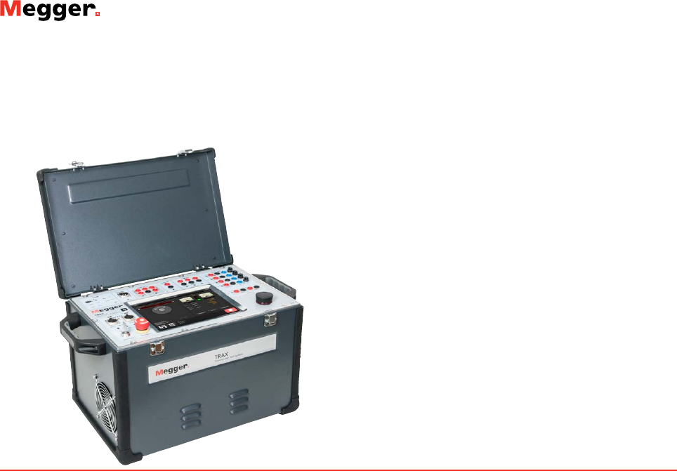
TRAX
Transformer and Substation Test System
DESCRIPTION
TRAX is a multi-function test system for transformer substation
testing. The test system replaces numerous individual testing devices
which makes testing with TRAX a time saving and cost effective al-
ternative to conventional measurements using separate instruments.
TRAX is a unique test system for testing power, distribution and
instrument transformers, as well as a variety of other substation
components. Providing up to 800 A (TRAX 279/280) and 2200 V
(2000A and 12kV with accessories) with a frequency range adjust-
able from 5 Hz (1 Hz with tan delta unit) to 500 Hz, TRAX can be
used with an integrated touch screen or external computer device
with web browser.
Variable levels of voltage and current can be generated and meas-
ured with high precision, allowing TRAX to be used for a wide range
of applications such as turns ratio, excitation current, winding and
contact resistance, impedance, tan delta/power factor testing and
various primary tests for LV, MV and HV electrical apparatus includ-
ing but not limited to:
Power & distribution transformers
Instrument transformers
Bushings
LV, MV and HV circuit-breakers
Busbars
Protection relays
Grounding systems
TRAX is designed to be a complete solution in transformer testing.
With its 4800 VA power capability it is a high efficiency, high ac-
curacy and excellent performance transformer test system.
TRAX
Transformer and Substation Test System
▪Replaces need for multiple test sets
▪Saves time by eliminating need for
multiple instruments learning
▪User-friendly interface reduces training
and testing time
▪Portable and compact system components
for easy shipping
▪“State of the art” measurement methods
for advanced diagnostic testing
Test capability
Winding resistance measurements
Adaptive algorithm for optimized transformer
demagnetization
True dynamic resistance measurements on load tap-
changers
250 V transformer turns ratio measurements
12kV dissipation factor and capacitance testing features
The user interface allows fully manual control where the user de-
fines a specific test setup. Alternatively, a variety of individual instru-
ments/apps are available to perform automated testing procedures
such as winding resistance, turns ratio, impedance measurements,
relay testing, circuit breaker analysis and more. The tests can be
organized and reported as separate tests or as a combined full set of
test results for the same asset.
The compact, light-weight design, only 26 kg (TRAX 220), allows
shipment in its transportation case within the limits of check-in lug-
gage (32 kg)
TRAX
Transformer and Substation Test System
2
FEATURES AND BENEFITS
One unit multi function system for transformer/substation
testing
▶Replaces need for multiple test sets
▶Saves time by eliminating need for multiple instruments
learning
▶User-friendly interface reduces training and testing time
▶Portable and compact system components for easy
shipping
Outstanding flexibility for selecting output current or
voltage signals for various tests
▶AC current up to 2000 A (with TCX 200)
▶DC current up to 100 A
▶AC voltage up to 12 kV (with TDX 120)
▶DC voltage up to 300 V
State of the art measurement methods for advanced
diagnostic testing, e.g.
▶3-phase Power transformer measurements of:
»Turns ratio
»Winding resistance
»Load tap-changer continuity, timing and dynamic
resistance (patent pending)
»Excitation current
»Leakage reactance/short-circuit impedance
»Demagnetization
»3-phase transformer measurements without manual
cable reconnections (with TSX300)
▶CT and VT testing
▶HV tan delta/power factor (with TDX 120)
Compact and lightweight
▶26 kg TRAX 220 (main unit), shipping weight <32 kg
▶Smart cable technology for reducing cable weight
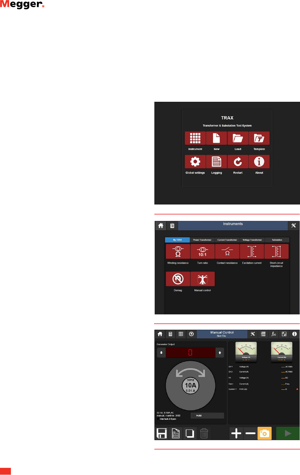
USER INTERFACE
TRAX user interface architecture is based on a number of individual
instruments/apps where only the necessary functionality is displayed
by default. For manual testing a generic instrument is available
where the user selects output, measurement inputs and how the
data should be processed.
For testing complete components (e.g. power transformers),
measurement results from multiple instruments can be collected and
presented in one report.
Manual Control
My TRAX
Start screen
TRAX
Transformer and Substation Test System
3
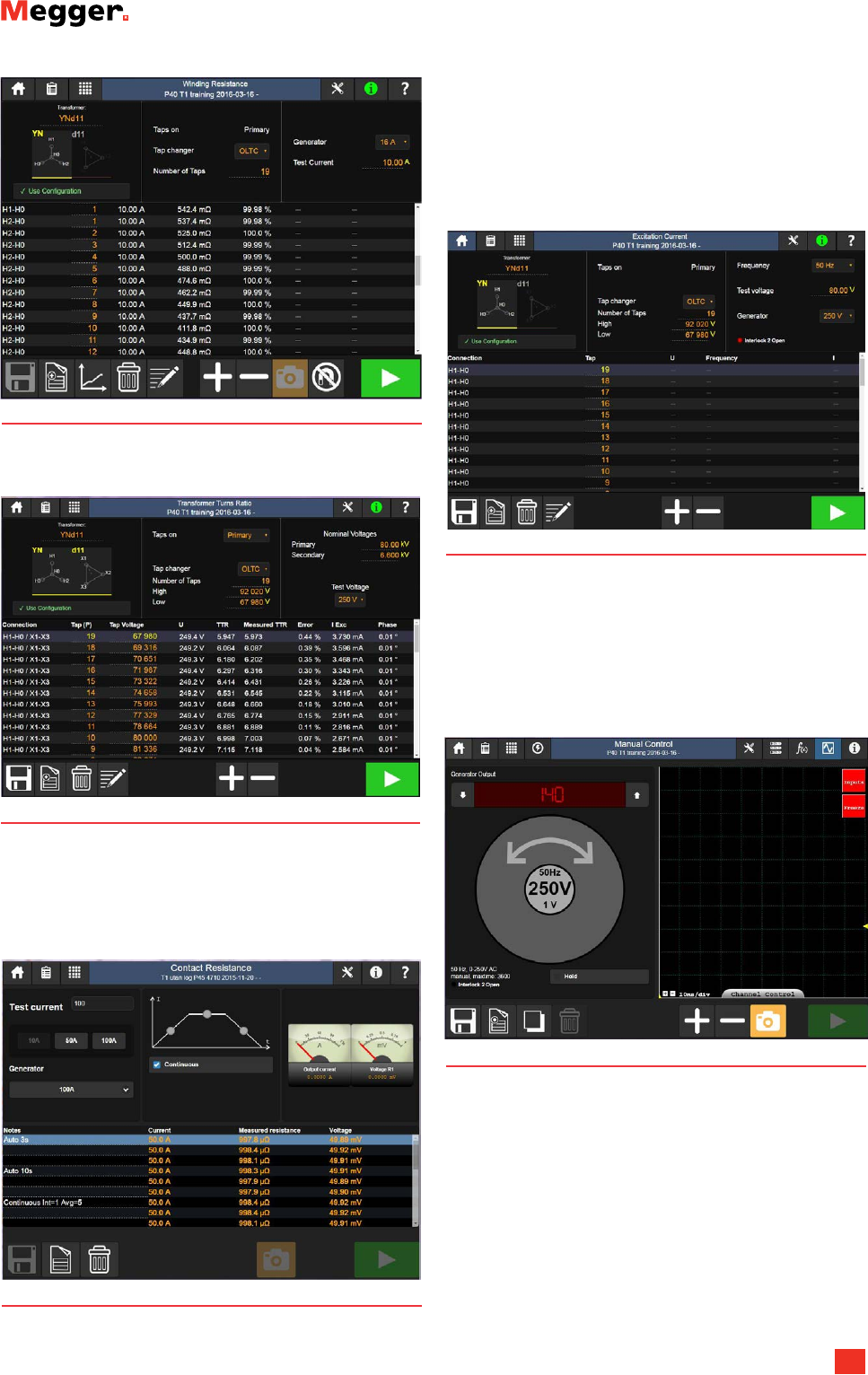
Winding resistance
Turns ratio
Excitation current
Oscilloscope
Contact resistance
TRAX
Transformer and Substation Test System
4
APPLICATION
A variety of voltage and current levels can be generated and meas-
ured with high precision which allows the multi-function test set to
be used for a wide range of applications. Examples are:
Power transformer
▶Ratio and phase
▶Winding resistance
»Single phase up to 100 A
»Three-phase/six windings up to 16 A
▶Tap changer testing (single-phase or three-phase)
»Continuity
»Dynamic current
»Dynamic voltage
»Dynamic resistance (new patent pending method)
▶Demagnetization (adaptive method for fast and efficient
process)
▶Magnetic balance
▶Excitation current
▶Leakage reactance/short-circuit impedance
▶Zero-sequence impedance
▶Frequency response of stray losses (FRSL)
▶Tan delta/power factor with individual temperature
correction (ITC) and voltage dependence detection
(VDD)
▶Capacitance
Current transformer
▶Ratio, burden and polarity
▶Phase and magnitude error
▶Excitation curve (knee - point)
▶Winding resistance
▶Secondary burden
▶Dielectric withstand voltage
Voltage transformer
▶Ratio and polarity
▶Phase and magnitude error
▶Secondary burden
▶Dielectric withstand voltage
Resistance testing
▶Contact resistance
▶DualGround™ measurements
Circuit breaker testing
▶Main and resistor contact timing
▶Motion
▶Operating voltage
▶Coil current
▶Contact resistance
Primary testing
▶Circuit breakers
▶General primary injection tests
Protection relays
▶Relay timing
AC insulation testing
▶Tan delta/Power factor
▶Capacitance
▶Tip-up testing
▶1-505 Hz frequency range
SPECIFICATIONS TRAX
Specifications are valid at nominal input voltage and an ambient
temperature of +25°C ±5°, (77°F). Specifications are subject to
change without notice.
Evironment
Application
field
For use in high-voltage substations and industrial
environments
Temperature
Operating -20°C to +55°C (-4°F to +131°F)
Storage -20°C to +70°C (-4°F to +158°F)
Humidity < 90%RH, non-condensing
CE- marking
EMC 2004/108/EC
LVD 2006/95/EC
General
Mains input 100-240 V, 50/60 Hz (± 10%)
Input current ≤ 16 A continuous
Short-term up to 30 A < 60 s
Main fuses F1 and F2, 25 A
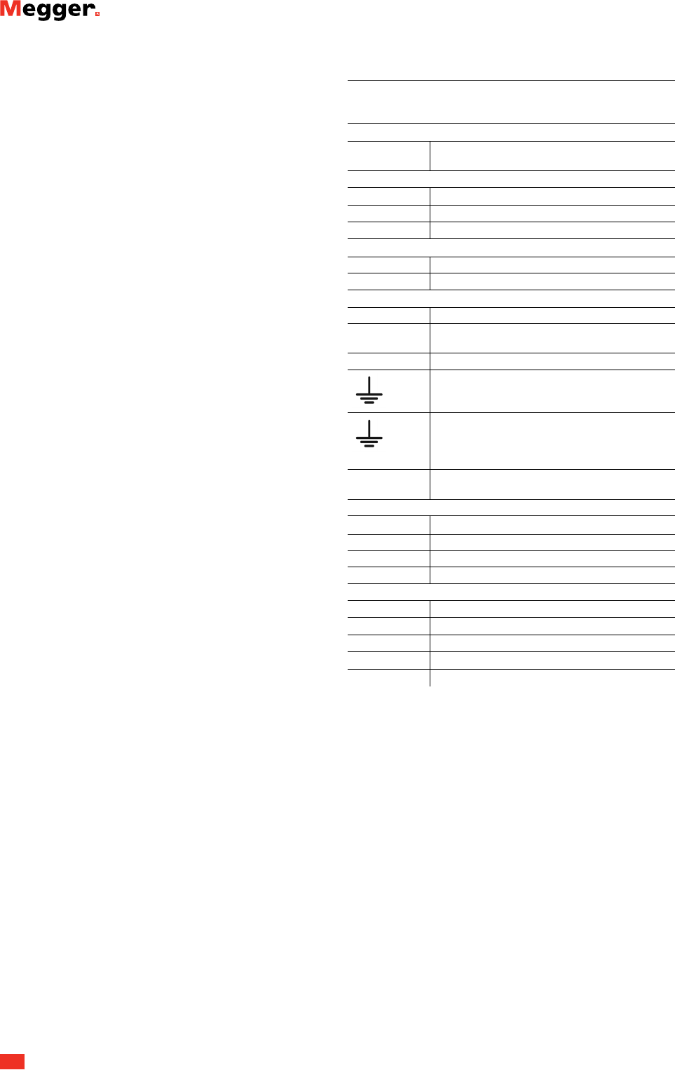
TEST GROUND
To be connected to the test object ground before
connecting any other cables to the unit.
GROUND
For connecting an additional ground between
the main unit and accessories or to ground exter-
nal objects e.g. optional trolley
Dimensions 475 x 315 x 330 mm (excl. handles)
(18.7” x 12.4” x 13”)
Weight
TR AX 219 25 kg (55 lbs)
TRAX 220 26 kg (57 lbs)
TRAX 279 29 kg (64 lbs)
TRAX 280 30 kg (66 lbs)
Display1)
Size 10.4”
Resolution 1024x768 XGA
Type TFT touch
Contrast ratio 1000:1
Brightness 1000 cd/m2
1) TRAX 219 and 279 has no display
TRAX
Transformer and Substation Test System
5
Outputs
Item Specification Comment
0-2200 VAC 1 A, 1 min
0.2 A, >2 h
2500 VA (max)
Frequency range:
5-70 Hz
The output is discon-
nected with a relay and
the output is “live” only
when this generator is
selected
0-250 VAC /
0-10 A AC
10 A, 1 min
20 A, max 10 s
2.5 A, >2 h
Frequency range:
5-505 Hz
0-200 AAC 200 A/6 V, 1 min
80 A, >2 h
Frequency range:
45-70 Hz
TRAX 219/220
0-800 AAC 0-800 A/6 V, 1 min
0-200 A/10 V, >2 h
Frequency range:
45-70 Hz
TRAX 279/280
0-16 ADC 16 A, continuous
1 A continuous
0-300 VDC 10 A,1 minute
2.5 A, >2 h
Rectified DC. Intended to
be used as e.g. auxiliary
DC supply
0-100 ADC 100 A, 2 minutes
70 A, continuous
DC output
power
Max 1000 VA , con-
tinuous
Max 50 V compliance
voltage
Binary output 250 V / 35 A (max)
2 x 0-10000 s
Output contacts for
OLTC and circuit breaker
operation with internal
voltage and current
measurements
AUX
CONTROL 54 V DC Ethernet communication
and power to acces-
sories.
POWER 0-235 V AC Directly from power
amplifier for powering
accessories (TDX / TCX)
With
TRAX TDX
12 kV AC
0-12 kV, 1 min
0-12 kV / 300 mA,
4 min
0-12 kV / 100 mA,
continuous
With
TRAX TCX
2000 A AC
0-2000 A/2.4 V, 1 min
0-1000 A/4.8 V, 1 min
Inputs
ANALOG
1 2 3 4
Current 4 x 0-10 A AC / DC
Voltage
4 x 250 / 350 V AC / DC
R1 R2 2 x 0-50 V DC Intended for resistance
measurements but can
be used for AC voltage
measurement up to
40 V RMS
TRANS Input for analog trans-
ducers and low level
analog signals
TRIG IN Contact or voltage sense
TIMING 3 x 0-10000 s Binary inputs for timing
measurements in timer
and relay testing applica-
tions. A and B inputs
dedicated for Start and
Stop.
Calculated / displayed parameters
Arithmetic +, -, *, /
Power P, VA, Q, S
Impedance R (DC), Z, Xp, Xs, Rs, Rp, Ls, Lp, Cs, Cp, phase
Derating at lower mains voltage
TRAX specification is valid at 230-240 V mains voltage. Output
power is decreased at lower mains voltages.
Derating at high ambient temperature
TRAX specification is valid at 23 ±5°C. Max output current times
will be reduced when using TRAX in high ambient temperature.
Derating at lower frequencies
TRAX voltage output specification is at 50 Hz. Maximum voltage
output at lower frequencies is limited by the transformer. Derating
is linear with frequency and max voltage output at 5 Hz is 10% of
rated output.
Measurement accuracy
External
AC / DC volta ge
and current
0.05% of reading + 0.05% FS
Internal DC
current
0.1% of reading + 0.1% FS
Internal AC
current
0.2% of reading + 0.2% FS
Internal AC
voltage
0.2% of reading + 0.2% FS
COM
Ethernet port For running the instrument from an external PC
or connect it to an external network.
Connector for
Wifi antenna
For running the instrument wireless from a PC or
tablet. (Option)
USB 3 USB ports for multipurpose use
TRAX
Transformer and Substation Test System
6
OPTIONAL ACCESSORIES
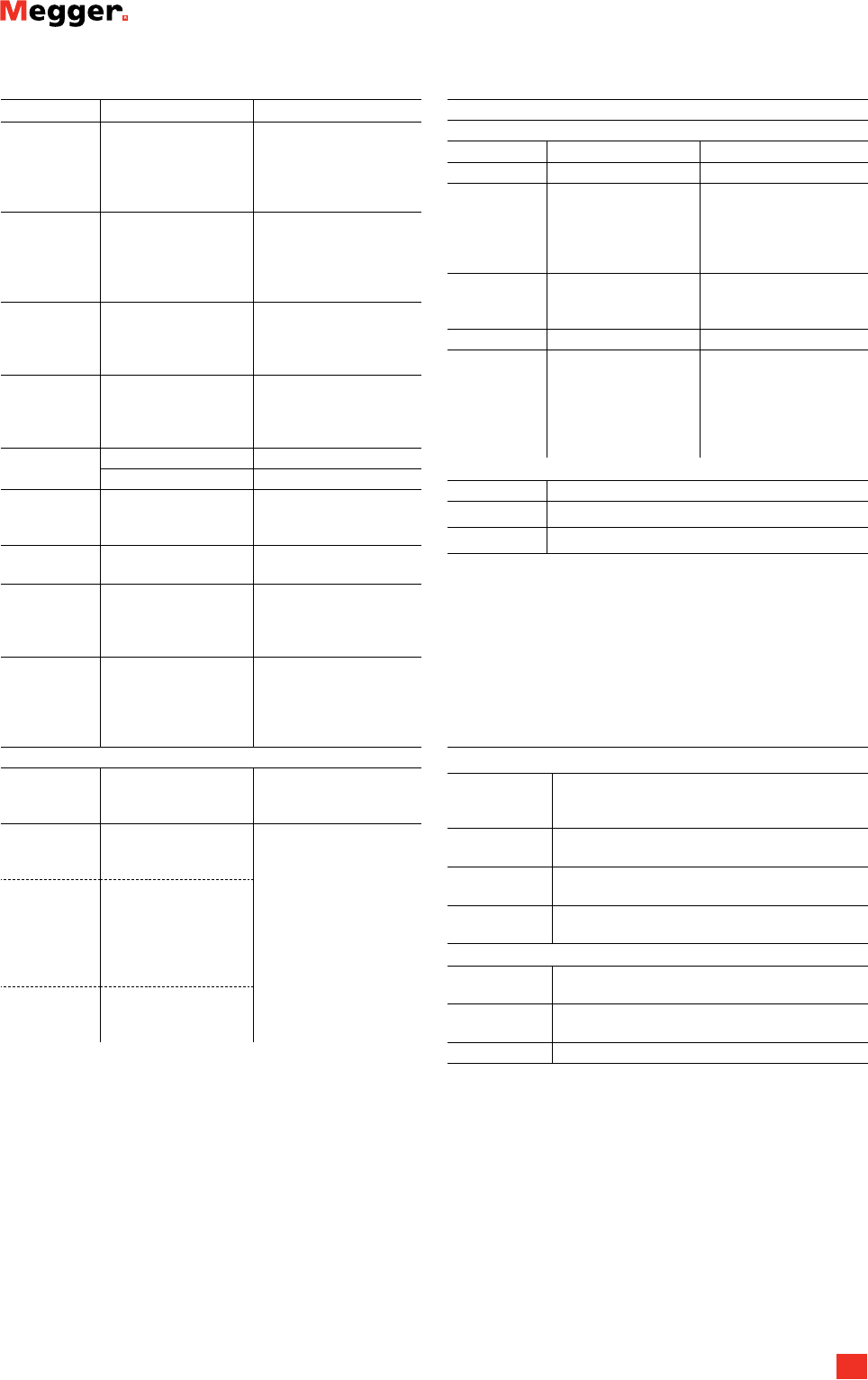
Instruments
TDX 120 – High voltage unit (12 kV)
for tan delta and capacitance
measurements, AJ-69090
TCX 200 – High current accessory,
AJ-69290
TSX 300 – 3-phase/6-winding switchbox,
AJ-69390 / AJ-69395
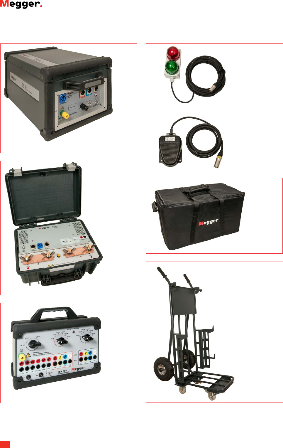
Miscellaneous
Strobe box, AJ-90030
Interlock foot switch,
G C-3 115 0
Soft light case, GD-31050
Trolley, AJ-90040

TRAX
Transformer and Substation Test System
Postal address
Megger Sweden AB
Box 724,
SE-182 17 Danderyd
SWEDEN
T. 08 510 195 00
E. seinfo@megger.com
TRAX_DS_en_V08a
Printed matter:
Art.No. ZI-AJ01E ▪ Doc. AJ0204HE ▪ 2017
Subject to change without notice
Registered to ISO 9001 and 14001
The word ‘Megger’ is a registered trademark
Item Art. No.
TRAX 280
800 A AC current output
With internal touch screen
Included software: Manual control and Standard trans-
former package (AJ-8010X
)AJ-19090
TRAX 279
800 A AC current output
No internal screen, remote control only
Included software: Manual control and Standard trans-
former package (AJ-8010X
)AJ-19190
TRAX 220
200 A AC current output
With internal touch screen
Included software: Manual control and Standard trans-
former package (AJ-8010X
)AJ-19290
TRAX 219
200 A AC current output
No internal screen, remote control only
Included software: Manual control and Standard trans-
former package (AJ-8010X
)AJ-19390
Standard transformer package
Software included for all models above
▪Winding resistance with OLTC continuity
▪Demagnetization
▪Turns ratio
▪Excitation current
▪Short-circuit impedance (leakage reactance) AJ-8010X
Included Accessories
(for all models above)
▪Mains cable
▪Ground cable 10 m (33 ft)
▪Test cable set
▪Sense cables 2 x 10 meter (33 ft)
▪Kelvin cables, 2 x 10 meter (33 ft)
▪Current cables, 16 mm2, 2 x 10 m (33 ft)
(TRAX 219/220)
▪Current cables, 50 mm2, 2 x 6 m (20 ft)
(TRAX 279/280)
▪HV cables, 2 x 5 m (16 ft)
▪Interlock Fixed, 2 m (6.5 ft)
▪Jumper cable 5 meter (16 ft)
▪Ethernet cable
▪Flight case with wheels
▪User Manual
Item Art. No.
Optional Accessories
Trolley AJ-90040
Soft light case GD-31050
Interlock foot switch G C-3 115 0
Green / red strobe box (flash light) AJ-90030
Additional software packages
Advanced transformer
▪Dynamic OLTC measurements (DRM)
▪FRSL (frequency response of stray losses)
▪Magnetic balance AJ-8020X
Instrument transformer
▪CT ratio
▪CT burden
▪CT excitation curve (knee point)
▪CT polarity
▪CT winding resistance
▪VT ratio
▪VT burden
▪VT polarity AJ-8030X
Substation
▪Circuit-breaker analyzer
▪Relay over current timing
▪Timer
▪Phase angle meter (manual)
▪Ground/earth/impedance (manual)
▪Line impedance/K-factor (manual) AJ-8040X
Instruments
TDX 120 – High voltage unit for tan delta, capaci-
tance and excitation current measurements. With
hardware connected to TRAX main unit the SW app
is activated.1) AJ-69090
TCX 200 – High current accessory (cable + booster)
that can be placed close to the measurement object
for minimizing high current cable length/weight
when performing high current primary testing up to
2000 A.1) AJ-69290
TSX 300 – 3-phase/6-winding switchbox for simpli-
fied measurements of turns ratio (250V), winding re-
sistance (16A), excitation current, leakage reactance
and FRSL.1)
IEC panel design AJ-69390
ANSI panel design AJ-69395
TSX 3032) – Same as TSX300 but automated. AJ-69490
Line impedance kit2) AJ-69690
1) See separate datasheets for more information.
2) To be released in 2017.
Other options e.g. SFRA/FRAX, DFR/IDAX, DC insulation/MIT
offered as separate products if requested.
ORDERING INFORMATION
