TRBO_Application Partner_BR_Low Res TRBO Application Partner BR Low
TRBO_ApplicationPartner_BR_LowRes TRBO_ApplicationPartner_BR_LowRes
User Manual: TRBO_ApplicationPartner_BR_LowRes
Open the PDF directly: View PDF ![]() .
.
Page Count: 16

MOTOTRBO™
Application Development Kit Overview

Table of Contents
Section 1
1.0 What is MOTOTRBO? 3
Section 2
2.0 Extending the MOTOTRBO Product 5
2.1 MOTOTRBO Option Board ADK 6
2.2 MOTOTRBO Telemetry ADK 7
2.3 MOTOTRBO Location Data ADK 8
2.4 MOTOTRBO Text Messaging ADK 9
2.5 Presence Notifier 10
2.6 Data Services 11
Section 3
3.0 Professional Radio Application Developer Programme 12
Section 4
4.0 Service & Support for Application Development 13
Section 5
5.0 Further Information and Contact 14
Section 6
6.0 Appendix: ADK Document Map 15
2 MOTOTRBO - Application Development Kit Overview

3 MOTOTRBO - Application Development Kit Overview
1.0
What is MOTOTRBO?
MOTOTRBO is Motorola’s next
generation of Professional Radio that
is capable of analogue and digital
two-way communications. In addition
to the standard features available with
Motorola’s other analogue-based
products, MOTOTRBO brings digital
enhancement to the voice quality as
well as an expanded feature set to
this product tier.
While operating in digital mode,
MOTOTRBO uses a two-slot Time
Division Multiple Access (TDMA) air
interface to transmit and receive
digitised voice and air protocol control
messages simultaneously. This leads
to a higher quality of service (QoS)
and a richer user experience with the
product.
With the digital mode operation of the
MOTOTRBO system, customers can
expect end-to-end operation of
advanced features and integrated
applications such as text messaging,
Location-Based Services (LBS), and
telemetry as well as customised
capabilities provided through an
internal option board.
Section 1
4 MOTOTRBO - Application Development Kit Overview
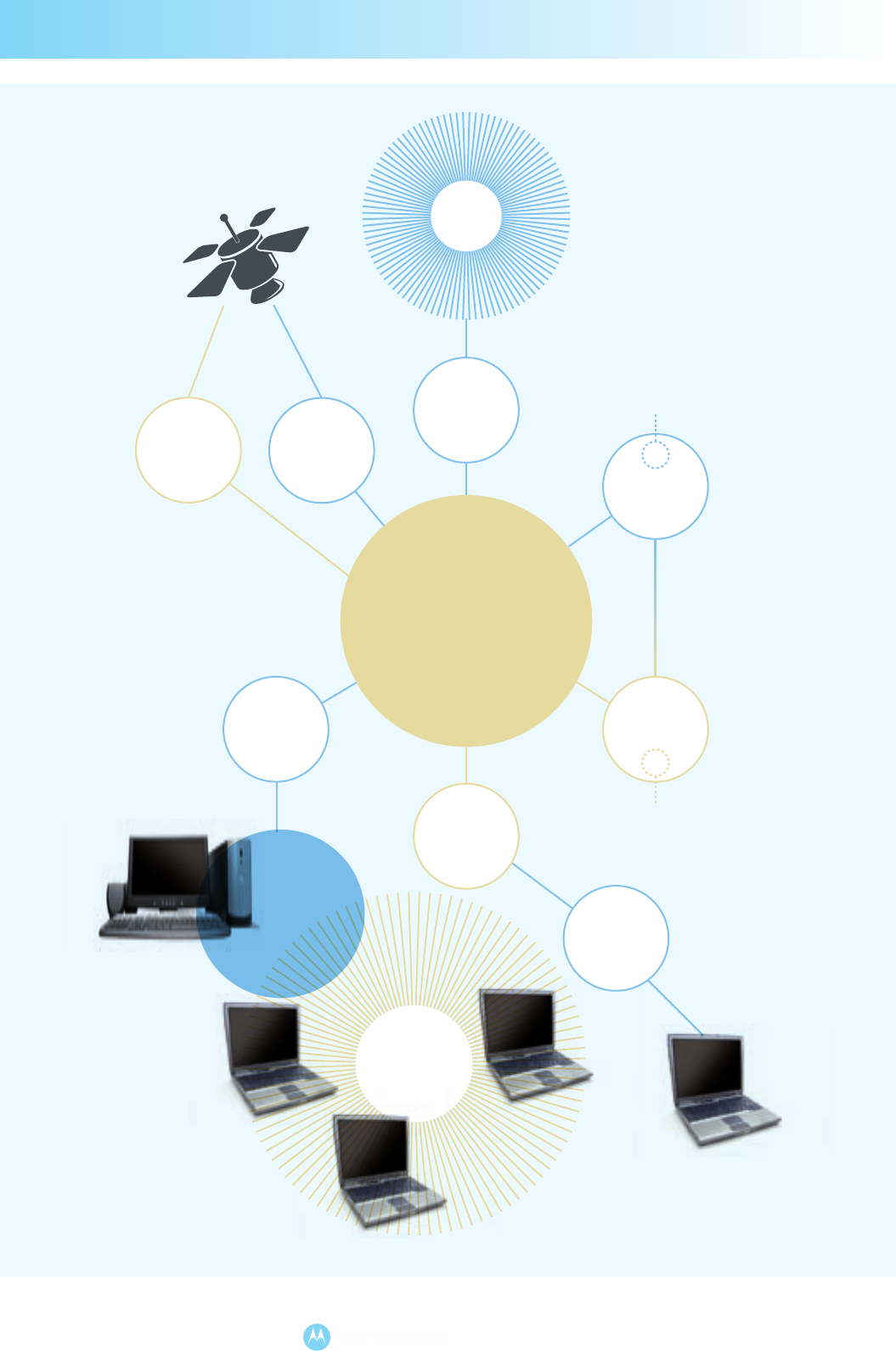
IP Network
UDP/IP
over USB
UDP/IP
over USB
Text
Messaging
Text
Messaging
Text
Messaging
Telemetry
Location
Data
Location
Data
GPS
GPIO
Telemetry
Location Data
Text Messaging
Text
Messaging
Location-Based
Services
Sensors &
Controls
MOTOTRBO
Repeater
MOTOTRBO
Option Board Interface
Option
Board
Signaling
MOTOTRBO
Option Board Interface
MOTOTRBO
Portable
MOTOTRBO
Mobile
MOTOTRBO
Mobile
MOTOTRBO
Mobile
MOTOTRBO
Mobile
MOTOTRBO
Portable
MOTOTRBO
Portable
MOTOTRBO
Mobile
Telemetry
Application
Presence
Notifier
Section 1
Figure 1 - MOTOTRBO System Example

5 MOTOTRBO - Application Development Kit Overview
2.0
Extending the MOTOTRBO Product
Section 2
Aside from the functionality embedded in the radio,
the MOTOTRBO subscriber’s capabilities can be
extended through defined application programming
interfaces for 3rd party developer use. The
MOTOTRBO Application Development Kits (ADKs)
offer an opportunity to customise a solution
specifically to a customer’s need.
The MOTOTRBO ADKs are comprised of protocol
specifications and development guidelines that are
intended as technical references for the external
vendor. These ADKs not only include software
specifications, but also include electrical and
mechanical specifications, where applicable. Each
interface’s set of technical references also detail the
specific domain knowledge required to successfully
implement a 3rd party application for the
MOTOTRBO product.
There are four primary ADKs for developer use:
• MOTOTRBO Option Board ADK
• MOTOTRBO Telemetry ADK
• MOTOTRBO Location Data ADK
• MOTOTRBO Text Messaging ADK
Please refer to the individual ADK sections for more
information on the interface. Refer also to the
Appendix: ADK Document Map for more information
on document components for each ADK.

6 MOTOTRBO - Application Development Kit Overview
Section 2
2.1
MOTOTRBO Option Board ADK
The MOTOTRBO portable and mobile radios provide
a physical and logical interface to accommodate an
internal option board with an onboard processor and
embedded logic. This option board interface is the
means by which an option board, executing its own
software application, interoperates with the main
board firmware to create the custom end-user
solution.
The option board interface of the MOTOTRBO
product uses the Extended Command and
Management Protocol (XCMP) to establish a
communication mechanism between the option
board device and the radio. Through this protocol, the
option board can request notification of ergonomic
events such as button presses or signals (i.e. carrier
detect, PL detect, etc.) in order to take further action
to process a customised feature. The option board
can also request the radio to execute certain actions
such as display text or route audio in order to present
a specific ergonomic experience to the user. In
addition, the option board can activate or de-activate
specific functionality, such as scan, the menu
system, or an over-the-air data session, to execute
the behavior of a new feature.
The option board interface uses a Synchronous Serial
Interface (SSI) to transport the XCMP control and
data messages within XCMP Network Layer (XNL)
packets to and from the radio and its available
services. The SSI is comprised of four logic lines:
clock, sync, data in, and data out. The option board
uses the SSI to transport logical and audio data to and
from the radio. There are no dedicated analogue
audio lines on the option board interface. Whether
the MOTOTRBO radio is operating in analogue or
digital mode, all audio is encoded into digital format
and transported on the SSI bus.
The SSI bus is a multi-slotted Time Division
Multiplexed (TDM) communication channel
that is shared with other chips and devices
contained within or attached to the Radio
Host. A separate Option Board Sync
(OBSync) logic signal is provided by the
main board so that the option board can
send and receive data during its proper timeslot.
Through the MOTOTRBO™ Option Board interface,
custom applications can be created to achieve a
desired user operation while the MOTOTRBO™
radio is operating in either analog or digital mode. The
extended functionality provided by an option board
can be a basic ergonomic feature, such as a
“Man-Down” lone worker application, or an advanced
signal processing feature, such as a custom signaling
system format.
The MOTOTRBO™ Option Board interface also has
the extended capability to communicate with other
devices within the radio system. This includes Data
Applications which are integrated into the Radio
Network through a PC environment. These Data
Applications communicate using User Datagram
Protocol over Internet Protocol (UDP/IP) sent over the
Common Air Interface (CAI) of the MOTOTRBO™
Radio. Interoperation with Data Applications is only
available while MOTOTRBO™ is operating in digital
mode.
For more information about the MOTOTRBO™
Option Board interface, please see the following
references:
• MOTOTRBO™ Option Board ADK Guide
•
MOTOTRBO™ Option Board PROIS Cross-
reference
• MOTOTRBO™ XCMP / XNL Development Guide
•
MOTOTRBO™ XCMP / XNL Development
Specification
For more information about the other interfaces,
please refer to the appropriate sections contained
within this overview.
UDP
IP
Slot
1
Slot
2
Slot
3
Slot
4... Slot
N
XCMP
XNL
SSI
XCMP
XNL
SSI
MOTOTRBO Radio
SSI Bus
Option Board Sync
MOTOTRBO
Option Board Interface
Main Board
(Radio Host)
Option Board
(3rd Party Device)
Radio
Network
UDP
IP
CAI
Figure 2 - MOTOTRBO Option Board
Interface Architecture

7 MOTOTRBO - Application Development Kit Overview
The MOTOTRBO product can be customised for
telemetry operation by developing a PC-based
application using the MOTOTRBO Telemetry
interface. A Telemetry Services PC application
interoperates with a MOTOTRBO radio via direct
USB connection and can monitor or control the
general purpose inputs and outputs (GPIOs) of a
radio. Telemetry operation is available while the
MOTOTRBO product is operating in digital
mode only.
Telemetry operation is available on 3 GPIOs for the
MOTOTRBO portable and on 5 GPIOs for the
MOTOTRBO mobile. The status of telemetry
events can be queried for inputs or outputs. The
state transition of telemetry inputs can also be
announced and shown on a display-capable
MOTOTRBO radio.
Routing of telemetry information in the radio
network is accomplished using UDP/IP. The
destination of the telemetry data can be either to a
Telemetry Services PC application or to another
device such as an option board. The Telemetry
interface can also broadcast telemetry status over-
the-air to specific MOTOTRBO subscribers within
the radio network.
The Telemetry interface enables remote detection
or activation of events through the MOTOTRBO
system. An example of a telemetry-based solution
is an irrigation system that is automatically
activated based on average moisture level.
For more information about the MOTOTRBO
Telemetry interface, please see the following
references:
• MOTOTRBO Telemetry ADK Guide
• MOTOTRBO Telemetry Protocol Specification
• MOTOTRBO Data Services Overview
For more information about the other interfaces,
please refer to the appropriate sections contained
within this overview.
2.2
MOTOTRBO Telemetry ADK
Figure 3 – MOTOTRBO Telemetry
Interface Architecture
Section 2
RNDIS USB
Radio
Network
Sensors
& Controls
MOTOTRBO
Radio
MOTOTRBO
Radio
Telemetry
Services
Application
TP UDP IP
CAI
TP
UDP
IP
CAI
TP
UDP
IP
GPIO
GPIO

8 MOTOTRBO - Application Development Kit Overview
Section 2
2.3
MOTOTRBO Location Data ADK
The MOTOTRBO product features optional
embedded GPS capability for Location-Based
Services (LBS) with the portable and mobile radio.
The location function provides latitude, longitude,
altitude, velocity, and heading data for the radio.
A LBS PC application can also interoperate with
the MOTOTRBO product to record a timestamp of
reported location data for any specified radio. The
Location Data interface is available while the
MOTOTRBO product is operating in digital
mode only.
Location status can be configured for periodic or
on-request reporting during normal operation.
During emergency operation, the MOTOTRBO
radio can be configured for more frequent
reporting of location data.
Architecture
Messages for requests and responses for location
data are handled through the Location Request and
Response Protocol (LRRP). LRRP is a location data
reporting protocol that is optimised for use within
the MOTOTRBO Radio Network. LRRP control and
data messages are sent via the Radio Network
within UDP/IP packets that are transported over
the Common Air Interface (CAI). The LRRP
messages are processed directly by the embedded
GPS components inside the MOTOTRBO radio as
well as within the LBS PC application. The Location
Data interface can also interoperate with the
MOTOTRBO Option Board interface to route
location data directly to a custom option board
device.
The Location Data interface facilitates asset
tracking via location-based services. For example, a
LBS application can provide an Automated Vehicle
Location (AVL) capability to track the position of
delivery trucks in the coverage area of the
MOTOTRBO system.
For more information about the MOTOTRBO
Location Data interface, please see the following
references:
• MOTOTRBO Location Data ADK Guide
• MOTOTRBO Location Request and Response
Protocol (LRRP) Specification
• Motorola Binary XML Encoding Specification
• MOTOTRBO Data Services Overview
For more information about the other interfaces,
please refer to the appropriate sections contained
within this overview.
Radio
Network
MOTOTRBO
Radio
LBS
Application
GPS
Component
LRRP
CAI
LRRP
UDP
IP
LRRP
CAI
IP
UDP
MOTOTRBO
Radio
RNDIS USBLRRP UDP IP
Figure 4 – MOTOTRBO Location Data Interface Architecture

9 MOTOTRBO - Application Development Kit Overview
Section 2
The MOTOTRBO product includes embedded text
messaging capability for one-to-one or one-to-
many device destinations. This capability can be
extended to interoperate with a PC-based
application to provide enhanced Text Messaging
Services (TMS) using the Text Messaging interface
of the MOTOTRBO radio. The TMS feature is
available while the MOTOTRBO product is
operating in digital mode only.
A text message containing up to 140 characters
can be sent between a subscriber, talkgroup,
subscriber with an attached PC (via USB),
dispatcher client, or external network (i.e. the
Internet). These messages can be pre-canned or
composed along with a received message inbox
for later viewing.
Interface Architecture
Text messages are routed within the Radio
Network as UDP/IP packets transported over the
MOTOTRBO Common Air Interface (CAI). The
destination of text messages is determined by the
target IP address and port number. This enables
the routing of text messages to two logically
different devices that are physically connected
together (e.g. PC attached to MOTOTRBO radio via
USB). In addition, the Text Message interface
interoperates with the MOTOTRBO Option Board
interface to route text messages directly to the
option board for processing.
The Text Messaging Services interface provides
alternate methods for sending and receiving text
messages within the MOTOTRBO system. A
model implementation of this interface would be a
PC-based dispatch messaging center. The
messaging center contains a user interface for
typing text messages to be sent to an individual
radio or a group of radios as well as an output
screen for displaying received messages.
For more information about the MOTOTRBO Text
Messaging Services Interface, please see the
following references:
• MOTOTRBO Text Messaging ADK Guide
• MOTOTRBO Text Messaging Protocol
Specification
• MOTOTRBO Data Services Overview
For more information about the other interfaces,
please refer to the appropriate sections contained
within this overview.
2.4
MOTOTRBO Text Messaging ADK
Radio
Network
TMS
Application
TMS
Component
CAI
UDP
IP
TMP
CAI
IP
UDP
MOTOTRBO
Radio
TMS
Component
MOTOTRBO
Radio
RNDIS USBTMP UDP IP
TMP
TMP
Figure 5 – MOTOTRBO Text Messaging
Services Interface Architecture

10 MOTOTRBO - Application Development Kit Overview
Section 2
2.5
Presence Notifier
The Presence Notifier is used to notify a PC-based
backend application, such as for telemetry, LBS, or
text messaging, that a MOTOTRBO radio has
powered on or off and has registered or de-
registered with the system. This application allows
for efficient bandwidth utilisation of the Radio
Network – messaging only occurs between the
backend application and those MOTOTRBO
subscribers that are available and that the
application is interested in. The Presence Notifier
component is for use in digital mode only.
The MOTOTRBO radio contains an Automatic
Registration Service (ARS) that sends a registration
message to the Presence Notifier within the Radio
Network. When the MOTOTRBO radio is powered
down, a de-registration message is sent. The
registration and de-registration messages are sent
as UDP/IP packets that are transported over the
CAI. The Presence Notifier ultimately receives the
UDP/IP packets and processes them for the
registration state of each MOTOTRBO radio.
The Presence Notifier tracks the state of each
MOTOTRBO radio on the Radio Network and
reports each radio’s state to each Backend
Application. Each backend application must
subscribe with the Presence Notifier in order to
receive notifications of each MOTOTRBO radio of
interest. Information between each Backend
Application and the Presence Notifier is exchanged
as UDP/IP packets.
For more information about the Presence Notifier,
please see the following references:
• Presence Notifier Application User’s Guide
• Presence Notifier-to-Watcher Interface
Specification
• MOTOTRBO Data Services Overview
For more information about the other interfaces,
please refer to the appropriate sections contained
within this overview.
Figure 6 - Presence Services Architecture
MOTOTRBO Radio
Automatic
Registration
Service
Backend
Application
Presence
Notifier
IP Data Pipe
Notification Subscription
Radio
Network
UDP
IP
UDP
IP
UDP
IP
CAI

11 MOTOTRBO - Application Development Kit Overview
Section 2
Aside from the data application capability of the
MOTOTRBO product for telemetry, location, and
text messaging, the MOTOTRBO radios can also
be used as a generic UDP/IP “pipe” for the
transport of data between multiple IP-capable
devices. These devices, such as laptop or desktop
PCs, must be attached to subscriber units
operating within the Radio Network. The Data
Services capability is available while the
MOTOTRBO product is operating in digital mode
only.
The attached PCs are mapped to an IP space that
is separate from the MOTOTRBO radio IP address
range. Therefore, data intended to the attached IP-
capable device or the MOTOTRBO radio can be
routed to the appropriate endpoint.
For more information about the Data Services
capability, please see the following reference:
• MOTOTRBO Data Services Overview
For more information about the other interfaces,
please refer to the appropriate sections contained
in this overview.
2.6
Data Services
Figure 7 – Data Services Architecture
MOTOTRBO
Mobile
MOTOTRBO
Mobile
Radio
Network
UDP/IP
over USB
UDP/IP
over USB

12 MOTOTRBO - Application Development Kit Overview
Section 3
3.0
Professional Radio Application Developer Programme
The Professional Radio Application Developer
Program now includes MOTOTRBO and is
comprised of three tiers of membership:
• Registered User
• Licensed Developer
• Application Partner / Application Provider
Each tier of membership brings greater
accessibility to program information and
development resources. Interested developers
must be approved for Licensed Developer or
Application Partner status in order to receive items
such as:
• Application Development Kit (ADK)
documentation
• Technical support, including developer forums
and training
• Program affiliation media, including partner logo
and application directory listing
• Motorola channel partner and customer
information
Registered Users have access to general
information and resources only.
Developer Programme Membership
Process Flow
The capability assessment is based on technical
competency, commercial capability, and product
portfolio. Characteristics that are considered
include:
• Adequate commercial capability
• Expertise in two-way radio communications
• Expertise in hardware / software engineering
development
• Adequate development and test environments
• Repeatable development and test processes
• Quality Assurance processes
Figure 8 – Professional Radio Application
Registration
Process
Registered
User
Licensed
Developer
Capability
Assessment
Licensed
Developer
Licensing
Agreement
Application
Partner
Licensing
Agreement
Licensed
Developer Application
Partner
Application
Partner
Capability
Assessment

13 MOTOTRBO - Application Development Kit Overview
Section 4
The MOTOTRBO Application Development Kits
(ADKs) are only one component of the service and
support for 3rd party developers. The Professional
Radio Application Developer Programme for
MOTOTRBO is staffed with full-time engineers
whose primary responsibility is to support 3rd party
application developers world-wide. Application
developers have direct access to Motorola
resources to assist in the development and
certification of the 3rd party application.
This service and support includes, but is not limited
to, the following items:
• Technical training on the use and capability of
the developer interfaces on the MOTOTRBO
radio
• Application notes and FAQs on relevant
MOTOTRBO development topics
• Technical consultation service during the design
and development phases of the 3rd party
product
• Access to a MOTOTRBO system test
environment with subscribers and infrastructure
for 3rd party product verification (where
supported by the local business region)
In order to ensure technical leadership and growth,
the capabilities of the MOTOTRBO product and the
developer interfaces will be continuously improved
and enhanced for greater functionality and
expansion. As a mechanism to support this
process, Motorola will:
• Assist developers to define feature
enhancements
• Document and submit change requests for
prioritisation
• Track and oversee defect repair of application
interfaces
Through this process, the MOTOTRBO product will
be ensured to have:
• Clear, concise, and accurate developer
documentation
• Full compliance with published specifications
and guides for each application interface
• Compatibility audit with older release versions
of published specifications
4.0
Service & Support for Application Development

14 MOTOTRBO - Application Development Kit Overview
Section 5
5.0
Further Information and Contact
For further information about MOTOTRBO and
MOTODEV, please visit the following websites:
• Motorola MOTOTRBO:
http://www.motorola.com/mototrbo
• MOTODEV developer network – Professional
Radio Application Developer Program:
http://developer.motorola.com
As an alternative, please contact your region’s
business development manager for further
information on how to develop applications for the
MOTOTRBO platform.
• Asia Pacific Region (APAC)
- Yit-Kai Lai (APACAPP@motorola.com)
• Europe, Middle East, and Africa (EMEA)
- Dietmar Kloss (EMEAAPP@motorola.com)
• Latin American Countries Region (LACR):
- Barbara Wakat (Barbara.Wakat@motorola.com)
• North America (NA)
- Dwain Lunau (NAGADP@motorola.com)
15 MOTOTRBO - Application Development Kit Overview
Section 6
6.0
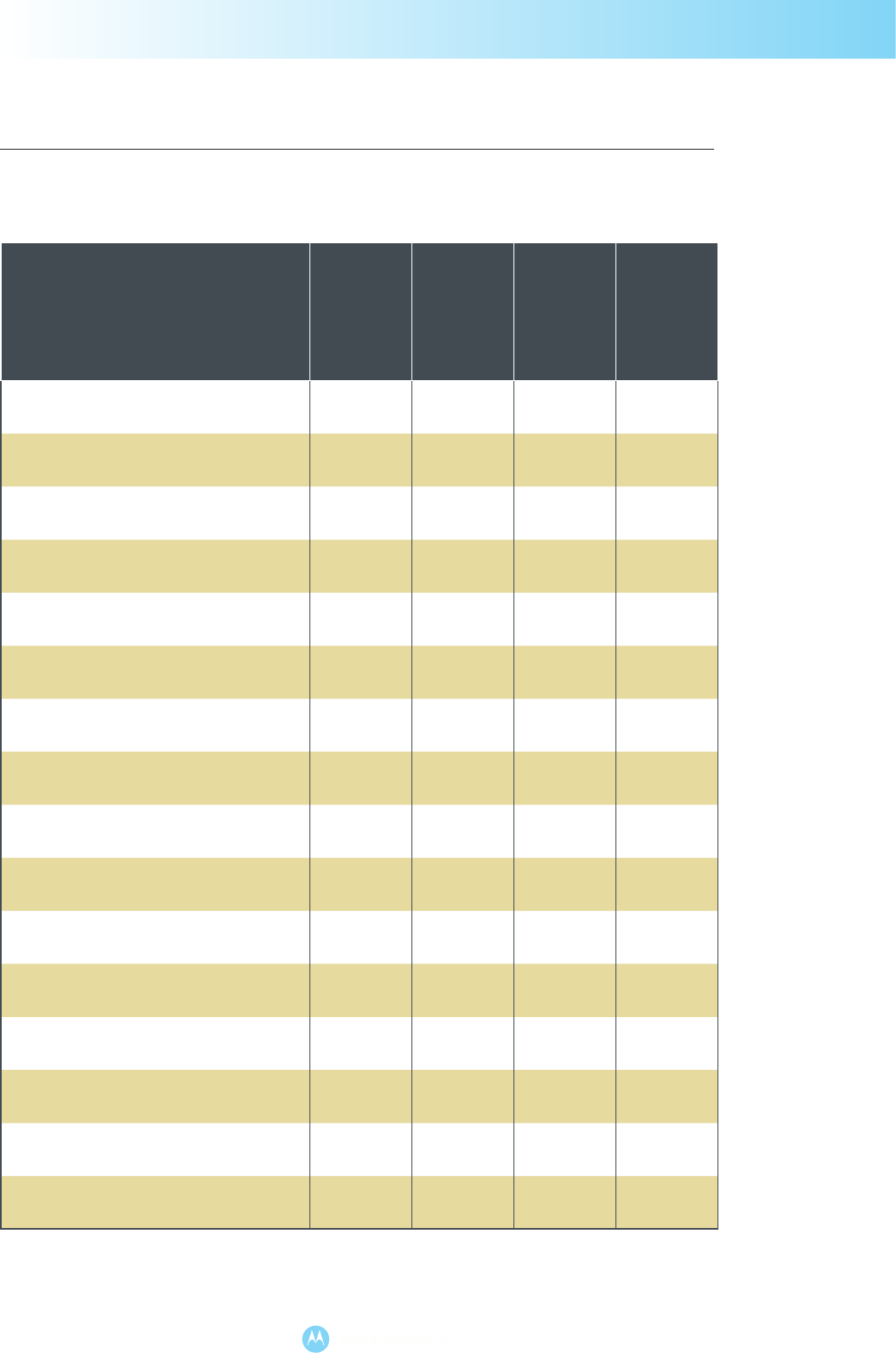
Appendix: ADK Document Map
Document
MOTOTRBO
Option Board
MOTOTRBO
Telemetry
MOTOTRBO
Location Data
MOTOTRBO
Text Messaging
MOTOTRBO ADK Overview ••••
MOTOTRBO Option Board ADK Guide •
MOTOTRBO Option Board PROIS
Cross-Reference •
MOTOTRBO XCMP / XNL Development
Guide •
MOTOTRBO XCMP / XNL Development
Specification •
MOTOTRBO Telemetry ADK Guide •
MOTOTRBO Telemetry Protocol
Specification •
MOTOTRBO Location Data ADK Guide •
MOTOTRBO LRRP Specification •
Motorola Binary XML Encoding
Specification •
MOTOTRBO Text Messaging ADK Guide •
MOTOTRBO Text Messaging Protocol
Specification •
Presence Notifier Application User’s Guide •••
Presence Notifier-to-Watcher Interface
Specification •••
MOTOTRBO Data Services Overview •••
MOTOTRBO USB Configuration Guide ••••

MOTOROLA and the Stylised M Logo are registered in the U.S. Patent & Trademark Office.
All other product or service names are the property of their respective owners.
© Motorola, Inc. 2006.
Motorola disclaims any liability for any use of the specification. Motorola limits all warranties to the extent allowed by
law. Furthermore, Motorola reserves the right to change this specification at any time without any prior notification, and
there is no guarantee that such changes will be backwards compatible with previous versions of the specification.
MOTOTRBO.APPL.BR-RE (04/07) 6880309T32
Motorola GmbH
Heinrich-Hertz-Strasse 1
65232 Taunusstein
Germany
Tel: +49-6128-70-0
Fax: +49-6128-951087
Motorola GmbH
Am Borsigturm 130
13507 Berlin
Germany
Tel: +49-30-6686-0
Fax: +49-30-6686-1916
Motorola Ltd.
Jays Close
Viables Industrial Estate
Basingstoke
RG22 4PD
UK
www.motorola.com/mototrbo
