TRIRIGA BIM User's Guide 3.6.0
User Manual:
Open the PDF directly: View PDF ![]() .
.
Page Count: 84

TRIRIGA Building Information
Models (BIM) User’s Guide
For TRIRIGA Platform 3.6
Technical Contact: Doug Wood doug.wood@wipro.com
Marketing Contact Paul Lacey placey@us.ibm.com
The Maxim extensions for Building Information Modeling (BIM) is released as trial software and
distributed on the IBM Service Management (ISM) Library. An existing Maximo Asset Management 7.5
or 7.6 license and installation is required. Trial software is not supported by the IBM Maximo support
program; however, support is available directly from the IBM Maximo development team for as long as
the software is available for download on the ISM Library. Check the ISM Library for the most recent
version as well as continued availability. Only an English version is distributed during the trial. Your
feedback is important because the software is being evaluated for possible integration with other
Maximo products. Send all support questions and feedback to: maxbim@ca.ibm.com
© Copyright International Business Machines Corporation 2018.
US Government Users Restricted Rights – Use, duplication or disclosure restricted by GSA ADP Schedule
Contract with IBM Corp.
TRIRIGA Building Information Models (BIM) User’s Guide
iii
CONTENTS
List of Figures ................................................................................................................. vi
1 Overview .............................................................................................................. 9
1.1 Utilizing Building Information Modeling (BIM) models with TRIRIGA ........ 9
1.2 Supported Software .................................................................................. 9
1.3 Features ................................................................................................... 9
2 BIM Connector for Revit ..................................................................................... 10
2.1 User ....................................................................................................... 12
2.1.1 Log In ............................................................................................ 12
2.1.2 Servers .......................................................................................... 13
2.1.3 Log Out ......................................................................................... 14
2.2 Setup...................................................................................................... 14
2.2.1 Project Settings ............................................................................. 14
2.2.2 Populate Parameters .................................................................... 17
2.2.3 Map Areas to Rooms .................................................................... 18
2.2.4 Space Use Class ........................................................................... 22
2.3 Integrate ................................................................................................. 24
2.3.1 Building ......................................................................................... 26
2.3.2 Levels ............................................................................................ 28
2.3.3 Rooms ........................................................................................... 30
iv
2.3.4 Spaces .......................................................................................... 33
2.3.5 Assets............................................................................................ 36
2.3.6 Detach ............................................................................................ 38
2.4 Update ................................................................................................... 39
2.4.1 Sync ............................................................................................... 39
2.4.2 Publish Floor Plans ........................................................................ 40
2.4.3 Publish Model ................................................................................. 40
2.5 Open in TRIRIGA ................................................................................... 41
2.5.1 Open Building ......................................................................................... 41
2.5.2 Open Selection ....................................................................................... 41
2.5.3 Launch Portal .......................................................................................... 41
2.6 Help ....................................................................................................... 41
2.6.1 Info ................................................................................................. 41
3 Autodesk Forge Model Administration ............................................................... 41
3.1 Setting up the Forge Service .................................................................. 42
3.1.1 Register with Autodesk Forge and Create an application ...................... 42
3.1.2 Entering Forge Credentials into TRIRIGA .............................................. 45
3.1.3 Configure TRIRIGA for access to Forge Management tool .................... 46
3.1.4 Autodesk SSL Certificate ........................................................................ 47
3.2 Exporting Navisworks Models................................................................. 50
3.2.1 Exporting the model ................................................................................ 50
3.2.2 Enhancing the model .............................................................................. 51
3.3 Importing models into the Forge Service ................................................ 51
3.3.1 Managing Model Storage ........................................................................ 52
3.3.2 Managing Model Files ............................................................................. 54
3.3.3 Upload Model .......................................................................................... 56

TRIRIGA Building Information Models (BIM) User’s Guide
v
3.3.4 Associating Translated Models with Buildings ........................................ 60
3.3.5 Previewing Models in the Viewer ............................................................ 62
4 Using the Autodesk Forge Viewer ...................................................................... 63
4.1 TRIRIGA context .................................................................................... 63
4.2 Viewer Navigation .................................................................................. 63
4.2.1 Viewer Toolbar ........................................................................................ 63
4.2.2 Model Tree .............................................................................................. 65
4.3 Sections ................................................................................................. 66
4.4 Saved views ........................................................................................... 67
4.5 Markup ................................................................................................... 70
5 Best Practices .................................................................................................... 73
6 Troubleshooting ................................................................................................. 74
6.1 Forge Viewer .......................................................................................... 74
6.2 BIM Connector for Revit ......................................................................... 75
6.3 Known Limitations .................................................................................. 76
7 Appendix REST API support .............................................................................. 76

vi
LIST OF FIGURES
Figure 1 - BIM Connector for Revit Toolbar ..................................................................................... 10
Figure 2 - Login Form ...................................................................................................................... 12
Figure 3 - Server definition list ......................................................................................................... 13
Figure 4 - Server Definition Form .................................................................................................... 14
Figure 5 - Project Configuration Form ............................................................................................. 15
Figure 6 - Parameter value creation rule form ................................................................................. 16
Figure 7 - Populate Parameters Form ............................................................................................. 17
Figure 8 - Link Areas to Rooms Form .............................................................................................. 21
Figure 9 - Space Use Classification Form ....................................................................................... 23
Figure 10 - Integration Error Form ................................................................................................... 25
Figure 11 - Building Integration Form .............................................................................................. 27
Figure 12 - Levels Integration Form ................................................................................................. 28
Figure 13 - Rooms Integration Form ................................................................................................ 31
Figure 14 - Space Integration Form ................................................................................................. 34
Figure 15 - Asset Integration Form .................................................................................................. 37
Figure 16 - Synchronize with TRIRIGA Form .................................................................................. 39
Figure 17 - Publish Floorplan Form ................................................................................................. 40
Figure 18 - Publish Model Form ..................................................................................................... 41
Figure 19 - Model Integration Process ............................................................................................. 42
Figure 20 – Create an Autodesk® Forge application ...................................................................... 43
Figure 21 – Forge application definitions ......................................................................................... 44
Figure 22 – Forge application credentials ........................................................................................ 45
Figure 23 – Configure Forge Credentials in TRIRIGA ..................................................................... 46
Figure 24 – TRIRIGA BIM User Security Group. ............................................................................. 47
Figure 25 - Model Upload ................................................................................................................ 56
Figure 26 - Translated Viewable (bubble) Details ........................................................................... 59
Figure 27 - Building to Model Link ................................................................................................... 61
Figure 28 - Building to Model Link Details ....................................................................................... 62
Figure 29 - Forge Viewer Toolbar .................................................................................................... 64
Figure 30 - TRIRIGA Extension to the Forge Viewer Toolbar ......................................................... 64
Figure 31- Forge Viewer Model Tree ............................................................................................... 66
Figure 32 - Forge Viewer Section Tool ............................................................................................ 67
Figure 33 - Saved View Dialog ........................................................................................................ 68

TRIRIGA Building Information Models (BIM) User’s Guide
vii
Figure 34 - Apply View Dialog ......................................................................................................... 68
Figure 35 - Manage Forge Views Popup ......................................................................................... 69
Figure 36 - Forge Viewer Markup Toolbar ....................................................................................... 70
Figure 37 - Save Markup Dialog ...................................................................................................... 72
Figure 38- Display Markup Dialog ................................................................................................... 73

8
Executive Summary
The TRIRIGA 3.6.0 platform provide integration with Building Information Models (BIM) to
enable initialization of facilities data at building hand-over, and to support facilities
management operations. There are two primary integration points for BIM data:
• The BIM Connector for Revit: This provide initial population of TRIRIGA facility data
from Revit authored models, and provide ongoing synchronization of data between
TRIRIGA and Revit models during operations.
• The Autodesk Forge viewer: This provide in context 3D visualization of BIM data
from TRIRIGA applications.
BIM Connector for Revit
The BIM Connector creates TRIRIGA building, floor, spaces, and asset records from Revit
models, including linked models. It synchronizes key attributes over the life of the building.
It can publish floor plans for use in the TRIRIGA floorplan viewer.
Forge Viewer
The Forge viewer is integrated into the Locate and Work Task applications providing in
context 3D visualization of spaces and asset, access to model properties, and model
markup.
BIM Model Management
All of the interaction with the Autodesk Forge service required to manage the models used
by the Forge viewer can be performed from within TRIRIGA using an intuitive graphic
interface
Change History
Version 2.6.0
New

TRIRIGA Building Information Models (BIM) User’s Guide
9
1 Overview
1.1 Utilizing Building Information Modeling (BIM) models with
TRIRIGA
Building Information Models are an industry representation of a building that are used
during the design and build phases of building construction. The data model provides the
information in its attributes to describe (in detail) the infrastructure of a building. The use of
data models is becoming more frequently used by contractors and is part of the turnover of
a building to the owner. A model that is provided at turnover is generally referred to as the
“as built” state of the building.
Building owners who are commissioning a building into production need the information in
this model to perform facilities management. The process of loading this information into
your maintenance products, such as Maximo, is costly, time consuming, and may introduce
errors. The TRIRIGA BIM support allows you to load data from a Revit® model into
TRIRIGA to begin the process of maintaining the building. This state is referred to by “as
maintained”.
When the data is imported, TRIRIGA provides 3D visualization of the full building model in
context with the imported data. This improves the efficiency of the maintenance, work
planning, and execution process. Finally, changes made during operations may be
synchronized with the.
1.2 Supported Software
TRIRIGA Platform 3.6.0
TRIRIGA Application 10.6.0
TRIRIGA BIM Connector for Revit 2.6.0
Autodesk Revit 2017, 2018, 2019. 2016 had been observed to work, but is not
supported.
Autodesk Forge Viewer: The Autodesk Forge Viewer is a cloud-based Viewer. To use it
in TRIRIGA, a subscription from Autodesk is required. The Forge Viewer requires a
browser that supports WebGL.
1.3 Features
The Forge Viewer integration provides visualization of Building Information Model (BIM)
data in the context of the TRIRIGA Assets, Locations, and Work Tasks applications. In this
context, it provides the following features:
BIM Connector for Revit
The BIM Connector for Revit is used to integrate BIM models authored in Revit with
TRIRIGA. It can create new TRIRIGA records from model elements, or link model
elements to existing TRIRIGA records. Once linked, a limited set of values can be
synchronized between TRIRIGA and the model.
Floorplans can be published from Revit directly into TRIRIGA, for use in the TRIRIGA
floorplan viewer. Rooms in the floorplan are automatically linked to TRIRIGA spaces
created from or linked to Revit rooms.

10
The Revit model can be published to the Forge service either directly from Revit or
indirectly through Navisworks. This enables the model to be viewed in the Forge viewer
Forge Viewer
The Forge viewer is embedded in Locate and Work Task applications.
TRIRIGA Space and BuildingEquipment records created from or linked to Revit elements
can be selected in the Forge viewer. And the full set of model properties are available in
the viewer
• Full 3D navigation
• Basic search
• Model properties
• Model tree
• Sectioning of a model
• Model walk through
• Save and restore views
• Markup
BIM Model Management Tool
A UI for administering the Autodesk Forge service as used by TRIRIGA including:
• Managing storage containers (Autodesk Forge Buckets)
• Uploading models to the Autodesk Forge service
• Translating models into viewable formats
• Associated models with TRIRIGA building records
• Manage saved views
2 BIM Connector for Revit
The BIM Connector for Revit is a Revit add-on access from with Revit. It adds a ribbon to
Revit with the TRIRIGA integration functions.
Figure 1 - BIM Connector for Revit Toolbar
The standard workflow is from left to right across the ribbon. Items on the ribbon are
context aware and are only enable when the operation they start is legal. They are
affected by:
• Whether or not the connector is logged into TRRIGA
• If pre-requisite steps have been completed
• If an integration operation is in progress
TRIRIGA Building Information Models (BIM) User’s Guide
11
Shared Parameters
The BIM Connector for Revit adds several Shard Parameters to the Revit Elements that
can be integrated with TRIRIGA. The values in these parameters are used for the initial
creation of TRIRIGA records from Revit Elements, then can later be updated to reflect
changes made to the linked TRIRIGA records. The parameters visible to users include:
All Elements
• IBM.Name
• IBM.Description
• IBM.isTRIRIGA (read-only)
Project Information
• IBM.ModelName
• IBM.ModelDescription
• IBM.BuildingName
• IBM.BuildingDescription
Level
• IBM.Level
Rooms and Spaces
• IBM.UseClassification
Components
• IBM.BarCode
Tools described below are provided to manage the values off all of these. They may also
be edited individually from the appropriate object property sheet or schedule. There are
also several hidden parameters that don’t appear on the property sheets, but can be added
to schedules. These should not be edited by modelers.
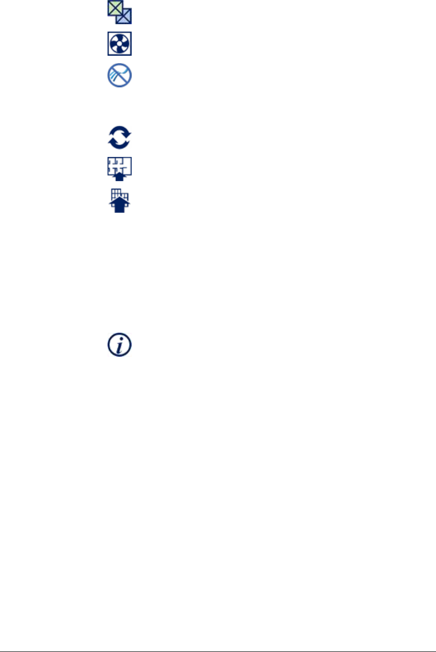
Filtering lists
Most lists and trees can be filter to help find the desired value. This is indicated by a filter
entry field above the list or tree.
To filter a list:
• Enter text in the filter field
• Press Enter to apply the filter or wait a few seconds and it is applied automatically.
Any entry that contains the filter text is displayed (substring match)
Clear filter
Filter on this
Filtered list or tree

12
• To clear the filter and restore the full list, click the clear button to the right of the
filter field or just delete the filter text.
• If the list being filtered is a tree, then parent nodes of any child that matches the
filter are also displayed even if they don’t match the filter.
Integration Process
The process of creating TRIRIGA records happens in two stages:
1. The Revit data is copied to the TRIRIGA server and stored in staging tables which
are found in the triBIM module. Staging records are updated or created as
necessary.
2. Publish workflows are run on the staging table records which create or update the
application objects. The workflow may also update the staging records from the
application records and these updated may flow back to the Revit model
The connector runs a background process that monitors the progress of the workflows, and
retrieves any errors for display in Revit.
The connector stores a globally unique identifier (GUID) in each model file when it is
integrated. This links the model to the TRIRIGA building record. Both staging and
application records that are created from or linked to Revit elements are tagged with the
linked Revit element unique ID. This is used both to link the Revit element and the
TRIRIGA record, and to associate TRIRIGA records with graphic elements in the Forge
viewer.
2.1 User
The user section manages the connection to TRIRIGA servers.
2.1.1 Log In
The connector require at least one pre-defined server configuration before a user can log
into TRIRIGA. If none exists, and empty one is created called “environment”. It must be
populated with a server configuration.
Figure 2 - Login Form
Select the desired server configuration. The user is populated from the configuration, but
may be edited. The password is not saved and must always be provide.
TRIRIGA Building Information Models (BIM) User’s Guide
13
If the configuration needs to be edited, it can either be edited here by selecting the edit
environment link or from the servers from.
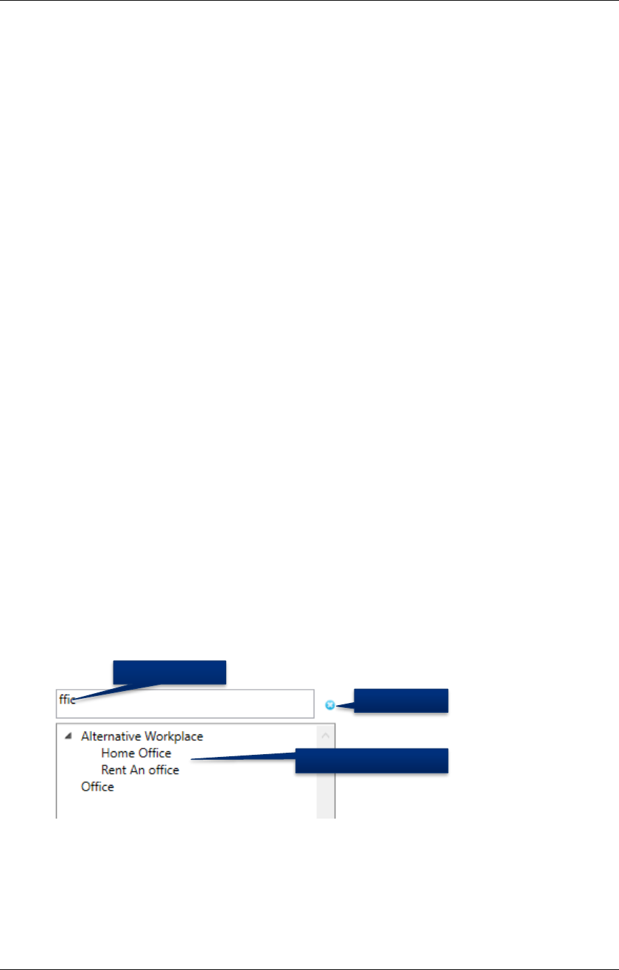
2.1.2 Servers
The connector maintains a list of TRIRIGA server definitions.
Figure 3 - Server definition list
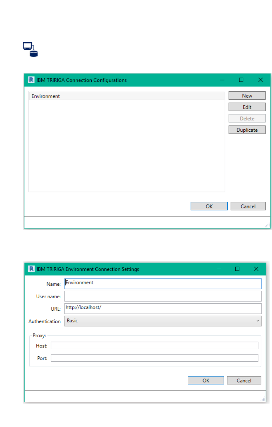
To create or edit a server configuration, Display the Environment Connection Settings
form.

14
Figure 4 - Server Definition Form
Name: The name of this configuration. It is displayed on the login dropdown and in the
Connections Configurations list. It is only visible to the current uses on the current
workstation.
User Name: The user ID to use for TRIRIGA login. This is a convenience and may be
edited later.
URL: The URL of the TRIRIGA server. This is the base URL used to access the TRIRIGA
portal. That is hostname, port, and context root.
Authentication: The Authentication mechanism used by the TRIRIGA server. If you are
unsure how your TRIRIGA server is configured, try each method to see which one
succeeds.
Proxy: If you must pass through a proxy server to assess the TRIRIGA server, specify it
here. This is usually the same configuration that is required for your browser to access
TRIRIGA.
The server configurations are stored in a property file on the workstation running Revit on a
per user basis. The file is located at:
<Current User>AppData\Local\IBM\TRIRIGA\AR Integrator\ environments.properties
2.1.3 Log Out
Disconnect from TRIRIGA.
2.2 Setup
The setup section covers model configuration tasks that must be performed before the
model is integrated with TRIRIGA. Most of these are independent of the TRIRIGA server.
2.2.1 Project Settings
The initial values of Name, and BarCode properties are created from other Revit
parameters. As part of the connector setup, rules must be defined for how the values for
these parameters are created. Rules are defined for each Revit Element type.
Use the Project Settings form to access the rule definitions.

TRIRIGA Building Information Models (BIM) User’s Guide
15
Figure 5 - Project Configuration Form
The button associated with each element type displays the dialog for creating a parameter
value rule. The dialog is the same for all element types, although the values in the
parameter dropdown differ. Rules must be defined in sequence from top to bottom. Each
button is enabled when the preceding rule is defined.
DFX Template: Sets a default DFX template for use in publishing floorplans. The value
becomes the default pre-selected template in the Publish Floorplan form. If the
configuration is loaded from the server, and the template that is stored on the server
doesn’t exist in the model, this value is empty.
Save: Saves the complete configuration to the TRIRIGA server. (you must be logged in for
the button to be active)
Load: Loads the complete configuration from the TRIRIGA server overwriting any existing
configuration. (you must be logged in for the button to be active)
Use the Name Generation Configuration from to define parameter value generation rules.
16
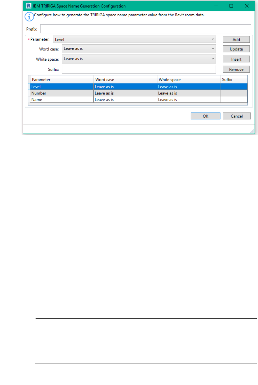
Figure 6 - Parameter value creation rule form
Prefix: A static text string that is applied once at the beginning of the name.
Parameter: The dropdown displays a list of all user visible parameters that are defined for
the element type. It also exposes some non-parameter values of the element. A value
generation rule requires at least one parameter and may have any number of additional
parameters.
For rules that apply to components and types, only parameters that are associated with
every supported category are included in the Parameters dropdown
There are several ways the original parameter value can be manipulated before it is used:
• Word case: This provides options for case folding and capitalization of the
parameter value
• White space: This provides options for normalizing the white space contained in a
parameter value.
• Suffix: This is static text that is appended to the end of the value of the referenced
parameter. It is useful for adding separators between parameters.
Add: Adds the parameter definition at the end of the list.
Update: Replaces the selected parameter definition with the current definition
Insert: Inserts the parameter definition before the selected definition
Delete: Deletes the selected definitions
Tip
Use the ability to save confirmation to and load it from the TRIRIGA
server to insure consistent rules are used across all models.
Tip
Including the element ID in Component names, Type Names, and
Barcodes can help with uniqueness.
TRIRIGA Building Information Models (BIM) User’s Guide
17
Tip
The parameters added by the COBie toolkit appear in the Parameters
dropdown. You can effectively use the COBie rules instead of defining
rules here by selecting just the COBie.name parameter for each element.
The project settings are stored in the model file.
2.2.2 Populate Parameters
Before a model can be integrated with TRIRIGA, the shared parameters required by
TRIRIGA must be added to the model, and have values assigned according to the rules
defined above. This is done with the Populate Parameter tool.
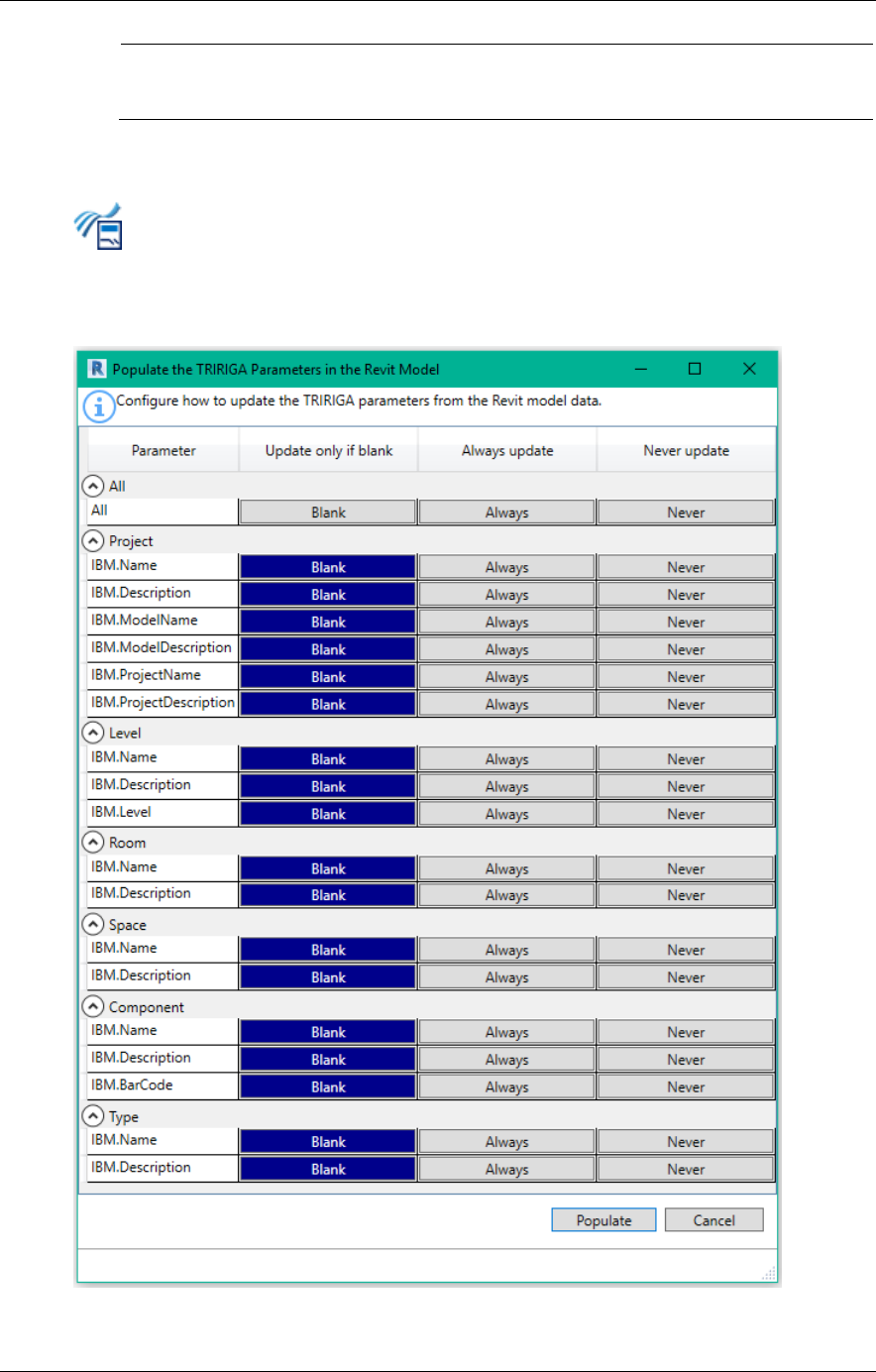
Figure 7 - Populate Parameters Form
18
There are 3 update options for each parameter.
• Blank: Only update the value if it is blank. This implies that either Populate
Parameters has never been run, or the element has been added since the last
time it was run.
• Always: Overwrite any existing value:
• Never: Don’t populate.
It is usually only necessary to run populate parameters before the initial integration and
before newly added elements are integrated. Blank works well for this if one of the forms
report error, it may be necessary to use Always to overwrite the values with corrections.
Once an element is linked to TRIRIGA or if it is integrated with an existing TRIRIGA record,
the name value is retrieved from TRIRIGA.
2.2.3 Map Areas to Rooms
Revit uses Area Plans to support space planning. Area plans are used to calculate space
and floor area. Revit support two types of Area Plans:
• Gross Building: Only one is allowed.
• Rentable: Area is calculated according to the BOMA 98 standard. A model may
define any number.
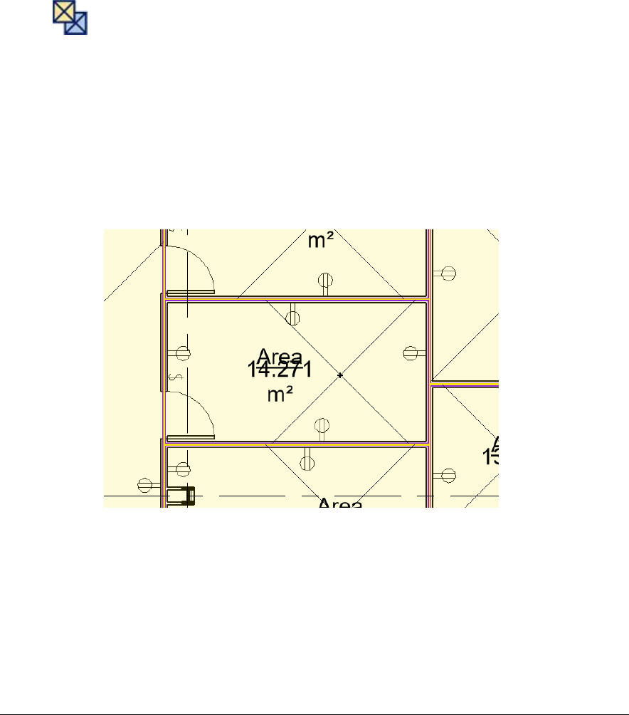
Area plans are divided into areas. Areas are drawn onto the floorplan and need not have
any relationship to Rooms or Spaces. This means that there are 4 possible relationships
between an Area and a Room:
1. The area boundaries match the room boundaries.
2. A room is comprised of exactly n areas. That is, none of the area boundaries for
areas within the room cross the room boundary, and there is more than one area
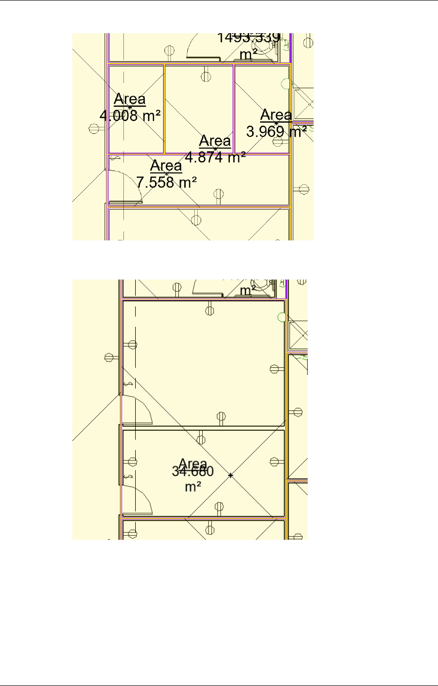
TRIRIGA Building Information Models (BIM) User’s Guide
19
within the room
3. An area is encompassing exactly n rooms. That is, none of the room boundaries
for rooms within the area cross the area boundaries, and there is more than one
room within the area, and the area is completely filled by rooms.
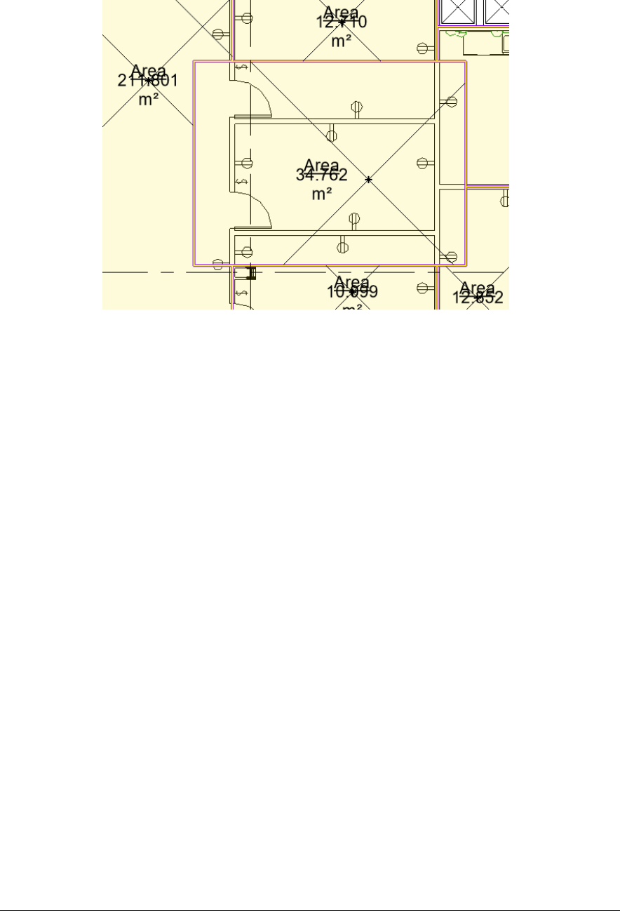
20
4. Areas are arbitrary: area and room boundaries cross.
The connector can use area plans to calculate TRIRIGA floor area and Areas to calculate
TRIRIGA Space area. Since there is only one gross area plan allowed, if it exists, it is used
to calculate gross floor area. The rentable area plan must be specified. And areas can be
linked to rooms assuming areas are specified as described in case 1 above. When an
area is linked to a room, the Revit room area is replaced by the area from the Area.
Use the Map Areas to Rooms tool to manage the association of area to room, and to select
the desired rentable area plan. When this form is first opened, it displays the current room
to area linkage in the model, and the active rentable area plan. The tool is only active if
there are Area Plan(s) defined in the model.
TRIRIGA Building Information Models (BIM) User’s Guide
21
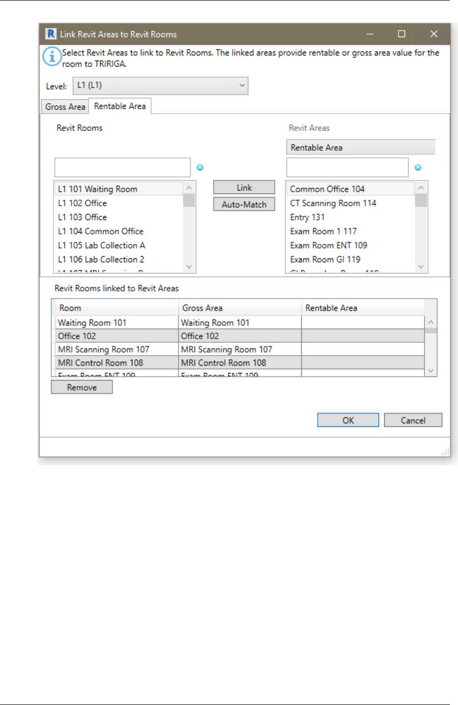
Figure 8 - Link Areas to Rooms Form
The form has several parts so some care should be taken to ensure you are working in the
right context.
Level: Area Plans and Areas are associated with Revit levels, so the level selection
controls the context of the rest of the form. The Rooms, Area Plans, and Areas displayed
are all for the level selected in the Level dropdown.
Gross Area/Rentable Area: The form has two tabs which control the type of area plan
displayed. These tabs are almost identical, except the rentable table requires selection of
the Area Plan. Since only one Gross Area plan is allowed, no selection is required.
Revit Rooms: This displays the list of Rooms on the Level not linked to an Area in the
selected Area Plan.. Each Area Plan has its own set of Rooms.
Revit Areas: For the Gross Area Plan, this displays the list of Areas defined for the Area
Plan. For Rentable Area Plans, the Area Plan must be selected. The list of areas
displayed is for the selected Area Plan. The selected Area Plan also controls what is
displayed in the last column of the link table.
22
Link: When an entry is selected in both the Rooms and Areas list, pressing Link
associates them removing them from their respective lists and adding them to the Linked
Rooms and Areas table in the correct columns.
Auto Match: Auto match performs an exact name match of each room against the
displayed area list. Each matching pair is linked as above.
Revit Rooms linked to Revit Areas: The table displays the room to area linkage that will
be applied to the model if the form is accepted. Pay attention to the rentable area column
as it changes based on the selected rentable area plan.
Remove: Removes the highlighted row(s) from the linkage table returning the rooms and
areas to their respective lists.
The association between Area and Rooms is stored with the Rooms in hidden parameters.
Tip
Even if you don’t map rentable areas to rooms, select a rentable area
plan for use in calculating floor rentable area.
Tip
If you have worked with more than one rentable Area Plan, be sure that
the correct one is selected when you accept the form. Only the mappings
for the selected Area Plan are saved and used.
2.2.4 Space Use Class
TRIRIGA requires all spaces to have a space Use Classification specified, therefore, to
create TRIRIGA spaces for Revit rooms or spaces, a Use Classification needs to be
provided. The Space Use Class tool retrieves the Use Classification hierarchy from the
TRIRIGA server and allows Use Classification to be assigned individually or in bulk to Revit
rooms and spaces. They are stored in the IBM.UseClassification parameter. These values
are then used when TRIRIGA spaces are created from the Revit objects. Once a Revit
Room or Space is integrated with a TRIRIGA space, TRIRIGA is the master for Use
Classification so updates here have no effect and are overwritten by a Sync operation.
Tip
The Integrate Room and Integrate Space tools both verify that a Use
Classification is assigned, and does not display the Room or Space if it is
missing. However, the Use Classification is only used for creating new
TRIRIGA spaces. Specify Use Classifications for Rooms and Spaces for
you intend to create new TRIRIGA spaces, then use the Assign Blank
function to set the remainder to a default value.
TRIRIGA Building Information Models (BIM) User’s Guide
23
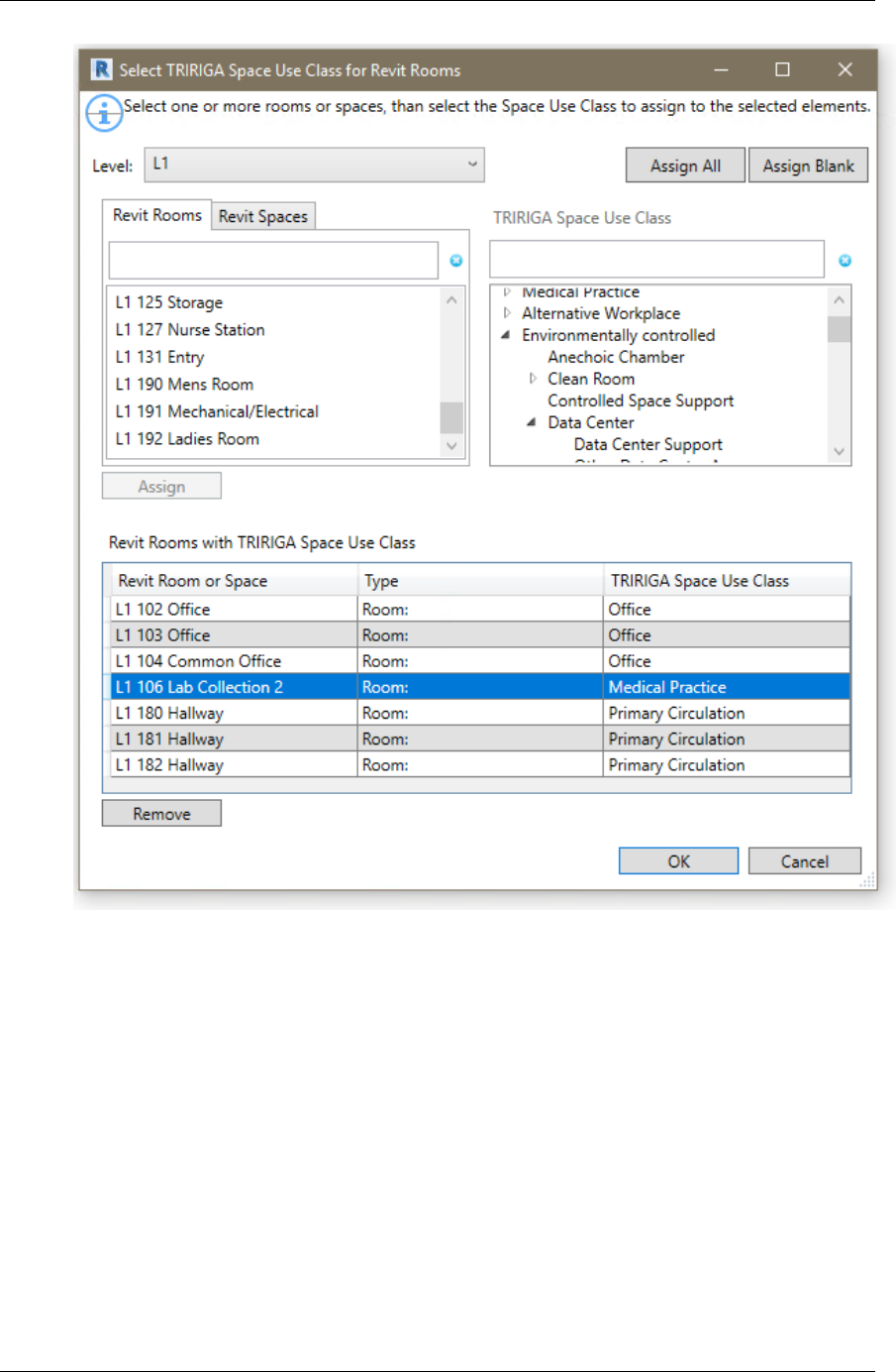
Figure 9 - Space Use Classification Form
Level: A list of all Revit levels. The selected level sets the context for the Revit Rooms
and Revit spaces tabs.
Revit Rooms: All of the Rooms on the selected Level that don’t have Use Classifications
assigned.
Revit Spaces: All of the Spaces on the selected Level that don’t have Use Classifications
assigned, and aren’t linked to a room either by Revit, or by the Connector Spaces tool
described below. If Rooms and Spaces are defined in the same model, and a Room and a
Space share the same boundary, then Revit links them.

24
Tip
Use Classification is only used for Spaces if a TRIRIGA Space is directly
created from the Revit Space. This is rare as Revit Spaces are typically
linked to TRIRIGA Spaces created from Rooms. You can bulk assign a
Use Classification to spaces, then individually edit any that will be directly
integrated.
Revit Rooms with TRIRIGA Space Use Class: This shows the current list of rooms and
spaces that have the have Use Classifications assigned, and their assigned value. When
the form is initially opened, this displays the current state of the model.
Assign: When a Use Classification is selected, and at least one Room or Space is
selected, this button is active. Pressing it assigns the Use Classification to all selected
Rooms and Spaces, removes the Rooms and Spaces from their respective list and add
them to the assigned table.
Remove: Removes all selected rows from the assigned table, clears the Use Classification
value and returns them to their respective lists.
TRIRIGA Space Use Class: The space use classification hierarchy from the server to
which the connector is logged into. This is retrieved at the time of login.
Assign All: Assigns the selected Use Classification to all rooms and spaces on all level.
Any previously assigned value is overwritten. All Rooms and Spaces are moved to the
assigned table with the new value.
Assign Blank: Assigns the selected Use Classification to all rooms and spaces on all level
that don’t currently have a value. All Rooms and Spaces are moved to the assigned table
with the new value.
Use Classifications are only used for creating new TRIRIGA spaces. When integrating
with existing spaces, or when synchronizing the model with TRIRIGA, the Use
Classification is updated from the linked TRIRIGA space.
2.3 Integrate
The integrate steps generally need to be performed in the order presented here. This
builds up the TRIRIGA location hierarchy. In addition, when working with federated
models, the architecture model, or the model containing the majority of the room definitions
should be the first model integrated. Additional models in the set are integrated as linked
models.
All of the integration forms use a two-step process:
• Data is uploaded to the triBIM staging tables on the TRIRIGA server. This is
synchronous and Revit cannot be used during its execution.
• The data is published via integration workflows from the triBIM object to the
application objects. This happens asynchronously on the TRIRIGA server. The
connector monitors the process. Many of the connector tools are not available
while a publish action is running on the server.
Validation
Each form performs validation on the values of the parameters added by TRIRIGA to the
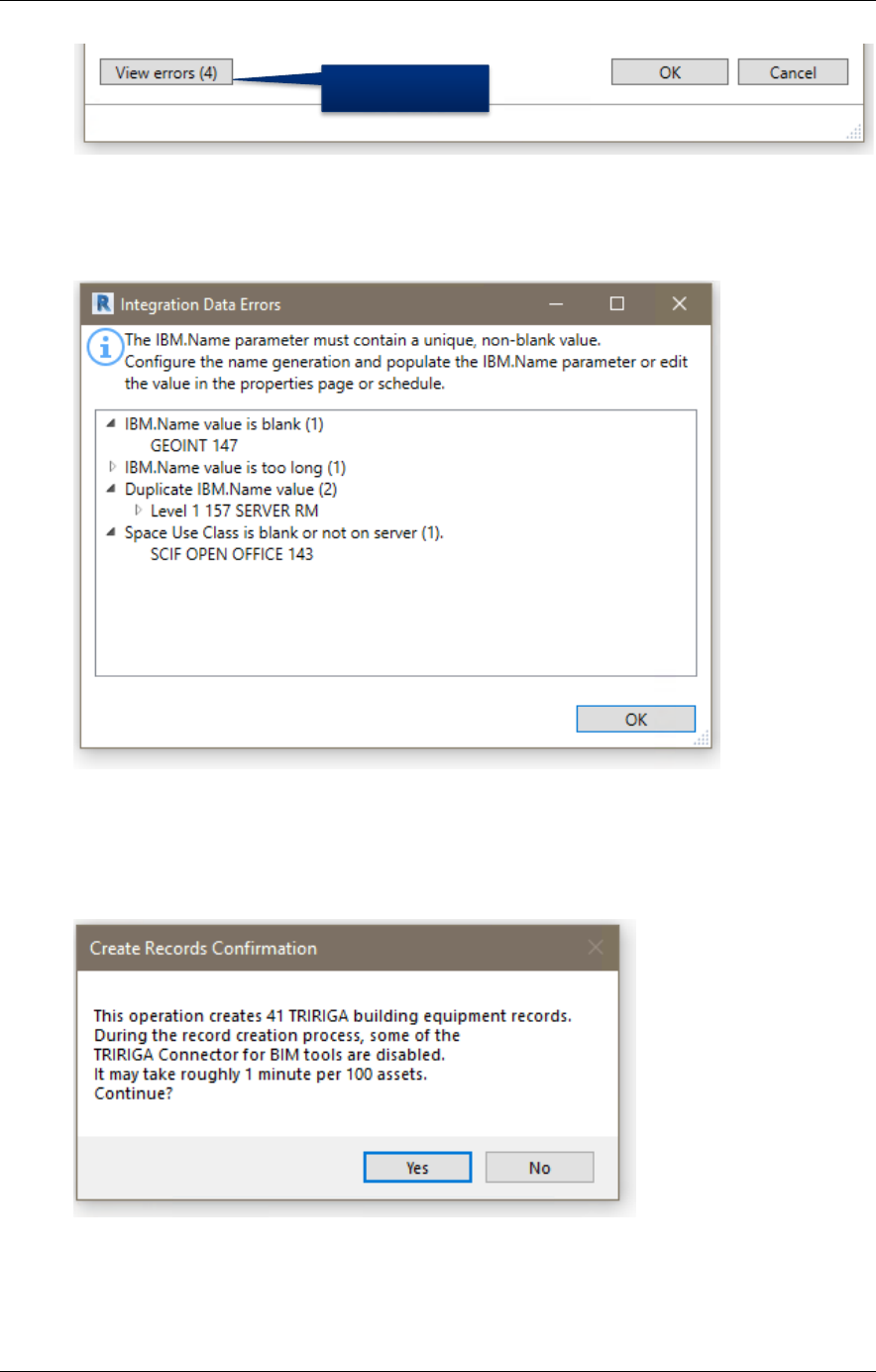
primary object handled by the form, for example, Levels. If errors are found, the View
Errors button is visible in the lower left corner of the form with an error count.
TRIRIGA Building Information Models (BIM) User’s Guide
25
The View Errors button provides a list of error types and under each type a list of
erroneous elements.
Note: Elements with errors are not displayed in the form and are not available for
integration.
Figure 10 - Integration Error Form
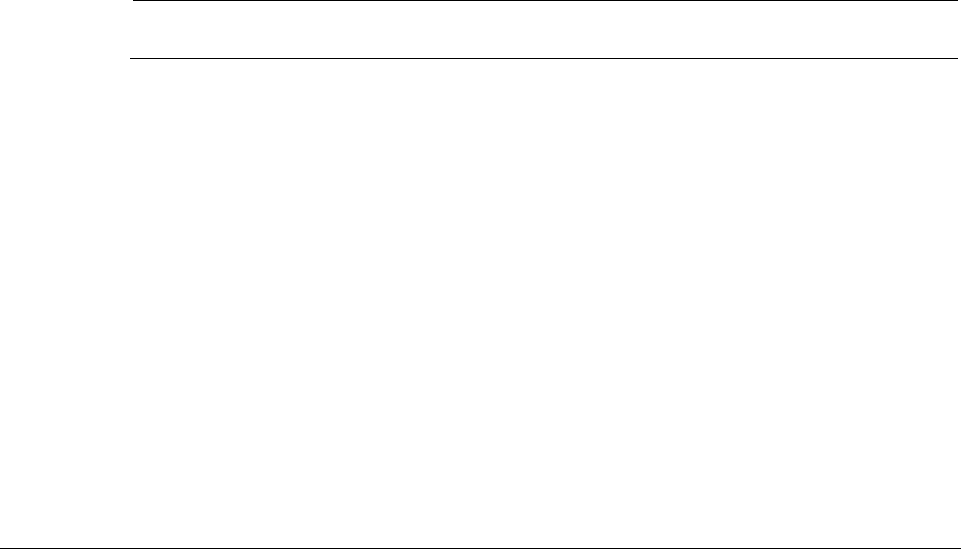
Confirmation
Each form request confirmation before initiating the integration process. The request
provides a general description of the action that will be performed.
Linked Models
Many models are composed of several federate or linked files. These are often organized
by discipline. The linked files contain many assets that are of interest to TRIRIGA users.
Visible if there
are errors

26
However, the asset information is much more useful if the assets are correctly placed in
the TRIRIGA location hierarchy. Linked model files often echo special elements from the
primary, usually architectural, model file: Levels are duplicated across the files set. MEP
Spaces are often, from a facilities management perspective, identical to Rooms.
The primary task of integrating a linked model file is to match the congruent spatial
elements to the master elements in the primary integration file. Once the match is made,
the connector writes the GUID of the matched element into a hidden parameter in the
linked file. When communicating with TRIRIGA about that element, including about the
locations of asset contained within it, the connector uses the GUID of the mater element in
place of the GUID in the current file.
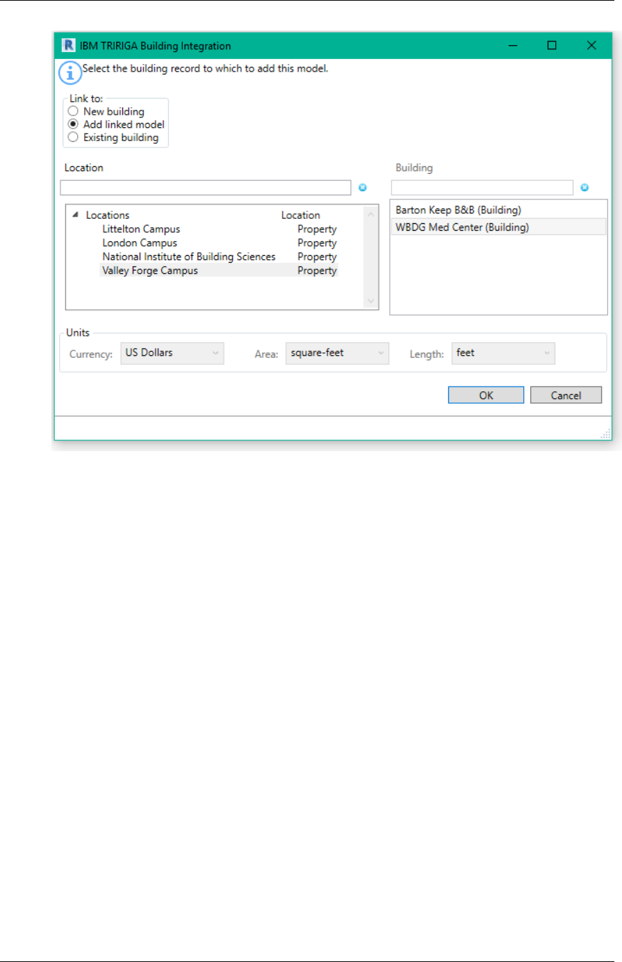
2.3.1 Building
There are three options for integrating a building:
• New Building: This creates a new TRIRIGA building record and new triBIMModel
record, and a triBIMBuilding record.
• Add Linked Model: This adds a linked (federated) model file to a previously
integrated building. This links the model file to the TRIRIGA building record, and
creates a new triBIMModel record.
• Existing Building: This links the model to an existing TRIRIGA building. This can
be:
o A building that was manually created in TRIRIGA. In this case a triBIMBuilding
record and a triBIMModel record are created. The triBIMBuildign is associated
with the existing TRIRIGA building.
o A building previously created by linking the same model file as a new building.
In this case no new records are created. The model GUID is updated from the
TRIRIGA building record.
Note in this version of the connector, a linked model cannot be detached and
re-integrated. It can be integrated again as a linked model, but a new
triBIMModel record is created, and it loses ownership of some records created
from the model.
TRIRIGA Building Information Models (BIM) User’s Guide
27
Figure 11 - Building Integration Form
To integrate the building with TRIRIGA:
1. Select how you want to integrate the building. The behavior of the rest of the form
varies slightly based on the option selected.
2. Select a location. The location list can be filtered if desired.
3. If “Add Linked Model”, or “Existing Building” is selected, the building list is
populated with buildings available for the location. The list is retrieved from the
TRIRIGA server when the location is selected, so large lists may take a moment to
load. For “Existing Building”, all buildings for the location are displayed. For “Add
Linked Model”, only building, that were previously linked to a model through one of
the other two options are displayed.
4. If “New Building” is selected, you can specify currency and units of measure.
Validation: When the form is opened, the following validations are performed on the list of
levels:
• Project Information: IBM.BuildingName, and the IBM.ModelName parameters have
values
• Project Information: IBM.BuildingName, and the IBM.ModelName don’t contain the
# character
• Project Information: IBM.BuildingName, and the IBM.ModelName don’t exceed
150 characters in length
Update: If “Existing Building” is selected, in the Project Information object:
• The IBM.Name is updated from the TRIRIGA building name
• The IBM.Description is updated from the TRIRIGA building description.

28
• The Connector GUID for the model is updated from the TRIRIGA building record
Once a model is integrated with TRIRIGA, the building tool is inactive. To integrate the
model with a different TRIRIGA server, or to create a second instance of the building on
the same server, the model must first be detached from TRIRIGA which clears all data
used by the connector.
2.3.2 Levels
The Levels tool can be used to: create TRIRIGA Floors from Revit Levels, to link Revit
Levels to existing TRIRIGA floors, or to link Levels from linked model files to Floors created
from the same Level in the primary model file.
Figure 12 - Levels Integration Form
Revit Levels: All the level in the model which are not yet integrated.

TRIRIGA Building Information Models (BIM) User’s Guide
29
TRIRIGA Floors: If the building integration process used the “Existing Building” or the
“Add Linked Model” option and the TRIRIGA building has existing floors, then the list of
Floors which are not integrated with a level is displayed.
Levels to Integrate: This shows all level that have been selected for integration or are
already integrated. If they are already integrated, the associated TRRIGA Floor is shown in
the TRIRIGA Floor column. If processing this form will create a new Floor, New is shown.
The Integration Method Column may have one any of:
• Blank: The level is not currently associated with a TRIRIGA Floor, and the process
will create a new TRIRIGA floor and link the level to the new floor.
• Integrated: The indicated TRIRIGA Floor was previously created from this level
and this model file. Or, that an existing TRIRIGA floor was selected that was not
created from a model. The integration process will update the TRIRIGA floor to
associate it with the Level.
• Linked: The indicated floor was previously created from a different model file that is
part of the linked model set, and is either already linked to the Level in this model,
or will be linked to the Level when the integration process runs.
• Locked: With Linked model files, in some cases Revit gives the Levels in the linked
model file the same ID as the Level in the primary model file. The connector
detects this and automatically associates the levels and marks them as “locked”
because the association cannot be edited.
When the form is displayed, it attempts to match Revit Levels to TRIRIGA Floors by GUID.
All matches are moved to the Levels to Integrate table. However, the form still needs to be
processed to write these matches into the model. Typically, there are matches if the Floors
were originally created from this model, the model has been detached, and is being re-
integrated.
Add: If one or more level is selected, the Add button is active. Pressing Add moves all the
selected levels from the Revit Levels list to the Levels to Integrate table and shows an
action of New.
If a single item is selected in the Revit Levels list, and an item is then selected in the
TRIRIGA Floors list, they are linked, removed from their respective list and added to the
Levels to Integrate list:
• If the Floor was either not created by the Connector, or was previously created
from this model file, the integration method is “Integrated”.
• If the Floor was created from a different model file in the linked set. the integration
method is “Linked”
Auto-Match: Auto-match attempts to match Revit Levels to TRIRIGA floors by matching
the IBM.Name value to the Floor name. Each match is processed as above.
Remove: Removes the selected Level(s) from the integration list, When the form is
processed, if it was previously integrated, the triBIM staging record is delete in TRIRIGA, if
it was previously linked, the link is clear in Revit.
When the form is initially loaded, it tries to match Revit Levels to TRIRIGA Floors based on
the GUID. If the model was previously detached, and is being re-integrated, all levels
previously created from the model match and are moved to the Levels to Integrate table.
Validate: When the form is opened, the following validations are performed on the list of
levels:
• All levels have a value in their IBM.Name parameter
• There are no duplicate values for the IBM.Name parameter in the list of levels

30
• The value of the IBM.Name parameter for all levels does not exceed 50
characters.
Update: If the level is integrated with an existing TRIRIGA Floor, the following updates are
made:
• Revit Level: IBM.Name is updated from the TRIRIGA floor name
• Revit Level: IBM.Description is updated from the TRIRIGA floor description.
• Revit Level: IBM.Level is updated from the TRIRIGA Floor Level
• TRIRIGA Floor: If a gross area plan is associated with the Level, the gross area for
the Floor is updated with the value calculated from the area plan by summing the
area of all Areas in the Area Plan.
When the integration process runs, the following actions are performed:
• If a new integration is requested, a new triBIM Staging record is created, and a
TRIRIGA floor record is created by workflow from the staging record.
• If integrate is requested, and a TRIRIGA Floor record exists, if a triBIM staging
record exists on the TRIRIGA server, the staging records is updated, if not, a new
staging record is created and associated with the Floor. The updates described
above are performed.
• If a link is requested, The GUID of the Revit level that the floor was originally
created from is retrieved from TRIRIGA and stored in a hidden parameter of the
linked Level
• If the Level was previously integrated, but now is not, the triBIM staging record is
deleted.
• If the Level was previously linked, but now is not, The GUID of the linked Level is
removed from the Level.
• The IBM.isTRIRIGA value is updated on all Levels to reflect their new state
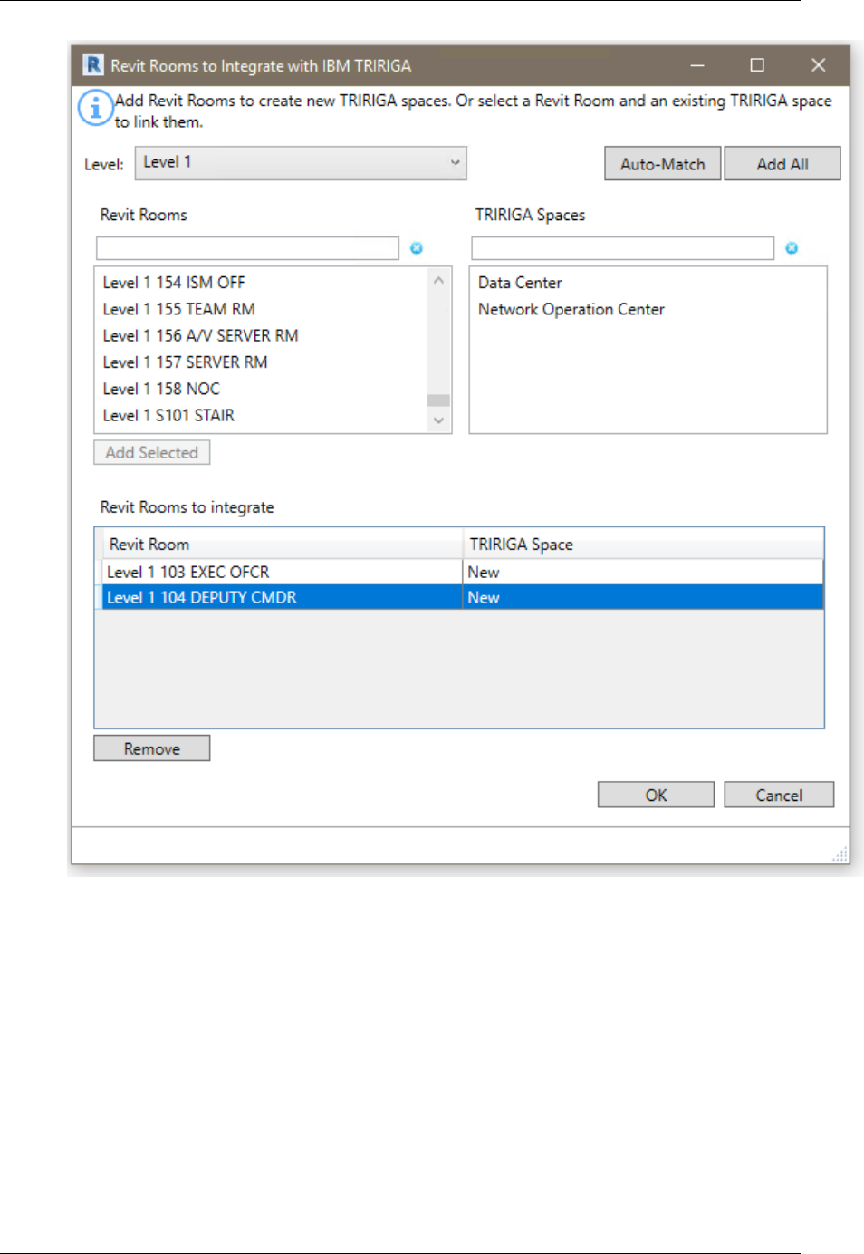
2.3.3 Rooms
Use the Room Tool to create TRIRIGA Spaces from Revit rooms, or to link Revit Rooms to
existing TRIRIGA Spaces.
Tip
Process all of the Rooms in the module you plan integrate before
processing any Spaces even if you need to switch between model files.
You can only link Space to Rooms, not Rooms to Spaces. So, if you
create a TRIRIGA Space from a Revit Space, you will not later be able to
link to a Room.
TRIRIGA Building Information Models (BIM) User’s Guide
31
Figure 13 - Rooms Integration Form
Levels: The list of Levels that were integrated in the Levels step. Select the active Level.
The Revit Rooms and TRIRIGA Spaces lists only contain Rooms and Spaces from the
selected Level.
Revit Rooms: All the Rooms on the selected Level which are not yet integrated
TRIRIGA Spaces: If the building integration process used the “Existing Building” or the
“Add Linked Model” option and the TRIRIGA building has existing Spaces, then the list of
Spaces for the Floor matching the selected Level is displayed.
Rooms to Integrate: This shows all Rooms that have been selected for integration or are
already integrated. If they are already integrated, the associated TRRIGA Space is shown
in the TRIRIGA Space column. If processing this form will create a new Space, New is
shown.
32
When the form is displayed, it attempts to match Revit Rooms to TRIRIGA Spaces by
GUID. All matches are moved to the Rooms to Integrate table. However, the form still
needs to be processed to write these matches into the model. Typically, there are matches
if the Spaces were originally created from this model, the model has been detached, and is
being re-integrated.
Add: If one or more Rooms are selected, the Add button is active. Pressing Add moves all
the selected Rooms from the Revit Rooms list to the Rooms to Integrate table and shows
an action of New.
If a single item is selected in the Revit Rooms list, and an item is then selected in the
TRIRIGA Spaces list, they are linked, removed from their respective list and added to the
Rooms to Integrate.
Auto-Match: Auto-match first attempts to match Revit Rooms to TRIRIGA Spaces by
matching the IBM.Name value to the Space name. Each match is processed as above.
Next it attempts to find exactly one TRIRIGA Spaces that contains the Revit Room name.
Each match is processed as above. Auto-match applies to all levels.
Add All: Add All is a short cut for large buildings. It adds all the rooms in the Revit Rooms
list for all levels to the Rooms to Integrate table.
Remove: Removes the selected Room(s) from the integration list, if it was previously
integrated, the triBIM staging record is deleted in TRIRIGA when the form is processed.
When the form is initially loaded, it tries to match Revit Rooms to TRIRIGA Spaces based
on the GUID. If the model was previously detached, and is being re-integrated, all Rooms
previously created from the model match and are moved to the Rooms to Integrate table.
Validate: When the form is opened, the following validations are performed on the list of
Rooms:
• All Rooms have a value in their IBM.Name parameter
• There are no duplicate values for the IBM.Name parameter in the list of Rooms
• The value of the IBM.Name parameter for all Rooms does not exceed 100
characters.
• All Rooms have a value for IBM.UseClassification
Tip
If the room list is empty, check the error listing. You may have forgotten
to assign Use Classifications.
Update: If the Rooms is integrated with an existing TRIRIGA Space, the following updates
are made:
• Revit Room: IBM.Name is updated from the TRIRIGA space name
• Revit Room: IBM.Description is updated from the TRIRIGA space description.
• Revit Room: IBM.UseClassification is updated from the TRIRIGA Use
Classification
• TRIRIGA Space: If an area from a gross area plan is associated with the Space,
the gross area for the Spaces is updated with the value from the associated Area.
Otherwise it is updated with the area from the Revit Room.
• TRIRIGA Space: If an area from a rentable area plan is associated with the Space,
the area for the Spaces is updated with the value from the associated Area.
Otherwise it is updated with the area from the Revit Room.
When the integration process runs, the following actions are performed:
TRIRIGA Building Information Models (BIM) User’s Guide
33
• If a new integration is requested, a new triBIM Staging record is created, and a
TRIRIGA Space record is created by workflow from the staging record.
• If integrate is requested, and a TRIRIGA Space record exists, if a triBIM staging
record exists on the TRIRIGA server, the staging the record is updated, if not, a
new staging record is created and associated with the Space. The updates
described above are performed by workflow.
• If the Space was previously integrated, but now is not, the triBIM staging record is
deleted.
• The IBM.isTRIRIGA value is updated on all Rooms to reflect their new state
2.3.4 Spaces
Use the Space Tool to associate Revit Spaces with TRIRIGA Spaces. This is typically
Spaces in a MEP model file with TRIRIGA Spaces that were created from Rooms in the
architectural model. This allows assets contained within Revit Spaces to be associated
with the correct TRIRIGA Space. You may also use this tool to create new TRIRIGA
Spaces just like the Room Tool.
34
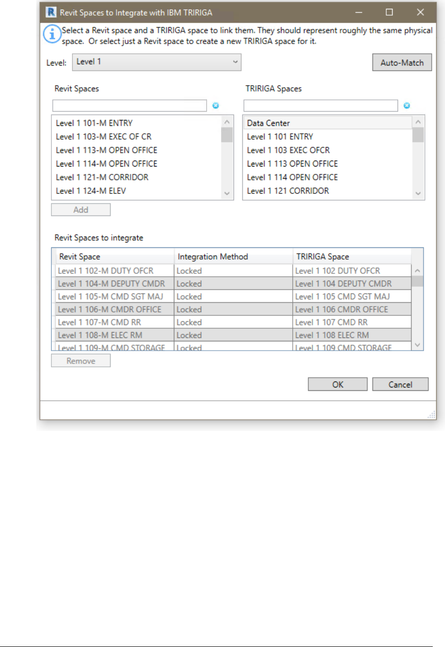
Figure 14 - Space Integration Form
When this form is displayed, it reflects the current state of the model, except where it
makes automatic matches. The form must still be processed for the automatic matches to
be written into the model.
Levels: The list of Levels that were integrated in the Levels step. Select the active Level.
The Revit Spaces and TRIRIGA Spaces lists only contain Spaces from the selected Level.
Revit Spaces: All the Spaces on the selected Level which are not yet integrated
TRIRIGA Spaces: All of the TRIRIGA. Spaces for the selected Level that are not yet
integrated. Typically, these Spaces were created from Rooms in a linked model file that
was previously integrated, and the current model file is integrated as a Linked Model.
Revit Spaces to Integrate: This shows all Spaces that have been selected for integration
or are already integrated. If they are already integrated, the associated TRRIGA Space is
shown in the TRIRIGA Space column. If processing this form will create a new Space, New
is shown. The Integration Method Column may have one any of:

TRIRIGA Building Information Models (BIM) User’s Guide
35
• Blank: The Space is not currently associated with a TRIRIGA Space, and the
process will create a new TRIRIGA Space and link the Revit and TRIRIGA
Spaces.
• Integrated: The indicated TRIRIGA Space was previously created from this Space
and this model file. Or, an existing TRIRIGA Space was selected that was not
created from a model. The integration process will update the TRIRIGA Space to
associate it with the Revit Space.
• Linked: The indicated Space was previously created from a different model file that
is part of the linked model set, and is either already linked to the Space in this
model, or will be linked to the Space when the integration process runs.
• Locked: If Rooms and Spaces exist in the same model file, and share the same
boundary, Revit recognizes that they describe the same space and links them. The
connector recognizes this, automatically matches them and shows the integration
method as “Locked”
Add: If one or more Revit Spaces are selected, the Add button is active. Pressing Add
moves all the selected Spaces from the Revit Spaces list to the Spaces to Integrate table
and shows an action of New.
If a single item is selected in the Revit Spaces list, and an item is then selected in the
TRIRIGA Spaces list, they are linked, removed from their respective list and added to the
Spaces to Integrate table.
Auto-Match: Auto-match first attempts to match Revit Rooms to TRIRIGA Spaces by
matching the IBM.Name value to the Space name. Each match is processed as above.
Next it attempts to find exactly one TRIRIGA Space the contains the Revit Room name.
Each match is processed as above. Auto-match applies to all levels.
Remove: Removes the selected Space(s) from the integration list, if it was previously
integrated, the triBIM staging record is deleted in TRIRIGA when the form is processed.
When the form is initially loaded, it tries to match Revit Rooms to TRIRIGA Spaces based
on the GUID. If the model was previously detached, and is being re-integrated, all Spaces
previously created from the model match and are moved to the Spaces to Integrate table.
Validate: When the form is opened, the following validations are performed on the list of
Revit Spaces:
• All Spaces have a value in their IBM.Name parameter
• There are no duplicate values for the IBM.Name parameter in the list of Spaces
• The value of the IBM.Name parameter for all Spaces does not exceed 100
characters.
• All Spaces have a value for IBM.UseClassification
Tip
If the Space list is empty, check the error listing. You may have forgotten
to assign Space Use Classifications.
Update: If the Space is integrated with an existing TRIRIGA Space, the following updates
are made:
• Revit Space: IBM.Name is updated from the TRIRIGA space name
• Revit Space: IBM.Description is updated from the TRIRIGA space description.
• Revit Space: IBM.UseClassification is updated from the TRIRIGA Use
Classification
When the integration process runs, the following actions are performed:
36
• If a new integration is requested, a new triBIM Staging record is created, and a
TRIRIGA Space record is created by workflow from the staging record.
• If integrate is requested, and a TRIRIGA Space record exists, if a triBIM staging
record exists on the TRIRIGA server, the staging records is updated, if not, a new
staging record is created and associated with the Space. The updates describe
above are performed.
• If a link is requested, the GUID of the Revit Room that the space was originally
created from is retrieved from TRIRIGA and stored in a hidden parameter of the
linked Space
• If the Space was previously integrated, but now is not, the triBIM staging record is
deleted.
• If the Space was previously linked, but now is not, The GUID of the linked Room is
removed from the Space.
• The IBM.isTRIRIGA value is updated on all Spaces to reflect their new state
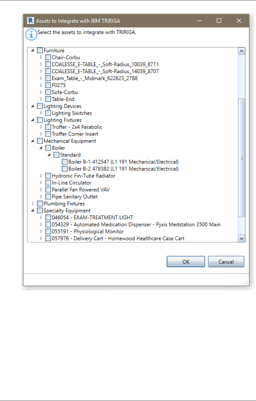
2.3.5 Assets
Use the Asset Tool to create TRIRIGA BuildingEquipment records from Revit Components.
The following categories of components can be integrated:
• Air Terminals
• Data Devices
• Doors
• Duct Fittings
• Electrical Equipment
• Furniture
• Lighting Devices
• Lighting Fixtures
• Mechanical Equipment
• Pipe Accessories
• Plumbing Fixtures
• Specialty Equipment
• Telephone Devices
Match to Existing Asset
Before creating a new asset, the connector attempts to match each asset to an existing
TRIRIGA BuildingEquipment record. First it attempts to match the Revit Component ID to
an ID in a triBIM staging record. This is useful If the building is being re-integrated,
Second, it tries to match the IBM.BarCode parameter value to the barcode of existing
BuildingEquipment records. If a match is found, the asset is linked to the existing record.
Match to Specification
All TRIRIGA BuildingEquipment records must be associated with a BuildingEquipment
specification. Specification records are not created by the connector so must exist before
the asset integration process is run.
TRIRIGA Building Information Models (BIM) User’s Guide
37
Figure 15 - Asset Integration Form
The Asset listing is filtered by previous integration choices. If an asset is on a level, it is
only shown if the level is integrated, if the asset is contained in a Room or a Space, it is
only shown if the containing Room or Space is integrated.
When the form is initially displayed, the currently integrated items are checked.
Check items are to be integrated when the form is processed.
Validate: When the form is opened, the following validations are performed on the list of
Revit Components:
• All Components have a value in their IBM.Name parameter
• There are no duplicate values for the IBM.Name parameter in the list of
Components

38
• The value of the IBM.Name parameter for all Components does not exceed 100
characters.
• All Components have a value in their IBM.BarCode parameter
• There are no duplicate values for the IBM.BarCode parameter in the list of
Components
Update: If the Space is integrated with an existing TRIRIGA Space, the following updates
are made:
• Revit Component: IBM.Name is updated from the TRIRIGA asset name
• Revit Component: IBM.Description is updated from the TRIRIGA asset
description.
When the integration process runs, the following actions are performed:
• If a new integration is requested, and no triBIM staging record exists, a new one is
created. Otherwise it is updated.
• If no TRIRIGA asset BuildingEquipment record is associated with the staging
record, the publish workflow attempts to find a match by searching for a record
with the same barcode. If it finds exactly one, it is associated with the staging
record
• If no match is found, the workflow that attempts to find a BuildingEquipment
specification.
o It first searches for a specification with a name that matches the
IBM.Name of the Revit Type of the Component. This is the value that was
generated during the populate parameters process from the Specification
Name generation rule configured in Project Settings.
o If no match is found, it next searches for a specification with a name that
matches the Revit category (one of the above values) of the Component.
o If no match is found, an error message is recorded and no
BuildigEquipment record is created.
o If a match is found, a new BuildingEquipment record is created and
associated with the triBIM staging record, the specification. The location is
set to the space, floor, or building as provided in the location path.
• If the Component was previously integrated, but now is not, the triBIM staging
record is deleted.
• The IBM.isTRIRIGA value is updated on all Components to reflect their new state
2.3.6 Detach
Detach removes ALL data added to the model by the connector, including deleting all
shared parameters used by the connector and all project settings.
It also clears the unique ID assigned to the model by the connector. For models that were
integrated as a new or existing building, this can be reestablished by integrating the model
again to the same server using the existing building option. For models that were
integrated using the Linked Model options, there is no way to recover this
TRIRIGA Building Information Models (BIM) User’s Guide
39
2.4 Update
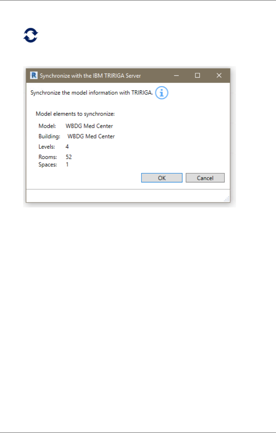
2.4.1 Sync
Use the Sync tool to synchronize a limited number of Floor and Space properties between
Revit and TRIRIGA.
Figure 16 - Synchronize with TRIRIGA Form
There is no user input for Sync.
Update: For Levels that are integrated with TRIRIGA Floors, the following updates are
made:
• Revit Level: IBM.Name is updated from the TRIRIGA floor name
• Revit Level: IBM.Description is updated from the TRIRIGA floor description.
• Revit Level: IBM.Level is updated from the TRIRIGA Floor Level
• TRIRIGA Floor: If a gross area plan is associated with the Level, the gross area for
the Floor is updated with the value calculated from the area plan by summing the
area of all Areas in the Area Plan.
For Rooms and Spaces that are integrated with existing TRIRIGA Spaces, the following
updates are made
• Revit Room or Space: IBM.Name is updated from the TRIRIGA space name
• Revit Room or Space: IBM.Description is updated from the TRIRIGA space
description.
• Revit Room or Space: IBM.UseClassification is updated from the TRIRIGA Use
Classification
• TRIRIGA Space: If an area from a gross area plan is associated with the Space,
the gross area for the Space is updated with the value from the associated Area.
Otherwise it is updated with the area from the Revit Room.
40
• TRIRIGA Space: If an area from rentable area plan is associated with the Space,
the area for the Spaces is updated with the value from the associated Area.
Otherwise it is updated with the area from the Revit Room.
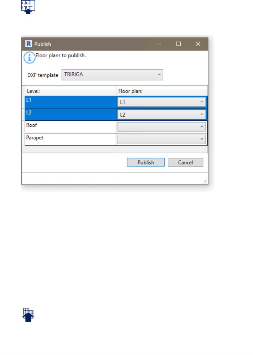
2.4.2 Publish Floor Plans
Use the Publish Floorplan Tool to publish one or more floorplans for use in the TRIRIGA
graphics section, and the Floorplan tab in the Locate and Work Task applications.
Figure 17 - Publish Floorplan Form
When this form is first displayed, it shows the options used in the last publish operation.
The Publish Floorplan tool uses the Revit DXF export feature to export the selected
floorplans in DFX format. Each DXF file is then imported into TRIRIGA and rooms on the
floorplan are automatically associated with TRIRIGA spaces created by the connector.
The DFX files are saved in:
<UsrProfile>\AppData\Local\IBM\TRIRIGA\AR Integrator\Drawings.
DXF Template: Revit uses DXF templates to control many visual aspects of a floorplan
exported in DXF format. The dropdown shows all the DXF templates included in the
model. If one is selected, it is applied to all of the selected floorplans.
Select the table rows for the Levels for which you want to publish floorplans.
The Floor plan dropdown on each row has a list of floorplans in the model for that level.
Select the desired plan.
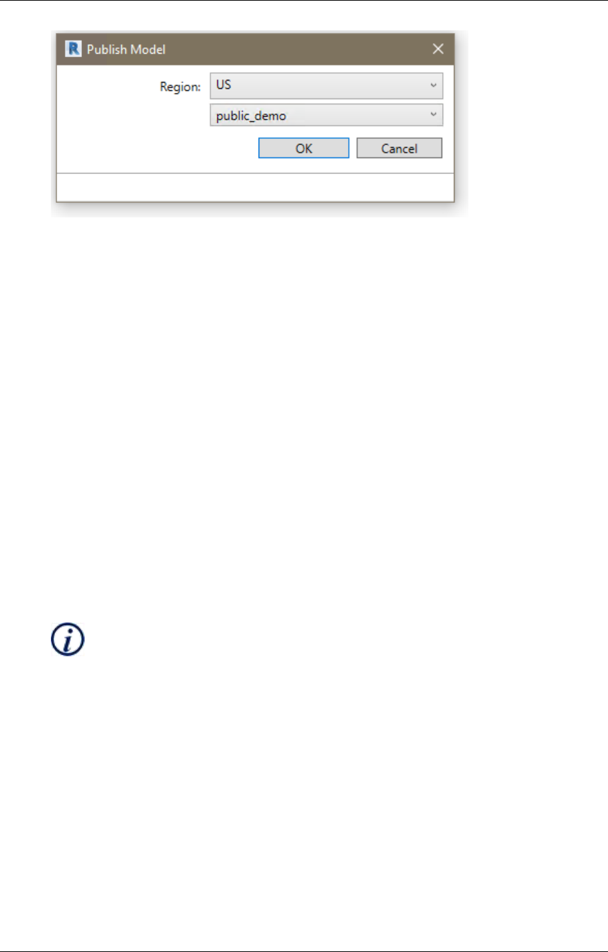
2.4.3 Publish Model
Publish the current Revit file to the Forge service, submit if for translation, and associate it
with the building record created from the connector.
TRIRIGA Building Information Models (BIM) User’s Guide
41
Figure 18 - Publish Model Form
Region. Selects the geographic region where the uploaded model and resulting translated
viewable will be physical stored. This filters the bucket list for bucked within the region.
Forge service access is proxied through TRIRIGA. It uses the Forge application
credentials configured in TRIRIGA and TRIRIGA security is applied.
2.5 Open in TRIRIGA
Each tool in this section launches the TRIRIGA application in the default browser using the
credentials and server definition used for the connector login.
2.5.1 Open Building
The tool opens the building record associated with the model.
2.5.2 Open Selection
The opens a single Floor or Space in TRIRIGA based on the Revit selection. The tool is
only active if there are items selected and only functions if the selection is either a single
Level or a single Room.
2.5.3 Launch Portal
This tool launches the main TRIRIGA portal
2.6 Help
2.6.1 Info
This tool displays connector version and build information
3 Autodesk Forge Model Administration
Model administration is performed from the BIM Administration Tool which is found in the
TRIRIGA portal under Tools. Typically, the model must be prepared using Autodesk Revit®
and Navisworks®. To utilize the Autodesk Forge viewer, models must be uploaded to the
Forge service, and translated to the format used by the viewer. The viewable format must
then be associated with the TRIRIGA building record that corresponds with the model.
Figure 19 depicts the process for configuring the Forge viewer for use in TRIRIGA and for
managing models.
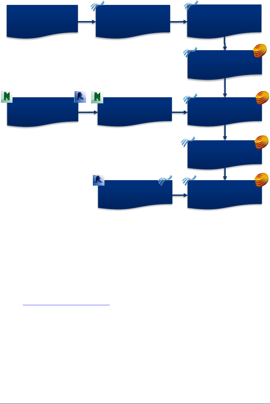
42
Figure 19 - Model Integration Process
3.1 Setting up the Forge Service
These steps are performed once when the Autodesk Forge service is first registered with
TRIRIGA, and may be revisited if there are changes in your Autodesk Forge account.
3.1.1 Register with Autodesk Forge and Create an application
The Forge Viewer and Forge Service are Autodesk® products integrated with TRIRIGA.
Use of the Forge service requires a subscription from Autodesk. A new subscription or a
free trial may be secured here:
https://developer.autodesk.com/
Or an existing Autodesk account may be used.
Define Forge Viewer
storage
Upload model file(s)
Request model
translation
Associate translated
model with Building
Upload Revit Model
to TRIRIGA
Define and edit
default view
Export Revit model
in NavisWorks
format
Configure TRIRIGA
for access to Forge
Management tool
Enter Forge app
credentials in
TRIRIGA
Register with
Forge and create
an application
TRIRIGA Building Information Models (BIM) User’s Guide
43
Figure 20 – Create an Autodesk® Forge application
Once you have registered for the service, Select Create Application to Create a Forge
application for use with TRIRIGA. A single application can be shared between multiple
instances of TRIRIGA or between TRIRIGA and Maximo. However, TRIRIGA does not
support BIM360 logins.
The Data Management API and Model Derivative APIs are required
None of the values entered in this screen are visible from within TRIRIGA. Select values
that will help you identify this application should you need to return to this screen.
TRIRIGA does not support 3 leg authentication, so the callback URL is not used. Enter
any value that is a valid URL format.
TRIRIGA User
Tririga.user@trirga.com

44
Figure 21 – Forge application definitions
Once the application is created, the application credentials are displayed (the yellow highlighted
fields). Keep these secure, as they allow access to all date and functions of the application. This
will include all the models that you use in TRIRIGA. If they are compromised, you can return to this
page to generate a new secret which must then be updated in TRIRIGA.
TRIRIGA User
Tririga.user@trirga.com

TRIRIGA Building Information Models (BIM) User’s Guide
45
Figure 22 – Forge application credentials
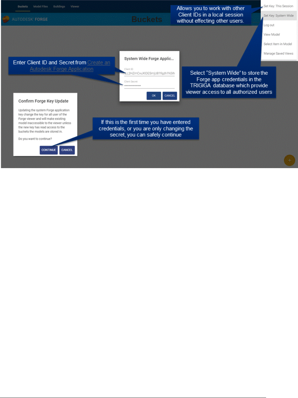
3.1.2 Entering Forge Credentials into TRIRIGA
To utilize Forge services from within TRIRIGA, the credentials created in the previous step
must be registered with TRIRIGA. All administration of the Forge service from within
TRIRIGA, as well as model management is done with the BIM Model Management Tool
found under Tools on the TRIRIGA portal.
1. From the BIM Model Management Tool menu, select “Set Key System Wide”. This
displays a dialog to enter the Forge Credentials
2. Enter the credentials from the application you created in the previous step.
3. When the dialog is accepted, a warning message is displayed. If this is the first
time you are entering credentials, or you are only updating the client secret, this
can be ignored.
TRIRIGA User
Tririga.user@trirga.com
46
Figure 23 – Configure Forge Credentials in TRIRIGA
If you need to work with other Forge applications, credentials can be set for your login
without affecting other users by selecting “Set Key: This Session”. Be sure to explicitly
logout when you are done to clear your credentials. When switching credentials, the first
access to the viewer fails. This forces a credential reset and subsequent access
succeeds.
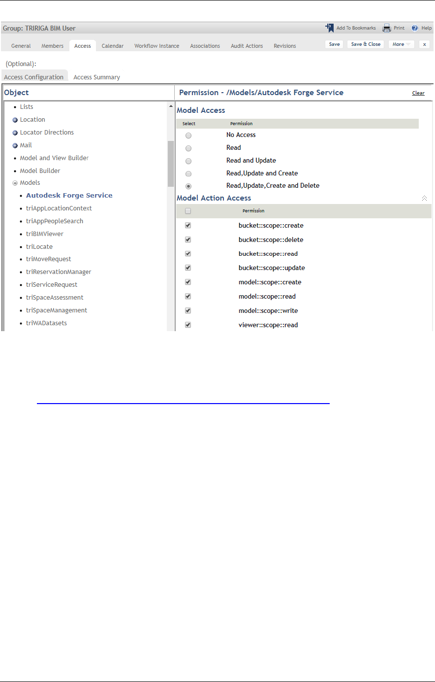
3.1.3 Configure TRIRIGA for access to Forge Management tool
When the Forge service is accessed through TRIRIGA, normal TRIRIGA security controls
which users can access Forge service operations. The BIM User security group is pre-
configured for full access to the Forge Service.
TRIRIGA Building Information Models (BIM) User’s Guide
47
Figure 24 – TRIRIGA BIM User Security Group.
Fined-grained access is controlled through the Autodesk Forge Service model. Model
actions are mapped directly to the scope parameter of the Forge Authenticate endpoint
defined here:
https://developer.autodesk.com/en/docs/oauth/v2/overview/scopes/
Viewer::scope::read is required for any user that access the Forge viewer. It may be
desirable to add this access to other security groups.
3.1.4 Autodesk SSL Certificate
For TRIRIGA to access the Autodesk Forge service, the app server must make an SSL
connection to the Autodesk cloud services. This requires the app server to trust the Forge
SSL Certificate. Typically, Java Virtual Machines (JVMs) browsers and app servers include
the signer certificate from most major certificate authorities so they trust any certificated
signed by these certificate authorities including those used by the Forge service. However,
high security app server deployments don’t include any certificate authority certificates in
the app server trust store as part of the base install. This means that the app server
doesn’t trust the Autodesk certificates and connections to the Forge service fail with an
SSL Handshake exception. To resolve this, the certificate authority public root certificate
use for by the Forge service must be imported into the app server trust store.
There has been some variance seen in the certificate presented by the Forge service both
over time and by region, so these steps may need to be periodically repeated.
The procedure varies by app server
WebSphere®
The certificate can be imported from the WebSphere admin console.
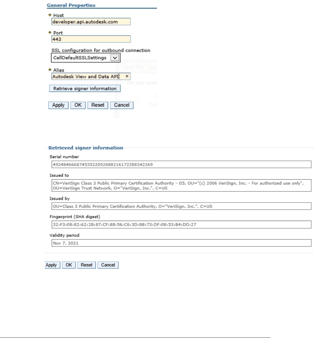
48
• Select Security->SSL certificate and key management
• From “Related Items”, select: Key stores and certificates
• Select NodeDefaultTrustStore if available. Otherwise select CellDefaultTrustStore
• From “Additional Properties” Select Signer certificates
• Select “Retrieve from port”
• Provide the following values:
Select “Retrieve signer information”
WebSphere should respond with:
• Click OK, and the save the changes on the following screens.
Note: The certificate may not match what is shown above.
WebSphere Liberty
WebSphere Liberty relies on the underling JVM trust store. The following is one of many
ways the Forge signer certificate can be retrieved and imported into the JVM trust store.
TRIRIGA Building Information Models (BIM) User’s Guide
49
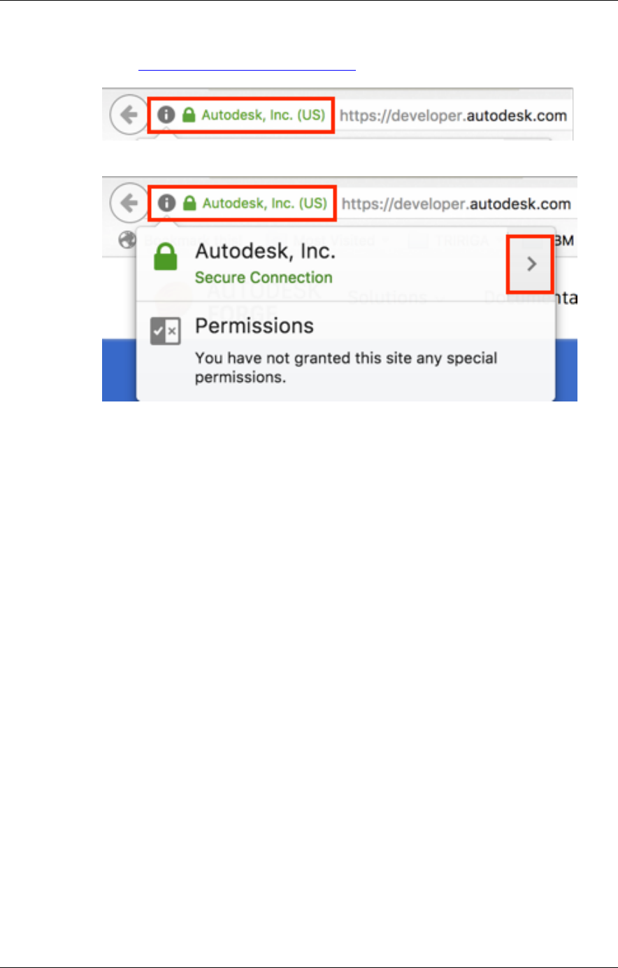
To retrieve the certificate:
Open the link https://developer.api.autodesk.com in FireFox
Click on the certificate (next to the site name)
• Click the “>” button
• Click on “More Information”
• Click on "View certificate"
• Click on "Details"
• Click on "Export..."
• Choose "X.509 Certificate with chain (PEM)", select the folder and name (e.g.,
developerapiautodeskcom.crt) to save it and click "Save"
To add the certificate to the JVM trust store
• Open a command prompt.
• Navigate to the bin directory of the JVM used by WebSphere Liberty. Liberty
locates JVM by testing the following:
o JAVA_HOME environment variable
o JRE_HOME environment variable
o Looking for a JVM in the path
• Use the keytool to import the certificate.
The following is a sample command line for Windows:
keytool -importcert -alias developerautodeskcom -keystore
"C:\Program Files\Java\jdk1.8.0_162\jre\lib\security\cacerts"
-file C:\temp\developerapiautodeskcom.crt
The following is a sample command line for Mac OS:
sudo keytool -import -alias developerautodeskcom -keystore
/Library/Java/JavaVirtualMachines/jdk1.8.0_161.jdk/Contents/H
ome/jre/lib/security/cacerts -file
~/Desktop/developerautodeskcom.crt
sudo password: <your log in password>
50
keystore password: changeit
• When prompted, the default password is changeit, or whatever you have set you
keystore password to.
The above command lines are for the Oracle® JVM. They differ slightly for the IBM JVM.
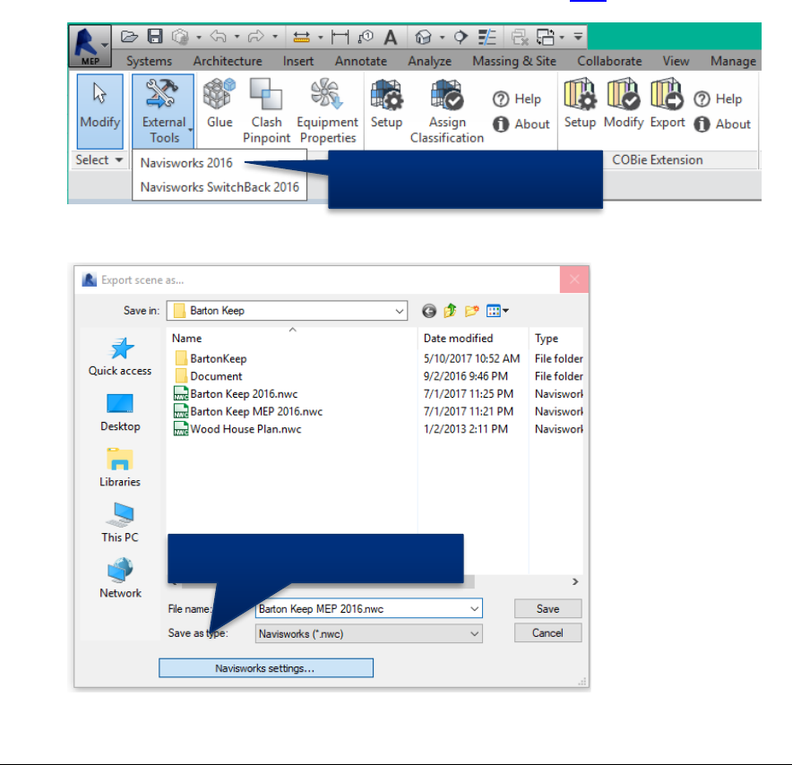
3.2 Exporting Navisworks Models
Forge viewer viewable objects created directly from Revit models have no visual
representation for Revit Rooms and Spaces. This means they cannot be used to visualize
TRIRIGA spaces, severally limiting their usefulness. This can be resolved by using
Navisworks models. To do that, the Revit model needs to be converted to Navisworks.
There are two ways to do that:
• Directly open the Revit file in Navisworks
• Use the Navisworks exporter plug-in for Revit.
3.2.1 Exporting the model
The plug-in appears to produce better files, and can be used without a Navisworks license,
so it is what is covered here. The exporter can be downloaded here
The exporter is found on the Revit add-in ribbon
There are several export options that may be useful. These are accessed from the file
selection dialog after export is selected.
If you don’t have a Navisworks license, you should select “Convert Linked Files” as this is
the only way to get a single Navisworks file that contains all of the model. If you do have a
NavisWorks Exporter
Display Export Settings
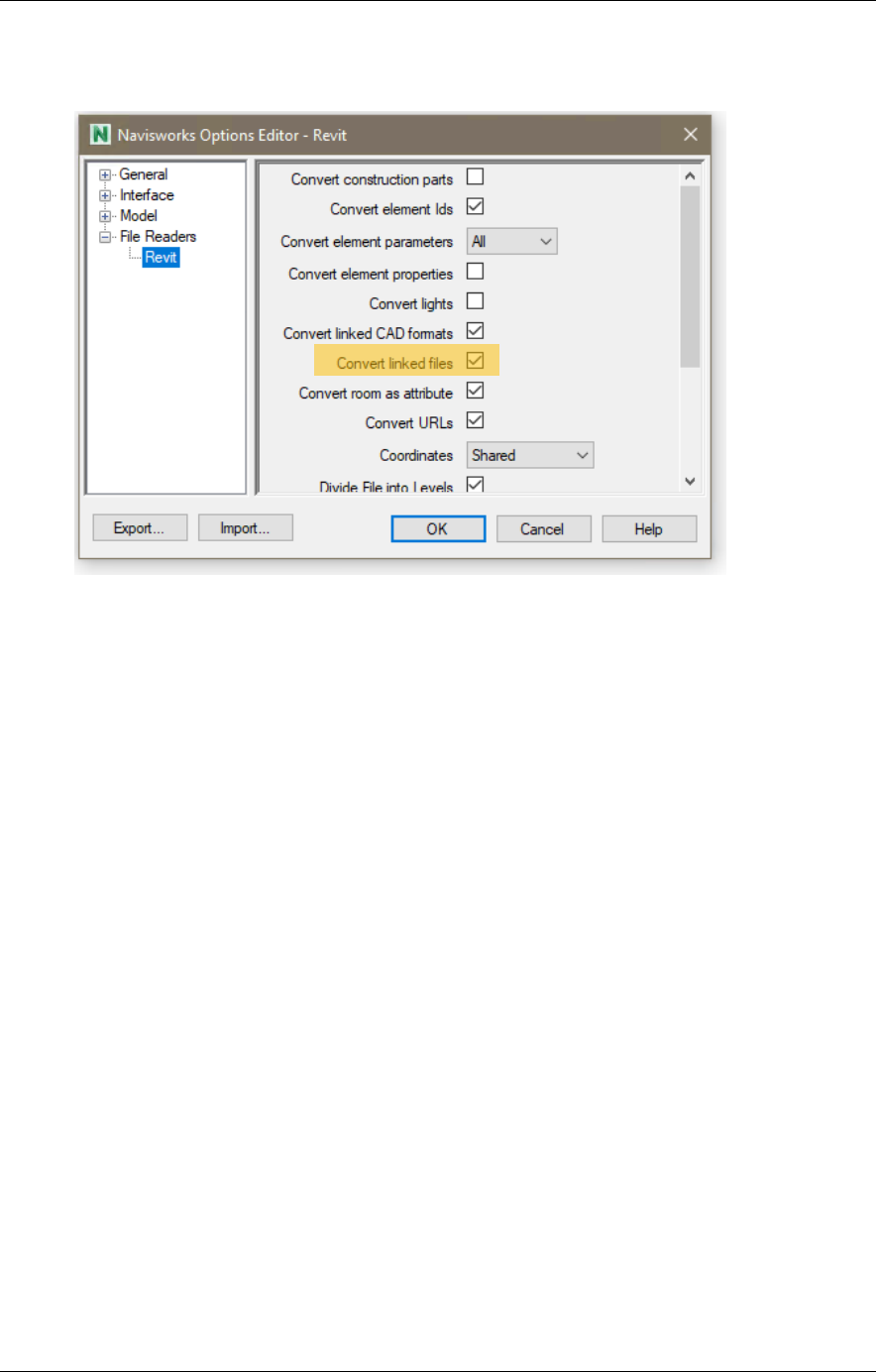
TRIRIGA Building Information Models (BIM) User’s Guide
51
Navisworks license, you can gain more control by exporting each file separately and
merging them in Navisworks.
3.2.2 Enhancing the model
If you have a Navisworks license, there are several things you can do to improve the
usefulness of the model in TRIRIGA:
Merging Files: You can add linked files to the Navisworks model by selecting:
Home->Append
Setting the Default View: The Forge translation service uses the default view. This is
what is displayed when you initially open the file, and is set by what is displayed when you
save the view.
Changing element visualization: There are several ways the visual aspect of elements
can be customized all of which require locating and selecting all instance of the item. One
way of doing this is with the Selection Tree. Navigate to the desired item set, and right
click to see a list of options. One useful approach is to use Revit Categories. These can
be found at:
Element->Category->Name
Suggested enhancements including
• Decreasing the transparency and changing the color of rooms
• Hiding all spaces except those explicitly integrated with TRIRIGA, for those that
are integrated, setting the transparency and color to match Rooms
• Color coding key assets or color-coding asset by category
3.3 Importing models into the Forge Service
There are 4 steps required to view a model with the Forge Viewer from within TRIRIGA:
1. Create one or more storage containers called Buckets in the Forge service to hold
the model files. For the purpose of a demo, only one storage container is required.
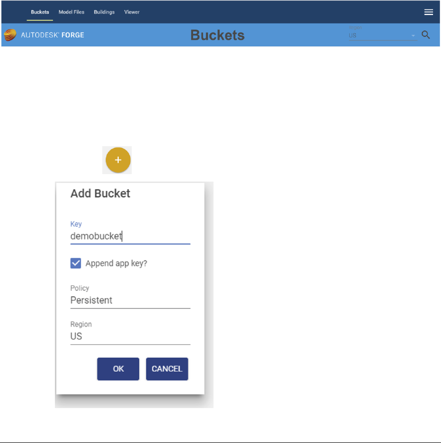
52
If you manage models for multiple projects or companies, you should create
additional container to organize you models.
2. Uploaded the model files(s) to the Forge service.
3. Request that the Forge service translate the model into a viewable format.
4. Associate the viewable model with the TRIRIGA Building record for the facility that
is represented by the model. The Building and its contained Floor, Space, and
BuildingEquipment records are typically created from Autodesk Revit with the
TRIRIGA Connector for BIM.
Some of the above steps may have been performed outside the current TRIRIGA
instance. If so, Buckets, Model Files and translated models may already be shown in
the BIM Model Administration tool.
3.3.1 Managing Model Storage
The Forge service uses storage containers (called buckets by Forge) to store any model
files that are uploaded to the service. A storage container is similar to a directory in a file
system. Buckets are managed from the Bucket tab of the BIM Model Administration tool.
When the Bucket tab is displayed, existing buckets are automatically displayed. Buckets
are filtered by region. US is the default region. To view Buckets for a different region,
select the region from the Region drop down and click the Search icon.
Creating a storage container:
To use the Forge service, you must create at least one storage container. To create a
storage container,
1. Select the icon to display the Create Bucket dialog
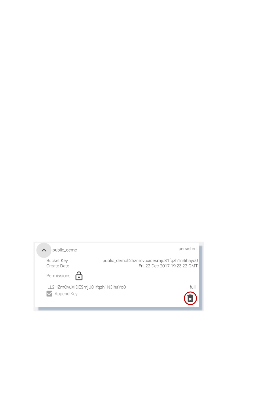
TRIRIGA Building Information Models (BIM) User’s Guide
53
2. Specify a storage container name and description. Names must be unique across the
Autodesk Forge service including all Autodesk Forge users. To facilitate this, TRIRIGA
can append your Autodesk Forge service key to your storage container name. If you
select this option, only the base name is displayed on the UI. If you don’t select this
option, it is highly recommended that you include in your storage container names
some unique string that is associated with your company or organization, such as a
registered domain name,
Unless you design your own strategy to ensure your storage names are unique across
the entire Forge Service, you should leave the Append Service key checkbox checked.
The name may contain -_.a-z0-9 and must be between 3-128 characters in length
including the appended key.
3. Select the desired retention policy. There are three types of buckets:
Transient: Model files are retained only for 24 hours
Temporary: Model files are retained only for 30 days
Permanent: Model files are retained until they are deleted.
Note: If a model has been translated to a viewable format and is then removed,
including through its storage period expiring, the viewable format is not removed.
4. The region displayed here is read only. It is set by the dropdown on the toolbar. That
is, buckets are always created from the actively displayed region. Buckets may be
created in the US or the EMEA region of the Forge service. The region controls the
physical location of the Forge service servers that host the Bucket.
Deleting a Storage Container:
A storage container can be deleted. Deleting a storage container also deletes everything
that is stored in it. This process CANNOT be undone. All models and translated
viewable bubbles stored in the container are also deleted. To delete a Bucket:
1. From the Bucket tile, click the “Delete Permanently” icon
2. This displays the delete confirmation dialog. Heed this warning. You can delete a
very large amount of data with a few mouse clicks!
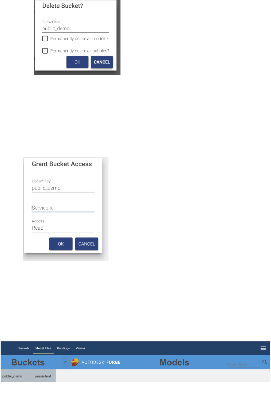
54
3. Check both the “Permanently delete all models” and the Permanently delete all
bubbles” check boxes. You cannot accept this dialog until you have acknowledged that
all the data in the bucket will also be deleted.
Rights
Rights to a storage container may be granted to other service keys. The actions Autodesk
currently allows through granted rights is extremely limited so it is currently of little use.
To grant rights:
1. On the tile for the bucket: select the lock icon, this displays the rights dialog
2. Enter the Service ID for any other Forge application
3. Select the rights to grant.
4. The bucket tile displays a list of all service ids that have access to the bucket
There is no validation that the service id is valid.
To remove access, click the trash can to delete the row. The row is deleted immediately.
3.3.2 Managing Model Files
Model files are managed from the Model tab of the BIM Model Management tool
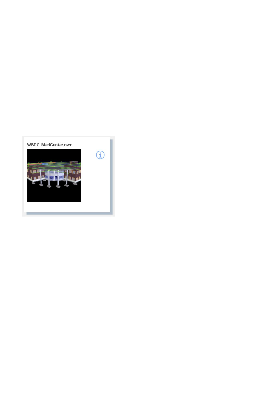
TRIRIGA Building Information Models (BIM) User’s Guide
55
The tab has a fly-out on the left that displays the list of buckets from the Bucket tab, and a
list of models contained in the selected bucket.
• When the tab is first displayed, the first bucket in the list is selected, and the first
50 models in the bucket are displayed. Autodesk does not guarantee any sort
order so it is effectively 50 random models.
• Additional models may be displayed by scrolling to the bottom of the model list.
• The model list may be filtered by entering a value in the model name field on the
tool bar and clicking the search icon. Models whose name begin with the search
string are listed. The search is case sensitive.
• Selecting a new bucket updates the model list using the current search criteria.
Any type of file can be uploaded to a bucket. However, only those file types that can be
translated into viewable format are of interest here. Each model file is displayed as a tile.
The content of the tile varies during the model upload and translation process (see below).
A fully translated model ready for use displays a thumbnail image of the model and a link to
drill into details of the model.
Selecting the thumbnail switches to the viewer tab and displays the model in the viewer.
Selecting the info icon drills into details of the model (see below).
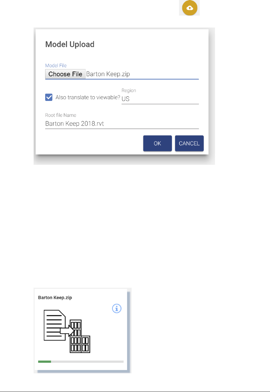
56
3.3.3 Upload Model
1. To upload a model file, click the Upload Model button .. This displays the
Upload Model dialog. The model is uploaded into the currently active bucket.
Figure 25 - Model Upload
2. Select a model file to upload.
3. Checking the Also Register Viewable checkbox causes the model to be automatically
submitted to the Forge Service for translation and eliminates the need to manually
perform the viewable translation process.
a. Select a region. This is where the translated viewable “bubble” will reside. This
may be different from the bucket containing the model.
b. If the model file is a zip archive containing a set of linked files (see below), specify
the base file name with extension of the root file. This is the file that you would
normally open to view the model set.
4. Click OK and you are returned to the Models tab. A tile is added for the new model as
the first tab in the model list. If the model list is refreshed while an upload is in
progress, the monitoring tile is lost, but if the upload is successful, a normal model tile
is available for display when it is complete.
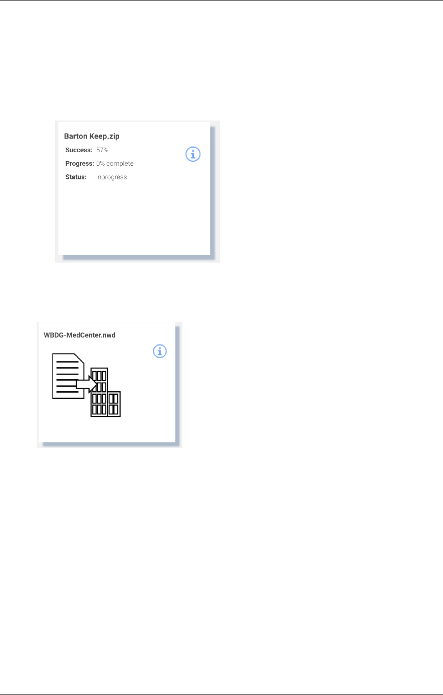
TRIRIGA Building Information Models (BIM) User’s Guide
57
5. If “Also translate to viewable” is selected, when the upload is complete, the translation
process is started. This may take a few seconds to several hours. The tile displays the
progress of the translation process. Initially, the translation progress is updated every
30 seconds. After a few minutes, the update is less frequent. The translation process
may be manually displayed and updated from the Bubble tab of the model details
dialog (see below). If the model list is refreshed during the translation process, the tile
is displayed in its normal position in the list instead of first and the progress monitoring
is halted. Progress can still be manually displayed.
Translating models
The model translation process may be run separately from the model upload. A model that
has been uploaded but not translated has the following tile:
Clicking the image displays the Model Translation dialog
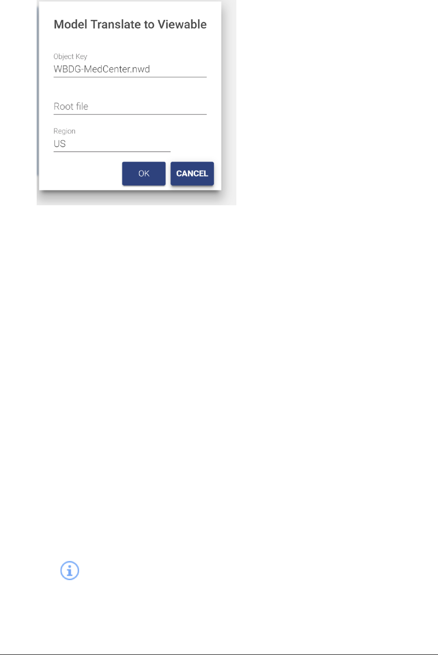
58
1. Select a region. This is where the translated viewable “bubble” will reside. This may be
different from the bucket containing the model.
2. If the model file is a zip archive containing a set of linked files (see below), specify the
base file name with extension as the root file. This is the file that you would normally
open to view the model set.
The translation process may take a few seconds to several hours. The tile displays the
progress of the translation process. Initially, the translation progress is updated every 30
seconds. After a few minutes, the update is less frequent. The translation process may be
manually displayed and updated from the Bubble tab of the model details dialog (see
below). If the model list is refreshed during the translation process, progress monitoring is
halted. Progress can still be manually displayed.
Working with multi-file models
Some modeling tools such as Revit have workflows that distribute a model across many
files that are then linked to form the complete model. For example, a model may be
divided into an architectural, and MEP, and a structure component each in different Revit
files. The Forge service can integrate these parts into a single model for display in the
Forge viewer. To do so, perform the following steps:
1. Gather the files composing the model into a directory tree that can easily be converted
into a .zip file. Ideally you should remove extraneous files such as auto-save files.
2. Select the file that will be the master file for the linked model. Ensure that all linked
parts or sub-model files load correctly when this file is opened.
3. Convert the directory containing the model files into a .zip archive.
4. Upload the .zip archive as described above.
Model Details
The provides a drill down into additional information about the model file and about
any translated viewable data which Autodesk refers to as the “Bubble”. The information
varies by type of file.

TRIRIGA Building Information Models (BIM) User’s Guide
59
If the model is in the process of translation, or translation has been attempted whether or
not it succeeded, the dialog has a Bubble tab that includes the status of the translation
process.
Figure 26 - Translated Viewable (bubble) Details
Has Thumbnail: Indicates if the bubble included a thumbnail image of the model. Revit,
Navisworks, and AutoCAD file all have a thumbnail.
Started At: Timestamp of when the model was submitted for translation
Progress: Percent of the translation process that has completed.
Success: Percent of the model that has been successfully translated
Status: Status of the translation process. Typically, In Progress, Success, or Failed
Fetch Time: When the information in the dialog was last refreshed
Use the Refresh button to update the dialog with the current values directly from the Forge
Service.
Other information on the bubble tab, and the information on the mode tab is only useful to
administrators that have other interactions with the Forge service.
The bubble for Revit files includes information from the Revit Project Information screen.
Translated Revit files have a Project Information tab with this information
Delete Model
A translated model consists of several Forge objects: the model files and a set of objects
that constitute the bubble. The model files and the bubble can be deleted independently of
each other.
• To delete the model with an option to also delete the bubble:
o Open the Model detail dialog as above
o From the Model tab, click the trash can (Permanent Delete) icon
o A confirmation dialog is displayed with an option to also delete the bubble.

60
• To delete just the bubble:
o Open the Model detail dialog as above
o From the bubble tab, click the trash can (Permanent Delete) icon
o A confirmation dialog is displayed
Autodesk provide no mechanism to list or search for bubbles, and TRIRIGA maintains no
record of model or bubbles outside of the Forge service. Therefore, if you delete the model
but not the bubble, you will not be able to later view or delete the bubble, however existing
references to the bubble continue to work. So, if a model has been associated with a
building and then just the model is deleted, you can continue use the viewer to display the
model for that building. If the model file is later re-loaded, it will automatically be
associated with the existing bubble.
3.3.4 Associating Translated Models with Buildings
To view a model from a TRIRIGA application, it must be associated with a building. For
TRIRIGA to be able to automatically select and focus on a space or asset, the space or
asset must be keyed to the model. If the Building, Space, and Asset records were created
by the BIM Connector for Revit, and the model is the Revit file used with the connector, or
a Navisworks file derived from the Revit file, this process is automatic.
There are two means of associating a model with a building:
• A single file Revit model may be published directly from Revit using the BIM
Connector for Revit. (See section 2.4.3). The publish process handles the model
upload, translation and linking to building. It is not necessary to use the BIM Model
Management tool.
• For federated Revit models, Navisworks models, and other types of models, the
model is linked to the building using the BIM Model Management tool.
Building to Model associations are managed from the Building tab of the BIM Model
Management Tool.
The tab displays all buildings that are accessible to the current user sorted by building
name.
• When the tab is first displayed, the first 50 buildings are displayed.
• Additional buildings may be displayed by scrolling to the bottom of the building list.

TRIRIGA Building Information Models (BIM) User’s Guide
61
• The buildings list may be filtered by entering a value in the Building Name field on
the toolbar and clicking the search icon. Buildings whose name or address
contains the search string are listed.
Each building is displayed as a tile.
Figure 27 - Building to Model Link
• The search button displays a model selection list with the same list of models that is
displayed on the Model Files tab. To display models from a different bucket, return to
the Model Files tab and select the desired bucket.
Use the search box to filter the list. This also filters the list on the Model Files tab.
Select a model to link it to the building. Scroll to the bottom to fetch additional records.
Select model to link to
building.
Preview model in viewer.
Delete link to model.
Additional model link
information
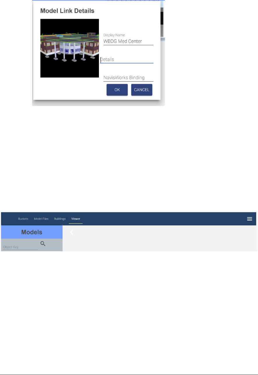
62
• Click the info icon to display additional details about the link
Figure 28 - Building to Model Link Details
o Details: Additional descriptive information not processed by TRIRIGA.
o Navisworks Binding: This is the name of the viewer property which is used to
match a viewer element with a TRIRIGA record. If it is not set, it defaults to
“GUID”. Some older Navisworks files require “Guid”. It can also be used to create
custom binding for other model file types or if the TRIRIGA records were not
created by the BIM Connector for Revit.
• Selecting the thumbnail switches to the viewer tab and displays the model in the
viewer.
3.3.5 Previewing Models in the Viewer
Any translated model may be previewed in the viewer included in the BIM Model
Management tool. To view a model, select the Viewer tab
There is a fly-out with a model list. This is the same model list that is displayed on the
Model Files tab, except only translated models are shown.
• To view models from a different bucket, return to the Model Files tab, select the
desired bucket and refresh the model list.
• Scrolling to the bottom of the list fetches the next 50 models
• The search field filters the existing list. It does not re-fetch the list from the Forge
service. The filter match is a substring match.
Select a model in the list to display it in the viewer.
Use the viewer to create saved views (see section 4.4) for use in the Work Tasks
application
Advanced Viewer Options
There are two advanced options on the BIM Model Management tool menu:

TRIRIGA Building Information Models (BIM) User’s Guide
63
View Model: This takes the base 64 encoded model URN and displays the model. The
base 64 URN is displayed on the bubble tab of the model details dialog, or it can be
obtained from other applications that utilize the Forge viewer.
Select item in Model: With the target model displayed, the allows selection of an item in
the model based on its raw ID. For Revit models, and Navisworks models derived from
Revit, this is the Revit export GUID.
4 Using the Autodesk Forge Viewer
The Autodesk® Forge Viewer is integrated into the TRIRIGA UI to support 3D viewing and
performing actions from building models. The Viewer is available from three places in the
TRIRIGA UI. They are:
• As an additional BIM tab in the Locate application
• As an additional BIM tab for locations and assets in Work Task application
• In the BIM Model Administrant Tool
4.1 TRIRIGA context
When the viewer is used with the Locate or Work Task application it displays the current
context of the application. The model displayed is for the building containing the active
location or asset. If the active space or asset is keyed to the model, it is also selected in
the model and the camera is placed in the model to display that item. For a space, that is
near the center of the space. This works well for reasonably regular shaped rooms but for
some rooms such as an L- shaped hall, the geometric center is not in the space.
For an asset that is a view that centers the asset in the view and zooms such that the asset
fills most of the view. On occasion, an asset can be obscured, and it may be necessary to
rotate the view to see the asset.
4.2 Viewer Navigation
Basic and extended viewer navigation and view manipulation is provided by Autodesk as
part of the Forge Viewers. These functions are accessed from the bottom toolbar. Various
TRIRIGA applications expose more or less of the toolbar, and the toolbar adjusts for
screen size so on a small screen some tools are hidden.
4.2.1 Viewer Toolbar
The left hand three sections of the bottom toolbar are part of the basic viewer package as
provided by Autodesk. This provided access to standard viewer navigation features,
viewer configuration, and model properties. Several of these features are highlighted
below:
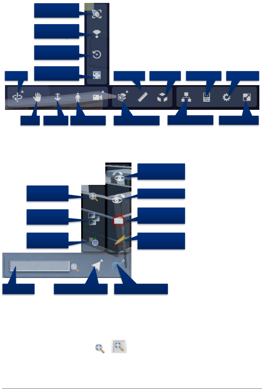
64
Figure 29 - Forge Viewer Toolbar
The right most section of the toolbar contains IBM extensions and access to TRIRIGA
specific features.
Figure 30 - TRIRIGA Extension to the Forge Viewer Toolbar
Search: The Viewer provides a quick search for items in the model. It searches all model
properties for all items for any property value that contains the search string. Any item that
has a match is part of the search result and is selected.
Toggle Zoom to Context: / The Toggle Zoom to Context button enables or
disables the auto zoom to context when an item is selected in the viewer.
1st Person Section Model
Zoom to
Selection
Zoom to
Model Properties
Model Tree
Measure
Zoom
Pan Full Screen
Orbit Explode Settings
Rotate Model
Camera
Focal Length
Search Selection Menu TRIRIGA Menu
Enter Markup
Mode
Display
Markup
Save View
Apply Saved
View
Enable
Auto Zoom
Hide
Selection
Isolate
Selection
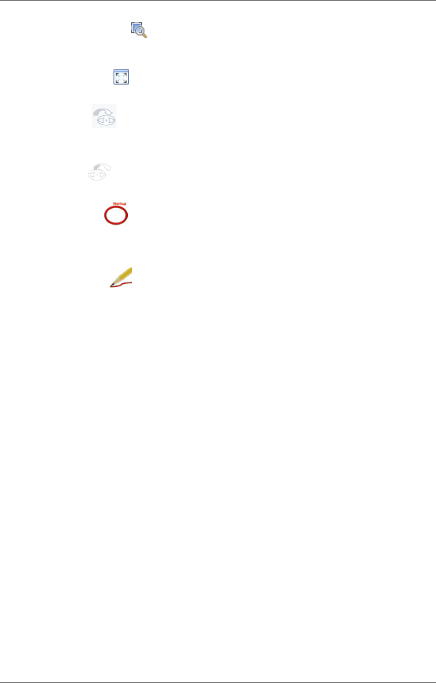
TRIRIGA Building Information Models (BIM) User’s Guide
65
Zoom to Selection: The Zoom to Selection button centers the model on the current
selection and zooms the view into the current selection. If multiple items are selected, the
view includes all selected items.
Zoom to Model: The Zoom to Model button zooms the view so that the entire model is
displayed.
Apply View This button displays a list of all the saved views that are associated with
this model. A saved view may be displayed in the viewer by double-clicking the saved
view description or by selecting the saved view description then pressing the Apply button.
Save View This button displays the save view dialog to allow the current view to be
saved to the TRIRIGA database.
Show Markup This button displays a list of all the Markup that are associated with
this model and Work Task. A markup may be displayed in the viewer by double-clicking
the markup description or by selecting the markup description then pressing the Apply
button (See below).
Create Markup This button switches the viewer to Markup Mode and displays the
Markup Toolbar (See below).
4.2.2 Model Tree
The model tree displays a hierarchical representation of the internal structure of the model.
Different types of models have different structures. So, the model tree for a Revit model
and a Navisworks model derived from the Revit model are not the same. The model tree
can be used to navigate through the model by using its structure. To select individual items
or groups of items, and through the context menu, to control how the currently selected
item(s) are shown in the model.
If the model tree is open, selecting an item in the model also selects and displays it in the
model tree.
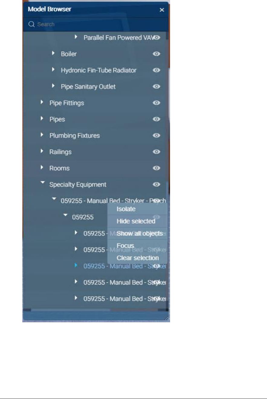
66
Figure 31- Forge Viewer Model Tree
4.3 Sections
A model can be cut by a section plane in the X,Y,or Z axis, or cut by a box in all three axis
at once.
Display the desired section tool and drag the arrow to move the cut plane through the
model. The cut plan can be rotated so almost any cut is possible

TRIRIGA Building Information Models (BIM) User’s Guide
67
Figure 32 - Forge Viewer Section Tool
Tip
Use the Z section plane and the top down Orth view to create 2D floor or
ceiling plans which can then be store as saved views for later use. A
view down the Z axis can be created by clicking on the Top of the view
cube
4.4 Saved views
Saved Views are available in the viewer embedded in the BIM Administration Tool, and in
the Work Task application.
Much of the Viewer state can be captured in a Saved View, stored in the TRIRIGA
database and later restored. This includes: The camera position and zoom, the current
selection, and section cuts and the selection. Saved views are created from within the
viewer. They can be found on the TRIRIGA submenu on the bottom toolbar.
Select and display the
desired view
Save the current view
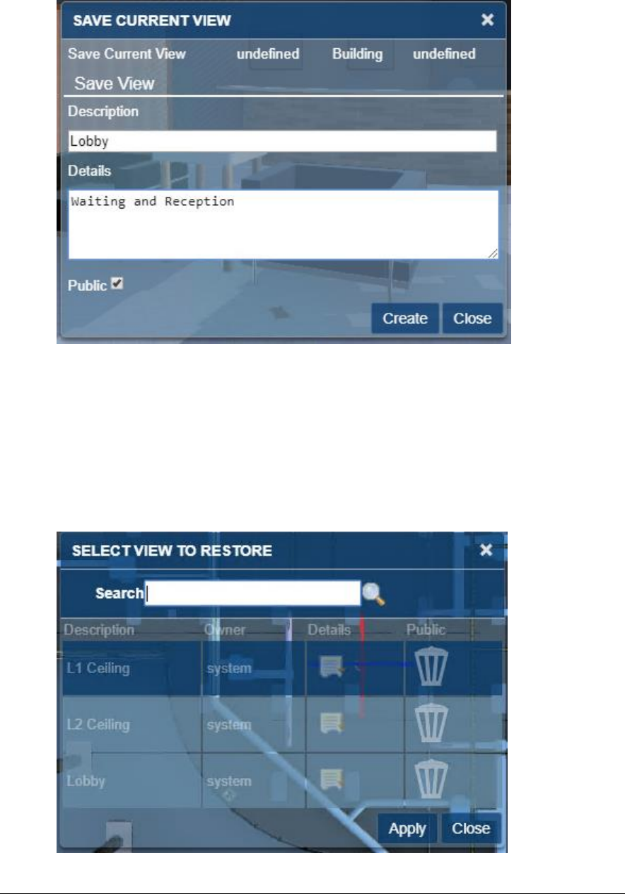
68
To create a Saved View: Setup the desired viewer image, then select the Save View
button on the Viewer toolbar. This displays the Save View dialog.
Figure 33 - Saved View Dialog
Description: The description is required and identifies the view for later use.
Details: Optional addition description
Public: Private views are only visible to the user who creates them. Public views are
visible to all users with access to the building.
To restore a view: Select the Apply Saved View button from the Viewer toolbar. Highlight
the desired view and click the Apply button or double-click the desired view.
Figure 34 - Apply View Dialog
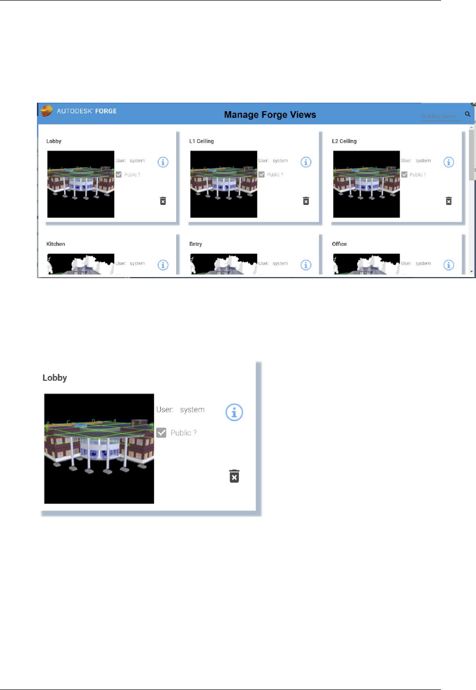
TRIRIGA Building Information Models (BIM) User’s Guide
69
The dialog only displays the first 20 views for the model. If the view you are looking for is
not displayed, use the search field to filter the dialog. The search is a substring match
against the description.
Managing Saved views: From the BIM Model Management Tool menus select Manage
Saved Views. This displays the first 50 saved views. Scroll to the bottom to display
additional views. Views may be filtered by description. This is a substring match.
Figure 35 - Manage Forge Views Popup
Views can be deleted from the Manage Saved Views dialog. However, views can only be
created from within the Viewer.
Each view is displayed as a tile. The tile has a thumbnail image of the model with which the
view is associated.
User: The login id of the user who created the view. (Read only)
Public?: Is the view restricted to its creator?
Info Icon: Displays and allows you to update the details information for the saved view
Trash can icon: Deletes the saved view.
Thumbnail image: Loads the model into the viewer, switches to the viewer tab, and
applies the save view to the model.
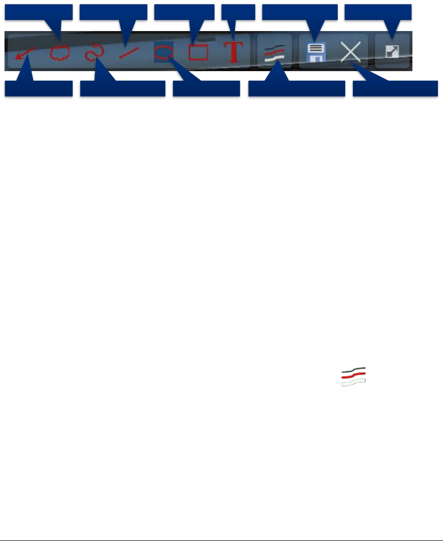
70
4.5 Markup
Markup mode provides a set of drawing tools that can be used to draw on top of the view
that is displayed at the time the markup mode is entered. Once in markup mode, the view
cannot be changed except to zoom and pan. Once complete, the markup can be saved
with the work task and displayed later. A work task can have any number of markups
associated with it.
When markup mode is entered, the Markup toolbar is displayed:
Figure 36 - Forge Viewer Markup Toolbar
Drawing markup
The first section of the Markup tool bar provides a set of drawing tools. The active drawing
tool is highlighted. The drawing mechanism differs slightly by tool type:
Arrow: Click and drag.
Cloud: Click to place each segment. Clicking on the start closes the cloud and allows it to
be filled.
Freehand: Hold the mouse down and drag.
Line: Click to place each segment. Clicking on the start closes the figure and allows it to
be filled.
Oval: Click and drag to form the bounding box.
Rectangle: Click and drag to create diagonally opposite corners.
Text: Click to place the top left corner of the text box, then type the text. When complete,
click on the background outside the text box to exit edit mode.
Markup Properties
The appearance of markup elements can be changed. Selecting the button displays
the Markup Properties dialog:
Draw Arrow Draw Freehand
Draw LineDraw Cloud TextDraw Box
Draw Circle Markup Properties
Save Markup
Cancel Markup
Full Screen
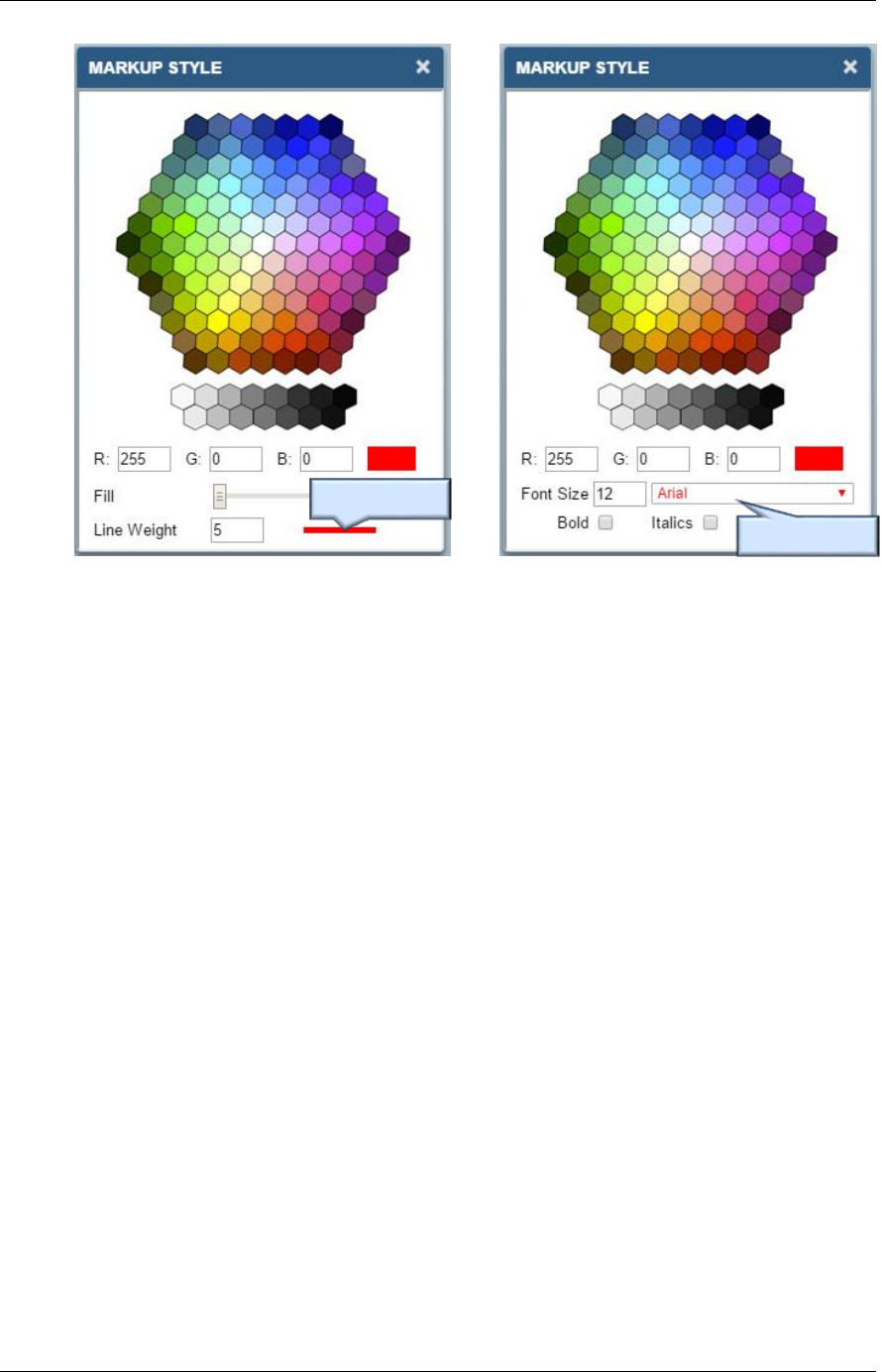
TRIRIGA Building Information Models (BIM) User’s Guide
71
The dialog has two slightly different forms depending on whether the active drawing tools is
the Text tool or any of the other tools.
The property setting remains in effect until it is changed. When a new tool is selected, it
uses the current markup properties.
Selecting a previously drawn markup sets the current drawing properties to those used to
draw the newly selected markup.
Editing Markup
Any previously drawn markup can be selected and edited. Click on the markup to select it.
Editing options vary by markup. Generally, markups can be moved, resized, deleted, and
in some cases rotated. And they may have their properties edited.
Active Text Style
Active Line Style
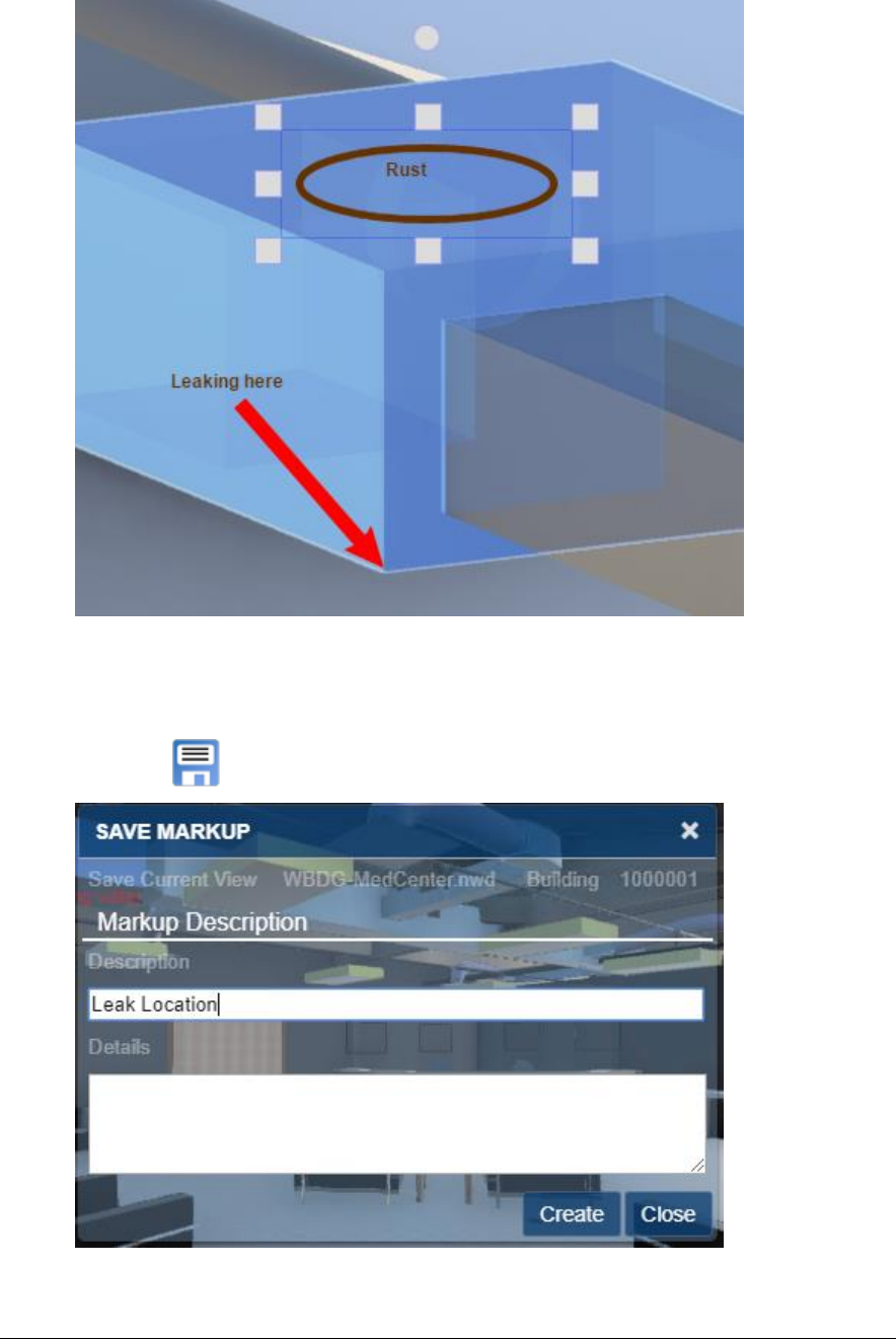
72
Selecting a markup also makes that markup type the currently selected drawing tool on the
Markup toolbar and updates the drawing properties.
Save Markup
Select the Save button to complete the markup session and to save the markup.
Figure 37 - Save Markup Dialog
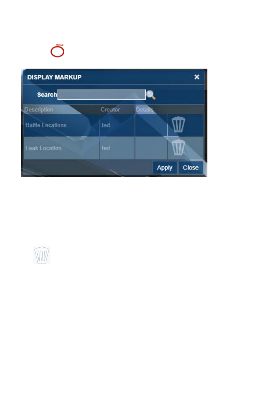
TRIRIGA Building Information Models (BIM) User’s Guide
73
When you click the Create button, TRIRIGA saves the just completed markup, the current
view, the markup name, and any description with the Work Task.
Display Markup
Select the Display Markup button to display a list of markups that are associated
with the work task.
Figure 38- Display Markup Dialog
The dialog only displays the first 20 markups for the model and work task combination If
the markup you are looking for is not displayed, use the search field to filter the dialog.
The search is a substring match against the description.
Applying a markup restores the view that was used to create the markup and displays the
drawing elements of the markup. The Viewer is locked except for zoom and pan until the
markup display is closed.
The Delete button can be used to delete the associated markup.
5 Best Practices
The following are recommended best practices:
• Integrate all Rooms you plan to integrate for all model files before you link spaces to
rooms or directly integrate Revit Spaces with TRIRIGA.
• For federated models, the IBM.ModelName value should be unique for each file in the
set, and ideally be descriptive of the role the file is playing in the model. For the
primary file, IBM.ModelName and IBM.BuildingName can be the same.
• A gross area plan should be created for any level that will be integrated with Revit.
Allow Revit to outline the exterior walls. If you subdivide the area plan into additional
areas, insure that the entire level is filled with areas.

74
• If area names are the same as room names, the auto-match can be used to link rooms
to areas. If you expect to detach and re-integrate the model with any frequency, this
will save work.
• If space names are the same as room names, the auto-match can be used to link
rooms to spaces. If you expect to detach and re-integrate the model with any
frequency, this will save work.
• Use a Navisworks model in the TRIRIGA viewer to be able to display and select
rooms.
Spaces: When assets are contained within a TRIRIGA space, it is highly desirable that the
relationship is established when the asset is created by the connector. This is problematic
for two reasons:
• The model for most large projects is divided into several linked files. Both Rooms
and Spaces can map to TRIRIGA spaces. Rooms typically appear in the
architectural model, and Spaces in the primary MEP model. Sub-discipline
models may not have spaces. Coordinating Rooms and Spaces across models
requires a well thought out strategy.
• Room definitions are often not created for service spaces such as plenums,
elevator shafts and the like. Many components exist in these areas and may not
have a logical association to a defined space although they are access and
serviced from a space.
There are several strategies that can be used to address this. These include:
• Rigorously define all spaces such that there is a space definition for every volume
in the model including external service areas
• Copy space definitions into linked models. This makes the spaces available in
those models. The connector can link the spaces in each model to the Rooms
used to create the TRIRIGA space. Even though the copied space has a different
internal identifier in each model, Assets in linked paces are Integrated into
TRIRIGA using the identity of the original room.
• Allow components to default to floor or facility references.
It is expected that most models will use a combination of these approaches.
6 Troubleshooting
6.1 Forge Viewer
Symptom: SSL Error
Resolution: The signer certificate that is used by the Autodesk Forge service is not in the
application server trust store. For WebSphere, this typically is the CellDefaultTrustStore,
but it can vary based on the deployment type.
Symptom: When using Safari on iOS, the viewer returns a 401 – Unauthorized error and
the model load spinner spins forever.
Resolution: enable cookies.
Symptom: When you use a Navisworks file, the viewer doesn’t zoom to context and when
you select an item that should match the imported data it doesn’t

TRIRIGA Building Information Models (BIM) User’s Guide
75
Resolution: The Navisworks Binding attribute that is displayed on the Model Link Info
dialog in the BIM Model Management Tool may be incorrect. Typically it is either Guid or
GUID, but it may be necessary to examine the model properties in the viewer to identify the
ID Property/GUID
6.2 BIM Connector for Revit
Symptom: When opening a new or second model in Revit whether or not the first one is
closed; the following error is displayed.

76
Resolution: Continuing to open the model will clear the model GUID which effectively
detaches it from TRIRIGA although it doesn’t appear to be detached. If this has happened,
the model can be detached and re-integrated.
Closing Revit and re-opening it with the new model bypasses this issue.
Symptom: Cannot log into TRIRIGA from the connector as an admin user.
Resolution: The number of allowed active admin users has been exceeded. Use the
TRIRIGA admin console to close some or all of the active admin users.
Note: logging out of the connector or just closing Revit may not close the session in
TRIRIGA.
6.3 Known Limitations
• In the Forge Viewer, large models can generate “out of memory” errors especially
in browsers on low memory devices, such as tablets. This can manifest as a
console error message or a browser crash.
• If a linked model is detached, it cannot be properly re-integrated. TRIRIGA
records created before it was detached are orphaned and cannot be updated from
the BIM Connector.
• For the Forge Storage Management, rights granted on storage to other IDs do not
in fact grant them rights.
• If the Revit application is open and the BIM Integrator is being updated from a
previous build of version 2.6.0 to a later build of the same version, the existing
revitintegrator.dll file will not be overwritten. As a result, version 2.6.0 will not
reflect the later build of the BIM Integration in the Revit application. To upgrade to
the later build, user should close the Revit application, delete the AR integrator
folder inside C>ProgramData > IBM >Tririga and install the later build. (Tri-53540)
• Internet Explorer 11 is not supported for BIM Model Management. This prevents
the loading of Tools > BIM Model Management. (Tri-54131)
• Within the BIM tab of the perceptive Work Task Service app running on tablets or
phones, if one wants to change the font size or the color after entering Markup
mode, if the font size is increased beyond 25pt, Bold & Italic options are hidden.
Try selecting the Bold & Italic option before changing the font size (Tri-53780).
• In iPhones running either Safari or Chrome, the BIM Viewer is not supported via
the "Request Desktop Site" or "Desktop Site" option of the browser menu. The BIM
Viewer is only available when those options are not used or you may encounter a
black screen in the BIM tab in the perceptive Locate app or the perceptive Work
Task Services app. (Tri-53902)
7 Appendix REST API support
The TRIRIGA server provides a proxy for the portion of the Autodesk® Forge REST
service use by the viewer and the BIM Model Management Tool. This resolves browse
Cross Object Resource Scripting (CORS) restrictions, and allows TRIRIGA security to be
applied to Forge access.
The proxy endpoints closely follow the original Forge endpoints. In most cases the body,
the result, and any error information are passed directly from the original Forge endpoint,
See the referenced Forge documentation for details.

TRIRIGA Building Information Models (BIM) User’s Guide
77
The Forge application key and secret are stored in the server HTTP session. The session
must be initiated by either calling Authenticate which initializes the session with the
credentials provided in the call. Or by calling GetAuthToken. This initializes the session
using the credentials stored in the TRIRIGA database in the triBIMConfig business object.
Authenticate
Return a Forge auth token with scope viewables:read which is suitable for use by the Forge
viewer. If successful, this also initializes the HTTP session with the provide key and
secret. These credentials are used for subsequent Forge service calls.
Forge Endpoint reference
Path: /api/p/v1/forge/token
Method: GET
Request Parameters:
• key: Client ID of the app
• secret: Client secret of the app
Get Auth Token
Forge Endpoint reference
Return a Forge auth token with scope viewables:read which is suitable for use by the Forge
viewer. The application key and secret stored in the TRIRIGA database is used to request
the token. On success, the credentials are copied into the current HTTP session.
Path: /api/p/v1/forge/auth/token
Method: GET
Body: The result from the Forge service Authenticate Endpoint or:
{
"key": "",
"authenticated": "false";
"error": <TRIRIGA Error message>
}
Get Application Key
Gets the application key currently associated with the HTTP session, if there is one, and
whether or not the session has successfully authenticated with the Forge service.
Path: /api/p/v1/forge/auth/key
Method: GET
Body: JSON
{
"key”: <Client ID>
"authenticated”: <true/false>
}

78
Logout
Clears the Forge credentials for the HTTML session which disconnects the session from
the Forge service. This is only needed or useful if the session was created by Authenticate
so session specific credentials were provided.
Path: /api/p/v1/forge/auth/logout
Method: POST
Return: None
Get Bucket List
Returns all the buckets associated with the application
Forge Endpoint reference
Path: /api/p/v1/forge/bucket
Method: GET
Request Parameters:
• region: The region where the bucket resides. Acceptable values: US, EMEA
Default: US
Query Bucket Details
Returns detailed information about the specified bucket.
Forge Endpoint reference
Path: /api/p/v1/forge/bucket/<bucketkey>
Method: GET
Path Parameters:
• bucketkey: URL-encoded bucket key for which to get details
Create Bucket
Creates a new bucket
Forge Endpoint reference
Path: /api/p/v1/forge/bucket/<bucketkey>
Method: POST
Path Parameters:
• bucketkey: URL-encoded bucket key for which to get details
Request Parameters:
• policy:
• region: The region where the bucket resides. Acceptable values: US, EMEA
Default: US

TRIRIGA Building Information Models (BIM) User’s Guide
79
Delete Bucket
Deletes the specified bucket which also deletes all models and bubbles associated with the
bucket.
Undocumented Forge Endpoint
Path: /api/p/v1/forge/bucket/<bucketkey>
Method: DELETE
Path Parameters:
• bucketkey:
Grand Rights to a Bucket
Grants rights to a different application key to access the bucket. Currently of limited
functions.
Undocumented Forge Endpoint
Path: /api/p/v1/forge/bucket/<bucketkey>/rights/<serviceId>
Method: PUT
Path Parameters:
• bucketkey: URL-encoded bucket key for which to get details
• serviced: Client ID of the app
Request Parameters:
• access:
Revoke Rights to a Bucket.
Revokes rights granted by Grant.
Undocumented Forge Endpoint
Path: /api/p/v1/forge/bucket/<bucketkey>/rights/<serviced>
Method: DELETE
Path Parameters:
• bucketkey: URL-encoded bucket key for which to get details
• serviced: Client ID of the app
Get Model List
Gets a filtered and paged list of models for the specified bucket.
Forge Endpoint Reference
Path: /api/p/v1/forge/model/< bucketkey>
Method: GET
Path Parameters:
bucketkey Request Parameters:
80
• name: String to filter the result set by. The result set is restricted to items whose
objectKey begins with the provided string.
• start: The position to start listing the result set. This parameter is used to request
the next set of items, when the response is paginated. The fetch the next page of
data, this should be the last item returned on the current page.
• pagesize: The number of objects to return in the result set. Acceptable values = 1 -
100. Default = 10.
Query Model Details
Returns detailed information about a single model file.
Forge Endpoint Reference
Path: /api/p/v1/forge/model/<bucketkey>/object
Method: GET
Path Parameters:
• bucketkey: URL-encoded bucket key for which to get details
Request Parameters:
• objectKey: URL-encoded object name to get details for
Upload Model
Uploads a model file to the selected bucket
Forge Endpoint Reference
Path: /api/p/v1/forge/model/<bucketkey>/object
Method: PUT
Path Parameters:
• bucketkey: URL-encoded bucket key for which to get details
Request Parameters:
• objectKey: URL-encoded object name to get details for
Delete Model
Deletes a model. If the model has been translated to a viewable bubble, the bubble is not
deleted.
Forge Endpoint Reference
Path: /api/p/v1/forge/model/<bucketkey>/object
Method: DELETE
Path Parameters:
• bucketkey: URL-encoded bucket key for which to get details
Request Parameters:
TRIRIGA Building Information Models (BIM) User’s Guide
81
• objectKey: URL-encoded object name to get details for
Query Bubble Details
Query details about a translated model, or a model in the process of being translated. This
can be used to get status and progress on the translation process.
Forge Endpoint Reference
Path: /api/p/v1/forge/bubble
Method: POST
Request Parameters:
• objectKey: URL-encoded object name to get details for
Delete Bubble
Delete the viewable bubble resulting from model translation
Forge Endpoint Reference
Path: /api/p/v1/forge/bubble
Method: DELETE
Translate Model to Bubble
Translate a model file into a viewable bubble. The translated format is required for use
with the Forge viewer
Forge Endpoint Reference
Path: /api/p/v1/forge/bubble/translate
Method: POST
Request Parameters:
• rootFileName: The root filename of the compressed file. Mandatory if the upload
file is a .zip file.
• region: The region where the bucket resides. Acceptable values: US, EMEA
Default: US
Get Thumbnail
Retrieves the thumbnail image for the translated bubble. This url is suitable for as a src url
attribute of a html img element.
Forge Endpoint Reference
Path: /api/p/v1/forge/bubble/<urn>/thumbnail
Method: GET
Path Parameters:
• urn: The Base64-encoded (URL-safe) design URN

82
Return: octet steam with thumbnail image.

TRIRIGA Building Information Models (BIM) User’s Guide
83
®
© Copyright IBM Corporation 2018
IBM United States of America
Produced in the United States of America
US Government Users Restricted Rights - Use, duplication or disclosure restricted by GSA ADP Schedule Contract with
IBM Corp.
IBM may not offer the products, services, or features discussed in this document in other countries. Consult your local IBM
representative for information on the products and services currently available in your area. Any reference to an IBM
product, program, or service is not intended to state or imply that only that IBM product, program, or service may be used.
Any functionally equivalent product, program, or service that does not infringe any IBM intellectual property right may be
used instead. However, it is the user's responsibility to evaluate and verify the operation of any non-IBM product, program,
or service.
IBM may have patents or pending patent applications covering subject matter described in this document. The furnishing of
this document does not grant you any license to these patents. You can send license inquiries, in writing, to:
IBM Director of Licensing
IBM Corporation
North Castle Drive
Armonk, NY 10504-1785
U.S.A.
The following paragraph does not apply to the United Kingdom or any other country where such provisions are
inconsistent with local law:
INTERNATIONAL BUSINESS MACHINES CORPORATION PROVIDES THIS PAPER “AS IS” WITHOUT WARRANTY OF
ANY KIND, EITHER EXPRESS OR IMPLIED, INCLUDING, BUT NOT LIMITED TO, THE IMPLIED WARRANTIES OF
NON-INFRINGEMENT, MERCHANTABILITY OR FITNESS FOR A PARTICULAR PURPOSE. Some states do not allow
disclaimer of express or implied warranties in certain transactions, therefore, this statement may not apply to you.
This information could include technical inaccuracies or typographical errors. Changes may be made periodically to the
information herein; these changes may be incorporated in subsequent versions of the paper. IBM may make improvements
and/or changes in the product(s) and/or the program(s) described in this paper at any time without notice.
Any references in this document to non-IBM Web sites are provided for convenience only and do not in any manner serve
as an endorsement of those Web sites. The materials at those Web sites are not part of the materials for this IBM product
and use of those Web sites is at your own risk.
IBM may have patents or pending patent applications covering subject matter described in this document. The furnishing of
this document does not give you any license to these patents. You can send license inquiries, in writing, to:
IBM Director of Licensing
IBM Corporation
4205 South Miami Boulevard
Research Triangle Park, NC 27709 U.S.A.
All statements regarding IBM's future direction or intent are subject to change or withdrawal without notice, and represent
goals and objectives only.
This information is for planning purposes only. The information herein is subject to change before the products described
become available.
If you are viewing this information softcopy, the photographs and color illustrations may not appear.

84
Trademarks
IBM, the IBM logo, and ibm.com are trademarks or registered trademarks of International Business Machines Corporation in
the United States, other countries, or both. If these and other IBM trademarked terms are marked on their first occurrence in
this information with a trademark symbol (® or ™), these symbols indicate U.S. registered or common law trademarks
owned by IBM at the time this information was published. Such trademarks may also be registered or common law
trademarks in other countries. A current list of IBM trademarks is available on the web at "Copyright and trademark
information" at http://www.ibm.com/legal/copytrade.shtml.
Autodesk, the Autodesk logo, BIM360, Navisworks, Revit, Forge are registered trademarks or trademarks of Autodesk, Inc.,
and/or its subsidiaries and/or affiliates in the USA and/or other countries. All other brand names, product names, or
trademarks belong to their respective holders. Autodesk reserves the right to alter product and services offerings, and
specifications and pricing at any time without notice, and is not responsible for typographical or graphical errors that may
appear in this document. © [2018] Autodesk, Inc. All rights reserved.
Microsoft, Windows, Windows NT, and the Windows logo are trademarks of Microsoft Corporation in the United States,
other countries, or both.
Other company, product, or service names may be trademarks or service marks of others.
