EMC COMPLIANCE REPORT TW100 BRF114 CE
User Manual: TW100-BRF114 CE .trendnet.com - /Certifications/CE/
Open the PDF directly: View PDF ![]() .
.
Page Count: 69
Report Number: 03E00023
December11, 2003
Page 1 of 69
Rev. 00
EMC COMPLIANCE TEST REPORT
For
Firewall Router
Trade Name : TRENDnet
Model Number : TW100-BRF114
Report Number : 03E00023
Date :
December11, 2003
Regulations : See below
Standards Results (Pass/Fail)
EN 55022 CLASS B: 1998+A1: 2001
EN 61000-3-2: 1995 + A1: 1998 + A2: 1998 + A14: 2000
EN 61000-3-3: 1995+A1: 2001
EN 55024: 1998+A1: 2001
--EN 61000-4-2:2001/ IEC 61000-4-2
--EN 61000-4-3:2002 / IEC 61000-4-3
--EN 61000-4-4:1995+A1:2000+A2:2001/ IEC 61000-4-4
--EN 61000-4-5:2001/ IEC 61000-4-5
--EN 61000-4-6:2001 / IEC 61000-4-6
--EN 61000-4-8:2001 / IEC 61000-4-8
--EN 61000-4-11:2001 / IEC 61000-4-11
PASS
PASS
PASS
PASS
PASS
PASS
PASS
PASS
PASS
PASS
PASS
N/A
PASS
Prepared for:
TRENDware International. Inc.
3135 Kashiwa Street, Torrance, CA90505 U.S.A..
Prepared by:
COMPLIANCE CERTIFICATION SERVICES (KUNSHAN) INC.
10#Weiye Rd, Innovation Park
Eco. & Tec. Development Zone
Kunshan city JiangSu, (215300) CHINA
TEL: 86-512-57355888
Lab. Code: 200581-0 FAX: 86-512-57370818
This report shall not be reproduced except in full, without the written approval of
COMPLIANCE CERTIFICATION SERVICES (KUNSHAN) INC.
The report must not be used by the client to claim product certification, approval, or
endorsement by NVLAP, NIST or any agency of the federal government.
Report Number: 03E00023
December11, 2003
Page 2
Rev. 00
TABLE OF CONTENTS
VERIFICATION OF COMPLIANCE.............................................................................3
PRODUCT INFORMATION............................................................................................4
GENERAL INFORMATION............................................................................................5
Test Facility..............................................................................................................................................5
Test Equipment List .................................................................................................................................6
Block Diagram of Test Setup ...................................................................................................................9
Support Equipment ................................................................................................................................10
System Description ................................................................................................................................11
SECTION 1 - EMISSION MEASUREMENT ..............................................................12
Procedure & Limit (Line Conducted Emission) ....................................................................................13
Procedure & Limit (Common Mode Conducted) ..................................................................................15
Procedure & Limit (Radiated Emission)................................................................................................17
SUMMARY DATA ................................................................................................................................19
EN 61000-3-2 & EN 61000-3-3 ............................................................................................................25
SECTION 2 – IMMUNITY TESTS (EN 55024)...........................................................29
IEC 61000-4-2 .......................................................................................................................................30
IEC 61000-4-3 .......................................................................................................................................35
IEC 61000-4-4 .......................................................................................................................................38
IEC 61000-4-5 .......................................................................................................................................40
IEC 61000-4-6 .......................................................................................................................................42
IEC 61000-4-8 .......................................................................................................................................45
IEC 61000-4-11......................................................................................................................................48
APPENDIX 1 Photographs of Test Setup..................................................................50
APPENDIX 2 Photographs (EUT).............................................................................62
APPENDIX 3 Certifications for CES ........................................................................68

Report Number: 03E00023
December11, 2003
Page 3
Rev. 00
VERIFICATION OF COMPLIANCE
Equipment Under Test: Firewall Router
Trade Name: TRENDnet
Model Number: TW100-BRF114
Applicant: TRENDware International. Inc
Manufacturer: TRENDware International. Inc
Type of Test: EMC Directive 89/336/EEC for CE Marking
Measurement Procedure:
EN 55022 CLASS B: 1998+A1: 2001
EN 61000-3-2: 1995 + A1: 1998 + A2: 1998 + A14: 2000
EN 61000-3-3: 1995+A1: 2001
EN 55024: 1998+A1: 2001
---EN 61000-4-2:2001/ IEC 61000-4-2; EN 61000-4-3:2002 / IEC 61000-4-3;
EN 61000-4-4:1995+A1:2000+A2:2001/ IEC 61000-4-4; EN 61000-4-5:2001/ IEC 61000-4-5
EN 61000-4-6:2001 / IEC 61000-4-6; EN 61000-4-8:2001 / IEC 61000-4-8
EN 61000-4-11:2001 / IEC 61000-4-11
File Number: 03E00016
Date of test: From November 21 to December 10, 2003
Condition of Test Sample: Normal
Test Site:
COMPLIANCE CERTIFICATION SERVICES (KUNSHAN) INC.
10#Weiye Rd, Innovation Park, Eco. & Tec. Development Zone, Kunshan city
JiangSu, (215300) CHINA.
Final Result: Pass
Worst data: See below
Test Item Freq.(MHz) Measured data Margin (MµC) Remark
Conducted Emission 0.29088 40.81(dBμV/m) -11.16 dB(± 2.15 dB) Avg/L1
ISN 10base 10.008016 73.92(dBμV/m) 9.92 dB (± 2.15 dB) Avg
ISN 100base 23.12224 54.44(dBμV/m) -9.56 dB (± 2.15 dB) Avg
Radiated Emission 30.00 25.55(dBμV/m) -4.45 dB (± 2.50 dB) Peak/Vertical
The negative sign in Margin cell means under the specific limit.
This test result traceable to national or international standards
The above equipment was tested by COMPLIANCE CERTIFICATION SERVICES (KUNSHAN) INC. for
compliance with the requirements set forth in EMC Directive 89/336/EEC, Amended by 92/31/EEC &
93/68/EEC & 98/13/EC and the Technical Standards mentioned above. This said equipment in the
configuration described in this report shows the maximum emission levels emanating from equipment
and the level of the immunity endurance of the equipment are within the compliance requirements.
The test results of this report relate only to the tested sample identified in this report.
Approved by Authorized Signatory:
Report Number: 03E00023
December11, 2003
Page 4
Rev. 00
PRODUCT INFORMATION
Housing type: Metal case
EUT Power Rating: 9VDC /700mA
AC Power during test: 230VAC/50Hz
DC Power Cord Type: Non-Shielded, 1.8m (Non -Detachable)
I/O PORT OF EUT:
I/O PORT TYPES Q’TY TESTED WITH
1.) WAN Port 1 1
2.) LAN Port 4 4
3.) POWER Port 1 1
Note: Only two I/O ports were tested on the condition of data transmission; the others were tested by
without data transmission and connection to load.
Report Number: 03E00023
December11, 2003
Page 5
Rev. 00
GENERAL INFORMATION
Test Facility
Location: 10#Weiye Rd, Innovation Park, Eco. & Tec. Development Zone, Kunshan city
JiangSu, (215300) CHINA.
Description: There are one 3/10m semi-anechoic chamber, one 3m semi-anechoic
chamber and one conducted test site on the internal shield room for final
test.
The semi-anechoic chamber and the Line Conducted labs are constructed
and calibrated to meet the FCC requirements in documents ANSI C63.4:
2001 and CISPR16 requirements.
Site Filing: A site description is on file with the Federal Communications
Commission, 7435 Oakland Mills Road, Columbia, MD 21046.
Registration also was made with Voluntary Control Council for
Interference (VCCI).
Site Accreditation: Accredited by NVLAP (Lab code: 200581-0)
Accredited by NEMKO (Authorization No.: ELA 105) for Emission.
Accredited by VCCI (Member No. 1938 and Registration No.: C-1707)
for Emission.
Instrument Tolerance: All measuring equipment is in accord with ANSI C63.4 and CISPR 22
requirements that meet industry regulatory agency and accreditation
agency requirement.
Ground Plane: Two conductive reference ground planes were used during the Line Conducted
Emission, one in vertical and the other in horizontal. The dimensions of these ground planes are as
below. The vertical ground plane was placed distancing 40 cm to the rear of the wooden test table on
where the EUT and the support equipment were placed during test. The horizontal ground plane
projected 50 cm beyond the footprint of the EUT system and distanced 80 cm to the wooden test table.
For Radiated Emission Test, one horizontal conductive ground plane extended at least 1m beyond the
periphery of the EUT and the largest measuring antenna, and covered the entire area between the EUT
and the antenna. It has no holes or gaps having longitudinal dimensions larger than one-tenth of a
wavelength at the highest frequency of measurement up to 1GHz.

Report Number: 03E00023
December11, 2003
Page 6
Rev. 00
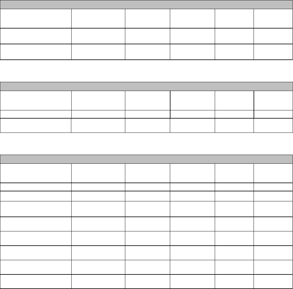
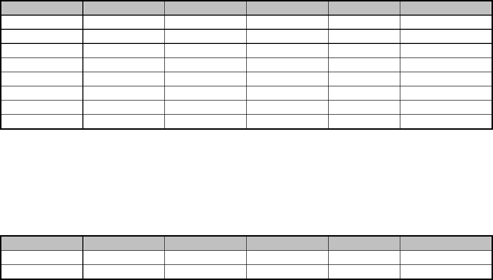
Test Equipment List
Instrumentation: The following list contains equipment used at COMPLIANCE CERTIFICATION
SERVICES (KUNSHAN) INC. for testing. The equipment conforms to the CISPR 16-1 / ANSI C63.2
Specifications for Electromagnetic Interference and Field Strength Instrumentation from 9kHz to 1.0 /
2.0 GHz.
Equipment used during the tests:
3/10m semi-anechoic chamber:
Site A (10m Chamber) for Radiated
EQUIPMENT
TYPE
MFR MODEL
NUMBER SERIAL
NUMBER LAST
CAL. CAL.
DUE
EMI Test Receiver R&S ESI26 100068 11/14/2003 11/13/2004
EMC Analyzer Agilent E7402A US41160329 12/30/2002 12/30/2003
Bilog Antenna Schaffner CBL 6143 5063 11/16/2003 11/15/2004
Coaxial Cable N/A N-type F1 N/A 05/26/2003 05/25/2004
Coaxial Cable N/A N-type C1 N/A 05/26/2003 05/25/2004
System Controller Sunol SC99V 121501-1 N/A N/A
Turn Table Sunol FM3022HS N/A N/A N/A
Antenna Mast Sunol TWR 99-4 121501-3 N/A N/A
Coax Switch Anitsu MP 598 M 80094 N/A N/A
Site A (10m Chamber) for Conducted
EQUIPMENT
TYPE
MFR MODEL
NUMBER SERIAL
NUMBER LAST
CAL. CAL.
DUE
EMI Test Receiver R&S ESI26 100068 11/14/2003 11/13/2004
EMC Analyzer Agilent E7402A US41160329 12/30/2003 12/30/2004
LISN FCC FCC-LISN-50-50-2-M 01067 11/30/2003 11/30/2004
LISN(EUT) FCC
FCC-LISN-50-50-2-M 01068 11/30/2003 11/30/2004
4-WIRE ISN R&S ENY41 830663/024 04/10/2003 04/09/2004
Double 2-Wire Isn R&S ENY22 830661/027 04/10/2003 04/09/2004
Coaxial Cable N/A N-type 01 N/A 05/26/2003 05/25/2004
EMI Monitor control box FCC 0-SVDC N/A N/A N/A
The calibrations of the measuring instruments, including any accessories that may effect such
calibration, are checked frequently to assure their accuracy. Adjustments are made and correction
factors applied in accordance with instructions contained in the manual for the measuring instrument.
Report Number: 03E00023
December11, 2003
Page 7
Rev. 00
Power Harmonic & Voltage Fluctuation/Flicker Measurement (61000-3-2&-3-3)
EQUIPMENT
TYPE MFR MODEL
NUMBER SERIAL
NUMBER LAST
CAL. CAL DUE.
Harmonic & Flicker
Tester Schaffner CCN 1000-1 72045 1/25/2003 1/25/2004
AC Power Source Schaffner NSG
1007-5-400 54788 1/25/2003 1/25/2004
ESD test (61000-4-2)
EQUIPMENT
TYPE MFR MODEL
NUMBER SERIAL
NUMBER LAST
CAL. CAL DUE.
ESD–Gun Schaffner NSG 432 2021 12/30/2002 12/30/2003
ESD-Simulator Schaffner 402-579 5015/4950
N
o Calibration
Required
N
o Calibration
Required
Radiated Electromagnetic Field immunity Measurement (61000-4-3)
EQUIPMENT
TYPE MFR MODEL
NUMBER SERIAL
NUMBER LAST
CAL. CAL DUE.
Signal Generator R&S SML 3 100564 05/21/2003 05/20/2004
Power Meter Schaffner CPW 9670 7004 01/10/2003 01/09/2004
E-Field Sensor Schaffner EMC-20
TYP-8
AI-0057
AM-0032 12/19/2002 12/19/2003
Bilog Antenna Schaffner CBL 6144 1006
N
o Calibration
Required
N
o Calibration
Required
Antenna Tower HD GmbH MM240 240/629 BJ01
N
o Calibration
Required
N
o Calibration
Required
Amplifier Research Schaffner 60S1G3 302728
N
o Calibration
Required
N
o Calibration
Required
Amplifier Power unit Schaffner CBA9433 3007
N
o Calibration
Required
N
o Calibration
Required
CCD GmbH Hmerau CE-SYS 19709529
N
o Calibration
Required
N
o Calibration
Required

Report Number: 03E00023
December11, 2003
Page 8
Rev. 00
Fast Transients/Burst test (61000-4-4)/Surge(61000-4-5)/Voltage Dips(61000-4-11)
EQUIPMENT
TYPE MFR MODEL
NUMBER SERIAL
NUMBER LAST
CAL. CAL DUE.
Transients/Burst/Surge
Test system Schaffner BEST EMC
V2.7 200132-001SC 12/30/2002 12/30/2003
Clamp Meter Fluke 36 78210055 07/09/2003 07/08/2004
Clamp Schaffner N/A N/A
N
o Calibration
Required
N
o Calibration
Required
Signal Line Coupling
Network Schaffner CDN-117 17396
N
o Calibration
Required
N
o Calibration
Required
Signal Line Coupling
Network Schaffner CDN-118 SL 400-187
N
o Calibration
Required
N
o Calibration
Required
CS test (61000-4-6)
EQUIPMENT
TYPE MFR MODEL
NUMBER SERIAL
NUMBER LAST
CAL. CAL DUE.
Transients/Burst/Surge
Test system Schaffner BEST EMC
V2.7 200132-001SC
N
o Calibration
Required
N
o Calibration
Required
EM-Koppelzange Schaffner KEMZ 801 17629 03/05/2003 03/04/2004
CDN Schaffner CDN A800 17890
N
o Calibration
Required
N
o Calibration
Required
CDN Schaffner CDN T002 19000
N
o Calibration
Required
N
o Calibration
Required
CDN Schaffner CDN T400 16918
N
o Calibration
Required
N
o Calibration
Required
CDN Schaffner CDN M216 16399
N
o Calibration
Required
N
o Calibration
Required
CDN Schaffner CDN M316 16939
N
o Calibration
Required
N
o Calibration
Required
CDN Schaffner CDN M316 16940
N
o Calibration
Required
N
o Calibration
Required
CDN Schaffner CDN M316 16935
N
o Calibration
Required
N
o Calibration
Required
Attenuator Schaffner INA 2070-1 2042
N
o Calibration
Required
N
o Calibration
Required
Power Frequency Magnetic Field Immunity test (61000-4-8)
EQUIPMENT
TYPE MFR MODEL
NUMBER SERIAL
NUMBER LAST
CAL. CAL DUE.
Induction Coil Interface Schaffner INA2141
INA702
6004
200149-078SC
N
o Calibration
Required
N
o Calibration
Required
AC Power Source Schaffner NSG
1007-5-400 54788
N
o Calibration
Required
N
o Calibration
Required
EMF TESTER TES TES-1390 010800365
N
o Calibration
Required
N
o Calibration
Required
Report Number: 00023
December1 2003
Page 9
Rev. 00
03E
1,
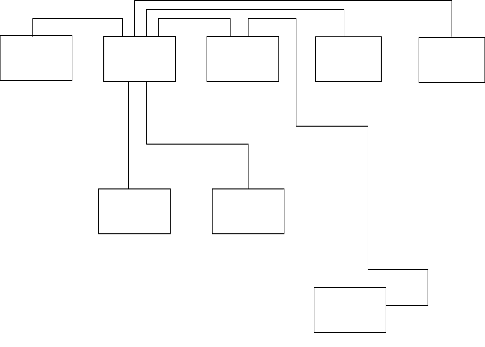
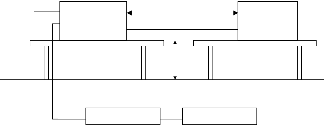
Block Diagram of Test Setup
System Diagram of Connections between EUT and Simulators
EUT: Firewall Router
Trade Name: TRENDnet
Model Number: TW100-BRF114
DC Power Cable: Non-shielded, 1.8 m (Non-Detachable)
6,
Monitor
5,
PC
EUT
1,
Keyboard
2,
Mouse
4,
Modem
3,
Print
7,
Notebook

Report Number: 03E00023
December11, 2003
Page 10
Rev. 00
Support Equipment
Equipment Model
# Serial
# FCC
ID Trade Name Data
Cable Power
Cord
1 (PS/2)Keyboard KB-9910 0081856 DoC IBM
Shielded,
2m N/A
2 MOUSE
(PS/2) MUS9JN F13640M67G9D
9F EMJMUSJR COMPAQ Shielded,
1.8m N/A
3 PRINT B162a EK6Y026422 DOC
EPSON stylus
C61
Shielded,
1.8m
with two Core
Un-Shielded,
1.8m
4 PRINT P310B C11344000HJ02 DOC EPSON
Shielded,
1.8m
with two Core
Un-Shielded,
1.8m
5 MODEM 2400SE
044-502501-000
94-364-176269 DK467GSM24
COMPUTER
PERIPHERAL
S
Shielded,
1.8m with one
Core
Un-Shielded,
1.0m
6 PC DPS-250GB-
2D DP4 DoC DELTA
Shielded,
1.2m
Shielded,
1.2m
7 Monitor CPD-G420 2404608 DoC SONY
Shielded
1.8m
with a Core
Un-Shielded,
1.5m
8 Notebook M285 1824064-1B DoC LEO N/A Shielded,
1.8m
9 Notebook PP01L
CN-04P240-4864
3-318-3259 DoC DELL N/A
Shielded,
1.8m
Note: All the above equipment/cables were placed in worse case positions to maximize emission signals
during emission test.
Grounding: Grounding was in accordance with the manufacturer’s requirements and conditions for the
intended use.
Report Number: 03E00023
December11, 2003
Page 11
Rev. 00
System Description
EUT Test Program:
1. A STP Cable connects the LAN port on EUT (mode:IP505LA) with a PC outside chamber. Using
DHCP options to provide the IP address of the PC, and then Running the order: ping 192.168.1.2 –t
under command pattern, the PC will have response to the LAN Port.
2. A STP Cable connects the LAN port on IP505LA with a PC inside chamber.
The IP address and gateway is settled separately to 192.168.1.2 and 192.168.1.0. The PC will have
response by running the order: ping 192.168.1.2 –t under command pattern.
3. When tested ISN, we used the 30 meters Non-shielded Twisted Pair Cable connected the EUT and
ISN.
4. A scroll ‘H’ test program was loaded and executed in Windows mode.
Report Number: 03E00023
December11, 2003
Page 12
Rev. 00
SECTION 1 - EMISSION MEASUREMENT
Conducted Emission Measurement
Radiated Emission Measurement
Power Harmonics Measurement (EN 61000-3-2)
Power Flicker Measurement ( EN 61000-3-3)
Report Number: 03E00023
December11, 2003
Page 13
Rev. 00
Procedure & Limit (Line Conducted Emission)
Preliminary Line Conducted Emission Test
1) The equipment was set up as per the test configuration to simulate typical actual usage per the user’s
manual. When the EUT is a tabletop system, a wooden table with a height of 0.8 meters is used
and is placed on the ground plane as per EN 55022 (see Test Facility for the dimensions of the
ground plane used). When the EUT is a floor-standing equipment, it is placed on the ground
plane which has a 3-12 mm non-conductive covering to insulate the EUT from the ground plane.
2) Support equipment, if needed, was placed as per EN 55022.
3) All I/O cables were positioned to simulate typical actual usage as per EN 55022.
4) The EUT received power source from the Power Supply, The Power Supply received AC power
(230V/50Hz) through a Line Impedance Stabilization Network (LISN) which supplied power source
and was grounded to the ground plane.
5) All support equipment received power from a second LISN supplying power of 220VAC/50Hz, if
any.
6) The EUT test program was started. Emissions were measured on each current carrying line of the
EUT using a spectrum analyzer / Receiver connected to the LISN powering the EUT. The LISN
has two monitoring points: Line 1 (Hot Side) and Line 2 (Neutral Side). Two scans were taken:
one with Line 1 connected to Analyzer / Receiver and Line 2 connected to a 50 ohm load; the
second scan had Line 1 connected to a 50 ohm load and Line 2 connected to the Analyzer / Receiver.
7) Analyzer / Receiver scanned from 150kHz to 30MHz for emissions in each of the test modes.
8) During the above scans, the emissions were maximized by cable manipulation.
9) The following test mode(s) were scanned during the preliminary test:
Mode(s):
run EMC test & ping WAN Port + LAN Port 1
run EMC test & ping WAN Port + LAN Port 1+LAN Port 2
run EMC test & ping WAN Port + LAN Port 1+LAN Port 2+LAN Port3
run EMC test & ping WAN Port + LAN Port 1+LAN Port 2+LAN Port3+LAN Port 4
10) After the preliminary scan, we found the following test mode(s) producing the highest emission
level.
Mode(s): run EMC test & ping WAN Port +LAN Port 1
(Temperature: 20oC / Humidity: 68%)
Then, the EUT configuration and cable configuration of the above highest emission level were recorded
for reference of final testing.

Report Number: 03E00023
December11, 2003
Page 14
Rev. 00
Final Line Conducted Emission Test
1) EUT and support equipment was set up on the test bench as per step 10 of the preliminary test.
2) A scan was taken on both power lines, Line 1 and Line 2, recording at least the six highest emissions.
Emission frequency and amplitude were recorded into a computer in which correction factors were
used to calculate the emission level and compare reading to the applicable limit. If EUT emission
level was less –2dB to the A.V. limit in Q.P. mode, then the emission signal was re-checked using an
A.V. detector.
3) The test data of the worst case condition(s) was reported on the Summary Data page.
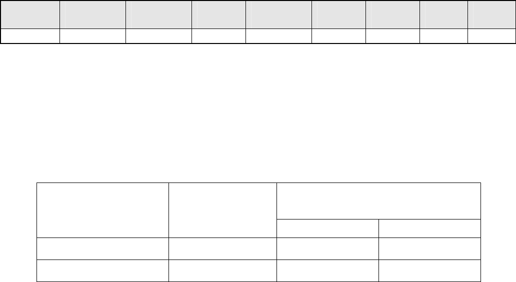
Data Sample:
Freq
(KHz)
Peak
Amptd
(dBuV)
QP
Amptd
(dBuV)
Avg
Amptd
(dBuV)
QP
Limit
(dBuV)
Avg
Limit
(dBuV)
Margin
(dB)
Factor
(dB)
281.70 38.04 37.74 37.18 62.17 52.17 -14.13 -1.61
Factor=Insertion Loss W/ Cable Loss
Amptd = Metering Reading + Factor
Margin=Amptd (Max. for Peak/QP/Avg) - Limits
QP=Quasi-peak
AVG=Average
L1=Hot
L2=Neutral
Line Conducted Emission Limit
Frequency Maximum RF Line Voltage
Q.P.( dBuV) AVERAGE(dBuV)
Class A Class B Class A Class B
150kHz-500kHz 79 66-56 66 56-46
500kHz-5MHz 73 56 60 46
5MHz-30MHz 73 60 60 50
Note: The lower limit shall apply at the transition frequency.

Report Number: 03E00023
December11, 2003
Page 15
Rev. 00
Procedure & Limit (Common Mode Conducted)
1) Selecting ISN for unscreened cable or a current probe for screened cable to take measurement.
2) The port of the EUT was connected to the remote side support equipment through the ISN/Current
Probe and communication in normal condition.
3) Making an overall range scan by using the test receiver controlled by controller and record at least six
highest emissions for showing in the test report.
4) Emission frequency and amplitude were recorded into a computer in which correction factors were
used to calculate the emission level and compare reading to the applicable limit.
5) In case of measuring on the screened cable, the current limit shall be applied, otherwise the voltage
limit should be applied.
6) The following test mode(s) were scanned during the preliminary test:
Mode(s):
run EMC test & ping WAN Port + LAN Port 1
run EMC test & ping WAN Port + LAN Port 1+LAN Port 2
run EMC test & ping WAN Port + LAN Port 1+LAN Port 2+LAN Port3
run EMC test & ping WAN Port + LAN Port 1+LAN Port 2+LAN Port3+LAN Port 4
7) After the preliminary scan, we found the worst mode producing the highest emission level.
Mode(s): run EMC test & ping WAN Port +LAN Port 1
(Temperature: 20oC / Humidity: 55%)
Data Sample:
Freq
(KHz)
Peak
Amptd
(dBuV)
QP
Amptd
(dBuV)
Avg
Amptd
(dBuV)
QP
Limit
(dBuV)
Avg
Limit
(dBuV)
Margin
(dB)
Factor
(dB)
3500.00 61.72 61.14 60.12 74.00 64.00 -2.28 10.76
Factor=Insertion Loss W/ Cable Loss
Amptd = Metering Reading + Factor
Margin=Amptd (Max. for Peak/QP/Avg) - Limits
QP=Quasi-peak
AVG=Average
L1=Hot
L2=Neutral

Report Number: 03E00023
December11, 2003
Page 16
Rev. 00
Common Mode Conducted Emission Limit
At Telecommunication Ports
Voltage limit dB(uV) Current limit dB(uA)
Q.P. AV Q.P. AV
Measuring
Band Class A Class B Class A Class B Class A Class B Class A Class B
150k-500kHz 97-87 84-74 87-74 74-64 53-43 40-30 40-30 30-20
500k-30MHz 87 74 74 64 43 30 30 20
Note 1: The lower limit shall apply at the transition frequency.
*Note 2*: Provisionally, a relaxation of 10dB over the frequency range of 6Mhz to 30Mhz is allowed for
high-speed services having significant spectral density in this band. However, this relaxation is restricted
to the common mode disturbance converted by the cable from the wanted signal. The provisional
relaxation of 10dB will be reviewed no later than three years after the date of withdrawal based on the
results and interference cases in this period.
Report Number: 03E00023
December11, 2003
Page 17
Rev. 00
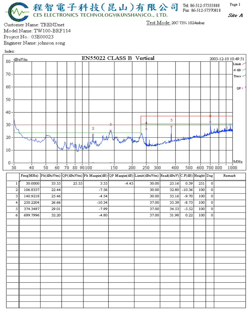
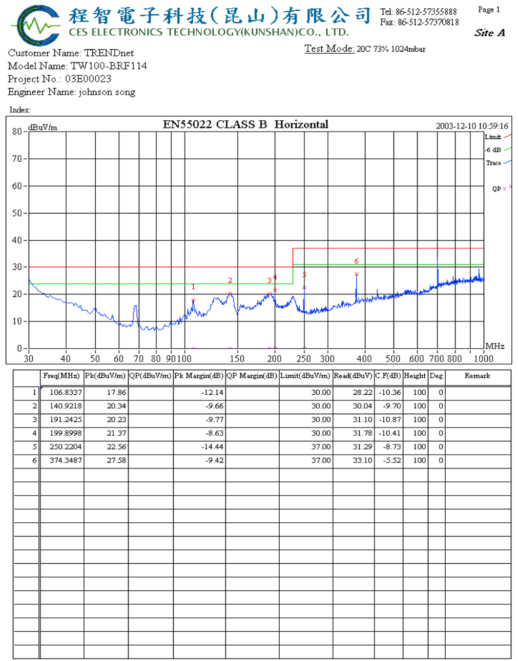
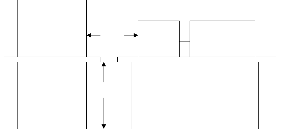
Procedure & Limit (Radiated Emission)
Preliminary Radiated Emission Test
1) The equipment was set up as per the test configuration to simulate typical actual usage per the user’s
manual. When the EUT is a tabletop system, a wooden turntable with a height of 0.8 meters is used
which is placed on the ground plane as per EN 55022 (see Test Facility for the dimensions of the
ground plane used). When the EUT is a floor-standing equipment, it is placed on the ground plane
which has a 3-12 mm non-conductive covering to insulate the EUT from the ground plane.
2) Support equipment, if needed, was placed as per EN 55022.
3) All I/O cables were positioned to simulate typical actual usage as per EN 55022.
4) The EUT received power source from the Power Supply. The Power Supply received AC power
source (230V/50Hz) from the outlet socket under the turntable .All support equipment received
220VAC/50Hz power from another socket under the turntable, if any.
5) The antenna was placed at 10 meter away from the EUT as stated in EN 55022. The antenna
connected to the Analyzer via a cable and at times a pre-amplifier would be used.
6) The Analyzer / Receiver quickly scanned from 30MHz to 1000MHz. The EUT test program was
started. Emissions were scanned and measured rotating the EUT to 360 degrees and positioning the
antenna 1 to 4 meters above the ground plane, in both the vertical and the horizontal polarization, to
maximize the emission reading level.
7) The following test mode(s) were scanned during the preliminary test:
Mode(s):
run EMC test & ping WAN Port + LAN Port 1
run EMC test & ping WAN Port + LAN Port 1+LAN Port 2
run EMC test & ping WAN Port + LAN Port 1+LAN Port 2+LAN Port3
run EMC test & ping WAN Port + LAN Port 1+LAN Port 2+LAN Port3+LAN Port 4
8) After the preliminary scan, we found the following test mode(s)producing the highest emission level.
Mode(s): run EMC test & ping WAN Port +LAN Port 1
(Temperature: 20oC / Humidity: 73%)
Then, the EUT and cable configuration, antenna position, polarization and turntable position of the
above highest emission level were recorded for final testing.
Report Number: 03E00023
December11, 2003
Page 18
Rev. 00
Final Radiated Emission Test
1) EUT and support equipment were set up on the turntable as per step 8 of the preliminary test.
2) The Analyzer / Receiver scanned from 30MHz to 1000MHz. Emissions were scanned and
measured rotating the EUT to 360 degrees, varying cable placement and positioning the antenna 1 to
4 meters above the ground plane, in both the vertical and the horizontal polarization, to maximize the
emission reading level.
3) Recorded at least the six highest emissions. Emission frequency, amplitude, antenna position,
polarization and turntable position were recorded into a computer in which correction factors were
used to calculate the emission level and compare reading to the applicable limit and only Q.P.
reading is presented.
4) The test data of the worst case condition(s) was reported on the Summary Data page.
Data Sample:
Freq
(MHz)
Peak
(dBuV/m)
QP
(dBuV/m)
Margin
(dB)
Limits
(dBuV/m)
Reading
(dBuV)
Factor
(dB)
Height
(cm)
Degree
(o)
92.10 28.69 25.02 -4.98 30.00 16.48 8.54 100 0
Factor=Antenna Factor + Cable Loss
Reading=Uncorrected Analyzer / Receiver Reading
Peak、QP (Corrected Reading) = Reading + Factor
Margin=Corrected Reading – Limits
QP=Quasi-peak
Radiated Emission Limit
Maximum Field Strength Limit
(dBu V/m/ Q.P.)
Frequency
(MHz)
Distance
(m)
Class A Class B
30-230 10 40 30
230-1000 10 47 37
Note: The lower limit shall apply at the transition frequency.
Report Number: 03E00023
December11, 2003
Page 19
Rev. 00
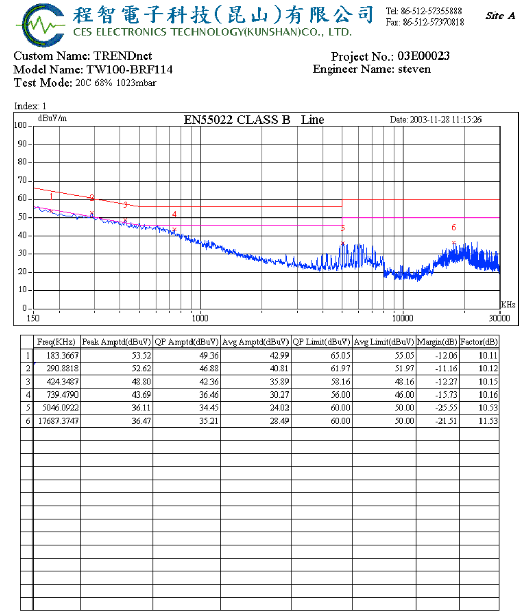
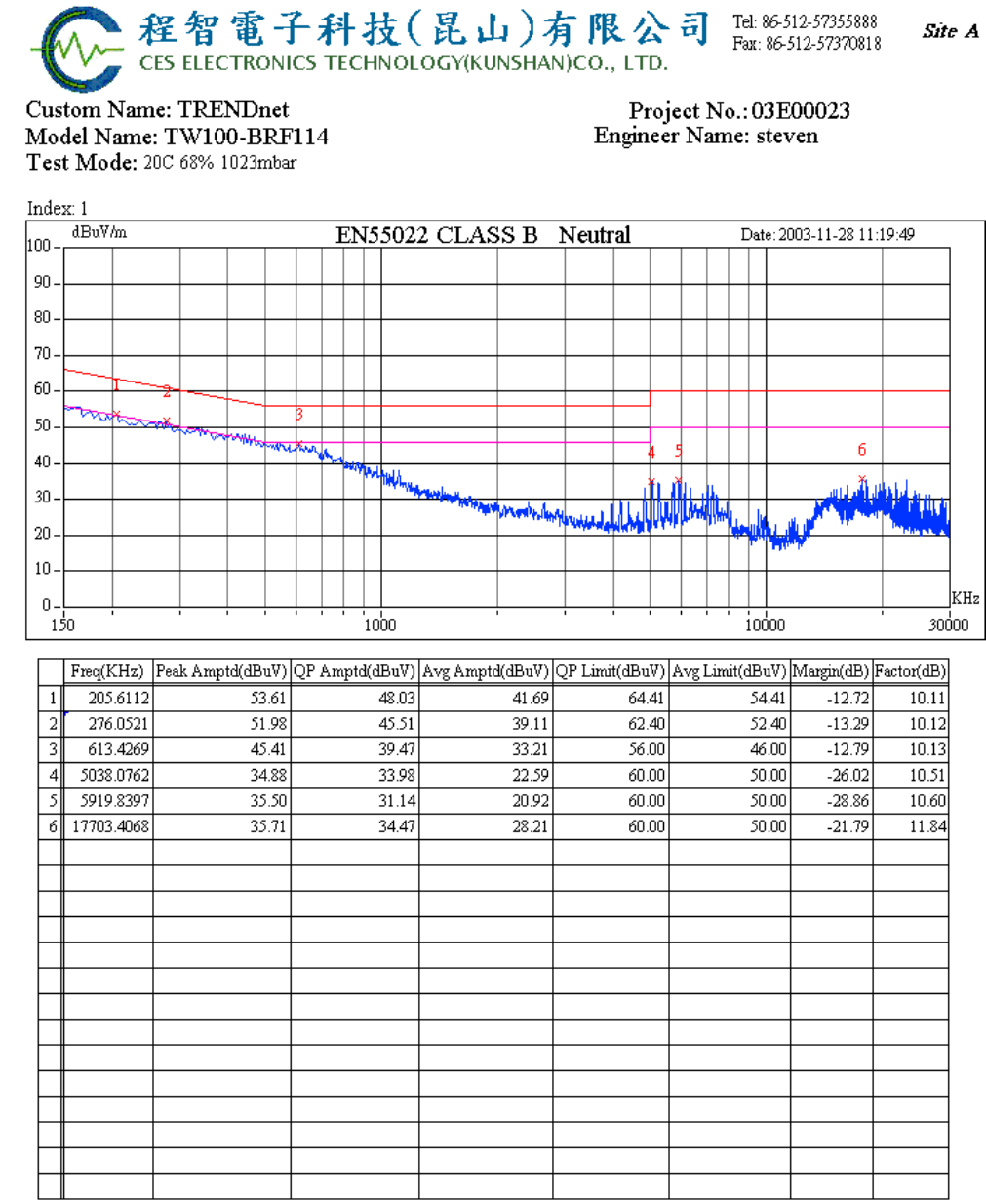
SUMMARY DATA (Line Conducted)
Comments: N/A
Report Number: 03E00023
December11, 2003
Page 20
Rev. 00
Comments: N/A
Report Number: 03E00023
December11, 2003
Page 21
Rev. 00
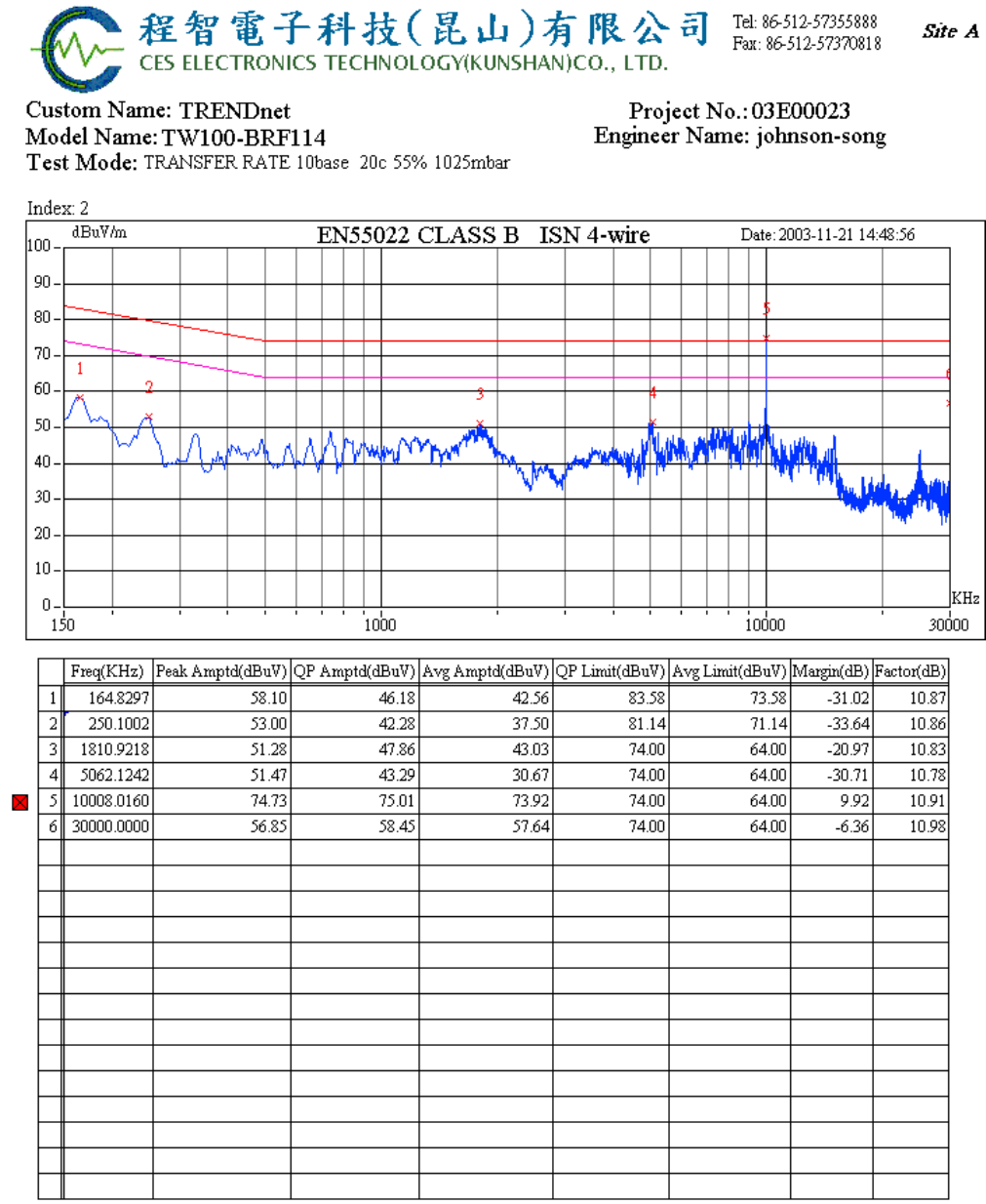
Common Mode Conducted
ISN 10BASE
Comments: reading page 16 *Note 2*.

Report Number: 03E00023
December11, 2003
Page 22
Rev. 00
ISN 100BASE
Comments: N/A
Report Number: 03E00023
December11, 2003
Page 23
Rev. 00
(Radiated Emission Test)
Comments: N/A
Report Number: 03E00023
December11, 2003
Page 24
Rev. 00
Comments: N/A
Report Number: 03E00023
December11, 2003
Page 25
Rev. 00
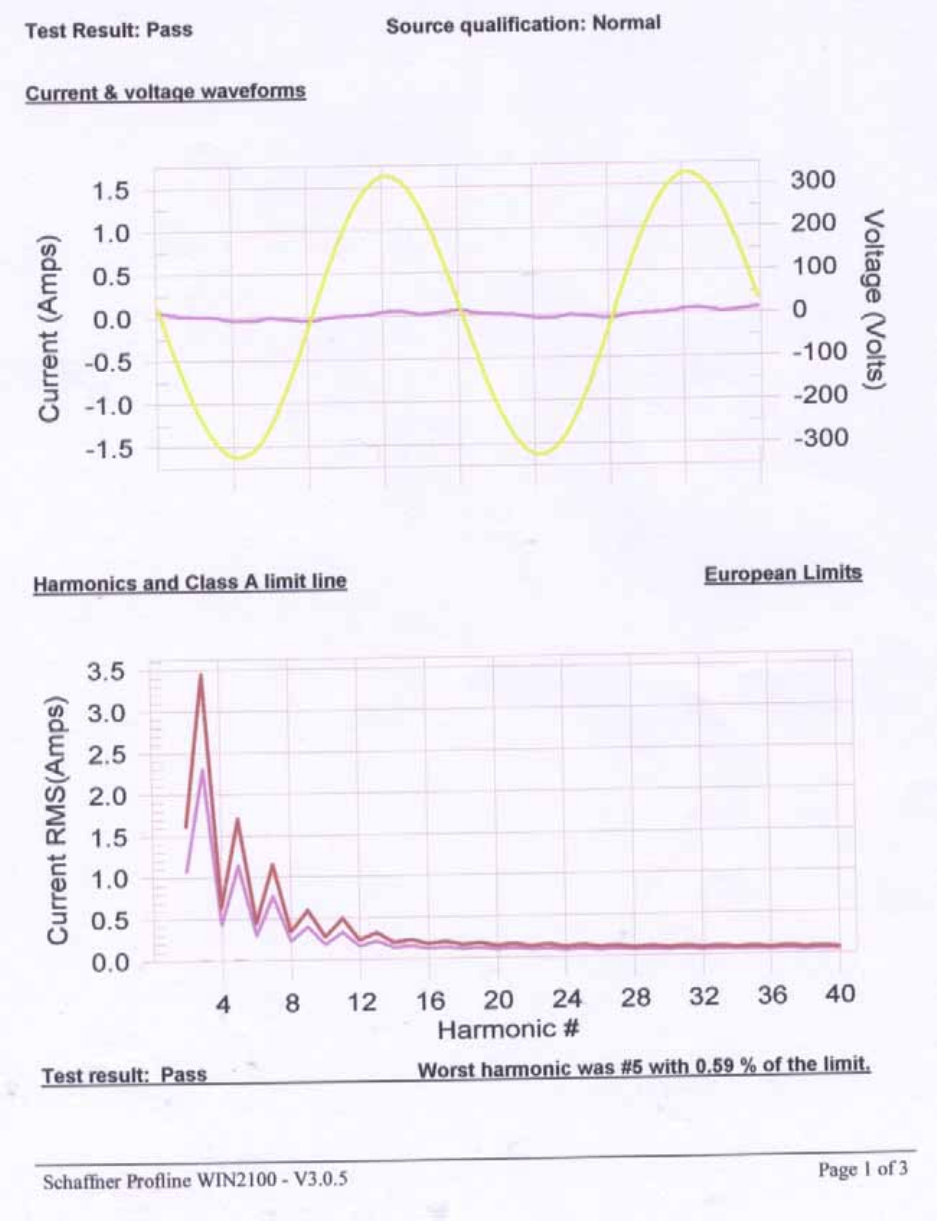
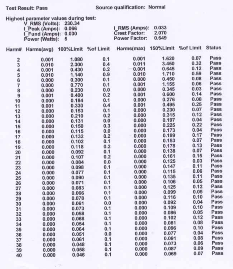
EN 61000-3-2 & EN 61000-3-3
(Power Harmonics & Voltage Fluctuation /Flicker)
POWER HARMONICS MEASUREMENT
Port : AC mains
Basic Standard : EN 61000-3-2: 1995 + A1: 1998 + A2: 1998 + A14: 2000
Limits : CLASS D
Tester : Ken
Temperature : 20oC
Humidity : 55%
Atmospheric Pressure ﹕1022mbar
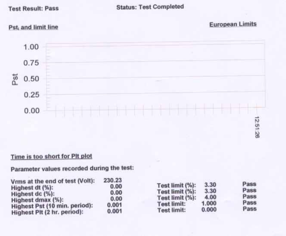
VOLTAGE FLUCTUATION/FLICKER MEASUREMENT
Port : AC mains
Basic Standard : EN 61000-3-3:1995+A1:2001
Limits : Section 5 of EN 61000-3-3
Tester : Ken
Temperature : 20oC
Humidity : 55%
Atmospheric Pressure ﹕1022mbar
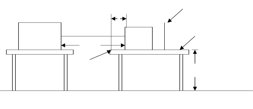
Block Diagram of Test Setup﹕
Harmonics & Flicker
Analyzer
+
Power Source
( PF 555 )
0.8m
Power cord
EUT
0.5m
Support Units
Result:
Please see the attached test data.
Report Number: 03E00023
December11, 2003
Page 26
Rev. 00
Harmonics-Class-A per A-14 (Run time)
Report Number: 03E00023
December11, 2003
Page 27
Rev. 00
Current TEST Result Summary (Run time)
Report Number: 03E00023
December11, 2003
Page 28
Rev. 00
Flicker Test Summary (Run time)
Report Number: 03E00023
December11, 2003
Page 29
Rev. 00
SECTION 2 – IMMUNITY TESTS (EN 55024)
Electrostatic discharge (ESD) immunity test (IEC 61000-4-2)
Radiated electromagnetic field (RS) immunity test (IEC 61000-4-3)
Fast transient / burst (EFT) immunity test (IEC 61000-4-4)
Surge immunity test (IEC 61000-4-5)
Conducted disturbances inducted by radio-frequency fields, (CS)
immunity test (IEC 61000-4-6)
Power Frequency Magnetic Field Immunity Test (IEC 61000-4-8)
Voltage dips, short interruption and voltage variation
immunity test (IEC 61000-4-11)
Report Number: 03E00023
December11, 2003
Page 30
Rev. 00
IEC 61000-4-2
ELECTROSTATIC DISCHARGE (ESD) IMMUNITY TEST
Port : Enclosure
Basic Standard : IEC 61000-4-2
Requirements :
+/- 8 kV (Air Discharge)
+/- 4 kV (Contact Discharge)
+/- 4 kV (Indirect Discharge)
Performance Criteria : B (Standard require)
Tester : Hadiif
Temperature/Humidity : 22 oC / 55%
Atmospheric Pressure ﹕1028mbar
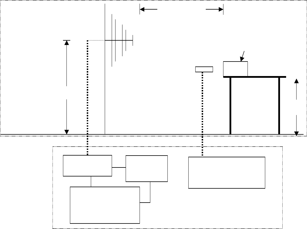
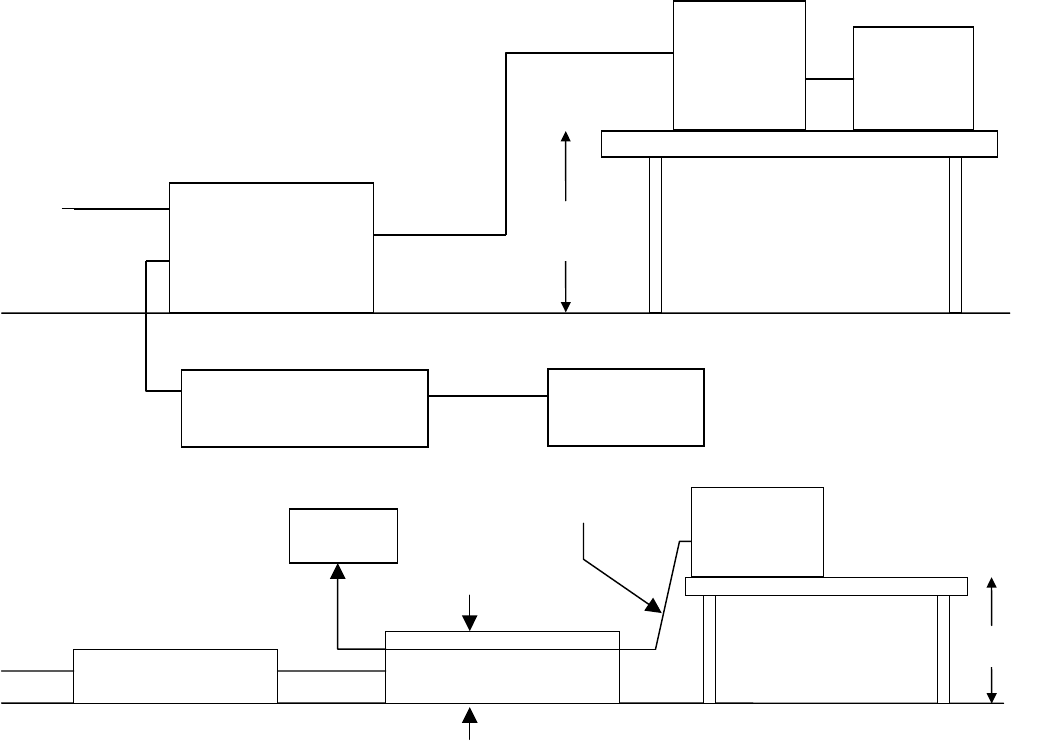
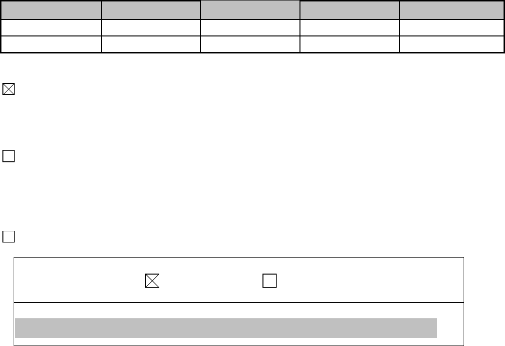
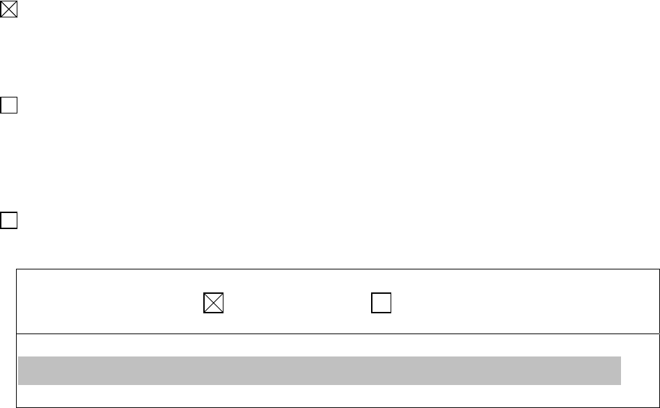
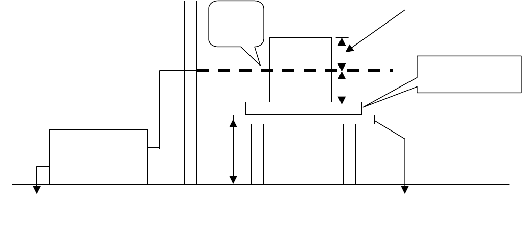
Block Diagram of Test Setup:
( The 470 k ohm resistors are installed per standard requirement )
Wooden Table
EUT HCP
>1m
Insulation0.5mm
0.8m
VCP
Support units
D≦0.1m
Ground Reference Plane

Report Number: 03E00023
December11, 2003
Page 31
Rev. 00
Test Procedure:
1. The EUT was located 0.1 m minimum from all side of the HCP.
2. The support units were located 1 m minimum away from the EUT.
3. Active the communication function if the EUT with such port(s).
4. As per the requirement of EN 55024; applying direct contact discharge at the sides other than front of
EUT at minimum 50 discharges (25 positive and 25 negative) if applicable, discharge time for each
point is 5 seconds. can’t be applied direct contact discharge side of EUT then the indirect discharge
shall be applied. One of the test points shall be subjected to at least 50 indirect discharge (contact) to
the front edge of horizontal coupling plane.
5. Other parts of EUT where it is not possible to perform contact discharge then selecting appropriate
points of EUT for air discharge, a minimum of 10 single air discharges shall be applied.
6. The application of ESD to the contact of open connectors is not required.
7. Putting a mark on EUT to show tested points. The following test condition was followed during the
tests.
Note: As per the A2 to IEC 61000-4-2, a bleed resistor(470kΩ cable is connected between the EUT and
HCP during the test.
The electrostatic discharges were applied as follows:
Amount of
Discharges Voltage Coupling Result (Pass/Fail)
Mini 25 /Point ±4kV Contact Discharge Pass
Mini 25 /Point ±4kV Indirect Discharge HCP (Front) Pass
Mini 25 /Point ±4kV Indirect Discharge VCP (Left) Pass
Mini 25 /Point ±4kV Indirect Discharge VCP (Back) Pass
Mini 25 /Point ±4kV Indirect Discharge VCP (Right) Pass
Mini 10 /Point ±8kV Air Discharge Pass
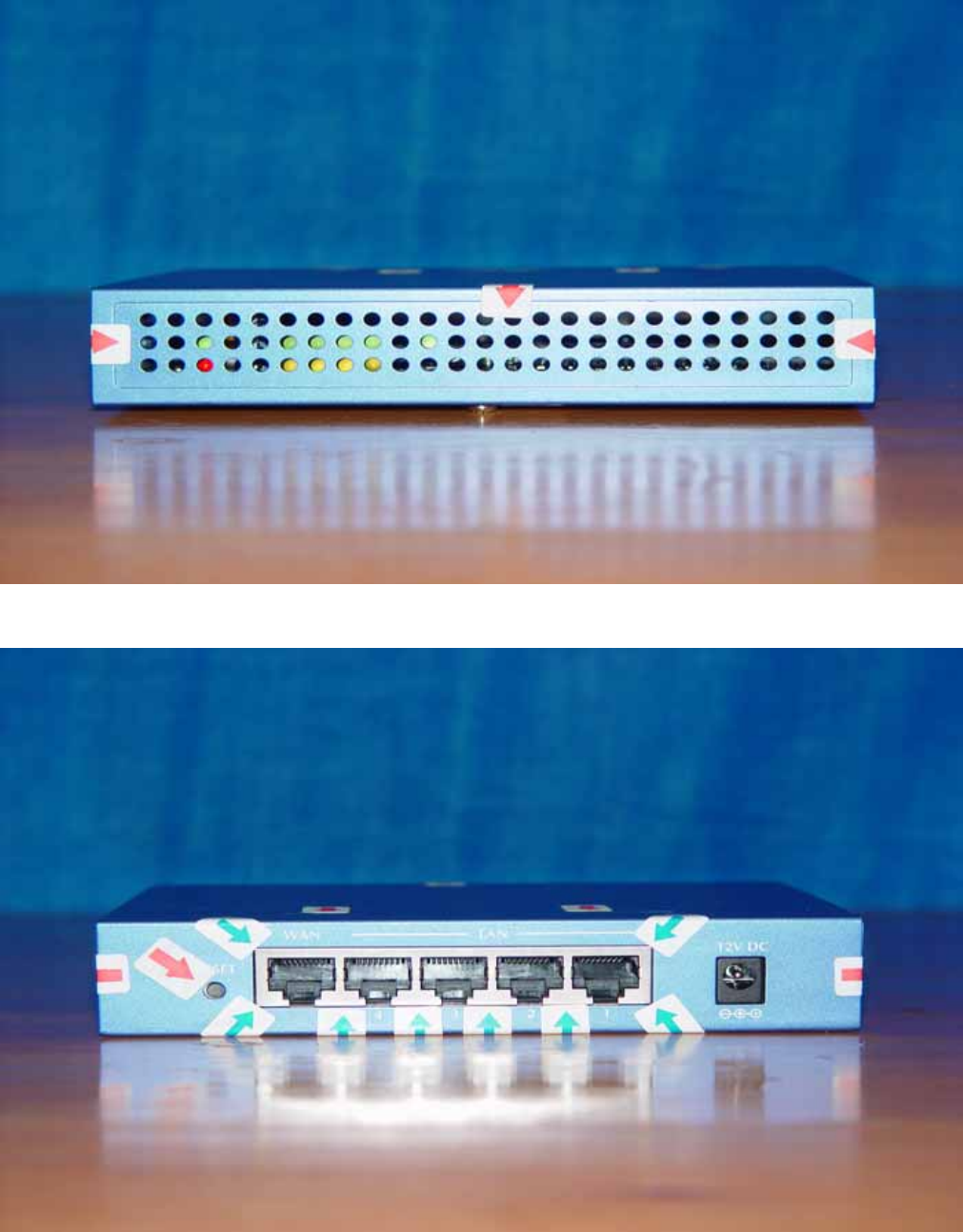
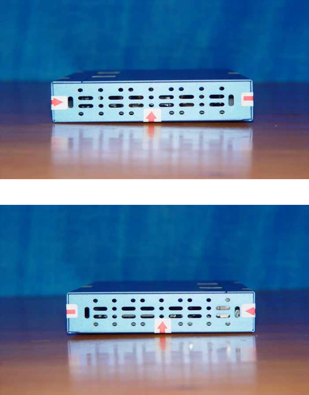
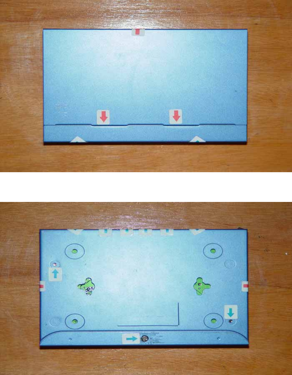
** The tested points to EUT, please refer to attached pages.
(Blue arrow mark for contact discharge, red arrow mark for air discharge.)
Report Number: 03E00023
December11, 2003
Page 32
Rev. 00
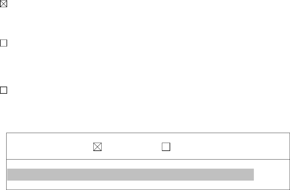
Performance & Result:
Criteria A: The apparatus continues to operate as intended. No degradation of performance or
loss of function is allowed below a performance level specified by the manufacturer,
when the apparatus is used as intended. In some cases the performance level may be
replaced by a permissible loss of performance.
Criteria B: The apparatus continues to operate as intended after the test. No degradation of
performance or loss of function is allowed below a performance level specified by the
manufacturer, when the apparatus is used as intended. In some cases the performance
level may be replaced by a permissible loss of performance. During the test,
degradation of performance is however allowed.
Criteria C: Temporary loss of function is allowed, provided the functions self recoverable or can
be restored by the operation of controls.
PASS FAILED
Observation: No any function degraded during the tests.
Report Number: 03E00023
December11, 2003
Page 33
Rev. 00
The Tested Points of EUT
Front view of EUT
Back view of EUT
Report Number: 03E00023
December11, 2003
Page 34
Rev. 00
left view of EUT
Right view of EUT
Report Number: 03E00023
December11, 2003
Page 35
Rev. 00
Top view of EUT
Bottom view of EUT
Report Number: 03E00023
December11, 2003
Page 36
Rev. 00
IEC 61000-4-3
RADIATED ELECTROMAGNETIC FIELD IMMUNITY TEST
Port : Enclosure
Basic Standard : IEC 61000-4-3
Requirements : 3 V/m / with 80% AM. 1kHz Modulation.
Performance Criteria : A (Standard require)
Tester : Hadiif
Temperature : 22oC
Humidity : 55%
Atmospheric Pressure ﹕1028mbar
Block Diagram of Test Setup:
Power Amp. Signal
Generator
EUT Monitoring by
using a camera
0.8m
Control Room
966 Chamber
EUT &
Support Units
1.5 Mete
r
PC Controller to control
S.G. & PA as well as
forward power
3 Meter
Report Number: 03E00023
December11, 2003
Page 37
Rev. 00
Test Procedure:
1. The EUT was located at the edge of supporting table keep 3 meter away from transmitting antenna, it
just the calibrated square area of field uniformity. The support units were located outside of the
uniformity area, but the cable(s) connected with EUT were exposed to the calibrated field as per IEC
61000-4-3.
2. Active the communication function if the EUT with such port(s).
2. Setting the testing parameters of RS test software per IEC 61000-4-3.
3. Performing the pre-test at each side of with double specified level (6V/m) at 4% steps.
4. From the result of pre-test in step 5, choice the worst side of EUT for final test from 80 MHz to 1000
MHz at 1% steps.
5. Recording the test result in following table.
6. It is not necessary to perform test as per annex A of EN 55024 if the EUT doesn’t belong to ITE
product.
IEC 61000-4-3 Preliminary test conditions:
Test level : 6V/m
Steps : 4 % of fundamental
Dwell Time : 3 sec
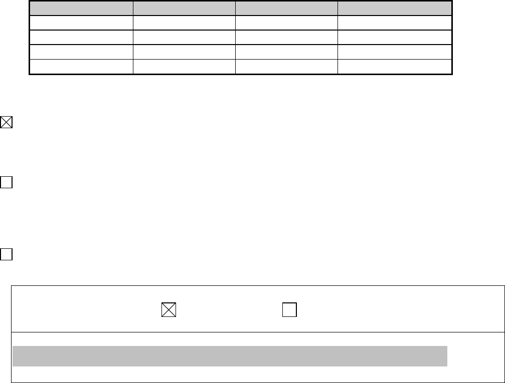
Range (MHz) Field Modulation Polarity Position (°) Result (Pass/Fail)
80-1000 6V Yes H Front Pass
80-1000 6V Yes V Front Pass
80-1000 6V Yes H Right Pass
80-1000 6V Yes V Right Pass
80-1000 6V Yes H Back Pass
80-1000 6V Yes V Back Pass
80-1000 6V Yes H Left Pass
80-1000 6V Yes V Left Pass
IEC 61000-4-3 Final test conditions:
Test level : 3V/m
Steps : 1 % of fundamental
Dwell Time : 3 sec
Range (MHz) Field Modulation Polarity Position (°) Result (Pass/Fail)
80-1000 3V Yes H Back Pass
80-1000 3V Yes V Back Pass
Report Number: 03E00023
December11, 2003
Page 38
Rev. 00
Performance & Result:
Criteria A: The apparatus continues to operate as intended. No degradation of performance or
loss of function is allowed below a performance level specified by the manufacturer,
when the apparatus is used as intended. In some cases the performance level may be
replaced by a permissible loss of performance.
Criteria B: The apparatus continues to operate as intended after the test. No degradation of
performance or loss of function is allowed below a performance level specified by the
manufacturer, when the apparatus is used as intended. In some cases the
performance level may be replaced by a permissible loss of performance. During the
test, degradation of performance is however allowed.
Criteria C: Temporary loss of function is allowed, provided the functions self-recoverable or can
be restored by the operation of controls.
PASS FAILED
Observation: No any function degraded during the tests.
Report Number: 03E00023
December11, 2003
Page 39
Rev. 00
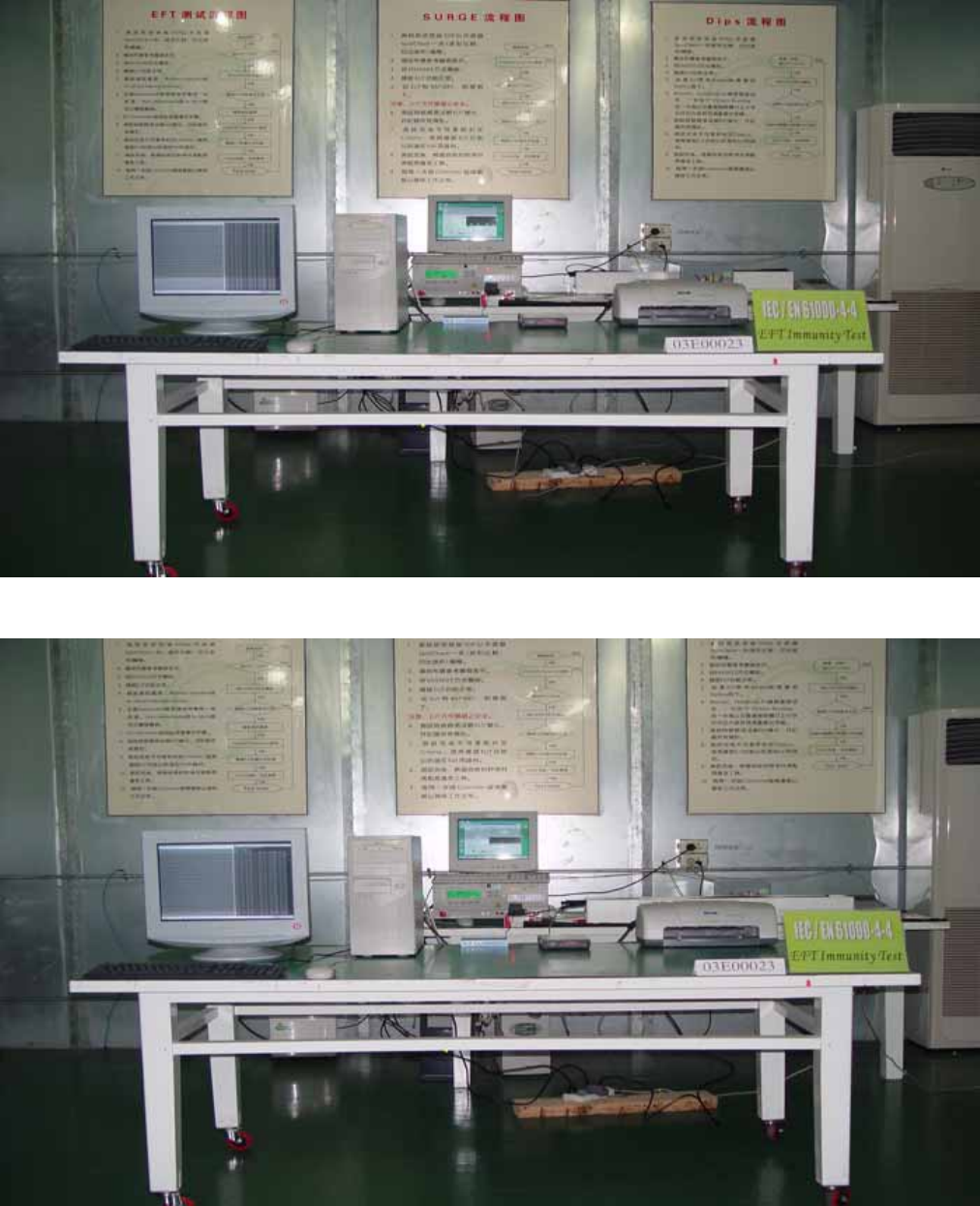
IEC 61000-4-4
FAST TRANSIENTS/BURST IMMUNITY TEST
Port : On Power Lines and Data Cable
Basic Standard : IEC 61000-4-4
Requirements : +/- 1kV for Power Supply Lines
+/- 0.5kV to Data Cable
Performance Criteria : B (Standard require)
Tester : Ken
Temperature : 20 oC
Humidity : 55%
Atmospheric Pressure ﹕1022mbar
Block Diagram of Test Setup:
EFT/Burst
Generator
EUT Support
Units
Reference Plane
Line
Non-Conductive Table
80cm
AC
Monitor
PC Controller
Injection Clamp Burst Generator
To Load
Comm. Line ≥ 3 m
10cm
Non-Conductive
Table 80cm
EUT
AC Line
Report Number: 03E00023
December11, 2003
Page 40
Rev. 00
Test Procedure:
1. The EUT and support units were located on a wooden table 0.8 m away from ground reference plane.
2. A 1.0 meter long power cord was attached to EUT during the test.
3. The length of communication cable between communication port and clamp was keeping within 1
meter.
4. A scroll ‘H’ test program was loaded and executed in Windows mode.
5. Active the communication function if the EUT with such port(s).
6. The test program exercised related support units sequentially.
7. Repeating step 3 to 5 through the test.
8. Recording the test result as shown in following table.
Test conditions:
Impulse Frequency: 5kHz
Tr/Th: 5/50ns
Burst Duration: 15ms
Burst Period: 300mS
Inject Line Voltage kV Inject Method Result (Pass/Fail)
L +/- 1 Direct Pass
N +/- 1 Direct Pass
L + N +/- 1 Direct Pass
RJ45 PORT +/- 0.5 Clamp Pass
Performance & Result:
Criteria A: The apparatus continues to operate as intended. No degradation of performance or
loss of function is allowed below a performance level specified by the manufacturer,
when the apparatus is used as intended. In some cases the performance level may be
replaced by a permissible loss of performance.
Criteria B: The apparatus continues to operate as intended after the test. No degradation of
performance or loss of function is allowed below a performance level specified by the
manufacturer, when the apparatus is used as intended. In some cases the
performance level may be replaced by a permissible loss of performance. During the
test, degradation of performance is however allowed.
Criteria C: Temporary loss of function is allowed, provided the functions self recoverable or can
be restored by the operation of controls.
PASS FAILED
Observation: No any function degraded during the tests.
Report Number: 03E00023
December11, 2003
Page 41
Rev. 00
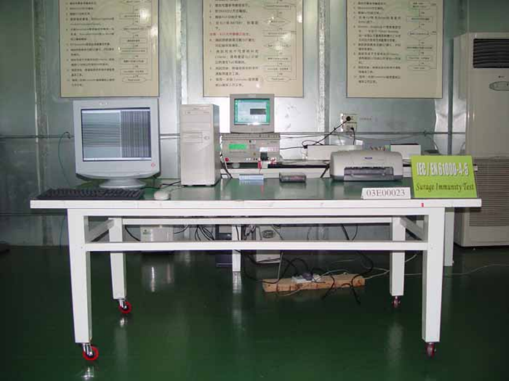
IEC 61000-4-5
SURGE IMMUNITY TEST
Port : AC Power cord
Basic Standard : IEC 61000-4-5
Requirements : +/- 1kV (Line to Line of AC Power Port)
Performance Criteria : B (Standard require)
Tester : Ken
Temperature : 22 oC
Humidity : 55%
Atmospheric Pressure ﹕1028mbar
Block Diagram of Test Setup:
0.5m
Surge Immunity
Test
Controller Computer
EUT
&
Support Units
Printer
To AC
Source
80 cm
Report Number: 03E00023
December11, 2003
Page 42
Rev. 00
Test Procedure:
1. The EUT and support units were located on a wooden table 0.8 m away from ground floor.
2. A test program was loaded and executed in Windows mode.
3. Active the communication function if the EUT with such port(s).
4. The test program exercised related support units sequentially.
5. Repeating step 4 through the test.
6. Recording the test result as shown in following table.
Test conditions:
Voltage Waveform : 1.2/50 us
Current Waveform : 8/20 us
Polarity : Positive/Negative
Phase angle : 0°, 90°, 270°
Number of Test : 5
Coupling Line Voltage (kV) Polarity Coupling Method Result (Pass/Fail)
L1-L2 1 Positive Capacitive Pass
L1-L2 1 Negative Capacitive Pass
Performance & Result:
Criteria A: The apparatus continues to operate as intended. No degradation of performance or
loss of function is allowed below a performance level specified by the manufacturer,
when the apparatus is used as intended. In some cases the performance level may be
replaced by a permissible loss of performance.
Criteria B: The apparatus continues to operate as intended after the test. No degradation of
performance or loss of function is allowed below a performance level specified by the
manufacturer, when the apparatus is used as intended. In some cases the
performance level may be replaced by a permissible loss of performance. During the
test, degradation of performance is however allowed.
Criteria C: Temporary loss of function is allowed, provided the functions self-recoverable or can
be restored by the operation of controls.
PASS FAILED
Observation: No any function degraded during the tests.
Report Number: 03E00023
December11, 2003
Page 43
Rev. 00
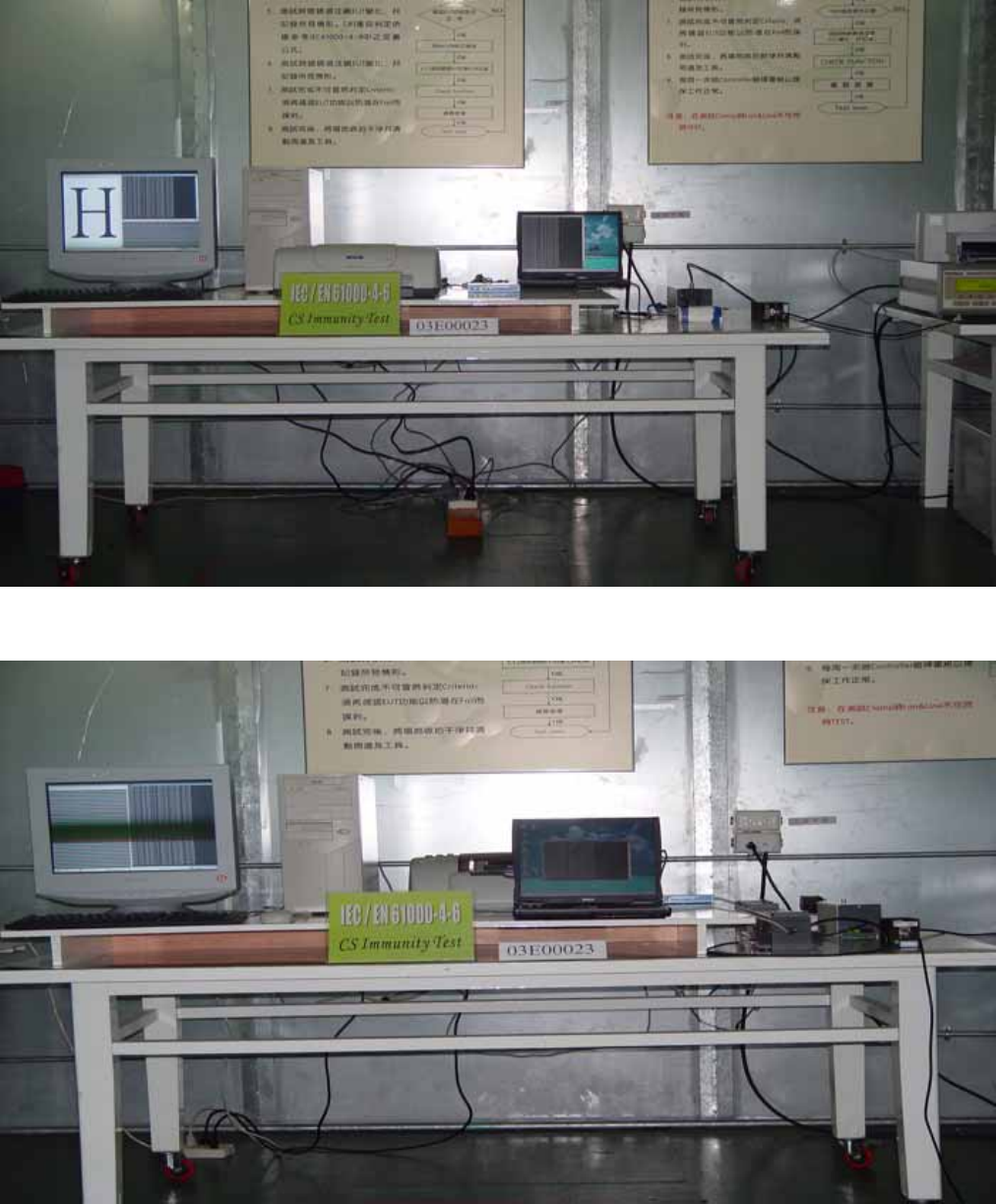
IEC 61000-4-6
CONDUCTED DISTURBANCE /INDUCED BY RADIO-FREQUENCY FIELD
Port : AC Port; Signal lines (Applicable only to ports which according to
manufacturer’s specification supports communication on cable lengths
greater than 3m.)
Base Standard : IEC 61000-4-6
Requirements : 3 V with 80% AM. Modulation
Injection Method : CDN-M316 for Power Cord
EM-Clamp for LAN Cable
Performance Criteria : A (Standard require)
Tester : Ken
Temperature : 20 oC
Humidity : 55%
Atmospheric Pressure ﹕1024mbar
Note : The EUT doesn’t belong to TTE product, the tests at limited number of
frequencies not required
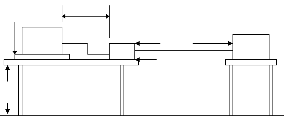
Block Diagram of Test Setup:
Side view:
0.8m
CDN
EUT and
Support units
10 cm isolation
supporter
0.1m< L <0.3
m
Ground
Reference Plane
0.5m RF
Generator
Report Number: 03E00023
December11, 2003
Page 44
Rev. 00
Top view:
0.1m<L<0.3m
Power
Amplifier
PC
Controller
EM-Cla
mp
EUT &
Support
Units
Support
Units
Ground Reference Plane
3 - 5 cm isolation supporter
10 cm isolation supporter
0.1m
0.1m
0.1m<L<0.3m
Test Procedure:
1. The EUT and support units were located at a ground reference plane with the interposition of a 0.1
m thickness insulating support and the CDN was located on GRP directly
2. Active the communication function if the EUT with such port(s).
3. Setting the testing parameters of CS test software per EN 61000-4-6.
4. Recording the test result in following table.
Test conditions:
Frequency Range : 0.15MHz-80MHz
Frequency Step : 1% of fundamental
Dwell Time : 3 sec
Range (MHz) Field Modulation Result (Pass/Fail)
0.15-80 3V Yes Pass
Report Number: 03E00023
December11, 2003
Page 45
Rev. 00
Performance & Result:
Criteria A: The apparatus continues to operate as intended. No degradation of performance or
loss of function is allowed below a performance level specified by the manufacturer,
when the apparatus is used as intended. In some cases the performance level may be
replaced by a permissible loss of performance.
Criteria B: The apparatus continues to operate as intended after the test. No degradation of
performance or loss of function is allowed below a performance level specified by the
manufacturer, when the apparatus is used as intended. In some cases the
performance level may be replaced by a permissible loss of performance. During the
test, degradation of performance is however allowed.
Criteria C: Temporary loss of function is allowed, provided the functions self-recoverable or can
be restored by the operation of controls.
PASS FAILED
Observation: No any function degraded during the tests.
Report Number: 03E00023
December11, 2003
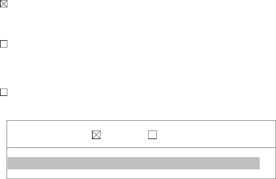
IEC 61000-4-8
POWER FREQUENCY MAGNETIC FIELD IMMUNITY TEST
Port : Enclosure
Basic Standard : IEC 61000-4-8
Requirements : 1 A/m
Performance Criteria : A (Standard Required)
Tester : N/A
Temperature : N/A
Humidity : N/A
Atmospheric Pressure ﹕N/A
Block Diagram of Test setup:
EUT
Signal
Generator 0.8m
10cm thick
Insulation Support
1/2 Dimension
of EUT
Induction
Coil
To
Earth Ground
To
Earth Ground
Page 46
Rev. 00

Report Number: 03E00023
December11, 2003
Page 47
Rev. 00
Test Procedure:
1. The EUT and support units were located on Ground Reference Plane with the interposition of a 0.1
m thickness insulation support.
2. Putting the induction coil on horizontal direction.( X direction )
3. A test program was loaded and executed in Windows mode.
4. Active the communication function if the EUT with such port(s).
5. The test program exercised related support units sequentially.
6. Repeating step 3 to 5 through the test.
7. Recording the test result as shown in following table.
8. Rotating the induction coil by 90o ( Y direction ) then repeat step 3 to 7.
9. Rotating the EUT by 90 o horizontly again( Z direction ) then repeat step 3 to 7.
*. Test conditions:
Field Strength: 1A/m
Power Freq.: 50Hz
Orientation: X, Y, Z
Orientation Field Result (Pass/Fail) Remark
X axis 1A/m Pass N/A
Y axis 1A/m Pass N/A
Z axis 1A/m Pass N/A
Report Number: 03E00023
December11, 2003
Page 48
Rev. 00
Performance & Result:
Criteria A: The apparatus continues to operate as intended. No degradation of performance or
loss of function is allowed below a performance level specified by the manufacturer,
when the apparatus is used as intended. In some cases the performance level may be
replaced by a permissible loss of performance.
Criteria B: The apparatus continues to operate as intended after the test. No degradation of
performance or loss of function is allowed below a performance level specified by the
manufacturer, when the apparatus is used as intended. In some cases the
performance level may be replaced by a permissible loss of performance. During the
test, degradation of performance is however allowed.
Criteria C: Temporary loss of function is allowed, provided the functions self recoverable or can
be restored by the operation of controls.
PASS FAILED
Observation: No any function degraded during the tests.
Report Number: 03E00023
December11, 2003
Page 49
Rev. 00
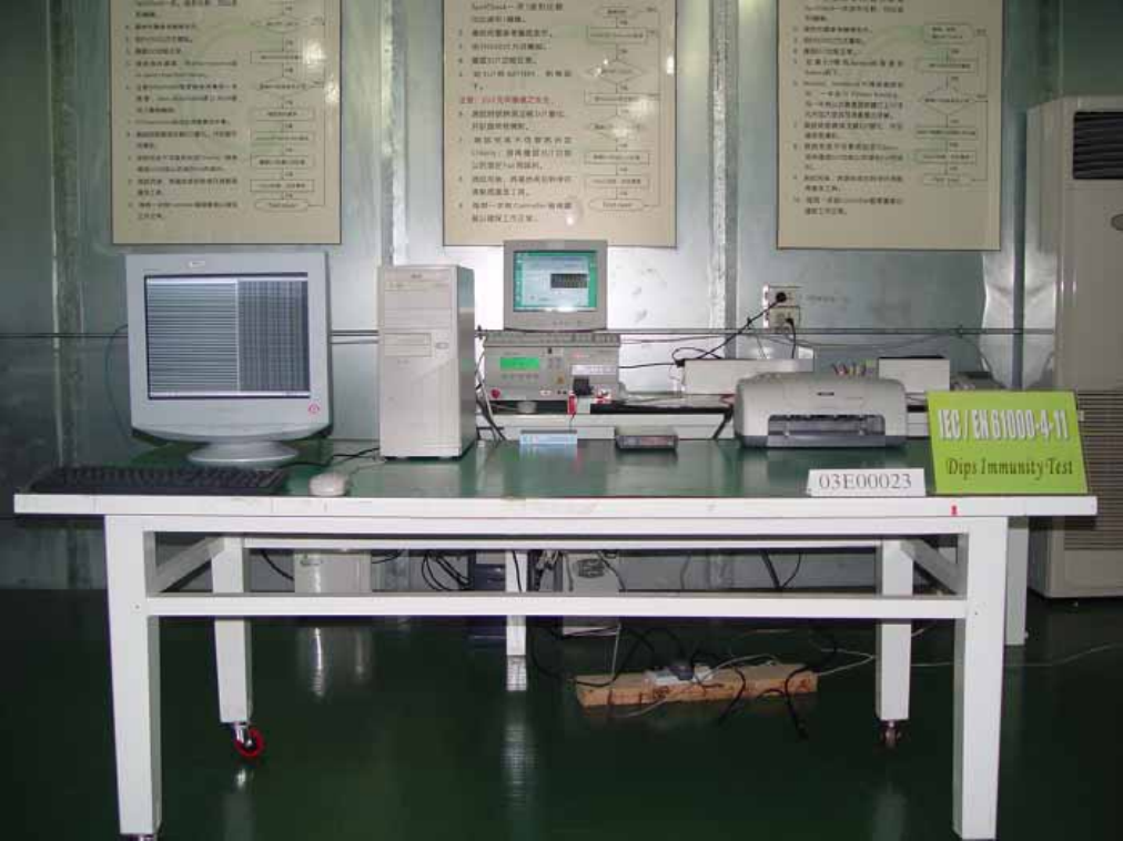
IEC 61000-4-11
Voltage Dips, Short Interruptions and Voltage Variations
Port : AC mains
Basic Standard : IEC 61000-4-11 (1994)
Requirement : Phase angles 0 degrees.
Test Level
% UT
Reduction
(%)
Duration
( periods )
Performance
Criteria
<5 >95 0.5 B
Voltage
Dips
70 30 25 C
Test Level
% UT
Reduction
(%)
Duration
( periods )
Performance
Criteria
Voltage
Interruptions <5 >95 250 C
Test Interval : Min. 60 sec.
Tester : Ken
Temperature : 20oC
Humidity : 55%
Atmospheric Pressure ﹕1022mbar
Block Diagram of Test Setup:
Dips/Interruption and
Variations Simulator
Controller Computer
EUT
&
Support Units
Printer
To AC
Source
80 mm
Report Number: 03E00023
December11, 2003
Page 50
Rev. 00
Test Procedure:
1. The EUT and support units were located on a wooden table, 0.8 m away from ground floor.
2. A test program was loaded and executed in Windows mode
3. Active the communication function if the EUT with such port(s).
4. The test program exercised related support units sequentially.
5. Setting the parameter of tests and then Perform the test software of test simulator.
6. Conditions changes to occur at 0 degree crossover point of the voltage waveform.
7. Repeating step 3 to 4 through the test.
8. Recording the test result in test record form.
Test conditions:
The duration with a sequence of three dips/interruptions with interval of 10s minimum
( between each test events)
Voltage Dips:
Test Level
% UT
Reduction
(%)
Duration
( periods)
Observation Meet Performance
Criteria
0 100 0.5 Normal B
70 30 25 Normal B
Voltage Interruptions:
Test Level
% UT
Reduction
(%)
Duration
( periods)
Observation Meet Performance
Criteria
0 100 250 EUT shut down but can
be recovered by manual,
as the events disappears
C
Normal: No any functions degrade during and after the test.
Performance & Result:
Criteria A: The apparatus continues to operate as intended. No degradation of performance or
loss of function is allowed below a performance level specified by the manufacturer,
when the apparatus is used as intended. In some cases the performance level may be
replaced by a permissible loss of performance.
Criteria B: The apparatus continues to operate as intended after the test. No degradation of
performance or loss of function is allowed below a performance level specified by the
manufacturer, when the apparatus is used as intended. In some cases the
performance level may be replaced by a permissible loss of performance. During the
test, degradation of performance is however allowed.
Criteria C: Temporary loss of function is allowed, provided the functions self recoverable or can
be restored by the operation of controls.
PASS FAILED
Report Number: 03E00023
December11, 2003
Page 51
Rev. 00
APPENDIX 1
Photographs of Test Setup
Report Number: 03E00023
December11, 2003
Page 52
Rev. 00
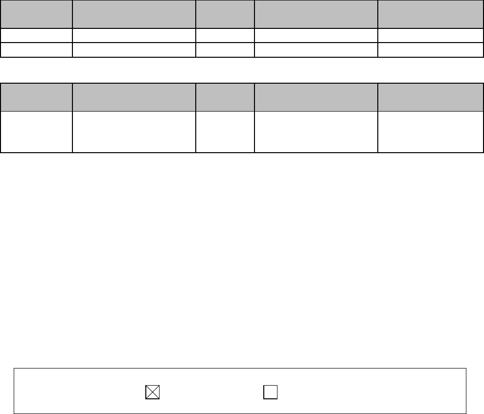
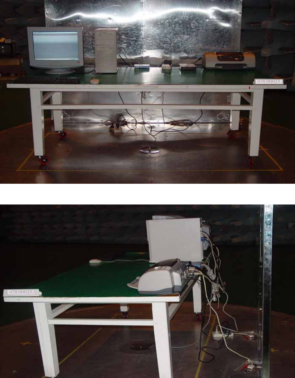
LINE CONDUCTED EMISSION TEST (EN 55022)
Front
BACK
Report Number: 03E00023
December11, 2003
Page 53
Rev. 00
Common Mode Conducted (EN 55022)
ISN
Report Number: 03E00023
December11, 2003
Page 54
Rev. 00
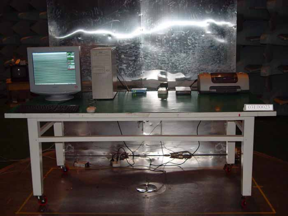
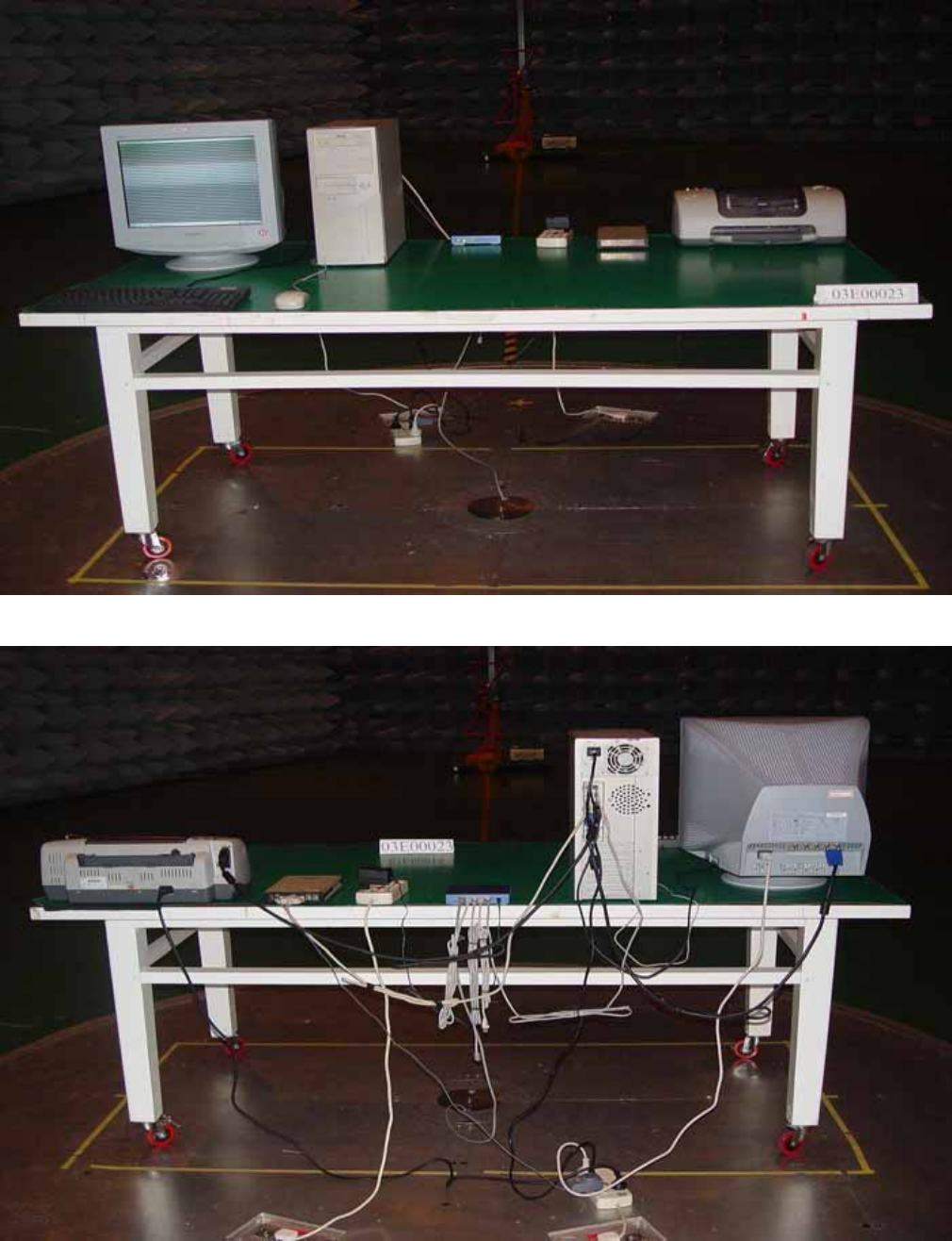
RADIATED EMISSION TEST (EN 55022)
Front
Back
Report Number: 03E00023
December11, 2003
Page 55
Rev. 00
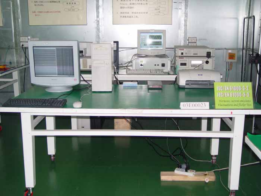
POWER HARMONIC & VOLTAGE FLUCTUATION / FLICKER TEST
(EN 61000-3-2, EN 61000-3-3)
Report Number: 03E00023
December11, 2003
Page 56
Rev. 00
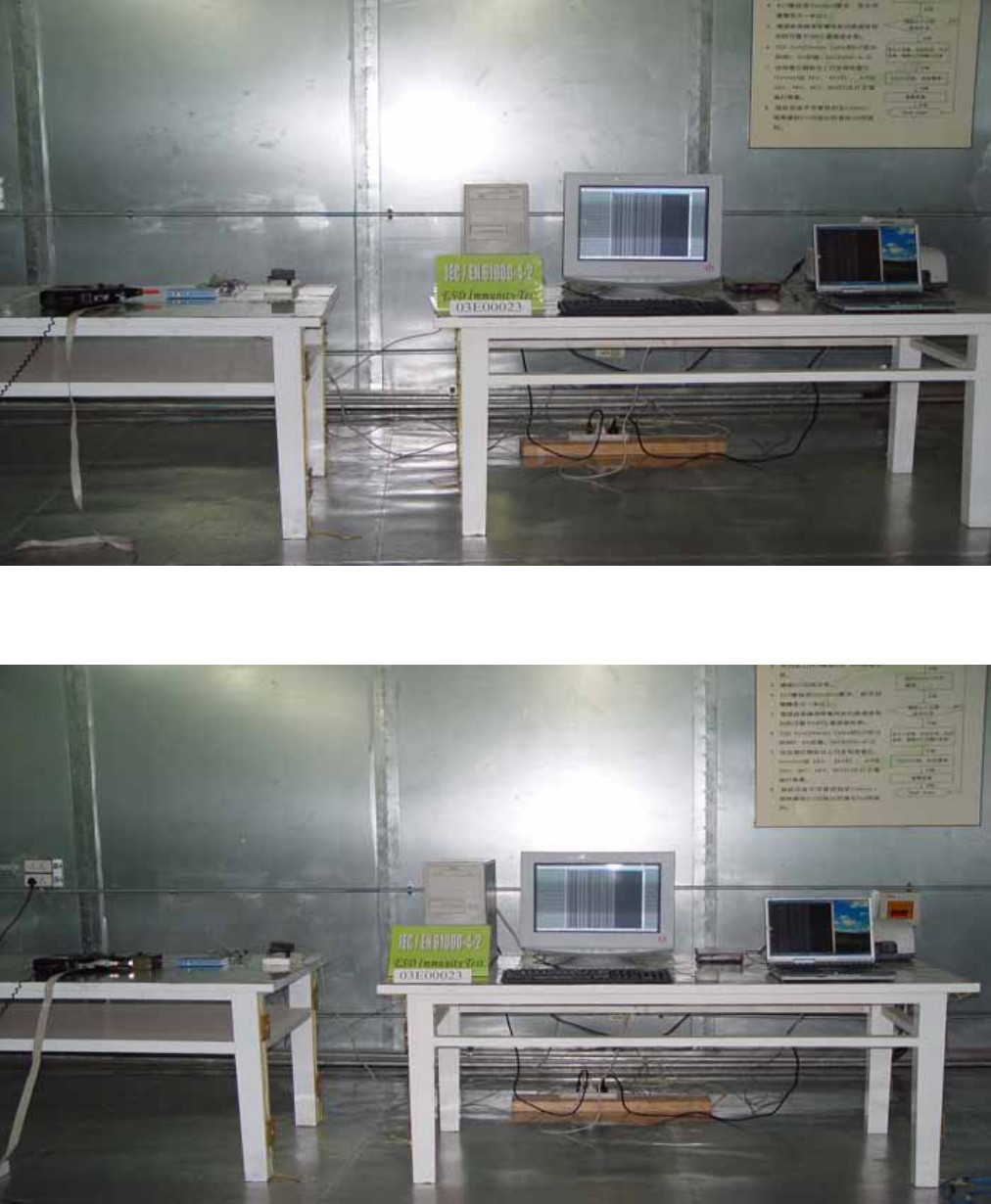
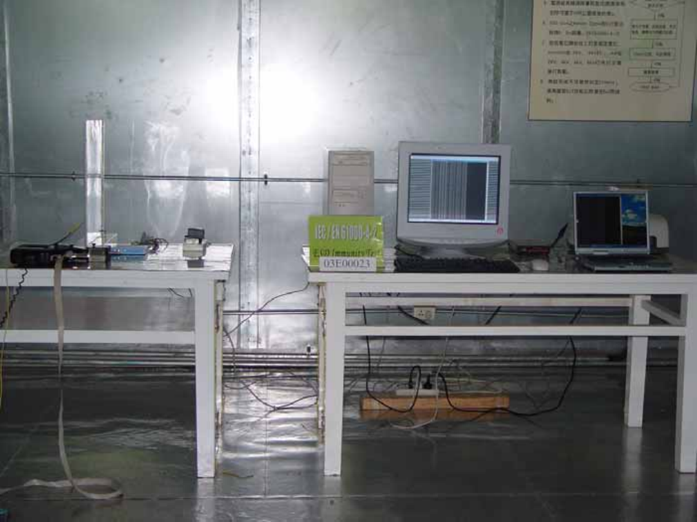
ELECTROSTATIC DISCHARGE TEST (IEC 61000-4-2)
ESD AIR
ESD CONTACT
Report Number: 03E00023
December11, 2003
Page 57
Rev. 00
ESD VCP
Report Number: 03E00023
December11, 2003
Page 58
Rev. 00
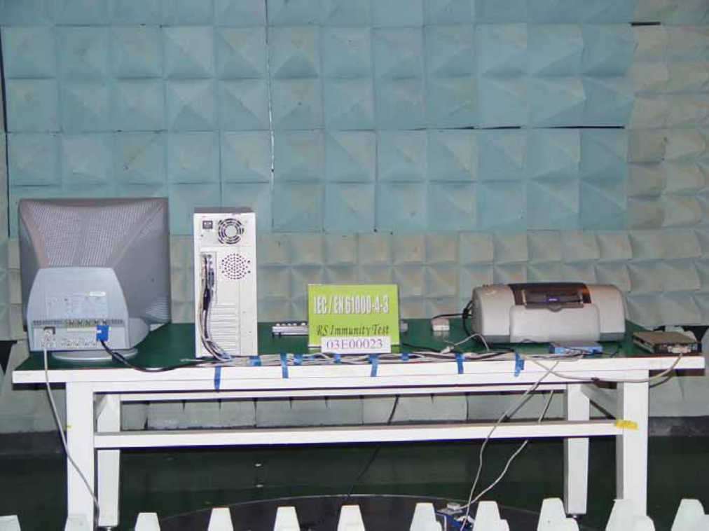
RADIATED ELECTROMAGNETIC FIELD (IEC 61000-4-3)
Report Number: 03E00023
December11, 2003
Page 59
Rev. 00
FAST TRANSIENTS/BURST TEST (IEC 61000-4-4)
For power
For I/O
Report Number: 03E00023
December11, 2003
Page 60
Rev. 00
SURGE IMMUNITY TEST (IEC 61000-4-5)
Report Number: 03E00023
December11, 2003
Page 61
Rev. 00
CONDUCTED DISTURBANCE, INDUCED BY RADIO-FREQUENCY FIELDS
TEST (IEC 61000-4-6)
CDN-M316 for Power Cord
EM-Clamp for LAN Cable
Report Number: 03E00023
December11, 2003
Page 62
Rev. 00
VOLTAGE DIPS / INTERRUPTION TEST (IEC 61000-4-11)
Report Number: 03E00023
December11, 2003
Page 63
Rev. 00
APPENDIX 2
Photographs (EUT)
Report Number: 03E00023
December11, 2003
Page 64
Rev. 00
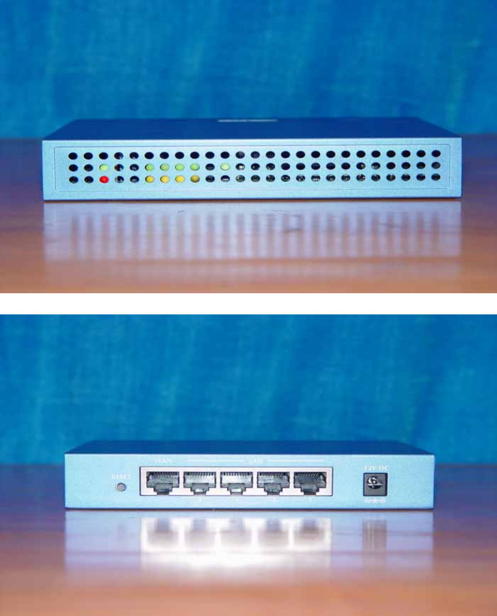
Front view of EUT
Back view of EUT
Report Number: 03E00023
December11, 2003
Page 65
Rev. 00
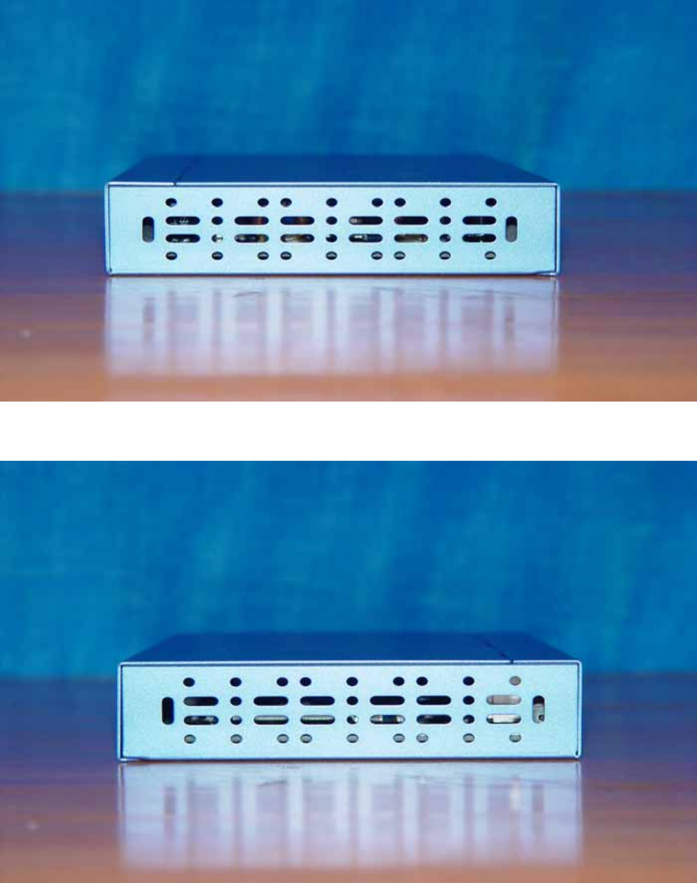
Left view of EUT
Right view of EUT
Report Number: 03E00023
December11, 2003
Page 66
Rev. 00
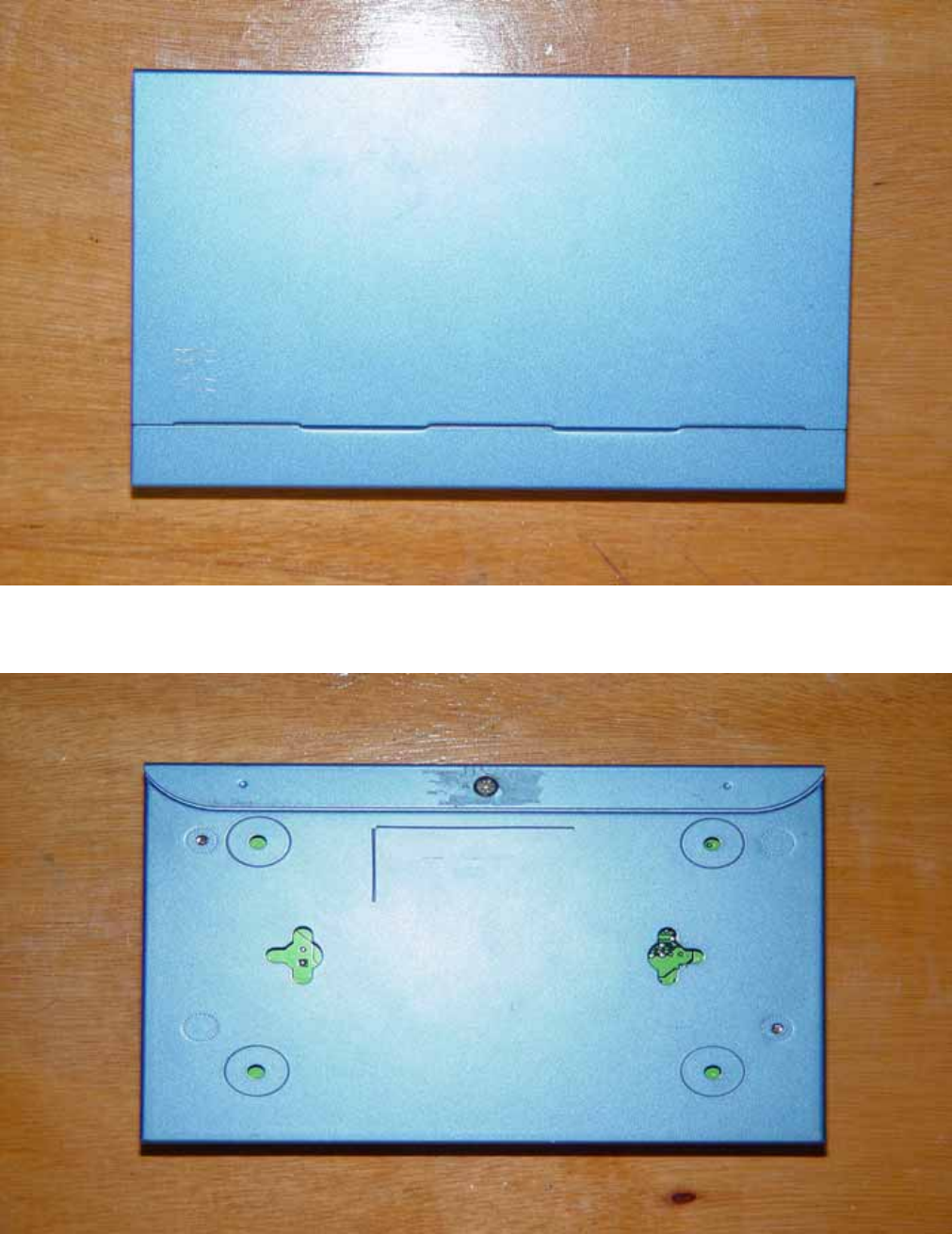
Top view of EUT
Bottom view of EUT
Report Number: 03E00023
December11, 2003
Page 67
Rev. 00
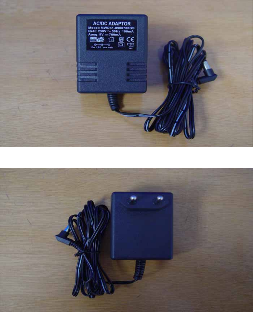
ADAPTER
Top view of EUT
Bottom view of EUT
Report Number: 03E00023
December11, 2003
Page 68
Rev. 00
APPENDIX 3
Sample of EC-Declaration of Conformity
Report Number: 03E00023
December11, 2003
Page 69
Rev. 00
EC-Declaration of Conformity
For the following equipment:
Firewall Router
( Product Name )
TRENDnet
( Model Designation / Trade name )
TRENDware International. Inc
( Manufacturer Name )
3135 Kashiwa Street, Torrance, CA90505 U.S.A.
(Manufacturer Address)
is herewith confirmed to comply with the requirements set out in the Council Directive on the
Approximation of the Laws of the Member States relating to Electromagnetic Compatibility Directive
(89/336/EEC, Amended by 92/31/EEC, 93/68/EEC & 98/13/EC), For the evaluation regarding the
Electromagnetic Compatibility (89/336/EEC, Amended by 92/31/EEC, 93/68/EEC & 98/13/EC), the
following standards are applied:
EN 55022: 1998+A1: 2001
EN 61000-3-2: 1995 + A1: 1998 + A2: 1998 + A14: 2000
EN 61000-3-3:1995+A1: 2001
EN 55024: 1998+A1: 2001
EN 61000-4-2:2001/ IEC 61000-4-2;EN 61000-4-3:2002 / IEC 61000-4-3;
EN 61000-4-4:1995+A1: 2000+A2:2001/ IEC 61000-4-4;EN 61000-4-5 :2001/ IEC 61000-4-5
EN 61000-4-6:2001 / IEC 61000-4-6;EN 61000-4-8:2001 / IEC 61000-4-8;
EN 61000-4-11:2001 / IEC 61000-4-11
The following manufacturer / importer or authorized representative established within the EUT is
responsible for this declaration:
( Company Name )
( Company Address )
Person responsible for making this declaration:
( Name, Surname )
( Position / Title )
( Place )
( Date )
( Legal Signature )
