TALON SRX Software Reference Manualx Victor SPX Manual
Talon%20SRX%20Victor%20SPX%20-%20Software%20Reference%20Manual%20v2.4
Talon%20SRX%20Victor%20SPX%20-%20Software%20Reference%20Manual
Talon%20SRX%20Victor%20SPX%20-%20Software%20Reference%20Manual
User Manual:
Open the PDF directly: View PDF ![]() .
.
Page Count: 164 [warning: Documents this large are best viewed by clicking the View PDF Link!]
- 1. CAN bus Device Basics
- 2. roboRIO Web-based Configuration: Firmware and diagnostics
- 3. Creating a Talon Object (and the basics)
- 4. Limit Switch and Neutral Brake Mode
- 5. Getting Status and Signals
- 6. Setting the Ramp Rate
- 7. Feedback Device (Sensor Feedback)
- 7.1. LabVIEW
- 7.2. C++
- 7.3. Java
- 7.4. Correcting sensor direction, best practices.
- 7.5. Supported Feedback Devices
- 7.6. Multiple Talon SRXs and single sensor
- 7.7. Pulse Width - Checking Sensor Health
- 7.8. Velocity Measurement
- 7.9. Tachometer Measurement
- 8. Soft Limits
- 9. Special Features
- 9.1. Follower Mode
- 9.2. Voltage Compensation
- 9.3. Current Limits
- 9.4. Adjusting Deadband
- 9.5. Capping Peak Output (for a particular Closed-Loop)
- 9.6. Modifying Closed-Loop Period
- 9.7. Feedback Coefficient
- 9.8. Remote Features
- 9.8.1. Remote Features - General Overview
- 9.8.2. Remote Limit Switch
- 9.8.3. Remote Sensor Selection
- 9.8.4. Configuring Remote Soft Limit
- 9.8.5. Closed-Loop with Remote Sensor
- 9.9. Sensor Sum / Sensor Difference
- 9.10. Auxiliary Closed-Loop / Arbitrary Feed-forward
- 10. Control Modes (Closed-Loop)
- 11. Motor Control Profile Parameters
- 12. Closed-Loop Code Excerpts/Walkthroughs
- 12.1. Setting Motor Control Profile Parameters
- 12.2. Setting/Clearing Integral Accumulator (I Accum)
- 12.3. Current Closed-Loop Walkthrough – LabVIEW
- 12.4. Velocity Closed-Loop Walkthrough – Java
- 12.4.1. Velocity Closed-Loop Walkthrough – Test GamepadCollect Sensor Data – Java
- 12.4.2. Velocity Closed-Loop Walkthrough – Collect Sensor Data – Java
- 12.4.3. 2Velocity Closed-Loop Walkthrough – Calculating Feed Forward– Java
- 12.4.4. 3Velocity Closed-Loop Walkthrough – Dialing Proportional Gain – Java
- 12.5. Velocity Closed-Loop Example – LabVIEW
- 12.6. Motion Magic Closed-Loop Walkthrough – Java
- 12.6.1. Motion Magic Closed-Loop Walkthrough – General Requirements
- 12.6.2. Motion Magic Closed-Loop Walkthrough – Test Gamepad
- 12.6.3. Motion Magic Closed-Loop Walkthrough – Collect Sensor Data – Java
- 12.6.4. 3Motion Magic Closed-Loop Walkthrough – Calculate F-Gain – Java
- 12.6.5. 4Motion Magic Closed-Loop Walkthrough – Initial Cruise-Velocity/Acceleration – Java
- 12.6.6. 5Motion Magic Closed-Loop Walkthrough – P-Gain – Java
- 12.6.7. 6Motion Magic Closed-Loop Walkthrough – D-Gain – Java
- 12.6.8. 7Motion Magic Closed-Loop Walkthrough – I-Gain – Java
- 13. Setting Sensor Position
- 14. Fault Flags
- 15. CAN bus Utilization/Error metrics
- 16. Troubleshooting Tips and Common Questions
- 16.1. When I press the B/C CAL button, the brake LED does not change, neutral behavior does not change.
- 16.2. The robot is TeleOperated/Autonomous enabled, but the Talon SRX continues to blink orange (disabled).
- 16.3. When I attach/power a particular Talon SRX to CAN bus, The LEDs on every Talon SRX occasionally blink red. Motor drive seems normal.
- 16.4. If I have a slave Talon SRX following a master Talon SRX, and the master Talon SRX is disconnected/unpowered, what will the slave Talon SRX do?
- 16.5. Is there any harm in creating a software Talon SRX for a device ID that’s not on the CAN bus? Will removing a Talon SRX from the CAN bus adversely affect other CAN devices?
- 16.6. Driver Station log says “Firm Vers could not be retrieved”.
- 16.7. Driver Station log says “Firmware too old”
- 16.8. Why are there multiple ways to get the same sensor data? GetSensorCollection().GetEncoder() versus GetSelectedSensor()?
- 16.9. All CAN devices have red LEDs. Recommended Preliminary checks for CAN bus.
- 16.10. Driver Station reports “MotorSafetyHelper.cpp: A timeout…”, motor drive no longer works. roboRIO Web-based Configuration says “No Drive” mode? Driver Station reports error -44075?
- 16.11. Motor drive stutters, misbehaves? Intermittent enable/disable?
- 16.12. What to expect when devices are disconnected in roboRIO’s Web-based Configuration. Failed Self-Test?
- 16.13. How do I get the raw ADC value (or voltage) on the Analog Input pin?
- 16.14. Recommendation for using relative sensors.
- 16.15. Does anything get reset or lost after firmware updates?
- 16.16. Analog Position seems to be stuck around ~100 units?
- 16.17. Limit switch behavior doesn’t match expected settings.
- 16.18. How fast can I control just ONE Talon SRX?
- 16.19. Expected symptoms when there is excessive signal reflection.
- 16.20. LabVIEW application reads incorrect Sensor Position. Sensor Position jumps to zero or is missing counts.
- 16.21. CAN devices do not appear in the roboRIO Web-based config.
- 16.22. When I make a change to a setting in the roboRIO Web-based configuration and immediately flash firmware into the Talon, the setting does not stick?
- 16.23. My mechanism has multiple Talon SRXs and one sensor. Can I still use the closed-loop/motion-profile modes?
- 16.24. My Closed-Loop is not working? Now what?
- 16.25. Where can I find application examples?
- 16.26. Can RobotDrive be used with Talon SRXs? What if there are six Talons?
- 16.27. How fast does the closed-loop run?
- 16.28. Driver Station log reports: The transmission queue is full. Wait until frames in the queue have been sent and try again.
- 17. Units and Term Definitions
- 17.1. Signal Definitions and Sensor Units
- 17.1.1. (Quadrature) Encoder Position
- 17.1.2. Analog (Encoder/Potentiometer)
- 17.1.3. Motor output
- 17.1.4. (Open-Loop) Ramp
- 17.1.5. (Closed-Loop) Ramp
- 17.1.6. Integral Zone (I Zone)
- 17.1.7. Integral Accumulator (I Accum)
- 17.1.8. Motor Invert
- 17.1.9. Sensor Phase
- 17.1.10. Closed-Loop Error
- 17.1.11. Closed-Loop gains
- 17.2. Sensor Resolutions
- 17.1. Signal Definitions and Sensor Units
- 18. How is the closed-loop implemented?
- 19. Motor Safety Helper
- 20. Going deeper - How does the framing work?
- 20.1. General Status 1
- 20.2. Feedback0 Status 2
- 20.3. Quadrature Encoder Status 3
- 20.4. Analog Input / Temperature / Battery Voltage Status 4
- 20.5. Pulse Width Status 8
- 20.6. Targets Status 10 (Motion Profile and Motion Magic)
- 20.7. PIDF0 Status 13
- 20.8. Modifying Status Frame Period
- 20.9. Control Frame (Control 3)
- 20.10. Modifying the Control Frame Period
- 21. Functional Limitations
- 21.1. roboRIO power up: User should manually refresh the web-based configuration after rebooting roboRIO.
- 21.2. Phoenix 5.1.3.1: Motion profile disabled in 2018 kickoff firmware.
- 21.3. Two sets of Param declarations for auto-clear position parameters.
- 21.4. getClosedLoopTarget() return milliamperes.
- 21.5. Auto-clear position feature on Quadrature Idx only works for rising edges.
- 21.6. Driver Station System Watchdog -63194 and motor controllers not enabling.
- 21.7. Motor output direction is incorrect or accelerates when current-limit is enabled.
- 21.8. Setting eSoftLimitDisableNeutralOnLOS has no effect if soft limit values are within two units.
- 22. CRF Firmware Version Information
- 23. Document Revision Information

217-8080 TALON SRX / Victor SPX Software Reference Manual 3/06/2018
Cross The Road Electronics Page 1 3/06/2018
TALON SRX / Victor SPX Software
Reference Manual
Revision 2.4
Cross The Road Electronics
www.ctr-electronics.com

217-8080 TALON SRX / Victor SPX Software Reference Manual 3/06/2018
Cross The Road Electronics Page 2 3/06/2018
Table of Contents
1. CAN bus Device Basics .....................................................................................................12
1.1. Supported Hardware Platforms ......................................................................................13
1.1.1. Cross The Road Electronics HERO Control System ............................................13
1.1.2. roboRIO FRC Control System ..............................................................................13
2. roboRIO Web-based Configuration: Firmware and diagnostics ..........................................14
2.1. Device ID ranges ............................................................................................................15
2.2. Common ID Talons ........................................................................................................16
2.2.1. Common ID Talons – Light Device LED ...............................................................17
2.3. Firmware Field-upgrade a Talon SRX / Victor SPX ........................................................18
2.3.1. When I update firmware, I get “You do not have permissions…” ..........................20
2.3.2. What if Firmware Field-upgrade is interrupted? ....................................................22
2.3.3. Other Field-upgrade Failure Modes .....................................................................23
2.3.4. Where to get CRF files? .......................................................................................24
2.4. Self-Test .........................................................................................................................25
2.4.1. Clearing Sticky Faults ..........................................................................................27
2.5. Custom Names ...............................................................................................................28
2.5.1. Re-default custom name ......................................................................................29
3. Creating a Talon Object (and the basics) ...........................................................................30
3.1. Programming API and Device ID ....................................................................................30
3.1.1. Including Libraries (FRC) .....................................................................................30
3.1.2. Configuration API .................................................................................................31
3.2. New Classes/Virtual Instruments ....................................................................................32
3.2.1. WPILIB Class integration .....................................................................................32
3.2.2. LabVIEW .............................................................................................................32
3.2.3. C++ ......................................................................................................................33
3.2.4. Java .....................................................................................................................33
3.3. Setting Output Mode and Value ......................................................................................34
3.3.1. LabVIEW .............................................................................................................34
3.3.2. C++ ......................................................................................................................34
3.3.3. Java .....................................................................................................................34
3.3.4. Check Control Mode with Self-Test ......................................................................34
3.4. WPILib RobotDrive Class ...............................................................................................35

217-8080 TALON SRX / Victor SPX Software Reference Manual 3/06/2018
Cross The Road Electronics Page 3 3/06/2018
3.4.1. LabVIEW .............................................................................................................35
3.4.2. C++ ......................................................................................................................35
3.4.3. Java .....................................................................................................................35
4. Limit Switch and Neutral Brake Mode ................................................................................36
4.1. Default Settings ..............................................................................................................36
4.2. roboRIO Web-based Configuration: Limit Switch and Brake ...........................................37
4.3. Overriding Brake and Limit Switch with API ....................................................................38
4.3.1. LabVIEW .............................................................................................................39
4.3.2. C++ ......................................................................................................................39
4.3.3. Java .....................................................................................................................40
5. Getting Status and Signals .................................................................................................41
5.1. LabVIEW ........................................................................................................................42
5.2. C++ ................................................................................................................................42
5.3. Java ...............................................................................................................................42
6. Setting the Ramp Rate .......................................................................................................43
6.1. LabVIEW ........................................................................................................................43
6.2. C++/ Java .......................................................................................................................43
6.3. Web-based configuration limitations ...............................................................................44
7. Feedback Device (Sensor Feedback) ................................................................................45
7.1. LabVIEW ........................................................................................................................45
7.2. C++ ................................................................................................................................45
7.3. Java ...............................................................................................................................46
7.4. Correcting sensor direction, best practices. ....................................................................47
7.5. Supported Feedback Devices .........................................................................................48
7.5.1. Quadrature ..........................................................................................................48
7.5.2. Analog (Potentiometer / Encoder) ........................................................................48
7.5.3. Pulse Width Decoder ...........................................................................................49
7.5.4. Cross The Road Electronics Magnetic Encoder (Absolute and Relative) .............49
7.6. Multiple Talon SRXs and single sensor ..........................................................................51
7.7. Pulse Width - Checking Sensor Health ...........................................................................51
7.8. Velocity Measurement ....................................................................................................52
7.8.1. Changing Velocity Measurement Parameters. .....................................................52
7.8.2. Recommended Procedure ...................................................................................54

217-8080 TALON SRX / Victor SPX Software Reference Manual 3/06/2018
Cross The Road Electronics Page 4 3/06/2018
7.8.3. Self-Test Velocity Settings ...................................................................................55
7.9. Tachometer Measurement..............................................................................................56
7.9.1. Tachometer Measurement – LabVIEW ................................................................56
7.9.2. Tachometer Measurement – Java ........................................................................56
7.9.3. Tachometer Measurement – C++ ........................................................................57
8. Soft Limits ..........................................................................................................................58
8.1. LabVIEW ........................................................................................................................59
8.2. C++ ................................................................................................................................59
8.3. Java ...............................................................................................................................59
9. Special Features ................................................................................................................60
9.1. Follower Mode ................................................................................................................60
9.1.1. LabVIEW .............................................................................................................60
9.1.2. C++ ......................................................................................................................60
9.1.3. Java .....................................................................................................................60
9.1.4. Correcting Follower Direction ...............................................................................61
9.2. Voltage Compensation ...................................................................................................62
9.2.1. LabVIEW .............................................................................................................62
9.2.2. C++ ......................................................................................................................63
9.2.3. Java .....................................................................................................................63
9.2.4. Self-Test ..............................................................................................................63
9.3. Current Limits .................................................................................................................64
9.3.1. Current Limit – LabVIEW .....................................................................................64
9.3.2. Current Limit – C++..............................................................................................64
9.3.3. Current Limit – Java .............................................................................................64
9.3.4. Current Limit – Theory of Operation .....................................................................65
9.4. Adjusting Deadband .......................................................................................................66
9.4.1. Dead Band – LabVIEW ........................................................................................66
9.4.2. Dead Band – C++ ................................................................................................66
9.4.3. Dead Band – Java ...............................................................................................66
9.5. Capping Peak Output (for a particular Closed-Loop) ......................................................67
9.5.1. LabVIEW .............................................................................................................67
9.5.2. C++ ......................................................................................................................67
9.5.3. Java .....................................................................................................................67

217-8080 TALON SRX / Victor SPX Software Reference Manual 3/06/2018
Cross The Road Electronics Page 5 3/06/2018
9.6. Modifying Closed-Loop Period ........................................................................................68
9.6.1. LabVIEW .............................................................................................................68
9.6.2. C++ ......................................................................................................................68
9.6.3. Java .....................................................................................................................68
9.7. Feedback Coefficient ......................................................................................................69
9.8. Remote Features ............................................................................................................70
9.8.1. Remote Features - General Overview ..................................................................70
9.8.2. Remote Limit Switch ............................................................................................72
9.8.3. Remote Sensor Selection ....................................................................................75
9.8.4. Configuring Remote Soft Limit .............................................................................78
9.8.5. Closed-Loop with Remote Sensor ........................................................................79
9.9. Sensor Sum / Sensor Difference ....................................................................................80
9.9.1. Sensor Sum / Sensor Difference – Configuring terms ..........................................81
9.9.2. Sensor Sum / Sensor Difference – Selected sensor feedback type ......................82
9.10. Auxiliary Closed-Loop / Arbitrary Feed-forward ...........................................................83
9.10.1. Functional Diagram ..........................................................................................83
9.10.2. Auxiliary Closed-Loop ......................................................................................84
9.10.3. Arbitrary Feed-forward .....................................................................................87
10. Control Modes (Closed-Loop) .........................................................................................88
10.1. Position Closed-Loop Control Mode ............................................................................89
10.2. Current Closed-Loop Control Mode ............................................................................89
10.3. Velocity Closed-Loop Control Mode ............................................................................90
10.4. Motion Profile Control Mode ........................................................................................90
10.4.1. Motion Profile Arc Control Mode .......................................................................90
10.5. Peak/Nominal Output ..................................................................................................91
10.5.1. Peak/Nominal Closed-Loop Output – LabVIEW ...............................................92
10.5.2. Peak/Nominal Output – C++ .............................................................................92
10.5.3. Peak/Nominal Output – Java ............................................................................92
10.5.4. Peak/Nominal Output – Web based Configuration Self-Test ............................92
10.6. Allowable Closed-Loop Error ......................................................................................93
10.6.1. Allowable Closed-Loop Error – LabVIEW .........................................................93
10.6.2. Allowable Closed-Loop Error – C++ .................................................................93
10.6.3. Allowable Closed-Loop Error – Java.................................................................94

217-8080 TALON SRX / Victor SPX Software Reference Manual 3/06/2018
Cross The Road Electronics Page 6 3/06/2018
10.6.4. Allowable Closed-Loop Error – Web based Configuration Self-Test .................94
10.7. Motion Magic Control Mode ........................................................................................95
10.7.1. Motion Magic Control Mode (with Auxiliary PIDF[1]) .........................................96
11. Motor Control Profile Parameters ...................................................................................97
11.1. Persistent storage and Reset/Startup behavior ...........................................................98
11.2. Inspecting Signals ..................................................................................................... 100
12. Closed-Loop Code Excerpts/Walkthroughs .................................................................. 101
12.1. Setting Motor Control Profile Parameters .................................................................. 101
12.1.1. LabVIEW ........................................................................................................ 101
12.1.2. C++ ................................................................................................................ 102
12.1.3. Java ............................................................................................................... 102
12.2. Setting/Clearing Integral Accumulator (I Accum) ....................................................... 103
12.2.1. LabVIEW ........................................................................................................ 103
12.2.2. Java ............................................................................................................... 103
12.2.3. C++ ................................................................................................................ 103
12.2.4. Is Integral Accum cleared any other time? ...................................................... 103
12.3. Current Closed-Loop Walkthrough – LabVIEW ......................................................... 104
12.3.1. Current Closed-Loop Walkthrough – Collect Sensor Data – LabVIEW ........... 104
12.3.2. Current Closed-Loop Walkthrough – Calculating Feed Forward– LabVIEW ... 105
12.3.3. Current Closed-Loop Walkthrough – Dialing Proportional Gain – LabVIEW ... 107
12.4. Velocity Closed-Loop Walkthrough – Java ................................................................ 109
12.4.1. Velocity Closed-Loop Walkthrough – Test Gamepad ..................................... 109
12.4.2. Velocity Closed-Loop Walkthrough – Collect Sensor Data – Java .................. 110
12.4.3. Velocity Closed-Loop Walkthrough – Calculating Feed Forward– Java .......... 111
12.4.4. Velocity Closed-Loop Walkthrough – Dialing Proportional Gain – Java .......... 113
12.5. Velocity Closed-Loop Example – LabVIEW .............................................................. 114
12.6. Motion Magic Closed-Loop Walkthrough – Java ....................................................... 115
12.6.1. Motion Magic Closed-Loop Walkthrough – General Requirements ................. 116
12.6.2. Motion Magic Closed-Loop Walkthrough – Test Gamepad ............................. 116
12.6.3. Motion Magic Closed-Loop Walkthrough – Collect Sensor Data – Java ......... 117
12.6.4. Motion Magic Closed-Loop Walkthrough – Calculate F-Gain – Java .............. 119
12.6.5. Motion Magic Closed-Loop Walkthrough – Initial Cruise-Velocity/Acceleration –
Java 120

217-8080 TALON SRX / Victor SPX Software Reference Manual 3/06/2018
Cross The Road Electronics Page 7 3/06/2018
12.6.6. Motion Magic Closed-Loop Walkthrough – P-Gain – Java .............................. 122
12.6.7. Motion Magic Closed-Loop Walkthrough – D-Gain – Java .............................. 126
12.6.8. Motion Magic Closed-Loop Walkthrough – I-Gain – Java ............................... 127
13. Setting Sensor Position ................................................................................................ 128
13.1. Setting Sensor Position – LabVIEW .......................................................................... 128
13.2. Setting Sensor Position – C++ .................................................................................. 128
13.3. Setting Sensor Position – Java ................................................................................. 128
13.4. Auto Clear Position using Index Pin .......................................................................... 128
13.4.1. Setting Sensor Position – LabVIEW ............................................................... 129
13.4.2. Setting Sensor Position – Java ....................................................................... 129
13.4.3. Setting Sensor Position – C++........................................................................ 129
14. Fault Flags ................................................................................................................... 130
14.1. Fault Flags - LabVIEW .............................................................................................. 130
14.2. Fault Flags - C++ ...................................................................................................... 131
14.3. Fault Flags - Java ..................................................................................................... 132
14.4. Fault Flags – Clearing ............................................................................................... 132
15. CAN bus Utilization/Error metrics ................................................................................. 133
15.1. How many Talons can we use? ................................................................................ 134
16. Troubleshooting Tips and Common Questions ............................................................. 135
16.1. When I press the B/C CAL button, the brake LED does not change, neutral behavior
does not change. .................................................................................................................... 135
16.2. The robot is TeleOperated/Autonomous enabled, but the Talon SRX continues to blink
orange (disabled). ................................................................................................................... 135
16.3. When I attach/power a particular Talon SRX to CAN bus, The LEDs on every Talon
SRX occasionally blink red. Motor drive seems normal. ......................................................... 135
16.4. If I have a slave Talon SRX following a master Talon SRX, and the master Talon SRX
is disconnected/unpowered, what will the slave Talon SRX do? ............................................. 135
16.5. Is there any harm in creating a software Talon SRX for a device ID that’s not on the
CAN bus? Will removing a Talon SRX from the CAN bus adversely affect other CAN devices?
136
16.6. Driver Station log says “Firm Vers could not be retrieved”. ........................................ 136
16.7. Driver Station log says “Firmware too old” ................................................................ 136
16.8. Why are there multiple ways to get the same sensor data?
GetSensorCollection().GetEncoder() versus GetSelectedSensor()? ................. 136
16.9. All CAN devices have red LEDs. Recommended Preliminary checks for CAN bus. . 137

217-8080 TALON SRX / Victor SPX Software Reference Manual 3/06/2018
Cross The Road Electronics Page 8 3/06/2018
16.10. Driver Station reports “MotorSafetyHelper.cpp: A timeout…”, motor drive no longer
works. roboRIO Web-based Configuration says “No Drive” mode? Driver Station reports error -
44075? 138
16.11. Motor drive stutters, misbehaves? Intermittent enable/disable? ................................ 138
16.12. What to expect when devices are disconnected in roboRIO’s Web-based
Configuration. Failed Self-Test? ............................................................................................. 139
16.13. How do I get the raw ADC value (or voltage) on the Analog Input pin? ..................... 140
16.14. Recommendation for using relative sensors.............................................................. 140
16.15. Does anything get reset or lost after firmware updates? ........................................... 141
16.16. Analog Position seems to be stuck around ~100 units? ............................................ 141
16.17. Limit switch behavior doesn’t match expected settings. ............................................ 142
16.18. How fast can I control just ONE Talon SRX? ............................................................ 143
16.19. Expected symptoms when there is excessive signal reflection. ................................. 143
16.20. LabVIEW application reads incorrect Sensor Position. Sensor Position jumps to zero
or is missing counts................................................................................................................. 143
16.21. CAN devices do not appear in the roboRIO Web-based config. ................................ 144
16.22. When I make a change to a setting in the roboRIO Web-based configuration and
immediately flash firmware into the Talon, the setting does not stick? ..................................... 144
16.23. My mechanism has multiple Talon SRXs and one sensor. Can I still use the closed-
loop/motion-profile modes? ..................................................................................................... 145
16.24. My Closed-Loop is not working? Now what? ............................................................ 145
16.24.1. Make sure Talon has latest firmware. ............................................................. 145
16.24.2. Confirm sensor is in phase with motor. ........................................................... 145
16.24.3. Confirm Slave/Follower Talons are driving ..................................................... 145
16.24.4. Drive (Master) Talon manually........................................................................ 145
16.24.5. Re-enable Closed-Loop.................................................................................. 145
16.24.6. Start with a simple gain set ............................................................................. 146
16.24.7. Confirm gains are set ..................................................................................... 147
16.25. Where can I find application examples? .................................................................... 147
16.26. Can RobotDrive be used with Talon SRXs? What if there are six Talons? ............... 148
16.27. How fast does the closed-loop run? .......................................................................... 149
16.28. Driver Station log reports: The transmission queue is full. Wait until frames in the
queue have been sent and try again. ...................................................................................... 149
17. Units and Term Definitions ........................................................................................... 150
17.1. Signal Definitions and Sensor Units .......................................................................... 150

217-8080 TALON SRX / Victor SPX Software Reference Manual 3/06/2018
Cross The Road Electronics Page 9 3/06/2018
17.1.1. (Quadrature) Encoder Position ....................................................................... 150
17.1.2. Analog (Encoder/Potentiometer) .................................................................... 150
17.1.3. Motor output ................................................................................................... 150
17.1.4. (Open-Loop) Ramp ........................................................................................ 151
17.1.5. (Closed-Loop) Ramp ...................................................................................... 151
17.1.6. Integral Zone (I Zone) ..................................................................................... 151
17.1.7. Integral Accumulator (I Accum) ...................................................................... 151
17.1.8. Motor Invert .................................................................................................... 151
17.1.9. Sensor Phase ................................................................................................. 151
17.1.10. Closed-Loop Error .......................................................................................... 151
17.1.11. Closed-Loop gains ......................................................................................... 152
17.2. Sensor Resolutions ................................................................................................... 152
18. How is the closed-loop implemented? .......................................................................... 153
19. Motor Safety Helper...................................................................................................... 155
19.1. Best practices ........................................................................................................... 155
19.2. C++ example ............................................................................................................ 156
19.3. Java example ............................................................................................................ 156
19.4. LabVIEW Example .................................................................................................... 156
19.5. RobotDrive ................................................................................................................ 156
20. Going deeper - How does the framing work? ................................................................ 157
20.1. General Status 1 ....................................................................................................... 157
20.2. Feedback0 Status 2 .................................................................................................. 157
20.3. Quadrature Encoder Status 3 ................................................................................... 157
20.4. Analog Input / Temperature / Battery Voltage Status 4 ............................................. 158
20.5. Pulse Width Status 8 ................................................................................................. 158
20.6. Targets Status 10 (Motion Profile and Motion Magic) ................................................ 158
20.7. PIDF0 Status 13 ....................................................................................................... 158
20.8. Modifying Status Frame Period ................................................................................. 159
20.8.1. C++ ................................................................................................................ 159
20.8.2. Java ............................................................................................................... 159
20.8.3. LabVIEW ........................................................................................................ 159
20.9. Control Frame (Control 3) ......................................................................................... 160
20.10. Modifying the Control Frame Period .......................................................................... 160

217-8080 TALON SRX / Victor SPX Software Reference Manual 3/06/2018
Cross The Road Electronics Page 10 3/06/2018
20.10.1. Modifying the Control Frame Rate – C++ ....................................................... 160
20.10.2. Modifying the Control Frame Rate – Java ...................................................... 160
20.10.3. Modifying the Control Frame Rate – LabVIEW ............................................... 160
21. Functional Limitations ................................................................................................... 161
21.1. roboRIO power up: User should manually refresh the web-based configuration after
rebooting roboRIO. ................................................................................................................. 161
21.2. Phoenix 5.1.3.1: Motion profile disabled in 2018 kickoff firmware. ............................. 161
21.3. Two sets of Param declarations for auto-clear position parameters. ......................... 161
21.4. getClosedLoopTarget() return milliamperes. ............................................................. 161
21.5. Auto-clear position feature on Quadrature Idx only works for rising edges. ............... 162
21.6. Driver Station System Watchdog -63194 and motor controllers not enabling. ........... 162
21.7. Motor output direction is incorrect or accelerates when current-limit is enabled. ....... 163
21.8. Setting eSoftLimitDisableNeutralOnLOS has no effect if soft limit values are within two
units. 163
22. CRF Firmware Version Information .............................................................................. 164
23. Document Revision Information .................................................................................... 164

217-8080 TALON SRX / Victor SPX Software Reference Manual 3/06/2018
Cross The Road Electronics Page 11 3/06/2018
TO OUR VALUED CUSTOMERS
It is our intention to provide our valued customers with the best documentation
possible to ensure successful use of your CTRE products. To this end, we will
continue to improve our publications, examples, and support to better suit your
needs.
If you have any questions or comments regarding this document, or any CTRE
product, please contact support@crosstheroadelectronics.com
To obtain the most recent version of this document, please visit
www.ctr-electronics.com.

217-8080 TALON SRX / Victor SPX Software Reference Manual 3/06/2018
Cross The Road Electronics Page 12 3/06/2018
1. CAN bus Device Basics
Talon SRX, when used with CAN bus, has similar functional requirements with other FRC
supported CAN devices. Specifically, every Talon SRX requires a unique device ID for typical
FRC use (settings, control and status). The device ID is usually expressed as a number
between ‘0’ and ‘62’, allowing use for up to 63 Talon SRXs at once. This range does not
intercept with device IDs of other CAN device types. For example, there is no harm in having a
Pneumatics Control Module (PCM) and a Talon SRX both with device ID ‘0’. However, having
two Talon SRXs with device ID ‘0’ will be problematic.
Talon SRXs are field upgradable, and the firmware shipped with your Talon SRX will predate
the “latest and greatest” tested firmware intended for FRC use. Firmware update can be done
easily using the FRC roboRIO Web-based Configuration.
Talon SRX provides two pairs of twisted CANH (yellow) and CANL (green) allowing for daisy
chaining. Unlike previous seasons, the CAN termination resistors are built into the FRC robot
controller (roboRIO) and in the Power Distribution Panel (PDP) assuming the PDP’s termination
jumper is in the ON position.
More information on wiring and hardware requirements can be found in the Talon SRX User’s
Guide.
This guide references Talon SRX in most of the content, however much of this content also
relates to Victor SPX.
217-8080 TALON SRX / Victor SPX Software Reference Manual 3/06/2018
Cross The Road Electronics Page 13 3/06/2018
1.1. Supported Hardware Platforms
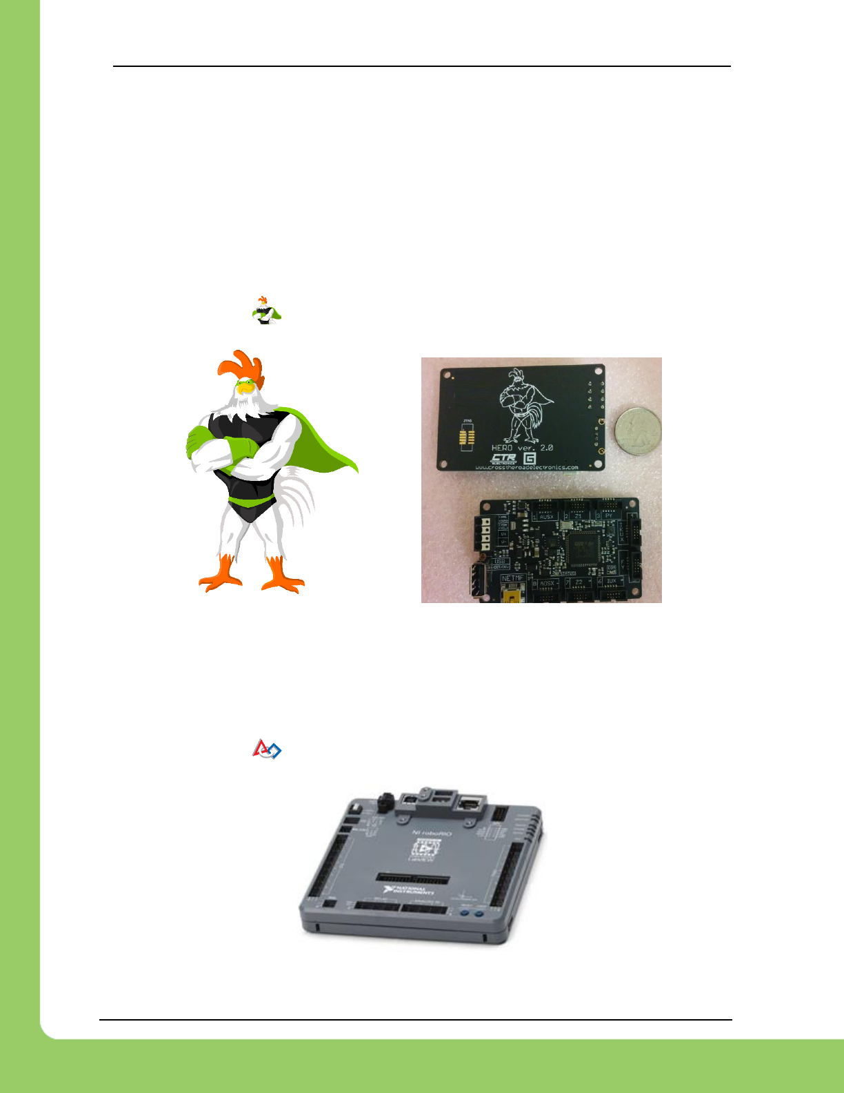
1.1.1. Cross The Road Electronics HERO Control System
The CTR HERO Control System board allows developers to utilize all features of the Talon
SRX. It is meant for education, custom development, and integration of Talon SRX into existing
applications.
The HERO also provides a method for field upgrading Talons to non-FRC firmware. It is the
ideal development kit for learning and integrating the Talon into custom applications!
Applications are developed in Visual Studio 2017 (C#) using .NETMF framework.
Be sure to look for the for HERO related tips.
1.1.2. roboRIO FRC Control System
The only legal robot controller for FRC competition. This requires the FRC version of Talon
SRX firmware. The roboRIO supports CAN bus and provides a Web-based configuration for re-
flashing and diagnostics.
Be sure to look for the for FRC related tips.
217-8080 TALON SRX / Victor SPX Software Reference Manual 3/06/2018
Cross The Road Electronics Page 14 3/06/2018
2. roboRIO Web-based Configuration: Firmware and
diagnostics
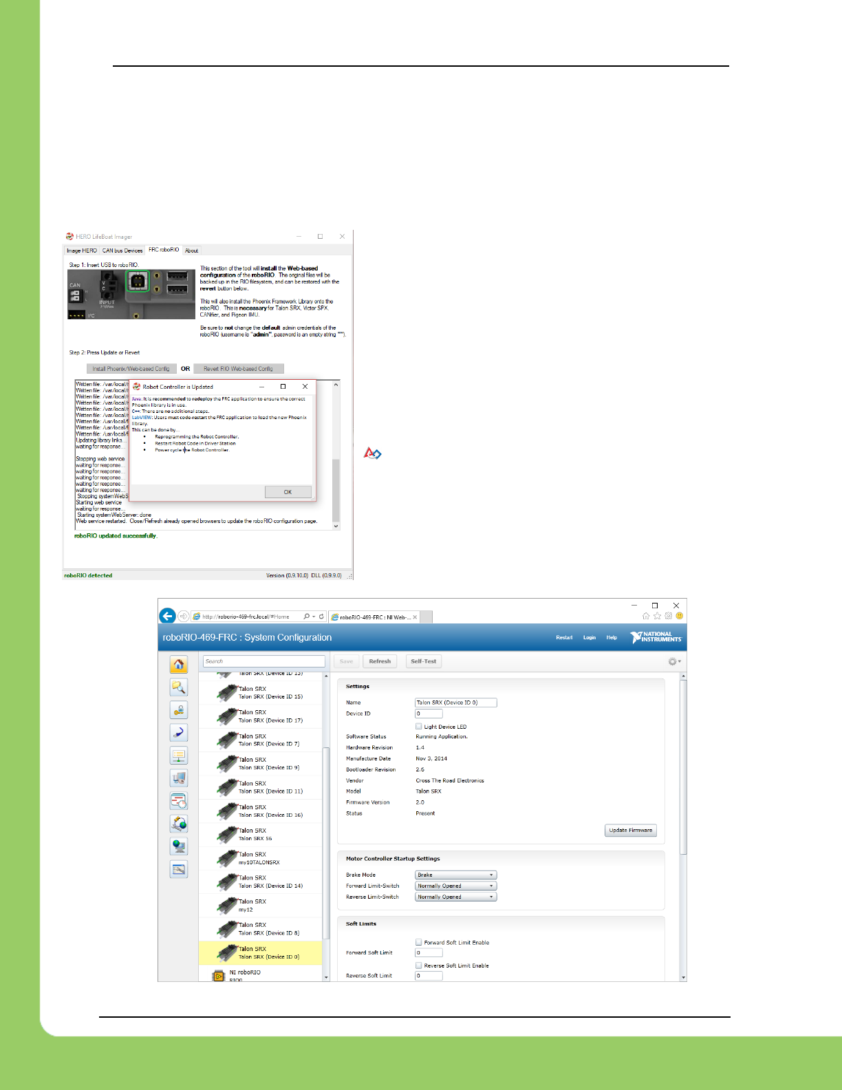
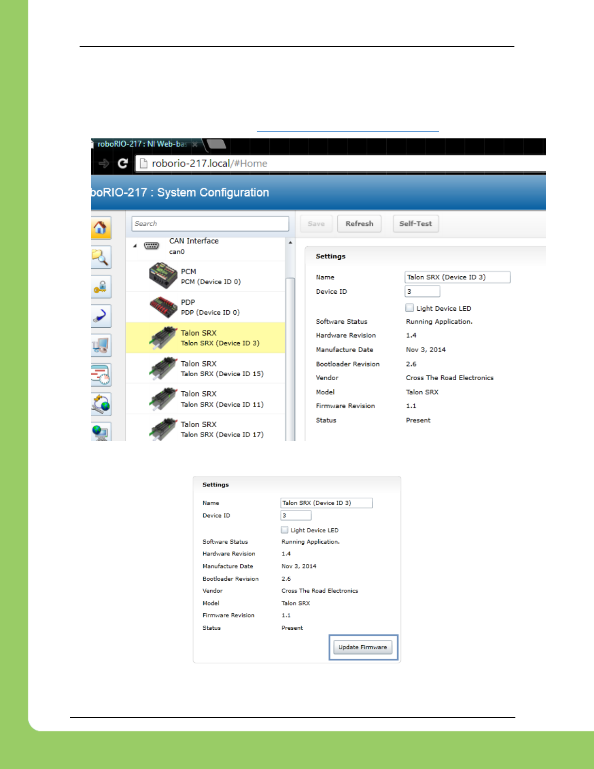
A useful diagnostic feature in the FRC Control system is the roboRIO’s Web-based
Configuration and Monitoring page. This provides diagnostic information on all discovered CAN
devices, including Talon SRXs. Talon SRXs can also be field-upgraded using this interface.
This feature is accessible by entering the mDNS name
of your robot in a web browser, typically roborio-XXXX-
frc.local where XXXX is the team number (no leading
zeros for three digit team numbers).
Web-based Configuration is not installed by default.
User must install Phoenix Framework and run the
roboRIO-Upgrade procedure in Phoenix LifeBoat. The
installer can be found at ctr-electronics.com
Because Chrome no longer supports NPAPI,
Silverlight will not function.
Internet Explorer functions adequately though
refreshing the page (F5 or CNTRL+R) often leaves an
empty page. The workaround is to simple create a new
tab with the same URL.
217-8080 TALON SRX / Victor SPX Software Reference Manual 3/06/2018
Cross The Road Electronics Page 15 3/06/2018
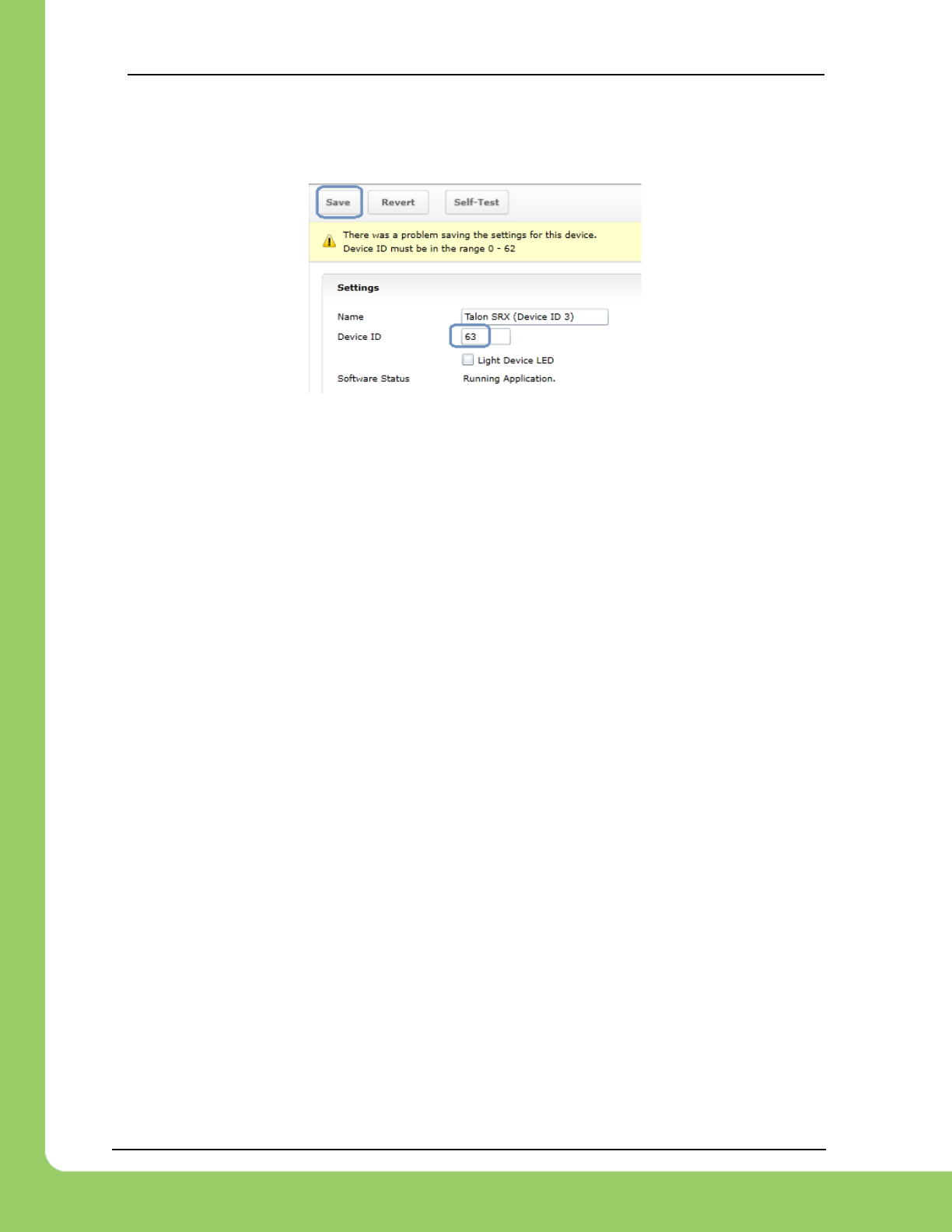
2.1. Device ID ranges
A Talon SRX can have a device ID from 0 to 62. 63 is reserved for broadcast.
If you select an invalid ID, you will get an immediate prompt.
217-8080 TALON SRX / Victor SPX Software Reference Manual 3/06/2018
Cross The Road Electronics Page 16 3/06/2018
2.2. Common ID Talons
During initial setup (and when making changes to your robot), there may be occasions where
the CAN bus contains multiple running Talon SRXs with the same device ID. “Common ID”
Talon SRXs are to be avoided since they prevent reliable communication and prevents your
robot application from being able to distinguish one Talon SRX from another. However, the
roboRIO’s Web-based Configuration and Talon SRX firmware is designed to be tolerant of this
problem condition to a degree.
No two Talon SRXs should have the same ID. No two Victor SPXs should have the same ID.
However, a Talon and Victor can have the same ID.
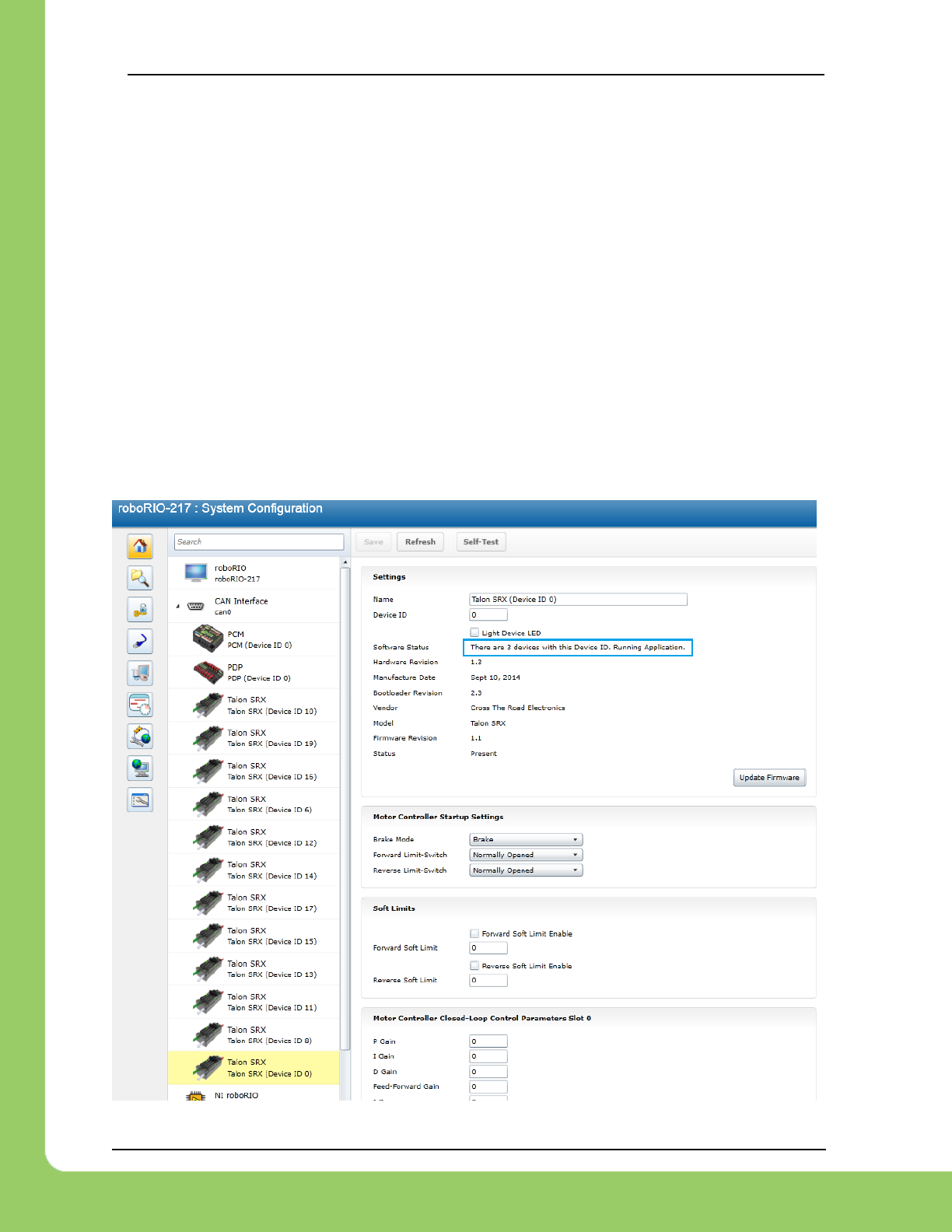
If there are “common ID” Talons, they will reveal themselves as a single tree element (see
image below). In this example, there is only one “Talon SRX (Device ID 0)” graphical element
on the left, however the software status shows that there are three detected Talon SRXs with
that device ID. If the number of “common ID” Talon SRXs is small (typically five or less) you will
still be able to firmware update, modify settings, and change the device ID. This makes solving
device ID contentions possible without having to isolate/disconnect “common ID” Talon SRXs.
217-8080 TALON SRX / Victor SPX Software Reference Manual 3/06/2018
Cross The Road Electronics Page 17 3/06/2018
When “common ID” Talon SRXs are present, correct this condition by changing the device ID to
a “free” number, (one not already in use) before doing anything else. Then manually refresh the
browser. This allows the web page to re-populate the left tree view with a new device ID.
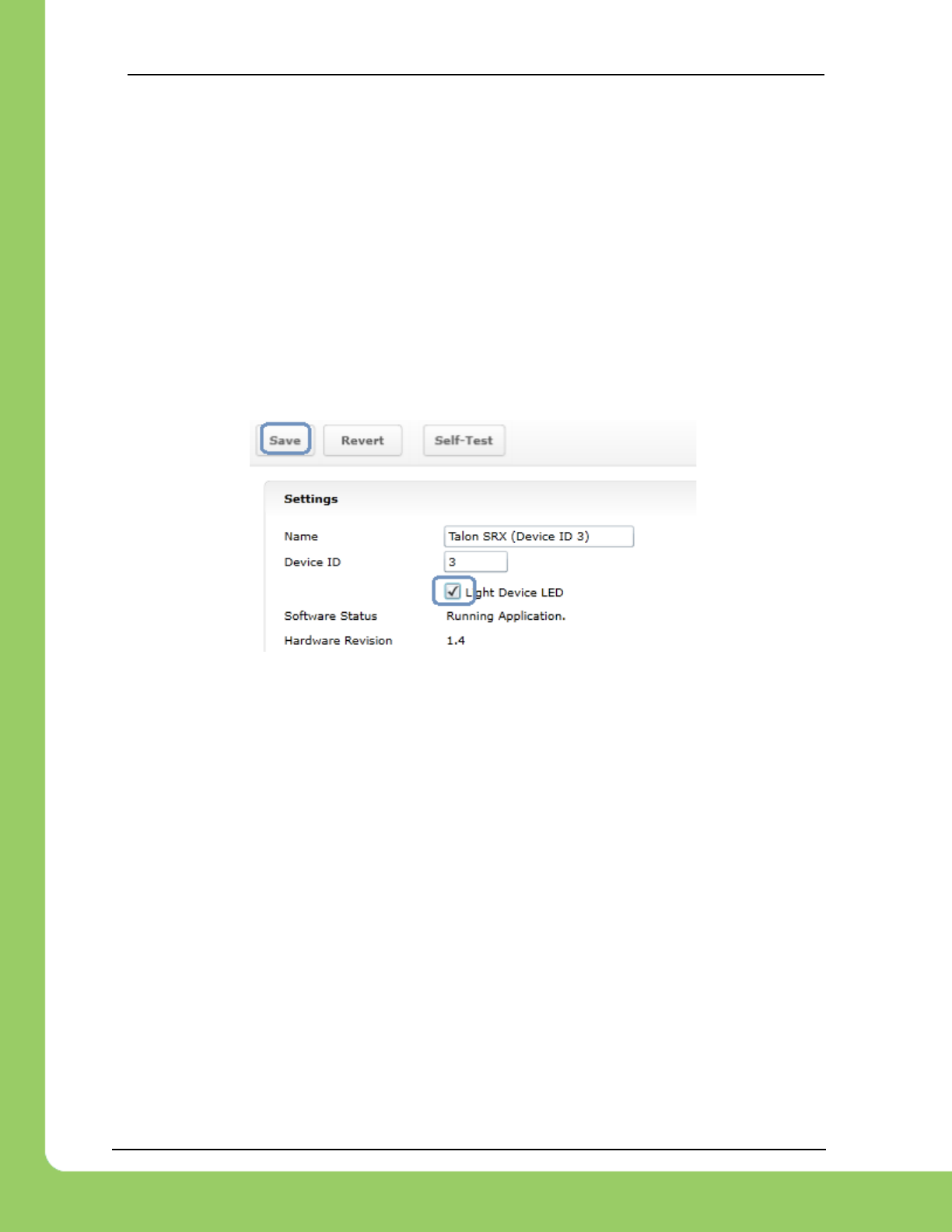
Since the web page allows control of one Talon SRX at a time, you may need to determine
which “common ID” Talon SRX you are modifying. Checking the “Light Device LED” and
pressing “Save” can be used to identify which physical Talon SRX is selected, and therefore
which one will be modified. This will cause the selected Talon SRX to blink its LEDs uniquely
(fast orange blink) for easy identification. In the unlikely event the device is in boot-loader
(orange/green LED), it will still respond to this by increasing the blink rate of the orange/green
pattern. The “Light Device LED” will uncheck itself after pressing “Save”.
2.2.1. Common ID Talons – Light Device LED
Tip: Since the default device ID of an “out of the box” Talon SRX is device ID ‘0’, start assigning
device IDs at ’1’. That way you can, at any time, add another default Talon to your bus and
easily identify it.
Tip: Light Device LED can also be used to clear sticky faults.
217-8080 TALON SRX / Victor SPX Software Reference Manual 3/06/2018
Cross The Road Electronics Page 18 3/06/2018
2.3. Firmware Field-upgrade a Talon SRX / Victor SPX
Talon SRX firmware file is a CRF file. To firmware flash a Talon SRX, navigate to the
following page and select it in the left tree view.
To get the latest firmware files see Section 2.3.4. Where to get CRF files?
Press “Update Firmware”.
217-8080 TALON SRX / Victor SPX Software Reference Manual 3/06/2018
Cross The Road Electronics Page 19 3/06/2018
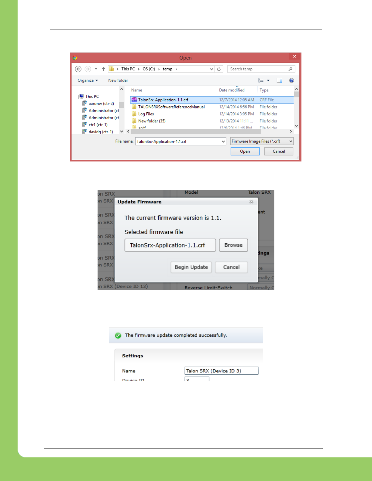
Select the firmware file (*.crf) to flash.
You will be prompted again, press “Begin Update”.
A progress bar will appear and finish with the following prompt. Total time to field-upgrade a
Talon SRX is approximately ten seconds. The progress bar will fill quickly, then pause briefly at
the near end, this is expected.
217-8080 TALON SRX / Victor SPX Software Reference Manual 3/06/2018
Cross The Road Electronics Page 20 3/06/2018
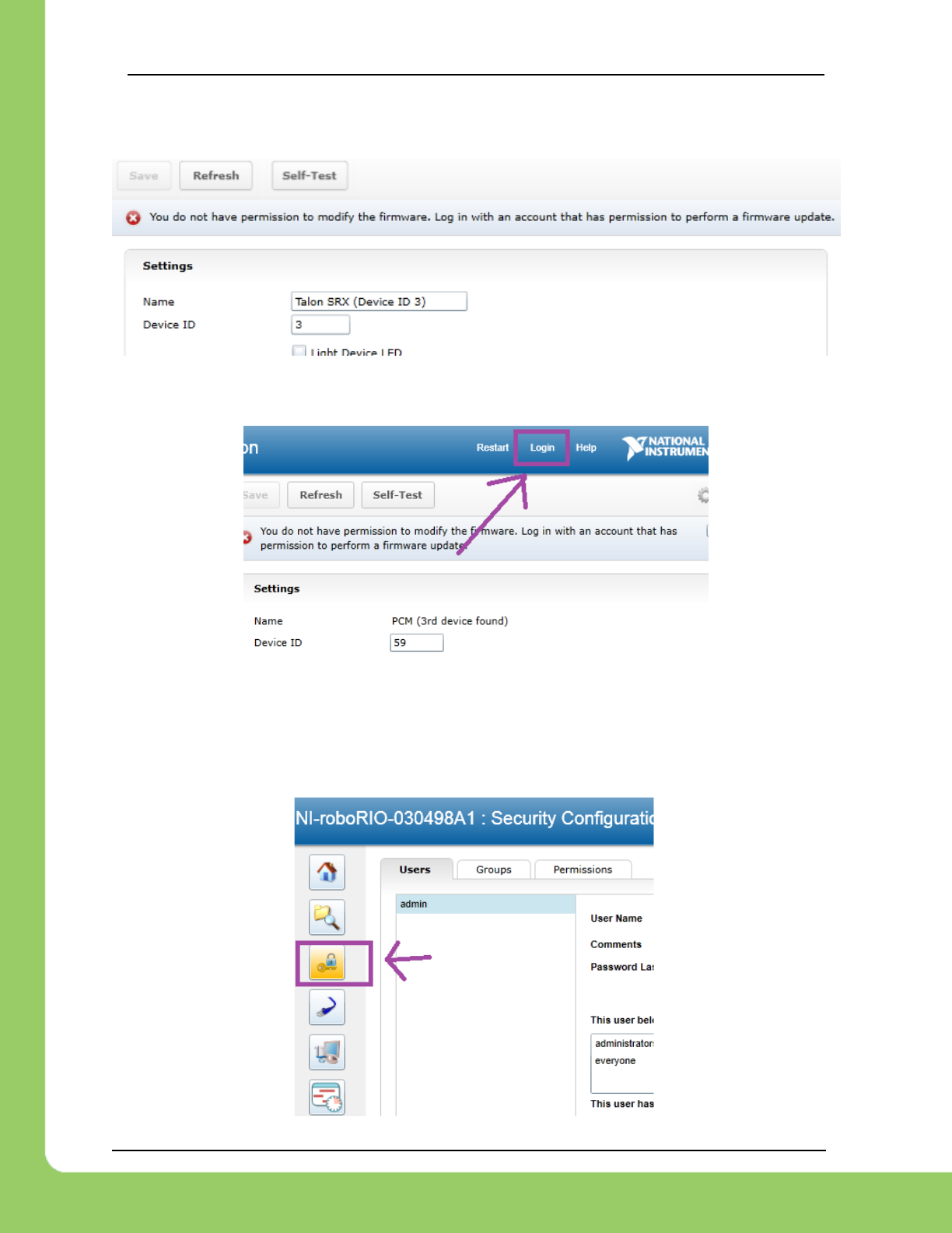
2.3.1. When I update firmware, I get “You do not have permissions…”
If you get the following error…
...then log into the web interface using the username “admin”.
The user name is “admin” and the password is blank “”. Don’t enter any keys for password.
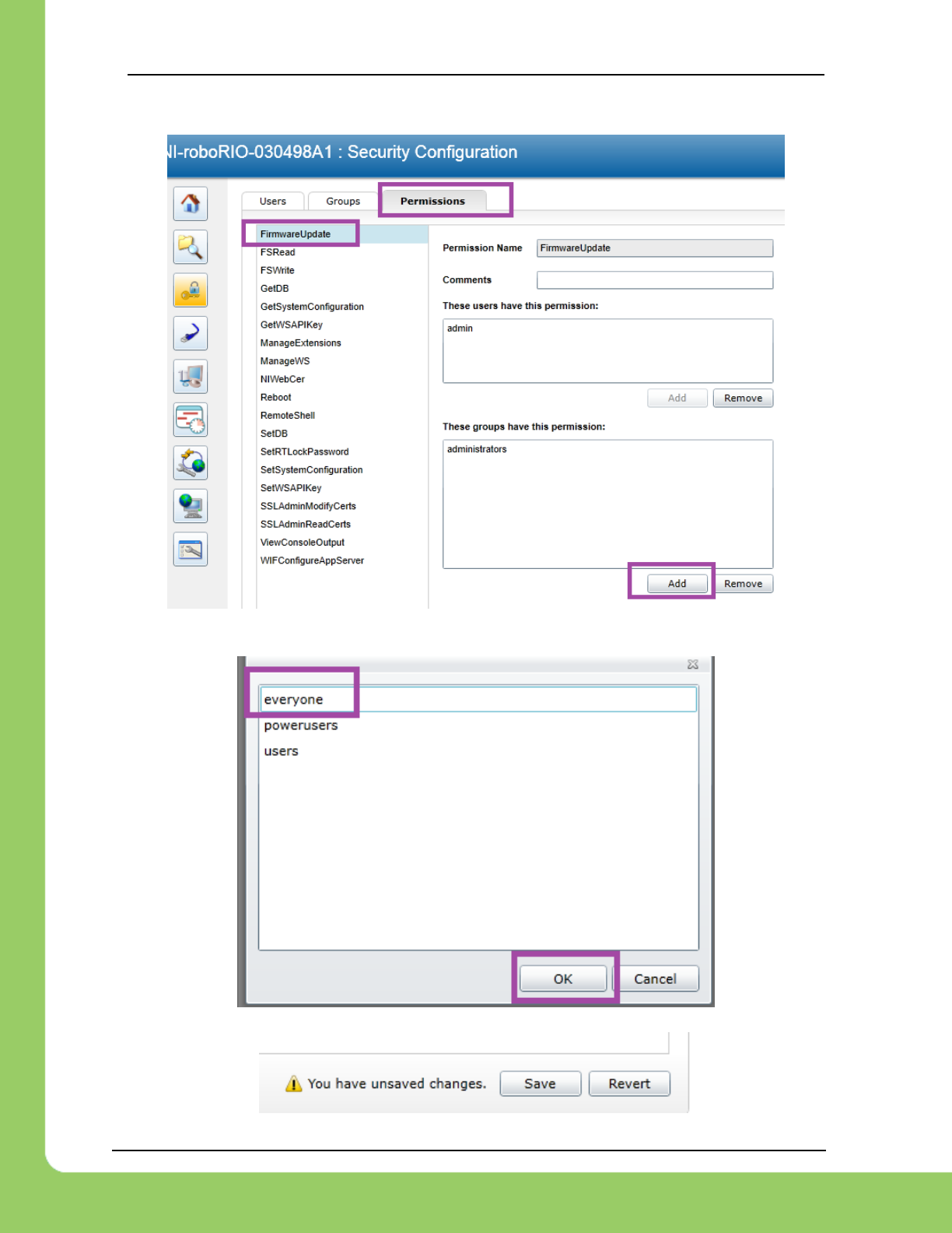
Additionally, you can modify permissions to allow field upgrade without being asked for login
every single time. If security isn’t a concern, then modify the permissions so that “anyone” can
access “FirmwareUpdate” features.
Click on the key/lock icon in the left icon list.
217-8080 TALON SRX / Victor SPX Software Reference Manual 3/06/2018
Cross The Road Electronics Page 21 3/06/2018
Then click on the “Permissions” tab. Select “FirmwareUpdate”, then press “Add” button.
Select everyone, then OK.
Click “Save” to save changes.
217-8080 TALON SRX / Victor SPX Software Reference Manual 3/06/2018
Cross The Road Electronics Page 22 3/06/2018
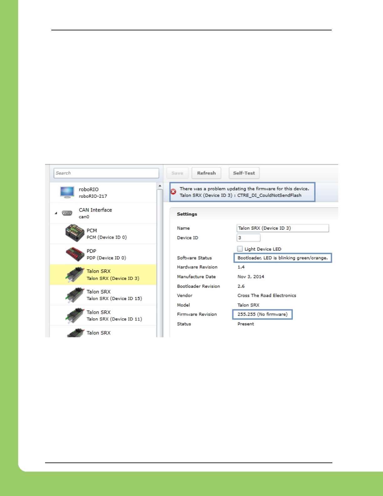
2.3.2. What if Firmware Field-upgrade is interrupted?
Because ten seconds is plenty of time for power or CAN bus to be disconnected, it is always
possible for a field-update to be interrupted. An error code will be reported if the firmware field-
update is interrupted or fails. Additionally, the Software Status will report “Bootloader” and
Firmware Revision will be 255.255 (blank).
If a Talon SRX has no firmware, its boot-loader will take over and blink green/yellow on the
device’s corresponding LED. It will also keep its device ID, so the roboRIO can still be used to
change the device ID or (re)flash a new application firmware (crf). This means you can
reattempt field-upgrade using the same web interface. There is no need for any sort of recovery
steps, nor is it necessary to isolate no-firmware Talon SRXs.
Example capture of disconnecting the CAN bus in the middle of a firmware-upgrade…
217-8080 TALON SRX / Victor SPX Software Reference Manual 3/06/2018
Cross The Road Electronics Page 23 3/06/2018
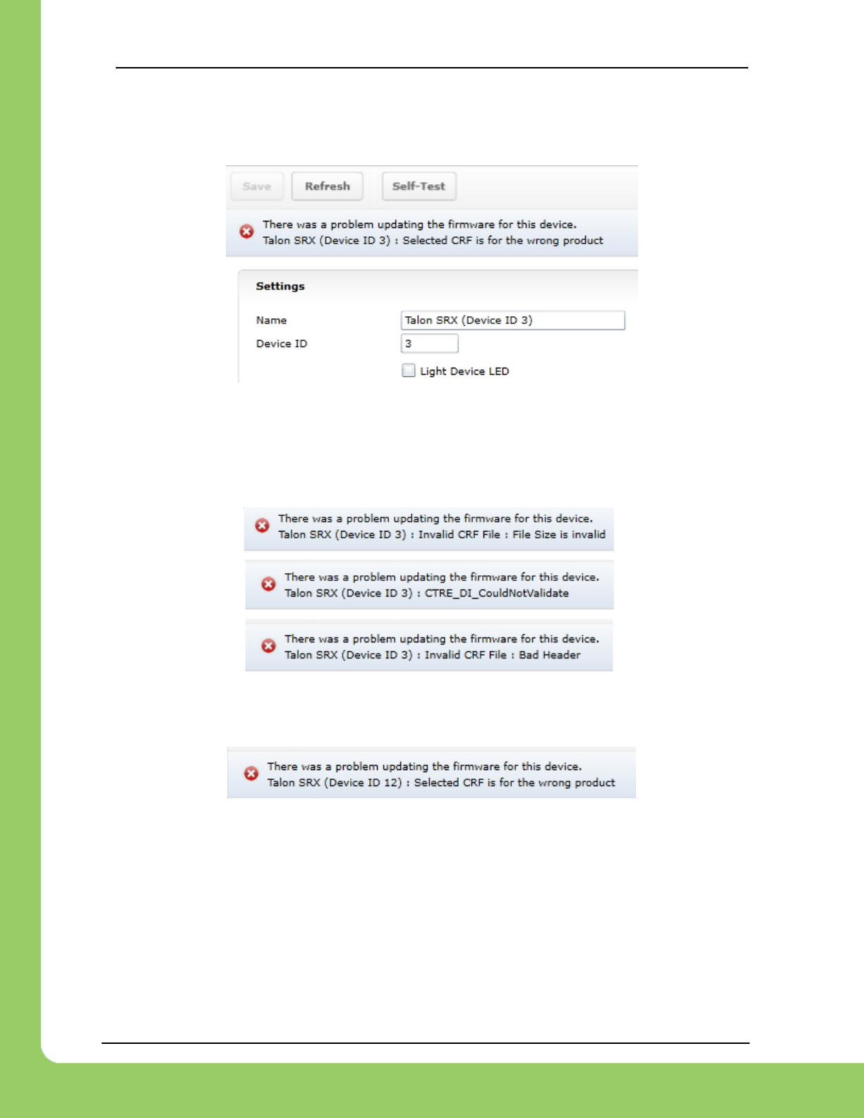
2.3.3. Other Field-upgrade Failure Modes
Here’s an example error when trying to flash the wrong CRF into the wrong product.
The device will harmlessly stay in boot-loader, ready to be (re)flashed again.
Here’s what to expect if your CRF file is corrupted (different errors depending on where the file
is corrupted). The device will harmlessly stay in boot-loader, ready to be (re)flashed again. Re-
downloading the CRF firmware file is recommended if this is occurring persistently.
Here’s what to expect if you flash the wrong product’s CRF. For example, if you try to flash the
CRF for the Power Distribution Panel (PDP) into a Talon SRX, you will get an error prompt.
217-8080 TALON SRX / Victor SPX Software Reference Manual 3/06/2018
Cross The Road Electronics Page 24 3/06/2018
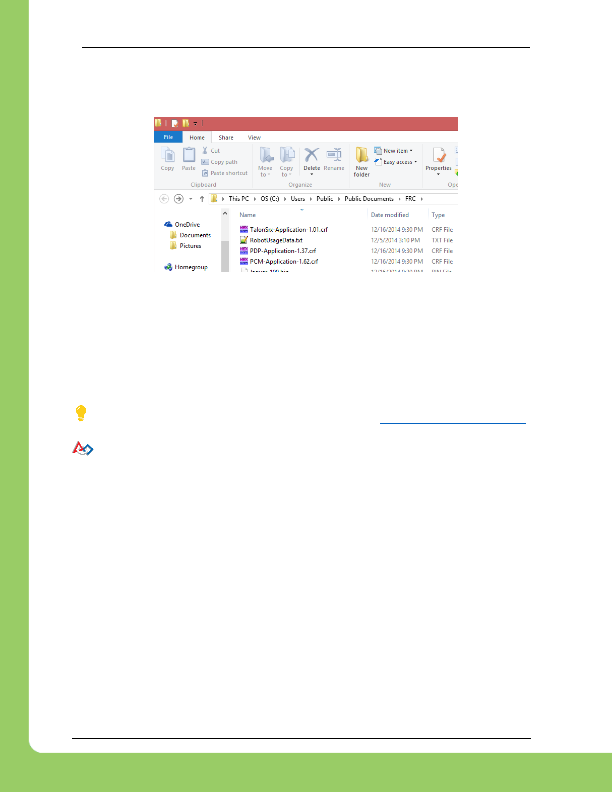
2.3.4. Where to get CRF files?
The FRC Software installer will create a directory with various firmware files/tools for many
control system components. Typically, the path is “C:\Users\Public\Documents\FRC”.
When the path is entered, the browser may fix-up the path into “C:\Users\Public\Public
Documents\FRC”. This is typical in Windows.
In this directory are the initial release firmware CRF files for all CTRE CAN bus devices, including
the Talon SRX.
The latest firmware to be used at time of writing is version 3.X (where X is the minor version).
TIP: Additionally, newer updates may be provided online at http://www.ctr-electronics.com.
FRC: Be sure to watch for team updates for what is legal and required!
217-8080 TALON SRX / Victor SPX Software Reference Manual 3/06/2018
Cross The Road Electronics Page 25 3/06/2018
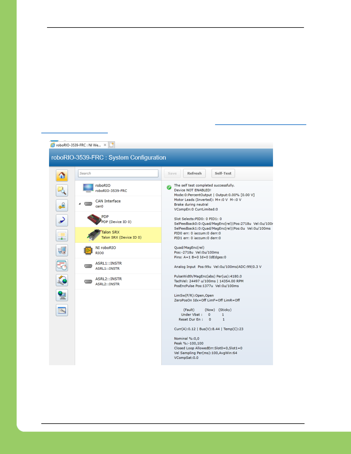
2.4. Self-Test
Pressing Self-Test will display data captured from CAN bus at the time of press. This can
include fault states, sensor inputs, output states, measured battery voltage, etc.
At the bottom of the Self-Test results, the build time of the library that implements web-based
CAN features is also present.
Here’s an example of pressing “Self-Test” with Talon SRX. Be sure to check if Talon SRX is
ENABLED or DISABLED. If Talon SRX is DISABLED, then either the robot is disabled or the
robot application has not yet created a Talon SRX object (see Section 3. Creating a Talon SRX
Object (and basic drive) .
217-8080 TALON SRX / Victor SPX Software Reference Manual 3/06/2018
Cross The Road Electronics Page 26 3/06/2018
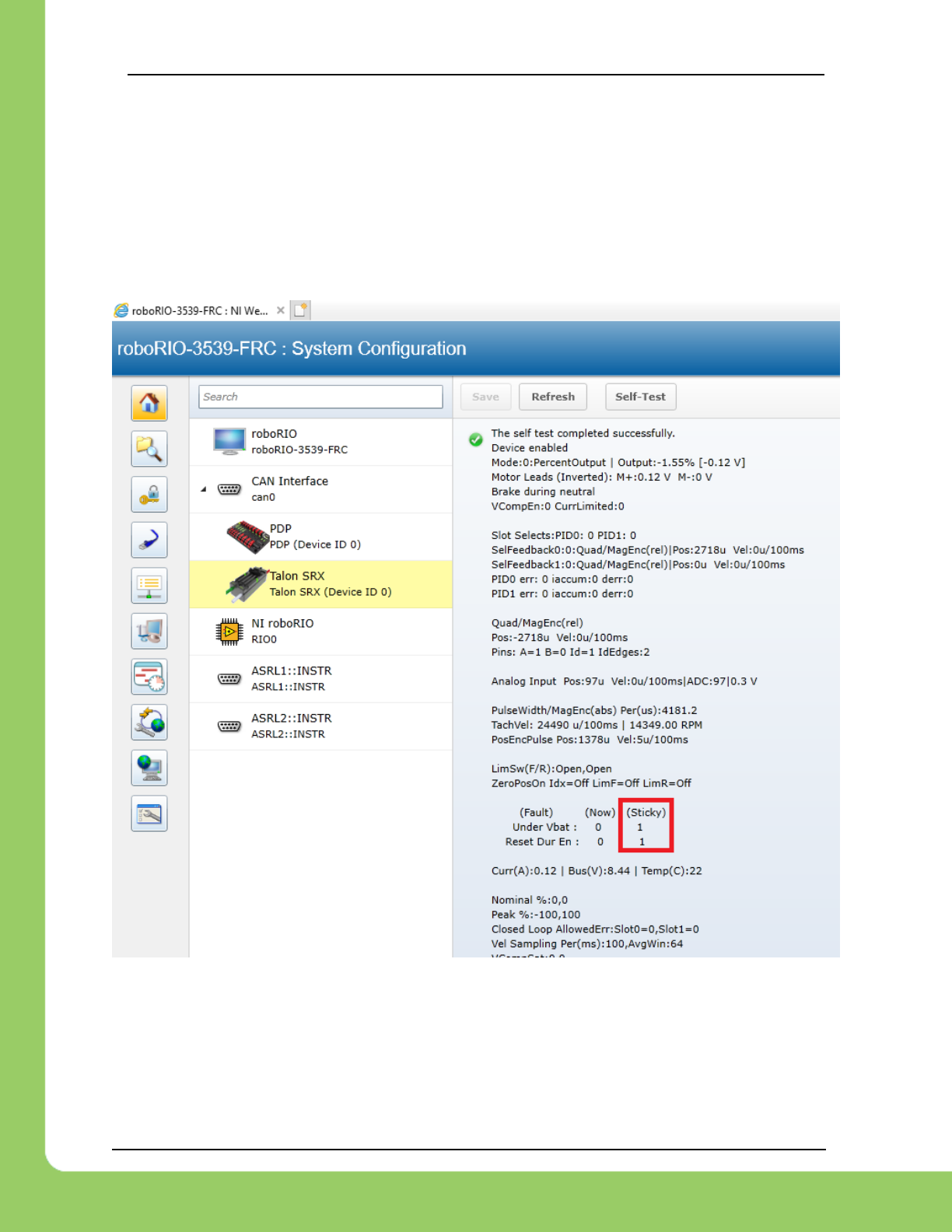
After enabling the robot and repressing “Self-Test” we see the Talon SRX is enabled.
Additionally, we see there is a sticky fault asserted for low battery voltage and reset during
enable (talon was powered cycled during robot enable).
Sticky faults persist across power cycles for identifying intermittent problems after they occur.
They can be cleared via robot API, or via the “Light Device ID” checkbox.
217-8080 TALON SRX / Victor SPX Software Reference Manual 3/06/2018
Cross The Road Electronics Page 27 3/06/2018
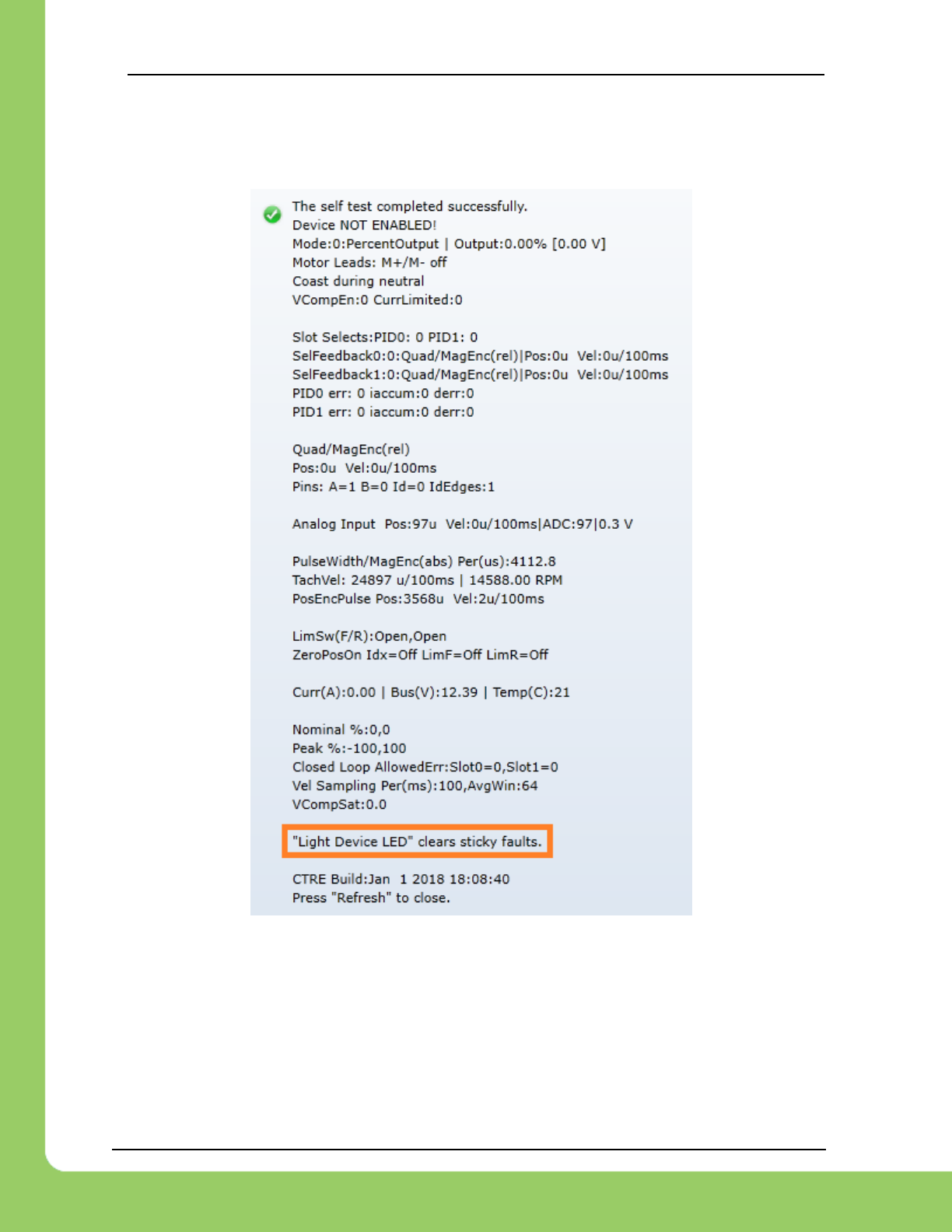
2.4.1. Clearing Sticky Faults
Use the “Light Device LED” checkbox to clear the sticky faults and illuminate the device LEDs
(rapid orange blink).

217-8080 TALON SRX / Victor SPX Software Reference Manual 3/06/2018
Cross The Road Electronics Page 28 3/06/2018
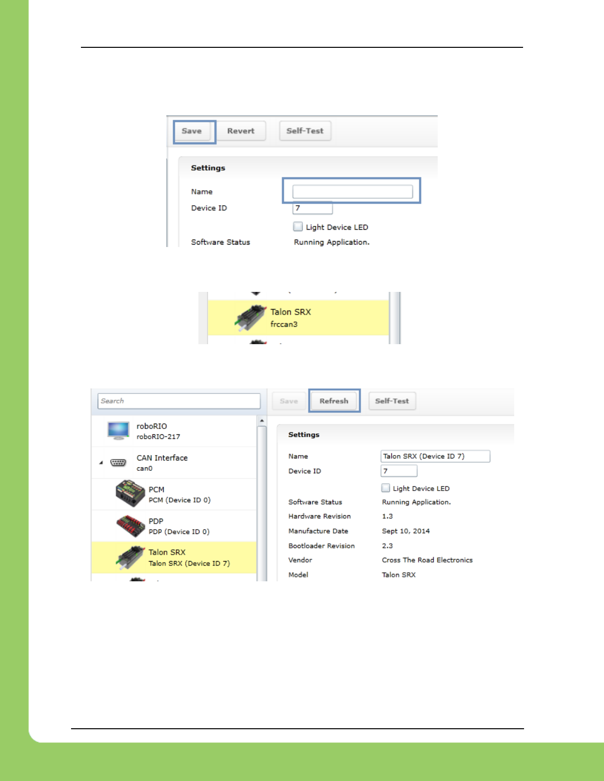
2.5. Custom Names
Another feature made available by the Web-based Configuration is the ability to rename Talon
SRXs with custom string descriptions. A Talon SRX’s custom name is saved persistently inside
the Talon. To modify the default name, highlight the contents of the “Name” text entry.
…then replace with a custom text description and press “Save”.
The new description will appear in the left tree view.
217-8080 TALON SRX / Victor SPX Software Reference Manual 3/06/2018
Cross The Road Electronics Page 29 3/06/2018
2.5.1. Re-default custom name
To re-default the custom name, clear the “Name” text entry and press “Save”.
Left tree view will update with a temporary name until the “Refresh” button is pressed.
After pressing “Refresh” the default name will appear.
217-8080 TALON SRX / Victor SPX Software Reference Manual 3/06/2018
Cross The Road Electronics Page 30 3/06/2018
3. Creating a Talon Object (and the basics)
3.1. Programming API and Device ID
Regardless of what language you use on the FRC control system (LabVIEW/C++/Java), the
method for specifying which Talon SRX you are programmatically controlling is the device ID.
Although the roboRIO Web-based Configuration is tolerant of “common ID” Talon SRXs to a
point, the robot programming API will not enable/control “common ID” Talons reliably. For the
robot to function properly, there CANNOT BE “COMMON ID” Talon SRXs. See Section 2.2.
Common ID Talons for more information.
TIP: Example projects for Talon SRX can also be found in the CTR GitHub account.
https://github.com/CrossTheRoadElec/Phoenix-Examples-LabVIEW
https://github.com/CrossTheRoadElec/Phoenix-Examples-Languages
Additional documentation may be found here…
https://github.com/CrossTheRoadElec/Phoenix-Documentation
3.1.1. Including Libraries (FRC)
To use Talon SRX libraries, FRC Teams need to download and install the Phoenix Framework
v5, which can be found on the CTR Electronics website.
Once the libraries have been installed, users can simply add them to their project using
standard import/include statements.
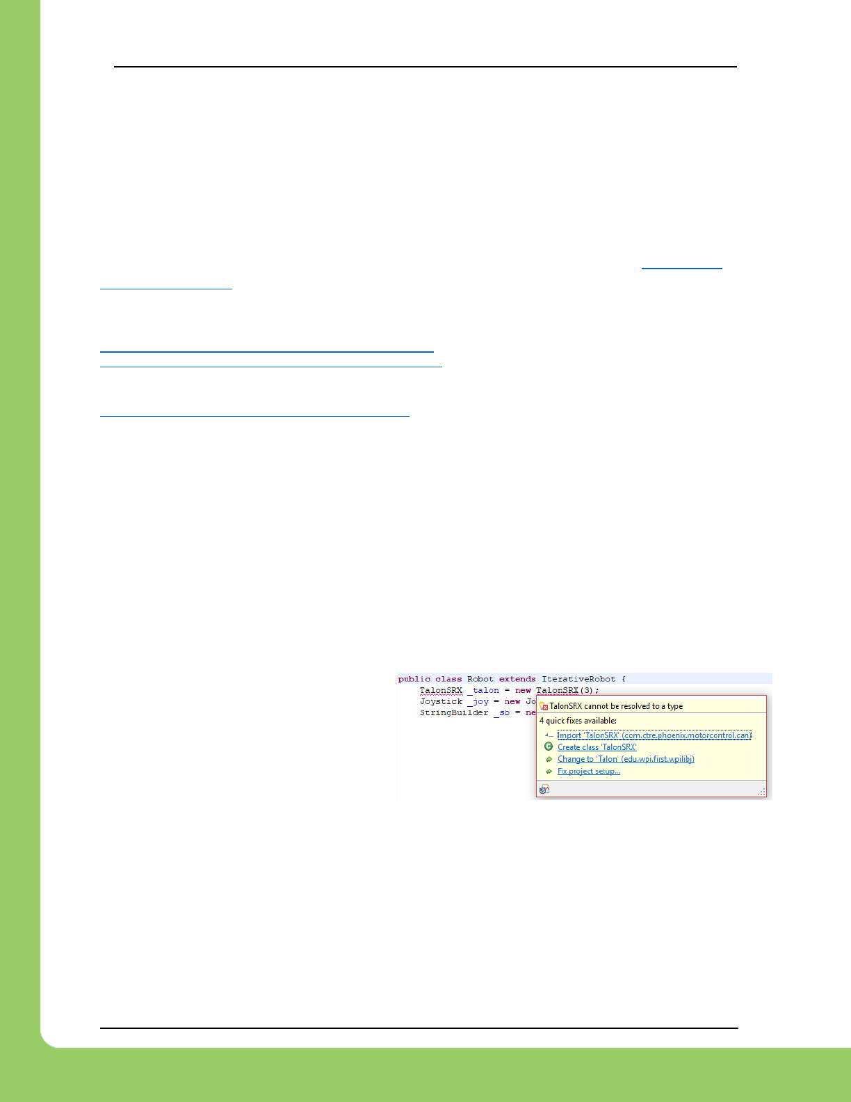
For Java, users should add an import statement as follows:
import com.ctre.phoenix.motorcontrol.can.TalonSRX;
If using Eclipse IDE, typically the IDE will
recommend imports as class names are
typed into the Java source. Click on
Import ‘TalonSRX’ to auto insert the
import line.
For C++, users should add the single include for Phoenix.
#include "ctre/Phoenix.h"
LabVIEW users will find the CAN Talon SRX VIs in a new CTRE subpalette.

217-8080 TALON SRX / Victor SPX Software Reference Manual 3/06/2018
Cross The Road Electronics Page 31 3/06/2018
3.1.2. Configuration API
Talon SRX and Victor SPX have many configuration functions / VIs.
These are recognizable as having the config* prefix, and a trailing parameter called timeoutMs.
These functions manipulate parameters that are persistent within the motor controller, and
therefore do not need to be called periodically unless the parameter value is genuinely changing
as a requirement of the robot (which is not typical).
As an example, functions such as configOpenloopRamp and configClosedloopRamp exist to
allow for once-on-boot configuration without having to continually change the ramp depending
on use.
3.1.2.1. Configuration API - timeoutMs
Since most config* calls occur during the robot boot sequence, the recommended value for
timeoutMs is 10 (ms). This ensures that each config will wait up to 10ms to ensure the
configuration was applied correctly, otherwise an error message will appear on the Driver
station.
This is also the case for setting/homing sensor values.
For configuration calls that are done during the robot loop, the recommended value for
timeoutMs is zero, which ensures no blocking or checking is performed (identical to the
implementation in previous seasons).
3.1.2.2. Factory Default
The configuration values can be factory defaulted by holding the B/C CAL on power boot and
confirming rapid green LEDs.
This will default all configurable parameters except for device ID and neutral brake.
This should be done when replacing/swapping TalonSRXs/VictorSPXs, otherwise the developer
will need to set every config routine to ensure all parameters are set to the desired values.
217-8080 TALON SRX / Victor SPX Software Reference Manual 3/06/2018
Cross The Road Electronics Page 32 3/06/2018
3.2. New Classes/Virtual Instruments
C++/Java now contains a new class TalonSRX (.h/.cpp/.java). CANTalon has been replaced
with TalonSRX.
Java TalonSRX and parent class is documented….
http://www.ctr-electronics.com/downloads/api/java/html/com/ctre/phoenix/motorcontrol/can/TalonSRX.html
http://www.ctr-electronics.com/downloads/api/java/html/com/ctre/phoenix/motorcontrol/can/BaseMotorController.html
C++ TalonSRX and parent class is documented….
http://www.ctr-electronics.com/downloads/api/cpp/html/classctre_1_1phoenix_1_1motorcontrol_1_1can_1_1_talon_s_r_x.html
http://www.ctr-electronics.com/downloads/api/cpp/html/classctre_1_1phoenix_1_1motorcontrol_1_1can_1_1_base_motor_controller.html
3.2.1. WPILIB Class integration
Note: To use the various WPILIB features (Motor-safety, drive train classes, LiveWindow, etc),
developers should use the WPI_TalonSRX and WPI_VictorSPX classes. These are
subclasses that implement the various WPILIB interfaces. This also includes a single
parameter set() that defaults the motor controller into PercentOutput mode.
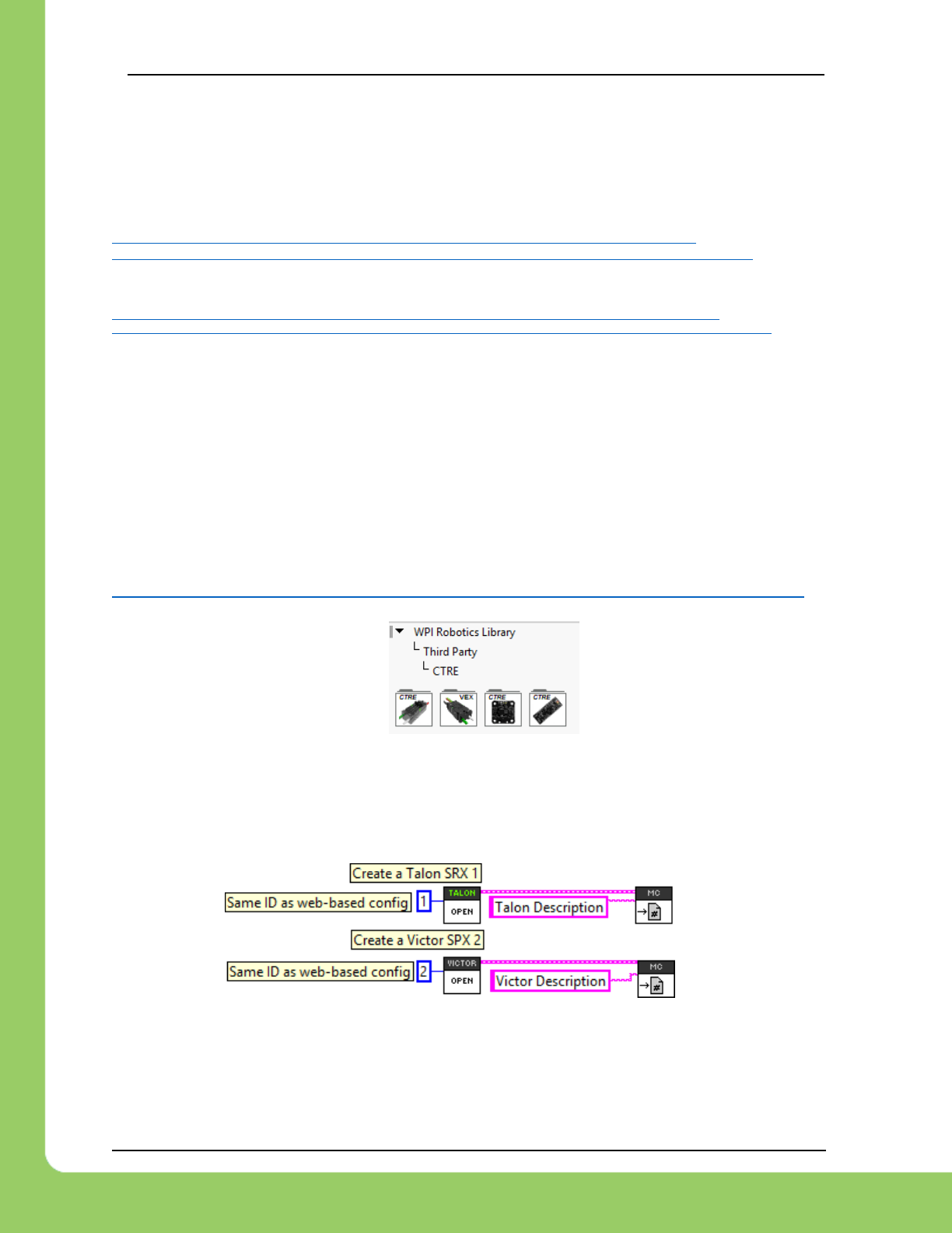
LabVIEW contains a new palette for Victor SPX and Talon SRX.
The VI locations are documented here….
https://github.com/CrossTheRoadElec/Phoenix-Documentation#labview---where-are-the-vis
3.2.2. LabVIEW
Creating a “bare-bones” Talon SRX or Victor SPX object is similar to previously supported
motor controllers. Start by using the OPEN VI and register a unique motor description.
Create a constant for the “Device Number. The control mode is set later via the SET vi. Enter
the appropriate Device ID that was selected in the roboRIO Web-based Configuration.
Also, similarly to other motor controllers, you may register a custom string reference to
reference the motor controller by description in other block diagrams.
217-8080 TALON SRX / Victor SPX Software Reference Manual 3/06/2018
Cross The Road Electronics Page 33 3/06/2018
3.2.3. C++
When using a programming language, the API classes for the CAN Motor controllers are called
TalonSRX/ VictorSPX (.cpp/.h/.java). When the object is constructed, the device ID is the
single parameter.
Note: use WPI_TalonSRX/WPI_VictorSPX instead, when using WPILIB features such as
motor-safety or drivetrain objects.
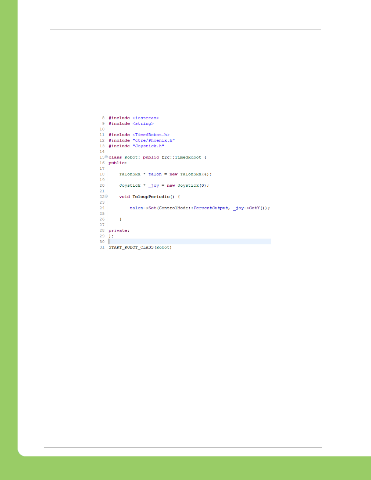
3.2.4. Java
When a TalonSRX/VictorSPX object is constructed in Java, the device ID is the first parameter.
Note: use WPI_TalonSRX/WPI_VictorSPX instead, when using WPILIB features such as
motor-safety or drivetrain objects.
public class Robot extends IterativeRobot {
TalonSRX talon = new TalonSRX(4);
Joystick joy = new Joystick(0);
/**
* This function is called periodically during operator control.
*/
@Override
public void teleopPeriodic() {
talon.set(ControlMode.PercentOutput, joy.getY());
}
217-8080 TALON SRX / Victor SPX Software Reference Manual 3/06/2018
Cross The Road Electronics Page 34 3/06/2018
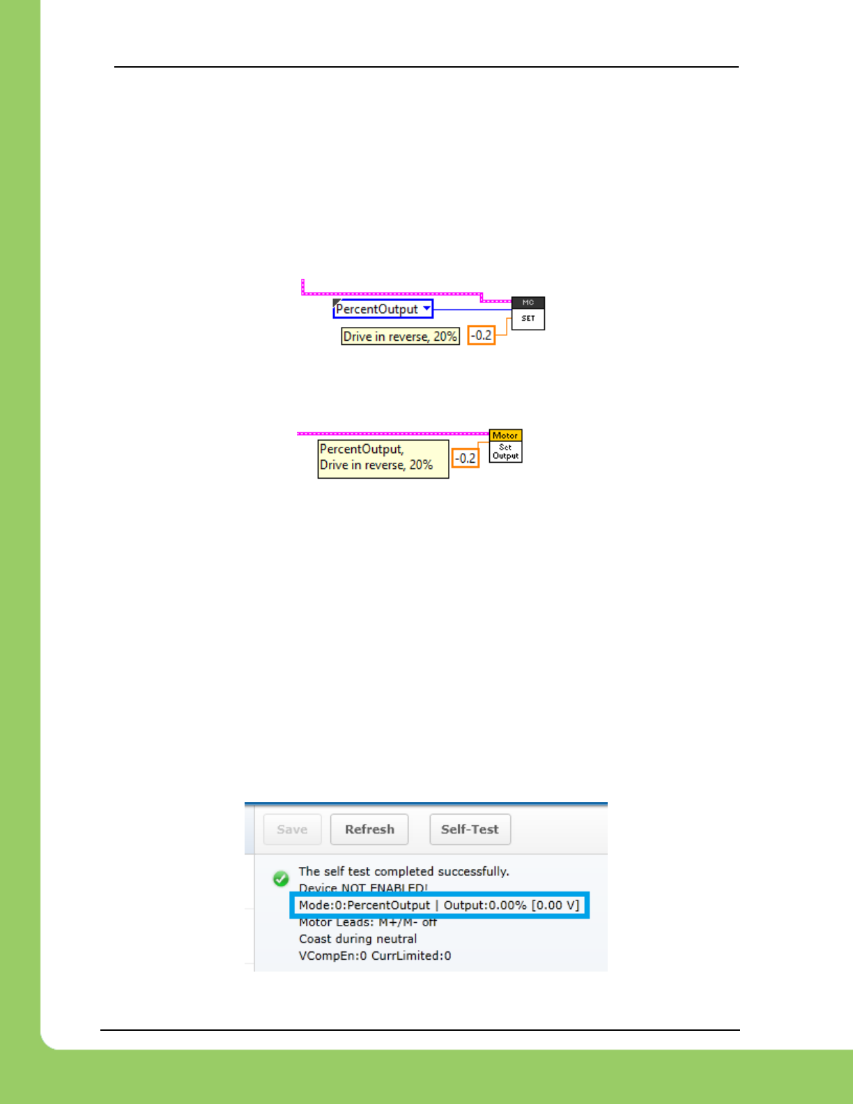
3.3. Setting Output Mode and Value
After a Talon software object is created, the Talon SRX mode and output can be changed using
the Set routine/VI. This season’s set routine takes both the Control Mode and the output
parameter. Because the output value is dependent on the control mode, the user must specify
both. This produces cleaner robot code that is simpler to troubleshoot.
3.3.1. LabVIEW
The control mode and output is specified using the same SET VI. Select PercentOutput to
directly control the output. The SET value is the percent output with a range of [-1,1].
Note when using the standard Set Output VI, the control mode is set to PercentOutput. This is
because the Set Output VI was designed for “simple” motor controllers.
3.3.2. C++
The function Set() can be used to change the Talon SRX mode and output value.
talon.Set(ControlMode.PercentOutput, joy.getY());
3.3.3. Java
The function set() can be used to change the Talon SRX mode and output value.
talon.set(ControlMode.PercentOutput, joy.getY());
3.3.4. Check Control Mode with Self-Test
The Self-Test can be used to confirm the desired mode of the Talon SRX (PercentOutput,
Follower, Position Closed-Loop, Velocity Closed-Loop, etc.).
Example Self-Test
217-8080 TALON SRX / Victor SPX Software Reference Manual 3/06/2018
Cross The Road Electronics Page 35 3/06/2018
3.4. WPILib RobotDrive Class
The Robotdrive class is maintained by WPILib. Any source intended to use these classes
should create WPI_TalonSRX and WPI_VictorSPX objects. These classes inherit the
TalonSRX and Victor SPX classes, and implement the various WPILib interfaces.
3.4.1. LabVIEW
The RoboDrive Vis are typically located in WPI Robotics Library -> RobotDrive.
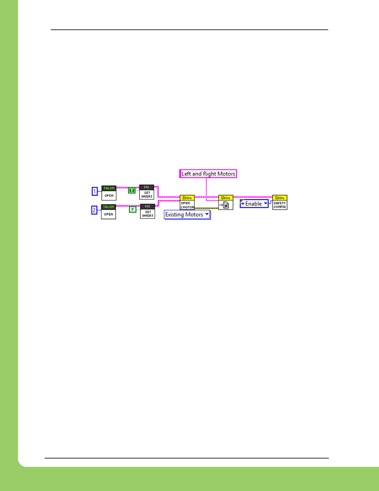
To use Talon SRX with either the 2 or 4 motor options, first use a Talon SRX Open Motor VI.
The RefNum output is then wired to the input of the Open 2/4 Motor VI when the “Existing
Motors” drop-down option is selected. The RobotDrive RefNum Set is then used as normal.
3.4.2. C++
RobotDrive is included in WPILib.h. Construct the appropriate WPI_TalonSRX objects and pass
them to the RobotDrive constructor.
FrontLeftMotor = new WPI_TalonSRX(1);
FrontRightMotor = new WPI_TalonSRX(2);
RearLeftMotor = new WPI_TalonSRX(3);
RearRightMotor = new WPI_TalonSRX(4);
drive = new RobotDrive(FrontLeftMotor, RearLeftMotor, FrontRightMotor,
RearRightMotor);
3.4.3. Java
RobotDrive is included in WPILib. Construct the appropriate WPI_TalonSRX objects and pass
them to the RobotDrive constructor.
FrontLeftMotor = new WPI_TalonSRX(1);
FrontRightMotor = new WPI_TalonSRX(2);
RearLeftMotor = new WPI_TalonSRX(3);
RearRightMotor = new WPI_TalonSRX(4);
drive = new RobotDrive(FrontLeftMotor, RearLeftMotor, FrontRightMotor,
RearRightMotor);

217-8080 TALON SRX / Victor SPX Software Reference Manual 3/06/2018
Cross The Road Electronics Page 36 3/06/2018
4. Limit Switch and Neutral Brake Mode
4.1. Default Settings
An “out of the box” Talon will default with the limit switch setting of “Normally Open” for both
forward and reverse. This means that motor drive is allowed when a limit switch input is not
closed (i.e. not connected to ground). When a limit switch input is closed (is connected to
ground) the Talon SRX will disable motor drive and individually blink both LEDs red in the
direction of the fault (red blink pattern will move towards the M+/white wire for positive limit fault,
and towards M-/green wire for negative limit fault).
An “out of the box” Talon SRX will typically have a default brake setting of “Brake during
neutral”. The B/C CALL button will be illuminated red (brake enabled).
Since an “out of the box” Talon will likely not be connected to limit switches (at least not initially)
and because limit switch inputs are internally pulled high (i.e. the switch is open), the limit switch
feature is default to “normally open”. This ensures an “out of the box” Talon will drive even if no
limit switches are connected.
For more information on Limit Switch wiring/setup, see the Talon SRX User’s Guide.
Forward
Limit Switch
Mode
Limit
Switch
NO pin
Limit
Switch
NC pin
Limit
Switch
COM pin
Motor Drive
Switch open
Fwd. output
Motor Drive
Switch closed
Fwd. output
*Voltage
(Switch
Open)
*Voltage
(Switch
Closed)
Normally
Open
pin4
N.A.
pin10
Y
N
~2.5V
0 V
Normally
Closed
N.A.
pin4
pin10
N
Y
0 V
~2.5V
Disabled
N.A.
N.A.
N.A.
Y
Y
N.A.
N.A.
Reverse
Limit Switch
Mode
Limit
Switch
NO pin
Limit
Switch
NC pin
Limit
Switch
COM pin
Motor Drive
Switch open
Rev. output
Motor Drive
Switch closed
Rev. output
*Voltage
(Switch
Open)
*Voltage
(Switch
Closed)
Normally
Open
pin8
N.A.
pin10
Y
N
~2.5V
0 V
Normally
Closed
N.A.
pin8
pin10
N
Y
0 V
~2.5V
Disabled
N.A.
N.A.
N.A.
Y
Y
N.A.
N.A.
*Measured voltage at the Talon SRX Limit Switch Input pin.
Limit Switch Input Forward Input - pin4 on Talon SRX
Limit Switch Input Reverse Input - pin8 on Talon SRX
Limit Switch Ground - pin10 on Talon SRX
217-8080 TALON SRX / Victor SPX Software Reference Manual 3/06/2018
Cross The Road Electronics Page 37 3/06/2018
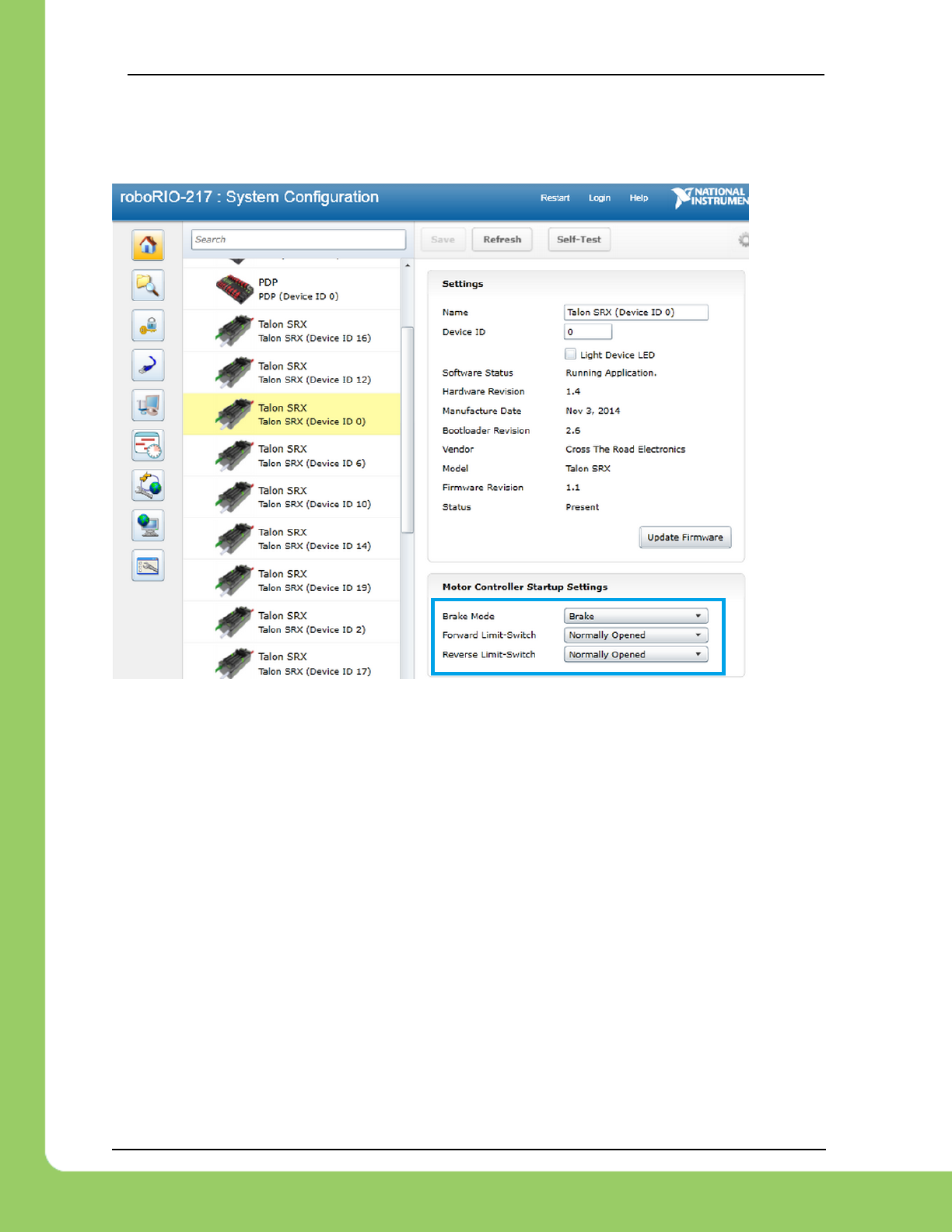
4.2. roboRIO Web-based Configuration: Limit Switch and Brake
Limit switch features can be disabled or changed to “Normally Closed” in the roboRIO Web-
based Configuration. Similarly, the neutral brake mode can be selected.
Changing the settings will take effect once the “Save” button is pressed. The settings are saved
in persistent memory.
If the Brake or Limit Switch mode is changed in the roboRIO Web-based Configuration, the
Talon SRX will momentarily disable then resume motor drive. All other settings can be changed
without impacting the motor drive or enabled-state of the Talon SRX.
Additionally, the brake mode can be modified by pressing the B/C CAL Button on the Talon SRX
itself, just like with previous generation Talons.
217-8080 TALON SRX / Victor SPX Software Reference Manual 3/06/2018
Cross The Road Electronics Page 38 3/06/2018
4.3. Overriding Brake and Limit Switch with API
The Brake and Limit Switch can be changed programmatically (during a match). A great
example of this would be for dynamic braking.
The programming API allows for overriding the active neutral brake mode. When this is done
the Brake/Coast LED will reflect the overridden value (illuminated red for brake, off for coast)
regardless of the startup brake mode specified in the roboRIO Web-based Configuration (i.e.
what’s saved in persistent memory).
Similarly, the enabled states of the limit switches (on/off) for the forward and reverse direction
can be enabled/disabled by overriding them with programming API.
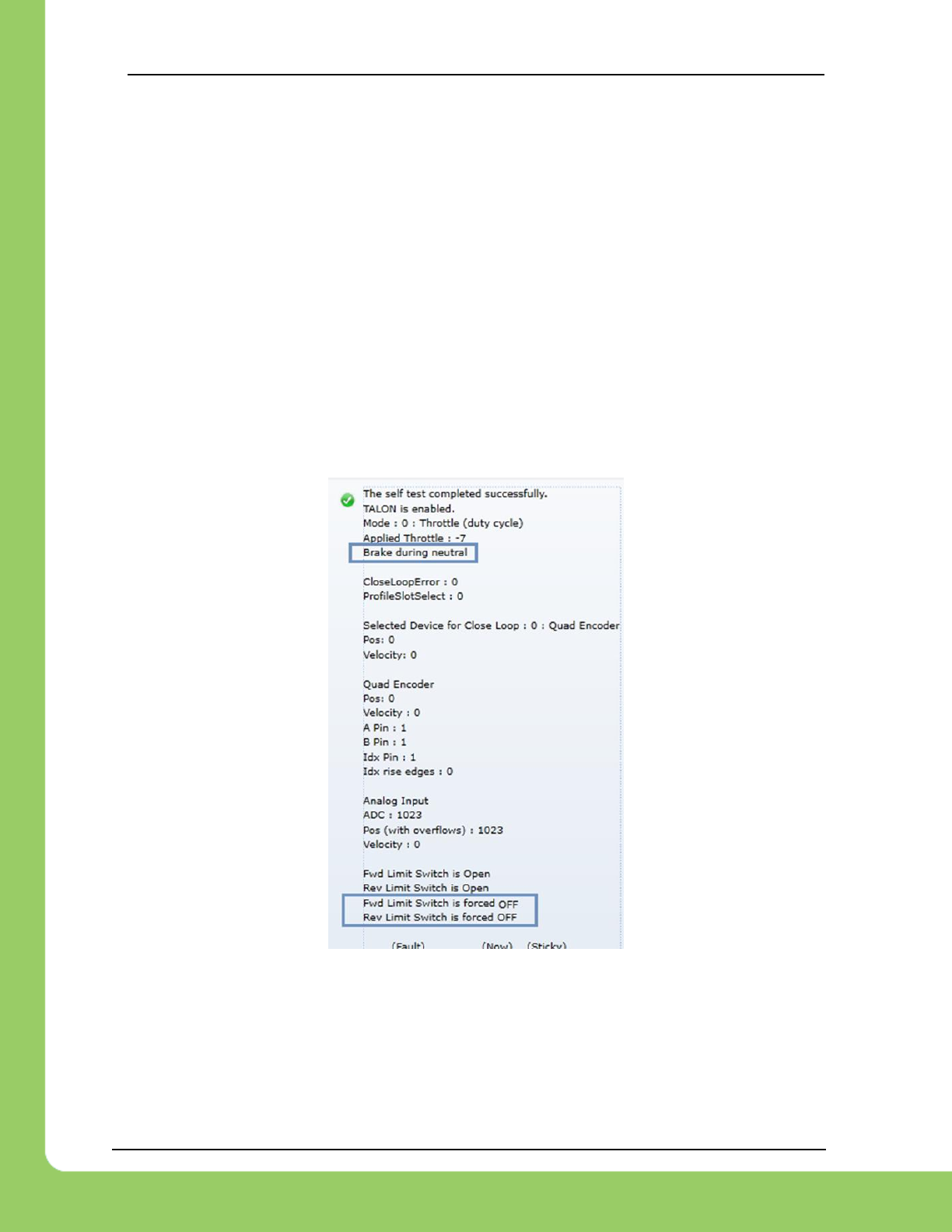
The brake and limit switch overrides can be confirmed in the Self-Test results. If limit switches
are overridden by the robot application, the forced states are displayed as “forced ON” or
“forced OFF”. The currently active brake mode is also in the Self-Test results.
(Self-test format has changed in 2018 since screenshot)
217-8080 TALON SRX / Victor SPX Software Reference Manual 3/06/2018
Cross The Road Electronics Page 39 3/06/2018
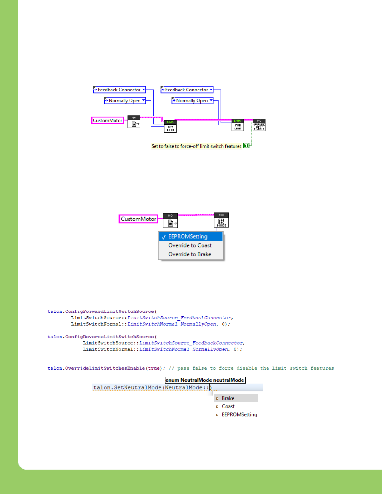
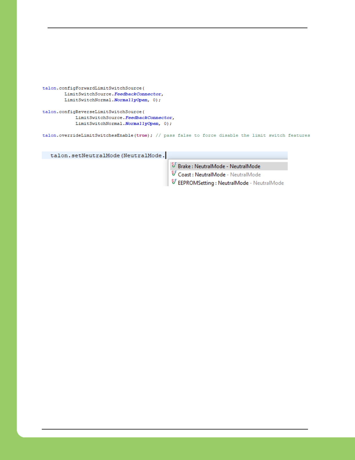
4.3.1. LabVIEW
The VIs below can be used to configure and override the limit switches. Select “Feedback
Connector” when using the Limit Switch pins on the Talon’s Gadgeteer pinout.
The neutral brake mode can also be overridden to Brake or Coast. If “EEPROMSetting” is
selected, then the Startup Brake Mode is used (B/C Cal button)
4.3.2. C++
Limit Switches and neutral brake can be configured using the functions below.
217-8080 TALON SRX / Victor SPX Software Reference Manual 3/06/2018
Cross The Road Electronics Page 40 3/06/2018
4.3.3. Java
Limit Switches and neutral brake can be configured using the functions below.

217-8080 TALON SRX / Victor SPX Software Reference Manual 3/06/2018
Cross The Road Electronics Page 41 3/06/2018
5. Getting Status and Signals
The Talon SRX transmits most of its status signals periodically, i.e. in an unsolicited fashion.
This improves bus efficiency by removing the need for “request” frames, and guarantees the
signals necessary for the wide range of use cases Talon supports, are available.
These signals are available in API regardless of what control mode the Talon SRX is in.
Additionally, the signals can be polled in the roboRIO Web-based Configuration (see Section
2.4. Self-Test).
Included in the list of signals are…
- Quadrature Encoder Position, Velocity, Index Rise Count, Pin States (A, B, Index)
- Analog-In Position, Analog-In Velocity, 10bit ADC Value,
- Battery Voltage, Current, Temperature
- Fault states, sticky fault states,
- Limit switch pin states
- Applied output (duty cycle) regardless of control mode.
- Applied Control mode: Percent Output, Position/Velocity closed-loop, or slave follower.
- Brake State (coast vs brake)
- Closed-Loop Error, the difference between closed-loop set point and actual position/velocity.
- Sensor Position and Velocity, the signed output of the selected Feedback device (robot must
select a Feedback device, or rely on default setting of Quadrature Encoder).
217-8080 TALON SRX / Victor SPX Software Reference Manual 3/06/2018
Cross The Road Electronics Page 42 3/06/2018
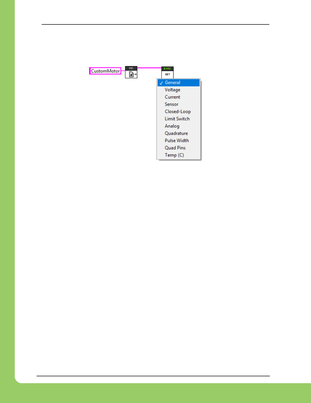
5.1. LabVIEW
The GET VI can be used to retrieve the latest value for the signals Talon SRX periodically
transmits. Choose the correct signal group from the drop down.
5.2. C++
Various get functions are available in C++. Here are a few examples…
double currentAmps = talon.GetOutputCurrent();
double outputV = talon.GetMotorOutputVoltage();
double busV = talon.GetBusVoltage();
double outputPerc = talon.GetMotorOutputPercent();
int quadPos = talon.GetSensorCollection().GetQuadraturePosition();
int quadVel = talon.GetSensorCollection().GetQuadratureVelocity();
int analogPos = talon.GetSensorCollection().GetAnalogIn();
int analogVel = talon.GetSensorCollection().GetAnalogInVel();
int selectedSensorPos = talon.GetSelectedSensorPosition(0); /* sensor selected for PID Loop 0 */
int selectedSensorVel = talon.GetSelectedSensorVelocity(0); /* sensor selected for PID Loop 0 */
int closedLoopErr = talon.GetClosedLoopError(0); /* sensor selected for PID Loop 0 */
double closedLoopAccum = talon.GetIntegralAccumulator(0); /* sensor selected for PID Loop 0 */
double derivErr = talon.GetErrorDerivative(0); /* sensor selected for PID Loop 0 */
5.3. Java
Various get functions are available in Java. Here are a few examples…
double currentAmps = talon.getOutputCurrent();
double outputV = talon.getMotorOutputVoltage();
double busV = talon.getBusVoltage();
double outputPerc = talon.getMotorOutputPercent();
int quadPos = talon.getSensorCollection().getQuadraturePosition();
int quadVel = talon.getSensorCollection().getQuadratureVelocity();
int analogPos = talon.getSensorCollection().getAnalogIn();
int analogVel = talon.getSensorCollection().getAnalogInVel();
int selectedSensorPos = talon.getSelectedSensorPosition(0); /* sensor selected for PID Loop 0 */
int selectedSensorVel = talon.getSelectedSensorVelocity(0); /* sensor selected for PID Loop 0 */
int closedLoopErr = talon.getClosedLoopError(0); /* sensor selected for PID Loop 0 */
double closedLoopAccum = talon.getIntegralAccumulator(0); /* sensor selected for PID Loop 0 */
double derivErr = talon.getErrorDerivative(0); /* sensor selected for PID Loop 0 */
217-8080 TALON SRX / Victor SPX Software Reference Manual 3/06/2018
Cross The Road Electronics Page 43 3/06/2018
6. Setting the Ramp Rate
The Talon SRX can be set to honor a ramp rate to prevent instantaneous changes in output.
There are two separate ramps, one for Open Loop (PercentOutput) and another for Closed
Loop.
Typically closed loop ramp is zero (off) or quite small as this can introduce oscillations.
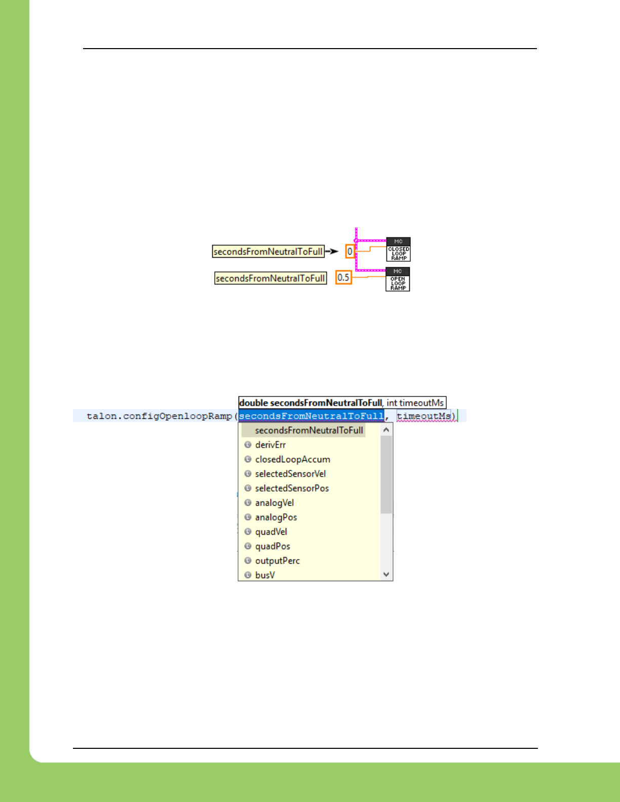
6.1. LabVIEW
Use the ramp VIs to specify the ramp rate in seconds (from neutral to full).
6.2. C++/ Java
configOpenloopRamp and configClosedloopRamp can be used to ramp the motor output in
the respective modes. Having two global configs allows users to avoid having to set and clear
the ramp when switching between open-loop and closed-loop use. Since these settings are
persistent, they can be typically set once on robot boot.
217-8080 TALON SRX / Victor SPX Software Reference Manual 3/06/2018
Cross The Road Electronics Page 44 3/06/2018
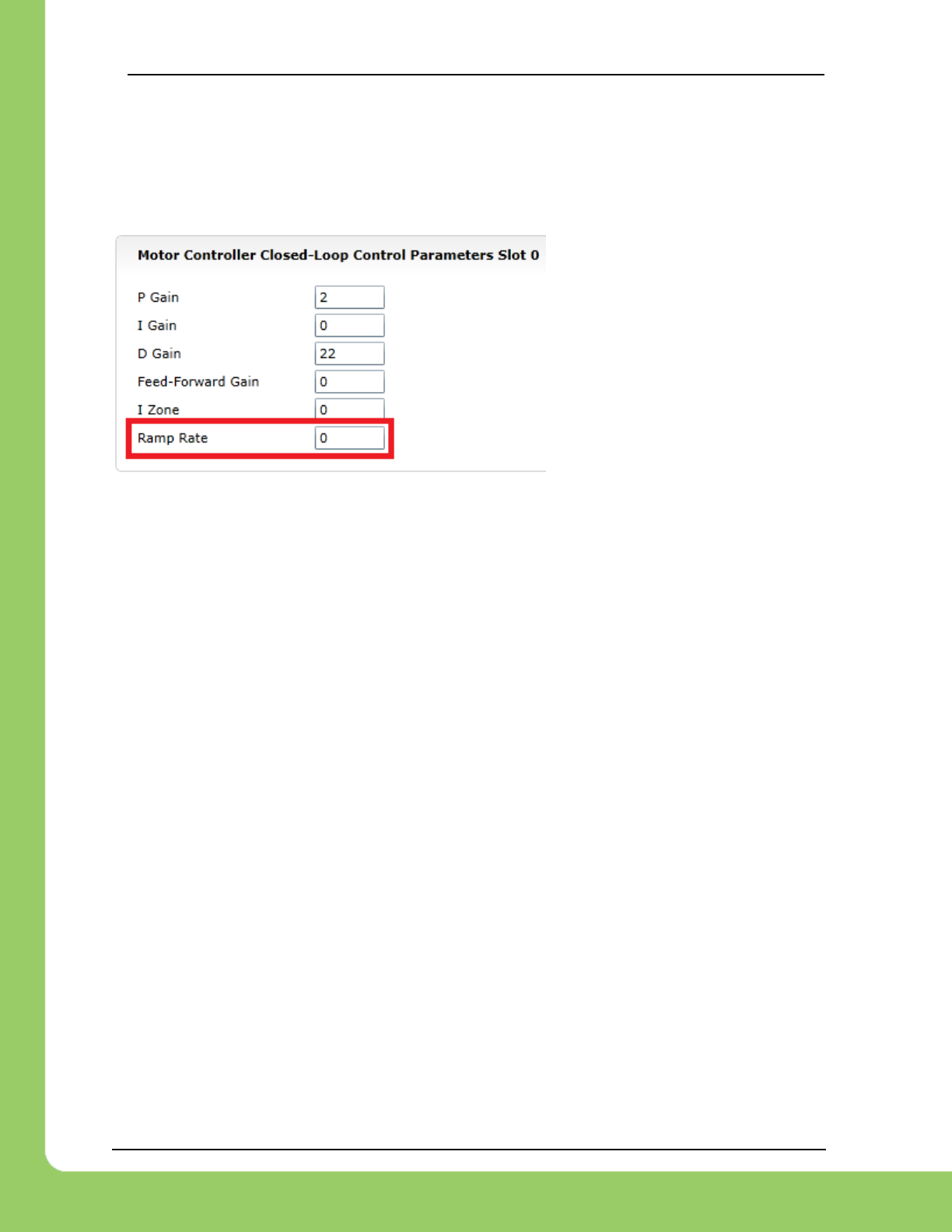
6.3. Web-based configuration limitations
The individual ramp rate inside the closed-loop slot has been replaced with
configOpenloopRamp and configClosedloopRamp. Instead use these routine as the web-
based config entry will always read zero.
Setting has been removed. Instead use the Open-loop and Closed-loop ramp config functions.
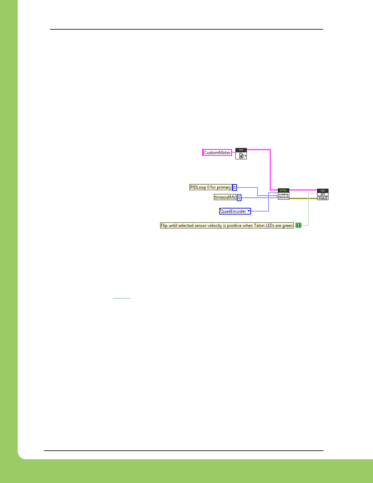
217-8080 TALON SRX / Victor SPX Software Reference Manual 3/06/2018
Cross The Road Electronics Page 45 3/06/2018
7. Feedback Device (Sensor Feedback)
Although the analog and quadrature signals are available all the time, the Talon SRX requires
the robot application to “pick” a “Feedback Device” for soft limit and closed-loop features.
The selected “Feedback Device” defaults to Quadrature Encoder.
Once a “Feedback Device” is selected, the “Sensor Position” and “Sensor Velocity” signals will
update with the output of the selected feedback device. It may be multiplied by (-1) to ensure
sensor is in phase with the motor.
7.1. LabVIEW
Use CONFIG SENSOR to select
which Feedback Sensor to use for
soft limits and closed-loop features.
The supported selections include:
Quadrature, Analog, and
Tachometer.
7.2. C++
SetFeedbackDevice() can be used to select Quadrature, Analog, or Tachometer (velocity).
/* analog signal with no wrap-around (0-3.3V) */
talon.ConfigSelectedFeedbackSensor(FeedbackDevice::Analog, 0, 0); /* PIDLoop=0,timeoutMs=0 */
/* eFeedbackNotContinuous = 1, subValue/ordinal/timeoutMs = 0*/
talon.ConfigSetParameter(ParamEnum::eFeedbackNotContinuous, 1, 0x00, 0x00, 0x00);
/* analog signal with wrap-arounds tracked (0-3.3V) */
talon.ConfigSelectedFeedbackSensor(FeedbackDevice::Analog, 0, 0); /* PIDLoop=0,timeoutMs=0 */
/* eFeedbackNotContinuous = 0, subValue/ordinal/timeoutMs = 0*/
talon.ConfigSetParameter(ParamEnum::eFeedbackNotContinuous, 0, 0x00, 0x00, 0x00);
/* quadrature */
talon.ConfigSelectedFeedbackSensor(FeedbackDevice::QuadEncoder, 0, 0); /* PIDLoop=0,timeoutMs=0 */
/* CTRE Magnetic Encoder relative, same as Quadrature */
talon.ConfigSelectedFeedbackSensor(FeedbackDevice::CTRE_MagEncoder_Relative, 0, 0); /* PIDLoop=0,timeoutMs=0 */
/* CTRE Magnetic Encoder absolute (within one rotation), same as PulseWidthEncodedPosition */
talon.ConfigSelectedFeedbackSensor(FeedbackDevice::CTRE_MagEncoder_Absolute, 0, 0); /*PIDLoop=0,timeoutMs=0 */
/* PulseWidthEncodedPosition, LIDAR for example */
talon.ConfigSelectedFeedbackSensor(FeedbackDevice::PulseWidthEncodedPosition, 0, 0); /*PIDLoop=0,timeoutMs=0 */
/* Tachometer (for velocity closed loop) */
talon.ConfigSelectedFeedbackSensor(FeedbackDevice::Tachometer, 0, 0); /* PIDLoop=0, timeoutMs=0 */
SetSensorPhase() can be used to keep the sensor and motor in phase for proper limit switch
and closed loop features.
/* flip input until sensor is in phase */
talon.SetSensorPhase(true);

217-8080 TALON SRX / Victor SPX Software Reference Manual 3/06/2018
Cross The Road Electronics Page 46 3/06/2018
7.3. Java
setFeedbackDevice()can be used to select Quadrature, Analog, or Tachometer (velocity).
/* analog signal with no wrap-around (0-3.3V) */
talon.configSelectedFeedbackSensor(FeedbackDevice.Analog, 0, 0); /* PIDLoop=0, timeoutMs=0 */
/* eFeedbackNotContinuous = 1, subValue/ordinal/timeoutMs = 0*/
talon.configSetParameter(ParamEnum.eFeedbackNotContinuous, 1, 0x00, 0x00, 0x00);
/* analog signal with wrap-arounds tracked (0-3.3V) */
talon.configSelectedFeedbackSensor(FeedbackDevice.Analog, 0, 0); /* PIDLoop=0, timeoutMs=0 */
/* eFeedbackNotContinuous = 0, subValue/ordinal/timeoutMs = 0*/
talon.configSetParameter(ParamEnum.eFeedbackNotContinuous, 0, 0x00, 0x00, 0x00);
/* quadrature */
talon.configSelectedFeedbackSensor(FeedbackDevice.QuadEncoder, 0, 0); /* PIDLoop=0, timeoutMs=0
*/
/* CTRE Magnetic Encoder relative, same as Quadrature */
talon.configSelectedFeedbackSensor(FeedbackDevice.CTRE_MagEncoder_Relative, 0, 0); /* PIDLoop=0,
timeoutMs=0 */
/* CTRE Magnetic Encoder absolute (within one rotation), same as PulseWidthEncodedPosition */
talon.configSelectedFeedbackSensor(FeedbackDevice.CTRE_MagEncoder_Absolute, 0, 0); /* PIDLoop=0,
timeoutMs=0 */
/* PulseWidthEncodedPosition, LIDAR for example */
talon.configSelectedFeedbackSensor(FeedbackDevice.PulseWidthEncodedPosition, 0, 0); /* PIDLoop=0,
timeoutMs=0 */
/* Tachometer (for velocity closed loop) */
talon.configSelectedFeedbackSensor(FeedbackDevice.Tachometer, 0, 0); /* PIDLoop=0, timeoutMs=0 */
setSensorPhase() can be used to keep the sensor and motor in phase for proper limit switch
and closed loop features.
/* flip input until sensor is in phase */
talon.setSensorPhase(true);
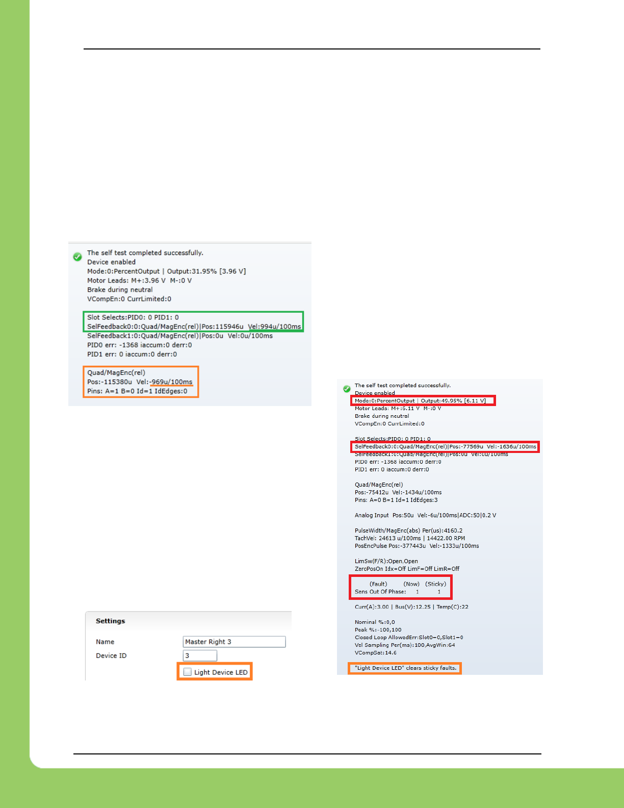
217-8080 TALON SRX / Victor SPX Software Reference Manual 3/06/2018
Cross The Road Electronics Page 47 3/06/2018
7.4. Correcting sensor direction, best practices.
For limit switches and closed-loop features to function correctly the sensor and motor must be
“in-phase”. This means that the sensor position must move in a positive direction as the motor
controller drives positive motor output. To test this, first drive the motor manually (using
gamepad axis for example). Watch the sensor position either in the roboRIO Web-based
Configuration Self-Test, or by calling GetSelectedSensorPosition() and printing it to console.
If the “Sensor Position” moves in a negative direction while Talon SRX motor output is positive
(blinking green), then use the setSensorPhase() routine/VI to multiply the sensor position by (-
1). Then retest to confirm “Sensor Position” moves in a positive direction with positive motor
drive. Additionally, the sensor-out-of-phase sticky fault will assert if the motor output exceeds
25% and the sensor is traveling in the wrong direction.
When using the Self-Test, be sure to track the
selected feedback position and velocity, which
is above the Quadrature Encoder signals.
Only these signals will reflect changes to the
sensor phase.
If the sensor is out of phase, typically the self-test
will reveal a sensor velocity and motor output with
mismatched signs. Additionally, the sensor out of
phase fault will appear.
Note: sticky faults can be cleared via Light Device
LED checkbox.
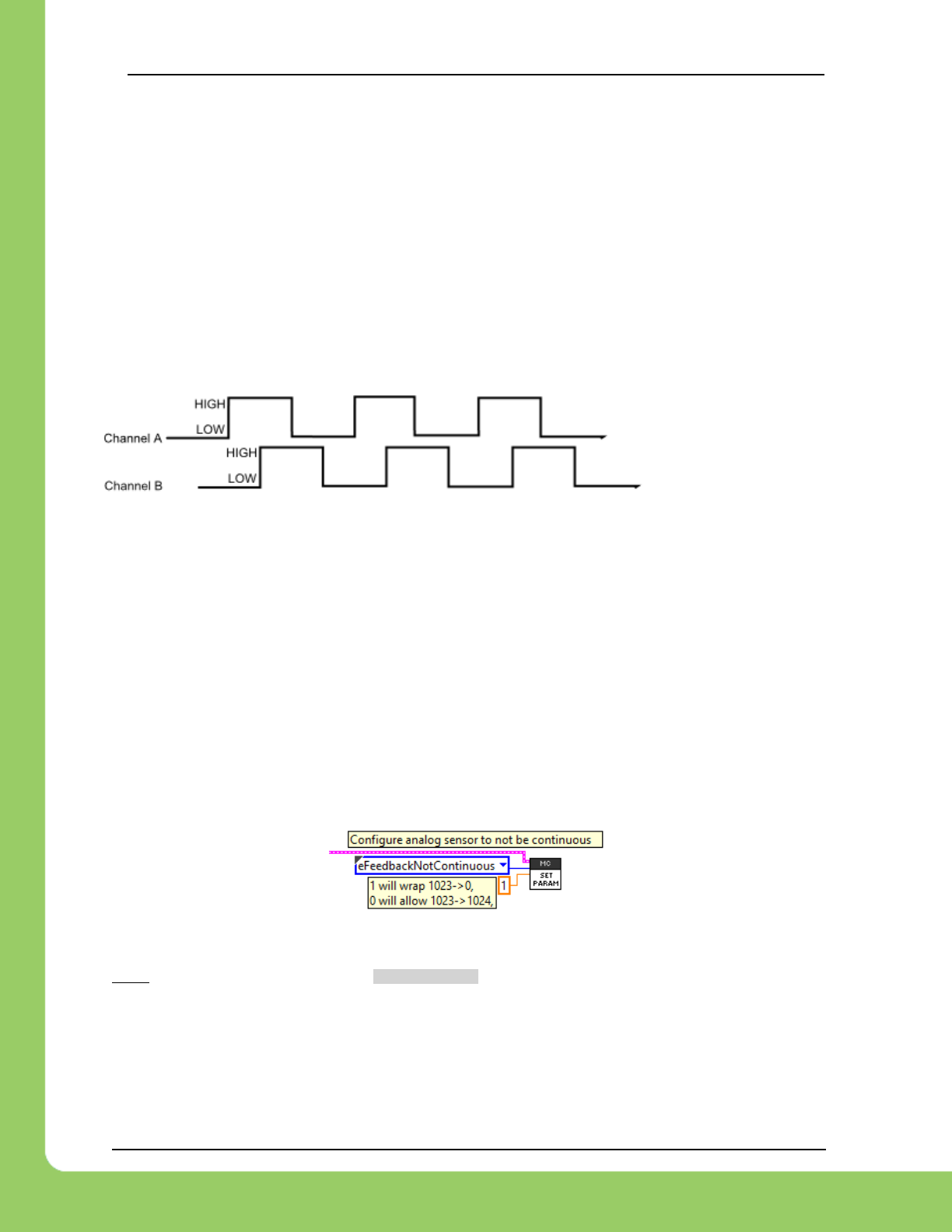
217-8080 TALON SRX / Victor SPX Software Reference Manual 3/06/2018
Cross The Road Electronics Page 48 3/06/2018
In the special case of using the “Tachometer” feedback device, the measured velocity is always
signed to match the motor output. This ensures the sensor is in-phase despite the inability of a
Tachometer signal to determine direction.
7.5. Supported Feedback Devices
Many feedback interfaces are supported. The complete list is below.
7.5.1. Quadrature
The Talon directly supports Quadrature Encoders. If Quadrature is selected, the decoding is
done in 4x mode. This means that each pulse will correspond to four counts.
In this example pulse
train, the Talon would
decode 12 counts (each
of the three pulses
contributes four edges).
7.5.2. Analog (Potentiometer / Encoder)
Analog feedback sensors, or sensors that provide a variable voltage to represent position, are
also supported. Some devices are continuous despite the voltage signal wrapping around from
3.3V back to 0V. For these sensors, the Talon will detect and count these wrap arounds.
Despite the base analog measurement holding 10 bits [0,1023], the sensor position will continue
from 1023 -> 1024.
7.5.2.1. Potentiometer (Discontinuous) Sensor
For other sensors (like potentiometers) that do not wrap the voltage signal and therefore must
not track the overflow, the Talon can be configured to wrap the position (1023 -> 0). This can be
done by setting the eFeedbackNotContinuous configurable parameter to ‘1’.
7.5.2.2. LabVIEW Example
7.5.2.3. C++ Example
/* analog signal with no wrap-around (0-3.3V) */
talon.ConfigSelectedFeedbackSensor(FeedbackDevice::Analog, 0, 0); /* PIDLoop=0, timeoutMs=0 */
/* eFeedbackNotContinuous = 1, subValue/ordinal/timeoutMs = 0*/
talon.ConfigSetParameter(ParamEnum::eFeedbackNotContinuous, 1, 0x00,0x00, 0x00);
7.5.2.4. Java Example
/* analog signal with no wrap-around (0-3.3V) */
talon.configSelectedFeedbackSensor(FeedbackDevice.Analog, 0,0); /* PIDLoop=0, timeoutMs=0 */
/* eFeedbackNotContinuous = 1, subValue/ordinal/timeoutMs = 0 */
talon.configSetParameter(ParamEnum.eFeedbackNotContinuous, 1, 0x00, 0x00, 0x00);

217-8080 TALON SRX / Victor SPX Software Reference Manual 3/06/2018
Cross The Road Electronics Page 49 3/06/2018
7.5.3. Pulse Width Decoder
For sensors that encode position as a pulse width, this sensor type can be used to decode the
position. The pulse width decoder is 1us accurate and the maximum time between edges is
120ms, which is wide enough to support many LIDAR distance sensors.
7.5.4. Cross The Road Electronics Magnetic Encoder (Absolute and Relative)
The CTRE Magnetic Encoder is composed of two sensor interfaces packaged into one (pulse
width and quadrature encoder). Therefore, the sensor provides two modes of use: absolute and
relative.
The advantage of absolute mode is having a solid reference to where a mechanism is without
re-tare-ing or re-zero-ing the robot. The advantage of the relative mode is the faster update
rate. However, both values can be read/written at the same time. So, a combined strategy of
seeding the relative position based on the absolute position can be used to benefit from the
higher sampling rate of the relative mode and still have an absolute sensor position.
Parameter
Absolute Mode
Relative Mode
Update rate (period)
4ms
100 us
Max RPM
7,500 RPM
15,000 RPM
Accuracy
12 bits per rotation
(4096 steps per rotation)
12 bits per rotation
(4096 steps per rotation)
Software API
Use Pulse Width API
Use Quadrature API
7.5.4.1. Selecting the Magnetic Encoder
Selecting the Magnetic Encoder for closed-loop / soft-limit features is no different than selecting
other sensor feedback devices. Depending on language, there are two new feedback types:
CTRE Magnetic Encoder (absolute) and CTRE Magnetic Encoder (relative). Alternatively, the
user can select Quadrature or PulseWidthEncodedPosition to select between relative and
absolute.
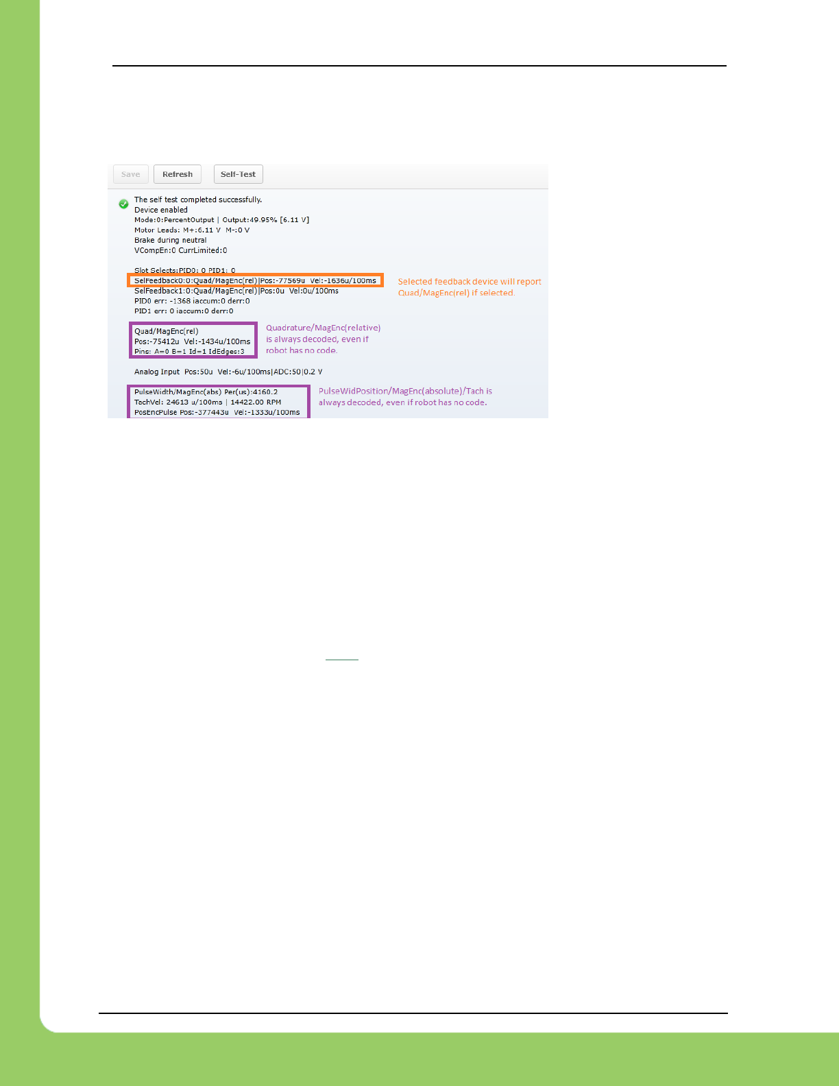
217-8080 TALON SRX / Victor SPX Software Reference Manual 3/06/2018
Cross The Road Electronics Page 50 3/06/2018
Additionally, the position and velocity can be retrieved without selecting the Magnetic Encoder
as the selected feedback device. One method is to utilize the self-test in the roboRIO web-
based configuration.
Note the purple entries are
always available
regardless of robot-code
status.
To programmatically read the absolute and relative position and velocities, the robot API
provides get routines for pulse width decoding and quadrature, which can be read any time
without sensor selection.
7.5.4.2. CTR Magnetic Encoder (absolute) – C++
/* get the decoded pulse width encoder position, 4096 units per rotation */
int pulseWidthPos = talon.GetSensorCollection().GetPulseWidthPosition();
/* get the pulse width in us, rise-to-fall in microseconds */
int pulseWidthUs = talon.GetSensorCollection().GetPulseWidthRiseToFallUs();
/* get the period in us, rise-to-rise in microseconds */
int periodUs = talon.GetSensorCollection().GetPulseWidthRiseToRiseUs();
/* get measured velocity in units per 100ms, 4096 units is one rotation */
int pulseWidthVel = talon.GetSensorCollection().GetPulseWidthVelocity();
/* is sensor plugged in to Talon */
bool sensorPluggedIn = false;
if (periodUs != 0) {
sensorPluggedIn = true;
}
7.5.4.3. CTR Magnetic Encoder (absolute) – Java
/* get the decoded pulse width encoder position, 4096 units per rotation */
int pulseWidthPos = _talon.getSensorCollection().getPulseWidthPosition();
/* get the pulse width in us, rise-to-fall in microseconds */
int pulseWidthUs = _talon.getSensorCollection().getPulseWidthRiseToFallUs();
/* get the period in us, rise-to-rise in microseconds */
int periodUs = _talon.getSensorCollection().getPulseWidthRiseToRiseUs();
/* get measured velocity in units per 100ms, 4096 units is one rotation */
int pulseWidthVel = _talon.getSensorCollection().getPulseWidthVelocity();
/* is sensor plugged in to Talon */
boolean sensorPluggedIn = false;
if (periodUs != 0) {
sensorPluggedIn = true;
}

217-8080 TALON SRX / Victor SPX Software Reference Manual 3/06/2018
Cross The Road Electronics Page 51 3/06/2018
7.6. Multiple Talon SRXs and single sensor
There are many uses where a mechanism requires multiple Talon SRXs but a single sensor.
For example, a single-side of a tank-drive or a shooter-wheel powered by two motors.
The recommended strategy for these mechanisms is to…
• Connect the sensor to one of the Talons. This Talon will be referred to the “master”
Talon.
• Set the supplemental Talon(s) to follower mode and follow the device ID of the “master”
Talon. See Section 9.1 for details.
• Select PercentOutput Mode on the “master” Talon. Write a test robot application to
drive the “master” Talon manually and confirm proper direction. Use SetInverted() to
correct direction if need be. Note: A talon’s LEDs will not change when inverted, but the
motor output voltage will. Consult Talon User’s Guide to avoid damaging Talons by
incorrectly wiring inputs/outputs.
• Next, connect motor to first follower Talon and disconnect master Talon from master
motor. Consult Talon User’s Guide to avoid damaging Talons by incorrectly
wiring inputs/outputs. Test follower direction. If follower direction is incorrect, use
SetInverted() on follower Talon to correct it. Repeat for each follower motor controller.
For example, when drive a shooter wheel, the motors may be oriented to require each
motor to drive in opposite directions. If this is the case signal the slave Talon to invert
its output (Section 9.1.4). Do not use excessive motor output. Otherwise you may
stall your motors if the follower and master Talon are driving against each other.
• Instrument the Sensor Position or Velocity using the roboRIO Web-based Configuration
Page Self-Test, or print/plot the values. Ensure that sensor moves in a positive
direction when master Talon is given positive forward motor output (green LEDs).
• Now that the motor(s) and sensor orientation has been confirmed, select the desired
control mode of the master Talon. Any of the closed-loop/motion-profile control modes
can be used.
• When using Velocity Closed-Loop, Current Closed-Loop, or MotionProfile Control Mode,
be sure to calculate the F gain when all slave Talon/motors are connected and used.
7.7. Pulse Width - Checking Sensor Health
When using the PulseWidthEncoded sensor, the health of the sensor can be determined by
polling the measured period. The period will read zero or 120ms after the last received valid
pulse.

217-8080 TALON SRX / Victor SPX Software Reference Manual 3/06/2018
Cross The Road Electronics Page 52 3/06/2018
7.8. Velocity Measurement
The Talon SRX measures the velocity of all supported sensor types as well as the current
position. In the case of quadrature and analog, every 1ms, a velocity sample is measured and
inserted into a rolling average.
The velocity sample is measured as the change in position at the time-of-sample versus the
position sampled 100ms-prior-to-time-of-sample. The rolling average is sized for 64 samples.
Though these configurations can be modified, the (100ms, 64 samples) parameters are default.
7.8.1. Changing Velocity Measurement Parameters.
The two characteristics for the Talon Velocity Measurement are…
• Sample Period (Default 100ms)
• Rolling Average Window Size (Default 64 samples).
These configurations are also persistent across power cycles.
Each can be modified through programming API, and through HERO LifeBoat (non-FRC).
NOTE – When the sample period is reduced, the units of the native velocity measurement is
still change-in-position-per-100ms. In other words, the measurement is up-scaled to normalize
the units. Additionally, a velocity sample is always inserted every 1ms regardless of setting
selection.
NOTE – The Velocity Measurement Sample Period is selected from a fixed list of pre-supported
sampling periods [1, 5, 10, 20, 25, 50, 100(default)] milliseconds.
NOTE – The Velocity Measurement Rolling Average Window is selected from a fixed list of pre-
supported sample counts: [1, 2, 4, 8, 16, 32, 64(default)]. If an alternative value is passed into
the API, the firmware will truncate to the nearest supported value.
7.8.1.1. Changing Parameters – HERO C#
_talon.ConfigVelocityMeasurementPeriod(CTRE.TalonSrx.VelocityMeasurementPeriod.Period_10Ms, 0);
_talon.ConfigVelocityMeasurementWindow(20, 0);

217-8080 TALON SRX / Victor SPX Software Reference Manual 3/06/2018
Cross The Road Electronics Page 53 3/06/2018
7.8.1.2. Changing Parameters – Hero LifeBoat
When using the HERO Development
Board, the Sample Period and Rolling
Average can be modified through the
graphical interface.
7.8.1.3. Changing Parameters – FRC Java
talon.ConfigVelocityMeasurementPeriod(VelocityMeasPeriod.Period_100Ms, 0);
talon.ConfigVelocityMeasurementWindow(64, 0);
7.8.1.4. Changing Parameters – FRC C++
_talon.ConfigVelocityMeasurementPeriod(VelocityMeasPeriod::Period_100Ms, 0);
_talon.ConfigVelocityMeasurementWindow(64, 0);
7.8.1.5. Changing Parameters – FRC LabVIEW

217-8080 TALON SRX / Victor SPX Software Reference Manual 3/06/2018
Cross The Road Electronics Page 54 3/06/2018
7.8.2. Recommended Procedure
The general recommended procedure is to first set these two parameters to the minimal value
of ‘1’ (Measure change in position per 1ms, and no rolling average). Then plot the measured
velocity while manually driving the Talon SRX(s) with a joystick/gamepad. Sweep the motor
output to cover the expected range that the sensor will be expected to cover.
Unless the sensor velocity is considerably fast (hundreds of sensor units per sampling period)
the measurement will be very coarse (visual stair-stepping as the motor output is increased).
Increase the sampling period until the measured velocity is sufficiently granular.
At this point the sensor velocity will have minimal stair-stepping (good) but will be quite noisy.
Increase the rolling average window until the velocity plot is sufficiently smooth, but still
responsive enough to meet the timing requirements of the mechanism.
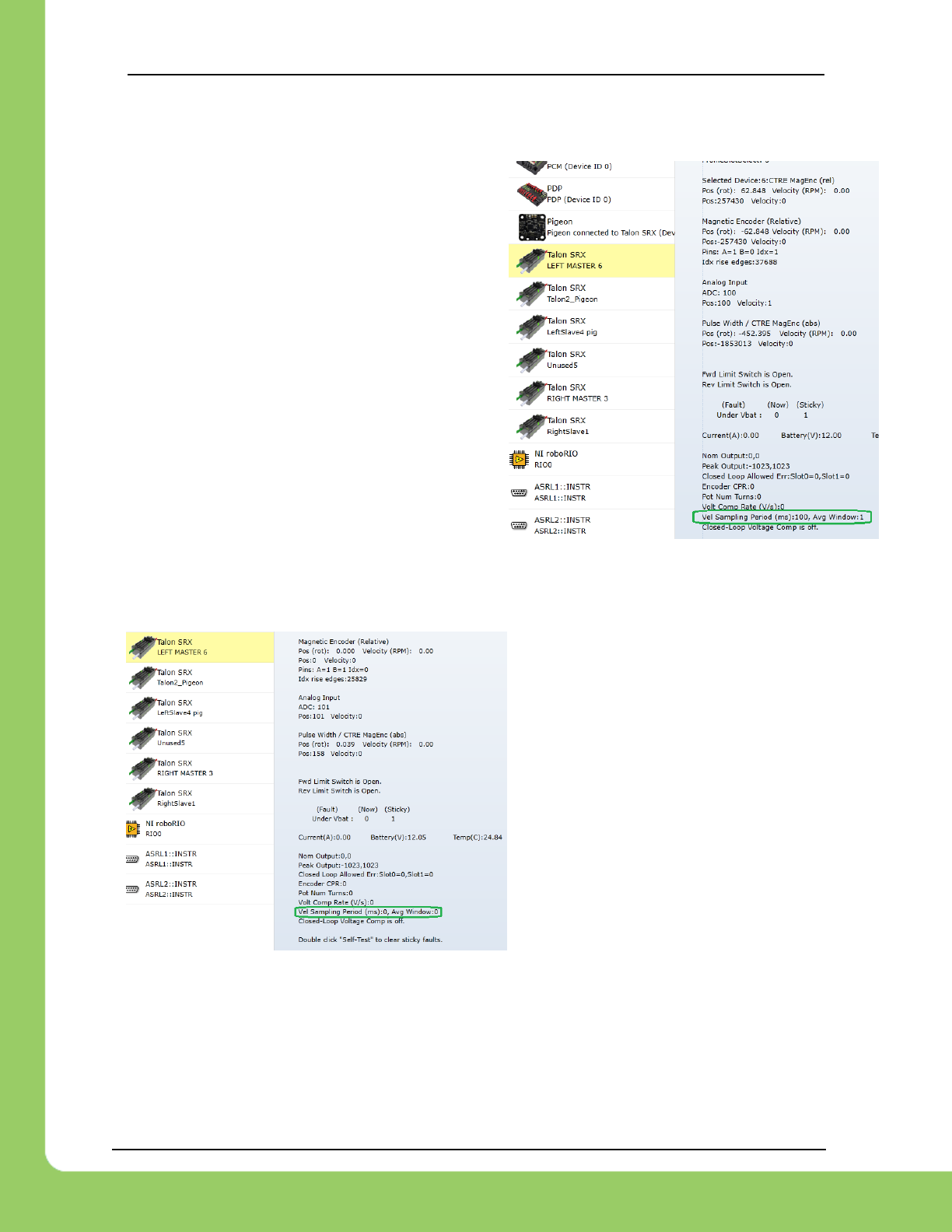
217-8080 TALON SRX / Victor SPX Software Reference Manual 3/06/2018
Cross The Road Electronics Page 55 3/06/2018
7.8.3. Self-Test Velocity Settings
The current Velocity Measurement Settings can
be confirmed by performing the Self-Test in the
roboRIO Web-based configuration page.
In this screenshot the Sampling Period is set to
100ms and the Rolling Average Window is set to 1
sample.
7.8.3.1. Self-Test reads 0 for Period and Window.
If the firmware is too old to allow
configuration of the velocity measurement
settings, then the self-test will report ‘0’ for
both. In this configuration, the firmware is
hardcoded to use 100ms and 64 samples.
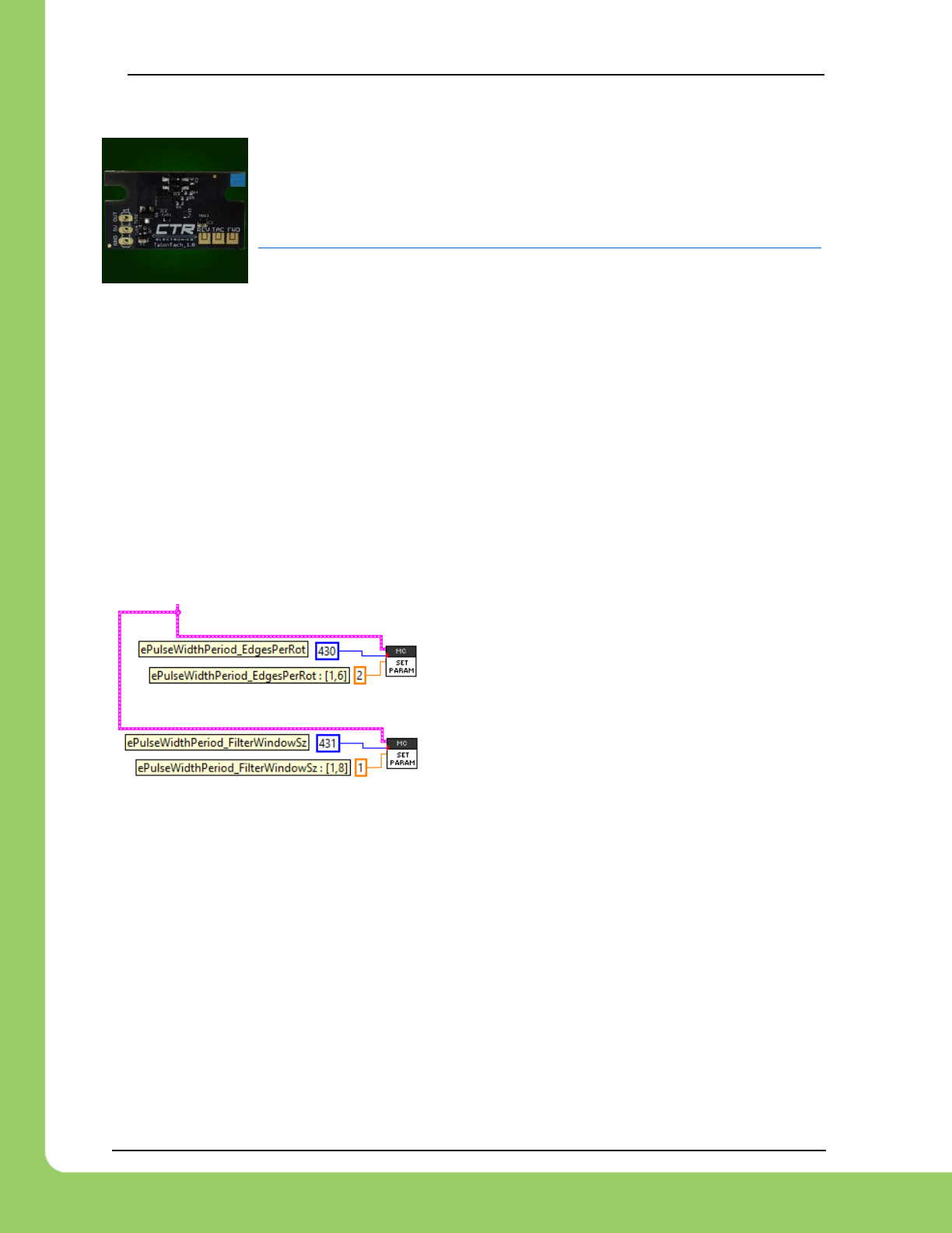
217-8080 TALON SRX / Victor SPX Software Reference Manual 3/06/2018
Cross The Road Electronics Page 56 3/06/2018
7.9. Tachometer Measurement
Talon SRX also supports decoding a Tachometer for sensing velocity.
Typically, this is used with velocity control mode.
The Talon SRX was tested using a CTRE Talon Tach
http://www.ctr-electronics.com/talon-tach-tachometer-new-limit-switch.html
Select Tachometer as the sensor type and use Self-test to review the measured values.
The base unit of a Tachometer measured velocity is in units per 100ms, such that…
1024 units per 100ms = 1 rotations per 100ms.
OR
1024 units per 100ms = 600RPM
For the sensor decoder to function correctly, users can...
- Ensure Talon is aware how many edges per rotation there are.
- Optionally select a rolling average to smooth measurement (typically not necessary).
7.9.1. Tachometer Measurement – LabVIEW
Use the general SET PARAM VI to adjust the Tachometer decoding parameters.
Set PulseWidthPeriod_EdgesPerRot (430) to a
value within [1,6], (default value is 1).
This should match the number of edges marked on
the wheel being measured.
If filtering is required, set the filter window size (431)
to a value within [1,8], (default is 1). This represents
the number of cells in a rolling average.
7.9.2. Tachometer Measurement – Java
Use the general SET PARAM VI to adjust the Tachometer decoding parameters.
/* ePulseWidthPeriod_EdgesPerRot : [1,6] */
int edgesPerRotation = 2;
/* ePulseWidthPeriod_FilterWindowSz : [1,8] */
int filterWindowSize = 1;
talon.configSetParameter(430, edgesPerRotation, 0x00, 0x00, 0);
talon.configSetParameter(431, filterWindowSize, 0x00, 0x00, 0);
Set PulseWidthPeriod_EdgesPerRot (430) to a value within [1,6], (default value is 1).
This should match the number of edges marked on the wheel being measured.

217-8080 TALON SRX / Victor SPX Software Reference Manual 3/06/2018
Cross The Road Electronics Page 57 3/06/2018
If filtering is required, set the filter window size (431) to a value within [1,8], (default is 1). This
represents the number of cells in a rolling average.
7.9.3. Tachometer Measurement – C++
Use the general SET PARAM VI to adjust the Tachometer decoding parameters.
/* ePulseWidthPeriod_EdgesPerRot : [1,6] */
int edgesPerRotation = 2;
/* ePulseWidthPeriod_FilterWindowSz : [1,8] */
int filterWindowSize = 1;
talon.ConfigSetParameter(430, edgesPerRotation, 0x00, 0x00, 0);
talon.ConfigSetParameter(431, filterWindowSize, 0x00, 0x00, 0);
Set PulseWidthPeriod_EdgesPerRot (430) to a value within [1,6], (default value is 1).
This should match the number of edges marked on the wheel being measured.
If filtering is required, set the filter window size (431) to a value within [1,8], (default is 1). This
represents the number of cells in a rolling average.
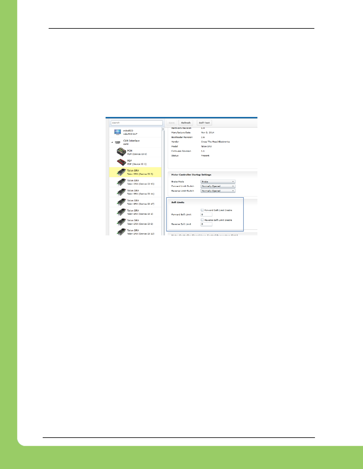
217-8080 TALON SRX / Victor SPX Software Reference Manual 3/06/2018
Cross The Road Electronics Page 58 3/06/2018
8. Soft Limits
Soft limits can be used to disable motor drive when the “Sensor Position” is outside of a
specified range. Forward motor output will be disabled if the “Sensor Position” is greater than
the Forward Soft Limit. Reverse motor output will be disabled if the “Sensor Position” is less
than the Reverse Soft Limit. The respective Soft Limit Enable must be enabled for this feature
to take effect.
The settings can be set and confirmed in the roboRIO Web-based Configuration.
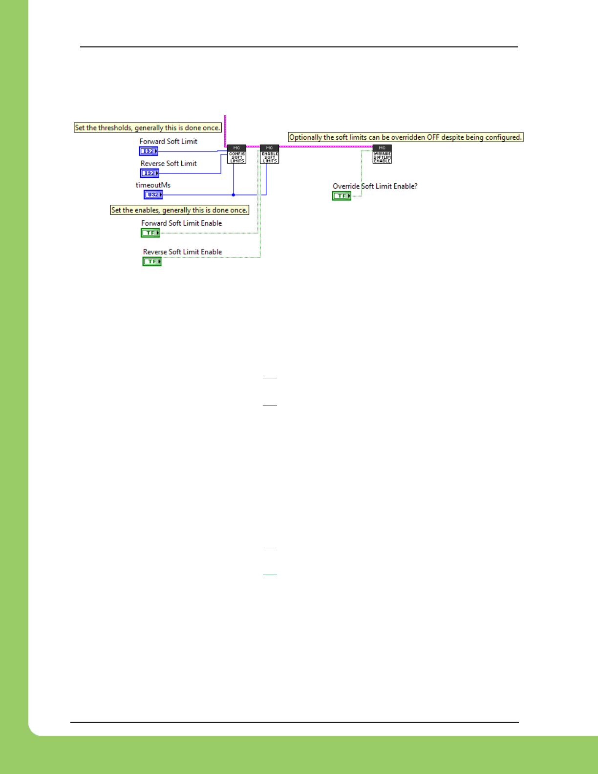
217-8080 TALON SRX / Victor SPX Software Reference Manual 3/06/2018
Cross The Road Electronics Page 59 3/06/2018
8.1. LabVIEW
The soft limits can also be set up programmatically. In LabVIEW, Soft Limit enables and
thresholds can be set using the following VIs.
8.2. C++
The limit threshold and enabled states can be individually specified using:
/* +14 rotations forward when using CTRE Mag encoder */
talon.ConfigForwardSoftLimitThreshold(+14*4096, 10);
/* -15 rotations reverse when using CTRE Mag encoder */
talon.ConfigReverseSoftLimitThreshold(-15*4096, 10);
talon.ConfigForwardSoftLimitEnable(true, 10);
talon.ConfigReverseSoftLimitEnable(true, 10);
/* pass false to FORCE OFF the feature. Otherwise the enable flags above are honored */
talon.OverrideLimitSwitchesEnable(true);
8.3. Java
The limit threshold and enabled states can be individually specified using:
/* +14 rotations forward when using CTRE Mag encoder */
talon.configForwardSoftLimitThreshold(+14*4096, 10);
/* -15 rotations reverse when using CTRE Mag encoder */
talon.configReverseSoftLimitThreshold(-15*4096, 10);
talon.configForwardSoftLimitEnable(true, 10);
talon.configReverseSoftLimitEnable(true, 10);
/* pass false to FORCE OFF the feature. Otherwise the enable flags above are honored */
talon.overrideLimitSwitchesEnable(true);
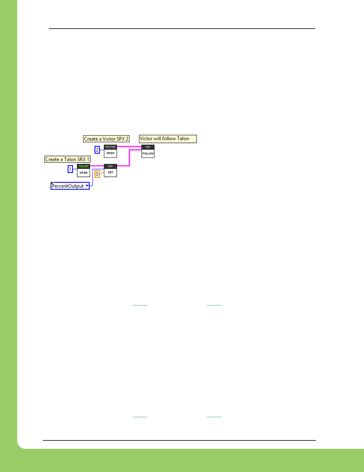
217-8080 TALON SRX / Victor SPX Software Reference Manual 3/06/2018
Cross The Road Electronics Page 60 3/06/2018
9. Special Features
9.1. Follower Mode
Any given Talon SRX on CAN bus can be instructed to “follow” the drive output of another Talon
SRX. This is done by putting a Talon SRX into “follower” mode and specifying the device ID of
the “Master Talon” to follow. The “Slave Talon” will then mirror the output of the “Master Talon”.
The “Master Talon” can be in any mode: closed-loop, percentOutput, motion profile control
mode, or even following yet another Talon SRX.
9.1.1. LabVIEW
The follow VI can be used to set up a
CTRE/VEX CAN motor controller to
follow another CTRE/VEX CAN motor
controller.
9.1.2. C++
Followers can be set up by…
• using the follow routine.
• passing the device ID of the Master motor controller into Set()if the follower product
model is the same as the master. The device ID should be between 0 and 62
(inclusive).
/* recommended method: use Follow routine */
victor.Follow(talon);
/* alternative method : victor will follow another Victor 7 - assume same model */
victor.Set(ControlMode::Follower, 7);
/* alternative method : talon will follow another Talon 7 - assume same model */
talon.Set(ControlMode::Follower, 7);
9.1.3. Java
Followers can be set up by…
• using the follow routine.
• passing the device ID of the Master motor controller into Set()if the follower product
model is the same as the master. The device ID should be between 0 and 62
(inclusive).
/* recommended method: use follow routine */
victor.follow(talon);
/* alternative method : victor will follow another Victor 7 - assume same model */
victor.set(ControlMode.Follower, 7);
/* alternative method : talon will follow another Talon 7 - assume same model */
talon.set(ControlMode.Follower, 7);

217-8080 TALON SRX / Victor SPX Software Reference Manual 3/06/2018
Cross The Road Electronics Page 61 3/06/2018
9.1.4. Correcting Follower Direction
If a follower motor controller must drive in the opposite direction use the motor controller invert
to correct this.
9.1.4.1. Correcting Follower Direction – C++
talon.SetInverted(true);
9.1.4.2. Correcting Follower Direction – Java
talon.setInverted(true);
9.1.4.3. Correcting Follower Direction – LabVIEW
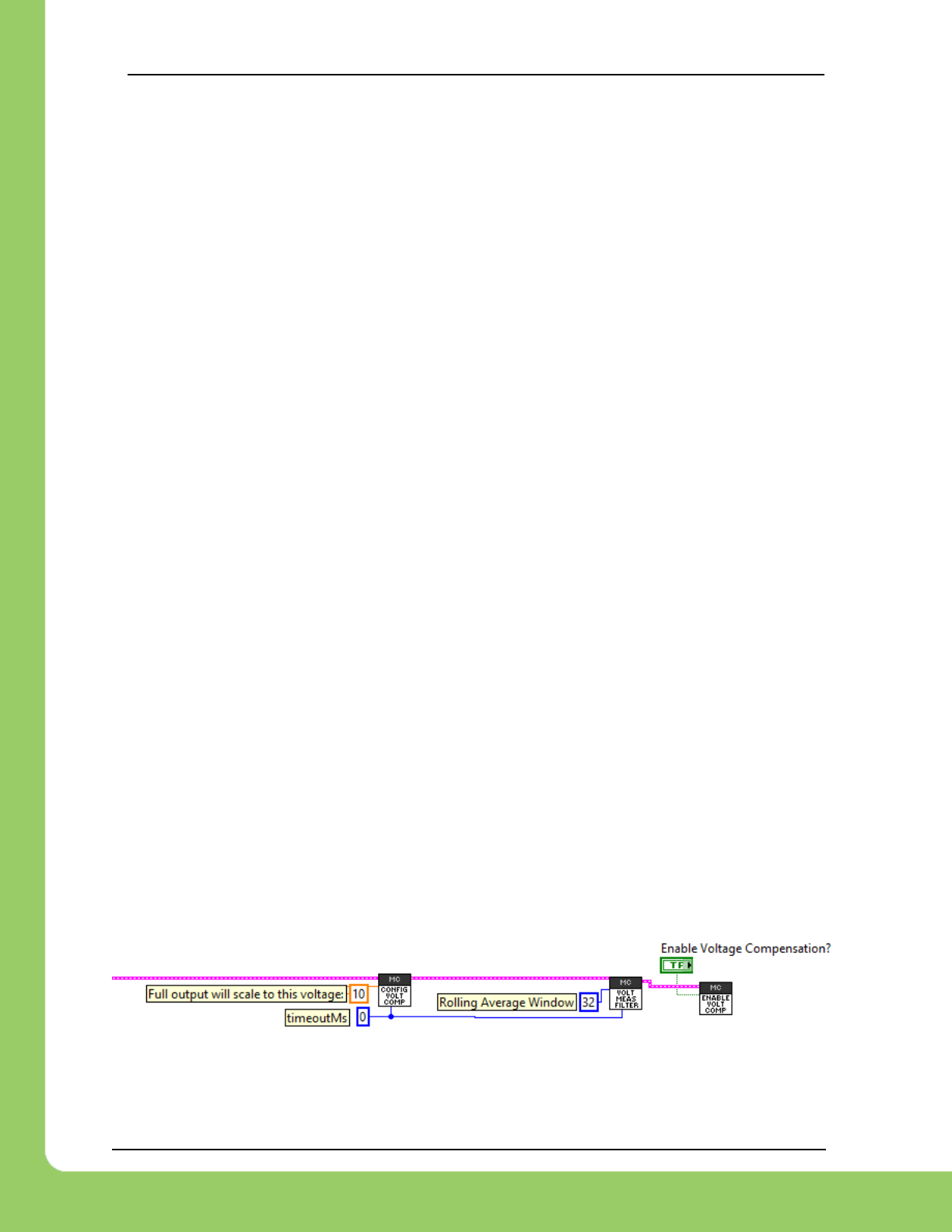
217-8080 TALON SRX / Victor SPX Software Reference Manual 3/06/2018
Cross The Road Electronics Page 62 3/06/2018
9.2. Voltage Compensation
When voltage compensation is enabled, the output duty cycle is calculated to meet the desired
output voltage. This is done by sampling the battery voltage and scaling the output duty cycle to
match the desired output voltage. If the desired output voltage exceeds battery voltage, then
Talon will drive full available voltage.
This feature affects all control modes, including…
• Percent Output Control Mode
• Position Closed-Loop Control Mode
• Velocity Closed-Loop Control Mode
• Current Closed-Loop Control Mode
• Motion Profile Control Mode
• Motion Magic Control Mode
As an example, if the Position Closed-Loop Control Mode calculates an output of 512 units
(50% motor output), then instead of applying 50% of max voltage, the Talon will apply 50% of
the specified Nominal Battery Voltage. This is accomplished by scaling the motor output
against the measured battery voltage.
If the measured battery voltage is below the necessary voltage to reach the calculated output of
the compensated closed-loop control mode, 100% motor output is applied.
This is done every 1ms synchronous with the closed-loop controller.
The configuration is persistent across power cycles and has a default value of 0.0.
Enabling this feature requires setting the saturation voltage and the feature enable. If either is
0/false, the feature is disabled.
Additionally, the voltage filter (rolling average) may be modified to tune out oscillations caused
by the voltage compensation. The Rolling average window defaults to 32 samples (each
sampled every millisecond).
Valid values for the rolling average window are {1,2,4,8,16, and 32}
9.2.1. LabVIEW
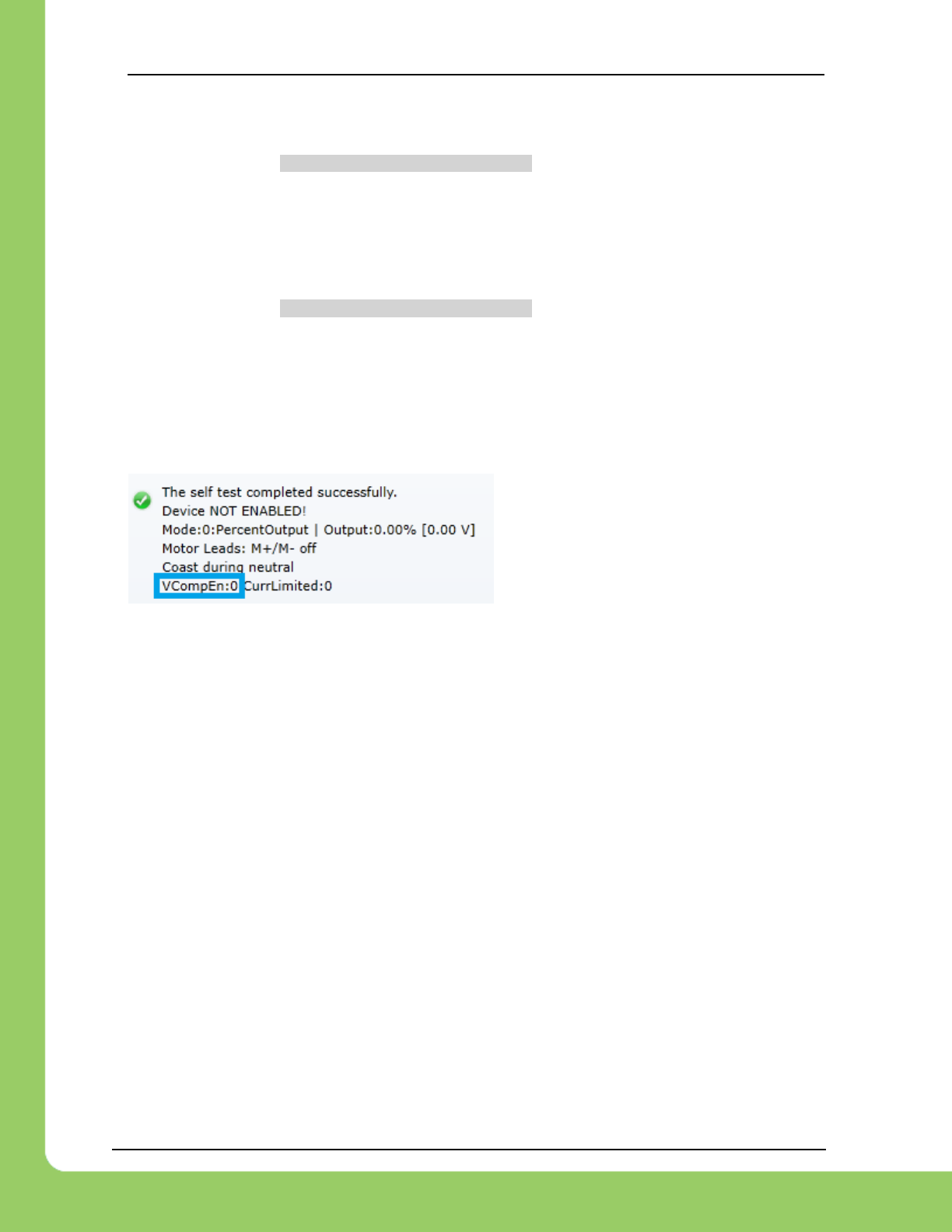
217-8080 TALON SRX / Victor SPX Software Reference Manual 3/06/2018
Cross The Road Electronics Page 63 3/06/2018
9.2.2. C++
/* "full" output will scale to 11 volts */
talon.ConfigVoltageCompSaturation(11.0, 10);
talon.EnableVoltageCompensation(true); /* turn on the feature */
/* tweak the voltage bus measurement filter,
* default is 32 cells in rolling average (1ms per sample) */
talon.ConfigVoltageMeasurementFilter(32, 10);
9.2.3. Java
/* "full" output will scale to 11 volts */
talon.configVoltageCompSaturation(11.0, 10);
talon.enableVoltageCompensation(true); /* turn on the feature */
/* tweak the voltage bus measurement filter,
* default is 32 cells in rolling average (1ms per sample) */
talon.configVoltageMeasurementFilter(32, 10);
9.2.4. Self-Test
The feature enable can be checked via the
Self-Test.
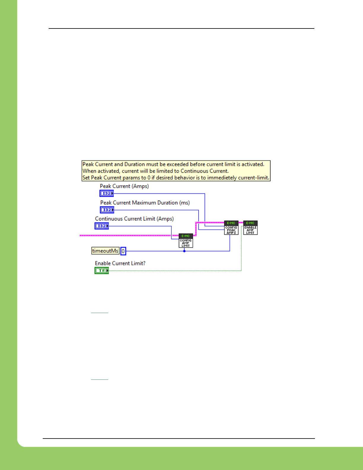
217-8080 TALON SRX / Victor SPX Software Reference Manual 3/06/2018
Cross The Road Electronics Page 64 3/06/2018
9.3. Current Limits
Talon SRX can limit the output current to a specified maximum threshold. This functionality is
available in all control modes. This feature is not available on Victor SPX.
Regardless of language or mode, there are two parameters that must be set – the numeric
current threshold (in amps) and the boolean flag to enable or disable the feature.
Additionally, a peak current and time threshold may be specified to allow excessive current
before enforcing the continuous current limit.
9.3.1. Current Limit – LabVIEW
The Talon SRX palette in LabVIEW contains a ConfigCurrentLimit VI for setting the current limit
parameters.
9.3.2. Current Limit – C++
/* Peak Current and Duration must be exceeded before current limit is activated.
When activated, current will be limited to Continuous Current.
Set Peak Current params to 0 if desired behavior is to immediately current-limit. */
talon.ConfigPeakCurrentLimit(35, 10); /* 35 A */
talon.ConfigPeakCurrentDuration(200, 10); /* 200ms */
talon.ConfigContinuousCurrentLimit(30, 10); /* 30A */
talon.EnableCurrentLimit(true); /* turn it on */
9.3.3. Current Limit – Java
/* Peak Current and Duration must be exceeded before current limit is activated.
When activated, current will be limited to Continuous Current.
Set Peak Current params to 0 if desired behavior is to immediately current-limit. */
talon.configPeakCurrentLimit(35, 10); /* 35 A */
talon.configPeakCurrentDuration(200, 10); /* 200ms */
talon.configContinuousCurrentLimit(30, 10); /* 30A */
talon.enableCurrentLimit(true); /* turn it on */

217-8080 TALON SRX / Victor SPX Software Reference Manual 3/06/2018
Cross The Road Electronics Page 65 3/06/2018
9.3.4. Current Limit – Theory of Operation
When current-limited, the Talon SRX holds the current at the target current-draw. The current
draw is compared against the current limit setting to determine if current is too high.
See the state machine below for details.
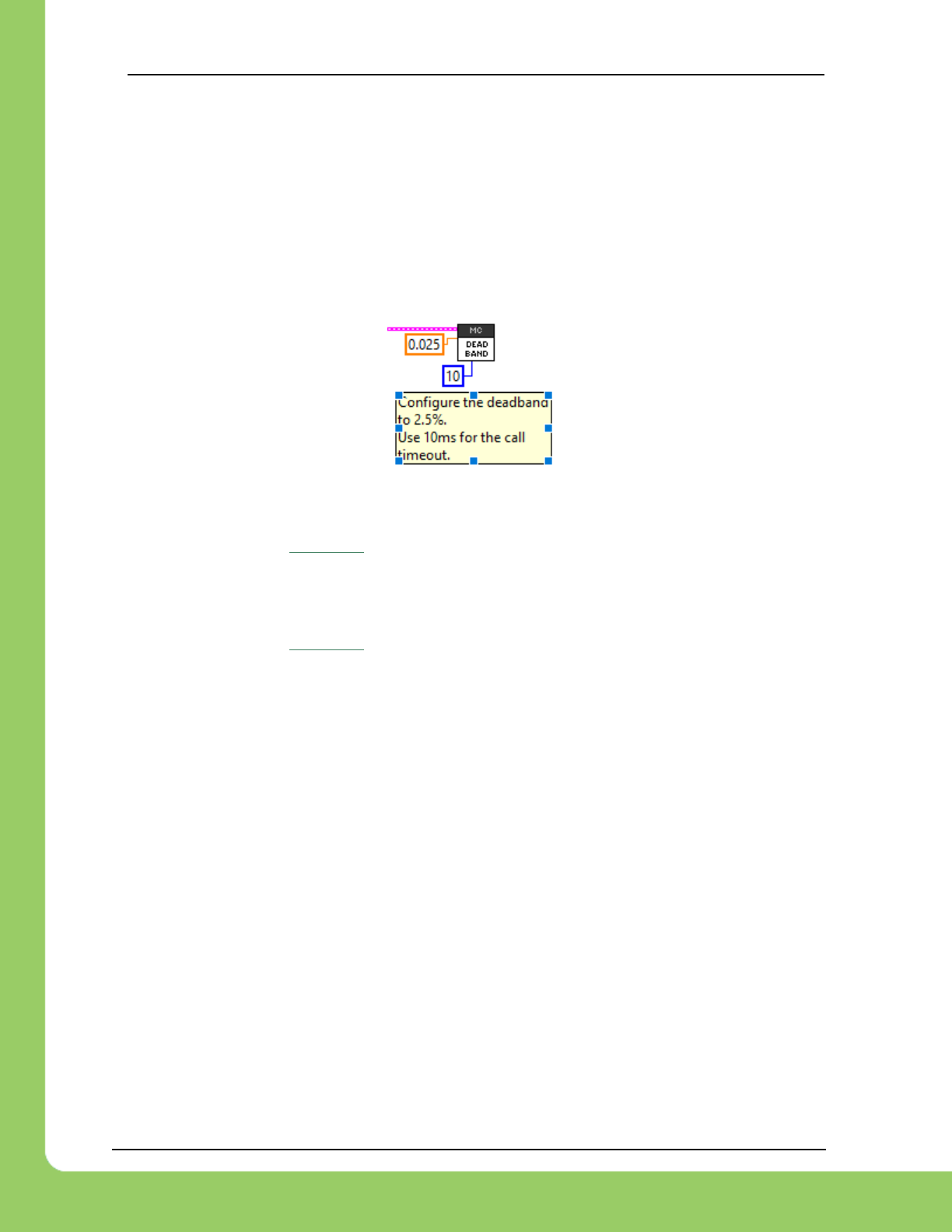
217-8080 TALON SRX / Victor SPX Software Reference Manual 3/06/2018
Cross The Road Electronics Page 66 3/06/2018
9.4. Adjusting Deadband
The Deadband is the percentage of output around zero percent that causes the motor controller
to have neutral output. The default deadband value is 4%, so the motor controller will have a
neutral output if the commanded output is less than 4% in either direction. Talon SRX and
Victor SPX support changing this deadband value. The deadband can be set to [0.001 – 0.25],
where 0.25 is 25%.
9.4.1. Dead Band – LabVIEW
9.4.2. Dead Band – C++
//Configure a 2.5% deadband.
_talon->ConfigNeutralDeadband(0.025,10);
9.4.3. Dead Band – Java
//Configure a 2.5% deadband.
talon.configNeutralDeadband(0.025, 10);
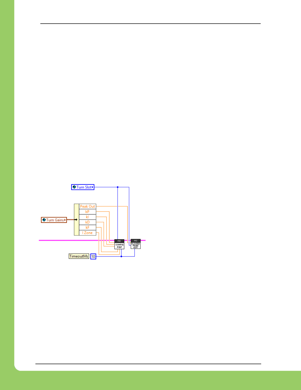
217-8080 TALON SRX / Victor SPX Software Reference Manual 3/06/2018
Cross The Road Electronics Page 67 3/06/2018
9.5. Capping Peak Output (for a particular Closed-Loop)
Talon SRX and Victor SPX supports a slot-specific peak output for a given closed-loop.
For example, if the application requires the PID0 output to be capped to ±50%, pass 0.5 to the
Config Closed-Loop peak output routine/VI.
This typically is used when running multiple PID loops (primary PID and auxiliary PID,
differential drive closed loops, etc.) and the application requires a cap on one or both PID
objects.
For example, suppose a differential drive closed loop is implemented using PID[0] for the
distance closed-loop, and PID[1] for the turn closed-loop. For robot stability, the application
may require the turn closed-loop output to not exceed a value. In which case, using the general
peak routines are not sufficient since the goal is to cap the contribution of a specified PID loop.
For this reason, the Closed Loop Peak Output routine/VI, requires specifying the closed-loop
slot. This also allows the peak contribution to be (gain) scheduled.
9.5.1. LabVIEW
Example demonstrates the Config Closed-Loop
Peak Output VI, along with the Config PIDF
gains VI. Both require deciding on what slot to
save the constants to.
9.5.2. C++
_talonRght.ConfigClosedLoopPeakOutput(
Constants.kSlot_Turning,
Constants.kGains_Turning.kPeakOutput,
Constants.kTimeoutMs);
9.5.3. Java
_talonRght.configClosedLoopPeakOutput(
Constants.kSlot_Turning,
Constants.kGains_Turning.kPeakOutput,
Constants.kTimeoutMs);
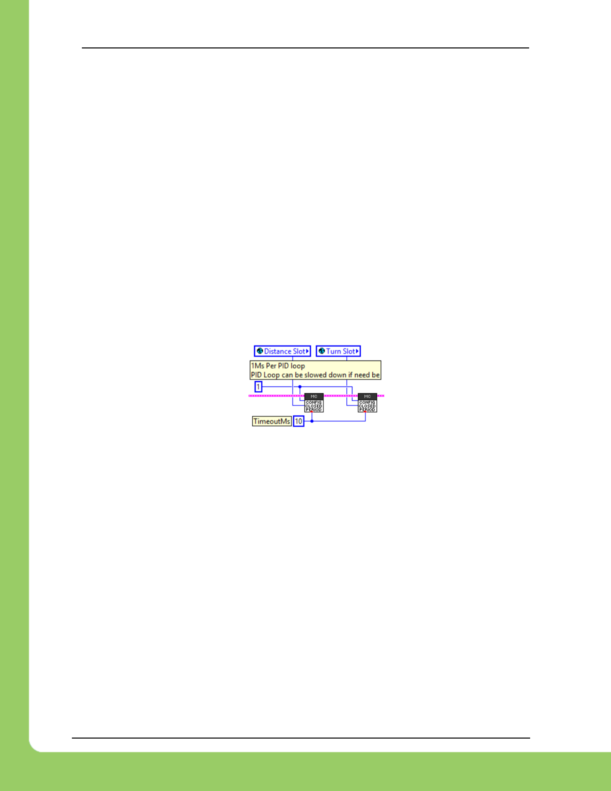
217-8080 TALON SRX / Victor SPX Software Reference Manual 3/06/2018
Cross The Road Electronics Page 68 3/06/2018
9.6. Modifying Closed-Loop Period
The Closed-Loop routine in CTRE CAN motor controllers default to an execution period of 1ms.
However, there are circumstances where the application may benefit from running the loop
slower.
This configuration parameter is also slotted, and therefore can be (gain) scheduled.
Examples include…
• Mechanism velocity is slow, causing the derivative term to be near-zero in all
circumstances.
• Sensor resolution is low, causing the derivative term to be near-zero in all
circumstances.
• Mechanism has unusually large time delay between motor-output-correction to change-
in-process-variable (Pilot-induced oscillation).
• Sensor updates are slower than 1ms, causing discontinuities in the derivate term.
9.6.1. LabVIEW
9.6.2. C++
int closedLoopTimeMs = 1;
_talonRght.ConfigClosedLoopPeriod(Constants.kSlot_Distanc,
closedLoopTimeMs,
Constants.kTimeoutMs );
_talonRght.ConfigClosedLoopPeriod(Constants.kSlot_Turning,
closedLoopTimeMs,
Constants.kTimeoutMs );
9.6.3. Java
int closedLoopTimeMs = 1;
_talonRght.configClosedLoopPeriod(Constants.kSlot_Distanc,
closedLoopTimeMs,
Constants.kTimeoutMs);
_talonRght.configClosedLoopPeriod(Constants.kSlot_Turning,
closedLoopTimeMs,
Constants.kTimeoutMs);

217-8080 TALON SRX / Victor SPX Software Reference Manual 3/06/2018
Cross The Road Electronics Page 69 3/06/2018
9.7. Feedback Coefficient
The selected sensor for PID[0] or PID[1] can be multiplied by a custom coefficient prior to being
latched for self-test/closed-loop/soft-limit/sensor-API/etc.
The coefficient must be within [0.000015258789, 1.000], and has a resolution of
0.0000152587890625.
This is useful for…
• Applying a gear ratio reduction so sensor value closely represents geared output.
For example, if sensor is 4096 units per motor rotation, geared output is 12:1, a
suggested coefficient would be 0.0203450521 (1000/4096/12). This ensures that every
mechanical rotation scales to 1000 units (which is passed into the closed-loop/soft
limits/self-test/etc.).
• Scaling turn sensor value for advanced differential two-axis closed-loops (turn
component).
For example, when configuring a closed-loop sensor for turning, sensor typically is
scaled to 3600 units per rotation (10 units per degree). This ensures adequate
resolution reaching the closed-loop, while scaling to a human-readable unit (3600 =>
360 degrees).
• Scaling Velocity to RPM.
For example, if sensor is 4096 units per rotation, and velocity closed-loop is being used,
application can provide a coefficient of 0.146484375 (600/4096), so velocity signal is in
RPM. This presumes that having the velocity process variable in RPM units is adequate
resolution (which is typically the case).
Note that if a coefficient is applied, the various SetSelectedSensorPosition() routines/VIs will
honor the coefficient (in firmware).

217-8080 TALON SRX / Victor SPX Software Reference Manual 3/06/2018
Cross The Road Electronics Page 70 3/06/2018
9.8. Remote Features
9.8.1. Remote Features - General Overview
Talon SRX and Victor SPX support a variety of features that utilize direct communication with
remote sensors on the CAN bus. A primary Talon SRX and Victor SPX can pull sensor data
from a remote…
- Pigeon IMU connected to a secondary Talon (different than the primary motor controller)
via Gadgeteer ribbon cable.
- Pigeon IMU connected directly to the CAN bus.
- CANifier Quadrature sensor connected directly to the CAN bus.
- The selected sensor of another secondary Talon (Quadrature, Analog, Pulse Width, etc.)
on CAN bus.
When using a remote source for limit-switching, generally all that is required is to specify the
remote device ID and type in the limit switch API. See section 9.8.2 for more information.
When using a remote source for soft-limit or closed-looping, the following is required…
• Remote filter 0 or 1 must be configured to capture the position/velocity of the remote
sensor source.
• The selected sensor type must be set to remote filter 0 or 1 (or sensor sum/difference
in the more advanced use cases).
• All motor controllers must have 3.8 firmware or later.
See section 9.8.3 for more information.
Examples of this feature can be found in the “Remote*” projects under…
https://github.com/CrossTheRoadElec/Phoenix-Examples-Languages
https://github.com/CrossTheRoadElec/Phoenix-Examples-LabVIEW
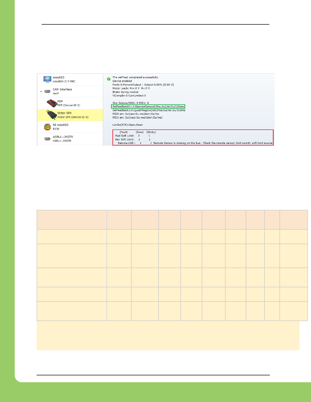
217-8080 TALON SRX / Victor SPX Software Reference Manual 3/06/2018
Cross The Road Electronics Page 71 3/06/2018
9.8.1.1. Remote Features – What happens if sensor is not present?
If a motor controller feature that depends on a remote sensor is enabled, and the remote sensor
is not present on the CAN bus (100 ms timeout) then the motor controller will neutral its output.
Such circumstances can be detected via the Remote Loss of Signal (LOS) fault.
If the remote limit switch feature is enabled and the remote sensor is no longer present (100
ms timeout), then the fault for forward/reverse limit switch will also assert.
If the remote software limit feature is enabled and the remote sensor is no longer present (100
ms timeout), then the fault for forward/reverse soft limit will also assert.
9.8.1.1.1. Remote fault conditions when remote sensor is missing
Description
Remote
Limit
Switch
Enabled
Remote
Filter
Configured
Remote
Sensor
Selected
Soft
Limit
Enabled
Closed
Loop
Control
mode
Remote
LOS
Fault
Limit
Switch
Fault
Soft
Limit
Fault
Motor
output
Application uses remote limit
switches.
TRUE
FALSE
FALSE
FALSE
FALSE
1
1(1)
Output set
to neutral
(1)
Application has configured a
remote sensor filter, but is not
directly using any remote sensor
features.
FALSE
TRUE
FALSE
FALSE
FALSE
1
(no
influence)
Remote sensor selected
FALSE
X
TRUE
FALSE
FALSE
1
(no
influence)
Remote sensor selected and
soft-limit features enabled.
FALSE
X
TRUE
TRUE
X
1
1(2)
Output set
to neutral
(2)
Remote sensor selected and
closed-loop control mode
enabled.
FALSE
X
TRUE
FALSE
TRUE
1
Output set
to neutral
(3)
Note 1: Requires LimitSwitchDisableNeutralOnLOS to be zero (default) and target duty cycle to be nonzero.
Note 2: Requires SoftLimitDisableNeutralOnLOS to be zero (default) and target duty cycle must be nonzero.
Note 3: Requires RemoteSensorClosedLoopDisableNeutralOnLOS to be zero(default).
X => don’t care

217-8080 TALON SRX / Victor SPX Software Reference Manual 3/06/2018
Cross The Road Electronics Page 72 3/06/2018
9.8.2. Remote Limit Switch
A primary Talon SRX or Victor SPX can be configured to use the forward and reverse limit
switch inputs of another device. Typically, this is done via the same routines/VIs as the on-
board Talon SRX limit switches, except the remote device type and device ID is specified.
Note the remote device is the source of limit switch inputs (Talon SRX or CANifier).
The primary motor controller (Talon SRX or Victor SPX) when configured, will automatically
measure the remote device’s limit pins and will output neutral and fault appropriately.
Some example use-cases…
• Limit switch is physically far from the motor controller, but a CANifier can be
placed/packaged with a limit switch at the mechanism.
• CTRE magnetic encoder is used on Talon SRX, and active sensors (that require power)
are used for limit switches. Active sensors can then be powered/connected via another
Talon (with a free Gadgeteer port) or CANifier.
• Limit switch pins on primary Talon SRX are already in use for other purposes, and/or
alternative limit switches are required.
9.8.2.1. Remote Limit Switch – C++
Example below will configure a motor controller’s limit switch sources to a remote CANifier.
Note the use of GetDeviceNumber() to retrieve the CAN device ID and the typical value of
10ms for the Config timeoutMs.
_motorCntrller.ConfigForwardLimitSwitchSource(
RemoteLimitSwitchSource::RemoteLimitSwitchSource_RemoteCANifier,
LimitSwitchNormal::LimitSwitchNormal_NormallyOpen,
_canifier.GetDeviceNumber(),
10); /* timeoutMs */
_motorCntrller.ConfigReverseLimitSwitchSource(
RemoteLimitSwitchSource::RemoteLimitSwitchSource_RemoteCANifier,
LimitSwitchNormal::LimitSwitchNormal_NormallyOpen,
_canifier.GetDeviceNumber(),
10); /* timeoutMs */
Example below will configure a motor controller’s limit switch sources to a remote Talon SRX
Gadgeteer limit switch pins. Note the use of GetDeviceID() to retrieve the CAN device ID and
the typical value of 10ms for the Config timeoutMs.
_motorCntrller.ConfigForwardLimitSwitchSource(
RemoteLimitSwitchSource::RemoteLimitSwitchSource_RemoteTalonSRX,
LimitSwitchNormal::LimitSwitchNormal_NormallyOpen,
_talonLimits.GetDeviceID(),
10); /* timeoutMs */
_motorCntrller.ConfigReverseLimitSwitchSource(
RemoteLimitSwitchSource::RemoteLimitSwitchSource_RemoteTalonSRX,
LimitSwitchNormal::LimitSwitchNormal_NormallyOpen,
_talonLimits.GetDeviceID(),
10); /* timeoutMs */
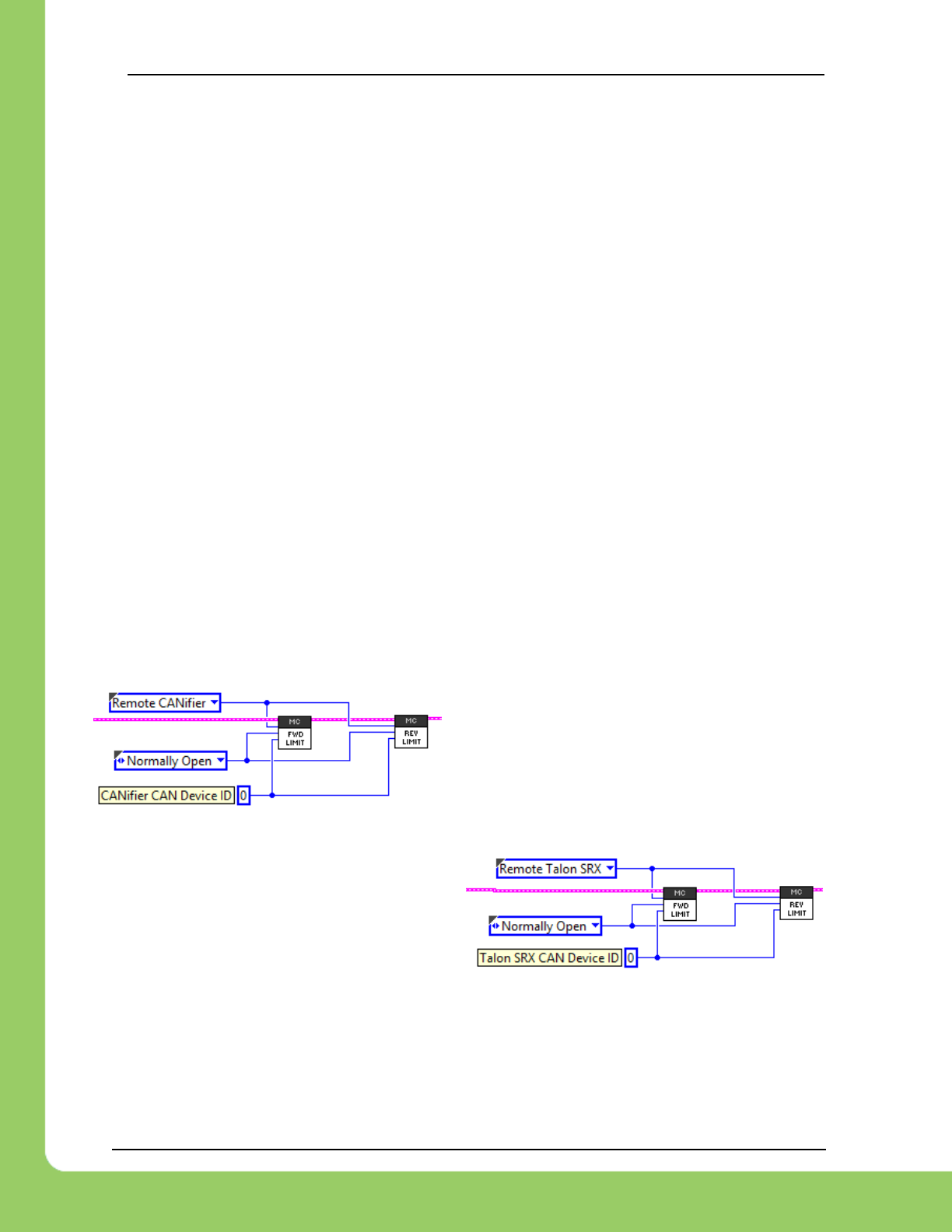
217-8080 TALON SRX / Victor SPX Software Reference Manual 3/06/2018
Cross The Road Electronics Page 73 3/06/2018
9.8.2.2. Remote Limit Switch – Java
Example below will configure a motor controller’s limit switch sources to a remote CANifier.
Note the use of GetDeviceID() to retrieve the CAN device ID and the typical value of 10ms for
the Config timeoutMs.
_motorCntrller.configForwardLimitSwitchSource(
RemoteLimitSwitchSource.RemoteCANifier,
LimitSwitchNormal.NormallyOpen,
_canifier.getDeviceID(),
10); /* timeoutMs */
_motorCntrller.configReverseLimitSwitchSource(
RemoteLimitSwitchSource.RemoteCANifier,
LimitSwitchNormal.NormallyOpen,
_canifier.getDeviceID(),
10); /* timeoutMs */
Example below will configure a motor controller’s limit switch sources to a remote Talon SRX
Gadgeteer limit switch pins. Note the use of GetDeviceID() to retrieve the CAN device ID and
the typical value of 10ms for the Config timeoutMs.
_motorCntrller.configForwardLimitSwitchSource(
RemoteLimitSwitchSource.RemoteTalonSRX,
LimitSwitchNormal.NormallyOpen,
_talonLimits.getDeviceID(),
10); /* timeoutMs */
_motorCntrller.configReverseLimitSwitchSource(
RemoteLimitSwitchSource.RemoteTalonSRX,
LimitSwitchNormal.NormallyOpen,
_talonLimits.getDeviceID(),
10); /* timeoutMs */
9.8.2.3. Remote Limit Switch – LabVIEW
Left example demonstrates configuring a Talon
SRX or Victor SPX to use the limit switch pins of a
remote CANifier.
The remote CANifier CAN device ID is zero.
Right example demonstrates using another
Talon’s LIM-F and LIM-R Gadgeteer pins for
limit switch features.
The remote Talon CAN device ID is 0.

217-8080 TALON SRX / Victor SPX Software Reference Manual 3/06/2018
Cross The Road Electronics Page 74 3/06/2018
9.8.2.4. Remote Limit Switch – Loss of Signal
When the remote limit switch feature is in use, the motor controller will output neutral if the
remote device is not present on the CAN bus (100 ms timeout). This ensures that the
mechanism does not drive into a hard stop due to loss-of-signal of the remote device.
If this is not desired, the following excerpts can be used to circumvent this check, allowing for
uninhibited motor control if the remote device is not present on the CAN bus.
9.8.2.4.1. Disable Neutral-During-LOS – LabVIEW
9.8.2.4.2. Disable Neutral-During-LOS – C++
int value = 1;
_motorCntrller.ConfigSetParameter(ParamEnum::eLimitSwitchDisableNeutralOnLOS,
value,
0x00,
0x00,
10); /* timeoutMs */
9.8.2.4.3. Disable Neutral-During-LOS – Java
int value = 1;
_motorCntrller.configSetParameter(ParamEnum.eLimitSwitchDisableNeutralOnLOS,
value,
0x00,
0x00,
10); /* timeoutMs */
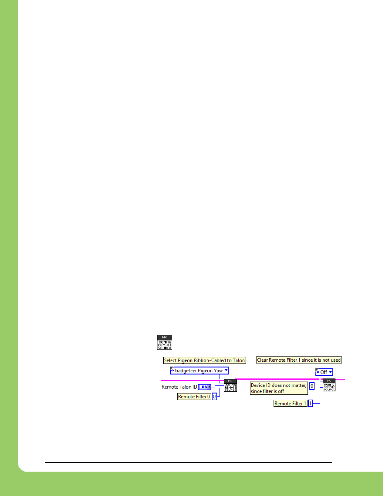
217-8080 TALON SRX / Victor SPX Software Reference Manual 3/06/2018
Cross The Road Electronics Page 75 3/06/2018
9.8.3. Remote Sensor Selection
A primary Talon or Victor SPX can be configured to decode the position/velocity of another
remote device. Typically, this is done by configuring a remote sensor filter, and then selecting
the remote filter as the “selected feedback device”.
Note the remote device is the source of position/velocity (Talon SRX, CANifier, Pigeon IMU).
The primary motor controller (Talon SRX or Victor SPX) when configured, will capture the
respective status frame from the remote device and decode the position (and velocity if
available).
Some example use-cases for selecting a remote sensor…
• Closed-looping a sensor that is connected to a CANifier or a separate Talon SRX.
• Configuring soft-limit features to use a sensor that is connected to a CANifier or a
separate Talon SRX.
• Integrating Pigeon IMU yaw, pitch, or roll for a single axis mechanism.
• Performing a complete differential drive (distance and heading via two-axis closed-loop)
when combined with the sensor sum and sensor-difference signals.
• Performing a complete differential drive (distance and heading via two-axis closed-loop)
when combined with Pigeon IMU and one or two encoders (depending on wiring).
9.8.3.1. Remote Filter Configuration
Remote Filters are the signal filters that decode the position (and potentially velocity) signal from
a status CAN frame from one of several remote device types.
The available options are …
• The selected sensor of remote Talon SRX
• Pigeon Yaw, Pitch, or Roll (Pigeon on CAN bus).
• Pigeon Yaw, Pitch, or Roll (Pigeon connected to a remote Talon SRX via ribbon
Gadgeteer cable).
• CANifier Quadrature
• CANifier PWM input (PWM Channel 0,1,2, or 3)
9.8.3.1.1. Remote Filter Configuration – LabVIEW
The remote filters are configured via .
In this example the remote filter 0 is
setup to acquire the Yaw signal
from a Pigeon connected to a
secondary Talon SRX with a CAN
ID of “Remote Talon ID”.
Note remote filter 1 is explicitly turned off. This is ideal as a previously configured remote filter
(from a different robot platform) can cause distracting loss-of-signal faults.

217-8080 TALON SRX / Victor SPX Software Reference Manual 3/06/2018
Cross The Road Electronics Page 76 3/06/2018
9.8.3.1.2. Remote Filter Configuration – C++
The example below configures remote filter 0 to filter the selected sensor of a remote Talon
SRX.
Note remote filter 1 is explicitly turned off. This is ideal as a previously configured remote filter
(from a different robot platform) can cause distracting loss-of-signal faults.
/* select a quadrature encoder connected to a remote Talon */
_motorCntrller.ConfigRemoteFeedbackFilter(
_remoteTalon.GetDeviceID(), /* device ID of the remote Talon */
RemoteSensorSource::RemoteSensorSource_TalonSRX_SelectedSensor,
0, /* remote filter 0 */
10); /* timeout ms */
/* not using remote 1 */
_motorCntrller.ConfigRemoteFeedbackFilter(
0x00, /* device ID doesn’t matter since filter is off */
RemoteSensorSource::RemoteSensorSource_Off,
1, /* remote filter 1 */
10); /* timeout ms */
9.8.3.1.3. Remote Filter Configuration – Java
The example below configures remote filter 1 to capture a Pigeon IMU’s Yaw signal from CAN
bus.
Note remote filter 0 is explicitly turned off. This is ideal as a previously configured remote filter
(from a different robot platform) can cause distracting loss-of-signal faults.
/* turn off remote 0 */
_motorCntrller.configRemoteFeedbackFilter(
0x00, /* device ID does not matter since filter is off */
RemoteSensorSource.Off,
0, /* remote filter 0 */
10); /* timeout ms */
/* select a Pigeon on CAN Bus. */
_motorCntrller.configRemoteFeedbackFilter(
_pigeonIMU.getDeviceID(),
RemoteSensorSource.Pigeon_Yaw,
1, /* remote filter 1 */
10); /* timeout ms */
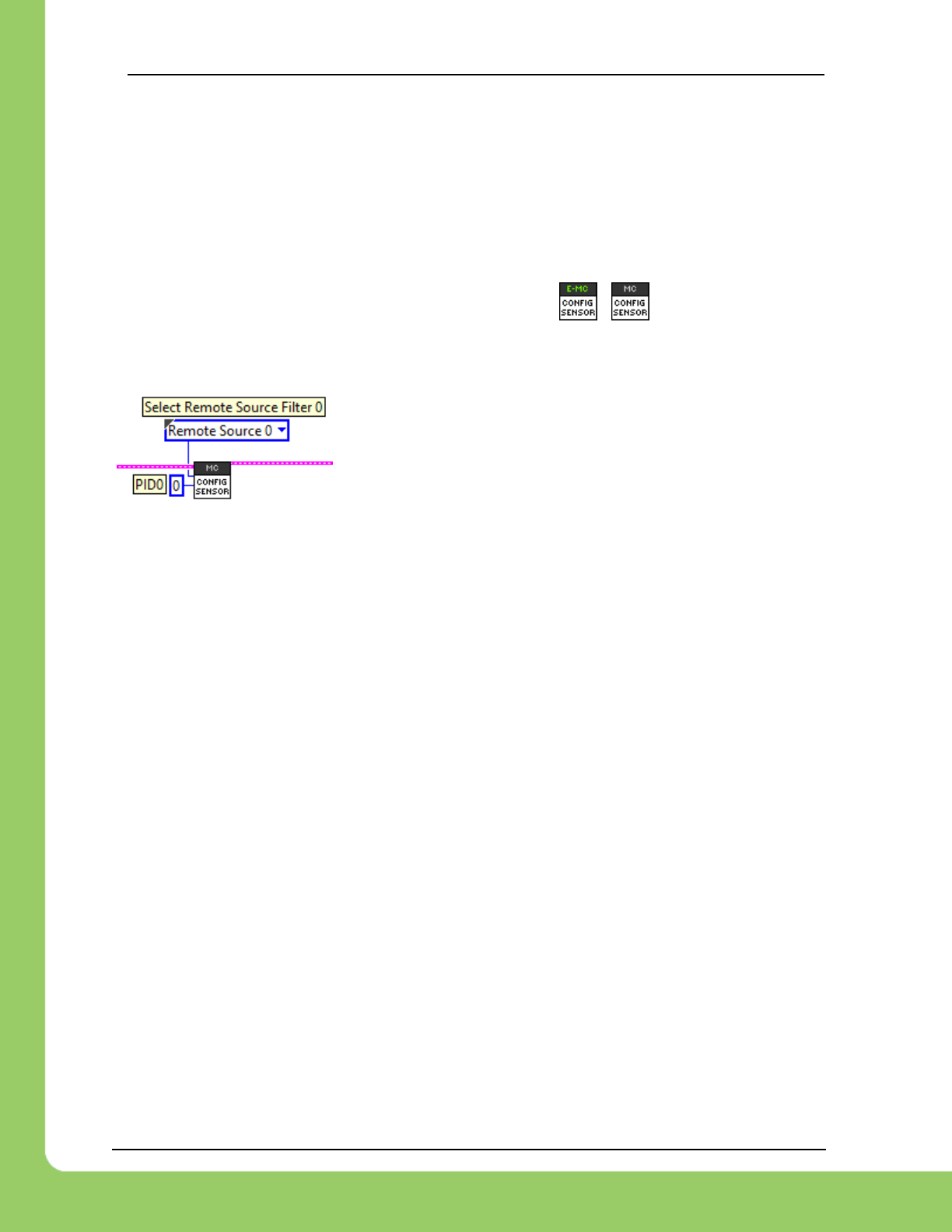
217-8080 TALON SRX / Victor SPX Software Reference Manual 3/06/2018
Cross The Road Electronics Page 77 3/06/2018
9.8.3.2. Config Selected Sensor Feedback Type
Selecting the selected sensor is no different when using a remote sensor than when using a
locally connected sensor to a Talon SRX via the Gadgeteer ribbon cable. The only difference is
that the selected type is remote filter 0 or remote filter 1.
9.8.3.2.1. Config Selected Sensor Feedback Type – LabVIEW
In LabVIEW, the Vis used for selecting the sensor type are / , for Talon SRX and
Victor SPX respectively. Note these are the same VIs used for selecting locally connected
sensors to a typical Talon SRX (non-remote use-case).
In this example, the remote filter 0 is selected for closed-
loop/soft-limit features.
9.8.3.2.2. Config Selected Sensor Feedback Type – Java
Talon SRX motor controllers can use the FeedbackDevice or RemoteFeedbackDevice
enumeration.
Victor SPX motor controllers can only use the RemoteFeedbackDevice enumeration, otherwise
source will not compile.
_motorCntrller.configSelectedFeedbackSensor(FeedbackDevice.RemoteSensor0,
0, /* PID0 is the primary loop */
10); /* timeoutMs */
9.8.3.2.3. Config Selected Sensor Feedback Type – C++
Talon SRX motor controllers can use the FeedbackDevice or RemoteFeedbackDevice
enumeration.
Victor SPX motor controllers can only use the RemoteFeedbackDevice enumeration, otherwise
source will not compile.
_motorCntrller.ConfigSelectedFeedbackSensor(
RemoteFeedbackDevice::RemoteFeedbackDevice_RemoteSensor0,
0, /* PID0 is the primary loop */
10); /* timeoutMs */
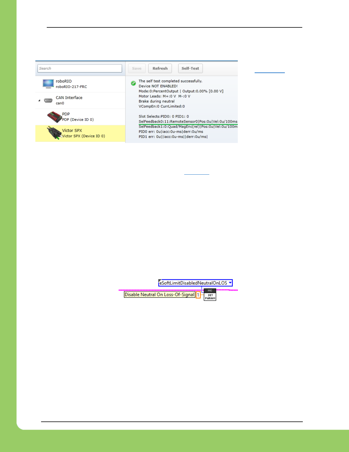
217-8080 TALON SRX / Victor SPX Software Reference Manual 3/06/2018
Cross The Road Electronics Page 78 3/06/2018
9.8.3.3. Selected Sensor in Web-based Configuration
Remote 0 / Remote 1 sensor values can be polled in the web-based configuration self-test.
See section 2.4 for
details on the self-test.
9.8.4. Configuring Remote Soft Limit
Once the sensor type has been selected and confirmed via the web-based configuration, the
soft-limit features can be configured normally. See section 8 for more information.
Follow the typical procedure for ensuring the sensor is in phase with motor output.
9.8.4.1. Configuring Remote Soft Limit – Loss of signal
When the soft limit feature is in use, the motor controller will neutral the output if the remote
device is not present on the CAN bus (100 ms timeout). This ensures that the mechanism does
not drive into a hard stop due to loss-of-signal of the remote device.
If this is not desired, the following excerpts can be used to circumvent this check, allowing for
uninhibited motor control if the remote device is not present on the CAN bus.
9.8.4.1.1. Disable Neutral-During-LOS – LabVIEW
9.8.4.1.2. Disable Neutral-During-LOS – C++
int value = 1;
_motorCntrller.ConfigSetParameter(ParamEnum::eSoftLimitDisableNeutralOnLOS,
value,
0x00,
0x00,
10); /* timeoutMs */
9.8.4.1.3. Disable Neutral-During-LOS – Java
int value = 1;
_motorCntrller.configSetParameter(ParamEnum.eSoftLimitDisableNeutralOnLOS,
value,
0x00,
0x00,
10); /* timeoutMs */
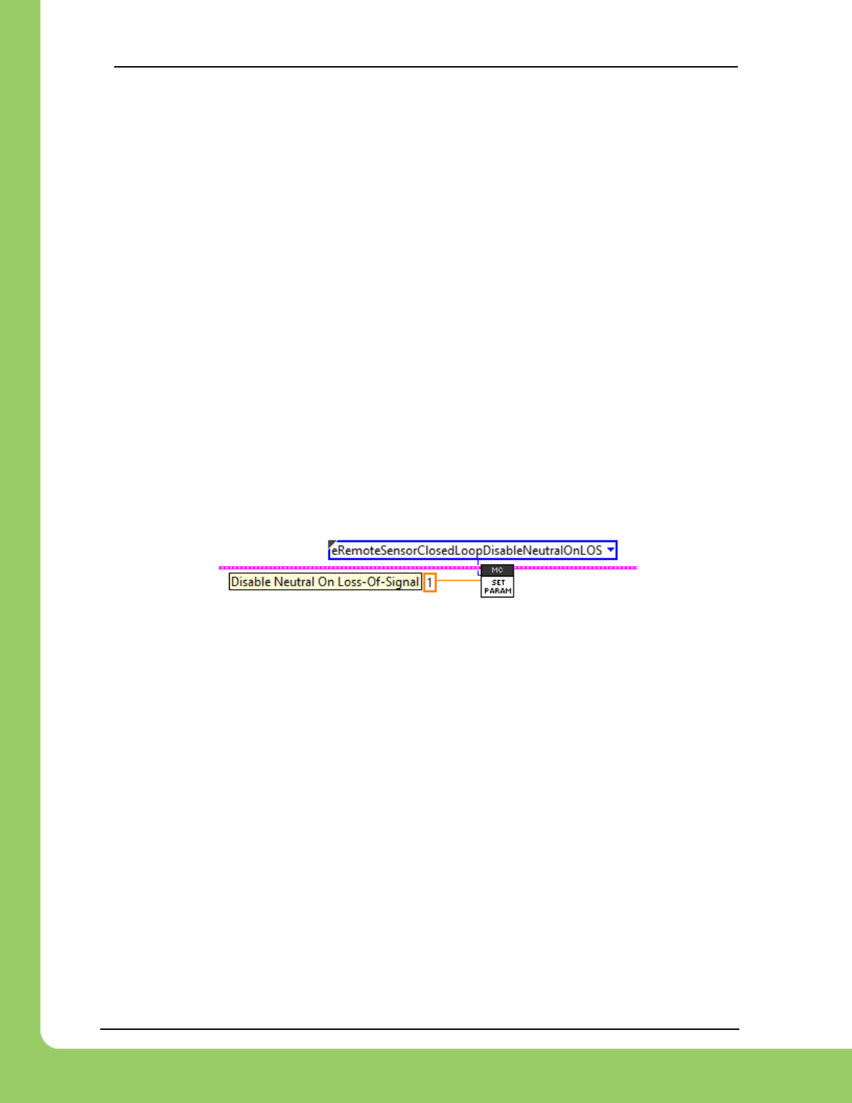
217-8080 TALON SRX / Victor SPX Software Reference Manual 3/06/2018
Cross The Road Electronics Page 79 3/06/2018
9.8.5. Closed-Loop with Remote Sensor
All closed-loop control modes support using a remote sensor.
Once the sensor type has been selected and confirmed via the web-based configuration, the
Closed-Loop features can be configured normally.
Follow the typical procedure for ensuring the sensor is in phase with motor output.
9.8.5.1. Closed-Loop – Loss of signal
When a closed-loop control mode is using a remote sensor, the motor controller will neutral
the output if the remote device is not present on the CAN bus (100 ms timeout). This
ensures that the mechanism does not drive into a hard stop due to loss-of-signal of the remote
device.
If this is not desired, the following excerpts can be used to circumvent this check, however the
closed-loop response will use the last received signal value, if this change is applied.
Typically, this is not desired, and careful thought should be taken before changing the default
behavior.
9.8.5.1.1. Disable Neutral-During-LOS – LabVIEW
9.8.5.1.2. Disable Neutral-During-LOS – C++
int value = 1;
_motorCntrller.ConfigSetParameter(ParamEnum::eRemoteSensorClosedLoopDisableNeutralOnLOS,
value,
0x00,
0x00,
10); /* timeoutMs */
9.8.5.1.3. Disable Neutral-During-LOS – Java
int value = 1;
_motorCntrller.configSetParameter(ParamEnum.eRemoteSensorClosedLoopDisableNeutralOnLOS,
value,
0x00,
0x00,
10); /* timeoutMs */

217-8080 TALON SRX / Victor SPX Software Reference Manual 3/06/2018
Cross The Road Electronics Page 80 3/06/2018
9.9. Sensor Sum / Sensor Difference
Starting with firmware 3.8, Talon SRX and Victor SPX can also use the sum or difference of two
signals for closed-looping / software limit features.
Examples of this feature can be found in the “Remote*” projects under…
https://github.com/CrossTheRoadElec/Phoenix-Examples-Languages
https://github.com/CrossTheRoadElec/Phoenix-Examples-LabVIEW
This is useful for
• Differential drive train distance (distance is the sum of right and left).
• Differential drive train heading (heading is the difference between right and left)
• Two-motor mechanisms (motors are not mechanically linked, or weakly mechanically
linked).
When using the sensor sum feature, the developer must …
• Specify the S0 term.
• Specify the S1 term.
• Confirm (via web-based config self-test or sensor API) that sensor sum (S0 + S1) is
signed correctly. Positive motor output should increase the sensor sum.
• Confirm sensor sum values are reasonable and continuous (plotting/controlled testing).
• Confirm all motor controllers have 3.8 or newer firmware.
When using the sensor difference feature, the developer must …
• Specify the D0 term.
• Specify the D1 term.
• Confirm (via web-based config self-test or sensor API) that sensor difference (D0 - D1) is
signed correctly. Positive motor output should increase the sensor difference.
• Confirm sensor difference values are reasonable and continuous (plotting/controlled
testing).
• Confirm all motor controllers have 3.8 or newer firmware.
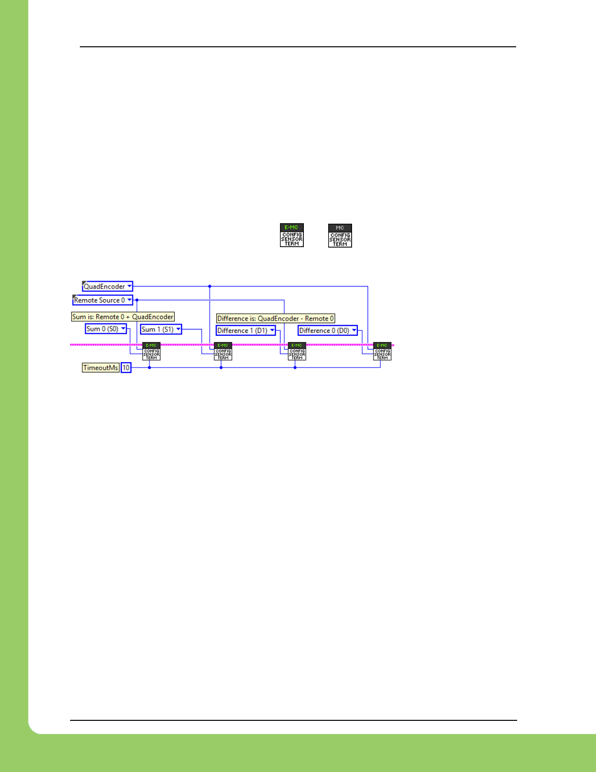
217-8080 TALON SRX / Victor SPX Software Reference Manual 3/06/2018
Cross The Road Electronics Page 81 3/06/2018
9.9.1. Sensor Sum / Sensor Difference – Configuring terms
In these examples…
• Sensor Sum is configured to be a remote sensor 0 + ribbon cabled quadrature
encoder (SRX).
• Sensor Difference is configured to be ribbon cabled quadrature encoder (SRX) -
remote sensor 0
• Talon SRX is on the right side of a drive train.
9.9.1.1. LabVIEW Example
Configuring a sensor term can be done with and , for Talon SRX and Victor SPX
respectively.
9.9.1.2. C++ Example
/* setup sum and difference signals - timeoutMs is 10ms */
_talonRght.ConfigSensorTerm(SensorTerm::SensorTerm_Sum0, FeedbackDevice::RemoteSensor0, 10);
_talonRght.ConfigSensorTerm(SensorTerm::SensorTerm_Sum1, FeedbackDevice::QuadEncoder, 10);
_talonRght.ConfigSensorTerm(SensorTerm::SensorTerm_Diff1, FeedbackDevice::RemoteSensor0, 10);
_talonRght.ConfigSensorTerm(SensorTerm::SensorTerm_Diff0, FeedbackDevice::QuadEncoder, 10);
9.9.1.3. Java Example
/* setup sum and difference signals - timeoutMs is 10ms */
_talonRght.configSensorTerm(SensorTerm.Sum0, FeedbackDevice.RemoteSensor0, 10);
_talonRght.configSensorTerm(SensorTerm.Sum1, FeedbackDevice.QuadEncoder, 10);
_talonRght.configSensorTerm(SensorTerm.Diff1, FeedbackDevice.RemoteSensor0, 10);
_talonRght.configSensorTerm(SensorTerm.Diff0, FeedbackDevice.QuadEncoder, 10);
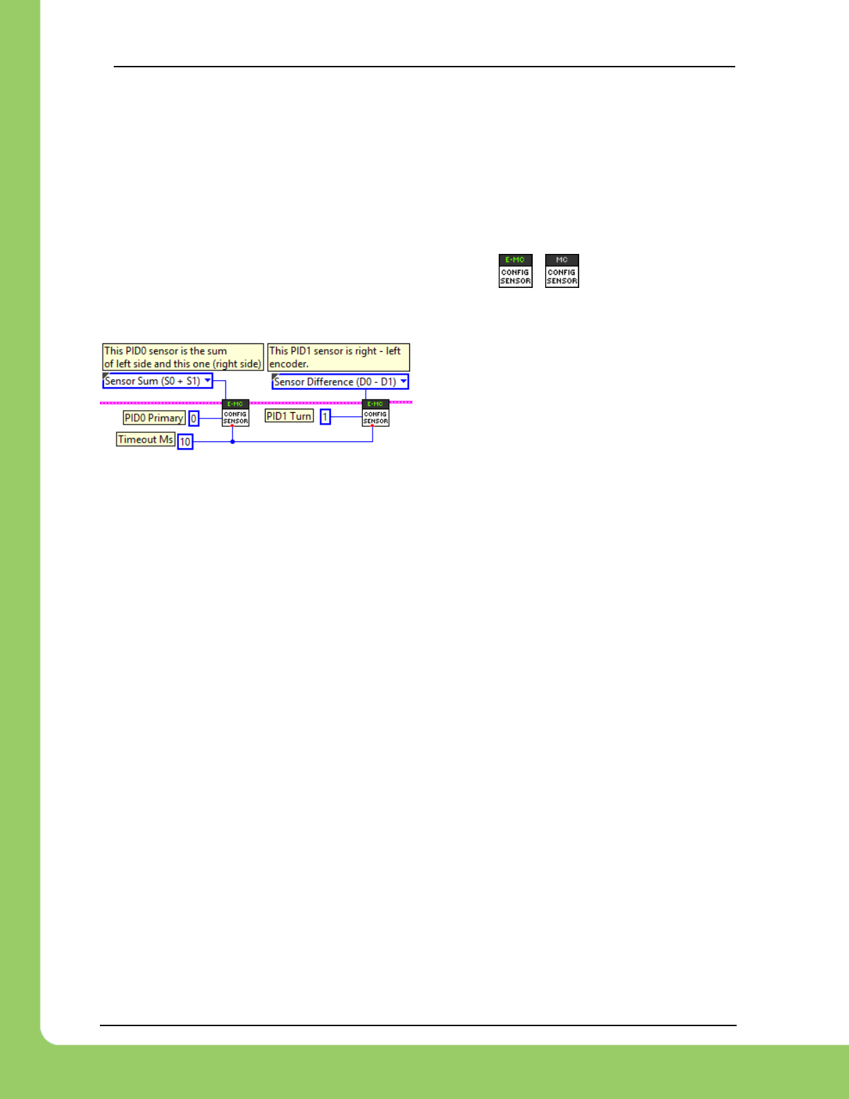
217-8080 TALON SRX / Victor SPX Software Reference Manual 3/06/2018
Cross The Road Electronics Page 82 3/06/2018
9.9.2. Sensor Sum / Sensor Difference – Selected sensor feedback type
Selecting the sensor is no different when using a sensor sum/different than when using a locally
connected sensor to a Talon SRX via the Gadgeteer ribbon cable. The only difference is that
the selected type is “sensor sum” or “sensor difference”.
9.9.2.1. Config Selected Sensor Feedback Type – LabVIEW
In LabVIEW, the Vis used for selecting the sensor type are / , for Talon SRX and
Victor SPX respectively. Note this is the same VI used for selecting locally connected sensors
to a typical Talon SRX (non-remote use-case).
In this example, the sensor sum and sensor
difference are used for closed-loop features.
9.9.2.2. Config Selected Sensor Feedback Type – Java
Talon SRX motor controllers can use the FeedbackDevice or RemoteFeedbackDevice
enumeration.
Victor SPX motor controllers can only use the RemoteFeedbackDevice enumeration. Otherwise
the source will not compile.
_motorCntrller.configSelectedFeedbackSensor(FeedbackDevice.SensorSum,
0, /* PID0 is the primary loop */
10); /* timeoutMs */
9.9.2.3. Config Selected Sensor Feedback Type – C++
Talon SRX motor controllers can use the FeedbackDevice or RemoteFeedbackDevice
enumeration.
Victor SPX motor controllers can only use the RemoteFeedbackDevice enumeration. Otherwise
the source will not compile.
_motorCntrller.ConfigSelectedFeedbackSensor(
RemoteFeedbackDevice::RemoteFeedbackDevice_SensorSum,
0, /* PID0 is the primary loop */
10); /* timeoutMs */
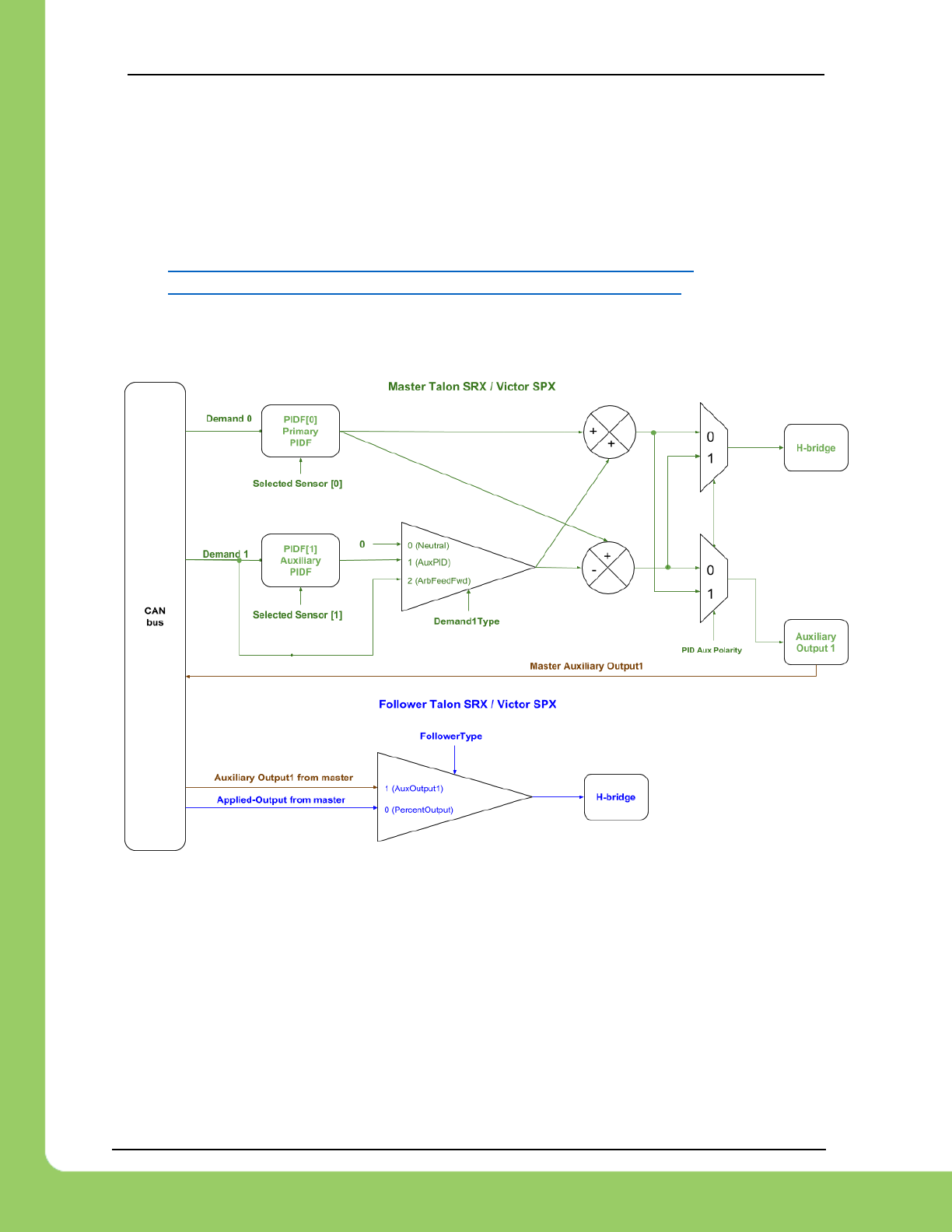
217-8080 TALON SRX / Victor SPX Software Reference Manual 3/06/2018
Cross The Road Electronics Page 83 3/06/2018
9.10. Auxiliary Closed-Loop / Arbitrary Feed-forward
Starting with firmware 3.8, Talon SRX and Victor SPX can be used with either an auxiliary
closed-loop or arbitrary feedforward (or both in the case of MotionProfileArc).
Examples of this feature can be found in the “Remote*” projects under…
https://github.com/CrossTheRoadElec/Phoenix-Examples-Languages
https://github.com/CrossTheRoadElec/Phoenix-Examples-LabVIEW
9.10.1. Functional Diagram

217-8080 TALON SRX / Victor SPX Software Reference Manual 3/06/2018
Cross The Road Electronics Page 84 3/06/2018
9.10.2. Auxiliary Closed-Loop
The Talon SRX and Victor supports a secondary closed-loop that can be run concurrently with
the primary closed-loop.
This allows for multi-closed-loop implementations for…
• Concurrently running distance and turn closed-loops on a differential drivetrain.
• Differential mechanisms where the sensor difference and sensor sum must
simultaneously be closed-looped.
• Two-motor mechanisms (with individual sensors) that are weakly linked (mechanically)
or not linked at all. Two-motor robot arm where each side is controlled via an individual
motor/sensor pair is an example of this.
The typically requirements are
• All motor controllers must have 3.8 or newer firmware.
• If using MotionProfile control mode: Instead use the MotionProfileArc and make sure
that each trajectory point’s auxiliary position is specified with the target for PIDF[1].
• If using MotionProfileArc, choose sensor coefficient for PIDF[1] to ensure sensor target
fits the range of [-8192,8191]. For example, if the auxiliary PIDF[1] is used for turning,
scaling 3600 => 360 degrees ensures ±2.2 rotation range for target signal.
See section 9.7 for more information.
• If not using Motion Profile control mode: The master must provide the target (auxiliary
position) for auxiliary closed-loop with the AuxPID demand type. Set routine/VI has
additional parameters to accomplish this.
• If using another motor controller (MC) for the “other side” of a differential, configure MC
to be a follower with a follower type of “Auxiliary Output 1”. This signals the following
MC to use the calculated output1 from the master talon, and not simply follow its applied
motor output.

217-8080 TALON SRX / Victor SPX Software Reference Manual 3/06/2018
Cross The Road Electronics Page 85 3/06/2018
9.10.2.1. Selecting auxiliary feedback sensor
The feedback sensors for PIDF[0] and PIDF[1] are configured using the same routines/VIs used
in the simpler single-variable closed-loop.
If using remote sensors see section 9.8.
If using sensor sum and sensor difference (for a differential drive for example) see section 9.9.
9.10.2.2. Auxiliary PIDF[1] Polarity
The default behavior for the auxiliary polarity is to calculated the local motor output and follower
output such that…
master-motor-output = PIDF[0] + PIDF[1]
follower-motor-output = PIDF[0] - PIDF[1]
However if this is not desired, robot application can set the PIDF[1] Polarity to true, so that…
master-motor-output = PIDF[0] - PIDF[1]
follower-motor-output = PIDF[0] + PIDF[1]
PID[0] must be in phase with motor output under all circumstances, and this can be achieved by
using the Sensor Phase API.
PID[1] can be made in phase by
• Leveraging this configuration setting.
• Deliberately choosing the motor output side that naturally is in phase.
• If using a sensor difference as the selected sensor, flip D0 and D1 terms to reverse the
sensor direction.

217-8080 TALON SRX / Victor SPX Software Reference Manual 3/06/2018
Cross The Road Electronics Page 86 3/06/2018
9.10.2.3. Differential Drivetrain Sensor Recommendations
When implementing a differential drive train, the recommendation is to select a sensor type
such that the PID0[0] sensor value increases as the robot moves forward, and decreases as the
robot moves backwards. This may mean selecting sensor sum or sensor difference depending
on the natural directions of the remote sensors used.
When selecting the turn sensor for PIDF[1], choose sensor components so that position
increases as the robot turns left (counter clockwise from above). This ensures turning process
variable is in phase with PID[1] output assuming the right-side motor controller is running the
closed-loops and left-side motor controller is an auxiliary follower. This breaks down as….
• The right-side motor runs PIDF[0] and PIDF[1] (i.e. is the master).
• Default Aux Polarity is false
=> Right-motor-output = PIDF[0] + PIDF[1]
=> Left-motor-output = PIDF[0] - PIDF[1]
• When target distance is forward (positive relative to current location),
PIDF[0] yields positive output on both.
• When target heading is counter clockwise (positive relative to current heading),
PIDF[1] yields positive output, moving right side forward and left side reverse.
• When using difference in encoder values for heading, select right-sensor minus left-
sensor to achieve an increasing signal as robot turns counter clockwise.
• When using a Pigeon IMU for heading, Yaw signal is already increasing when robot
turns counter clockwise.
If the recommendations above cannot be met, then the auxiliary PIDF[1] polarity
configuration can be used to flip the motor outputs such that…
=> master-motor-output = PIDF[0] - PIDF[1]
=> follower-motor-output = PIDF[0] + PIDF[1]
…or developer may choose to swap the configured roles (move the master config to the
“other side”) to match the above recommendations.

217-8080 TALON SRX / Victor SPX Software Reference Manual 3/06/2018
Cross The Road Electronics Page 87 3/06/2018
9.10.3. Arbitrary Feed-forward
Alternatively, user can provide an arbitrary and supplemental feed-forward which is added to the
output of the primary closed-loop output. This term is unrelated to the kF constant and
subsequent term in the base closed-loop equation.
This allows custom implementation for…
• Adding a constant offset (gravity compensation, etc.)
• On-the-fly modification of supplemental feed-forward that can be updated synchronous
with the PIDF[0] target (also referred to as demand0).
• Alternative to the (kF mult PIDF[0].target) term so that robot application has greater
control of feedforward strategy.
The typically requirements are
• The master must provide the target (auxiliary position) for auxiliary closed-loop with the
AuxPID demand type. Set routine/VI has additional parameters to accomplish this.
• All motor controllers involved must have firmware 3.8 or greater.
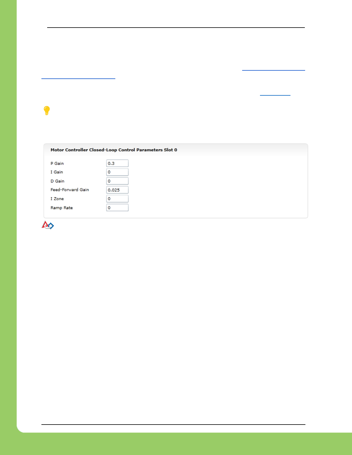
217-8080 TALON SRX / Victor SPX Software Reference Manual 3/06/2018
Cross The Road Electronics Page 88 3/06/2018
10. Control Modes (Closed-Loop)
Talon SRX supports position closed-loop, velocity closed-loop, current closed-loop, Motion
Profiling, and Motion Magic. The actual implementation can be seen in Section 18. How is the
closed-loop implemented?
All closed-loop modes update every 1ms (1000Hz) – unless modified via API (section 9.6).
TIP: While tuning the closed-loop, use the roboRIO web-based configuration to quickly
change the gains “on the fly”. Once the PID is stable, set the gain values in code so that Talons
can be swapped/replaced easily. Below is an example of tweaking the gains in the roboRIO
Web-based configuration.
TIP: Example code of the parameters in Java once initial tweaking is done. Parameters
can also be tweaked “on the fly” using the roboRIO Web-based configuration or reading values
from a file.
/* set closed loop gains in slot0 - see documentation */
_talon.selectProfileSlot(kSlotIdx, 0);
_talon.config_kF(kSlotIdx, 0.2, kTimeoutMs);
_talon.config_kP(kSlotIdx, 0.2, kTimeoutMs);
_talon.config_kI(kSlotIdx, 0, kTimeoutMs);
_talon.config_kD(kSlotIdx, 0, kTimeoutMs);
_talon.config_IntegralZone(0, 100, Constants.kTimeoutMs);

217-8080 TALON SRX / Victor SPX Software Reference Manual 3/06/2018
Cross The Road Electronics Page 89 3/06/2018
10.1. Position Closed-Loop Control Mode
The Talon’s Closed-Loop logic can be used to maintain a target position. Target and sampled
position is passed into the equation in Section 18 in native units.
TIP: A simple strategy for setting up a closed loop is to zero out all Closed-Loop
Control Parameters and start with the Proportional Gain.
For example, if you want your mechanism to drive 50% motor output when the error is
4096, then the calculated Proportional Gain would be (0.50 X 10²³) / 4096 = ~0.125.
To check our math, take an error (native units) of 4096 X 0.125 => 512 (50% motor
output).
Tune this until the sensed value is close to the target under typical load. Many prefer to
simply double the P-gain until oscillations occur, then reduce accordingly.
If the mechanism accelerates too abruptly, Derivative Gain can be used to smooth the
motion. Typically start with 10x to 100x of your current Proportional Gain.
If the mechanism never quite reaches the target and increasing Integral Gain is viable,
start with 1/100th of the Proportional Gain.
See Section 12.5 for HERO C# complete example of Position Closed-Loop. The functions used
are comparable to the WPILIB C++/Java API.
10.2. Current Closed-Loop Control Mode
The Talon’s Closed-Loop logic can be used to approach a target current-draw. Target and
sampled current is passed into the equation in Section 18 in milliamperes. However, the robot
API expresses the target current in amperes.
Note: Current Control Mode is separate from Current Limit. See Section 9.3 for Current Limit.
TIP: A simple strategy for setting up a current-draw closed loop is to zero out all Closed-
Loop Control Parameters and start with the Feed-Forward Gain. Tune this until the current-
draw is close to the target under typical load. Then start increasing P gain so that the closed-
loop will make up for the remaining error. If necessary, reduce Feed-Forward gain and increase
P Gain so that the closed-loop will react more strongly to the ClosedLoopError.
See Section 12.3 for a walk-through in LabVIEW. Though the example is written in LabVIEW,
the procedure is the similar for all supported languages.

217-8080 TALON SRX / Victor SPX Software Reference Manual 3/06/2018
Cross The Road Electronics Page 90 3/06/2018
10.3. Velocity Closed-Loop Control Mode
The Talon’s Closed-Loop logic can be used to maintain a target velocity. Target and sampled
velocity is passed into the equation in Section 18 in native units per 100ms. See Section 17.1
for information regarding native units.
TIP: A simple strategy for setting up a closed loop is to zero out all Closed-Loop Control
Parameters and start with the Feed-Forward Gain. Tune this until the sensed value is close to
the target under typical load. Then start increasing P gain so that the closed-loop will make up
for the remaining error. If necessary, reduce Feed-Forward gain and increase P Gain so that
the closed-loop will react more strongly to the ClosedLoopError.
TIP: Velocity Closed-Loop tuning is similar to Current Closed-Loop tuning in their use of
feed-forward. Begin by measuring the sensor velocity while driving the Talon at a large motor
output.
A complete Java example is available in Section 12.4.
10.4. Motion Profile Control Mode
A recent addition to the Talon SRX is the motion profile mode. With this, a savvy developer can
stream motion profile trajectory points into the Talon’s internal buffer (even while executing the
profile). This allows fine control of position and speed throughout the entire movement. Since
this is an advanced feature addition, a separate document is provided to cover this.
10.4.1. Motion Profile Arc Control Mode
If the application requires using the secondary (auxiliary) closed-loop, the user can select
Motion Profile Arc to activate the second loop. This simply signals the Motion Profile Executor
to run both PIDF[0] and PIDF[1], which is explained in section 9.10.
Because the Motion Profile Executor acquires the targets for PIDF[0] and PIDF[1] via the
trajectory point, the user is also free to leverage the arbitrary feed forward term if need be
(section 9.10.3).
Examples of this feature can be found in the “Remote*” projects under…
https://github.com/CrossTheRoadElec/Phoenix-Examples-Languages
https://github.com/CrossTheRoadElec/Phoenix-Examples-LabVIEW
Note, when using the second PIDF[1] loop, the recommended sensor coefficient for the sensor
should be scaled to ensure sensor target fits the range of [-8192,8191]. For example, if the
auxiliary PIDF[1] is used for turning, scaling 3600 => 360 degrees ensures ±2.2 rotation range
for target signal.

217-8080 TALON SRX / Victor SPX Software Reference Manual 3/06/2018
Cross The Road Electronics Page 91 3/06/2018
10.5. Peak/Nominal Output
Since firmware 2.0, The Talon SRX supports bounding the output of the motor controller. These
settings are in effect during all control modes.
To clearly communicate what these parameters accomplish, the following terms are introduced.
• Peak Output- The “maximal” or “strongest” motor output allowed.
These settings are useful to reduce the maximum velocity of the mechanism, and can
make tuning the closed-loop simpler.
The “Positive Peak Output” or “Forward Peak Output” refers to the “strongest” motor
output when the motor output is positive. If the Output exceeds this setting, the motor
output is capped.
This value is typically positive or zero. The default value is +1023 as read in the web-
based configuration Self-Test.
The “Negative Peak Output” or “Reverse Peak Output” refers to the “strongest” motor
output when the motor output is negative. If the Output exceeds this setting, the motor
output is capped.
This value is typically negative or zero. The default value is -1023 as read in the web-
based configuration Self-Test.
• Nominal Output- The “minimal” or “weakest” motor output allowed if the output is
nonzero.
This is expressed using two signals: “Positive Nominal Output” and “Negative Nominal
Output”, to uniquely describe a limit for each direction.
If the motor-output is too “weak”, the robot application can use these signals to promote
the motor-output to a minimum limit. With this, the robot application can ensure the
motor-output is large enough to drive the mechanism. Typically, in a closed-loop
system, this is accomplished with Integral gain, however this method may be a simpler
alternative as there is no risk of Integral wind-up.
Note this feature is not related to the Closed-Loop Peak Output Configuration which merely
caps the output of a specific PID loop. See section 9.5 for more information.
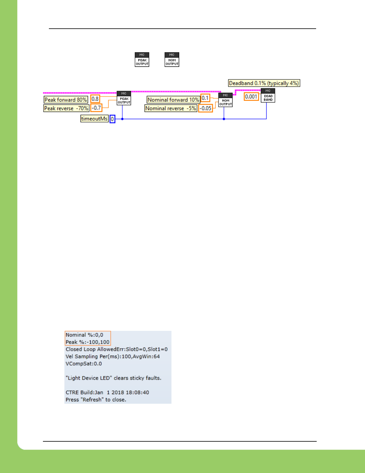
217-8080 TALON SRX / Victor SPX Software Reference Manual 3/06/2018
Cross The Road Electronics Page 92 3/06/2018
10.5.1. Peak/Nominal Closed-Loop Output – LabVIEW
These signals can be set using and .
Peak and nominal values range from -1.0 (full reverse) to +1.0 (full forward).
10.5.2. Peak/Nominal Output – C++
The parameters are expressed in percent output where +1 represents full forward, and -1
represents full reverse.
/* set the peak and nominal outputs, 1.0 means full */
_talon.ConfigNominalOutputForward(0, kTimeoutMs);
_talon.ConfigNominalOutputReverse(0, kTimeoutMs);
_talon.ConfigPeakOutputForward(1, kTimeoutMs);
_talon.ConfigPeakOutputReverse(-1, kTimeoutMs);
/* 0.001 represents 0.1% - default value is 0.04 or 4% */
_talon.ConfigNeutralDeadband(0.001, kTimeoutMs);
10.5.3. Peak/Nominal Output – Java
The parameters are expressed in percent output where +1 represents full forward, and -1
represents full reverse.
/* set the peak and nominal outputs, 1.0 means full */
_talon.configNominalOutputForward(0, kTimeoutMs);
_talon.configNominalOutputReverse(0, kTimeoutMs);
_talon.configPeakOutputForward(1, kTimeoutMs);
_talon.configPeakOutputReverse(-1, kTimeoutMs);
/* 0.001 represents 0.1% - default value is 0.04 or 4% */
_talon.configNeutralDeadband(0.001, kTimeoutMs);
10.5.4. Peak/Nominal Output – Web based Configuration Self-Test
The parameters are also available for review in the Self-Test.
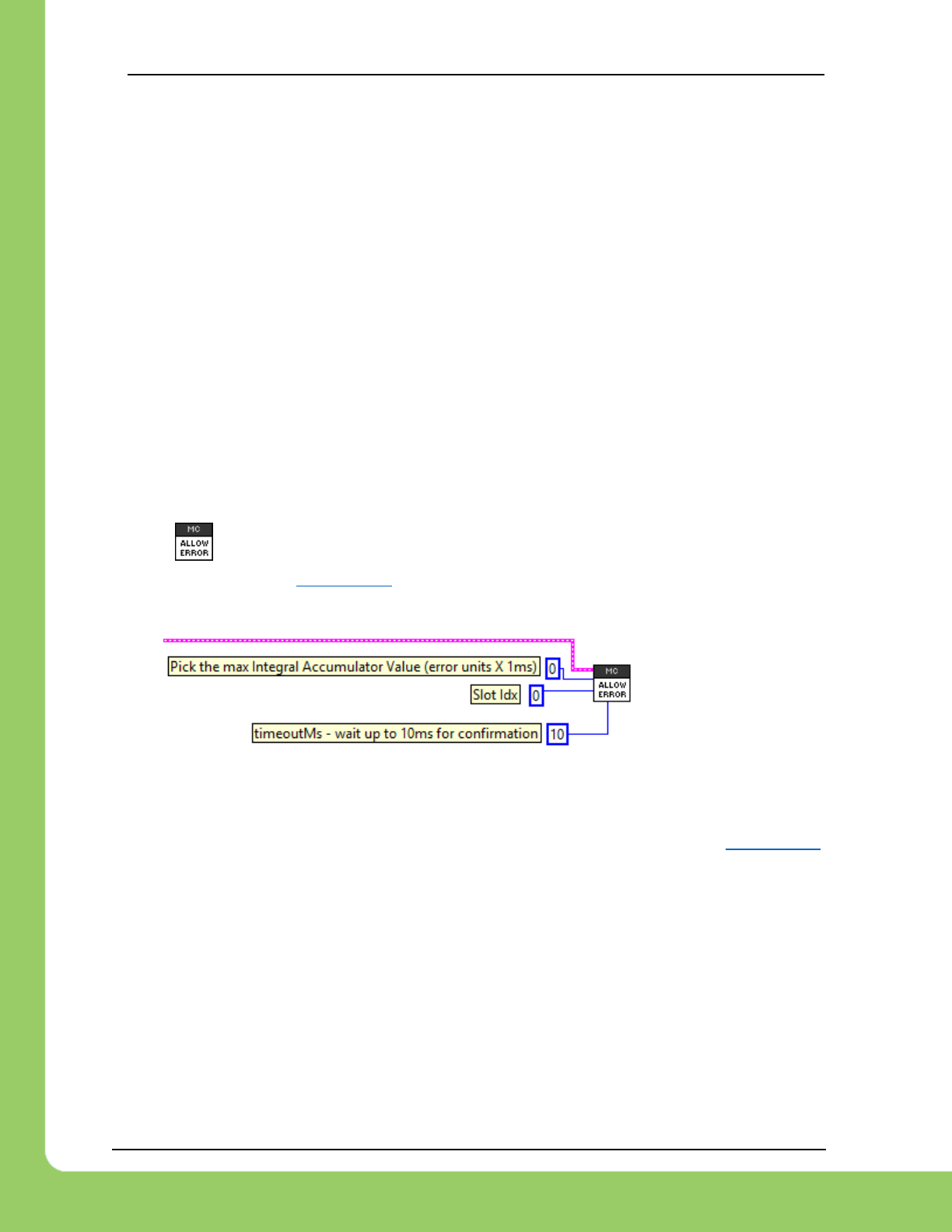
217-8080 TALON SRX / Victor SPX Software Reference Manual 3/06/2018
Cross The Road Electronics Page 93 3/06/2018
10.6. Allowable Closed-Loop Error
Since firmware 2.0, The Talon SRX supports specifying an Allowable Closed-Loop Error
whereby the motor output is neutral regardless of the calculated result. This signal affects…
• Position Closed-Loop Control Mode
• Velocity Closed-Loop Control Mode
• Current Closed-Loop Control Mode
• Motion Profile Control Mode
• Motion Magic Control Mode
When the Closed-Loop Error is within the Allowable Closed-Loop Error
• P, I, D terms are zeroed. In other words, the math that uses P, I, and D gains is
disabled. However, F term is still in effect.
• Integral Accumulator is cleared.
Allowable Closed-Loop Error defaults to zero, and is persistently saved.
10.6.1. Allowable Closed-Loop Error – LabVIEW
Use the VI to set this signal. The Allowable Closed-Loop error is in the same units as
Closed-Loop Error. See Section 17.1 for more information. Each Closed-Loop Motor Profile slot
has a unique Allowable Closed-Loop Error. Select ‘0’ or ‘1’ for slot 0 or slot 1 respectively.
10.6.2. Allowable Closed-Loop Error – C++
The Allowable Closed-Loop error is in the same units as Closed-Loop Error. See Section 17.1
for more information. Each Closed-Loop Motor Profile slot has a unique Allowable Closed-Loop
Error. This function affects the currently selected slot/profile.
/* Slot 0 => allowable error = 409 units (10% or a rotation if using CTRE MagEncoder)*/
talon.ConfigAllowableClosedloopError(0, 409, 10);
In this example, 409 corresponds to 9.985% of a rotation or 35.95 degrees (assuming 4096
units per rotation, such as 1024CPR encoder or CTRE Mag Encoder).
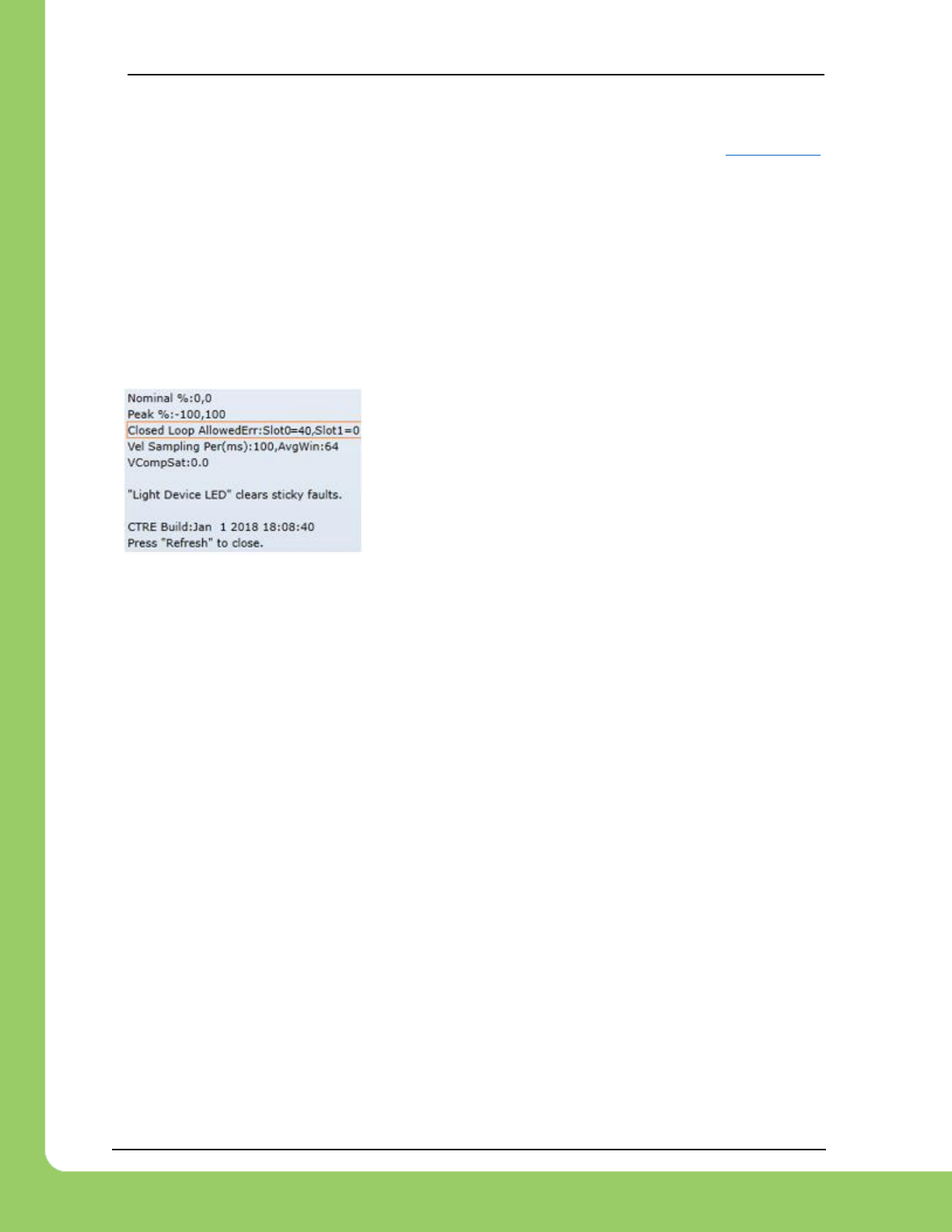
217-8080 TALON SRX / Victor SPX Software Reference Manual 3/06/2018
Cross The Road Electronics Page 94 3/06/2018
10.6.3. Allowable Closed-Loop Error – Java
The Allowable Closed-Loop error is in the same units as Closed-Loop Error. See Section 17.1
for more information. Each Closed-Loop Motor Profile slot has a unique Allowable Closed-Loop
Error. This function affects the currently selected slot/profile.
/* Slot 0 => allowable error = 409 units (10% or a rotation if using CTRE MagEncoder)*/
talon.configAllowableClosedloopError(0, 409, 10);
In this example, 409 corresponds to 9.985% of a rotation or 35.95 degrees (assuming 4096
units per rotation, such as 1024CPR encoder or CTRE Mag Encoder).
10.6.4. Allowable Closed-Loop Error – Web based Configuration Self-Test
The Allowable Closed-Loop Error for both slots can be read
using the roboRIO Web based configuration Self-Test.
The values are in the same units as Closed-Loop Error.
In this example 40 corresponds to 0.9767% of a rotation or
3.52 degrees (assuming 4096 units per rotation, such as
1024CPR encoder or CTRE Mag Encoder).
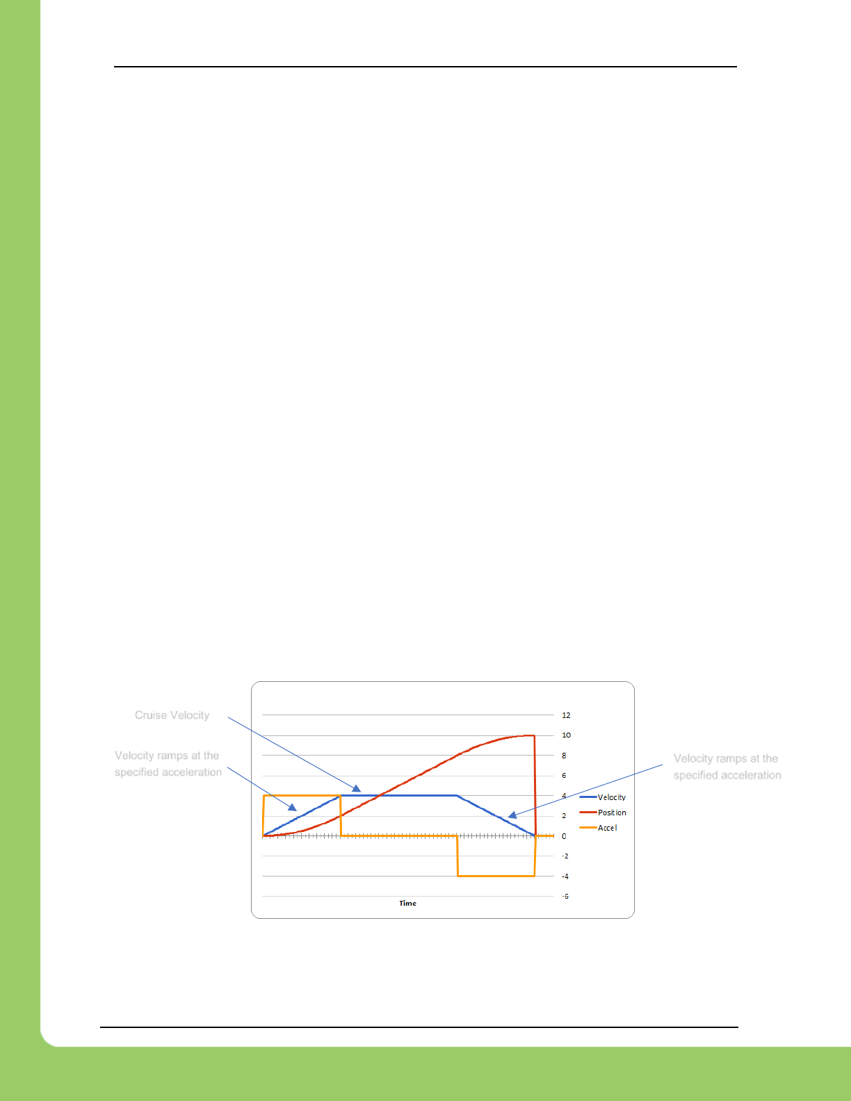
217-8080 TALON SRX / Victor SPX Software Reference Manual 3/06/2018
Cross The Road Electronics Page 95 3/06/2018
10.7. Motion Magic Control Mode
Motion Magic is a control mode for Talon SRX that provides the benefits of Motion Profiling
without needing to generate motion profile trajectory points. When using Motion Magic, Talon
SRX will move to a set target position using a Trapezoidal Motion Profile, while honoring the
user specified acceleration and maximum velocity (cruise velocity).
The benefits of this control mode over “simple” PID position closed-looping are…
• Control of the mechanism throughout the entire motion (as opposed to racing to the end
target position).
• Control of the mechanism’s inertia to ensure smooth transitions between set points.
• Improved repeatability despite changes in battery voltage.
• Improved repeatability despite changes in motor load.
After gain/settings are determined, the robot-application only needs to periodically set the target
position.
There is no general requirement to “wait for the profile to finish”, however the robot application
can poll the sensor position and determine when the motion is finished if need be.
A Trapezoidal Motion Profile generally ramps the output velocity at a specified acceleration until
cruise velocity is reached. This cruise velocity is then maintained until the system needs to
deaccelerate to reach the target position and stop motion. Talon determines when these critical
points occur on-the-fly.
NOTE: If the remaining sensor distance to travel is small, the velocity may not reach cruise
velocity as this would overshoot the target position. This is often refered to as a “triangle
profile”.
Example Trapezoidal Motion Profile
Motion Magic utilizes the same PIDF parameters as Motion Profiling.
Velocity ramps at the
specified acceleration
Velocity ramps at the
specified acceleration
Cruise Velocity
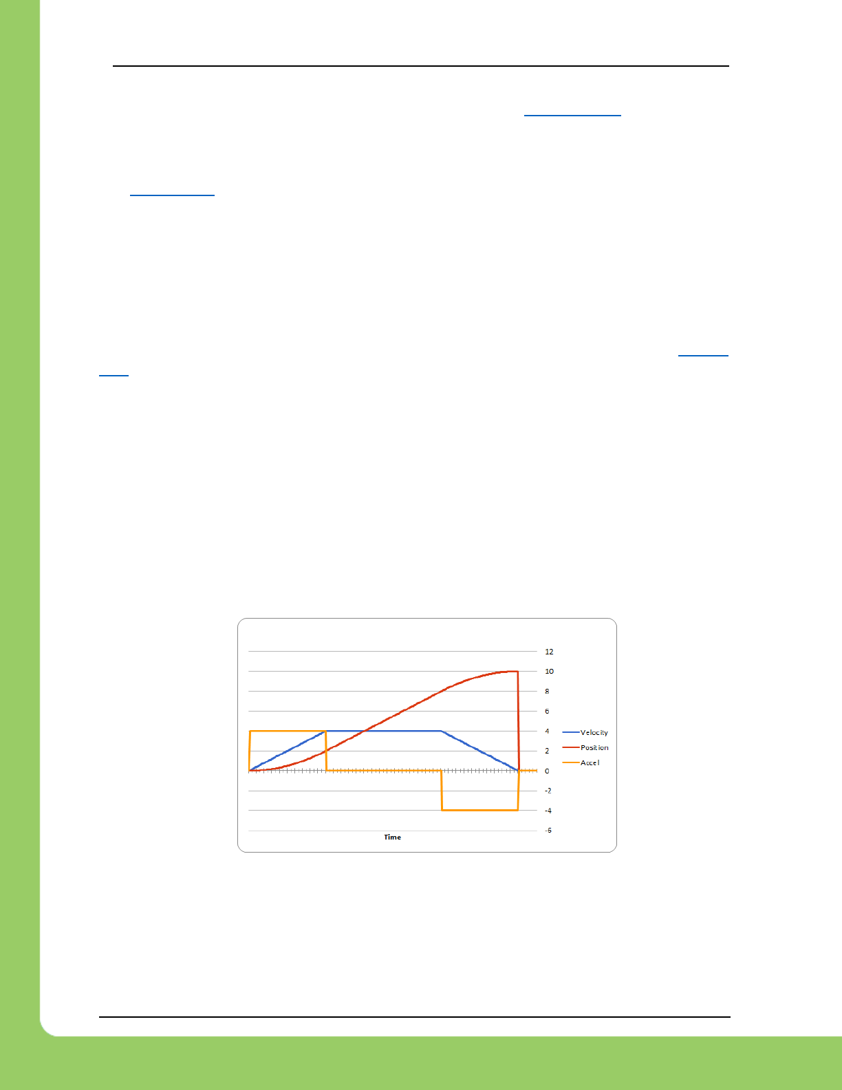
217-8080 TALON SRX / Victor SPX Software Reference Manual 3/06/2018
Cross The Road Electronics Page 96 3/06/2018
The F parameter should be tuned using the process outlined in Section 12.6.3. Note that while
the F parameter is not normally used for Position Closed-Loop control, Motion Magic requires
this parameter to be properly tuned.
See Section 12.6 for complete FRC JAVA walkthrough on tuning.
Two additional parameters need to be set in the Talon SRX– Acceleration and Cruise Velocity.
The Acceleration parameter controls acceleration and deacceleration rates during the beginning
and end of the trapezoidal motion. The Cruise Velocity parameter controls the cruising velocity
of the motion.
This feature is further enhanced when used with Closed-Loop Voltage Compensation (Section
10.8).
The upper bound for trajectory velocity (RPM) is 278045700/sensor-units-per-rotation.
10.7.1. Motion Magic Control Mode (with Auxiliary PIDF[1])
If auxiliary PIDF1 is enabled (See section 9.10), the PIDF1 target also is profiled to follow the
waveform of PIDF0.
As an example, if Motion Magic produces a robot distance curve to achieve a 0-to-10 position
profile (as illustrated below in red), and the application also targets a 90-degree final heading
(with an initial heading of 0), then the target heading will curve from 0 to 90 degree following the
same red curvature as the position plot below.
If zero-turning is required, simply change the PIDF[1] final target without changing the PIDF[0]
final target, and the auxiliary closed loop will immediately approach the final heading with no
profiling. This is because there is no profiling on PIDF[0] in this circumstance.

217-8080 TALON SRX / Victor SPX Software Reference Manual 3/06/2018
Cross The Road Electronics Page 97 3/06/2018
11. Motor Control Profile Parameters
The Talon persistently saves four unique Motor Control Profiles.
Each Motor Control Profile contains several configurable values, including…
P Gain: Kp constant to use when control mode is a closed-loop mode.
I Gain: KI constant to use when control mode is a closed-loop mode.
D Gain: KD constant to use when control mode is a closed-loop mode.
F Gain: KF constant to use when control mode is a closed-loop mode.
I Zone: Integral Zone. When nonzero, Integral Accumulator is automatically cleared
when the absolute value of Closed-Loop Error exceeds it.
Allowable Closed-Loop Error: When Closed-Loop Error’s magnitude is less than this
signal, Integral Accum and motor output are auto-zeroed during closed-loop.
I Max Maximum value Integral Accum can become. If Integral Accum becomes larger, it
is capped to this value.
One unique feature of the Talon SRX is that gain values specified in a Motor Control Profile are
not dedicated to just one type of closed-loop. When selecting a closed-loop mode (for example
position or velocity) the robot application can select any of the four Motor Control Profiles to
select which set of values to use. This can be useful for gain scheduling (changing gain values
on-the-fly) or for persistently saving two sets of gains for two entirely different closed loop
modes.
The settings for the first two slots can be set and
read in the web control page.
Note that the Ramp Rate is no longer
supported, as it has been replaced by Open-
Loop and Closed-Loop Ramp API.

217-8080 TALON SRX / Victor SPX Software Reference Manual 3/06/2018
Cross The Road Electronics Page 98 3/06/2018
11.1. Persistent storage and Reset/Startup behavior
The Talon SRX was designed to reduce the “setup” necessary for a Talon SRX to be functional,
particularly with closed-loop features. This is accomplished with efficient CAN framing and
persistent storage.
All settings in the Motor Control Profile (MCP) are saved persistently in flash. Additionally, there
are two complete Motor Control Profiles. Teams that use a constant set of values can simply
set them using the roboRIO Web-based Configuration, and they will “stick” until they are
changed again.
Additionally, Motor Control Profile (MCP) Parameters can be changed though programming API.
When they are changed, the values are ultimately copied to persistent memory using a wear
leveled strategy that ensures Flash longevity, but also meets the requirements for teams.
-Changing MCP values programmatically always take effect immediately (necessary for gain
tuning).
-If the MCP Parameters have remained unchanged for fifteen seconds, and an MCP Parameter
value is then changed using programming API, they are copied to persistent memory
immediately.
-If the persistent memory has been updated within the last fifteen seconds due to a previous
value change, and an MCP Parameter value is changed again, it will be applied to persistent
memory once fifteen seconds has passed since the last persistent memory update. However,
the closed-loop will react immediately to the latest values sent over CAN bus.
-If power loss occurs during the period when MCP Parameters are being saved to persistent
storage, the previous values for all MCP Parameters prior to last value-change is loaded. This
is possible because the Talon SRX keeps a small history of all value changes.
These features fit well with the two common strategies that FRC teams utilize when
programmatically changing closed-loop parameters...
(1) Teams use programming API at startup to apply previous tested constants.
(2) Teams use programming API to periodically set/change the constants because they are
“gain scheduled” or action specific.
For use case (1), the constants are eventually saved in Talon SRX persistent memory (worst
case fifteen seconds after robot startup). Once this is done the Talon SRX will have the values
in persistent storage, so even after Talons are power cycled, they will load the constants that
were previous set. This frees the robot controller from needing to re-set the values during a
power cycle (reset, brownout, etc.). On subsequent robot startups, when the robot controller
sends the same values again, and Talon SRX will still react by updating its variables, and
comparing against what’s saved in persistent storage to see if it needs to be updated again. In
the event the robot code changes to use new constants, the Talon will again update the
persistent storage shortly after getting the new values.

217-8080 TALON SRX / Victor SPX Software Reference Manual 3/06/2018
Cross The Road Electronics Page 99 3/06/2018
For use case (2) teams, there are two “best” solutions depending on what’s being
accomplished. If a team needs to switch between two sets of gains, they can leverage both
MCP slots by setting one set of constants in slot 0, and another unique set of constants in slot 1.
Then during the match, teams can switch between the two with a single API. This means that
as far as the Talon is concerned, the values in each slot never changes so the contents of the
Talon’s persistent storage never changes. Instead the robot controller just changes which slot
to use. So, this use case regresses to use case (1), and a freshly booted Talon already has all
the MCP parameters it needs to function.
For use case(2) teams that requires more than two gain sets likely are changing gain values so
frequently (as a function of autonomous, or state machine driven logic) that they would prefer
not to rely on the previous set of gains sent to the Talon (despite it being available at startup).
In which case they likely will periodically set the MCP parameters continuously (every number of
loops or fixed period of time). Talon SRX always honors whatever parameters are requested
over CAN bus, overriding what was loaded at startup or mirrored in persistent storage. And
since the persistent storage is wear-leveled and mirrored at fifteen second intervals, this has no
harmful impact on Flash longevity. So this use case is also supported well.
Beyond the Motor Control Profile Parameters, closed-loop modes require selecting
-which control mode (position or velocity)
-which feedback sensor to use
-if the feedback sensor should be reversed
-if the closed-loop output should be reversed
-what is the latest target or set point
- ramp rate (if needed)
-which Motor Control Profile Slot to use.
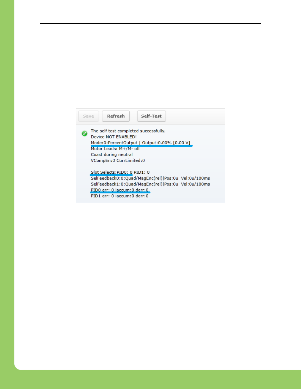
217-8080 TALON SRX / Victor SPX Software Reference Manual 3/06/2018
Cross The Road Electronics Page 100 3/06/2018
11.2. Inspecting Signals
When testing/calibrating closed-loops it is helpful to plot/check…
-Closed-Loop Error
-Applied motor percent output
-Profile Slot Select (which profile slot the closed-loop math is using).
-Position and Velocity depending control mode.
The Self-Test can provide these values for quick sanity checking. These values are also
available with programming API for custom plotting, smart dashboard, LabVIEW front panels,
etc...
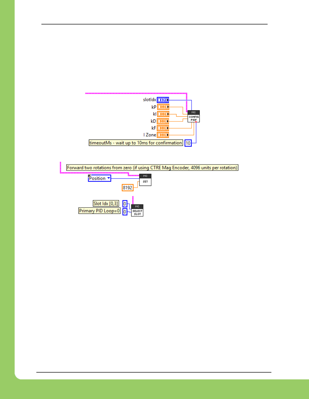
217-8080 TALON SRX / Victor SPX Software Reference Manual 3/06/2018
Cross The Road Electronics Page 101 3/06/2018
12. Closed-Loop Code Excerpts/Walkthroughs
12.1. Setting Motor Control Profile Parameters
12.1.1. LabVIEW
Setting the Motor Controller Profile parameters can be done with the SET PID VI.
This allows filling all parameters for a given Parameter Slot.
Specifying the set point is also done with the Set VI.

217-8080 TALON SRX / Victor SPX Software Reference Manual 3/06/2018
Cross The Road Electronics Page 102 3/06/2018
12.1.2. C++
Closed-loop parameters for a given profile slot can be modified with several different functions.
/* first param is the slot, second param is generally zero (for primary PID loop) */
talon.SelectProfileSlot(0, 0);
talon.Config_kF(0, 0.2, Constants.kTimeoutMs);
talon.Config_kP(0, 0.2, Constants.kTimeoutMs);
talon.Config_kI(0, 0, Constants.kTimeoutMs);
talon.Config_kD(0, 0, Constants.kTimeoutMs);
Setting the target position or velocity is also done with set().
/* servo position, plus/minus one CTRE Mag Enc rotation via gamepad */
talon.set(ControlMode.Position, joy.getY() * 4096);
12.1.3. Java
Closed-loop parameters for a given profile slot can be modified using setPID(). This also sets
the “Profile Slot Select” to the slot being modified. There are also individual Set functions for
each signal.
/* first param is the slot, second param is generally zero (for primary PID loop) */
talon.selectProfileSlot(0, 0);
talon.config_kF(0, 0.2, Constants.kTimeoutMs);
talon.config_kP(0, 0.2, Constants.kTimeoutMs);
talon.config_kI(0, 0, Constants.kTimeoutMs);
talon.config_kD(0, 0, Constants.kTimeoutMs);
Setting the target position or velocity is also done with set().
/* servo position, plus/minus one CTRE Mag Enc rotation via gamepad */
talon.set(ControlMode.Position, joy.getY() * 4096);
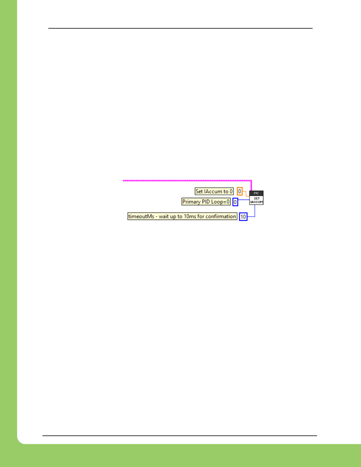
217-8080 TALON SRX / Victor SPX Software Reference Manual 3/06/2018
Cross The Road Electronics Page 103 3/06/2018
12.2. Setting/Clearing Integral Accumulator (I Accum)
Clearing the integral accumulator (“I Accum”) may be necessary to prevent integral windup.
When using “IIZone” this is done automatically when the Closed-Loop Error is outside the
“IIZone”. However, there may be other situations when manually clearing the integral
accumulator is necessary. For example, if the mechanism that’s being closed-looped is “close
enough” and its desirable to reduce occasional spurts of movement caused by a slowly
incrementing integral term, then the robot logic can periodically clear the “I Accum” to prevent
this.
12.2.1. LabVIEW
In this example a case structure is leveraged to conditionally clear the Integral Accumulator
when the case structure conditional evaluates true (this example uses a system button on the
front panel).
12.2.2. Java
double iaccum = 0;
talon.setIntegralAccumulator(iaccum, 0, 10);
12.2.3. C++
double iaccum = 0;
talon.SetIntegralAccumulator(iaccum, 0, 10);
12.2.4. Is Integral Accum cleared any other time?
In addition to the “IIZone” feature and manual clear, there are certain cases where the integral
accumulator is automatically cleared for more predicable motor response…
-Whenever the control mode of a Talon is changed.
-When a Talon is in the disabled state.
-When the motor control profile slot has changed.
-When the Closed Loop Error’s magnitude is smaller than the “Allowable Closed Loop Error”.
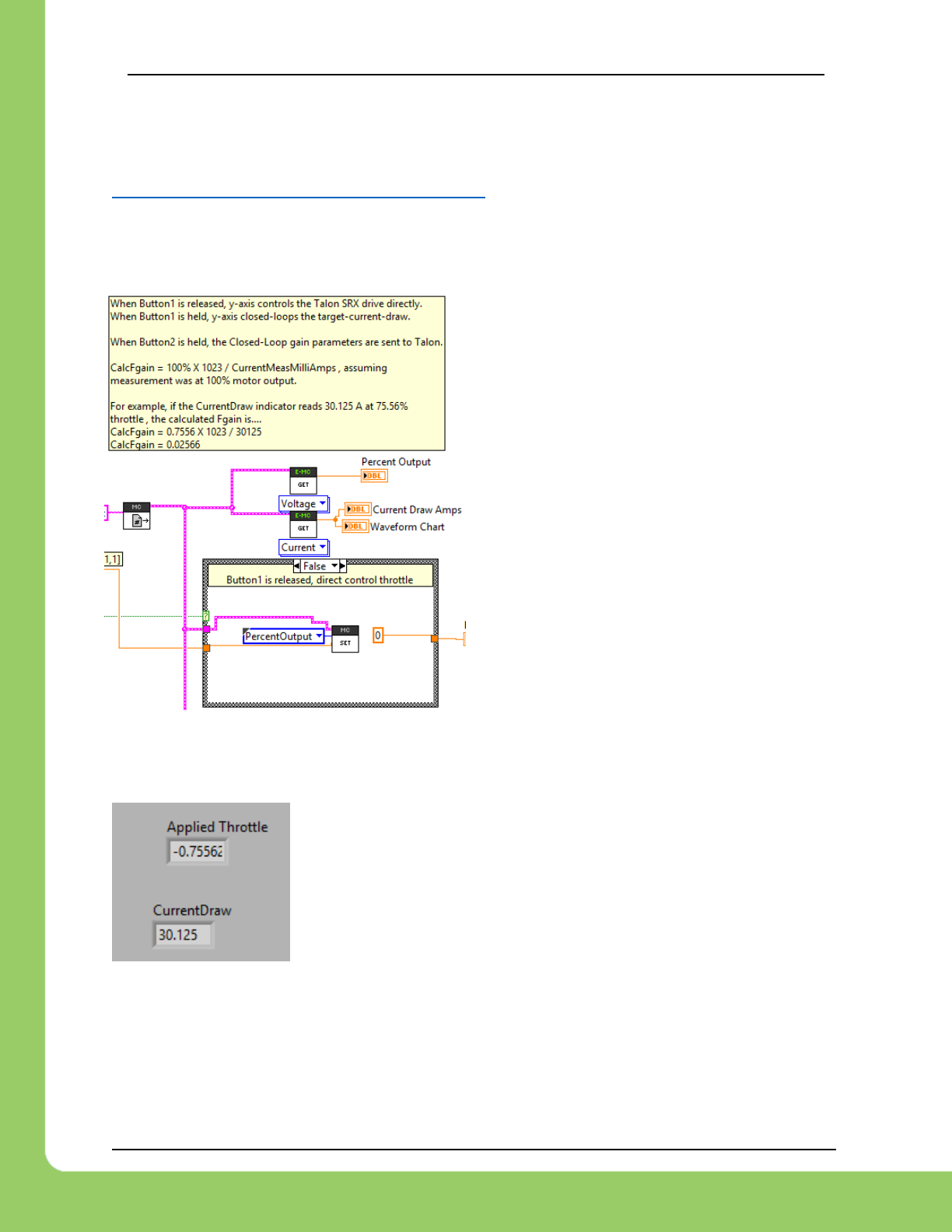
217-8080 TALON SRX / Victor SPX Software Reference Manual 3/06/2018
Cross The Road Electronics Page 104 3/06/2018
12.3. Current Closed-Loop Walkthrough – LabVIEW
This example can be found on the CTR GitHub account.
https://github.com/CrossTheRoadElec/Phoenix-Examples-LabVIEW
12.3.1. Current Closed-Loop Walkthrough – Collect Sensor Data – LabVIEW
The first step is to confirm that the sensor is functional and in-phase with the motor.
Additionally, data can be collected to be used later to determine a decent Feed-forward gain.
Create a Talon and instrument its current draw
and motor output. Also, provide a method to
directly control the Talon to servo (Percent
Output). In this example Talon is in Percent
Output mode when button is off, and in current
closed-loop when button is on.
Enable the Robot and drive the motor to a reasonable output. Take note of what the motor
output in percent. This will give us a basic relationship between current and motor-output.
Shown to the left is the LabVIEW front panel, however these values
can also be retrieved in the roboRIO web-based configuration (works
for all FRC languages). Print statements can also be used for C++,
JAVA, and HERO C#.
This example was taken by using a Talon SRX and CIM to back drive
a secondary CIM motor with leads connected together. At full output
this setup will exceed the 40A breaker rating so less-the-full output was used. However, in a
typical mechanism, full output may be used to acquire a more accurate measurement.
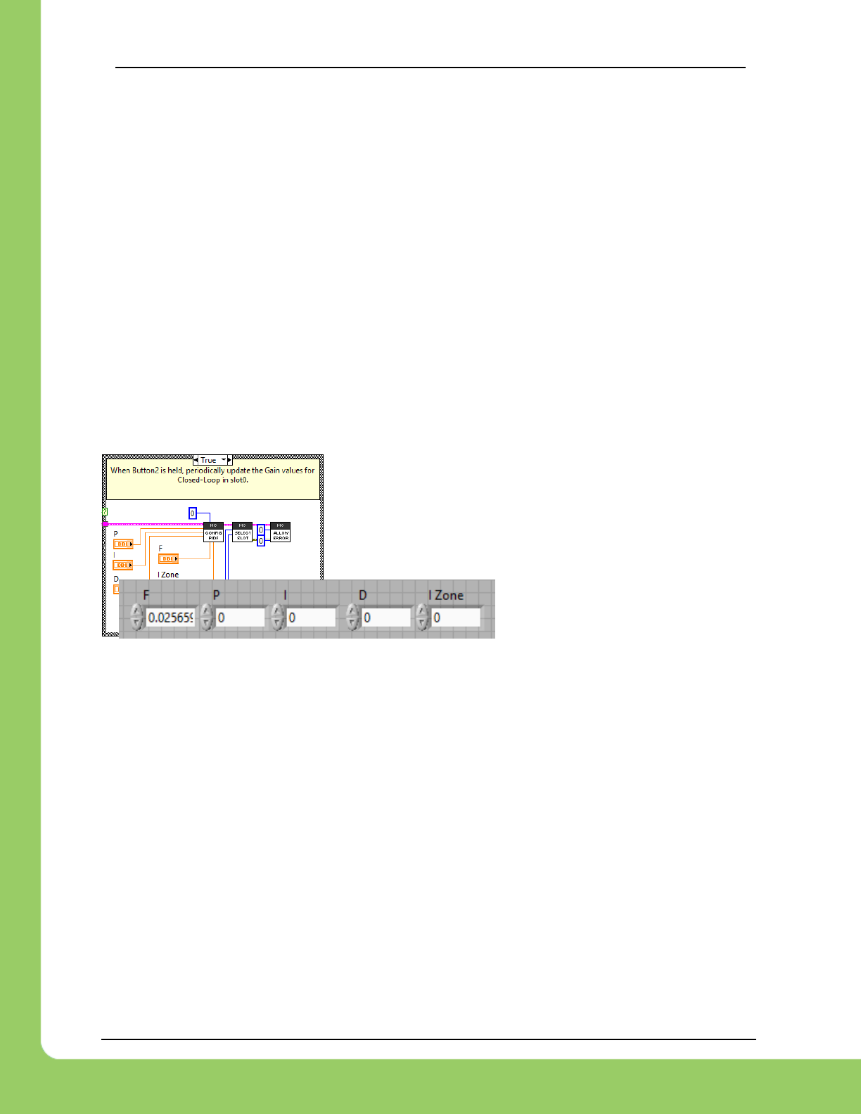
217-8080 TALON SRX / Victor SPX Software Reference Manual 3/06/2018
Cross The Road Electronics Page 105 3/06/2018
12.3.2. Current Closed-Loop Walkthrough – Calculating Feed Forward–
LabVIEW
From this we can calculate our initial Feed-Forward gain. Since measured current is always
positive, we ignore the negative sign of applied output.
The Talon SRX firmware operates on the desired current in milliamps and outputs a motor
output value [-1023 to +1023]. Knowing this, we calculate a Feedforward that will gives us 75%
output when the Target current-draw is 30125 mA.
( 0.7556 X 10²³) / 30125 mA => ~0.02566
As a math check, when the set point is 30125mA, the feedforward term will be 30125 X 0.02566
gives us 773 motor output units (~75%).
Next we will set the F gain to 0.02566, while zeroing the PID gains. This can be done in the
web-based configuration or programmatically using the robot API.
On the left we have an example in LabVIEW, setting the
closed-loop parameters in Begin.vi.
The values are entered below in the front panel, though they
could also be constants if need be.
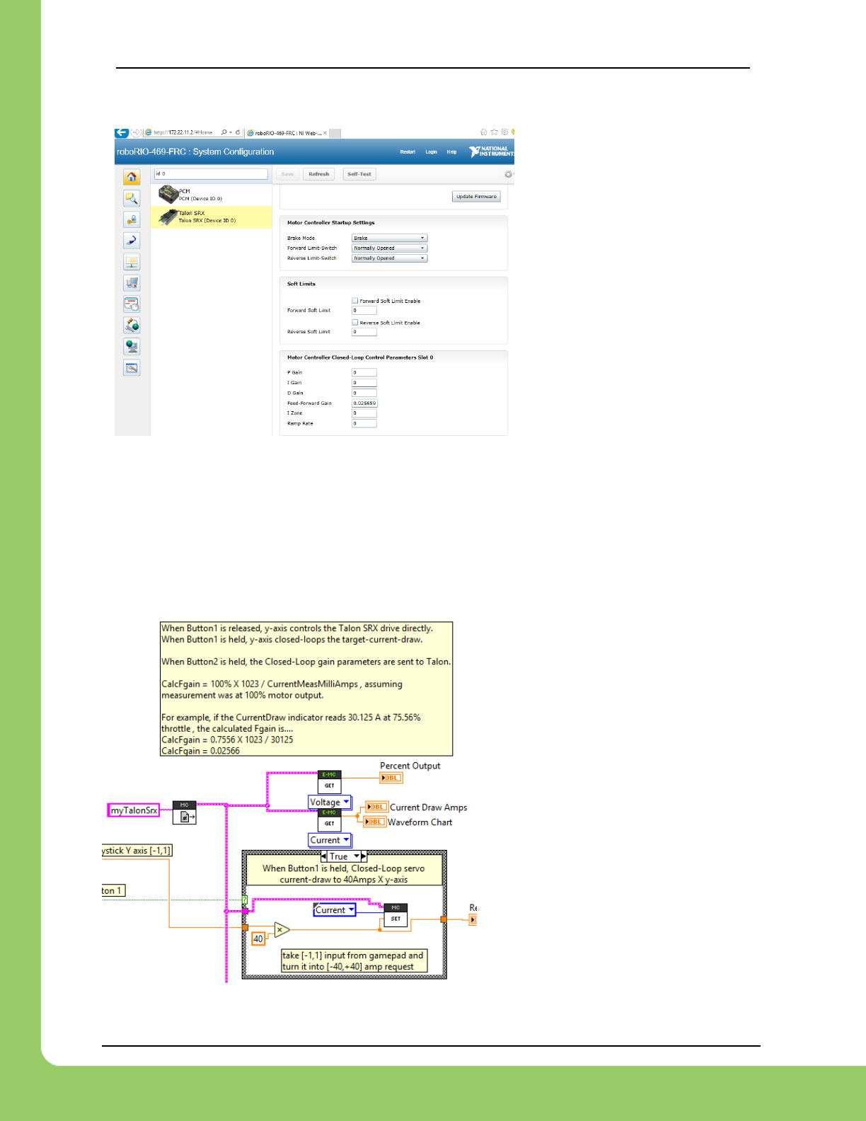
217-8080 TALON SRX / Victor SPX Software Reference Manual 3/06/2018
Cross The Road Electronics Page 106 3/06/2018
Additionally, the other languages
have comparable APIs for gain-
setting, or the gains can be set
using the roboRIO web-based
configuration.
Web-based configuration can also
be used to double check that the
settings are what you expect.
Now rerun the test setup, but now we will press and hold our button to conditionally enable
Current-closed loop mode.
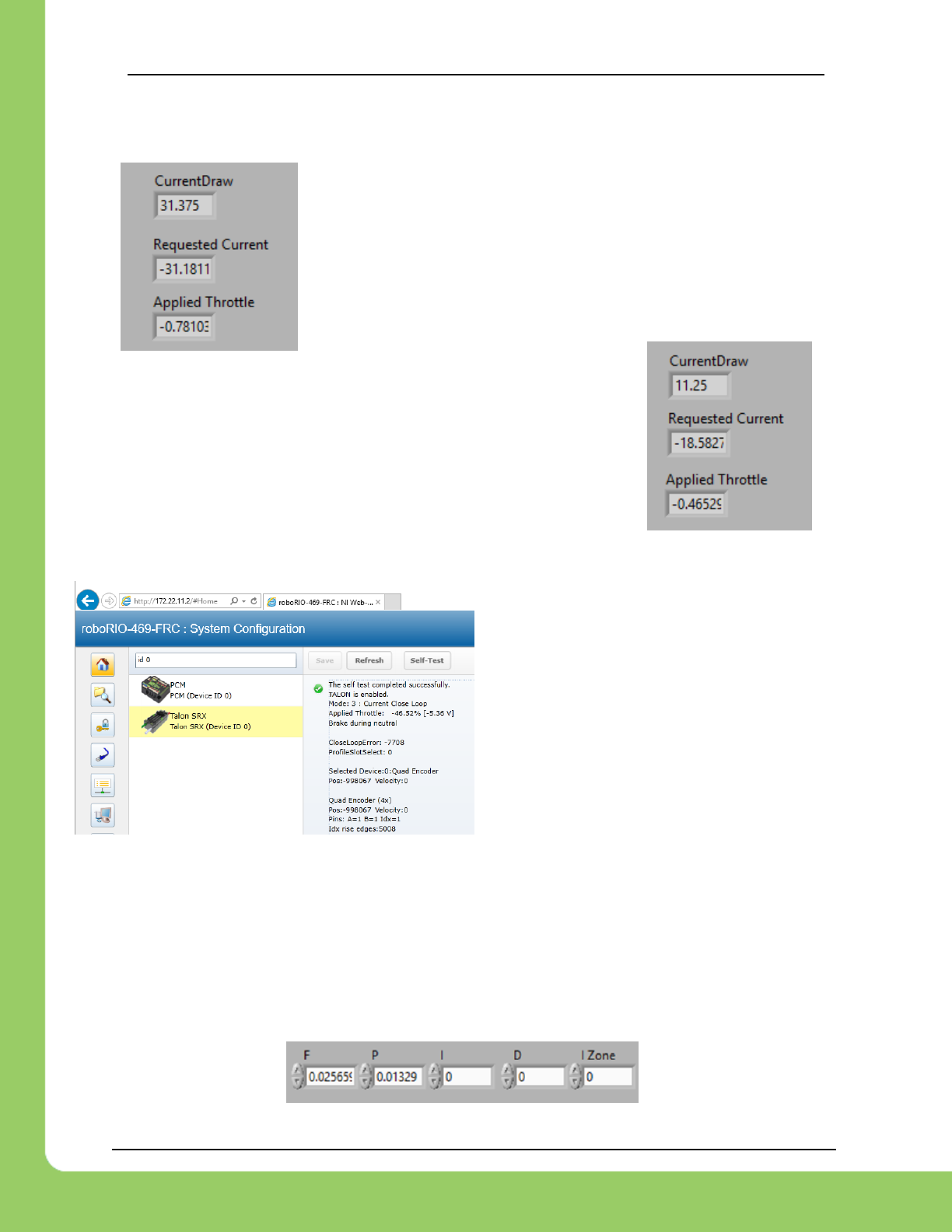
217-8080 TALON SRX / Victor SPX Software Reference Manual 3/06/2018
Cross The Road Electronics Page 107 3/06/2018
Not surprisingly the desired and measured current draw are nearly
identical.
Of course, there is no guarantee this will be the case at all request
current draws under differing battery conditions. Remember this is
just Feed-forward, we’re not closed-looping yet! For example, as we
deviate away from our tuned point, we see error between our
desired and measured current.
Next we will tune P gain so that the closed-loop responds to error.
12.3.3. Current Closed-Loop Walkthrough – Dialing
Proportional Gain – LabVIEW
In this example the Closed-Loop Err was
~7000 (mA).
Perhaps we want to start with adding another
10% motor output to help approach our target
current.
10% output X 1023 = 102 output units
Since we want 102 output units when the error is 7700, calculate P gain by dividing the two…
102.3 / 7700 = 0.01329
To check our math, let’s take our P-gain of 0.01329 and multiply by Closed Loop Err (7700mA)
0.01329 X 7700 = 102 (10% of 1023 full output).
Now we can expect approximately 10% more motor output when our error is ~7 amps.
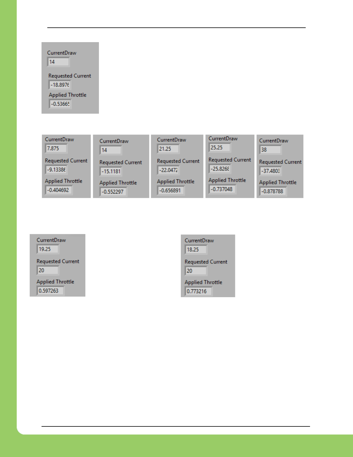
217-8080 TALON SRX / Victor SPX Software Reference Manual 3/06/2018
Cross The Road Electronics Page 108 3/06/2018
Here we attempt to reproduce the same target point. We see our motor
output has increased because of the stronger P-gain and our current draw
is closer to our target.
Keep increasing the P-gain until the desired response is achieved. To
save time, many will double the P-gain until oscillation is observed
(overshooting the target and then returning to target. This can also be
observed by plotting, or watching the color change on the Talon SRX
LEDs).
After further increasing P-gain, we see our desired and measured current-draw to follow closely.
We can also observe how the closed-loop responds to a change in load. Disconnecting the
back driven CIM motor’s connected leads and connecting them to a 0.2 ohm power resistor
reveals how the Closed-Loop increases its motor output to target the desired 20 amps.
With additional tweaking and leveraging the remaining gains (I and D), the closed-loop can be
further improved, though many will find that a simple FP loop will be sufficient for many
applications.
Closed Loop driving
59.7% when back-
driven CIM has
leads connected.
Closed Loop driving
77.7% when back-
driven CIM has
power resistor in
series with leads.
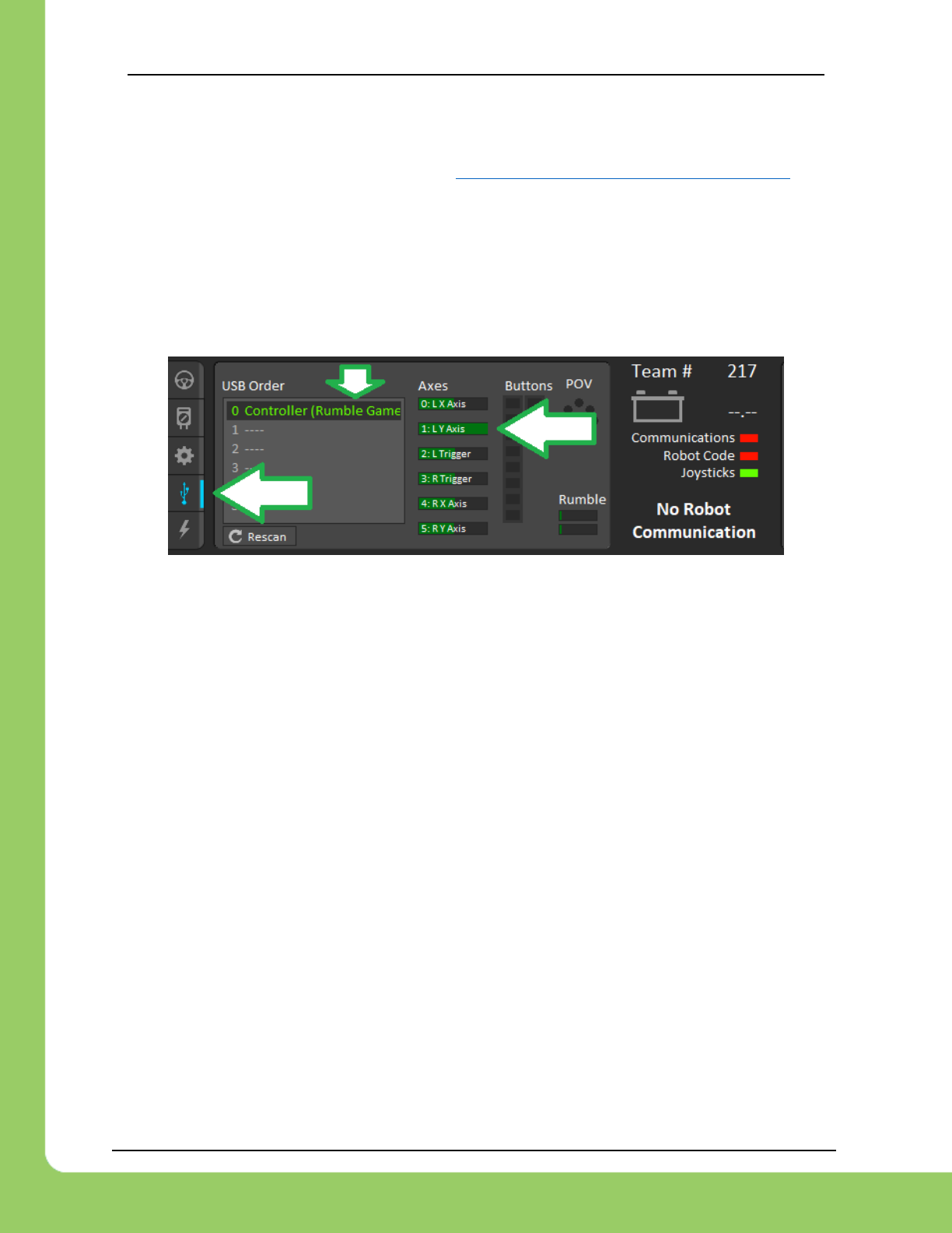
217-8080 TALON SRX / Victor SPX Software Reference Manual 3/06/2018
Cross The Road Electronics Page 109 3/06/2018
12.4. Velocity Closed-Loop Walkthrough – Java
This example is on the CTR GitHub account. https://github.com/CrossTheRoadElec/Phoenix-Examples-Languages
12.4.1. Velocity Closed-Loop Walkthrough – Test Gamepad
The first step is to check the axis of the gamepad is functional and configured in the correct
direction. This is done by ensuring the robot is disabled, and moving the gamepad’s desired
stick to its extremities. While doing this, look at the Driver Station’s USB devices under the 4th
tab, and check that the gamepad’s values are changing as expected.

217-8080 TALON SRX / Victor SPX Software Reference Manual 3/06/2018
Cross The Road Electronics Page 110 3/06/2018
12.4.2. Velocity Closed-Loop Walkthrough – Collect Sensor Data – Java
Then, drive the Talon SRX manually to check that the selected sensor is functioning and in
phase with the motor. The following example below will accomplish this. Deploy and drive the
Talon forward by pulling the gamepad’s y-axis.
public class Robot extends IterativeRobot {
TalonSRX _talon = new TalonSRX(3);
Joystick _joy = new Joystick(0);
StringBuilder _sb = new StringBuilder();
int _loops = 0;
public void robotInit() {
/* first choose the sensor */
_talon.configSelectedFeedbackSensor(FeedbackDevice.CTRE_MagEncoder_Relative, 0,
Constants.kTimeoutMs);
_talon.setSensorPhase(true);
/* set the peak, nominal outputs, and deadband */
_talon.configNominalOutputForward(0, Constants.kTimeoutMs);
_talon.configNominalOutputReverse(0, Constants.kTimeoutMs);
_talon.configPeakOutputForward(1, Constants.kTimeoutMs);
_talon.configPeakOutputReverse(-1, Constants.kTimeoutMs);
/* set closed loop gains in slot0 */
_talon.config_kF(Constants.kPIDLoopIdx, 0.34, Constants.kTimeoutMs);
_talon.config_kP(Constants.kPIDLoopIdx, 0.2, Constants.kTimeoutMs);
_talon.config_kI(Constants.kPIDLoopIdx, 0, Constants.kTimeoutMs);
_talon.config_kD(Constants.kPIDLoopIdx, 0, Constants.kTimeoutMs);
}
/** This function is called periodically during operator control */
public void teleopPeriodic() {
/* get gamepad axis */
double leftYstick = _joy.getY();
double motorOutput = _talon.getMotorOutputPercent();
/* prepare line to print */
_sb.append("\tout:");
_sb.append(motorOutput);
_sb.append("\tspd:");
_sb.append(_talon.getSelectedSensorVelocity(Constants.kPIDLoopIdx));
if (_joy.getRawButton(1)) {
/* Speed mode */
/*
* 4096 Units/Rev * 500 RPM / 600 100ms/min in either direction:
* velocity setpoint is in units/100ms
*/
double targetVelocity_UnitsPer100ms = leftYstick * 4096 * 500.0 / 600;
/* 1500 RPM in either direction */
_talon.set(ControlMode.Velocity, targetVelocity_UnitsPer100ms);
/* append more signals to print when in speed mode. */
_sb.append("\terr:");
_sb.append(_talon.getClosedLoopError(Constants.kPIDLoopIdx));
_sb.append("\ttrg:");
_sb.append(targetVelocity_UnitsPer100ms);
} else {
/* Percent output mode */
_talon.set(ControlMode.PercentOutput, leftYstick);
}
if (++_loops >= 10) {
_loops = 0;
System.out.println(_sb.toString());
}
_sb.setLength(0);
}
}
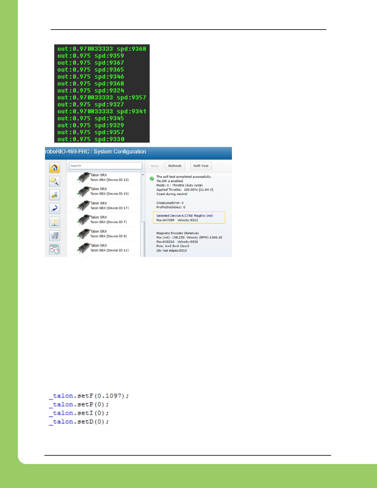
217-8080 TALON SRX / Victor SPX Software Reference Manual 3/06/2018
Cross The Road Electronics Page 111 3/06/2018
While driving the Talon in the positive direction, make sure
the sensor speed is also positive.
Additionally, note the approximate sensor speed while the
Talon is driven.
getSelectedSensorVelocity () will return the speed in
position units per 100ms.
The same values can be read
in the roboRIO web-based
configuration under Self-Tests.
12.4.3. Velocity Closed-Loop Walkthrough – Calculating Feed Forward–
Java
Now that we’ve confirmed that the position/speed moves in the positive direction with forward
(green LEDs on Talon), we can calculate our Feed-forward gain. Our measurement of 9326
native units per 100ms is used for this. This was captured in the Self-Test.
Now let’s calculate a Feed-forward gain so that 100% motor output is calculated when the
requested speed is 9328 native units per 100ms.
F-gain = (100% X 1023) / 9326
F-gain = 0.1097
Let’s check our math, if the target speed is 9326 native units per 100ms, Closed-loop output will
be (0.1097 X 9326) => 1023 (full forward).
Next we will set the calculated gain. This can also be done in the
roboRIO web-based configuration or programmatically.
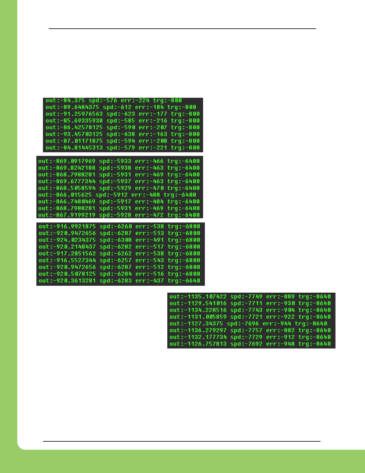
217-8080 TALON SRX / Victor SPX Software Reference Manual 3/06/2018
Cross The Road Electronics Page 112 3/06/2018
After applying the new gain, rerun the test but hold down button1 to put Talon into Speed
Control Mode. Now review the target and measured speed to see how close we are.
A few DS console samples are shown below, which contain the print statements. Looking at
“spd” and “trg” we see that we’re within ~600 units per 100ms for most of the captures.
Since the sensor is 4096 units per
rotation, ~600 units per 100ms scales
to ~87 RPM for most of the speed-
sweep.
Additionally, since we have no
feedback, you will find changes in load
will impact the error considerably.
Remember “err” is in native units per
100ms. So an error of 900 units per
100ms equals an error of 131RPM since
each rotation is 4096 units.

217-8080 TALON SRX / Victor SPX Software Reference Manual 3/06/2018
Cross The Road Electronics Page 113 3/06/2018
12.4.4. Velocity Closed-Loop Walkthrough – Dialing Proportional Gain –
Java
Next we will add in P-gain so that the closed-loop can react to error. Suppose given our worst
error so far (900 native units per 100ms), we want to respond with another 10% of motor output.
Then our starting p-gain would be…
(10% X 1023) / (900) = 0.113333
Now let’s check our math, if the Talon SRX sees an error of 900 the P-term will be
900 X 0.113333 = 102 (which is about 10% of 1023)
P-gain = 0.113333
Apply the P -gain programmatically using your preferred method. Now retest to see how well
the closed-loop responds to varying loads. Double the P -gain until the system oscillates (too
much) or until the system responds adequately.
/* set closed loop gains in slot0 */
_talon.config_kF(Constants.kPIDLoopIdx, 0.1097, Constants.kTimeoutMs);
_talon.config_kP(Constants.kPIDLoopIdx, 0.113333, Constants.kTimeoutMs);
_talon.config_kI(Constants.kPIDLoopIdx, 0, Constants.kTimeoutMs);
_talon.config_kD(Constants.kPIDLoopIdx, 0, Constants.kTimeoutMs);
If the mechanism is moving to swiftly, you can add D-gain to smooth the motion. Start with 10x
the p-gain.
If the mechanism is not quite reaching the final target position (and P -gain cannot be increased
further without hurting overall performance) begin adding I-gain. Start with 1/100th of the P-gain.
Some mechanisms may require that the closed-loop can never spin in reverse of the desired
direction (due to closed-loop wanting to slow down). This behavior can be achieved by reducing
the peak output to zero.
/* set the peak, nominal outputs */
_talon.configNominalOutputForward(0, Constants.kTimeoutMs);
_talon.configNominalOutputReverse(0, Constants.kTimeoutMs);
_talon.configPeakOutputForward(+1, Constants.kTimeoutMs);
_talon.configPeakOutputReverse(0, Constants.kTimeoutMs); /* only positive */
/* set closed loop gains in slot0 */
_talon.config_kF(Constants.kPIDLoopIdx, 0.1097, Constants.kTimeoutMs);
_talon.config_kP(Constants.kPIDLoopIdx, 0.22, Constants.kTimeoutMs);
_talon.config_kI(Constants.kPIDLoopIdx, 0, Constants.kTimeoutMs);
_talon.config_kD(Constants.kPIDLoopIdx, 0, Constants.kTimeoutMs);
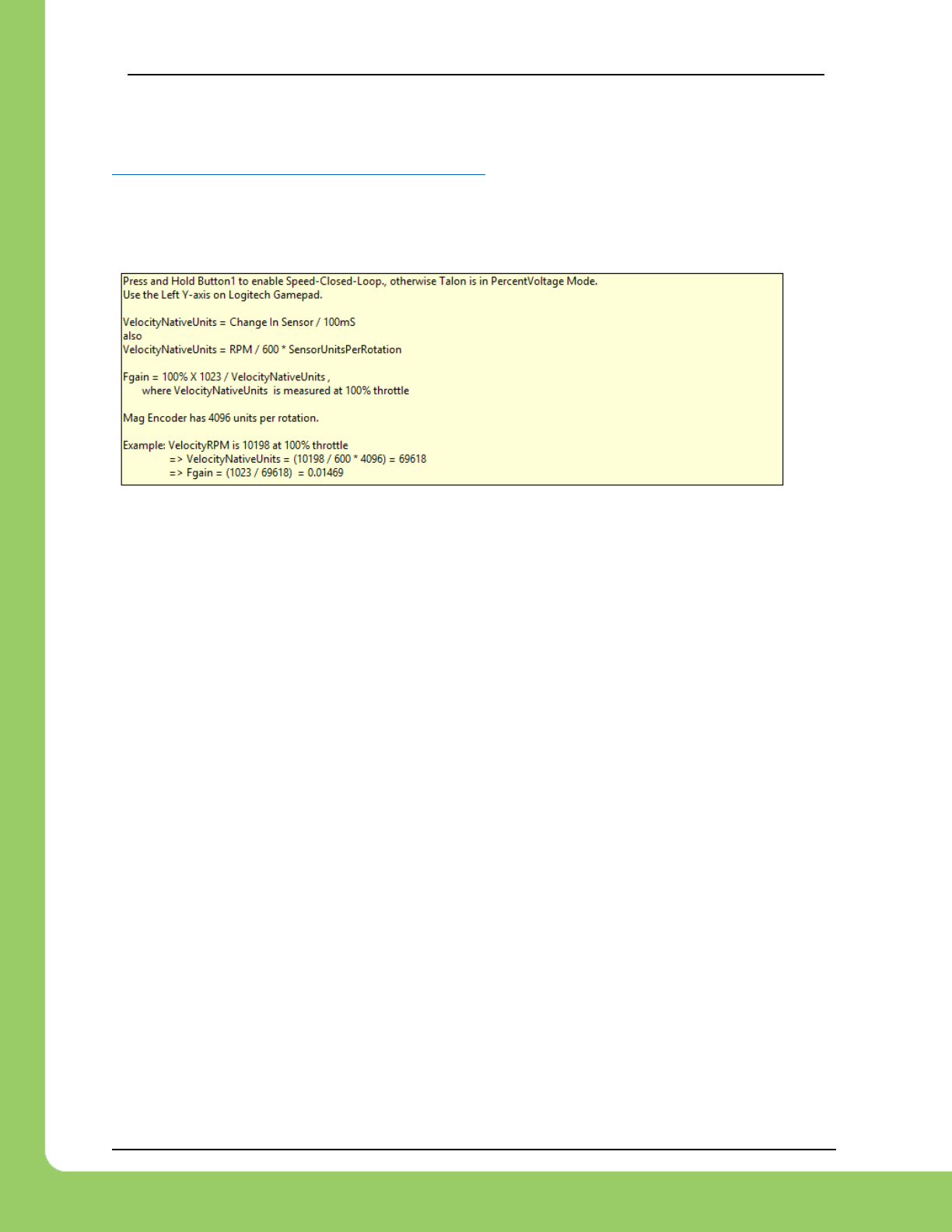
217-8080 TALON SRX / Victor SPX Software Reference Manual 3/06/2018
Cross The Road Electronics Page 114 3/06/2018
12.5. Velocity Closed-Loop Example – LabVIEW
This example can be found on the CTR GitHub account.
https://github.com/CrossTheRoadElec/Phoenix-Examples-LabVIEW
Look at the teleop VI to confirm how the Feed Forward gain is calculated.
There will be a text label similar to the following…
The calibration procedure is identical to the Java Velocity Walkthrough.

217-8080 TALON SRX / Victor SPX Software Reference Manual 3/06/2018
Cross The Road Electronics Page 115 3/06/2018
12.6. Motion Magic Closed-Loop Walkthrough – Java
This latest example should be downloaded from the CTR GitHub account.
https://github.com/CrossTheRoadElec/Phoenix-Examples-Languages
The example will appear similar to the snippet below…
public class Robot extends IterativeRobot {
TalonSRX _talon = new TalonSRX(3);
Joystick _joy = new Joystick(0);
StringBuilder _sb = new StringBuilder();
public void robotInit() {
/* first choose the sensor */
_talon.configSelectedFeedbackSensor(FeedbackDevice.CTRE_MagEncoder_Relative,
Constants.kPIDLoopIdx, Constants.kTimeoutMs);
_talon.setSensorPhase(true);
_talon.setInverted(false);
/* Set relevant frame periods to be at least as fast as periodic rate*/
_talon.setStatusFramePeriod(StatusFrameEnhanced.Status_13_Base_PIDF0, 10,
Constants.kTimeoutMs);
_talon.setStatusFramePeriod(StatusFrameEnhanced.Status_10_MotionMagic, 10,
Constants.kTimeoutMs);
/* set the peak and nominal outputs */
_talon.configNominalOutputForward(0, Constants.kTimeoutMs);
_talon.configNominalOutputReverse(0, Constants.kTimeoutMs);
_talon.configPeakOutputForward(1, Constants.kTimeoutMs);
_talon.configPeakOutputReverse(-1, Constants.kTimeoutMs);
/* set closed loop gains in slot0 - see documentation */
_talon.selectProfileSlot(Constants.kSlotIdx, Constants.kPIDLoopIdx);
_talon.config_kF(0, 0.2, Constants.kTimeoutMs);
_talon.config_kP(0, 0.2, Constants.kTimeoutMs);
_talon.config_kI(0, 0, Constants.kTimeoutMs);
_talon.config_kD(0, 0, Constants.kTimeoutMs);
/* set acceleration and vcruise velocity - see documentation */
_talon.configMotionCruiseVelocity(15000, Constants.kTimeoutMs);
_talon.configMotionAcceleration(6000, Constants.kTimeoutMs);
/* zero the sensor */
_talon.setSelectedSensorPosition(0, Constants.kPIDLoopIdx, Constants.kTimeoutMs);
}
/**
* This function is called periodically during operator control
*/
public void teleopPeriodic() {
/* get gamepad axis - forward stick is positive */
double leftYstick = -1.0 * _joy.getY();
/* calculate the percent motor output */
double motorOutput = _talon.getMotorOutputPercent();
/* prepare line to print */
_sb.append("\tOut%:");
_sb.append(motorOutput);
_sb.append("\tVel:");
_sb.append(_talon.getSelectedSensorVelocity(Constants.kPIDLoopIdx));
if (_joy.getRawButton(1)) {
/* Motion Magic */
double targetPos = leftYstick * 4096 * 10.0;
/* 4096 ticks/rev * 10 Rotations in either direction*/
_talon.set(ControlMode.MotionMagic, targetPos);
/* append more signals to print when in speed mode. */
_sb.append("\terr:");
_sb.append(_talon.getClosedLoopError(Constants.kPIDLoopIdx));
_sb.append("\ttrg:");
_sb.append(targetPos);
} else {
/* Percent output mode */
_talon.set(ControlMode.PercentOutput, leftYstick);
}
/* instrumentation */
Instrum.Process(_talon, _sb);
try { TimeUnit.MILLISECONDS.sleep(10); } catch(Exception e) {}
}
}
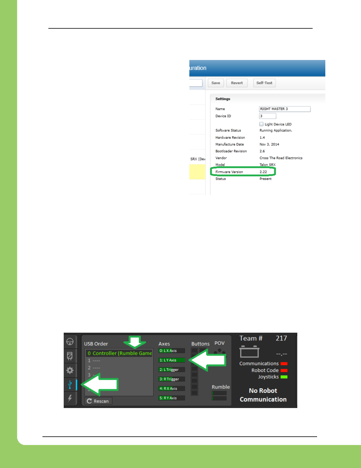
217-8080 TALON SRX / Victor SPX Software Reference Manual 3/06/2018
Cross The Road Electronics Page 116 3/06/2018
12.6.1. Motion Magic Closed-Loop Walkthrough – General Requirements
Be sure to check that the firmware is up to date.
See CRF release notes for when motion magic
was added.
Firmware should in the format 3.X.
Additionally, a reliable signal plotter is helpful for tuning parameters.
The signals of interest are the…
• Sensor Position
• Sensor Velocity
• Active Trajectory Position
• Active Trajectory Velocity
• Applied Motor Output
• ClosedLoopErr
12.6.2. Motion Magic Closed-Loop Walkthrough – Test Gamepad
The first step is to check the axis of the gamepad is functional and configured in the correct
direction. This is done by ensuring the robot is disabled, and moving the gamepad’s desired
stick to its extremities. While doing this, look at the Driver Station’s USB devices under the 4th
tab, and check that the gamepad’s values are changing as expected.
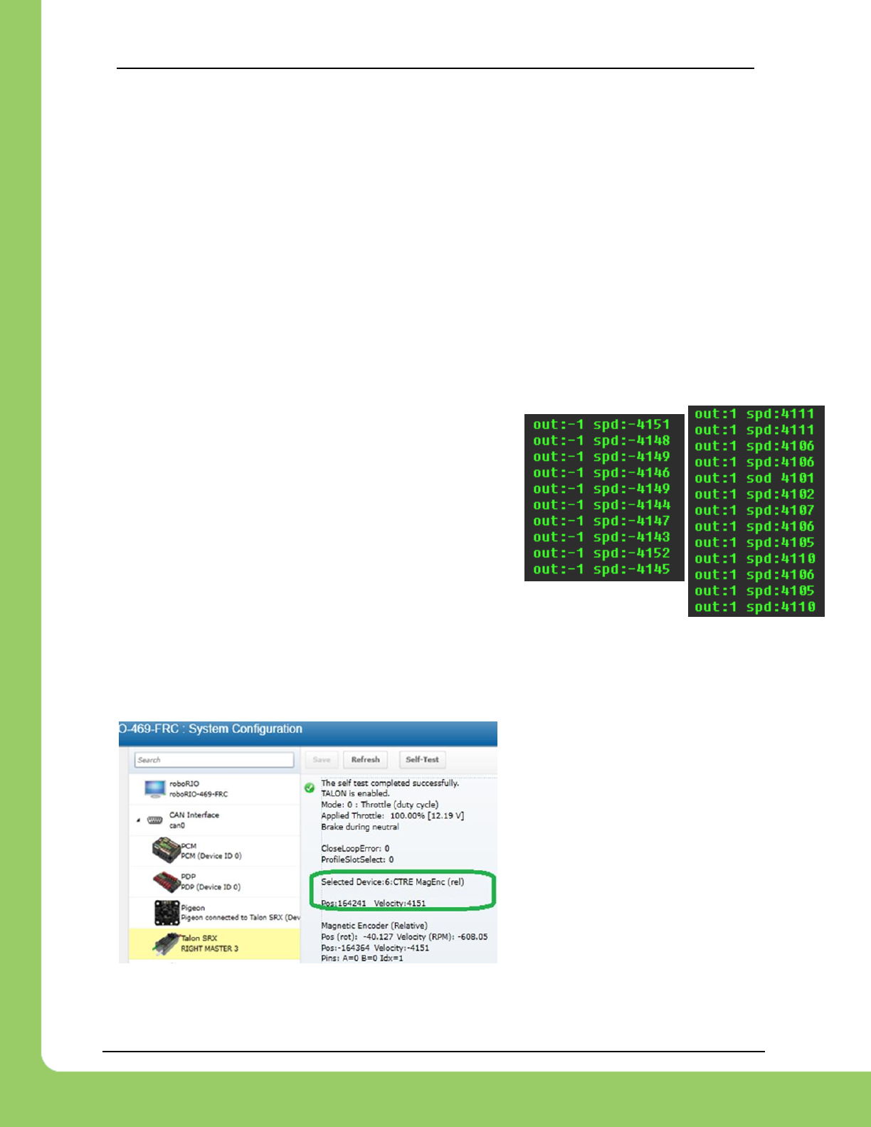
217-8080 TALON SRX / Victor SPX Software Reference Manual 3/06/2018
Cross The Road Electronics Page 117 3/06/2018
12.6.3. Motion Magic Closed-Loop Walkthrough – Collect Sensor Data –
Java
Next, drive the Talon SRX manually to check that the selected sensor is functioning and in
phase with the motor. Deploy the GitHub example (or similar drive code) and drive the Talon by
pulling the gamepad’s y-axis.
Checking the sensor means…
• Confirming the sensor direction matches Talon motor output.
• Confirm position and speed measurement is accurate throughout entire position/speed
range.
• Confirming the velocity is approximately correct given the mechanical setup.
• Noting the measured speed at a given motor output for calculating f-gain
• Noting the measured max speed for initial selection of velocity cruise and acceleration.
While throttling the Talon in the positive direction, make
sure the sensor speed is also positive. Talon should be
illuminating green when doing this. If this is not the cause,
change the parameter in setSensorPhase() and retest.
Additionally, note the approximate sensor velocity while
the Talon is driven. The displayed value is in units per
100ms.
The same values can be read in the roboRIO web-based configuration under Self-
Tests.
It’s important to note the speed for calculating the f-gain and for picking cruise velocity and
acceleration.
Example screenshot while driving
shown here.
Capture several to sanity check
sensor.
The self-test capture used for testing
showed 4123 native units per
100ms, so this is used in the next
section. This is comparable to the
4151 show in the left screenshot.

217-8080 TALON SRX / Victor SPX Software Reference Manual 3/06/2018
Cross The Road Electronics Page 118 3/06/2018
12.6.3.1. Is velocity magnitude correct?
In this example, we measure 4123 units per 100ms (captured from previous section). This
scales to ~604 RPM at full motor output (averaged of peak in both directions), assuming 4096
units per rotation (CTRE Mag encoder resolution).
This setup involves 1 X CIM Motor motor (free speed 5330 RPM). The selected gear ratio is
~9:1. The CTRE magnetic encoder is on the geared output. So, a measurement of ~604 RPM
is reasonable since it is close to 1/9th of 5330 RPM.
12.6.3.2. Is direction correct?
Looking at the screenshots above, positive motor output yielded a positive speed.
12.6.3.3. Sweep motor output and plots signals
While sweeping position and velocity, look for any discontinuities or unexplained behavior. In
the capture below, the sensor velocity and position appear to follow with no discontinuities or
plateaus.
12.6.3.4. Measurements
For the calculations done in the next section, the measurement 4123 units per 100ms at full
motor output is observed.
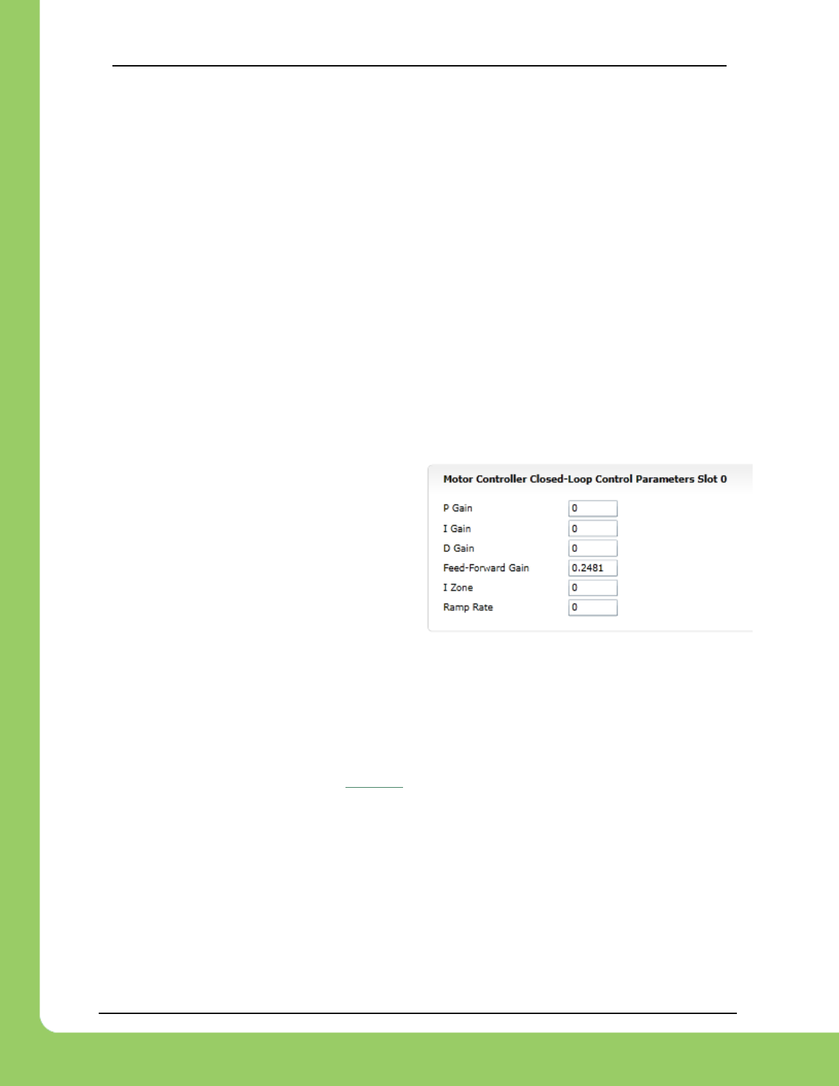
217-8080 TALON SRX / Victor SPX Software Reference Manual 3/06/2018
Cross The Road Electronics Page 119 3/06/2018
12.6.4. Motion Magic Closed-Loop Walkthrough – Calculate F-Gain – Java
The Motion-Magic Closed-Loop mode operates by closed-loop servoing to a calculated position
with a fed-forward calculated velocity. The calculations are based on the set-point, cruise
velocity, acceleration parameter, and time. This requires knowing the sensor units per rotation.
For this example, the CTRE Magnetic Encoder (quadrature) was used, which has 4096 native
units per rotation. That is how we can deduce that the 4123 native units per 100ms
measurement scales to ~604 RPM.
Velocity is measured in change in native units per TvelMeas= 100ms.
Now let’s calculate a Feed-forward gain so that 100% motor output is calculated when the
requested speed is 4123 native units per 100ms.
F-gain = (100% X 1023) / 4123
F-gain = 0.2481
Let’s check our math, if the target speed is 4123 native units per 100ms, Closed-loop output will
be (0.2481 X 4123 ) => 1023 (full forward).
Next we will set the calculated gain. This can
also be done in the roboRIO web-based
configuration or programmatically.
/* set closed loop gains in slot0 - see documentation */
_talon.selectProfileSlot(Constants.kSlotIdx, Constants.kPIDLoopIdx);
_talon.config_kF(0, 0.2481, Constants.kTimeoutMs);
_talon.config_kP(0, 0, Constants.kTimeoutMs);
_talon.config_kI(0, 0, Constants.kTimeoutMs);
_talon.config_kD(0, 0, Constants.kTimeoutMs);
/* set acceleration and vcruise velocity - see documentation */
_talon.configMotionCruiseVelocity(0, Constants.kTimeoutMs);
_talon.configMotionAcceleration(0, Constants.kTimeoutMs);

217-8080 TALON SRX / Victor SPX Software Reference Manual 3/06/2018
Cross The Road Electronics Page 120 3/06/2018
12.6.5. Motion Magic Closed-Loop Walkthrough – Initial Cruise-
Velocity/Acceleration – Java
Since our peak measured velocity was 4123 units per 100ms, the initial cruise velocity should
be set to a smaller value to ensure the speed can be reached. In this example, we will
arbitrarily take 75% of the top speed. Depending on the mechanism type, how safe the
mechanism is, and what is trying to be accomplished, a lower or higher cruise velocity could be
specified. Also remember that this setting can be changed easily and at any time.
75% X 4123 units per 100ms = ~3092 units per 100ms
For the initial acceleration value, we will arbitrarily choose a value so that it takes an entire
second to reach our cruise velocity. This will ensure the acceleration is slow enough to be
observable. If this is too fast/slow, adjust accordingly. Since the acceleration is in terms of
change in velocity per second, an acceleration of 3092 units per 100ms per sec will achieve
our 1 second accel time.
/* set closed loop gains in slot0 - see documentation */
_talon.selectProfileSlot(Constants.kSlotIdx, Constants.kPIDLoopIdx);
_talon.config_kF(0, 0.2481, Constants.kTimeoutMs);
_talon.config_kP(0, 0, Constants.kTimeoutMs);
_talon.config_kI(0, 0, Constants.kTimeoutMs);
_talon.config_kD(0, 0, Constants.kTimeoutMs);
/* set acceleration and vcruise velocity - see documentation */
_talon.configMotionCruiseVelocity(3092, Constants.kTimeoutMs);
_talon.configMotionAcceleration(3092, Constants.kTimeoutMs);
With the F gain and initial cruise velocity/acceleration configured, potentially you may start the
servo by holding down button 1 and manipulating the gamepad stick.
Before doing this be aware of the following…
• The servo range is programmed for ±10 rotations (see code snippet below).
if (_joy.getRawButton(1)) {
/* Motion Magic */
double targetPos = leftYstick * 4096 * 10.0;
/* 4096 ticks/rev * 10 Rotations in either direction */
_talon.set(ControlMode.MotionMagic, targetPos);
If that is beyond the mechanism’s range, reduce this and/or setup soft-limits/limit-switches so
that there is no risk in reaching the mechanism’s hard limits (potentially damaging mechanism).
• Consider that the current sensor position may be far from ‘0’ because of manual-driving
the motor when collecting sensor values in the previous sections. If needed, reset the
sensor by calling setSelectedSensorPosition().
• Since PID gains are zero, the movement may coast past the target position, particularly
if the Talon’s neutral mode is in coast. But the motor output will reach neutral near the
final target position passed into set().
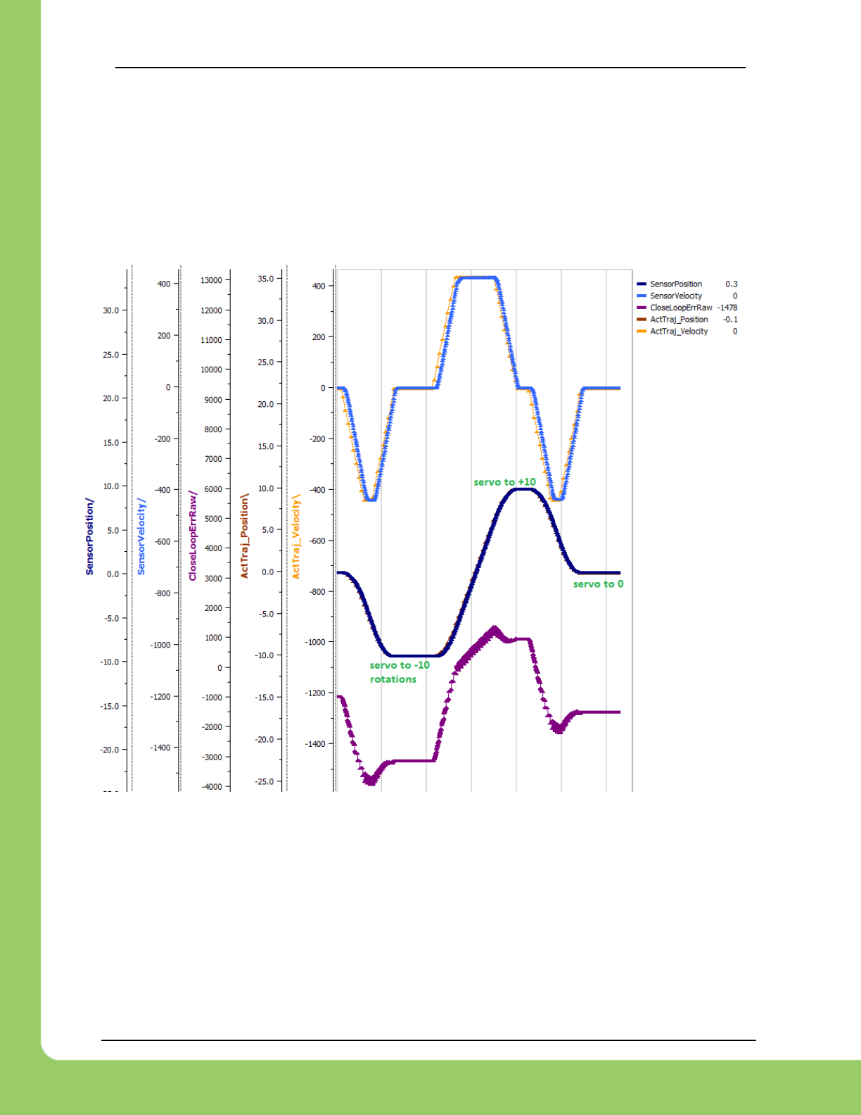
217-8080 TALON SRX / Victor SPX Software Reference Manual 3/06/2018
Cross The Road Electronics Page 121 3/06/2018
In this example the mechanism is the left-side of a robot’s drivetrain. The robot is elevated such
that the wheels spin free. In the capture below we see the sensor position/velocity (blue) and
the Active Trajectory position/velocity (brown/orange). At the end of the movement the closed-
loop error (which is in raw units) is sitting at ~1400.units. Given the resolution of the sensor this
is approximately 0.34 rotations (4096 units per rotation). Another note is that when the
movement is finished, you can freely back-drive the mechanism without motor-response
(because PID gains are zero).
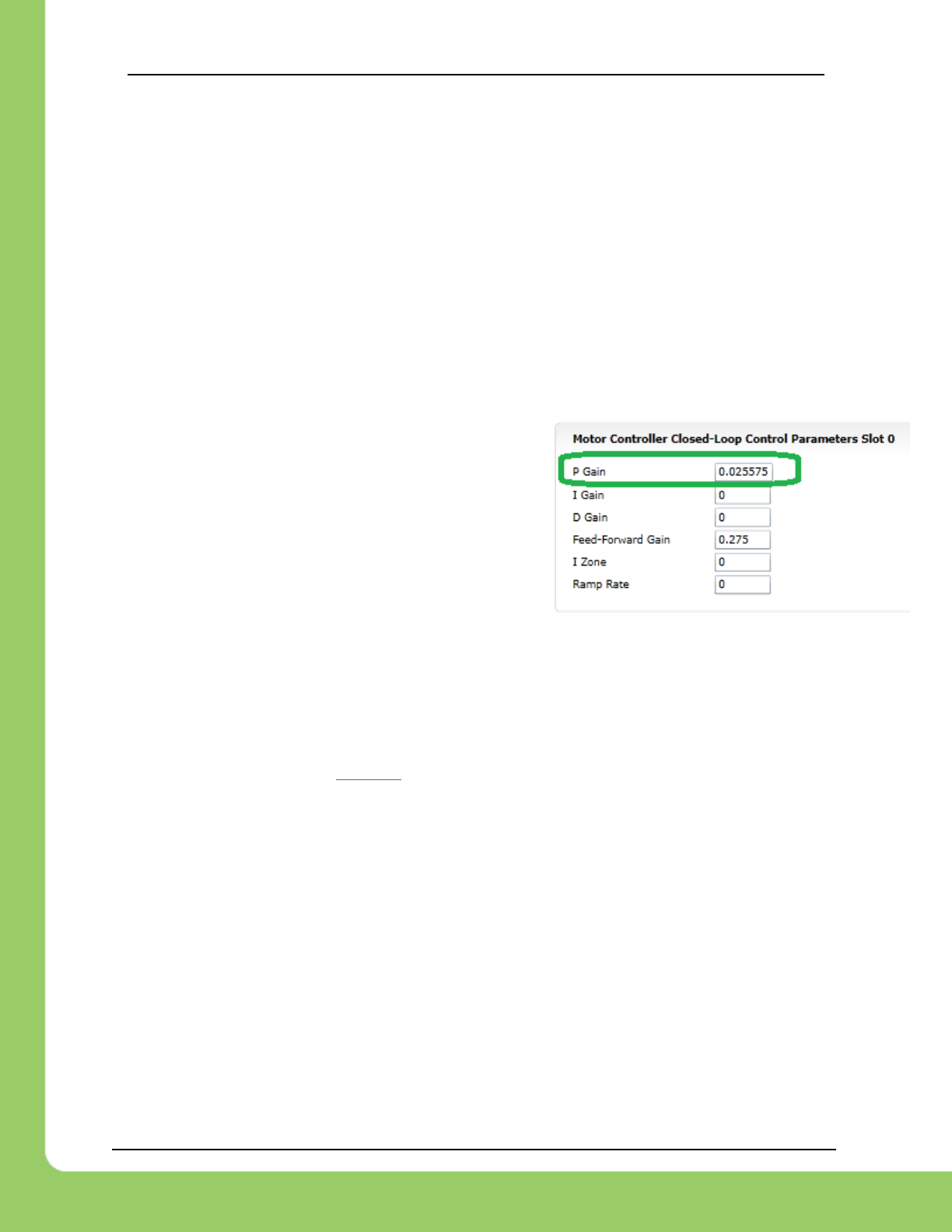
217-8080 TALON SRX / Victor SPX Software Reference Manual 3/06/2018
Cross The Road Electronics Page 122 3/06/2018
12.6.6. Motion Magic Closed-Loop Walkthrough – P-Gain – Java
Next we will add in P-gain so that the closed-loop can react to error. In the previous section,
after running the mechanism with just F-gain, the servo appears to settle with an error or ~1400.
Given an error of (~1400.), suppose we want to respond with another 10% of motor output.
Then our starting p-gain would be….
(10% X 1023) / (1400) = 0.0731
Now let’s check our math, if the Talon SRX sees an error of 1400 the P-term will be
1400 X 0.0731= 102 (which is about 10% of 1023)
P-gain = 0.0731
Apply the P -gain programmatically using your
preferred method. Now retest to see how well the
closed-loop responds to varying loads.
/* set closed loop gains in slot0 - see documentation */
_talon.selectProfileSlot(Constants.kSlotIdx, Constants.kPIDLoopIdx);
_talon.config_kF(0, 0.2481, Constants.kTimeoutMs);
_talon.config_kP(0, 0.0731, Constants.kTimeoutMs);
_talon.config_kI(0, 0, Constants.kTimeoutMs);
_talon.config_kD(0, 0, Constants.kTimeoutMs);
/* set acceleration and vcruise velocity - see documentation */
_talon.configMotionCruiseVelocity(3092, Constants.kTimeoutMs);
_talon.configMotionAcceleration(3092, Constants.kTimeoutMs);
Retest the maneuver by holding button 1 and sweeping the gamepad stick.
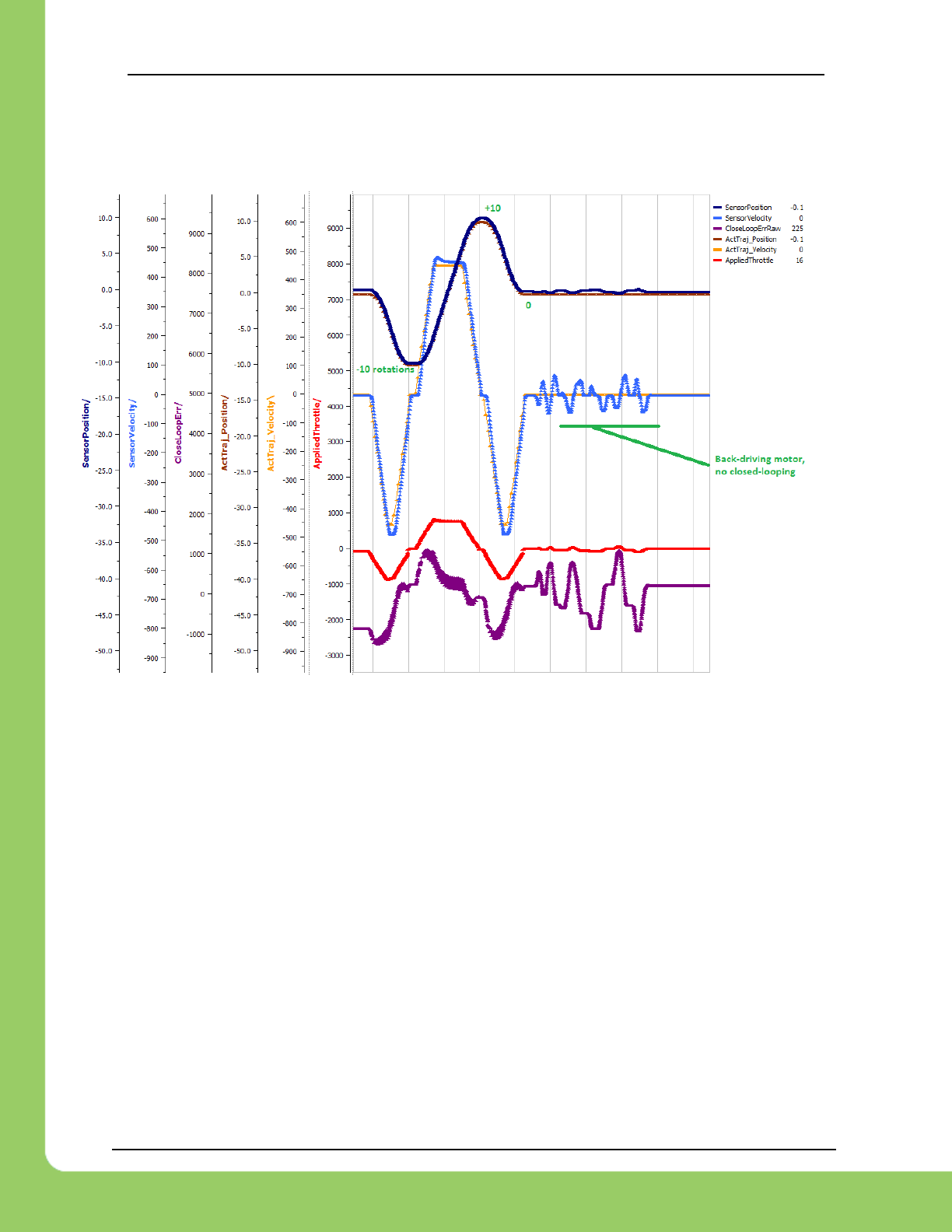
217-8080 TALON SRX / Victor SPX Software Reference Manual 3/06/2018
Cross The Road Electronics Page 123 3/06/2018
At the end of this capture, the wheels were hand-spun to demonstrate how aggressive the
position servo responds. Because the wheel still backdrives considerably before motor holds
position, the P-gain still needs to be increased.
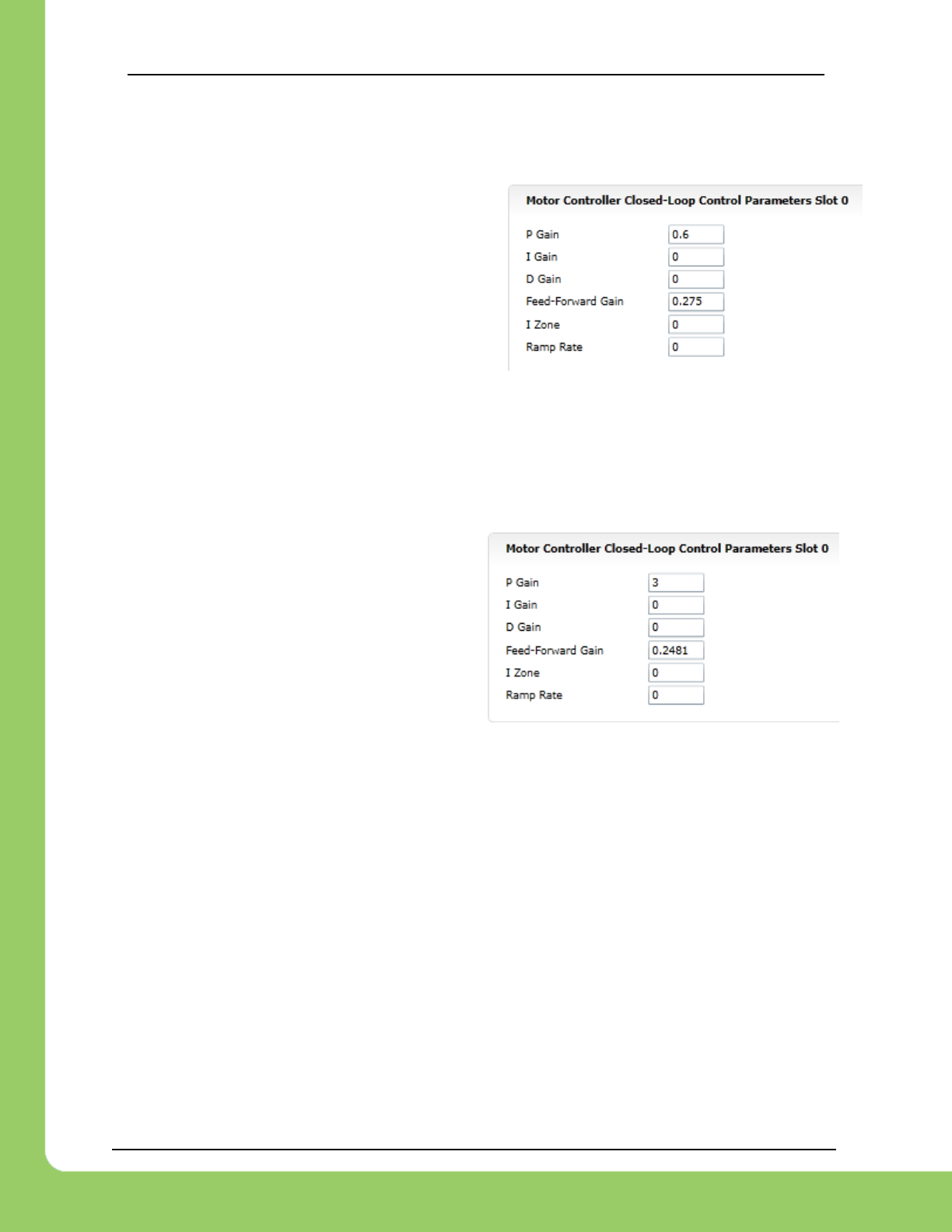
217-8080 TALON SRX / Victor SPX Software Reference Manual 3/06/2018
Cross The Road Electronics Page 124 3/06/2018
Double the P-gain until the system oscillates (by a small amount) or until the system responds
adequately.
After a few rounds the P gain is at 0.6.
Scope captures below show the sensor position
and target position follows visually, but back-
driving the motor still shows a minimal motor
response.
After several rounds, we’ve landed on a P gain
value of 3. The mechanism overshoots a bit at
the end of the maneuver. Additionally, back-
driving the wheel is very difficult as the motor-
response is immediate (good).
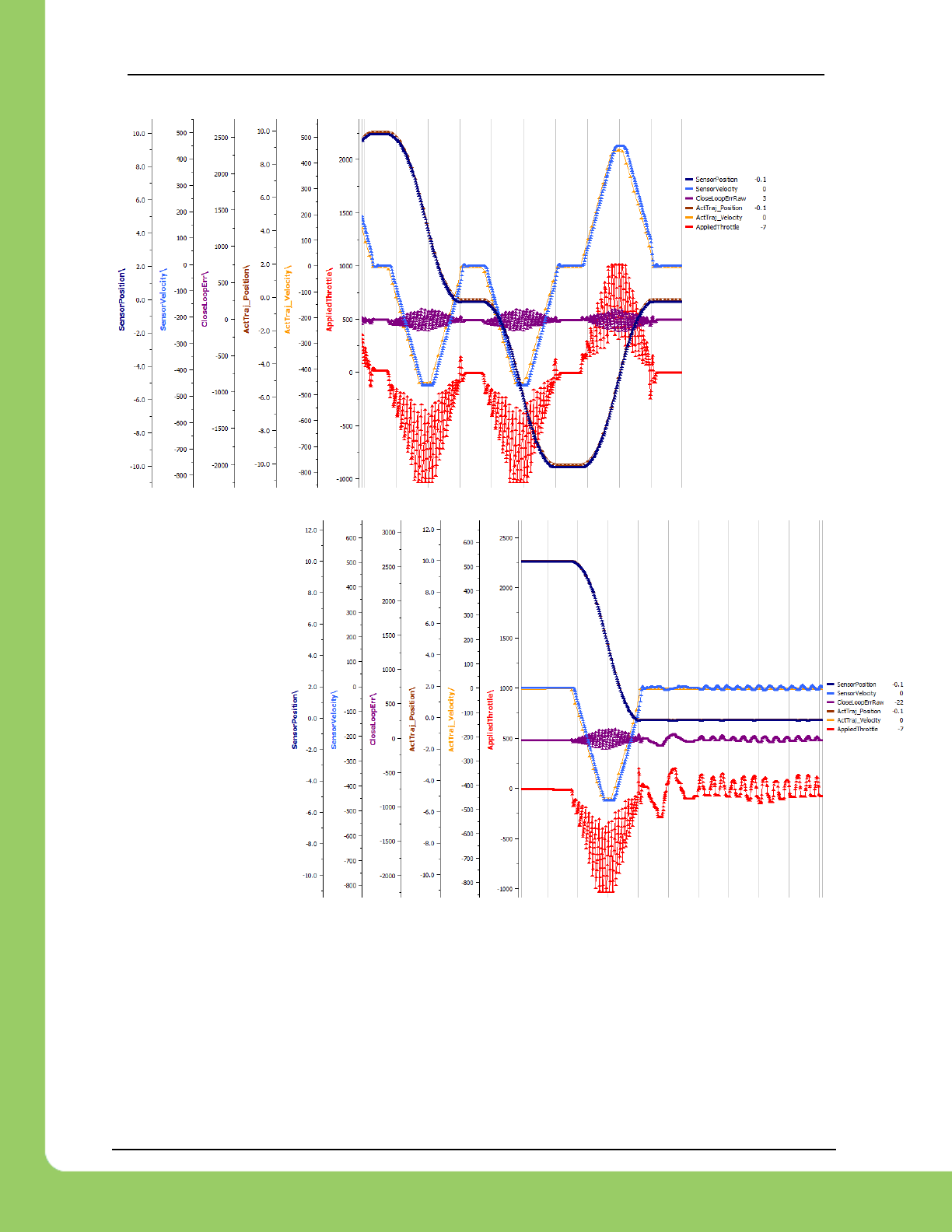
217-8080 TALON SRX / Victor SPX Software Reference Manual 3/06/2018
Cross The Road Electronics Page 125 3/06/2018
Once settles, the
motor is back-driven
to assess how firm
the motor holds
position.
The wheel is held by
the motor firmly.
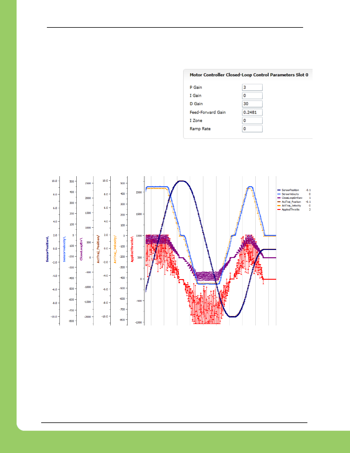
217-8080 TALON SRX / Victor SPX Software Reference Manual 3/06/2018
Cross The Road Electronics Page 126 3/06/2018
12.6.7. Motion Magic Closed-Loop Walkthrough – D-Gain – Java
To resolve the overshoot at the end of the
maneuver, D-gain is added. D-gain can start
typically at 10 X P-gain.
With this change the visual overshoot of the wheel is gone. The plots also reveal reduced
overshoot at the end of the maneuver.
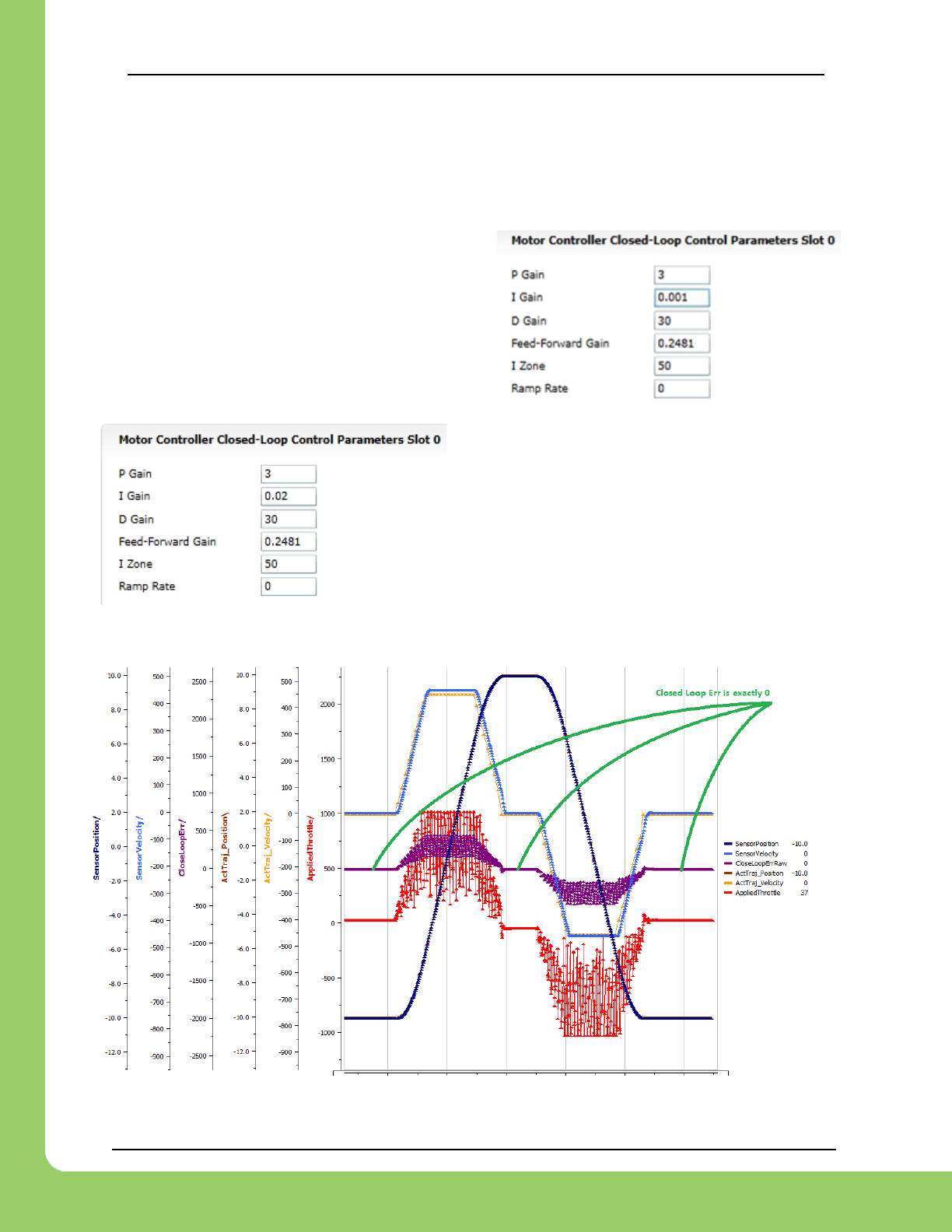
217-8080 TALON SRX / Victor SPX Software Reference Manual 3/06/2018
Cross The Road Electronics Page 127 3/06/2018
12.6.8. Motion Magic Closed-Loop Walkthrough – I-Gain – Java
Typically, the final step is to confirm the sensor settles very close to the target position. If the
final closed-loop error is not quite close enough to zero, consider adding I-gain and I-zone to
ensure the Closed-Loop Error ultimately lands at zero (or close enough).
In testing the closed-loop error settles around 20
units, so we’ll set the Izone to 50 units (large
enough to cover the typical error), and start the I-
gain at something small (0.001).
Keep doubling I-gain until the error reliably
settles to zero.
With some tweaking, we find an I-gain that
ensures maneuver settles with an error of 0.
At this point the acceleration and cruise-velocity can be modified to hasten/dampen the
maneuver as the application requires.
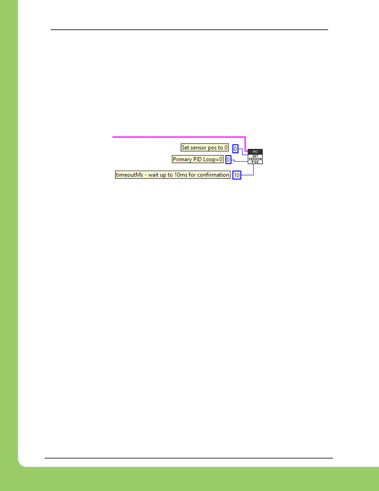
217-8080 TALON SRX / Victor SPX Software Reference Manual 3/06/2018
Cross The Road Electronics Page 128 3/06/2018
13. Setting Sensor Position
Depending on the sensor selected, the user can modify the “Sensor Position”. This is
particularly useful when using a Quadrature Encoder (or any relative sensor) which needs to be
“zeroed” or “home-ed” when the robot is in a known position.
13.1. Setting Sensor Position – LabVIEW
To modify the “Sensor Position”, user will likely have to leverage the SET SENSOR POS VI. In
this example “0” is selected to re-zero the sensor.
13.2. Setting Sensor Position – C++
SetSelectedPosition() can be used to change the current sensor position, if a relative
sensor is used.
int sensorPos = 0; // sensor units
talon.SetSelectedSensorPosition(sensorPos, 0, 10);
13.3. Setting Sensor Position – Java
setSelectedPosition() can be used to change the current sensor position, if a relative
sensor is used.
int sensorPos = 0; // sensor units
talon.setSelectedSensorPosition(sensorPos, 0, 10);
13.4. Auto Clear Position using Index Pin
In addition to manually changing the sensor position, the Talon SRX supports automatically
resetting the Selected Sensor Position to zero whenever a digital edge is detected on the
Quadrature Index Pin.
This feature can be enabled regardless of which sensor is selected. This allows a means of
resetting the position using a digital sensor, switch, or any external event that can drive a 3.3V
digital signal. Since the Quadrature Index Pin has an internal pullup, the signal source can be
an open-drain signal that provides ground when asserted, and high-impedance when not
asserted (or vice versa).
This feature is useful for minimizing the latency of resetting the Sensor Position after the
external event since the robot controller is not involved. The maximum delay is <1ms.
Additionally, this feature functions even if the Talon is disabled.
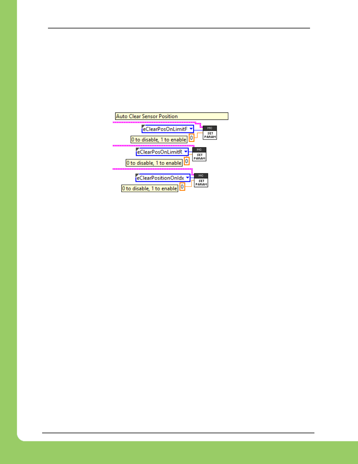
217-8080 TALON SRX / Victor SPX Software Reference Manual 3/06/2018
Cross The Road Electronics Page 129 3/06/2018
The feature can use the Quadrature Index Pin, (and/or Forward Limit/Reverse Limit), which is
convenient if the selected sensor is a Quadrature encoder and the application requires syncing
the position to the sensor’s index signal.
When using Index Pin, a rising edge will clear the position register.
When using Forward/Reverse Limit Pin, position register is cleared when signal is “closed”.
13.4.1. Setting Sensor Position – LabVIEW
13.4.2. Setting Sensor Position – Java
double value = 1; // 1-on, 0-off
talon.configSetParameter(ParamEnum.eClearPositionOnQuadIdx, value, 0x00, 0x00, 10);
talon.configSetParameter(ParamEnum.eClearPositionOnLimitF, value, 0x00, 0x00, 10);
talon.configSetParameter(ParamEnum.eClearPositionOnLimitR, value, 0x00, 0x00, 10);
13.4.3. Setting Sensor Position – C++
double value = 1; // 1-on, 0-off
talon.ConfigSetParameter(ParamEnum::eClearPositionOnQuadIdx, value, 0x00, 0x00, 10);
talon.ConfigSetParameter(ParamEnum::eClearPositionOnLimitF, value, 0x00, 0x00, 10);
talon.ConfigSetParameter(ParamEnum::eClearPositionOnLimitR, value, 0x00, 0x00, 10);
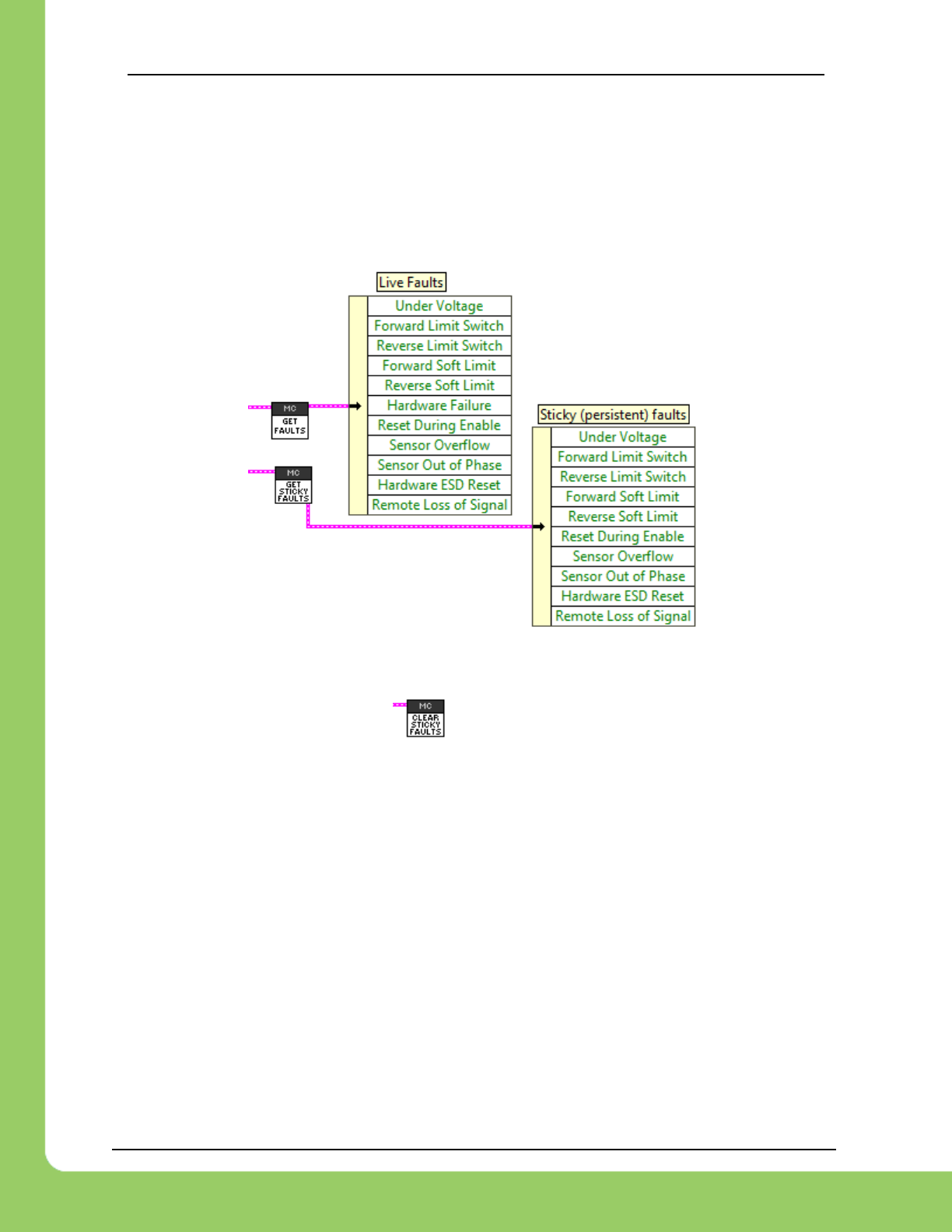
217-8080 TALON SRX / Victor SPX Software Reference Manual 3/06/2018
Cross The Road Electronics Page 130 3/06/2018
14. Fault Flags
The GET STATUS VI can be used to retrieve sticky flags, and clear them.
14.1. Fault Flags - LabVIEW
Clearing sticky faults can be done in the roborio web-based configuration page, or this VI.
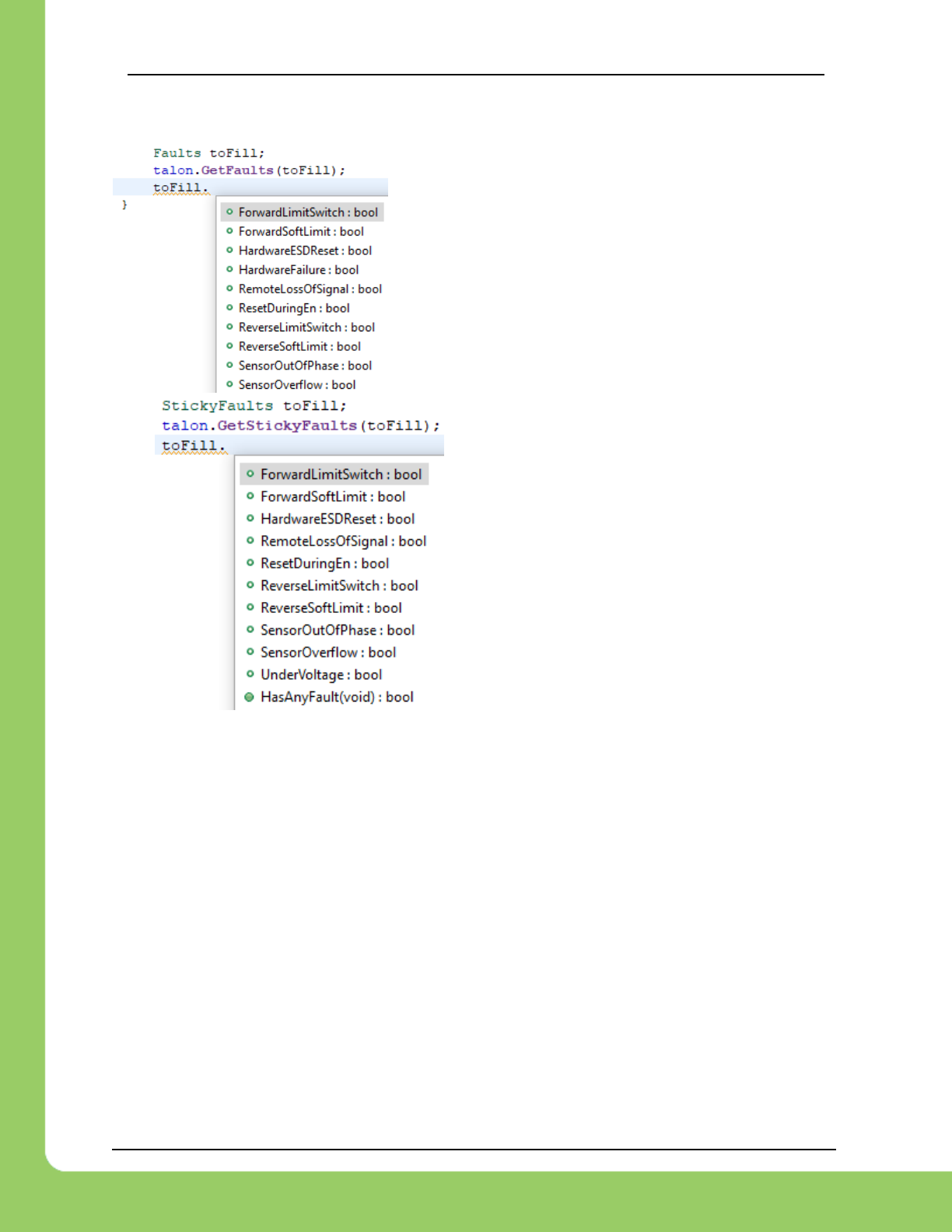
217-8080 TALON SRX / Victor SPX Software Reference Manual 3/06/2018
Cross The Road Electronics Page 131 3/06/2018
14.2. Fault Flags - C++
Create an empty Faults object, and pass into the
GetFaults routine to update. Now inspect the member
variables to poll fault behavior.
Sticky faults operate similarly.
Clearing the faults can be done via the clear routine.
talon.ClearStickyFaults(0);

217-8080 TALON SRX / Victor SPX Software Reference Manual 3/06/2018
Cross The Road Electronics Page 132 3/06/2018
14.3. Fault Flags - Java
Create an empty Faults object,
and pass into the GetFaults
routine to update. Now inspect
the member variables to poll fault
behavior.
Sticky faults operate similarly.
Clearing the faults can be done via the clear routine.
talon.clearStickyFaults(0);
14.4. Fault Flags – Clearing
The above examples include routines to programmatically clear sticky faults.
They can also be cleared via the web-based config as documented in section 2.2.1.
Sticky Faults do not impact any motor controller behavior. They are purely a type of logging and
do not need to be cleared to restore any base functionality.
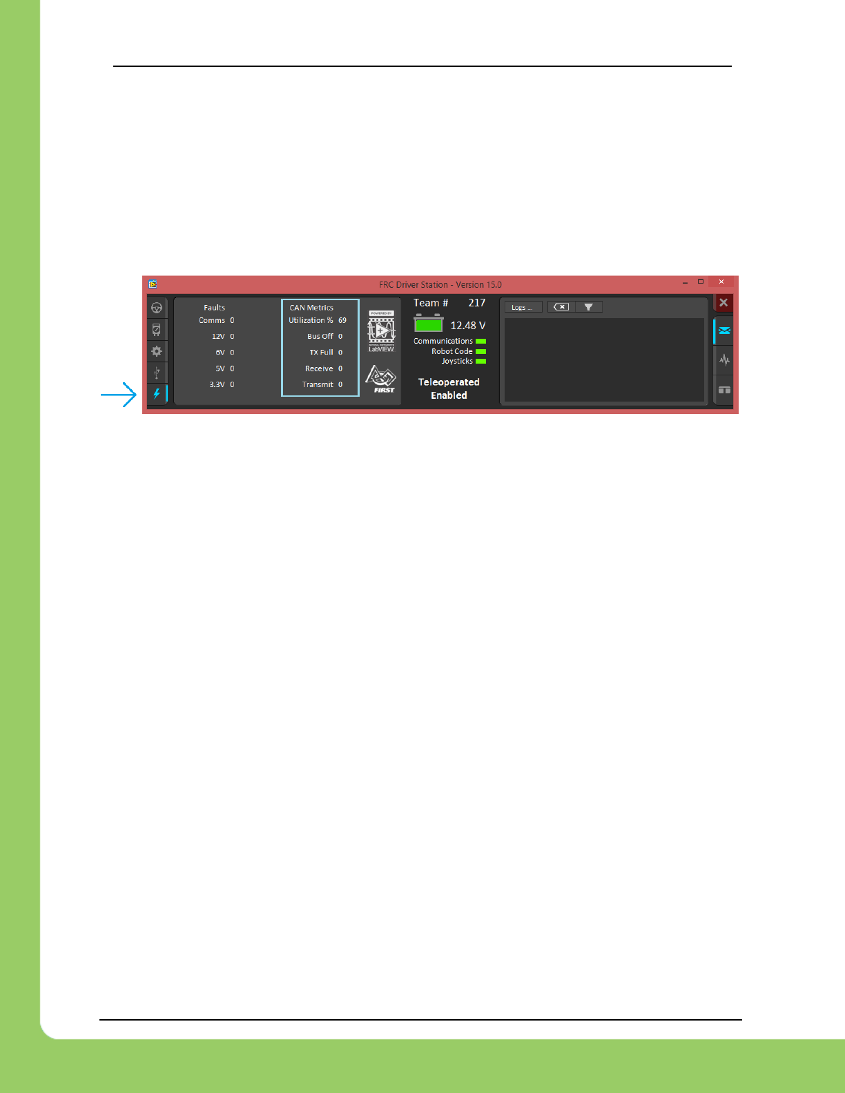
217-8080 TALON SRX / Victor SPX Software Reference Manual 3/06/2018
Cross The Road Electronics Page 133 3/06/2018
15. CAN bus Utilization/Error metrics
The driver station provides various CAN bus metrics under the “lightning bolt” tab.
Utilization is the percent of bus time that is in use relative to the total bandwidth available of the
1Mbps Dual Wire CAN bus. So, at 100% there is no idle bus time (no time between frames on
the CAN bus).
Demonstrated here is 70% bus use when controlling 16 Talon SRXs, along with 1 Pneumatics
Control Module (PCM) and the Power Distribution Panel (PDP).
The “Bus Off” counter increments every time the CAN Controller in the roboRIO enters “bus-off”,
a state where the controller “backs off” transmitting until the CAN bus is deemed “healthy”
again. A good method for watching it increment is to short/release the CAN bus High and Low
lines together to watch it enter and leave “Bus Off” (counter increments per short).
The “TX Full” counter tracks how often the buffer holding outgoing CAN frames (RIO to CAN
device) drops a transmit request. This is another common symptom when the roboRIO no
longer is connected to the CAN bus.
The “Receive” and “Transmit” signal is shorthand for “Receive Error Counter” and “Transmit
Error Counter”. These signals are straight from the CAN bus spec, and track the error instances
occurred “on the wire” during reception and transmission respectively. These counts should
always be zero. Attempt to short the CAN bus and you can confirm that the error counts rise
sharply, then decrement back down to zero when the bus is restored (remove short, reconnect
daisy chain).
When starting out with the FRC control system and Talon SRXs, it is recommended to watch
how these CAN metrics change when CAN bus is disconnected from the roboRIO and other
CAN devices to learn what to expect when there is a harness or a termination resistor issue.
Determining hardware related vs software related issues is key to being successful when using
many CAN devices.

217-8080 TALON SRX / Victor SPX Software Reference Manual 3/06/2018
Cross The Road Electronics Page 134 3/06/2018
15.1. How many Talons can we use?
Generally speaking, a maximum of 16 Motor controllers can be powered at once using a single
PDP (sixteen breaker slots). However, FRC game rules should always be checked as it
determines what it considered legal. This is typically the bottleneck for how many Talon SRXs
can be used despite having CAN device ID space for 63 device IDs. Release software is
always tested to support 16 Talon SRXs, 1 PCM, and 1 PDP with guaranteed control of each
Talon at a rate of 10ms. However, this is not the limit. There is still additional bandwidth for
more nodes. Additionally, if faster response time is desired, control frame periods can be
decreased from the default 10ms, but keep a watchful eye of the CAN bus utilization to ensure
reliable communication.

217-8080 TALON SRX / Victor SPX Software Reference Manual 3/06/2018
Cross The Road Electronics Page 135 3/06/2018
16. Troubleshooting Tips and Common Questions
Just because a firmware issue has been resolved does not mean your out-of-the-box
hardware doesn’t have old firmware. Immediately update your CAN devices to ensure your
development time is not wasted chasing down an issue that has already been solved.
16.1. When I press the B/C CAL button, the brake LED does not change,
neutral behavior does not change.
This is the expected behavior if the robot application is overriding the brake mode. The B/C
CAL button press does toggle the brake mode in persistent memory, however the LED and
selected neutral behavior will honor the override sent over CAN bus. Check if the override API
is being used in the robot application logic.
16.2. The robot is TeleOperated/Autonomous enabled, but the Talon SRX
continues to blink orange (disabled).
Most likely the device ID of that Talon is not being used. In other words, there is no Open Motor
(LabVIEW) or constructed TalonSRX (C++/Java) with that device ID. This can be confirmed by
doing a Self-Test in the roboRIO Web-based Configuration, and confirm the “DEVICE IS NOT
ENABLED!” message at the top.
16.3. When I attach/power a particular Talon SRX to CAN bus, The LEDs on
every Talon SRX occasionally blink red. Motor drive seems normal.
If there is a single CAN error frame, you can expect all Talon SRXs on the bus to synchronously
blink red. This is a great feature for detecting intermittent issues that normally would go
unnoticed. If attaching a particular Talon brings this behavior out, most likely its device ID is
common with another Talon already on the bus. This means two or more “common ID” Talon
SRXs are periodically attempting to transmit using the same CAN arbitration ID, and are
stepping on each other’s frame. This causes an intermittent error frame which then reveals
itself when all Talon SRXs blink red. Check the roboRIO Web-based Configuration for the
“There are X devices with this Device ID” explained in Section 2.2. Common ID Talons.
16.4. If I have a slave Talon SRX following a master Talon SRX, and the
master Talon SRX is disconnected/unpowered, what will the slave
Talon SRX do?
The follower Talon SRX monitors for motor output updates from the master. If the slave Talon
doesn’t see an update after 100ms, it will disable its drive. The LEDs will reflect robot-enable
but with zero motor output (solid orange LEDs).
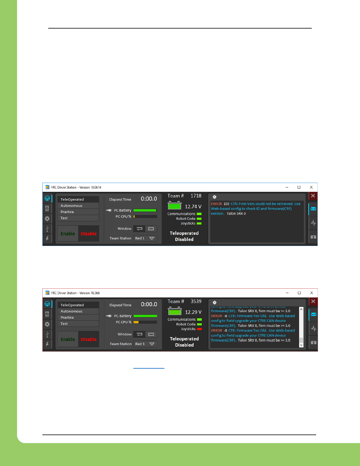
217-8080 TALON SRX / Victor SPX Software Reference Manual 3/06/2018
Cross The Road Electronics Page 136 3/06/2018
16.5. Is there any harm in creating a software Talon SRX for a device ID
that’s not on the CAN bus? Will removing a Talon SRX from the CAN
bus adversely affect other CAN devices?
No! Attempting to communicate with a Talon SRX that is not present will not harm the
communication with other CAN nodes. The communication strategy is very different than
previously support CAN devices, and this use case was in mind when it was designed.
Creating more Talon software objects (LabVIEW Motor Open, or C++/Java class instances) will
increase the bus utilization since it means sending more frames, however this should not
adversely affect robot behavior so long as the bus utilization is reasonable.
However, the resulted error messages in the DS may be a distraction so when permanently
removing a Talon SRX from the CAN bus, it is helpful to synchronously remove it from the robot
software.
16.6. Driver Station log says “Firm Vers could not be retrieved”.
This is to be expected when constructing a TalonSRX with a device ID that is not present on
CAN bus in C++/Java. This can also happen if the firmware predates to 2018 season.
16.7. Driver Station log says “Firmware too old”
Follow the update procedure in section 2.3.
16.8. Why are there multiple ways to get the same sensor data?
GetSensorCollection().GetEncoder() versus GetSelectedSensor()?
The API that fetches latest values for Encoder (Quadrature) and Analog-In (potentiometer or a
continuous analog sensor) reflect the pure decoded values sent over CAN bus (every 100ms).
They are available all the time, regardless of which control mode is applied or whether the

217-8080 TALON SRX / Victor SPX Software Reference Manual 3/06/2018
Cross The Road Electronics Page 137 3/06/2018
sensor type has been selected for soft limits and closed-loop mode. These signals are ideal for
instrumenting/logging/plotting sensor values to confirm the sensors are wired and functional.
Additionally, they can be read at the same time (you can wire a potentiometer AND a
quadrature encoder and get both position and velocities programmatically). Furthermore, the
robot application could use this method to process sensor information directly. If the 100ms
update rate is not sufficient, it can be overridden to a faster rate.
For using soft limits and/or closed-loop modes, the robot application must select which sensor to
use for position/velocity. Selecting a sensor will cause the Talon SRX to mux the appropriate
sensor to the closed-loop logic, the soft limit logic, to the “Sensor Position” and “Sensor
Velocity” signals (update 20ms). These signals can be signed using setSensorPhase()in order
to keep the sensor in phase with the motor.
Since “Sensor Position” and “Sensory Velocity” are updated faster (20ms) they can also be
used for processing sensor information instead of overriding the frame rates.
16.9. All CAN devices have red LEDs. Recommended Preliminary checks
for CAN bus.
Some basic checks for the CAN harness are…
Turn off robot, measure resistance between CANH and CANL.
▪ ~60 ohm is typical (120ohm at each end of the cable).
▪ ~120 ohm suggests that one end is missing termination resistor. Terminate the end
using PDP jumper or explicit 120 ohm resistor.
▪ ~0 ohm suggests a short between CANH and CANL.
▪ INF or large resistances, missing termination resistor at each side.
More information can be found in Talon SRX User’s Guide.
Check the roboRIO’s Web-based Configuration to see if any devices appear, and ensure
there are no Talon SRX’s sharing the same device ID.

217-8080 TALON SRX / Victor SPX Software Reference Manual 3/06/2018
Cross The Road Electronics Page 138 3/06/2018
16.10. Driver Station reports “MotorSafetyHelper.cpp: A timeout…”,
motor drive no longer works. roboRIO Web-based Configuration
says “No Drive” mode? Driver Station reports error -44075?
This can happen after enabling Motor Safety Enable and not calling Set()/set() often enough
to meet the expiration timeout.
Another symptom of this is seeing “No Drive” has the
control mode in the Self-Test.
When the safety timeout expires in LabVIEW, the error
message will be different…
See section 19 for more information.
16.11. Motor drive stutters, misbehaves? Intermittent enable/disable?
Check the CAN Utilization to ensure it’s not near 100%. An abnormally high percent may be a
symptom of “common ID” Talons. This also can occur when selecting custom frame rates that
are too fast.
Ensure robot application calls Set() on each Talon at least once per loop. Avoid strategies that
attempt to write the Talon set-output “only when it changes”. There is no cost to updating the
set-output of the Talon SRX using the robot API, and often such strategies trip the motor-safety
features (section 19). If using LabVIEW avoid using tunnels/shift-registers to only call
when the input parameter has changed.
Check the roboRIO’s Web-based Configuration to confirm all expected Talons are populated
and are enabled per the Self-Test.
Check the “Under Vbat” sticky flag in the Self-Test. This will rule out power/voltage related
issues.
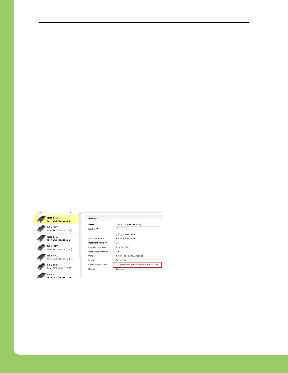
217-8080 TALON SRX / Victor SPX Software Reference Manual 3/06/2018
Cross The Road Electronics Page 139 3/06/2018
Check the “Reset During Enable” sticky flag in the Self-Test. This will rule out
power/voltage/ESD-or-reset related issues.
If the issues occur only during rapid changes in direction and magnitude, the power
cables/crimps may not be efficient enough to deliver power during the stall-period when a
loaded motor changes direction. This can be confirmed if increasing the voltage ramp rate
removes/fixes this symptom.
Be sure to check the Driver Station Logs for packet loss since that can cause intermittent robot
disables.
When using the DAP-1522 (or similar radio) be sure to use latest stable firmware. For example,
rev-A DAP1522s (with production ship firmware) will not reliably enable the robot. Additionally,
consult FRC rules and documentation for which hardware rev is legal for competition and how to
properly setup the radio.
16.12. What to expect when devices are disconnected in roboRIO’s
Web-based Configuration. Failed Self-Test?
Depending what version of software is released, a discovered Talon will display loss of
connection one of two ways.
The Firmware Version may report (Device is not responding).
Alternatively, the tree element will gray out to indicate loss of communication….
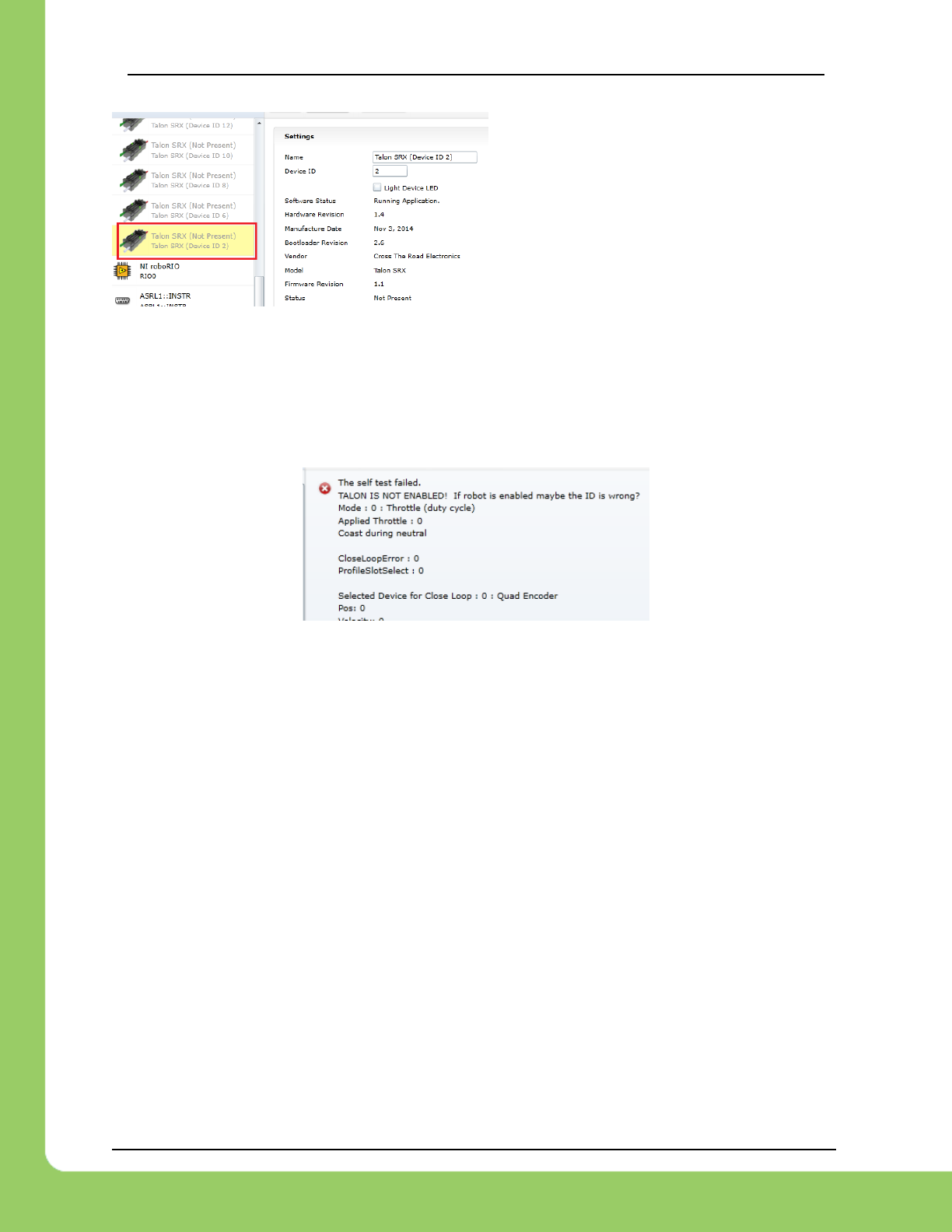
217-8080 TALON SRX / Victor SPX Software Reference Manual 3/06/2018
Cross The Road Electronics Page 140 3/06/2018
The roboRIO internals rechecks the CAN bus once every five seconds so when
connecting/disconnecting Talons to/from the bus, be sure to wait at least five seconds and
refresh the webpage to detect changes in connection state.
Doing a Self-Test when the Talon SRX is not present on the CAN bus will report a red ‘X’ in the
top left portion of the Self-Test report. Depending on what robot controller image is release you
may see the stale values of all signals when the red “X” is present.
16.13. How do I get the raw ADC value (or voltage) on the Analog Input
pin?
The bottom ten bits of Analog-In Position is equal to the converted ADC value. The range of [0,
1023] scales to [0V, 3.3V]. Additionally, if “Analog Potentiometer” is selected as the Feedback
Device, the signal “Sensor Position” will exactly equal the bottom ten bits of Analog-In Position.
16.14. Recommendation for using relative sensors.
When using relative sensors for closed-loop control, it’s always good practice to design in a way
to re-zero your robot. Regardless of how/where relative sensors are connected (robot controller
IO, Talon SRX, etc.), there is always the potential for sensors to “walk” or “drift” due to…
-Mechanical slip issues
-Skipped gear teeth in chain
-Intermittent electrical connections (harness gets damaged in middle of a match)
-Power cycle robot when armatures are not in their “home” position.
-Remote resets of robot controller when armatures are not in their “home” position.
A common solution to this is to design a way in the gamepad logic to force your robot into a
“manual mode” where the driver/arm operator can manually servo motors to a home position
and press a button (or button combination) to re-zero (or set to the “home” position values) all
involved sensors.

217-8080 TALON SRX / Victor SPX Software Reference Manual 3/06/2018
Cross The Road Electronics Page 141 3/06/2018
Teams that do this already can continue to use this method with Talon SRX since there is are
set functions to modify “Sensor Position”.
16.15. Does anything get reset or lost after firmware updates?
The transition from v4_legacy Tool suite to Phoenix will default the configuration
parameters. This occurs when firmware is updated to 3.X firmware from 2.X firmware.
The device ID is not affected in this circumstance.
Notwithstanding the above, the device ID, limit switch startup settings, brake startup settings,
Motor Control Profile Parameters, and sticky flags are generally unaffected by the act of field-
upgrading. If a particular firmware release has a “back-breaking” change, it will be explicitly
documented (see paragraph above).
16.16. Analog Position seems to be stuck around ~100 units?
When the analog input is left unconnected, it will hover around 100 units. If an analog sensor
has been wired, most likely it’s connected to the wrong pin. Recheck wiring against the Talon
SRX User’s Guide.
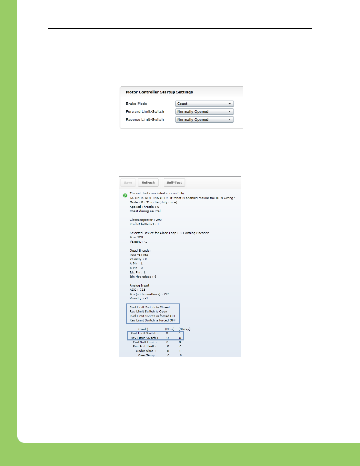
217-8080 TALON SRX / Victor SPX Software Reference Manual 3/06/2018
Cross The Road Electronics Page 142 3/06/2018
16.17. Limit switch behavior doesn’t match expected settings.
First check the Startup Settings in the roboRIO Web-based Configuration to determine that the
“Normally Open”/ “Normally Closed” settings are correct. They can be changed
programmatically and in the web page so it’s worth confirming. Here we see both directions use
NO limit switches...
Then press the “Self-Test” button to check…
-The open/closed state of the limit switch input pin on the Talon SRX.
-If enable/disable state of the limit-switch logic is overridden programmatically.
-Check the fault and sticky faults to see if limit fault conditions are detected.
In this example the Fwd. Limit Switch fault is not set despite the Fwd. Limit Switch being closed.
This is because the Limit Switch logic forced OFF, because the feature is disable
programmatically. As a result, closing the forward limit switch will not disable motor drive.

217-8080 TALON SRX / Victor SPX Software Reference Manual 3/06/2018
Cross The Road Electronics Page 143 3/06/2018
16.18. How fast can I control just ONE Talon SRX?
The fastest control frame rate that can be specified is 1ms. That means that the average period
at which the output/set point can be updates is 1ms. This will increase bus utilization by
approximately 15%, which is acceptable if the number of Talon SRXs is few. Always check the
CAN bus performance metrics in the Driver Station when doing this.
16.19. Expected symptoms when there is excessive signal reflection.
If the CAN bus harness has excessive signal reflection due to improper wiring or missing
termination resistors, the following symptoms may be seen…
-Driver Station will show Rx and Tx CAN errors intermittently (see Section 15), particularly with
higher bus utilization.
-CAN bus utilization will be higher than normal. This is because CAN devices transmit error
frames in response to detecting improper frames. This is helpful if you are in the habit of
checking your bus utilization every once in a while and knowing what is typical for your robot.
See Section 15 for more details.
-The LED of every CAN device on the bus will blink red intermittently during normal use (the
same symptom as Section 16.4). Both common-ID Talons and excessive signal reflection can
cause error frames to appear, which trigger every CTRE CAN device to intermittently blink red
during normal use.
One reliable way to observe this LED behavior is to deliberately leave a couple common-ID
Talon SRXs on your CAN Bus. Then, power up your robot and leave it disabled. All Talon
SRXs will rail-road orange (healthy CAN bus and disabled). Now watch any particular Talon
SRX for a minute or so. It will blink red intermittently as the two (or more) common-ID Talon
SRXs inevitably disrupt each other’s frame transmission.
-Measured DC resistance between CANH and CANL (when robot is unpowered) should be
approximately 60 Ω. If this is not the case then recheck the CAN wiring and termination
resistors (see Talon SRX User’s Guide).
16.20. LabVIEW application reads incorrect Sensor Position. Sensor
Position jumps to zero or is missing counts.
This is a common symptom if the LabVIEW application is calling the Motor Enable VI
periodically. This VI has the side-effect of modifying the Sensor Position every time it’s invoked.
Additionally, wiring the current Sensor Position to this signal also will prevent proper signal
decoding since the RIO will send stale positions to the Talon SRX, overwriting valid signal
changes in the Talon. See Section 13.1.1 for more information.
Additionally, check that the correct Feedback Device is selected (Section 7). Remember that
the Feedback Device Select is sent only when the robot is enabled. Since there is only one
control frame that contains all control signals, this ensures Talon has the correct sensor
selected when Talon is enabled (Section 20.6).
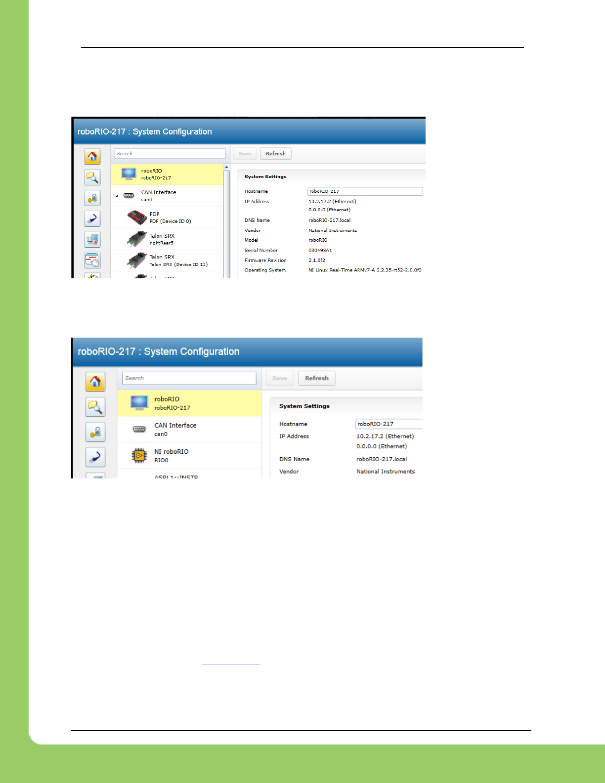
217-8080 TALON SRX / Victor SPX Software Reference Manual 3/06/2018
Cross The Road Electronics Page 144 3/06/2018
16.21. CAN devices do not appear in the roboRIO Web-based config.
Normally devices appear under the “CAN Interface” tree node…
…however if the roboRIO is not correctly wired to the CAN Bus, then the tree node will have no
elements listed underneath…
…in which case double-check the CAN bus wiring and termination strategy. See the Talon SRX
User’s Guide for more information on wiring Talon SRXs. Also see the “FRC Screen steps”
online documentation for more information on wiring the other CAN devices in the control
system. Additionally, check the status LEDs of the CAN devices. Generally, red LED states
reflect an unhealthy CAN connection, which will help diagnose wiring issues.
16.22. When I make a change to a setting in the roboRIO Web-based
configuration and immediately flash firmware into the Talon, the
setting does not stick?
When any of the Motor Control Profile (MCP) settings are changed, a certain amount of time
must pass before the settings are committed to persistent storage (if a previous change hadn’t
been made recently). See section 11.1 for an explanation of how the wear-leveling works. This
only occurs when re-flashing the firmware immediately after two subsequent setting changes
where the two changes are also done immediately after each other.

217-8080 TALON SRX / Victor SPX Software Reference Manual 3/06/2018
Cross The Road Electronics Page 145 3/06/2018
16.23. My mechanism has multiple Talon SRXs and one sensor. Can I
still use the closed-loop/motion-profile modes?
See Section 7.6 for recommended procedure.
16.24. My Closed-Loop is not working? Now what?
The common observations when setting up a closed-loop initially is
• The motor output saturates immediately when enabled.
• The motor output is neutral despite sensor not being near target position/velocity.
• Oscillation or over-shooting the target.
• Motor output is not enough to reach target.
When debugging a closed-loop mechanism, follow the procedure in order.
16.24.1. Make sure Talon has latest firmware.
See Section 2.3 for instructions. See Section 22 for firmware release notes.
16.24.2. Confirm sensor is in phase with motor.
See Section 7.4 for instructions on how to check if sensor and motor are in phase.
This is often the culprit if the closed-loop “runs away” or reaches maximum motor output
immediately.
16.24.3. Confirm Slave/Follower Talons are driving
If there are slave Talon SRXs, ensure their LED output matches the master Talon. If a slave
Talon is not driving due to improper software setup or incorrect wiring, a master Talon may
back-drive the slave Talon(s), causing excessive current-draw and/or breaker trips.
To test that the Slave Talons are functioning, unplug all motors and manually drive each motor
one at a time. If the follower is driving in the wrong direction, it may need to be inverted using
the API in Section 7.4.
See Section 7.6 for complete instructions on testing Slave/Follower Talons setup.
16.24.4. Drive (Master) Talon manually
Drive the Talon (or if using slave Talons, drive the master Talon) using PercentOutput mode.
Cover the full range of speed to ensure mechanical system is functioning as expected.
Measure the sensor positions at the critical points to ensure sensor is functioning. This also
aids in confirming what the target sensor positions should be if the goal is to use Position
Closed-Loop.
See Section 17 to lookup sensor resolution of each sensor type.
16.24.5. Re-enable Closed-Loop
Zero all four gains (F, P, I, D) and place Talon SRX into Closed-Loop mode. Use the Self-
Test to ensure Talon is enabled and in the appropriate mode (Section 2.4).
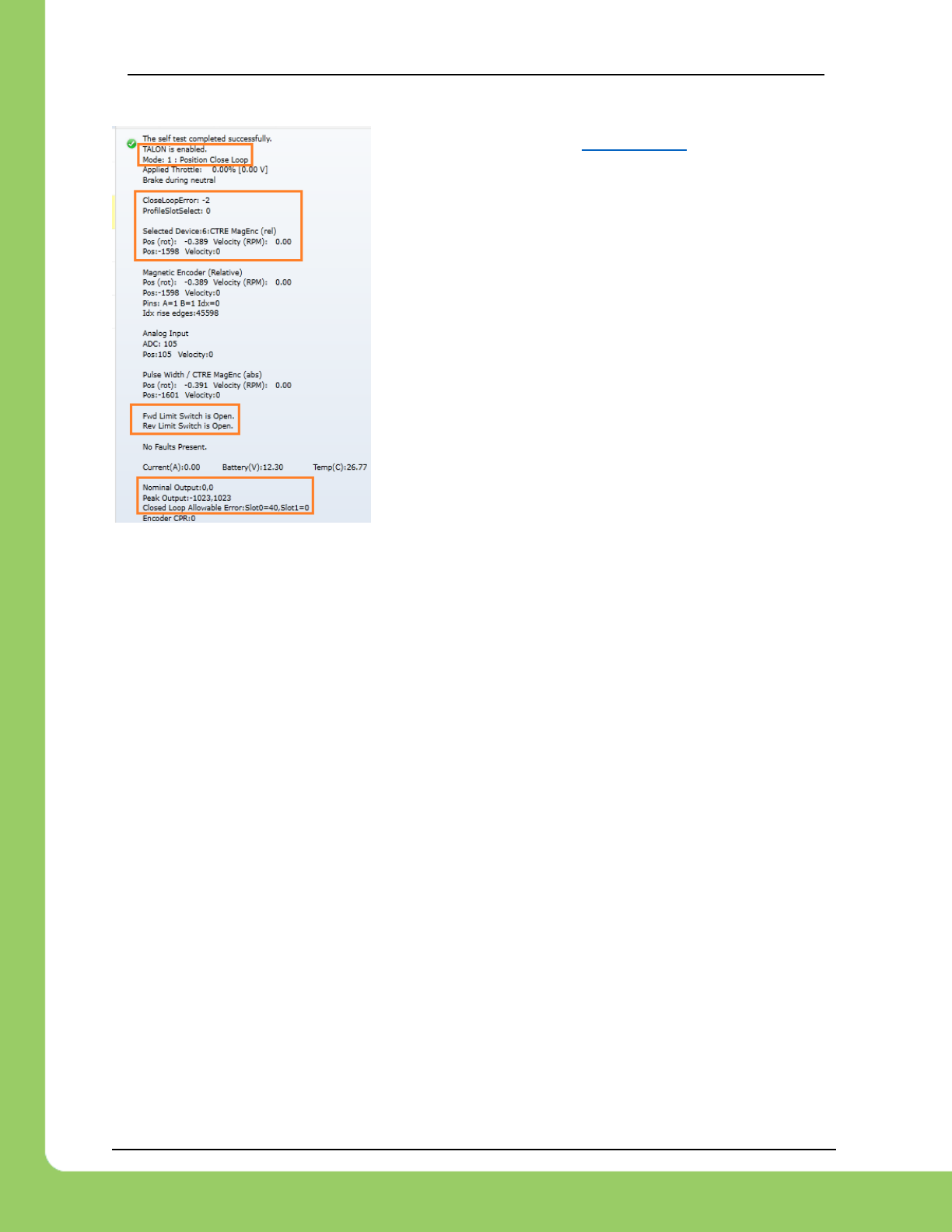
217-8080 TALON SRX / Victor SPX Software Reference Manual 3/06/2018
Cross The Road Electronics Page 146 3/06/2018
If Mode is “No Drive”, see Section 16.12. If Mode is the
wrong one, inspect robot-code to see why the wrong mode
is selected.
Applied motor output will be 0% since the gains are all
zeroed.
Ensure the Closed-Loop Peak Outputs are correct.
“-100%, 100%” represent the full range (no restriction) of
motor-output (default).
Ensure the Closed-Loop Nominal Outputs are correct.
“0, 0” represent no restriction on the “smallest” nonzero
motor-output of the Closed-Loop (default).
Ensure that Allowable Closed Loop Error is correct. A value
of zero represent motor output is allowed anytime Closed
Loop Error is nonzero (default).
16.24.6. Start with a simple gain set
The next step depends on whether you are using Position or Velocity Closed-Loop.
16.24.6.1. Start with a simple gain set – Position Closed-Loop
If using Position Closed-Loop, look at the Closed-Loop Error. This is the error between the
target and currently-sampled position. It will be measured in native sensor units. This value is
multiplied by the P gain and sent to the motor output.
For example, if the Closed Loop error is 4096 and the P gain is 0.10, then…
4096 X 0.10
409 or 39.98% (409/1023) motor output.
An error of 4096 represent an error of one-full rotation when using the CTRE Magnetic
Encoder). So with a P gain of 0.10, the Closed-Loop output will be 39.98% when sensor is off
by one rotation.
Choose a P gain so that the worst case error yields a small motor-output. Set the P gain and
re-enable the Closed-Loop. The motor-output will be “soft” meaning the movement will likely fail
to reach the final target (or come up “short”). Double the P gain accordingly until the response
is sharp without major overshoot. If the P gain is too large, the mechanism will oscillate about
the target position.
At this point, the Closed-Loop will have the basic ability to servo to a target position.
Additionally, tune the remaining Closed Loop Parameters (ramping, I, D, Peak/Nominal Output,
etc.) to dial in the acceleration and near-target response of the closed-loop.
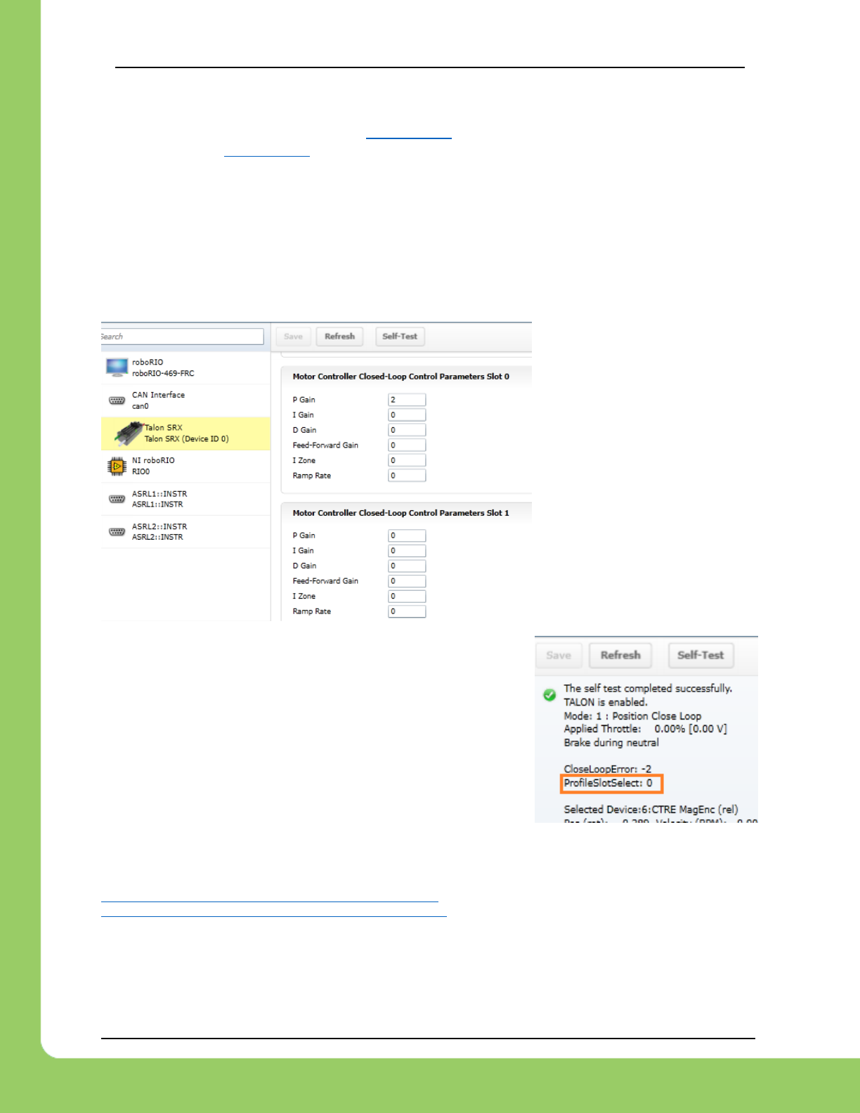
217-8080 TALON SRX / Victor SPX Software Reference Manual 3/06/2018
Cross The Road Electronics Page 147 3/06/2018
16.24.6.2. Start with a simple gain set – Velocity Closed-Loop
The first gain to set is the F gain. See Section 12.6 for LabVIEW instruction/examples on how
this is done. See Section 12.4 for Java instruction/examples (C++ users should also review this
section as the procedure is identical).
With just F gain, the motor’s output should follow the requested target velocity reasonably. At
this point you can begin dialing in P gain so that the closed-loop performs error correction.
16.24.7. Confirm gains are set
If the motion output is still neutral, use the roboRIO Web based configuration page to confirm
that gains are actually nonzero, and that the correct slot is selected.
Here P gain of ‘2’ is in Slot 0.
Now perform the Self-Test to confirm which Profile Slot is
selected. In this example we would like to use slot ‘0’.
16.25. Where can I find application examples?
Example projects for Talon SRX can also be found in the CTR GitHub account.
https://github.com/CrossTheRoadElec/Phoenix-Examples-LabVIEW
https://github.com/CrossTheRoadElec/Phoenix-Examples-Languages

217-8080 TALON SRX / Victor SPX Software Reference Manual 3/06/2018
Cross The Road Electronics Page 148 3/06/2018
16.26. Can RobotDrive be used with Talon SRXs? What if there are six
Talons?
The default RobotDrive object in LabVIEW/C++/Java already supports two-Talon and four-Talon
drivetrains. Simply create the WPI_TalonSRX objects and pass them into the RobotDrive
example.
For six drive Talons, the four-motor examples for Robot Drive can be used with four
WPI_TalonSRX objects, then create the final two Talons and set them to slave/follower mode.
The JAVA_Six_CANTalon_ArcadeDrive example can be downloaded at…
https://github.com/CrossTheRoadElec/Phoenix-Examples-Languages
The screenshot below can be used as a reference.
Although the example is in Java, the strategy can be used in all three FRC languages.
Although the example uses arcadeDrive, the robot application could use tankDrive as well.
public class Robot extends IterativeRobot {
/* talons for arcade drive */
WPI_TalonSRX _frontLeftMotor = new WPI_TalonSRX(11); /* device IDs here (1 of 2) */
WPI_TalonSRX _frontRightMotor = new WPI_TalonSRX(14);
/* extra talons for six motor drives */
WPI_VictorSPX _leftSlave1 = new WPI_VictorSPX(13);
WPI_VictorSPX _rightSlave1 = new WPI_VictorSPX(15);
WPI_VictorSPX _leftSlave2 = new WPI_VictorSPX(16);
WPI_VictorSPX _rightSlave2 = new WPI_VictorSPX(17);
final int kTimeoutMs = 10;
DifferentialDrive _drive = new DifferentialDrive(_frontLeftMotor, _frontRightMotor);
Joystick _joy = new Joystick(0);
/**
* This function is run when the robot is first started up and should be
* used for any initialization code.
*/
public void robotInit() {
/* take our extra talons and just have them follow the Talons updated in arcadeDrive */
_leftSlave1.follow(_frontLeftMotor);
_leftSlave2.follow(_frontLeftMotor);
_rightSlave1.follow(_frontRightMotor);
_rightSlave2.follow(_frontRightMotor);
_frontLeftMotor.configSelectedFeedbackSensor(FeedbackDevice.QuadEncoder, 0, kTimeoutMs);
_frontRightMotor.configSelectedFeedbackSensor(FeedbackDevice.QuadEncoder, 0, kTimeoutMs);
/* do this first */
/*flip values until sensor is positive with positive motor output (green LEDs) */
_frontLeftMotor.setSensorPhase(false);
_frontRightMotor.setSensorPhase(true);
/* do this second */
boolean invertLeft = false;
boolean invertRight = false;
_frontLeftMotor.setInverted(invertLeft);
_frontLeftMotor.setInverted(invertLeft);
_frontLeftMotor.setInverted(invertLeft);
_frontRightMotor.setInverted(invertRight);
_frontRightMotor.setInverted(invertRight);
_frontRightMotor.setInverted(invertRight);

217-8080 TALON SRX / Victor SPX Software Reference Manual 3/06/2018
Cross The Road Electronics Page 149 3/06/2018
}
/**
* This function is called periodically during operator control
*/
public void teleopPeriodic() {
double forward = _joy.getY(); // logitech gampad left X, positive is forward
double turn = _joy.getZ(); //logitech gampad right X, positive means turn right
_drive.arcadeDrive(forward, turn);
}
}
16.27. How fast does the closed-loop run?
Talon SRX updates the motor output every 1ms by recalculating the PIDF output.
Additionally, when using the motion magic control mode, the target position and target velocity
is recalculated every 10ms to honor the user’s specified acceleration and cruise-velocity.
16.28. Driver Station log reports: The transmission queue is full. Wait until frames in
the queue have been sent and try again.
This error means the roboRIO is sending more CAN bus frames than can be physically
sent. Usually because of a cable disconnect. Check your wiring for opportunities for CAN bus
to disconnect.
Check for changes in the CAN error counts (Section 15) to confirm cable integrity.
Section 16.24 has additional cable troubleshooting tips.

217-8080 TALON SRX / Victor SPX Software Reference Manual 3/06/2018
Cross The Road Electronics Page 150 3/06/2018
17. Units and Term Definitions
Listed below are the native units and term definitions for the signals inside the motor controller.
17.1. Signal Definitions and Sensor Units
17.1.1. (Quadrature) Encoder Position
When measuring the position of a Quadrature Encoder, the position is measured in 4X encoder
edges. For example, if a US Digital Encoder with a 360-cycles-per-revolution (CPR) will count
1440 units per rotation when read using “Encoder Position” or “Sensor Position”.
The velocity units of a Quadrature Encoder is the change in Encoder Position per TvelMea
(TvelMeas=0.1sec). For example, if a US Digital Encoder (CPR=360) spins at 20 rotations per
second, this will result in a velocity of 2880 (28800 position units per second).
17.1.2. Analog (Encoder/Potentiometer)
When measuring the position of a 3.3V Analog Potentiometer, the position is measured as a 10
bit ADC value. A value of 1023 corresponds to 3.3V. A value of 0 corresponds to 0.0V.
The velocity units of a 3.3V Analog Potentiometer is the change in Analog Position per TvelMea
(TvelMeas=0.1sec). For example if an Analog Potentiometer transitions from 0V to 3.3V (1023
units) in one second, the Analog Velocity will be 102.
Like 3.3V Analog Potentiometers, the 10 bit ADC is used to scale [0 V, 3.3 V] => [0, 1023].
However when the Analog Encoder “wraps around” from 1023 to 0, the Analog Position will
continue to 1024. In other words, the sensor is treated as “continuous”.
The velocity units of a 3.3V Analog Encoder is the change in Analog Position per 100ms
(TvelMeas=0.1sec). For example if an Analog Encoder transitions from 0V to 3.3V (1023 units) in
one second, the Analog Velocity will be 102.
17.1.3. Motor output
The Talon SRX uses 10bit resolution for the percent output. This means a -1023 represents full
reverse, +1023 represents full forward, and 0 represents neutral.
The programming API made available in LabVIEW and C++/Java performs the scaling into
percent, so the duty cycle resolution is not necessary for programming purposes. However
when evaluating PIDF gain values, it is helpful to understand how the calculated output of the
closed-loop is interpreted.

217-8080 TALON SRX / Victor SPX Software Reference Manual 3/06/2018
Cross The Road Electronics Page 151 3/06/2018
17.1.4. (Open-Loop) Ramp
The Talon SRX natively represents Open-Loop Ramp as the change in output per TRampRate
(TRampRate=10ms). Motor output is represented as a 10bit signed value (1023 is full forward, -
1023 is full reverse). For example, if the robot application requires motor drive ramping from 0%
to 100% to take one second of ramping, the result Ramp Rate would be ( [1023 – 0] / 1000ms X
TRampRate) or 10 units.
The programming API made available in LabVIEW and C++/Java performs the scaling into
appropriate units (percent-output and time).
17.1.5. (Closed-Loop) Ramp
The Talon SRX natively represents Closed-Loop Ramp as the change in output per TRampRate
(TRampRate=10ms). Motor output is represented as a 10bit signed value (1023 is full forward, -
1023 is full reverse). For example, if the robot application requires motor drive ramping from 0%
to 100% to take one second of ramping, the result Ramp Rate would be ( [1023 – 0] / 1000ms X
TRampRate) or 10 units.
The programming API made available in LabVIEW and C++/Java performs the scaling into
appropriate units (percent-output and time).
17.1.6. Integral Zone (I Zone)
The motor control profile contains Integral Zone (I Zone), which (when nonzero), is the
maximum error where Integral Accumulation will occur during a closed-loop Mode. If the
Closed-loop error is outside of the I Zone, “I Accum” is automatically cleared. This can prevent
total instability due to integral windup, particularly when tweaking gains.
The units are in the same units as the selected feedback device (Quadrature Encoder, Analog
Potentiometer, Analog Encoder, and EncRise).
17.1.7. Integral Accumulator (I Accum)
The accumulated sum of Closed-Loop Error. It is accumulated in line with Closed-Loop math
every 1ms.
17.1.8. Motor Invert
Boolean signal for reversing the h-bridge output. This signal does not impact Talon LEDs in
order to ensure LEDs are in phase with limit switch wiring and soft-limit configuration.
Changing the motor invert does not impact Sensor Phase. This is because the firmware will
compensate for the motor inversion internally.
17.1.9. Sensor Phase
Boolean signal for reversing the sensor phase. Generally, this will multiply the sensor value by -
1 when set to true.
17.1.10. Closed-Loop Error
Calculated as the difference between target set point and the actual Sensor Position/Velocity.
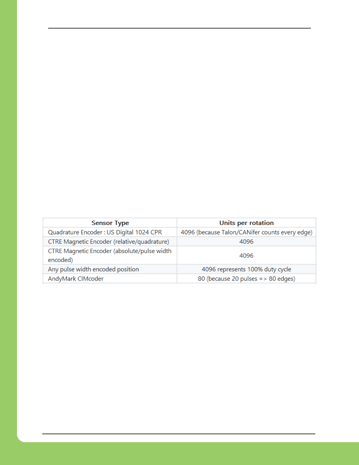
217-8080 TALON SRX / Victor SPX Software Reference Manual 3/06/2018
Cross The Road Electronics Page 152 3/06/2018
The units are matched to Analog-In or Encoder depending on which “Feedback Device” and
control mode (position vs. speed) is selected.
17.1.11. Closed-Loop gains
P gain is specified in motor output unit per error unit. For example, a value of 102 is ~9.97%
(which is 102/1023) motor output per 1 unit of Closed-Loop Error.
I gain is specified in motor output unit per integrated error. For example, a value of 10 equates
to ~0.97% for each accumulated error (Integral Accumulator). Integral accumulation is done
every 1ms.
D gain is specified in motor output unit per derivative error. For example, a value of 102 equates
to ~9.97% (which is 102/1023) per change of Sensor Position/Velocity unit per 1ms.
F gain is multiplied directly by the set point passed into the programming API made available in
LabVIEW and C++/Java. This allows the robot to feed-forward using the target set-point.
17.2. Sensor Resolutions
Position units are in the natural units of the sensor. This ensures the best resolution possible
when performing closed-loops in firmware.
Velocity is measured in sensor units per 100ms. This ensures sufficient resolution regardless of
the sensing strategy. For example, when using the CTRE Magnetic Encoder, 1u velocity
represents 1/4096 of a rotation every 100ms. Generally, you can multiply the velocity units by
600/UnitsPerRotation to obtain RPM.
Tachometer velocity measurement is unique in that it measures time directly. Thus, the reported
velocity is calculated where 1024 represents a full "rotation". This means that a velocity
measurement of 1 represents 1/1024 of a rotation every 100ms.

217-8080 TALON SRX / Victor SPX Software Reference Manual 3/06/2018
Cross The Road Electronics Page 153 3/06/2018
18. How is the closed-loop implemented?
The closed-loop logic is the same regardless of which feedback sensor or closed-loop mode is
selected. The verbatim implementation in the Talon firmware is displayed below.
This includes…
The logic for PIDF style closed-loop.
Inverting the output of the closed-loop if enabled in API.
Capping the output to positive values only IF using a single direction feedback sensor.
Note: The PID_Mux_Unsigned and PID_Mux_Sign routines are merely multiply functions.
/**
* 1ms process for PIDF closed-loop.
* @param pid ptr to pid object
* @param pos signed integral position (or velocity when in velocity mode).
* The target pos/velocity is ramped into the target member from caller's 'in'.
* PIDF is traditional, unsigned coefficients for P,i,D, signed for F.
* Target pos/velocity is feed forward.
*
* Izone gives the abilty to autoclear the integral sum if error is wound up.
* @param oneDirOnly when using positive only sensor, keep the closed-loop from outputing negative throttle.
*/
void PID_Calc1Ms(pid_t * pid, MotorControlProfile_t * slot, int32_t pos, int8_t oneDirOnly, int16_t peakOutput,
int periodMs)
{
if (++pid->timeMs < periodMs) {
/* don't run yet, keep out the same */
return;
}
/* time to fire, reset time */
pid->timeMs = 0;
/* Save last sensor measurement for debugging. */
pid->lastInput = pos;
/* calc error : err = target - pos*/
int32_t err = pid->target - pos;
pid->err = err;
/*abs error */
int32_t absErr = err;
if(err < 0)
absErr = -absErr;
/* integrate error and handle the first pass since PID_Reset() */
if(0 == pid->notFirst){
/* first pass since reset/init */
pid->iAccum = 0;
/* also tare the before ramp throt */
pid->out = BXDC_GetThrot(); /* the save the current ramp */
}else if((!slot->IZone) || (absErr < slot->IZone) ){
/* izone is not used OR absErr is within iZone */
pid->iAccum += err;
}else{
pid->iAccum = 0;
}
/* max iaccum */
if (slot->maxIAccum == 0) {
/* don't cap */
} else if (pid->iAccum > slot->maxIAccum) {
pid->iAccum = slot->maxIAccum;
} else if (pid->iAccum < -slot->maxIAccum) {
pid->iAccum = -slot->maxIAccum;
} else {
/* leave it alone */
}
/* dErr/dt */
if(pid->notFirst){
/* calc dErr */

217-8080 TALON SRX / Victor SPX Software Reference Manual 3/06/2018
Cross The Road Electronics Page 154 3/06/2018
pid->dErr = pid->prevPos - pos;
}else{
/* clear dErr */
pid->dErr = 0;
}
/* if error is within the allowable range, we will clear it and clear the integral accum */
uint16_t allowClosedLoopEr = slot->allowableErr;
if(absErr < allowClosedLoopEr){
/* clear Iaccum */
pid->iAccum = 0;
/* clear dErr */
pid->dErr = 0;
/* wipe this out so PID response is identical to no error */
err = 0;
}
//------------------ P ------------------------//
pid->out = PID_Mux_Unsigned(err, slot->P);
//------------------ I ------------------------//
if(pid->iAccum && slot->I){
/* our accumulated error times kI. If you want the robot to creep up then set nonzero kI */
pid->out += PID_Mux_Unsigned(pid->iAccum, slot->I);
}
//------------------ D ------------------------//
/* derivative gain, if you want to react to sharp changes in error (smooth things out). */
pid->out += PID_Mux_Unsigned(pid->dErr, slot->D);
//------------------ F ------------------------//
/* feedforward on the set point */
pid->out += PID_Mux_Signed(pid->target, slot->F);
/* arm for next pass */
{
pid->prevPos = pos; /* save the prev pos for D */
pid->notFirst = 1; /* already serviced first pass */
}
if(oneDirOnly > 0){
/* positive only */
if(pid->out < 0)
pid->out = 0;
}else if(oneDirOnly < 0){
/* negative only */
if(pid->out > 0)
pid->out = 0;
}else{
/* no bounds */
}
/* output cap */
if (pid->out > +peakOutput) {
pid->out = +peakOutput;
} else if (pid->out < -peakOutput) {
pid->out = -peakOutput;
}
}

217-8080 TALON SRX / Victor SPX Software Reference Manual 3/06/2018
Cross The Road Electronics Page 155 3/06/2018
19. Motor Safety Helper
The Motor Safety feature works in a similar manner as the other motor controllers. The goal is
to set an expiration time to a given motor controller, such that, if the Set()/set() routine is not
called within the expiration time, the motor controller will disable. Additionally, the DS will report
the error and the roboRIO Web-based Configuration Self-Test will report Disabled as the
mode. Thus, the set routine must be called periodically for sustained motor drive when motor
safety is enabled.
Be sure to use WPI_TalonSRX and WPI_VictorSPX classes to leverage motor-safety.
One example where this feature is useful is when laying breakpoints with the debugger while
the robot is enabled and moving. Ideally when a breakpoint lands, its safest to disable motor
drive while the developer performs source-level debugging.
19.1. Best practices
Be sure to test that the time between enabling Motor Safety features, and the first Set()/set()
call is small enough to not risk accidently timing out. Calling Set()/set() immediately after
enabling the feature can be used to ensure transitioning into the enabled modes doesn’t
intermittently cause a timeout.
Even if tripping the motor-safety expiration time is not an expected condition, it’s best to re-
enable the motors somewhere in the source so that the timeouts can be reset easily, for
example in AutonInit()/TeleopInit(). That way normal robot functionality can be safely resumed
after a motor controller expires (usually during source-level debugging).
Additionally, if source-level debugging is not required (for example during a competition or if
logging-style debugging is preferred) the motor-safety enable can be turned off.

217-8080 TALON SRX / Victor SPX Software Reference Manual 3/06/2018
Cross The Road Electronics Page 156 3/06/2018
19.2. C++ example
SetSafetyEnabled() can be used to turn on this feature. SetExpiration() can be used to
set the expiration time. The default expiration time is typically 100ms.
19.3. Java example
setSafetyEnabled() can be used to turn on this feature. setExpiration() can be used to
set the expiration time. The default expiration time is typically 100ms.
19.4. LabVIEW Example
The Motor SAFETY CONFIG VI can be used to turn on this feature. Select “Enable” for the
mode and specify the timeout in seconds.
19.5. RobotDrive
The examples in this section refer to the WPI_TalonSRX objects directly. However higher level
class types such as RobotDrive can have their own motor safety objects as well. Although
WPI_TalonSRX safety features default off, the higher-level drive objects tend to default safety
enable to on. If you are still witnessing disabled motor drive behavior and Motor Safety Driver
Station Log Messages (see Section 16.14) then you may need to call
setSafetyEnabled(false) (or similar routines/VI) on RobotDrive objects as well. Keep in
mind that disabling safety enable means that motor drive can continue if a source-level
breakpoint halts program flow. Take the necessary precautions to debug the robot safely or
alternatively only enable motor safety features when performing source level debugging.

217-8080 TALON SRX / Victor SPX Software Reference Manual 3/06/2018
Cross The Road Electronics Page 157 3/06/2018
20. Going deeper - How does the framing work?
The Talon periodically transmits four status frames with sensor data at the given periods. This
ensures that certain signals are always available with a deterministic update rate. This also
keeps bus utilization stable.
Similarly, the control frame sent to the Talon SRX is periodic and contains almost all the
information necessary for all control modes. The rest of the necessary parameters are are
persistent and modified via configuration function/VIs, which are typically configured during
robot boot up.
Although the frame rates are default to ensure stable CAN bandwidth, there is API to override
the frame rates for performance reasons. If this is done, be sure to check the CAN performance
metrics to ensure custom settings don’t exceed the available CAN bandwidth, see “CAN bus
Utilization and Performance metrics”.
Changing the frame periods are not persistent. This is deliberate to ensure you can power
cycle a CTRE CAN Device and restore normal communication. Developers can use the “has
reset” API to check if a device has been rebooted, and therefore restore custom frame periods.
20.1. General Status 1
The General Status frame has a default period of 10ms, and provides…
-Motor Output: The current 10bit motor output duty cycle (-1023 full reverse to +1023 full
forward).
-Forward Limit Switch Pin State
-Reverse Limit Switch Pin State
-Fault bits
-Applied Control Mode
-Soft limit and limit switch overrides
-Invert/Brake selections
… These signals are accessible in the various get functions in the programming API.
20.2. Feedback0 Status 2
The Feedback0 Status 2 frame has a default period of 20ms, and provides…
-Sensor Position: Position of the selected sensor for PID Loop 0
-Sensor Velocity: Velocity of the selected sensor for PID Loop 0
-Motor Current
-Sticky Faults
-Motor Control Profile Select
… These signals are accessible in the various get functions in the programming API.
20.3. Quadrature Encoder Status 3
The Quadrature Encoder Status frame has a default period of 160ms.
-Encoder Position: Position of the quadrature sensor
-Encoder Velocity: Velocity of the selected sensor

217-8080 TALON SRX / Victor SPX Software Reference Manual 3/06/2018
Cross The Road Electronics Page 158 3/06/2018
-Number of rising edges counted on the Index Pin.
-Quad A pin state.
-Quad B pin state.
-Quad Index pin state.
… These signals are accessible in the various get functions in the programming API.
The quadrature decoder is always engaged, whether the feedback device is selected or not,
and whether a quadrature encoder is actually wired or not. This means that the Quadrature
Encoder signals are always available in programming API regardless of how the Talon is used.
The default update rate is sufficient for logging, instrumentation and debugging. If a faster
update rate is required the robot application can select the appropriate sensor and leverage the
Sensor Position and Sensor Velocity.
20.4. Analog Input / Temperature / Battery Voltage Status 4
The Analog/Temp/BattV status frame has a default period of 160ms.
-Analog Position: Position of the selected sensor
-Analog Velocity: Velocity of the selected sensor
-Temperature
-Battery Voltage
-Selected feedback sensor for PIDLoop 0.
… These signals are accessible in the various get functions in the programming API.
The Analog to Digital Convertor is always engaged, whether the feedback device is selected or
not, and whether an analog sensor is wired or not. This means that the Analog In signals are
always available in programming API regardless of how the Talon is used. The default update
rate is sufficient for logging, instrumentation and debugging. If a faster update rate is required,
the robot application can select the appropriate sensor and leverage the Sensor Position and
Sensor Velocity.
20.5. Pulse Width Status 8
The status frame has a default period of 160ms.
-Period and pulse width capture on the Talon Idx pin.
-Velocity (of a PulseWidthEncoded sensor such as CTRE Mag Encoder).
-Position (of a PulseWidthEncoded sensor such as CTRE Mag Encoder).
… These signals are accessible in the various get functions in the programming API.
20.6. Targets Status 10 (Motion Profile and Motion Magic)
The status frame has a default period of 160ms.
-Target Position, velocity, and heading for the active trajectory point.
20.7. PIDF0 Status 13
The status frame has a default period of 160ms.
-Closed-loop error of PIDLoop 0.
-Integral Accumulator of PIDLoop 0.
-Derivative term of PIDLoop 0.
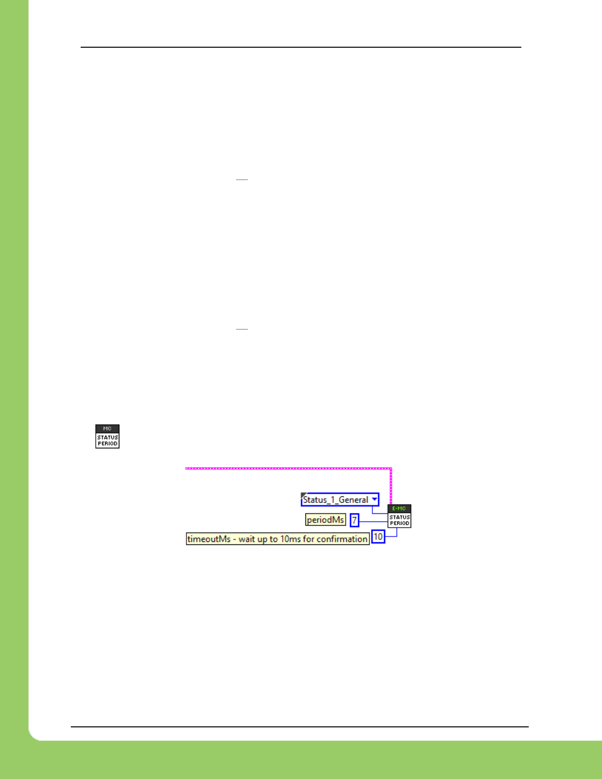
217-8080 TALON SRX / Victor SPX Software Reference Manual 3/06/2018
Cross The Road Electronics Page 159 3/06/2018
20.8. Modifying Status Frame Period
The frame rates of these signals may be modifiable through programming API.
20.8.1. C++
The SetStatusFramePeriod() function can be used to modify the frame rate period of a
particular Status Frame.
/* change frame period to 7 ms */
talon.SetStatusFramePeriod(StatusFrameEnhanced::Status_10_MotionMagic, 7, 0);
Use StatusFrameEnhanced for products that have a Feedback Gadgeteer Port (such as Talon
SRX). VictorSPX objects must use StatusFrame.
20.8.2. Java
The setStatusFramePeriod() function can be used to modify the frame rate period of a
particular Status Frame.
/* change frame period to 7 ms */
talon.setStatusFramePeriod(StatusFrameEnhanced.Status_10_MotionMagic, 7, 0);
Use StatusFrameEnhanced for products that have a Feedback Gadgeteer Port (such as Talon
SRX). VictorSPX objects must use StatusFrame.
20.8.3. LabVIEW
The VI can be used to adjust the period of a status frame.

217-8080 TALON SRX / Victor SPX Software Reference Manual 3/06/2018
Cross The Road Electronics Page 160 3/06/2018
20.9. Control Frame (Control 3)
The Talon is primarily controlled by one periodic control frame. The default period of this frame
is 10ms. The control frame provides the Talon…
-which Motor Control Profile Slot to use.
-which control mode (position, velocity, duty cycle, slave mode)
-if the feedback sensor should be reversed
-if the closed-loop output should be reversed
-the target/set point or duty cycle or which Talon to follow
-the (voltage) ramp rate
-brake neutral mode override if specified
-limit switch overrides if specified
… These signals are accessible in the various set functions in the programming API.
20.10. Modifying the Control Frame Period
Advanced users can modify the Control Frame Rate to increase the update rate of the control
parameters, or decrease to reduce total bus bandwidth.
20.10.1. Modifying the Control Frame Rate – C++
Note there is no timeoutMs, as this setting is applied to the roboRIO.
/* change period to 7 ms */
talon.SetControlFramePeriod(ControlFrame::Control_3_General, 7);
20.10.2. Modifying the Control Frame Rate – Java
Note there is no timeoutMs, as this setting is applied to the roboRIO.
/* change period to 7 ms */
talon.setControlFramePeriod(ControlFrame.Control_3_General, 7);
20.10.3. Modifying the Control Frame Rate – LabVIEW

217-8080 TALON SRX / Victor SPX Software Reference Manual 3/06/2018
Cross The Road Electronics Page 161 3/06/2018
21. Functional Limitations
Functional Limitations describe behavior that deviates than what is documented. Feature
additions and improvements are always possible thanks to the field-upgrade features of the
Talon SRX.
Just because a firmware issue has been resolved does not mean your out-of-the-box hardware
doesn’t have old firmware. Immediately update your CAN devices to ensure your development
time is not wasted chasing down an issue that has already been solved.
21.1. roboRIO power up: User should manually refresh the web-based
configuration after rebooting roboRIO.
It is recommended to manually refresh the web browser if the roboRIO has been reset or power
cycled. This ensures that the web browser and roboRIO are synchronized well. Otherwise
device icons may not match the device type in the web-based config.
21.2. Phoenix 5.1.3.1: Motion profile disabled in 2018 kickoff firmware.
Talon SRX/ Victor SPX motion-profile mode is not available in the kickoff release. This is due to
the modifications done to support Pigeon IMU integration. This will be remedied in a future
release. [Resolved in Phoenix 5.2.1.1]
21.3. Two sets of Param declarations for auto-clear position parameters.
The paramEnum list includes two sets of enumerated values…
eClearPositionOnLimitF = 320,
eClearPositionOnLimitR = 321,
eClearPositionOnQuadIdx = 322,
eClearPositionOnIdx = 100,
eClearPosOnLimitF = 144,
eClearPosOnLimitR = 145,
…both sets are supported in Talon SRX firmware.
21.4. getClosedLoopTarget() return milliamperes.
getClosedLoopTarget reports in units of milliamperes when in current closed-loop mode.
Divide the returned value by 1000 to obtain amperes.

217-8080 TALON SRX / Victor SPX Software Reference Manual 3/06/2018
Cross The Road Electronics Page 162 3/06/2018
21.5. Auto-clear position feature on Quadrature Idx only works for rising
edges.
eQuadIdxPolarity signal is not supported in current firmware.
If falling edge is necessary, use the Limit Forward or Limit Reverse auto-clear features.
21.6. Driver Station System Watchdog -63194 and motor controllers not
enabling.
Driver Station reports the following error:
ERROR 0 [Phoenix] System Watchdog reported error code: -63194. Motor Controllers were
disabled, Contact NI/CTRE if this occurs.
This error code has been seen by Java and LabVIEW teams. C++ teams are not affected by
this.
This error can only occur during application startup. Once it has occurred, the error will be
repeatedly displayed on the Driver Station. The error can only be stopped by restarting robot
code or rebooting the roboRIO.
If the robot has connected to the Driver Station and the user has confirmed the error is not
being displayed in the Driver Station, then there is no risk the issue will occur (during a
match).
This error code is returned from the NI system watchdog that is called to verify robot enable
state. As a safety precaution, motor controllers are disabled when error codes are received from
this function.
Issue observed in: Phoenix 5.1.3.1, Phoenix 5.2.1.1
Workaround 1: Check Driver Station message window to ensure error is not present after
robot has booted and connected to the Driver Station/FMS. If it is occurring, restart robot code
via Driver Station or reboot the roboRIO.
Workaround 2: Update to Phoenix 5.2.2.0. For Java teams, the issue appears to be
eliminated.
For LabVIEW teams, the issue may occur only after frequent temporary deploys between
different robot programs and can be resolved by rebooting the RIO or permanently
deploying your robot code.

217-8080 TALON SRX / Victor SPX Software Reference Manual 3/06/2018
Cross The Road Electronics Page 163 3/06/2018
21.7. Motor output direction is incorrect or accelerates when current-limit
is enabled.
The factory default setting for "Peak Current Duration" is incorrect/invalid, causing the motor
controller to transition between current-limited and not current-limited erroneously.
Issue exists in: Phoenix 5.1.3.1, Phoenix 5.2.1.1, Phoenix 5.2.2.0, Phoenix 5.3.1.0
Workaround: Call ConfigPeakCurrentDuration to ensure proper assignment. Valid values are
within the range [0,60000] ms.
C++ Example…
https://github.com/CrossTheRoadElec/Phoenix-Examples-Languages/tree/master/C++/Current%20Limit
Java Example…
https://github.com/CrossTheRoadElec/Phoenix-Examples-Languages/tree/master/Java/Current%20Limit
LabVIEW users must call CONFIG PEAK AMPS VI.
21.8. Setting eSoftLimitDisableNeutralOnLOS has no effect if soft limit
values are within two units.
Normally if eSoftLimitDisableNeutralOnLoss is set (to 1) and remote sensor source is
disconnected from the CAN bus, Talon SRX / Victor SPX will still allow motor control (instead of
setting output to neutral and faulting appropriately).
However, if the soft-limit forward and reverse threshold have the same value, or has a
difference of 1 sensor unit, the auto-neutral-during-loss-of-signal feature will still neutral and
fault the motor.
The workaround is to ensure the soft-limit thresholds have a difference of two units or greater
when leveraging this configuration parameter to override the neutral-on-LOS feature.
Note – This limitation has no effect if soft-limit and remote sensor features are not both active.
Note – This limitation has no effect if eSoftLimitDisableNeutralOnLOS is cleared (default value).
In other words, this limitation has no effect if user wants the motor controller to auto-neutral
when remote sensor communication is lost.

217-8080 TALON SRX / Victor SPX Software Reference Manual 3/06/2018
Cross The Road Electronics Page 164 3/06/2018
22. CRF Firmware Version Information
CRF Version
Date
Description
3.8 (FRC)
Feb 2018
Remote sensor and Arc features added.
3.3 (FRC)
Jan 2018
Motion profile feature re-enabled for Talon SRX.
3.1 (FRC)
Jan 2018
Initial release for Victor SPX and Talon SRX for 2018.
23. Document Revision Information
Rev
Date
Description
2.4
06-Mar-2018
-Added Section 9.3.4
2.3
28-Feb-2018
-Added Section 9.5, 9.6, 9.7, 9.8, 9.9, 9.10 for new Arc features.
-Added Section 10.4.1 and 10.7.1.
-Added clarification in 10.5 regarding closed-loop peak configuration.
-Added Section 21.6, 21.7, 21.8.
2.2
24-Feb-2018
-Bookmark corrections across entire document.
2.1
14-Feb-2018
-Updated Section 18.0 to the latest implementation.
2.0
18-Jan-2018
-Initial release that is Phoenix compliant.
