TALON SRX Software Reference Manualx Manual 5
User Manual: Talon SRX Software Reference Manual-5
Open the PDF directly: View PDF ![]() .
.
Page Count: 169 [warning: Documents this large are best viewed by clicking the View PDF Link!]
- 1. CAN bus Device Basics
- 2. roboRIO Web-based Configuration: Firmware and diagnostics
- 3. Creating a Talon Object (and basic drive)
- 4. Limit Switch and Neutral Brake Mode
- 5. Getting Status and Signals
- 6. Setting the Ramp Rate
- 7. Selecting a Feedback Device
- 7.1. LabVIEW
- 7.2. C++
- 7.3. Java
- 7.4. Reversing sensor direction, best practices.
- 7.5. Supported Feedback Devices
- 7.6. Multiple Talon SRXs and single sensor
- 7.7. Checking Sensor Health
- 7.8. Velocity Measurement
- 8. Soft Limits
- 9. Special Control Modes
- 10. Closed-Loop Modes
- 11. Motor Control Profile Parameters
- 12. Closed-Loop Code Excerpts/Walkthroughs
- 12.1. Setting Motor Control Profile Parameters
- 12.2. Clearing Integral Accumulator (I Accum)
- 12.3. Current Closed-Loop Walkthrough – LabVIEW
- 12.4. Velocity Closed-Loop Walkthrough – Java
- 12.5. Position Closed-Loop – HERO C# (non-FRC)
- 12.6. Velocity Closed-Loop Example – LabVIEW
- 12.7. Motion Magic Closed-Loop HERO C# (non-FRC)
- 12.8. Motion Magic Closed-Loop Walkthrough – Java
- 12.8.1. Motion Magic Closed-Loop Walkthrough – General Requirements
- 12.8.2. Motion Magic Closed-Loop Walkthrough – Collect Sensor Data – Java
- 12.8.3. Motion Magic Closed-Loop Walkthrough – Calculate F-Gain – Java
- 12.8.4. Motion Magic Closed-Loop Walkthrough – Initial Cruise-Velocity/Acceleration – Java
- 12.8.5. Motion Magic Closed-Loop Walkthrough – P-Gain – Java
- 12.8.6. Motion Magic Closed-Loop Walkthrough – D-Gain – Java
- 12.8.7. Motion Magic Closed-Loop Walkthrough – I-Gain – Java
- 13. Setting Sensor Position
- 14. Fault Flags
- 15. CAN bus Utilization/Error metrics
- 16. Troubleshooting Tips and Common Questions
- 16.1. When I press the B/C CAL button, the brake LED does not change, neutral behavior does not change.
- 16.2. Changing certain settings in Disabled Loop doesn’t take effect until the robot is enabled.
- 16.3. The robot is TeleOperated/Autonomous enabled, but the Talon SRX continues to blink orange (disabled).
- 16.4. When I attach/power a particular Talon SRX to CAN bus, The LEDs on every Talon SRX occasionally blink red. Motor drive seems normal.
- 16.5. If I have a slave Talon SRX following a master Talon SRX, and the master Talon SRX is disconnected/unpowered, what will the slave Talon SRX do?
- 16.6. Is there any harm in creating a software Talon SRX for a device ID that’s not on the CAN bus? Will removing a Talon SRX from the CAN bus adversely affect other CAN devices?
- 16.7. Driver Station log says Error on line XXX of CANTalon.cpp
- 16.8. Driver Station log says -44087 occurred at NetComm...
- 16.9. Why are there multiple ways to get the same sensor data? GetEncoder() versus GetSensor()?
- 16.10. So there are two types of ramp rate?
- 16.11. Why are there two feedback “analog” device types: Analog Encoder and Analog Potentiometer?
- 16.12. After changing the mode in C++/Java, motor drive no longer works. Self-Test says “No Drive” mode?
- 16.13. All CAN devices have red LEDs. Recommended Preliminary checks for CAN bus.
- 16.14. Driver Station reports “MotorSafetyHelper.cpp: A timeout…”, motor drive no longer works. roboRIO Web-based Configuration says “No Drive” mode? Driver Station reports error -44075?
- 16.15. Motor drive stutters, misbehaves? Intermittent enable/disable?
- 16.16. What to expect when devices are disconnected in roboRIO’s Web-based Configuration. Failed Self-Test?
- 16.17. When I programmatically change the “Normally Open” vs “Normally Closed” state of a limit switch, the Talon SRX blinks orange momentarily.
- 16.18. How do I get the raw ADC value (or voltage) on the Analog Input pin?
- 16.19. Recommendation for using relative sensors.
- 16.20. Does anything get reset or lost after firmware updates?
- 16.21. Analog Position seems to be stuck around ~100 units?
- 16.22. Limit switch behavior doesn’t match expected settings.
- 16.23. How fast can I control just ONE Talon SRX?
- 16.24. Expected symptoms when there is excessive signal reflection.
- 16.25. LabVIEW application reads incorrect Sensor Position. Sensor Position jumps to zero or is missing counts.
- 16.26. CAN devices do not appear in the roboRIO Web-based config.
- 16.27. After a power boot of the robot, and then enabling, occasionally a single CAN actuator does not enable (blinks orange as though it is disabled). Issue corrects itself after pressing “Restart Robot Code” in Driver Station and re-enabling robot.
- 16.28. Occasionally when a firmware update is attempted we get an immediate error. Talon SRX is blinking green/orange. However when we re-imaged the RIO the issue went away?
- 16.29. When I make a change to a setting in the roboRIO Web-based configuration and immediately flash firmware into the Talon, the setting does not stick?
- 16.30. My mechanism has multiple Talon SRXs and one sensor. Can I still use the closed-loop/motion-profile modes?
- 16.31. My Closed-Loop is not working? Now what?
- 16.32. Where can I find application examples?
- 16.33. Can RobotDrive be used with CAN Talons? What if there are six Talons?
- 16.34. How fast does the closed-loop run?
- 16.35. Driver Station log reports: The transmission queue is full. Wait until frames in the queue have been sent and try again.
- 16.36. Adding CANTalon to my C++ FRC application causes the Driver Station log to report: ERROR -52010 NIFPGA: Resource not initialized, GetFPGATime, or similar.
- 17. Units and Signal Definitions
- 17.1. Signal Definitions and Talon Native Units
- 17.1.1. (Quadrature) Encoder Position
- 17.1.2. Analog Potentiometer
- 17.1.3. Analog Encoder, “Analog-In Position”
- 17.1.4. EncRise (a.k.a. Rising Counter)
- 17.1.5. Duty-Cycle (Throttle)
- 17.1.6. (Voltage) Ramp Rate
- 17.1.7. (Closed-Loop) Ramp Rate
- 17.1.8. Integral Zone (I Zone)
- 17.1.9. Integral Accumulator (I Accum)
- 17.1.10. Reverse Feedback Sensor
- 17.1.11. Reverse Closed-Loop Output
- 17.1.12. Closed-Loop Error
- 17.1.13. Closed-Loop gains
- 17.2. API Unit Scaling
- 17.1. Signal Definitions and Talon Native Units
- 18. How is the closed-loop implemented?
- 19. Motor Safety Helper
- 20. Going deeper - How does the framing work?
- 21. Functional Limitations
- 21.1. Firmware 1.1-1.4: Voltage Compensation Mode is not supported.
- 21.2. Firmware 1.1-1.4: Current Closed-Loop Mode is not supported.
- 21.3. Firmware 1.1-1.4: EncFalling Feedback device not supported.
- 21.4. Firmware 1.1-1.4: ConfigMaxOutputVoltage() not supported.
- 21.5. Firmware 1.1-1.4: ConfigFaultTime() not needed
- 21.6. Firmware 1.1: Changes in Limit Switch “Normally Open” vs “Normally Closed” may require power cycle during a specific circumstance.
- 21.7. FRC2015 LabVIEW: EncRising Feedback mode not selectable.
- 21.8. FRC2015 LabVIEW/C++/Java API: ConfigEncoderCodesPerRev() is not supported.
- 21.9. FRC2015 LabVIEW/C++/Java API: ConfigPotentiometerTurns() is not supported.
- 21.10. Java: Once a Limit Switch is overridden, they can’t be un-overridden.
- 21.11. FRC2015 LabVIEW: Modifying status frame rate is not available.
- 21.12. FRC2015 LabVIEW: Modifying control frame rate is not available.
- 21.13. Firmware 1.1: After selecting “Analog Encoder”, “Sensor Position” does not reliably decode when sensor wraps around (3.3V => 0V).
- 21.14. FRC2015 LabVIEW: Certain SRX VI's running in parallel can affect the GET PID VI signals.
- 21.15. C++: There is no method to reverse the output of a slave Talon SRX.
- 21.16. Firmware <0.36: Limit Switch Faults and Soft Limit Faults may cause Talon SRX to disable for approximately two seconds during the “first time”.
- 21.17. Firmware 1.4: When setting the “Sensor Position” of an analog encoder, multiple set commands are required.
- 21.18. roboRIO power up: roboRIO startup software may not be ready for Robot Application. As a result, certain resources (like CAN actuators) may not enable on teleOp-Enabled after a roboRIO power boot.
- 21.19. roboRIO power up: User should manually refresh the web-based configuration after rebooting roboRIO.
- 21.20. LabVIEW: Settings applied in begin.vi may not stick unless there is a terminating “Set Output”.
- 21.21. LabVIEW 2015, 2016: Set Values outside of [-1,+1] do not saturate in Percent VBus control mode.
- 21.22. Java 2016: getForwardSoftLimit() and getReverseSoftLimit() returns Native Units.
- 21.23. FRC2016 roboRIO: CAN Device does not appear in web page diagnostics.
- 21.24. FRC2016 LabVIEW: Un-bundled Sensor Velocity may be one-fourth of the expected value.
- 21.25. FRC2016 LabVIEW: API Unit-Scaling Inconsistencies
- 21.26. FRC2016 LabVIEW: Talon SRX Settings Appear to Change After Stopping and Re-Running Code From Robot Main VI
- 21.27. FRC2017 Web-Based Config: Some settings are defaulted after saving a change in the web-based config.
- 21.28. Firmware 2.21-2.22: Velocity RPM measurement wraps from positive to negative at ~4800 RPM.
- 22. CRF Firmware Version Information
- 23. Document Revision Information

217-8080 TALON SRX Software Reference Manual 2/14/2017
Cross The Road Electronics Page 1 2/14/2017
TALON SRX Software Reference Manual
Revision 1.25
Cross The Road Electronics
www.ctr-electronics.com

217-8080 TALON SRX Software Reference Manual 2/14/2017
Cross The Road Electronics Page 2 2/14/2017
Table of Contents
1. CAN bus Device Basics ........................................................................................................12
1.1. Supported Hardware Platforms ..........................................................................................13
1.1.1. Cross The Road Electronics HERO Control System ................................................13
1.1.2. roboRIO FRC Control System ..................................................................................14
2. roboRIO Web-based Configuration: Firmware and diagnostics .............................................15
2.1. Device ID ranges................................................................................................................16
2.2. Common ID Talons ............................................................................................................17
2.3. Firmware Field-upgrade a Talon SRX ................................................................................19
2.3.1. When I update firmware, I get “You do not have permissions…” ..............................21
2.3.2. What if Firmware Field-upgrade is interrupted? ........................................................23
2.3.3. Other Field-upgrade Failure Modes ..........................................................................24
2.3.4. Where to get CRF files? ...........................................................................................25
2.4. Self-Test ............................................................................................................................26
2.4.1. Clearing Sticky Faults ..............................................................................................28
2.5. Custom Names ..................................................................................................................29
2.5.1. Re-default custom name ..........................................................................................30
3. Creating a Talon Object (and basic drive) .............................................................................31
3.1. Programming API and Device ID ........................................................................................31
3.1.1 Including Libraries (FRC) ..........................................................................................31
3.2. New Classes/Virtual Instruments ........................................................................................32
3.2.1. LabVIEW ..................................................................................................................33
3.2.2. C++ ..........................................................................................................................34
3.2.3. Java .........................................................................................................................34
3.2.4. Visual Studio .NETMF ..............................................................................................35
3.3. Changing Mode ..................................................................................................................36
3.3.1. LabVIEW ..................................................................................................................36
3.3.2. C++ ..........................................................................................................................36
3.3.3. Java .........................................................................................................................36
3.3.4. Check Control Mode with Self-Test ..........................................................................37
3.4. WPILib RobotDrive Class ...................................................................................................38
3.4.1. LabVIEW ..................................................................................................................38
3.4.2. C++ ..........................................................................................................................38

217-8080 TALON SRX Software Reference Manual 2/14/2017
Cross The Road Electronics Page 3 2/14/2017
3.4.3. Java .........................................................................................................................38
4. Limit Switch and Neutral Brake Mode....................................................................................39
4.1. Default Settings ..................................................................................................................39
4.2. roboRIO Web-based Configuration: Limit Switch and Brake ..............................................40
4.3. Overriding Brake and Limit Switch with API ........................................................................41
4.3.1. LabVIEW ..................................................................................................................42
4.3.2. C++ ..........................................................................................................................42
4.3.3. Java .........................................................................................................................42
4.4. Changing limit switch mode between “Normally Open” or “Normally Closed” .....................43
4.4.1. LabVIEW ..................................................................................................................43
4.4.2. C++ ..........................................................................................................................43
4.4.3. Java .........................................................................................................................43
5. Getting Status and Signals ....................................................................................................44
5.1. LabVIEW ............................................................................................................................45
5.2. C++ ....................................................................................................................................46
5.3. Java ...................................................................................................................................47
6. Setting the Ramp Rate ..........................................................................................................48
6.1. LabVIEW ............................................................................................................................48
6.2. C++ ....................................................................................................................................48
6.3. Java ...................................................................................................................................48
6.4. What is the slowest ramp possible? ...................................................................................48
7. Selecting a Feedback Device ................................................................................................49
7.1. LabVIEW ............................................................................................................................49
7.2. C++ ....................................................................................................................................49
7.3. Java ...................................................................................................................................50
7.4. Reversing sensor direction, best practices. ........................................................................51
7.4.1. Reversing Sensor – C++ ..........................................................................................51
7.4.2. Reversing Slave Motor Drive – Java ........................................................................51
7.4.3. Reversing Feedback Sensor – LabVIEW .................................................................51
7.5. Supported Feedback Devices ............................................................................................52
7.5.1. Quadrature / Count Rising Edge / Count Falling Edge..............................................52
7.5.2. Analog Potentiometer / Analog Encoder ...................................................................52
7.5.3. Pulse Width Decoder................................................................................................52

217-8080 TALON SRX Software Reference Manual 2/14/2017
Cross The Road Electronics Page 4 2/14/2017
7.5.4. Cross The Road Electronics Magnetic Encoder (Absolute and Relative) ..................52
7.6. Multiple Talon SRXs and single sensor ..............................................................................54
7.7. Checking Sensor Health .....................................................................................................55
7.7.1. Checking Sensor Health – C++ ................................................................................55
7.7.2. Checking Sensor Health – Java ...............................................................................55
7.8. Velocity Measurement ........................................................................................................56
7.8.1. Changing Velocity Measurement Parameters. .........................................................56
7.8.2. Recommended Procedure .......................................................................................58
8. Soft Limits .............................................................................................................................59
8.1. LabVIEW ............................................................................................................................59
8.2. C++ ....................................................................................................................................60
8.3. Java ...................................................................................................................................60
9. Special Control Modes ..........................................................................................................61
9.1. Follower Mode ...................................................................................................................61
9.1.1. LabVIEW ..................................................................................................................61
9.1.2. C++ ..........................................................................................................................61
9.1.3. Java .........................................................................................................................61
9.1.4. Reversing Slave Motor Drive ....................................................................................62
9.2. Voltage Compensation Mode .............................................................................................63
9.2.1. LabVIEW ..................................................................................................................63
9.2.2. C++ ..........................................................................................................................63
9.2.3. Java .........................................................................................................................63
10. Closed-Loop Modes ............................................................................................................64
10.1. Position Closed-Loop .......................................................................................................65
10.2. Current Closed-Loop ........................................................................................................65
10.3. Velocity Closed-Loop .......................................................................................................66
10.4. Motion Profile Control Mode .............................................................................................66
10.5. Peak/Nominal Closed-Loop Output ..................................................................................67
10.5.1. Peak/Nominal Closed-Loop Output – LabVIEW .....................................................68
10.5.2. Peak/Nominal Closed-Loop Output – C++ ..............................................................68
10.5.3. Peak/Nominal Closed-Loop Output – Java .............................................................68
10.5.4. Peak/Nominal Closed-Loop Output – Web based Configuration Self-Test .............68
10.6. Allowable Closed-Loop Error ............................................................................................69

217-8080 TALON SRX Software Reference Manual 2/14/2017
Cross The Road Electronics Page 5 2/14/2017
10.6.1. Allowable Closed-Loop Error – LabVIEW ...............................................................69
10.6.2. Allowable Closed-Loop Error – C++ .......................................................................70
10.6.3. Allowable Closed-Loop Error – Java ......................................................................70
10.6.4. Allowable Closed-Loop Error – Web based Configuration Self-Test .......................70
10.7. Motion Magic Control Mode .............................................................................................71
10.8. Closed-Loop Nominal Battery Voltage ..............................................................................73
10.8.1. HERO C# ...............................................................................................................73
10.8.2. HERO LifeBoat.......................................................................................................74
10.8.3. FRC Java ...............................................................................................................74
10.8.4. FRC C++ ................................................................................................................74
10.8.5. FRC LabVIEW........................................................................................................74
11. Motor Control Profile Parameters ........................................................................................75
11.1. Persistent storage and Reset/Startup behavior ................................................................76
11.2. Inspecting Signals ............................................................................................................78
12. Closed-Loop Code Excerpts/Walkthroughs .........................................................................79
12.1. Setting Motor Control Profile Parameters .........................................................................79
12.1.1. LabVIEW ................................................................................................................79
12.1.2. C++ ........................................................................................................................79
12.1.3. Java .......................................................................................................................79
12.2. Clearing Integral Accumulator (I Accum) ..........................................................................80
12.2.1. LabVIEW ................................................................................................................80
12.2.2. C++/Java ................................................................................................................80
12.2.3. Is Integral Accum cleared any other time? ..............................................................80
12.3. Current Closed-Loop Walkthrough – LabVIEW ................................................................81
12.3.1. Current Closed-Loop Walkthrough – Collect Sensor Data – LabVIEW ...................81
12.3.2. Current Closed-Loop Walkthrough – Calculating Feed Forward– LabVIEW ...........81
12.3.3. Current Closed-Loop Walkthrough – Dialing Proportional Gain – LabVIEW ...........83
12.4. Velocity Closed-Loop Walkthrough – Java .......................................................................85
12.4.1. Velocity Closed-Loop Walkthrough – Collect Sensor Data – Java ..........................85
12.4.2. Velocity Closed-Loop Walkthrough – Calculating Feed Forward– Java ..................86
12.4.3. Velocity Closed-Loop Walkthrough – Dialing Proportional Gain – Java ..................88
12.5. Position Closed-Loop – HERO C# (non-FRC) ..................................................................89
12.6. Velocity Closed-Loop Example – LabVIEW ......................................................................93

217-8080 TALON SRX Software Reference Manual 2/14/2017
Cross The Road Electronics Page 6 2/14/2017
12.7. Motion Magic Closed-Loop HERO C# (non-FRC) ............................................................94
12.8. Motion Magic Closed-Loop Walkthrough – Java ...............................................................97
12.8.1. Motion Magic Closed-Loop Walkthrough – General Requirements.........................98
12.8.2. Motion Magic Closed-Loop Walkthrough – Collect Sensor Data – Java .................99
12.8.3. Motion Magic Closed-Loop Walkthrough – Calculate F-Gain – Java .................... 101
12.8.4. Motion Magic Closed-Loop Walkthrough – Initial Cruise-Velocity/Acceleration –
Java ................................................................................................................................. 102
12.8.5. Motion Magic Closed-Loop Walkthrough – P-Gain – Java .................................... 104
12.8.6. Motion Magic Closed-Loop Walkthrough – D-Gain – Java ................................... 107
12.8.7. Motion Magic Closed-Loop Walkthrough – I-Gain – Java ..................................... 108
13. Setting Sensor Position ..................................................................................................... 109
13.1. Setting Sensor Position – LabVIEW ............................................................................... 109
13.1.1. Motor Enable ........................................................................................................ 109
13.2. Setting Sensor Position – C++ ....................................................................................... 109
13.3. Setting Sensor Position – Java ....................................................................................... 109
13.4. Auto Clear Position using Index Pin ............................................................................... 110
13.4.1. Setting Sensor Position – LabVIEW ..................................................................... 110
13.4.2. Setting Sensor Position – Java ............................................................................. 110
13.4.3. Setting Sensor Position – C++ ............................................................................. 110
14. Fault Flags ........................................................................................................................ 111
14.1. LabVIEW ........................................................................................................................ 111
14.2. C++ ................................................................................................................................ 111
14.3. Java ............................................................................................................................... 112
15. CAN bus Utilization/Error metrics ...................................................................................... 113
15.1. How many Talons can we use? ...................................................................................... 114
16. Troubleshooting Tips and Common Questions .................................................................. 115
16.1. When I press the B/C CAL button, the brake LED does not change, neutral behavior does
not change. ............................................................................................................................. 115
16.2. Changing certain settings in Disabled Loop doesn’t take effect until the robot is enabled.
............................................................................................................................................... 115
16.3. The robot is TeleOperated/Autonomous enabled, but the Talon SRX continues to blink
orange (disabled). ................................................................................................................... 116
16.4. When I attach/power a particular Talon SRX to CAN bus, The LEDs on every Talon SRX
occasionally blink red. Motor drive seems normal. ................................................................. 116

217-8080 TALON SRX Software Reference Manual 2/14/2017
Cross The Road Electronics Page 7 2/14/2017
16.5. If I have a slave Talon SRX following a master Talon SRX, and the master Talon SRX is
disconnected/unpowered, what will the slave Talon SRX do? ................................................. 116
16.6. Is there any harm in creating a software Talon SRX for a device ID that’s not on the CAN
bus? Will removing a Talon SRX from the CAN bus adversely affect other CAN devices? ..... 116
16.7. Driver Station log says Error on line XXX of CANTalon.cpp ........................................... 117
16.8. Driver Station log says -44087 occurred at NetComm... ................................................. 117
16.9. Why are there multiple ways to get the same sensor data? GetEncoder() versus
GetSensor()? .......................................................................................................................... 117
16.10. So there are two types of ramp rate? ........................................................................... 118
16.11. Why are there two feedback “analog” device types: Analog Encoder and Analog
Potentiometer?........................................................................................................................ 118
16.12. After changing the mode in C++/Java, motor drive no longer works. Self-Test says “No
Drive” mode? .......................................................................................................................... 118
16.13. All CAN devices have red LEDs. Recommended Preliminary checks for CAN bus. .... 119
16.14. Driver Station reports “MotorSafetyHelper.cpp: A timeout…”, motor drive no longer
works. roboRIO Web-based Configuration says “No Drive” mode? Driver Station reports error -
44075? .................................................................................................................................... 119
16.15. Motor drive stutters, misbehaves? Intermittent enable/disable? ................................... 120
16.16. What to expect when devices are disconnected in roboRIO’s Web-based Configuration.
Failed Self-Test? ..................................................................................................................... 121
16.17. When I programmatically change the “Normally Open” vs “Normally Closed” state of a
limit switch, the Talon SRX blinks orange momentarily. .......................................................... 122
16.18. How do I get the raw ADC value (or voltage) on the Analog Input pin? ........................ 122
16.19. Recommendation for using relative sensors. ................................................................ 122
16.20. Does anything get reset or lost after firmware updates? ............................................... 122
16.21. Analog Position seems to be stuck around ~100 units? ............................................... 122
16.22. Limit switch behavior doesn’t match expected settings. ................................................ 123
16.23. How fast can I control just ONE Talon SRX? ................................................................ 124
16.24. Expected symptoms when there is excessive signal reflection. .................................... 124
16.25. LabVIEW application reads incorrect Sensor Position. Sensor Position jumps to zero or
is missing counts. .................................................................................................................... 124
16.26. CAN devices do not appear in the roboRIO Web-based config. ................................... 125
16.27. After a power boot of the robot, and then enabling, occasionally a single CAN actuator
does not enable (blinks orange as though it is disabled). Issue corrects itself after pressing
“Restart Robot Code” in Driver Station and re-enabling robot. ................................................ 125

217-8080 TALON SRX Software Reference Manual 2/14/2017
Cross The Road Electronics Page 8 2/14/2017
16.28. Occasionally when a firmware update is attempted we get an immediate error. Talon
SRX is blinking green/orange. However when we re-imaged the RIO the issue went away? . 126
16.29. When I make a change to a setting in the roboRIO Web-based configuration and
immediately flash firmware into the Talon, the setting does not stick? ..................................... 126
16.30. My mechanism has multiple Talon SRXs and one sensor. Can I still use the closed-
loop/motion-profile modes? ..................................................................................................... 126
16.31. My Closed-Loop is not working? Now what? ............................................................... 127
16.31.1. Make sure Talon has latest firmware. ................................................................. 127
16.31.2. Confirm sensor is in phase with motor. ............................................................... 127
16.31.3. Confirm Slave/Follower Talons are driving ......................................................... 127
16.31.4. Drive (Master) Talon manually ........................................................................... 127
16.31.5. Re-enable Closed-Loop ..................................................................................... 128
16.31.6. Start with a simple gain set ................................................................................. 128
16.31.7. Confirm gains are set ......................................................................................... 129
16.32. Where can I find application examples? ....................................................................... 129
16.33. Can RobotDrive be used with CAN Talons? What if there are six Talons? .................. 130
16.34. How fast does the closed-loop run? ............................................................................. 131
16.35. Driver Station log reports: The transmission queue is full. Wait until frames in the queue
have been sent and try again. ................................................................................................. 131
16.36. Adding CANTalon to my C++ FRC application causes the Driver Station log to report:
ERROR -52010 NIFPGA: Resource not initialized, GetFPGATime, or similar. ........................ 131
17. Units and Signal Definitions .............................................................................................. 132
17.1. Signal Definitions and Talon Native Units ....................................................................... 132
17.1.1. (Quadrature) Encoder Position ............................................................................. 132
17.1.2. Analog Potentiometer ........................................................................................... 132
17.1.3. Analog Encoder, “Analog-In Position” ................................................................... 132
17.1.4. EncRise (a.k.a. Rising Counter) ........................................................................... 132
17.1.5. Duty-Cycle (Throttle) ............................................................................................ 132
17.1.6. (Voltage) Ramp Rate............................................................................................ 133
17.1.7. (Closed-Loop) Ramp Rate.................................................................................... 133
17.1.8. Integral Zone (I Zone) ........................................................................................... 133
17.1.9. Integral Accumulator (I Accum) ............................................................................ 133
17.1.10. Reverse Feedback Sensor ................................................................................. 133
17.1.11. Reverse Closed-Loop Output ............................................................................. 133

217-8080 TALON SRX Software Reference Manual 2/14/2017
Cross The Road Electronics Page 9 2/14/2017
17.1.12. Closed-Loop Error .............................................................................................. 134
17.1.13. Closed-Loop gains ............................................................................................. 134
17.2. API Unit Scaling ............................................................................................................. 135
17.2.1. API requirements and Native Units for Unit Scaling .............................................. 135
17.2.2. Unit Scaling Features (C++/Java)......................................................................... 136
17.2.3. Java – Configuring Quadrature Encoder (4x) ....................................................... 137
17.2.4. Java – Configuring CTR Magnetic Encoder .......................................................... 137
17.2.5. Java – Configuring Edge Counter......................................................................... 138
18. How is the closed-loop implemented? ............................................................................... 139
19. Motor Safety Helper .......................................................................................................... 141
19.1. Best practices ................................................................................................................ 141
19.2. C++ example .................................................................................................................. 142
19.3. Java example ................................................................................................................. 143
19.4. LabVIEW Example ......................................................................................................... 143
19.5. RobotDrive ..................................................................................................................... 144
20. Going deeper - How does the framing work? .................................................................... 145
20.1. General Status ............................................................................................................... 145
20.2. Feedback Status ............................................................................................................ 145
20.3. Quadrature Encoder Status ............................................................................................ 145
20.4. Analog Input / Temperature / Battery Voltage Status ...................................................... 146
20.5. Modifying Status Frame Rates ....................................................................................... 146
20.5.1. C++ ...................................................................................................................... 146
20.5.2. Java ..................................................................................................................... 147
20.5.3. LabVIEW Example ............................................................................................... 147
20.6. Control Frame ................................................................................................................ 147
20.7. Modifying the Control Frame Rate .................................................................................. 148
20.7.1. Modifying the Control Frame Rate – C++ ............................................................. 148
20.7.2. Modifying the Control Frame Rate – Java ............................................................ 148
20.7.3. Modifying the Control Frame Rate – LabVIEW ..................................................... 148
21. Functional Limitations ....................................................................................................... 149
21.1. Firmware 1.1-1.4: Voltage Compensation Mode is not supported. ................................. 149
21.2. Firmware 1.1-1.4: Current Closed-Loop Mode is not supported. .................................... 149
21.3. Firmware 1.1-1.4: EncFalling Feedback device not supported. ...................................... 149

217-8080 TALON SRX Software Reference Manual 2/14/2017
Cross The Road Electronics Page 10 2/14/2017
21.4. Firmware 1.1-1.4: ConfigMaxOutputVoltage() not supported. .............................. 149
21.5. Firmware 1.1-1.4: ConfigFaultTime() not needed ................................................. 149
21.6. Firmware 1.1: Changes in Limit Switch “Normally Open” vs “Normally Closed” may require
power cycle during a specific circumstance. ............................................................................ 149
21.7. FRC2015 LabVIEW: EncRising Feedback mode not selectable. .................................... 150
21.8. FRC2015 LabVIEW/C++/Java API: ConfigEncoderCodesPerRev() is not supported.
............................................................................................................................................... 150
21.9. FRC2015 LabVIEW/C++/Java API: ConfigPotentiometerTurns() is not supported.
............................................................................................................................................... 150
21.10. Java: Once a Limit Switch is overridden, they can’t be un-overridden. ......................... 150
21.11. FRC2015 LabVIEW: Modifying status frame rate is not available. ................................ 150
21.12. FRC2015 LabVIEW: Modifying control frame rate is not available. ............................... 151
21.13. Firmware 1.1: After selecting “Analog Encoder”, “Sensor Position” does not reliably
decode when sensor wraps around (3.3V => 0V). ................................................................... 151
21.14. FRC2015 LabVIEW: Certain SRX VI's running in parallel can affect the GET PID VI
signals. ................................................................................................................................... 152
21.15. C++: There is no method to reverse the output of a slave Talon SRX. ......................... 153
21.16. Firmware <0.36: Limit Switch Faults and Soft Limit Faults may cause Talon SRX to
disable for approximately two seconds during the “first time”. ................................................. 154
21.17. Firmware 1.4: When setting the “Sensor Position” of an analog encoder, multiple set
commands are required. ......................................................................................................... 155
21.18. roboRIO power up: roboRIO startup software may not be ready for Robot Application. As
a result, certain resources (like CAN actuators) may not enable on teleOp-Enabled after a
roboRIO power boot. ............................................................................................................... 156
21.19. roboRIO power up: User should manually refresh the web-based configuration after
rebooting roboRIO. ................................................................................................................. 157
21.20. LabVIEW: Settings applied in begin.vi may not stick unless there is a terminating “Set
Output”. ................................................................................................................................... 157
21.21. LabVIEW 2015, 2016: Set Values outside of [-1,+1] do not saturate in Percent VBus
control mode. .......................................................................................................................... 158
21.22. Java 2016: getForwardSoftLimit() and getReverseSoftLimit() returns Native Units. ...... 158
21.23. FRC2016 roboRIO: CAN Device does not appear in web page diagnostics. ................ 159
21.24. FRC2016 LabVIEW: Un-bundled Sensor Velocity may be one-fourth of the expected
value. ...................................................................................................................................... 160
21.25. FRC2016 LabVIEW: API Unit-Scaling Inconsistencies ................................................. 161

217-8080 TALON SRX Software Reference Manual 2/14/2017
Cross The Road Electronics Page 11 2/14/2017
TO OUR VALUED CUSTOMERS
It is our intention to provide our valued customers with the best documentation
possible to ensure successful use of your CTRE products. To this end, we will
continue to improve our publications, examples, and support to better suit your
needs.
If you have any questions or comments regarding this document, or any CTRE
product, please contact support@crosstheroadelectronics.com
To obtain the most recent version of this document, please visit
www.ctr-electronics.com.
21.26. FRC2016 LabVIEW: Talon SRX Settings Appear to Change After Stopping and Re-
Running Code From Robot Main VI ........................................................................................ 163
21.27. FRC2017 Web-Based Config: Some settings are defaulted after saving a change in the
web-based config. ................................................................................................................... 164
21.28. Firmware 2.21-2.22: Velocity RPM measurement wraps from positive to negative at
~4800 RPM. ............................................................................................................................ 165
22. CRF Firmware Version Information ................................................................................... 166
23. Document Revision Information ........................................................................................ 167

217-8080 TALON SRX Software Reference Manual 2/14/2017
Cross The Road Electronics Page 12 2/14/2017
1. CAN bus Device Basics
Talon SRX, when used with CAN bus, has similar functional requirements with other FRC
supported CAN devices. Specifically, every Talon SRX requires a unique device ID for typical
FRC use (settings, control and status). The device ID is usually expressed as a number
between ‘0’ and ‘62’, allowing use for up to 63 Talon SRXs at once. This range does not
intercept with device IDs of other CAN device types. For example, there is no harm in having a
Pneumatics Control Module (PCM) and a Talon SRX both with device ID ‘0’. However, having
two Talon SRXs with device ID ‘0’ will be problematic.
Talon SRXs are field upgradable, and the firmware shipped with your Talon SRX will predate
the “latest and greatest” tested firmware intended for FRC use. Firmware update can be done
easily using the FRC roboRIO Web-based Configuration.
Talon SRX provides two pairs of twisted CANH (yellow) and CANL (green) allowing for daisy
chaining. Unlike previous seasons, the CAN termination resistors are built into the FRC robot
controller (roboRIO) and in the Power Distribution Panel (PDP) assuming the PDP’s termination
jumper is in the ON position.
More information on wiring and hardware requirements can be found in the Talon SRX User’s
Guide.
217-8080 TALON SRX Software Reference Manual 2/14/2017
Cross The Road Electronics Page 13 2/14/2017
1.1. Supported Hardware Platforms
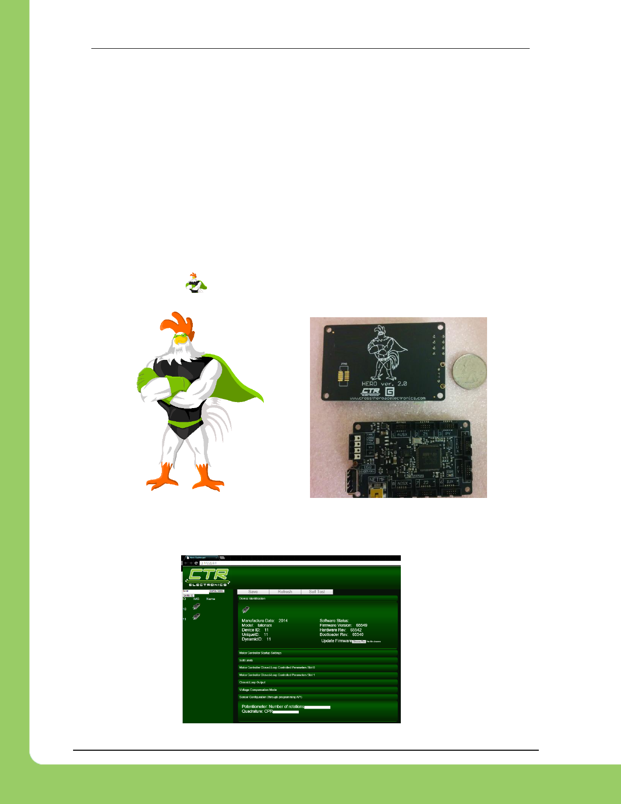
1.1.1. Cross The Road Electronics HERO Control System
The CTR HERO Control System board allows developers to utilize all features of the Talon
SRX. It is meant for education, custom development, and integration of Talon SRX into existing
applications.
The HERO also provides a method for field upgrading Talons to non-FRC firmware. It is the
ideal development kit for learning and integrating the Talon into custom applications!
Applications are developed in Visual Studio 2015 (C#, VB, managed-C++) using .NETMF
framework.
Be sure to look for the for HERO related tips.
1.1.1.1. HERO Web-based Configuration (coming soon)
Hero supports an internal web-page with setting configuration and field-upgrade capability.

217-8080 TALON SRX Software Reference Manual 2/14/2017
Cross The Road Electronics Page 14 2/14/2017
1.1.2. roboRIO FRC Control System
The only legal robot controller for FRC competition. This requires the FRC version of Talon
SRX firmware. The roboRIO supports CAN bus and provides a Web-based configuration for re-
flashing and diagnostics.
Be sure to look for the for FRC related tips.
217-8080 TALON SRX Software Reference Manual 2/14/2017
Cross The Road Electronics Page 15 2/14/2017
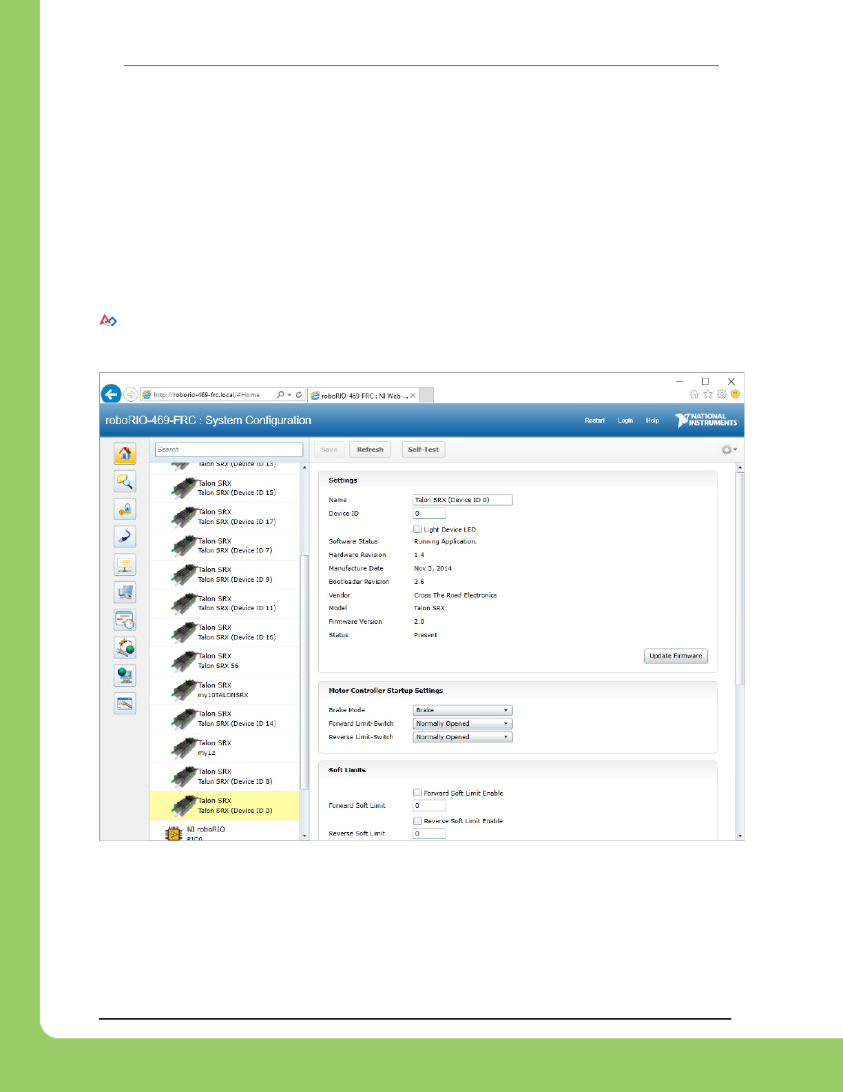
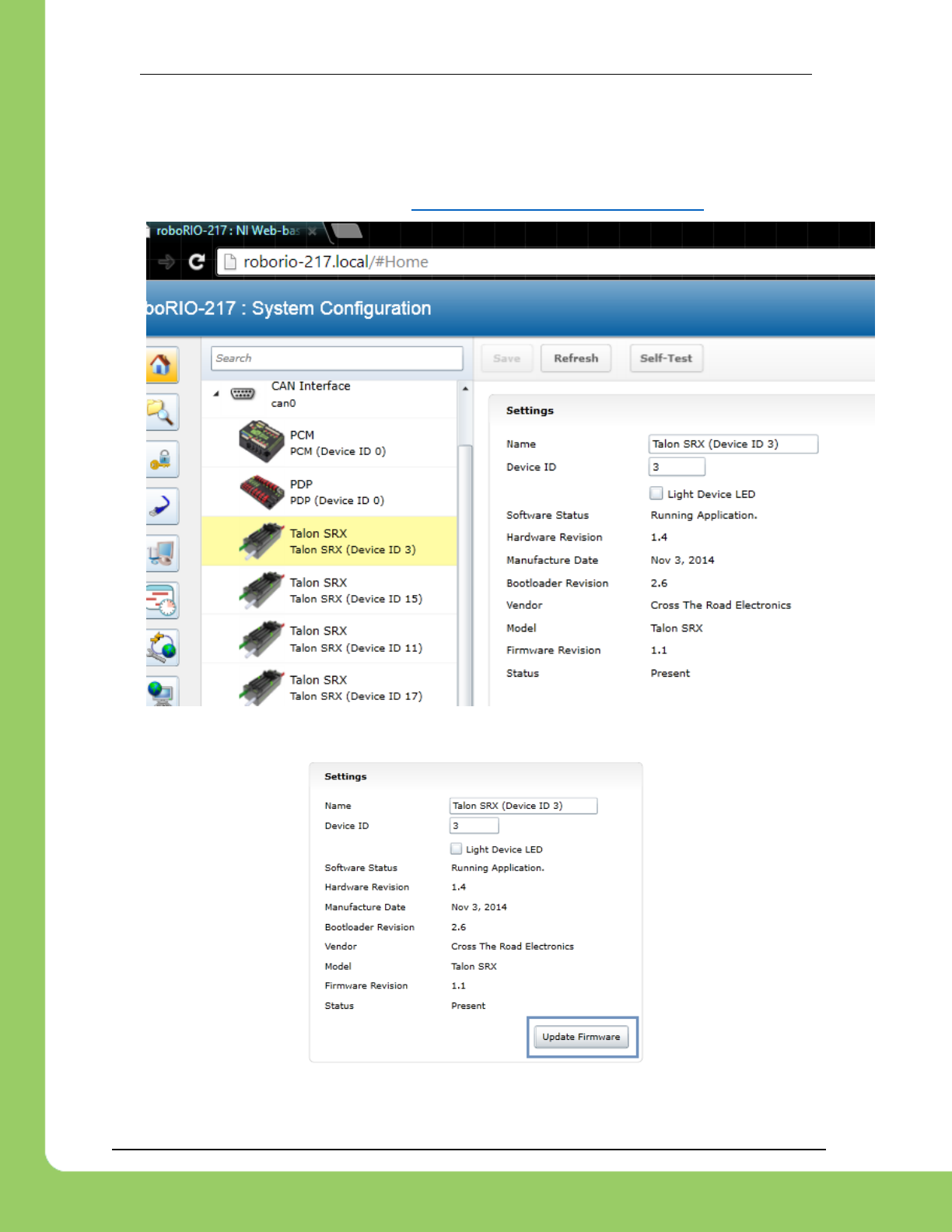
2. roboRIO Web-based Configuration: Firmware and
diagnostics
A useful diagnostic feature in the FRC Control system is the roboRIO’s Web-based
Configuration and Monitoring page. This provides diagnostic information on all discovered CAN
devices, including Talon SRXs. Talon SRXs can also be field-upgraded using this interface.
This feature is accessible by entering the mDNS name of your robot in a web browser, typically
roborio-XXXX-frc.local where XXXX is the team number (no leading zeros for three digit team
numbers).
Because Chrome no longer supports NPAPI, Silverlight will not function.
Internet Explorer functions adequately though refreshing the page (F5 or CNTRL+R) often
leaves an empty page. The workaround is to simple create a new tab with the same URL.
217-8080 TALON SRX Software Reference Manual 2/14/2017
Cross The Road Electronics Page 16 2/14/2017
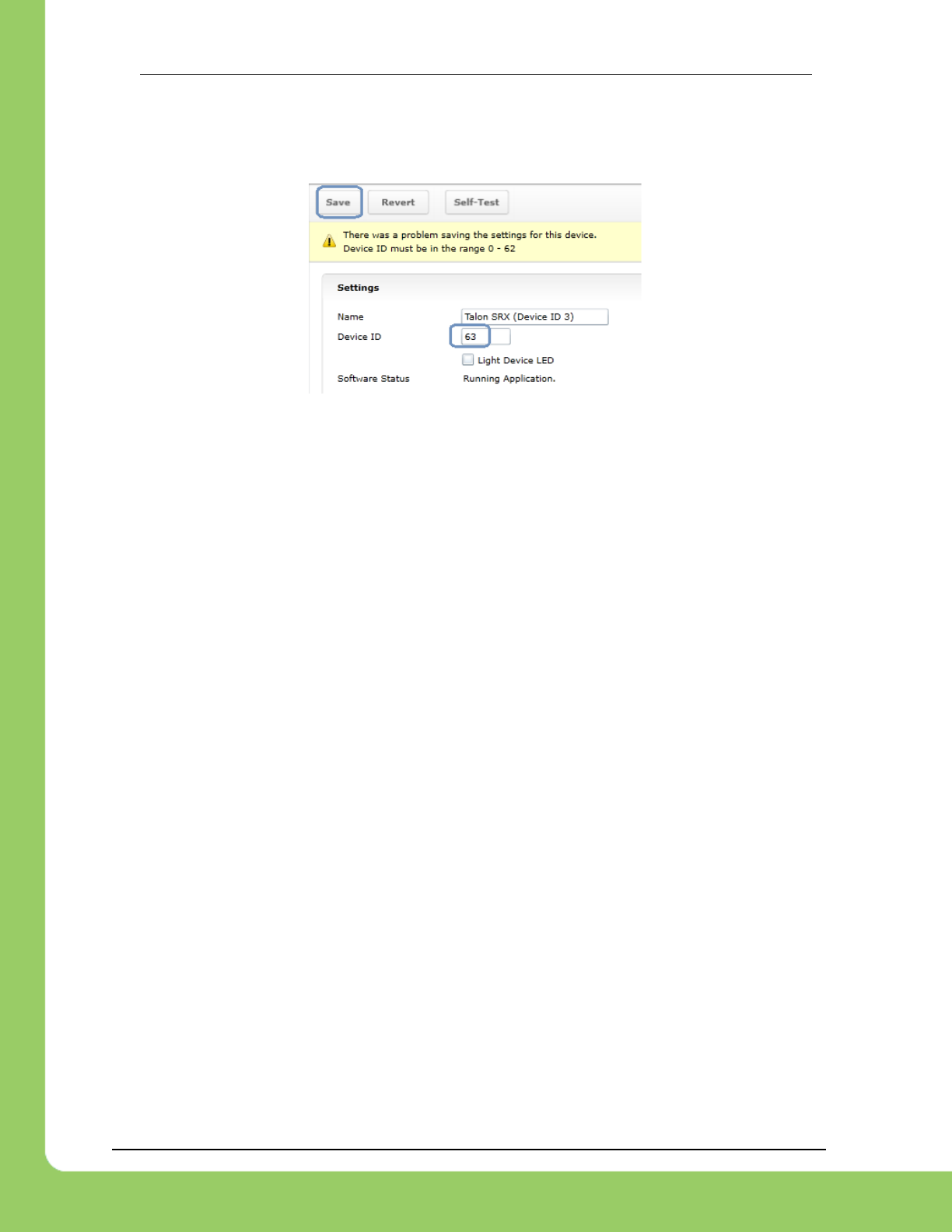
2.1. Device ID ranges
A Talon SRX can have a device ID from 0 to 62. 63 is reserved for broadcast.
If you select an invalid ID, you will get an immediate prompt.
217-8080 TALON SRX Software Reference Manual 2/14/2017
Cross The Road Electronics Page 17 2/14/2017
2.2. Common ID Talons
During initial setup (and when making changes to your robot), there may be occasions where
the CAN bus contains multiple running Talon SRXs with the same device ID. “Common ID”
Talon SRXs are to be avoided since they prevent reliable communication and prevents your
robot application from being able to distinguish one Talon SRX from another. However, the
roboRIO’s Web-based Configuration and Talon SRX firmware is designed to be tolerant of this
problem condition to a degree.
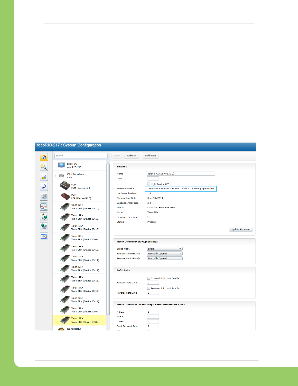
In the event there are “common ID” Talons, they will reveal themselves as a single tree element
(see image below). In this example, there is only one “Talon SRX (Device ID 0)” graphical
element on the left, however the software status shows that there are three detected Talon
SRXs with that device ID. If the number of “common ID” Talon SRXs is small (typically five or
less) you will still be able to firmware update, modify settings, and change the device ID. This
makes solving device ID contentions possible without having to isolate/disconnect “common ID”
Talon SRXs.
217-8080 TALON SRX Software Reference Manual 2/14/2017
Cross The Road Electronics Page 18 2/14/2017
When “common ID” Talon SRXs are present, correct this condition by changing the device ID to
a “free” number, (one not already in use) before doing anything else. Then manually refresh the
browser. This allows the web page to re-populate the left tree view with a new device ID.
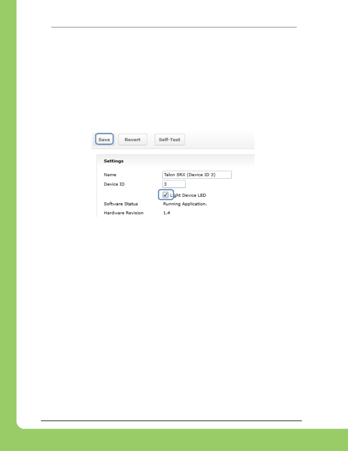
Since the web page allows control of one Talon SRX at a time, you may need to determine
which “common ID” Talon SRX you are modifying. Checking the “Light Device LED” and
pressing “Save” can be used to identify which physical Talon SRX is selected, and therefore
which one will be modified. This will cause the selected Talon SRX to blink its LEDs uniquely
(fast orange blink) for easy identification. In the unlikely event the device is in boot-loader
(orange/green LED), it will still respond to this by increasing the blink rate of the orange/green
pattern. The “Light Device LED” will uncheck itself after pressing “Save”.
Tip : Since the default device ID of an “out of the box” Talon SRX is device ID ‘0’, when you
setup your robot for the first time, start assigning device IDs at ’1’. That way you can, at any
time, add another default Talon to your bus and easily identify it.
217-8080 TALON SRX Software Reference Manual 2/14/2017
Cross The Road Electronics Page 19 2/14/2017
2.3. Firmware Field-upgrade a Talon SRX
Talon SRX uses a file format call CRF. To firmware flash a Talon SRX, navigate to the
following page and select it in the left tree view.
To get the latest firmware files see Section 2.3.4. Where to get CRF files?
Press “Update Firmware”.
217-8080 TALON SRX Software Reference Manual 2/14/2017
Cross The Road Electronics Page 20 2/14/2017
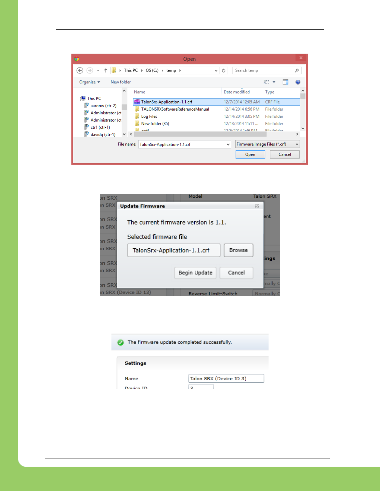
Select the firmware file (*.crf) to flash.
You will be prompted again, press “Begin Update”.
A progress bar will appear and finish with the following prompt. Total time to field-upgrade a
Talon SRX is approximately ten seconds. The progress bar will fill quickly, then pause briefly at
the near end, this is expected.
217-8080 TALON SRX Software Reference Manual 2/14/2017
Cross The Road Electronics Page 21 2/14/2017
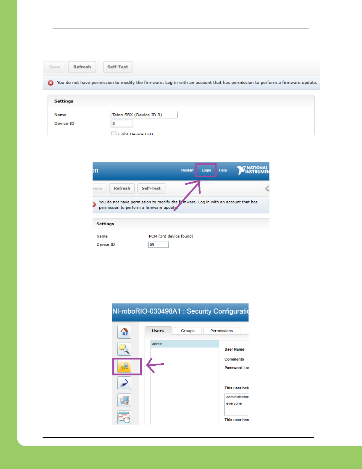
2.3.1. When I update firmware, I get “You do not have permissions…”
If you get the following error…
...then you have to log into the web interface using the username “admin”.
The user name is “admin” and the password is blank “”. Don’t enter any keys for password.
Additionally, you can modify permissions to allow field upgrade without being asked for login
every single time. If security isn’t a concern then modify the permissions so that “anyone” can
access “FirmwareUpdate” features.
Click on the key/lock icon in the left icon list.

217-8080 TALON SRX Software Reference Manual 2/14/2017
Cross The Road Electronics Page 22 2/14/2017
Then click on the “Permissions” tab. Select “FirmwareUpdate”, then press “Add” button.
Select everyone, then OK.
Click “Save” to save changes.
217-8080 TALON SRX Software Reference Manual 2/14/2017
Cross The Road Electronics Page 23 2/14/2017
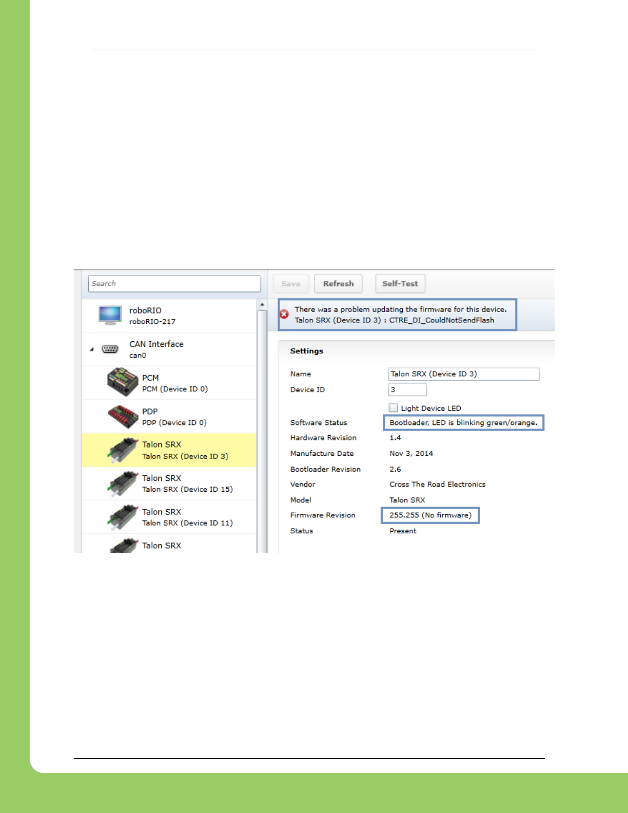
2.3.2. What if Firmware Field-upgrade is interrupted?
Since ten seconds is plenty of time for power or CAN bus to be disconnected, it is always
possible for a field-update to be interrupted. An error code will be reported if the firmware field-
update is interrupted or fails. Additionally, the Software Status will report “Bootloader” and
Firmware Revision will be 255.255 (blank).
If a Talon SRX has no firmware, its boot-loader will take over and blink green/yellow on the
device’s corresponding LED. It will also keep its device ID, so the roboRIO can still be used to
change the device ID or (re)flash a new application firmware (crf). This means you can
reattempt field-upgrade using the same web interface. There is no need for any sort of recovery
steps, nor is it necessary to isolate no-firmware Talon SRXs.
Example capture of disconnecting the CAN bus in the middle of a firmware-upgrade…

217-8080 TALON SRX Software Reference Manual 2/14/2017
Cross The Road Electronics Page 24 2/14/2017
2.3.3. Other Field-upgrade Failure Modes
Here’s an example error when trying to flash the wrong CRF into the wrong product.
The device will harmlessly stay in boot-loader, ready to be (re)flashed again.
Here’s what to expect if your CRF file is corrupted (different errors depending on where the file
is corrupted). The device will harmlessly stay in boot-loader, ready to be (re)flashed again. Re-
downloading the CRF firmware file is recommended if this is occurring persistently.
Here’s what to expect if you flash the wrong product’s CRF. For example, if you try to flash the
CRF for the Power Distribution Panel (PDP) into a Talon SRX, you will get an error prompt.

217-8080 TALON SRX Software Reference Manual 2/14/2017
Cross The Road Electronics Page 25 2/14/2017
2.3.4. Where to get CRF files?
The FRC Software installer will create a directory with various firmware files/tools for many
control system components. Typically the path is “C:\Users\Public\Documents\FRC”.
When the path is entered into a browser, the browser may fix-up the path into
“C:\Users\Public\Public Documents\FRC”.
In this directory are the initial release firmware CRF files for all CTRE CAN bus devices,
including the Talon SRX.
The latest firmware to be used at time of writing is version 2.0 (or newer).
TIP: Additionally newer updates may be provided online at http://www.ctr-electronics.com.
FRC: Be sure to watch for team updates for what is legal and required!
217-8080 TALON SRX Software Reference Manual 2/14/2017
Cross The Road Electronics Page 26 2/14/2017
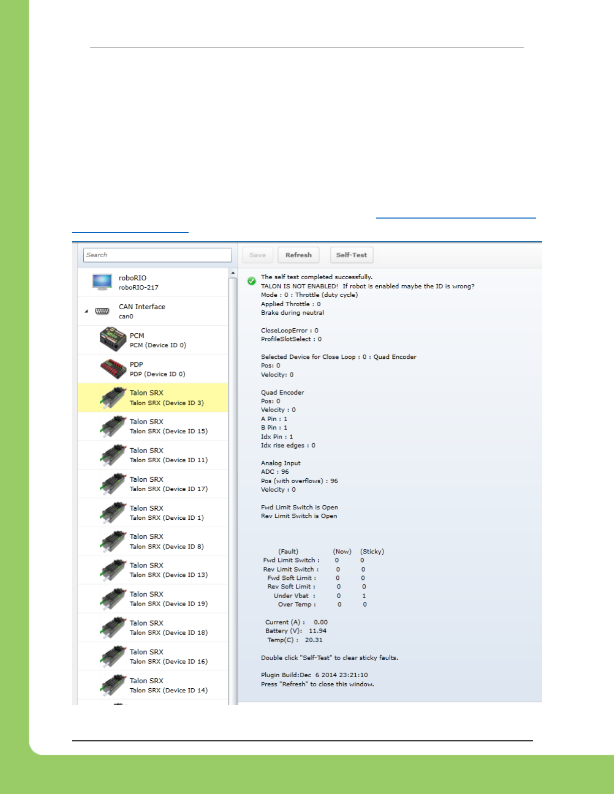
2.4. Self-Test
Pressing Self-Test will display data captured from CAN bus at the time of press. This can
include fault states, sensor inputs, output states, measured battery voltage, etc.
At the bottom of the Self-Test results, the build time of the library that implements web-based
CAN features is also present.
Here’s an example of pressing “Self-Test” with Talon SRX. Be sure to check if Talon SRX is
ENABLED or DISABLED. If Talon SRX is DISABLED then either the robot is disabled or the
robot application has not yet created a Talon SRX object (see Section 3. Creating a Talon SRX
Object (and basic drive) ).
217-8080 TALON SRX Software Reference Manual 2/14/2017
Cross The Road Electronics Page 27 2/14/2017
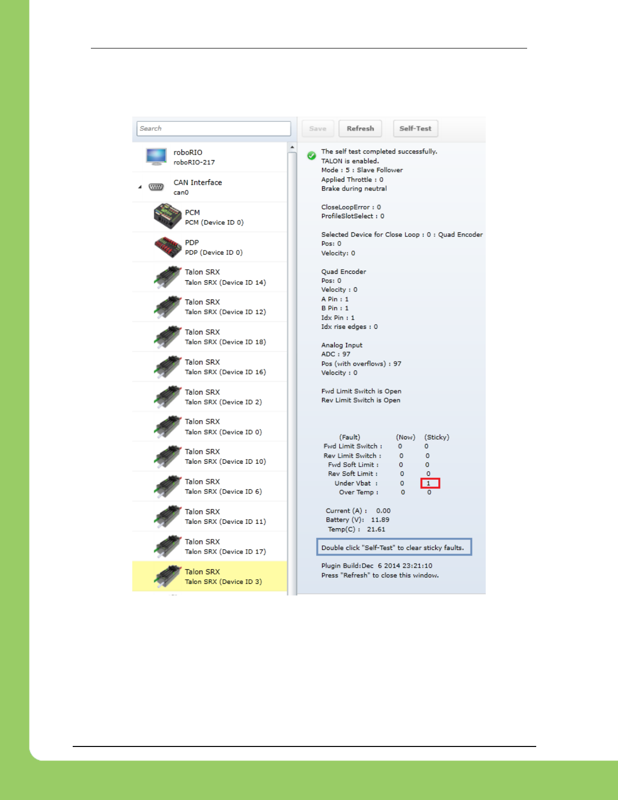
After enabling the robot and repressing “Self-Test” we see the Talon SRX is enabled.
Additionally we see there is a sticky fault asserted for low battery voltage.
Sticky faults persist across power cycles for identifying intermittent problems after they occur.
217-8080 TALON SRX Software Reference Manual 2/14/2017
Cross The Road Electronics Page 28 2/14/2017
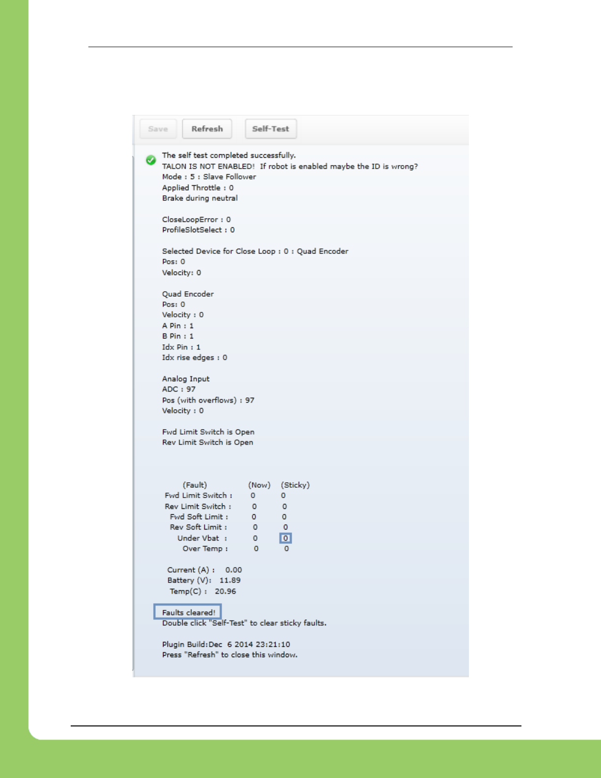
2.4.1. Clearing Sticky Faults
After double clicking Self-Test in a rapid fashion we see our fault gets cleared.
217-8080 TALON SRX Software Reference Manual 2/14/2017
Cross The Road Electronics Page 29 2/14/2017
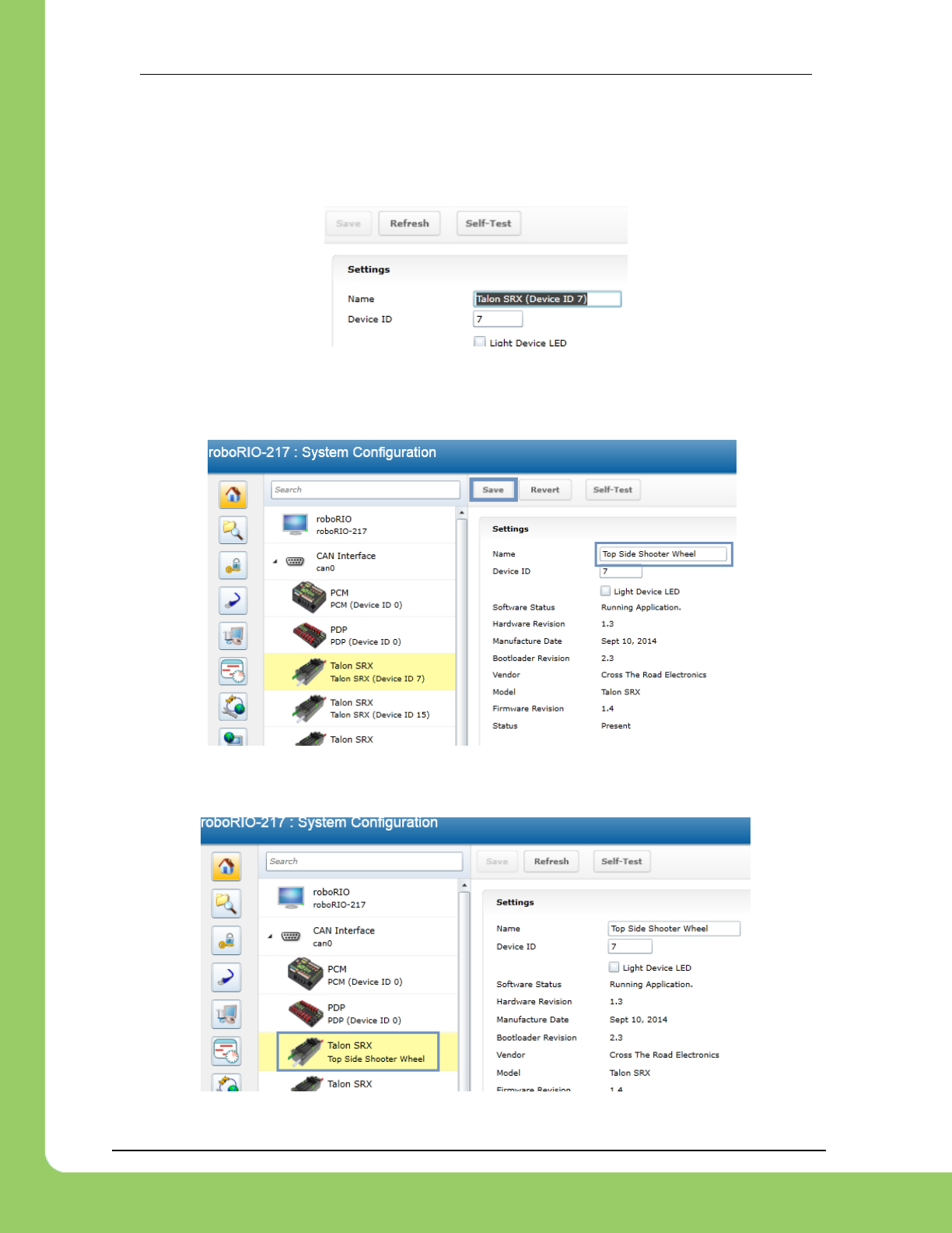
2.5. Custom Names
Another feature made available by the Web-based Configuration is the ability to rename Talon
SRXs with custom string descriptions. A Talon SRX’s custom name is saved persistently inside
the Talon. To modify the default name highlight the contents of the “Name” text entry.
…then replace with a custom text description and press “Save”.
The new description will appear in the left tree view.
217-8080 TALON SRX Software Reference Manual 2/14/2017
Cross The Road Electronics Page 30 2/14/2017
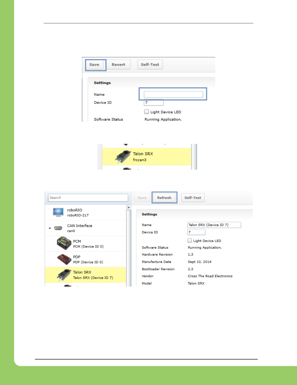
2.5.1. Re-default custom name
To re-default the custom name, clear the “Name” text entry and press “Save”.
Left tree view will update with a temporary name until the “Refresh” button is pressed.
After pressing “Refresh” the default name will appear.

217-8080 TALON SRX Software Reference Manual 2/14/2017
Cross The Road Electronics Page 31 2/14/2017
3. Creating a Talon Object (and basic drive)
3.1. Programming API and Device ID
Regardless of what language you use on the FRC control system (LabVIEW/C++/Java), the
method for specifying which Talon SRX you are programmatically controlling is the device ID.
Although the roboRIO Web-based Configuration is tolerant of “common ID” Talon SRXs to a
point, the robot programming API will not enable/control “common ID” Talons reliably. For the
robot to function properly, there CANNOT BE “COMMON ID” Talon SRXs. See Section 2.2.
Common ID Talons for more information.
TIP: Example projects for Talon SRX can also be found in the CTR GitHub account.
https://github.com/CrossTheRoadElec/FRC-Examples
3.1.1 Including Libraries (FRC)
To use Talon SRX libraries, FRC Teams need to download and install the CTRE Toolsuite,
which can be found on the CTR Electronics website.
Once the libraries have been installed, users can simply add them to their project using
standard import/include statements.
For Java, users should add an import statement as follows:
import com.ctre.CANTalon;
For C++, users should add an include for the CANTalon header file as follows:
#include "CANTalon.h"
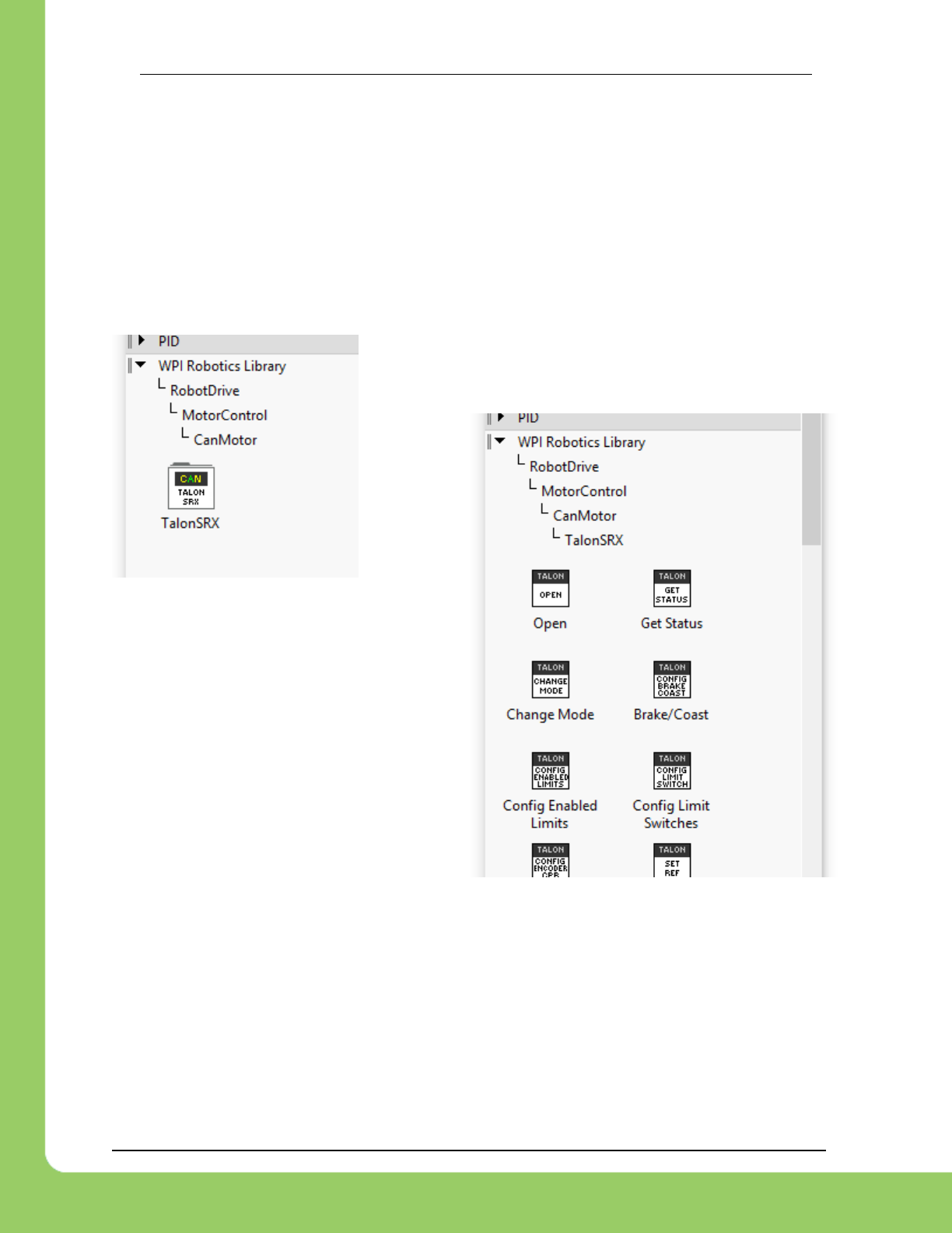
LabVIEW users will find the CAN Talon SRX VIs in a new subpalette in the WPI Robotics
palette:
WPI Robotics -> Robot Drive -> MotorControl -> CANMotor -> TalonSRX
217-8080 TALON SRX Software Reference Manual 2/14/2017
Cross The Road Electronics Page 32 2/14/2017
3.2. New Classes/Virtual Instruments
C++/Java now contains a new class CANTalon (.h/.cpp/.java).
LabVIEW contains three CTRE motor types for the FRC season: Talon SRX, Victor SP, CAN
Talon SRX. When using Talon SRX on CAN bus, use the new Talon SRX Open VI. The other
two modes are for PWM use and use the WPILib Motor Open VI. Additional VIs are available in
the CAN Talon SRX palette.
After selecting Talon SRX, the VIs are visible...
There are 24 current Vis, covering all new
features of the Talon SRX, including the VIs
relating to the motion profile and motion
magic control modes.
217-8080 TALON SRX Software Reference Manual 2/14/2017
Cross The Road Electronics Page 33 2/14/2017
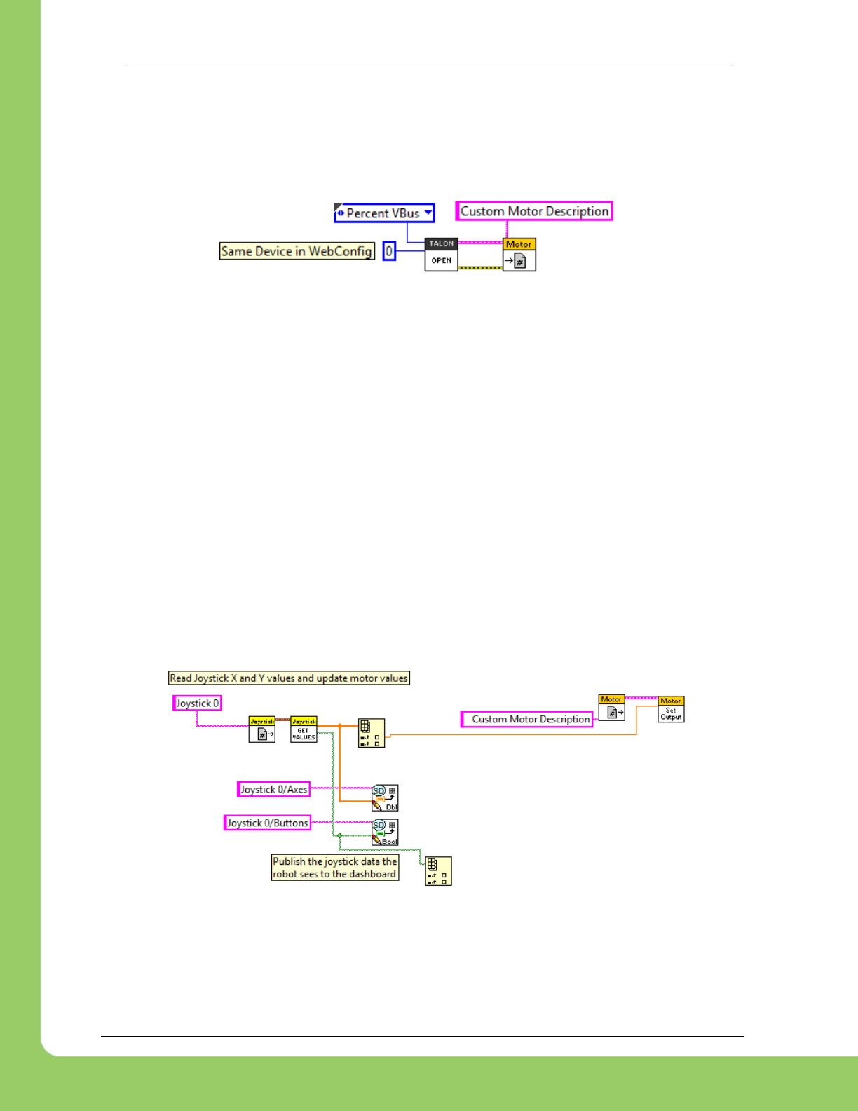
3.2.1. LabVIEW
Creating a “bare-bones” Talon SRX object is similar to previously supported motor controllers.
Start by creating a WPI_CANTalonSRXOpen.vi object (left) and a WPI_MotorControlRefNum.vi
object (right).
The WPI_CANTalonSRXOpen.vi is located in the Talon SRX palette, and the
WPI_MotorControlRefNum.vi is accessible in the actuator palette (same VI as previous
seasons).
Create two constants for the “Device Number” and “Control Mode” inputs. The control mode will
default to “Percent VBus” and “0” for the Device ID. Enter the appropriate Device ID that was
selected in the roboRIO Web-based Configuration.
Also similarly to other motor controllers, you may register a custom string reference using
WPI_MotorControlRefNum.vi to reference the motor controller by description in other block
diagrams. In this example we use “Custom Motor Description”.
Setting the output value of the Talon SRX is done similarly to other motor controllers.
In this example we directly control the motor output with a Joystick axis.
When using a closed-loop mode, the Set Output VI is also the method for specifying the set-
point.
217-8080 TALON SRX Software Reference Manual 2/14/2017
Cross The Road Electronics Page 34 2/14/2017
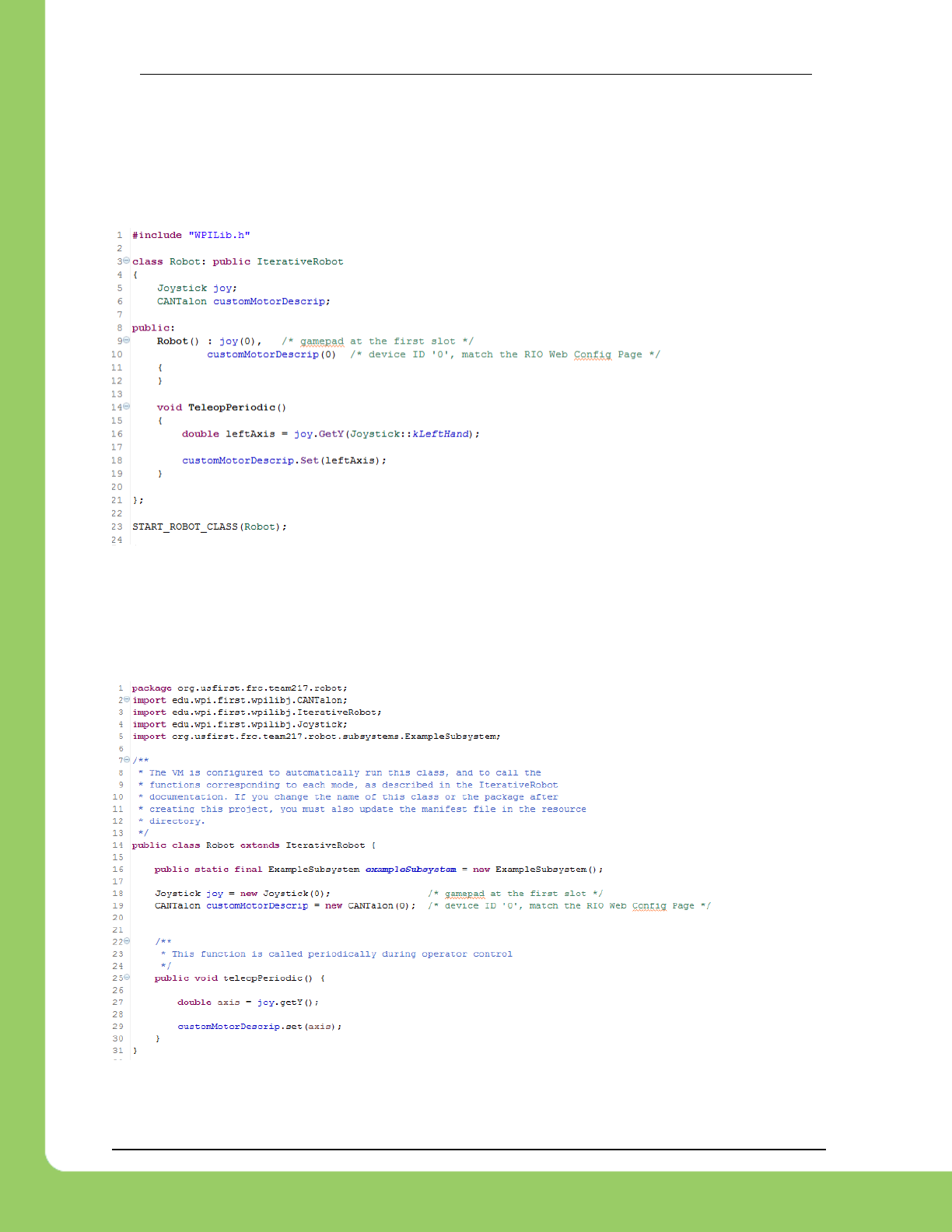
3.2.2. C++
When using a script language, the API class to support Talon SRX is called CANTalon
(.cpp/.h/.java). When the object is constructed, the device ID is the first parameter. There may
be an optional second parameter to change the frequency at which the Talon SRX is updated
over CAN (default 10ms).
3.2.3. Java
When a CANTalon object is constructed in Java, the device ID is the first parameter. There
may be an optional second parameter to change the frequency at which the Talon SRX is
updated over CAN (default 10ms).
217-8080 TALON SRX Software Reference Manual 2/14/2017
Cross The Road Electronics Page 35 2/14/2017
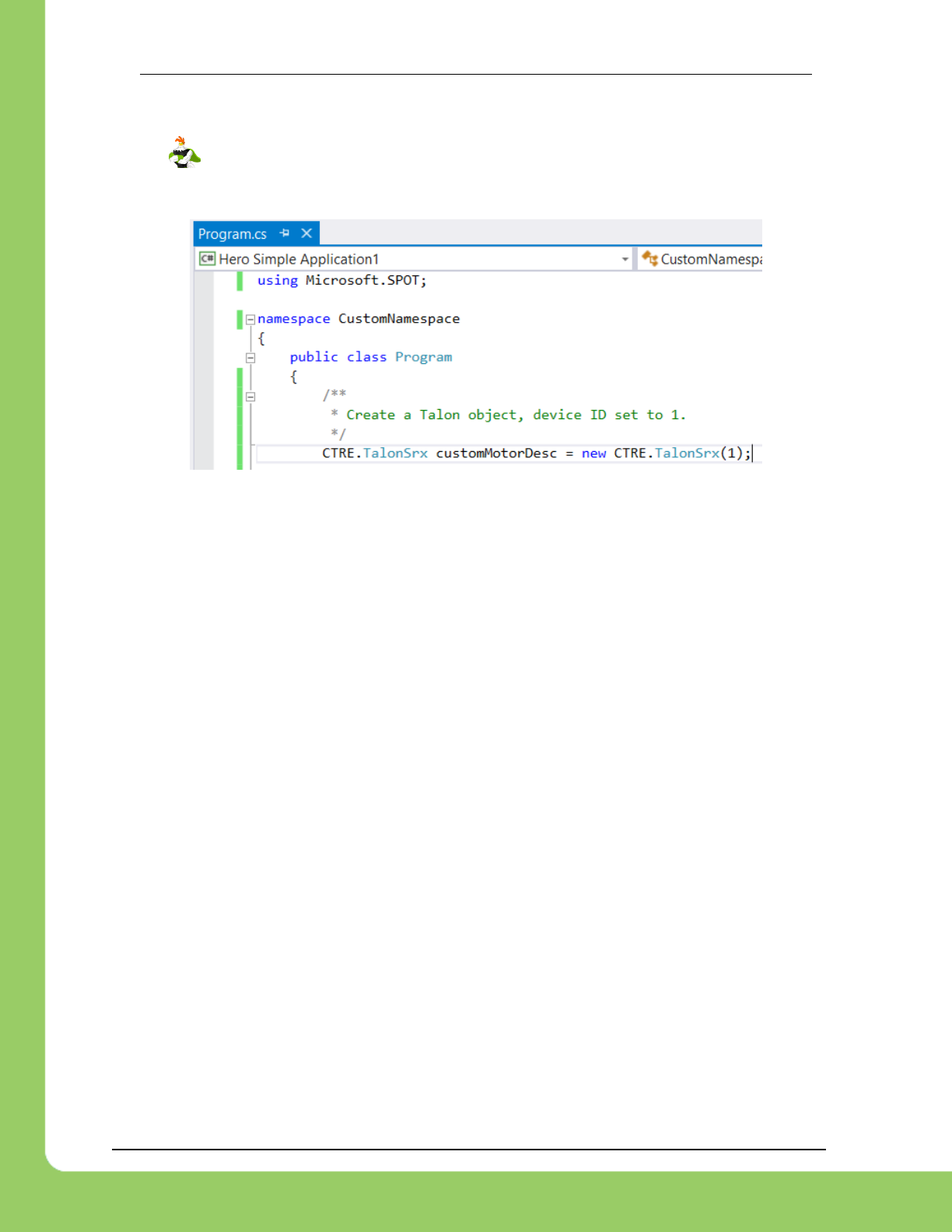
3.2.4. Visual Studio .NETMF
A similar Talon SRX class is available using the HERO Control System. All CTRE
classes are in the CTRE namespace. The member functions are comparable to the API
available in the WPILIB languages available in the roboRIO.
217-8080 TALON SRX Software Reference Manual 2/14/2017
Cross The Road Electronics Page 36 2/14/2017
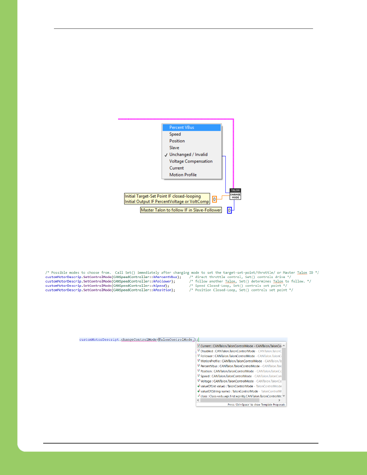
3.3. Changing Mode
After a Talon software object is created, the Talon SRX mode can be changed from the default
Percent Vbus (open loop throttle) to the other supported modes programmatically. Additionally
the LabVIEW OPEN CAN TALON VI also allows caller to select the initial control mode.
3.3.1. LabVIEW
The CHANGE MODE VI can be used to change the Talon SRX mode, and set the first target set
point, throttle, or Talon Master ID to follow.
3.3.2. C++
The function SetControlMode() can be used to change the Talon SRX mode. Caller should
ensure Set() is called immediately after to properly set the initial target set point, throttle, or
Master ID to follow.
3.3.3. Java
The function changeControlMode() can be used to change the Talon SRX mode. Caller
should ensure set() is called immediately after to properly set the initial target set point,
throttle, or Master ID to follow.
217-8080 TALON SRX Software Reference Manual 2/14/2017
Cross The Road Electronics Page 37 2/14/2017
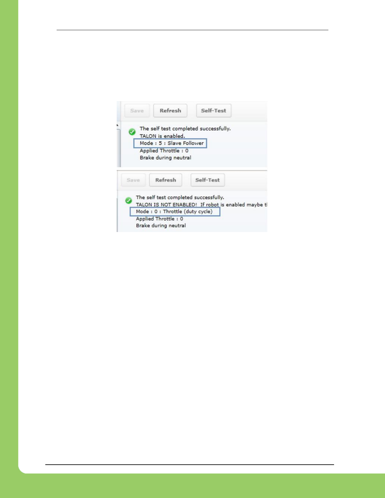
3.3.4. Check Control Mode with Self-Test
The Self-Test can be used to confirm the desired mode of the Talon SRX (Throttle, Slave,
Position Closed-Loop, and Velocity Closed-Loop). However note that the Talon SRX mode will
not update until robot is enabled.
Example Self-Test
217-8080 TALON SRX Software Reference Manual 2/14/2017
Cross The Road Electronics Page 38 2/14/2017
3.4. WPILib RobotDrive Class
The Robotdrive class is maintained by WPILib. CAN Talon SRX can be used with this class in
LabVIEW, Java, and C++.
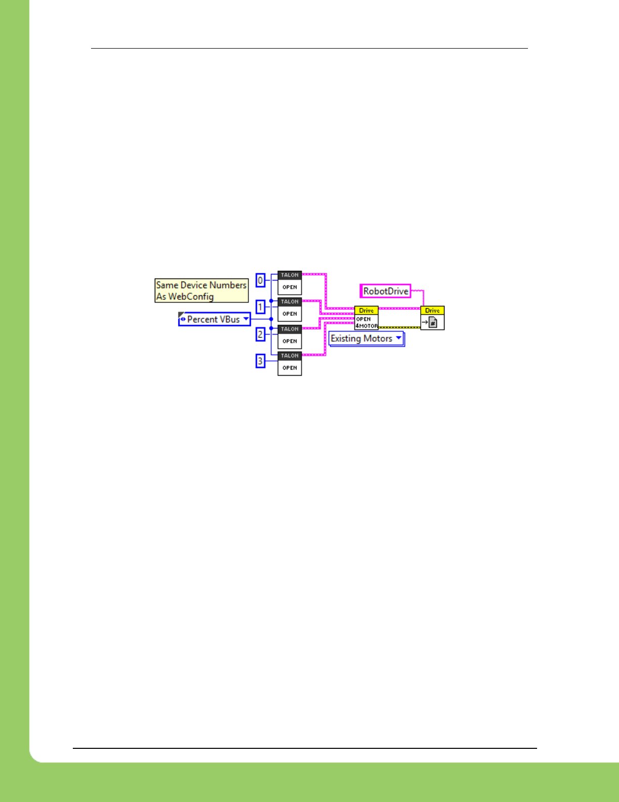
3.4.1. LabVIEW
The RoboDrive Vis are typically located in WPI Robotics Library -> RobotDrive.
To use CAN Talon SRX with either the 2 or 4 motor options, first use a Talon SRX Open Motor
VI. The RefNum output is then wired to the input of the Open 2/4 Motor VI when the “Existing
Motors” drop-down option is selected. The RobotDrive RefNum Set is then used as normal.
3.4.2. C++
RobotDrive is included in WPILib.h. Construct the appropriate CANTalon objects and pass
them to the RobotDrive constructor.
FrontLeftMotor = new CANTalon(1);
FrontRightMotor = new CANTalon(2);
RearLeftMotor = new CANTalon(3);
RearRightMotor = new CANTalon(4);
drive = new RobotDrive(FrontLeftMotor, RearLeftMotor, FrontRightMotor,
RearRightMotor);
3.4.3. Java
RobotDrive is included in WPILib. Construct the appropriate CANTalon objects and pass them
to the RobotDrive constructor.
FrontLeftMotor = new CANTalon(1);
FrontRightMotor = new CANTalon(2);
RearLeftMotor = new CANTalon(3);
RearRightMotor = new CANTalon(4);
drive = new RobotDrive(FrontLeftMotor, RearLeftMotor, FrontRightMotor,
RearRightMotor);

217-8080 TALON SRX Software Reference Manual 2/14/2017
Cross The Road Electronics Page 39 2/14/2017
4. Limit Switch and Neutral Brake Mode
4.1. Default Settings
An “out of the box” Talon will default with the limit switch setting of “Normally Open” for both
forward and reverse. This means that motor drive is allowed when a limit switch input is not
closed (i.e. not connected to ground). When a limit switch input is closed (is connected to
ground) the Talon SRX will disable motor drive and individually blink both LEDs red in the
direction of the fault (red blink pattern will move towards the M+/white wire for positive limit fault,
and towards M-/green wire for negative limit fault).
An “out of the box” Talon SRX will typically have a default brake setting of “Brake during
neutral”. The B/C CALL button will be illuminated red (brake enabled).
Since an “out of the box” Talon will likely not be connected to limit switches (at least not initially)
and because limit switch inputs are internally pulled high (i.e. the switch is open), the limit switch
feature is default to “normally open”. This ensures an “out of the box” Talon will drive even if no
limit switches are connected.
For more information on Limit Switch wiring/setup, see the Talon SRX User’s Guide.
Forward
Limit Switch
Mode
Limit
Switch
NO pin
Limit
Switch
NC pin
Limit
Switch
COM pin
Motor Drive
Switch open
Fwd. throttle
Motor Drive
Switch closed
Fwd. throttle
*Voltage
(Switch
Open)
*Voltage
(Switch
Closed)
Normally
Open
pin4
N.A.
pin10
Y
N
~2.5V
0 V
Normally
Closed
N.A.
pin4
pin10
N
Y
0 V
~2.5V
Disabled
N.A.
N.A.
N.A.
Y
Y
N.A.
N.A.
Reverse
Limit Switch
Mode
Limit
Switch
NO pin
Limit
Switch
NC pin
Limit
Switch
COM pin
Motor Drive
Switch open
Rev. throttle
Motor Drive
Switch closed
Rev. throttle
*Voltage
(Switch
Open)
*Voltage
(Switch
Closed)
Normally
Open
pin8
N.A.
pin10
Y
N
~2.5V
0 V
Normally
Closed
N.A.
pin8
pin10
N
Y
0 V
~2.5V
Disabled
N.A.
N.A.
N.A.
Y
Y
N.A.
N.A.
*Measured voltage at the Talon SRX Limit Switch Input pin.
Limit Switch Input Forward Input - pin4 on Talon SRX
Limit Switch Input Reverse Input - pin8 on Talon SRX
Limit Switch Ground - pin10 on Talon SRX
217-8080 TALON SRX Software Reference Manual 2/14/2017
Cross The Road Electronics Page 40 2/14/2017
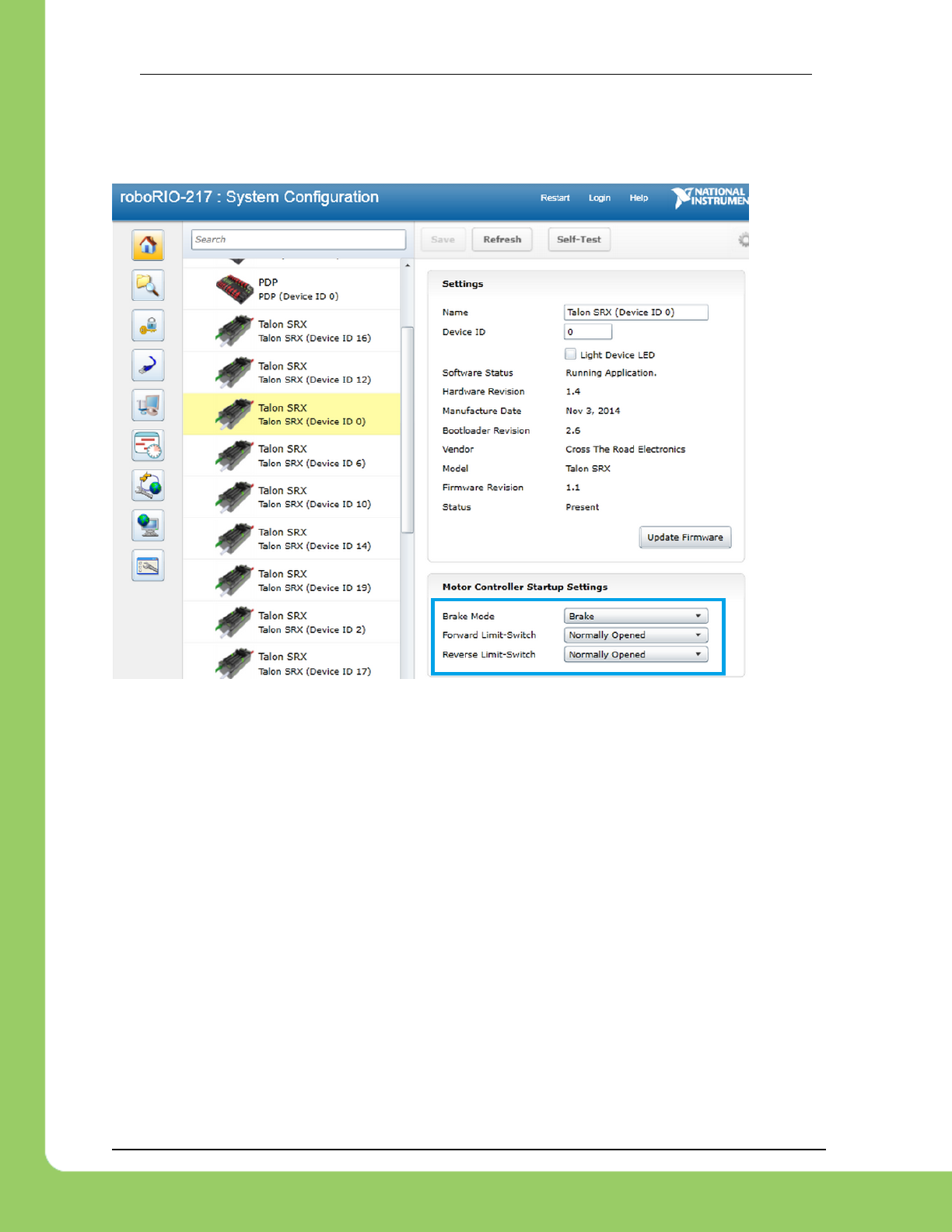
4.2. roboRIO Web-based Configuration: Limit Switch and Brake
Limit switch features can be disabled or changed to “Normally Closed” in the roboRIO Web-
based Configuration. Similarly the brake mode can be change through the same interface.
Changing the settings will take effect once the “Save” button is pressed. The settings are saved
in persistent memory.
If the Brake or Limit Switch mode is changed in the roboRIO Web-based Configuration, the
Talon SRX will momentarily disable then resume motor drive. All other settings can be changed
without impacting the motor drive or enabled-state of the Talon SRX.
Additionally the brake mode can be modified by pressing the B/C CAL Button on the Talon SRX
itself, just like with previous generation Talons.
217-8080 TALON SRX Software Reference Manual 2/14/2017
Cross The Road Electronics Page 41 2/14/2017
4.3. Overriding Brake and Limit Switch with API
The Brake and Limit Switch can, to a degree, be changed programmatically (during a match). A
great example of this would be for dynamic braking.
The programming API allows for overriding the active neutral brake mode. When this is done
the Brake/Coast LED will reflect the overridden value (illuminated red for brake, off for coast)
regardless of the startup brake mode specified in the roboRIO Web-based Configuration (i.e.
what’s saved in persistent memory).
Similarly the enabled states of the limit switches (on/off) for the forward and reverse direction
can be individually enabled/disabled by overriding them with programming API.
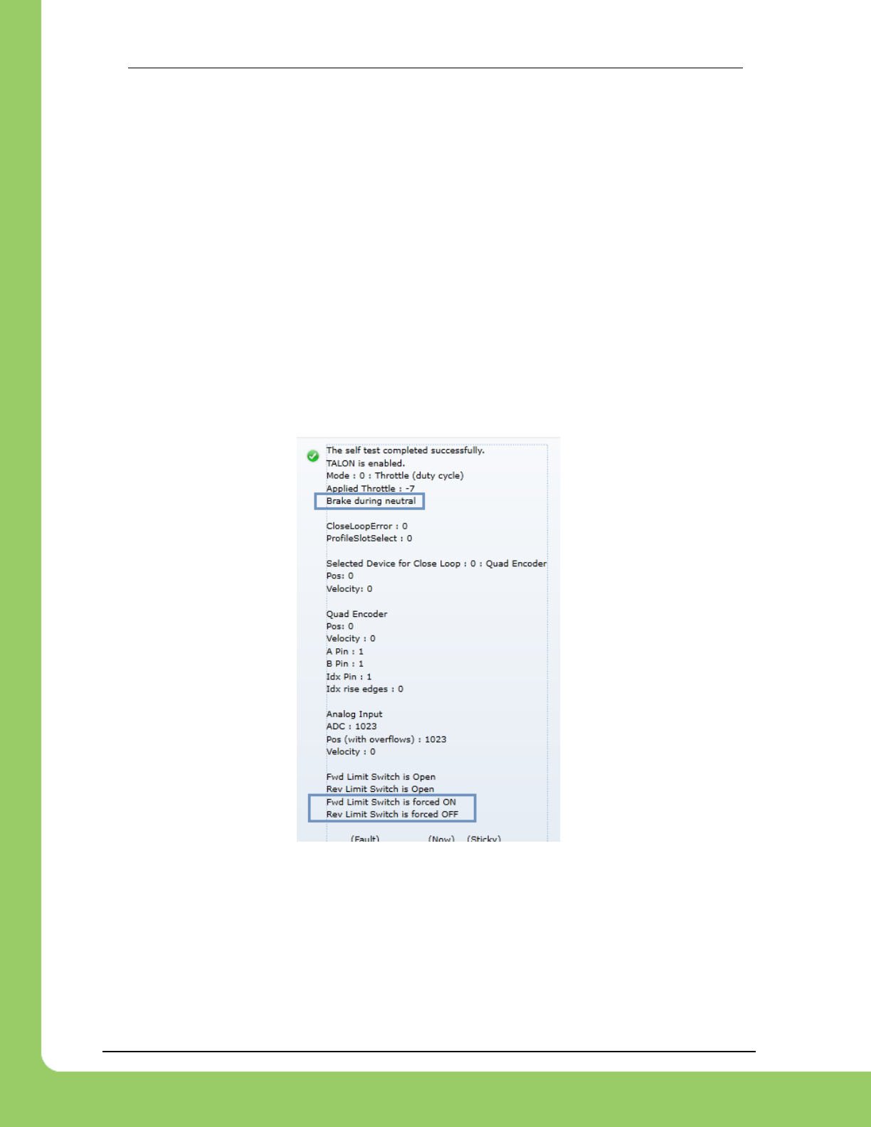
The brake and limit switch overrides can be confirmed in the Self-Test results. If limit switches
are overridden by the robot application, the forced states are displayed as “forced ON” or
“forced OFF”. Also the currently active brake mode is in the Self-Test results.
217-8080 TALON SRX Software Reference Manual 2/14/2017
Cross The Road Electronics Page 42 2/14/2017
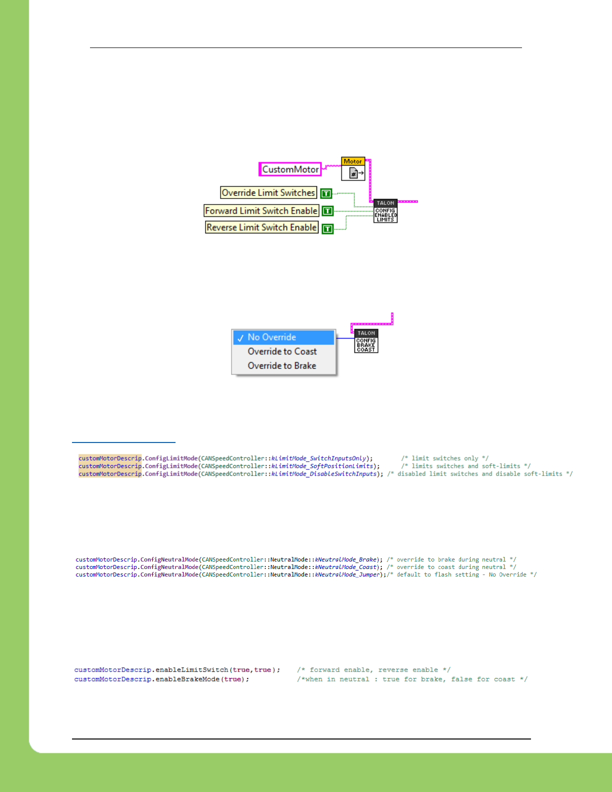
4.3.1. LabVIEW
The CONFIG ENABLED LIMITS VI can be used to override the limit switch enable states. When
overriding the limit switch enable states, set the override signal to true, then pass true/false to
the forward and reverse limit switch enable.
The neutral brake mode can also be overridden to Brake or Coast using the CONFIG BRAKE
COAST VI. If “No Override” is selected then the Startup Brake Mode is used.
4.3.2. C++
Limit Switches can be forced on or off using ConfigLimitMode(), along with soft limits (see
Section 8. Soft Limits).
ConfigNeutralMode() can be used to override the brake/coast mode. Also selecting the
enumerated value of kNeutralMode_Jumper will signal the Talon SRX to use its default setting
(controlled by roboRIO Web-based Configuration and B/C CAL button).
4.3.3. Java
enableLimitSwitch() can be used to override the enabled state for forward and reverse limit
switch enable. enableBrakeMode() can be used to override the brake/coast setting.
217-8080 TALON SRX Software Reference Manual 2/14/2017
Cross The Road Electronics Page 43 2/14/2017
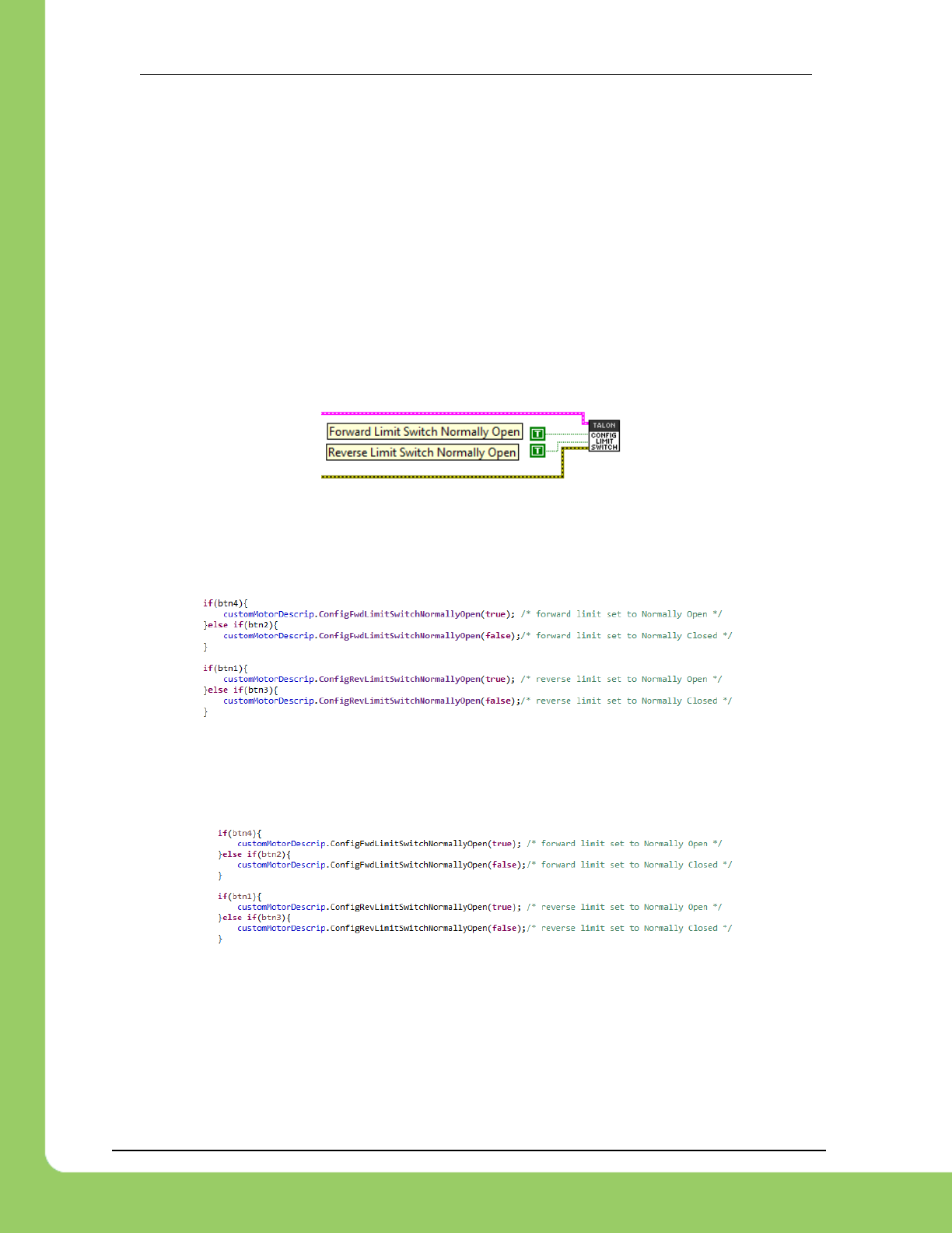
4.4. Changing limit switch mode between “Normally Open” or “Normally
Closed”
The limit switch setting that determines “Normally Open” vs “Normally Closed” can also be set
programmatically using the CONFIG LIMIT SWITCH VI. However care should be taken when
this is done. When a Talon SRX’s limit switch mode is changed from its current setting to a
different value, it briefly disables motor drive during the transition. This should not be a problem
since the limit switches in the robot are typically not changed during a match.
However it may be convenient to ensure NO/NC settings at startup (particularly when using the
non-default setting of Normally Closed) so as to avoid needing to use the roboRIO Web-based
Configuration to select NC whenever a Talon SRX needs to be added/replaced.
4.4.1. LabVIEW
4.4.2. C++
ConfigFwdLimitSwitchNormallyOpen() and ConfigRevLimitSwitchNormallyOpen() can
be used to change the NO/NC state of a limit switch input.
4.4.3. Java
ConfigFwdLimitSwitchNormallyOpen() and ConfigRevLimitSwitchNormallyOpen() can
be used to change the NO/NC state of a limit switch input.

217-8080 TALON SRX Software Reference Manual 2/14/2017
Cross The Road Electronics Page 44 2/14/2017
5. Getting Status and Signals
The Talon SRX transmits most of its status signals periodically, i.e. in an unsolicited fashion.
This improves bus efficiency by removing the need for “request” frames, and guarantees the
signals necessary for the wide range of use cases Talon supports, are available.
These signals are available in API regardless of what control mode the Talon SRX is in.
Additionally the signals can be polled in the roboRIO Web-based Configuration (see Section
2.4. Self-Test).
Included in the list of signals are…
- Quadrature Encoder Position, Velocity, Index Rise Count, Pin States (A, B, Index)
- Analog-In Position, Analog-In Velocity, 10bit ADC Value,
- Battery Voltage, Current, Temperature
- Fault states, sticky fault states,
- Limit switch pin states
- Applied Throttle (duty cycle) regardless of control mode.
- Applied Control mode: Voltage % (duty-cycle), Position/Velocity closed-loop, or slave follower.
- Brake State (coast vs brake)
- Closed-Loop Error, the difference between closed-loop set point and actual position/velocity.
- Sensor Position and Velocity, the signed output of the selected Feedback device (robot must
select a Feedback device, or rely on default setting of Quadrature Encoder).
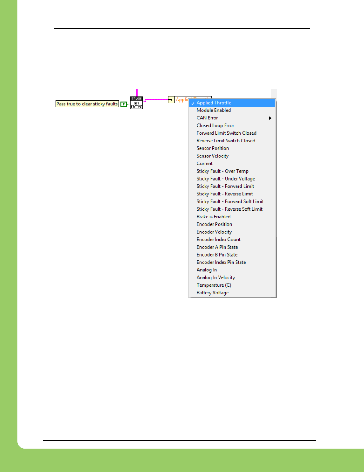
217-8080 TALON SRX Software Reference Manual 2/14/2017
Cross The Road Electronics Page 45 2/14/2017
5.1. LabVIEW
The GET STATUS VI can be used to retrieve the latest value for the signals Talon SRX
periodically transmits. Additionally, sticky faults can be cleared if “true” is passed into the “Clear
Sticky Fault” signal. To get a particular signal, unbundle-by-name the output of the GET STATUS
VI. Then select the signal to get by right clicking the center of the unbundle object.
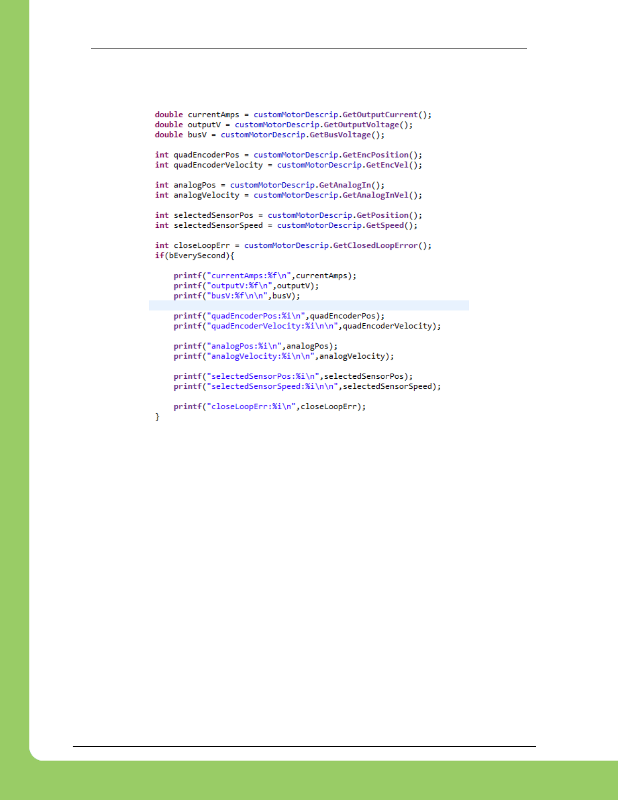
217-8080 TALON SRX Software Reference Manual 2/14/2017
Cross The Road Electronics Page 46 2/14/2017
5.2. C++
All get functions are available in C++. Here are a few examples….
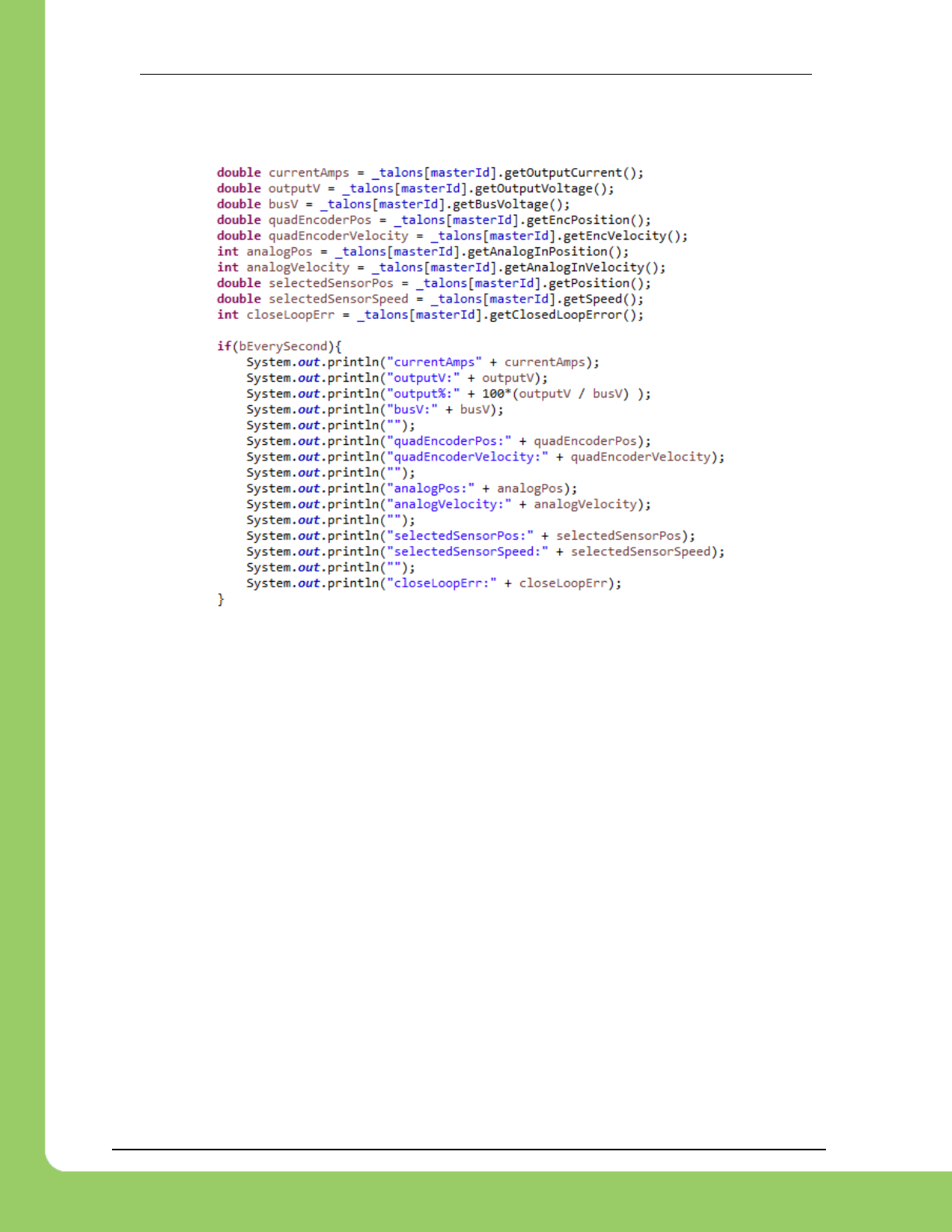
217-8080 TALON SRX Software Reference Manual 2/14/2017
Cross The Road Electronics Page 47 2/14/2017
5.3. Java
All get functions are available in java. Here are a few examples….
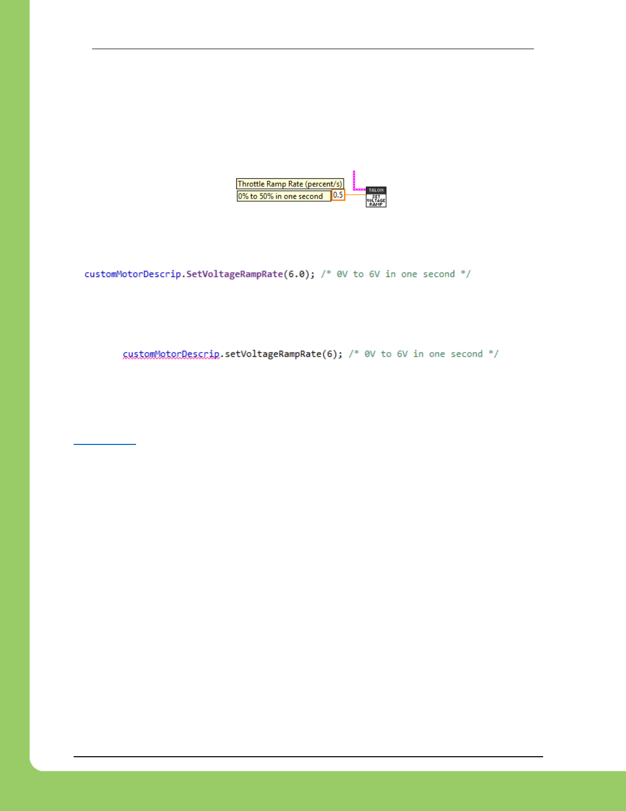
217-8080 TALON SRX Software Reference Manual 2/14/2017
Cross The Road Electronics Page 48 2/14/2017
6. Setting the Ramp Rate
The Talon SRX can be set to honor a ramp rate to prevent instantaneous changes in throttle.
This ramp rate is in effect regardless of which mode is selected (throttle, slave, or closed-loop).
6.1. LabVIEW
Use the SET VOLTAGE RAMP to specify the ramp rate in percent per second.
6.2. C++
Ramp can be set in Volts per second using SetVoltageRampRate().
6.3. Java
Ramp can be set in Volts per second using setVoltageRampRate().
6.4. What is the slowest ramp possible?
The Talon SRX internally expresses the (Voltage) Ramp Rate in throttle units per 10ms (see
Section 17.6). As a result, at the minimum (slowest) ramp rate, the time from zero-to-full-throttle
is 10.23 seconds. This is derived from 1 throttle unit per 10ms. In terms of voltage per second,
this is equivalent to 1.173 V per second or 9.77% per second. When choosing an initial ramp
rate avoid specifying a rate that is slower than this limitation. Choosing a slower rate than
what’s possible will cause the programming API to truncate the calculated result to zero throttle
units per 10ms, leading to the effect of no ramp at all.
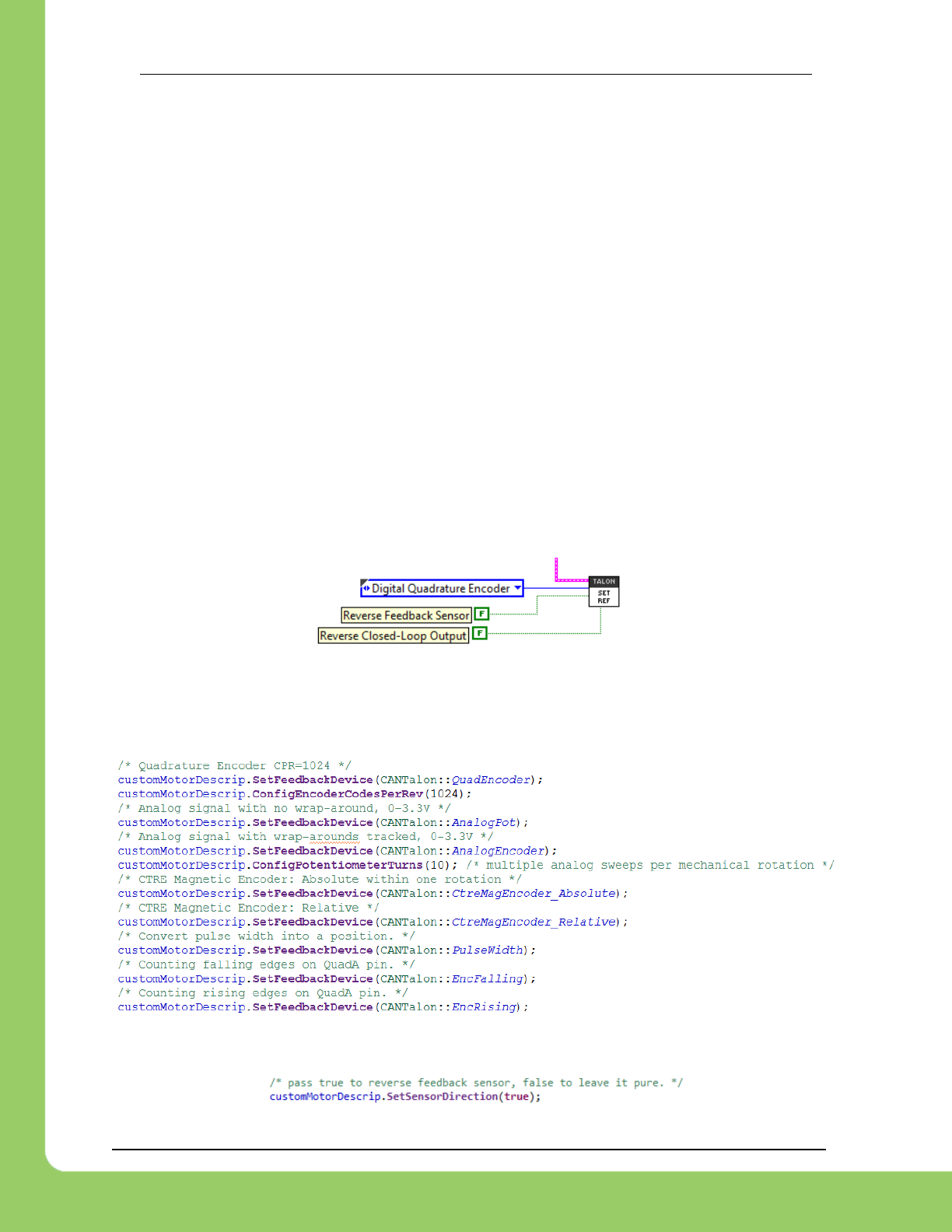
217-8080 TALON SRX Software Reference Manual 2/14/2017
Cross The Road Electronics Page 49 2/14/2017
7. Selecting a Feedback Device
Although the analog and quadrature signals are available all the time, the Talon SRX requires
the robot application to “pick” a particular “Feedback Device” for soft limit and closed-loop
features.
The selected “Feedback Device” defaults to Quadrature Encoder.
Once a “Feedback Device” is selected, the “Sensor Position” and “Sensor Velocity” signals will
update with the output of the selected feedback device. It will also be multiplied by (-1) if
“Reverse Feedback Sensor" is asserted programmatically.
Alternatively, the output of the closed loop logic can also be inverted if necessary.
7.1. LabVIEW
Use SET REF to select which Feedback Sensor to use for soft limits and closed-loop features.
The supported selections include: Quadrature Encoder, Analog Encoder (or any continuous
3.3V analog sensor), Analog Potentiometer and more.
7.2. C++
SetFeedbackDevice() can be used to select Quadrature Encoder, Analog Encoder (or any
continuous 3.3V analog sensor), Analog Potentiometer and more.
SetSensorDirection() can be used to keep the sensor and motor in phase for proper limit
switch and closed loop features. This functions sets the "Reverse Feedback Sensor" signal.
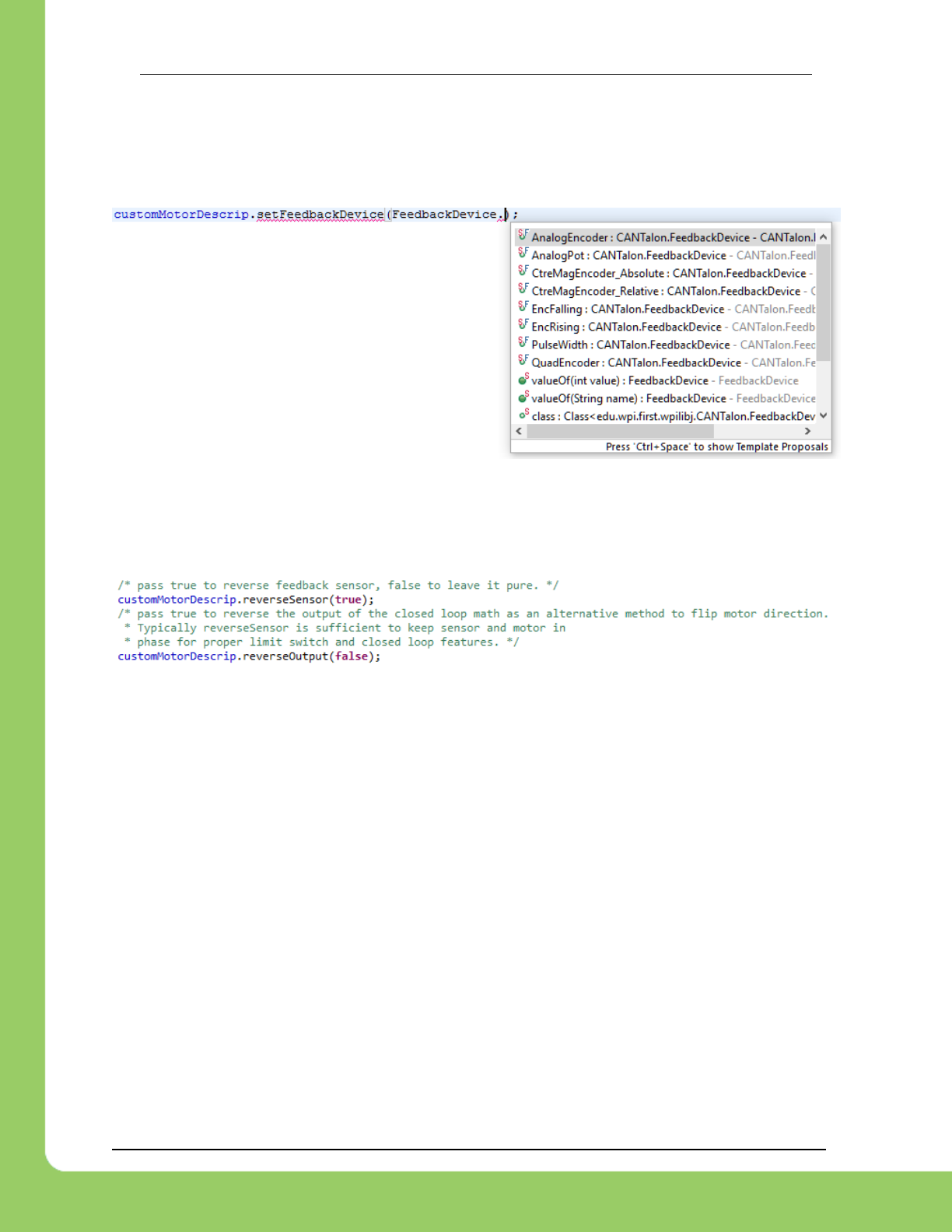
217-8080 TALON SRX Software Reference Manual 2/14/2017
Cross The Road Electronics Page 50 2/14/2017
7.3. Java
setFeedbackDevice() can be used to select Quadrature Encoder, Analog Encoder (or any
continuous 3.3V analog sensor) or Analog Potentiometer. Depending on software release
EncRising may also be supported (increment position per rising edge on Quadrature-A).
reverseSensor() and reverseOutput() are also available in java. reverseSensor() sets
the "Reverse Feedback Sensor" signal. reverseOutput() sets the "Reverse Closed-Loop
Output" signal.
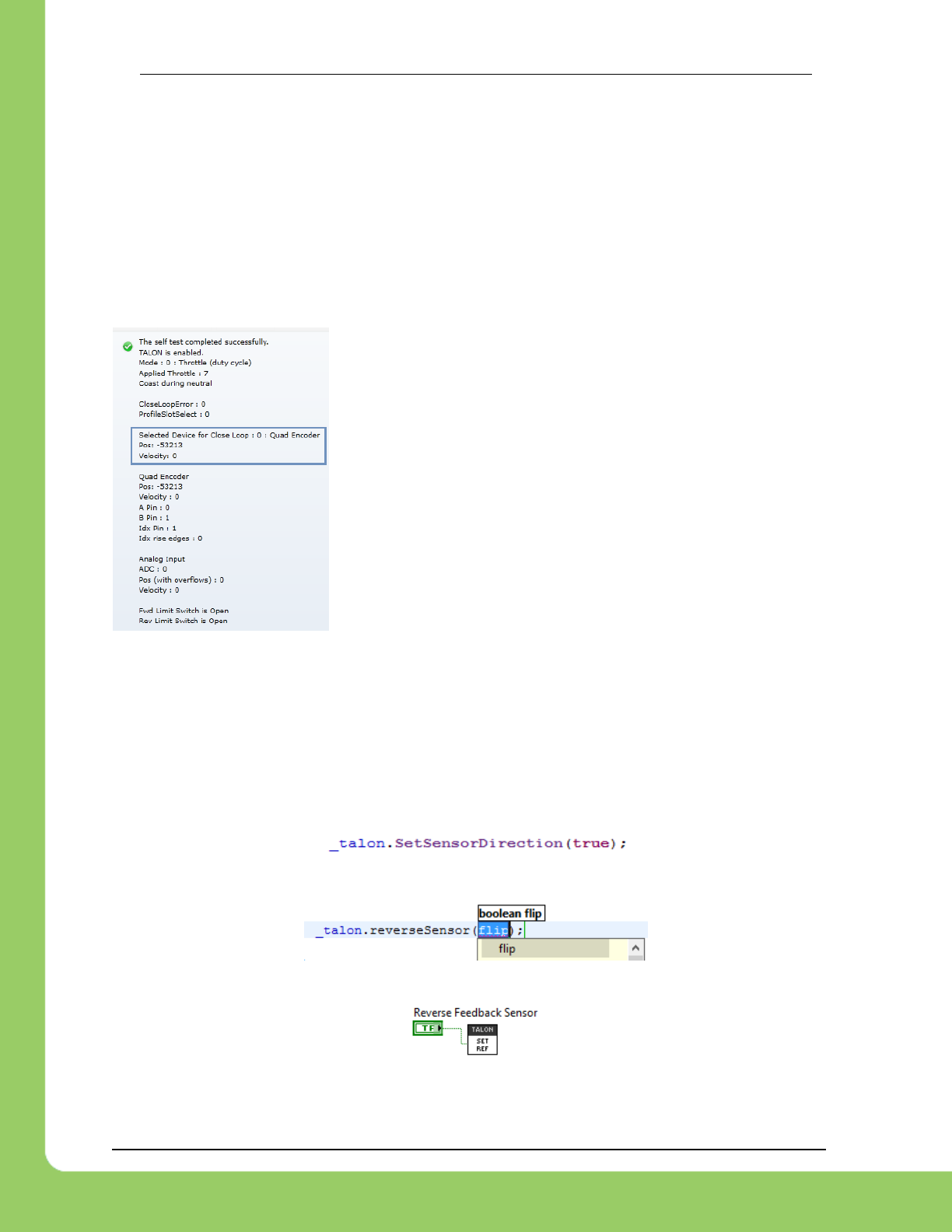
217-8080 TALON SRX Software Reference Manual 2/14/2017
Cross The Road Electronics Page 51 2/14/2017
7.4. Reversing sensor direction, best practices.
In order for limit switches and closed-loop features to function correctly the sensor and motor
has to be “in-phase”. This means that the sensor position must move in a positive direction as
the motor controller drives positive throttle. To test this, first drive the motor manually (using
gamepad axis for example). Watch the sensor position either in the roboRIO Web-based
Configuration Self-Test, or by calling GetSensorPosition() and printing it to console. If the
“Sensor Position” moves in a negative direction while Talon SRX throttle is positive (blinking
green), then use the “Reverse Feedback Sensor” signal to multiply the sensor position by (-1).
Then retest to confirm “Sensor Position” moves in a positive direction with positive motor drive.
When using the Self-Test be sure to track the Selected Device
Position which is above the Quadrature Encoder signals. These
signals will reflect if "Reverse Feedback Sensor" is asserted.
In the special case of using the EncRising feedback device, "Reverse Feedback Sensor" will
need to be false. This Feedback Device is guaranteed to be positive since it increments per
rising edge, and never decrements. "Reverse Closed-Loop Output" can then be used to output
a negative motor duty-cycle. "Reverse Closed-Loop Output" can also be used to reverse a slave
Talon SRX to be the signed opposite of the master Talon SRX.
“Reverse Feedback Sensor" can be changed with the following APIs.
7.4.1. Reversing Sensor – C++
7.4.2. Reversing Slave Motor Drive – Java
7.4.3. Reversing Feedback Sensor – LabVIEW
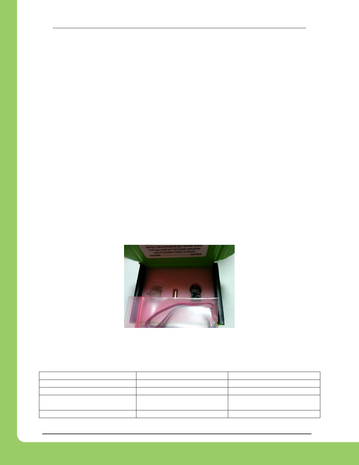
217-8080 TALON SRX Software Reference Manual 2/14/2017
Cross The Road Electronics Page 52 2/14/2017
7.5. Supported Feedback Devices
Many feedback back interfaces are supported. The complete list is below.
7.5.1. Quadrature / Count Rising Edge / Count Falling Edge
The Talon directly supports Quadrature Encoders. If Quadrature is selected, the decoding is
done in 4x mode. Additionally the Talon can be put into counter mode where edges on
Quadrature A are counted, if the selected FeedbackDevice is changed to “Count Rising Edge”
or “Count Falling Edge”.
7.5.2. Analog Potentiometer / Analog Encoder
Analog feedback sensors, or sensors that provide a variable voltage to represent position, are
also supported. Some devices are continuous and wrap around from 3.3V back to 0V. For
these sensors choose “Analog Encoder” so that these wrap arounds are detected and counted.
For other sensors (like potentiometers) that do not wrap around the voltage signal, choose
“Analog Potentiometer”.
7.5.3. Pulse Width Decoder
For sensors that encode position as a pulse width this mode can be used to decode the
position. The pulse width decoder is 1us accurate and the maximum time between edges is
15ms.
7.5.4. Cross The Road Electronics Magnetic Encoder (Absolute and Relative)
The CTRE Magnetic Encoder is actually two sensor interfaces packaged into one (pulse width
and quadrature encoder). Therefore the sensor provides two modes of use: absolute and
relative.
The advantage of absolute mode is having a solid reference to where a mechanism is without
re-tare-ing or re-zero-ing the robot. The advantage of the relative mode is the faster update
rate. However both values can be read/written at the same time. So a combined strategy of
seeding the relative position based on the absolute position can be used to benefit from the
higher sampling rate of the relative mode and still have an absolute sensor position.
Parameter
Absolute Mode
Relative Mode
Update rate (period)
4ms
100 us
Max RPM
7,500 RPM
15,000 RPM
Accuracy
12 bits per rotation
(4096 steps per rotation)
12 bits per rotation
(4096 steps per rotation)
Software API
Use Pulse Width API
Use Quadrature API
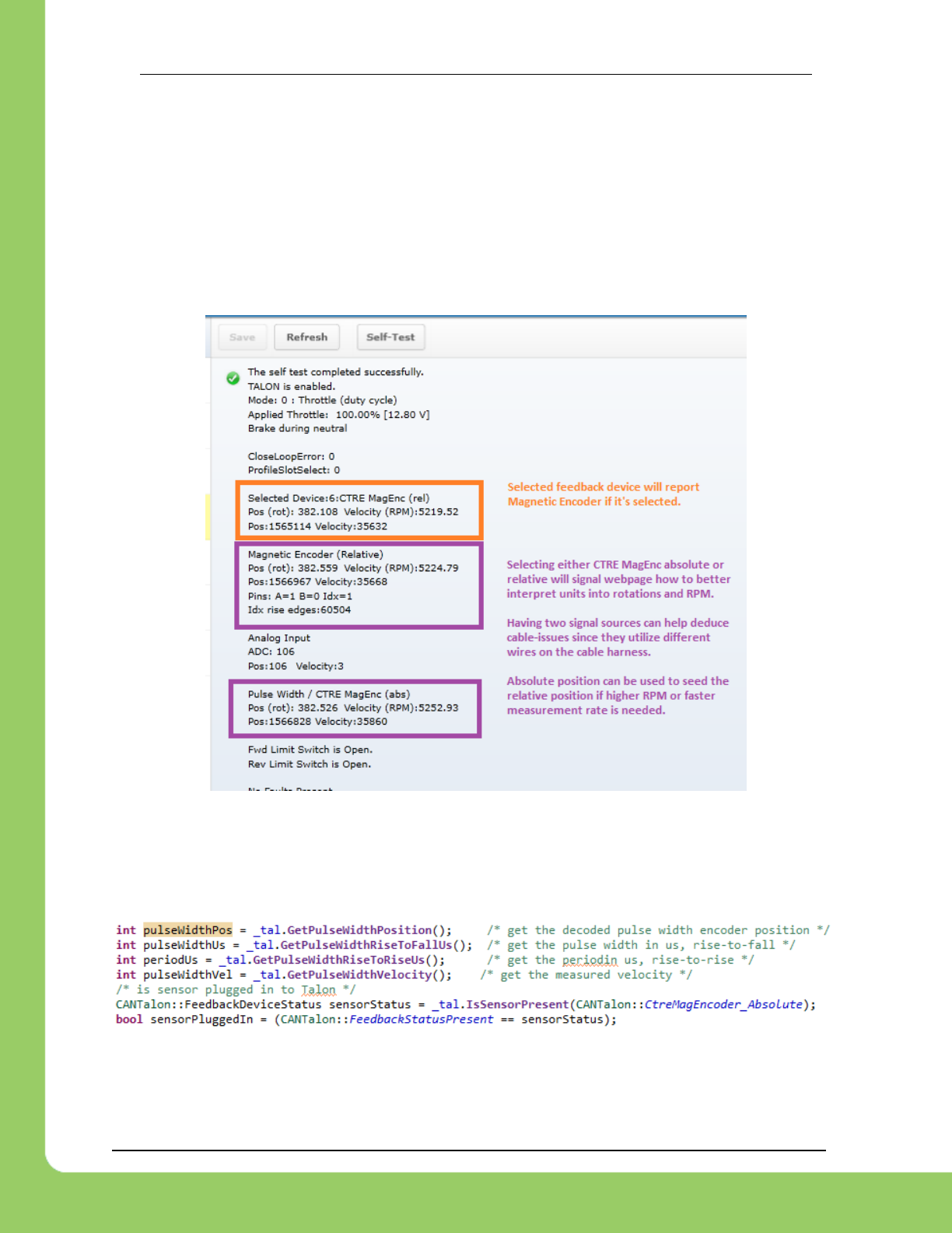
217-8080 TALON SRX Software Reference Manual 2/14/2017
Cross The Road Electronics Page 53 2/14/2017
7.5.4.1. Selecting the Magnetic Encoder
Selecting the Magnetic Encoder for closed-loop / soft-limit features is no different than selecting
other sensor feedback devices. There are two new feedback types: CTRE Magnetic Encoder
(absolute) and CTRE Magnetic Encoder (relative). After selecting the Magnetic Encoder, no
configuration calls are necessary to ensure proper scaling into rotations/RPMs.
Additionally the position and velocity can be retrieved without selecting the Magnetic Encoder as
the selected feedback device. One method is to utilize the self-test in the roboRIO web-based
configuration.
To programmatically read the absolute and relative position and velocities, the robot API
provides get routines for pulse width decoding and quadrature, which can be read any time
without sensor selection.
7.5.4.2. CTR Magnetic Encoder (absolute) – C++

217-8080 TALON SRX Software Reference Manual 2/14/2017
Cross The Road Electronics Page 54 2/14/2017
7.5.4.3. CTR Magnetic Encoder (absolute) – Java
7.6. Multiple Talon SRXs and single sensor
There are many uses where a mechanism requires multiple Talon SRXs but a single sensor.
For example, a single-side of a tank-drive or a shooter-wheel powered by two motors.
The recommended strategy for these mechanisms is to…
Connect the sensor to one of the Talons. This Talon will be referred to the “master”
Talon.
Set the supplemental Talon(s) to slave/follower mode and follow the device ID of the
“master” Talon. See Section 9.1 for details.
Select PercentVoltage Mode on the “master” Talon. Write a test robot application to
drive the “master” Talon manually and confirm all slave Talon(s) correctly follow by
watching the LEDs on all involved Talon SRXs. This can be done without motors
connected. Consult Talon User’s Guide to avoid damaging Talons by incorrectly
wiring inputs/outputs.
Next, connect the motors to all involved Talons. Consult Talon User’s Guide to avoid
damaging Talons by incorrectly wiring inputs/outputs. Test to make sure all motors
drive in the correct directions. For example, when drive a shooter wheel, the motors
may be oriented to require each motor to drive in opposite directions. If this is the case
signal the slave Talon to reverse its output (Section 9.1.4). Do not use excessive
motor output. Otherwise you may stall your motors if the slave and master Talon are
driving against each other.
Instrument the Sensor Position or Velocity using the roboRIO Web-based Configuration
Page Self-Test, or print/plot the values. Ensure that sensor moves in a positive
direction when master Talon is given positive forward throttle (green LEDs).
Now that the motor(s) and sensor orientation has been confirmed, select the desired
control mode of the master Talon. Any of the closed-loop/motion-profile control modes
can be used.
When using Velocity Closed-Loop, Current Closed-Loop, or MotionProfile Control Mode,
be sure to calculate the F gain when all slave Talon/motors are connected and used.
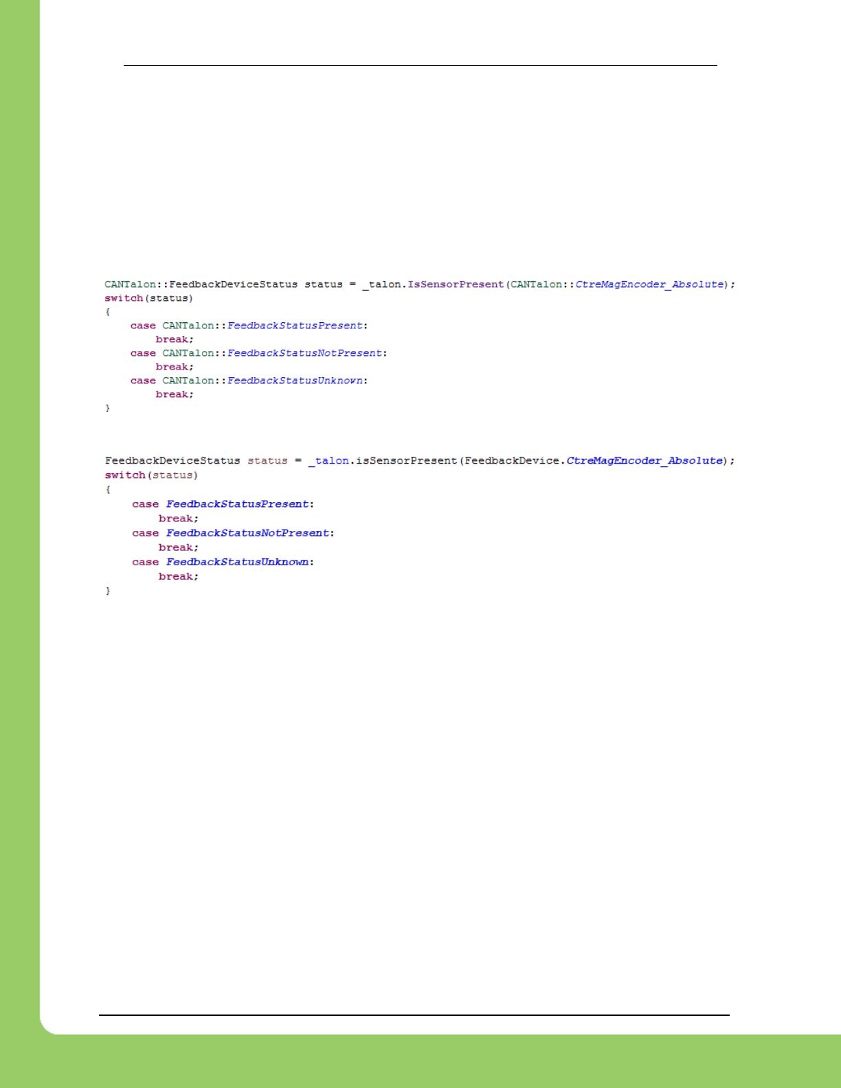
217-8080 TALON SRX Software Reference Manual 2/14/2017
Cross The Road Electronics Page 55 2/14/2017
7.7. Checking Sensor Health
Certain languages may have a routine for detecting if a sensor is plugged in. Not all sensor
types support this as some interfaces do not provide a method to determine this reliably. But for
the sensors that do, this provides a sanity check that the sensor is actually plugged in.
The supported sensor types are: CTRE Mag Encoder, Pulse-Width Encoded.
All other signals will return FeedbackStatusUnknown.
7.7.1. Checking Sensor Health – C++
7.7.2. Checking Sensor Health – Java

217-8080 TALON SRX Software Reference Manual 2/14/2017
Cross The Road Electronics Page 56 2/14/2017
7.8. Velocity Measurement
The Talon SRX measures the velocity of all supported sensor types as well as the current
position. Every 1ms a velocity sample is measured and inserted into a rolling average.
The velocity sample is measured as the change in position at the time-of-sample versus the
position sampled 100ms-prior-to-time-of-sample. The rolling average is sized for 64 samples.
Though these settings can be modified, the (100ms, 64 samples) parameters are default.
7.8.1. Changing Velocity Measurement Parameters.
The two characteristics for the Talon Velocity Measurement are…
Sample Period (Default 100ms)
Rolling Average Window Size (Default 64 samples).
These settings are also persistent across power cycles.
To change these values, the Talon SRX must be updated to…
Greater or equal to 10.22 (HERO, non-FRC)
Greater or equal to 2.22 (FRC)
Each can be modified through programming API, and through HERO LifeBoat (non-FRC).
NOTE – When the sample period is reduced, the units of the native velocity measurement is
still change-in-position-per-100ms. In other words, the measurement is up-scaled to normalize
the units. Additionally, a velocity sample is always inserted every 1ms regardless of setting
selection.
NOTE – The Velocity Measurement Period is selected from a fixed list of pre-supported
sampling periods.
7.8.1.2. Changing Parameters – HERO C#
_talon.SetVelocityMeasurementPeriod(CTRE.TalonSrx.VelocityMeasurementPeriod.Period_10Ms);
_talon.SetVelocityMeasurementWindow(20);

217-8080 TALON SRX Software Reference Manual 2/14/2017
Cross The Road Electronics Page 57 2/14/2017
7.8.1.1. Changing Parameters – Hero LifeBoat
When using the HERO Development
Board, the Sample Period and Rolling
Average can be modified through the
graphical interface.
7.8.1.3. Changing Parameters – FRC Java
talon.SetVelocityMeasurementPeriod(VelocityMeasurementPeriod.Period_100Ms);
talon.SetVelocityMeasurementWindow(64);
7.8.1.4. Changing Parameters – FRC C++
_talon.SetVelocityMeasurementPeriod(CANTalon::Period_100Ms);
_talon.SetVelocityMeasurementWindow(64);
7.8.1.5. Changing Parameters – FRC LabVIEW

217-8080 TALON SRX Software Reference Manual 2/14/2017
Cross The Road Electronics Page 58 2/14/2017
7.8.2. Recommended Procedure
The general recommended procedure is to first set these two parameters to the minimal value
of ‘1’ (Measure change in position per 1ms, and no rolling average). Then plot the measured
velocity while manually driving the Talon SRX(s) with a joystick/gamepad. Sweep the motor
output to cover the expected range that the sensor will be expected to cover.
Unless the sensor velocity is considerably fast (hundreds of sensor units per sampling period)
the measurement will be very coarse (visual stair-stepping as the motor output is increased).
Increase the sampling period until the measured velocity is sufficiently granular.
At this point the sensor velocity will have minimal stair-stepping (good) but will be quite noisy.
Increase the rolling average window until the velocity plot is sufficiently smooth, but still
responsive enough to meet the timing requirements of the mechanism.
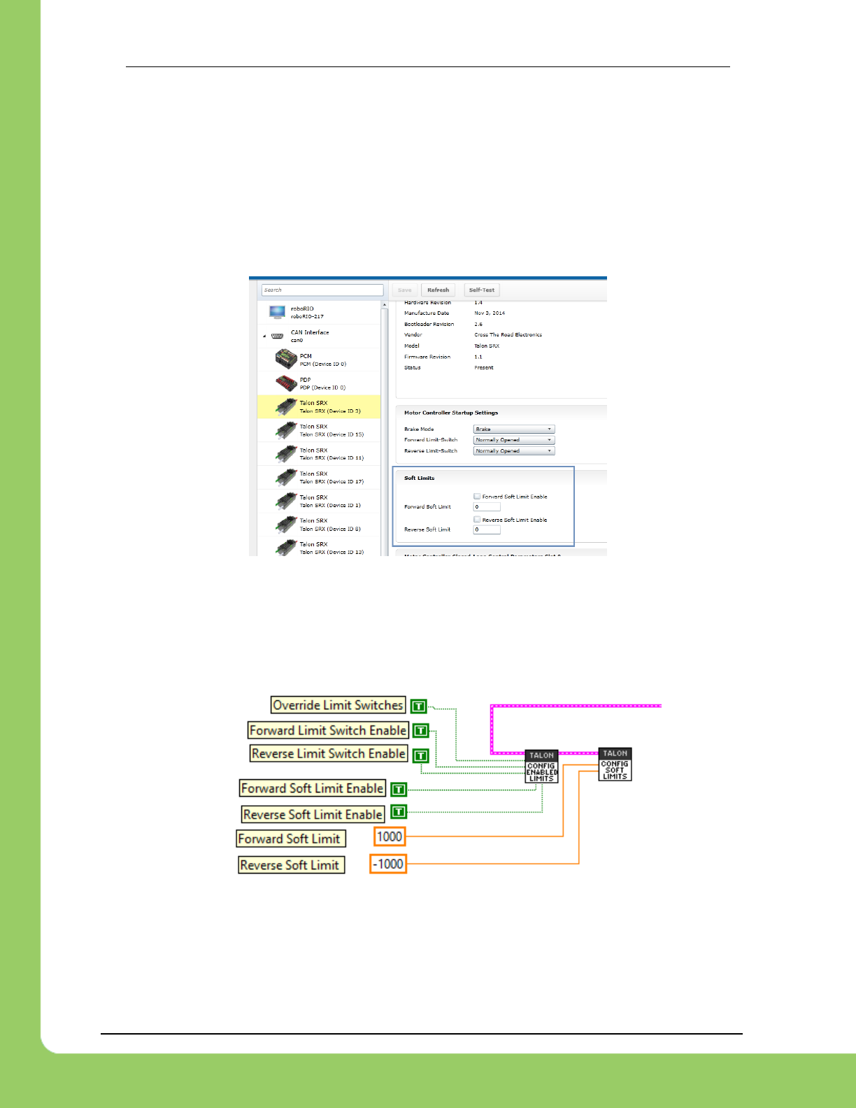
217-8080 TALON SRX Software Reference Manual 2/14/2017
Cross The Road Electronics Page 59 2/14/2017
8. Soft Limits
Soft limits can be used to disable motor drive when the “Sensor Position” is outside of a
specified range. Forward throttle will be disabled if the “Sensor Position” is greater than the
Forward Soft Limit. Reverse throttle will be disabled if the “Sensor Position” is less than the
Reverse Soft Limit. The respective Soft Limit Enable must be enabled for this feature to take
effect.
The settings can be set and confirmed in the roboRIO Web-based Configuration.
8.1. LabVIEW
The soft limits can also be set up programmatically. In LabVIEW, Soft Limit enables and
thresholds can be set using both the CONFIG ENABLED LIMITS VI and CONFIG SOFT LIMITS
VI.
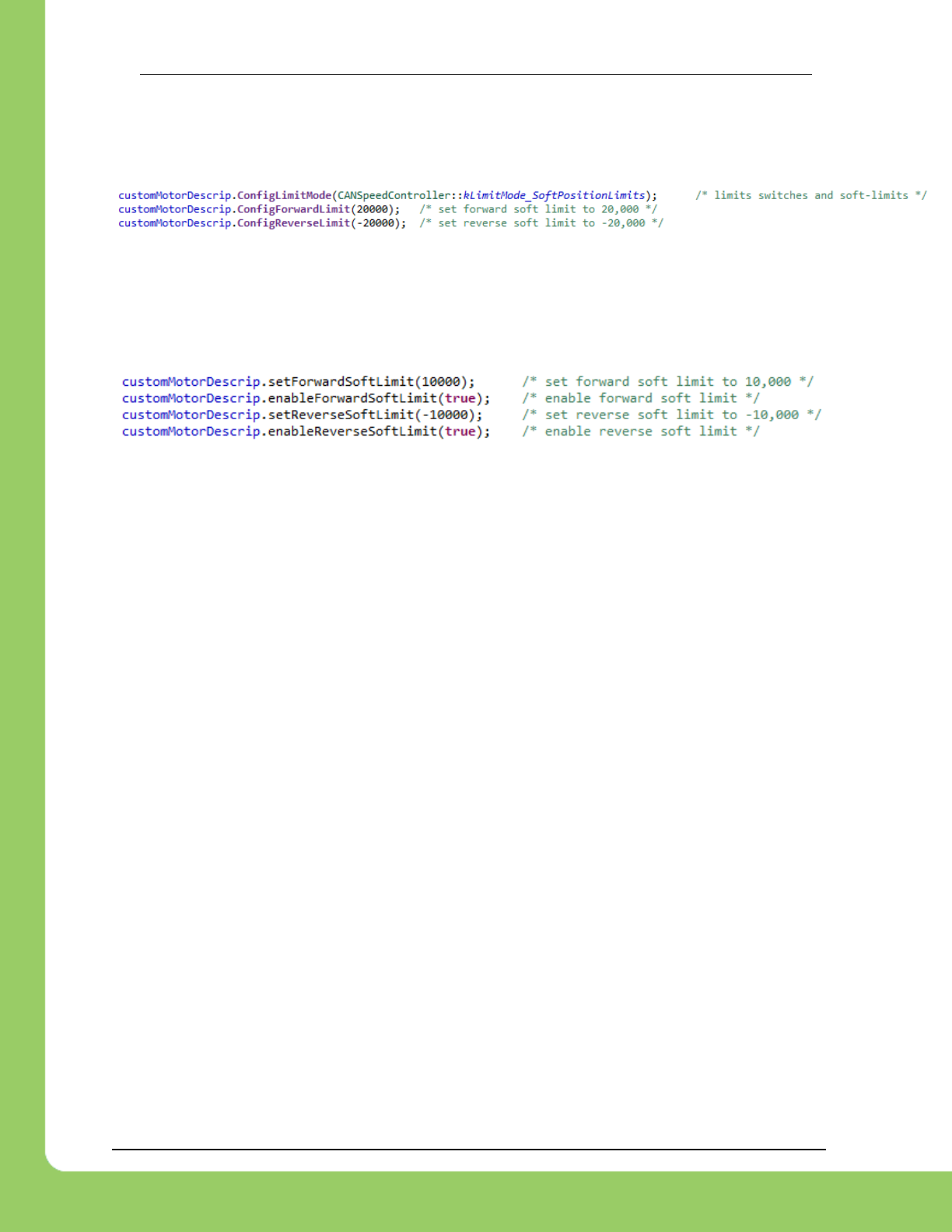
217-8080 TALON SRX Software Reference Manual 2/14/2017
Cross The Road Electronics Page 60 2/14/2017
8.2. C++
ConfigLimitMode() can be used to enable soft limits (and optionally limit switches if they are
wired).
8.3. Java
The limit threshold and enabled states can be individually specified using:
setForwardSoftLimit(), enableForwardSoftLimit(), setReverseSoftLimit(), and
enablReverseSoftLimit().
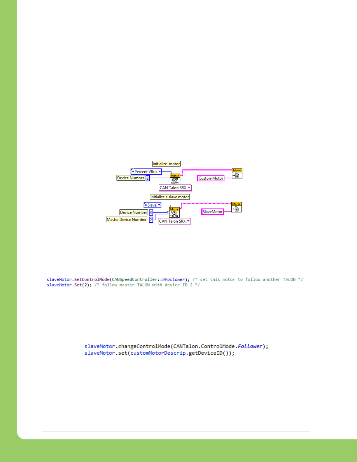
217-8080 TALON SRX Software Reference Manual 2/14/2017
Cross The Road Electronics Page 61 2/14/2017
9. Special Control Modes
9.1. Follower Mode
Any given Talon SRX on CAN bus can be instructed to “follow” the drive output of another Talon
SRX. This is done by putting a Talon SRX into “slave” mode and specifying the device ID of the
“Master Talon” to follow. The “Slave Talon” will then mirror the output of the “Master Talon”.
The “Master Talon” can be in any mode: closed-loop, voltage percent (duty-cycle), motion
profile control mode, or even following yet another Talon SRX.
9.1.1. LabVIEW
When opening a Talon SRX, the Master Device Number determines which Talon to follow when
in Slave Mode. The CHANGE MODE VI can also be used to enter Slave mode and specify the
Master Device ID to follow.
9.1.2. C++
CANTalon objects can be constructed with the Follower mode, or can be changed afterwards.
Pass the device ID of the Master Talon into Set(). The device ID should be between 0 and 62
(inclusive).
9.1.3. Java
CANTalon objects can be constructed with the Follower mode, or can be changed afterwards.
Pass the device ID, of the Master Talon into set(). The device ID should be between 0 and 62
(inclusive). Alternatively you can call the getDeviceID() routine of the Talon object created
with the Master Talon SRX’s device ID.
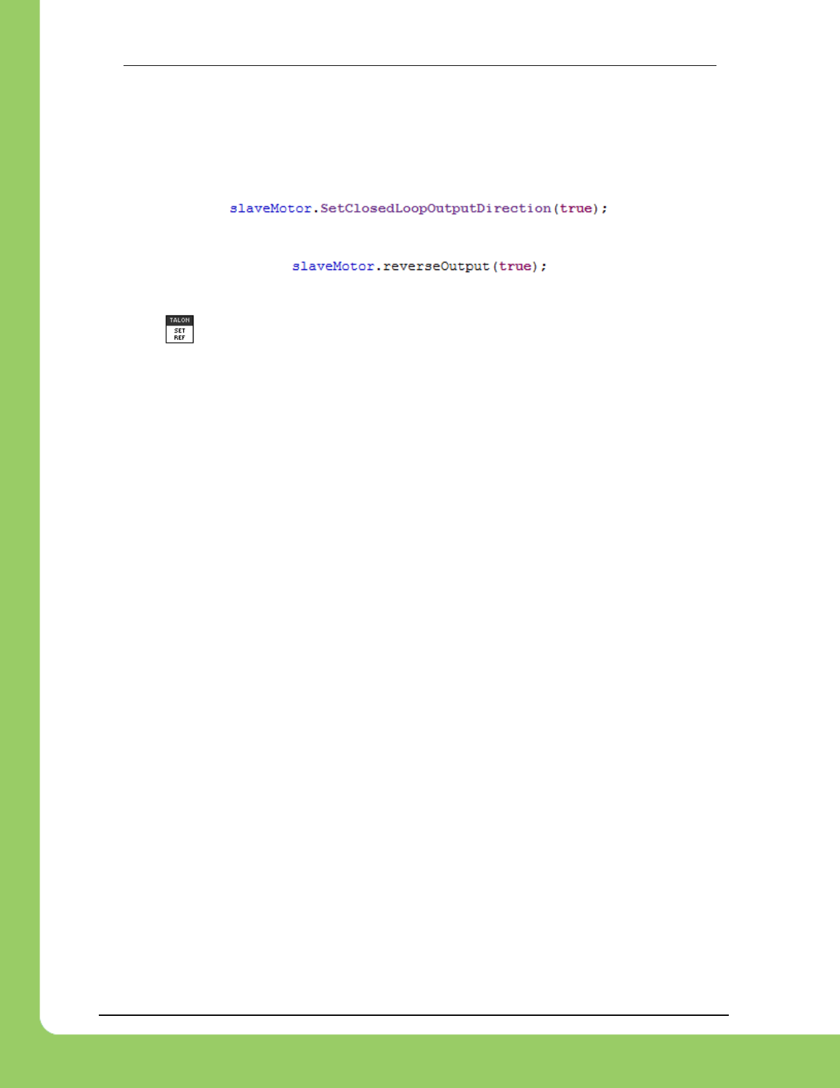
217-8080 TALON SRX Software Reference Manual 2/14/2017
Cross The Road Electronics Page 62 2/14/2017
9.1.4. Reversing Slave Motor Drive
"Reverse Closed-Loop Output" can be used to invert the output of a slave Talon. This may be
useful if a slave and master Talon are wired out of phase with each other.
9.1.4.1. Reversing Slave Motor Drive – C++
9.1.4.2. Reversing Slave Motor Drive – Java
9.1.4.3. Reversing Slave Motor Drive – LabVIEW
The VI explained in Section 7.1 can be used to set Reverse Closed-Loop output.
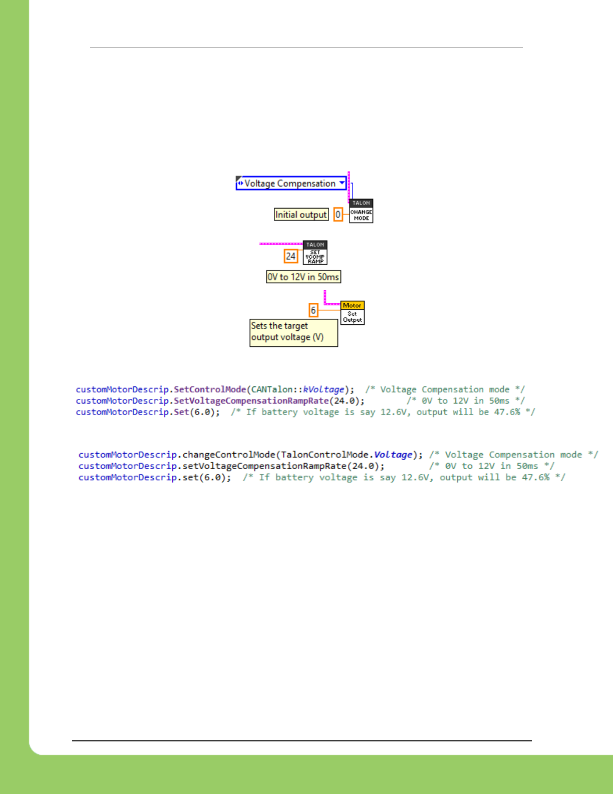
217-8080 TALON SRX Software Reference Manual 2/14/2017
Cross The Road Electronics Page 63 2/14/2017
9.2. Voltage Compensation Mode
In Voltage Compensation Mode, the output duty cycle is calculated to meet the desired output
voltage. This is done by sampling the battery voltage and scaling the output duty cycle to match
the desired output voltage. If the desired output voltage exceeds battery voltage, then Talon will
drive full available voltage.
9.2.1. LabVIEW
9.2.2. C++
9.2.3. Java
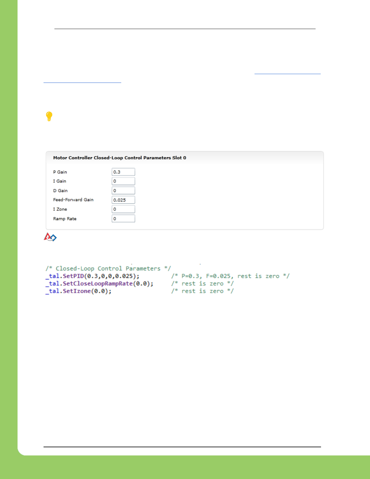
217-8080 TALON SRX Software Reference Manual 2/14/2017
Cross The Road Electronics Page 64 2/14/2017
10. Closed-Loop Modes
Talon SRX supports position closed-loop, velocity closed-loop, current closed-loop, Motion
Profiling, and Motion Magic. The actual implementation can be seen in Section 18. How is the
closed-loop implemented?
All closed-loop modes update every 1ms (1000Hz).
TIP: While tuning the closed-loop, use the roboRIO web-based configuration to quickly
change the gains “on the fly”. Once the PID is stable, set the gain values in code so that Talons
can be swapped/replaced easily. Below is an example of tweaking the gains in the roboRIO
Web-based configuration.
TIP: Example code of the parameters in C++ once initial tweaking is done. Parameters
can also be tweaked “on the fly” using the roboRIO Web-based configuration or reading values
from a file.

217-8080 TALON SRX Software Reference Manual 2/14/2017
Cross The Road Electronics Page 65 2/14/2017
10.1. Position Closed-Loop
The Talon’s Closed-Loop logic can be used to maintain a target position. Target and sampled
position is passed into the equation in Section 18 in native units. However the robot API uses
values expressed in decimal precision rotations if the requirements in Section 17.2.1 are met.
TIP: A simple strategy for setting up a closed loop is to zero out all Closed-Loop
Control Parameters and start with the Proportional Gain.
For example if you want your mechanism to drive 50% throttle when the error is 4096
(one rotation when using CTRE Mag Encoder, see section 17.2.1), then the calculated
Proportional Gain would be (0.50 X 10²³) / 4096 = ~0.125.
To check our math, take an error (native units) of 4096 X 0.125 => 512 (50% throttle).
Tune this until the sensed value is close to the target under typical load. Many prefer to
simply double the P-gain until oscillations occur, then reduce accordingly.
If the mechanism accelerates too abruptly, Derivative Gain can be used to smooth the
motion. Typically start with 10x to 100x of your current Proportional Gain.
If the mechanism never quite reaches the target and increasing Integral Gain is viable,
start with 1/100th of the Proportional Gain.
See Section 12.5 for HERO C# complete example of Position Closed-Loop. The functions used
are comparable to the WPILIB C++/Java API.
10.2. Current Closed-Loop
The Talon’s Closed-Loop logic can be used to approach a target current-draw. Target and
sampled current is passed into the equation in Section 18 in milliamperes. However the robot
API expresses the target current in amperes.
TIP: A simple strategy for setting up a current-draw closed loop is to zero out all Closed-
Loop Control Parameters and start with the Feed-Forward Gain. Tune this until the current-
draw is close to the target under typical load. Then start increasing P gain so that the closed-
loop will make up for the remaining error. If necessary, reduce Feed-Forward gain and increase
P Gain so that the closed-loop will react more strongly to the ClosedLoopError.
See Section 12.3 for a walk-through in LabVIEW. Though the example is written in LabVIEW,
the procedure is the similar for all supported languages.

217-8080 TALON SRX Software Reference Manual 2/14/2017
Cross The Road Electronics Page 66 2/14/2017
10.3. Velocity Closed-Loop
The Talon’s Closed-Loop logic can be used to maintain a target velocity. Target and sampled
velocity is passed into the equation in Section 18 in native units per 100ms. See Section 17.2.1
for information regarding native units.
TIP: A simple strategy for setting up a closed loop is to zero out all Closed-Loop Control
Parameters and start with the Feed-Forward Gain. Tune this until the sensed value is close to
the target under typical load. Then start increasing P gain so that the closed-loop will make up
for the remaining error. If necessary, reduce Feed-Forward gain and increase P Gain so that
the closed-loop will react more strongly to the ClosedLoopError.
TIP: Velocity Closed-Loop tuning is similar to Current Closed-Loop tuning in their use of
feed-forward. Begin by measuring the sensor velocity while driving the Talon at a large throttle.
A complete Java example is available in Section 12.4.
10.4. Motion Profile Control Mode
A recent addition to the Talon SRX is the motion profile mode. With this, a savvy developer can
actually stream motion profile trajectory points into the Talon’s internal buffer (even while
executing the profile). This allows fine control of position and speed throughout the entire
movement. Since this is an advanced feature addition, a separate document will be provided
shortly to cover this.

217-8080 TALON SRX Software Reference Manual 2/14/2017
Cross The Road Electronics Page 67 2/14/2017
10.5. Peak/Nominal Closed-Loop Output
Since firmware 2.0, The Talon SRX supports bounding the output of the Closed-Loop modes.
These settings are in effect during…
Position Closed-Loop Control Mode
Velocity Closed-Loop Control Mode
Current Closed-Loop Control Mode
Motion Profile Control Mode
Motion Magic Control Mode
To clearly communicate what these parameters accomplish, the following terms are introduced.
Peak Output- The “maximal” or “strongest” motor output allowed during closed-loop.
These settings are useful to reduce the maximum velocity of the mechanism, and can
make tuning the closed-loop simpler.
The “Positive Peak Output” or “Forward Peak Output” refers to the “strongest” motor
output when the Closed-Loop motor output is positive. If the Closed-Loop Output
exceeds this setting, the motor output is capped.
This value is typically positive or zero. The default value is +1023 as read in the web-
based configuration Self-Test.
The “Negative Peak Output” or “Reverse Peak Output” refers to the “strongest” motor
output when the Closed-Loop motor output is negative. If the Closed-Loop Output
exceeds this setting, the motor output is capped.
This value is typically negative or zero. The default value is -1023 as read in the web-
based configuration Self-Test.
Nominal Output- The “minimal” or “weakest” motor output allowed during closed-loop if
the “Closed-Loop Error” is nonzero and outside of the “Allowable Closed-Loop Error”.
This is expressed using two signals: “Positive Nominal Output” and “Negative Nominal
Output”, to uniquely describe a limit for each direction.
If the Closed-Loop is calculating a motor-output that is too “weak”, the robot application
can use these signals to promote the motor-output to a minimum limit. With this the
robot application can ensure the motor-output is large enough to drive the mechanism.
Typically this is accomplished with Integral gain, however this method may be a simpler
alternative as there is no risk of Integral wind-up.
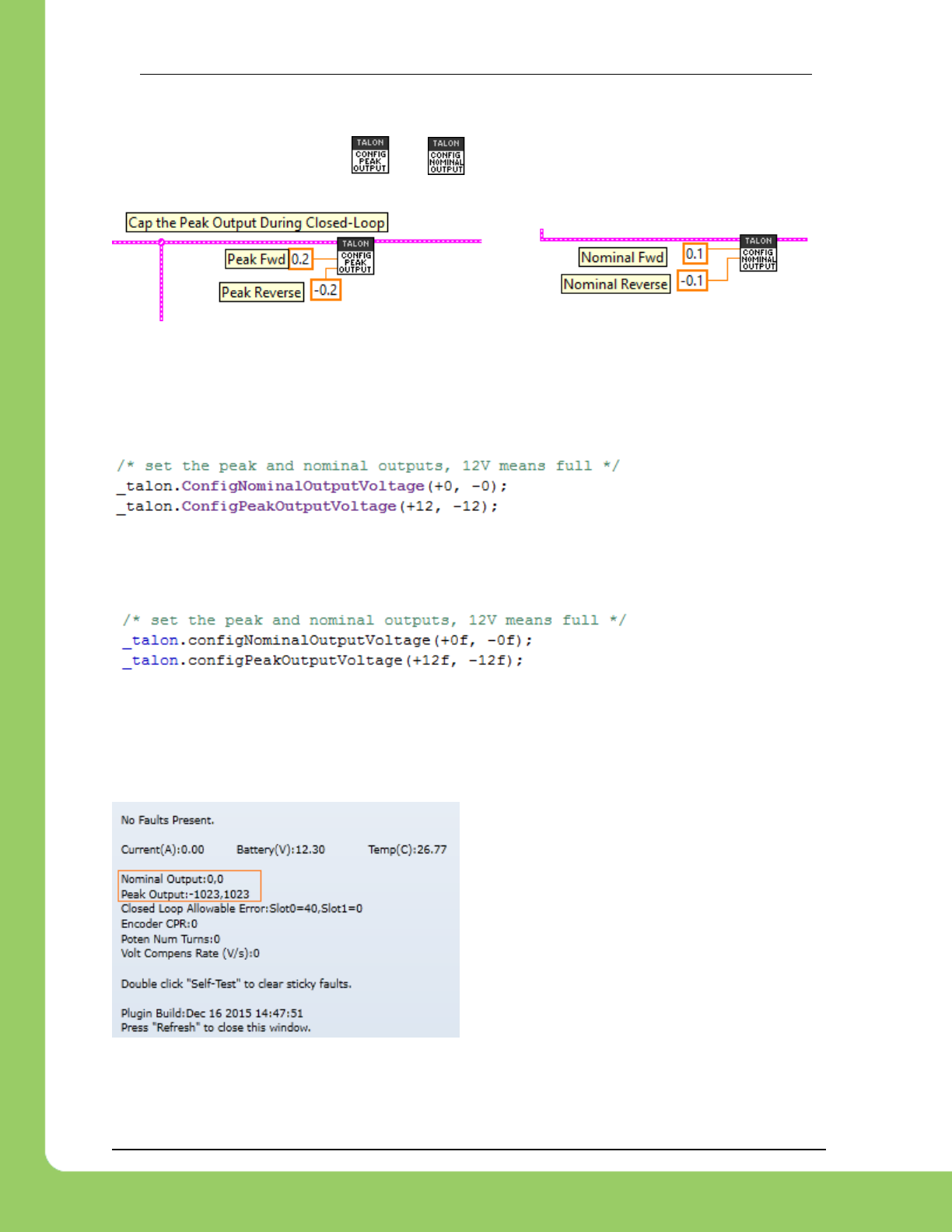
217-8080 TALON SRX Software Reference Manual 2/14/2017
Cross The Road Electronics Page 68 2/14/2017
10.5.1. Peak/Nominal Closed-Loop Output – LabVIEW
These signals can be set using and .
Peak and nominal values range from -1.0 (full reverse) to +1.0 (full forward).
10.5.2. Peak/Nominal Closed-Loop Output – C++
The parameters are expressed in voltage where +12V represents full forward, and -12V
represents full reverse.
10.5.3. Peak/Nominal Closed-Loop Output – Java
The parameters are expressed in voltage where +12V represents full forward, and -12V
represents full reverse.
10.5.4. Peak/Nominal Closed-Loop Output – Web based Configuration Self-Test
The parameters are expressed in native units where +1023 represents full forward, and -1023
represents full reverse.
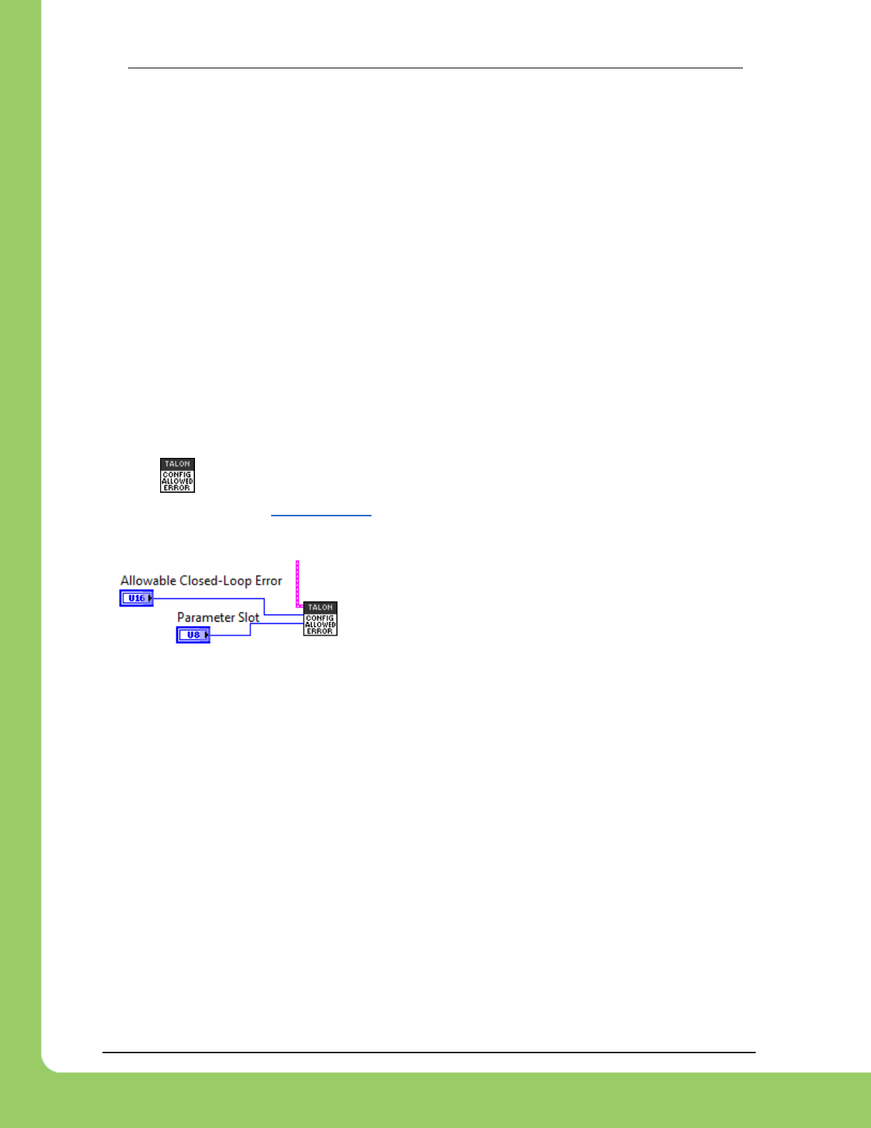
217-8080 TALON SRX Software Reference Manual 2/14/2017
Cross The Road Electronics Page 69 2/14/2017
10.6. Allowable Closed-Loop Error
Since firmware 2.0, The Talon SRX supports specifying an Allowable Closed-Loop Error
whereby the motor output is neutral regardless of the calculated result. This signal affects…
Position Closed-Loop Control Mode
Velocity Closed-Loop Control Mode
Current Closed-Loop Control Mode
Motion Profile Control Mode
Motion Magic Control Mode
When the Closed-Loop Error is within the Allowable Closed-Loop Error
P, I, D terms are zeroed. In other words, the math that uses P, I, and D gains is
disabled. However, F term is still in effect.
Integral Accumulator is cleared.
Allowable Closed-Loop Error defaults to zero, and is persistently saved.
10.6.1. Allowable Closed-Loop Error – LabVIEW
Use the VI to set this signal. The Allowable Closed-Loop error is in the same units as
Closed-Loop Error. See Section 17.2.2 for more information. Each Closed-Loop Motor Profile
slot has a unique Allowable Closed-Loop Error. Select ‘0’ or ‘1’ for slot 0 or slot 1 respectively.

217-8080 TALON SRX Software Reference Manual 2/14/2017
Cross The Road Electronics Page 70 2/14/2017
10.6.2. Allowable Closed-Loop Error – C++
The Allowable Closed-Loop error is in the same units as Closed-Loop Error. See Section 17.2.2
for more information. Each Closed-Loop Motor Profile slot has a unique Allowable Closed-Loop
Error. This function affects the currently selected slot/profile.
In this example, 409 corresponds to 9.985% of a rotation or 35.95 degrees (assuming 4096
units per rotation, such as 1024CPR encoder or CTRE Mag Encoder).
10.6.3. Allowable Closed-Loop Error – Java
The Allowable Closed-Loop error is in the same units as Closed-Loop Error. See Section 17.2.2
for more information. Each Closed-Loop Motor Profile slot has a unique Allowable Closed-Loop
Error. This function affects the currently selected slot/profile.
In this example, 409 corresponds to 9.985% of a rotation or 35.95 degrees (assuming 4096
units per rotation, such as 1024CPR encoder or CTRE Mag Encoder).
10.6.4. Allowable Closed-Loop Error – Web based Configuration Self-Test
The Allowable Closed-Loop Error for both slots
can be read using the roboRIO Web based
configuration Self-Test.
The values are in the same units as Closed-
Loop Error.
In this example 40 corresponds to 0.9767% of a
rotation or 3.52 degrees (assuming 4096 units
per rotation, such as 1024CPR encoder or
CTRE Mag Encoder).
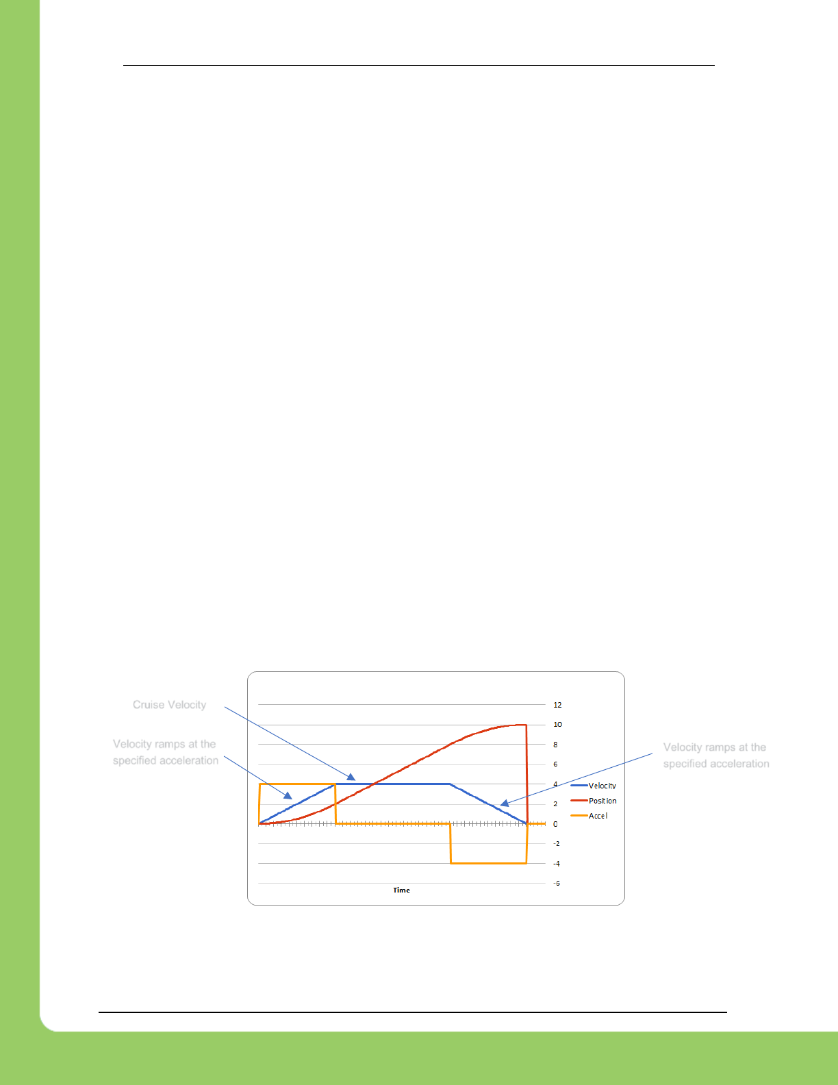
217-8080 TALON SRX Software Reference Manual 2/14/2017
Cross The Road Electronics Page 71 2/14/2017
10.7. Motion Magic Control Mode
Motion Magic is a control mode for Talon SRX that provides the benefits of Motion Profiling
without needing to generate motion profile trajectory points. When using Motion Magic, Talon
SRX will move to a set target position using a Trapezoidal Motion Profile, while honoring the
user specified acceleration and maximum velocity (cruise velocity).
The benefits of this control mode over “simple” PID position closed-looping are…
Control of the mechanism throughout the entire motion (as opposed to racing to the end
target position).
Control of the mechanism’s inertia to ensure smooth transitions between set points.
Improved repeatability despite changes in battery voltage.
Improved repeatability despite changes in motor load.
After gain/settings are determined, the robot-application only needs to periodically set the target
position.
There is no general requirement to “wait for the profile to finish”, however the robot application
can poll the sensor position and determine when the motion is finished if need be.
A Trapezoidal Motion Profile generally ramps the output velocity at a specified acceleration until
cruise velocity is reached. This cruise velocity is then maintained until the system needs to
deaccelerate to reach the target position and stop motion. Talon determines when these critical
points occur on-the-fly.
NOTE: If the remaining sensor distance to travel is small, the velocity may not reach cruise
velocity as this would overshoot the target position. This is often refered to as a “triangle
profile”.
Example Trapezoidal Motion Profile
Motion Magic utilizes the same PIDF parameters as Motion Profiling.
Velocity ramps at the
specified acceleration
Velocity ramps at the
specified acceleration
Cruise Velocity

217-8080 TALON SRX Software Reference Manual 2/14/2017
Cross The Road Electronics Page 72 2/14/2017
The F parameter should be tuned using the process outlined in Section 12.8.3. Note that while
the F parameter is not normally used for Position Closed-Loop control, Motion Magic requires
this parameter to be properly tuned.
See Section 12.7 for a HERO C# complete example of Motion Magic. The functions used are
comparable to the WPILIB C++/Java API.
See Section 12.8 for complete FRC JAVA walkthrough on tuning.
Two additional parameters need to be set in the Talon SRX– Acceleration and Cruise Velocity.
The Acceleration parameter controls acceleration and deacceleration rates during the beginning
and end of the trapezoidal motion. The Cruise Velocity parameter controls the cruising velocity
of the motion. Both parameters follow the API Unit Scaling in Section 17.2.2.
This feature is further enhanced when used with Closed-Loop Voltage Compensation (Section
10.8).

217-8080 TALON SRX Software Reference Manual 2/14/2017
Cross The Road Electronics Page 73 2/14/2017
10.8. Closed-Loop Nominal Battery Voltage
Since firmware 2.22, The Talon SRX supports an additional signal called Closed-Loop Nominal
Battery Voltage. When set, the output of the Closed Loop mode is compensated for the
measured battery voltage.
This signal affects…
Position Closed-Loop Control Mode
Velocity Closed-Loop Control Mode
Current Closed-Loop Control Mode
Motion Profile Control Mode
Motion Magic Control Mode
As an example, if the Position Closed-Loop Control Mode calculates an output of 512 units
(50% motor output), then instead of applying 50% of max voltage, the Talon will apply 50% of
the specified Nominal Battery Voltage. This is accomplished by scaling the motor output
against the measured battery voltage.
If the measured battery voltage is below the necessary voltage to reach the calculated output of
the compensated closed-loop control mode, 100% motor output is applied (unless capped by
the peak motor output setting, see Section 10.5).
This is done every 1ms synchronous with the closed-loop controller.
Two functions are available to enable/disable this feature. Additionally, this signal can be set in
HERO Lifeboat utility.
The setting is persistent across power cycles and has a default value of 0.0 (disabled).
To leverage this feature, the Talon SRX must be updated to…
Greater or equal to 10.22 (HERO, non-FRC)
Greater or equal to 2.22 (FRC)
10.8.1. HERO C#
/* disables nominal battery voltage so that closed-loop output is purely the % of
available source voltage */
_talon.DisableNominalClosedLoopVoltage();
/* set nominal battery voltage to 12.0. When closed loop output 100%, output 12.0V */
_talon.SetNominalClosedLoopVoltage(12.0f);
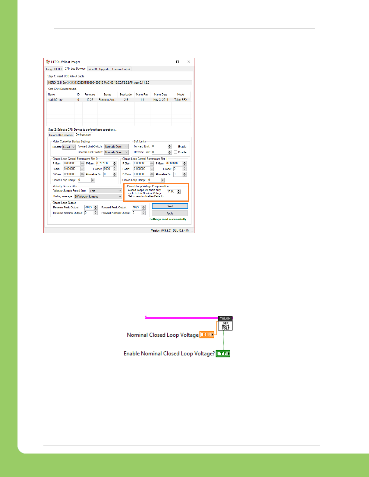
217-8080 TALON SRX Software Reference Manual 2/14/2017
Cross The Road Electronics Page 74 2/14/2017
10.8.2. HERO LifeBoat
When using the HERO Development
board, the Closed-Loop Nominal Voltage
can be set using HERO LifeBoat.
10.8.3. FRC Java
talon.disableNominalClosedLoopVoltage();
talon.setNominalClosedLoopVoltage(12.0);
10.8.4. FRC C++
_talon.DisableNominalClosedLoopVoltage();
_talon.SetNominalClosedLoopVoltage(12.0);
10.8.5. FRC LabVIEW
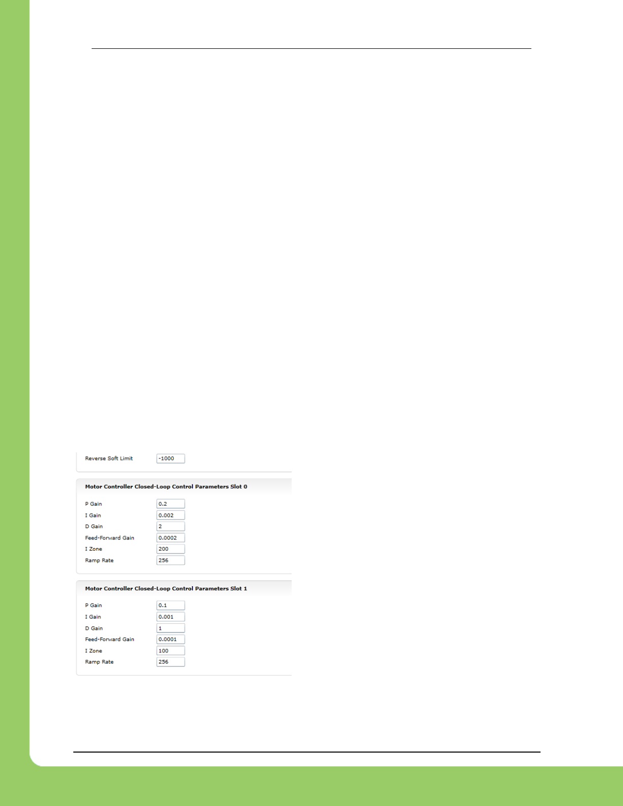
217-8080 TALON SRX Software Reference Manual 2/14/2017
Cross The Road Electronics Page 75 2/14/2017
11. Motor Control Profile Parameters
The Talon persistently saves two unique Motor Control Profiles.
Each Motor Control Profile contains…
P Gain: Kp constant to use when control mode is a closed-loop mode.
I Gain: KI constant to use when control mode is a closed-loop mode.
D Gain: KD constant to use when control mode is a closed-loop mode.
F Gain: KF constant to use when control mode is a closed-loop mode.
I Zone: Integral Zone. When nonzero, Integral Accumulator is automatically cleared
when the absolute value of Closed-Loop Error exceeds it.
(Closed-Loop) Ramp Rate: Ramp rate to apply when control mode is a closed-loop
mode.
Allowable Closed-Loop Error: When Closed-Loop Error’s magnitude is less than this
signal, Integral Accum and motor output are auto-zeroed during closed-loop.
Peak Closed-Loop Output: Caps the maximal or peak motor-output during closed-loop.
Nominal Closed-Loop Output: Promotes the minimal or weakest motor-output during
closed-loop.
One unique feature of the Talon SRX is that gain values specified in a Motor Control Profile are
not dedicated to just one type of closed-loop. When selecting a closed-loop mode (for example
position or velocity) the robot application can select either of the two Motor Control Profiles to
select which set of values to use. This can be useful for gain scheduling (changing gain values
on-the-fly) or for persistently saving two sets of gains for two entirely different closed loop
modes.
The settings can be set and read in the web control page.

217-8080 TALON SRX Software Reference Manual 2/14/2017
Cross The Road Electronics Page 76 2/14/2017
11.1. Persistent storage and Reset/Startup behavior
The Talon SRX was designed to reduce the “setup” necessary for a Talon SRX to be functional,
particularly with closed-loop features. This is accomplished with efficient CAN framing and
persistent storage.
All settings in the Motor Control Profile (MCP) are saved persistently in flash. Additionally there
are two complete Motor Control Profiles. Teams that use a constant set of values can simply
set them using the roboRIO Web-based Configuration, and they will “stick” until they are
changed again.
Additionally Motor Control Profile (MCP) Parameters can be changed though programming API.
When they are changed, the values are ultimately copied to persistent memory using a wear
leveled strategy that ensures Flash longevity, but also meets the requirements for teams.
-Changing MCP values programmatically always take effect immediately (necessary for gain
tuning).
-If the MCP Parameters have remained unchanged for fifteen seconds, and an MCP Parameter
value is then changed using programming API, they are copied to persistent memory
immediately.
-If the persistent memory has been updated within the last fifteen seconds due to a previous
value change, and an MCP Parameter value is changed again, it will be applied to persistent
memory once fifteen seconds has passed since the last persistent memory update. However
the closed-loop will react immediately to the latest values sent over CAN bus.
-If power loss occurs during the period of time when MCP Parameters are being saved to
persistent storage, the previous values for all MCP Parameters prior to last value-change is
loaded. This is possible because the Talon SRX keeps a small history of all value changes.
These features fit well with the two common strategies that FRC teams utilize when
programmatically changing closed-loop parameters...
(1) Teams use programming API at startup to apply previous tested constants.
(2) Teams use programming API to periodically set/change the constants because they are
“gain scheduled” or action specific.
For use case (1), the constants are eventually saved in Talon SRX persistent memory (worst
case fifteen seconds after robot startup). Once this is done the Talon SRX will have the values
in persistent storage, so even after Talons are power cycled, they will load the constants that
were previous set. This frees the robot controller from needing to re-set the values during a
power cycle, reset, brownout, etc…. On subsequent robot startups, when the robot controller
sends the same values again, and Talon SRX will still react by updating its variables, and
comparing against what’s saved in persistent storage to see if it needs to be updated again. In
the event the robot code changes to use new constants, the Talon will again update the
persistent storage shortly after getting the new values.

217-8080 TALON SRX Software Reference Manual 2/14/2017
Cross The Road Electronics Page 77 2/14/2017
For use case (2) teams, there are two “best” solutions depending on what’s being
accomplished. If a team needs to switch between two sets of gains, they can leverage both
MCP slots by setting one set of constants in slot 0, and another unique set of constants in slot 1.
Then during the match, teams can switch between the two with a single API. This means that
as far as the Talon is concerned, the values in each slot never changes so the contents of the
Talon’s persistent storage never changes. Instead the robot controller just changes which slot
to use. So this use case regresses to use case (1), and a freshly booted Talon already has all
the MCP parameters it needs to function.
For use case(2) teams that requires more than two gain sets likely are changing gain values so
frequently (as a function of autonomous, or state machine driven logic) that they would prefer
not to rely on the previous set of gains sent to the Talon (despite it being available at startup).
In which case they likely will periodically set the MCP parameters continuously (every number of
loops or fixed period of time). Talon SRX always honors whatever parameters are requested
over CAN bus, overriding what was loaded at startup or mirrored in persistent storage. And
since the persistent storage is wear-leveled and mirrored at fifteen second intervals, this has no
harmful impact on Flash longevity. So this use case is also supported well.
Beyond the Motor Control Profile Parameters, closed-loop modes requires selecting
-which control mode (position or velocity)
-which feedback sensor to use
-if the feedback sensor should be reversed
-if the closed-loop output should be reversed
-what is the latest target or set point
-the global ramp rate (if specified)
-which Motor Control Profile Slot to use.
The programming API provides set functions for all of these, but what’s noteworthy is that all of
these signals are saved in the robot controller, and periodically sent inside one complete CAN
frame. This means that if a Talon SRX loses power and is booted back up again (due to cable
disconnect, battery brownout, etc…) the Talon receives all of the necessary signals after getting
one single control frame. This is far more robust than requiring the robot application to re-set
and re-acknowledge each parameter individually in the event of a reset.
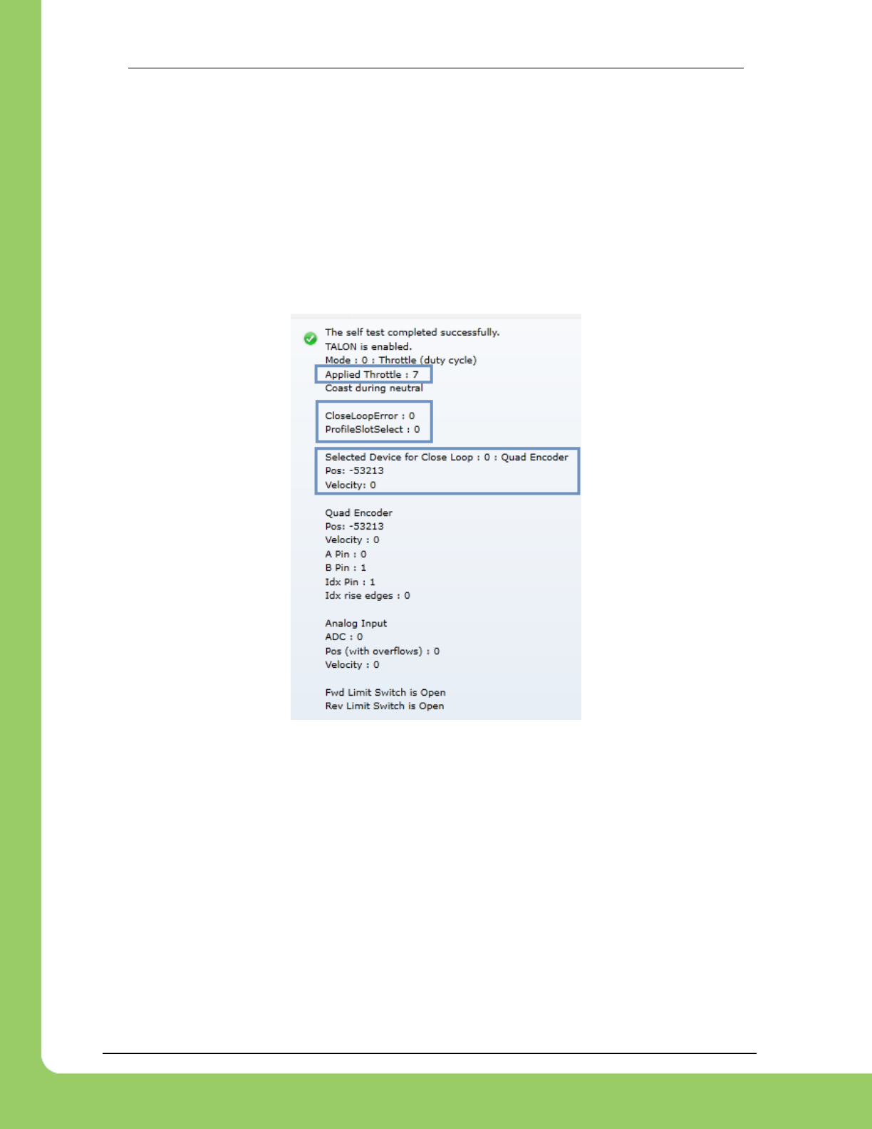
217-8080 TALON SRX Software Reference Manual 2/14/2017
Cross The Road Electronics Page 78 2/14/2017
11.2. Inspecting Signals
When testing/calibrating closed-loops it is helpful to plot/check…
-Closed-Loop Error
-Output (Applied) Throttle
-Profile Slot Select (which profile slot the closed-loop math is using).
-Position and Velocity depending control mode.
The Self-Test can provide these values for quick sanity checking. These values are also
available with programming API for custom plotting, smart dashboard, LabVIEW front panels,
etc...
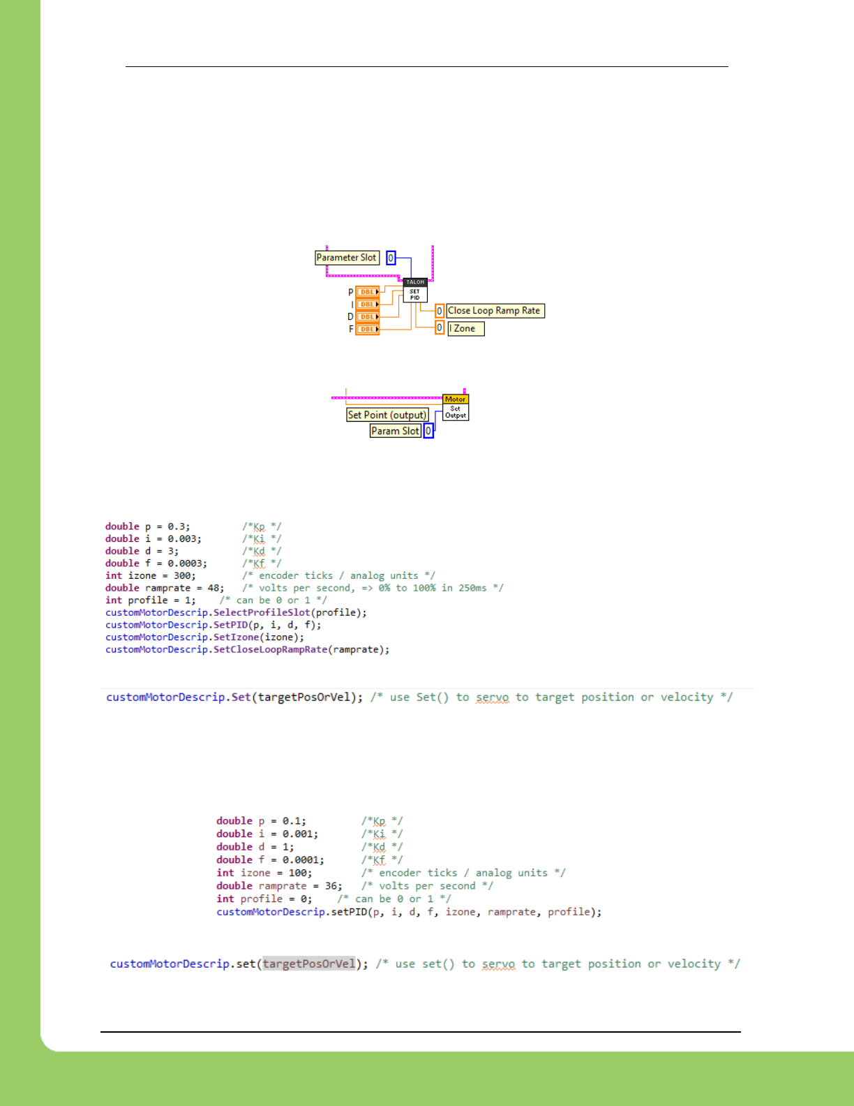
217-8080 TALON SRX Software Reference Manual 2/14/2017
Cross The Road Electronics Page 79 2/14/2017
12. Closed-Loop Code Excerpts/Walkthroughs
12.1. Setting Motor Control Profile Parameters
12.1.1. LabVIEW
Setting the Motor Controller Profile parameters can be done with the SET PID VI.
This allows filling all parameters for a given Parameter Slot.
Specifying the set point is also done with the Set Output VI. Additionally you can select the
Parameter Slot to use for the selected closed-loop.
12.1.2. C++
Closed-loop parameters for a given profile slot can be modified with several different functions.
Setting the target position or velocity is also done with Set().
12.1.3. Java
Closed-loop parameters for a given profile slot can be modified using setPID(). This also sets
the “Profile Slot Select” to the slot being modified. There are also individual Set functions for
each signal.
Setting the target position or velocity is also done with set().
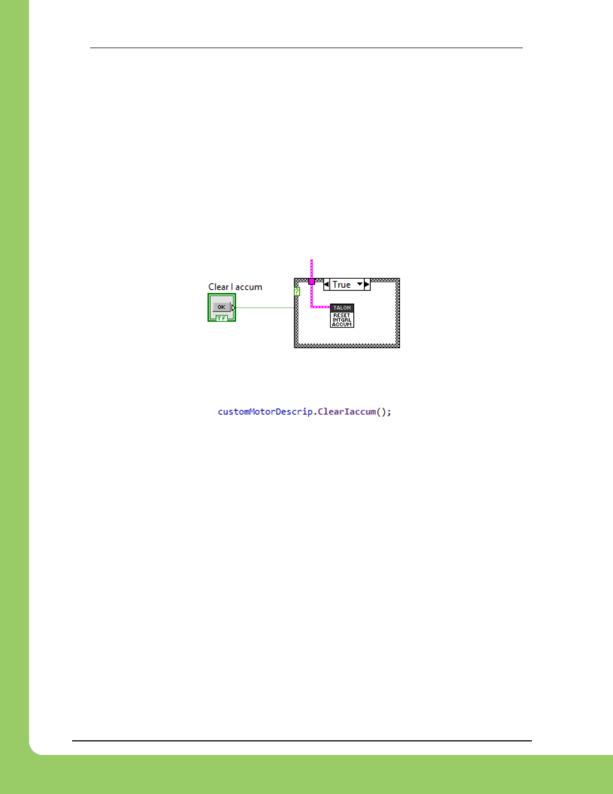
217-8080 TALON SRX Software Reference Manual 2/14/2017
Cross The Road Electronics Page 80 2/14/2017
12.2. Clearing Integral Accumulator (I Accum)
Clearing the integral accumulator (“I Accum”) may be necessary to prevent integral windup.
When using “IIZone” this is done automatically when the Closed-Loop Error is outside the
“IIZone”. However there may be other situations when manually clearing the integral
accumulator is necessary. For example, if the mechanism that’s being closed-looped is “close
enough” and its desirable to reduce occasional spurts of movement caused by a slowly
incrementing integral term, then the robot logic can periodically clear the “I Accum” to prevent
this.
12.2.1. LabVIEW
In this example a case structure is leveraged to conditionally clear the Integral Accumulator
when the case structure conditional evaluates true (this example uses a system button on the
front panel).
12.2.2. C++/Java
The ClearIaccum() function is available in C++/Java.
12.2.3. Is Integral Accum cleared any other time?
In addition to the “IIZone” feature and manual clear, there are certain cases where the integral
accumulator is automatically cleared for more predicable motor response…
-Whenever the control mode of a Talon is changed.
-When a Talon is in the disabled state.
-When the motor control profile slot has changed.
-When the Closed Loop Error’s magnitude is smaller than the “Allowable Closed Loop Error”.
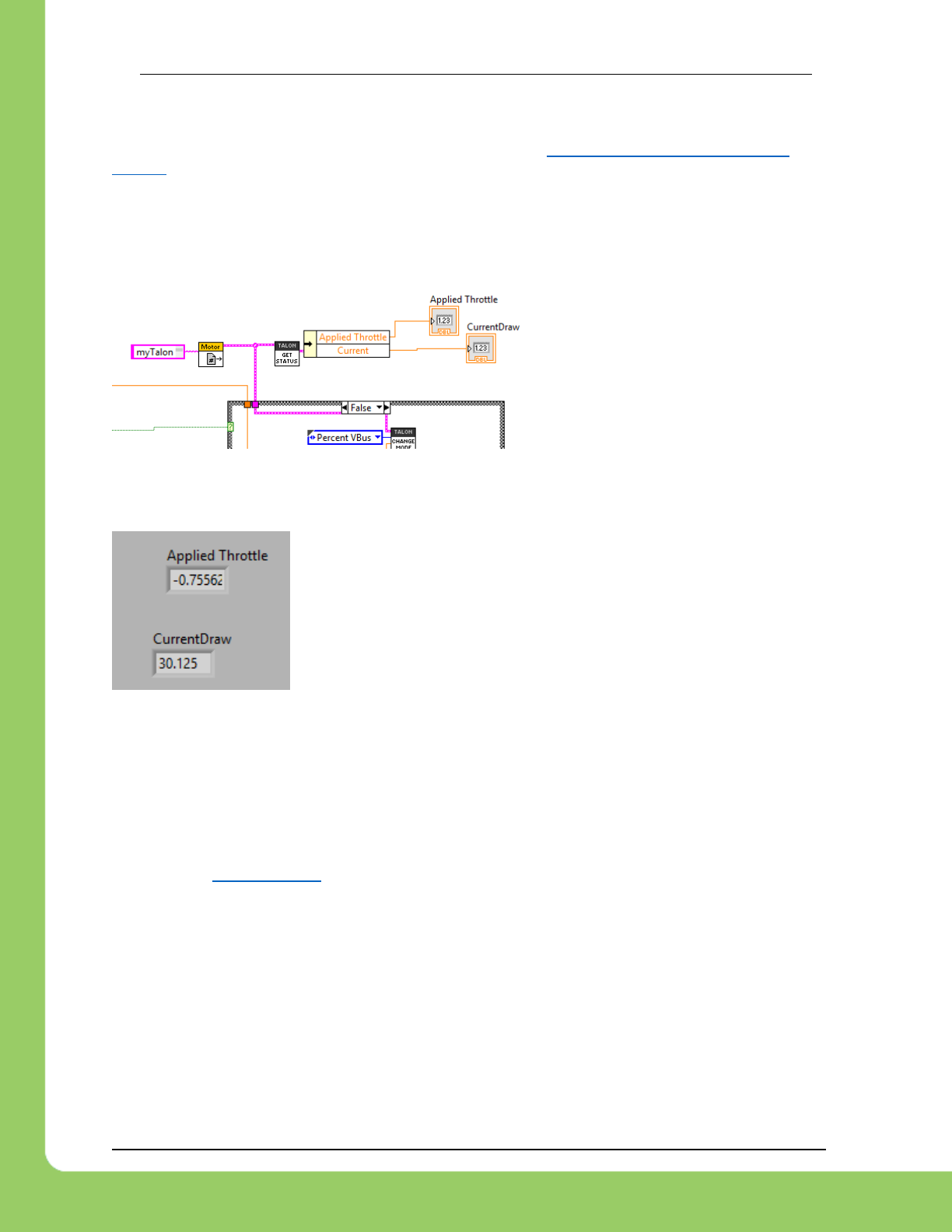
217-8080 TALON SRX Software Reference Manual 2/14/2017
Cross The Road Electronics Page 81 2/14/2017
12.3. Current Closed-Loop Walkthrough – LabVIEW
This example can be found on the CTR GitHub account. https://github.com/CrossTheRoadElec/FRC-
Examples
12.3.1. Current Closed-Loop Walkthrough – Collect Sensor Data – LabVIEW
The first step is to confirm that the sensor is functional and in-phase with the motor. Additionally
data can be collected to be used later to determine a decent Feed-forward gain.
Create a Talon and instrument its
current draw and throttle output. Also
provide a method to directly control the
Talon to servo (Percent Voltage). In
this example Talon is in Percent
Voltage mode when button is off, and in
current closed-loop when button is on.
Enable the Robot and drive the motor to a reasonable output. Take note of what the throttle
output in percent. This will gives us a basic relationship between current and motor-output.
Shown to the left is the LabVIEW front panel, however these values
can also be retrieved in the roboRIO web-based configuration (works
for all FRC languages). Print statements can also be used for C++,
JAVA, and HERO C#.
This example was taken by using a Talon SRX and CIM to back drive
a secondary CIM motor with leads connected together. At full throttle
this setup will exceed the 40A breaker rating so less-the-full throttle was used. However in a
typical mechanism full throttle may be used to acquire a more accurate measurement.
12.3.2. Current Closed-Loop Walkthrough – Calculating Feed Forward– LabVIEW
From this we can calculate our initial Feed-Forward gain. Since measured current is always
positive, we ignore the negative sign of applied throttle.
According to Section 17.2.2, the Talon SRX closed loop takes the desired current in milliamps
and outputs a throttle value (-1023 to +1023). Knowing this we calculate a Feedforward that will
gives us 75% throttle when the Target currentDraw is 30125 mA.
( 0.7556 X 10²³) / 30125 mA => ~0.02566
As a math check, when the set point is 30125mA, the feedforward term will be 30125 X 0.02566
gives us 773 throttle units (~75%).
Next we will set the F gain to 0.02566, while zeroing the PID gains. This can be done in the
web-based configuration or programmatically using the robot API.
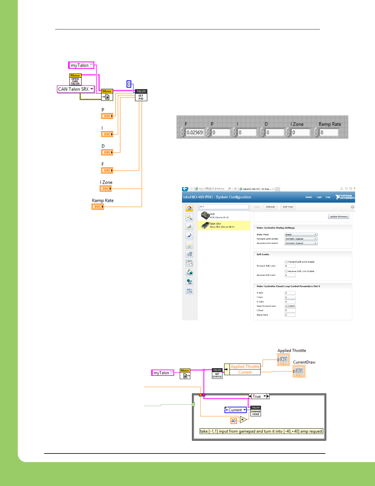
217-8080 TALON SRX Software Reference Manual 2/14/2017
Cross The Road Electronics Page 82 2/14/2017
On the left we have an example in LabVIEW,
setting the closed-loop parameters in Begin.vi.
The values are entered below in the front panel,
though they could also be constants if need be.
Additionally, the other languages have
comparable APIs for gain-setting, or the
gains can be set using the roboRIO web-
based configuration.
Web-based configuration can also be used
to double check that the settings are what
you expect.
Now rerun the test setup, but
now we will press and hold our
button to conditionally enable
Current-closed loop mode.
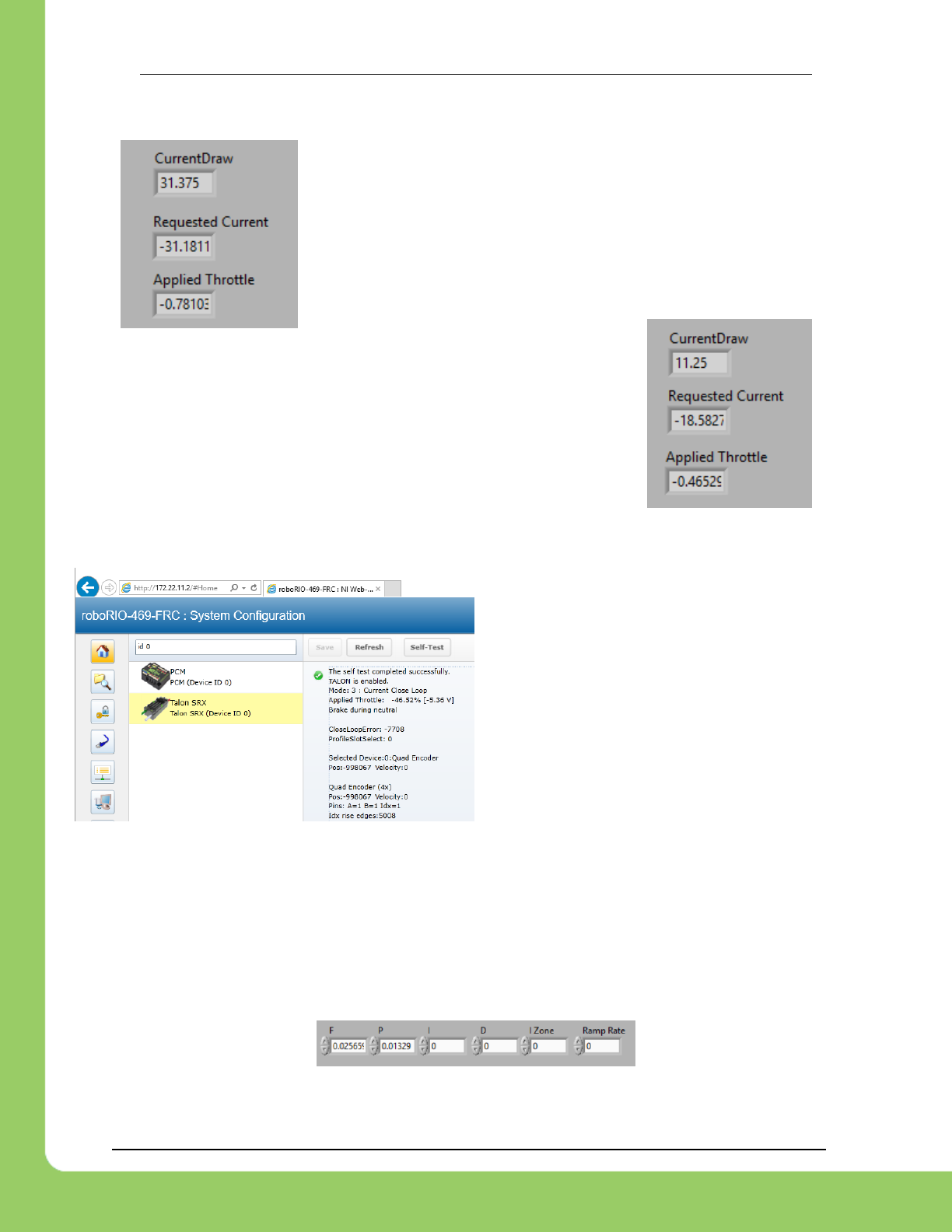
217-8080 TALON SRX Software Reference Manual 2/14/2017
Cross The Road Electronics Page 83 2/14/2017
Not surprisingly the desired and measured current draw are nearly
identical.
Of course there is no guarantee this will be the case at all request
current draws under differing battery conditions. Remember this is
just Feed-forward, we’re not close-looping yet! For example, as we
deviate away from our tuned point, we see error between our
desired and measured current.
Next we will tune P gain so that the closed-loop actually responds to
error.
12.3.3. Current Closed-Loop Walkthrough – Dialing Proportional Gain – LabVIEW
In this example the Closed-Loop Err was
~7000 (mA).
Perhaps we want to start with adding another
10% motor output to help approach our target
current.
10% throttle X 1023 = 102 throttle units
Since we want 102 throttle units when the error is 7700, calculate P gain by dividing the two…
102.3 / 7700 = 0.01329
To check our math, let’s take our P-gain of 0.01329 and multiply by Closed Loop Err (7700mA)
0.01329 X 7700 = 102 (10% of 1023 full throttle).
Now we can expect approximately 10% more motor output when our error is ~7 amps.

217-8080 TALON SRX Software Reference Manual 2/14/2017
Cross The Road Electronics Page 84 2/14/2017
Closed Loop driving
59.7% when back-
driven CIM has
leads connected.
Closed Loop driving
77.7% when back-
driven CIM has
power resistor in
series with leads.
Here we attempt to reproduce the same target point. We see our throttle
output has increased as a result of the stronger P-gain and our current
draw is closer to our target.
Keep increasing the P-gain until the desired response is achieved. To
save time, many will double the P-gain until oscillation is observed
(overshooting the target and then returning to target. This can also be
observed by plotting, or watching the color change on the Talon SRX
LEDs).
After further increasing P-gain, we see our desired and measured current-draw to follow closely.
We can also observe how the closed-loop responds to a change in load. Disconnecting the
back driven CIM motor’s connected leads and connecting them to a 0.2 ohm power resistor
reveals how the Closed-Loop increases its motor output to target the desired 20 amps.
With additional tweaking and leveraging the remaining gains (I and D), the closed-loop can be
further improved, though many will find that a simple FP loop will be sufficient for many
applications.

217-8080 TALON SRX Software Reference Manual 2/14/2017
Cross The Road Electronics Page 85 2/14/2017
12.4. Velocity Closed-Loop Walkthrough – Java
This example can be found on the CTR GitHub account. https://github.com/CrossTheRoadElec/FRC-Examples
12.4.1. Velocity Closed-Loop Walkthrough – Collect Sensor Data – Java
The first step is to drive the Talon SRX manually to check that the selected sensor is functioning
and in phase with the motor. The following example below will accomplish this. Deploy and
drive the Talon forward by pulling the gamepad’s y-axis.
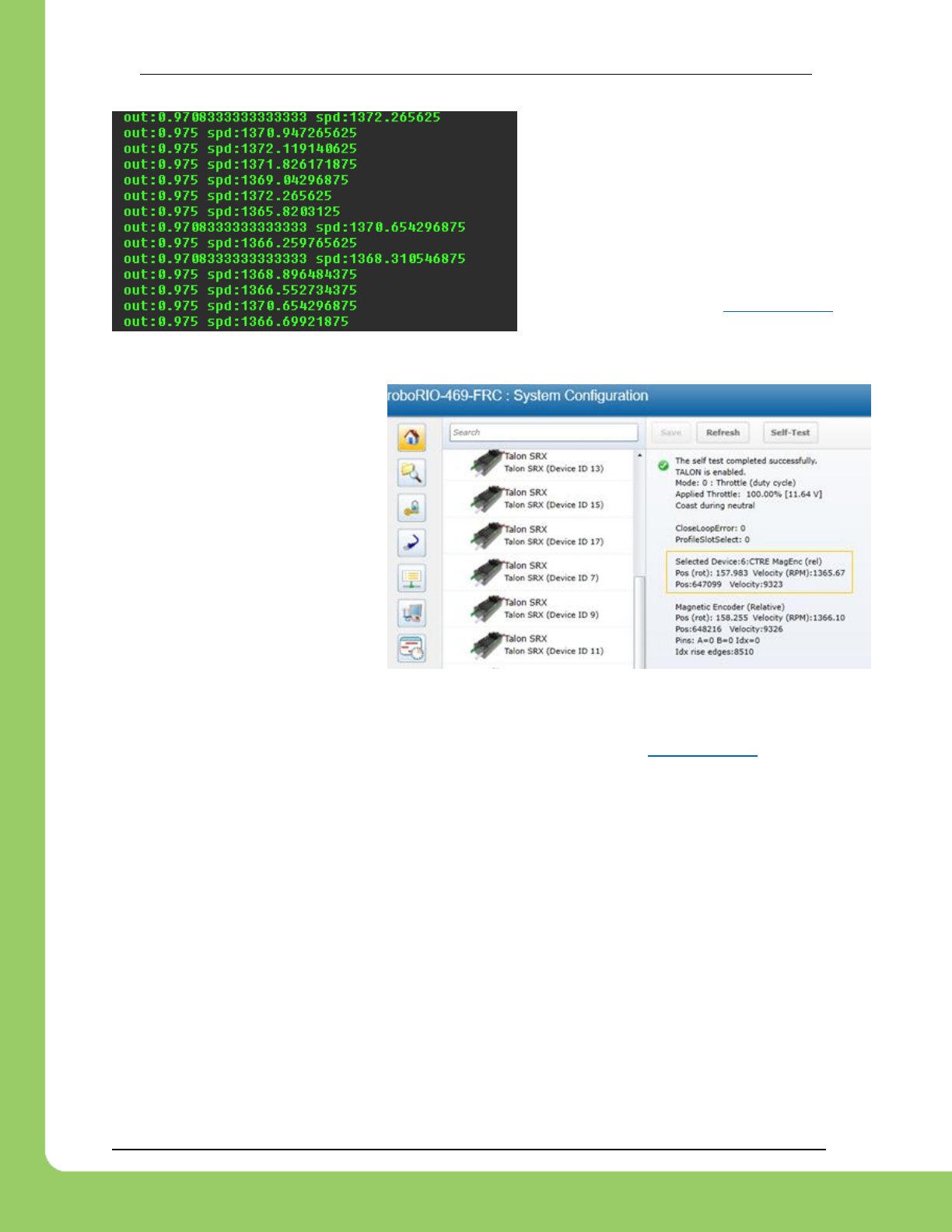
217-8080 TALON SRX Software Reference Manual 2/14/2017
Cross The Road Electronics Page 86 2/14/2017
While throttling the Talon in the positive
direction, make sure the sensor speed is
also positive.
Additionally note the approximate sensor
speed while the Talon is driven.
getSpeed() will return the speed in RPM
since the requirements in Section 17.2.1
are met.
The same values can be read in
the roboRIO web-based
configuration under Self-Tests.
12.4.2. Velocity Closed-Loop Walkthrough – Calculating Feed Forward– Java
Now that we’ve confirmed that the position/speed moves in the positive direction with forward
(green throttle), we can calculate our Feed-forward gain. According to Section 17.2.1, our
selected sensor uses 4096 native units per rotation. That means our measurement of 1366RPM
scales to 9326 native units per 100ms. This is also calculated for you in the Self-Test.
Velocity is measured in change in native units per TvelMeas= 100ms.
(1366 Rotations / min) X (1 min / 60 sec) X (1 sec / 10 TvelMeas) X (4096 native units / rotation)
= 9326 native units per 100ms
Now let’s calculate a Feed-forward gain so that 100% motor output is calculated when the
requested speed is 9328 native units per 100ms.
F-gain = (100% X 1023) / 9326
F-gain = 0.1097
Let’s check our math, if the target speed is 9326 native units per 100ms, Closed-loop output will
be (0.1097 X 9326) => 1023 (full forward).
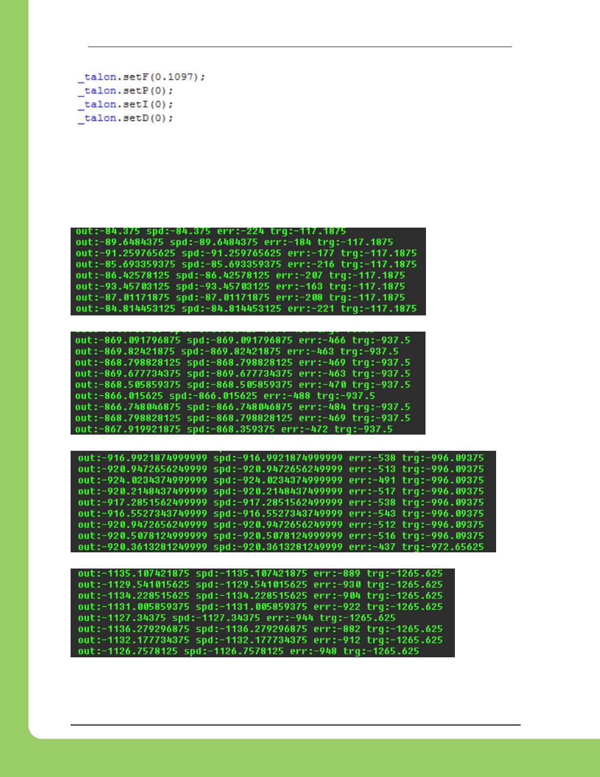
217-8080 TALON SRX Software Reference Manual 2/14/2017
Cross The Road Electronics Page 87 2/14/2017
Next we will set the calculated gain. This can also be done in the
roboRIO web-based configuration or programmatically.
After applying the new gain, rerun the test but hold down button1 to put Talon into Speed
Control Mode. Now review the target and measured speed to see how close we are.
A few DS console samples are shown below, which contain the print statements. Looking at
“spd” and “trg” we see that we’re within ~100RPM for most of the speed-sweep. Remember “err”
is in native units per 100ms. So an error of 900 units per 100ms equals an error of 131RPM
since each rotation is 4096 units.
Additionally, since we have no feedback, you will find changes in load will impact the error
considerably.
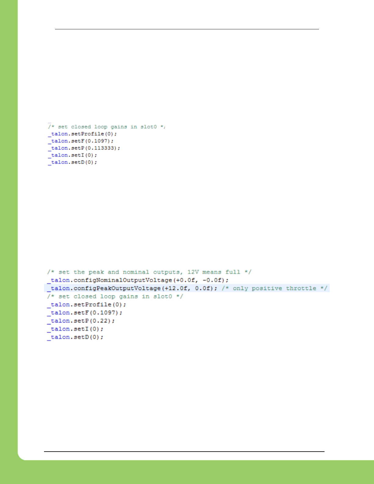
217-8080 TALON SRX Software Reference Manual 2/14/2017
Cross The Road Electronics Page 88 2/14/2017
12.4.3. Velocity Closed-Loop Walkthrough – Dialing Proportional Gain – Java
Next we will add in P-gain so that the closed-loop can react to error. Suppose given our worst
error so far (900 native units per 100ms), we want to respond with another 10% of throttle.
Then our starting p-gain would be….
(10% X 1023) / (900) = 0.113333
Now let’s check our math, if the Talon SRX sees an error of 900 the P-term will be
900 X 0.113333 = 102 (which is about 10% of 1023)
P-gain = 0.113333
Apply the P -gain programmatically using your
preferred method. Now retest to see how well the
closed-loop responds to varying loads. Double the P
-gain until the system oscillates (too much) or until the
system responds adequately.
If the mechanism is moving to swiftly, you can add D-gain to smooth the motion. Start with 10x
the p-gain.
If the mechanism is not quite reaching the final target position (and P -gain cannot be increased
further without hurting overall performance) begin adding I-gain. Start with 1/100th of the P-gain.
Some mechanisms may require that the closed-loop can never spin in reverse of the desired
direction (due to closed-loop wanting to slow down). This behavior can be achieve by reducing
the Closed-Loop peak output voltage as show below (second parameter changed from -12V to
0).

217-8080 TALON SRX Software Reference Manual 2/14/2017
Cross The Road Electronics Page 89 2/14/2017
12.5. Position Closed-Loop – HERO C# (non-FRC)
Below is a full example for Position Closed-Looping using the HERO development
board. These functions are also available in FRC C++/Java, and comparable VIs are
available in LabVIEW.
This example also demonstrates switching between Position Closed-Loop and
PercentVoltage mode.
This example can be found on the CTR GitHub account.
https://github.com/CrossTheRoadElec/HERO-Examples
/**
* Example demonstrating the position closed-loop servo.
* Tested with Logitech F350 USB Gamepad inserted into HERO.
*
* Use the mini-USB cable to deploy/debug.
*
* Be sure to select the correct feedback sensor using SetFeedbackDevice() below.
*
* After deploying/debugging this to your HERO, first use the left Y-stick
* to throttle the Talon manually. This will confirm your hardware setup.
* Be sure to confirm that when the Talon is driving forward (green) the
* position sensor is moving in a positive direction. If this is not the cause
* flip the boolean input to the SetSensorDirection() call below.
*
* Once you've ensured your feedback device is in-phase with the motor,
* use the button shortcuts to servo to target positions.
*
* Tweak the PID gains accordingly.
*/
using System.Threading;
using Microsoft.SPOT;
using System.Text;
namespace Hero_Position_Servo_Example
{
/** Simple stub to start our project */
public class Program
{
static RobotApplication _robotApp = new RobotApplication();
public static void Main()
{
while(true)
{
_robotApp.Run();
}
}
}
/**
* The custom robot application.
*/
public class RobotApplication
{
/** scalor to max throttle in manual mode. negative to make forward joystick positive */
const float kJoystickScaler = -0.3f;
/** hold bottom left shoulder button to enable motors */
const uint kEnableButton = 7;
/** make a talon with deviceId 0 */
CTRE.TalonSrx _talon = new CTRE.TalonSrx(0,true);
/** Use a USB gamepad plugged into the HERO */
CTRE.Gamepad _gamepad = new CTRE.Gamepad(CTRE.UsbHostDevice.GetInstance());

217-8080 TALON SRX Software Reference Manual 2/14/2017
Cross The Road Electronics Page 90 2/14/2017
/** hold the current button values from gamepad*/
bool[] _btns = new bool[10];
/** hold the last button values from gamepad, this makes detecting on-press events trivial */
bool[] _btnsLast = new bool[10];
/** some objects used for printing to the console */
StringBuilder _sb = new StringBuilder();
int _timeToPrint = 0;
float _targetPosition = 0;
uint [] _debLeftY = { 0, 0 }; // _debLeftY[0] is how many times its zero,
// _debLeftY[1] is how many times nonzero.
public void Run()
{
/* first choose the sensor */
_talon.SetFeedbackDevice(CTRE.TalonSrx.FeedbackDevice.CtreMagEncoder_Relative);
_talon.SetSensorDirection(false);
//_talon.ConfigEncoderCodesPerRev(XXX), // if using CTRE.TalonSrx.FeedbackDevice.QuadEncoder
//_talon.ConfigPotentiometerTurns(XXX), // if using AnalogEncoder or AnalogPot
/* set closed loop gains in slot0 */
_talon.SetP(0, 0.2f); /* tweak this first, a little bit of overshoot is okay */
_talon.SetI(0, 0f);
_talon.SetD(0, 0f);
_talon.SetF(0, 0f); /* For position servo kF is rarely used. Leave zero */
/* use slot0 for closed-looping */
_talon.SelectProfileSlot(0);
/* set the peak and nominal outputs, 12V means full */
_talon.ConfigNominalOutputVoltage(+0.0f, -0.0f);
_talon.ConfigPeakOutputVoltage(+3.0f, -3.0f);
/* how much error is allowed? This defaults to 0. */
_talon.SetAllowableClosedLoopErr(0,0);
/* zero the sensor and throttle */
ZeroSensorAndThrottle();
/* loop forever */
while (true)
{
Loop10Ms();
if(_gamepad.GetButton(kEnableButton)) // check if bottom left shoulder btn is held down.
{
/* then enable motor outputs*/
CTRE.Watchdog.Feed();
}
/* print signals to Output window */
Instrument();
/* 10ms loop */
Thread.Sleep(10);
}
}
/**
* Zero the sensor and zero the throttle.
*/
void ZeroSensorAndThrottle()
{
_talon.SetPosition(0); /* start our position at zero, this example uses relative positions */
_targetPosition = 0;
/* zero throttle */

217-8080 TALON SRX Software Reference Manual 2/14/2017
Cross The Road Electronics Page 91 2/14/2017
_talon.SetControlMode(CTRE.TalonSrx.ControlMode.kPercentVbus);
_talon.Set(0);
Thread.Sleep(100); /* wait a bit to make sure the Setposition() above takes effect */
}
void EnableClosedLoop()
{
/* user has let go of the stick, lets closed-loop whereever we happen to be */
_talon.SetVoltageRampRate(0); /* V per sec */
_talon.SetControlMode(CTRE.TalonSrx.ControlMode.kPosition);
_talon.Set(_targetPosition);
}
void GetJoystickValues (out float y, ref bool[] btns)
{
/* get all the buttons */
FillBtns(ref btns);
/* get the left y stick, invert so forward is positive */
float leftY = kJoystickScaler * _gamepad.GetAxis(1);
Deadband(ref leftY);
/* debounce the transition from nonzero => zero axis */
y = leftY;
}
void Loop10Ms()
{
float filteredY;
GetJoystickValues (out filteredY, ref _btns);
if (filteredY != 0)
{
/* put in a ramp to prevent the user from flipping their mechanism */
_talon.SetVoltageRampRate(12.0f); /* V per sec */
/* directly control the output */
_talon.SetControlMode(CTRE.TalonSrx.ControlMode.kPercentVbus);
_talon.Set(filteredY);
}
else if (_talon.GetControlMode() == CTRE.TalonSrx.ControlMode.kPercentVbus)
{
_targetPosition = _talon.GetPosition();
/* user has let go of the stick, lets closed-loop whereever we happen to be */
EnableClosedLoop();
}
/* if a button is pressed while stick is let go, servo position */
if (filteredY == 0)
{
if (_btns[1])
{
_targetPosition = _talon.GetPosition() ; /* twenty rotations forward */
EnableClosedLoop();
}
else if(_btns[4])
{
_targetPosition = +10.0f; /* twenty rotations forward */
EnableClosedLoop();
}
else if (_btns[2])
{
_targetPosition = -10.0f; /* twenty rotations reverese */
EnableClosedLoop();
}
}
/* copy btns => btnsLast */
System.Array.Copy(_btns, _btnsLast, _btns.Length);
}
/**
* @return a filter value for the y-axis.

217-8080 TALON SRX Software Reference Manual 2/14/2017
Cross The Road Electronics Page 92 2/14/2017
* Don't return zero unless we've been in deadband for a number of loops.
* This is only done because this example will throttle the motor with
*/
float FilterLeftY(float y, uint numLoop)
{
/* get the left y stick */
float leftY = -1 * _gamepad.GetAxis(1);
Deadband(ref leftY);
if (leftY == 0)
{
_debLeftY[1] = 0;
++_debLeftY[0];
}
else
{
_debLeftY[0] = 0;
++_debLeftY[1];
}
if (_debLeftY[0] > numLoop)
return 0;
return y;
}
/**
* If value is within 10% of center, clear it.
*/
void Deadband(ref float value)
{
if (value < -0.10)
{
/* outside of deadband */
}
else if (value > +0.10)
{
/* outside of deadband */
}
else
{
/* within 10% so zero it */
value = 0;
}
}
/** throw all the gamepad buttons into an array */
void FillBtns(ref bool[] btns)
{
for (uint i = 1; i < btns.Length; ++i)
btns[i] = _gamepad.GetButton(i);
}
/** occasionally builds a line and prints to output window */
void Instrument()
{
if (--_timeToPrint <= 0)
{
_timeToPrint = 20;
_sb.Clear();
_sb.Append( "pos=");
_sb.Append(_talon.GetPosition());
_sb.Append(" vel=");
_sb.Append(_talon.GetSpeed());
_sb.Append(" err=");
_sb.Append(_talon.GetClosedLoopError());
_sb.Append(" out%=");
_sb.Append(_talon.GetOutputVoltage()*100.0f/12.0f);
Debug.Print(_sb.ToString());
}
}
}
}
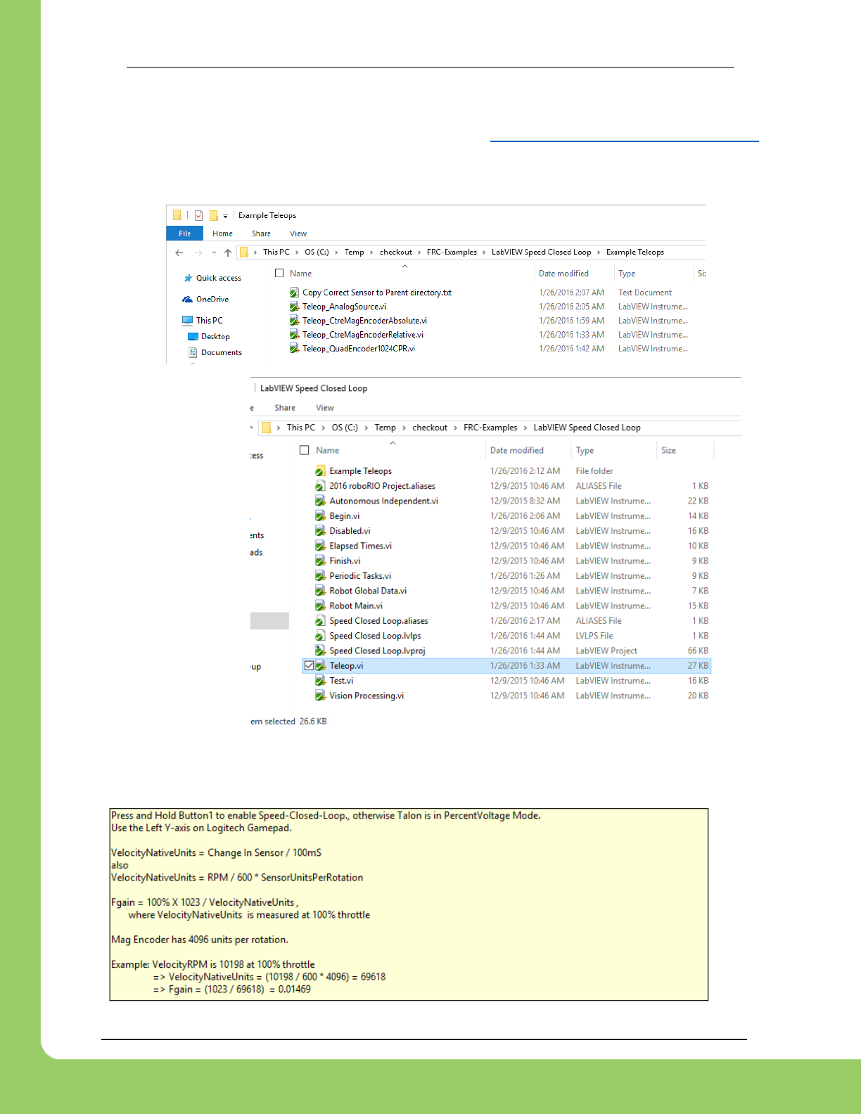
217-8080 TALON SRX Software Reference Manual 2/14/2017
Cross The Road Electronics Page 93 2/14/2017
12.6. Velocity Closed-Loop Example – LabVIEW
This example can be found on the CTR GitHub account. https://github.com/CrossTheRoadElec/FRC-Examples
Supplemental Teleop_XXXX VIs can be found for various sensor types.
These can be copied over Teleop.vi.
Then replace the
active Telep.vi file
in “LabVIEW Speed
Closed Loop”
directory.
Look at the sensor-specific teleop VIs to confirm how the Feed Forward gain is calculated.
There will be a text label similar to the following…

217-8080 TALON SRX Software Reference Manual 2/14/2017
Cross The Road Electronics Page 94 2/14/2017
12.7. Motion Magic Closed-Loop HERO C# (non-FRC)
Below is a full example for Motion Magic using the HERO development board. These
functions are also available in FRC C++/Java, and comparable VIs are available in
LabVIEW.
The latest example can be found on the CTR GitHub account.
https://github.com/CrossTheRoadElec/HERO-Examples
/**
* Example using the Motion Magic Control Mode of Talon SRX and the Magnetic Encoder.
Other sensors can be used by
* changing the selected sensor type below.
* MotionMagic control mode requires Talon firmware 10.10 or greater.
* The test setup is ...
* A single Talon SRX (Device ID 0) http://www.ctr-electronics.com/talon-srx.html
* A VEX VersaPlanetary Gearbox http://www.vexrobotics.com/versaplanetary.html
* Gearbox uses the CTRE Magnetic Encoder http://www.vexrobotics.com/vexpro/all/new-
for-2016/217-5046.html
* Ribbon cable http://www.ctr-electronics.com/talon-srx-data-cable-4-pack.html
*
* Talon SRX ribbon cable is connected to the Magnetic Encoder. This provies the
Talon with rotar position.
* See Talon SRX Software Reference Manual for gain-tuning suggestions.
*
* Press the top left shoulder button for direct-control of Talon's motor output using
the left-y-axis.
* Press the bottom left shoulder button to set the target position of the Talon's closed
loop servo
* using the left-y-axis. Notice the geared output will ramp up initiallly then ramp
down as it approaches
* the target position.
*/
using System.Threading;
using System;
using Microsoft.SPOT;
namespace HERO_Motion_Magic_Example
{
public class Program
{
/** talon to control */
private CTRE.TalonSrx _talon = new CTRE.TalonSrx(0);
/** desired mode to put talon in */
private CTRE.TalonSrx.ControlMode _mode = CTRE.TalonSrx.ControlMode.kPercentVbus;
/** attached gamepad to HERO, tested with Logitech F710 */
private CTRE.Gamepad _gamepad = new CTRE.Gamepad(new CTRE.UsbHostDevice());
/** constant slot to use */
const uint kSlotIdx = 0;
/** How long to wait for receipt when setting a param. Many setters take an
optional timeout that API will wait for.

217-8080 TALON SRX Software Reference Manual 2/14/2017
Cross The Road Electronics Page 95 2/14/2017
This is benefical for initial setup (before movement), though typically not
desired when changing parameters concurrently with robot operation (gain scheduling for
example).*/
const uint kTimeoutMs = 1;
/**
* Setup all of the configuration parameters.
*/
public int SetupConfig()
{
/* binary OR all the return values so we can make a quick decision if our
init was successful */
int status = 0;
/* specify sensor characteristics */
_talon.SetFeedbackDevice(CTRE.TalonSrx.FeedbackDevice.CtreMagEncoder_Relative);
_talon.SetSensorDirection(false); /* make sure positive motor output means
sensor moves in position direction */
// call ConfigEncoderCodesPerRev or ConfigPotentiometerTurns for Quadrature
or Analog sensor types.
/* brake or coast during neutral */
status |= _talon.ConfigNeutralMode(CTRE.TalonSrx.NeutralMode.Brake);
/* closed-loop and motion-magic parameters */
status |= _talon.SetF(kSlotIdx, 0.1153f, kTimeoutMs); // 1300RPM (8874 native
sensor units per 100ms) at full motor output (+1023)
status |= _talon.SetP(kSlotIdx, 2.00f, kTimeoutMs);
status |= _talon.SetI(kSlotIdx, 0f, kTimeoutMs);
status |= _talon.SetD(kSlotIdx, 20f, kTimeoutMs);
status |= _talon.SetIzone(kSlotIdx, 0, kTimeoutMs);
status |= _talon.SelectProfileSlot(kSlotIdx); /* select this slot */
status |= _talon.ConfigNominalOutputVoltage(0f, 0f, kTimeoutMs);
status |= _talon.ConfigPeakOutputVoltage(+12f, -12f, kTimeoutMs);
status |= _talon.SetMotionMagicCruiseVelocity(1000f, kTimeoutMs); // 1000 RPM
status |= _talon.SetMotionMagicAcceleration(2000f, kTimeoutMs); // 2000 RPM
per sec, (0.5s to reach cruise velocity).
/* Home the relative sensor,
alternatively you can throttle until limit switch,
use an absolute signal like CtreMagEncoder_Absolute or analog sensor.
*/
status |= _talon.SetPosition(0, kTimeoutMs);
return status;
}
/** spin in this routine forever */
public void RunForever()
{
/* config our talon, don't continue until it's successful */
int initStatus = SetupConfig(); /* configuration */
while (initStatus != 0)
{
Instrument.PrintConfigError();
initStatus = SetupConfig(); /* (re)config*/
}
/* robot loop */
while (true)

217-8080 TALON SRX Software Reference Manual 2/14/2017
Cross The Road Electronics Page 96 2/14/2017
{
/* get joystick params */
float leftY = -1f * _gamepad.GetAxis(1);
bool btnTopLeftShoulder = _gamepad.GetButton(5);
bool btnBtmLeftShoulder = _gamepad.GetButton(7);
Deadband(ref leftY);
/* keep robot enabled if gamepad is connected and in 'D' mode */
if (_gamepad.GetConnectionStatus() == CTRE.UsbDeviceConnection.Connected)
CTRE.Watchdog.Feed();
/* set the control mode based on button pressed */
if (btnTopLeftShoulder)
_mode = CTRE.TalonSrx.ControlMode.kPercentVbus;
if (btnBtmLeftShoulder)
_mode = CTRE.TalonSrx.ControlMode.kMotionMagic;
/* calc the Talon output based on mode */
if (_mode == CTRE.TalonSrx.ControlMode.kPercentVbus)
{
float output = leftY; // [-1, +1] percent duty cycle
_talon.SetControlMode(_mode);
_talon.Set(output);
}
else if (_mode == CTRE.TalonSrx.ControlMode.kMotionMagic)
{
float servoToRotation = leftY * 10;// [-10, +10] rotations
_talon.SetControlMode(_mode);
_talon.Set(servoToRotation);
}
/* instrumentation */
Instrument.Process(_talon);
/* wait a bit */
System.Threading.Thread.Sleep(5);
}
}
/** @param [in,out] value to zero if within plus/minus 10% */
public static void Deadband(ref float val)
{
if (val > 0.10f) { /* do nothing */ }
else if (val < -0.10f) { /* do nothing */ }
else { val = 0; } /* clear val since its within deadband */
}
/** singleton instance and entry point into program */
public static void Main()
{
Program program = new Program();
program.RunForever();
}
}
}

217-8080 TALON SRX Software Reference Manual 2/14/2017
Cross The Road Electronics Page 97 2/14/2017
12.8. Motion Magic Closed-Loop Walkthrough – Java
This latest example should be downloaded from the CTR GitHub account.
https://github.com/CrossTheRoadElec/FRC-Examples
The example will appear similar to the snippet below..
public class Robot extends IterativeRobot {
CANTalon _talon = new CANTalon(3);
Joystick _joy = new Joystick(0);
StringBuilder _sb = new StringBuilder();
public void robotInit() {
/* first choose the sensor */
_talon.setFeedbackDevice(FeedbackDevice.CtreMagEncoder_Relative);
_talon.reverseSensor(false);
// _talon.configEncoderCodesPerRev(XXX)
// _talon.configPotentiometerTurns(XXX)
/* set the peak and nominal outputs, 12V means full */
_talon.configNominalOutputVoltage(+0.0f, -0.0f);
_talon.configPeakOutputVoltage(+12.0f, -12.0f);
/* set closed loop gains in slot0 - see documentation */
_talon.setProfile(0);
_talon.setF(0);
_talon.setP(0);
_talon.setI(0);
_talon.setD(0);
_talon.setMotionMagicCruiseVelocity(0);
_talon.setMotionMagicAcceleration(0);
}
/**
* This function is called periodically during operator control
*/
public void teleopPeriodic() {
/* get gamepad axis - forward stick is positive */
double leftYstick = -1.0 * _joy.getAxis(AxisType.kY);
double motorOutput = _talon.getOutputVoltage() / _talon.getBusVoltage();
/* prepare line to print */
_sb.append("\tout:");
_sb.append(motorOutput);
_sb.append("\tspd:");
_sb.append(_talon.getSpeed());
if (_joy.getRawButton(1)) {
/* Motion Magic */
double targetPos = leftYstick
* 10.0; /* 10 Rotations in either direction */
_talon.changeControlMode(TalonControlMode.MotionMagic);
_talon.set(targetPos);
/* append more signals to print when in speed mode. */
_sb.append("\terr:");
_sb.append(_talon.getClosedLoopError());
_sb.append("\ttrg:");
_sb.append(targetPos);
} else {
/* Percent voltage mode */
_talon.changeControlMode(TalonControlMode.PercentVbus);
_talon.set(leftYstick);
}
/* instrumentation */
Instrum.Process(_talon, _sb);
}
}
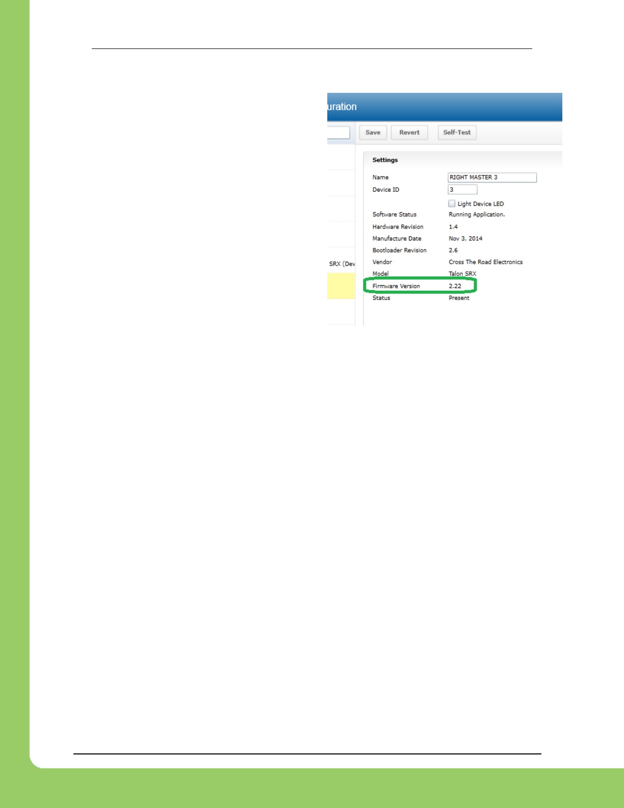
217-8080 TALON SRX Software Reference Manual 2/14/2017
Cross The Road Electronics Page 98 2/14/2017
12.8.1. Motion Magic Closed-Loop Walkthrough – General Requirements
Be sure to check that the firmware is up to date.
See CRF release notes for when motion magic
was added.
Additionally, a reliable signal plotter is helpful for tuning parameters.
The signals of interest are the…
Sensor Position
Sensor Velocity
Active Trajectory Position(1,2)
Active Trajectory Velocity(1,2)
Motor Output (AppliedThrottle)
ClosedLoopErr
(1): These signals are calculated by the Talon SRX Motion Magic controller. These represent
the target position and velocity at a given moment in time.
(2): API will be added in future HERO/FRC release to retrieve these signals.
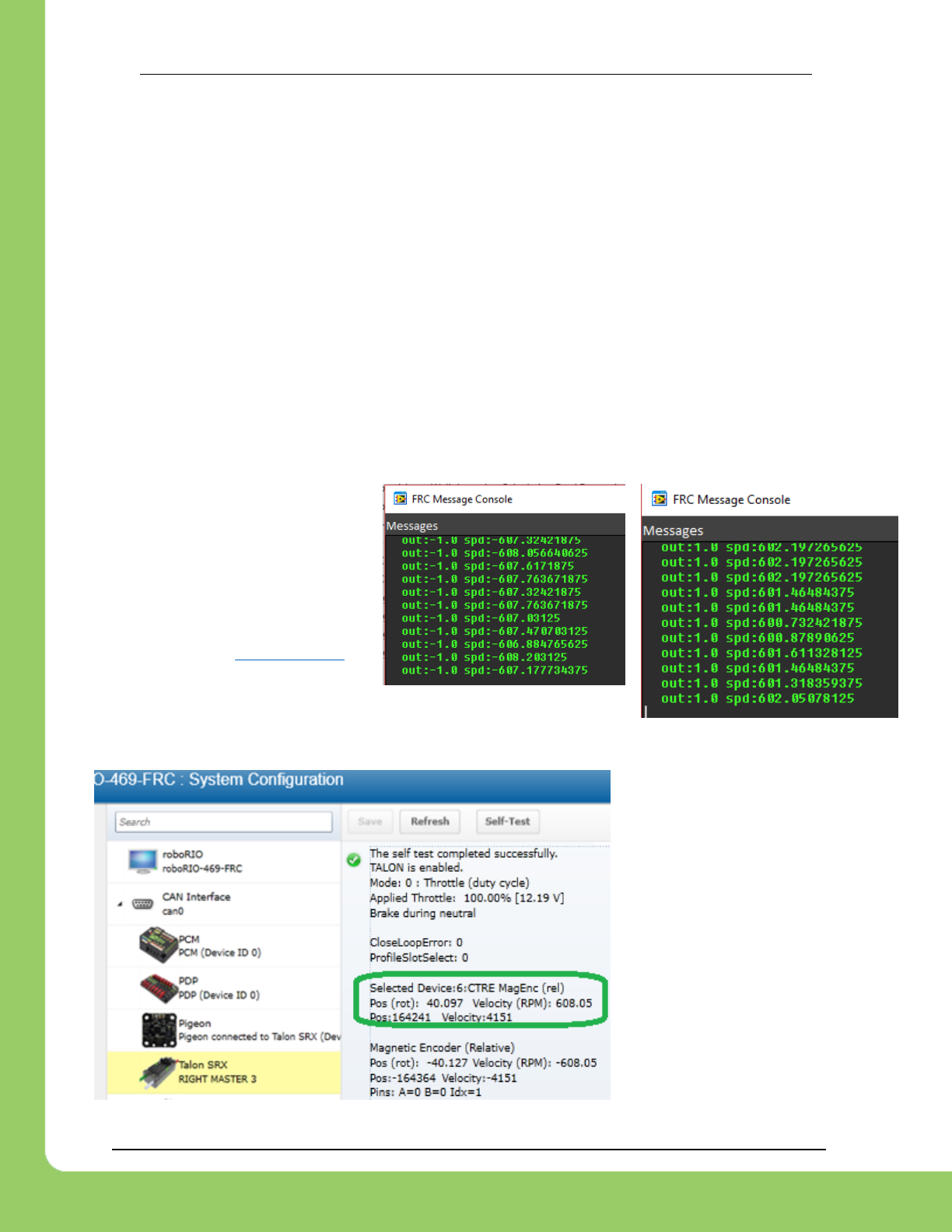
217-8080 TALON SRX Software Reference Manual 2/14/2017
Cross The Road Electronics Page 99 2/14/2017
12.8.2. Motion Magic Closed-Loop Walkthrough – Collect Sensor Data – Java
The first step is to drive the Talon SRX manually to check that the selected sensor is functioning
and in phase with the motor. Deploy the GitHub example (or similar drive code) and drive the
Talon by pulling the gamepad’s y-axis.
Checking the sensor means…
Confirming the sensor direction matches Talon motor output.
Confirm position and speed measurement is accurate throughout entire position/speed
range.
Confirming the speed is approximately correct given the mechanical setup.
Noting the measured speed at a given motor output for calculating f-gain
Noting the measured max speed for initial selection of velocity cruise and acceleration.
While throttling the Talon in the positive direction, make sure the sensor speed is also positive.
Talon should be illuminating green when doing this. If this is not the cause, change the
parameter in reverseSensor()
and retest.
Additionally, note the
approximate sensor speed while
the Talon is driven. getSpeed()
will return the speed in RPM if the
requirements in Section 17.2.1
are met.
The same values can be read in the roboRIO web-based
configuration under Self-Tests.
It’s important to note the
speed for calculating the f-
gain and for picking cruise
velocity and acceleration.
The self-test confirms ~608
RPM (or 4151 native units
per 100ms)
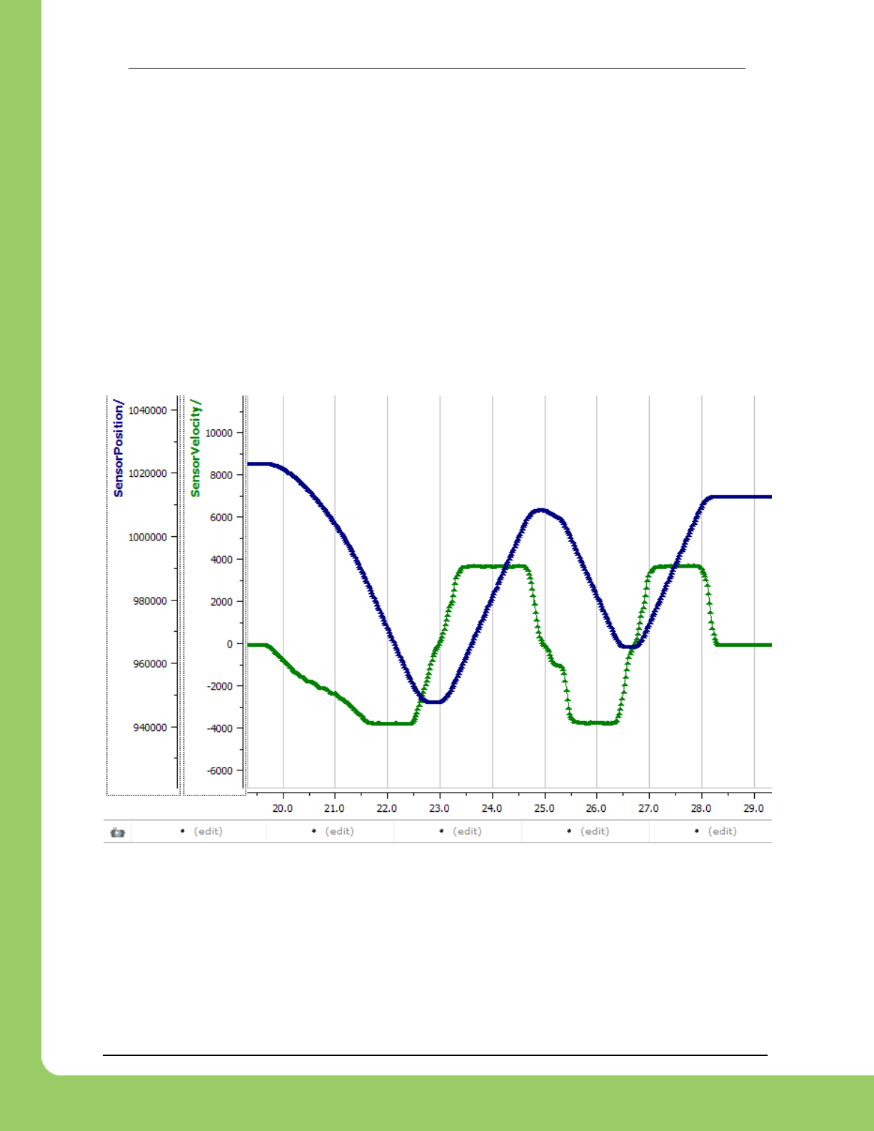
217-8080 TALON SRX Software Reference Manual 2/14/2017
Cross The Road Electronics Page 100 2/14/2017
12.8.2.1. Is speed magnitude correct?
In this example, we measure ~604 RPM at full motor output (averaged of peak in both
directions). This setup involves 1 X CIM Motor motor (free speed 5330 RPM). The selected
gear ratio is ~9:1. The CTRE magnetic encoder is on the geared output. So, a measurement of
~604 RPM is reasonable.
12.8.2.2. Is direction correct?
Looking at the screenshots above, positive motor output yielded a positive speed.
12.8.2.3. Sweep motor output and plots signals
While sweeping position and velocity, look for any discontinuities or unexplained behavior. In
the capture below, the sensor velocity and position appear to follow with no discontinuities or
plateaus.
12.8.2.4. Measurements
For the calculations done in the next section, the measurement of ~604 RPM at full motor
output is observed.
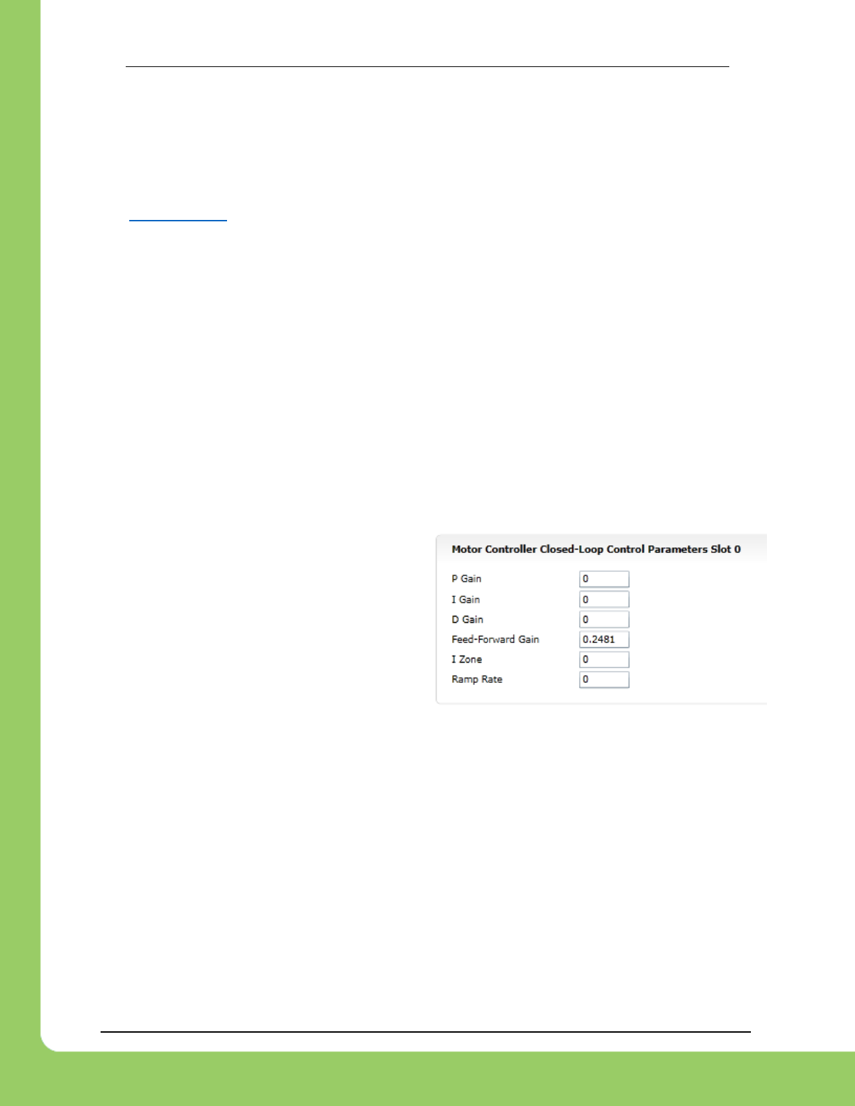
217-8080 TALON SRX Software Reference Manual 2/14/2017
Cross The Road Electronics Page 101 2/14/2017
12.8.3. Motion Magic Closed-Loop Walkthrough – Calculate F-Gain – Java
The Motion-Magic Closed-Loop mode operates by closed-loop servoing to a calculated position
with a fed-forward calculated velocity. The calculations are based on the set-point, cruise
velocity, acceleration parameter, and time. This requires the use of the Feed-Forward gain.
Per Section 17.2.1, our selected sensor uses 4096 native units per rotation. That means the
measurement of 604 RPM scales to 4123 native units per 100ms. This is also
calculated/displayed in the Self-Test.
Velocity is measured in change in native units per TvelMeas= 100ms.
(600 Rotations / min) X (1 min / 60 sec) X (1 sec / 10 TvelMeas) X (4096 native units / rotation)
= 4123 native units per 100ms
Now let’s calculate a Feed-forward gain so that 100% motor output is calculated when the
requested speed is 4123 native units per 100ms.
F-gain = (100% X 1023) / 4123
F-gain = 0.2481
Let’s check our math, if the target speed is 4123 native units per 100ms, Closed-loop output will
be (0.2481 X 4123 ) => 1023 (full forward).
Next we will set the calculated gain. This can
also be done in the roboRIO web-based
configuration or programmatically.
/* set closed loop gains in slot0 */
_talon.setProfile(0);
_talon.setF(0.2481);
_talon.setP(0);
_talon.setI(0);
_talon.setD(0);
_talon.setMotionMagicCruiseVelocity(0);
_talon.setMotionMagicAcceleration(0);

217-8080 TALON SRX Software Reference Manual 2/14/2017
Cross The Road Electronics Page 102 2/14/2017
12.8.4. Motion Magic Closed-Loop Walkthrough – Initial Cruise-
Velocity/Acceleration – Java
Since our peak measured velocity was 604 RPM, the initial cruise velocity should be set to a
smaller value to ensure the speed can be reached. In this example, we will arbitrarily take 75%
of the top speed. Depending on the mechanism type, how safe the mechanism is, and what is
trying to be accomplished, a lower or higher cruise velocity could be specified. Also remember
that this setting can be changed easily and at any time.
75% X 604 RPM = ~453 RPM
For the initial acceleration value, we will arbitrarily choose a value so that it takes an entire
second to reach our cruise velocity. This will ensure the acceleration is slow enough to be
observable. If this is too fast/slow, adjust accordingly. Since the acceleration is in terms of
change in velocity per second, an acceleration of 453 RPM per sec will achieve our 1 second
accel time.
/* set closed loop gains in slot0 */
_talon.setProfile(0);
_talon.setF(0.2481);
_talon.setP(0);
_talon.setI(0);
_talon.setD(0);
_talon.setMotionMagicCruiseVelocity(453); /* 453 RPM */
_talon.setMotionMagicAcceleration(453); /* 453 RPM per second */
With the F gain and initial cruise velocity/acceleration configured, potentially you may start the
servo by holding down button 1 and manipulating the gamepad stick.
Before doing this be aware of the following…
The servo range is programmed for ±10 rotations (see code snippet below).
If that is beyond the mechanism’s range, reduce this and/or setup soft-limits/limit-
switches so that there is no risk in reaching the mechanism’s hard limits (potentially
damaging mechanism).
Consider that the current sensor position may be far from ‘0’ because of manual-driving
the motor when collecting sensor values in the previous sections. If needed, reset the
sensor by calling setPosition().
Since PID gains are zero, the movement may coast past the target position, particularly
if the Talon’s neutral mode is in coast. But the motor output will reach neutral near the
final target position passed into set().

217-8080 TALON SRX Software Reference Manual 2/14/2017
Cross The Road Electronics Page 103 2/14/2017
In this example the mechanism is the left-side of a robot’s drivetrain. The robot is elevated such
that the wheels spin free. In the capture below we see the sensor position/velocity (blue) and
the Active Trajectory position/velocity (brown/orange). At the end of the movement the closed-
loop error (which is in raw units) is sitting at ~1400.units. Given the resolution of the sensor this
is approximately 0.34 rotations (4096 units per rotation). Another note is that when the
movement is finished, you can freely back-drive the mechanism without motor-response
(because PID gains are zero).
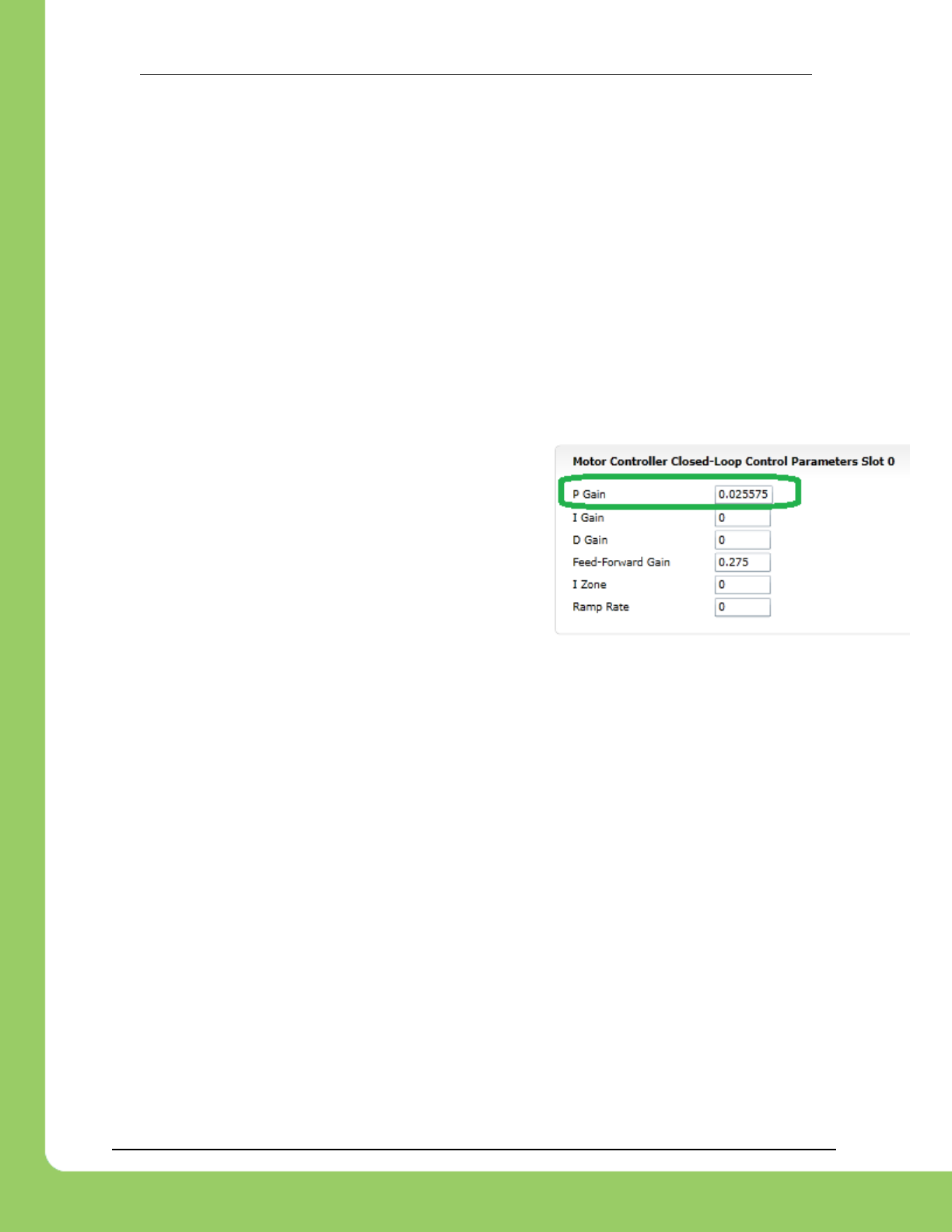
217-8080 TALON SRX Software Reference Manual 2/14/2017
Cross The Road Electronics Page 104 2/14/2017
12.8.5. Motion Magic Closed-Loop Walkthrough – P-Gain – Java
Next we will add in P-gain so that the closed-loop can react to error. In the previous section,
after running the mechanism with just F-gain, the servo appears to settle with an error or ~1400.
Given an error of (~1400.), suppose we want to respond with another 10% of throttle. Then our
starting p-gain would be….
(10% X 1023) / (1400) = 0.0731
Now let’s check our math, if the Talon SRX sees an error of 1400 the P-term will be
1400 X 0.0731= 102 (which is about 10% of 1023)
P-gain = 0.0731
Apply the P -gain programmatically using your
preferred method. Now retest to see how well the
closed-loop responds to varying loads.
/* set closed loop gains in slot0 */
_talon.setProfile(0);
_talon.setF(0.2481);
_talon.setP(0.0731);
_talon.setI(0);
_talon.setD(0);
_talon.setMotionMagicCruiseVelocity(453);/* 453 RPM */
_talon.setMotionMagicAcceleration(453);/* 453 RPM per sec */
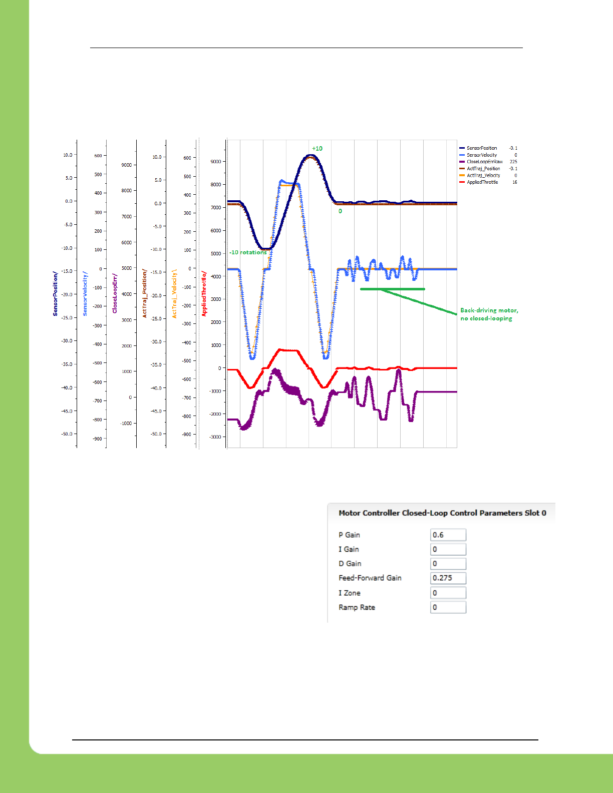
217-8080 TALON SRX Software Reference Manual 2/14/2017
Cross The Road Electronics Page 105 2/14/2017
Retest the maneuver by holding button 1 and sweeping the gamepad stick.
At the end of this capture, the wheels were hand-spun to demonstrate how aggressive the
position servo responds. Because the wheel still backdrives considerably before motor holds
position, the P-gain still needs to be increased.
Double the P-gain until the system oscillates (by a small amount) or until the system responds
adequately.
After a few rounds the P gain is at 0.6.
Scope captures below show the sensor position
and target position follows visually, but back-
driving the motor still shows a minimal motor
response.
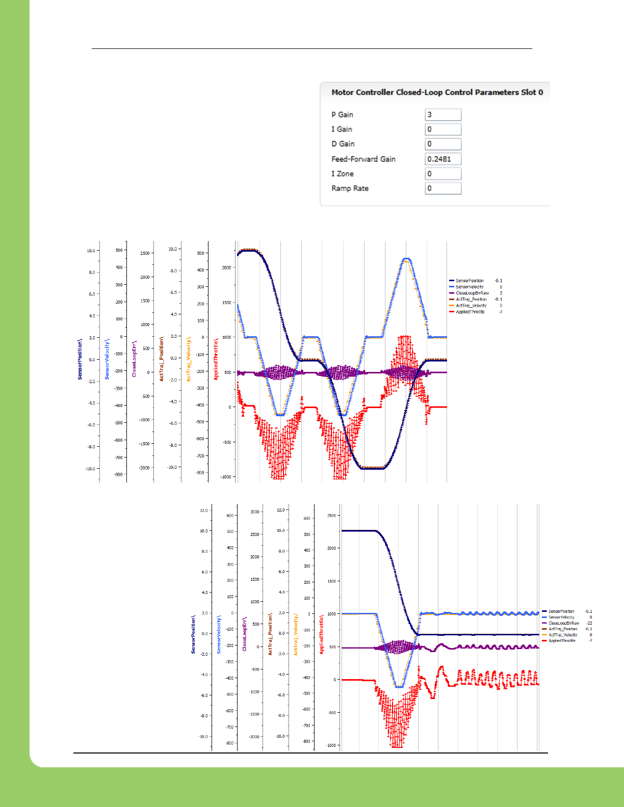
217-8080 TALON SRX Software Reference Manual 2/14/2017
Cross The Road Electronics Page 106 2/14/2017
After several rounds, we’ve landed on a P gain
value of 3. The mechanism overshoots a bit at
the end of the maneuver. Additionally, back-
driving the wheel is very difficult as the motor-
response is immediate (good).
Once settles, the
motor is back-driven
to assess how firm
the motor holds
position.
The wheel is held by
the motor firmly.
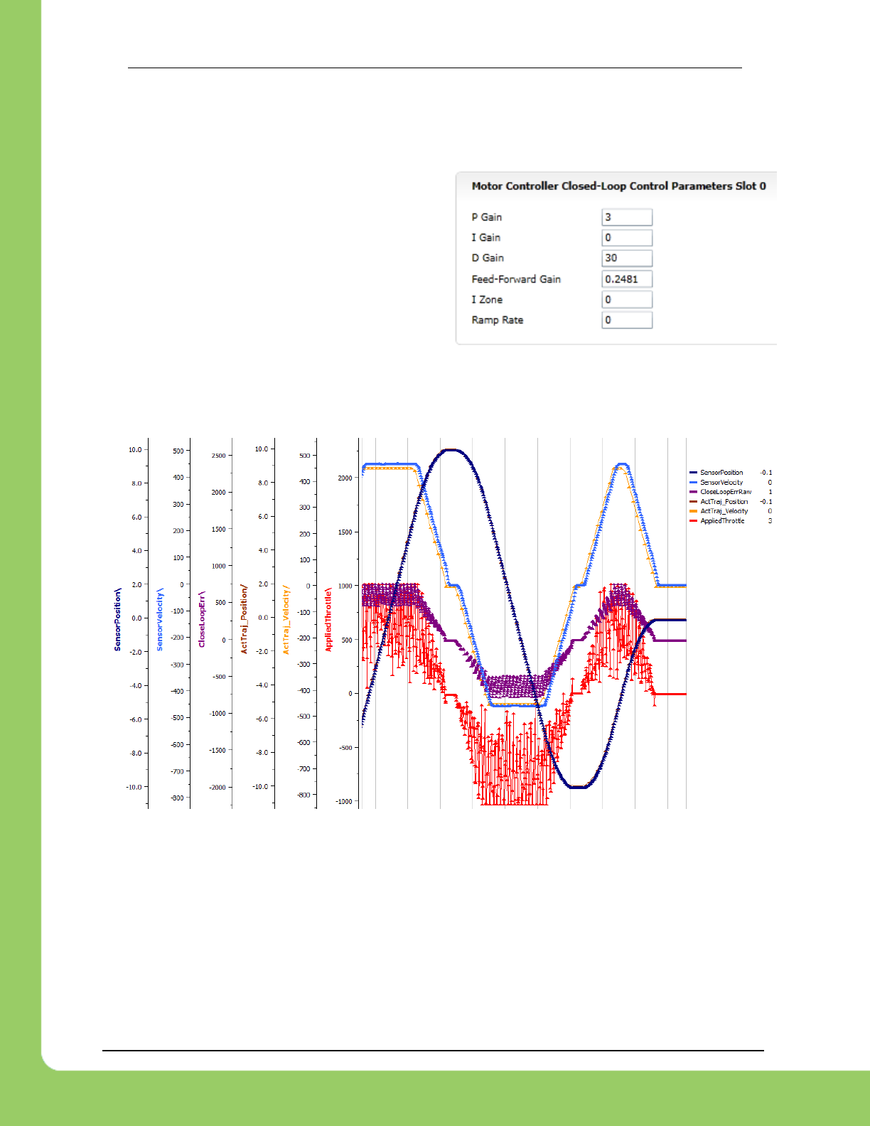
217-8080 TALON SRX Software Reference Manual 2/14/2017
Cross The Road Electronics Page 107 2/14/2017
12.8.6. Motion Magic Closed-Loop Walkthrough – D-Gain – Java
To resolve the overshoot at the end of the
maneuver, D-gain is added. D-gain can start
typically at 10 X P-gain.
With this change the visual overshoot of the wheel is gone. The plots also reveal reduced
overshoot at the end of the maneuver.
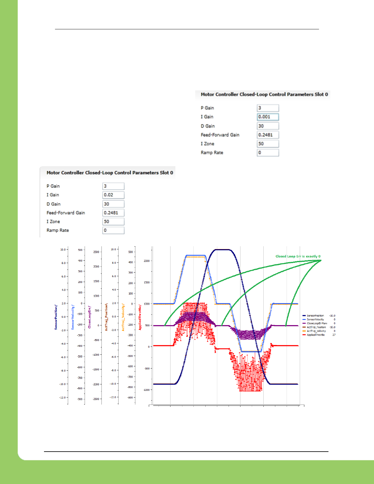
217-8080 TALON SRX Software Reference Manual 2/14/2017
Cross The Road Electronics Page 108 2/14/2017
12.8.7. Motion Magic Closed-Loop Walkthrough – I-Gain – Java
Typically, the final step is to confirm the sensor settles very close to the target position. If the
final closed-loop error is not quite close enough to zero, consider adding I-gain and I-zone to
ensure the Closed-Loop Error ultimately lands at zero (or close enough).
In testing the closed-loop error settles around 20
units, so we’ll set the Izone to 50 units (large
enough to cover the typical error), and start the I-
gain at something small (0.001).
Keep doubling I-gain until the error reliably
settles to zero.
With some tweaking, we find an I-gain that
ensures maneuver settles with an error of 0.
At this point the acceleration and cruise-velocity can be modified to hasten/dampen the
maneuver as the application requires.
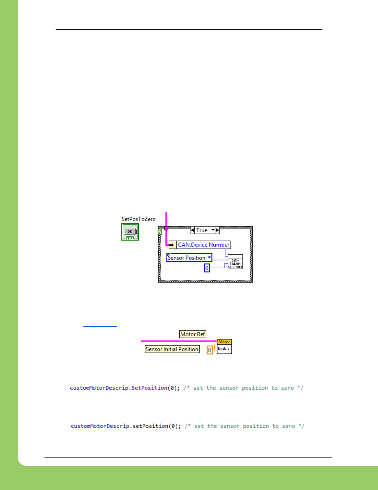
217-8080 TALON SRX Software Reference Manual 2/14/2017
Cross The Road Electronics Page 109 2/14/2017
13. Setting Sensor Position
Depending on the sensor selected, the user can modify the “Sensor Position”. This is
particularly useful when using a Quadrature Encoder (or any relative sensor) which needs to be
“zeroed” or “home-ed” when the robot is in a known position.
Firmware 1.1: When using an “Analog Encoder”, setting the “Sensor Position” updates the top
14 bits of the 24bit Sensor Position value (which is the overflow/underflow portion). The bottom
10 bits will still reflect the analog voltage scaled over 3.3V (read only). With version 1.4 and on
the full Sensor Position can be set.
Setting this signal when “Analog Potentiometer” is selected has no effect.
13.1. Setting Sensor Position – LabVIEW
In order to modify the “Sensor Position”, user will likely have to leverage the
WPI_CANTalonSRX_SetParameter.vi. This can be drag dropped after locating the LabVIEW
installer directory and searching for the VI file location. Select “Sensor Position” for the
“Parameter” signal and the desired constant for the “Value” signal. In this example “0” is
selected to re-zero the sensor when a front panel button is pressed.
13.1.1. Motor Enable
Alternatively the Motor Enable VI can be used to change the Sensor Position. If the Robot
Application needs to turn on/off motor control in a periodic fashion, change the control mode
instead (see Section 3.6) since this VI has the side effect of modifying Sensor Position.
13.2. Setting Sensor Position – C++
SetPosition() can be used to change the current sensor position, if a relative sensor is used.
13.3. Setting Sensor Position – Java
setPosition() can be used to change the current sensor position, if a relative sensor is used.
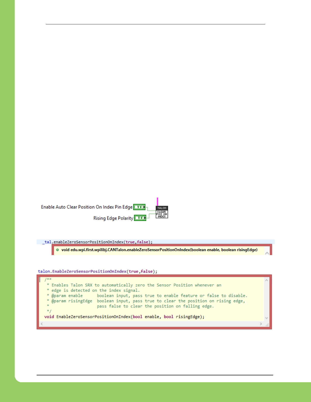
217-8080 TALON SRX Software Reference Manual 2/14/2017
Cross The Road Electronics Page 110 2/14/2017
13.4. Auto Clear Position using Index Pin
In addition to manually changing the sensor position, the Talon SRX supports automatically
resetting the Selected Sensor Position to zero whenever a digital edge is detected on the
Quadrature Index Pin.
This feature can be enabled regardless of which sensor is selected. This allows a means of
resetting the position using a digital sensor, switch, or any external event that can drive a 3.3V
digital signal. Since the Quadrature Index Pin has an internal pullup, the signal source can be
an open-drain signal that provides ground when asserted, and high-impedance when not
asserted (or vice versa).
This feature is useful for minimizing the latency of resetting the Sensor Position after the
external event since the robot controller is not involved. The maximum delay is <1ms.
Additionally this feature functions even if the Talon is disabled.
The feature uses the Quadrature Index Pin, which is convenient if the selected sensor is a
Quadrature encoder and the application requires syncing the position to the sensor’s index
signal.
The polarity of the trigger edge can be set to rising or falling.
13.4.1. Setting Sensor Position – LabVIEW
13.4.2. Setting Sensor Position – Java
13.4.3. Setting Sensor Position – C++
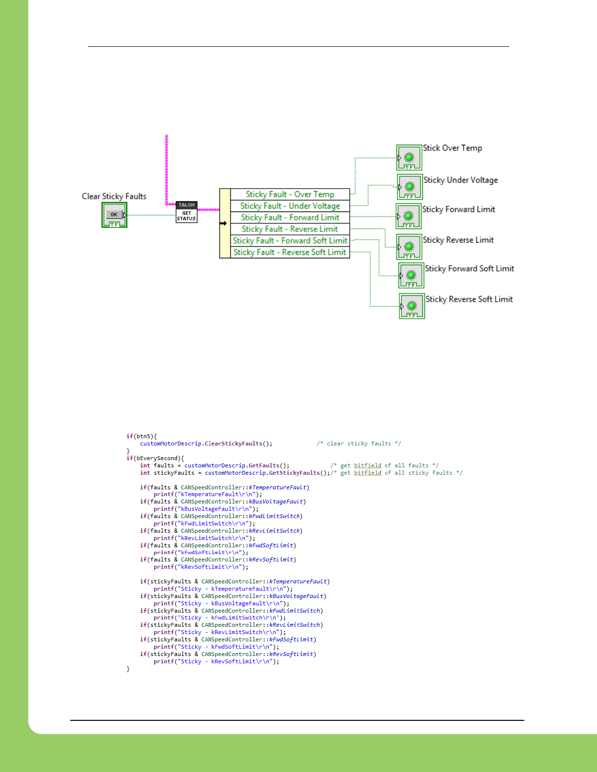
217-8080 TALON SRX Software Reference Manual 2/14/2017
Cross The Road Electronics Page 111 2/14/2017
14. Fault Flags
The GET STATUS VI can be used to retrieve sticky flags, and clear them.
14.1. LabVIEW
14.2. C++
Use GetFaults() and GetStickyFaults() to get integral bit fields that can be masked against
the constants available in the CANSpeedController header.
ClearStickyFaults() can be used to clear all sticky fault flags.
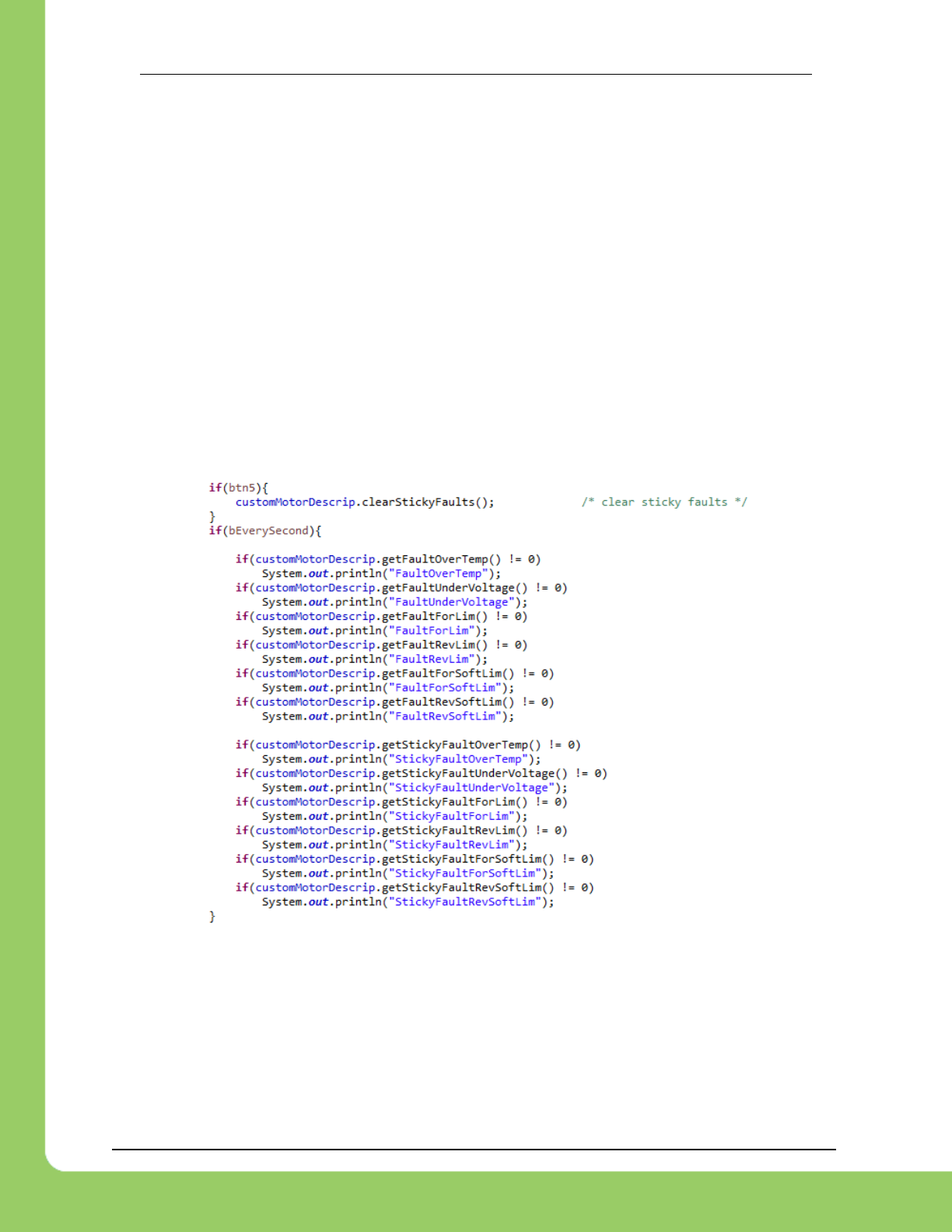
217-8080 TALON SRX Software Reference Manual 2/14/2017
Cross The Road Electronics Page 112 2/14/2017
14.3. Java
Use the various getFault<name> and getStickyFault<name> functions to individually detect
the various fault conditions.
getFaultOverTemp()
getFaultUnderVoltage()
getFaultForLim()
getFaultRevLim()
getFaultForSoftLim()
getFaultRevSoftLim()
getStickyFaultOverTemp()
getStickyFaultUnderVoltage()
getStickyFaultForLim()
getStickyFaultRevLim()
getStickyFaultForSoftLim()
getStickyFaultRevSoftLim()
clearStickyFaults() can be used to clear all sticky fault flags.
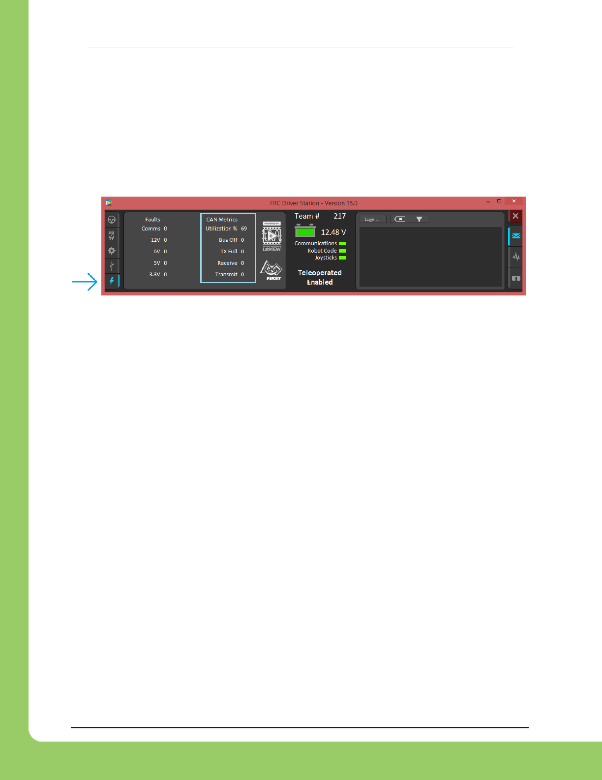
217-8080 TALON SRX Software Reference Manual 2/14/2017
Cross The Road Electronics Page 113 2/14/2017
15. CAN bus Utilization/Error metrics
The driver station provides various CAN bus metrics under the “lightning bolt” tab.
Utilization is the percent of bus time that is in use relative to the total bandwidth available of the
1Mbps Dual Wire CAN bus. So at 100% there is no idle bus time (no time between frames on
the CAN bus).
Demonstrated here is 69% bus use when controlling 16 Talon SRXs, along with 1 Pneumatics
Control Module (PCM) and the Power Distribution Panel (PDP).
The “Bus Off” counter increments every time the CAN Controller in the roboRIO enters “bus-off”,
a state where the controller “backs off” transmitting until the CAN bus is deemed “healthy”
again. A good method for watching it increment is to short/release the CAN bus High and Low
lines together to watch it enter and leave “Bus Off” (counter increments per short).
The “TX Full” counter tracks how often the buffer holding outgoing CAN frames (RIO to CAN
device) drops a transmit request. This is another common symptom when the roboRIO no
longer is connected to the CAN bus.
The “Receive” and “Transmit” signal is shorthand for “Receive Error Counter” and “Transmit
Error Counter”. These signals are straight from the CAN bus spec, and track the error instances
occurred “on the wire” during reception and transmission respectively. These counts should
always be zero. Attempt to short the CAN bus and you can confirm that the error counts rise
sharply, then decrement back down to zero when the bus is restored (remove short, reconnect
daisy chain).
When starting out with the FRC control system and Talon SRXs, it is recommend to watch how
these CAN metrics change when CAN bus is disconnected from the roboRIO and other CAN
devices to learn what to expect when there is a harness or a termination resistor issue.
Determining hardware related vs software related issues is key to being successful when using
a large number of CAN devices.

217-8080 TALON SRX Software Reference Manual 2/14/2017
Cross The Road Electronics Page 114 2/14/2017
15.1. How many Talons can we use?
Generally speaking a maximum of 16 Motor controllers can be powered at once using a single
PDP (sixteen breaker slots). However FRC game rules should always be checked as it
determines what it considered legal. This is typically the bottleneck for how many Talon SRXs
can be used despite having CAN device ID space for 63 device IDs. Release software is
always tested to support 16 Talon SRXs, 1 PCM, and 1 PDP with guaranteed control of each
Talon at a rate of 10ms. However this is not the limit. There is still additional bandwidth for
more nodes. Additionally, if faster response time is desired, control frame periods can be
decreased from the default 10ms, but keep a watchful eye of the CAN bus utilization to ensure
reliable communication.

217-8080 TALON SRX Software Reference Manual 2/14/2017
Cross The Road Electronics Page 115 2/14/2017
16. Troubleshooting Tips and Common Questions
2016 season refers to Kickoff January 2016 (FIRST Stronghold).
2015 season refers to Kickoff January 2015 (Recycle Rush). Issues that have been
resolved since then are grayed out.
Just because a firmware issue has been resolved does not mean your out-of-the-box
hardware doesn’t have old firmware. Immediately update your CAN devices to ensure your
development time is not wasted chasing down an issue that has already been solved.
16.1. When I press the B/C CAL button, the brake LED does not change,
neutral behavior does not change.
This is the expected behavior if the robot application is overriding the brake mode. The B/C
CAL button press does toggle the brake mode in persistent memory, however the LED and
selected neutral behavior will honor the override sent over CAN bus. Check if the override API
is being used in the robot application logic.
16.2. Changing certain settings in Disabled Loop doesn’t take effect until
the robot is enabled.
This has been improved in FRC2016 Talon SRX Firmware by sending control parameters
during disable. The motor controllers are still disabled, but the control signals are updated and
can be confirmed in the roboRIO-web-based configuration Self-Test.
This is the expected behavior, the control frame that updates the Talon SRX with the latest
brake/limit switch override, control mode, and set-point does not get transmitted in robot-disable
mode. However the values are saved so that when the robot is enabled, the first control frame
sent will have up to date values.
For example, the B/C CAL LED will not reflect changes in the overridden brake mode if
SetBrake()is called in the disabled loop until after the robot has been enabled. Once the robot
is enabled, the control frame sent to the Talon will enable the motor controller and contain the
latest settings that were cached during disabled loop (including the brake override).
Similarly Self-Test results also won’t reflect parameters that are changed programmatically until
the robot is enabled, specifically the brake/limit switch overrides.
The startup values for limit switch and brake mode can be specified in the roboRIO’s Web-
based Configuration if they must be configured prior to robot enable.

217-8080 TALON SRX Software Reference Manual 2/14/2017
Cross The Road Electronics Page 116 2/14/2017
16.3. The robot is TeleOperated/Autonomous enabled, but the Talon SRX
continues to blink orange (disabled).
Most likely the device ID of that Talon is not being used. In other words there is no Open Motor
(LabVIEW) or constructed CANTalon (C++/Java) with that device ID. This can be confirmed by
doing a Self-Test in the roboRIO Web-based Configuration, and confirm the “TALON IS NOT
ENABLED!” message at the top.
16.4. When I attach/power a particular Talon SRX to CAN bus, The LEDs on
every Talon SRX occasionally blink red. Motor drive seems normal.
If there is a single CAN error frame, you can expect all Talon SRXs on the bus to synchronously
blink red. This is a great feature for detecting intermittent issues that normally would go
unnoticed. If attaching a particular Talon brings this behavior out, most likely its device ID is
common with another Talon already on the bus. This means two or more “common ID” Talon
SRXs are periodically attempting to transmit using the same CAN arbitration ID, and are
stepping on each other’s frame. This causes an intermittent error frame which then reveals
itself when all Talon SRXs blink red. Check the roboRIO Web-based Configuration for the
“There are X devices with this Device ID” explained in Section 2.2. Common ID Talons.
16.5. If I have a slave Talon SRX following a master Talon SRX, and the
master Talon SRX is disconnected/unpowered, what will the slave Talon
SRX do?
The slave Talon SRX monitors for throttle updates from the master. If the slave Talon doesn’t
see an update after 100ms, it will disable its drive. The LEDs will reflect robot-enable but with
zero throttle (solid orange LEDs).
16.6. Is there any harm in creating a software Talon SRX for a device ID
that’s not on the CAN bus? Will removing a Talon SRX from the CAN bus
adversely affect other CAN devices?
No! Attempting to communicate with a Talon SRX that is not present will not harm the
communication with other CAN nodes. The communication strategy is very different than
previously support CAN devices, and this use case was in mind when it was designed.
Creating more Talon software objects (LabVIEW Motor Open, or C++/Java class instances) will
increase the bus utilization since it means sending more frames, however this should not
adversely affect robot behavior so long as the bus utilization is reasonable.
However the resulted error messages in the DS may be a distraction so when permanently
removing a Talon SRX from the CAN bus, it is helpful to synchronously remove it from the robot
software.
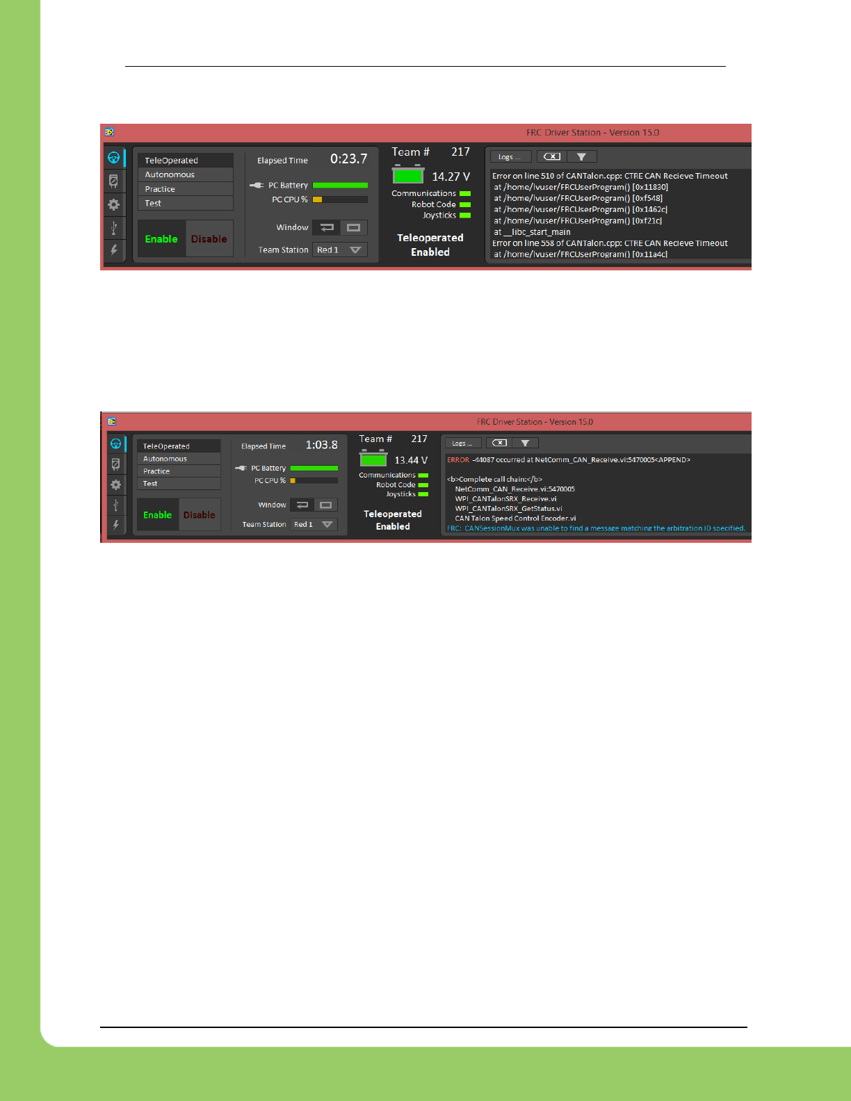
217-8080 TALON SRX Software Reference Manual 2/14/2017
Cross The Road Electronics Page 117 2/14/2017
16.7. Driver Station log says Error on line XXX of CANTalon.cpp
This is to be expected when constructing a CANTalon with a device ID that is not present on
CAN bus in C++/Java. These are caused by asserts in the programming API meant to signal
the developer that some expected CAN frame was not detected on the bus. Although it should
not impact other CAN nodes, it can be a distraction since it may mask other unrelated errors
reported in the driver station that are no longer visible.
16.8. Driver Station log says -44087 occurred at NetComm...
This is to be expected when referencing a “CAN Talon SRX” with a device ID that is not present
on CAN bus in LabVIEW. Although it should not impact other CAN nodes, it can be a
distraction since it may mask other unrelated errors reported in the driver station that are no
longer visible.
16.9. Why are there multiple ways to get the same sensor data?
GetEncoder() versus GetSensor()?
The API that fetches latest values for Encoder (Quadrature) and Analog-In (potentiometer or a
continuous analog sensor) reflect the pure decoded values sent over CAN bus (every 100ms).
They are available all the time, regardless of which control mode is applied or whether the
sensor type has been selected for soft limits and closed-loop mode. These signals are ideal for
instrumenting/logging/plotting sensor values to confirm the sensors are wired and functional.
Additionally they can be read at the same time (you can wire a potentiometer AND a quadrature
encoder and get both position and velocities programmatically). Furthermore the robot
application could actually use this method to process sensor information directly. If the 100ms
update rate is not sufficient, it can be overridden to a faster rate.
For the purpose of using soft limits and/or closed-loop modes, the robot application must select
which sensor to use for position/velocity. Selecting a sensor will cause the Talon SRX to mux
the appropriate sensor to the closed-loop logic, the soft limit logic, to the “Sensor Position” and
“Sensor Velocity” signals (update 20ms). These signals also can be inverted using the
"Reverse Feedback Sensor" signal in order to keep the sensor in phase with the motor.

217-8080 TALON SRX Software Reference Manual 2/14/2017
Cross The Road Electronics Page 118 2/14/2017
Since “Sensor Position” and “Sensory Velocity” are updated faster (20ms) they can also be
used for processing sensor information instead of overriding the frame rates.
16.10. So there are two types of ramp rate?
There are two ways to “ramp” or acceleration cap the motor drive.
The “Voltage Ramp” API in all three languages are functional, and takes effect regardless of
which mode the Talon SRX is in (duty cycle, slave, Position, Speed).
The selected Motor Control Profile also has a “Closed-Loop Ramp Rate” which can be used to
apply a unique ramp rate only when the motor controller is closed-looping and the Profile Slot
has been selected.
By having two options, a robot can have mode specific ramping with minimal effort in the robot
controller. For example, a team may require a “weak” ramp to slightly dampen motor drive to
prevent driver error (flipping the robot), or to reduce impulse stress (snapping chains). But
when closed-looping, an additional ramp might be necessary to smooth the closed-loop
maneuver.
16.11. Why are there two feedback “analog” device types: Analog Encoder
and Analog Potentiometer?
When Analog Potentiometer is selected, the 10 bit Analog to Digital Converter (ADC) converts
the 0 to 3.3V signal present on the analog input pin to a value between 0 and 1023.
When Analog Encoder is selected, the same conversion takes place, but rollovers to and from
the min/max voltage are tracked so that analog sensors can be used as relative sensors. If an
overflow is detected (1023 => 0), the position signal transitions (1023 => 1024). Likewise an
underflow (0=>1023) is interpreted as (0 => -1). This is useful when using an analog encoder
and allowing it to exceed the max turn count. This way an analog encoder can be used as a
continuous relative sensor.
16.12. After changing the mode in C++/Java, motor drive no longer works.
Self-Test says “No Drive” mode?
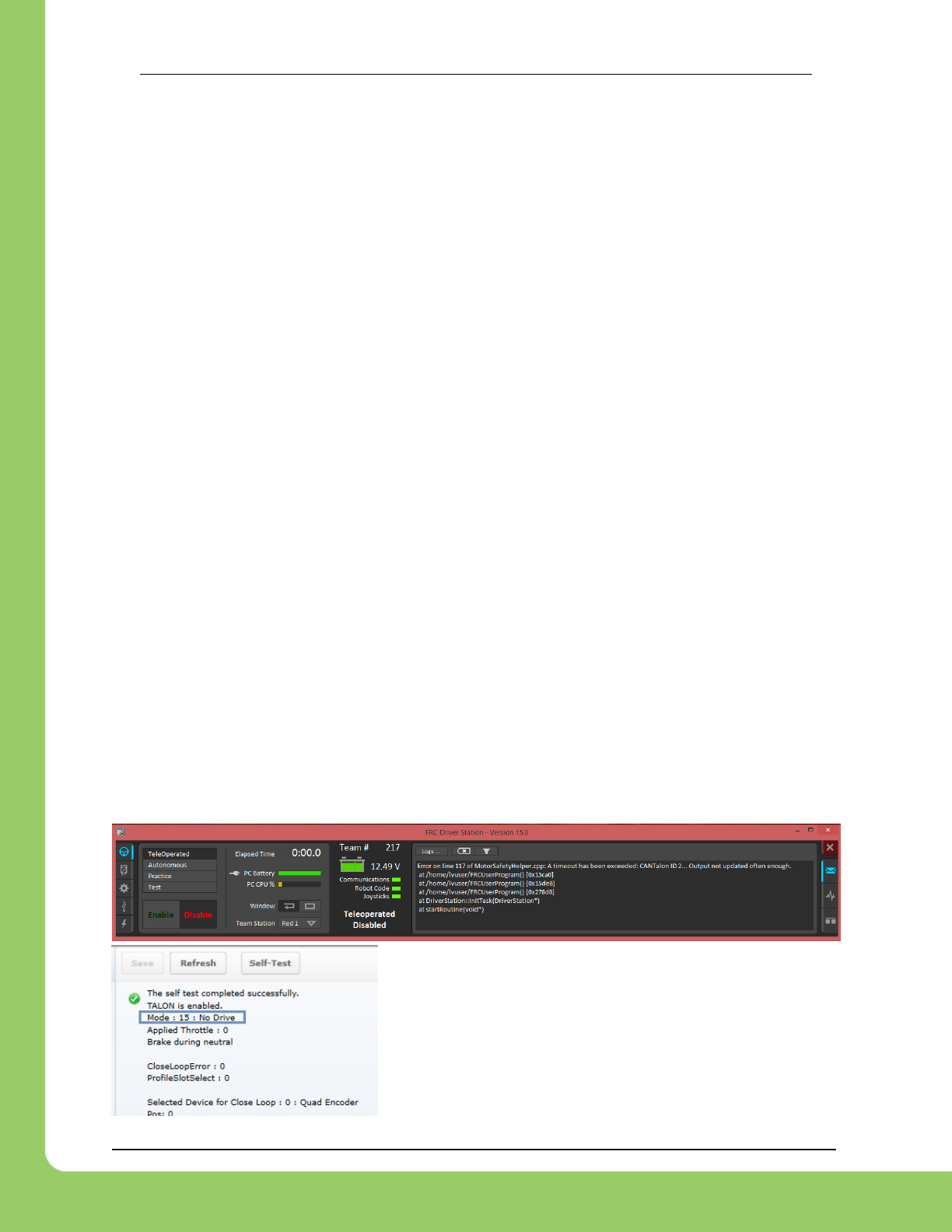
217-8080 TALON SRX Software Reference Manual 2/14/2017
Cross The Road Electronics Page 119 2/14/2017
After calling a Talon SRX object’s changeMode() function, the Talon SRX mode is set to
disabled until the Set()/set() routine is called. This is to ensure the robot application has a
chance to pass a new target set point before the new control mode is applied. Any call to
changeMode() should be immediately followed with a Set()so that motor drive is not set to
neutral.
This ensures that when the robot application changes a Talon’s mode, it also specifies the
throttle/set-point/or slave ID for the new mode to ensure all the necessary information is set for
the mode switch.
16.13. All CAN devices have red LEDs. Recommended Preliminary checks
for CAN bus.
Some basic checks for the CAN harness are…
Turn off robot, measure resistance between CANH and CANL.
~60 ohm is typical (120ohm at each end of the cable).
~120 ohm suggests that one end is missing termination resistor. Terminate the end
using PDP jumper or explicit 120 ohm resistor.
~0 ohm suggests a short between CANH and CANL.
INF or large resistances, missing termination resistor at each side.
More information can be found in Talon SRX User’s Guide.
Check the roboRIO’s Web-based Configuration to see if any devices appear, and ensure
there are no Talon SRX’s sharing the same device ID.
16.14. Driver Station reports “MotorSafetyHelper.cpp: A timeout…”, motor
drive no longer works. roboRIO Web-based Configuration says “No Drive”
mode? Driver Station reports error -44075?
This can happen after enabling Motor Safety Enable and not calling Set()/set() often enough
to meet the expiration timeout.
Another symptom of this is seeing “No Drive” has the
control mode in the Self-Test.
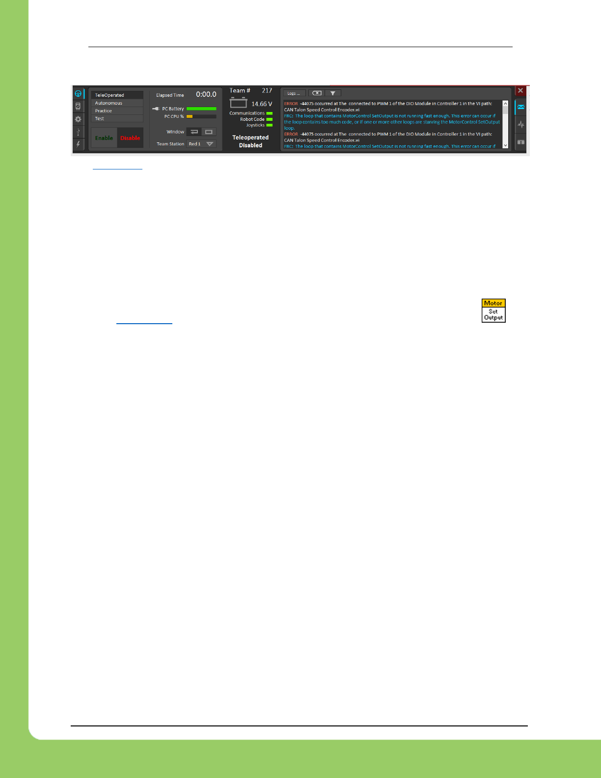
217-8080 TALON SRX Software Reference Manual 2/14/2017
Cross The Road Electronics Page 120 2/14/2017
When the safety timeout expires in LabVIEW, the error message will be different…
See section 19 for more information.
16.15. Motor drive stutters, misbehaves? Intermittent enable/disable?
Check the CAN Utilization to ensure it’s not near 100%. An abnormally high percent may be a
symptom of “common ID” Talons. This also can occur when selecting custom frame rates that
are too fast.
Ensure robot application calls Set() on each Talon at least once per loop. Avoid strategies that
attempt to write the Talon set-output “only when it changes”. There is no cost to updating the
set-output of the Talon SRX using the robot API, and often such strategies trip the motor-safety
features (section 19). If using LabVIEW avoid using tunnels/shift-registers to only call
when the input parameter has changed.
Check the roboRIO’s Web-based Configuration to confirm all expected Talons are populated
and are enabled according to the Self-Test.
Check the “Under Vbat” sticky flag in the Self-Test. This will rule out power/voltage related
issues.
If the issues occur only during rapid changes in direction and magnitude, the power
cables/crimps may not be efficient enough to deliver power during the stall-period when a
loaded motor changes direction. This can be confirmed if increasing the voltage ramp rate
removes/fixes this symptom.
Be sure to check the Driver Station Logs for packet loss since that can cause intermittent robot
disables.
If the Driver Station has 3rd party software that uses network communication, or if the Driver
Station
When using the DAP-1522 (or similar radio) be sure to use latest stable firmware. For example,
rev-A DAP1522s (with production ship firmware) will not reliably enable the robot. Additionally
consult FRC rules and documentation for which hardware rev is legal for competition and how to
properly setup the radio.

217-8080 TALON SRX Software Reference Manual 2/14/2017
Cross The Road Electronics Page 121 2/14/2017
16.16. What to expect when devices are disconnected in roboRIO’s Web-
based Configuration. Failed Self-Test?
Depending what version of software is released, a discovered Talon will display loss of
connection one of two ways.
The Firmware Version may report (Device is not responding).
Alternatively the tree element will gray out to indicate loss of communication….
The roboRIO internals rechecks the CAN bus once every five seconds so when
connecting/disconnecting Talons to/from the bus, be sure to wait at least five seconds and
refresh the webpage to detect changes in connection state.
Doing a Self-Test when the Talon SRX is not present on the CAN bus will report a red ‘X’ in the
top left portion of the Self-Test report. Depending on what robot controller image is release you
may see the stale values of all signals when the red “X” is present.

217-8080 TALON SRX Software Reference Manual 2/14/2017
Cross The Road Electronics Page 122 2/14/2017
16.17. When I programmatically change the “Normally Open” vs “Normally
Closed” state of a limit switch, the Talon SRX blinks orange momentarily.
Changing the “Normally Open” versus “Normally Closed” setting of a motor controller will cause
it to disable motor drive momentarily. If the goal is to enable/disable the limit switch feature, this
can be done without affecting motor drive using the Limit Switch overrides.
Typically the only time a Talon SRX NO/NC setting won’t match what is specified
programmatically will be when a new Talon SRX is installed for the first time. Once the
programming API has changed the setting once, the Talon SRX’s persistent limit switch mode
will match what the programming API requests, and therefore will not impact robot performance.
16.18. How do I get the raw ADC value (or voltage) on the Analog Input pin?
The bottom ten bits of Analog-In Position is equal to the converted ADC value. The range of [0,
1023] scales to [0V, 3.3V]. Additionally, if “Analog Potentiometer” is selected as the Feedback
Device, the signal “Sensor Position” will exactly equal the bottom ten bits of Analog-In Position.
16.19. Recommendation for using relative sensors.
When using relative sensors for closed-loop control, it’s always good practice to design in a way
to re-zero your robot. Regardless of how/where relative sensors are connected (robot controller
IO, Talon SRX, etc…), there is always the potential for sensors to “walk” or “drift” due to…
-Mechanical slip issues
-Skipped gear teeth in chain
-Intermittent electrical connections (harness gets damaged in middle of a match)
-Power cycle robot when armatures are not in their “home” position.
-Remote resets of robot controller when armatures are not in their “home” position.
A common solution to this is to design a way in the gamepad logic to force your robot into a
“manual mode” where the driver/arm operator can manually servo motors to a home position
and press a button (or button combination) to re-zero (or set to the “home” position values) all
involved sensors.
Teams that do this already can continue to use this method with Talon SRX since there is are
set functions to modify “Sensor Position”.
16.20. Does anything get reset or lost after firmware updates?
The device ID, limit switch startup settings, brake startup settings, Motor Control Profile
Parameters, and sticky flags are all unaffected by the act of field-upgrading. If a particular
firmware release has a “back-breaking” change, it will be explicitly documented.
16.21. Analog Position seems to be stuck around ~100 units?
When the analog input is left unconnected, it will hover around 100 units. If an analog sensor
has been wired, most likely it’s connected to the wrong pin. Recheck wiring against the Talon
SRX User’s Guide.

217-8080 TALON SRX Software Reference Manual 2/14/2017
Cross The Road Electronics Page 123 2/14/2017
16.22. Limit switch behavior doesn’t match expected settings.
First check the Startup Settings in the roboRIO Web-based Configuration to determine that the
“Normally Open”/ “Normally Closed” settings are correct. They can be changed
programmatically and in the web page so it’s worth confirming. Here we see both directions use
NO limit switches...
Then press the “Self-Test” button to check…
-The open/closed state of the limit switch input pin on the Talon SRX.
-If enable/disable state of the limit-switch logic is overridden programmatically.
-Check the fault and sticky faults to see if limit fault conditions are detected.
In this example the Fwd. Limit Switch fault is not set despite the Fwd. Limit Switch being closed.
This is because the Limit Switch logic forced OFF, because the feature is disable
programmatically. As a result closing the forward limit switch will not disable motor drive.

217-8080 TALON SRX Software Reference Manual 2/14/2017
Cross The Road Electronics Page 124 2/14/2017
16.23. How fast can I control just ONE Talon SRX?
The fastest control frame rate that can be specified is 1ms. That means that the average period
at which the throttle/set point can be updates is 1ms. This will increase bus utilization by
approximately 15%, which is acceptable if the number of Talon SRXs is few. Always check the
CAN bus performance metrics in the Driver Station when doing this.
16.24. Expected symptoms when there is excessive signal reflection.
If the CAN bus harness has excessive signal reflection due to improper wiring or missing
termination resistors, the following symptoms may be seen…
-Driver Station will show Rx and Tx CAN errors intermittently (see Section 15), particularly with
higher bus utilization.
-CAN bus utilization will be higher than normal. This is because CAN devices transmit error
frames in response to detecting improper frames. This is helpful if you are in the habit of
checking your bus utilization every once in a while and knowing what is typical for your robot.
See Section 15 for more details.
-The LED of every CAN device on the bus will blink red intermittently during normal use (the
same symptom as Section 16.4). Both common-ID Talons and excessive signal reflection can
cause error frames to appear, which trigger every CTRE CAN device to intermittently blink red
during normal use.
One reliable way to observe this LED behavior is to deliberately leave a couple common-ID
Talon SRXs on your CAN Bus. Then, power up your robot and leave it disabled. All Talon
SRXs will rail-road orange (healthy CAN bus and disabled). Now watch any particular Talon
SRX for a minute or so. It will blink red intermittently as the two (or more) common-ID Talon
SRXs inevitably disrupt each other’s frame transmission.
-Measured DC resistance between CANH and CANL (when robot is unpowered) should be
approximately 60 Ω. If this is not the case then recheck the CAN wiring and termination
resistors (see Talon SRX User’s Guide).
16.25. LabVIEW application reads incorrect Sensor Position. Sensor
Position jumps to zero or is missing counts.
This is a common symptom if the LabVIEW application is calling the Motor Enable VI
periodically. This VI has the side-effect of modifying the Sensor Position every time it’s invoked.
Additionally wiring the current Sensor Position to this signal also will prevent proper signal
decoding since the RIO will send stale positions to the Talon SRX, overwriting valid signal
changes in the Talon. See Section 13.1.1 for more information.
Additionally, check that the correct Feedback Device is selected (Section 7). Remember that
the Feedback Device Select is sent only when the robot is enabled. Since there is only one
control frame that contains all control signals, this ensures Talon has the correct sensor
selected when Talon is enabled (Section 20.6).
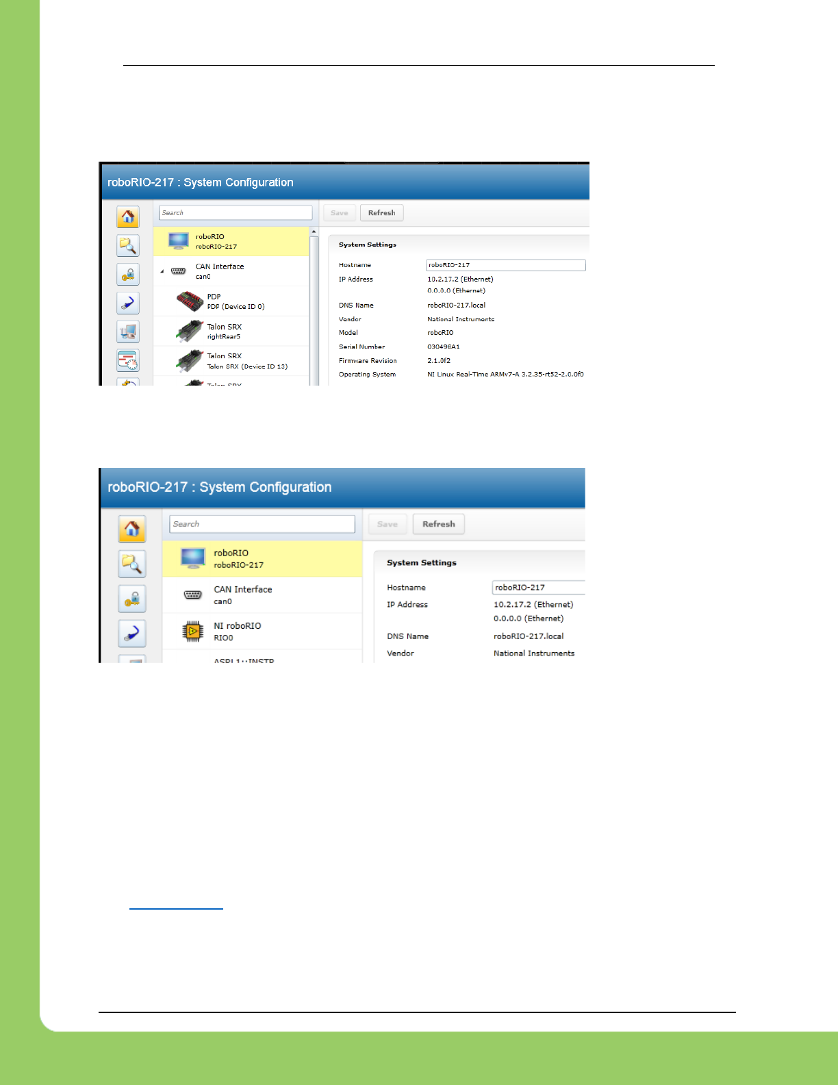
217-8080 TALON SRX Software Reference Manual 2/14/2017
Cross The Road Electronics Page 125 2/14/2017
16.26. CAN devices do not appear in the roboRIO Web-based config.
Normally devices appear under the “CAN Interface” tree node…
…however if the roboRIO is not correctly wired to the CAN Bus, then the tree node will have no
elements listed underneath…
…in which case double-check the CAN bus wiring and termination strategy. See the Talon SRX
User’s Guide for more information on wiring Talon SRXs. Also see the “FRC Screen steps”
online documentation for more information on wiring the other CAN devices in the control
system. Additionally, check the status LEDs of the CAN devices. Generally, red LED states
reflect an unhealthy CAN connection, which will help diagnose wiring issues.
16.27. After a power boot of the robot, and then enabling, occasionally a
single CAN actuator does not enable (blinks orange as though it is
disabled). Issue corrects itself after pressing “Restart Robot Code” in
Driver Station and re-enabling robot.
See section 21.18. If using C++, an alternative solution is to simply update to WPILib 2015-02-
24.
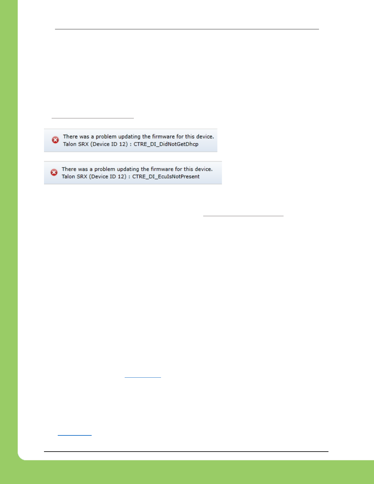
217-8080 TALON SRX Software Reference Manual 2/14/2017
Cross The Road Electronics Page 126 2/14/2017
16.28. Occasionally when a firmware update is attempted we get an
immediate error. Talon SRX is blinking green/orange. However when we
re-imaged the RIO the issue went away?
The root-cause of this issue has been address in the 2016 release.
If you are a C++ team using a WPLib version prior to 2015-02-24, then you may be susceptible
to Functional Limitation 21.18. A secondary symptom of the roboRIO startup issue is that the
first attempt at field-updating a CAN device will cause this error.
A second attempt at field-updating it will cause this error.
Although the root-cause is a startup condition in the roboRIO, there are many solutions to this…
16.28.1. The simplest solution is to update your C++ WPILib to 2015-02-24 or newer. This
resolves the root-cause, the startup race that creates Functional Limitation 21.18. Rebuild,
redeploy, and reboot the roboRIO, then reattempt flashing CAN devices.
16.28.2. Another alternative is to “undeploy” your C++ built FRCUserProgram application.
Deleting/renaming the file (inside /home/lvuser using SSH or FTP) is sufficient. Then reboot
roboRIO and re-attempt flashing CAN devices. Re-deploy your robot application when you’ve
finished re-flashing your CAN devices.
16.28.3. A third alternative is to re-image the roboRIO, however this is an excessive solution
and is not recommended. The reason this has worked for teams previously is because it has
the side effect of removing the deployed application, just like 16.28.2. However reimaging the
RIO takes considerably more time (several minutes) whereas the two previous solutions are
much faster and lower risk.
16.29. When I make a change to a setting in the roboRIO Web-based
configuration and immediately flash firmware into the Talon, the setting
does not stick?
When any of the Motor Control Profile (MCP) settings are changed, a certain amount of time
must pass before the settings are committed to persistent storage (if a previous change hadn’t
been made recently). See section 11.1 for an explanation of how the wear-leveling works. This
only occurs when re-flashing the firmware immediately after two subsequent setting changes
where the two changes are also done immediately after each other.
16.30. My mechanism has multiple Talon SRXs and one sensor. Can I still
use the closed-loop/motion-profile modes?
See Section 7.6 for recommended procedure.

217-8080 TALON SRX Software Reference Manual 2/14/2017
Cross The Road Electronics Page 127 2/14/2017
16.31. My Closed-Loop is not working? Now what?
The common observations when setting up a closed-loop initially is
The motor output saturates immediately when enabled.
The motor output is neutral despite sensor not being near target position/velocity.
Oscillation or over-shooting the target.
Motor output is not enough to reach target.
When debugging a closed-loop mechanism, follow the procedure in order.
16.31.1. Make sure Talon has latest firmware.
See Section 2.3 for instructions. See Section 22 for firmware release notes.
16.31.2. Confirm sensor is in phase with motor.
See Section 7.4 for instructions on how to check if sensor and motor are in phase.
This is often the culprit if the closed-loop “runs away” or reaches maximum motor output
immediately.
16.31.3. Confirm Slave/Follower Talons are driving
If there are slave Talon SRXs, ensure their LED output matches the master Talon. If a slave
Talon is not driving due to improper software setup or incorrect wiring, a master Talon may
back-drive the slave Talon(s), causing excessive current-draw and/or breaker trips.
To test that the Slave Talons are functioning, unplug all motors and manually drive while looking
at the Talon LEDs. Generally the LEDs of all involved Talons should blink red or green
synchronously (all Talons are the same color and blink rate). The exception to this is if a slave
Talon is inverted using the API in Section 7.4.
See Section 7.6 for complete instructions on testing Slave/Follower Talons setup.
16.31.4. Drive (Master) Talon manually
Drive the Talon (or if using slave Talons, drive the master Talon) using PercentVoltage mode.
Cover the full range of speed to ensure mechanical system is functioning as expected.
Measure the sensor positions at the critical points to ensure sensor is functioning. This also
aids in confirming what the target sensor positions should be if the goal is to use Position
Closed-Loop.
See Section 17.2.1 to lookup sensor resolution of each sensor type.
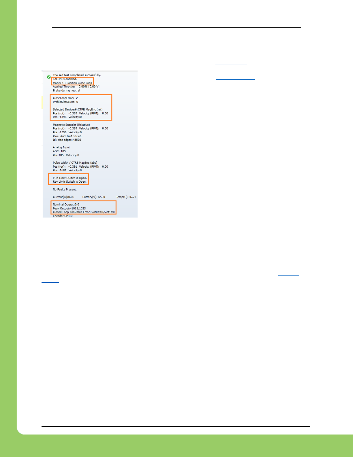
217-8080 TALON SRX Software Reference Manual 2/14/2017
Cross The Road Electronics Page 128 2/14/2017
16.31.5. Re-enable Closed-Loop
Zero all four gains (F, P, I, D) and place Talon SRX into Closed-Loop mode. Use the Self-
Test to ensure Talon is enabled and in the appropriate mode (Section 2.4).
If Mode is “No Drive”, see Section 16.12. If Mode is the
wrong one, inspect robot-code to see why the wrong mode
is selected.
Applied Throttle will be 0% since the gains are all zeroed.
Ensure the Closed-Loop Peak Outputs are correct.
“-1023, 1023” represent the full range (no restriction) of
motor-output (default).
Ensure the Closed-Loop Nominal Outputs are correct.
“0, 0” represent no restriction on the “smallest” nonzero
motor-output of the Closed-Loop (default).
Ensure that Allowable Closed Loop Error is correct. A value
of zero represent motor output is allowed anytime Closed
Loop Error is nonzero (default).
16.31.6. Start with a simple gain set
The next step depends on whether you are using Position or Velocity Closed-Loop.
16.31.6.1. Start with a simple gain set – Position Closed-Loop
If using Position Closed-Loop, look at the Closed-Loop Error. This is the error between the
target and currently-sampled position. It will be measured in Talon native units (see Section
17.2.1). This value is multiplied by the P gain and sent to the motor output.
For example, if the Closed Loop error is 4096 and the P gain is 0.10, then…
4096 X 0.10
409 or 39.98% (409/1023) motor output.
An error of 4096 represent an error of one-full rotation when using the CTRE Magnetic
Encoder). So with a P gain of 0.10, the Closed-Loop output will be 39.98% when sensor is off
by one rotation.
Choose a P gain so that the worst case error yields a small motor-output. Set the P gain and
re-enable the Closed-Loop. The motor-output will be “soft” meaning the movement will likely fail
to reach the final target (or come up “short”). Double the P gain accordingly until the response
is sharp without major overshoot. If the P gain is too large, the mechanism will oscillate about
the target position.
At this point, the Closed-Loop will have the basic ability to servo to a target position.
Additionally tune the remaining Closed Loop Parameters (ramping, I, D, Peak/Nominal Output,
etc.) to dial in the acceleration and near-target response of the closed-loop.
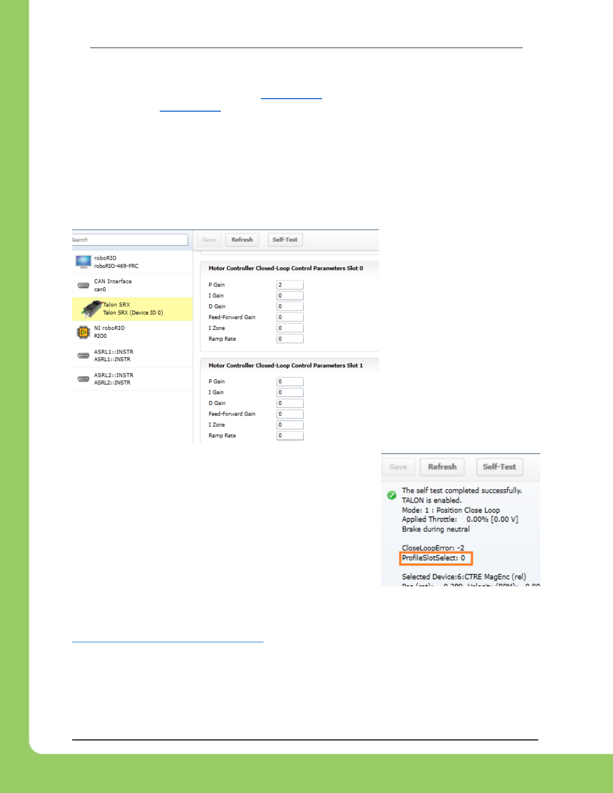
217-8080 TALON SRX Software Reference Manual 2/14/2017
Cross The Road Electronics Page 129 2/14/2017
16.31.6.2. Start with a simple gain set – Velocity Closed-Loop
The first gain to set is the F gain. See Section 12.6 for LabVIEW instruction/examples on how
this is done. See Section 12.4 for Java instruction/examples (C++ users should also review this
section as the procedure is identical).
With just F gain, the motor’s output should follow the requested target velocity reasonably. At
this point you can begin dialing in P gain so that the closed-loop performs error correction.
16.31.7. Confirm gains are set
If the motion output is still neutral, use the roboRIO Web based configuration page to confirm
that gains are actually nonzero, and that the correct slot is selected.
Here P gain of ‘2’ is in Slot 0.
Now perform the Self-Test to confirm which Profile Slot is
selected. In this example we would like to use slot ‘0’.
16.32. Where can I find application examples?
Example projects for Talon SRX can also be found in the CTR GitHub account.
https://github.com/CrossTheRoadElec/FRC-Examples
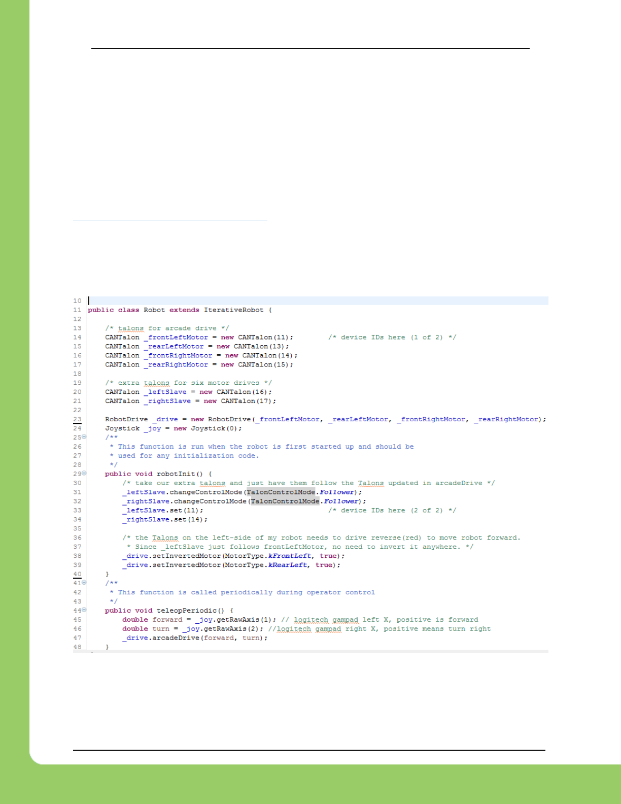
217-8080 TALON SRX Software Reference Manual 2/14/2017
Cross The Road Electronics Page 130 2/14/2017
16.33. Can RobotDrive be used with CAN Talons? What if there are six
Talons?
The default RobotDrive object in LabVIEW/C++/Java already supports two-Talon and four-Talon
drivetrains. Simply create the CANTalon objects and pass them into the RobotDrive example.
For six drive Talons, the four-motor examples for Robot Drive can be used with four CANTalon
objects, then create the final two Talons and set them to slave/follower mode.
The JAVA_Six_CANTalon_ArcadeDrive example can be downloaded at…
https://github.com/CrossTheRoadElec/FRC-Examples
The screenshot below can be used as a reference.
Although the example is in Java, the strategy can be used in all three FRC languages.
Although the example uses arcadeDrive, the robot application could use tankDrive as well.

217-8080 TALON SRX Software Reference Manual 2/14/2017
Cross The Road Electronics Page 131 2/14/2017
16.34. How fast does the closed-loop run?
Talon SRX updates the motor output every 1ms by recalculating the PIDF output.
Additionally, when using the motion magic control mode, the target position and target velocity
is recalculated every 10ms to honor the user’s specified acceleration and cruise-velocity.
16.35. Driver Station log reports: The transmission queue is full. Wait until frames in the
queue have been sent and try again.
This error means the roboRIO is sending more CAN bus frames than can be physically
sent. Usually because of a cable disconnect. Check your wiring for opportunities for CAN bus
to disconnect.
Check for changes in the CAN error counts (Section 15) to confirm cable integrity.
Section 16.24 has additional cable troubleshooting tips.
16.36. Adding CANTalon to my C++ FRC application causes the Driver
Station log to report: ERROR -52010 NIFPGA: Resource not initialized, GetFPGATime, or
similar.
A full example of the crashed call stack is below…
ERROR -52010 NIFPGA: Resource not initialized GetFPGATime
[Utility.cpp:171]
Error at GetFPGATime [Utility.cpp:171]: NIFPGA: Resource not initialized
at frc::GetFPGATime()
at frc::Timer::GetFPGATimestamp()
at frc::MotorSafetyHelper::MotorSafetyHelper(frc::MotorSafety*)
… this can happen if a CANTalon is constructed before the C++ WPILIB initialization routine is
called.
At the time of writing, this condition can occur when cleanly creating a C++ Command-based
project with the latest Eclipse Plugins. An example workaround can be found here…
https://github.com/CrossTheRoadElec/FRC-Examples/commit/24deb61fef6df69f83d5f6436d74df894f7bbf2d
…demonstrating how to ensure motor controller object is constructed after WPILIB initialization.
C++ Command-based projects generated with latest Robot Builder appears to ensure that
motor controller objects are created after WPILIB initialization, and therefore do not cause this
failure symptom.
More information on C++ Command-based projects can be found at the FRC screenstepslive
page, as this is not maintained by CTRE.
https://wpilib.screenstepslive.com

217-8080 TALON SRX Software Reference Manual 2/14/2017
Cross The Road Electronics Page 132 2/14/2017
17. Units and Signal Definitions
Listed below are the native units used for various signals.
17.1. Signal Definitions and Talon Native Units
17.1.1. (Quadrature) Encoder Position
When measuring the position of a Quadrature Encoder, the position is measured in 4X encoder
edges. For example, if a US Digital Encoder with a 360 cycles per revolution (CPR) will count
1440 units per rotation when read using “Encoder Position” or “Sensor Position”.
The velocity units of a Quadrature Encoder is the change in Encoder Position per TvelMea
(TvelMeas=0.1sec). For example, if a US Digital Encoder (CPR=360) spins at 20 rotations per
second, this will result in a velocity of 2880 (28800 position units per second).
17.1.2. Analog Potentiometer
When measuring the position of a 3.3V Analog Potentiometer, the position is measured as a 10
bit ADC value. A value of 1023 corresponds to 3.3V. A value of 0 corresponds to 0.0V.
The velocity units of a 3.3V Analog Potentiometer is the change in Analog Position per TvelMea
(TvelMeas=0.1sec). For example if an Analog Potentiometer transitions from 0V to 3.3V (1023
units) in one second, the Analog Velocity will be 102.
17.1.3. Analog Encoder, “Analog-In Position”
Like 3.3V Analog Potentiometers, the 10 bit ADC is used to scale [0 V, 3.3 V] => [0, 1023].
However when the Analog Encoder “wraps around” from 1023 to 0, the Analog Position will
continue to 1024. In other words, the sensor is treated as “continuous”.
The velocity units of a 3.3V Analog Encoder is the change in Analog Position per 100ms
(TvelMeas=0.1sec). For example if an Analog Encoder transitions from 0V to 3.3V (1023 units) in
one second, the Analog Velocity will be 102.
17.1.4. EncRise (a.k.a. Rising Counter)
Every rising edge seen on the Quadrature A pin is counted as a unit.
The velocity units is the change in RisingEdge Count per TvelMea (TvelMeas=0.1sec).
This mode is useful for single direction sensors (tachometer / gear-tooth sensor).
17.1.5. Duty-Cycle (Throttle)
The Talon SRX uses 10bit resolution for the output duty cycle. This means a -1023 represents
full reverse, +1023 represents full forward, and 0 represents neutral.
The programming API made available in LabVIEW and C++/Java performs the scaling into
percent, so the duty cycle resolution is not necessary for programming purposes. However
when evaluating PIDF gain values, it is helpful to understand how the calculated output of the
closed-loop is interpreted.

217-8080 TALON SRX Software Reference Manual 2/14/2017
Cross The Road Electronics Page 133 2/14/2017
17.1.6. (Voltage) Ramp Rate
The Talon SRX natively represents Ramp Rate as the change in throttle per TRampRate
(TRampRate=10ms). Throttle is represented as a 10bit signed value (1023 is full forward, -1023 is
full reverse). For example, if the robot application requires motor drive ramping from 0% to
100% to take one second of ramping, the result Ramp Rate would be ( [1023 – 0] / 1000ms X
TRampRate) or 10 units.
The programming API made available in LabVIEW and C++/Java performs the scaling into
appropriate units (Voltage or percent).
17.1.7. (Closed-Loop) Ramp Rate
The Closed Loop Ramp Rate that can be specified in the selected Motor Control Profile is
measured in change in output throttle (from PIDF loop) per TClosedLoopRampRate (TClosedLoopRampRate
=1ms). For example, if the selected Motor Control Profile requires motor drive ramping from 0%
to 100% to take one second of ramping, the result Ramp Rate would be ( [1023 – 0] / 1000ms X
TRampRate) or 1 unit.
The programming API made available in LabVIEW and C++/Java performs the scaling into
appropriate units (Voltage or percent).
However when inspecting/setting the Closed-Loop Ramp Rate in the roboRIO webpage, the
units will be shown in output throttle per TClosedLoopRampRate.
17.1.8. Integral Zone (I Zone)
The motor control profile contains Integral Zone (I Zone), which (when nonzero), is the
maximum error where Integral Accumulation will occur during a closed-loop Mode. If the
Closed-loop error is outside of the I Zone, “I Accum” is automatically cleared. This can prevent
total instability due to integral windup, particularly when tweaking gains.
The units are in the same units as the selected feedback device (Quadrature Encoder, Analog
Potentiometer, Analog Encoder, and EncRise).
17.1.9. Integral Accumulator (I Accum)
The accumulated sum of Closed-Loop Error. It is accumulated in line with Closed-Loop math
every 1ms.
17.1.10. Reverse Feedback Sensor
Boolean signal for inverting the selected Feedback Sensor’s position and velocity. This is the
preferred method for keeping the motor and sensor in phase for limit switch, soft limit, and
closed-loop mode.
17.1.11. Reverse Closed-Loop Output
Boolean signal for inverting the output of the closed-loop PIDF controller. This signal is also
used during slave-follower mode to drive slave Talon in the opposite direction of the master.

217-8080 TALON SRX Software Reference Manual 2/14/2017
Cross The Road Electronics Page 134 2/14/2017
17.1.12. Closed-Loop Error
Calculated as the difference between target set point and the actual Sensor Position/Velocity.
The units are matched to Analog-In or Encoder depending on which “Feedback Device” and
control mode (position vs. speed) is selected.
17.1.13. Closed-Loop gains
P gain is specified in throttle per error unit. For example, a value of 102 is ~9.97% (which is
102/1023) throttle per 1 unit of Closed-Loop Error.
I gain is specified in throttle per integrated error. For example, a value of 10 equates to ~0.97%
for each accumulated error (Integral Accumulator). Integral accumulation is done every 1ms.
D gain is specified in throttle per derivative error. For example a value of 102 equates to ~9.97%
(which is 102/1023) per change of Sensor Position/Velocity unit per 1ms.
F gain is multiplied directly by the set point passed into the programming API made available in
LabVIEW and C++/Java. This allows the robot to feed-forward using the target set-point.

217-8080 TALON SRX Software Reference Manual 2/14/2017
Cross The Road Electronics Page 135 2/14/2017
17.2. API Unit Scaling
The Talon’s firmware uses a native unit set for the various signals. However the programming
API allows for conversion into human-readable units, such as rotations and RPM. Depending
on sensor selection, this may require the application to inform the API the resolution of the
sensor using configuration routines.
17.2.1. API requirements and Native Units for Unit Scaling
The following table shows the sensor resolution (which is the native unit of measure in Talon
firmware), and the requirements of the robot application to leverage unit scaling (rotations and
RPM). The requirements column shows the C++ functions, however Java, LabVIEW, and
HERO C# have comparable APIs.
Selected Sensor Type
Native Units
Per Mechanical Rotation
(also the resolution)
Requirements to leverage
Unit Scaling
IsSensorPresent()
supported
Quadrature Encoder
4 X CPR
ConfigEncoderCodesPerRev()
Edge Counter
(On-Rise or On-Fall on
QuadA pin)
1 X CPR
ConfigEncoderCodesPerRev()
Analog Encoder or
Potentiometer
1024 / TotalPotentiometerTurns
units per rotation
ConfigPotentiometerTurns()
CTRE Mag Encoder
(absolute or relative)
4096 units per rotation
No requirements
Yes
Pulse Width Position
Sensors
4096 units per rotation
No requirements
Yes

217-8080 TALON SRX Software Reference Manual 2/14/2017
Cross The Road Electronics Page 136 2/14/2017
17.2.2. Unit Scaling Features (C++/Java)
Listed below is the expected scaling of each sensor-related API.
Robot API Group
Robot API
Units
Getting/Setting Selected Sensor Position
Rotations if requirements are met, otherwise its Native Units.
Selected Sensor API
Getting Selected Sensor Velocity
RPM if requirements are met, otherwise its change in Native
Units per 100ms
Setting Soft Limit Thresholds
Rotations if requirements are met, otherwise its Native Units.
Specific Sensor API
(low level debugging or
managing multiple
sensors)
Getting/Setting Analog Position
Native Units only
Getting Analog Velocity
Native Units only
Getting/Setting Quadrature (Enc)
Position
Native Units only
Getting Quadrature (Enc) Velocity
Native Units only
Getting/Setting Pulse Width Position
Native Units only
Getting Pulse Width Velocity
Native Units only
Closed-Loop Terms in
Talon Firmware
Setting Allowable Closed-Loop Error
Raw Units for Position/Velocity Closed-Loop.
mA if using Current closed-loop
Closed-Loop Error
Raw Units for Position/Velocity Closed-Loop.
mA if using Current closed-loop
The target of the closed-loop via Set().
if requirements are met…
Position Set Param is in rotations.
Velocity Set Param is in RPM.
If requirements are not met…
Position Set Param is in Native Units.
Velocity Set Param is in Native Units per 100ms.
Current Set Param is in Amperes.
FeedForward Term
Fgain X SetPoint in native units.
A final result of 1023 represent full throttle
Proportional Term
Pgain X (Closed-Loop Error) in native units.
A final result of 1023 represent full throttle
Integral Term
Igain X sum, where sum adds the Closed-Loop Error every 1ms.
Derivative Term
The derivate term is the Dgain multiplied by the change in
Closed-Loop Error.
Position Closed-Loop: Dgain X Change in [Native Units] per 1ms.
Velocity Closed-Loop: Dgain X Change in [Native Unit per
100ms] per 1ms.
Current Closed-Loop: Dgain X Change in [mA] per 1ms.
A final result of 1023 represent full throttle
Motion Magic
Cruise Velocity
RPM (if requirements are met),
otherwise its change in Native Units per 100ms
Acceleration
RPM per second (if requirements are met),
otherwise its change in Native Units per 100ms per second
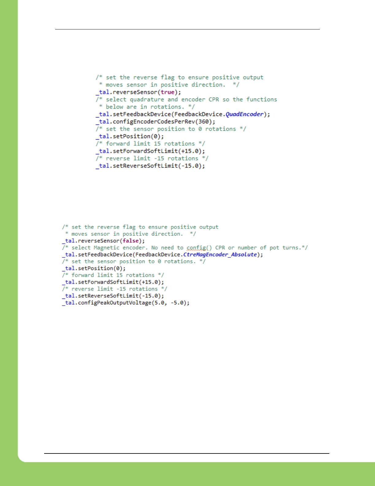
217-8080 TALON SRX Software Reference Manual 2/14/2017
Cross The Road Electronics Page 137 2/14/2017
17.2.3. Java – Configuring Quadrature Encoder (4x)
In addition to selecting the Quadrature Encoder, the robot application can also set the counts
per rotation.
This then allows various functions to be in terms of rotations and RPM instead of the Talon’s
native units.
17.2.4. Java – Configuring CTR Magnetic Encoder
In the case of the CTR Magnetic Encoder, setting the CPR is not required. However it is
noteworthy that the Magnetic Encoder in relative mode is equivalent to a 1024 CPR encoder.
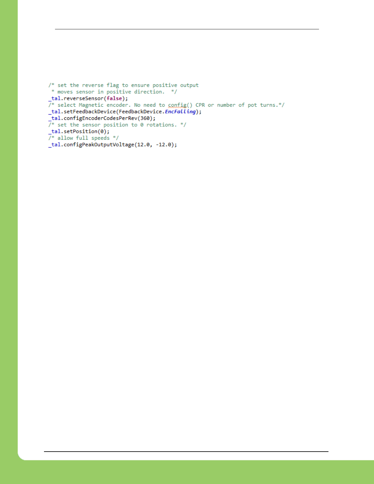
217-8080 TALON SRX Software Reference Manual 2/14/2017
Cross The Road Electronics Page 138 2/14/2017
17.2.5. Java – Configuring Edge Counter
The Count Rising and Falling Edge feedback types are used to count single direction sensors.
Using the same routine as in the Quadrature use case, the application can provides the number
of counts per rotation.

217-8080 TALON SRX Software Reference Manual 2/14/2017
Cross The Road Electronics Page 139 2/14/2017
18. How is the closed-loop implemented?
The closed-loop logic is the same regardless of which feedback sensor or closed-loop mode is
selected. The verbatim implementation in the Talon firmware is displayed below.
This includes…
- The logic for PIDF style closed-loop.
- Inverting the output of the closed-loop if enabled in API.
- Capping the output to positive values only IF using a single direction feedback sensor.
- Closed- Loop Ramp Rate, ramping the output if enabled.
Note: The PID_Mux_Unsigned and PID_Mux_Sign routines are merely multiply functions.
/**
* 1ms process for PIDF closed-loop.
* @param pid ptr to pid object
* @param pos signed integral position (or velocity when in velocity mode).
* The target pos/velocity is ramped into the target member from caller's 'in'.
* If the CloseLoopRamp in the selected Motor Controller Profile is zero then
* there is no ramping applied. (throttle units per ms)
* PIDF is traditional, unsigned coefficients for P,i,D, signed for F.
* Target pos/velocity is feed forward.
*
* Izone gives the abilty to autoclear the integral sum if error is wound up.
* @param revMotDuringCloseLoopEn nonzero to reverse PID output direction.
* @param oneDirOnly when using positive only sensor, keep the closed-loop from outputing negative throttle.
*/
void PID_Calc1Ms(pid_t * pid, int32_t pos,uint8_t revMotDuringCloseLoopEn, uint8_t oneDirOnly)
{
/* grab selected slot */
MotorControlProfile_t * slot = MotControlProf_GetSlot();
/* calc error : err = target - pos*/
int32_t err = pid->target - pos;
pid->err = err;
/*abs error */
int32_t absErr = err;
if(err < 0)
absErr = -absErr;
/* integrate error */
if(0 == pid->notFirst){
/* first pass since reset/init */
pid->iAccum = 0;
/* also tare the before ramp throt */
pid->out = BDC_GetThrot(); /* the save the current ramp */
}else if((!slot->IZone) || (absErr < slot->IZone) ){
/* izone is not used OR absErr is within iZone */
pid->iAccum += err;
}else{
pid->iAccum = 0;
}
/* dErr/dt */
if(pid->notFirst){
/* calc dErr */
pid->dErr = (err - pid->prevErr);
}else{
/* clear dErr */
pid->dErr = 0;
}
/* P gain X the distance away from where we want */
pid->outBeforRmp = PID_Mux_Unsigned(err, slot->P);
if(pid->iAccum && slot->I){
/* our accumulated error times I gain. If you want the robot to creep up then pass a nonzero Igain */
pid->outBeforRmp += PID_Mux_Unsigned(pid->iAccum, slot->I);
}
/* derivative gain, if you want to react to sharp changes in error (smooth things out). */
pid->outBeforRmp += PID_Mux_Unsigned(pid->dErr, slot->D);
/* feedforward on the set point */
pid->outBeforRmp += PID_Mux_Signed(pid->target, slot->F);
/* arm for next pass */
{
pid->prevErr = err; /* save the prev error for D */
pid->notFirst = 1; /* already serviced first pass */
}
/* if we are using one-direction sensor, only allow throttle in one dir.

217-8080 TALON SRX Software Reference Manual 2/14/2017
Cross The Road Electronics Page 140 2/14/2017
If it's the wrong direction, use revMotDuringCloseLoopEn to flip it */
if(oneDirOnly){
if(pid->outBeforRmp < 0)
pid->outBeforRmp = 0;
}
/* honor the direction flip from control */
if(revMotDuringCloseLoopEn)
pid->outBeforRmp = -pid->outBeforRmp;
/* honor closelooprampratem, ramp out towards outBeforRmp */
if(0 != slot->CloseLoopRampRate){
if(pid->outBeforRmp >= pid->out){
/* we want to increase our throt */
int32_t deltaUp = pid->outBeforRmp - pid->out;
if(deltaUp > slot->CloseLoopRampRate)
deltaUp = slot->CloseLoopRampRate;
pid->out += deltaUp;
}else{
/* we want to decrease our throt */
int32_t deltaDn = pid->out - pid->outBeforRmp;
if(deltaDn > slot->CloseLoopRampRate)
deltaDn = slot->CloseLoopRampRate;
pid->out -= deltaDn;
}
}else{
pid->out = pid->outBeforRmp;
}
}

217-8080 TALON SRX Software Reference Manual 2/14/2017
Cross The Road Electronics Page 141 2/14/2017
19. Motor Safety Helper
The Motor Safety feature works in a similar manner as the other motor controllers. The goal is
to set an expiration time to a given motor controller, such that, if the Set()/set() routine is not
called within the expiration time, the motor controller will disable. Additionally the DS will report
the error and the roboRIO Web-based Configuration Self-Test will report kDisabled as the
mode. As a result, the set routine must be called periodically for sustained motor drive when
motor safety is enabled.
One example where this feature is useful is when laying breakpoints with the debugger while
the robot is enabled and moving. Ideally when a breakpoint lands, its safest to disable motor
drive while the developer performs source-level debugging.
19.1. Best practices
Be sure to test that the time between enabling Motor Safety features, and the first Set()/set()
call is small enough to not risk accidently timing out. Calling Set()/set() immediately after
enabling the feature can be used to ensure transitioning into the enabled modes doesn’t
intermittently cause a timeout.
Even if tripping the motor-safety expiration time is not an expected condition, it’s best to re-
enable the motors somewhere in the source so that the timeouts can be reset easily, for
example in AutonInit()/TeleopInit(). That way normal robot functionality can be safely resumed
after a motor controller expires (usually during source-level debugging).
Additionally if source-level debugging is not required (for example during a competition or if
logging-style debugging is preferred) the motor-safety enable can be turned off.
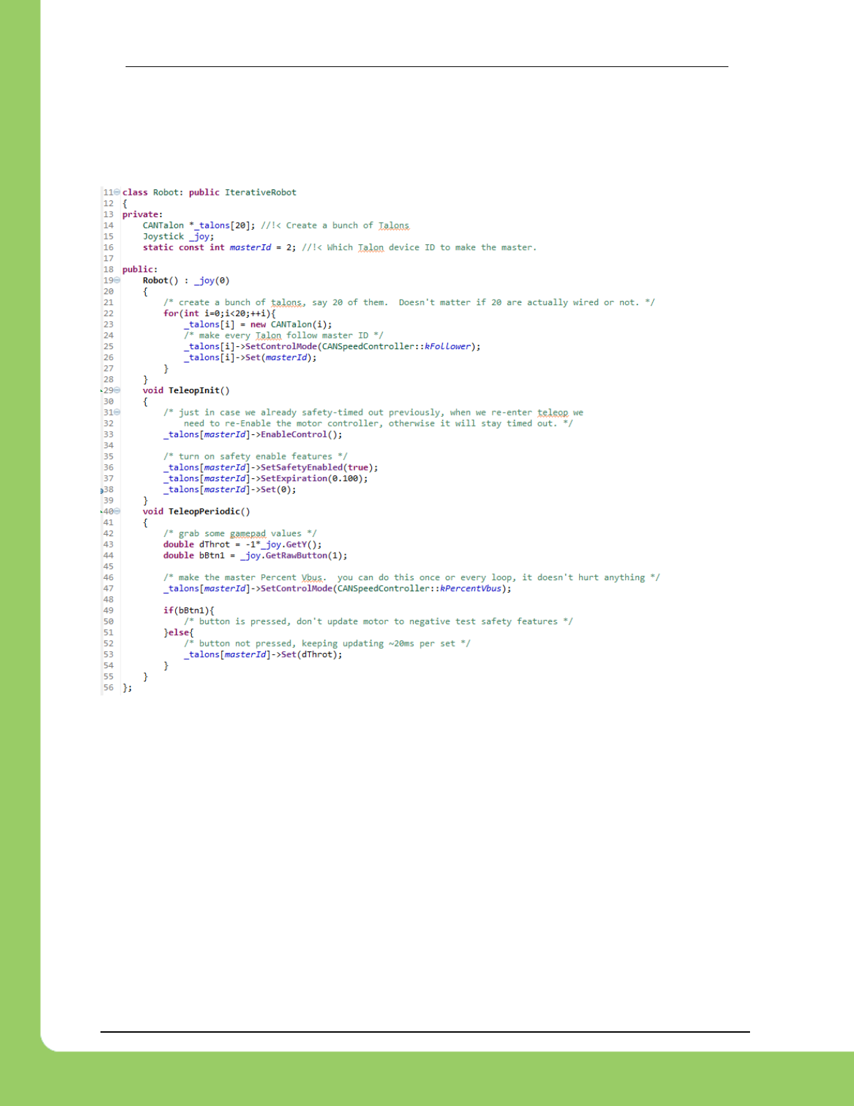
217-8080 TALON SRX Software Reference Manual 2/14/2017
Cross The Road Electronics Page 142 2/14/2017
19.2. C++ example
SetSafetyEnabled() can be used to turn on this feature. SetExpiration() can be used to
set the expiration time. The default expiration time is typically 100ms.
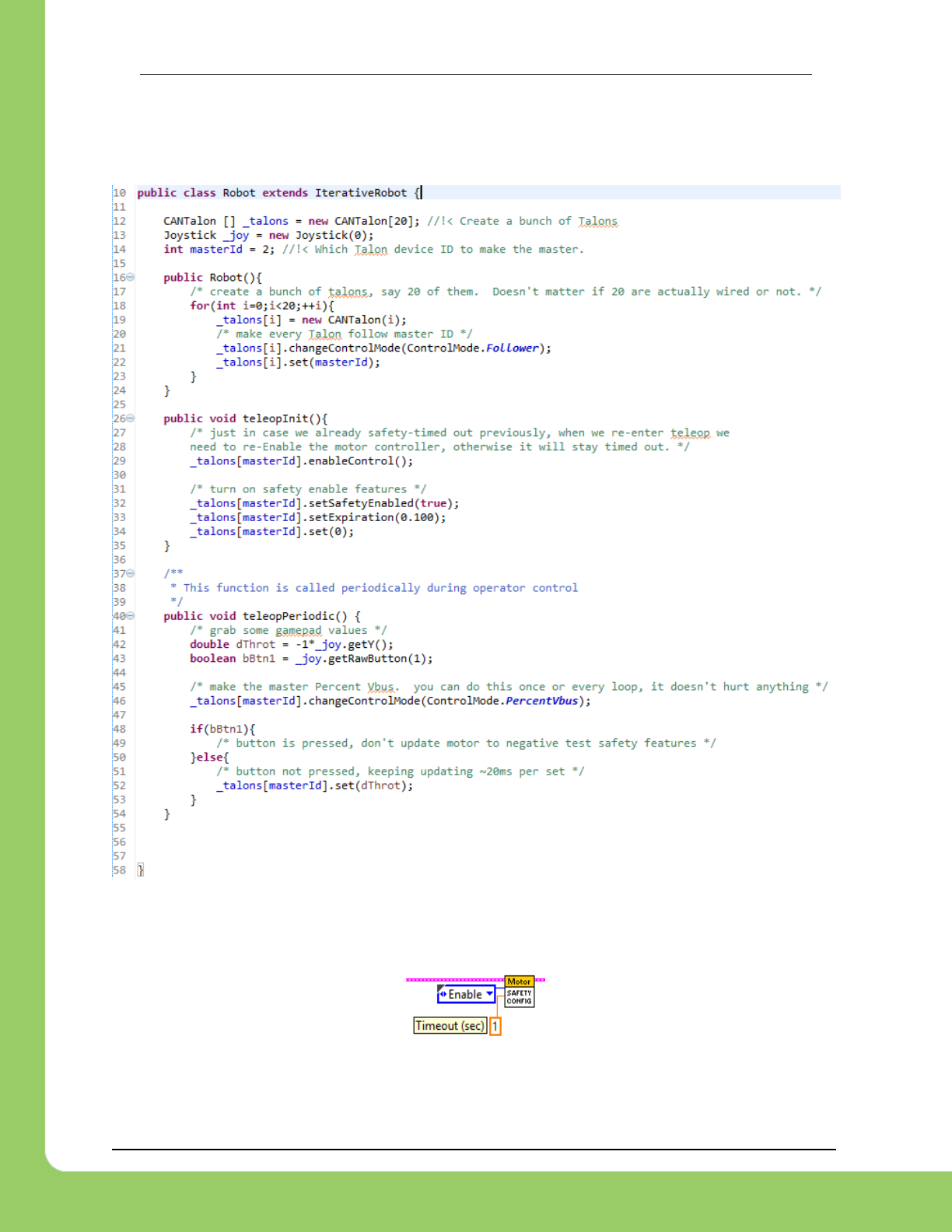
217-8080 TALON SRX Software Reference Manual 2/14/2017
Cross The Road Electronics Page 143 2/14/2017
19.3. Java example
setSafetyEnabled() can be used to turn on this feature. setExpiration() can be used to
set the expiration time. The default expiration time is typically 100ms.
19.4. LabVIEW Example
The Motor SAFETY CONFIG VI can be used to turn on this feature. Select “Enable” for the
mode and specify the timeout in seconds.

217-8080 TALON SRX Software Reference Manual 2/14/2017
Cross The Road Electronics Page 144 2/14/2017
19.5. RobotDrive
The examples in this section refer to the CANTalon objects directly. However higher level class
types such as RobotDrive can have their own motor safety objects as well. Although
CANTalon safety features default off, the higher level drive objects tend to default safety enable
to on. If you are still witnessing disabled motor drive behavior and Motor Safety Driver Station
Log Messages (see Section 16.14) then you may need to call setSafetyEnabled(false) (or
similar routines/VI) on RobotDrive objects as well. Keep in mind that disabling safety enable
means that motor drive is allowed to continue if a source-level breakpoint halts program flow.
Take the necessary precautions to debug the robot safely or alternatively only enable motor
safety features when performing source level debugging.

217-8080 TALON SRX Software Reference Manual 2/14/2017
Cross The Road Electronics Page 145 2/14/2017
20. Going deeper - How does the framing work?
The Talon periodically transmits four status frames with sensor data at the given periods. This
ensures that certain signals are always available with a deterministic update rate. This also
keeps bus utilization stable.
Similarly the control frame sent to the Talon SRX is periodic and contains almost all the
information necessary for all control modes.
Although the frame rates are default to ensure stable CAN bandwidth, there may be available
API to override the frame rates for performance reasons. If this is done, be sure to check the
CAN performance metrics to ensure custom settings don’t exceed the available CAN bandwidth,
see “CAN bus Utilization and Performance metrics”.
20.1. General Status
The General Status frame has a default period of 10ms, and provides…
-Closed Loop Error: the closed-loop target minus actual position/velocity.
-Throttle: The current 10bit motor output duty cycle (-1023 full reverse to +1023 full forward).
-Forward Limit Switch Pin State
-Reverse Limit Switch Pin State
-Fault bits
-Applied Control Mode
… These signals are accessible in the various get functions in the programming API.
20.2. Feedback Status
The Feedback Status frame has a default period of 20ms, and provides…
-Sensor Position: Position of the selected sensor
-Sensor Velocity: Velocity of the selected sensor
-Motor Current
-Sticky Faults
-Brake Neutral State
-Motor Control Profile Select
… These signals are accessible in the various get functions in the programming API.
20.3. Quadrature Encoder Status
The Quadrature Encoder Status frame has a default period of 100ms.
-Encoder Position: Position of the quadrature sensor
-Encoder Velocity: Velocity of the selected sensor
-Number of rising edges counted on the Index Pin.
-Quad A pin state.
-Quad B pin state.
-Quad Index pin state.
… These signals are accessible in the various get functions in the programming API.
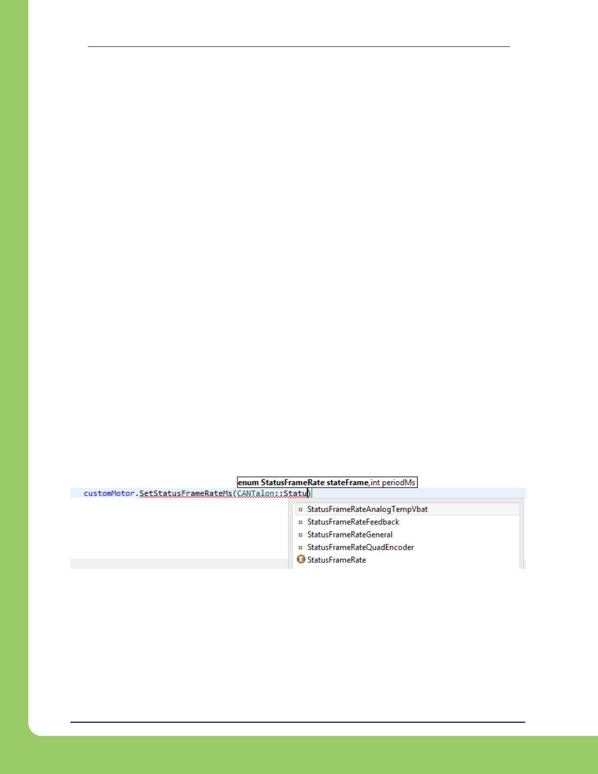
217-8080 TALON SRX Software Reference Manual 2/14/2017
Cross The Road Electronics Page 146 2/14/2017
The quadrature decoder is always engaged, whether the feedback device is selected or not,
and whether a quadrature encoder is actually wired or not. This means that the Quadrature
Encoder signals are always available in programming API regardless of how the Talon is used.
The 100ms update rate is sufficient for logging, instrumentation and debugging. If a faster
update rate is required the robot application can select the appropriate sensor and leverage the
Sensor Position and Sensor Velocity.
20.4. Analog Input / Temperature / Battery Voltage Status
The Analog/Temp/BattV status frame has a default period of 100ms.
-Analog Position: Position of the selected sensor
-Analog Velocity: Velocity of the selected sensor
-Temperature
-Battery Voltage
… These signals are accessible in the various get functions in the programming API.
The Analog to Digital Convertor is always engaged, whether the feedback device is selected or
not, and whether an analog sensor is actually wired or not. This means that the Analog In
signals are always available in programming API regardless of how the Talon is used. The
100ms update rate is sufficient for logging, instrumentation and debugging. If a faster update
rate is required the robot application can select the appropriate sensor and leverage the Sensor
Position and Sensor Velocity.
20.5. Modifying Status Frame Rates
The frame rates of these signals may be modifiable through programming API.
20.5.1. C++
The SetStatusFrameMs() function can be used to modify the frame rate period of a particular
Status Frame. Use the StatusFrameRate… enumerations to specify which frame period to
modify.
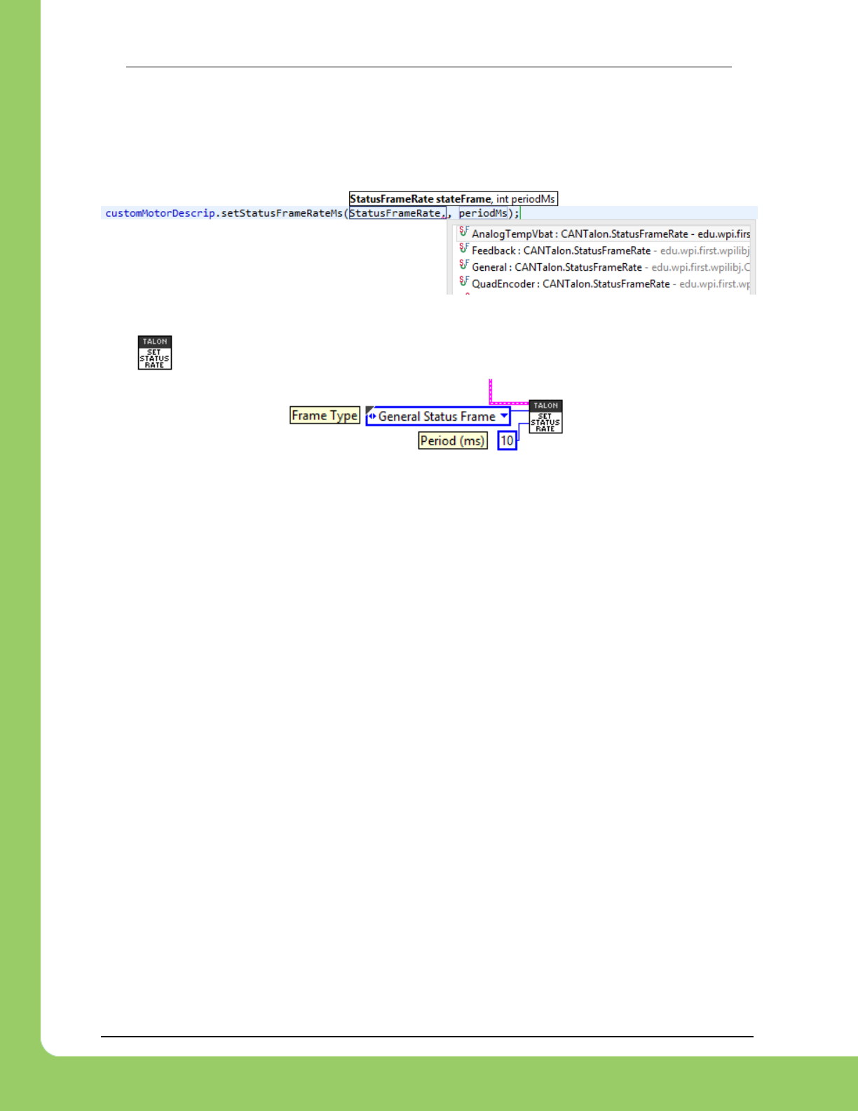
217-8080 TALON SRX Software Reference Manual 2/14/2017
Cross The Road Electronics Page 147 2/14/2017
20.5.2. Java
The setStatusFrameMs() function can be used to modify the frame rate period of a particular
Status Frame. Use the StatusFrameRate… enumerations to specify which frame period to
modify.
20.5.3. LabVIEW Example
The VI can be used to adjust the period of a particular status frame.
20.6. Control Frame
The Talon is primarily controlled by one periodic control frame. The default period of this frame
is 10ms. The control frame provides the Talon…
-which Motor Control Profile Slot to use.
-which control mode (position, velocity, duty cycle, slave mode)
-which feedback sensor to use
-if the feedback sensor should be reversed
-if the closed-loop output should be reversed
-the target/set point or duty cycle or which Talon to follow
-the (voltage) ramp rate
-brake neutral mode override if specified
-limit switch overrides if specified
… These signals are accessible in the various set functions in the programming API.
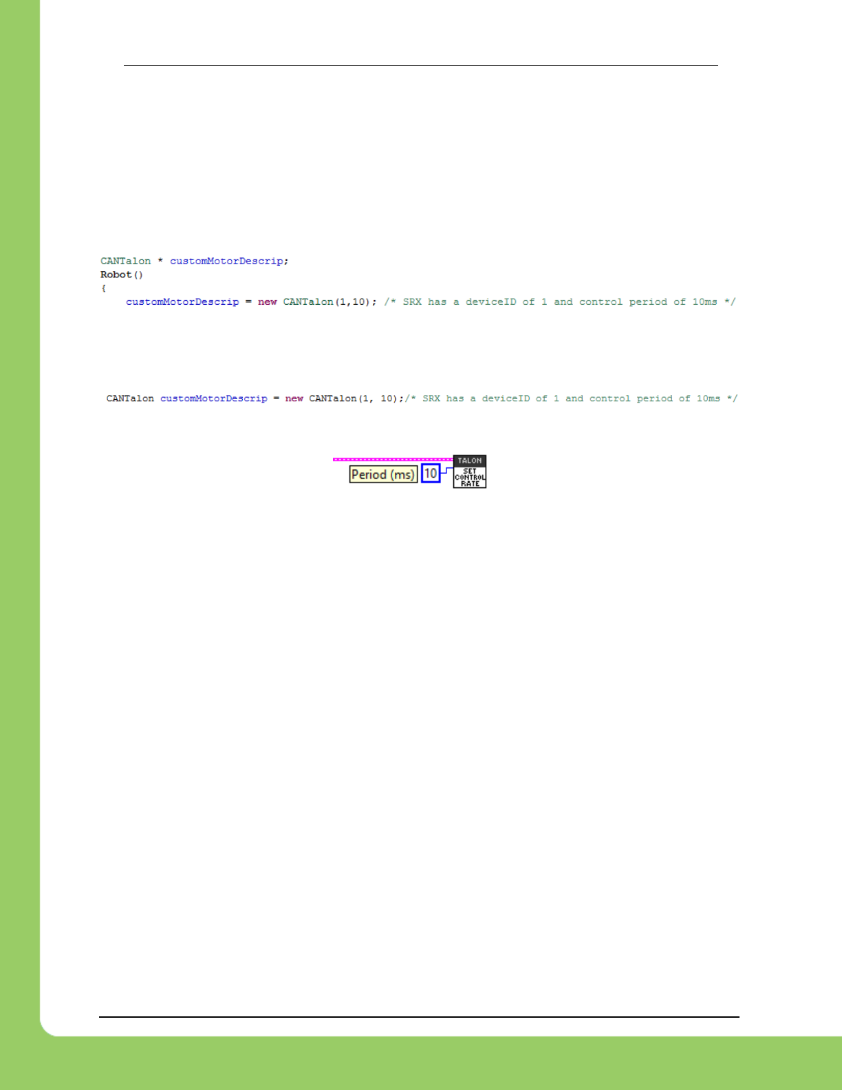
217-8080 TALON SRX Software Reference Manual 2/14/2017
Cross The Road Electronics Page 148 2/14/2017
20.7. Modifying the Control Frame Rate
Advanced users can modify the Control Frame Rate to increase the update rate of the control
parameters, or decrease to reduce total bus bandwidth.
20.7.1. Modifying the Control Frame Rate – C++
The CANTalon constructor contains a second parameter to specify control frame period in
milliseconds.
20.7.2. Modifying the Control Frame Rate – Java
The CANTalon constructor contains a second parameter to specify control frame period in
milliseconds.
20.7.3. Modifying the Control Frame Rate – LabVIEW

217-8080 TALON SRX Software Reference Manual 2/14/2017
Cross The Road Electronics Page 149 2/14/2017
21. Functional Limitations
Functional Limitations describe behavior that deviates than what is documented. Feature
additions and improvements are always possible thanks to the field-upgrade features of the
Talon SRX.
2016 season refers to Kickoff January 2016 (FIRST Stronghold). Issues that have been
resolved since then are grayed out.
2015 season refers to Kickoff January 2015 (Recycle Rush). Issues that have been
resolved since then are grayed out.
Just because a firmware issue has been resolved does not mean your out-of-the-box
hardware doesn’t have old firmware. Immediately update your CAN devices to ensure your
development time is not wasted chasing down an issue that has already been solved.
21.1. Firmware 1.1-1.4: Voltage Compensation Mode is not supported.
Feature was not prioritized for FRC 2015 season.
21.2. Firmware 1.1-1.4: Current Closed-Loop Mode is not supported.
Feature was not prioritized for FRC 2015 season.
21.3. Firmware 1.1-1.4: EncFalling Feedback device not supported.
Feature was not prioritized for FRC 2015 season. Firmware does support EncRising Mode
(a.k.a. Rising Edge Counter).
21.4. Firmware 1.1-1.4: ConfigMaxOutputVoltage() not supported.
Feature was not prioritized for FRC 2015 season.
21.5. Firmware 1.1-1.4: ConfigFaultTime() not needed
Firmware only disables drive for limit faults and soft limits (which are time invariant). Motor drive
is not disabled due to current, temp, or battery voltage, therefore there is no fault time.
21.6. Firmware 1.1: Changes in Limit Switch “Normally Open” vs “Normally
Closed” may require power cycle during a specific circumstance.
In the specific situation where programming API overrides a limit switch enable (to true or false),
then changes the NO/NC mode of the same limit switch using programming API, the setting will
not take effect until the motor controller is power cycled, or until the limit switch is no longer
overridden.
The “first” time a new Talon SRX’s NO/NC setting is changed programmatically, power cycle the
Talon so the setting takes effect. After the initial power cycle, new NO/NC setting will be loaded
correctly and match what the robot controller is requesting, therefore Talon will honor the new
NO/NC state from then on.
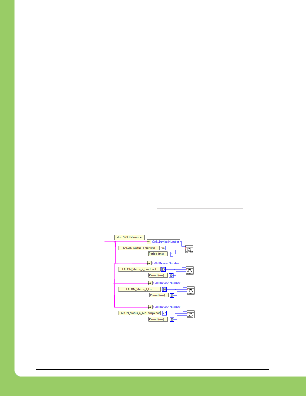
217-8080 TALON SRX Software Reference Manual 2/14/2017
Cross The Road Electronics Page 150 2/14/2017
If not setting NO/NC state programmatically, then no symptoms are observed that deviate from
reference manual. Changing the NO/NC state in the the roboRIO Web-based Configuration
works as expected.
This is fixed in 1.4.
21.7. FRC2015 LabVIEW: EncRising Feedback mode not selectable.
Release software of LabVIEW does not provide option to select EncRising Mode.
21.8. FRC2015 LabVIEW/C++/Java API: ConfigEncoderCodesPerRev() is
not supported.
Talon does not configure units. Instead the quadrature units are always in 4X mode.
21.9. FRC2015 LabVIEW/C++/Java API: ConfigPotentiometerTurns() is
not supported.
Talon does not configure units. Instead the 3.3V ADC is 10 bit, therefore 0 => 3.3V scales to 0
=> 1023 units.
21.10. Java: Once a Limit Switch is overridden, they can’t be un-overridden.
This does not cause any observable symptoms, just an inconsistency between C++ and Java
API.
21.11. FRC2015 LabVIEW: Modifying status frame rate is not available.
See below for an example workaround as well as Functional Limitation Section 21.14.
Although there is no explicit VI for modifying the Status Frame Rates, modifying the frame rates
can be accomplished with the generic CAN TALON SETPRM.
The WPI_CANTalonSRX_SetParameter.vi can be drag and dropped from where it resides.
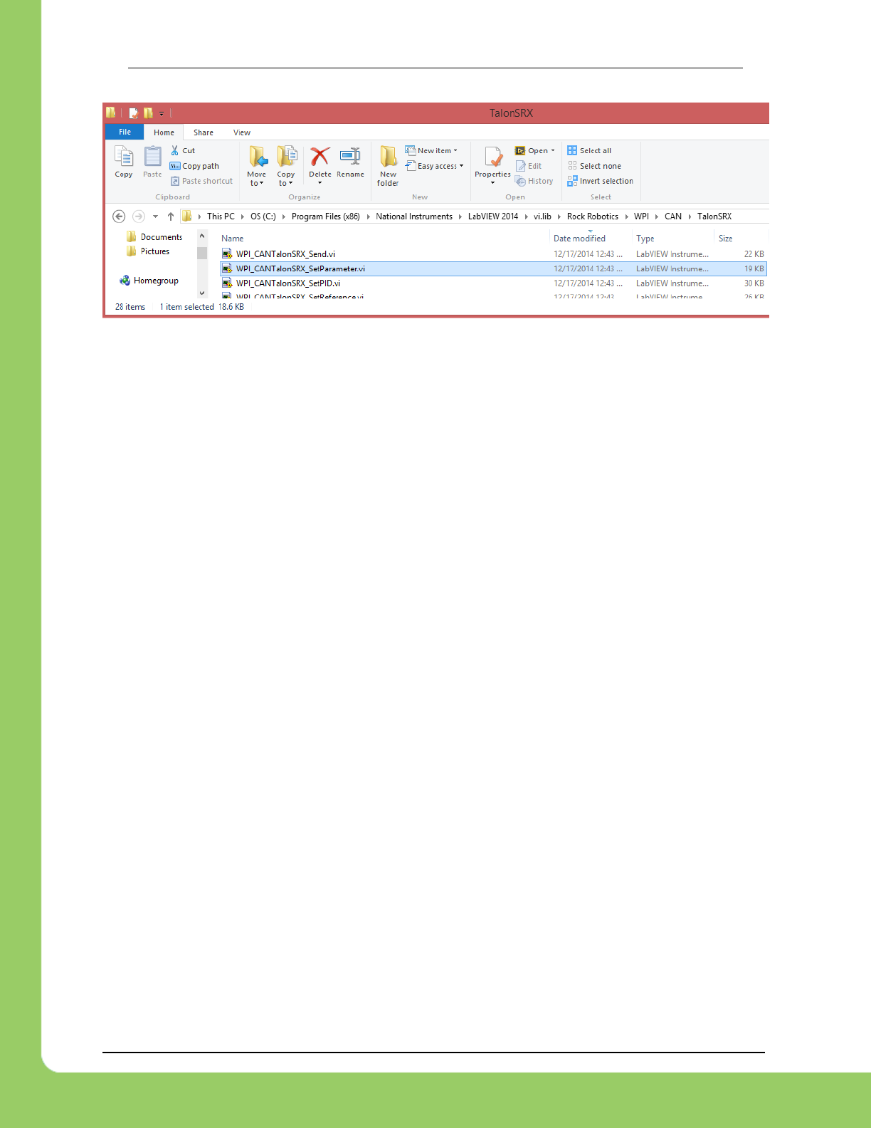
217-8080 TALON SRX Software Reference Manual 2/14/2017
Cross The Road Electronics Page 151 2/14/2017
21.12. FRC2015 LabVIEW: Modifying control frame rate is not available.
This will not be available in the initial season release.
21.13. Firmware 1.1: After selecting “Analog Encoder”, “Sensor Position”
does not reliably decode when sensor wraps around (3.3V => 0V).
Sensor Position may not travel above 1023 or below 0, despite selecting “Analog Encoder” and
spinning the sensor in one direction in a continuous fashion.
This is fixed in 1.4.
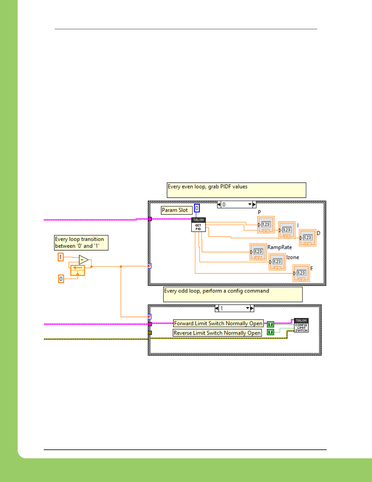
217-8080 TALON SRX Software Reference Manual 2/14/2017
Cross The Road Electronics Page 152 2/14/2017
21.14. FRC2015 LabVIEW: Certain SRX VI's running in parallel can affect
the GET PID VI signals.
Avoid using the following VIs in “parallel” to reading the signals provided by GET PID.
Affected VIs:
RESET INTEGRAL ACCUM,
CONFIG LIMIT SWITCH,
CONFIG SOFT LIMIT,
SET PID,
CAN TALON SETPRM,
For example, use a state variable to control whether GET PID is used, or the other mentioned
VIs are used per periodic loop. Otherwise the GET PID signals may erroneously return zero.
Example Workaround
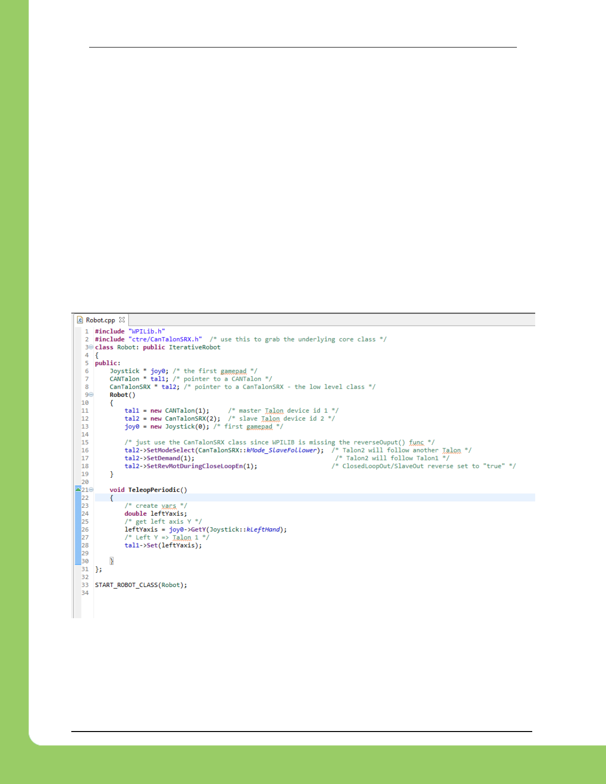
217-8080 TALON SRX Software Reference Manual 2/14/2017
Cross The Road Electronics Page 153 2/14/2017
21.15. C++: There is no method to reverse the output of a slave Talon SRX.
The initial release of WPILIB C++ does not have a method for setting the “Reverse Closed-Loop
output” signal. This signal is useful for reversing the output of a slave Talon SRX, ensuring it
drives in the opposite direction of its master Talon SRX.
Additionally when using a single-direction sensor in EncRising mode (Rising Counter) this is the
preferred method for keeping motor and sensor in phase since “Reverse Feedback Sensor”
must be false for single-direction sensors.
The following example can be used to work around this limitation by using the core class
CanTalonSrx to directly reverse the output signal. Notice the additional include for
“ctre/CanTalonSRX.h” and the use of SetRevMotDuringCloseLoopEn() to accomplish
reversing the output.
Although using CanTalonSRX is generally not recommended (CANTalon is the top-level class
designed for team-use) this functional limitation is an example where using the lower level class
is beneficial.
Example Workaround – Inverting a Slave Talon SRX
Note: This example also demonstrates using heap class pointers instead of regular member
variables in the interest of covering different methods for allocating objects. Teams may use
non-pointer variables if desired.

217-8080 TALON SRX Software Reference Manual 2/14/2017
Cross The Road Electronics Page 154 2/14/2017
21.16. Firmware <0.36: Limit Switch Faults and Soft Limit Faults may cause
Talon SRX to disable for approximately two seconds during the “first time”.
In the specific situation where a particular limit switch or particular soft limit fault trips for the
“first time” when using a Talon SRX with pre-FRC2015-kickoff firmware, the Talon SRX may
blink orange for a two second period of time, during which it behaves as though it’s disabled.
This can only happen when a Talon SRX is initially out-of-the-box or when a Talon SRX’s sticky
faults have been cleared (using the roboRIO web-based configuration or through programming
API). The cause is due to the way that firmware earlier than 0.36 saves the sticky faults in
persistent memory.
Since teams using CAN are required to update to at least 1.1, this functional limitation will not
occur.
Also Talon SRXs used with PWM have no method for clearing sticky faults, so this symptom will
only appear once and then never occur again. Additionally PWM-use Talons can easily be
firmware updated using the method described in Talon SRX User’s Guide Section 1.3.4.2.
Fixed in 0.36.
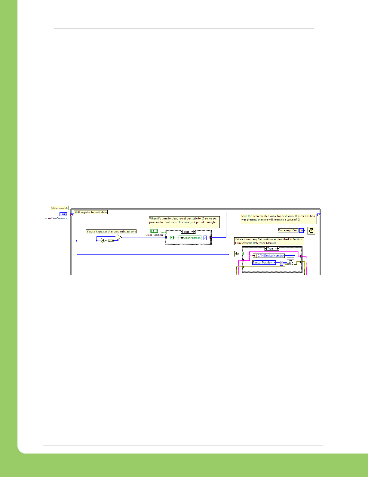
217-8080 TALON SRX Software Reference Manual 2/14/2017
Cross The Road Electronics Page 155 2/14/2017
21.17. Firmware 1.4: When setting the “Sensor Position” of an analog
encoder, multiple set commands are required.
In the specific situation of setting the “Sensor Position” when the selected feedback device is an
analog encoder, the robot application will have to send two set commands to reliably change the
sensor position. Additionally there must be at least 9 ms between the two set commands.
The symptom occurs when a sensor position is changed by a large enough value to cause a
false detection of an analog encoder wraparound. By re-setting the sensor position to the same
new value a second time after the false wrap around is detected, the analog encoder position
can be reliably modified.
In C++/Java this can be done by calling the SetPosition()/setPosition() function twice with
the same parameter, and ensuring there is at least 9 ms between the calls.
In LabVIEW this can be accomplished by using state (shift register) to count the number times
to consecutively set the Sensor Position. The following example demonstrates clearing the
sensor position when the “Clear Position” front panel button is pressed.
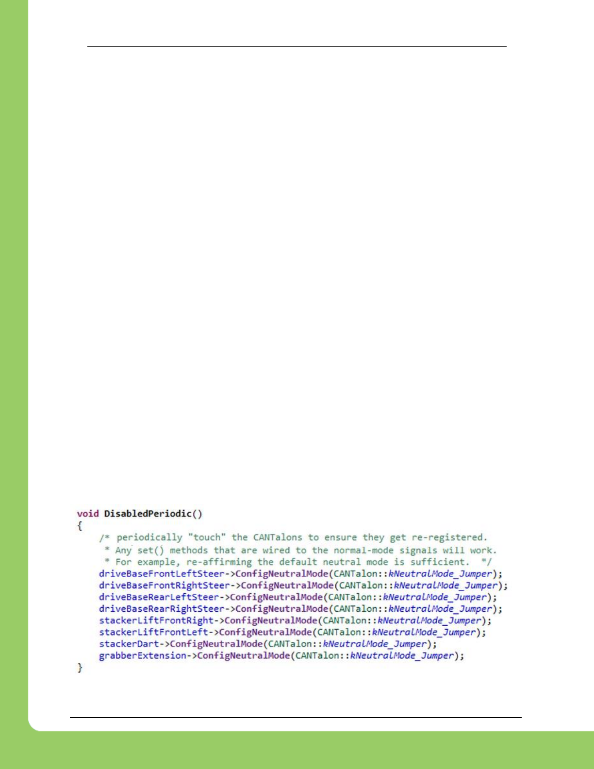
217-8080 TALON SRX Software Reference Manual 2/14/2017
Cross The Road Electronics Page 156 2/14/2017
21.18. roboRIO power up: roboRIO startup software may not be ready for
Robot Application. As a result, certain resources (like CAN actuators) may
not enable on teleOp-Enabled after a roboRIO power boot.
This is a specific race condition that causes the RIO’s start up processes to boot in a different
order then intended. The symptom a team would see is: we power cycled the robot, enabled,
and some of our CAN devices (Talon SRX for example) does not enabled (LEDs blink orange).
Although the circumstances are intermittent, the workaround to guarantee the Robot Application
is robust is simple. In the Disable Loop, “set” one of the following signals periodically to ensure
the roboRIO background process is well-aware of what CAN actuators the Robot Application
intends to use.
Setting any of these signals in the disabled loop will meet the workaround requirements. Also
setting these will have no effect on the Talon itself since these signals are not sent over CAN
bus until the robot is enabled. The signals that can be used for this workaround are…
Brake Mode during Neutral,
Throttle or Closed-Loop set point,
Control Mode,
Limit Switch Enable Overrides,
Feedback Device Select,
(Voltage) Ramp Rate,
Reverse Feedback Sensor,
Reverse Closed-Loop Output,
Profile Slot Select,
These signals exist in the periodic control frame. As such, setting them will not block or hold up
program execution.
In this C++ workaround example, we redundantly set the brake mode to its default setting. The
brake mode already defaults to kNeutralMode_Jumper so the actual behavior of the Talon
hasn’t changed, and no additional CAN traffic is generated since the control frame is unsolicited
and periodic.
In this example any brake mode will work and the new signal value does not have to be
different than the original signal value.
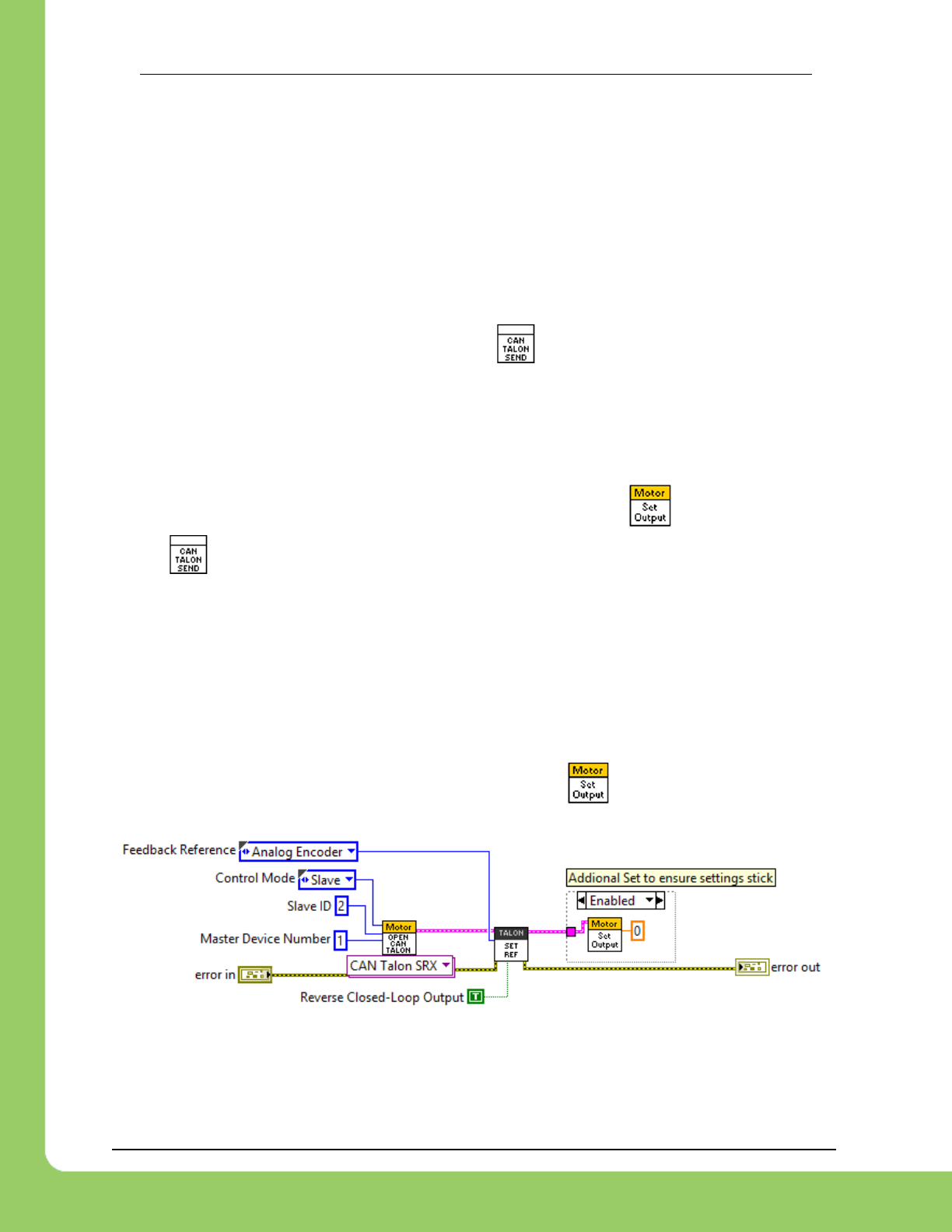
217-8080 TALON SRX Software Reference Manual 2/14/2017
Cross The Road Electronics Page 157 2/14/2017
21.19. roboRIO power up: User should manually refresh the web-based
configuration after rebooting roboRIO.
It is recommended to manually refresh the web browser if the roboRIO has been reset or power
cycled. This ensures that the web browser and roboRIO are synchronized well. Otherwise
device icons may not match the device type in the web-based config.
21.20. LabVIEW: Settings applied in begin.vi may not stick unless there is a
terminating “Set Output”.
Because not all of the modifiers have a terminating , it’s possible that SRX motor controller
objects that are configured in begin.vi may not have the initial settings applied. This is
specific to situations where a Talon SRX object is created and configured in begin.vi, and then
is never modified in any of the active loops, thereby never providing the programming API an
opportunity to flush all changes into the lower level.
To ensure the configuration “takes”, add a terminating Set Output ( ) or any other VI that
utilizes .
The typical situation where this may occur is when creating a Talon SRX object for the sole
purpose of being a slave follower, which only requires initial configuration. However if non-
default settings are applied, such as Reverse Closed-Loop Output, the settings are not
guaranteed to be applied. If Reverse Closed-Loop Output is not applied, then the slave motor
may drive in a direction opposite of what is desired.
In this example we modify several settings of a slave Talon for testing purposes. To ensure the
“Reverse Closed-Loop Output” signal is set properly, a final is done. Note that the
surrounding structure is unnecessary and merely highlights the workaround.

217-8080 TALON SRX Software Reference Manual 2/14/2017
Cross The Road Electronics Page 158 2/14/2017
21.21. LabVIEW 2015, 2016: Set Values outside of [-1,+1] do not saturate in
Percent VBus control mode.
When using CANTalons in Percent VBus control mode, ensure the set value stays between -1
and +1. A value outside of this range will cause a wraparound condition causing the throttle to
reverse direction.
The workaround is to use the coerce block (or similar logic) to saturate the value to -1 and +1.
21.22. Java 2016: getForwardSoftLimit() and getReverseSoftLimit() returns
Native Units.
Although the set routines for soft limits leverages the new Unit Scaling features, getting the soft
limits in Java always returns in Native Units. The workaround is to manually scale using the
scalars in Section 17.2.1.

217-8080 TALON SRX Software Reference Manual 2/14/2017
Cross The Road Electronics Page 159 2/14/2017
21.23. FRC2016 roboRIO: CAN Device does not appear in web page
diagnostics.
Under specific conditions, a CAN device may no longer appear in the left tree view in the
roboRIO web-based configuration page. For this to occur the following criteria must be met.
FRC_roboRIO_2016_v19.zip is imaged in the roboRIO.
The missing device ID must be greater than 20.
All other device IDs must be either: greater than the missing ID, or less than missing ID
minus 50.
If there is a CAN device which has an ID that meets this criteria, and therefore is no longer
appearing in the web-page, the user can apply the following procedure. This procedure will
force the device to appear, and will allow the user to change the device ID so as to work around
this limitation. The user can either…
Power cycle just the missing-ID-device and manually refresh the browser until device
appears…
…or alternatively disconnect CAN bus between the robot controller and the missing-ID-
device. Then power-cycle or reboot the roboRIO. Navigate to the roboRIO’s webpage
and wait until page fully renders. Now reconnect CAN bus and manually-refresh the
browser until device appears.
After forcing the missing device to appear, modify its device ID so that this limitation doesn’t
occur again. To work around this limitation, either…
use device IDs less than 20 or …
…avoid gaps in IDs that exceed 50 and ensure there is (at least) one device ID less than
20.
This limitation will not prevent the robot API from controlling/monitoring CTRE CAN Devices.
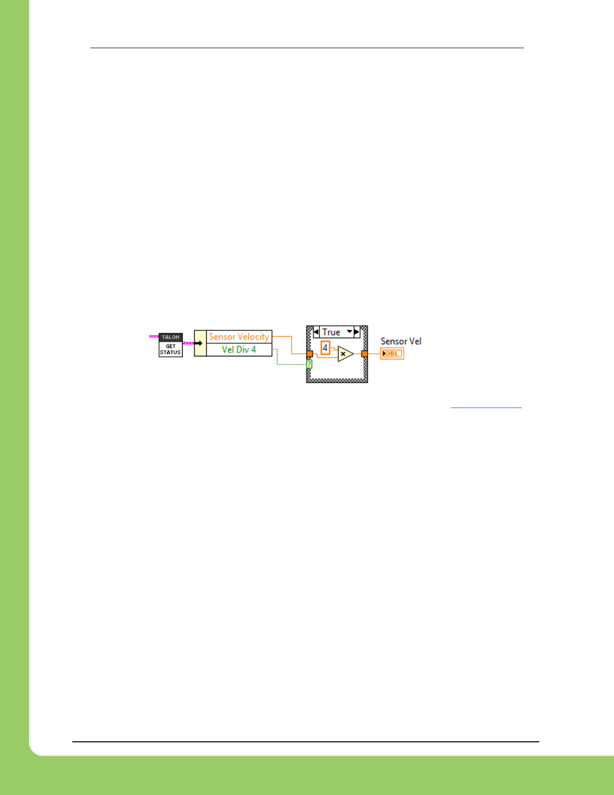
217-8080 TALON SRX Software Reference Manual 2/14/2017
Cross The Road Electronics Page 160 2/14/2017
21.24. FRC2016 LabVIEW: Un-bundled Sensor Velocity may be one-fourth
of the expected value.
The “Sensor Velocity” will reduce to one-fourth of the expected value at a threshold determined
by the sensor resolution. For example if the Sensor has a resolution of 4096 units per rotation
(1024CPR Quadrature or CTRE Mag Encoder) an increasing “Sensor Velocity” will abruptly
drop to one-fourth of its expected value as it passes above 4800 RPM.
The RPM threshold at which this limitation occurs can be calculated as…
ThresholdRPM = 4800 X 4096 / SensorResolutionPerRotation
There is a signal to determine when this occurs, which was meant to be used by the robot API
to adjust the “Sensor Velocity” automatically. As a result, the calling application may have to
check “Vel Div 4” and if it is set to true, simply multiple the Sensor Velocity by ‘4’. If “Vel Div 4”
is false, then the limitation is not in effect, and “Sensor Velocity” is valid.
This workaround will ensure proper decoding of the Sensor Velocity.
This workaround is necessary regardless if API Unit Scaling is utilized or not (Section 17.2.1).
This limitation does not affect the Closed-Loop features of Talon SRX. It only affects
interpreting the reported velocity over CAN bus to the LabVIEW robot API.
This limitation does not affect the reported sensor velocity in C++, Java, and the Self-Test of the
roboRIO web-based configuration page.
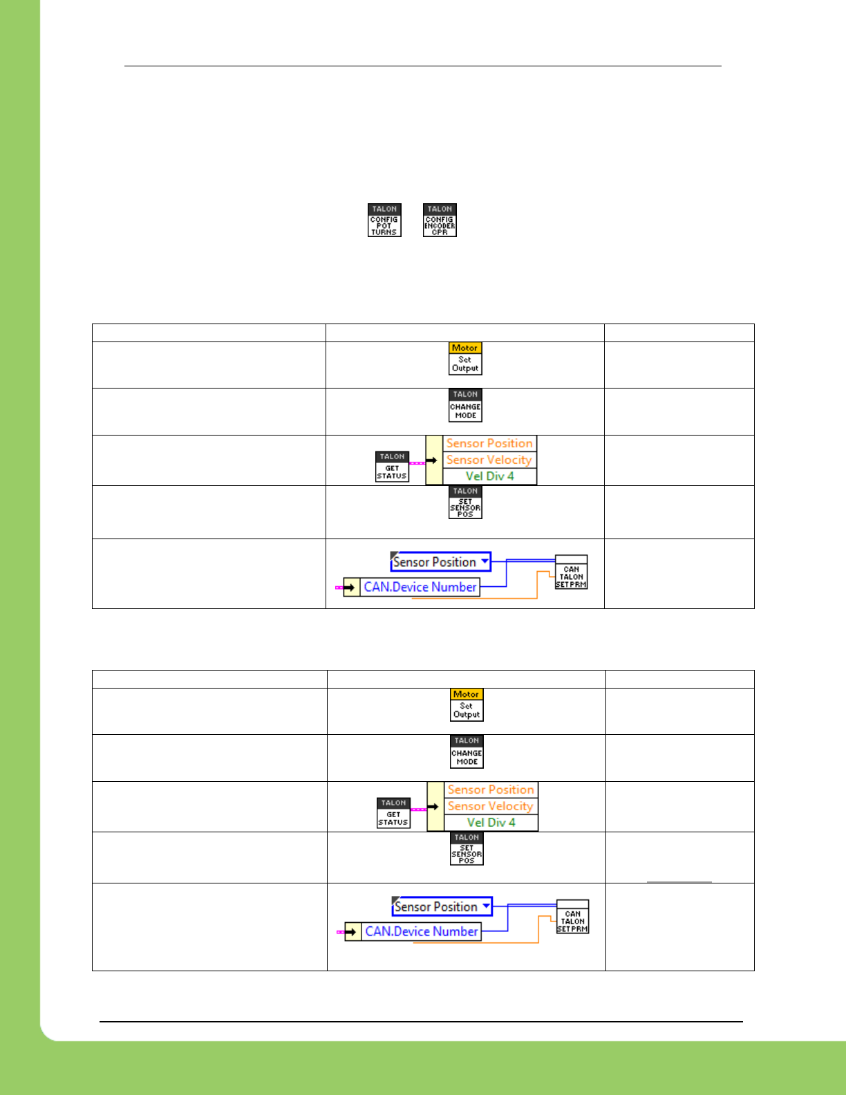
217-8080 TALON SRX Software Reference Manual 2/14/2017
Cross The Road Electronics Page 161 2/14/2017
21.25. FRC2016 LabVIEW: API Unit-Scaling Inconsistencies
The LabVIEW implementation of API Unit Scaling has the following inconsistencies (see tables
below). The unit-scaling features were meant to allow Rotations / RPM to be used in all
Position/Velocity APIs, however there are sensor-specific limitations that need to be considered.
As a result, it is recommend to not wire or when using any of the Feedback Sensor
Types. The following tables can be used to determine what scaling is taking effect per VI,
based on the sensor selection.
CTRE Magnetic Encoder (Relative)
Operation
VI
Units
Set Target Position/Speed with
“Output”
Native Units
Set Target Position/Speed with
“Output”
Native Units
Getting Sensor Position/Speed
Rotations / RPM
Setting Sensor Position
Rotations
Setting Sensor Position
(FRC 2015)
Native Units
CTRE Magnetic Encoder (Absolute)
Operation
VI
Units
Set Target Position/Speed with
“Output”
Native Units
Set Target Position/Speed with
“Output”
Native Units
Getting Sensor Position/Speed
Rotations / RPM
Setting Sensor Position
Not functional.
Use the method
described in
Section 13.1
Setting Sensor Position
(FRC 2015)
Rotations
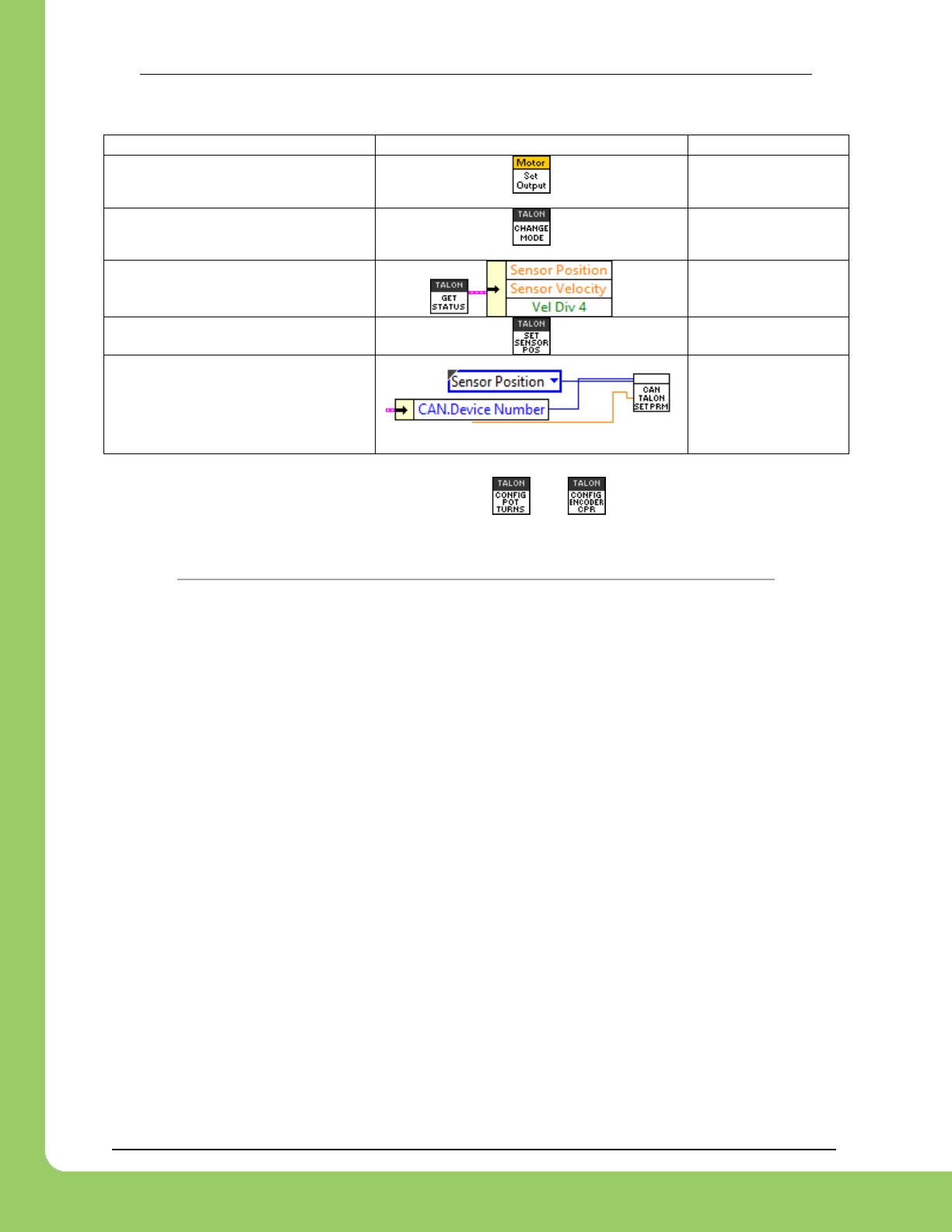
217-8080 TALON SRX Software Reference Manual 2/14/2017
Cross The Road Electronics Page 162 2/14/2017
Quadrature/Analog Encoder/ Analog Potentiometer / Edge Counter
Operation
VI
Units
Set Target Position/Speed with
“Output”
*Native Units
Set Target Position/Speed with
“Output”
*Native Units
Getting Sensor Position/Speed
*Native Units
Setting Sensor Position
*Native Units
Setting Sensor Position
(FRC 2015)
*Native Units
*Native Units – This requires that the and VIs are not used.
Velocity Closed-Loop Examples with these workarounds can be downloaded at…
https://github.com/CrossTheRoadElec/FRC-Examples/tree/master/LabVIEW%20Speed%20Closed%20Loop
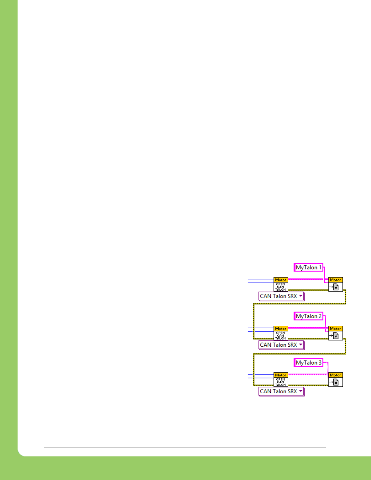
217-8080 TALON SRX Software Reference Manual 2/14/2017
Cross The Road Electronics Page 163 2/14/2017
21.26. FRC2016 LabVIEW: Talon SRX Settings Appear to Change After
Stopping and Re-Running Code From Robot Main VI
The Talon SRX Settings on the roboRIO persist between Run sessions of LabVIEW (until the
roboRIO is reset). Additionally, the hardware initializations in the Begin VI are run
‘concurrently’, so the order of creation is not consistent.
Intermittently, the initialization order of hardware may be different such that a Talon SRX may
be assigned memory that was formerly assigned to a different unit, and if the settings in that
memory are not overwritten by the new Talon SRX initialization the former settings will persist.
This is not an issue with permanently deployed code, as the roboRIO will be reset upon ‘Run as
Start-up’ and upon any code re-start from the Driver Station.
The settings that may be affected by this issue are as follows:
Reverse Closed-Loop Output (Boolean)
Reverse Sensor Direction (Boolean)
Feedback Reference (Sensor Typedef)
Throttle Ramp Rate (Double)
Override Limit Switches (Boolean)
Brake Override (Brake/Coast Typedef)
Any Output Set in the Begin VI
The recommended workaround is to link the error nodes of the
Talon SRX initializations to ensure consistent order of initialization
(see example to the right).
An alternative workaround is to ensure that any parameter being
set for any Talon SRX is also set for every other device. This will
ensure that any persisting setting will be overwritten upon being re-
run.
For example, passing the error signal through the Open calls will
ensure consistent creation order. Passing the error signal through
the various TALON configuration VIs is not necessary (and
genereally not recommended) however chaining the OPEN calls is
sufficient for this workaround.
Workaround to Ensure
Consistent Initialization Order

217-8080 TALON SRX Software Reference Manual 2/14/2017
Cross The Road Electronics Page 164 2/14/2017
21.27. FRC2017 Web-Based Config: Some settings are defaulted after
saving a change in the web-based config.
When a change is saved in the web-
based configuration page, certain
settings may be defaulted.
The settings defaulted are…
Peak Forward Output
Peak Reverse Output
Nominal Forward Output
Nominal Reverse Output
Allowable ClosedLoop Err (slot0)
Allowable ClosedLoop Err (slot1)
This only affects plugin versions that
are earlier than Feb 3 2017
display the signals mentioned
above in the self-test.
Plugins versioned at Feb 3 2017 and on
do not default these values, but instead
leave them unmodified.
The plugin installed with CTRE
Toolsuite 4.4.1.10 is versioned Feb 3
2017, and therefore will not default
these signals.
Additionally, these signals can be restored with programming API if roboRIO plugin cannot be
updated.

217-8080 TALON SRX Software Reference Manual 2/14/2017
Cross The Road Electronics Page 165 2/14/2017
21.28. Firmware 2.21-2.22: Velocity RPM measurement wraps from positive
to negative at ~4800 RPM.
Firmware versions 2.21 and 2.22 (and non-FRC 10.22) have an issue where the velocity
measurement is truncated and so wraps from positive to negative (or negative to positive) at
around +/- 4800 RPM.
This can be fixed by updating to firmware 2.23 (or non-FRC 10.23) or later.

217-8080 TALON SRX Software Reference Manual 2/14/2017
Cross The Road Electronics Page 166 2/14/2017
22. CRF Firmware Version Information
CRF Version
Date
Description
10.23 (HERO)
2.23 (FRC)
14-Feb-2017
RPM Measurement Wrapping Fix.
To ensure all features function as documented, Talons should be updated to this
version.
10.22 (HERO)
2.22 (FRC)
3-Feb-2017
Closed-Loop Nominal Battery Voltage setting added.
Velocity Sampling now has two settings that can be tweaked: Sample Period and Rolling
Average Window.
10.20 (HERO)
2.20 (FRC)
7-Jan-2017
Kickoff Release features the following:
New Control Mode: Motion Magic Control Mode
New API for limiting current output.
New ability to auto-zero Sensor Position using Limit Switches.
New Support for CTRE Pigeon IMU.
2.0
9-Jan-2016
Kickoff Release which features the following…
New Control Mode: Current-Closed Loop, Voltage Compensation Mode.
New Control Mode: Voltage Compensation Mode.
New Control Mode: Motion Profile Control Mode.
New Support for CTRE Mag Encoder (absolute and relative).
New API for selecting the nominal and peak output of closed-loop.
New API for AllowableClosedLoop Err (native units) where motor output is neutral.
New Unit scaling so robot API uses rotations and RPM for position and velocity.
New ability to auto-zero Sensor Position using Digital Edge detection.
1.16
11-Oct-2015
Added bounds checking for Allowable Closed-Loop Error.
1.15
1-Oct-2015
All functional limitations fixed (that were firmware side) from 2015.
Unit support.
CTR Magnetic Encoder sensor types added.
Pulse Width Decoder Improvements.
Nominal And Peak Closed Loop Outputs added.
Velocity measurements are averaged / smoothed.
Voltage Compensation Mode Added
Current Closed loop added.
Allowable Closed-Loop Error added for each slot.
1.4
20-Jan-2015
Functional Limitation 21.6 fixed.
Functional Limitation 21.13 fixed.
Analog Encoder/Potentiometer Velocity uses a rolling window average to reduce noise.
Analog Encoder/Potentiometer Position averaged to reduce noise.
1.1
26-Dec-2014
Initial Release for 2015 FRC Season – Any firmware earlier than this will likely not
support most of the documented features.
0.19 or 0.28
Factory
Firmware
An out-of-box Talon will contain ship firmware which will not support most of the
documented features and will likely not be FRC legal for CAN-use.

217-8080 TALON SRX Software Reference Manual 2/14/2017
Cross The Road Electronics Page 167 2/14/2017
23. Document Revision Information
Rev
Date
Description
1.25
14-Feb-2017
-Added Section 21.28
1.24
11-Feb-2017
-Section 21.25 grayed out.
-Section 12.8 added.
-Content added to Section 10.7.
-Section 17.2.2 updated with motion magic.
-Removed references to the 2016 LabVIEW workaround in Section 21.25.
1.23
7-Feb-2017
-Section 21.27 added.
1.22
5-Feb-2017
-Section 7.8 added.
-Added Motion Magic to support list in sections 10.5, 10.6, 10.8.
-Spelling correction in Section 19.2, 19.3.
-Section 16.34 added.
-Section 16.35 added.
-Section 16.36 added.
-Section 10.8 added.
-Whitespace fix above Section 1.
1.21
26-Jan-2017
-Section 3.4 added.
1.20
25-Jan-2017
-Section 3.2 Updated.
-Section 10.7, 12.7 added.
1.19
8-Jan-2017
-Section 3.1.1 added.
1.18
2-Aug-2016
-Section 10.1 Typo Fix.
1.17
30-Mar-2016
-Section 7.5.4 Mag Encoder Max RPM updated.
-Section 21.26 added
1.16
6-Mar-2016
-Section 21.25 correction to table
1.15
31-Jan-2016
-Section 7.4.1, 7.4.2, 7.4.3 added
-Section 7.6 and 7.7 added
-Section 10.5 added
-Section 10.6 added
-Section 11.1 updated to include new parameters.
-Section 12.3.1, 12.3.2, 12.3.3 added
-Section 12.4.1, 12.4.2, 12.4.3 added
-Section 16.15 updated.
-Section 16.30 added
-Section 16.31 added
-Section 16.32 added
-Section 16.33 added

217-8080 TALON SRX Software Reference Manual 2/14/2017
Cross The Road Electronics Page 168 2/14/2017
1.14
25-Jan-2016
-Section 21.24 added.
-Section 21.25 added.
-Section 12.6 added.
1.13
24-Jan-2016
-Section 21.23 added.
-Section 9.1.4 subsection bookmarks corrected.
1.12
20-Jan-2016
-Section 3.3.3 updated for FRC 2016 season.
1.11
9-Jan-2016
-Section 17.2.1 corrected.
1.10
8-Jan-2016
-Section 16 updated for FRC 2016 season.
-Section 21 updated for FRC 2016 season.
-Section 21.21 and 21.22 added.
-Section 17.2 added.
-Section 12.2, 12.3, 12.4 added.
1.9
28-Dec-2015
-Magnetic Encoder added to section 7.2 and 7.3.
-Section 10 Tips added.
-Section 10.2, 10.3, 10.4
1.8
12-Oct-2015
-Various 2016 FRC Season updates.
-Follower mode moved from Section 9 to 9.1.
-Sections 3.3,3.4,3.5 moved under Section 3.2
1.7
17-August-2015
-Added section 16.29
-Updated company logo.
1.6
1-April-2015
-Added Section 21.20
1.5
26-Feb-2015
-Added Section 16.27
-Added Section 16.28
1.4
17-Feb-2015
-Added screenshot of wrong CRF in Section 2.3.3.
-Section 13.1.1 added.
-Section 16.25 added.
-Section 16.26 added.
-Section 19.5 added.
-Section 21.18 added.
-Section 21.19 added.
1.3
1-Feb-2015
-Section 6.4 added.
-Section 12.2.3 added.
-Section 16.24 added.
-Section 21.16 and 21.17 added.
1.2
23-Jan-2015
-Section 21.15 added. Reversing a slave Talon in C++.
-Section 3.6 Added for changing Talon SRX mode.

217-8080 TALON SRX Software Reference Manual 2/14/2017
Cross The Road Electronics Page 169 2/14/2017
1.1
20-Jan-2015
-Section 22 moved to Section 23.
-New Section 22 added for CRF Firmware.
-Updates relating to CRF 1.4.
-Section 21.14 Added. Workaround for GET PID VI.
-Section 20.5.3 Added. Example for LabVIEW status frame modification.
-Section 2.5 Added. Custom Device Names.
-Section 13, Clarifying statement added for CRF 1.4.
1.0
26-Dec-2014
-Initial Release for 2015 FRC Season
