XP 3000 Manual Tecan Cavro Operator
cavro-xp-3000-syringe-pump-operators-manual
cavro-xp3000-syringe-pump-operators-manual
cavro-xp-3000-syringe-pump-operators-manual
cavro-xp3000-syringe-pump-operators-manual
User Manual:
Open the PDF directly: View PDF ![]() .
.
Page Count: 134 [warning: Documents this large are best viewed by clicking the View PDF Link!]
- Contents
- 1 - Getting Started
- 2 - Hardware Setup
- 3 - Software Communication
- 4 - Setting Up the XP 3000 for Your Application
- 5 - Maintenance
- 6 -Technical Service
- A - Ordering Information
- B - Plunger Information
- C - ASCII Chart of Codes for U.S. Characters
- D - Chemical Resistance Chart
- E - XP 3000 Physical Specifications
- F - CAN Communication Commands
- G - Command Quick Reference
- Control Commands
- Initialization Commands for 3-Port Valve and T-Valve
- Initialization Commands for 3-Port Distribution Valve
- Plunger Movement Commands/Status Bit Reports
- Valve Commands
- Valve Leakage Detection Commands
- Set Commands
- Microstep-Enabled Firmware Commands
- Report Commands
- Error Codes
- Error Codes and Status Byte
- DB-15 Connector Pin Assignments
- Index

Contents i
XP 3000 Modular Digital Pump
OPERATOR’S MANUAL
725730C
AUGUST, 1998
CAVRO
CAVRO SCIENTIFIC INSTRUMENTS, INC.
2450 ZANKER ROAD, SAN JOSE, CA 95131
TELEPHONE: (408) 953-3100 • (800) 231-0711 • FAX: (408) 953-3107
E-MAIL: CAVRO@CAVRO.COM
CAVRO

Contents ii
Copyright © 1998 Cavro Scientific Instruments, Inc.
Part number: 725730C
Copyright and Trademark Information
Teflon is a registered trademark of E.I. DuPont de Nemours & Co., Inc.
Kel-F is a registered trademark of the 3M Company
CONTRADâ is a registered trademark of Decon Laboratories, Inc.
Microsoft Windowsâ, Windows 3.1â, Windows 95â, and Windows NTâ are registered trademarks of Microsoft
Corporation.
Product Warranty Information
Cavro warrants that instruments manufactured and sold by Cavro will be free from defects in materials and
workmanship for a period of twelve (12) months from the date of shipment to customer. Cavro’s liability for the
breach of the foregoing warranty is limited to the repair or replacement of the products found to be other than
warranted. Such products will be accepted for return only if customer returns them to Cavro’s factory or repair depot
within thirty (30) days from the time of discovery of the alleged defect, and prior to return, obtains a return
authorization number from Cavro, provides Cavro with the serial number of each instrument to be returned, and
prepays freight charges to the factory or a designated Cavro repair depot. No warranty is expressed or implied for:
• Breakage • Syringes
• Maltreatment • Syringe seals
• Unauthorized service • Tubing and tubing connections
• Units not returned in original or adequate packaging • Cavro Valves
• Units which are “life-cycled” • Cavro Probes
The foregoing warranties and limitations are customer’s exclusive remedies and are in lieu of all other warranties,
express or implied, including without limitation any warranty of merchantability or fitness for a particular purpose.
Product Documentation Warranty Information
The information contained in this document is subject to change without notice. Cavro makes no warranty of any
kind with regard to this material, including, but not limited to, the implied warranties of merchantability and fitness
for a particular purpose.
Cavro shall not be liable for errors contained in this document or for incidental or consequential damages in
connection with the furnishing, performance, or use of this material.

Contents iii
Contents
1 GETTING STARTED............................................................................. 1-1
Regulatory Considerations..................................................................................1-1
CE .................................................................................................................1-1
Radio Interference ........................................................................................1-1
XP 3000 Features at-a-Glance............................................................................1-2
Unpacking the XP 3000.......................................................................................1-2
ESD Considerations......................................................................................1-2
Functional Description of the XP 3000................................................................1-3
Syringe and Syringe Drive............................................................................1-4
Valve and Valve Drive...................................................................................1-5
Printed Circuit Board.....................................................................................1-5
Communication Interfaces ............................................................................1-6
Multi-Pump Configurations ...........................................................................1-7
Valve Sensor.................................................................................................1-7
Tips for Setting Up the XP 3000..........................................................................1-7
Mating Connector Suppliers................................................................................1-8
Power and Electrical Considerations ..................................................................1-9
Choosing a Power Supply.............................................................................1-9
Integrating a Power Supply...........................................................................1-9
Switching Power Supplies ..........................................................................1-10
2 HARDWARE SETUP ............................................................................ 2-1
Power ..................................................................................................................2-1
Cabling ................................................................................................................2-2
Communication Interfaces ............................................................................2-3
Printed Circuit Board Settings and Options.........................................................2-8
Configuration Jumpers (JP1) for Standard Firmware...................................2-8
Configuration Jumpers (JP1) for Microstep-Enabled Firmware .................2-10
Address Switch Settings .............................................................................2-13
Self-Test......................................................................................................2-14
Inputs/Outputs.............................................................................................2-14
XP 3000 Without Valve .....................................................................................2-15
Installing Components.......................................................................................2-16
Installing the XP 3000 Valve.......................................................................2-16
Installing a Syringe......................................................................................2-18
Mounting the XP 3000.......................................................................................2-19
Contents iv
3 SOFTWARE COMMUNICATION.......................................................... 3-1
XP 3000 Addressing Scheme .............................................................................3-1
Communication Protocols ...................................................................................3-3
OEM Communication Protocol .....................................................................3-4
Data Terminal (DT) Protocol.........................................................................3-8
Using DT Protocol with Microsoft Windows................................................3-10
CAN Interface Communications .................................................................3-12
Using the XP 3000 Command Set ....................................................................3-21
Command Execution Guidelines ................................................................3-21
Control Commands.....................................................................................3-23
Initialization Commands..............................................................................3-27
Plunger Movement Commands ..................................................................3-29
Valve Commands........................................................................................3-31
Valve Leakage Detection Commands ........................................................3-33
Set Commands (Velocity and Acceleration) ...............................................3-34
Report Commands......................................................................................3-39
XP 3000 Microstep-Enabled Firmware Commands ...................................3-41
Error Codes and Query Status ...................................................................3-43
4 SETTING UP THE XP 3000 FOR YOUR APPLICATION...................... 4-1
Glossary ..............................................................................................................4-1
Optimizing XP 3000 Performance.......................................................................4-3
Helpful Hints ........................................................................................................4-8
5 MAINTENANCE.................................................................................... 5-1
Daily Maintenance...............................................................................................5-1
Weekly Maintenance ...........................................................................................5-1
Weak Detergent Cleaning.............................................................................5-2
Weak Acid-Base-Sequence Cleaning...........................................................5-2
10% Bleach Cleaning....................................................................................5-3
Periodic Maintenance..........................................................................................5-3
Quality Control Assurance ............................................................................5-3
Replacing Dispense or Reagent Tubing.......................................................5-4
Replacing a Syringe......................................................................................5-5
Replacing the Reagent Syringe Seals..........................................................5-6
Replacing the XP 3000 Valve.......................................................................5-7
On-Site Replacements ........................................................................................5-8
Replacing the Printed Circuit Board (PCB)...................................................5-8
Replacing the EPROM..................................................................................5-8
6 TECHNICAL SERVICE ......................................................................... 6-1
Contents v
A ORDERING INFORMATION.................................................................... 1
Available Configurations.........................................................................................1
XP 3000 Spare Parts..............................................................................................2
Syringes ...........................................................................................................3
Syringe Seals...................................................................................................3
Syringe “O”-Rings ............................................................................................3
Valves ..............................................................................................................4
Printed Circuit Board........................................................................................4
Interconnect Tubing .........................................................................................5
Pump Evaluation Accessories .........................................................................6
Miscellaneous Parts.........................................................................................6
Other Cavro Products.............................................................................................7
RSP 9000 Robotic Sample Processor.............................................................7
MSP 9000/9500 Mini Sample Processors .......................................................7
XL Series Smart Valve.....................................................................................8
XL Series Smart Peristaltic Pump....................................................................8
XL 3000 Series Multi-Channel Pumps.............................................................8
XL 3000 Modular Digital Pumps ......................................................................8
XE 1000 Pump.................................................................................................8
Smart I/O Board...............................................................................................9
Cavro MiniWash...............................................................................................9
Accessories......................................................................................................9
B PLUNGER INFORMATION ..................................................................... 1
Plunger Force.........................................................................................................1
Plunger Time Calculations .....................................................................................2
Symbol Definitions ...........................................................................................2
Move Calculations............................................................................................3
C ASCII CHART OF CODES FOR U.S. CHARACTERS ............................ 1
D CHEMICAL RESISTANCE CHART......................................................... 1
E XP 3000 PHYSICAL SPECIFICATIONS.................................................. 1
F CAN COMMUNICATION COMMANDS ................................................... 1
G COMMAND QUICK REFERENCE .......................................................... 1
Control Commands ................................................................................................1
Initialization Commands for 3-Port Valve and T-Valve...........................................1
Initialization Commands for 3-Port Distribution Valve............................................1
Plunger Movement Commands/Status Bit Reports................................................2
Valve Commands ...................................................................................................2
Valve Leakage Detection Commands....................................................................2

Contents vi
Set Commands.......................................................................................................2
Microstep-Enabled Firmware Commands..............................................................3
Report Commands .................................................................................................3
Error Codes ............................................................................................................3
Error Codes and Status Byte..................................................................................4
DB-15 Connector Pin Assignments........................................................................4
Figures
Figure 1-1. XP 3000 Modular Digital Pump.............................................................................................. 1-3
Figure 1-2. Syringe Components ............................................................................................................. 1-4
Figure 1-3. 3-Port Valve Components...................................................................................................... 1-5
Figure 1-4. XP 3000 Printed Circuit Board External Connectors .............................................................. 1-6
Figure 2-1. DB-15 Connector Pins ........................................................................................................... 2-3
Figure 2-2. Termination Jumpers ............................................................................................................. 2-4
Figure 2-3. RS-232 Multi-Pump Cabling .................................................................................................. 2-5
Figure 2-4. RS-485 Multi-Pump Cabling ................................................................................................... 2-6
Figure 2-5. CAN Multi-Pump Cabling........................................................................................................ 2-7
Figure 2-6. Configuration Jumpers........................................................................................................... 2-8
Figure 2-7. JP4 Jumper Settings Per Mode ........................................................................................... 2-10
Figure 2-8. Printed Circuit Board Settings for Microstep-Enabled Firmware ......................................... 2-12
Figure 2-9. Address Switch .................................................................................................................... 2-13
Figure 2-10. XP 3000 Valve Installation (3-Port Valve Shown).............................................................. 2-16
Figure 2-11. Syringe Installation............................................................................................................. 2-18
Figure 2-12. XP 3000 Threaded Mount Holes........................................................................................ 2-20
Figure 3-1. Valve Positions for all Valve Types...................................................................................... 3-32
Figure 4-1. Syringe Speed........................................................................................................................ 4-2
Figure 5-1. Syringe Replacement............................................................................................................. 5-5
Figure 5-2. Syringe Seal Assembly.......................................................................................................... 5-6
Figure 5-3. XP 3000 Valve Replacement (3-Port Valve Shown).............................................................. 5-7
Figure B-1. Plunger Force Curve .................................................................................................................1
Getting Started 1-1
1 - Getting Started
Congratulations on your purchase of the Model XP 3000 Modular Digital Pump from
Cavro Scientific Instruments, Inc.
The XP 3000 is a compact OEM pump module designed to handle precision liquid
handling applications in the 5 µL to 5 mL range. It is controlled by an external computer
or microprocessor and automates pipetting, diluting, and dispensing functions.
This chapter includes these topics:
• Regulatory Considerations
• XP 3000 Features at-a-Glance
• Unpacking the XP 3000
• Functional Description of the XP 3000
• Tips for Setting Up the XP 3000
• Mating Connector Suppliers
• Power and Electrical Considerations
• Choosing a Power Supply
Regulatory Considerations
The XP 3000 is a general laboratory module. Since it is not a medical device, it is not
subject to FDA regulatory approval. The XP 3000 uses UL-approved components
wherever possible.
CE
Wherever possible, UL-approved components have been used in the design and
manufacturing of the XP 3000. As a module designed for incorporation into larger
systems which require independent testing and certification, the XP 3000 does not carry
its own CE mark. Compliance with EMC Directive 89/336 EEC may be inferred from
testing of the Cavro MSP 9000 Mini Sample Processor, including the XP 3000, which
meets all requirements of the EMC Directive.
Radio Interference
The XP 3000 generates, uses, and can radiate radio frequency energy which may cause
interference to radio and television communications. Follow standard good engineering
practices relating to radio frequency interference when integrating the XP 3000 into
electronic laboratory systems.
Getting Started 1-2
XP 3000 Features at-a-Glance
The XP 3000 is a compact syringe pump that is designed for OEM precision liquid
handling applications. It has the following standard features and functions:
• Small and lightweight
• Syringe sizes from 50 µL to 5 mL
• Accuracy < 1.0% at full stroke
• Precision ≤ 0.05% at full stroke
• Standard dispense/aspirate resolution of 3,000 steps
• Microstep dispense/aspirate resolution of 24,000 steps
• 3-port-, 3-port distribution-, and T- valves, or Y-block
• Borosilicate glass, Kel-F and Teflon fluid contact
• Optional RS-232/RS-485 or CAN/RS-485 interface
• Programmable plunger speeds from 1.2 sec/stroke to 20 min/stroke, with ramps
and on-the-fly speed changes
• Valve leak detection
• Rack and pinion drive with lost-step detection
• Manually movable syringe drive (power off)
• Pump diagnostics, self-test, and error reporting
• 5K programmable EEPROM
• Auxiliary inputs and outputs
• Operates using a single 24VDC power supply
Unpacking the XP 3000
To unpack the module, follow these steps:
1 Remove the pump module(s) and accessories from the shipping cartons.
2 Check the contents against the packing slip to make sure that all the components are
present.
ESD Considerations
The XP 3000 is an electronic device that is sensitive to electrostatic discharge (ESD).
Static discharge from clothing or other fixtures can damage these components. To
prevent premature failure of pump components, the XP 3000 should be handled using
good ESD practices. These include, but are not limited to:
• Using wrist or ankle straps
• ESD mats or worktables
• ESD wax on the floor
Prepare an ESD-free work area before the chassis is grounded.
Getting Started 1-3
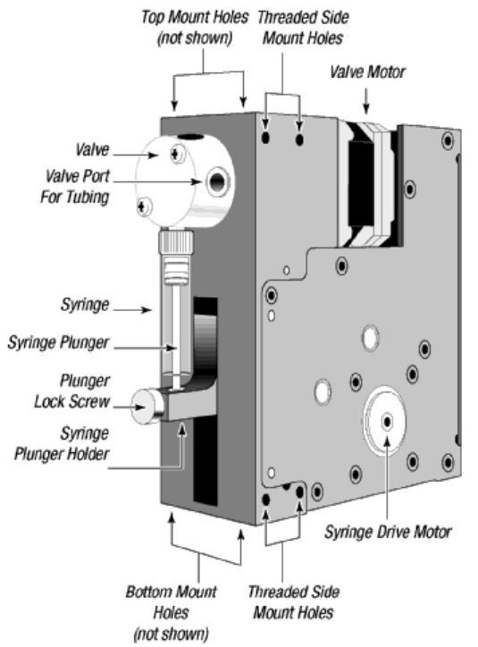
Functional Description of the XP 3000
The XP 3000 uses a stepper-motor driven syringe and valve design to aspirate and
dispense measured quantities of liquid. Both the syringe and the valve are replaceable.
Functional descriptions and illustrations of each major XP 3000 component are provided
in the sections that follow.
Figure 1-1. XP 3000 Modular Digital Pump
Getting Started 1-4
Syringe and Syringe Drive
The syringe plunger is moved within the syringe barrel by a rack and pinion drive that
incorporates a 1.8° stepper motor and quadrature encoder to detect lost steps.
The syringe drive has a 30 mm travel length and resolution of 3000 steps (3000 or 24000
steps for microstep-enabled firmware). When power is not applied to the pump, the
syringe drive can be moved by pushing up or down firmly on the plunger holder
assembly. This facilitates syringe removal.
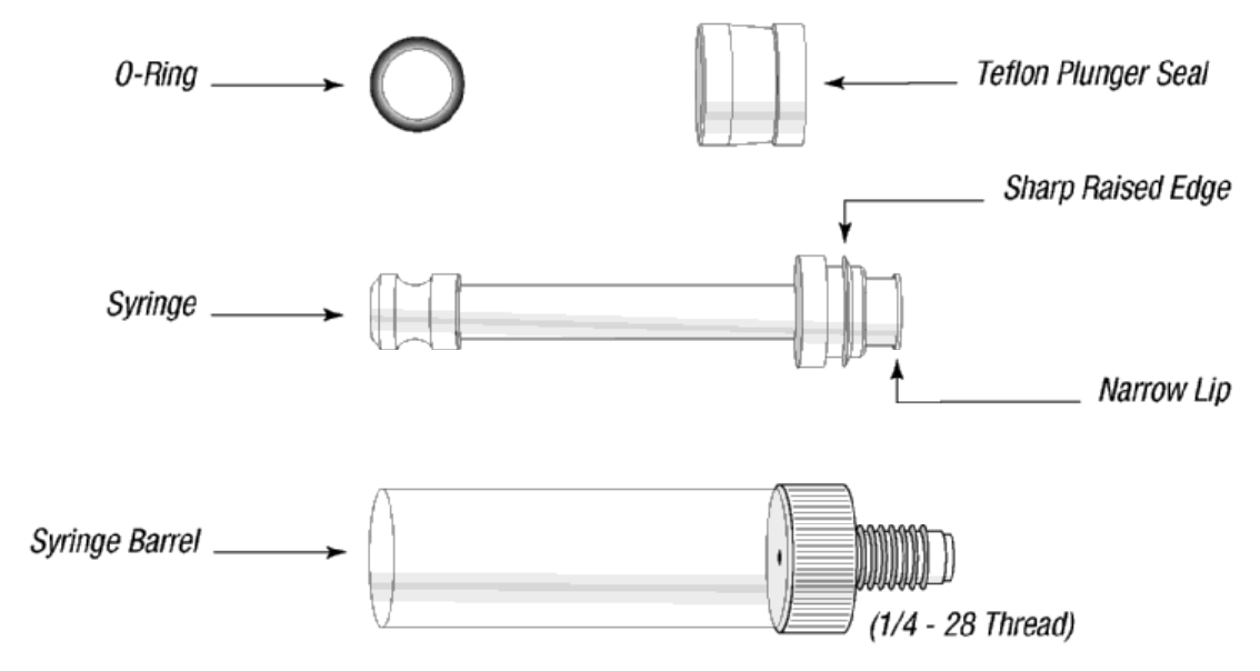
The base of the syringe plunger is held to the drive by a knurled screw. The top of the
syringe barrel attaches to the pump valve by a 1/4-28" fitting.
Figure 1-2 shows the components of a typical syringe.
Figure 1-2. Syringe Components
Syringes are available in these sizes: 50 µL, 100 µL, 250 µL, 500 mL, 1.0 mL, 2.5 mL,
and 5.0 mL. For ordering information, see Appendix A, “Ordering Information.”
Getting Started 1-5
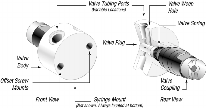
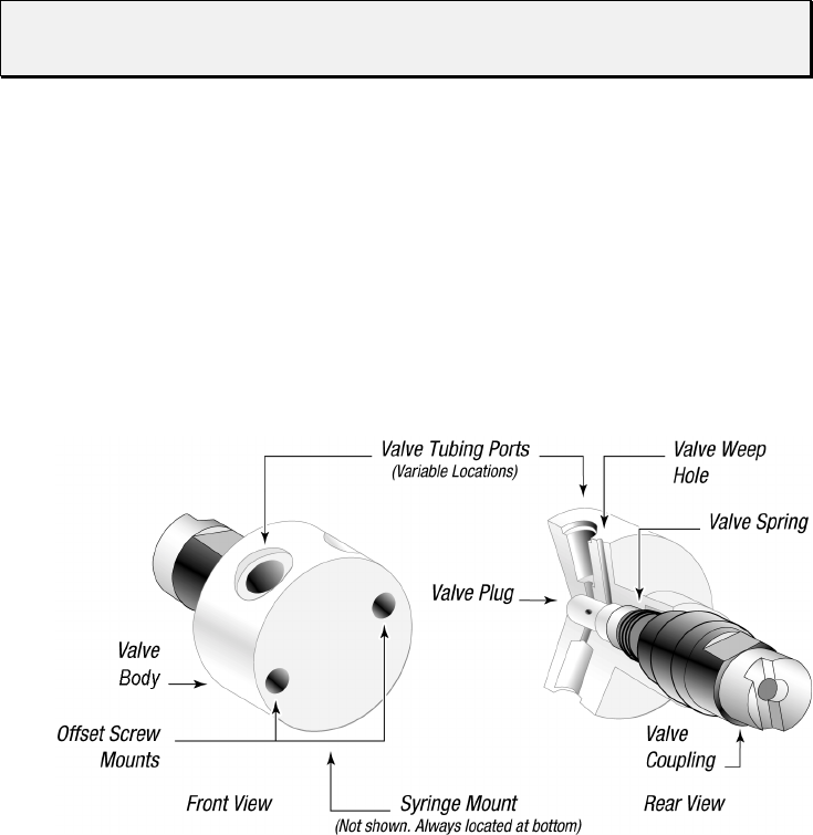
Valve and Valve Drive
The valve is made of a Kel-F body and Teflon plug. The plug rotates inside the valve
body to connect the syringe port to the various input and output ports. The valve is turned
by a 1.8° stepper motor that has an encoder coupled to it for positioning feedback. A
small circuit board is located under the valve drive. This board contains the optical sensor
for the valve encoder and a home sensor for the syringe drive.
Figure 1-3 shows the components of a 3-port valve.
Figure 1-3. 3-Port Valve Components
The XP 3000 is available with the following valves:
• Three-port valve. This valve has an input port, output port, and syringe port. The
syringe port is a “common” port, which means it is always connected to one of the
other two ports. In the standard configuration, the ports are placed at 120° intervals
around the circular valve body.
• T-valve. This valve has an input port, output port, and syringe port. The syringe
port is a “common” port, which means it is always connected to one of the other
two ports. The input and output ports are designed to be easily flushed. The ports
are placed at 90° intervals from the syringe port.
• Three-port distribution valve. This valve has four ports. The common syringe port
can distribute fluid to an input port, an output port, and an extra port. The ports are
placed at 90° intervals around the circular valve body.
• Y-block. In place of the switchable valve, there is a Kel-F manifold with two ports
at 120° intervals from the syringe port for input and output. No valve motor is
included.
Printed Circuit Board
The printed circuit board (PCB) holds the microprocessor and circuitry to control the
syringe and valve drives. The accessible external face of the PCB provides connectors for
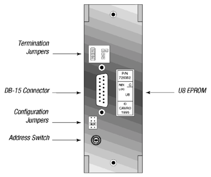
Getting Started 1-6
electrical inputs and outputs, jumpers for configuring different modes of operation, and a
communications address switch. Jumpers can be added or removed to select the desired
communication mode. For more information on the modes of operations, see Chapter 3,
“Software Communication.”
Figure 1-4 shows the accessible components of the printed circuit board.
Figure 1-4. XP 3000 Printed Circuit Board External Connectors
For more information on the printed circuit board inputs/outputs, jumpers, the address
switch, and EPROM, see Chapter 2, “Hardware Setup.”
Communication Interfaces
Depending on the pump configuration, the XP 3000 can communicate singly or in a
multi-pump configuration through an RS-232, RS-485, or CAN (Controller Area
Network) interface. For RS-232 and RS-485, baud rates of 9600 and 38400 are
supported. For CAN, baud rates of 100K and 125K are supported.
For details on the communications interfaces, see Chapter 2, “Hardware Setup.”
Getting Started 1-7
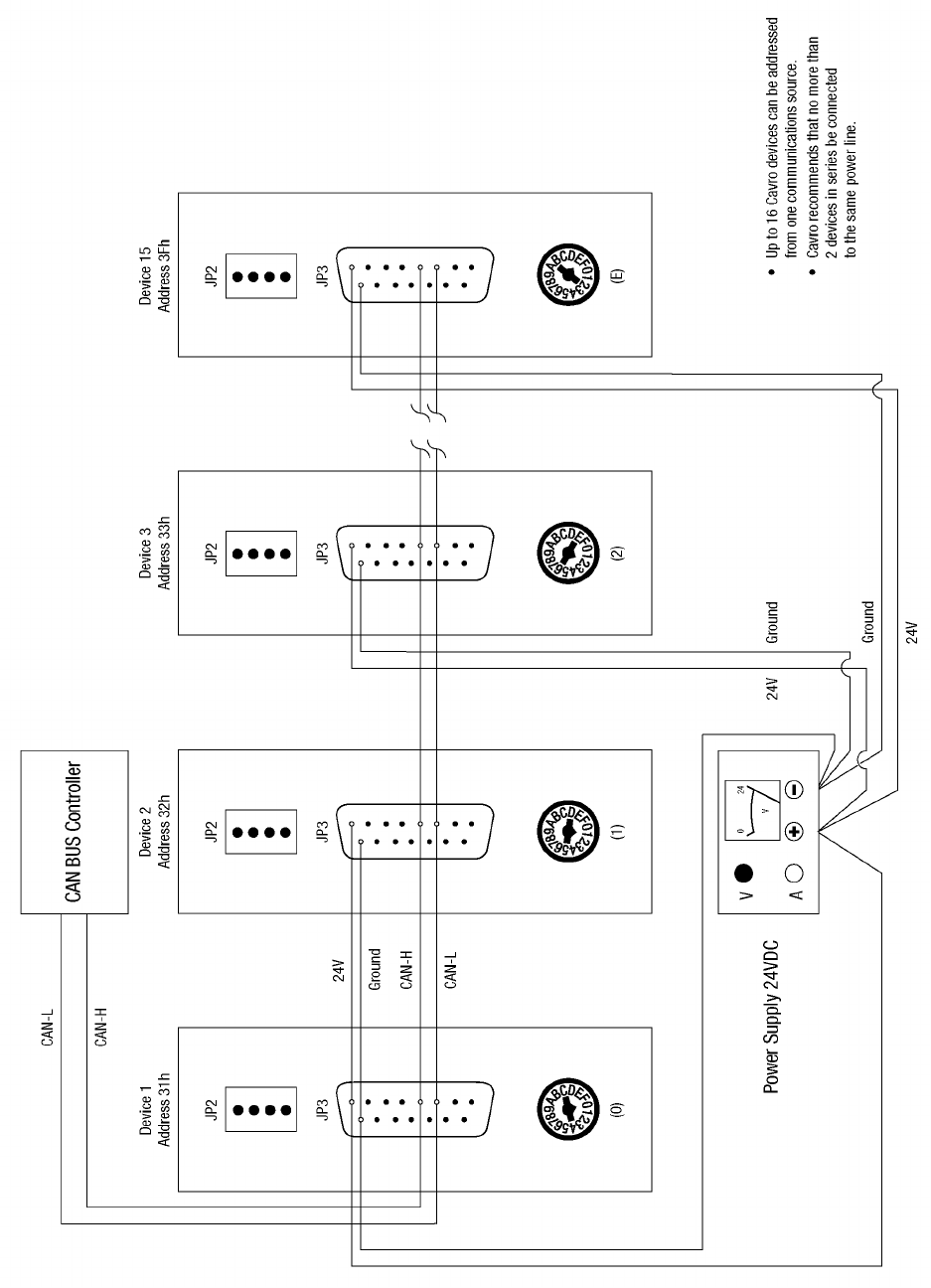
Multi-Pump Configurations
Up to fifteen XP 3000s can be connected together in a multi-pump configuration (also
called “daisy-chaining”). Within a multi-pump configuration, the RS-485
communications bus is required, although the first pump in the chain may receive either
RS-232 or RS-485 communications. For CAN communication, neither RS-232 or RS-485
is required. Each pump can be addressed separately from a single terminal via its unique
address, which is set using the address switch on the back panel of the pump. For more
information on setting addresses, see Chapter 2, “Hardware Setup.” For XPs with
microstep-enabled firmware, up to 16 XP 3000s can be connected together in a multi-
pump configuration.
Valve Sensor
The XP 3000 sensor board includes a circuit that detects fluid leakage out the back of the
valve. The valve is made of a Kel-F body and a Teflon plug which rotates inside the
body. Over time, the plug wears, causing the valve to leak. The length of time before
leakage occurs depends on the type of fluids used, duty cycle of the pump, and
maintenance procedures. The circuit will detect conductive fluid (i.e., ionic solution). On
power-up, the valve leak detector is set to 0, which means it is disabled. The user sets the
sensitivity of the leak detector. If fluid is detected, the pump returns an error code.
Tips for Setting Up the XP 3000
For complete information on setting up the XP 3000, see Chapter 2, “Hardware Setup”
and Chapter 3, “Software Communication.”
To ensure proper operation, follow these tips:
GAlways set up and mount the pump in an upright position. Failure to do so can cause
problems priming the system.
GAlways run liquid through the syringe and valve when they are moving. Failure to do
so can damage the sealing surfaces.
GBefore running any organic solvents through the pump, see Appendix D, “Chemical
Resistance Chart” for more information on solvents.
G Keep fingers out of the syringe slot while the pump is running. Failure to do so can
cause injury.
GAlways power down the instrument when connecting or disconnecting pumps.

Getting Started 1-8
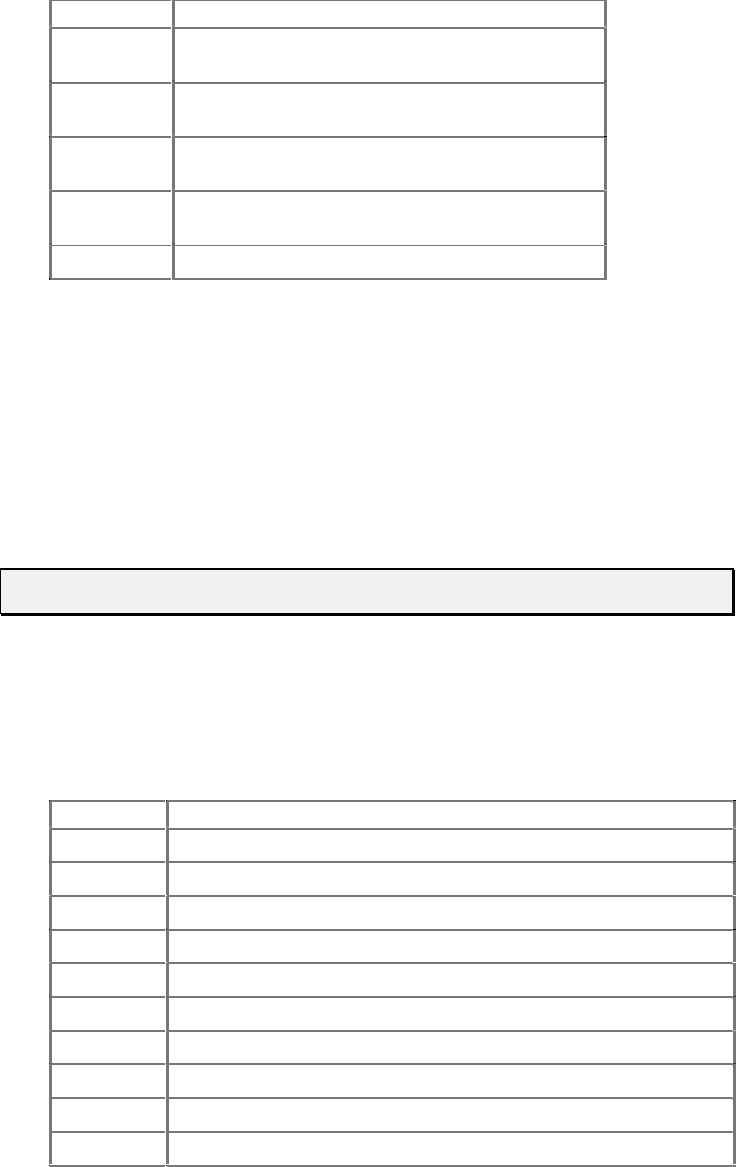
Mating Connector Suppliers
Cavro does not sell mating connectors beyond those found on its evaluation power
supply. For customer convenience, a list of DB-15 mating connectors is provided below
(Table 1-1).
Table 1-1. DB-15 Mating Connectors
Manufacturer Description Manufacturing Part
Number
Cable Connector, Receptacle
AMP 15 pin female - solder cup, receptacle 747909-2
Cinch 15 pin female - solder cup, receptacle DA-15S
Cable Connector, Housing
AMP Plastic housing with locks 207908-4
Cinch Plastic housing with locks SDH-15GL-CS
Fujitsu Metal Housing FCN-770C015-C/E
Fujitsu Locking post screw FCN-770A15
Circuit Board Connectors
Fujitsu 15 pin female - straight for .62 to .93 mm
thick PCB FCN-774J015-G/C
AMP 15 pin female - straight for .62 to .93 mm
thick PCB 745184-1
Flat Ribbon
3M 15 pin female - 15 pin flat ribbon receptacle 89815-8000
3M 15 pin female - strain relief 3448-8D15A
Getting Started 1-9
Power and Electrical Considerations
Choosing a Power Supply
The XP 3000 is powered by a 24VDC line via the DB-15 connector. The 24VDC supply
for a single XP 3000 should meet the following basic requirements:
• Output voltage: 24V nominal
• Output voltage tolerance: ±10% minimum, ±5% preferred
• Output voltage regulation: ±1% with varying line (input voltage) and load
• Output current (not including loads other than a single pump):
– ≥ 1.5A for power supplies with minimal capacitance
– ≥ 850mA for power supplies with internal filter capacitance of at least 1000
µF per amp of output current
– ≥ 850mA for power supplies with external capacitance of at least 1000 µF per
amp of output current (aluminum electrolytic capacitor preferred)
• Output voltage ripple: 50mV rms maximum at full load
• Conformance to required safety and EMI/RFI specifications
• Voltage turn-on and turn-off overshoot: < 2 volts
• Minimum current load (for switchers): see “Switching Power Supplies” in this
chapter.
To meet the above basic requirements, the supply must incorporate either linear or
switching regulation; it must have adequate output filter capacitance.
A current-limiting power supply is recommended. Current limiting above 1.0A is
acceptable, assuming that no additional equipment is operated from the supply.
If the power supply uses current feedback, the time-current foldback point must be
sufficient to allow charging of a 470 µF capacitor without folding back. If an external
capacitor is used, exercise care to ensure that the supply always starts after foldback,
particularly at low AC line voltage.
Integrating a Power Supply
When a power supply is used to operate more than one XP 3000 or other device, it must
provide the total average current for all devices. The power supply and filter capacitance
together must satisfy the total peak input current for all devices.
For example, if a system incorporates six XP 3000s with other equipment that together
require 4 amps, a 10A power supply is satisfactory, provided the output filter capacitance
in the supply is at least 10,000 µF:
6 x 0.85 = 5.1A; +4A = 9.1A (choose a 10A power supply)
If the power supply filter capacitance is less than 10,000 µF, use either additional
external capacitance or a 15A power supply:

Getting Started 1-10
6 x 1.5 = 9.0A; +4A = 13A (choose a 15A power supply)
In this example, it is assumed that all the pumps and other equipment will sometimes
operate simultaneously.
External equipment with inadequate bypass capacitance or that is inadequately sourced
for current can cause overvoltage transients and sags, and can create unnecessary ripple
current in the XP 3000. This can result in decreased component life. Additionally, it is
possible for a regulated power supply to become unstable with certain loads and oscillate
if adequate filter capacitance is not present. Some forms of oscillation can cause failures
in the XP 3000. These issues can be avoided by using a properly designed commercial
power supply.
Consideration should also be given to the wiring of the XP 3000 and any additional
devices. Wiring should be of sufficient gauge for the current, and as short as possible.
Unless otherwise required by safety requirements, the power supply lines to the XP 3000
should be 20AWG or heavier. Multiple XP 3000s can be daisy-chained, provided that the
wire size and the power supply are adequate for the total current. In the example of the
six XP 3000s above, use 18AWG wire if the units are daisy-chained. It is best if each pair
is twisted or dressed together from the device to the supply. For more information on
multi-pump cabling, see Chapter 2, “Hardware Setup.”
To control power to the XP 3000, switch power to the power supply. Do not use a relay
or switch contacts between the 24V supply and the XP 3000 (i.e., do not switch DC input
to the pump).
Switching Power Supplies
Be sure to check carefully the minimum load requirement of the power supply. Typically,
switching supplies have a minimum load requirement of up to 10% of the rated output
current.
NOTE The XP 3000 idle current is less than 10% of the full running current.
For example, in a system with multiple XP 3000s, a 24V 5-amp switcher with a
minimum load less that 500mA may not provide sufficient current when the XP 3000
motors are idle and all other devices are in a low current state. If the XP 3000 is the only
load on the 24V supply, a switcher should have a minimum load specification of 50mA
or less. An appropriate external power resistor can be used to ensure that the minimum
load is met.
Hardware Setup 2-1
2 - Hardware Setup
This chapter includes these sections describing the various parts of hardware setup:
Power XP 3000 Without Valve
Cabling Installing Components
Printed Circuit Board Settings and
Options Mounting the XP 3000
Power
The XP 3000 requires a 24VDC power supply with a current rating of at least 1.5A,
provided through a DB-15 connector. Cavro recommends using one power cable for
every two pumps to provide noise immunity; i.e., power should not be daisy-chained to
more than two pumps.
For complete information on choosing a power supply, see Chapter 1, “Getting Started.”

Hardware Setup 2-2
Cabling
A single cable supplies both power and communications to each XP 3000. (Power is
described in the “Power” section in this chapter.)
Set a unique address to identify each pump module. For more information, see “Address
Switch Settings” in this chapter; see also Chapter 3, “Software Communication.”
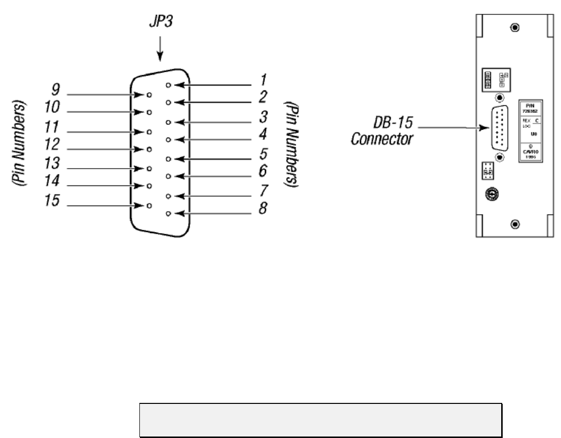
Table 2-1. DB-15 Connector Pin Assignments
Pin Function Remarks
124VDC
2 RS-232 TxD line Output data
3 RS-232 RxD line Input data
4 Unused
5 CAN high signal line
6 CAN low signal line
7 Auxiliary input #1 TTL level
8 Auxiliary input #2 TTL level
9 Ground Power and logic
10 Ground Power and logic
11 RS-485 A line
12 RS-485 B line
13 Auxiliary output #1 TTL level
14 Auxiliary output #2 TTL level
15 Auxiliary output #3 TTL level
Hardware Setup 2-3
Figure 2-1 shows the pin positions of the DB-15 connector on the printed circuit board.
This is a male connector that requires a female connector on the mating cable.
Figure 2-1. DB-15 Connector Pins
Communication Interfaces
The computer or controller communicates with the XP 3000 through an RS-485 interface,
RS-232 interface, or CAN (Controller Area Network) interface. The RS-232 interface
automatically converts the protocol to RS-485 for the benefit of any other devices which
may be connected to the XP 3000’s RS-485 communications bus (this constitutes a so
called “multi-drop” device configuration).
NOTE The RS-232 interface does not support hardware handshaking and requires
only three lines: RXD, TXD, and Signal Ground.
When using a multi-drop arrangement, up to 15 pumps can be addressed by the controller
on the same communications bus (up to 16 pumps for microstep-enabled firmware). Take
special care to ensure that the RS-485 A and B lines are not reversed. Special
consideration must be given to the position of jumpers on JP2. These jumpers switch
termination resistors into the RS-485 A and B line circuits, thereby dampening the signal
at the ends of the RS-485 chain. This prevents echoing of the signal back to the listeners
on the chain. Multi-drop configurations require jumpers in both positions of JP2 for the
first and last pump in the RS-485 chain (i.e., the ends of the chain). Single pump
configurations (i.e., only one pump communicating with a controller) always require that
jumpers be installed on JP2.
Hardware Setup 2-4
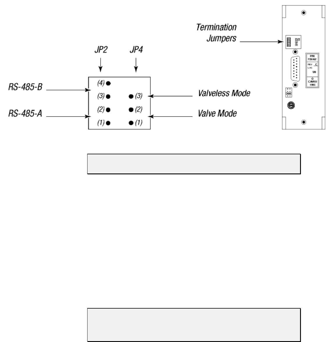
Figure 2-2 shows the termination jumpers on the printed circuit board.
Figure 2-2. Termination Jumpers
NOTE Pumps are shipped with the RS-485 termination jumper installed on JP2.
Please remove the jumpers if they are not needed.
When communicating with the pumps via RS-232, one pump in the chain must be
configured for RS-232 communication. This pump receives the RS-232 signal from the
PC or controller and converts it to RS-485, then passes the RS-485 signal to all other
pumps in the chain.
Refer to the cabling illustrations on the following pages. These illustrations show the
multi-pump cabling for RS-232, RS-485, and CAN connections, respectively. Also
shown is the external termination scheme for the RS-485 chain. This scheme can be used
if the terminators are installed in the system instead of on the pump.
The CAN interface is a two-wire serial system. The bus is driven differentially in a
manner similar to RS-485. The major difference is in the protocol. The CAN protocol is
designed to allow any device on the bus to send a message at any time. This is unlike
other two-wire interfaces in which the slave devices can only transmit in response to a
query. Using the CAN interface, the pump can send a message to inform the master that it
has completed its task. Anti-collision detection (which reconciles problems that occur
when two devices talk at once) is carried out by the CAN controller hardware.
NOTE Always power off pumps before connecting to or disconnecting from the bus.
For XP 3000s with microstep-enabled firmware, please refer to “Configuration
Jumpers (JP1) for Microstep-Enabled Firmware” and “Termination Jumpers
(JP4) for Microstep-Enabled Firmware,” later in this chapter.
Hardware Setup 2-5
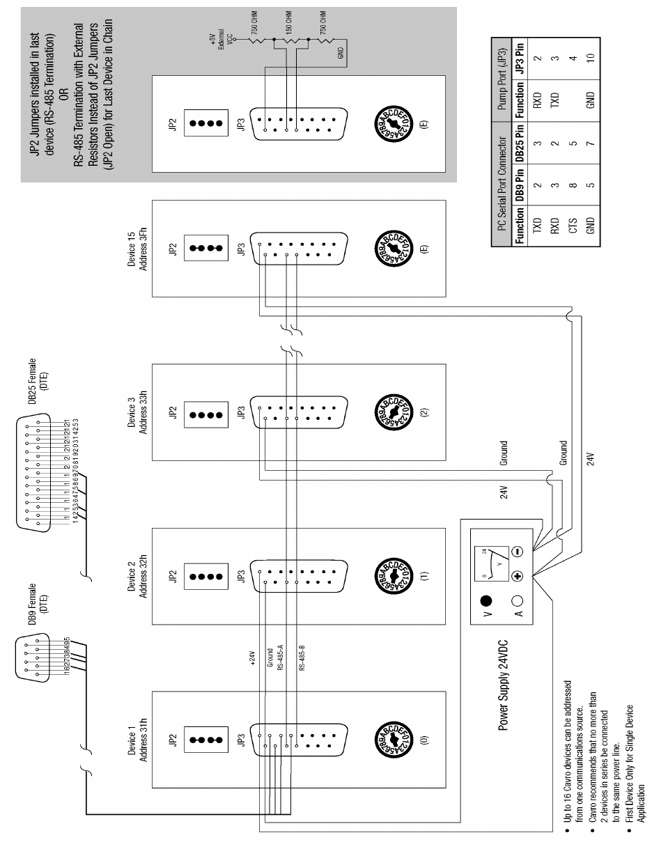
RS-232 CABLING
Figure 2-3. RS-232 Multi-Pump Cabling
nc
Hardware Setup 2-6
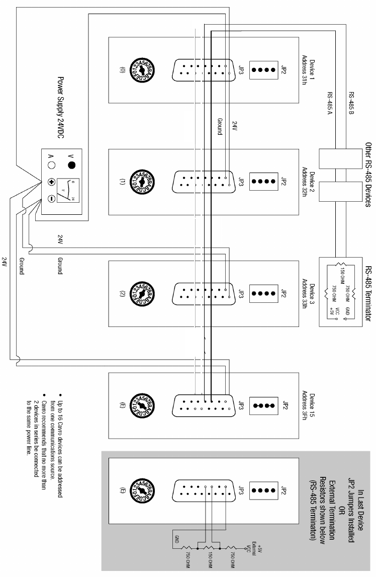
RS-485 CABLING
Figure 2-4. RS-485 Multi-Pump Cabling
RS-485-A
RS-485-B
Hardware Setup 2-7
CAN CABLING
Figure 2-5. CAN Multi-Pump Cabling
Hardware Setup 2-8
Printed Circuit Board Settings and Options
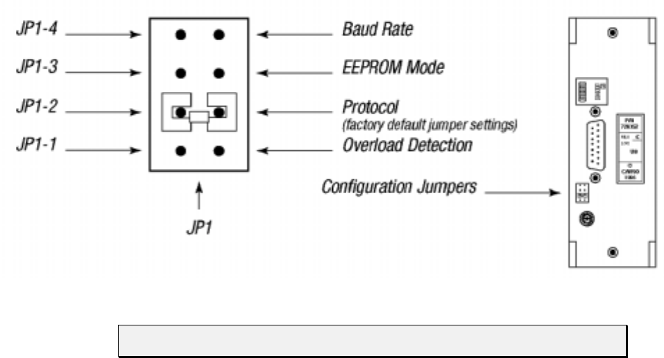
Configuration Jumpers (JP1) for Standard Firmware
Connector JP1 on the XP 3000 printed circuit board is used to configure different modes
of operation (see Figure 2-6). Jumpers are added or removed to enable or disable the
different modes. The jumpers control set the following:
Plunger overload detection (JP1-1)
Communications protocol (JP1-2)
EEPROM, autostart mode (JP1-3)
Baud rate (JP1-4)
Figure 2-6. Configuration Jumpers
NOTE Always power off the XP 3000 before changing any of the jumpers on JP1.

Hardware Setup 2-9
JP1-1: PLUNGER OVERLOAD DETECTION
This jumper position allows enabling or disabling of plunger overload detection. There
are two settings:
JP1-1 removed Plunger overload detection enabled (default setting)
JP1-1 installed Plunger overload detection disabled
CAUTION! Do not disable plunger overload detection; it is used for manufacturing
test only. If a jumper is installed at JP1-1, plunger overload will not be
detected and the pump will not generate an error code if it is losing steps.
JP1-2: COMMUNICATIONS PROTOCOL (UNUSED FOR CAN)
This jumper position sets the XP 3000 communications protocol. There are two settings:
JP1-2 removed Data Terminal (DT) protocol
JP1-2 installed OEM protocol (default setting)
For more information on the XP 3000 communications protocols, see Chapter 3,
Software Communication.”
JP1-3: EEPROM AUTOSTART
This jumper position activates or inactivates the autostart mode of the EEPROM. For
instructions on programming or running the XP 3000 using the EEPROM, see Chapter 3,
Software Communication.” There are two settings:
JP1-3 removed EEPROM autostart mode inactivated (default setting)
JP1-3 installed EEPROM autostart mode activated
JP1-4: BAUD RATE
This jumper position is used to select the baud rate for the RS-232/RS-485 version of the
XP 3000. There are two baud rates to select from:
JP1-4 removed 9600 baud (default setting)
100K baud for CAN (for microstep-enabled firmware)
JP1-4 installed 38400 baud
125K baud for CAN (for microstep-enabled firmware)
NOTE The XP 3000 is shipped with spare jumper placed across the top of pin JP4.
This can be used to change the default configuration settings.

Hardware Setup 2-10
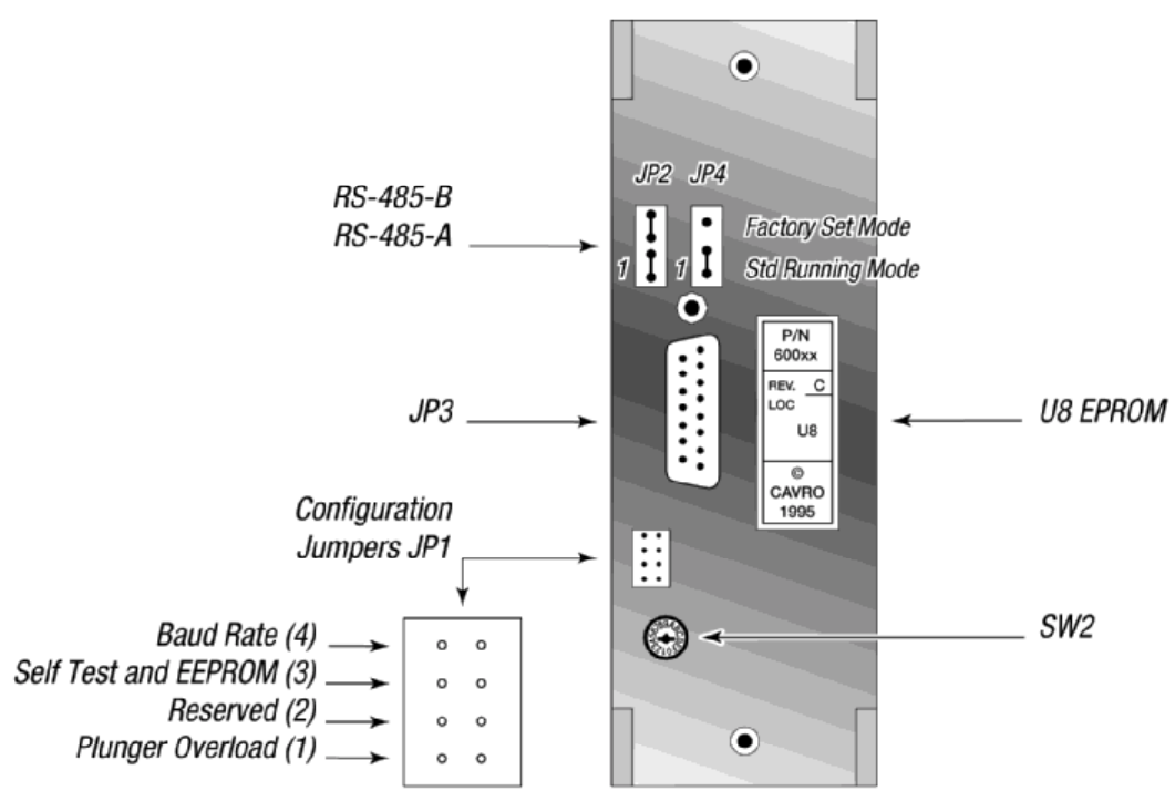
Configuration Jumpers (JP1) and Termination Jumpers (JP4) for
Microstep-Enabled Firmware
NOTE To determine whether or not your XP 3000 carries microstep-enabled
firmware, check the part number on the EPROM label. If the part number is
600,xxx, this section applies to your pump.
The XP 3000 microstep-enabled firmware automatically detects the mode the user is
programming in, OEM or DT. Jumpers are not needed to engage this feature.
Two jumpers on the XP 3000 have new functionality:
• JP1 (configuration jumper)
• JP4 (mode jumper)
MODE JUMPER JP4
When pins 1 and 2 are jumpered, the XP 3000 is in standard running mode. In this mode,
the pump accepts all commands.
CAUTION! For microstep-enabled firmware, when pins 2 and 3 are jumpered, the
XP 3000 is in factory set mode. This mode is reserved for Cavro factory
use only. Enabling the factory set mode may cause major functional
changes to the unit. Simply moving the jumper back to the standard
running mode will not reset the pump to its original configuration. If the
factory set mode is accidentally enabled, please call Cavro’s Technical
Service to reset the unit.
The JP4 jumper settings for each mode are shown below.
•3 Factory Set Mode •3
•2•2 Standard Running Mode
•1•1
Figure 2-7. JP4 Jumper Settings Per Mode

Hardware Setup 2-11
CONFIGURATION JUMPER JP1
The table below describes the features of JP1.
Jumper Standard Running Mode
JP1-1 Overload Disable
JP1-2 Reserved
JP1-3 Self-Test and EEPROM
JP1-4 Baud Rate
JP1-1, Plunger Overload Detection
This jumper position allows enabling or disabling of plunger overload detection. There
are two possible settings:
JP1-1 removed Plunger overload detection enabled (default setting)
JP1-1 installed Plunger overload detection disabled
JP1-2, Reserved
JP1-3, Self-Test and EEPROM AutoStart
When JP1-3 is in and the address switch is set to position “F,” the self-test diagnostic
program will be activated. For more information on using the address switch and the self-
test, see “Address Switch Settings” in this chapter.
When the address switch is in any position other than “F,” the autostart mode of the
EEPROM can be activated or inactivated.
JP1-3 removed EEPROM, self-test disabled (default setting)
JP1-3 installed EEPROM self-test enabled
JP1-4, Baud Rate
This jumper position is used to select the baud rate for the RS-232/RS-485 version of the
XP 3000. There are two baud rates to select from:
JP1-4 removed 9600 baud (default setting) (100K baud for CAN)
JP1-4 installed 38400 baud (125K baud for CAN)
Hardware Setup 2-12
Figure 2-8 shows the printed circuit board settings for the microstep-enabled firmware.
Figure 2-8. Printed Circuit Board Settings for Microstep-Enabled Firmware
Hardware Setup 2-13
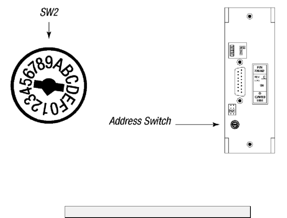
Address Switch Settings
The address switch (see Figure 2-9) is located on the lower left of the XP 3000’s back
panel. It is used to give each XP 3000 in a multi-pump configuration a unique or specific
address, allowing the user to direct commands to specific pumps. The address switch has
sixteen positions (numbered 0 through F). Fifteen positions (addresses 0 through E) are
valid pump addresses for standard firmware modules, sixteen (0 through F) for
microstep-enabled firmware modules.
Figure 2-9. Address Switch
To set the address switch:
To set the address switch, use a jeweler’s screwdriver or small flat head screwdriver and
turn the switch in either direction to the desired position.
NOTE Power cycle (or power up) the pump after setting the address switch.
For information on the addressing schemes for different pump configurations, see
Chapter 3, “Software Communication.”

Hardware Setup 2-14
Self-Test
The “F” address switch position is used to activate the XP 3000 self-test. Self-test causes
the XP 3000 to initialize then cycle repeatedly through a series of plunger movements at
fifteen different speeds. If an error condition occurs, the pump stops moving. Typically,
the self-test activates the pump at 800 strokes/hour.
To run the self-test, set the address switch to position “F.” If the pump carries microstep-
enabled firmware, the configuration jumper JP1-3 must also be installed. Then supply
power to the pump.
CAUTION! Always run liquid through the syringe and valve. Failure to do so can
damage the valve and syringe seal.
Do not run self-test with a 5.0 mL syringe installed. Remove the valve
and 5.0 mL syringe. Failure to do so can result in plunger overloads.
Inputs/Outputs
The XP 3000 provides two auxiliary inputs and three auxiliary outputs that can be
accessed through the DB-15 connector, JP3. They provide TTL level signals. The outputs
are controlled by the [J] command.
The auxiliary inputs are located on JP3 pins 7 and 8. They can be read back using report
commands ?13 and ?14. Additionally, the inputs can be used to externally trigger a
command sequence using the [H] command. The commands are described in Chapter 3,
“Software Communication.”
The auxiliary outputs are located on JP3, pins 13, 14, and 15.

Hardware Setup 2-15
XP 3000 Without Valve
The XP 3000 without valve is available in an RS-232/RS-485 or CAN/RS-485
configuration. It uses the same components and operates the same as the XP 3000 with
valve, except that it does not contain a valve, valve motor, or valve encoder. Syringes are
attached using a Kel-F block which replaces the XP 3000 valve. The block has a “Y”
configuration with input and output port (available in 1/4-28 or M6 fittings) and a 1/4-28
screw fitting for the syringe. Valveless pumps use the same syringes as pumps with
valves.
NOTE When using a valveless pump, remove the additional jumper and set JP4 to
pins 2 and 3.
The XP 3000 without valve uses the same commands as the XP 3000 with valve with the
exception of the initialize command, valve commands and valve overload error. For more
information on the commands, see Chapter 3, “Software Communication.”
NOTE Valveless pumps require a system valve external to the pump. They are
commonly used with other Cavro devices.
During power-up, the valve initializes. The valve encoder will make a complete
revolution in a clockwise direction. The valve stops at the left-hand port (as viewed from
the front of the pump). If the valve is at another position during power-up, the encoder
will turn clockwise to the left-hand port, then it will make a complete revolution. The
syringe plunger does not move.
Hardware Setup 2-16
Installing Components
See Chapter 5, “Maintenance,” for the procedures for replacing and maintaining
components.
Installing the XP 3000 Valve
NOTE The valves are not interchangeable among pumps. To use a different model
valve, contact Cavro Customer Support.
These instructions apply to the 3-port valve, the 3-port distribution valve, and the T-
valve.
To install the XP 3000 valve, follow these steps:
1 Place the pump upright on a table surface, with the front facing you.
2 Verify that the offset tab on the encoder in the pump is correctly oriented (vertically
with the tab to your right).
3 Rotate the valve coupling to the position shown on the left in Figure 2-10 (vertically
with the offset tab to your left).
Figure 2-10. XP 3000 Valve Installation (3-Port Valve Shown)
Hardware Setup 2-17
4 Install the valve by inserting the slot in the valve coupling onto the tab of the
encoder. The valve should be oriented with the tube fittings on top and the syringe
fitting on the bottom.
5 Gently push the valve in place, matching the locating pins on the valve fit the holes
on the front of the pump.
6 Secure the valve with two Phillips head valve screws through the mounting holes.
After the screws contact the valve body, tighten further ¼ to ½ turn.
Hardware Setup 2-18
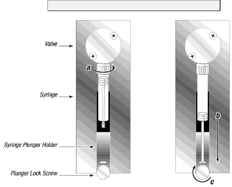
Installing a Syringe
To install a syringe, follow these steps:
1 Loosen the plunger lock screw approximately three full turns.
2 Lower the plunger drive by sending the command [A3000R]. If power is not applied,
the plunger drive can be manually lowered by pushing down firmly on the plunger
holder assembly.
3 To install the syringe, do the following (as shown in Figure 2-11):
a Screw the syringe into the valve.
b Pull the syringe plunger down to the plunger holder assembly.
c Screw the syringe plunger into place.
NOTE Make sure the plunger lock screw is securely tightened.
Figure 2-11. Syringe Installation

Hardware Setup 2-19
Mounting the XP 3000
Numerous tapped M3 x 0.5 mounting holes provide flexibility in mounting the XP 3000;
there are several mounting options:
mounting from the bottom
mounting from the top
mounting from the sides
Mounting requirements vary for pumps with different valves. For more information, see
the specific valve outline drawings. If necessary, custom mounting brackets can be
designed, or, the pump can be mounted directly into an instrument.
NOTE Always mount the pump in an upright position. Failure to do so can cause
problems in priming the system.
To facilitate mounting, Figure 2-12 shows the locations of the threaded mounting holes
(top, bottom, left and right side plates) of the XP 3000.
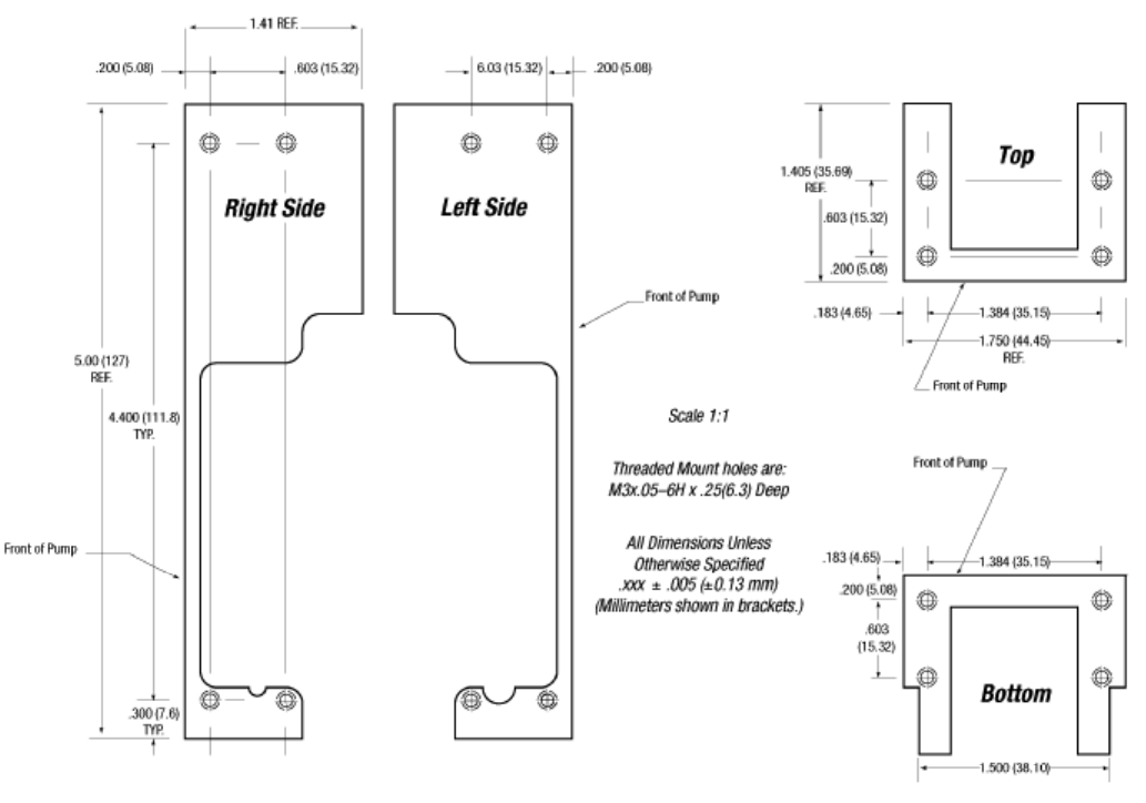
Hardware Setup 2-20
Figure 2-12. XP 3000 Threaded Mount Holes

Software Communication 3-1
3 - Software Communication
This chapter describes how to communicate with the XP 3000: through an
RS-232, RS-485, or CAN (Controller Area Network) interface, depending on the pump
configuration.
This chapter includes these topics:
XP 3000 Addressing Scheme
Communication Protocols
Using the XP 3000 Command Set
Error Codes and Query Status
XP 3000 Addressing Scheme
As part of the communication protocol, an address for each pump must be specified. The
user has the option of addressing a single pump, two pumps (dual device), four pumps
(quad device), or all 15 pumps (all devices), depending on the address byte used. Each
physical address in the address switch corresponds to a hexadecimal value, as shown in
Table 3-1.
Table 3-1. Hexadecimal Addressing Scheme
Address (hex) Device
RS-232/
RS-485 CAN
30 0 Master Address (master controller, personal computer, etc.)
31..3F 1..F Addresses single device
41..50 11..20 Addresses two devices at a time (dual device)
51..5D 21..2D Addressed four devices at a time (quad device)
5F 2F Addresses all devices on the bus
For example, an XP 3000 with address switch set to 0 is addressed as device “31h” in the
RS-232 or RS-485 communication protocol, hardware address 1 is addressed as device
“32h,” and so on.
Table 3-2 shows the different address switch settings for each of these configurations.

Software Communication 3-2
NOTE When using the Pump:Link software to send commands to a device, use the
ASCII address values in Table 3-2
Table 3-2. Address Switch Settings in Hex (ASCII)
Switch
Setting Single Device Dual Device Quad Device All Devices
Hex
Address ASCII
Address Hex
Address ASCII
Address Hex
Address ASCII
Address Address Value
to Send
0 31 1 41 A 51 Q 5F _
1322
2333 43C
3344
4355 45E55U
5366
6377 47G
7388
8399 49I 59Y
93A:
A3B; 4BK
B3C<
C3D= 4DM5D]
D3E>
E3F? 4FO
FSelf Test
The user can communicate with all pumps in the chain by using address “5Fh,” for
example to initialize all pumps at once. Then each pump can be controlled independently
by using addresses “31h” to “3Fh.”
NOTE Multiple address commands cannot be used to determine device status, nor
will they respond to Report commands. Each device must be queried
separately.

Software Communication 3-3
Communication Protocols
Three communication protocols are available:
OEM communications protocol
Data Terminal (DT) protocol
CAN protocol
On standard firmware pumps, select a communication protocol using JP1-2 on the back
panel of the XP 3000.
NOTE Microstep-enabled XP firmware automatically detects the communication
protocol. There is no need to select JP1-2 when using this firmware.
The DT protocol can be run via an ASCII data terminal because no sequence numbers or
checksums are used. For instructions on using a Microsoft Windows Terminal Emulator,
see “Using DT Protocol with Microsoft Windows” in this chapter.
NOTE Cavro recommends using the OEM protocol. It provides increased error
checking, i.e., checksums and sequence numbers are used.

Software Communication 3-4
OEM Communication Protocol
OEM communication is a robust protocol that includes automatic recovery from
transmission errors. Table 3- describes each setting within the OEM communication
protocol.
Table 3-3. OEM Protocol (JP1-2, Jumper IN)
Parameter Setting
Character Format
Baud rate 9600 or 38400 (set using JP1-4)
Data bits 8
Parity None
Stop bit 1
Command Block
(see “OEM Protocol Command Block Characters”)
1 STX (^B or 02h)
2 Pump address
3 Sequence number
3+n Data block (length n)
4+n ETX (^C or 03h)
5+n Checksum
Answer Block
(see “OEM Protocol Answer Block Characters”)
1 STX (^B or 02h)
2 Master address (0 or 30h)
3 Status code
3+n Data block (length n)
4+n ETX (^C or 03h)
5+n Checksum
OEM PROTOCOL COMMAND BLOCK CHARACTERS
The command block characters in the OEM communication protocol are described
below. All characters outside the command block are ignored.
When developing a parsing algorithm, the programmer should key on the STX as the
beginning of the answer block and the checksum (character after the ETX) as the end of
the answer block.
STX (^B or 02h)
The STX character indicates the beginning of a command.

Software Communication 3-5
Pump Address
The pump address is a hexadecimal number specific for each pump.
Sequence Number/Repeat Flag
The sequence number is a single byte that conveys both a sequence number (legal
values: 1 to 7) and a bit-flag indicating that the command block is being repeated
due to a communications breakdown. The sequence number is used as an identity
stamp for each command block. Since it is only necessary that every message
carries a different sequence number from the previous message (except when
repeated), the sequence number may be toggled between two different values (e.g.,
“1” and “2”) as each command block is constructed. During normal
communication exchanges, the sequence number is ignored. If, however, the repeat
flag is set, the pump compares the sequence number with that of the previously
received command block to determine if the command should be executed or
merely acknowledged without executing.
NOTE If the operator chooses not to use this option, the sequence number can be set
to a fixed value of 1 (31h).
The following two scenarios should clarify this error detection mechanism.
Scenario 1.
1 The computer sends a command block stamped with sequence #1 to the pump.
2 The pump receives the command, sends an acknowledgement to the PC, and
executes it.
3 Transmission of the acknowledgement message is imperfect; the PC does not
receive it.
4 The PC waits 100 ms for the acknowledgement, then retransmits the command
block with the sequence number left at 1 and the repeat bit set to indicate a
retransmission.
5 The pump receives the transmission, identified as such by the repeat bit.
6 The pump checks the sequence number against that of the previously received
command block. Noting a match, the pump sends an acknowledgement to the
PC, but it does not execute the command (since it has already been executed).
7 The PC receives the acknowledgement and continues with normal
communications.
8 The next command block is stamped with sequence #2 to indicate a new
command.
Software Communication 3-6
Scenario 2.
1 The computer sends a command block stamped with sequence #1 to the pump.
2 The pump never receives the command due to a communication error and thus does
not send an acknowledgement to the PC.
3 The PC waits 100 ms for the acknowledgement, then retransmits the command block
with the sequence number left at 1 and the repeat bit set to indicate a retransmission.
4 The pump receives the retransmission, identified as such by the repeat bit.
5 The pump checks the sequence number against that of the previously received
command block. Noting a mismatch, the pump recognizes this as a new command
block and sends an acknowledgement to the PC. It then executes the command.
6 The PC receives the acknowledgement and continues with normal communications.
7 The next command block is stamped with sequence #2 to indicate a new command.
The sequence number/repeat byte is constructed as follows:
Bit # 76543210
Value 0011REPSQ2SQ1SQ0
REP: 0 for non-repeated / 1 for repeated
SQ0 – SQ2: sequence value, as follows:
Sequence
Value SQ2 SQ1 SQ0
1001
2010
3011
4100
5101
6110
7111
NOTE Bits 4 through 7 are always fixed to the values shown.
Data Block (length n)
The data block consists of the data or commands sent to the pump or host (this is
an ASCII string). When the pump is responding to a move or [Q] command, the
data block length is 0 (i.e., no data string exists).
ETX
The ETX character indicates the end of a command string.
Software Communication 3-7
Checksum
The checksum is the last byte of the message string. All bytes (excluding line
synchronization and checksums) are XORed to form an 8-bit checksum. This is
appended as the last character of the block. The receiver compares the transmitted
value to the computed value. If the two values match, an error free transmission is
assumed; otherwise, a transmission error is assumed.
OEM PROTOCOL ANSWER BLOCK CHARACTERS
The answer block characters in the OEM communication protocol are described below.
Only the unique answer block entries are listed in this section. For common commands
and answer block commands (characters), see the previous section, “OEM Protocol
Command Block Characters.”
Master Address
The master address is the address of the host system. This should always be 30h
(ASCII value “0”).
Status and Error Codes
The status and error codes define pump status and signal error conditions. For a
description of status and error codes, see “Error Codes and Query Status” in this
chapter.

Software Communication 3-8
Data Terminal (DT) Protocol
The DT protocol can be used easily from any terminal or terminal emulator capable of
generating ASCII characters at 9600 baud, 8 bits, and no parity.
Table 3-4. DT Protocol (JP1-2, Jumper OUT)
Character Format
Parameter Setting
Baud rate 9600 or 38400 (set using JP1-4)
Data bits 8
Parity None
Stop bit 1
Command Block
(see “DT Protocol Command Block Characters”)
1 Start command (ASCII “/” or 2Fh)
2 Pump address
2+n Data block (length n)
3+n Carriage Return ([CR] or 0Dh)
Answer Block
(see “DT Protocol Answer Block Characters”)
1 Start answer (ASCII “/” or 2Fh)
2 Master address (ASCII “0” or 30h)
3 Status character
3+n Data block (if applicable)
4+n ETX (03h)
5+n Carriage Return (0Dh)
6+n Line feed (0Ah)
DT PROTOCOL COMMAND BLOCK CHARACTERS
The command block characters in the DT communication protocol are described below.
Start Block
The start character indicates the beginning of a message block.
Pump Address
The pump address is an ASCII character specific to each pump.
Data Block (length n)
The data block consists of the ASCII data or commands sent to the pump or host.
End Block
The end character indicates the end of a message block.
Software Communication 3-9
DT PROTOCOL ANSWER BLOCK CHARACTERS
The answer block characters comprising the DT communication protocol are described
below.
Only unique answer block entries are listed in this section. For information on command
and answer block commands (characters), see the previous section, “DT Protocol
Command Block Characters.”
Master Address
The master address is the address of the host system. This should always be 30h
(ASCII “0”).
Status Character
The status and error codes define pump status and signal error conditions. See the
description of the [Q] command in “Error Codes and Query Status.”
Data Block
This is the response from all Report commands with the exception of the [Q]
command.
Carriage Return (0Dh)/Line Feed (0Ah)
This character terminates the reply block.
Software Communication 3-10
Using DT Protocol with Microsoft Windows
The XP 3000 can be controlled in DT protocol mode directly from the Microsoft
Windows terminal accessory.
To communicate with the XP 3000 using Windows 3.x, follow these steps:
1 Connect the XP 3000 to a communications port of the PC (for example, COM1).
2 From the Microsoft Program Manager window, select Terminal from the
Accessories group window.
3 Select the Settings menu, and choose Communications.
4 Select a baud rate of 9600, 8 data bits, 1 stop bit, no parity, communications port
connector, and no flow control.
5 Click OK.
6 Set the pump address switch to 0 and remove all configuration jumpers in JP1-2 and
JP1-4.
7 Power on the pump.
8 Type /1ZR<CR> to initialize the pump.
To run the pump, see the commands listed in “Using the XP 3000 Command Set” in
this chapter.
To communicate with the XP 3000 using Windows 95/NT, follow these steps:
1 To connect the XP 3000 to a communication ports on the PC, first select the Start
menu and choose Run.
2 In the Run dialog box, type Hyperterm.exe. The Connection Description dialog box
appears.
3 Enter a name for the connection and select an icon, then click OK. The Phone
Number dialog box appears.
4 Select the following in the fields provided:
Connect using: Direct to <communication port> (usually COM1 or COM2,
depending on how the hardware is set up)
Click OK. The COM Properties dialog box appears.
5 Select the following in the fields provided:
Bits per second: 9600
Data bits: 8
Parity: None
Stop bits: 1
Flow control: None
Click OK.
Software Communication 3-11
6 Select the File menu, and choose Properties. The Properties dialog box appears.
7 Select the Settings tab, and enter or select these options:
Function, arrow, and Control keys act as:
– Select “Terminal keys”
Emulation:
– Select “Autodetect”
– Enter “500” in Backscroll buffer lines
Click the ASCII Setup button. The ASCII Setup dialog box appears.
8 Enter or select these options:
– Select “Send line ends with line feed”
– Select “Echo typed characters locally”
– Enter a Line delay of “0”
– Enter a Charater delay of “0”
– Select “Wrap lines that exceed terminal width”
9 Click OK to close the ASCII Setup dialog box, then click OK to close the Properties
dialog box.
10 Set the pump address to 0 or the appropriate address.
11 Set jumper JP1-2 to DT protocol (JP1-2 removed). Note that no jumper is needed for
microstep-enabled firmware. The communication protocol is detected automatically.
12 Power on the pump and initialize it by typing /1ZR and pressing Enter.
To run the pump, see the commands listed in “Using the XP 3000 Command Set” in
this chapter.

Software Communication 3-12
CAN Interface Communications
CAN (Controller Area Network) is a two-wire, serial communication bus. It eliminates
polling sequences that verify task completion. Using CAN, the pumps asynchronously
report to the master or host when they have finished the current task.
NOTE All Cavro XP 3000s use CAN controller chip compatible with Philips
Semiconductor CAN bus specification, version 2.0.
CAN MESSAGES
CAN messages consist of frames. Each frame has an 11-bit Message Identifier (MID).
The bits:
indicate to which device on the bus the message is directed
identify the message type
show the direction of the message (to or from the master device)
represent the length of the data block. Data blocks can be from zero to eight bytes
in length. Any message that requires more than eight bytes must be sent in a series
of multi-frame messages. The receiving unit then assembles the separate frames
into one long string.
CAN MESSAGE CONSTRUCTION
Each message frame begins with the MID. The data block (up to 8 bytes in length)
follows the MID and length information. This information makes up two bytes that are
transmitted first in a message frame. Their bits are grouped as shown:
Byte 1 Byte 2
0/1 210 3210 210 0/1 3210
Dir Group Device Frame RTR Length
11 Bit MID
Dir
This is the direction bit. It lets the devices on the bus know whether the current
message is to or from the master. “0” means that the message is from master to
slave; “1” means the message is from the slave to the master.
Group
This is the group number (0 - 7). Each type device on the XP 3000 CAN has a
group assignment. The XP 3000 is assigned to group 2. The group number “1” is
reserved for the boot request procedure.
Software Communication 3-13
Device
This is the address of the module in the particular group. Each group can have up
to 16 devices. The address value is 0 - 15.
Frames
This lets the device know what type message is coming. See “CAN Frame Types.”
RTR
This bit is not used in Cavro’s CAN implementation and should always be set to 0.
Length
This is the length of the data block in the message. Data blocks can be from zero to
eight bytes in length.
CAN FRAME TYPES
The frame types allow each device to know what type of command is coming in and
enables faster processing of commands. Pumps respond to the frame types described
below.
“On-the-Fly” Commands (V and T)
Normal commands use a frame type 0 of “1” (i.e., “Action Commands”). Since
commands sent over the CAN bus with a particular frame type must complete
before a subsequent command using the same frame type can be issued, a different
ID must be used when issuing an “on-the-fly” command. For this reason, “on-the-
fly” moves must be issued over the CAN bus with a frame type of “0” (zero). Note
that a frame type of “0” specifies Set commands.
When issuing “on-the-fly” commands, the “frame type 0” commands will not
generate completion messages and thus no pairing code is needed (these commands
are simply acknowledged immediately).
Action Frames, Type 1
This frame type is used for action commands, such as Initialization commands,
Movement commands, Valve commands, or to set pump operating parameters. All
“task-type” commands are sent in this type message frame. When multi-frame
messages are used to send an action command, this frame is the end message sent
to the pump.
Common Commands, Type 2
This frame is used for commands that are common to every device on the bus. The
frame type is set to 2 and the command is a single ASCII character in the data
block. The single ASCII character is described below.
Software Communication 3-14
Command Description
0 Reset mode. This resets the pump and begins the boot
request procedure.
1 Start loaded command. Just like sending an [R]
command after a string has been loaded.
2 Clear loaded command. This clears out the command
buffer.
3 Repeat last command. This command does the same
thing as the [X] command.
4 Stop action immediately. This acts like a [T] command.
Multi-Frame Start Message, Type 3
This frame type lets the pump know that the next message will be longer than the
8-byte maximum for each frame. Subsequent frames will follow to complete the
message.
Multi-Frame Data, Type 4
This frame type is used to identify a frame in the middle of a multi-frame message.
The last frame of a multi-frame message for action commands must be type 1. The
last frame of a multi-frame message response from the pump for report commands
will be type 6.
NOTE There is no type 5 frame.
Report/Answer Commands, Type 6
This frame type is used to get information back from the pump. It is similar in
operation to the query commands (i.e., [?]) used in the OEM and DT protocols.
The report command is one byte long and is a single ASCII character in the data
block. Report commands in ASCII format are:
Command Description
0 Report plunger position, like the [?] command in OEM or DT protocols
4 Report top velocity, like the [?2] command
6 Report start velocity, like the [?1] command
7 Report cutoff velocity, like the [?3] command
10 Report buffer status, like the [F] command
12 Report backlash
13 Report status of input #1, like the [?13] command
14 Report status of input #2, like the [?14] command
23 Report firmware version, like the [&] command
29 Report current status, like the [Q] command
Software Communication 3-15
When the pump responds to a query, the first byte of the data block is the status
byte. It is defined like the status byte in the RS-232 and RS-485 protocols. The
next byte is a null character. The remaining six bytes are for the response in ASCII.
If the pump is only reporting current status, the message is only two bytes long. If
the reply consists of more than six bytes, multi-frame messages are used.
CAN DATA BLOCK
The data block tells the pump what to do. Pump commands are sent in ASCII just like in
RS-232 or RS-485. For command strings that are more than eight bytes in length, multi-
frame messages are used. This permits long program strings to be sent as with the other
communications interfaces (remember that the XP 3000 buffer size is 256 characters).
Software Communication 3-16
HANDLING OF PUMP BOOT REQUESTS
When the pump is first powered up or receives a system reset command (frame type,
command 0), the pump notifies the host of this condition by sending a boot request
message at 10 to 12 second intervals until it receives a proper response. The group
number is 1 for the boot request message. The frame type is 2 when the pump sends
messages to the host, and the frame type must be 0 when the host replies to the boot
request.
Example 1. The pump is set to address 0
Pump sends:
Dir Group Device Frame RTR Length
1 001 0000 010 0 0000
Host acknowledges:
Dir Group Device Frame RTR Length Node ID Slave ID
0 001 0000 000 0 0010 0010 0000 0010 0000
Host acknowledges the boot request with:
Dir = 0 Host to slave
Group = 1 Boot request response group
Device = 0 Always 0 in boot response
Note:
Boot MID is the same for all nodes
Frame = 0 Boot request response frame
Rtr = 0 Always 0
Length = 2 Two data bytes in return message
Node ID Group ID (2) + Pump
Address (0) “ ” 00h Must respond with Group & Address
Slave ID Same as Node ID
(hex 20) “ ” 00h
Software Communication 3-17
Example 2. The pump is set to address 6
Pump sends:
Dir Group Device Frame RTR Length
1 001 0110 010 0 0000
Host acknowledges:
Dir Group Device Frame RTR Length Node ID Slave ID
0 001 0000 000 0 0010 0010 0110 0010 0110
Host acknowledges the boot request with:
Dir = 0 Host to slave
Group = 1 Boot request response group
Device = 0 Always 0 in boot response
Note:
Boot MID is the same for all nodes
Frame = 0 Boot request response frame
Rtr = 0 Always 0
Length = 2 Two data bytes in return message
Node ID Group ID (2) + Pump
Address (6) “&” Hex 26
Slave ID Same as Node ID
(hex 26) Hex 26
The pump will save the Node ID to use for message filter Group ID.
CAN HOST AND PUMP EXCHANGES
When a slave pump receives a command, finishes a command, encounters an error
condition, or responds to a query, it sends an answer frame to the host using the same
frame type as the command it belongs to. The answer frame format is device dependent.
Generally, it will have the following format:
<MID><DLC><Answer>
Where:
<MID>: 11-bit message identifier. The direction bit is 1. The group number and
the frame type are the same as received. Device is the current device
address.
<DLC>: 4-bit data length code.
<Answer>: Data bytes block. The first byte of the data block is always the status
byte. It is defined as in Table 3-. The second byte is a null character.
The remaining bytes contain the response in ASCII format. If the reply
consists of more than six bytes, the multi-frame messages are used.

Software Communication 3-18
NOTE Only one command of a given frame type can be in progress at any one time;
e.g., after issuing a command to a slave pump with frame type = 1, the master
must wait for the answer with frame type = 1 before issuing the next command
with frame type = 1. If the user insists on sending the command, a command
overload status results. Several commands with different frame types can be in
progress at the same time; e.g., an action command and a query command.
Following are typical exchanges between the host and slave for action commands, multi-
frame commands, common commands, and query commands.
Action Command
The host commands [ZR] a pump, and the pump is set to address 0.
Host sends:
0 010 0000 001 0 0010 ZR
Dir Group Device Frame
type RTR DLC Data bytes
Pump acknowledges:
1 010 0000 001 0 0000
Dir Group Device Frame
type RTR DLC
After executing the command, pump reports status:
1 010 0000 001 0 0010 <60h><00h>
Dir Group Device Frame
type RTR DLC Data bytes
NOTE The mixed formats ASCII and hexadecimal are used in the data bytes block.
The hexadecimal number is bracketed (< >). The rest of the fields are
displayed in binary format.

Software Communication 3-19
Multi-Frame Command
The host commands [Z2S5IA3000OgHD300G10G5R] to a pump, and the pump is set to
address 0.
Host sends:
0 010 0000 011 0 1000 Z2S51A30
Dir Group Device Frame
type RTR DLC Data bytes
0 010 0000 100 0 1000 00OgHD30
Dir Group Device Frame
type RTR DLC Data bytes
0 010 0000 001 0 0111 0G10G5R
Dir Group Device Frame
type RTR DLC Data bytes
Pump acknowledges:
1 010 0000 001 0 0000
Dir Group Device Frame
type RTR DLC
After executing the command, pump reports status:
1 010 0000 001 0 0010 <60h><00h>
Dir Group Device Frame
type RTR DLC Data bytes
NOTE For multi-frame commands, the pump only acknowledges the last frame.
Common Command
After the host has sent command [A1000A0] to the pump, it sends command 0 of frame
type 2 to a pump and makes the pump move. The pump is set to address 0.
Host sends:
0 010 0000 010 0 0001 1
Dir Group Device Frame
type RTR DLC Data bytes
Pump acknowledges:
1 010 0000 010 0 0000
Dir Group Device Frame
type RTR DLC
After executing the command, pump reports status:
1 010 0000 010 0 0010 <60h><00h>
Dir Group Device Frame
type RTR DLC Data bytes

Software Communication 3-20
Query Command
The host commands 29 of frame type 6 to a pump, and the pump is set to address 1.
Host sends:
0 010 0001 110 0 0010 29
Dir Group Device Frame
type RTR DLC Data bytes
Pump reports:
1 010 0001 110 0 0010 <60h><00h>
Dir Group Device Frame
type RTR DLC Data bytes
NOTE For query commands, no acknowledge frame is needed.
The host sends command report 23 of frame type 6 to a pump, and the pump is set to
address 1.
Host sends:
0 010 0001 110 0 0010 23
Dir Group Device Frame
type RTR DLC Data bytes
Pump reports:
1 010 0001 011 0 1000 <60h><00h><00h>P/N: 6
Dir Group Device Frame
type RTR DLC Data bytes
1 010 0001 110 0 0111 00024<00h>A
Dir Group Device Frame
type RTR DLC Data bytes
NOTE For a multi-frame reply, the start frame is type 3, the middle frame is type 4,
and the last frame is type 6.

Software Communication 3-21
Using the XP 3000 Command Set
The XP 3000 features a robust command set which allows a wide range of parameters to
be defined by the user. Many of the commands have default values; however, the default
values may not provide the optimal settings for your application. Take a moment to
familiarize yourself with each command in order to obtain the best performance for your
application.
For information on microstep-enabled firmware for the XP 3000, see “XP 3000
Microstep-Enabled Firmware Commands,” in this chapter.
Commands and Valve Types
There are three valve types: 3-port, T-valve, and 3-port distribution. The initialization
of valve commands vary depending on the valve type being used.
For a quick summary of all commands, see Appendix G, “Command Quick Reference.”
When problems are detected, the XP 3000 sends an error code. The error codes are
described in “Error Codes” at the end of this chapter.
NOTE Some commands are invalid in the CAN interface. For a list of these
commands, see Appendix F, “CAN Communication Commands.”
Command Execution Guidelines
To use the commands properly, keep the following in mind:
❑ All commands, except Report commands and most Control commands, must be
followed by an [R] (Execute) command.
❑ Single or multiple command strings can be sent to the pump.
For example:
– A single command such as [A3000R] moves the plunger to position 3000.
– A multi-command string such as [IA3000OA0R] moves the valve to the input
position, moves the plunger to position 3000, turns the valve to the output
position, and finally returns the plunger to position 0.
❑ The pump’s command buffer holds a maximum of 256 characters. If a command is
sent without the [R] (Execution) command, it is placed into the buffer without
being executed. If a second command is sent before the first command is executed,
the second command overwrites the first command (i.e., the first command string is
erased).
❑ Once a command is executed, new commands are not accepted until the sequence
is completed. Exceptions to this rule include interruptible (see “T Terminate
Command” in this chapter) and Report commands.

Software Communication 3-22
❑ When a command is sent, the pump answers immediately. If an invalid command
has been sent in a command string, the pump reports an error immediately. If there
was an invalid parameter in the command, the pump will execute up to the invalid
parameter, then it stops. In the case of a [Q] (Query) command, the error is read
back to the host computer.
❑ It is important to send the velocity commands in the proper order to insure that all
parameters are read. The XP 3000 queries for the input of the velocity commands
in the following order: backlash [K], slope [L], start velocity [v], top velocity [V],
and cutoff velocity [c]. Not inputting these values in the above order causes the
XP 3000 to rely on the default values for these commands.
❑ Always run liquid through the syringe and valve when issuing a Move command.
Failure to do so may damage the valve and syringe seal.
❑ Keep fingers out of the syringe slot while the pump is running. Failure to do so can
result in injury.
Command Syntax
The syntax for each command in the command set is:
<n> Numerical value within a given range
0..6000 Range of numerical values allowed
(n) Default value
NOTE Square brackets, [ ], are used to distinguish commands and should not be sent
as part of the command strings.
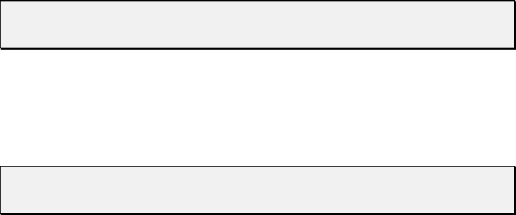
Software Communication 3-23
Control Commands
R EXECUTE COMMAND OR PROGRAM STRING
The [R] command tells the pump to execute a previously sent command or program
string.
Commands containing an [R] at the end of the string will execute immediately. If the
command or program string is sent without the [R], it is placed in the command buffer.
Sending the [R] alone will execute the last unexecuted command in the buffer. Sending
another [R] will not repeat the program string (i.e., the string has been executed).
NOTE The [R] command is invalid in CAN communication. The equivalent
command is ASCII 1 for frame type 2.
X EXECUTE THE LAST COMMAND OR PROGRAM STRING
The [X] command repeats the last executed command or program string.
NOTE The [X] command is invalid in CAN communication. The equivalent
command is ASCII 3 for frame type 2.
G <n> REPEAT COMMAND SEQUENCE
The [G] command repeats a command or program string the specified number of times. If
a GR or G0R is sent, the sequence is repeated endlessly until a Terminate command [T]
is issued. The syntax for this command is:
[G<n>], where <n> = 0..30000
For example:
[A3000A0G10R] moves the syringe plunger to position 3000 then back to position
0. This sequence is repeated 10 times.
g MARK THE START OF A REPEAT SEQUENCE
The [g] command is used in conjunction with the [G] command. The [g] command marks
the beginning of a repeat sequence (loop) that occurs within a program string (i.e., the
entire string is not repeated). Both the [g] and [G] commands can be used to nest up to 10
loops.
Table 3-5 shows the various segments of the command string
[A0gP50gP100D100G10G5R].

Software Communication 3-24
Table 3-5. Example Program String
Command
Segment Description
A0 Move plunger to position 0.
g Outer loop start.
P50 Move plunger down 50 steps.
g Inner loop start.
P100 Move plunger down 100 steps.
D100 Move plunger up 100 steps.
G10 Inner loop, repeat 10 times.
G5 Outer loop, repeat five times.
R Execute command string.
M <n> DELAY COMMAND EXECUTION
The [M] command delays execution of a command in milliseconds to the closest multiple
of five. This command is typically used to allow time for liquid in the syringe and tubing
to stop oscillating, thereby enhancing precision. The syntax for this command is:
[M<n>], where <n> = 5..30,000 milliseconds
H <n> HALT COMMAND EXECUTION
The [H] command is used within a program string to halt execution of the string. To
resume execution, an [R] command or TTL signal must be sent.
The syntax for this command is:
[H<n>]
Two TTL inputs are available, input 1 (JP3 pin 7) and input 2 (JP3 pin 8). They control
execution as follows:
<n> = 0 Waits for [R] or either input 1 or 2 to go low
<n> = 1 Waits for [R] or input 1 to go low
<n> = 2 Waits for [R] or input 2 to go low
NOTE If <n> does not have a value, <n> defaults to 0.
The status of the TTL input lines can also be read using [?13 ]and [?14]. These
commands are described in “Report Commands” in this chapter.
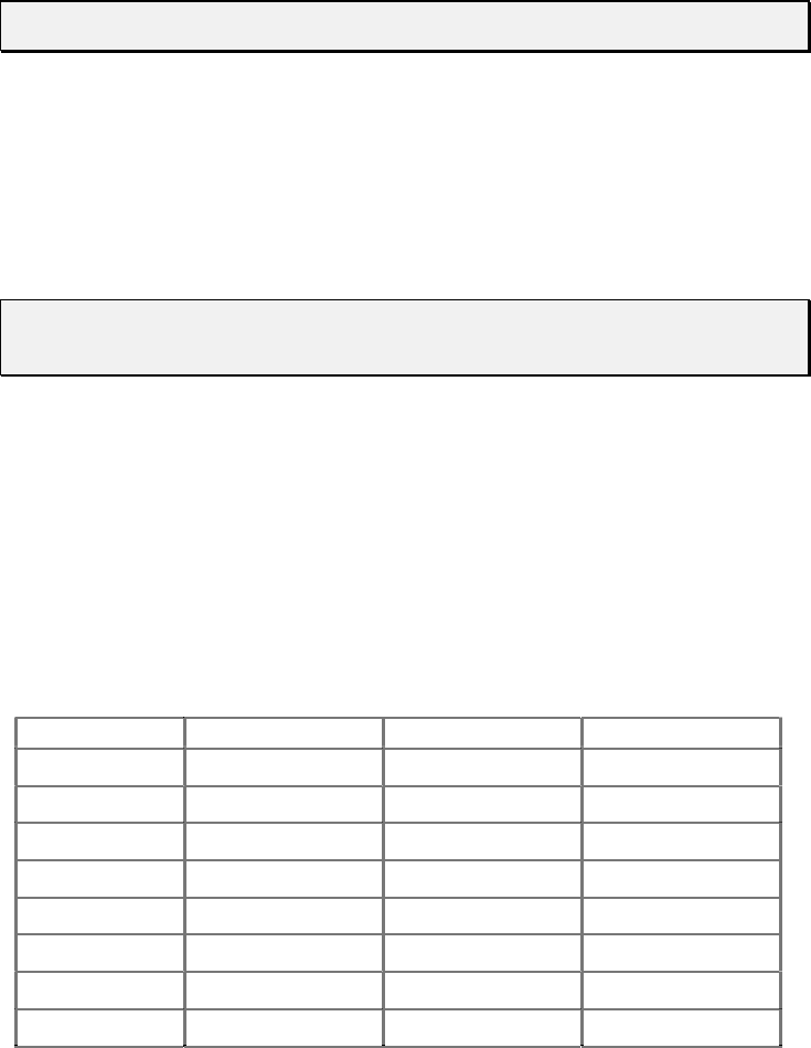
Software Communication 3-25
T TERMINATE COMMAND
The [T] command terminates plunger moves in progress ([A], [a], [P], [p], [D], and [d])
and delays [M]).
NOTE The [T] command will not terminate Valve Move commands.
The [T] command will terminate both single commands and program strings. If a
program string is terminated before completion, the [R] (Execution) command will
resume the program string. If the command was terminated due to a problem or error, the
pump must be reinitialized.
When a plunger move is terminated, lost steps may result. Reinitialization is
recommended following termination.
NOTE The [T] command is invalid in CAN communication. The equivalent
command is ASCII 4 for frame type 2.
J <n> AUXILIARY OUTPUTS
The [J] command sets the TTL ouput lines.
The syntax for this command is:
[J<n>], where <n> = 0..7 (0 is the default)
The XP 3000 provides three TTL outputs on JP3 (pins 13, 14, and 15) that correspond to
outputs 1, 2, and 3. They are controlled as follows:
XP Command Output 3 (Pin 15) Output 2 (Pin 14) Output 1 (Pin 13)
J0000
J1001
J2010
J3011
J4100
J5101
J6110
J7111
(0 = low; i.e., Gnd; 1 = high; i.e., +5VDC)
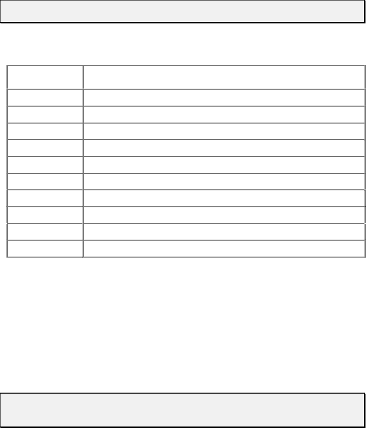
Software Communication 3-26
S <n> LOAD PROGRAM STRING INTO EEPROM
The EEPROM is non-volatile memory within the XP 3000. Once a program string is
stored in the EEPROM it provides the user with the option of computer-free operation.
The [s] command is placed at the beginning of a program string to load the string into the
EEPROM. The syntax for this command is:
[s<n>], where<n> = 0..14
Up to 15 program strings (numbered 0 through 14) can be loaded into the EEPROM.
Each string can use up to 42 commands or 128 bytes. Each command segment requires
three bytes in the command buffer. For example, [IA3000OA0R] has five command
segments and requires 10 bytes.
NOTE [A3000] and [A0] are considered single command segments.
Example Program String: [s8ZS1gIA3000OA0GR]
Command
Segment Description
s8 Loads string into program 8 of EEPROM (Address switch position 8)
Z Initializes pump
S1 Sets plunger speed
g Marks start of loop
I Turns valve to input position
A3000 Moves plunger to position 3000
O Turns valve to output position
A0 Moves plunger to position 0
G Endlessly repeats loop
R Executes command string
e <n> EXECUTE EEPROM PROGRAM STRING
There are two ways to execute command strings loaded into the EEPROM:
Through the address switch on power up
Through a command sent via the communications port
Address Switch. The address switch setting (0-14) determines which string
(0-14) is to be executed on power-up, provided a jumper is installed in JP1-3.
NOTE An Initialization command should always be included in the EEPROM
command string if the pump will be used in standalone mode.
Transmitted Commands. EEPROM command strings are executed by sending an [e]
command. The executing program string can be terminated using the [T] command.

Software Communication 3-27
[e<n>], where<n> = 0..14 (the string number)
Linking Program Strings in the EEPROM
EEPROM program strings can be linked by ending one program string with an [e]
command that refers to a second program string.
Example Program Strings: [slZIA3000OA0G5e2R]
[s2gIA3000OgHD300G10GR]
The first string loads an initialization and prime sequence into program 1 of the
EEPROM (address switch position 1). It then links to string 2 in the EEPROM.
The second string loads an aspirate and dispense sequence into program 2 of the
EEPROM. The second EEPROM program string fills the syringe, then performs 10
dispenses of 300 steps each. The dispenses are triggered by an [R] command. This
string is repeated endlessly until the pump is powered down.
On power-up the pump will automatically initialize, prime and perform the multiple
dispenses until it is again powered down.
Initialization Commands
INITIALIZATION FORCES
Initialization moves the plunger to the top of the syringe, which is set to position 0. Also,
the output position of the valve is assigned to the left or right side, depending upon the
Initialization command, and all command parameters are reset to default values.
The top of the syringe is recognized in two ways:
• upward movement of the plunger causes an overload condition
• the home flag has been detected
If either of these conditions is not met, initialization will fail. The force at which the
plunger presses against the top of the syringe can be controlled via a parameter after the
Initialization command (possible values are 0 and 1).
Table 3-6 lists the recommended initialization force for each type of syringe.
CAUTION! To retain the integrity of the seal on smaller syringes, use a lower
initialization force than that for larger syringes. The default initialization
speed is 500 Hz.

Software Communication 3-28
Table 3-6. Recommended Initialization Forces by Syringe
Parameter Force Syringes
0, 3-40 Full 1.0 mL and larger
1 Half 50, 100, 250, 500 µL
1Z = Z0
2) 2 - 9 are reserved
3) Z10-Z40 (or Y10-Y40) are initialization speeds which correspond to ([S] commands,
Set Speeds) S10-S40 found in “Set Commands (Velocity and Acceleration)” in this
chapter. These commands can be used to change the standard initialization speeds.
Slower initialization speeds may be useful when working with viscous fluids or
small I.D. (inner diameter) tubing.
INITIALIZATION COMMANDS FOR VALVE TYPES 3-PORT, 3-PORT DISTRIBUTION AND T-VALVE
Z <n> Initialize Plunger (Set Output Valve to Right)
The [Z] command initializes the plunger drive and sets valve output to the right (as
viewed from the front of the pump). The parameters are described below.
Command Parameter Description
Z <n> = 0 Initializes at full plunger force
<n> = 1 Initializes at half plunger force
Y <n> Initialize Plunger (Set Output Valve to Left)
The [Y] command initializes the plunger drive and sets valve output to the left (as viewed
from the front of the pump). The parameters are described below.
Command Parameter Description
Y <n> = 0 Initializes at full plunger force
<n> = 1 Initializes at half plunger force
INITIALIZATION COMMANDS FOR VALVELESS OR BLOCK UNITS
W <N> Initialize Plunger (Without Valve)
The [W] command initializes plunger drive for pumps without valves.
Command Parameter Description
W <n> = 0 Initializes at full plunger force
<n> = 1 Initializes at half plunger force

Software Communication 3-29
CAUTION! Once the [W] command is issued to a pump with a valve mounted, the
valve will not move until the power is cycled to the pump.
z Set Counter Position (3-Port Distribution Valve Only)
The [z] command sets the pump’s position counter to the value contained in the current
encoder position. This command is used after a plunger overload error to resynchronize
the pump’s actual position with its internally recorded position without having to go
through the entire initialization sequence.
Plunger Movement Commands
A <n> ABSOLUTE POSITION
The [A] command moves the plunger to the absolute position <n>, where <n> = 0..3000.
For example:
[A300] moves the syringe plunger to position 300.
[A600] moves the syringe plunger to position 600.
a <n> ABSOLUTE POSITION (NOT BUSY)
This is the same as the [A] command, except that the status bit within the reply string
indicates that the pump is not busy. This is useful for on-the-fly speed changes.
P <n> RELATIVE PICKUP
The [P] command moves the plunger down the number of steps commanded. The new
absolute position is the previous position + <n>, where <n> = 0..3000.
For example:
The syringe plunger is at position 0. [P300] moves the plunger down 300 steps.
[P600] moves the plunger down an additional 600 steps to an absolute position of
900. The [P] command will return error 3 (invalid operand) if the final plunger
position would be greater than 3000.
Software Communication 3-30
p <n> RELATIVE PICKUP (NOT BUSY)
This is the same as the [P] command, except that the status bit of the reply string
indicates that the pump is not busy. This is useful for on-the-fly speed changes.
D <n> RELATIVE DISPENSE
The [D] command moves the plunger upward the number of steps commanded. The new
absolute position is the previous position <n>, where <n> = 0..3000.
For example:
The syringe plunger is at position 3000. [D300] will move the plunger up 300 steps
to an absolute position of 2700.
The [D] command will return error 3 (invalid operand) if the final plunger position would
be less than 0.
d <n> RELATIVE DISPENSE (NOT BUSY)
This is the same as the [D] command, except that the status bit of the reply string
indicates that the pump is not busy. This is useful for on-the-fly speed changes.

Software Communication 3-31
Valve Commands
NOTE If a Valve command is issued to a valveless pump, the command is ignored.
I MOVE VALVE TO INPUT POSITION
The [I] command moves the valve on the XP 3000 to the input position set by the [Y] and
[Z] commands.
For example:
If the [I] command is sent after the [Z] command, the valve will be open on the left
side (as viewed from the front of the pump).
O MOVE VALVE TO OUTPUT POSITION
The [O] command moves the valve on the XP 3000 to the output position set by the [Y]
and [Z] commands.
For example:
If the [O] command is sent after the [Z] command, the valve will be open on the
right side (as viewed from the front of the pump).
The illustration below shows the positions of the valves in relation to the Initialization
command and valve movement used.
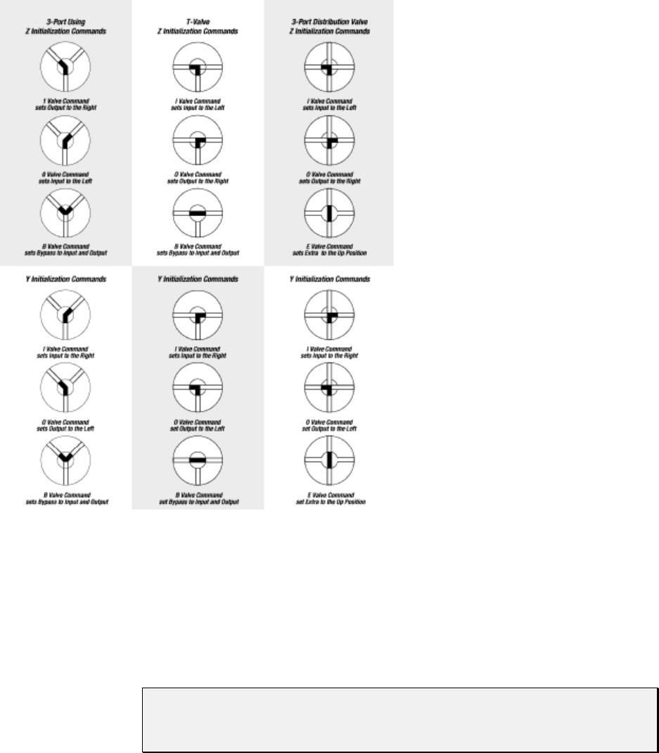
Software Communication 3-32
Figure 3-1. Valve Positions for all Valve Types
B MOVE VALVE TO BYPASS (THROUGHPUT POSITION)
The [B] command connects the input and output positions, bypassing the syringe.
CAUTION! When the valve is in this position, do not move the syringe plunger.
Sending a Plunger Movement command causes an error 11 (plunger
move not allowed).
E MOVE VALVE TO EXTRA POSITION (3-PORT DISTRIBUTION VALVE ONLY)
The [E] command moves the valve on the XP 3000 to the extra position (port) relative to
the [Y] and [Z] commands.

Software Communication 3-33
Valve Leakage Detection Commands
^<n> SET THRESHOLD VALUE FOR FLUID DETECTION
The [^] command is used to set a fluid detection value that best suits the application and
fluids used. The syntax is:
[^<n>], where <n> = 0..255
The higher the value, the more sensitive the detector. A setting of 150 detects water
leakage. Detection limits depend upon the application and the humidity of the
environment.
NOTE Setting the value to 0 disables error reporting.

Software Communication 3-34
Set Commands (Velocity and Acceleration)
Set commands are used to control the speed of the plunger. Plunger movement is
structured into three phases:
Ramping Up. Plunger movement begins with the start velocity and accelerates
with the programmed slope to the constant or top speed.
Constant or Top Speed. The plunger is moved at the constant or top speed.
Plunger speed or velocity can be programmed in Hz (half-steps/second) or in
preprogrammed Set Speeds. The actual time the plunger travels is dependent on the
ramping up and down. If the plunger move is short, it may never reach top speed.
Ramping Down. The plunger will decelerate based on the programmed slope. To
enhance fluid breakoff, the Cutoff command ([c]) can be used to define the end
velocity of the plunger just before it stops.
NOTE The Cutoff command is only active in a dispense move. During aspiration the
move will end at the start velocity [v].
For each plunger move, the firmware calculates how many steps the plunger must travel
during each phase in order to move the total number of steps commanded. If the plunger
is moving less than 1024 Hz, the pump automatically microsteps to reduce the pulsation.
The top velocity can be changed on-the-fly (while the plunger is moving) providing the
initial speed is less than the start velocity. Ramps are not included in on-the-fly speed
changes; therefore, large speed changes (100 Hz to 1000 Hz) are not recommended.
NOTE Unless the top speed is less than the start or cutoff velocity, always program
the pump in order of the move: start velocity [v], top velocity [V], cutoff
velocity [c].
K <n> BACKLASH STEPS
The [K] command sets the number of backlash steps. The syntax for this command is:
[K<n>], where <n> 0..31 (0 is the default)
When the syringe drive motor reverses direction, the carriage will not move until the
backlash due to mechanical play within the system is compensated. To provide this
compensation, during aspiration, the plunger moves down additional steps, then backs up
the set number of backlash steps. This ensures that the plunger is in the correct position to
begin a dispense move. Note that a small volume of fluid flows out the “input” side of the
valve during this operation.

Software Communication 3-35
Changing Speed on the Fly
Speed changes can be made while the syringe plunger is moving. This is called
“changing speed on the fly.”
Speeds can be decreased or increased between 5 and 1024 Hz (i.e., in the microstepping
region).
To change speed on the fly:
1 Issue speed commands with identical start and top velocities (e.g., [v100V100]),
followed by a lowercase Plunger Move command. Ramping is not allowed in on-
the-fly changes.
2 Issue a new top velocity in the range 5 to 1024 while the plunger is moving to
change the speed on the fly.
NOTE When the move completes, speed values revert to original values (i.e., value
sent on-the-fly is temporary).
Software Communication 3-36
L <n> SET SLOPE
During the beginning and end of a move, the plunger ramps up and down to top speed.
The ramp is programmed using the Slope command. It is calculated as <n> x 2.5
kHz/sec. The syntax for this command is:
[L<n>], where <n> = 1..20 (14 is the default)
The corresponding slopes in kHz/sec are listed below.
Slope Code kHz/Sec
12.5
25.0
37.5
4 10.0
5 12.5
6 15.0
7 17.5
8 20.0
9 22.5
10 25.0
11 27.5
12 30.0
13 32.5
14 35.0
15 37.5
16 40.0
17 42.5
18 45.0
19 47.5
20 50.0
v <n> START VELOCITY
The [v] command sets the velocity at which the plunger begins its movement. The
plunger will then ramp up (slope) to the top velocity. The start velocity should always be
less than the top velocity. The syntax for this command is:
[v<n>], where <n> = 50..1000 Hz
(900 is the default; 901 is the default on the 3-port distribution valve)

Software Communication 3-37
V <n> SET TOP VELOCITY
The [V] command sets the peak speed in Hz (half-steps/second). The syntax for this
command is:
[V<n>], where <n> = 5..5800 Hz (1400 is the default)
NOTE Syringes 2.5 mL and larger may require slower speeds. Users must determine
the appropriate speeds for their applications.
S <n> SET SPEED
The [S] command sets a predefined top plunger speed. As <n> increases, the plunger
speed decreases. The syntax for this command is:
[S<n>], where <n> = 1..40 (11 is the default)
These speeds do not cover the full range of speeds the plunger can travel. They are
commonly used velocities provided for the convenience of the user. All times are
approximate and will vary with different ramp speeds and cutoffs. Cavro also provides a
utility for performing theoretical speed calculations in Pump:Link Evaluation Software
(in the Utility menu on the user interface). For information on determining timing for
specific applications, see Appendix B, "Plunger Information.”
The [S] command sets top velocity without changing start velocity, slope, and cutoff
velocity, except:
• If the start velocity is higher than the (new) top velocity, start velocity is set = top
velocity.
• If the cutoff velocity is higher than the (new) top velocity, cutoff velocity is set =
top velocity.

Software Communication 3-38
Speed codes, the Hz (half-steps/second) equivalent, and seconds per stroke are listed
below. Seconds/stroke values are based on default ramping.
Speed Code Pump Freq (Hz) Seconds/Stroke
1 5600 1.2
2 5000 1.3
3 4400 1.4
4 3800 1.6
5 3200 1.9
6 2600 2.2
7 2200 2.6
8 2000 2.9
9 1800 3.3
10 1600 3.7
11 1400 4.3
12 1200 5.0
13 1000 6.0
14 800 7.5
15 600 10.0
16 400 15.0
17 200 30.0
18 190 31.0
19 180 33.0
20 170 35.5
21 160 37.5
22 150 40.0
23 140 43.0
24 130 46.0
25 120 50.0
26 110 55.0
27 100 60.0
28 90 67.0
29 80 75.0
30 70 86.0
31 60 100.0
32 50 120.0
33 40 150.0
34 30 200.0
35 20 300.0
36 18 333.3
37 16 375.0
38 14 428.6
39 12 500.0
40 10 600.0

Software Communication 3-39
NOTE To achieve maximum stroke time (20 minutes or 1200 seconds), you must use
the [V5] command.
c <n> CUTOFF VELOCITY IN HZ
The [c] command sets the velocity at which the plunger ends its movement. The plunger
will ramp down (slope) from the peak velocity. The [c] command overwrites the [C]
command. The syntax for this command is:
[c<n>], where <n> = 50..2700 Hz
(900 is the default; 901 is the default on the 3-port distribution valve)
NOTE [c] is only valid in a dispense move. During aspiration [c] = [v].
C <n> CUTOFF VELOCITY IN STEPS
During the last phase of a plunger move, the speed ramps down (as defined by the
programmed slope) toward the cutoff velocity [c]. When cutoff steps are specified, the
plunger stops at <n> steps before reaching the cutoff velocity. The total number of steps
required by the plunger movement is maintained by adding <n> steps to the second phase
(top velocity) of the plunger move. The syntax of this command is:
[C<n>], where <n> = 0..25 steps (0 is the default)
The [C] command overwrites the [c] command and resets cutoff velocity to start velocity.
For example, [C5] stops the plunger five steps short of the final velocity. The total
number of steps is automatically maintained by adding five steps to the second phase of
plunger movement. In other words, the deceleration phase of the move is shortened by
five steps and the constant speed phase is lengthened by five steps.
Report Commands
Report commands do not require an [R] command.
NOTE All Report commands are invalid in CAN communication. The frame type 6 is
provided to retrieve information from the pump. For more information, see
Appendix F, “CAN Communication Commands.”

Software Communication 3-40
? REPORT ABSOLUTE PLUNGER POSITION
The [?] command reports the absolute position of the plunger in steps [0..3000],
[0..24000 in microstep mode].
?1 REPORT START VELOCITY
The [?1] command reports the start velocity in kHz/sec [50..1000].
?2 REPORT TOP VELOCITY
The [?2] command reports the set top velocity in kHz/sec [5..5800].
?3 REPORT CUTOFF VELOCITY
The [?3] command reports the cutoff velocity in kHz/sec [50..2700].
NOTE Velocities reported back may not reflect the exact programmed value due to
rounding within the control routine.
?4 REPORT ACTUAL POSITION OF PLUNGER
The [?4] command reports the actual position of the plunger in steps.
?12 REPORT NUMBER OF BACKLASH STEPS
The [?12] command reports the number of backlash steps.
?13 REPORT STATUS OF AUXILIARY INPUT #1 (JP3, PIN 7)
0 = low
1 = high
?14 REPORT STATUS OF AUXILIARY INPUT #2 (JP3, PIN 8)
0 = low
1 = high

Software Communication 3-41
?22 REPORT CURRENT VALUE FROM FLUID SENSOR
The [?22] command reports the current value read from the fluid sensor [0..255].
0 = very wet
255 = very dry
F REPORT BUFFER STATUS
The [F] command reports the command buffer status. If the buffer is empty, the pump
returns status code 0. If the buffer is not empty, the pump returns a 1. If a program string
is sent to the pump without an [R] command, the string is loaded into the buffer and the
buffer status becomes 1. An [R] command will then execute the command stored in the
buffer.
& REPORT FIRMWARE VERSION
The [&] command returns the XP 3000 firmware revision in ASCII.
# REPORT FIRMWARE CHECKSUM
The [#] command reports back the firmware checksum. The checksum is the same for all
part numbers at the same revision level.
XP 3000 Microstep-Enabled Firmware Commands
NOTE To determine whether or not your XP 3000 carries microstep-enabled
firmware, check the part number on the EPROM label. If the part number is
600,xxx, this section applies to your pump.
N <n> SET MICROSTEP MODE OFF/ON
The [N] command enables or disables microstepping. The syntax for this command is:
[N<n>], where <n> = 0 or 1
When <n> = 0, the microstep mode is off and the XP 3000 uses the standard 3000
increments/full stroke. If <n> = 1, microstep mode is on and the XP 3000 uses 24,000
increments/full stroke. Velocities are programmed in increments per second. The default
is 0.

Software Communication 3-42
k <n> SYRINGE DEAD VOLUME COMMAND
The [k] command allows the setting of the number of steps that the plunger travels after
initialization. This is to minimize deal volume. The syntax for this command is:
[k<n>], where <n> = the offset in steps from zero position
<n> = 0..80
<n> = 0..640 in microstep mode
Under default initializations, the plunger moves upward until it contacts the top of the
syringe, causing a forced stall initialization. The plunger then moves downward and
upward, leaving a small gap between the syringe seal and the top of the plunger. This
small gap was designed so that the Teflon seal does not hit the top of the plunger each
time the syringe moves to the “home” position. This maximizes the life of the syringe
seal.
The [k] command must be followed by the Initialization command [Z], [Y], or [W]. Each
time the unit is powered down, the “k” value will return to the default condition.
For example, to offset 10 steps away from the zero position, send the following
commands:
1 k10R
2 ZR
NOTE Commands are case-sensitive.
EXPANDED PARAMETER RANGES
S <n> Set speed [<n>=0..40]
V <n> Set end velocity in HS/s [<n>=5..6000] default: 900
v <n> Set start velocity in HS/s [<n>=50..1000] default: 900
c <n> Set cutoff velocity in HS/s [<n>=50..2700] default: 900
L <n> Set ramp slope [<n>=1..20] default: 7
where slope = n * 2500 (HS/s)/s
K <n> Set backlash [<n>=1..31 default: 11
microstep off
[<n>=1..255] default: 88
microstep on
Software Communication 3-43
Error Codes and Query Status
The [Q] command reports error codes and pump status (ready or busy). The user should
send a [Q] command before sending a program string or individual command to ensure
that the pump has completed the previous command successfully.
NOTE The Query command ([Q]) is the only valid method of obtaining status.
The response to the [Q] command (the status byte) provides two items of information:
Pump status (bit 5) and error code (bits 0-3).
STATUS BIT
Bit 5 is the status bit. It indicates when the pump is busy or not busy. The designations
for bit 5 are listed below.
Status Bit 5 Description
X = 1 Pump is ready to accept new commands.
X = 0 Pump is busy and will only accept Report and Terminate commands.
In response to uppercase Move commands ([A], [P] and [D]), the [Q] command reports
that the pump is busy. In response to lowercase Move commands ([a], [p] and [d]), the
[Q] command reports that the pump is not busy. Additionally, commands addressed to
multiple pumps at once cannot be used to obtain pump status; pumps must be queried
separately.
NOTE Although the answer block for other commands contains a status bit, it should
not be used for determining pump status. A [Q] command is the only valid
method to determine if the pump is busy. The error information in the status
byte of the answer block is always valid.
ERROR CODES
Error codes describe problem conditions that may be detected in the XP 3000 (excluding
error code 0). Error codes are returned in the least significant four bits of the status byte.
If an error occurs, the pump stops executing commands, clears the command buffer, and
inserts the error code into the status byte. Some errors continue to appear, such as syringe
overloads, until they are cleared by the Initialization command. On a plunger overload,
the device will not execute another valve or syringe Move command until it is
reinitialized. The last error has precedence in the status byte. For example, if a command
overflow occurs, an error 15 results. If the next command causes an error #3, the status
byte reflects the error #3 (invalid operand).

Software Communication 3-44
Table 3-7. Error Codes
Error Code Description
0 (00h) Error Free Condition.
1 (01h) Initialization error. This error occurs when the pump fails to initialize.
Check for blockages and loose connections before attempting to
reinitialize. The pump will not accept commands until it has been
successfully initialized. This error can only be cleared by successfully
initializing the pump.
2 (02h) Invalid Command. This error occurs when an unrecognized command is
issued. Correct the command and operation will continue normally.
3 (03h) Invalid Operand. This error occurs when an invalid parameter (<n>) is
given with a command. Correct the parameter and pump operation will
continue normally.
4 (04h) Invalid Command Sequence. This error occurs when the command
structure or communication protocol is incorrect. Review the information
describing the communication protocol then repeat the command sequence.
5 (05h) Fluid Detection. This error occurs when the sensor board detects fluid,
which is caused by fluid leaking out the back of the valve.
To clear the error:
1 Power off the pump.
2 Remove the valve.
3 Wipe up any detectable fluid on the sensor board using a cotton swab.
You can insert the swab through the valve opening on the front panel,
and gently wipe the circuit.
4 Assuming the valve is leaking fluid, put a new valve on the pump
following the instructions in Chapter 5, “Maintenance.”
5 Reinitialize the pump.
6 (06h) EEPROM Failure. This error occurs when the EEPROM is faulty. If you
receive this error, please call Cavro Technical Service.
7 (07h) Device Not Initialized. This error occurs when the pump is not initialized.
To clear the error, initialize the pump.
9 (09h) Plunger Overload. This error occurs when movement of the syringe
plunger is blocked by excessive back pressure. The pump must be
reinitialized before normal operation can resume. This error can only be
cleared by reinitializing the pump.
10 (0Ah) Valve Overload. This error occurs when the valve drive loses steps by
blockage or excess back pressure. The pump must be reinitialized before
normal operation can resume. Sending another Valve command
reinitializes the valve and sets it to the correct location. Continual valve
overload errors are an indication the valve should be replaced.
11 (0Bh) Plunger Move Not Allowed. When the valve is in the bypass or throughput
position, Plunger Movement commands are not allowed.
15 (0Fh) Command Overflow. This error occurs when the command buffer contains
too many characters. Commands in the buffer must be executed before
more commands can be sent.
Software Communication 3-45
The pump handles errors differently, depending on the error type. There are four error
types, which are described below.
Immediate Errors. These include “Invalid Command” (error 2), “Invalid Operand”
(error 3), “Invalid Command Sequence” (error 4), and “Plunger Move Not Allowed”
(error 11). After the command is sent, the answer block immediately returns an error.
Once a valid command is sent, the pump will continue to function normally. Since the
[Q] command is a valid command, the pump will not return an error. In this case, the [Q]
command is not required.
Initialization Errors. These include “Initialization errors” (error 1) and “Device not
Initialized” (error 7). If the pump fails to initialize or if an Initialization command has not
been sent, subsequent commands will not be executed.
To ensure that the pump initializes successfully, send a [Q] command after the
Initialization command.
If the [Q] command indicates both a successful initialization and that the pump is
ready, subsequent Move commands can be sent.
If the [Q] command indicates the pump has not initialized, the pump must be
reinitialized until the [Q] command indicates successful initialization.
If initialization is not successful, a “Device Not Initialized” error is returned as
soon as the next Move command is sent.
Overload Errors. These include the “Plunger Overload” and “Valve Overload” errors
(errors 9 and 10). If the pump returns either a plunger or valve overload, the pump must
be reinitialized before continuing. If another command is sent without reinitializing the
pump, another overload error will be returned when the next Move command is issued.
The [Q] command clears the error; however, if a successful initialization has not
occurred, an initialization error is returned.
Command Overflow Error. This is error 15, and it occurs if a Move command, Set
command (except [V]), or Valve command is sent while the plunger is moving. The
pump ignores the command and issues an error 15. The [Q] command allows the
controller to determine when the command is complete and the pump is ready to accept
new commands.
Report commands, Control commands, and the Top Velocity command [V] will not
return an error 15. Report and Control commands are considered valid commands during
a Move. Because the pump can change speed while the plunger is moving in the 5-1024
Hz range, the [V] commands will not return a “Command Overflow” error.

Software Communication 3-46
Table 3-8. Error Codes and ASCII and Hexadecimal Values
Status Byte Hex # if
Bit 5 = Dec # if
Bit 5 = Error
Code
7 6 5 4 3 2 1 0 0 or 1 0 or 1 Number Error
0 1 X 0 0 0 0 0 40h 60h 64 96 0 No Error
0 1 X 0 0 0 0 1 41h 61h 65 97 1 Initialization
0 1 X 0 0 0 1 0 42h 62h 66 98 2 Invalid Command
0 1 X 0 0 0 1 1 43h 63h 67 99 3 Invalid Operand
0 1 X 0 0 1 0 0 44h 64h 68 100 4 Invalid Command Seq.
0 1 X 0 0 1 0 1 45h 65h 69 101 5 Fluid Detection
0 1 X 0 0 1 1 0 46h 66h 70 102 6 EEPROM Failure
0 1 X 0 0 1 1 1 47h 67h 71 103 7 Device not Initialized
0 1 X 0 1 0 0 1 49h 69h 73 105 9 Plunger Overload
0 1 X 0 1 0 1 0 4Ah 6Ah 74 106 10 Valve Overload
0 1 X 0 1 0 1 1 4Bh 6Bh 75 107 11 Plunger Move Not
Allowed
0 1 X 0 1 1 1 1 4Fh 6Fh 79 111 15 Command Overflow
Error Reporting Examples
[A4000R] Does not return an error immediately after the
command, but when queried ([Q] command),
returns an “Invalid Parameter” error.
[A3000A3500R] Moves to position 3000, then stops. A [Q]
command returns an error.
[E2000R] Returns an invalid command error immediately.
The pump status is “Not Busy.”
[A3000E2000R] Returns an invalid command error immediately.
The pump is “Not Busy.”
Valve in Bypass [A1000R] Does not return an error immediately, but when
queried ([Q] command), returns a “Plunger Move
Not Allowed” error.
Setting Up the XP3000 for Your Application 4-1
4 - Setting Up the XP 3000 for Your Application
The XP 3000 is capable of providing precision pumping in a wide variety of hardware
and fluid systems. The interplay of fluid viscosity, aspiration and dispense speeds, and
system geometry [syringe size, tubing inner diameter (I.D.), and valve I.D.] determines
the behavior of the XP 3000 in a particular application. Following is a description of the
hardware, fluid, and pump control parameters to be evaluated and optimized in managing
these interdependencies for optimal pump performance.
Glossary
air gap
A small volume of air at the end of the output tubing or sandwiched between two
fluids in the pump system tubing. Air gaps may be created by aspirating air
(programmed air gaps) or by the spring action of the fluid system (inertial air gaps).
aspirate/dispense tubing
Connects the valve output port (1/4-28 thread or M6 fitting) to a sample source and
destination. To ensure good breakoff, aspirate/dispense tubing tends to have a
smaller I.D. than reagent tubing, and a necked-down or tapered end.
backlash
Mechanical play in the syringe drive created by accumulated mechanical clearances.
To maintain accuracy and precision when the syringe drive changes direction, the XP
3000 incorporates programmable backlash compensation.
backpressure
The pressure which must be exceeded to move fluid through tubing. Backpressure is
created by a combination of fluid inertia and friction.
breakoff
Describes how the last droplet of fluid exits the end of the output tubing following a
dispense. Rapid or sharp breakoff means that the droplet exits cleanly with high
inertia.
breakup
Undesired air gaps created by overly rapid aspiration.
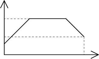
Setting Up the XP3000 for Your Application 4-2
carryover
Contamination of a volume of fluid by residual fluid from a previous aspiration or
dispense. Carryover causes variability in final volume and concentration.
cavitation
Formation of air bubbles due to rapid pressure changes.
dilution effect
Reduction in sample or reagent concentration, caused by contact with system fluid or
residual fluid from a previous aspiration or dispense.
I.D. (“inner diameter”)
Diameter of the constraining wall of a fluid path.
priming
Completely filling the pump tubing and syringe with bubble-free fluid to allow
sustained, reproducible pumping action. The air in an unprimed line acts as a spring,
adversely affecting accuracy and precision.
reagent tubing
Connects the valve input port (1/4-28 thread or M6 fitting) to a reagent source.
Reagent tubing is used to fill the pump syringe; it tends to have a larger I.D. than
aspirate/dispense tubing, and a blunt-cut end which extends into the reagent.
system fluid
A fluid used to prime the pump system that does not act as sample or reagent.
Typically the system fluid is deionized water or a wash buffer and is isolated from
sample or reagent fluid by an air gap to avoid intermixing.
Typically, the syringe plunger begins moving slowly, then ramps up to top velocity.
This allows the plunger to start moving gradually, without overloading the motor,
and still provide maximum flowrate. The syringe plunger stops by ramping down in
speed. This results in the most reproducible fluid breakoff for accurate dispensing.
v
V
Speed [Hz]
c
time in st
Figure 4-1. Syringe Speed
start velocity (v)
The speed at which the syringe plunger starts moving.
top velocity (V)
The maximum speed at which the syringe plunger moves.
cutoff velocity (c)
The speed of the syringe plunger just before stopping.

Setting Up the XP3000 for Your Application 4-3
slope (L)
Acceleration (deceleration) of the syringe plunger between start velocity, top
velocity, and cutoff velocity.
The volume aspirated or dispensed when the syringe plunger moves a specified number
of steps depends on the syringe size. To determine the number of steps required to
aspirate or dispense a given volume, use the following formula:
# of steps = (pump resolution) x volume
(syringe size)
For example, to aspirate 100 µL using an XP 3000 pump with 1 mL syringe, move the
plunger as follows:
# of steps = 3000 steps x 100 µL = 300 steps
1 mL x 1000 µL/mL
Optimizing XP 3000 Performance
CAUTION! Run the pump only in the upright position. Do not move the pump valve
or syringe plunger without first wetting or priming the pump.
For command details, see Chapter 3, “Software Communication.”
To optimize XP 3000 performance, follow these steps:
1 Check chemical compatibility.
Check the chemical compatibility chart in Appendix D, “Chemical Resistance
Chart,” to determine if the fluids in your application are compatible with the XP
3000 syringe and valve materials. If not, a system fluid is required. Complete the
optimization procedure with the fluids you will use in your final system.
Note that the system fluid is used to prime the syringe and tubing from inlet to outlet.
After the tubing is primed (and before any sample or reagent is aspirated), an air gap
must be taken into the aspirate/dispense tubing to separate the system fluid from
subsequently aspirated sample or reagent. Air gaps should be aspirated slowly to
avoid break-ups, and they should be one-tenth the volume of the aspirated fluidor
at least 10 µLto avoid any dilution effect. Similar air gaps should separate each
aspirated fluid when performing multiple aspirates with no intervening dispenses, in
order to prevent premature mixing and/or contamination. In addition, the
aspirate/dispense tubing must be long enough to hold the total aspirate volume
without coming in contact with the valve or syringe.

Setting Up the XP3000 for Your Application 4-4
2 Select syringe size.
Determine your volume and flowrate requirements. Select a syringe that
accommodates the smallest and largest volumes to be dispensed without refill, as
well as the desired flowrate (see Table 4-1). While smaller syringes allow better
accuracy and precision, a larger syringe allows more aliquots when multiple
aspirations or multiple dispenses are required, and they allow better breakoff and
longer seal life.
Table 4-1. Flowrate Ranges
Syringe Size Minimum Flowrate
(mL/min) Maximum Flowrate
(mL/min)
50 µL0.0025 2.6
100 µL0.0050 5.23
250 µL0.012 13.1
500 µL0.025 26.2
1 mL 0.050 52.3
5 mL 0.25 261.6
3 Select tubing.
In tubing selection, the general rule is that smaller syringes work best with smaller
I.D. tubing and larger syringes with larger I.D. tubing. Most XP 3000 valve styles
have an internal I.D. of 0.059" (approx. 1/16"). For aspirate/dispense tubing a
thermal-drawn tip or tapered tip is most common, providing good breakoff and
excellent accuracy and precision for most applications. A necked-down tip may be
used when aspirating very small volumes of sample, i.e., 1 - 5 µL. A blunt-cut tip is
better suited for large volume applications. For tubing recommendations, see Table
4-2; for a description of the various types of tubing, see Appendix A, “Ordering
Information.”
Table 4-2. Tubing Recommendations
Syringe Size Aspirate/Dispense Tubing P/N Reagent Tubing P/N
50 µL, 100 µL, 250 µL5133 721370
5723 *
500 µL, 1 mL, 2.5 mL 5133 4609
720595 5729
720597 721370
5 mL 4333 720592
720595 721370
Setting Up the XP3000 for Your Application 4-5
4 Make pump connections.
Connect power and communications cables to the pump, install syringe and tubing.
Place the end of the input tubing in a reservoir of particle-free fluid; place the end of
the output tubing in a waste reservoir.
5 Check communications to the pump.
a) Open the Pump:Link program to the XP 3000 menu (full page), or use
your own communications program.
b) Send the command [&] to read the pump’s firmware revision number.
Successful communication will return the revision number and a “Ready”
status.
Possible errors:
No response. Check for loose or incorrectly connected cables, or
connection to the wrong computer COM port. Retry.
6 Initialize pump and set initialization speed.
The following information assumes that your input tubing connects to the right valve
port. If your input tubing connects to the left valve port, exchange [Y] for all
instances of [Z] in the following commands.
Send the command [ZR] to initialize the pump. Successful initialization
will move the syringe plunger to the position “0” (fully dispensed) and
return a “Ready” status.
Possible errors:
Error 1 (initialization error). Check for tubing blockage and reinitialize. If
you are using very narrow I.D. tubing or pumping a viscous fluid, the
initialization speed may need to be reduced.
This is accomplished (only if using a 1 mL or larger syringe) by sending
the command [Z16R] (initializes at full-force, reduced speed). Repeat with
decreasing initialization speed (increase “Z_” value) until the pump
successfully initializes.
7 Prime the syringe.
a) Send the command [IA3000OA0R] to pull fluid through the valve input
position and into the syringe.
b) Inspect the pump tubing and syringe for bubbles and re-prime until all
bubbles are completely gone.
If bubbles remain after several priming strokes, disassemble the syringe
and clean it with alcohol. Also check to ensure the fittings are tight and
the syringe is tight within the Teflon fitting.
c) Re-prime.
Possible errors:
Error 9 (plunger overload). See step 8.
Setting Up the XP3000 for Your Application 4-6
8 Check aspirate/dispense.
Send the command [IA3000OA0R] to aspirate a full syringe stroke (3000 steps)
from input and dispense it to output. Successful execution will move the syringe
plunger to position “3000” then back to “0,” then it will return a “Ready” status.
Possible errors:
Error 9 (plunger overload). The stepper motor is unable to move the syringe
plunger, probably because of excessive backpressure caused by excessive
flowrate, narrow tubing I.D., or valve or tubing blockage. Note whether the error
occurred during aspiration or dispensing. To differentiate between blockage and
flowrate limitation, reduce syringe plunger speed by sending the command
[S12IA3000OA0R]. Repeat with decreasing plunger speed (increase “S_” value)
until the pump aspirates and dispenses successfully.
9 Set start velocity and top velocity.
The XP 3000 plunger speed can be controlled from 1.2 seconds per stroke to 20
minutes per stroke (top speed) using the [S] command. (The [V] command allows a
slightly larger speed range.) As a general rule, aspiration should be slow (to avoid
cavitation) and dispense fast (to promote breakoff). Since cavitation and breakoff
will affect both accuracy and precision, velocity settings may be optimized
separately for aspiration and dispense.
Using aspirate/dispense commands, set start velocity [v] and top velocity [V] to meet
application throughput goals.
a) Send the command [v50IA3000OA0R]. Repeat with increasing start velocity
(increase “v_” value) to find the maximum value.
b) Send the command [vxVxIA3000OA0R] to set top velocity equal to start
velocity (x). Repeat with increasing top velocity (increase “V_” value) to the
maximum value that does not overload the plunger or cause cavitation.
Now optimize start velocity and top velocity for dispensing using a similar
approach.
10 Set cutoff velocity and slope.
Using aspirate/dispense commands, set slope [L] and cutoff velocity [c] to attain
reproducible breakoff. Note that cutoff velocity controls only dispensing.
To optimize the slope, send the command [vxVyL14IA3000OA0R]. Repeat with
modified slope (“L_” value) to achieve the overall time suited to your application
without plunger overload.
To optimize the cutoff velocity, start with the maximum cutoff velocity allowed for
your application (the lower of 2700Hz or the top velocity). Send the command
[cxIA3000OA0R] and monitor the dispense for plunger overload or any splattering
of the fluid dispensed outside of the dispense vessel. If any of these conditions
occurs, lower the cutoff velocity until the pump can dispense the fluid with clean
breakoff.

Setting Up the XP3000 for Your Application 4-7
Another condition that affects breakoff is the formation of inertial air gaps. This is
seen as a small air gap inside the tubing at the tip. This occurs to a greater extent on
larger reagent syringes, and it enhances the breakoff of liquid from the tip of the
tubing. If an inertial air gap is not desired in the application, lowering the cutoff
velocity and/or the top velocity will remove the inertial air gap. However, this may
not give a clean breakoff of the fluid.
In some instances it may not be possible to improve fluid breakoff. Clean breakoff is
important to accuracy and precision; it is a concern especially when using slow
speeds because drops will usually adhere to the tip.
For example, using a 2.5 mL reagent syringe (P/N 5133, dispense tubing and
deionized water with a surfactant added):
* [S24IA3000OA0R] - will leave a drop on the tip
* [S24IA3000OA5S1A0R] - no drop will be left
* [V100IA3000OA0R] - will leave a drop on the tip
* [V100IA3000OA5V5500A0R] - no drop will be left
Increasing the cutoff velocity and ramp (slope) may also improve the fluid breakoff.
Smaller I.D. tubing may improve breakoff, especially for smaller syringes.
NOTE It may not be possible to achieve good fluid breakoff under all
circumstances, especially with syringes smaller than 500 µL or with some
fluids.
11 Set backlash compensation.
The XP 3000 pump control includes backlash compensation during aspiration. The
backlash compensation causes the plunger to move down to the calculated stopping
point, then down an additional set number of steps. On reversing direction, the
plunger moves back up the same number of steps. Backlash compensation maintains
accuracy and precision in the syringe plunger movement when the plunger changes
direction.
Aspirate, then perform multiple dispenses. Compare the first aliquot to others; if low,
increase backlash and retest. Set backlash as low as possible, but keep the first
aliquot equal to subsequent aliquots.
Setting Up the XP3000 for Your Application 4-8
Helpful Hints
To maintain pump performance, keep the following in mind when operating the XP 3000:
❑ Wipe up all spills immediately.
❑ Pumping cold fluids may cause leaks, the result of differing coefficients of
expansion of Teflon and glass. Leaks may occur when pumping fluids that are at or
below 15°C (61°F).
❑ To reduce the amount of carryover, a ratio of three parts reagent to one part sample
is recommended.
❑ Use organic solvents in the XP 3000 with caution. Using organic solvents may
reduce tubing and seal life.

Maintenance 5-1
5 - Maintenance
Although required maintenance may vary with your application, the following procedures
are recommended for optimal performance and maximum life of the XP 3000.
Perform maintenance tasks in these intervals:
• daily
• weekly
• periodically
Daily Maintenance
To ensure proper operation of the XP 3000, perform these tasks daily:
❑ Inspect the pump(s) for leaks, and correct any problems.
❑ Wipe up all spills on and around the pump.
❑ Flush the pump(s) thoroughly with distilled or deionized water after each use and
when the pump is not in use.
Do not allow the pump(s) to run dry for more than a few cycles.
Weekly Maintenance
The fluid path of the XP 3000 must be cleaned weekly to remove precipitates such as
salts, eliminate bacterial growth, and so on. Any of the three following cleaning
procedures can be used:
• Weak detergent
• Weak acid and base
• 10% bleach
The procedures using these solutions are described in the sections that follow.

Maintenance 5-2
Weak Detergent Cleaning
To clean the pump with weak detergent, follow these steps:
1 Prime the pump with a weak detergent solution (e.g., 2% solution of CONTRAD®,
RoboScrub, or flo-kleen) and allow the solution to remain in the pump with the
syringe fully lowered for 30 minutes.
2 After the 30-minute period, remove the reagent tubing from the detergent and cycle
all the fluid from the syringe and tubing into a waste container.
3 Prime the pump a minimum of 10 cycles with distilled or deionized water. Leave the
fluid pathways filled for storage.
CONTRAD can be purchased through Curtis Matheson Scientific, Inc. Order P/N 117-
655 for 500 mL syringe size.
flo-kleen can be purchased through Ciba Corning Gilford Systems. Order P/N 402342
for 400 mL syringe size.
RoboScrub is a phosphate-free detergent for cleaning and conditioning liquid handling
systems. RoboScrub rinses away chemicals, solvents, blood, and corrosive acids.
Weak Acid-Base-Sequence Cleaning
To clean the pump with weak acid and base, follow these steps:
1 Prime the pump with 0.1 N NaOH and allow the solution to remain in the pump(s)
for 10 minutes with the syringes fully lowered.
2 Flush the pump with distilled or deionized water.
3 Prime the pump with 0.1 N HCl, and allow the solution to remain in the pump for 10
minutes with the syringes fully lowered.
4 After a 10-minute period, remove the reagent tubing from 0.1 N HCl solution and
cycle all the fluid from the syringes and tubing into a waste container.
5 Prime the pump a minimum of 10 cycles with distilled or deionized water.
Maintenance 5-3
10% Bleach Cleaning
To clean the pump with 10% bleach, follow these steps:
1 Make a solution of 10% bleach by adding one part of commercial bleach to nine
parts of water.
2 Prime the pump with the 10% bleach and allow the solution to remain in the pump
with the syringes fully lowered for 30 minutes.
3 After the 30-minute period, remove the reagent tubing from 10% bleach solution and
cycle all the fluid from the syringes and tubing into a waste container.
4 Prime the pump a minimum of 10 cycles with distilled or deionized water.
Periodic Maintenance
Tubing, syringe seals, and valves require periodic maintenance. If they become worn, you
are likely to notice these symptoms:
• Poor precision and accuracy
• Variable or moving air gap
• Leakage
If any of these symptoms occurs and it is not obvious which component is causing the
problem, it is easiest and most economical to replace one component at a time in the
following order:
• input and output tubing
• plunger seal
• valve
The frequency of replacement will depend on the duty cycle, fluids used, and instrument
maintenance.
Quality Control Assurance
Check the accuracy and precision of the XP 3000 on a regular basis.
Cavro recommends checking both accuracy and precision gravimetrically, using an
analytical balance with the capability to measure to 0.1 mg. Gravimetric measurements
should be corrected for the specific gravity of water at the ambient temperature.
The syringe can be checked by programming in the desired volume and determining the
weight of fluid dispensed.
To determine precision and accuracy, run a minimum of 20 replicates. The Mean,
Standard Deviation and Coefficient of Variation (see formula below) can then be
calculated. The calculations to determine accuracy must take into account the specific
gravity of water, which is dependent upon temperature. In addition, to prevent a false

Maintenance 5-4
reading caused by fluid adhering to the tip of the aspirate tubing, a small amount of
surfactant should be added to the water (e.g., Fluoradâ at a 0.01% concentration).
% Coefficient of Variation = (Standard Deviation/Mean) * 100
%CV =
1
1100
22
1
nn
i
i
nXX
X
−−
ì
í
î
ü
ý
þ
æ
è
ç
ç
ç
ç
ç
ö
ø
÷
÷
÷
÷
÷
=
å
*
% Accuracy =
X
sg
Vol ected
æ
è
çö
ø
÷
é
ë
ê
ê
ê
ê
ê
ù
û
ú
ú
ú
ú
ú
−
*
exp
100
100
where:
sg = specific gravity of H20 @ 25°C = 0.99707
Volexpected = Expected volume to be dispensed
n = number of replicate
X = individual result
X = mean of all results
Replacing Dispense or Reagent Tubing
To replace dispense or reagent tubing, follow these steps:
1 To remove the tubing, use a 5/16" wrench and gently loosen the fittings.
2 Unscrew the fittings and remove the tubing.
3 To install new tubing, insert the fitting into the valve and tighten it finger tight.
4 Using a 5/16" wrench, turn the fitting another ¼ to ½ turn.
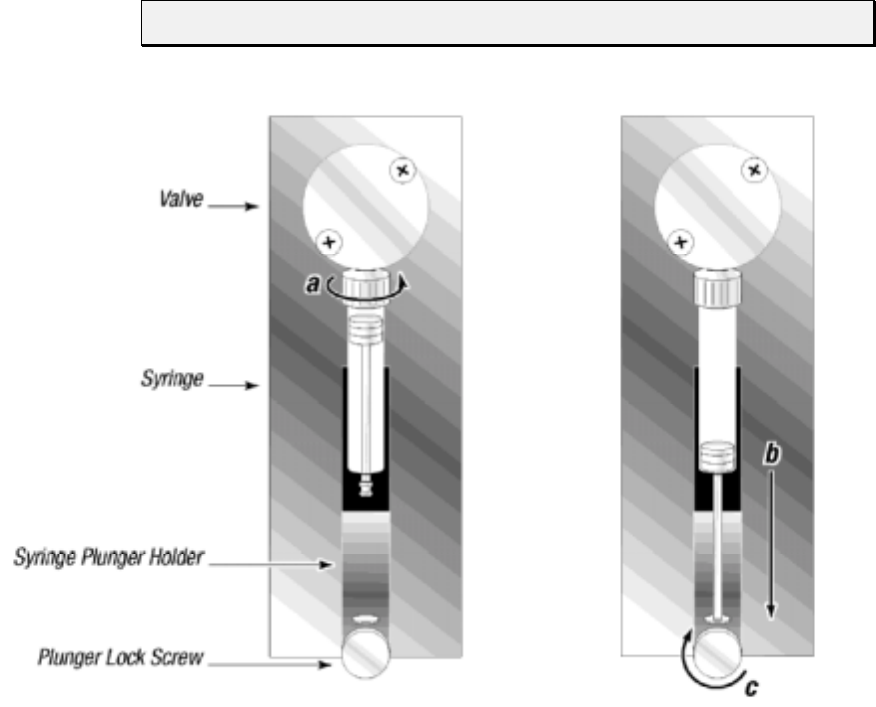
Maintenance 5-5
Replacing a Syringe
To replace a syringe, follow these steps:
1Remove the liquid from the syringe.
2Loosen the plunger lock screw approximately three full turns.
3Lower the plunger drive by sending the [A3000R] command. If power is not
applied, the plunger drive can be manually lowered by firmly pushing down on
the plunger holder assembly.
4Unscrew the syringe from the valve.
5To install the syringe, do the following, as shown in Figure 5-1:
a Screw the syringe into the valve.
b Pull the syringe plunger down to the plunger holder assembly.
c Screw the syringe plunger into place.
NOTE Make sure the plunger lock screw is securely tightened.
Figure 5-1. Syringe Replacement
6Re-initialize the pump.
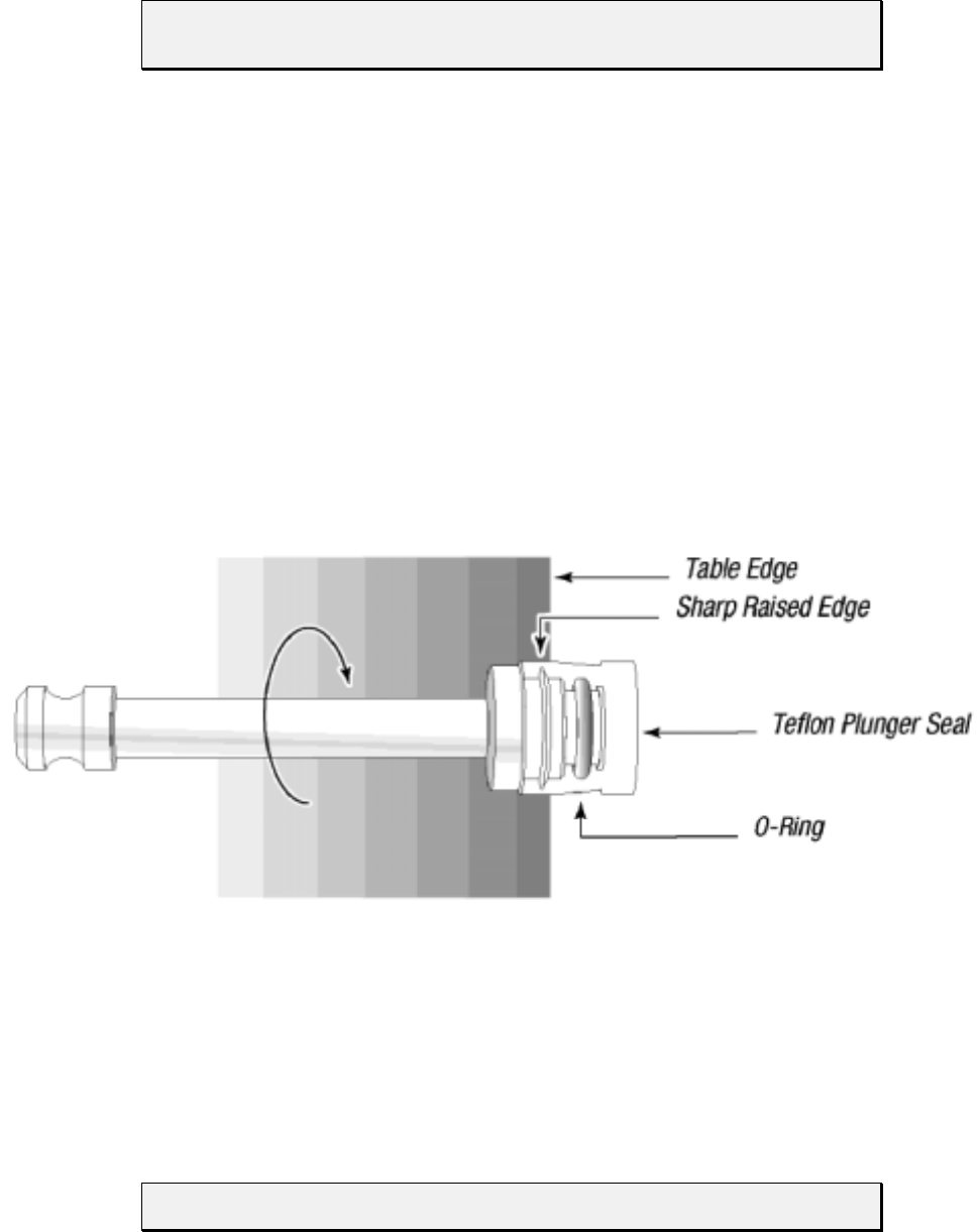
Maintenance 5-6
Replacing the Reagent Syringe Seals
NOTE See Chapter 2, “Hardware Setup,” for an illustration of the syringe
components.
To replace the reagent syringe seals, follow these steps:
1 Remove the syringe from the pump.
2 Remove the syringe plunger from the barrel.
3 Using a single edged razor or precision knife, carefully slice the old seal lengthwise
and remove it from the plunger. Care must be taken not to damage the plunger or
“O”-rings beneath the seal.
4 Wet the “O”-ring (if present) and plunger tip with distilled or deionized water.
5 Place the seal on a flat surface with the open end facing up. Press the plunger tip
firmly into the hole until it snaps into position.
6 Lay the plunger on a flat table top, and position it so that the seal (from the “O”-ring
up) hangs over the edge.
7 Slowly roll the plunger along the table edge pressing firmly on the portion of the seal
below the “O”-ring. See Figure 5-2.
Figure 5-2. Syringe Seal Assembly
8 Rotate the plunger three complete turns. This is necessary to make the sharp raised
edge of the plunger bite into the seal for a secure fit.
9 Wet the seal with distilled or deionized water, replace the plunger, then replace the
syringe.
NOTE Syringe sizes 250 µL, 500 µL, 1 mL, 2.5 mL, and 5.0 mL have “O”-rings.

Maintenance 5-7
Replacing the XP 3000 Valve
To replace the XP 3000 valve, follow these steps:
1 Remove the fluid from the pump.
2 Initialize the pump using the [ZR] command so that the offset tab on the encoder is
in the correct orientation (vertically and to your right).
3 Remove the syringe and tubing.
4 Remove the two Phillips head screws on the front of the valve, then remove the
valve from the pump.
5 To install the valve, first rotate the valve coupling to the position shown on the left in
Figure 5-3 (vertically with the tab to your left).
Figure 5-3. XP 3000 Valve Replacement (3-Port Valve Shown)
6 Verify that the offset tab on the encoder in the pump is correctly oriented (vertically
with the tab to your right).
7 Install the new valve by inserting the slot in the valve coupling onto the tab of the
encoder. The valve should be oriented with the tube fittings on top and the syringe
fitting on the bottom.
8 Gently push the valve in place, matching the locating pins on the valve with the
holes on the pump front.
9 Replace the valve screws. Tighten ¼ to ½ turn after the screws contact the valve
body.

Maintenance 5-8
On-Site Replacements
Replacing the Printed Circuit Board (PCB)
To replace the printed circuit board, follow these steps:
1 Power off the pump.
2 Remove the back panel by unscrewing the four hex side panel screws and the two
standoff screws holding the DB-15 connector.
3 Remove the two hex screws that hold the printed circuit board to the pump.
4 Note the cable connection locations and unplug the cable from the board.
5 Plug the cables into the new board.
6 Install the new board and screw it into place.
7 Reinstall the DB-15 connector using the two standoff screws, then replace the back
panel using the four back panel screws.
8 Power on and reinitialize the pump.
Replacing the EPROM
To replace the EPROM, follow these steps:
1 Power down the pump.
2 Remove the back panel by unscrewing the four hex side panel screws and the two
standoff screws holding the DB-15 connector.
3 Remove the old EPROM by using a PROM puller. The EPROM is located in
position U8 on the printed circuit board. (See Chapter 2, “Hardware Setup.”)
4 To install the new EPROM, position the notched end of the EPROM so that it faces
the bottom of the pump. Make sure all metal pins are aligned with the holes on the
receptacle.
5 Once the pins are seated in the holes, press the EPROM firmly into place. If the two
rows of pins are too far apart to match the hole on the receptacle, gently press the
side of a complete row of pins against a table top to push the row slightly toward the
center.
NOTE Care must be taken not to bend any of the pins on the EPROM.
6 Replace the back panel and DB-15 connector.
7 Power on and reinitialize the pump.
Technical Service 6-1
6 - Technical Service
For information or questions regarding ordering or operating the XP 3000, please contact
Cavro Technical Service using one of the methods listed below.
By phone 408-953-3100 or
800-231-0711
By fax 408-953-3107
By e-mail cavro@cavro.com
Our mailing address is:
Cavro Scientific Instruments, Inc.
2450 Zanker Road
San Jose, CA 95131
USA
When calling for technical service, have the following information ready:
• Part number
• Serial number
• Model type
• Description of the problem

Ordering Information A-1
A - Ordering Information
This appendix is a summary of available XP 3000 configurations, other Cavro liquid
handling components, and spare parts for the XP 3000.
Available Configurations
The available configurations and their respective part numbers for both standard
firmware and microstep-enabled firmware are listed below.
Table A-1. XP 3000 with Microstep-Enabled Firmware Configurations
Description Part
Number Communication
Protocol Fittings Valve Is Similar to
Part Number
XP 3000 with 3-port valve with
microstepping (RS232/485, 1/4-28") 728925 RS 232/485 1/4-28" 3-Port 725644
XP 3000 with 3-port valve with
microstepping (RS232/485, M6) 728927 RS 232/485 M6 3-Port 725643
XP 3000 with 3-port distribution valve
with microstepping (RS232/485, 1/4-28") 728964 RS 232/485 1/4-28" 3-Port
Distribution 726349
XP 3000 with T- valve with
microstepping (RS232/485, 1/4-28") 728878 RS 232/485 1/4-28" T-Valve New Product
XP 3000 with 3-port valve with
microstepping (CAN, 1/4-28") 728922 CAN 1/4-28" 3-Port 725586
XP 3000 with 3-port valve with
microstepping (CAN, M6) 728924 CAN M6 3-Port 725585
XP 3000 with 3-port distribution valve
with microstepping
(CAN, 1/4-28")
728966 CAN 1/4-28" 3-Port
Distribution 728187
XP 3000 with T- valve with
microstepping (CAN, 1/4-28") 728896 CAN 1/4-28" T-Valve New Product
Microstep-enabled firmware for
3-port valves 600002 Both NA 3-Port 725436
Microstep-enabled firmware for
3-port distribution valves 600004 Both NA 3-Port
Distribution 726352
Microstep-enabled firmware for
T-valve 600005 Both NA T-Valve 726336

Ordering Information A-2
Table A-2. XP 3000 Standard Firmware Configurations
Configuration Part Number Communication
Protocol
XP 3000 with 3-port valve, 1/4-28" fittings 725644 RS-232/RS-485
725586 CAN/RS-485
XP 3000 with valve, M6 fittings 725643 RS-232/RS-485
725585 CAN/RS-485
XP 3000 without valve (with “Y” block, 1/4-
28" fittings) 725658 RS-232/RS-485
725660 CAN/RS-485
XP 3000 without valve (with “Y” block, 1/4-
28" fittings) 725659 RS-232/RS-485
725661 CAN/RS-485
XP 3000 with 90º 3-port distribution valve,
1/4-28" fittings 726349 RS-232/RS-485
XP 3000, T-90, 1/4-28" fittings 728878 RS-232/RS-485
NOTE This table is provided for customers who are not using Cavro’s microstep-
enabled firmware.
XP 3000 Spare Parts
The following spare parts are available:
• Syringes • Printed Circuit Board
• Syringe Seals • Interconnect Tubing
• Syringe “O”-Rings • Pump Evaluation Accessories
• Valves • Miscellaneous Parts

Ordering Information A-3
Syringes
Table A-3. Syringes
Part Number Description
725676 Syringe, 50 µL
725682 Syringe, 100 µL
725589 Syringe, 250 µL
725590 Syringe, 500 µL
725591 Syringe, 1.0 mL
725592 Syringe, 2.5 mL
725593 Syringe, 5.0 mL
Syringe Seals
Table A-4. Seals
Part Number Description
3225 Seal, 50 µL
725684 Seal, 100 µL
1469 Seal, 250 µL
725707 Seal, 500 µL
725712 Seal, 1.0 mL
6740 Seal, 2.5 mL
6739 Seal, 5.0 mL
Syringe “O”-Rings
Table A-5. “O”-Rings
Part Number Description
720396 “O”-Ring, 250 µL
9321 “O”-Ring, 500 µL
9322 “O”-Ring, 1.0 mL
6633 “O”-Ring, 2.5 mL
6634 “O”-Ring, 5.0 mL
Ordering Information A-4
Valves
Table A-6. Valves
Part Number Description
725587 Valve, 3-Port (1/4-28" fitting)
725588 Valve, 3-Port (M6 fitting)
725727 “Y” Block (1/4-28" fitting)
725729 “Y” Block (M6 fitting)
726273 T-valve (1/4-28" fitting)
726346 3-port distribution (1/4-28" fitting)
Printed Circuit Board
Table A-7. Printed Circuit Board
Part Number Description
725688 PCB, RS-232/RS-485
725689 PCB, CAN/RS-485
NOTE When ordering spare PCBs, request the EPROM part number to be installed
on the board at no charge.

Ordering Information A-5
Interconnect Tubing
Table A-8. Interconnect Tubing
Part
Number Description Material Length
(Inches) Units Tube Ends
1067 Reagent tube TFE 60" .063 1/4-28" to blunt cut
4333 Aspirate/Dispense tube TFE 30" .053 Necked
4410 Aspirate/Dispense tube FEP 40" .031 Thermal drawn
4609 Reagent tube FEP 12" .031 1/4-28" to blunt cut
5133 Aspirate/Dispense tube FEP 29" .031 Thermal drawn
5723 Aspirate/Dispense tube FEP 29" .031 Necked
5729 Reagent tube TFE 20" .031 1/4-28" to blunt cut
5402 Aspirate/
Dispense coiled tube FEP 64" .031 Thermal drawn
6865 Interconnect tube FEP 3" 0.054 1/4-28" to 1/4-28"
720592 Reagent tube TFE 60" .063 1/4-28" to blunt cut
720595 Aspirate/Dispense tube FEP 60" .053 Necked
720597 Aspirate/Dispense tube FEP 60" .031 Thermal drawn
721370 Reagent tube TFE 27" .053 1/4-28" to blunt cut
722540 Reagent tube FEP 35" .079 M6 to blunt cut
722541 Interconnect tube FEP 20" 0.059 M6 to M6
723114 Aspirate/Dispense tube FEP 6" 0.079 1/4-28" to M6
724169 Aspirate/Dispense tube FEP 29" .031 Thermal drawn, M6
724170 Reagent tube TFE 27" .053 M6 to blunt cut
724275 Aspirate/Dispense tube FEP 22" 0.079 1/4-28" to M6
724780 Aspirate/Dispense tube FEP 39" 0.079 1/4-28" to 1/4-28"
725788 Interconnect tube FEP 8" 0.054 1/4-28" to 1/4-28"
725876 Aspirate/Dispense tube FEP 29" 0.059 1/4-28" to M6
725896 Interconnect tube TFE 20" 0.062 1/4-28" to 1/4-28"
726172 Aspirate/Dispense tube TFE 24" 0.062 1/4-28" to 1/4-28"
NOTE Custom tubing is available upon request.

Ordering Information A-6
Pump Evaluation Accessories
Table A-9. Evaluation Software
Part Number Description
727899 Pump:Link Software [package includes manual, programmer’s kit, 3.5"
diskettes (4)]
723914 AC power supply, 24V (120V). Evaluation, two pumps.
723942 AC power supply, 24V (220V). Evaluation, two pumps.
725744 DB-15 adapter. (Order two adapters per power supply).
Miscellaneous Parts
Table A-30. Miscellaneous Parts
Part Number Description
1590 Fitting, Tube, 0.076 ID, (2/pk)
1589 Fitting, Tube, 0.138 ID, (2/pk)
724757 Wrench, 5/16" and 9/64"
725730 Manual, Operator's, XP 3000
725731 Packaging
725772 Connector, XP mating
973309 Fitting, Tube, 0.085 ID, M6
973308 Fitting, Tube, 0.100 ID, M6
973307 Fitting, Tube, 0.125 ID, M6
972395 Jumper
Ordering Information A-7
Other Cavro Products
RSP 9000 Robotic Sample Processor
An XYZ robotic arm module, the RSP 9000 automates OEM liquid handling applications
and is available with one or two arms, liquid level sensing, and step loss detectors on all
three axes. The electronics support a number of auxiliary devices including diluters,
valves, I/O boards, disposable tips, and multi-channel probes.
MSP 9000/9500 Mini Sample Processors
One- or two-arm robotic benchtop workstations designed for automating sample
preparation or assay methods. Cavro’s modular component technology allows both
flexibility and quick customization. A variety of liquid-handling modules and a choice of
standard cap-piercing, disposable tip, or multi-channel probes are available. All
instruments include liquid-level sensing and step-loss detection.
Ordering Information A-8
XL Series Smart Valve
A compact, stepper motor driven module for OEM liquid handling applications, the
Smart Valve is available with 3-, 4-, or 6-port valves. It uses the same communication
characteristics as the XL 3000 Modular Digital Pump: RS-232 or RS-485 interfaces and a
choice of two communication protocols. Up to fifteen devices can be addressed
individually from a single communication port. The Smart Valve uses a single 24 VDC
power supply and contains a buffered output which can be used to drive an additional
relay or solenoid.
XL Series Smart Peristaltic Pump
A compact, eight roller unit with 1, 2, 3, or 4 channels. Smart Pump modules are stepper
motor driven and are designed to provide highly reproducible flow rates with minimum
pulsing and long tubing life. The SP modules use the same interface characteristics as the
XL 3000 Modular Digital Pump: RS-232 or RS-485 interfaces and a choice of two
communication protocols. Up to fifteen devices can be addressed individually from a
single communication port. The Smart Pump uses a single 24 VDC power supply and
contains a buffered output which can be used to drive an additional relay or solenoid.
XL 3000 Series Multi-Channel Pumps
These pumps are based on the single channel XL 3000 and are available in 2, 3, 4, 5, 6, or
8 channels. Each channel has an independently operated solenoid valve and can
accommodate syringes ranging from 500 µL to 2.5 mL. The pumps use an RS-232 or RS-
485 interface and a simple command set. They can aspirate and dispense fluids and are
specifically designed for OEM applications in the liquid handling, instrumentation, and
systems markets.
XL 3000 Modular Digital Pumps
An advanced stepper motor driven syringe pump designed for OEM precision liquid
handling applications, the XL 3000 automates pipetting, diluting, and dispensing with
excellent accuracy and precision over a wide range of speeds using a variety of syringe
sizes. The XL 3000 is an intelligent device, programmable through an RS-232 or RS-485
interface, and it operates from a single 24 VDC power supply.
The XL 3000 with 8-port distribution valve minimizes the amount of space needed to
distribute up to eight fluids in a system.
XE 1000 Pump
A simple, compact, economical pump module, the XE 1000 is designed for high volume
OEM instrument manufacturers who need to perform pipetting and diluting functions
such as reagent additions or aspirating and dispensing fluids.
Ordering Information A-9
Smart I/O Board
The Smart I/O board is a microprocessor driven PC board that allows the operation of a
number of I/O ports from an external serial line. The board can be controlled by RS-232
or RS-485. It can also be placed on an RS-485 bus with other Cavro pumps and smart
devices. The I/O signal is CMOS (0-5 volts). I/O lines include 16 inputs, 16 outputs, and
four analog inputs. The board uses a standard Cavro OEM communications protocol.
Cavro MiniWash
A compact, OEM module for rapidly aspirating or dispensing fluids, this module consists
of a control board and a small diaphragm pump attached to a small mounting frame
(similar to the Cavro Smart Valve). The module has many uses including: as a pump for
aspirating and/or dispensing fluids with a wash head; for rapidly pumping fluid through a
dispense probe for washing; and as a pump for moving fluid in and out of the Active
Wash Station.
Accessories
Tubing, syringes, evaluation power supply, and evaluation software are available for all
Cavro modules.
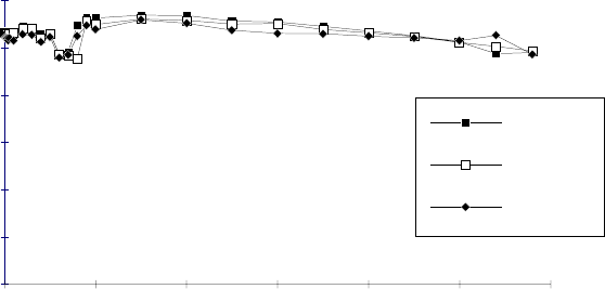
Plunger Information B-1
B - Plunger Information
Plunger Force
Figure B-1 shows a typical XP 3000 force curve for reference use only. Forces were
determined by hanging weights from the plunger pin and pulling them up at various
speeds. The plunger speed in Hz is shown on the X axis of the graph; plunger force is
shown on the Y axis.
FREQ UENC Y [Hz]
PLUNGER FORCE [lb
0.00
5.00
10.00
15.00
20.00
25.00
30.00
0 1000 2000 3000 4000 5000 6000
24V -10%
24V
24V+10%
Figure B-1. Plunger Force Curve
Plunger Information B-2
Plunger Time Calculations
Following are calculations for determining XP 3000 plunger speeds. Four different cases
are presented below.
1 Start, top, and cutoff velocities are equal, or top velocity is less than 50 Hz.
2 Typical move with ramp up, constant speed and ramp down.
3 Move is too small to reach cutoff velocity.
4 Move is too small to reach top velocity.
Symbol Definitions
Table B-1. Symbol Defintions
Symbol Name Range (n) Unit
v Start Velocity 50..1000 Half Steps/sec or Hz
V Top Velocity 5..5800 Half Steps/sec or Hz
c Cutoff Velocity 50..2700 Half Steps/sec or Hz
L Slope 1..20 n*2500 Half Steps/sec²
or Hz
A Move Distance 0..3000 Full Steps
t¹Ramp Up Time Seconds
t²Constant Speed Time Seconds
t³Ramp Down Time Seconds
tTotal Move Timet
¹+t²+t³Seconds
A¹Ramp Up Steps Half Steps
A²Ramp Up Steps Half Steps
A³Ramp Up Steps Half Steps
NOTE Cutoff velocity cannot be smaller than start velocity.
During aspiration, v is used in place of c.
The XP 3000 uses 3000 full steps per stroke.
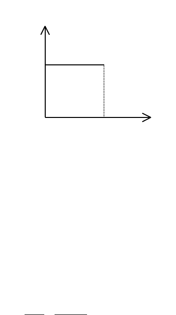
Plunger Information B-3
Move Calculations
CASE 1. START, TOP, AND CUTOFF VELOCITIES ARE EQUAL OR TOP VELOCITY IS SMALLER
THAN 50 HZ
Case 1 is used when v = V = c or v = <50
Diagram of move:
Calculation:
v = 900 Hz L = 14
V = 900 Hz A = 3000 full steps
c = 900 Hz
Total Move Time
t
A
V
=∗=∗=
2 2 3000
900 667. seconds
CASE 2. RAMP UP, CONSTANT SPEED, RAMP DOWN
Case 2 is used when AA A
13
2+<
Diagram of Move:
Speed [Hz]
V=c=v
t time in s
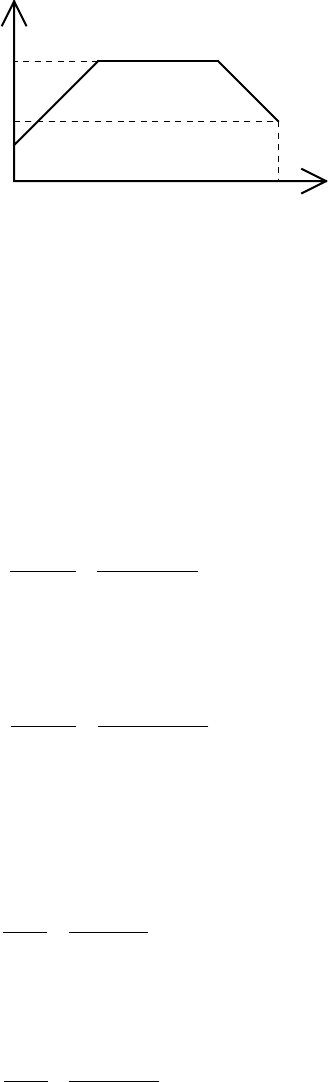
Plunger Information B-4
v
V
Speed [Hz]
c
time in st
Calculation:
v = 50 Hz L = 14
V = 5800 Hz A = 3000 full steps
c = 500 Hz
Ramp Up Steps
AVv
L
1
22 2 2
2
5800 50
2 14 2500 481=−=−
∗∗ =half steps
Ramp Down Steps
AVc
L
3
22 2 2
2
5800 500
2 14 2500 477=−=−
∗∗ =half steps
If AA A
13
2+< (481 + 477 < 6000) then:
Ramp Up Time
t
V
v
L
15800 50
14 2500 16=−=−
∗=. seconds
Ramp Down Time
t
V
c
L
35800 500
14 2500 15=−=−
∗=. seconds
Constant Speed Steps
AAAA
213
2 2 3000 481 477 5042=−−=∗ −− = half steps

Plunger Information B-5
Constant Speed Time
tA
V
235042
5800 87== =. seconds
Total Move Time
tt t t=++= + + =
123
16 87 15 1 18. . . . seconds
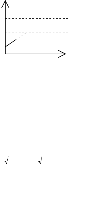
Plunger Information B-6
CASE 3. MOVE TOO SMALL TO REACH CUTOFF VELOCITY
Case 3 is used when Vn < c
Diagram of Move:
v
V
Speed [Hz]
c
time in st
Vn
Calculation:
v = 50 Hz L = 14
V = 5800 Hz A = 5 full steps
c = 900 Hz
Theoretical Top Velocity
Vn
A
Lv=+=∗∗∗+=4 4 5 14 2500 50 838
22
Hz
if Vn c< then
Total Move Time
tVn v
L
=−=−
∗=
838 50
14 2500 023. seconds
Ramp Up Steps
AA
15== full steps
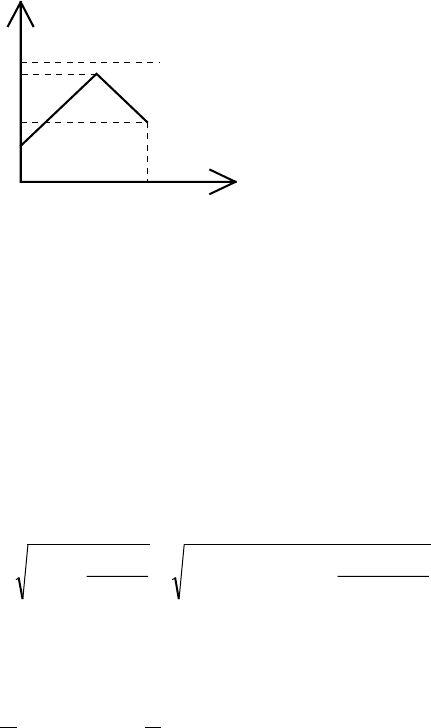
Plunger Information B-7
CASE 4. MOVE TOO SMALL TO REACH TOP VELOCITY
Case 4 is used when Vn < V and Vn > c
Diagram of Move:
v
V
Speed [Hz]
c
time in st
Vn
Calculation:
v = 50 Hz L = 14
V = 5800 Hz A = 350 full steps
c = 900 Hz
Top Velocity
Vn AL vc
=+
+=∗∗∗ + +=222 350 14 2500 50 900
24991
22 2 2 Hz
Total Move Time
t
L
Vn v c
L
=−−=∗−−=
1212 4991 50 900 26( ) ( ) . seconds

ASCII Chart of Codes for U. S. Characters C-1
C - ASCII Chart of Codes for U.S. Characters
Table C-1. ASCII Chart of Codes for U.S. Characters
Decimal Hexadecimal Character or
Function Decimal Hexadecimal Character or
Function
0 00 none 65 41 A
1 01 SOH 66 42 B
2 02 STX 67 43 C
3 03 ETX 68 44 D
4 04 EOT 69 45 E
5 05 ENQ 70 46 F
6 06 ACK 71 47 G
7 07 BEL 72 48 H
808BS7349I
909 HT 744A J
10 0A LF 75 4B K
11 0B VT 76 4C L
12 0C FF 77 4D M
13 0D CR 78 4E N
14 0E SO 79 4F O
15 0F SI 80 50 P
16 10 DLE 81 51 Q
17 11 DC1 82 52 R
18 12 DC2 83 53 S
19 13 DC3 84 54 T
20 14 DC4 85 55 U
21 15 NAK 86 56 V
22 16 SYN 87 57 W
23 17 ETB 88 58 X
24 18 CAN 89 59 Y
25 19 EM 90 5A Z
26 1A SUB 91 5B [
27 1B ESC 92 5C \ (backslash)
28 1C FS 93 5D ]
29 1D GS 94 5E ^ (control)
30 1E RS 95 5F — (emdash)
31 1F US 96 60 ` (tick)
32 20 SP 97 61 a
33 21 ! 98 62 b
34 22 " 99 63 c
35 23 # 100 64 d
36 24 $ 101 65 r
37 25 % 102 66 f
38 26 & 103 67 g

ASCII Chart of Codes for U. S. Characters C-2
Decimal Hexadecimal Character or
Function Decimal Hexadecimal Character or
Function
39 27 ' (apostrophe) 104 68 h
40 28 ( 105 69 i
41 29 ) 106 6A j
42 2A * 107 6B k
43 2B + 108 6C l
44 2C , (comma) 109 6D m
45 2D - (en dash) 110 6E n
46 2E . (period) 111 6F o
47 2F / 112 70 p
48 30 0 113 71 q
49 31 1 114 72 r
50 32 2 115 73 s
51 33 3 116 74 t
52 34 4 117 75 u
53 35 5 118 76 v
54 36 6 119 77 w
55 37 7 120 78 x
56 38 8 121 79 y
57 39 9 122 7A z
58 3A : 123 7B {
(left brace)
59 3B ; 124 7C |
(vertical bar)
60 3C < 125 7D }
(right brace)
61 3D = 126 7E ~ (tilde)
62 3E > 127 7F DEL
63 3F ?
64 40 @

Chemical Resistance Chart D-1
D - Chemical Resistance Chart
Table D-1, which starts on the following page, provides a summary of chemical
compatibility information provided by the manufacturers of components in the XP 3000
fluid path. Cavro recommends that you use this information as a guideline only, and that
you test each application fluid for chemical compatibility.
CAUTION! Failure to test chemicals used in individual applications with the XP
3000 may result in damage to the pump and/or test results.
The materials listed in Table D-1 are used in the following areas of the XP 3000:
Telfon® (PTFE, TFE, FEP) Tubing, Valve Plug, Seal
Kel F® Valve Body
Polypropylene Fittings for Tubing

Chemical Resistance Chart D-2
The codes and symbols in Table D-1 are as follows:
-No Data
0 No effect – excellent
1 Minor effect – good
2 Moderate effect – fair
3 Severe effect - not recommended
* Polypropylene - Satisfactory to 22° C (72° F)
** Polypropylene - Satisfactory to 49° C (120° F)
Table D-1. Plastic Materials Used in Cavro Pumps
Solvent Teflon Kel F Polypropylene
Acetaldehyde 0 0 0
Acetates - 0 0
Acetic Acid 0 0 0
Acetic Anhydride - 0 -
Acetone 0 0 0
Acetyl Bromide 0 -
Ammonia 0 - 0
Ammonium Acetate 0 - -
Ammonium Hydroxide 0 0 0
Ammonium Phosphate - 0 0
Ammonium Sulfate - 0 0
Amyl Acetate 0 - 3
Aniline 0 0 0
Benzene 0 3 *
Benzyl Alcohol 0 0 0
Boric Acid 0 0 0
Bromine 0 0 *
Butyl Alcohol 0 0 1
Butyl Acetate 0 - *
Carbon Sulfide 0 - *
Carbon Tetrachloride 0 1 3
Chloracetic Acid 0 0 -
Chlorine 0 1 3
Chlorobenzene - - 3
Chloroform 0 - 3
Chromic Acid 0 0 -
Cresol 0 - *
Cyclohexane 0 - 3
Ethers 0 - **
Ethyl Acetate 0 - 0
Ethyl Alcohol 0 - 0
Ethyl Chromide 0 1 3
Formaldehyde 0 0 0

Chemical Resistance Chart D-3
Solvent Teflon Kel F Polypropylene
Formic Acid 0 0 0
Freon 0 2 0
Gasoline 0 0 3
Glycerin 0 0 0
Hydrochloric Acid 0 0 0
Hydrochloric Acid (conc) 0 0 0
Hydrofluoric Acid 0 0 *
Hydrogen Peroxide 0 0 0
Hydrogen Peroxide (conc) 0 0 0
Hydrogen Sulfide 0 0 0
Kerosene 0 0 0
Methyl Ethyl Ketone (MEK) 0 - 0
Methyl Alcohol 0 - 0
Methylene Chloride 0 0 3
Naptha 0 1 0
Nitric Acid 0 0 0
Nitric Acid 0 0 -
Nitrobenzene 0 - **
Phenol 0 - 0
Pyridine 0 - -
Silver Nitrate 0 - 0
Soap Solutions 0 - 0
Stearic Acid 0 - *
Sulfuric Acid 0 0 0
Sulfuric Acid (conc) 0 0 -
Sulfurous Acid 0 0 0
Tannic Acid 0 0 0
Tanning Extracts - - -
Tartaric Acid 0 - -
Toluene 0 1 **
Trichloroethylene 0 3 3
Turpentine 0 0 **
Water 0 0 0
Xylene 0 0 *

XP 3000 Physical Specifications E-1
E - XP 3000 Physical Specifications
Table E-1. XP 3000 Physical Specifications
Dimensions Height 5.0 in (127 mm)
Width 1.8 in (45.7 mm)
Depth 4.5 in (114.3 mm) from front panel to connector
Weight 2.5 lbs (1.1 kg)
Resolution 3000 steps (24000-step capability when using microstep-enabled
firmware)
Plunger Drive Principle Rack and pinion drive with quadrature encoder and home flag
Travel 30 mm
Plunger Speed Variable from 1.2 secs/stroke to 20 min/stroke
Syringes Sizes 50 µL, 100 µL, 250 µL, 500 µL, 1.0 mL, 2.5 mL and 5.0 mL
Barrel Material Borosilicate Glass
Plunger Material Stainless Steel
Seal Material Virgin Teflon (PTFE, TFE)
Precision <0.05% CV at full stroke (250 µL syringe and above)
<0.1% CV at full stroke (50 µL and 100 µL syringe)
Accuracy <1% at full stroke
Valve Drive Turn time ≈250 ms between adjacent ports (3-port valve)
Drive Stepper motor with optical encoder for positioning feedback
Valves Plug Material Virgin Teflon
Body Material Kel-F
Fittings 1/4-28 tubing and syringe fittings
M6 or 1/4-28" syringe fitting
Valve Positions 120° 3-port, 3-port Distribution, T-Valve, Y-Block
Fluid Contact Glass, Kel-F, Teflon
Power Requirements Voltage 24VDC + 10%
Current 1.5 A (peak)

XP 3000 Physical Specifications E-2
Interface Type RS-232, RS-485 or CAN
Baud Rate 9600 or 38400 (RS-232 and RS-485 only)
Format Data Bits: 8
Parity: No
Stop Bit: 1
Half Duplex
Communications Addressing Up to 15 pumps can be addressed individually (up to 16 pumps w/
microstep FW)
Communications Data terminal and OEM protocol (with error recognition)
Firmware Programmable Ramps
Programmable Backlash Compensation
Programmable Plunger Speeds
Programmable Delays
Programmable Loops
Change Speed on the Fly
Terminate Moves
Diagnostics
Absolute or Relative Positions
Programmable EEPROM
Inputs Two TTL level inputs with 4.7k pull ups
Outputs Three outputs, CMOS (HC) level
Environmental Operating Temperature
(mechanism) 59°F (15°C) to 104°F (40°C)
Operating Humidity
(mechanism) 20-95% RH at 104°F (40°C)
Storage Temperature -4°F (20°C) to 149°F (65°C)

CAN Communication Commands F-1
F - CAN Communication Commands
Command Type Command Valid/Invalid CAN Equivalent
Initialization Z, Y Valid None
Initialization z Valid None
Plunger Movement A, a, P, p, D, d Valid None
Valve I, O, B Valid None
Valve E, ^ Valid None
Set S, V, v, C, c, L, K Valid None
Command for
microstep-enabled
firmware
N Valid None
Control G, g, M, H Valid None
Control X Valid Frame type = 2
Command = “3” (ASCII)
Control R Invalid Frame type = 2
Command = “1” (ASCII)
Control T Invalid Frame type = 2
Command = “4” (ASCII)
Control J, s, e Valid None
Report ? Invalid Frame type = 6
Command = “0” (ASCII)
Report ?1 Invalid Frame type = 6
Command = “6” (ASCII)
Report ?2 Invalid Frame type = 6
Command = “4” (ASCII)
Report ?3 Invalid Frame type = 6
Command = “7” (ASCII)
Report ?4 Invalid Frame type = 6
Command = “1” (ASCII)
Report ?5 Invalid Frame type = 6
Command = “2” (ASCII)
Report ?6 Invalid Frame type = 6
Command = “3” (ASCII)
Report ?7 Invalid Frame type = 6
Command = “8” (ASCII)
Report ?8 Invalid Frame type = 6
Command = “5” (ASCII)
Report ?9 through ?24 Invalid Frame type = 6
Command = “9” through
“24” (ASCII)
Report F Invalid Frame type = 6
Command = “10” (ASCII)
Report & Invalid Frame type = 6
Command = “23” (ASCII)
Report Q Invalid Frame type = 6
Command = “29” (ASCII)

Command Quick Reference G-1
G - Command Quick Reference
Control Commands
Command Value Description
R Executes command or command string
X Repeats last command string
G <n> <n> = 0..30000 Repeats command sequence
G Marks start of a repeat sequence
M <n> <n> = 5..30000 Delay in milliseconds
H <n> <n> = 0..2 Halts command execution
T Terminate command
J <n> <n> = 0..7 Auxillary outputs
s <n> <n> = 0..14 Loads common string in EEPROM
e <n> <n> = 0..14 Executes EEPROM common string
Initialization Commands for 3-Port Valve and T-Valve
Command Value Description
Z <n> <n> = 0, 10-40 = full plunger force
1 = half plunger force Initializes the plunger drive and sets the valve to the right or
output position.
Y <n> <n> = 0, 10-40 = full plunger force
1 = half plunger force Initializes the plunger drive and sets the valve to the left or
output position.
W <n> <n> = 0, 10-40 = full plunger force
1 = half plunger force Initializes the plunger drive. This command is used for
pumps without valves.
Initialization Commands for 3-Port Distribution Valve
Command Value Description
Z <n> <n> = 0, 10-40 = full plunger force
1 = half plunger force Initializes the plunger drive and sets the valve output to the right.
10 – 40 refers to Set speed commands S10 to S40.
Y <n> <n> = 0, 10-40 = full plunger force
1 = half plunger force Initializes the plunger drive and sets the valve output to the left.
Z none Sets the pump’s position counter to the valve contained in the
current encoder position. This command is used after a plunger
overload error to resynchronize the pump’s actual position with
its internally recorded position without having to go through the
entire initialization sequence.

Command Quick Reference G-2
Plunger Movement Commands/Status Bit Reports
Command Value Description Status
A <n> <n> = 0..3000 [A]bsolute Position Busy
a <n> <n> = 0..3000 [a]bsolute Position Ready
P <n> <n> = 0..3000 Relative [P]ickup Busy
p <n> <n> = 0..3000 Relative [p]ickup Ready
D <n> <n> = 0..3000 Relative [D]ispense Busy
d <n> <n> = 0..3000
<n> = 0..24,000 in microstep mode Relative [d]ispense Ready
Valve Commands
Command Description
I Moves valve to input position
O Moves valve to output position
B Moves valve to bypass position
E Moves valve to extra position (3-port distribution valve only)
Valve Leakage Detection Commands
Command Value Description
^ <n> = 0..255 Sets threshold value for fluid detection
Set Commands
Command Value Description Default Setting
S <n> <n> = 1..40 Set speed (11)
V <n> <n> = 5..6000 Peak velocity (1400)
v <n> <n> = 50..1000 Start velocity (900)
C <n> <n> = 0..25 Cutoff steps (0)
c <n> <n> = 50..2700 Cutoff steps (900)
L <n> <n> = 1..20 Slope (14)
K <n> <n> = 0..31
<n> = 0..255 in microstep mode Backlash (10)

Command Quick Reference G-3
Microstep-Enabled Firmware Commands
Command Value Description
N <n> = 0 or 1 Sets the microstep mode off or on.
S <n> = 0..40 Sets speed
V <n> = 5..6000 Sets end velocity in HS/s
v <n> = 50..1000 Sets start velocity in HS/s
c <n> = 50..2700 Sets cutoff velocity in HS/s
L <n> = 1..20 Sets ramp slope
K <n> = 0..31 (default 11) Backlash
k <n> = 0..80 or 0..640 in microstep mode
Report Commands
Command Description
Q Query, Status and Error Bytes
? Reports absolute plunger position
?1 Reports start velocity
?2 Reports top velocity
?3 Reports cutoff velocity
?4 Reports actual position of plunger
?12 Reports number of backlash steps
?13 Reports status of input #1
?14 Reports status of input #2
?22 Reports current value from fluid sensor
F Reports buffer status
& Reports firmware version
# Reports firmware checksum
Error Codes
Command Description Notes
0 Error free condition
1 (01h) Initialization error Fatal error. Reinitialize pump before resuming normal operation.
2 (02h) Invalid command
3 (03h) Invalid operand
4 (04h) Invalid command sequence
6 (06h) EEPROM failure
7 (07h) Device not initialized
9 (09h) Plunger overload Fatal error. Reinitialize pump before resuming normal operation.
10 (0Ah) Valve overload Fatal error. Reinitialize pump before resuming normal operation.
11 (0Bh) Plunger move not allowed
15 (0Fh) Command overflow

Command Quick Reference G-4
Error Codes and Status Byte
Status Byte Hex # if
Bit 5 = Dec # if
Bit 5 = Error
Code
7 6 5 4 3 2 1 0 0 or 1 0 or 1 Number Error
0 1 X 0 0 0 0 0 40h 60h 64 96 0 No error
0 1 X 0 0 0 0 1 41h 61h 65 97 1 Initialization
0 1 X 0 0 0 1 0 42h 62h 66 98 2 Invalid command
0 1 X 0 0 0 1 1 43h 63h 67 99 3 Invalid operand
0 1 X 0 0 1 0 0 44h 64h 68 100 4 Invalid command seq.
0 1 X 0 0 1 0 1 45h 65h 69 101 5 Fluid detection
0 1 X 0 0 1 1 0 46h 66h 70 102 6 EEPROM failure
0 1 X 0 0 1 1 1 47h 67h 71 103 7 Device not initialized
0 1 X 0 1 0 0 1 49h 69h 73 105 9 Plunger overload
0 1 X 0 1 0 1 0 4Ah 6Ah 74 106 10 Valve overload
0 1 X 0 1 0 1 1 4Bh 6Bh 75 107 11 Plunger move not allowed
0 1 X 0 1 1 1 1 4Fh 6Fh 79 111 15 Command overflow
DB-15 Connector Pin Assignments
Pin Function Remarks
1 24 VDC
2 RS-232 TxD line Output data
3 RS-232 RxD line Input data
4 Unused
5 CAN high signal line
6 CAN low signal line
7 Auxiliary input #1 TTL level
8 Auxiliary input #2 TTL level
9 Ground Power and logic
10 Ground Power and logic
11 RS-485 A line
12 RS-485 B line
13 Auxiliary output #1 TTL level
14 Auxiliary output #2 TTL level
15 Auxiliary output #3 TTL level
Index
Index
A
accuracy
determining · 5-4
address switch · 2-13
setting · 2-13
air gap · 4-1
answer frame format · 3-17
ASCII chart of codes for U.S. characters · C-1
aspirate/dispense
checking · 4-6
aspirate/dispense tubing · 4-1
auxiliary inputs · 2-14
auxiliary outputs · 2-14
B
backlash · 4-1
backlash compensation
setting · 4-7
backpressure · 4-1
breakoff · 4-1
breakup · 4-1
C
cabling · 2-2
CAN communication commands · F-1
Control · F-1
Initialization · F-1
microstep-enabled firmware · F-1
Plunger Movement · F-1
Report · F-1
CAN interface communications · 3-12
CAN messages · 3-12
frame types · 3-13
message construction · 3-12
CAN protocol · 3-3, 3-12
carryover · 4-2
cavitation · 4-2
Cavro Mini Wash (MW) · A-9
chemical compatibility
checking · 4-3
chemical resistance chart · D-1
Coefficient of Variation
percentage · 5-4
command overflow error · 3-45
commands · 3-21
# (Report Firmware Checksum) · 3-41
& (Report Firmware Version) · 3-41
? (Report Absolute Plunger Position) · 3-40
?12 (Report Backlash Steps) · 3-40
?13 (Report Auxiliary Input #1 Status) · 3-40
?14 (Report Auxiliary Input #2 Status) · 3-40
?2 (Report Top Velocity) · 3-40
?22 (Report Value from Fluid Sensor) · 3-41
?3 (Report Cutoff Velocity) · 3-40
?4 (Report Plunger Position) · 3-40
^ (Set Threshold Value for Fluid Detection) · 3-
33
a (Absolute Position) · 3-29
A (Absolute Position) · 3-29
B (Move Valve to Bypass) · 3-33
c (Cutoff Velocity in Hz) · 3-39
C (Cutoff Velocity in Steps) · 3-39
CAN · F-1
command string example · 3-23
Control · 3-23, G-1
d (Relative Dispense) · 3-30
D (Relative Dispense) · 3-30
e (Execute EEPROM Command String) · 3-26
e (Execute EEPROM Program String) · 3-26
E (Move Valve to Extra Position) · 3-33
error codes · 3-43
execution guidelines · 3-21
F (Report Buffer Status) · 3-41
g (Mark Start of Repeat Sequence) · 3-23
G (Repeat Command Sequence) · 3-23
H (Halt Command Execution) · 3-24
I (Move Valve to Input Position) · 3-31
Initialization · 3-27, G-1
Initialization for 3-port distribution valve · G-1
Initialization, 3-port and T-valve · 3-28
J (auxiliary outputs) · 3-25
Index 1
K (Backlash Steps) · 3-34
k (Syringe Dead Volume) · 3-42
L (Set Slope) · 3-36
M (Delay Command Execution) · 3-24
microstep-enabled firmware · G-3
N (Set Microstep Mode Off/On) · 3-41
O (Move Valve to Output Position) · 3-31
p (Relative Pickup) · 3-30
P (Relative Pickup) · 3-29
Plunger Movement · 3-29, G-2
Q (Query) · 3-43
query status · 3-43
R (Execute command) · 3-23
Report · 3-39, G-3
s (Load Command String into EEPROM) · 3-
26
S (Set Speed) · 3-37
Set · 3-34, G-2
syntax · 3-22
T (Terminate command) · 3-25
V (Set Top Velocity) · 3-37
v (Start Velocity) · 3-36
Valve · 3-31, G-2
Valve Leakage Detection · 3-33, G-2
W (Initialize Plunger) · 3-28
X (Execute Last command) · 3-23
X?1 (Report Start Velocity) · 3-40
Y (Initialize Plunger) · 3-28
Z (Initialize Plunger) · 3-28
z (Set Counter Position) · 3-29
commands for microstep-enabled firmware · 3-
41
communication interfaces · 1-7, 2-3
configuration jumpers · 2-8, 2-11
connectors
JP1 · 2-8, 2-10
JP2 · 2-3
JP3 · 2-14
JP4 · 2-10
cutoff velocity · 4-3
setting · 4-6
D
data block · 3-15
DB-15 connector
mating connectors · 1-9
pin assignments · G-4
DB-15 connector pin positions · 2-3
dilution effect · 4-2
Index 1
dispense or reagent tubing
replacing · 5-4
DT protocol · 3-3, 3-8
answer block characters · 3-9
command block characters · 3-8
using with Windows 3.x · 3-10
using with Windows 95 · 3-10
using with Windows NT · 3-10
E
EPROM
replacing · 5-8
error codes · 3-43, G-3
error codes and ASCII and hexadecimal values ·
3-46
error codes and status byte · G-4
error reporting examples · 3-45
error types · 3-45
F
flowrate ranges · 4-4
frames · 3-12
H
host to pump exchange examples · 3-17
I
initialization errors · 3-45
initialization forces · 3-27
by syringe · 3-28
inner diameter · 4-2
J
jumpers
JP1 · 2-10, 2-11
JP1-1 · 2-9, 2-11
JP1-2 · 2-9, 2-11
JP1-3 · 2-9, 2-11
JP1-4 · 2-9, 2-11
JP2 · 2-3
JP3 · 2-14
JP4 · 2-10, 2-11
mode · 2-10
M
maintenance
10% bleach cleaning · 5-3
daily · 5-1
periodic · 5-3
weak acid-base-sequence cleaning · 5-2
weak detergent cleaning · 5-2
weekly · 5-1
mating connector suppliers · 1-9
message identifier (MID) · 3-12
microstep-enabled firmware
commands for · 3-41
configuration jumper JP1 · 2-11
JP1-2 · 2-11
JP1-3 · 2-11
JP1-4 · 2-11
jumper settings · 2-10
mode jumper JP4 · 2-10
parameter ranges · 3-42
plunger overload detection · 2-11
microstep-enabled firmware configurations · A-1
mode jumpers · 2-10
move calculations · B-3
MSP 9000/9500 Mini Sample Processors · A-7
multi-frame, types 3 and 4 · 3-19, 3-20
multi-pump configurations · 1-8
O
OEM protocol · 3-3, 3-4
answer block characters · 3-7
command block characters · 3-4
overload errors · 3-45
P
plunger force · B-1
plunger movement phases · 3-34
plunger overload detection · 2-11
plunger time calculations · B-2
power supply · 2-1
choosing · 1-10
integrating · 1-10
requirements · 1-10
switching · 1-11
Index 1
precision
determining · 5-4
priming · 4-2
printed circuit board · 1-7
components · 2-12
configuration jumpers · 2-8
replacing · 5-8
termination jumpers · 2-4
printed circuit board components · 1-7
pump
initializing · 4-5
pump boot requests · 3-16
pump busy/not busy status bit · 3-43
pump communications
checking · 4-5
pump connection · 4-5
Pump:Link · 3-2, 3-37
Q
quality control maintenance · 5-3
R
reagent tubing · 4-2
regulatory considerations · 1-1
CE · 1-1
radio interference · 1-2
repeat flag · 3-5
RSP 9000 Robotic Sample Processor · A-7
S
self-test · 2-14
sequence number · 3-5
slope · 4-3
setting · 4-6
Smart I/O Board · A-9
speed
changing on the fly · 3-34
standard firmware configurations · A-2
start velocity · 4-2
setting · 4-6
status byte · G-4
symbol definitions · B-2
syringe · 1-5
installing · 2-18
priming · 4-5
replacing · 5-5
syringe components · 1-5
Index 1
syringe plunger · 1-5
syringe seals
replacing · 5-6
syringe size
selecting · 4-4
syringe sizes · 1-5
with "o"-rings · 5-6
syringe speed · 4-2
system fluid · 4-2
T
technical service · 6-1
termination jumpers · 2-4
top velocity · 4-2
setting · 4-6
tubing
selecting · 4-4
tubing recommendations · 4-4
V
valve · 1-6
components · 1-6
drive · 1-6
installing · 2-16
replacing · 5-7
sensor · 1-8
types · 1-6
valve positions · 3-31
X
XE 1000 Pump · A-9
XL 3000 Modular Digital Pumps · A-8
XL 3000 Series Multi-Channel Pumps · A-8
XL Series Smart Peristaltic Pump · A-8
XL Series Smart Valve · A-8
XP 3000 · See also address switch, commands,
communication interfaces, EPROM, jumpers,
microstep-enabled firmware, multi-pump
configurations, power supply, printed circuit
board, syringe, syringe drive, valve
accessories · A-9
address switch settings in hex · 3-2
addressing scheme · 3-1
command set · 3-21
communication protocols · 3-3
DB-15 connector pin positions · 2-3
ESD considerations · 1-3
evaluation software part number · A-6
Index 1
features · 1-2
functional description · 1-4
interconnect tubing part numbers · A-5
microstep-enabled firmware configurations ·
A-1
miscellaneous part numbers · A-6
mounting · 2-19
ordering information · A-1
physical specifications · E-1
printed circuit board part numbers · A-4
setting up · 1-8
spare parts · A-2
standard firmware configurations · A-2
syringe "o"-ring part numbers · A-3
syringe part numbers · A-3
syringe seal part numbers · A-3
unpacking · 1-3
valve part numbers · A-4
valve types · 3-21
XP 3000 performance
optimizing · 4-3, 4-8
XP 3000 without valve · 2-15
