Technical_sheets Technical Sheets
User Manual: Technical_sheets
Open the PDF directly: View PDF ![]() .
.
Page Count: 227 [warning: Documents this large are best viewed by clicking the View PDF Link!]

TECHNICAL SHEETS
351000
BT00595-a
6
3 3
4
5
1 2
789
10
11
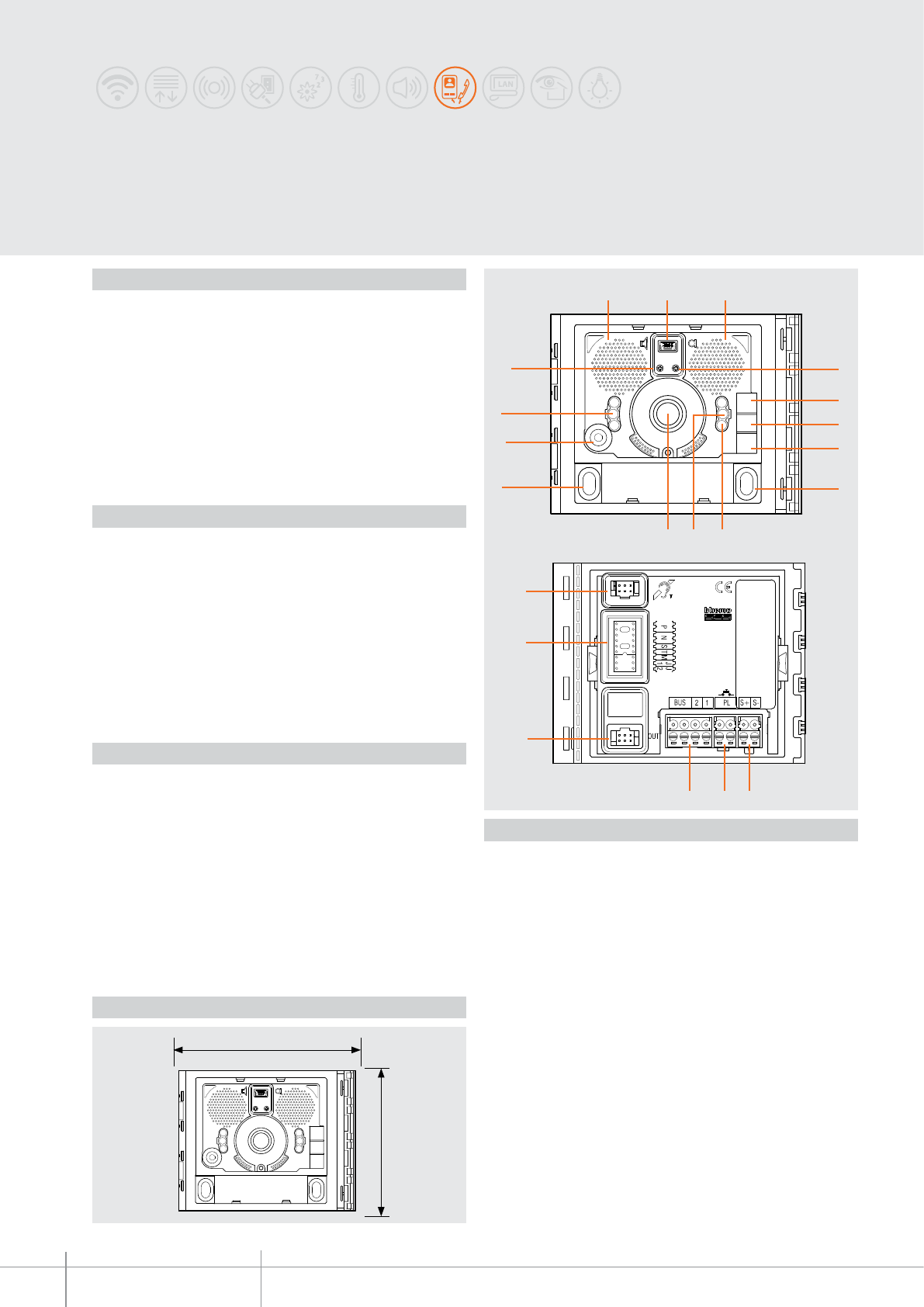
115 mm
91 mm
-EN
TECHNICAL SHEETS
188 2 WIRE VDE system
SFERA NEW - SFERA ROBUR
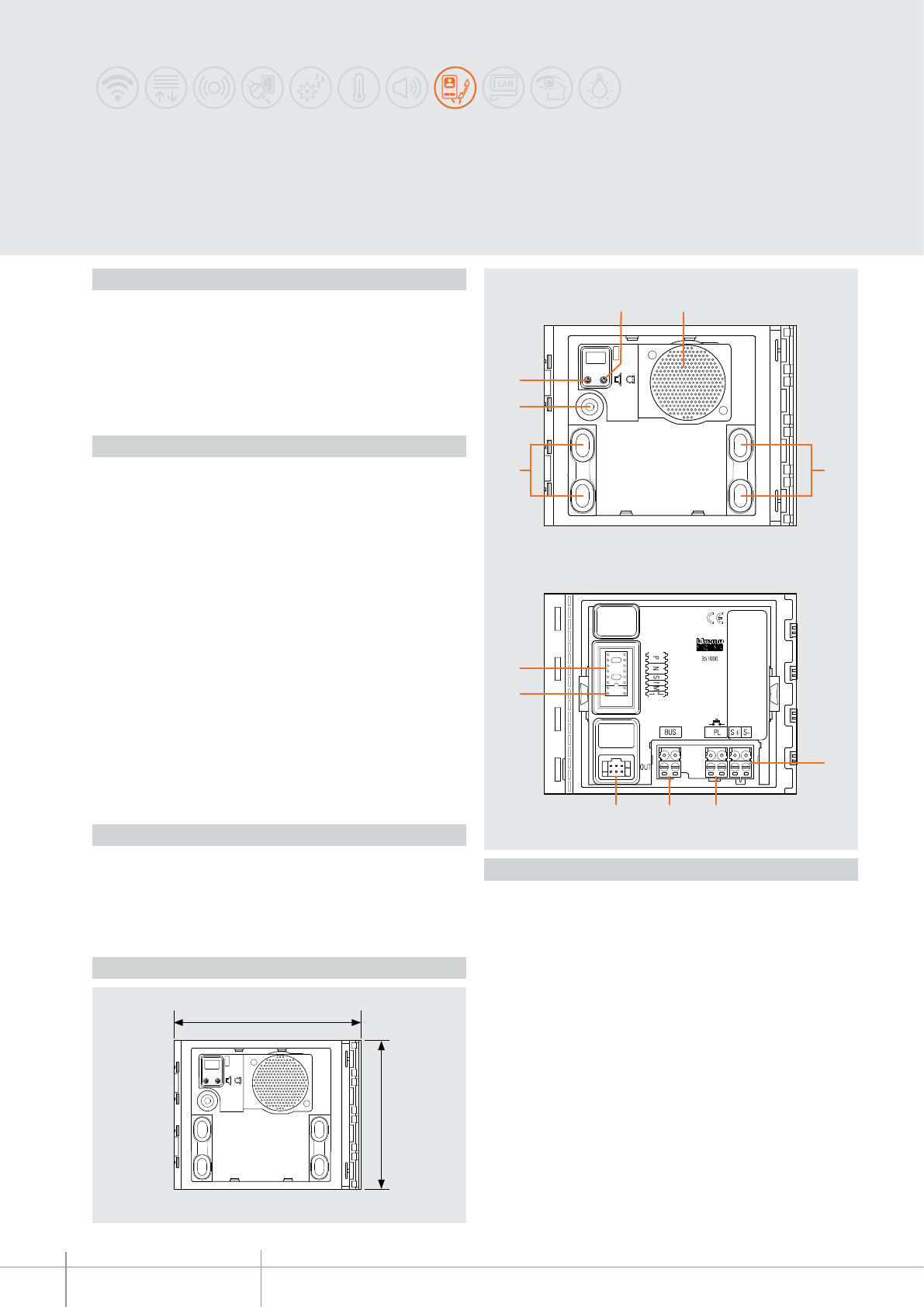
Basic speaker module
Basic speaker module for the creation of 2 WIRE audio systems. Fitted with loudspeaker
and microphone volume adjustment.
It manages up to 100 pushbutton calls using additional double row pushbuttons.
It can be used for opening an electrical door lock directly connected to the S+ and S-
clamps (18 V 4 A impulsive - 250 mA holding current 30 Ohm max) and the connection
to a local door lock release pushbutton on the PL clamps. To be completed with
surround plate. The device must be physically configured.
Description
Legend
Dimensional data
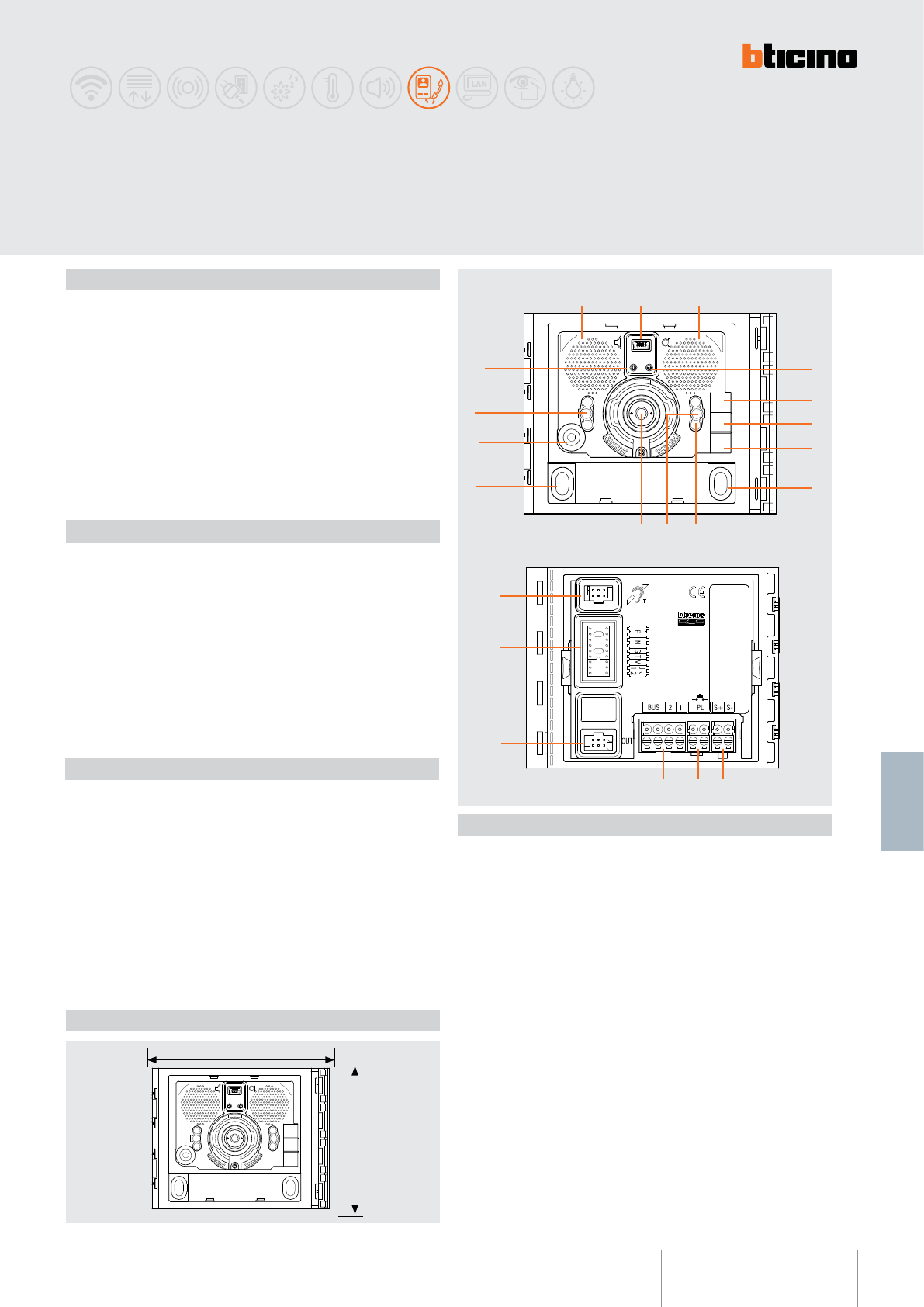
Front view
Rear view
1. Microphone volume adjustment
2. Loudspeaker
3. Call pushbuttons
4. Microphone
5. Loudspeaker volume adjustment
6. Plug-in clamps for the connection and control of the electrical door lock
(18 V 4 A impulsive 250 mA holding current 30 ohm max)
7. Plug-in clamps for the connection of the local door lock release pushbutton
8. Plug-in clamps for 2 WIRE SCS/BUS connection
9. Connector for the connection to subsequent pushbutton modules
10. Jumper J1: when connected it enables the right pushbutton column.
When disconnected it enables the left pushbutton column
11. Configurator socket
Related items
351001 Sfera New speaker module front cover - Allmetal (IK 08)
351002 Sfera New speaker module front cover - Allwhite (IK 08)
351003 Sfera New speaker module front cover - Allstreet (IK 08)
351011 Sfera New speaker module front cover, 1 pushbutton - Allmetal (IK 08)
351012 Sfera New speaker module front cover, 1 pushbutton - Allwhite (IK 08)
351013 Sfera New speaker module front cover, 1 pushbutton - Allstreet (IK 08)
351021 Sfera New speaker module front cover, 2 pushbuttons - Allmetal (IK 08)
351022 Sfera New speaker module front cover, 2 pushbuttons - Allwhite (IK 08)
351023 Sfera New speaker module front cover, 2 pushbuttons - Allstreet (IK 08)
351041
Sfera New speaker module f/cover, 2 pushbuttons on double column - Allmetal (IK 08)
351042
Sfera New speaker module f/cover, 2 pushbuttons on double column - Allwhite (IK 08)
351043
Sfera New speaker module f/cover, 2 pushbuttons on double column - Allstreet (IK 08)
351081
Sfera New speaker module f/cover, 4 pushbuttons on double column - Allmetal (IK 08)
351082
Sfera New speaker module f/cover, 4 pushbuttons on double column - Allwhite (IK 08)
351083
Sfera New speaker module f/cover, 4 pushbuttons on double column - Allstreet (IK 08)
351005 Sfera Robur speaker module front cover (IK 10)
351015 Sfera Robur speaker module front cover, 1 pushbutton (IK 10)
351025 Sfera Robur speaker module front cover, 2 pushbuttons (IK 10)
51045 Sfera Robur speaker module front cover, 2 pushbuttons on double column (IK 10)
351085 Sfera Robur speaker module front cover, 4 pushbuttons on double column (IK 10)
Power supply from SCS BUS: 18 – 27 Vdc
Stand by absorption: 15 mA
Max. operating absorption: 65 mA
Operating temperature: (-25) – (+70) °C
Protection index (pushbutton panel assembled): IP 54
Technical data
BT00595-a
P N S T M
J1
351000
-EN
TECHNICAL SHEETS
189
2 WIRE VDE system
* Operation as pushbutton for 10 sec. max after which it goes in stand-by.
In order to extend this type of operation over 10 seconds, use the actuator, item
346200 configured with MOD = 5.
T - door lock relay timing
Configurator 0 = no
configurator 1 2 3 4* 5 6 7
4 sec. 1 sec 2 sec 3 sec
as
pushbutt.
6 sec 8 sec 10 sec
M - enabling/disabling of call tones and door lock release tones
The M configurations gives the possibility of managing the entrance panel call and door
lock release tones according to the following table:
Configurator 0 1 2 3
Tone status All tones
enabled
Door lock tone
disabled
Call tone
disabled
All tones
disabled
J1 - activation of call pushbutton columns
The J1 configurator gives the possibility of managing the Call pushbuttons of the speaker
module as follows:
J1 CONNECTED = Only the right pushbutton column is enabled
J1 DISCONNECTED = Both pushbutton columns are enabled (right + left)
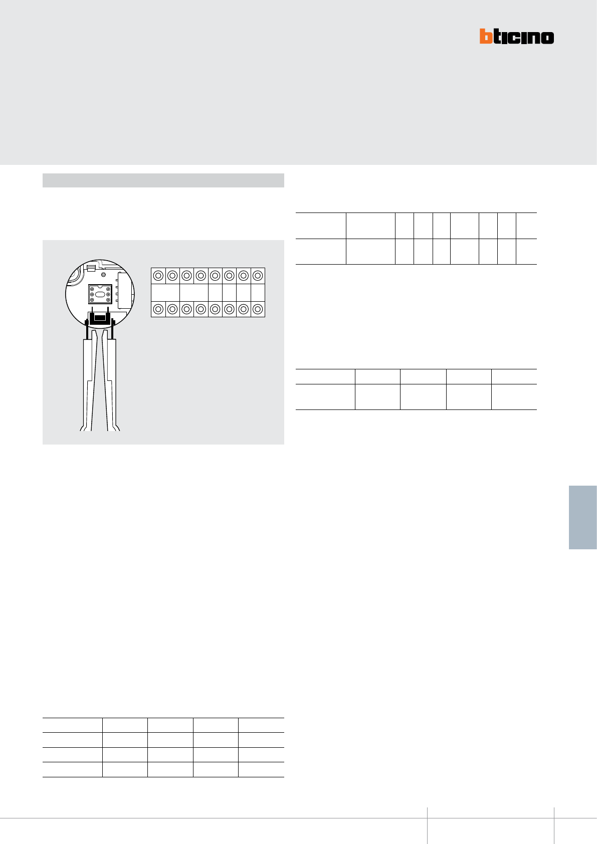
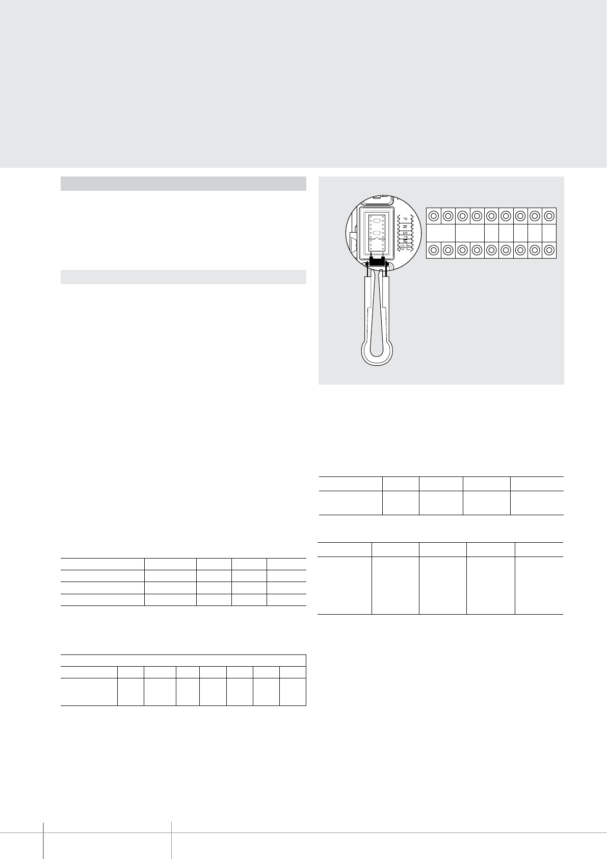
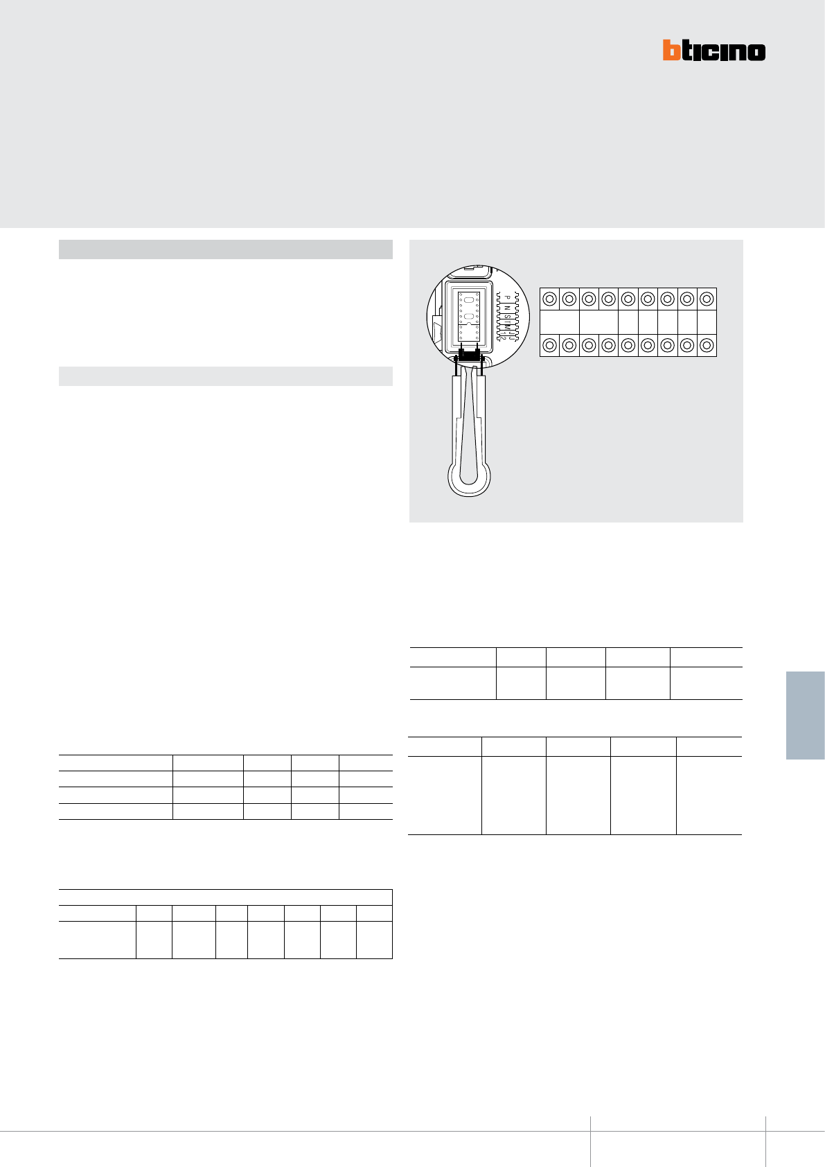
The device must be configured with physical configurator connection to the ap-
propriate sockets as follows:
Configuration
P - entrance panel number
The configurator in socket P of the speaker module assigns to this a recognition number
inside the system. The numbering of the entrance panels must always start from P=0.
The entrance panel configured with P=0 must be a common (or main) entrance panel.
N - call number
Assigns the correspondence between the entrance panel pushbuttons and the audio
handsets or video handsets.
In common entrance panels made using pushbutton modules, 1 must be inserted in N of
the speaker module. The number of the first riser handset must be inserted in the local
entrance panels.
S - type of call signal
The configuration of S determines the call tone of handsets.
One can thus differentiate the calls from different entrance panels.
For the SWING, PIVOT, POLYX and AXOLUTE handsets, S associates the Entrance panel to
the bell programmed in the same apartment. It is possible to chose between 16 dierent
preset bells.
For the SPRINT handsets, S sets the call ringtone, according to the following table:
In one-family systems S=9 to configure the general call.
Configurator 0 1 2 3
Type of bell 2-tone 2-tone 2-tone One-tone
1200 Hz 1200 Hz 1200 Hz 1200 Hz
600 Hz 0 Hz 2400 Hz
351100
BT00596-a
115 mm
91 mm
4
5
6
7
8 8
9
10
1 2 3
111213
15
14
16
17
-EN
TECHNICAL SHEETS
190 2 WIRE VDE system
SFERA NEW - SFERA ROBUR
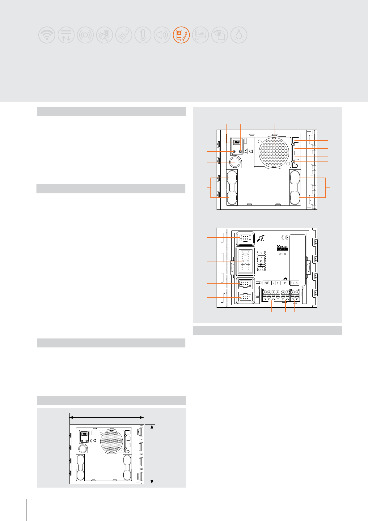
Speaker module
Speaker module for the creation of 2 WIRE audio & video systems. Fitted with loudspeaker
and microphone volume adjustment. It can manage up to 100 pushbutton calls when using
additional double row pushbutton modules. It can be used for opening an electrical door lock
directly connected to the S+ and S- clamps (18 V 4 A impulsive - 250 mA holding current 30 Ohm
max) and the connection to a local door lock release pushbutton on the PL clamps. Preset for
additional power supply. Fitted with front LEDs for the notification of the operating status: door
lock release, communication active, call put through, and system busy. Integrated optic sensor
for the switching on of the night backlighting. To be completed with surround plate. The device
can be configured either physically or using the PC and the TiSferaDesign software.
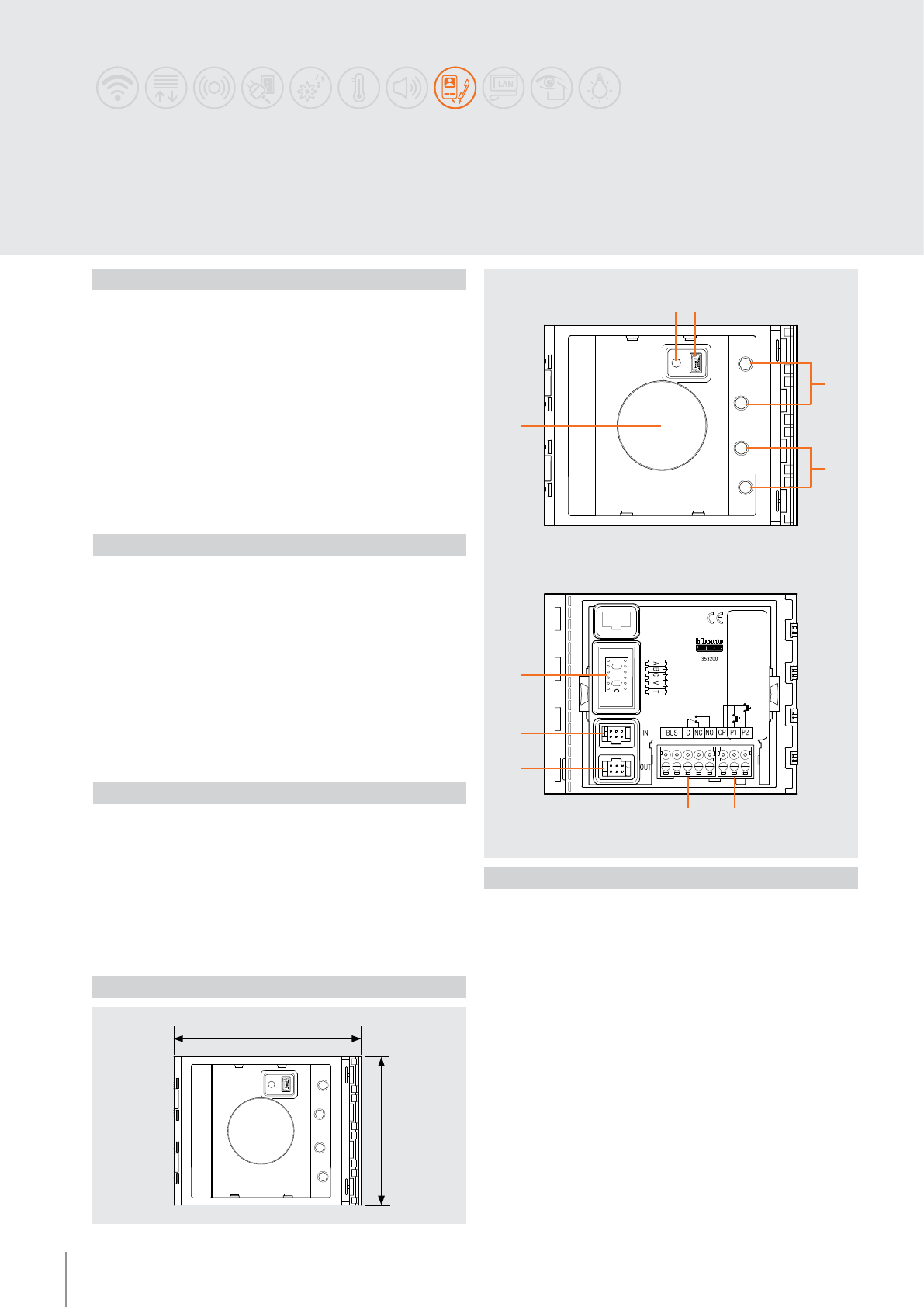
Description
Legend
Dimensional data
Front view
Rear view
1. Mini-USB connector for the connection to the PC : download/upload the advanced
configuration and device firmware update
2. Microphone volume adjustment
3. Loudspeaker
4. LED for door status notification. GREEN ON = door open
5. LED for communication status notification. GREEN ON = active communication
6. LED for system status notification. GREEN ON = put through call
RED ON= busy system
7. Light sensor for automatic switching on of the night backlighting
8. Call pushbuttons
9. Microphone
10. Loudspeaker volume adjustment
11. Plug-in clamps for the connection and control of the electrical door lock
(18 V 4 A impulsive 250 mA holding current 30 ohm max)
12. Plug-in clamps for the connection of the local door lock release pushbutton
13. Plug-in clamps for the connection of the local power supply and the 2 WIRE SCS BUS
14. Connector for the connection to subsequent pushbutton modules
15. Connector for the connection of the N&D 352400 camera module
16. Configurator socket
17. Connector for the connection of the 352700 inductive loop module
Related items
351101 Sfera New speaker module front cover - Allmetal (IK 08)
351102 Sfera New speaker module front cover - Allwhite (IK 08)
351103 Sfera New speaker module front cover - Allstreet (IK 08)
351111 Sfera New speaker module front cover, 1 pushbutton - Allmetal (IK 08)
351112 Sfera New speaker module front cover, 1 pushbutton - Allwhite (IK 08)
351113 Sfera New speaker module front cover, 1 pushbutton - Allstreet (IK 08)
351121 Sfera New speaker module front cover, 2 pushbuttons - Allmetal (IK 08)
351122 Sfera New speaker module front cover, 2 pushbuttons - Allwhite (IK 08)
351123 Sfera New speaker module front cover, 2 pushbuttons - Allstreet (IK 08)
351141
Sfera New speaker module f/cover, 2 pushbuttons on double column - Allmetal (IK 08)
351142
Sfera New speaker module f/cover, 2 pushbuttons on double column - Allwhite (IK 08)
351143
Sfera New speaker module f/cover, 2 pushbuttons on double column - Allstreet (IK 08)
351181
Sfera New speaker module f/cover, 4 pushbuttons on double column - Allmetal (IK 08)
351182
Sfera New speaker module f/cover, 4 pushbuttons on double column - Allwhite (IK 08)
351183
Sfera New speaker module f/cover, 4 pushbuttons on double column - Allstreet (IK 08)
351105 Sfera Robur speaker module front cover (IK 10)
351115 Sfera Robur speaker module front cover, 1 pushbutton (IK 10)
351125 Sfera Robur speaker module front cover, 2 pushbuttons (IK 10)
351145
Sfera Robur speaker module front cover on double column, 2 pushbuttons (IK 10)
351185
Sfera Robur speaker module front cover on double column, 4 pushbuttons (IK 10)
Power supply from SCS BUS: 18 - 27 Vdc
Stand by absorption (with backlighting LEDs off): 10 mA
Stand by absorption (with backlighting LEDs on): 15 mA
Max. operating absorption: 65 mA
Operating temperature: (-25) – (+70) °C
Protection index (pushbutton panel assembled): IP 54
Technical data
BT00596-a
351100
P N S T M
J1 J2
-EN
TECHNICAL SHEETS
191
2 WIRE VDE system
Configuration
* Operation as pushbutton for 10 sec. max after which it goes in stand-by.
In order to extend this type of operation over 10 seconds, use the actuator, item
346200 configured with MOD = 5.
T - door lock relay timing
Configurator 0 = no
configurator 1 2 3 4* 5 6 7
4 sec 1 sec 2 sec 3 sec
as
pushbutt.
6 sec 8 sec 10 sec
M - enabling/disabling of call tones and door lock release tones, and
management of night backlighting always ON
The M configurations gives the possibility of managing the entrance panel call and door
lock release tones . It also gives the possibility of enabling night backlighting always ON
(light sensor disabled) according to the following table:
Configurator M = 0 M = 1 M = 2 M = 3
Tone status All tones
enabled
Door lock tone
disabled
Call tone
disabled
All tones
disabled
Configurator M = 4 M = 5 M = 6 M = 7
Backlighting status All tones
enabled
+
backlighting
always ON
Door lock tone
disabled
+
backlighting
always ON
Call tone
disabled
+
backlighting
always ON
All tones
disabled
+
backlighting
always ON
P - entrance panel number
The configurator in socket P of the speaker module assigns to this a recognition number
inside the system. The numbering of the entrance panels must always start from P=0.
The entrance panel configured with P=0 must be a common (or main) entrance panel.
N - call number
Assigns the correspondence between the entrance panel pushbuttons and the audio
handsets or video handsets.
In common entrance panels made using pushbutton modules, 1 must be inserted in N of
the speaker module. The number of the first riser handset must be inserted in the local
entrance panels.
S - type of call signal
The configuration of S determines the call tone of handsets.
One can thus differentiate the calls from different entrance panels.
For the SWING, PIVOT, POLYX and AXOLUTE handsets, S associates the Entrance panel to
the bell programmed in the same apartment. It is possible to chose between 16 different
preset bells.
For the SPRINT handsets, S sets the call ringtone, according to the following table:
In one-family systems S=9 to configure the general call.
Configurator 0 1 2 3
Type of bell 2-tone 2-tone 2-tone One-tone
1200 Hz 1200 Hz 1200 Hz 1200 Hz
600 Hz 0 Hz 2400 Hz
J1 - activation of call pushbutton columns
The J1 configurator gives the possibility of managing the Call pushbuttons of the speaker
module as follows:
J1 CONNECTED = Only the right pushbutton column is enabled
J1 DISCONNECTED = Both pushbutton columns are enabled (right + left)
J2 - additional EP power supply
Configurator J2 gives the possibility of enabling the additional power supply (1-2) of the
speaker module in the following mode :
J2 CONNECTED = Additional power supply disabled
J2 DISCONNECTED = Additional power supply enabled
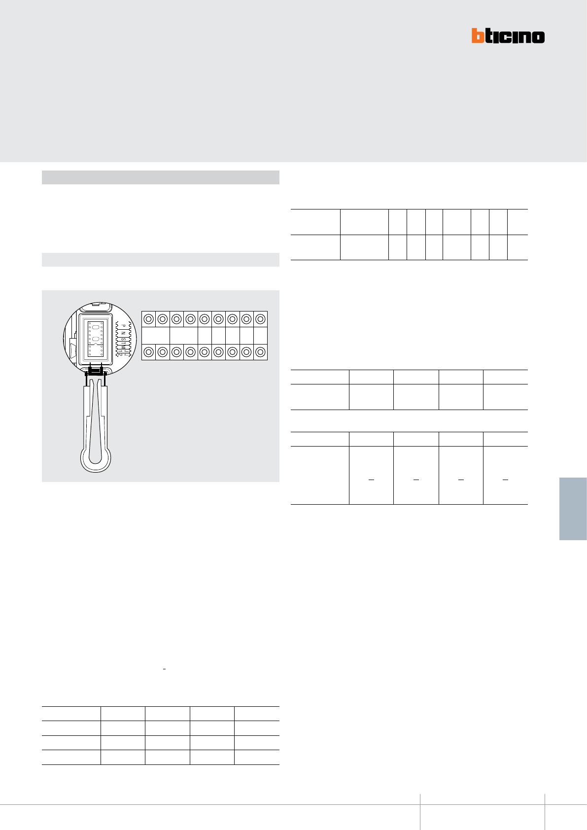
The device must be configured. The configuration can be performed in two ways:
Mode 1 - with physical configurator connection
Mode 2 - with PC and software TiSferaDesign
Mode 1
Mode 1 requires the physical connection of the configurators to their sockets:
351100
BT00596-a-EN
TECHNICAL SHEETS
192 2 WIRE VDE system
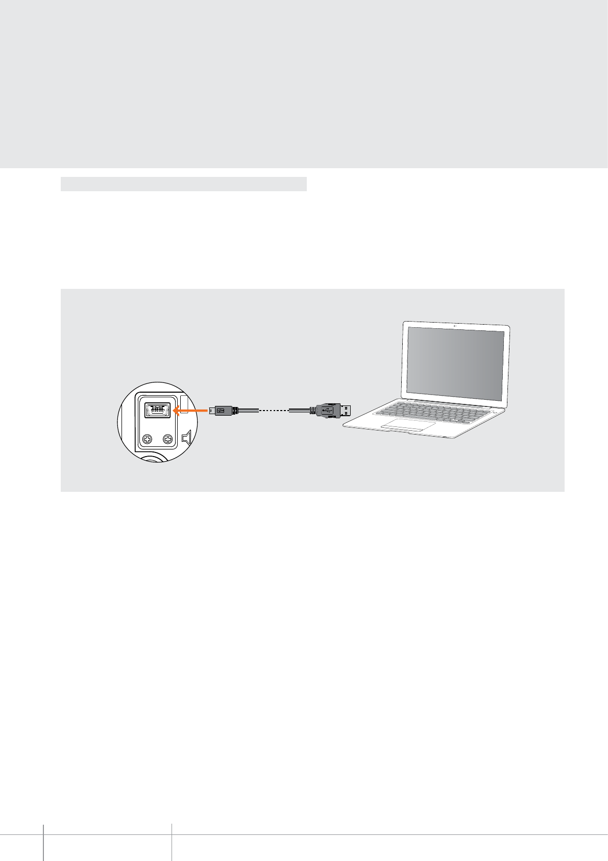
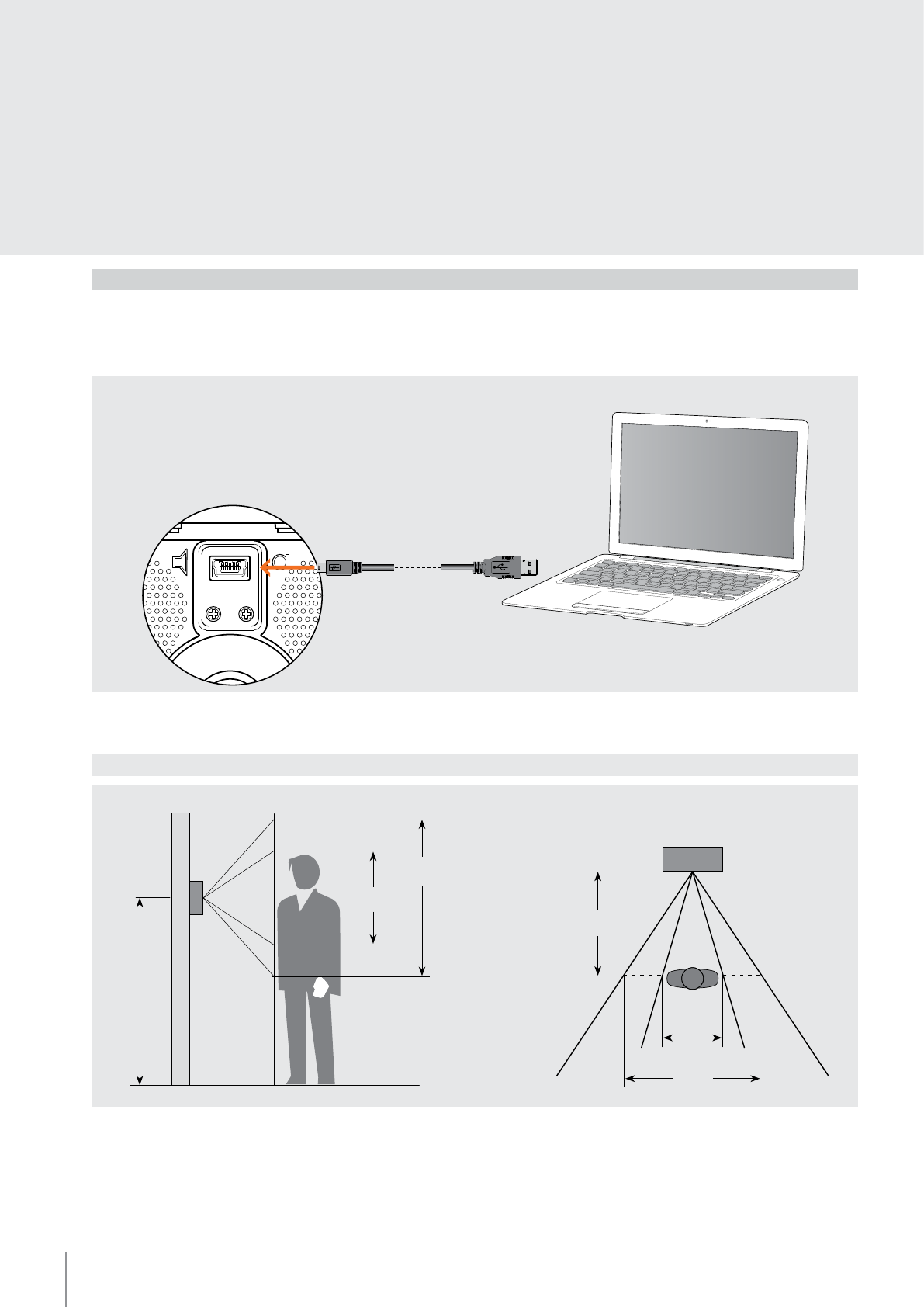
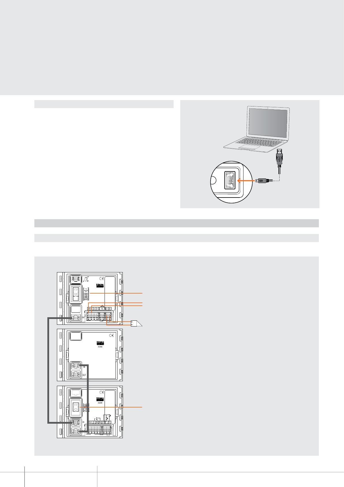
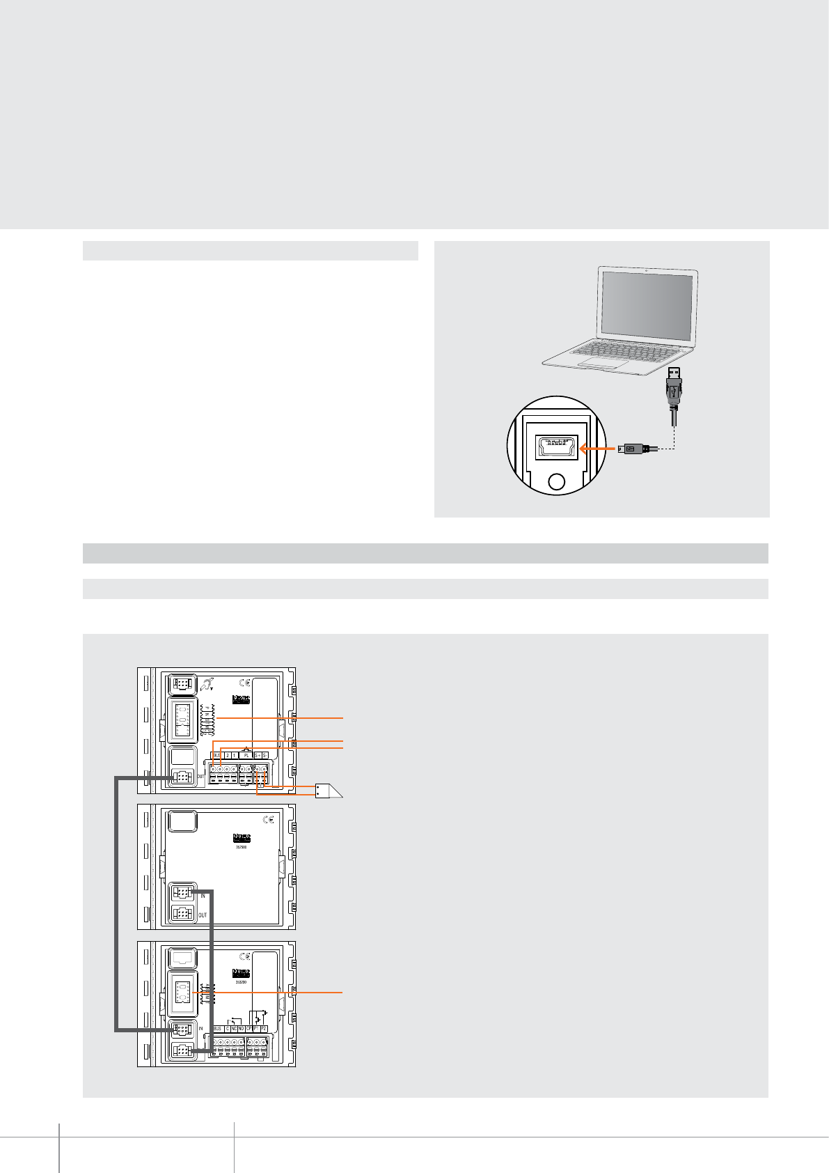
Mode 2 requires advanced configuration of the device, performed using a PC
and the TisferaDesign software (which can be downloaded free of charge from the
www.bticino.com). For the connection to the PC use a USB - mini USB cable. The
software gives the possibility of configuring, programming, and updating the firmware
of the speaker module.The presence of the mini USB connection of the front of the
speaker module gives the possibility of performing these operations without the need
to disassemble the device.
Mode 2
Warning: In order to correctly send the configuration to the device, jumper (J1) must be removed. Also ensure that there are no configurators connected to the socket on the back of
the module.
351200
BT00597-a
3
12
4
8
7
5
6
11
9
2
10
7
17
18
14
8
1 1
1516
13
115 mm
91 mm
-EN
TECHNICAL SHEETS
193
2 WIRE VDE system
SFERA NEW - SFERA ROBUR
Audio video module
Audio/video module for the installation of 2 WIRE colour video systems.
With Colour camera with 1/3” sensor and white LEDs for the lighting of the shooting
field. Mist prevention heating resistance. Loudspeaker and Microphone volume
adjustments. It can manage up to 98 pushbutton calls using the additional double
row pushbutton modules. Horizontal and vertical camera position adjustment,
+/- 10° in both directions. It offers the possibility of opening an electrical door lock
directly connected to clamps S+ and S- (18 V 4 A impulsive - 250 mA holding current
30 Ohm max) and of connecting a local door lock release pushbutton on clamps PL.
Preset for additional power supply. Fitted with front LEDs for the notification of the
operating status: door lock release, communication active, call put through, and
system busy. Integrated optic sensor for the switching on of the night backlighting.
To be completed with surround plate. The device must be configured physically or
using a PC and the TiSferaDesign software.
Description
Legend
Dimensional data
Front view
Rear view
1. Loudspeaker
2. Mini-USB connector for the connection to the PC : download/upload the advanced
configuration and device firmware update
3. Microphone volume adjustment
4. LED for door status notification. GREEN ON = door open
5. LED for communication status notification. GREEN ON = active communication
6. LED for system status notification. GREEN ON = put through call
RED ON= busy system
7. Call pushbuttons
8. White LEDs for night lighting of the shooting field
9. Light sensor for automatic switching on of the night backlighting
10. Colour camera
11. Microphone
12. Loudspeaker volume adjustment
13. Connector for the connection of the 352700 inductive loop module
14. Plug-in clamps for the connection and control of the electrical door lock
(18 V 4 A impulsive 250 mA holding current 30 ohm max)
15. Plug-in clamps for the connection of the local door lock release pushbutton
16. Plug-in clamps for the connection of the local power supply and the 2 WIRE SCS BUS
17. Connector for the connection to subsequent modules
18. Configurator socket
Related items
351201 Sfera New A/V front cover - Allmetal
(IK 08)
351202 Sfera New A/V front cover - Allwhite
(IK 08)
351203 Sfera New A/V front cover - Allstreet
(IK 08)
351211 Sfera New A/V front cover, 1 pushbutton - Allmetal
(IK 08)
351212 Sfera New A/V front cover, 1 pushbutton - Allwhite
(IK 08)
351213 Sfera New A/V front cover, 1 pushbutton - Allstreet
(IK 08)
351221 Sfera New A/V front cover, 2 pushbuttons on double column - Allmetal
(IK 08)
351222 Sfera New A/V front cover, 2 pushbuttons on double column - Allwhite
(IK 08)
351223 Sfera New A/V front cover, 2 pushbuttons on double column - Allstreet
(IK 08)
351205 Sfera Robur A/V front cover
(IK 10)
351215 Sfera Robur A/V front cover, 1 pushbutton
(IK 10)
351225 Sfera Robur A/V front cover, 2 pushbuttons on double column
(IK 10)
Power supply from SCS BUS: 18 - 27 Vdc
Stand by absorption (with backlighting LEDs off): 15 mA
Stand by absorption (with backlighting LEDs on): 20 mA
Max. operating absorption: 140 mA
Colour sensor: 1/3”
Lens: F2.5 f3.3 mm
Resolution: 330 TV lines (horizontal)
Illumination of the viewing field: white LED
Brightness adjustment: Automatic
Interlace: 2 : 1
Mist prevention heating resistance
Operating temperature: (-25) - (+70)°C
Protection index (pushbutton panel assembled): IP 54
Technical data
BT00597-a
351200
P N S T M
J1 J2
-EN
TECHNICAL SHEETS
194 2 WIRE VDE system
Configuration
The device must be configured. The configuration can be performed in two ways :
Mode 1 - with physical configurator connection
Mode 2 - with PC and software TiSferaDesign
Mode 1
Mode 1 requires the physical connection of the configurators to their sockets
P - entrance panel number
The congurator in socket P of the speaker module assigns to this a recognition number
inside the system. The numbering of the entrance panels must always start from P=0.
The entrance panel congured with P=0 must be a common (or main) entrance panel.
N - call number
Assigns the correspondence between the entrance panel pushbuttons and the audio
handsets or video handsets.
In common entrance panels made using pushbutton modules, 1 must be inserted in N of
the speaker module. The number of the rst riser handset must be inserted in the local
entrance panels.
S - type of call signal
The conguration of S determines the call tone of handsets.
One can thus dierentiate the calls from dierent entrance panels.
For the SWING, PIVOT, POLYX and AXOLUTE handsets, S associates the Entrance panel to
the bell programmed in the same apartment. It is possible to chose between 16 dierent
preset bells.
For the SPRINT handsets, S sets the call ringtone, according to the following table:
Configurator 0 1 2 3
Type of bell 2-tone 2-tone 2-tone One-tone
1200 Hz 1200 Hz 1200 Hz 1200 Hz
600 Hz 0 Hz 2400 Hz
In one-family systems S=9 to congure the general call.
T - door lock relay timing
Configurator number
0=no configurator 1 2 3 4* 5 6 7
4 sec 1 sec 2 sec 3 sec as
pushbutt. 6 sec 8 sec 10 sec
*Operation as pushbutton for 10 sec. max, after which standby mode is activated.
To extend operation time over 10 seconds, use actuator item 346200
congured with MOD=5.
M - enabling/disabling of call tones, door lock release tones night lighting
management always ON
The M congurations gives the possibility of managing the entrance panel call and door
lock release tones . It also gives the possibility of enabling night backlighting always ON
(light sensor disabled) according to the following table:
Configurator M=0 M=1 M=2 M=3
Tone status All tones
enabled
Door lock tone
disabled
Call tone
disabled
All tones
disabled
Configurator M=4 M=5 M=6 M=7
Night
backlighting
status
All tones
enabled
+
backlighting
always ON
Door lock tone
disabled
+
backlighting
always ON
Call tone
disabled
+
backlighting
always ON
All tones
disabled
+
backlighting
always ON
J1 - activation of call pushbutton columns
The J1 congurator gives the possibility of managing the Call pushbuttons of the speaker
module as follows:
J1 CONNECTED = Only the right pushbutton column is enabled
J1 DISCONNECTED = Both pushbutton columns are enabled (right + left)
J2 - additional EP power supply
Congurator J2 gives the possibility of enabling the additional power supply (1-2) of the
speaker module in the following mode :
J2 CONNECTED = Additional power supply disabled
J2 DISCONNECTED = Additional power supply enabled
351200
BT00597-a
160 cm
50 cm
(60 cm) - (60°)
(351200)
(115 cm) - (96°)
(351300)
(240 cm)
(135°)
(351300)
(105 cm)
(92°)
(351200)
-EN
TECHNICAL SHEETS
195
2 WIRE VDE system
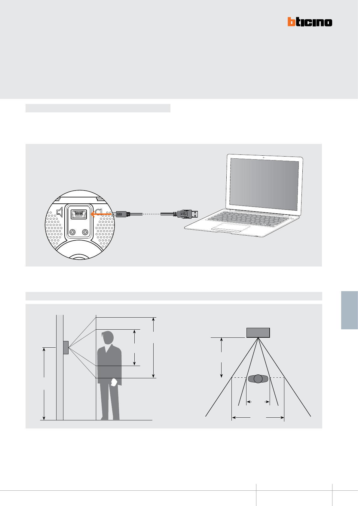
Mode 2 requires advanced conguration of the device, performed using a PC and
the TiSferaDesign software (which can be downloaded free of charge from the
www.bticino.com). For the connection to the PC use a USB - mini USB cable. The
software gives the possibility of conguring, programming, and updating the rmware
of the speaker module.The presence of the mini USB connection of the front of the
speaker module gives the possibility of performing these operations without the need to
disassemble the device.
CONFIGURATION - Mode 2
Camera shooting field
Warning: In order to correctly send the configuration to the device, jumper (J1) must be removed. Also ensure that there are no configurators connected to the socket on the back of
the module.
351300
BT00598-a
115 mm
91 mm
3
12
4
8
7
5
6
11
9
2
10
7
17
18
8
1 1
13
141516
-EN
TECHNICAL SHEETS
196 2 WIRE VDE system
SFERA NEW - SFERA ROBUR
Wide angle audio and video module
Wide angle audio/video module for the installation of 2 WIRE colour video systems.
With Colour camera with 1/3” sensor and white LEDs for the lighting of the shooting
field. Mist prevention heating resistance. Loudspeaker and Microphone volume
adjustments. It can manage up to 98 pushbutton calls using the additional double
row pushbutton modules. It offers the possibility of opening an electrical door lock
directly connected to clamps S+ and S- (18 V 4 A impulsive - 250 mA holding current
30 Ohm max) and of connecting a local door lock release pushbutton on clamps PL.
Preset for additional power supply. Fitted with front LEDs for the notification of the
operating status: door lock release, communication active, call put through, and
system busy. Integrated optic sensor for the switching on of the night backlighting.
To be completed with surround plate. The device must be configured physically or
using a PC and the TiSferaDesign software.
Description
Legend
Dimensional data
Front view
Rear view
1. Loudspeaker
2. Mini-USB connector for the connection to the PC : download/upload the advanced
configuration and device firmware update
3. Microphone volume adjustment
4. LED for door status notification. GREEN ON = door open
5. LED for communication status notification. GREEN ON = active communication
6. LED for system status notification. GREEN ON = put through call
RED ON= busy system
7. Call pushbuttons
8. White LEDs for night lighting of the shooting field
9. Light sensor for automatic switching on of the night backlighting
10. Wide angle colour camera
11. Microphone
12. Loudspeaker volume adjustment
13. Connector for the connection of the 352700 inductive loop module
14. Plug-in clamps for the connection and control of the electrical door lock
(18 V 4 A impulsive 250 mA holding current 30 ohm max)
15. Plug-in clamps for the connection of the local door lock release pushbutton
16. Plug-in clamps for the connection of the local power supply and the 2 WIRE SCS BUS
17. Connector for the connection to subsequent modules
18. Configurator socket
Related items
351301 Sfera New wide angle A/V front cover - Allmetal
(IK 08)
351302 Sfera New wide angle A/V front cover - Allwhite
(IK 08)
351303 Sfera New wide angle A/V front cover - Allstreet
(IK 08)
351311 Sfera New wide angle A/V front cover with 1 pushbutton - Allmetal
(IK 08)
351312 Sfera New wide angle A/V front cover with 1 pushbutton - Allwhite
(IK 08)
351313 Sfera New wide angle A/V front cover with 1 pushbutton - Allstreet
(IK 08)
351321
Sfera New wide angle A/V f/cover with 2 pushbuttons on double row - Allmetal (IK 08)
351322
Sfera New wide angle A/V f/cover with 2 pushbuttons on double row - Allwhite (IK 08)
351323
Sfera New wide angle A/V f/cover with 2 pushbuttons on double row - Allstreet (IK 08)
351305 Sfera Robur wide angle A/V f/cover
(IK 10)
351315 Sfera Robur wide angle A/V f/cover with 1 pushbutton
(IK 10)
351325
Sfera Robur wide angle A/V f/cover with 2 pushbuttons on double row (IK 10)
Power supply from SCS BUS: 18 - 27 Vdc
Stand by absorption (with backlighting LEDs off): 15 mA
Stand by absorption (with backlighting LEDs on): 20 mA
Max. operating absorption: 140 mA
Colour sensor: 1/3”
Lens: F2.5 f1.8 mm
Resolution: 330 TV lines (horizontal)
Illumination of the viewing field: white LED
Brightness adjustment: Automatic
Interlace: 2 : 1
Mist prevention heating resistance
Operating temperature: (-25) - (+70)°C
Protection index (pushbutton panel assembled): IP 54
Technical data
BT00598-a
351300
P N
S T M J1 J2
-EN
TECHNICAL SHEETS
197
2 WIRE VDE system
Configuration
The device must be configured. The configuration can be performed in two ways :
Mode 1 - with physical configurator connection
Mode 2 - with PC and software TiSferaDesign
Mode 1
Mode 1 requires the physical connection of the configurators to their sockets
P - entrance panel number
The congurator in socket P of the speaker module assigns to this a recognition number
inside the system. The numbering of the entrance panels must always start from P=0.
The entrance panel congured with P=0 must be a common (or main) entrance panel.
N - call number
Assigns the correspondence between the entrance panel pushbuttons and the audio
handsets or video handsets.
In common entrance panels made using pushbutton modules, 1 must be inserted in N of
the speaker module. The number of the rst riser handset must be inserted in the local
entrance panels.
S - type of call signal
The conguration of S determines the call tone of handsets.
One can thus dierentiate the calls from dierent entrance panels.
For the SWING, PIVOT, POLYX and AXOLUTE handsets, S associates the Entrance panel to
the bell programmed in the same apartment. It is possible to chose between 16 dierent
preset bells.
For the SPRINT handsets, S sets the call ringtone, according to the following table:
Configurator 0 1 2 3
Type of bell 2-tone 2-tone 2-tone One-tone
1200 Hz 1200 Hz 1200 Hz 1200 Hz
600 Hz 0 Hz 2400 Hz
In one-family systems S=9 to congure the general call.
T - door lock relay timing
Configurator number
0=no configurator 1 2 3 4* 5 6 7
4 sec 1 sec 2 sec 3 sec as
pushbutt. 6 sec 8 sec 10 sec
*Operation as pushbutton for 10 sec. max after which standby mode is activated.
To extend operation time over 10 seconds, use actuator item 346200 congured
with MOD=5.
M - enabling/disabling of call tones and door lock release tones, and management
of night backlighting always ON
The M congurations gives the possibility of managing the entrance panel call and door
lock release tones. It also gives the possibility of enabling night backlighting always ON
(light sensor disabled) according to the following table:
Configurator M=0 M=1 M=2 M=3
Tone status All tones
enabled
Door lock tone
disabled
Call tone
disabled
All tones
disabled
Configurator M=4 M=5 M=6 M=7
Backlighting status All tones
enabled
+
backlighting
always ON
Door lock tone
disabled
+
backlighting
always ON
Call tone
disabled
+
backlighting
always ON
All tones
disabled
+
backlighting
always ON
J1 - activation of call pushbutton columns
The J1 congurator gives the possibility of managing the Call pushbuttons of the speaker
module as follows:
J1 CONNECTED = Only the right pushbutton column is enabled
J1 DISCONNECTED = Both pushbutton columns are enabled (right + left)
J2 - additional EP power supply
Congurator J2 gives the possibility of enabling the additional power supply (1-2) of the
speaker module in the following mode :
J2 CONNECTED = Additional power supply disabled
J2 DISCONNECTED = Additional power supply enabled
351300
BT00598-a
160 cm
50 cm
(60 cm) - (60°)
(351200)
(115 cm) - (96°)
(351300)
(240 cm)
(135°)
(351300)
(105 cm)
(92°)
(351200)
-EN
TECHNICAL SHEETS
198 2 WIRE VDE system
Configuration
Mode 2 requires advanced conguration of the device, performed using a PC and
the TiSferaDesign software (which can be downloaded free of charge from the
www.bticino.com). For the connection to the PC use a USB - mini USB cable. The
software gives the possibility of conguring, programming, and updating the rmware
of the speaker module.The presence of the mini USB connection of the front of the
speaker module gives the possibility of performing these operations without the need to
disassemble the device.
Camera shooting field
Warning: In order to correctly send the configuration to the device, jumper (J1) must be removed. Also ensure that there are no configurators connected to the socket on the back of
the module.
352000
BT00599-a
1
3
2
115 mm
91 mm
-EN
TECHNICAL SHEETS
199
2 WIRE VDE system
SFERA NEW - SFERA ROBUR
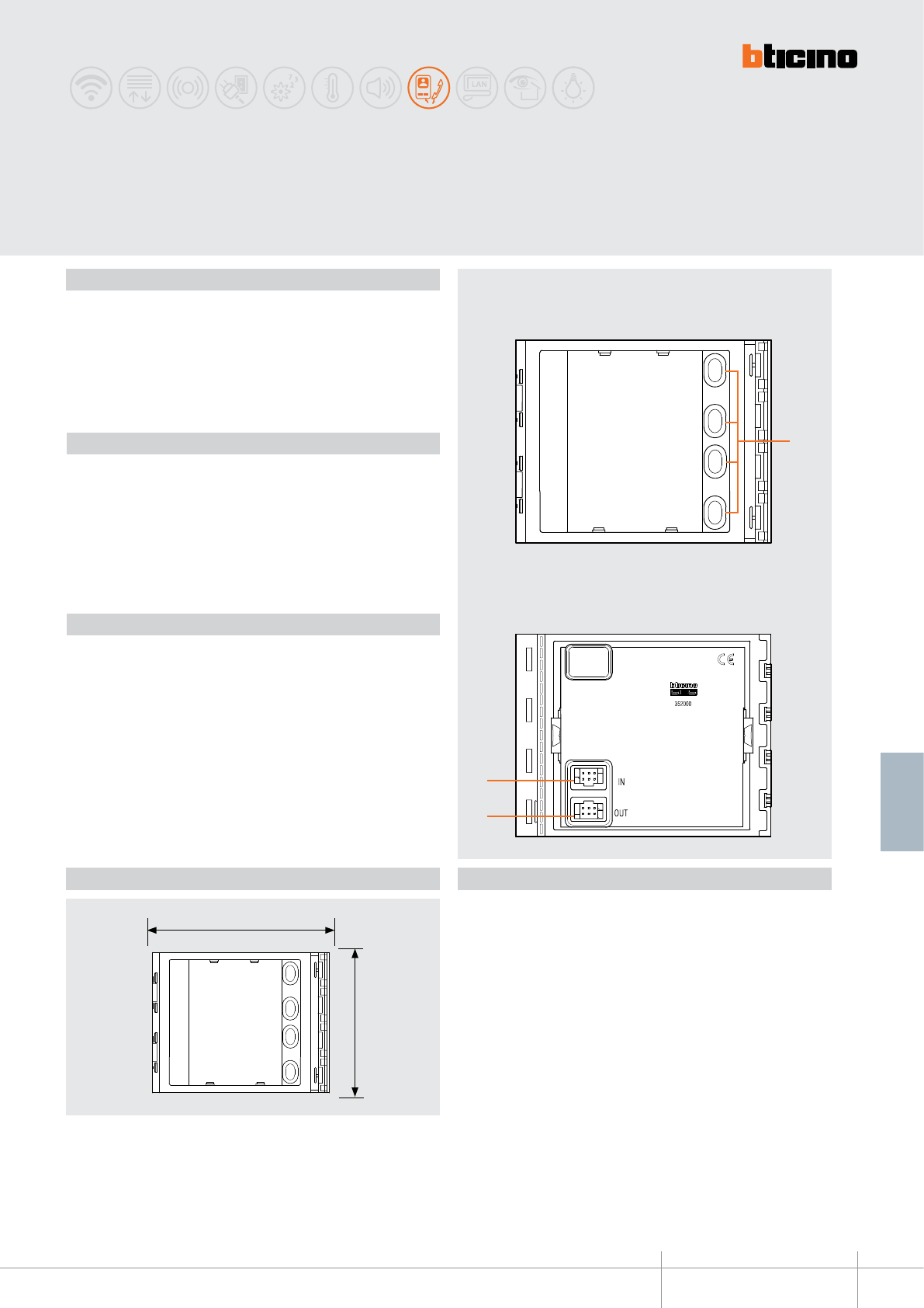
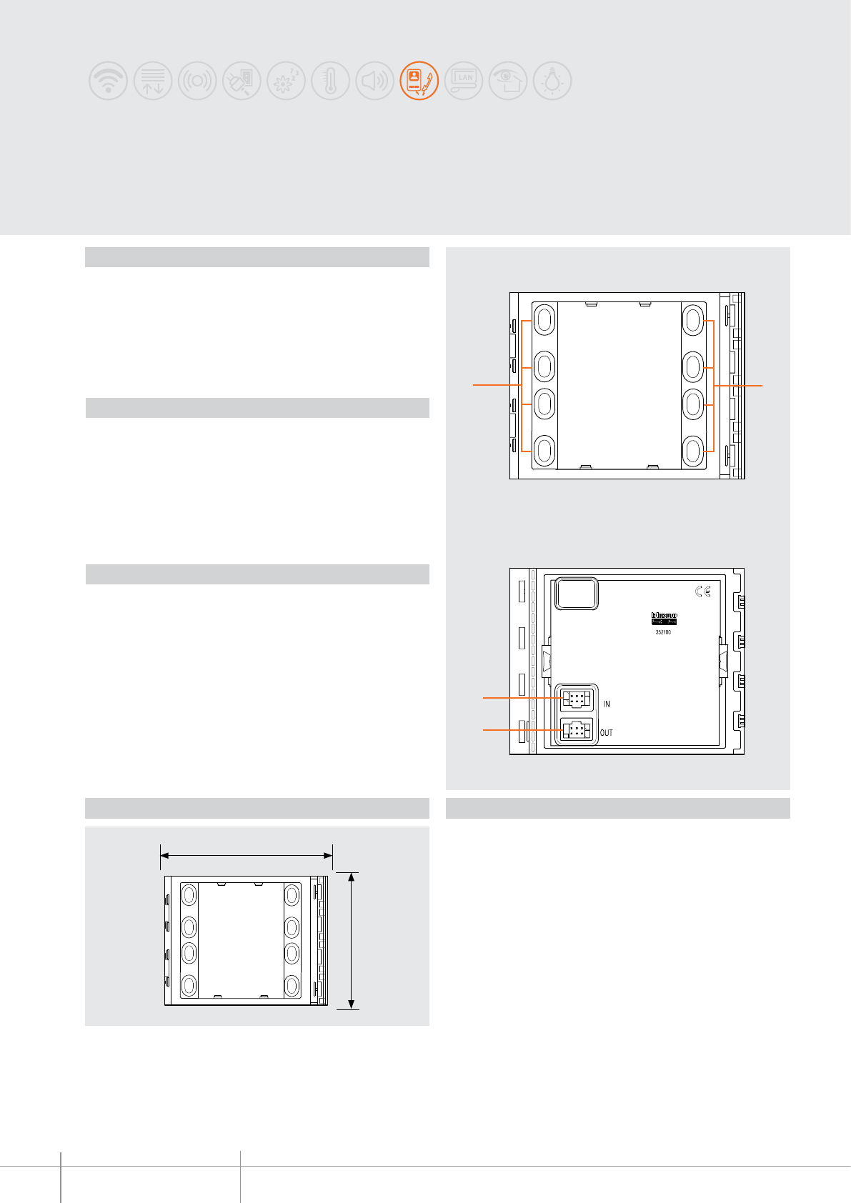
4-pushbutton module on single column
Additional 4-pushbutton modules arranged on single column. To be used with speaker
modules 351000 – 351100 and audio/video modules 351200 - 351300.
Connection using the appropriate multicable supplied. Backlighting of nameplates
controlled by the speaker module or the audio/video module connected.
To be completed with surround plate.
The device must not be configured.
Description
Power supply from SCS BUS: 18 - 27 Vdc
Stand by absorption with backlighting LEDs off: 1 mA
Stand by absorption with backlighting LEDs on: 7 mA
Max. operating absorption: 7 mA
Operating temperature: (-25) – (+70)°C
Protection index (pushbutton panel assembled): IP 54
Technical data
Front view
Rear view
Legend
1. Call pushbuttons
2. Connector for the connection to subsequent pushbutton modules
3. Connector for the connection to previous modules
Related items
352031 Sfera New cover plate for 3 pushbuttons on single column - Allmetal
(IK 08)
352032 Sfera New cover plate for 3 pushbuttons on single column - Allwhite
(IK 08)
352033 Sfera New cover plate for 3 pushbuttons on single column - Allstreet
(IK 08)
352041 Sfera New cover plate for 4 pushbuttons on single column - Allmetal
(IK 08)
352042 Sfera New cover plate for 4 pushbuttons on single column - Allwhite
(IK 08)
352043 Sfera New cover plate for 4 pushbuttons on single column - Allstreet
(IK 08)
352035 Sfera Robur cover plate for 3 pushbuttons on single column
(IK 10)
352045 Sfera Robur cover plate for 4 pushbuttons on single column
(IK 10)
Dimensional data
352100
BT00600-a
1
3
2
115 mm
91 mm
1
-EN
TECHNICAL SHEETS
200 2 WIRE VDE system
SFERA NEW - SFERA ROBUR
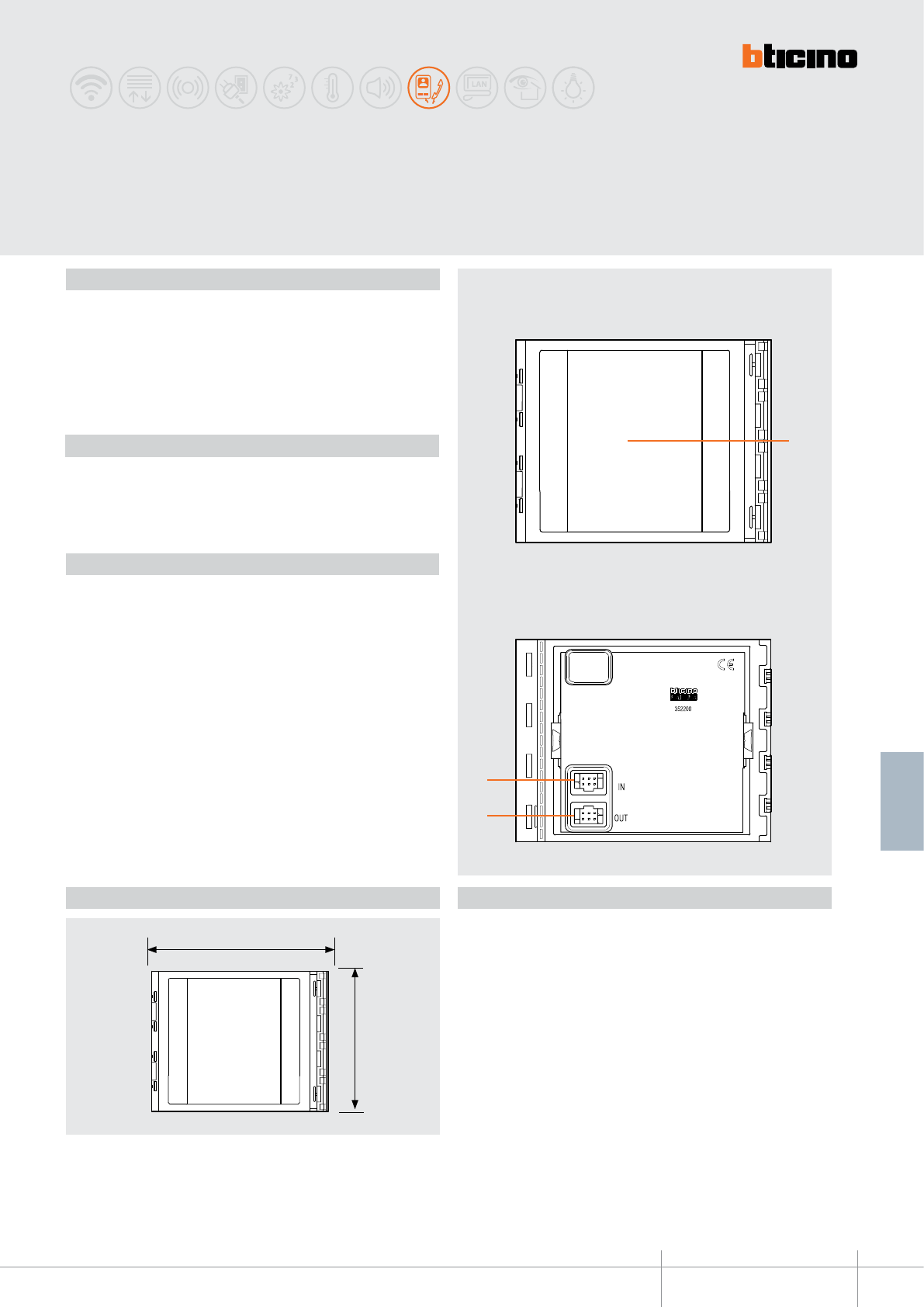
8-pushbutton module on double column
Additional 8-pushbutton modules arranged on double column. To be used with
speaker modules 351000 – 351100 and audio/video modules 351200 - 351300.
Connection using the appropriate multicable supplied. Backlighting of nameplates
controlled by the speaker module or the audio/video module connected. To be
completed with surround plate.
The device must not be configured.
Description
Power supply from SCS BUS : 18 - 27 Vdc
Stand by absorption with backlighting LEDs o: 1 mA
Stand by absorption with backlighting LEDs on: 7 mA
Max. operating absorption: 7 mA
Operating temperature: (-25) – (+70)°C
Protection index (pushbutton panel assembled): IP 54
Technical data
Front view
Rear view
Legend
1. Call pushbuttons
2. Connector for the connection to subsequent pushbutton modules
3. Connector for the connection to previous modules
Related items
352161 Sfera New cover plate for 6 pushbuttons on double column - Allmetal
(IK 08)
352162 Sfera New cover plate for 6 pushbuttons on double column - Allwhite
(IK 08)
352163 Sfera New cover plate for 6 pushbuttons on double column - Allstreet
(IK 08)
352181 Sfera New cover plate for 8 pushbuttons on double column - Allmetal
(IK 08)
352182 Sfera New cover plate for 8 pushbuttons on double column - Allwhite
(IK 08)
352183 Sfera New cover plate for 8 pushbuttons on double column - Allstreet
(IK 08)
352165 Sfera Robur cover plate for 6 pushbuttons on double column
(IK 10)
352185 Sfera Robur cover plate for 8 pushbuttons on double column
(IK 10)
Dimensional data
352200
BT00601-a
1
115 mm
91 mm
3
2
-EN
TECHNICAL SHEETS
201
2 WIRE VDE system
SFERA NEW - SFERA ROBUR
Nameplate module
Nameplate module normally used for displaying the house number or other notications
(e.g. Legend for calls using digital pushbutton panels, opening/closing times, etc.).
Connection using the appropriate multicable supplied. Night backlighting controlled by
the speaker module or the audio/video module connected.
To be completed with surround plate.
The device must not be congured.
Description
Legend
Rear view
Front view
1. Area used for entering information
2. Connector for the connection to subsequent modules
3. Connector for the connection to previous modules
Related items
352201 Sfera New nameplate front cover - Allmetal
(IK 08)
352202 Sfera New nameplate front cover - Allwhite
(IK 08)
352203 Sfera New nameplate front cover - Allstreet
(IK 08)
352205 Sfera Robur nameplate front cover
(IK 10)
Power supply from SCS BUS: 18 - 27 Vdc
Stand by absorption with backlighting LEDs off: 0 mA
Stand by absorption with backlighting LEDs on: 6 mA
Operating temperature: (-25) – (+70)°C
Protection index (pushbutton panel assembled): IP 54
Technical data
Dimensional data
352400
BT00602-a
115 mm
91 mm
21
44
3
5
-EN
TECHNICAL SHEETS
202 2 WIRE VDE system
SFERA NEW - SFERA ROBUR
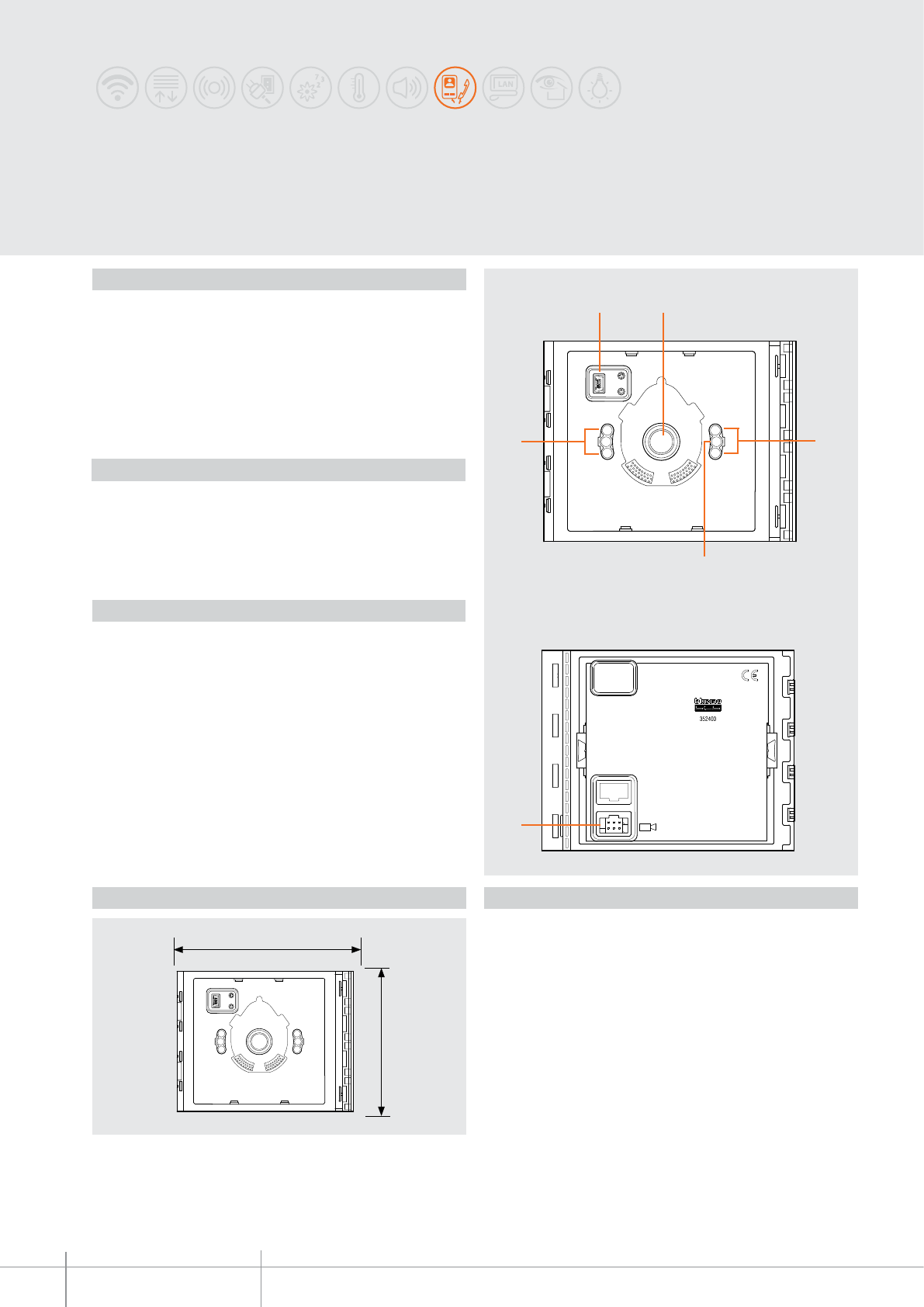
N&D and wide angle camera module
Night & Day and wide angle camera module for the installation of colour video systems.
Fitted with 1/3” sensor with N&D function and automatic removal of the IR lter.
IR LED for the lighting of the eld of view. Mist prevention heating resistance.
Automatic brightness adjustment. Connection to the speaker module (351100) using the
multicable supplied. To be completed with surround plate.
The device must not be congured.
The device must not be congured.
Description
LegendDimensional data
Rear view
Front view
1. Mini-USB connector for the connection to the PC : device firmware update
2. Night & Day camera
3. Light sensor
4. IR LED for night lighting of the field of view
5. Connector for the connection of the speaker module 351100
Related items
352401 Sfera New front cover for N&D and wide angle camera - Allmetal
(IK 08)
352402 Sfera New front cover for N&D and wide angle camera - Allwhite
(IK 08)
352403 Sfera New front cover for N&D and wide angle camera - Allstreet
(IK 08)
352405 Sfera Robur front cover for N&D and wide angle camera
(IK 10)
Power supply from SCS BUS: 18 - 27 Vdc
Stand by absorption: 20 mA
Max. operating absorption: 115 mA
Colour sensor: 1/3”
Lens: F2.5 f1.85 mm
Resolution: 330 TV lines (horizontal)
Illumination of the viewing field: LED IR
Brightness adjustment: automatic
Interlace: 2 : 1
N&D function with automatic IR filter removal:
Mist prevention heating resistance:
Operating temperature: (-25) - (+70)°C
Protection index (pushbutton panel assembled): IP 54
Technical data
BT00602-a
352400
160 cm
( 115 cm) - (96°)
50 cm
(240 cm) - (135°)
-EN
TECHNICAL SHEETS
203
2 WIRE VDE system
Camera shooting field
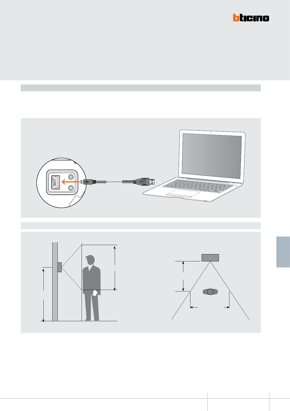
Connection to the PC
It is possible to update the device Firmware using a PC and the TiSferaDesign software
(which can be downloaded free of charge from the www.bticino.com). For the connection
to the PC use a USB - mini USB cable.
The software gives the possibility of updating the rmware of the speaker module.
The presence of the mini USB connection of the front of the speaker module gives the
possibility of performing these operations without the need to disassemble the device.
352500
BT00603-a
3
4
5
1 2
7
8
6
115 mm
91 mm
-EN
TECHNICAL SHEETS
204 2 WIRE VDE system
SFERA NEW - SFERA ROBUR
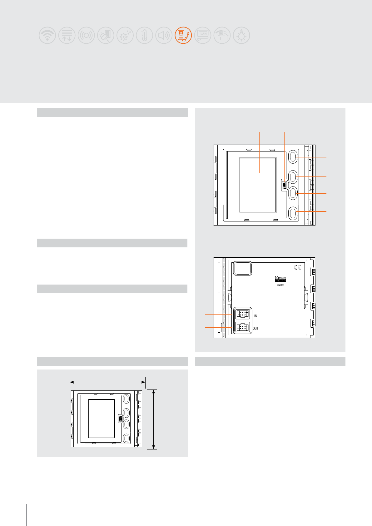
Display module
Graphic display module to be used with speaker module 351100 or with audio/video
modules 351200 – 351300 (connection using the multicable supplied). It can operate in
two modes: call from address book, or digital call. The call from the address book gives the
possibility of sending the call by scrolling on the display the names associated to the residents.
It is possible to store up to 4000 residents names. Using the keypad module item 353000
it is also possible to directly call the apartment by entering the number corresponding
to the resident. The digital call is also performed using the keypad module item 353000
by entering the numerical code. It is recommended that one or more nameplate
modules, item 352200, are installed at the side of the pushbutton panel to display the
correspondence between the numerical codes and the names of the users. It is possible
to program the names in the address book in two different ways: manual inclusion using
the pushbuttons of the display module or inclusion using a PC with the TiSferaDesign
software installed, by downloading the file to the display module (RECOMMENDED).
System power supply cuts do NOT cause the loss of memory data. To be completed with
surround plate.
The device must not be congured.
Description
LegendDimensional data
Rear view
Front view
1. Graphic display
2. Mini-USB connector for the connection to the PC : programming of residents address
book and device firmware update
3. Residents names scroll pushbutton (UP)
4. Residents names scroll pushbutton (DOWN)
5. Confirmation pushbutton – send call (OK)
6. Quick scroll pushbutton
7. Connector for the connection to subsequent modules
8. Connector for the connection to previous modules
Related items
352501 Sfera New display front cover - Allmetal
(IK 08)
352502 Sfera New display front cover - Allwhite
(IK 08)
352503 Sfera New display front cover - Allstreet
(IK 08)
352505 Sfera Robur display front cover
(IK 09)
Power supply from SCS BUS: 18 - 27 Vdc
Stand by absorption: 40 mA
Max. operating absorption: 50 mA
Display type: Negative transflective
FSTN
Display resolution: 160 x 240
Operating temperature: (-25) – (+70)°C
Protection index (pushbutton panel assembled): IP 54
Technical data
BT00603-a
352500
-EN
TECHNICAL SHEETS
205
2 WIRE VDE system
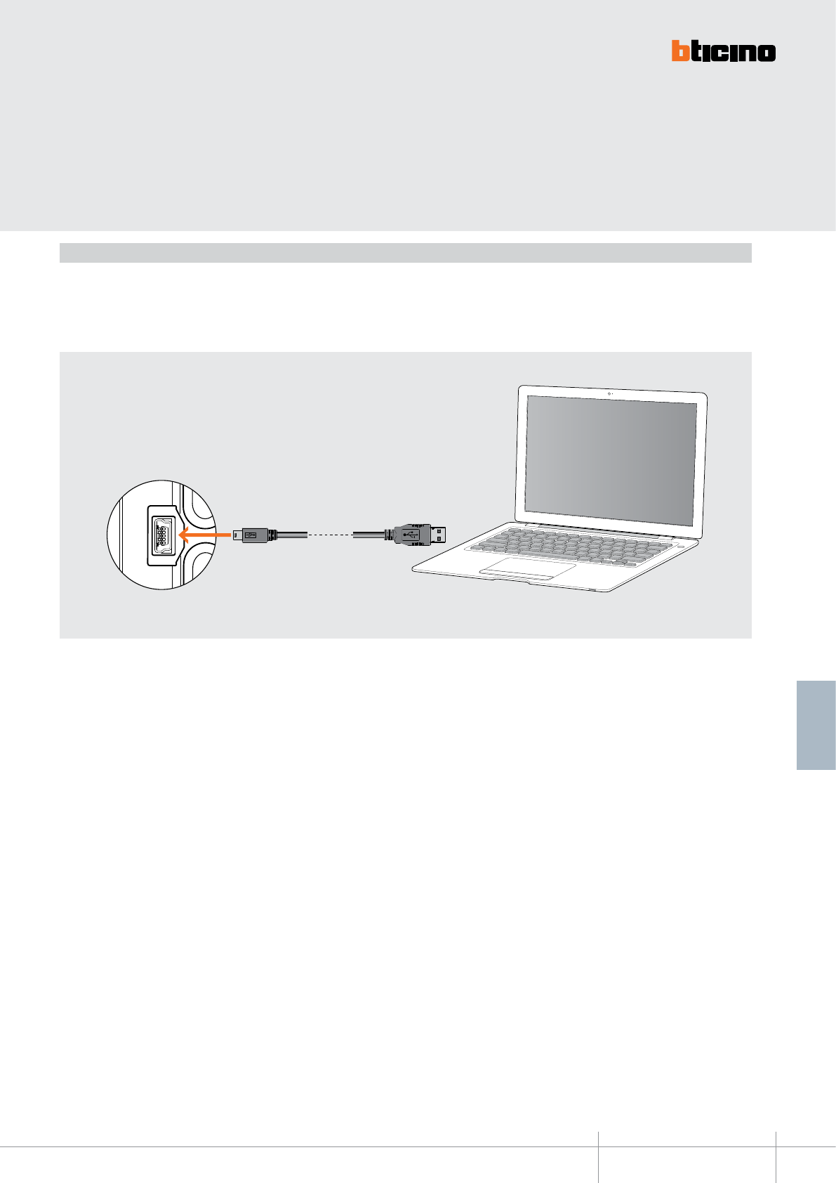
Connection to the PC
It is possible to program the residents address book and update the device Firmware using
a PC and the TiSferaDesign software (which can be downloaded free of charge from the
www.bticino.com).
For the Connection to the PC, use a USB - mini USB cable.
The software gives the possibility of updating the device and download the residents
address book.The presence of the mini USB connection of the front of the speaker module
gives the possibility of performing these operations without the need to disassemble the
device.
352700
BT00604-a
3
1 2
456
115 mm
91 mm
-EN
TECHNICAL SHEETS
206 2 WIRE VDE system
SFERA NEW - SFERA ROBUR
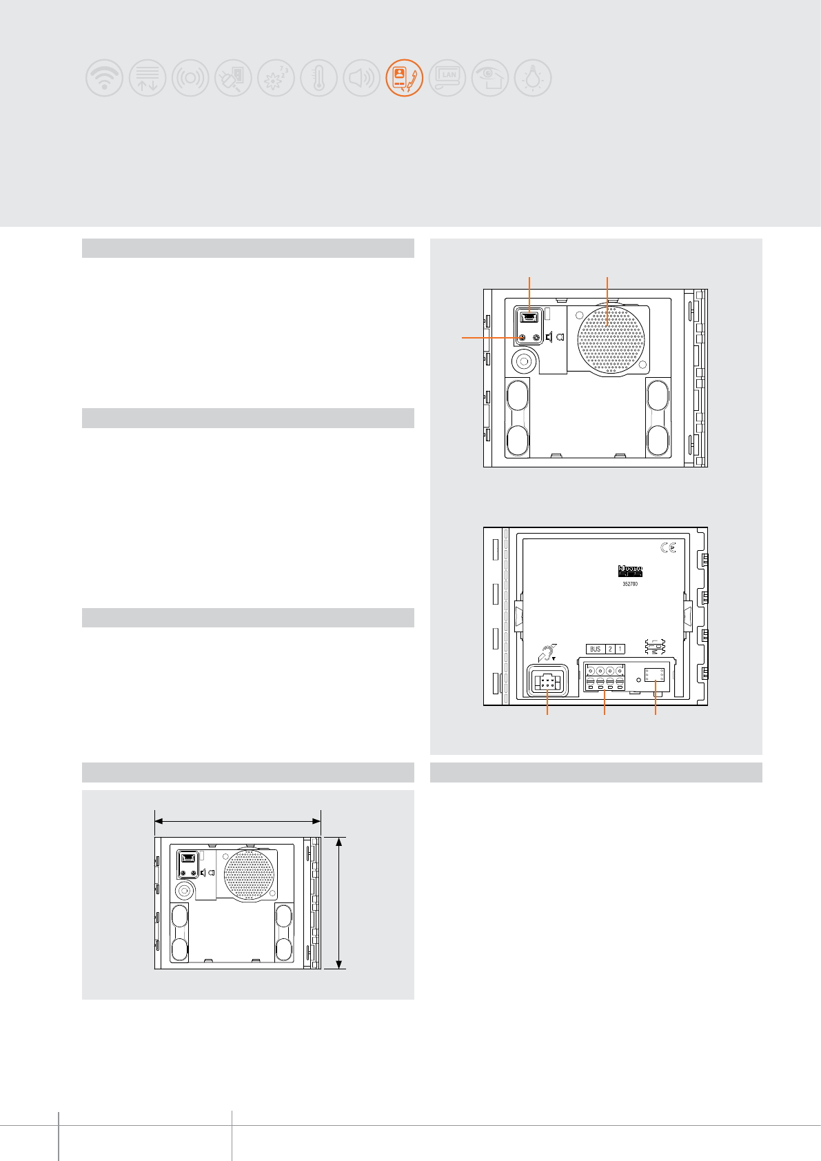
Inductive loop and control speech synthesis module
Inductive loop and control speech synthesis module, to be used with the 351100
speaker module or with audio/video modules 351200 - 351300, to enable use by
people wearing hearing aids (fitted with T selector). It is connected to the speaker
module using the appropriate multicable supplied. To be completed with surround
plate. The device can be configured either physically or using the PC and the
TiSferaDesign software.
Description
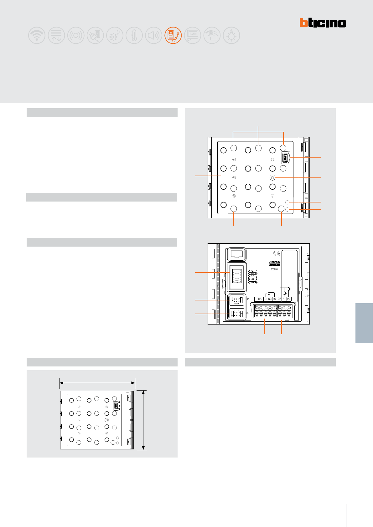
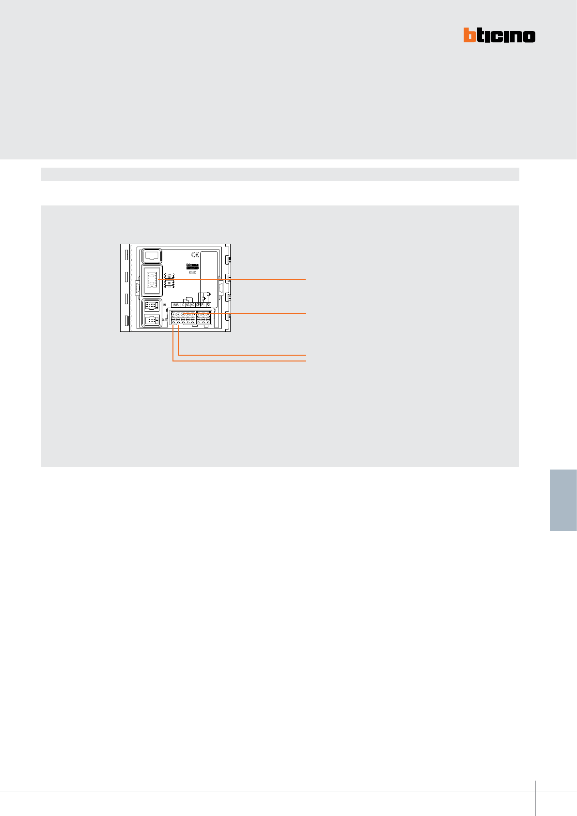
Legend
Front view
Rear view
1. Mini-USB connector for the connection to the PC : configuration and device firmware
update
2. Loudspeaker
3. Loudspeaker volume adjustment
4. Configurator socket
5. Plug-in clamps for the connection of the local power supply and the 2 WIRE SCS BUS
6. Connector for the connection of the speaker module
Related items
352701 front cover for the Sfera New inductive loop and control speech synthesis -
Allmetal
(IK 08)
352702 front cover for the Sfera New inductive loop and control speech synthesis -
Allwhite
(IK 08)
352703 front cover for the Sfera New inductive loop and control speech synthesis -
Allstreet
(IK 08)
352705 front cover for the Sfera Robur inductive loop and control speech synthesis
(IK 10)
Power supply from SCS BUS: 18 – 27 Vdc
Stand by absorption: 18 mA
Max. operating absorption: 60 mA
Operating temperature: (-25) – (+70) °C
Protection index (pushbutton panel assembled): IP 54
Technical data
Dimensional data
BT00604-a
352700
LD
L
M
-EN
TECHNICAL SHEETS
207
2 WIRE VDE system
The device must be configured.
The configuration can be performed in two ways:
Mode 1 - with physical configurator connection
Mode 2 - with PC and software TiSferaDesign
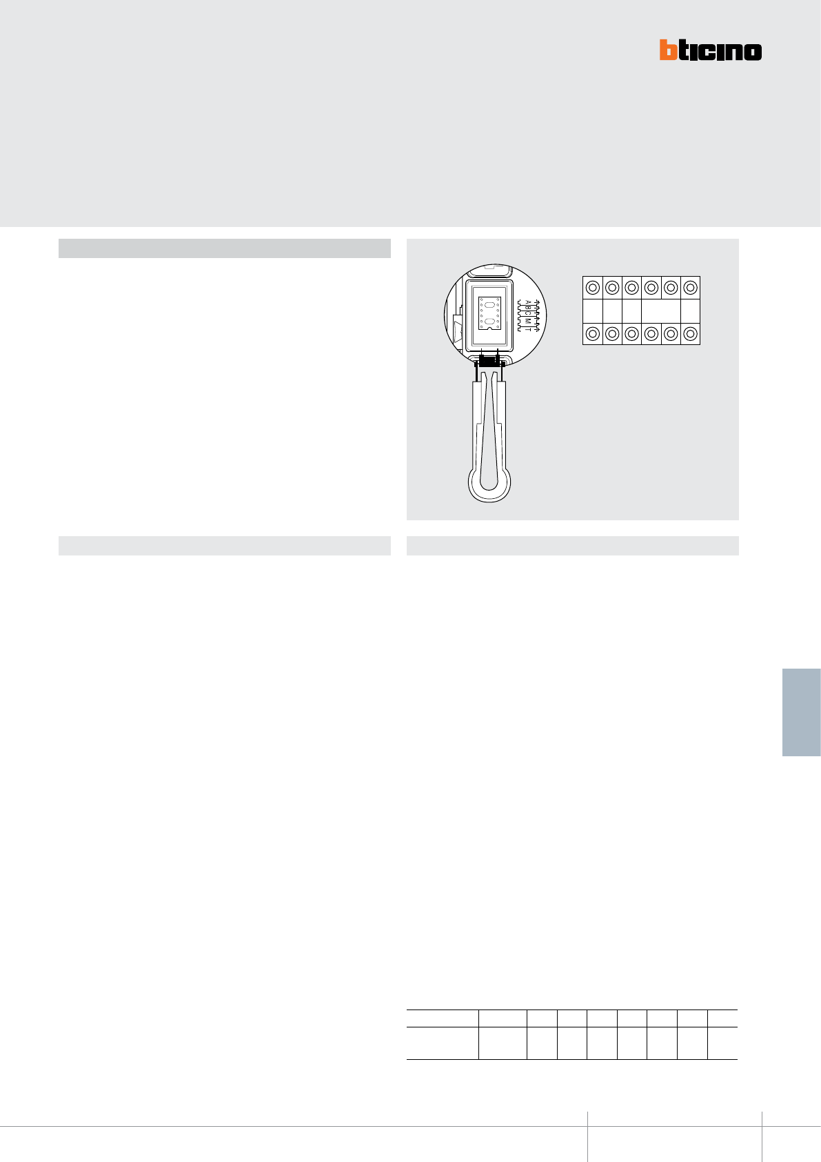
Configuration
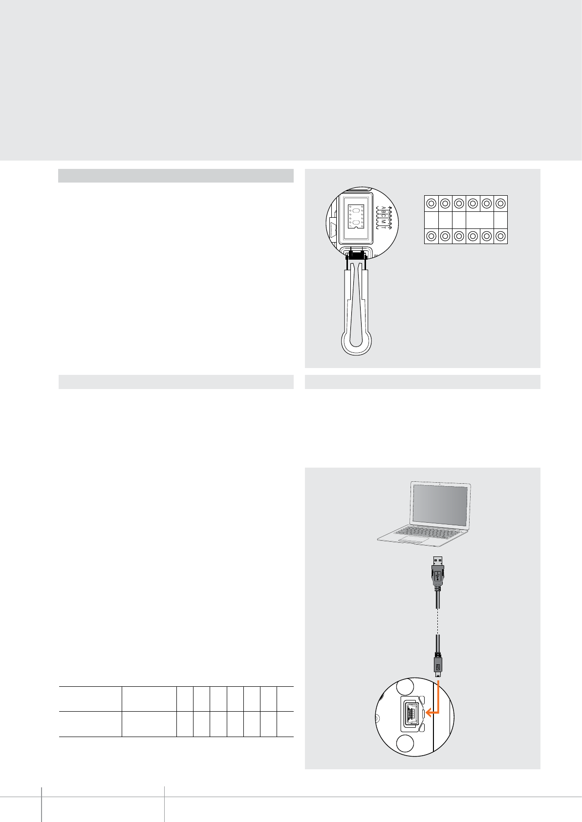
Mode 1
Mode 1 requires the physical connection of the configurators to their sockets:
The congurator connected to the L socket denes the language for the control speech
synthesis.
L- Selection of the speech synthesis language:
The congurator connected to the L socket denes the language for the control speech
synthesis as for the following table:
Configurator Language
none default language (English)
1 English
2 French
3 Italian
4 Spanish
5 German
6 Flemish
7 Portuguese
DL - Selection of the default speech synthesis language:
The congurator connected to the DL socket denes the default language for the control
speech synthesis. The default language is selected from the preloaded language pack, as
for the following table:
Configurator Language
none 1st language of the preloaded language pack
1 2nd language of the preloaded language pack
2 3rd language of the preloaded language pack
3 4th language of the preloaded language pack
4 5th language of the preloaded language pack
5 6th language of the preloaded language pack
6 7th language of the preloaded language pack
7 8th language of the preloaded language pack
8 9th language of the preloaded language pack
9 10th language of the preloaded language pack
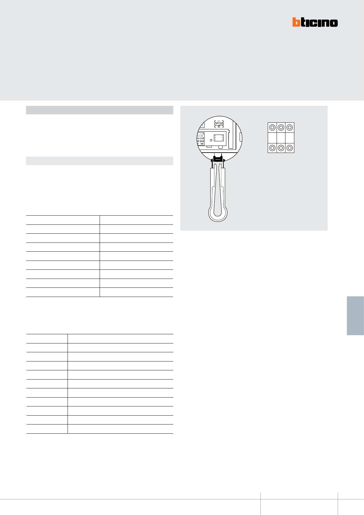
M - Operating mode:
The congurator connected to the M socket sets the operating mode of the device as
indicated below:
M = O (no congurator) - Inductive loop and control speech synthesis both enabled
M = 1 - Inductive loop enable, control speech synthesis disabled
352700
BT00604-a
2
5-
3
5
c
m
4
0
c
m
-EN
TECHNICAL SHEETS
208 2 WIRE VDE system
Mode 2 requires advanced configuration of the device, performed using a PC
and the TisferaDesign software (which can be downloaded free of charge from the
www.bticino.com). For the connection to the PC, use a USB - mini USB cable. The
software gives the possibility of configuring, programming, and updating the firmware
of the speaker module. The presence of the mini USB connection of the front of the
speaker module gives the possibility of performing these operations without the need
to disassemble the device.
Mode 2
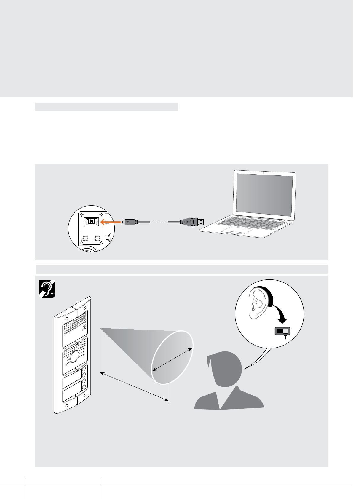
Notes on the use of the inductive loop
To ensure correct magnetic coupling between the device and the acoustic device, we
recommend a position in front of the device, at a distance of 25-35 cm.
It is reminded that the presence of metal and background noise generated by
electric/electronic devices (e.g. computer) may compromise the performance and
the quality of the coupling device.
Switch the selector of the acoustic device to the T position
353000
BT00605-a
115 mm
91 mm
1
2
3
4
67
8
5
13
12
11
910
-EN
TECHNICAL SHEETS
209
2 WIRE VDE system
SFERA NEW - SFERA ROBUR
Keypad module
Door lock release keypad module. It is fitted with relay with contacts (C – NC – NO) and
clamps (CP- P1 – P2) for the connection of a local door lock release pushbutton.
The numerical code for the opening of the door lock can be programmed using the
keypad itself, or using a PC after downloading the module programming file. It also has a
programming reset pushbutton and LEDS for the visual notification of the access status.
Night backlighting with LEDs. To be completed with surround plate. It is connected to the
other modules using the appropriate multicable supplied. The device may also be used as
a stand alone unit with independent power supply and operation.
Configuration performed using physical configurators, or a PC with the TiSferaDesign
software installed.
Description
LegendDimensional data
Rear view
Front view
1. LEDs for night backlighting
2. Mini-USB connector for the connection to the PC : download/upload the
configuration and device firmware update
3. RESET pushbutton
4. Red LED for access status notification Red LED ON = access denied
5. Green LED for access status notification Green LED ON = access granted
6. Cancel pushbutton (C)
7. Pushbutton for the selection of the door lock release code
8. Numeric keypad used for entering the codes
9. Plug-in clamps (CP – P1 P2) for connection of the additional local pushbutton
10. Plug-in clamps (C – NC – NO) for local relay contacts and connection to the 2 WIRE
SCS BUS
11. Connector for the connection to subsequent modules
12. Connector for the connection to previous modules
13. Configurator socket
Related items
353001 Sfera New keypad front cover - Allmetal
(IK 08)
353002 Sfera New keypad front cover - Allwhite
(IK 08)
353003 Sfera New keypad front cover - Allstreet
(IK 08)
353005 Sfera Robur keypad front cover
(IK 09)
Power supply from SCS BUS: 18 - 27 Vdc
Stand by absorption (with backlighting LEDs off): 10 mA
Stand by absorption (with backlighting LEDs on): 25 mA
Max. operating absorption: 45 mA
Operating temperature: (-25) – (+70) °C
Protection index (pushbutton panel assembled): IP 54
Technical data
BT00605-a
353000
A B C
M
T
-EN
TECHNICAL SHEETS
210 2 WIRE VDE system
Configuration
The configuration of the device is different depending on the type of installation:
•Device installation inside a SFERA NEW pushbutton panel in 2 WIRE SCS
systems.
•installation as STAND ALONE device
In both cases, the configuration can be performed in two ways:
•Mode 1 - with physical configurator connection
•Mode 2 - with PC and software TiSferaDesign
Mode 1
Mode 1 requires the physical connection of the configurators to their sockets.
PHYSICAL CONFIGURATION FOR INSTALLATION WITH A SFERA NEW EP:
A + B + C - NOT USED
M - Operating mode - NOT USED
T -local relay time delay – NOT USED
(the time delay of the local relay is set by the T congurator connected to the speaker
module or to the audio video module used).
PHYSICAL CONFIGURATION IN STAND ALONE INSTALLATION:
A + B + C - progressive address of the device
The congurators connected to the A B C sockets assign a progressive address to the
device inside the system (range 000 – 999).
Example : A+B+C = 003 - device 003 of the system.
M - Operating mode - NOT USED
T – local relay time delay
The congurator connected to T sets the relay closing time delay as shown in the
following table:
Configurator 0 = no
configurator 1234567
Contact closing
time 4’’ 1’’ 10’’ 20’’ 40’’ 1’ 1.5’ 3’
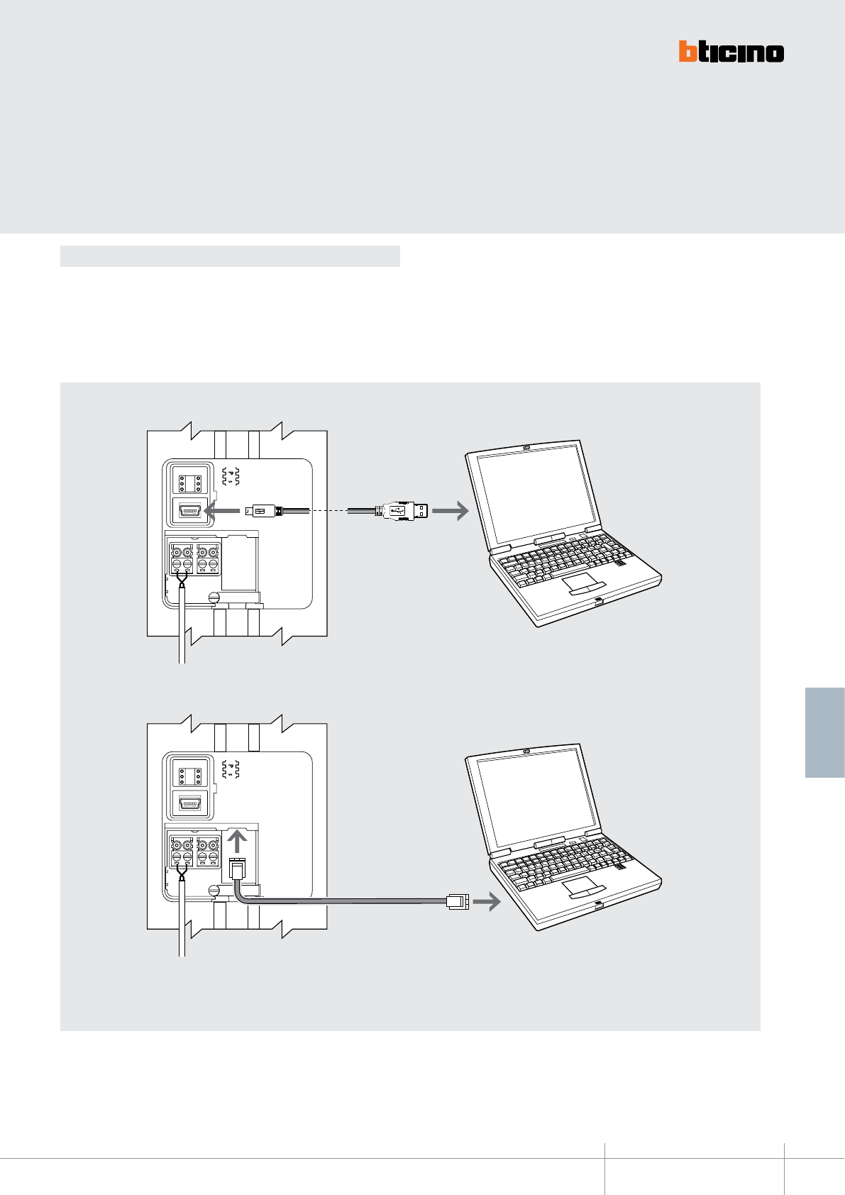
Mode 2
Mode 2 requires advanced configuration of the device, performed using a PC and
the TisferaDesign software (which can be downloaded free of charge from the
www.bticino.com).
For the connection to the PC use a USB - mini USB cable. The software gives the possibility
of configuring, programming, and updating the firmware of the speaker module.
The presence of the mini USB connection of the front of the speaker module gives the
possibility of performing these operations without the need to disassemble the device.
353000
BT00605-a-EN
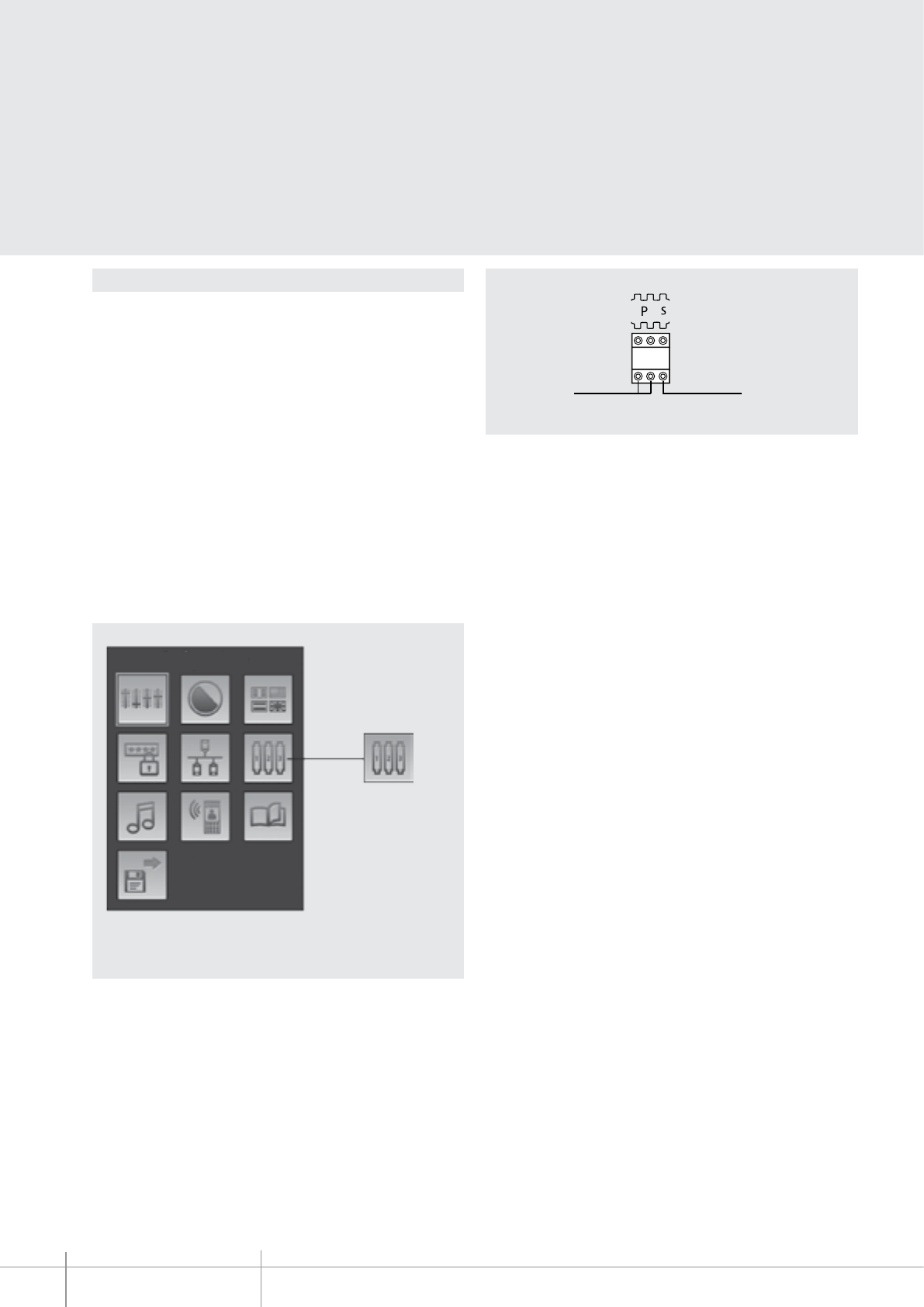
TECHNICAL SHEETS
211
2 WIRE VDE system
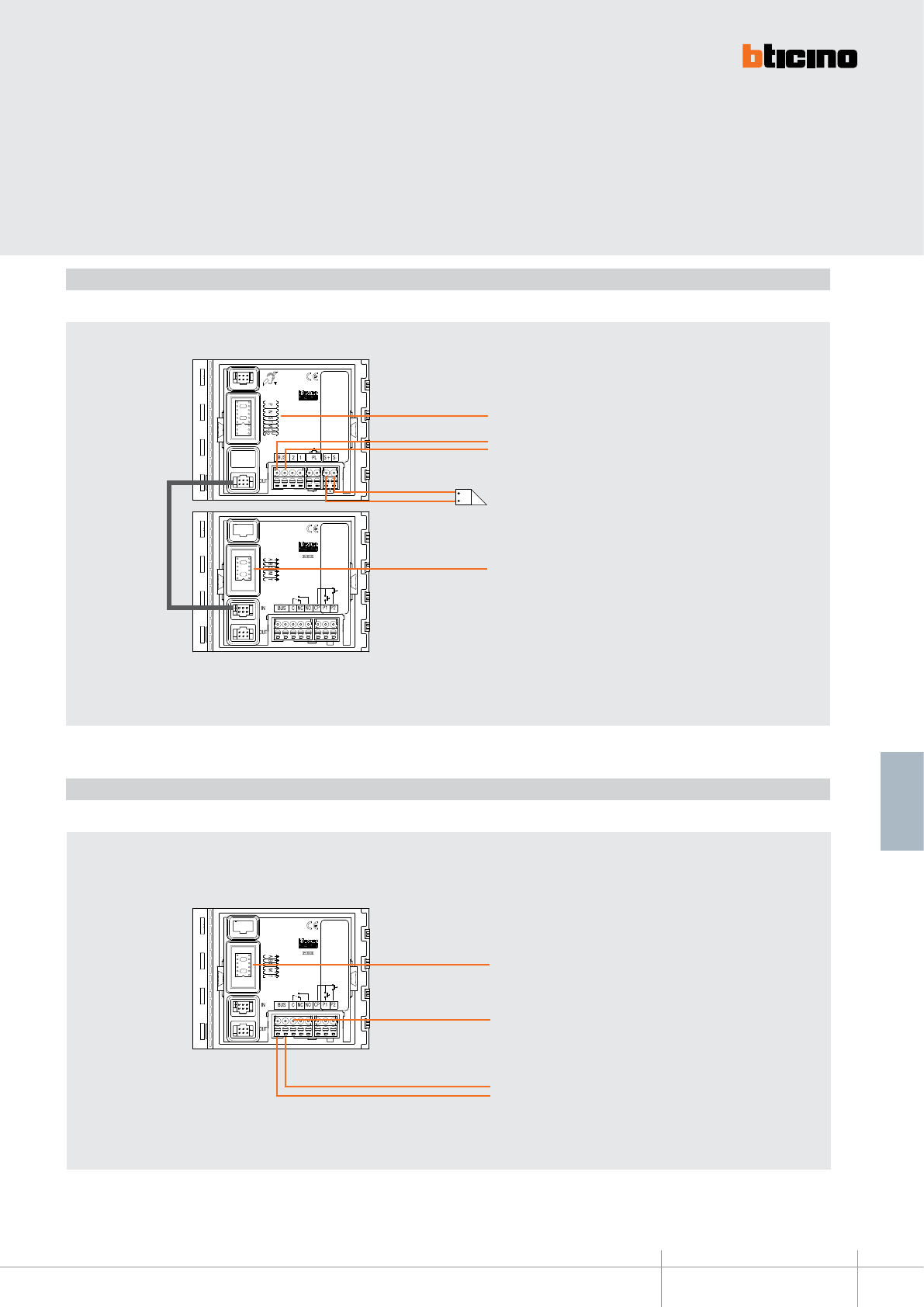
Wiring diagram- Installation with SFERA NEW EP
Example of installation of the keypad module inside a 2 WIRE SFERA NEW pushbutton panel with SCS BUS NOT CONNECTED to the keypad module
Wiring diagram- STAND ALONE installation
Example of STAND ALONE installation connection with the SCS BUS connected to the keypad module.
Configure as indicated on the
device technical sheet
BUS TK - 2-WIRE SCS
Electrical door lock 18 V 4 A impulsive - 250 mA
holding current 30 Ohm max
A + B + C - DO NOT CONFIGURE
M - DO NOT CONFIGURE
T - DO NOT CONFIGURE
2 WIRE A/V module
Keypad module 353000
Keypad module 353000
SCS BUS
A + B + C = 003
(SCS device No. 3)
M - DO NOT CONFIGURE
T = 2 (contact closed for 10”)
Contact load:
8 A 30 Vdc
8 A 30 Vac cos@ 1
3.5 A 30 Vac cos@ 0.4
353200
BT00606-a
3
4
1 2
5
67
8
9
10
115 mm
91 mm
-EN
TECHNICAL SHEETS
212 2 WIRE VDE system
SFERA NEW - SFERA ROBUR
Badge reader module
RFID badge reader module for the release of the door lock by swiping
the badge. It manages up to 20000 badges. It’s fitted wiTh relay contacts
(C – NO - NC) and clamps (CP - P1 - P2) for the connection of a local door release pushbutton.
The badge for the release of the door lock can be programmed from the module itself,
or using a PC after downloading the module programming file.
It also has a programming reset pushbutton and LEDS for the visual notification of the
access status. Night backlighting a LEDs. To be completed with surround plate. It is
connected to the other modules using the appropriate multicable supplied. The device
may also be used as a stand alone unit with independent power supply and operation.
Configuration performed using physical configurators, or a PC with the TiSferaDesign
software installed.
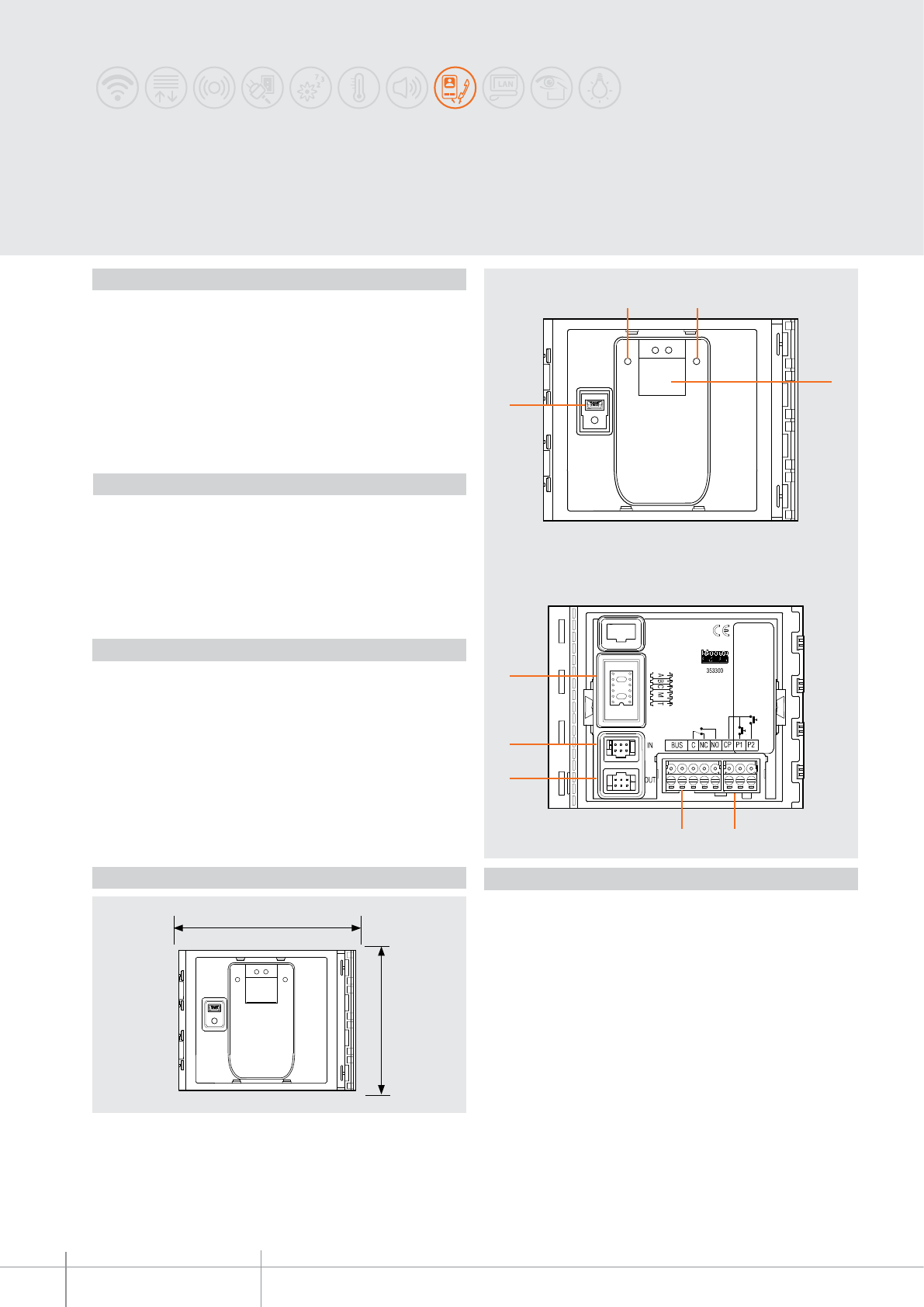
Description
Legend
Power supply from SCS BUS: 18 – 27 Vdc
Stand by absorption
(with backlighting LEDs o): 75 mA
Stand by absorption
(with backlighting LEDs on): 85 mA
Max. operating absorption: 105 mA
Operating temperature: (-25) – (+70) °C
Protection index (pushbutton panel assembled): IP 54
Technical data
Front view
Rear view
1. RESET pushbutton
2. Mini-USB connector for the connection to the PC : programming and device
firmware update
3. Red LED for access status notification. Red LED ON = access denied
4. Green LED for access status notification. Green LED ON = access granted
5. Antenna
6. Plug-in clamps (CP - P1 - P2) for the connection of an additional pushbutton and
tamper
7. Plug-in clamps (C – NC – NO) for local relay contacts and connection to the 2 WIRE
SCS BUS
8. Connector for the connection to subsequent modules
9. Connector for the connection to previous modules
10. Configurator socket
Related items
353201 Sfera New badge reader front cover - Allmetal
(IK 08)
353202 Sfera New badge reader front cover - Allwhite
(IK 08)
353203 Sfera New badge reader front cover - Allstreet
(IK 08)
353205 Sfera Robur badge reader front cover
(IK 09)
348200 badge - black
348201 badge - red
348202 badge - green
348203 badge - blue
348204 badge - orange
348205 badge - grey
348206 badge - yellow
Dimensional data

BT00606-a
353200
A B C
M T
-EN
TECHNICAL SHEETS
213
2 WIRE VDE system
Configuration
Physical configuration in stand alone installation:
A + B + C - progressive address of the device
The configurators connected to the A B C sockets assign a progressive address to the
device inside the system (range 000 – 999).
Example: A+B+C = 003 – device 003 of the system.
M - operating mode, badges management
The configurator connected to the M socket sets the badges management mode as
indicated below:
M = 0 - management of badges with MANAGER MASTER ONLY
The MANAGER MASTER badges (max. 20) are used both for the management of
PASSEPARTOUT badges (MAX. 100) and for the management of the RESIDENTS badges
(max. 5) of each apartment.
M = 1 - badges management with APARTMENT MASTER
The MANAGER MASTER badges (max. 20) directly manage the
PASSPARTOUT badges (max. 100) and the APARTMENT MASTER badges
(max. 4000); the APARTMENT MASTER badges manage the RESIDENTS badges (max. 5)
of the corresponding apartment.
T – local relay time delay
The configurator connected to T sets the relay closing time delay as shown in the
following table:
The configuration of the device is different depending on the type of installation:
- device installation inside a SFERA NEW pushbutton panel in 2 WIRE SCS systems,
- installation as STAND ALONE device.
In both cases, The configuration can be performed in two ways:
Mode 1 - with physical configurator connection
Mode 2 - with PC and software TiSferaDesign
Mode 1
Mode 1 requires the physical connection of the configurators to their sockets.
Physical configuration for installation with a sfera new ep:
A + B + C - NOT USED
M - operating mode, badges management
The configurator connected to the M socket sets the badges management mode as
indicated below:
M = 0 - management of badges with manager MASTER ONLY
The MANAGER MASTER badges (max. 20) are used both for the management of
PASSEPARTOUT badges (max. 100) and for the management of the RESIDENTS max
(max. 5) of each apartment.
M = 1 - badges management with APARTMENT MASTER
The MANAGER MASTER badges (max. 20) directly manage the PASSPARTOUT badges
(max. 100) and the APARTMENT MASTER badges (max. 4000); the APARTMENT MASTER
badges manage the RESIDENTS badges (max. 5) of the corresponding apartment.
T -local relay time delay – NOT USED
(the time delay of the local relay is set by the T configurator connected to the speaker
module or audio video module used).
Configurator 0 none 1 2 3 4 5 6 7
Contact closing
time 4” 1” 10” 20” 40” 1’ 1.5’ 3’
353200
BT00606-a-EN
TECHNICAL SHEETS
214 2 WIRE VDE system
Mode 2 requires advanced configuration of the device, performed using a PC and the
TisferaDesign software (which can be downloaded free of charge from the ww w.bticino.com)
.
For the connection to the PC use a USB - mini USB cable. The software gives the
possibility of configuring, programming, and updating the firmware of the speaker
module. The presence of the mini USB connection of the front of the speaker module
gives the possibility of performing these operations without the need to disassemble
the device.
Mode 2
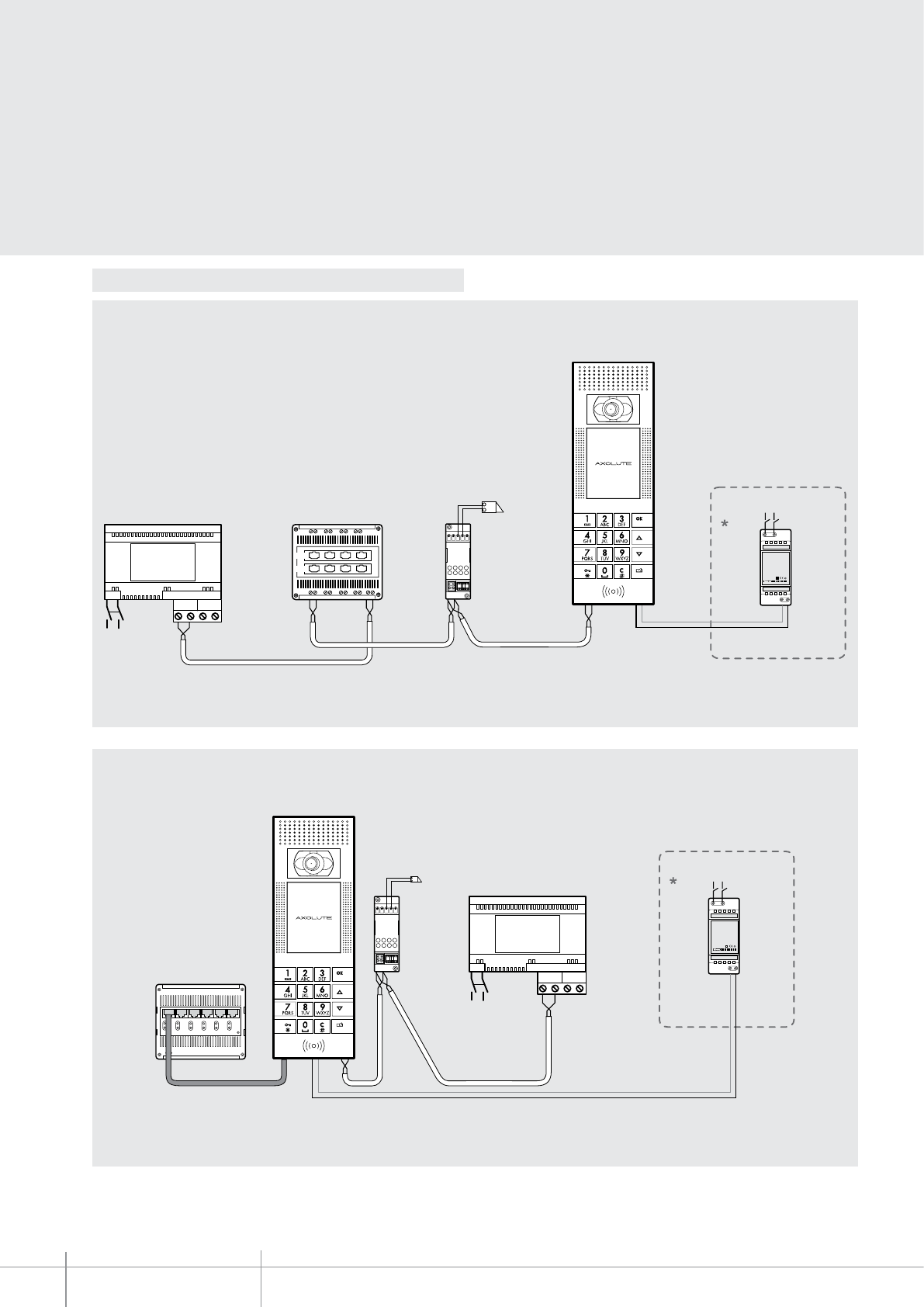
Wiring diagram
Wiring diagram- Installation with SFERA NEW EP
Example of installation of the RFID module inside a 2 WIRE SFERA NEW pushbutton panel with SCS BUS NOT CONNECTED to the RFID module
Configure as indicated on the
device technical sheet
BUS TK - 2-WIRE SCS
Electrical door lock
18 V 4 A impulsive - 250 mA holding
current 30 Ohm max
Pushbutton
module
A + B + C - DO NOT CONFIGURE
M - DO NOT CONFIGURE
T - DO NOT CONFIGURE
2 WIRE A/V module
WARNING: Irrespective of the position of the SFERA NEW
modules, the RFID module must the FIRST DEVICE connected
to the advanced speaker module or to the audio/video module.
Any other modules (e.g. pushbuttons) must be connected after
the RFID module.
NOTE: the M = 0 configuration (no configurator
connected), only enables management of RESIDENTS badges.
To add and/or delete residents badges, the badge programmed
as MANAGER MASTER badge is required.

353200
BT00606-a-EN
TECHNICAL SHEETS
215
2 WIRE VDE system
Wiring diagram- STAND ALONE installation
Example of STAND ALONE installation connection with the SCS BUS connected to the RFID module.
Keypad module 353200
SCS BUS
A + B + C = 003
(SCS device No. 3)
M - DO NOT CONFIGURE
T = 2 (contact closed for 10”)
Contact load:
8 A 30 Vdc
8 A 30 Vac cos@ 1
3.5 A 30 Vac cos@ 0.4
NOTE: The M = 1 configuration also gives the possibility of
managing APARTMENT MASTER badges. To add and/or delete
residents badges, the badge programmed as APARTMENT
MASTER badge is required.
BT00607-a
9
8
7
56
4
3
1 2
115 mm
91 mm
353300
-EN
TECHNICAL SHEETS
216 2 WIRE VDE system
SFERA NEW - SFERA ROBUR
Fingerprint reader module
Fingerprint reader module for the release of the door lock. It’s fitted with relay contacts
(C – NO - NC) and clamps (CP - P1 - P2) for the connection of a local door release pushbutton.
It also has a programming reset pushbutton and LEDS for the visual notification of
the access status. To be completed with surround plate. It is connected to the other
modules using the appropriate multicable supplied. The device may also be used as a
stand alone unit with independent power supply and operation.
Configuration performed using physical configurators, or a PC with the TiSferaDesign
software installed.
Power supply from SCS BUS: 18 – 27 Vdc
Stand by absorption: 30 mA
Max. operating absorption: 80 mA
Operating temperature: (-25) – (+70) °C
Protection index (pushbutton panel assembled): IP 54
Front view
Rear view
1. Green LED for access status notification. LED ON = access granted
2. Red LED for access status notification. LED ON = access denied
3. Digital fingerprint reader sensor
4. Mini-USB connector for the connection to the PC: download/upload the configuration
and device firmware update
5. Plug-in clamps (CP – P1 P2) for connection of the additional local pushbutton
6. Plug-in clamps (C – NC – NO) for local relay contacts and connection to the 2 WIRE
SCS BUS
7. Connector for the connection to subsequent modules
8. Connector for the connection to previous modules
9. Configurator socket
353301 Sfera New fingerprint reader front cover - Allmetal (IK 06)
353302 Sfera New fingerprint reader front cover - Allwhite (IK 06)
353303 Sfera New fingerprint reader front cover - Allstreet (IK 06)
353305 Sfera Robur fingerprint reader front cover (IK 06)
Description
Related items
Legend
Technical data
Dimensional data
BT00607-a
A B C
M T
353300
-EN
TECHNICAL SHEETS
217
2 WIRE VDE system
Configuration
A + B + C - progressive address of the device
The configurators connected to the A B C sockets assign a progressive address to the
device inside the system (range 000 – 999).
Example: A+B+C = 003 – device 003 of the system.
M - operating mode, fingerprint management
The configurator connected to the M socket sets the fingerprint management mode as
indicated below:
M = 0 - management of fingerprint with MANAGER MASTER ONLY
The MANAGER MASTER fingerprints (max. 5) are used both for the management of
PASSEPARTOUT fingerprints (MAX. 30) and for the management of the RESIDENTS
fingerprints (max. 5) of each apartment.
M = 1 - fingerprint management with APARTMENT MASTER
The MANAGER MASTER fingerprints (max. 5) directly manage the PASSEPARTOUT
fingerprints (max. 30) and the APARTMENT MASTER fingerprints (max. 30); the
APARTMENT MASTER fingerprints manage the RESIDENTS fingerprints (max. 5) of the
corresponding apartment.
T – local relay time delay
The configurator connected to T sets the relay closing time delay as shown in the
following table:
The configuration of the device is different depending on the type of installation:
- device installation inside a SFERA NEW pushbutton panel in 2 WIRE SCS systems,
- installation as STAND ALONE device.
In both cases, the configuration can be performed in two ways :
Mode 1 - with physical configurator connection
Mode 2 - with PC and software TiSferaDesign
PHYSICAL CONFIGURATION FOR INSTALLATION WITH A SFERA NEW EP:
A + B + C - NOT USED
M - operating mode, fingerprint management
The configurator connected to the M socket sets the fingerprint management mode as
indicated below:
M = 0 - management of fingerprint with manager MASTER ONLY
The MANAGER MASTER fingerprints (max. 5) are used both for the management of
PASSEPARTOUT fingerprints (MAX. 30) and for the management of the RESIDENTS
fingerprints (max. 5) of each apartment.
M = 1 - fingerprint management with APARTMENT MASTER
The MANAGER MASTER fingerprints (max. 5) directly manage the PASSEPARTOUT
fingerprints (max. 30) and the APARTMENT MASTER fingerprints (max. 30); the
APARTMENT MASTER fingerprints manage the RESIDENTS fingerprints (max. 5) of the
corresponding apartment.
T - local relay time delay – NOT USED
(the time delay of the local relay is set by the T configurator connected to the speaker
module or audio video module used).
Configurator 0 none 1 2 3 4 5 6 7
Contact closing
time 4” 1” 10” 20” 40” 1’ 1.5’ 3’
PHYSICAL CONFIGURATION IN STAND ALONE INSTALLATION:
BT00607-a
353300
-EN
TECHNICAL SHEETS
218 2 WIRE VDE system
Mode 2 requires advanced configuration of the device, performed using a PC and the
TisferaDesign software (which can be downloaded free of charge from the ww w.bticino.com).
For the connection to the PC use a USB - mini USB cable. The software gives the possibility
of configuring, programming, and updating the firmware of the speaker module.
The presence of the mini USB connection of the front of the speaker module gives the
possibility of performing these operations without the need to disassemble the device.
Mode 2
Wiring diagrams
Wiring diagram - Installation with SFERA NEW EP
Example of installation of the fingerprint module inside a 2 WIRE SFERA NEW pushbutton panel with SCS BUS NOT CONNECTED to the fingerprint module
Configure as indicated on the
device technical sheet
BUS TK - 2-WIRE SCS
Electrical door lock
18 V 4 A impulsive - 250 mA holding
current 30 Ohm max
Pushbutton
module
A + B + C - DO NOT CONFIGURE
M - DO NOT CONFIGURE
T - DO NOT CONFIGURE
WARNING: Irrespective of the position of the SFERA NEW
modules, the fingerprint module must the FIRST DEVICE
connected to the advanced speaker module or to the audio/
video module. Any other modules (e.g. pushbuttons) must be
connected after the fingerprint module.
NOTE: the M = 0 configuration (no configurator connected),
only enables management of RESIDENTS fingerprints.
To add and/or delete residents fingerprints, the fingerprint
programmed as MANAGER MASTER fingerprint is required.
Fingerprint module 353300
BT00607-a
353300
-EN
TECHNICAL SHEETS
219
2 WIRE VDE system
Wiring diagram- STAND ALONE installation
Example of STAND ALONE installation connection with the SCS BUS connected to the fingerprint module.
BUS SCS
A + B + C = 003
((SCS device No. 3)
M - DO NOT CONFIGURE
T = 2 (contact closed for 10”)
Contact load:
8 A 30 Vdc
8 A 30 Vac cos@ 1
3.5 A 30 Vac cos@ 0,4
NOTE: The M = 1 configuration also gives the possibility of
managing APARTMENT MASTER fingerprints. To add and/or
delete residents fingerprints, the fingerprint programmed as
APARTMENT MASTER fingerprint is required.
Keypad module 353300
BT00607-a
353300
-EN
TECHNICAL SHEETS
220 2 WIRE VDE system
The function of the fingerprint scanner is to read and analyse the image of the digital
fingerprint and compare it with a reference model previously programmed in the device.
If the comparison is positive, the door lock release is enabled, or an auxiliary system is
activated.
Functional notes
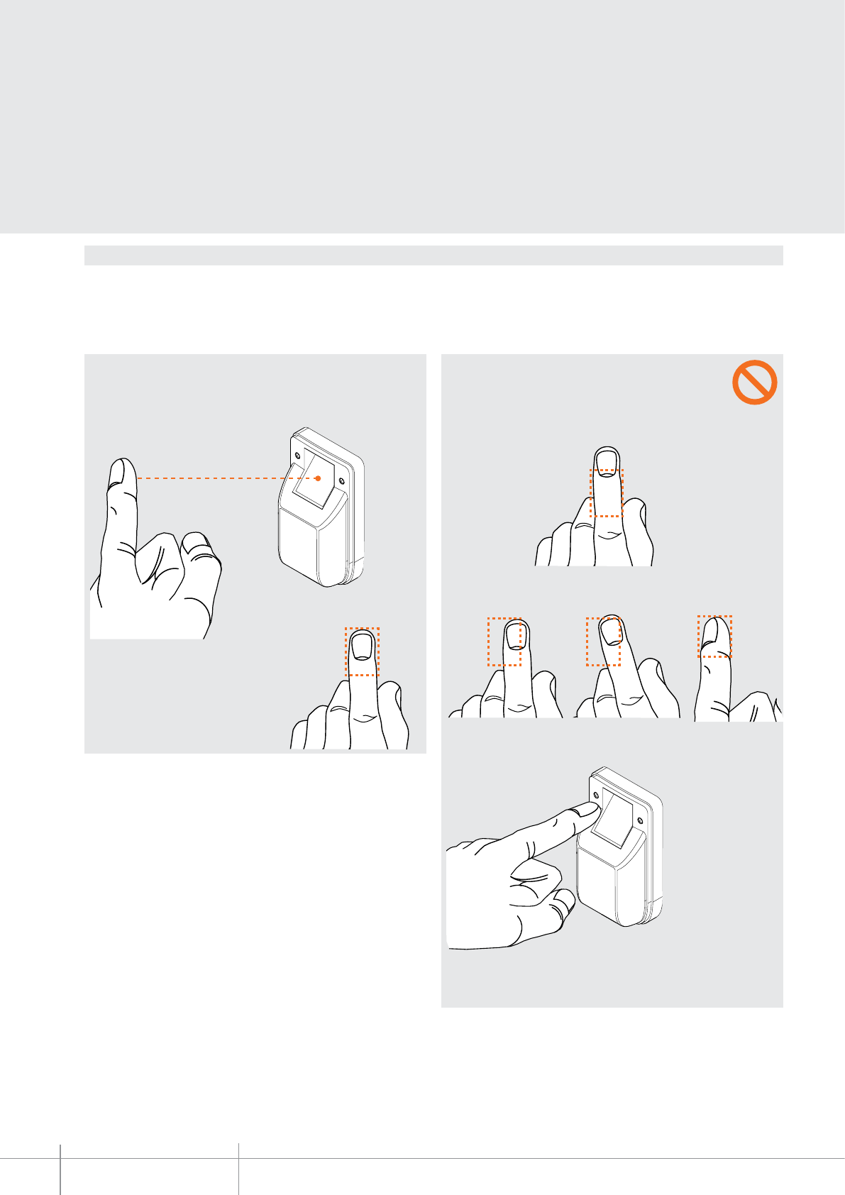
For correct operation we recommend compliance with the following indications:
- your finger must be placed straight and flat on the reader at the point indicated;
What you must NOT do:
The device performs the reading of the 3rd phalange of your fiNger. It is therefore
necessary that the finger is place correctly in the specific position on the reader and
moved downwards across the sensor at the correct speed.
- Do NOT place the 3rd phalange in a higher position in relation to the reference point
on the reader
- Do NOT position the finger on the right or left half of the reader, tilted, or in any way
with the phalange not flat against the finger recess of the reader.
- Do NOT position the finger at a too wide angle in relation to the reader finger recess.
- Do NOT move the finger away before the device has completed the acquisition,
confirmed by the switching off of the luminous sensor window.
349140
BT00608-a
1
2
3
5
6
8
7
4
9
10
11
12
104 mm 84 mm
50 mm
35,5 mm
300 mm
253 mm
139 mm 139 mm
27,5
mm 30 mm
330 mm
355 mm
-EN
TECHNICAL SHEETS
221
2 WIRE VDE system
Dimensional data
Description
Axolute outdoor entrance panel suitable for connection to the 2-WIRE system BUS or to
be used in BTicino IP systems. It’s tted with capacitive soft touch control backlit keypad,
motorised colour camera (which swivelling operation can be controlled from the preset
handsets), colour display with home page that can be fully customised by the installer,
and transponder reader for the release of the door lock, which may also be activated
using a numeric code for residents. Module to be completed with ush mounted box
and surround plate. Programming, residents directory, and the conguration are
completed using the appropriate software supplied with the product.
Related items
339313 (Steel ush mounted box with tearing protection)
331130 (SFERA plastic ush mounted box)
339213 (Surround plate + frame, steel nish)
339223 (Surround plate + frame, brass nish)
Technical data
Power supply from SCS BUS: 18 – 27 Vdc
Stand by absorption: 220 mA
Max. operating absorption: 420 mA
Operating temperature: (-25)-(+70)°C
Connections: 2-WIRE SCS BUS
Ethernet 10/100 Mbit/sec
Protection index: IP54
PI against mechanical impact: IK07
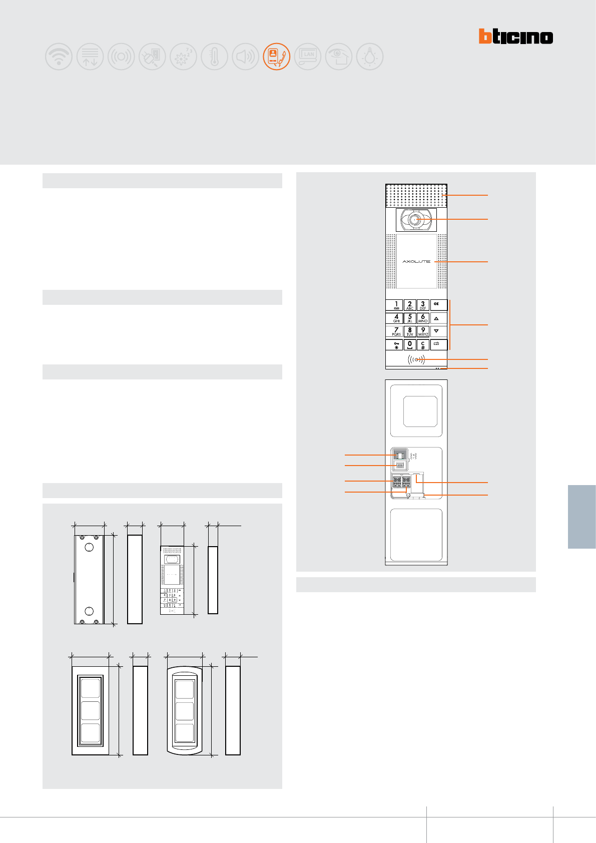
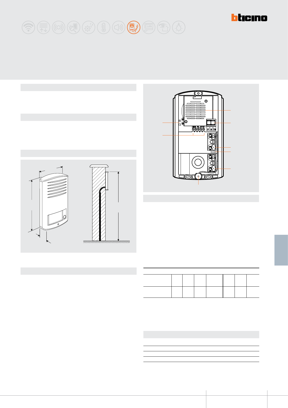
Legend
1. Loudspeakers
2. Colour camera that can be swivelled
3. LCD colour display
4. Capacitive alphanumeric keypad: to search for the extension and for sending the
call, as well as for enabling the installer to complete the programming procedure
5. Transponder reader: to open the door lock using the transponder
6. Microphone
7. Ethernet connector: for connection to the IP BTicino system and for programming
and firmware update from PC
8. Cable fastener
9. Additional power supply connection clamps
10. Clamps for the connection of the 2-wire SCS BUS
11. Mini-USB connector: for PC connection, for programming or firmware update
12. Configurator socket
Flush mounted box Electric module
Steel surround plate + frame
Protrusion from the wall:
11 mm
Brass surround plate + frame
Protrusion from the wall:
13.5 mm
Front view
Rear view
AXOLUTE Outdoor
entrance panel
BT00608-a
349140
-EN
TECHNICAL SHEETS
222 2 WIRE VDE system
Conguration
The device can be congured in three dierent modes:
1) Physical connection fo the congurators to their sockets:
P - entrance panel number
The congurator connected to P socket assigns an identication number within the
system to the EP. The numbering of the EP must always start from P=0.
The EP congured with P=0 must be the main one.
S - selection of the ring tone to send to the Handset and general call
When a call is received: S=0 (RING TONE 1 - Default)
S=1 (RING TONE 2)
S=2 (RING TONE 3)
S=3 (RING TONE 4)
S=9 (GENERAL CALL TO ALL THE HANDSETS)
2) Directly from the keypad of the electronic module:
Using the installer menu (Password protected function)
Entrance panel
address
Ring tone selection /
general call
Conguration
WARNING: the presence of physical congurators in the congurator sockets
WILL PREVENT keypad conguration.
Conguration of the
SCS address of the
entrance panel
349140
BT00608-a-EN
TECHNICAL SHEETS
223
2 WIRE VDE system
Conguration
3) Using the TiAxoluteOutdoor Software supplied:
For the connection to the PC use an USB-mini cable or an Ethernet cable (cross cable).
The dedicated application can be used for conguration, programming, device Firmware
update, ll the residents list, save all information, and download to the device.
Cross cable
BUS
BUS
USB connection
Ethernet connection
If the Axolute EP is installed and has Ethernet connection, remote connection is also possible.
WARNING: in order for the communication to take place, the EP must be powered and not physically congured.
349140
BT00608-a-EN
TECHNICAL SHEETS
224 2 WIRE VDE system
Wiring diagrams
12
S+ S-
37
PL
346230
BUS 2 1
230 ac
SCS
OUT1 OUT2 OUT3 OUT4
IN1IN2 IN3IN4
OUT
IN
11
22BUS
346230
or
346260
346830
or
F441
346000 346020
OP TIONAL
349140
230 Vac
35,
PRI:220 - 240V~
175-
165m
A
50/60
H
z
1-
2:
27Vdc
600
m
A
V
12
S+ S-
37
PL
346230
349140
1
12
2BUS
346020
12 V ac 1 A
346230
or
346260
BUS 2 1
230 V ac
346000
IP
SWITCH C9455
OP TIONAL
230 Vac
'&,Q
35,
PRI: 220 - 240V~
175-
165m
A
50/60
H
z
1-
2:
27Vdc
600
m
A
2-WIRE SCS BUS connection
NOTE (*): needed for lines (SCS power supply - EP) > 50 m (with cable item 336904)
NOTE (*): needed for lines (SCS power supply - EP) > 50 m (with cable item 336904)
IP Ethernet connection
342911 - 342921
1
2
3
3
4
5
6
7
BT00609-a
98 mm
176
mm
31
mm
cm
160 ÷
165
-EN
TECHNICAL SHEETS
225
2 WIRE VDE system
Legend
1. Loudspeaker
2. Configurator housing
3. Call keys
4. JUMPER for exclusion of the call tone on the entrance panel (can be enabled
removing the jumper)
5. Microphone
6. Terminals for BUS and door lock connection: the module allows to control an
electric door lock directly connected to the S+ S- terminals (18 V 4 A impulsive -
250 mA holding current 30 Ohm max)
7. Microphone and loudspeaker volume adjustment
Dimensional data
Description
2 WIRE system audio pushbutton panel.
Wall mounted. Green LED backlit name plate.
One to four calls version available.
Technical data
Power supply from SCS BUS: 18 - 27 Vdc
Stand by absorption: 30 mA
Max. operating absorption: 65 mA
Operating temperature: (-25) - (+70)°C
LINEA 2000
Audio entrance panel
Conguration
The device must be congured (only phisically) as follows:
P - entrance panel number
The congurator in socket P of the speaker module assigns to this a recognition number
inside the system.
The numbering of the entrance panels must always start from P=0. The entrance panel
congured with P=0 must be a common (or main) entrance panel.
N - call number
Assigns the correspondence between the entrance panel pushbuttons and the audio
handsets or video handsets.
S - type of call signal
The conguration of S determines the call tone of SPRINT handsets.
One can thus dierentiate the calls from dierent entrance panels.
Congurator 0 1 2 3
Type of bell 2-tone 2-tone 2-tone One-tone
1200Hz 1200Hz 1200Hz 1200Hz
600Hz 0 Hz 2400Hz
Table for SPRINT handset call signal
For the SWING, PIVOT, POLYX and AXOLUTE handsets, the S congurator associates the
entrance panel to the bell programmed in the same apartment. It is possible to chose
between 16 dierent bells. In one-family systems, S=9 congures the general call
and the handsets ring, the same as with the S=0.
T – Door lock control time delay
0= No
congurator
4 sec.
1
1 sec. 6 sec. 8 sec. 10 sec.
2
2 sec.
3
3 sec. as
pushbutt.
4 * 5 6 7
Congurator number
* Operation as pushbutton for 10 sec. max., after which standby mode is activated.
To extend operation time over 10 seconds, use actuator item 346200 congured with
MOD=5.
342931 - 342941
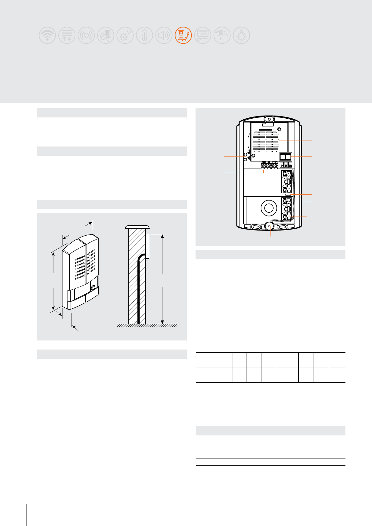
342971 - 342972
BT00610-a
1
2
4
5
6
7
3
35
mm
185
mm
106 mm
cm
160 ÷ 165
-EN
TECHNICAL SHEETS
226 2 WIRE VDE system
Legend
1. Loudspeaker
2. Configurator housing
3. JUMPER for exclusion of the call tone on the entrance panel
(can be enabled removing the jumper)
4. Call keys
5. Microphone
6. Terminals for BUS and door lock connection: the module allows to control an
electric door lock directly connected to the S+ S- terminals (18 V 4 A impulsive -
250 mA holding current 30 Ohm max)
7. Microphone and loudspeaker volume adjustment
Dimensional data
Description
2 WIRE system audio pushbutton panel with Zamak front cover.
Wall mounted. Blue LED backlit name plate
One and two-family version available.
Technical data
Power supply from SCS BUS: 18-27 Vdc
Stand by absorption: 30 mA
Max. operating absorption: 65 mA
Operating temperature: (-25)-(+70)°C
PI against mechanical impact: IK10
LINEA 2000 METAL
Audio entrance panel
Conguration
The device must be congured (only phisically) as follows:
P - entrance panel number
The congurator in socket P of the speaker module assigns to this a recognition number
inside the system.
The numbering of the entrance panels must always start from P=0. The entrance panel
congured with P=0 must be a common (or main) entrance panel.
N - call number
Assigns the correspondence between the entrance panel pushbuttons and the audio
handsets or video handsets.
S - type of call signal
The conguration of S determines the call tone of SPRINT handsets.
One can thus dierentiate the calls from dierent entrance panels.
Congurator 0 1 2 3
Type of bell 2-tone 2-tone 2-tone One-tone
1200Hz 1200Hz 1200Hz 1200Hz
600Hz 0 Hz 2400Hz
Table for SPRINT handset call signal
For the SWING, PIVOT, POLYX and AXOLUTE handsets, the S congurator associates the
entrance panel to the bell programmed in the same apartment. It is possible to chose
between 16 dierent bells. In one-family systems, S=9 congures the general call
and the handsets ring, the same as with the S=0.
T – Door lock control time delay
0= No
congurator
4 sec.
1
1 sec. 6 sec. 8 sec. 10 sec.
2
2 sec.
3
3 sec. as
pushbutt.
4* 5 6 7
congurator number
* Operation as pushbutton for 10 sec. max, after which standby mode is activated.
To extend operation time over 10 seconds, use actuator item 346200 congured with
MOD=5.
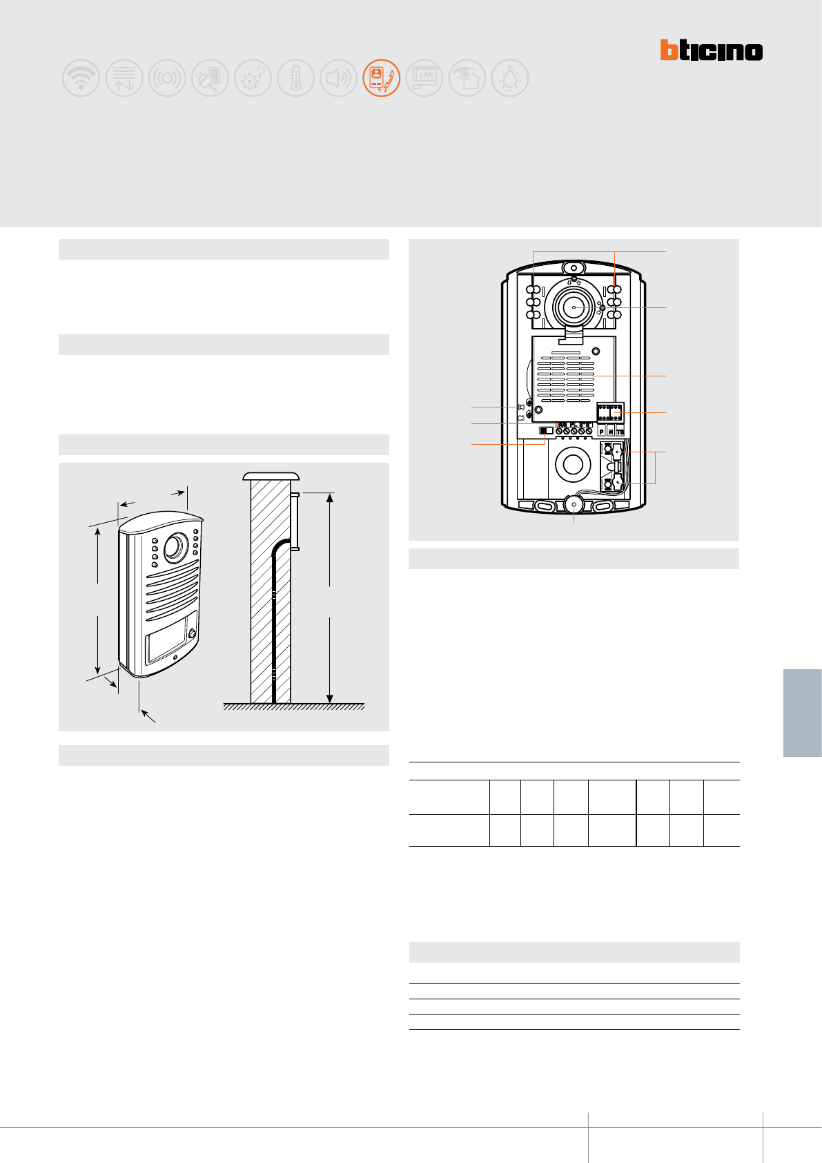
342951 - 342961
BT00611-a
cm
160 ÷165
31
mm
176
mm
98 mm
2
3
5
6
8
7
94
1
-EN
TECHNICAL SHEETS
227
2 WIRE VDE system
Dimensional data
Description
2 WIRE black and white video pushbutton panel.
Wall mounted. Green LED backlit name plate.
Camera adjustable by +/- 15° on both axes during installation.
One and two-family version available.
Technical data
Power supply from SCS BUS: 18 - 27 Vdc
Stand by absorption: 30 mA
Max. operating absorption: 270 mA
Operating temperature: (-25) - (+70)°C
Legend
1 - IR LED for night lighting of the eld of view
2 - B/W camera with camera slant adjustment horizontally and vertically by ±15°
3 - Loudspeaker
4 - Congurator socket
5 - Call keys
6 - Microphone
7 - Door lock release sound enable/disable
8 - Clamps for BUS connection, door lock and local pushbutton: the module allows
to control an electric door lock directly connected to the clamps S+ S- (18 V 4 A
impulsive - 250 mA holding current 30 Ohm max)
9 - Microphone and loudspeaker volume adjustment
LINEA 2000
B/W entrance panel
Conguration
The device must be congured (only phisically) as follows:
P - entrance panel number
The congurator in socket P of the speaker module assigns to this a recognition number
inside the system.
The numbering of the entrance panels must always start from P=0. The entrance panel
congured with P=0 must be a common (or main) entrance panel.
N - call number
Assigns the correspondence between the entrance panel pushbuttons and the audio
handsets or video handsets.
S - type of call signal
The conguration of S determines the call tone of SPRINT handsets.
One can thus dierentiate the calls from dierent entrance panels.
Congurator 0 1 2 3
Type of bell 2-tone 2-tone 2-tone One-tone
1200Hz 1200Hz 1200Hz 1200Hz
600Hz 0 Hz 2400Hz
Table for SPRINT handset call signal
For the SWING, PIVOT, POLYX and AXOLUTE handsets, the S congurator associates the
Entrance panel to the bell programmed in the same apartment. It is possible to chose
between 16 dierent bells. In one-family systems, S=9 congures the general call
and the handsets ring, the same as with the S=0.
T – Door lock control time delay
0= No
congurator
4 sec.
1
1 sec. 6 sec. 8 sec. 10 sec.
2
2 sec.
3
3 sec. as
pushbutt.
4* 5 6 7
congurator number
* Operation as pushbutton for 10 sec. max, after which standby mode is activated.
To extend operation time over 10 seconds, use actuator item 346200 congured with
MOD=5.
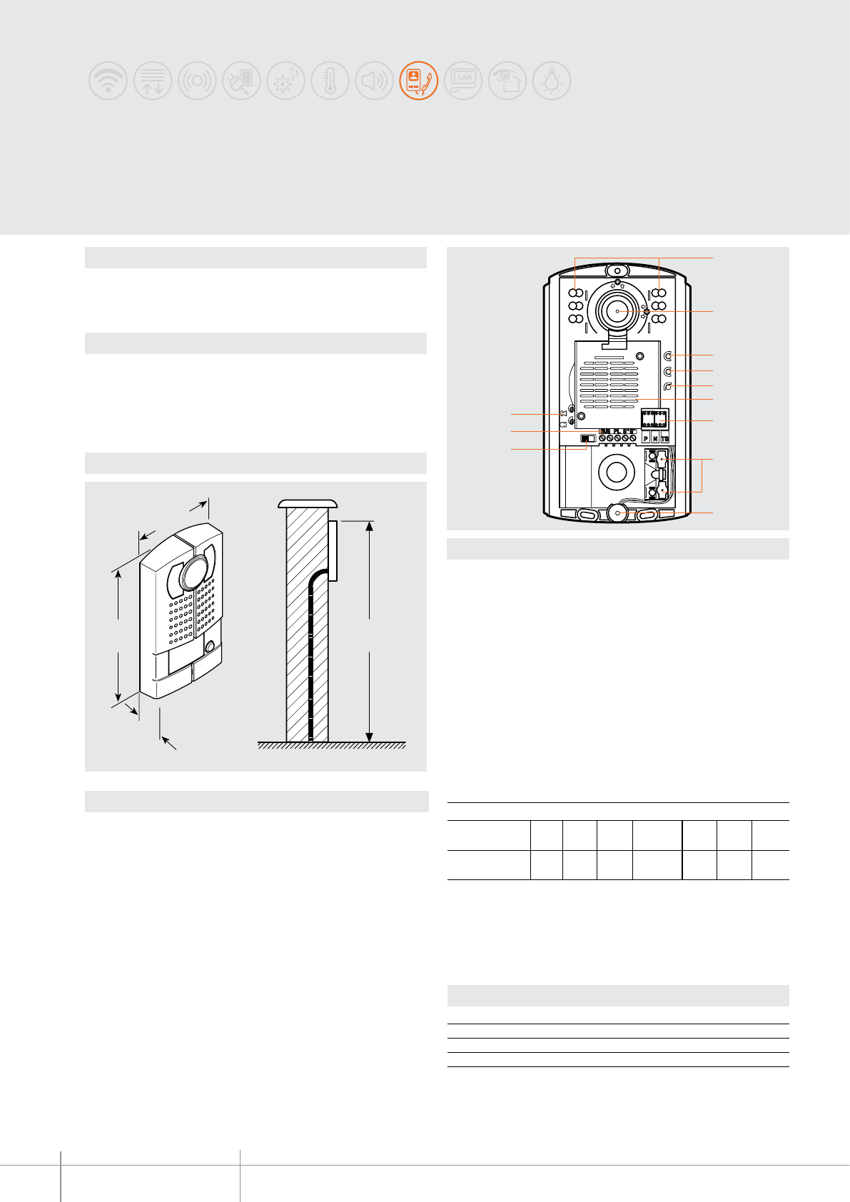
342981 - 342982
BT00612-a
5
4
1
6
12
72
3
9
10
11
8
35
mm
185
mm
106 mm
cm
160 – 165
-EN
TECHNICAL SHEETS
228 2 WIRE VDE system
Dimensional data
Description
2 WIRE black and white video pushbutton panel with Zamak front cover.
Wall mounted. Blue LED backlit name plate
One and two-family version available.
Technical data
Power supply from SCS BUS: 18 - 27 Vdc
Stand by absorption: 30 mA
Max. operating absorption: 270 mA
Operating temperature: (-25) - (+70)°C
PI against mechanical impact: IK07
Legend
1 - Call keys
2 - Congurator socket
3 - Microphone
4 - Loudspeaker
5 - B/W camera with camera slant adjustment horizontally and vertically by ±15°
6 - Clamps for BUS connection and door lock: the module allows to control an
electric door lock directly connected to the clamps S+ S- (18 V 4 A impulsive -
250 mA holding current 30 Ohm max)
7 - Microphone and loudspeaker volume adjustment
8 - White LEDs for night lighting of the eld of view
9 - Green LED: door open notication
10 - Green LED: communication active notication
11 - System status LED: ashing green = put through call
ashing red = busy system notication
12 -
Door lock opening sound enable/disable micro-switch
LINEA 2000 METAL
B/W entrance panel
Conguration
The device must be congured (only phisically) as follows:
P - entrance panel number
The congurator in socket P of the speaker module assigns to this a recognition number
inside the system.
The numbering of the entrance panels must always start from P=0. The entrance panel
congured with P=0 must be a common (or main) entrance panel.
N - call number
Assigns the correspondence between the entrance panel pushbuttons and the audio
handsets or video handsets.
S - type of call signal
The conguration of S determines the call tone of SPRINT handsets.
One can thus dierentiate the calls from dierent entrance panels.
Congurator 0 1 2 3
Type of bell 2-tone 2-tone 2-tone One-tone
1200Hz 1200Hz 1200Hz 1200Hz
600Hz 0 Hz 2400Hz
Table for SPRINT handset call signal
For the SWING, PIVOT, POLYX and AXOLUTE handsets, the S congurator associates the Entrance
panel to the bell programmed in the same apartment. It is possible to chose between 16 dierent
bells. In one-family systems, S=9 congures the general call and the handsets ring, the same
as with the S=0.
T – Door lock control time delay
0= No
congurator
4 sec.
1
1 sec. 6 sec. 8 sec. 10 sec.
2
2 sec.
3
3 sec. as
pushbutt.
4* 5 6 7
congurator number
* Operation as pushbutton for 10 sec. max, after which standby mode is activated.
To extend operation time over 10 seconds, use actuator item 346200 congured with
MOD=5.
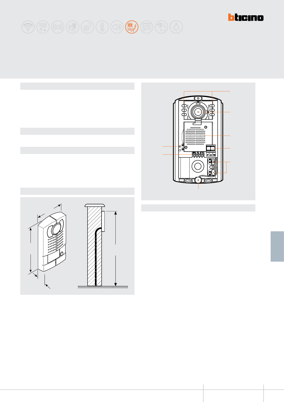
342991 - 342992
BT00613-a
160 ÷ 165
cm
106
mm
185
mm
35
mm
2
3
5
6
7
84
1
-EN
TECHNICAL SHEETS
229
2 WIRE VDE system
Dimensional data
Description
Wall mounted 2-wire pushbutton panel with Zamak front cover, colour camera, and
night viewing white LED light. One and two-family version available.
The camera can be swivelled by +/-15°, both horizontally and vertically.
It provides the possibility of opening an electrical door lock connected directly to clamps
S+ and S- (18 V 4 A impulsive, 250 mA holding current). Blue LED backlit name plate
Technical data
Power supply from SCS BUS: 18 - 27 Vdc
Stand by absorption: 20 mA
Max. operating absorption: 240 mA
Operating temperature: (-25) - (+70)°C
PI against mechanical impact: IK07
Legend
1 - White LEDs for night lighting
2 - Colour camera with camera slant adjustment horizontally and vertically by ±15°
3 - Loudspeaker
4 - Congurator socket
5 - Call keys
6 - Microphone
7 - Clamps for BUS and door lock connection: the module allows to control an electric
door lock directly connected to the clamps S+ S- (18 V 4 A impulsive - 250 mA
holding current 30 Ohm max)
8 - Microphone and loudspeaker volume adjustment
Wall mounted
LINEA 2000 METAL entrance panel
Related items
346250 (gate release relay module)

BT00613-a
342991 - 342992
-EN
TECHNICAL SHEETS
230 2 WIRE VDE system
Conguration
The device must be congured as follows:
P - entrance panel number
The congurator in seat P of the speaker module assigns to it a recognition number
inside the system. The numbering of the entrance panels must always start from P=0.
The entrance panel congured with P=0 must be a common (or main) entrance panel.
N - call number
Assigns the correspondence between the entrance panel pushbuttons, and the audio
or video handsets.
In common entrance panels made using pushbutton modules, 1 must be inserted in N of
the speaker module. In secondary entrance panels, the number of the rst riser handset
must be inserted in N.
S - type of call signal
The conguration of S determines the call tone of the SPRINT handsets.
One can thus dierentiate the calls from dierent entrance panels.
Congurator 0 1 2 3
Type of bell 2-tone 2-tone 2-tone One-tone
1200Hz 1200Hz 1200Hz 1200Hz
600Hz 0 Hz 2400Hz
Table for SPRINT handset call signal
For the SWING, PIVOT, POLYX and AXOLUTE handsets, the S congurator associates the
Entrance panel to the bell programmed in the same apartment. It is possible to chose
between 16 dierent bells. In one-family systems S=9 congure the general call.
T - door lock relay timing
0= No
congurator
4 sec.
1
1 sec. 6 sec. 8 sec. 10 sec.
2
2 sec.
3
3 sec. as
pushbutt.
4 5 6 7
congurator number
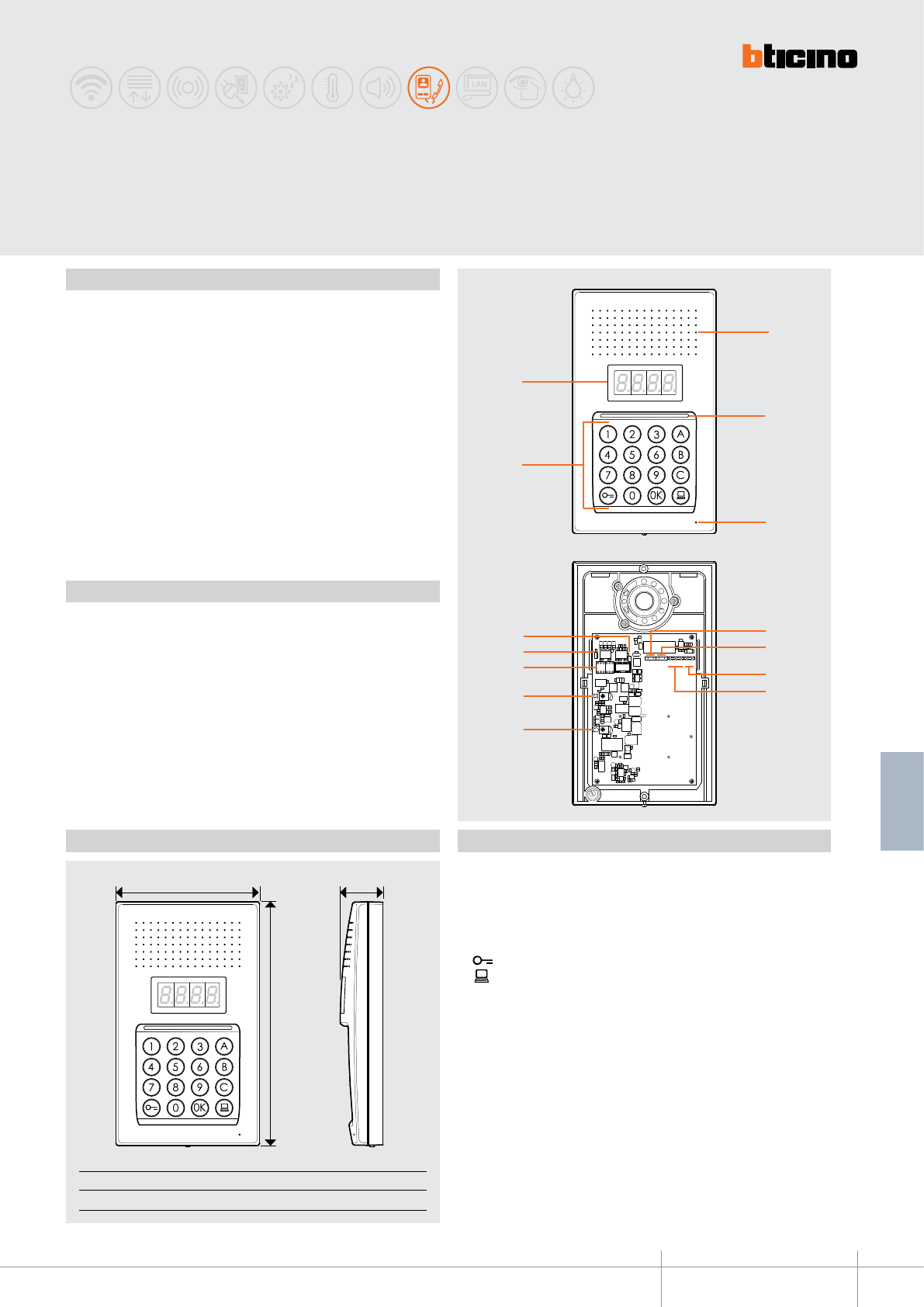
N T SP P N
BUS 1 2 C NO NC PL
J1
J2
1
2
4
10
11
13
14
12
5
3
7
9
6
8
B
CA
343100
-EN
TECHNICAL SHEETS
231
2 WIRE VDE system
BT00714-a
N T SP P N
BUS 1 2 C NO NC PL
J1
J2
1
2
4
10
11
13
14
12
5
3
7
9
6
8
B
CA
Front view
View without lid
A B C
130 mm 221 mm 38.7 mm
LINEA 100
Digital call pushbutton panel
Description
2 WIRE AUDIO digital call pushbutton panel for wall mounted installation. The device
consists in a pushbutton panel with 16 keys and a digital display for the display of the
operating status. Through the recognition of previously saved numerical (SCS addresses)
or alphanumerical codes (logic addresses), it can be used to call handsets, and to give
residents the possibility of opening the door lock using a dedicated numerical code.
The pushbutton panel can manage up to 4000 handset addresses (from 0 to 3999),
and the direct call to the 2 WIRE switchboard. It has an internal contact (C – NO – NC)
for connection of an electrical door lock, or an external actuator (for the powering of
the electrical door lock use an auxiliary transformer, item 336842). Connection (PL) for
connecting a local door lock release pushbutton. System power supply cuts do NOT cause
the loss of memory data.
Legend
1. Loudspeaker
2. Keypad lighting LED
3. Microphone
4. Alphanumeric keypad
OK key, code confirmation
key, door lock release
key, call to the switchboard
5. Display
6. 2 WIRE SCS/BUS connection clamps (BUS)
7. Clamps (1 - 2) for the connection of the additional power supply
8. Clamps (PL) for the connection of a local door lock release pushbutton
9. Contact clamps (C - NO - NC), for the connection of the door lock /external actuator
10. Microphone volume adjustment
11. Loudspeaker volume adjustment
12. Configurator socket
13. Jumper J2- connected = enabled tones
disconnected = disabled tones
14. Jumper J1- connected = additional power supply disabled
disconnected = additional power supply enabled
Technical data
Power supply from SCS BUS: 18 – 27 Vdc
Stand-by absorption: 30 mA
Max. operating absorption: 100 mA
Contact load (C - NO - NC): 1.2 A – 12 Vac / dc
Operating temperature: (-25) – (+70) °C
Protection index: IP44
Protection index against mechanical impact: IK08
Dimensional data
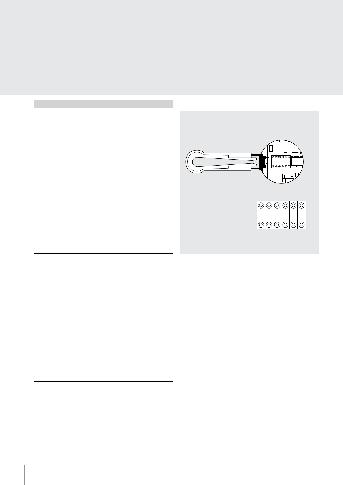
N T SP P N
J2
P N T S
343100
-EN
TECHNICAL SHEETS
232 2 WIRE VDE system
BT00714-a
Configuration
The device MUST be configured with physical configurator connection to the
appropriate sockets as follows:
P - entrance panel number
The configurator in socket P of the device assigns to this a recognition number inside the
system
. The numbering of the entrance panels must always start from P = 0 (unless
the system includes a 2 WIRE switchboard). The entrance panel configured with P =
0 (no configurator connected) must be a standard (or main) entrance panel.
N - NOT USED
T -
door lock relay timing
* Operation as pushbutton for 10 sec. max after which it goes in stand-by.
In order to extend this type of operation over 10 seconds, use the actuator, item
346200 congured with MOD = 5.
S - type of call signal
The configurator in socket S of the device determines the call tone of handsets. One can
thus differentiate the calls from different entrance panels.
For the SWING, PIVOT, POLYX, AXOLUTE and LIVINGLIGHT handsets, S associates the
Entrance panel to the bell programmed in the same apartment. It is possible to chose
between 16 different preset bells.
For the SPRINT and SPRINT L2 handsets, S sets the call ringtone, according to the
following table:
In one-family systems S=9 to configure the general call.
Configurator number
0 = no
configurator 1 2 3 4* 567
4 sec 1 sec 2 sec 3 sec as
pushbutt. 6 sec 8 sec 10 sec
Configurator 0 1 2 3
Type of bell 2-tone 2-tone 2-tone One-tone
1200 Hz 1200 Hz 1200 Hz 1200 Hz
600 Hz 0 Hz 2400 Hz
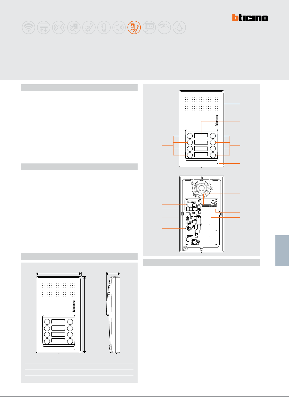
343101 - 343102
B
CA
1
3
4
3
2
N T SP P N
J2
BUS C NO NC PL
5
6
7
8
9
10
11
-EN
TECHNICAL SHEETS
233
2 WIRE VDE system
LINEA 100 audio pushbutton
panel for pushbutton call
Description
2 WIRE audio pushbutton panel with pushbutton call, available in two versions: 4 call
pushbuttons (343101) and 8 call pushbuttons (343102). They have an internal contact
(C – NO – NC) for connection of an electrical door lock, or an external actuator (for
the powering of the electrical door lock use an auxiliary transformer, item 336842).
Connection (PL) for connecting a local door lock release pushbutton. Wall mounted
installation.
Technical data
Power supply from SCS BUS: 18 – 27 Vdc
Stand-by absorption: 25 mA
Max. operating absorption: 55 mA
Local contact load (C - NO - NC): 2 A – 12/24 Vac/dc
Operating temperature: (-25) – (+70) °C
Protection index: IP44
Protection index against mechanical impact: IK08
Dimensional data
Legend
1. Loudspeaker
2. Nameplate
3. Call pushbuttons
4. Microphone
5. 2 WIRE SCS/BUS connection clamps (BUS)
6. Clamps (PL) for the connection of a local door lock release pushbutton
7. Contact clamps (C - NO - NC), for the connection of the door lock /external actuator
8. Microphone volume adjustment
9. Loudspeaker volume adjustment
10. Configurator socket
11. Jumper J2 - connected = additional power supply disabled
disconnected = additional power supply enabled
Front view
View without lid
A B C
130 mm 221 mm 38.7 mm
BT00715-a
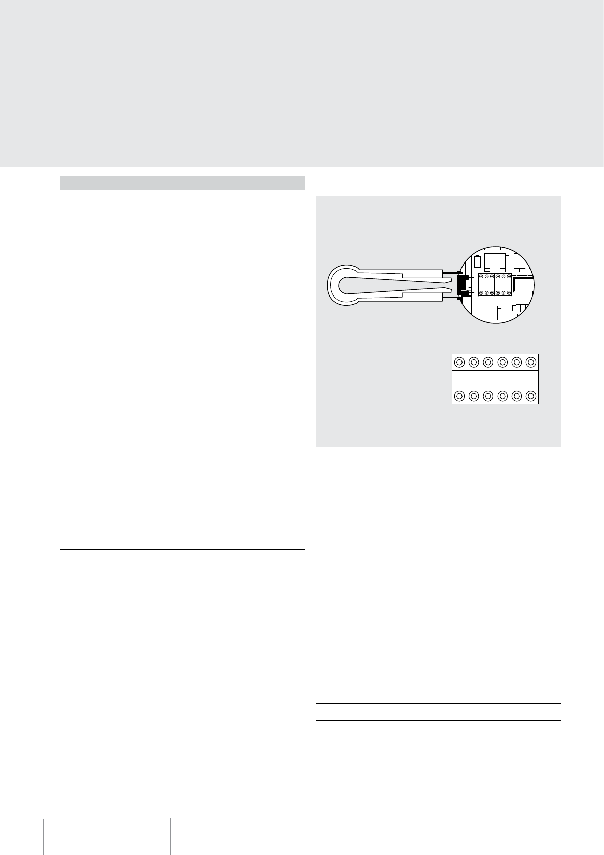
343101 - 343102
N T SP P N
J2
P N T S
-EN
TECHNICAL SHEETS
234 2 WIRE VDE system
Configuration
The device MUST be configured with physical configurator connection to the
appropriate sockets as follows:
P - entrance panel number
The configurator in socket P of the device assigns to this a recognition number inside the
system
. The numbering of the entrance panels must always start from P = 0 (unless
the system includes a 2 WIRE switchboard). The entrance panel configured with P =
0 (no configurator connected) must be a standard (or main) entrance panel.
N - call number
The configurator connected to socket N of the device assigns the correspondence
between the entrance panel call pushbuttons and the handsets. For common
pushbutton entrance panels N must be configured with N = 0 (no configurator
connected). In local entrance panels, the first handset of the riser being called will
be the one configured with N+1 in relation to the entrance panel.
T - temporizzazione serratura
* Operation as pushbutton for 10 sec. max after which it goes in stand-by.
In order to extend this type of operation over 10 seconds, use the actuator, item
346200 congured with MOD = 5.
S - type of call signal
The configurator in socket S of the device determines the call tone of handsets. One can
thus differentiate the calls from different entrance panels.
For the SWING, PIVOT, POLYX, AXOLUTE and LIVINGLIGHT handsets, S associates the
Entrance panel to the bell programmed in the same apartment. It is possible to chose
between 16 different preset bells.
For the SPRINT and SPRINT L2 (344242) handsets, S sets the call ringtone, according to
the table at the side.
Configurator number
0 = no
configurator 1 2 3 4* 567
4 sec 1 sec 2 sec 3 sec as
pushbutt. 6 sec 8 sec 10 sec
In one-family systems S=9 to configure the general call.
Configurator 0 1 2 3
Type of bell 2-tone 2-tone 2-tone One-tone
1200 Hz 1200 Hz 1200 Hz 1200 Hz
600 Hz 0 Hz 2400 Hz
BT00715-a
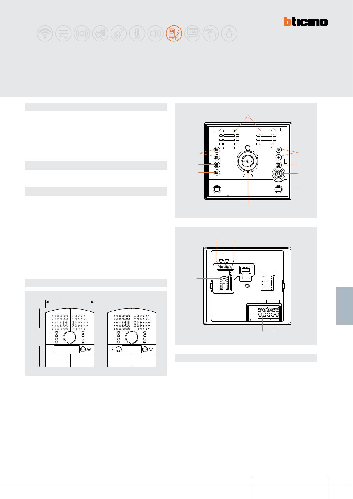
343001 - 343002
BT00614-a
136 mm
163 mm
J2
P
N
TS
BUS PL S+ S−
9
1213
10 11
14
1
6
5 5
7
22
8 3
4
J2
P
N
TS
BUS PL S+ S−
9
1213
10 11
14
1
6
5 5
7
22
8 3
4
-EN
TECHNICAL SHEETS
235
2 WIRE VDE system
Description
Flush mounted 2-wire audio and video speaker module with Zamak front cover, colour
camera and night viewing white LED light. One and two-family version available.
The camera can be swivelled by +/-20°, both horizontally and vertically.
It provides the possibility of opening an electrical door lock connected directly to clamps
S+ and S- (18 V 4 A impulsive, 250 mA holding current). Flush mounted box supplied
as standard.
Related items
346250 (gate release relay module)
Technical data
Power supply from SCS BUS: 18 - 27 Vdc
Stand by absorption: 40 mA
Max. operating absorption: 160 mA
Operating temperature: (-20) - (+70)°C
PI against mechanical impact IK10
Sensor: 1/3”
Lens: f: 4,3 mm; F: 1.5 mm
Interlace: 2:1
Resolution: 330 horizontal lines
Night lighting: white LEDs
Brightness adjustment: automatic
Dimensional data
Legend
1 - Loudspeakers
2 - White LEDs for night lighting
3 - Green LED for door status notication
4 - Microphone
5 - Call keys
6 - Colour camera
7 - Green LED: put through call notication
Red LED: busy system notication
8 - Green LED: active communication notication
9 - Microphone volume adjustment
10 - Loudspeaker volume adjustment
11 - J2: when connected, two columns of call pushbuttons are active, when disconnected
only one
12 - Door lock connection and local open door pushbutton
13 - Connection to the 2-wire SCS BUS.
14 - Congurator socket
Flush mounted
LINEA 2000 METAL entrance panel
Zamak front without panel
Rear view
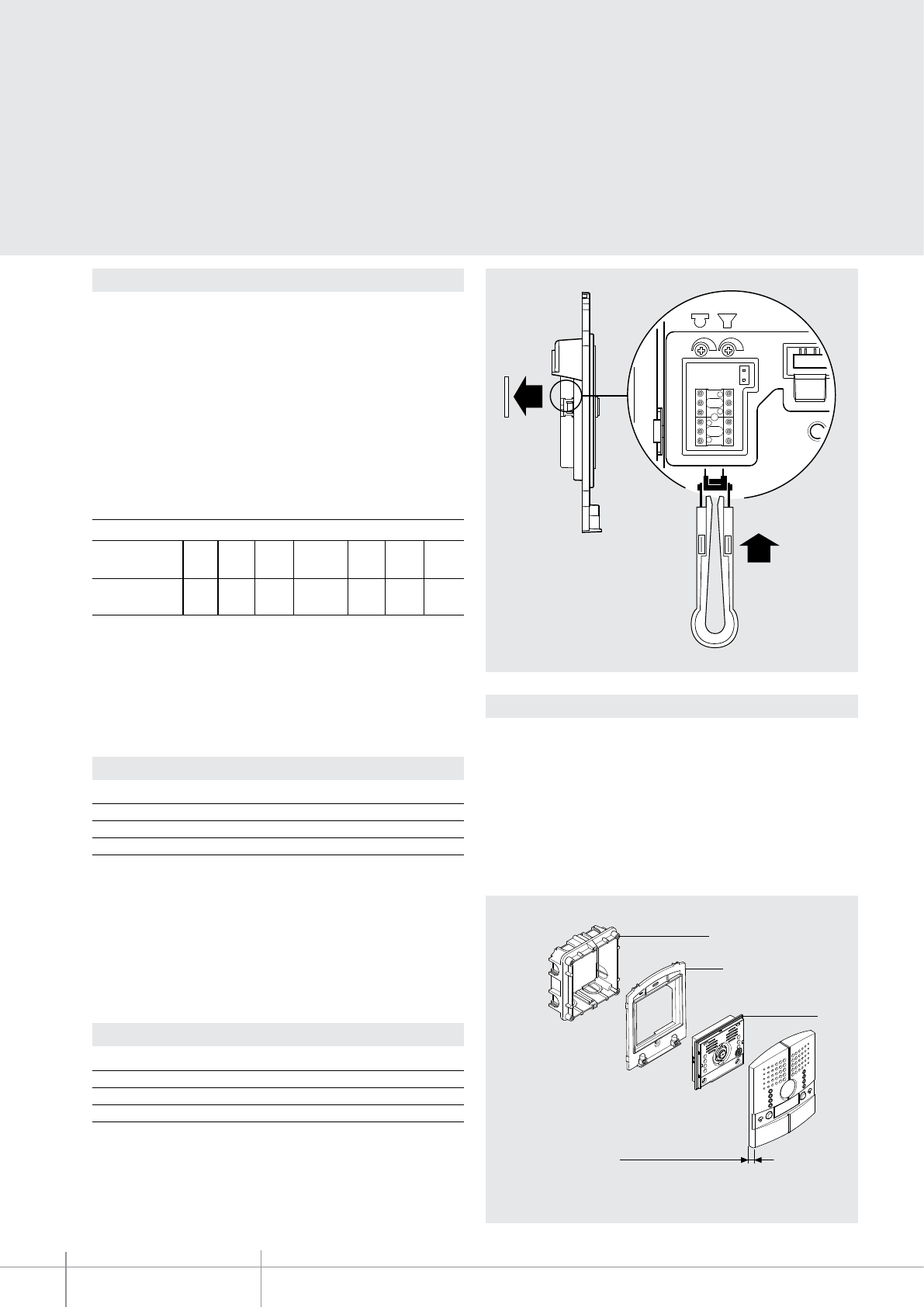
BT00614-a
343001 - 343002
1
2
-EN
TECHNICAL SHEETS
236 2 WIRE VDE system
Conguration
The device must be congured as follows:
P - entrance panel number
The congurator in seat P of the speaker module assigns to it a recognition number
inside the system. The numbering of the entrance panels must always start from P=0.
The entrance panel congured with P=0 must be a common (or main) entrance panel.
N - call number
Assigns the correspondence between the entrance panel pushbuttons and the audio
handsets or video handsets. In the common entrance panels made with pushbutton
modules, 1 must be inserted in N of the speaker module. The number of the rst riser
handset must be inserted in the local entrance panels in N.
The camera must not be installed in front of intense light sources, or in locations where
the subject might be backlit. To avoid these problems try to change the installation
height of the camera, normally from 160-165 cm, to a height of 180 mm, and to
direct the lens downwards so that the shooting quality may be improved. In low light
conditions, the picture of the colour camera may be reproduced with a lower colour
rendition, in order to ensure the possibility to better identify the subject. For optimal
viewing, it is however recommended that an extra light sources is installed in scarcely
illuminated locations.
Installation
* Operation as pushbutton for 10 sec. max, after which standby mode is activated.
To extend operation time over 10 seconds, use actuator item 346200 congured with
MOD=5.
T - door lock relay timing
0= No
congurator
4 sec.
1
1 sec. 6 sec. 8 sec. 10 sec.
2
2 sec.
3
3 sec. as
pushbutt.
4*5 6 7
congurator number
Protrusion from
the wall: 21 mm
Flush mounted box
Speaker module
Frame
S-type of call signal with entrance panel door lock opening notication beep
The conguration of S determines the call tone of the SPRINT handsets.
One can thus dierentiate the calls from dierent entrance panels.
S-type of call signal without entrance panel door lock opening notication
beep
The conguration of S determines the call tone of the SPRINT handsets.
One can thus dierentiate the calls from dierent entrance panels.
Congurator 0 1 2 3
Type of bell 2-tone 2-tone 2-tone One-tone
1200Hz 1200Hz 1200Hz 1200Hz
600Hz 0 Hz 2400Hz
Congurator 4 5 6 7
Type of bell 2-tone 2-tone 2-tone One-tone
1200Hz 1200Hz 1200Hz 1200Hz
600Hz 0 Hz 2400Hz
Table for SPRINT handset call signal
Table for SPRINT handset call signal
For the SWING, PIVOT, POLYX and AXOLUTE handsets, the S congurator associates the
Entrance panel to the bell programmed in the same apartment. It is possible to chose
between 16 dierent bells. In one-family systems, S=9 congures the general call and
the handsets ring, the same as with the S=0.
For the SWING, PIVOT, POLYX and AXOLUTE handsets, the S congurator associates the
Entrance panel to the bell programmed in the same apartment. It is possible to chose
between 16 dierent bells. In one-family systems, S=8 congures the general call and
the handsets ring, the same as with the S=0.
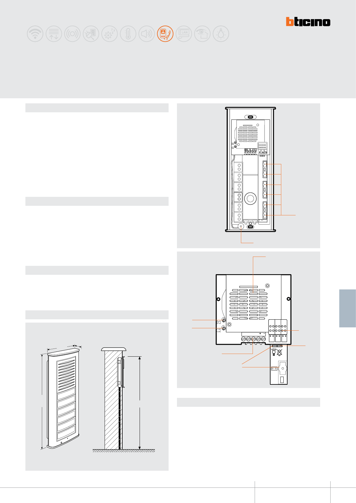
342702
BT00615-a
160cm
21 mm
100 mm
245 mm
BUS PL S S
PN TS
9
8
6
5
3
7
4
2
1
-EN
TECHNICAL SHEETS
237
2 WIRE VDE system
Description
2 WIRE speaker module to be used in audio systems.
Preset for 6 calls (expandable), it must be tted with surround plate (item 332721,or
item 332726) and keys (item 332712, item 332713, item 332714, item 332715),
according to personal installation requirements.
The device must be congured depending on the type of key used.
The Loudspeaker volume and the sensitivity level of the microphone may be adjusted
using the corresponding potentiometers. The name plates are illuminated by green LEDs.
The dedicated jumpers can be removed to enable the following functions: Staircase light
switching on with dedicated key, and exclusion of the conrmation of the call from the
entrance panel.
The speaker module may be used to open an electric door lock connected using the
S+ and S- clamps (18 V 4 A impulsive, 250 mA holding current 30 Ω max).
Related items
332710 (ush mounted box)
332711 (surface-mounted box)
332712 (narrow key 1 module with name label)
332713 (wide key 2 modules with name label)
332714 (2 modules nameplate with label)
332715 (1 module false key - grey)
332721 (aluminium surround plate)
332726 (titanium surround plate)
Technical data
Power supply from SCS BUS: 18 - 27 Vdc
Stand by absorption: 40 mA
Max. operating absorption: 90 mA
Operating temperature: (-25) - (+70)°C
Dimensional data
Legend
1 - Call keys
2 - Microphone
3 - Loudspeaker
4 - Congurator socket
5 - Entrance panel call sound exclusion (remove the jumper to enable)
6 - Staircase light switching on with dedicated key (remove the jumper to enable)
7 - Clamps for BUS connection, door lock and local pushbutton.
8 - Microphone sensitivity adjustment
9 - Loudspeaker volume adjustment
MINISFERA
Audio pushbutton panel
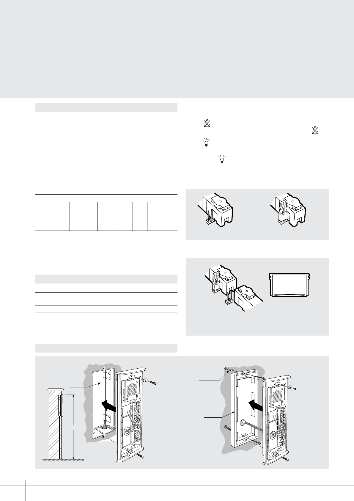
BT00615-a
342702
max ø 5mm
art. 332711
art. 332710
160cm
max ø 5mm
art. 332711
art. 332710
160cm
-EN
TECHNICAL SHEETS
238 2 WIRE VDE system
Conguration
The device must be congured (only phisically) as follows:
P - entrance panel number
The congurator in socket P of the speaker module assigns to this a recognition number
inside the system. The numbering of the entrance panels must always start from P=0.
The entrance panel congured with P=0 must be a common (or main) entrance panel.
N - call number
Assigns the correspondence between the entrance panel pushbuttons, and the audio
handsets.
In common entrance panels made using pushbutton modules, 1 must be inserted in N of
the speaker module. In secondary entrance panels, the number of the rst riser handset
must be inserted in N.
S - type of call signal
The conguration of S determines the call tone of SPRINT handsets.
One can thus dierentiate the calls from dierent entrance panels.
T - Door lock relay timing
* Operation as pushbutton for 10 sec. max, after which standby mode is activated.
To extend operation time over 10 seconds, use actuator item 346200 congured with
MOD=5.
0= No
congurator
4 sec.
1
1 sec. 6 sec. 8 sec. 10 sec.
2
2 sec.
3
3 sec. as
pushbutt.
4*5 6 7
congurator number
Congurator 0 1 2 3
Type of bell 2-tone 2-tone 2-tone One-tone
1200Hz 1200Hz 1200Hz 1200Hz
600Hz 0 Hz 2400Hz
Table for SPRINT handset call signal
For the SWING, PIVOT, POLYX and AXOLUTE handsets, the S congurator associates the
entrance panel to the bell programmed in the same apartment. It is possible to chose
between 16 dierent bells. In one-family systems S=9 to congure the general call
(all the system handsets ring at the same time).
Inside the MINISFERA audio speaker module are JUMPERS that can be used for
performing the following functions:
• Jumper - EP call conrmation
To eliminate the entrance panel call conrmation sound remove the JUMPER .
• Jumper - staircase light switching on with call key
To switch on the staircase the light from the entrance panel using the last call key,
remove the JUMPER .
• Jumper – call pushbutton exclusion
Connect the jumper to exclude the call pushbutton.
NOTA: disable the pushbuttons based on the false poles, and the single, or the double
keys connected.
Example - To use the double key the upper level call must be disabled.
Double
keys
call pushbutton enabled call pushbutton disabled
Flush mounted installation
Installation
Wall mounted installation
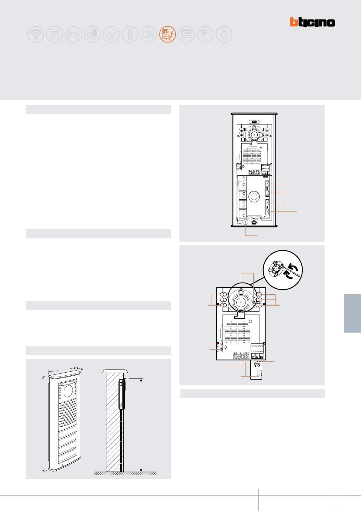
342708
BT00616-a
160cm
21 mm
100 mm
245 mm
2
1
15°
15°
15°
15°
10
11
4
8
6
4
3
7
5
9
-EN
TECHNICAL SHEETS
239
2 WIRE VDE system
Description
2 WIRE speaker module to be used in video or mixed audio/video systems.
Preset for 4 calls (expandable), it must be tted with surround plate (item 332721, item
332726) and keys (item 332712, item 332713, item 332714, item 332715), according to
personal installation requirements.
The device must be congured depending on the type of key used.
The Loudspeaker volume and the sensitivity level of the microphone may be adjusted
using the corresponding potentiometers.
The dedicated jumpers can be removed to enable the following functions: Staircase light
switching on with dedicated key, and exclusion of the conrmation of the call from the
entrance panel. If the IR LED allow night lighting of the eld of view.
The camera eld of view may be adjusted by +/-15 degrees both horizontally and
vertically.
The speaker module provides the possibility of opening an electrical door lock connected
directly to clamps S+ and S- (18V 4A impulsive, 250mA holding current 30Ω max). The
door lock can also be powered locally using a transformer, or the actuator item 346230/
item 346260.
Related items
332710 (ush mounted box)
332711 (surface-mounted box)
332712 (narrow key 1 module with name label)
332713 (wide key 2 modules with name label)
332714 (2 modules nameplate with label)
332715 (1 module false key - grey)
332721 (aluminium surround plate)
332726 (titanium surround plate)
Technical data
Power supply from SCS BUS: 18 - 27 Vdc
Stand by absorption: 40 mA
Max. operating absorption: 280 mA
Operating temperature: (-25) - (+70)°C
Dimensional data
Legend
1 - Call keys
2 - Microphone
3 - Camera eld of view adjustment screws
4 - IR LED for night lighting of the eld of view
5 - Congurator socket
6 - Entrance panel call conrmation exclusion. (remove the jumper to enable)
7 - Staircase light switching on with dedicated key (remove the jumper to enable)
8 - Terminal board for 2 WIRE connections, door lock and opening of entrance door lock
9 - Microphone sensitivity adjustment
10 - Loudspeaker volume adjustment
11 - Loudspeaker
MINISFERA black and white
video pushbutton panel
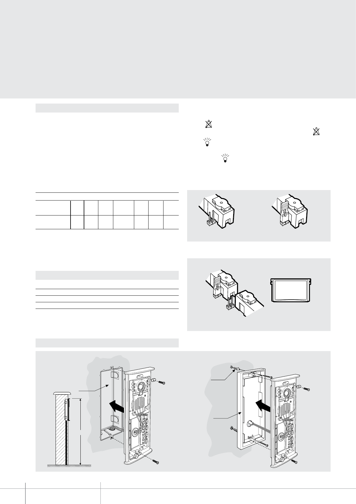
BT00616-a
342708
160cm
art. 332710
max ø 5mm
art. 332711
160cm
art. 332710
max ø 5mm
art. 332711
-EN
TECHNICAL SHEETS
240 2 WIRE VDE system
Conguration
The device must be congured (only phisically) as follows:
P - entrance panel number
The congurator in socket P of the speaker module assigns to this a recognition number
inside the system. The numbering of the entrance panels must always start from P=0.
The entrance panel congured with P=0 must be a common (or main) entrance panel.
N - call number
Assigns the correspondence between the entrance panel pushbuttons, and the audio
handsets.
In common entrance panels made using pushbutton modules, 1 must be inserted in N of
the speaker module. In secondary entrance panels, the number of the rst riser handset
must be inserted in N.
S - type of call signal
The conguration of S determines the call tone of SPRINT handsets.
One can thus dierentiate the calls from dierent entrance panels.
T - Door lock relay timing
0= No
congurator
4 sec.
1
1 sec. 6 sec. 8 sec. 10 sec.
2
2 sec.
3
3 sec. as
pushbutt.
4* 5 6 7
congurator number
Congurator 0 1 2 3
Type of bell 2-tone 2-tone 2-tone One-tone
1200Hz 1200Hz 1200Hz 1200Hz
600Hz 0 Hz 2400Hz
Table for SPRINT handset call signal
For the SWING, PIVOT, POLYX and AXOLUTE handsets, the S congurator associates the
entrance panel to the bell programmed in the same apartment. It is possible to chose
between 16 dierent bells. In one-family systems S=9 to congure the general call
(all the system handsets ring at the same time).
Inside the MINISFERA audio speaker module are JUMPERS that can be used for
performing the following functions:
• Jumper - EP call conrmation
To eliminate the entrance panel call conrmation sound remove the JUMPER .
• Jumper - staircase light switching on with call key
To switch on the staircase the light from the entrance panel using the last call key,
remove the JUMPER .
• Jumper – call pushbutton exclusion
Connect the jumper to exclude the call pushbutton.
NOTE: disable the pushbuttons based on the false poles, and the single, or the double
keys connected.
Example - To use the double key the upper level call must be disabled.
Double
keys
call pushbutton enabled call pushbutton disabled
Flush mounted installation
Installation
Wall mounted installation
* Operation as pushbutton for 10 sec. max, after which standby mode is activated.
To extend operation time over 10 seconds, use actuator item 346200 congured with
MOD=5.
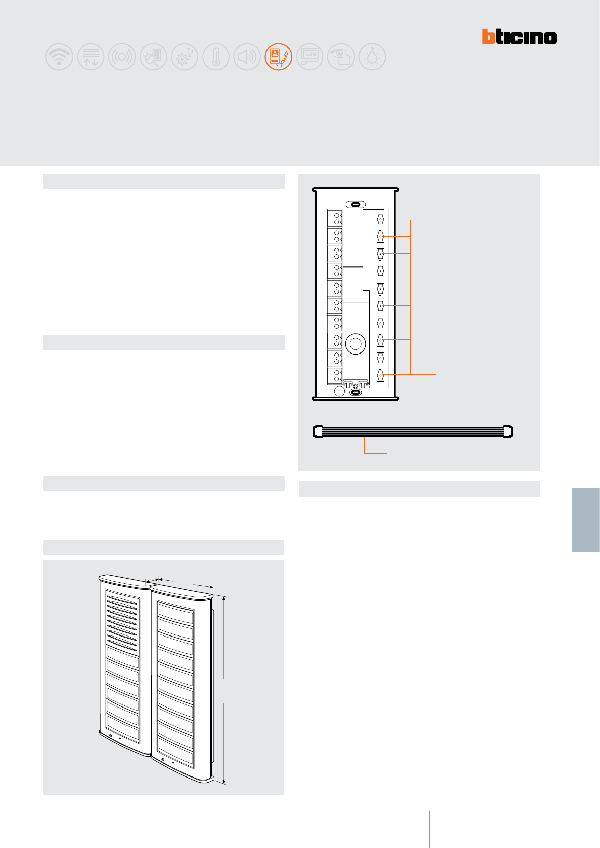
342704
BT00617-a
21 mm
100 mm
245 mm
1
2
-EN
TECHNICAL SHEETS
241
2 WIRE VDE system
Description
Additional 2 WIRE pushbutton module to be used together with audio modules item
342702 and item 342708.
Preset for 10 calls, it must be tted with surround plate (item 332721, item 332726)
and keys (item 332712, item 332713, item 332714, item 332715), according to personal
installation requirements.
It may be installed side by side with, or above/below, the speaker module.
Maximum 6 expansion modules may be connected to a speaker module, item 342702,
or item 342708.
It is supplied with multicable for the connection of the speaker module to other key
expansion modules.
The device must be congured based on the type of keys used, as for audio modules
items 342702 and item 342708.
Related items
342702 (MINISFERA audio speaker module)
342708 (MINISFERA video speaker module)
332710 (ush mounted box)
332711 (surface-mounted box)
332712 (narrow key 1 module with name label)
332713 (wide key 2 modules with name label)
332714 (2 modules nameplate with label)
332715 (1 module false key - grey)
332721 (aluminium surround plate)
332726
(titanium surround plate)
Technical data
Power supply from SCS BUS: 18 - 27 Vdc
Max. operating absorption: 30 mA
Operating temperature: (-25) - (+70)°C
Dimensional data
Legend
1 - Call keys
2 - Multicable supplied
MINISFERA
additional pushbutton panel
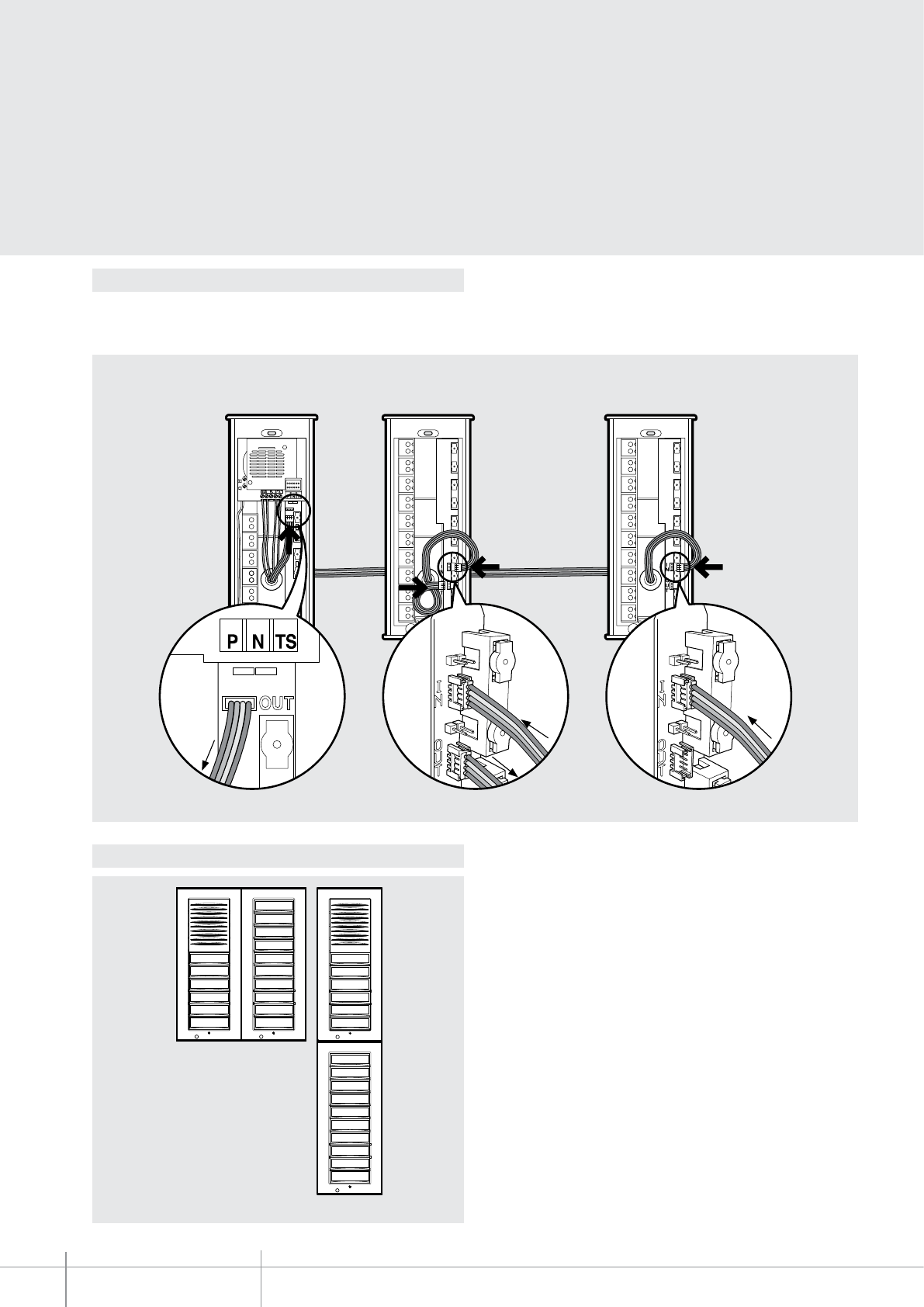
OUT
BT00617-a
342704
-EN
TECHNICAL SHEETS
242 2 WIRE VDE system
To connect the speaker module (audio or video) to the 10 key module, the cable supplied
must be used. The same cable must be used to connect other key modules to each other.
Connect the cable to OUT of the speaker module and to IN of the rst key module.
Connect the 2nd cable to OUT to the rst key module and to IN of the second key module,
and so on.
Example - Connection of two expansion modules, item 342704, and one MINISFERA audio or video speaker module.
A
Audio or video
speaker module
B
First
key module
C
Second
key module
to
IN B a
IN C
from
OUT A
from
OUT B
Wiring diagram
Installation
Horizontal side-by-side
Vertical side-by-side
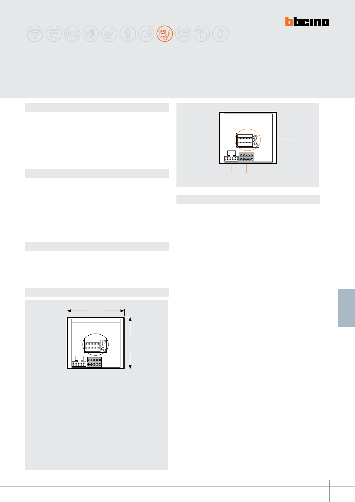
342150
BT00618-a
100 mm
89 mm
32
1
-EN
TECHNICAL SHEETS
243
2 WIRE VDE system
Description
Speaker module for 2 WIRE system.
It is possible to connect to this device nameplate modules (item 342200), or pushbutton
modules (item 342240). It can be used to install audio systems with up to 56 handsets.
It is possible to connect to this device one electric door lock that may be powered by the
item 336842 transformer placed nearby the speaker module.
Related items
332111 (speaker module front cover, 1 pushbutton - Allmetal)
332112 (speaker module front cover, 1 pushbutton - White)
332113 (speaker module front cover, 1 pushbutton - Alugray)
332121 (speaker module front cover, 2 pushbuttons - Allmetal)
332122 (speaker module front cover, 2 pushbuttons - White)
332123 (speaker module front cover, 2 pushbuttons - Alugray)
For the use of monobloc front covers refer to the catalogue.
Technical data
Power supply from SCS BUS: 18 – 27 Vdc
Stand by absorption: 25 mA
Max. operating absorption: 75 mA
Operating temperature: (-25)-(+70)°C
Dimensional data
Legend
1 - Congurator socket and potentiometers for the adjustment of the microphone and
loudspeaker volumes.
3 - Connector socket, for connection to the BUS, the electric door lock, and the entrance
hall door lock release pushbutton.
2 - Connector socket, for connection to the nameplate module or the pushbutton
module.
SFERA CLASSIC,
speaker module for audio systems
BT00618-a
342150
-EN
TECHNICAL SHEETS
244 2 WIRE VDE system
Conguration
The device must be phisically congured as follows:
P - entrance panel number
The congurator in socket P of the speaker module assigns to this a recognition number
inside the system.
The numbering of the entrance panels must always start from P=0. The entrance panel
congured with P=0 must be a common (or main) entrance panel.
N - call number
Assigns the correspondence between the entrance panel pushbuttons, and the audio
handsets. In the common entrance panels made with pushbutton modules, 1 must
be inserted in N of the speaker module. The number of the rst riser handset must be
inserted in the local entrance panels in N.
S - type of call signal
The conguration of S determines the call tone of SPRINT handsets.
One can thus dierentiate the calls from dierent entrance panels.
Congurator 0 1 2 3
Type of bell 2-tone 2-tone 2-tone One-tone
1200Hz 1200Hz 1200Hz 1200Hz
600Hz 0 Hz 2400Hz
T - Door lock relay timing
0= No
congurator
4 sec.
1
1 sec. 6 sec. 8 sec. 10 sec.
2
2 sec.
3
3 sec. as
pushbutt.
4 5 6 7
congurator number
Table for SPRINT handset call signal
For the SWING, PIVOT, POLYX and AXOLUTE handsets, the S congurator associates the
Entrance panel to the bell programmed in the same apartment.
It is possible to chose between 16 dierent bells.
In one-family systems, S=9 congures the general call and the handsets ring, the
same as with the S=0.
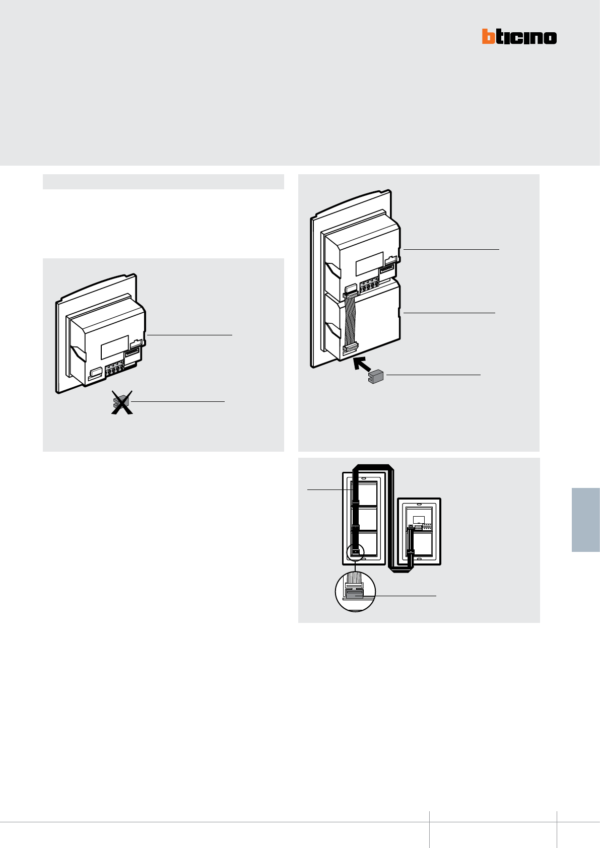
342150
BT00618-a
346902
-EN
TECHNICAL SHEETS
245
2 WIRE VDE system
Installation and connection
Supplied as standard with the speaker module is a closing accessory with connector.
The accessory must be tted in the last pushbutton module of the pushbutton panel,
after connecting the modules to each other using the multicables with connectors.
It must not be used if the pushbutton panel only consists of a 1 or 2 pushbutton speaker
module, in addition to a camera module that may be installed.
- In order to connect several key modules vertically on dierent columns, item 346092
must be used (see Example), and the closing accessory must be tted in the last
module.
Example – entrance panel only consisting of the Speaker module. It does not
require the accessory.
Speaker module
Closing accessory
Example – entrance panel consisting of the speaker module and 4 keys: the
accessory must be tted.
Speaker module
Closing accessory
Pushbutton module
Example - connection of
pushbutton panel.
Closing accessory
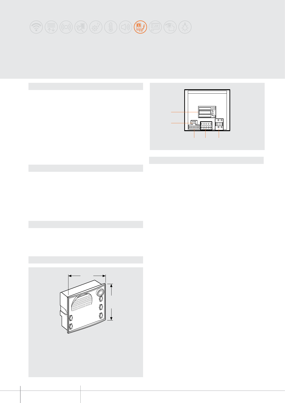
342170
BT00619-a
100 mm
89 mm
32
5
4
1
-EN
TECHNICAL SHEETS
246 2 WIRE VDE system
Description
Speaker module for 2 WIRE system.
The following devices can be connected to the speaker module:
- Colour camera module to realize the video systems item 342550
- Black and white camera module to realize video systems item 342510
- Nameplate module item 342200
- Pushbuttons module item 342240
- Numeric digital call module item 342610
- Alphanumeric digital call module item 342600
All the described modules are connected to the speaker module by means of the
appropriate multi-cables. The speaker module allows to make systems of up to 100
handsets and the opening of an electric door lock directly connected between clamps
S+ S- (18 V 4 A impulsive, 250 mA holding current). The door lock can be locally supplied
by a transformer or using the actuators item 346230 or item 346260.
Related items
332111 (speaker module front cover, 1 pushbutton - Allmetal)
332112 (speaker module front cover, 1 pushbutton - White)
332113 (speaker module front cover, 1 pushbutton - Alugray)
332121 (speaker module front cover, 2 pushbuttons - Allmetal)
332122 (speaker module front cover, 2 pushbuttons - White)
332123 (speaker module front cover, 2 pushbuttons - Alugray)
For the use of monobloc front covers refer to the catalogue.
Technical data
Power supply from SCS BUS: 18 – 27 Vdc
Stand by absorption: 25 mA
Max. operating absorption: 75 mA
Operating temperature: (-25)-(+70)°C
Dimensional data
Legend
1 - Removable connector for the connection of the additional power supply
2 - Removable connector for the connection of the BUS, the electrical door lock, and the
entrance hall door lock release pushbutton.
3 - Socket for the connection of the nameplate module, the pushbuttons module or the
digital call module
4 - Connection socket for the camera connector.
5 - Socket for congurators and potentiometers to adjust the microphone and
loudspeaker volume, jumper for adaptation to the type of door lock and the
alphanumeric call module.
SFERA CLASSIC speaker module
with 2 call pushbuttons
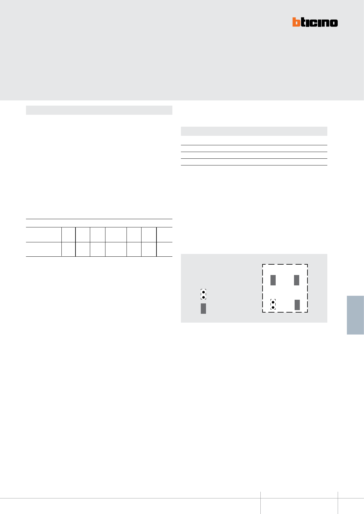
BT00619-a
342170
JMP 1
JMP 2
JMP 3
JMP 4
-EN
TECHNICAL SHEETS
247
2 WIRE VDE system
Conguration
The device must be congured as follows:
P - entrance panel number
The congurator in socket P of the speaker module assigns to this a recognition number
inside the system. The numbering of the entrance panels must always start from P=0.
The entrance panel congured with P=0 must be a common (or main) entrance panel.
N - call number
Assigns the correspondence between the entrance panel pushbuttons and the audio
handsets or video handsets. In common entrance panels made using pushbutton
modules, 1 must be inserted in N of the speaker module. The number of the rst riser
handset must be inserted in the local entrance panels. When the entrance panel is
made with speaker module and digital call module (item 342630 or item 342610) no
congurator must be inserted in N.
S - type of call signal
The conguration of S determines the call tone of SPRINT handsets.
One can thus dierentiate the calls from dierent entrance panels.
Congurator 0 1 2 3
Type of bell 2-tone 2-tone 2-tone One-tone
1200Hz 1200Hz 1200Hz 1200Hz
600Hz 0 Hz 2400Hz
T - door lock relay timing
* Operation as pushbutton for 10 sec. max, after which standby mode is activated.
To extend operation time over 10 seconds, use actuator item 346200 congured with
MOD=5.
0= No
congurator
4 sec.
1
1 sec. 6 sec. 8 sec. 10 sec.
2
2 sec.
3
3 sec. as
pushbutt.
4*5 6 7
congurator number
Table for SPRINT handset call signal
For the SWING, PIVOT, POLYX and AXOLUTE handsets, the S congurator associates the
Entrance panel to the bell programmed in the same apartment. It is possible to chose
between 16 dierent bells. In one-family systems S=9 to congure the general call.
JUMPERS (JMP1) and ( JMP2) - Critical door lock power supply:
Remove the JMP1 and JMP2 jumpers to connect to the speaker module a door lock with
independent power supply.
JUMPER (JMP3) - EP local power supply
Remove the JMP3 jumpers when the speaker module is powered by an additional power
supply.
= disconnected jumper
= connected jumper
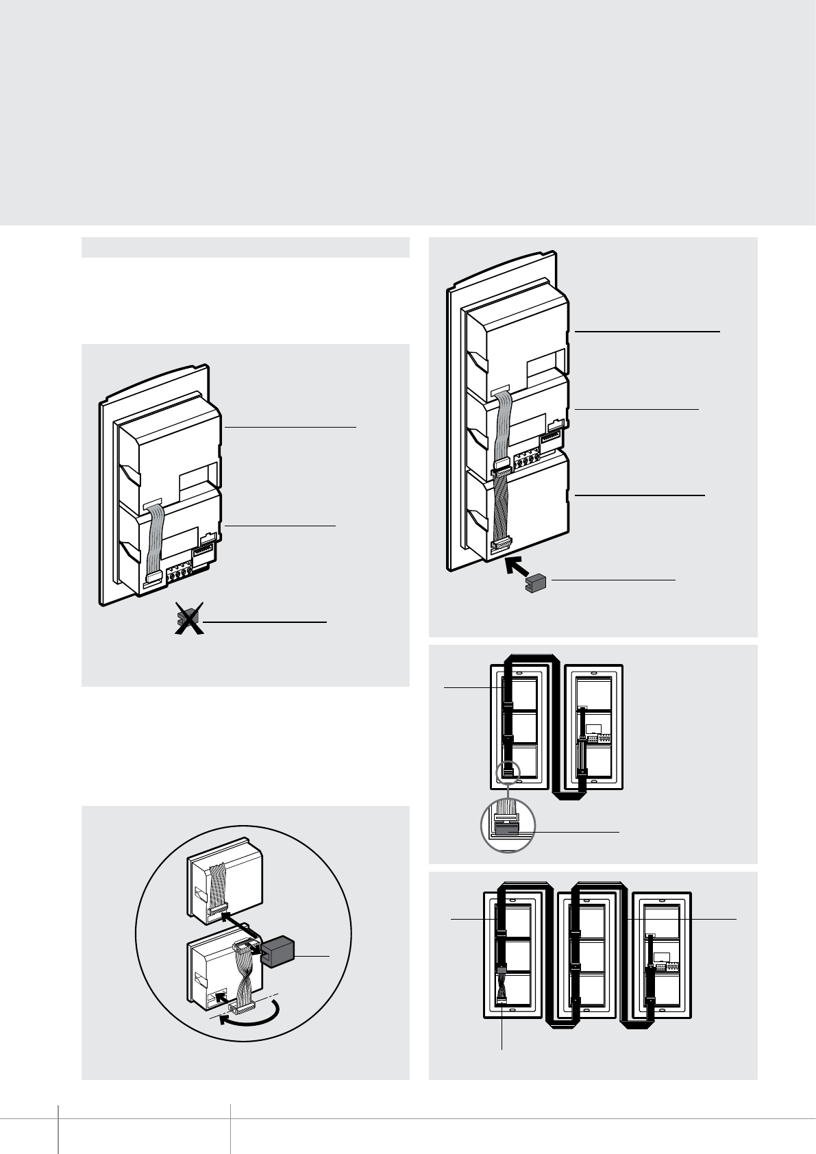
342170
BT00619-a
180°
1
2
3
4
346902 346902
346902
346903
-EN
TECHNICAL SHEETS
248 2 WIRE VDE system
Installation and connection
Supplied as standard with the speaker module is a closing accessory with connector.
The accessory must be tted in the last pushbutton module of the pushbutton panel,
after connecting the modules to each other using the multicables with connectors.
It must not be used if the pushbutton panel only consists of a 1 or 2 pushbutton speaker
module, in addition to a camera module that may be installed.
Camera module
Speaker module
Example: entrance panel consisting of camera module and speaker module. It
does not require the accessory supplied with the product.
Accessory
- With entrance panels with less than 26 calls, it is necessary to connect the modules
in a vertical position on several columns using item 346902, and to t in the last
pushbutton module the accessory supplied as standard.
- For entrance panels with more than 26 calls it is necessary to connect the modules
in a vertical position on several columns using item 346902 . After the sixth key
module (or after 26 calls), t item 346903 and invert the at supplied as standard.
In the last key module t the accessory supplied as standard.
Connection item 346903 and at inversion.
Example: speaker module consisting of camera module, speaker module and
4-pushbutton module; the accessory supplied as standard must also be used.
Camera module
Speaker module
Accessory
Pushbuttons module
Example - Connection of
pushbutton panel with less
than 26 calls
Accessory
Example - Connection of pushbutton panel with more than 26 calls.
Accessory
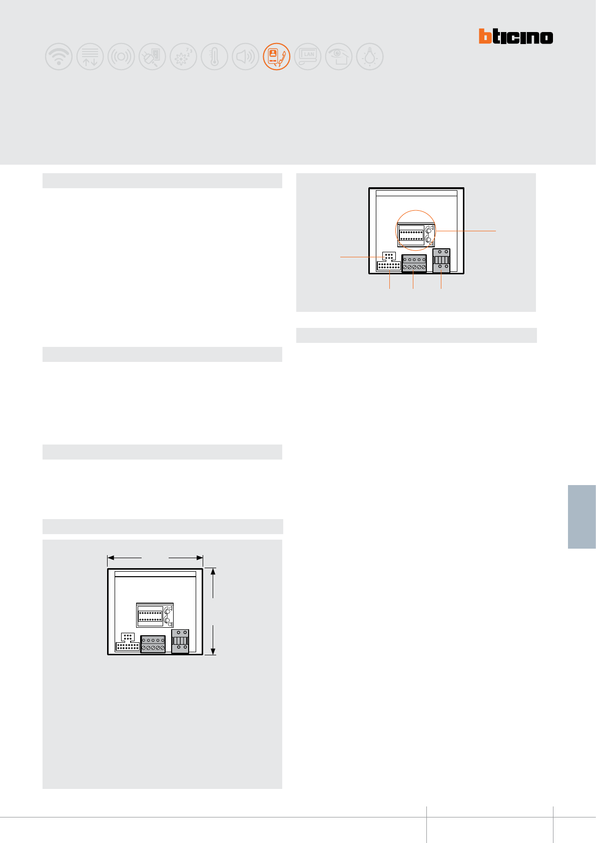
342350
BT00620-a
100 mm
89 mm
43
1
5
2
-EN
TECHNICAL SHEETS
249
2 WIRE VDE system
Description
Speaker module for 2 WIRE system.
The following devices can be connected to the speaker module:
- Colour camera module to realize the video systems item 342550
- Black and white camera module to realize video systems item 342510
- Nameplate module item 342200
- Pushbutton module item 342480
- Numeric digital call module item 342610
- Alphanumeric digital call module item 342600
All the described modules are connected to the speaker module by means of the
appropriate multi-cables. The speaker module allows to make systems of up to 50
handsets and the opening of an electric door lock directly connected between clamps
S+ S–(18 V 4 A impulsive, 250 mA holding current). The door lock can be locally supplied
by a transformer or using the actuators 346230 or item 346260.
Related items
332321 (speaker module front cover, 2 pushbuttons - Allmetal)
332341 (speaker module front cover, 4 call pushbuttons - Allmetal)
332322 (speaker module front cover, 2 pushbuttons - White)
332342 (speaker module front cover, 4 call pushbuttons - White)
332323 (speaker module front cover, 2 pushbuttons - Alugray)
332343 (speaker module front cover, 4 call pushbuttons - Alugray)
Technical data
Power supply from SCS BUS: 18 – 27 Vdc
Stand by absorption: 25 mA
Max. operating absorption: 75 mA
Operating temperature: (-25)-(+70)°C
Dimensional data
Legend
1 - Socket for congurators and potentiometers to adjust the microphone and
loudspeaker volume, jumper for adaptation to the type of door lock and the
alphanumeric call module.
2 - Removable connector for the connection of the additional power supply.
3 - Removable connector for the connection of the BUS, the electrical door lock, and the
entrance hall door lock release pushbutton.
4 - Socket for the connection of the nameplate module, the pushbutton module or the
digital call module.
5 - Connection socket for the camera connector.
SFERA CLASSIC, speaker module
with 4 call pushbuttons
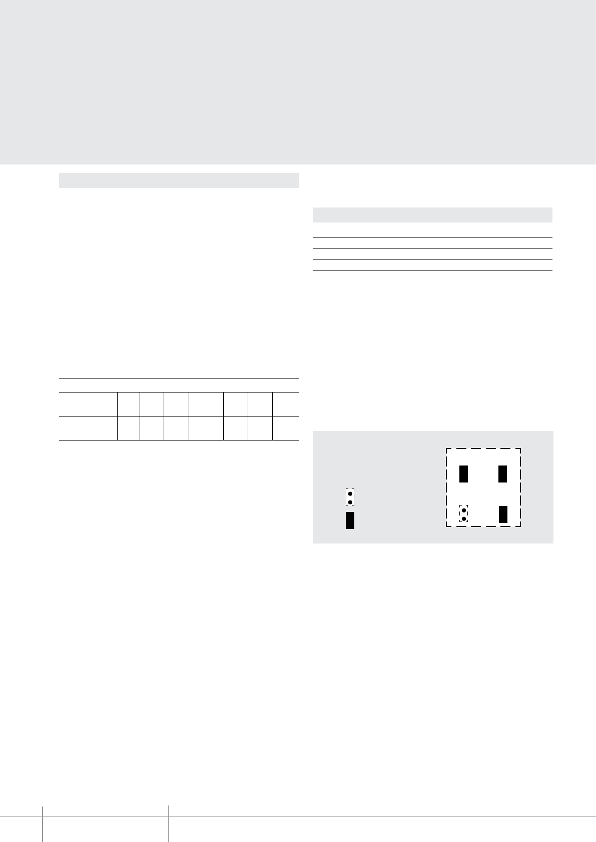
BT00620-a
342350
JMP 1
JMP 2
JMP 3
JMP 4
-EN
TECHNICAL SHEETS
250 2 WIRE VDE system
Conguration
The device must be phisically congured as follows:
P - entrance panel number
The congurator in socket P of the speaker module assigns to this a recognition number
inside the system.
The numbering of the entrance panels must always start from P=0.
The entrance panel congured with P=0 must be a common (or main) entrance panel.
N - call number
Assigns the correspondence between the entrance panel pushbuttons and the audio
handsets or video handsets. In the common entrance panels made with pushbutton
modules, 1 must be inserted in N of the speaker module. The number of the rst riser
handset must be inserted in the local entrance panels in N. When the entrance panel
is made with speaker module and digital call module (item 342630 or item 342610) no
congurator must be inserted in N.
S - type of call signal
The conguration of S determines the call tone of SPRINT handsets.
One can thus dierentiate the calls from dierent entrance panels.
Congurator 0 1 2 3
Type of bell 2-tone 2-tone 2-tone One-tone
1200Hz 1200Hz 1200Hz 1200Hz
600Hz 0 Hz 2400Hz
T – Door lock control time delay
* Operation as pushbutton for 10 sec. max, after which standby mode is activated.
To extend operation time over 10 seconds, use actuator item 346200 congured with
MOD=5.
0= No
congurator
4 sec.
1
1 sec. 6 sec. 8 sec. 10 sec.
2
2 sec.
3
3 sec. as
pushbutt.
4*5 6 7
congurator number
Table for SPRINT handset call signal
For the SWING, PIVOT, POLYX and AXOLUTE handsets, the S congurator associates the
entrance panel to the bell programmed in the same apartment. It is possible to chose
between 16 dierent bells.
In one-family systems, S=9 congures the general call and the handsets ring, the
same as with the S=0.
JUMPERS (JMP1) and ( JMP2) - Critical door lock power supply:
Remove the JMP1 and JMP2 jumpers to connect to the speaker module a door lock with
independent power supply.
JUMPER (JMP3) - EP local power supply
Remove the JMP3 jumpers when the speaker module is powered by an additional power
supply.
= disconnected jumper
= connected jumper
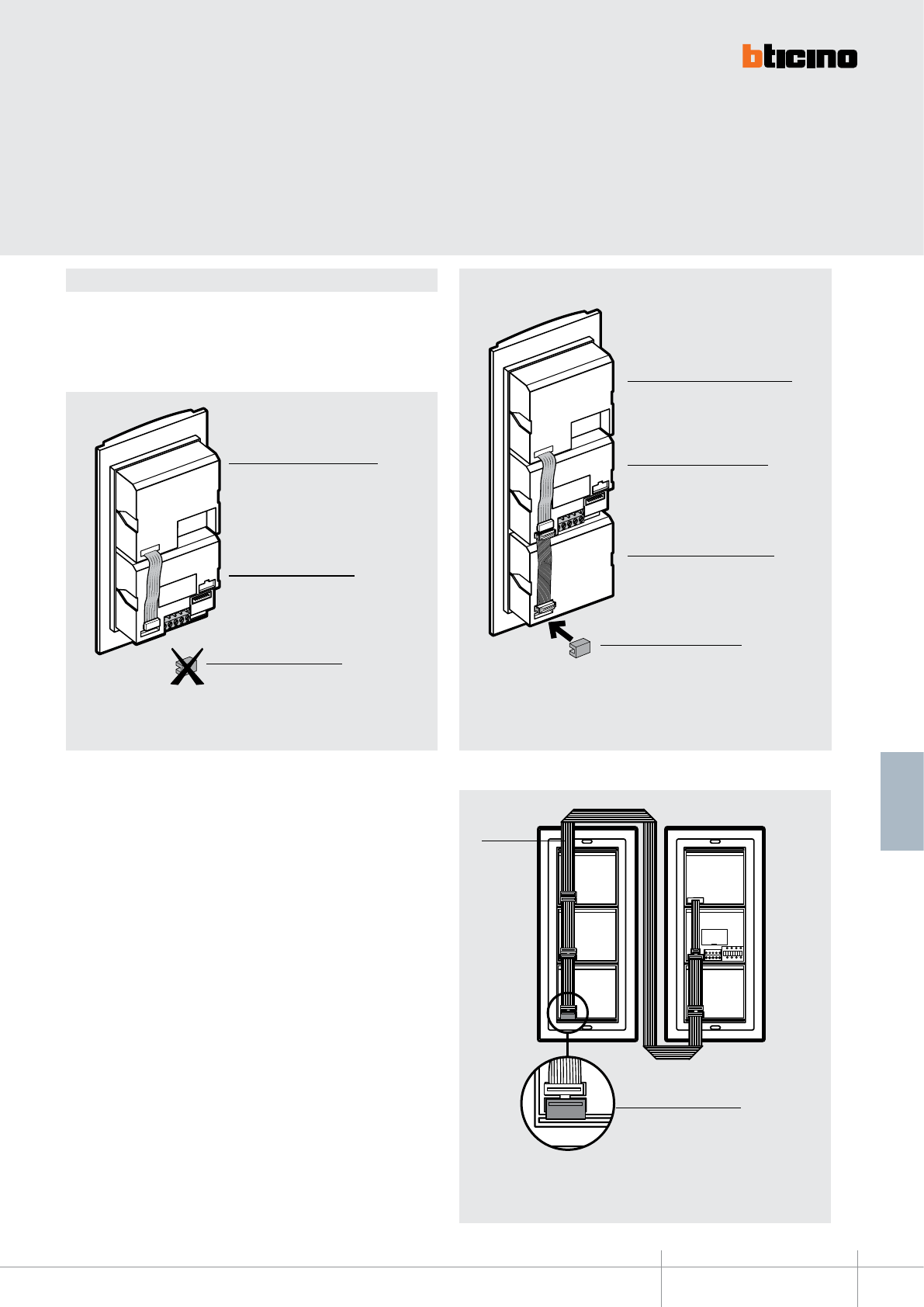
342350
BT00620-a
346902
-EN
TECHNICAL SHEETS
251
2 WIRE VDE system
Installation and connection
Supplied as standard with the speaker module is a closing accessory with connector.
The accessory must be tted in the last pushbutton module of the pushbutton panel,
after connecting the modules to each other using the multicables with connectors.
It must not be used if the pushbutton panel only consists of a 1 or 2 pushbutton speaker
module, in addition to a camera module that may be installed.
- In order to connect several key modules vertically on dierent columns, item 346092
must be used, tting the closing accessory in the last module.
Example - Entrance panel consisting of camera module and speaker module.
It does not require the accessory.
Camera module
Speaker module
Closing accessory
Camera module
Speaker module
Closing accessory
Pushbutton module
Example - entrance panel consisting of camera module, speaker module and
pushbutton module. It requires the accessory supplied with the product.
Example - connection with pushbutton modules.
Closing accessory
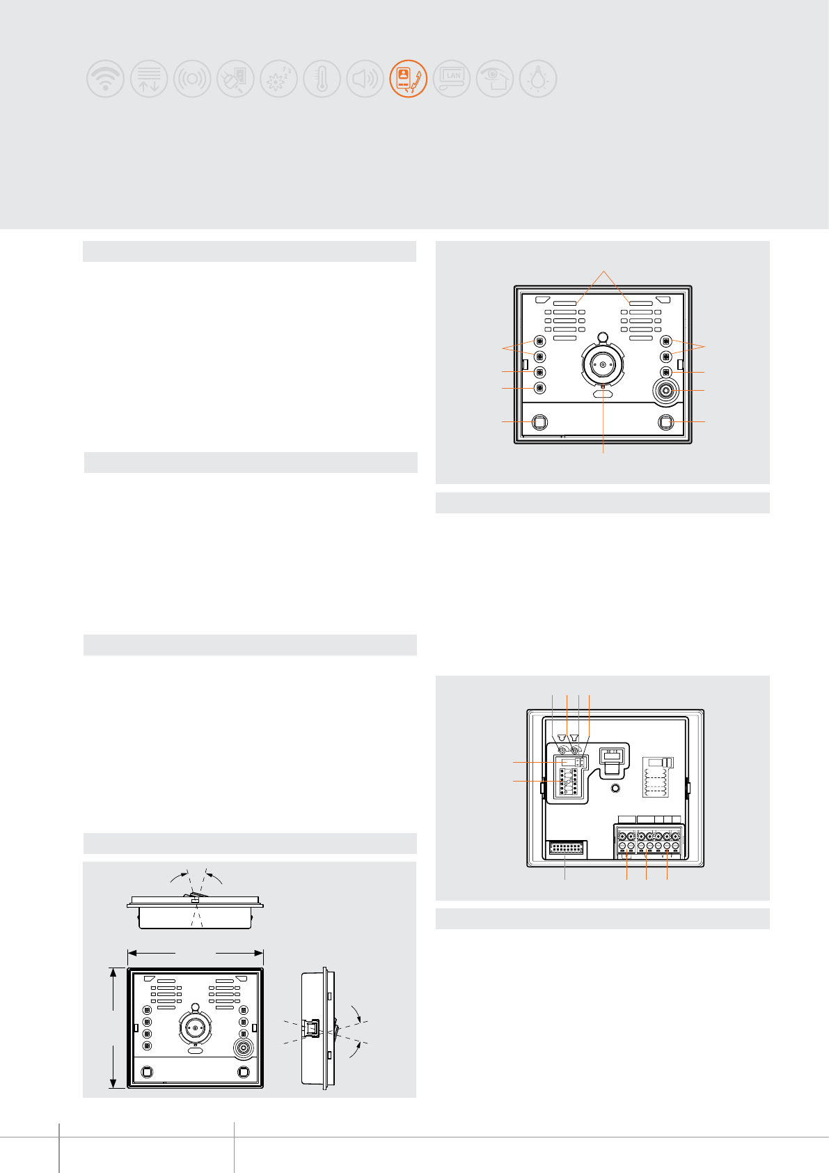
342560
BT00621-a
40°
40°
100 mm
89 mm
1
6
5 5
7
22
8 3
4
USB
J1
J2
P
N
TS
21BUSPL S+ S−
ART.342560
13
5678
2 4
9
10
-EN
TECHNICAL SHEETS
252 2 WIRE VDE system
Description
Audio/video speaker module for 2 wire system tted with colour camera with LED
lighting for night viewing.
Camera with slant adjustment horizontally and vertically by ±20°.
The connections to the system are made by wiring the removable clamp supplied; the
nameplates are illuminated by green LEDs. A closing card to be inserted in the last
pushbutton module is supplied.
To be completed with the modular “Audio/video” front covers.
The speaker module allows to make systems of up to 100 handsets and the opening of
an electric door lock directly connected between the clamps S+ S– (18 V 4 A impulsive,
250 mA holding current). The door lock can be locally supplied with a transformer, or
using the actuators item 346230 or item 346260.
Related items
342461 (modular A/V front cover without call pushbuttons - Allmetal)
342462 (modular A/V front cover without call pushbuttons - White)
342463 (modular A/V front cover without call pushbuttons - Alugray)
342471 (modular A/V front cover with 1 call pushbutton - Allmetal)
342472 (modular A/V front cover with 1 call pushbutton - White)
342473 (modular A/V front cover with 1 call pushbutton - Alugray)
342481 (modular A/V front cover with 2 call pushbutton - Allmetal)
342482 (modular A/V front cover with 2 call pushbutton - White)
342483 (modular A/V front cover with 2 call pushbutton - Alugray)
Technical data
Power supply from SCS BUS: 18 – 27 Vdc
Stand by absorption: 40 mA
Max. operating absorption: 160 mA
Operating temperature: (-25)-(+70)°C
Lens: F: 1.5 mm ; f: 4.3 mm
Sensor: 1/3”
Interlace: 2:1
Horizontal resolution: 330 lines
Night lighting: white LEDs
Brightness adjustment: automatic
Dimensional data
Legend
1 - Loudspeakers
2 - White LEDs for night lighting
3 - Green LED for door status notication
4 - Microphone
5 - Call pushbuttons
6 - Colour camera
7 - Green LED: put through call notication
Red LED: busy system notication
8 - Green LED: active communication notication
Legend
1 - Microphone volume adjustment
2 - Loudspeaker volume adjustment
3 - J1: remove to enable additional power supply
4 - J2: when connected, two columns of call pushbuttons are active, when disconnected
only one column is active
5 - Door lock connection and local open door pushbutton
6 - Connection to the 2 wire BUS
7 - Connection to the additional power supply
8 - Connection to the additional pushbuttons
9 - Congurator socket
10 - USB connector for PC connection
SFERA CLASSIC
audio video speaker module
Front view
Rear view
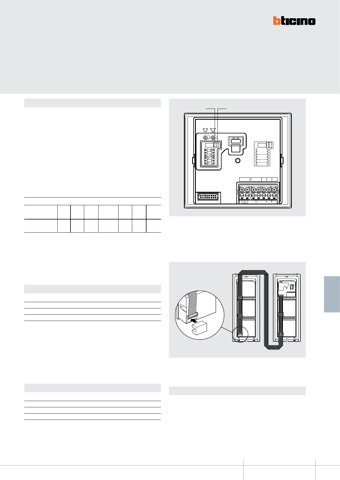
BT00621-a
342560
USB
P
N
TS
21BUS PL S+ S−
ART.342560
USB
J1
J2
P
N
TS
21BUS PL S+ S−
ART.342560
(J1) (J2)
-EN
TECHNICAL SHEETS
253
2 WIRE VDE system
Conguration
The device must be congured as follows:
P - entrance panel number
The congurator in seat P of the speaker module assigns to it a recognition number
inside the system. The numbering of the entrance panels must always start from P=0.
The entrance panel congured with P=0 must be a common (or main) entrance panel.
N - call number
Assigns the correspondence between the entrance panel pushbuttons and the audio
handsets or video handsets. In the common entrance panels made with pushbutton
modules, 1 must be inserted in N of the speaker module. The number of the rst riser
audio and video handset must be inserted in the local entrance panels in N.
Camera installation notes
The camera must not be installed facing strong light sources, or in locations where the
area being shot is strongly backlit. In order to resolve these problems, we recommend
that the camera is installed at a height of 180 cm, instead of the usual 160-165 cm,
with the lens pointing down. This will improve image quality. In low light situations,
the colour rendition of the image displayed by the colour camera may decrease. This is
to ensure that the person being displayed can be better recognised. For optimal viewing
in low light conditions, the installation of an additional light source is recommended.
T - door lock relay timing
* Operation as pushbutton for 10 sec. max, after which standby mode is activated.
To extend operation time over 10 seconds, use actuator item 346200 congured with
MOD=5.
0= No
congurator
4 sec.
1
1 sec. 6 sec. 8 sec. 10 sec.
2
2 sec.
3
3 sec. as
pushbutt.
4*5 6 7
congurator number
S-type of call signal with entrance panel door lock opening notication beep
The conguration of S determines the call tone of the SPRINT handsets. One can thus
dierentiate the calls from dierent entrance panels.
S-type of call signal without entrance panel door lock opening notication beep
The conguration of S determines the call tone of the SPRINT handsets.
One can thus dierentiate the calls from dierent entrance panels.
Congurator 0 1 2 3
Type of bell 2-tone 2-tone 2-tone One-tone
1200Hz 1200Hz 1200Hz 1200Hz
600Hz 0 Hz 2400Hz
Table for SPRINT handset call signal
Congurator 4 5 6 7
Type of bell 2-tone 2-tone 2-tone One-tone
1200Hz 1200Hz 1200Hz 1200Hz
600Hz 0 Hz 2400Hz
Table for SPRINT handset call signal
For the SWING, PIVOT, POLYX and AXOLUTE handsets, the S congurator associates the
Entrance panel to the bell programmed in the saMe apartment. It is possible to chose
between 16 dierent bells. In one-family systems, S=9 congures the general call and
the handsets ring, the same as with the S=0.
For the SWING, PIVOT, POLYX and AXOLUTE handsets, the S congurator associates the
Entrance panel to the bell programmed in the same apartment. It is possible to chose
between 16 dierent bells. In one-family systems, S=8 congures the general call and
the handsets ring, the same as with the S=0.
J1 - EP local power supply
Remove the JMP1 jumpers when the speaker module is supplied by a dedicated power
supply.
J2 - activation of pushbutton columns
When connected, two columns of call pushbuttons are active, when disconnected only
one column is active.
Supplied as standard with the audio and video speaker module, is a closing accessory
with connector. The accessory must be tted in the last pushbutton module of the
entrance panel, after connecting the modules to each other using the multicables.
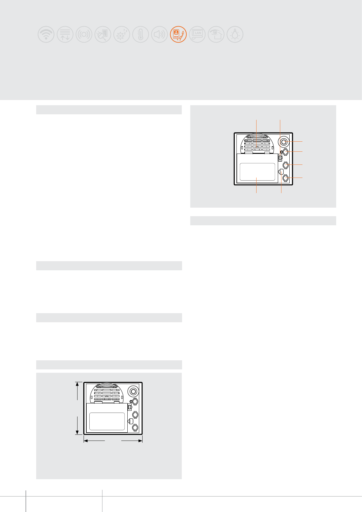
342630
BT00622-a
100 mm
89 mm
1 2
87
5
4
6
3
-EN
TECHNICAL SHEETS
254 2 WIRE VDE system
Dimensional data
Description
Speaker module for 2 WIRE system with graphic display.
Can send the call to an handset by scrolling the residents’ names or codes on a display
(previously programmed).
It integrates the speaker module and the resident search function on graphic display in
one device. The module can save up to 1000 residents’ names and surnames associating
them to the apartment SCS address.
500 names can be saved when the option of coupling a message with them is selected.
If only the residents’ codes are saved, the capacity extends to 5000 codes
The names may be programmed in the address book in the following ways:
- Using the keys of the module
- Using the dedicated TICALL software (which can be downloaded from the www.bticino
website) - (it also gives the possibility of updating the rmware after entering the user
password).
To make the call:
- Scroll the names using keys ref. 5 and 6
- Press key ref. 4 (ashing) to send the call
NOTE: System power supply cuts do not cause the loss of memory data.
Related items
332661 (speaker module front cover - Allmetal)
332662 (speaker module front cover - White)
332663 (speaker module front cover - Alugray)
For the use of monobloc front covers refer to the catalogue.
Technical data
Power supply from SCS BUS: 18 – 27 Vdc
Stand by absorption: 110 mA
Max. operating absorption: 160 mA
Operating temperature: (-25)-(+70)°C
Legend
1 - Loudspeaker
2 - Connector to the RS-232 port of the PC (use the cable item 335919)
3 - Microphone
4 - Call forward key
5 - Scroll key (Up)
6 - Scroll key (Down)
7 - IR receiver (programming using the remote control)
8 - Graphic display
SFERA CLASSIC,
speaker module with graphic display
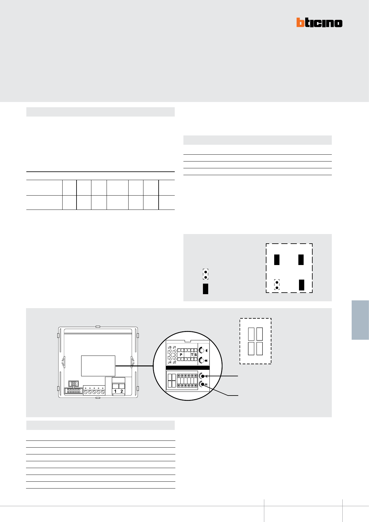
BT00622-a
342630
JMP 1
JMP 2
JMP 3
JMP 4
-EN
TECHNICAL SHEETS
255
2 WIRE VDE system
Conguration
The device must be phisically congured as follows:
P - entrance panel number
The congurator in socket P of the speaker module assigns to this a recognition number
inside the system.
The numbering of the entrance panels must always start from P=0. The entrance panel
congured with P=0 must be a common (or main) entrance panel.
T - Door lock relay timing
* Operation as pushbutton for 10 sec. max, after which standby mode is activated.
To extend operation time over 10 seconds, use actuator item 346200 congured with
MOD=5.
0= No
congurator
4 sec.
1
1 sec. 6 sec. 8 sec. 10 sec.
2
2 sec.
3
3 sec. as
pushbutt.
4*5 6 7
congurator number
S – type of call signal
The conguration of S determines the call tone of handsets.
One can thus dierentiate the calls from dierent entrance panels.
Congurator 0 1 2 3
Type of bell 2-tone 2-tone 2-tone One-tone
1200Hz 1200Hz 1200Hz 1200Hz
600Hz 0 Hz 2400Hz
Table for handset call signal
J1/J2 - Critical door lock power supply
Remove the JMP1 and JMP2 jumpers to connect to the speaker module a door lock with
independent power supply.
J3 - EP local power supply
When the device is powered locally remove jumper JMP3
J4 - it conrms the EP call
To eliminate the entrance panel call conrmation sound, remove the J4 jumper.
For the SWING, PIVOT, POLYX and AXOLUTE handsets, the congurator associates the
entrance panel to the bell programmed in the same apartment. It is possible to chose
between 16 dierent bells. In one-family systems S=9 to congure the general call.
= disconnected jumper
= connected jumper
loudspeaker volume
adjustment
microphone sensitivity
adjustment
J3 J1
J4 J2
Secret code 1234
Language Italian
Address book format
Alphanumeric without message
Switchboard 4000 Disabled
Direct call 0000 and 0001 Disabled
Door code 1234, 1235, 1236, 1237 and 1238
Contrast 50
Recall Disabled
Factory conguration
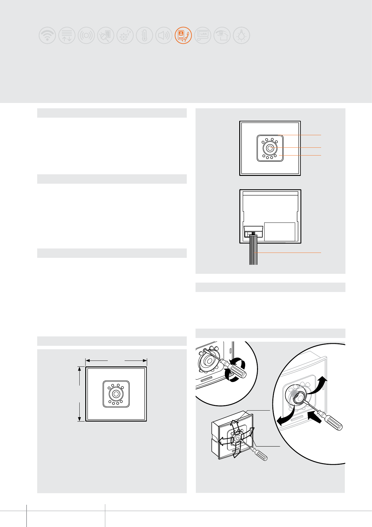
342510
BT00623-a
12
89 mm
100 mm
12
2
3
1
4
1
3
(-15)-(+15)°
(-15)-(+15)°
-EN
TECHNICAL SHEETS
256 2 WIRE VDE system
Description
SFERA 2 WIRE black & white camera module.
CMOS technology, tted with IR so that it can be used in poorly lit surroundings.
To be used together with 2-wire speaker modules (connection using a multicable).
During installation it is possible to swivel the lens horizontally and vertically by +/- 15°.
The device must not be congured.
Related items
342170 (speaker module with 2 call pushbuttons)
342350 (speaker module with 4 call pushbuttons)
342630 (speaker module with graphic display)
332511 (modular camera front cover - Allmetal)
332512 (modular camera front cover - White)
332513 (modular camera front cover - Alugray)
For the use of monobloc front covers refer to the catalogue.
Technical data
Power supply from SCS BUS: 18-27 Vdc
Max. operating absorption: 250 mA
Stand by absorption: 15 mA
Operating temperature: (-25)-(+70)°C
Camera sensor: 1/3”
Lens: f : 2.0 mm; F : 4.3 mm
Interlace: 2:1
Resolution: 380 horizontal lines
Night lighting: LED IR
Brightness adjustment: automatic (linear)
Dimensional data
Lens adjustment
Legend
1 - Fixing screw for the adjustment of the lens position
2 - Lens
3 - IR LED for night lighting of the eld of view
4 - Multicable for connection to speaker module
SFERA CLASSIC,
black & white camera module
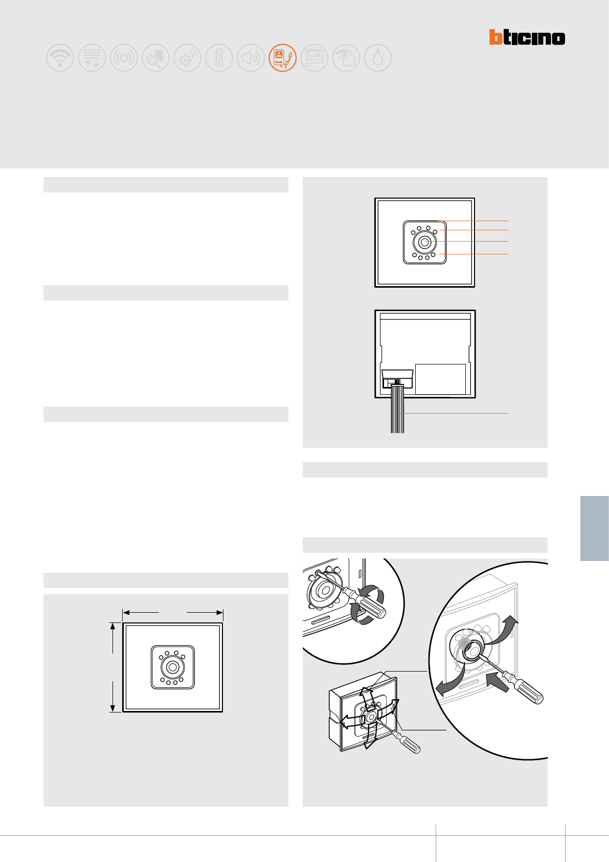
342550
BT00624-a
12
89 mm
100 mm
12
3
2
2
1
4
1
3
(-15) ÷ (+15)°
(-15) ÷ (+15)°
-EN
TECHNICAL SHEETS
257
2 WIRE VDE system
Description
SFERA swivel colour camera module
CCD technology, tted with white LEDs so that it can be used in
poorly lit surroundings. To be used together with 2-wire speaker modules (connection
using a multicable).
During installation it is possible to swivel the lens horizontally and vertically.
The device must not be congured.
Related items
342170 (Speaker module with 2 call pushbuttons)
342350 (Speaker module with 4 call pushbuttons)
342630 (Speaker module with Graphic display)
332511 (modular camera front cover - Allmetal)
332512 (modular camera front cover - White)
332513 (modular camera front cover - Alugray)
For the use of monobloc front covers refer to the catalogue.
Technical data
Power supply from SCS BUS: 18-27 Vdc
Max. operating absorption: 165 mA
Stand by absorption: 15 mA
Operating temperature: (-25)-(+70)°C
Camera sensor: 1/4”
Lens: f : 2.8 mm; F : 3 mm
Sensibility: 0.4 lux - F1.4
Interlace: 2:1
Horizontal resolution: > 330 lines
Vertical resolution: 400 lines
Night lighting: white LEDs
Brightness adjustment: automatic (linear)
Dimensional data
Lens adjustment
Legend
1 - Lens slant adjustment
2 - White LEDs for night lighting
3 - Lens
4 - Multicable for connection to speaker module
SFERA CLASSIC,
Colour camera module
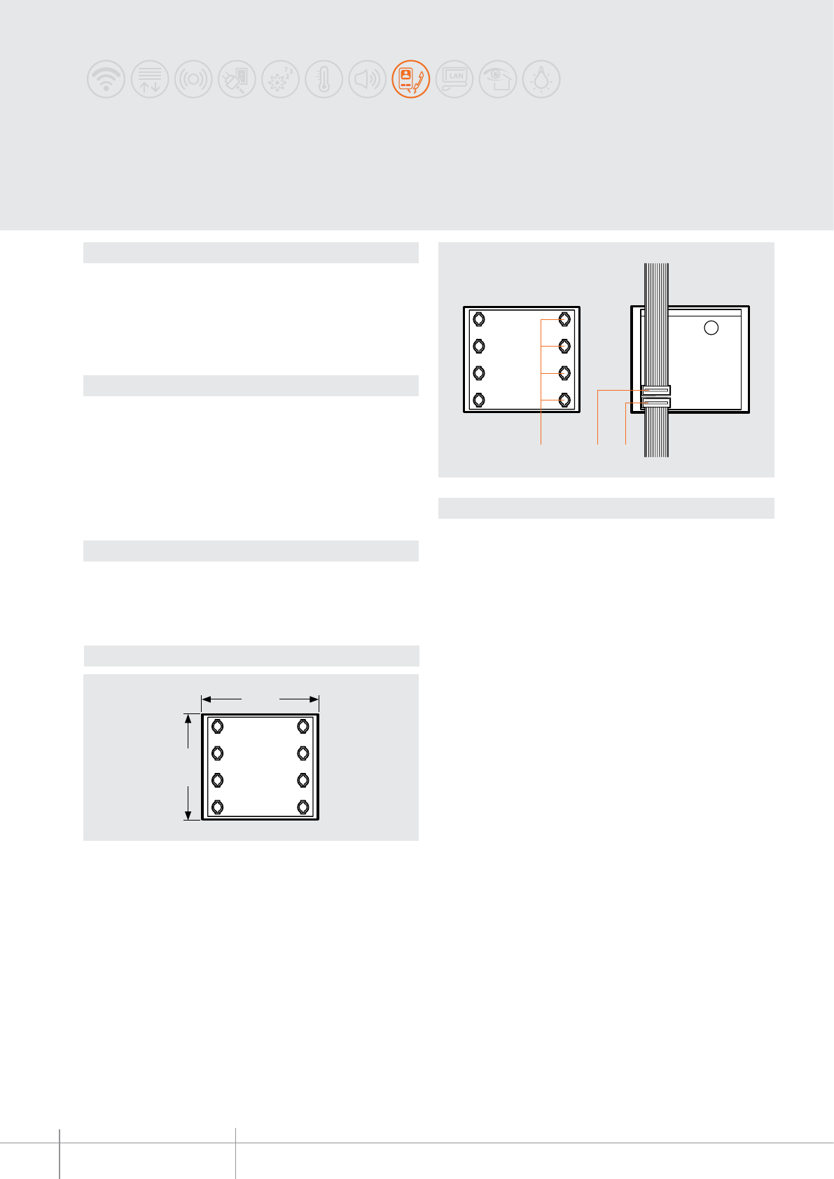
342240
BT00625-a
100 mm
89 mm
1
2
3
-EN
TECHNICAL SHEETS
258 2 WIRE VDE system
Description
2 WIRE pushbutton module with 4 call pushbuttons. The connections to the system are
made using the multi-cable supplied; also, the nameplates are illuminated by 12 green
LED. To be used with speaker modules, items 342150 and 342170, and with modular
front covers and pushbutton monobloc.
The device must not be congured.
Related items
332231 (front cover with 3 keys - Allmetal)
332232 (front cover with 3 keys - White)
332233 (front cover with 3 keys - Alugray)
332241 (front cover with 4 keys - Allmetal)
332242 (front cover with 4 keys - White)
332243 (front cover with 4 keys - Alugray)
For the use of monobloc front covers refer to the catalogue.
Technical data
Power supply from SCS BUS: 18 – 27 Vdc
Stand by absorption: 15 mA
Max. operating absorption: 15 mA
Operating temperature: (-25) – (+70) °C
Dimensional data
Legend
1 - Connector socket for output connection with other modules and for the last
pushbutton module, housing for the electronic card supplied as standard with the
speaker module.
2 - Input socket for connection with other modules.
3 - Call pushbuttons.
SFERA CLASSIC
4-pushbutton module
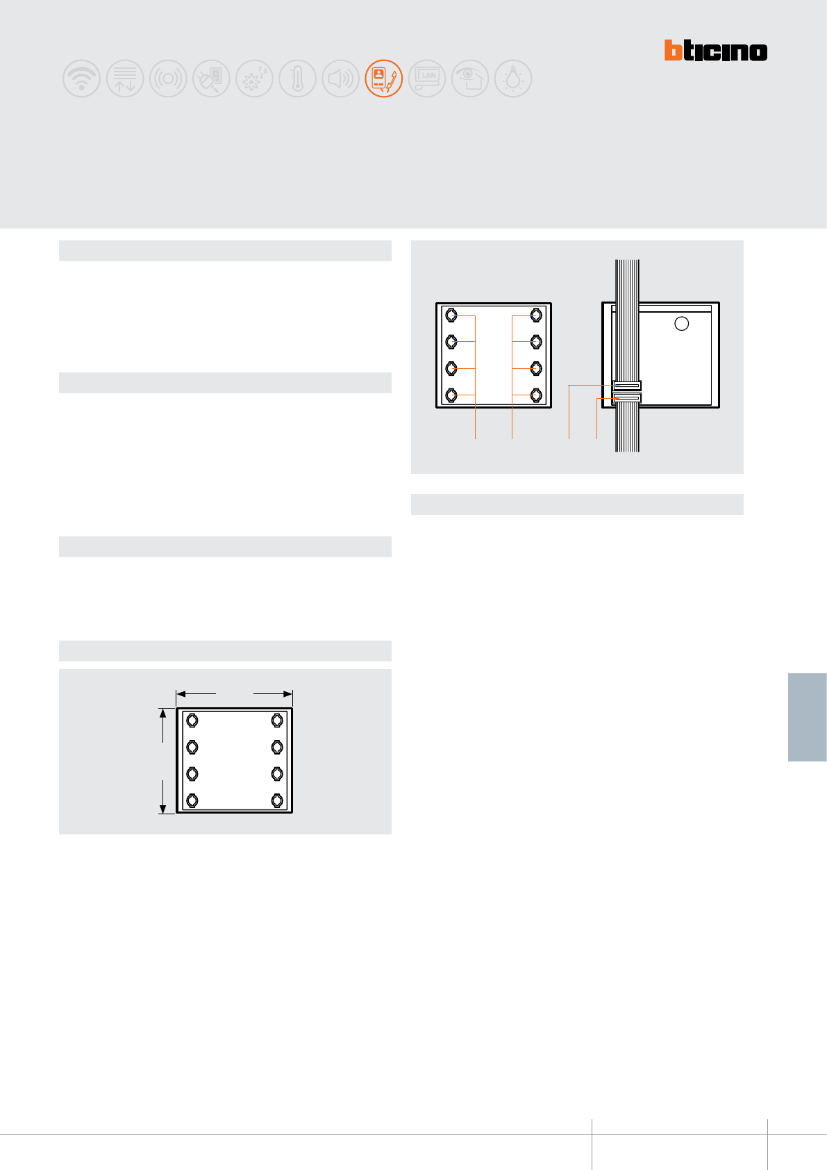
342480
BT00626-a
100 mm
89 mm
1
2
33
-EN
TECHNICAL SHEETS
259
2 WIRE VDE system
Description
2 WIRE pushbutton module with 8 call pushbuttons. Connections to the system are
made using the multicable supplied: also, name plates are illuminated by 12 green
LEDs. To be used with speaker modules, items 342560 and 342350, and with modular
“pushbutton” front covers with double row of keys.
The device must not be congured.
Related items
332461 (modular front cover with 6 pushbuttons - Allmetal)
332462 (modular front cover with 6 pushbuttons - White)
332463 (modular front cover with 6 pushbuttons - Alugray)
332481 (modular front cover with 8 pushbuttons - Allmetal)
332482 (modular front cover with 8 pushbuttons - White)
332483 (modular front cover with 8 pushbuttons - Alugray)
For the use of monobloc front covers refer to the catalogue.
Technical data
Power supply from SCS BUS: 18 – 27 Vdc
Stand by absorption: 15 mA
Max. operating absorption: 15 mA
Operating temperature: (-25) – (+70) °C
Dimensional data
Legend
1 - Connector socket for output connection with other modules and for the last
pushbutton module, housing for the electronic card supplied as standard with the
speaker module.
2 - Input socket for connection with other modules.
3 - Call pushbuttons
SFERA CLASSIC
8 pushbutton module
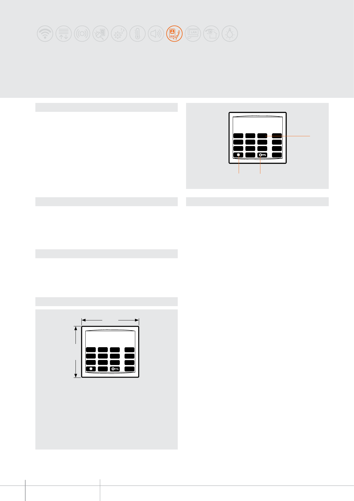
342640
BT00627-a
100 mm
89 mm
1
9
4
7
2
5
8
0
3
6
A
B
C
D
1
9
4
7
2
5
8
0
3
6
A
B
C
D
3 2
1
-EN
TECHNICAL SHEETS
260 2 WIRE VDE system
Dimensional data
Description
Additional alphanumeric keypad module to be used in conjunction with the speaker
module with graphic display, item 342630.
It can call the resident directly (by typing the programmed code) and access the door
lock release function (by typing the secret code).
It is supplied with multi-cable and connector for connection to the speaker module.
To be used with the “Alphanumeric keypad” front covers.
Once the last digit has been entered, the call is forwarded automatically.
The digits are NOT displayed on the speaker module display, item 342630.
System power supply cuts do NOT cause the loss of memory data.
The device must not be congured.
Related items
332671 (modular keypad front cover - Allmetal)
332672 (modular keypad front cover - White)
332673 (modular keypad front cover - Alugray)
For the use of monobloc front covers refer to the catalogue.
Technical data
Power supply from SCS BUS: 18 – 27 Vdc
Stand by absorption: 15 mA
Max. operating absorption: 15 mA
Operating temperature: (-25) – (+70) °C
Legend
1 - Alphanumeric keypad
2 - Door lock opening key
3 - Cancel key
SFERA CLASSIC, additional alphanumeric
Keypad module
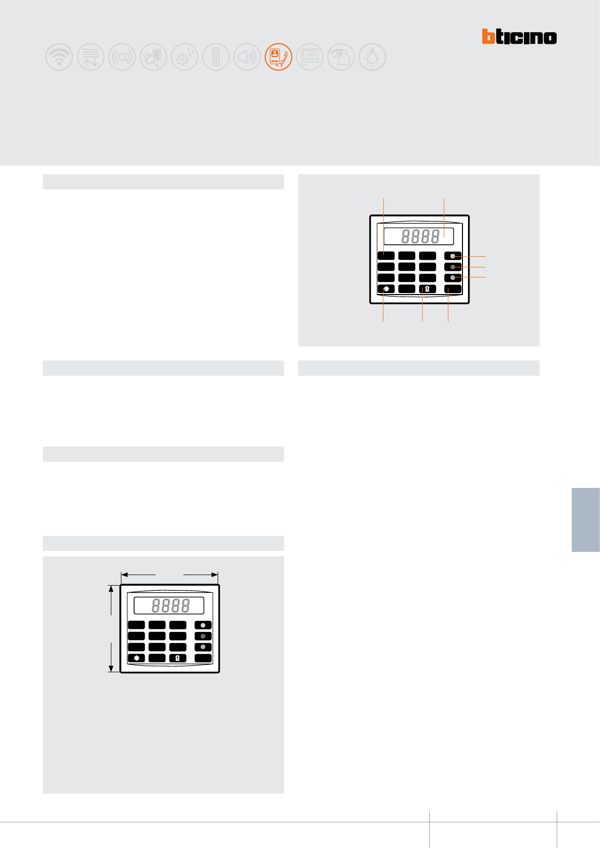
342610
BT00628-a
100 mm
89 mm
1
9
4
7
2
5
8
0
3
6
C
1
9
4
7
2
5
8
0
3
6
C
8 7 6
1 2
5
4
3
-EN
TECHNICAL SHEETS
261
2 WIRE VDE system
Dimensional data
Description
The numeric call module can make calls from the entrance panel to handsets by just
keying in the number corresponding to the handset required.
The correspondence between the numbers and the user names is found from a phone
book by the side of the module and made up of nameplate modules Item 342200.
From one to four numbers may be keyed in to make the call, as programmed by the
installer.
The module can also activate the electric door lock by means of a secret code number.
The module is supplied with a multicable for the connection to the speaker module.
To be used with keypad monobloc front covers and alphanumeric keypad modular front
cover.
The call is forwarded automatically after the last digit has been entered.
System power supply cuts do NOT cause the loss of memory data.
The device must not be congured.
Related items
332651 (modular keypad front cover - Allmetal)
332652 (modular keypad front cover - White)
332653 (modular keypad front cover - Alugray)
For the use of monobloc front covers refer to the catalogue.
Technical data
Power supply from SCS BUS: 18 – 27 Vdc
Stand by absorption: 15 mA
Max. operating absorption: 15 mA
Operating temperature: (-25) – (+70) °C
Legend
1 - Numeric keypad
2 - Numeric LED display (4 digits)
3 - Yellow call conrmation LED
4 - Red local conversation active signalling LED
5 - Green line free signalling LED
6 - Deleting key
7 - Door lock opening key
8 - Key for programming
SFERA CLASSIC, digital numeric
call module
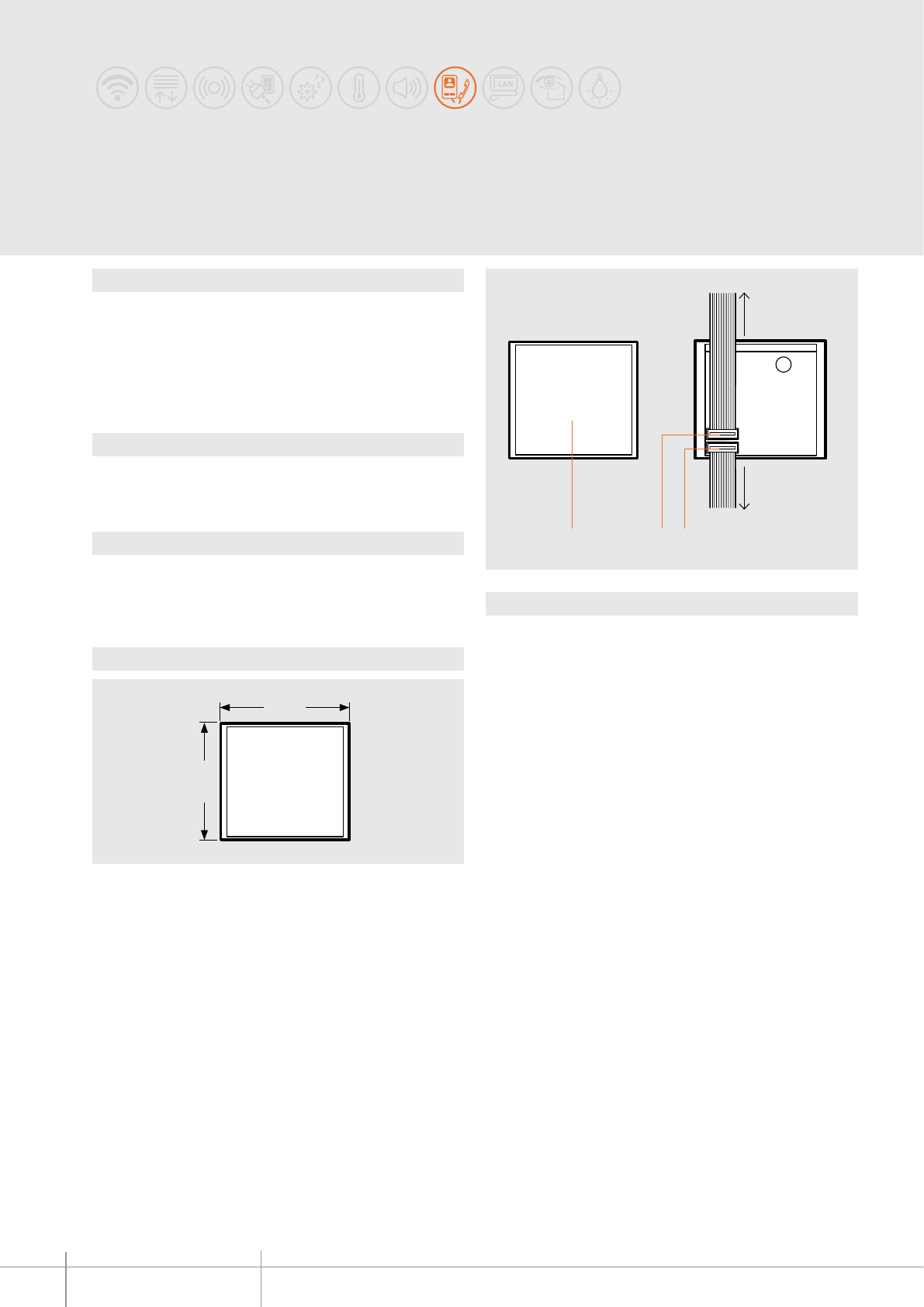
342200
BT00629-a
89 mm
100 mm
123
-EN
TECHNICAL SHEETS
262 2 WIRE VDE system
Description
SFERA nameplate module which can be used to enter the street number or any other
information. Can be used to enter a caption in pushbutton panels with numerical call
module item 342610. To be used with the “Nameplate” modular front cover.
Nameplate lighting by green LEDs.
A at-cable for the connection to other modules is supplied.
The device must not be congured.
Related items
332201 (Allmetal nameplate front cover)
332202 (White nameplate front cover)
332203 (Alugray nameplate front cover)
Technical data
Power supply from SCS BUS: 18-27 Vdc
Max. operating absorption: 15 mA
Stand by absorption: 15 mA
Operating temperature: (-25)-(+70)°C
Dimensional data
Legend
1 - Connector socket for output connection with other modules, and housing for the
electronic card supplied as standard with the speaker module (to be used on the last
nameplate module only)
2 - Input socket for connection with other modules.
3 - Namecard for address number, legend of call addresses or other information.
to the speaker
module or to other
pushbuttons or
nameplate module
to other
pushbuttons
or nameplate
module
SFERA CLASSIC
Nameplate module
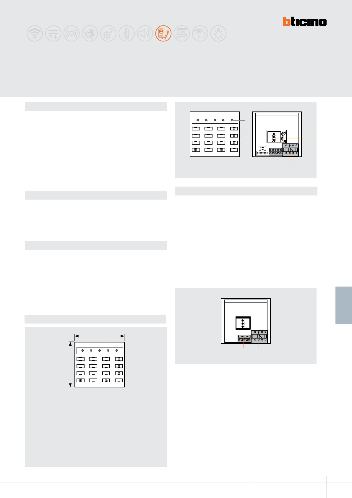
332650
BT00630-a
*
89 mm
100 mm
*
4
5 8 7
36
2
1
RELAY B RELAY A
-EN
TECHNICAL SHEETS
263
2 WIRE VDE system
Dimensional data
Description
Electronic module tted with lit keypad for the activation of electric door locks and
auxiliary systems, by entering 3, 4, and 5 digit numbers. The programming of numerical
codes is performed directly on the keypad. It is possible to save two dierent codes for
the control of two dierent door locks, or one door lock and one auxiliary system.
The device consists of a pushbutton panel with 12 keys, luminous indicators for correct
programming control, and the activation of the desired function; an audible signal
conrms that the key had been activated.
The device has independent power supply and operation.
The device must not be congured.
Related items
332651 (code-lock modular front cover - Allmetal)
332652 (code-lock modular front cover - White)
332653 (code-lock modular front cover - Alugray)
For the use of monobloc front covers refer to the catalogue.
Technical data
Power supply (external): 12 Vdc (+20) - (-5)%, 100 mA
12 Vac (+20) - (-5)%, 110 mA
Operating temperature: (-25)-(+70)°C
Legend
1 - Red Conrmation LED
2 - LED available for signalling purposes
3 - Connector output enabling LED (8)
4 - Connector output enabling LED (7)
5 - Numeric keypad
6 - Jumper to be removed/retted to RESET the device and the factory codes
7 - Connector (RELAY A)
8 - Connector (RELAY B)
Sound signals for:
- Acceptance of the pressed key
- Acceptance of the new programming performed
- Programming or code error
Connector (7):
1 - 0 Vdc / 0 Vac
2 - 12 Vdc / 12 Vac
3 - Common - relay A
4 - A relay NO contact
5 - A relay NC contact
6 - Common - relay B
7 - B relay NO contact
8 - B relay NC contact
Connector (8):
9 - 0 Vdc signalling LED
10 - 12 Vdc signalling LED
11 - Day/night timer input
12 - Day/night timer output
13 - Input of the relay control, output (B) from the door lock key of the handset
SFERA CLASSIC
CODE-LOCK module
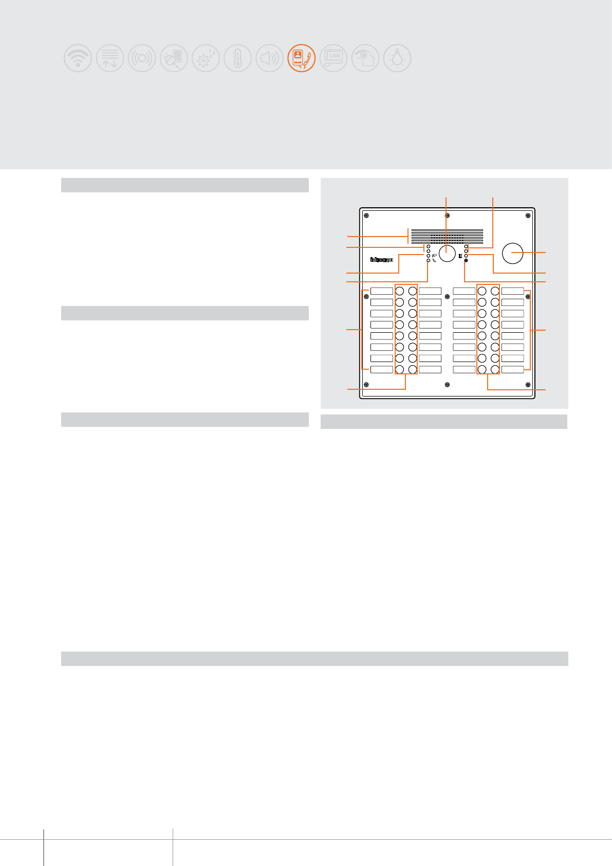
308001 - 308002
308003 - 308004 - 308005 - 308011
308012 - 308013 - 308014 - 308015
BT00631-a
1 2
3 4
5 6
7 8
9 10
11 12
13 14
15 16
17 18
19 20
21 22
23 24
25 26
26 28
29 30
31 32
1 2
3
4
5
6
77
6
8
9
2
10
-EN
TECHNICAL SHEETS
264 2 WIRE VDE system
Vandal-resistant monobloc
pushbutton panels
Description
Monobloc vandal-resistant 2 wire video pushbutton panels for flush mounted or wall
mounted installation (with dedicated box sold separately). Solutions available with
1 to 32 call keys, with aluminium or stainless steel finishing front cover.
The item includes: flush-mounted box, frame, colour video and audio electronic module,
module/s and pushbuttons already wired. Presetting for the mounting of transponder
reader or key switch. Backlit call keys. Visual and sound notification of the communication
status for: call presence, system busy, door lock status.
Direct control of an electric door lock 18 V - 4 A impulsive, 250 mA holding current
(30 ohm max).
Technical data
Power supply from SCS BUS: 18 – 27 Vdc
Stand-by absorption: 308001 – 308011 (55 mA)
308002 – 308012 (70 mA)
308003 – 308013 (85 mA)
308004 – 308014 (115 mA)
308005 – 308015 (160 mA)
Operating absorption: 308001 – 308011 (175 mA)
308002 – 308012 (190 mA)
308003 – 308013 (205 mA)
308004 – 308014 (235 mA)
308005 – 308015 (280 mA)
Camera sensor: 1/3”
Camera lens: F:1.5 mm ; f:4.3 mm
Resolution: 330 lines (horizontal)
Brightness adjustment: automatic
Night lighting: with white LEDs
Operating temperature: (-25) – (+70) °C
Protection index: IP44
Mechanical impact: IK07
Legend
1. Colour camera
2. White LEDs for the lighting of the camera shooting field
3. Preset housing for transponder reader or key switch
4. Door status notification LED: green LED = door open
5. Microphone
6. Name labels
7. Call key
8. Call status notification LED: green LED = call forwarded
red LED = system busy
9. Communication status notification LED: green LED = communication active
10. Loudspeaker
Related items
308021 Wall mounted box - for 4 keys set 308001 - 308011
308022 Wall mounted box - for 8 keys set 308002 - 308012
308023 Wall mounted box - for 12 keys set 308003 - 308013
308024 Wall mounted box - for 20 keys set 308004 - 308014
308025 Wall mounted box - for 32 keys set308005 - 308015
346250 Relay to control door lock not managed by BUS
346020 additional 2 DIN modules power supply
Front view
Dimensional data
2 - 4 calls pushbutton panels - item 308001 - 308011
dimensions: W 180 x H 270 mm
Wall mounted box - item 308021 : W 178 x H 267 x D 40 mm
Flush mounted box (supplied): W 128 x H 220 x P 53 mm
5 - 8 calls pushbutton panels - item 308002 - 308012
dimensions: W 180 x H 330 mm
Wall mounted box - item 308022 : W 178 x H 327 x D 40 mm
Flush mounted box (supplied): W 128 x H 260 x P 53 mm
9 - 12 calls pushbutton panels - item 308003 - 308013
dimensions: W 180 x H 360 mm
Wall mounted box - item 308023 : W 178 x H 357 x D 40 mm
Flush mounted box (supplied): W 128 x H 310 x P 53 mm
13 - 20 calls pushbutton panels - item 308004 - 308014
dimensions: W 180 x H 440 mm
Wall mounted box - item 308024 : W 178 x H 437 x D 40 mm
Flush mounted box (supplied): W 128 x H 400 x P 53 mm
21 - 32 calls pushbutton panels - item 308005 - 308015
dimensions: W 340 x H 370 mm
Wall mounted box - item 308025 : W 338 x H 367 x D 40 mm
Flush mounted box (supplied): W 310 x H 328 x P 53 mm
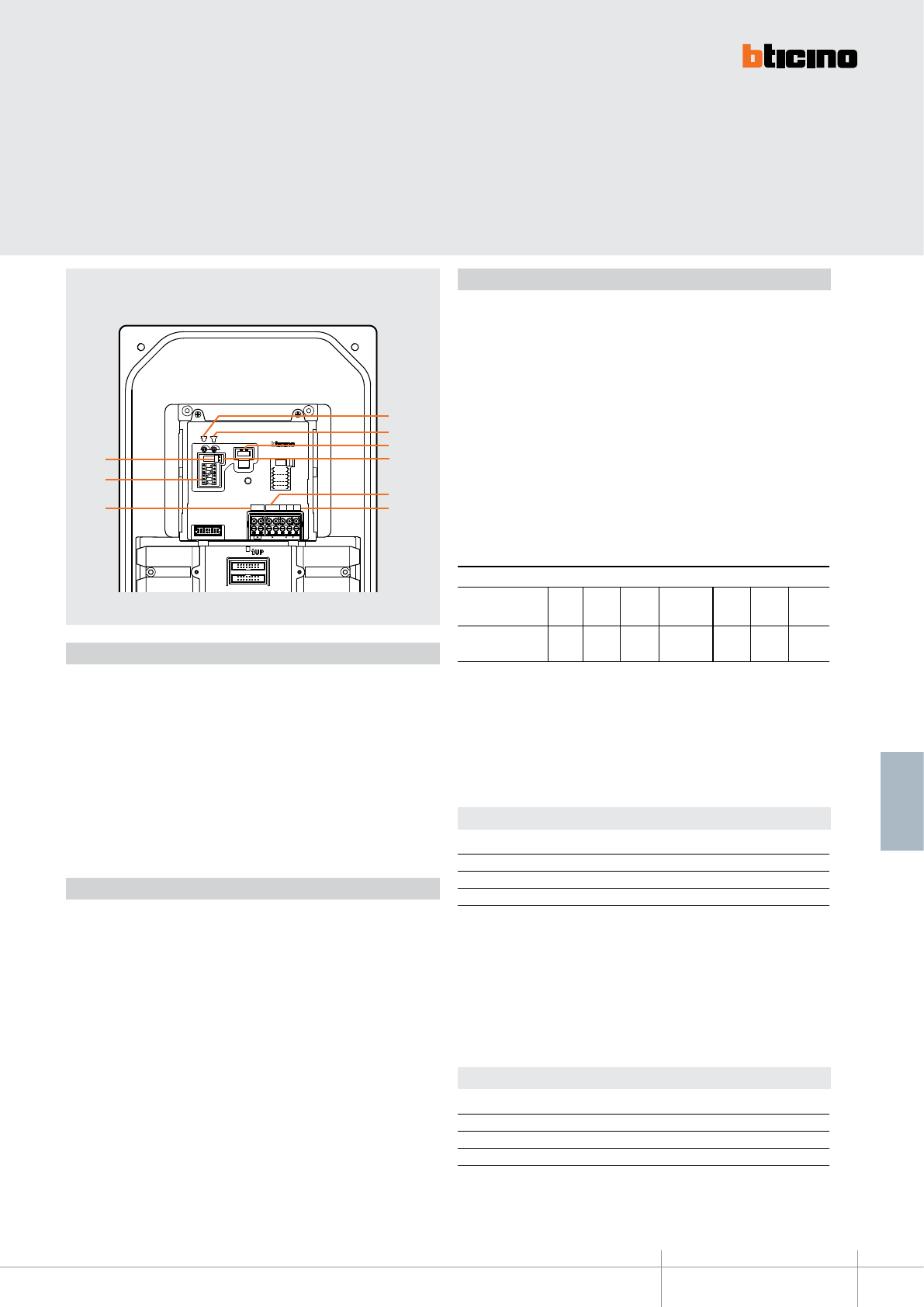
BT00631-a
308001 - 308002
308003 - 308004 - 308005 - 308011
308012 - 308013 - 308014 - 308015
P
N
TS
21BUS PL S+ S−
USB
J1
J2
7
9
85
2
1
6
4
3
-EN
TECHNICAL SHEETS
265
2 WIRE VDE system
Configuration
The device must be physically congured as follows:
P - entrance panel number
The congurator connected to the P housing of the speaker module assigns to the same
an identication number within the system.
The numbering of the entrance panels must always start from P=0. The EP congured
with P=0 must be a common (or main) EP.
N - call number
It assigns the correspondence between the entrance panel call keys and the handsets or
video handsets. In common entrance panels made using key modules, N in the speaker
module must be congured with 0. In local entrance panels, the rst handset or video
handset of the riser being called will be the one congured with N+1 in relation to the
entrance panel.
T - door lock relay timing
* Operation as pushbutton for 10 sec. maximum after which it goes in stand-by.
In order to extend this type of operation over 10 seconds, use the actuator,
item 346200 congured with MOD=5.
0= No
congurator
4 sec.
1
1 sec. 6 sec. 8 sec. 10 sec.
2
2 sec.
3
3 sec. as
pushbutton
4*5 6 7
congurator number
S – call signal type WITH handset door lock release notication BEEP
The conguration of S sets the SPRINT handset call ringtone.
In this way, it is possible to dierentiate the calls from dierent entrance panels.
S – call signal type WITHOUT handset door lock release notication BEEP
The conguration of S sets the SPRINT handset call ringtone.
In this way, it is possible to dierentiate the calls from dierent entrance panels.
Congurator 0 1 2 3
Type of bell Double-tone Double-tone Double-tone One-tone
1200 Hz 1200 Hz 1200 Hz 1200 Hz
600 Hz 0 Hz 2400 Hz
Congurator 4 5 6 7
Type of bell Double-tone Double-tone Double-tone One-tone
1200 Hz 1200 Hz 1200 Hz 1200 Hz
600 Hz 0 Hz 2400 Hz
In the case of SWING, PIVOT, POLYX and AXOLUTE handsets, the S congurator associates
the entrance panel to the ringtone programmed inside the same. It is possible to choose
among 16 dierent ringtones.
In the case of SWING, PIVOT, POLYX and AXOLUTE handsets, the S congurator associates
the entrance panel to the ringtone programmed inside the same. It is possible to choose
among 16 dierent ringtones.
SPRING handsets call signal table
Tabella per segnale di chiamata posti interni SPRINT
1. Microphone volume adjustment
2. Loudspeaker volume adjustment
3. USB connector for connection to the PC
4. J2: NOT USED
5. 2 WIRE SCS/BUS connection clamps
6. Clamps for the connection of the door lock and the room door opening pushbutton
7. Additional power supply connection clamps
8. Configurator socket
9. J1: remove to enable additional power supply
Legend
Rear view
Camera installation notes
The camera must not be installed facing strong light sources, or in locations where the
area being shot is strongly backlit. In order to resolve these problems, we recommend
that the camera is installed at a height of 180 cm, instead of the usual 160-165 cm, with
the lens pointing down. This will improve image quality.
In low light situations, the colour rendition of the image displayed by the colour camera
may decrease. This is to ensure that the person being displayed can be better recognised.
For optimal viewing in low lit rooms, the installation of an additional light source is
recommended.
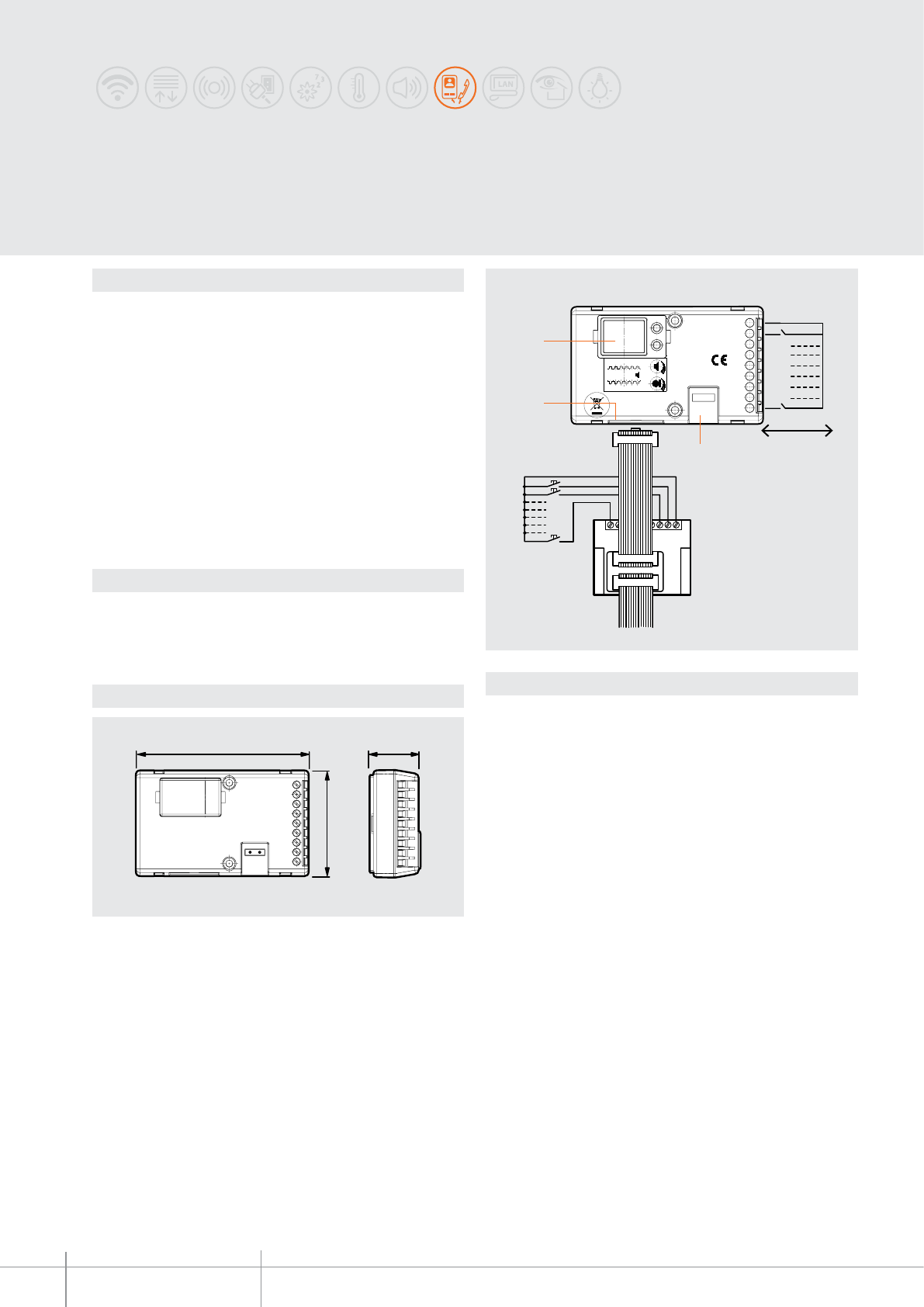
346991 - 346992
BT00632-a
90 mm 26 mm
55 mm
C
N+15
N+8
C
128
IN
OUT
N+9
87654321C
BUS
S
N
P
346991
346991
346992
1
3
2
-EN
TECHNICAL SHEETS
266 2 WIRE VDE system
Description
The universal speaker unit can be used to install the 2 WIRE audio system in new or
refurbished systems, where special pushbutton panels are present or required (mail
boxes, patterned brass, monobloc laminates, etc.) preset for a traditional type speaker
module (e.g. 2659N). The universal speaker unit has a set of clamps for the connection of
8 call pushbuttons. In systems with more than 8 call pushbuttons, one item 346992 must
be added for every 8 pushbuttons (max. 56); For the connection, the multicable with 2
connectors supplied with item 346992 must be used.
Microphone sensitivity adjustment and loudspeaker volume using dedicated
potentiometers. For the control of an electric door lock, an actuator item 346230/346260
appropriately congured must be used.
The microphone of the speaker unit may be disconnected from the device and positioned
at a distance of 15 cm (max.).
In video systems, the device must be used together with native 2 WIRE cameras or
camera with coaxial output using interface item 347400.
Legend
Item 346991:
1 - Clamps for the connection of the 2 WIRE BUS
2 - Item 346992 connector socket
3 - Congurator socket
(C) common pushbuttons
(1-8) connection of call pushbuttons
Clamps item 346992:
(C) common pushbuttons
(1-8) connection of call pushbuttons
Universal speaker unit
and pushbutton expansion
Technical data
Dimensional data
Power supply from SCS BUS: 18-27 Vdc
Max. operating absorption: 65 mA
Stand by absorption: 15 mA
Operating temperature: (-25)-(+70)°C
max. dist. ≤ 3 m
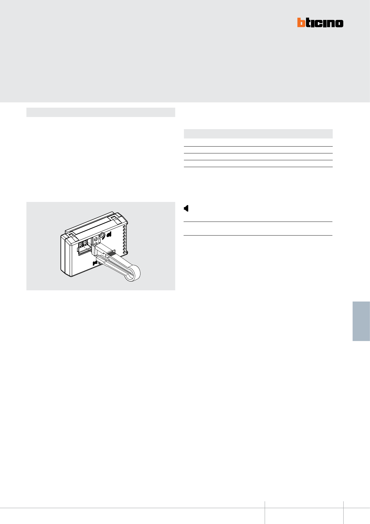
346991 - 346992
BT00632-a-EN
TECHNICAL SHEETS
267
2 WIRE VDE system
Conguration
N – call number
Assigns the correspondence between the entrance panel pushbuttons, and the audio
handsets.
In common entrance panels made using pushbutton modules, 1 must be inserted in N of
the speaker module. In secondary entrance panels, the number of the rst riser handset
must be inserted in N.
P – entrance panel number
The congurator in socket P of the speaker module assigns to this a recognition number
inside the system. The numbering of the entrance panels must always start from P=0.
The entrance panel congured with P=0 must be a common (or main) entrance panel.
S – type of call signal
The conguration of S determines the call tone of SPRINT handsets.
One can thus dierentiate the calls from dierent entrance panels.
Congurator 0 1 2 3
Type of bell 2-tone 2-tone 2-tone One-tone
1200Hz 1200Hz 1200Hz 1200Hz
600Hz 0 Hz 2400Hz
For the SWING, PIVOT, POLYX and AXOLUTE handsets, the S congurator associates the
entrance panel to the bell programmed in the same apartment. It is possible to chose
between 16 dierent bells. In one-family systems, S=9 congures the general call and
the handsets ring, the same as with the S=0.
call sound volume adjustment
Congurator 8 3 0
Type of bell max. min. excluded
call conrmation
Table for SPRINT handset call signal
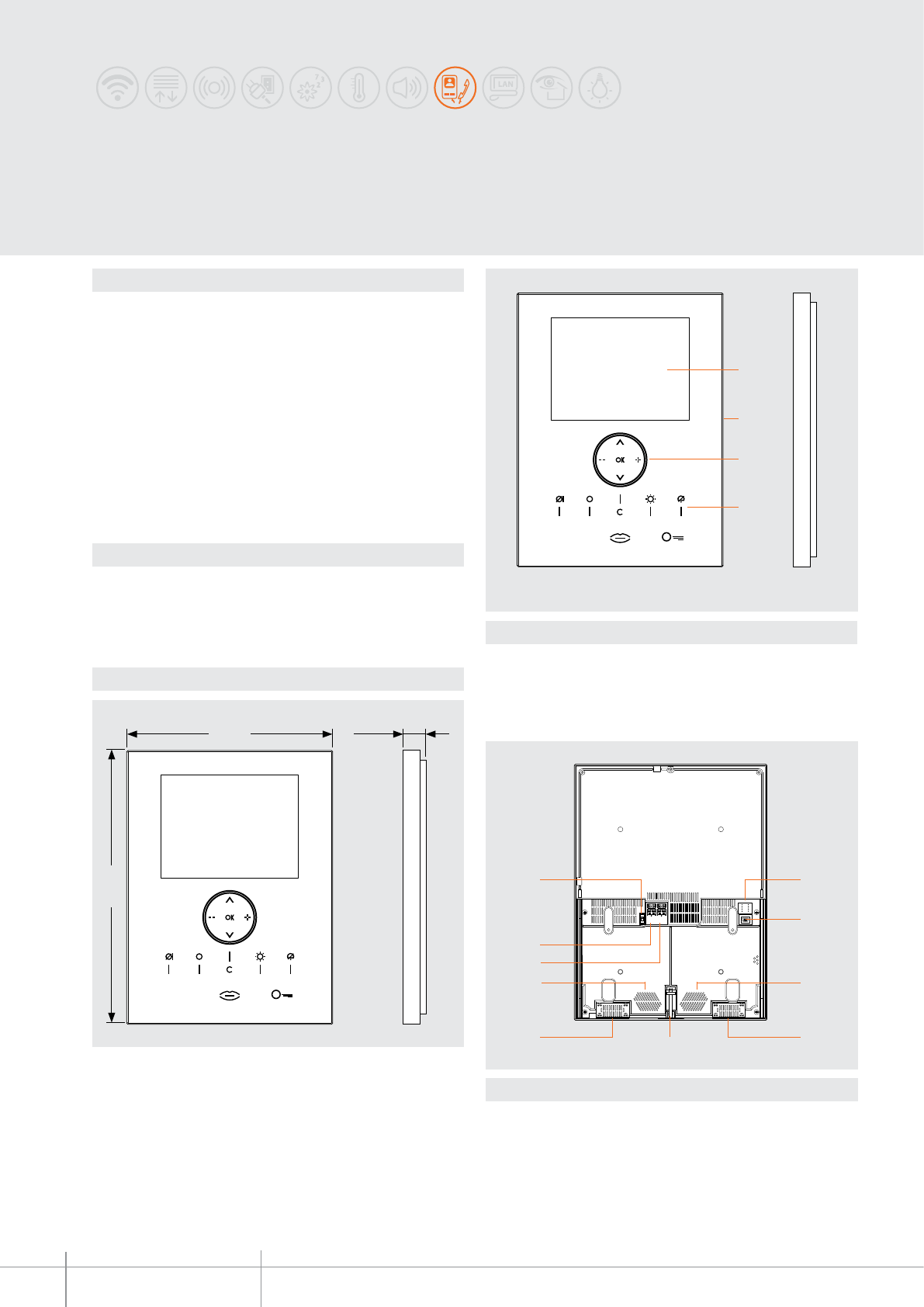
349320 - 349321
BT00633-a
305 mm
230 mm 25 mm
1
3
4
2
2
3
7 1
34
5
6
33
-EN
TECHNICAL SHEETS
268 2 WIRE VDE system
Description
2-wire speaker phone video handset for wall mounted installation. With 8” colour LCD
display, backlit capacitive keypad with soft touch controls and PC customisable OSD
navigation icon menu for the management of the following MY HOME applications:
video door entry system, temperature control, sound system and multimedia,
automation (scenarios) and anti-intrusion.
In systems integrated with the sound system, the VIDEO STATION behaves as an
amplier, enabling playback of all audio/video sources connected to the system.
LED signalling for: call exclusion, door status, and connection to the entrance panel.
It can be integrated with MY HOME, also in combination with the Multimedia interface,
item 3465 - (in this case, allow for a local video door entry system power supply).
Suitable for wall mounted installation using the special bracket (supplied as standard).
Programming and conguration using the TiNighterandWhiceStation software supplied
with the product.
Legend
1 - 8“ LCD colour display
2 - Microphone
3 - Navigation keys and conrmation inside the menu
4 - Led and video door entry function keys
Legend
1 - Congurator socket
2 - Mini-USB connector for PC connection
3 - Loudpspeakers; for the broadcasting of voice and stereo sound
4 - Screw used to fasten the Video Station to the metal base
5 - Additional power supply connection clamps
6 - Clamps for the connection of the 2-wire SCS BUS
7 - Line termination ON/OFF micro switch
Dimensional data
Technical data
Power supply from SCS BUS: 18 – 27 Vdc
Stand by absorption: 30 mA
Max. operating absorption: 520 mA
Operating temperature: 5 - 40°C
Front view
Rear view
AXOLUTE
Nighter & Whice VIDEO STATION
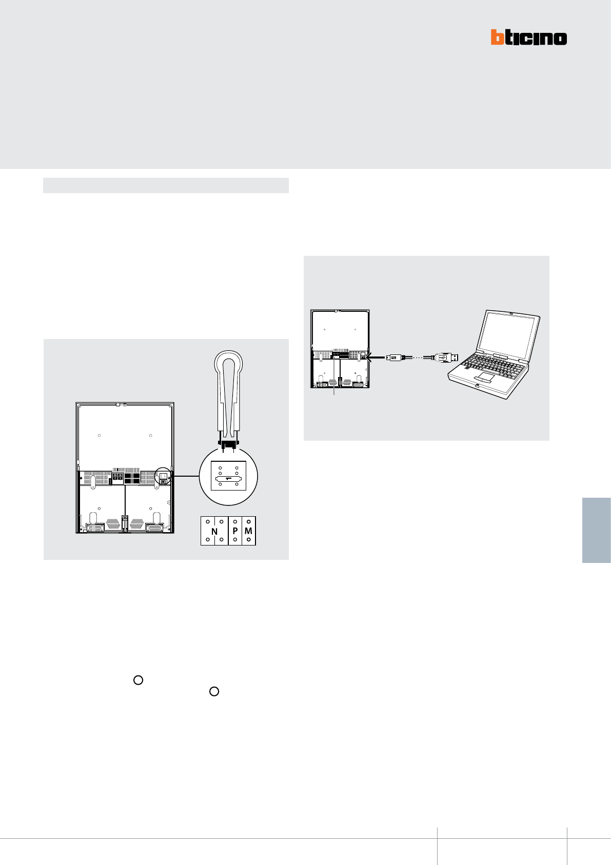
BT00633-a
349320 - 349321
BUS
-EN
TECHNICAL SHEETS
269
2 WIRE VDE system
Conguration
AXOLUTE Nighter & Whice VIDEO STATION can be congured in 2 dierent modes:
- Fast conguration (through the connection of physical congurators)
- Advanced conguration using the TiAxoluteNighterAndWhiceStation
software (CD supplied)
Fast conguration enables the user to access the menu of the video door entry functions.
This is the standard conguration using congurators to be connected to the appropriate
housing on the back of the device itself.
If the apartment interface, item 346850, is installed in the apartment, conguration of the
video handset using the software supplied is recommended.
The advanced PC conguration using the TiAxoluteNighterAndwhiceStation
software (CD supplied), provides the user with a higher degree of customisation, with
the possibility to:
- create exible menus
- customize text messages
- access all home automation functions
WARNING
The device conguration made using congurators
CANNOT BE MODIFIED from the software.
To ensure that communication is successful, Axolute Video Station
must be powered and not congured physically.
To transfer the conguration performed using the
TiAxoluteNighterAndwhiceStation software, or to update the rmware,
connect Axolute Video Station to the PC using the USB-mini cable.
N - handset number
The N congurator assigns each video handset an identication number within the
system. The handsets must be congured in progressive mode. Handsets with parallel
connection (max 3 are allowed inside the apartment without item 346850) must be
congured with the same N congurator. Additional audio handsets, video handsets
and/or bells can be installed in parallel to the basic video handset.
P - entrance panel association
The P congurator identies the associated EP, or the rst entrance panel that switches
itself on when the pushbutton ( ) is pressed the rst time, as well as which door lock
with idle video hanset is activated, when the pushbutton ( ) is pressed.
M - Operating mode
The M congurator identies the main menu of the device and therefore all the usable
functions (see manual supplied with the product).
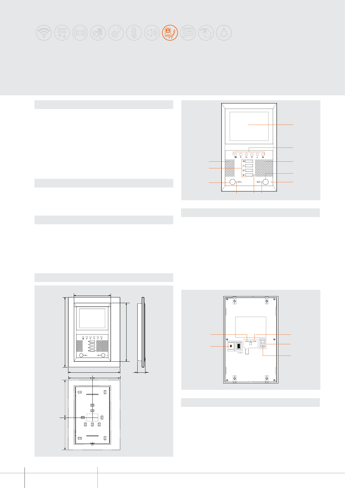
349310
BT00634-a
35
307 mm
226 mm
161 mm
257 mm
120,5 mm 105,5 mm
165 mm 140 mm
10
9
3
678
2
4
3
5
1
2
3
4
5 1
-EN
TECHNICAL SHEETS
270 2 WIRE VDE system
Dimensional data
Description
2-wire speaker phone video handset for wall mounted installation.
With 5.6” colour LCD display with PC customisable OSD navigation icon menu for
the management of the following MY HOME applications: video door entry system,
temperature control, sound system, automation (scenarios) and anti-intrusion.
In systems integrated with the sound system, the VIDEO STATION behaves as an amplier,
enabling playback of all audio/video sources connected to the system.
LED signalling for: call exclusion, door status, and connection to the entrance panel.
Suitable for wall mounted installation using the special bracket (supplied as standard).
Programming and conguration using the TiAxoluteStation software supplied with the
product.
Related items
349210 - Surround plate (satin-nished aluminium)
349211 - Surround plate (KRISTALL glass)
349212 - Surround plate (TEAK wood)
Technical data
Power supply from SCS BUS: 18 – 27 Vdc
Stand by absorption: 10 mA
Max. operating absorption: 410 mA
Operating temperature: 5 - 40°C
AXOLUTE
VIDEO STATION
Legend
1 - 5.6” colour LCD display
2 - Navigation keypad and conrmation inside the menu
3 - Loudpspeakers; for the diusion of voice and stereo sound
4 - Connection key; enable/disable the connection
5 - Microphone
6 - Connection status LED
7 - LED for call exclusion notication
8 - Door lock status LED
9 - Door lock opening key
10 - Keys for video door entry functions
Legend
1 - Clamps for the connection of the 2-wire SCS BUS
2 - Congurator socket
3 - Line termination ON/OFF micro-switch
4 - Mini-USB connector for PC connection
5 - Additional power supply connection clamps
Front view
Rear view
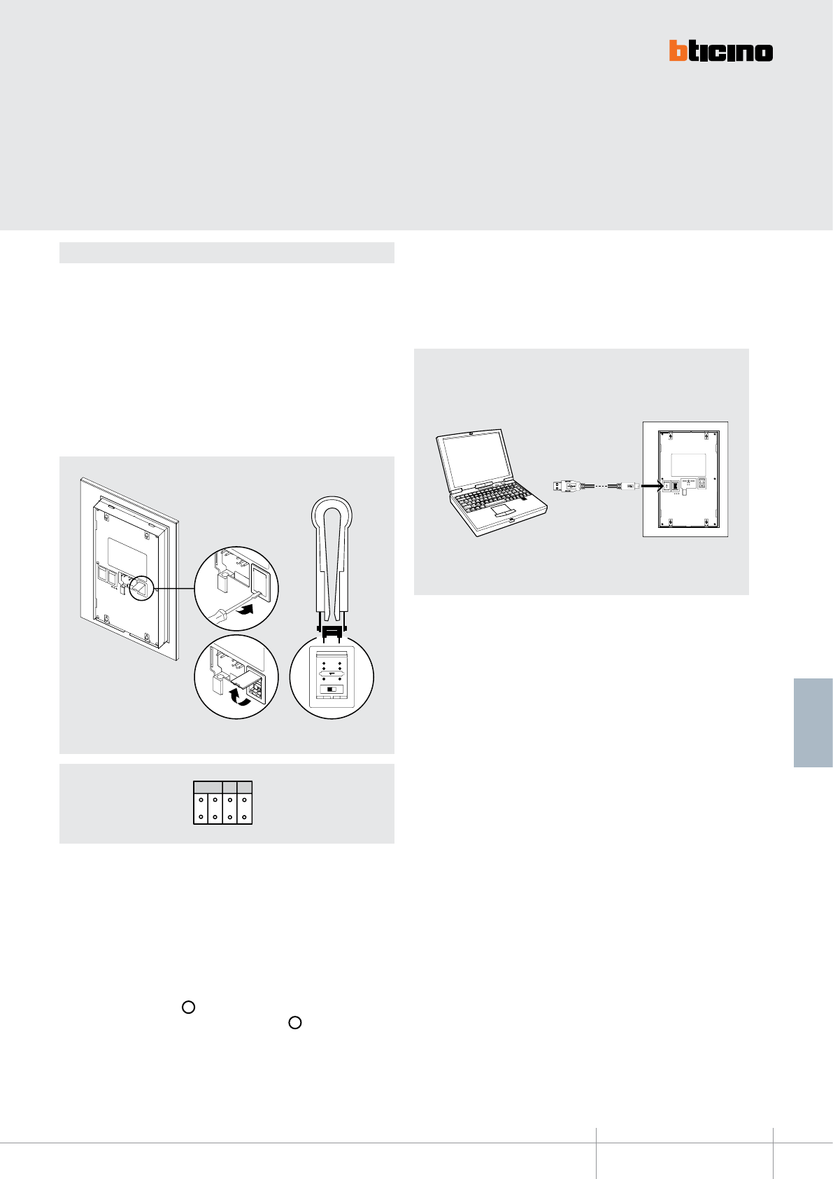
BT00634-a
349310
1
2 3
USB-miniUSB
NPM
-EN
TECHNICAL SHEETS
271
2 WIRE VDE system
Conguration
AXOLUTE VIDEO STATION can be congured in 2 dierent modes:
- Fast conguration (through the connection of physical congurators)
- Advanced conguration using the TiAxoluteStation software supplied with the
product.
WARNING
The device conguration
made using congurators
CANNOT BE MODIFIED using
the software.
Fast conguration enables the user to access the menu of the video door entry
functions. This is the standard conguration using congurators to be connected to the
appropriate socket on the back of the device itself.
Warning: If the apartment interface, item 346850, is installed in the apartment,
conguration of the video handset using the software supplied is recommended.
The advanced PC conguration using the TiAxolutestation software (CD supplied),
provides the user with a higher degree of customisation, with the possibility to:
- create exible menus
- customize text messages
- access all home automation functions
To ensure that communication is successful, Axolute Video Station
must be powered and not physically congured.
To transfer the conguration performed using the TiAxolutestation software,
or to update the rmware, connect Axolute Video Station to the PC using the
USB-mini cable.
N - handset number
The N congurator assigns each video handset an identication number within the
system. The handsets must be congured in progressive mode. Handsets with parallel
connection (max 3 are allowed inside the apartment without item 346850) must be
congured with the same N congurator. Additional audio handsets, video handsets
and/or bells can be installed in parallel to the basic video handset.
P - entrance panel association
The P congurator identies the associated EP, or the rst entrance panel that switches
itself on when the pushbutton ( ) is pressed the rst time, as well as which door lock
with idle video handset is activated, when the pushbutton ( ) is pressed.
M - Operating mode
The M congurator identies the main menu of the device and therefore all the usable
preset functions (see manual supplied with the product).
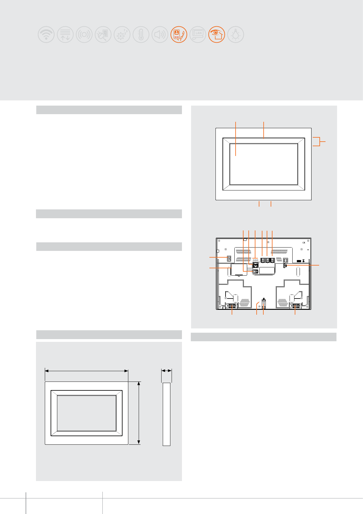
HC/HS 4690
BT00635-a
PSTN BUS 2 1
ON
OFF
ETH
SCS AUDIO OUT
96
13
87
15 14 13
17
16 12
10 11
5 4
2
3
1
305 mm
228 mm
17 mm
-EN
TECHNICAL SHEETS
272 2 WIRE VDE system
Multimedia Touch Screen
Front view
Rear view
Multimedia Touch Screen is a device that enables controlling all the functions of the
MY HOME system by means of simple and intuitive icons displayed on the 10” 16:9 LCD
Touch Screen.
In addition to the management of the automation functions, lights, temperature
control, sound system, burglar alarm, and scenarios, by using the device it is also
possible to answer to video door entry system calls, and display the images transmitted
by the entrance panel, or the connected cameras. Thanks to the USB device and SD card
inputs, Multimedia Touch Screen can manage multimedia files, allowing the users to
listen to their favourite music or to view films and images.
When integrated with a domestic LAN network with internet connection, the device
enables (following the activation of specific icons) receiving RSS services such as “news”
and weather information, displaying images transmitted through webcams, and
listening to internet radio channels.
Description
Surround plate: HA4690XC, HA4690VBB, HA4690LTK, HA4690VNB, HA4690VSW
Power supply: 346020
Related items
Power supply from SCS BUS: 18 – 27 Vdc
Local power supply (1 – 2): 18 – 27 Vdc
Max. local absorption (1 – 2): 600 mA
Absorption from SCS BUS: 50 mA
Operating temperature: 5 – 45 °C
Technical data
Dimensional data Legend
1. 10” Touch Screen colour LED display
2. Microphone
3. USB connection
4. Mini USB PC connection
5. SD card connector
6. Sound system source output connector
7. RJ45 connector for Ethernet connection
8. LAN connection signalling LED
9. PSTN telephone line connector (future application)
10. 2 wire video BUS/SCS connector
11. 1-2 power supply connector
12. End of line ON/OFF micro switch
13. Loudspeaker
14. Bracket fixing screw
15. Factory configuration reset pushbutton
16. NiMh 7.2 V battery compartment; 160 mAh
17. RS232 PC connector
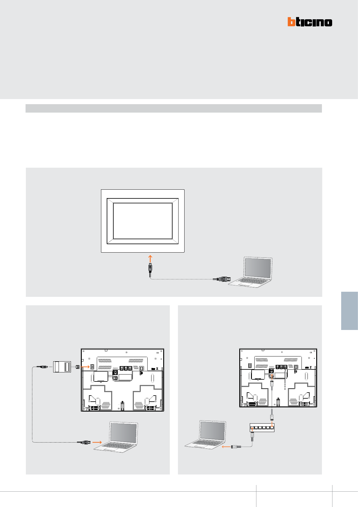
BT00635-a
HC/HS 4690
PSTN BUS 2 1
ON
OFF
ETH
SCS AUDIO OUT
PSTN BUS 2 1
ON
OFF
ETH
SCS AUDIO OUT
Switch
3559
-EN
TECHNICAL SHEETS
273
2 WIRE VDE system
Multimedia Touch Screen must be configured using the TiMultimediaTouchScreen
software supplied as standard. In order to receive/transfer the configuration performed,
or to update the firmware, connect Multimedia Touch Screen to the PC using one of the
three solutions:
- USB-miniUSB cable;
- serial connector (3559);
- Ethernet cable.
Configuration
USB connection
Serial connection Ethernet connection
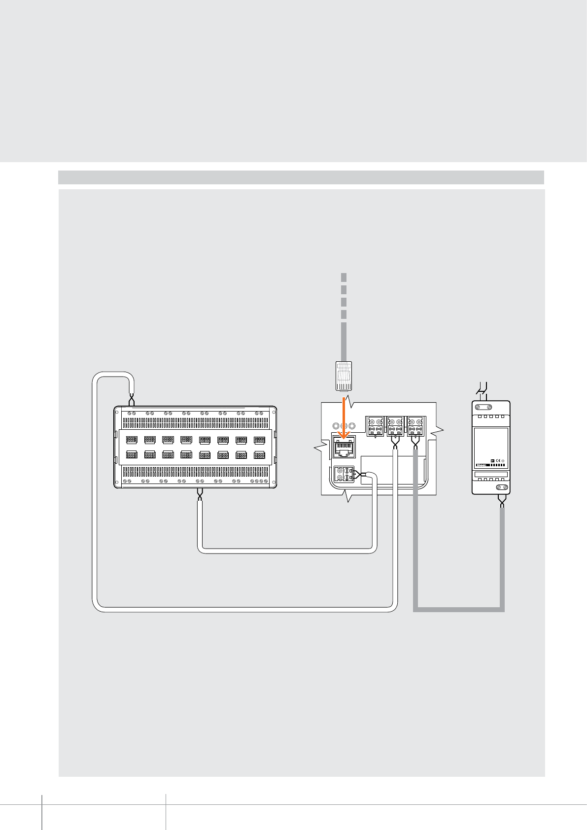
HC/HS 4690
BT00635-a
PSTN BUS 2 1
ETH
SCS AUDIO OUT
PR I
1
-
2
346020
PRI: 220 - 240 V~
175 - 165 mA
47 / 63 Hz
1-2: 27 Vdc
600 mA
230 Vac
-EN
TECHNICAL SHEETS
274 2 WIRE VDE system
Wiring diagram
F441M
Multichannel matrix
Ethernet cable
346020
Power supply
Audio SCS BUS
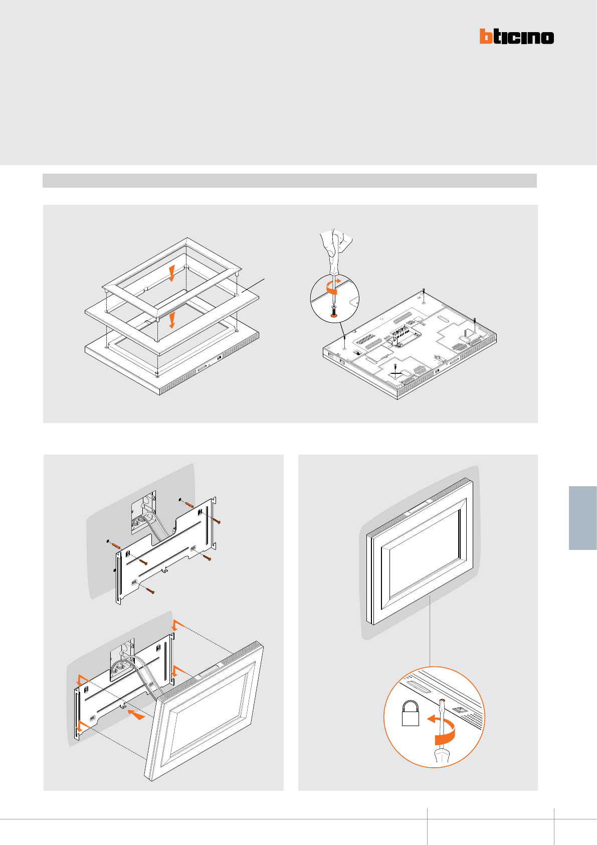
BT00635-a
HC/HS 4690
HA4690...
-EN
TECHNICAL SHEETS
275
2 WIRE VDE system
Before xing the device to the wall apply the surround plate item HA4690...
Installation
Connect Multimedia Touch Screen to the system and x it to the wall using the bracket
supplied with the product.
To complete the installation rotate the fixing screws at the back of Multimedia Touch
Screen clockwise.
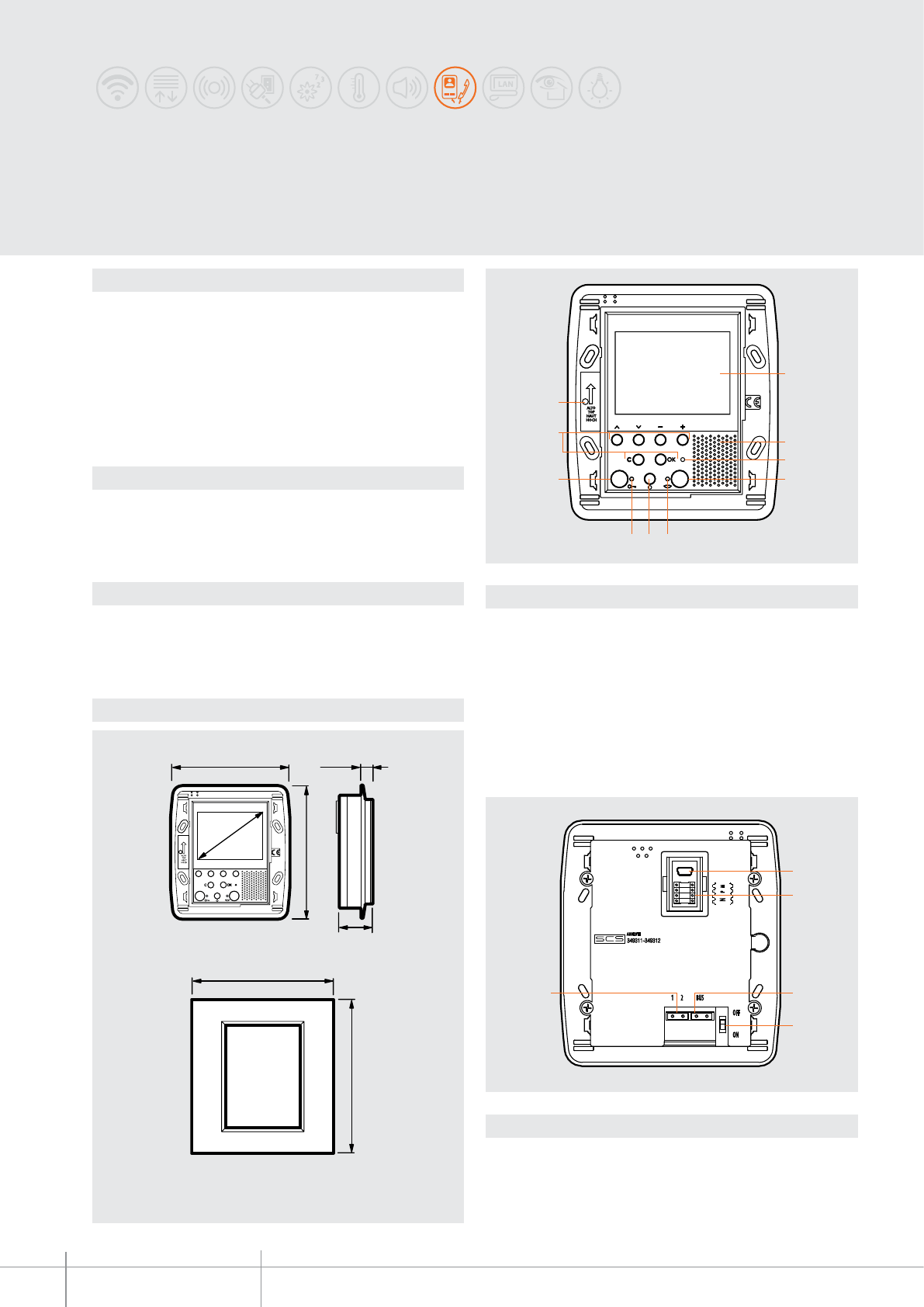
349311 - 349312 - 349313
BT00636-a
1
2
3
4
10
9
8
7 6 5
BUS1 2
OFF
ON
AXOLUTE
1
2
3
4
5
105,5 mm
30,2 mm
9,5 mm
118 mm
2,5”
127 mm
141,5 mm
-EN
TECHNICAL SHEETS
276 2 WIRE VDE system
Description
2-wire speaker phone video handset for ush mounted installation. With 2.5” colour LCD
display with PC customisable OSD navigation icon menu for the management of the
following MY HOME applications: video door entry system, temperature control, sound
system, automation (scenarios) and anti-intrusion. LED signalling for: call exclusion,
door status, and connection to the entrance panel.
Suitable for ush mounted installation using item 506 boxes. To be completed with front
cover plate (all those suitable for item 506E of the AXOLUTE series).
Programming and conguration using the TiAxoluteDisplay software supplied with the
product.
Legend
1 - Mini-USB connector for PC connection
2 - Congurator socket
3 - 2 WIRE SCS/BUS connection clamps
4 - Line termination ON/OFF micro switch
5 - Clamp for connection of the additional power supply
Legend
1 - 2.5” colour LCD display
2 - Loudspeaker
3 - LED for call exclusion notication
4 - Connection key; enable/disable the connection
5 - Connection status LED
6 - Entrance panel and cycling activation key
7 - Door lock status LED
8 - Tasto Door lock opening
9 - Navigation keys and conrmation inside the menu
10 - Microphone
AXOLUTE VIDEO DISPLAY
Technical data
Dimensional data
Related items
Power supply from SCS BUS: 18 – 27 Vdc
Stand by absorption: 10 mA
Max. operating absorption: 320 mA
Operating temperature: 5 - 40°C
506E 3+3 modules ush mounted box
PB526 3+3 modules plasterboard box
HA/HB4826... 3+3 modules front cover plate (see AXOLUTE nishes)
349319 VIDEO DISPLAY table-top base
Front view
Rear view
Maximum space requirement with front cover plate
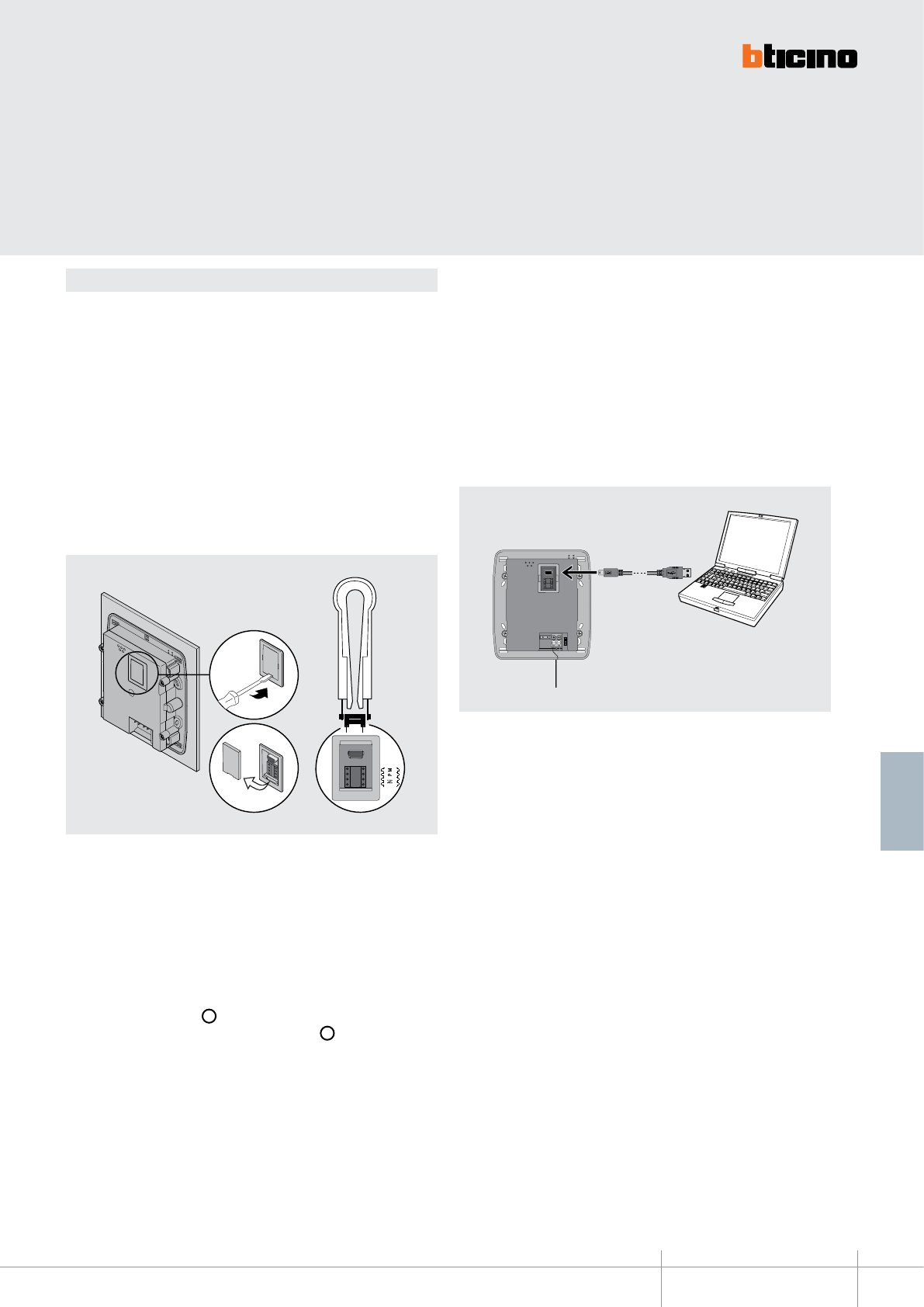
BT00636-a
349311 - 349312 - 349313
N
P M
1
2
3
BUS
-EN
TECHNICAL SHEETS
277
2 WIRE VDE system
Conguration
AXOLUTE VIDEO DISPLAY can be congured in 2 dierent modes:
- Fast conguration (through the connection of physical congurators)
- Advanced conguration using the TiAxoluteDisplay software supplied with the
product.
Fast conguration enables the user to access the menu of the video door entry
functions. This is the standard conguration using congurators to be connected to the
appropriate sockets on the back of the device itself.
If the apartment interface, item 346850, is installed in the apartment, conguration of
the video handset using the software supplied is recommended.
WARNING: The conguration of the device is performed using congurators and
cAnnot be changed from the menu.
N - handset number
The N congurator assigns each video handset an identication number within the
system. The handsets must be congured in progressive mode. Handsets with parallel
connection (max 3 are allowed inside the apartment without item 346850) must be
congured with the same N congurator. Additional audio handsets, video handsets
and/or bells can be installed in parallel to the basic video handset.
P - entrance panel association
The P congurator identies the associated EP, or the rst entrance panel that switches
itself on when the pushbutton ( ) is pressed the rst time, as well as which door lock
with idle video handset is activated, when the pushbutton ( ) is pressed.
M - Operating mode
The M congurator identies the main menu of the device and therefore all the usable
functions (see manual supplied with the product).
The advanced PC conguration using the TiAxoluteDisplay software (CD supplied),
provides the user with a higher degree of customisation, with the possibility to:
- create customized menus;
- customize text messages;
- access all home automation functions.
To transfer the conguration performed using the TiAxoluteDisplay software, or to
update the rmware, connect AXOLUTE VIDEO DISPLAY to the PC using an USB-miniUSB
cable.
To ensure that the communication is successful, AXOLUTE VIDEO DISPLAY must be
powered and not physically congured.
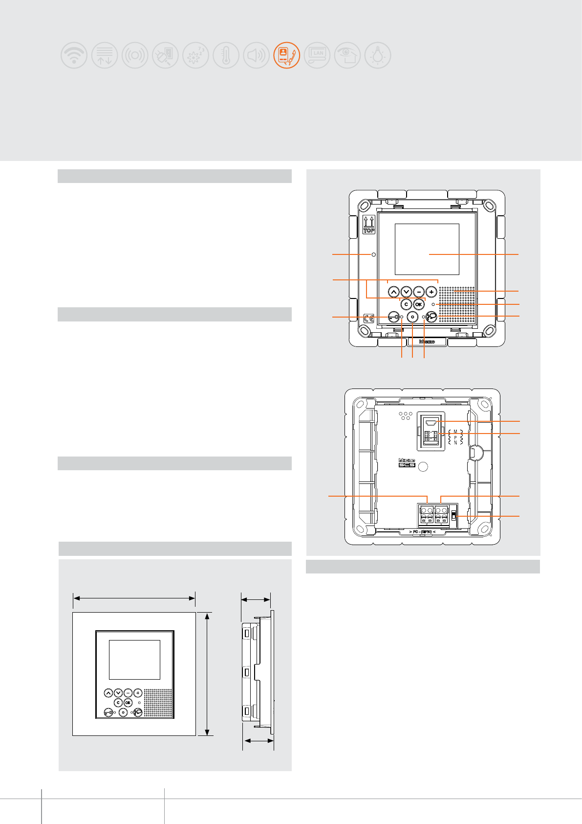
349340
BT00637-a
1
2
3
57 6
8
9
10
4
11
12
1315
14
128 mm 29 mm
128 mm
31 mm
-EN
TECHNICAL SHEETS
278 2 WIRE VDE system
2 WIRE speaker phone video handset for flush mounted installation. With 2.5” colour
LCD display with PC customisable icons OSD navigation menu for the management of
the following MY HOME applications: Video door entry system, temperature control,
sound system, scenarios, burglar alarm. LED signalling for: call exclusion, door status,
connection with entrance panel. Flush mounted / plasterboard installation using the
appropriate boxes.
To be completed with dedicated front cover and front cover plate available in the Axolute
white, anthracite, and tech colour variants. Programming and configuration using the
TiAxoluteMemoryDisplay software supplied with the product.
Description
528W Flush mounted box
PB528W Plasterboard box
349243 White front cover
349241 Axolute tech front cover
349242 Anthracite front cover
HW4826HD White front cover plate
HW4826HC Axolute tech front cover plate
HW4826HS Tech front cover plate
346020 (additional 2 DIN modules power supply) - optional, for local powering of
the video handset, when maximum installation distances are necessary.
Related items
Legend
1. 2.5 “ LCD colour display
2. Loudspeaker
3. Bell exclusion notification LED
4. Audio connection activation/deactivation key
5. Connection status LED
6. Entrance panel/camera scrolling activation key
7. Door lock status LED
8. Door lock activation key
9. Navigation and confirmation keys in the icon menu
10. Microphone
11. Mini USB connector for connection to the PC
12. Configurator socket
13. 2 WIRE SCS/BUS connection clamps
14. Line termination ON/OFF micro-switch
15. Additional power supply connection clamps (1-2)
Power supply from SCS BUS: 18 – 27 Vdc
Stand-by absorption: 10 mA
Max. operating absorption: 320 mA
Operating temperature: 0 – 40 °C
Technical data
Dimensional data
Front view
Back view
Axolute Etèris Video Display
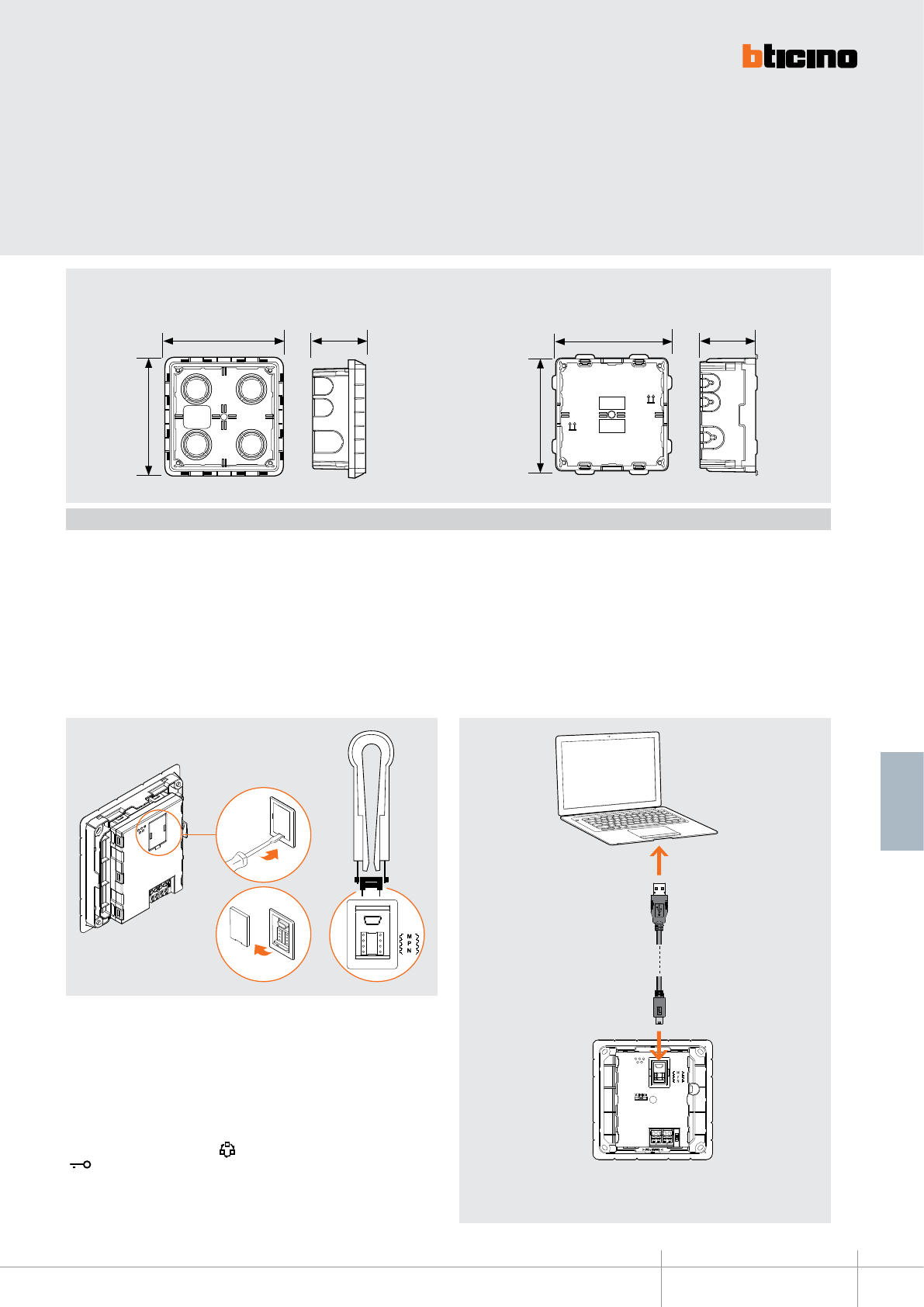
BT00637-a
349340
TOP
TOP
128,5 mm
128,5 mm
58 mm
TOP
TOP
116,5 mm
116,5 mm
58 mm
TOP
TOP
1
2
3
USB-miniUSB
-EN
TECHNICAL SHEETS
279
2 WIRE VDE system
Axolute Etèris Video Display can be configured in two different modes:
- Quick configuration (with physical configurator connection)
- Advanced configuration (using the TiAxoluteDisplay software supplied)
The quick configuration enables the user to access the video door entry system function
menu. This is the standard configuration with configurators to be connected to their
own housing on the back of the device itself.
If the apartment interface, item 346850, is installed inside the apartment, configuration
of the video handset using the software supplied is recommended.
Configuration
N – handset number
The N configurator assigns to each video handset an identification number within the
system. The handsets must be configured in progressive order.Handsets with parallel
connection (max 3 are allowed inside apartments without item 346850) must be
configured using the same N configurator. In parallel with the main video handset,
additional handsets, video handsets and/or bells may be installed.
P – entrance panel association
The P configurator identifies the entrance panel associated, or the first entrance panel
to activate before pressing the key and which door lock is activated when the key
is pressed while the video handset is idle.
M – operating mode
The M configurator identifies the main menu page and therefore the preset functions
that may be used (see manual supplied with the product).
The PC advanced configuration using the software (CD supplied), provides the user with
the highest degree of customisation, with the possibility of:
- create customized menus;
- customize text messages;
- access all home automation functions.
Connection to the PC
To transfer the configuration performed using the software, or to update the firmware,
connect Axolute Etèris Video Display to the PC using the USB-miniUSB cable.
Flush mounted box 528W Plasterboard box PB528W
To ensure that the communication is successful, the video handset must
be powered and not physically configured.
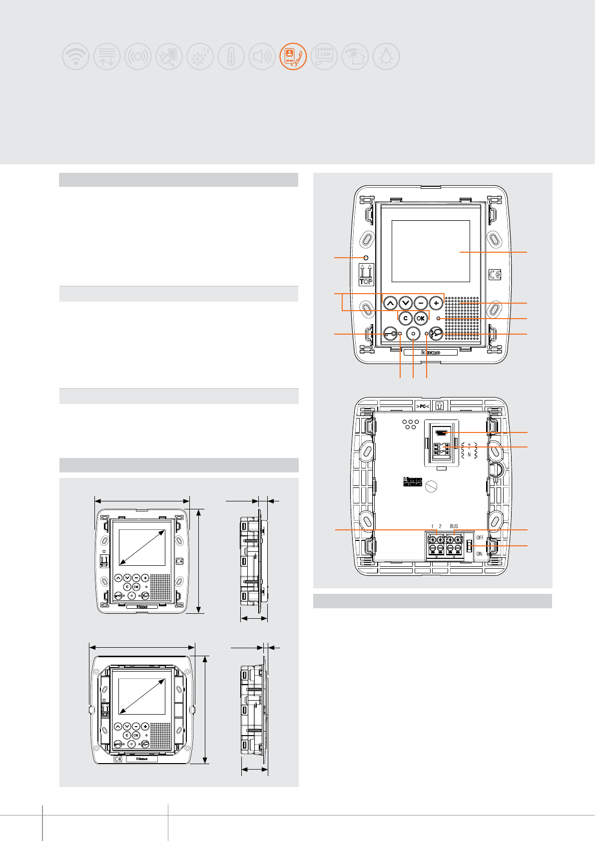
344400 - 344401
BT00638-a
11
12
13
14
8
15
10
9
344400
344401
106 mm
119 mm
10,5 mm
5 mm
31 mm
31 mm
117 mm
121 mm
2,5”
2,5”
1
2
3
4
57 6
-EN
TECHNICAL SHEETS
280 2 WIRE VDE system
LIVINGLIGHT VIDEO DISPLAY
2-WIRE hands free video handsets for flush mounted installation or in FLATWALL
column. 2.5” colour LCD display with PC customisable OSD navigation icon menu for the
management of the following applications: video door entry system, temperature control,
sound system, scenarios and anti-intrusion. Signalling LEDs for: call exclusion, door status,
and connection to the entrance panel. Firmware update/programming USB port. Suitable
for flush mounted installation using item 506E boxes. To be completed with dedicated
front covers and LIVINGLIGHT front cover plates. Programming and configuration using the
TiLivingLightDisplay software supplied with the
product.
Description
Legend
1. 2.5” colour LCD display
2. Loudspeaker
3. Bell exclusion notification LED
4. Audio connection activation / deactivation key
5. Connection status LED
6. Entrance panel / camera cycling activation key
7. Door lock status LED
8. Door lock activation key
9. Navigation keys and confirmation inside the icon menu
10. Microphone
11. Mini-USB connector for PC connection
12. Configurator socket
13. Clamps for the connection of the 2-WIRE SCS BUS
14. Line termination ON/OFF micro-switch
15. Additional power supply connection clamps (1 - 2)
506E 3+3 modules flush mounted box
344413 LIVINGLIGHT front cover - White
344411 LIVINGLIGHT front cover - Tech
344412 LIVINGLIGHT front cover - Anthracite
LNA4826... Front cover plate, 3+3 modules, square (see LIVINGLIGHT finishes)
LNB4826... Front cover plate, 3+3 modules, elliptical (see LIVINGLIGHT finishes)
LNC4826... Front cover plate, 3+3 modules, AIR (see LIVINGLIGHT AIR finishes)
Related items
Power supply from SCS BUS: 18 – 27 Vdc
Stand by absorption: 10 mA
Max. operating absorption: 320 mA
Operating temperature: 0 – 40 °C
Technical data
Dimensional data
Front view
Rear view
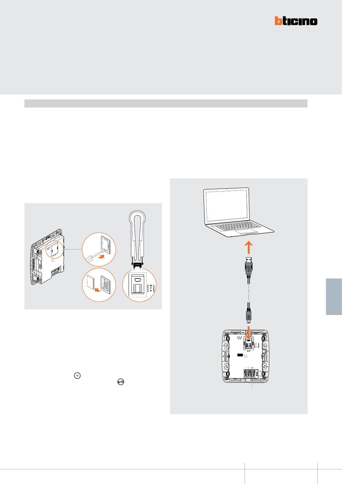
BT00638-a
344400 - 344401
1
2
3
USB-miniUSB
BUS
-EN
TECHNICAL SHEETS
281
2 WIRE VDE system
LIVINGLIGHT VIDEO DISPLAY can be configured in 2 different modes:
- Fast configuration (through the connection of physical configurators)
- Advanced configuration (using the TiLivingLightDisplay software supplied with
the product).
Fast configuration enables the user to access the menu of the video door entry
functions. This is the standard configuration using configurators to be connected to
the appropriate socket on the back of the device itself. If the apartment interface, item
346850, is installed in the apartment, configuration of the video handset using the
software supplied is recommended.
WARNING: The device configuration made using configurators CANNOT BE MODIFIED
using the menu.
The advanced PC configuration using the software (CD supplied), provides the user
with a higher degree of customisation, with the possibility to:
- create flexible menus
- customize text messages
- access all home automation functions.
Connection to the PC
To transfer the configuration performed using the software, or to update the firmware,
connect LIVINGLIGHT VIDEO DISPLAY to the PC using the USB-mini cable.
To ensure that communication is successful, the video handset must be
powered and NOT physically configured.
N - handset number
The N configurator assigns each video handset an identification number within the
system. The handsets must be configured in progressive mode. Handsets with parallel
connection (max 3 are allowed inside the apartment without item 346850) must be
configured with the same N configurator. Additional audio handsets, video handsets
and/or bells can be installed in parallel to the basic video handset.
P - entrance panel association
The P configurator identifies the associated EP, or the first entrance panel that switches
itself on when the pushbutton is pressed the first time, as well as which door lock
with idle video handset is activated, when the pushbutton is pressed.
M - operating mode
The M configurator identifies the main menu of the device and therefore all the usable
preset functions (see manual supplied with the product).
Configuration
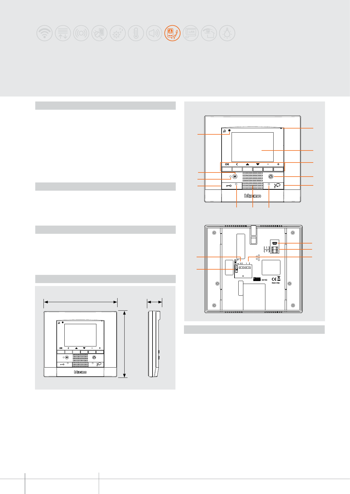
344163
BT00639-a
1
2
3
4
5
68 7
10
9
11
12
13
14
1517
16
168 mm
150 mm
30 mm
-EN
TECHNICAL SHEETS
282 2 WIRE VDE system
Polyx Memory Display
2 WIRE wall mounted speaker phone video handset with audio and video memory.
With 3.5” colour LCD display with PC customisable icons OSD navigation menu for
the management of the following MY HOME applications: Video door entry system,
temperature control, sound system, scenarios, burglar alarm. With video door entry
system answering machine with call memory function.
LED signalling for: call exclusion, door status, connection with entrance panel, and
answering machine status. It can be wall mounted using the appropriate bracket
(supplied).
Programming and configuration using the TiPolyxMemoryDisplay software supplied
with the product.
Description
346020 (additional 2 DIN modules power supply) - optional, for local powering of the
video handset, when maximum installation distances are necessary.
Related items
Legend
1. Microphone
2. 3.5 “ LCD colour display
3. Navigation and confirmation keys in the icon menu
4. Entrance panel/camera scrolling activation key
5. Audio connection activation/deactivation key
6. Connection status LED
7. Loudspeaker
8. Door lock status LED
9. Door lock activation key
10. Audio video answering machine status LED
11. Answering machine key: enable/disable the answering machine function
(if enabled by the menu)
12. Bell exclusion notification LED
13. Mini USB connector for connection to the PC
14. Configurator socket
15. Additional power supply connector (1-2)
16. Line termination ON/OFF micro-switch
17. 2 WIRE SCS/BUS connection
Dimensional data
Power supply from SCS BUS: 18 – 27 Vdc
Stand-by absorption: 10 mA
Max. operating absorption: 330 mA
Operating temperature: 0 - 40 °C
Technical data
Front view
Back view
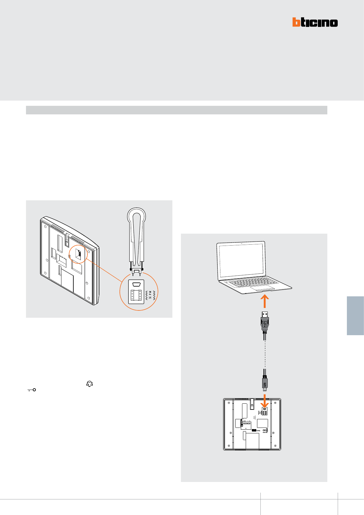
344163
NP M
USB-miniUSB
BT00639-a-EN
TECHNICAL SHEETS
283
2 WIRE VDE system
Polyx Memory Display can be configured in two different modes:
- Quick configuration (with physical configurator connection);
- Advanced configuration (using the TiPolyxMemoryDisplay software supplied).
The quick configuration enables the user to access the video door entry system function
menu. This is the standard configuration with configurators to be connected to their
own housing on the back of the device itself.
If the apartment interface, item 346850, is installed inside the apartment, configuration
of the video handset using the software supplied is recommended.
Configuration
N – handset number
The N configurator assigns to each video handset an identification number within the
system. The handsets must be configured in progressive order.Handsets with parallel
connection (max 3 are allowed inside apartments without item 346850) must be
configured using the same N configurator. In parallel with the main video handset,
additional handsets, video handsets and/or bells may be installed.
P – entrance panel association
The P configurator identifies the entrance panel associated, or the first entrance panel
to activate before pressing the key and which door lock is activated when the key
is pressed while the video handset is idle.
M – operating mode
The M configurator identifies the main menu page and therefore the preset functions
that may be used (see manual supplied with the product).
The PC advanced configuration using the software (CD supplied), provides the user with
the highest degree of customisation, with the possibility of:
- create customized menus;
- customize text messages;
- access all home automation functions.
Connection to the PC
To transfer the configuration performed using the TiPolyxMemoryDisplay software
or to update the firmware, connect POLYX MEMORY DISPLAY to the PC using the
USB-miniUSB cable.
To ensure that the communication is successful, the POLYX MEMORY DISPLAY must
be powered and not physically configured.
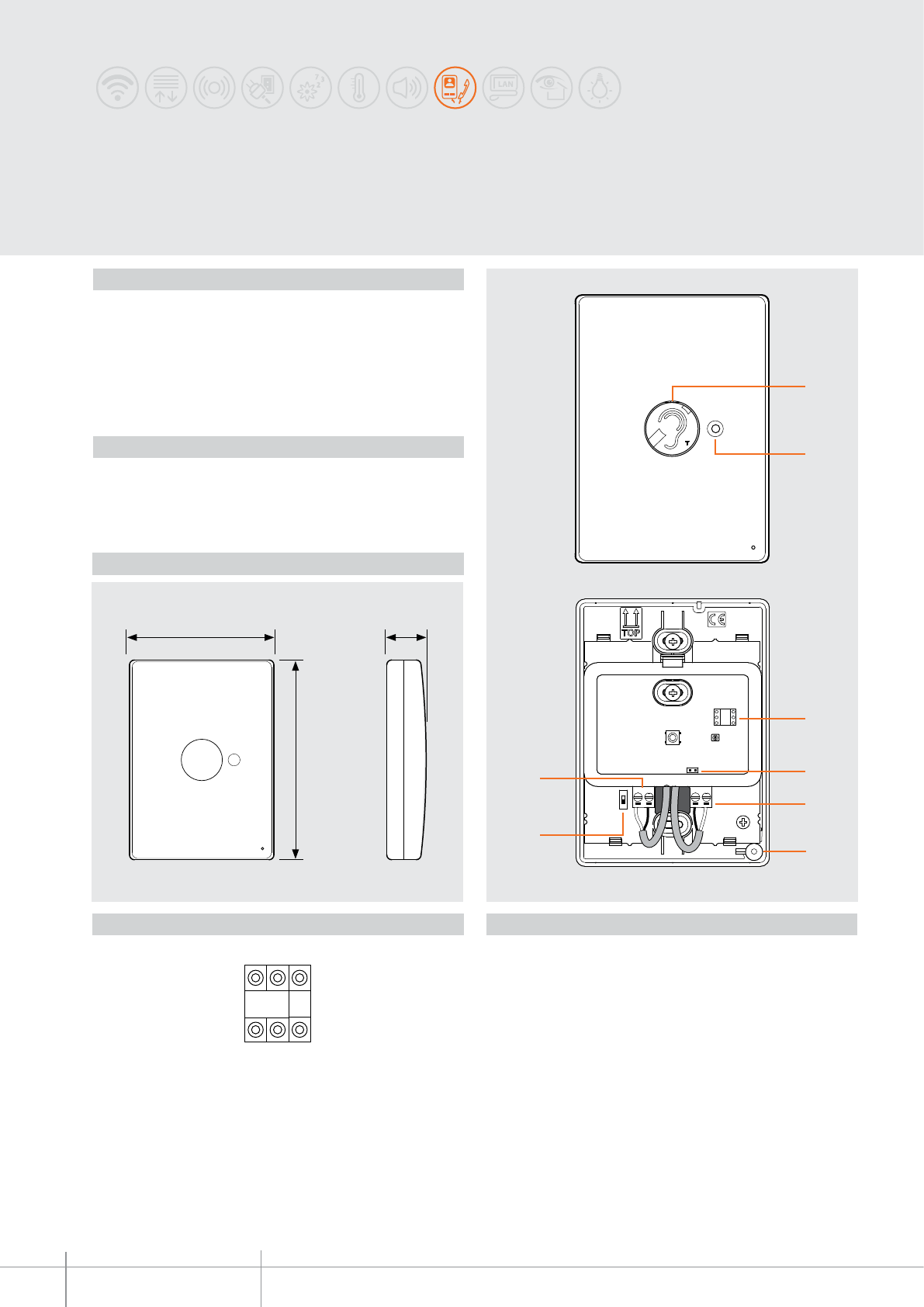
344165
BT00640-a
88 mm
122 mm
24,5 mm
2
1
ON OFF
N
ON
OFF
3
4
5
6
7
8
N*
-EN
TECHNICAL SHEETS
284 2 WIRE VDE system
2 WIRE inductive LOOP module to be used with Polyx Memory Display 344163 video
handset, to enable use by people wearing hearing aids (fitted with T selector).
The device must be configured with the same address (N) of the corresponding video
handset. Wall mounted installation without the need of accessories.
WARNING: The inductive loop module must only be activated AFTER establi-
shing the connection of the associated video handset to the entrance panel.
Description
Power supply dal SCS BUS: 18 – 27 Vdc
Stand by absorption: 5 mA
Max. operating absorption: 200 mA
Operating temperature: 5 - 40 °C
Technical data
Legend
1. Activation key
2. Status signalling LED: green flashing = call notification
green steady = connection established
3. Configurator socket
4. Jumper, to be removed to enable additional power supply connection
5. Additional power supply connection clamps
6. Microphone
7. Line termination ON/OFF micro-switch
8. 2 WIRE SCS/BUS connection clamps
Dimensional data
Configuration
N = associated video handset number
The N configurator assign to the device the same number of the handset of the associa-
ted video handset (configure with the same N of the video handset).
(*) = NOT USED
Inductive LOOP module
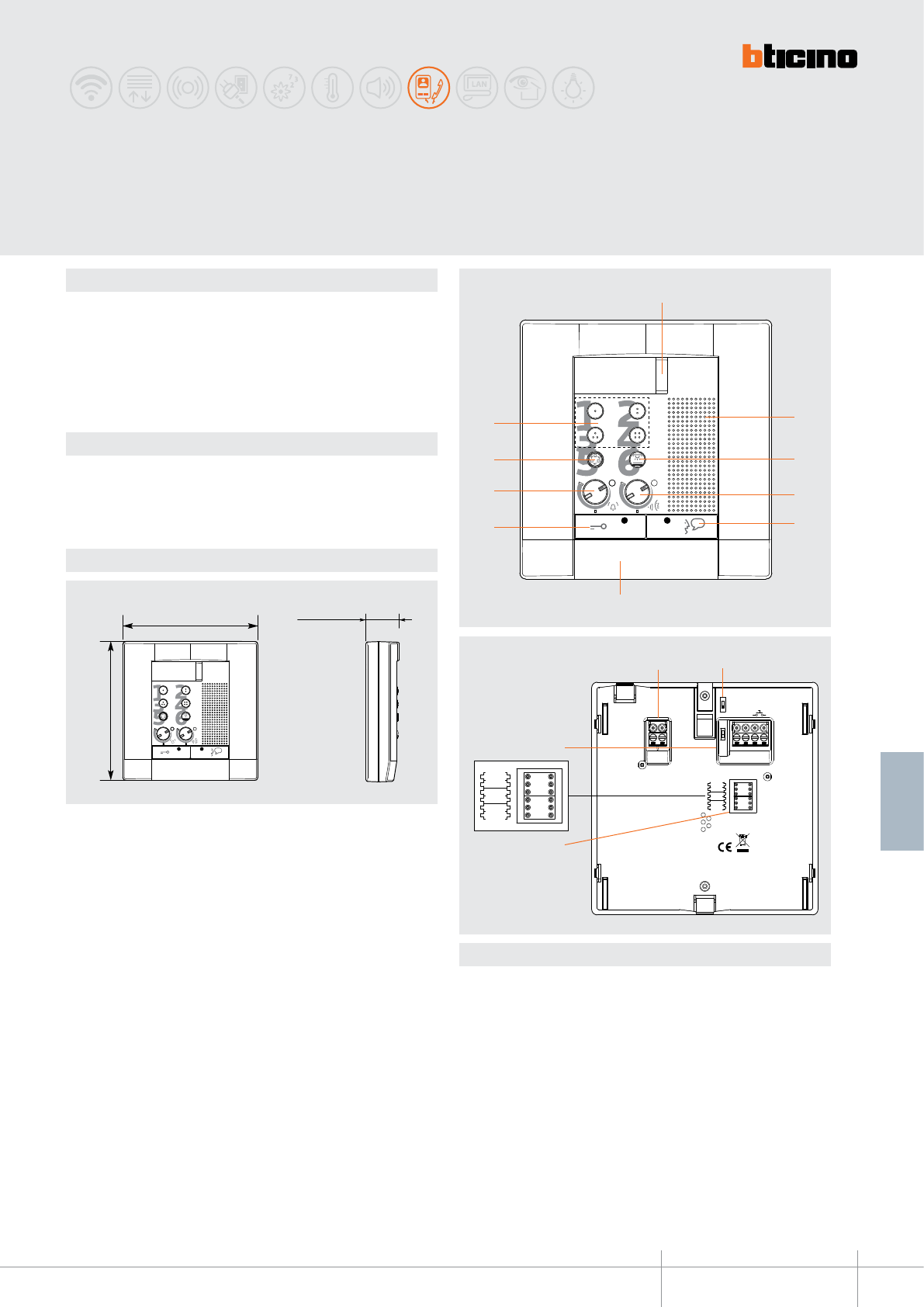
344082
BT00641-a
128 mm
124,5 mm 30 mm
10
9
8
7
2
3
4
5
1
6
ART.344082
P M
N
BUS 51
OFF
ON
P M
N
14
13
1211
-EN
TECHNICAL SHEETS
285
2 WIRE VDE system
Dimensional data
Description
2 WIRE handsfree handset for wall mounted installation.
It’s tted with keys for: EP activation/cycling, door lock release, staircase light switching
on and 4 programmable keys, which operating mode is set through the conguration.
Specic audible and visual signals mean that it is also suitable for use by disabled people.
Fixing bracket supplied.
Technical data
Power supply from SCS BUS: 18 – 27 Vdc
Stand by absorption: 5 mA
Max. operating absorption: 55 mA
Operating temperature: 5 - 40°C
Legend
1 - Call signalling LED
2 - Loudspeaker
3 - Staircase light key
4 - Loudspeaker volume adjustment
5 - Connection key+ LED
6 - Microphone
7 - Door lock key + LED
8 - Bell volume adjustment and exclusion + LED
9 - EP Activation/cycling
10 - 4 programmable keys (through conguration)
11 - Clamps for the connection to the 2 WIRE BUS
12 - Line termination ON/OFF micro-switch
13 - Congurator socket
14 - Clamps for the connection of the Floor call auxiliary services and extra bell
Audio
POLYX
Front
Rear view
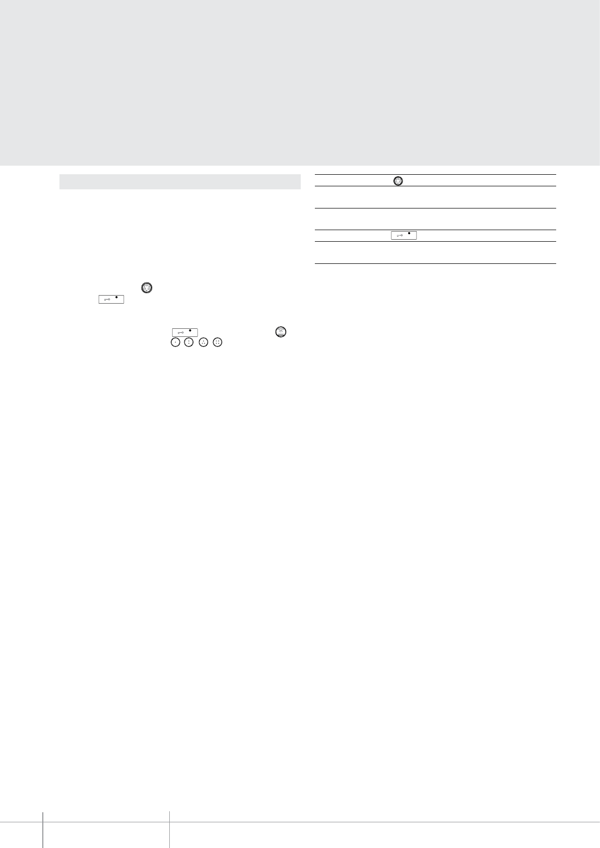
BT00641-a
344082
-EN
TECHNICAL SHEETS
286 2 WIRE VDE system
N - handset number
Assigns to each handset an identication number within the system. The handsets
must be congured in progressive order. Handsets with parallel connection (max 3 are
allowed inside apartments without item 346850) must be congured using the same
N congurator.
P - entrance panel association
The P congurator identies the associated EP, or the rst entrance panel on which the
audio is activated when the ( ) key is pressed, as well as which door lock is activated
when the key is pressed while the handset is idle.
M - Operating mode of the keys
In addition to the door lock opening key and the staircase light key ( ), the
handset also has 4 programmable keys ( - - - ).
These keys may be associated to dierent operating modes (e.g. activation of external
actuators, intercom, activation of additional EPs, etc., based on the type of congurator
connected to M).
The handset oers the possibility to select among 16 types of bells with pre-programmed
ringtones, which can be associated to the following type of calls:
- Calls from the entrance panel (congured with S=0 - S=4)
- Calls from the entrance panel (congured with S=0 - S=5)
- Intercom call
- Floor call
(See the bell programming table in the following pages)
Conguration Congurator in P key ( ) function
0-9 Entrance panel audio activation
(congured with P=0-9)
Congurator in P key function
0-9 Opening of the EP door lock
(congured with P=0-9)
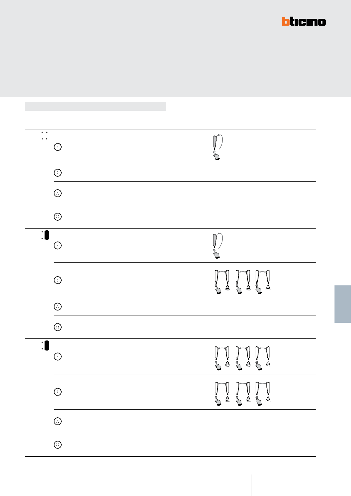
344082
BT00641-a-EN
TECHNICAL SHEETS
287
2 WIRE VDE system
Below are the various operating modes that can be assigned to the 4 programmable keys:
Conguration
MODE KEY FUNCTION NOTES
MOD =
1Intercom on itself, it sends the call to all handsets with the same address.
2EP activation (congured with P+1), directly, without call, or activation of the
actuator, item 346200 (congured with P+1 and MOD=9)
3
EP door lock release (congured with P+1), directly, without call, or activation of
the actuator, item 346200 (congured with P+1 and MOD=5), or activation of door
lock actuators 346230-346260 (congured with P+1)
4
EP door lock release (congured with P+2), directly, without call, or activation of the
actuator, item 346200 (congured with P+2 and MOD=5), or activation of door lock
actuators 346230-346260 (congured with P+2)
1
MOD =
1Intercom on itself, it sends the call to all handsets with the same address.
2Intercom inside the apartment, in systems with apartment interface item 346850,
or intercom among apartments without apartment interface. 2
N=1N=2
2
N=2N=3
2
N=3N=2
3EP activation (congured with P+1), directly, without call, or activation of the
actuator, item 346200 (congured with P+1 and MOD=9)
4
EP door lock release (congured with P+1), directly, without call, or activation of
the actuator, item 346200 (congured with P+1 and MOD=5), or activation of door
lock actuators 346230-346260 (congured with P+1)
2
MOD =
1Intercom inside the apartment, in systems with apartment interface item 346850,
or intercom among apartments without apartment interface. 1
N=1N=3
1
N=2N=1
1
N=3N=1
2Intercom inside the apartment, in systems with apartment interface item 346850,
or intercom among apartments without apartment interface. 2
N=1N=2
2
N=2N=3
2
N=3N=2
3
EP door lock release (congured with P+1), directly, without call, or activation of
the actuator, item 346200 (congured with P+1 and MOD=5), or activation of door
lock actuators 346230-346260 (congured with P+1)
4
EP door lock release (congured with P+2), directly, without call, or activation of
the actuator, item 346200 (congured with P+2 and MOD=5), or activation of door
lock actuators 346230-346260 (congured with P+2)
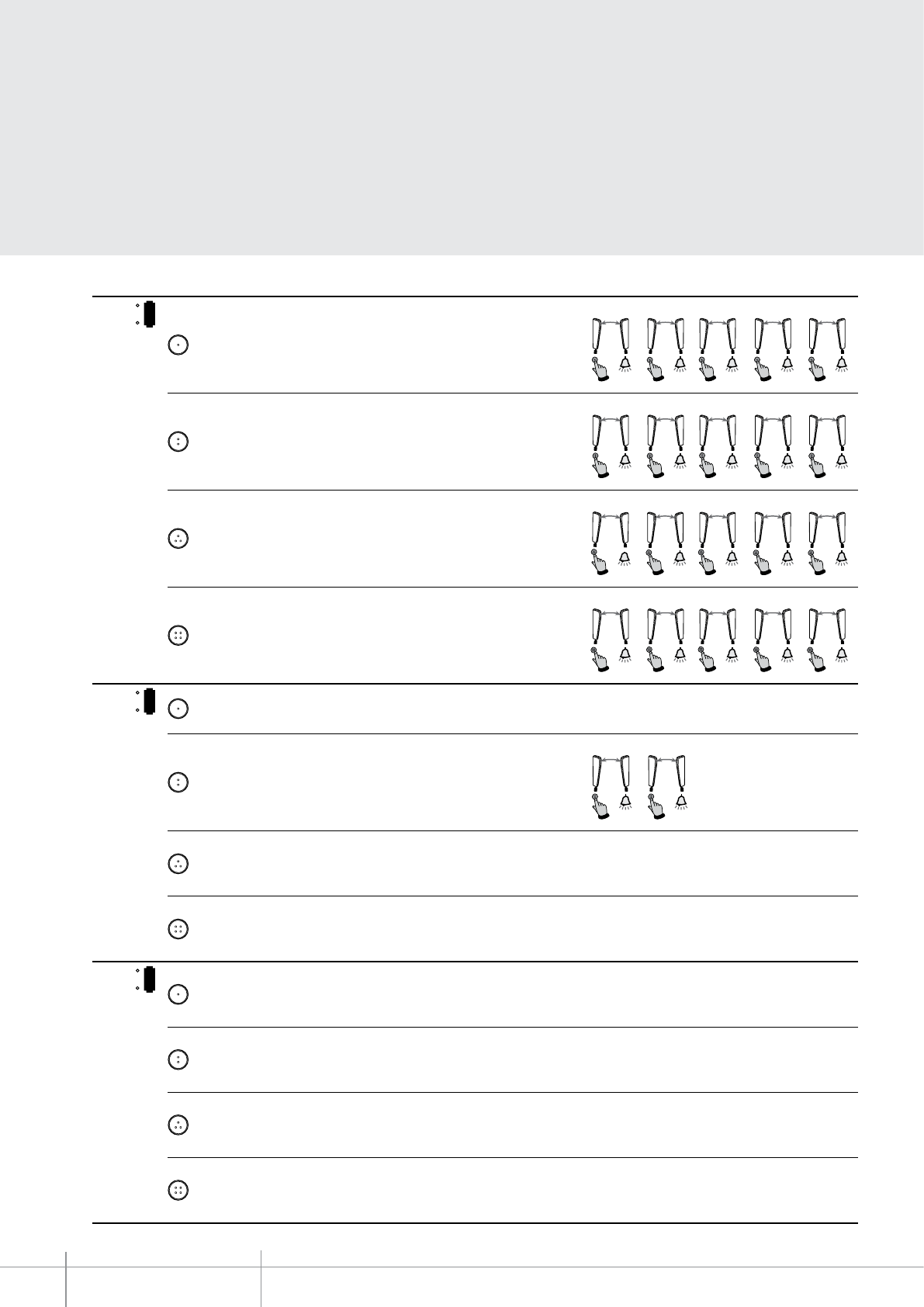
BT00641-a
344082
-EN
TECHNICAL SHEETS
288 2 WIRE VDE system
MODE KEY FUNCTION NOTES
3
MOD =
1Intercom inside the apartment, in systems with apartment interface item 346850,
or intercom among apartments without apartment interface. 1
N=1N=5
1
N=2N=1
1
N=3N=1
1
N=4N=1
1
N=5N=1
2Intercom inside the apartment, in systems with apartment interface item 346850,
or intercom among apartments without apartment interface. 2
N=1N=2
2
N=2N=5
2
N=3N=2
2
N=4N=2
2
N=5N=2
3Intercom inside the apartment, in systems with apartment interface item 346850,
or intercom among apartments without apartment interface.
3
N
=
N1
=
3
3
N=2N=3
3
N=3N=5
3
N=4N=3
3
N=5N=3
4Intercom inside the apartment, in systems with apartment interface item 346850,
or intercom among apartments without apartment interface. 4
N=1N=4
4
N=2N=4
4
N=3N=4
4
N=4N=5
4
N=
5N
=4
4
MOD = 1EP activation (congured with P+1), directly, without call, or activation of the
actuator, item 346200 (congured with P+1 and MOD=9)
2Intercom inside the apartment, in systems with apartment interface item 346850,
or intercom among apartments without apartment interface. 2
N=1N=2
2
N=2N=1
3
EP door lock release (congured with P+1), directly, without call, or activation of
the actuator, item 346200 (congured with P+1 and MOD=5), or activation of door
lock actuators 346230-346260 (congured with P+1)
4
EP door lock release (congured with P+2), directly, without call, or activation of
the actuator, item 346200 (congured with P+2 and MOD=5), or activation of door
lock actuators 346230-346260 (congured with P+2)
5
MOD =
1
EP door lock release (congured with P+1), directly, without call, or activation of
the actuator, item 346200 (congured with P+1 and MOD=5), or activation of door
lock actuators 346230-346260 (congured with P+1)
2
EP door lock release (congured with P+2), directly, without call, or activation of
the actuator, item 346200 (congured with P+2 and MOD=5), or activation of door
lock actuators 346230-346260 (congured with P+2)
3
EP door lock release (congured with P+3), directly, without call, or activation of
the actuator, item 346200 (congured with P+3 and MOD=5), or activation of door
lock actuators 346230-346260 (congured with P+3)
4
EP door lock release (congured with P+4), directly, without call, or activation of
the actuator, item 346200 (congured with P+4 and MOD=5), or activation of door
lock actuators 346230-346260 (congured with P+4)
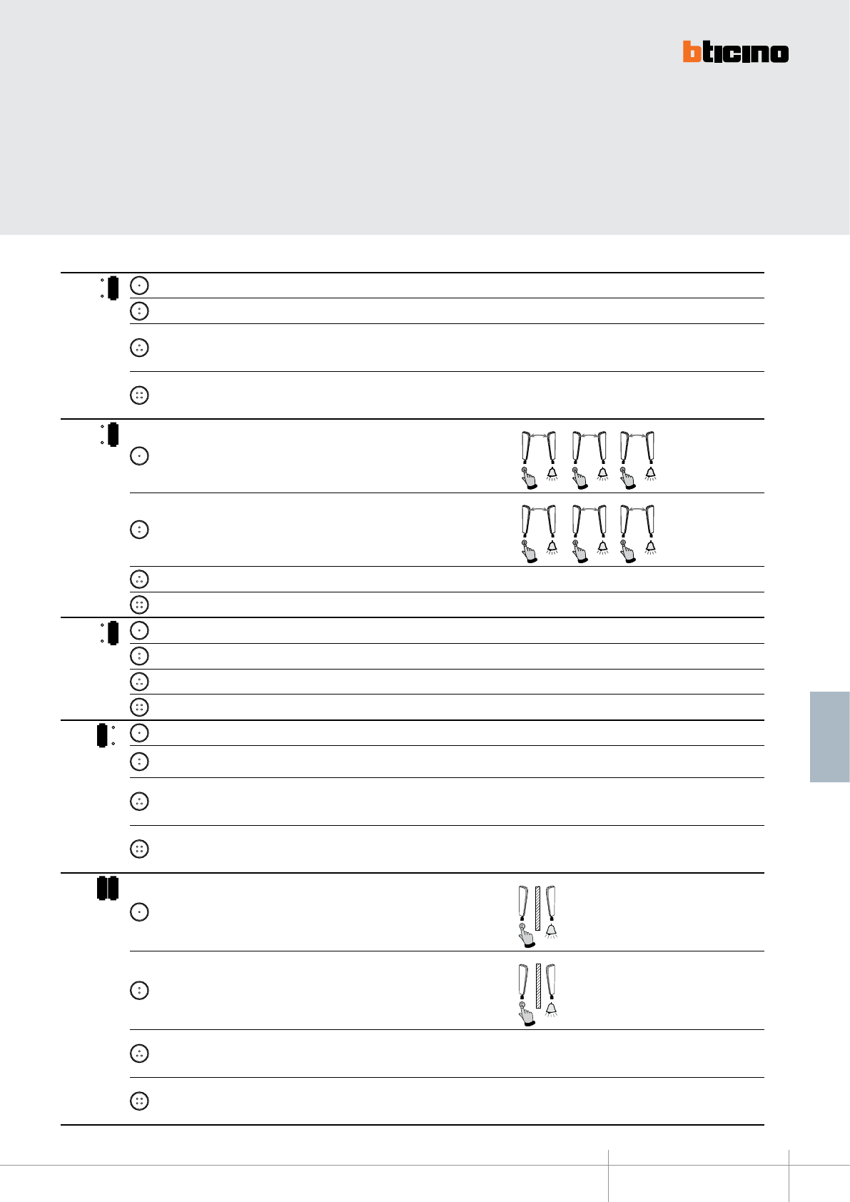
344082
BT00641-a-EN
TECHNICAL SHEETS
289
2 WIRE VDE system
MODE KEY FUNCTION NOTES
6
MOD = 1Activation of the scenario saved in the scenario module (SCENARIO 1)
2Activation of the scenario saved in the scenario module (SCENARIO 2)
3
EP door lock release (congured with P+1), directly, without call, or activation of
the actuator, item 346200 (congured with P+1 and MOD=5), or activation of door
lock actuators 346230-346260 (congured with P+1)
4
EP door lock release (congured with P+2), directly, without call, or activation of
the actuator, item 346200 (congured with P+2 and MOD=5), or activation of door
lock actuators 346230-346260 (congured with P+2)
7
MOD =
1Intercom inside the apartment, in systems with apartment interface item 346850,
or intercom among apartments without apartment interface. 1
N=1N=3
1
N=2N=1
1
N=
3N
=1
2Intercom inside the apartment, in systems with apartment interface item 346850,
or intercom among apartments without apartment interface. 2
N=1N=2
2
N=2N=3
2
N=3N=2
3Activation of the scenario saved in the scenario module (SCENARIO 1)
4Activation of the scenario saved in the scenario module (SCENARIO 2)
8
MOD = 1Activation of the scenario saved in the scenario module (SCENARIO 1)
2Activation of the scenario saved in the scenario module (SCENARIO 2)
3Activation of the scenario saved in the scenario module (SCENARIO 3)
4Activation of the scenario saved in the scenario module (SCENARIO 4)
1
MOD = 1General Intercom, sends a call to all the handsets of the system.
2EP activation (congured with P+1), directly, without call, or activation of the
actuator, item 346200 (congured with P+1 and MOD=9)
3
EP door lock release (congured with P+1), directly, without call, or activation of
the actuator, item 346200 (congured with P+1 and MOD=5), or activation of door
lock actuators 346230-346260 (congured with P+1)
4
EP door lock release (congured with P+2), directly, without call, or activation of
the actuator, item 346200 (congured with P+2 and MOD=5), or activation of door
lock actuators 346230-346260 (congured with P+2)
1 2
MOD =
1Intercom between apartments, in systems with apartment interface, item 346850
1
N=1
2Intercom between apartments, in systems with apartment interface, item 346850
2
N=2
3
EP door lock release (congured with P+1), directly, without call, or activation of
the actuator, item 346200 (congured with P+1 and MOD=5), or activation of door
lock actuators 346230-346260 (congured with P+1)
4
EP door lock release (congured with P+2), directly, without call, or activation of
the actuator, item 346200 (congured with P+2 and MOD=5), or activation of door
lock actuators 346230-346260 (congured with P+2)

BT00641-a
344082
-EN
TECHNICAL SHEETS
290 2 WIRE VDE system
MODE KEY FUNCTION NOTES
1 3
MOD =
1Intercom between apartments, in systems with apartment interface, item 346850
1
N=1
2Intercom between apartments, in systems with apartment interface, item 346850
2
N=2
3Intercom between apartments, in systems with apartment interface, item 346850
3
N=3
4Intercom between apartments, in systems with apartment interface, item 346850
4
N=4
1 6
MOD = 1Activation of the scenario saved in the scenario module (SCENARIO 1)
2Activation of the scenario saved in the scenario module (SCENARIO 2)
3General Intercom, sends a call to all the handsets of the system.
4
EP door lock release (congured with P+1), directly, without call, or activation of
the actuator, item 346200 (congured with P+1 and MOD=5), or activation of door
lock actuators 346230-346260 (congured with P+1)
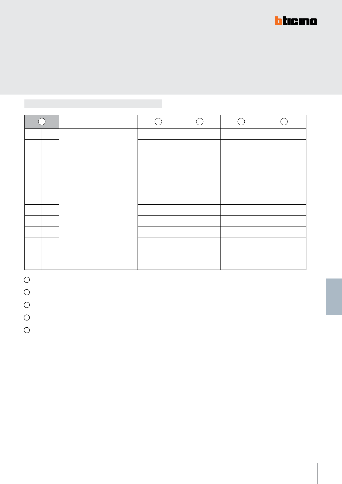
344082
BT00641-a-EN
TECHNICAL SHEETS
291
2 WIRE VDE system
Conguration
A B C D E
0 0
+
20 = B
40 = C
60 = D
80 = E
20 40 60 80
1 0 30 50 70 90
0 1 21 41 61 81
0 2 22 42 62 82
1 2 32 52 72 92
0 3 23 43 63 83
1 3 33 53 73 93
0 4 24 44 64 84
0 5 25 45 65 85
0 6 26 46 66 86
1 6 36 56 76 96
0 7 27 47 67 87
0 8 28 48 68 88
A Conguration selected for the operation of the keys (see previous pages)
B Conguration selected for the operation of the keys + OFFICE function
C Conguration selected for the operation of the keys + PAGING function
D Conguration selected for the operation of the keys + HANDSFREE function (Can be activated only on a single device for each unit system)
E Conguration selected for the operation of the keys, OFFICE and PAGING function
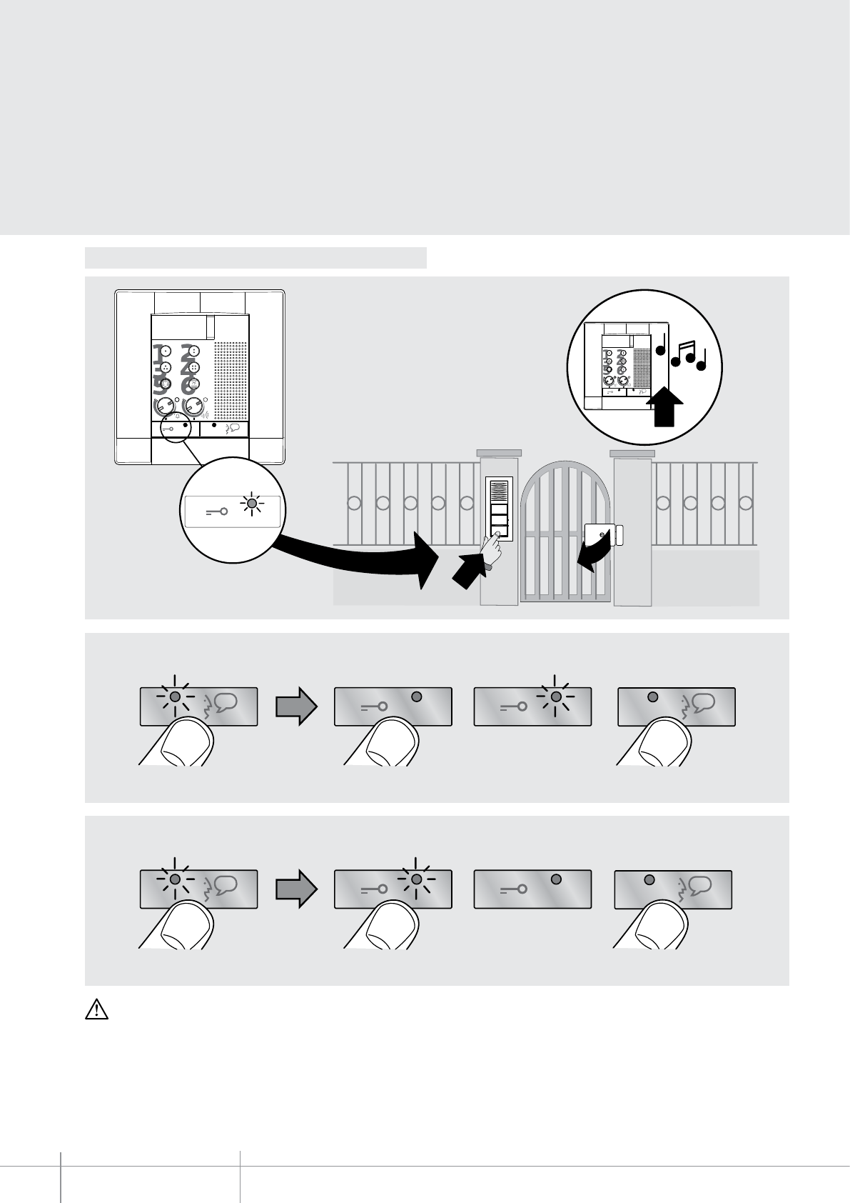
BT00641-a
344082
2
1
3
CLAK
>3s
Led ON
Led ON
>3s
BEEP
BEEP
BEEP
EXIT
EXIT
>3s
Led ON
>3s
BEEP
BEEP
BEEP
EXIT
EXIT
>3s
Led ON
Led ON
>3s
BEEP
BEEP
BEEP
EXIT
EXIT
>3s
Led ON
>3s
BEEP
BEEP
BEEP
EXIT
EXIT
-EN
TECHNICAL SHEETS
292 2 WIRE VDE system
OFFICE FUNCTION DETAIL
With the function active, when a call is received from
the entrance panel, the video handset rings and the
associated door lock is automatically released, without
the need for pressing the door lock release key on the
handset.
To ENABLE the function
To DISABLE the function
WARNING: the “OFFICE” function cannot be activated together with the “DOOR STATUS” function.
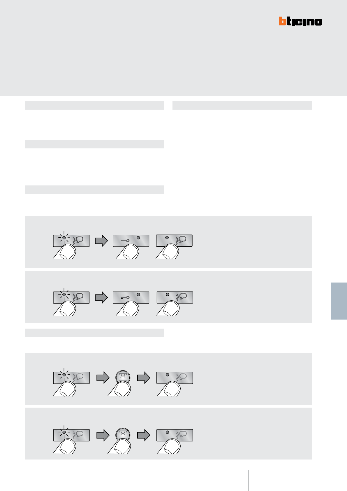
344082
BT00641-a
>3s
>3s
BEEP
EXIT
EXIT
BEEP
BEEP
>3s
>3s
BEEP EXIT
EXIT
BEEP
BEEP
BEEP
>3s
BEEP
BEEP
>3s
>3s
>3s
BEEP
EXIT
EXIT
BEEP
BEEP
>3s
>3s
BEEP EXIT
EXIT
BEEP
BEEP
BEEP
>3s
BEEP
BEEP
>3s
-EN
TECHNICAL SHEETS
293
2 WIRE VDE system
DOOR STATUS function PUSH TO TALK function
PAGING function
HANDSFREE function
This function noties the status of the door lock. If open, the “door lock LED” ashes, if
closed, the LED stays o.
NOTA: è attivabile solo se l’impianto lo prevede; NON è attivabile contemporaneamente
alla OFFICE function.
Enable/disable key sound
In the base conguration, when a key is pressed, a beep is emitted. This function may be
disabled/enabled with the following procedure:
If the entrance panel is in a particularly noisy position, during the conversation it will
be possible to enable the “PUSH TO TALK” function, which will provide a better quality
of communication.
To enable the PUSH TO TALK function during the conversation proceed as follows:
- Press the Connection key for at least 2 seconds, to enable the communication with the
entrance panel.
The LED stays green.
-
Release the key to listen to the entrance panel. The LED turns red.
- To end the connection press the Connection key briey. The LED turns o.
This function can be used to send voice messages using the microphone of the device
through the speakers of the sound system. To activate briey press the ”Connection” key
while the device is in the idle condition. The activation of the function is conrmed by the
green LED coming on. To DISABLE the function press the ”Connection” key again.
The HANDSFREE function automatically activates the microphone and the loudspeaker
when a call is received, without the need for pressing the Connection key to answer (the
connection is automatically established when the call is received).
To ENABLE the function
To ENABLE the function
To DISABLE the function
To DISABLE the function
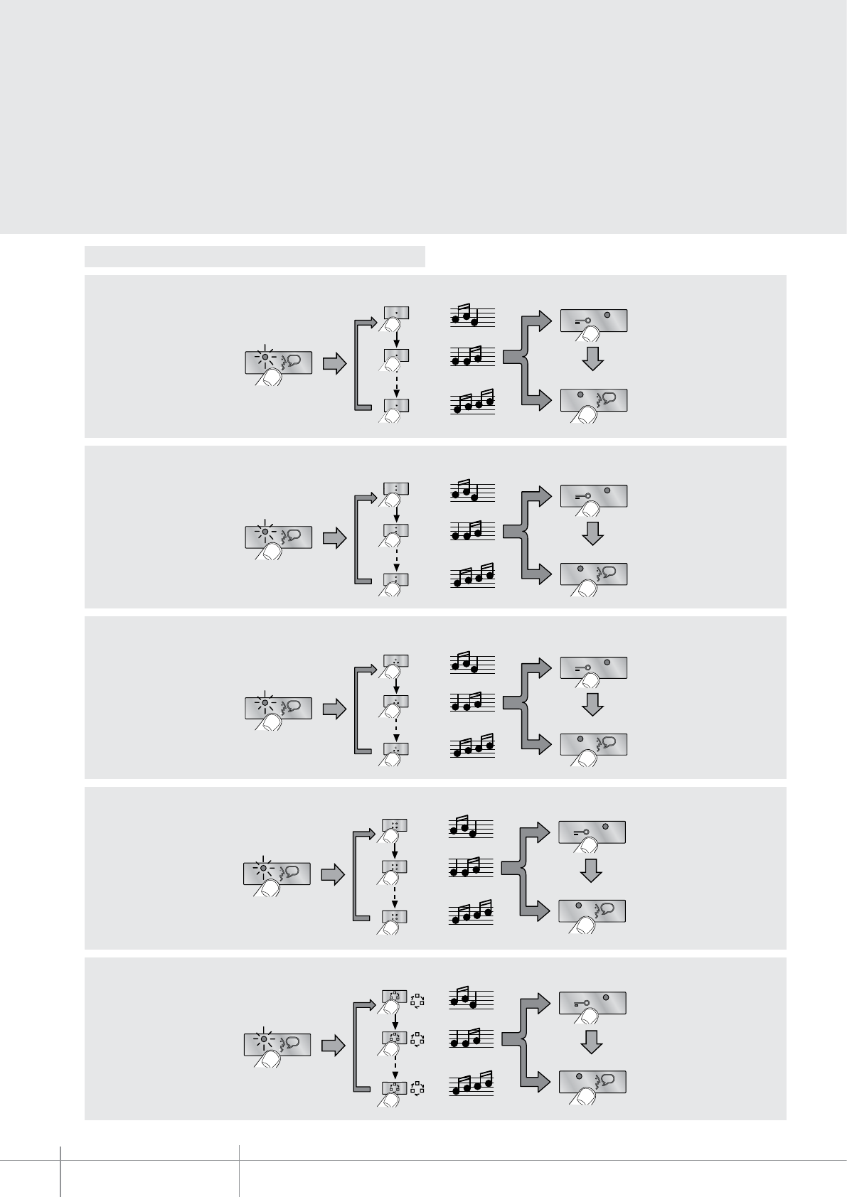
BT00641-a
344082
EXIT
OK
1
17
2
>3s
2
2
2
EXIT
OK
1
17
2
>3s
1
1
1
EXIT
OK
1
17
2
>3s
3
3
3
EXIT
OK
1
16
2
>3s
4
4
4
EXIT
OK
1
17
2
>3s
EXIT
OK
1
17
2
>3s
2
2
2
EXIT
OK
1
17
2
>3s
1
1
1
EXIT
OK
1
16
2
>3s
3
3
3
EXIT
OK
1
17
2
>3s
4
4
4
EXIT
OK
1
17
2
>3s
EXIT
OK
1
16
2
>3s
2
2
2
EXIT
OK
1
17
2
>3s
1
1
1
EXIT
OK
1
17
2
>3s
3
3
3
EXIT
OK
1
17
2
>3s
4
4
4
EXIT
OK
1
17
2
>3s
EXIT
OK
1
17
2
>3s
2
2
2
EXIT
OK
1
16
2
>3s
1
1
1
EXIT
OK
1
17
2
>3s
3
3
3
EXIT
OK
1
17
2
>3s
4
4
4
EXIT
OK
1
17
2
>3s
EXIT
OK
1
17
2
>3s
2
2
2
EXIT
OK
1
17
2
>3s
1
1
1
EXIT
OK
1
17
2
>3s
3
3
3
EXIT
OK
1
17
2
>3s
4
4
4
EXIT
OK
1
16
2
>3s
EXIT
OK
1
17
2
>3s
2
2
2
EXIT
OK
1
17
2
>3s
1
1
1
EXIT
OK
1
17
2
>3s
3
3
3
EXIT
OK
1
16
2
>3s
4
4
4
EXIT
OK
1
17
2
>3s
EXIT
OK
1
17
2
>3s
2
2
2
EXIT
OK
1
17
2
>3s
1
1
1
EXIT
OK
1
16
2
>3s
3
3
3
EXIT
OK
1
17
2
>3s
4
4
4
EXIT
OK
1
17
2
>3s
EXIT
OK
1
16
2
>3s
2
2
2
EXIT
OK
1
17
2
>3s
1
1
1
EXIT
OK
1
17
2
>3s
3
3
3
EXIT
OK
1
17
2
>3s
4
4
4
EXIT
OK
1
17
2
>3s
EXIT
OK
1
17
2
>3s
2
2
2
EXIT
OK
1
16
2
>3s
1
1
1
EXIT
OK
1
17
2
>3s
3
3
3
EXIT
OK
1
17
2
>3s
4
4
4
EXIT
OK
1
17
2
>3s
EXIT
OK
1
17
2
>3s
2
2
2
EXIT
OK
1
17
2
>3s
1
1
1
EXIT
OK
1
17
2
>3s
3
3
3
EXIT
OK
1
17
2
>3s
4
4
4
EXIT
OK
1
16
2
>3s
EXIT
OK
1
17
2
>3s
2
2
2
EXIT
OK
1
17
2
>3s
1
1
1
EXIT
OK
1
17
2
>3s
3
3
3
EXIT
OK
1
16
2
>3s
4
4
4
EXIT
OK
1
17
2
>3s
EXIT
OK
1
17
2
>3s
2
2
2
EXIT
OK
1
17
2
>3s
1
1
1
EXIT
OK
1
16
2
>3s
3
3
3
EXIT
OK
1
17
2
>3s
4
4
4
EXIT
OK
1
17
2
>3s
EXIT
OK
1
16
2
>3s
2
2
2
EXIT
OK
1
17
2
>3s
1
1
1
EXIT
OK
1
17
2
>3s
3
3
3
EXIT
OK
1
17
2
>3s
4
4
4
EXIT
OK
1
17
2
>3s
EXIT
OK
1
17
2
>3s
2
2
2
EXIT
OK
1
16
2
>3s
1
1
1
EXIT
OK
1
17
2
>3s
3
3
3
EXIT
OK
1
17
2
>3s
4
4
4
EXIT
OK
1
17
2
>3s
EXIT
OK
1
17
2
>3s
2
2
2
EXIT
OK
1
17
2
>3s
1
1
1
EXIT
OK
1
17
2
>3s
3
3
3
EXIT
OK
1
17
2
>3s
4
4
4
EXIT
OK
1
16
2
>3s
EXIT
OK
1
17
2
>3s
2
2
2
EXIT
OK
1
17
2
>3s
1
1
1
EXIT
OK
1
17
2
>3s
3
3
3
EXIT
OK
1
16
2
>3s
4
4
4
EXIT
OK
1
17
2
>3s
EXIT
OK
1
17
2
>3s
2
2
2
EXIT
OK
1
17
2
>3s
1
1
1
EXIT
OK
1
16
2
>3s
3
3
3
EXIT
OK
1
17
2
>3s
4
4
4
EXIT
OK
1
17
2
>3s
EXIT
OK
1
16
2
>3s
2
2
2
EXIT
OK
1
17
2
>3s
1
1
1
EXIT
OK
1
17
2
>3s
3
3
3
EXIT
OK
1
17
2
>3s
4
4
4
EXIT
OK
1
17
2
>3s
EXIT
OK
1
17
2
>3s
2
2
2
EXIT
OK
1
16
2
>3s
1
1
1
EXIT
OK
1
17
2
>3s
3
3
3
EXIT
OK
1
17
2
>3s
4
4
4
EXIT
OK
1
17
2
>3s
EXIT
OK
1
17
2
>3s
2
2
2
EXIT
OK
1
17
2
>3s
1
1
1
EXIT
OK
1
17
2
>3s
3
3
3
EXIT
OK
1
17
2
>3s
4
4
4
EXIT
OK
1
16
2
>3s
EXIT
OK
1
17
2
>3s
2
2
2
EXIT
OK
1
17
2
>3s
1
1
1
EXIT
OK
1
17
2
>3s
3
3
3
EXIT
OK
1
16
2
>3s
4
4
4
EXIT
OK
1
17
2
>3s
EXIT
OK
1
17
2
>3s
2
2
2
EXIT
OK
1
17
2
>3s
1
1
1
EXIT
OK
1
16
2
>3s
3
3
3
EXIT
OK
1
17
2
>3s
4
4
4
EXIT
OK
1
17
2
>3s
EXIT
OK
1
16
2
>3s
2
2
2
EXIT
OK
1
17
2
>3s
1
1
1
EXIT
OK
1
17
2
>3s
3
3
3
EXIT
OK
1
17
2
>3s
4
4
4
EXIT
OK
1
17
2
>3s
EXIT
OK
1
17
2
>3s
2
2
2
EXIT
OK
1
16
2
>3s
1
1
1
EXIT
OK
1
17
2
>3s
3
3
3
EXIT
OK
1
17
2
>3s
4
4
4
EXIT
OK
1
17
2
>3s
EXIT
OK
1
17
2
>3s
2
2
2
EXIT
OK
1
17
2
>3s
1
1
1
EXIT
OK
1
17
2
>3s
3
3
3
EXIT
OK
1
17
2
>3s
4
4
4
EXIT
OK
1
16
2
>3s
-EN
TECHNICAL SHEETS
294 2 WIRE VDE system
Programming of bells
Bell selection from MAIN ENTRANCE PANEL (S=0)
Bell selection from SECONDARY ENTRANCE PANEL (S=1)
INTERCOM CALL bell selection
EXTERNAL INTERCOM CALL bell selection
(only with interface item 346850)
FLOOR CALL bell selection
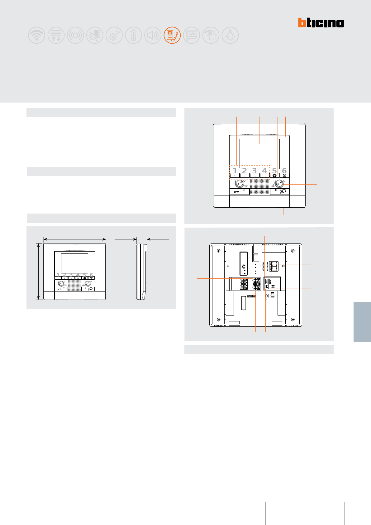
344192
BT00642-a
30 mm
168 mm
150 mm
ON
OFF
J1 J2
BUS
1
2
5
1
P M
N
ART.344182
ON
OFF
J1 J2
BUS
1
2
5
1
P M
N
ART.344182
1 2 43
6
5
7
12
11
910 8
13
1617
19
18
14
15
-EN
TECHNICAL SHEETS
295
2 WIRE VDE system
Dimensional data
Description
2 WIRE handsfree video handset for wall mounted installation.
With 3.5” colour LCD dislay.
Keys available: auto-switching on, door lock release, staircase lights, handsfree
connection, and four programmable keys.
Signalling LED for call exclusion, door status, connection with the entrance panel.
It can be wall mounted using the appropriate bracket (supplied).
Technical data
Power supply from SCS BUS: 18 – 27 Vdc
Stand by absorption: 5 mA
Max. operating absorption: 320 mA
Operating temperature: 5 - 40°C
Legend
1 - 4 Programmable keys (through conguration)
2 - 3.5” colour LCD display
3 - Entrance panel/cycling key
4 - Microphone
5 - Staircase light switching on key
6 - Loudspeaker volume adjustment
7 - Connection key + LED
8 - Brightness adjustment
9 - Loudspeaker
10 - Display colour adjustment
11 - Door lock key + LED
12 - Bell adjustment and exclusion (LED)
13 - Line termination ON/OFF micro-switch
14 - Congurator socket
15 - Jumper J2 - MASTER/SLAVE (remove to enable SLAVE)
16 - Jumper J1 - remove to enable additional power supply
17 - Additional power supply connection clamps
18 - Clamps for the connection of oor call auxiliary services and extra bell
19 - Clamps for the connection of the 2-WIRE SCS BUS
POLYX
handsfree video handset
Rear view
Front view
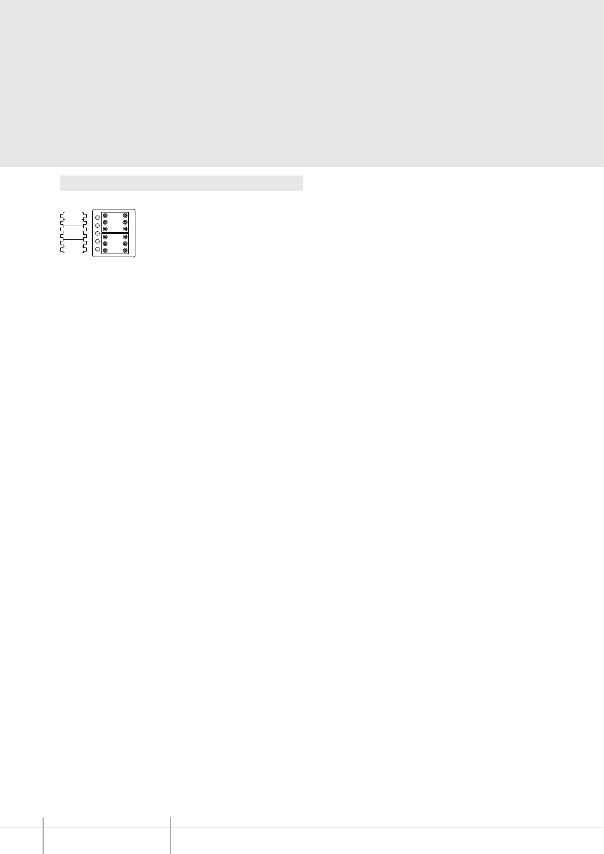
BT00642-a
344192
P M
N
-EN
TECHNICAL SHEETS
296 2 WIRE VDE system
Conguration
The device must be only physically congured.
N – handset number
The N congurator assigns each video handset an identication number within the
system. The handsets must be congured in progressive order. The handsets must be
congured in progressive mode. Handsets with parallel connection (max 3 are allowed
inside the apartment without item 346850) must be congured with the same N
congurator. Additional audio handsets, video handsets and/or bells can be installed in
parallel to the basic video handset.
P – entrance panel association
The P congurator identies the associated EP, or the rst entrance panel that switches
itself on when the pushbutton is pressed the rst time, as well as which door lock with
idle video handset is activated, when the pushbutton is pressed.
M – operating mode
The M congurator assigns the operating mode to the 4 programmable keys following
the indications of the following pages.
The video handset oers the possibility to select among 16 types of bells with
programmed ringtones, which can be freely associated to the following type of calls:
- Calls from the entrance panel (congured with S=0)
- Calls from the entrance panel (congured with S=1)
- Intercom call
- Floor call
(See the bell programming table in the following pages)
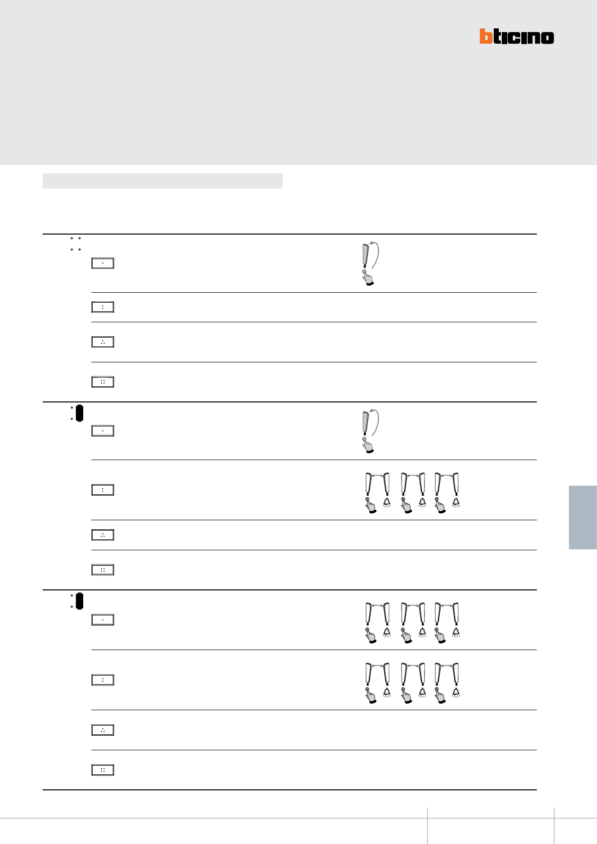
344192
BT00642-a-EN
TECHNICAL SHEETS
297
2 WIRE VDE system
Below are the various operating modes that can be assigned to the 4 programmable keys:
Conguration
MODE KEY FUNCTION NOTES
MOD =
1Intercom on itself, it sends the call to all handsets with the same address.
2EP activation (congured with P+1), directly, without call, or activation of the
actuator, item 346200 (congured with P+1 and MOD=9)
3
EP door lock release (congured with P+1), directly, without call, or activation of
the actuator, item 346200 (congured with P+1 and MOD=5), or activation of door
lock actuators 346230-346260 (congured with P+1)
4
EP door lock release (congured with P+2), directly, without call, or activation of
the actuator, item 346200 (congured with P+2 and MOD=5), or activation of door
lock actuators 346230-346260 (congured with P+2)
1
MOD =
1Intercom on itself, it sends the call to all handsets with the same address.
2Intercom inside the apartment, in systems with apartment interface item 346850,
or intercom among apartments without apartment interface. 2
N=1N=2
2
N=2N=3
2
N=3N=2
3EP activation (congured with P+1), directly, without call, or activation of the
actuator, item 346200 (congured with P+1 and MOD=9)
4
EP door lock release (congured with P+1), directly, without call, or activation of
the actuator, item 346200 (congured with P+1 and MOD=5), or activation of door
lock actuators 346230-346260 (congured with P+1)
2
MOD =
1Intercom inside the apartment, in systems with apartment interface item 346850,
or intercom among apartments without apartment interface. 1
N=1N=3
1
N=2N=1
1
N=
3N
=1
2Intercom inside the apartment, in systems with apartment interface item 346850,
or intercom among apartments without apartment interface. 2
N=1N=2
2
N=2N=3
2
N=3N=2
3
EP door lock release (congured with P+1), directly, without call, or activation of
the actuator, item 346200 (congured with P+1 and MOD=5), or activation of door
lock actuators 346230-346260 (congured with P+1)
4
EP door lock release (congured with P+2), directly, without call, or activation of
the actuator, item 346200 (congured with P+2 and MOD=5), or activation of door
lock actuators 346230-346260 (congured with P+2)
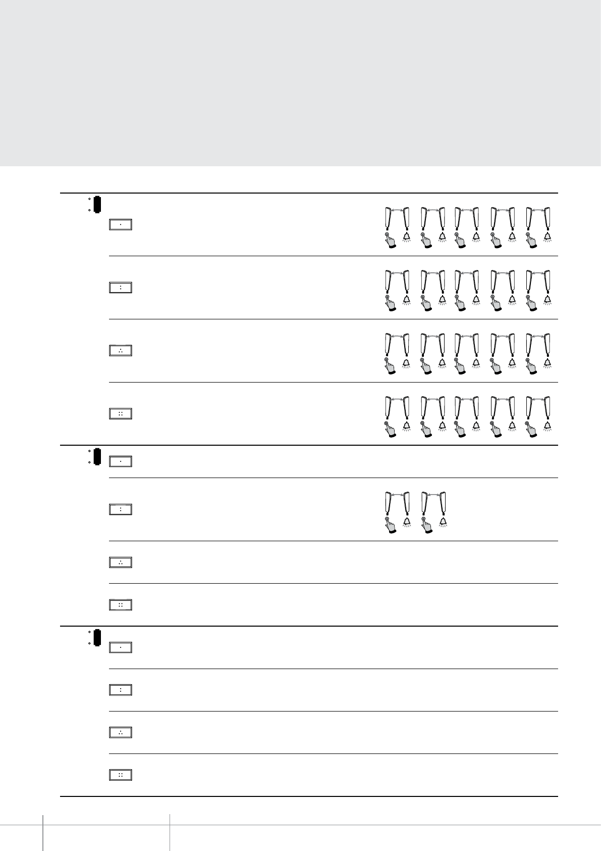
BT00642-a
344192
-EN
TECHNICAL SHEETS
298 2 WIRE VDE system
MODE KEY FUNCTION NOTES
3
MOD =
1Intercom inside the apartment, in systems with apartment interface item 346850,
or intercom among apartments without apartment interface. 1
N=1N=5
1
N=2N=1
1
N=3N=1
1
N=4N=1
1
N=5N=1
2Intercom inside the apartment, in systems with apartment interface item 346850,
or intercom among apartments without apartment interface. 2
N=1N=2
2
N=2N=5
2
N=3N=2
2
N=4N=2
2
N=5N=2
3Intercom inside the apartment, in systems with apartment interface item 346850,
or intercom among apartments without apartment interface.
3
N
=
N1
=
3
3
N=2N=3
3
N=3N=5
3
N=4N=3
3
N=5N=3
4Intercom inside the apartment, in systems with apartment interface item 346850,
or intercom among apartments without apartment interface. 4
N=1N=4
4
N=2N=4
4
N=3N=4
4
N=4N=5
4
N=
5N
=4
4
MOD = 1EP activation (congured with P+1), directly, without call, or activation of the
actuator, item 346200 (congured with P+1 and MOD=9)
2Intercom inside the apartment, in systems with apartment interface item 346850,
or intercom among apartments without apartment interface. 2
N=1N=2
2
N=2N=1
3
EP door lock release (congured with P+1), directly, without call, or activation of
the actuator, item 346200 (congured with P+1 and MOD=5), or activation of door
lock actuators 346230-346260 (congured with P+1)
4
EP door lock release (congured with P+2), directly, without call, or activation of
the actuator, item 346200 (congured with P+2 and MOD=5), or activation of door
lock actuators 346230-346260 (congured with P+2)
5
MOD =
1
EP door lock release (congured with P+1), directly, without call, or activation of
the actuator, item 346200 (congured with P+1 and MOD=5), or activation of door
lock actuators 346230-346260 (congured with P+1)
2
EP door lock release (congured with P+2), directly, without call, or activation of
the actuator, item 346200 (congured with P+2 and MOD=5), or activation of door
lock actuators 346230-346260 (congured with P+2)
3
EP door lock release (congured with P+3), directly, without call, or activation of
the actuator, item 346200 (congured with P+3 and MOD=5), or activation of door
lock actuators 346230-346260 (congured with P+3)
4
EP door lock release (congured with P+4), directly, without call, or activation of
the actuator, item 346200 (congured with P+4 and MOD=5), or activation of door
lock actuators 346230-346260 (congured with P+4)
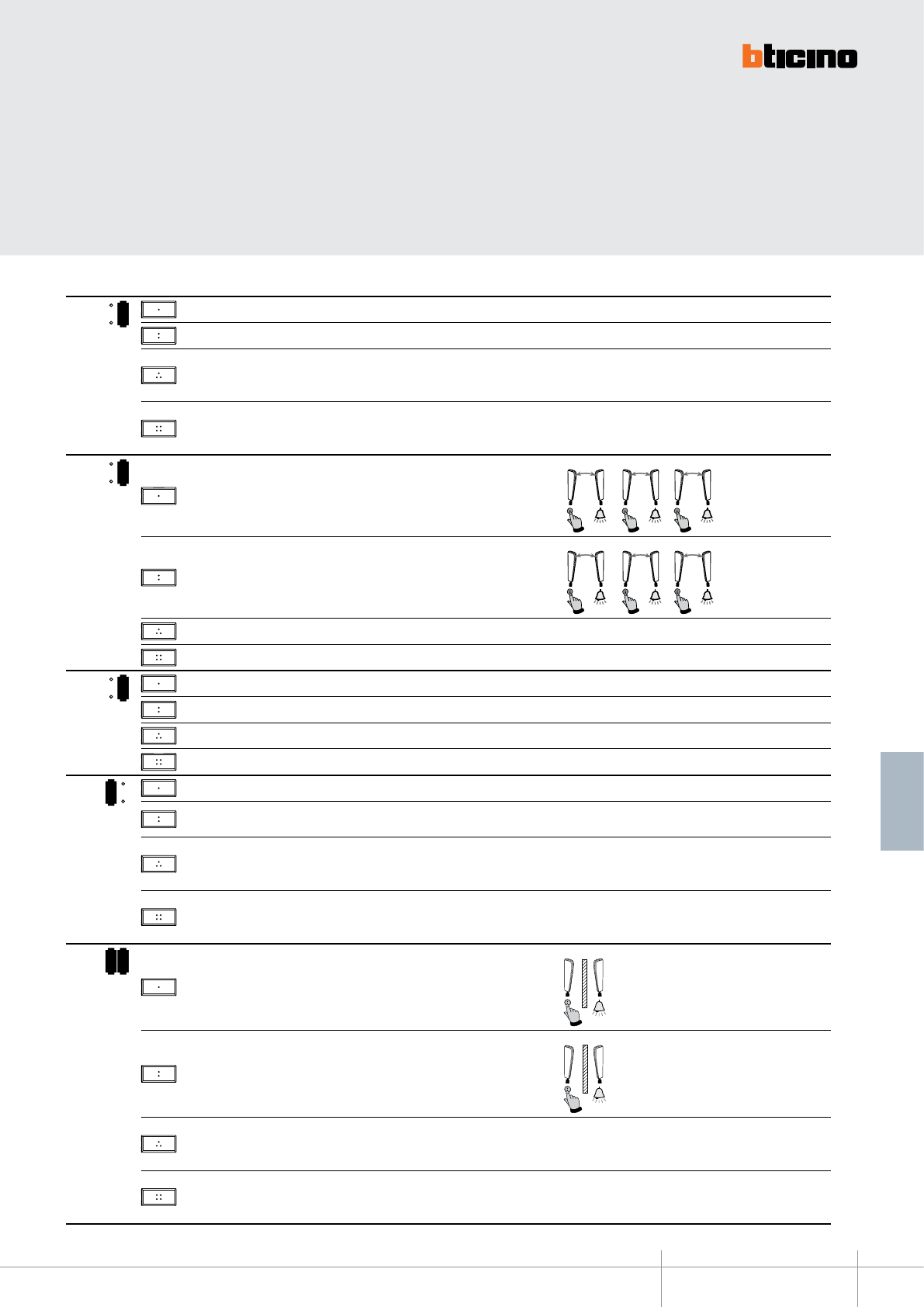
344192
BT00642-a-EN
TECHNICAL SHEETS
299
2 WIRE VDE system
MODE KEY FUNCTION NOTES
6
MOD = 1Activation of the scenario saved in the scenario module (SCENARIO 1)
2Activation of the scenario saved in the scenario module (SCENARIO 2)
3
EP door lock release (congured with P+1), directly, without call, or activation of
the actuator, item 346200 (congured with P+1 and MOD=5), or activation of door
lock actuators 346230-346260 (congured with P+1)
4
EP door lock release (congured with P+2), directly, without call, or activation of
the actuator, item 346200 (congured with P+2 and MOD=5), or activation of door
lock actuators 346230-346260 (congured with P+2)
7
MOD =
1Intercom inside the apartment, in systems with apartment interface item 346850,
or intercom among apartments without apartment interface. 1
N=1N=3
1
N=2N=1
1
N=3N=1
2Intercom inside the apartment, in systems with apartment interface item 346850,
or intercom among apartments without apartment interface. 2
N=1N=2
2
N=2N=3
2
N=3N=2
3Activation of the scenario saved in the scenario module (SCENARIO 1)
4Activation of the scenario saved in the scenario module (SCENARIO 2)
8
MOD = 1Activation of the scenario saved in the scenario module (SCENARIO 1)
2Activation of the scenario saved in the scenario module (SCENARIO 2)
3Activation of the scenario saved in the scenario module (SCENARIO 3)
4Activation of the scenario saved in the scenario module (SCENARIO 4)
1
MOD = 1General Intercom, sends a call to all the handsets of the system.
2EP activation (congured with P+1), directly, without call, or activation of the
actuator, item 346200 (congured with P+1 and MOD=9)
3
EP door lock release (congured with P+1), directly, without call, or activation of
the actuator, item 346200 (congured with P+1 and MOD=5), or activation of door
lock actuators 346230-346260 (congured with P+1)
4
EP door lock release (congured with P+2), directly, without call, or activation of
the actuator, item 346200 (congured with P+2 and MOD=5), or activation of door
lock actuators 346230-346260 (congured with P+2)
1 2
MOD =
1Intercom between apartments, in systems with apartment interface, item 346850
1
N=1
2Intercom between apartments, in systems with apartment interface, item 346850
2
N=2
3
EP door lock release (congured with P+1), directly, without call, or activation of
the actuator, item 346200 (congured with P+1 and MOD=5), or activation of door
lock actuators 346230-346260 (congured with P+1)
4
EP door lock release (congured with P+2), directly, without call, or activation of
the actuator, item 346200 (congured with P+2 and MOD=5), or activation of door
lock actuators 346230-346260 (congured with P+2)
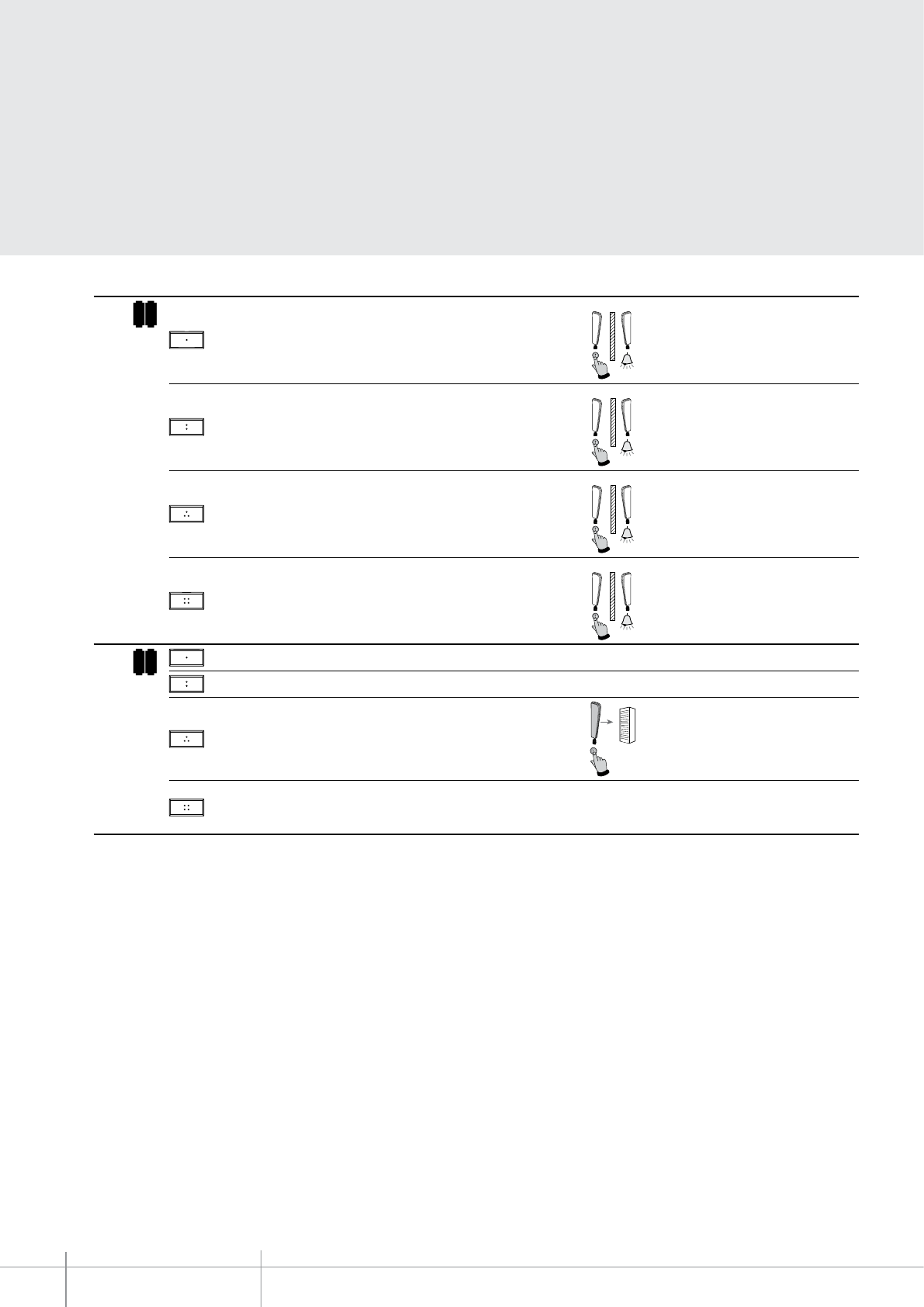
BT00642-a
344192
-EN
TECHNICAL SHEETS
300 2 WIRE VDE system
MODE KEY FUNCTION NOTES
1 3
MOD =
1Intercom between apartments, in systems with apartment interface, item 346850
1
N=1
2Intercom between apartments, in systems with apartment interface, item 346850
2
N=2
3Intercom between apartments, in systems with apartment interface, item 346850
3
N=3
4Intercom between apartments, in systems with apartment interface, item 346850
4
N=4
1 6
MOD = 1Activation of the scenario saved in the scenario module (SCENARIO 1)
2Activation of the scenario saved in the scenario module (SCENARIO 2)
3General Intercom, sends a call to all the handsets of the system.
4
EP door lock release (congured with P+1), directly, without call, or activation of
the actuator, item 346200 (congured with P+1 and MOD=5), or activation of door
lock actuators 346230-346260 (congured with P+1)
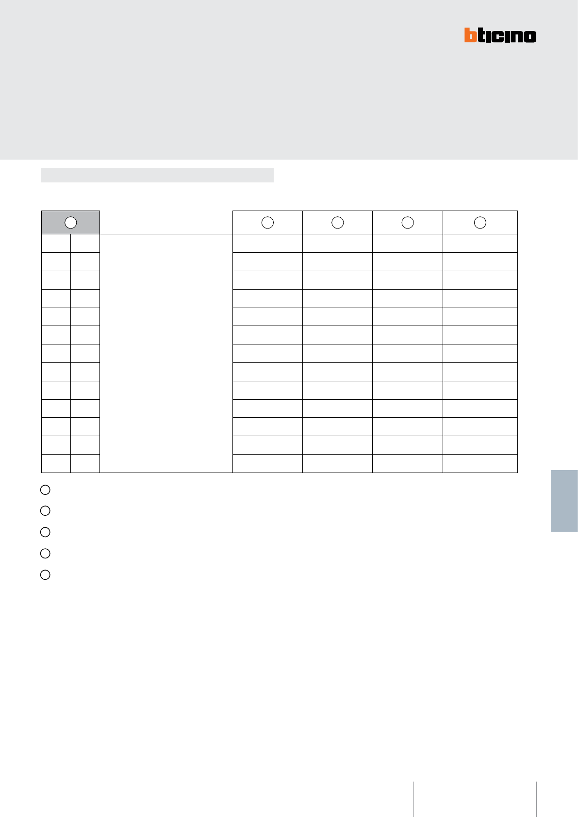
344192
BT00642-a-EN
TECHNICAL SHEETS
301
2 WIRE VDE system
Conguration
A Conguration selected for the operation of the keys (see previous pages)
B Conguration selected for the operation of the keys + OFFICE function
C Conguration selected for the operation of the keys + PAGING function
D Conguration selected for the operation of the keys + HANDSFREE function (Can be activated only on a single device for each unit system)
E Conguration selected for the operation of the keys + OFFICE and PAGING function
Further SPECIAL functions (e.g. professional studio, pager, handsfree) can be enabled by
conguring MOD in the following modes:
A B C D E
0 0
+
20 = B
40 = C
60 = D
80 = E
20 40 60 80
1 0 30 50 70 90
0 1 21 41 61 81
0 2 22 42 62 82
1 2 32 52 72 92
0 3 23 43 63 83
1 3 33 53 73 93
0 4 24 44 64 84
0 5 25 45 65 85
0 6 26 46 66 86
1 6 36 56 76 96
0 7 27 47 67 87
0 8 28 48 68 88
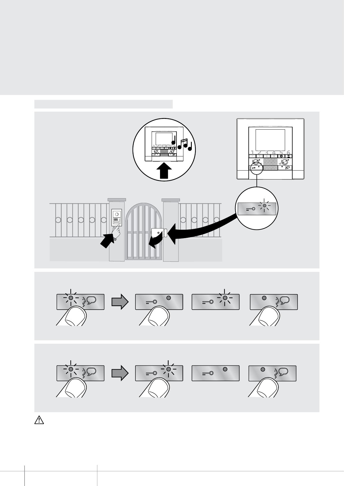
BT00642-a
344192
>3s
Led ON
Led ON
>3s
BEEP
BEEP
BEEP
EXIT
EXIT
>3s
Led ON
>3s
BEEP
BEEP
BEEP
EXIT
EXIT
>3s
Led ON
Led ON
>3s
BEEP
BEEP
BEEP
EXIT
EXIT
>3s
Led ON
>3s
BEEP
BEEP
BEEP
EXIT
EXIT
2
1
CLAK
3
-EN
TECHNICAL SHEETS
302 2 WIRE VDE system
OFFICE FUNCTION DETAIL
To ENABLE the function
To DISABLE the function
It cannot be enabled together with the “DOOR STATUS” function.
With the function active, when a call is received from
the entrance panel, the video handset rings and the
associated door lock is automatically released, without
the need for pressing the door lock release key on the
video handset.
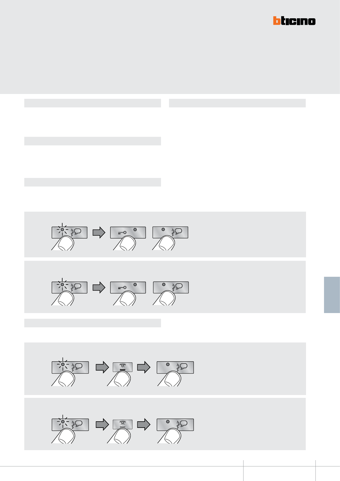
344192
BT00642-a
>3s
>3s
BEEP
EXIT
EXIT
BEEP
BEEP
>3s
>3s
BEEP EXIT
EXIT
BEEP
BEEP
>3s
>3s
BEEP
EXIT
EXIT
BEEP
BEEP
>3s
>3s
BEEP EXIT
EXIT
BEEP
BEEP
BEEP
BEEP
>3s
BEEP
BEEP
>3s
BEEP
BEEP
>3s
BEEP
BEEP
>3s
-EN
TECHNICAL SHEETS
303
2 WIRE VDE system
DOOR STATUS function PUSH TO TALK function
PAGING function
HANDSFREE function
This function noties the status of the door lock. If open, the “door lock LED” ashes, if
closed, the LED stays o.
NOTA: è attivabile solo se l’impianto lo prevede; NON è attivabile contemporaneamente
alla OFFICE function.
Enable/disable key sound
In the base conguration when a key is pressed, a beep is emitted. This function may be
disabled/enabled with the following procedure:
If the entrance panel is in a particularly noisy position, during the conversation it will
be possible to enable the “PUSH TO TALK” function, which will provide a better quality
of communication.
To enable the PUSH TO TALK function during the conversation proceed as follows:
- Press the Connection key for at least 2 seconds, to enable the communication with the
entrance panel.
The LED stays green.
- Release the key to listen to the entrance panel. The LED turns red.
- To end the connection press the Connection key briey.
The LED turns o.
This function can be used to send voice messages using the microphone of the device
through the speakers of the sound system. To activate briey press the ”Connection” key
while the device is in the idle condition. The activation of the function is conrmed by
the green LED coming on. To DISABLE the function press the ”Connection” key again.
The HANDSFREE function automatically activates the microphone and the loudspeaker
when a call is received, without the need for pressing the Connection key to answer (the
connection is automatically established when the call is received).
To ENABLE the function
To ENABLE the function
To DISABLE the function
To DISABLE the function
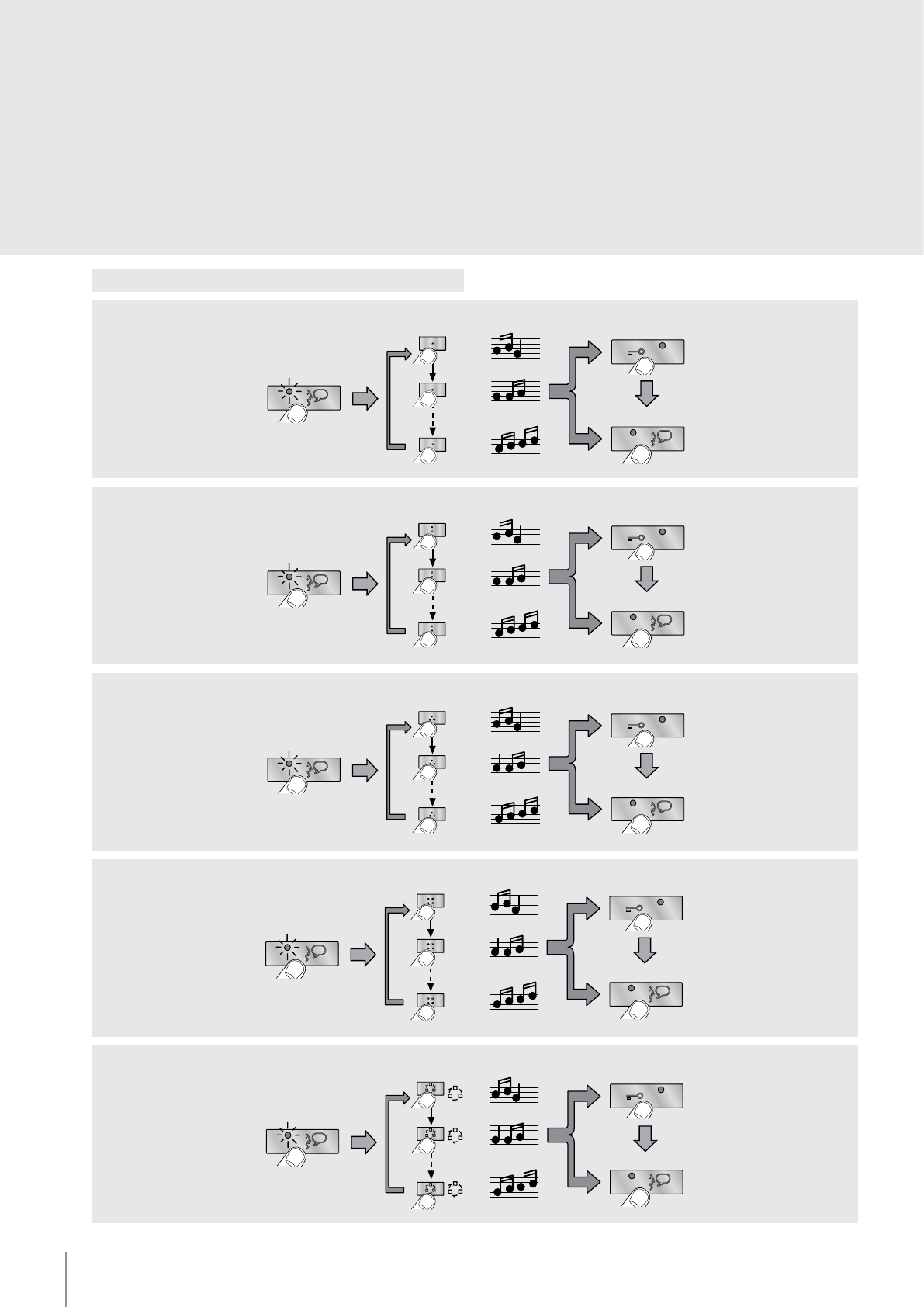
BT00642-a
344192
EXIT
OK
1
17
2
>3s
2
2
2
EXIT
OK
1
17
2
>3s
1
1
1
EXIT
OK
1
17
2
>3s
3
3
3
EXIT
OK
1
16
2
>3s
4
4
4
EXIT
OK
1
17
2
>3s
EXIT
OK
1
17
2
>3s
2
2
2
EXIT
OK
1
17
2
>3s
1
1
1
EXIT
OK
1
16
2
>3s
3
3
3
EXIT
OK
1
17
2
>3s
4
4
4
EXIT
OK
1
17
2
>3s
EXIT
OK
1
16
2
>3s
2
2
2
EXIT
OK
1
17
2
>3s
1
1
1
EXIT
OK
1
17
2
>3s
3
3
3
EXIT
OK
1
17
2
>3s
4
4
4
EXIT
OK
1
17
2
>3s
EXIT
OK
1
17
2
>3s
2
2
2
EXIT
OK
1
16
2
>3s
1
1
1
EXIT
OK
1
17
2
>3s
3
3
3
EXIT
OK
1
17
2
>3s
4
4
4
EXIT
OK
1
17
2
>3s
EXIT
OK
1
17
2
>3s
2
2
2
EXIT
OK
1
17
2
>3s
1
1
1
EXIT
OK
1
17
2
>3s
3
3
3
EXIT
OK
1
17
2
>3s
4
4
4
EXIT
OK
1
16
2
>3s
EXIT
OK
1
17
2
>3s
2
2
2
EXIT
OK
1
17
2
>3s
1
1
1
EXIT
OK
1
17
2
>3s
3
3
3
EXIT
OK
1
16
2
>3s
4
4
4
EXIT
OK
1
17
2
>3s
EXIT
OK
1
17
2
>3s
2
2
2
EXIT
OK
1
17
2
>3s
1
1
1
EXIT
OK
1
16
2
>3s
3
3
3
EXIT
OK
1
17
2
>3s
4
4
4
EXIT
OK
1
17
2
>3s
EXIT
OK
1
16
2
>3s
2
2
2
EXIT
OK
1
17
2
>3s
1
1
1
EXIT
OK
1
17
2
>3s
3
3
3
EXIT
OK
1
17
2
>3s
4
4
4
EXIT
OK
1
17
2
>3s
EXIT
OK
1
17
2
>3s
2
2
2
EXIT
OK
1
16
2
>3s
1
1
1
EXIT
OK
1
17
2
>3s
3
3
3
EXIT
OK
1
17
2
>3s
4
4
4
EXIT
OK
1
17
2
>3s
EXIT
OK
1
17
2
>3s
2
2
2
EXIT
OK
1
17
2
>3s
1
1
1
EXIT
OK
1
17
2
>3s
3
3
3
EXIT
OK
1
17
2
>3s
4
4
4
EXIT
OK
1
16
2
>3s
EXIT
OK
1
17
2
>3s
2
2
2
EXIT
OK
1
17
2
>3s
1
1
1
EXIT
OK
1
17
2
>3s
3
3
3
EXIT
OK
1
16
2
>3s
4
4
4
EXIT
OK
1
17
2
>3s
EXIT
OK
1
17
2
>3s
2
2
2
EXIT
OK
1
17
2
>3s
1
1
1
EXIT
OK
1
16
2
>3s
3
3
3
EXIT
OK
1
17
2
>3s
4
4
4
EXIT
OK
1
17
2
>3s
EXIT
OK
1
16
2
>3s
2
2
2
EXIT
OK
1
17
2
>3s
1
1
1
EXIT
OK
1
17
2
>3s
3
3
3
EXIT
OK
1
17
2
>3s
4
4
4
EXIT
OK
1
17
2
>3s
EXIT
OK
1
17
2
>3s
2
2
2
EXIT
OK
1
16
2
>3s
1
1
1
EXIT
OK
1
17
2
>3s
3
3
3
EXIT
OK
1
17
2
>3s
4
4
4
EXIT
OK
1
17
2
>3s
EXIT
OK
1
17
2
>3s
2
2
2
EXIT
OK
1
17
2
>3s
1
1
1
EXIT
OK
1
17
2
>3s
3
3
3
EXIT
OK
1
17
2
>3s
4
4
4
EXIT
OK
1
16
2
>3s
EXIT
OK
1
17
2
>3s
2
2
2
EXIT
OK
1
17
2
>3s
1
1
1
EXIT
OK
1
17
2
>3s
3
3
3
EXIT
OK
1
16
2
>3s
4
4
4
EXIT
OK
1
17
2
>3s
EXIT
OK
1
17
2
>3s
2
2
2
EXIT
OK
1
17
2
>3s
1
1
1
EXIT
OK
1
16
2
>3s
3
3
3
EXIT
OK
1
17
2
>3s
4
4
4
EXIT
OK
1
17
2
>3s
EXIT
OK
1
16
2
>3s
2
2
2
EXIT
OK
1
17
2
>3s
1
1
1
EXIT
OK
1
17
2
>3s
3
3
3
EXIT
OK
1
17
2
>3s
4
4
4
EXIT
OK
1
17
2
>3s
EXIT
OK
1
17
2
>3s
2
2
2
EXIT
OK
1
16
2
>3s
1
1
1
EXIT
OK
1
17
2
>3s
3
3
3
EXIT
OK
1
17
2
>3s
4
4
4
EXIT
OK
1
17
2
>3s
EXIT
OK
1
17
2
>3s
2
2
2
EXIT
OK
1
17
2
>3s
1
1
1
EXIT
OK
1
17
2
>3s
3
3
3
EXIT
OK
1
17
2
>3s
4
4
4
EXIT
OK
1
16
2
>3s
EXIT
OK
1
17
2
>3s
2
2
2
EXIT
OK
1
17
2
>3s
1
1
1
EXIT
OK
1
17
2
>3s
3
3
3
EXIT
OK
1
16
2
>3s
4
4
4
EXIT
OK
1
17
2
>3s
EXIT
OK
1
17
2
>3s
2
2
2
EXIT
OK
1
17
2
>3s
1
1
1
EXIT
OK
1
16
2
>3s
3
3
3
EXIT
OK
1
17
2
>3s
4
4
4
EXIT
OK
1
17
2
>3s
EXIT
OK
1
16
2
>3s
2
2
2
EXIT
OK
1
17
2
>3s
1
1
1
EXIT
OK
1
17
2
>3s
3
3
3
EXIT
OK
1
17
2
>3s
4
4
4
EXIT
OK
1
17
2
>3s
EXIT
OK
1
17
2
>3s
2
2
2
EXIT
OK
1
16
2
>3s
1
1
1
EXIT
OK
1
17
2
>3s
3
3
3
EXIT
OK
1
17
2
>3s
4
4
4
EXIT
OK
1
17
2
>3s
EXIT
OK
1
17
2
>3s
2
2
2
EXIT
OK
1
17
2
>3s
1
1
1
EXIT
OK
1
17
2
>3s
3
3
3
EXIT
OK
1
17
2
>3s
4
4
4
EXIT
OK
1
16
2
>3s
-EN
TECHNICAL SHEETS
304 2 WIRE VDE system
Programming of bells
Bell selection from MAIN ENTRANCE PANEL (S=0)
Bell selection from SECONDARY ENTRANCE PANEL (S=1)
INTERCOM CALL bell selection
EXTERNAL INTERCOM CALL bell selection
(only with interface item 346850)
FLOOR CALL bell selection
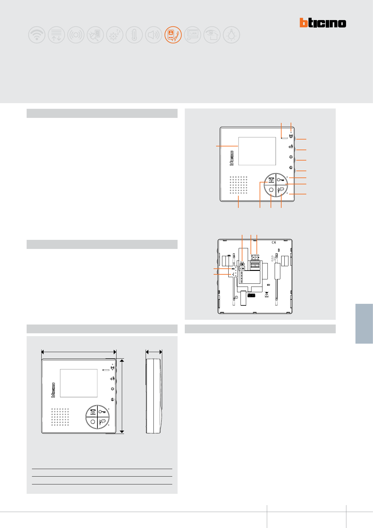
2
4
5
7
9
13
3
6
10
11
14
12
8
1
15
18
19
16 17
A B C
140 mm 140 mm 27 mm
C
B
A
344502
BT00717-a-EN
TECHNICAL SHEETS
305
2 WIRE VDE system
Colour video handsfree
Description
2 WIRE colour video handsfree internal unit for wall mounted installation.
It has a 3.5” colour LCD display. Keys available: auto-switching on / cycling, door lock
release, staircase lights control, and handsfree connection.
Depending on the configurator connected to (M), the same keys will perform different
functions (see the specific configuration section).
LED used for: call exclusion, door status, connection with the entrance panel. Adjustments
for: display colour, display brightness, speaker volume, and call tone volume/exclusion
(16 different ringtones available).
For the installation to the wall, the bracket supplied must be used.
Legend
1. Microphone
2. Red LED for call exclusion notication
3. Bell volume adjustment/call exclusion
4. Incoming audio volume adjustment
5. Display brightness adjustment
6. Display colour adjustment
7. Door lock activation and/or door status red LED
8. Door lock key
9. Operating status two-colour red/green LED
10. Communication enabling/disabling key
11. Entrance panel/cycling key
12. Staircase light switching on key
13. Loudspeaker
14. 3.5” LCD display
15. Line termination ON/OFF micro-switch
16. MASTER/SLAVE J1 configurator socket (remove for SLAVE)
17. Configurator socket
18. Clamps for the connection of an external call to the floor pushbutton
19. 2 WIRE SCS/BUS connection clamps
Technical data
Power supply from SCS BUS: 18 – 27 Vdc
Stand by absorption: 10 mA
Max. operating absorption: 200 mA
Operating temperature: 5 – 40 °C
Dimensional data
Front view
Rear view
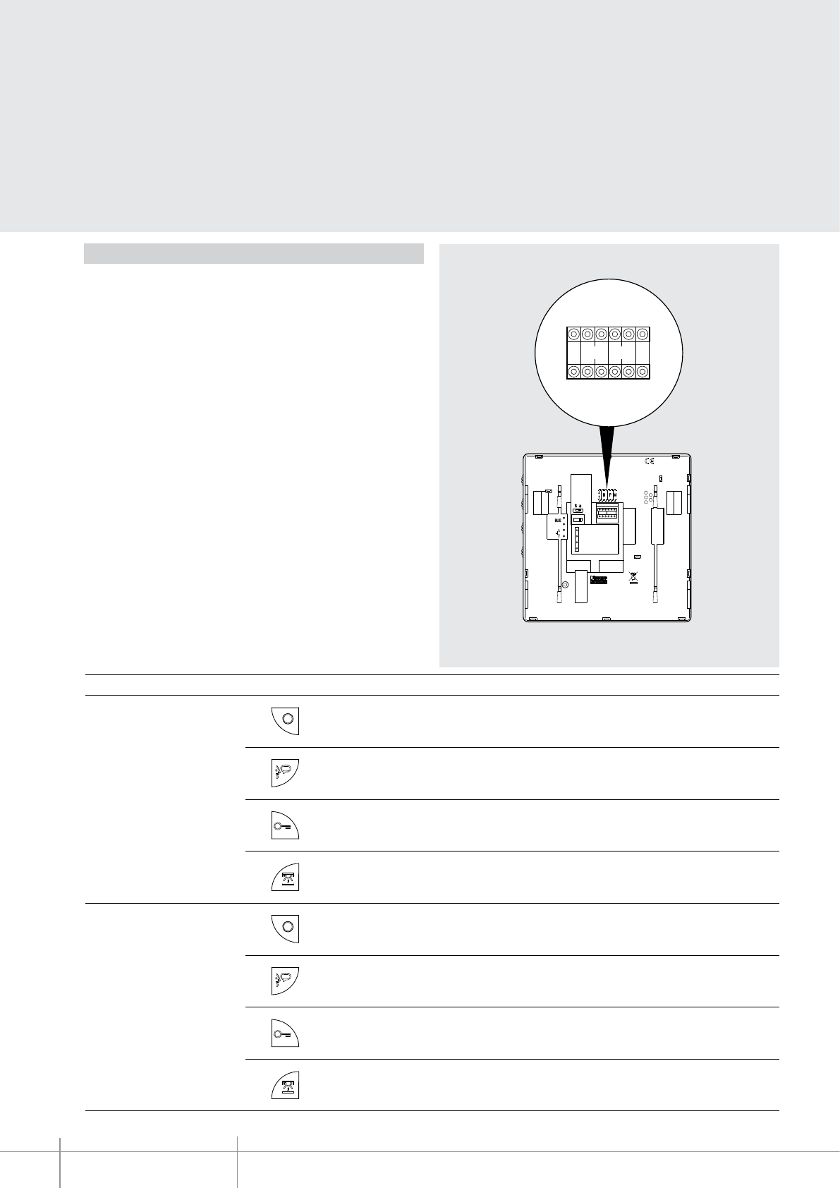
344502
BT00717-a
J
1MN P
-EN
TECHNICAL SHEETS
306 2 WIRE VDE system
Configuration
The device must be only physically congured
.
N - handset number
The congurators connected to the N sockets of the device assign an identication
number within the system to each video handset.
The handsets must be congured
in progressive order.
Handsets with parallel connection (max 3 are allowed inside the
apartment without item 346850) must be congured with the same N congurator
.
Additional audio handsets, video handsets and/or bells can be installed in parallel to
the basic video handset
.
P –
entrance panel association
The configurators connected to the P sockets of the device identify the associated
EP, which is the first entrance panel that switches itself on when the pushbutton
is pressed the first time, as well as which door lock is activated when pressing the
pushbutton while the video handset is idle.
M –
operating mode
The configurator connected to the M socket of the device assigns the operating
modes to the 4 programmable keys based on the following indications.
J1 – MASTER/SLAVE function
The JMP configurator connected to the J1 socket of the device enables or disables the
MASTER/SLAVE function: JMP connected = MASTER; JMP removed = SLAVE.
Below are the various operating modes that can be assigned to the 4 programmable
keys:
MODE KEY FUNCTION
M = 0 (with key tone active) Activation of the EP (congured with the same P) directly without call.
Cycling of EP and cameras installed in the system. Direct call to the switchboard, if present in the system.
Audio enabling / disabling following a call.
Direct EP door lock activation (EP congured with the same P), or activation of the EP door lock upon connection.
Staircase light switching on.
M = 1 (with key tone active) Activation of the EP (congured with the same P) directly without call.
Cycling of EP and cameras installed in the system. Direct call to the switchboard, if present in the system.
Audio enabling / disabling following a call.
Direct EP door lock activation (EP congured with the same P), or activation of the EP door lock upon connection.
EP door lock activation (EP congured with P+1), directly without call, or activation of an actuator 346200 (congured with P+1
and MOD=5), or activation of a door lock actuator 346230 - 346260 (congured with P+1).
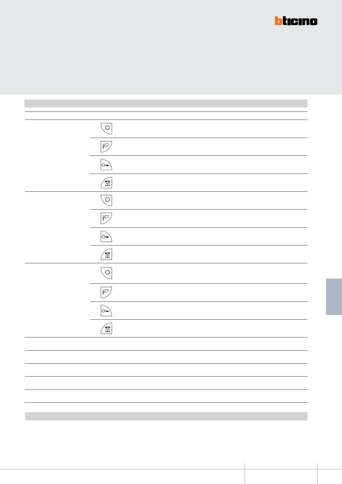
344502
BT00717-a-EN
TECHNICAL SHEETS
307
2 WIRE VDE system
Configuration
PUSH TO TALK function
If the entrance panel is in a particularly noisy position, during the conversation it will be possible to enable the “PUSH TO TALK” function, which will provide a better quality of communication.
To use the PUSH TO TALK function, during a conversation proceed as indicated below.
During a conversation press the conversation key for >2 minutes: the LED switches ON green, and communication from the video handset to the entrance panel is established; when the communication
key is released, the LED turns red and communication from the entrance panel to the video handset is established. To terminate the conversation press and release the conversation key.
TIME-OUT and conversation times are respectively: 30” after the call, 1’ after the start of the conversation.
MODE KEY FUNCTION
M = 2 (with key tone active) Internal intercom. It sends the call to all the handsets with the same address.
Audio enabling / disabling following a call.
Direct EP door lock activation (EP congured with the same P), or activation of the EP door lock upon connection.
Staircase light switching on.
M = 3 (with key tone active) Activation of the EP (congured with the same P) directly without call.
Cycling of EP and cameras installed in the system. Direct call to the switchboard, if present in the system.
Audio enabling / disabling following a call.
Direct EP door lock activation (EP congured with the same P), or activation of the EP door lock upon connection.
Internal intercom. It sends the call to all the handsets with the same address.
M = 4 (with key tone active)
“PRESET INTERCOM” function with intercommunicating call to the Handset congured with N=1.
From the system handsets it is possible to send an intercom call to the handset congured with N=1.
The entrance panel congured with N=1 can intercom calls, but is UNABLE to send them.
Audio enabling / disabling following a call.
Direct EP door lock activation (EP congured with the same P), or activation of the EP door lock upon connection.
Staircase light switching on.
M = 5 As M=0 but with key tone disabled
M = 6 As M=10 but with key tone disabled
M = 7 As M=2 but with key tone disabled
M = 8 As M=3 but with key tone disabled
M = 9 As M=4 but with key tone disabled
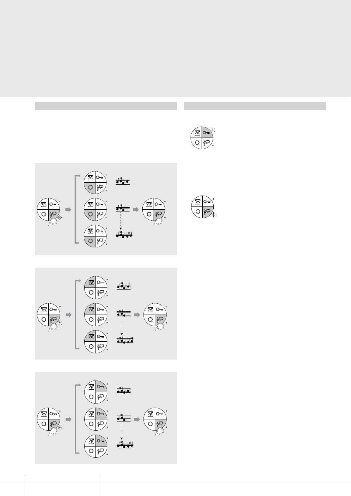
BT00717-a
344502
-EN
TECHNICAL SHEETS
308 2 WIRE VDE system
Programming of bells
Selection of the call bells from the main EP (S = 0).
The video handset offers the possibility to select among 16 types of bells with
programmed ringtones, which can be freely associated to the following type of calls:
- Calls from the entrance panel (configured with S = 0);
- INTERCOM call;
- Floor call.
LED notifications
Door lock status and/or door status red LED notifications:
Operating status two-colour (red/green) LED notifications:
LED ON steady = door lock pushbutton pressed;
LED ON ashing = door open;
LED OFF= door closed.
LED ON steady (green) = conversation active;
LED ON ashing (green) = call active or intercom call forwarded;
LED ON ashing (red) = programming procedure being performed.
NOTE: The door status function notifies the status of the door lock. If open the “LED door lock”
flashes, and if closed, the LED stays off.
This function is only available in preset systems.
> 3s
1
2
16
RED
LED
ON
RED
LED
OFF
> 3s
RED
LED
ON
RED
LED
OFF
1
2
16
> 3s
RED
LED
ON
RED
LED
OFF
1
2
16
Preset intercom / intercom call bell selection.
Floor call bell selection.
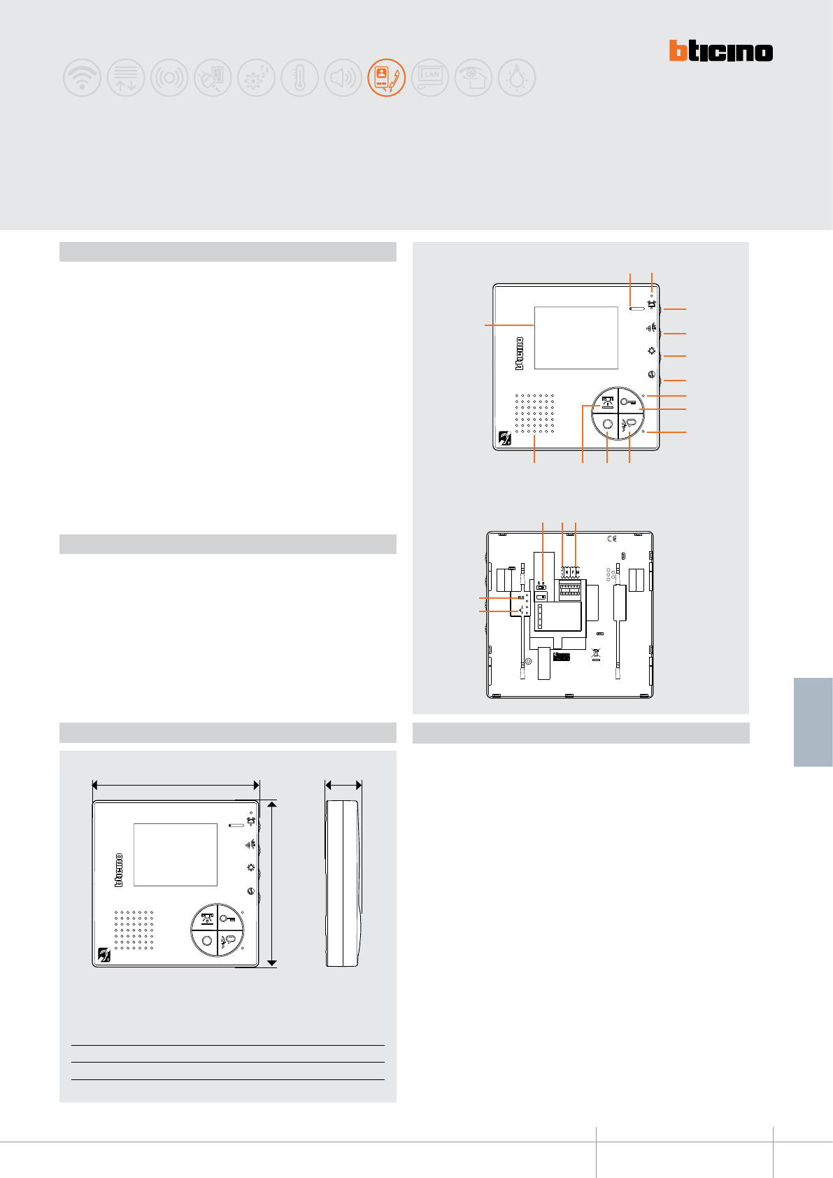
344512
BT00716-a
A B C
140 mm 140 mm 27 mm
C
B
A
2
4
5
7
9
13
3
6
10
11
14
12
8
1
15
18
19
16 17
-EN
TECHNICAL SHEETS
309
2 WIRE VDE system
Video handsfree
with inductive loop
Description
2 WIRE colour video handsfree internal unit with inductive loop for wall mounted
installation.
It has a 3.5” colour LCD display. Keys available: auto-switching on / cycling, door lock
release, staircase lights control, and handsfree connection.
Depending on the configurator connected to (M), the same keys will perform different
functions (see the specific configuration section).
LED used for: call exclusion, door status, connection with the entrance panel. Adjustments
for: display colour, display brightness, speaker volume, and call tone volume/exclusion
(16 different ringtones available).
The inductive loop function enables the device to be used by people wearing hearing
aids with (T) selector.
For the installation to the wall, the bracket supplied must be used.
Legend
1. Microphone
2. Red LED for call exclusion notication
3. Bell volume adjustment/call exclusion
4. Incoming audio volume adjustment
5. Display brightness adjustment
6. Display colour adjustment
7. Door lock activation and/or door status red LED
8. Door lock key
9. Operating status two-colour red/green LED
10. Communication enabling/disabling key
11. Entrance panel/cycling key
12. Staircase light switching on key
13. Loudspeaker
14. 3.5” LCD display
15. Line termination ON/OFF micro-switch
16. MASTER/SLAVE J1 configurator socket (remove for SLAVE)
17. Configurator socket
18. Clamps for the connection of an external call to the floor pushbutton
19. 2 WIRE SCS/BUS connection clamps
Technical data
Power supply from SCS BUS: 18 – 27 Vdc
Stand by absorption: 10 mA
Max. operating absorption: 200 mA
Operating temperature: 5 – 40 °C
Dimensional data
Front view
Rear view
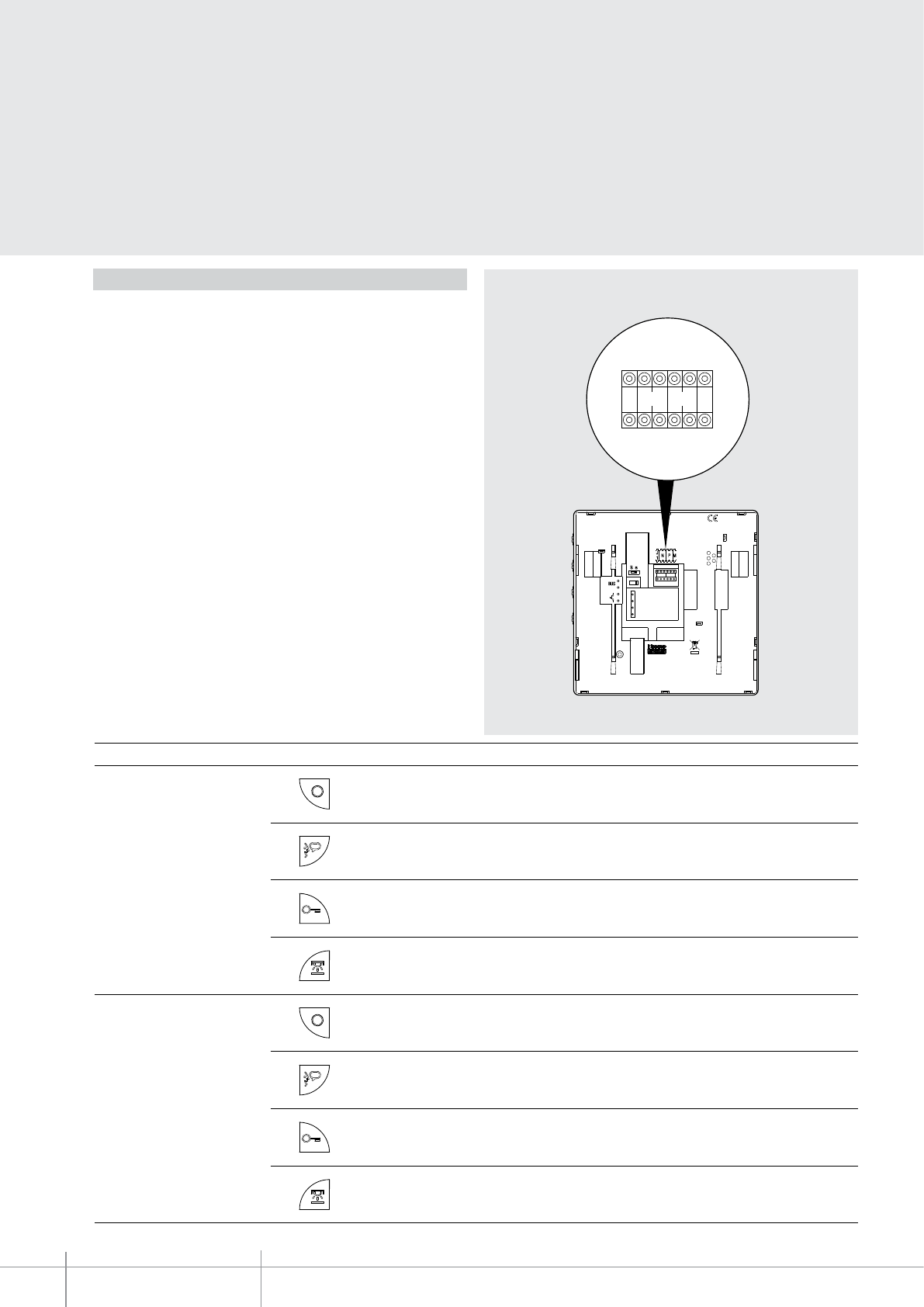
344512
BT00716-a
J
1MN P
-EN
TECHNICAL SHEETS
310 2 WIRE VDE system
Configuration
The device must be only physically congured
.
N - handset number
The congurators connected to the N sockets of the device assign an identication
number within the system to each video handset. The handsets must be congured
in progressive order
.
Handsets with parallel connection (max 3 are allowed inside the
apartment without item 346850) must be congured with the same N congurator
.
Additional audio handsets, video handsets and/or bells can be installed in parallel to
the basic video handset
.
P –
entrance panel association
The configurators connected to the P sockets of the device identify the associated
EP, which is the first entrance panel that switches itself on when the pushbutton
is pressed the first time, as well as which door lock is activated when pressing the
pushbutton while the video handset is idle.
M –
operating mode
The configurator connected to the M socket of the device assigns the operating
modes to the 4 programmable keys based on the following indications.
J1 – MASTER/SLAVE function
The JMP configurator connected to the J1 socket of the device enables or disables the
MASTER/SLAVE function: JMP connected = MASTER; JMP removed = SLAVE.
Below are the various operating modes that can be assigned to the 4 programmable
keys:
MODE KEY FUNCTION
M = 0 (with key tone active) Activation of the EP (congured with the same P) directly without call.
Cycling of EP and cameras installed in the system. Direct call to the switchboard, if present in the system.
Audio enabling / disabling following a call.
Direct EP door lock activation (EP congured with the same P), or activation of the EP door lock upon connection.
Staircase light switching on.
M = 1 (with key tone active) Activation of the EP (congured with the same P) directly without call.
Cycling of EP and cameras installed in the system. Direct call to the switchboard, if present in the system.
Audio enabling / disabling following a call.
Direct EP door lock activation (EP congured with the same P), or activation of the EP door lock upon connection.
EP door lock activation (EP congured with P+1), directly without call, or activation of an actuator 346200 (congured with P+1
and MOD=5), or activation of a door lock actuator 346230 - 346260 (congured with P+1).

344512
BT00716-a-EN
TECHNICAL SHEETS
311
2 WIRE VDE system
Configuration
PUSH TO TALK function
If the entrance panel is in a particularly noisy position, during the conversation it will be possible to enable the “PUSH TO TALK” function, which will provide a better quality of communication.
To use the PUSH TO TALK function, during a conversation proceed as indicated below.
During a conversation press the conversation key for >2 minutes: the LED switches ON green, and communication from the video handset to the entrance panel is established; when the communication
key is released, the LED turns red and communication from the entrance panel to the video handset is established. To terminate the conversation press and release the conversation key.
TIME-OUT and conversation times are respectively: 30” after the call, 1’ after the start of the conversation.
MODE KEY FUNCTION
M = 2 (with key tone active) Internal intercom. It sends the call to all the handsets with the same address.
Audio enabling / disabling following a call.
Direct EP door lock activation (EP congured with the same P), or activation of the EP door lock upon connection.
Staircase light switching on.
M = 3 (with key tone active) Activation of the EP (congured with the same P) directly without call.
Cycling of EP and cameras installed in the system. Direct call to the switchboard, if present in the system.
Audio enabling / disabling following a call.
Direct EP door lock activation (EP congured with the same P), or activation of the EP door lock upon connection.
Internal intercom. It sends the call to all the handsets with the same address.
M = 4 (with key tone active)
“PRESET INTERCOM” function with intercommunicating call to the Handset congured with N=1.
From the system handsets it is possible to send an intercom call to the handset congured with N=1.
The entrance panel congured with N=1 can intercom calls, but is UNABLE to send them.
Audio enabling / disabling following a call.
Direct EP door lock activation (EP congured with the same P), or activation of the EP door lock upon connection.
Staircase light switching on.
M = 5 As M=0 but with key tone disabled.
M = 6 As M= 1 but with key tone disabled.
M = 7 As M= 2 but with key tone disabled.
M = 8 As M= 3 but with key tone disabled.
M = 9 As M= 4 but with key tone disabled.
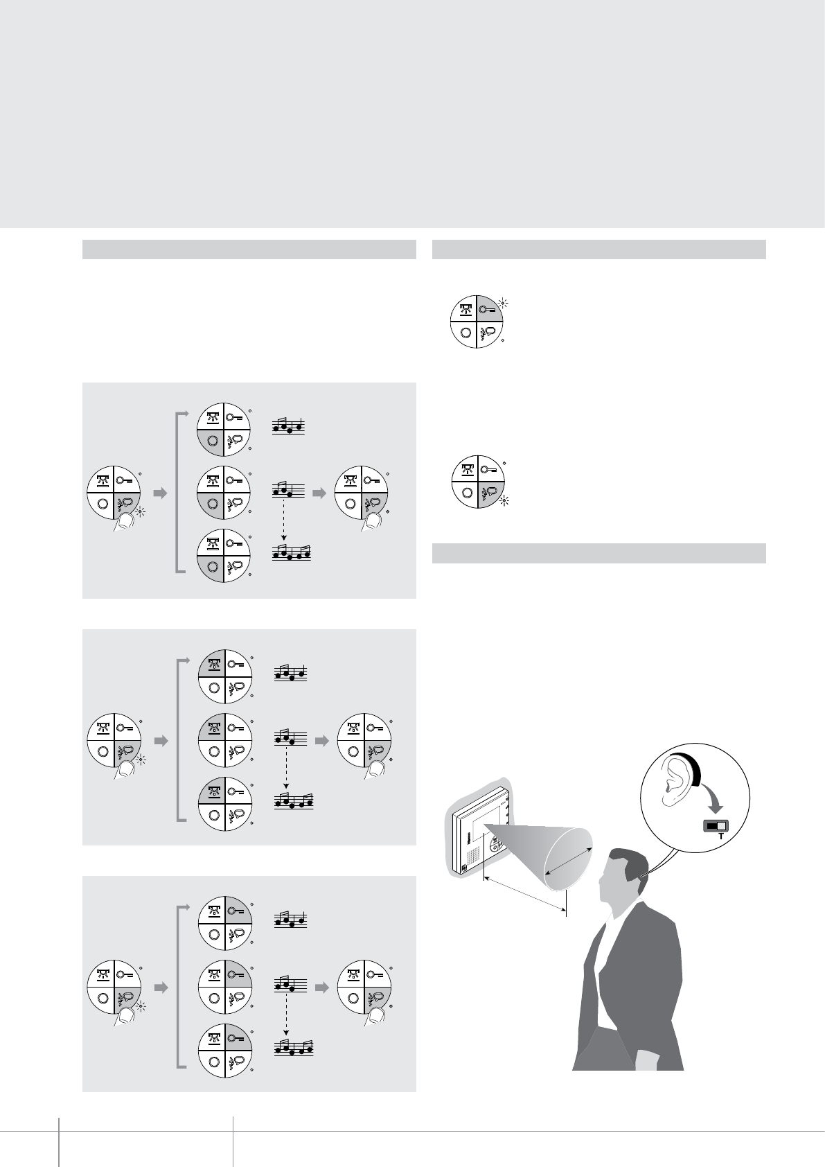
BT00716-a
344512
2
5
-3
5 c
m
40 cm
-EN
TECHNICAL SHEETS
312 2 WIRE VDE system
Programming of bells
Selection of the call bells from the main EP (S = 0).
Preset intercom / intercom call bell selection.
Floor call bell selection.
LED notifications
Door lock status and/or door status red LED notifications:
Operating status two-colour (red/green) LED notifications:
LED ON steady = door lock pushbutton pressed;
LED ON ashing = door open;
LED OFF= door closed.
LED ON steady (green) = conversation active;
LED ON ashing (green) = call active or intercom call forwarded;
LED ON ashing (red) = programming procedure being performed.
INDUCTIVE LOOP use
The inductive loop function enables the device to be used by people wearing hearing
aids with (T) selector.
Switch the selector of the acoustic device to the T position
and to ensure correct magnetic
coupling between the device and the acoustic device, we recommend a position in front
of the device, at a distance of 25-35 cm.
NOTE: the presence of metal and background noise generated by electric/electronic
devices (e.g. computer) may compromise the performance and the quality of the
coupling device.
The video handset offers the possibility to select among 16 types of bells with
programmed ringtones, which can be freely associated to the following type of calls:
- Calls from the entrance panel (configured with =0)
- INTERCOM call
- Floor call
NOTE: The door status function notifies the status of the door lock. If open the “LED door lock”
flashes, and if closed, the LED stays off.
This function is only available in preset systems.
> 3s
1
2
16
RED
LED
ON
RED
LED
OFF
> 3s
RED
LED
ON
RED
LED
OFF
1
2
16
> 3s
RED
LED
ON
RED
LED
OFF
1
2
16
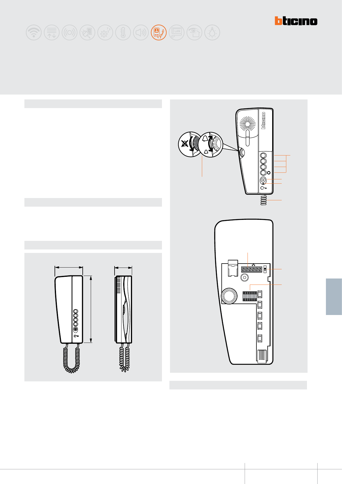
344704
BT00643-a
56 mm
90 mm
3
2
1
215 mm
%86
0
2
'
13
2)) 21
(7
5
1
2
3
4
7
8
6
-EN
TECHNICAL SHEETS
313
2 WIRE VDE system
Dimensional data
Description
2 WIRE audio handset for wall mounted installation. It’s tted with keys for: door lock
release, and 4 programmable keys (0-1-2-3), which operating mode is set through the
conguration. The volume of the bell can be adjusted, or the bell may be disabled. It has
16 dierent pre-programmed bells.
It also performs the following functions: conversation secrecy, oce (when the call is
made from the entrance panel the associated door lock automatically opens without the
need for pressing the relevant key on the handset), door lock status check.
When a SWING handset is used toghether with an “Elettrika” CISA door lock (with
accessory 346240), it is possible to control the status of the door lock connected to the
system using door lock actuators, item 346230/item 346260.
If the “Elettrika” CISA door lock is open, the SWING Handset LED ashes. The LED will
continue ashing while the lock remains open.
Wall xing bracket supplied.
Technical data
Power supply from SCS BUS: 18 – 27 Vdc
Stand by absorption: 5 mA
Max. operating absorption: 35 mA
Operating temperature: 5 - 40°C
Legend
1 - 4 programmable keys using the conguration (0-1-2-3)
2 - Door lock key
3 - DOOR STATUS signalling LED or activation of the OFFICE function
4 - Extensible cord capped on both ends with RJ connectors
5 - Bell volume adjustment and exclusion
6 - Clamps for the connection of the 2 WIRE BUS, additional oor call functions and extra bell.
7 - Line termination ON/OFF micro-switch (audio/video systems only)
8 - Congurator socket
SWING
audio handset
Front view
Internal view
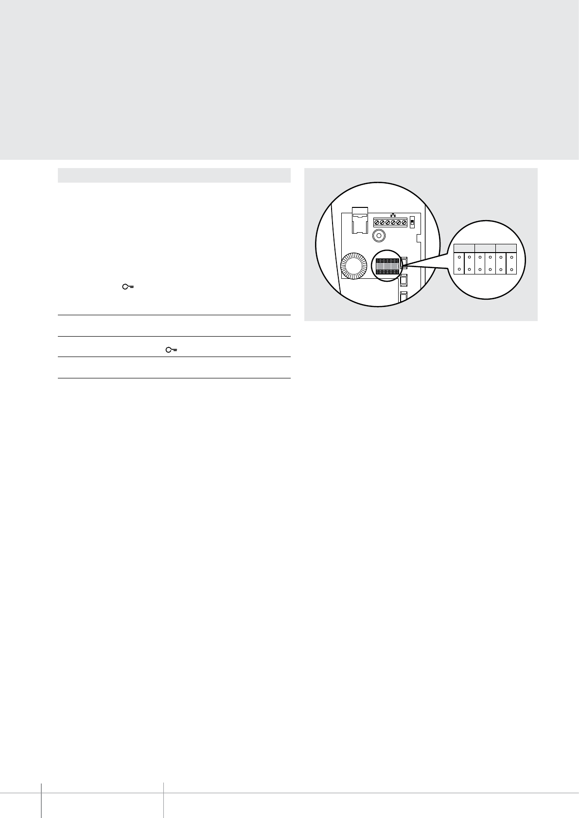
BT00643-a
344704
1
5BUS
M
O
D
N P
OFF ON
ET
P
MOD
N
-EN
TECHNICAL SHEETS
314 2 WIRE VDE system
Conguration
N – handset number
The N congurator assigns to each handset an identication number within the
system. The handsets must be congured in progressive order. In case of handsets with
parallel connection (max 3) inside the apartment without item 346850, these must be
congured using the same N congurator.
P – entrance panel association
The P congurator identies the associated EP, or the rst entrance panel on which the
audio is activated when the (0) is pressed for the rst time, as well as which door lock is
activated when the key is pressed while the handset is idle.
Congurator in P Key function (0)
0-9 Entrance panel audio activation
(congured with P = 0-9)
Congurator in P Key function
0-9 Opening of the EP door lock
(congured with P = 0-9)
MOD = Operating mode of the keys
In addition to the door lock opening key, the SWING handset also has 4 programmable
keys (0-1-2-3). The programmable keys may be associated to dierent operating modes
(e.g. activation of external actuators, intercom, additional EP activation, “oce” mode
activation), depending on the type of congurators connected to MOD (see details in
the following pages).
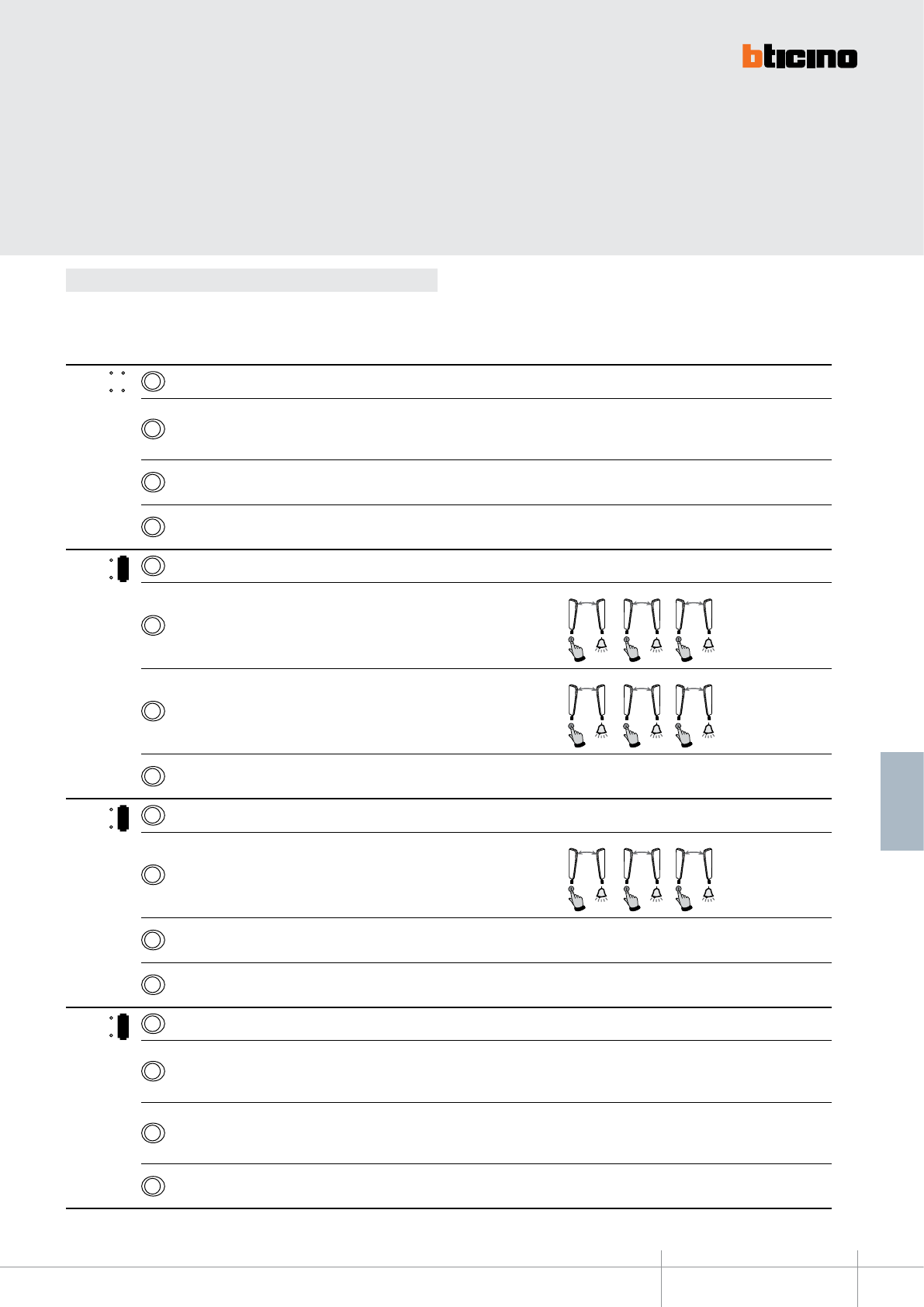
344704
BT00643-a-EN
TECHNICAL SHEETS
315
2 WIRE VDE system
Below are the various operating modes that can be assigned to the 4 programmable keys:
Conguration
MODE KEY FUNCTION NOTES
MOD = 3Staircase light switching on
2
EP door lock release (congured with P+1), directly, without call, or activation of
the actuator, item 346200 (congured with P+1 and MOD=5), or activation of door
lock actuators 346230-346260 (congured with P+1)
1Audio/video EP or camera activation (congured with P+1), directly, without
call, or activation of the actuator, item 346200 (congured with P+1 and MOD=9)
0
Audio/video EP or camera activation (congured with P), directly, without call, and
cycling
1
MOD = 3Staircase light switching on
2Intercom inside the apartment, in systems with apartment interface item 346850,
or intercom among apartments without apartment interface. 2
N=1N=2
2
N=2N=3
2
N=3N=2
1Intercom inside the apartment, in systems with apartment interface item 346850,
or intercom among apartments without apartment interface. 1
N=1N=3
1
N=2N=1
1
N=3N=1
0
Audio/video EP or camera activation (congured with P), directly, without call, and
cycling
3
MOD = 3Staircase light switching on
2Intercom inside the apartment, in systems with apartment interface item 346850,
or intercom among apartments without apartment interface. 2
N=1N=2
2
N=2N=3
2
N=3N=2
1Audio/video EP or camera activation (congured with P+1), directly, without
call, or activation of the actuator, item 346200 (congured with P+1 and MOD=9)
0
Audio/video EP or camera activation (congured with P), directly, without call, and
cycling
5
MOD = 3Staircase light switching on
2
EP door lock release (congured with P+2), directly, without call, or activation of
the actuator, item 346200 (congured with P+2 and MOD=5) or activation of the
actuator item 346230/item 346260 (congured with P+2)
1
EP door lock release (congured with P+1), directly, without call, or activation of
the actuator, item 346200 (congured with P+1 and MOD=5) or activation of the
actuator item 346230/item 346260 (congured with P+1)
0
Audio/video EP or camera activation (congured with P), directly, without call, and
cycling
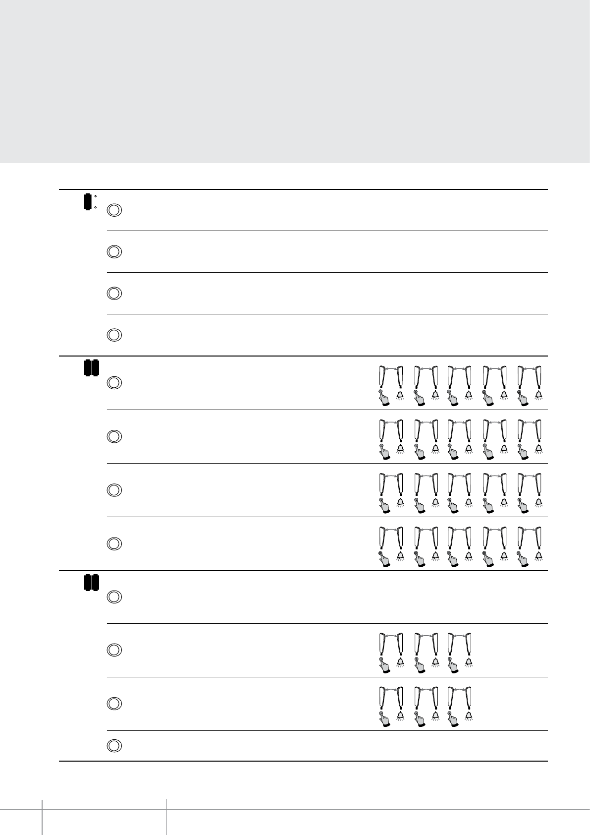
BT00643-a
344704
-EN
TECHNICAL SHEETS
316 2 WIRE VDE system
MODE KEY FUNCTION NOTES
1
MOD = 3Audio/video EP or camera activation (congured with P+3), directly, without
call, or activation of the actuator, item 346200 (congured with P+3 and MOD=9)
2Audio/video EP or camera activation (congured with P+2), directly, without
call, or activation of the actuator, item 346200 (congured with P+2 and MOD=9)
1Audio/video EP or camera activation (congured with P+1), directly, without
call, or activation of the actuator, item 346200 (congured with P+1 and MOD=9)
0
Audio/video EP or camera activation (congured with P), directly, without call, and
cycling
1 1
MOD =
3Intercom inside the apartment, in systems with apartment interface item 346850, or
intercom among apartments without apartment interface.
3
N
=
N1
=
3
3
N=2N=3
3
N=3N=5
3
N=4N=3
3
N=5N=3
2Intercom inside the apartment, in systems with apartment interface item 346850, or
intercom among apartments without apartment interface. 2
N=1N=2
2
N=2N=5
2
N=3N=2
2
N=4N=2
2
N=5N=2
1Intercom inside the apartment, in systems with apartment interface item 346850, or
intercom among apartments without apartment interface. 1
N=1N=5
1
N=2N=1
1
N=3N=1
1
N=4N=1
1
N=5N=1
0Intercom inside the apartment, in systems with apartment interface item 346850, or
intercom among apartments without apartment interface. 4
N=1N=4
4
N=2N=4
4
N=3N=4
4
N=4N=5
4
N=
5N
=4
1 3
MOD =
3
EP door lock release (congured with P+1), directly, without call, or activation of the
actuator, item 346200 (congured with P+1 and MOD=5) or activation of the actuator item
346230/item 346260 (congured with P+1)
2Intercom inside the apartment, in systems with apartment interface item 346850, or
intercom among apartments without apartment interface. 2
N=1N=2
2
N=2N=3
2
N=3N=2
1Intercom inside the apartment, in systems with apartment interface item 346850, or
intercom among apartments without apartment interface. 1
N=1N=3
1
N=2N=1
1
N=3N=1
0EP activation (congured with P), directly, without call
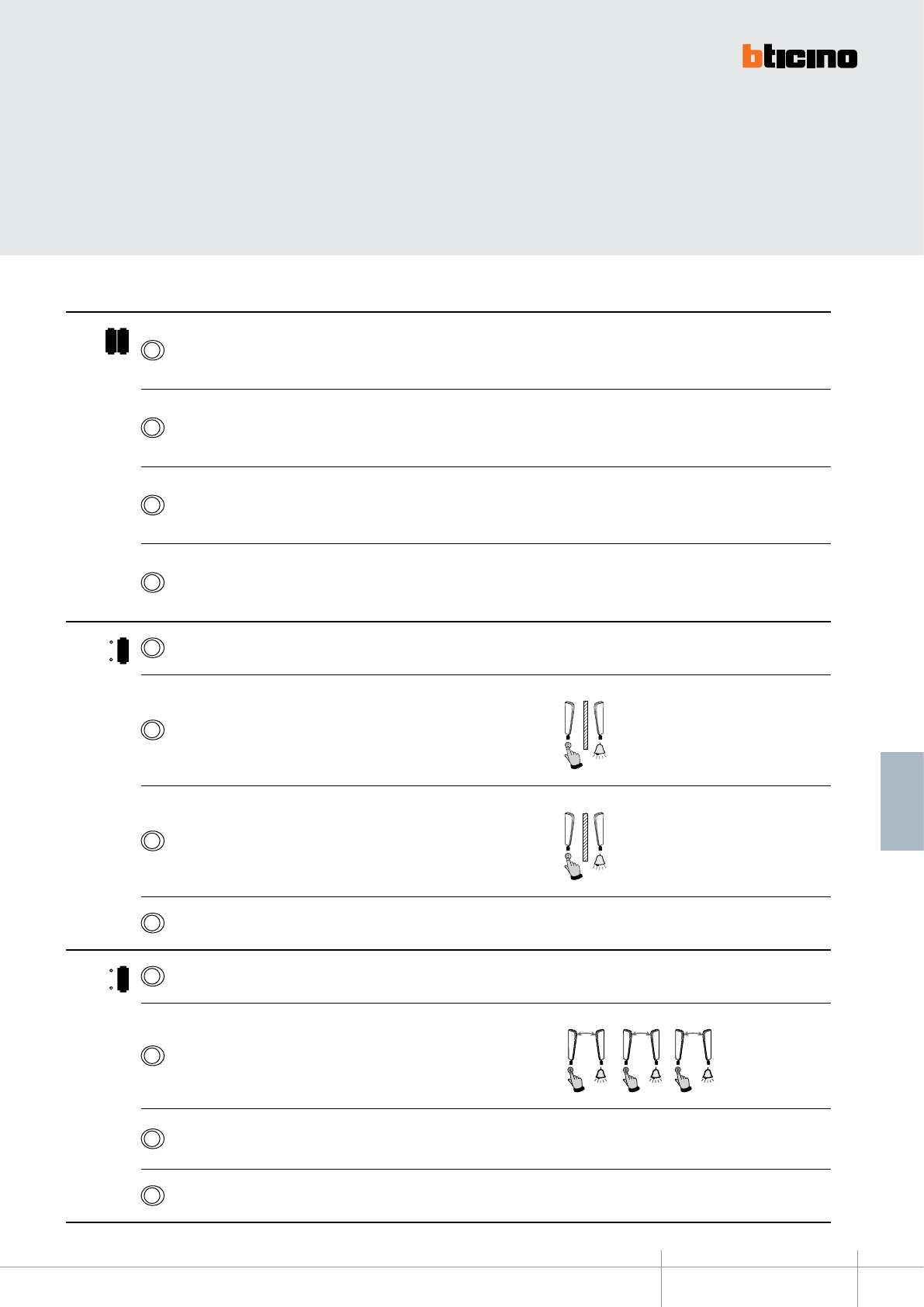
344704
BT00643-a-EN
TECHNICAL SHEETS
317
2 WIRE VDE system
MODE KEY FUNCTION NOTES
1 5
MOD = 3
EP door lock release (congured with P+4), directly, without call, or activation of the
actuator, item 346200 (congured with P+4 and MOD=5) or activation of the actuator item
346230/item 346260 (congured with P+4)
2
EP door lock release (congured with P+3), directly, without call, or activation of the
actuator, item 346200 (congured with P+3 and MOD=5) or activation of the actuator item
346230/item 346260 (congured with P+3)
1
EP door lock release (congured with P+2), directly, without call, or activation of the
actuator, item 346200 (congured with P+2 and MOD=5) or activation of the actuator item
346230/item 346260 (congured with P+2)
0
EP door lock release (congured with P+1), directly, without call, or activation of the
actuator, item 346200 (congured with P+1 and MOD=5) or activation of the actuator item
346230/item 346260 (congured with P+1)
2
MOD = 3Staircase light switching on
2Intercom between apartments, in systems with apartment interface, item 346850
2
N=2
1Intercom between apartments, in systems with apartment interface, item 346850
1
N=1
0EP activation (congured with P), directly, without call
3
MOD = 3Staircase light switching on
2Intercom inside the apartment, in systems with apartment interface item 346850, or
intercom among apartments without apartment interface. 2
N=1N=2
2
N=2N=3
2
N=3N=2
1EP activation (congured with P+1), directly, without call, or activation of the
actuator, item 346200 (congured with P+1 and MOD=9)
0EP activation (congured with P), directly, without call
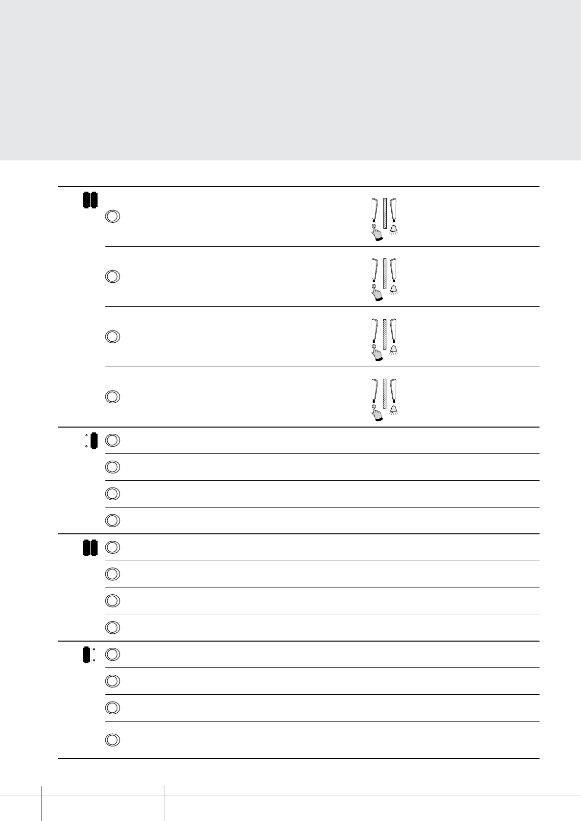
BT00643-a
344704
-EN
TECHNICAL SHEETS
318 2 WIRE VDE system
MODE KEY FUNCTION NOTES
1 2
MOD =
3
Intercom between apartments, in systems with apartment interface, item 346850
3
N=3
2
Intercom between apartments, in systems with apartment interface, item 346850
2
N=2
1
Intercom between apartments, in systems with apartment interface, item 346850
1
N=1
0
Intercom between apartments, in systems with apartment interface, item 346850
4
N=4
6
MOD = 3Staircase light switching on
2Activation of the scenario 2 saved in the scenario module (SCENARIO 2)
1Activation of the scenario 1 saved in the scenario module (SCENARIO 1)
0EP activation (congured with P), directly, without call
1 6
MOD = 3Activation of the scenario 3 saved in the scenario module (SCENARIO 3)
2Activation of the scenario 2 saved in the scenario module (SCENARIO 2)
1Activation of the scenario 1 saved in the scenario module (SCENARIO 1)
0Activation of the scenario 4 saved in the scenario module (SCENARIO 4)
4
MOD = 3Activation of the paging function on all the sound system loudspeakers
2EP door lock release congured with P, directly, without call
1Audio/video EP or camera activation (congured with P+1), directly, without call
0Audio/video EP or camera activation (congured with P), directly, without call,
and cycling
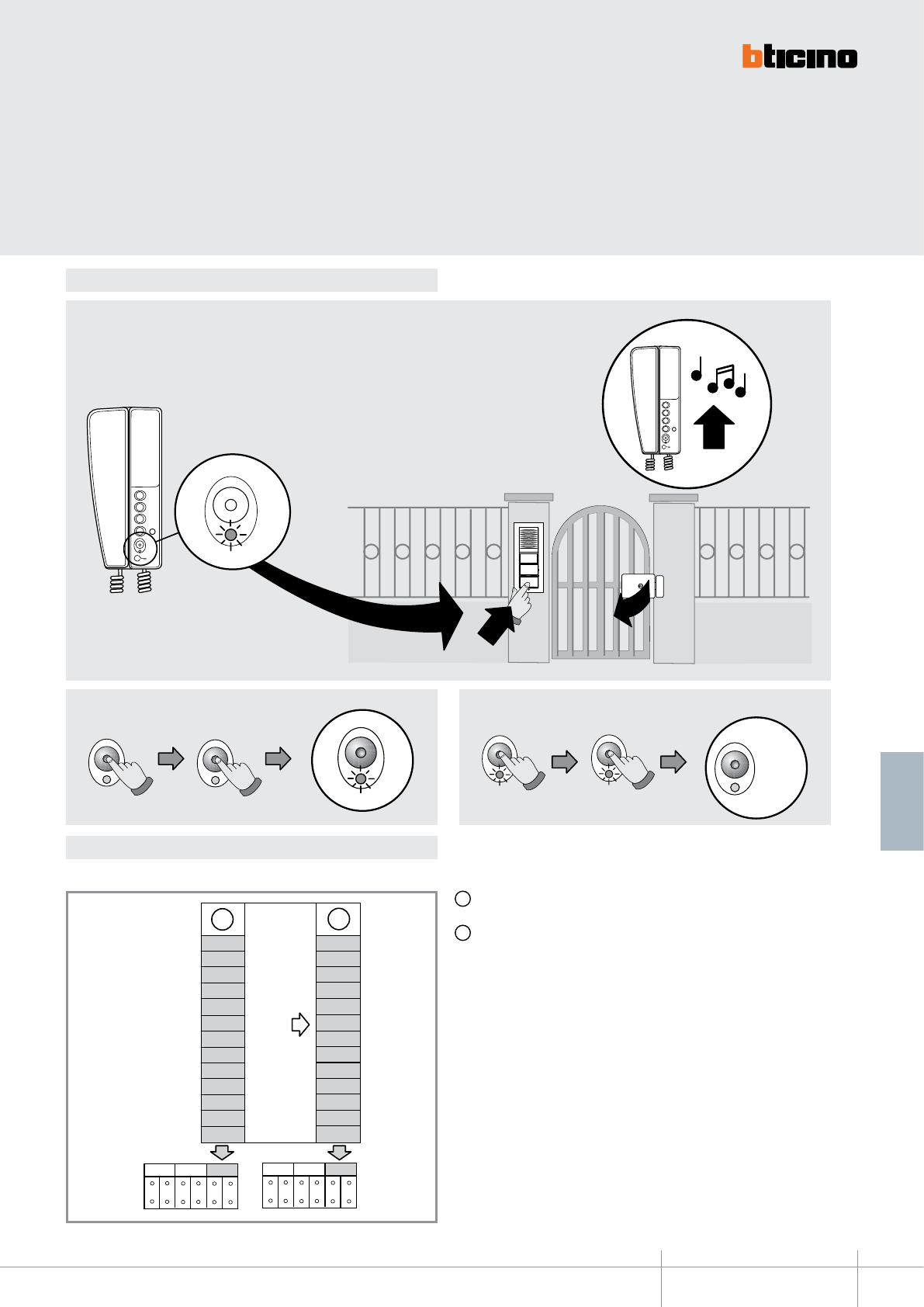
344704
BT00643-a
00
01
03
02
05
06
10
11
12
13
15
16
40
A
+20
20
21
23
22
25
26
30
31
33
32
35
36
60
B
P
N
P
NMODMOD
10s
BIP
10s
BIP
Led OFF
Led OFF Led OFF
3
2
1
3
2
1
2
1
3
CLAK
10s
BIP
10s
BIP
Led OFF
Led OFF Led OFF
-EN
TECHNICAL SHEETS
319
2 WIRE VDE system
OFFICE function
MOD Conguration
To activate the OFFICE function refer to the following:
A Conguration selected for the operation of the keys (see previous pages)
B Conguration selected for the operation of the keys + OFFICE function
To ENABLE the function To DISABLE the function
With the function active, when a call is received from the
entrance panel, the handset rings and the associated door lock
is automatically released, without the need for pressing the door
lock release key on the handset.
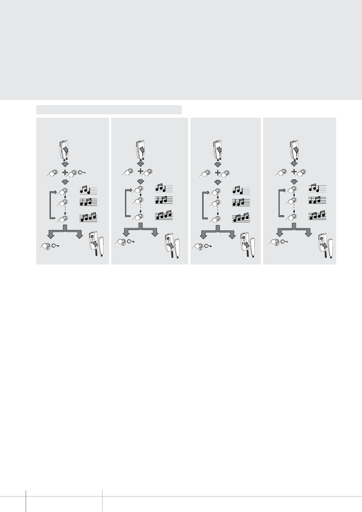
BT00643-a
344704
1
16
2
OK
RESET
3
2
1
1
1
1
1
3
4
3
2
1
1
2
O
1
16
2
OK
RESET
1
1
1
1
3
4
2
3
2
1
1
3
2
1
1
16
2
RESET
1
1
1
2
1
3
4
3
OK
3
2
1
1
3
2
1
1
16
2
RESET
1
1
1
2
1
3
4
2
OK
3
2
1
3
2
1
1
-EN
TECHNICAL SHEETS
320 2 WIRE VDE system
Programming of bells
Bell selection from MAIN ENTRANCE
PANEL (S=0)
FLOOR CALL bell selectionBell selection from SECONDARY
ENTRANCE PANEL (S=1)
INTERCOM CALL bell selection
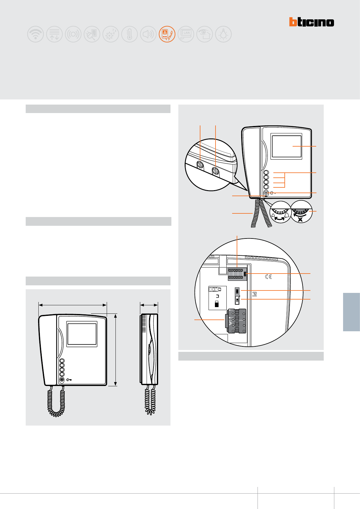
3
2
1
O
5
BUS
1
ET
2 1
N P MOD
JMP 2
OFF
ON
JMP 1
N P
MOD
344824
BT00644-a
3
2
1
O
5
BUS
1
ET
2 1
N P MOD
JMP 2
OFF
ON
JMP 1
N P
MOD
1 2
11
5
6
8
7
9
12
13
4
3
3
2
1
0
210 mm 56 mm
215 mm
10
-EN
TECHNICAL SHEETS
321
2 WIRE VDE system
SWING 2 wire TFT colour video handset for wall mount installation. It has the following
pushbuttons: door lock release, and 4 programmable keys (0-1-2-3), which operating
mode is set through the conguration.
The volume of the bell can be adjusted, or the bell may be disabled. It has 16 dierent
pre-programmed bells. It also performs the following functions: conversation secrecy,
master/slave, oce (when the call is made from the entrance panel the associated
door lock automatically opens without the need for pressing the relevant key on the
handset), door lock status check.
When a SWING handset is used together with an “Elettrika” CISA door lock (with
accessory 346240), it is possible to control the status of the door lock connected to the
system using door lock actuators, item 346230 art.346260.
If the “Elettrika” CISA door lock is open, the SWING Handset LED ashes. The LED will
continue ashing while the lock remains open.
Wall xing bracket supplied.
Power supply from SCS BUS: 18 – 27 Vdc
Stand by absorption: 5 mA
Max. operating absorption: 290 mA
Horizontal resolution: 250 TV lines
Vertical resolution: 300 TV lines
Operating temperature: 5 – 40 °C
SWING
Colour video handsets
Description
Technical data
Dimensional data
Front view
Rear view
Legend
1. Monitor colour adjustment
2. Brightness adjustment monitor
3. 4” colour LCD monitor
4. 4 programmable keys (0-1-2-3) using the configuration
5. Door lock key
6. Bell volume adjustment and exclusion
7. Extensible cord capped on both ends with RJ connectors
8. Door status signalling LED or activation of the office function
9. Configurator socket
10. Master/Slave jumper (JMP1) (Remove for Slave)
11. Jumper (JMP2) to be removed when an additional power supply is used
12. Line termination ON/OFF micro-switch
13. Clamps for the connection of the 2 WIRE BUS, additional power supply, and
auxiliary floor call function, as well as extra bell.
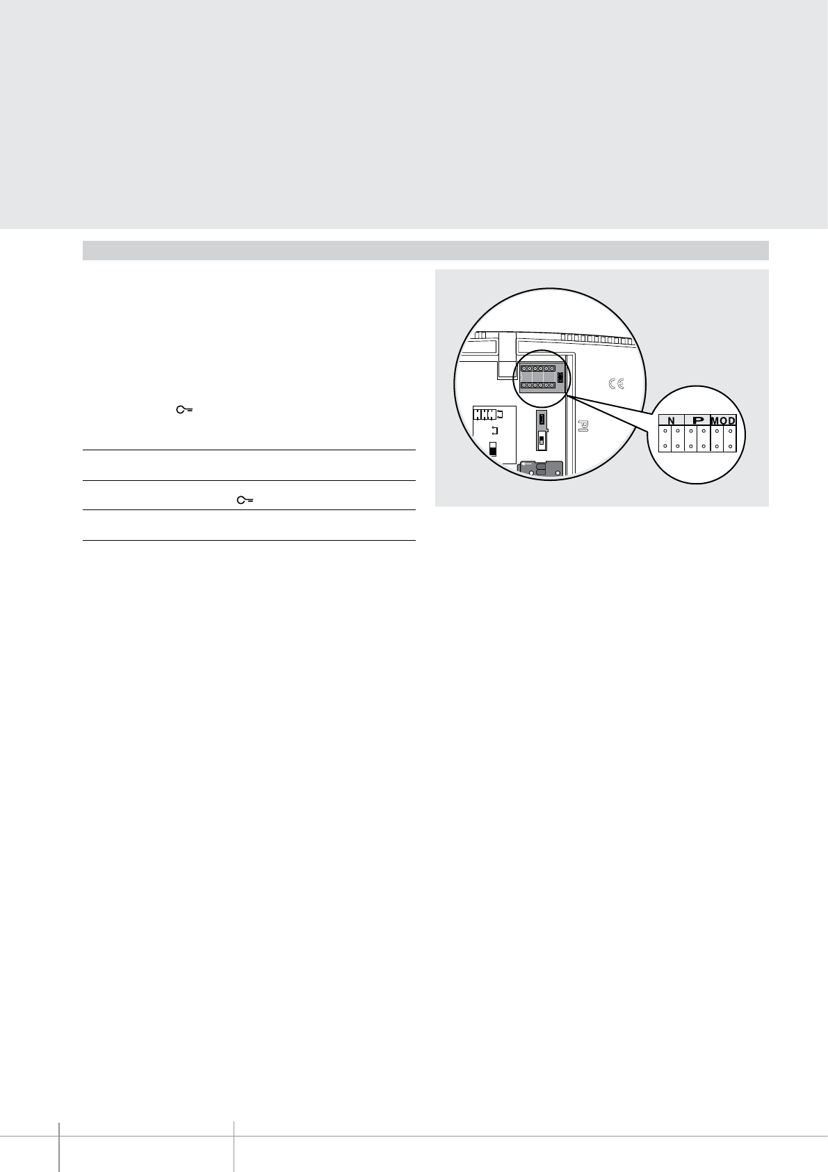
BT00644-a
344824
5
BUS
1
N P MOD
JMP 2
OFF
ON
JMP 1
N P
MOD
-EN
TECHNICAL SHEETS
322 2 WIRE VDE system
N – handset number
The N congurator assigns each video handset an identication number within the
system. The handsets must be congured in progressive order. In case of handsets with
parallel connection (max max.3) inside the apartment without item 346850, these must
be congured using the same N congurator.
P – entrance panel switching on
The P congurator identies the associated EP, or the rst entrance panel to switch
on automatically when the (0) key is pressed for the rst time, and which door lock to
activate by pressing the key while the video handset is idle.
Congurator in P Key function (0)
0-9 Entrance panel audio activation
(congured with P = 0-9)
Congurator in P Key function
0-9 Opening of the EP door lock
(congured with P = 0-9)
MOD = Operating mode of the keys
In addition to the door lock opening key, the SWING video handset also has 4
programmable keys (0-1-2-3). The programmable keys may be associated to dierent
operating modes (e.g. activation of external actuators, intercom, additional EP activation,
“OFFICE” mode activation), depending on the type of congurators connected to MOD.
Configuration
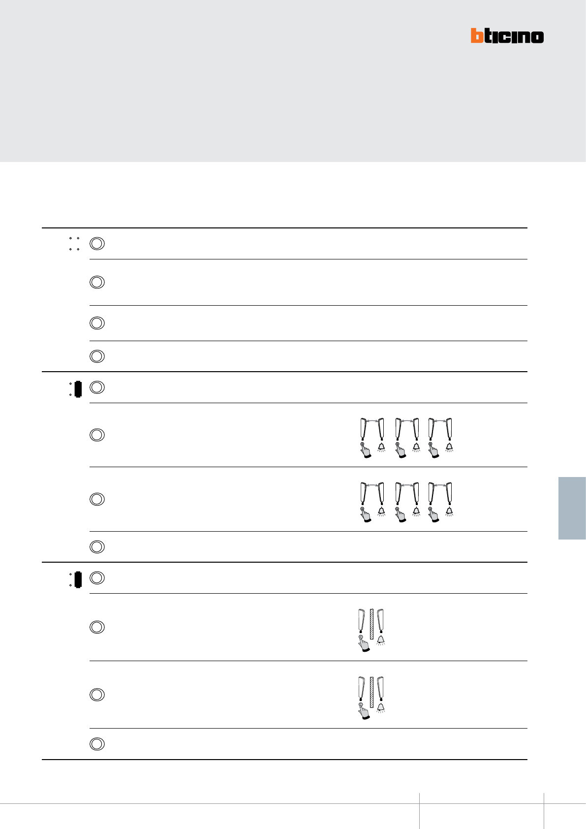
344824
BT00644-a-EN
TECHNICAL SHEETS
323
2 WIRE VDE system
Below are the various operating modes that can be assigned to the 4 programmable keys:
MODE KEY FUNCTION NOTES
MOD = 3Staircase light switching on
2
EP door lock release (congured with P+1), directly, without call, or activation of
the actuator, item 346200 (congured with P+1 and MOD=5), or activation of door
lock actuators 346230-346260 (congured with P+1)
1Audio/video EP or camera activation (congured with P+1), directly, without
call, or activation of the actuator, item 346200 (congured with P+1 and MOD=9)
0
Audio/video EP or camera activation (congured with P), directly, without call, and cycling
1
MOD = 3Staircase light switching on
2Intercom inside the apartment, in systems with apartment interface item 346850,
or intercom among apartments without apartment interface. 2
N=1N=2
2
N=2N=3
2
N=3N=2
1Intercom inside the apartment, in systems with apartment interface item 346850,
or intercom among apartments without apartment interface. 1
N=1N=3
1
N=2N=1
1
N=3N=1
0
Audio/video EP or camera activation (congured with P), directly, without call, and cycling
2
MOD = 3Staircase light switching on
2Intercom between apartments, in systems with apartment interface, item 346850
2
N=2
1Intercom between apartments, in systems with apartment interface, item 346850
1
N=1
0EP activation (congured with P), directly, without call
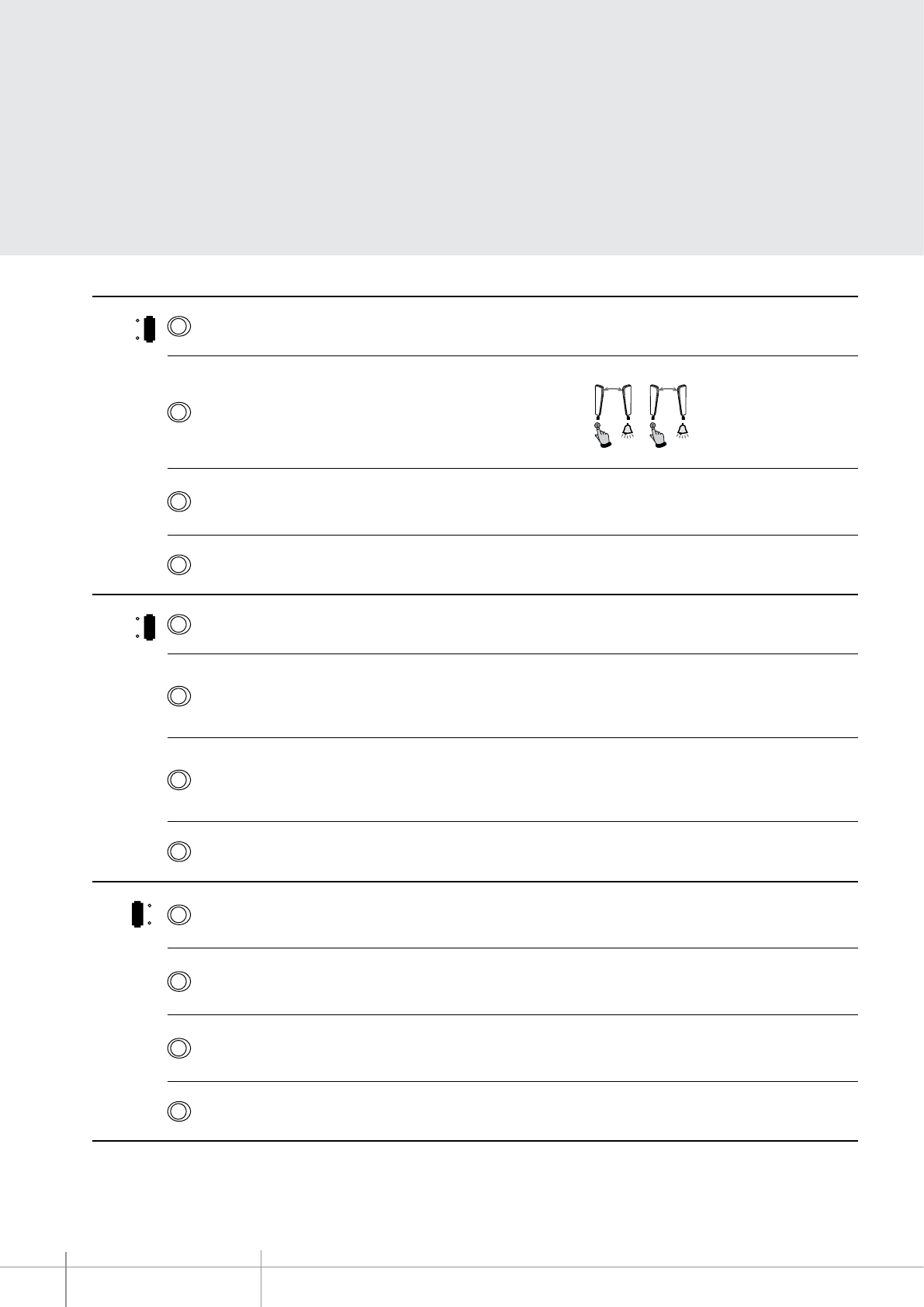
BT00644-a
344824
-EN
TECHNICAL SHEETS
324 2 WIRE VDE system
MODE KEY FUNCTION NOTES
3
MOD = 3Staircase light switching on
2Intercom inside the apartment, in systems with apartment interface item 346850, or
intercom among apartments without apartment interface. 2
N=1 N=2
2
N=2 N=1
1Audio/video EP or camera activation (congured with P+1), directly, without
call, or activation of the actuator, item 346200 (congured with P+1 and MOD=9)
0
Audio/video EP or camera activation (congured with P), directly, without call, and cycling
5
MOD = 3Staircase light switching on
2
EP door lock release (congured with P+2), directly, without call, or activation of
the actuator, item 346200 (congured with P+2 and MOD=5) or activation of the
actuator item 346230/item 346260 (congured with P+2)
1
EP door lock release (congured with P+1), directly, without call, or activation of
the actuator, item 346200 (congured with P+1 and MOD=5) or activation of the
actuator item 346230/item 346260 (congured with P+1)
0
Audio/video EP or camera activation (congured with P), directly, without call, and cycling
1
MOD = 3Audio/video EP or camera activation (congured with P+3), directly, without
call, or activation of the actuator, item 346200 (congured with P+3 and MOD=9)
2Audio/video EP or camera activation (congured with P+2), directly, without
call, or activation of the actuator, item 346200 (congured with P+2 and MOD=9)
1Audio/video EP or camera activation (congured with P+1), directly, without
call, or activation of the actuator, item 346200 (congured with P+1 and MOD=9)
0
Audio/video EP or camera activation (congured with P), directly, without call, and cycling
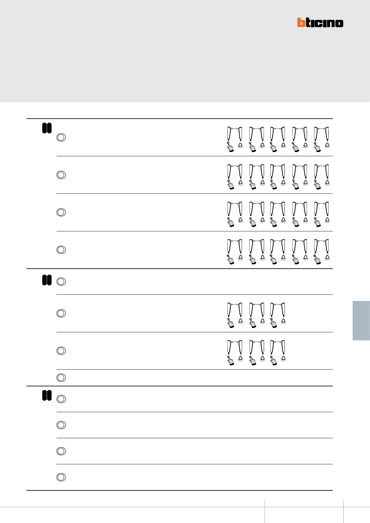
344824
BT00644-a-EN
TECHNICAL SHEETS
325
2 WIRE VDE system
MODE KEY FUNCTION NOTES
1 1
MOD =
3Intercom inside the apartment, in systems with apartment interface item 346850, or
intercom among apartments without apartment interface.
3
N
=
N
1
=
3
3
N=2N=3
3
N=3N=5
3
N=4N=3
3
N=
5N
=3
2Intercom inside the apartment, in systems with apartment interface item 346850, or
intercom among apartments without apartment interface. 2
N=1N=2
2
N=2N=5
2
N=3N=2
2
N=4N=2
2
N=5N=2
1Intercom inside the apartment, in systems with apartment interface item 346850, or
intercom among apartments without apartment interface. 1
N=1N=5
1
N=2N=1
1
N=3N=1
1
N=4N=1
1
N=5N=1
0Intercom inside the apartment, in systems with apartment interface item 346850, or
intercom among apartments without apartment interface. 4
N=1N=4
4
N=2N=4
4
N=3N=4
4
N=4N=5
4
N=5N=4
1 3
MOD = 3
EP door lock release (congured with P+1), directly, without call, or activation of the
actuator, item 346200 (congured with P+1 and MOD=5) or activation of the actuator item
346230/item 346260 (congured with P+1)
2Intercom inside the apartment, in systems with apartment interface item 346850, or
intercom among apartments without apartment interface. 2
N=1N=2
2
N=2N=3
2
N=3N=2
1Intercom inside the apartment, in systems with apartment interface item 346850, or
intercom among apartments without apartment interface. 1
N=1N=3
1
N=2N=1
1
N=3N=1
0EP activation (congured with P), directly, without call
1 5
MOD = 3
EP door lock release (congured with P+4), directly, without call, or activation of the
actuator, item 346200 (congured with P+4 and MOD=5) or activation of the actuator item
346230/item 346260 (congured with P+4)
2
EP door lock release (congured with P+3), directly, without call, or activation of the
actuator, item 346200 (congured with P+3 and MOD=5) or activation of the actuator item
346230/item 346260 (congured with P+3)
1
EP door lock release (congured with P+2), directly, without call, or activation of the
actuator, item 346200 (congured with P+2 and MOD=5) or activation of the actuator item
346230/item 346260 (congured with P+2)
0
EP door lock release (congured with P+1), directly, without call, or activation of the
actuator, item 346200 (congured with P+1 and MOD=5) or activation of the actuator item
346230/item 346260 (congured with P+1)
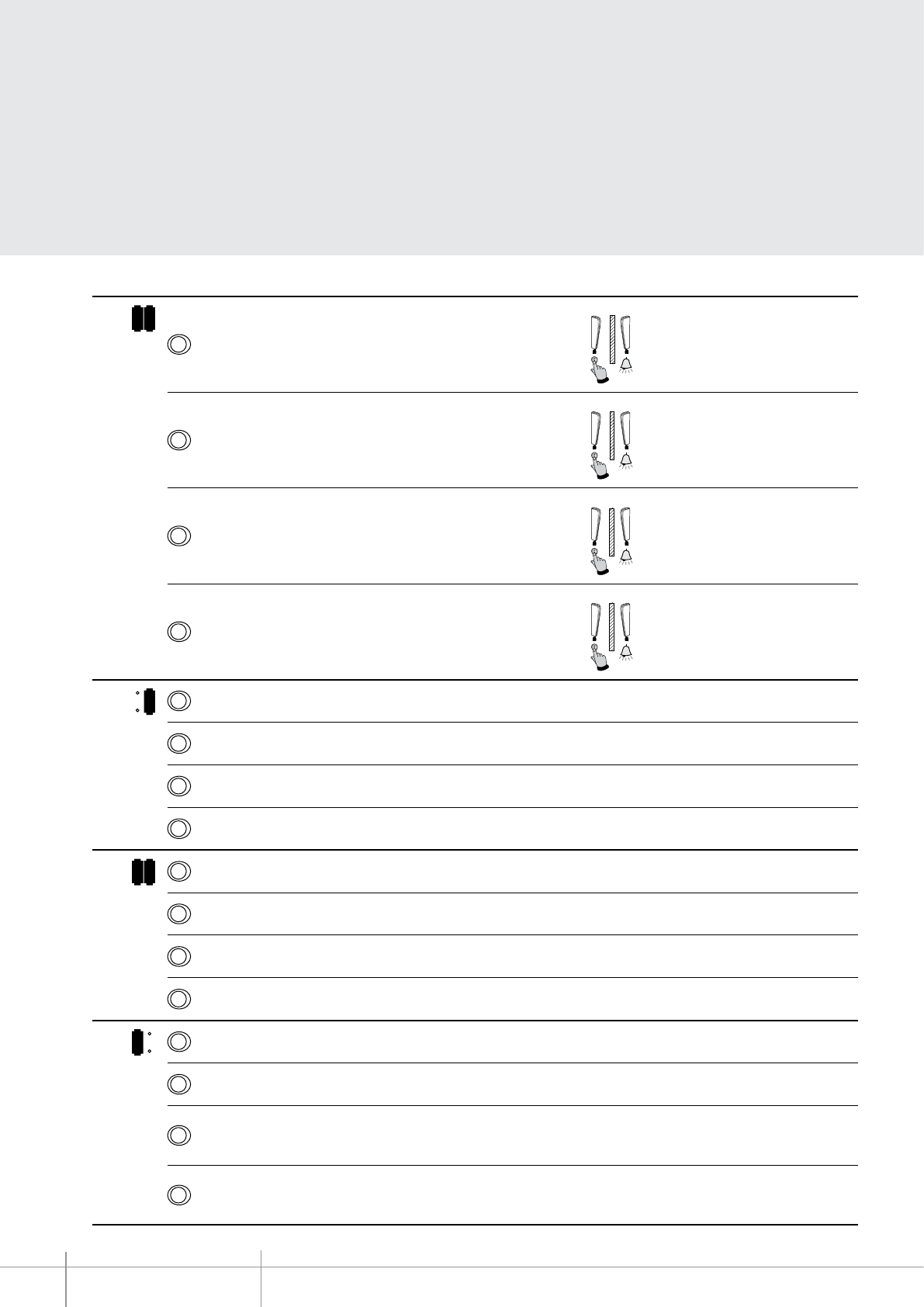
BT00644-a
344824
-EN
TECHNICAL SHEETS
326 2 WIRE VDE system
MODE KEY FUNCTION NOTE
1 2
MOD =
3Intercom between apartments, in systems with apartment interface, item 346850
3
N=3
2Intercom between apartments, in systems with apartment interface, item 346850
2
N=2
1Intercom between apartments, in systems with apartment interface, item 346850
1
N=1
0Intercom between apartments, in systems with apartment interface, item 346850
4
N=4
6
MOD = 3Staircase light switching on
2Activation of the scenario 2 saved in the scenario module (SCENARIO 2)
1Activation of the scenario 1 saved in the scenario module (SCENARIO 1)
0EP activation (congured with P), directly, without call
1 6
MOD = 3Activation of the scenario 3 saved in the scenario module (SCENARIO 3)
2Activation of the scenario 2 saved in the scenario module (SCENARIO 2)
1Activation of the scenario 1 saved in the scenario module (SCENARIO 1)
0Activation of the scenario 4 saved in the scenario module (SCENARIO 4)
4
MOD = 3Activation of the paging function on all the sound system loudspeakers
2EP door lock release congured with P, directly, without call
1Audio/video EP or camera activation (congured with P+1), directly, without
call
0Audio/video EP or camera activation (congured with P), directly, without call,
and cycling
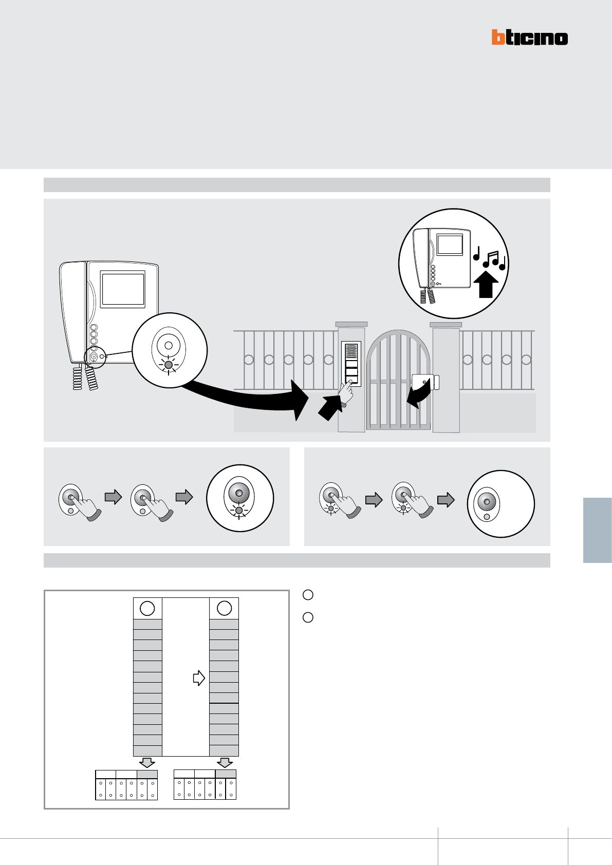
344824
BT00644-a
00
01
03
02
05
06
10
11
12
13
15
16
40
A
+20
20
21
23
22
25
26
30
31
33
32
35
36
60
B
P
N
P
NMODMOD
10s
BIP
10s
BIP
Led OFF
Led OFF Led OFF
3
2
1
O
1
3
CLAK
3
2
1
O2
10s
BIP
10s
BIP
Led OFF
Led OFF Led OFF
-EN
TECHNICAL SHEETS
327
2 WIRE VDE system
OFFICE function
To activate the oce function refer to the following:
A Conguration selected for the operation of the keys (see previous pages)
B Conguration selected for the operation of the keys + OFFICE function
To ENABLE the function To DISABLE the function
With the function active, when a call is received from the
entrance panel, the video handset rings and the associated door
lock is automatically released, without the need for pressing the
door lock release key on the video handset.
MOD configuration
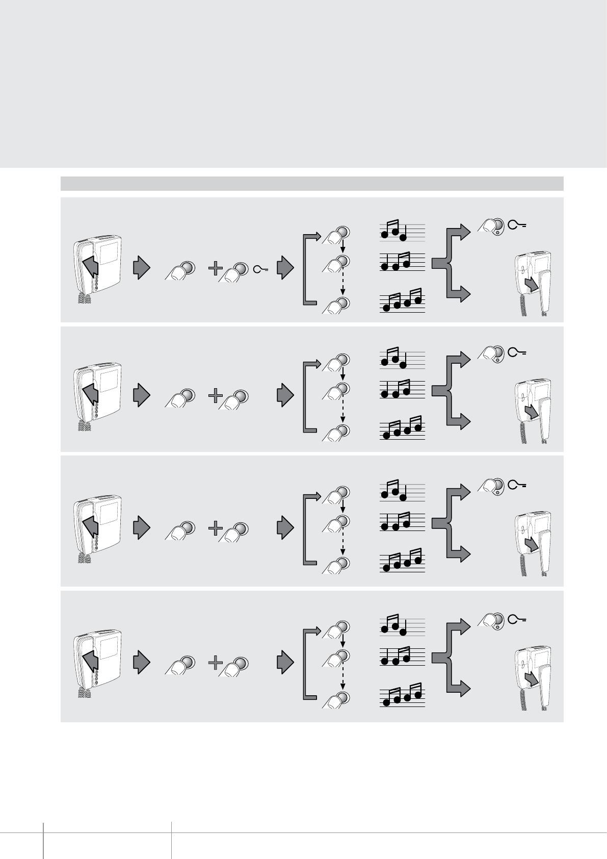
BT00644-a
344824
RESET
3
2
1
OK
RESET
3
2
1
OK
1
16
2
1
1
1
34
1212
1
16
2
1
1
1
34
1213
RESET
3
2
1
OK
1
16
2
1
1
1
34
121
RESET
3
2
1
OK
1
16
2
1
1
1
34
121O
-EN
TECHNICAL SHEETS
328 2 WIRE VDE system
Bell selection from MAIN ENTRANCE PANEL (S=0)
FLOOR CALL bell selection
Bell selection from SECONDARY ENTRANCE PANEL (S=1)
INTERCOM CALL bell selection
Programming of bells
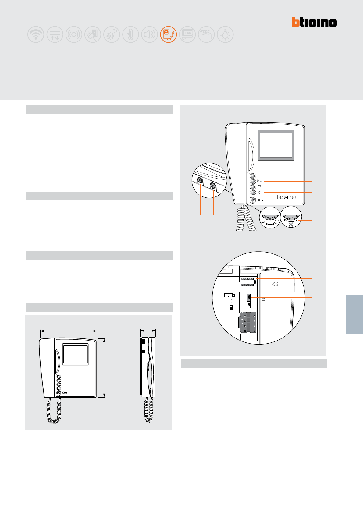
344832
BT00645-a
Art. 344832
5
BUS
1
ET
2 1
N P MOD
JMP 2
OFF
ON
JMP 1
N P
MOD
67
1
2
3
5
8
9
10
12
11
4
3
2
1
0
3
2
1
0
210 mm
215 mm
56 mm
-EN
TECHNICAL SHEETS
329
2 WIRE VDE system
SWING
Black and white basic video handset
Description
Wall video handset with black and white 4” monitor for use in 2 WIRE systems.
With the following pushbuttons for video door entry system functions: door lock release,
entrance panel/ camera scrolling activation, staircase lights switching on and intercom.
The volume of the bell can be adjusted, or the bell may be disabled.
With 16 different types of already preset bells, selectable for the call to the floor, main
entrance panel bell, and intercom functions.
It also has a secret conversation function, and “door status” control (function possible in
conjunction with the door lock actuators 346230 - 346260 and with CISA ELETTRIKA door
lock with 346240 accessory).
Wall mounting bracket supplied as standard.
Legend
1. Intercom call pushbutton
2. Staircase lights pushbutton
3. Entrance panel/camera scrolling activation pushbutton
4. Door lock release pushbutton + door status LED
5. Bell adjustment and exclusion
6. Monitor brightness adjustment
7. Monitor contrast adjustment
8. Configurator socket
9. MASTER/SLAVE jumper (Remove to enable SLAVE)
10. Additional power supply jumper. (Remove if a local power supply is connected to
clamps 1 - 2)
11. Line termination ON/OFF microswitch
12. Connection clamp for: 2 WIRE BUS, call to the floor, additional power supply and
additional bell.
Technical data
Power supply from SCS BUS : 20.5 – 27 Vdc
Stand-by absorption: 5 mA
Max. operating absorption: 400 mA @ 27 V - 650 mA @ 20.5 V
Operating temperature: 5 - 40°C
Correlated items
346020 (additional 2 DIN modules power supply) - optional, for local powering of the
video handset, when maximum installation distances are necessary
346230 2 DIN door lock actuator
346260 4 DIN timed door lock actuator
346240 CISA ELETTRIKA door lock accessory
Dimensional data
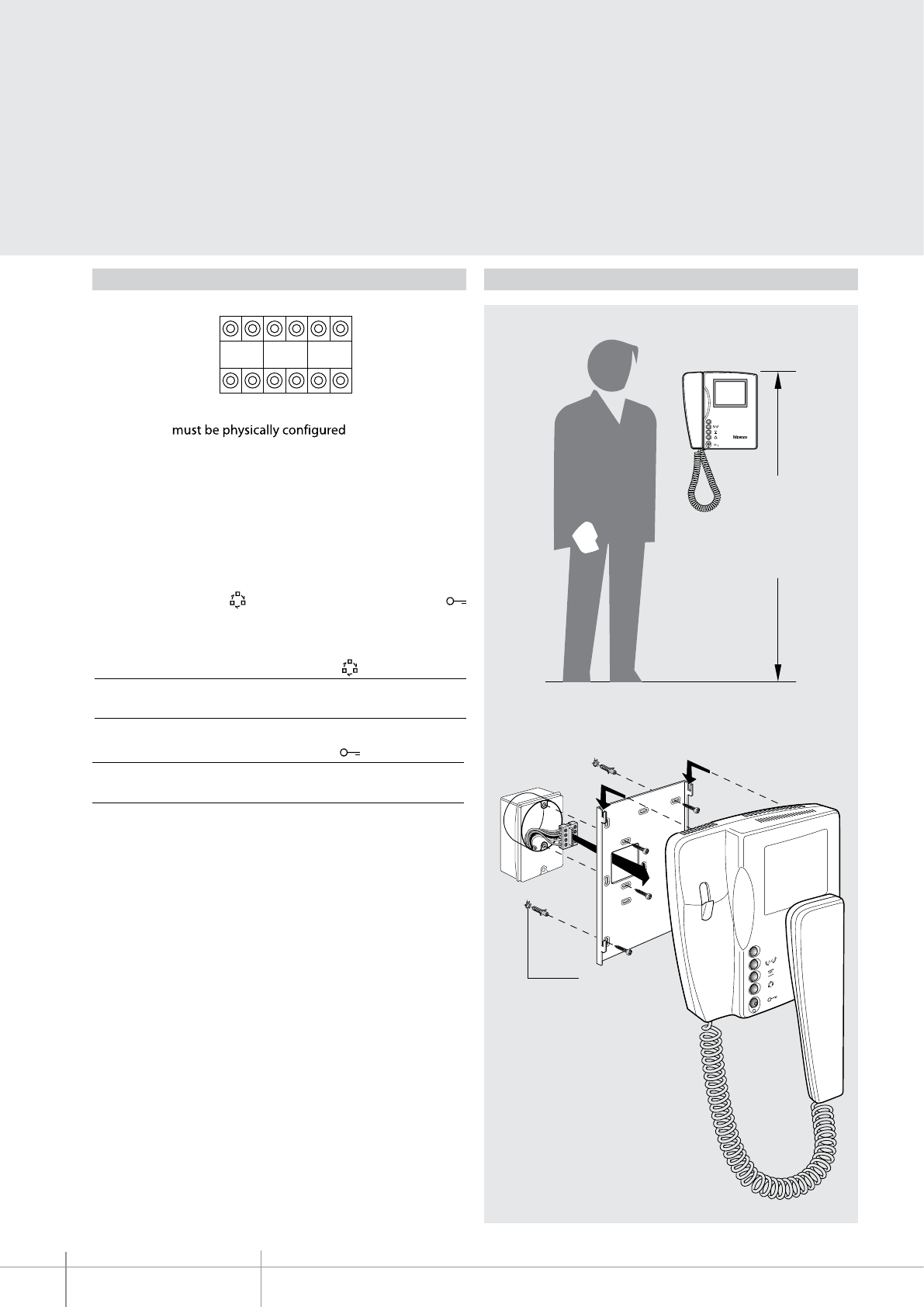
BT00645-a
344832
160 – 165 cm
Ø 5 mm
N P MOD
-EN
TECHNICAL SHEETS
330 2 WIRE VDE system
Configuration
The video handset in terms of:
N - handset number
The N configurator assigns to each video handset an identification number within the 2
wire system. The handsets must be configured in progressive order.
Handsets with parallel connection (max 3 are allowed inside apartments without
346850 interface) must be configured using the same N configurator.
P - entrance panel number
The P configurator identifies the entrance panel associated, or the first entrance panel to
activate before pressing the key and which door lock is activated when the key
is pressed while the video handset is idle.
Configuration in P Key function
P= 0-96 Activation of the audio function on the
entrance panel (configured with P= 0-96)
Configuration in P Key function
P= 0-96 Opening of the EP door lock
(configured with P= 0-96)
M - intercom operating mode
The intercom function enables audio communication (maximum 3 minutes) between
handsets within the same apartment.
Two configuration modes are possible:
M = 00 (no configurator connected). Multi-family Intercom between devices (max. 3)
configured with the same N configurator.
M =10 general intercom to be used in single family systems, or in systems installed
below the apartment interface 346850.
Installation
Height recommended, unless otherwise required by the law
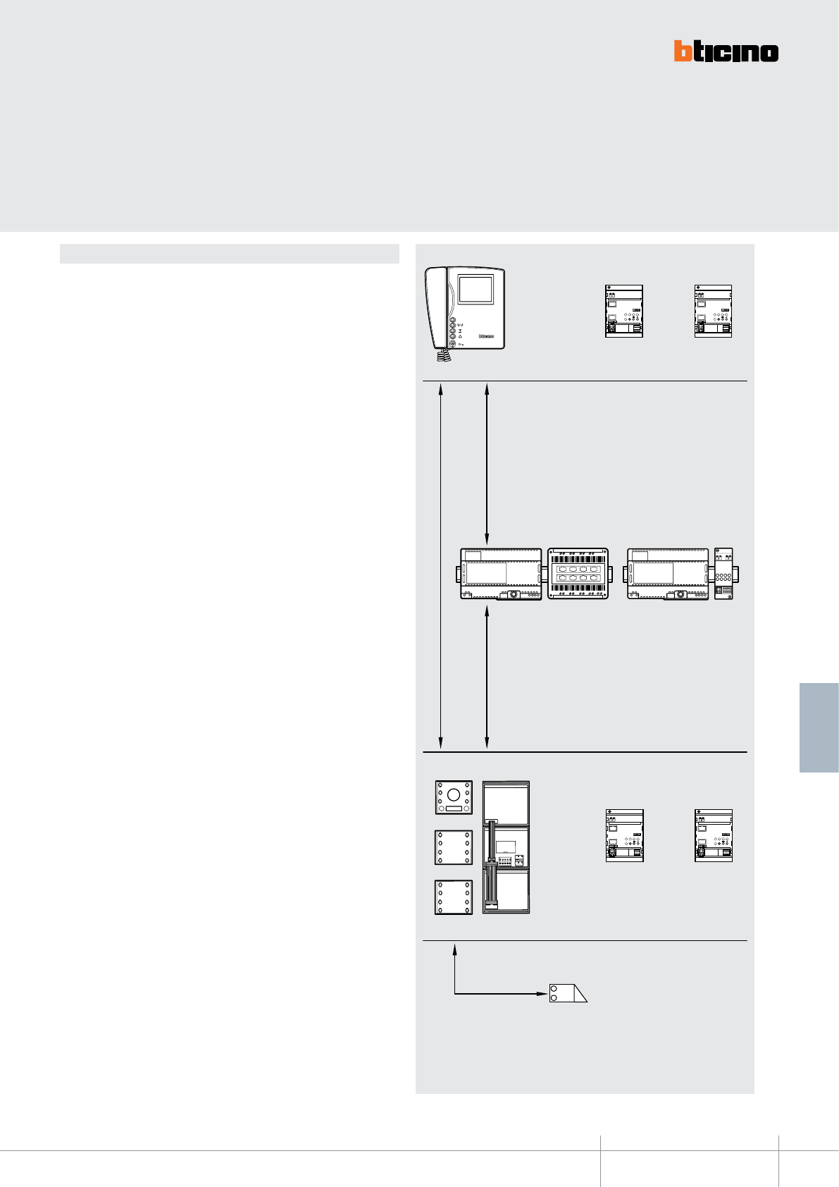
344832
BT00645-a
SC S
BUS
TK
BUS
PI
PS
ON
OUT
IN
ON OFF
ON
OUT
IN
ON OFF
ON
OUT
IN
ON OFF
ON
OUT
IN
ON OFF
346000 F441 346000 346830
346850 346581
346850 346581
-EN
TECHNICAL SHEETS
331
2 WIRE VDE system
General rules for installation
The connection of the devices is non polarised, and may be completed by wiring the
system in two different ways:
- In-out wiring directly on the device clamps (handsets)
- star wiring, with floor shunt (item 346841) installed directly inside the round box
(recommended).
The use of conductors with characteristics other than the prescribed ones does not guar-
antee good performance and good quality of the video signal. Therefore, only the cables
described in the following tables should be used.
When using the distance tables, interfaces 346850 and 346851 must be treated as hand-
sets within LINE C, and as a two buttons entrance panels within line B.
Handset
The furthest
video handset
Entrance panel
LINE A
LINE CLINE B
LINE D
Note: For those systems where only apartment interfaces are installed (in/out
connection), the distance of the C line to take into account is 200 m (with BTicino
cable 336904)
*
*Max variable distance Door lock
LINE C - systems with only 1 entrance panel:
SFERA (342170 + 342510 + 342240)
SFERA (342170 + 342550 + 342240)
LINEA 2000
MOD=0
and
MOD=5
MOD=0
and
MOD=5
*
*
*
BT00645-a
344832
-EN
TECHNICAL SHEETS
332 2 WIRE VDE system
Max. distances and features of cables in MULTI-FAMILY VIDEO SYSTEMS
The HANDSETS classed as (BASE) are: BASE SWING video handset;
The HANDSETS classed as (TRADITIONAL) are: PIVOT, SWING, SPRINT, POLYX VIDEO;
The HANDSETS classed as (ADVANCED) are: POLYX VIDEO DISPLAY, AXOLUTE VIDEO DIS-
PLAY, AXOLUTE VIDEO STATION, AXOLUTE N&W VIDEO STATION, POLYX MEMORY STATION.
Maximum LINE A distance, Entrance panel - furthest Handset
Cable section mm2
2 normal cables
>0.2 mm2
BTicino 336904 cable
Telephone twisted
pair - 0.28 mm
A pair of the multi-pair
data cable C9881U/5E
2 HA/2 pushbuttons 50 200 135 135
5 HA/5 pushbuttons 50 200 135 120
10 HA/10 pushbuttons 50 200 135 115
26 HA/26 pushbuttons 50 200 135 105
40 HA/entrance panel with local power
supply
50 200 135 -
40 HA/digital call modules
50 200 135 -
System created using traditional handsets and at least one base
swing handset - black and white entrance panel
Maximum LINE C distance, Power supply - furthest Handset (1)
Cable section mm2
2 normal cables
>0.2 mm2
BTicino 3 36904 cable
Telephone twisted
pair - 0.28 mm2
A pair of the multi-pair
data cable C9881U/5E
2 In/out HA 45 100 65 45
5 In/out HA 45 100 65 45
10 In/out HA 45 100 65 45
18 In/out HA 45 100 65 45
22 In/out HA
40 95 65 40
26 In/out HA 40 90 60 40
5 HA (shunted) 45 100 65 45
10 HA (shunted) 40 95 65 40
18 HA (shunted) 40 85 55 40
22 HA (shunted) - 75 50 -
26 HA (shunted) - 60 40 -
30 HA (shunted) (2) - 80 50 -
40 HA (shunted) (2) - 60 40 -
Maximum LINE B distance, Entrance panel - Power supply
Cable section mm2
2 normal cables
>0.2 mm2 or L4669
BTicino 336904 cable
Telephone twisted
pair - 0.28 mm2
A pair of the multi-pair
data cable C9881U/5E
2 pushbuttons 50 200 115 90
10 pushbuttons 50 170 100 75
26 pushbuttons 50 150 95 65
Digital call 50 150 95 65
Entrance panel with local power supply
50 200 140 120
Maximum LINE D distance Entrance panel - Door lock
Cable section mm2
0.28 mm2
BTicino L4669 cable
BTicino 336904 cable
1 mm2
S+S– clamps 30 m 30 m 50 m 100 m
Note (1): LINE C valid for SFERA (342170 + 342510 + 342240), SFERA (342170 +
342550 + 342240), SFERA A/V (342560 + 342240) or LINEA 2000 entrance
panels.
Note (2): if necessary, power the entrance panel locally.
WARNING: in order to reach longer distances, instead of the video adapter item.
346830, the audio/video node, item F441 (generating up to 4 risers), may be used. In
this mode one of the previous conditions, with less Handsets and a longer distance on
the C LINE, is recreated.
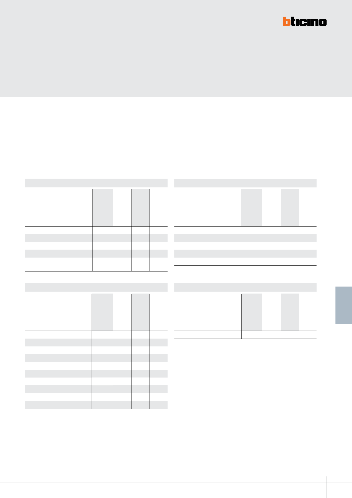
344832
BT00645-a-EN
TECHNICAL SHEETS
333
2 WIRE VDE system
System created using advanced or traditional handsets and at least
one base SWING handset – colour entrance panel
Maximum LINE A distance, Entrance panel - furthest Handset
Cable section mm2
2 normal cables
>0.2 mm2
BTicino 336904 cable
Telephone twisted
pair - 0.28 mm2
A pair of the multi-pair
data cable C9881U/5E
2 HA/2 pushbuttons 50 200 140 135
5 HA/5 pushbuttons 50 200 140 120
10 HA/10 pushbuttons 50 200 140 115
24 HA/24 pushbuttons 50 200 140 100
30 HA/entrance panel with local power
supply
50 200 140 -
Maximum LINE C distance, Power supply - furthest Handset (1)
Cable section mm2
2 normal cables
>0.2 mm2
BTicino 336904 cable
Telephone twisted
pair - 0.28 mm2
A pair of the multi-pair
data cable C9881U/5E
2 In/out HA 45 100 65 45
5 In/out HA 45 100 65 45
10 In/out HA 40 90 60 40
18 In/out HA 40 85 55 40
24 In/out HA - 75 50 35
5 HA (shunted) 40 100 65 45
10 HA (shunted) 40 85 55 40
18 HA (shunted) - 80 50 -
24 HA (shunted) - 50 - -
30 HA (shunted) (2) - 60 40 -
Maximum LINE B distance, Entrance panel - Power supply
Cable section mm2
2 normal cables
>0.2 mm2 or L4669
BTicino 336904 cable
Telephone twisted
pair - 0.28 mm2
A pair of the multi-pair
data cable C9881U/5E
2 pushbuttons 50 200 115 90
10 pushbuttons 50 170 100 75
26 pushbuttons 50 150 95 65
Digital call 50 150 95 65
Entrance panel with local power supply
50 200 140 120
Maximum LINE D distance Entrance panel - Door lock
Cable section mm2
0.28 mm2
BTicinor L4669 cable
BTicino 336904 cable
1 mm2
S+S– clamps 30 m 30 m 50 m 100 m
Note (1): LINE C valid for SFERA (342170 + 342510 + 342240), SFERA (342170 +
342550 + 342240), SFERA A/V (342560 + 342240) or LINEA 2000 entrance
panels.
Note (2): if necessary, power the entrance panel locally.
WARNING: in order to reach longer distances, instead of the video adapter item 346830,
the audio/video node, item F441 (generating up to 4 risers), may be used. In this mode
one of the previous conditions, with less Handsets and a longer distance on the C LINE,
is recreated.
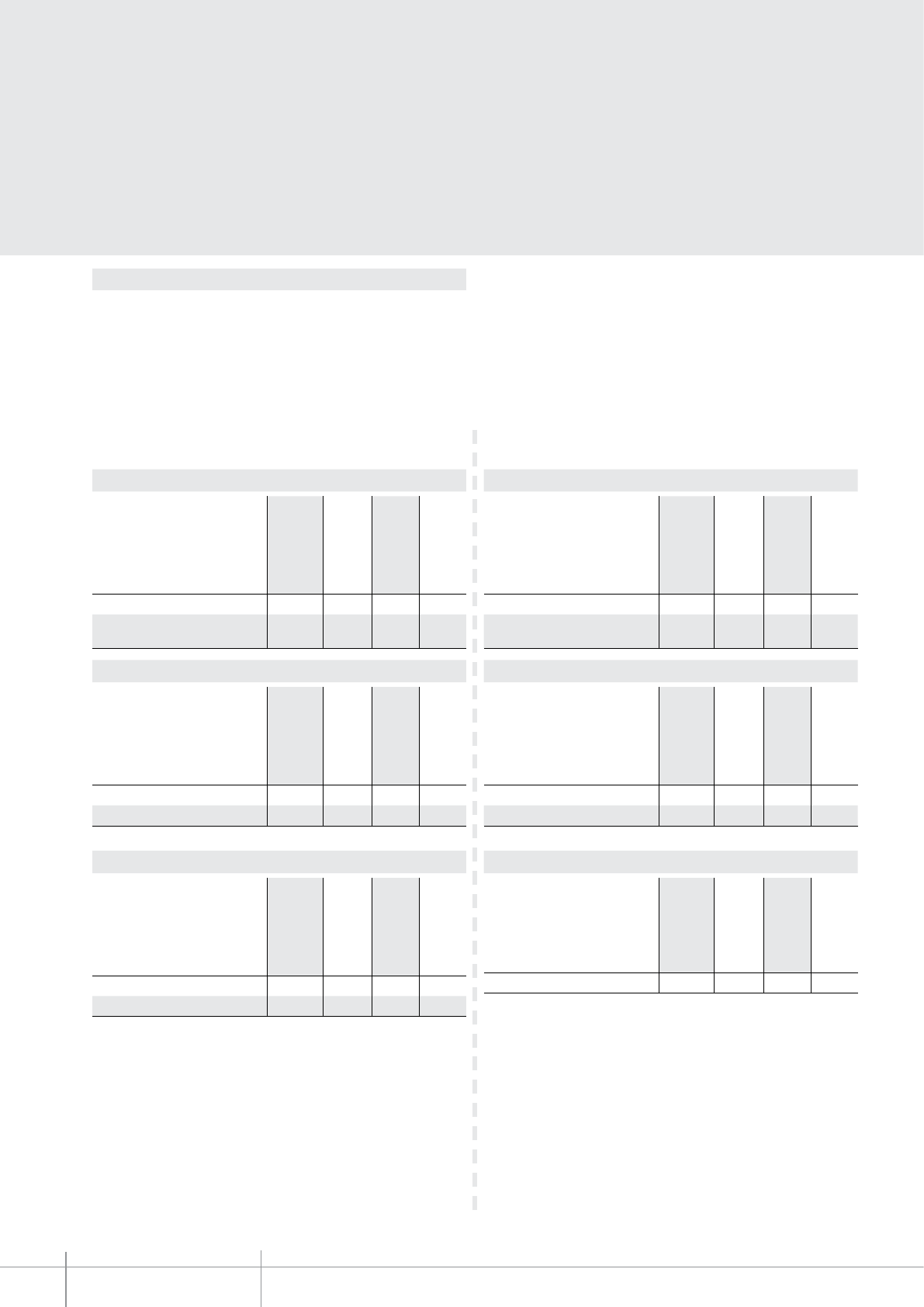
BT00645-a
344832
-EN
TECHNICAL SHEETS
334 2 WIRE VDE system
Max. distances and features of cables in SINGLE-FAMILY VIDEO SYSTEMS
The HANDSETS classed as (BASE) are: BASE SWING video handset;
The HANDSETS classed as (TRADITIONAL) are: PIVOT, SWING, SPRINT, POLYX VIDEO;
The HANDSETS classed as (ADVANCED) are: POLYX VIDEO DISPLAY, AXOLUTE VIDEO
DISPLAY, AXOLUTE VIDEO STATION, AXOLUTE N&W VIDEO STATION, POLYX MEMORY STATION.
Maximum LINE A distance, Entrance panel - furthest Handset
Cable section mm2
2 normal cables
>0.2 mm2
BTicino 336904 cable
Telephone twisted
pair - 0.28 mm2
A pair of the multi-pair
data cable C9881U/5E
5 S-family HA/pushbutton EP 50 200 140 135
5 S-family HA/EP with local power
supply
50 200 140 165
System created using traditional handsets and at least one base
swing handset - black and white entrance panel
System created using advanced or traditional handsets and at least
one base swing handset - colour entrance panel
Maximum LINE A distance, Entrance panel - furthest Handset
Cable section mm2
2 normal cables
>0.2 mm2
BTicino 336904 cable
Telephone twisted
pair - 0.28 mm2
A pair of the multi-pair
data cable C9881U/5E
5 S-family HA/pushbutton EP 50 200 140 135
5 S-family HA/EP with local power
supply
50 200 140 165
Maximum LINE C distance, Power supply - furthest Handset (1)
Cable section mm2
2 normal cables
>0.2 mm2
BTicino 336904 cable
Telephone twisted
pair - 0.28 mm2
A pair of the multi-pair
data cable C9881U/5E
5 In/out HA 45 100 65 45
5 HA (shunted) 45 100 65 45
Maximum LINE C distance, Power supply - furthest Handset (1)
Cable section mm2
2 normal cables
>0.2 mm2
BTicino 336904 cable
Telephone twisted
pair - 0.28 mm2
A pair of the multi-pair
data cable C9881U/5E
5 In/out HA 45 100 65 45
5 HA (shunted) 45 100 65 45
Maximum LINE B distance, Entrance panel - Power supply
Cable section mm2
2 normal cables
>0.2 mm2
BTicino 336904 cable
Telephone twisted
pair - 0.28 mm2
A pair of the multi-pair
data cable C9881U/5E
2 pushbuttons 50 200 115 90
Entrance panel with local power supply 50 200 140 120
Maximum LINE D distance, Entrance panel - Door lock
Cable section mm2
2 normal cables
>0.2 mm2
BTicino 336904 cable
Telephone twisted
pair - 0.28 mm2
A pair of the multi-pair
data cable C9881U/5E
S+S– clamps 30 m 30 m 50 m 100 m
Note (1): LINE C valid for SFERA (342170 + 342510 + 342240), SFERA (342170 +
342550 + 342240), SFERA A/V (342560 + 342240) or LINEA 2000 entrance
panels.
Note (1): LINE C valid for SFERA (342170 + 342510 + 342240), SFERA (342170 +
342550 + 342240), SFERA A/V (342560 + 342240) or LINEA 2000 entrance
panels.
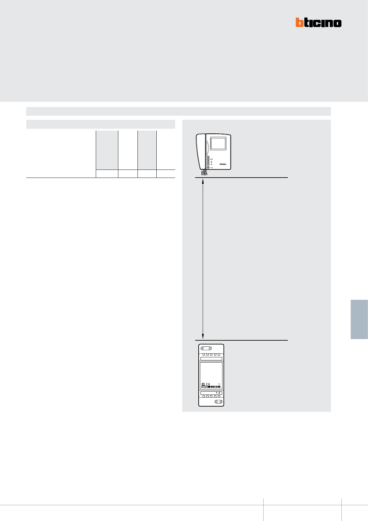
344832
BT00645-a
PRI
346020
PRI: 220 – 240 V~
175 – 165 mA
47/63 Hz
SCS: 27 Vdc
600 mA
-EN
TECHNICAL SHEETS
335
2 WIRE VDE system
MAXIMUM DISTANCES AND CABLE FEATURES FOR CONNECTION OF THE ADDITIONAL POWER SUPPLY
SWING BASE
video handset
344832
Maximum distance for base SWING video handset additional power supply
Additional power
supply 346020
WARNING: For situations or installation conditions other than the ones listed in
this document (e.g. different entrance panels), the distances may be calculated
using the YouDiagram software (this can be downloaded free of charge from the
www.international.bticino.com website - ASSISTANCE AND TOOLS - TECHNICAL
SOFTWARE.
Maximum LINE distance between the power supply and the entrance panel
Cable section mm2
2 normal cables
>0.2 mm2
BTicino 336904 cable
Telephone twisted
pair - 0.28 mm2
A pair of the multi-pair
data cable C9881U/5E
50 100 75 50
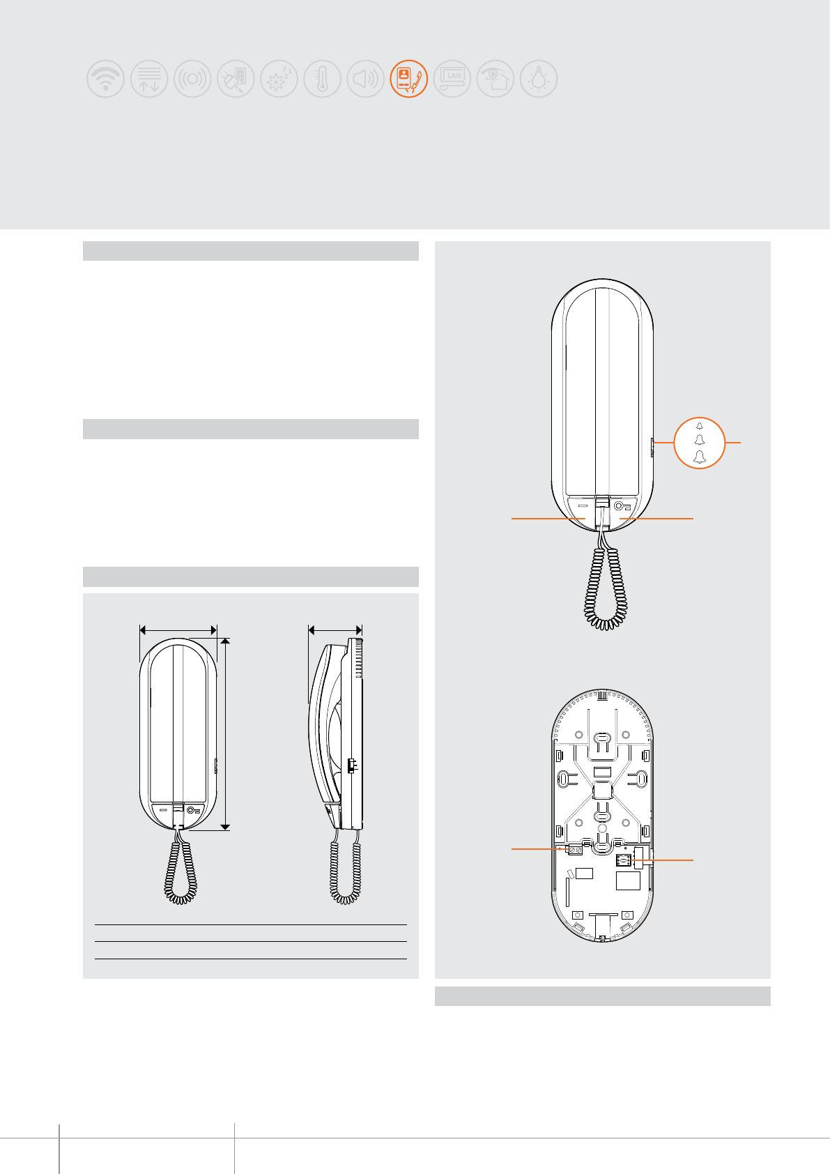
BT00646-b
344242
1
2
4
3
5
B
CA
A B C
78 mm 194 mm 54,5 mm
-EN
TECHNICAL SHEETS
336 2 WIRE VDE system
SPRINT L2
Handset
Description
2 WIRE handset that CANNOT be fitted with accessories, wall mounted. It has a door
lock release pushbutton, and a pushbutton that can be configured for auxiliary functions
(staircase light switching on, entrance panel activation, call to the switchboard). If
installed in video, or mixed audio/video systems, as the last apartment line or riser
device, it must include a line termination, item 3499, with IN-OUT connection on the
handset itself. The ringtone volume can be adjusted to three different levels using the
appropriate selector.
Legend
1. Ringtone volume selector, adjustable to three different levels
2. Door lock release pushbutton
3. Auxiliary function pushbutton (configurable) - see configuration
4. Configurator socket
5. 2 WIRE SCS/BUS connection clamps
Technical data
Power supply from SCS BUS: 18 – 27 Vdc
Stand by absorption: 3.5 mA
Max. operating absorption: 35 mA
Operating temperature: 5 – 40 °C
Dimensional data
Front view
View without lid
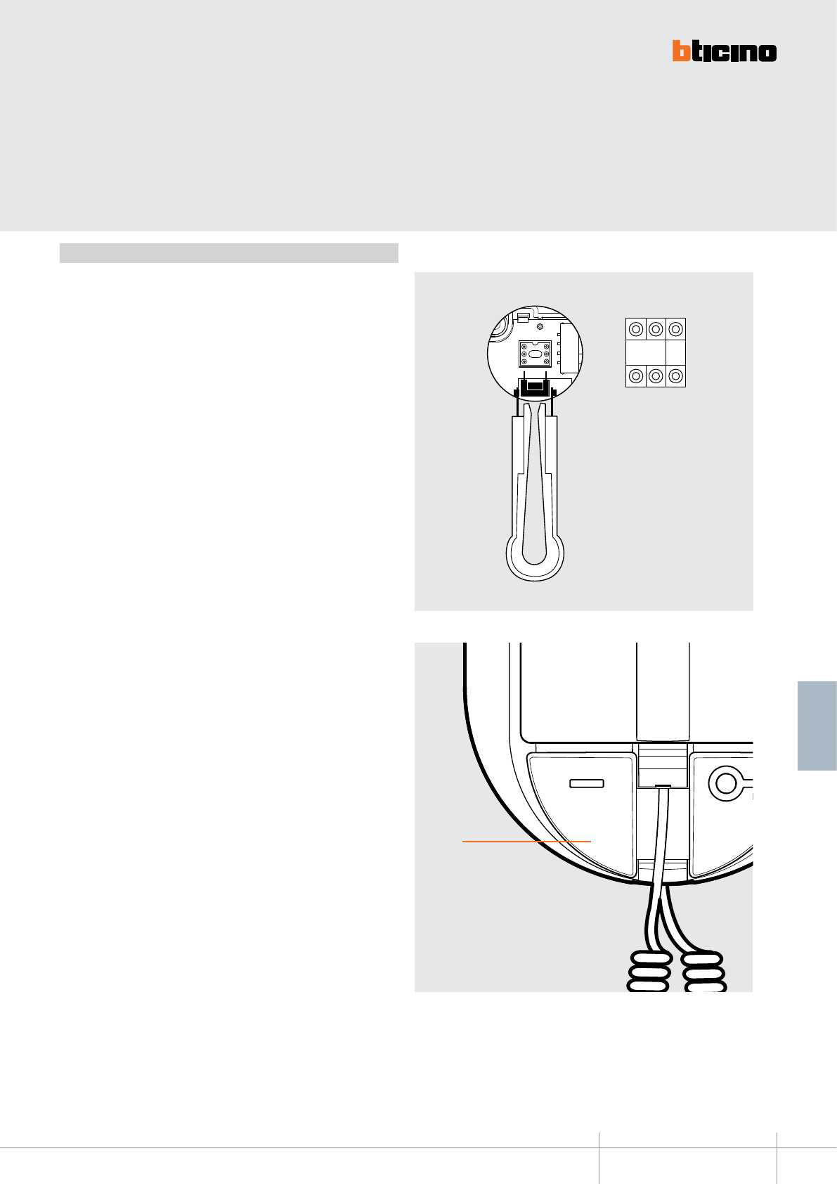
BT00646-b
344242
P
N P
-EN
TECHNICAL SHEETS
337
2 WIRE VDE system
Configuration
The handset MUST be configured by physically connecting the configurators to the
appropriate sockets as follows:
N - handset number
The N configurator assigns to each handset an identification number (1 - 99)
within the system. The handsets must be configured in progressive order. In case
of handsets with parallel connection (max 3), these must be configured using the
same N configurator.
P - auxiliary function pushbutton
The configurator connected to P allocates the operating mode to the auxiliary
function pushbutton, as shown below:
(P = 0 no configurator connected) - staircase light switching on/activation of
the additional door lock
(P = 1 – 8) - activation of the entrance panel configured with P = 1-8
(P = 9) - entrance panel activation configured with P = 0 (corresponds to
no configurator connected) or call to the main switchboard.
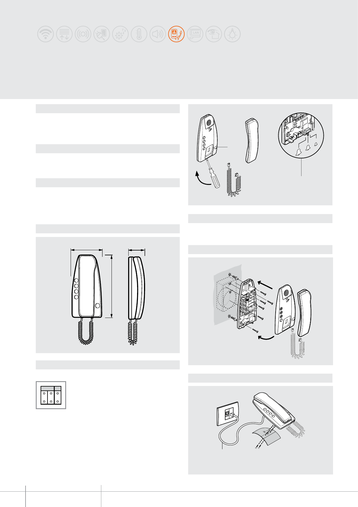
BT00647-a
344202
56 mm
101 mm
216 mm
2
1
c
l
a
c
k
2
1
c
l
a
c
k
2
1
c
l
a
c
k
PN
2
1
336803
-EN
TECHNICAL SHEETS
338 2 WIRE VDE system
Dimensional data
Conguration
Description
2 WIRE handset that cannot be tted with accessories, wall mounted or table top installation.
Whit door lock opening key.
Bell volume adjustable on 3 levels.
Technical data
Power supply from SCS BUS: 18 – 27 Vdc
Stand by absorption: 5 mA
Max. operating absorption: 35 mA
Operating temperature: 5 - 40°C
The handset must be physically congured:
N - handset number
The N congurator assigns to each handset an identication number within the AUDIO
system.
The handsets must be congured in progressive order.
In case of handsets with parallel connection (max 3) inside the apartment without item
346850 apartment interface, these must be congured using the same N congurator.
P - entrance panel association
the P congurator identies the associated EP.
Related items
Item 337242 Handset table-top base
Item 336803 AMP cable for connection on table-top base
Legend
1 - Door lock key
2 - Bell volume adjustment
Wall mounted installation
Table installation
SPRINT handset
(without the possibility of tting with accessories)
Handset suitable for wall mounted installation
without the need of any accessories
Table installation of the handset
with base item 337242
5 - Brown
6 - Brown-white
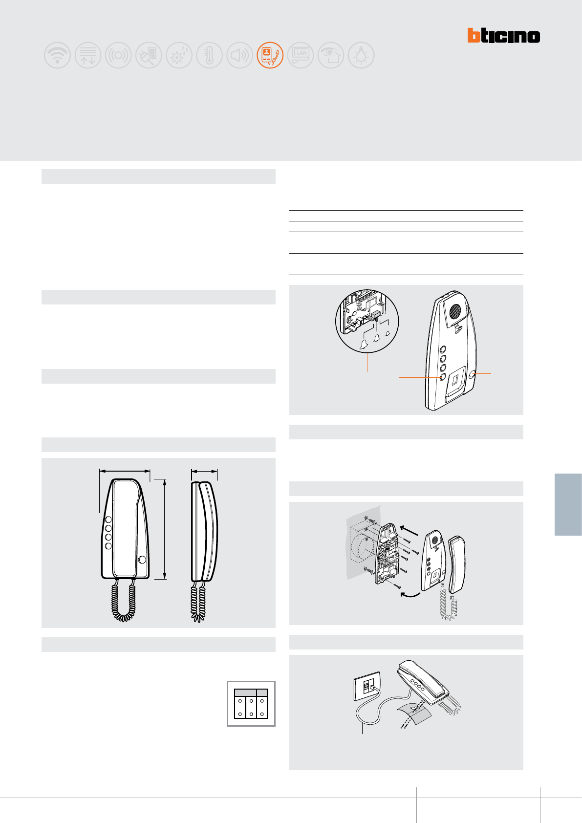
BT00648-a
344212
56 mm
101 mm
216 mm
2
1
c
l
a
c
k
2
1
c
l
a
c
k
31
2
2
1
c
l
a
c
k
336803
PN
-EN
TECHNICAL SHEETS
339
2 WIRE VDE system
Dimensional data
Description
2 WIRE handset that can be tted with accessories, wall mounted or table top installation.
It has auxiliary function pushbuttons.
It can be accessorised with additional pushbuttons and signalling LED (traditional
wiring), as well as call exclusion card, item 346800. Using the conguration procedure,
the user can decide which function to associate to the auxiliary function pushbutton.
When the item 344212 handset is installed on video or mixed audio/video systems as
the last device of the riser, or apartment line, an INPUT/OUTPUT termination, item 3499,
must be connected to the handset itself.
Technical data
Power supply from SCS BUS: 18 – 27 Vdc
Stand by absorption: 5 mA
Max. operating absorption: 35 mA
Operating temperature: 5 - 40°C
P - Auxiliary function pushbutton
The auxiliary function pushbutton on the handset item 344212 can be used to perform
several functions, determined by the value of the congurator connected to P.
Congurator in P Auxiliary pushbutton function
0 Light actuator control
1 - 7 Activation of the audio function on the entrance panel
congured with P = 1 to 7
9 Call to the Switchboard, in systems with the 8/2-WIRE
interface item 346150
Related items
item 337242 Handset table-top base
item 346800 Extra bell and/or call exclusion card
item 336803 AMP cable for connection on table-top base
item 337430 Additional pushbutton
item 3499 Line termination
Legend
1 - Door lock key
2 - Key for auxiliary functions
3 - Bell volume adjustment
Wall mounted installation
Table installation
Conguration
The handset must be physically congured:
N - handset number
The N congurator assigns to each handset an identication
number within the system. The handsets must be congured in
progressive order.
In case of handsets with parallel connection (max 3) inside the
apartment without item 346850 apartment interface, these must
be congured using the same N congurator. Table installation of the handset
with base item 337242
5 - Brown
6 - Brown-white
Handset suitable for wall
mounted installation
without the need of any accessories
SPRINT handset
(that can be tted with accessories)
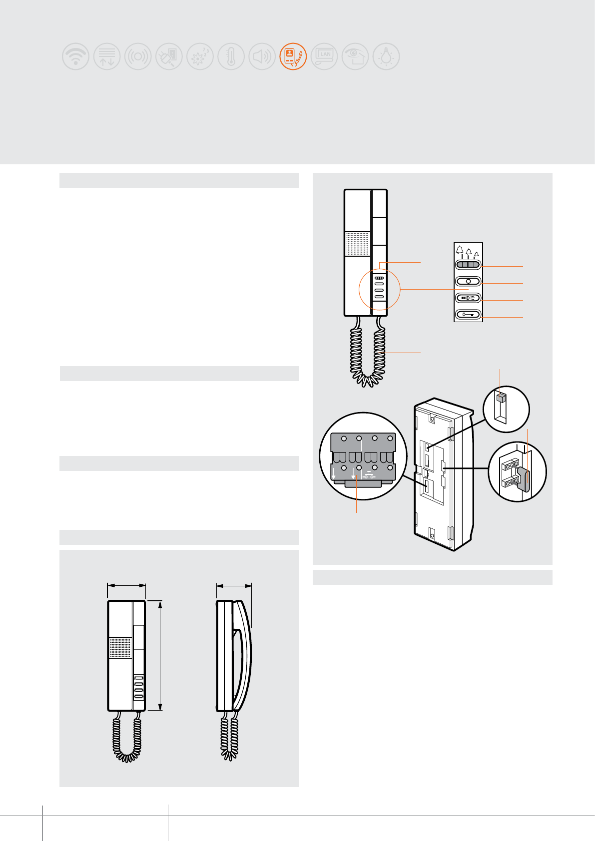
344032
BT00649-a
68,5 mm
210 mm
70 mm
6
2
3
4
1
5
5
BUS
1
ET
21
OFF
ON
NP
7
9
8
-EN
TECHNICAL SHEETS
340 2 WIRE VDE system
Dimensional data
Description
2 WIRE PIVOT handset for wall mounted, ush mounted, or table top installation. It has
door lock release, staircase light and EP activation keys.
The device oers the possibility of selecting among 16 already programmed bells for
oor call, main entrance panel, INTERCOM CALL, and secondary entrance panel. The call
volume can be set on three levels: high, medium and disabled (this condition is signalled
by a ashing red LED).
It also has a call secrecy function. It is connected to the system using the removable
clamp supplied.
Wall mounting bracket supplied as standard.
WARNING: Table installation is possible in video or mixed audio/video
systems where the wiring to the handset uses oor shunt item
346841 or the audio/video node item F441.
Technical data
Power supply from SCS BUS: 18 – 27 Vdc
Stand by absorption: 5 mA
Max. operating absorption: 35 mA
Operating temperature: 5 - 40°C
Related items
item 346812 4 key small block for auxiliary functions - white
item 337102 table-top support - white
NOTE: for ush mounted installation refer to the specic accessories of the MULTIBOX
range.
Legend
1 - electronic call with volume adjustable on 3 levels: high, medium, disabled
(the excluded call is signalled by a ashing red LED).
2 - Entrance panel activation
3 - Staircase light key
4 - Door lock key
5 - Extensible cord capped on both ends with RJ connectors
6 - Socket for 4 key small block (optional)
7 - Line termination ON/OFF micro-switch
8 - Congurator socket
9 - Plug-in clamp for the connection of the 2 WIRE BUS, additional power supply, and
auxiliary oor call function, as well as extra bell.
PIVOT
Handset
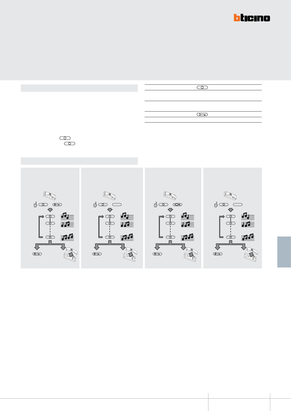
BT00649-a
344032
+
1
16
OK RESET
2
+
1
16
OK RESET
2
1
+
1
16
OK RESET
2
4
+
1
16
OK RESET
2
-EN
TECHNICAL SHEETS
341
2 WIRE VDE system
Conguration
N – handset number
The N congurator assigns to each handset an identication number within the system.
The handsets must be congured in progressive order. In case of handsets with parallel
connection (max 3 inside the same apartment without item 346850), these must be
congured using the same N congurator.
P – entrance panel association
The P congurator identies the associated EP or the rst entrance panel on which the
audio is activated when the key is pressed for the rst time, as well as which
door lock is activated when the key is pressed while the handset is idle.
Congurator in P key function
0-9 Activation of the audio function on the entrance panel
(congured with P=0-9)
Congurator in P key function
0-9 Entrance panel door lock release with handset idle
Bell selection from MAIN ENTRANCE
PANEL (S=0 - S=4)
FLOOR CALL bell selectionBell selection from SECONDARY
ENTRANCE PANEL (S=0 - S=5)
INTERCOM CALL bell selec-
tion
Programming of bells
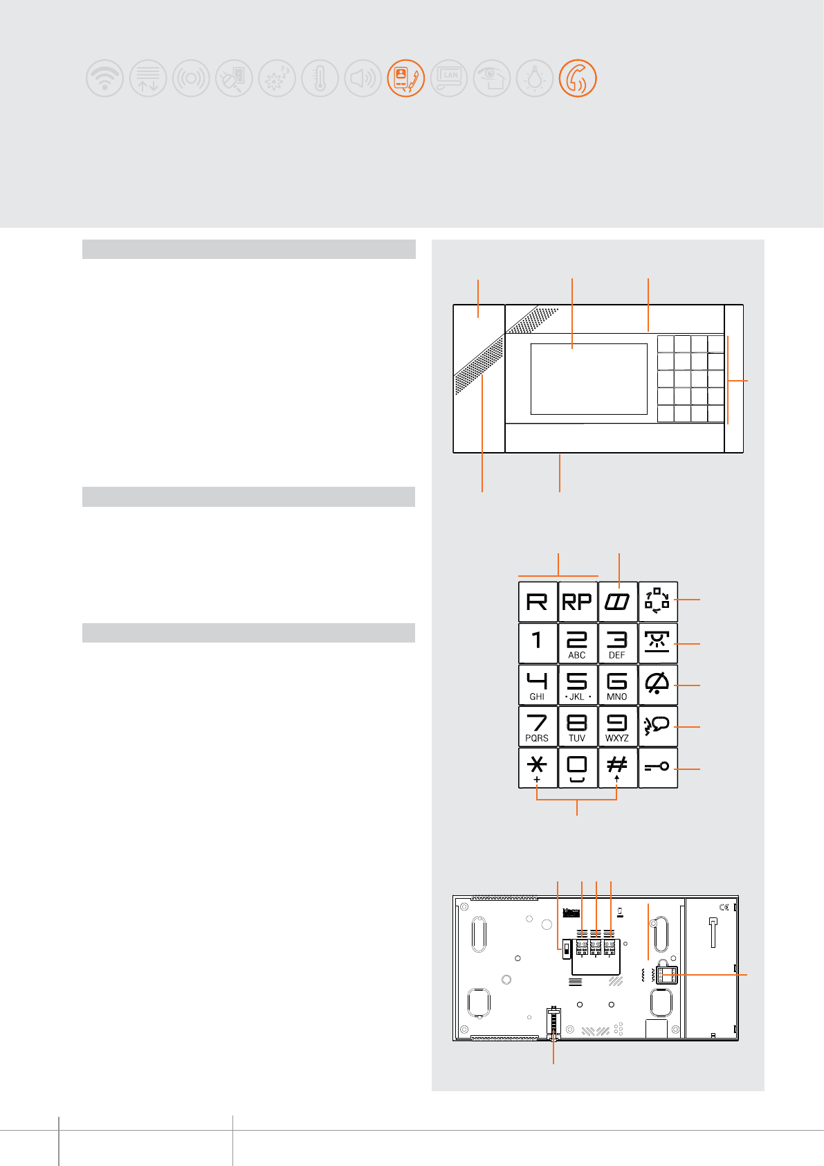
345020 - 345021
BT00650-a
5
. , ?
12 3
4
6
7 8
9
10
11
12
13
14
ON
OFF
ART. 345021
PSTN BUS 2 1
N P M
20
15 16 17 18
19
-EN
TECHNICAL SHEETS
342 2 WIRE VDE system
Iryde Touch Phone
Description
2 wire telephone and video handset for wall mounted installation (with optional
bracket, item 345024) or table-top version (with optional support, item 345023). It has
a 16/9, 4.3”LCD colour touch screen display with icon navigation menu, which can be
customised using a PC for the management of the functions:
- telephone;
- video door entry
- MY HOME automation: temperature control, sound system, automation scenarios,
burglar alarm.
The device also features:
- backlit keypad with blue LED.
- handset with magnet for logic release functions through the Hall sensor fitted inside
the base, with extendable spiral cable. On the back of the receiver is a loudspeaker for
the handsfree function.
Programming and configuration using the TiIrydeTouch Phone software supplied with
the product.
Legend
1. Handsfree loudspeaker
2. Handset
3. LCD colour touch screen display: it displays the user menus and shows the images
recorded from the entrance panel and from other cameras
4. Handsfree microphone
5. Backlit keypad
6. Mini USB PC connection
7. Call forwarding and repeat/pause telephone function keys
8. Telephone address book key
9. EP switching on and camera cycling key
10. Stair lights switching on key
11. Call exclusion key: press once to disable the ringtone (telephone and video door entry
system), and press again to enable. Steady red LED with ringtone disabled, flashing for
incoming call and ringtone disabled
12. Handsfree enable/disable key. Green LED when enabled
13. Main EP door lock release key. Notification LED:
14. - off when the door lock is idle and the door is locked, red when the door is open
15. - red flashing when the Office function is active
16. * and # keys used for telephone services
17. Line termination ON/OFF switch
18. PSTN telephone line or PABX switchboard connector
19. 2 wire video SCS/BUS connector
20. 1-21) power supply connector
21. Configurator socket
22. Bracket fixing screw.
Note: 1) The telephone functions are still ensured in case of power cut to the SCS/BUS,
provided that an additional power supply is present. (1= –; 2= +)
Technical data
Power supply from SCS BUS: 18 – 27 Vdc
Maximum absorptions from the BUS:
- Standby 35 mA and up to 160 mA when the telephone
functions are used.
- ON 350 mA
- With additional power supply (1-2) 20 mA
Operating temperature: 5 – 45 °C
Front view
Keypad
Rear view
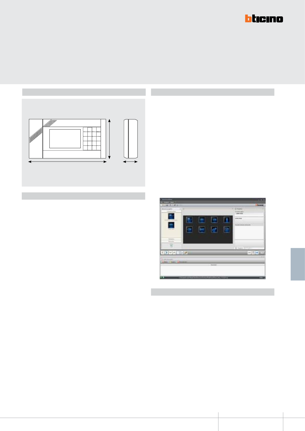
BT00650-a
345020 - 345021
235 mm
120
mm
22 mm
-EN
TECHNICAL SHEETS
343
2 WIRE VDE system
Configuration
Iryde Touch Phone can be configured in two different modes:
- Basic configuration: when switched on for the first time, the product asks the
user to select the language. After this has been done, if no physical configurators are
present, the device displays a main page showing the video door entry system icon
(inside which, standard door entry system commands can be found: camera, door
lock release, intercom, automatic cycling), the telephone icon, and the settings icon.
The basic configuration can also be performed using physical configurators: N (address
of the device within the video door entry system), P (address of the EP associated to the
device)
- Configuration using the PC: using the TiIrydeTouchPhone software, it gives the
possibility of configuring the main menu page without being limited to a pre-set number
of functions. Each function may be customised in terms of type, parameter, and text.
PC configuration provides:
- better flexibility in the creation of the menu;
- customisation of text;
- functionalities for the management of the MY HOME automation systems.
Rules, certification, marks
Iryde Touch Phone 345020 – 345021 complies with the 1999/5EC directive, certified
following the current regulations listed below:
• EN 60950-1:2006-04 + EN 60950-1/A11:2009-03
• EN 50090-2-2/Ec:1997-03 + EN 50090-2-2/A1:2002-01+ EN 50090-2-2/A2:2007-04
Main functions
• Simultaneous switching on with additional power supply: it is possible to connect up
to 4 ITPs with no additional power supply. In case of simultaneous switching on of several
menus, display brightness limitation occurs. In system with or without PABX switchbo-
ard, where however the PSTN telephone line and the SCS BUS are connected using
the star wiring solution, the image from the camera is visible on all the ITPs, provided
that these are powered individually using the additional power supply (item 346020).
In general, when installing systems in apartments with ITPs connected to the telepho-
ne line, the installation of the apartment interface, item 346850, is also required.
• Home automation functions: using the software, it is possible to configure the
pages for the control of the home automation systems installed inside the home.
The available pages are: alarms (alarm log display), sound system (programming of
the rooms and source names), temperature control (management of the 4 zone and 99
zone system), execution of scenarios.
• Ringtones: stored in the ITP, can be associated to specific events: door entry system,
telephone, and intercom call, alarms, etc. The ringtones are played by the loudspeaker
used for the handsfree function. It is possible to update the ringtones, with Wav or
MP3 files, using the configuration software.
Dimensional Data

345020 - 345021
BT00650-a-EN
TECHNICAL SHEETS
344 2 WIRE VDE system
- Address book: using the telephone menu, the address book can be used for the
following functions: add a contact, delete a contact, change a contact, select and
call a contact, customise a contact by associating a photo to the number (using the
software), management of several numbers (max 3) for eachcontact.
Telephone services
• Calling a number on the PSTN line: using the appropriate keypad command, the
user can select the PSTN telephone line on which to make the call. ITP is capable of
selecting a telephone number on the PSTN line in touch tone mode (DTMF).
• Calling a number on the private, or system, address book using the PSTN line.
• Pager: Press the dedicated icon to communicate with handsets and telephones with
handsfree function.
• Answering incoming calls.
• Differentiated call: when a call arrives, the user has the possibility of distinguishing
between type of calls (intercommunicating, from the outside line, or video door entry
system call), by using different sound tracks.
• CID service: upon arrival of a PSTN line call, the caller number or name is displayed (if
the number is included in the address book), together with the photo of the caller (if
present in the private address book). The availability of the service is subjected to the
activation of the function for forwarding information by the central unit.
• Extension call (intercommunicating call): possibility for the extensions to talk to
each other. The selection of the extension to call can be made in two ways:
- by entering on the code of the extension to call on the keypad (from 401 to 408)
- by selecting the extension to call from the menu, and then pressing “OK” to confirm
the call
• General call of all the extensions: it is possible to make an announcement on all
CTB and ITP extensions using the loudspeaker on the bases of the telephones. To
activate the service lift the handset and press the dedicated icon. The first telephone
engaging the line enters in conversation with the caller, excluding all the other
extensions called. If no answer is received within the activation time, the service is
interrupted and the caller receives a time-out tone. The service can be interrupted by
replacing the handset. Press the “pager” key during the activation time or when the
time-out tone is heard from the handset to reactivate the service. The microphone
used for the pager function can be the handset or the handsfree microphone.
• Automatic redial of the last external number.
• Putting a call on and off hold on the telephone line: the extension engaged in the
call can put the user of the PSTN line on hold by pressing the “R/HOLD” key. While on
hold the extension can:
- enable a permitted service.
- restart the conversation by replacing the handset (call return).
- restart the conversation on hold by pressing the “R/HOLD” key again.
• Answering a second call.
• Transfer without consent in case of free tone: in case of installation with PABX,
after pressing “R” and selecting the number of the extension to which to transfer the
conversation, the user can replace the handset once a free tone is heard.
• Transferring a door entry system and DOSA outside line call: in case of installation
with PABX.
• DISA service, selection of the handset from the outside line using the voice
menu: in case of installation with PABX.
• Day/lunchtime/night scenarios for the various telephone lines: in case of
installation with PABX.
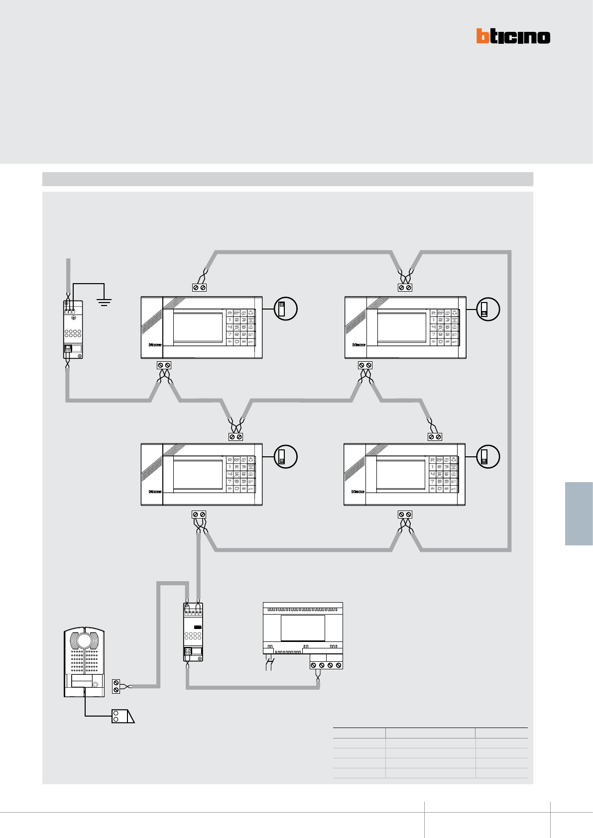
BT00650-a
345020 - 345021
BUS
PI
BUS
TK
PS
BUS
BUS
BUS
PSTNPSTN
BUS
BUS 2 1
BUS
PSTNPSTN
PLT1
ab
IN
ab
OUT
OFF OFF
OFF
ON
345020
345020
345020
345020
346830
346000
230 Vac
PLT1
-EN
TECHNICAL SHEETS
345
2 WIRE VDE system
Telephone line
Entrance
panel
Wiring diagrams
One-family system without PABX
ITEM DESCRIPTION QUANTITY
PLT1 Protection of telephone line 1
345020 Iryde Touch Phone 4
346830 Video adapter 1
346000 AV Power supply, 230 V 1
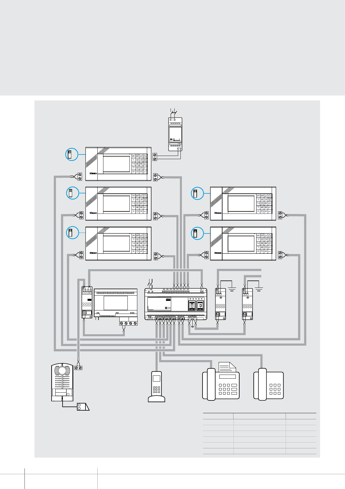
345020 - 345021
BT00650-a
ON
ON
Speed Full Link Aux
System
345829
PABX 288 exp
PRI: 110 - 240V~
210 - 130mA
50/60 Hz
PD max 13W
10W39 06
PLT1
ab
IN
ab
OUT
PLT1
ab
IN
ab
OUT
PSTN
PSTN
BUS
BUS
PSTN
PSTN
BUS
BUS
PRI
346020
PRI: 220 – 240 V~
175 – 165 mA
47/63 Hz
SCS: 27 Vdc
600 mA
2
1
PSTN
BUS
PI
BUS
TK
PS
ON
ON
BUS
BUS 2 1
ON
230 Vac
345020*
345020* 345020*
345020*
345829
PLT1 PLT1
346830 346000
346020
230 Vac
345020*
110-240 Vac
-EN
TECHNICAL SHEETS
346 2 WIRE VDE system
One-family system with PABX
ITEM DESCRIPTION QUANTITY
PLT1 Protection of telephone line 2
345020 Iryde Touch Phone 5
346830 Video adapter 1
346000 AV Power supply, 230 V 1
345829 Switchboard 1
346020 Power supply 1
Telephone
line
Fax
Cordless Telephone
Entrance
panel
Note (*): congure the ITPs (using the Menu or the Software) to recognise that the
PABX switchboard is present

6
5
4
1
2
8
3
7
OFF
ON
5
BUS
1
ET
21
NP
9
10
11
12
344102
68,5 mm
210 mm
210 mm
BT00651-a-EN
TECHNICAL SHEETS
347
2 WIRE VDE system
Dimensional data
Technical data
Power supply from SCS BUS: 18 – 27 Vdc
Stand by absorption: 5 mA
Max. operating absorption: 290 mA
Operating temperature: 5 - 40°C
Related items
item 346812 4 key small block for auxiliary functions - white
item 337122 table-top support - white
NOTE: for ush mounted installation refer to the specic accessories of the MULTIBOX
range.
PIVOT
black & white video handset
Legend
1. 4” TFT colour monitor
2. Monitor colour, contrast, and brightness adjustment
3. Extensible cord capped on both ends with RJ connectors
4. Door lock key
5. Staircase light key
6. Entrance panel activation/cycling
7. Electronic call with volume adjustable on 3 levels: high, medium, disabled (the
excluded call is signalled by a ashing red LED)
8. 4-key block housing (optional)
9. Line termination ON/OFF micro-switch
10. Congurator socket
11. MASTER-SLAVE Jumper (remove to enable SLAVE)
12. Plug-in clamp for the connection of the 2 WIRE BUS, additional power supply, and
auxiliary oor call function, as well as extra bell.
Description
2 WIRE PIVOT video handset for wall mounted, ush mounted, or table top installation.
Black & white 4” at monitor. It has door lock release, staircase light, and entrance panel
activation keys.
The device oers the possibility of selecting among 16 already programmed bells for
oor call, main entrance panel, intercom call, and secondary entrance panel. The call
volume can be set on three levels: high, medium and disabled (this condition is signalled
by a ashing red LED).
It also has a call secrecy function. It is connected to the system using
the removable clamp supplied.
Wall mounting bracket supplied as standard.
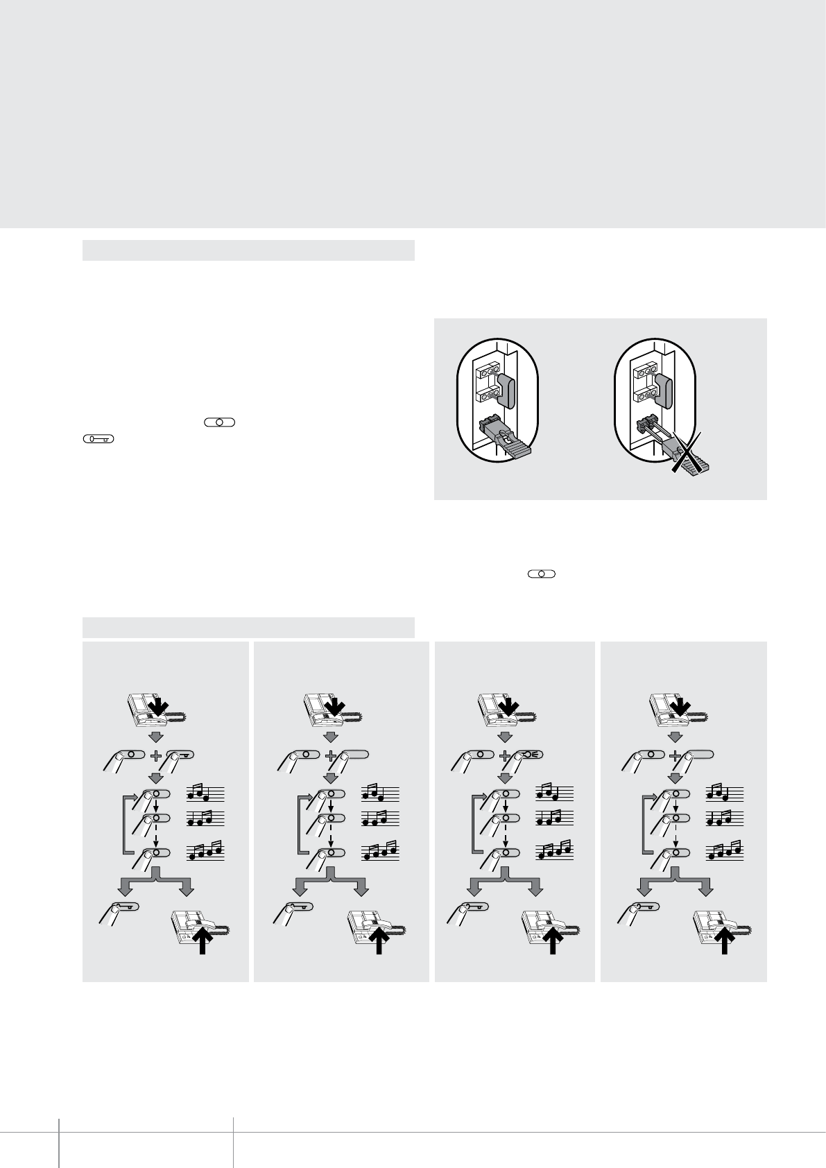
SLAVE
NP
1
MASTER
NP
1
SLAVE
NP
1
MASTER
NP
1
41
1
16
2
RESET
1
16
2
RESET
1
16
2
RESET
1
16
2
RESET
OK
OK OK OK
2
4
3
1
2
4
3
1
2
4
3
1
2
4
3
1
41
1
16
2
RESET
1
16
2
RESET
1
16
2
RESET
1
16
2
RESET
OK
OK
OK OK
2
4
3
1
2
4
3
1
2
4
3
1
2
4
3
1
4
1
1
16
2
RESET
1
16
2
RESET
1
16
2
RESET
1
16
2
RESET
OK OK
OK
OK
2
4
3
1
2
4
3
1
2
4
3
1
2
4
3
1
4
1
1
16
2
RESET
1
16
2
RESET
1
16
2
RESET
1
16
2
RESET
OK OK OK
OK
2
4
3
1
2
4
3
1
2
4
3
1
2
4
3
1
BT00651-a
344102
-EN
TECHNICAL SHEETS
348 2 WIRE VDE system
Conguration
N – handset number
The N congurator assigns each video handset an identication number within the
system. The handsets must be congured in progressive order. The handsets must
be congured in progressive order.Handsets with parallel connection (max 3 are
allowed inside apartments without item 346850) must be congured using the same
N congurator. In parallel with the main video handset, additional handsets, video
handsets and/or bells may be installed.
P – entrance panel association
The P congurator identies the entrance panel associated, or the rst entrance panel to
activate before pressing the key and which door lock is activated when the key
is pressed while the video handset is idle. Connected
jumper
Disconnected
jumper
MASTER – SLAVE selection jumper
In multi-family systems with several video handsets (max. 3) connected in parallel
inside the same apartment (without using item 346850), both the MASTER and the
SLAVE handsets must be set, by connecting or removing the selection jumper.
When a call is received, the MASTER video handset of the system rings and switches on,
while the video handsets congured as SLAVE only rings.
If the call is answered from a SLAVE unit, the MASTER unit switches o again, while the
monitor of the SLAVE unit the call has been answered from comes on.
When a pushbutton of SLAVE unit is pressed before answering, the MASTER
handset monitor switches o, while the monitor of SLAVE on which the pushbutton has
been pressed switches on, but without audio connection.
Bell selection from MAIN ENTRANCE
PANEL (S=0 - S=4)
FLOOR CALL bell selectionBell selection from SECONDARY
ENTRANCE PANEL (S=0 - S=5)
INTERCOM CALL bell selection
Programming of bells
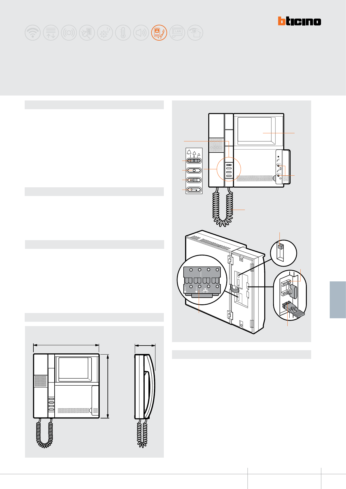
6
5
4
1
2
8
3
7
OFF
ON
5
BUS
1
ET
21
NP
9
10
11
12
344122
68,5 mm
210 mm
210 mm
BT00652-a-EN
TECHNICAL SHEETS
349
2 WIRE VDE system
Dimensional data
Description
2 WIRE PIVOT video handset for wall mounted, ush mounted, or table top installation.
TFT colour 4” at monitor. It has door lock release, staircase light, and entrance panel
activation keys.
The device oers the possibility of selecting among 16 already programmed bells for
oor call, main entrance panel, intercom call, and secondary entrance panel. The call
volume can be set on three levels: high, medium and disabled (this condition is signalled
by a ashing red LED).
It also has a call secrecy function. It is connected to the system using
the removable clamp supplied.
Wall mounting bracket supplied as standard.
Technical data
Power supply from SCS BUS: 18 – 27 Vdc
Stand by absorption: 5 mA
Max. operating absorption: 290 mA
Operating temperature: 5 - 40°C
Related items
item 346812 4 key small block for auxiliary functions - white
item 337122 table-top support - white
NOTE: for ush mounted installation refer to the specic accessories of the MULTIBOX
range.
PIVOT
colour video handset
Legend
1. 4” TFT colour monitor
2. Monitor colour, contrast, and brightness adjustment
3. Extensible cord capped on both ends with RJ connectors
4. Door lock key
5. Staircase light key
6. Entrance panel activation/cycling
7. Electronic call with volume adjustable on 3 levels: high, medium, disabled (the
excluded call is signalled by a ashing red LED)
8. 4-key block housing (optional)
9. Line termination ON/OFF micro-switch
10. Congurator socket
11. MASTER-SLAVE Jumper (remove to enable SLAVE)
12. Plug-in clamp for the connection of the 2 WIRE BUS, additional power supply,
and auxiliary oor call function, as well as extra bell.

SLAVE
NP
1
MASTER
NP
1
SLAVE
NP
1
MASTER
NP
1
41
1
16
2
RESET
1
16
2
RESET
1
16
2
RESET
1
16
2
RESET
OK
OK OK OK
2
4
3
1
2
4
3
1
2
4
3
1
2
4
3
1
41
1
16
2
RESET
1
16
2
RESET
1
16
2
RESET
1
16
2
RESET
OK
OK
OK OK
2
4
3
1
2
4
3
1
2
4
3
1
2
4
3
1
4
1
1
16
2
RESET
1
16
2
RESET
1
16
2
RESET
1
16
2
RESET
OK OK
OK
OK
2
4
3
1
2
4
3
1
2
4
3
1
2
4
3
1
4
1
1
16
2
RESET
1
16
2
RESET
1
16
2
RESET
1
16
2
RESET
OK OK OK
OK
2
4
3
1
2
4
3
1
2
4
3
1
2
4
3
1
BT00652-a
344122
-EN
TECHNICAL SHEETS
350 2 WIRE VDE system
Conguration
N – handset number
The N congurator assigns each video handset an identication number within the
system. The handsets must be congured in progressive order. The handsets must
be congured in progressive order.Handsets with parallel connection (max 3 are
allowed inside apartments without item 346850) must be congured using the same
N congurator. In parallel with the main video handset, additional handsets, video
handsets and/or bells may be installed.
P – entrance panel association
The P congurator identies the entrance panel associated, or the rst entrance panel to
activate before pressing the key and which door lock is activated when the key
is pressed while the video handset is idle. Connected
jumper
Disconnected
jumper
MASTER – SLAVE selection jumper
In multi-family systems with several video handsets (max. 3) connected in parallel
inside the same apartment (without using item 346850), both the MASTER and the
SLAVE handsets must be set, by connecting or removing the selection jumper.
When a call is received, the MASTER video handset of the system rings and switches on,
while the video handsets congured as SLAVE only rings.
If the call is answered from a SLAVE unit, the MASTER unit switches o again, while the
monitor of the SLAVE unit the call has been answered from comes on.
When a pushbutton of SLAVE unit is pressed before answering, the MASTER
handset monitor switches o, while the monitor of SLAVE on which the pushbutton has
been pressed switches on, but without audio connection.
Bell selection from MAIN ENTRANCE
PANEL (S=0 - S=4)
FLOOR CALL bell selectionBell selection from SECONDARY
ENTRANCE PANEL (S=0 - S=5)
INTERCOM CALL bell selection
Programming of bells
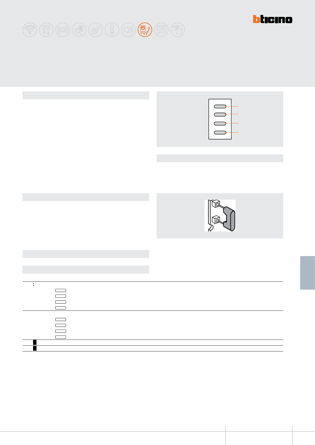
346812
1
2
3
4
1
2
3
4
1
2
3
4
MOD
BT00653-a-EN
TECHNICAL SHEETS
351
2 WIRE VDE system
Description
4 key accessory for handsets item 344032, and video handsets item 344102, 344122, .
It must be installed inside the handset, in the preset location.
It can be used to perform the listed functions, based on the type of conguration set:
- Intercom call among various system devices and apartments (max. 5)
- control of actuators for additional door locks
- control of actuators for general uses and auto-switching on of the entrance panel
- mixed activations
- paging function through the 2 WIRE sound system
- enabling/disabling of home automation scenarios
- apartment intercom in two-family system Legend
1 - Key 1
2 - Key 2
3 - Key 3
4 - Key 4
PIVOT 4 key
handset accessory
Conguration
Conguration
The device must be congured sicamente per stabilirne la operating mode:
M - Operating mode
It sets the operating mode allocated to the individual keys of the accessory block.
The mode changes depending on whether the apartment interface, item 346850, has
been installed or not.
MODE FUNCTION OF KEYS WITHOUT item 346850
FOR MULTI-FAMILY SYSTEMS WITHIN THE APARTMENT WITH item 346850
MOD= Direct switching on of the EPs
Direct switching on of the EPs congured with P+1
Direct switching on of the EPs congured with P+2
Direct switching on of the EPs congured with P+3
Direct switching on of the EPs congured with P+4
Control of the actuator for generic loads (Item 346200)
346200 congured with MOD=9 and P=P+1
346200 congured with MOD=9 and P=P+2
346200 congured with MOD=9 and P=P+3
346200 congured with MOD=9 and P=P+4
MOD= 1 Intercom among the apartment with N-1-5 Intercom among Handsets with N=1-5
MOD= 2 Intercom among apartments with interface item 346850 – N=1-4 Intercom among apartments congured with N=1-4
4
3
2
1
4
3
2
1
Selection of MOD congurators
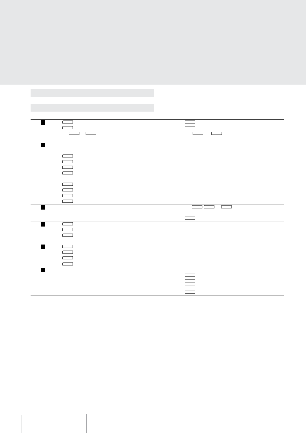
BT00653-a
346812
-EN
TECHNICAL SHEETS
352 2 WIRE VDE system
Conguration
Selection of MOD congurators
MODE FUNCTION OF KEYS WITHOUT item 346850
FOR MULTI-FAMILY SYSTEMS WITHIN THE APARTMENT WITH item 346850
MOD = 3 1 Auto-switching on of EPs congured with P+1 1 Auto-switching on of local entrance panels
2 Door lock control for EPs congured with P+1 2 Door lock control for the local EP (direct mode)
Keys
3
and
4
for intercom among the handsets
Keys 3 and 4 for intercom among the handsets of the
of dierent apartments cong. with N=1-3
apartment congured with N=1-3
MOD = 5 Control of door lock relay with:
Actuator for generic loads (Item 346200)
1 346200 congured with MOD=5 and P=P+1
2 346200 congured with MOD=5 and P=P+2
3 346200 congured with MOD=5 and P=P+3
4 346200 congured with MOD=5 and P=P+4
Door lock actuator (Item 346230 - Item 346260)
1 Actuator congured with P=1
2 Actuator congured with P=2
3 Actuator congured with P=3
4 Actuator congured with P=4
MOD = 6 Keys
1, 2 and 3 for intercom among handsets
congured with N=1 - 4
4 Paging function
MOD = 7 1 Intercom among apart. devices (general call)
(two-family 2 Intercom with devices of other apart. (general call)
installations) 3 Door lock control for EPs cong. with P+1
Door lock control for EPs cong. with P+2
MOD = 7 1 Intercom within the same apartment
(multy-family 2 NOT USED
installations 3 Door lock control for EPs cong. with P+1
cong. with N = 3)
4
Door lock control for EPs cong. with P+2
MOD = 9 Scenario central unit control (Item F420) A=0 and PL=1
1 Activate scenario 1
2 Activate scenario 2
3 Activate scenario 3
4 Activate scenario 4
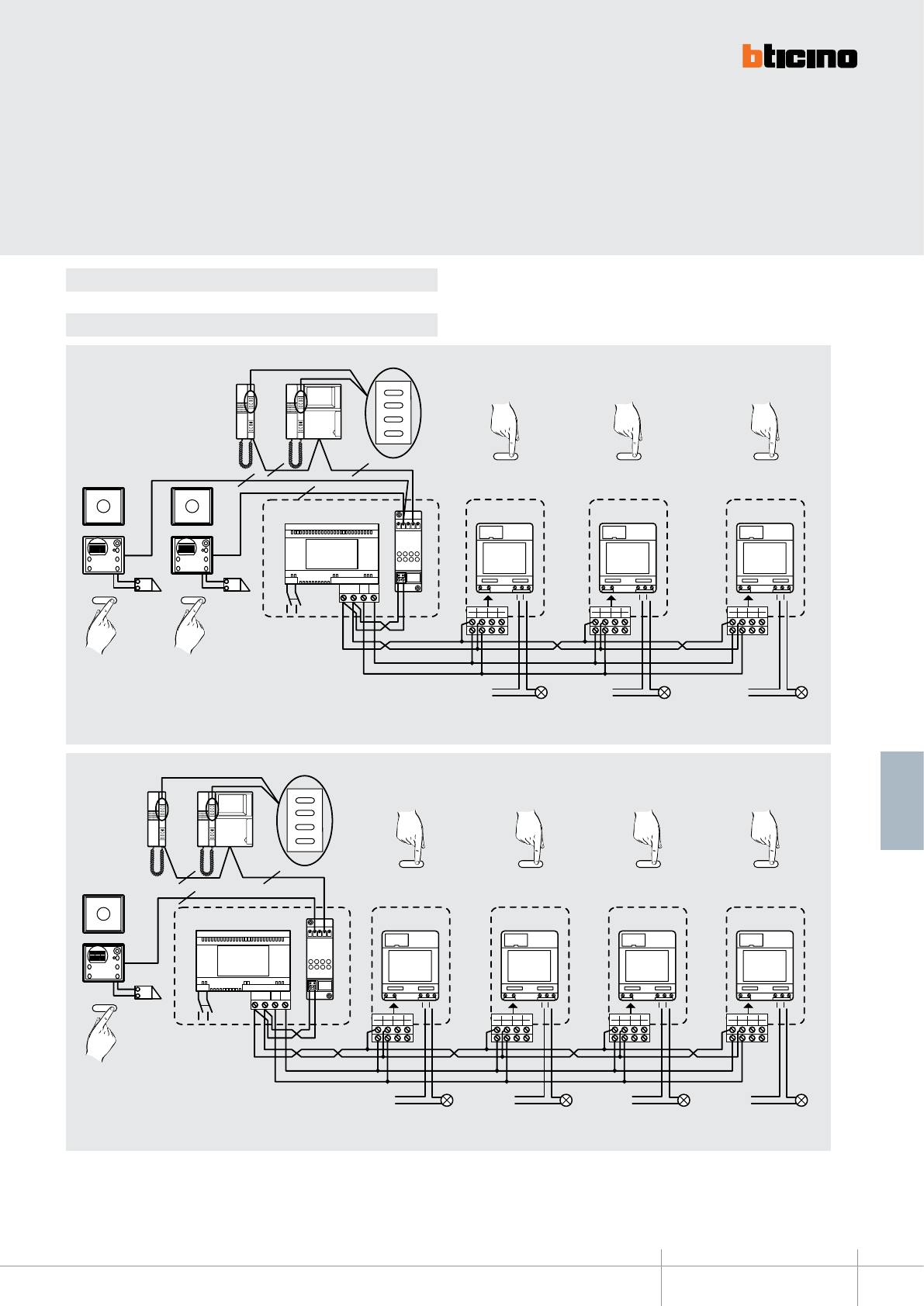
PS
BUS
TK
BUS
PI
2
14
3
6
58
7
NC NO
C
2
2
2
1
2
3
4
O
1
346830
2
14
3
6
58
7
NC NO
C
2
2
14
3
6
58
7
NC NO
C
3
2
14
3
6
58
7
NC NO
C
4
BUS 2 1
346000
230V a. c. 230V a. c. 230V a. c. 230V a. c.
BUS
MOD=0
346200 346200 346200
MOD=9 P=1 MOD=9 P=3 MOD=9 P=4
PE
principale
Alimentatore 346200
MOD=9 P=2
230V a. c.
BUS BUS
230V a. c.
PS
BUS
TK
BUS
PI
2
2
2
1
2
3
4
1346830
2
14
3
6
58
7
NC NO
C
230V a. c.
2
2
14
3
6
58
7
NC NO
C
230V a. c.
3
2
14
3
6
58
7
NC NO
C
230V a. c.
4
BUS 2 1
2
O
346000
BUS
MOD=0
346200 346200 346200
MOD=9 P=2 MOD=9 P=3 MOD=9 P=4
BUS BUS
P=0 P=1
PE
principale
PE
secondario (P+1)
Alimentatore
346812
BT00653-a-EN
TECHNICAL SHEETS
353
2 WIRE VDE system
Conguration
Example 1 - MOD = 0
Activation of general use actuators
Direct auto-switching on of the second entrance panel and activation of general use actuators
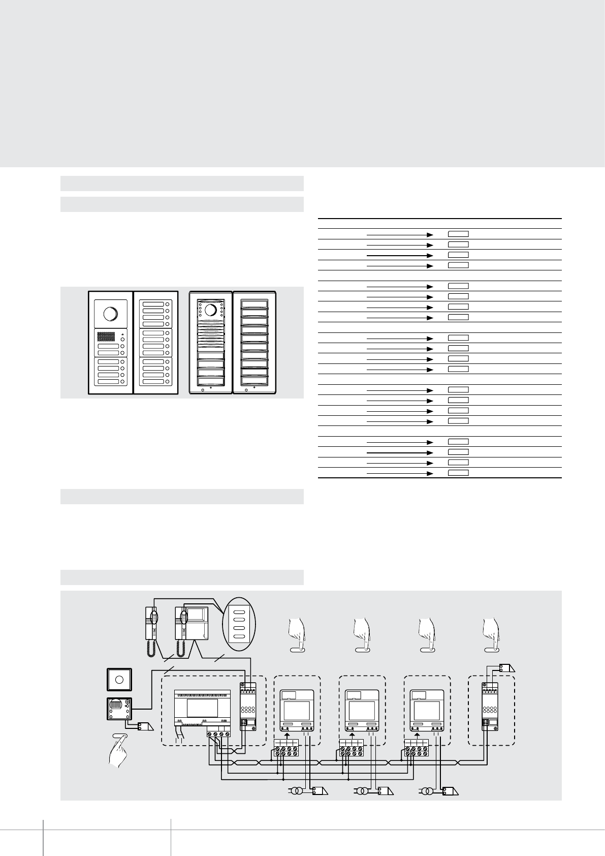
346812
N=5
N=4
N=3
N=2
N=1
N=5
N=4
N=3
N=2
N=1
230V a. c.
PS
BUS
TK
BUS
PI
PS
BUS
TK
BUS
PI
2
14
3
6
58
7
NC NO
C
230V a. c.
2
2
2
1
2
3
4
O
1
346830
2
14
3
6
58
7
NC NO
C
2
2
14
3
6
58
7
NC NO
C
3 4
BUS 2 1
346230
346000
BUS
MOD=5
346200 346200 346200
MOD=5 P=1 MOD=5 P=3 P=4
PE
principale
Alimentatore
BUS BUS
MOD=5 P=2
230V a. c. 230V a. c.
BT00653-a-EN
TECHNICAL SHEETS
354 2 WIRE VDE system
Conguration
Example 2 - MOD = 1
Example 3 - MOD=2
Example 4 - MOD = 5
The handset keys call in succession the handsets congured from 1 to 5 in N, excluding
themselves.
Example: If the call is made from the Handset congured with N=3
- Key 1 calls the handset congured with N=1
- Key 2 calls the handset congured with N=2
- Key 3 calls the handset congured with N=4
- Key 4 calls the handset congured with N=5
In multi-family systems, the use of the accessory item 346812, appropriately
congured (MOD=1) enables intercommunication among up to 5 system users.
Inside the apartment building there may only be one group of up to 5 users that may
be able to use the intercommunicating function. For this purpose, the 5 users of the
intercommunicating function must be entered in the pushbutton panel as shown below.
In multi-family systems with apartment interface item 346850, the item accessory
346812 congured with (MOD=2) allows a maximum of 4 users to intercommunicate
among themselves (intercom external to the apartment).
The handset keys call in succession the apartments congured with N=1 – N=2-
N=3-N=4.
Activation of additional door locks
Handset with N=1 Call to the
Pushbutton 1 1Handset 2
Pushbutton 2 2Handset 3
Pushbutton 3 3Handset 4
Pushbutton 4 4Handset 5
Handset with N=2 Call to the
Pushbutton 1 1Handset 1
Pushbutton 2 2Handset 3
Pushbutton 3 3Handset 4
Pushbutton 4 4Handset 5
Handset with N=3 Call to the
Pushbutton 1 1Handset 1
Pushbutton 2 2Handset 2
Pushbutton 3 3Handset 4
Pushbutton 4 4Handset 5
Handset with N=4 Call to the
Pushbutton 1 1Handset 1
Pushbutton 2 2Handset 2
Pushbutton 3 3Handset 3
Pushbutton 4 4Handset 5
Handset with N=5 Call to the
Pushbutton 1 1Handset 1
Pushbutton 2 2Handset 2
Pushbutton 3 3Handset 3
Pushbutton 4 4Handset 4
Example:
- Key 1 calls the apartment congured with N=1
- Key 2 calls the apartment congured with N=2
- Key 3 calls the apartment congured with N=3
- Key 4 calls the apartment congured with N=4
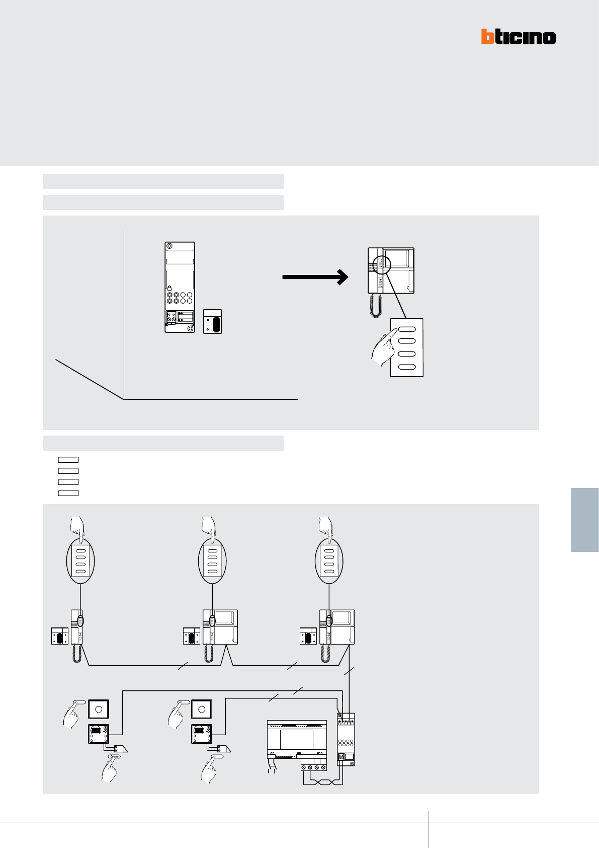
F420
DE L
A
1
PL
1
2
3
4
MOD=9
Scenario 1/16
Scenario 2/16
Scenario 3/16
Scenario 4/16
346812
230V a. c.
PS
BU S
TK
BU S
PI
1
2
3
4
1
2
3
4
2
2
22
2
1
2
3
4
346830
NP
3
NP
2
NP
1
2
1O
BUS 2 1
346000
BUS
MOD=3
P=0 P=1
PE PE (P+1)
Alimentatore
BUS
MOD=3 MOD=3
clack clack
BT00653-a-EN
TECHNICAL SHEETS
355
2 WIRE VDE system
Conguration
Example 5 - MOD = 9
Example 6 - MOD = 3 (mixed mode)
Control of the rst 4 scenarios (1-2-3-4) of the 16 saved in the F420 scenario module.
Auto-switching on of the EP (P+1)
door lock of sec. EP (P+1)
intercom call to N=1
intercom call to N=2
Auto-switching on of the EP (P+1)
door lock of EP (P+1)
intercom call to N=1
intercom call to N=3
Auto-switching on of the EP (P+1)
door lock of EP (P+1)
intercom call to N=2
intercom call to N=3
NOTE: The operating mode of the intercom
function is the same as explained in example 2.
In this case however the intercommunication
is only established among 3 apartment, or 3
handsets for one-family installations.
- Key 1 Auto-switching on of the EP (congured with P+1)
- Key 2 Activation of the door lock of the EP (congured with P+1), directly, without call
- Key 3 Intercom function
- Key 4 Intercom function
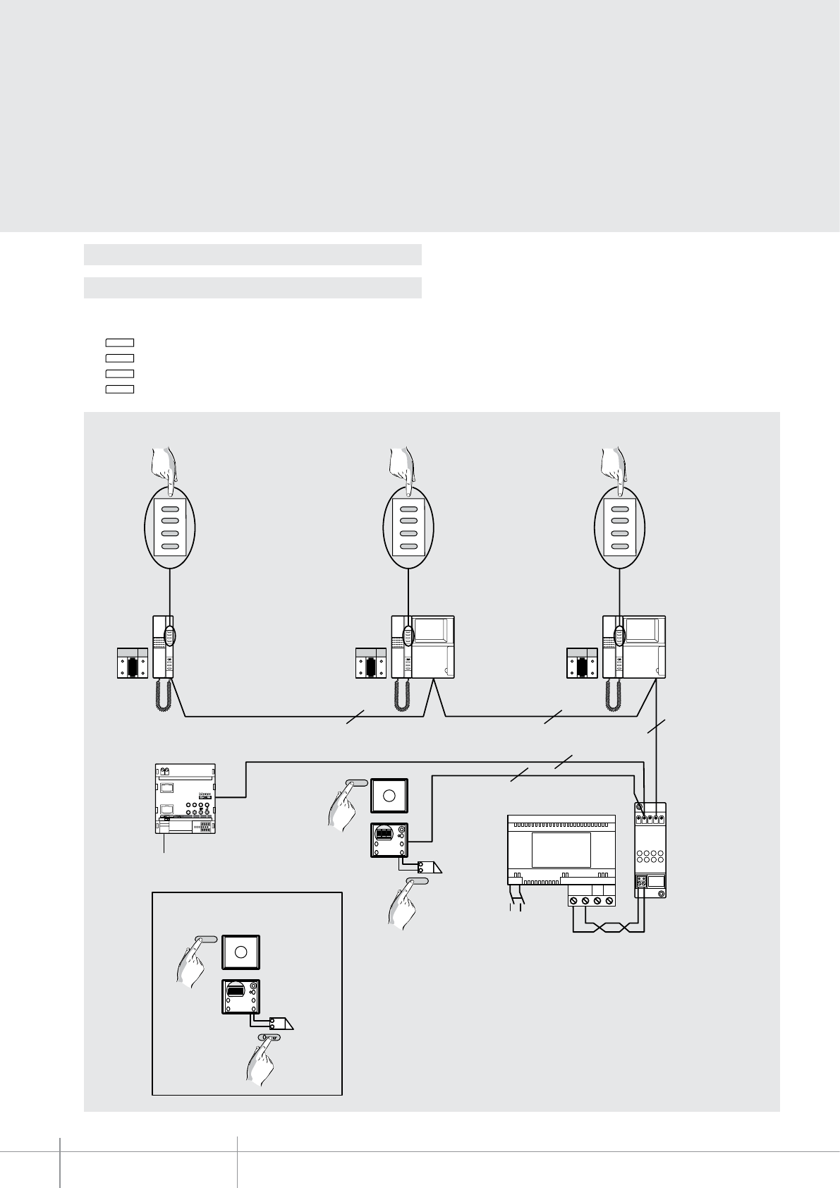
BT00653-a
346812
-EN
TECHNICAL SHEETS
356 2 WIRE VDE system
230 Vac
PS
BU S
TK
BU S
PI
1
2
3
4
1
2
3
4
2
2
22
2
1
2
3
4
346830
NP
3
NP
2
NP
1
2
1
O
BUS 2 1
346000
BUS
MOD=3
P=0
P=1
PE
PE local
Power supply
BUS
MOD=3 MOD=3
clack
clack
ON
346850
IN T
EXT
ON OF F
2 wire
riser
N = 8
M = 3
main
Local
door lock
Auto-switching on of the local EP
door lock of local EP
intercom call to N=1
intercom call to N=2
Auto-switching on of the local EP
door lock of local EP
intercom call to N=1
intercom call to N=3
Auto-switching on of the local EP
door lock of local EP
intercom call to N=2
intercom call to N=3
Apartment 8
Conguration
Example 7 - MOD = 3 (mixed mode) with item 346850
For systems with apartment interface item 346850
- Key 1 Auto-switching on and cycling of local EPs
- Key 2 Activation of the door lock of the local EP directly without call
- Key 3 Intercom function among the apartment handsets
- Key 4 Intercom function among the apartment handsets
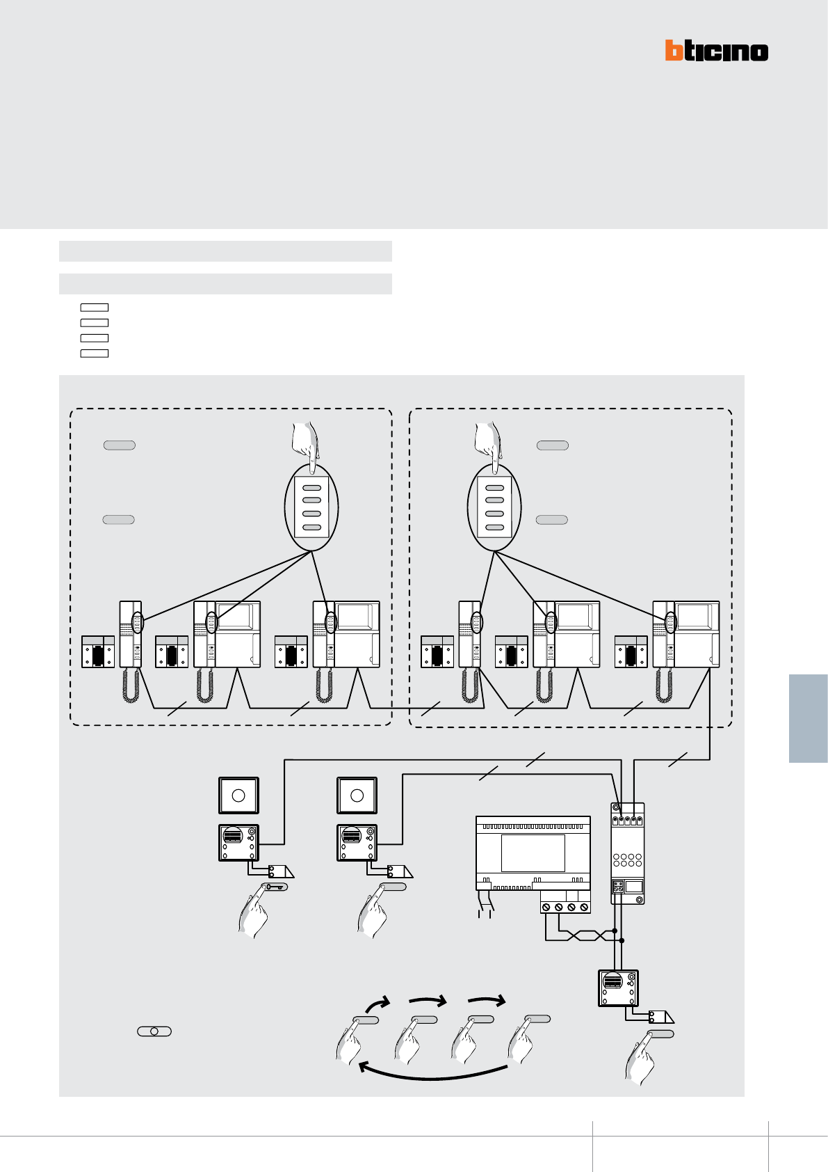
BT00653-a
346812
-EN
TECHNICAL SHEETS
357
2 WIRE VDE system
Conguration
Example 8 - MOD = 7 Intercom in two-family systems
- Key 1 Calls the handsets of the same apartment (the handsets congured with the same N as the one the call is made from)
- Key 2 Calls the handsets of the other apartment (the handsets congured with a dierent N from the one the call is made from)
- Key 3 Opens the door lock associated with the EP congured with P + 1
- Key 4 Opens the door lock associated with the EP congured with P + 2
3
PS
BU S
TK
BU S
PI
230 Vac
1
2
3
4
1
2
3
4
2
2
22
346830
NP
2
NP
2
NP
1
BUS 2 1
346000
BUS
MOD=7
P=0 P=1
PE
main
PE
main (P+1)
Power supply
BUS
MOD=7
NP
1
2
NP
1
Apartment 2
NP
2
Apartment 1
2 2 2
PE
audio (P+2)
P=2
4
OOOO
P=2P=1P=0
NOTE: Maximum 3 devices per apartment.
Press repeatedly for entrance panel cycling.
It calls the handsets (general call)
congured with 2 (other devices
in apartment 2), same apartment
intercom
It calls the handsets (general
call) congured with 1 (devices in
apartment 1), intercom between
apartments
It calls the handsets (general call)
congured with 1 (other devices
in apartment 1), same apartment
intercom
It calls the handsets (general
call) congured with 2 (devices in
apartment 2), intercom between
apartments
1
2
3
4
1
2
3
4
1
2
3
4
1
2
3
4
NOTE: Maximum 3 PIVOT devices per apartment
with MASTER-SLAVE function.
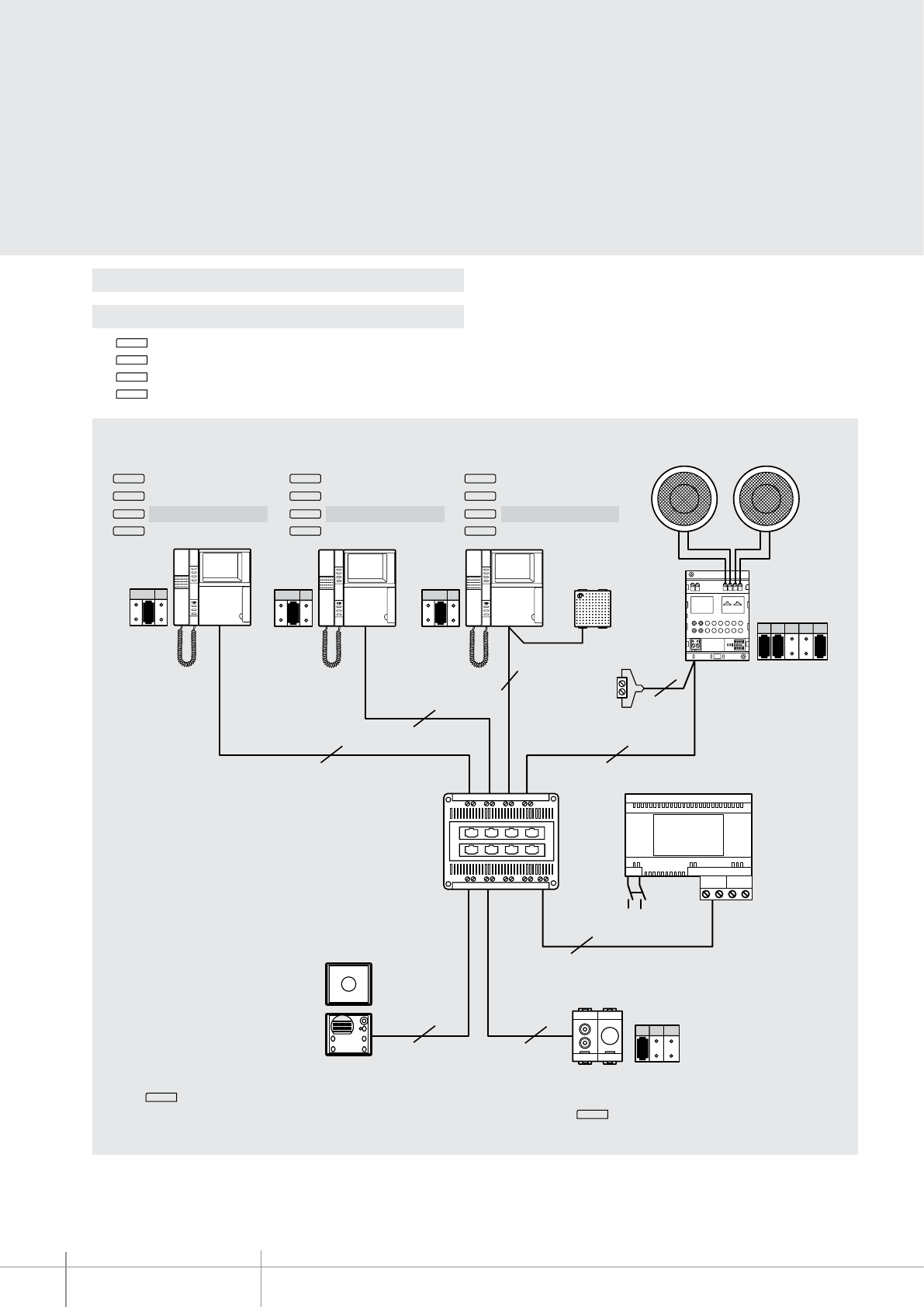
BT00653-a
346812
-EN
TECHNICAL SHEETS
358 2 WIRE VDE system
Conguration
Example 9 - MOD = 6
- Key 1 Intercom
- Key 2 Intercom
- Key 3 Intercom
- Key 4 Paging function using the loudspeakers of the 2 WIRE sound system and melodic bells with M = 1
Press key 4 to communicate with the outside using the loudspeakers of the 2 WIRE sound system and the Melodic bells M = 1.
The “paging” function can be used, for example, for communications inside supermarkets or oces: press key 4 to switch the selected sound source o and activate the
audio on the loudspeakers. Once the handset has been replaced the sound source comes on again.
230 Vac
2
NP
3
MOD=7
P=0
PE
main
NP
2
2
346000
BUS 2 1
F441
2
NP
1
SCS
OUT 1
OUT
OUT2 OUT3 OUT4
IN
IN 1 IN 2 IN 3 IN 4
2 2
2
SM2
1
M1
APF M1 M2 M3
103
2
2
Celing mounted loudspeakers L4566
DIN amplier
F502
Intercom call N = 2
Intercom call N = 3
Intercom call N = 4
Paging
Intercom call N = 1
Intercom call N = 3
Intercom call N = 4
Paging
Intercom call N = 1
Intercom call N = 2
Intercom call N = 4
Paging
RCA input L4560
3499
M = 1
4
3
2
1
4
3
2
1
4
3
2
1
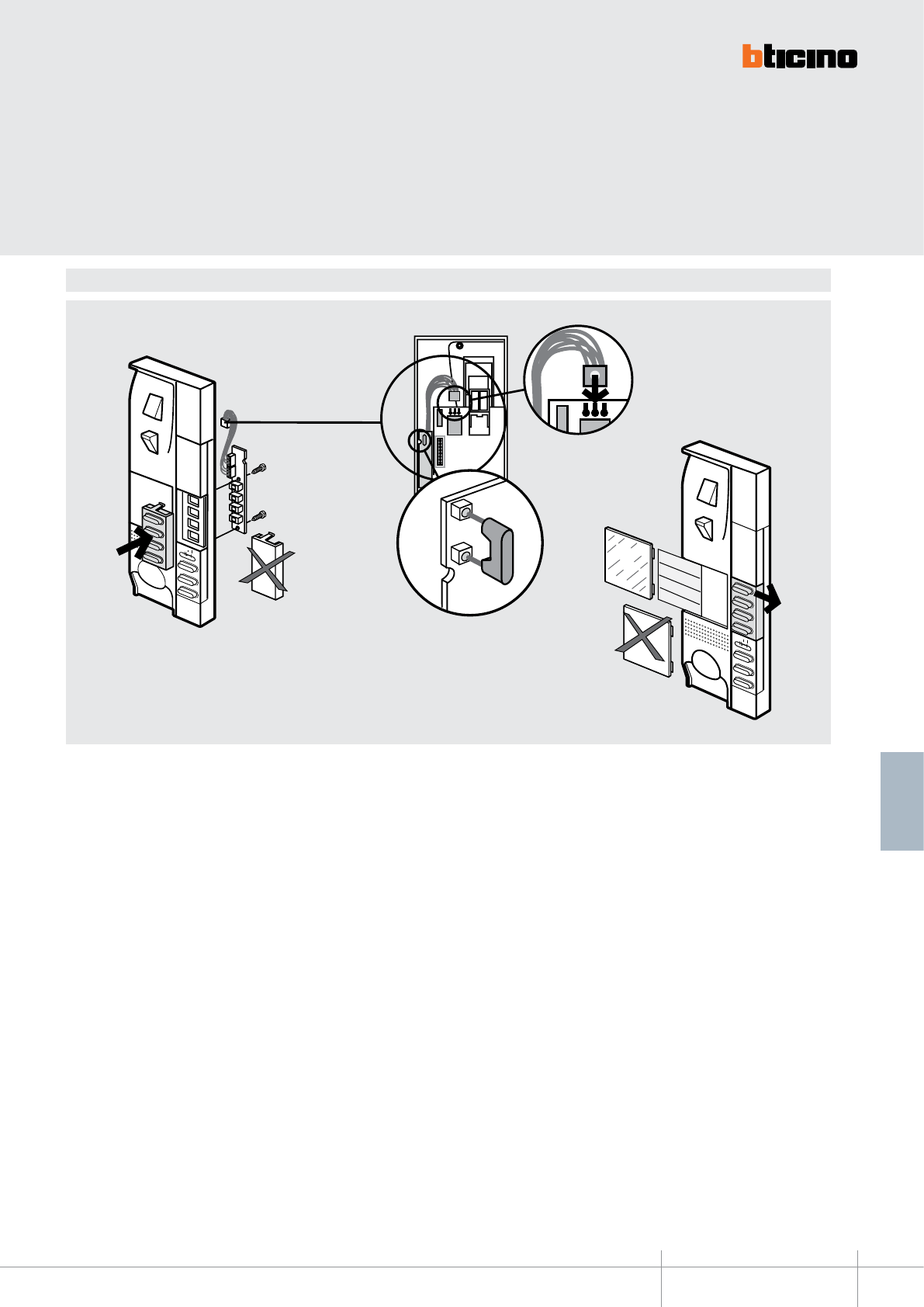
02'
BT00653-a
346812
-EN
TECHNICAL SHEETS
359
2 WIRE VDE system
Assembly, Installation
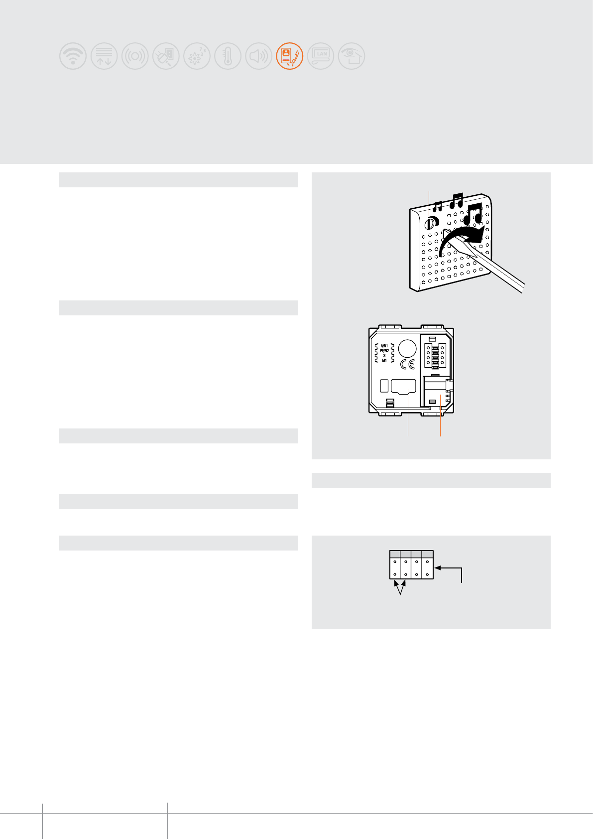
N1 N2
SM
C
L
A
C
K
C
L
A
C
K
3 2
1
BT00654-a
349412-349413-346982-346983-346984
-EN
TECHNICAL SHEETS
360 2 WIRE VDE system
Description
Flush mounted 2 WIRE melodic bell.
It’s used (in the same way as an intercom handset) as a call repeater or pager. It includes
a potentiometer on the front for the adjustment of the bell volume. It can be connected
to the PC (using a serial connection) for the selection of the melody.
The bell has the same absorption of a handset with extra bell. It is therefore possible to
install systems with maximum 3 devices (handsets, video handsets and bells) within the
same apartment; (max 5 for one-family systems).
The bell programming software (TiRing) may be downloaded from the www.bticino.it
website free of charge.
Related items
3559 (serial interface for connection to the PC)
3499 (line termination), use if the device is the last device of the line
F422 (SCS/SCS gateway), use in systems integrated with the burglar-alarm system to
receive burglar-alarm, tampering, and auxiliary notications.
The device must be completed with the accessories and the front cover plates of the
AXOLUTE, LIVINGLIGHT, LIGHT TECH residential series.
Refer to the corresponding catalogues.
Technical data
Power supply from SCS BUS: 18 - 27 Vdc
Stand-by absorption: 10 mA
Max. operating absorption: 100 mA
Operating temperature: 5 - 40°C
Dimensional data
2 DIN modules
Legend
1 - Loudspeaker volume adjustment
2 - Congurator socket
3 - Socket for the connection of the PC serial connector
Conguration
The device must be physically congured in terms of:
N1 - N2 = address of the bell within the system
congure with the same address of an apartment handset.
S = NOT USED
M = Operating mode
M = 0 - operation as extra bell
M = 1 - operation as pager
Melodic bells
bell address
operating mode
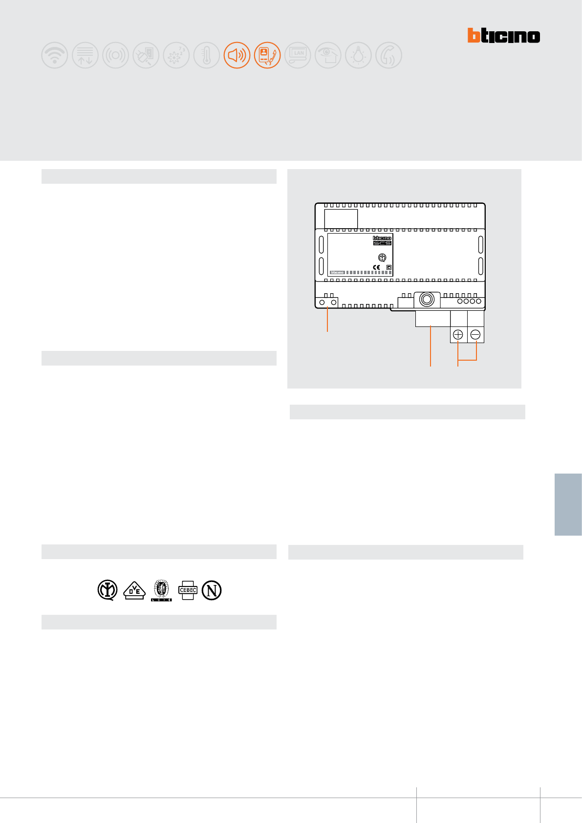
346000
21
BUS
346000
12
3
BT00655-a-EN
TECHNICAL SHEETS
361
2 WIRE VDE system
Description
2 wire system power supply unit, to be used in audio systems together with 2 wire
speaker modules, or with the universal speaker unit, item 346991, for the installation
of systems with up to 100 entrance panels (56 when item 346991 is used), as well as
in video or mixed audio/video systems, when using video adapter item 346830, or
the audio/video node item F441, or the multichannel matrix F441M. The device is
also suitable as a power supply for sound systems. Additionally, it can also be used
as supplementary power supply (output 1 – 2) for local supply to advanced preset
handsets. It must be powered at 230 Vac. On the output it provides two power supply
outlets, which can be used in alternative to each other, but not both at the same time
(27Vdc 1.2 A BUS clamps, and 1-2 27Vdc 1.2 A clamps). It is electronically protected
(without fuse) from short-circuit and overload.
It is a double insulation safety device in accordance with CEI.
The power supply unit is inside a 8 DIN modules rail enclosure, and its installation must
be in accordance with the regulations of the country of use.
The device must not be congured.
Dati tecnici
PRI (Power supply Vac input):
Rated voltage: 220 – 240 Vac
Rated current: 230 – 250 mA
Working voltage range: 207 – 253 Vac
Working frequency range: 50 – 60 Hz
Input power at full load: 44.9 W (max)
Dissipated power: 11.5 W (max)
Input power without load: 4.2 W (max)
Operating temperature: 5 – 40 °C
Protection index: IP30
SEC (Vdc output):
Rated voltage (BUS): 27 Vdc +/- 0,1 Vdc
Rated voltage (1-2): 27 Vdc +/- 0.1 Vdc (1=** - 2=**)
Rated current: 0 – 1.2 A
Rated power: 32.4 W
Legenda
1. Output connection clamps 1=GND – 2=+27Vdc
2. SCS/BUS output connection clamps
3. 230 Vac input connection clamps
Assembly, Installation
Comply with the following installation requirements:
- The power supply must always be installed in appropriate enclosures.
- It must be kept away from water drips and sprays.
- Do not to obstruct the air vents.
- A double-pole thermal magnetic circuit breaker with contact separation of at least
3 mm must be used, positioned near the power supply. The circuit breaker is used
both to disconnect the power supply from the electric network, and to protect it.
230 V A/V SCS/BUS power supply
Standards, Certications, Marks
Standards: CEI EN60065 - CEI 64-8-4 (punto 411.1.2.5)
Marks obtained :
Dimensional data
8 DIN modules
Front view
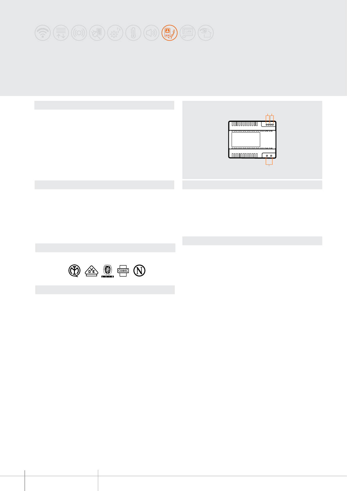
BT00656-a
3
1 2
346010
-EN
TECHNICAL SHEETS
362 2 WIRE VDE system
Description
2-WIRE system power supply to be used in audio systems with audio modules or
universal speaker unit, item 346991, for the installation of systems with up to 26
handsets.
On the output it supplies 27 Vdc continuous low voltage, with a maximum current of
250 mA. It’s electronically protected (without fuses) againstshort circuit and overload.
It is a double insulation safety device.
The power supply unit is inside a 6 DIN modules rail enclosure, and its installation must
be in accordance with the regulations of the country of use.
The device must not be congured.
Standards, Certications, Marks
Standards: CEI EN60065
Marks obtained:
Technical data
Power supply: 230 Vac +/- 10% @ 50/60 Hz
Output voltage of the BUS clamps: 24 Vdc - 250 mA
Output voltage of the 1-2 clamps: 12 Vac - 1A
Max. dissipated power: 11 W
Input power without load : 3.5 W (max)
Operating temperature: 5 – 40 °C
Protection index: IP30
Dimensional data
6 DIN modules
Legend
1 - Output connection clamps (12 Vac)
2 - BUS output connection clamps (24 Vdc - 250 mA)
3 - 230 Vac input connection clamps
Assembly, Installation
Comply with the following installation requirements:
- The power supply must always be installed in appropriate enclosures.
- It must be kept away from water drips and sprays.
- Do not to obstruct the air vents.
- A double-pole thermal magnetic circuit breaker with contact separation of at least
3 mm must be used, positioned near the power supply. The circuit breaker is used both
to disconnect the power supply from the electric network, and to protect it.
Audio power supply 230 V
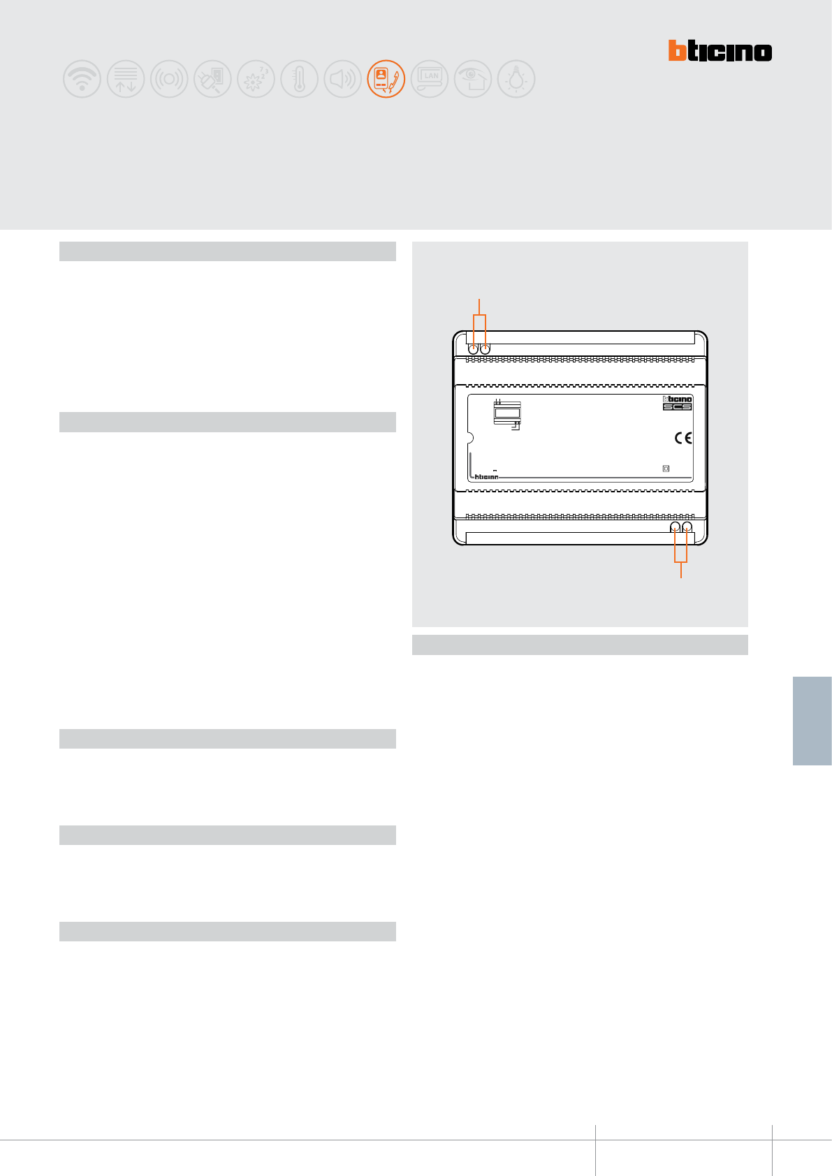
BT00657-a
346040
346040
PRI 110 - 240 V 50 - 60 Hz 370 mA - 225 mA
BUS 26.0 V 600 mA BUS
PRI PRI
BUS
1
2
-EN
TECHNICAL SHEETS
363
2 WIRE VDE system
110 – 240 V Audio power supply
Description
2 WIRE audio system power supply with 6 DIN modular housing.
Power supply 110 – 240 Vac @ 50 – 60 Hz. The output provides 26 Vdc continuous low
voltage, with maximum current of 600 mA. It is electronically protected against overload
and short circuit by means of an integrated fuse (NOT REPLACEABLE). It’s a SELV double
insulation safety device. Operating temperature 5 – 45 °C. The device must be installed
in compliance with current regulations.
Legend
1. Input connection clamps 110 – 240 Vac
2. Output connection clamps BUS 26 V (0 – 600 mA)
Technical data
PRI (AC power supply input):
Rated voltage: 110 – 240 Vac
Rated current: 370 – 225 mA
Working voltage range: 100 – 265 V
Working frequency range: 47 – 63 Hz
Input power at full load: 20.5 W
Dissipated power: 4.9 W (max.)
Performance at full load: 80 % (typ.)
Power in stand by: < 1 W
Operating temperature: 5 – 45 °C
Integrated fuse (PRI side): F1 T2A 250 V (CANNOT BE REPLACED)
BUS (DC output)
Rated voltage: 26 V
Rated current: 0 – 0,6 A
Rated power: 15.6 W
Standards, Certifications, Marks
Standards: CEI EN60950 - CEI 64-8-4 (point 411.1.2.5)
Dimensional data
Size: 6 DIN modules
Installation
Comply with the following installation requirements:
- The power supply MUST always be installed in appropriate enclosures.
- IT MUST BE KEPT AWAY from water drips and sprays.
- DO NOT to obstruct the air vents.
- A double-pole thermal magnetic circuit breaker with contact separation of at least
3 mm MUST be used, positioned near the power supply. The circuit breaker is used both
to disconnect the power supply from the electric network, and to protect it.
Front view
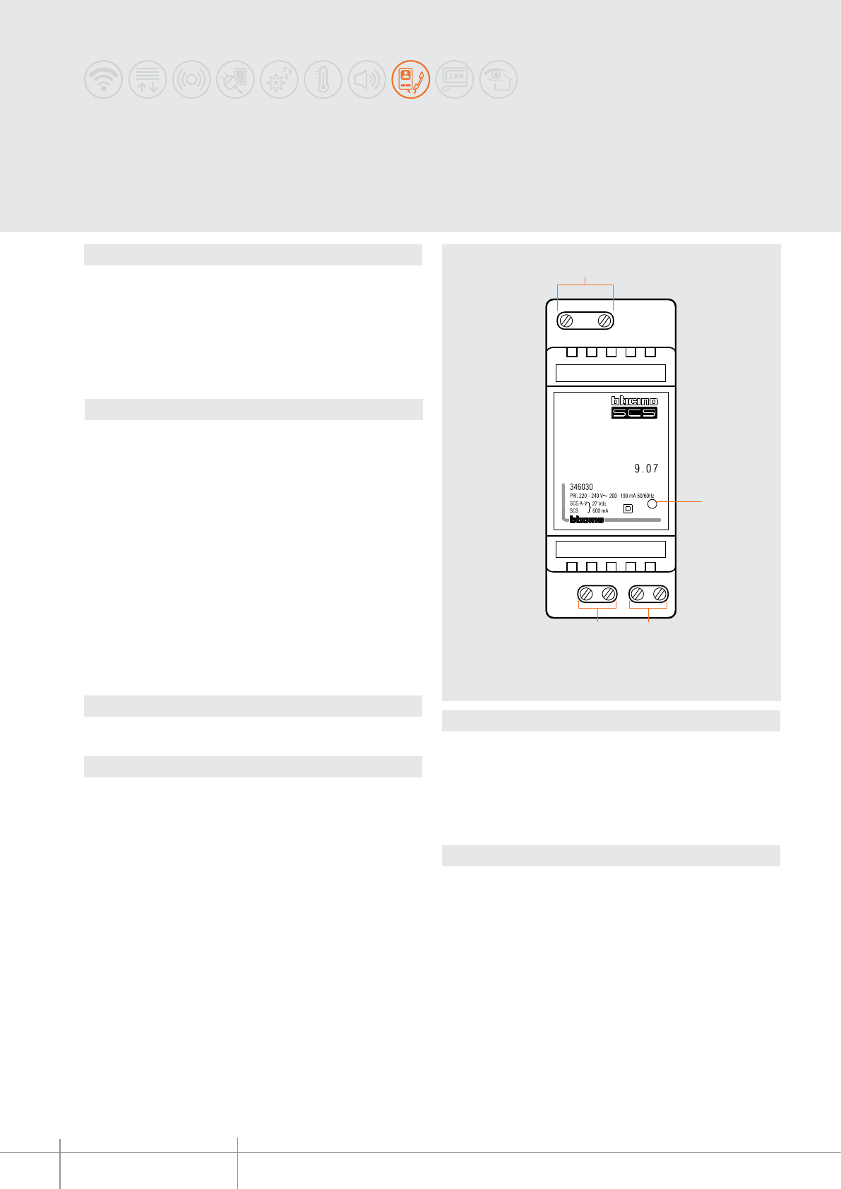
346030
BT00658-a
PRI
SCS A-V SCS
1
34
2
-EN
TECHNICAL SHEETS
364 2 WIRE VDE system
Description
2 DIN module device for:
- basic video door entry systems (e.g. apartment intercom)
- mini SOUND SYSTEMS (absorption up to 600 mA).
It is a double insulation safety device.
The power supply is inside a module plastic rail enclosure, and its installation must be in
accordance with the regulations of the country of use.
The device must not be congured.
Standards, Certications, Marks
Standards: CEI EN60065 - CEI 64-8-4
Technical data
PRI (AC power supply input):
Rated voltage: 220 – 240 Vac
Rated current: 200 - 190 mA
Working voltage range: 187 – 265 V
Working frequency range: 47 – 63 Hz
Input power at full load: 21.5 W max
Dissipated power: 5.3 W (max.)
Performance at full load: 80% typ.
Power in stand by: < 1 W
Operating temperature: 5 – 40 °C
Integrated fuse (PRI side): F1 T2A 250V (CANNOT BE REPLACED)
SCS A-V; SCS:
Rated voltage: 27 V +/- 100 mV
Rated current: 0 – 0.6 A
Rated power: 16.2 W
Dimensional data
2 DIN modules
Legend
1 - 230 Vac input connection clamps 50-60 Hz
2 - Operating status notication LEDs:
(GREEN ON) - normal operation of the power supply
(RED ON) - output current overload
3 - SCS output connection clamps (BUS 27V)
4 - SCS AV output connection clamps (27 V)
Assembly, Installation
Comply with the following installation requirements:
- The power supply must always be installed in appropriate enclosures.
- It must be kept away from water drips and sprays.
- Do not to obstruct the air vents.
- A double-pole thermal magnetic circuit breaker with contact separation of at least
3mm must be used, positioned near the power supply. The circuit breaker is used both
to disconnect the power supply from the electric network, and to protect it.
Compact power supply 230 V
WARNING : THE (SCS - AV) AND (SCS) OUTPUTS CAN BE USED AT THE
SAME TIME IN RESPECT TO THE MAXIMUM CURRENT ABSORPTION OF
600 mA
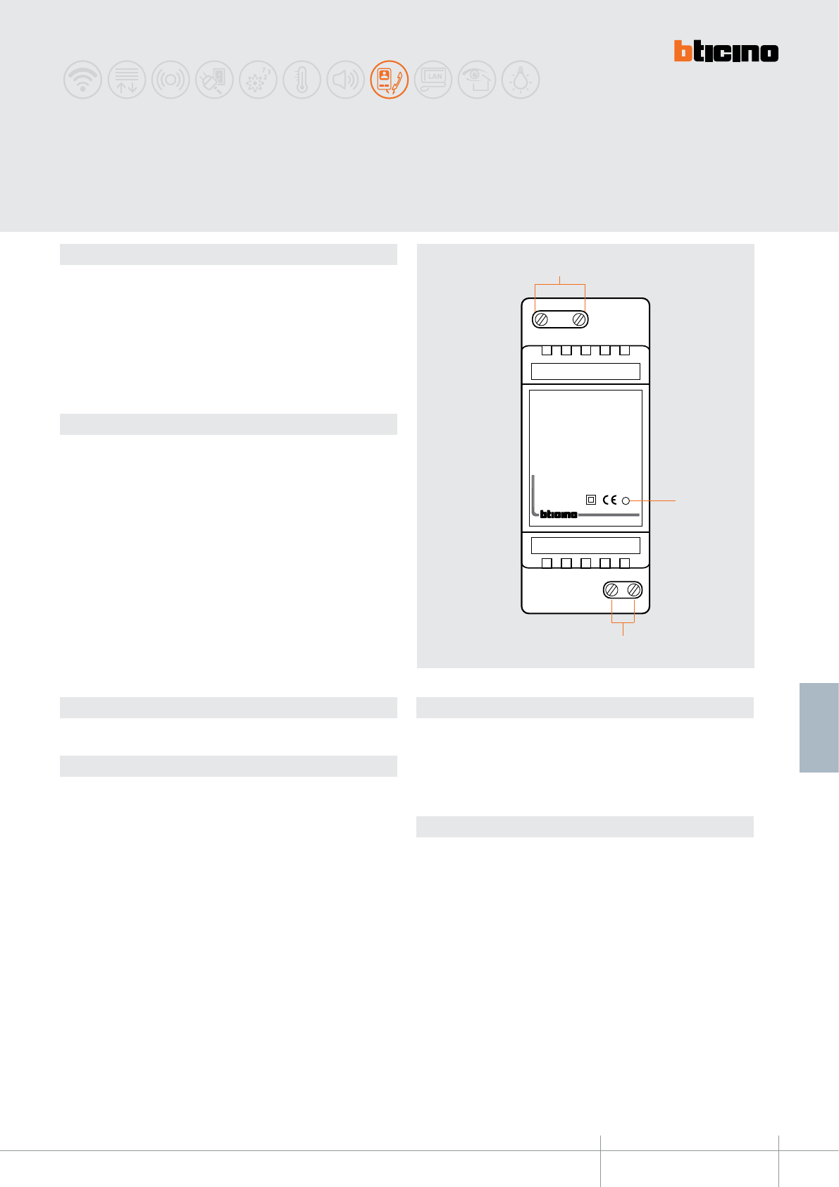
PR I
1- 2
346020
PRI: 220 - 240V~
175-165mA
50/60Hz
1-2: 27Vdc
600mA
1
3
2
346020
BT00659-a-EN
TECHNICAL SHEETS
365
2 WIRE VDE system
Description
2 DIN module devices which allows to:
- locally supply the single video door entry handsets and entrance panels.
- supply some accessories of the Communication and MY HOME catalogues (ex: Web
server, A/V server, scenario programmers, 2 WIRE/IP interface, switch 10/100, ADSL
modem router, Hub-TV and SCS modulator).
It is a double insulation safety device in accordance with CEI.
The power supply is enclosed by a 2 DIN module plastic rail enclosure, and its installation
must be in accordance with the regulations of the country of use.
The device must not be congured.
Standards, Certications, Marks
Standards: CEI EN60065
Technical data
PRI (AC power supply input)
Rated voltage: 220 – 240 Vac
Rated current: 180 – 190 mA
Working voltage range: 187 – 265 V
Working frequency range: 47 – 63 Hz
Input power at full load: 20 W max
Dissipated power: 3.8 W (max.)
Performance at full load: 80% typ.
Power in stand by: < 1 W
Operating temperature: 5 – 40 °C
Integrated fuse (PRI side): F1 T2A 250V (CANNOT BE REPLACED)
1 - 2 (DC output):
Rated voltage: 27 V +/- 100 mV
Rated current: 0 – 0.6 A
Rated power: 16.2 W
Dimensional data
2 DIN modules
Legend
1 - 230 Vac input connection clamps
2 - Operating status notication LEDs:
(GREEN ON) – normal operation of the power supply
(RED ON) – output current overload
3 - Output 1 – 2 connection clamps
Assembly, Installation
Comply with the following installation requirements:
- The power supply must always be installed in appropriate enclosures
- It must be kept away from water drips and sprays.
- Do not to obstruct the air vents.
- A double-pole thermal magnetic circuit breaker with contact separation of at least 3
mm must be used, positioned near the power supply. The circuit breaker is used to
disconnect the power supply from the mains, and to protect it.
Additional power supply
230 V

336904
BT00660-a-EN
TECHNICAL SHEETS
366 2 WIRE VDE system
Description
This cable is used for the distribution of the power supplies and the operating signals to
all BUS system devices.
The cable consists of a white external sheathing and two twisted exible conductors
with a section of 0.5 mm2, one brown and one brown/white.
The cable is sold in 200 m coils.
It is thus suitable to be used:
- in the open air, inside trunkings, passage-ways and pipes
- inside walls with suitable pipes.
- laid underground by means of suitable pipes
The white SCS-BUS cable is suitable for underground installation
Standards, Certications, Marks
Reference standards: - It complies with the tests required by the following standards:
EN60811, EN50289, EN50290, EN60228, EN50265-2-1, EN50395, EN50396 as described
in the IMQ CPT 062 document.
Marks obtained:
Technical data
Insulation voltage: 450/750 V
Can be buried: YES (see installation notes)
External sheath colour: white (RAL 9010)
External sheath diameter: 5.0 +/- 0.1 mm
External sheath thickness: 0.7 mm
External sheath material: PVC (RZ)
Number of internal conductors: 2 unshielded twisted exible conductors with
sheath
Colour of internal conductors: brown – brown/white
Sheath thickness of internal conductors: 0.40 mm
Sheath diameter of internal conductors: 1.70 mm
Sheath material of internal conductors: XLPE polyethylene
Conductor material: red electrolytic copper
Conductor section: 0.50 mm2 (16 x 0.20 mm2)
Operating temperature: (-15) – (+70) °C
Coil length: 200 m
Installation notes
Underground cable installation
The 336904 BUS SCS cable can be installed underground (protected using appropriate
piping), together with other signalling cables, provided the voltage is <50V.
It is however strictly forbidden to install the 336904 cable in the same conduit as power
supply cables with voltages >50V. Failure to comply with the installation requirements
will relieve BTicino of all responsibilities for the operation of the system installed.
Installation together with other cables
Although the construction of the white cable guarantees the necessary electrical
insulation level for installation together with 450/750 V system cables, it is however
not capable of guaranteeing immunity from any electromagnetic disturbances that may
occur when installed in the same conduits used for the power supply cables.
It is therefore strongly recommended that the white BUS/SCS cable and the power
supply cables are installed in separate conduits.
A/V SCS/BUS cable (white)
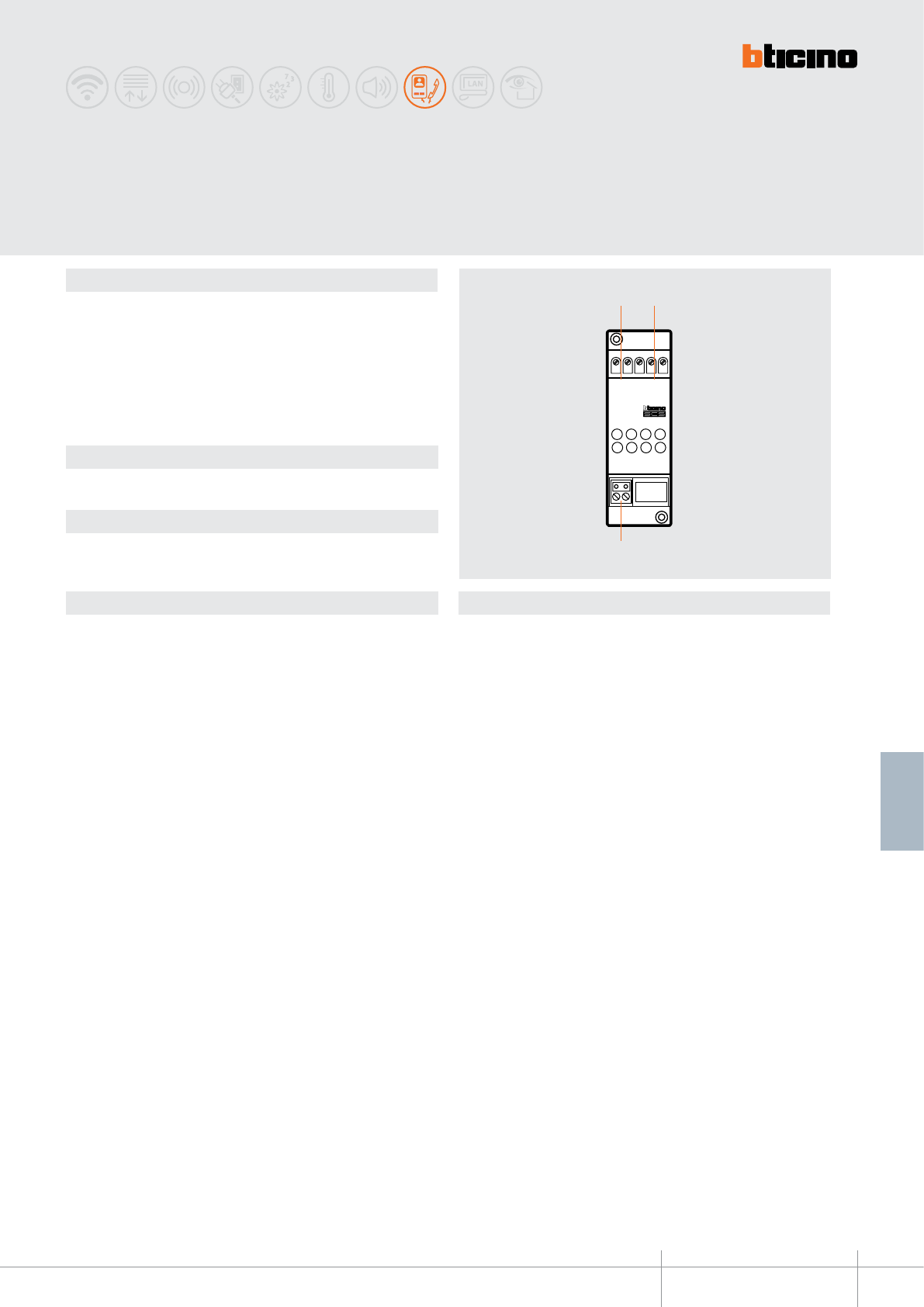
BUS
PI
BUS
TK
PS
3
1 2
346830
BT00661-a-EN
TECHNICAL SHEETS
367
2 WIRE VDE system
Description
2 WIRES video adapter that must be used wih the power supply item 346000 in the
installation of video systems (or audio/video combined), video door entry systems and
sound systems.
Allows the connection to its 3 BUS clamps. Hence it is possible to realize installations
with 2 video entrance panels and 1 riser and installations with 1 video entrance panel
and 2 risers.
The device must be installed next to the system power supply item 346000.
The device must not be congured.
Legend
1 - BUS TK output towards the EP (xed clamp entrance panels)
2 - BUS output towards the handsets (xed clamp handsets)
3 - BUS PS input from the power supply (removable clamp)
Video adapter
Related items
346000 (2 WIRE system power supply)
Technical data
Dimensional data
Power supply from SCS BUS: 18 - 27 Vdc
Operating temperature: 5 - 40°C
2 DIN modules.
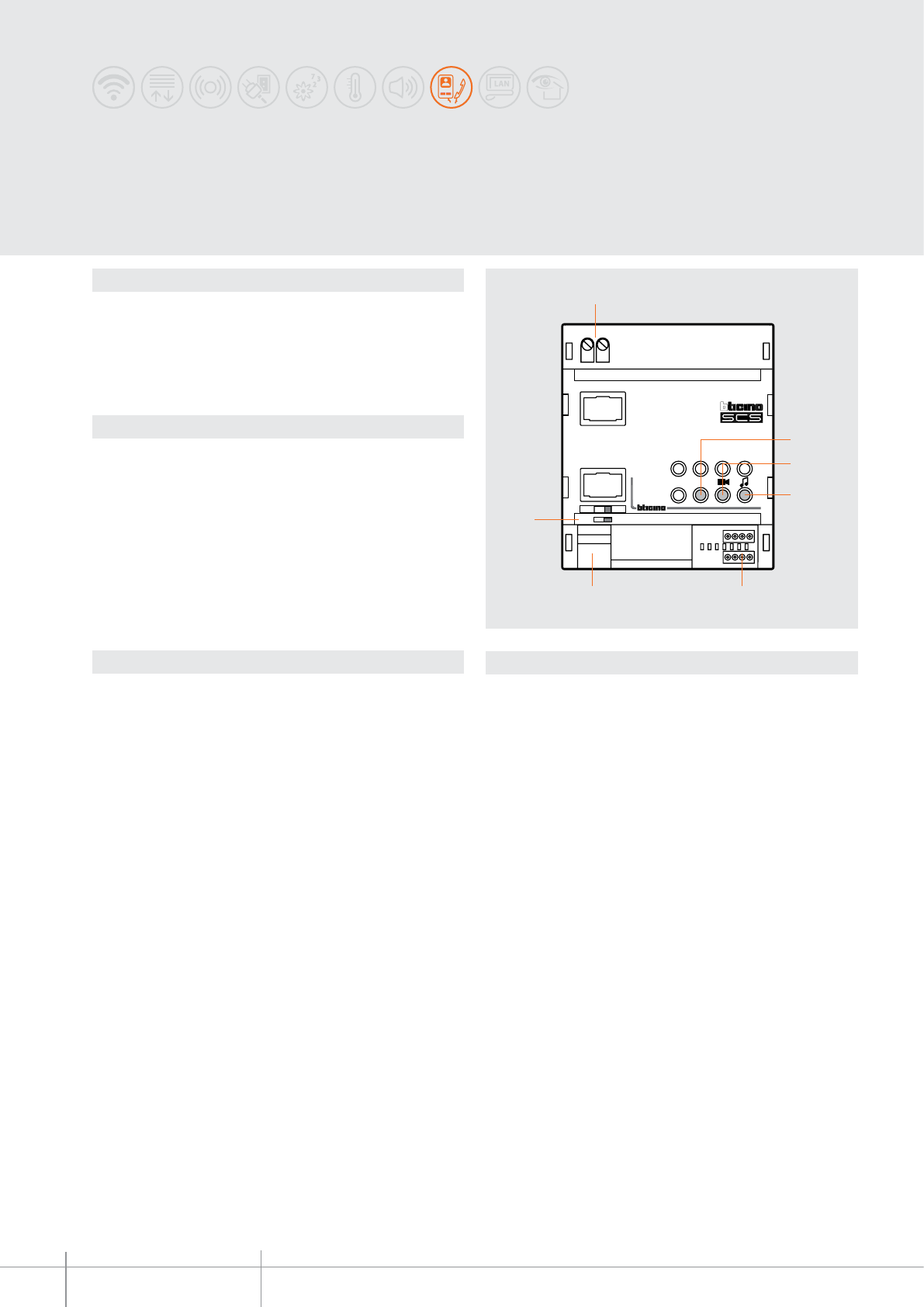
ON
346850
INT
EXT
ON OFF
1
6 5
7
4
3
2
346850
BT00662-a-EN
TECHNICAL SHEETS
368 2 WIRE VDE system
Description
Interface to be used to install a dedicated 2-wire system inside the home, isolated from
the riser.
The system downstream the interface may include local CCTV, sound system, and MY
HOME applications control.
It can be used for calls within the building, as well as outside calls.
Legend
1 - Clamp for the connection of the apartment 2 WIRE system
2 - Interface status notication LED:
Flashing green LED = STAND BY
Fixed green LED = EXT-INT connection active
3 - Video signal status notication LED:
Green LED = OK
Green/red LED = operation close to the limit
Red LED = no video signal or limits exceeded
4 - Not used
5 - Congurator socket: N = interface address, M = 3 (connected at the factory)
6 - Clamp for the connection to the 2 WIRE riser
7 - Line termination ON/OFF micro-switch
Apartment interface
Technical data
Dimensional data
Power supply from SCS BUS: 18 – 27 Vdc
Operating temperature: 5 - 40°C
Dissipated power: 2.25 W
Stand by absorption:
from the INT 15 mA connection
from the EXT 5 mA connection
Maximum absorption in funzionamento :
from the INT 50 mA connection
from the EXT 30 mA connection
4 DIN modules
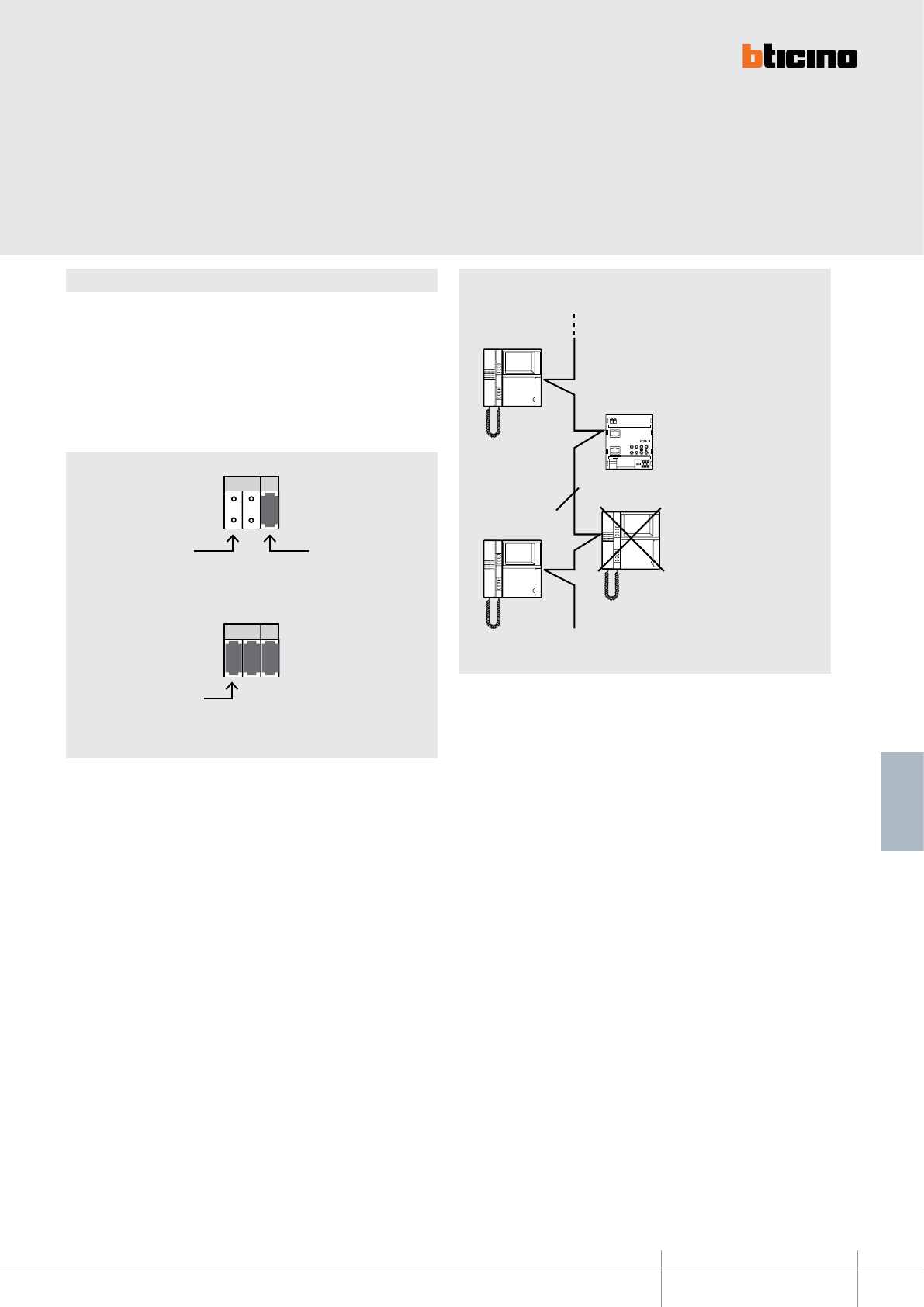
3
31 2
N M
N M
3
31 2
N M
N M
ON
346850
IN T
EXT
ON OF F
2
NO
346850
BT00662-a-EN
TECHNICAL SHEETS
369
2 WIRE VDE system
The device must be physically congured in terms of:
N = device ID number
The congurator assigns to the interface a unique handset number inside the system.
M = Operating mode
factory conguration with 3
system identication
number on the
handsets side
operating mode
the interface must
be considered as
handset number 12
Example of conguration
2 WIRE riser No handset within the system can be
congured with N = 12
N = 12
N = 1
Conguration
Installation
example
N = 13
N = 12
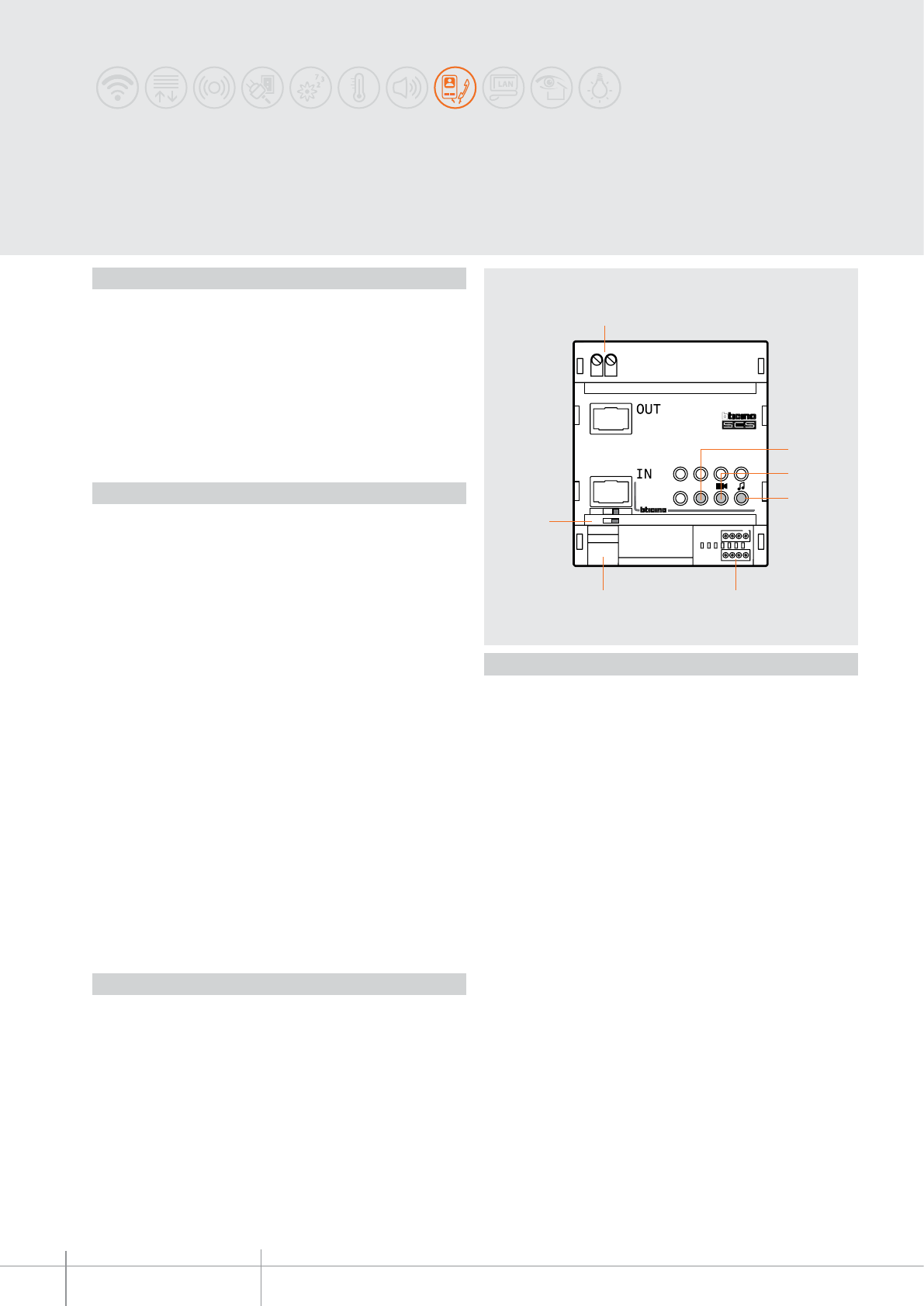
BT00663-a
ON
346851
ON
OFF
1
6 5
7
4
3
2
346851
*
-EN
TECHNICAL SHEETS
370 2 WIRE VDE system
System expansion
interface
Description
Interface in DIN modular enclosure, used to increase the performance of the 2 WIRE
system in one-family or apartment installations. It enables creating 2 WIRE risers with
entrance panels at the bottom of the stairs, independent audio and video, as well as
providing expansion for: regeneration of the video signal and extension of distances for
a further 200 meters (cable item 336904 required), increase of the number of devices
that can be connected to the BUS, and use of up to a maximum of 3 interface modules
connected in cascade.
Legend
1. OUT clamps for the connection of the output SCS BUS
2. Interface status notification LED:
- green flashing = STAND BY
- green steady = IN - OUT connection active
3. Video signal level notification LED:
- green steady = operation OK
- green / red = operation nearing the limit
- red steady = no video signal or limit exceeded
4. Presetting - NOT USED
5. Configurator socket - the socket marked with the asterisk * is NOT USED
6. SCS/BUS IN connection clamps
7. Line termination ON/OFF micro-switch
Technical data
Power supply from SCS BUS: 18 – 27 Vdc
Dissipated power: 2.25 W (max)
Operating temperature: 5 – 40°C
Absorption:
IN clamp (configuration MOD = 0)
Stand by absorption: 30 mA
Max. operating absorption: 30 mA
IN clamp (configuration MOD = 2 - MOD = 7)
Stand by absorption: 20 mA
Max. operating absorption: 30 mA
IN clamp (configuration MOD = 5 - MOD = 6)
Stand by absorption: 5 mA
Max. operating absorption: 30 mA
OUT clamp (configuration MOD = 0)
Stand by absorption: 50 mA
Max. operating absorption: 50 mA
OUT clamp (configuration MOD = 2 - MOD = 7)
Stand by absorption: 30 mA
Max. operating absorption: 50 mA
OUT clamp (configuration MOD = 5 - MOD = 6)
Stand by absorption: 15 mA
Max. operating absorption: 50 mA
Dimensional data
Size: 4 DIN modules
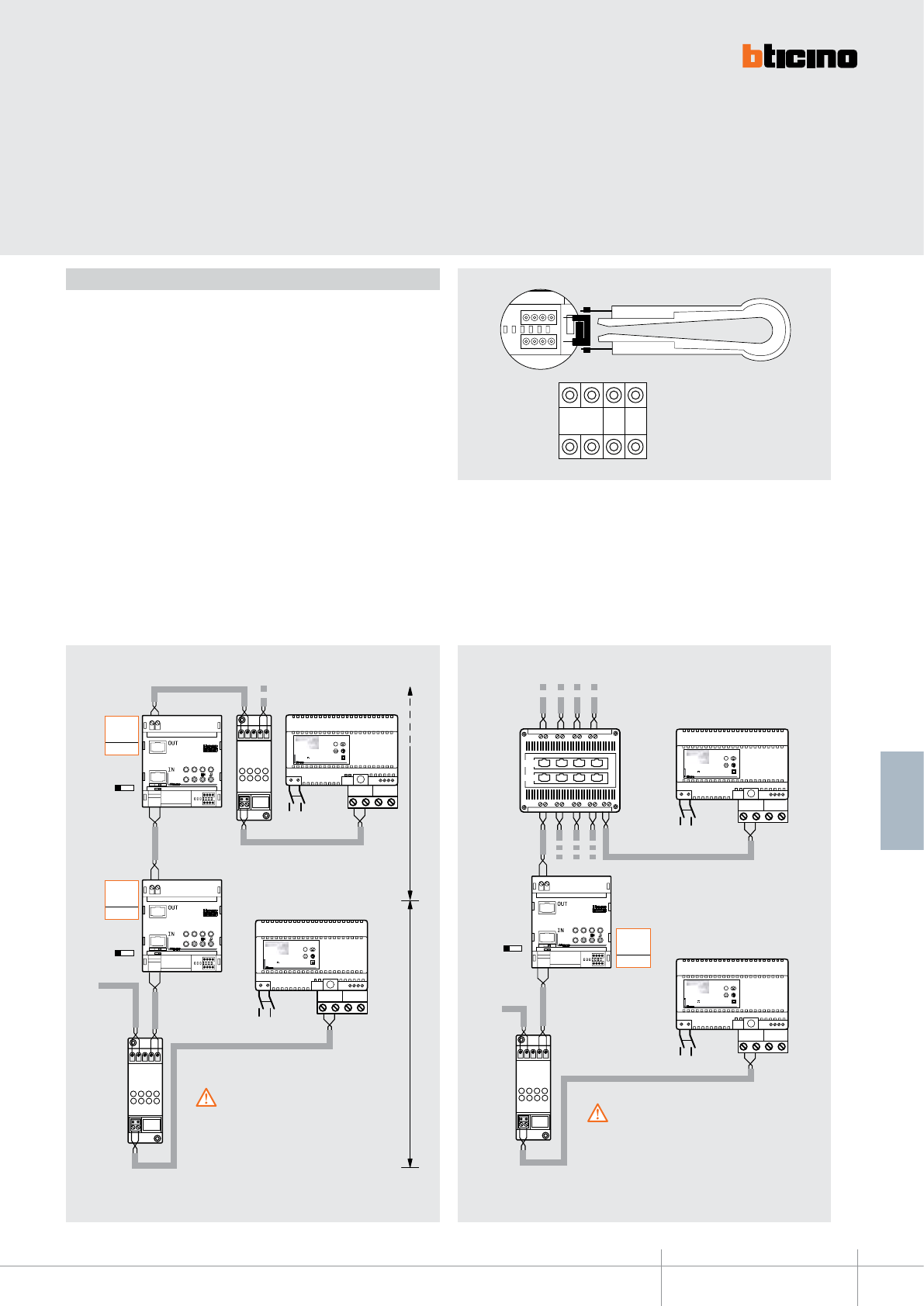
BT00663-a
346851
M MOD *
SCS
OUT1 OUT2 OUT3 OUT4
IN1IN2 IN3IN4
OUT
IN
PS
BUS
TK
BUS
PI
ON OFF
BUS 2 1
230 Vac
BUS 2 1
230 Vac
IP30
PRI
PRI 230 V~ 50 - 60 Hz 260 mA
346000
}
BUS
2 - 1 27V 1,2A
CEBEC
N
N
F
IP30
PRI
PRI 230 V~ 50 - 60 Hz 260 mA
346000
}
BUS
2 - 1 27V 1,2A
CEBEC
N
N
F
ON
346851
ON
OFF
PS
BUS
TK
BUS
PI
ON OFF
ON
BUS 2 1
230 Vac
BUS 2 1
230 Vac
IP30
PRI
PRI 230 V~ 50 - 60 Hz 260 mA
346000
}
BUS
2 - 1 27V 1,2A
CEBEC
N
N
F
IP30
PRI
PRI 230 V~ 50 - 60 Hz 260 mA
346000
}
BUS
2 - 1 27V 1,2A
CEBEC
N
N
F
PS
BUS
TK
BUS
PI
ON
346851
ON
OFF
ON
346851
ON
OFF
BUS PI
F441 346000
346000
346851
M= –
= 1
MOD
= 2
346830
346830
BUS
PE
BUS
PE
M= –
= 2
MOD
= –
M= –
= 1
MOD
= –
346851
346851
346000
346000
346830
-EN
TECHNICAL SHEETS
371
2 WIRE VDE system
Configuration
The device MUST BE configured with physical configurator connection to the
appropriate sockets as follows:
M = progressive number within the system
The configurator connected to the M sockets (from 1 to 99) assigns an identification
number within the system to the interface. Addresses in M with (MOD = 0 - MOD
= 2 - MOD = 7) and (MOD = 5 - MOD = 6) ARE NOT IN CONFLICT.
MOD = operating mode
The configurator connected to the MOD socket of the interface defines its operating
mode as follows:
MOD = 0 (no configurator connected) - GALVANIC SEPARATION MODE
MOD = 2 - ENTRANCE PANEL LINE EXPANSION MODE
MOD = 5 - Independent risers MODE
MOD = 6 - Extended riser MODE
MOD = 7 - Extended riser expansion MODE
MOD = 2 (entrance panel line expansion)
This mode is used in systems with interface connection between the entrance panel
and the F441 audio/video node, to extend the entrance panel line – see the following
example:
MOD = 0 (galvanic separation)
This configuration mode is used to double the line length or to increase the system
performance - see the following example:
To the handsets/interfaces
�After the system expansion module item 346851 200
metres of line B are available (interface 346851 - Furthest
Handset). A maximum of 3 interfaces item 346850 and
item 346851 can be installed in cascade. Only 2 of them
will regenerate the signal.
WARNING
�After the system expansion module item
346851, 200 metres of line B are available
(interface 346851 - Furthest Handset).
A maximum of 3 interfaces item 346850 and
item 346851 can be installed in cascade. Only
2 of them will regenerate the signal.
WARNING
200 m
line B
200 m
line A
M - interface progressive
number (from 1 to 99)
* Not used
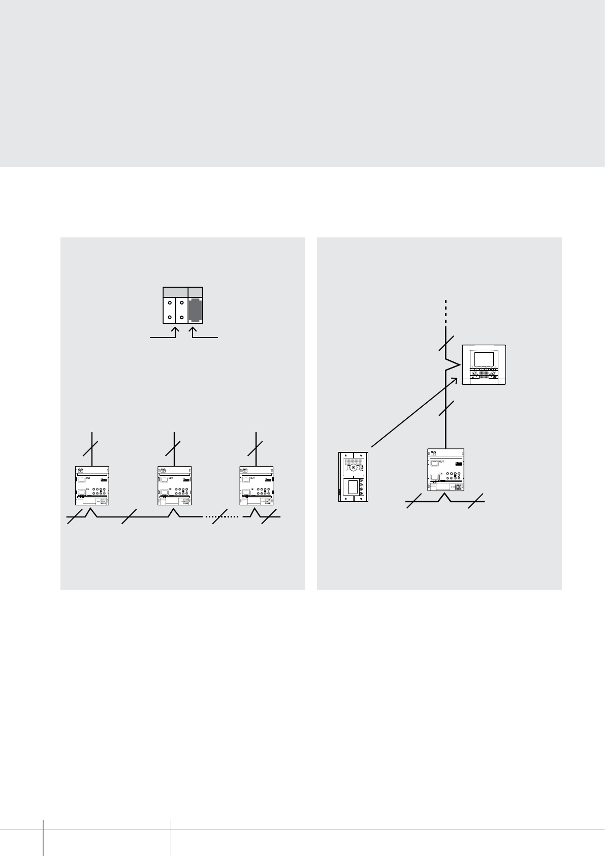
346851
M
MOD
5
ON
346851
ON
OFF
ON
346851
ON
OFF
ON
346851
ON
OFF
2 2 2 2
2 2 2
ON
346851
ON
OFF
2
2
2 2
718
BT00663-a-EN
TECHNICAL SHEETS
372 2 WIRE VDE system
M = 1
Mod = 5
M = 2
Mod = 5
M = 39
Mod = 5
N = 18
M = 7
MOD = 5
346851
MOD = 5 (independent risers)
This mode is used to create systems with 2 WIRE risers, with independent audio and
video (39 risers maximum) - see the following example:
Riser No. Independent riser
interface
Riser
1
Riser
2
Riser
3
2 wire backbone
The handsets connected to the single riser will be identified at the main entrance panel
by the M configurator of 346851 x 100 + the N configurator of the single handset.
Handset 18
2 wire backbone
As far as the EP is concerned, the handset is number 718: this is the M of 346851 (7) x
100 + N of the handset connected to the riser (18).
(7 x 100) + 18 = 718
Main entrance
panel
Riser 7
NOTE:
A maximum of 3 interfaces item 346850 and 346851 can be installed in cascade. Only 2
of them will regenerate the signal.
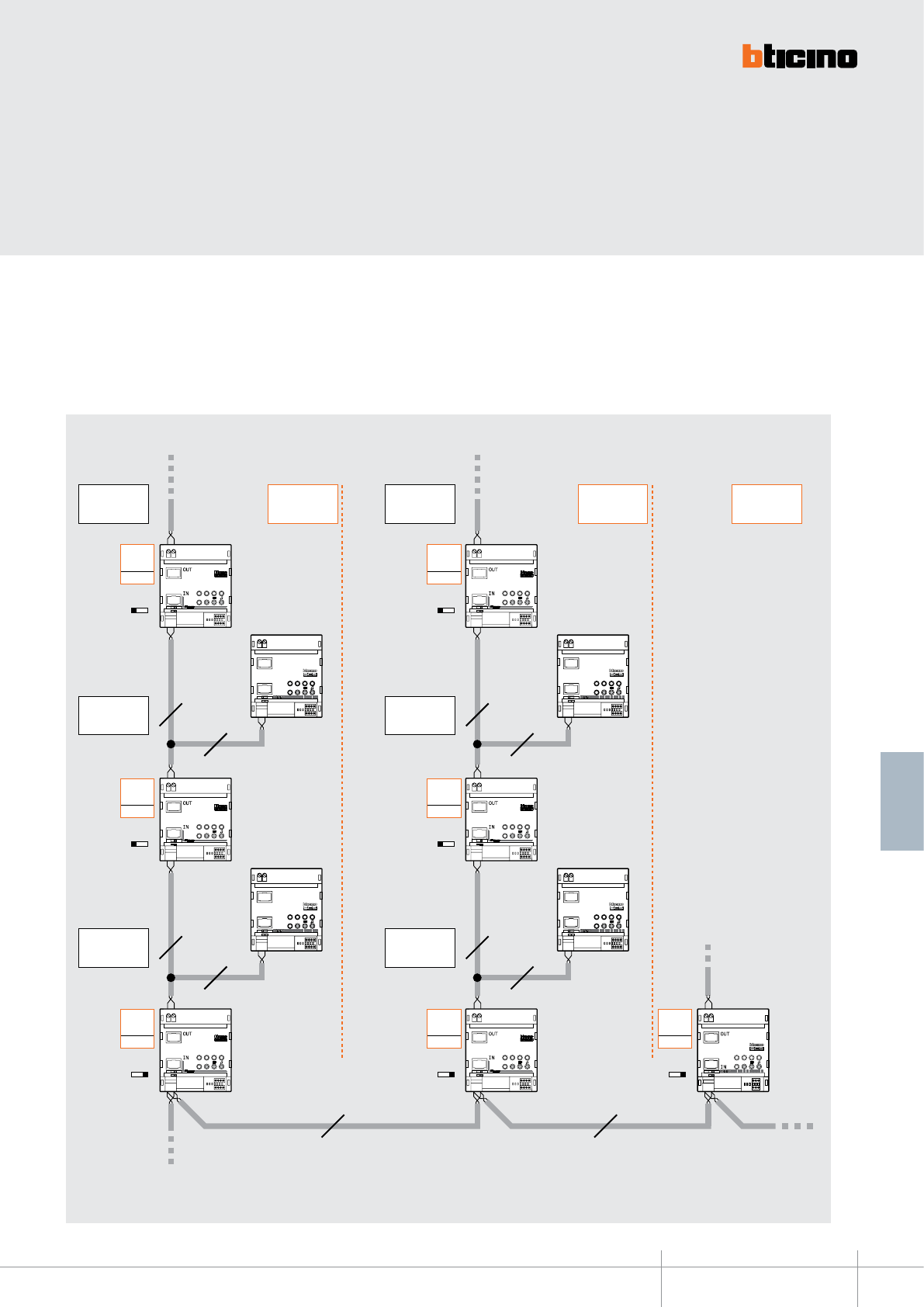
BT00663-a
ON
346850
INT
EXT
ON OFF
ON
346850
INT
EXT
ON OFF
ON
346850
INT
EXT
ON OFF
ON
346850
INT
EXT
ON OFF
ON
346851
ON
OFF
ON OFF
ON OFF
ON OFF
ON OFF
ON OFF ON OFF ON OFF
ON
346851
ON
OFF
ON
346851
ON
OFF
ON
346851
ON
OFF
ON
346851
ON
OFF
ON
346851
ON
OFF
ON
346851
ON
OFF
BUS PI BUS PI
M= –
= 3
MOD
= 7
M= –
= 6
MOD
= 7
M= –
= 2
MOD
= 7
M= –
= 5
MOD
= 7
M= –
= 1
MOD
= 6
M= –
= 4
MOD
= 6
M= –
= 7
MOD
= 6
346851 346851
346851 346851
346851 346851 346851
346850 346850
346850 346850
2 2
2 2
2 2
2 2
2 2
346851
-EN
TECHNICAL SHEETS
373
2 WIRE VDE system
Handsets
(201 – 299)
Handsets
(501 – 599)
Handsets
(301 – 399)
Handsets
(101 – 399)
Handsets
(401 – 699)
Handsets
(701 – 999)
Handsets
(601 – 699)
Handsets
(101 – 199)
Handsets
(401 – 499)
Maximum 100 interfaces item 346850
Note 1: maximum 3 interfaces
item 346850 and 346851 can be
installed in cascade. Two of them
will regenerate the signal.
Note 2: for this type of systems
we recommend that you contact
your local technical support
service representative.
EP BUS
(Main Entrance Panel)
MOD = 6 (extended riser)
MOD = 7 (extended riser expansion)
These configuration modes offer the possibility of riser line expansion up to the logic
limit of 300 riser handsets (3 lines of 100 handsets each).
The limit of 100 handsets for each line is subjected to the use of apartment interface
item 346850.
When interface item 346850 is not used, this 100 handsets line limit will be further
reduced (refer to the system technical guide for more information).
Interface item 346850 CANNOT be installed on the last line. It is possible to cross up to
3 interfaces item 346850 and 346851 connected in cascade.
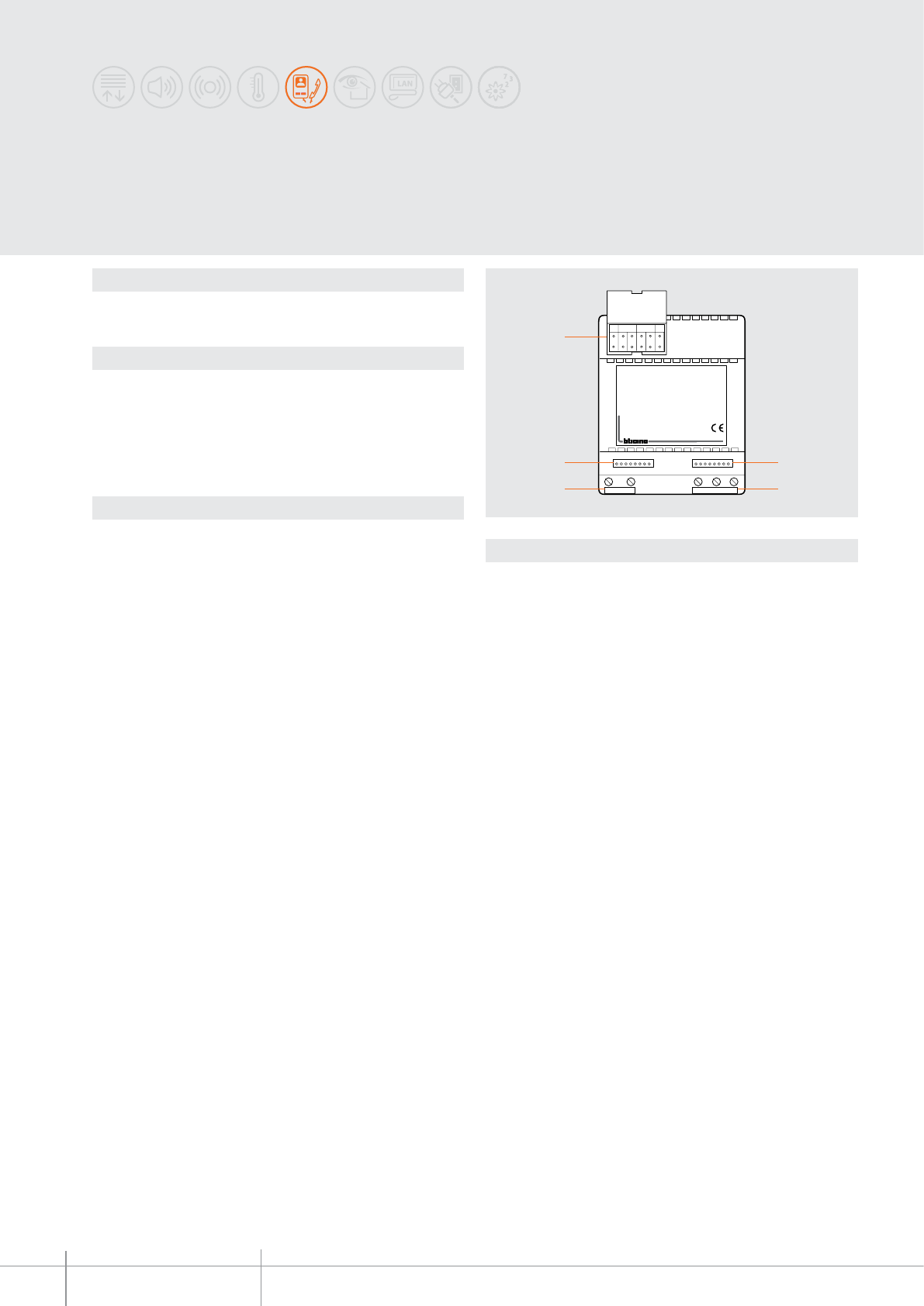
346200
MODM N/PT
1
4
3
1
2
BT00664-a-EN
TECHNICAL SHEETS
374 2 WIRE VDE system
Dimensional data
Description
Relay actuator for digital systems. It allows to switch on lights, to open gate door locks,
to control other devices and to repeat call on bell (badenia type).
Technical data
Power supply from SCS BUS: 18 – 27 Vdc
Stand by absorption: 15 mA
Max. operating absorption: 30 mA
Operating temperature: 5 – 40 °C
Contact output: 230 Vac - 6 A resistive - 2 A inductive (cosϕ = 0.5)
SELV device
Legend
1 - Clamps for the connection of the 2-wire BUS and power supply 1 - 2
2 - Clamps for the connection of the load to be controlled
3 - Clamps for the connection of an additional pushbutton
4 - Congurator socket
Actuator
4 DIN modules
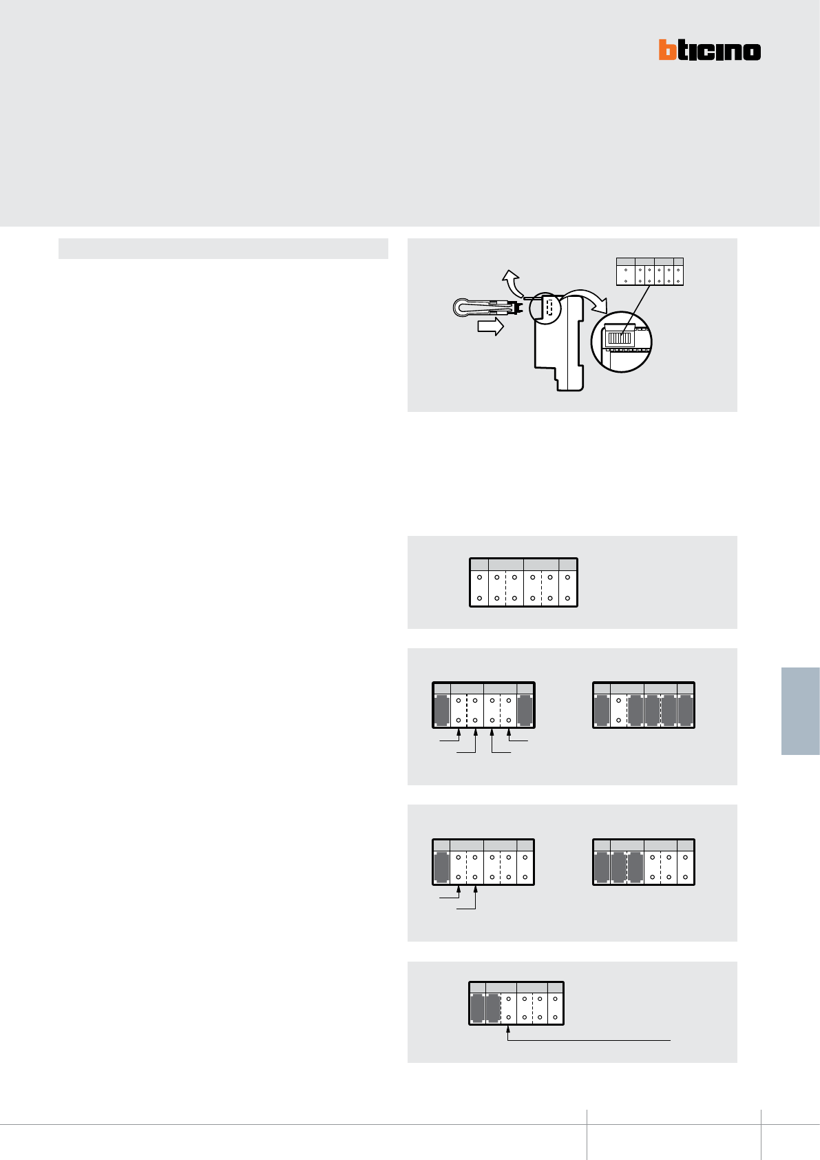
4
MOD MT
N/P
5
346200
BT00664-a-EN
TECHNICAL SHEETS
375
2 WIRE VDE system
Conguration
The device must be physically congured in terms of:
MOD = Operating mode
The congurator in MOD establishes the operating mode of the actuator (see following
tables)
M = number of the riser
In systems with several risers, it identies on which riser the actuation must be
performed
N/P = Handset/Entrance panel number
It denes the association with the Handset or the EP address from which the actuation
must be performed.
T = relay closure time delay
The congurator connected to T sets the relay closing time delay (see corresponding
table).
MOD = 0 - Staircase light from any handset and EP
- The actuator is enabled by pressing the light pushbutton of the handset and the light
key on the entrance panel
- Customize the time through the congurator T.
Example
MOD M N/P T
Unit
Tens
Tens
Unit
MOD M N/P T
1 1 1 1 1 2 1
Door lock control from the light key of the
handsets congured from 1 to 12
T = 1 closes the contact for 1”
MOD M N/P T
T = 0 closes the contact for 30”
MOD M N/P T
Tens
Unit
MOD M N/P T
2 2 1 9
Example
Staircase light control from all handsets of
the riser 19
T = 0 closes the contact for 30”
MOD = 1 - Sundry services (door lock/open the gate/staircase light) from
handset unit
- The actuator is enabled by pressing the light pushbutton of the handset belonging to
a group
- Customize the time through the congurator T.
- Insert in M the ten and the units of the rst handset of the group
- Insert in N/P the ten and the units of the last handset of the group
NOTE: a group is a sequence set of handsets.
MOD = 2 - Staircase lights from all riser handsets
- The actuator is enabled by pressing the staircase light key of all riser handsets
- Customize the time through the congurator T.
- Connect the M congurator of the system expansion interface, item 346851
(congured with MOD = 5) to M
MOD = 2 - Staircase lights from all entrance panel (if tted with the
corresponding key)
- With (MOD = 2) the actuator activates when the light pushbutton of any (preset)
entrance Panel is pressed
- Customize the time through the congurator T.
MOD M N/P T
2
Not inserting the congurator
corresponds to insert 0
4
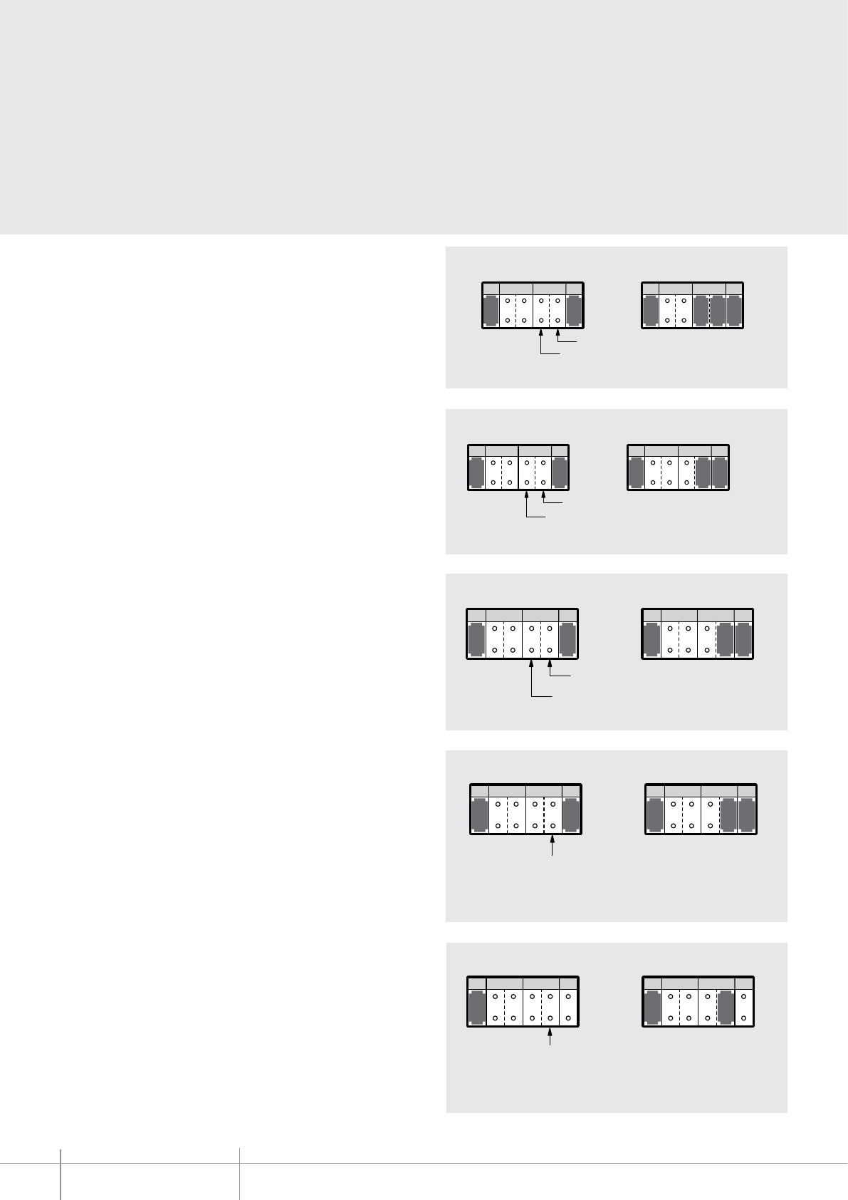
BT00664-a
346200
-EN
TECHNICAL SHEETS
376 2 WIRE VDE system
MOD = 3 - Sundry services from single handset
- The actuator is enabled by pressing the light pushbutton of only one handset.
- Customize the time through the congurator T.
- Put in N/P the ten and the units of the handset that controls the relay
MOD = 4 - Staircase light from EP
- With (MOD = 4) the actuator is enabled by pressing the light pushbutton of only one
entrance panel.
- Customize the time through the congurator T.
- Put in N/P the ten and the units of the handset that controls the relay
MOD = 5 - Door lock control from all handsets
- Direct door lock opening with handset in pause. The actuator is enabled by pressing
the door lock pushbutton of all handsets.
- Customize the time through the congurator T.
- Put in N/P the ten and the units of the associated entrance panel that controls the door
lock.
MOD = 5 - Door lock control from PIVOT/SWING/POLYX handsets additional keys
- Direct door lock opening with handset in pause.
- Customize the time through the congurator T.
- Insert in N/P the address that the actuator must take inside the system.
The N/P value inserted in the actuator must be between P + 1 and P + 4 of
the P congurator P inserted in the handset which controls the door lock.
For further information on the congurations of the SWING/POLYX handsets and the 4
additional keys set for PIVOT make reference to the relating technical sheets.
MOD = 7 - Light on for illumination of the viewing eld
At the same time as sending a call from the entrance panel or activating a camera (N/P
conguration), the actuator also closes the contact, keeping it closed until:
- if the call is answered, the contact opens when the communication is terminated or
the conversation timeout activates (<1 min.)
- if the call is not answered, the contact opens after 30 seconds (at the end of the call
forwarding timeout).
Example
Door lock control from the light key of the
handset congured with 15
T=1 closes the contact for 1 s
Example
MOD M N/P T
Unit
Tens
MOD M N/P T
4 5 4 3 5
Door lock control from the light key of the
handset congured with P=3
T=5 closes the contact for 1 min
MOD M N/P T
Unit
Tens
MOD M N/P T
5 1 5 2 1
Example
Door lock control of the entrance panel
congured with P=2 from the door lock
pushbutton of all the associated handsets
T=1 closes the contact for 1 s
MOD M N/P T MOD M N/P T
5 1 5 2 1
Example
Door lock control by pressing the key
2 of the 4 keys set for PIVOT (PIVOT
congured with P = 0)
T=1 closes the contact for 1 s
P + 1
P + 2
P + 3
P + 4
Example
MOD M N/P T MOD M N/P T
7 7 2
The number of the EP or camera to
associate to the actuator
Closing of contact upon call from the
EP congured with P=2.
The contact opens after the call is
terminated or after 30 seconds
(if there is no answer)
MOD M N/P T
Unit
Tens
MOD M N/P T
3 1 3 1 5 1
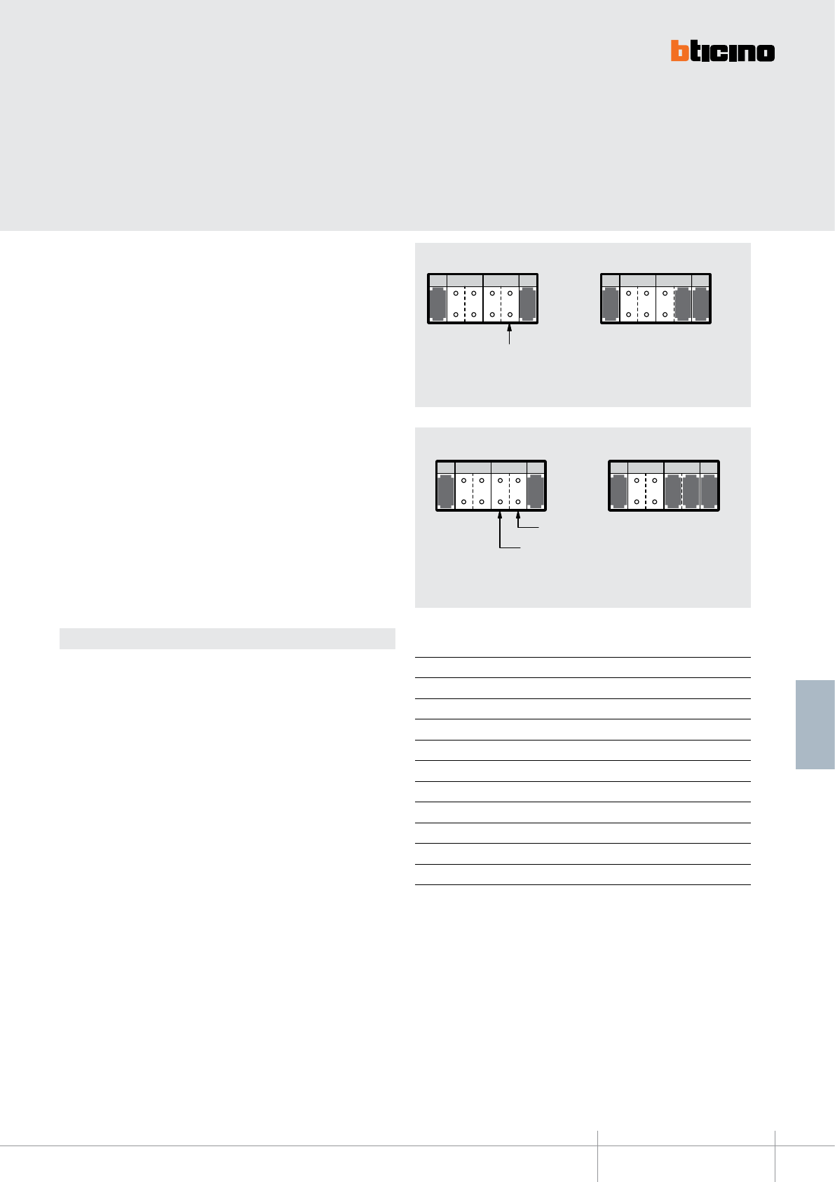
MOD M N/P T MOD M N/P T
9 2 9 3 2
346200
BT00664-a-EN
TECHNICAL SHEETS
377
2 WIRE VDE system
T conguration (timing)
The T values mentioned in the examples are only an indication of the times commonly
used for the dierent applications.
By inserting in the T socket a congurator (as mentioned in the table) the relay door
locking time can be customized.
T congurator Time
none 3 min.
1 1 sec.
2 3 sec.
3 6 sec.
4 10 sec.
5 1 min.
6 6 min.
7 10 min.
8 pushbutton
9 cyclic (ON/OFF)
MOD = SLA - Call repetition on Badenia bell
- Repeat the calls coming from the entrance panel on Badenia bell.
- Customize the time through the congurator T (Accepted congurators are: 1, 2, 3, 4
and 8).
- Insert in N/P the tens and units of the handset associated to the function.
* The SLA congurator must be bought separately from the congurator kit
(item 3501K). Item code for SLA congurator: item 3501/SLA.
Example
MOD M N/P T
Unit
Tens
MOD M N/P T
3 1 6 3
S
L
A
S
L
A
The Badenia bell rings for 6 seconds each
time there is a call addressed to the handsets
congured with N=16
T =3 the Badenia bell rings for 6 s and stops
when the call is answered
MOD = 9 - Sundry services (door lock/open the gate/staircase light) from
PIVOT/SWING/POLYX handsets additional keys
- Direct door lock opening with handset in pause.
- Customize the time through the congurator T.
- Insert in N/P the address that the actuator must take inside the system.
The N/P value inserted in the actuator must be between P + 1 and P + 4 of the P
congurator P inserted in the handset which controls the service.
For further information on the congurations of the SWING/POLYX handsets and the
4 additional keys set for PIVOT make reference to the relating sections congurations.
MOD M N/P T MOD M N/P T
9 2 9 3 2
Example
Device control by pressing the key 2 of the 4
keys set for PIVOT (PIVOT congured with P = 2)
T=2 closes the contact for 3 s
P + 1
P + 2
P + 3
P + 4
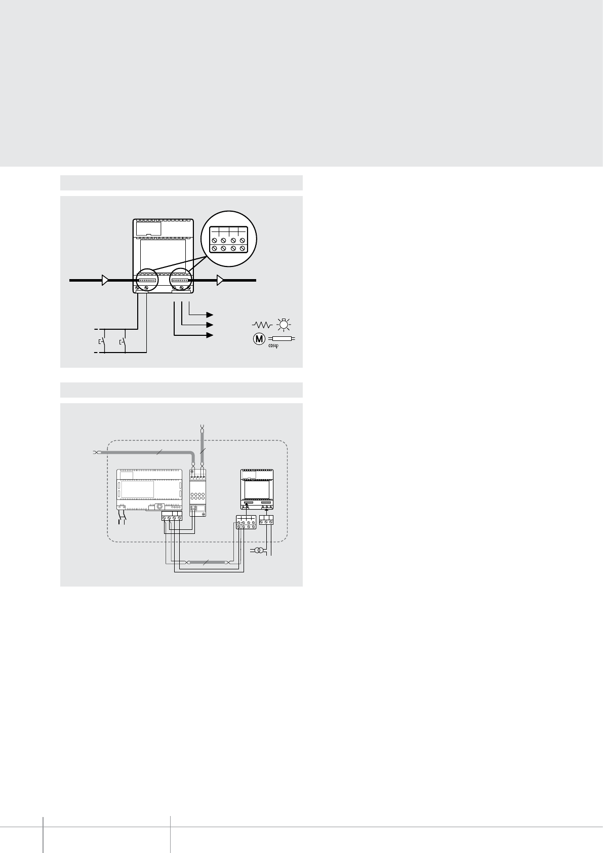
6A
2A
SELV
230V~
= 0,5
BUS IN
A
BUS OUT
2
14
3
6
58
7
NC C NO
A
BUS
TK
PS
BUS
PI
346830
230V a.c.
BUS 21
NC NO
C
346200346000
~
2
14
3
6
58
7
2
2
Bus TK
Bus PI
2
C NO
BT00664-a
346200
-EN
TECHNICAL SHEETS
378 2 WIRE VDE system
Wiring diagram
2-wire standard wiring diagram
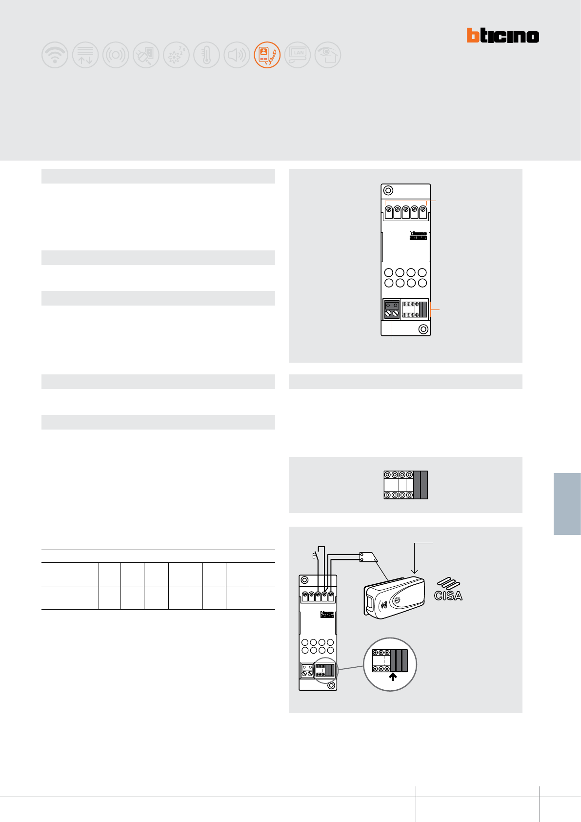
346230
12PL S+ S-
PTMJ
1
J
2
J
M
P
J
M
P
1
ELETTRIKA
18V 4A
J
M
P
J
M
P
1P T
M=1
PT
J
M M
P
J
M
P
BT00665-a
12PL S+ S-
346230
PT
J
M M
P
J
M
P
1
2
3
-EN
TECHNICAL SHEETS
379
2 WIRE VDE system
Dimensional data
Conguration
Description
2-wire system door lock actuator.
It can be used to actuate an electrical door lock without the need for a local transformer,
activated by a dedicated handset key.
In systems with handsets with specic LED, it enables to perform the “LOCK STATUS”
function when a CISA ELETTRIKA door lock is used.
Related items
346240 CISA ELETTRIKA door lock accessory
Technical data
Power supply from SCS BUS: 18 – 27 Vdc
Stand by absorption: 10 mA
Max. operating absorption: 300 mA
Operating temperature: 5 – 40 °C
Contact load (PL/S+): 6 A – 24 Vac max (cosϕ=1)
Legend
1 - Clamps for the connection of door lock and additional pushbutton
2 - Congurator socket
3 - 2 WIRE BUS connection clamps
Door lock actuator
2 DIN modules
The device must be physically congured in terms of:
P - Associated entrance panel number
A congurator like the one connected to P of the entrance panel must be connected to
this socket. When the actuator is associated to the main entrance panel, no congurator
must be connected to P.
T - Door lock relay timing
The congurator connected to T sets the relay closing time delay as shown in the
following table:
M - Operating mode
M=0 - Door lock relay standard operation
M=1 - Door lock relay operation + “door lock status control” – only with handsets tted
with door lock status LED and specic CISA ELETTRIKA door lock with Accessory item
346240.
M=4 - With interface 349410 only it enables:
- with analogue system and audio Tersystem, the direct control of the electrical door lock
- with videoporter 2000, the call to the switchboard
JMP - Jumpers to be removed when an auxiliary transformer is used (4A max.)
congurator number
0= No
congurator 1
1 sec.4 sec.
2
2 sec.
3
3 sec.
5
6 sec.
6
8 sec.
7
10 sec.
4
as
pushbutt.
The accessory item 346240
must be tted inside the
door lock.
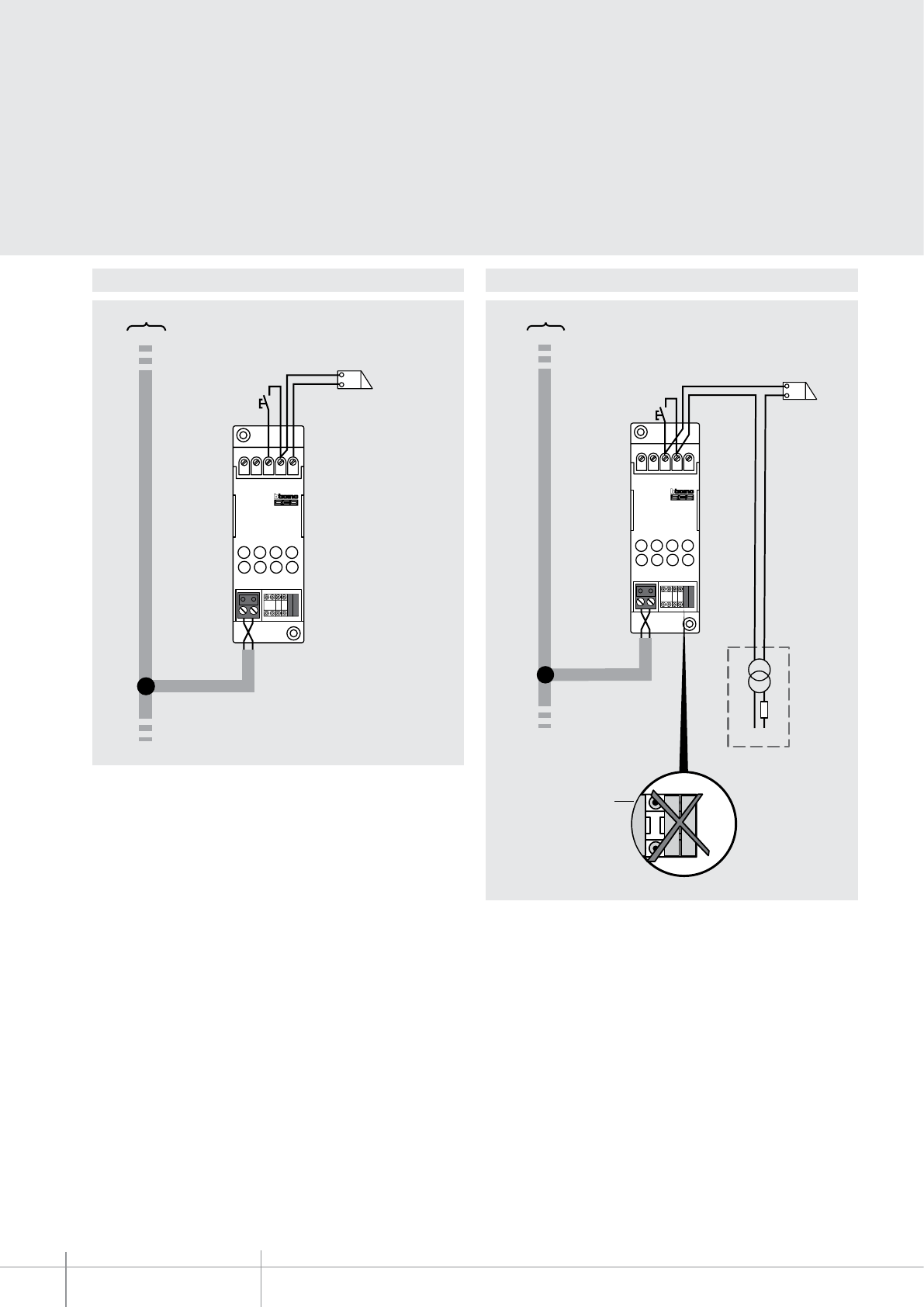
346230
BT00665-a-EN
TECHNICAL SHEETS
380 2 WIRE VDE system
Wiring diagram - 2-wire standard Wiring diagram - with auxiliary transformer
12PL S+ S-
346230
PT
J
MM
P
J
M
P
346000
*A 18 V - 4 A impulsive
250 mA holding current
*A = door lock release
pushbutton
SCS-BUS
12PL S+ S-
346230
PT
J
MM
P
J
M
P
346000 V~
*A
J
M
P
J
M
P
*A= door lock release
pushbutton
Remove the jumpers
SCS-BUS
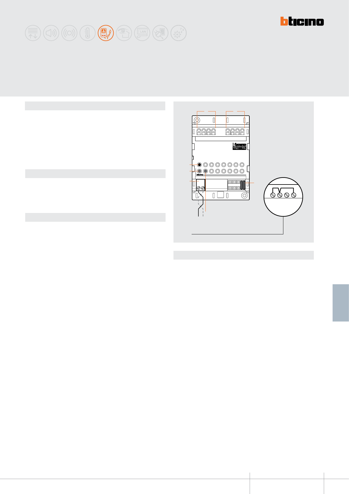
ART. 346260
T= -5 +45°C
IP 30
C NC
NO/S+
S-
- TMP PL RC
SCS
J
M
P
J
M
P
-
TMPPL RC
4
3
5
6
7
1 2
346260
BT00666-a-EN
TECHNICAL SHEETS
381
2 WIRE VDE system
Dimensional data
Description
Timed door lock actuator for 2 WIRE system.
It can be used for switching the lights on, opening gates, or manage electromagnetic
door locks, timed door opening, and door status (with NC contact).
The DOOR STATUS function can only be used with door entry systems and video door
entry systems tted with signalling LEDs, and when a magnetic door status contact is
present.
It may also be used in systems integrated with an appropriately congured ACCESS
CONTROL system.
Technical data
Power supply from SCS BUS: 18 – 27 Vdc
Stand by absorption: 5 mA
Max. operating absorption: 250 mA
Operating temperature: 5 – 40 °C
Timed door lock
actuator
4 DIN modules WARNING: if the TMP and RC contacts are not used,
short circuit TMP and RC with (-)
Legend
1 - Door status connection clamps:
(-) Common
(TMP) Anti tamper line contact (normally closed on -)
(PL) Door opening pushbutton contacts (normally open on -)
(RC) Door status magnetic contact (normally closed on -)
2 - Electromagnetic door lock connection clamps:
(C) Common
(NC) Normally closed contact
(NO/S+) Normally open contact
(S-) Contact for door lock power supply from BUS (to be used with NO/S+)
3 - Congurator socket
4 - Notication orange LED: on when the relay is active
(ashing orange + red LEDs for open door notication)
5 - 2 WIRE BUS connection clamps
6 - Notication red LED: ashing in case of system tampering
7 - Door opening local pushbutton
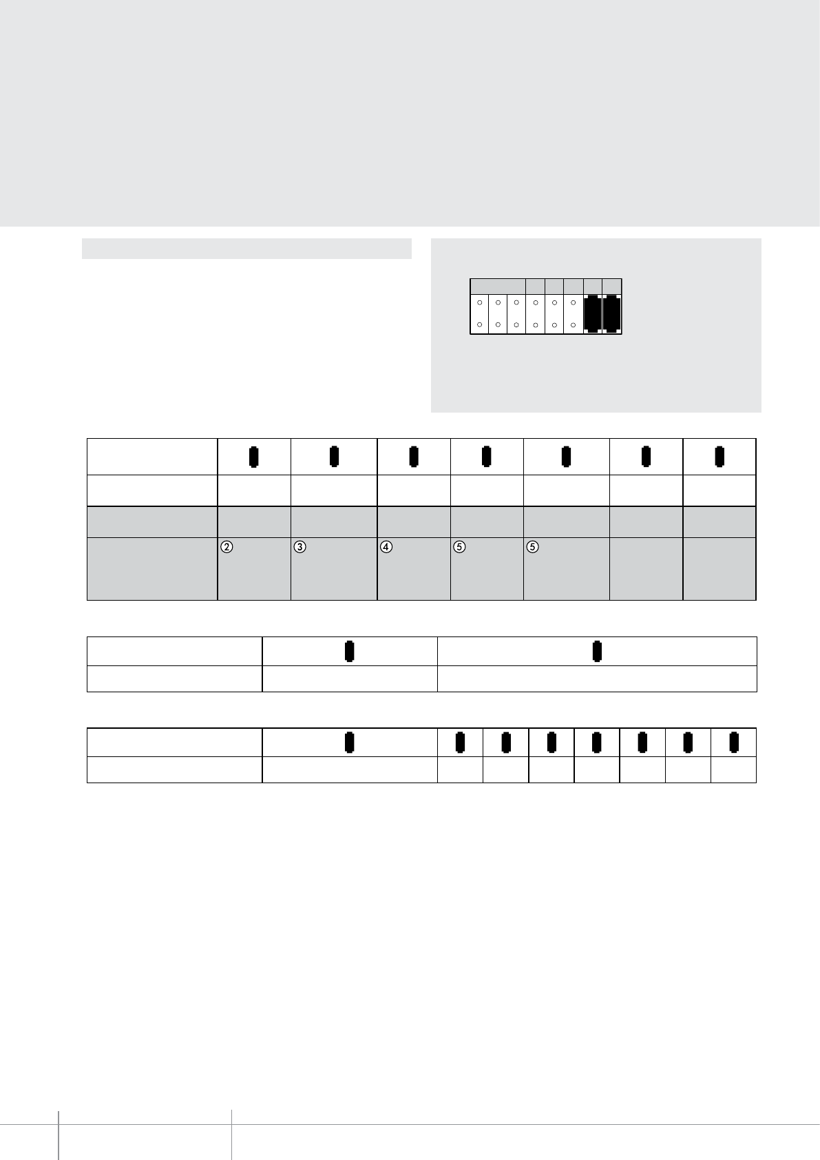
BT00666-a
346260
J
M
P
J
M
P
ABC
P M R T J1 J2
-EN
TECHNICAL SHEETS
382 2 WIRE VDE system
Conguration
The device must be physically congured in terms of:
P - Associated entrance panel number
A congurator like the one inserted in P of the entrance panel must be connected to
this socket. When the actuator is associated to the main entrance panel, no congurator
must be connected to P.
M = Operating mode
Assigns the operating mode to the internal relay of the actuator, based on the following
table:
A = DO NOT USE (access control only)
B - C = P CONFIGURATOR SOCKETS
Congurator
0 1 234567
Time sec.
Congurator
0 1
Advance of closing DisabledEnabled (2 sec.)
M =
012
3456
Signal
repetition
Management of 2 WIRE
video door entry system
Actuator relay status Normally
open
NO NO NO YES YES YES YES
YESYESYES
41 10 20 40 60 90 180
YES NO NO
Normally closed.
Electromagnetic
door lock
Signal
repetition
Normally
open
Normally closed.
Electromagnetic
door lock
Normally
open
Normally
closed
Management of
access control
Congurator
0 1 234567
Time sec.
Congurator
0 1
Advance of closing DisabledEnabled (2 sec.)
M =
012
3456
Signal
repetition
Management of 2 WIRE
video door entry system
Actuator relay status Normally
open
NO NO NO YES YES YES YES
YESYESYES
41 10 20 40 60 90 180
YES NO NO
Normally closed.
Electromagnetic
door lock
Signal
repetition
Normally
open
Normally closed.
Electromagnetic
door lock
Normally
open
Normally
closed
Management of
access control
T = Door lock relay timing
J1 - J2 = Jumpers for the selection of the door lock power supply
CONNECTED = DOOR LOCK POWERED BY THE BUS
DISCONNECTED = DOOR LOCK POWERED BY AN EXTERNAL DEVICE
R = Enabling/disabling of the anticipated relay switching function(1)
Note:
(1) If enabled, 2 seconds after the opening of the entrance, anticipated relay switching
occurs, irrespective of the T time set (this function can be used with door status
magnetic contact and for T = s).
(2) The device supplies the NC and NO contacts of the internal relay. It is therefore
possible, also with M = 0, to use the internal relay as normally closed.
It must be noted that in case of power cut from the power line (230 Vac), the relay
stays normally closed and, if the power supply of the electric door lock is tted with
a back-up battery, the door lock stays closed.
(3) In this mode, the software forces the relay to perform the opposite operation
(positive safety). The NO contact stays in the closed status, and is opened in order to
open the door (passage). In case of power cut from the main power line (230 Vac),
the relay opens, and the door lock opens, even if the power supply line of the door
locks is tted with a back-up battery.
(4) Operation as signal repeater. In case of system intrusion or opening of a door,
the relay output can also activate an external notication device (sound or visual
notication), based on the time value set in T.
(5) Integration mode between video door entry system and access control (see
instructions of item 348000).
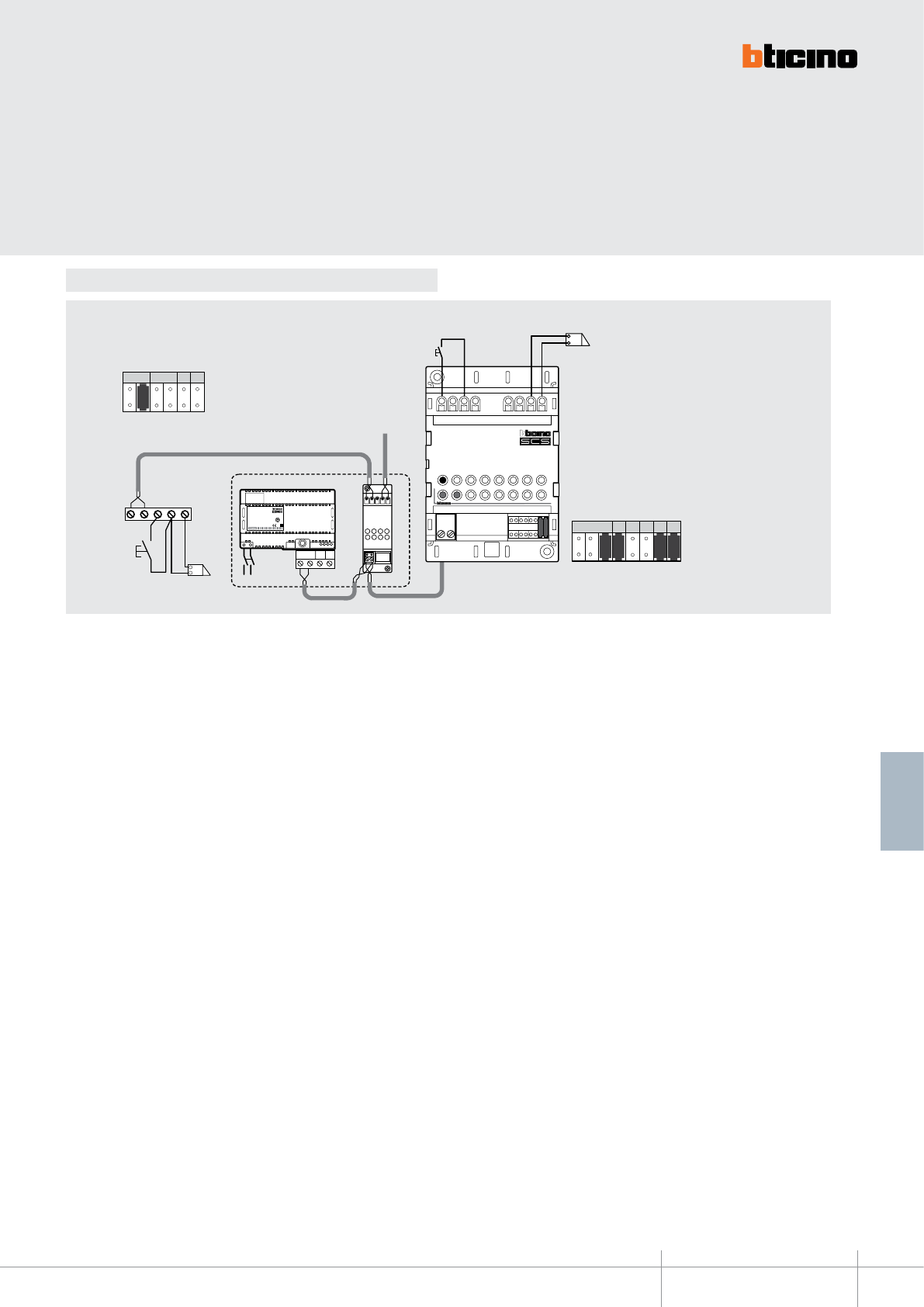
BT00666-a
346260
-EN
TECHNICAL SHEETS
383
2 WIRE VDE system
Connection example
230 Vac
PS
BUS
TK
BUS
PI
346830
BUS
PL S+
S-
BUS
H
A
TK BUS
S1
EP: P=1
PNTS
1
*
1
J
M
P
J
M
P
5
P M R T J1 J2
A = Door lock pushbutton in the entrance-hall
*S+ S- = 18V 4A impulsive 250mA
holding current
21
BUS
346000
ART. 346260
T= -5 +45°C
IP 30
C NC
NO/S+
S-
-TMP PL RC
SCS
J
M
P
J
M
P
18 V 4 A
A
S2
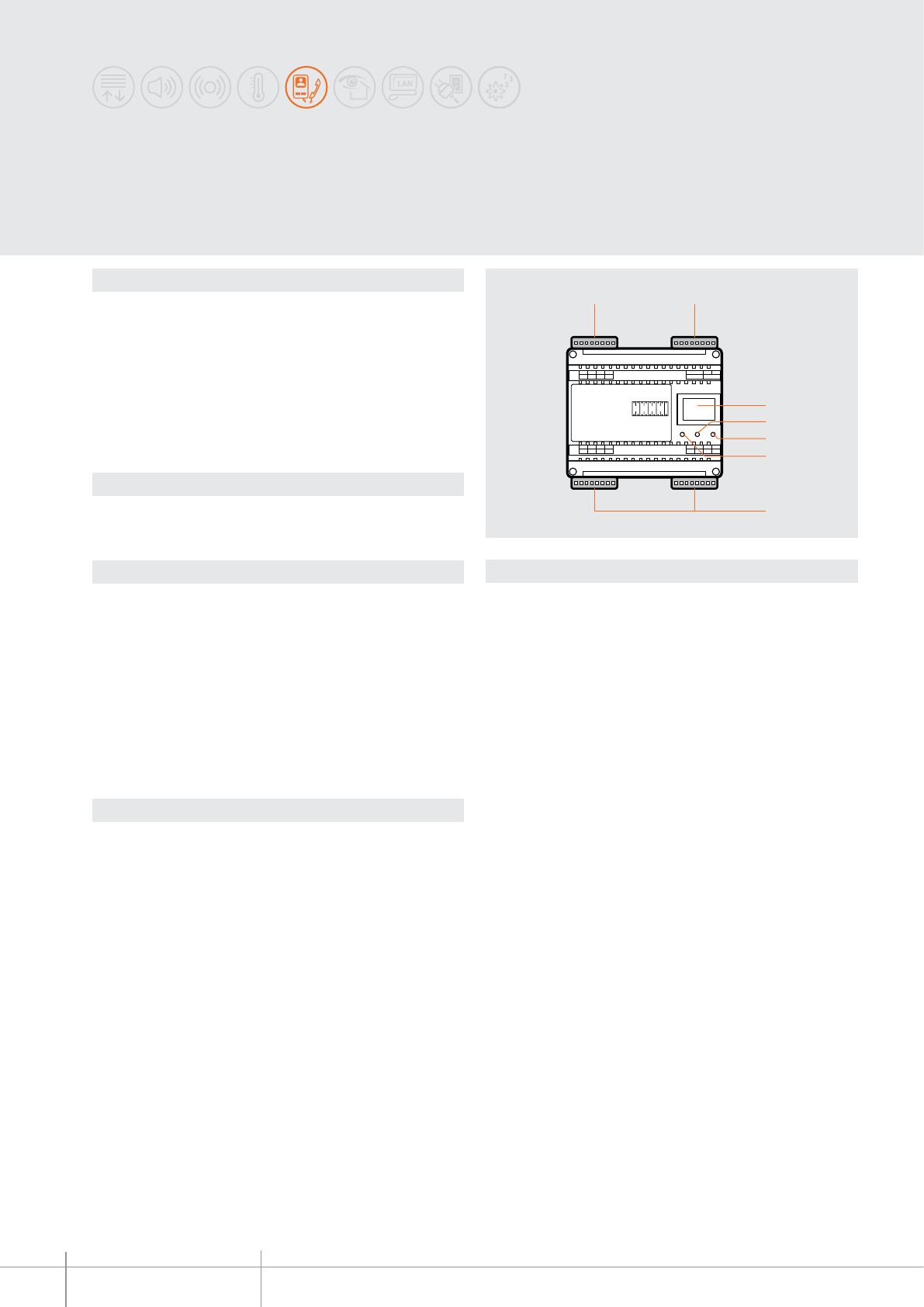
PE
IN 1234
5678
1234
5678
1234
5678
BUS PI BUS TK
PS 21
OUT M
OUT
M1 N1 M2 N2
JMP
OUT M
OUTIN
PE
7
6
4
3
5
1 2
346150
BT00667-a-EN
TECHNICAL SHEETS
384 2 WIRE VDE system
Dimensional data
Description
8/2-WIRE interface is a device that can be used for installing mixed video door entry
systems, with common backbones using the digital system (8 WIRES), and risers using
the 2 WIRE system.
It is ideal for very large systems as all the performance advantages of the digital system
can be combined with the installation advantages of the 2 WIRE system (simple wiring
system, intercommunication, no need for local power supply of monitors).
The device must be used together with the 346000 power supply.
In installing a system with local entrance panel, the entrance panel itself may be wired
using both the 2 WIRE, or the 8 WIRE procedure.
Related items
346000 (2 WIRE system power supply)
Technical data
Power supply from SCS BUS: 18 – 27 Vdc
Operating temperature: 5 – 40 °C
SELV device
BACKBONE SIDE (IN-OUT):
- Stand-by absorption: 60 mA
- Max. operating absorption: 145 mA
RISER SIDE (EP-OUT M):
- Stand-by absorption: 25 mA
- Max. operating absorption: 110 mA
Legend
1 - 8 WIRE local entrance panel connection clamp
2 - 2 WIRE riser and power supply connection clamp
3 - Congurator socket
4 - Local conversation active signalling LED
5 - Powered device ashing (stand by) signalling LED
6 - Conversation with backbone active signalling LED
7 - 8 WIRE backbone (IN-OUT) connection clamps
NOTE: the three ashing LEDs indicate a device conguration error.
8/2-WIRE interface
6 DIN modules
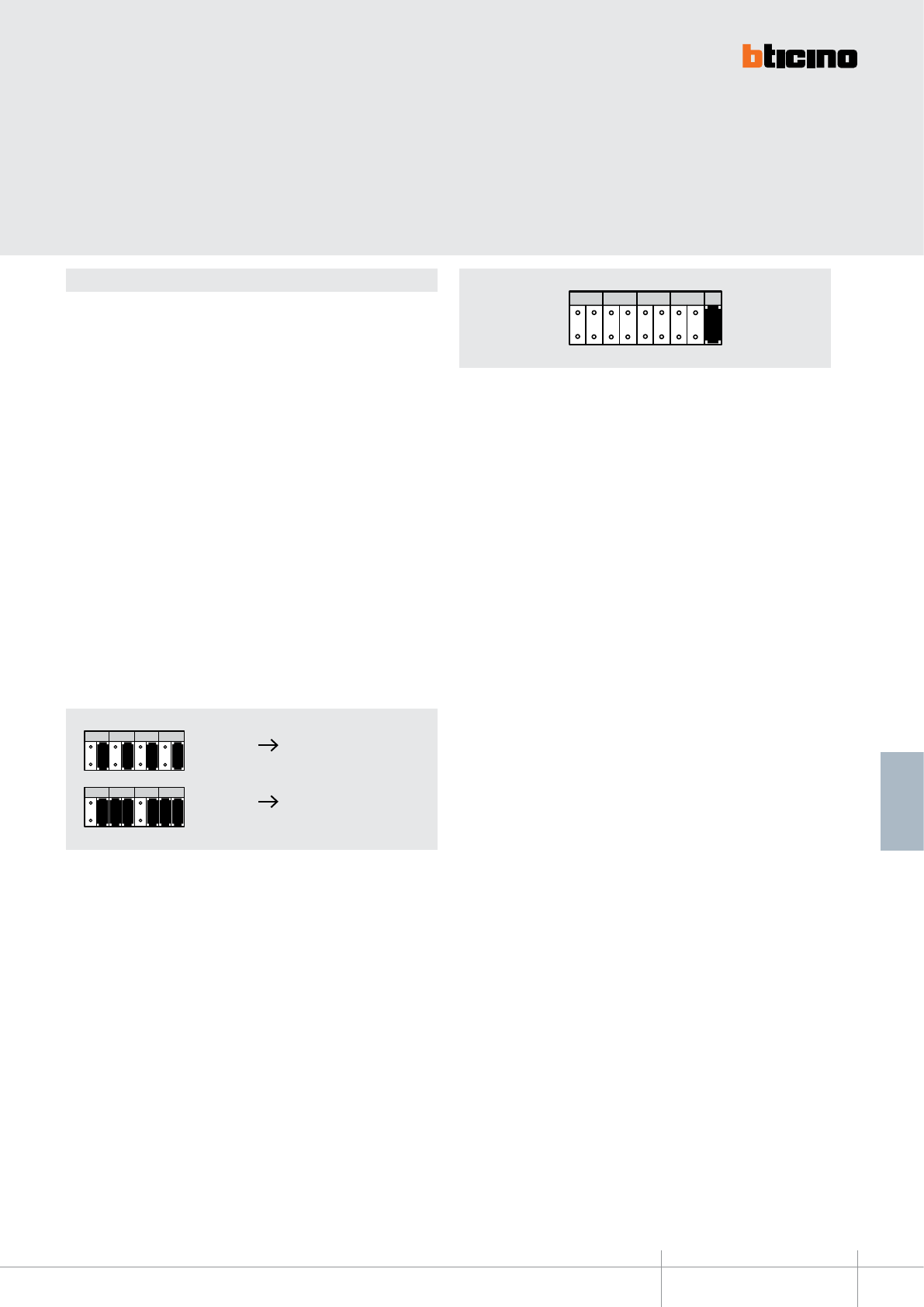
346150
BT00667-a-EN
TECHNICAL SHEETS
385
2 WIRE VDE system
Conguration
The device must be physically congured to set the operating mode:
MODE A: It is possible to generate up to 40 risers, each with up to 100 handsets (devices).
The total number of handsets installed on the riser column must also include any
handsets and video handsets connected in parallel. With each extra device added in
parallel to the base device, the total number of calls or apartments decreases by one. It
is recommended that the risers in M1 are numbered starting with 1.
The congurators must only be connected to the M1 position. On the generated riser,
handsets (max. 100) must be congured (in N) from 1 to 99.
MODE B: it is possible to generate up to 100 risers, with the possibility of installing on
each of them a number of handset based on the value of the congurator connected to
M1 and N1. However, the total number of calls in the system is 4000.
The congurators to be used are M1, N1, M2, N2; for each riser these will dene the
address of the rst and the last video handset of the riser.
In this mode M1 must be the same as M2, and therefore up to 100 call address Handsets
(N1 and N2) may be allocated to each riser.
NOTE: if only one handset can be installed on a riser (M1=M2 and N1=N2), the
handset shall always be congured with N=1 due to the fact that the call on the 2 WIRE
line (in this conguration) becomes general.
M1 = number of the riser
It allocates to the handsets the number of the riser they belong to
N1 = Call number
Mode A: MUST not be congured.
Mode B: it allocates the initial number of the handsets installed on the riser.
M2 = number of the riser
Mode A: MUST not be congured.
Mode B: It allocates to the handsets the number of the riser they belong to (it must be
equal to M1)
N2 = Call number
Mode A: MUST not be congured.
Mode B: it allocates the nal number of the handsets installed on the riser
J = Selection of the secondary riser entrance panel
It is possible to install a riser EP belonging to the 2 WIRE system range or a riser EP
belonging to the digital system range However, both types of EPs cannot be installed
at the same time.
Congurator J connected = 2 WIRE system EP
Congurator J disconnected = digital system EP (6-8 wires)
PE
IN 1234
5678
1234
5678
1234
5678
BUS PI BUS TK
PS 21
OUT M
OUT
M1 N1 M2 N2
JMP
M1 N1 M2 N2 J
J
M
P
M1 N1 M2 N2
219219
M1 N1 M2 N2
13 1 3
Handsets The connected handset must
from 103 to 103
be congured with N =1
Handsets The connected handset must
from 219 to 219
be congured with N =1
PE
IN 1234
5678
1234
5678
1234
5678
BUS PI BUS TK
PS 21
OUT M
OUT
M1 N1 M2 N2
JMP
M1 N1 M2 N2 J
J
M
P
M1 N1 M2 N2
219219
M1 N1 M2 N2
13 1 3
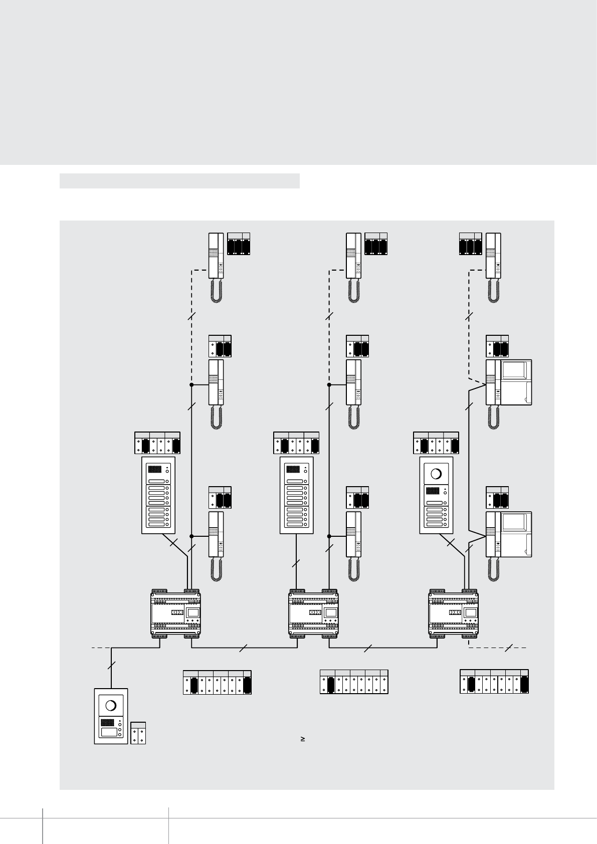
M1 N1 M2 N2 J
2
6
2 2 2
2 2 2
8
888
2
2 2 2
PNM
12
PNM
14
PNM
16
P
NP
1 2
NP
1 4
NP
1 6
NP
2 2
NP
2 4
NP
2 6
NP
9 29
NP
9 49
NP
8 61
2
(101-199) (201-299) (301-318)
M1 N1 M2 N2 J
J
M
P
1
M1 1
M1 N1 M2 N2 J
J
M
P
3
346150
BT00667-a-EN
TECHNICAL SHEETS
386 2 WIRE VDE system
Example of conguration in mode (A)
Example of conguration in mode (A):
The EP must be realised using numeric or alphanumeric call modules. On the 8/2 interface it is possible to install both 2 WIRE or 6/8 WIRE secondary (or local) entrance
panels. On the risers it is possible to install both audio and video 2 WIRE handsets, complying with the installation limits of the 2 WIRE system.
If M1=2 the 100 handsets installed on this riser will take on the absolute address from
201 to 299 and will be congured from N=1 to N=99.
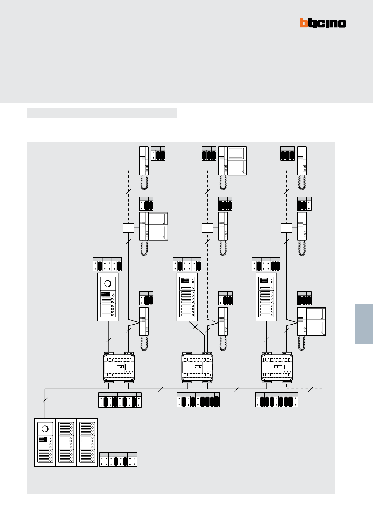
NP
41
8
2
222
222
8
8
8 8 8
222
PNM
12
PNM
94
NP
8
PNM
36 1
PM NT
11
S
M1 = M2
(101-108) (109-112) (113-121)
M1 N1 M2 N2 J
111 8
M1 N1 M2 N2 J
J
M
P
119 21
M1 N1 M2 N2 J
1 13 121
NP
12 6
NP
21 4
2
NP
11 4
NP
22
NP
31 6
NP
94
NP
12
346150
BT00667-a-EN
TECHNICAL SHEETS
387
2 WIRE VDE system
Example of conguration in mode (B)
If M1=12 N1=50 and M2=12 N2=65, on the riser the handsets will have an absolute
address going from 1250 to 1265. Therefore the riser handsets must themselves be
congured in N from 50 to 65.
Example of conguration in mode (B)
On the 8/2 interface it is possible to install both 2 WIRE or 6/8 WIRE secondary (or local) entrance panels. On the risers it is possible to install both audio and video 2 WIRE
handsets, complying with the installation limits of the 2 WIRE system.
Floor
shunt
Floor
shunt
Floor
shunt
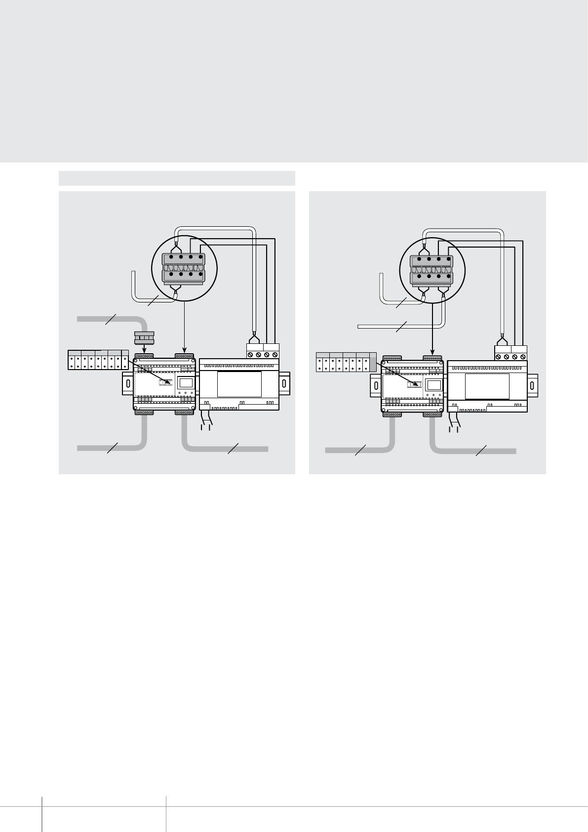
BUS 2 1
BUS PI BUS TK
PS 21
OUT M
230 Vac
8
12 43
56 87
8
8
2
M1 N1 M2 N2 J
PE
IN 1234
5678
1234
5678
1234
5678
BUS P IBUS TK
PS 21
OUT M
OU T
M1 N1 M2 N2
2
BUS 2 1
PE
IN 1234
5678
1234
5678
1234
5678
BUS P IBUS TK
PS 21
OUT M
OU T
M1 N1 M2 N2
JM P
BUS PI BUS TK
PS 21
OUT M
230 Vac
88
2
M1 N1 M2 N2 J
J
M
P
346150
BT00667-a-EN
TECHNICAL SHEETS
388 2 WIRE VDE system
Wiring diagrams
346150 346000
(PI)
(PE)
Other EPs or
switchboards
Connection of local 8 WIRE EP Connection of local 2 WIRE EP
346150 346000
Other EPs or
switchboards
(PE)
(PI)
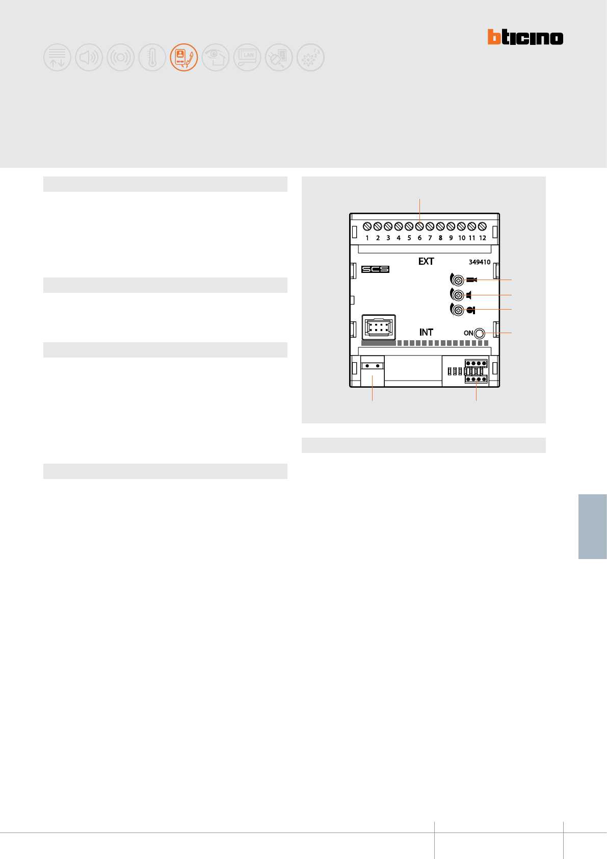
349410
2
3
4
5
1
67
BT00668-a-EN
TECHNICAL SHEETS
389
2 WIRE VDE system
Dimensional data
Legend
Description
ANALOGUE/2 WIRE communication interface.
It can be used for interfacing an ANALOGUE, 8 WIRE DIGITAL, TERSYSTEM audio, and
VIDEOPORTER 2000 riser to a dedicated apartment 2 WIRE video door entry system with
local video monitoring system, sound system, and MY HOME application control.
Activations addressed on the ANALOGUE/8 WIRE side are not possible.
NOTE: The conguration of private devices (entrance panels, actuators, video cameras
etc.), must start from 1.
Related items
346000 (2-wire system power supply)
F441 (audio/video node)
346830 (video adapter)
Technical data
Power supply from SCS BUS: 18 – 27 Vdc
Operating temperature: 5 - 40°C
Absorption:
SIDE (INT): Stand by absorption: 15 mA
Max. operating absorption: 55 mA
SIDE (EXT): Stand by absorption: 15 mA
Max. operating absorption: 35 mA
ANALOGUE/2 wire interface
1 - Clamps for the connection of the ANALOGUE system riser
2 - Trimmer for the adjustment of the video signal
3 - Trimmer for the adjustment of the incoming audio signal
4 - Trimmer for the adjustment of the outgoing audio signal
5 - Interface status notication LED:
(FLASHING GREEN = STAND BY)
(FIXED GREEN = active INT-EXT connection)
6 - Congurator socket
7 - Clamps for the connection of the 2-wire SCS BUS
4 DIN modules
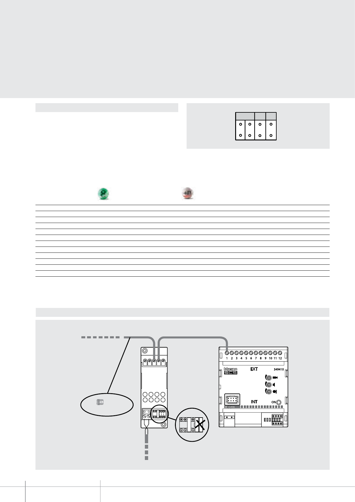
MOD
12PL S+ S-
346230
PTMJ
1
J
2
4
J
M
P
J
M
P
P T4
BUS
349410
346230
- 6 ( )
- T (Tersystem Audio)
349410
BT00668-a-EN
TECHNICAL SHEETS
390 2 WIRE VDE system
Conguration
The device must be physically congured in terms of:
MOD = type of riser connected on the input
The congurator connected to MOD indicates to which type of riser our input is
connected to the device:
MOD = 0 audio or video 8 WIRE DIGITAL riser
MOD = 1 audio or video ANALOGUE riser
MOD = 2 VIDEOPORTER 2000 riser
MOD = 3 TERSYSTEM audio riser
349410 Videoporter Tersystem
Clamps (EXT) Video Audio Video Audio 2000 Audio
1 1 1 1 1 15 (20) 3
2 2 - 2 - 19 -
3 3 3 3 3 1 2
4 4 4 4 4 21 1
5 5 5 5 5 17 6
6 6 6 6
*
13
*
7 7 - 7 - - -
8 8 - 8 - 9 -
9 - - - - 10 -
10 - - - - - -
11 14 14 14 14 12 -
12 - - - - - -
NOTE: activations addressed on the analogue/2 wire side are not possible.
For more information refer to the instruction leaet supplied with the item.
* For direct control of the electric door lock, a door lock actuator, item 346230/346260, must be installed
Riser
Direct electrical door lock control connection diagram
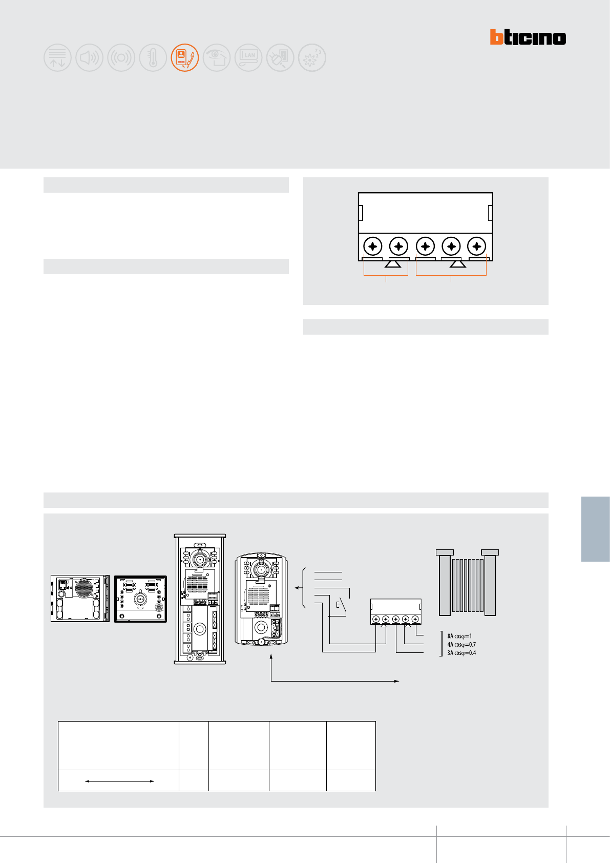
346250
S- S+ CNC NO
1 2
BT00669-a-EN
TECHNICAL SHEETS
391
2 WIRE VDE system
Description
Relay module for gate opening to be used only with audio/video SFERA New, SFERA
ROBUR, SFERA Classic item 342560, LINEA 2000, LINEA 2000 METAL and MINISFERA
entrance panels.
It allows to open door locks (NOT managed by BUS) by means of the above mentioned
entrance panels (NOT tted with relay). The device must not be congured.
Related items
341000 (SFERA New - SFERA Robur BASIC speaker phone module)
341100 (SFERA New - SFERA Robur speaker phone module)
341200 (SFERA New - SFERA Robur audio video module)
341300 (SFERA New - SFERA Robur wide angle audio video module)
342560 (SFERA Classic audio/video speaker module)
342702 (MINISFERA audio speaker module)
342708 (MINISFERA video speaker module)
342911/21 (LINEA 2000 audio EP)
342951/61 (LINEA 2000 video EP)
342971/72 (LINEA 2000 METAL audio EP)
342981/82 (LINEA 2000 METAL b/w video EP)
342991/92 (LINEA 2000 METAL colour video EP)
343001/02 (LINEA 2000 METAL ush mounted EP)
Legend
1 - Clamps for connection to the entrance panel
2 - Clamps- contacts for connection to the electrical door lock
Connection example
Door lock relay
A
NO
NC
C
BUS
PL
S+
S-
24 Vac/24 Vdc
24 Vac
24 Vac
D - EP - relay distance
346250
S- S+ CNC NO
Max. distance (D) depending on the cable used
A = door lock release pushbutton
mm²
0.28
30 m 50 m 30 m 100 m
BTicino
Item 336904
mm²
1
BTicino
Item L4669
D
TYPE OF CABLE
CABLE SECTION
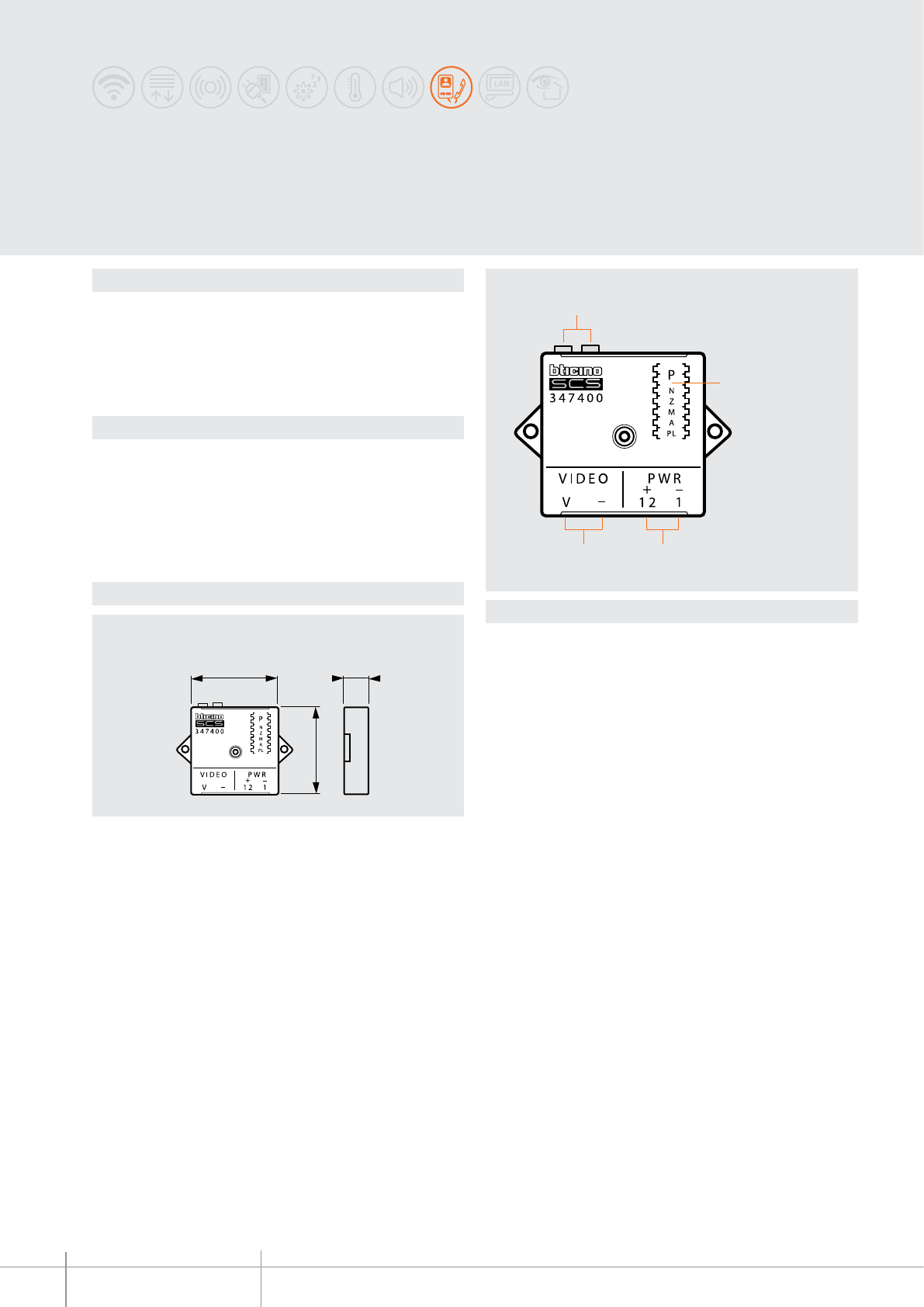
40 mm
40 mm
18 mm
1
2
4 3
347400
BT00670-a-EN
TECHNICAL SHEETS
392 2 WIRE VDE system
Description
Interface used for connecting the cameras with 12 Vdc power supply (max. absorption
150 mA) and coaxial video output (1 Vpp @ 75 ohm) to the 2-wire video BUS.
The interface provides direct power supply to the camera.
the device can be used as an interface for the separate camera; to associate a camera to
an audio entrance panel simply congure both the camera and the entrance panel using
the same congurator in P.
Legend
1 - 2 WIRE BUS connection clamps
2 - Congurator socket (to access remove the upper plastic protection cover)
3 - Clamps for the connection of the camera power supply (12 Vdc - 150 mA max.)
4 - Clamps for the connection of the camera video signal output
Coaxial to 2 WIRE
interface
Technical data
Dimensional data
Power supply from SCS BUS: 18 – 27 Vdc
Stand by absorption: 5 mA
Max. operating absorption: 210 mA - see note (*)
Operating temperature: (-20) – (+70)°C
(*) note: max. 150 mA when the interface supplies power to the 12 V camera
BASIC plastic enclosure
Distance
347400 - COAX cameras
max. 3 m
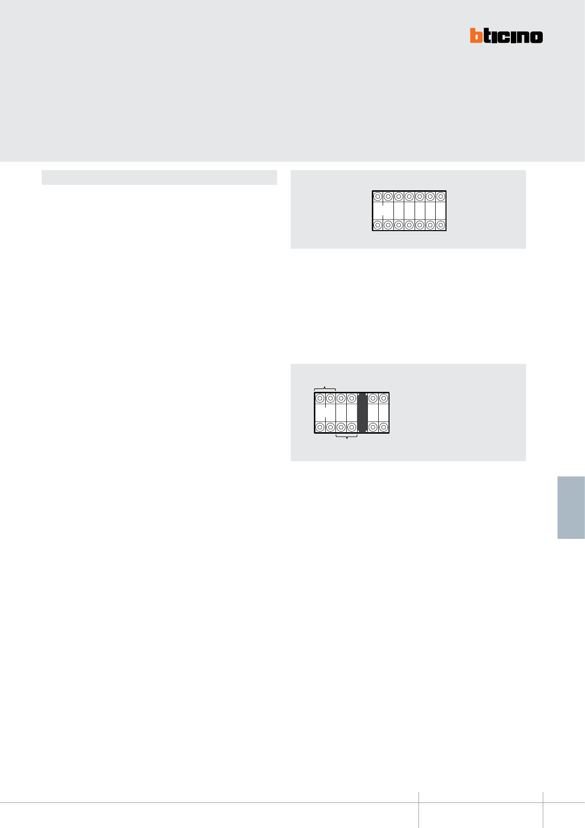
PLN Z
PMA
PL
N
PN
PI
Z
PA
S
L
A
M= SLA
347400
BT00670-a-EN
TECHNICAL SHEETS
393
2 WIRE VDE system
Conguration
The device must be physically congured in terms of:
P = camera address
The congurator in seat P of the interface assigns to it a recognition number inside
the system. The interface is considered as a video entrance panel, therefore it must be
congured with a progressive number in relation to (P) of the entrance panel.
N = address of the handset called in case of alarm
In those systems integrated with Bticino burglar alarm systems, the congurator
connected to N of the interface, determines which handset must be called in case of
alarm occurred in the Z zone congured in the interface. Then, the handset will display
the images of the interface associated to the Z zone.
Z = zone of the burglar-alarm system associated to the camera
M = Operating mode
M = 0 - standard operation
M = SLA - Conguration for association to several audio EP
A/PL = Address of the SCS light actuator connected to the camera
Address of the scenarios module associated to the camera
In systems integrated with BTicino automation applications, the congurator connected
to A/PL of the interface associates the switching on of the camera with the activation of
a SCS actuator congured with the same A/PL.
(Example: switching on of lights to illuminate the eld of view, only with camera active).
PI - PN = Range of audio EP associated
to the camera (max 5).
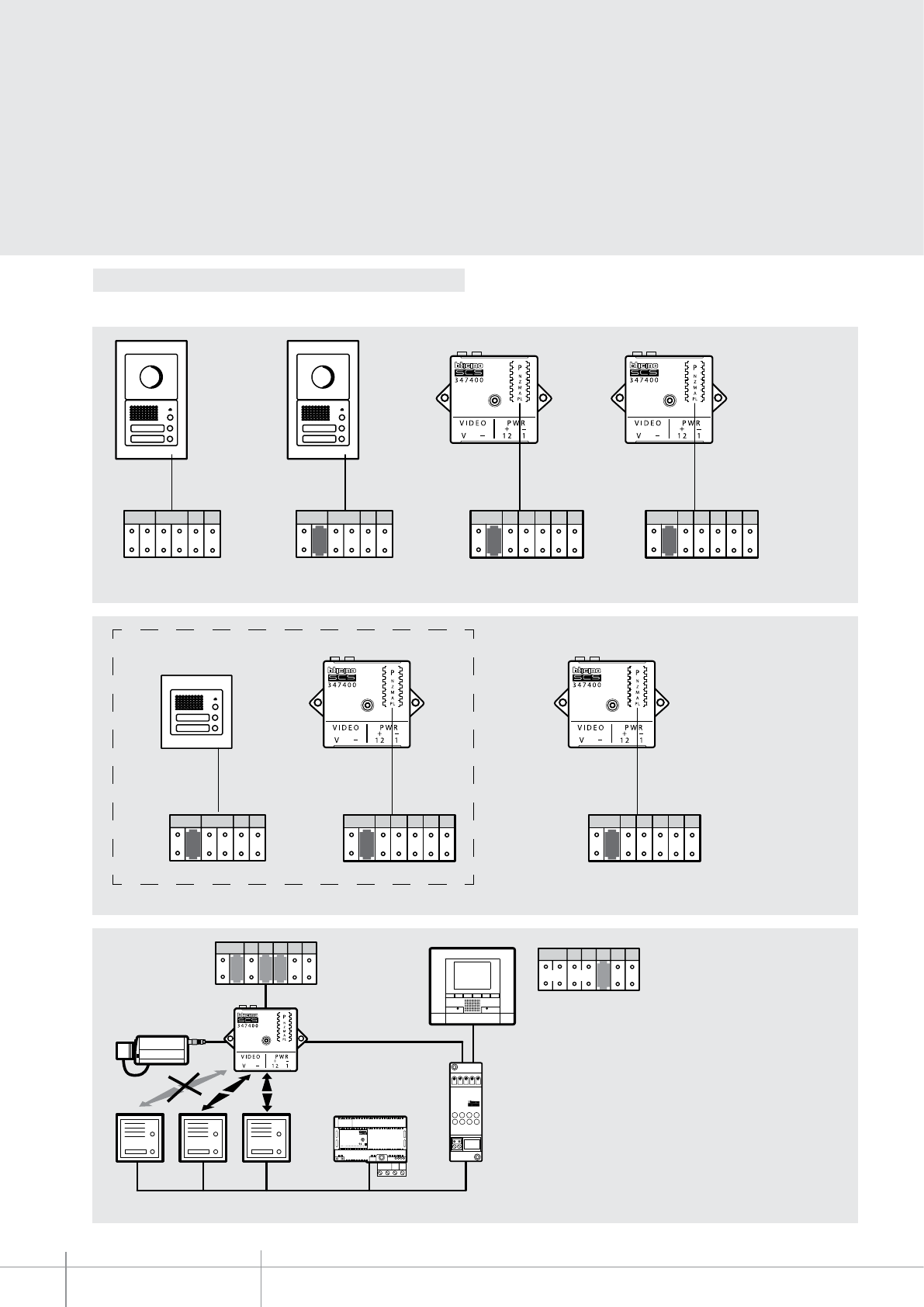
NZMAPLP
S
L
A
21
346830
346000
P=2P=1P=0 21
BUS
346000
NZMAPLP
S
L
A
PIPN
BUS
PI
BUS
TK
PS
N Z M A PLP
3
N Z M A PLP
2
PT
N
1
S
PT
NS
N Z M A PLP
2
N Z M A PLP
1
PT
N
1
S
BT00670-a
347400
-EN
TECHNICAL SHEETS
394 2 WIRE VDE system
EP 1 EP 2
Interface
CAM. 1
Interface
CAM. 2
Pi: address of the rst audio EP
Pn: address of the last audio EP
System with 2 video EP and 2 cameras.
Coupling the switching on of the camera with several audio EP (max. 5)
Interface
CAM. 1
Interface
CAM. 2
System with audio EP and 2 camera (CAM. 1 associated to the EP)
Conguration
Example of conguration
EP 1
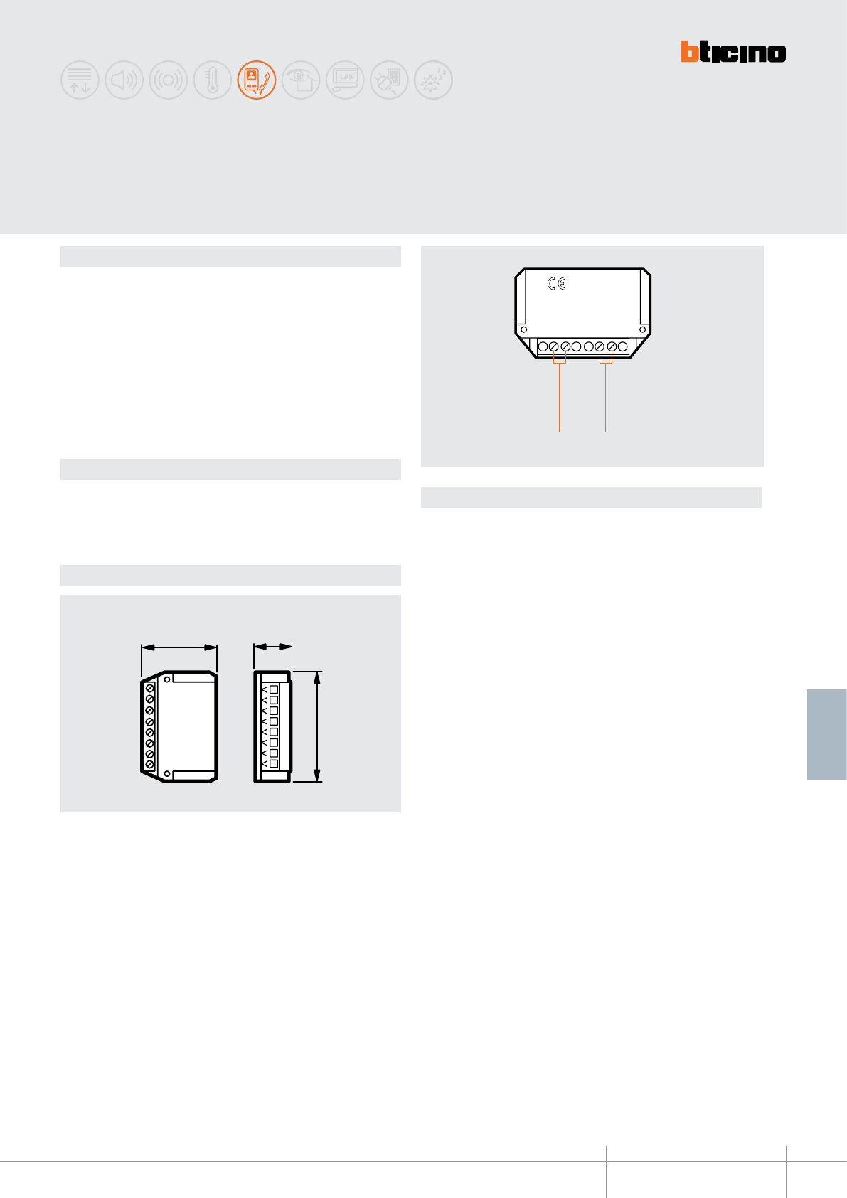
IN OUT
2 1
346870
346870
52 mm
35 mm 15 mm
BT00671-a-EN
TECHNICAL SHEETS
395
2 WIRE VDE system
Description
The line amplier is an accessory device that in 2 WIRE video systems using non-twisted
cables (with section ≥ 0.28 mm2) can be used to increase the distance between the
entrance panel and the furthest handset from 50 m to 100 m max.
The device must be installed at the 50th metre distance from the entrance panel. If it
is installed before the 50th metre, an image distortion will occur, while an installation
beyond the 50 metres will not bring any advantages.
The amplier oers the following advantages: it does not need conguration, or power
supply, and can be installed in a round box thanks to it compact size.
On the new riser line generated by the amplier it will be possible to install up to 18
handsets (maximum), including both audio and video handsets.
Legend
1 - 2 WIRE BUS OUTPUT connection clamps
2 - 2 WIRE BUS INPUT connection clamps
Line amplier
Technical data
Power supply from SCS BUS: 18 – 27 Vdc
Stand by absorption: 20 mA
Max. operating absorption: 20 mA
Operating temperature: 5 – 40 °C
Dimensional data
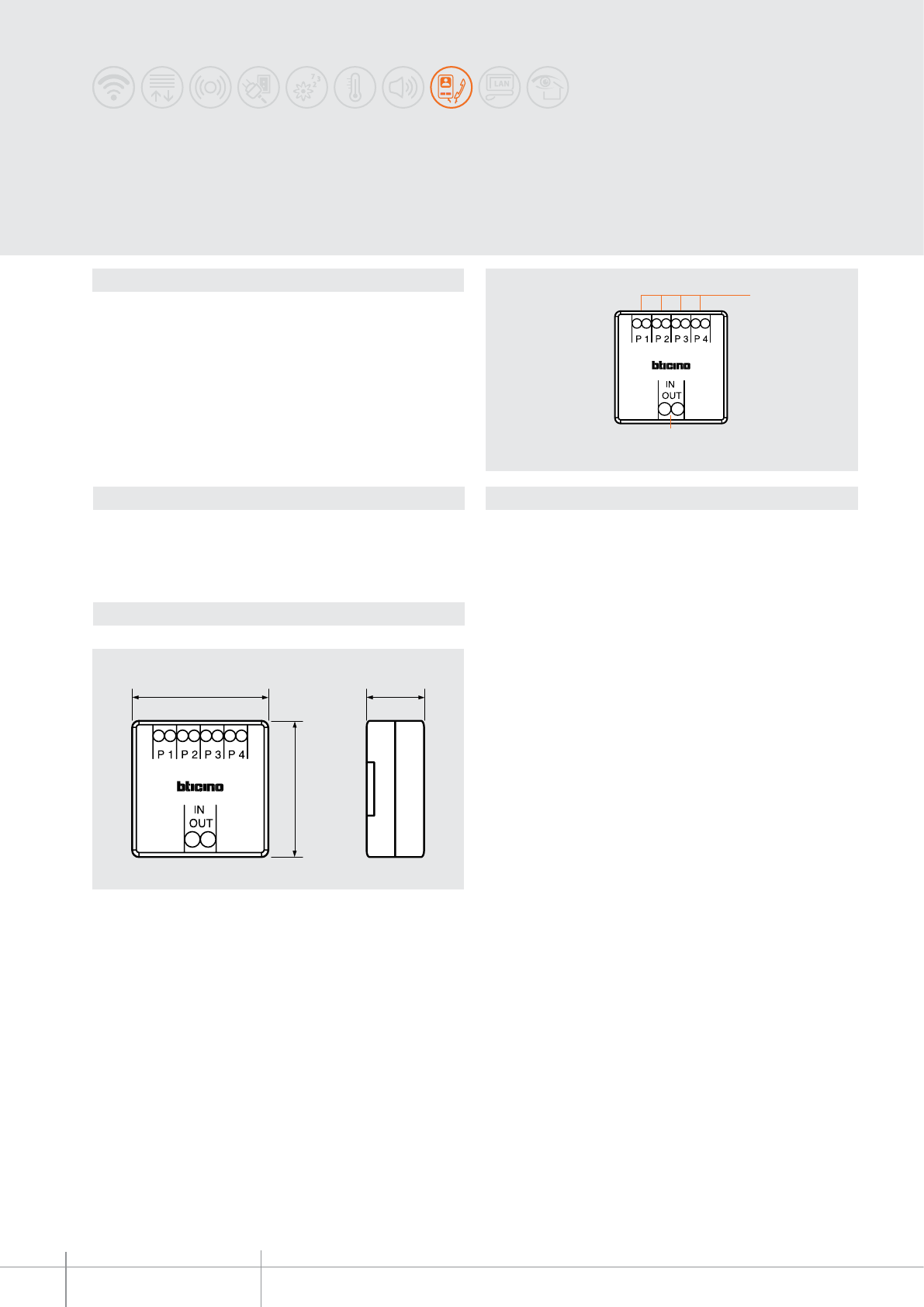
ART. 346841
1
2
40 mm 18 mm
40 mm
ART. 346841
BT00672-a
346841
-EN
TECHNICAL SHEETS
396 2 WIRE VDE system
Description
The oor distribution block can be used for video door entry systems with a star
distribution of the wiring.
The distribution block is in a plastic enclosure with much reduced dimensions for easier
positioning (above all during the refurbishments) even with the installation inside ush
mounted boxes.
It is also possible to install systems with combined wiring risers, where a part can be of
IN/OUT type and the other part is used for the oor distribution block.
The device automatically adapts the video signal.
Max. 3 devices (handsets, bells or additional bells) can be connected on the same output.
The device must not be congured.
Legend
1 - 4 outputs (P1, P2, P3, P4) - handset BUS
2 - Input/output of riser (IN-OUT) on the same pair of clamps
Floor shunt
Technical data
Dimensional data
Power supply from SCS BUS: 18 – 27 Vdc
Stand by absorption: 15 mA
Max. operating absorption: 15 mA
Operating temperature: 5 – 40 °C
BASIC plastic enclosure
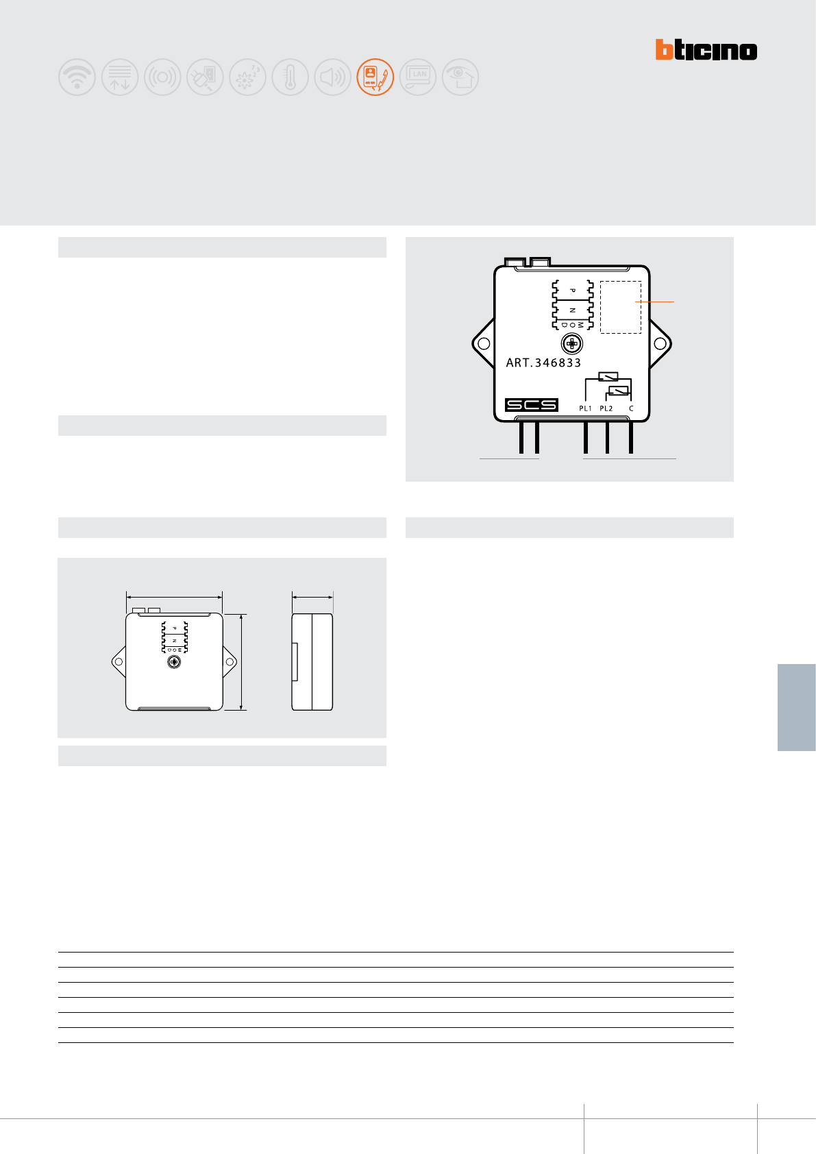
346833
1
2
3
40 mm 18 mm
40 mm
BT00673-a-EN
TECHNICAL SHEETS
397
2 WIRE VDE system
Description
Floor call interface which allows, by means of a traditional pushbutton, to make the
following functions:
- general oor call
- addressed oor call
- staircase light switching on
- Door lock opening (with specic actuator)
- associate the video image to the call to the oor
WARNING: the maximum connection distance between the interface and the
connected pushbuttons must not exceed 3 metres.
Legend
1 - Congurator socket (to access remove the upper plastic protection cover)
2 - Clamps for the connection of the pushbuttons / contacts (connect a pushbutton
between PL1 and C and one between PL2 and C)
3 - Clamps for the connection to the 2-WIRE BUS
Floor call
interface
Conguration
The device must be physically congured in terms of:
N = address of the handset to call
(To be used only with MOD = 0)
P = address of the entrance panel associated to the door lock to open
(To be used only with MOD = 2 and MOD = 3)
MOD = Operating mode
the congurator connected to MOD assigns the operating modes to the pushbuttons
connected between (PL1 and C) and (PL2 and C), as shown in the table:
Technical data
Dimensional data
Power supply from SCS BUS: 18 – 27 Vdc
Stand by absorption: 15 mA
Max. operating absorption: 15 mA
Operating temperature: 5 – 40°C
MOD N P PL1 PL2
0 Handset address (00-99) - Addressed oor call Staircase lights from Handset with 00
1 - - General oor call Staircase lights from Handset with 00
2 - Door lock address (00-95) Door lock opening Staircase lights from Handset with 00
3 - Door lock address (00-95) Door lock opening Door lock opening (P+1)
4(*) Handset address (00-99) Camera address (00-95) - -
(*): see installation notes on next page.
BASIC plastic enclosure

346833
BT00673-a-EN
TECHNICAL SHEETS
398 2 WIRE VDE system
Installation notes
The MOD = 4 conguration mode enables associating the video image of a camera to the
call to the oor generated by the o-door pushbutton.
To use this function correctly, the following must be taken into account:
- The involved handsets, the 346833 interface, and the camera must be physically
connected on the same SCS BUS.
- In multi-family systems connect the involved devices downstream the apartment
interface item 346850 - (cameras and handsets are local resources of the individual
user).
- The active function keeps the SCS BUS busy for approximately 30”, during which no
other call can be forwarded. If the handset connects, the BUS will be busy until the
TIME OUT period elapses, or the handset itself is disconnected.
- Only the following 2-wire BTicino cameras that can be used for this function: 391670
– 391657 – 391658 – 391659 – 391667 – 391668 - 391669 – 391661 – 391662 –
391663.
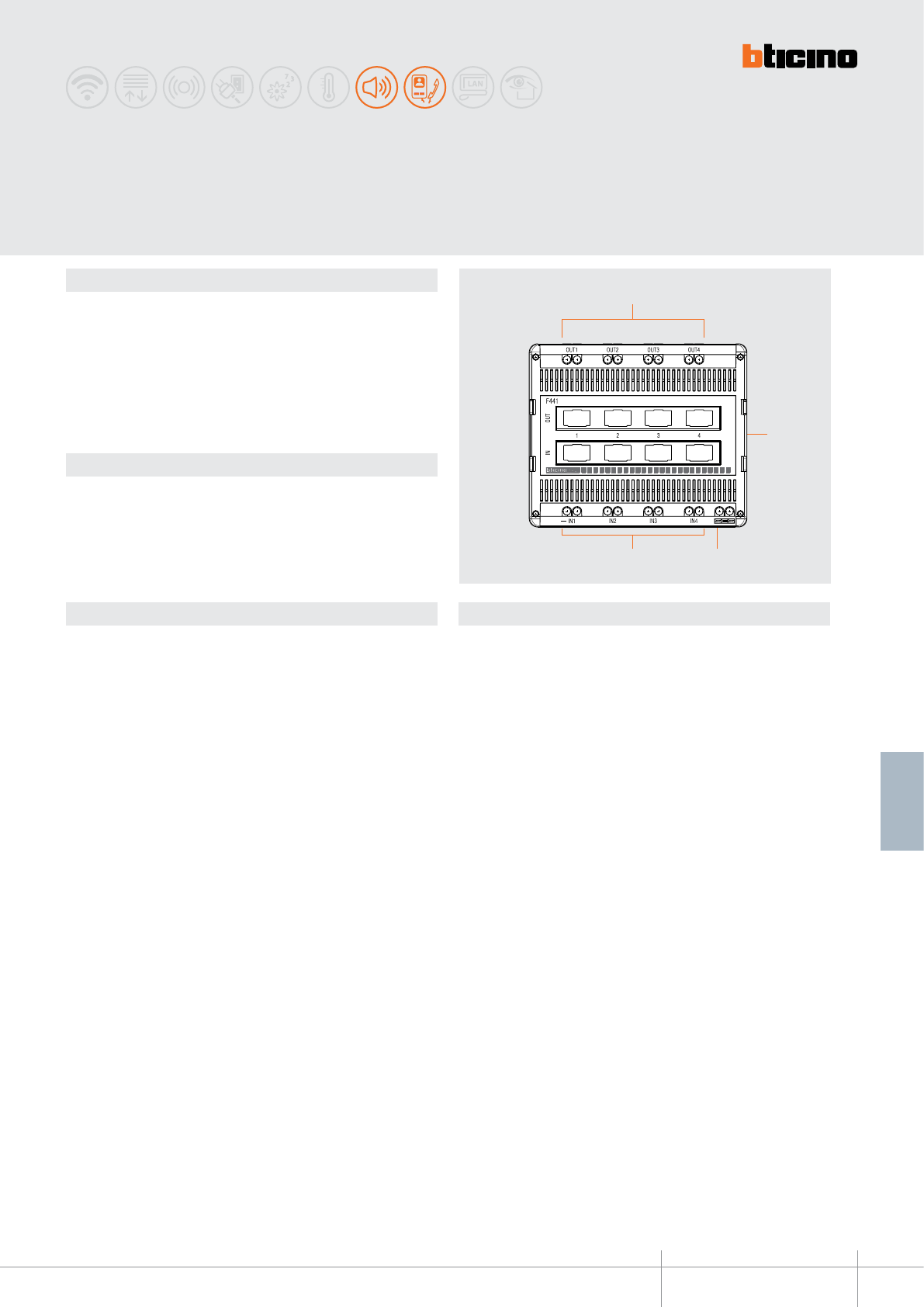
F441
1
4 3
2
BT00674-a-EN
TECHNICAL SHEETS
399
2 WIRE VDE system
Dimensional data Legend
Description
The audio/video node is a mixer device enabling distribution of up to 4 sound sources or
2-wire audio/video risers.
The 4 outputs will all have the same signal coming from the input selected among the
4 available.
The device must not be congured.
WARNING : Connections using both screw clamps and patch cords at the same
time are NOT possible.
Technical data
Power supply from SCS BUS: 18 - 27 Vdc
Absorption from BUS: 20 mA
Dissipated power: 0.5 W
Operating temperature: 5 – 40 °C
Number of inputs available: 4
Number of outputs available: 4
Audio/video node
1 - Output clamps (OUT1 - OUT2 - OUT3 - OUT4) for the connection of 2-wire video risers
or ampliers
2 - Sockets for patch cord connection
3 - Clamps for the connection of the SCS BUS
4 - Input clamps (IN1 - IN2 - IN3 - IN4) for the connection of sound sources or entrance
panels / cameras
6 DIN modules
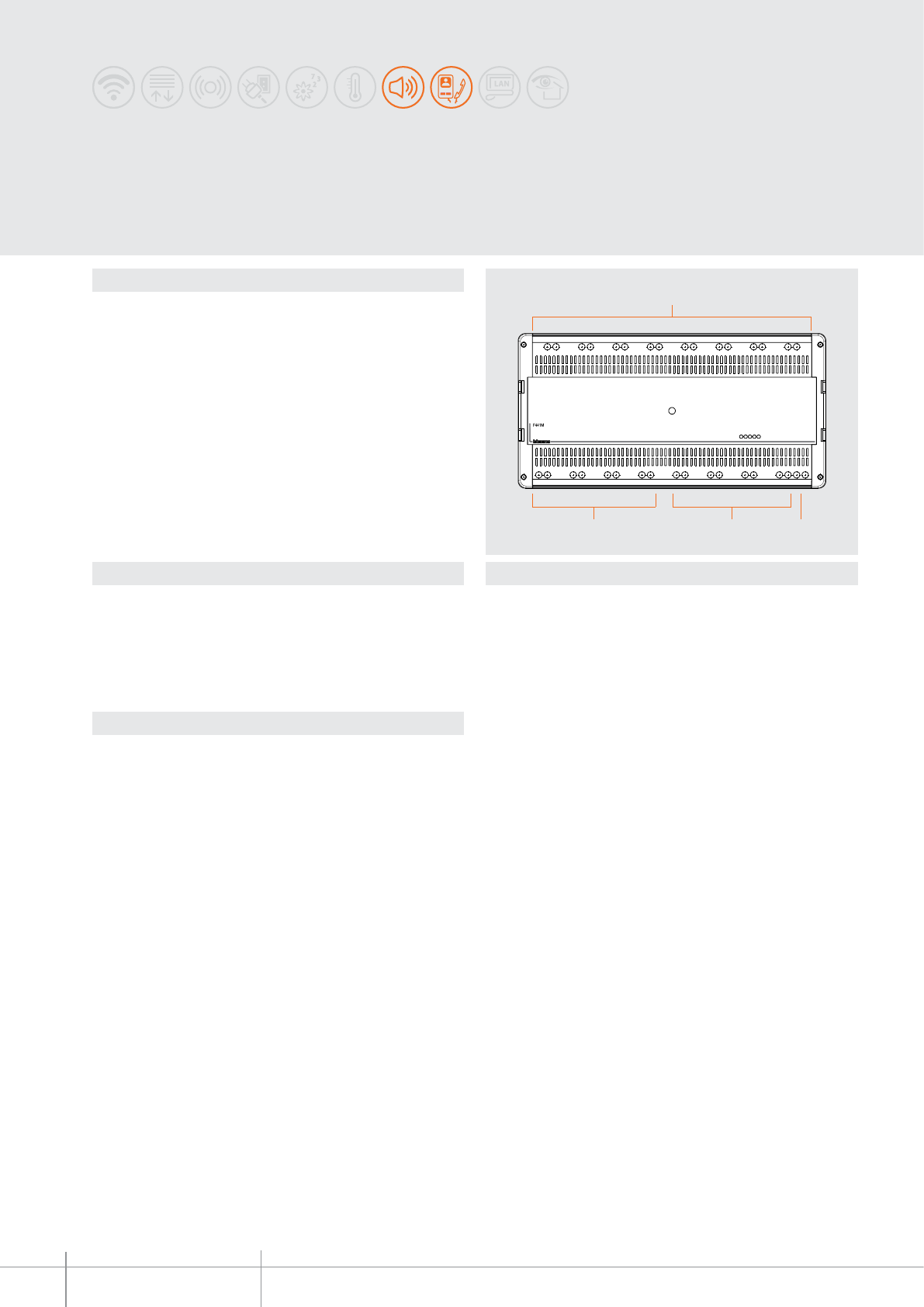
F441M
1
234
BT00675-a
OUT 1 OUT 2 OUT 3 OUT 4 OUT 5 OUT 6 OUT 7 OUT 8
TK1 TK2 TK3 TK4 S1 S2 S3 S4 BUS
-EN
TECHNICAL SHEETS
400 2 WIRE VDE system
Dimensional data
Legend
Description
The multi-channel matrix is a device which can distribute up to 4 stereo sound sources
and a video signal from entrance panels or cameras simultaneously.
The matrix is made up of 8 inputs and 8 outputs (to wire 8 rooms).
Video entrance panels and cameras (rst 4 inputs) and stereo sound sources (last 4
inputs) can be wired in input.
On each output of the matrix there is a clearly separate room.
The rooms must be set in ascending order (room 1 - OUT, room 2 - OUT 2 etc.).
The stereo signals are distributed at the same time and independently on any output.
However, it is not possible for the audio signals of two separate sound sources to be
mixed on the same output branch.
The stereo signal of a sound sources and the video signal of one of the 2-wire video
door entry sources can travel at the same time on the same branch (entrance panel or
camera).
The device must not be congured.
Technical data
Power supply from SCS BUS: 18 - 27 Vdc
Absorption da BUS: 46 - 60 mA
Dissipated power: 1.5 W
Operating temperature: 5 – 45 °C
Number of inputs available: 8
Number of outputs available: 8
Multi-channel matrix
1 - Clamps for the connection of the amplier and the video door entry system handsets.
2 - Clamps for the connection of the SCS BUS
3 - Clamps for the connection of the input sound sources (S1-S2-S3-S4)
4 - Clamps for the connection of the 2-wire cameras / entrance panels (TK1-TK2-TK3-TK4)
10 DIN modules
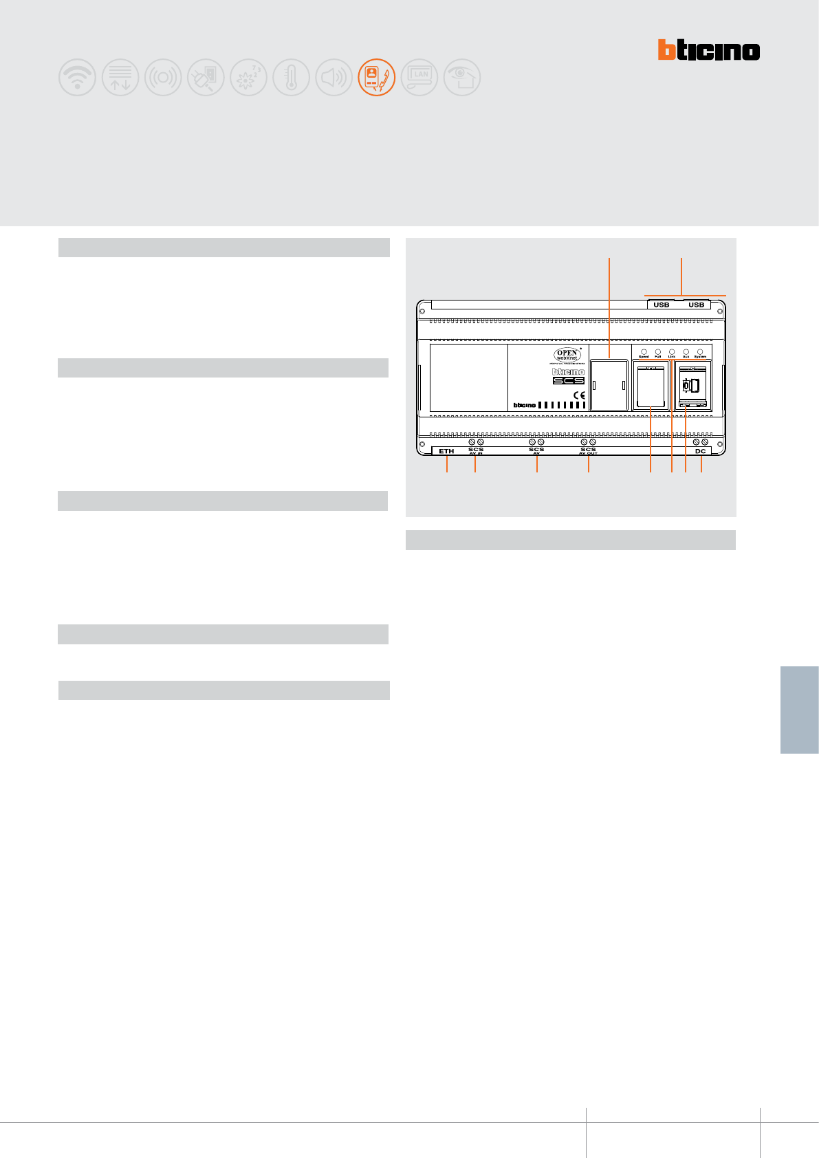
BT00676-a
346890
1 2
5 4 3678910
-EN
TECHNICAL SHEETS
401
2 WIRE VDE system
2 WIRE to IP Interface
Description
2 WIRE/IP interface in 10 DIN modular socket It can be used for the installation of very
large 2 WIRE/IP systems and a high number of devices (entrance panels, handsets
and interfaces). The system will consist of an IP backbone and 2 WIRE risers. Advanced
functions can be managed thanks to the IP switchboard (software).
The device must be configured.
Technical data
Power supply from BUS SCS: 18 - 27 Vdc
Stand by absorption (SCS SIDE): 5 mA
Stand by absorption (DC SIDE): 150 mA
Max. operating absorption (SCS SIDE): 70 mA
Max. operating absorption (DC SIDE) : 300 mA
Operating temperature: 5 - 40°C
Related items
Legend
1. Configurator socket
2. NOT USED (arrangement for future applications)
3. Clamps for the connection of the second power supply, item 346020 (clamps
1- 2)
4. USB ports for PC configuration and Firmware update
+ RESET pushbutton
5. User interface LED for the notification of:
SPEED = connection speed (on = 100 Mbit)
(off = 10 Mbit)
FULL Duplex / HALF Duplex (on = full duplex)
(off = half duplex)
LINK = network found (on = Ethernet network found)
(off = Ethernet network not found)
AUX = NOT USED
SYSTEM = power supply status (on = power connected /operating interface)
(off = power not connected)
6. NOT USED (arrangement for future applications)
7. Clamps for the connection of the 2 WIRE BUS (video door entry system
handsets)
8. Clamps for the connection of the first power supply, item 346000 (BUS clamps)
9. Clamps for the connection of the 2 WIRE BUS (video door entry system
entrance panels)
10. RJ45 for the connection of the 10/100 Mbit Ethernet LAN
346300 Switchboard Suite
346000 A/V power supply
346020 Additional power supply
TiDeviceIP 2 WIRE/IP interface configuration software
C9451 10/100 Mbit switch (wall mounted) - 8 RJ45 ports
C9455 10/100 Mbit switch (DIN 35 rail) - 6 RJ45 ports
Dimensional data
10 DIN modules
Installation notes
The following items must be considered IP devices: switchboard sw (346300), interfaces
(346890), AXOLUTE Outdoor Entrance Panel (349140), AXOLUTE Handset (HD/HC/HS
4690 - 349320 - 349321), if wired in IP mode.
The switchboard software suite offers of several services:
• call management, SoftSwitchboard (the switchboard);
• alarm logger (the server recording alarm events);
• communication framework (always present in the PC);
• alarm manager.
Therefore, a PC unit can include from a minimum of 2 and a maximum 4 IP devices.
For most installations, only one alarm recording service is sufficient.
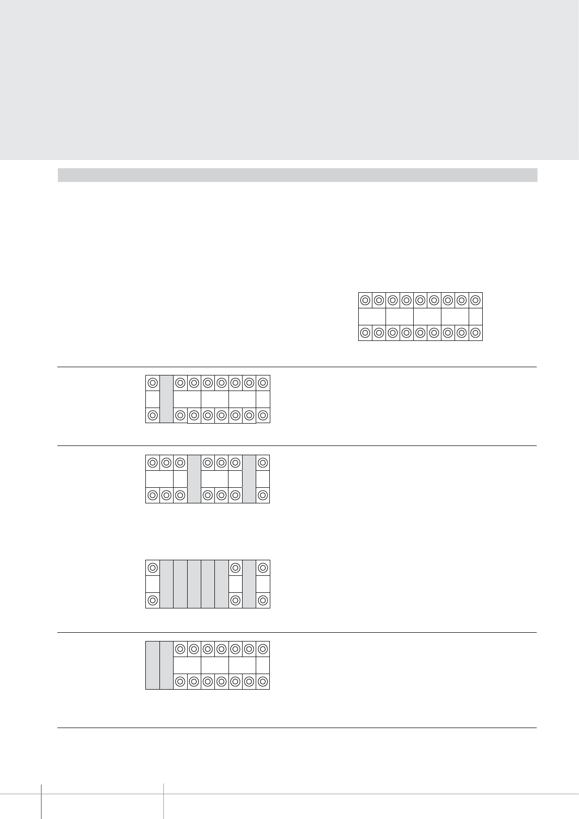
BT00676-a
346890
-EN
TECHNICAL SHEETS
402 2 WIRE VDE system
Configuration
The device must be configured in two different modes:
- Quick configuration (with physical configurator connection)
- Advanced configuration using the TiDeviceIP software (supplied as standard with
the device).
The quick configuration is performed by connecting the physical configurators.
The following parameters must be configured:
M1 - first part of lowest handset address (00 - 99 - OFF)
If M1 = OFF, all other sockets (N1, M2, N2) must not be configured: only entrance
panels must be connected to the interface
The quick configuration provides access to 3 operating modes:
MODE 1 - The device only manages entrance panels and cameras detected automatically.
The number of the IP switchboard called is connected to the C socket (1 to 9).
MODE 2 - The device manages handsets with configurations between N1 and N2 and the
entrance panels/cameras detected automatically. This configuration must be used for
installations with risers with a low number of handsets and low address. The number of the
IP switchboard called is connected to the C socket (1 to 9).
(*) These sockets must be left empty
The devices manages handsets with addresses between (M1 x 100) + N1 < PI < (M2 x 100) +
N2 and entrance panels/cameras detected automatically. The number of the IP switchboard
called is connected to the C socket (1 to 9).
MODE 3 - The device manages handsets with addresses
between M1 x 100 < PI < (M1 x 100) + 99. The number of
the IP switchboard called is connected to the C socket (1 to 9).
(*) These sockets must be left empty
Note: with this configuration mode, the maximum number of devices that may be
connected to the single interface is 95 entrance panels and 3900 handsets.
O
F
F
M1 N1 M2 N2 C
M1 N1 M2 N2 C
11232 9
M1 N2 C
1 2 N1 M2 N2 C
112 ≤ PI ≤ 3209
1200 < PI 1299
N1 second part of lowest handset address (00 - 99)
M2 first part of highest handset Address (00 - 99)
N2 second part of highest handset address (00 - 99)
C IP switchboard address (1 - 9)
* * * * * * *
1 5
M1 N1 M2 N2 C
1 ≤ PI ≤ 5
* * * *
* * * * * *
(*) These sockets must be left empty
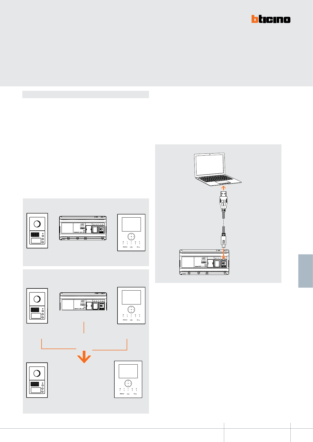
BT00676-a
346890
-EN
TECHNICAL SHEETS
403
2 WIRE VDE system
When the interface is configured using physical configurators, the physical and the
system address are the same; The advanced configuration using the TiDeviceIP software
gives the possibility of exceeding the 2 WIRE system address limit. This is possible by
allocating to the IU (handsets) and the EP (entrance panels) a basic local address. These
addresses give the possibility of increasing the number of handsets (basic max. 3999) and
Entrance Panels (basic max. 95), that can be managed by the video door entry system.
- Handsets: Enter the value which, when added to the physical address of the handsets
connected to the interface, will define their system address (e.g. if the handsets are
configured from 1 to 3999, and the value of 4000 is entered, the system addresses of the
handsets will be between 4001 and 7999).
- Entrance panels and door locks: Enter the value which, when added to the physical
address of the EPs connected to the interface, will define their system addresses (if the
EPs are configured from 1 to 90, and the value of 100 is entered, the system address of
the entrance panels will be from 101 to 190).
PHYSICAL ADDRESS AND SYSTEM ADDRESS
The PC advanced configuration, which can be performed using the TiDeviceIP (CD
supplied), gives the possibility of performing a higher number of functions, of
customising text, and of fully exploiting the system performance features.
In order to transfer the configuration performed using the TiDeviceIP software to the
device, or to update the Firmware, connect the 346890 interface to the PC using an USB
- mini USB cable.
WARNING: to establish connection between the device and the PC, the interface
must be powered and not physically configured.
USB-Mini USB cable
NOTE : PHYSICAL ADDRESS = 2 WIRE ADDRESS
SYSTEM ADDRESS = PHYSICAL ADDRESS + BASE LOCAL EP or HANDSET ADDRESS
346890
PHYSICAL ADDRESS
SYSTEM ADDRESS
HandsetsEntrance panels
Entrance panels
EP physical address
1 – 95
Handsets
Handset physical address
1 – 3999
346890Entrance panels
EP physical address
1 – 95
Handsets
Handset physical address
1 – 3999
EP system address
101 – 190
Handset system address
4001 – 7999
No physical configurator connected
EP local base
address = 100
IU local base
address = 4000
TiDevice IP configuration
+ +
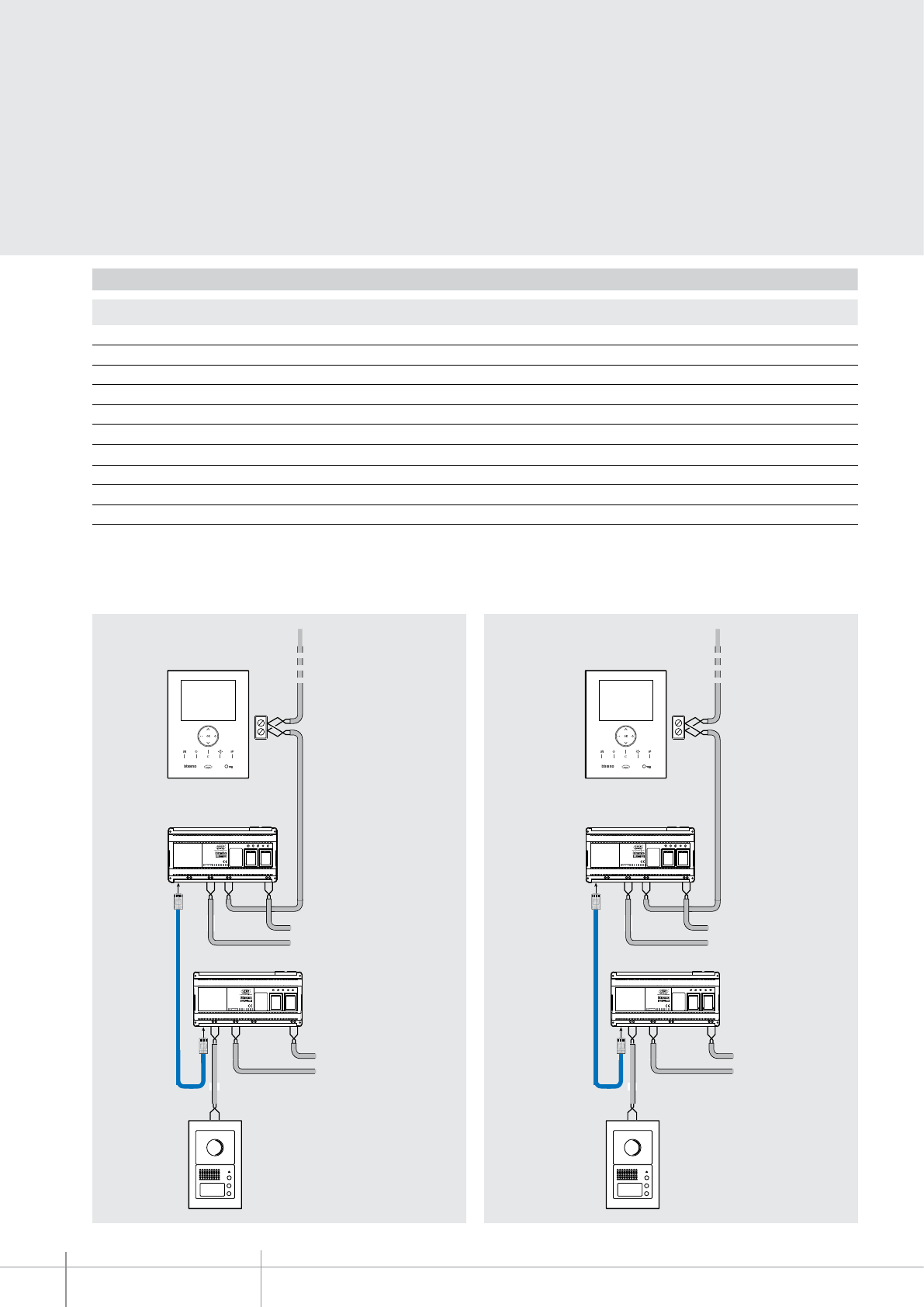
346890
BT00676-a-EN
TECHNICAL SHEETS
404 2 WIRE VDE system
Configuration
Quick Advanced
Max. No. of system Handsets (audio or video) 3,900 10,000
Max. No. of system EPs 95 1,000
Highest address that can be called from the EP 4,000 10,000
Max. no. of IP devices 100 (Note 1) 100 (Note 1)
Max. no. of IP switchboards 9 max.100 IP devices (Note 2)
Advanced management of physical and system addresses
NO YES
Conguration consistency check YES (Note 3) YES
Direct Entrance panel - Handset call NO YES
Activation redirection NO YES
Cycling of cameras NO YES
Physical SCS address System address
Configuration examples
Note 1: the IP switchboard can consist of 2 to 4 IP devices depending on the activation or non-activation of the Alarm logger and the Alarm manager of the IP switchboard itself;
Note 2: the maximum no. of IP switchboards that may be installed is within the limit of the 100 IP devices maximum, taking however into account the requirements of Note 1;
Note 3: the test must be performed using the “TiDeviceIP” software.
LAN
346890
346890
0319 06
USB USB
ETH DC
SCS
AV IN
SCS
AV
SCS
AV OUT
Speed Full Link Aux System
Power supply
BUS
LAN
346890
346890
0319 06
USB USB
ETH DC
SCS
AV IN
SCS
AV
SCS
AV OUT
Speed Full Link Aux System
Power supply
BUS
Calls from
1 to 4000
Handset
Handset from 1 to 4000
Handset base = 0
Entrance panel base = 0
Call base = 0
Handset base = 0
Entrance panel base = 0
Call base = 0
LAN
346890
346890
0319 06
USB USB
ETH DC
SCS
AV IN
SCS
AV
SCS
AV OUT
Speed Full Link Aux System
Power supply
BUS
LAN
346890
346890
0319 06
USB USB
ETH DC
SCS
AV IN
SCS
AV
SCS
AV OUT
Speed Full Link Aux System
Power supply
BUS
Calls from
4001 to 8000
Handset
Handset from 4001 to 8000
Handset base = 4000
Entrance panel base = 0
Call base= 0
Handset base = 0
Entrance panel base = 0
Call base = 4000
LAN
346890
346890
0319 06
USB USB
ETH DC
SCS
AV IN
SCS
AV
SCS
AV OUT
Speed Full Link Aux System
Power supply
BUS
LAN
346890
346890
0319 06
USB USB
ETH DC
SCS
AV IN
SCS
AV
SCS
AV OUT
Speed Full Link Aux System
Power supply
BUS
Calls from
1 to 4000
Handset
Handset from 1 to 4000
Handset base = 0
Entrance panel base = 0
Call base = 0
Handset base = 0
Entrance panel base = 0
Call base = 0
LAN
346890
346890
0319 06
USB USB
ETH DC
SCS
AV IN
SCS
AV
SCS
AV OUT
Speed Full Link Aux System
Power supply
BUS
LAN
346890
346890
0319 06
USB USB
ETH DC
SCS
AV IN
SCS
AV
SCS
AV OUT
Speed Full Link Aux System
Power supply
BUS
Calls from
4001 to 8000
Handset
Handset from 4001 to 8000
Handset base = 4000
Entrance panel base = 0
Call base= 0
Handset base = 0
Entrance panel base = 0
Call base = 4000
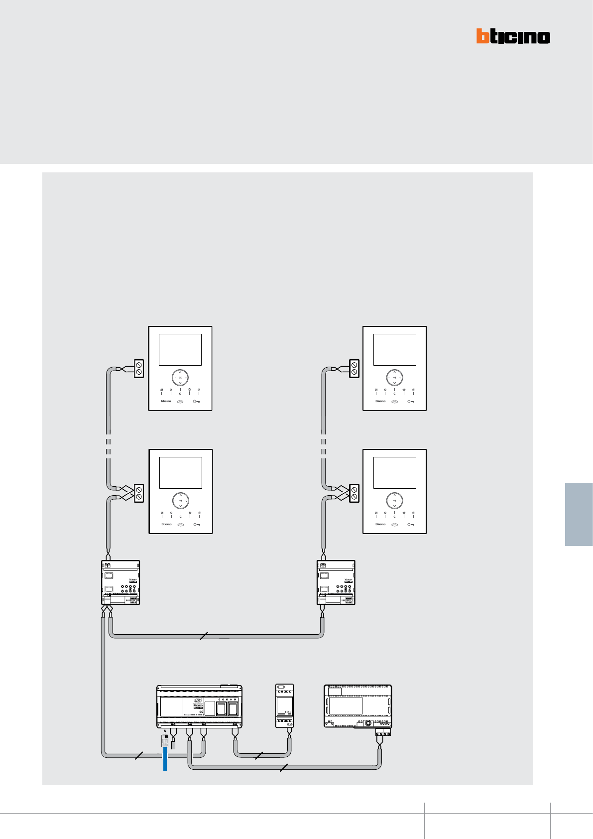
346890
BT00676-a-EN
TECHNICAL SHEETS
405
2 WIRE VDE system
Advanced management of the physical and system addresses of
the handsets
In order to perform (with less than 100 handsets, connected to the 346890 interface) a
configuration with system addresses across the 200 level (e.g. from 190 to 210) on a riser,
the following procedure may be followed (as an example):
• Using physical configurators, to manage less than 100 handsets with address
between 190 and 210, addresses (190 - 199) and (200 - 210) must be recreated on
the 2 WIRE system. For this purpose, two system expansion interfaces, item 346851,
must be used, appropriately configured
Configuration examples
346851
ON
346851
IN T
IN
ON OF F
(Handset from 190 to 199)
346851
ON
346851
IN T
IN
ON OF F
BUS 2 1
346000
346000
2
346890
MOD = 5
M = 1
MOD = 5
M = 2
2
2
346020
PR I
1 - 2
346020
PRI: 220 - 240 V~
175-165m A
50 / 60H z
1-2: 27Vdc
600m A
2
N=90 (190)
N=99 (199)
(Handset from 200 to 210)
N=0 (200)
N=10 (210)
LAN
346890
0319 06
USB USB
ETH DC
SCS
AV IN
SCS
AV
SCS
AV OUT
Speed Full Link Aux System
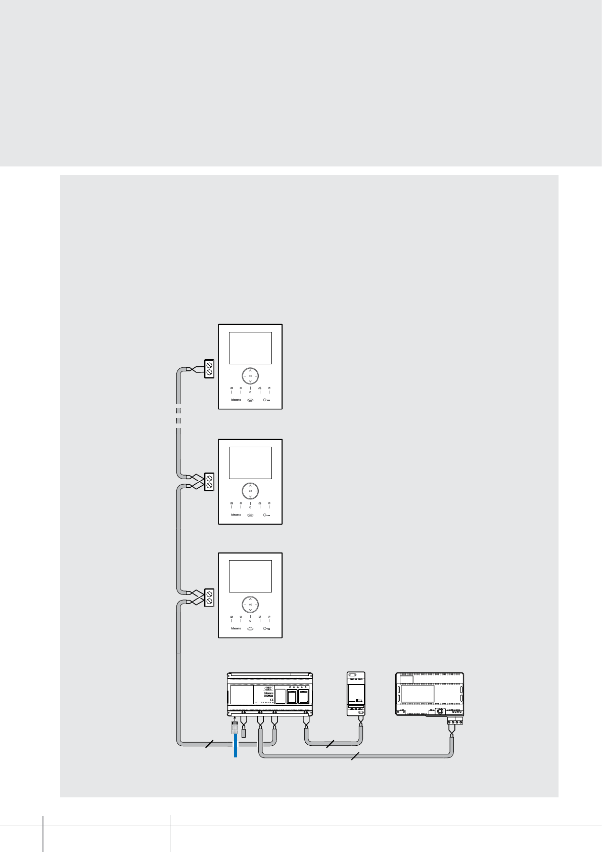
346890
BT00676-a-EN
TECHNICAL SHEETS
406 2 WIRE VDE system
Advanced management of the physical and system addresses
of the handsets
• Using the TiDeviceIP software, in order to perform a configuration with system
addresses across the 200 level (e.g. from 190 to 210) on a riser (with less than 100
handsets, connected to the 346890 interface), it will be necessary to physically
configure the handsets with address between 1 and 21, and then use the advanced
programming procedure, to assign to the 346890 interface a local base address (H =
189), which, when added to the physical address of the handsets, will recreate the
desired interval (189 + 1 = 190), (189 + 21 = 210). This solution does not require the
installation of system expansion interfaces, item 346851.
Configuration examples
(Handset from 190 to 210)
BUS 2 1
346000
346000
2
346890
2
346020
PR I
1 - 2
346020
PRI: 220 - 240 V~
175-165m A
50 / 60H z
1-2: 27Vdc
600m A
2
N=2 (191)
N=1 (190)
N=21 (210)
LAN
Local base address
Handsets = 189
346890
0319 06
USB USB
ETH DC
SCS
AV IN
SCS
AV
SCS
AV OUT
Speed Full Link Aux System
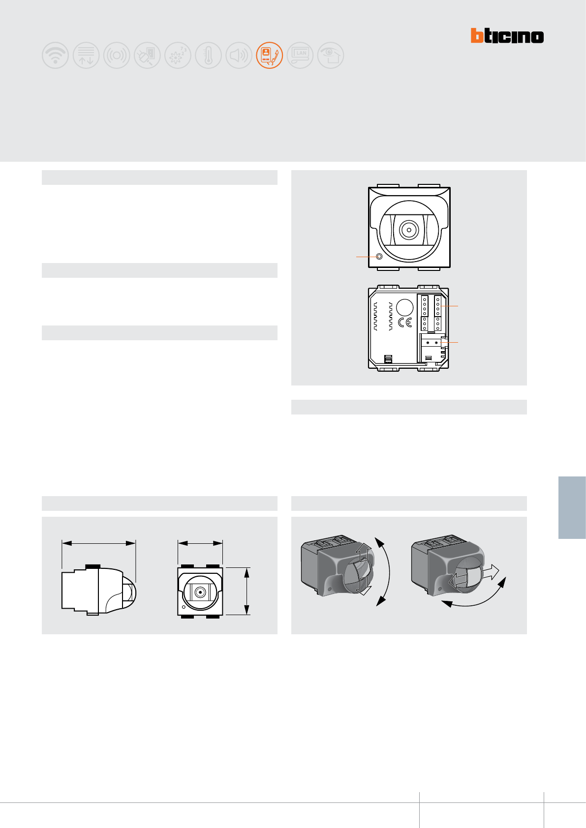
P
N
Z
M
A
PL
2
3
+30°
-30°
+25°
-25°
1
65 mm 43 mm
43 mm
+ 30°
- 30°
+ 25°
- 25°
BT00677-a
391667-391668-391669
-EN
TECHNICAL SHEETS
407
2 WIRE VDE system
Dimensional data Camera adjustment
Legend
Description
2-WIRE black & white indoor camera for video monitoring/video surveillance
functions. Flush mounted or wall mounted installation using the items of the AXOLUTE,
LIVINGLIGHT and LIGHT TECH series.
WARNINGS : do not point the camera towards the sun or towards light sources.
Related items
The device must be completed with the accessories and the front cover plates of the
AXOLUTE, LIVINGLIGHT, LIGHT TECH residential series.
Refer to the corresponding catalogues.
Technical data
Power supply from SCS BUS: 18-27 Vdc
Sensor: 1/3” b/w CCD
Stand by absorption: 5 mA
Max. operating absorption: 160 mA
Lens: “semi pin-hole” 3.7 mm
Interlace: 2:1
Scanning: Standard CCIR
Horizontal frequency: 15625 Hz
Vertical frequency: 50 Hz
Image elements: 537 (H) x 597 (V)
Horizontal resolution: 380 TV lines
Minimum illumination: 1 lux
Operating temperature: 5 – 40 °C
391667-391668-391669
2 WIRE black & white
ush mounted camera
1 - Microphone
2 - Congurator socket
3 - 2 WIRE BUS connection clamp

391667-391668-391669
BT00677-a-EN
TECHNICAL SHEETS
408 2 WIRE VDE system
Conguration
The device must be physically congured in terms of:
P – Camera address
The congurator assigns to the camera the address inside the apartment.
NOTE (*) : connect an OFF congurator here to disable the microphone
(function available for cameras congured from 0 to 9, for other cameras the
microphone cannot be excluded).
N – Address of the handset called in case of alarm
Z – Zone of the alarm system the camera is associated to
M – Mode of operation when a camera is switched on
Each time a camera is switched on (call, selfswitching on, alarm) the MY HOME actuator
and the scenario congured in A and PL are activated. When the camera is switched o,
the associated actuator also switches o, while the scenario remains active.
If an actuator used by the automation system is also associated to the camera, the
actuator will switch itself o when the camera is switched o, even if it was already on
when the camera came on. To avoid this problem, the load should be activated using
an actuator item F411/2, conguring dierent PL and setting the contacts with parallel
connection.
P N Z M A PL
*
M A/PL
M = 0 Address of the SCS control device associated to the camera
M = 1 - 9 Address of the scenarios module associated to the camera
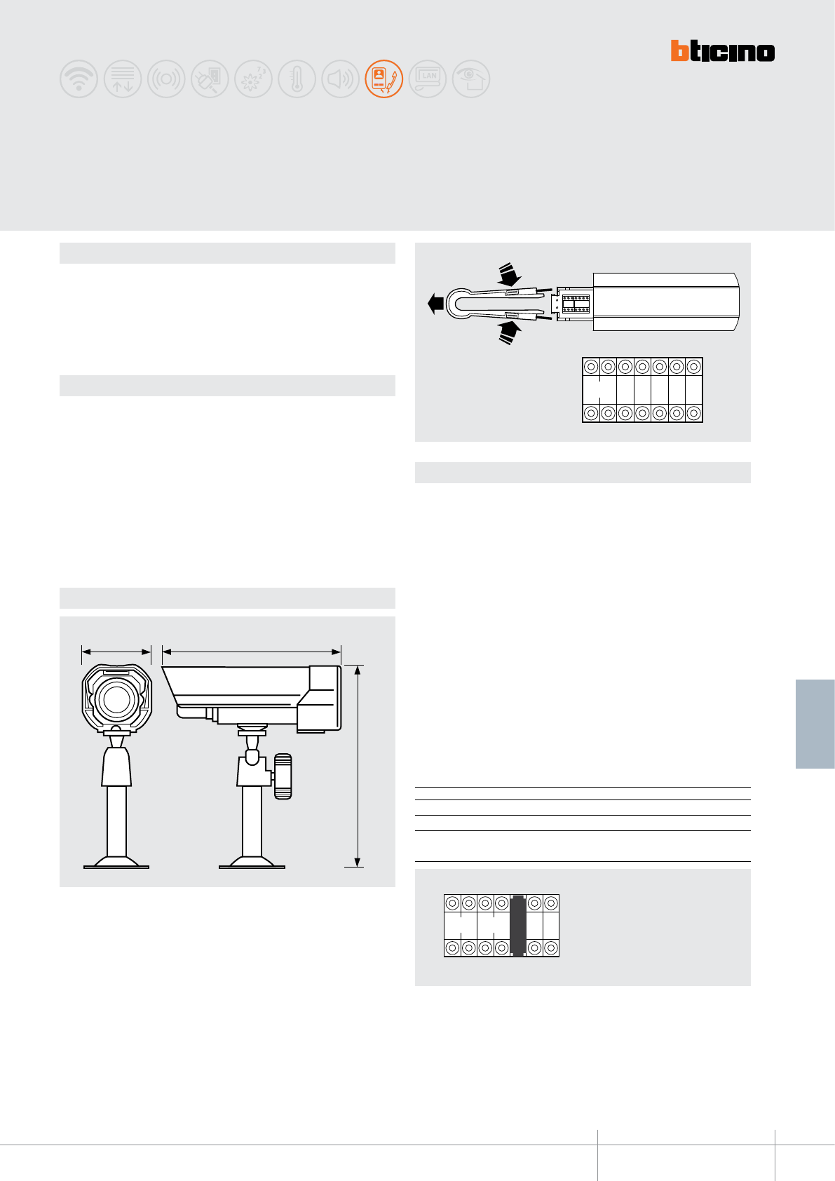
PLN Z P M A
38 mm 98 mm
85 mm
BT00678-a
391670
PI PLAPN
S
L
A
-EN
TECHNICAL SHEETS
409
2 WIRE VDE system
Dimensional data
Conguration
Description
2-wire compact outdoor (IP65) colour camera.
It can be used for video monitoring system installations, or for turning audio systems
into video systems, using a separate camera.
WARNINGS : do not point the camera towards the sun or towards light sources.
Technical data
Power supply from SCS BUS: 18 – 27 Vdc
Enclosure: aluminium
Sensor: 1/3” CMOS colour
Stand by absorption: 5 mA
Max. operating absorption: 65 mA
Lens: f: 6 mm; F: 2.3 mm
Image elements: 628 (H) x 586 (V)
Horizontal resolution: 330 TV lines at the image centre
Minimum illumination: 2 Lux F=2.0
Operating temperature: (-20) – (+70) °C; RH 95% max
Protection index: IP65
Outdoor 2-wire
colour camera
The device must be physically congured in terms of:
P – Camera address
The congurator assigns to the camera the address inside the apartment.
N – Address of the handset called in case of alarm
Z – Zone of the alarm system the camera is associated to
M – Mode of operation when a camera is switched on
Each time a camera is switched on (call, selfswitching on, alarm) the MY HOME
actuator and the scenario congured in A and PL are activated. When the camera is
switched o, the associated actuator also switches o, while the scenario remains
active.
If an actuator used by the automation system is also associated to the camera, the
actuator will switch itself o when the camera is switched o, even if it was already
on when the camera came on. To avoid this problem, the load should be activated
using an actuator item F411/2, conguring dierent PL and setting the contacts
with parallel connection.
M A/PL
M = 0 Address of the SCS control device associated to the camera
M = 1 - 9 Address of the scenarios module associated to the camera
M = SLA Conguration of the audio entrance panel associated to the camera
(see following details)
Pi - Pn = range of audio EP associated to the camera (max.5)
M = SLA
PI - PN = Audio entrance panels associated to the camera (max. 5)
PI = Address of rst associated EP
PN = Address of last associated EP
A/PL = Address of the SCS control associated to the camera
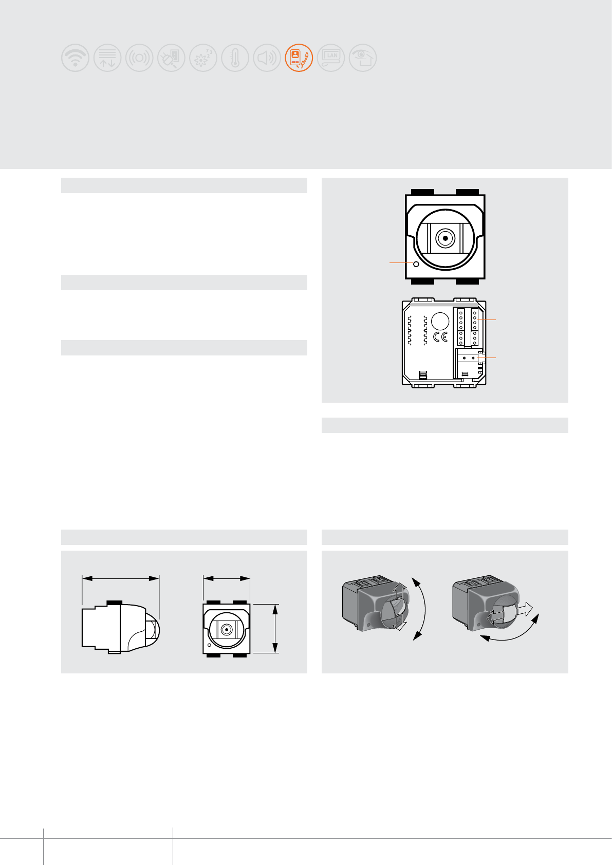
P
N
Z
M
A
PL
2
3
1
391657-391658-391659
391661-391662-391663
65 mm 43 mm
43 mm
+ 30°
- 30°
+ 25°
- 25°
BT00679-a-EN
TECHNICAL SHEETS
410 2 WIRE VDE system
Dimensional data Camera adjustment
Legend
Description
2 wire indoor colour camera for video monitoring system functions. Flush mounted
or wall mounted installation using the dedicated accessories of the AXOLUTE, LIVING,
LIGHT, LIGHT TECH residential series.
WARNINGS : do not point the camera towards the sun or towards light sources.
Related items
The device must be completed with the accessories and the front cover plates of the
AXOLUTE, LIVING, LIGHT, LIGHT TECH residential series.
Refer to the corresponding catalogues.
Technical data
Power supply from SCS BUS: 18-27 Vdc
Sensor: from 1/3” colour CCD
Stand by absorption: 5 mA
Max. operating absorption: 140 mA
Lens: “semi pin-hole” 3.7 mm
Interlace: 2:1
Scanning: Standard CCIR
Horizontal frequency: 15625 Hz
Vertical frequency: 50 Hz
Image elements: 537 (H) x 597 (V)
Horizontal resolution: 380 TV lines at the image centre
Video signal: PAL compatible
Minimum illumination: 5 lux
Operating temperature: 5 – 40 °C
Flush mounted
2 wire indoor colour camera
1 - Microphone
2 - Congurator socket
3 - 2 WIRE BUS connection clamp
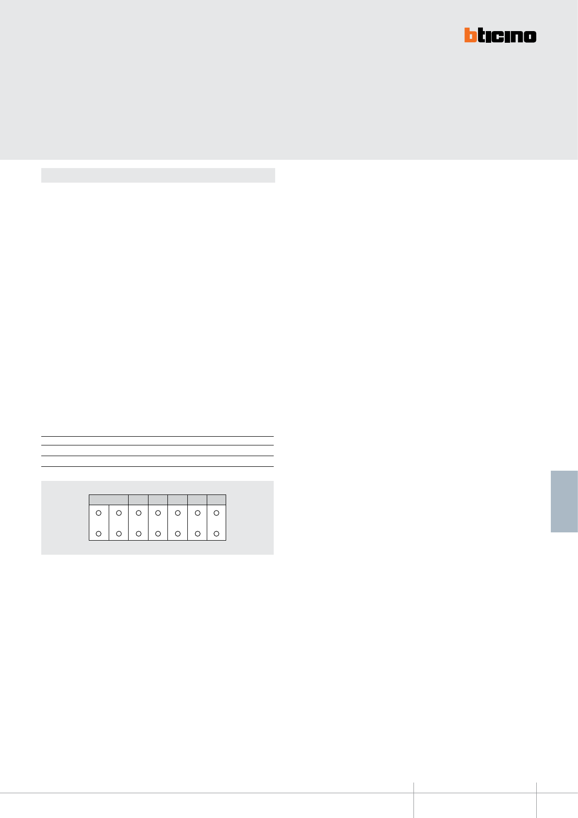
391657-391658-391659
391661-391662-391663
BT00679-a-EN
TECHNICAL SHEETS
411
2 WIRE VDE system
Conguration
The device must be physically congured in terms of:
P – Camera address
The congurator assigns to the camera the address inside the apartment.
NOTE (*) : connect an OFF congurator here to disable the microphone
(function available for cameras congured from 0 to 9, for other cameras the
microphone cannot be excluded).
N – Address of the handset called in case of alarm
Z – Zone of the alarm system the camera is associated to
M – Mode of operation when a camera is switched on
Each time a camera is switched on (call, selfswitching on, alarm) the MY HOME
actuator and the scenario congured in A and PL are activated. When the camera is
switched o, the associated actuator also switches o, while the scenario remains
active.
If an actuator used by the automation system is also associated to the camera, the
actuator will switch itself o when the camera is switched o, even if it was already
on when the camera came on. To avoid this problem, the load should be activated
using an actuator item F411/2, conguring dierent PL and setting the contacts
with parallel connection.
M A/PL
M = 0 Address of the SCS control device associated to the camera
M = 1 - 9 Address of the scenarios module associated to the camera
P N Z M A PL
*
P N Z M A PL
*
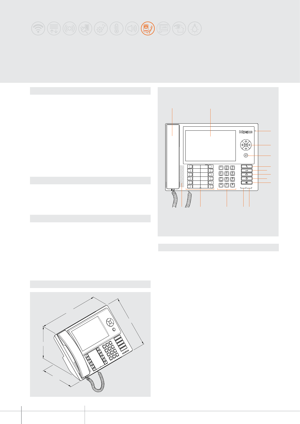
346310
BT00680-a
290 mm
170 mm
170 mm
210 mm
1 2
3
11
4
5
6
78
10
9
12131415
-EN
TECHNICAL SHEETS
412 2 WIRE VDE system
Description
Switchboard for 2 WIRE audio and video systems. It provides access to various services
(video door entry system functions, door lock and/or stair light management, and
monitoring of apartment alarms) directly from the keyboard, or using the intuitive
icons menu. The switchboard is supplied with built-in table-top support and has a
7”colour LCD display, receiver and handsfree, dedicated keys for the main functions,
and configurable keys. Programming can be performed directly from the device, or
using a PC with the TiSwitchBoardDevice software installed (supplied). It gives the
possibility of creating a directory of handsets, entrance panels, and switchboard.
the device DOES NOT MANAGE secondary EPs and apartment EPs (connected
downstream the apartment interface 346850). The use of additional power supply
is recommended.
It is possible to connect up to maximum 16 switchboards (configured from 0 to 15).
WARNING: the switchboard cannot be used in systems with 2 WIRE IP interface
346890.
Technical data
Power supply from SCS BUS: 19 – 27 Vdc
Absorptions from BUS (without additional supply):
- stand by absorption: 35 mA
- max. operating absorption: 450 mA
Absorptions from BUS (with additional supply):
- stand by absorption: 5 mA
- max. operating absorption: 20 mA
Operating temperature: 5 - 40 °C
Load of relay contacts: 24 Vac / 24 Vdc
3 A, cosφ = 1
Dimensional data
Legend
1. Handset
2. 7” colour LCD display for the displaying of the user and programming menu
and of the images recorded by the entrance panel or cameras
3. Microphone
4. Navigation keypad. It enables navigating through the menus, with the
possibility of confirming the selection (OK key)
5. Cancel key
6. Direct call key
7. Door lock release key
8. Directory access key
9. Entrance panel and camera cycling activation key
10. Handsfree key
11. Alarm warning LED
12. Operation status LED:
LED ON (steady)=device in stand-by
LED ON (flashing quickly)=call pending
LED ON (flashing slowly)=busy
13. Alphanumeric key
14. Keypad + legend of configurable functions
15. Loudspeaker
Related items
336982 LIVINGLIGHT white series 8 pole socket for table-top installation of the
switchboard
336803 (8 poles - frayed) cable for table-top installation of the switchboard
346020 additional 2 DIN modules power supply
Front view
2 WIRE Switchboard
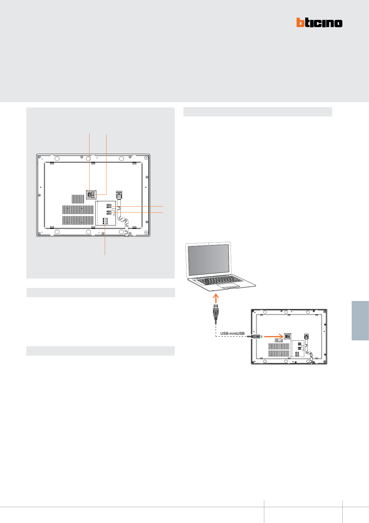
BT00680-a
346310
1 2
3
4
5
-EN
TECHNICAL SHEETS
413
2 WIRE VDE system
Legend
1. Mini-USB connector for PC connection
2. Line termination ON/OFF micro-switch
3. Clamps for the connection of the 2-WIRE SCS BUS BTicino
4. Additional power supply connection clamps (1 - 2)
5. Clamps for the connection of the power supply of the audible signal device
(optional)
Rear view Conguration
The switchboard must be configured as far as:
- Setting of the local switchboard address (0 or 1 - 15)
- Setting of the associated entrance panel address (1 - 80)
- Setting of any associated service handset
Two different configuration modes are available:
- directly from the icon menu of the switchboard
-
using a PC with the TiSwitchboardDevice software installed (available in the CD supplied)
WARNING: certain specific functions, such as the filling of the directories and the
management of the ringtones, require the configuration to be performed using the PC.
To transfer the configuration performed using the software or to update the device,
connect the switchboard to the PC using the USB-mini cable.
Functional notes
The maximum installation distances are the same as for 2 WIRE handsets.
Calls from entrance panels are received by all switchboards connected to the system
(the first switchboard answering takes the call).
Calls from handsets may be managed in two different ways (based on the configuration
of the handsets themselves):
mode 1 – handsets configured with P=0 – the calls from these handsets are received
by all the switchboards of the system (the first switchboard answering takes the call).
mode 2 – example, Handset configured with P=81 – the calls from these handsets
are only received by the secondary switchboard configured with 1; handsets configured
with P=95 – calls from these Handsets are only received by the secondary handset
configured with 15.
The management of the operating mode (day/night) is only entrusted to the main
switchboard (configured with 0).
To enable communication the device must be powered.
