Technics SU 8022 Amplifier Stereo Integrated Service Manual
User Manual: Technics-SU-8022-Service-Manual
Open the PDF directly: View PDF ![]() .
.
Page Count: 10

U-S022!X
• CHANGE
OF
PARTS
LIST
(0), (OG), (XGH), (XE), (XSW) ,(EB)
Notes:
This
parts
list
included
only
the
change
of
the
model
SU-8022
parts
list_
Ref.!
Change
of
Part No. I Part Name & Description
No-l
SU-8022
..
SU-8022K
i
CABINET
and
CHASSIS
PARTS
1 I S8NS13 S8NS33 I Knob. Volume Control
I , I Knob,
Bass,
Treble, Balance &
2 , SBN815 S8NS35
i I
Input
Selector
Switch
3 i SGWUS022D SGWU8022KD i Panel, Front Ass'y 18lack)
4 i
SBD21
S8D21-1 I Knob, Loudness,
Rec
Mode, Tape
, I
MOnitor
Switch
5 i SHR5037 ! SHR5037-1 1 Spacer, Loudness
Switch
6 I SHR5043
! SHR5043-1 !
Spacer
Rec
Mode,
Tape
Monitor
I Switch
9 S8C211 i
,Button,
High Filter, Subsonic
I I S8C211-1 I Filter
and
Speaker Switch
13
I S8C209 I S8C209-1 !
Button.
Power
Switch
! SGP1790A [01 I i
SGPUS022D
[XE,
XGH, I
i I SGP17908 [01 I
Rear
Panel
20
I XGF, DG,
E81
I
i
[xALI
! SGPUB022L SGPUB022KD [DG, XGH, i
Rear
Panel, SGP17908
with
I SGPUB022W [XSWI
E8,XEI
I
Name
Plate ISGT20150)
I SGP1790-1A
[X,
XAI
I SGPU8022KW
[xSWI
I.Rear Panel, SGP17908
with
Name
Plate ISGT2061
0)
I RJA23ZC [D, XGH, XGF, : RJA23ZC [D, DG,
E8,
I
AC
Cord,
with
Plug
,
23 I
EB,DG,XSWI
XGH,XSWI
RJA45ZC
[X
El I ,
SJAll1
[X,
XAI
i RJA45ZC
[XEI
AC
Cord
i QFC1207M
[xALI
I
i SHR127 I SHR127 !
;
[0,
DG, XGH, E8,
xswl
8ushing,
AC
Cord
24 i SHR129
[xEI
only i SHR129
IXEl
:
Bushing,
AC
Cord
I SKA 10676
SKA10677[D.
DG,XGH,EBiI
Cabinet IBlack)
25
I SKAU8022E
[XE,
xswl
SKAU8022KE
[XSW, XEI ! Cabinet IBlack)
SCREWS
and
WASHERS
~
I XTB4+8FFN XTB4+SFFZ I Screw, Cabinet M'tg
~i
XTB3+8BFN XTB3+SFFZ I Screw, Cabinet M'tg
PACKING
PARTS
:
SPS2177
P2
1
SPS2177-1
[XALI
only SPS2177 I
Pad,
Left Side
l
SPS2179
i SPS2179 i
P3
I
SPS2179-1
[xALI
only i
Pad,
Right
Side
SPG2077 [01 I !
I SPG2079 I
!
[XE,XGH,EB,DG.XSWI
P5
i SPG20Bl
[X,
XAI
I SPG20S5
Carton
Box
I SPG2083
[xALI
I
SPG20B7
[XGFI
!
P6
1
SQF10199 [D, XGH, I SQF10199
Instructions
Book,
Printed
Matter
XGF, EB, DG,
xswl
1
[0,
DG, XGH, EB,
xswl
I SQF10201 I SQF10201
[XEI
[,nstructions Book, Printed Matter
[XE,
X,
XA,
XALI
I
Notes:
ID)
and
lOG)
are available in
Scandinavia
and
European
only.
(XGH)
is
available in
Holland
only.
(XE)
is
available in
United
Kingdom
only.
(XSW)
is
available
in
Switzerland
only.
(EB)
is
available in
Belgium
only.
Printed
in Japan
7902-6S00G
0·
·
..
t:~.
S
ORDER!.NfY:SD7902-1!i·-
,
..
. • "
M··"':
. . .
.•.
,.~--
..
.
eMce
-:
anua
SU-8022K
Stereo I ntegrated Amplifier
SU-80:22
(0), (OG), (XGH), (XGF),
(EB),
(XE), (XSW),
(X),
(XA),
(XAL)
SU-8022K
(0), (OG), (XGH),
(XE),
(XSW) , (EB)
'~~models
SU-S022
(0,
DG)
and
SU-8022K
ID,
DG)
,re
available
in
Scandinavia
and European
only.
:The
models
SU-8022
IXGH)
and
SU-S022K
(XGH)
are
available
in
Holland
only.
•
The
model
SU-S022
(XGF)
is
available in France
only.
•
The
model
SU-8022
(ES)
and
SU-8022K
(ES)
are
available
in
Belgium
only.
•
The
models
SU-S022
(XE)
and
SU-8022K
(XE)
are
available
in
United
Kingdom
only.
•
The
models
SU-8022
(XSW)
and
SU-8022K
(XSW)
are
available
in
Switzerland
only,
•
The
models
SU-S022
(X,
XA)
are
available in Asia
Latin
America,
Middle
East and
Africa
only.
'
•
The
model
SU-S022
(XAU
is
available in Australia
only.
TECHNICAL
SPECIFICATIONS
[DIN
45
500]
Specifications
are
subject
to
change
without
notice
for
further
improvement.
AMPLIFIER SECTION
20
Hz
-
20
kHz
continuous
power
output
both
channels
driven
40
Hz
-16
kHz
continuous
power
output
both
channels
driven
2 x 40 W
(40),2
x
35
W (SO)
2 x 35W (SO)
1
kHz
continuous
power
output.
both
channels
driven
Power
bandwidth
both
channels
driven.
-3
dB
Total
harmonic
distortion
rated
power
at
20
Hz
~
20
kHz
rated
power
at
40
Hz
-
16
kHz
rated
power
at
1
kHz
half
power
at
20
Hz
~
20
kHz
half
power
at
1
kHz
-26
dB
power
at
1
kHz
SOmW
power
at
1
kHz
Intermodulation
distortion
2 x
45
W
(4D1,
2 x
38
W
(SDI
5
Hz
~
30
kHz
(4D)
5
Hz
~
30
kHz
(SDI
0.05%
(40),0.03%
(SO)
0.05%
(40),0.03%
(SO)
0.05%
(401.
0.03%
(SD)
0.02%
(SDI
0.008%
(SDI
0.15%
(40)
0.2% (4D1
rated
power
at
250
Hz:
a
kHz
=
4:1.
40
0.05%
rated
power
at
60
Hz:
7
kHz
=
4:1.
SMPTE.
aD 0.03%
ReSIdual
hum
& noise
0.6
mV
(0.6
mV,
IHF)
Damping
factor
16
(4D),
32
(SDI
Input
sensitivity
and
impedance
PHONO
TUNER.AUX
TAPE
1.
PLAYBACK
PHONO
maximum
input
voltage
(1
kHz.
RMS)
Technics
2.5
mV/47
kO
150
mV/27
kO
lS0
mV/33
kO
150
mV
SIN
rated
power
at
40
PHONO
TUNER.AUX
72
dB
(IHF,
A:
80 dB)
S6
dB
(IHF,
A:
97
dB)
-26
dB
power
at
40
PHONO
62 dB
TUNER.
AUX
63
dB
50
mW
power
at
40
PHONO
62 dB
TUNER.AUX
62dB
Frequency
response
PHONO
R I
AA
standard curve
30
Hz
~
15
kHz,
±O.S
dB
TUNER.
AUX.
TAPE
20
Hz
~
20
kHz,±0.5
dB
Tone
controls
High
filter
Subsonic
filter
BASS
TREBLE
10
Hz
~50
kHz,
-1
dB
50
Hz,
+10
dB
~-10
dB
20
kHz,
+10
dB
~-10
dB
7
kHz,
-6
dB/oct.
Loudness
switch
(volume
at
-30
dB)
Output
voltage
and
impedance
REC
OUT
30
Hz,
-6
dB/oct.
50
Hz,
+9 dB
150
mV
30
mV/S2
kO
± 1.0
dB
55
dB
330
mV/3300
4~160
8~160
REC/PLAY
Channel balance
(250
Hz
~6300
Ht).
AUX
Channel
separation
at
1
kHz
AUX
Headphones
output
level
and
impedance
Load
impedance
MAIN
or
REMOTE
MAIN
+
REMOTE
GENERAL
Power
consumption
Power
supply
(50
Hz/60
Hz)
Dimensions
(W x H x
D)
Weight
400W
11
OV
/120V
/220V
/240V
430
x 97 x
240
mm
(
16-29/32"x3-13/16"x9-7/16")
5.4
kg
(11.9 Ib.)
Matsushita
Electric
Trading
Co.,
Ltd_
PO.
Box
288, Central Osaka
Japan

U-B022/K
TECHNISCHE OATEN
[DIN 45 500]
Spezifikationen konnen
infolge
von Verbesserungen oh ne
Ankundigung
geiindert werden.
VERSTARKERTEIL
Dauertonleistung bei
20
Hz
-
20
kHz
beide Kaniile zusammen ausgesteuert
Dauertonleistung bei
40
Hz
-
16
kHz
beide Kaniile zusammen ausgesteuert
Dauertonleistung bei 1
kHz
beide Kaniile zusammen ausgesteuert
2x
35W
(SO)
2x
40W
(40)
2 x
35
W
(So)
2 x
45
W
(4D),
2 x 38 W (SO)
Leistungsbandbreite
beide Kaniile zusammen ausgesteuert,
-3
dB
5 Hz
-30
kHz
(40)
5 Hz -30 kHz (SD)
Harmonische Verzerrungen
Nennausgangsleistung bei
20
Hz -
20
kHz
0,05%
(4D)
0,03%
(So)
Nennausgangsleistung bei
40
Hz
-16
kHz
0.05%
(40),0,03%
(So)
Nennausgangsleistung bei 1
kHz
0,05%
(4D),
0,03% (SO)
Halber Ausgangsleistung bei 20
Hz
-
20
kHz
0,02%
(S
D)-
Halber Ausgangsleistung bei 1
kHz
O,OOS%
(S
D) _
-26
dB
Ausgangsleistung bei 1
kHz
0,15%
(40)
50
mW Ausgangsleistung bei 1
kHz
0,2%
(4D)
Intermodulationsverzerrung
Nennausgangsleistung bei
250
Hz:
8
kHz
=
4:1,
4D
0,05%
Nennausgangsleistung bei
60
Hz:
7
kHz
=
4:1,
SMPTE
8D
Brummen & Rauschen
Diimpfungsfaktor
Eingangsempfindlichkeit & Impedanz
0,03%
0,6
mV
(0,6
mY,
IHF)
16
(40),
32 (SO)
PHONO 2,5
mV
/47
kD
TUNER,AUX
150mV/27kD
TAPE
1,
PLAYBACK
lS0
mV/33
kD
PHONO Maximale Eingangsspannungen
(1
kHz
RMS) 150
mV
Fremdspannungsabstand
Nennausgangsleistung bei 4 D
PHONO
72
dB
(lHF,
A:
SO
dB)
TUNER,
AUX
S6
dB
(lHF,
A:
97
dB)
-26
dB
Ausgangsleistung bei
4D
PHONO
62
dB
TUNER,AUX
63dB
50
mW Ausgangsleistung bei
4D
PHONO
62
dB
TUNER,AUX
62
dB
Frequenzgang PHONO
RIAA
Standardkurve
30
Hz-15
kHz,±O,S
dB
TUNER,
AUX,
TAPE
20
Hz-20
kHz,±0,5
dB
10
Hz
-50
kHz,
-1
dB
BASSE
50Hz,+10dB--l0dB
HOHEN
20kHz,+10dB--l0dB
Unterschallfilter
30
Hz,
-6
dB/oct.
Klengragler
Hochton
filter
7
kHz,
-6
dB/oct.
Gehorgerechte
Lautstiirkekonektur
(Lautstiirke
bei
-30
dB)
AusgangtlPllnnungen & Impedanz
REC
OUT
REC/PLAY
Kanalabweichung
(250
Hz
-6300
Hz),
AUX
Kanaltrennung bei 1
kHz,
AUX
Kopfhorerpagel
und
Ausgangsimpedanz
Lautsprecher·Ausgangsimpedanz
MAIN
oder
REMOTE
MAIN
und
REMOTE
ALLGEMEINE OATEN
50
Hz,
+9
dB
150mV
30
mV/S2
kD
±l,OdB
55dB
330
mV/330D
Leistungsaufnahme
400
W
Netzspannung umschaltbar
(50
Hz/60
Hz)
110V/120V/220V/240V
Abmessungen (B x H x
T)
430
x 97 x
240
mm
Gewicht
5.4
kg
CARACTERISTIOUES TECHIOUES
[DIN 45 500]
Sujet a changement
sans
prElaris.
PARTIE AMPLlFICATEUR
Puissance de sortie
continue
de 20
Hz
-20
kHz
les
deux canaux en
circuit
avec distorsion
Puissance de sortie
continue
de
40
Hz
-
16
kHz
les
deux canaux en
circuit
avec distorsion
Puissance de sortie
continue
a 1
kHz
les
deux canaux en
circuit
avec distorsion
Largeur de bande de puissance
2 x
35
W
(So)
2 x 40 W
(4D)
2 x
35W
(SD)
2 x 45 W
(4D)
2 x 38 W (SO)
pour
I'ensemble des canaux excites,
-3
dB
5 Hz -
30
kHz
(4D)
5 Hz -30 kHz
(So)
Distorsion
harmonique
totale
pour
la puissance mesuree a 20
Hz
-20
kHz
0,05%
(40)
0,03% (SO)
pour
la puissance mesuree a 40
Hz
-16
kHz
0,05%
(4D),
0,03%
(Sm
pour
la puissance mesuree a 1
kHz
0,05%
(40),0,03%
(SD)
pour
la demi'puissance mesuree a
20
Hz
-
20
kHz
0,02% (SO)
pour la demi·puissance mesuree a 1
kHz
O,OOS%
(So)
pour
une
puissance mesuree de
-26
dB,
1
kHz
0,15%
(4D)
pour
une
puissance mesuree de
50
mW,
1
kHz
0,2%
(4D)
Distorsion
d'intermodulation
pour
la puissance mesuree a
250
Hz:
8
kHz
=
4:
1,
4D
0,05%
pour
la puissance mesuree a
60
Hz:
7
kHz
=
4:1,
8D
0,03%
Tension residuelle de
bruit
0.6
mV
(0.6
mV,
I H
F)
Facteur d'amortissement 16
(4D),
32
(SO)
Sensibilite & impedance d'entree
PHONO
TUNER,AUX
TAPE
1,
PLAYBACK
2,5
mV/47
kD
150mV/27kD
lS0
mV/33
kD
Voltage d'entree
maximum
(PHONO, 1
kHz,
RMS)
Repport
signal/bruit
150mV
pour
la puissance nominale,
4D
PHONO
TUNER,AUX
pour
une sortie de
-26
dB,
4D
72
dB
(lHF,
A:
SO
dB)
S6
dB
(iHF,
A:
97 dB)
PHONO
62dB
TUNER,AUX
63dB
pour
une sortie de
50
mW,
4D
PHONO 62 dB
Reponse de frilquence
PHONO
TUNER,AUX
TUNER,AUX,TAPE
62dB
eou
rbe standard R
IAA
30
Hz -
15
kHz,
±O,S dB
20
Hz
-
20
kHz,
±0,5
dB
10
Hz
-50
kHz,
-1
dB
Reglage de la
tonalite
BASS (graves)
50
Hz,
+10
dB
--10
dB
TREBLE
(aigus)
20kHz,+10dB--l0dB
Filtre
subsonique
30
Hz,
-6
dB/oct.
Filtre
haut
7
kHz,
-6
dB/oct.
Correction
physiologique (volume a
30
dB)
50
Hz,
+9
dB
Tension de sortie & impedance
REC
OUT
150
mV
REC/PLAY
30
mV/S2
kD
Equilibrage de canaux (250 Hz -
6300
Hz),
AUX
± 1
,g
~~
separation des canaux A!-,X 1
kHz
. 5 D
Niveau du casque
et
impedance de sortie
330
mV
/33g
D
Impedance de charge
MAIN
ou
REMOTE
-4s~
~6D
MAIN
et
REMOTE-
GENERALlTES
Consommation
Alimentation
(50
Hz/60
Hz)
Dimensions
(L
x H x Pr)
Poids
400W
110V
/120V /220V
/240V
430
x
97-x240:mm
5:~g
• CONTENTS
LOCATION
OF
CONTROLS,
..................
3-4
NOTE
...................................
4
HOW
TO
REMOVE
THE
CABINET,
BOTTOM
BOARD
AND
FRONT
PANEL
..........•..........
4-5
BEFORE
STARTING
THE
REPAIRING
...............
5
HOW
TO
REMOVE
THE
POWER IC
....••............
5
PRINTED
CIRCUIT
BOARD
WIRING
VIEW
.........•
6
-8
SCHEMATIC
DIAGRAM
.•.......•..........
9
-12
BLOCK
DIAGRAM
OF
INTEGRATED
CIRCUITS
........
12
• LOCATION
OF
CONTROLS
Speakers
S'·lItf'h
.
....<
Power
Bass
Selector switch
(tuner -phono -
Ba
I
""""'
__
Treble
REC/PLAY (DIN
Tape deck
1-EPLAYn""
.. ,,---,
REC
Grou
-E
HO
Input TUN
AUx-----'
TERMINAL
GUIDE
OF
TRANSISTOR
& IC
............
12
REPLACEMENT
PARTS
LIST
(Electric
Parts)
...........
13
BLOCK
DIAGRAM
...........................
14
REPLACEMENT
PARTS
LIST
(Cabinet and Chassis Parts)
....
14
EXPLODED
VIEWS
.......................
15
-
16
REPLACEMENT
PARTS
LIST
(Accessories and
Packing Parts)
............................
17
PACKINGS
...............................
17
ACCESSORIES
.............................
17
CHANGE
OF
PARTS
LIST
......................
18
ubsonic filter
(.
off
.-on)
Volume
Tape
monitor switch
(tape 1 - source -tape 2)
Recording mode switch
(tape 1
~
2 - source -tape 2
~
1)
udness switch
Voltage adjuster
AC
outlets
circuit protection fuses
* This
photo
shows only
the
products
for
(X) and (XA).
*
The
products for
other
destinations
except
(X) and (XA) are
not
equipped with AC outlets.

"022/K
SU-S022/K
·
...
12
·
...
13
·
...
14
·
...
14
.15~16
·
...
17
·
...
17
·
...
17
·
...
18
2
~
1)
Jtlets
Left
ch.
power amplifier I
• NOTE
main Ctmplifier
ci
Right
ch.
power amplifier
le
Equalizer
amplifier circuitry
The
unit
is
provided
with
the speaker
circuit
protection
fuses at the right and
left
channels respectively. The fuse
is
to
prevent the power IC
from
destruction, should the speaker terminals
be
short-circuited.
Accordingly,
if
the
unit
fails
to
function
upon
completion
of
the speaker connections, check the speaker
circuit
protection
fuses
first
of
all
for
possible
blowing.
• HOW
TO
REMOVE THE CABINET, BOTTOM BOARD AND FRONT PANEL
How
to
remove the cabinet
1.
Remove the 4 setscrews
(CD
~
@ in Fig.
1)
on the side and 4 setscrews
(@~
® in Fig. 2) on the back
of
the cabinet.
2.
Shift
the
cabinet backward
and
lift
it
upward.
(Arrow
G in Fig.
1)
Fig. 1
How
to
detach the bottom board
1.
Remove the 4 setscrews
(@
~
@ in Fig. 3)
used
to
secure
bottom
board and 4 setscrews ( ®
~
@ in
Fig. 3)
for
the
legs.
Then the
bottom
board
can
be
detached.
Fig. 2
How
10
detach the front panel
1.
Remove the 4 setscrews ( @ - ® in Fig. 4)
and
then
carefully pull the
front
panel toward you.
~
y-®
T
~
~
(9)@
r®
,9
T
~set
Foot
@
~
Bottom Board
Fig. 3
• BEFORE STARTING THE REPAIRING
Before adjusting or repairing,
be
sure
to
short-circuit
opposite poles
of
the
8200pF
capacitors (C501, 502)
with
a
resistor
approximately
of
"50[2,
5W"
for
discharging the
charged voltage .
Short-circuiting
with
a screw driver and the like
is
not
only
dangerous, but may destroy transistors
and
diodes,
and
should therefore
be
avoided.
• HOW
TO
REMOVE THE POWER IC
1.
Remove the solder
of
power
IC
for
both
Lch
and Rch.
2. Remove the 3 setscrews
(CD
-®
in
Fig.
5)
use
to
fasten the heat sink
from
the center bracket.
3.
Remove the heat sink along
with
power IC in
the
direction
of
arrow G (Fig.
6)
4.
Remove the 2 setscrews
(@,
CID
in Fig.
6)
used
to
secure the power
IC
on the heat sink,
and
then pull the power IC in
the
direction
of
arrow
@.
5.
When
mounting
the power IC,
apply
silicone
compound
(or equivalent heat diffuser)
to
the
back
of
power I
C,
and then
follow
the steps 1
- 4 reversely.
POWER
IC
IIC3031
CENTER BRACKET
Fig. 5
POWER
IC
IIC3041
SU-8022/K
~
19
i
Fig. 4
Electrolytic
Capacitor
Resistor(500,50W)
r=J
Lspeaker Tenniral J Speaker Circuit
Rear
Panel
Protection Fuses
PRINTED
CIRCUIT
BOARD
Fig. 6
LEFT
CH
POWER le

SU-S022/K
Earth (Ground)
Lines
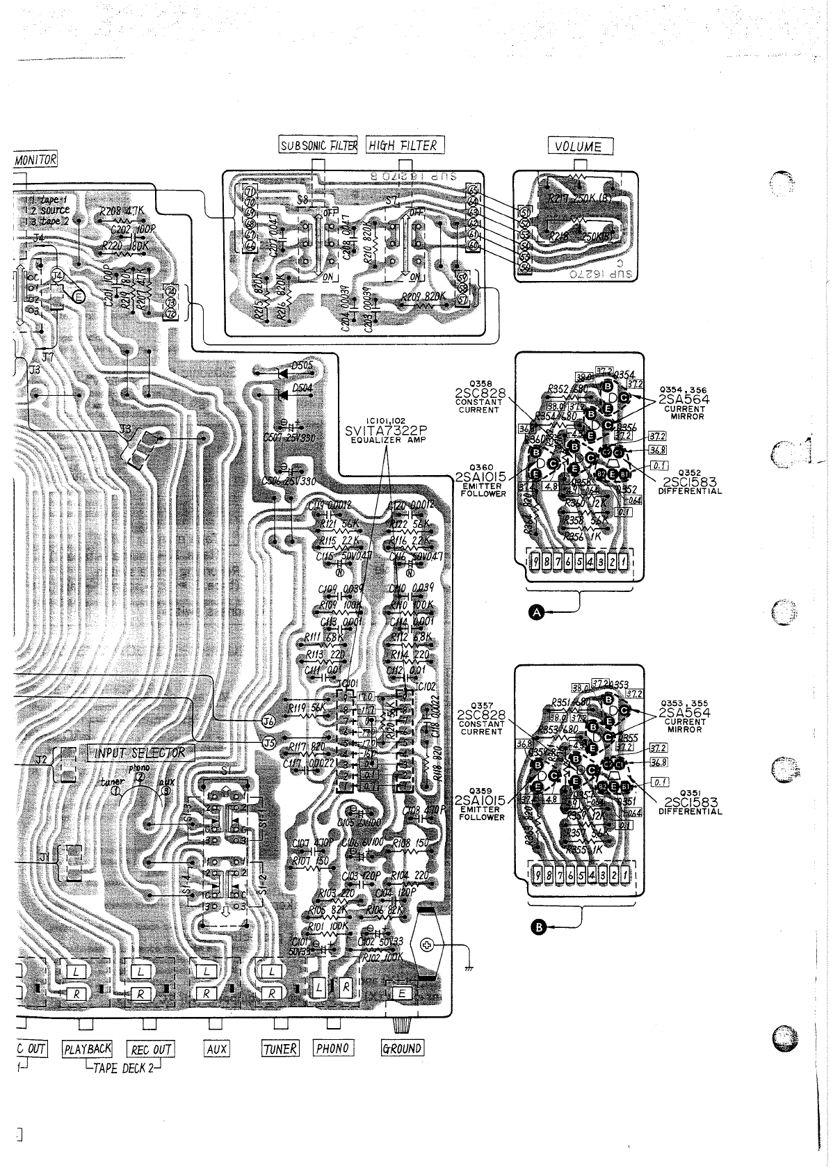
• PRINTED CIRCUIT BOARD WIRING VIEW
IHEADPHONES
JACK
I
I
REMOTE
SPEAKER
SWITCH
IIMAIN
SPEAKER
SWITCHII,,-,PO=WE=R...:.:.:IN=DI=CA~TO;::R
I~-L~~~=~
__
-.-J:::L...,......-
__
r
l
(S5)
I I
I I
IT!)
POWER
TRANSFORMER
AC
LINE
(SO//,OHl.)
110':
1201
2201
24.0
V
Q30l,302
2SA912
PRE DRIVE
IC303,304
SVISTK0039N
DARING
TON
POWER PACK
r -
IMAIN>
:
SPEAKERS
I
I
I I
IREMOTP
I I
L
I
_ - _ - - _ -
_________________
J
!REC/PLAyl
!PLAYBACKI
I
RECJUTI
IPLAytCKI
LI
____
.--1-1
TAPE
DECK
f
TAPE
C}UTJ
[PLAY
t
CKI
I
REC
~T
I
f
TAPE
DECK
2
J
0358
2SC828
CONSTANT
CURRENT
0360
'----H---
.........
2SAIOI5
EMITTER
FOLLOWER
0357
2SC828
CONSTANT
CURRENT
0354,356
2SA564
CURRENT
MIRROR
0351
2SCI583
DIFFERENTIAL
(
;'"."
..
'.'"'\
J
__
A
B
c
o
E
F
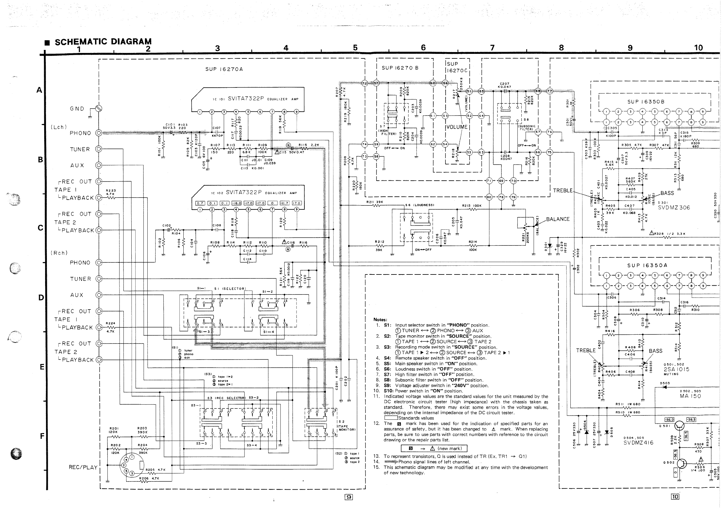
• SCHEMATIC DIAGRAM
1 2 3 4 5 6 7 8 9
10
r-----------------------------------~
1
SUP
16270A
:
r-------,
---l
r--------
I
SUPI6270B
I
Isup
I I I
r----------------------
I
I I
I
,"':'c
cc"'--_---4
c
7c2
1 I
116270C
1 I 1
•
57:1-'c.
;;:;';;~:":':"";~;';"':':"':':":':';';";;:;';;-'{~
c~
I I
C207
I,
I
I
1
~~~
m !le Y
Y'
~
KO.047
~ ~
I 1
~
~'"
y
.~
,",,":;""".-:-.,.--"""{MI
1---
-
-------------:
I
I
---------------l
i
1 1 C
10
I
GND
(Lch)
SVITA7322P
o
...
N
=
co
'"
N
N
6
EQUALIZER
AMP
8 9
PHONO
"'n=~
: I
'"
L-_.
______
~
TUNER
AUX
r
REC
OUT
((
cri}'---t--
TAPE I
LpLAYBACK
r
REC
OUT
R223
4.7K
- 0
U
~
RI13
Rill
RI09
,®
'0",~115
220
~C8j~100K~C'iI5
50VO.47
CIII
JO.Oli~
JO.039
CII3
KO.OOI
~
c
102
SVITA7322P
EQUALIZER
AMP
lID
[£J]
C£:::D
1-16.011-17.011-17.01
CIJ
EiQJ
GI:Q]
123456789
o
N
;;<
TAPE
2
LpLAYBACK(,~--~~
L-
__
+-
______
~~~
(Rc
h)
N
o
'"
RI08
~,
+
R 114 R 112
RIIO
@
PHONO(
(,~----++-++-~~
U
GI~O
~I~
~
~l
Nr:r
TU
NE
R
\..u07---+-+-++-~-----------------_.,
- : l
N?~-L
51-1
SI
ISELECTOR)
~m~I"'rIr
~I
AUX
rREC
OUT
TAPE
I
L
PLAYBAC
K
rREC
OUT
TAPE 2
L
PLAYBACK
I
I
I
I
I
I
I
I
j
1
R224
4.7K
R201
120K
L-~+--++-_____________________
~
S{-2
8'~ci3------i'~~-~3-1
I I
I
L~)
.
r-'
I
I
UI
-J~~£.
h
____
J _
~I_
2~~
C_
~_J
Lt
4l1?-s1-3.
-T
Lf
51-4
~--4--~----~---*~
L---+--r------~
(511
CD
tuner
l2l
phono
~
cux
-
(S3)(J)
tope
'.2
'-------+-+-1---,
!2>
source
R203
390K
53-3
G
tape
2.'
53-4
!
..
o
o
3
l I
I
N
"'.",
f----;"'h:
I I
~il-
~I
I
I'
- \ -
~I
~-L~
I I
~
~~..J!
I,
r - -
I '-'=::! I
~Ig
I j : =
up-
J,.
'1
1
'
'I~OLU~J11
!
0==_
?;g
I
.,
"'co
I
:m
I
J
58
I
{SUBSONIC,
I
F1L~
-;
0"
"'-
'"
' i
l:~_
2
~-~~~.~3
:o~
"-Q-qJ-J
i
L_
1-
2
-0--¥-
5 -
6)--ct>--<$--d)--J
C~~5
C313
.
'L-----1r-..,--+-!1
r-'
K 3 P .. C
315
I
FILTER)
~
~5
~-L~
I I I
N
C\I
N 0
~
II
",couo~I'
I
74
59
'"
62
54
_
I,
I
OFF-ON
""'Hi'
co
~
1 I
~
53
6
3hrl---<C>-i20f-8----.....,6~
l Y
7;6
l
OFF_ON!
!
75)----
1
KIOOP
:l
to
KI80P
'"
'"
b-1
~l
~
R305
47K
R307
47K
~
~
~I~m
~2
+±~~
~?
~
51!
! 1 I L m _ -J I KO.047
~ ~
1
I I L
______
j
Ttr
I
~
'"
I L
______________
71
-
69-
70---
J
~
~
I
1
~:~~
+ U
~
ro'l
1 I
...
I
c;lg
R407
560K
'"
~
0
'"
'"
It
'"
T L
________________
_
80
-
78-
J1 TREBLEr----
UJ
~
g
~f'-=-
_ BASS m
79
-----
r---M?
KO,Ol2
~~
R211
39K
~-+------'IN\r------'
5 6
(LOUDNESSI
R213
lOOK
~:~
a::~~
D301
-
'"
.....,Rv4\/'0v-5-+-_C4-1r~
-
SVDMZ
306
R
212
39K
lOOK
1
+ N
!
,
i
r------------------------l
I I
I I
I 1
I I
I I
I Notes: I
I
1.
Sl:
Input
selector
switch
in
"PHONO"
position.
1
CD
TUNER
+-?- @
PHONO
+-?- @
AUX
I
2.
S2:
Tape
monitor
switch
in
"SOURCE"
position. I
I
CDTAPE
1 -<---+@SOURCE-<---+@
TAPE
2
3.
S3:
Recording
mode
switch
in
"SOURCE"
position.
I
f~
u
(j)TAPE
1
~
2-<---+@SOURCE+-?-@TAPE
2
~
1 I
4.
S4:
Remote speaker
switch
in
"OFF"
position.
I
5.
SS: Main speaker
switch
in
"ON"
position.
6.
S6:
Loudness
switch
in
"OFF"
position. I
7.
S7:
High
filter
switch
in
"OFF"
position.
I
8.
S8:
Subsonic
filter
switch
in
"OFF"
position.
I
9. S9: Voltage adjuster
switch
in
"240V"
position.
1
O.
S10:
Power
switch
in
"ON"
position.
I
11. Indicated voltage values are
the
standard values
for
the
unit
measured
by
the
I
DC
electronic
circuit
tester (high impedance)
with
the
chassis taken
as
1
standard.
Therefore,
there may exist some errors in
the
voltage values,
depending on
the
internal
impedance
of
the DC
circuit
tester. I
c:::=JStandards
values
O~
39K
KO
068
~-
.
"'50'"
'"
N
o N
"TO
Urtro
x
RS
11
"
...
'"
"
!
"
'"
IW
680
m
Ir
RSIO
IW
680
L!:.R328
1/2
3.3K
N
'"
'"
rfr
MUTING
0503
0502,503
MA
150
IS
2
I(TAPE
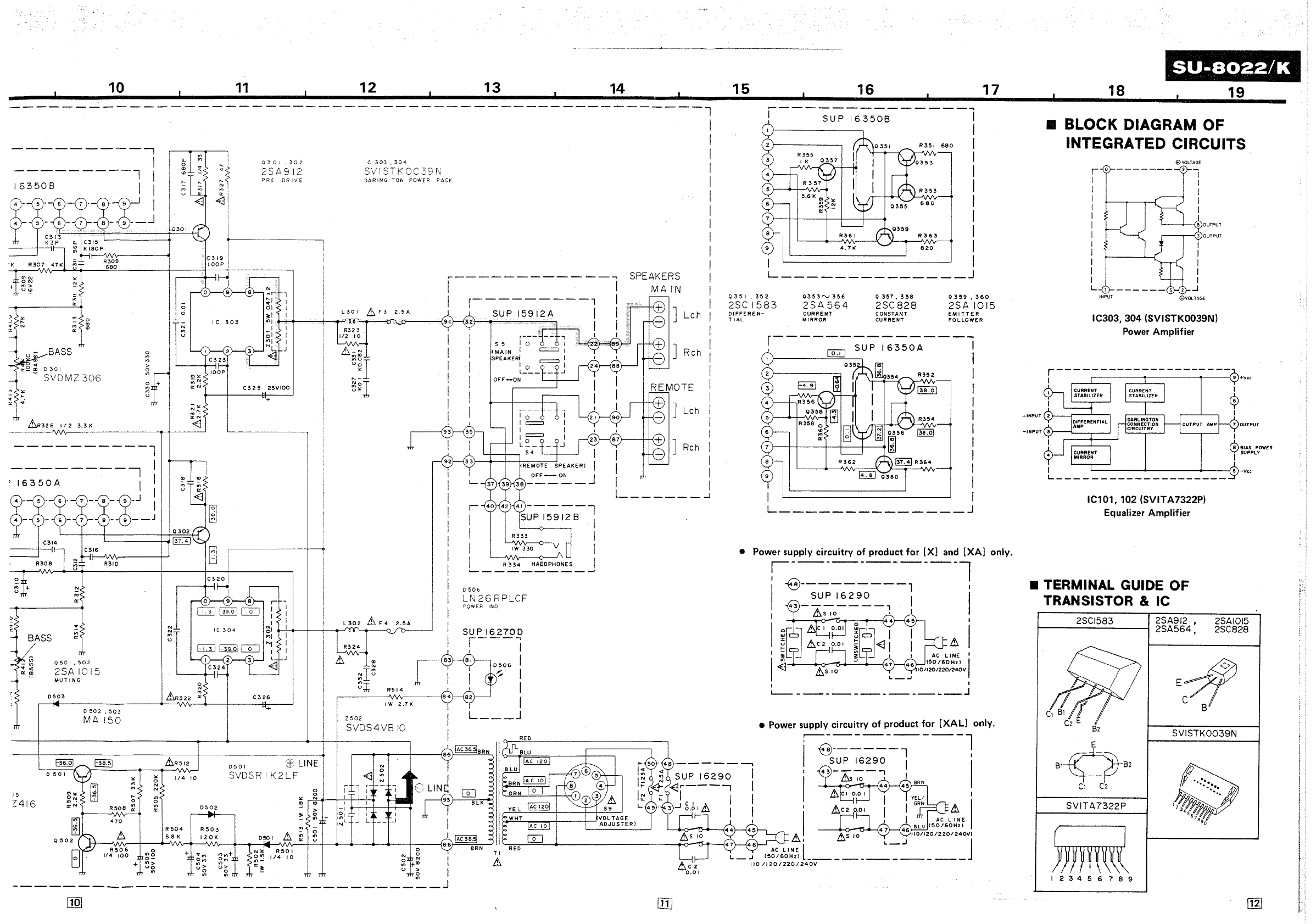
12.
The
I1J
mark
has
been used
for
the
indication
of
specified parts
for
an
assurance
of
safety,
but
it
has
been changed
to
L!l
mark.
When replacing
parts,
be
sure
to
use
parts
with
correct numbers
with
reference
to
the
circuit
drawing
or
the
repair
parts list.
I
I MONITOR}
~
(52)
CD
tape
I
(2)
louree
13
tape
2
I
I1J
-r
L!:. (new mark) I
To
represent transistors, 0
is
used instead
of
TR
(Ex. TR1
-r
01)
~'Phono
signal lines
of
left
channel.
U)
o
",
u T
...
o
'"
u 7
0504,505
SVDMZ416
x
'"
'"
...
o
R50e
~
410
AY
i
~~::::
~::::
REC/PL
I 5 3
R205
4.7
K I
l
R206
4.7K
• 1
13.
14.
15.
This
schematic diagram may
be
modified
at
any
time
with
the
development
of
new
technology.
I
I
I
1
1
I
I
RSO
6
114 :100 C
"'c
0-
+
"'>
Uc
'"
---
_________________________________
J l
___________________
--
am
-----~.------------~.~-----
10
11
12
13
14
15
16
17
----------------------------------------------~------l
-----------,
I
---------l
I
16350
B I I
~~~~~-J
•
I
I
I
I
I
I
i
I
I
I
I
'"
~1
:
.,
,
'"
-
0301
0
0
N
'"
u
:~
N.
~i
~1
!
Q301,302
2S
A 9 i 2
PRE
DRIVE
D
301
~n
SVDMZ306
1/
2
3.3
K
----------l
--------,
I
)
16350A
I
R310
0501,502
2SA
1015
MUTING
'"
0503
&R322
Q:
C 3
26
0502,503
+
MA
150
&R512
0501
Et
LINE
o
50
I
SVDSRIK2LF
"
1/4
10
"
~
'"
'"
N 0
J 5
...
'"
" 0
Z416
0 0
~
.,
R508
'"
'"
0502
'" '"
;.
470
&
R
504
R503
~
68K
120
K
0501
&
'"
'"
IC303,304
SViSTKOC39N
DARING
TON
POWER
PACr:
&n
2.5A
.,
N
~I~
~I
R514
r---------~Ar------~B4
IW
2.7K
Z
502
SVDS4VB
10
N
~
0
'"
N
r---------
l
I
SU
P
15912
A I
32
I
S 5
(MAIN
4~~~~;;i
I
I
I R
334
HAEoPHONES
I
------------'
0506
LN
26
RPLCF
DOWER
INO
SUP
16270D
r---'"
I I
I
I
I
82
I
I
L
___
J
TI
&
SPEAKERS
MA
IN
]
Lch
I
I
I
I
I
I
I
]
Lch
I
I
I
] Rch I
I I
I i
[
_______
..J
R351
6BO
R
353
6 BO
CE>-I
R363
10\9
'
V
4.71<
820
I
L
______________
J
0351,352
0353rv356
o
357,
358
0359,360
2SC
1583
2SA
564
2SC
828
2SAI015
DIFFEREN-
TIAL
CURRENT
MIRROR
CONSTANT
CURRENT
EMITTER
FOLLOWER
r---------------
I
r,;-:--,
SU P
16350A
I
~------~~=O=.,~~
I
R352
R354
I
I
I
I
I
I
I
I
I
I I
L
______________
J
• Power supply circuitry
of
product
for
[X] and [XA] only.
i-----------l
I
1
-9---------,
1
43
_
SU~~::~_,
I I
I
&s
10
•
!
~~~
.1>::
:::
.1>
i
l.(j
&5
10
• Power supply circuitry
of
product
for
[XAL] only.
i
~;~p
~629~~1---ll
I
&5
10
4~
4~
BRN
&CI
0.0
I 1
'1
I
AC
L~E
I
BLU
(SO/60Hz)
~
As
10
46110/120/220/240VI
15~~6L,;~,E)
L
________
~-=-_.J
______
J
110/120/220/240V
SU-B022/K
18
19
• BLOCK DIAGRAM OF
INTEGRATED CIRCUITS
r 0
I
I
I
I
I
I
I
I
I
I
I
I
L
INPUT
®VOLTAGE
9
8VOlTAGE
IC303, 304 (SVISTK0039N)
Power Amplifier
r---------------------
I 9 +Vcc
T OUTPUT
I &
-Vcc
L
___________________
_
IC101, 102 (SVITA7322P)
Equalizer Amplifier
• TERMINAL GUIDE
OF
TRANSISTOR &
le
2SCI583 2SA912 ,
2SA564,
2SAIOl5
2SC828
E;;!l
B
SVISTK0039N
SVITA7322P
123456789
SU-S022/K
SU-S
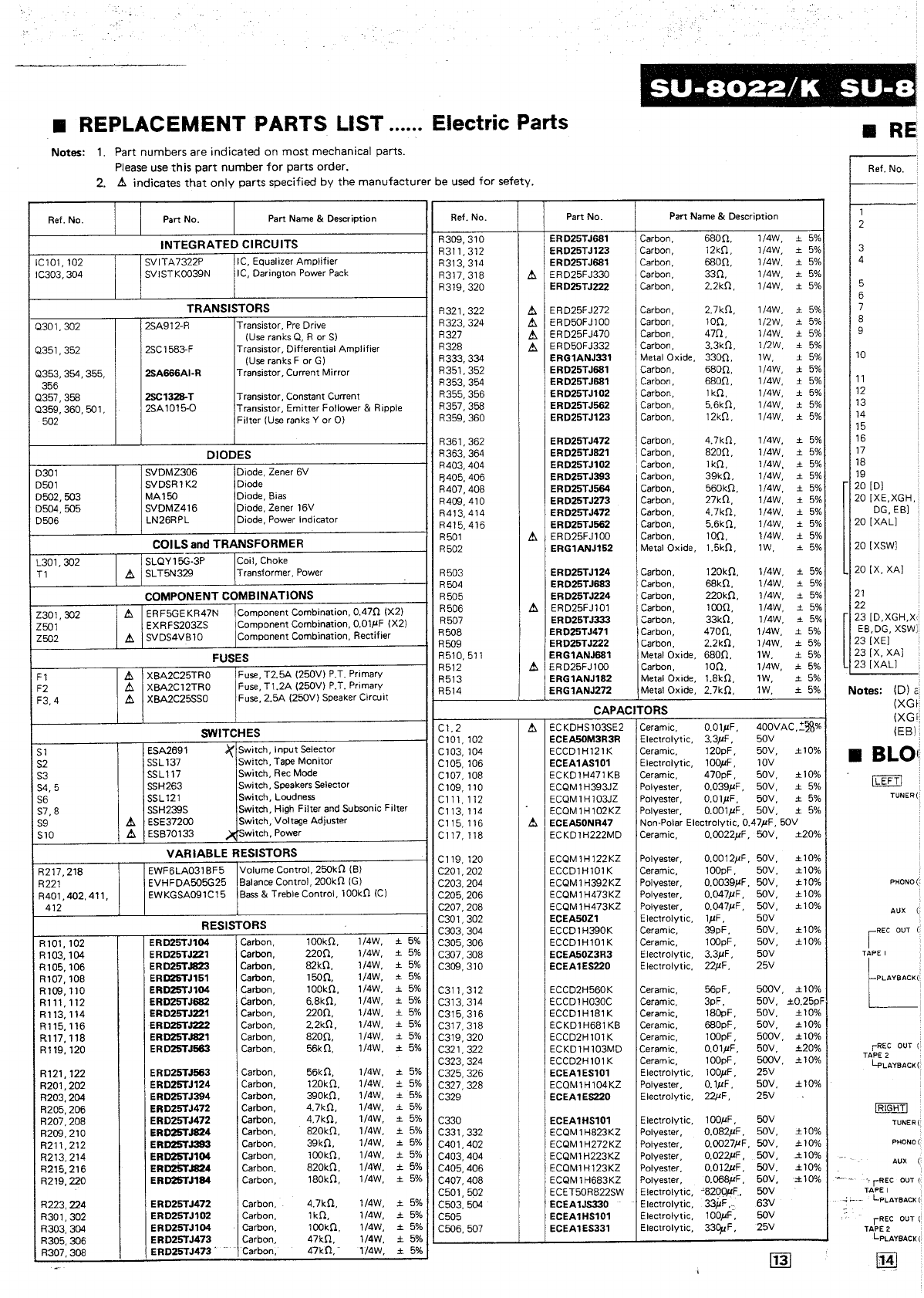
• REPLACEMENT PARTS LIST ...... Electric Parts •
RE
Notes:
1.
Part numbers are indicated on
most
mechanical parts.
Please use this
part
number
for
parts order.
2.
t.
indicates
that
only parts specified by
the
manufacturer be used for sefety.
Ref.
No. Part No. Part
Name
& Description Ref. No.
INTEGRATED
CIRCUITS
R309,310
R311,312
IC10l,102
SVITA7322P IC, Equalizer Amplifier
R313,314
IC303,304 SVISTK0039N I
C,
Darington Power
Pack
R317,318
t.
R319,320
TRANSISTORS
R321,322
t.
0301,302
2SA912-R Transistor,
Pre
Drive
R323,324
t.
(Use
ranks
0,
R or
S)
R327
t.
0351,352
2SC1583-F Transistor, Differential Amplifier R328
t.
(Use
ranks F or
G)
R333,334
Q353, 354, 355, 2SA666AI-R Transistor, Current Mirror
R351,352
356
R353,354
Q357,368 2SC1328-T Transistor, Constant Current
R355,356
0359,360,501,
2SA1015-0 Transistor, Emitter Follower & Ripple
R357,368
502 Filter
(Use
ranks Y
or
0)
R359,360
R361,362
DIODES
R363,364
SVDMZ306
Diode, Zener 6V R403,404
0301 f3405,406
0501 SVDSR1K2 Diode
R407,408
0502,503
MAl50
Diode,
Bias
R409,410
0504,505
SVDMZ416
Diode, Zener 16V
R413,414
0506
LN26RPL Diode, Power Indicator
R415,416
COILS
and
TRANSFORMER
R501
t.
R502
L301,302
SLOYl5G-3P Coil, Choke
T1
t.
SLT5N329 Transformer,
Power
R503
R504
COMPONENT COMBINATIONS R505
Z301,302
t.
ERF5GEKR47N Component Combination,
0.470
(X2) R506
t.
Z501 EXRFS203ZS Component Combination, O.OlI'F (X2) R507
Z502
t.
SVDS4VB10 Component Combination, Rectifier R508
R509
FUSES R510,511
t.
Fuse,
T2.5A
(250V) P.T. Primary R512
t.
Fl
XBA2C25TRO R513
F2
t.
XBA2C12TRO
Fuse,
Tl.2A
(250V)
P.T.
Primary R514
F3,4
t.
XBA2C25SS0 Fuse, 2.5A (250V) Speaker Circuit
SWITCHES
Cl,2
t.
C101,102
Sl
ESA2691
>(
Switch, I nput Selector
Cl03,104
S2
SSL
137 Switch, Tape
Monitor
C105,106
S3
SSLl17
Switch,
Rec
Mode
Cl07,108
S4,5
SSH263 Switch,
Speakers
Selector C 109, 110
S6
SSL121
Switch, Loudness
Cll1,112
S7,8
SSH239S Switch, High Filter
and
Subsonic Filter C113,114
S9
t.
ESE37200 Switch, Voltage Adiuster
Cl15,116
t.
SlO
t.
ESB70133
>-
rswi
tch, Power C117,118
VARIABLE
RESISTORS
Cl19,120
R217,218 EWF6LA0318F5 Volume ContrOl, 250kO
(B)
C201,202
R221
EVHFDA505G25 Balance Control, 200kO
(G)
C203,204
R401,402,411,
EWKGSA091C15
Bass
& Treble ContrOl, 100kO
(C)
C205,206
412 C207,208
RESISTORS C301,302
C303,304
Rl0l,102
ERD25TJ104 Carbon, 100kO, 1/4W, ±
5%
C305,306
Rl03,104
ERD25TJ221 Carbon,
2200,
1/4W, ±
5%
C307,308
Rl05,106
ERD25TJ823 Carbon, 82kO, 1/4W, ±
5%
C309,310
R107,108 ERD25TJ151 Carbon,
1500,
1/4W, ±
5%
Rl09,110
ERD25TJ104 Carbon, 100kO, 1/4W, ±
5%
C311,312
Rl11,112
ERD25TJ682 Carbon, 6.8kO, 1/4W, ±
5%
C313,314
Rl13,114
ERD25TJ221 Carbon,
2200,
1/4W, ±
5%
C315,316
Rl15,116
ERD25TJ222 Carbon, 2.2kO, 1/4W, ±
5%
C317,318
R117,118 ERD25TJ821 Carbon,
8200,
1/4W, ±
5%
C319,320
R119,120 ERD25TJ563 Carbon, 56kO, 1/4W, ±
5%
C321,322
C323,324
R121,122 ERD25TJ563 Carbon, 56kO, 1/4W, ±
5%
C325,326
R201,202 ERD25TJ124 Carbon, 120kO,
1/4W,
±
5%
C327,328
R203,204 ERD25TJ394 Carbon, 390kO, 1/4W, ± 5% C329
R205,206 ERD25TJ472 Carbon, 4.7kO, 1/4W, ±
5%
R207,208 ERD25TJ472 Carbon, 4,7kO, 1/4W, ±
5%
C330
R209,210 ERD25TJ824 Carbon, 820kO, 1/4W, ±
5%
C331,332
R211,212 ERD25TJ393 Carbon, 39kO, 1/4W, ±
5%
C401,402
R213,214 ERD25TJ104 Carbon,
l00kO,
1/4W, ±
5%
C403,404
R215.216
ER025TJ824 Carbon, 820kO, 1/4W, ±
5%
C405,406
R219,220 ERD25TJ184 Carbon, 180kO, 1/4W, ±
5%
C407,408
C501,502
R223,224
ERD25TJ472 Carbon, 4.7kO, 1/4W, ±
5%
C503,504
R301,302
ERD25TJ102 Carbon,
lkO,
1/4W, ±
5%
C505
R303,304
ER
D25TJ1 04 C1lrbon,
l00kO,
1/4W, ±
5%
C506,507
R305,306 ERD25TJ473 Carbon. 47kO, 1/4W, ±
5%
R307,308 ERD25TJ473 . Carbon,
47kO,-
1/4W, ±
5%
Part No. Part Name & Description
ERD25TJ681 Carbon,
680ft
1/4W, ±
5%
ERD25TJ123 Carbon, 12kO, 1/4W, ±
5%
ERD25TJ681 Carbon,
6800,
1/4W, ±
5%
ERD25FJ330 Carbon,
330,
1/4W. ±
5%
ERD25TJ222 Carbon, 2.2kO, 1/4W, ±
5%
ERD25FJ272 Carbon, 2.7kO, 1/4W, ±
5%
ERD50FJ100 Carbon,
100,
1/2W, ±
5%
ERD25FJ470 Carbon,
470,
1/4W. ± 5%
ERD50FJ332 Carbon, 3.3kO. 1/2W, ±
5%
ERG1ANJ331 MelalOxide,
3300,
lW,
±
5%
ERD25TJ681 Carbon,
6800,
1/4W, ± 5%
ERD25TJ681 Carbon,
6800,
1/4W, ± 5%
ERD25TJ102 Carbon,
lkO,
1/4W, ±
5%
ERD25TJ562 Carbon, 5.6kO, 1/4W, ±
5%
ERD25TJ123 Carbon, 12kO, 1/4W, ±
5%
ERD25TJ472 Carbon, 4.7kO, 1/4W, ±
5%
ERD25TJ821 Carbon,
8200,
1/4W, ± 5%
ERD25TJ102 Carbon, 1kO, 1/4W. ±
5%
ERD25TJ393 Carbon,
39kO,
1/4W, ±
5%
ERD25TJ564 Carbon, 560kO, 1/4W, ±
5%
ERD25TJ273 Carbon, 27kO, 1/4W, ± 5%
ERD25TJ472 Carbon, 4.7kO, 1/4W, ±
5%
ERD25TJ562 Carbon, 5.6kO, 1/4W, ±
5%
ERD25FJ100 Carbon,
100,
1/4W, ±
5%
ERG1ANJ152 Metal Oxide, 1.5kO,
lW,
±
5%
ERD25TJ124 Carbon, 120kO, 1/4W, ±
5%
ERD25TJ683 Carbon, 68kO, 1/4W, ±
5%
ERD25TJ224 Carbon, 220kO, 1/4W, ±
5%
ERD25FJ10l Carbon,
1000,
1/4W, ±
5%
ERD25TJ333
Carbon,
33kO, 1/4W, ±
5%
ERD25TJ471 Carbon,
4700,
1/4W, ±
5%
ERD25TJ222 Carbon, 2.2kO, 1/4W, ±
5%
ERG1ANJ681 Metal Oxide,
6800,
lW,
±
5%
ERD25FJ100 Carbon,
100,
1/4W, ±
5%
ERG1ANJ182 Metal Oxide, 1.8kO,
lW,
±
5%
ERG1ANJ272 Metal Ox ide, 2.7kO,
lW,
±
5%
CAPACITORS
ECKDHS103SE2 Ceramic, O.OlI'F, 400VAC,:'::i\l%
ECEASOM3R3R Electrolytic, 3.3I'F, 50V
ECCD1H121K
Ceramic,
120pF,
5OV,
±1O%
ECEA1AS101 Electrolytic, lOOI'F, 10V
ECKD1H471
KB
Ceramic, 470pF, 50V,
±1O%
ECQM
1 H393JZ Polyester, 0,039I'F, 50V, ±
5%
ECOM1Hl03JZ Polyester, O.OlI'F, 50V, ±
5%
ECQM1Hl02KZ Polyester, O.OOlI'F, 50V, ±
5%
ECEA50NR47 Non-Polar Electrolytic, 0.47I'F, 50V
ECKD1H222MD Ceramic, 0.OO22I'F, 5OV, ±20%
ECOM1H122KZ Polyester, 0.0012I'F, 50V, ±10%
ECCD1Hl01K
Ceramic,
l00pF,
5OV,
±10%
ECOM
1 H392KZ Polyester, 0.0039I'F,
5OV,
±10%
ECOM1H473KZ Polyester, 0.047I'F,
5OV,
±10%
ECOM1H473KZ Polyester, 0,047I'F,
5OV,
±10%
ECEA50Z1 Electrolytic,
11'F,
50V
ECCD1H390K Ceramic, 39pF, 50V, ±10%
ECCD1H101 K
Ceramic,
l00pF,
5OV,
±10%
ECEA50Z3R3 Electrolytic, 3.3I'F,
50V
ECEA1ES220 Electrolytic, 221'F,
25V
ECCD2H560K Ceramic, 56pF,
5OOV,
±10%
ECCD1H030C
Ceramic,
3pF, 50V, ±0.25pF
ECCD1H181K Ceramic, 18()pF, 50V, ±10%
ECKDl
H681
KB
Ceramic, 680pF, 50V,
±1O%
ECCD2Hl01K Ceramic,
l00pF,
500V, ±10%
ECKD1Hl03MD
Ceramic,
O.OlI'F, 50V, ±20%
ECCD2Hl01K
Ceramic,
l00pF,
5OOV,
±10%
ECEA1ES101 Electrolytic, lOOI'F, 25V
ECQM1H104KZ Polyester,
O.
11'F
, 50V,
±10%
ECEA1ES220 Electrolytic, 22}lF,
25V
ECEA1HS101 Electrolytic, 1
OO,uF
, 50V
ECOM
1 H823KZ Polyester, 0.082I'F,
5OV,
±1O%
ECOM
1 H272KZ Polyester, 0.OO27I'F,
5OV,
±10%
ECQM1
H223KZ Polyester, 0.022}lF, 5OV, ±10%
ECOM1H123KZ Polyester, O.Ol2}lF,
5OV,
±10%
I ECOM1H683KZ Polyester, 0.068I'F, 50V,
±10%
ECET50R822SW Electrolytic, "8200,uF,
50V
ECEA1JS330 Electrolytic, 33jlF,
63V
ECEA1HS101 Electrolytic, 100I'F-, 50V
ECEA1ES331 Electrolytic, 33OpF, 25V
13
1
2
3
4
5
6
7
8
9
10
11
12
13
14
15
16
17
18
19
Ref, No.
20 [D)
20 [XE,XGH,
DG,
EB)
20
[XAL)
20 [XSW)
20 [X, XA)
21
22
[
23
[D,XGH,X
EB,DG,
XSW;
23 [XE)
23
[X,
XA)
23
[XAL)
Notes: (D) c
(XGf
(XGI
(EB)
• BLOI
ILEFTI
TUNER(
PHONO(
AUX
iREC
OUT
TAPE I
r''"''''''
rREC
OUT
(
TAPE 2
4LAYBACK(
IRIGHTI
TUNER (
PHONO(
AUX
(
'~rREC
OUT
(
TAPE I
-:
;....
.. -. LpLAYBACK(
rREC
OUT
(
TAPE 2
LpL.AYBACK(
5%
5%
5%
5%
5%
5%
5%
5%
5%
5%
5%
5%
5%
5%
5%
5%
5%
5%
5%
5%
5%
t.
5%
5%
5%
t
5%
t..
5%
5%
5%
5%
5%
5%
5%
5%
5%
5%
5%
,10%
,10%
5%
5%
5%
,20%
,10%
:.10%
,10%
,10%
,10%
,10%
10%
,10%
.25pF
-10%
10%
10%
_20%
10%
10%
10%
10%
10%
10%
10%
SU-S022/K
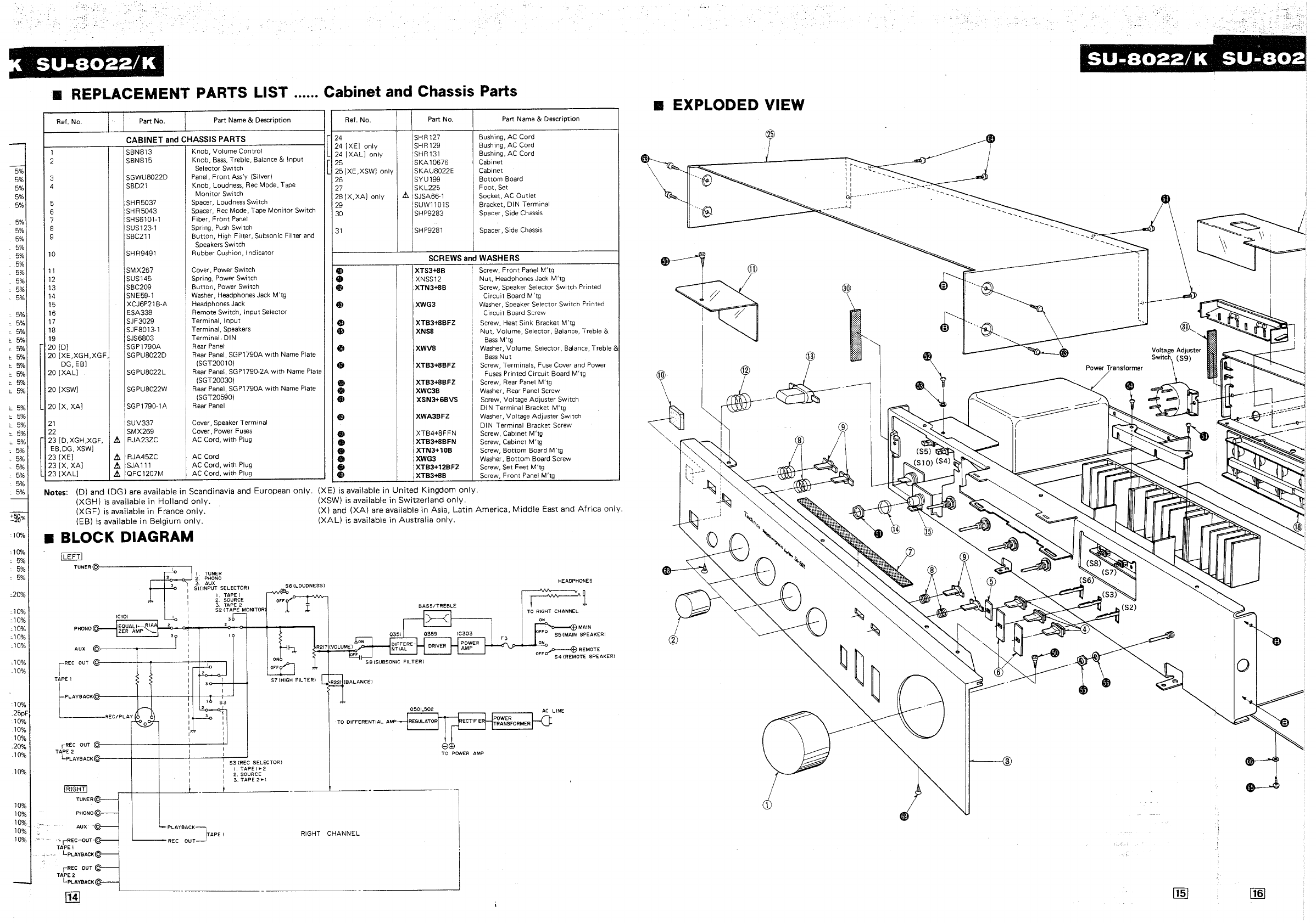
• REPLACEMENT PARTS LIST ...... Cabinet and Chassis Parts
Ref. No. Part No. Part Name & Description Ref. No. Part No. Part Name & Description
CABINET
and
CHASSIS PARTS
1 SBN813 Knob, Volume Control
2 SBN815 Knob,
Bass,
Treble, Balance &
Input
Selector Switch
3 SGWU8022D Panel,
Front
Ass'y (Silver)
4 SBD21 Knob, Loudness,
Rec
Mode. Tape
Man
itor
Switch
5 SHR5037 Spacer, Loudness Swi tch
6 SHR5043 Spacer,
Rec
Mode, Tape
Monitor
Switch
7 SHS6101-1 Fiber,
Front
Panel
24
SHR
127 Bushing, AC Cord
24 [XEJ only SHR129 Bushing. AC Cord
24
[XALJ
only SHR131 Bushing. AC Cord
[
25
SKA
10676 Cabinet
25 [XE,XSWJ only SKAU8022E Cabinet
26 SYU199
Bottom
Board
27
SKL225
Foot,
Set
28
[X.XAJ
only A SJSA66-1 Socket,
AC
Outlet
29
SUWll01S
Bracket, DIN Terminal
30 SHP9283 Spacer, Side
Chassis
[
8 SUS123-1 Spring,
Push
Switch
9 SBC211
Button,
High
Filter,
Subsonic
Filter
and
31
SHP9281 Spacer, Side
Chassis
Speakers Switch
10 SHR9491 Rubber Cushion. Indicator SCREWS
and
WASHERS
11
SMX267 Cover, Power Switch
Gl
XTS3+SB Screw,
Front
Panel
M'tg
12
SUS145 Spring. Power Switch • XNSS12
Nut.
Headphones Jack
M'tg
13 SBC209
Button,
Power Switch *
XTN3+8B
Screw, Speaker Selector Switch Printed
14 SNE59-1 Washer, Headphones Jack M'tg
Circuit
Board
M'tg
15 XCJ6P21B-A Headphones Jack • XWG3 Washer. Speaker Selector Switch Printed
16 ESA338 Remote Switch,
Input
Selector
Circuit
Board Screw
17 SJF3029 Terminal.
Input
18 SJF8013-1 Terminal. Speakers
19 SJS6803 Terminal. DIN
20
[DJ
SGP1790A Rear
Panel
20
[XE,XGH,XGF,
SGPU8022D Rear Panel, SGP1790A
with
Name Plate
• XTB3+SBFZ Screw. Heat Sink Bracket M'tg
.,
XNSB
Nut,
Volume. Selector, Balance, Treble &
Bass
M'tg
Cl
XWVS Washer, Volume, Selector. Balance. Treble &
Bass
Nut
DG,
EBJ
(SGT20010) XTB3+SBFZ
20
[XAL]
SGPU8022L Rear Panel, SGP1790-2A
with
Name Plate " Screw, Terminals,
Fuse
Cover and Power
Fuses
Printed
Circuit
Board M'tg
(SGT20030)
20
[XSWJ
SGPU8022W Rear Panel, SGP1790A
with
Name Plate
(SGT20590)
20
[X,
XAJ SGP1790-1A Rear
Panel
21
SUV337
Cover, Speaker Terminal
22 SMX269 Cover, Power
Fuses
[
"[O.'G".'G'.
A RJA23ZC AC Cord,
with
Plug
EB,DG,
XSWJ
23 [XEJ A RJA45ZC AC Cord
23
[X,
XAJ A
SJAlll
AC
Cord,
with
Plug
23
[XAL]
A QFC1207M
AC
Cord,
with
Plug
Notes: (D) and (DG) are available in Scandinavia and European
only.
(XGH)
is
available in Holland
only.
(XGFJ
is
available in France
only.
(EB)
is
available
in
Belgium
only
.
• BLOCK DIAGRAM
!LEFT!
TUNER@--------,----,
PHONO@
AUX
iREC
OUT
TAPE 1
,REC
OUT
@
___
+
__
+---,----<-J
TAPE 2
lpLAYBACK@~--+--+---'----T-S:-:3:-:(:-RE:'C-
SELECTOR)
I.
TAPE
1"2
2. SOURCE
:3.
TAPE2"!
!RIGHT!
TUNER@
PHONO@
e XTB3+8BFZ
0>
XWC3B
• XSN3+6BVS
4f)
XWA3BFZ
411
XTB4+8FFN
I)
XTB3+SBFN
4»
XTN3+10B
CII
XWG3
I)
XTB3+12BFZ
G XTB3+8B
(X
E)
is
available in United Kingdom
only.
(XSW)
is
available in Switzerland
only.
Screw, Rear
Panel
M'tg
Washer. Rear
Panel
Screw
Screw, Voltage Adjuster Switch
DIN
Terminal Bracket M'tg
Washer, Voltage Adjuster Switch
DIN Terminal Bracket Screw
Screw, Cabinet M'tg
Screw, Cabinet M'tg
Screw,
Bottom
Board
M'tg
Washer.
Bottom
Board Screw
Screw, Set Feet M'tg
Screw,
Front
Panel
M'tg
(X) and
(XA)
are available in Asia, Latin America,
Middle
East and
Africa
only.
(XAL)
is
available in Australia
only.
HEADPHONES
TO DIFFERENTIAL
AWP
8EB
TO
POWER
AMP
AUX
-@
"-rREC-OUT'@
PLAYBACK]
TAPE I
'----
REC OUT
RIGHT
CHANNEL l
TAPE I '
LPLAYBACKS
rREe
OUT
TAPE 2
LpLAYBACK@
lHl
'-----
-!
i-i'§4¥iji'"
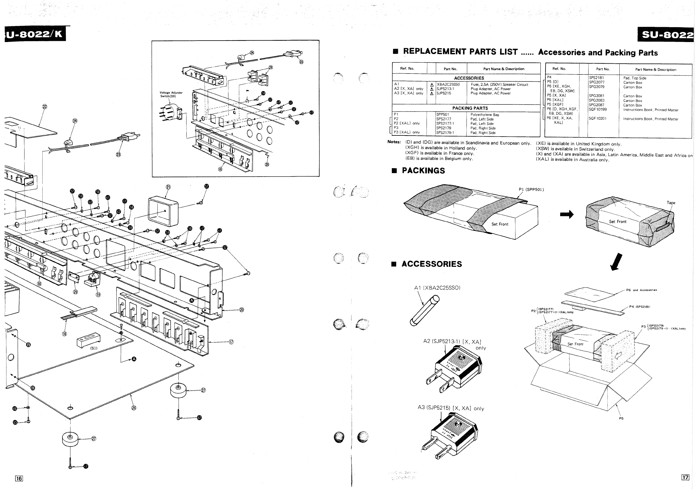
• EXPLODED VIEW
==
______
.-JL-------::';,:::
__
_
'~_
, I -
" 1
, 1
"
b}--
, 1
______
-1...!
---""'--.
:
----a
Voltage Adjuster
\;i
~
SWitCh
(59)
j~'
~
.
,
.,.,. ,
-
.'
-,
Power
Transformer
:
o
i-'---{3
Voltage
Adjuster
~
:
o
•
j
I_--@
(
"CC,
'- -
.~
~'
£:."
~.
SU-S022
• REPLACEMENT PARTS LIST ...... Accessories and Packing Parts
[
[
Ref. No,
A1
A2
[X,
XA]
only
A3
[X,
XA]
only
P1
P2
P2
[XAL]
only
P3
P3
[XAL]
only
L!:.
L!:.
L!:.
Part No. Part Name & Description
ACCESSORIES
XBA2C25SS0
Fuse,
2.5A 1250V) Speaker Circuit
SJP5213·1
Plug
Adapter, AC Power
SJP5215
Plug
Adapter, AC Power
PACKING PARTS
SPP501
Polyethylene
Bag
SPS2177
Pad,
Left
Side
SPS2177-1
Pad,
Left
Side
SPS2179
Pad,
Right Side
SPS2179·1
Pad,
Right
Side
Notes: (D) and (DG) are available in Scandinavia and European
only.
(XGH)
is
available in Holland
only.
(XGF)
is
available in France
only.
(EB)
is
available
in
Belgium
only.
• PACKINGS
• ACCESSORIES
A 1 (X BA2C25SS0)
Jf
A2
(SJP5213-1)
[X,
XA]
A3
(SJP5215)
[X,
XA]
only
Ref. No. Part No.
P4
SPS2181
P5ID]
SPG2077
P5
[XE,
XGH, SPG2079
EB,DG,XSW]
P5
[X,
XA]
SPG2081
P5
[XAL]
SPG2083
P5
[XGF]
SPG2087
[
P6
[0,
XGH,XGF,
SQF10199
E8, DG,
XSW]
P6
[XE, X,
XA,
SQF
10201
[
XAL]
(XE)
is
available
in
United Kingdom
only.
(XSW)
is
available
in
Switzerland
only.
Part Name & Description
Pad,
Top Side
Carton Box
Carton Box
Carton Box I
Carton Box
Carton Box
Instructions Book, Printed Matter
Instructions Book, Printed Matter
(X) and
(XA)
are available in Asia, Latin America,
Middle
East and
Africa
on
(XAL)
is
available
in
Australia
only.
I
PG
and
Accessories
~
~
P41SPS2181l
{
(SPS2177)
P2
(SPS2177-[)
--(XAUonly
\
~/--.:""
--
--
-.
--
-.~,","'P"'
__
p
~
{SPS2179l
3
USPS2179-D
(XAUonly
P5
