AT Commands Reference Guide Telit R17
User Manual:
Open the PDF directly: View PDF ![]() .
.
Page Count: 625 [warning: Documents this large are best viewed by clicking the View PDF Link!]

Contents
1. Introduction.................................................................................................................................... 17
1.1. Scope ......................................................................................................................................................17
1.2. Audience ................................................................................................................................................17
1.3. Contact Information, Support .............................................................................................................17
1.4. Document Organization .......................................................................................................................17
1.5. Text Conventions ..................................................................................................................................18
1.6. Related Documents ...............................................................................................................................18
2. Overview ......................................................................................................................................... 19
2.1. About the document .............................................................................................................................19
3. AT COMMANDS .......................................................................................................................... 20
3.1. Definitions .............................................................................................................................................20
3.2. AT Command Syntax ...........................................................................................................................21
3.2.1. String Type Parameters ................................................................................................................................. 22
3.2.2. Command Lines............................................................................................................................................. 22
3.2.2.1. ME Error Result Code - +CME ERROR: <err> ....................................................................................... 23
3.2.2.2. Message Service Failure Result Code - +CMS ERROR: <err> ................................................................ 27
3.2.3. Information Responses And Result Codes .................................................................................................... 28
3.2.4. Command Response Time-Out ..................................................................................................................... 29
3.2.5. Command Issuing Timing ............................................................................................................................. 32
3.3. Storage ...................................................................................................................................................33
3.3.1. Factory Profile And User Profiles ................................................................................................................. 33
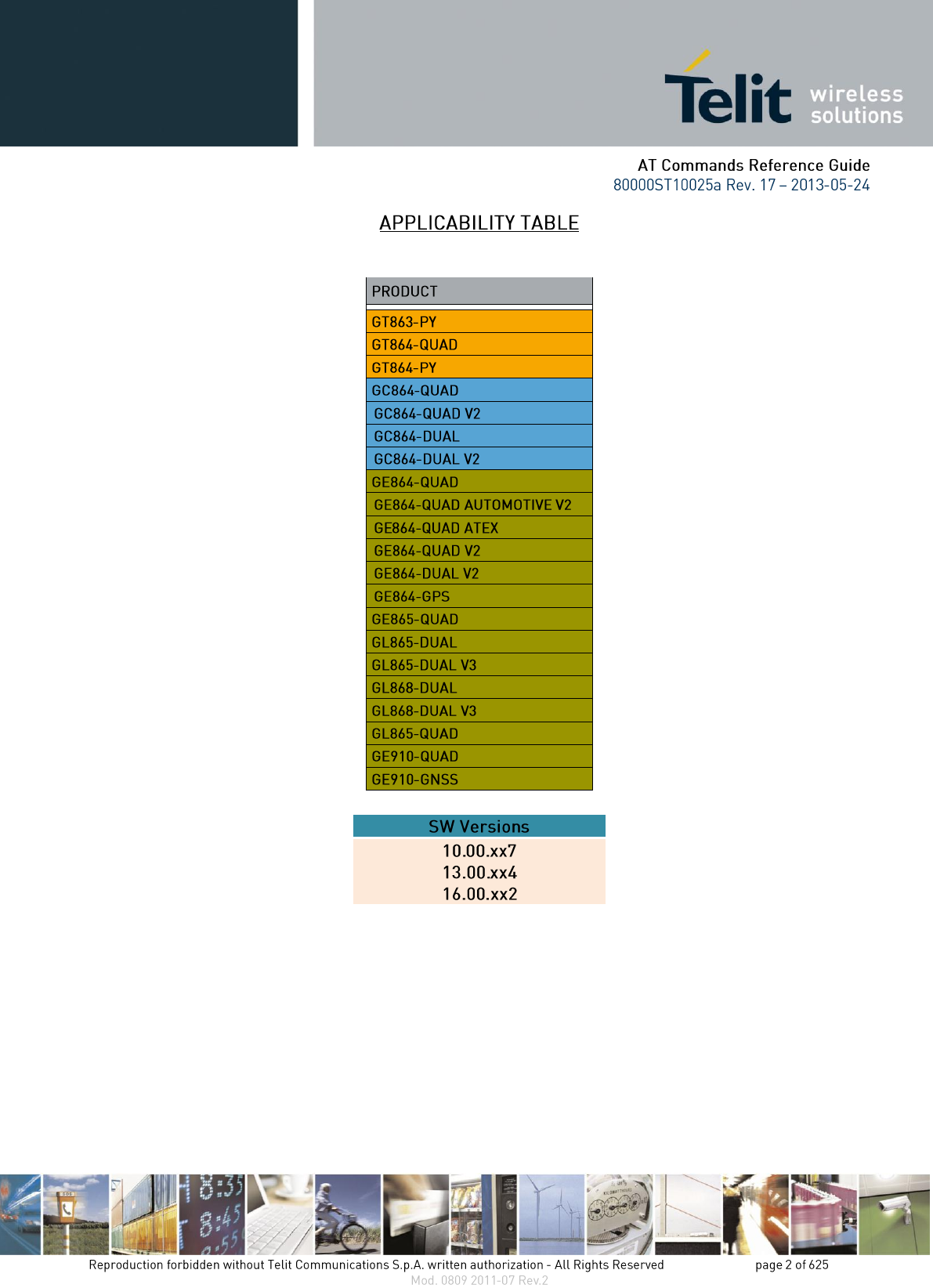
3.4. AT Commands Availability Table ......................................................................................................36
3.5. AT Commands References ..................................................................................................................47
3.5.1. Command Line General Format .................................................................................................................... 47
3.5.1.1. Command Line Prefixes ............................................................................................................................ 47
3.5.1.1.1. Starting A Command Line - AT.......................................................................................................... 47
3.5.1.1.2. Last Command Automatic Repetition - A/ ......................................................................................... 47
3.5.1.1.3. Repeat Last Command - AT#/ ............................................................................................................ 47
3.5.2. General Configuration Commands ................................................................................................................ 47
3.5.2.1. AT Interface Backward Compatibility ...................................................................................................... 47
3.5.2.1.1. Select Interface Style - #SELINT ....................................................................................................... 49
3.5.3. Hayes Compliant AT Commands .................................................................................................................. 50
3.5.3.1. Generic Modem Control ........................................................................................................................... 50
3.5.3.1.1. Set To Factory-Defined Configuration - &F ....................................................................................... 50
3.5.3.1.2. Soft Reset - Z ...................................................................................................................................... 50
3.5.3.1.3. Select Active Service Class - +FCLASS ............................................................................................ 50
3.5.3.1.4. Default Reset Basic Profile Designation - &Y .................................................................................... 51
3.5.3.1.5. Default Reset Full Profile Designation - &P ....................................................................................... 51
3.5.3.1.6. Store Current Configuration - &W ..................................................................................................... 51
3.5.3.1.7. Store Telephone Number - &Z ........................................................................................................... 52
3.5.3.1.8. Display Stored Numbers - &N ........................................................................................................... 52

3.5.3.1.9. Manufacturer Identification - +GMI ................................................................................................... 52
3.5.3.1.10. Model Identification - +GMM .......................................................................................................... 53
3.5.3.1.11. Revision Identification - +GMR ....................................................................................................... 53
3.5.3.1.12. Capabilities List - +GCAP ................................................................................................................ 53
3.5.3.1.13. Serial Number - +GSN ...................................................................................................................... 53
3.5.3.1.14. Display Configuration And Profile - &V ......................................................................................... 53
3.5.3.1.15. Display Configuration And Profile - &V0 ....................................................................................... 54
3.5.3.1.16. S Registers Display - &V1 ................................................................................................................ 54
3.5.3.1.17. Extended S Registers Display - &V3 ................................................................................................ 54
3.5.3.1.18. Display Last Connection Statistics - &V2 ........................................................................................ 55
3.5.3.1.19. Single Line Connect Message - \V .................................................................................................... 55
3.5.3.1.20. Country Of Installation - +GCI ......................................................................................................... 55
3.5.3.1.21. Line Signal Level - %L ..................................................................................................................... 55
3.5.3.1.22. Line Quality - %Q ............................................................................................................................. 56
3.5.3.1.23. Speaker Loudness - L ........................................................................................................................ 56
3.5.3.1.24. Speaker Mode - M ............................................................................................................................ 56
3.5.3.1.25. Master Reset - +CMAR .................................................................................................................... 56
3.5.3.2. DTE - Modem Interface Control ............................................................................................................... 57
3.5.3.2.1. Command Echo - E ............................................................................................................................. 57
3.5.3.2.2. Quiet Result Codes - Q ....................................................................................................................... 57
3.5.3.2.3. Response Format - V .......................................................................................................................... 58
3.5.3.2.4. Extended Result Codes - X ................................................................................................................. 59
3.5.3.2.5. Identification Information - I .............................................................................................................. 59
3.5.3.2.6. Data Carrier Detect (DCD) Control - &C ........................................................................................... 60
3.5.3.2.7. Data Terminal Ready (DTR) Control - &D ........................................................................................ 60
3.5.3.2.8. Standard Flow Control - \Q ................................................................................................................. 61
3.5.3.2.9. Flow Control - &K .............................................................................................................................. 62
3.5.3.2.10. Data Set Ready (DSR) Control - &S ................................................................................................. 62
3.5.3.2.11. Ring (RI) Control - \R ....................................................................................................................... 63
3.5.3.2.12. Fixed DTE Interface Rate - +IPR...................................................................................................... 63
3.5.3.2.13. DTE-Modem Local Flow Control - +IFC ......................................................................................... 65
3.5.3.2.14. DTE-Modem Local Rate Reporting - +ILRR ................................................................................... 65
3.5.3.2.15. DTE-Modem Character Framing - +ICF .......................................................................................... 66
3.5.3.3. Call Control ............................................................................................................................................... 67
3.5.3.3.1. Dial - D ............................................................................................................................................... 67
3.5.3.3.2. Tone Dial - T ....................................................................................................................................... 71
3.5.3.3.3. Pulse Dial - P ...................................................................................................................................... 71
3.5.3.3.4. Answer - A .......................................................................................................................................... 71
3.5.3.3.5. Disconnect - H .................................................................................................................................... 72
3.5.3.3.6. Return To On Line Mode - O .............................................................................................................. 72
3.5.3.4. Modulation Control ................................................................................................................................... 72
3.5.3.4.1. Modulation Selection - +MS ............................................................................................................... 72
3.5.3.4.2. Line Quality And Auto Retrain - %E .................................................................................................. 73
3.5.3.5. Compression Control ................................................................................................................................ 73
3.5.3.5.1. Data Compression - +DS .................................................................................................................... 73
3.5.3.5.2. Data Compression Reporting - +DR ................................................................................................... 73
3.5.3.6. S Parameters .............................................................................................................................................. 74
3.5.3.6.1. Number Of Rings To Auto Answer - S0 ............................................................................................. 74
3.5.3.6.2. Ring Counter - S1 ............................................................................................................................... 75
3.5.3.6.3. Escape Character - S2 ......................................................................................................................... 75
3.5.3.6.4. Command Line Termination Character - S3 ....................................................................................... 76
3.5.3.6.5. Response Formatting Character - S4 ................................................................................................... 77

3.5.3.6.6. Command Line Editing Character - S5 ............................................................................................... 78
3.5.3.6.7. Connection Completion Time-Out - S7 .............................................................................................. 78
3.5.3.6.8. – Carrier Off With Firm Time - S10 ................................................................................................... 79
3.5.3.6.9. Escape Prompt Delay - S12 ................................................................................................................ 79
3.5.3.6.10. Delay To DTR Off - S25................................................................................................................... 80
3.5.3.6.11. Disconnect Inactivity Timer - S30 .................................................................................................... 81
3.5.3.6.12. Delay Before Forced Hang Up - S38 ................................................................................................ 82
3.5.4. 3GPP TS 27.007 AT Commands ................................................................................................................... 83
3.5.4.1. General ...................................................................................................................................................... 83
3.5.4.1.1. Request Manufacturer Identification - +CGMI ................................................................................... 83
3.5.4.1.2. Request Model Identification - +CGMM ............................................................................................ 83
3.5.4.1.3. Request Revision Identification - +CGMR ......................................................................................... 83
3.5.4.1.4. Request Product Serial Number Identification - +CGSN ................................................................... 84
3.5.4.1.5. Select TE Character Set - +CSCS ....................................................................................................... 84
3.5.4.1.6. International Mobile Subscriber Identity (IMSI) - +CIMI .................................................................. 85
3.5.4.1.7. Multiplexing Mode - +CMUX ............................................................................................................ 85
3.5.4.1.8. Select Wireless Network - +WS46 ..................................................................................................... 87
3.5.4.1.9. Select preferred MT power class - +CPWC ........................................................................................ 87
3.5.4.2. Call Control ............................................................................................................................................... 88
3.5.4.2.1. Hang Up Call - +CHUP ...................................................................................................................... 88
3.5.4.2.2. Select Bearer Service Type - +CBST .................................................................................................. 89
3.5.4.2.3. Radio Link Protocol - +CRLP ............................................................................................................ 90
3.5.4.2.4. Service Reporting Control - +CR ........................................................................................................ 91
3.5.4.2.5. Extended Error Report - +CEER......................................................................................................... 92
3.5.4.2.6. Cellular Result Codes - +CRC ............................................................................................................ 93
3.5.4.2.7. Single Numbering Scheme - +CSNS .................................................................................................. 94
3.5.4.2.8. Voice Hang Up Control - +CVHU ..................................................................................................... 94
3.5.4.3. Network Service Handling ........................................................................................................................ 95
3.5.4.3.1. Subscriber Number - +CNUM ............................................................................................................ 95
3.5.4.3.2. Read Operator Names - +COPN ......................................................................................................... 96
3.5.4.3.3. Network Registration Report - +CREG .............................................................................................. 97
3.5.4.3.4. Operator Selection - +COPS ............................................................................................................. 100
3.5.4.3.5. Facility Lock/Unlock - +CLCK ........................................................................................................ 103
3.5.4.3.6. Facility Improved Lock/Unlock - @CLCK ...................................................................................... 106
3.5.4.3.7. Change Facility Password - +CPWD ................................................................................................ 107
3.5.4.3.8. Calling Line Identification Presentation - +CLIP ............................................................................. 108
3.5.4.3.9. Calling Line Identification Restriction - +CLIR ............................................................................... 111
3.5.4.3.10. Call Forwarding Number And Conditions - +CCFC ...................................................................... 112
3.5.4.3.11. Call Waiting - +CCWA .................................................................................................................. 114
3.5.4.3.12. Call Holding Services - +CHLD ..................................................................................................... 117
3.5.4.3.13. Unstructured Supplementary Service Data - +CUSD ..................................................................... 119
3.5.4.3.14. Advice Of Charge - +CAOC ........................................................................................................... 121
3.5.4.3.15. List Current Calls - +CLCC ............................................................................................................ 122
3.5.4.3.16. SS Notification - +CSSN ................................................................................................................ 124
3.5.4.3.17. Closed User Group - +CCUG ........................................................................................................ 126
3.5.4.3.18. Preferred Operator List - +CPOL .................................................................................................... 127
3.5.4.3.19. Selection of preferred PLMN list - +CPLS ..................................................................................... 128
3.5.4.3.20. Call deflection - +CTFR ................................................................................................................. 128
3.5.4.4. Mobile Equipment Control ..................................................................................................................... 129
3.5.4.4.1. Phone Activity Status - +CPAS ........................................................................................................ 129
3.5.4.4.2. Set Phone Functionality - +CFUN .................................................................................................... 130
3.5.4.4.3. Enter PIN - +CPIN ............................................................................................................................ 132

3.5.4.4.4. Signal Quality - +CSQ ...................................................................................................................... 137
3.5.4.4.5. Indicator Control - +CIND ................................................................................................................ 139
3.5.4.4.6. Mobile Equipment Event Reporting - +CMER................................................................................. 141
3.5.4.4.7. Select Phonebook Memory Storage - +CPBS ................................................................................... 142
3.5.4.4.8. Read Phonebook Entries - +CPBR ................................................................................................... 143
3.5.4.4.9. Find Phonebook Entries - +CPBF ..................................................................................................... 145
3.5.4.4.10. Write Phonebook Entry - +CPBW .................................................................................................. 147
3.5.4.4.11. Clock Management - +CCLK ......................................................................................................... 149
3.5.4.4.12. Alarm Management - +CALA ........................................................................................................ 151
3.5.4.4.13. Postpone alarm - +CAPD ................................................................................................................ 155
3.5.4.4.14. Setting date format - +CSDF .......................................................................................................... 155
3.5.4.4.15. Setting time format - +CSTF .......................................................................................................... 156
3.5.4.4.16. Time Zone reporting - +CTZR ........................................................................................................ 157
3.5.4.4.17. Automatic Time Zone update - +CTZU .......................................................................................... 157
3.5.4.4.18. Restricted SIM Access - +CRSM ................................................................................................... 158
3.5.4.4.19. Alert Sound Mode - +CALM .......................................................................................................... 159
3.5.4.4.20. Ringer Sound Level - +CRSL ......................................................................................................... 160
3.5.4.4.21. Loudspeaker Volume Level - +CLVL ............................................................................................ 161
3.5.4.4.22. Microphone Mute Control - +CMUT ............................................................................................. 162
3.5.4.4.23. Silence command - +CSIL .............................................................................................................. 163
3.5.4.4.24. Accumulated Call Meter - +CACM ................................................................................................ 163
3.5.4.4.25. Accumulated Call Meter Maximum - +CAMM ............................................................................. 164
3.5.4.4.26. Price per Unit and Currency Table - +CPUC .................................................................................. 165
3.5.4.4.27. Call meter maximum event - +CCWE ............................................................................................ 167
3.5.4.4.28. Available AT Commands - +CLAC ............................................................................................... 167
3.5.4.4.29. Delete Alarm - +CALD................................................................................................................... 167
3.5.4.4.30. Read ICCID - +CCID ..................................................................................................................... 168
3.5.4.4.31. Generic SIM access - +CSIM ......................................................................................................... 168
3.5.4.4.32. Set Voice Mail Number - +CSVM.................................................................................................. 171
3.5.4.5. Mobile Equipment Errors ........................................................................................................................ 171
3.5.4.5.1. Report Mobile Equipment Error - +CMEE ....................................................................................... 171
3.5.4.5.2. Set CMEE mode - #CMEEMODE ................................................................................................... 173
3.5.4.6. Voice Control .......................................................................................................................................... 173
3.5.4.6.1. DTMF Tones Transmission - +VTS ................................................................................................. 173
3.5.4.6.2. Tone Duration - +VTD ..................................................................................................................... 175
3.5.4.7. Commands For GPRS ............................................................................................................................. 176
3.5.4.7.1. GPRS Mobile Station Class - +CGCLASS ....................................................................................... 176
3.5.4.7.2. GPRS Attach Or Detach - +CGATT ................................................................................................. 177
3.5.4.7.3. GPRS Event Reporting - +CGEREP................................................................................................. 177
3.5.4.7.4. GPRS Network Registration Status - +CGREG ............................................................................... 179
3.5.4.7.5. Define PDP Context - +CGDCONT ................................................................................................. 181
3.5.4.7.6. Quality Of Service Profile - +CGQMIN ........................................................................................... 183
3.5.4.7.7. Quality Of Service Profile - +CGQREQ ........................................................................................... 185
3.5.4.7.8. PDP Context - +CGACT................................................................................................................... 187
3.5.4.7.9. Show PDP Address - +CGPADDR................................................................................................... 188
3.5.4.7.10. Enter Data State - +CGDATA ........................................................................................................ 190
3.5.4.7.11. Modify PDP context - +CGCMOD................................................................................................. 191
3.5.4.8. Commands For Battery Charger ............................................................................................................. 191
3.5.4.8.1. Battery Charge - +CBC ..................................................................................................................... 191
3.5.5. 3GPP TS 27.005 AT Commands for SMS and CBS ................................................................................... 193
3.5.5.1. General Configuration ............................................................................................................................. 193
3.5.5.1.1. Select Message Service - +CSMS ..................................................................................................... 193

3.5.5.1.2. Preferred Message Storage - +CPMS ............................................................................................... 195
3.5.5.1.3. Message Format - +CMGF ............................................................................................................... 198
3.5.5.2. Message Configuration ........................................................................................................................... 199
3.5.5.2.1. Service Center Address - +CSCA ..................................................................................................... 199
3.5.5.2.2. Set Text Mode Parameters - +CSMP ................................................................................................ 200
3.5.5.2.3. Show Text Mode Parameters - +CSDH ............................................................................................ 206
3.5.5.2.4. Select Cell Broadcast - +CSCB ........................................................................................................ 207
3.5.5.2.5. Save Settings - +CSAS ..................................................................................................................... 208
3.5.5.2.6. Restore Settings - +CRES ................................................................................................................. 209
3.5.5.3. Message Receiving And Reading ........................................................................................................... 210
3.5.5.3.1. New Message Indications - +CNMI ................................................................................................. 210
3.5.5.3.2. List Messages - +CMGL ................................................................................................................... 221
3.5.5.3.3. List Messages - @CMGL ................................................................................................................. 228
3.5.5.3.4. Read Message - +CMGR .................................................................................................................. 231
3.5.5.3.5. Read Message - @CMGR ................................................................................................................. 237
3.5.5.4. Message Sending And Writing ............................................................................................................... 240
3.5.5.4.1. Send Message - +CMGS ................................................................................................................... 240
3.5.5.4.2. Send Message From Storage - +CMSS ............................................................................................. 247
3.5.5.4.3. Write Message To Memory - +CMGW ............................................................................................ 249
3.5.5.4.4. Delete Message - +CMGD ................................................................................................................ 256
3.5.5.4.5. Select service for MO SMS messages - +CGSMS ........................................................................... 258
3.5.6. FAX Class 1 AT Commands ....................................................................................................................... 260
3.5.6.1. General Configuration ............................................................................................................................. 260
3.5.6.1.1. Manufacturer ID - +FMI ................................................................................................................... 260
3.5.6.1.2. Model ID - +FMM ............................................................................................................................ 260
3.5.6.1.3. Revision ID - +FMR ......................................................................................................................... 260
3.5.6.2. Transmission/Reception Control ............................................................................................................. 261
3.5.6.2.1. Stop Transmission And Pause - +FTS .............................................................................................. 261
3.5.6.2.2. Wait For Receive Silence - +FRS ..................................................................................................... 261
3.5.6.2.3. Transmit Data Modulation - +FTM .................................................................................................. 262
3.5.6.2.4. Receive Data Modulation - +FRM .................................................................................................... 263
3.5.6.2.5. Transmit Data With HDLC Framing - +FTH ................................................................................... 263
3.5.6.2.6. Receive Data With HDLC Framing - +FRH ..................................................................................... 264
3.5.6.3. Serial Port Control .................................................................................................................................. 264
3.5.6.3.1. Select Flow Control - +FLO ............................................................................................................. 264
3.5.6.3.2. Serial Port Rate - +FPR ..................................................................................................................... 265
3.5.6.3.3. Double Escape Character Replacement - +FDD ............................................................................... 265
3.5.7. Custom AT Commands ............................................................................................................................... 266
3.5.7.1. General Configuration AT Commands ................................................................................................... 266
3.5.7.1.1. Network Selection Menu Availability - +PACSP ............................................................................. 266
3.5.7.1.2. Manufacturer Identification - #CGMI ............................................................................................... 266
3.5.7.1.3. Model Identification - #CGMM ........................................................................................................ 266
3.5.7.1.4. Revision Identification - #CGMR ..................................................................................................... 267
3.5.7.1.5. Product Serial Number Identification - #CGSN................................................................................ 267
3.5.7.1.6. International Mobile Subscriber Identity (IMSI) - #CIMI ................................................................ 267
3.5.7.1.7. Read ICCID (Integrated Circuit Card Identification) - #CCID ......................................................... 267
3.5.7.1.8. Service Provider Name - #SPN ......................................................................................................... 268
3.5.7.1.9. Extended Numeric Error report - #CEER ......................................................................................... 268
3.5.7.1.10. Extended error report for Network Reject cause - #CEERNET ...................................................... 270
3.5.7.1.11. Select Registration Operation Mode - #REGMODE ...................................................................... 272
3.5.7.1.12. SMS Commands Operation Mode - #SMSMODE ......................................................................... 272
3.5.7.1.13. PLMN List Selection - #PLMNMODE .......................................................................................... 273

3.5.7.1.14. Display PIN Counter - #PCT .......................................................................................................... 273
3.5.7.1.15. Software Shut Down - #SHDN ....................................................................................................... 274
3.5.7.1.16. Extended Reset - #Z ........................................................................................................................ 274
3.5.7.1.17. Periodic Reset - #ENHRST ............................................................................................................. 275
3.5.7.1.18. Wake From Alarm Mode - #WAKE ............................................................................................... 276
3.5.7.1.19. Query Temperature Overflow - #QTEMP ...................................................................................... 277
3.5.7.1.20. Temperature Monitor - #TEMPMON ............................................................................................. 279
3.5.7.1.21. Set General Purpose Output - #SGPO ............................................................................................ 282
3.5.7.1.22. General Purpose Input - #GGPI ...................................................................................................... 282
3.5.7.1.23. General Purpose Input/Output Pin Control - #GPIO....................................................................... 283
3.5.7.1.24. Alarm Pin - #ALARMPIN .............................................................................................................. 287
3.5.7.1.25. STAT_LED GPIO Setting - #SLED ............................................................................................... 287
3.5.7.1.26. Save STAT_LED GPIO Setting - #SLEDSAV .............................................................................. 288
3.5.7.1.27. SMS Ring Indicator - #E2SMSRI ................................................................................................... 288
3.5.7.1.28. Analog/Digital Converter Input - #ADC ......................................................................................... 289
3.5.7.1.29. Digital/Analog Converter Control - #DAC ..................................................................................... 291
3.5.7.1.30. Auxiliary Voltage Output Control - #VAUX .................................................................................. 292
3.5.7.1.31. Auxiliary Voltage Output Save - #VAUXSAV .............................................................................. 294
3.5.7.1.32. V24 Output pins mode - #V24MODE ............................................................................................ 294
3.5.7.1.33. V24 Output Pins Configuration - #V24CFG ................................................................................... 295
3.5.7.1.34. V24 Output Pins Control - #V24 .................................................................................................... 296
3.5.7.1.35. RF Transmission Monitor Mode - #TXMONMODE ..................................................................... 296
3.5.7.1.36. Battery And Charger Status - #CBC ............................................................................................... 297
3.5.7.1.37. GPRS Auto-Attach Property - #AUTOATT ................................................................................... 298
3.5.7.1.38. Multislot Class Control - #MSCLASS ............................................................................................ 299
3.5.7.1.39. Cell Monitor - #MONI .................................................................................................................... 300
3.5.7.1.40. Serving Cell Information - #SERVINFO ........................................................................................ 305
3.5.7.1.41. Network Survey Of Timing Advance - #CSURVTA ..................................................................... 307
3.5.7.1.42. +COPS Mode - #COPSMODE ....................................................................................................... 309
3.5.7.1.43. Query SIM Status - #QSS ............................................................................................................... 309
3.5.7.1.44. ATD Dialing Mode - #DIALMODE ............................................................................................... 311
3.5.7.1.45. Automatic Call - #ACAL ................................................................................................................ 312
3.5.7.1.46. Extended Automatic Call - #ACALEXT ........................................................................................ 314
3.5.7.1.47. Extended Call Monitoring - #ECAM .............................................................................................. 314
3.5.7.1.48. SMS Overflow - #SMOV ............................................................................................................... 316
3.5.7.1.49. Mailbox Numbers - #MBN ............................................................................................................. 317
3.5.7.1.50. Message Waiting Indication - #MWI .............................................................................................. 318
3.5.7.1.51. Audio Codec - #CODEC................................................................................................................. 319
3.5.7.1.52. Network Timezone - #NITZ ........................................................................................................... 321
3.5.7.1.53. Clock management - #CCLK .......................................................................................................... 323
3.5.7.1.54. Enhanced Network Selection - #ENS ............................................................................................. 324
3.5.7.1.55. Select Band - #BND ........................................................................................................................ 325
3.5.7.1.56. Automatic Band Selection - #AUTOBND ...................................................................................... 326
3.5.7.1.57. Lock to single band - #BNDLOCK ................................................................................................ 327
3.5.7.1.58. Skip Escape Sequence - #SKIPESC ............................................................................................... 328
3.5.7.1.59. Escape Sequence Guard Time - #E2ESC ........................................................................................ 329
3.5.7.1.60. PPP-GPRS Connection Authentication Type - #GAUTH .............................................................. 330
3.5.7.1.61. PPP-GPRS Parameters Configuration - #GPPPCFG ...................................................................... 331
3.5.7.1.62. Enables/disables PPP compression - #GPPPCFGEXT ................................................................... 332
3.5.7.1.63. RTC Status - #RTCSTAT ............................................................................................................... 332
3.5.7.1.64. GSM Antenna Detection - #GSMAD ............................................................................................. 333
3.5.7.1.65. SIM Detection Mode - #SIMDET................................................................................................... 335

3.5.7.1.66. SIM Enhanced Speed - #ENHSIM ................................................................................................. 335
3.5.7.1.67. Subscriber number - #SNUM ......................................................................................................... 336
3.5.7.1.68. SIM Answer to Reset - #SIMATR .................................................................................................. 337
3.5.7.1.69. CPU Clock Mode - #CPUMODE ................................................................................................... 337
3.5.7.1.70. GSM Context Definition - #GSMCONT ........................................................................................ 338
3.5.7.1.71. IPEGSM configurations - #GSMCONTCFG ................................................................................. 338
3.5.7.1.72. Show Address - #CGPADDR ......................................................................................................... 339
3.5.7.1.73. Network Scan Timer - #NWSCANTMR ........................................................................................ 340
3.5.7.1.74. Call Establishment Lock - #CESTHLCK ....................................................................................... 340
3.5.7.1.75. Phone Activity Status - #CPASMODE ........................................................................................... 341
3.5.7.1.76. ICCID SIM file reading mode - #FASTCCID ................................................................................ 341
3.5.7.1.77. Write to I2C - #I2CWR ................................................................................................................... 342
3.5.7.1.78. Read to I2C - #I2CRD .................................................................................................................... 343
3.5.7.1.79. Power saving mode ring - #PSMRI ................................................................................................ 344
3.5.7.1.80. Software level selection - #SWLEVEL .......................................................................................... 344
3.5.7.1.81. Control Command Flow - #CFLO .................................................................................................. 345
3.5.7.1.82. Report concatenated SMS indexes - #CMGLCONCINDEX .......................................................... 345
3.5.7.1.83. Codec Information - #CODECINFO .............................................................................................. 346
3.5.7.1.84. Second Interface Instance - #SII ..................................................................................................... 348
3.5.7.1.85. SIMIN pin configuration - #SIMINCFG ........................................................................................ 350
3.5.7.1.86. System turn-off - #SYSHALT ........................................................................................................ 350
3.5.7.1.87. Enable USIM application - #ENAUSIM ........................................................................................ 351
3.5.7.1.88. Select language - #LANG ............................................................................................................... 351
3.5.7.1.89. Call forwarding Flags - #CFF ......................................................................................................... 352
3.5.7.1.90. Hang up call - #CHUP .................................................................................................................... 353
3.5.7.1.91. Set Encryption algorithm - #ENCALG ........................................................................................... 353
3.5.7.1.92. RS485 enable/disable and configure - #RS485 ............................................................................... 355
3.5.7.1.93. Read current network status - #RFSTS ........................................................................................... 355
3.5.7.1.94. Set CMUX Mode - #CMUXMODE ............................................................................................... 356
3.5.7.1.95. Connect physical ports to Service Access Points - #PORTCFG ..................................................... 357
3.5.7.2. AT Run Commands................................................................................................................................. 358
3.5.7.2.1. Enable SMS Run AT Service - #SMSATRUN ................................................................................. 358
3.5.7.2.2. Set SMS Run AT Service parameters - #SMSATRUNCFG............................................................. 358
3.5.7.2.3. SMS AT Run White List - #SMSATWL .......................................................................................... 359
3.5.7.2.4. Set TCP Run AT Service parameter - #TCPATRUNCFG ............................................................... 360
3.5.7.2.5. TCP Run AT Service in listen (server) mode - #TCPATRUNL ....................................................... 362
3.5.7.2.6. TCP AT Run Firewall List - #TCPATRUNFRWL........................................................................... 363
3.5.7.2.7. TCP AT Run Authentication Parameters List - #TCPATRUNAUTH.............................................. 364
3.5.7.2.8. TCP AT Run in dial (client) mode - #TCPATRUND ....................................................................... 365
3.5.7.2.9. Closing TCP Run AT Socket - #TCPATRUNCLOSE ..................................................................... 366
3.5.7.2.10. TCP AT Run Command Sequence - #TCPATCMDSEQ ............................................................... 366
3.5.7.2.11. TCP Run AT service to a serial port - #TCPATCONSER .............................................................. 366
3.5.7.2.12. Run AT command execution - #ATRUNDELAY .......................................................................... 367
3.5.7.3. Event Monitor Commands ...................................................................................................................... 368
3.5.7.3.1. Enable EvMoni Service - #ENAEVMONI ....................................................................................... 368
3.5.7.3.2. EvMoni Service parameter - #ENAEVMONICFG........................................................................... 368
3.5.7.3.3. Event Monitoring - #EVMONI ......................................................................................................... 369
3.5.7.3.4. Send Message - #CMGS ................................................................................................................... 372
3.5.7.3.5. Write Message To Memory - #CMGW ............................................................................................ 374
3.5.7.4. CONSUME Commands .......................................................................................................................... 375
3.5.7.4.1. Configure consume parameters - #CONSUMECFG ........................................................................ 375
3.5.7.4.2. Enable consume functionality - #ENACONSUME .......................................................................... 377

3.5.7.4.3. Report consume statistics - #STATSCONSUME ............................................................................. 378
3.5.7.4.4. Block/unblock a type of service - #BLOCKSCONSUME................................................................ 379
3.5.7.5. FOTA Commands ................................................................................................................................... 380
3.5.7.5.1. OTA Set Network Access Point - #OTASNAP ................................................................................ 380
3.5.7.5.2. OTA Set User Answer - #OTASUAN .............................................................................................. 382
3.5.7.5.3. OTA Set Ring Indicator - #OTASETRI ............................................................................................ 386
3.5.7.5.4. Saves IP port and IP address for OTA over IP - #OTAIPCFG ......................................................... 387
3.5.7.5.5. Starts an OTA Update over IP - #OTAIPUPD ................................................................................. 388
3.5.7.5.6. OTA Set IP port and address for OTA over IP - #OTASNAPIP ...................................................... 389
3.5.7.5.7. OTA Set Access Point Name for OTA over IP - #OTASNAPIPCFG .............................................. 391
3.5.7.6. Multisocket AT Commands .................................................................................................................... 393
3.5.7.6.1. Socket Status - #SS ........................................................................................................................... 393
3.5.7.6.2. Socket Info - #SI ............................................................................................................................... 395
3.5.7.6.3. Context Activation - #SGACT .......................................................................................................... 397
3.5.7.6.4. Socket Shutdown - #SH .................................................................................................................... 398
3.5.7.6.5. Socket Configuration - #SCFG ......................................................................................................... 398
3.5.7.6.6. Socket Configuration Extended - #SCFGEXT ................................................................................. 399
3.5.7.6.7. Socket configuration Extended 2 - #SCFGEXT2 ............................................................................. 401
3.5.7.6.8. Socket Dial - #SD ............................................................................................................................. 404
3.5.7.6.9. Socket Restore - #SO ........................................................................................................................ 406
3.5.7.6.10. Socket Listen - #SL ......................................................................................................................... 406
3.5.7.6.11. Socket Listen UDP - #SLUDP ........................................................................................................ 407
3.5.7.6.12. Socket Accept - #SA ....................................................................................................................... 408
3.5.7.6.13. Receive Data In Command Mode - #SRECV ................................................................................. 408
3.5.7.6.14. Send Data In Command Mode - #SSEND ...................................................................................... 410
3.5.7.6.15. Send data in Command Mode extended - #SSENDEXT ................................................................ 411
3.5.7.6.16. IP Easy Authentication Type - #SGACTAUTH ............................................................................. 412
3.5.7.6.17. Context activation and configuration - #SGACTCFG .................................................................... 412
3.5.7.6.18. Context activation and configuration extended - #SGACTCFGEXT ............................................. 413
3.5.7.6.19. PAD command features - #PADCMD ............................................................................................ 414
3.5.7.6.20. PAD forward character - #PADFWD ............................................................................................. 415
3.5.7.6.21. Base64 encoding/decoding of data sent/received on a socket - #BASE64 ..................................... 415
3.5.7.6.22. Send UDP data to a specific remote host - #SSENDUDP .............................................................. 417
3.5.7.6.23. Send UDP data to a specific remote host extended - #SSENDUDPEXT ....................................... 419
3.5.7.6.24. Socket Type - #ST .......................................................................................................................... 420
3.5.7.6.25. Detect the cause of a socket disconnection - #SLASTCLOSURE .................................................. 422
3.5.7.7. FTP AT Commands ................................................................................................................................ 423
3.5.7.7.1. FTP Time-Out - #FTPTO ................................................................................................................. 423
3.5.7.7.2. FTP Open - #FTPOPEN ................................................................................................................... 424
3.5.7.7.3. FTP Close - #FTPCLOSE ................................................................................................................. 425
3.5.7.7.4. FTP Put - #FTPPUT .......................................................................................................................... 425
3.5.7.7.5. FTP Get - #FTPGET ......................................................................................................................... 426
3.5.7.7.6. FTP GET in command mode - #FTPGETPKT ................................................................................ 427
3.5.7.7.7. FTP Type - #FTPTYPE .................................................................................................................... 428
3.5.7.7.8. FTP Read Message - #FTPMSG ....................................................................................................... 428
3.5.7.7.9. FTP Delete - #FTPDELE .................................................................................................................. 429
3.5.7.7.10. FTP Print Working Directory - #FTPPWD..................................................................................... 430
3.5.7.7.11. FTP Change Working Directory - #FTPCWD ................................................................................ 430
3.5.7.7.12. FTP List - #FTPLIST ...................................................................................................................... 430
3.5.7.7.13. Get file size - #FTPFSIZE .............................................................................................................. 431
3.5.7.7.14. FTP Append - #FTPAPP................................................................................................................. 431
3.5.7.7.15. send data on a FTP data port while the module is in command mode - #FTPAPPEXT ................. 432

3.5.7.7.16. Set restart position - # FTPREST .................................................................................................... 434
3.5.7.7.17. Receive Data In Command Mode - #FTPRECV ............................................................................ 435
3.5.7.7.18. FTP configuration - #FTPCFG ....................................................................................................... 437
3.5.7.8. Enhanced IP Easy Extension AT Commands ......................................................................................... 438
3.5.7.8.1. Authentication User ID - #USERID ................................................................................................. 438
3.5.7.8.2. Authentication Password - #PASSW ................................................................................................ 439
3.5.7.8.3. Packet Size - #PKTSZ....................................................................................................................... 440
3.5.7.8.4. Data Sending Time-Out - #DSTO ..................................................................................................... 441
3.5.7.8.5. Socket Inactivity Time-Out - #SKTTO ............................................................................................. 442
3.5.7.8.6. Socket Definition - #SKTSET .......................................................................................................... 444
3.5.7.8.7. Socket Open - #SKTOP .................................................................................................................... 446
3.5.7.8.8. Query DNS - #QDNS ....................................................................................................................... 446
3.5.7.8.9. DNS Response Caching - #CACHEDNS ......................................................................................... 448
3.5.7.8.10. Manual DNS Selection - #DNS ...................................................................................................... 448
3.5.7.8.11. DNS from Network - #NWDNS ..................................................................................................... 449
3.5.7.8.12. Socket TCP Connection Time-Out - #SKTCT ............................................................................... 450
3.5.7.8.13. Socket Parameters Save - #SKTSAV ............................................................................................. 451
3.5.7.8.14. Socket Parameters Reset - #SKTRST ............................................................................................. 452
3.5.7.8.15. GPRS Context Activation - #GPRS ................................................................................................ 453
3.5.7.8.16. Socket Dial - #SKTD ...................................................................................................................... 456
3.5.7.8.17. Socket Listen - #SKTL ................................................................................................................... 458
3.5.7.8.18. Socket Listen Improved - @SKTL ................................................................................................. 462
3.5.7.8.19. Socket Listen Ring Indicator - #E2SLRI ........................................................................................ 464
3.5.7.8.20. Firewall Setup - #FRWL ................................................................................................................. 464
3.5.7.8.21. Firewall Setup for IPV6 addresses - #FRWLIPV6 ......................................................................... 467
3.5.7.8.22. GPRS Data Volume - #GDATAVOL ............................................................................................. 468
3.5.7.8.23. ICMP Ping Support - #ICMP .......................................................................................................... 469
3.5.7.8.24. Maximum TCP Payload Size - #TCPMAXDAT ............................................................................ 469
3.5.7.8.25. TCP Reassembly - #TCPREASS .................................................................................................... 470
3.5.7.8.26. PING request - #PING .................................................................................................................... 470
3.5.7.9. E-mail Management AT Commands ....................................................................................................... 471
3.5.7.9.1. E-mail SMTP Server - #ESMTP ....................................................................................................... 471
3.5.7.9.2. E-mail Sender Address - #EADDR ................................................................................................... 472
3.5.7.9.3. E-mail Authentication User Name - #EUSER .................................................................................. 473
3.5.7.9.4. E-mail Authentication Password - #EPASSW .................................................................................. 474
3.5.7.9.5. E-mail Sending With GPRS Context Activation - #SEMAIL .......................................................... 475
3.5.7.9.6. E-mail GPRS Context Activation - #EMAILACT............................................................................ 477
3.5.7.9.7. E-mail Sending - #EMAILD ............................................................................................................. 479
3.5.7.9.8. E-mail Parameters Save - #ESAV ..................................................................................................... 481
3.5.7.9.9. E-mail Parameters Reset - #ERST .................................................................................................... 482
3.5.7.9.10. SMTP Read Message - #EMAILMSG ........................................................................................... 482
3.5.7.9.11. Send mail with attachment - #SMTPCL ......................................................................................... 483
3.5.7.9.12. calculate and update date and time - #NTP ..................................................................................... 484
3.5.7.10. Easy Scan® Extension AT Commands............................................................................................... 485
3.5.7.10.1. Network Survey - #CSURV ............................................................................................................ 485
3.5.7.10.2. Network Survey - #CSURVC ......................................................................................................... 491
3.5.7.10.3. Network Survey - #CSURVU ......................................................................................................... 497
3.5.7.10.4. Network Survey - #CSURVUC ...................................................................................................... 498
3.5.7.10.5. BCCH Network Survey - #CSURVB ............................................................................................. 500
3.5.7.10.6. BCCH Network Survey - #CSURVBC ........................................................................................... 500
3.5.7.10.7. Network Survey Format - #CSURVF ............................................................................................. 501
3.5.7.10.8. <CR><LF> Removing On Easy Scan® Commands Family - #CSURVNLF ................................ 502

3.5.7.10.9. Extended Network Survey - #CSURVEXT .................................................................................... 503
3.5.7.10.10. PLMN Network Survey - #CSURVP............................................................................................ 504
3.5.7.10.11. PLMN Network Survey (Numeric Format) - #CSURVPC ........................................................... 504
3.5.7.11. SIM Toolkit AT Commands ............................................................................................................... 504
3.5.7.11.1. SIM Tookit Interface Activation - #STIA ....................................................................................... 504
3.5.7.11.2. SIM Tookit Get Information - #STGI ............................................................................................. 510
3.5.7.11.3. SIM Tookit Send Response - #STSR .............................................................................................. 516
3.5.7.11.4. SIM Tookit terminal Attach - #STTA ............................................................................................. 518
3.5.7.12. Jammed Detect & Report AT Commands .......................................................................................... 518
3.5.7.12.1. Jammed Detect & Report - #JDR.................................................................................................... 518
3.5.7.12.2. Jammed detect and report enhanced - #JDRENH ........................................................................... 521
3.5.7.13. Easy Script® Extension - Python Interpreter, AT Commands ........................................................... 523
3.5.7.13.1. Write Script - #WSCRIPT .............................................................................................................. 523
3.5.7.13.2. Select Active Script - #ESCRIPT ................................................................................................... 526
3.5.7.13.3. Script Execution Start Mode - #STARTMODESCR ...................................................................... 527
3.5.7.13.4. Execute Active Script - #EXECSCR .............................................................................................. 529
3.5.7.13.5. Read Script - #RSCRIPT ................................................................................................................ 529
3.5.7.13.6. List Script Names - #LSCRIPT....................................................................................................... 530
3.5.7.13.7. Delete Script - #DSCRIPT .............................................................................................................. 533
3.5.7.13.8. Reboot - #REBOOT ........................................................................................................................ 533
3.5.7.13.9. CMUX Interface Enable - #CMUXSCR ......................................................................................... 534
3.5.7.14. MMS AT Command Set ..................................................................................................................... 535
3.5.7.14.1. Set network parameters for MMS - #MMSSET ............................................................................. 535
3.5.7.14.2. General settings - #MMSGS ........................................................................................................... 536
3.5.7.14.3. Create/Update MMS Message Mailing List - #MMSTO ................................................................ 537
3.5.7.14.4. Send a MMS Message - #MMSSEND ............................................................................................ 537
3.5.7.14.5. Add MMS attachment - #MMSATTD ............................................................................................ 539
3.5.7.14.6. HTTP last message - #MMSMSG .................................................................................................. 540
3.5.7.14.7. Set notification handling - #MMSSNH ........................................................................................... 540
3.5.7.14.8. List notifications - #MMSLN ......................................................................................................... 541
3.5.7.14.9. Get MMS - #MMSGET .................................................................................................................. 542
3.5.7.14.10. Forward MMS - #MMSFWD ....................................................................................................... 542
3.5.7.14.11. Delete MMS from the MMS proxy server - #MMSDEL .............................................................. 542
3.5.7.14.12. List MMS files - #MMSLIMG ..................................................................................................... 543
3.5.7.14.13. Delete image file - #MMSDIMG .................................................................................................. 543
3.5.7.15. HTTP client AT Command Set ........................................................................................................... 543
3.5.7.15.1. Configure HTTP parameters - #HTTPCFG .................................................................................... 543
3.5.7.15.2. Send HTTP GET, HEAD or DELETE request - #HTTPQRY ....................................................... 545
3.5.7.15.3. Send HTTP POST or PUT request - #HTTPPSND ........................................................................ 547
3.5.7.15.4. Receive HTTP server data - #HTTPPRCV ..................................................................................... 549
3.5.7.16. GPS AT Commands Set ..................................................................................................................... 549
3.5.7.16.1. GPS Controller Power Management - $GPSP ................................................................................ 549
3.5.7.16.2. GPS Reset - $GPSR ........................................................................................................................ 550
3.5.7.16.3. GPS Device Type Set - $GPSD ...................................................................................................... 551
3.5.7.16.4. GPS Software Version - $GPSSW .................................................................................................. 552
3.5.7.16.5. GPS Antenna Type Definition - $GPSAT ...................................................................................... 552
3.5.7.16.6. GPS Antenna Supply Voltage Readout - $GPSAV ........................................................................ 554
3.5.7.16.7. GPS Antenna Current Readout - $GPSAI....................................................................................... 554
3.5.7.16.8. GPS Antenna Protection - $GPSAP ................................................................................................ 554
3.5.7.16.9. GPS NMEA Serial Port Speed - $GPSS ......................................................................................... 555
3.5.7.16.10. Unsolicited NMEA Data Configuration - $GPSNMUN ............................................................... 556
3.5.7.16.11. Get Acquired Position - $GPSACP ............................................................................................... 557

3.5.7.16.12. Direct Access to GPS Module - $GPSCON .................................................................................. 559
3.5.7.16.13. Set The GPS Module In Programming Mode - $GPSPRG ........................................................... 559
3.5.7.16.14. Set The GPS Module In Power Saving Mode - $GPSPS .............................................................. 560
3.5.7.16.15. Wake Up GPS From Power Saving Mode - $GPSWK ................................................................. 560
3.5.7.16.16. Save GPS Parameters Configuration - $GPSSAV ........................................................................ 561
3.5.7.16.17. Restore To Default GPS Parameters - $GPSRST ......................................................................... 561
3.5.7.16.18. GPS Controller Disabling - $GPSCMODE .................................................................................. 561
3.5.7.16.19. Get SGEE File for SiRFInstantFix™ - $FTPGETIFIX ................................................................ 562
3.5.7.16.20. GPIO Configuration for GPS control - $GPSGPIO ...................................................................... 563
3.5.7.16.21. GPS SiRFInstantFix™ - $GPSIFIX .............................................................................................. 565
3.5.7.17. SAP AT Commands Set ..................................................................................................................... 570
3.5.7.17.1. Remote SIM Enable - #RSEN ........................................................................................................ 570
3.5.7.18. Telefonica OpenGate M2M AT Commands Set ................................................................................. 571
3.5.7.19. Audio Commands ............................................................................................................................... 571
3.5.7.19.1. Audio Basic configuration .............................................................................................................. 571
3.5.7.19.1.1. Change Audio Path - #CAP ......................................................................................................... 571
3.5.7.19.1.2. AXE Pin Reading - #AXE ........................................................................................................... 573
3.5.7.19.1.3. Select Ringer Sound - #SRS ........................................................................................................ 573
3.5.7.19.1.4. Select Ringer Path - #SRP ........................................................................................................... 575
3.5.7.19.1.5. Handsfree Microphone Gain - #HFMICG ................................................................................... 576
3.5.7.19.1.6. Handset Microphone Gain - #HSMICG ....................................................................................... 577
3.5.7.19.1.7. Handsfree Receiver Gain - #HFRECG ........................................................................................ 577
3.5.7.19.1.8. Handset Receiver Gain - #HSRECG ............................................................................................ 578
3.5.7.19.1.9. Set Headset Sidetone - #SHFSD .................................................................................................. 578
3.5.7.19.1.10. Set Handset Sidetone - #SHSSD ................................................................................................ 579
3.5.7.19.1.11. Speaker Mute Control - #SPKMUT ........................................................................................... 579
3.5.7.19.1.12. Open Audio Loop - #OAP ......................................................................................................... 580
3.5.7.19.1.13. Setting two frequency modes for buzzer - #BUZZERMODE ................................................... 580
3.5.7.19.2. Tones configuration ........................................................................................................................ 581
3.5.7.19.2.1. Signaling Tones Mode - #STM .................................................................................................... 581
3.5.7.19.2.2. Tone Playback - #TONE .............................................................................................................. 582
3.5.7.19.2.3. Extended tone generation - #TONEEXT ..................................................................................... 582
3.5.7.19.2.4. Tone Classes Volume - #TSVOL ................................................................................................ 583
3.5.7.19.2.5. User Defined Tone SET - #UDTSET command .......................................................................... 585
3.5.7.19.2.6. User Defined Tone SAVE - #UDTSAV command ...................................................................... 585
3.5.7.19.2.7. User Defined Tone Reset - #UDTRST command ........................................................................ 586
3.5.7.19.3. Audio profiles ................................................................................................................................. 586
3.5.7.19.3.1. Audio Profile Selection - #PSEL ................................................................................................. 586
3.5.7.19.3.2. Audio Profile Configuration Save - #PSAV ................................................................................ 587
3.5.7.19.3.3. Audio Profile Factory Configuration - #PRST............................................................................. 587
3.5.7.19.4. Audio filters .................................................................................................................................... 588
3.5.7.19.4.1. Cascaded filters - #BIQUADIN ................................................................................................... 588
3.5.7.19.4.2. Cascaded filters - #BIQUADOUT ............................................................................................... 589
3.5.7.19.4.3. Extended Uplink Biquad Filters - #BIQUADINEX ..................................................................... 589
3.5.7.19.4.4. Extended Downlink Biquad Filters - #BIQUADOUTEX ............................................................ 590
3.5.7.19.5. Echo canceller configuration .......................................................................................................... 591
3.5.7.19.5.1. Audio Profile Setting - #PSET ..................................................................................................... 591
3.5.7.19.5.2. Handsfree Configuration - #HFCFG ............................................................................................ 592
3.5.7.19.5.3. TX Noise Injector configuration - #TXCNI ................................................................................. 593
3.5.7.19.5.4. Handsfree Echo Canceller - #SHFEC .......................................................................................... 593
3.5.7.19.5.5. Handset Echo Canceller - #SHSEC ............................................................................................. 594
3.5.7.19.5.6. Echo Reducer Configuration - #ECHOCFG ................................................................................ 595

3.5.7.19.5.7. Handsfree Automatic Gain Control - #SHFAGC ......................................................................... 596
3.5.7.19.5.8. Handset Automatic Gain Control - #SHSAGC ............................................................................ 596
3.5.7.19.5.9. Handsfree Noise Reduction - #SHFNR ....................................................................................... 597
3.5.7.19.5.10. Handset Noise Reduction - #SHSNR ......................................................................................... 597
3.5.7.19.6. Embedded DTMF decoder .............................................................................................................. 597
3.5.7.19.6.1. Embedded DTMF decoder enabling - #DTMF ............................................................................ 597
3.5.7.19.6.2. Embedded DTMF decoder configuration - #DTMFCFG ............................................................ 598
3.5.7.19.7. Digital Voice Interface .................................................................................................................... 599
3.5.7.19.7.1. Digital Voiceband Interface - #DVI ............................................................................................. 599
3.5.7.19.7.2. Digital voiceband interface extension - #DVIEXT ...................................................................... 600
3.5.7.19.8. Misellaneous commands ................................................................................................................. 601
3.5.7.19.8.1. PCM Play and Receive - #SPCM ................................................................................................. 601
3.5.7.19.8.2. TeleType Writer - #TTY .............................................................................................................. 602
3.5.7.20. Emergency call and ECall Management ............................................................................................. 603
3.5.7.20.1. Dial an emergency call - #EMRGD ................................................................................................ 603
3.5.7.20.2. IVS push mode activation - #MSDPUSH ....................................................................................... 605
3.5.7.20.3. Sending MSD data to IVS - #MSDSEND ...................................................................................... 605
3.5.7.20.4. Initiate eCall - +CECALL ............................................................................................................... 605
3.5.7.21. SSL Commands .................................................................................................................................. 606
3.5.7.21.1. Configure general parameters of a SSL socket - #SSLCFG ........................................................... 606
3.5.7.21.2. Opening a socket SSL to a remote server - #SSLD ........................................................................ 607
3.5.7.21.3. Enabling a SSL socket - #SSLEN ................................................................................................... 609
3.5.7.21.4. Fast redial of a SSL socket - #SSLFASTD ..................................................................................... 610
3.5.7.21.5. Closing a SSL socket - #SSLH ....................................................................................................... 611
3.5.7.21.6. Restoring a SSL socket after a +++ - #SSLO ................................................................................. 611
3.5.7.21.7. Reading data from a SSL socket - #SSLRECV .............................................................................. 612
3.5.7.21.8. Reporting the status of a SSL socket - #SSLS ................................................................................ 613
3.5.7.21.9. Configuring security parameters of a SSL socket - #SSLSECCFG ................................................ 614
3.5.7.21.10. Managing the security data - #SSLSECDATA ............................................................................. 615
3.5.7.21.11. Sending data through a SSL socket - #SSLSEND ........................................................................ 617
3.5.7.21.12. Sending data through a secure socket in Command Mode extended - #SSLSENDEXT .............. 618
4. List of acronyms ........................................................................................................................... 620
5. Document History ........................................................................................................................ 622

SPECIFICATIONS SUBJECT TO CHANGE WITHOUT NOTICE
Notice
While reasonable efforts have been made to assure the accuracy of this document, Telit assumes
no liability resulting from any inaccuracies or omissions in this document, or from use of the
information obtained herein. The information in this document has been carefully checked and is
believed to be entirely reliable. However, no responsibility is assumed for inaccuracies or
omissions. Telit reserves the right to make changes to any products described herein and
reserves the right to revise this document and to make changes from time to time in content
hereof with no obligation to notify any person of revisions or changes. Telit does not assume
any liability arising out of the application or use of any product, software, or circuit described
herein; neither does it convey license under its patent rights or the rights of others.
It is possible that this publication may contain references to, or information about Telit products
(machines and programs), programming, or services that are not announced in your country.
Such references or information must not be construed to mean that Telit intends to announce
such Telit products, programming, or services in your country.
Copyrights
This instruction manual and the Telit products described in this instruction manual may be,
include or describe copyrighted Telit material, such as computer programs stored in
semiconductor memories or other media. Laws in the Italy and other countries preserve for Telit
and its licensors certain exclusive rights for copyrighted material, including the exclusive right
to copy, reproduce in any form, distribute and make derivative works of the copyrighted
material. Accordingly, any copyrighted material of Telit and its licensors contained herein or in
the Telit products described in this instruction manual may not be copied, reproduced,
distributed, merged or modified in any manner without the express written permission of Telit.
Furthermore, the purchase of Telit products shall not be deemed to grant either directly or by
implication, estoppel, or otherwise, any license under the copyrights, patents or patent
applications of Telit, as arises by operation of law in the sale of a product.
Computer Software Copyrights
The Telit and 3rd Party supplied Software (SW) products described in this instruction manual
may include copyrighted Telit and other 3rd Party supplied computer programs stored in
semiconductor memories or other media. Laws in the Italy and other countries preserve for Telit
and other 3rd Party supplied SW certain exclusive rights for copyrighted computer programs,
including the exclusive right to copy or reproduce in any form the copyrighted computer
program. Accordingly, any copyrighted Telit or other 3rd Party supplied SW computer programs
contained in the Telit products described in this instruction manual may not be copied (reverse
engineered) or reproduced in any manner without the express written permission of Telit or the
3rd Party SW supplier. Furthermore, the purchase of Telit products shall not be deemed to grant
either directly or by implication, estoppel, or otherwise, any license under the copyrights,
patents or patent applications of Telit or other 3rd Party supplied SW, except for the normal
non-exclusive, royalty free license to use that arises by operation of law in the sale of a product.

Usage and Disclosure Restrictions
License Agreements
The software described in this document is the property of Telit and its licensors. It is furnished
by express license agreement only and may be used only in accordance with the terms of such
an agreement.
Copyrighted Materials
Software and documentation are copyrighted materials. Making unauthorized copies is
prohibited by law. No part of the software or documentation may be reproduced, transmitted,
transcribed, stored in a retrieval system, or translated into any language or computer language,
in any form or by any means, without prior written permission of Telit
High Risk Materials
Components, units, or third-party products used in the product described herein are NOT fault-
tolerant and are NOT designed, manufactured, or intended for use as on-line control equipment
in the following hazardous environments requiring fail-safe controls: the operation of Nuclear
Facilities, Aircraft Navigation or Aircraft Communication Systems, Air Traffic Control, Life
Support, or Weapons Systems (High Risk Activities"). Telit and its supplier(s) specifically
disclaim any expressed or implied warranty of fitness for such High Risk Activities.
Trademarks
TELIT and the Stylized T Logo are registered in Trademark Office. All other product or service
names are the property of their respective owners.
Copyright © Telit Communications S.p.A.

1. Introduction
1.1. Scope
This document is aimed in providing an detailed specification and a comprehensive listing as a
reference for the whole set of AT command
1.2. Audience
Readers of this document should be familiar with Telit modules and their ease of controlling by
means of AT Commands.
1.3. Contact Information, Support
For general contact, technical support, to report documentation errors and to order manuals,
contact Telit Technical Support Center (TTSC) at:
TS-EMEA@telit.com
TS-NORTHAMERICA@telit.com
TS-LATINAMERICA@telit.com
TS-APAC@telit.com
Alternatively, use:
http://www.telit.com/en/products/technical-support-center/contact.php
For detailed information about where you can buy the Telit modules or for recommendations on
accessories and components visit:
http://www.telit.com
To register for product news and announcements or for product questions contact Telit
Technical Support Center (TTSC).
Our aim is to make this guide as helpful as possible. Keep us informed of your comments and
suggestions for improvements.
Telit appreciates feedback from the users of our information.
1.4. Document Organization
This document contains the following chapters:
Chapter 1: “Introduction” provides a scope for this document, target audience, contact and
support information, and text conventions.
Chapter 2: “Overview” about the aim of this document and implementation suggestions.
Chapter 3: “AT Commands” The core of this reference guide.
1.5. Text Conventions
Danger – This information MUST be followed or catastrophic equipment failure or bodily
injury may occur.
Caution or Warning – Alerts the user to important points about integrating the module, if
these points are not followed, the module and end user equipment may fail or malfunction.
Tip or Information – Provides advice and suggestions that may be useful when integrating
the module.
All dates are in ISO 8601 format, i.e. YYYY-MM-DD.
1.6. Related Documents
3GPP TS 27.007 specification and rules
http://www.3gpp.org/ftp/Specs/archive/27_series/27.007/
3GPP TS 27.005 specification and rules
http://www.3gpp.org/ftp/Specs/archive/27_series/27.005/
Hayes standard AT command set

2. Overview
2.1. About the document
This document is to describe all AT commands implemented on the Telit wireless modules
listed on the Applicabilty Table.
NOTE:
Telit suggests all the system developers to use always the newer AT Commands Interface Style
defined by AT#SELINT=2; and in case you are starting a new design we highly recommend you
to use the newer AT Commands Interface Style defined by AT#SELINT=2 which gives you a
possibility to include all Telit’s new features and also all future implementations.
Moreover, Telit suggests to use the following settings to get the performance most customers are
looking for:
AT#SMSMODE=1
AT#REGMODE=1

3. AT COMMANDS
The Telit wireless module family can be controlled via the serial interface using the standard AT
commands
1
. The Telit wireless module family is compliant with:
1. Hayes standard AT command set, in order to maintain the compatibility with existing
SW programs.
2. 3GPP TS 27.007 specific AT command and GPRS specific commands.
3. 3GPP TS 27.005 specific AT commands for SMS (Short Message Service) and CBS
(Cell Broadcast Service)
4. FAX Class 1 compatible commands
Moreover Telit wireless module family supports also Telit proprietary AT commands for special
purposes.
The following is a description of how to use the AT commands with the Telit wireless module
family.
3.1. Definitions
The following syntactical definitions apply:
<CR> Carriage return character, is the command line and result code terminator character,
which value, in decimal ASCII between 0 and 255,is specified within parameter S3. The
default value is 13.
<LF> Linefeed character, is the character recognised as line feed character. Its value, in
decimal ASCII between 0 and 255, is specified within parameter S4. The default value
is 10. The line feed character is output after carriage return character if verbose result
codes are used (V1 option used ) otherwise, if numeric format result codes are used (V0
option used) it will not appear in the result codes.
<...> Name enclosed in angle brackets is a syntactical element. They do not appear in the
command line.
[...] Optional subparameter of a command or an optional part of TA information response is
enclosed in square brackets. Brackets themselves do not appear in the command line.
When subparameter is not given in AT commands which have a Read command, new
value equals to its previous value. In AT commands which do not store the values of
any of their subparameters, and so have not a Read command, which are called action
type commands, action should be done on the basis of the recommended default setting
of the subparameter.
1
The AT is an ATTENTION command and is used as a prefix to other parameters in a string. The AT command combined
with other parameters can be set up in the communications package or typed in manually as a command line
instruction.combined with other parameters can be set up in the communications package or typed in manually as a
command line instruction.

3.2. AT Command Syntax
The syntax rules followed by Telit implementation of either Hayes AT commands, GSM
commands and FAX commands are very similar to those of standard basic and extended AT
commands. A special command (#SELINT, see §3.5.2.1.1) has been introduced in order to have
an AT interface very close to the standard one.
There are two types of extended command:
- Parameter type commands. This type of commands may be “set” (to store a value or
values for later use), “read” (to determine the current value or values stored), or “tested”
(to determine ranges of values supported). Each of them has a test command (trailing
=?) to give information about the type of its subparameters; they also have a Read
command (trailing ?) to check the current values of subparameters.
- Action type commands. This type of command may be “executed” or “tested”.
“executed“ to invoke a particular function of the equipment, which generally involves
more than the simple storage of a value for later use
“tested” to determine:
(if the command #SELINT=0 or #SELINT=1 has been issued, see §3.5.2.1.1)
if subparameters are associated with the action, the ranges of subparameters values that are
supported; if the command has no subparameters, issuing the correspondent Test command
(trailing =?) raises the result code “ERROR”.
Note: issuing the Read command (trailing ?) causes the command to be executed.
(if the command #SELINT=2 has been issued, see §3.5.2.1.1)
whether or not the equipment implements the Action Command (in this case issuing the
correspondent Test command - trailing =? - returns the OK result code), and, if
subparameters are associated with the action, the ranges of subparameters values that are
supported.
Action commands don’t store the values of any of their possible subparameters.
Moreover:
(for #SELINT=0 or #SELINT=1 only)
An enhanced test command (trailing =??) has been introduced to maintain
backward compatibility for those commands whose subparameters changed the
range of possible values from version to version.
(for #SELINT=2 only)
The response to the Test Command (trailing =?) may be changed in the future by
Telit to allow the description of new values/functionalities

(for #SELINT=2 only)
If all the subparameters of a parameter type command +CMD are optional, issuing
AT+CMD=<CR> causes the OK result code to be returned and the previous values of
the omitted subparameters to be retained.
3.2.1. String Type Parameters
A string, either enclosed between quotes or not, is considered to be a valid string type parameter
input. According to V25.ter space characters are ignored on the command line and may be used
freely for formatting purposes, unless they are embedded in numeric or quoted string constants;
therefore a string containing a space character has to be enclosed between quotes to be
considered a valid string type parameter (e.g. typing AT+COPS=1,0,”A1” is the same as typing
AT+COPS=1,0,A1; typing AT+COPS=1,0,”A BB” is different from typing AT+COPS=1,0,A
BB).
When #SELINT=0 (or 1) mode is selected, a string not enclosed between quotes is changed in
upper case (e.g. mickey become MICKEY), while a string enclosed between quotes is case
sensitive.
When #SELINT=2 mode is selected, a string is always case sensitive.
A small set of commands requires always to write the input string parameters within quotes: this
is explicitly reported in the specific descriptions.
3.2.2. Command Lines
A command line is made up of three elements: the prefix, the body and the termination
character.
The command line prefix consists of the characters “AT” or “at”, or, to repeat the execution of
the previous command line, the characters “A/” or “a/” or AT#/ or at#/.
The termination character may be selected by a user option (parameter S3), the default being
<CR>.
The basic structures of the command line are:
ATCMD1<CR> where AT is the command line prefix, CMD1 is the body of a basic
command (nb: the name of the command never begins with the character “+”) and <CR> is
the command line terminator character
ATCMD2=10<CR> where 10 is a subparameter

AT+CMD1;+CMD2=, ,10<CR> These are two examples of extended commands (nb: the
name of the command always begins with the character “+”
2
). They are delimited with
semicolon. In the second command the subparameter is omitted.
+CMD1?<CR> This is a Read command for checking current subparameter values
+CMD1=?<CR> This is a test command for checking possible subparameter values
These commands might be performed in a single command line as shown below:
ATCMD1 CMD2=10+CMD1;+CMD2=, ,10;+CMD1?;+CMD1=?<CR>
anyway it is always preferable to separate into different command lines the basic commands and
the extended commands; furthermore it is suggested to avoid placing several action commands
in the same command line, because if one of them fails, then an error message is received but it
is not possible to argue which one of them has failed the execution.
If command V1 is enabled (verbose responses codes) and all commands in a command line has
been performed successfully, result code <CR><LF>OK<CR><LF> is sent from the TA to the
TE, if subparameter values of a command are not accepted by the TA or command itself is
invalid, or command cannot be performed for some reason, result code
<CR><LF>ERROR<CR><LF> is sent and no subsequent commands in the command line are
processed.
If command V0 is enabled (numeric responses codes), and all commands in a command line has
been performed successfully, result code 0<CR> is sent from the TA to the TE, if sub-parameter
values of a command are not accepted by the TA or command itself is invalid, or command
cannot be performed for some reason, result code 4<CR> and no subsequent commands in the
command line are processed.
In case of errors depending on ME operation, ERROR (or 4) response may be replaced by
+CME ERROR: <err> or +CMS ERROR: <err>.
NOTE:
The command line buffer accepts a maximum of 80 characters. If this number is exceeded none
of the commands will be executed and TA returns ERROR.
3.2.2.1. ME Error Result Code - +CME ERROR: <err>
This is NOT a command, it is the error response to +Cxxx 3GPP TS 27.007 commands.
Syntax: +CME ERROR: <err>
2
The set of proprietary AT commands differentiates from the standard one because the name of each of them begins with
either “@”, “#”, “$” or “*”. Proprietary AT commands follow the same syntax rules as extended commands

Parameter: <err> - error code can be either numeric or verbose (see +CMEE).The
possible values of <err> are reported in the table:
Numeric Format
Verbose Format
General errors:
0
phone failure
1
No connection to phone
2
phone-adaptor link reserved
3
operation not allowed
4
operation not supported
5
PH-SIM PIN required
10
SIM not inserted
11
SIM PIN required
12
SIM PUK required
13
SIM failure
14
SIM busy
15
SIM wrong
16
incorrect password
17
SIM PIN2 required
18
SIM PUK2 required
20
memory full
21
invalid index
22
not found
23
memory failure
24
text string too long
25
invalid characters in text string
26
dial string too long
27
invalid characters in dial string
30
no network service
31
network time-out
32
network not allowed - emergency calls only
40
network personalization PIN required
41
network personalization PUK required
42
network subset personalization PIN required
43
network subset personalization PUK required
44
service provider personalization PIN required
45
service provider personalization PUK required
46
corporate personalization PIN required
47
corporate personalization PUK required
General purpose error:
100
unknown
GPRS related errors to a failure to perform an Attach:
103
Illegal MS (#3)*
106
Illegal ME (#6)*
107
GPRS service not allowed (#7)*
111
PLMN not allowed (#11)*
112
Location area not allowed (#12)*
113
Roaming not allowed in this location area (#13)*
GPRS related errors to a failure to Activate a Context and others:
132
service option not supported (#32)*
133
requested service option not subscribed (#33)*
134
service option temporarily out of order (#34)*

Numeric Format
Verbose Format
148
unspecified GPRS error
149
PDP authentication failure
150
invalid mobile class
Network survey errors:
(only if command #SELINT=0 or #SELINT=1 has been issued - see §3.5.2.1.1):
257
Network survey error (No Carrier)*
258
Network survey error (Busy)*
259
Network survey error (Wrong request)*
260
Network survey error (Aborted)*
IP Easy related errors
(only if command #SELINT=0 or #SELINT=1 has been issued - see §3.5.2.1.1):
400
generic undocumented error
401
wrong state
402
wrong mode
403
context already activated
404
stack already active
405
activation failed
406
context not opened
407
cannot setup socket
408
cannot resolve DN
409
time-out in opening socket
410
cannot open socket
411
remote disconnected or time-out
412
connection failed
413
tx error
414
already listening
FTP related errors
(only if command #SELINT=0 or #SELINT=1 has been issued - see §3.5.2.1.1):
420
ok
421
connect
422
disconnect
423
error
424
wrong state
425
can not activate
426
can not resolve name
427
can not allocate control socket
428
can not connect control socket
429
bad or no response from server
430
not connected
431
already connected
432
context down
433
no photo available
434
can not send photo
IP Easy related errors
(only if command #SELINT=2 has been issued - see §3.5.2.1.1):
550
generic undocumented error
551
wrong state
552
wrong mode
553
context already activated
554
stack already active
555
activation failed
556
context not opened
557
cannot setup socket

Numeric Format
Verbose Format
558
cannot resolve DN
559
timeout in opening socket
560
cannot open socket
561
remote disconnected or time-out
562
connection failed
563
tx error
564
already listening
566
can not resume socket
567
wrong APN
568
wrong PDP
569
service not supported
570
QOS not accepted
571
NSAPI already used
572
LLC or SNDCP failure
573
network reject
Custom SIM Lock related errors:
586
MCL personalisation PIN required
FTP related errors
(only if command #SELINT=2 has been issued - see §3.5.2.1.1):
600
Generic undocumented error
601
wrong state
602
Can not activate
603
Can not resolve name
604
Can not allocate control socket
605
Can not connect control socket
606
Bad or no response from server
607
Not connected
608
Already connected
609
Context down
610
No photo available
611
Can not send photo
612
Resource used by other instance
613
Data socket yet opened in CmdMode
614
FTP CmdMode data socket closed
Network survey errors:
(only if command #SELINT=2 has been issued - see §3.5.2.1.1):
657
Network survey error (No Carrier)*
658
Network survey error (Busy)*
659
Network survey error (Wrong request)*
660
Network survey error (Aborted)*
SAP related errors:
(only if command #SELINT=2 has been issued - see §3.5.2.1.1):
731
Unspecified
732
Activation command is busy
733
Activation started with CMUX off
734
Activation started on invalid CMUX
736
Remote SIM already active
737
Invalid parameter
SSL related errors
(only if command #SELINT=2 has been issued - see §3.5.2.1.1):
830
SSL generic error
831
SSL cannot activate
832
SSL socket error

Numeric Format
Verbose Format
833
SSL not connected
834
SSL already connected
835
SSL already activated
836
SSL not activated
837
SSL certs and keys wrong or not stored
838
SSL error enc/dec data
839
SSL error during handshake
840
SSL disconnected
PING related errors
(only if command #SELINT=2 has been issued - see §3.5.2.1.1):
900
Generic undocumented error
901
Timeout
902
Destination unreachable
903
Can not resolve name
904
Context down
SiRFInstantFix related errors
920
SGEE update initialization stage failed
921
SGEE file is not newer than the last stored one
922
SGEE update generic error
*(values in parentheses are GSM 04.08 cause codes)
3.2.2.2. Message Service Failure Result Code - +CMS ERROR: <err>
This is NOT a command, it is the error response to +Cxxx 3GPP TS 27.005 commands.
Syntax: +CMS ERROR: <err>
Parameter: <err> - numeric error code.
The <err> values are reported in the table:
Numeric Format
Meaning
0...127
GSM 04.11 Annex E-2 values
128...255
3GPP TS 23.040 sub clause 9.2.3.22
values
300
ME failure
301
SMS service of ME reserved
302
operation not allowed
303
operation not supported
304
invalid PDU mode parameter
305
invalid text mode parameter
310
SIM not inserted
311
SIM PIN required
312
PH-SIM PIN required
313
SIM failure
314
SIM busy

Numeric Format
Meaning
315
SIM wrong
316
SIM PUK required
317
SIM PIN2 required
318
SIM PUK2 required
320
memory failure
321
invalid memory index
322
memory full
330
SMSC address unknown
331
no network service
332
network time-out
500
unknown error
512
FDN not allowed number
3.2.3. Information Responses And Result Codes
The TA response, in case of verbose response format enabled, for the previous examples
command line could be as shown below:
information response to +CMD1?
<CR><LF>+CMD1:2,1,10<CR><LF>
information response to +CMD1=?
<CR><LF>+CMD1(0-2),(0,1),(0-15)<CR><LF>
final result code <CR><LF>OK<CR><LF>
Moreover there are other two types of result codes:
result codes that inform about progress of TA operation (e.g. connection establishment
CONNECT)
result codes that indicate occurrence of an event not directly associated with issuance of a
command from TE (e.g. ring indication RING).
Here the basic result codes according to ITU-T V25Ter recommendation
Result Codes
Numeric form
Verbose form
0
OK
1
CONNECT
or
CONNECT <text>3
2
RING
3
NO CARRIER
3
For SELINT 0,1 <text> is only “300”; for SELINT 2 <text> can be”300”, “1200”, “2400”, “4800”, “9600”, “14400” or
“1200/75”

Result Codes
4
ERROR
5
CONNECT 12004
6
NO DIALTONE
7
BUSY
8
NO ANSWER
10
CONNECT 24004
11
CONNECT 48004
12
CONNECT 96004
15
CONNECT 144004
23
CONNECT 1200/754
3.2.4. Command Response Time-Out
Every command issued to the Telit modules returns a result response, if response codes are
enabled (default). The time needed to process the given command and return the response varies,
depending on the command type. Commands that do not interact with the SIM or the network,
and only involve internal setups or readings, have an immediate response. Commands that
interact with the SIM or the network could take many seconds to send a response, depending on
SIM configuration (e.g., number of contacts stored in the phonebook, number of stored SMS), or
on the network the command may interact with.
In the table below are listed only the commands whose interaction with the SIM or the network
could lead to long response timings. When not otherwise specified, timing is referred to set
command.
For phonebook and SMS writing and reading related commands, timing is referred to commands
issued after phonebook sorting is completed.
For DTMF sending and dialling commands timing is referred to module registered on network
(“AT+CREG?” answer is “+CREG: 0,1” or “+CREG: 0,5”).
For Python commands, timing is referred to commands issued with module in idle, flash
memory not full and not fragmented, and after the first Python command. The first Python
command to be issued causes a system initialization that could last a couple of minutes. Baud
rate is fixed at 115200.
Command
Estimated maximum time to get response
(Seconds)
+COPS
30 (test command)
+CLCK
25 (SS operation)
5 (FDN enabling/disabling)
+CLAC
5
+CPWD
15 (SS operation)
5 (PIN modification)
+CLIP
15 (read command)
+CLIR
15 (read command)
+CCFC
15
+CCWA
15
+CHLD
30
4
Valid for SELINT 0,1 only

Command
Estimated maximum time to get response
(Seconds)
+CPIN
5
+CPBS
5 (FDN enabling/disabling)
+CPBR
5 (single reading)
15 (complete reading of a 250 records full
phonebook)
+CPBF
10 (string present in a 250 records full
phonebook)
5(string not present)
+CPBW
5
+CACM
5
+CAMM
5
+CPUC
5
+VTS
20 (transmission of full “1234567890*#ABCD”
string with no delay between tones, default
duration)
+CSCA
5 (read and set commands)
+CSAS
5
+CRES
5
+CMGS
60 after CTRL-Z for SMS not concatenated;
1 to get ‘>’ prompt
+CMSS
60 after CTRL-Z; 1 to get ‘>’ prompt
+CMGW
5 after CTRL-Z for SMS not concatenated; 1
to get ‘>’ prompt
+CMGD
5 (single SMS cancellation)
25 (cancellation of 50 SMS)
+CMGR
5
+CMGL
20 (full listing of 50 SMS)
+CGACT
150
+CGATT
10
D
30 (voice call)
Timeout set with ATS7 (data call)
A
30 (voice call)
Timeout set with ATS7 (data call)
H
30
+CHUP
5
+COPN
10
+CPOL
10 (set command; read command of 84 records)
+CRSM
5
+FRH
Timeout set with ATS7
+FTH
Timeout set with ATS7
+FRM
Timeout set with ATS7
+FTM
Timeout set with ATS7
+FRS
Timeout set with the command itself
+FTS
Timeout set with the command itself
#MBN
10
#TONE
5 (if no duration specified)
#ADC
5
#EMAILD
20

Command
Estimated maximum time to get response
(Seconds)
#EMAILACT
150
#SEMAIL
170 (context activation + DNS resolution)
#MSCLASS
15
#SPN
5
#STSR
10
#CCID
5
#GPRS
150
#SKTD
140 (DNS resolution + timeout set with
AT#SKTCT)
#SKTOP
290 (context activation + DNS resolution +
timeout set with AT#SKTCT)
#QDNS
20
#FTPOPEN
100
#FTPCLOSE
500 (timeout set with AT#FTPTO, in case no
response is received from server)
#FTPTYPE
500 (timeout set with AT#FTPTO, in case no
response is received from server)
#FTPDELE
500 (timeout set with AT#FTPTO, in case no
response is received from server)
#FTPPWD
500 (timeout set with AT#FTPTO, in case no
response is received from server)
#FTPCWD
500 (timeout set with AT#FTPTO, in case no
response is received from server)
#FTPLIST
500 (timeout set with AT#FTPTO, in case no
response is received from server) + time to get
listing
#FTPFSIZE
500 (timeout set with AT#FTPTO, in case no
response is received from server)
#FTPPUT
500 (timeout set with AT#FTPTO, in case no
response is received from server)
#FTPAPP
500 (timeout set with AT#FTPTO, in case no
response is received from server)
#FTPGET
500 (timeout set with AT#FTPTO,
in case no response is received from server)
#FTPGETPKT
500 (timeout set with AT#FTPTO,
in case no response is received from server)
#SGACT
150
#SH
3
#SD
140 (DNS resolution + connection timeout set

Command
Estimated maximum time to get response
(Seconds)
with AT#SCFG)
#CSURV
10 to start data output; 120 seconds to complete
scan
#CSURVC
10 to start data output; 120 seconds to complete
scan
#CSURVU
10 to start data output; 120 seconds to complete
scan
#CSURVUC
10 to start data output; 120 seconds to complete
scan
#CSURVB
10 to start data output; 120 seconds to complete
scan
#CSURVBC
10 to start data output; 120 seconds to complete
scan
#CSURVP
10 to start data output; 120 seconds to complete
scan
#CSURVPC
10 to start data output; 120 seconds to complete
scan
#LSCRIPT
10 (40 files, 10 Kbyte each)
#REBOOT
5
#RSCRIPT
30 seconds for a 100 Kbyte file
30 seconds timeout and ERROR message if no
bytes are received on the serial line
#WSCRIPT
35 seconds for a 100 Kbyte file
30 seconds timeout and ERROR message if no
bytes are sent on the serial line and the file has
not been completely sent
#DSCRIPT
120
$GPSAI
5
3.2.5. Command Issuing Timing
The chain Command -> Response shall always be respected and a new command must not be
issued before the module has terminated all the sending of its response result code (whatever it
may be).
This applies especially to applications that “sense” the OK text and therefore may send the next
command before the complete code <CR><LF>OK<CR><LF> is sent by the module.
It is advisable anyway to wait for at least 20ms between the end of the reception of the response
and the issue of the next AT command.
If the response codes are disabled and therefore the module does not report any response to the
command, then at least the 20ms pause time shall be respected.
During command mode, due to hardware limitations, under severe CPU load the serial port can
loose some characters if placed in autobauding at high speeds. Therefore if you encounter this
problem fix the baud rate with +IPR command.

3.3. Storage
3.3.1. Factory Profile And User Profiles
The Telit wireless modules stores the values set by several commands in the internal non
volatile memory (NVM), allowing to remember this setting even after power off. In the NVM
these values are set either as factory profile or as user profiles: there are two customizable
user profiles and one factory profile in the NVM of the device: by default the device will start
with user profile 0 equal to factory profile.
For backward compatibility each profile is divided into two sections, one base section which
was historically the one that was saved and restored in early releases of code, and the extended
section which includes all the remaining values.
The &W command is used to save the actual values of both sections of profiles into the NVM
user profile.
Commands &Y and &P are both used to set the profile to be loaded at startup. &Y instructs the
device to load at startup only the base section. &P instructs the device to load at startup the full
profile: base + extended sections.
The &F command resets to factory profile values only the command of the base section of
profile, while the &F1 resets to factory profile values the full set of base + extended section
commands.
The values set by other commands are stored in NVM outside the profile: some of them are
stored always, without issuing any &W, some other are stored issuing specific commands
(+CSAS, #SLEDSAV, #VAUXSAV, #SKTSAV, #ESAV, #PSAV and $GPSSAV); all of
these values are read at power-up.
The values set by following commands are stored in the profile base section; if #SELINT=2
they depend on the specific AT instance:
GSM DATA MODE
+CBST
AUTOBAUD
+IPR
COMMAND ECHO
E
RESULT MESSAGES
Q
VERBOSE MESSAGES
V
EXTENDED MESSAGES
X
FLOW CONTROL OPTIONS
&K, +IFC
DSR (C107) OPTIONS
&S
DTR (C108) OPTIONS
&D
RI (C125) OPTIONS
\R
POWER SAVING
+CFUN
DEFAULT PROFILE
&Y0
S REGISTERS
S0;S2;S3;S4;S5;S7;S12;S25;S30;S38
CHARACTER FORMAT
+ICF

The values set by following commands are stored in the profile extended section and, if the
newer AT command interface style has been selected (see #SELINT=2), they depend on the
specific AT instance (see +CMUX):
+FCLASS
+ILRR
+DR
+CSCS
+CR
+CRLP
+CRC
+CSNS
+CVHU
+CREG
+CLIP
+CLIR
+CCWA
+CUSD
+CAOC
+CSSN
+CIND
+CMER
+CPBS
+CMEE
+CGREG
+CGEREP
+CMGF
+CSDH
+CNMI
#QSS
#ACAL5
#TEMPMON6
#ACALEXT
#ECAM
#SMOV
#MWI
#NITZ
#SKIPESC
#E2ESC
#STIA
$GPSNMUN
#CESTHLCK
#CFLO
+CSTF
+CSDF
+CTZU
+CAPD
+CCWE
+CSIL
+CTZR
#CFF
#CODECINFO
#CMEEMODE
#MMSSNH
The values set by following commands are stored in the profile extended section and they don’t
depend on the specific AT instance (see +CMUX):
+CALM
+CRSL
+CMUT5
+CLVL5
+VTD
+CSCB7
#CAP5
#SRS5
#SRP5
#STM5
#DVI
#E2SMSRI
#DAC
#CODEC
#SHFEC5
#HFMICG5
#HSMICG
#SHFSD5
#SPKMUT
#NITZ
#E2SLRI
#SIMDET
#TEMPMON6
#PSEL
#HFRECG
#HSRECG
#SHFAGC
#SHSAGC
#SHSEC
#SHSNR
#SHFNR
#SHSSD
#TSVOL
#CPUMODE
#DVIEXT
#PSMRI
The values set by following commands are automatically stored in NVM, without issuing any
storing command and independently from the profile (unique values), and are automatically
restored at startup:
5
If #SELINT=2 they depend on the CMUX 0 instance only
6
It is partially stored in NVM, moreover only a part of it can depend on the specific CMUX instance; see command
description.
7
+CSCB is still stored in the profile extended section only for backward compatibility issues: its actual storing and restoring
are accomplished issuing +CSAS and +CRES
#SELINT
+COPS8
+CGCLASS
+CGDCONT
+CGQMIN
+CGQREQ
#REGMODE
#PLMNODE
#COPSMODE
#DIALMODE
#BND
#AUTOBND
#ENS
#SCFG
#JDR
#ENHSIM
#AUTOATT
#TXMONMODE
#TTY
#ICMP
#GSMCONT
#NWSCANTMR
#SMSMODE
#DNS
#TCPMAXDAT
#TCPREASS
#SWLEVEL
#CPASMODE
#FASTCCID
+CGSMS
#V24MODE
+CPLS
#SIMINCFG
#RS485
The values set by following commands are stored in NVM on demand, issuing specific
commands and independently from the profile:
+CSCA
+CSMP
+CSCB
stored by +CSAS
9
command and restored by +CRES9 command
#SLED
stored by #SLEDSAV
10
command
#VAUX
stored by #VAUXSAV
11
command
#USERID
#PASSW
#PKTSZ
#DSTO
#SKTTO
#SKTSET
#SKTCT
stored by #SKTSAV command and automatically restored at startup; factory default valutes are restored by #SKTRST command
#ESMTP
#EADDR
#EUSER
#EPASSW
stored by #ESAV command and automatically restored at startup; factory default valutes are restored by #ERST command.
$GPSP
$GPSD
$GPSAT
$GPSAP
$GPSS
$GPSCON
stored by $GPSSAV command and automatically restored at startup; factory default valutes are restored by $GPSRST command
#BIQUADIN
# BIQUADINEX
# BIQUADOUT
# BIQUADOUTEX
stored by #PSAV command and automatically restored at startup; factory default valutes are restored by #PRST command.
8
It is partially stored in NVM; see command description.
9
Both commands +CSAS (see §3.x.3.2.5) and +CRES (see §3.x.3.2.6) deal with non-volatile memory, intending for it
either the NVM and the SIM storage.
10
Valid for #SELINT=2 only.
11
Valid for #SELINT=2 only.

3.4. AT Commands Availability Table
The following table shows the link Software Version / Product. It is used jointly with the second
reported table to verify if the selected AT command is supported by the couple Software
Version / Product.
Software
Version
Applicable products
SW 10.00.xx7
16.00.xx2
GE865-QUAD, GC864-QUAD V2, GC864-DUAL V2, GE864-QUAD V2, GE864-DUAL V2, GE864-QUAD
AUTOMOTIVE V2, GE864-QUAD ATEX, GL865-DUAL, GL865-DUAL V3, GL868-DUAL V3, GL868-
DUAL, GL865-QUAD, GT863-PY, GT864-PY, GT864-QUAD, GE864-GPS
SW 13.00.xx4
GE910-QUAD, GE910-GNSS
The following table lists the AT commands set and matches the availability of every single
command with the Telit module by means of the software version as showed on the table above.
COMMAND
SW 10.00.xx7
16.00.xx2
SW 13.00.xx4
Function
Page
Command Line General Format – Command Line Prefixes
AT
Starting A Command Line
47
A/
Last Comm Automatic Repetition Prefix
47
AT#/
Repeat last command
47
#SELINT
Select Interface Style
49
Hayes AT Commands – Generic Modem Control
&F
Set To Factory-Defined Configuration
50
Z
Soft Reset
50
+FCLASS
Select Active Service Class
50
&Y
Designate A Default Reset Basic Profile
51
&P
Designate A Default Reset Full Profile
51
&W
Store Current Configuration
51
&Z
Store Telephone Number In The Module Internal
Phonebook
52
&N
Display Internal Phonebook Stored Numbers
52
+GMI
Manufacturer Identification
52
+GMM
Model Identification
53
+GMR
Revision Identification
53
+GCAP
Capabilities List
53
+GSN
Serial Number
53
&V
Display Current Base Configuration And Profile
53
&V0
Display Current Configuration And Profile
54
&V1
S Registers Display
54
&V3
Extended S Registers Display
54
&V2
Display Last Connection Statistics
55
\V
Single Line Connect Message
55
+GCI
Country Of Installation
55
%L
Line Signal Level
55
%Q
Line Quality
56
L
Speaker Loudness
56
M
Speaker Mode
56

COMMAND
SW 10.00.xx7
16.00.xx2
SW 13.00.xx4
Function
Page
+CMAR
Master Reset
56
Hayes AT Commands – DTE-Modem Interface Control
E
Command Echo
57
Q
Quiet Result Codes
57
V
Response Format
58
X
Extended Result Codes
59
I
Identification Information
59
&C
Data Carrier Detect (DCD) Control
60
&D
Data Terminal Ready (DTR) Control
60
\Q
Standard Flow Control
61
&K
Flow Control
62
&S
Data Set Ready (DSR) Control
62
\R
Ring (RI) Control
63
+IPR
Fixed DTE Interface Rate
63
+IFC
DTE-Modem Local Flow Control
65
+ILRR
DTE-Modem Local Rate Reporting
65
+ICF
DTE-Modem Character Framing
66
Hayes AT Commands – Call Control
D
Dial
67
T
Tone Dial
71
P
Pulse Dial
71
A
Answer
71
H
Disconnect
72
O
Return To On Line Mode
72
Hayes AT Commands – Modulation Control
+MS
Modulation Selection
72
%E
Line Quality Monitor And Auto Retrain Or
Fallback/Fallforward
73
Hayes AT Commands – Compression Control
+DS
Data Compression
73
+DR
Data Compression Reporting
73
Hayes AT Commands – S Parameters
S0
Number Of Rings To Auto Answer
74
S1
Ring Counter
75
S2
Escape Character
75
S3
Command Line Termination Character
76
S4
Response Formatting Character
77
S5
Command Line Editing Character
78
S7
Connection Completion Time-Out
78
S10
Carrier off with firm time
79
S12
Escape Prompt Delay
79
S25
Delay To DTR Off
80
S30
Disconnect Inactivity Timer
81
S38
Delay Before Forced Hang Up
82
3GPP TS 27.007 – General
+CGMI
Request Manufacturer Identification
83
+CGMM
Request Model Identification
83
+CGMR
Request Revision Identification
83
+CGSN
Request Product SN Identification
84
+CSCS
Select TE Character Set
84
+CIMI
Request IMSI
85
+CMUX
Multiplexing Mode
85
+WS46
PCCA STD-101 Select Wireless Network
87
+CPWC
Select preferred MT power class
87
3GPP TS 27.007 – Call Control
+CHUP
Hang Up Call
88
+CBST
Select Bearer Service Type
89

COMMAND
SW 10.00.xx7
16.00.xx2
SW 13.00.xx4
Function
Page
+CRLP
Radio Link Protocol
90
+CR
Service Reporting Control
91
+CEER
Extended Error Report
92
+CRC
Cellular Result Codes
93
+CSNS
Single Numbering Scheme
94
+CVHU
Voice Hang Up Control
94
3GPP TS 27.007 – Network Service Handling
+CNUM
Subscriber Number
95
+COPN
Read Operator Names
96
+CREG
Network Registration Report
97
+COPS
Operator Selection
100
+CLCK
Facility Lock/Unlock
102
@CLCK
Facility Improved Lock/Unlock
106
+CPWD
Change Facility Password
107
+CLIP
Calling Line Identification Presentation
108
+CLIR
Calling Line Identification Restriction
111
+CCFC
Call Forwarding Number And Conditions
112
+CCWA
Call Waiting
114
+CHLD
Call Holding Services
117
+CUSD
Unstructured Supplementary Service Data
119
+CAOC
Advice Of Charge
121
+CLCC
List Current Calls
122
+CSSN
SS Notification
124
+CCUG
Closed User Group Supplementary Service Control
126
+CPOL
Preferred Operator List
127
+CPLS
Selection of preferred PLMN list
128
+CTFR
Call deflection
128
3GPP TS 27.007 – Mobile Equipment Control
+CPAS
Phone Activity Status
129
+CFUN
Set Phone Functionality
130
+CPIN
Enter PIN
132
+CSQ
Signal Quality
137
+CIND
Indicator Control
139
+CMER
Mobile Equipment Event Reporting
141
+CPBS
Select Phonebook Memory Storage
141
+CPBR
Read Phonebook Entries
142
+CPBF
Find Phonebook Entries
145
+CPBW
Write Phonebook Entry
147
+CCLK
Clock Management
149
+CALA
Alarm Management
151
+CAPD
Postpone alarm
155
+CSDF
Setting date format
155
+CSTF
Setting time format
156
+CTZR
Time zone reporting
157
+CTZU
Automatic time zone update
157
+CRSM
Restricted SIM Access
158
+CALM
Alert Sound Mode
159
+CRSL
Ringer Sound Level
160
+CLVL
Loudspeaker Volume Level
161
+CMUT
Microphone Mute Control
162
+CSIL
Silence command
163
+CACM
Accumulated Call Meter
163
+CAMM
Accumulated Call Meter Maximum
164
+CPUC
Price Per Unit And Currency Table
165
+CCWE
Call meter maximum event
167
+CLAC
Available AT commands
167
+CALD
Delete Alarm
167

COMMAND
SW 10.00.xx7
16.00.xx2
SW 13.00.xx4
Function
Page
+CCID
-
Read ICCID (Integrated Circuit Card Identification)
168
+CSIM
Generic SIM access
168
+CSVM
Set Voice Mail Number
171
3GPP TS 27.007 – Mobile Equipment Errors
+CMEE
Report Mobile Equipment Error
171
#CMEEMODE
Set CMEE mode
173
3GPP TS 27.007 – Voice Control
+VTS
DTMF Tones Transmission
173
+VTD
Tone Duration
175
3GPP TS 27.007 – Commands For GPRS
+CGCLASS
GPRS Mobile Station Class
176
+CGATT
GPRS Attach Or Detach
177
+CGEREP
GPRS Event Reporting
177
+CGREG
GPRS Network Registration Status
179
+CGDCONT
Define PDP Context
181
+CGQMIN
Quality Of Service Profile (Minimum Acceptable)
183
+CGQREQ
Quality Of Service Profile (Requested)
185
+CGACT
PDP Context Activate Or Deactivate
187
+CGPADDR
Show PDP Address
188
+CGDATA
Enter Data State
190
+CGCMOD
Modify PDP context
191
3GPP TS 27.007 – Commands For Battery Charger
+CBC
Battery Charge
191
3GPP TS 27.005 – General Configuration
+CSMS
Select Message Service
193
+CPMS
Preferred Message Storage
194
+CMGF
Message Format
198
3GPP TS 27.005 – Message Configuration
+CSCA
Service Center Address
199
+CSMP
Set Text Mode Parameters
200
+CSDH
Show Text Mode Parameters
206
+CSCB
Select Cell Broadcast Message Types
207
+CSAS
Save Settings
208
+CRES
Restore Settings
209
3GPP TS 27.005 – Message Receiving And Reading
+CNMI
New Message Indications To Terminal Equipment
210
+CMGL
List Messages
221
@CMGL
List Messages Improved
228
+CMGR
Read Message
230
@CMGR
Read Message Improved
237
3GPP TS 27.005 – Message Sending And Writing
+CMGS
Send Message
240
+CMSS
Send Message From Storage
247
+CMGW
Write Message To Memory
249
+CMGD
Delete Message
256
+CGSMS
Select service for MO SMS messages
258
FAX AT Commands – General Configuration
+FMI
Manufacturer ID
260
+FMM
Model ID
260
+FMR
Revision ID
260
FAX AT Commands – Transmission/Reception Control
+FTS
Stop Transmission And Pause
261
+FRS
Wait For Receive Silence
261
+FTM
Transmit Data Modulation
262
+FRM
Receive Data Modulation
262
+FTH
Transmit Data With HDLC Framing
263
+FRH
Receive Data With HDLC Framing
264

COMMAND
SW 10.00.xx7
16.00.xx2
SW 13.00.xx4
Function
Page
FAX AT Commands – Serial Port Control
+FLO
Select Flow Control Specified By Type
264
+FPR
Select Serial Port Rate
265
+FDD
Double Escape Character Replacement Control
265
Custom AT Commands – General Configuration
+PACSP
Network Selection Menu Availability
266
#CGMI
Manufacturer Identification
266
#CGMM
Model Identification
266
#CGMR
Revision Identification
267
#CGSN
Product Serial Number Identification
267
#CIMI
International Mobile Subscriber Identity (IMSI)
267
#CCID
Read ICCID (Integrated Circuit Card Identification)
267
#SPN
Service Provider Name
268
#CEER
Extended Numeric Error Report
268
#CEERNET
Extended error report for Network reject cause
270
#REGMODE
Select Registration Operation Mode
272
#SMSMODE
SMS Commands Operation Mode
272
#PLMNMODE
PLMN List Selection
273
#PCT
Display PIN Counter
273
#SHDN
Software Shut Down
274
#Z
Extended Reset
274
#ENHRST
Periodic reset
275
#WAKE
Wake From Alarm Mode
276
#QTEMP
Query Temperature Overflow
277
#TEMPMON
Temperature Monitor
279
#SGPO
-
Set General Purpose Output
282
#GGPI
-
General Purpose Input
282
#GPIO
General Purpose I/O Pin Control
283
#ALARMPIN
Alarm Pin
287
#SLED
STAT_LED GPIO Setting
287
#SLEDSAV
Save STAT_LED GPIO Setting
288
#E2SMSRI
SMS Ring Indicator
288
#ADC
Analog/Digital Converter Input
289
#DAC
-
Digital/Analog Converter Control
291
#VAUX
12
-
Auxiliary Voltage Output Control
292
#VAUXSAV
13
-
#VAUX Saving
294
#V24MODE
V24 Output pins mode
294
#V24CFG
V24 Output Pins Configuration
295
#V24
V24 Output Pins Control
296
#TXMONMODE
-
TTY-CTM-DSP Operating Mode
296
#CBC
Battery and Charger Status
297
#AUTOATT
GPRS Auto-Attach Property
298
#MSCLASS
Multislot Class Control
299
#MONI
Cell Monitor
300
#SERVINFO
Serving Cell Information
305
#COPSMODE
14
-
+COPS Mode
309
#QSS
Query SIM Status
309
#DIALMODE
ATD Dialing Mode
311
#ACAL
Automatic Call
312
#ACALEXT
Extended Automatic Call
314
#ECAM
Extended Call Monitoring
314
12
Command available only on GE864-QUAD and GC864-QUAD, GL865-DUAL, GL865-QUAD and GL868-DUAL
13
Not available on GL865-DUAL, GL865-DUAL V3, GL868-DUAL V3, GL868-DUAL and GL865-QUAD
14
Not available on GE865-QUAD, GE864-DUAL V2, GE864-QUAD AUTOMOTIVE V2, GL865-DUAL, GL865-DUAL
V3, GL868-DUAL V3, GL868-DUAL, GL865-QUAD, GC864-DUAL V2, GE864-QUAD ATEX

COMMAND
SW 10.00.xx7
16.00.xx2
SW 13.00.xx4
Function
Page
#SMOV
SMS Overflow
316
#MBN
Mailbox Numbers
317
#MWI
Message Waiting Indicator
318
#CODEC
Audio Codec
319
#NITZ
Network Timezone
321
#CCLK
Clock management
323
#ENS
Enhanced Network Selection
324
#BND15
Select Band
325
#AUTOBND17
Automatic Band Selection
326
#BNDLOCK
Lock to single band
327
#SKIPESC
Skip Escape Sequence
326
#E2ESC
Escape Sequence Guard Time
329
#GAUTH
PPP-GPRS Connection Authentication Type
330
#GPPPCFG
PPP-GPRS Parameters Configuration
331
#GPPPCFGEXT
-
enables/disables PPP compression
332
#RTCSTAT
RTC Status
332
#GSMAD
GSM Antenna Detection
333
#SIMDET
SIM Detection Mode
335
#ENHSIM
SIM Enhanced Speed
335
#SNUM
Subscriber Number
336
#SIMATR
SIM Answer to reset
337
#CPUMODE
-
CPU Clock Mode
337
#GSMCONT
GSM Context Definition
338
#GSMCONTCFG
IPEGSM configurations
338
#CGPADDR
Show Address
339
#NWSCANTMR
Network Selection Timer
340
#CESTHLCK
Call Establishment Lock
340
#CPASMODE
Phone activity status
341
#FASTCCID
ICCID SIM file reading mode
341
#I2CWR
I2C data via GPIO
342
#I2CRD
I2C data from GPIO
343
#PSMRI
Power saving mode ring
344
#SWLEVEL
Software level selection
344
#CFLO
Command flow control
345
#CMGLCONCINDEX
Report concatenated SMS indexes
345
#CODECINFO
Codec Information
346
#SII
Second Interface Instance
348
#SYSHALT
16
-
System turn-off
350
#ENAUSIM
-
Enable USIM application
351
#SIMINCFG
18
-
SIMIN pin configuration
350
#LANG
Select language
351
#CFF
Call Forwarding Flags
352
#CHUP
Hang Up Call
353
#ENCALG
Set Encryption Algorithm
353
#RS485
-
RS485 enable/disable and configure
355
+CAPD
Postpone alarm
155
#CSURVTA
Network Survey Of Timing Advance
307
#RFSTS
Read current network status
355
#CMUXMODE
Set CMUX mode
356
#PORTCFG
-
Connect physical ports to Service Access Points
357
Audio Commands
#CAP
15
-
Change audio path
571
15
Not available for GC864-DUAL, GC864-DUAL V2, GE864-DUAL V2, GL865-DUAL, GL865-DUAL V3, GL868-
DUAL V3 and GL868-DUAL
16
Only available on GL865-QUAD, GL865-DUAL, GL865-DUAL V3, GL868-DUAL V3, GL868-DUAL

COMMAND
SW 10.00.xx7
16.00.xx2
SW 13.00.xx4
Function
Page
#AXE
17
-
AXE pin reading
573
#SRS
Select ringer sound
573
#SRP
15
-
Select ringer path
575
#HFMICG
Hands free microphone gain
576
#HSMICG
15
-
Handset microphone gain
577
#HFRECG
Handsfree receiver gain
577
#HSRECG
15
-
Handset Receiver Gain
578
#SHFSD
Set headset sidetone
578
#SHSSD
15
-
Set handset sidetone
578
#SPKMUT
Speaker Mute Control
579
#OAP
Open audio path
580
#BUZZERMODE
-
Sets two frequency modes for buzzer
580
#STM
Signaling Tones Mode
581
#TONE
Tone playback
582
#TONEEXT
Extended tone generation
582
#TSVOL
Tone classes volume
583
#UDTSET
UDTSET command
585
#UDTSAV
UDTSAV command
585
#UDTRST
UDTRST command
586
#PSEL
Audio profile selection
586
#PSAV
Audio profile configuration save
587
#PRST
Audio profile factory configuration
587
#PSET
Audio profile setting
591
#HFCFG
18
-
Handsfree configuration
592
#TXCNI
20
-
TX noise injector configuration
593
#SHFEC
Handsfree echo canceller
593
#SHSEC
15
-
Handset echo canceller
594
#SHFAGC
Handsfree automatic gain control
596
#SHSAGC
15
Handset automatic gain
596
#SHFNR
Handsfree noise reduction
597
#SHSNR
15
-
Handset noise reduction
597
#ECHOCFG
19
Echo reducer configuration
595
#BIQUADIN
Cascaded filters
588
#BIQUADOUT
Cascaded filters
589
#BIQUADINEX
Extended uplink biquad filters
589
#BIQUADOUTEX
Extended downlink biquad filters
590
#DTMF
Embedded DTMF decoder enabling
597
#DTMFCFG
Embedded DTMF decoder configuration
598
#SPCM
PCM play and receive
601
#TTY
Teletype writer
602
#DVI
Digital voiceband interface
599
#DVIEXT
Digital Voiceband Interface Extension
600
ECALL Commands
#EMRGD
Dial an emergency call
603
#MSDPUSH
20
-
IVS push mode activation
605
#MSDSEND
23
-
Sending MSD data to IVS
605
+CECALL
23
-
Initiate eCall
605
SSL Commands
#SSLCFG
Config general params of a SSL socket
606
#SSLD
Opening a socket SSL to a remote server
607
17
Not available on GE865-QUAD, GL865-DUAL, GL865-DUAL V3, GL868-DUAL V3, GL868-DUAL and GL865-
QUAD
18
Not available on GL865-DUAL V3, GL868-DUAL V3
19
Available only on GL865-DUAL V3, GL868-DUAL V3
20
GE864-QUAD AUTOMOTIVE V2, GE864-GPS e GL865-QUAD only

COMMAND
SW 10.00.xx7
16.00.xx2
SW 13.00.xx4
Function
Page
#SSLEN
Enabling a SSL socket
609
#SSLFASTD
Fast redial
610
#SSLH
Closing a SSL socket
611
#SSLO
Restoring a SSL socket afte a +++
611
#SSLRECV
Reading data from a SSL socket
612
#SSLS
Reporting the status
613
#SSLSECCFG
Configuring security params of a SSL socket
614
#SSLSECDATA
Managing the security data
615
#SSLSEND
Sending data through a SSL socket
617
#SSLSENDEXT
Sending data through a secure socket in Command
Mode extended
618
Custom AT Commands – AT Run Commands
#SMSATRUN
Enable SMS Run AT Service
358
#SMSATRUNCFG
Set SMS Run AT Service parameters
358
#SMSATWL
SMS AT Run white list
359
#TCPATRUNCFG
Set TCP Run AT service parameters
360
#TCPATRUNL
TCP Run AT Service in server mode
362
#TCPATRUNFRWL
TCP AT Run Firewall list
363
#TCPATRUNAUTH
TCP AT Run authentication param list
364
#TCPATRUND
TCP AT Run in client mode
365
#TCPATRUNCLOSE
Close TCP Run AT socket
366
#TCPATCMDSEQ
TCP AT Run command sequence
366
#TCPATCONSER
TCP Run AT service to serial port
366
#ATRUNDELAY
Run AT Command execution
367
CONSUME Commands
#CONSUMECFG
Configure consume parameters
375
#ENACONSUME
Enable consume functionality
377
#STATSCONSUME
Report consume statistics
378
#BLOCKCONSUME
Block/unblock a type of service
379
Custom AT Commands – Event Monitor Commands
#ENAEVMONI
Enable EvMoni Service
368
#ENAEVMONICFG
EvMoni Service params
368
#EVMONI
Event monitoring
369
#CMGS
Send message
372
#CMGW
Write message to memory
374
Custom AT Commands – FOTA Commands
#OTASNAP
set network access point
380
#OTASUAN
set user answer
382
#OTASETRI
OTA Set Ring Indicator
386
#OTAIPCFG
Saves IP port and IP address for OTA over IP
387
#OTAIPUPD
Starts an OTA Update over IP
388
#OTASNAPIP
OTA Set IP port and address for OTA over IP
389
#OTASNAPIPCFG
OTA Set Access Point Name for OTA over IP
391
Custom AT Commands – Multisocket
#SS
Socket Status
393
#SI
Socket Info
395
#SGACT
Context Activation
397
#SH
Socket Shutdown
398
#SCFG
Socket Configuration
398
#SCFGEXT
Socket Configuration Extended
399
#SCFGEXT2
Socket Configuration Extended
401
#SD
Socket Dial
404
#SO
Socket Restore
406
#SL
Socket Listen
406
#SA
Socket Accept
408
#SRECV
Receive Data In Command Mode
408
#SSEND
Send Data In Command Mode
410

COMMAND
SW 10.00.xx7
16.00.xx2
SW 13.00.xx4
Function
Page
#SSENDEXT
Send Data In Command Mode Extended
411
#SLUDP
Socket listen UDP
407
#SGACTAUTH
IP Easy authentication type
412
#SGACTCFG
Context activation and configuration
412
#SGACTCFGEXT
Context activation and configuration extended
413
#PADCMD
PAD Command features
414
#PADFWD
PAD forward character
415
#BASE64
Base64 encoding/decoding of data sent/received on a
skt
415
#SSENDUDP
send UDP data to a specific remote host
417
#SSENDUDPEXT
send UDP data to a specific remote host extended
419
#ST
Socket Type
420
#SLASTCLOSURE
Detect the cause of a socket disconnection
422
Custom AT Commands – FTP
#FTPTO
FTP Time-Out
423
#FTPOPEN
FTP Open
424
#FTPCLOSE
FTP Close
425
#FTPPUT
FTP Put
425
#FTPGET
FTP Get
426
#FTPGETPKT
FTP Get in command mode
427
#FTPTYPE
FTP Type
428
#FTPMSG
FTP Read Message
428
#FTPDELE
FTP Delete
429
#FTPPWD
FTP Print Working Directory
430
#FTPCWD
FTP Change Working Directory
430
#FTPLIST
FTP List
430
#FTPAPP
FTP append
431
#FTPAPPEXT
send data on a FTP data port
432
#FTPFSIZE
Get file size
431
#FTPRECV
Receive data in command mode
435
#FTPCFG
FTP configuration
437
#FTPREST
Set restart position
434
Custom AT Commands – Enhanced IP Easy Extension
#USERID
Authentication User ID
438
#PASSW
Authentication Password
439
#PKTSZ
Packet Size
440
#DSTO
Data Sending Time-Out
441
#SKTTO
Socket Inactivity Time-Out
442
#SKTSET
Socket Definition
444
#SKTOP
Socket Open
446
#QDNS
Query DNS
446
#CACHEDNS
DNS Response Caching
448
#DNS
Manual DNS Selection
448
#SKTCT
Socket TCP Connection Time-Out
450
#SKTSAV
Socket Parameters Save
451
#SKTRST
Socket Parameters Reset
452
#GPRS
GPRS fext Activation
453
#SKTD
Socket Dial
456
#SKTL
Socket Listen
458
@SKTL
Socket Listen Improved
462
#E2SLRI
Socket Listen Ring Indicator
464
#FRWL
Firewall Setup
464
#FRWLIPV6
-
Firewall Setup for IPV6 addresses
467
#GDATAVOL
GPRS Data Volume
468
#ICMP
ICMP Support
469
#TCPMAXDAT
Maximum TCP Payload Size
469
#TCPREASS
TCP Reassembly
470

COMMAND
SW 10.00.xx7
16.00.xx2
SW 13.00.xx4
Function
Page
#PING
Ping command
470
#NWDNS
DNS from Network
449
Custom AT Commands – E-Mail Management
#ESMTP
E-mail SMTP Server
471
#EADDR
E-mail Sender Address
472
#EUSER
E-mail Authentication User Name
473
#EPASSW
E-mail Authentication Password
474
#SEMAIL
E-mail Sending With GPRS Context Activation
475
#EMAILACT
E-mail GPRS Context Activation
477
#EMAILD
E-mail Sending
479
#ESAV
E-mail Parameters Save
481
#ERST
E-mail Parameters Reset
482
#EMAILMSG
SMTP Read Message
482
#SMTPCL
send mail with attachment
483
#NTP
Network Time
484
Custom AT Commands – Easy Scan Extension
#CSURV
Network Survey
485
#CSURVC
Network Survey (Numeric Format)
491
#CSURVU
Network Survey Of User Defined Channels
497
#CSURVUC
Network Survey Of User Defined Channels (Numeric
Format)
498
#CSURVB
BCCH Network Survey
500
#CSURVBC
BCCH Network Survey (Numeric Format)
500
#CSURVF
Network Survey Format
501
#CSURVNLF
<CR><LF> Removing On Easy Scan® Commands
Family
502
#CSURVEXT
Extended Network Survey
503
#CSURVP
PLMN Network Survey
503
#CSURVPC
PLMN Network Survey (Numeric Format)
504
Custom AT Commands – SIM Toolkit
#STIA
SIM Toolkit Interface Activation
504
#STGI
SIM Toolkit Get Information
510
#STSR
SIM Toolkit Send Response
516
#STTA
SIM Toolkit Terminal Attach
518
Jammed Detect & Report AT commands
#JDR
Jammed Detect & Report
518
#JDRENH
control Jammed Detect & Report feature
521
Custom AT Commands - Easy Script Extension - Python Interpreter21
#WSCRIPT
Write Script
523
#ESCRIPT
Select Active Script
526
#STARTMODESCR
Script Execution Start Mode
527
#EXECSCR
Execute Active Script
529
#RSCRIPT
Read Script
529
#LSCRIPT
List Script Names
530
#DSCRIPT
Delete Script
533
#REBOOT
Reboot
533
#CMUXSCR
-
CMUX Interface Enable
534
Custom AT Commands - SAP
#RSEN
Remote SIM Enable
570
Custom AT Commands - MMS
#MMSSET
-
Set network parameters for MMS
535
#MMSGS
-
General settings
536
#MMSTO
-
Create/Update MMS Message Mailing List
537
#MMSSEND
-
Send a MMS Message
537
#MMSATTD
-
Add MMS Attachment
539
21
Python is a registered trademark of the Python Software Foundation.

COMMAND
SW 10.00.xx7
16.00.xx2
SW 13.00.xx4
Function
Page
#MMSMSG
-
HTTP Last Message
540
#MMSSNH
-
Set Notification Handling
540
#MMSLN
-
List Notifications
541
#MMSGET
-
Get MMS
542
#MMSFWD
-
Forward MMS
542
#MMSDEL
-
Delete MMS from the MMS proxy server
542
#MMSLIMG
-
List MMS files
543
#MMSDIMG
-
Delete image file
543
Custom AT Commands – HTTP client
#HTTPCFG
Configure HTTP parameters
543
#HTTPQRY
Send HTTP GET, HEAD or DELETE request
545
#HTTPSND
Send HTTP POST or PUT request
547
#HTTPRCV
Receive HTTP server data
549
Custom AT Commands - GPS Application
COMMAND
GE865-QUAD,
GL865-QUAD,
GL865-DUAL,
GL865-DUAL V3,
GL868-DUAL V3,
GL868-DUAL
GE864-GPS
GE910-QUAD,
GE910-GNSS
Function
Page
$GPSP
GPS Controller Power Management
549
$GPSR
GPS Reset
550
$GPSD
GPS Device Type Set
551
$GPSSW
GPS Software Version
555
$GPSAT
GPS Antenna Type Definition
552
$GPSAV22
-
-
GPS Antenna Supply Voltage Readout
554
$GPSAI24
-
-
GPS Antenna Current Readout
554
$GPSAP24
-
-
GPS Antenna Protection
554
$GPSS23,24
-
-
GPS NMEA Serial Port Speed
555
$GPSNMUN
Unsolicited GPS NMEA Data Configuration
556
$GPSACP
GPS Actual Position Information
557
$GPSCON
Direct Access To GPS Module
559
$GPSPRG24
-
Set The GPS Module In Programming Mode
559
$GPSPS
Set the GPS Module In Power Saving Mode
560
$GPSWK
Wake Up GPS From Power Saving Mode
560
$GPSSAV
Save GPS Parameters Configuration
560
$GPSRST
Restore Default GPS Parameters
561
$GPSCMODE24
-
-
GPS Controller Disabled at Start-up With Charger
Inserted
561
$GPSIFIX
Set GPS SiRFInstantFix™ Parameters
565
$FTPGETIFIX
Get SGEE File for SiRFInstantFix™
562
$HTTPGETIFIX
-
-
Get SGEE File for SiRFInstantFix™
563
$GPSGPIO
-
GPIO Configuration for GPS control
563
$GPSSERSPEED
-
-
Set the GPS serial port speed
566
$DPATCH
-
-
Delete Patch from NVM
567
$EPATCH
-
-
Enable Patch
567
$LPATCH
-
-
List Available Patch
568
$WPATCH
-
-
Write Patch on flash
569
22
GE864-GPS Excluded
23
Available for the GPS producs with the following Order-Num.: 3990250689 and 3990250690

3.5. AT Commands References
3.5.1. Command Line General Format
3.5.1.1. Command Line Prefixes
3.5.1.1.1. Starting A Command Line - AT
AT - Starting A Command Line
SELINT 0 / 1 / 2
AT
The prefix AT, or at, is a two-character abbreviation (ATtention), always used to
start a command line to be sent from TE to TA, with the only exception of AT#/
prefix
Reference
3GPP TS 27.007
3.5.1.1.2. Last Command Automatic Repetition - A/
A/ - Last Command Automatic Repetition
SELINT 0 / 1 / 2
A/
If the prefix A/ or a/ is issued, the MODULE immediately execute once again the
body of the preceding command line. No editing is possible and no termination
character is necessary. A command line may be repeated multiple times through
this mechanism, if desired.
If A/ is issued before any command line has been executed, the preceding command
line is assumed to have been empty (that results in an OK result code).
Note: this command works only at fixed IPR.
Note: the custom prefix AT#/ has been defined: it causes the last command to be
executed again too; but it doesn’t need a fixed IPR.
Reference
V25ter
3.5.1.1.3. Repeat Last Command - AT#/
AT#/ - Repeat Last Command
SELINT 0 / 1 / 2
AT#/
The prefix is used to execute again the last received command.
3.5.2. General Configuration Commands
3.5.2.1. AT Interface Backward Compatibility
There are some slight modifications amongst the AT interfaces of Telit products. In order to
keep backward compatibility and on the same time to give the opportunity to the customer to get
competitor compatibility, Telit modules offer the specific command #SELINT to switch the
behaviour of the device and its AT command interface. It is up to the user to select the AT
interface he prefers.

The following table shows which AT commands interface can be applied and is default for the
specific product:
Product
#SELINT=0
#SELINT=1
#SELINT=2
GT863-PY
(default)
GT864-QUAD
(default)
GT864-PY
(default)
GE864-QUAD
(default)
GE864-QUAD V2
(default)
GE864-GPS
(default)
GE864-QUAD ATEX
(default)
GE864-QUAD AUTOMOTIVE V2
(default)
GC864-QUAD with and without SIM Holder
(default)
GC864-QUAD V2 with and without SIM Holder
(default)
GC864-DUAL and GC864-DUAL V2
(default)
GE864-DUAL V2
(default)
GE865-QUAD
(default)
GL865-DUAL
(default)
GL865-DUAL V3, GL868-DUAL V3
(default)
GL868-DUAL
(default)
GE910-QUAD
·
·
(default)
GE910-GNSS
(default)

3.5.2.1.1. Select Interface Style - #SELINT
#SELINT - Select Interface Style
SELINT 0 / 1
AT#SELINT[=<v>]
Set command sets the AT command interface style depending on parameter <v>.
Parameter:
<v> - AT command interface style
0 - switches the AT command interface of the products, to the GM862-GSM and
GM862-GPRS interface style
1 - switches the AT command interface of the products, to the GM862-PCS,
PYTHON, QUAD-PY, TRIZIUM and GE863-QUAD, PY interface style
2 - switches the AT command interface style of the product, to the new products
like GE864, GC864 and the GPS products24
Note: If parameter is omitted then the behaviour of Set command is the same as
read command.
AT#SELINT?
Read command reports the current interface style.
AT#SELINT=?
Test command reports the available range of values for parameter <v>.
Note
It’s suggested to reboot the module after every #SELINT setting.
#SELINT - Select Interface Style
SELINT 2
AT#SELINT=[<v>]
Set command sets the AT command interface style depending on parameter <v>.
Parameter:
<v> - AT command interface style
0 - switches the AT command interface of the products, to the GM862-GSM and
GM862-GPRS interface style
1 - switches the AT command interface of the products, to the GM862-PCS,
PYTHON, QUAD-PY, TRIZIUM and GE863-QUAD, PY interface style
2 - switches the AT command interface style of the product, to the new products
like GE864, GC864 and the GPS products12
AT#SELINT?
Read command reports the current interface style.
AT#SELINT=?
Test command reports the available range of values for parameter <v>.
Note
It’s suggested to reboot the module after every #SELINT setting.
Note
Issuing AT#SELINT=<v> when the 3GPP TS 27.010 multiplexing protocol
control channel has been enabled (see +CMUX) causes an ERROR result code to
be returned.
Note
Issuing AT#SELINT=<v> when the ENS functionality has been previously
enabled (see #ENS) causes an ERROR result code to be returned.
Note
Issuing AT#SELINT=<v> when the SMS Commands Operation Mode has been
previously enabled (see #SMSMODE) causes an ERROR result code to be
returned.
24
Under the #SELINT=2, all the new functionalities like CMUX, SAP, Multisocket are available. Moreover, all the AT
commands have been improved according to the ETSI specifications.

3.5.3. Hayes Compliant AT Commands
3.5.3.1. Generic Modem Control
3.5.3.1.1. Set To Factory-Defined Configuration - &F
&F - Set To Factory-Defined Configuration
SELINT 0 / 1 / 2
AT&F[<value>]
Execution command sets the configuration parameters to default values specified by
manufacturer; it takes in consideration hardware configuration switches and other
manufacturer-defined criteria.
Parameter:
<value>:
0 - just the factory profile base section parameters are considered.
1 - either the factory profile base section and the extended section are considered
(full factory profile).
Note: if parameter <value> is omitted, the command has the same behaviour as
AT&F0
Reference
V25ter.
3.5.3.1.2. Soft Reset - Z
Z - Soft Reset
SELINT 0 / 1 / 2
ATZ[<n>]
Execution command loads the base section of the specified user profile and the
extended section of the default factory profile.
Parameter:
<n>
0..1 - user profile number
Note: any call in progress will be terminated.
Note: if parameter <n> is omitted, the command has the same behaviour as ATZ0.
Reference
V25ter.
3.5.3.1.3. Select Active Service Class - +FCLASS
+FCLASS - Select Active Service Class
SELINT 0 / 1 / 2
AT+FCLASS=<n>
Set command sets the wireless module in specified connection mode (data, fax,
voice), hence all the calls done afterwards will be data or voice.
Parameter:
<n>
0 - data
1 - fax class 1
8 - voice

+FCLASS - Select Active Service Class
SELINT 0 / 1 / 2
AT+FCLASS?
Read command returns the current configuration value of the parameter <n>.
AT+FCLASS=?
Test command returns all supported values of the parameters <n>.
Reference
3GPP TS 27.007
3.5.3.1.4. Default Reset Basic Profile Designation - &Y
&Y - Default Reset Basic Profile Designation
SELINT 0 / 1 / 2
AT&Y[<n>]
Execution command defines the basic profiles which will be loaded on startup.
Parameter:
<n>
0..1 - profile (default is 0): the wireless module is able to store 2 complete
configurations (see &W).
Note: differently from command Z<n>, which loads just once the desired profile,
the one chosen through command &Y will be loaded on every startup.
Note: if parameter is omitted, the command has the same behaviour as AT&Y0
3.5.3.1.5. Default Reset Full Profile Designation - &P
&P - Default Reset Full Profile Designation
SELINT 0 / 1 / 2
AT&P[<n>]
Execution command defines which full profile will be loaded on startup.
Parameter:
<n>
0..1 – profile number: the wireless module is able to store 2 full configurations
(see command &W).
Note: differently from command Z<n>, which loads just once the desired profile,
the one chosen through command &P will be loaded on every startup.
Note: if parameter is omitted, the command has the same behaviour as AT&P0
Reference
Telit Specifications
3.5.3.1.6. Store Current Configuration - &W
&W - Store Current Configuration
SELINT 0 / 1 / 2
AT&W[<n>]
Execution command stores on profile <n> the complete configuration of the device.
Parameter:
<n>

&W - Store Current Configuration
SELINT 0 / 1 / 2
0..1 - profile
Note: if parameter is omitted, the command has the same behaviour of AT&W0.
3.5.3.1.7. Store Telephone Number - &Z
&Z - Store Telephone Number In The Wireless Module Internal Phonebook
SELINT 0 / 1 / 2
AT&Z<n>=<nr>
Execution command stores in the record <n> the telephone number <nr>. The
records cannot be overwritten, they must be cleared before rewriting.
Parameters:
<n> - phonebook record
<nr> - telephone number (string type)
Note: the wireless module has a built in non volatile memory in which 10 telephone
numbers of a maximum 24 digits can be stored
Note: to delete the record <n> the command AT&Z<n>=<CR> must be issued.
Note: the records in the module memory can be viewed with the command &N,
while the telephone number stored in the record n can be dialed by giving the
command ATDS=<n>.
3.5.3.1.8. Display Stored Numbers - &N
&N - Display Internal Phonebook Stored Numbers
SELINT 0 / 1 / 2
AT&N[<n>]
Execution command returns the telephone number stored at the <n> position in the
internal memory.
Parameter:
<n> - phonebook record number
Note: if parameter <n> is omitted then all the internal records are shown.
3.5.3.1.9. Manufacturer Identification - +GMI
+GMI - Manufacturer Identification
SELINT 0 / 1 / 2
AT+GMI
Execution command returns the manufacturer identification.
Note: this is one of the commands whose output differs depending on the last
#SELINT setting.
Reference
V.25ter
3.5.3.1.10. Model Identification - +GMM
+GMM - Model Identification
SELINT 0 / 1 / 2
AT+GMM
Execution command returns the model identification.
Reference
V.25ter
3.5.3.1.11. Revision Identification - +GMR
+GMR - Revision Identification
SELINT 0 / 1 / 2
AT+GMR
Execution command returns the software revision identification.
Reference
V.25ter
3.5.3.1.12. Capabilities List - +GCAP
+GCAP - Capabilities List
SELINT 0 / 1 / 2
AT+GCAP
Execution command returns the equipment supported command set list.
Where:
+CGSM: GSM ETSI command set
+FCLASS: Fax command set
+DS: Data Service common modem command set
+MS: Mobile Specific command set
Reference
V.25ter
3.5.3.1.13. Serial Number - +GSN
+GSN - Serial Number
SELINT 0 / 1 / 2
AT+GSN
Execution command returns the device board serial number.
Note: The number returned is not the IMSI, it is only the board number
Reference
V.25ter
3.5.3.1.14. Display Configuration And Profile - &V
&V - Display Current Base Configuration And Profile
SELINT 0 / 1 / 2
AT&V
Execution command returns some of the base configuration parameters
settings.
Note: this is one of the commands whose output differs depending on the last
#SELINT setting.
Note: the row of information about CTS (C106) OPTIONS is in the output of &V
only for compatibility reasons and represents only a dummy value.

3.5.3.1.15. Display Configuration And Profile - &V0
&V0 - Display Current Configuration And Profile
SELINT 0 / 1 / 2
AT&V0
Execution command returns all the configuration parameters settings.
Note: this command is the same as &V, it is included only for backwards
compatibility.
Note: this is one of the commands whose output differs depending on the last
#SELINT setting.
Note: the row of information about CTS (C106) OPTIONS is in the output of &V0
only for compatibility reasons and represents only a dummy value.
3.5.3.1.16. S Registers Display - &V1
&V1 - S Registers Display
SELINT 0 / 1 / 2
AT&V1
Execution command returns the value of the S registers in decimal and hexadecimal
value in the format:
REG DEC HEX
<reg0> <dec> <hex>
<reg1> <dec> <hex>
...
where
<regn> - S register number
000..005
007
012
025
038
<dec> - current value in decimal notation
<hex> - current value in hexadecimal notation
3.5.3.1.17. Extended S Registers Display - &V3
&V3 - Extended S Registers Display
SELINT 0 / 1 / 2
AT&V3
Execution command returns the value of the S registers in decimal and hexadecimal
value in the format:
REG DEC HEX
<reg0> <dec> <hex>
<reg1> <dec> <hex>
...
where
<regn> - S register number
000..005
007

&V3 - Extended S Registers Display
SELINT 0 / 1 / 2
012
025
030
038
<dec> - current value in decimal notation
<hex> - current value in hexadecimal notation
3.5.3.1.18. Display Last Connection Statistics - &V2
&V2 - Display Last Connection Statistics
SELINT 0 / 1 / 2
AT&V2
Execution command returns the last connection statistics & connection failure
reason.
3.5.3.1.19. Single Line Connect Message - \V
\V - Single Line Connect Message
SELINT 0 / 1 / 2
AT\V<n>
Execution command set single line connect message.
Parameter:
<n>
0 - off
1 - on
3.5.3.1.20. Country Of Installation - +GCI
+GCI - Country Of Installation
SELINT 0 / 1 / 2
AT+GCI=<code>
Set command selects the installation country code according to
ITU-T.35 Annex A.
Parameter:
<code>
59 - it currently supports only the Italy country code
AT+GCI?
Read command reports the currently selected country code.
AT+GCI=?
Test command reports the supported country codes.
Reference
V25ter.
3.5.3.1.21. Line Signal Level - %L
%L - Line Signal Level
SELINT 0 / 1 / 2
AT%L
It has no effect and is included only for backward compatibility with landline
modems

3.5.3.1.22. Line Quality - %Q
%Q - Line Quality
SELINT 0 / 1 / 2
AT%Q
It has no effect and is included only for backward compatibility with landline
modems
3.5.3.1.23. Speaker Loudness - L
L - Speaker Loudness
SELINT 0 / 1 / 2
ATL<n>
It has no effect and is included only for backward compatibility with landline
modems
3.5.3.1.24. Speaker Mode - M
M - Speaker Mode
SELINT 0 / 1 / 2
ATM<n>
It has no effect and is included only for backward compatibility with landline
modems
3.5.3.1.25. Master Reset - +CMAR
+CMAR – Master Reset
SELINT 0 / 1
AT+CMAR=< phone lock
code>
This command requests the MT to reset user data. The user data in the
phone will be reset to default values.
Parameters:
< phone lock code> - string type representing an 8 digits security code. It
must be verified before performing the
master reset.
Note: issuing the command will cause an NVM formatting. After the
formatting is completed the module will automatically reboot. It is
strongly recommended to issue an AT+CFUN=4 command before starting
to format NVM, in order to not interfere with the formatting process.
Note: the command is available for SELINT 0 and 1 only in 10.00.xx3
release and onwards.
AT+CMAR=?
Test command tests for command existence.
+CMAR – Master Reset
SELINT 2
AT+CMAR=< phone lock
code>
This command requests the MT to reset user data. The user data in the
phone will be reset to default values.
Parameters:

< phone lock code> - string type representing an 8 digits security code. It
must be verified before performing the
master reset.
Note: issuing the command will cause an NVM formatting. After the
formatting is completed the module will automatically reboot. It is
strongly recommended to issue an AT+CFUN=4 command before starting
to format NVM, in order to not interfere with the formatting process.
AT+CMAR=?
Test command tests for command existence.
3.5.3.2. DTE - Modem Interface Control
3.5.3.2.1. Command Echo - E
E - Command Echo
SELINT 0 / 1 / 2
ATE[<n>]
Set command enables/disables the command echo.
Parameter:
<n>
0 - disables command echo
1 - enables command echo (factory default) , hence command sent to the device
are echoed back to the DTE before the response is given.
Note: if parameter is omitted, the command has the same behaviour of ATE0
Reference
V25ter
3.5.3.2.2. Quiet Result Codes - Q
Q - Quiet Result Codes
SELINT 0 / 1
ATQ[<n>]
Set command enables or disables the result codes.
Parameter:
<n>
0 - enables result codes (factory default)
1 - every result code is replaced with a <CR>
2 - disables result codes
Note: After issuing either ATQ1 or ATQ2 every information text transmitted in
response to commands is not affected
Note: if parameter is omitted, the command has the same behaviour as ATQ0
Example
After issuing ATQ1
AT+CGACT=?
+CGACT: (0-1) a <cr> ends the response

Q - Quiet Result Codes
SELINT 0 / 1
After issuing ATQ2
AT+CGACT=?
+CGACT: (0-1) nothing is appended to the response
Reference
V25ter
Q - Quiet Result Codes
SELINT 2
ATQ[<n>]
Set command enables or disables the result codes.
Parameter:
<n>
0 - enables result codes (factory default)
1 - disables result codes
2 - disables result codes (only for backward compatibility)
Note: After issuing either ATQ1 or ATQ2 every information text transmitted in
response to commands is not affected
Note: if parameter is omitted, the command has the same behaviour of ATQ0
Example
After issuing ATQ1 or ATQ2
AT+CGACT=?
+CGACT: (0-1) nothing is appended to the response
Reference
V25ter
3.5.3.2.3. Response Format - V
V - Response Format
SELINT 0 / 1 / 2
ATV[<n>]
Set command determines the contents of the header and trailer transmitted with
result codes and information responses. It also determines if result codes are
transmitted in a numeric form or an alphanumeric form (see [§3.2.3 Information
Responses And Result Codes] for the table of result codes).
Parameter:
<n>
0 - limited headers and trailers and numeric format of result codes
information responses
<text><CR><LF>
result codes
<numeric code><CR>
1 - full headers and trailers and verbose format of result codes (factory default)

V - Response Format
SELINT 0 / 1 / 2
information responses
<CR><LF>
<text><CR><LF>
result codes
<CR><LF>
<verbose code><CR><LF>
Note: the <text> portion of information responses is not affected by this setting.
Note: if parameter is omitted, the command has the same behaviour of ATV0
Reference
V25ter
3.5.3.2.4. Extended Result Codes - X
X - Extended Result Codes
SELINT 0 / 1 / 2
ATX[<n>]
Set command selects the result code messages subset used by the modem to inform
the DTE of the result of the commands.
Parameter:
<n> - (factory default is 1)
0 - on entering dial-mode CONNECT result code is given; OK, CONNECT,
RING, NO CARRIER, ERROR, NO ANSWER result codes are enabled .
Dial tone and busy detection (NO DIALTONE and BUSY result codes) are
disabled.
1..4 - on entering dial-mode CONNECT <text> result code is given; all the other
result codes are enabled.
Note: If parameter is omitted, the command has the same behaviour of ATX0
Note
For complete control on CONNECT response message see also +DR command.
Reference
V25ter
3.5.3.2.5. Identification Information - I
I - Identification Information
SELINT 0 / 1 / 2
ATI[<n>]
Execution command returns one or more lines of information text followed by a
result code.
Parameter:
<n>
0 - numerical identifier
1 - module checksum
2 - checksum check result
3 - manufacturer
4 - product name
5 - DOB version

I - Identification Information
SELINT 0 / 1 / 2
Note: this is one of the commands whose output differs depending on the last
#SELINT setting.
Note: if parameter is omitted, the command has the same behaviour of ATI0
Reference
V25ter
3.5.3.2.6. Data Carrier Detect (DCD) Control - &C
&C - Data Carrier Detect (DCD) Control
SELINT 0 / 1 / 2
AT&C[<n>]
Set command controls the RS232 DCD output behaviour.
Parameter:
<n>
0 - DCD remains high always.
1 - DCD follows the Carrier detect status: if carrier is detected DCD is high,
otherwise DCD is low. (factory default)
2 - DCD off while disconnecting
Note: if parameter is omitted, the command has the same behaviour of AT&C0
Reference
V25ter
3.5.3.2.7. Data Terminal Ready (DTR) Control - &D
&D - Data Terminal Ready (DTR) Control
SELINT 0 / 1
AT&D[<n>]
Set command controls the Module behaviour to the RS232 DTR transitions.
Parameter:
<n>
0 - device ignores DTR transitions (factory default)
1 - when the MODULE is connected, the High to Low transition of DTR pin sets
the device in command mode, the current connection is NOT closed
2 - when the MODULE is connected , the High to Low transition of DTR pin sets
the device in command mode and the current connection is closed
3 - device ignores DTR transitions
4 - C108/1 operation is disabled
5 - C108/1 operation is enabled; same behaviour as for <n>=2
Note: if a connection has been set up issuing either #SKTD or #SKTOP, then
AT&D1 has the same effect as AT&D2.
Note: if AT&D2 has been issued and the DTR has been tied low, autoanswering is
inhibited and it is possible to answer only issuing command ATA.
Note: if parameter is omitted, the command has the same behaviour as AT&D0
Reference
V25ter

&D - Data Terminal Ready (DTR) Control
SELINT 2
AT&D[<n>]
Set command controls the Module behaviour to the RS232 DTR transitions.
Parameter:
<n>
0 - device ignores DTR transitions (factory default); if +CVHU current setting is
different from 2 then every setting AT&D0 is equivalent to AT&D5
1 - when the MODULE is connected, the High to Low transition of DTR pin sets
the device in command mode, the current connection is NOT closed; if +CVHU
current setting is different from 2 then issuing AT&D1 is equivalent to
AT&D5
2 - when the MODULE is connected , the High to Low transition of DTR pin sets
the device in command mode and the current connection is closed; if +CVHU
current setting is different from 2 then issuing AT&D2 is equivalent to
AT&D5
3 - device ignores DTR transitions; if +CVHU current setting is different from 2
then issuing AT&D3 is equivalent to AT&D5
4 - C108/1 operation is disabled; if +CVHU current setting is different from 2
then issuing AT&D4 is equivalent to AT&D5
5 - C108/1 operation is enabled; same behaviour as for <n>=2
Note: if a connection has been set up issuing either #SKTD or #SKTOP, then
AT&D1 has the same effect as AT&D2. If a connection has been set up issuing
AT#SD then AT&D1 and AT&D2 have different effect, as described above.
Note: if AT&D2 has been issued and the DTR has been tied Low, autoanswering is
inhibited and it is possible to answer only issuing command ATA.
Note: if parameter is omitted, the command has the same behaviour of AT&D0
Reference
V25ter
3.5.3.2.8. Standard Flow Control - \Q
\Q - Standard Flow Control
SELINT 0 / 1 / 2
AT\Q[<n>]
Set command controls the RS232 flow control behaviour.
Parameter:
<n>
0 - no flow control
1 - software bi-directional with filtering (XON/XOFF)
2 - hardware mono-directional flow control (only CTS active)
3 - hardware bi-directional flow control (both RTS/CTS active) (factory default)
Note: if parameter is omitted, the command has the same behaviour as AT\Q0

\Q - Standard Flow Control
SELINT 0 / 1 / 2
Note: Hardware flow control (AT\Q3) is not active in command mode.
Note: \Q’s settings are functionally a subset of &K’s ones.
Reference
V25ter
3.5.3.2.9. Flow Control - &K
&K - Flow Control
SELINT 0 / 1 / 2
AT&K[<n>]
Set command controls the RS232 flow control behaviour.
Parameter:
<n>
0 - no flow control
1 - hardware mono-directional flow control (only CTS active)
2 - software mono-directional flow control (XON/XOFF)
3 - hardware bi-directional flow control (both RTS/CTS active) (factory default)
4 - software bi-directional with filtering (XON/XOFF)
5 - pass through: software bi-directional without filtering (XON/XOFF)
6 - both hardware bi-directional flow control (both RTS/CTS active) and software
bi-directional flow control (XON/XOFF) with filtering
Note: if parameter is omitted, the command has the same behaviour as AT&K0
Note: &K has no Read Command. To verify the current setting of &K, simply
check the settings of the active profile issuing AT&V.
Note: Hardware flow control (AT&K3) is not active in command mode.
3.5.3.2.10. Data Set Ready (DSR) Control - &S
&S - Data Set Ready (DSR) Control
SELINT 0 / 1 / 2
AT&S[<n>]
Set command controls the RS232 DSR pin behaviour.
Parameter:
<n>
0 - always High
1 - follows the GSM traffic channel indication.
2 - High when connected
3 - High when device is ready to receive commands (factory default).
Note: if option 1 is selected then DSR is tied High when the device receives from
the network the GSM traffic channel indication.
Note: in power saving mode the DSR pin is always tied Low.

&S - Data Set Ready (DSR) Control
SELINT 0 / 1 / 2
Note: if parameter is omitted, the command has the same behaviour of AT&S0
Note: If Selint=2 is selected, and option 1 and 2 are active, DSR will not tied High
in case of GSM voice connection
3.5.3.2.11. Ring (RI) Control - \R
\R - Ring (RI) Control
SELINT 0 / 1 / 2
AT\R[<n>]
Set command controls the RING output pin behaviour.
Parameter:
<n>
0 - RING on during ringing and further connection
1 - RING on during ringing (factory default)
2 - RING follows the ring signal
Note: to check the ring option status use the &V command.
Note: if parameter is omitted, the command has the same behaviour of AT\R0
3.5.3.2.12. Fixed DTE Interface Rate - +IPR
+IPR - Fixed DTE Interface Rate
SELINT 0 / 1
AT+IPR=<rate>
Set command specifies the DTE speed at which the device accepts commands
during command mode operations; it may be used to fix the DTE-DCE interface
speed.
Parameter:
<rate>
0
..300
1200
2400
4800
9600
19200
38400
57600
115200
If <rate> is set to 0, then automatic speed detection is enabled and also character
format (see +ICF) is set to auto-detect. (default)
If <rate> is specified and not 0, DTE-DCE speed is fixed at that speed,
hence no speed auto-detection (autobauding) is enabled.

+IPR - Fixed DTE Interface Rate
SELINT 0 / 1
Note: While in autobauding mode the 300 baud rate is not supported.
AT+IPR?
Read command returns the current value of +IPR parameter.
AT+IPR=?
Test command returns the supported serial port speed list.
Reference
V25ter
+IPR - Fixed DTE Interface Rate
SELINT 2
AT+IPR=<rate>
Set command specifies the DTE speed at which the device accepts commands
during command mode operations; it may be used to fix the DTE-DCE interface
speed.
Parameter:
<rate>
0 (default; not supported for 13.00.xxx SW version)
..300
1200
2400
4800
9600
19200
38400
57600
115200 (default for 13.00.xxx SW version)
230400 (supported only for 13.00.xxx SW version, starting from 13.00.xx2)
460800 (supported only for 13.00.xxx SW version, starting from 13.00.xx2)
921600 (supported only for 13.00.xxx SW version, starting from 13.00.xx2)
If <rate> is set to 0, then automatic speed detection is enabled and also character
format (see +ICF) is set to auto-detect. (default)
If <rate> is specified and not 0, DTE-DCE speed is fixed at that speed,
hence no speed auto-detection (autobauding) is enabled.
Note: While in autobauding mode the 300 baud rate is not supported.
AT+IPR?
Read command returns the current value of +IPR parameter.
AT+IPR=?
Test command returns the list of supported autodetectable <rate> values and the
list of fixed-only <rate> values in the format:
+IPR:(list of supported autodetectable <rate> values), (list of fixed-only <rate>
values)
In 13.00.xxx SW version test command returns the list of fixed-only <rate> values
in the format:
+IPR: (list of fixed-only <rate> values)
Reference
V25ter

3.5.3.2.13. DTE-Modem Local Flow Control - +IFC
+IFC - DTE-Modem Local Flow Control
SELINT 0 / 1 / 2
AT+IFC=<by_te>,
<by_ta>
Set command selects the flow control behaviour of the serial port in both directions:
from DTE to modem (<by_ta> option) and from modem to DTE (<by_te>)
Parameters:
<by_te> - flow control option for the data received by DTE
0 - flow control None
1 - XON/XOFF filtered
2 - C105 (RTS) (factory default)
3 - XON/XOFF not filtered
<by_ta> - flow control option for the data sent by modem
0 - flow control None
1 - XON/XOFF
2 - C106 (CTS) (factory default)
Note: Hardware flow control (AT+IFC=2,2) is not active in command mode.
Note: This command is equivalent to &K command.
AT+IFC?
Read command returns active flow control settings.
Note: If flow control behavior has been set with AT&Kn command
with the parameter that is not allowed by AT+IFC the read
command AT+IFC? will return:
+IFC: 0,0
AT+IFC=?
Test command returns all supported values of the parameters <by_te> and
<by_ta>.
Reference
V25ter
3.5.3.2.14. DTE-Modem Local Rate Reporting - +ILRR
+ILRR - DTE-Modem Local Rate Reporting
SELINT 0 / 1 / 2
AT+ILRR=<n>
Set command controls whether or not the +ILRR: <rate> information text is
transmitted from the modem (module) to the DTE.
Parameter:
<n>
0 - local port speed rate reporting disabled (factory default)
1 - local port speed rate reporting enabled
Note: If AT+IPR=0 (in autobauding) local port speed reported will be 0.
Note: this information if enabled is sent upon connection.
AT+ILRR?
Read command returns active setting of <n>.
AT+ILRR=?
Test command returns all supported values of the parameter <n>
Reference
V25ter

3.5.3.2.15. DTE-Modem Character Framing - +ICF
+ICF - DTE-Modem Character Framing
SELINT 0 / 1 / 2
AT+ICF=<format>
[,<parity>]
Set command defines the asynchronous character framing to be used when
autobauding is disabled.
Parameters:
<format> - determines the number of bits in the data bits, the presence of a parity
bit, and the number of stop bits in the start-stop frame.
0 – autodetection (not available for GE910-QUAD and GE910-GNSS)
1 - 8 Data, 2 Stop
2 - 8 Data, 1 Parity, 1 Stop
3 - 8 Data, 1 Stop
5 - 7 Data, 1 Parity, 1 Stop
<parity> - determines how the parity bit is generated and checked, if present;
setting this subparameter is mandatory and has a meaning only if
<format> subparameter is either 2 or 5 (for GE910-QUAD and GE910-
GNSS meaningless <format> values are not allowed).
0 - Odd
1 - Even
AT+ICF?
Read command returns current settings for subparameters <format> and <parity>.
If current setting of subparameter <format> is neither 2 nor 5, the current setting of
subparameter <parity> will always represented as 0.
AT+ICF=?
Test command returns the ranges of values for the parameters <format> and
<parity>
Reference
V25ter
Example
Auto detect
AT+ICF = 0
OK
8N2
AT+ICF = 1
OK
8O1
AT+ICF = 2,0
OK
8E1
AT+ICF = 2,1
OK

+ICF - DTE-Modem Character Framing
SELINT 0 / 1 / 2
8N1
AT+ICF = 3
OK
7O1
AT+ICF = 5,0
OK
7E1
AT+ICF = 5,1
OK
3.5.3.3. Call Control
3.5.3.3.1. Dial - D
D – Dial
SELINT 0 / 1
ATD<number>[;]
Execution command starts a call to the phone number given as parameter.
If “;” is present, a VOICE call to the given number is performed, regardless of the
current value of the connection mode set by +FCLASS command.
Parameter:
<number> - phone number to be dialed
Note: type of call (data, fax or voice) depends on last +FCLASS setting.
Note: the numbers accepted are 0-9 and *,#,”A”, ”B”, ”C”, ”D”,”+”.
Note: for backwards compatibility with landline modems modifiers
“T”, ”P”, ”R”, ”,”, ”W”, “!”, “@” are accepted but have no effect.
ATD><str>[;]
Issues a call to phone number which corresponding alphanumeric field is <str>;
all available memories will be searched for the correct entry.
If “;” is present a voice call is performed.
Parameter:
<str> - alphanumeric field corresponding to phone number; it must be enclosed in
quotation marks.
Note: parameter <str> is case sensitive.
Note: used character set should be the one selected with command Select TE
character set +CSCS.
ATD><mem><n>[;]
Issues a call to phone number in phonebook memory storage <mem>, entry
location <n> (available memories may be queried with AT+CPBS=?).

D – Dial
SELINT 0 / 1
If “;” is present a voice call is performed.
Parameters:
<mem> - phonebook memory storage
SM - SIM phonebook
FD - SIM fixed dialling-phonebook
LD - SIM last-dialling-phonebook
MC - device missed (unanswered received) calls list
RC - ME received calls list
<n> - entry location; it should be in the range of locations available in the memory
used.
ATD><n>[;]
Issues a call to phone number in entry location <n> of the active phonebook
memory storage (see +CPBS).
If “;” is present a voice call is performed.
Parameter:
<n> - active phonebook memory storage entry location; it should be in the range
of locations available in the active phonebook memory storage.
ATDL
Issues a call to the last number dialed.
ATDS=<nr>[;]
Issues a call to the number stored in the MODULE internal phonebook position
number <nr>.
If “;” is present a VOICE call is performed.
Parameter:
<nr> - internal phonebook position to be called (See either &N and &Z)
ATD<number>I[;]
ATD<number>i[;]
Issues a call overwriting the CLIR supplementary service subscription default
value for this call
If “;” is present a VOICE call is performed.
I - invocation, restrict CLI presentation
i - suppression, allow CLI presentation
ATD<number>G[;]
ATD<number>g[;]
Issues a call checking the CUG supplementary service information for the current
call. Refer to +CCUG command.
If “;” is present a VOICE call is performed.
ATD*<gprs_sc>
[*<addr>][*[<L2P>]
[*[<cid>]]]]#
This command is specific of GPRS functionality and causes the MT to perform
whatever actions are necessary to establish communication between the TE and
the external PDN.
Parameters:
<gprs_sc> - GPRS Service Code, a digit string (value 99) which identifies a
request to use the GPRS
<addr> - string that identifies the called party in the address space applicable to
the PDP.
<L2P> - a string which indicates the layer 2 protocol to be used (see +CGDATA
command). For communications software that does not support

D – Dial
SELINT 0 / 1
arbitrary characters in the dial string, the following numeric
equivalents shall be used:
1 - PPP
<cid> - a digit which specifies a particular PDP context definition (see
+CGDCONT command).
Example
To dial a number in SIM phonebook entry 6:
ATD>SM6
OK
To have a voice call to the 6-th entry of active phonebook:
ATD>6;
OK
To call the entry with alphanumeric field “Name”:
ATD>”Name”;
OK
Reference
V25ter.
D – Dial
SELINT 2
ATD<number>[;]
Execution command starts a call to the phone number given as parameter.
If “;” is present, a voice call to the given number is performed, regardless of the
current value of the connection mode set by +FCLASS command.
Parameter:
<number> - phone number to be dialed
Note: type of call (data, fax or voice) depends on last +FCLASS setting.
Note: the numbers accepted are 0-9 and *,#,”A”, ”B”, ”C”, ”D”,”+”.
Note: for backwards compatibility with landline modems modifiers
“T”, ”P”, ”R”, ”,”, ”W”, “!”, “@” are accepted but have no effect.
ATD><str>[;]
Issues a call to phone number which corresponding alphanumeric field is <str>;
all available memories will be searched for the correct entry.
If “;” is present a voice call is performed.
Parameter:
<str> - alphanumeric field corresponding to phone number; it must be enclosed in
quotation marks.
Note: parameter <str> is case sensitive.
Note: used character set should be the one selected with +CSCS.
ATD><mem><n>[;]
Issues a call to phone number in phonebook memory storage <mem>, entry
location <n> (available memories may be queried with AT+CPBS=?).

D – Dial
SELINT 2
If “;” is present a voice call is performed.
Parameters:
<mem> - phonebook memory storage
SM - SIM phonebook
FD - SIM fixed dialling-phonebook
LD - SIM last-dialling-phonebook
MC - device missed (unanswered received) calls list
RC - ME received calls list
MB - mailbox numbers stored on SIM, if this service is provided by the SIM (see
#MBN).
<n> - entry location; it should be in the range of locations available in the memory
used.
ATD><n>[;]
Issues a call to phone number in entry location <n> of the active phonebook
memory storage (see +CPBS).
If “;” is present a voice call is performed.
Parameter:
<n> - active phonebook memory storage entry location; it should be in the range
of locations available in the active phonebook memory storage.
ATDL
Issues a call to the last number dialed.
ATDS=<nr>[;]
Issues a call to the number stored in the MODULE internal phonebook position
number <nr>.
If “;” is present a voice call is performed.
Parameter:
<nr> - internal phonebook position to be called (See commands &N and &Z)
ATD<number>I[;]
ATD<number>i[;]
Issues a call overwriting the CLIR supplementary service subscription default
value for this call
If “;” is present a voice call is performed.
I - invocation, restrict CLI presentation
i - suppression, allow CLI presentation
ATD<number>G[;]
ATD<number>g[;]
Issues a call checking the CUG supplementary service information for the current
call. Refer to +CCUG command.
If “;” is present a voice call is performed.
ATD*<gprs_sc>
[*<addr>][*[<L2P>]
[*[<cid>]]]]#
This command is specific of GPRS functionality and causes the MT to perform
whatever actions are necessary to establish communication between the TE and
the external PDN.
Parameters:
<gprs_sc> - GPRS Service Code, a digit string (value 99) which identifies a
request to use the GPRS
<addr> - string that identifies the called party in the address space applicable to
the PDP.
<L2P> - a string which indicates the layer 2 protocol to be used (see +CGDATA

D – Dial
SELINT 2
command). For communications software that does not support
arbitrary characters in the dial string, the following numeric
equivalents shall be used:
1 - PPP
<cid> - a digit which specifies a particular PDP context definition (see
+CGDCONT command).
Example
To dial a number in SIM phonebook entry 6:
ATD>SM6
OK
To have a voice call to the 6-th entry of active phonebook:
ATD>6;
OK
To call the entry with alphanumeric field “Name”:
ATD>”Name”;
OK
Reference
V25ter.
3.5.3.3.2. Tone Dial - T
T - Tone Dial
SELINT 0 / 1 / 2
ATT
Set command has no effect is included only for backward compatibility with
landline modems.
Reference
V25ter.
3.5.3.3.3. Pulse Dial - P
P - Pulse Dial
SELINT 0 / 1 / 2
ATP
Set command has no effect is included only for backward compatibility with
landline modems.
Reference
V25ter.
3.5.3.3.4. Answer - A
A - Answer
SELINT 0 / 1 / 2
ATA
Execution command is used to answer to an incoming call if automatic answer is
disabled.
Note: This command MUST be the last in the command line and must be followed
immediately by a <CR> character.
Reference
V25ter.

3.5.3.3.5. Disconnect - H
H - Disconnect
SELINT 0 / 1 / 2
ATH
Execution command is used to close the current conversation (voice, data or fax).
Note: this command can be issued only in command mode; when a data
conversation is active the device is in on-line mode (commands are not sensed and
characters are sent to the other party), hence escape sequence (see register S2) is
required before issuing this command, otherwise if &D1 option is active, DTR pin
has to be tied Low to return in command mode.
Reference
V25ter.
3.5.3.3.6. Return To On Line Mode - O
O - Return To On Line Mode
SELINT 0 / 1
ATO
Execution command is used to return to on-line mode from command mode. If
there's no active connection it returns ERROR.
Note: After issuing this command, if the device is in conversation, to send other
commands to the device you must return to command mode by issuing the escape
sequence (see register S2) or tying low DTR pin if &D1 option is active.
Reference
V25ter.
O - Return To On Line Mode
SELINT 2
ATO
Execution command is used to return to on-line mode from command mode. If
there's no active connection it returns NO CARRIER.
Note: After issuing this command, if the device is in conversation, to send other
commands to the device you must return to command mode by issuing the escape
sequence (see register S2) or tying low DTR pin if &D1 option is active.
Reference
V25ter.
3.5.3.4. Modulation Control
3.5.3.4.1. Modulation Selection - +MS
+MS - Modulation Selection
SELINT 0 / 1 / 2
AT+MS=
<carrier>
[,<automode>
[,<min_rate>
[,<max_rate>]]]
Set command has no effect is included only for backward compatibility with
landline modems.
Parameters:
<carrier> - a string which specifies the preferred modem carrier to use in
originating or answering a connection
V21

+MS - Modulation Selection
SELINT 0 / 1 / 2
V22
V22B
V23C
V32
V34
<automode> - it enables/disables automatic modulation negotiation.
0 - disabled
1 - enabled. It has effect only if it is defined for the associated modulation.
<min_rate> - it specifies the lowest value at which the DCE may establish a
connection.
0 - unspecified
<max_rate> - it specifies the highest value at which the DCE may establish a
connection.
0 - unspecified
300..14400 - rate in bps
Note: to change modulation requested use +CBST command.
AT+MS?
Read command returns the current value of <carrier>, <automode>, <min_rate>,
<max_rate> parameters.
AT+MS=?
Test command returns all supported values of the <carrier>, <automode>,
<min_rate>, <max_rate> parameters.
3.5.3.4.2. Line Quality And Auto Retrain - %E
%E - Line Quality Monitor And Auto Retrain Or Fallback/Fallforward
SELINT 0 / 1 / 2
AT%E<n>
Execution command has no effect and is included only for backward compatibility
with landline modems.
3.5.3.5. Compression Control
3.5.3.5.1. Data Compression - +DS
+DS - Data Compression
SELINT 0 / 1 / 2
AT+DS=[<n>]
Set command sets the V42 compression parameter.
Parameter:
<n>
0 - no compression, it is currently the only supported value; the command has no
effect, and is included only for backward compatibility
AT+DS?
Read command returns current value of the data compression parameter.
AT+DS=?
Test command returns all supported values of the parameter <n>
Reference
V25ter
3.5.3.5.2. Data Compression Reporting - +DR

+DR - Data Compression Reporting
SELINT 0 / 1 / 2
AT+DR=<n>
Set command enables/disables the data compression reporting upon connection.
Parameter:
<n>
0 - data compression reporting disabled;
1 - data compression reporting enabled upon connection.
Note: if enabled, the following intermediate result code is transmitted before the
final result code:
+DR: <compression>
(the only supported value for <compression> is “NONE”)
AT+DR?
Read command returns current value of <n>.
AT+DR=?
Test command returns all supported values of the parameter <n>
Reference
V25ter
3.5.3.6. S Parameters
Basic commands that begin with the letter “S” are known as “S-Parameters”. The number
following the “S” indicates the “parameter number” being referenced. If the number is not
recognized as a valid parameter number, an ERROR result code is issued.
If no value is given for the sub parameter of an S-Parameter, an ERROR result code will be
issued and the stored value left unchanged.
Reference: V25ter
3.5.3.6.1. Number Of Rings To Auto Answer - S0
S0 - Number Of Rings To Auto Answer
SELINT 0 / 1
ATS0[=<n>]
Set command sets the number of rings required before device automatically
answers an incoming call.
Parameter:
<n> - number of rings
0 - auto answer disabled (factory default)
1..255 - number of rings required before automatic answer.
ATS0?
Read command returns the current value of S0 parameter.
ATS0=?
Test command returns the range for <n> without command echo and parenthesis.
Note
For either Read and Test command the format of the numbers in output is always 3
digits, left-filled with 0s
Note
Automatically answer is not enabled if current instance is in

S0 - Number Of Rings To Auto Answer
SELINT 0 / 1
online mode
Reference
V25ter
S0 - Number Of Rings To Auto Answer
SELINT 2
ATS0=[<n>]
Set command sets the number of rings required before device automatically
answers an incoming call.
Parameter:
<n> - number of rings
0 - auto answer disabled (factory default)
1..255 - number of rings required before automatic answer.
ATS0?
Read command returns the current value of S0 parameter.
Reference
V25ter
3.5.3.6.2. Ring Counter - S1
S1 - Ring Counter
SELINT 0 / 1
ATS1
S1 is incremented each time the device detects the ring signal of an incoming call.
S1 is cleared as soon as no ring occur.
Note: the form ATS1 has no effect.
ATS1?
Read command returns the value of S1 ring counter.
ATS1=?
Test command returns the range of values for S1 ring counter without command
echo and parenthesis.
Note
For either Read and Test command the format of the numbers in output is always 3
digits, left-filled with 0s
S1 - Ring Counter
SELINT 2
ATS1
S1 is incremented each time the device detects the ring signal of an incoming call.
S1 is cleared as soon as no ring occur.
Note: the form ATS1 has no effect.
ATS1?
Read command returns the value of this parameter.
3.5.3.6.3. Escape Character - S2
S2 - Escape Character
SELINT 0 / 1
ATS2[=<char>]
Set command sets the ASCII character to be used as escape character.
Parameter:
<char> - escape character decimal ASCII
0..255 - factory default value is 43 (+).

S2 - Escape Character
SELINT 0 / 1
Note: the escape sequence consists of three escape characters preceded and
followed by n ms of idle (see S12 to set n).
ATS2?
Read command returns the current value of S2 parameter.
ATS2=?
Test command returns the range for <char> without command echo and parenthesis
Note
For either Read and Test command the format of the numbers in output is always 3
digits, left-filled with 0s
S2 - Escape Character
SELINT 2
ATS2=[<char>]
Set command sets the ASCII character to be used as escape character.
Parameter:
<char> - escape character decimal ASCII
0..255 - factory default value is 43 (+).
Note: the escape sequence consists of three escape characters preceded and
followed by n ms of idle (see S12 to set n).
ATS2?
Read command returns the current value of S2 parameter.
Note: the format of the numbers in output is always 3 digits, left-filled with 0s
3.5.3.6.4. Command Line Termination Character - S3
S3 - Command Line Termination Character
SELINT 0 / 1
ATS3[=<char>]
Set command sets the value of the character either recognized by the device as
command line terminator and generated by the device as part of the header, trailer,
and terminator for result codes and information text, along with S4 parameter.
Parameter:
<char> - command line termination character (decimal ASCII)
0..127 - factory default value is 13 (ASCII CR)
Note: the “previous” value of S3 is used to determine the command line termination
character for entering the command line containing the S3 setting command.
However the result code issued shall use the “new” value of S3 (as set during the
processing of the command line).
ATS3?
Read command returns the current value of S3 parameter.
ATS3=?
Test command returns the range for <char> without command echo and
parenthesis.
Note
For either Read and Test command the format of the numbers in output is always 3
digits, left-filled with 0s
Reference
V25ter
S3 - Command Line Termination Character
SELINT 2
ATS3=[<char>]
Set command sets the value of the character either recognized by the device as

S3 - Command Line Termination Character
SELINT 2
command line terminator and generated by the device as part of the header, trailer,
and terminator for result codes and information text, along with S4 parameter.
Parameter:
<char> - command line termination character (decimal ASCII)
0..127 - factory default value is 13 (ASCII <CR>)
Note: the “previous” value of S3 is used to determine the command line termination
character for entering the command line containing the S3 setting command.
However the result code issued shall use the “new” value of S3 (as set during the
processing of the command line)
ATS3?
Read command returns the current value of S3 parameter.
Note: the format of the numbers in output is always 3 digits, left-filled with 0s
Reference
V25ter
3.5.3.6.5. Response Formatting Character - S4
S4 - Response Formatting Character
SELINT 0 / 1
ATS4[=<char>]
Set command sets the value of the character generated by the device as part of the
header, trailer, and terminator for result codes and information text, along with the
S3 parameter.
Parameter:
<char> - response formatting character (decimal ASCII)
0..127 - factory default value is 10 (ASCII LF)
Note: if the value of S4 is changed in a command line the result code issued in
response of that command line will use the new value of S4.
ATS4?
Read command returns the current value of S4 parameter.
ATS4=?
Test command returns the range for <char> without command echo and parenthesis
Note
For either Read and Test command the format of the numbers in output is always 3
digits, left-filled with 0s
Reference
V25ter
S4 - Response Formatting Character
SELINT 2
ATS4=[<char>]
Set command sets the value of the character generated by the device as part of the
header, trailer, and terminator for result codes and information text, along with the
S3 parameter.
Parameter:
<char> - response formatting character (decimal ASCII)
0..127 - factory default value is 10 (ASCII LF)
Note: if the value of S4 is changed in a command line the result code issued in
response of that command line will use the new value of S4.

S4 - Response Formatting Character
SELINT 2
ATS4?
Read command returns the current value of S4 parameter.
Note: the format of the numbers in output is always 3 digits, left-filled with 0s
Reference
V25ter
3.5.3.6.6. Command Line Editing Character - S5
S5 - Command Line Editing Character
SELINT 0 / 1
ATS5[=<char>]
Set command sets the value of the character recognized by the device as a request
to delete from the command line the immediately preceding character.
Parameter:
<char> - command line editing character (decimal ASCII)
0..127 - factory default value is 8 (ASCII BS).
ATS5?
Read command returns the current value of S5 parameter.
ATS5=?
Test command returns the range for <char> without command echo and
parenthesis.
Note
For either Read and Test command the format of the numbers in output is always 3
digits, left-filled with 0s
Reference
V25ter
S5 - Command Line Editing Character
SELINT 2
ATS5=[<char>]
Set command sets the value of the character recognized by the device as a request
to delete from the command line the immediately preceding character.
Parameter:
<char> - command line editing character (decimal ASCII)
0..127 - factory default value is 8 (ASCII BS)
ATS5?
Read command returns the current value of S5 parameter.
Note: the format of the numbers in output is always 3 digits, left-filled with 0s
Reference
V25ter
3.5.3.6.7. Connection Completion Time-Out - S7
S7 - Connection Completion Time-Out
SELINT 0 / 1
ATS7[=<tout>]
Set command sets the amount of time, in seconds, that the device shall allow
between either answering a call (automatically or by A command) or completion of
signalling of call addressing information to network (dialling), and establishment of
a connection with the remote device.
Parameter:
<tout> - number of seconds

S7 - Connection Completion Time-Out
SELINT 0 / 1
1..255 - factory default value is 60.
ATS7?
Read command returns the current value of S7 parameter.
ATS7=?
Test command returns the range for <tout> without command echo and
parenthesis.
Note
For either Read and Test command the format of the numbers in output is always 3
digits, left-filled with 0s
Reference
V25ter
S7 - Connection Completion Time-Out
SELINT 2
ATS7=[<tout>]
Set command sets the amount of time, in seconds, that the device shall allow
between either answering a call (automatically or by A command) or completion of
signalling of call addressing information to network (dialling), and establishment of
a connection with the remote device.
Parameter:
<tout> - number of seconds
1..255 - factory default value is 60
ATS7?
Read command returns the current value of S7 parameter.
Note: the format of the numbers in output is always 3 digits, left-filled with 0s
Reference
V25ter
3.5.3.6.8. – Carrier Off With Firm Time - S10
S10 –Carrier Off With Firm Time
SELINT 0 / 1 / 2
ATS10
Execution command has no effect and is included only for backward compatibility
with landline modems
3.5.3.6.9. Escape Prompt Delay - S12
S12 - Escape Prompt Delay
SELINT 0 / 1
ATS12[=<time>]
Set command sets:
1) the minimum period, before receipt of the first character of the three escape
character sequence, during which no other character has to be detected in
order to accept it as valid first character;
2) the maximum period allowed between receipt of first, or second, character
of the three escape character sequence and receipt of the next;
3) the minimum period, after receipt of the last character of the three escape
character sequence, during which no other character has to be detected in
order to accept the escape sequence as a valid one.
Parameter:

S12 - Escape Prompt Delay
SELINT 0 / 1
<time> - expressed in fiftieth of a second
20..255 - factory default value is 50.
Note: after CONNECT result code it is possible to accept the first
character of the three escape character sequence without having to wait
for a minimum period to be passed.
ATS12?
Read command returns the current value of S12 parameter.
ATS12=?
Test command returns the range for <time> without command echo and
parenthesis.
Note
For either Read and Test command the format of the numbers in output is always 3
digits, left-filled with 0s
S12 - Escape Prompt Delay
SELINT 2
ATS12=[<time>]
Set command sets:
1) the minimum period, before receipt of the first character of the three escape
character sequence, during which no other character has to be detected in
order to accept it as valid first character;
2) the maximum period allowed between receipt of first or second character of
the three escape character sequence and receipt of the next;
3) the minimum period, after receipt of the last character of the three escape
character sequence, during which no other character has to be detected in
order to accept the escape sequence as a valid one.
Parameter:
<time> - expressed in fiftieth of a second
2..255 - factory default value is 50.
Note: the minimum period S12 has to pass after CONNECT result code
too, before a received character is accepted as valid first character of the
three escape character sequence.
ATS12?
Read command returns the current value of S12 parameter.
Note: the format of the numbers in output is always 3 digits, left-filled with 0s
3.5.3.6.10. Delay To DTR Off - S25
S25 - Delay To DTR Off
SELINT 0 / 1
ATS25[=<time>]
Set command defines the amount of time, in hundredths of second, that the device
will ignore the DTR for taking the action specified by command &D.
Parameter:
<time> - expressed in hundredths of a second
0..255 - factory default value is 5.

S25 - Delay To DTR Off
SELINT 0 / 1
Note: the delay is effective only if its value is greater than 5.
ATS25?
Read command returns the current value of S25 parameter.
ATS25=?
Test command returns the range for <time> without command echo and
parenthesis.
Note: the output depends on the choice made through #SELINT command.
Note
For either Read and Test command the format of the numbers in output is always 3
digits, left-filled with 0s
S25 -Delay To DTR Off
SELINT 2
ATS25=[<time>]
Set command defines the amount of time, in hundredths of second, that the device
will ignore the DTR for taking the action specified by command &D.
Parameter:
<time> - expressed in hundredths of a second
0..255 - factory default value is 5.
Note: the delay is effective only if its value is greater than 5.
ATS25?
Read command returns the current value of S25 parameter.
Note: the format of the numbers in output is always 3 digits, left-filled with 0s
3.5.3.6.11. Disconnect Inactivity Timer - S30
S30 - Disconnect Inactivity Timer
SELINT 0 / 1
ATS30[=<tout>]
Set command defines the inactivity time-out in minutes. The device disconnects if
no characters are exchanged for a time period of at least <tout> minutes.
Parameter:
<tout> - expressed in minutes
0 - disabled, disconnection due to inactivity is disabled (factory default).
1..255 - inactivity time-out value.
ATS30?
Read command returns the current value of S30 parameter.
ATS30=?
Test command returns the range for <tout> without command echo and
parenthesis.
Note: the output depends on the choice made through #SELINT command.
Note
For either Read and Test command the format of the numbers in output is always 3
digits, left-filled with 0s
S30 -Disconnect Inactivity Timer
SELINT 2
ATS30=[<tout>]
Set command defines the inactivity time-out in minutes. The device disconnects if
no characters are exchanged for a time period of at least <tout> minutes.

S30 -Disconnect Inactivity Timer
SELINT 2
Parameter:
<tout> - expressed in minutes
0 - disabled, disconnection due to inactivity is disabled (factory default).
1..127 - inactivity time-out value
ATS30?
Read command returns the current value of S30 parameter.
Note: the format of the numbers in output is always 3 digits, left-filled with 0s
3.5.3.6.12. Delay Before Forced Hang Up - S38
S38 -Delay Before Forced Hang Up
SELINT 0 / 1
ATS38[=<delay>]
Set command sets the delay, in seconds, between the device’s receipt of H
command (or ON-to-OFF transition of DTR if device is programmed to follow the
signal) and the disconnect operation.
Parameter:
<delay> - expressed in seconds
0..254 - the device will wait <delay> seconds for the remote device to
acknowledge all data in the device buffer before disconnecting (factory
default value is 0).
255 - the device doesn’t time-out and continues to deliver data in the buffer until
the connection is lost or the data is delivered.
Note: <delay> parameter can be used to ensure that data in device buffer is sent
before device disconnects.
ATS38?
Read command returns the current value of S38 parameter.
ATS38=?
Test command returns the range of supported values for <delay> without command
echo and parenthesis.
Note
For either Read and Test command the format of the numbers in output is always 3
digits, left-filled with 0s
S38 -Delay Before Forced Hang Up
SELINT 2
ATS38=[<delay>]
Set command sets the delay, in seconds, between the device’s receipt of H
command (or ON-to-OFF transition of DTR) and the disconnect operation.
Parameter:
<delay> - acknowledge timer in units of seconds
0..254 - the device will wait <delay> seconds for the remote device to
acknowledge all data in the device buffer before disconnecting (factory
default value is 0).
255 - the device doesn’t time-out and continues to attempt to deliver data in the
buffer until the connection is lost or the data is delivered.
Note: <delay> parameter can be used to ensure that data in device buffer is sent
before device disconnects.
S38 -Delay Before Forced Hang Up
SELINT 2
ATS38?
Read command returns the current value of S38 parameter.
Note: the format of the numbers in output is always 3 digits, left-filled with 0s
3.5.4. 3GPP TS 27.007 AT Commands
3.5.4.1. General
3.5.4.1.1. Request Manufacturer Identification - +CGMI
+CGMI - Request Manufacturer Identification
SELINT 0 / 1
AT+CGMI
Execution command returns the device manufacturer identification code without
command echo. The output depends on the choice made through #SELINT
command.
AT+CGMI?
Read command has the same behaviour as Execution command
Reference
3GPP TS 27.007
+CGMI - Request Manufacturer Identification
SELINT 2
AT+CGMI
Execution command returns the device manufacturer identification code without
command echo. The output depends on the choice made through #SELINT
command.
AT+CGMI=?
Test command returns OK result code.
Reference
3GPP TS 27.007
3.5.4.1.2. Request Model Identification - +CGMM
+CGMM - Request Model Identification
SELINT 0 / 1
AT+CGMM
Execution command returns the device model identification code without
command echo.
Reference
3GPP TS 27.007
+CGMM - Request Model Identification
SELINT 2
AT+CGMM
Execution command returns the device model identification code without
command echo.
AT+CGMM=?
Test command returns OK result code.
Reference
3GPP TS 27.007
3.5.4.1.3. Request Revision Identification - +CGMR
+CGMR - Request Revision Identification
SELINT 0 / 1
AT+CGMR
Execution command returns device software revision number without command
echo.
AT+CGMR?
Read command has the same behaviour as Execution command

+CGMR - Request Revision Identification
SELINT 0 / 1
Reference
3GPP TS 27.007
+CGMR - Request Revision Identification
SELINT 2
AT+CGMR
Execution command returns device software revision number without command
echo.
AT+CGMR=?
Test command returns OK result code.
Reference
3GPP TS 27.007
3.5.4.1.4. Request Product Serial Number Identification - +CGSN
+CGSN - Request Product Serial Number Identification
SELINT 0 / 1
AT+CGSN
Execution command returns the product serial number, identified as the IMEI of
the mobile, without command echo.
AT+CGSN?
Read command has the same behaviour as Execution command
Reference
3GPP TS 27.007
+CGSN - Request Product Serial Number Identification
SELINT 2
AT+CGSN
Execution command returns the product serial number, identified as the IMEI of
the mobile, without command echo.
AT+CGSN=?
Test command returns OK result code.
Reference
3GPP TS 27.007
3.5.4.1.5. Select TE Character Set - +CSCS
+CSCS - Select TE Character Set
SELINT 0 / 1
AT+CSCS
[=<chset>]
Set command sets the current character set used by the device.
Parameter:
<chset> - character set
“IRA” - ITU-T.50
”8859-1” - ISO 8859 Latin 1
”PCCP437” - PC character set Code Page 437.
”UCS2” - 16-bit universal multiple-octet coded character set (ISO/IEC10646)
Note: If parameter is omitted then the behaviour of Set command is the same as
Read command.
AT+CSCS?
Read command returns the current value of the active character set.
AT+CSCS=?
Test command returns the supported values of the parameter <chset>.
For compatibility with previous versions, Test command returns
+CSCS: (“IRA”)
An enhanced version of Test command has been defined: AT+CSCS=??, that
provides the complete range of values for <chset>.
AT+CSCS=??
Enhanced test command returns the supported values of the parameter <chset>
+CSCS - Select TE Character Set
SELINT 0 / 1
Reference
3GPP TS 27.007
+CSCS - Select TE Character Set
SELINT 2
AT+CSCS=
[<chset>]
Set command sets the current character set used by the device.
Parameter:
<chset> - character set
“GSM” - GSM default alphabet (3GPP TS 23.038)
“IRA” - international reference alphabet (ITU-T T.50)
”8859-1” - ISO 8859 Latin 1 character set
”PCCP437” - PC character set Code Page 437
”UCS2” - 16-bit universal multiple-octet coded character set (ISO/IEC10646)
AT+CSCS?
Read command returns the current value of the active character set.
AT+CSCS=?
Test command returns the supported values for parameter <chset>.
Reference
3GPP TS 27.007
3.5.4.1.6. International Mobile Subscriber Identity (IMSI) - +CIMI
+CIMI - Request International Mobile Subscriber Identify (IMSI)
SELINT 0 / 1
AT+CIMI
Execution command returns the value of the Internal Mobile Subscriber Identity
stored in the SIM without command echo.
Note: a SIM card must be present in the SIM card housing, otherwise the command
returns ERROR.
AT+CIMI?
Read command has the same behaviour as Execution command
Reference
3GPP TS 27.007
+CIMI - Request International Mobile Subscriber Identify (IMSI)
SELINT 2
AT+CIMI
Execution command returns the value of the Internal Mobile Subscriber Identity
stored in the SIM without command echo.
Note: a SIM card must be present in the SIM card housing, otherwise the command
returns ERROR.
AT+CIMI=?
Test command returns OK result code.
Reference
3GPP TS 27.007
3.5.4.1.7. Multiplexing Mode - +CMUX
+CMUX - Multiplexing Mode
SELINT 2
AT+CMUX=
<mode>
[,<subset>
Set command is used to enable/disable the 3GPP TS 27.010 multiplexing
protocol control channel.

[,<port_speed>
[,<N1>
]]]
Parameters:
<mode> multiplexer transparency mechanism
0 - basic option; it is currently the only supported value.
<subset>
0 - UIH frames used only; it is currently the only supported value.
<port_speed >
2 – 19200 bps
3 – 38400 bps
4 – 57600 bps
5 – 115200 bps
<N1> max frame size, it indicates the maximum lenght of the
information field of CMUX frame (point 5.7.2 of 3GPP TS
07.10)
1 to MaxFrameSize
Note: after entering the Multiplexed Mode an inactive timer of five
seconds starts. If no CMUX control channel is established before this
inactivity timer expires the engine returns to AT Command Mode
Note: CMUX cannot work with the automatic speed detection; the speed
must be set with AT+IPR=<rate> (before sending AT+CMUX) or using
the 3rd parameter <port_speed>.
If the <port_speed> parameter has been used, the speed will be changed
after the OK (response to AT+CMUX). At the end of the CMUX session
the IPR preserve the value set with <port_speed>.
To be sure that the firmware supports this feature, check it with the test
command.
Note: all the CMUX protocol parameters are fixed as defined in
GSM07.10 and cannot be changed. The parameter <N1> is not supported
by all products or software version; to be sure check it with the test
command. If <N1> is not supported or not used it will be set to the default
value.
Note: the default max frame size is: N1=127; using this configuration, the
largest allowed CMUX frame (including start and end flag) is 133 bytes
long.
Note: to set a N1 greater then 127, it is mandatory to configure the
module using the command AT#CPUMODE=3
AT+CMUX?
Read command returns all the current values of the parameters in the
format:
+CMUX: <mode>,<subset>,<port_speed>,<N1>
Note: the <port_speed> will be reported only if it has a supported value.
AT+CMUX=?
Test command returns the range of supported values for parameters
<mode>, <subset>, <port_speed> and <N1>.

Reference
3GPP TS 27.007, 3GPP TS 27.010, 3GPP TS 07.10
3.5.4.1.8. Select Wireless Network - +WS46
+WS46 - PCCA STD-101 Select Wireless Network
SELINT 2
AT+WS46=[<n>]
Set command selects the cellular network (Wireless Data Service, WDS) to
operate with the TA (WDS-Side Stack Selection).
Parameter:
<n> - integer type, it is the WDS-Side Stack to be used by the TA.
12 - GSM digital cellular
AT+WS46?
Read command reports the currently selected cellular network, in the format:
+ WS46: <n>
AT+WS46=?
Test command reports the range for the parameter <n>.
Reference
3GPP TS 27.007
3.5.4.1.9. Select preferred MT power class - +CPWC
+CPWC – Select preferred MT power class
SELINT 2
AT+CPWC=
[<class>
[,<band>]]
The set command is used to select the preferred MT power class for each GSM
frequency band supported.
<class>: numeric parameter which indicates the power class preference to be used;
its possible values are:
0 - default power class for the relevant band
1, 2 - allowable power classes on DCS1800 and PCS1900 bands;
4, 5 - allowable power classes on GSM900 and GSM850 bands;
<band>: numeric parameter which indicates the band to apply the power class
setting; its possible values are:
0 - GSM900 and GSM850;
1 - DCS1800;
2 - PCS1900;
Using this command is possible to reduce the Nominal Maximum output power
according to the following tables:
GSM900 and GSM850
Power class
Nominal Maximum output power
4 (default)
2 W (33 dBm)
5
0,8 W (29 dBm)
DCS1800
Power class
Nominal Maximum output power
1 (default)
1 W (30 dBm)
2
0,25 W (24 dBm)
PCS1900
Power class
Nominal Maximum output power
1 (default)
1 W (30 dBm)
2
0,25 W (24 dBm)
Note: it is advisable to use this command for reducing power consumption when the
received signal strength is high (about -70 dBm) and the module is working in static
conditions.
Note: if <class> is given but <band> is left out, the power class setting is applied to
GSM900 and GSM850 bands.
Note: the setting is saved in NVM (and available on following reboot).
AT+CPWC?
The read command returns the currently output power class and default output
power class for each supported frequency band in the format:
+CPWC: <curr_class1>,<def_class1>,<band1>
[,<curr_class2>,<def_class2>,<band2>[…]]
Note: <band1> parameter and its associated power class parameters refer to the
currently used frequency band.
AT+CPWC=?
Test command returns supported bands and their power classes in the format:
+CPWC: list of supported ( <band> , (list of <class>s) ) pairs
Reference
3GPP TS 27.007 and GSM 05.05
3.5.4.2. Call Control
3.5.4.2.1. Hang Up Call - +CHUP
+CHUP - Hang Up Call
SELINT 0 / 1 / 2
AT+CHUP
Execution command cancels all active and held calls, also if a multi-party session
is running.
AT+CHUP=?
Test command returns the OK result code
Reference
3GPP TS 27.007

3.5.4.2.2. Select Bearer Service Type - +CBST
+CBST - Select Bearer Service Type
SELINT 0 / 1
AT+CBST
[=<speed>
[,<name>
[,<ce>]]]
Set command sets the bearer service <name> with data rate <speed>, and the
connection element <ce> to be used when data calls are originated. This setting is
also used during mobile terminated data call setup, in case of single numbering
scheme calls (refer +CSNS).
Parameters:
<speed> - data rate
0 - autobauding (automatic selection of the speed, factory default)
1 - 300 bps (V.21)
2 - 1200 bps (V.22)
3 - 1200/75 bps (V.23)
4 - 2400 bps (V.22bis)
6 - 4800 bps (V.32)
7 - 9600 bps (V.32)
14 - 14400 bps (V.34)
65 - 300 bps (V.110)
66 - 1200 bps (V.110)
68 - 2400 bps (V.110 or X.31 flag stuffing)
70 - 4800 bps (V.110 or X.31 flag stuffing)
71 - 9600 bps (V.110 or X.31 flag stuffing)
75 - 14400 bps (V110 or X.31 flag stuffing)
<name> - bearer service name
0 - data circuit asynchronous (factory default)
<ce> - connection element
0 - transparent
1 - non transparent (default)
Note: the settings
AT+CBST=0,0,0
AT+CBST=14,0,0
AT+CBST=75,0,0
are not supported.
Note: If all parameters are omitted then the behaviour of Set command is the same
as Read command.
Note: the following settings are recommended
AT+CBST=71,0,1 for mobile-to-mobile calls
AT+CBST=7,0,1 for mobile-to-fix calls
AT+CBST?
Read command returns current value of the parameters <speed>, <name> and
<ce>
AT+CBST=?
Test command returns the supported range of values for the parameters.
Reference
3GPP TS 27.007

+CBST - Select Bearer Service Type
SELINT 2
AT+CBST=
[<speed>
[,<name>
[,<ce>]]]
Set command sets the bearer service <name> with data rate <speed>, and the
connection element <ce> to be used when data calls are originated. This setting is
also used during mobile terminated data call setup, in case of single numbering
scheme calls (refer +CSNS).
Parameters:
<speed> - data rate
0 - autobauding (automatic selection of the speed, factory default)
1 - 300 bps (V.21)
2 - 1200 bps (V.22)
3 - 1200/75 bps (V.23)
4 - 2400 bps (V.22bis)
6 - 4800 bps (V.32)
7 - 9600 bps (V.32)
14 - 14400 bps (V.34)
65 - 300 bps (V.110)
66 - 1200 bps (V.110)
68 - 2400 bps (V.110 or X.31 flag stuffing)
70 - 4800 bps (V.110 or X.31 flag stuffing)
71 - 9600 bps (V.110 or X.31 flag stuffing)
75 - 14400 bps (V110 or X.31 flag stuffing)
<name> - bearer service name
0 - data circuit asynchronous (factory default)
<ce> - connection element
0 - transparent
1 - non transparent (default)
Note: the settings
AT+CBST=0,0,0
AT+CBST=14,0,0
AT+CBST=75,0,0
are not supported.
Note: the following settings are recommended
AT+CBST=71,0,1 for mobile-to-mobile calls
AT+CBST=7,0,1 for mobile-to-fix calls
AT+CBST?
Read command returns current value of the parameters <speed>, <name> and
<ce>
AT+CBST=?
Test command returns the supported range of values for the parameters.
Reference
3GPP TS 27.007
3.5.4.2.3. Radio Link Protocol - +CRLP
+CRLP - Radio Link Protocol
SELINT 0 / 1 / 2
AT+CRLP=[<iws>
Set command sets Radio Link Protocol (RLP) parameters used when non-

+CRLP - Radio Link Protocol
SELINT 0 / 1 / 2
[,<mws>[,<T1>
[,<N2>[,<ver>]]]]]
transparent data calls are originated
Parameters:
<iws> - IWF window Dimension
1..61 - factory default value is 61
<mws> - MS window Dimension
1..61 - default value is 61
<T1> - acknowledge timer (10 ms units).
39..255 - default value is 78
<N2> - retransmission attempts
1..255 - default value is 6
<ver> - protocol version
0
AT+CRLP?
Read command returns the current value of the RLP protocol parameters.
AT+CRLP=?
Test command returns supported range of values of the RLP protocol parameters.
Reference
3GPP TS 27.007
3.5.4.2.4. Service Reporting Control - +CR
+CR - Service Reporting Control
SELINT 0 / 1 / 2
AT+CR=[<mode>]
Set command controls whether or not intermediate result code +CR is returned
from TA to TE.
Parameter:
<mode>
0 - disables +CR reporting (factory default)
1 - enables +CR reporting: the intermediate result code is transmitted at the point
during connect negotiation at which the TA has determined which speed and
quality of service will be used, before any error control or data compression
reports are transmitted, and before the intermediate result code CONNECT is
transmitted. Its format is:
+CR: <serv>
where:
<serv>
ASYNC - asynchronous transparent
SYNC - synchronous transparent
REL ASYNC - asynchronous non-transparent
REL SYNC - synchronous non-transparent.
Note: this command replaces V.25ter [14] command Modulation Reporting Control

+CR - Service Reporting Control
SELINT 0 / 1 / 2
(+MR), which is not appropriate for use with a GSM terminal.
AT+CR?
Read command returns whether or not intermediate result code +CR is enabled, in
the format:
+CR: <mode>
AT+CR=?
Test command returns the supported range of values of parameter <mode>.
Reference
3GPP TS 27.007
3.5.4.2.5. Extended Error Report - +CEER
+CEER - Extended Error Report
SELINT 0 / 1
AT+CEER
Execution command returns one or more lines of information text <report>
offering the TA user an extended error report, in the format:
+CEER: <report>
This report regards some error condition that may occur:
the failure in the last unsuccessful call setup (originating or answering)
the last call release
Note: if none of the previous conditions has occurred since power up then “No
error” condition is reported
AT+CEER?
Read command reports a information text regarding some error condition that may
occur
AT+CEER=?
Test command returns OK result code.
Reference
3GPP TS 27.007, GSM 04.08
+CEER - Extended Error Report
SELINT 2
AT+CEER
Execution command returns one or more lines of information text <report>
offering the TA user an extended error report, in the format:
+CEER: <report>
This report regards some error condition that may occur:
the failure in the last unsuccessful call setup (originating or answering)
the last call release
Note: if none of the previous conditions has occurred since power up then
“Normal, unspecified” condition is reported
AT+CEER=?
Test command returns OK result code.

+CEER - Extended Error Report
SELINT 2
Reference
3GPP TS 27.007, GSM 04.08
3.5.4.2.6. Cellular Result Codes - +CRC
+CRC - Cellular Result Codes
SELINT 0 / 1
AT+CRC=<mode>
Set command controls whether or not the extended format of incoming call
indication is used.
Parameter:
<mode>
0 - disables extended format reporting (factory default)
1 - enables extended format reporting
When enabled, an incoming call is indicated to the TE with unsolicited result code:
+CRING:<type>
instead of the normal RING.
where
<type> - call type:
DATA
FAX - facsimile (TS 62)
VOICE - normal voice (TS 11)
AT+CRC?
Read command returns current value of the parameter <mode>.
AT+CRC=?
Test command returns supported values of the parameter <mode>.
Reference
3GPP TS 27.007
+CRC - Cellular Result Codes
SELINT 2
AT+CRC=
[<mode>]
Set command controls whether or not the extended format of incoming call
indication is used.
Parameter:
<mode>
0 - disables extended format reporting (factory default)
1 - enables extended format reporting:
When enabled, an incoming call is indicated to the TE with unsolicited result code
+CRING: <type>
instead of the normal RING.
where
<type> - call type:
ASYNC - asynchronous transparent data

+CRC - Cellular Result Codes
SELINT 2
SYNC - synchronous transparent data
REL ASYNC - asynchronous non-transparent data
REL SYNC - synchronous non-transparent data
FAX - facsimile (TS 62)
VOICE - normal voice (TS 11)
AT+CRC?
Read command returns current value of the parameter <mode>.
AT+CRC=?
Test command returns supported values of the parameter <mode>.
Reference
3GPP TS 27.007
3.5.4.2.7. Single Numbering Scheme - +CSNS
+CSNS - Single Numbering Scheme
SELINT 0 / 1 / 2
AT+CSNS=
[<mode>]
Set command selects the bearer to be used when no bearer capability information is
provided within a mobile terminated call. The command has to be set before the call
comes. Parameter values set with +CBST command shall be used when <mode>
equals to a data service.
Parameter:
<mode>
0 - voice (factory default)
2 - fax (TS 62)
4 - data
Note: if +CBST parameter is set to a value that is not applicable to single
numbering calls, ME/TA shall map the value to the closest valid one. E.g. if user
has set <speed>=71, <name>=0 and <ce>=1 (non-transparent asynchronous 9600
bps V.110 ISDN connection) for mobile originated calls, ME/TA shall map the
values into non-transparent asynchronous 9600 bps V.32 modem connection when
single numbering scheme call is answered.
AT+CSNS?
Read command returns current value of the parameter <mode>.
AT+CSNS=?
Test command returns supported values of parameter <mode>.
Reference
3GPP TS 27.007
3.5.4.2.8. Voice Hang Up Control - +CVHU
+CVHU - Voice Hang Up Control
SELINT 0 / 1
AT+CVHU[=
<mode>]
Set command selects whether ATH or “drop DTR" shall cause a voice connection
to be disconnected or not.
Parameter:
<mode>
0 - "Drop DTR" ignored but OK result code given. ATH disconnects.

+CVHU - Voice Hang Up Control
SELINT 0 / 1
1 - "Drop DTR" and ATH ignored but OK result code given.
2 - "Drop DTR" behaviour according to &D setting. ATH disconnects (factory
default).
Note: if parameter <mode> is omitted the behaviour of Set command is the same as
Read command.
AT+CVHU?
Read command reports the current value of the <mode> parameter,
+CVHU: <mode>
AT+CVHU=?
Test command reports the range of supported values for parameter <mode>
+CVHU - Voice Hang Up Control
SELINT 2
AT+CVHU=
[<mode>]
Set command selects whether ATH or "drop DTR" shall cause a voice connection
to be disconnected or not.
Parameter:
<mode>
0 - "Drop DTR" ignored but OK result code given. ATH disconnects.
1 - "Drop DTR" and ATH ignored but OK result code given.
2 - "Drop DTR" behaviour according to &D setting. ATH disconnects
(factory default).
AT+CVHU?
Read command reports the current value of the <mode> parameter, in the format:
+CVHU: <mode>
AT+CVHU=?
Test command reports the range of supported values for parameter <mode>
3.5.4.3. Network Service Handling
3.5.4.3.1. Subscriber Number - +CNUM
+CNUM - Subscriber Number
SELINT 0 / 1
AT+CNUM
Execution command returns the MSISDN (if the phone number of the device has
been stored in the SIM card) in the format:
+CNUM: <number>,<type>
where
<number> - string containing the phone number in the format <type>
<type> - type of number:
129 - national numbering scheme
145 - international numbering scheme (contains the character "+").
Reference
3GPP TS 27.007
+CNUM - Subscriber Number
SELINT 2
AT+CNUM
If the ENS functionality has not been

+CNUM - Subscriber Number
SELINT 2
previously enabled (see #ENS)
Execution command returns the MSISDN (if the phone number of the device has
been stored in the SIM card) in the format:
+CNUM: <alpha>,<number>,<type>
If the ENS functionality has been previously
enabled (see #ENS)
Execution command returns the MSISDN (if the phone number of the device has
been stored in the SIM card) in the format:
+CNUM: <alpha>,<number>,<type>[<CR><LF>
+CNUM: <alpha>,<number>,<type>[…]]
where:
<alpha> - alphanumeric string associated to <number>; used character set should
be the one selected with +CSCS.
<number> - string containing the phone number in the format <type>
<type> - type of number:
129 - national numbering scheme
145 - international numbering scheme (contains the character "+").
AT+CNUM=?
Test command returns the OK result code
Reference
3GPP TS 27.007
3.5.4.3.2. Read Operator Names - +COPN
+COPN - Read Operator Names
SELINT 0 / 1
AT+COPN
Execution command returns the list of operator names from the ME in the format:
+COPN: <numeric1>,<alpha1>[<CR><LF><CR><LF>
+COPN: <numeric2>,<alpha2>[…]]
where:
<numericn> - string type, operator in numeric format (see +COPS)
<alphan> - string type, operator in long alphanumeric format (see +COPS)
Note: each operator code <numericn> that has an alphanumeric equivalent
<alphan> in the ME memory is returned
Reference
3GPP TS 27.007

+COPN - Read Operator Names
SELINT 2
AT+COPN
Execution command returns the list of operator names from the ME in the format:
+COPN: <numeric1>,<alpha1>[<CR><LF>
+COPN: <numeric2>,<alpha2>[…]]
where:
<numericn> - string type, operator in numeric format (see +COPS)
<alphan> - string type, operator in long alphanumeric format (see +COPS)
Note: each operator code <numericn> that has an alphanumeric equivalent
<alphan> in the ME memory is returned
AT+COPN=?
Test command returns the OK result code
Reference
3GPP TS 27.007
3.5.4.3.3. Network Registration Report - +CREG
+CREG - Network Registration Report
SELINT 0 / 1
AT+CREG[=
[<mode>]]
Set command enables/disables network registration reports depending on the
parameter <mode>.
Parameter:
<mode>
0 - disable network registration unsolicited result code (factory default)
1 - enable network registration unsolicited result code
2 - enable network registration unsolicited result code with network Cell
identification data
If <mode>=1, network registration result code reports:
+CREG: <stat>
where
<stat>
0 - not registered, ME is not currently searching a new operator to register to
1 - registered, home network
2 - not registered, but ME is currently searching a new operator to register to
3 - registration denied
4 -unknown
5 - registered, roaming
If <mode>=2, network registration result code reports:
+CREG: <stat>[,<Lac>,<Ci>]
where:
<Lac> - Local Area Code for the currently registered on cell

+CREG - Network Registration Report
SELINT 0 / 1
<Ci> - Cell Id for the currently registered on cell
Note: <Lac> and <Ci> are reported only if <mode>=2 and the mobile is
registered on some network cell.
Note: issuing AT+CREG<CR> is the same as issuing the Read command.
Note: issuing AT+CREG=<CR> is the same as issuing the command
AT+CREG=0<CR>.
AT+CREG?
Read command reports the <mode> and <stat> parameter values in the format:
+CREG: <mode>,<stat>[,<Lac>,<Ci>]
Note: <Lac> and <Ci> are reported only if <mode>=2 and the mobile is
registered on some network cell.
AT+CREG=?
Test command returns the range of supported <mode>
Example
AT
OK
at+creg?
+CREG: 0,2
OK
(the MODULE is in network searching state)
at+creg?
+CREG: 0,2
OK
at+creg?
+CREG: 0,2
OK
at+creg?
+CREG: 0,2
OK
at+creg?
+CREG: 0,1
OK
(the MODULE is registered )
at+creg?
+CREG: 0,1
OK
Reference
3GPP TS 27.007
+CREG - Network Registration Report
SELINT 2
AT+CREG=
[<mode>]
Set command enables/disables network registration reports depending on the
parameter <mode>.
Parameter:

+CREG - Network Registration Report
SELINT 2
<mode>
0 - disable network registration unsolicited result code (factory default)
1 - enable network registration unsolicited result code
2 - enable network registration unsolicited result code with network Cell
identification data
If <mode>=1, network registration result code reports:
+CREG: <stat>
where
<stat>
0 - not registered, ME is not currently searching a new operator to register to
1 - registered, home network
2 - not registered, but ME is currently searching a new operator to register to
3 - registration denied
4 -unknown
5 - registered, roaming
If <mode>=2, network registration result code reports:
+CREG: <stat>[,<Lac>,<Ci>]
where:
<Lac> - Local Area Code for the currently registered on cell
<Ci> - Cell Id for the currently registered on cell
Note: <Lac> and <Ci> are reported only if <mode>=2 and the mobile is
registered on some network cell.
AT+CREG?
Read command reports the <mode> and <stat> parameter values in the format:
+CREG: <mode>,<stat>[,<Lac>,<Ci>]
Note: <Lac> and <Ci> are reported only if <mode>=2 and the mobile is
registered on some network cell.
AT+CREG=?
Test command returns the range of supported <mode>
Example
AT
OK
at+creg?
+CREG: 0,2
OK
(the MODULE is in network searching state)
at+creg?
+CREG: 0,2
OK
at+creg?

+CREG - Network Registration Report
SELINT 2
+CREG: 0,2
OK
at+creg?
+CREG: 0,2
OK
at+creg?
+CREG: 0,1
OK
(the MODULE is registered)
at+creg?
+CREG: 0,1
OK
Reference
3GPP TS 27.007
Note
There are situations in which the presentation of the URC controlled by +CREG is
slightly different from ETSI specifications: e.g. it is possible to have an excessive
presentation of the URC +CREG: 4. We identified this behaviour and decided to
maintain it as default for backward compatibility issues. It is indeed possible to
avoid it simply issuing AT#REGMODE=1 (see #REGMODE): this puts the
Operation Mode of Registration Status Commands in ‘Enhanced Registration
Operation Mode’ which is more formal.
3.5.4.3.4. Operator Selection - +COPS
+COPS - Operator Selection
SELINT 0 / 1
AT+COPS[=
[<mode>
[,<format>
[,<oper>]]]]
Set command forces an attempt to select and register the GSM network operator.
<mode> parameter defines whether the operator selection is done automatically or
it is forced by this command to operator <oper>.
The operator <oper> shall be given in format <format>.
The behaviour of +COPS command depends on the last #COPSMODE setting.
(#COPSMODE=0)
Parameters:
<mode>
0 - automatic choice (the parameter <oper> will be ignored) (factory default)
1 - manual choice unlocked (network is kept as long as available, then it can be
changed with some other suited networks to guarantee the service)
2 - deregister from GSM network; the MODULE is kept unregistered until a
+COPS with <mode>=0, 1, 4 or 5 is issued
3 - set only <format> parameter (the parameter <oper> will be ignored)
4 - manual/automatic (<oper> field shall be present); if manual selection fails,
automatic mode (<mode>=0) is entered
5 - manual choice locked (network is kept fixed, if the chosen network is not
available, then the mobile has no service)

+COPS - Operator Selection
SELINT 0 / 1
<format>
0 - alphanumeric long form (max length 16 digits)
1 - alphanumeric short form
2 - Numeric 5 or 6 digits [country code (3) + network code (2 or 3)]
<oper>: network operator in format defined by <format> parameter.
(#COPSMODE=1)
Parameters:
<mode>
0 - automatic choice (the parameter <oper> will be ignored) (default)
1 - manual choice (<oper> field shall be present)
2 - deregister from GSM network; the MODULE is kept unregistered until a
+COPS with <mode>=0, 1 or 4 is issued
3 - set only <format> parameter (the parameter <oper> will be ignored)
4 - manual/automatic (<oper> field shall be present); if manual selection fails,
automatic mode (<mode>=0) is entered
<format>
0 - alphanumeric long form (max length 16 digits)
2 - Numeric 5 or 6 digits [country code (3) + network code (2 or 3)]
<oper>: network operator in format defined by <format> parameter.
Note: <mode> parameter setting is stored in NVM and available at next reboot, if it
is not 3 (i.e.: set only <format> parameter).
Note: if <mode>=1 or 4 (or 5 if #COPSMODE=0), the selected network is stored
in NVM too and is available at next reboot (this will happen even with a new SIM
inserted)
Note: <format> parameter setting is never stored in NVM
Note: issuing AT+COPS<CR> is the same as issuing the Read command.
Note: issuing AT+COPS=<CR> is the same as issuing the command
AT+COPS=0<CR>.
AT+COPS?
Read command returns current value of <mode>,<format> and <oper> in format
<format>; if no operator is selected, <format> and <oper> are omitted
+COPS: <mode>[, <format>, <oper>]
AT+COPS=?
Test command returns a list of quadruplets, each representing an operator present in
the network.

+COPS - Operator Selection
SELINT 0 / 1
The behaviour of Test command depends on the last #COPSMODE setting.
(#COPSMODE=0)
The command outputs as many rows as the number of quadruplets, each of them in
the format:
+COPS: (<stat> ,<oper (in <format>=0)>,””,
<oper (in <format>=2)>)
where
<stat> - operator availability
0 - unknown
1 - available
2 - current
3 - forbidden
(#COPSMODE=1)
The quadruplets in the list are separated by commas:
+COPS: [list of supported (<stat> ,<oper (in <format>=0)>,,
<oper (in <format>=2)> )s][,,(list of supported <mode>s),
(list of supported<format>s)]
where
<stat> - operator availability
0 - unknown
1 - available
2 - current
3 - forbidden
Note: since with this command a network scan is done, this command may require
some seconds before the output is given.
Note: The value of parameter <oper> (in <format>=0) is the same as the former
GM862 family products.
Reference
3GPP TS 27.007
+COPS - Operator Selection
SELINT 2
AT+COPS=
[<mode>
[,<format>
[,<oper>]]]
Set command forces an attempt to select and register the GSM network operator.
<mode> parameter defines whether the operator selection is done automatically or
it is forced by this command to operator <oper>.
The operator <oper> shall be given in format <format>.
Parameters:
<mode>

+COPS - Operator Selection
SELINT 2
0 - automatic choice (the parameter <oper> will be ignored) (factory default)
1 - manual choice (<oper> field shall be present)
2 - deregister from GSM network; the MODULE is kept unregistered until a
+COPS with <mode>=0, 1 or 4 is issued
3 - set only <format> parameter (the parameter <oper> will be ignored)
4 - manual/automatic (<oper> field shall be present); if manual selection fails,
automatic mode (<mode>=0) is entered
<format>
0 - alphanumeric long form (max length 16 digits)
2 - Numeric 5 or 6 digits [country code (3) + network code (2 or 3)]
<oper>: network operator in format defined by <format> parameter.
Note: <mode> parameter setting is stored in NVM and available at next reboot, if it
is not 3 (i.e.: set only <format> parameter).
Note: if <mode>=1 or 4, the selected network is stored in NVM too and is
available at next reboot (this will happen even with a new SIM inserted)
Note: <format> parameter setting is never stored in NVM
AT+COPS?
Read command returns current value of <mode>,<format> and <oper> in format
<format>; if no operator is selected, <format> and <oper> are omitted
+COPS: <mode>[, <format>, <oper>]
AT+COPS=?
Test command returns a list of quadruplets, each representing an operator present in
the network.
The quadruplets in the list are separated by commas:
+COPS: [list of supported (<stat> ,<oper (in <format>=0)>,,
<oper (in <format>=2)>)s][,,(list of supported <mode>s),
(list of supported<format>s)]
where
<stat> - operator availability
0 - unknown
1 - available
2 - current
3 - forbidden
Note: since with this command a network scan is done, this command may require
some seconds before the output is given.
Reference
3GPP TS 27.007
3.5.4.3.5. Facility Lock/Unlock - +CLCK
+CLCK - Facility Lock/Unlock
SELINT 0 / 1
AT+CLCK=
Execution command is used to lock or unlock a ME o a network facility.

+CLCK - Facility Lock/Unlock
SELINT 0 / 1
<fac>,<mode>
[,<passwd>
[,<class>]]
Parameters:
<fac> - facility
"SC" - SIM (PIN request) (device asks SIM password at power-up and when this
lock command issued)
"AO"- BAOC (Barr All Outgoing Calls)
"OI" - BOIC (Barr Outgoing International Calls)
"OX" - BOIC-exHC (Barr Outgoing International Calls except to Home Country)
"AI" - BAIC (Barr All Incoming Calls)
"IR" - BIC-Roam (Barr Incoming Calls when Roaming outside the home country)
"AB" - All Barring services (applicable only for <mode>=0)
"AG" - All outGoing barring services (applicable only for <mode>=0)
"AC" - All inComing barring services (applicable only for <mode>=0)
"FD" - SIM fixed dialling memory feature (if PIN2 authentication has not been
done during the current session, PIN2 is required as <passwd>)
"PN" - network Personalisation
"PU" - network subset Personalisation
<mode> - defines the operation to be done on the facility
0 - unlock facility
1 - lock facility
2 - query status
<passwd> - shall be the same as password specified for the facility from the DTE
user interface or with command Change Password +CPWD
<class> - sum of integers each representing a class of information (default is 7)
1- voice (telephony)
2 - data (refers to all bearer services)
4 - fax (facsimile services)
8 - short message service
16 - data circuit sync
32 - data circuit async
64 - dedicated packet access
128 - dedicated PAD access
Note: when <mode>=2 and command successful, it returns:
+CLCK: <status>
where
<status> - current status of the facility
0 - not active
1 - active
AT+CLCK=?
Test command reports all the facility supported by the device.
Reference
3GPP TS 27.007

+CLCK - Facility Lock/Unlock
SELINT 0 / 1
Note
The improving command @CLCK has been defined.
+CLCK - Facility Lock/Unlock
SELINT 2
AT+CLCK=
<fac>,<mode>
[,<passwd>
[,<class>]]
Execution command is used to lock or unlock a ME o a network facility.
Parameters:
<fac> - facility
"PS" - PH-SIM (lock PHone to SIM card) MT asks password when other than
current SIM card inserted; MT may remember certain amount of previously
used cards thus not requiring password when they are inserted
"PF" - lock Phone to the very First inserted SIM card (MT asks password when
other than the first SIM card is inserted)
"SC" - SIM (PIN request) (device asks SIM password at power-up and when this
lock command issued)
"AO"- BAOC (Barr All Outgoing Calls)
"OI" - BOIC (Barr Outgoing International Calls)
"OX" - BOIC-exHC (Barr Outgoing International Calls except to Home Country)
"AI" - BAIC (Barr All Incoming Calls)
"IR" - BIC-Roam (Barr Incoming Calls when Roaming outside the home country)
"AB" - All Barring services (applicable only for <mode>=0)
"AG" - All outGoing barring services (applicable only for <mode>=0)
"AC" - All inComing barring services (applicable only for <mode>=0)
"FD" - SIM fixed dialling memory feature (if PIN2 authentication has not been
done during the current session, PIN2 is required as <passwd>)
"PN" - network Personalisation
"PU" - network subset Personalisation
"PP" - service Provider Personalization
"PC" - Corporate Personalization
“MC” – Multi Country Lock25
<mode> - defines the operation to be done on the facility
0 - unlock facility
1 - lock facility
2 - query status
<passwd> - shall be the same as password specified for the facility from the DTE
user interface or with command Change Password +CPWD
<class> - sum of integers each representing a class of information (default is 7)
1 - voice (telephony)
2 - data (refers to all bearer services)
4 - fax (facsimile services)
8 - short message service
16 - data circuit sync
32 - data circuit async
64 - dedicated packet access
128 - dedicated PAD access
25
Only available on software version 10.00.00x

+CLCK - Facility Lock/Unlock
SELINT 2
Note: when <mode>=2 and command successful, it returns:
+CLCK: <status>[,<class1>[<CR><LF>+CLCK: <status>,<class2>
[…]]
where
<status> - the current status of the facility
0 - not active
1 - active
<classn> - class of information of the facility
AT+CLCK=?
Test command reports all the facilities supported by the device.
Reference
3GPP TS 27.007
Example
Querying such a facility returns an output on three rows, the first for voice, the
second for data, the third for fax:
AT+CLCK =”AO”,2
+CLCK: <status>,1
+CLCK: <status>,2
+CLCK: <status>,4
3.5.4.3.6. Facility Improved Lock/Unlock - @CLCK
@CLCK - Facility Improved Lock/Unlock
SELINT 0 / 1
AT@CLCK=
<fac>,<mode>
[,<passwd>
[,<class>]]
Execution command is used to lock or unlock a ME or a network facility.
Parameters:
<fac> - facility
"SC" - SIM (PIN request) (device asks SIM password at power-up and when this
lock command issued)
"AO"- BAOC (Barr All Outgoing Calls)
"OI" - BOIC (Barr Outgoing International Calls)
"OX" - BOIC-exHC (Barr Outgoing International Calls except to Home Country)
"AI" - BAIC (Barr All Incoming Calls)
"IR" - BIC-Roam (Barr Incoming Calls when Roaming outside the home country)
"AB" - All Barring services (applicable only for <mode>=0)
"AG" - All outGoing barring services (applicable only for <mode>=0)
"AC" - All inComing barring services (applicable only for <mode>=0)
"FD" - SIM fixed dialling memory feature (if PIN2 authentication has not been
done during the current session, PIN2 is required as <passwd>)
"PN" - network Personalisation
"PU" - network subset Personalisation
<mode> - defines the operation to be done on the facility
0 - unlock facility
1 - lock facility
2 - query status

@CLCK - Facility Improved Lock/Unlock
SELINT 0 / 1
<passwd> - shall be the same as password specified for the facility from the DTE
user interface or with command Change Password +CPWD
<class> - sum of integers each representing a class of information (default is 7)
1- voice (telephony)
2 - data (refers to all bearer services)
4 - fax (facsimile services)
8 - short message service
16 - data circuit sync
32 - data circuit async
64 - dedicated packet access
128 - dedicated PAD access
Note: when <mode>=2 and command successful, it returns:
@CLCK: <status>[,<class1>
[<CR><LF>@CLCK: <status>,<class2>[…]]
where
<status> - the current status of the facility
0 - not active
1 - active
<classn> - class of information of the facility
AT@CLCK=?
Test command reports all the facilities supported by the device.
Reference
3GPP TS 27.007
Example
Querying such a facility returns an output on three rows, the first for voice, the
second for data, the third for fax:
AT@CLCK =”AO”,2
@CLCK: <status>,1
@CLCK: <status>,2
@CLCK: <status>,4
OK
3.5.4.3.7. Change Facility Password - +CPWD
+CPWD - Change Facility Password
SELINT 0 / 1
AT+CPWD=<fac>,
<oldpwd>,
<newpwd>
Execution command changes the password for the facility lock function defined by
command Facility Lock +CLCK.
Parameters:
<fac> - facility
“SC” - SIM (PIN request)
“AB” - All barring services
“P2” - SIM PIN2

+CPWD - Change Facility Password
SELINT 0 / 1
<oldpwd> - string type, it shall be the same as password specified for the facility
from the ME user interface or with command +CPWD.
<newpwd> - string type, it is the new password
Note: parameter <oldpwd> is the old password while <newpwd> is the new one.
AT+CPWD=?
Test command returns a list of pairs (<fac>,<pwdlength>) which presents the
available facilities and the maximum length of their password (<pwdlength>)
Example
at+cpwd=?
+CPWD: ("SC",8),("AB",4),("P2",4)
OK
Reference
3GPP TS 27.007
+CPWD - Change Facility Password
SELINT 2
AT+CPWD=<fac>,
<oldpwd>,
<newpwd>
Execution command changes the password for the facility lock function defined by
command Facility Lock +CLCK.
Parameters:
<fac> - facility
“SC” - SIM (PIN request)
“AB” - All barring services
“P2” - SIM PIN2
“PS”- SIM VO
<oldpwd> - string type, it shall be the same as password specified for the facility
from the ME user interface or with command +CPWD.
<newpwd> - string type, it is the new password
Note: parameter <oldpwd> is the old password while <newpwd> is the new one.
AT+CPWD=?
Test command returns a list of pairs (<fac>,<pwdlength>) which presents the
available facilities and the maximum length of their password (<pwdlength>)
Example
at+cpwd=?
+CPWD: ("SC",8),("AB",4),("P2",8),("PS",8)
OK
Reference
3GPP TS 27.007
3.5.4.3.8. Calling Line Identification Presentation - +CLIP
+CLIP - Calling Line Identification Presentation
SELINT 0 / 1
AT+CLIP[=[<n>]]
Set command enables/disables the presentation of the CLI (Calling Line Identity) at
the TE. This command refers to the GSM supplementary service CLIP (Calling
Line Identification Presentation) that enables a called subscriber to get the CLI of
the calling party when receiving a mobile terminated call.
Parameters:

+CLIP - Calling Line Identification Presentation
SELINT 0 / 1
<n>
0 - disables CLI indication (factory default)
1 - enables CLI indication
If enabled the device reports after each RING the response:
+CLIP: <number>,<type>,””,128,<alpha>,<CLI_validity>
where:
<number> - string type phone number of format specified by <type>
<type> - type of address octet in integer format
128 - both the type of number and the numbering plan are unknown
129 - unknown type of number and ISDN/Telephony numbering plan
145 - international type of number and ISDN/Telephony numbering plan (contains
the character "+")
<alpha> - string type; alphanumeric representation of <number> corresponding to
the entry found in phonebook; used character set should be the one
selected with command Select TE character set +CSCS.
<CLI_validity>
0 - CLI valid
1 - CLI has been withheld by the originator.
2 - CLI is not available due to interworking problems or limitation or originating
network.
Note: in the +CLIP: response they are currently not reported either the subaddress
information (it’s always “” after the 2nd comma) and the subaddress type
information (it’s always 128 after the 3rd comma)
Note: issuing AT+CLIP<CR> is the same as issuing the Read command.
Note: issuing AT+CLIP=<CR> is the same as issuing the command
AT+CLIP=0<CR>.
AT+CLIP?
Read command returns the presentation status of the CLI in the format:
+CLIP: <n>,<m>
where:
<n>
0 - CLI presentation disabled
1 - CLI presentation enabled
<m> - status of the CLIP service on the GSM network
0 - CLIP not provisioned
1 - CLIP provisioned
2 - unknown (e.g. no network is present )

+CLIP - Calling Line Identification Presentation
SELINT 0 / 1
Note: This command issues a status request to the network, hence it may take a few
seconds to give the answer due to the time needed to exchange data with it.
AT+CLIP=?
Test command returns the supported values of the parameter <n>
Reference
3GPP TS 27.007
Note
The command changes only the report behaviour of the device, it does not change
CLI supplementary service setting on the network.
+CLIP - Calling Line Identification Presentation
SELINT 2
AT+CLIP=[<n>]
Set command enables/disables the presentation of the CLI (Calling Line Identity) at
the TE. This command refers to the GSM supplementary service CLIP (Calling
Line Identification Presentation) that enables a called subscriber to get the CLI of
the calling party when receiving a mobile terminated call.
Parameters:
<n>
0 - disables CLI indication (factory default)
1 - enables CLI indication
If enabled the device reports after each RING the response:
+CLIP: <number>,<type>,””,128,<alpha>,<CLI_validity>
where:
<number> - string type phone number of format specified by <type>
<type> - type of address octet in integer format
128 - both the type of number and the numbering plan are unknown
129 - unknown type of number and ISDN/Telephony numbering plan
145 - international type of number and ISDN/Telephony numbering plan (contains
the character "+")
<alpha> - string type; alphanumeric representation of <number> corresponding to
the entry found in phonebook; used character set should be the one
selected with command Select TE character set +CSCS.
<CLI_validity>
0 - CLI valid
1 - CLI has been withheld by the originator.
2 - CLI is not available due to interworking problems or limitation or originating
network.
Note: in the +CLIP: response they are currently not reported either the subaddress
information (it’s always “” after the 2nd comma) and the subaddress type
information (it’s always 128 after the 3rd comma)
AT+CLIP?
Read command returns the presentation status of the CLI in the format:
+CLIP: <n>,<m>

+CLIP - Calling Line Identification Presentation
SELINT 2
where:
<n>
0 - CLI presentation disabled
1 - CLI presentation enabled
<m> - status of the CLIP service on the GSM network
0 - CLIP not provisioned
1 - CLIP provisioned
2 - unknown (e.g. no network is present )
Note: This command issues a status request to the network, hence it may take a few
seconds to give the answer due to the time needed to exchange data with it.
AT+CLIP=?
Test command returns the supported values of parameter <n>
Reference
3GPP TS 27.007
Note
The command changes only the report behaviour of the device, it does not change
CLI supplementary service setting on the network.
3.5.4.3.9. Calling Line Identification Restriction - +CLIR
+CLIR - Calling Line Identification Restriction
SELINT 0 / 1
AT+CLIR[=[<n>]]
Set command overrides the CLIR subscription when temporary mode is provisioned
as a default adjustment for all following outgoing calls. This adjustment can be
revoked by using the opposite command.
This command refers to CLIR-service (GSM 02.81) that allows a calling subscriber
to enable or disable the presentation of the CLI to the called party when originating
a call.
Parameter:
<n> - facility status on the Mobile
0 - CLIR facility according to CLIR service network status
1 - CLIR facility active (CLI not sent)
2 - CLIR facility not active (CLI sent)
Note: issuing AT+CLIR<CR> is the same as issuing the Read command.
Note: issuing AT+CLIR=<CR> is the same as issuing the command
AT+CLIR=0<CR>.
AT+CLIR?
Read command gives the default adjustment for all outgoing calls (<n>) and also
triggers an interrogation of the provision status of the CLIR service (<m>), where
<n> - facility status on the Mobile
0 - CLIR facility according to CLIR service network status
1 - CLIR facility active (CLI not sent)
2 - CLIR facility not active (CLI sent)
<m> - facility status on the Network

+CLIR - Calling Line Identification Restriction
SELINT 0 / 1
0 - CLIR service not provisioned
1 - CLIR service provisioned permanently
2 - unknown (e.g. no network present, etc.)
3 - CLI temporary mode presentation restricted
4 - CLI temporary mode presentation allowed
AT+CLIR=?
Test command reports the supported values of parameter <n>.
Reference
3GPP TS 27.007
Note
This command sets the default behaviour of the device in outgoing calls.
+CLIR - Calling Line Identification Restriction
SELINT 2
AT+CLIR=[<n>]
Set command overrides the CLIR subscription when temporary mode is provisioned
as a default adjustment for all following outgoing calls. This adjustment can be
revoked by using the opposite command. This command refers to CLIR-service
(GSM 02.81) that allows a calling subscriber to enable or disable the presentation of
the CLI to the called party when originating a call.
Parameter:
<n> - facility status on the Mobile
0 - CLIR facility according to CLIR service network status
1 - CLIR facility active (CLI not sent)
2 - CLIR facility not active (CLI sent)
AT+CLIR?
Read command gives the default adjustment for all outgoing calls (<n>) and also
triggers an interrogation of the provision status of the CLIR service (<m>), where
<n> - facility status on the Mobile
0 - CLIR facility according to CLIR service network status
1 - CLIR facility active (CLI not sent)
2 - CLIR facility not active (CLI sent)
<m> - facility status on the Network
0 - CLIR service not provisioned
1 - CLIR service provisioned permanently
2 - unknown (e.g. no network present, etc.)
3 - CLI temporary mode presentation restricted
4 - CLI temporary mode presentation allowed
AT+CLIR=?
Test command reports the supported values of parameter <n>.
Reference
3GPP TS 27.007
Note
This command sets the default behaviour of the device in outgoing calls.
3.5.4.3.10. Call Forwarding Number And Conditions - +CCFC
+CCFC - Call Forwarding Number And Condition
SELINT 0 / 1 / 2
AT+CCFC=
Execution command controls the call forwarding supplementary service.

+CCFC - Call Forwarding Number And Condition
SELINT 0 / 1 / 2
<reason>,
<cmd>[,<number>[,<
type>[,<class>
[,,,<time>]]]
Registration, erasure, activation, deactivation, and status query are supported.
Parameters:
<reason>
0 - unconditional
1 - mobile busy
2 - no reply
3 - not reachable
4 - all calls (not with query command)
5 - all conditional calls (not with query command)
<cmd>
0 - disable
1 - enable
2 - query status
3 - registration
4 - erasure
<number> - string type phone number of forwarding address in format specified
by <type> parameter
<type> - type of address octet in integer format :
129 - national numbering scheme
145 - international numbering scheme (contains the character "+")
<class> - sum of integers each representing a class of information which the
command refers to; default 7 (voice + data + fax)
1 - voice (telephony)
2 - data
4 - fax (facsimile services)
8 - short message service
16 - data circuit sync
32 - data circuit async
64 - dedicated packet access
128 - dedicated PAD access
<time> - time in seconds to wait before call is forwarded; it is valid only when
<reason> "no reply" is enabled (<cmd>=1) or queried (<cmd>=2)
1..30 - automatically rounded to a multiple of 5 seconds (default is 20)
Note: when <cmd>=2 and command successful, it returns:
+CCFC: <status>,<class1>[,<number>,<type>[,,,<time>]][<CR><LF>
+CCFC: <status>,<class2>[,<number>,<type>[,,,<time>]][ … ]]
where:
<status> - current status of the network service

+CCFC - Call Forwarding Number And Condition
SELINT 0 / 1 / 2
0 - not active
1 - active
<classn> - same as <class>
<time> - it is returned only when <reason>=2 (“no reply”) and <cmd>=2.
The other parameters are as seen before.
AT+CCFC=?
Test command reports supported values for the parameter <reason>.
Reference
3GPP TS 27.007
Note
When querying the status of a network service (<cmd>=2) the response line for 'not
active' case (<status>=0) should be returned only if service is not active for any
<class>.
3.5.4.3.11. Call Waiting - +CCWA
+CCWA - Call Waiting
SELINT 0 / 1
AT+CCWA[=
[<n>[,<cmd>
[,<class>]]]]
Set command allows the control of the call waiting supplementary service.
Activation, deactivation, and status query are supported.
Parameters:
<n> - enables/disables the presentation of an unsolicited result code:
0 - disable
1 - enable
<cmd> - enables/disables or queries the service at network level:
0 - disable
1 - enable
2 - query status
<class> - is a sum of integers each representing a class of information which the
command refers to; default is 7 (voice + data + fax)
1 - voice (telephony)
2 - data
4 - fax (facsimile services)
8 - short message service
16 - data circuit sync
32 - data circuit async
64 - dedicated packet access
128 - dedicated PAD access
Note: the response to the query command is in the format:
+CCWA: <status>,<class1>[<CR><LF>
+CCWA: <status>,<class2>[ … ]]
where
<status> represents the status of the service:
0 - inactive
1 - active

+CCWA - Call Waiting
SELINT 0 / 1
<classn> - same as <class>
Note: the unsolicited result code enabled by parameter <n> is in the format:
+CCWA: <number>,<type>,<class>,<alpha>,<cli_validity>
where
<number> - string type phone number of calling address in format specified by
<type>
<type> - type of address in integer format
<class> - see before
<alpha> - string type; alphanumeric representation of <number> corresponding to
the entry found in phonebook; used character set should be the one
selected with +CSCS.
<cli_validity>
0 - CLI valid
1 - CLI has been withheld by the originator
2 - CLI is not available due to interworking problems or limitations of originating
network
Note: if parameter <cmd> is omitted then network is not interrogated.
Note: in the query command the class parameter must not be issued.
Note: the difference between call waiting report disabling (AT+CCWA = 0,1,7)
and call waiting service disabling (AT+CCWA = 0,0,7) is that in the first case the
call waiting indication is sent to the device by network but this last one does not
report it to the DTE; instead in the second case the call waiting indication is not
generated by the network. Hence the device results busy to the third party in the
2nd case while in the 1st case a ringing indication is sent to the third party.
Note: The command AT+CCWA=1,0 has no effect a non sense and must not be
issued.
Note: issuing AT+CCWA<CR> is the same as issuing the Read command.
Note: issuing AT+CCWA=<CR> is the same as issuing the command
AT+CCWA=0<CR>.
AT+CCWA?
Read command reports the current value of the parameter <n>.
AT+CCWA=?
Test command reports the supported values for the parameter <n>.
Reference
3GPP TS 27.007
+CCWA - Call Waiting
SELINT 2
AT+CCWA=
[<n>[,<cmd>
[,<class>]]]
Set command allows the control of the call waiting supplementary service.
Activation, deactivation, and status query are supported.

+CCWA - Call Waiting
SELINT 2
Parameters:
<n> - enables/disables the presentation of an unsolicited result code:
0 - disable
1 - enable
<cmd> - enables/disables or queries the service at network level:
0 - disable
1 - enable
2 - query status
<class> - is a sum of integers each representing a class of information which the
command refers to; default is 7 (voice + data + fax)
1 - voice (telephony)
2 - data
4 - fax (facsimile services)
8 - short message service
16 - data circuit sync
32 - data circuit async
64 - dedicated packet access
128 - dedicated PAD access
Note: the response to the query command is in the format:
+CCWA: <status>,<class1>[<CR><LF>
+CCWA: <status>,<class2>[ … ]]
where
<status> represents the status of the service:
0 - inactive
1 - active
<classn> - same as <class>
Note: the unsolicited result code enabled by parameter <n> is in the format::
+CCWA: <number>,<type>,<class>,[<alpha>][,<cli_validity>]
where:
<number> - string type phone number of calling address in format specified by
<type>
<type> - type of address in integer format
<class> - see before
<alpha> - string type; alphanumeric representation of <number> corresponding to
the entry found in phonebook; used character set should be the one
selected with +CSCS.
<cli_validity>
0 - CLI valid
1 - CLI has been withheld by the originator
2 - CLI is not available due to interworking problems or limitations of originating
network

+CCWA - Call Waiting
SELINT 2
Note: if parameter <cmd> is omitted then network is not interrogated.
Note: in the query command the class parameter must not be issued.
Note: the difference between call waiting report disabling (AT+CCWA = 0,1,7)
and call waiting service disabling (AT+CCWA = 0,0,7) is that in the first case the
call waiting indication is sent to the device by network but this last one does not
report it to the DTE; instead in the second case the call waiting indication is not
generated by the network. Hence the device results busy to the third party in the
2nd case while in the 1st case a ringing indication is sent to the third party.
Note: The command AT+CCWA=1,0 has no effect a non sense and must not be
issued..
AT+CCWA?
Read command reports the current value of the parameter <n>.
AT+CCWA=?
Test command reports the supported values for the parameter <n>.
Reference
3GPP TS 27.007
3.5.4.3.12. Call Holding Services - +CHLD
+CHLD - Call Holding Services
SELINT 0 / 1
AT+CHLD=<n>
Execution command controls the network call hold service. With this service it is
possible to disconnect temporarily a call and keep it suspended while it is retained
by the network, contemporary it is possible to connect another party or make a
multiparty connection.
Parameter:
<n>
0 - releases all held calls, or sets the UDUB (User Determined User Busy)
indication for a waiting call.
1 - releases all active calls (if any exist), and accepts the other (held or waiting)
call
1X - releases a specific active call X
2 - places all active calls (if any exist) on hold and accepts the other (held or
waiting) call.
2X - places all active calls on hold except call X with which communication shall
be supported
3 - adds an held call to the conversation
Note: "X" is the numbering (starting with 1) of the call given by the sequence of
setting up or receiving the calls (active, held or waiting) as seen by the served
subscriber. Calls hold their number until they are released. New calls take the
lowest available number.
Note: where both a held and a waiting call exist, the above procedures apply to the
waiting call (i.e. not to the held call) in conflicting situation.

+CHLD - Call Holding Services
SELINT 0 / 1
AT+CHLD=?
Test command returns the list of supported <n>s.
+CHLD: (0,1,2,3)
Note: consider what has been written about the Set command relating the actions on
a specific call (X).
Reference
3GPP TS 27.007
Note
ONLY for VOICE calls
+CHLD - Call Holding Services
SELINT 2
AT+CHLD=[<n>]
Execution command controls the network call hold service. With this service it is
possible to disconnect temporarily a call and keep it suspended while it is retained
by the network, contemporary it is possible to connect another party or make a
multiparty connection.
Parameter:
<n>
0 - releases all held calls, or sets the UDUB (User Determined User Busy)
indication for a waiting call. (only from version D)
1 - releases all active calls (if any exist), and accepts the other (held or waiting)
call
1X - releases a specific active call X
2 - places all active calls (if any exist) on hold and accepts the other (held or
waiting) call.
2X - places all active calls on hold except call X with which communication shall
be supported (only from version D).
3 - adds an held call to the conversation
4 - connects the two calls and disconnects the subscriber from both calls (Explicit
Call Transfer (ECT))
Note: "X" is the numbering (starting with 1) of the call given by the sequence of
setting up or receiving the calls (active, held or waiting) as seen by the served
subscriber. Calls hold their number until they are released. New calls take the
lowest available number.
Note: where both a held and a waiting call exist, the above procedures apply to the
waiting call (i.e. not to the held call) in conflicting situation.
AT+CHLD=?
Test command returns the list of supported <n>s.
+CHLD: (0,1,1X,2,2X,3,4)
Reference
3GPP TS 27.007
Note
ONLY for VOICE calls

3.5.4.3.13. Unstructured Supplementary Service Data - +CUSD
+CUSD - Unstructured Supplementary Service Data
SELINT 0 / 1
AT+CUSD[=
[<n>[,<str>
[,<dcs>]]]]
Set command allows control of the Unstructured Supplementary Service Data
(USSD [GSM 02.90]).
Parameters:
<n> - is used to disable/enable the presentation of an unsolicited result code.
0 - disable the result code presentation in the DTA
1 - enable the result code presentation in the DTA
<str> - USSD-string (when <str> parameter is not given, network is not
interrogated)
- If <dcs> indicates that GSM338 default alphabet is used ME/TA converts
GSM alphabet into current TE character set (see +CSCS)
- If <dcs> indicates that 8-bit data coding scheme is used: ME/TA converts
each 8-bit octet into two IRA character long hexadecimal number; e.g. octet
with integer value 42 is presented to TE as two characters 2A (IRA 50 and
65).
<dcs> - GSM 3.38 Cell Broadcast Data Coding Scheme in integer format (default
is 0).
Note: the unsolicited result code enabled by parameter <n> is in the format:
+CUSD: <m>[,<str>,<dcs>] to the TE
where:
<m>:
0 - no further user action required (network initiated USSD-Notify, or no further
information needed after mobile initiated operation).
1 - further user action required (network initiated USSD-Request, or further
information needed after mobile initiated operation)
2 - USSD terminated by the network
3 - other local client has responded
4 - operation not supported
5 - network time out
Note: in case of successful mobile initiated operation, DTA waits the USSD
response from the network and sends it to the DTE before the final result code.
This will block the AT command interface for the period of the operation.
Note: issuing AT+CUSD<CR> is the same as issuing the Read command.
Note: issuing AT+CUSD=<CR> is the same as issuing the command
AT+CUSD=0<CR>.

+CUSD - Unstructured Supplementary Service Data
SELINT 0 / 1
AT+CUSD?
Read command reports the current value of the parameter <n>
AT+CUSD=?
Test command reports the supported values for the parameter <n>
Reference
3GPP TS 27.007
Note
Only mobile initiated operations are supported
+CUSD - Unstructured Supplementary Service Data
SELINT 2
AT+CUSD=
[<n>[,<str>
[,<dcs>]]]
Set command allows control of the Unstructured Supplementary Service Data
(USSD [GSM 02.90]).
Parameters:
<n> - is used to disable/enable the presentation of an unsolicited result code.
0 - disable the result code presentation in the DTA
1 - enable the result code presentation in the DTA
2 - cancel an ongoing USSD session (not applicable to read command
response)
<str> - USSD-string (when <str> parameter is not given, network is not
interrogated)
- If <dcs> indicates that GSM338 default alphabet is used ME/TA converts
GSM alphabet into current TE character set (see +CSCS).
- If <dcs> indicates that 8-bit data coding scheme is used: ME/TA converts
each 8-bit octet into two IRA character long hexadecimal number; e.g. octet
with integer value 42 is presented to TE as two characters 2A (IRA 50 and 65).
<dcs> - GSM 3.38 Cell Broadcast Data Coding Scheme in integer format (default
is 0).
Note: the unsolicited result code enabled by parameter <n> is in the format:
+CUSD: <m>[,<str>,<dcs>] to the TE
where:
<m>:
0 - no further user action required (network initiated USSD-Notify, or no further
information needed after mobile initiated operation).
1 - further user action required (network initiated USSD-Request, or further
information needed after mobile initiated operation)
2 - USSD terminated by the network
3 - other local client has responded
4 - operation not supported
5 - network time out
AT+CUSD?
Read command reports the current value of the parameter <n>
AT+CUSD=?
Test command reports the supported values for the parameter <n>
Reference
3GPP TS 27.007
Note
Only mobile initiated operations are supported

3.5.4.3.14. Advice Of Charge - +CAOC
+CAOC - Advice Of Charge
SELINT 0 / 1
AT+CAOC[=
[<mode>]]
Set command refers to the Advice of Charge supplementary services that enable
subscriber to get information about the cost of calls; the command also includes the
possibility to enable an unsolicited event reporting of the Current Call Meter
(CCM) information.
Parameter:
<mode>
0 - query CCM value
1 - disables unsolicited CCM reporting
2 - enables unsolicited CCM reporting
Note: the unsolicited result code enabled by parameter <mode> is in the format:
+CCCM: <ccm>
where:
<ccm> - current call meter in home units, string type: three bytes of the CCM
value in hexadecimal format (e.g. “00001E” indicates decimal value 30)
Note: the unsolicited result code +CCCM is sent when the CCM value changes,
but not more than every 10 seconds.
Note: issuing AT+CAOC<CR> is the same as issuing the Read command.
Note: issuing AT+CAOC=<CR> is the same as issuing the command
AT+CAOC=0<CR>.
AT+CAOC?
Read command reports the value of parameter <mode> in the format:
+CAOC: <mode>
AT+CAOC=?
Test command reports the supported values for <mode> parameter.
Note: the representation format doesn’t match the v.25ter §5.7.3 “Information text
formats for test commands”. The output is:
+CAOC: 0, 1, 2
Reference
3GPP TS 27.007
Note
+CAOC command returns an estimate of the cost of the current call only, produced
by the MS and based on the information provided by either AoCI or AOCC
supplementary services; it is not stored in the SIM.
+CAOC - Advice Of Charge
SELINT 2
AT+CAOC=
<mode>
Set command refers to the Advice of Charge supplementary services that enable
subscriber to get information about the cost of calls; the command also includes the
possibility to enable an unsolicited event reporting of the Current Call Meter
(CCM) information.

+CAOC - Advice Of Charge
SELINT 2
Parameter:
<mode>
0 - query CCM value
1 - disables unsolicited CCM reporting
2 - enables unsolicited CCM reporting
Note: the unsolicited result code enabled by parameter <mode> is in the format:
+CCCM: <ccm>
where:
<ccm> - current call meter in home units, string type: three bytes of the CCM
value in hexadecimal format (e.g. “00001E” indicates decimal value 30)
Note: the unsolicited result code +CCCM is sent when the CCM value changes, but
not more than every 10 seconds.
AT+CAOC?
Read command reports the value of parameter <mode> in the format:
+CAOC: <mode>
AT+CAOC=?
Test command reports the supported values for <mode> parameter.
Reference
3GPP TS 27.007
Note
+CAOC command returns an estimate of the cost of the current call only, produced
by the MS and based on the information provided by either AoCI or AOCC
supplementary services; it is not stored in the SIM.
3.5.4.3.15. List Current Calls - +CLCC
+CLCC - List Current Calls
SELINT 0 / 1
AT+CLCC
Execution command returns the list of current calls and their characteristics in the
format:
[+CLCC:<id1>,<dir>,<stat>,<mode>,<mpty>,<number>,<type>
[<CR><LF>+CLCC:<id2>,<dir>,<stat>,<mode>,<mpty>,<number>,<type>[
…]]]
where:
<idn> - call identification number
<dir> - call direction
0 - mobile originated call
1 - mobile terminated call
<stat> - state of the call
0 - active

+CLCC - List Current Calls
SELINT 0 / 1
1 - held
2 - dialling (MO call)
3 - alerting (MO call)
4 - incoming (MT call)
5 - waiting (MT call)
<mode> - call type
0 - voice
1 - data
2 - fax
9 - unknown
<mpty> - multiparty call flag
0 - call is not one of multiparty (conference) call parties
1 - call is one of multiparty (conference) call parties
<number> - string type phone number in format specified by <type>
<type> - type of phone number octet in integer format
129 - national numbering scheme
145 - international numbering scheme (contains the character "+")
Note: If no call is active then only OK message is sent. This command is useful in
conjunction with command +CHLD to know the various call status for call holding.
Reference
3GPP TS 27.007
+CLCC - List Current Calls
SELINT 2
AT+CLCC
Execution command returns the list of current calls and their characteristics in the
format:
[+CLCC:<id1>,<dir>,<stat>,<mode>,<mpty>,<number>,<type>
,<alpha>[<CR><LF>+CLCC:<id2>,<dir>,<stat>,<mode>,
<mpty>,<number>,<type>,<alpha>[…]]]
where:
<idn> - call identification number
<dir> - call direction
0 - mobile originated call
1 - mobile terminated call
<stat> - state of the call
0 - active
1 - held
2 - dialing (MO call)
3 - alerting (MO call)
4 - incoming (MT call)
5 - waiting (MT call)

+CLCC - List Current Calls
SELINT 2
<mode> - call type
0 - voice
1 - data
2 - fax
9 - unknown
<mpty> - multiparty call flag
0 - call is not one of multiparty (conference) call parties
1 - call is one of multiparty (conference) call parties
<number> - string type phone number in format specified by <type>
<type> - type of phone number octet in integer format
129 - national numbering scheme
145
- international numbering scheme (contains the
character "
+
")
<alpha> - string type; alphanumeric representation of <number> corresponding to
the entry found in phonebook; used character set should be the one
selected with +CSCS.
Note: If no call is active then only OK message is sent. This command is useful in
conjunction with command +CHLD to know the various call status for call holding.
AT+CLCC=?
Test command returns the OK result code
Reference
3GPP TS 27.007
3.5.4.3.16. SS Notification - +CSSN
+CSSN - SS Notification
SELINT 0 / 1
AT+CSSN[=
[<n>[,<m>]]]
It refers to supplementary service related network initiated notifications.
Set command enables/disables the presentation of notification result codes from TA
to TE.
Parameters:
<n> - sets the +CSSI result code presentation status
0 - disable
1 - enable
<m> - sets the +CSSU result code presentation status
0 - disable
1 - enable
When <n>=1 and a supplementary service notification is received after a mobile
originated call setup, an unsolicited code:
+CSSI: <code1>
is sent to TE before any other MO call setup result codes, where:
<code1>:
0 - unconditional call forwarding is active
1 - some of the conditional call forwarding are active

+CSSN - SS Notification
SELINT 0 / 1
2 - call has been forwarded
3 - call is waiting
5 - outgoing calls are barred
6 - incoming calls are barred
When <m>=1 and a supplementary service notification is received during a mobile
terminated call setup or during a call, an unsolicited result code
+CSSU: <code2>
is sent to TE, where:
<code2>:
0 - this is a forwarded call (MT call setup)
2 - call has been put on hold (during a voice call)
3 - call has been retrieved (during a voice call)
Note: issuing AT+CSSN<CR> is the same as issuing the Read command.
Note: issuing AT+CSSN=<CR> is the same as issuing the command
AT+CSSN=0<CR>.
AT+CSSN?
Read command reports the current value of the parameters.
AT+CSSN=?
Test command reports the supported range of values for parameters <n>, <m>.
Reference
3GPP TS 27.007
+CSSN - SS Notification
SELINT 2
AT+CSSN=[<n>
[,<m>]]
It refers to supplementary service related network initiated notifications.
Set command enables/disables the presentation of notification result codes from TA
to TE.
Parameters:
<n> - sets the +CSSI result code presentation status
0 - disable
1 - enable
<m> - sets the +CSSU result code presentation status
0 - disable
1 - enable
When <n>=1 and a supplementary service notification is received after a mobile
originated call setup, an unsolicited code:
+CSSI: <code1>
is sent to TE before any other MO call setup result codes, where:
<code1>:
0 - unconditional call forwarding is active
1 - some of the conditional call forwardings are active

+CSSN - SS Notification
SELINT 2
2 - call has been forwarded
3 - call is waiting
5 - outgoing calls are barred
6 - incoming calls are barred
When <m>=1 and a supplementary service notification is received during a mobile
terminated call setup or during a call, an unsolicited result code:
+CSSU: <code2>
is sent to TE, where:
<code2>:
0 - this is a forwarded call (MT call setup)
2 - call has been put on hold (during a voice call)
3 - call has been retrieved (during a voice call).
AT+CSSN?
Read command reports the current value of the parameters.
AT+CSSN=?
Test command reports the supported range of values for parameters <n>, <m>.
Reference
3GPP TS 27.007
3.5.4.3.17. Closed User Group - +CCUG
+CCUG - Closed User Group Supplementary Service Control
SELINT 0 / 1
AT+CCUG[=
[<n>[,<index>
[,<info>]]]]
Set command allows control of the Closed User Group supplementary service
[GSM 02.85].
Parameters:
<n>
0 - disable CUG temporary mode (factory default).
1 - enable CUG temporary mode: it enables to control the CUG information on the
air interface as a default adjustment for all following outgoing calls.
<index>
0..9 - CUG index
10 - no index (preferential CUG taken from subscriber data) (default)
<info>
0 - no information (default)
1 - suppress Outgoing Access (OA)
2 - suppress preferential CUG
3 - suppress OA and preferential CUG
Note: issuing AT+CCUG<CR> is the same as issuing the Read command.
Note: issuing AT+CCUG=<CR> is the same as issuing the command
AT+CCUG=0<CR>.

+CCUG - Closed User Group Supplementary Service Control
SELINT 0 / 1
AT+CCUG?
Read command reports the current value of the parameters
AT+CCUG=?
Test command reports the supported range of values for the parameters <n>,
<index>, <info>
Reference
3GPP TS 27.007
+CCUG - Closed User Group Supplementary Service Control
SELINT 2
AT+CCUG=
[<n>[,<index>
[,<info>]]]
Set command allows control of the Closed User Group supplementary service
[GSM 02.85].
Parameters:
<n>
0 - disable CUG temporary mode (factory default).
1 - enable CUG temporary mode: it enables to control the CUG information on the
air interface as a default adjustment for all following outgoing calls.
<index>
0..9 - CUG index
10 - no index (preferential CUG taken from subscriber data) (default)
<info>
0 - no information (default)
1 - suppress Outgoing Access (OA)
2 - suppress preferential CUG
3 - suppress OA and preferential CUG
AT+CCUG?
Read command reports the current value of the parameters
AT+CCUG=?
Test command returns the OK result code
Reference
3GPP TS 27.007
3.5.4.3.18. Preferred Operator List - +CPOL
+CPOL - Preferred Operator List
SELINT 2
AT+CPOL=
[<index>][,<format>
[,<oper>]]
Execution command writes an entry in the SIM list of preferred operators.
Parameters:
<index> - integer type; the order number of operator in the SIM preferred operator
list
1..n
<format>
2 - numeric <oper>
<oper> - string type
Note: if <index> is given but <oper> is left out, entry is deleted. If <oper> is given
but <index> is left out, <oper> is put in the next free location. If only <format> is
given, the format of the <oper> in the read command is changed.
AT+CPOL?
Read command returns all used entries from the SIM list of preferred operators.
AT+CPOL=?
Test command returns the whole <index> range supported by the SIM and the
range for the parameter <format>

+CPOL - Preferred Operator List
SELINT 2
Reference
3GPP TS 27.007
3.5.4.3.19. Selection of preferred PLMN list - +CPLS
+CPLS – Selection of preferred PLMN list
SELINT 2
AT+CPLS=<list>
The execution command is used to select a list of preferred PLMNs in the
SIM/USIM.
Parameters:
<list>:
0 - User controlled PLMN selector with Access Technology
EFPLMNwAcT, if not found in the SIM/UICC then PLMN
preferred list EFPLMNsel (this file is only available in SIM card or
GSM application selected in UICC)
1 - Operator controlled PLMN selector with Access Technology
EFOPLMNwAcT
2 - HPLMN selector with Access Technology EFHPLMNwAcT
Note: the value set by command is directly stored in NVM and doesn’t
depend on the specific CMUX instance.
AT+CPLS?
Read command returns the selected PLMN selector <list> from the
SIM/USIM.
AT+CPLS=?
Test command returns the whole index range supported <list>s by the
SIM/USIM.
3.5.4.3.20. Call deflection - +CTFR
+CTFR – Call deflection
SELINT 2
AT+CTFR=<number>[,<type>]
Set command is used to request a service that causes an incoming
alerting call to be forwarded to a specified number. This is based
on the GSM/UMTS supplementary service CD (Call Deflection;
refer 3GPP TS 22.072).
Parameters:
<number>: string type phone number of format specified by
<type>
<type>: type of address octet in integer format; default 145 when
dialling string includes international access code character "+",
otherwise 129
Note: Call Deflection is only applicable to an incoming voice call
AT+CTFR=?
Test command tests for command existence

3.5.4.4. Mobile Equipment Control
3.5.4.4.1. Phone Activity Status - +CPAS
+CPAS - Phone Activity Status
SELINT 0 / 1
AT+CPAS
Execution command reports the device status in the form:
+CPAS: <pas>
Where:
<pas> - phone activity status
0 - ready (device allows commands from TA/TE)
1 - unavailable (device does not allow commands from TA/TE)
2 - unknown (device is not guaranteed to respond to instructions)
3 - ringing (device is ready for commands from TA/TE, but the ringer is active)
4 - call in progress (device is ready for commands from TA/TE, but a call is in
progress)
AT+CPAS?
Read command has the same effect as Execution command.
AT+CPAS=?
Test command reports the supported range of values for <pas>.
Note: although +CPAS is an execution command, ETSI 07.07 requires the Test
command to be defined.
Reference
3GPP TS 27.007
+CPAS - Phone Activity Status
SELINT 2
AT+CPAS
Execution command reports the device status in the form:
+CPAS: <pas>
Where:
<pas> - phone activity status
0 - ready (device allows commands from TA/TE)
1 - unavailable (device does not allow commands from TA/TE)
2 - unknown (device is not guaranteed to respond to instructions)
3 - ringing (device is ready for commands from TA/TE, but the ringer is active)
4 - call in progress (device is ready for commands from TA/TE, but a call is in
progress)
AT+CPAS=?
Test command reports the supported range of values for <pas>.
Note: although +CPAS is an execution command, ETSI 07.07 requires the Test
command to be defined.
Example
ATD03282131321;
OK
AT+CPAS
+CPAS: 4 the called phone has answered to your call
OK
ATH

+CPAS - Phone Activity Status
SELINT 2
OK
Reference
3GPP TS 27.007
3.5.4.4.2. Set Phone Functionality - +CFUN
+CFUN - Set Phone Functionality
SELINT 0 / 1
AT+CFUN=<fun>
Set command selects the level of functionality in the ME.
Parameter:
<fun> - is the power saving function mode
0 - minimum functionality, NON-CYCLIC SLEEP mode: in this mode, the AT
interface is not accessible. Consequently, once you have set <fun> level 0, do
not send further characters. Otherwise these characters remain in the input
buffer and may delay the output of an unsolicited result code. The first wake-up
event, or rising RTS line, stops power saving and takes the ME back to full
functionality level <fun>=1.
1 - mobile full functionality with power saving disabled (factory default)
2 - disable TX
4 - disable either TX and RX
5 - mobile full functionality with power saving enabled
Note: issuing AT+CFUN=4 actually causes the module to perform either a network
deregistration and a SIM deactivation.
Note: if power saving enabled, it reduces the power consumption during the idle
time, thus allowing a longer standby time with a given battery capacity.
Note: to place the module in power saving mode, set the <fun> parameter at value
= 5 and the line DTR (RS232) must be set to OFF. Once in power saving, the CTS
line switch to the OFF status to signal that the module is really in power saving
condition.
During the power saving condition, before sending any AT command on the serial
line, the DTR must be set to ON (0V) to exit from power saving and must be
waited for the CTS (RS232) line to go in ON status.
Until the DTR line is ON, the module will not return back in the power saving
condition.
Note: the power saving function does not affect the network behavior of the
MODULE, even during the power save condition the module remains registered on
the network and reachable for incoming calls or SMS. If a call arrives during the
power save, then the module will wake up and proceed normally with the
unsolicited incoming call code
AT+CFUN?
Read command reports the current level of functionality.
AT+CFUN=?
Test command returns the list of supported values for <fun>
For compatibility with previous versions, Test command returns

+CFUN - Set Phone Functionality
SELINT 0 / 1
+CFUN: (1, 5)
An enhanced version of Test command has been defined: AT+CFUN=??, that
provides the complete range of values for <fun>.
AT+CFUN=??
Enhanced test command returns the list of supported values for <fun>
Reference
3GPP TS 27.007
+CFUN - Set Phone Functionality
SELINT 2
AT+CFUN=
[<fun>[,<rst>]]
Set command selects the level of functionality in the ME.
Parameters:
<fun> - is the power saving function mode
0 - minimum functionality, NON-CYCLIC SLEEP mode: in this mode, the AT
interface is not accessible. Consequently, once you have set <fun> level 0, do
not send further characters. Otherwise these characters remain in the input
buffer and may delay the output of an unsolicited result code. The first wake-up
event, or rising RTS line, stops power saving and takes the ME back to full
functionality level <fun>=1.
1 - mobile full functionality with power saving disabled (factory default)
2 - disable TX
4 - disable both TX and RX
5 - mobile full functionality with power saving enabled
7 - CYCLIC SLEEP mode: in this mode, the serial interface is periodically
enabled while CTS is active. If characters are recognized on the serial interface,
the ME stays active for 2 seconds after the last character was sent or received.
ME exits SLEEP mode only, if AT+CFUN=1 is entered
9 – just as 0 but with different wake-up events (see SW User Guide)
<rst> - reset flag
0 - do not reset the ME before setting it to <fun> functionality level
1 – reset the device. The device is fully functional after the reset. This value is
available only for <fun> = 1. The parameter <rst> is not supported by all products
or software versions; to be sure check it with the test command.
Note: issuing AT+CFUN=4[,0] actually causes the module to perform either a
network deregistration and a SIM deactivation.
Note: if power saving enabled, it reduces the power consumption during the idle
time, thus allowing a longer standby time with a given battery capacity.
Note: to place the module in power saving mode, set the <fun> parameter at value
= 5 and the line DTR (RS232) must be set to OFF. Once in power saving, the CTS
line switch to the OFF status to signal that the module is really in power saving
condition.
During the power saving condition, before sending any AT command on the serial

+CFUN - Set Phone Functionality
SELINT 2
line, the DTR must be set to ON (0V) to exit from power saving and it must be
waited for the CTS (RS232) line to go in ON status.
Until the DTR line is ON, the module will not return back in the power saving
condition.
Note: the power saving function does not affect the network behaviour of the
MODULE, even during the power save condition the module remains registered on
the network and reachable for incoming calls or SMS. If a call incomes during the
power save, then the module will wake up and proceed normally with the
unsolicited incoming call code
AT+CFUN?
Read command reports the current setting of <fun>.
AT+CFUN=?
Test command returns the list of supported values for <fun> and <rst>.
Reference
3GPP TS 27.007
3.5.4.4.3. Enter PIN - +CPIN
+CPIN - Enter PIN
SELINT 0 / 1
AT+CPIN[=<pin>
[,<newpin>]]
Set command sends to the device a password which is necessary before it can be
operated (SIM PIN, SIM PUK, PH-SIM PIN, etc.).
If the PIN required is SIM PUK or SIM PUK2, the <newpin> is required. This
second pin, <newpin>, will replace the old pin in the SIM.
The command may be used to change the SIM PIN by sending it with both
parameters <pin> and <newpin> when PIN request is pending; if no PIN request is
pending the command will return an error code and to change the PIN the command
+CPWD must be used instead.
Parameters:
<pin> - string type value
<newpin> - string type value.
To check the status of the PIN request use the command AT+CPIN?
Note: If all parameters are omitted then the behaviour of Set command is the same
as Read command.
AT+CPIN?
Read command reports the PIN/PUK/PUK2 request status of the device in the form:
+CPIN:<code>
where:
<code> - PIN/PUK/PUK2 request status code
READY - ME is not pending for any password
SIM PIN - ME is waiting SIM PIN to be given
SIM PUK - ME is waiting SIM PUK to be given
PH-SIM PIN - ME is waiting phone-to-SIM card password to be given
PH-FSIM PIN - ME is waiting phone-to-very first SIM card password to be
given
PH-FSIM PUK - ME is waiting phone-to-very first SIM card unblocking

+CPIN - Enter PIN
SELINT 0 / 1
password to be given
SIM PIN2 - ME is waiting SIM PIN2 to be given; this <code> is returned only
when the last executed command resulted in PIN2 authentication
failure (i.e. +CME ERROR: 17)
SIM PUK2 - ME is waiting SIM PUK2 to be given; this <code> is returned only
when the last executed command resulted in PUK2 authentication
failure (i.e. +CME ERROR: 18)
PH-NET PIN - ME is waiting network personalization password to be given
PH-NET PUK - ME is waiting network personalization unblocking password to be
given
PH-NETSUB PIN - ME is waiting network subset personalization password to be
given
PH-NETSUB PUK - ME is waiting network subset personalization unblocking
password to be given
PH-SP PIN - ME is waiting service provider personalization password to be given
PH-SP PUK - ME is waiting service provider personalization unblocking
password to be given
PH-CORP PIN - ME is waiting corporate personalization password to be given
PH-CORP PUK - ME is waiting corporate personalization unblocking password to
be given
PH-MCL PIN – ME is waiting Multi Country Lock password to be given
Note: Pin pending status at startup depends on PIN facility setting, to change or
query the default power up setting use either the AT+CLCK=SC,<mode>, <pin>
command or the AT@CLCK=SC,<mode>, <pin> command.
AT+CPIN=?
Test command returns OK result code.
Example
AT+CMEE=1
OK
AT+CPIN?
+CME ERROR: 10 error: you have to insert the SIM
AT+CPIN?
+CPIN: READY you inserted the SIM and device is not waiting for PIN to be given
OK
Note
What follows is a list of the commands which are accepted when ME is pending
SIM PIN or SIM PUK
A
#GPIO
#CSURVB
+CPIN
D
#ADC
#CSURVBC
+CSQ
H
#DAC
#CSURVF
+CCLK
O
#VAUX
#CSURVNLF
+CALA
E
#CBC
#CSURVEXT
+CRSM
I
#AUTOATT
#JDR
+CALM
L
#MONI
#WSCRIPT
+CRSL
M
#SERVINFO
#ESCRIPT
+CLVL
P
#COPSMODE
#RSCRIPT
+CMUT

+CPIN - Enter PIN
SELINT 0 / 1
Q
#QSS
#LSCRIPT
+CMEE
S
#DIALMODE
#DSCRIPT
+CGREG
T
#ACAL
#REBOOT
+CBC
V
#ACALEXT
#STARTMODESCR
+CSDH
X
#CODEC
#EXECSCR
+CNMI
Z
#SHFEC
+FMI
&C
#HFMICG
#PLMNMODE
+FMM
&D
#HSMICG
+FCLASS
+FMR
&F
#SHFSD
+GCAP
+FTS
&K
#BND
+GCI
+FRS
&N
#AUTOBND
+IPR
+FTM
&P
#RTCSTAT
+IFC
+FRM
&S
#USERID
+ILRR
+FTH
&V
#PASSW
+ICF
+FRH
&W
#PKTSZ
+MS
+FLO
&Y
#DSTO
+DS
+FPR
&Z
#SKTTO
+DR
+FDD
%E
#SKTSET
+CGMI
$GPSP
%L
#SKTOP
+CGMM
$GPSPS
%Q
#SKTCT
+CGMR
$GPSR
\Q
#SKTSAV
+GMI
$GPSD
\R
#SKTRST
+GMM
$GPSSW
\V
#ESMTP
+GMR
$GPSAT
#SELINT
#EADDR
+CGSN
$GPSAV
#CGMI
#EUSER
+GSN
$GPSAI
#CGMM
#EPASSW
+CHUP
$GPSAP
#CGMR
#SEMAIL
+CRLP
$GPSS
#CGSN
#EMAILD
+CR
$GPSNMUN
#CAP
#ESAV
+CRC
$GPSACP
#SRS
#ERST
+CSNS
$GPSWK
#SRP
#EMAILMSG
+CREG
$GPSSAV
#STM
#CSURV
+COPS
$GPSRST
#PCT
#CSURVC
+CLIP
$GPSCON
#SHDN
#CSURVU
+CPAS
$GPSPRG
#WAKE
#CSURVUC
+CFUN
#QTEMP
All the above commands, but the ones in the grayed cells, can be issued even if the
SIM card is not inserted yet.
All the above commands, but +CSDH and +CNMI, can be issued even if ME is
waiting for phone-To-SIM card password to be given
Reference
3GPP TS 27.007

+CPIN - Enter PIN
SELINT 2
AT+CPIN=<pin>
[,<newpin>]
Set command sends to the device a password which is necessary before it can be
operated (SIM PIN, SIM PUK, PH-SIM PIN, etc.).
If the PIN required is SIM PUK or SIM PUK2, the <newpin> is required. This
second pin, <newpin> will replace the old pin in the SIM.
The command may be used to change the SIM PIN by sending it with both
parameters <pin> and <newpin> when PIN request is pending; if no PIN request is
pending the command will return an error code and to change the PIN the command
+CPWD must be used instead.
Parameters:
<pin> - string type value
<newpin> - string type value.
To check the status of the PIN request use the command AT+CPIN?
Note: If all parameters are omitted then the behaviour of Set command is the same
as Read command.
AT+CPIN?
Read command reports the PIN/PUK/PUK2 request status of the device in the form:
+CPIN: <code>
where:
<code> - PIN/PUK/PUK2 request status code
READY - ME is not pending for any password
SIM PIN - ME is waiting SIM PIN to be given
SIM PUK - ME is waiting SIM PUK to be given
PH-SIM PIN - ME is waiting phone-to-SIM card password to be given
PH-FSIM PIN - ME is waiting phone-to-very first SIM card password to be
given
PH-FSIM PUK - ME is waiting phone-to-very first SIM card unblocking
password to be given
SIM PIN2 - ME is waiting SIM PIN2 to be given; this <code> is returned only
when the last executed command resulted in PIN2 authentication
failure (i.e. +CME ERROR: 17)
SIM PUK2 - ME is waiting SIM PUK2 to be given; this <code> is returned only
when the last executed command resulted in PUK2 authentication
failure (i.e. +CME ERROR: 18)
PH-NET PIN - ME is waiting network personalization password to be given
PH-NET PUK - ME is waiting network personalization unblocking password to be
given
PH-NETSUB PIN - ME is waiting network subset personalization password to be
given
PH-NETSUB PUK - ME is waiting network subset personalization unblocking
password to be given
PH-SP PIN - ME is waiting service provider personalization password to be given
PH-SP PUK - ME is waiting service provider personalization unblocking
password to be given

+CPIN - Enter PIN
SELINT 2
PH-CORP PIN - ME is waiting corporate personalization password to be given
PH-CORP PUK - ME is waiting corporate personalization unblocking password to
be given
Note: Pin pending status at startup depends on PIN facility setting, to change or
query the default power up setting use the command
AT+CLCK=SC,<mode>,<pin>
AT+CPIN=?
Test command returns OK result code.
Example
AT+CMEE=1
OK
AT+CPIN?
+CME ERROR: 10 error: you have to insert the SIM
AT+CPIN?
+CPIN: READY you inserted the SIM and device is not waiting for PIN to be given
OK
Note
What follows is a list of the commands which are accepted when ME is pending
SIM PIN or SIM PUK
A
#DAC
#CSURVNLF
+CPIN
D
#VAUX
#CSURVEXT
+CSQ
H
#VAUXSAV
#JDR
+CIND
O
#CBC
#WSCRIPT
+CMER
E
#AUTOATT
#ESCRIPT
+CCLK
I
#MONI
#RSCRIPT
+CALA
L
#SERVINFO
#LSCRIPT
+CALD
M
#QSS
#DSCRIPT
+CRSM
P
#DIALMODE
#REBOOT
+CALM
Q
#ACAL
#CMUXSCR
+CRSL
S
#ACALEXT
#STARTMODESCR
+CLVL
T
#CODEC
#EXECSCR
+CMUT
V
#SHFEC
#RSEN
+CLAC
X
#HFMICG
#CCID
+CMEE
Z
#HSMICG
+CGREG
&C
#SHFSD
#PLMNMODE
+CBC
&D
#BND
#V24CFG
+CSDH
&F
#AUTOBND
#V24
+CNMI
&K
#RTCSTAT
+FCLASS
+FMI
&N
#USERID
+GCAP
+FMM
&P
#PASSW
+GCI
+FMR
&S
#PKTSZ
+IPR
+FTS
&V
#DSTO
+IFC
+FRS
&W
#SKTTO
+ILRR
+FTM
&Y
#SKTSET
+ICF
+FRM
&Z
#SKTOP
+MS
+FTH
%E
#SKTCT
+DS
+FRH

+CPIN - Enter PIN
SELINT 2
%L
#SKTSAV
+DR
+FLO
%Q
#SKTRST
+CGMI
+FPR
\Q
#SPKMUT
+CGMM
+FDD
\R
#ESMTP
+CGMR
$GPSP
\V
#EADDR
+GMI
$GPSPS
#SELINT
#EUSER
+GMM
$GPSR
#CGMI
#EPASSW
+GMR
$GPSD
#CGMM
#SEMAIL
+CGSN
$GPSSW
#CGMR
#EMAILD
+GSN
$GPSAT
#CGSN
#ESAV
+CMUX
$GPSAV
#CAP
#ERST
+CHUP
$GPSAI
#SRS
#EMAILMSG
+CRLP
$GPSAP
#SRP
#CSURV
+CR
$GPSS
#STM
#CSURVC
+CRC
$GPSNMUN
#PCT
#CSURVU
+CSNS
$GPSACP
#SHDN
#CSURVUC
+CREG
$GPSWK
#WAKE
#CSURVB
+COPS
$GPSSAV
#QTEMP
#CSURVBC
+CLIP
$GPSRST
#GPIO
#CSURVF
+CPAS
$GPSCON
#ADC
+CFUN
$GPSPRG
All the above commands, but the ones in the grayed cells, can be issued even if the
SIM card is not inserted yet.
All the above commands, but +CSDH and +CNMI, can be issued even if ME is
waiting for phone-To-SIM card password to be given
Reference
3GPP TS 27.007
3.5.4.4.4. Signal Quality - +CSQ
+CSQ - Signal Quality
SELINT 0 / 1
AT+CSQ
Execution command reports received signal quality indicators in the form:
+CSQ: <rssi>,<ber>
where
<rssi> - received signal strength indication
0 - (-113) dBm or less
1 - (-111) dBm
2..30 - (-109)dBm..(-53)dBm / 2 dBm per step
31 - (-51)dBm or greater
99 - not known or not detectable
<ber> - bit error rate (in percent)

+CSQ - Signal Quality
SELINT 0 / 1
0 - less than 0.2%
1 - 0.2% to 0.4%
2 - 0.4% to 0.8%
3 - 0.8% to 1.6%
4 - 1.6% to 3.2%
5 - 3.2% to 6.4%
6 - 6.4% to 12.8%
7 - more than 12.8%
99 - not known or not detectable
Note: this command should be used instead of the %Q and %L commands, since
GSM relevant parameters are the radio link ones and no line is present,
hence %Q %L and have no meaning.
AT+CSQ?
Read command has the same effect as Execution command.
AT+CSQ=?
Test command returns the supported range of values of the parameters <rssi> and
<ber>.
Note: although +CSQ is an execution command without parameters, ETSI 07.07
requires the Test command to be defined.
Reference
3GPP TS 27.007
+CSQ - Signal Quality
SELINT 2
AT+CSQ
Execution command reports received signal quality indicators in the form:
+CSQ: <rssi>,<ber>
where
<rssi> - received signal strength indication
0 - (-113) dBm or less
1 - (-111) dBm
2..30 - (-109)dBm..(-53)dBm / 2 dBm per step
31 - (-51)dBm or greater
99 - not known or not detectable
<ber> - bit error rate (in percent)
0 - less than 0.2%
1 - 0.2% to 0.4%
2 - 0.4% to 0.8%
3 - 0.8% to 1.6%
4 - 1.6% to 3.2%
5 - 3.2% to 6.4%
6 - 6.4% to 12.8%
7 - more than 12.8%
99 - not known or not detectable
Note: this command should be used instead of the %Q and %L commands, since
GSM relevant parameters are the radio link ones and no line is present, hence %Q
and %L have no meaning.

+CSQ - Signal Quality
SELINT 2
AT+CSQ=?
Test command returns the supported range of values of the parameters <rssi> and
<ber>.
Note: although +CSQ is an execution command without parameters, ETSI 07.07
requires the Test command to be defined.
Reference
3GPP TS 27.007
3.5.4.4.5. Indicator Control - +CIND
+CIND - Indicator Control
SELINT 0/1/2
AT+CIND=
[<state>
[,<state>[,…]]]
Set command is used to control the registration state of ME indicators, in order to
automatically send the +CIEV URC, whenever the value of the associated indicator
changes. The supported indicators (<descr>) and their order appear from test
command AT+CIND=?
Parameter:
<state> - registration state
0 - the indicator is deregistered; there’s no unsolicited result code (+CIEV URC)
automatically sent by the ME to the application, whenever the value of the
associated indicator changes; the value can be directly queried with +CIND?
1 - the indicator is registered: an unsolicited result code (+CIEV URC) is
automatically sent by the ME to the application, whenever the value of the
associated indicator changes; it is still possible to query the value through
+CIND? (default)
Note: When the ME is switched on all of the indicators are in registered mode.
AT+CIND?
Read command returns the current value of ME indicators, in the format:
+CIND: <ind>[,<ind>[,…]]
Note: the order of the values <ind>s is the same as that in which the associated
indicators appear from test command AT+CIND=?
AT+CIND=?
Test command returns pairs, where string value <descr> is a description (max. 16
chars) of the indicator and compound value is the supported values for the indicator,
in the format:
+CIND: ((<descr>, (list of supported <ind>s))[,(<descr>, (list of supported
<ind>s))[,…]])
where:
<descr> - indicator names as follows (along with their <ind> ranges)
“battchg” - battery charge level
<ind> - battery charge level indicator range
0..5
99 - not measurable
“signal” - signal quality
<ind> - signal quality indicator range
0..7
99 - not measurable
“service” - service availability

+CIND - Indicator Control
SELINT 0/1/2
<ind> - service availability indicator range
0 - not registered to any network
1 - registered
“sounder” - sounder activity
<ind> - sounder activity indicator range
0 - there’s no any sound activity
1 - there’s some sound activity
“message” - message received
<ind> - message received indicator range
0 - there is no unread short message at memory location “SM”
1 - unread short message at memory location “SM”
“call” - call in progress
<ind> - call in progress indicator range
0 - there’s no calls in progress
1 - at least a call has been established
“roam” - roaming
<ind> - roaming indicator range
0 - registered to home network or not registered
1 - registered to other network
“smsfull” - a short message memory storage in the MT has become full (1), or
memory locations are available (0)
<ind> - short message memory storage indicator range
0 - memory locations are available
1 - a short message memory storage in the MT has become full.
“rssi” - received signal (field) strength
<ind> - received signal strength level indicator range
0 - signal strength ≤ (-112) dBm
1..4 - signal strength in (-97) dBm..(-66) dBm (15 dBm steps)
5 - signal strength ≥ (-51) dBm
99 - not measurable
Example
Next command causes all the indicators to be registered
AT+CIND=1,1,1,1,1,1,1,1,1
Next command causes all the indicators to be de-registered
AT+CIND=0,0,0,0,0,0,0,0,0
Next command to query the current value of all indicators
AT+CIND?
CIND: 4,0,1,0,0,0,0,0,2
OK
Note
See command +CMER
Reference
3GPP TS 27.007

3.5.4.4.6. Mobile Equipment Event Reporting - +CMER
+CMER - Mobile Equipment Event Reporting
SELINT 0/1/2
AT+CMER=
[<mode>
[,<keyp>
[,<disp>
[,<ind>
[,<bfr>]]]]]
Set command enables/disables sending of unsolicited result codes from TA to TE
in the case of indicator state changes (n.b.: sending of URCs in the case of key
pressings or display changes are currently not implemented).
Parameters:
<mode> - controls the processing of unsolicited result codes
0 - discard +CIEV Unsolicited Result Codes.
1 - discard +CIEV Unsolicited Result Codes when TA-TE link is reserved (e.g.
on-line data mode); otherwise forward them directly to the TE.
2 - buffer +CIEV Unsolicited Result Codes in the TA when TA-TE link is
reserved (e.g. on-line data mode) and flush them to the TE after reservation;
otherwise forward them directly to the TE.
3 - forward +CIEV Unsolicited Result Codes directly to the TE; when TA is in
on-line data mode each +CIEV URC is replaced with a Break (100 ms), and is
stored in a buffer; once the ME goes into command mode (after +++ was
entered), all URCs stored in the buffer will be output.
<keyp> - keypad event reporting
0 - no keypad event reporting
<disp> - display event reporting
0 - no display event reporting
<ind> - indicator event reporting
0 - no indicator event reporting
2 - indicator event reporting
<bfr> - TA buffer clearing
0 - TA buffer of unsolicited result codes is cleared when <mode> 1..3 is entered
Note: After AT+CMER has been switched on, URCs for all registered indicators
will be issued.
Although it is possible to issue the command when SIM PIN is pending, it will
answer ERROR if “message” or “smsfull” indicators are enabled in AT+CIND,
because with pending PIN it is not possible to give a correct indication about SMS
status. To issue the command when SIM PIN is pending you have to disable
“message” and “smsfull” indicators in AT+CIND first.
AT+CMER?
Read command returns the current setting of parameters, in the format:
+CMER: <mode>,<keyp>,<disp>,<ind>,<bfr>
AT+CMER=?
Test command returns the range of supported values for parameters <mode>,
<keyp>, <disp>, <ind>, <bfr>, in the format:
+CMER: (list of supported <mode>s),(list of supported <keyp>s),
(list of supported <disp>s),(list of supported <ind>s),(list of supported <bfr>s)

+CMER - Mobile Equipment Event Reporting
SELINT 0/1/2
Reference
3GPP TS 27.007
3.5.4.4.7. Select Phonebook Memory Storage - +CPBS
+CPBS - Select Phonebook Memory Storage
SELINT 0 / 1
AT+CPBS[=
<storage>]
Set command selects phonebook memory storage <storage>, which will be used by
other phonebook commands.
Parameter:
<storage>
"SM" - SIM phonebook
"FD" - SIM fixed dialling-phonebook (only phase 2/2+ SIM)
"LD" - SIM last-dialling-phonebook (+CPBF is not applicable for this storage)
"MC" - device missed (unanswered received) calls list (+CPBF is not applicable
for this storage)
"RC" - ME received calls list (+CPBF is not applicable for this storage)
Note: If parameter is omitted then Set command has the same behaviour as Read
command.
AT+CPBS?
Read command returns the actual values of the parameter <storage>, the number of
occupied records <used> and the maximum index number <total>, in the format:
+CPBS: <storage>,<used>,<total>
Note: For <storage>=”MC”: if there are more than one missed calls from the
same number the read command will return only the last call
AT+CPBS=?
Test command returns the supported range of values for the parameters <storage>.
Note: the presentation format of the Test command output is the set of available
values for <storage>, each of them enclosed in parenthesis:
+CPBS: ("SM"),("FD"),("LD"),("MC"),("RC")
Reference
3GPP TS 27.007
+CPBS - Select Phonebook Memory Storage
SELINT 2
AT+CPBS=
<storage>
Set command selects phonebook memory storage <storage>, which will be used by
other phonebook commands.
Parameter:
<storage>
"SM" - SIM phonebook
"FD" - SIM fixed dialling-phonebook (only phase 2/2+ SIM)
"LD" - SIM last-dialling-phonebook (+CPBF is not applicable for this storage)
"MC" - device missed (unanswered received) calls list (+CPBF is not applicable
for this storage)
"RC" - ME received calls list (+CPBF is not applicable for this storage).

+CPBS - Select Phonebook Memory Storage
SELINT 2
“MB” - mailbox numbers stored on SIM; it is possible to select this storage only
if the mailbox service is provided by the SIM (see #MBN).
AT+CPBS?
Read command returns the actual values of the parameter <storage>, the number of
occupied records <used> and the maximum index number <total>, in the format:
+CPBS: <storage>,<used>,<total>
Note: For <storage>=”MC”: if there are more than one missed calls from the same
number the read command will return only the last call
AT+CPBS=?
Test command returns the supported range of values for the parameters <storage>.
Reference
3GPP TS 27.007
3.5.4.4.8. Read Phonebook Entries - +CPBR
+CPBR - Read Phonebook Entries
SELINT 0 / 1
AT+CPBR=
<index1>
[,<index2>]
Execution command returns phonebook entries in location number range
<index1>..<index2> from the current phonebook memory storage selected with
+CPBS. If <index2> is omitted, only location <index1> is returned.
Parameters:
<index1> - integer type value in the range of location numbers of phonebook
memory
<index2> - integer type value in the range of location numbers of phonebook
memory
The response format is:
+CPBR: <index>,<number>,<type>,<text>
where:
<index> - the current position number of the PB index (to see the range of values
use +CPBR=?)
<number> - string type phone number in format <type>
<type> - type of phone number octet in integer format
129 - national numbering scheme
145 - international numbering scheme (contains the character "+")
<text> - the alphanumeric text associated to the number; used character set should
be the one selected with command +CSCS.
Note: if “MC” is the current selected phonebook memory storage, all the missed
calls coming from the same number will be saved as one missed call and +CPBR
will show just one line of information.
Note: If all queried locations are empty (but available), no information text lines

+CPBR - Read Phonebook Entries
SELINT 0 / 1
will be returned, while if listing fails in an ME error, +CME ERROR: <err> is
returned.
AT+CPBR=?
Test command returns the supported range of values of the parameters in the form:
+CPBR: (<minIndex> - <maxIndex>),<nlength>,<tlength>
where:
<minIndex> - the minimum <index> number, integer type
<maxIndex> - the maximum <index> number, integer type
<nlength> - maximum <number> field length, integer type
<tlength> - maximum <name> field length, integer type
Note
Remember to select the PB storage with +CPBS command before issuing PB
commands.
Reference
3GPP TS 27.007
+CPBR - Read Phonebook Entries
SELINT 2
AT+CPBR=
<index1>
[,<index2>]
Execution command returns phonebook entries in location number range
<index1>..<index2> from the current phonebook memory storage selected with
+CPBS. If <index2> is omitted, only location <index1> is returned.
Parameters:
<index1> - integer type, value in the range of location numbers of the currently
selected phonebook memory storage (see +CPBS).
<index2> - integer type, value in the range of location numbers of the currently
selected phonebook memory storage (see +CPBS).
The response format is:
[+CPBR: <index1>,<number>,<type>,<text>[<CR><LF>
+CPBR: <index2>,<number>,<type>,<text>[…]]]
where:
<indexn> - the location number of the phonebook entry
<number> - string type phone number of format <type>
<type> - type of phone number octet in integer format
129 - national numbering scheme
145 - international numbering scheme (contains the character "+")
<text> - the alphanumeric text associated to the number; used character set should
be the one selected with command +CSCS.
Note: if “MC” is the currently selected phonebook memory storage, a sequence of
missed calls coming from the same number will be saved as one missed call and
+CPBR will show just one line of information.
Note: If all queried locations are empty (but available), no information text lines
will be returned, while if listing fails in an ME error, +CME ERROR: <err> is
returned.

+CPBR - Read Phonebook Entries
SELINT 2
AT+CPBR=?
Test command returns the supported range of values for parameters <indexn> and
the maximum lengths of <number> and <text> fields, in the format:
+CPBR: (<minIndex> - <maxIndex>),<nlength>,<tlength>
where:
<minIndex> - the minimum <index> number, integer type
<maxIndex>- the maximum <index> number, integer type
<nlength> - maximum <number> field length, integer type
<tlength> - maximum <name> field length, integer type
Note: the value of <nlength> could vary, depending on whether or not the ENS
functionality has been previously enabled (see #ENS), in the following situations:
1. if “SM” memory storage has been selected (see +CPBS) and the SIM
supports the Extension1 service
2. if “FD” memory storage has been selected (see +CPBS) and the SIM
supports the Extension2 service
3. if “MB” memory storage has been selected (see +CPBS) and the SIM
supports the Extension6 service
Note
Remember to select the PB storage with +CPBS command before issuing PB
commands.
Reference
3GPP TS 27.007
3.5.4.4.9. Find Phonebook Entries - +CPBF
+CPBF - Find Phonebook Entries
SELINT 0 / 1
AT+CPBF=
<findtext>
Execution command returns phonebook entries (from the current phonebook
memory storage selected with +CPBS) which alphanumeric field start with string
<findtext>.
Parameter:
<findtext> - string type, it is NOT case sensitive; used character set should be the
one selected with command +CSCS.
The command returns a report in the form:
+CPBF: <index1>,<number>,<type>,<text>[[…]<CR><LF>
+CPBF: <indexn>,<number>,<type>,<text>]
where <indexn>, <number>, <type>, and <text> have the same meaning as in
the command +CPBR report.
Note: +CPBF is not applicable if the current selected storage (see +CPBS) is
either “MC”, either “RC” or “LD”.
Note: if no PB records satisfy the search criteria then an ERROR message is
reported.

+CPBF - Find Phonebook Entries
SELINT 0 / 1
AT+CPBF=?
Test command reports the maximum lengths of <number> and <text> fields.
+CPBF: [<max_number_length>],[<max_text_length>]
Note
Remember to select the PB storage with +CPBS command before issuing PB
commands.
Reference
3GPP TS 27.007
+CPBF - Find Phonebook Entries
SELINT 2
AT+CPBF=
<findtext>
Execution command returns phonebook entries (from the current phonebook
memory storage selected with +CPBS) which alphanumeric field start with string
<findtext>.
Parameter:
<findtext> - string type; used character set should be the one selected with
command +CSCS.
The command returns a report in the form:
[+CPBF: <index1>,<number>,<type>,<text>[<CR><LF>
+CPBF: <index2>,<number>,<type>,<text>[…]]]
where:
<indexn> - the location number of the phonebook entry
<number> - string type phone number of format <type>
<type> - type of phone number octet in integer format
129 - national numbering scheme
145 - international numbering scheme (contains the character "+")
<text> - the alphanumeric text associated to the number; used character set should
be the one selected with command +CSCS.
Note: +CPBF is not applicable if the current selected storage (see +CPBS) is
either “MC”, either “RC” or “LD”.
Note: if <findtext>=”” the command returns all the phonebook records.
Note: if no PB records satisfy the search criteria then an ERROR message is
reported.
AT+CPBF=?
Test command reports the maximum lengths of <number> and <text> fields, in the
format:
+CPBF: [<nlength>],[<tlength>]
where:
<nlength> - maximum length of field <number>, integer type
<tlength> - maximum length of field <text>, integer type

+CPBF - Find Phonebook Entries
SELINT 2
Note: the value of <nlength> could vary, depending on whether or not the ENS
functionality has been previously enabled (see #ENS), in the following situations:
1. if “SM” memory storage has been selected (see +CPBS) and the SIM
supports the Extension1 service
2. if “FD” memory storage has been selected (see +CPBS) and the SIM
supports the Extension2 service
1. if “MB” memory storage has been selected (see +CPBS) and the
SIM supports the Extension6 service
Note
Remember to select the PB storage with +CPBS command before issuing PB
commands.
Reference
3GPP TS 27.007
3.5.4.4.10. Write Phonebook Entry - +CPBW
+CPBW - Write Phonebook Entry
SELINT 0 / 1
AT+CPBW=
[<index>]
[,<number> [,<type>
[,<text>]]]
Execution command stores at the position <index> a phonebook record defined by
<number>, <type> and <text> parameters
Parameters:
<index> - record position
<number> - string type, phone number in the format <type>
<type> - the type of number
129 - national numbering scheme
145 - international numbering scheme (contains the character "+")
<text> - the text associated to the number, string type; used character set should be
the one selected with command +CSCS.
Note: If record number <index> already exists, it will be overwritten.
Note: if only <index> is given, the record number <index> is deleted.
Note: if <index> is omitted or <index>=0, the number <number> is stored in the
first free phonebook location.
(example at+cpbw=0,2,129,"Testo" and at+cpbw=,2,129,"Testo")
Note: omission of all the subparameters causes an ERROR result code.
AT+CPBW=?
Test command returns location range supported by the current storage as a
compound value, the maximum length of <number> field, supported number
format of the storage and maximum length of <text> field. The format is:
+CPBW: (list of supported <index>s),<nlength>,
(list of supported <type>s),<tlength>
where:

+CPBW - Write Phonebook Entry
SELINT 0 / 1
<nlength> - integer type value indicating the maximum length of field <number>
<tlength> - integer type value indicating the maximum length of field <text>
Reference
3GPP TS 27.007
Note
Remember to select the PB storage with +CPBS command before issuing PB
commands.
+CPBW - Write Phonebook Entry
SELINT 2
AT+CPBW=
[<index>]
[,<number> [,<type>
[,<text>]]]
Execution command writes phonebook entry in location number <index> in the
current phonebook memory storage selected with +CPBS.
Parameters:
<index> - integer type, value in the range of location numbers of the currently
selected phonebook memory storage (see +CPBS).
<number> - string type, phone number in the format <type>
<type> - the type of number
129 - national numbering scheme
145 - international numbering scheme (contains the character "+")
<text> - the text associated to the number, string type; used character set should be
the one selected with command +CSCS.
Note: If record number <index> already exists, it will be overwritten.
Note: if either <number>, <type> and <text> are omitted, the phonebook entry in
location <index> is deleted.
Note: if <index> is omitted or <index>=0, the number <number> is stored in the
first free phonebook location.
(example at+cpbw=0,"+390404192701",129,"Text" and
at+cpbw=,"+390404192701",129,"Text")
Note: if either “LD”, “MC” or “RC” memory storage has been selected (see
+CPBS) it is possible just to delete the phonebook entry in location <index>,
therefore parameters <number>, <type> and <text> must be omitted.
AT+CPBW=?
Test command returns location range supported by the current storage as a
compound value, the maximum length of <number> field, supported number
format of the storage and maximum length of <text> field. The format is:
+CPBW: (list of supported <index>s),<nlength>,
(list of supported <type>s),<tlength>
where:
<nlength> - integer type value indicating the maximum length of field
<number>.
<tlength> - integer type value indicating the maximum length of field <text>

+CPBW - Write Phonebook Entry
SELINT 2
Note: the value of <nlength> could vary, depending on whether or not the ENS
functionality has been previously enabled (see #ENS), in the following situations:
1. if “SM” memory storage has been selected (see +CPBS) and the SIM
supports the Extension1 service
2. if “FD” memory storage has been selected (see +CPBS) and the SIM
supports the Extension2 service
1. if “MB” memory storage has been selected (see +CPBS) and the
SIM supports the Extension6 service
Reference
3GPP TS 27.007
Note
Remember to select the PB storage with +CPBS command before issuing PB
commands.
3.5.4.4.11. Clock Management - +CCLK
+CCLK - Clock Management
SELINT 0 / 1
AT+CCLK
[=<time>]
Set command sets the real-time clock of the ME.
Parameter:
<time> - current time as quoted string in the format : "yy/MM/dd,hh:mm:ss±zz"
yy - year (two last digits are mandatory), range is 00..99
MM - month (two last digits are mandatory), range is 01..12
dd - day (two last digits are mandatory);
The range for dd(day) depends either on the month and on the year it refers to.
Available ranges are:
(01..28)
(01..29)
(01..30)
(01..31)
Trying to enter an out of range value will raise an error
hh - hour (two last digits are mandatory), range is 00..23
mm - minute (two last digits are mandatory), range is 00..59
ss - seconds (two last digits are mandatory), range is 00..59
±zz - time zone (indicates the difference, expressed in quarter of an hour, between
the local time and GMT; two last digits are mandatory), range is -47..+48
Note: If the parameter is omitted the behaviour of Set command is the same as Read
command.
AT+CCLK?
Read command returns the current setting of the real-time clock, in the format
<time>.
Note: the three last characters of <time> are not returned by +CCLK? because the
ME doesn’t support time zone information.
AT+CCLK=?
Test command returns the OK result code.
Example
AT+CCLK="02/09/07,22:30:00+00"
OK

+CCLK - Clock Management
SELINT 0 / 1
AT+CCLK?
+CCLK: 02/09/07,22:30:25
OK
Reference
3GPP TS 27.007
+CCLK - Clock Management
SELINT 2
AT+CCLK=<time>
Set command sets the real-time clock of the ME.
Parameter:
<time> - current time as quoted string in the format: "yy/MM/dd,hh:mm:ss±zz"
yy - year (two last digits are mandatory), range is 00..99
MM - month (two last digits are mandatory), range is 01..12
dd - day (two last digits are mandatory);
The range for dd(day) depends either on the month and on the year it refers to.
Available ranges are:
(01..28)
(01..29)
(01..30)
(01..31)
Trying to enter an out of range value will raise an error
hh - hour (two last digits are mandatory), range is 00..23
mm - minute (two last digits are mandatory), range is 00..59
ss - seconds (two last digits are mandatory), range is 00..59
±zz - time zone (indicates the difference, expressed in quarter of an hour, between
the local time and GMT; two last digits are mandatory), range is -47..+48
AT+CCLK?
Read command returns the current setting of the real-time clock, in the format
<time>.
Note: the three last characters of <time>, i.e. the time zone information, are
returned by +CCLK? only if the #NITZ URC ‘extended’ format has been enabled
(see #NITZ).
AT+CCLK=?
Test command returns the OK result code.
Example
AT+CCLK="02/09/07,22:30:00+00"
OK
AT+CCLK?
+CCLK: 02/09/07,22:30:25
OK
Reference
3GPP TS 27.007

3.5.4.4.12. Alarm Management - +CALA
+CALA - Alarm Management
SELINT 0 / 1
AT+CALA[=
<time>[,<n>[,<type>
[,<text>[,<recurr>
[,<silent>]]]]]]
Set command stores in the internal Real Time Clock an alarm time with respective
settings. It is possible to set up a recurrent alarm for one or more days in the week.
Currently just one alarm can be set.
When the RTC time reaches the alarm time then the alarm starts, the behaviour of
the MODULE depends upon the setting <type> and if the device was already ON
at the moment when the alarm time had come.
Parameters:
<time> - current alarm time as quoted string
“” - (empty string) deletes the current alarm and resets all the +CALA parameters
to the “factory default” configuration
"hh:mm:ss±zz" - format to be used only when issuing +CALA with parameter
<recurr> too.
"yy/MM/dd,hh:mm:ss±zz" - generic format: it’s the same as defined for +CCLK
(see)
<n> - index of the alarm
0 - The only value supported is 0.
<type> - alarm behaviour type
0 - reserved for other equipment use.
1 - the MODULE simply wakes up fully operative as if the ON/OFF button had
been pressed. If the device is already ON at the alarm time, then it does nothing
(default).
2 - the MODULE wakes up in "alarm mode" if at the alarm time it was off,
otherwise it remains fully operative. In both cases the MODULE issues an
unsolicited code every 3s:
+CALA: <text>
where <text> is the +CALA optional parameter previously set.
The device keeps on sending the unsolicited code every 3s until a #WAKE or
#SHDN command is received or a 90 seconds timer expires. If the device is in
"alarm mode" and it does not receive the #WAKE command within 90 seconds
then it shuts down.
3 - the MODULE wakes up in "alarm mode" if at the alarm time it was off,
otherwise it remains fully operative. In both cases the MODULE starts playing
the alarm tone on the selected path for the ringer (see #SRP)
The device keeps on playing the alarm tone until a #WAKE or #SHDN
command is received or a 90 seconds timer expires. If the device is in "alarm
mode" and it does not receive the #WAKE command within 90s then it shuts
down.
4 - the MODULE wakes up in "alarm mode" if at the alarm time it was off,
otherwise it remains fully operative. In both cases the MODULE brings the pin
GPIO6 high, provided its <direction> has been set to alarm output, and keeps

+CALA - Alarm Management
SELINT 0 / 1
it in this state until a #WAKE or #SHDN command is received or a 90 seconds
timer expires. If the device is in "alarm mode" and it does not receive the
#WAKE command within 90s then it shuts down.
5 - the MODULE will make both the actions as for <type>=2 and <type>=3.
6 - the MODULE will make both the actions as for <type>=2 and <type>=4.
7 - the MODULE will make both the actions as for <type>=3 and <type>=4.
<text> - unsolicited alarm code text string. It has meaning only if <type> is equal
to 2 or 5 or 6.
<recurr> - string type value indicating day of week for the alarm in one of the
following formats:
“<1..7>[,<1..7>[, … ]]” - it sets a recurrent alarm for one or more days in the
week; the digits 1 to 7 corresponds to the days in the week (Monday is 1).
“0” - it sets a recurrent alarm for all days in the week.
<silent> - integer type indicating if the alarm is silent or not.
0 - the alarm will not be silent;
1 - the alarm will be silent.
During the "alarm mode" the device will not make any network scan and will not
register to any network and therefore is not able to dial or receive any call or SMS,
the only commands that can be issued to the MODULE in this state are the
#WAKE and #SHDN, every other command must not be issued during this state.
Note: If the parameter is omitted the behavior of Set command is the same as Read
command.
AT+CALA?
Read command returns the list of current active alarm settings in the ME, in the
format:
[+CALA: <time>,<n>,<type>,[<text>],<recurr>,<silent>]
Note: if no alarm is present a <CR><LF> is issued.
AT+CALA=?
Test command returns the list of supported index values (currently just 0), alarm
types and maximum length of the text to be displayed, in the format:
+CALA: (list of supported <n>s),(list of supported <type>s),<tlength>
where:
<n> and <type> as before
<tlength> - maximum <text> field length, integer type
Note: an enhanced version of Test command has been defined, AT+CALA=??,
providing the range of available values for <rlenght> and <silent> too.
AT+CALA=??
Test command returns the list of supported index values (currently just 0), alarm
types, maximum length of the text to be displayed, maximum length of <recurr>
and supported <silent>s, in the format:
+CALA: (list of supported <n>s),(list of supported <type>s),<tlength>,

+CALA - Alarm Management
SELINT 0 / 1
<rlength>,(list of supported <silent>s)
where:
<n>, <type>, <tlength> and <silent> as before
<rlength> - maximum <recurr> field length, integer type
Example
AT+CALA="02/09/07,23:30:00+00"
OK
Reference
ETSI 07.07, ETSI 27.007
+CALA - Alarm Management
SELINT 2
AT+CALA=
<time>[,<n>[,<type>
[,<text>[,<recurr>
[,<silent>]]]]]
Set command stores in the internal Real Time Clock an alarm time with respective
settings. It is possible to set up a recurrent alarm for one or more days in the week.
Currently just one alarm can be set.
When the RTC time reaches the alarm time then the alarm starts, the behaviour of
the MODULE depends upon the setting <type> and if the device was already ON at
the moment when the alarm time had come.
Parameters:
<time> - current alarm time as quoted string
“” - (empty string) deletes the current alarm and resets all the +CALA parameters
to the “factory default” configuration
"hh:mm:ss±zz" - format to be used only when issuing +CALA with parameter
<recurr> too.
"yy/MM/dd,hh:mm:ss±zz" - generic format: it’s the same as defined for +CCLK
(see)
<n> - index of the alarm
0 - The only value supported is 0.
<type> - alarm behaviour type
0 - reserved for other equipment use.
1 - the MODULE simply wakes up fully operative as if the ON/OFF button had
been pressed. If the device is already ON at the alarm time, then it does nothing
(default).
2 - the MODULE wakes up in "alarm mode" if at the alarm time it was off,
otherwise it remains fully operative. In both cases the MODULE issues an
unsolicited code every 3s:
+CALA: <text>
where <text> is the +CALA optional parameter previously set.
The device keeps on sending the unsolicited code every 3s until a #WAKE or
#SHDN command is received or a 90 seconds timer expires. If the device is in
"alarm mode" and it does not receive the #WAKE command within 90s then it
shuts down.
3 - the MODULE wakes up in "alarm mode" if at the alarm time it was off,

+CALA - Alarm Management
SELINT 2
otherwise it remains fully operative. In both cases the MODULE starts playing
the alarm tone on the selected path for the ringer (see command #SRP)
The device keeps on playing the alarm tone until a #WAKE or #SHDN
command is received or a 90 s time-out occurs. If the device is in "alarm mode"
and it does not receive the #WAKE command within 90s then it shuts down.
4 - the MODULE wakes up in "alarm mode" if at the alarm time it was off,
otherwise it remains fully operative. In both cases the MODULE brings the pin
GPIO6 high, provided its <direction> has been set to alarm output, and keeps it
in this state until a #WAKE or #SHDN command is received or a 90 seconds
timer expires. If the device is in "alarm mode" and it does not receive the
#WAKE command within 90s then it shuts down.
5 - the MODULE will make both the actions as for type=2 and <type>=3.
6 - the MODULE will make both the actions as for type=2 and <type>=4.
7 - the MODULE will make both the actions as for type=3 and <type>=4.
8 - the MODULE wakes up in "alarm mode" if at the alarm time it was off,
otherwise it remains fully operative. In both cases the MODULE sets High the
RI output pin. The RI output pin remains High until next #WAKE issue or
until a 90s timer expires. If the device is in "alarm mode" and it does not receive
the #WAKE command within 90s. After that it shuts down.
<text> - unsolicited alarm code text string. It has meaning only if <type> is equal
to 2 or 5 or 6.
<recurr> - string type value indicating day of week for the alarm in one of the
following formats:
“<1..7>[,<1..7>[, … ]]” - it sets a recurrent alarm for one or more days in the
week; the digits 1 to 7 corresponds to the days in the week (Monday is 1).
“0” - it sets a recurrent alarm for all days in the week.
<silent> - integer type indicating if the alarm is silent or not.
0 - the alarm will not be silent;
1 - the alarm will be silent.
During the "alarm mode" the device will not make any network scan and will not
register to any network and therefore is not able to dial or receive any call or SMS,
the only commands that can be issued to the MODULE in this state are the
#WAKE and #SHDN, every other command must not be issued during this state.
Note: it is mandatory to set at least once the RTC (issuing +CCLK) before it is
possible to issue +CALA with <type>=8
AT+CALA?
Read command returns the list of current active alarm settings in the ME, in the
format:
[+CALA: <time>,<n>,<type>,[<text>],<recurr>,<silent>]
AT+CALA=?
Test command returns the list of supported index values (currently just 0), alarm
types, maximum length of the text to be displayed, maximum length of <recurr>
and supported <silent>s, in the format:
+CALA: (list of supported <n>s),(list of supported <type>s),<tlength>,

+CALA - Alarm Management
SELINT 2
<rlength>,(list of supported <silent>s)
Example
AT+CALA="02/09/07,23:30:00+00"
OK
Reference
ETSI 07.07, ETSI 27.007
3.5.4.4.13. Postpone alarm - +CAPD
+CAPD – postpone or dismiss an alarm
SELINT 2
AT+CAPD=[<sec>]
Set command postpones or dismisses a currently active alarm.
Parameters:
<sec>: integer type value indicating the number of seconds to postpone the
alarm (maximum 60 seconds). If <sec> is set to 0 (default), the alarm is
dismissed.
AT+CAPD=?
Test command reports the supported range of values for parameter <sec>
3.5.4.4.14. Setting date format - +CSDF
+CSDF – setting date format
SELINT 2
AT+CSDF=[<mode>
[,<auxmode>]]
This command sets the date format of the date information presented to
the user, which is specified by use of the <mode> parameter. The
<mode> affects the date format on the phone display and doesn't affect the
date format of
the AT command serial interface, so it not used.
The command also sets the date format of the TE-TA interface, which is
specified by use of the <auxmode> parameter (i.e., the <auxmode>
affects the <time> of AT+CCLK and AT+CALA). If the parameters are
omitted then this sets the default value of <mode>.
Parameters:
<mode>:
1 DD-MMM-YYYY (default)
2 DD-MM-YY
3 MM/DD/YY
4 DD/MM/YY
5 DD.MM.YY

6 YYMMDD
7 YY-MM-DD
<auxmode>:
1 yy/MM/dd (default)
2 yyyy/MM/dd
Note: The <time> format of +CCLK and +CALA is
"yy/MM/dd,hh:mm:ss+zz" when <auxmode>=1 and it is
"yyyy/MM/dd,hh:mm:ss+zz" when <auxmode>=2.
AT+CSDF?
Read command reports the currently selected <mode> and <auxmode> in
the format:
+CSDF: <mode>,<auxmode>
AT+CSDF=?
Test command reports the supported range of values for parameters
<mode> and <auxmode>
3.5.4.4.15. Setting time format - +CSTF
+CSTF – setting time format
SELINT 2
AT+CSTF=[<mode>]
This command sets the time format of the time information presented to
the user, which is specified by use of the <mode> parameter. The
<mode> affects the time format on the phone display and doesn't affect
the time format of
the AT command serial interface, so it not actually not used.
Parameters:
<mode>:
1 HH:MM (24 hour clock; default)
2 HH:MM a.m./p.m.
AT+CSTF?
Read command reports the currently selected <mode> in the format:
+CSTF: <mode>
AT+CSTF=?
Test command reports the supported range of values for parameter
<mode>

3.5.4.4.16. Time Zone reporting - +CTZR
+CTZR – Time Zone reporting
SELINT 2
AT+CTZR=<onoff>
This command enables and disables the time zone change event reporting.
If the reporting is enabled the MT returns
the unsolicited result code +CTZV: <tz> whenever the time zone is
changed.
Parameters:
<onoff>:
0 Disable time zone change event reporting (default)
1 Enable time zone change event reporting
AT+CTZR?
Read command reports the currently selected <onoff> in the format:
+CTZR: <onoff>
AT+CTZR=?
Test command reports the supported range of values for parameter
<onoff>
3.5.4.4.17. Automatic Time Zone update - +CTZU
+CTZU – automatic Time Zone update
SELINT 2
AT+CTZU=<onoff>
This command enables and disables automatic time zone update via NITZ.
Parameters:
<onoff>:
0 Disable automatic time zone update via NITZ (default)
1 Enable automatic time zone update via NITZ
Note: despite of the name, the command AT+CTZU=1 enables automatic
update of the date and time set by AT+CCLK command (not only time
zone). This happens when a Network Identity and Time Zone (NITZ)
message is sent by the network. This command is the ETSI standard
equivalent of Telit custom command AT#NITZ=1. If command
AT+CTZU=1, or AT#NITZ=1 (or both) has been issued, NITZ message
will cause a date and time update.
AT+CTZU?
Read command reports the currently selected <onoff> in the format:
+CTZU: <onoff>
AT+CTZU=?
Test command reports the supported range of values for parameter
<onoff>

3.5.4.4.18. Restricted SIM Access - +CRSM
+CRSM - Restricted SIM Access
SELINT 0 / 1 / 2
AT+CRSM=
<command>
[,<fileid>
[,<P1>,<P2>,<P3>
[,<data>]]]
Execution command transmits to the ME the SIM <command> and its required
parameters. ME handles internally all SIM-ME interface locking and file selection
routines. As response to the command, ME sends the actual SIM information
parameters and response data.
Parameters:
<command> - command passed on by the ME to the SIM
176 - READ BINARY
178 - READ RECORD
192 - GET RESPONSE
214 - UPDATE BINARY
220 - UPDATE RECORD
242 - STATUS
<fileid> - identifier of an elementary data file on SIM. Mandatory for every
command except STATUS.
<P1>,<P2>,<P3> - parameter passed on by the ME to the SIM; they are mandatory
for every command except GET RESPONSE and STATUS
0..255
<data> - information to be read/written to the SIM (hexadecimal character format).
The response of the command is in the format:
+CRSM: <sw1>,<sw2>[,<response>]
where:
<sw1>,<sw2> - information from the SIM about the execution of the actual
command either on successful or on failed execution.
<response> - on a successful completion of the command previously issued it gives
the requested data (hexadecimal character format). It’s not returned
after a successful UPDATE BINARY or UPDATE RECORD
command.
Note: this command requires PIN authentication. However commands READ
BINARY and READ RECORD can be issued before PIN authentication and if the
SIM is blocked (after three failed PIN authentication attempts) to access the
contents of the Elementary Files.
Note: use only decimal numbers for parameters <command>, <fileid>, <P1>,
<P2> and <P3>.
AT+CRSM=?
Test command returns the OK result code
Reference
3GPP TS 27.007, GSM 11.11

3.5.4.4.19. Alert Sound Mode - +CALM
+CALM - Alert Sound Mode
SELINT 0 / 1
AT+CALM[=
<mode>]
Set command is used to select the general alert sound mode of the device.
Parameter:
<mode>
0 - normal mode
1 - silent mode; no sound will be generated by the device, except for alarm sound
2 - stealth mode; no sound will be generated by the device
Note: if silent mode is selected then incoming calls will not produce alerting sounds
but only the unsolicited messages RING or +CRING.
Note: If parameter is omitted then the behaviour of Set command is the same as
Read command.
AT+CALM?
Read command returns the current value of parameter <mode>.
AT+CALM=?
Test command returns the supported values for the parameter <mode> as
compound value.
For compatibility with previous versions, Test command returns
+CALM: (0,1)
An enhanced version of Test command has been defined: AT+CALM=??, that
provides the complete range of values for <mode>.
AT+CALM=??
Enhanced test command returns the complete range of values for the parameter
<mode> as compound value:
+CALM: (0-2)
Reference
3GPP TS 27.007
+CALM - Alert Sound Mode
SELINT 2
AT+CALM=
<mode>
Set command is used to select the general alert sound mode of the device.
Parameter:
<mode>
0 - normal mode
1 - silent mode; no sound will be generated by the device, except for alarm sound
2 - stealth mode; no sound will be generated by the device
Note: if silent mode is selected then incoming calls will not produce alerting sounds
but only the unsolicited messages RING or +CRING.
AT+CALM?
Read command returns the current value of parameter <mode>.
AT+CALM=?
Test command returns the supported values for the parameter <mode> as
compound value.
+CALM: (0-2)
Reference
3GPP TS 27.007

3.5.4.4.20. Ringer Sound Level - +CRSL
+CRSL - Ringer Sound Level
SELINT 0
AT+CRSL[=
<level>]
Set command is used to select the incoming call ringer sound level of the device.
Parameter:
<level> - ringer sound level
0 - Off
1 - low
2 - middle
3 - high
4 - progressive
Note: if parameter is omitted then the behaviour of Set command is the same as
Read command
AT+CRSL?
Read command reports the current <level> setting of the call ringer in the format:
+CRSL: <level>
AT+CRSL=?
Test command reports <level> supported values as compound value.
For compatibility with previous versions, Test command returns
+CRSL: (0-3)
An enhanced version of Test command has been defined: AT+CRSL=??, that
provides the complete range of values for <level>.
AT+CRSL=??
Enhanced Test command returns the complete range of supported values for the
parameter <mode>:
+CRSL: (0-4)
Reference
3GPP TS 27.007
+CRSL - Ringer Sound Level
SELINT 1
AT+CRSL[=
<level>]
Set command is used to select the incoming call ringer sound level of the device.
Parameter:
<level> - ringer sound level
0 - Off
1 - low
2 - middle
3 - high
4 - progressive
Note: if parameter is omitted then the behaviour of Set command is the same as
Read command
AT+CRSL?
Read command reports the current <level> setting of the call ringer in the format:
+CRSL: <level>
AT+CRSL=?
Test command reports <level> supported values as compound value, in the format:

+CRSL - Ringer Sound Level
SELINT 1
+CRSL: (0-4)
Note: an enhanced version of Test command has been defined: AT+CRSL=??.
AT+CRSL=??
Enhanced Test command returns the complete range of supported values for the
parameter <mode>:
+CRSL: (0-4)
Reference
3GPP TS 27.007
+CRSL - Ringer Sound Level
SELINT 2
AT+CRSL=<level>
Set command is used to select the incoming call ringer sound level of the device.
Parameter:
<level> - ringer sound level
0 - Off
1 - low
2 - middle
3 - high
4 - progressive
AT+CRSL?
Read command reports the current <level> setting of the call ringer in the format:
+CRSL: <level>
AT+CRSL=?
Test command reports <level> supported values as compound value.
+CRSL: (0-4)
Reference
3GPP TS 27.007
3.5.4.4.21. Loudspeaker Volume Level - +CLVL
+CLVL - Loudspeaker Volume Level
SELINT 0 / 1
AT+CLVL[=
<level>]
Set command is used to select the volume of the internal loudspeaker audio output
of the device.
Parameter:
<level> - loudspeaker volume
0..max - the value of max can be read by issuing the Test command AT+CLVL=?
Note: If the parameter is omitted the behavior of Set command is the same as Read
command.
AT+CLVL?
Read command reports the current <level> setting of the loudspeaker volume in
the format:
+CLVL: <level>
AT+CLVL=?
Test command reports <level> supported values range in the format:

+CLVL - Loudspeaker Volume Level
SELINT 0 / 1
+CLVL: (0-max)
Reference
3GPP TS 27.007
+CLVL - Loudspeaker Volume Level
SELINT 2
AT+CLVL=<level>
Set command is used to select the volume of the internal loudspeaker audio output
of the device.
Parameter:
<level> - loudspeaker volume
0..max - the value of max can be read by issuing the Test command AT+CLVL=?
AT+CLVL?
Read command reports the current <level> setting of the loudspeaker volume in
the format:
+CLVL: <level>
AT+CLVL=?
Test command reports <level> supported values range in the format:
+CLVL: (0-max)
Reference
3GPP TS 27.007
3.5.4.4.22. Microphone Mute Control - +CMUT
+CMUT - Microphone Mute Control
SELINT 0 / 1
AT+CMUT[=[<n>]]
Set command enables/disables the muting of the microphone audio line during a
voice call.
Parameter:
<n>
0 - mute off, microphone active (factory default)
1 - mute on, microphone muted.
Note: this command mutes/activates both microphone audio paths, internal mic and
external mic.
Note: issuing AT+CMUT<CR> is the same as issuing the Read command.
Note: issuing AT+CMUT=<CR> is the same as issuing the command
AT+CMUT=0<CR>.
AT+CMUT?
Read command reports whether the muting of the microphone audio line during a
voice call is enabled or not, in the format:
+CMUT: <n>
AT+CMUT=?
Test command reports the supported values for <n> parameter.
Reference
3GPP TS 27.007
+CMUT - Microphone Mute Control
SELINT 2
AT+CMUT=<n>
Set command enables/disables the muting of the microphone audio line during a

+CMUT - Microphone Mute Control
SELINT 2
voice call.
Parameter:
<n>
0 - mute off, microphone active (factory default)
1 - mute on, microphone muted.
Note: this command mutes/activates both microphone audio paths, internal mic and
external mic.
AT+CMUT?
Read command reports whether the muting of the microphone audio line during a
voice call is enabled or not, in the format:
+CMUT: <n>
AT+CMUT=?
Test command reports the supported values for <n> parameter.
Reference
3GPP TS 27.007
3.5.4.4.23. Silence command - +CSIL
+CSIL – silence command
SELINT 2
AT+CSIL=[<mode>]
This command enables/disables the silent mode. When the phone is in
silent mode, all signalling tones from MT are suppressed.
Parameters:
<mode>:
0 Silent mode off (default)
1 Silent mode on
AT+CSIL?
Read command reports the currently selected <mode> in the format:
+CSIL: <mode>
AT+CSIL=?
Test command reports the supported range of values for parameter
<mode>
3.5.4.4.24. Accumulated Call Meter - +CACM
+CACM - Accumulated Call Meter
SELINT 0 / 1
AT+CACM[=
<pwd>]
Set command resets the Advice of Charge related Accumulated Call Meter stored in
SIM (ACM): it contains the total number of home units for both the current and
preceding calls.
Parameter:
<pwd> - to access this command PIN2 is required; if PIN2 has been already input
once after startup, it is required no more
Note: If the parameter is omitted the behavior of Set command is the same as Read
command.

+CACM - Accumulated Call Meter
SELINT 0 / 1
AT+CACM?
Read command reports the current value of the SIM ACM in the format:
+CACM: <acm>
where:
<acm> - accumulated call meter in home units, string type: three bytes of the
ACM value in hexadecimal format (e.g. “00001E” indicates decimal
value 30)
Note: the value <acm> is in units whose price and currency are defined with
command +CPUC
AT+CACM=?
Test command returns the OK result code
Reference
3GPP TS 27.007
+CACM - Accumulated Call Meter
SELINT 2
AT+CACM=
[<pwd>]
Set command resets the Advice of Charge related Accumulated Call Meter stored in
SIM (ACM): it contains the total number of home units for both the current and
preceding calls.
Parameter:
<pwd> - to access this command PIN2; if PIN2 has been already input once after
startup, it is required no more
AT+CACM?
Read command reports the current value of the SIM ACM in the format:
+CACM: <acm>
where:
<acm> - accumulated call meter in home units, string type: three bytes of the
ACM value in hexadecimal format (e.g. “00001E” indicates decimal
value 30)
Note: the value <acm> is in home units; price per unit and currency are defined
with command +CPUC
AT+CACM=?
Test command returns the OK result code
Reference
3GPP TS 27.007
3.5.4.4.25. Accumulated Call Meter Maximum - +CAMM
+CAMM - Accumulated Call Meter Maximum
SELINT 0 / 1
AT+CAMM[=
<acmmax>
[,<pwd>]]
Set command sets the Advice of Charge related Accumulated Call Meter Maximum
Value stored in SIM (ACMmax). This value represents the maximum number of
home units allowed to be consumed by the subscriber. When ACM reaches
<acmmax> value further calls are prohibited.
Parameter:
<acmmax> - ACMmax value, integer type: it is the maximum number of home

+CAMM - Accumulated Call Meter Maximum
SELINT 0 / 1
units allowed to be consumed by the subscriber.
<pwd> - PIN2; if PIN2 has been already input once after startup, it is
required no more
Note: <acmmax>=0 value disables the feature.
Note: if the parameters are omitted the behavior of Set command is the same as
Read command.
AT+CAMM?
Read command reports the ACMmax value stored in SIM in the format:
+CAMM : <acmm>
where:
<acmm> - ACMmax value in home units, string type: ACMmax value in decimal
format.
Reference
3GPP TS 27.007
+CAMM - Accumulated Call Meter Maximum
SELINT 2
AT+CAMM=
[<acmmax>
[,<pwd>]]
Set command sets the Advice of Charge related Accumulated Call Meter Maximum
Value stored in SIM (ACMmax). This value represents the maximum number of
home units allowed to be consumed by the subscriber. When ACM reaches
<acmmax> value further calls are prohibited.
Parameter:
<acmmax> - ACMmax value, integer type: it is the maximum number of home
units allowed to be consumed by the subscriber.
<pwd> - PIN2; if PIN2 has been already input once after startup, it is
required no more
Note: <acmmax> = 0 value disables the feature.
AT+CAMM?
Read command reports the ACMmax value stored in SIM in the format:
+CAMM : <acmm>
where:
<acmm> - ACMmax value in home units, string type: three bytes of the ACMmax
value in hexadecimal format (e.g. “00001E” indicates decimal value 30)
AT+CAMM=?
Test command returns the OK result code
Reference
3GPP TS 27.007
3.5.4.4.26. Price per Unit and Currency Table - +CPUC
+CPUC - Price Per Unit And Currency Table
SELINT 0 / 1
AT+CPUC[=
<currency>,
<ppu>[,<pwd>]]
Set command sets the values of Advice of Charge related Price per Unit and
Currency Table stored in SIM (PUCT). The PUCT information can be used to
convert the home units (as used in commands +CAOC, +CACM and +CAMM)

+CPUC - Price Per Unit And Currency Table
SELINT 0 / 1
into currency units.
Parameters:
<currency> - string type; three-character currency code (e.g. LIT, USD, DEM
etc..); used character set should be the one selected with command
+CSCS.
<ppu> - price per unit, string type (dot is used as decimal separator) e.g.
“1989.27”
<pwd> - SIM PIN2; if PIN2 has been already input once after startup, it is required
no more
Note: if the parameters are omitted the behavior of Set command is the same as
Read command.
AT+CPUC?
Read command reports the current values of <currency> and <ppu> parameters
in the format:
+CPUC : <currency>,<ppu>
Reference
3GPP TS 27.007
+CPUC - Price Per Unit And Currency Table
SELINT 2
AT+CPUC=
<currency>,
<ppu>[,<pwd>]
Set command sets the values of Advice of Charge related Price per Unit and
Currency Table stored in SIM (PUCT). The PUCT information can be used to
convert the home units (as used in commands +CAOC, +CACM and +CAMM)
into currency units.
Parameters:
<currency> - string type; three-character currency code (e.g. “LIT”, “L. “,
“USD”, “DEM” etc..); used character set should be the one selected with
command +CSCS.
<ppu> - price per unit, string type (dot is used as decimal separator) e.g.
“1989.27”
<pwd> - SIM PIN2; if PIN2 has been already input once after startup, it is required
no more
AT+CPUC?
Read command reports the current values of <currency> and <ppu> parameters
in the format:
+CPUC : <currency>,<ppu>
AT+CPUC=?
Test command returns the OK result code
Reference
3GPP TS 27.007

3.5.4.4.27. Call meter maximum event - +CCWE
+CCWE – Call Meter maximum event
SELINT 2
AT+CCWE=<mode>
Set command is used to enable/disable sending of an unsolicited result
code +CCWV shortly before the ACM (Accumulated Call Meter)
maximum value is reached. The warning is issued approximately when 30
seconds call time remains. It is also issued when starting a call if less than
30 seconds call time remains.
Parameters:
<mode>:
0 Disable the call meter warning event (default)
1 Enable the call meter warning event
Note: the set command will respond with an error if the Accumulated Call
Meter service is not active in SIM
AT+CCWE?
Read command reports the currently selected <mode> in the format:
+CCWE: <mode>
AT+CCWE=?
Test command reports the supported range of values for parameter
<mode>
3.5.4.4.28. Available AT Commands - +CLAC
+CLAC - Available AT Commands
SELINT 2
AT+CLAC
Execution command causes the ME to return the AT commands that are available
for the user, in the following format:
<AT cmd1>[<CR><LF><AT cmd2>[…]]
where:
<AT cmdn> - defines the AT command including the prefix AT
AT+CLAC=?
Test command returns the OK result code
Reference
3GPP TS 27.007
3.5.4.4.29. Delete Alarm - +CALD
+CALD - Delete Alarm
SELINT 2
AT+CALD=<n>
Execution command deletes an alarm in the ME
Parameter:
<n> - alarm index
0

+CALD - Delete Alarm
SELINT 2
AT+CALD=?
Test command reports the range of supported values for <n> parameter.
Reference
3G TS 27.007
3.5.4.4.30. Read ICCID - +CCID
+CCID - Read ICCID (Integrated Circuit Card Identification)
SELINT 0 / 1
AT+CCID
Execution command reads on SIM the ICCID (card identification number that
provides a unique identification number for the SIM)
AT+ CCID?
Read command has the same effect as Execution command.
AT+CCID=?
Test command reports OK.
3.5.4.4.31. Generic SIM access - +CSIM
+CSIM – Generic SIM access
SELINT 0 / 1 / 2
AT+CSIM=<lock>
Between two successive +CSIM command the SIM-ME interface must be locked to
avoid commands can modify wrong SIM file. The locking and unlocking of the
SIM-ME interface must be done explicitly respectively at the beginning and at the
end of the +CSIM commands sequence.
Parameters:
<lock>=1 locking of the interface
<lock>=0 unlocking of the interface
In case that TE application does not use the unlock command in a certain timeout
value, ME releases the locking.
AT+CSIM=<length>,
<command>
The ME shall send the <command> as it is to the SIM. As response to the
command, ME sends back the actual SIM <response> to the TA as it is.
Parameters:
<lenght>: number of the characters that are sent to TE in <command> or
<response> (two times the actual length of the command or response)
<command>: command passed on by the ME to the SIM in the format as described
in GSM 11.11 (hexadecimal character format)
The response of the command is in the format:

+CSIM – Generic SIM access
SELINT 0 / 1 / 2
+CSIM: <length>,<response>
where:
<response> : response to the command passed on by the SIM to the ME in the
format as described in GSM 11.11 (hexadecimal character format).
Error case:
+CME ERROR: <err>
possible <err> values (numeric format followed by verbose format):
3 operation not allowed (operation mode is not allowed by the ME, wrong
interface lock/unlock status )
4 operation not supported (wrong format or parameters of the command)
13 SIM failure (SIM no response)
AT+CSIM=?
Test command returns the OK result code.
Example
Lock SIM interface
AT+CSIM=1
OK
STATUS
AT+CSIM=10,”A0F2000002”
+CSIM: 8,”00009000”
OK
STATUS
AT+CSIM=10,A0F2000016
+CSIM:48,”000002A87F20020000000000099300220800838A838A9000”
OK
SELECT EF 6F07
AT+CSIM=14,A0A40000026F07
+CSIM: 4,”9F0F”
OK
GET RESPONSE
AT+CSIM=10,A0C000000F
+CSIM: 34,”000000096F0704001A001A010200009000”
OK
SELECT EF 6F30

+CSIM – Generic SIM access
SELINT 0 / 1 / 2
AT+CSIM=14,A0A40000026F30
+CSIM: 4,”9F0F”
OK
READ BINARY
AT+CSIM=10,A0B00000FC
+CSIM:508,”FFFFFF1300831300901300541300301300651300381300801301801
3000113110913013013009813007713005913004313008113009513014013002313
0016330420130041FFFFFFFFFFFF21436542F41922F28822F201FFFFFFFFFFFF
FFFFFFFFFFFFFFFFFFFFFFFFFFFFFFFFFFFFFFFFFFFFFFFFFFFFFFFFFFFF
FFFFFFFFFFFFFFFFFFFFFFFFFFFFFFFFFFFFFFFFFFFFFFFFFFFFFFFFFFFF
FFFFFFFFFFFFFFFFFFFFFFFFFFFFFFFFFFFFFFFFFFFFFFFFFFFFFFFFFFFF
FFFFFFFFFFFFFFFFFFFFFFFFFFFFFFFFFFFFFFFFFFFFFFFFFFFFFFFFFFFF
FFFFFFFFFFFFFFFFFFFFFFFFFFFFFFFFFFFFFFFFFFFFFFFFFFFFFFFFFFFF
FFFFFFFFFFFFFFFFFF9000”
OK
Unlock SIM interface
AT+CSIM=0
OK
Note
For the following instructions ( value of the second byte):
A4 : SELECT
10 : TERMINAL PROFILE
C2 : ENVELOPE
14 : TERMINAL RESPONSE
A2 : SEEK
the value of the fifth byte of <command> must be equal to the number of bytes
which follow (data starting from 6th byte) and this must be equal to <length>/2 – 5
otherwise the command is not send to the SIM and CME_ERROR=4 is returned.
Note
After the locking of the SIM-ME interface (AT+CSIM=1) the SIM will be
accessible only by AT+CSIM commands (#QSS: 0). The GSM and GPRS services
will be automatically deregistered to avoid the TE commands alter the GSM
application. They will be automatically reconditioned after the unlocking of the
SIM-ME interface. After the unlocking of the SIM-ME interface if PIN is required
it will be necessary to enter it another time.

3.5.4.4.32. Set Voice Mail Number - +CSVM
+CSVM – Set Voice Mail Number
SELINT 2
AT+CSVM=<mode>[,<number>[,<type
>]]
The number to the voice mail server is set with this command.
The parameters <number> and <type> can be left out if the
parameter <mode> is set to 0.
Parameters:
<mode>
0 – disable the voice mail number
1 – enable the voice mail number (factory default)
<number> - string type phone number of format specified by
<type>
<type> - type of address octet in integer format
129 - unknown type of number and ISDN/Telephony
numbering plan
145 - international type of number and ISDN/Telephony
numbering plan (contains the character "+")
Note: Set command only checks for parameters values validity;
it does not any actual write to SIM to update voice mail number.
AT+CSVM?
Read command returns the currently selected voice mail number
and the status (i.e. enabled/disabled) in the format
+CSVM:<mode>,<number>,<type>
AT+CSVM=?
Test command reports the range for the parameters <mode> and
<type>.
3.5.4.5. Mobile Equipment Errors
3.5.4.5.1. Report Mobile Equipment Error - +CMEE
+CMEE - Report Mobile Equipment Error
SELINT 0 / 1
AT+CMEE[=[<n>]]
Set command enables/disables the report of result code:
+CME ERROR: <err>
as an indication of an error relating to the +Cxxx commands issued.
When enabled, device related errors cause the +CME ERROR: <err> final result
code instead of the default ERROR final result code. ERROR is anyway returned
normally when the error message is related to syntax, invalid parameters, or DTE
functionality.
Parameter:

+CMEE - Report Mobile Equipment Error
SELINT 0 / 1
<n> - enable flag
0 - disable +CME ERROR:<err> reports, use only ERROR report.
1 - enable +CME ERROR:<err> reports, with <err> in numeric format
2 - enable +CME ERROR: <err> reports, with <err> in verbose format
Note: issuing AT+CMEE<CR> is the same as issuing the Read command.
Note: issuing AT+CMEE=<CR> is the same as issuing the command
AT+CMEE=0<CR>.
AT+CMEE?
Read command returns the current value of subparameter <n>
+CMEE: <n>
AT+CMEE=?
Test command returns the range of values for subparameter <n> in the format:
+CMEE: 0, 1, 2
Note: the representation format of the Test command output is not included in
parenthesis.
Note
+CMEE has no effect on the final result code +CMS
Reference
3GPP TS 27.007
+CMEE - Report Mobile Equipment Error
SELINT 2
AT+CMEE=[<n>]
Set command enables/disables the report of result code:
+CME ERROR: <err>
as an indication of an error relating to the +Cxxx commands issued.
When enabled, device related errors cause the +CME ERROR: <err> final result
code instead of the default ERROR final result code. ERROR is anyway returned
normally when the error message is related to syntax, invalid parameters, or DTE
functionality.
Parameter:
<n> - enable flag
0 - disable +CME ERROR:<err> reports, use only ERROR report.
1 - enable +CME ERROR:<err> reports, with <err> in numeric format
2 - enable +CME ERROR: <err> reports, with <err> in verbose format
AT+CMEE?
Read command returns the current value of subparameter <n>:
+CMEE: <n>
AT+CMEE=?
Test command returns the range of values for subparameter <n>
Note
+CMEE has no effect on the final result code +CMS
Reference
3GPP TS 27.007

3.5.4.5.2. Set CMEE mode - #CMEEMODE
#CMEEMODE – Set CMEE mode
SELINT 2
AT#CMEEMODE=<mode>
This command allows to extend the set of error codes reported by CMEE
to the GPRS related error codes.
Parameters:
<mode>:
0 – disable support of GPRS related error codes by AT+CMEE ( default )
1 – enable support of GPRS related error codes by AT+CMEE
This parameter is stored in the user profile
AT#CMEEMODE?
Read command reports the currently selected < mode > in the format:
#CMEEMODE: <mode>
AT#CMEEMODE =?
Test command reports the supported range of values for parameter <
mode >
3.5.4.6. Voice Control
3.5.4.6.1. DTMF Tones Transmission - +VTS
+VTS - DTMF Tones Transmission
SELINT 0 / 1
AT+VTS=
<dtmfstring>
[,duration]
Execution command allows the transmission of DTMF tones.
Parameters:
<dtmfstring> - string of <dtmf>s, i.e. ASCII characters in the set (0-9), #,*,(A-D);
it allows the user to send a sequence of DTMF tones, each of them with a
duration that was defined through +VTD command.
<duration> - duration of a tone in 1/100 sec.; this parameter can be specified only
if the length of first parameter is just one ASCII character
0 - a single DTMF tone will be transmitted for a duration depending on the
network, no matter what the current +VTD setting is.
1..255 - a single DTMF tone will be transmitted for a time <duration> (in 10 ms
multiples), no matter what the current +VTD setting is.
Note: this commands operates in voice mode only (see +FCLASS).
Note: the character P does not correspond to any DTMF tone, but it is interpreted as
a pause of 3 seconds between the preceding and succeeding DTMF string elements
AT+VTS=?
For compatibility with previous versions, Test command returns
+VTS: (),(),()
An enhanced version of Test command has been defined: AT+VTS=??, that
provides the correct range of values for <DTMF>.

+VTS - DTMF Tones Transmission
SELINT 0 / 1
AT+VTS=??
Test command provides the list of supported <dtmf>s and the list of supported
<duration>s in the format:
(list of supported <dtmf>s)[,(list of supported <duration>s)]
Reference
3GPP TS 27.007 and TIA IS-101
+VTS - DTMF Tones Transmission
SELINT 2
AT+VTS=
<dtmfstring>
[,duration]
Execution command allows the transmission of DTMF tones.
Parameters:
<dtmfstring> - string of <dtmf>s, i.e. ASCII characters in the set (0-9),
#,*,(A-D),P; it allows the user to send a sequence of DTMF tones, each of
them with a duration that was defined through +VTD command.
<duration> - duration of a tone in 1/100 sec.; this parameter can be specified only
if the length of first parameter is just one ASCII character
0 - a single DTMF tone will be transmitted for a duration depending on the
network, no matter what the current +VTD setting is.
1..255 - a single DTMF tone will be transmitted for a time <duration> (in 10 ms
multiples), no matter what the current +VTD setting is.
Note: this commands operates in voice mode only (see +FCLASS).
Note: the character P does not correspond to any DTMF tone, but it is interpreted as
a pause of 3 seconds between the preceding and succeeding DTMF string elements
AT+VTS=?
Test command provides the list of supported <dtmf>s and the list of supported
<duration>s in the format:
(list of supported <dtmf>s)[,(list of supported <duration>s)]
Reference
3GPP TS 27.007 and TIA IS-101

3.5.4.6.2. Tone Duration - +VTD
+VTD - Tone Duration
SELINT 0 / 1
AT+VTD[=
<duration>]
Set command sets the length of tones transmitted with +VTS command.
Parameter:
<duration> - duration of a tone
0 - the duration of every single tone is dependent on the network (factory default)
1..255 - duration of every single tone in 1/10 sec.
Note: If parameter is omitted the behavior of Set command is the same as Read
command.
AT+VTD?
Read command reports the current Tone Duration, in the format:
<duration>
AT+VTD=?
Test command provides the list of supported <duration>s in the format:
(list of supported <duration>s)
Reference
3GPP TS 27.007 and TIA IS-101
+VTD - Tone Duration
SELINT 2
AT+VTD=
<duration>
Set command sets the length of tones transmitted with +VTS command.
Parameter:
<duration> - duration of a tone
0 - the duration of every single tone is dependent on the network (factory default)
1..255 - duration of every single tone in 1/10 sec.
AT+VTD?
Read command reports the current Tone Duration, in the format:
<duration>
AT+VTD=?
Test command provides the list of supported <duration>s in the format:
(list of supported <duration>s)
Reference
3GPP TS 27.007 and TIA IS-101

3.5.4.7. Commands For GPRS
3.5.4.7.1. GPRS Mobile Station Class - +CGCLASS
+CGCLASS - GPRS Mobile Station Class
SELINT 0 / 1
AT+CGCLASS
[=<class>]
Set command sets the GPRS class according to <class> parameter.
Parameter:
<class> - GPRS class
“B” - GSM/GPRS (factory default)
“CG” - class C in GPRS only mode (GPRS only)
“CC” - class C in circuit switched only mode (GSM only)
Note: the setting is saved in NVM (and available on following reboot).
Note: if parameter <class> is omitted, then the behaviour of Set command is the
same as Read command.
AT+CGCLASS?
Read command returns the current value of the GPRS class in the format:
+CGLASS: <class>
AT+CGCLASS=?
Test command reports the range for the parameter <class>
+CGCLASS - GPRS mobile station class
SELINT 2
AT+CGCLASS=
[<class>]
Set command sets the GPRS class according to <class> parameter.
Parameter:
<class> - GPRS class
“B” - GSM/GPRS (factory default)
“CG” - class C in GPRS only mode (GPRS only)
“CC” - class C in circuit switched only mode (GSM only)
Note: the setting is saved in NVM (and available on following reboot).
AT+CGCLASS?
Read command returns the current value of the GPRS class in the format:
+CGLASS: <class>
AT+CGCLASS=?
Test command reports the range for the parameter <class>

3.5.4.7.2. GPRS Attach Or Detach - +CGATT
+CGATT - GPRS Attach Or Detach
SELINT 0 / 1
AT+CGATT[=
<state>]
Execution command is used to attach the terminal to, or detach the terminal from,
the GPRS service depending on the parameter <state>.
Parameter:
<state> - state of GPRS attachment
0 - detached
1 - attached
Note: If the parameter is omitted the behavior of Execution command is the same as
Read command.
AT+CGATT?
Read command returns the current GPRS service state.
AT+CGATT=?
Test command requests information on the supported GPRS service states.
Example
AT+CGATT?
+CGATT: 0
OK
AT+CGATT=?
+CGATT: (0,1)
OK
AT+CGATT=1
OK
Reference
3GPP TS 27.007
SELINT 2
AT+CGATT=[
<state>]
Execution command is used to attach the terminal to, or detach the terminal from,
the GPRS service depending on the parameter <state>.
Parameter:
<state> - state of GPRS attachment
0 - detached
1 - attached
AT+CGATT?
Read command returns the current GPRS service state.
AT+CGATT=?
Test command requests information on the supported GPRS service states.
Example
AT+CGATT?
+CGATT: 0
OK
AT+CGATT=?
+CGATT: (0,1)
OK
AT+CGATT=1
OK
Reference
3GPP TS 27.007
3.5.4.7.3. GPRS Event Reporting - +CGEREP

+CGEREP - GPRS Event Reporting
SELINT 2
AT+CGEREP=
[<mode>[,<bfr>]]
Set command enables or disables sending of unsolicited result codes +CGEV:
XXX (see below) from TA to TE in the case of certain events occurring in the TA
or the network.
Parameters:
<mode> - controls the processing of URCs specified with this command
0 - Buffer unsolicited result codes in the TA. If TA result code buffer is full, the
oldest one can be discarded. No codes are forwarded to the TE.
1 - Discard unsolicited result codes when TA-TE link is reserved (e.g. in on-line
data mode); otherwise forward them directly to the TE.
2 - Buffer unsolicited result codes in the TA when TA-TE link is reserved (e.g. in
on-line data mode) and flush them to the TE when TA-TE link becomes
available; otherwise forward them directly to the TE.
<bfr> - controls the effect on buffered codes when <mode> 1 or 2 is entered:
0 - TA buffer of unsolicited result codes defined within this command is cleared
when <mode>=1 or 2 is entered.
1 - TA buffer of unsolicited result codes defined within this command is flushed to
the TE when <mode>=1 or 2 is entered (OK response shall be given before
flushing the codes)
Unsolicited Result Codes
The following unsolicited result codes and the corresponding events are defined:
+CGEV: REJECT <PDP_type>, <PDP_addr>
A network request for PDP context activation occurred when the TA was
unable to report it to the TE with a +CRING unsolicited result code and was
automatically rejected
+CGEV: NW REACT <PDP_type>, <PDP_addr>, [<cid>]
The network has requested a context reactivation. The <cid> that was used to
reactivate the context is provided if known to TA
+CGEV: NW DEACT <PDP_type>, <PDP_addr>, [<cid>]
The network has forced a context deactivation. The <cid> that was used to
activate the context is provided if known to TA
+CGEV: ME DEACT <PDP_type>, <PDP_addr>, [<cid>]
The mobile equipment has forced a context deactivation. The <cid> that was
used to activate the context is provided if known to TA
+CGEV: NW DETACH
The network has forced a GPRS detach. This implies that all active contexts
have been deactivated. These are not reported separately
+CGEV: ME DETACH
The mobile equipment has forced a GPRS detach. This implies that all active

+CGEREP - GPRS Event Reporting
SELINT 2
contexts have been deactivated. These are not reported separately
+CGEV: ME CLASS <class>
The mobile equipment has forced a change of MS class. The highest available
class is reported (see +CGCLASS)
AT+CGEREP?
Read command returns the current <mode> and <bfr> settings, in the format:
+CGEREP: <mode>,<bfr>
AT+CGEREP=?
Test command reports the supported range of values for the +CGEREP command
parameters.
Reference
3GPP TS 27.007
3.5.4.7.4. GPRS Network Registration Status - +CGREG
+CGREG - GPRS Network Registration Status
SELINT 0 / 1
AT+CGREG[=
[<n>]]
Set command controls the presentation of an unsolicited result code
+CGREG: (see format below).
Parameter:
<n> - result code presentation mode
0 - disable network registration unsolicited result code
1 - enable network registration unsolicited result code; if there is a change in the
terminal GPRS network registration status, it is issued the unsolicited result
code:
+CGREG: <stat>
where:
<stat> - registration status
0 - not registered, terminal is not currently searching a new operator to register
to
1 - registered, home network
2 - not registered, but terminal is currently searching a new operator to register
to
3 - registration denied
4 - unknown
5 - registered, roaming
2 - enable network registration and location information unsolicited result code; if
there is a change of the network cell, it is issued the unsolicited result code:
+CGREG: <stat>[,<lac>,<ci>]
where:
<stat> - registration status (see above for values)
<lac> - location area code in hexadecimal format (e.g. "00C3" equals 195 in

+CGREG - GPRS Network Registration Status
SELINT 0 / 1
decimal)
<ci> - cell ID in hexadecimal format
Note: <lac> and <Ci> are reported only if <mode>=2 and the mobile is registered
on some network cell.
Note: issuing AT+CGREG<CR> is the same as issuing the Read command.
Note: issuing AT+CGREG=<CR> is the same as issuing the command
AT+CGREG=0<CR>.
AT+CGREG?
Read command returns the status of result code presentation mode <n> and the
integer <stat> which shows whether the network has currently indicated the
registration of the terminal in the format:
+CGREG:<n>,<stat>[,<lac>,<ci>]
Note: <lac> and <Ci> are reported only if <mode>=2 and the mobile is registered
on some network cell.
AT+CGREG=?
Test command returns supported values for parameter <n>
Reference
3GPP TS 27.007
+CGREG - GPRS Network Registration Status
SELINT 2
AT+CGREG=[<n>]
Set command controls the presentation of an unsolicited result code
+CGREG: (see format below).
Parameter:
<n> - result code presentation mode
0 - disable network registration unsolicited result code
1 - enable network registration unsolicited result code; if there is a change in the
terminal GPRS network registration status, it is issued the unsolicited result
code:
+CGREG: <stat>
where:
<stat> - registration status
0 - not registered, terminal is not currently searching a new operator to register
to
1 - registered, home network
2 - not registered, but terminal is currently searching a new operator to register
to
3 - registration denied
4 - unknown
5 - registered, roaming
2 - enable network registration and location information unsolicited result code; if
there is a change of the network cell, it is issued the unsolicited result code:

+CGREG - GPRS Network Registration Status
SELINT 2
+CGREG: <stat>[,<lac>,<ci>]
where:
<stat> - registration status (see above for values)
<lac> - location area code in hexadecimal format (e.g. "00C3" equals 195 in
decimal)
<ci> - cell ID in hexadecimal format.
Note: <lac> and <Ci> are reported only if <mode>=2 and the mobile is registered
on some network cell.
AT+CGREG?
Read command returns the status of result code presentation mode <n> and the
integer <stat> which shows whether the network has currently indicated the
registration of the terminal in the format:
+CGREG: <n>,<stat>[,<lac>,<ci>]
Note: <lac> and <Ci> are reported only if <mode>=2 and the mobile is registered
on some network cell.
AT+CGREG=?
Test command returns supported values for parameter <n>
Reference
3GPP TS 27.007
3.5.4.7.5. Define PDP Context - +CGDCONT
+CGDCONT - Define PDP Context
SELINT 0 / 1
AT+CGDCONT[=
[<cid>
[,<PDP_type>
[,<APN>
[,<PDP_addr>
[,<d_comp>
[,<h_comp>
[,<pd1>
[,…[,pdN]]]]]]]]]]
Set command specifies PDP context parameter values for a PDP context identified
by the (local) context identification parameter, <cid>
Parameters:
<cid> - (PDP Context Identifier) numeric parameter which specifies a particular
PDP context definition.
1..max - where the value of max is returned by the Test command
<PDP_type> - (Packet Data Protocol type) a string parameter which specifies the
type of packet data protocol
"IP" - Internet Protocol
<APN> - (Access Point Name) a string parameter which is a logical name that is
used to select the GGSN or the external packet data network. If the value
is empty (“”) or omitted, then the subscription value will be requested.
<PDP_addr> - a string parameter that identifies the terminal in the address space
applicable to the PDP. The allocated address may be read using the
+CGPADDR command.
<d_comp> - numeric parameter that controls PDP data compression
0 - off (default if value is omitted)
1 - on
<h_comp> - numeric parameter that controls PDP header compression

+CGDCONT - Define PDP Context
SELINT 0 / 1
0 - off (default if value is omitted)
1 - on
<pd1>, …, <pdN> - zero to N string parameters whose meanings are specific to the
<PDP_type>
Note: a special form of the Set command, +CGDCONT=<cid>, causes the values
for context number <cid> to become undefined.
Note: issuing AT+CGDCONT<CR> is the same as issuing the Read command.
Note: issuing AT+CGDCONT=<CR> returns the OK result code.
AT+CGDCONT?
Read command returns the current settings for each defined context in the format:
+CGDCONT: <cid>,<PDP_type>,<APN>,<PDP_addr>,<d_comp>,
<h_comp>[,<pd1>[,…[,pdN]]]<CR><LF>[<CR><LF>+CGDCONT:
<cid>,<PDP_type>,<APN>,<PDP_addr>,<d_comp>,<h_comp>
[,<pd1>[,…[,pdN]]]<CR><LF>[…]]
AT+CGDCONT=?
Test command returns values supported as a compound value
Example
AT+CGDCONT=1,”IP”,”APN”,”10.10.10.10”,0,0
OK
AT+CGDCONT?
+CGDCONT: 1,”IP”,“APN”,”10.10.10.10”,0,0
OK
AT+CGDCONT=?
+CGDCONT: (1-5),”IP”,,,(0-1),(0-1)
OK
Reference
3GPP TS 27.007
+CGDCONT – Define PDP Context
SELINT 2
AT+CGDCONT=
[<cid>
[,<PDP_type>
[,<APN>
[,<PDP_addr>
[,<d_comp>
[,<h_comp>
[,<pd1>
[,…[,pdN]]]]]]]]]
Set command specifies PDP context parameter values for a PDP context
identified by the (local) context identification parameter, <cid>
Parameters:
<cid> - (PDP Context Identifier) numeric parameter which specifies a
particular PDP context definition.
1..max - where the value of max is returned by the Test command
<PDP_type> - (Packet Data Protocol type) a string parameter which
specifies the type of packet data protocol
"IP" - Internet Protocol
"IPV6" - Internet Protocol version 6
<APN> - (Access Point Name) a string parameter which is a logical name
that is used to select the GGSN or the external packet data
network. If the value is empty (“”) or omitted, then the
subscription value will be requested.
<PDP_addr> - a string parameter that identifies the terminal in the
address space applicable to the PDP. The allocated

address may be read using the +CGPADDR command.
<d_comp> - numeric parameter that controls PDP data compression
0 - off (default if value is omitted)
1 - on
<h_comp> - numeric parameter that controls PDP header compression
0 - off (default if value is omitted)
1 - on
<pd1>, …, <pdN> - zero to N string parameters whose meanings are
specific to the <PDP_type>
Note: a special form of the Set command, +CGDCONT=<cid>, causes
the values for context number <cid> to become undefined.
AT+CGDCONT?
Read command returns the current settings for each defined context in the
format:
+CGDCONT: <cid>,<PDP_type>,<APN>,<PDP_addr>,<d_comp>,
<h_comp>[,<pd1>[,…[,pdN]]][<CR><LF>+CGDCONT: <cid>,
<PDP_type>,<APN>,<PDP_addr>,<d_comp>,<h_comp>
[,<pd1>[,…[,pdN]]][…]]
AT+CGDCONT=?
Test command returns values supported as a compound value
3.5.4.7.6. Quality Of Service Profile - +CGQMIN
+CGQMIN - Quality Of Service Profile (Minimum Acceptable)
SELINT 0 / 1
AT+CGQMIN[=
[<cid>
[,<precedence>
[,<delay>
[,<reliability>
[,<peak>
[,<mean>]]]]]]]
Set command allows to specify a minimum acceptable profile which is checked by
the terminal against the negotiated profile returned in the Activate PDP Context
Accept message.
Parameters:
<cid> - PDP context identification (see +CGDCONT).
<precedence> - precedence class
<delay> - delay class
<reliability> - reliability class
<peak> - peak throughput class
<mean> - mean throughput class
If a value is omitted for a particular class then this class is not checked.
Note: a special form of the Set command, +CGQMIN=<cid> causes the requested
profile for context number <cid> to become undefined.
Note: issuing AT+CGQMIN<CR> is the same as issuing the Read command.
Note: issuing AT+CGQMIN=<CR> returns the OK result code.
AT+CGQMIN?
Read command returns the current settings for each defined context in the format:
+CGQMIN: <cid>,<precedence>,<delay>,<reliability>,<peak>,

+CGQMIN - Quality Of Service Profile (Minimum Acceptable)
SELINT 0 / 1
<mean><CR><LF>[<CR><LF>+CGQMIN: <cid>,<precedence>,
<delay>,<reliability>,<peak>,<mean><CR><LF>[…]]
If no PDP context has been defined, it has no effect and OK result code is returned.
AT+CGQMIN=?
Test command returns as a compound value the type of the current PDP context and
the supported values for the subparameters in the format:
+CGQMIN: <PDP_Type>,(list of supported <precedence>s),
(list of supported <delay>s),(list of supported <reliability>s),
(list of supported <peak>s),(list of supported <mean>s)
Note: only the “IP” PDP_Type is currently supported.
Example
AT+CGQMIN=1,0,0,3,0,0
OK
AT+CGQMIN?
+CGQMIN: 1,0,0,5,0,0
OK
AT+CGQMIN=?
+CGQMIN: “IP”,(0-3),(0-4),(0-5),(0-9),(0-19,31)
OK
Reference
3GPP TS 27.007; GSM 03.60
+CGQMIN - Quality Of Service Profile (Minimum Acceptable)
SELINT 2
AT+CGQMIN=
[<cid>
[,<precedence>
[,<delay>
[,<reliability>
[,<peak>
[,<mean>]]]]]]
Set command allows to specify a minimum acceptable profile which is checked by
the terminal against the negotiated profile returned in the Activate PDP Context
Accept message.
Parameters:
<cid> - PDP context identification (see +CGDCONT command).
<precedence> - precedence class
<delay> - delay class
<reliability> - reliability class
<peak> - peak throughput class
<mean> - mean throughput class
If a value is omitted for a particular class then this class is not checked.
Note: a special form of the Set command, +CGQMIN=<cid> causes the requested
profile for context number <cid> to become undefined.
AT+CGQMIN?
Read command returns the current settings for each defined context in the format:
+CGQMIN: <cid>,<precedence>,<delay>,<reliability>,<peak>,
<mean>[<CR><LF>+CGQMIN: <cid>,<precedence>,
<delay>,<reliability>,<peak>,<mean>[…]]
If no PDP context has been defined, it has no effect and OK result code is returned.

+CGQMIN - Quality Of Service Profile (Minimum Acceptable)
SELINT 2
AT+CGQMIN=?
Test command returns as a compound value the type of the current PDP context and
the supported values for the subparameters in the format:
+CGQMIN: <PDP_Type>,(list of supported <precedence>s),
(list of supported <delay>s),(list of supported <reliability>s),
(list of supported <peak>s),(list of supported <mean>s)
Note: only the “IP” PDP_Type is currently supported.
Example
AT+CGQMIN=1,0,0,3,0,0
OK
AT+CGQMIN?
+CGQMIN: 1,0,0,5,0,0
OK
AT+CGQMIN=?
+CGQMIN: “IP”,(0-3),(0-4),(0-5),(0-9),(0-18,31)
OK
Reference
3GPP TS 27.007; GSM 03.60
3.5.4.7.7. Quality Of Service Profile - +CGQREQ
+CGQREQ - Quality Of Service Profile (Requested)
SELINT 0 / 1
AT+CGQREQ[=
[<cid>
[,<precedence>
[,<delay>
[,<reliability>
[,<peak>
[,<mean>]]]]]]]
Set command allows to specify a Quality of Service Profile that is used when the
terminal sends an Activate PDP Context Request message to the network. It
specifies a profile for the context identified by the (local) context identification
parameter, <cid>.
Parameters:
<cid> - PDP context identification (see +CGDCONT command).
<precedence> - precedence class
<delay> - delay class
<reliability> - reliability class
<peak> - peak throughput class
<mean> - mean throughput class
If a value is omitted for a particular class then this class is not checked.
Note: a special form of the Set command, +CGQREQ=<cid> causes the requested
profile for context number <cid> to become undefined.
Note: issuing AT+CGQREQ<CR> is the same as issuing the Read command.
Note: issuing AT+CGQREQ=<CR> returns the OK result code.
AT+CGQREQ?
Read command returns the current settings for each defined context in the format:
+CGQREQ: <cid>,<precedence>,<delay>,<reliability>,<peak>,

+CGQREQ - Quality Of Service Profile (Requested)
SELINT 0 / 1
<mean><CR><LF>[<CR><LF>+CGQREQ: <cid>,<precedence>,
<delay>,<reliability>,<peak>,<mean><CR><LF>[…]]
If no PDP context has been defined, it has no effect and OK result code is returned.
AT+CGQREQ=?
Test command returns as a compound value the type of the current PDP context and
the supported values for the subparameters in the format:
+CGQREQ: <PDP_Type>,(list of supported <precedence>s),
(list of supported <delay>s),(list of supported <reliability>s),
(list of supported <peak>s),(list of supported <mean>s)
Note: only the “IP” PDP_Type is currently supported.
Example
AT+CGQREQ?
+CGQREQ: 1,0,0,3,0,0
OK
AT+CGQREQ=1,0,0,3,0,0
OK
AT+CGQREQ=?
+CGQREQ: ”IP”,(0-3),(0-4),(0-5),(0-9),(0-19,31)
OK
Reference
3GPP TS 27.007; GSM 03.60
+CGQREQ - Quality Of Service Profile (Requested)
SELINT 2
AT+CGQREQ=
[<cid>
[,<precedence>
[,<delay>
[,<reliability>
[,<peak>
[,<mean>]]]]]]
Set command allows to specify a Quality of Service Profile that is used when the
terminal sends an Activate PDP Context Request message to the network. It
specifies a profile for the context identified by the (local) context identification
parameter, <cid>.
Parameters:
<cid> - PDP context identification (see +CGDCONT command).
<precedence> - precedence class
<delay> - delay class
<reliability> - reliability class
<peak> - peak throughput class
<mean> - mean throughput class
If a value is omitted for a particular class then this class is not checked.
Note: a special form of the Set command, +CGQREQ=<cid> causes the requested
profile for context number <cid> to become undefined.
AT+CGQREQ?
Read command returns the current settings for each defined context in the format:
+CGQREQ: <cid>,<precedence>,<delay>,<reliability>,<peak>,
<mean>[<CR><LF>+CGQREQ: <cid>,<precedence>,
<delay>,<reliability>,<peak>,<mean>[…]]

+CGQREQ - Quality Of Service Profile (Requested)
SELINT 2
If no PDP context has been defined, it has no effect and OK result code is returned.
AT+CGQREQ=?
Test command returns as a compound value the type of the current PDP context and
the supported values for the subparameters in the format:
+CGQREQ: <PDP_Type>,(list of supported <precedence>s),
(list of supported <delay>s),(list of supported <reliability>s),
(list of supported <peak>s),(list of supported <mean>s)
Note: only the “IP” PDP_Type is currently supported.
Example
AT+CGQREQ?
+CGQREQ: 1,0,0,3,0,0
OK
AT+CGQREQ=1,0,0,3,0,0
OK
AT+CGQREQ=?
+CGQREQ: ”IP”,(0-3),(0-4),(0-5),(0-9),(0-18,31)
OK
Reference
3GPP TS 27.007; GSM 03.60
3.5.4.7.8. PDP Context - +CGACT
+CGACT - PDP Context Activate Or Deactivate
SELINT 0 / 1
AT+CGACT[=
[<state>[,<cid>
[,<cid>[,…]]]]]
Execution command is used to activate or deactivate the specified PDP context(s)
Parameters:
<state> - indicates the state of PDP context activation
0 - deactivated
1 - activated
<cid> - a numeric parameter which specifies a particular PDP context definition
(see +CGDCONT)
Note: if no <cid>s are specified the activation/deactivation form of the command
activates/deactivates all defined contexts.
Note: issuing AT+CGACT<CR> is the same as issuing the Read command.
Note: issuing AT+CGACT=<CR> returns the OK result code.
AT+CGACT?
Read command returns the current activation state for all the defined PDP contexts
in the format:
+CGACT: <cid>,<state><CR><LF>[<CR><LF>+CGACT:
<cid>,<state><CR><LF>[…]]
AT+CGACT=?
Test command reports information on the supported PDP context activation states
parameters in the format:

+CGACT - PDP Context Activate Or Deactivate
SELINT 0 / 1
+CGACT: (0-1)
Example
AT+CGACT?
+CGACT: 1,1
OK
AT+CGACT=1,1
OK
Reference
3GPP TS 27.007
+CGACT - PDP Context Activate Or Deactivate
SELINT 2
AT+CGACT=
[<state>[,<cid>
[,<cid>[,…]]]]
Execution command is used to activate or deactivate the specified PDP context(s)
Parameters:
<state> - indicates the state of PDP context activation
0 - deactivated
1 - activated
<cid> - a numeric parameter which specifies a particular PDP context definition
(see +CGDCONT command)
Note: if no <cid>s are specified the activation/deactivation form of the command
activates/deactivates all defined contexts.
AT+CGACT?
Read command returns the current activation state for all the defined PDP contexts
in the format:
+CGACT: <cid>,<state>[<CR><LF>+CGACT: <cid>,<state>[…]]
AT+CGACT=?
Test command reports information on the supported PDP context activation states
parameters in the format:
+CGACT: (0,1)
Example
AT+CGACT=1,1
OK
AT+CGACT?
+CGACT: 1,1
OK
Reference
3GPP TS 27.007
3.5.4.7.9. Show PDP Address - +CGPADDR
+CGPADDR - Show PDP Address
SELINT 0 / 1
AT+CGPADDR=
[<cid>[,<cid>
[,…]]]
Execution command returns a list of PDP addresses for the specified context
identifiers in the format:
+CGPADDR: <cid>[,<PDP_addr>]<CR><LF>[<CR><LF>
+CGPADDR: <cid>[,<PDP_addr>]<CR><LF>[…]]

+CGPADDR - Show PDP Address
SELINT 0 / 1
Parameters:
<cid> - a numeric parameter which specifies a particular PDP context definition
(see +CGDCONT command). If no <cid> is specified, the addresses for all
defined contexts are returned.
<PDP_addr> - a string that identifies the terminal in the address space applicable
to the PDP. The address may be static or dynamic. For a static
address, it will be the one set by the +CGDCONT command when
the context was defined. For a dynamic address it will be the one
assigned during the last PDP context activation that used the
context definition referred to by <cid>; if no address is available
the <PDP_addr> parameter is not shown
AT+CGPADDR=?
Test command returns a list of defined <cid>s.
Example
AT#GPRS=1
+IP: xxx.yyy.zzz.www
OK
AT+CGPADDR=1
+CGPADDR: 1,”xxx.yyy.zzz.www”
OK
AT+CGPADDR=?
+CGPADDR: (1)
OK
Reference
3GPP TS 27.007
+CGPADDR - Show PDP Address
SELINT 2
AT+CGPADDR=
[<cid>[,<cid>
[,…]]]
Execution command returns a list of PDP addresses for the specified context
identifiers in the format:
+CGPADDR: <cid>,<PDP_addr>[<CR><LF>+CGPADDR: <cid>,
<PDP_addr>[…]]
Parameters:
<cid> - a numeric parameter which specifies a particular PDP context definition
(see +CGDCONT command). If no <cid> is specified, the addresses for all
defined contexts are returned.
<PDP_addr> - a string that identifies the terminal in the address space applicable
to the PDP. The address may be static or dynamic. For a static
address, it will be the one set by the +CGDCONT command when
the context was defined. For a dynamic address it will be the one
assigned during the last PDP context activation that used the
context definition referred to by <cid>; if no address is available
the empty string (“”) is represented as <PDP_addr>
AT+CGPADDR=?
Test command returns a list of defined <cid>s.

+CGPADDR - Show PDP Address
SELINT 2
Example
AT#GPRS=1
+IP: xxx.yyy.zzz.www
OK
AT+CGPADDR=1
+CGPADDR: 1,”xxx.yyy.zzz.www”
OK
AT+CGPADDR=?
+CGPADDR: (1)
OK
Reference
3GPP TS 27.007
3.5.4.7.10. Enter Data State - +CGDATA
+CGDATA - Enter Data State
SELINT 0 / 1
AT+CGDATA=
[<L2P>,[<cid>
[,<cid>[,…]]]]
Execution command causes to perform whatever actions are necessary to establish a
communication with the network using one or more GPRS PDP types.
Parameters:
<L2P> - string parameter that indicates the layer 2 protocol to be used
"PPP" - PPP Point-to-point protocol
<cid> - numeric parameter which specifies a particular PDP context definition (see
+CGDCONT command).
Note: if parameter <L2P> is omitted, the layer 2 protocol is unspecified
AT+CGDATA=?
Test command reports information on the supported layer 2 protocols.
Note: the representation format of the Test command output is not included in
parenthesis
Example
AT+CGDATA=?
+CGDATA: ”PPP”
OK
AT+CGDATA=”PPP”,1
CONNECT
Reference
3GPP TS 27.007
+CGDATA - Enter Data State
SELINT 2
AT+CGDATA=
[<L2P>,[<cid>
[,<cid>[,…]]]]
Execution command causes to perform whatever actions are necessary to establish a
communication with the network using one or more GPRS PDP types.
Parameters:
<L2P> - string parameter that indicates the layer 2 protocol to be used
"PPP" - PPP Point-to-point protocol
<cid> - numeric parameter which specifies a particular PDP context definition (see
+CGDCONT command).

+CGDATA - Enter Data State
SELINT 2
Note: if parameter <L2P> is omitted, the layer 2 protocol is unspecified
AT+CGDATA=?
Test command reports information on the supported layer 2 protocols.
Example
AT+CGDATA=?
+CGDATA: (”PPP”)
OK
AT+CGDATA=”PPP”,1
CONNECT
Reference
3GPP TS 27.007
3.5.4.7.11. Modify PDP context - +CGCMOD
+CGCMOD – Modify PDP context
SELINT 2
AT+CGCMOD=[<cid1>
[,<cid2>[,…,<cidN>]]]
The execution command is used to modify the specified PDP context(s)
with respect to QoS profiles.
If no <cidi> is specified the command modifies all active contexts.
Parameters:
<cidi>:
a numeric parameter which specifies a particular PDP context
AT+CGCMOD=?
Test command returns a list of <cid>s associated with active contexts.
3.5.4.8. Commands For Battery Charger
3.5.4.8.1. Battery Charge - +CBC
+CBC - Battery Charge
SELINT 0 / 1
AT+CBC
Execution command returns the current Battery Charge status in the format:
+CBC: <bcs>,<bcl>
where:
<bcs> - battery charge status
0 - ME is powered by the battery
1 - ME has a battery connected, and charger pin is being powered
2 - ME does not have a battery connected
3 - Recognized power fault, calls inhibited
<bcl> - battery charge level, only if <bcs>=0
0 - battery is exhausted, or ME does not have a battery connected
25 - battery charge remained is estimated to be 25%
50 - battery charge remained is estimated to be 50%
75 - battery charge remained is estimated to be 75%
100 - battery is fully charged.

+CBC - Battery Charge
SELINT 0 / 1
Note: <bcs>=1 indicates that the battery charger supply is inserted and the battery
is being recharged if necessary with it. Supply for ME operations is taken anyway
from VBATT pins.
Note: without battery/power connected on VBATT pins or during a power fault the
unit is not working, therefore values <bcs>=2 and <bcs>=3 will never appear.
Note: <bcl> indicates battery charge level only if battery is connected and charger
is not connected
AT+CBC?
Read command has the same effect as Execution command.
AT+CBC=?
Test command returns parameter values supported as a compound value.
For compatibility with previous versions, Test command returns
+CBC: (0-2),(0-100)
An enhanced version of Test command has been defined: AT+CBC=??, that
provides the complete range of values for <bcs> and <bcl>.
Note: although +CBC is an execution command, ETSI 07.07 requires the Test
command to be defined.
AT+CBC=??
Enhanced test command returns the complete range of values for <bcs> and <bcl>:
+CBC: (0-3),(0-100)
Example
AT+CBC
+CBC: 0,75
OK
Note
The ME does not make differences between being powered by a battery or by a
power supply on the VBATT pins, so it is not possible to distinguish between these
two cases.
Reference
3GPP TS 27.007
+ CBC - Battery Charge
SELINT 2
AT+CBC
Execution command returns the current Battery Charge status in the format:
+CBC: <bcs>,<bcl>
where:
<bcs> - battery status
0 - ME is powered by the battery
1 - ME has a battery connected, and charger pin is being powered
2 - ME does not have a battery connected
3 - Recognized power fault, calls inhibited
<bcl> - battery charge level, only if <bcs>=0
0 - battery is exhausted, or ME does not have a battery connected
25 - battery charge remained is estimated to be 25%
50 - battery charge remained is estimated to be 50%

+ CBC - Battery Charge
SELINT 2
75 - battery charge remained is estimated to be 75%
100 - battery is fully charged.
Note: <bcs>=1 indicates that the battery charger supply is inserted and the battery is
being recharged if necessary with it. Supply for ME operations is taken anyway
from VBATT pins.
Note: without battery/power connected on VBATT pins or during a power fault the
unit is not working, therefore values <bcs>=2 and <bcs>=3 will never appear.
Note: <bcl> indicates battery charge level only if battery is connected and charger
is not connected
AT+CBC=?
Test command returns parameter values supported as a compound value.
+CBC: (0-3),(0-100)
Note: although +CBC is an execution command, ETSI 07.07 requires the Test
command to be defined.
Example
AT+CBC
+CBC: 0,75
OK
Note
The ME does not make differences between being powered by a battery or by a
power supply on the VBATT pins, so it is not possible to distinguish between these
two cases.
Reference
3GPP TS 27.007
3.5.5. 3GPP TS 27.005 AT Commands for SMS and CBS
3.5.5.1. General Configuration
3.5.5.1.1. Select Message Service - +CSMS
+CSMS - Select Message Service
SELINT 0 / 1
AT+CSMS
[=<service>]
Set command selects messaging service <service>. It returns the types of messages
supported by the ME:
Parameter:
<service>
0 - The syntax of SMS AT commands is compatible with GSM 27.005 (factory
default)
Set command returns current service setting along with the types of messages
supported by the ME:

+CSMS - Select Message Service
SELINT 0 / 1
+CSMS: <service>,<mt>,<mo>,<bm>
where:
<mt> - mobile terminated messages support
0 - type not supported
1 - type supported
<mo> - mobile originated messages support
0 - type not supported
1 - type supported
<bm> - broadcast type messages support
0 - type not supported
1 - type supported
Note: If parameter is omitted then the behavior of Set command is the same as Read
command.
AT+CSMS?
Read command reports current service setting along with supported message types
in the format:
+CSMS: <service>,<mt>,<mo>,<bm>
where:
<service> - messaging service (see above)
<mt> - mobile terminated messages support (see above)
<mo> - mobile originated messages support (see above)
<bm> - broadcast type messages support (see above)
AT+CSMS=?
Test command reports a list of all services supported by the device. The supported
value of the parameter <service>.
Reference
GSM 27.005; 3GPP TS 23.040; 3GPP TS 23.041
+CSMS - Select Message Service
SELINT 2
AT+CSMS=
<service>
Set command selects messaging service <service>. It returns the types of messages
supported by the ME:
Parameter:
<service>
0 - The syntax of SMS AT commands is compatible with GSM 27.005 (factory
default)
Set command returns the types of messages supported by the ME:
+CSMS: <mt>,<mo>,<bm>
where:
<mt> - mobile terminated messages support
0 - type not supported

+CSMS - Select Message Service
SELINT 2
1 - type supported
<mo> - mobile originated messages support
0 - type not supported
1 - type supported
<bm> - broadcast type messages support
0 - type not supported
1 - type supported
AT+CSMS?
Read command reports current service setting along with supported message types
in the format:
+CSMS: <service>,<mt>,<mo>,<bm>
where:
<service> - messaging service (see above)
<mt> - mobile terminated messages support (see above)
<mo> - mobile originated messages support (see above)
<bm> - broadcast type messages support (see above)
AT+CSMS=?
Test command reports the supported value of the parameter <service>.
Reference
GSM 27.005; 3GPP TS 23.040; 3GPP TS 23.041
3.5.5.1.2. Preferred Message Storage - +CPMS
+CPMS - Preferred Message Storage
SELINT 0 / 1
AT+CPMS[=
<memr>
[,<memw>
[,<mems>]]]
Set command selects memory storages <memr>, <memw> and <mems> to be
used for reading, writing, sending and storing SMs.
Parameters:
<memr> - memory from which messages are read and deleted
"SM" - SIM SMS memory storage
"ME" - ME internal storage
<memw> - memory to which writing and sending operations are made
"SM" - SIM SMS memory storage
<mems> - memory to which received SMs are preferred to be stored
"SM" - SIM SMS memory storage
The command returns the memory storage status in the format:
+CPMS: <usedr>,<totalr>,<usedw>,<totalw>,<useds>,<totals>
where
<usedr> - number of SMs stored into <memr>
<totalr> - max number of SMs that <memr> can contain
<usedw> - number of SMs stored into <memw>
<totalw> max number of SMs that <memw> can contain
<useds> - number of SMs stored into <mems>

+CPMS - Preferred Message Storage
SELINT 0 / 1
<totals> - max number of SMS that <mems> can contain
Note: The only supported memory storage for writing and sending SMs is the SIM
internal memory "SM", so <memw>=<mems>="SM".
Note: the received class 0 SMS are stored in the "ME" memory regardless the
<mems> setting and they are automatically deleted at power off.
Note: If all parameters are omitted the behavior of Set command is the same as
Read command.
AT+CPMS?
Read command reports the message storage status in the format:
+CPMS: <memr>,<usedr>,<totalr>,<memw>,<usedw>,<totalw>,
<mems>,<useds>,<totals>
where <memr>, <memw> and <mems> are the selected storage memories for
reading, writing and storing respectively.
AT+CPMS=?
Test command reports the supported values for parameters <memr>, <memw> and
<mems>
Example
AT+CPMS?
+CPMS: "SM",5,10,"SM",5,10,"SM",5,10
OK you have 5 out of 10 SMS SIM positions occupied
Reference
GSM 27.005
+CPMS - Preferred Message Storage
SELINT 2
Note: the behaviour of command +CPMS differs depending on whether or not the improved SMS commands
operation mode has been enabled (see #SMSMODE)
(#SMSMODE=0)
#
S
M
S
M
O
D
E
=
0
#
S
M
AT+CPMS=
<memr>
[,<memw>
[,<mems>]]
Set command selects memory storages <memr>, <memw> and <mems> to
be used for reading, writing, sending and storing SMs.
Parameters:
<memr> - memory from which messages are read and deleted
"SM" - SIM SMS memory storage
"ME" - ME internal storage
<memw> - memory to which writing and sending operations are made
"SM" - SIM SMS memory storage
<mems> - memory to which received SMs are preferred to be stored
"SM" - SIM SMS memory storage
The command returns the memory storage status in the format:
+CPMS: <usedr>,<totalr>,<usedw>,<totalw>,<useds>,<totals>

+CPMS - Preferred Message Storage
SELINT 2
S
M
O
D
E
=
0
#
S
M
S
M
O
D
E
=
0
#
S
M
S
M
where:
<usedr> - number of SMs stored into <memr>
<totalr> - max number of SMs that <memr> can contain
<usedw> - number of SMs stored into <memw>
<totalw> max number of SMs that <memw> can contain
<useds> - number of SMs stored into <mems>
<totals> - max number of SMs that <mems> can contain
Note: The only supported memory storage for writing and sending SMs is the
SIM internal memory "SM", so <memw>=<mems>="SM".
Note: the received class 0 SMS are stored in the "ME" memory regardless the
<mems> setting and they are automatically deleted at power off.
AT+CPMS?
Read command reports the message storage status in the format:
+CPMS: <memr>,<usedr>,<totalr>,<memw>,<usedw>,<totalw>,
<mems>,<useds>,<totals>
where <memr>, <memw> and <mems> are the selected storage memories
for reading, writing and storing respectively.
AT+CPMS=?
Test command reports the supported values for parameters <memr>,
<memw> and <mems>
Example
AT+CPMS?
+CPMS: "SM",5,10,"SM",5,10,"SM",5,10
OK
(you have 5 out of 10 SMS SIM positions occupied)
Reference
GSM 27.005
(#SMSMODE=1)
#
S
M
S
M
O
D
E
=
1
#
S
AT+CPMS=
<memr>
[,<memw>
[,<mems>]]
Set command selects memory storages <memr>, <memw> and <mems> to
be used for reading, writing, sending and storing SMs.
Parameters:
<memr> - memory from which messages are read and deleted
"SM" - SIM SMS memory storage
<memw> - memory to which writing and sending operations are made
"SM" - SIM SMS memory storage
<mems> - memory to which received SMs are preferred to be stored
"SM" - SIM SMS memory storage
The command returns the memory storage status in the format:
+CPMS: <usedr>,<totalr>,<usedw>,<totalw>,<useds>,<totals>

+CPMS - Preferred Message Storage
SELINT 2
M
S
M
O
D
E
=
1
#
S
M
S
M
O
D
E
=
1
where:
<usedr> - number of SMs stored into <memr>
<totalr> - max number of SMs that <memr> can contain
<usedw> - number of SMs stored into <memw>
<totalw> max number of SMs that <memw> can contain
<useds> - number of SMs stored into <mems>
<totals> - max number of SMs that <mems> can contain
Note: The only supported memory storage for reading, writing and sending
SMs is the SIM internal memory "SM":
<memr>=<memw>=<mems>="SM".
AT+CPMS?
Read command reports the message storage status in the format:
+CPMS: <memr>,<usedr>,<totalr>,<memw>,<usedw>,<totalw>,
<mems>,<useds>,<totals>
where <memr>, <memw> and <mems> are the selected storage memories
for reading, writing and storing respectively.
AT+CPMS=?
Test command reports the supported values for parameters <memr>,
<memw> and <mems>
Example
AT+CPMS?
+CPMS: "SM",5,10,"SM",5,10,"SM",5,10
OK
(you have 5 out of 10 SMS SIM positions occupied)
Reference
GSM 27.005
3.5.5.1.3. Message Format - +CMGF
+CMGF - Message Format
SELINT 0 / 1
AT+CMGF[=
[<mode>]]
Set command selects the format of messages used with send, list, read and write
commands.
Parameter:
<mode>
0 - PDU mode, as defined in GSM 3.40 and GSM 3.41 (factory default)
1 - text mode
Note: issuing AT+CMGF<CR> is the same as issuing the Read command.
Note: issuing AT+CMGF=<CR> is the same as issuing the command
AT+CMGF=0<CR>.
AT+CMGF?
Read command reports the current value of the parameter <mode>.
AT+CMGF=?
Test command reports the supported value of <mode> parameter.
Reference
GSM 27.005

+CMGF - Message Format
SELINT 2
AT+CMGF=
[<mode>]
Set command selects the format of messages used with send, list, read and write
commands.
Parameter:
<mode>
0 - PDU mode, as defined in GSM 3.40 and GSM 3.41 (factory default)
1 - text mode
AT+CMGF?
Read command reports the current value of the parameter <mode>.
AT+CMGF=?
Test command reports the supported value of <mode> parameter.
Reference
GSM 27.005
3.5.5.2. Message Configuration
3.5.5.2.1. Service Center Address - +CSCA
+CSCA - Service Center Address
SELINT 0 / 1
AT+CSCA[=
[<number>
[,<type>]]]
Set command sets the Service Center Address to be used for mobile originated SMS
transmissions.
Parameter:
<number> - SC phone number in the format defined by <type>
<type> - the type of number
129 - national numbering scheme
145 - international numbering scheme (contains the character "+")
Note: to use the SM service, is mandatory to set a Service Center Address at which
service requests will be directed.
Note: in Text mode, this setting is used by send and write commands; in PDU
mode, setting is used by the same commands, but only when the length of the
SMSC address coded into the <pdu> parameter equals zero.
Note: the current settings are stored through +CSAS
Note: issuing AT+CSCA<CR> is the same as issuing the Read command.

+CSCA - Service Center Address
SELINT 0 / 1
Note: issuing AT+CSCA=<CR> causes an OK result code to be issued.
AT+CSCA?
Read command reports the current value of the SCA in the format:
+CSCA: <number>,<type>
Note: if SCA is not present the device reports an error message.
AT+ CSCA=?
Test command returns the OK result code.
Reference
GSM 27.005
+CSCA -Service Center Address
SELINT 2
AT+CSCA=
<number>
[,<type>]
Set command sets the Service Center Address to be used for mobile originated SMS
transmissions.
Parameter:
<number> - SC phone number in the format defined by <type>
<type> - the type of number
129 - national numbering scheme
145 - international numbering scheme (contains the character "+")
Note: to use the SM service, is mandatory to set a Service Center Address at which
service requests will be directed.
Note: in Text mode, this setting is used by send and write commands; in PDU
mode, setting is used by the same commands, but only when the length of the
SMSC address coded into the <pdu> parameter equals zero.
Note: the current settings are stored through +CSAS
AT+CSCA?
Read command reports the current value of the SCA in the format:
+CSCA: <number>,<type>
Note: if SCA is not present the device reports an error message.
AT+CSCA=?
Test command returns the OK result code.
Reference
GSM 27.005
3.5.5.2.2. Set Text Mode Parameters - +CSMP
+CSMP - Set Text Mode Parameters
SELINT 0 / 1
AT+CSMP[=
[<fo>
[,<vp>
[,<pid>
[,<dcs>]]]]]
Set command is used to select values for additional parameters for storing and
sending SMs when the text mode is used (+CMGF=1)
Parameters:
<fo> - depending on the command or result code:
first octet of 3GPP TS 23.040 SMS-DELIVER, SMS-SUBMIT (default 17),
SMS-STATUS-REPORT, or SMS-COMMAND (default 2) in integer format.
<vp> - depending on SMS-SUBMIT <fo> setting:

+CSMP - Set Text Mode Parameters
SELINT 0 / 1
3GPP TS 23.040 TP-Validity-Period either in integer format (default 167) or
in quoted time-string format
<pid> - 3GPP TS 23.040 TP-Protocol-Identifier in integer format (default 0).
<dcs> - depending on the command or result code:
3GPP TS 23.038 SMS Data Coding Scheme (default 0), or Cell
Broadcast Data Coding Scheme
Note: the current settings are stored through +CSAS
Note: issuing AT+CSMP<CR> is the same as issuing the Read command.
Note: issuing AT+CSMP=<CR> is the same as issuing the command
AT+CSMP=0<CR>.
Note: <vp>, <pid> and <dcs> default values are loaded from first SIM SMS
Parameters profile, if present. If it is not present, then the default values are those
above indicated.
AT+CSMP?
Read command reports the current setting in the format:
+CSMP: < fo>,<vp>,<pid>,<dcs>
AT+CSMP=?
Test command reports the supported range of values for <fo>, <vp>, <pid> and
<dcs> parameters.
Example
Set the parameters for an outgoing message with 24 hours of validity period and
default properties:
AT+CSMP=17,167,0,0
OK
Reference
GSM 27.005; 3GPP TS 23.040; 3GPP TS 23.038
+CSMP - Set Text Mode Parameters
SELINT 2
Note: the behaviour of command +CPMS differs depending on whether or not the improved SMS commands
operation mode has been enabled (see #SMSMODE)
(#SMSMODE=0)
#
S
M
S
M
O
D
E
=
0
AT+CSMP=
[<fo>
[,<vp>
[,<pid>
[,<dcs>]]]]
Set command is used to select values for additional parameters for storing
and sending SMs when the text mode is used (AT+CMGF=1)
Parameters:
<fo> - first octet of 3GPP TS 23.040 SMS-SUBMIT in integer format
(default 17, i.e. SMS-SUBMIT with validity period in relative format).
As first octet of a PDU has the following bit field description (we’ll
refer to bit[7]bit[6]bit[5]bit[4]bit[3]bit[2]bit[1]bit[0]):
bit[1]bit[0]: Message Type Indicator, 2-bit field describing the message
type: all the combinations are converted in [01] (default is [01]);

+CSMP - Set Text Mode Parameters
SELINT 2
#
S
M
S
M
O
D
E
=
0
#
S
M
S
M
O
D
E
=
0
#
S
M
S
M
O
D
E
=
0
#
S
M
S
[00] - converted in [01]
[01] - SMS-SUBMIT
[10] - converted in [01]
[11] - converted in [01]
bit[2]: Reject Duplicates, 1-bit field: user is not responsible for setting
this bit and, if any set, it will have no meaning (default is [0]);
bit[4]bit[3]: Validity Period Format, 2-bit field indicating whether or
not the Validity Period field is present (default is [10]):
[00] - Validity Period field not present
[01] - Validity Period field present in enhanced format: it is currently
converted in [00], i.e. not present
[10] - Validity Period field present in relative format, (i.e. integer type,
see below)
[11] - Validity Period field present in absolute format (i.e. quoted
time-string type); we strongly suggest to not use this format
because its implementation is currently under refinement
bit[5]: Status Report Request, 1-bit field indicating the MS is requesting
a status report (default is [0]);
[0] - MS is not requesting a status report
[1] - MS is requesting a status report
bit[6]: User Data Header Indicator, 1-bit field: user is not responsible
for setting this bit and, if any set, it will have no meaning (default
is [0]);
bit[7]: Reply Path, 1-bit field indicating the request for Reply Path
(default is [0]);
[0] - Reply Path not requested
[1] - Reply Path requested
<vp> - depending on <fo> setting: if <fo> asks for a Validity Period in
relative format <vp> shall be integer type (default 167, i.e. 24 hours);
if <fo> asks for a Validity Period in absolute format we strongly
suggest to modify it in relative format, because the implementation of
this topic is currently under refinement and it is currently not possible
to set <vp> with a quoted time string type.
(for relative format only:)
0..143 - (<vp> + 1) x 5 minutes;
144..167 - 12 hours + ((<vp> - 143) x 30 minutes);
168..196 - (<vp> - 166) x 1 day;
197..255 - (<vp> - 192) x 1 week;
<pid> - 3GPP TS 23.040 TP-Protocol-Identifier in integer format (default 0).
<dcs> - depending on the command or result code: 3GPP TS 23.038 SMS
Data Coding Scheme (default 0), or Cell Broadcast Data Coding
Scheme
Note: the current settings are stored through +CSAS
Note: <vp>, <pid> and <dcs> default values are loaded from first SIM SMS

+CSMP - Set Text Mode Parameters
SELINT 2
M
O
D
E
=
0
Parameters profile, if present. If it is not present, then the default values are
those above indicated.
AT+CSMP?
Read command reports the current setting in the format:
+CSMP: < fo>,<vp>,<pid>,<dcs>
AT+CSMP=?
Test command returns the OK result code.
Example
Set the parameters for an outgoing message with 24 hours of validity period
and default properties:
AT+CSMP=17,167,0,0
OK
Reference
GSM 27.005; 3GPP TS 23.040; 3GPP TS 23.038
(#SMSMODE=1)
#
S
M
S
M
O
D
E
=
1
#
S
M
S
M
O
D
E
=
1
#
S
M
S
M
O
AT+CSMP=
[<fo>
[,<vp>
[,<pid>
[,<dcs>]]]]
Set command is used to select values for additional parameters for storing
and sending SMs when the text mode is used (AT+CMGF=1)
Parameters:
<fo> - first octet of 3GPP TS 23.040 SMS-SUBMIT or SMS-DELIVER, in
integer format (default 17, i.e. SMS-SUBMIT with validity period in
relative format). As first octet of a PDU has the following bit field
description (bit[7]bit[6]bit[5]bit[4]bit[3]bit[2]bit[1]bit[0]):
bit[1]bit[0]: Message Type Indicator, 2-bit field describing the message
type;
[00] - SMS-DELIVER;
[01] - SMS-SUBMIT (default) ;
bit[2]: Reject Duplicates, 1-bit field: user is not responsible for setting
this bit and, if any set, it will have no meaning (default is [0]);
bit[4]bit[3]: Validity Period Format, 2-bit field indicating whether or
not the Validity Period field is present (default is [10]):
[00] - Validity Period field not present
[01] - Validity Period field present in enhanced format(i.e. quoted
time-string type, see below)
[10] - Validity Period field present in relative format, (i.e. integer type,
see below)
[11] - Validity Period field present in absolute format (i.e. quoted
time-string type, see below)
bit[5]: Status Report Request, 1-bit field indicating the MS is requesting
a status report (default is [0]);
[0] - MS is not requesting a status report
[1] - MS is requesting a status report
bit[6]: User Data Header Indicator, 1-bit field: user is not responsible
for setting this bit and, if any set, it will have no meaning (default
is [0]);
bit[7]: Reply Path, 1-bit field indicating the request for Reply Path
(default is [0]);

+CSMP - Set Text Mode Parameters
SELINT 2
D
E
=
1
#
S
M
S
M
O
D
E
=
1
#
S
M
S
M
O
D
E
=
1
#
S
M
S
M
O
D
E
=
1
[0] - Reply Path not requested
[1] - Reply Path requested
<vp> - depending on <fo> setting:
a) if <fo> asks for a Not Present Validity Period, <vp> can be any
type and it will be not considered;
b) if <fo> asks for a Validity Period in relative format, <vp> shall
be integer type (default 167, i.e. 24 hours);
0..143 - (<vp> + 1) x 5 minutes
144..167 - 12 hours + ((<vp> - 143) x 30 minutes)
168..196 - (<vp> - 166) x 1 day
197..255 - (<vp> - 192) x 1 week
c) if <fo> asks for a Validity Period in absolute format, <vp> shall
be quoted time-string type (see +CCLK); this is the only
admitted format if <fo> value defines SMS-DELIVER as
message type
d) if <fo> asks for a Validity Period in enhanced format, <vp> shall
be the quoted hexadecimal representation (string type) of 7
octets, as follows:
the first octet is the Validity Period Functionality Indicator,
indicating the way in which the other 6 octets are used; let’s
consider its bit field description:
bit[7]: extension bit
[0] - there are no more VP Fuctionality Indicator extension
octets to follow
bit[6]: Single Shot SM;
[0] - the SC is not required to make up to one delivery
attempt
[1] - the SC is required to make up to one delivery attempt
bit[5]bit[4]bit[3]: reserved
[000]
bit[2]bit[1]bit[0]: Validity Period Format
[000] - No Validity Period specified
[001] - Validity Period specified as for the relative format.
The following octet contains the VP value as described
before; all the other octets are 0’s.
[010] - Validity Period is relative in integer representation.
The following octet contains the VP value in the range 0
to 255, representing 0 to 255 seconds; all the other octets
are 0’s.
[011] - Validity Period is relative in semi-octet
representation. The following 3 octets contain the relative
time in Hours, Minutes and Seconds, giving the length of
the validity period counted from when the SMS-SUBMIT
is received by the SC; all the other octets are 0’s.
<pid> - 3GPP TS 23.040 TP-Protocol-Identifier in integer format (default 0).
<dcs> - depending on the command or result code: 3GPP TS 23.038 SMS Data Coding

+CSMP - Set Text Mode Parameters
SELINT 2
#
S
M
S
M
O
D
E
=
1
#
S
M
S
M
O
D
E
=
1
#
S
M
S
M
O
D
E
=
1
Scheme (default 0), or Cell Broadcast Data Coding Scheme
Note: the current settings are stored through +CSAS
Note: we’re storing through +CSAS the <vp> value too, but only as integer
type, i.e. only in its relative format
Note: <vp>, <pid> and <dcs> default values are loaded from first SIM SMS
Parameters profile, if present. If it is not present, then the default values are
those above indicated.
AT+CSMP?
Read command reports the current setting in the format:
+CSMP: <fo>,<vp>,<pid>,<dcs>
Note: if the Validity Period Format (<fo>’s bit[4]bit[3]) is [00] (i.e. Not
Present), <vp> is represented just as a quoted empty string (“”).
AT+CSMP=?
Test command returns the OK result code.
Example
Set the parameters for an outgoing message with 24 hours of validity period
and default properties:
AT+CSMP=17,167,0,0
OK
Set the parameters for an outgoing message with validity period in enhanced
format: the <vp> string actually codes 24 hours of validity period.
AT+CSMP=9,“01A80000000000“
OK
Set the parameters for an outgoing message with validity period in enhanced
format: the <vp> string actually codes 60 seconds of validity period.
AT+CSMP=9,“023C0000000000“
OK
Set the parameters for an outgoing message with validity period in enhanced
format: the <vp> string actually codes 29 hours 85 minutes 30 seconds of
validity period.
AT+CSMP=9,“03925803000000“
OK
Reference
GSM 27.005; 3GPP TS 23.040; 3GPP TS 23.038

3.5.5.2.3. Show Text Mode Parameters - +CSDH
+CSDH - Show Text Mode Parameters
SELINT 0 / 1
AT+CSDH[=
[<show>]]
Set command controls whether detailed header information is shown in text mode
(+CMGF=1) result codes.
Parameter:
<show>
0 - do not show header values defined in commands +CSCA and +CSMP (<sca>,
<tosca>, <fo>, <vp>, <pid> and <dcs>) nor <length>, <toda> or <tooa> in
+CMT, +CMGL, +CMGR result codes for SMS-DELIVERs and SMS-
SUBMITs in text mode. For SMS-COMMANDs in +CMGR result code do not
show <pid>, <mn>, <da>, <toda>, <length> or <cdata>
1 - show the values in result codes
Note: issuing AT+CSDH<CR> is the same as issuing the Read command.
Note: issuing AT+CSDH=<CR> is the same as issuing the command
AT+CSDH=0<CR>.
AT+CSDH?
Read command reports the current setting in the format:
+CSDH: <show>
AT+CSDH=?
Test command reports the supported range of values for parameter <show>
Reference
GSM 27.005
+CSDH - Show Text Mode Parameters
SELINT 2
AT+CSDH=
[<show>]
Set command controls whether detailed header information is shown in text mode
(AT+CMGF=1) result codes.
Parameter:
<show>
0 - do not show header values defined in commands +CSCA and +CSMP (<sca>,
<tosca>, <fo>, <vp>, <pid> and <dcs>) nor <length>, <toda> or <tooa> in
+CMT, +CMGL, +CMGR result codes for SMS-DELIVERs and SMS-
SUBMITs in text mode. For SMS-COMMANDs in +CMGR result code do not
show <pid>, <mn>, <da>, <toda>, <length> or <cdata>
1 - show the values in result codes
AT+CSDH?
Read command reports the current setting in the format:
+CSDH: <show>
AT+CSDH=?
Test command reports the supported range of values for parameter <show>
Reference
GSM 27.005

3.5.5.2.4. Select Cell Broadcast - +CSCB
+CSCB -Select Cell Broadcast Message Types
SELINT 0 / 1
AT+CSCB[=
[<mode>
[,<mids>
[,<dcss>]]]]
Set command selects which types of Cell Broadcast Messages are to be received by
the device.
Parameter:
<mode>
0 - the message types defined by <mids> and <dcss> are accepted (factory
default)
1 - the message types defined by <mids> and <dcss> are rejected
<mids> - Message Identifiers, string type: all different possible combinations of the
CBM message identifiers; default is empty string (“”).
<dcss> - Data Coding Schemes, string type: all different possible combinations of
CBM data coding schemes; default is empty string (“”).
Note: the current settings are stored through +CSAS
Note: issuing AT+CSCB<CR> is the same as issuing the Read command.
Note: issuing AT+CSCB=<CR> is the same as issuing the command
AT+CSCB=0<CR>.
AT+CSCB?
Read command reports the current value of parameters <mode>, <mids> and
<dcss>.
AT+CSCB=?
Test command returns the range of values for parameter <mode>.
Example
AT+CSCB?
+CSCB: 1,"",""
OK (all CBMs are accepted, none is rejected)
AT+CSCB=0,"0,1,300-315,450","0-3"
OK
Reference
GSM 27.005, 3GPP TS 23.041, 3GPP TS 23.038.
+CSCB -Select Cell Broadcast Message Types
SELINT 2
AT+CSCB=
[<mode>[,<mids>
[,<dcss>]]]
Set command selects which types of Cell Broadcast Messages are to be received by
the device.
Parameters:
<mode>
0 - the message types defined by <mids> and <dcss> are accepted (factory
default)
1 - the message types defined by <mids> and <dcss> are rejected
<mids> - Message Identifiers, string type: all different possible combinations of the
CBM message identifiers; default is empty string (“”).
<dcss> - Data Coding Schemes, string type: all different possible combinations of
CBM data coding schemes; default is empty string (“”).
Note: the current settings are stored through +CSAS
AT+CSCB?
Read command reports the current value of parameters <mode>, <mids> and

+CSCB -Select Cell Broadcast Message Types
SELINT 2
<dcss>.
AT+CSCB=?
Test command returns the range of values for parameter <mode>.
Example
AT+CSCB?
+CSCB: 1,"",""
OK (all CBMs are accepted, none is rejected)
AT+CSCB=0,"0,1,300-315,450","0-3"
OK
Reference
GSM 27.005, 3GPP TS 23.041, 3GPP TS 23.038.
3.5.5.2.5. Save Settings - +CSAS
+CSAS - Save Settings
SELINT 0 / 1
AT+CSAS
[=<profile>]
Execution command saves settings which have been made by the +CSCA, +CSMP
and +CSCB commands in local non volatile memory.
Parameter:
<profile>
0 - it saves the settings to NVM (factory default).
1..n - SIM profile number; the value of n depends on the SIM and its max is 3.
Note: certain settings may not be supported by the SIM and therefore they are
always saved to NVM, regardless the value of <profile>.
Note: If parameter is omitted the settings are saved in the non volatile memory.
Note: +CSCB <mids> ( Message Identifiers ) parameter can be saved to SIM only
if the “Cell broadcast message identifier selection” file is present on the SIM itself.
This file, if present, has storage for only a single set of data. Therefore, it is not
possible to save different <mids> in different SIM profiles; <mids> value, once
changed and saved, will be the same for all SIM profiles.
AT+CSAS?
Read command has the same effect as Execution command with parameter omitted.
AT+CSAS=?
Test command returns the possible range of values for the parameter <profile>.
Reference
GSM 27.005
+CSAS - Save Settings
SELINT 2
AT+CSAS
[=<profile>]
Execution command saves settings which have been made by the +CSCA, +CSMP
and +CSCB commands in local non volatile memory.
Parameter:
<profile>
0 - it saves the settings to NVM (factory default).
1..n - SIM profile number; the value of n depends on the SIM and its max is 3.
Note: certain settings may not be supported by the SIM and therefore they are
always saved to NVM, regardless the value of <profile>.

+CSAS - Save Settings
SELINT 2
Note: If parameter is omitted the settings are saved in the non volatile memory.
Note: +CSCB <mids> ( Message Identifiers ) parameter can be saved to SIM only
if the “Cell broadcast message identifier selection” file is present on the SIM itself.
This file, if present, has storage for only a single set of data. Therefore, it is not
possible to save different <mids> in different SIM profiles; <mids> value, once
changed and saved, will be the same for all SIM profiles.
AT+CSAS=?
Test command returns the possible range of values for the parameter <profile>.
Reference
GSM 27.005
3.5.5.2.6. Restore Settings - +CRES
+CRES - Restore Settings
SELINT 0 / 1
AT+CRES
[=<profile>]
Execution command restores message service settings saved by +CSCA command
from either NVM or SIM.
Parameter:
<profile>
0 - it restores message service settings from NVM.
1..n - it restores message service settings from SIM. The value of n depends on the
SIM and its max is 3.
Note: certain settings may not be supported by the SIM and therefore they are
always restored from NVM, regardless the value of <profile>.
Note: If parameter is omitted the command restores message service settings from
NVM.
AT+CRES?
Read command has the same effect as Execution command with parameter omitted.
AT+CRES=?
Test command returns the possible range of values for the parameter <profile>.
Reference
GSM 27.005
+CRES - Restore Settings
SELINT 2
AT+CRES
[=<profile>]
Execution command restores message service settings saved by +CSAS command
from either NVM or SIM.
Parameter:
<profile>
0 - it restores message service settings
from NVM.
1..n - it restores message service settings from SIM. The value of n depends on the
SIM and its max is 3.
Note: certain settings may not be supported by the SIM and therefore they are
always restored from NVM, regardless the value of <profile>.
Note: If parameter is omitted the command restores message service settings from

+CRES - Restore Settings
SELINT 2
NVM.
AT+CRES=?
Test command returns the possible range of values for the parameter <profile>.
Reference
GSM 27.005
3.5.5.3. Message Receiving And Reading
3.5.5.3.1. New Message Indications - +CNMI
+CNMI - New Message Indications To Terminal Equipment
SELINT 0 / 1
AT+CNMI[=[
<mode>[,<mt>
[,<bm>[,<ds>
[,<bfr>]]]]]]
Set command selects the behaviour of the device on how the receiving of new
messages from the network is indicated to the DTE.
Parameter:
<mode> - unsolicited result codes buffering option
0 - Buffer unsolicited result codes in the TA. If TA result code buffer is full,
indications can be buffered in some other place or the oldest indications may
be discarded and replaced with the new received indications.
1 - Discard indication and reject new received message unsolicited result codes
when TA-TE link is reserved, otherwise forward them directly to the TE.
2 - Buffer unsolicited result codes in the TA in case the DTE is busy and flush
them to the TE after reservation. Otherwise forward them directly to the TE.
3 - if <mt> is set to 1 an indication via 100 ms break is issued when a SMS is
received while the module is in GPRS online mode. It enables the hardware
ring line for 1 s. too.
<mt> - result code indication reporting for SMS-DELIVER
0 - No SMS-DELIVER indications are routed to the TE.
1 - If SMS-DELIVER is stored into ME/TA, indication of the memory location is
routed to the TE using the following unsolicited result code:
+CMTI: <memr>,<index>
where:
<memr> - memory storage where the new message is stored
"SM"
"ME"
<index> - location on the memory where SM is stored.
2 - SMS-DELIVERs (except class 2 messages and messages in the message
waiting indication group) are routed directly to the TE using the following
unsolicited result code:
(PDU Mode)
+CMT: ,<length><CR><LF><pdu>
where:
<length> - PDU length
<pdu> - PDU message
(TEXT Mode)

+CNMI - New Message Indications To Terminal Equipment
SELINT 0 / 1
+CMT:<oa>,,<scts>[,<tooa>,<fo>,<pid>,<dcs>,
<sca>,<tosca>,<length>]<CR><LF><data> (the information written in
italics will be present depending on +CSDH last setting)
where:
<oa> - originating address, string type converted in the currently selected
character set (see +CSCS)
<scts> - arrival time of the message to the SC
<tooa>, <tosca> - type of number <oa> or <sca>:
129 - number in national format
145 - number in international format (contains the "+")
<fo> - first octet of 3GPP TS 23.040
<pid> - Protocol Identifier
<dcs> - Data Coding Scheme
<sca> - Service Centre address, string type, converted in the currently
selected character set (see +CSCS)
<length> - text length
<data> - TP-User-Data
Class 2 messages and messages in the message waiting indication group
(stored message) result in indication as defined in <mt>=1.
3 - Class 3 SMS-DELIVERs are routed directly to TE using unsolicited result
codes defined in <mt>=2. Messages of other data coding schemes result in
indication as defined in <mt>=1.
<bm> - broadcast reporting option
0 - Cell Broadcast Messages are not sent to the DTE
2 - New Cell Broadcast Messages are sent to the DTE with the unsolicited result
code:
(PDU Mode)
+CBM: <PDU>
where:
<PDU> - message PDU
(TEXT Mode)
+CBM:<sn>,<mid>,<dcs>,<pag>,<pags><CR><LF><data>
where:
<sn> - message serial number
<mid> - message ID
<dcs> - Data Coding Scheme
<pag> - page number
<pags> - total number of pages of the message
<data> - CBM Content of Message
<ds> - SMS-STATUS-REPORTs reporting option
0 - status report receiving is not reported to the DTE
1 - the status report is stored and is also sent to the DTE with the following

+CNMI - New Message Indications To Terminal Equipment
SELINT 0 / 1
unsolicited result code:
(PDU Mode)
+CDS: <length><CR><LF><PDU>
where:
<length> - PDU length
<PDU> - message PDU
(TEXT Mode)
+CDS: <fo>,<mr>,,,<scts>,<dt>,<st>
where:
<fo> - first octet of the message PDU
<mr> - message reference number
<scts> - arrival time of the message to the SC
<dt> - sending time of the message
<st> - message status as coded in the PDU
2 - if a status report is stored, then the following unsolicited result code is sent:
+CDSI: <memr>,<index>
where:
<memr> - memory storage where the new message is stored
"SM"
<index> - location on the memory where SM is stored
<bfr> - buffered result codes handling method:
0 - TA buffer of unsolicited result codes defined within this command is flushed to
the TE when <mode>=1..3 is entered (OK response shall be given before
flushing the codes)
1 - TA buffer of unsolicited result codes defined within this command is cleared
when <mode>=1..3 is entered.
Note: issuing AT+CNMI<CR> is the same as issuing the Read command.
Note: issuing AT+CNMI=<CR> is the same as issuing the command
AT+CNMI=0<CR>.
AT+CNMI?
Read command returns the current parameter settings for +CNMI command in the
form:
+CNMI: <mode>,<mt>,<bm>,<ds>,<bfr>
AT+CNMI=?
Test command reports the supported range of values for the +CNMI command
parameters.
For compatibility with previous versions, Test command returns:
+CNMI: (0-2),(0-3),(0,2),(0-2),(0,1)
An enhanced version of Test command has been defined: AT+CNMI=??, that
+CNMI - New Message Indications To Terminal Equipment
SELINT 0 / 1
provides the complete range of values for parameter <mode>.
AT+CNMI=??
Enhanced test command reports the supported range of values for all the +CNMI
command parameters.
Reference
GSM 27.005
Note
DTR signal is ignored, hence the indication is sent even if the DTE is inactive
(DTR signal is Low). In this case the unsolicited result code may be lost so if
MODULE remains active while DTE is not, at DTE startup is suggested to check
whether new messages have reached the device meanwhile with command
AT+CMGL=0 that lists the new messages received.
+CNMI - New Message Indications To Terminal Equipment
SELINT 2
Note: the behaviour of command +CNMI differs depending on whether or not the improved SMS commands
operation mode has been enabled (see #SMSMODE)
(#SMSMODE=0)
#
S
M
S
M
O
D
E
=
0
#
S
M
S
M
O
D
E
=
0
#
S
M
S
AT+CNMI=[
<mode>[,<mt>
[,<bm>[,<ds>
[,<bfr>]]]]]
Set command selects the behaviour of the device on how the receiving of
new messages from the network is indicated to the DTE.
Parameter:
<mode> - unsolicited result codes buffering option
0 - Buffer unsolicited result codes in the TA. If TA result code buffer is full,
indications can be buffered in some other place or the oldest indications
may be discarded and replaced with the new received indications.
1 - Discard indication and reject new received message unsolicited result
codes when TA-TE link is reserved, otherwise forward them directly to
the TE.
2 - Buffer unsolicited result codes in the TA in case the DTE is busy and
flush them to the TE after reservation. Otherwise forward them directly
to the TE.
3 - if <mt> is set to 1 an indication via 100 ms break is issued when a SMS
is received while the module is in GPRS online mode. It enables the
hardware ring line for 1 s. too.
<mt> - result code indication reporting for SMS-DELIVER
0 - No SMS-DELIVER indications are routed to the TE.
1 - If SMS-DELIVER is stored into ME/TA, indication of the memory
location is routed to the TE using the following unsolicited result code:
+CMTI: <mems>,<index>
where:
<mems> - memory storage where the new message is stored (see
+CPMS)
<index> - location on the memory where SMS is stored.
2 - SMS-DELIVERs (except class 2 messages and messages in the “store”
message waiting indication group) are routed directly to the TE using
the following unsolicited result code:

+CNMI - New Message Indications To Terminal Equipment
SELINT 2
M
O
D
E
=
0
#
S
M
S
M
O
D
E
=
0
#
S
M
S
M
O
D
E
=
0
#
S
M
S
M
O
D
E
=
0
(PDU Mode)
+CMT: <alpha>,<length><CR><LF><pdu>
where:
<alpha> - alphanumeric representation of originator/destination
number corresponding to the entry found in MT
phonebook; used character set should be the one selected
with command +CSCS.
<length> - PDU length
<pdu> - PDU message
(TEXT Mode)
+CMT:<oa>,<alpha>,<scts>[,<tooa>,<fo>,<pid>,<dcs>,
<sca>,<tosca>,<length>]<CR><LF><data> (the information written
in italics will be present depending on +CSDH last setting)
where:
<oa> - originating address, string type converted in the currently
selected character set (see +CSCS)
<alpha> - alphanumeric representation of <oa>; used character set
should be the one selected with command +CSCS.
<scts> - arrival time of the message to the SC
<tooa>, <tosca> - type of number <oa> or <sca>:
129 - number in national format
145 - number in international format (contains the "+")
<fo> - first octet of 3GPP TS 23.040
<pid> - Protocol Identifier
<dcs> - Data Coding Scheme
<sca> - Service Centre address, string type, converted in the currently
selected character set (see +CSCS)
<length> - text length
<data> - TP-User-Data
If <dcs> indicates that GSM03.38 default alphabet is used and
<fo> indicates that GSM03.40 TP-User-Data-Header-Indication
is not set (bit 6 of <fo> is 0), each character of GSM alphabet will
be converted into current TE character set (see +CSCS)
If <dcs> indicates that 8-bit or UCS2 data coding scheme is used
or <fo> indicates that GSM03.40 TP-User-Data-Header-
Indication is set (bit 6 of <fo> is 1), each 8-bit octet will be
converted into two IRA character long hexadecimal number (e.g.
octet 0x2A will be converted as two characters 0x32 0x41)
Class 2 messages and messages in the “store” message waiting
indication group result in indication as defined in <mt>=1.
3 - Class 3 SMS-DELIVERs are routed directly to TE using unsolicited
result codes defined in <mt>=2. Messages of other data coding schemes
result in indication as defined in <mt>=1.
<bm> - broadcast reporting option

+CNMI - New Message Indications To Terminal Equipment
SELINT 2
#
S
M
S
M
O
D
E
=
0
#
S
M
S
M
O
D
E
=
0
#
S
M
S
M
O
D
E
=
0
#
S
M
S
M
0 - Cell Broadcast Messages are not sent to the DTE
2 - New Cell Broadcast Messages are sent to the DTE with the unsolicited
result code:
(PDU Mode)
+CBM: <PDU>
where:
<PDU> - message PDU
(TEXT Mode)
+CBM:<sn>,<mid>,<dcs>,<pag>,<pags><CR><LF><data>
where:
<sn> - message serial number
<mid> - message ID
<dcs> - Data Coding Scheme
<pag> - page number
<pags> - total number of pages of the message
<data> - CBM Content of Message
If <dcs> indicates that GSM03.38 default alphabet is used , each
character of GSM alphabet will be converted into current TE
character set (see +CSCS)
If <dcs> indicates that 8-bit or UCS2 data coding scheme is used,
each 8-bit octet will be converted into two IRA character long
hexadecimal number (e.g. octet 0x2A will be converted as two
characters 0x32 0x41)
<ds> - SMS-STATUS-REPORTs reporting option
0 - status report receiving is not reported to the DTE
1 - the status report is stored and is also sent to the DTE with the following
unsolicited result code:
(PDU Mode)
+CDS: <length><CR><LF><PDU>
where:
<length> - PDU length
<PDU> - message PDU
(TEXT Mode)
+CDS: <fo>,<mr>,,,<scts>,<dt>,<st>
where:
<fo> - first octet of the message PDU
<mr> - message reference number; 3GPP TS 23.040 TP-Message-
Reference in integer format
<scts> - arrival time of the message to the SC
<dt> - sending time of the message
<st> - message status as coded in the PDU

+CNMI - New Message Indications To Terminal Equipment
SELINT 2
O
D
E
=
0
#
S
M
S
M
O
D
E
=
0
#
S
M
S
M
O
D
E
=
0
2 - if a status report is stored, then the following unsolicited result code is
sent:
+CDSI: <memr>,<index>
where:
<memr> - memory storage where the new message is stored
"SM"
<index> - location on the memory where SMS is stored
<bfr> - buffered result codes handling method:
0 - TA buffer of unsolicited result codes defined within this command is
flushed to the TE when <mode>=1..3 is entered (OK response shall be
given before flushing the codes)
1 - TA buffer of unsolicited result codes defined within this command is
cleared when <mode>=1..3 is entered.
AT+CNMI?
Read command returns the current parameter settings for +CNMI command
in the form:
+CNMI: <mode>,<mt>,<bm>,<ds>,<bfr>
AT+CNMI=?
Test command reports the supported range of values for the +CNMI
command parameters.
Reference
GSM 27.005
Note
DTR signal is ignored, hence the indication is sent even if the DTE is
inactive ( DTR signal is Low). In this case the unsolicited result code may be
lost so if MODULE remains active while DTE is not, at DTE startup is
suggested to check whether new messages have reached the device
meanwhile with command AT+CMGL=0 that lists the new messages
received.
(#SMSMODE=1)
#
S
M
S
M
O
D
E
=
AT+CNMI=[
<mode>[,<mt>
[,<bm>[,<ds>
[,<bfr>]]]]]
Set command selects the behaviour of the device on how the receiving of
new messages from the network is indicated to the DTE.
Parameter:
<mode> - unsolicited result codes buffering option
0 - Buffer unsolicited result codes in the TA. If TA result code buffer is full,
indications can be buffered in some other place or the oldest indications
may be discarded and replaced with the new received indications.
1 - Discard indication and reject new received message unsolicited result

+CNMI - New Message Indications To Terminal Equipment
SELINT 2
1
#
S
M
S
M
O
D
E
=
1
#
S
M
S
M
O
D
E
=
1
#
S
M
S
M
O
D
E
=
1
#
S
M
codes when TA-TE link is reserved, otherwise forward them directly to
the TE.
2 - Buffer unsolicited result codes in the TA in case the DTE is busy and
flush them to the TE after reservation. Otherwise forward them directly
to the TE.
3 - if <mt> is set to 1 an indication via 100 ms break is issued when a SMS
is received while the module is in GPRS online mode. It enables the
hardware ring line for 1 s. too.
<mt> - result code indication reporting for SMS-DELIVER
0 - No SMS-DELIVER indications are routed to the TE and messages are
stored in SIM.
1 - If SMS-DELIVER is stored into ME/TA, indication of the memory
location is routed to the TE using the following unsolicited result code:
+CMTI: <mems>,<index>
where:
<mems> - memory storage where the new message is stored (see
+CPMS)
<index> - location on the memory where SMS is stored.
2 - SMS-DELIVERs (except class 2 messages and messages in the “store”
message waiting indication group) are routed directly to the TE using
the following unsolicited result code:
(PDU Mode)
+CMT: <alpha>,<length><CR><LF><pdu>
where:
<alpha> - alphanumeric representation of originator/destination
number corresponding to the entry found in MT
phonebook; used character set should be the one selected
with command +CSCS.
<length> - PDU length
<pdu> - PDU message
(TEXT Mode)
+CMT:<oa>,<alpha>,<scts>[,<tooa>,<fo>,<pid>,<dcs>,
<sca>,<tosca>,<length>]<CR><LF><data> (the information written
in italics will be present depending on +CSDH last setting)
where:
<oa> - originating address, string type converted in the currently
selected character set (see +CSCS)
<alpha> - alphanumeric representation of <oa>; used character set
should be the one selected with command +CSCS.
<scts> - arrival time of the message to the SC
<tooa>, <tosca> - type of number <oa> or <sca>:
129 - number in national format
145 - number in international format (contains the "+")
<fo> - first octet of 3GPP TS 23.040

+CNMI - New Message Indications To Terminal Equipment
SELINT 2
S
M
O
D
E
=
1
#
S
M
S
M
O
D
E
=
1
#
S
M
S
M
O
D
E
=
1
#
S
M
S
M
O
D
E
=
1
<pid> - Protocol Identifier
<dcs> - Data Coding Scheme
<sca> - Service Centre address, string type, converted in the currently
selected character set (see +CSCS)
<length> - text length
<data> - TP-User-Data
If <dcs> indicates that GSM03.38 default alphabet is used and
<fo> indicates that GSM03.40 TP-User-Data-Header-Indication
is not set (bit 6 of <fo> is 0), each character of GSM alphabet will
be converted into current TE character set (see +CSCS)
If <dcs> indicates that 8-bit or UCS2 data coding scheme is used
or <fo> indicates that GSM03.40 TP-User-Data-Header-
Indication is set (bit 6 of <fo> is 1), each 8-bit octet will be
converted into two IRA character long hexadecimal number (e.g.
octet 0x2A will be converted as two characters 0x32 0x41)
Class 2 messages and messages in the “store” message waiting
indication group result in indication as defined in <mt>=1.
3 - Class 3 SMS-DELIVERs are routed directly to TE using unsolicited
result codes defined in <mt>=2. Messages of other data coding schemes
result in indication as defined in <mt>=1.
<bm> - broadcast reporting option
0 - Cell Broadcast Messages are not sent to the DTE
2 - New Cell Broadcast Messages are sent to the DTE with the unsolicited
result code:
(PDU Mode)
+CBM: <length><CR><LF><PDU>
where:
<length> - PDU length
<PDU> - message PDU
(TEXT Mode)
+CBM:<sn>,<mid>,<dcs>,<pag>,<pags><CR><LF><data>
where:
<sn> - message serial number
<mid> - message ID
<dcs> - Data Coding Scheme
<pag> - page number
<pags> - total number of pages of the message
<data> - CBM Content of Message
If <dcs> indicates that GSM03.38 default alphabet is used , each
character of GSM alphabet will be converted into current TE
character set (see +CSCS)
If <dcs> indicates that 8-bit or UCS2 data coding scheme is used,
each 8-bit octet will be converted into two IRA character long

+CNMI - New Message Indications To Terminal Equipment
SELINT 2
#
S
M
S
M
O
D
E
=
0
#
S
M
S
M
O
D
E
=
1
#
S
M
S
M
O
D
E
=
1
#
S
M
hexadecimal number (e.g. octet 0x2A will be converted as two
characters 0x32 0x41)
<ds> - SMS-STATUS-REPORTs reporting option
0 - status report receiving is not reported to the DTE and is not stored
1 - the status report is sent to the DTE with the following unsolicited result
code:
(PDU Mode)
+CDS: <length><CR><LF><PDU>
where:
<length> - PDU length
<PDU> - message PDU
(TEXT Mode)
+CDS: <fo>,<mr>,<ra>,<tora>,<scts>,<dt>,<st>
where:
<fo> - first octet of the message PDU
<mr> - message reference number; 3GPP TS 23.040 TP-Message-
Reference in integer format
<ra> - recipient address, string type, represented in the currently
selected character set (see +CSCS)
<tora> - type of number <ra>
<scts> - arrival time of the message to the SC
<dt> - sending time of the message
<st> - message status as coded in the PDU
2 - if a status report is stored, then the following unsolicited result code is
sent:
+CDSI: <memr>,<index>
where:
<memr> - memory storage where the new message is stored
"SM"
<index> - location on the memory where SMS is stored
<bfr> - buffered result codes handling method:
0 - TA buffer of unsolicited result codes defined within this command is
flushed to the TE when <mode>=1..3 is entered (OK response shall be
given before flushing the codes)
1 - TA buffer of unsolicited result codes defined within this command is
cleared when <mode>=1..3 is entered.
AT+CNMI?
Read command returns the current parameter settings for +CNMI command
in the form:
+CNMI: <mode>,<mt>,<bm>,<ds>,<bfr>

+CNMI - New Message Indications To Terminal Equipment
SELINT 2
S
M
O
D
E
=
1
#
S
M
S
M
O
D
E
=
1
#
S
M
S
M
O
D
E
=
1
AT+CNMI=?
Test command reports the supported range of values for the +CNMI
command parameters.
Reference
GSM 27.005
Note
DTR signal is ignored, hence the indication is sent even if the DTE is
inactive ( DTR signal is Low). In this case the unsolicited result code may be
lost so if MODULE remains active while DTE is not, at DTE startup is
suggested to check whether new messages have reached the device
meanwhile with command AT+CMGL=0 that lists the new messages
received.
Note
It has been necessary to take the following decisions to get over any
incoherence problem in a multiplexed environment (see +CMUX), due to the
possibility to have contemporaneous different settings of parameter <mt> in
different sessions:
Message Class or
Indication group,
as in the DCS
<mt> settings in
different sessions
SM Class is No Class
OR
SM Class is 0 or 1 or 3
OR
SM is an Indication with
group “Discard”
SM Class is 3
<mt>=2 for session “0”
AND
<mt>=anyvalue for other
session(s)
URC is shown only
on session “0”
<mt>=3 for session “0”
AND
<mt>=0 or 1 for other session(s)
URC is shown only
on session “0”
The URC behaviour in all the other cases follows rules reported on below
table concerning <mt> parameter. Storing and ackowledgement on the other
hand follow rules specified on instance 0.
Note
The following table clarifies which URC is shown and if the DELIVER SM
is stored, depending on the <mt> parameter value and the SM class.
SM CLASS
0 / msg
waiting
discard
1 / no class
2
3
msg
waiting
store
<mt>
0
Store in
<mems>
Store in
<mems>
Store in
SIM
Store in
<mems>
Store in
<mems>
1
Store in
<mems> -
Send ind
+CMTI
Store in
<mems> -
Send ind
+CMTI
Store in
SIM - Send
ind +CMTI
Store in
<mems> -
Send ind
+CMTI
Store in
<mems> -
Send ind
+CMTI
+CNMI - New Message Indications To Terminal Equipment
SELINT 2
2
Route msg
to TE:
+CMT26
Route msg
to TE:
+CMT1
Store in
SIM - Send
ind +CMTI
Route msg
to TE:
+CMT1
Store in
<mems> -
Send ind
+CMTI
3
Store in
<mems> -
Send ind
+CMTI
Store in
<mems>-
Send ind
+CMTI
Store in
SIM - Send
ind +CMTI
Route msg
to TE:
+CMT1
Store in
<mems> -
Send ind
+CMTI
where <mems> is the memory where the received messages are stored (see
+CPMS)
Note
It has been necessary to take the following decision to get over an
incoherence problem in a multiplexed environment (see +CMUX), due to the
possibility to have contemporaneous different settings of parameter <ds> in
different sessions:
<ds> settings in different sessions
<ds>=1 for session “0”
AND
<ds>=2 for at least one of the other sessions
URC +CDS is shown only on session
“0” and no status report is stored on
SIM
<ds>=0 for session “0”
AND
<ds>=2 for at least one of the other sessions
no URC is shown on any session and
no status report is stored on SIM
3.5.5.3.2. List Messages - +CMGL
+CMGL - List Messages
SELINT 0 / 1
AT+CMGL
[=<stat>]
Execution command reports the list of all the messages with status value <stat>
stored into <memr> message storage (<memr> is the message storage for read and
delete SMs as last settings of command +CPMS).
The parameter type and the command output depend on the last settings of
command +CMGF (message format to be used)
(PDU Mode)
Parameter:
<stat>
26
The SM is not stored!

+CMGL - List Messages
SELINT 0 / 1
0 - new message
1 - read message
2 - stored message not yet sent
3 - stored message already sent
4 - all messages.
Each message to be listed is represented in the format:
+CMGL: <index>,<stat>,<length><CR><LF><pdu>
where
<index> - message position in the memory storage list.
<stat> - status of the message
<length> - length of the PDU in bytes
<pdu> - message in PDU format according to GSM 3.40
(Text Mode)
Parameter:
<stat>
"REC UNREAD" - new message
"REC READ" - read message
"STO UNSENT" - stored message not yet sent
"STO SENT" - stored message already sent
"ALL" - all messages.
Each message to be listed is represented in the format (the information written in
italics will be present depending on +CSDH last setting):
+CMGL: <index>,<stat>,<oa/da>,,[,<tooa/toda>,<length>]
<CR><LF> <data>
where
<index> - message position in the storage
<stat> - message status
<oa/da> - originator/destination address, string type, represented in the currently
selected character set (see +CSCS)
<tooa/toda> - type of number <oa/da>
129 - number in national format
145 - number in international format (contains the "+")
<length> - text length
<data> - TP-User-Data
Each message delivery confirm is represented in the format:
+CMGL: <index>,<stat>,<fo>,<mr>,,,<scts>,<dt>,<st>

+CMGL - List Messages
SELINT 0 / 1
where
<index> - message position in the storage
<stat> - message status
<fo> - first octet of the message PDU
<mr> - message reference number
<scts> - arrival time of the message to the SC
<dt> - sending time of the message
<st> - message status as coded in the PDU
Note: OK result code is sent at the end of the listing.
Note: If parameter is omitted the command returns the list of sms with “REC
UNREAD” status.
AT+CMGL?
Read command has the same effect as Execution command with parameter omitted
AT+CMGL=?
Test command returns a list of supported <stat>s
Note
If Text Mode (+CMGF=1) the Test command output is not included in parenthesis
AT+CMGL=?
+CMGL: "REC UNREAD","REC READ","STO UNSENT",
"STO SENT","ALL"
Note
The improving command @CMGL has been defined
Reference
GSM 27.005
+CMGL - List Messages
SELINT 2
Note: the behaviour of command +CMGL differs depending on whether or not the improved SMS commands
operation mode has been enabled (see #SMSMODE)
(#SMSMODE=0)
#
S
M
S
M
O
D
E
=
0
#
S
M
S
M
AT+CMGL
[=<stat>]
Execution command reports the list of all the messages with status value
<stat> stored into <memr> message storage (<memr> is the message
storage for read and delete SMs as last settings of command +CPMS).
The parameter type and the command output depend on the last settings of
command +CMGF (message format to be used)
(PDU Mode)
Parameter:
<stat>
0 - new message
1 - read message
2 - stored message not yet sent
3 - stored message already sent
4 - all messages.
If there is at least one message to be listed the representation format is:

+CMGL - List Messages
SELINT 2
O
D
E
=
0
#
S
M
S
M
O
D
E
=
0
#
S
M
S
M
O
D
E
=
0
#
S
M
S
M
O
D
E
=
0
+CMGL: <index>,<stat>,<alpha>,<length><CR><LF><pdu>
[<CR><LF>
+CMGL: <index>,<stat>,<alpha>,<length><CR><LF><pdu>[...]]
where:
<index> - message position in the memory storage list.
<stat> - status of the message
<alpha> - string type alphanumeric representation of <da> or <oa>,
corresponding to an entry found in the phonebook; used character
set is the one selected with command +CSCS.
<length> - length of the PDU in bytes
<pdu> - message in PDU format according to GSM 3.40
(Text Mode)
Parameter:
<stat>
"REC UNREAD" - new message
"REC READ" - read message
"STO UNSENT" - stored message not yet sent
"STO SENT" - stored message already sent
"ALL" - all messages.
The representation format for stored messages (either sent or unsent) or
received messages (either read or unread, not message delivery confirm) is
(the information written in italics will be present depending on +CSDH last
setting):
+CMGL: <index>,<stat>,<oa/da>,<alpha>,<scts>[,<tooa/toda>,
<length>]<CR><LF><data>[<CR><LF>
+CMGL: <index>,<stat>,<oa/da>,<alpha>,<scts>[,<tooa/toda>,
<length>]<CR><LF><data>[...]]
where:
<index> - message position in the storage
<stat> - message status
<oa/da> - originator/destination address, string type , represented in the
currently selected character set (see +CSCS)
<alpha> - string type alphanumeric representation of <da> or <oa>,
corresponding to an entry found in the phonebook; used character
set is the one selected with command +CSCS.
<scts> - TP-Service Centre Time Stamp in Time String Format
<tooa/toda> - type of number <oa/da>
129 - number in national format
145 - number in international format (contains the "+")
<length> - text length

+CMGL - List Messages
SELINT 2
#
S
M
S
M
O
D
E
=
0
#
S
M
S
M
O
D
E
=
0
#
S
M
S
M
O
D
E
=
0
<data> - TP-User-Data
If <dcs> indicates that GSM03.38 default alphabet is used , each
character of GSM alphabet will be converted into current TE character
set (see +CSCS)
If <dcs> indicates that 8-bit or UCS2 data coding scheme is used, each
8-bit octet will be converted into two IRA character long hexadecimal
number (e.g. octet 0x2A will be converted as two characters 0x32 0x41)
If there is at least one message delivery confirm to be listed the
representation format is:
+CMGL: <index>,<stat>,<fo>,<mr>,,,<scts>,<dt>,<st>[<CR><LF>
+CMGL: <index>,<stat>,<fo>,<mr>,<ra>,<tora>,<scts>,<dt>,<st>
[...]]
where
<index> - message position in the storage
<stat> - message status
<fo> - first octet of the message PDU
<mr> - message reference number; 3GPP TS 23.040 TP-Message-
Reference in integer format
<scts> - arrival time of the message to the SC
<dt> - sending time of the message
<st> - message status as coded in the PDU
Note: If parameter is omitted the command returns the list of sms with “REC
UNREAD” status.
Note: the order in which the messages are reported by +CMGL is the same
order in which these messages have been processed by the module
AT+CMGL?
Read command has the same effect as Execution command with parameter
omitted.
AT+CMGL=?
Test command returns a list of supported <stat>s
Reference
GSM 27.005, 3GPP TS 23.040
(#SMSMODE=1)
#
S
M
S
M
AT+CMGL
[=<stat>]
Execution command reports the list of all the messages with status value
<stat> stored into <memr> message storage (<memr> is the message
storage for read and delete SMs as last settings of command +CPMS).
The parameter type and the command output depend on the last settings of

+CMGL - List Messages
SELINT 2
O
D
E
=
1
#
S
M
S
M
O
D
E
=
1
#
S
M
S
M
O
D
E
=
1
#
S
M
S
M
O
D
E
=
1
command +CMGF (message format to be used)
(PDU Mode)
Parameter:
<stat>
0 - new message
1 - read message
2 - stored message not yet sent
3 - stored message already sent
4 - all messages.
If there is at least one message to be listed the representation format is:
+CMGL:
<index>,<stat>,<alpha>,<length><CR><LF><pdu>[<CR><LF>
+CMGL: <index>,<stat>,<alpha>,<length><CR><LF><pdu>[...]]
where:
<index> - message position in the memory storage list.
<stat> - status of the message
<alpha> - string type alphanumeric representation of <da> or <oa>,
corresponding to an entry found in the phonebook; used character
set is the one selected with command +CSCS.
<length> - length of the PDU in bytes
<pdu> - message in PDU format according to GSM 3.40
(Text Mode)
Parameter:
<stat>
"REC UNREAD" - new message
"REC READ" - read message
"STO UNSENT" - stored message not yet sent
"STO SENT" - stored message already sent
"ALL" - all messages.
The representation format for stored messages (either sent or unsent) or
received messages (either read or unread, not message delivery confirm) is
(the information written in italics will be present depending on +CSDH last
setting):
+CMGL: <index>,<stat>,<oa/da>,<alpha>,<scts>[,<tooa/toda>,
<length>]<CR><LF><data>[<CR><LF>
+CMGL: <index>,<stat>,<oa/da>,<alpha>,<scts>[,<tooa/toda>,
<length>]<CR><LF><data>[...]]

+CMGL - List Messages
SELINT 2
#
S
M
S
M
O
D
E
=
1
#
S
M
S
M
O
D
E
=
1
#
S
M
S
M
O
D
E
=
1
#
S
M
S
M
O
where:
<index> - message position in the storage
<stat> - message status
<oa/da> - originator/destination address, string type , represented in the
currently selected character set (see +CSCS)
<alpha> - string type alphanumeric representation of <da> or <oa>,
corresponding to an entry found in the phonebook; used character
set is the one selected with command +CSCS.
<scts> - TP-Service Centre Time Stamp in Time String Format
<tooa/toda> - type of number <oa/da>
129 - number in national format
145 - number in international format (contains the "+")
<length> - text length
<data> - TP-User-Data
If <dcs> indicates that GSM03.38 default alphabet is used , each
character of GSM alphabet will be converted into current TE character
set (see +CSCS)
If <dcs> indicates that 8-bit or UCS2 data coding scheme is used, each
8-bit octet will be converted into two IRA character long hexadecimal
number (e.g. octet 0x2A will be converted as two characters 0x32 0x41)
If <fo> indicates that a UDH is present each 8-bit octet will be
converted into two IRA character long hexadecimal number. The
<length> indicates text length in characters without UDH length.
If there is at least one message delivery confirm to be listed the
representation format is:
+CMGL: <index>,<stat>,<fo>,<mr>,<ra>,<tora>,<scts>,<dt>,<st>
[<CR><LF>
+CMGL: <index>,<stat>,<fo>,<mr>,<ra>,<tora>,<scts>,<dt>,<st>
[...]]
where
<index> - message position in the storage
<stat> - message status
<fo> - first octet of the message PDU
<mr> - message reference number; 3GPP TS 23.040 TP-Message-
Reference in integer format
<ra> - recipient address, string type , represented in the currently selected
character set (see +CSCS)
<tora> - type of number <ra>
<scts> - arrival time of the message to the SC
<dt> - sending time of the message
<st> - message status as coded in the PDU
Note: If parameter is omitted the command returns the list of sms with “REC
UNREAD” status.

+CMGL - List Messages
SELINT 2
D
E
=
1
Note: the order in which the messages are reported by +CMGL corresponds
to their position in the memory storage
AT+CMGL=?
Test command returns a list of supported <stat>s
Reference
GSM 27.005, 3GPP TS 23.040
3.5.5.3.3. List Messages - @CMGL
@CMGL - List Messages Improved
SELINT 0
AT@CMGL
[=<stat>]
Execution command reports the list of all the messages with status value <stat>
stored into <memr> message storage (<memr> is the message storage for read and
delete SMs as last settings of command +CPMS).
The parameter type and the command output depend on the last settings of
command +CMGF (message format to be used)
(PDU Mode)
Parameter:
<stat>
0 - new message
1 - read message
2 - stored message not yet sent
3 - stored message already sent
4 - all messages.
Each message to be listed is represented in the format:
@CMGL: <index>,<stat>,<length><CR><LF><pdu>
where
<index> - message position in the memory storage list.
<stat> - status of the message
<length> - length of the PDU in bytes
<pdu> - message in PDU format according to GSM 3.40
(Text Mode)
Parameter:
<stat>
"REC UNREAD" - new message
"REC READ" - read message
"STO UNSENT" - stored message not yet sent
"STO SENT" - stored message already sent
"ALL" - all messages.

@CMGL - List Messages Improved
SELINT 0
Each message to be listed is represented in the format (the information written in
italics will be present depending on +CSDH last setting):
@CMGL: <index>,<stat>,<oa/da>,,[,<tooa/toda>,<length>]
<CR><LF> <data>
where
<index> - message position in the storage
<stat> - message status
<oa/da> - originator/destination address, string type, represented in the currently
selected character set (see +CSCS)
<tooa/toda> - type of number <oa/da>
129 - number in national format
145 - number in international format (contains the "+")
<length> - text length
<data> - TP-User-Data
Each message delivery confirm is represented in the format:
@CMGL: <index>,<stat>,<fo>,<mr>,,,<scts>,<dt>,<st>
where
<index> - message position in the storage
<stat> - message status
<fo> - first octet of the message PDU
<mr> - message reference number
<scts> - arrival time of the message to the SC
<dt> - sending time of the message
<st> - message status as coded in the PDU
Note: The command differs from the +CMGL because at the end of the listing a
<CR><LF> is put before the OK result code.
Note: If parameter is omitted the command returns the list of sms with “REC
UNREAD” status.
AT@CMGL?
Read command has the same effect as Execution command with parameter omitted
AT@CMGL=?
Test command returns a list of supported <stat>s
Note
If Text Mode (+CMGF=1) the Test command output is not included in parenthesis
AT@CMGL=?
@CMGL: "REC UNREAD","REC READ","STO UNSENT",
"STO SENT","ALL"
Reference
GSM 27.005

@CMGL - List Messages Improved
SELINT 1
AT@CMGL
[=<stat>]
Execution command reports the list of all the messages with status value <stat>
stored into <memr> message storage (<memr> is the message storage for read and
delete SMs as last settings of command +CPMS).
The parameter type and the command output depend on the last settings of
command +CMGF (message format to be used)
(PDU Mode)
Parameter:
<stat>
0 - new message
1 - read message
2 - stored message not yet sent
3 - stored message already sent
4 - all messages.
Each message to be listed is represented in the format:
@CMGL: <index>,<stat>,<length><CR><LF><pdu>
where
<index> - message position in the memory storage list.
<stat> - status of the message
<length> - length of the PDU in bytes
<pdu> - message in PDU format according to GSM 3.40
(Text Mode)
Parameter:
<stat>
"REC UNREAD" - new message
"REC READ" - read message
"STO UNSENT" - stored message not yet sent
"STO SENT" - stored message already sent
"ALL" - all messages.
Each message to be listed is represented in the format:
@CMGL: <index>,<stat>,<oa/da>[,,,<tooa/toda>,<length>]
<CR><LF> <data>
where
<index> - message position in the storage
<stat> - message status
<oa/da> - originator/destination address, string type, represented in the currently
selected character set (see +CSCS)
<tooa/toda> - type of number <oa/da>

@CMGL - List Messages Improved
SELINT 1
129 - number in national format
145 - number in international format (contains the "+")
<length> - text length
<data> - TP-User-Data
Each message delivery confirm is represented in the format:
@CMGL: <index>,<stat>,<fo>,<mr>,,,<scts>,<dt>,<st>
where
<index> - message position in the storage
<stat> - message status
<fo> - first octet of the message PDU
<mr> - message reference number
<scts> - arrival time of the message to the SC
<dt> - sending time of the message
<st> - message status as coded in the PDU
Note: The command differs from the +CMGL because at the end of the listing a
<CR><LF> is put before the OK result code.
Note: If parameter is omitted the command returns the list of sms with “REC
UNREAD” status.
AT@CMGL?
Read command has the same effect as Execution command with parameter omitted
AT@CMGL=?
Test command returns a list of supported <stat>s
Note
If Text Mode (+CMGF=1) the Test command output is not included in parenthesis
AT@CMGL=?
@CMGL: "REC UNREAD","REC READ","STO UNSENT",
"STO SENT","ALL"
Reference
GSM 27.005
3.5.5.3.4. Read Message - +CMGR
+CMGR - Read Message
SELINT 0 / 1
AT+CMGR=
<index>
Execution command reports the message with location value <index> from
<memr> message storage (<memr> is the message storage for read and delete SMs
as last settings of command +CPMS).
Parameter:
<index> - message index.
The output depends on the last settings of command +CMGF (message format to
be used)
(PDU Mode)

+CMGR - Read Message
SELINT 0 / 1
The output has the following format:
+CMGR: <stat>,<length><CR><LF><pdu>
where
<stat> - status of the message
0 - new message
1 - read message
2 - stored message not yet sent
3 - stored message already sent
<length> - length of the PDU in bytes.
<pdu> - message in PDU format according to GSM 3.40.
The status of the message and entire message data unit <pdu> is returned.
(Text Mode)
Output format for received messages (the information written in italics will be
present depending on +CSDH last setting):
+CMGR: <stat>,<oa>,,<scts> [,<tooa>,<fo>,<pid>,<dcs>,<sca>,
<tosca>,<length>]<CR><LF><data>
Output format for either sent or unsent messages:
+CMGR: <stat>,<da>,[,<toda>,<fo>,<pid>,<dcs>,
<sca>,<tosca>,<length>]<CR><LF><data>
Output format for message delivery confirm:
+CMGR: <stat>,<fo>,<mr>,,,<scts>,<dt>,<st>
where:
<stat> - status of the message
"REC UNREAD" - new received message unread
"REC READ" - received message read
"STO UNSENT" - message stored not yet sent
"STO SENT" - message stored already sent
<fo> - first octet of the message PDU
<mr> - message reference number
<scts> - arrival time of the message to the SC
<dt> - sending time of the message
<st> - message status as coded in the PDU
<pid> - Protocol Identifier
<dcs> - Data Coding Scheme
<oa> - Originator address, string type represented in the currently selected
character set (see +CSCS)
<da> - Destination address, string type represented in the currently selected
character set (see +CSCS)

+CMGR - Read Message
SELINT 0 / 1
<sca> - Service Centre number
<tooa>,<toda >,<tosca> - type of number <oa>,<da>,<sca>
129 - number in national format
145 - number in international format (contains the "+")
<length> - text length
<data> - TP-User_data
Note: in both cases if status of the message is 'received unread', status in the
storage changes to 'received read'.
Note: an error result code is sent on empty record <index>.
AT+CMGR=?
Test command returns the OK result code.
Note
The improving command @CMGR has been defined
Reference
GSM 27.005
+CMGR - Read Message
SELINT 2
Note: the behaviour of command +CMGR differs depending on whether or not the improved SMS commands
operation mode has been enabled (see #SMSMODE)
(#SMSMODE=0)
#
S
M
S
M
O
D
E
=
0
#
S
M
S
M
O
D
E
=
0
AT+CMGR=
<index>
Execution command reports the message with location value <index> from
<memr> message storage (<memr> is the message storage for read and
delete SMs as last settings of command +CPMS).
Parameter:
<index> - message index.
The output depends on the last settings of command +CMGF (message
format to be used)
(PDU Mode)
If there is a message in location <index>, the output has the following
format:
+CMGR: <stat>,<alpha>,<length><CR><LF><pdu>
where
<stat> - status of the message
0 - new message
1 - read message
2 - stored message not yet sent
3 - stored message already sent
<alpha> - string type alphanumeric representation of <da> or <oa>,
corresponding to an entry found in the phonebook; used character
set is the one selected with command +CSCS.

+CMGR - Read Message
SELINT 2
#
S
M
S
M
O
D
E
=
0
#
S
M
S
M
O
D
E
=
0
#
S
M
S
M
O
D
E
=
0
#
S
M
S
M
<length> - length of the PDU in bytes.
<pdu> - message in PDU format according to GSM 3.40.
The status of the message and entire message data unit <pdu> is returned.
(Text Mode)
If there is a Received message in location <index> the output format is (the
information written in italics will be present depending on +CSDH last
setting):
+CMGR: <stat>,<oa>,<alpha>,<scts>[,<tooa>,<fo>,<pid>,
<dcs>,<sca>,<tosca>,<length>]<CR><LF><data>
If there is either a Sent or an Unsent message in location <index> the
output format is:
+CMGR: <stat>,<da>,<alpha>[,<toda>,<fo>,<pid>,<dcs>,<vp>,
<sca>,<tosca>,<length>]<CR><LF><data>
If there is a Message Delivery Confirm in location <index> the output
format is:
+CMGR: <stat>,<fo>,<mr>,,,<scts>,<dt>,<st>
where:
<stat> - status of the message
"REC UNREAD" - new received message unread
"REC READ" - received message read
"STO UNSENT" - message stored not yet sent
"STO SENT" - message stored already sent
<fo> - first octet of the message PDU
<mr> - message reference number; 3GPP TS 23.040 TP-Message-
Reference in integer format
<scts> - arrival time of the message to the SC
<dt> - sending time of the message
<st> - message status as coded in the PDU
<pid> - Protocol Identifier
<dcs> - Data Coding Scheme
<vp> - Validity period; only the integer format is supported
<oa> - Originator address, string type represented in the currently selected
character set (see +CSCS)
<da> - Destination address, string type represented in the currently selected
character set (see +CSCS)
<alpha> - string type alphanumeric representation of <da> or <oa>,
corresponding to an entry found in the phonebook; used character
set is the one selected with command +CSCS.
<sca> - Service Centre number
<tooa>,<toda >,<tosca> - type of number <oa>,<da>,<sca>
129 - number in national format

+CMGR - Read Message
SELINT 2
O
D
E
=
0
#
S
M
S
M
O
D
E
=
0
145 - number in international format (contains the "+")
<length> - text length
<data> - TP-User_data
If <dcs> indicates that GSM03.38 default alphabet is used , each
character of GSM alphabet will be converted into current TE character
set (see +CSCS)
If <dcs> indicates that 8-bit or UCS2 data coding scheme is used, each
8-bit octet will be converted into two IRA character long hexadecimal
number (e.g. octet 0x2A will be converted as two characters 0x32 0x41)
Note: in both cases if status of the message is 'received unread', status in the
storage changes to 'received read'.
Note: an error result code is sent on empty record <index>.
AT+CMGR=?
Test command returns the OK result code
Reference
GSM 27.005
(#SMSMODE=1)
#
S
M
S
M
O
D
E
=
1
#
S
M
S
M
O
D
E
=
1
AT+CMGR=
<index>
Execution command reports the message with location value <index> from
<memr> message storage (<memr> is the message storage for read and
delete SMs as last settings of command +CPMS).
Parameter:
<index> - message index.
The output depends on the last settings of command +CMGF (message
format to be used)
(PDU Mode)
If there is a message in location <index>, the output has the following
format:
+CMGR: <stat>,<alpha>,<length><CR><LF><pdu>
where
<stat> - status of the message
0 - new message
1 - read message
2 - stored message not yet sent
3 - stored message already sent
<alpha> - string type alphanumeric representation of <da> or <oa>,
corresponding to an entry found in the phonebook; used character
set is the one selected with command +CSCS.

+CMGR - Read Message
SELINT 2
#
S
M
S
M
O
D
E
=
1
#
S
M
S
M
O
D
E
=
1
#
S
M
S
M
O
D
E
=
1
#
S
M
S
M
O
<length> - length of the PDU in bytes.
<pdu> - message in PDU format according to GSM 3.40.
The status of the message and entire message data unit <pdu> is returned.
(Text Mode)
If there is a Received message in location <index> the output format is (the
information written in italics will be present depending on +CSDH last
setting):
+CMGR: <stat>,<oa>,<alpha>,<scts>[,<tooa>,<fo>,<pid>,
<dcs>,<sca>,<tosca>,<length>]<CR><LF><data>
If there is either a Sent or an Unsent message in location <index> the
output format is:
+CMGR: <stat>,<da>,<alpha>[,<toda>,<fo>,<pid>,<dcs>,[<vp>],
<sca>,<tosca>,<length>]<CR><LF><data>
If there is a Message Delivery Confirm in location <index> the output
format is:
+CMGR: <stat>,<fo>,<mr>,<ra>,<tora>,<scts>,<dt>,<st>
where:
<stat> - status of the message
"REC UNREAD" - new received message unread
"REC READ" - received message read
"STO UNSENT" - message stored not yet sent
"STO SENT" - message stored already sent
<fo> - first octet of the message PDU
<mr> - message reference number; 3GPP TS 23.040 TP-Message-
Reference in integer format
<ra> - recipient address, string type, represented in the currently selected
character set (see +CSCS)
<tora> - type of number <ra>
<scts> - arrival time of the message to the SC
<dt> - sending time of the message
<st> - message status as coded in the PDU
<pid> - Protocol Identifier
<dcs> - Data Coding Scheme
<vp> - Validity Period; its format depends on SMS-SUBMIT <fo> setting
(see +CSMP):
a) Not Present if <fo> tells that the Validity Period Format is Not
Present
b) Integer type if <fo> tells that the Validity Period Format is
Relative
c) Quoted time-string type if <fo> tells that the Validity Period
Format is Absolute
d) Quoted hexadecimal representation of 7 octets if <fo> tells that

+CMGR - Read Message
SELINT 2
D
E
=
1
#
S
M
S
M
O
D
E
=
1
the Validity Period Format is Enhanced.
<oa> - Originator address, string type represented in the currently selected
character set (see +CSCS)
<da> - Destination address, string type represented in the currently selected
character set (see +CSCS)
<alpha> - string type alphanumeric representation of <da> or <oa>,
corresponding to an entry found in the phonebook; used character
set is the one selected with command +CSCS.
<sca> - Service Centre number
<tooa>,<toda >,<tosca> - type of number <oa>,<da>,<sca>
129 - number in national format
145 - number in international format (contains the "+")
<length> - text length
<data> - TP-User_data
If <dcs> indicates that GSM03.38 default alphabet is used , each
character of GSM alphabet will be converted into current TE character
set (see +CSCS)
If <dcs> indicates that 8-bit or UCS2 data coding scheme is used, each
8-bit octet will be converted into two IRA character long hexadecimal
number (e.g. octet 0x2A will be converted as two characters 0x32 0x41)
Note: in both cases if status of the message is 'received unread', status in the
storage changes to 'received read'.
AT+CMGR=?
Test command returns the OK result code
Reference
GSM 27.005
3.5.5.3.5. Read Message - @CMGR
@CMGR - Read Message Improved
SELINT 0
AT@CMGR=
<index>
Execution command reports the message with location value <index> from
<memr> message storage (<memr> is the message storage for read and delete SMs
as last settings of command +CPMS).
Parameter:
<index> - message index.
The output depends on the last settings of command +CMGF (message format to
be used)
(PDU Mode)
The output has the following format:
@CMGR: <stat>,<length><CR><LF><pdu>
where

@CMGR - Read Message Improved
SELINT 0
<stat> - status of the message
0 - new message
1 - read message
2 - stored message not yet sent
3 - stored message already sent
<length> - length of the PDU in bytes.
<pdu> - message in PDU format according to GSM 3.40.
The status of the message and entire message data unit <pdu> is returned.
(Text Mode)
Output format for received messages (the information written in italics will be
present depending on +CSDH last setting):
@CMGR: <stat>,<oa>,,<scts> [,<tooa>,<fo>,<pid>,<dcs>,<sca>,
<tosca>,<length>]<CR><LF><text>
Output format for either sent or unsent messages:
@CMGR: <stat>,<da>,[,<toda>,<fo>,<pid>,<dcs>,,
<sca>,<tosca>,<length>]<CR><LF><text>
Output format for message delivery confirm:
@CMGR: <stat>,<fo>,<mr>,,,<scts>,<dt>,<st>
where:
<stat> - status of the message
"REC UNREAD" - new received message unread
"REC READ" - received message read
"STO UNSENT" - message stored not yet sent
"STO SENT" - message stored already sent
<fo> - first octet of the message PDU
<mr> - message reference number
<scts> - arrival time of the message to the SC
<dt> - sending time of the message
<st> - message status as coded in the PDU
<pid> - Protocol Identifier
<dcs> - Data Coding Scheme
<oa> - Originator address, string type represented in the currently selected
character set (see +CSCS)
<da> - Destination address, string type represented in the currently selected
character set (see +CSCS)
<sca> - Service Centre number
<tooa>,<toda >,<tosca> - type of number <oa>,<da>,<sca>
129 - number in national format
145 - number in international format (contains the "+")
<length> - text length

@CMGR - Read Message Improved
SELINT 0
<text> - message text
Note: the command differs from the +CMGR because after the message <pdu> or
<text> a <CR><LF> is put before the OK result code.
Note: in both cases if status of the message is 'received unread', status in the
storage changes to 'received read'.
Note: an error result code is sent on empty record <index>.
AT@CMGR=?
Test command has no effect; the answer is OK
Reference
GSM 27.005
@CMGR - Read Message Improved
SELINT 1
AT@CMGR=
<index>
Execution command reports the message with location value <index> from
<memr> message storage (<memr> is the message storage for read and delete SMs
as last settings of command +CPMS).
Parameter:
<index> - message index.
The output depends on the last settings of command +CMGF (message format to
be used)
(PDU Mode)
The output has the following format:
@CMGR: <stat>,<length><CR><LF><pdu>
where
<stat> - status of the message
0 - new message
1 - read message
2 - stored message not yet sent
3 - stored message already sent
<length> - length of the PDU in bytes.
<pdu> - message in PDU format according to GSM 3.40.
The status of the message and entire message data unit <pdu> is returned.
(Text Mode)
Output format for received messages:
@CMGR: <stat>,<oa>,,<scts> [,<tooa>,<fo>,<pid>,<dcs>,<sca>,
<tosca>,<length>]<CR><LF><text>
Output format for either sent or unsent messages:
@CMGR: <stat>,<da>[,,<toda>,<fo>,<pid>,<dcs>,,

@CMGR - Read Message Improved
SELINT 1
<sca>,<tosca>,<length>]<CR><LF><text>
Output format for message delivery confirm:
@CMGR: <stat>,<fo>,<mr>,,,<scts>,<dt>,<st>
where:
<stat> - status of the message
"REC UNREAD" - new received message unread
"REC READ" - received message read
"STO UNSENT" - message stored not yet sent
"STO SENT" - message stored already sent
<fo> - first octet of the message PDU
<mr> - message reference number
<scts> - arrival time of the message to the SC
<dt> - sending time of the message
<st> - message status as coded in the PDU
<pid> - Protocol Identifier
<dcs> - Data Coding Scheme
<oa> - Originator address, string type represented in the currently selected
character set (see +CSCS)
<da> - Destination address, string type represented in the currently selected
character set (see +CSCS)
<sca> - Service Centre number
<tooa>,<toda >,<tosca> - type of number <oa>,<da>,<sca>
129 - number in national format
145 - number in international format (contains the "+")
<length> - text length
<text> - message text
Note: the command differs from the +CMGR because after the message <pdu> or
<text> a <CR><LF> is put before the OK result code.
Note: in both cases if status of the message is 'received unread', status in the
storage changes to 'received read'.
Note: an error result code is sent on empty record <index>.
AT@CMGR=?
Test command has no effect; the answer is OK
Reference
GSM 27.005
3.5.5.4. Message Sending And Writing
3.5.5.4.1. Send Message - +CMGS
+CMGS - Send Message
SELINT 0 / 1
(PDU Mode)
AT+CMGS=
<length>
(PDU Mode)
Execution command sends to the network a message.

+CMGS - Send Message
SELINT 0 / 1
Parameter:
<length> - length of the PDU to be sent in bytes (excluding the SMSC address
octets).
7..164
After command line is terminated with <CR>, the device responds sending a four
character sequence prompt:
<CR><LF><greater_than><space> (IRA 13, 10, 62, 32)
and waits for the specified number of bytes.
Note: the DCD signal shall be in ON state while PDU is given.
Note: the echoing of given characters back from the TA is controlled by echo
command E
Note: the PDU shall be hexadecimal format (each octet of the PDU is given as two
IRA character long hexadecimal number) and given in one line.
Note: when the length octet of the SMSC address (given in the PDU) equals zero,
the SMSC address set with command +CSCA is used; in this case the SMSC Type-
of-Address octet shall not be present in the PDU.
To send the message issue Ctrl-Z char (0x1A hex).
To exit without sending the message issue ESC char (0x1B hex).
If message is successfully sent to the network, then the result is sent in the format:
+CMGS: <mr>
where
<mr> - message reference number.
Note: if message sending fails for some reason, an error code is reported.
Note: care must be taken to ensure that during the command execution, which may
take several seconds, no other SIM interacting commands are issued.
(Text Mode)
AT+CMGS=<da>
[,<toda>]
(Text Mode)
Execution command sends to the network a message.
Parameters:
<da> - destination address, string type.
<toda> - type of destination address
129 - number in national format
145 - number in international format (contains the "+")

+CMGS - Send Message
SELINT 0 / 1
After command line is terminated with <CR>, the device responds sending a four
character sequence prompt:
<CR><LF><greater_than><space> (IRA 13, 10, 62, 32)
After this prompt text can be entered; the entered text should be formatted as
follows:
- if current <dcs> (see +CSMP) indicates that GSM03.38 default alphabet is used
and current <fo> (see +CSMP) indicates that 3GPP TS 23.040 TP-User-Data-
Header-Indication is not set, then ME/TA converts the entered text into GSM
alphabet, according to GSM 27.005, Annex A; backspace can be used to delete
last character and carriage returns can be used.
- if current <dcs> (see +CSMP) indicates that 8-bit or UCS2 data coding scheme is
used or current <fo> (see +CSMP) indicates that 3GPP TS 23.040 TP-User-Data-
Header-Indication is set, the entered text should consist of two IRA character long
hexadecimal numbers which ME/TA converts into 8-bit octet (e.g. the ‘asterisk’
will be entered as 2A (IRA50 and IRA65) and this will be converted to an octet
with integer value 0x2A)
Note: the DCD signal shall be in ON state while text is entered.
Note: the echoing of entered characters back from the TA is controlled by echo
command E
To send the message issue Ctrl-Z char (0x1A hex).
To exit without sending the message issue ESC char (0x1B hex).
If message is successfully sent to the network, then the result is sent in the format:
+CMGS: <mr>
where
<mr> - message reference number.
Note: if message sending fails for some reason, an error code is reported.
Note: care must be taken to ensure that during the command execution, which may
take several seconds, no other SIM interacting commands are issued.
Note: it is possible to send a concatenation of at most 10 SMs; the maximum
number of chars depends on the <dcs>: 1530 chars if 3GPP TS 23.038 default
alphabet is used, 1340 chars if 8-bit is used, 670 chars if UCS2 is used
Note
To avoid malfunctions is suggested to wait for the +CMGS: <mr> or +CMS
ERROR: <err> response before issuing further commands.
Reference
GSM 27.005

+CMGS - Send Message
SELINT 2
Note: the behaviour of command +CMGS differs depending on whether or not the improved SMS commands
operation mode has been enabled (see #SMSMODE)
(#SMSMODE=0)
#
S
M
S
M
O
D
E
=
0
#
S
M
S
M
O
D
E
=
0
#
S
M
S
M
O
D
E
=
0
#
(PDU Mode)
AT+CMGS=
<length>
(PDU Mode)
Execution command sends to the network a message.
Parameter:
<length> - length of the PDU to be sent in bytes (excluding the SMSC
address octets).
7..164
After command line is terminated with <CR>, the device responds sending a
four character sequence prompt:
<CR><LF><greater_than><space> (IRA 13, 10, 62, 32)
and waits for the specified number of bytes.
Note: the DCD signal shall be in ON state while PDU is given.
Note: the echoing of given characters back from the TA is controlled by echo
command E
Note: the PDU shall be hexadecimal format (each octet of the PDU is given
as two IRA character long hexadecimal number) and given in one line.
Note: when the length octet of the SMSC address (given in the PDU) equals
zero, the SMSC address set with command +CSCA is used; in this case the
SMSC Type-of-Address octet shall not be present in the PDU.
To send the message issue Ctrl-Z char (0x1A hex).
To exit without sending the message issue ESC char (0x1B hex).
If message is successfully sent to the network, then the result is sent in the
format:
+CMGS: <mr>
where
<mr> - message reference number; 3GPP TS 23.040 TP-Message-
Reference in integer format.
Note: if message sending fails for some reason, an error code is reported.

+CMGS - Send Message
SELINT 2
S
M
S
M
O
D
E
=
0
#
S
M
S
M
O
D
E
=
0
#
S
M
S
M
O
D
E
=
0
#
S
M
S
M
O
D
E
Note: care must be taken to ensure that during the command execution,
which may take several seconds, no other SIM interacting commands are
issued.
(Text Mode)
AT+CMGS=<da>
[,<toda>]
(Text Mode)
Execution command sends to the network a message.
Parameters:
<da> - destination address, string type represented in the currently selected
character set (see +CSCS).
<toda> - type of destination address
129 - number in national format
145 - number in international format (contains the "+")
After command line is terminated with <CR>, the device responds sending a
four character sequence prompt:
<CR><LF><greater_than><space> (IRA 13, 10, 62, 32)
After this prompt text can be entered; the entered text should be formatted as
follows:
- if current <dcs> (see +CSMP) indicates that GSM03.38 default alphabet is
used and current <fo> (see +CSMP) indicates that 3GPP TS 23.040 TP-
User-Data-Header-Indication is not set, then ME/TA converts the entered
text into GSM alphabet, according to GSM 27.005, Annex A; backspace
can be used to delete last character and carriage returns can be used.
- if current <dcs> (see +CSMP) indicates that 8-bit or UCS2 data coding
scheme is used or current <fo> (see +CSMP) indicates that 3GPP TS
23.040 TP-User-Data-Header-Indication is set, the entered text should
consist of two IRA character long hexadecimal numbers which ME/TA
converts into 8-bit octet (e.g. the ‘asterisk’ will be entered as 2A (IRA50
and IRA65) and this will be converted to an octet with integer value 0x2A)
Note: the DCD signal shall be in ON state while text is entered.
Note: the echoing of entered characters back from the TA is controlled by
echo command E
To send the message issue Ctrl-Z char (0x1A hex).
To exit without sending the message issue ESC char (0x1B hex).
If message is successfully sent to the network, then the result is sent in the
format:
+CMGS: <mr>

+CMGS - Send Message
SELINT 2
=
0
#
S
M
S
M
O
D
E
=
0
where
<mr> - message reference number; 3GPP TS 23.040 TP-Message-
Reference in integer format.
Note: if message sending fails for some reason, an error code is reported.
Note: care must be taken to ensure that during the command execution,
which may take several seconds, no other SIM interacting commands are
issued.
Note: it is possible to send a concatenation of at most 10 SMs; the maximum
number of chars depends on the <dcs>: 1530 chars if 3GPP TS 23.038
default alphabet is used, 1340 chars if 8-bit is used, 670 chars if UCS2 is
used.
AT+CMGS=?
Test command resturns the OK result code.
Note
To avoid malfunctions is suggested to wait for the +CMGS: <mr> or +CMS
ERROR: <err> response before issuing further commands.
Reference
GSM 27.005
(#SMSMODE=1)
#
S
M
S
M
O
D
E
=
1
#
S
M
S
M
O
D
E
=
1
(PDU Mode)
AT+CMGS=
<length>
(PDU Mode)
Execution command sends to the network a message.
Parameter:
<length> - length of the PDU to be sent in bytes (excluding the SMSC
address octets).
7..164
After command line is terminated with <CR>, the device responds sending a
four character sequence prompt:
<CR><LF><greater_than><space> (IRA 13, 10, 62, 32)
and waits for the specified number of bytes.
Note: the DCD signal shall be in ON state while PDU is given.
Note: the echoing of given characters back from the TA is controlled by echo
command E
Note: the PDU shall be hexadecimal format (each octet of the PDU is given
as two IRA character long hexadecimal number) and given in one line.
Note: when the length octet of the SMSC address (given in the PDU) equals
zero, the SMSC address set with command +CSCA is used; in this case the

+CMGS - Send Message
SELINT 2
#
S
M
S
M
O
D
E
=
1
#
S
M
S
M
O
D
E
=
1
#
S
M
S
M
O
D
E
=
1
#
S
M
S
M
O
SMSC Type-of-Address octet shall not be present in the PDU.
To send the message issue Ctrl-Z char (0x1A hex).
To exit without sending the message issue ESC char (0x1B hex).
If message is successfully sent to the network, then the result is sent in the
format:
+CMGS: <mr>
where
<mr> - message reference number; 3GPP TS 23.040 TP-Message-
Reference in integer format.
Note: if message sending fails for some reason, an error code is reported.
Note: care must be taken to ensure that during the command execution,
which may take several seconds, no other SIM interacting commands are
issued.
(Text Mode)
AT+CMGS=<da>
[,<toda>]
(Text Mode)
Execution command sends to the network a message.
Parameters:
<da> - destination address, string type represented in the currently selected
character set (see +CSCS).
<toda> - type of destination address
129 - number in national format
145 - number in international format (contains the "+")
After command line is terminated with <CR>, the device responds sending a
four character sequence prompt:
<CR><LF><greater_than><space> (IRA 13, 10, 62, 32)
After this prompt text can be entered; the entered text should be formatted as
follows:
- if current <dcs> (see +CSMP) indicates that GSM03.38 default alphabet is
used and current <fo> (see +CSMP) indicates that 3GPP TS 23.040 TP-
User-Data-Header-Indication is not set, then ME/TA converts the entered
text into GSM alphabet, according to GSM 27.005, Annex A; backspace
can be used to delete last character and carriage returns can be used; after
every <CR> entered by the user the sequence
<CR><LF><greather_than><space> is sent to the TE.
- if current <dcs> (see +CSMP) indicates that 8-bit or UCS2 data coding
scheme is used or current <fo> (see +CSMP) indicates that 3GPP TS

+CMGS - Send Message
SELINT 2
D
E
=
1
#
S
M
S
M
O
D
E
=
1
#
S
M
S
M
O
D
E
=
1
23.040 TP-User-Data-Header-Indication is set, the entered text should
consist of two IRA character long hexadecimal numbers which ME/TA
converts into 8-bit octet (e.g. the ‘asterisk’ will be entered as 2A (IRA50
and IRA65) and this will be converted to an octet with integer value 0x2A)
Note: the DCD signal shall be in ON state while text is entered.
Note: the echoing of entered characters back from the TA is controlled by
echo command E
To send the message issue Ctrl-Z char (0x1A hex).
To exit without sending the message issue ESC char (0x1B hex).
If message is successfully sent to the network, then the result is sent in the
format:
+CMGS: <mr>
where
<mr> - message reference number; 3GPP TS 23.040 TP-Message-
Reference in integer format.
Note: if message sending fails for some reason, an error code is reported.
Note: care must be taken to ensure that during the command execution,
which may take several seconds, no other SIM interacting commands are
issued.
Note: it is possible to send a concatenation of at most 10 SMs; the maximum
number of chars depends on the <dcs>: 1520 chars if 3GPP TS 23.038
default alphabet is used, 1330 chars if 8-bit is used, 660 chars if UCS2 is
used. If entered text is longer than this maximum value an error is raised
AT+CMGS=?
Test command resturns the OK result code.
Note
To avoid malfunctions is suggested to wait for the +CMGS: <mr> or +CMS
ERROR: <err> response before issuing further commands.
Reference
GSM 27.005
3.5.5.4.2. Send Message From Storage - +CMSS
+CMSS - Send Message From Storage
SELINT 0 / 1
AT+CMSS=
<index>[,<da>
[,<toda>]]
Execution command sends to the network a message which is already stored in the
<memw> storage (see +CPMS) at the location <index>.

+CMSS - Send Message From Storage
SELINT 0 / 1
Parameters:
<index> - location value in the message storage <memw> of the message to send
<da> - destination address, string type represented in the currently selected
character set (see +CSCS); if it is given it shall be used instead of the one
stored with the message.
<toda> - type of destination address
129 - number in national format
145 - number in international format (contains the "+")
If message is successfully sent to the network then the result is sent in the format:
+CMSS: <mr>
where:
<mr> - message reference number.
If message sending fails for some reason, an error code is reported:
+CMS ERROR:<err>
Note: to store a message in the <memw> storage see command +CMGW.
Note: care must be taken to ensure that during the command execution, which may
take several seconds, no other SIM interacting commands are issued.
Note
To avoid malfunctions is suggested to wait for the +CMSS: <mr> or +CMS
ERROR: <err> response before issuing further commands.
Reference
GSM 27.005
+CMSS - Send Message From Storage
SELINT 2
AT+CMSS=
<index>[,<da>
[,<toda>]]
Execution command sends to the network a message which is already stored in the
<memw> storage (see +CPMS) at the location <index>.
Parameters:
<index> - location value in the message storage <memw> of the message to send
<da> - destination address, string type represented in the currently selected
character set (see +CSCS); if it is given it shall be used instead of the one
stored with the message.
<toda> - type of destination address
129 - number in national format
145 - number in international format (contains the "+")
If message is successfully sent to the network then the result is sent in the format:
+CMSS: <mr>
where:
<mr> - message reference number.

+CMSS - Send Message From Storage
SELINT 2
If message sending fails for some reason, an error code is reported:
+CMS ERROR:<err>
Note: to store a message in the <memw> storage see command +CMGW.
Note: care must be taken to ensure that during the command execution, which may
take several seconds, no other SIM interacting commands are issued.
AT+CMSS=?
Test command resturns the OK result code.
Note
To avoid malfunctions is suggested to wait for the +CMSS: <mr> or +CMS
ERROR: <err> response before issuing further commands.
Reference
GSM 27.005
3.5.5.4.3. Write Message To Memory - +CMGW
+CMGW - Write Message To Memory
SELINT 0 / 1
(PDU Mode)
AT+CMGW=
<length>
[,<stat>]
(PDU Mode)
Execution command writes in the <memw> memory storage a new message.
Parameter:
<length> - length in bytes of the PDU to be written.
7..164
<stat> - message status.
0 - new message
1 - read message
2 - stored message not yet sent (default)
3 - stored message already sent
The device responds to the command with the prompt '>' and waits for the
specified number of bytes.
To write the message issue Ctrl-Z char (0x1A hex).
To exit without writing the message issue ESC char (0x1B hex).
If message is successfully written in the memory, then the result is sent in the
format:
+CMGW: <index>
where:
<index> - message location index in the memory <memw>.
If message storing fails for some reason, an error code is reported.

+CMGW - Write Message To Memory
SELINT 0 / 1
Note: care must be taken to ensure that during the command execution, no other
SIM interacting commands are issued.
Note: in PDU Mode, only SUBMIT messages can be stored in memory and only
with status 2 or 3.
(Text Mode)
AT+CMGW[=<da>[,
<toda>
[,<stat>]]]
(Text Mode)
Execution command writes in the <memw> memory storage a new message.
Parameters:
<da> - destination address, string type represented in the currently selected
character set (see +CSCS).
<toda> - type of destination address.
129 - number in national format
145 - number in international format (contains the "+")
<stat> - message status.
"REC UNREAD" - new received message unread
"REC READ" - received message read
"STO UNSENT" - message stored not yet sent (default)
"STO SENT" - message stored already sent
After command line is terminated with <CR>, the device responds sending a four
character sequence prompt:
<CR><LF><greater_than><space> (IRA 13, 10, 62, 32)
After this prompt text can be entered; the entered text should be formatted as
follows:
- if current <dcs> (see +CSMP) indicates that GSM03.38 default alphabet is used
and current <fo> (see +CSMP) indicates that 3GPP TS 23.040 TP-User-Data-
Header-Indication is not set, then ME/TA converts the entered text into GSM
alphabet, according to GSM 27.005, Annex A; backspace can be used to delete
last character and carriage returns can be used.
- if current <dcs> (see +CSMP) indicates that 8-bit or UCS2 data coding scheme is
used or current <fo> (see +CSMP) indicates that 3GPP TS 23.040 TP-User-Data-
Header-Indication is set, the entered text should consist of two IRA character long
hexadecimal numbers which ME/TA converts into 8-bit octet (e.g. the ‘asterisk’
will be entered as 2A (IRA50 and IRA65) and this will be converted to an octet
with integer value 0x2A)
Note: the DCD signal shall be in ON state while text is entered.
Note: the echoing of entered characters back from the TA is controlled by echo
command E

+CMGW - Write Message To Memory
SELINT 0 / 1
To write the message issue Ctrl-Z char (0x1A hex).
To exit without writing the message issue ESC char (0x1B hex).
If message is successfully written in the memory, then the result is sent in the
format:
+CMGW: <index>
where:
<index> - message location index in the memory <memw>.
If message storing fails for some reason, an error code is reported.
Note: care must be taken to ensure that during the command execution, no other
SIM interacting commands are issued.
Note: it is possible to save a concatenation of at most 10 SMs; the maximum
number of chars depends on the <dcs>: 1530 chars if 3GPP TS 23.038 default
alphabet is used, 1340 chars if 8-bit is used, 670 chars if UCS2 is used.
Note: in Text Mode, only SUBMIT messages can be stored in memory and only
with status "STO UNSENT" or "STO SENT".
Reference
GSM 27.005
Note
To avoid malfunctions is suggested to wait for the +CMGW: <index> or +CMS
ERROR: <err> response before issuing further commands.
+CMGW - Write Message To Memory
SELINT 2
Note: the behaviour of command +CMGW differs depending on whether or not the improved SMS
commands operation mode has been enabled (see #SMSMODE).
(#SMSMODE=0)
#
S
M
S
M
O
D
E
=
0
#
S
(PDU Mode)
AT+CMGW=
<length>
[,<stat>]
(PDU Mode)
Execution command writes in the <memw> memory storage a new
message.
Parameter:
<length> - length in bytes of the PDU to be written.
7..164
<stat> - message status.
0 - new message
1 - read message
2 - stored message not yet sent (default)
3 - stored message already sent
The device responds to the command with the prompt '>' and waits for the
specified number of bytes.

+CMGW - Write Message To Memory
SELINT 2
M
S
M
O
D
E
=
0
#
S
M
S
M
O
D
E
=
0
#
S
M
S
M
O
D
E
=
0
#
S
M
S
M
O
D
E
=
To write the message issue Ctrl-Z char (0x1A hex).
To exit without writing the message issue ESC char (0x1B hex).
If message is successfully written in the memory, then the result is sent in
the format:
+CMGW: <index>
where:
<index> - message location index in the memory <memw>.
If message storing fails for some reason, an error code is reported.
Note: care must be taken to ensure that during the command execution, no
other SIM interacting commands are issued.
(Text Mode)
AT+CMGW[=<da>
[,<toda>
[,<stat>]]]
(Text Mode)
Execution command writes in the <memw> memory storage a new
message.
Parameters:
<da> - destination address, string type represented in the currently selected
character set (see +CSCS).
<toda> - type of destination address.
129 - number in national format
145 - number in international format (contains the "+")
<stat> - message status.
"REC UNREAD" - new received message unread
"REC READ" - received message read
"STO UNSENT" - message stored not yet sent (default)
"STO SENT" - message stored already sent
After command line is terminated with <CR>, the device responds sending a
four character sequence prompt:
<CR><LF><greater_than><space> (IRA 13, 10, 62, 32)
After this prompt text can be entered; the entered text should be formatted as
follows:
- if current <dcs> (see +CSMP) indicates that GSM03.38 default alphabet is
used and current <fo> (see +CSMP) indicates that 3GPP TS 23.040 TP-
User-Data-Header-Indication is not set, then ME/TA converts the entered
text into GSM alphabet, according to GSM 27.005, Annex A; backspace
can be used to delete last character and carriage returns can be used.

+CMGW - Write Message To Memory
SELINT 2
0
#
S
M
S
M
O
D
E
=
0
#
S
M
S
M
O
D
E
=
0
- if current <dcs> (see +CSMP) indicates that 8-bit or UCS2 data coding
scheme is used or current <fo> (see +CSMP) indicates that 3GPP TS
23.040 TP-User-Data-Header-Indication is set, the entered text should
consist of two IRA character long hexadecimal numbers which ME/TA
converts into 8-bit octet (e.g. the ‘asterisk’ will be entered as 2A (IRA50
and IRA65) and this will be converted to an octet with integer value 0x2A)
Note: the DCD signal shall be in ON state while text is entered.
Note: the echoing of entered characters back from the TA is controlled by
echo command E
To write the message issue Ctrl-Z char (0x1A hex).
To exit without writing the message issue ESC char (0x1B hex).
If message is successfully written in the memory, then the result is sent in
the format:
+CMGW: <index>
where:
<index> - message location index in the memory <memw>.
If message storing fails for some reason, an error code is reported.
Note: care must be taken to ensure that during the command execution, no
other SIM interacting commands are issued.
Note: it is possible to save a concatenation of at most 10 SMs; the maximum
number of chars depends on the <dcs>: 1530 chars if 3GPP TS 23.038
default alphabet is used, 1340 chars if 8-bit is used, 670 chars if UCS2 is
used.
AT+CMGW=?
Test command returns the OK result code.
Reference
GSM 27.005
Note
To avoid malfunctions is suggested to wait for the +CMGW: <index> or
+CMS ERROR: <err> response before issuing further commands.
(#SMSMODE=1)
#
S
M
S
M
O
D
E
(PDU Mode)
AT+CMGW=
<length>
[,<stat>]
(PDU Mode)
Execution command writes in the <memw> memory storage a new
message.
Parameter:
<length> - length in bytes of the PDU to be written.
7..164
<stat> - message status.

+CMGW - Write Message To Memory
SELINT 2
=
1
#
S
M
S
M
O
D
E
=
1
#
S
M
S
M
O
D
E
=
1
#
S
M
S
M
O
D
E
=
1
#
S
0 - new message (received unread message; default for DELIVER
messages (3GPP TS 23.040 SMS-DELIVER messages))
1 - read message
2 - stored message not yet sent (default for SUBMIT messages(3GPP TS
23.040 SMS-SUBMIT messages))
3 - stored message already sent
The device responds to the command with the prompt '>' and waits for the
specified number of bytes.
To write the message issue Ctrl-Z char (0x1A hex).
To exit without writing the message issue ESC char (0x1B hex).
If message is successfully written in the memory, then the result is sent in
the format:
+CMGW: <index>
where:
<index> - message location index in the memory <memw>.
If message storing fails for some reason, an error code is reported.
Note: care must be taken to ensure that during the command execution, no
other SIM interacting commands are issued.
Note: in PDU mode, not only SUBMIT messages can be stored in SIM as per
#SMSMODE=0, but also DELIVER and STATUS REPORT messages
(3GPP TS 23.040 SMS-STATUS-REPORT messages). SUBMIT messages
can only be stored with status 2 or 3; DELIVER and STATUS REPORT
messages can only be stored with status 0 or 1.
(Text Mode)
AT+CMGW[=<da>
[,<toda>
[,<stat>]]]
(Text Mode)
Execution command writes in the <memw> memory storage a new
message.
Parameters:
<da> - destination address, string type represented in the currently selected
character set (see +CSCS).
<toda> - type of destination address.
129 - number in national format
145 - number in international format (contains the "+")
<stat> - message status.
"REC UNREAD" - new received message unread (default for DELIVER
messages)
"REC READ" - received message read

+CMGW - Write Message To Memory
SELINT 2
M
S
M
O
D
E
=
1
#
S
M
S
M
O
D
E
=
1
#
S
M
S
M
O
D
E
=
1
"STO UNSENT" - message stored not yet sent (default for SUBMIT
messages)
"STO SENT" - message stored already sent
After command line is terminated with <CR>, the device responds sending a
four character sequence prompt:
<CR><LF><greater_than><space> (IRA 13, 10, 62, 32)
After this prompt text can be entered; the entered text should be formatted as
follows:
- if current <dcs> (see +CSMP) indicates that GSM03.38 default alphabet is
used and current <fo> (see +CSMP) indicates that 3GPP TS 23.040 TP-
User-Data-Header-Indication is not set, then ME/TA converts the entered
text into GSM alphabet, according to GSM 27.005, Annex A; backspace
can be used to delete last character and carriage returns can be used; after
every <CR> entered by the user the sequence
<CR><LF><greather_than><space> is sent to the TE.
- if current <dcs> (see +CSMP) indicates that 8-bit or UCS2 data coding
scheme is used or current <fo> (see +CSMP) indicates that 3GPP TS
23.040 TP-User-Data-Header-Indication is set, the entered text should
consist of two IRA character long hexadecimal numbers which ME/TA
converts into 8-bit octet (e.g. the ‘asterisk’ will be entered as 2A (IRA50
and IRA65) and this will be converted to an octet with integer value 0x2A)
Note: the DCD signal shall be in ON state while text is entered.
Note: the echoing of entered characters back from the TA is controlled by
echo command E
To write the message issue Ctrl-Z char (0x1A hex).
To exit without writing the message issue ESC char (0x1B hex).
If message is successfully written in the memory, then the result is sent in
the format:
+CMGW: <index>
where:
<index> - message location index in the memory <memw>.
If message storing fails for some reason, an error code is reported.
Note: care must be taken to ensure that during the command execution, no
other SIM interacting commands are issued.

+CMGW - Write Message To Memory
SELINT 2
Note: it is possible to save a concatenation of at most 10 SMs; the maximum
number of chars depends on the <dcs>: 1530 chars if 3GPP TS 23.038
default alphabet is used, 1340 chars if 8-bit is used, 670 chars if UCS2 is
used. If entered text is longer than this maximum value an error is raised.
Note: in text mode, not only SUBMIT messages can be stored in SIM as per
#SMSMODE=0, but also DELIVER messages.
The type of saved message depends upon the current <fo> parameter (see
+CSMP). For a DELIVER message, current <vp> parameter (see +CSMP)
is used to set the message Service Centre Time Stamp <scts>, so it has to be
an absolute time string, e.g. "09/01/12,11:15:00+04".
SUBMIT messages can only be stored with status "STO UNSENT" or "STO
SENT"; DELIVER messages can only be stored with status "REC
UNREAD" or "REC READ".
AT+CMGW=?
Test command returns the OK result code.
Reference
GSM 27.005
Note
To avoid malfunctions is suggested to wait for the +CMGW: <index> or
+CMS ERROR: <err> response before issuing further commands.
3.5.5.4.4. Delete Message - +CMGD
+CMGD - Delete Message
SELINT 0 / 1
AT+CMGD=
<index>
[,<delflag>]
Execution command deletes from memory <memr> the message(s).
Parameter:
<index> - message index in the selected storage <memr> that can have values
form 1 to N, where N depends on the available space (see +CPMS)
<delflag> - an integer indicating multiple message deletion request.
0 (or omitted) - delete message specified in <index>
1 - delete all read messages from <memr> storage, leaving unread messages and
stored mobile originated messages (whether sent or not) untouched
2 - delete all read messages from <memr> storage and sent mobile originated
messages, leaving unread messages and unsent mobile originated messages
untouched
3 - delete all read messages from <memr> storage, sent and unsent mobile
originated messages, leaving unread messages untouched
4 - delete all messages from <memr> storage.
Note: if <delflag> is present and not set to 0 then <index> is ignored and ME shall
follow the rules for <delflag> shown above.
Note: if the location to be deleted is empty, an error message is reported.
AT+CMGD=?
Test command shows the valid memory locations and optionally the supported

+CMGD - Delete Message
SELINT 0 / 1
values of <delflag>.
+CMGD: (list of supported <index>s)[,(list of supported <delflag>s)]
Example
AT+CMGD=?
+CMGD: (1,2,3,6,7,17,18,19,20,37,38,39,47),(0-4)
OK
Reference
GSM 27.005
+CMGD - Delete Message
SELINT 2
Note: the behaviour of command +CMGD differs depending on whether or not the improved SMS commands
operation mode has been enabled (see #SMSMODE).
(#SMSMODE=0)
#
S
M
S
M
O
D
E
=
0
#
S
M
S
M
O
D
E
=
0
AT+CMGD=
<index>
[,<delflag>]
Execution command deletes from memory <memr> the message(s).
Parameter:
<index> - message index in the selected storage <memr> that can have
values form 1 to N, where N depends on the available space (see +CPMS)
<delflag> - an integer indicating multiple message deletion request.
0 (or omitted) - delete message specified in <index>
1 - delete all read messages from <memr> storage, leaving unread
messages and stored mobile originated messages (whether sent or not)
untouched
2 - delete all read messages from <memr> storage and sent mobile
originated messages, leaving unread messages and unsent mobile
originated messages untouched
3 - delete all read messages from <memr> storage, sent and unsent mobile
originated messages, leaving unread messages untouched
4 - delete all messages from <memr> storage.
Note: if <delflag> is present and not set to 0 then, if <index> is greater than
0, <index> is ignored and ME shall follow the rules for <delflag> shown
above.
Note: if the location to be deleted is empty, an error message is reported.
AT+CMGD=?
Test command shows the valid memory locations and optionally the
supported values of <delflag>.
+CMGD: (supported <index>s list)[,(supported <delflag>s list)]
Example
AT+CMGD=?
+CMGD: (1,2,3,6,7,17,18,19,20,37,38,39,47),(0-4)
OK
Reference
GSM 27.005

+CMGD - Delete Message
SELINT 2
(#SMSMODE=1)
#
S
M
S
M
O
D
E
=
1
#
S
M
S
M
O
D
E
=
1
AT+CMGD=
<index>
[,<delflag>]
Execution command deletes from memory <memr> the message(s).
Parameter:
<index> - message index in the selected storage <memr> that can have
values form 1 to N, where N depends on the available space (see +CPMS)
<delflag> - an integer indicating multiple message deletion request.
0 (or omitted) - delete message specified in <index>
1 - delete all read messages from <memr> storage, leaving unread
messages and stored mobile originated messages (whether sent or not)
untouched
2 - delete all read messages from <memr> storage and sent mobile
originated messages, leaving unread messages and unsent mobile
originated messages untouched
3 - delete all read messages from <memr> storage, sent and unsent mobile
originated messages, leaving unread messages untouched
4 - delete all messages from <memr> storage.
Note: if <delflag> is present and not set to 0 then, if <index> is greater than
0, <index> is ignored and ME shall follow the rules for <delflag> shown
above.
AT+CMGD=?
Test command shows the valid memory locations and optionally the
supported values of <delflag>.
+CMGD: (supported <index>s list)[,(supported <delflag>s list)]
Example
AT+CMGD=?
+CMGD: (1,2,3,6,7,17,18,19,20,37,38,39,47),(0-4)
OK
Reference
GSM 27.005
3.5.5.4.5. Select service for MO SMS messages - +CGSMS
+CGSMS – Select service for MO SMS messages
SELINT 2
AT+CGSMS=
[<service>]
The set command is used to specify the service or service preference that the MT
will use to send MO SMS messages.
<service>: a numeric parameter which indicates the service or service preference to
be used
0 - GPRS
1 - circuit switched (default)
2 - GPRS preferred (use circuit switched if SMS via GPRS service not available or
GPRS not registered)
+CGSMS – Select service for MO SMS messages
SELINT 2
3 - circuit switched preferred (use GPRS if SMS via GSM service not available or
GSM not registered)
Note: the <service> value is saved on NVM as global parameter
AT+CGSMS?
The read command returns the currently selected service or service preference in
the form:
+CGSMS: <service>
AT+CGSMS=?
Test command reports the supported list of currently available <service>s.
3.5.6. FAX Class 1 AT Commands
3.5.6.1. General Configuration
3.5.6.1.1. Manufacturer ID - +FMI
+FMI - Manufacturer ID
SELINT 0
AT+FMI?
Read command reports the manufacturer ID. The output depends on the choice
made through #SELINT command.
Example
AT+FMI?
Telit_Mobile_Terminals
OK
Reference
ITU T.31 and TIA/EIA-578-A specifications
+FMI - Manufacturer ID
SELINT 1 / 2
AT+FMI?
Read command reports the manufacturer ID. The output depends on the choice
made through #SELINT command.
Example
AT+FMI?
Telit
OK
Reference
ITU T.31 and TIA/EIA-578-A specifications
3.5.6.1.2. Model ID - +FMM
+FMM - Model ID
SELINT 0 / 1 / 2
AT+FMM?
Read command reports the model ID
Reference
ITU T.31 and TIA/EIA-578-A specifications
3.5.6.1.3. Revision ID - +FMR
+FMR - Revision ID
SELINT 0 / 1 / 2
AT+FMR?
Read command reports the software revision ID
Reference
ITU T.31 and TIA/EIA-578-A specifications

3.5.6.2. Transmission/Reception Control
3.5.6.2.1. Stop Transmission And Pause - +FTS
+FTS - Stop Transmission And Pause
SELINT 0 / 1 / 2
AT+FTS=<time>
Execution command causes the modem to terminate a transmission and wait for
<time> 10ms intervals before responding with OK result.
Parameter:
<time> - duration of the pause, expressed in 10ms intervals.
0..255
AT+FTS=?
Test command returns all supported values of the parameter <time>.
Note: test command result is without command echo
Reference
ITU T.31 and TIA/EIA-578-A specifications
3.5.6.2.2. Wait For Receive Silence - +FRS
+FRS - Wait For Receive Silence
SELINT 0 / 1 / 2
AT+FRS=<time>
Execution command causes the modem to listen and report OK when silence has
been detected for the specified period of time. This command will terminate when
the required silence period is detected or when the DTE sends another character
other than XON or XOFF.
Parameter:
<time> - amount of time, expressed in 10ms intervals.
..0..255
AT+FRS=?
Test command returns all supported values of the parameter <time>.
Note: test command result is without command echo.
Reference
ITU T.31 and TIA/EIA-578-A specifications

3.5.6.2.3. Transmit Data Modulation - +FTM
+FTM - Transmit Data Modulation
SELINT 0 / 1
AT+FTM=<mod>
Execution command causes the module to transmit facsimile data using the
modulation defined by the parameter <mod>.
Parameter:
<mod> - carrier modulation
24 - V27ter/2400 bps
48 - V27ter/4800 bps
72 - V29/7200 bps
96 - V29/9600 bps
AT+FTM=?
Test command returns all supported values of the parameter <mod>.
Note: the output is not bracketed and without command echo.
Reference
ITU T.31 and TIA/EIA-578-A specifications
+FTM - Transmit Data
SELINT 2
AT+FTM=<mod>
Execution command causes the module to transmit facsimile data using the
modulation defined by the parameter <mod>.
Parameter:
<mod> - carrier modulation
24 - V27ter/2400 bps
48 - V27ter/4800 bps
72 - V29/7200 bps
96 - V29/9600 bps
AT+FTM=?
Test command returns all supported values of the parameter <mod>.
Note: test command result is without command echo.
Reference
ITU T.31 and TIA/EIA-578-A specifications

3.5.6.2.4. Receive Data Modulation - +FRM
+FRM - Receive Data Modulation
SELINT 0 / 1
AT+FRM=<mod>
Execution command causes the module to receive facsimile data using the
modulation defined by the parameter <mod>.
Parameter:
<mod> - carrier modulation
24 - V27ter/2400 bps
48 - V27ter/4800 bps
72 - V29/7200 bps
96 - V29/9600 bps
AT+FRM=?
Test command returns all supported values of the parameter <mod>.
Note: the output is not bracketed and without command echo.
Reference
ITU T.31 and TIA/EIA-578-A specifications
+FRM - Receive Data Modulation
SELINT 2
AT+FRM=<mod>
Execution command causes the module to receive facsimile data using the
modulation defined by the parameter <mod>.
Parameter:
<mod> - carrier modulation
24 - V27ter/2400 bps
48 - V27ter/4800 bps
72 - V29/7200 bps
96 - V29/9600 bps
AT+FRM=?
Test command returns all supported values of the parameter <mod>.
Note: test command result is without command echo.
Reference
ITU T.31 and TIA/EIA-578-A specifications
3.5.6.2.5. Transmit Data With HDLC Framing - +FTH
+FTH - Transmit Data With HDLC Framing
SELINT 0 / 1 / 2
AT+FTH=<mod>
Execution command causes the module to transmit facsimile data using HDLC
protocol and the modulation defined by the parameter <mod>.
Parameter:
<mod> - carrier modulation
3 - V21/300 bps
AT+FTH=?
Test command returns all supported values of the parameter <mod>.
Note: test command result is without command echo.
Reference
ITU T.31 and TIA/EIA-578-A specifications

3.5.6.2.6. Receive Data With HDLC Framing - +FRH
+FRH - Receive Data With HDLC Framing
SELINT 0 / 1 / 2
AT+FRH=<mod>
Execution command causes the module to receive facsimile data using HDLC
protocol and the modulation defined by the parameter <mod>.
Parameter:
<mod> - carrier modulation
3 - V21/300 bps
AT+FRH=?
Test command returns all supported values of the parameter <mod>.
Note: test command result is without command echo.
Reference
ITU T.31 and TIA/EIA-578-A specifications
3.5.6.3. Serial Port Control
3.5.6.3.1. Select Flow Control - +FLO
+FLO - Select Flow Control Specified By Type
SELINT 0 / 1 / 2
AT+FLO=<type>
Set command selects the flow control behaviour of the serial port in both directions:
from DTE to DTA and from DTA to DTE.
Parameter:
<type> - flow control option for the data on the serial port
0 - flow control None
1 - flow control Software (XON-XOFF)
2 - flow control Hardware (CTS-RTS) – (factory default)
Note: This command is a shortcut of the +IFC command.
Note: +FLO’s settings are functionally a subset of &K’s ones.
AT+FLO?
Read command returns the current value of parameter <type>
Note: If flow control behavior has been set with AT&Kn command
with the parameter that is not allowed by AT+FLO the read
command AT+FLO? will return:
+FLO: 0
AT+FLO=?
Test command returns all supported values of the parameter <type>.
Note: test command result is without command echo.
Reference
ITU T.31 and TIA/EIA-578-A specifications

3.5.6.3.2. Serial Port Rate - +FPR
+FPR - Select Serial Port Rate
SELINT 0 / 1 / 2
AT+FPR=<rate>
Set command selects the the serial port speed in both directions, from DTE to DTA
and from DTA to DTE. When autobauding is selected, then the speed is detected
automatically.
Parameter:
<rate> - serial port speed selection
0 – autobauding
Note: it has no effect and is included only for backward compatibility with landline
modems
AT+FPR?
Read command returns the current value of parameter <rate>
AT+FPR=?
Test command returns all supported values of the parameters <rate>.
Note: test command result is without command echo.
Reference
ITU T.31 and TIA/EIA-578-A specifications
3.5.6.3.3. Double Escape Character Replacement - +FDD
+FDD - Double Escape Character Replacement Control
SELINT 0 / 1 / 2
AT+FDD=<mode>
Set command concerns the use of the <DLE><SUB> pair to encode consecutive
escape characters (<10h><10h>) in user data.
Parameter
<mode>
0 - currently the only available value. The DCE decode of <DLE><SUB> is
either <DLE><DLE> or discard. The DCE encode of <10h><10h> is
<DLE><DLE><DLE><DLE>
AT+FDD?
Read command returns the current value of parameter <mode>
AT+FDD=?
Test command returns all supported values of parameter <mode>.
Note: test command result is without command echo.
Reference
ITU T.31 and TIA/EIA-578-A specifications

3.5.7. Custom AT Commands
3.5.7.1. General Configuration AT Commands
3.5.7.1.1. Network Selection Menu Availability - +PACSP
+PACSP - Network Selection Menu Availability
SELINT 2
AT+PACSP?
Read command returns the current value of the <mode> parameter in the format:
+PACSP<mode>
where:
<mode> - PLMN mode bit (in CSP file on the SIM)
0 - restriction of menu option for manual PLMN selection.
1 - no restriction of menu option for Manual PLMN selection.
AT+PACSP=?
Test command returns the OK result code.
Note
The command is available only if the ENS functionality has been previously
enabled (see #ENS)
3.5.7.1.2. Manufacturer Identification - #CGMI
#CGMI - Manufacturer Identification
SELINT 0 / 1
AT#CGMI
Execution command returns the device manufacturer identification code with
command echo. The output depends on the choice made through #SELINT
command.
AT#CGMI?
Read command has the same effect as the Execution command
#CGMI - Manufacturer Identification
SELINT 2
AT#CGMI
Execution command returns the device manufacturer identification code with
command echo. The output depends on the choice made through #SELINT
command.
AT#CGMI=?
Test command returns the OK result code.
3.5.7.1.3. Model Identification - #CGMM
#CGMM - Model Identification
SELINT 0 / 1
AT#CGMM
Execution command returns the device model identification code with command
echo.
AT#CGMM?
Read command has the same effect as the Execution command
#CGMM - Model Identification
SELINT 2
AT#CGMM
Execution command returns the device model identification code with command
echo.
AT#CGMM=?
Test command returns the OK result code.
3.5.7.1.4. Revision Identification - #CGMR
#CGMR - Revision Identification
SELINT 0 / 1
AT#CGMR
Execution command returns device software revision number with command echo.
AT#CGMR?
Read command has the same effect as the Execution command
#CGMR - Revision Identification
SELINT 2
AT#CGMR
Execution command returns device software revision number with command echo.
AT#CGMR=?
Test command returns the OK result code.
3.5.7.1.5. Product Serial Number Identification - #CGSN
#CGSN - Product Serial Number Identification
SELINT 0 / 1
AT#CGSN
Execution command returns the product serial number, identified as the IMEI of the
mobile, with command echo.
AT#CGSN?
Read command has the same effect as the Execution command
#CGSN - Product Serial Number Identification
SELINT 2
AT#CGSN
Execution command returns the product serial number, identified as the IMEI of the
mobile, with command echo.
AT#CGSN=?
Test command returns the OK result code.
3.5.7.1.6. International Mobile Subscriber Identity (IMSI) - #CIMI
#CIMI - International Mobile Subscriber Identity (IMSI)
SELINT 0 / 1
AT#CIMI
Execution command returns the international mobile subscriber identity, identified
as the IMSI number, with command echo.
AT#CIMI?
Read command has the same effect as the Execution command
#CIMI - International Mobile Subscriber Identity (IMSI)
SELINT 2
AT#CIMI
Execution command returns the international mobile subscriber identity, identified
as the IMSI number, with command echo.
AT#CIMI=?
Test command returns the OK result code.
3.5.7.1.7. Read ICCID (Integrated Circuit Card Identification) - #CCID
#CCID - Read ICCID
SELINT 2
AT#CCID
Execution command reads on SIM the ICCID (card identification number that
provides a unique identification number for the SIM)
AT#CCID=?
Test command returns the OK result code.

3.5.7.1.8. Service Provider Name - #SPN
#SPN - Service Provider Name
SELINT 2
AT#SPN
Execution command returns the service provider string contained in the SIM field
SPN, in the format:
#SPN: <spn>
where:
<spn> - service provider string contained in the SIM field SPN, represented in the
currently selected character set (see +CSCS).
Note: if the SIM field SPN is empty, the command returns just the OK result code.
Note: if the SIM field SPN is not available in the SIM card, the command returns
just the ERROR result code.
AT#SPN=?
Test command returns the OK result code.
3.5.7.1.9. Extended Numeric Error report - #CEER
#CEER – Extended numeric error report
SELINT 2
AT#CEER
Execution command causes the TA to return a numeric code in the format
#CEER: <code>
which should offer the user of the TA a report of the reason for
the failure in the last unsuccessful call setup (originating or answering);
the last call release;
the last unsuccessful GPRS attach or unsuccessful PDP context activation;
the last GPRS detach or PDP context deactivation.
Note: if none of the previous conditions has occurred since power up then 0 is
reported (i.e. No error, see below)
<code> values as follows
Value
Diagnostic
0
No error
1
Unassigned (unallocated) number
3
No route to destination
6
Channel unacceptable
8
Operator determined barring
16
Normal call clearing
17
User busy
18
No user responding
19
User alerting, no answer

#CEER – Extended numeric error report
SELINT 2
21
Call rejected
22
Number changed
26
Non selected user clearing
27
Destination out of order
28
Invalid number format (incomplete number)
29
Facility rejected
30
Response to STATUS ENQUIRY
31
Normal, unspecified
34
No circuit/channel available
38
Network out of order
41
Temporary failure
42
Switching equipment congestion
43
Access information discarded
44
Requested circuit/channel not available
47
Resources unavailable, unspecified
49
Quality of service unavailable
50
Requested facility not subscribed
55
Incoming calls barred with in the CUG
57
Bearer capability not authorized
58
Bearer capability not presently available
63
Service or option not available, unspecified
65
Bearer service not implemented
68
ACM equal to or greater than ACMmax
69
Requested facility not implemented
70
Only restricted digital information bearer capability is
available
79
Service or option not implemented, unspecified
81
Invalid transaction identifier value
87
User not member of CUG
88
Incompatible destination
91
Invalid transit network selection
95
Semantically incorrect message
96
Invalid mandatory information
97
Message type non-existent or not implemented
98
Message type not compatible with protocol state
99
Information element non-existent or not implemented
100
Conditional IE error
101
Message not compatible with protocol state
102
Recovery on timer expiry
111
Protocol error, unspecified
127
Interworking, unspecified
GPRS related errors
224
MS requested detach
225
NWK requested detach
226
Unsuccessful attach cause NO SERVICE

#CEER – Extended numeric error report
SELINT 2
227
Unsuccessful attach cause NO ACCESS
228
Unsuccessful attach cause GPRS SERVICE REFUSED
229
PDP deactivation requested by NWK
230
PDP deactivation cause LLC link activation Failed
231
PDP deactivation cause NWK reactivation with same TI
232
PDP deactivation cause GMM abort
233
PDP deactivation cause LLC or SNDCP failure
234
PDP unsuccessful activation cause GMM error
235
PDP unsuccessful activation cause NWK reject
236
PDP unsuccessful activation cause NO NSAPI available
237
PDP unsuccessful activation cause SM refuse
238
PDP unsuccessful activation cause MMI ignore
239
PDP unsuccessful activation cause Nb Max Session Reach
256
PDP unsuccessful activation cause wrong APN
257
PDP unsuccessful activation cause unknown PDP address or
type
258
PDP unsuccessful activation cause service not supported
259
PDP unsuccessful activation cause QOS not accepted
260
PDP unsuccessful activation cause socket error
Other custom values
240
FDN is active and number is not in FDN
241
Call operation not allowed
252
Call barring on outgoing calls
253
Call barring on incoming calls
254
Call impossible
255
Lower layer failure
AT#CEER=?
Test command returns OK result code.
Reference
GSM 04.08
3.5.7.1.10. Extended error report for Network Reject cause - #CEERNET
#CEERNET – Ext error report for Network reject cause
SELINT 2
AT#CEERNET
Execution command causes the TA to return a numeric code in the format
#CEERNET: <code>
which should offer the user of the TA a report for the last mobility management(MM) or
session management(SM) procedure not accepted by the network and a report of detach
or deactivation causes from network.
<code> values as follows
Value
Diagnostic
2
IMSI UNKNOWN IN HLR
3
ILLEGAL MS

#CEERNET – Ext error report for Network reject cause
SELINT 2
4
IMSI UNKNOWN IN VISITOR LR
5
IMEI NOT ACCEPTED
6
ILLEGAL ME
7
GPRS NOT ALLOWED
8
GPRS AND NON GPRS NOT ALLOWED
9
MS IDENTITY CANNOT BE DERIVED BY NETWORK
10
IMPLICITLY DETACHED
11
PLMN NOT ALLOWED
12
LA NOT ALLOWED
13
ROAMING NOT ALLOWED
14
GPRS NOT ALLOWED IN THIS PLMN
15
NO SUITABLE CELLS IN LA
16
MSC TEMP NOT REACHABLE
17
NETWORK FAILURE
22
CONGESTION
25
LLC OR SNDCP FAILURE
26
INSUFFICIENT RESOURCES
27
MISSING OR UNKNOWN APN
28
UNKNOWN PDP ADDRESS OR PDP TYPE
29
USER AUTHENTICATION FAILED
30
ACTIVATION REJECTED BY GGSN
31
ACTIVATION REJECTED UNSPECIFIED
32
SERVICE OPTION NOT SUPPORTED
33
REQ. SERVICE OPTION NOT SUBSCRIBED
34
SERV.OPTION TEMPORARILY OUT OF ORDER
35
NSAPI ALREADY USED
36
REGULAR DEACTIVATION
37
QOS NOT ACCEPTED
38
SMN NETWORK FAILURE
39
REACTIVATION REQUIRED
40
FEATURE NOT SUPPORTED
41
SEM ERROR IN TPF
42
SYNT ERROR IN TPF
43
UNKNOWN PDP CNTXT
44
SEM ERR IN PKT FILTER
45
SYNT ERR IN PKT FILTER
46
PDP CNTXT WITHOUT TPF ACT
48
RETRY ON NEW CELL ENTRY
81
INVALID TRANSACTION IDENTIFIER
95
SEMANTICALLY INCORRECT MESSAGE
96
INVALID MANDATORY INFORMATION
97
MSG TYPE NON EXISTENT OR NOT IMPLEMENTED
98
MSG TYPE NOT COMPATIBLE WITH PROTOCOL STATE
99
IE NON_EXISTENT OR NOT IMPLEMENTED
100
CONDITIONAL IE ERROR
101
MSG NOT COMPATIBLE WITH PROTOCOL STATE
111
PROTOCOL ERROR UNSPECIFIED
Note: causes 15, 41 to 46 are not considered for R98 products(GSM 04.08).
AT#CEERNET=?
Test command returns OK result code.
Reference
GSM 24.008 for REL4 and GSM 04.08 for R98

3.5.7.1.11. Select Registration Operation Mode - #REGMODE
#REGMODE – Select Registration Operation Mode
SELINT 2
AT#REGMODE=
<mode>
There are situations in which the presentation of the URCs controlled by either
+CREG and +CGREG are slightly different from ETSI specifications. We
identified this behaviour and decided to maintain it as default for backward
compatibility issues, while we’re offering a more formal ‘Enhanced Operation
Mode’ through #REGMODE.
Set command sets the operation mode of registration status commands.
Parameter:
<mode> - operation mode of registration status commands
0 - basic operation mode (default for all products, except GE865-QUAD, GE864-
DUAL V2, GL865-DUAL, GL865-QUAD, GL865-DUAL V3, GL868-DUAL
V3, GL868-DUAL, GE910-QUADand GE910-GNSS)
1 - enhanced operation mode (default for GE865-QUAD, GE864-DUAL V2,
GL865-DUAL, GL865-QUAD, GL865-DUAL V3, GL868-DUAL V3,
GL868-DUAL, GE910-QUAD and GE910-GNSS)
AT#REGMODE?
Read command returns the current registration operation mode.
AT#REGMODE=?
Test command reports the available range of values for parameter <mode>
Note
The affected commands are +CREG and +CGREG
3.5.7.1.12. SMS Commands Operation Mode - #SMSMODE
#SMSMODE - SMS Commands Operation Mode
SELINT 2
AT#SMSMODE=
<mode>
Set command enables/disables the improved SMS commands operation mode
Parameter:
<mode> - SMS commands operation mode
0 - disable improved SMS commands operation mode (default for all products,
except GE865-QUAD, GE864-DUAL V2, GL865-DUAL, GL865-QUAD, GL865-
DUAL V3, GL868-DUAL V3, GL868-DUAL, GE910-QUAD and GE910-GNSS)
1 - enable improved SMS commands operation mode (default for GE865-QUAD,
GE864-DUAL V2, GL865-DUAL, GL865-QUAD, GL865-DUAL V3,
GL868-DUAL V3, GL868-DUAL, GE910-QUAD and GE910-GNSS)
2 –when FDN are enabled, check for presence of SMS service centre address in the
FDN phonebook; if not present, SMS cannot be sent

#SMSMODE - SMS Commands Operation Mode
SELINT 2
AT#SMSMODE?
Read command reports whether the improved SMS commands operation mode is
enabled or not, in the format:
#SMSMODE: <mode>
(<mode> described above)
AT#SMSMODE=?
Test command reports the supported range of values for parameter <mode>
Note
The SMS commands affected by #SMSMODE are: +CPMS, +CNMI, +CMGS,
+CMGW, +CMGL, +CMGR, +CMGD, +CSMP
3.5.7.1.13. PLMN List Selection - #PLMNMODE
#PLMNMODE - PLMN List Selection
SELINT 0 / 1 / 2
AT#PLMNMODE=
[<plmnlist>]
Set command selects the list of PLMN names to be used currently
Parameter:
<plmnlist> - list of PLMN names
0 - PLMN names list, currently used in commands like +COPS or #MONI, is
fixed and depends upon currently selected interface (see #SELINT) (default for
all products, except GE865-QUAD, GE864-DUAL V2, GL865-DUAL, GL865-
QUAD, GL865-DUAL V3, GL868-DUAL V3, GL868-DUAL, GE910-QUAD
and GE910-GNSS)
1 - PLMN names list is not fixed and can be updated in newer software versions
(default for GE865-QUAD, GE864-DUAL V2, GL865-DUAL, GL865-QUAD,
GL865-DUAL V3, GL868-DUAL V3, GL868-DUAL, GE910-QUAD and
GE910-GNSS)
Note: <plmnlist> parameter is saved in NVM
AT#PLMNMODE?
Read command reports whether the currently used list of PLMN names is fixed or
not, in the format:
#PLMNMODE: <plmnlist>
(<plmnlist> described above)
AT#PLMNMODE=?
Test command returns the supported range of values for parameter <plmnlist>.
3.5.7.1.14. Display PIN Counter - #PCT
#PCT - Display PIN Counter
SELINT 0 / 1
AT#PCT
Execution command reports the PIN/PUK or PIN2/PUK2 input remaining attempts,
depending on +CPIN requested password in the format:
#PCT: <n>
where:
<n> - remaining attempts

#PCT - Display PIN Counter
SELINT 0 / 1
0 - the SIM is blocked.
1..3 - if the device is waiting either SIM PIN or SIM PIN2 to be given.
1..10 - if the device is waiting either SIM PUK or SIM PUK2 to be given.
AT#PCT?
Read command has the same behaviour as Execution command.
#PCT - Display PIN Counter
SELINT 2
AT#PCT
Execution command reports the PIN/PUK or PIN2/PUK2 input remaining attempts,
depending on +CPIN requested password in the format:
#PCT: <n>
where:
<n> - remaining attempts
0 - the SIM is blocked.
1..3 - if the device is waiting either SIM PIN or SIM PIN2 to be given.
1..10 - if the device is waiting either SIM PUK or SIM PUK2 to be given.
AT#PCT=?
Test command returns the OK result code.
3.5.7.1.15. Software Shut Down - #SHDN
#SHDN - Software Shutdown
SELINT 0 / 1
AT#SHDN
Execution command causes device detach from the network and shut down.
Before definitive shut down an OK response is returned.
Note: after the issuing of this command any previous activity is terminated and the
device will not respond to any further command.
Note: to turn it on again Hardware pin ON/OFF must be tied low.
AT#SHDN?
Read command has the same behaviour as Execution command.
#SHDN - Software Shutdown
SELINT 2
AT#SHDN
Execution command causes device detach from the network and shut down.
Before definitive shut down an OK response is returned.
Note: after the issuing of this command any previous activity is terminated and the
device will not respond to any further command.
Note: to turn it on again Hardware pin ON/OFF must be tied low.
AT#SHDN=?
Test command returns the OK result code.
3.5.7.1.16. Extended Reset - #Z
#Z – Extended reset
SELINT 2
AT#Z=<profile>
Set command loads both base section and extended section of the specified user
profile stored with AT&W and selected with AT&P.

#Z – Extended reset
SELINT 2
Parameter
<profile>
0 – user profile 0
1 – user profile 1
AT#Z=?
Test command tests for command existence.
3.5.7.1.17. Periodic Reset - #ENHRST
#ENHRST – Periodic ReSeT
SELINT 2
AT#ENHRST=<mod>[,<del
ay>]
Set command enables/disables the unit reset after <delay> minutes.
Parameters:
<mod>
0 – disables the unit reset (factory default)
1 – enables the unit reset only for one time
2 – enables the periodic unit reset
<delay> - time interval after that the unit reboots; numeric value in minutes
Note: the settings are saved automatically in NVM only if old or new mod
is 2. Any change from 0 to 1 or from 1 to 0 is not stored in NVM
Note: the particular case AT#ENHRST=1,0 causes the immediate module
reboot. In this case if AT#ENHRST=1,0 follows an AT command that
stores some parameters in NVM, it is recommended to insert a delay of at
least 5 seconds before to issue AT#ENHRST=1,0, to permit the complete
NVM storing.
AT#ENHRST?
Read command reports the current parameter settings for # EHNRST
command in the format:
# EHNRST: < mod >[,<delay>,<remainTime>]
<remainTime> - time remaining before next reset
AT#ENHRST=?
Test command reports supported range of values for parameters <mod> and
<delay>.
Examples
AT#ENHRST=1,60
…. Module reboots after 60 minutes …

#ENHRST – Periodic ReSeT
SELINT 2
AT#ENHRST=1,0
…. Module reboots now …
AT#ENHRST=2,60
…. Module reboots after 60 minutes and indefinitely after every following
power on …
3.5.7.1.18. Wake From Alarm Mode - #WAKE
#WAKE - Wake From Alarm Mode
SELINT 0 / 1
AT#WAKE[=
<opmode>]
Execution command stops any eventually present alarm activity and, if the module
is in alarm mode, it exits the alarm mode and enters the normal operating
mode.
Parameter:
<opmode> - operating mode; any input is possible: no control is made on the
<opmode> value, although it is mandatory to have it; the module exits the
alarm mode, enters the normal operating mode, any alarm activity is
stopped (e.g. alarm tone playing) and an OK result code is returned.
Note: if parameter is omitted, the command returns the operating status of the
device in the format:
#WAKE: <status>
where:
<status>
0 - normal operating mode
1 - alarm mode or normal operating mode with some alarm activity.
Note: the alarm mode is indicated by status ON of hardware pin CTS and by status
ON of pin DSR, the power saving status is indicated by a CTS - OFF and DSR -
OFF status; the normal operating status is indicated by DSR - ON.
Note: during the alarm mode the device will not make any network scan and will
not register to any network and therefore is not able to dial or receive any call or
SM, the only commands that can be issued to the MODULE in this state are the
#WAKE and #SHDN, every other command must not be issued during this state.

#WAKE - Wake From Alarm Mode
SELINT 0 / 1
Note: if #WAKE=0 command is issued after an alarm has been set with +CALA
command, but before the alarm has expired, it will answer OK but have no effect.
AT#WAKE?
Read command has the same effect as Execution command when parameter is
omitted.
AT#WAKE=?
Test command returns OK result code.
#WAKE - Wake From Alarm Mode
SELINT 2
AT#WAKE=
[<opmode>]
Execution command stops any eventually present alarm activity and, if the module
is in alarm mode, it exits the alarm mode and enters the normal operating
mode.
Parameter:
<opmode> - operating mode
0 - normal operating mode; the module exits the alarm mode, enters the normal
operating mode, any alarm activity is stopped (e.g. alarm tone playing) and an
OK result code is returned.
Note: the alarm mode is indicated by status ON of hardware pin CTS and by status
ON of pin DSR; the power saving status is indicated by a CTS - OFF and DSR -
OFF status; the normal operating status is indicated by DSR - ON.
Note: during the alarm mode the device will not make any network scan and will
not register to any network and therefore is not able to dial or receive any call or
SM, the only commands that can be issued to the MODULE in this state are the
#WAKE and #SHDN, every other command must not be issued during this state.
Note: if #WAKE=0 command is issued after an alarm has been set with +CALA
command, but before the alarm has expired, it will answer OK but have no effect.
AT#WAKE?
Read command returns the operating status of the device in the format:
#WAKE: <status>
where:
<status>
0 - normal operating mode
1 - alarm mode or normal operating mode with some alarm activity.
AT#WAKE=?
Test command returns OK result code.
3.5.7.1.19. Query Temperature Overflow - #QTEMP
#QTEMP - Query Temperature Overflow
SELINT 0 / 1
AT#QTEMP
Set command has currently no effect. The interpretation of parameter <mode> is

#QTEMP - Query Temperature Overflow
SELINT 0 / 1
[=<mode>]
currently not implemented.
Note: if parameter <mode> is omitted the behaviour of Set command is the same as
Read command
Note: Only <mode>=0 is accepted.
AT#QTEMP?
Read command queries the device internal temperature sensor for over temperature
and reports the result in the format:
#QTEMP: <temp>
where
<temp> - over temperature indicator
0 - the device temperature is in the working range
1 - the device temperature is out of the working range
Note: typical temperature working range is (-10°C..+55°C); anyway you are
strongly recommended to consult the “Hardware User Guide” to verify the real
temperature working range of your module
#QTEMP=?
Test command reports supported range of values for parameter <mode>.
Note
The device should not be operated out of its temperature working range; if
temperature is out of range proper functioning of the device is not ensured.
#QTEMP - Query Temperature Overflow
SELINT 2
AT#QTEMP=
[<mode>]
Set command has currently no effect. The interpretation of parameter
<mode> is currently not implemented: any value assigned to it will simply have no
effect.
AT#QTEMP?
Read command queries the device internal temperature sensor for over temperature
and reports the result in the format:
#QTEMP: <temp>
where
<temp> - over temperature indicator
0 - the device temperature is in the working range
1 - the device temperature is out of the working range
Note: typical temperature working range is (-10°C..+55°C); anyway you are
strongly recommended to consult the “Hardware User Guide” to verify the real
temperature working range of your module
#QTEMP=?
Test command reports supported range of values for parameter <mode>.
Note
The device should not be operated out of its temperature working range, elsewhere
proper functioning of the device is not ensured.

3.5.7.1.20. Temperature Monitor - #TEMPMON
#TEMPMON - Temperature Monitor
SELINT 2
AT#TEMPMON=
<mod>
[,<urcmode>
[,<action>
[,<hyst_time>
[,<GPIO>]]]]
Set command sets the behaviour of the module internal temperature monitor.
Parameters:
<mod>
0 - sets the command parameters.
1 - triggers the measurement of the module internal temperature, reporting the
result in the format:
#TEMPMEAS: <level>,<value>
where:
<level> - threshold level
-2 - extreme temperature lower bound (see Note)
-1 - operating temperature lower bound (see Note)
0 - normal temperature
1 - operating temperature upper bound (see Note)
2 - extreme temperature upper bound (see Note)
<value> - actual temperature expressed in Celsius degrees.
Setting of the following optional parameters has meaning only if <mod>=0
<urcmode> - URC presentation mode.
0 - it disables the presentation of the temperature monitor URC
1 - it enables the presentation of the temperature monitor URC, whenever the
module internal temperature reaches either operating or extreme levels; the
unsolicited message is in the format:
#TEMPMEAS: <level>,<value>
where:
<level> and <value> are as before
<action> - sum of integers, each representing an action to be done whenever the
module internal temperature reaches either operating or extreme levels
(default is 0). If <action> is not zero, it is mandatory to set the
<hyst_time> parameter too.
0..7 - as a sum of:
0 - no action
1 - automatic shut-down when the temperature is beyond the extreme
bounds
2 - RF TX circuits automatically disabled (using +CFUN=2) when
operating temperature bounds are reached. When the temperature is back
to normal the module is brought back to the previous state, before RF

TX disabled.
4 - the output pin <GPIO> is tied HIGH when operating temperature
bounds are reached; when the temperature is back to normal the output
pin <GPIO> is tied LOW. If this <action> is required, it is mandatory to
set the <GPIO> parameter too.
<hyst_time> - hysteresis time: all the actions happen only if the extreme or
operating bounds are maintained at least for this period. This
parameter is needed and required if <action> is not zero.
0..255 - time in seconds
<GPIO> - GPIO number. valid range is “any output pin” (see “Hardware User’s
Guide”). This parameter is needed and required only if <action>=4 is
required.
Note: the URC presentation mode <urcmode> is related to the current AT instance
only (see +cmux); last <urcmode> settings are saved for every instance as
extended profile parameters, thus it is possible to restore them either if the
multiplexer control channel is released and set up, back and forth.
Note: last <action>, <hyst_time> and <GPIO> settings are saved in NVM too,
but they are not related to the current CMUX instance only (see +cmux).
AT#TEMPMON?
Read command reports the current parameter settings for #TEMPMON command
in the format:
#TEMPMON: <urcmode>,<action>[,<hyst_time>[,<GPIO>]]
AT#TEMPMON=?
Test command reports the supported range of values for parameters <mod>,
<urcmode>, <action>, <hyst_time> and <GPIO>

Note
In the following table typical temperature bounds are represented for all products
except GE864-QUAD AUTOMOTIVE V2 and GE864-QUAD ATEX
Extreme Temperature Lower Bound
-30°C
Operating Temperature Lower Bound
-10°C
Operating Temperature
Operating Temperature Upper Bound
55°C
Extreme Temperature Upper Bound
80°C
In the following table typical temperature bounds are represented for GE864-
QUAD AUTOMOTIVE V2 and GE864-QUAD ATEX products.
Extreme Temperature Lower Bound
-50°C
Operating Temperature Lower Bound
-30°C
Operating Temperature
Operating Temperature Upper Bound
85°C
Extreme Temperature Upper Bound
120°C

3.5.7.1.21. Set General Purpose Output - #SGPO
#SGPO - Set General Purpose Output
SELINT 0 / 1
AT#SGPO[=
[<stat>]]
Set command sets the value of the general purpose output pin GPIO2.
Parameter:
<stat>
0 - output pin cleared to 0 (Low)
1 - output pin set to 1 (High)
Note: the GPIO2 is an OPEN COLLECTOR output, the command sets the
transistor base level, hence the open collector output is negated:
AT#SGPO=0 sets the open collector output High
AT#SGPO=1 sets the open collector output Low
A pull up resistor is required on pin GPIO2.
Note: issuing AT#SGPO<CR> is the same as issuing the Read command.
Note: issuing AT#SGPO=<CR> is the same as issuing the command
AT#SGPO=0<CR>.
AT#SGPO?
Read command reports the #SGPO command setting, hence the opposite status of
the open collector pin in the format:
#SGPO: <stat>.
AT#SGPO=?
Test command reports the supported range of values of parameter <stat>.
3.5.7.1.22. General Purpose Input - #GGPI
#GGPI - General Purpose Input
SELINT 0 / 1
AT#GGPI[=[<dir>]]
Set command sets the general purpose input pin GPIO1.
Parameter:
<dir> - auxiliary input GPIO1 setting
0 - the Read command AT#GGPI? reports the logic input level read from GPIO1
pin.
Note: The device has an insulated input pin (the input goes the base of an internal
decoupling transistor) which can be used as a logic general purpose input. This
command sets the read behaviour for this pin, since only direct read report is
supported, the issue of this command is not needed.
In future uses the behavior of the read input may be more complex.
Note: If parameter is omitted then the behaviour of Set command is the same as
Read command
AT#GGPI?
Read command reports the read value for the input pin GPIO1, in the format:
#GGPI: <dir>,<stat>

#GGPI - General Purpose Input
SELINT 0 / 1
where
<dir> - direction setting (see #GGPI=<dir> )
<stat> - logic value read from pin GPIO1
Note: Since the reading is done after the insulating transistor, the reported value is
the opposite of the logic status of the GPIO1 input pin.
AT#GGPI=?
Test command reports supported range of values for parameter <dir>.
3.5.7.1.23. General Purpose Input/Output Pin Control - #GPIO
#GPIO - General Purpose Input/Output Pin Control
SELINT 0/1
AT#GPIO=[<pin>,
<mode>[,<dir>]]
Execution command sets the value of the general purpose output pin GPIO<pin>
according to <dir> and <mode> parameter.
Not all configurations for the three parameters are valid.
Parameters:
<pin> - GPIO pin number; supported range is from 1 to a value that depends on the
hardware.
<mode> - its meaning depends on <dir> setting:
0 - no meaning if <dir>=0 - INPUT
- output pin cleared to 0 (Low) if <dir>=1 - OUTPUT
- no meaning if <dir>=2 - ALTERNATE FUNCTION
- no meaning if <dir>=3 – TRISTATE PULL DOWN
1 - no meaning if <dir>=0 - INPUT
- output pin set to 1 (High) if <dir>=1 - OUTPUT
- no meaning if <dir>=2 - ALTERNATE FUNCTION
- no meaning if <dir>=3 – TRISTATE PULL DOWN
2 - Reports the read value from the input pin if <dir>=0 - INPUT
- Reports the read value from the input pin if <dir>=1 - OUTPUT
- Reports a no meaning value if <dir>=2 - ALTERNATE FUNCTION
- Reports a no meaning if <dir>=3 – TRISTATE PULL DOWN
<dir> - GPIO pin direction
0 - pin direction is INPUT
1 - pin direction is OUTPUT
2 - pin direction is ALTERNATE FUNCTION (see Note).
3 - pin is set to PULL DOWN ( see Note)
Note: when <mode>=2 (and <dir> is omitted) the command reports the direction
and value of pin GPIO<pin> in the format:
#GPIO: <dir>,<stat>

#GPIO - General Purpose Input/Output Pin Control
SELINT 0/1
where:
<dir> - current direction setting for the GPIO<pin>
<stat>
logic value read from pin GPIO<pin> in the case the pin <dir> is set to
input;
logic value present in output of the pin GPIO<pin> in the case the pin
<dir> is currently set to output;
no meaning value for the pin GPIO<pin> in the case the pin <dir> is set
to alternate function or Tristate pull down
Note: "ALTERNATE FUNCTION" value is valid only for following pins:
GPIO4 - alternate function is “RF Transmission Control”
GPIO5 - alternate function is “RF Transmission Monitor”
GPIO6 - alternate function is "Alarm Output" (see +CALA and
#ALARMPIN)
GPIO7 - alternate function is "Buzzer Output" (see #SRP)
Note: while using the pins in the alternate function, the GPIO read/write access to
that pin is not accessible and shall be avoided.
Note: Tristate pull down settings is available only on some products and GPIO. In
case it is not available, automatically the setting is reverted to INPUT. Check the
product HW user guide to verify if Tristate pull down settings is available and if it
is the default at system start-up
AT#GPIO?
Read command reports the read direction and value of all GPIO pins, in the format:
#GPIO: <dir>,<stat>[<CR><LF>#GPIO: <dir>,<stat>[…]]
where
<dir> - as seen before
<stat> - as seen before
AT#GPIO=?
Test command reports the supported range of values of the command parameters
<pin>, <mode> and <dir>.
Example
AT#GPIO=3,0,1
OK
AT#GPIO=3,2
#GPIO: 1,0
OK
AT#GPIO=4,1,1
OK
AT#GPIO=5,0,0
OK
AT#GPIO=6,2
#GPIO: 0,1
OK

#GPIO - General Purpose Input/Output Pin Control
SELINT 2
AT#GPIO=[<pin>,
<mode>[,<dir>]]
Execution command sets the value of the general purpose output pin GPIO<pin>
according to <dir> and <mode> parameter.
Not all configurations for the three parameters are valid.
Parameters:
<pin> - GPIO pin number; supported range is from 1 to a value that depends on the
hardware.
<mode> - its meaning depends on <dir> setting:
0 - no meaning if <dir>=0 - INPUT
- output pin cleared to 0 (Low) if <dir>=1 - OUTPUT
- no meaning if <dir>=2 - ALTERNATE FUNCTION
- no meaning if <dir>=3 – TRISTATE PULL DOWN
- no meaning if <dir>=4 – 2nd ALTERNATE FUNCTION
1 - no meaning if <dir>=0 - INPUT
- output pin set to 1 (High) if <dir>=1 - OUTPUT
- no meaning if <dir>=2 - ALTERNATE FUNCTION
- no meaning if <dir>=3 – TRISTATE PULL DOWN
- no meaning if <dir>=4 – 2nd ALTERNATE FUNCTION
2 - Reports the read value from the input pin if <dir>=0 - INPUT
- Reports the read value from the input pin if <dir>=1 - OUTPUT
- Reports a no meaning value if <dir>=2 - ALTERNATE FUNCTION
- Reports a no meaning if <dir>=3 – TRISTATE PULL DOWN
- Reports a no meaning value if <dir>=4 – 2nd ALTERNATE FUNCTION
<dir> - GPIO pin direction
0 - pin direction is INPUT
1 - pin direction is OUTPUT
2 - pin direction is ALTERNATE FUNCTION (see Note).
3 - pin is set to PULL DOWN ( see Note)
4 - pin direction is 2nd ALTERNATE FUNCTION (see Note).
Note: when <mode>=2 (and <dir> is omitted) the command reports the direction
and value of pin GPIO<pin> in the format:
#GPIO: <dir>,<stat>
where:
<dir> - current direction setting for the GPIO<pin>
<stat>
logic value read from pin GPIO<pin> in the case the pin <dir> is set to
input;
logic value present in output of the pin GPIO<pin> in the case the pin
<dir> is currently set to output;
no meaning value for the pin GPIO<pin> in the case the pin <dir> is set
to alternate function or Tristate pull down

#GPIO - General Purpose Input/Output Pin Control
SELINT 2
Note: "ALTERNATE FUNCTION" value is valid only for following pins:
GPIO4 - alternate function is “RF Transmission Control”
GPIO5 - alternate function is “RF Transmission Monitor”
GPIO6 - alternate function is "Alarm Output" (see +CALA and
#ALARMPIN)
GPIO7 - alternate function is "Buzzer Output" (see #SRP)
Note: "2nd ALTERNATE FUNCTION" has no effect except on GE866 family, and
it will return always OK, but the GPIO direction doesn’t change.
Note: while using the pins in the alternate function, the GPIO read/write access to
that pin is not accessible and shall be avoided.
For GE866 family products only
Note: "ALTERNATE FUNCTION" value is valid only for following pins:
GPIO4 - alternate function is “RF Transmission Control”
GPIO5 - alternate function is “RF Transmission Monitor”
GPIO6 - alternate function is "Alarm Output" (see +CALA and
#ALARMPIN)
Note: "2nd ALTERNATE FUNCTION" value is valid only for following pin:
GPIO6 – 2nd alternate function is "Buzzer Output" (see #SRP)
For other GPIO the command returns OK but the GPIO direction doesn’t change
Note: while using the pins in the alternate function, the GPIO read/write access to
that pin is not accessible and shall be avoided.
For GM862 family products only
GPIO1 is input only and GPIO2 is output only.
since the GPIO1 reading is done after an insulating transistor, the reported
value is the opposite of the logic status of the GPIO1 input pin
1. GPIO2 is an OPEN COLLECTOR output, the command sets the transistor
base level, hence the open collector output is negated
Note: Tristate pull down settings is available only on some products and GPIO. In
case it is not available, automatically the setting is reverted to INPUT. Check the
product HW user guide to verify if Tristate pull down settings is available and if it
is the default at system start-up
AT#GPIO?
Read command reports the read direction and value of all GPIO pins, in the format:
#GPIO: <dir>,<stat>[<CR><LF>#GPIO: <dir>,<stat>[…]]
where
<dir> - as seen before

#GPIO - General Purpose Input/Output Pin Control
SELINT 2
<stat> - as seen before
AT#GPIO=?
Test command reports the supported range of values of the command parameters
<pin>, <mode> and <dir>.
Example
AT#GPIO=3,0,1
OK
AT#GPIO=3,2
#GPIO: 1,0
OK
AT#GPIO=4,1,1
OK
AT#GPIO=5,0,0
OK
AT#GPIO=6,2
#GPIO: 0,1
OK
3.5.7.1.24. Alarm Pin - #ALARMPIN
#ALARMPIN – Alarm Pin
SELINT 2
AT#ALARMPIN=
<pin>
Set command sets the GPIO pin for the ALARM pin
Parameters:
<pin>
defines which GPIO shall be used as ALARM pin instead of GPIO6/ALARM.
For the <pin> actual range check the “Hardware User Guide”. Default value is 6.
Note: the setting is saved in NVM
Note: setting <pin> equal to 0 disables the ALARM pin
AT#ALARMPIN?
Read command returns the current parameter settings for #ALARMPIN command
in the format:
#ALARMPIN: <pin>
AT#ALARMPIN=?
Test command reports the supported range of values for parameter <pin>.
3.5.7.1.25. STAT_LED GPIO Setting - #SLED
#SLED - STAT_LED GPIO Setting
SELINT 2
AT#SLED=<mode>
[,<on_duration>
[,<off_duration>]]
Set command sets the behaviour of the STAT_LED GPIO
Parameters:

#SLED - STAT_LED GPIO Setting
SELINT 2
<mode> - defines how the STAT_LED GPIO is handled
0 - GPIO tied Low (default for GL865-DUAL, GL868-DUAL, GE910-QUAD and
GE910-GNSS)
1 - GPIO tied High
2 - GPIO handled by Module Software (factory default)
3 - GPIO is turned on and off alternatively, with period defined by the sum
<on_duration> + <off_duration>
<on_duration> - duration of period in which STAT_LED GPIO is tied High while
<mode>=3
1..100 - in tenth of seconds (default is 10)
<off_duration> - duration of period in which STAT_LED GPIO is tied Low while
<mode>=3
1..100 - in tenth of seconds (default is 10)
Note: values are saved in NVM by command #SLEDSAV
Note: at module boot the STAT_LED GPIO is always tied High and holds this
value until the first NVM reading.
AT#SLED?
Read command returns the STAT_LED GPIO current setting, in the format:
#SLED: <mode>,<on_duration>,<off_duration>
AT#SLED=?
Test command returns the range of available values for parameters <mode>,
<on_duration> and <off_duration>.
3.5.7.1.26. Save STAT_LED GPIO Setting - #SLEDSAV
#SLEDSAV - Save STAT_LED GPIO Setting
SELINT 2
AT#SLEDSAV
Execution command saves STAT_LED setting in NVM.
AT#SLED=?
Test command returns OK result code.
3.5.7.1.27. SMS Ring Indicator - #E2SMSRI
#E2SMSRI - SMS Ring Indicator
SELINT 0 / 1
AT#E2SMSRI[=
[<n>]]
Set command enables/disables the Ring Indicator pin response to an incoming SMS
message. If enabled, a negative going pulse is generated on receipt of an incoming
SMS message. The duration of this pulse is determined by the value of <n>.
Parameter:
<n> - RI enabling
0 - disables RI pin response for incoming SMS messages (factory default)
50..1150 - enables RI pin response for incoming SMS messages. The value of <n>
is the duration in ms of the pulse generated on receipt of an incoming SM.
Note: if +CNMI=3,1 command is issued and the module is in a GPRS connection,

#E2SMSRI - SMS Ring Indicator
SELINT 0 / 1
a 100 ms break signal is sent and a 1 sec. pulse is generated on RI pin, no matter if
the RI pin response is either enabled or not.
Note: issuing AT#E2SMSRI<CR> is the same as issuing the Read command.
Note: issuing AT#E2SMSRI=<CR> returns the OK result code.
AT#E2SMSRI?
Read command reports the duration in ms of the pulse generated on receipt of an
incoming SM, in the format:
#E2SMSRI: <n>
Note: as seen before, the value <n>=0 means that the RI pin response to an
incoming SM is disabled.
AT#E2SMSRI=?
Reports the range of supported values for parameter <n>
#E2SMSRI - SMS Ring Indicator
SELINT 2
AT#E2SMSRI=
[<n>]
Set command enables/disables the Ring Indicator pin response to an incoming SMS
message. If enabled, a negative going pulse is generated on receipt of an incoming
SMS message. The duration of this pulse is determined by the value of <n>.
Parameter:
<n> - RI enabling
0 - disables RI pin response for incoming SMS messages (factory default)
50..1150 - enables RI pin response for incoming SMS messages. The value of <n>
is the duration in ms of the pulse generated on receipt of an incoming SM.
Note: if +CNMI=3,1 command is issued and the module is in a GPRS connection,
a 100 ms break signal is sent and a 1 sec. pulse is generated on RI pin, no matter if
the RI pin response is either enabled or not.
AT#E2SMSRI?
Read command reports the duration in ms of the pulse generated on receipt of an
incoming SM, in the format:
#E2SMSRI: <n>
Note: as seen before, the value <n>=0 means that the RI pin response to an
incoming SM is disabled.
AT#E2SMSRI=?
Reports the range of supported values for parameter <n>
3.5.7.1.28. Analog/Digital Converter Input - #ADC
#ADC - Analog/Digital Converter Input
SELINT 0 / 1
AT#ADC[=
<adc>,<mode>
[,<dir>]]
Execution command reads pin<adc> voltage, converted by ADC, and outputs it in
the format:
#ADC: <value>

#ADC - Analog/Digital Converter Input
SELINT 0 / 1
where:
<value> - pin<adc> voltage, expressed in mV
Parameters:
<adc> - index of pin
For the number of available ADCs see HW User Guide
<mode> - required action
2 - query ADC value
<dir> - direction; its interpretation is currently not implemented
0 - no effect.
If all parameters are omitted the command reports all pins voltage, converted by
ADC, in the format:
#ADC: <value>[<CR><LF>#ADC: <value>[…]]
Note: The command returns the last valid measure.
AT#ADC?
Read command has the same effect as Execution command when all parameters
are omitted.
AT#ADC=?
Test command reports the supported range of values of the command parameters
<adc>, <mode> and <dir>.
#ADC - Read Analog/Digital Converter input
SELINT 2
AT#ADC=
[<adc>,<mode>
[,<dir>]]
Execution command reads pin<adc> voltage, converted by ADC, and outputs it in
the format:
#ADC: <value>
where:
<value> - pin<adc> voltage, expressed in mV
Parameters:
<adc> - index of pin
For the number of available ADCs see HW User Guide
<mode> - required action
2 - query ADC value
<dir> - direction; its interpretation is currently not implemented
0 - no effect.
Note: The command returns the last valid measure.
AT#ADC?
Read command reports all pins voltage, converted by ADC, in the format:
#ADC: <value>[<CR><LF>#ADC: <value>[…]]

#ADC - Read Analog/Digital Converter input
SELINT 2
AT#ADC=?
Test command reports the supported range of values of the command parameters
<adc>, <mode> and <dir>.
3.5.7.1.29. Digital/Analog Converter Control - #DAC
#DAC - Digital/Analog Converter Control
SELINT 0 / 1
AT#DAC[=
<enable>
[,<value>]]
Set command enables/disables the DAC_OUT pin.
Parameters:
<enable> - enables/disables DAC output.
0 - disables pin; it is in high impedance status (factory default)
1 - enables pin; the corresponding output is driven
<value> - scale factor of the integrated output voltage; it must be present if
<enable>=1
0..1023 - 10 bit precision
Note: integrated output voltage = MAX_VOLTAGE * value / 1023
Note: if all parameters are omitted then the behaviour of Set command is the same
as the Read command.
AT#DAC?
Read command reports whether the DAC_OUT pin is currently enabled or not,
along with the integrated output voltage scale factor, in the format:
#DAC: <enable>,<value>
AT#DAC=?
Test command reports the range for the parameters <enable> and <value>.
Example
Enable the DAC out and set its integrated output to the 50% of the max value:
AT#DAC=1,511
OK
Disable the DAC out:
AT#DAC=0
OK
Note
With this command the DAC frequency is selected internally.
D/A converter must not be used during POWERSAVING.
DAC_OUT line must be integrated (for example with a low band pass filter) in
order to obtain an analog voltage.
For a more in depth description of the integration filter refer to the hardware user
guide.
#DAC - Digital/Analog Converter Control
SELINT 2
AT#DAC=
[<enable>
Set command enables/disables the DAC_OUT pin.

#DAC - Digital/Analog Converter Control
SELINT 2
[,<value>]]
Parameters:
<enable> - enables/disables DAC output.
0 - disables pin; it is in high impedance status (factory default)
1 - enables pin; the corresponding output is driven
<value> - scale factor of the integrated output voltage; it must be present if
<enable>=1
0..1023 - 10 bit precision
Note: integrated output voltage = MAX_VOLTAGE * value / 1023
AT#DAC?
Read command reports whether the DAC_OUT pin is currently enabled or not,
along with the integrated output voltage scale factor, in the format:
#DAC: <enable>,<value>
AT#DAC=?
Test command reports the range for the parameters <enable> and <value>.
Example
Enable the DAC out and set its integrated output to the 50% of the max value:
AT#DAC=1,511
OK
Disable the DAC out:
AT#DAC=0
OK
Note
With this command the DAC frequency is selected internally.
D/A converter must not be used during POWERSAVING.
DAC_OUT line must be integrated (for example with a low band pass filter) in
order to obtain an analog voltage.
For a more in depth description of the integration filter refer to the hardware user
guide.
3.5.7.1.30. Auxiliary Voltage Output Control - #VAUX
#VAUX- Auxiliary Voltage Output Control
SELINT 0 / 1
AT#VAUX[=<n>,
<stat>]
Set command enables/disables the Auxiliary Voltage pins output.
Parameters:
<n> - VAUX pin index
1 - there is currently just one VAUX pin
<stat>
0 - output off
1 - output on
2 - query current value of VAUX pin
Note: when <stat>=2 and command is successful, it returns:

#VAUX- Auxiliary Voltage Output Control
SELINT 0 / 1
#VAUX: <value>
where:
<value> - power output status
0 - output off
1 - output on
Note: If all parameters are omitted the command has the same behaviour as Read
command.
Note: for the GPS product: if the Auxiliary Voltage pin output is disabled while
GPS is powered on they’ll both also be turned off.
Note: for the GPS products, at commands $GPSP, $GPSPS, $GPSWK control
VAUX and can interfere with AT# command.
AT#VAUX?
Read command reports whether the Auxiliary Voltage pin output is currently
enabled or not, in the format:
#VAUX: <value>
AT#VAUX=?
Test command reports the supported range of values for parameters <n>, <stat>.
NOTE:
Command available only on GE864-QUAD and GC864-QUAD with SW 10.00.xxx
#VAUX- Auxiliary Voltage Output Control
SELINT 2
AT#VAUX=
[<n>,<stat>]
Set command enables/disables the Auxiliary Voltage pins output.
Parameters:
<n> - VAUX pin index
1 - there is currently just one VAUX pin
<stat>
0 - output off
1 - output on
2 - query current value of VAUX pin
Note: when <stat>=2 and command is successful, it returns:
#VAUX: <value>
where:
<value> - power output status
0 - output off
1 - output on
Note: for the GPS product: if the Auxiliary Voltage pins output is disabled while
GPS is powered on they’ll both also be turned off.

#VAUX- Auxiliary Voltage Output Control
SELINT 2
Note: for the GPS products, at commands $GPSP, $GPSPS, $GPSWK control
VAUX and can interfere with AT# command.
Note: the current setting is stored through #VAUXSAV
AT#VAUX?
Read command reports whether the Auxiliary Voltage pin output is currently
enabled or not, in the format:
#VAUX: <value>
AT#VAUX=?
Test command reports the supported range of values for parameters <n>, <stat>.
NOTE:
Command available only on GE864-QUAD and GC864-QUAD with SW 10.00.xxx
3.5.7.1.31. Auxiliary Voltage Output Save - #VAUXSAV
#VAUXSAV - Auxiliary Voltage Output Save
SELINT 2
AT#VAUXSAV
Execution command saves the actual state of #VAUX pin to NVM. The state will
be reload at power-up.
AT#VAUXSAV=?
Test command returns the OK result code.
3.5.7.1.32. V24 Output pins mode - #V24MODE
#V24MODE - V24 Output Pins Mode
SELINT 2
AT#V24MODE=<port>,
<mode>,
<when>
Set command sets the <port> serial interface functioning <mode>.
Parameters:
<port> - serial port:
0 – ASC0 (AT command port)
1 – ASC1 (trace port)
<mode> - AT commands serial port interface hardware pins mode:
0 – Tx and Rx pins are set in push/pull function during power saving. (default)
1 – Tx and Rx pins are set in open drain function during power saving.
2 – Reserved
<when> - When the command is applied:
0 – Always (default)
1 – In power saving only
AT#V24MODE?
Read command returns actual functioning <mode> for all ports in the format:
#V24MODE: 0,<mode_port0>,<when0>[<CR><LF>
#V24MODE: 1,<mode_port1>,<when1> [<CR><LF>
Where:
< mode_port0> - mode of the serial port 0,
< mode_port1> - mode of the serial port 1,
<when0> - when setting for serial port 0,
<when1> - when setting for serial port 1
AT#V24MODE=?
Test command reports supported range of values for parameters <port>, <mode>

#V24MODE - V24 Output Pins Mode
SELINT 2
and <when>.
3.5.7.1.33. V24 Output Pins Configuration - #V24CFG
#V24CFG - V24 Output Pins Configuration
SELINT 2
AT#V24CFG=<pin>,
<mode>
Set command sets the AT commands serial port interface output pins mode.
Parameters:
<pin> - AT commands serial port interface hardware pin:
0 - DCD (Data Carrier Detect)
1 - CTS (Clear To Send)
2 - RI (Ring Indicator)
3 - DSR (Data Set Ready)
4 - DTR (Data Terminal Ready). This is not an output pin: we maintain this value
only for backward compatibility, but trying to set its state raises the result code
“ERROR”
5 - RTS (Request To Send). This is not an output pin: we maintain this value only
for backward compatibility, but trying to set its state raises the result code
“ERROR”
<mode> - AT commands serial port interface hardware pins mode:
0 - AT commands serial port mode: output pins are controlled by serial port device
driver. (default)
1 - GPIO mode: output pins are directly controlled by #V24 command only.
AT#V24CFG?
Read command returns actual mode for all the pins (either output and input) in the
format:
#V24CFG: <pin1>,<mode1>[<CR><LF><CR><LF>
#V24CFG: <pin2>,<mode2>[...]]
Where:
<pinn> - AT command serial port interface HW pin
<moden> - AT commands serial port interface hardware pin mode
AT#V24CFG=?
Test command reports supported range of values for parameters <pin> and
<mode>.

3.5.7.1.34. V24 Output Pins Control - #V24
#V24 - V24 Output Pins Control
SELINT 2
AT#V24=<pin>
[,<state>]
Set command sets the AT commands serial port interface output pins state.
Parameters:
<pin> - AT commands serial port interface hardware pin:
0 - DCD (Data Carrier Detect)
1 - CTS (Clear To Send)
2 - RI (Ring Indicator)
3 - DSR (Data Set Ready)
4 - DTR (Data Terminal Ready). This is not an output pin: we maintain this value
only for backward compatibility, but trying to set its state raises the result code
“ERROR”
5 - RTS (Request To Send). This is not an output pin: we maintain this value only
for backward compatibility, but trying to set its state raises the result code
“ERROR”
<state> - State of AT commands serial port interface output hardware pins(0, 1, 2,
3) when pin is in GPIO mode (see #V24CFG):
0 - Low
1 - High
Note: if <state> is omitted the command returns the actual state of the pin <pin>.
AT#V24?
Read command returns actual state for all the pins (either output and input) in the
format:
#V24: <pin1>,<state1>[<CR><LF>
#V24: <pin2>,<state2>[...]]
where
<pinn> - AT command serial port interface HW pin
<staten> - AT commands serial port interface hardware pin state
AT#V24=?
Test command reports supported range of values for parameters <pin> and <state>.
3.5.7.1.35. RF Transmission Monitor Mode - #TXMONMODE
#TXMONMODE- RF Transmission Monitor Mode
SELINT 2
AT#TXMONMODE=
<mode>
Set TXMON pin behaviour.
Parameter:
<mode>
0 - TXMON pin goes high when a call is started and it drops down when the call
is ended. It also goes high when a location update starts, and it drops down
when the location update procedure stops. Finally it goes high during SMS
transmission and receiving. Even if the TXMON in this case is set as GPIO in

#TXMONMODE- RF Transmission Monitor Mode
SELINT 2
output, the read command AT#GPIO=5,2 returns #GPIO:2,0, as the GPIO is
in alternate mode.
1 - TXMON is set in alternate mode and the Timer unit controls its state.
TXMON goes high 200s before TXEN goes high. Then power ramps start
raising and there is the burst transmission. Finally TXMON drops down 47s
after power ramps stop falling down. This behaviour is repeated for every
transmission burst.
Note: if user sets GPIO 5 as input or output the TXMON does not follow the above
behaviour.
Note: if <mode> is change during a call from 1 to 0, TXMON goes down. If it is
restored to 1, TXMON behaves as usual, following the bursts.
AT#TXMONMODE?
Read command reports the <mode> parameter set value, in the format:
#TXMONMODE: <mode>
AT#TXMONMODE=?
Test command reports the supported values for <mode> parameter.
3.5.7.1.36. Battery And Charger Status - #CBC
#CBC- Battery And Charger Status
SELINT 0 / 1
AT#CBC
Execution command returns the current Battery and Charger state in the format:
#CBC: <ChargerState>,<BatteryVoltage>
where:
<ChargerState> - battery charger state
0 - charger not connected
1 - charger connected and charging
2 - charger connected and charge completed
<BatteryVoltage> - battery voltage in units of ten millivolts: it is the real battery
voltage only if charger is not connected; if the charger is connected this value
depends on the charger voltage.
AT#CBC?
Read command has the same meaning as Execution command.
AT#CBC=?
Test command returns the OK result code.
#CBC- Battery And Charger Status
SELINT 2
AT#CBC
Execution command returns the current Battery and Charger state in the format:
#CBC: <ChargerState>,<BatteryVoltage>
where:
<ChargerState> - battery charger state
0 - charger not connected

#CBC- Battery And Charger Status
SELINT 2
1 - charger connected and charging
2 - charger connected and charge completed
<BatteryVoltage> - battery voltage in units of ten millivolts: it is the real battery
voltage only if charger is not connected; if the charger is connected this value
depends on the charger voltage.
AT#CBC=?
Test command returns the OK result code.
3.5.7.1.37. GPRS Auto-Attach Property - #AUTOATT
#AUTOATT - Auto-Attach Property
SELINT 0 / 1
AT#AUTOATT
[=<auto>]
Set command enables/disables the TE GPRS auto-attach property when the module
is in GPRS class B (see AT+CGCLASS).
Parameter:
<auto>
0 - disables GPRS auto-attach property
1 - enables GPRS auto-attach property (factory default): after the command
#AUTOATT=1 has been issued (and at every following startup) the terminal
will automatically try to attach to the GPRS service.
Note: If parameter is omitted then the behaviour of Set command is the same as
Read command.
AT#AUTOATT?
Read command reports whether the auto-attach property is currently enabled or not,
in the format:
#AUTOATT: <auto>
AT#AUTOATT=?
Test command reports available values for parameter <auto>.
#AUTOATT - Auto-Attach Property
SELINT 2
AT#AUTOATT=
[<auto>]
Set command enables/disables the TE GPRS auto-attach property when the module
is in GPRS class B (see AT+CGCLASS).
Parameter:
<auto>
0 - disables GPRS auto-attach property
1 - enables GPRS auto-attach property (factory default): after the command
#AUTOATT=1 has been issued (and at every following startup) the terminal
will automatically try to attach to the GPRS service.
AT#AUTOATT?
Read command reports whether the auto-attach property is currently enabled or not,
in the format:
#AUTOATT: <auto>
AT#AUTOATT=?
Test command reports available values for parameter <auto>.

3.5.7.1.38. Multislot Class Control - #MSCLASS
#MSCLASS - Multislot Class Control
SELINT 0 / 1
AT#MSCLASS[=
<class>[,
<autoattach>]]
Set command sets the multislot class
Parameters:
<class> - multislot class; take care: class 7 is not supported.
1..6 - GPRS class
8..10 - GPRS class
<autoattach>
0 - the new multislot class is enabled only at the next detach/attach or after a
reboot.
1 - the new multislot class is enabled immediately, automatically forcing a detach
/ attach procedure.
Note: if all parameters are omitted the behaviour of set command is the same as
read command.
AT#MSCLASS?
Read command reports the current value of the multislot class in the format:
#MSCLASS: <class>
AT#MSCLASS=?
Test command reports the range of available values for parameter <class>.
#MSCLASS - Multislot Class Control
SELINT 2
AT#MSCLASS=
[<class>[,
<autoattach>]]
Set command sets the multislot class
Parameters:
<class> - multislot class; take care: class 7 is not supported.
1..6 - GPRS class
8..10 - GPRS class
<autoattach>
0 - the new multislot class is enabled only at the next detach/attach or after a
reboot.
1 - the new multislot class is enabled immediately, automatically forcing a detach
/ attach procedure.
AT#MSCLASS?
Read command reports the current value of the multislot class in the format:
#MSCLASS: <class>
AT#MSCLASS=?
Test command reports the range of available values for both parameters <class>
and <autoattach>.

3.5.7.1.39. Cell Monitor - #MONI
#MONI - Cell Monitor
SELINT 0 / 1
AT#MONI[=
[<number>]]
#MONI is both a set and an execution command.
Set command sets one cell out of seven, in a the neighbour list of the serving cell
including it, from which we extract GSM-related information.
Parameter:
<number>
0..6 - it is the ordinal number of a cell, in a the neighbour list of the serving cell
(default 0, serving cell).
7 - it is a special request to obtain GSM-related informations from the whole set of
seven cells in the neighbour list of the serving cell.
Note: issuing AT#MONI<CR> is the same as issuing the Read command.
Note: issuing AT#MONI=<CR> is the same as issuing the command
AT#MONI=0<CR>.
AT#MONI?
Execution command reports GSM-related informations for selected cell and
dedicated channel (if exists).
a) When extracting data for the serving cell and the network name is known the
format is:
#MONI: <netname> BSIC:<bsic> RxQual:<qual> LAC:<lac> Id:<id>
ARFCN:<arfcn> PWR:<dBm> dBm TA: <timadv>
b) When the network name is unknown, the format is:
#MONI: <cc> <nc> BSIC:<bsic> RxQual:<qual> LAC:<lac> Id:<id>
ARFCN:<arfcn> PWR:<dBm> dBm TA: <timadv>
c) When extracting data for an adjacent cell, the format is:
#MONI: Adj Cell<n> [LAC:<lac> Id:<id>] ARFCN:<arfcn>
PWR:<dBm> dBm
where:
<netname> - name of network operator
<cc> - country code
<nc> - network operator code
<n> - progressive number of adjacent cell
<bsic> - base station identification code
<qual> - quality of reception
0..7
<lac> - localization area code
<id> - cell identifier
<arfcn> - assigned radio channel

#MONI - Cell Monitor
SELINT 0 / 1
<dBm> - received signal strength in dBm
<timadv> - timing advance
Note: TA: <timadv> is reported only for the serving cell.
1. If the last setting done by #MONI is 7, the execution command produces
a table-like formatted output, as follows:
a. First row reports the identifying name of the ‘columns’
#MONI:
Cell BSIC LAC CellId ARFCN Power C1 C2 TA RxQual PL
MN<CR><LF>
b. Second row reports a complete set of GSM-related information for
the serving cell:
#MONI:
S: <bsic> <lac> <id> <arfcn> <dBm> <C1value> <C2value> <ti
madv> <qual> <netname><CR><LF>
c. 3rd to 8th rows report a reduced set of GSM-related information for
the cells in the neighbours:
#MONI:
N<n> <bsic> <lac> <id> <arfcn> <dBm> <C1value> <C2value>[
<CR><LF>]
where:
<C1value> - C1 reselection parameter
<C2value> - C2 reselection parameter
other parameters as before
AT#MONI=?
Test command reports the maximum number of cells, in the neighbour list of the
serving cell, from which we can extract GSM-related informations, along with the
ordinal number of the current selected cell, in the format:
#MONI: (<MaxCellNo>,<CellSet>)
where:
<MaxCellNo> - maximum number of cells, in the neighbour list of the serving cell,
from which we can extract GSM-related informations (for compatibility with
previous versions of code this value is always 5).
<CellSet> - the last setting done with command #MONI.
An enhanced version of the Test command has been defined:
AT#MONI=??
Note: The serving cell is the current serving cell or the last available serving cell, if
the module loses coverage.

#MONI - Cell Monitor
SELINT 0 / 1
AT#MONI=??
Enhanced test command reports the maximum number of cells, in a the neighbour
list of the serving cell and including it, from which we can extract GSM-related
informations, along with the ordinal number of the current selected cell, in the
format:
#MONI: (<MaxCellNo>,<CellSet>)
where:
<MaxCellNo> - maximum number of cells, in a the neighbour list of the serving
cell and including it, from which we can extract GSM-related informations. This
value is always 7.
<CellSet> - the last setting done with command #MONI.
Note: The serving cell is the current serving cell or the last available serving cell, if
the module loses coverage.
Example
Set command selects the cell 0
at#moni=0
OK
Execution command reports GSM-related information for cell 0
at#moni
#MONI: I WIND BSIC:70 RxQual:0 LAC:55FA Id:1D23 ARFCN:736 PWR:-83dbm TA:1
OK
Set command selects the special request to obtain GSM-related information from
the whole set of seven cells in the neighbour list of the serving cell
at#moni=7
OK
Execution command reports the requested information in table-like format
at#moni
#MONI: Cell BSIC LAC CellId ARFCN Power C1 C2 TA RxQual PLMN
#MONI: S 70 55FA 1D23 736 -83dbm 19 33 1 0 I WIND
#MONI: N1 75 55FA 1297 983 -78dbm 26 20
#MONI: N2 72 55FA 1289 976 -82dbm 22 16
#MONI: N3 70 55FA 1D15 749 -92dbm 10 18
#MONI: N4 72 55FA 1D0D 751 -92dbm 10 18
#MONI: N5 75 55FA 1296 978 -95dbm 9 3
#MONI: N6 70 55FA 1D77 756 -99dbm 3 11
OK
Note
The refresh time of the measures is preset to 3 sec.
The timing advance value is meaningful only during calls or GPRS transfers active.
Note
The serving cell is the current serving cell or the last available serving cell, if the
module loses coverage.
#MONI - Cell Monitor
SELINT 2
AT#MONI[=
#MONI is both a set and an execution command.

#MONI - Cell Monitor
SELINT 2
[<number>]]
Set command sets one cell out of seven, in a the neighbour list of the serving cell
including it, from which extract GSM-related information.
Parameter:
<number>
0..6 - it is the ordinal number of the cell, in a the neighbour list of the serving cell
(default 0, serving cell).
7 - it is a special request to obtain GSM-related information from the whole set of
seven cells in the neighbour list of the serving cell.
Execution command (AT#MONI<CR>) reports GSM-related information for
selected cell and dedicated channel (if exists).
2. If the last setting done by #MONI is in the range [0..6], the output format
is as follows:
d) When extracting data for the serving cell and the network name is known the
format is:
#MONI: <netname> BSIC:<bsic> RxQual:<qual> LAC:<lac> Id:<id>
ARFCN:<arfcn> PWR:<dBm> dBm TA: <timadv>
e) When the network name is unknown, the format is:
#MONI: <cc> <nc> BSIC:<bsic> RxQual:<qual> LAC:<lac> Id:<id>
ARFCN:<arfcn> PWR:<dBm> dBm TA: <timadv>
f) When extracting data for an adjacent cell, the format is:
#MONI: Adj Cell<n> [LAC:<lac> Id:<id>] ARFCN:<arfcn>
PWR:<dBm> dBm
where:
<netname> - name of network operator
<cc> - country code
<nc> - network operator code
<n> - progressive number of adjacent cell
<bsic> - base station identification code
<qual> - quality of reception
0..7
<lac> - localization area code
<id> - cell identifier
<arfcn> - assigned radio channel
<dBm> - received signal strength in dBm
<timadv> - timing advance
Note: TA: <timadv> is reported only for the serving cell.

#MONI - Cell Monitor
SELINT 2
3. If the last setting done by #MONI is 7, the execution command produces
a table-like formatted output, as follows:
a. First row reports the identifying name of the ‘columns’
#MONI:
Cell BSIC LAC CellId ARFCN Power C1 C2 TA RxQual PL
MN<CR><LF>
b. Second row reports a complete set of GSM-related information for
the serving cell:
#MONI:
S: <bsic> <lac> <id> <arfcn> <dBm> <C1value> <C2value> <ti
madv> <qual> <netname><CR><LF>
c. 3rd to 8th rows report a reduced set of GSM-related information for
the cells in the neighbours:
#MONI:
N<n> <bsic> <lac> <id> <arfcn> <dBm> <C1value> <C2value>[
<CR><LF>]
where:
<C1value> - C1 reselection parameter
<C2value> - C2 reselection parameter
other parameters as before
AT#MONI=?
Test command reports the maximum number of cells, in a the neighbour list of the
serving cell excluding it, from which we can extract GSM-related informations,
along with the ordinal number of the current selected cell, in the format:
#MONI: (<MaxCellNo>,<CellSet>)
where:
<MaxCellNo> - maximum number of cells, in a the neighbour list of the serving
cell and excluding it, from which we can extract GSM-related
informations. This value is always 6.
<CellSet> - the last setting done with command #MONI.
Example
Set command selects the cell 0
at#moni=0
OK
Execution command reports GSM-related information for cell 0
at#moni
#MONI: I WIND BSIC:70 RxQual:0 LAC:55FA Id:1D23 ARFCN:736 PWR:-83dbm TA:1
OK
Set command selects the special request to obtain GSM-related information from
the whole set of seven cells in the neighbour list of the serving cell

#MONI - Cell Monitor
SELINT 2
at#moni=7
OK
Execution command reports the requested information in table-like format
at#moni
#MONI: Cell BSIC LAC CellId ARFCN Power C1 C2 TA RxQual PLMN
#MONI: S 70 55FA 1D23 736 -83dbm 19 33 1 0 I WIND
#MONI: N1 75 55FA 1297 983 -78dbm 26 20
#MONI: N2 72 55FA 1289 976 -82dbm 22 16
#MONI: N3 70 55FA 1D15 749 -92dbm 10 18
#MONI: N4 72 55FA 1D0D 751 -92dbm 10 18
#MONI: N5 75 55FA 1296 978 -95dbm 9 3
#MONI: N6 70 55FA 1D77 756 -99dbm 3 11
OK
Note
The refresh time of the measures is preset to 3 sec.
The timing advance value is meaningful only during calls or GPRS transfers active.
Note
The serving cell is the current serving cell or the last available serving cell, if the
module loses coverage.
3.5.7.1.40. Serving Cell Information - #SERVINFO
#SERVINFO - Serving Cell Information
SELINT 0 / 1
AT#SERVINFO
Execution command reports information about serving cell, in the format:
#SERVINFO: <B-ARFCN>,<dBM>,<NetNameAsc>,<NetCode>,
<BSIC>,<LAC>,<TA>,<GPRS>[,[<PB-ARFCN>],[<NOM>],
<RAC>[,<PAT>]]
where:
<B-ARFCN> - BCCH ARFCN of the serving cell
<dBM> - received signal strength in dBm
<NetNameAsc> - operator name, quoted string type
<NetCode> - string representing the network operator in numeric format: 5 or 6
digits [country code (3) + network code (2 or 3)]
<BSIC> - Base Station Identification Code
<LAC> - Localization Area Code
<TA> - Time Advance: it’s available only if a GSM or GPRS is running
<GPRS> - GPRS supported in the cell
0 - not supported
1 - supported
The following information will be present only if GPRS is supported in the cell
<PB-ARFCN> -

#SERVINFO - Serving Cell Information
SELINT 0 / 1
if PBCCH is supported by the cell
o if its content is the PBCCH ARFCN of the serving cell, then
<PB-ARFCN> is available
o else the label “hopping” will be printed
else <PB-ARFCN> is not available
<NOM> - Network Operation Mode
”I”
“II”
”III”
<RAC> - Routing Area ColoUr Code
<PAT> - Priority Access Threshold
0
3..6
Note: during a call, a SMS sending/receiving or a location update the values of
<GPRS>, <PB-ARFCN>, <NOM>, <RAC> and <PAT> parameters don’t
make sense.
AT#SERVINFO?
Read command has the same effect as Execution command
AT#SERVINFO=?
Test command tests for command existence (available only for 10.0x.xx5 and
following versions)
#SERVINFO - Serving Cell Information
SELINT 2
AT#SERVINFO
Execution command reports information about serving cell, in the format:
#SERVINFO: <B-ARFCN>,<dBM>,<NetNameAsc>,<NetCode>,
<BSIC>,<LAC>,<TA>,<GPRS>[,[<PB-ARFCN>],[<NOM>],
<RAC>[,<PAT>]]
where:
<B-ARFCN> - BCCH ARFCN of the serving cell
<dBM> - received signal strength in dBm
<NetNameAsc> - operator name, quoted string type
<NetCode> - string representing the network operator in numeric format: 5 or 6
digits [country code (3) + network code (2 or 3)]
<BSIC> - Base Station Identification Code
<LAC> - Localization Area Code
<TA> - Time Advance: it’s available only if a GSM or GPRS is running
<GPRS> - GPRS supported in the cell
0 - not supported
1 - supported
The following information will be present only if GPRS is supported in the cell
<PB-ARFCN> -

#SERVINFO - Serving Cell Information
SELINT 2
if PBCCH is supported by the cell
o if its content is the PBCCH ARFCN of the serving cell, then
<PB-ARFCN> is available
o else the label “hopping” will be printed
else <PB-ARFCN> is not available
<NOM> - Network Operation Mode
”I”
“II”
”III”
<RAC> - Routing Area Colour Code
<PAT> - Priority Access Threshold
0
3..6
Note: during a call, a SMS sending/receiving or a location update the values of
<GPRS>, <PB-ARFCN>, <NOM>, <RAC> and <PAT> parameters don’t
make sense.
AT#SERVINFO=?
Test command tests for command existence (available only for 10.0x.xx5 and
following versions)
3.5.7.1.41. Network Survey Of Timing Advance - #CSURVTA
#CSURVTA – Network Survey Of Timing Advance
SELINT 2
AT#CSURVTA=<ch1>,[<ch2>
,[,...[,<chn>]]]
Execution command allows to perform a quick survey of timing advance
through the given channels.
Parameters:
<chn> - channel number (arfcn)
After issuing the command the device responds with the string:
Network survey started…
and, after a while, a list of timing advance values, one for each received
carrier, is reported, each of them in the format:
arfcn: <arfcn> TA: <TAValue><CR><LF><CR><LF><CR><LF>
where:
<arfcn> - decimal number; it is the RF channel
< TAValue > - decimal number; it is the timing advance value in bit
periods (1 bit period = 48/13 μs); the range of this value is 0-63; this value
is -1 if time advance measurement fails

Lastly, the #CSURVTA output ends in two ways, depending on the last
#CSURVF setting:
if #CSURVF=0 or #CSURVF=1
The output ends with the string:
Network survey ended
if #CSURVF=2
the output ends with the string:
Network survey ended (Carrier: <NoARFCN> BCCh: 0)
where
<NoARFCN> - number of scanned frequencies
Note: the maximum number of channels is 20.
Note: during the execution of this command calls and sms, either
incoming or outgoing, are not supported.
Note: after the end of this command it is strongly suggested to wait at least
5 seconds before sending other AT commands.
Note: this command can only be executed when mobile is in idle state.
Note: it is possible to measure timing advance of cells that do not belong
to current selected PLMN or current neighbour cell list.
Note:if serving cell timing advance is needed, it is strongly suggested to
measure its timing advance with this command, adding serving cell
ARFCN to the list, in order to have even measures.
Note: the command may be aborted and return ERROR in case of higher
priority protocol stack event.
Note: AT#CSURVNLF configuration affects this command behaviour.
Note: AT#CSURVEXT configuration does not affect this command
behaviour.
AT#CSURVTA=?
Test command response is OK.
Example
AT#CSURVTA=9,7,4

Network survey started ...
arfcn: 9 TA: 2
arfcn: 7 TA: 11
arfcn: 4 TA: 2
Network survey ended
OK
3.5.7.1.42. +COPS Mode - #COPSMODE
#COPSMODE - +COPS Mode
SELINT 0 / 1
AT#COPSMODE
[=<mode>]
Set command sets the behaviour of +COPS command (see +COPS).
Parameter:
<mode>
0 - +COPS behaviour like former GM862 family products (default)
1 - +COPS behaviour compliant with ETSI format
Note: The setting is saved in NVM (and available on following reboot).
Note: if parameter <mode> is omitted the behaviour of Set command is the same
as Read command.
AT#COPSMODE?
Read command returns the current behaviour of +COPS command, in the format:
#COPSMODE: <mode>
where
<mode> - +COPS behaviour as seen before.
AT#COPSMODE=?
Test command returns the range of available values for parameter <mode>.
Note
It’s suggested to reboot the module after every #COPSMODE setting.
3.5.7.1.43. Query SIM Status - #QSS
#QSS - Query SIM Status
SELINT 0 / 1

#QSS - Query SIM Status
SELINT 0 / 1
AT#QSS[=
[<mode>]]
Set command enables/disables the Query SIM Status unsolicited indication in the
ME.
Parameter:
<mode> - type of notification
0 - disabled (factory default); it’s possible only to query the current SIM status
through Read command AT#QSS?
1 - enabled; the ME informs at every SIM status change through the following
unsolicited indication:
#QSS: <status>
where:
<status> - current SIM status
0 - SIM NOT INSERTED
1 - SIM INSERTED
Note: issuing AT#QSS<CR> is the same as issuing the Read command.
AT#QSS?
Read command reports whether the unsolicited indication #QSS is currently
enabled or not, along with the SIM status, in the format:
#QSS: <mode>,<status>
(<mode> and <status> are described above)
AT#QSS=?
Test command returns the supported range of values for parameter <mode>.
#QSS - Query SIM Status
SELINT 2
AT#QSS=
[<mode>]
Set command enables/disables the Query SIM Status unsolicited indication in the
ME.
Parameter:
<mode> - type of notification
0 - disabled (factory default); it’s possible only to query the current SIM status
through Read command AT#QSS?
1 - enabled; the ME informs at every SIM status change through the following
basic unsolicited indication:
#QSS: <status>
where:
<status> - current SIM status
0 - SIM NOT INSERTED
1 - SIM INSERTED
2 - enabled; the ME informs at every SIM status change through the following
unsolicited indication:

#QSS - Query SIM Status
SELINT 2
#QSS: <status>
where:
<status> - current SIM status
0 - SIM NOT INSERTED
1 - SIM INSERTED
2 - SIM INSERTED and PIN UNLOCKED
3 - SIM INSERTED and READY (SMS and Phonebook access are
possible).
Note: the command reports the SIM status change after the <mode> has been set to
2. We suggest to set <mode>=2 and save the value in the user profile, then
power off the module. The proper SIM status will be available at the next
power on.
AT#QSS?
Read command reports whether the unsolicited indication #QSS is currently
enabled or not, along with the SIM status, in the format:
#QSS: <mode>,<status>
(<mode> and <status> are described above)
AT#QSS=?
Test command returns the supported range of values for parameter <mode>.
3.5.7.1.44. ATD Dialing Mode - #DIALMODE
#DIALMODE - ATD Dialing Mode
SELINT 0 / 1
AT#DIALMODE[=
<mode>]
Set command sets ATD modality.
Parameter:
<mode>
0 - (voice call only) OK result code is received as soon as it starts remotely
ringing (factory default)
1 - (voice call only) OK result code is received only after the called party answers.
Any character typed aborts the call and NO CARRIER result code is received.
2 - (voice call and data call) the following custom result codes are received,
monitoring step by step the call status:
DIALING (MO in progress)
RINGING (remote ring)
CONNECTED (remote call accepted)
RELEASED (after ATH)
DISCONNECTED (remote hang-up)
Note: The setting is saved in NVM and available on following reboot.
Note: In case a BUSY tone is received and at the same time ATX0 is enabled ATD
will return NO CARRIER instead of DISCONNECTED.

#DIALMODE - ATD Dialing Mode
SELINT 0 / 1
Note: if parameter <mode> is omitted the behaviour of Set command is the same as
Read command.
AT#DIALMODE?
Read command returns current ATD dialing mode in the format:
#DIALMODE: <mode>
AT#DIALMODE=?
Test command returns the range of values for parameter <mode>
#DIALMODE - Dialing Mode
SELINT 2
AT#DIALMODE=
[<mode>]
Set command sets dialing modality.
Parameter:
<mode>
0 - (voice call only) OK result code is received as soon as it starts remotely
ringing (factory default)
1 – (voice call only) OK result code is received only after the called party
answers. Any character typed aborts the call and OK result code is received.
2 - (voice call and data call) the following custom result codes are received,
monitoring step by step the call status:
DIALING (MO in progress)
RINGING (remote ring)
CONNECTED (remote call accepted)
RELEASED (after ATH)
DISCONNECTED (remote hang-up)
Note: In case a BUSY tone is received and at the same time ATX0 is enabled ATD
will return NO CARRIER instead of DISCONNECTED.
Note: The setting is saved in NVM and available on following reboot.
AT#DIALMODE?
Read command returns current ATD dialing mode in the format:
#DIALMODE: <mode>
AT#DIALMODE=?
Test command returns the range of values for parameter <mode>
3.5.7.1.45. Automatic Call - #ACAL
#ACAL - Automatic Call
SELINT 0 / 1
AT#ACAL[=
[<mode>]]
Set command enables/disables the automatic call function.
Parameter:
<mode>
0 - disables the automatic call function (factory default)
1 - enables the automatic call function. If enabled (and &D2 has been issued), the
transition OFF/ON of DTR causes an automatic call to the first number
(position 0) stored in the internal phonebook.

#ACAL - Automatic Call
SELINT 0 / 1
Note: type of call depends on the last issue of command +FCLASS.
Note: issuing AT#ACAL<CR> is the same as issuing the Read command.
AT#ACAL?
Read command reports whether the automatic call function is currently enabled or
not, in the format:
#ACAL: <mode>
AT#ACAL=?
Test command returns the supported range of values for parameter <mode>.
Note
See &Z to write and &N to read the number on module internal phonebook.
#ACAL - Automatic Call
SELINT 2
AT#ACAL=
[<mode>]
Set command enables/disables the automatic call function.
Parameter:
<mode>
0 - disables the automatic call function (factory default)
1 - enables the automatic call function. If enabled (and &D2 has been issued), the
transition OFF/ON of DTR causes an automatic call to the first number
(position 0) stored in the internal phonebook.
Note: type of call depends on the last issue of command +FCLASS.
AT#ACAL?
Read command reports whether the automatic call function is currently enabled or
not, in the format:
#ACAL: <mode>
Note: as a consequence of the introduction of the command #ACALEXT
(Extended Automatic Call) it is possible that the Read Command returns a value
supported by #ACALEXT but NOT supported by #ACAL.
AT#ACAL?
#ACAL : 2
OK
Due to this possible situation it is strongly recommended not to use
contemporaneously both commands.
AT#ACAL=?
Test command returns the supported range of values for parameter <mode>.
Note
See &Z to write and &N to read the number on module internal phonebook.

3.5.7.1.46. Extended Automatic Call - #ACALEXT
#ACALEXT - Extended Automatic Call
SELINT 0 / 1 / 2
AT#ACALEXT=
<mode>,<index>
Set command enables/disables the extended automatic call function.
Parameters:
<mode>
0 - disables the automatic call function (factory default)
1 - enables the automatic call function from “ME” phonebook.
2 - enables the automatic call function from “SM” phonebook.
<index> - it indicates a position in the currently selected phonebook.
If the extended automatic call function is enabled and &D2 has been issued, the
transition OFF/ON of DTR causes an automatic call to the number stored in
position <index> in the selected phonebook.
Note: type of call depends on the last issue of command +FCLASS.
AT#ACALEXT?
Read command reports either whether the automatic call function is currently
enabled or not, and the last <index> setting in the format:
#ACALEXT: <mode>,<index>
AT#ACALEXT=?
The range of available positions in a phonebook depends on the selected
phonebook. This is the reason why the test command returns three ranges of
values: the first for parameter <mode>, the second for parameter <index> when
“ME” is the chosen phonebook, the third for parameter <index> when “SM” is the
chosen phonebook.
Note
Issuing #ACALEXT causes the #ACAL <mode> to be changed.
Issuing AT#ACAL=1 causes the #ACALEXT <index> to be set to default.
It is recommended to NOT use contemporaneously either #ACALEXT and
#ACAL
Note
See &Z to write and &N to read the number on module internal phonebook.
3.5.7.1.47. Extended Call Monitoring - #ECAM
#ECAM - Extended Call Monitoring
SELINT 0 / 1
AT#ECAM[=
[<onoff>]]
This command enables/disables the call monitoring function in the ME.
Parameter:
<onoff>
0 - disables call monitoring function (factory default)
1 - enables call monitoring function; the ME informs about call events, such as
incoming call, connected, hang up etc. using the following unsolicited
indication:
#ECAM: <ccid>,<ccstatus>,<calltype>,,, [<number>,<type>]

#ECAM - Extended Call Monitoring
SELINT 0 / 1
where
<ccid> - call ID
<ccstatus> - call status
0 - idle
1 - calling (MO)
2 - connecting (MO)
3 - active
4 - hold
5 - waiting (MT)
6 - alerting (MT)
7 - busy
<calltype> - call type
1 - voice
2 - data
<number> - called number (valid only for <ccstatus>=1)
<type> - type of <number>
129 - national number
145 - international number
Note: the unsolicited indication is sent along with usual codes (OK, NO
CARRIER, BUSY...).
Note: issuing AT#ECAM<CR> is the same as issuing the Read command.
Note: issuing AT#ECAM=<CR> returns the OK result code.
AT#ECAM?
Read command reports whether the extended call monitoring function is
currently enabled or not, in the format:
#ECAM: <onoff>
AT#ECAM=?
Test command returns the list of supported values for <onoff>
#ECAM - Extended Call Monitoring
SELINT 2
AT#ECAM=
[<onoff>]
This command enables/disables the call monitoring function in the ME.
Parameter:
<onoff>
0 - disables call monitoring function (factory default)
1 - enables call monitoring function; the ME informs about call events, such as
incoming call, connected, hang up etc. using the following unsolicited
indication:
#ECAM: <ccid>,<ccstatus>,<calltype>,,,[<number>,<type>]
where
<ccid> - call ID

#ECAM - Extended Call Monitoring
SELINT 2
<ccstatus> - call status
0 - idle
1 - calling (MO)
2 - connecting (MO)
3 - active
4 - hold
5 - waiting (MT)
6 - alerting (MT)
7 - busy
<calltype> - call type
1 - voice
2 - data
<number> - called number (valid only for <ccstatus>=1)
<type> - type of <number>
129 - national number
145 - international number
Note: the unsolicited indication is sent along with usual codes (OK, NO
CARRIER, BUSY...).
AT#ECAM?
Read command reports whether the extended call monitoring function is
currently enabled or not, in the format:
#ECAM: <onoff>
AT#ECAM=?
Test command returns the list of supported values for <onoff>
3.5.7.1.48. SMS Overflow - #SMOV
#SMOV - SMS Overflow
SELINT 0 / 1
AT#SMOV[=
[<mode>]]
Set command enables/disables the SMS overflow signalling function.
Parameter:
<mode>
0 - disables SMS overflow signalling function(factory default)
1 - enables SMS overflow signalling function; when the maximum storage
capacity has been reached, the following notification is sent:
#SMOV: <memo>
where <memo> is a string indicating the SMS storage that has reached
maximum capacity:
“SM” – SIM Memory
Note: issuing AT#SMOV<CR> is the same as issuing the Read command.

#SMOV - SMS Overflow
SELINT 0 / 1
Note: issuing AT#SMOV=<CR> is the same as issuing the command
AT#SMOV=0<CR>.
AT#SMOV?
Read command reports whether the SMS overflow signalling function is currently
enabled or not, in the format:
#SMOV: <mode>
AT#SMOV=?
Test command returns the supported range of values of parameter <mode>.
#SMOV - SMS Overflow
SELINT 2
AT#SMOV=
[<mode>]
Set command enables/disables the SMS overflow signalling function.
Parameter:
<mode>
0 - disables SMS overflow signalling function (factory default)
1 - enables SMS overflow signalling function; when the maximum storage
capacity has been reached, the following network initiated notification is sent:
#SMOV: <memo>
where <memo> is a string indicating the SMS storage that has reached
maximum capacity:
“SM” – SIM Memory
AT#SMOV?
Read command reports whether the SMS overflow signalling function is currently
enabled or not, in the format:
#SMOV: <mode>
AT#SMOV=?
Test command returns the supported range of values of parameter <mode>.
3.5.7.1.49. Mailbox Numbers - #MBN
#MBN - Mailbox Numbers
SELINT 2
AT#MBN
Execution command returns the mailbox numbers stored on SIM, if this service is
provided by the SIM.
The response format is:
[#MBN: <index>,<number>,<type>[,<text>][,mboxtype][<CR><LF>
#MBN: <index>,<number>,<type>[,<text>][,mboxtype][…]]]
where:
<index> - record number
<number> - string type mailbox number in the format <type>
<type> - type of mailbox number octet in integer format
129 - national numbering scheme
145 - international numbering scheme (contains the character "+")

#MBN - Mailbox Numbers
SELINT 2
<text> - the alphanumeric text associated to the number; used character set should
be the one selected with command +CSCS
<mboxtype> - the message waiting group type of the mailbox, if available:
"VOICE" - voice
"FAX" - fax
"EMAIL" - electronic mail
"OTHER" - other
Note: if all queried locations are empty (but available), no information text lines
will be returned.
AT#MBN=?
Test command returns the OK result code.
3.5.7.1.50. Message Waiting Indication - #MWI
#MWI - Message Waiting Indication
SELINT 2
AT#MWI=<enable>
Set command enables/disables the presentation of the message waiting indicator
URC.
Parameter:
<enable>
0 - disable the presentation of the #MWI URC
1 - enable the presentation of the #MWI URC each time a new message waiting
indicator is received from the network and, at startup, the presentation of the
status of the message waiting indicators, as they are currently stored on SIM..
The URC format is:
#MWI: <status>,<indicator>[,<count>]
where:
<status>
0 - clear: it has been deleted one of the messages related to the indicator
<indicator>.
1 - set: there’s a new waiting message related to the indicator <indicator>
<indicator>
1 - either Line 1 (CPHS context) or Voice (3GPP context)
2 - Line 2 (CPHS context only)
3 - Fax
4 - E-mail
5 - Other
<count> - message counter: network information reporting the number of pending

#MWI - Message Waiting Indication
SELINT 2
messages related to the message waiting indicator <indicator>.
The presentation at startup of the message waiting indicators status, as they are
currently stored on SIM, is as follows:
#MWI: <status>[,<indicator>[,<count>][<CR><LF>
#MWI: <status>,<indicator>[,<count>][...]]]
where:
<status>
0 - no waiting message indicator is currently set: if this the case no other
information is reported
1 - there are waiting messages related to the message waiting indicator
<indicator>.
<indicator>
1 - either Line 1 (CPHS context) or Voice (3GPP context)
2 - Line 2 (CPHS context)
3 - Fax
4 - E-mail
5 - Other
<count> - message counter: number of pending messages related to the message
waiting indicator <indicator> as it is stored on SIM.
AT#MWI?
Read command reports wheter the presentation of the message waiting indicator
URC is currently enabled or not, and the current status of the message waiting
indicators as they are currently stored on SIM. The format is:
#MWI: <enable>,<status>[,<indicator>[,<count>][<CR><LF>
#MWI: <enable>,<status>,<indicator>[,<count>][...]]]
AT#MWI=?
Test command returns the range of available values for parameter <enable>.
3.5.7.1.51. Audio Codec - #CODEC
#CODEC - Audio Codec
SELINT 0 / 1
AT#CODEC[=
<codec>]
Set command sets the audio codec mode.
Parameter:
<codec>
0 - all the codec modes are enabled (factory default)
1..31 - sum of integers each representing a specific codec mode:
1 - FR, full rate mode enabled
2 - EFR, enhanced full rate mode enabled
4 - HR, half rate mode enabled
8 - AMR-FR, AMR full rate mode enabled

#CODEC - Audio Codec
SELINT 0 / 1
16 - AMR-HR, AMR half rate mode enabled
Note: the full rate mode is added by default to any setting in the SETUP message
(as specified in ETSI 04.08), but the call drops if the network assigned codec mode
has not been selected by the user.
Note: the setting 0 is equivalent to the setting 31.
Note: The codec setting is saved in the profile parameters.
Note: if optional parameter <codec> is omitted the behaviour of Set command is
the same as Read command.
AT#CODEC?
Read command returns current audio codec mode in the format:
#CODEC: <codec>
AT#CODEC=?
Test command returns the range of available values for parameter <codec>
Example
AT#CODEC=14
OK
sets the codec modes HR (4), EFR (2) and AMR-FR (8)
#CODEC - Audio Codec
SELINT 2
AT#CODEC=
[<codec>]
Set command sets the audio codec mode.
Parameter:
<codec>
0 - all the codec modes are enabled (factory default)
1..31 - sum of integers each representing a specific codec mode:
1 - FR, full rate mode enabled
(This is the only option available for SW 13.00.000)
2 - EFR, enhanced full rate mode enabled
4 - HR, half rate mode enabled
8 - AMR-FR, AMR full rate mode enabled
16 - AMR-HR, AMR half rate mode enabled
Note: the full rate mode is added by default to any setting in the SETUP message
(as specified in ETSI 04.08), but the call drops if the network assigned codec mode
has not been selected by the user.
Note: the setting 0 is equivalent to the setting 31.
Note: The codec setting is saved in the profile parameters.

#CODEC - Audio Codec
SELINT 2
AT#CODEC?
Read command returns current audio codec mode in the format:
#CODEC: <codec>
AT#CODEC=?
Test command returns the range of available values for parameter <codec>
Example
AT#CODEC=14
OK
sets the codec modes HR (4), EFR (2) and AMR-FR (8)
3.5.7.1.52. Network Timezone - #NITZ
#NITZ - Network Timezone
SELINT 0 / 1
AT#NITZ[=
[<val>
[,<mode>]]]
Set command enables/disables automatic date/time updating and Network
Timezone unsolicited indication.
Date and time information can be sent by the network after GSM registration or
after GPRS attach.
Parameters:
<val>
0 - disables automatic set (factory default)
1 - enables automatic set
<mode>
0 - disables unsolicited message (factory default)
1 - enables unsolicited message; after date and time updating the following
unsolicited indication is sent:
#NITZ: “yy/MM/dd,hh:mm:ss”
where:
yy - year
MM - month (in digits)
dd - day
hh - hour
mm - minute
ss - second
Note: issuing AT#NITZ<CR> is the same as issuing the Read command.
Note: issuing AT#NITZ=<CR> is the same as issuing the command
AT#NITZ=0<CR>.
AT#NITZ?
Read command reports whether automatic date/time updating is currently enabled
or not, and whether Network Timezone unsolicited indication is enabled or not, in
the format:
#NITZ: <val>,<mode>

#NITZ - Network Timezone
SELINT 0 / 1
AT#NITZ=?
Test command returns supported values of parameters <val> and <mode>.
#NITZ - Network Timezone
SELINT 2
AT#NITZ=
[<val>
[,<mode>]]
Set command enables/disables (a) automatic date/time updating, (b) Full Network
Name applying and (c) #NITZ URC; moreover it permits to change the #NITZ
URC format.
Date and time information can be sent by the network after GSM registration or
after GPRS attach.
Parameters:
<val>
0 - disables (a) automatic data/time updating, (b) Full Network Name applying and
(c) #NITZ URC; moreover it sets the #NITZ URC ‘basic’ format (see
<datetime> below) (factory default for all products except GE865-QUAD,
GE864-DUAL V2, GL865-DUAL, GL865-QUAD, GL865-DUAL V3, GL868-
DUAL V3, GL868-DUAL, GE910-QUAD and GE910-GNSS)
1..15 - as a sum of:
1 - enables automatic date/time updating
2 - enables Full Network Name applying
4 - it sets the #NITZ URC ‘extended’ format (see <datetime> below)
8 - it sets the #NITZ URC ‘extended’ format with Daylight Saving Time
(DST) support (see <datetime> below)
(default for GE865-QUAD, GE864-DUAL V2, GL865-DUAL, GL865-
QUAD, GL865-DUAL V3, GL868-DUAL V3, GL868-DUAL,
GE910-QUAD and GE910-GNSS: 7)
<mode>
0 - disables #NITZ URC (factory default)
1 - enables #NITZ URC; after date and time updating the following unsolicited
indication is sent:
#NITZ: <datetime>
where:
<datetime> - string whose format depends on subparameter <val>
“yy/MM/dd,hh:mm:ss” - ‘basic’ format, if <val> is in (0..3)
“yy/MM/dd,hh:mm:ss±zz” - ‘extended’ format, if <val> is in (4..7)
“yy/MM/dd,hh:mm:ss±zz,d” - ‘extended’ format with DST support, if <val>
is in (8..15)
where:
yy - year
MM - month (in digits)
dd - day
hh - hour
mm - minute

#NITZ - Network Timezone
SELINT 2
ss - second
zz - time zone (indicates the difference, expressed in quarter of an hour,
between the local time and GMT; two last digits are mandatory, range is -
47..+48)
d – number of hours added to the local TZ because of Daylight Saving Time
(summertime) adjustment; range is 0-3.
Note: If the DST information isn’t sent by the network, then the <datetime>
parameter has the format “yy/MM/dd,hh:mm:ss±zz”
AT#NITZ?
Read command reports whether (a) automatic date/time updating, (b) Full Network
Name applying, (c) #NITZ URC (as well as its format) are currently enabled or not,
in the format:
#NITZ: <val>,<mode>
AT#NITZ=?
Test command returns supported values of parameters <val> and <mode>.
3.5.7.1.53. Clock management - #CCLK
#CCLK - Clock Management
SELINT 2
AT#CCLK=<time>
Set command sets the real-time clock of the ME.
Parameter:
<time> - current time as quoted string in the format:
"yy/MM/dd,hh:mm:ss±zz,d"
yy - year (two last digits are mandatory), range is 00..99
MM - month (two last digits are mandatory), range is 01..12
dd - day (two last digits are mandatory)
The range for dd(day) depends either on the month and on the year it refers
to. Available ranges are:
(01..28)
(01..29)
(01..30)
(01..31)
Trying to enter an out of range value will raise an error
hh - hour (two last digits are mandatory), range is 00..23
mm - minute (two last digits are mandatory), range is 00..59
ss - seconds (two last digits are mandatory), range is 00..59
±zz - time zone (indicates the difference, expressed in quarter of an hour, between
the local time and GMT; two last digits are mandatory), range is -47..+48
d – number of hours added to the local TZ because of Daylight Saving Time
(summertime) adjustment; range is 0-2.
AT#CCLK?
Read command returns the current setting of the real-time clock, in the format
<time>.
Note: if the time is set by the network but the DST information is missing, or the

#CCLK - Clock Management
SELINT 2
time is set by +CCLK command, then the <time> format is:
"yy/MM/dd,hh:mm:ss±zz"
AT#CCLK=?
Test command returns the OK result code.
Example
AT#CCLK="02/09/07,22:30:00+04,1"
OK
AT#CCLK?
#CCLK: 02/09/07,22:30:25+04,1
OK
3.5.7.1.54. Enhanced Network Selection - #ENS
#ENS - Enhanced Network Selection
SELINT 2
AT#ENS=[<mode>]
Set command is used to activate the ENS functionality.
Parameter:
<mode>
0 - disable ENS functionality (default)
1 - enable ENS functionality; if AT#ENS=1 has been issued, the following values
will be automatically set:
at every next power-up
a Band GSM 850 and PCS enabled (AT#BND=3)
b SIM Application Toolkit enabled on user interface 0 if not previously
enabled on a different user interface (AT#STIA=2)
just at first next power-up
a Automatic Band Selection enabled (AT#AUTOBND=2) only if the
previous setting was equal to AT#AUTOBND=0
b PLMN list not fixed (AT#PLMNMODE=1).
Note: the new setting will be available just at first next power-up.
Note: If ‘Four Band’ Automatic Band Selection has been activated
(AT#AUTOBND=2), at power-up the value returned by AT#BND? could be
different from 3 when ENS functionality is enabled.
Note: on version 10.0x.xx4 the set command AT#ENS=1 doesn’ t enable the SIM
Application Toolkit if the command AT#ENAUSIM? returns 1.
AT#ENS?
Read command reports whether the ENS functionality is currently enabled or not,
in the format:
#ENS: <mode>
where:
<mode> as above
AT#ENS=?
Test command reports the available range of values for parameter <mode>.
Reference
Cingular Wireless LLC Requirement

3.5.7.1.55. Select Band - #BND
#BND - Select Band
SELINT 0 / 1
AT#BND[=
[<band>]]
Set command selects the current band.
Parameter
<band>:
0 - GSM 900MHz + DCS 1800MHz
1 - GSM 900MHz + PCS 1900MHz
2 - GSM 850MHz + DCS 1800MHz (available only on quadri-band modules)
3 - GSM 850MHz + PCS 1900MHz (available only on quadri-band modules)
Note: This setting is maintained even after power off.
Note: issuing AT#BND<CR> is the same as issuing the Read command.
Note: issuing AT#BND=<CR> is the same as issuing the command
AT#BND=0<CR>.
AT#BND?
Read command returns the current selected band in the format:
#BND: <band>
AT#BND=?
Test command returns the supported range of values of parameter <band>.
Note: the range of values differs between triband modules and quadric-band
modules
Note:
Not available for GC864-DUAL, GC864-DUAL V2 and GE864-DUAL V2
#BND - Select Band
SELINT 2
AT#BND=
[<band>]
Set command selects the current band.
Parameter
<band>:
0 - GSM 900MHz + DCS 1800MHz
1 - GSM 900MHz + PCS 1900MHz; this value is not available if the ENS
functionality has been activated (see #ENS)
2 - GSM 850MHz + DCS 1800MHz (available only on quadri-band modules); this
value is not available if the ENS functionality has been activated (see #ENS)
3 - GSM 850MHz + PCS 1900MHz (available only on quadri-band modules)
Note: This setting is maintained even after power off.
Note: if the normal automatic band selection is enabled (AT#AUTOBND=1) then
the last #BND settings can automatically change at power-up; then you can
normally use the command.

#BND - Select Band
SELINT 2
Note: if the ‘four bands’ automatic band selection is enabled (AT#AUTOBND=2)
then you can issue AT#BND=<band> but it will have no functional effect;
nevertheless every following read command AT#BND? will report that setting.
AT#BND?
Read command returns the current selected band in the format:
#BND: <band>
AT#BND=?
Test command returns the supported range of values of parameter <band>.
Note: the range of values differs between tri-band modules and quadri-band
modules
Note:
Not available for GC864-DUAL, GC864-DUAL V2 and GE864-DUAL V2
3.5.7.1.56. Automatic Band Selection - #AUTOBND
#AUTOBND - Automatic Band Selection
SELINT 0 / 1
AT#AUTOBND[=
<value>]
Set command enables/disables the automatic band selection at power-on.
Parameter:
<value>:
0 - disables automatic band selection at power-on (default for all products)
1 - enables automatic band selection at power-on; +COPS=0 is necessary
condition to effectively have automatic band selection at next power-on; the
automatic band selection stops as soon as a GSM cell is found.
Note: if automatic band selection is enabled the band changes every about 90
seconds through available bands until a GSM cell is found.
Note: if parameter <value> is omitted the behaviour of Set command is the same as
Read command.
AT#AUTOBND?
Read command returns whether the automatic band selection is enabled or not in
the format:
#AUTOBND: <value>
AT#AUTOBND=?
Test command returns the range of supported values for parameter <value>.
#AUTOBND - Automatic Band Selection
SELINT 2
AT#AUTOBND=
[<value>]
Set command enables/disables the automatic band selection at power-on.
Parameter:

#AUTOBND - Automatic Band Selection
SELINT 2
<value>:
0 - disables automatic band selection at next power-up (default for all products,
except GE865-QUAD, GL865-QUAD, GE910-QUAD and GE910-GNSS)
1 - enables automatic band selection at next power-up; the automatic band
selection stops as soon as a GSM cell is found (deprecated).
2 –enables automatic band selection in four bands (at 850/1900 and 900/1800);
differently from previous settings it takes immediate effect (default for GE865-
QUAD, GL865-QUAD, GE910-QUAD and GE910-GNSS)
Note: necessary condition to effectively have automatic band selection at next
power-up (due to either AT#AUTOBND=1 or AT#AUTOBND=2) is that
AT+COPS=0 has to be previously issued
Note: if automatic band selection is enabled (AT#AUTOBND=1) the band changes
every about 90 seconds through available bands until a GSM cell is found.
Note: if the current setting is equal to AT#AUTOBND=0 and we’re issuing
AT#ENS=1, at first next power-up after the ENS functionality has been activated
(see #ENS) the automatic band selection (AT#AUTOBND=2) is enabled.
AT#AUTOBND?
Read command returns whether the automatic band selection is enabled or not in
the form:
#AUTOBND: <value>
AT#AUTOBND=?
Test command returns the range of supported values for parameter <value>.
3.5.7.1.57. Lock to single band - #BNDLOCK
#BNDLOCK – Lock to single band
SELINT 2
AT#BNDLOCK=<LockedBan
d>
This command allows to set the single band the device must be locked to,
selectable within those allowed for the specific product.
Parameters:
<LockedBand>:
0 - disables band locking (factory default);
1 - enables band locking on GSM 900MHz;
2 - enables band locking on DCS 1800MHz;
3 - enables band locking on GSM 850MHz;
4 - enables band locking on PCS 1900MHz.
Note: the value set by command is directly stored in NVM and doesn’t
depend on the specific CMUX instance.
Note: the new setting takes effect after a new registration procedure to the
network.

For this reason it is strongly recommended a power cycle (power-off and
power-on the device) after new setting.
Another possibility is to keep the device on and to force a new registration
to the network as in the following example:
- set AT+COPS=1,2,00001 (manual registration to not existing real
network)
- wait for +CREG: 0,3
- set AT+COPS=0,0 (for automatic registration) or set AT+COPS=1,0,...
(for manual registration)
Note: in case of a four bands device with current setting
AT#AUTOBND=0 there might be conflicts between AT#BND and
AT#BNDLOCK stored values. It is user responsibility to set proper
values avoiding conflicts (no cross check is available between the two
commands).
AT#BNDLOCK?
Read command reports the currently stored parameter <LockedBand> in
the format:
#BNDLOCK: <LockedBand>
AT#BNDLOCK=?
Test command reports the supported range of values for parameter
<LockedBand> according to specific product.
3.5.7.1.58. Skip Escape Sequence - #SKIPESC
#SKIPESC - Skip Escape Sequence
SELINT 0 / 1
AT#SKIPESC[=
[<mode>]]
Set command enables/disables skipping the escape sequence +++ while
transmitting during a data connection.
Parameter:
<mode>
0 - doesn’t skip the escape sequence; its transmission is enabled (factory default).
1 - skips the escape sequence; its transmission is not enabled.
Note: in case of an FTP connection, the escape sequence is not transmitted,
regardless of the command setting.
Note: issuing AT#SKIPESC<CR> is the same as issuing the Read command.
Note: issuing AT#SKIPESC=<CR> is the same as issuing the command
AT#SKIPESC=0<CR>.
AT#SKIPESC?
Read command reports whether escape sequence skipping is currently enabled or
not, in the format:

#SKIPESC - Skip Escape Sequence
SELINT 0 / 1
#SKIPESC: <mode>
AT#SKIPESC=?
Test command reports supported range of values for parameter <mode>.
#SKIPESC - Skip Escape Sequence
SELINT 2
AT#SKIPESC=
[<mode>]
Set command enables/disables skipping the escape sequence +++ while
transmitting during a data connection.
Parameter:
<mode>
0 - doesn’t skip the escape sequence; its transmission is enabled (factory default).
1 - skips the escape sequence; its transmission is not enabled.
Note: in case of an FTP connection, the escape sequence is not transmitted,
regardless of the command setting.
AT#SKIPESC?
Read command reports whether escape sequence skipping is currently enabled or
not, in the format:
#SKIPESC: <mode>
AT#SKIPESC=?
Test command reports supported range of values for parameter <mode>.
3.5.7.1.59. Escape Sequence Guard Time - #E2ESC
#E2ESC - Escape Sequence Guard Time
SELINT 0 / 1
AT#E2ESC[=
[<gt>]]
Set command sets a guard time in seconds for the escape sequence in GPRS to be
considered a valid one (and return to on-line command mode).
Parameter:
<gt>
0 - guard time defined by command S12 (factory default)
1..10 - guard time in seconds
Note: if the Escape Sequence Guard Time is set to a value different from zero, it
overrides the one set with S12.
Note: issuing AT#E2ESC<CR> is the same as issuing the Read command.
Note: issuing AT#E2ESC=<CR> returns the OK result code.
AT#E2ESC?
Read command returns current value of the escape sequence guard time, in the
format:
#E2ESC: <gt>
AT#E2ESC=?
Test command returns the OK result code.
#E2ESC - Escape Sequence Guard Time
SELINT 2
AT#E2ESC=
Set command sets a guard time in seconds for the escape sequence in GPRS to be

#E2ESC - Escape Sequence Guard Time
SELINT 2
[<gt>]
considered a valid one (and return to on-line command mode).
Parameter:
<gt>
0 - guard time defined by command S12 (factory default)
1..10 - guard time in seconds
Note: if the Escape Sequence Guard Time is set to a value different from zero, it
overrides the one set with S12.
AT#E2ESC?
Read command returns current value of the escape sequence guard time, in the
format:
#E2ESC: <gt>
AT#E2ESC=?
Test command returns the range of supported values for parameter <gt>.
AT#E2ESC=
[<gt>]
Set command sets a guard time in seconds for the escape sequence in GPRS to be
considered a valid one (and return to on-line command mode).
Parameter:
<gt>
0 - guard time defined by command S12 (factory default)
1..10 - guard time in seconds
Note: if the Escape Sequence Guard Time is set to a value different from zero, it
overrides the one set with S12.
3.5.7.1.60. PPP-GPRS Connection Authentication Type - #GAUTH
#GAUTH - PPP-GPRS Connection Authentication Type
SELINT 0 / 1
AT#GAUTH[=
<type>]
Set command sets the authentication type either for PPP-GPRS and PPP-GSM
connections.
Parameter
<type>
0 - no authentication
1 - PAP authentication (factory default)
2 - CHAP authentication
Note: if parameter <type> is omitted the behaviour of Set command is the same as
Read command.
AT#GAUTH?
Read command reports the current PPP-GPRS connection authentication type, in
the format:
#GAUTH: <type>
AT#GAUTH=?
Test command returns the range of supported values for parameter <type>.

#GAUTH - PPP-GPRS Connection Authentication Type
SELINT 2
AT#GAUTH=
[<type>]
Set command sets the authentication type either for PPP-GPRS and PPP-GSM
connections.
Parameter
<type>
0 - no authentication
1 - PAP authentication (factory default)
2 - CHAP authentication
3 - automatic (PAP and CHAP)
AT#GAUTH?
Read command reports the current PPP-GPRS connection authentication type, in
the format:
#GAUTH: <type>
AT#GAUTH=?
Test command returns the range of supported values for parameter <type>.
3.5.7.1.61. PPP-GPRS Parameters Configuration - #GPPPCFG
#GPPPCFG - PPP-GPRS Parameters Configuration
SELINT 2
AT#GPPPCFG=
<hostIPaddress>
[,<LCPtimeout>
[,<PPPmode>]]
Set command sets three parameters for a PPP-GPRS connection.
Parameters:
<hostIPaddress> - Host IP Address that is assigned to the PPP server side (the
host application); Sstring type, it can be any valid IP address
in the format: xxx.xxx.xxx.xxx.
<LCPtimeout> - LCP response timeout value in 100ms units
10..600 - hundreds of ms (factory default is 25)
<PPPmode> - PPP mode
0 - passive mode (default), the module waits the first message coming from the
remote application (e.g. LCP Conf Req) before starting the LCP negotiation
1 - active mode, the module starts autonomously the LCP negotiation
immediately after the CONNECT message
2 - passive mode, the module waits the first message coming from the remote
application (e.g. LCP Conf Req) before starting the LCP negotiation;
LCP termination is performed by the module
3 - active mode, the module starts autonomously the LCP negotiation
immediately after the CONNECT message;
LCP termination is performed by the module
Note: if <hostIPaddress>=”0.0.0.0” (factory default) the Host IP Address
assigned to the host application is the previous remote IP Address obtained by the
Network.
AT# GPPPCFG?
Read command reports the current PPP-GPRS connection parameters in the

#GPPPCFG - PPP-GPRS Parameters Configuration
SELINT 2
format:
#GPPPCFG: <hostIPaddress>,<LCPtimeout>,<PPPmode>
AT# GPPPCFG=?
Test command returns the range of supported values for parameter <LCPtimeout>
and <PPPmode>, in the format:
#GPPPCFG: (10-600),(0-3)
3.5.7.1.62. Enables/disables PPP compression - #GPPPCFGEXT
#GPPPCFGEXT – enables/disables PPP compression
SELINT 2
AT#GPPPCFGEXT
=<Comp>[,<unused_
A>[,<unused_B>[,<u
nused_C>]]]
Set command enables/disables the use of protocol and address/control field
compression in PPP.
Parameter:
< Comp >
0 – disables compression
1 – enables compression (default)
AT#GPPPCFGEXT?
Read command returns the current configuration parameters value:
#GPPPCFGEXT: < Comp >,0,0,0<CR><LF>
AT#GPPPCFGEXT=
?
Test command returns the range of supported values for all the parameters.
3.5.7.1.63. RTC Status - #RTCSTAT
#RTCSTAT - RTC Status
SELINT 0 / 1
AT#RTCSTAT[=
<status>]
Set command resets the RTC status flag.
Parameter:
<status>
0 - Set RTC Status to RTC HW OK
Note: the initial value of RTC status flag is RTC HW Error and it doesn’t change
until a command AT#RTCSTAT=0 is issued.
Note: if a power failure occurs and the buffer battery is down the RTC status flag
is set to 1. It doesn’t change until command AT#RTCSTAT=0 is issued.
Note: if parameter <status> is omitted the behaviour of Set command is the same
as Read command.
AT#RTCSTAT?
Read command reports the current value of RTC status flag, in the format:

#RTCSTAT - RTC Status
SELINT 0 / 1
#RTCSTAT: <status>
AT#RTCSTAT=?
Test command returns the range of supported values for parameter <status>
#RTCSTAT - RTC Status
SELINT 2
AT#RTCSTAT=
[<status>]
Set command resets the RTC status flag.
Parameter:
<status>
0 - Set RTC Status to RTC HW OK
Note: the initial value of RTC status flag is RTC HW Error and it doesn’t change
until a command AT#RTCSTAT=0 is issued.
Note: if a power failure occurs and the buffer battery is down the RTC status flag
is set to 1. It doesn’t change until command AT#RTCSTAT=0 is issued.
AT#RTCSTAT?
Read command reports the current value of RTC status flag, in the format:
#RTCSTAT: <status>
AT#RTCSTAT=?
Test command returns the range of supported values for parameter <status>
3.5.7.1.64. GSM Antenna Detection - #GSMAD
#GSMAD - GSM Antenna Detection
SELINT 2
AT#GSMAD=
<mod>,
[<urcmode>
[,<interval>
[,<detGPIO>
[,<repGPIO>]]]]
Set command sets the behaviour of antenna detection algorithm
Parameters:
<mod>
0 - antenna detection algorithm not active
1 - periodic activation of the antenna detection algorithm; detection is started
every <interval> period, using <detGPIO> for detection; if the algorithm
detects a change in the antenna status the module is notified by URC
#GSMAD (see format below)
2 - instantaneous activation of the antenna detection algorithm; if the algorithm
detects a change in the antenna status the module is notified by URC
#GSMAD (see format below); this instantaneous activation doesn’t affect a
periodic activation eventually started before. This modality is obsolete and is
maintained only for backward compatibility. We suggest to use the modality 3
URC format:
#GSMAD: <presence>
where:
<presence>

0 - antenna connected.
1 - antenna connector short circuited to ground.
2 - antenna connector short circuited to power.
3 - antenna not detected (open).
3 - instantaneous activation of the antenna detection algorithm as modality 2 but in
this case the command doesn’t return until the algorithm ended. The returned
value is the antenna <presence> status just detected. Format:
AT#GSMAD=3
#GSMAD: <presence>
OK
This instantaneous activation doesn’t affect a periodic activation eventually
started before, then the output format would be:
AT#GSMAD=3
#GSMAD: <presence>
OK
#GSMAD: <presence> // URC resulting of previous #GSMAD=1
<urcmode> - URC presentation mode. It has meaning and can be set only if
<mod> is 1.
0 - it disables the presentation of the antenna detection URC
1 - it enables the presentation of the antenna detection URC, whenever the antenna
detection algorithm detects a change in the antenna status; the unsolicited
message is in the format:
#GSMAD: <presence>
where:
<presence> is as before
<interval> - duration in seconds of the interval between two consecutive antenna
detection algorithm runs (default is 120). It has meaning and can be set
only if <mod> is 1.
..1..3600 - seconds
<detGPIO> - defines which GPIO shall be used as input by the Antenna Detection
algorithm. For the <detGPIO> actual range see Test Command
<repGPIO> - defines which GPIO shall be used by the Antenna Detection
algorithm to report antenna condition. It has meaning only if <mod> is
1. For the <repGPIO> actual range see Test Command.

Note: the URC presentation mode <urcmode> is related to the current AT instance
only (see +cmux); last <urcmode> settings are saved for every instance as
extended profile parameters, thus it is possible to restore them either if the
multiplexer control channel is released and set up, back and forth.
Note: GPIO is set to LOW when antenna is connected. Set to HIGH otherwise
Note: #GSMAD parameters, excluding <urcmode>, are saved in NVM.
AT#GSMAD?
Read command returns the current parameter settings for #GSMAD command in
the format:
#GSMAD: <mod>,<urcmode>,<interval>,<detGPIO>,<repGPIO>
AT#GSMAD=?
Test command reports the supported range of values for parameters <mod>,
<urcmode>, <interval>, <detGPIO> and <repGPIO>.
3.5.7.1.65. SIM Detection Mode - #SIMDET
#SIMDET - SIM Detection Mode
SELINT 2
AT#SIMDET=
<mode>
Set command specifies the SIM Detection mode
Parameter:
<mode> - SIM Detection mode
0 - ignore SIMIN pin and simulate the status ‘SIM Not Inserted’
1 - ignore SIMIN pin and simulate the status ‘SIM Inserted’
2 - automatic SIM detection through SIMIN Pin (default)
AT#SIMDET?
Read command returns the currently selected Sim Detection Mode in the format:
#SIMDET: <mode>,<simin>
where:
<mode> - SIM Detection mode, as before
<simin> - SIMIN pin real status
0 - SIM not inserted
1 - SIM inserted
AT#SIMDET=?
Test command reports the supported range of values for parameter <mode>
3.5.7.1.66. SIM Enhanced Speed - #ENHSIM
#ENHSIM - SIM Enhanced Speed
SELINT 2
AT#ENHSIM=
<mod>
Set command activates or deactivates the Sim Enhanced Speed Functionality.
Parameter:
<mod>

0 - Not Active (default for all 7.3.xxx software release)
1 - BRF is (F=512 D=8) (default for 10.00.xxx software release)
(For BRF definition refer to ISO-7816-3
Note: value <mod> is saved in NVM and will be used since next module startup or
new SIM insertion.
Note: module will use the slowest speed between the one programmed and the one
supported by the SIM.
AT#ENHSIM?
Read command returns whether the Sim Enhanced Speed Functionality is currently
activated or not, in the format:
#ENHSIM: <mod>
AT#ENHSIM=?
Test command reports the supported range of values for parameter <mod>.
Reference
GSM 11.11, ISO-7816-3
Note
It is strongly suggested to verify which is the maximum speed supported by the
final application
3.5.7.1.67. Subscriber number - #SNUM
#SNUM – Subscriber Number
SELINT 2
AT#SNUM=
<index>,<number>[,<
alpha>]
Set command writes the MSISDN information related to the subscriber (own
number) in the EFmsisdn SIM file.
Parameter:
<index> - record number
The number of record in the EFmsisdn depends on the SIM. If only <index> value
is given, then delete the EFmsisdn record in location <index> is deleted.
For all SW versions except 13.00.xxx and 16.00.xxx, if the ENS functionality has
not been previously enabled (see #ENS), <index>=1 is the only value admitted.
<number> - string containing the phone number
The string could be written between quotes.
For all SW versions except 13.00.xxx and 16.00.xxx, if the ENS functionality has
been previously enabled (see #ENS) “+” at start only is also admitted (international
numbering scheme).
<alpha> - alphanumeric string associated to <number>. Default value is empty
string (“”), otherwise the used character set should be the one selected with +CSCS.
The string could be written between quotes, the number of characters depends on
the SIM. If empty string is given (""), the corresponding <alpha> will be an empty
string.
Note: the command return ERROR if EFmsisdn file is not present in the SIM or if

MSISDN service is not allocated and activated in the SIM Service Table (see 3GPP
TS 11.11).
AT#SNUM=?
Test command returns the OK result code
3.5.7.1.68. SIM Answer to Reset - #SIMATR
#SIMATR – SIM Answer To Reset
SELINT 2
AT#SIMATR
This command returns the characters collected from the Reset/ATR
procedure.
Note: The ATR is the information presented by the SIM to the ME at the
beginning of the card session and gives operational requirements
(ISO/IEC 7816-3).
3.5.7.1.69. CPU Clock Mode - #CPUMODE
#CPUMODE - CPU Clock Mode
SELINT 2
AT#CPUMODE=
<mode>
Set command specifies the CPU clock mode
Parameter:
<mode>
0 - normal CPU clock @26Mhz
1 - CPU clock @52Mhz
2 - CPU clock @52Mhz, during GPRS TX/RX only
3 – CPU clock @104Mhz
4 - CPU clock @104Mhz, during GPRS TX/RX only
Note: using <mode> greater than 0, the power consumption will increase
AT#CPUMODE?
Read command returns the currently selected CPU clock mode in the format:
#CPUMODE: <mode>
AT#CPUMODE=?
Test command reports the supported range of values for parameter <mode>.

3.5.7.1.70. GSM Context Definition - #GSMCONT
#GSMCONT - GSM Context Definition
SELINT 2
AT#GSMCONT=
<cid>[,<P_type>,
<CSD_num>]
Set command specifies context parameter values for the only GSM context,
identified by the (local) context identification parameter 0.
Parameters:
<cid> - context Identifier; numeric parameter which specifies the only GSM
context
0
<P_type> - protocol type; a string parameter which specifies the type of protocol
"IP" - Internet Protocol
<CSD_num> - phone number of the internet service provider
Note: issuing #GSMCONT=0 causes the values for context number 0 to become
undefined.
AT#GSMCONT?
Read command returns the current settings for the GSM context, if defined, in the
format:
+GSMCONT: <cid>,<P_type>,<CSD_num>
AT#GSMCONT=?
Test command returns the supported range of values for all the parameters.
3.5.7.1.71. IPEGSM configurations - #GSMCONTCFG
#GSMCONTCFG - IPEGSM configurations
SELINT 2
AT#GSMCONTCFG=
<actTo>[,<unused_A >
[,<unused_B >[,<unused_C>]]]]
Set command sets the IPEGSM configuration.
Parameters:
<actTo> - activation timer value
0 – no timer (default)
50..65535 – timeout value in hundreds of milliseconds
Note: this timeout starts as soon as the PPP activation starts (refer
to EasyGPRS User Guide). It does not include the time for the
CSD call to be established.
Note: the value set by command is directly stored in NVM and
doesn’t depend on the specific AT instance.
AT#GSMCONTCFG?
Read command returns the current configuration parameters
value:
#GSMCONTCFG:<actTo>,0,0,0<CR><LF>
AT#GSMCONTCFG=?
Test command returns the range of supported values for all the
subparameters.

3.5.7.1.72. Show Address - #CGPADDR
#CGPADDR - Show Address
SELINT 2
AT#CGPADDR=
[<cid>[,<cid>
[,…]]]
Execution command returns either the IP address for the GSM context (if specified)
and/or a list of PDP addresses for the specified PDP context identifiers
Parameters:
<cid> - context identifier
0 - specifies the GSM context (see +GSMCONT).
1..5 - numeric parameter which specifies a particular PDP context definition (see
+CGDCONT command).
Note: if no <cid> is specified, the addresses for all defined contexts are returned.
Note: issuing the command with more than 6 parameters raises an error.
Note: the command returns only one row of information for every specified <cid>,
even if the same <cid> is present more than once.
The command returns a row of information for every specified <cid> whose
context has been already defined. No row is returned for a <cid> whose context has
not been defined yet. Response format is:
#CGPADDR: <cid>,<address>[<CR><LF>
#CGPADDR: <cid>,<address>[…]]
where:
<cid> - context identifier, as before
<address> - its meaning depends on the value of <cid>
a) if <cid> is the (only) GSM context identifier (<cid>=0) it is the
dynamic address assigned during the GSM context activation.
b) if <cid> is a PDP context identifier (<cid> in (1..5)) it is a string
that identifies the terminal in the address space applicable to the
PDP. The address may be static or dynamic. For a static address,
it will be the one set by the +CGDCONT command when the
context was defined. For a dynamic address it will be the one
assigned during the last PDP context activation that used the
context definition referred to by <cid>.
Note: if no address is available the empty string (“”) is represented as <address>.
AT#CGPADDR=?
Test command returns a list of defined <cid>s.
Example
AT#SGACT=0,1
#SGACT: xxx.yyy.zzz.www
OK
AT#CGPADDR=0
#CGPADDR: 0,”xxx.yyy.zzz.www”

OK
AT#CGPADDR=?
#CGPADDR: (0)
OK
3.5.7.1.73. Network Scan Timer - #NWSCANTMR
#NWSCANTMR - Network Scan Timer
SELINT 2
AT#NWSCANTMR=
<tmr>
Set command sets the Network Scan Timer that is used by the module to schedule
the next network search when it is without network coverage (no signal).
Parameter:
<tmr> - timer value in units of seconds
5 3600 - time in seconds (default 5 secs.)
AT#NWSCANTMR
Execution command reports time, in seconds, when the next scan activity will be
executed. The format is:
#NWSCANTMREXP: <time>
Note: if <time> is zero it means that the timer is not running
AT#NWSCANTMR?
Read command reports the current parameter setting for #NWSCANTMR
command in the format:
#NWSCANTMR: <tmr>
AT#NWSCANTMR=?
Test command reports the supported range of values for parameter <tmr>
Note
How much time it takes to execute the network scan depends either on how much
bands have been selected and on network configuration (mean value is 5 seconds)
3.5.7.1.74. Call Establishment Lock - #CESTHLCK
#CESTHLCK – Call establishment lock
SELINT 2
AT#CESTHLCK=
[<closure_type >]
This command can be used to disable call abort before the DCE enters connected
state.
< closure_type >:
0 - Aborting the call setup by reception of a character is generally possible at any
time before the DCE enters connected state (default)
1 - Aborting the call setup is disabled until the DCE enters connected state
AT#CESTHLCK?
Read command returns the current setting of <closure_type> parameter in the
format:
#CESTHLCK: <closure_type>

#CESTHLCK – Call establishment lock
SELINT 2
AT#CESTHLCK=?
Test command returns the supported range of values for the <closure_type>
parameter
3.5.7.1.75. Phone Activity Status - #CPASMODE
#CPASMODE – AT+CPAS answer mode
SELINT 2
AT#CPASMODE=<mode>
Set command enables/disables a modified AT+CPAS command response
when the command is issued before an incoming call starts ringing (RING
unsolicited code sent to the TE). If <mode> is 0, AT+CPAS response will
be
+CPAS: 4
otherwise the response will be
+CPAS: 3
Parameter:
<mode> - AT+CPAS response selection
0 – standard AT+CPAS response (factory default)
1 – modified AT+CPAS response.
Note: the value set by command is directly stored in NVM and doesn’t
depend on the specific AT instance
AT#CPASMODE?
Read command reports the currently selected <mode> in the format:
#CPASMODE: <mode>
AT#CPASMODE=?
Test command reports the supported range of values for parameter
<mode>
3.5.7.1.76. ICCID SIM file reading mode - #FASTCCID
#FASTCCID – Set ICCID SIM file reading mode
SELINT 2
AT#FASTCCID=
[<fast>]
The set command is used to specify the ICCID reading mode.
<fast>: a numeric parameter which indicates the reading mode
0 – the ICCID value is read from the SIM card each time the AT#CCID command
is issued and not during SIM card initialization
(default for all products, except for GE910-QUAD and GE910-GNSS)
1 – the ICCID value is read from the SIM card during SIM card initialization
(default for GE910-QUAD and GE910-GNSS)
Note: the value is saved in NVM and has effect only at the next power cycle.
AT#FASTCCID?
The read command returns the currently selected reading mode in the form:

#FASTCCID – Set ICCID SIM file reading mode
SELINT 2
#FASTCCID: <fast>
AT#FASTCCID=?
Test command reports the supported list of currently available <fast>s.
3.5.7.1.77. Write to I2C - #I2CWR
#I2CWR – Write to I2C
SELINT 2
AT#I2CWR=
<sdaPin>,
<sclPin>,
<deviceId>,
<registerId>,
<len>
This command is used to Send Data to an I2C peripheral connected to module
GPIOs
<sdaPin >: GPIO number for SDA . Valid range is “any input/output pin” (see Test
Command.)
<sclPin>: GPIO number to be used for SCL. Valid range is “any output pin” (see
Test Command).
<deviceId>: address of the I2C device, with the LSB, used for read\write
command. It doesn’t matter if the LSB is set to 0 or to 1. 10 bit addressing
supported.
Value has to be written in hexadecimal form (without 0x).
<registerId>: Register to write data to , range 0..255.
Value has to be written in hexadecimal form (without 0x).
<len>: number of data to send. Valid range is 1-254.
The module responds to the command with the prompt '>' and awaits for the data to
send.
To complete the operation send Ctrl-Z char (0x1A hex); to exit without writing
the message send ESC char (0x1B hex).
Data shall be written in Hexadecimal Form.
If data are successfully sent, then the response is OK.
If data sending fails for some reason, an error code is reported.
Example if CheckAck is set and no Ack signal was received on the I2C bus
E.g.
AT#I2CWR=2,3,20,10,14
> 00112233445566778899AABBCCDD<ctrl-z>
OK
Set GPIO2 as SDA, GPIO3 as SCL;
Device I2C address is 0x20;
0x10 is the address of the first register where to write I2C data;

#I2CWR – Write to I2C
SELINT 2
14 data bytes will be written since register 0x10
NOTE: At the end of the execution GPIO will be restored to the original setting
( check AT#GPIO Command )
NOTE: device address, register address where to read from\ write to, and date
bytes have to be written in hexadecimal form without 0x.
AT#I2CWR=?
Test command reports the supported list of currently available <service>s.
3.5.7.1.78. Read to I2C - #I2CRD
#I2CRD – Read to I2C
SELINT 2
AT#I2CRD=
<sdaPin>,
<sclPin>,
<deviceId>,
<registerId>,
<len>
This command is used to Receive Data from an I2C peripheral connected to module
GPIOs
<sdaPin >: GPIO number for SDA . Valid range is “any input/output pin” (see Test
Command.)
<sclPin>: GPIO number to be used for SCL. Valid range is “any output pin” (see
Command Test).
<deviceId>: address of the I2C device, with the LSB, used for read\write
command. It doesn’t matter if the LSB is set to 0 or to 1. 10 bit addressing
supported.
Value has to be written in hexadecimal form (without 0x before).
<registerId>: Register to read data from, range 0..255.
Value has to be written in hexadecimal form (without 0x before).
<len>: number of data to receive. Valid range is 1-254.
Data Read from I2C will be dumped in Hex:
E.g.
AT#I2CRD=2,3,20,10,12
#I2CRD: 00112233445566778899AABBCC
OK
NOTE: If data requested are more than data available in the device, dummy data
( normally 0x00 or 0xff ) will be dumped.
NOTE: At the end of the execution GPIO will be restored to the original setting
( check AT#GPIO Command )
NOTE: device address, register address where to read from\ write to, and date
bytes have to be written in hexadecimal form without 0x.

#I2CRD – Read to I2C
SELINT 2
AT#I2CRD=?
Test command reports the supported list of currently available <service>s.
3.5.7.1.79. Power saving mode ring - #PSMRI
#PSMRI – Power Saving Mode Ring
SELINT 2
AT#PSMRI=
<x>
Set command enables/disables the Ring Indicator pin response to an
URC message while modem is in power saving mode. If enabled, a
negative going pulse is generated, when URC message for specific event is
invoked.
The duration of this pulse is determined by the value of <x>.
Parameter:
<x> - RI enabling
0 - disables RI pin response for URC message(factory default)
50-1150 - enables RI pin response for URC messages.
Note: when RING signal from incoming call/SMS/socket listen is enabled, the
behaviour for #PSMRI will be ignored.
Note: to avoid missing of URC messages while modem is in power saving mode
flow control has to be enabled in command mode (AT#CFLO=1)
Note: the behavior for #PSMRI is invoked, only when modem is in sleep mode
(AT+CFUN=5 and DTR Off on Main UART)
Note: the value set by command is stored in the profile extended section and
doesn’t depend on the specific AT instance
AT#PSMRI?
Read command reports the duration in ms of the pulse generated, in the
format:
#PSMRI: <x>
AT#PSMRI=?
Test command reports the supported range of values for parameter <x>
3.5.7.1.80. Software level selection - #SWLEVEL
#SWLEVEL – SW Level selection
SELINT 2
AT#SWLEVEL=<level>
Set command enables 2 enhanced features:
1) It permits to get a faster indication of SIM status when the PIN is
not required (see command #QSS)
2) DTMF duration (see AT+VTS;AT+VTD ) can be controlled even
for values shorter than 300mS.
Parameters:
<level> - SW level

0 - disable SW level (default for for all products, except GE865-QUAD,
GE864-DUAL V2, GL865-DUAL, GL865-QUAD, GL865-DUAL
V3, GL868-DUAL V3, GL868-DUAL, GE910-QUAD and GE910-
GNSS)
1 - enable SW level (default for GE865-QUAD, GE864-DUAL V2,
GL865-DUAL, GL865-QUAD, GL865-DUAL V3, GL868-DUAL V3,
GL868-DUAL, GE910-QUAD and GE910-GNSS)
Note1: the value of <level> parameter is directly stored in NVM and
doesn’t depend on the specific AT instance.
Note2: please remember that DTMFs are generated at network level, and
the real duration can be operator dependant.
AT#SWLEVEL?
Read command reports the currently selected <level> in the format:
#SWLEVEL: <level>
AT#SWLEVEL=?
Test command reports the supported range of values for parameter<level>
3.5.7.1.81. Control Command Flow - #CFLO
#CFLO – Command Flow Control
SELINT 2
AT#CFLO=
<enable>
Set command enables/disables the flow control in command mode. If enabled,
current flow control is applied to both data mode and command mode.
Parameter:
<enable> -
0 – disable flow control in command mode <default value>
1 – enable flow control in command mode
Note: setting value is saved in the profile
AT#CFLO?
Read command returns current setting value in the format
#CFLO: <enable>
AT#CFLO=?
Test command returns the range of supported values for parameter <enable>
3.5.7.1.82. Report concatenated SMS indexes - #CMGLCONCINDEX
#CMGLCONCINDEX – Report concatenated SMS indexes
SELINT 2
AT#CMGLCONCINDEX
The command will report a line for each concatenated SMS containing:
#CMGLCONCINDEX: N,i,j,k,...
where
N is the number of segments that form the whole concatenated SMS

#CMGLCONCINDEX – Report concatenated SMS indexes
SELINT 2
i,j,k are the SMS indexes of each SMS segment , 0 if segment has not been
received
If no concatenated SMS is present on the SIM, only OK result code will
be returned.
AT#CMGLCONCINDEX=?
Test command returns OK result code.
Example
at#cmglconcindex
#CMGLCONCINDEX: 3,0,2,3
#CMGLCONCINDEX: 5,4,5,6,0,8
OK
3.5.7.1.83. Codec Information - #CODECINFO
#CODECINFO – Codec Information
SELINT 2
AT#CODECINFO[
=<format>[,
<mode>]]
This command is both a set and an execution command.
Set command enables/disables codec information reports depending on the
parameter <mode>, in the specified <format>.
Parameters:
<format>
0 – numeric format (default)
1 – textual format
<mode>
0 - disable codec information unsolicited report (default)
1 - enable codec information unsolicited report only if the codec changes
2 - enable short codec information unsolicited report only if the codec changes
If <mode>=1 the unsolicited channel mode information is reported in the
following format:
(if <format>=0)
#CODECINFO: <codec_used>,<codec_set>
(if <format>=1)
#CODECINFO: <codec_used>,<codec_set1>
[,<codec_set2>[..[,codec_setn]]]
If <mode>=2 the unsolicited codec information is reported in the following
format:
#CODECINFO: <codec_used>

#CODECINFO – Codec Information
SELINT 2
The reported values are described below.
Execution command reports codec information in the specified <format>.
(if <format>=0)
#CODECINFO: <codec_used>,<codec_set>
(if <format>=1)
#CODECINFO: <codec_used>,<codec_set1>
[,<codec_set2>[..[,codec_setn]]]
The reported values are:
(if <format>=0)
<codec_used> - one of the following channel modes:
0 – no TCH
1 - full rate speech 1 on TCH
2 - full rate speech 2 on TCH
4 - half rate speech 1 on TCH
8 - full rate speech 3 – AMR on TCH
16 - half rate speech 3 – AMR on TCH
128 – full data 9.6
129 – full data 4.8
130 – full data 2.4
131 – half data 4.8
132 – half data 2.4
133 – full data 14.4
<codec_set>
1..31 - sum of integers each representing a specific codec mode:
1 - FR, full rate mode enabled
2 - EFR, enhanced full rate mode enabled
4 - HR, half rate mode enabled
8 - FAMR, AMR full rate mode enabled
16 - HAMR, AMR half rate mode enabled
(if <format>=1)
<codec_used> - one of the following channel modes:
None – no TCH
FR - full rate speech 1 on TCH
EFR - full rate speech 2 on TCH
HR - half rate speech 1 on TCH
FAMR - full rate speech 3 – AMR on TCH
HAMR - half rate speech 3 – AMR on TCH
FD96 - full data 9.6
FD48 - full data 4.8

#CODECINFO – Codec Information
SELINT 2
FD24 - full data 2.4
HD48 - half data 4.8
HD24 - half data 2.4
FD144 - full data 14.4
<codec_setn>
FR - full rate mode enabled
EFR - enhanced full rate mode enabled
HR - half rate mode enabled
FAMR - AMR full rate mode enabled
HAMR - AMR half rate mode enabled
Note: The command refers to codec information in speech call and to channel
mode in data/fax call.
Note: if AT#CODEC is 0, the reported codec set for <format>=0 is 31 (all
codec).
AT#CODECINFO?
Read command reports <format> and <mode> parameter values in the format:
#CODECINFO: <format>,<mode>
AT#CODECINFO=?
Test command returns the range of supported <format> and <mode>.
3.5.7.1.84. Second Interface Instance - #SII
#SII – Second Interface Instance
SELINT 2
AT#SII=<inst>[,<rate>[,<form
at>[,<parity>]]]
This command activates one of the three AT instances available, and
assigns it to the ASC1 serial port at a particular speed and format.
Parameters:
<inst>:
is a number that identifies the instance that will be activated on ASC1. The
parameter is mandatory and can be 0, 1 or 2:
0 – disables the other AT instance and restores the trace service;
1 – enables instance 1;
2 – enables instance 2;
<rate>:
Set command specifies the DTE speed at which the device accepts
commands during command mode operations; it may be used to fix the
DTE-DCE interface speed. The default value is 115200. It has sense only
if <inst> parameter has value either 1 or 2.
Parameter:
300

1200
2400
4800
9600
19200
38400
57600
115200
<format>:
determines the number of bits in the data bits, the presence of a parity bit,
and the number of stop bits in the start-stop frame. The default value is
3,0, (N81) format. It has sense only if <inst> parameter has value either 1
or 2.
Parameter:
1 - 8 Data, 2 Stop
2 - 8 Data, 1 Parity, 1 Stop
3 - 8 Data, 1 Stop
5 - 7 Data, 1 Parity, 1 Stop
<parity>:
determines how the parity bit is generated and checked, if present. It has a
meaning only if <format> parameter has value either 2 or 5 and only if
<inst> parameter has value either 1 or 2.
Parameter:
0 - Odd
1 - Even
Note: the value set by command is directly stored in NVM and doesn’t
depend on the specific AT instance.
Note: two sets of <rate>, <format> and <parity> parameters values are
stored in NVM: one for instance 1 (<inst> = 1) and the other for instance
2 (<inst> = 2). The <rate>, <format> and <parity> parameters values
are ignored when <inst> parameter has value 0.
Note: ASC1 port doesn’t support hardware flow control.
AT#SII?
Read command reports the currently active parameters settings in the
format:
#SII: <inst>[,<rate>,<format>,<parity>]
Note: the <rate>, <format> and <parity> parameters values are showed
only if <inst> parameter has value either 1 or 2.
AT#SII=?
Test command reports the supported range of values for parameter <inst>,
<rate>, <format> and <parity>

3.5.7.1.85. SIMIN pin configuration - #SIMINCFG
#SIMINCFG – SIMIN pin configuration
SELINT 2
AT#SIMINCFG=<GPIO_pin>
This command allows to configure a General Purpose I/O pin as SIM
DETECT input
Parameters:
<GPIO_pin> - GPIO pin number:
0 – no GPIO pin is selected (default value)
1 to Max_GPIO_Pin_Number
Note: Max_GPIO_Pin_Number is the highest GPIO pin number
available: this value depends on the hardware. (See Test command or
Hardware User Guide)
AT#SIMINCFG?
Read command reports the selected GPIO pin in the format:
#SIMINCFG: <GPIO_pin>
AT#SIMINCFG=?
Test command reports supported range of values for parameter
<GPIO_pin>
3.5.7.1.86. System turn-off - #SYSHALT
#SYSHALT – system turn-off
SELINT 0,1,2
AT#SYSHALT[=
<GPIO_restore>,
<DTR_wakeup_en>]
The module is turned off. It can be awaken by reset pin, alarm or DTR pin
transition to low.
Parameters:
< GPIO_restore >:
0 – GPIOs and serial ports pins are left unchanged (default)
1 – GPIO and serial pins are set in input with pull down
<DTR_wakeup_en>:
0 – DTR has no effect on module turned off by SYSHALT (default)
1 – DTR transition from high to low turns on again the module turned off
by SYSHALT command
AT#SYSHALT?
Read command reports the default state of the parameters
<GPIO_restore> and <DTR_wakeup_en> in the format:
#SYSHALT: 0,0
AT#SYSHALT=?
Test command reports supported range of values for all parameters.

3.5.7.1.87. Enable USIM application - #ENAUSIM
#ENAUSIM – Enable USIM application
SELINT 2
AT#ENAUSIM=<enable>
This command enables/disables the USIM application
Parameters:
<enable>:
0: USIM application Disabled
1: USIM application Enabled, SIM Application Toolkit disabled
2: USIM application Enabled, SIM Application Toolkit enabled
Note: the value set by command is directly stored in NVM and available
on following reboot. USIM application activation/deactivation is only
performed at power on.
Each time <enable> value is changed a power cycle is needed
Note: when the USIM application is enabled with <enable> equal to 1,
SIM Application Toolkit will be automatically disabled and cannot be
activated. In particular, the request of SAT activation (see #STIA) will
return ERROR and entering AT#ENS = 1 doesn’t activate SAT.
AT#ENAUSIM?
Read command reports the currently selected <enable> in the format:
#ENAUSIM: <enable>
AT#ENAUSIM=?
Test command reports the supported range of values for parameter
<enable>
3.5.7.1.88. Select language - #LANG
#LANG – select language
SELINT 2
AT#LANG=<lan>
Set command selects the currently used language for displaying different
messages
Parameter:
<lan> - selected language
“en” – English (factory default)
“it” – Italian
AT#LANG?
Read command reports the currently selected <lan> in the format:

#LANG: <lan>
AT#LANG=?
Test command reports the supported range of values for parameter <lan>
3.5.7.1.89. Call forwarding Flags - #CFF
#CFF – Call Forwarding Flags
SELINT 2
AT#CFF=<enable>
Set command enables/disables the presentation of the SIM call forwarding flags
URC.
Parameter:
<enable>
0 - disable the presentation of the #CFF URC
1 - enable the presentation of the #CFF URC each time the Call Forwarding
Unconditional (CFU) SS setting is changed or checked and, at startup, the
presentation of the status of the call forwarding flags, as they are currently
stored on SIM.
The URC format is:
#CFF: <status>,<fwdtonum>
where:
<status>
0 – CFU disabled
1 – CFU enabled
< fwdtonum > - number incoming calls are forwarded to
The presentation at start up of the call forwarding flags status, as they are
currently stored on SIM, is as follows:
#CFF: <status>,< fwdtonum >
where:
<status>
0 – CFU disabled
1 – CFU enabled
< fwdtonum > - number incoming calls are forwarded to
AT#CFF?
Read command reports whether the presentation of the call forwarding flags URC
is currently enabled or not, and, if the flags field is present in the SIM, the current
status of the call forwarding flags as they are currently stored on SIM, and the
number incoming calls are forwarded to. The format is:

#CFF – Call Forwarding Flags
SELINT 2
#CFF: <enable>[,<status>,< fwdtonum >]
AT#CFF=?
Test command returns the range of available values for
parameter <enable>.
3.5.7.1.90. Hang up call - #CHUP
#CHUP - Hang Up Call
SELINT 2
AT#CHUP
Execution command ends all active and held calls, also if a multi-party session is
running. It also allows disconnecting of a data call from a CMUX instance
different from the one that was used to start the data call.
AT#CHUP=?
Test command returns the OK result code
3.5.7.1.91. Set Encryption algorithm - #ENCALG
#ENCALG – Set Encryption Algorithm
SELINT 2
AT#ENCALG=[<encGSM>][,
<encGPRS>]
This command enables or disables the GSM and/or GPRS encryption
algorithms supported by the module.
Parameters:
<encGSM>:
0 – no GSM encryption algorithm
1..7 - sum of integers each representing a specific GSM encryption
algorithm:
1 – A5/1
2 – A5/2
4 – A5/3
255 - reset the default values
<encGPRS>:
0 – no GPRS encryption algorithm
1..3 - sum of integers each representing a specific GPRS encryption
algorithm:
1 – GEA1
2 – GEA2
255 - reset the default values
Note: the values are stored in NVM and available on following reboot.
AT#ENCALG?
Read command reports the currently selected <encGSM> and

<encGPRS>, and the last used <useGSM> and <useGPRS> in the
format:
#ENCALG: <encGSM>,<encGPRS>,<usedGSM>,<usedGPRS>
Parameters:
<usedGSM>:
0 – no GSM encryption algorithm
1 – A5/1
2 – A5/2
4 – A5/3
<usedGPRS>:
0 – no GPRS encryption algorithm
1 – GEA1
2 – GEA2
AT#ENCALG=?
Test command reports the supported range of values for parameters in the
format:
< encGSM > and <encGPRS>.
Example
AT#ENCALG?
#ENCALG: 5,2,1,1
OK
AT#ENCALG=5,1
OK
sets the GSM encryption algorithm A5/1 and A5/3, and the GPRS
encryption algorithm GEA1.
It will be available at the next reboot.
AT#ENCALG?
#ENCALG: 5,2,1,1
The last two values indicate that the last used GSM encryption algorithm
is A5/1 and the last used GPRS encryption algorithm is GEA1
After reboot
AT#ENCALG?
#ENCALG: 5,1,1,1

3.5.7.1.92. RS485 enable/disable and configure - #RS485
#RS485 – RS485 enable/disable and configure
SELINT 2
AT#RS485=<enable>
[,<gpio>]
Set command enables/disables the half-RS485 standard using an
additional configurable GPIO. The GPIO is set ON when the UART of
module is transmitting and it is reset as soon as transmission is completed.
Optionally it allows specifying the GPIO to use.
Parameters:
<enable> - enable/disable the simulation:
0 – disable half-RS485
1 – enable half-RS485
Note: if gpio is omitted, the first available GPIO will be selected.
<gpio> - GPIO pin number:
The test command returns the range of usable GPIO; this value depends
on the hardware.
Note: if <enable>=0, <gpio> has no meaning and can be omitted,
otherwise it is mandatory to set this parameter.
Note: the value set by command is stored in NVM.
Note: sending two consecutive enable commands without a disable
between them will produce an error; the configuration will remain the first.
AT#RS485?
Read command reports the current state and the selected GPIO in the
format:
#RS485: < enable >,< gpio >
AT#RS485=?
Test command reports the supported range of values for the parameters <
enable > and < gpio >
3.5.7.1.93. Read current network status - #RFSTS
#RFSTS – Read current network status
SELINT 2
AT#RFSTS
Execution command reads current network status, in the format:
#RFSTS:<PLMN>,<ARFCN>,<RSSI>,<LAC>,<RAC>,<TXPWR>,<MM>,<RR
>,<NOM>,<CID>,<IMSI>,<NetNameAsc>,<SD>,<ABND>
Where:
<PLMN> - Country code and operator code(MCC, MNC)

<ARFCN> - GSM Assigned Radio Channel
<RSSI> - Received Signal Strength Indication
<LAC> - Localization Area Code
<RAC> - Routing Area Code
<TXPWR> - Tx Power
<MM> - Mobility Management State (NOT AVAILABLE)
<RR> - Radio Resource State (NOT AVAILABLE) <NOM> - Network Operator
Mode
<CID> - Cell ID
<IMSI> - International Mobile Subscriber Identity
<NetNameAsc> - Operator name
<SD> - Service Domain
0 - No Service
1 - CS only
2 - PS only
3 - CS+PS
<ABND> - Active Band
1 - GSM 850
2 - GSM 900
3 - DCS 1800
4 - PCS 1900
AT#RFSTS=?
Test command tests for command existence.
3.5.7.1.94. Set CMUX Mode - #CMUXMODE
#CMUXMODE – CMUX Mode Set
SELINT 2
AT#CMUXMODE=<mode>
Set command specifies the CMUX mode
Parameter:
<mode>:
0 – Old break octect format (0x01) and ignore DTR feature is disabled
(default)
1 – New break octect format (0x03) and ignore DTR feature is disabled
4 – Old break octect format (0x01) and ignore DTR feature is enabled
5 – New break octect format (0x03) and ignore DTR feature is enabled
If the ignore DTR feature is enabled, then the DCE doesn’t care the state
and the transitions of the DTR line of the DTE. Otherwise a transition of
the DTR instructs the DCE to disable the CMUX and switches to the
normal command mode.
Note: a software or hardware reset restores the default value.

AT#CMUXMODE?
Read command reports the currently selected <mode> in the format:
#CMUXMODE: <mode>
AT#CMUXMODE =?
Test command reports the supported range of values for parameter
<mode>
Response:
#CMUXMODE: (0,1,4,5)
3.5.7.1.95. Connect physical ports to Service Access Points - #PORTCFG
#PORTCFG – connect physical ports to Service Access Points
SELINT 2
AT#PORTCFG=<Variant>
AT#PORTCFG command allows to connect Service Access Points
(software anchorage points) to the external physical ports giving a great
flexibility. Examples of Service Access Points: AT Parser Instance #1,#2,
#3, TT(Telit Trace).
<Variant> parameter range: 0 ÷ 6; factory setting: 0.
Please, refer to “GE-910 Family Ports Arrangements User Guide”
document for a detailed explanation of all port configurations
Note: in order to enable the set port configuration, the module has to be
rebooted.
AT#PORTCFG?
Read command reports:
<requested> value shows the requested configuration that will be activated
on the next power off /on of the module;
<active> value shows the actual configuration.
#PORTCFG: <requested>,<active>
AT#PORTCFG=?
Test command reports a brief description of the supported ports
arrangement solutions. For each <Variant> parameter value are displayed,
on one row, the allowed couples formed by: a physical port and the
logically connected internal software Access Point (AT, TT). On each row
are reported the couples concerning both configurations: USB cable
plugged into USB port or not plugged in.
AT, indicated on each command row result, can be AT0, AT1, or AT2.

3.5.7.2. AT Run Commands
3.5.7.2.1. Enable SMS Run AT Service - #SMSATRUN
#SMSATRUN – Enable SMS AT Run service
SELINT 2
AT#SMSATRUN=
<mod>
Set command enables/disables the SMS AT RUN service.
Parameter:
< mod >
0: Service Disabled
1: Service Enabled
Note1: When the service is active on a specific AT instance (see
AT#SMSATRUNCFG), that instance cannot be used for any other scope, except
for OTA service that has the highest priority.
For example in the multiplexer request to establish the Instance, the request will
be rejected.
Note2: the current settings are stored in NVM.
AT#SMSATRUN?
Read command returns the current settings of <mode> and the value of <stat> in
the format:
# SMSATRUN: <mod>,<stat>
where:
<stat> - service status
0 – not active
1 - active
AT#SMSATRUN =?
Test command returns the supported values for the SMSATRUN parameters
Notes:
By default the SMS ATRUN service is disabled
It can be activated either by the command AT#SMSATRUN or
receiving a special SMS that can be sent from a Telit server.
3.5.7.2.2. Set SMS Run AT Service parameters - #SMSATRUNCFG
#SMSATRUNCFG – Set SMS AT Run Parameters
AT#SMSATRUNCFG=
<instance>
[,<urcmod>
[,<timeout>]]
Set command configures the SMS AT RUN service.
Parameter:
<instance>:
AT instance that will be used by the service to run the AT Command. Range
2 - 3, default 3.
<urcmod>:

#SMSATRUNCFG – Set SMS AT Run Parameters
0 – disable unsolicited message
1 - enable an unsolicited message when an AT command is
requested via SMS (default).
When unsolicited is enabled, the AT Command requested via SMS is
indicated to TE with unsolicited result code:
#SMSATRUN: <Text>
e.g.:
#SMSATRUN: AT+CGMR;+CGSN;+GSN;+CCLK
Unsolicited is dumped on the instance that requested the service activation.
<timeout>:
It defines in minutes the maximum time for a command execution. If timeout
expires the module will be rebooted. Range 1 – 60, default 5.
Note 1: the current settings are stored in NVM.
Note 2: the instance used for the SMS AT RUN service is the same used for
the EvMoni service. Therefore, when the #SMSATRUNCFG sets the
<instance> parameter, the change is reflected also in the <instance>
parameter of the #ENAEVMONICFG command, and viceversa.
Note 3: the set command returns ERROR if the command
AT#ENAEVMONI? returns 1 as <mod> parameter or the command
AT#SMSATRUN? returns 1 as <mod> parameter
AT#SMSATRUNCFG?
Read command returns the current settings of parameters in the format:
#SMSATRUNCFG:<instance>,<urcmod>,<timeout>
AT#SMSATRUNCFG=?
Test command returns the supported values for the SMSATRUNCFG
parameters
3.5.7.2.3. SMS AT Run White List - #SMSATWL
#SMSATWL – SMS AT Run White List
SELINT 2
AT#SMSATWL=
<action>
,<index>
[,<entryType>
[,<string>]]
Set command to handle the white list.
<action >:
0 – Add an element to the WhiteList
1 – Delete an element from the WhiteList
2 – Print and element of the WhiteList

#SMSATWL – SMS AT Run White List
SELINT 2
< index >: Index of the WhiteList. Range 1-8
< entryType >:
0 – Phone Number
1 – Password
NOTE: A maximum of two Password Entry can be present at same time in the
white List
<string>: string parameter enclosed between double quotes containing or the
phone number or the password
Phone number shall contain numerical characters and/or the character “+” at the
beginning of the string and/or the character “*” at the end of the string.
Password shall be 16 characters length
NOTE: When the character “*” is used, it means that all the numbers that begin
with the defined digit are part of the white list.
E.g.
“+39*” All Italian users can ask to run AT Command via SMS
“+39349*” All vodafone users can ask to run AT Command via SMS.
AT#SMSATWL?
Read command returns the list elements in the format:
#SMSATWL: [<entryType>,<string>]
AT#SMSATWL=?
Test command returns the supported values for the parameter <action>, <index>
and <entryType>
3.5.7.2.4. Set TCP Run AT Service parameter - #TCPATRUNCFG
#TCPATRUNCFG– Set TCP AT Run Service Parameters
SELINT 2
AT#TCPATRUNCFG=
<connId>
,<instance>
,<tcpPort>
,<tcpHostPort>
,<tcpHost>
[,<urcmod>
[,<timeout>
[,<authMode>
[,<retryCnt>
[,<retryDelay>]]]]]
Set command configures the TCP AT RUN service Parameters:
<connId>
socket connection identifier. Default 1.
Range 1..6. This parameter is mandatory.
<instance>:
AT instance that will be used by the service to run the AT Command. Default
2. Range 2 - 3. This parameter is mandatory.
<tcpPort>

#TCPATRUNCFG– Set TCP AT Run Service Parameters
SELINT 2
Tcp Listen port for the connection to the service in server mode. Default
1024. Range 1...65535. This parameter is mandatory.
<tcpHostPort>
Tcp remote port of the Host to connect to, in client mode. Default 1024.
Range 1...65535. This parameter is mandatory.
<tcpHost>
IP address of the Host, string type.
This parameter can be either:
- any valid IP address in the format: “xxx.xxx.xxx.xxx”
- any host name to be solved with a DNS query
This parameter is mandatory. Default “”.
<urcmod>:
0 – disable unsolicited messages
1 - enable an unsolicited message when the TCP socket is
connected or disconnect ( default ).
When unsolicited is enabled, an asynchronous TCP Socket connection is
indicated to TE with unsolicited result code:
#TCPATRUN: <iphostaddress>
When unsolicited is enabled, the TCP socket disconnection is indicated to TE
with unsolicited result code:
#TCPATRUN: <DISCONNECT>
Unsolicited is dumped on the instance that requested the service activation.
<timeout>:
Define in minutes the maximum time for a command execution. If timeout
expires the module will be rebooted. The default value is 5 minutes. Range
1…5.
<authMode>:
determines the authentication procedure in server mode:
0 – ( default ) when connection is up, username and password (in this
order and each of them followed by a Carriage Return) have to be sent to the
module before the first AT command.
1 – when connection is up, the user receives a request for username
and, if username is correct, a request for password. Then a message of ”Login
successfull” will close authentication phase.

#TCPATRUNCFG– Set TCP AT Run Service Parameters
SELINT 2
Note: if username and/or password are not allowed (see
AT#TCPATRUNAUTH) the connection will close immediately.
<retryCnt>:
in client mode, at boot or after a socket disconnection, this parameter
represents the number of attempts that are made in order to re-connect to the
Host. Default: 0. Range 0…5.
<retryDelay>:
in client mode, delay between one attempt and the other. In minutes.
Default: 2. Range 1…3600.
Note2: the current settings are stored in NVM.
Note3: to start automatically the service when the module is powered-on, the
automatic PDP context activation has to be set (see AT#SGACTCFG
command).
Note 4: the set command returns ERROR if the command
AT#TCPATRUNL? returns 1 as <mod> parameter or the command AT#
TCPATRUND? returns 1 as <mod> parameter
AT#TCPATRUNCFG?
Read command returns the current settings of parameters in the format:
#TCPATRUNCFG:
<connId>,<instance>,<tcpPort>,<tcpHostPort>,<tcpHost>,<urcmod>,<ti
meout>,<authMode>,<retryCnt>,<retryDelay>
AT#TCPATRUNCFG=?
Test command returns the supported values for the TCPATRUNCFG
parameters
3.5.7.2.5. TCP Run AT Service in listen (server) mode - #TCPATRUNL
#TCPATRUNL– Enables TCP AT Run Service in listen (server) mode
SELINT 2
AT#TCPATRUNL=
<mod>
Set command enables/disables the TCP AT RUN service in server mode. When
this service is enabled, the module tries to put itself in TCP listen state.
Parameter:
< mod >
0: Service Disabled
1: Service Enabled
Note1: If SMSATRUN is active on the same instance (see
AT#TCPATRUNCFG) the command will return ERROR.

#TCPATRUNL– Enables TCP AT Run Service in listen (server) mode
SELINT 2
Note2: when the service is active it is on a specific AT instance (see
AT#TCPATRUNCFG), that instance cannot be used for any other scope. For
example, if the multiplexer requests to establish the Instance, the request will
be rejected.
Note3: the current settings are stored in NVM.
Note4: to start automatically the service when the module is powered-on, the
automatic PDP context activation has to be set (see AT#SGACTCFG
command).
AT#TCPATRUNL?
Read command returns the current settings of <mode> and the value of <stat>
in the format:
#TCPATRUNL: <mod>,<stat>
where:
<stat> - connection status
0 – not in listen
1 - in listen or active
AT#TCPATRUNL =?
Test command returns the supported values for the TCPATRUNL parameters
3.5.7.2.6. TCP AT Run Firewall List - #TCPATRUNFRWL
# TCPATRUNFRWL – TCP AT Run Firewall List
SELINT 2
AT#TCPATRUNFRWL =
<action>,
<ip_addr>,
<net_mask>
Set command controls the internal firewall settings for the TCPATRUN
connection.
Parameters:
<action> - command action
0 - remove selected chain
1 - add an ACCEPT chain
2 - remove all chains (DROP everything); <ip_addr> and <net_mask>
has no meaning in this case.
<ip_addr> - remote address to be added into the ACCEPT chain; string
type, it can be any valid IP address in the format:
xxx.xxx.xxx.xxx
<net_mask> - mask to be applied on the <ip_addr>; string type, it can be
any valid IP address mask in the format: xxx.xxx.xxx.xxx
Command returns OK result code if successful.
Firewall general policy is DROP, therefore all packets that are not
included into an ACCEPT chain rule will be silently discarded.

# TCPATRUNFRWL – TCP AT Run Firewall List
SELINT 2
When a packet comes from the IP address incoming_IP, the firewall chain
rules will be scanned for matching with the following criteria:
incoming_IP & <net_mask> = <ip_addr> & <net_mask>
If criteria is matched, then the packet is accepted and the rule scan is
finished; if criteria is not matched for any chain the packet is silently
dropped.
Note1: A maximum of 5 firewall can be present at same time in the List.
Note2: the firewall list is saved in NVM
AT# TCPATRUNFRWL?
Read command reports the list of all ACCEPT chain rules registered in
the
Firewall settings in the format:
#TCPATRUNFRWL: <ip_addr>,<net_mask>
#TCPATRUNFRWL: <ip_addr>,<net_mask>
…
OK
AT#TCPATRUNFRWL=?
Test command returns the allowed values for parameter <action>.
3.5.7.2.7. TCP AT Run Authentication Parameters List - #TCPATRUNAUTH
# TCPATRUNAUTH – TCP AT Run Authentication Parameters List
SELINT 2
AT# TCPATRUNAUTH =
<action>,
<userid>,
<passw>
Execution command controls the authentication parameters for the
TCPATRUN connection.
Parameters:
<action> - command action
0 - remove selected chain
1 - add an ACCEPT chain
2 - remove all chains (DROP everything); < userid > and < passw >
has no meaning in this case.
< userid > - user to be added into the ACCEPT chain; string type,
maximum length 50
< passw > - password of the user on the < userid >; string type,
maximum length 50
Command returns OK result code if successful.
Note1: A maximum of 3 entry (password and userid) can be present at
same time in the List.

# TCPATRUNAUTH – TCP AT Run Authentication Parameters List
SELINT 2
Note2: the Authentication Parameters List is saved in NVM.
AT#TCPATRUNAUTH?
Read command reports the list of all ACCEPT chain rules registered in
the Authentication settings in the format:
#TCPATRUNAUTH: <user_id>,<passw>
#TCPATRUNAUTH: <user_id>,<passw>
….
OK
AT#TCPATRUNAUTH =?
Test command returns the allowed values for parameter <action>.
3.5.7.2.8. TCP AT Run in dial (client) mode - #TCPATRUND
#TCPATRUND – Enables TCP Run AT Service in dial (client) mode
SELINT 2
AT#TCPATRUND=<mod>
Set command enables/disables the
TCP AT RUN service in client mode. When this service is enabled, the
module tries to open a connection to the Host (the Host is specified in
AT#TCPATRUNCFG).
Parameter:
< mod >
0: Service Disabled
1: Service Enabled
Note1: If SMSATRUN is active on the same instance (see
AT#TCPATRUNCFG) the command will return ERROR.
Note2: when the service is active it is on a specific AT instance (see
AT#TCPATRUNCFG), that instance cannot be used for any other scope.
For example if the multiplexer request to establish the Instance, the
request will be rejected.
Note3: the current setting are stored in NVM
Note4: to start automatically the service when the module is powered-on,
the automatic PDP context activation has to be set (see AT#SGACTCFG
command).
Note5: if the connection closes or at boot, if service is enabled and context
is active, the module will try to reconnect for the number of attempts
specified in AT#TCPATRUNCFG; also the delay between one attempt
and the other will be the one specified in AT#TCPATRUNCFG.
AT# TCPATRUND?
Read command returns the current settings of <mode> and the value of
<stat> in the format:

#TCPATRUND – Enables TCP Run AT Service in dial (client) mode
SELINT 2
#TCPATRUND: <mod>,<stat>
where:
<stat> - connection status
0 - not connected
1 – connected or connecting at socket level
2 - not connected but still trying to connect, attempting every delay
time (specified in AT#TCPATRUNCFG)
AT#TCPATRUND =?
Test command returns the supported values for the TCPATRUND
parameters
3.5.7.2.9. Closing TCP Run AT Socket - #TCPATRUNCLOSE
#TCPATRUNCLOSE – Closes TCP Run AT Socket
SELINT 2
AT#TCPATRUNCLOSE
Closes the socket used by TCP ATRUN service.
Note: TCP ATRUN status is still enabled after this command, so the
service re-starts automatically.
AT#TCPATRUNCLOSE =?
Test command returns OK
3.5.7.2.10. TCP AT Run Command Sequence - #TCPATCMDSEQ
#TCPATCMDSEQ – For TCP Run AT Service, allows the user to give AT commands
in sequence
SELINT 2
AT#TCPATCMDSEQ=
<mod>
Set command enable/disable, for TCP Run AT service, a feature that allows
giving more than one AT command without waiting for responses.
It does not work with commands that uses the prompt '>' to receive the
message body text (e.g. “at+cmgs”, “at#semail”)
Parameter:
< mod >
0: Service Disabled (default)
1: Service Enabled
AT# TCPATCMDSEQ?
Read command returns the current settings of parameters in the format:
#TCPATCMDSEQ: <mod>
AT# TCPATCMDSEQ =?
Test command returns the supported values for the TCPATCMDSEQ
parameters
3.5.7.2.11. TCP Run AT service to a serial port - #TCPATCONSER
#TCPATCONSER – Connects the TCP Run AT service to a serial port
SELINT 2
AT#TCPATCONSER=
<port>,<rate>
Set command sets the TCP Run AT in transparent mode, in order to have
direct access to the serial port specified. Data will be transferred directly,

#TCPATCONSER – Connects the TCP Run AT service to a serial port
SELINT 2
without being elaborated, between the TCP Run AT service and the serial
port specified.
If the CMUX protocol is running the command will return ERROR.
Parameter:
< port >
0 – 1. Serial port to connect to.
< rate >
baud rate for data transfer. Allowed values are
300,1200,2400,4800,9600,19200,38400,57600,115200.
Note1: the command has to be issued from the TCP ATRUN instance
Note2: After this command has been issued, if no error has occurred, then a
“CONNECT” will be returned by the module to advise that the TCP
ATRUN instance is in online mode and connected to the port specified.
Note3: To exit from online mode and close the connection, the escape
sequence (+++) has to be sent on the TCP ATRUN instance
AT# TCPATCONSER =?
Test command returns the supported values for the TCPATCONSER
parameters
3.5.7.2.12. Run AT command execution - #ATRUNDELAY
#ATRUNDELAY – Set the delay on Run AT command execution
SELINT 2
AT#ATRUNDELAY=
<srv>,<delay>
Set command enables the use of a delay before the execution of AT command
received by Run AT service (TCP and SMS). It affects just AT commands
given through Run AT service.
<srv>
0 – TCP Run AT service
1 - SMS Run AT service
<delay> Value of the delay, in seconds. Range 0..30.
Default value 0 for both services (TCP and SMS).
Note1 - The use of the delay is recommended to execute some AT commands
that require network interaction or switch between GSM and GPRS services.
For more details see the RUN AT User Guide.
Note2: The delay is valid till a new AT#ATRUNDELAY is set.
AT#ATRUNDELAY?
Read command returns the current settings of parameters in the format:
#ATRUNDELAY: 0, <delayTCP>
#ATRUNDELAY: 1, <delaySMS>

#ATRUNDELAY – Set the delay on Run AT command execution
SELINT 2
OK
AT#ATRUNDELAY=?
Test command returns the supported values for the ATRUNDELAY
parameters
3.5.7.3. Event Monitor Commands
3.5.7.3.1. Enable EvMoni Service - #ENAEVMONI
#ENAEVMONI – Enable EvMoni Service
SELINT 2
AT#ENAEVMONI=
<mod>
Set command enables/disables the EvMoni service.
Parameter:
< mod >
0: Service Disabled (default)
1: Service Enabled
Note1: When the service is active on a specific AT instance, that instance
cannot be used for any other scope, except for OTA service that has the highest
priority. For example in the multiplexer request to establish the Instance, the
request will be rejected.
Note2: the current settings are stored in NVM.
AT#ENAEVMONI?
Read command returns the current settings of <mode> and the value of <stat>
in the format:
# ENAEVMONI: <mod>,<stat>
where:
<stat> - service status
0 – not active (default)
1 - active
AT#ENAEVMONI =?
Test command returns the supported values for the ENAEVMONI parameters
3.5.7.3.2. EvMoni Service parameter - #ENAEVMONICFG
#ENAEVMONICFG – Set EvMoni Service Parameters
SELINT 2
AT#ENAEVMONICFG=
<instance>
[,<urcmod>
[,<timeout>]]
Set command configures the EvMoni service.
Parameter:
<instance>:
AT instance that will be used by the service to run the AT Command. Range 2
- 3. (Default: 3)

#ENAEVMONICFG – Set EvMoni Service Parameters
SELINT 2
<urcmod>:
0 – disable unsolicited message
1 - enable an unsolicited message when an AT command is executed
after an event is occurred (default)
When unsolicited is enabled, the AT Command is indicated to TE with
unsolicited result code:
#EVMONI: <Text>
e.g.:
#EVMONI: AT+CGMR;+CGSN;+GSN;+CCLK
Unsolicited is dumped on the instance that requested the service activation.
<timeout>:
It defines in minutes the maximum time for a command execution. If timeout
expires the module will be rebooted. (Default: 5)
Note 1: the current settings are stored in NVM.
Note 2: the instance used for the EvMoni service is the same used for the SMS
AT RUN service. Therefore, when the #ENAEVMONICFG sets the
<instance> parameter, the change is reflected also in the <instance> parameter
of the #SMSATRUNCFG command, and viceversa.
Note 3: the set command returns ERROR if the command AT#ENAEVMONI?
returns 1 as <mod> parameter or the command AT#SMSATRUN? returns 1 as
<mod> parameter
AT#ENAEVMONICFG?
Read command returns the current settings of parameters in the format:
#ENAEVMONICFG:<instance>,<urcmod>,<timeout>
AT# ENAEVMONICFG
=?
Test command returns the supported values for the ENAEVMONICFG
parameters
3.5.7.3.3. Event Monitoring - #EVMONI
#EVMONI – Set the single Event Monitoring
SELINT 2
AT#EVMONI=
<label>,
<mode>,
[,<paramType >
,<param>]
Set command enables/disables the single event monitoring, configures the related
parameter and associates the AT command
<label>: string parameter (that has to be enclosed between double quotes)
indicating the event under monitoring. It can assume the following values:
VBATT - battery voltage monitoring (not yet implemented)
DTR - DTR monitoring (not yet implemented)
ROAM - roaming monitoring

#EVMONI – Set the single Event Monitoring
SELINT 2
CONTDEACT - context deactivation monitoring
RING - call ringing monitoring
STARTUP – module start-up monitoring
REGISTERED – network registration monitoring
GPIO1 – monitoring on a selected GPIO in the GPIO range
GPIO2 – monitoring on a selected GPIO in the GPIO range
GPIO3 – monitoring on a selected GPIO in the GPIO range
GPIO4 – monitoring on a selected GPIO in the GPIO range
GPIO5 – monitoring on a selected GPIO in the GPIO range
ADCH1 – ADC High Voltage monitoring
ADCL1 – ADC Low Voltage monitoring
DTMF1 –monitoring on user defined DTMF string
DTMF2 –monitoring on user defined DTMF string
DTMF3 –monitoring on user defined DTMF string
DTMF4 –monitoring on user defined DTMF string
CONSUME1 – used to define an action to be used in consume functionality
(see parameter <action_id> in #CONSUMECFG command)
CONSUME2 – used to define an action to be used in consume functionality
(see parameter <action_id> in #CONSUMECFG command)
CONSUME3 – used to define an action to be used in consume functionality
(see parameter <action_id> in #CONSUMECFG command)
CONSUME4 – used to define an action to be used in consume functionality
(see parameter <action_id> in #CONSUMECFG command)
CONSUME5 – used to define an action to be used in consume functionality
(see parameter <action_id> in #CONSUMECFG command)
<mode>:
0 – disable the single event monitoring (default)
1 – enable the single event monitoring
< paramType >: numeric parameter indicating the type of parameter contained in
<param>. The 0 value indicates that <param> contains the AT command string to
execute when the related event has occurred. Other values depend from the type of
event.
<param>: it can be a numeric or string value depending on the value of
<paramType> and on the type of event.
If <paramType> is 0, then <param> is a string containing the AT command:
It has to be enclosed between double quotes
It has to start with the 2 chars AT (or at)
If the string contains the character ”, then it has to be replaced with the 3
characters \22
the max string length is 96 characters
if it is an empty string, then the AT command is erased

#EVMONI – Set the single Event Monitoring
SELINT 2
If <label> is VBATT, <paramType> can assume values in the range 0 - 2.
o if <paramType> = 1, <param> indicates the battery voltage
threshold in the range 0 – 500, where one unit corresponds to 10
mV (therefore 500 corresponds to 5 V). (Default: 0)
o if <paramType> = 2, <param> indicates the time interval in
seconds after that the voltage battery under the value specified with
<paramType> = 1 causes the event. The range is 0 – 255.
(Default: 0)
If <label> is DTR, <paramType> can assume values in the range 0 - 2.
o if <paramType> = 1, <param> indicates the status high or low
under monitoring. The values are 0 (low) and 1 (high). (Default: 0)
o if <paramType> = 2, <param> indicates the time interval in
seconds after that the DTR in the status specified with
<paramType> = 1 causes the event. The range is 0 – 255.
(Default: 0)
If <label> is ROAM, <paramType> can assume only the value 0. The
event under monitoring is the roaming state.
If <label> is CONTDEACT, <paramType> can assume only the value 0.
The event under monitoring is the context deactivation.
If <label> is RING, <paramType> can assume values in the range 0 - 1.
o if <paramType> = 1, <param> indicates the numbers of call rings
after that the event occurs. The range is 1-50. (Default: 1)
If <label> is STARTUP, <paramType> can assume only the value 0. The
event under monitoring is the module start-up.
If <label> is REGISTERED, <paramType> can assume only the value 0.
The event under monitoring is the network registration (to home network or
in roaming) after the start-up and the SMS ordening.
If <label> is GPIOX, <paramType> can assume values in the range 0 - 3.
o if <paramType> = 1, <param> indicates the GPIO pin number;
supported range is from 1 to a value that depends on the hardware.
(Default: 1)
o if <paramType> = 2, <param> indicates the status high or low
under monitoring. The values are 0 (low) and 1 (high) . (Default: 0)
o if <paramType> = 3, <param> indicates the time interval in
seconds after that the selected GPIO pin in the status specified with
<paramType> = 1 causes the event. The range is 0 – 255.
(Default: 0)
If <label> is ADCH1, <paramType> can assume values in the range 0 - 3.
o if <paramType> = 1, <param> indicates the ADC pin number;
supported range is from 1 to a value that depends on the hardware.
(Default: 1)
o if <paramType> = 2, <param> indicates the ADC High voltage
threshold in the range 0 – 2000 mV. (Default: 0)
o if <paramType> = 3, <param> indicates the time interval in
seconds after that the selected ADC pin above the value specified

#EVMONI – Set the single Event Monitoring
SELINT 2
with <paramType> = 1 causes the event. The range is 0 – 255.
(Default: 0)
If <label> is ADCL1, <paramType> can assume values in the range 0 - 3.
o if <paramType> = 1, <param> indicates the ADC pin number;
supported range is from 1 to a value that depends on the hardware.
(Default: 1)
o if <paramType> = 2, <param> indicates the ADC Low voltage
threshold in the range 0 – 2000 mV. (Default: 0)
o if <paramType> = 3, <param> indicates the time interval in
seconds after that the selected ADC pin under the value specified
with <paramType> = 1 causes the event. The range is 0 – 255.
(Default: 0)
If <label> is DTMFX, <paramType> can assume values in the range 0 - 2.
o if <paramType> = 1, <param> indicates the DTMF string; the
single DTMF characters have to belong to the range ((0-9),#,*,(A-
D)); the maximum number of characters in the string is 15
o if <paramType> = 2, <param> indicates the timeout in
milliseconds. It is the maximum time interval within which a
DTMF tone must be detected after detecting the previous one, to be
considered as belonging to the DTMF string. The range is (500 –
5000). (Default: 1000)
If <label> is CONSUMEX, <paramType> can assume only the value 0.
Note: the DTMF string monitoring is available only if the DTMF decode has been
enabled (see #DTMF command)
AT# EVMONI?
Read command returns the current settings for each event in the format:
#EVMONI: <label>,<mode>,<param0>[,<param1>[,<param2>[,<param3>]]]
Where <param0>, <param1>, <param2> and <param3> are defined as before
for <param> depending on <label> value
AT#EVMONI=?
Test command returns values supported as a compound value
3.5.7.3.4. Send Message - #CMGS
#CMGS - Send Message
SELINT 2
(PDU Mode)
AT#CMGS=
<length>,<pdu>
(PDU Mode)
Execution command sends to the network a message.
Parameter:
<length> - length of the PDU to be sent in bytes (excluding the SMSC address
octets).
7..164
<pdu> - PDU in hexadecimal format (each octet of the PDU is given as two
IRA character long hexadecimal number) and given in one line.

#CMGS - Send Message
SELINT 2
Note: when the length octet of the SMSC address (given in the <pdu>) equals
zero, the SMSC address set with command +CSCA is used; in this case the
SMSC Type-of-Address octet shall not be present in the <pdu>.
If message is successfully sent to the network, then the result is sent in the
format:
#CMGS: <mr>
where
<mr> - message reference number; 3GPP TS 23.040 TP-Message-Reference
in integer format.
Note: if message sending fails for some reason, an error code is reported.
(Text Mode)
AT#CMGS=<da>
,<text>
(Text Mode)
Execution command sends to the network a message.
Parameters:
<da> - destination address, string type represented in the currently selected
character set (see +CSCS).
<text> - text to send
The entered text should be enclosed between double quotes and formatted as
follows:
- if current <dcs> (see +CSMP) indicates that GSM03.38 default alphabet is
used and current <fo> (see +CSMP) indicates that 3GPP TS 23.040 TP-
User-Data-Header-Indication is not set, then ME/TA converts the entered
text into GSM alphabet, according to GSM 27.005, Annex A.
- if current <dcs> (see +CSMP) indicates that 8-bit or UCS2 data coding
scheme is used or current <fo> (see +CSMP) indicates that 3GPP TS 23.040
TP-User-Data-Header-Indication is set, the entered text should consist of two
IRA character long hexadecimal numbers which ME/TA converts into 8-bit
octet (e.g. the ‘asterisk’ will be entered as 2A (IRA50 and IRA65) and this
will be converted to an octet with integer value 0x2A)
If message is successfully sent to the network, then the result is sent in the
format:
#CMGS: <mr>
where
<mr> - message reference number; 3GPP TS 23.040 TP-Message-Reference
in integer format.

#CMGS - Send Message
SELINT 2
Note: if message sending fails for some reason, an error code is reported.
AT#CMGS=?
Test command resturns the OK result code.
Note
To avoid malfunctions is suggested to wait for the #CMGS: <mr> or #CMS
ERROR: <err> response before issuing further commands.
Reference
GSM 27.005
3.5.7.3.5. Write Message To Memory - #CMGW
#CMGW - Write Message To Memory
SELINT 2
(PDU Mode)
AT#CMGW=
<length>,<pdu>
(PDU Mode)
Execution command writes in the <memw> memory storage a new message.
Parameter:
<length> - length in bytes of the PDU to be written.
7..164
<pdu> - PDU in hexadecimal format (each octet of the PDU is given as two
IRA character long hexadecimal number) and given in one line.
If message is successfully written in the memory, then the result is sent in the
format:
#CMGW: <index>
where:
<index> - message location index in the memory <memw>.
If message storing fails for some reason, an error code is reported.
(Text Mode)
AT#CMGW=<da>
,<text>
(Text Mode)
Execution command writes in the <memw> memory storage a new message.
Parameters:
<da> - destination address, string type represented in the currently selected
character set (see +CSCS).
<text> - text to write
The entered text should be enclosed between double quotes and formatted as
follows:
- if current <dcs> (see +CSMP) indicates that GSM03.38 default alphabet is
used and current <fo> (see +CSMP) indicates that 3GPP TS 23.040 TP-
User-Data-Header-Indication is not set, then ME/TA converts the entered
text into GSM alphabet, according to GSM 27.005, Annex A.
- if current <dcs> (see +CSMP) indicates that 8-bit or UCS2 data coding
scheme is used or current <fo> (see +CSMP) indicates that 3GPP TS 23.040

#CMGW - Write Message To Memory
SELINT 2
TP-User-Data-Header-Indication is set, the entered text should consist of two
IRA character long hexadecimal numbers which ME/TA converts into 8-bit
octet (e.g. the ‘asterisk’ will be entered as 2A (IRA50 and IRA65) and this
will be converted to an octet with integer value 0x2A)
If message is successfully written in the memory, then the result is sent in the
format:
#CMGW: <index>
where:
<index> - message location index in the memory <memw>.
If message storing fails for some reason, an error code is reported.
AT#CMGW=?
Test command returns the OK result code.
Reference
GSM 27.005
Note
To avoid malfunctions is suggested to wait for the #CMGW: <index> or
+CMS ERROR: <err> response before issuing further commands.
3.5.7.4. CONSUME Commands
3.5.7.4.1. Configure consume parameters - #CONSUMECFG
#CONSUMECFG – configure consume parameters
SELINT 2
AT#CONSUMECFG=<rule_i
d>[,<service_type>[,<rule_ena
ble>[,<period>[,<limit_amoun
t>[,<action_id>]]]]]
This command sets the parameters related to the consume functionality
Parameters:
<rule_id>
Index of the rule to apply to a defined <service_type>
Range: (0-10)
The available rules are 10 and their identifier ranges from 1 to 10. The
special case of <rule_id>=0 is explained below in a note.
<service_type>
Type of service to count:
0 – No service (default)
1 – SMS Sent
2 – SMS Received
3 – Total SMS
4 – CS MO Calls
5 – CS MT Calls
6 – Total CS Calls
7 – IP All Data Sent
8 – IP All Data Received

9 – IP All Data
10 – IP All Data Sent (with Header)
11 – IP All Data Received (with Header)
12 – IP All Data (with Header)
<rule_enable>
Enable the counter on the rule
0 – rule disabled (default)
1 – rule enabled
<period>
Time period over which the service type data are counted:
0 – life (entire module life) (default)
1 – 8760 (hours)
<limit_amount>
Limit amount of data to count. 0 is default value and means no set limit: in
this case only the counter is active.
0 – 4294967295 KBytes, for <service_type>=7,8,9,10,11 and 12
0 – 65535 number of SMS, for <service_type>=1,2, and 3
0 – 65535 minutes, for <service_type>=4,5 and 6
<action_id>
Identifier of the action to trigger when the threshold limit has been
reached. It corresponds to the AT command associated to the event
CONSUMEX, where X=1,…5. (Refer to #EVMONI command)
Range: (0-5); 0 means no action associated: in this case only the counter is
active.
Note: the Set command #CONSUMECFG=0 has a special behaviour: for
all the enabled rules, the data and time of related counters are reset (if they
are not-life counters)
Note: the values set by command are directly stored in NVM and don’t
depend on the specific CMUX instance
Note: the life counters are disabled if <enable> parameter of
AT#ENACONSUME is equal to 0
Note: a rule can be changed only setting <rule_enable>=0. The data and
time of related counter are also reset (if it’s not a life counter).
Note: when the period expires and the limit amount of data has not been
reached, then the counted data are reset, so the counting in the next period
starts from 0.
Note: if a service is blocked, then the related (life or not) counter is

stopped also in terms of time (as well as in terms of data obviously).
AT#CONSUMECFG?
Read command returns the current settings for each rule in the format:
#CONSUMECFG:
<rule_id>,<service_type>,<rule_enable>,<period>,<limit_amount>,<a
ction_id>
AT#CONSUMECFG=?
Test command reports the supported range of values for all parameters
3.5.7.4.2. Enable consume functionality - #ENACONSUME
#ENACONSUME – enable consume functionality
SELINT 2
AT#ENACONSUME=<enable
>[,<storing_mode>[,<storing_
period>]]
Set command enables/disables the consume functionality.
Parameters:
<enable>
0 – disable consume functionality (default)
1 – disable consume functionality except life counters
2 – enable consume functionality
<storing_mode>:
0 – the counters are saved in NVM at every shuthdown (default)
1 – the counters are saved in NVM at every shuthdown and periodically
at regular intervals specified by <storing_period> parameter
<storing_period> - number of hours after that the counters are saved;
numeric value in hours; range (0,8-24); 0 is default value and means no set
period (as <storing_mode>=0)
Note: the values set by command are directly stored in NVM and don’t
depend on the specific CMUX instance
Note: when the functionality is disabled with <enable>=0, the data
counters are stopped but not reset: to reset them (except life counters) set
<rule_enable>=0 with AT#CONSUMECFG command.
Note: when the functionality is disabled with <enable>=1, the data
counters are stopped except life counters.
Note: the life counters are never reset, neither in terms of counted data nor
in terms of time
AT#ENACONSUME?
Read command returns the current settings for all parameters in the
format:
#ENACONSUME: <enable>,<storing_mode>,<storing_period>

AT#ENACONSUME=?
Test command reports the supported range of values for all parameters
3.5.7.4.3. Report consume statistics - #STATSCONSUME
#STATSCONSUME – report consume statistics
SELINT 2
AT#STATSCONSUME[=<cou
nter_type>]
Execution command reports the values of the life counters for every type
of service or the values of period counters for every rule.
Parameter:
<counter_type>
Type of counter: range (0-1)
0 – period counter: the command returns the values of period counters for
every rule defined with AT#CONSUMECFG command in the format:
#STATSCONSUME:
<rule_1>,<service_type>,<counted_data>,<threshold>,<current_time
>,<period><CR><LF>#STATSCONSUME:
<rule_2>,<service_type>,<counted_data>,<threshold>,<current_time
>,<period><CR><LF>….<CR><LF>>#STATSCONSUME:
<rule_10>,<service_type>,<counted_data>,<threshold>,<current_tim
e>,<period>
where
<rule_i>
Index of the rule defined with AT#CONSUMECFG
<service_type>
Type of service:
1 – SMS Sent
2 – SMS Received
3 – Total SMS
4 – CS MO Calls
5 – CS MT Calls
6 – Total CS Calls
7 – IP All Data Sent
8 – IP All Data Received
9 – IP All Data
10 – IP All Data Sent (with Header)
11 – IP All Data Received (with Header)
12 – IP All Data (with Header)
<counted_data>
Number of data counted during <current_time>
<threshold>

Limit amount of data to count (set in parameter <limit_amount> with
AT#CONSUMECFG)
<current_time>
Number of passed hours in the current <period>
<period>
Number of total hours in the period where the data are counted
(corresponds to the value set in <period> with AT#CONSUMECFG)
1 – life counter: the command returns the values of life counters for
every service type in the format:
#STATSCONSUME:
<service_1>,<life_data>,<current_time><CR><LF>#STATSCONSU
ME:
<service_2>,<life_data>,<current_time><CR><LF>…<CR><LF>#ST
ATSCONSUME: <service_12>,<life_data>,<current_time>
where
<service_i> is defined as <service_type> above
<life_data>
Number of data counted during entire life time period
<current_time>
Number of passed hours during entire life time period
Note: issuing AT#STATSCONSUME without parameters has the same
effect as AT#STATSCONSUME=0
AT#STATSCONSUME=?
Test command returns OK result code
3.5.7.4.4. Block/unblock a type of service - #BLOCKSCONSUME
#BLOCKCONSUME – block/unblock a type of service
SELINT 2
AT#BLOCKCONSUME=<ser
vice_type>,<block>
Execution command blocks/unblocks a type of service
Parameter:
<service_type>
Type of service:
1 – SMS Sending
2 – SMS Receiving
3 – SMS Sending/ Receiving
4 – CS MO Calls
5 – CS MT Calls
6 – MO/MT CS Calls

7 – IP Data
<block>
0 – unblock the service specified in <service_type>
1 – block the service specified in <service_type>
Note: even if the service “SMS Received” has been blocked, an SMS
ATRUN digest SMS can be received and managed.
Note: the type of service 7 “IP Data” comprises all the IP services (i.e.
IP ,with or without header, sent, receive and sent/receive data)
AT#BLOCKCONSUME?
Read command reports the status blocked/unblocked of every type of
service in the following format:
#BLOCKCONSUME: <service_type>,<block>
AT#BLOCKCONSUME=?
Test command reports the supported range of values for <service_type>
and <block> parameters
3.5.7.5. FOTA Commands
3.5.7.5.1. OTA Set Network Access Point - #OTASNAP
#OTASNAP – OTA Set Network Access Point
SELINT 0/1
AT#OTASNAP=
<addr>[,<company_na
me>]
Set command specifies the SMS number that the module has to use to send the
Remote Registration SM. If the current IMSI hasn’t been yet registered, the
Remote Registration SM is automatically sent.
Parameters:
<addr> - string parameter which specifies the phone number
<company_name> - string parameter containing a client identifier
Note1: a special form of the Set command, #OTASNAP=””, causes the deletion
of the SMS number
Note2: the value of <addr> parameter can be overwritten from the OTA server by
the Provisioning SMS
Note3: a change of the value of <company_name> parameter causes a new
FOTA Registration procedure
Note4: if the <company_name> is an empty string, an ERROR is returned
Note5: the setting is saved in NVM
AT#OTASNAP?
Read command reports the current settings in the format:

#OTASNAP – OTA Set Network Access Point
SELINT 0/1
#OTASNAP: <addr>[,<company_name>]
AT#OTASNAP
Execution command has the same effect as the Read command
AT#OTASNAP =?
Test command returns the maximum length of <addr> field and maximum
length of <company_name> field. The format is:
#OTASNAP: <nlength>,<tlength>
where:
<nlength> - integer type value indicating the maximum length of field <addr>
<tlength> - integer type value indicating the maximum length of field
<company_name>
Example
AT#OTASNAP=”SMS Number”,”Client Alpha”
OK
AT#OTASNAP?
#OTASNAP:”SMS Number”,”Client Alpha”
OK
AT#OTASNAP=?
#OTASNAP: 21,15
OK
#OTASNAP – OTA Set Network Access Point
SELINT 2
AT#OTASNAP=
<addr>[,<company_na
me>]
Set command specifies the SMS number that the module has to use to send the
Remote Registration SM. If the current IMSI hasn’t been yet registered, the
Remote Registration SM is automatically sent.
Parameters:
<addr> - string parameter which specifies the phone number
<company_name> - string parameter containing a client identifier
Note1: a special form of the Set command, #OTASNAP=””, causes the deletion
of the SMS number
Note2: the value of <addr> parameter can be overwritten from the OTA server by
the Provisioning SMS
Note3: a change of the value of <company_name> parameter causes a new
FOTA Registration procedure
Note4: if the <company_name> is an empty string, an ERROR is returned
Note5: the setting is saved in NVM
AT#OTASNAP?
Read command reports the current settings in the format:
#OTASNAP: <addr>[,<company_name>]
AT#OTASNAP =?
Test command returns the maximum length of <addr> field and maximum

#OTASNAP – OTA Set Network Access Point
SELINT 2
length of <company_name> field. The format is:
#OTASNAP: <nlength>,<tlength>
where:
<nlength> - integer type value indicating the maximum length of field <addr>
<tlength> - integer type value indicating the maximum length of field
<company_name>
Example
AT#OTASNAP=”SMS Number”,”Client Alpha”
OK
AT#OTASNAP?
#OTASNAP:”SMS Number”,”Client Alpha”
OK
AT#OTASNAP=?
#OTASNAP: 21,15
OK
3.5.7.5.2. OTA Set User Answer - #OTASUAN
#OTASUAN – OTA Set User Answer
SELINT 0/1
AT#OTASUAN=
<response>[,<mode>[
,<bfr>]]
Set command:
a) enables or disables sending of unsolicited result code #OTAEV that asks
the TE to accept or reject the Management Server request to download a
firmware
b) allows the TE to accept or reject the request
Parameters:
<response> - numeric parameter used to accept or reject the download request
0 – the request is rejected
1 – the request is accepted
2 – the request is delayed indefinitely: the URC is prompted indefinitely until the
request is accepted or reject
<mode> - numeric parameter that controls the processing of unsolicited result code
#OTAEV
0 –buffer unsolicited result codes in the MT; if MT result code buffers is full, the
oldest ones can be discarded. No codes are forwarded to the TE.
1 –discard unsolicited result codes when MT-TE link is reserved (e.g. in on-line
data mode); otherwise forward them directly to the TE
2 –buffer unsolicited result codes in the MT when MT-TE link is reserved (e.g. in
on-line data mode) and flush them to the TE when MT-TE link becomes
available; otherwise forward them directly to the TE
<bfr> - numeric parameter that controls the effect on buffered codes when <mode>

#OTASUAN – OTA Set User Answer
SELINT 0/1
1 or 2 is entered
0 – MT buffer of unsolicited result codes #OTAEV is cleared when <mode> 1 or
2 is entered
1 – MT buffer of unsolicited result codes #OTAEV is flushed to TE when
<mode> 1 or 2 is entered
Note: the following unsolicited result codes and the corresponding events are
defined:
#OTAEV: Do you want to upgrade the firmware?
A management server request to start the firmware upgrade. The user answer is
expected
#OTAEV: User Answer Timeout
Expected User Answer not received within server defined time interval
#OTAEV: Automatic Fw Upgrade Requested
An automatic Fw Upgrade procedure has started
#OTAEV: Start Fw Download
The firmware download is started
#OTAEV: Fw Download Complete
The firmware download is finished
#OTAEV: OTA Fw Upgrade Failed
The Fw upgrade has failed
#OTAEV: Module Upgraded To New Fw
The Fw upgrade is successfully finished
#OTAEV: Server notified about successfull FW Upgrade
The final SMS has been sent to the server notifying the successful FW upgrade
"#OTAEV: Registered"
The module has registered itself to a server
"#OTAEV: Not registered"
The registration procedure has failed
"#OTAEV: Company Name Registered"
The company name is registered
"#OTAEV: Company Name not registered"
The company name is not registered

#OTASUAN – OTA Set User Answer
SELINT 0/1
"#OTAEV: Provisioned"
A server has provisioned the module
"#OTAEV: Notified"
A server has notified the module
AT# OTASUAN?
Read command reports the current settings in the format:
#OTASUAN: ,<mode>,<bfr>
AT#OTASUAN
Execution command has the same effect as the Read command
AT#OTASUAN =?
Test command returns values supported as a compound value
Example
AT#OTASUAN=,2,1
OK
AT#OTASUAN?
#OTASUAN: ,2,1
OK
AT#OTASUAN =?
#OTASUAN: (0-2),(0-2),(0,1)
OK
#OTASUAN – OTA Set User Answer
SELINT 2
AT#OTASUAN=
<response>[,<mode>[
,<bfr>]]
Set command:
a) enables or disables sending of unsolicited result code #OTAEV that asks
the TE to accept or reject the Management Server request to download a
firmware
b) allows the TE to accept or reject the request
Parameters:
<response> - numeric parameter used to accept or reject the download request
0 – the request is rejected
1 – the request is accepted
2 – the request is delayed indefinitely: the URC is prompted indefinitely until the
request is accepted or reject
<mode> - numeric parameter that controls the processing of unsolicited result code
#OTAEV
0 –buffer unsolicited result codes in the MT; if MT result code buffers is full, the
oldest ones can be discarded. No codes are forwarded to the TE.
1 –discard unsolicited result codes when MT-TE link is reserved (e.g. in on-line
data mode); otherwise forward them directly to the TE
2 –buffer unsolicited result codes in the MT when MT-TE link is reserved (e.g. in
on-line data mode) and flush them to the TE when MT-TE link becomes
available; otherwise forward them directly to the TE
<bfr> - numeric parameter that controls the effect on buffered codes when <mode>
1 or 2 is entered

#OTASUAN – OTA Set User Answer
SELINT 2
0 – MT buffer of unsolicited result codes #OTAEV is cleared when <mode> 1 or
2 is entered
1 – MT buffer of unsolicited result codes #OTAEV is flushed to TE when
<mode> 1 or 2 is entered
Note: the following unsolicited result codes and the corresponding events are
defined:
#OTAEV: Do you want to upgrade the firmware?
A management server request to start the firmware upgrade. The user answer is
expected
#OTAEV: User Answer Timeout
Expected User Answer not received within server defined time interval
#OTAEV: Automatic Fw Upgrade Requested
An automatic Fw Upgrade procedure has started
#OTAEV: Start Fw Download
The firmware download is started
#OTAEV: Fw Download Complete
The firmware download is finished
#OTAEV: OTA Fw Upgrade Failed
The Fw upgrade has failed
#OTAEV: Module Upgraded To New Fw
The Fw upgrade is successfully finished
#OTAEV: Server notified about successful FW Upgrade
The final SMS has been sent to the server notifying the successful FW upgrade
"#OTAEV: Registered"
The module has registered itself to a server
"#OTAEV: Not registered"
The registration procedure has failed
"#OTAEV: Company Name Registered"
The company name is registered
"#OTAEV: Company Name not registered"
The company name is not registered
"#OTAEV: Provisioned"

#OTASUAN – OTA Set User Answer
SELINT 2
A server has provisioned the module
"#OTAEV: Notified"
A server has notified the module
AT# OTASUAN?
Read command reports the current settings in the format:
#OTASUAN: ,<mode>,<bfr>
AT#OTASUAN =?
Test command returns values supported as a compound value
Example
AT#OTASUAN=,2,1
OK
AT#OTASUAN?
#OTASUAN: ,2,1
OK
AT#OTASUAN =?
#OTASUAN: (0-2),(0-2),(0,1)
OK
3.5.7.5.3. OTA Set Ring Indicator - #OTASETRI
#OTASETRI - OTA Set Ring Indicator
SELINT 0/1
AT#OTASETRI=
[<n>]
Set command enables/disables the Ring Indicator pin response to a manual OTA
server request to start the firmware upgrade. If enabled, a negative going pulse is
generated when the URC “#OTAEV: Do you want to upgrade the firmware?” is
prompted (see AT#OTASUAN command). The duration of this pulse is determined
by the value of <n>.
Parameter:
<n> - RI enabling
0 - disables RI pin response when the URC “#OTAEV: Do you want to upgrade
the firmware?” is prompted (factory default)
50..1150 - enables RI pin response. The value of <n> is the duration in ms of the
pulse generated when the URC “#OTAEV: Do you want to upgrade the
firmware?” is prompted.
Note: if the <response> parameter of the AT#OTASUAN command has the value
2, then the URC is prompted indefinitely until the Fw update request is accepted or
reject and, for every URC, a pulse is generated.
Note: the setting is saved in the profile parameters
AT#OTASETRI?
Read command reports the duration in ms of the pulse generated when the URC
“#OTAEV: Do you want to upgrade the firmware?” is prompted, in the format:
#OTASETRI: <n>

#OTASETRI - OTA Set Ring Indicator
SELINT 0/1
Note: as seen before, the value <n>=0 means that the RI pin response to the URC is
disabled.
AT#OTASETRI
Execution command has the same effect as the Read command
AT#OTASETRI =?
Reports the range of supported values for parameter <n>
#OTASETRI - OTA Set Ring Indicator
SELINT 2
AT#OTASETRI=
[<n>]
Set command enables/disables the Ring Indicator pin response to a manual OTA
server request to start the firmware upgrade. If enabled, a negative going pulse is
generated when the URC “#OTAEV: Do you want to upgrade the firmware?” is
prompted (see AT#OTASUAN command). The duration of this pulse is determined
by the value of <n>.
Parameter:
<n> - RI enabling
0 - disables RI pin response when the URC “#OTAEV: Do you want to upgrade
the firmware?” is prompted (factory default)
50..1150 - enables RI pin response. The value of <n> is the duration in ms of the
pulse generated when the URC “#OTAEV: Do you want to upgrade the
firmware?” is prompted.
Note: if the <response> parameter of the AT#OTASUAN command has the value
2, then the URC is prompted indefinitely until the Fw update request is accepted or
reject and, for every URC, a pulse is generated.
Note: the setting is saved in the profile parameters
AT#OTASETRI?
Read command reports the duration in ms of the pulse generated when the URC
“#OTAEV: Do you want to upgrade the firmware?” is prompted, in the format:
#OTASETRI: <n>
Note: as seen before, the value <n>=0 means that the RI pin response to the URC is
disabled.
AT#OTASETRI =?
Reports the range of supported values for parameter <n>
3.5.7.5.4. Saves IP port and IP address for OTA over IP - #OTAIPCFG
#OTAIPCFG – Saves IP port and IP address for OTA over IP
SELINT 0/1
AT#OTAIPCFG=<IPort>,<IP
addr>[,<unused>]
This command saves in NVM the IP port number and IP address of the
OTA server.
Parameters:
<IPort >: IP port of the OTA server
<IPaddr>: IP address of the OTA server, string type. This parameter can
be any valid IP address in the format: “xxx.xxx.xxx.xxx”

Note: the values set by the command are directly stored in NVM and don’t
depend on the specific CMUX instance.
Note2: a special form of the Set command, #OTAIPCFG=<IPort>,”” sets
the IP address to “0.0.0.0”.
AT#OTAIPCFG?
Read command reports the currently selected <IPort > and <IPaddr> in
the format:
#OTAIPCFG: <IPort >,<IPaddr>,0
AT#OTAIPCFG
Execution command has the same effect as the Read command
AT#OTAIPCFG =?
Test command reports the range of supported values for parameters
<IPort> and <unused>
#OTAIPCFG – Saves IP port and IP address for OTA over IP
SELINT 2
AT#OTAIPCFG=<IPort>,<IP
addr>[,<unused>]
This command saves in NVM the IP port number and IP address of the
OTA server.
Parameters:
<IPort >: IP port of the OTA server
<IPaddr>: IP address of the OTA server, string type. This parameter can
be any valid IP address in the format: “xxx.xxx.xxx.xxx”
Note: the values set by the command are directly stored in NVM and don’t
depend on the specific CMUX instance.
Note2: a special form of the Set command, #OTAIPCFG=<IPort>,”” sets
the IP address to “0.0.0.0”.
AT#OTAIPCFG?
Read command reports the currently selected <IPort > and <IPaddr> in
the format:
#OTAIPCFG: <IPort >,<IPaddr>,0
AT#OTAIPCFG=?
Test command reports the range of supported values for parameters
<IPort> and <unused>
3.5.7.5.5. Starts an OTA Update over IP - #OTAIPUPD
#OTAIPUPD – Starts an OTA Update over IP
SELINT 0/1/2
AT#OTAIPUPD
This command starts an OTA Update over IP.
Note: in order to complete the update, the device has to be registered in
the OTA server.

Note: it is necessary to set some parameters beforehand: the bearer (CSD
or GPRS) and the APN, through the command AT#OTASNAPIPCFG, the
IP port and IP address, through the command AT#OTAIPCFG.
After the command AT#OTAIPUPD has been set, some unsolicited
messages will inform the user about the status of the update process:
- #OTAEV: Start Fw Download
- #OTAEV: Fw Download Complete
- #OTAEV: Module Upgraded To New FW
- #OTAEV: Server notified about successfull
FW Upgrade
Or, in case of failure:
- #OTAEV: OTA FW Upgrade Failed
AT#OTAIPUPD?
Read command reports the current status of the OTA over IP: the value 1
is returned if the OTA over IP is running (in this case the user shall
receive the unsolicited messages), 0 otherwise.
#OTAIPUPD: <status>
AT#OTAIPUPD =?
Test command tests for command existence
3.5.7.5.6. OTA Set IP port and address for OTA over IP - #OTASNAPIP
#OTASNAPIP – OTA Set IP port and address for OTA over IP
SELINT 0/1
AT#OTASNAPIP=
<IPort>,<IPaddr>[,<
mynumber>[,<compa
ny_name>[,<unused>
]]]
Set command specifies the IP port number and IP address that the module has to use
to send the Remote Registration message. If the current IMSI hasn’t been yet
registered, the Remote Registration message is automatically sent.
Parameters:
<IPort> - IP port of the OTA server
<IPaddr> - IP address of the OTA server, string type.
This parameter can be any valid IP address in the format: “xxx.xxx.xxx.xxx”
<mynumber> - string parameter which specifies the phone number of the client
<company_name> - string parameter containing a client identifier
Note1: the command returns ERROR if the APN has not been set through the
command AT#OTASNAPIPCFG
Note2: a special form of the Set command, #OTASNAP=<IPort>,””, sets the IP

#OTASNAPIP – OTA Set IP port and address for OTA over IP
SELINT 0/1
address to “0.0.0.0”.
Note3: the values of <IPort> and <IPaddr> parameters can be overwritten from
the OTA server by any SMS ( Command, RSA Discovery Registration … )
Note4: a change of the value of <company_name> parameter causes a new FOTA
Registration procedure
Note5: if the <company_name> is an empty string, an ERROR is returned
Note6: all the settings are saved in NVM but < mynumber>
AT#OTASNAPIP?
Read command reports the current settings in the format:
#OTASNAPIP: <IPort>,<IPaddr>[,<company_name>],0
AT#OTASNAPIP
Execution command has the same effect as the Read command
AT#OTASNAPIP =?
Test command returns the range for <IPort> values and the maximum length of
<mynumber> field and of <company_name> field. The format is:
#OTASNAPIP: (0-65535),,<nlength>,<tlength>
where:
<nlength> - integer type value indicating the maximum length of field
<mynumber>
<tlength> - integer type value indicating the maximum length of field
<company_name>
#OTASNAPIP – OTA Set IP port and address for OTA over IP
SELINT 2
AT#OTASNAPIP=
<IPort>,<IPaddr>[,<
mynumber>[,<compa
ny_name>[,<unused>
]]]
Set command specifies the IP port number and IP address that the module has to use
to send the Remote Registration massage. If the current IMSI hasn’t been yet
registered, the Remote Registration message is automatically sent.
Parameters:
<IPort> - IP port of the OTA server
<IPaddr> - IP address of the OTA server, string type.
This parameter can be any valid IP address in the format: “xxx.xxx.xxx.xxx”
<mynumber> - string parameter which specifies the phone number of the client
<company_name> - string parameter containing a client identifier
Note1: the command returns ERROR if the APN has not been set through the
command AT#OTASNAPIPCFG
Note2: a special form of the Set command, #OTASNAP=<IPort>,””, sets the IP
address to “0.0.0.0”.
Note3: the values of <IPort> and <IPaddr> parameters can be overwritten from

#OTASNAPIP – OTA Set IP port and address for OTA over IP
SELINT 2
the OTA server by any SMS ( Command, RSA Discovery Registration … )
Note4: a change of the value of <company_name> parameter causes a new FOTA
Registration procedure
Note5: if the <company_name> is an empty string, an ERROR is returned
Note6: all the settings are saved in NVM but < mynumber>
AT#OTASNAPIP?
Read command reports the current settings in the format:
#OTASNAPIP: <IPort>,<IPaddr>[,<company_name>],0
AT#OTASNAPIP =?
Test command returns the range for <IPort> values and the maximum length of
<mynumber> field and of <company_name> field. The format is:
#OTASNAPIP: (10-65535),,<nlength>,<tlength>
where:
<nlength> - integer type value indicating the maximum length of field
<mynumber>
<tlength> - integer type value indicating the maximum length of field
<company_name>
3.5.7.5.7. OTA Set Access Point Name for OTA over IP - #OTASNAPIPCFG
#OTASNAPIPCFG – OTA Set Access Point Name for OTA over IP
SELINT 0/1
AT#OTASNAPIPCF
G=
<bearer>,<APN>[,<u
sername>,<password
>[,<rspTimeout>]]
Set command specifies the bearer (GSM or GPRS) and the APN that the module
has to use to send the Remote Registration message.
The APN is the Access Point Name in case of GPRS bearer or the internet service
provider number in case of GSM bearer.
Parameters:
<bearer>
0 – Undefined ( default value )
1 – GSM
2 - GPRS
<APN> - string parameter; in case of GPRS bearer: Access Point Name, a logical
name that is used to select the GGSN or the external packet data network;
in case of GSM bearer: phone number of the internet service provider
<username> - string parameter, used only if the context requires it
<password> - string parameter, used only if the context requires it

#OTASNAPIPCFG – OTA Set Access Point Name for OTA over IP
SELINT 0/1
<rspTimeout> - used when waiting for a response from OTA server, after the
module has sent a message: if there’s no response within this timeout period the
TCP connection is closed.
0 - no timeout
1..65535 - timeout value in seconds (default 300 s.)
Note1: if the <bearer> is set to 0, then the APN is erased. If the bearer is already 0,
any <APN> or <username> or <password> will not be set
Note2: the values of <bearer>, <APN>, <username> and <password>
parameters can be overwritten from the OTA server by any SMS ( Command, RSA
Discovery Registration … )
Note3: all the settings are saved in NVM
AT#OTASNAPIPCF
G?
Read command reports the current settings in the format:
#OTASNAPIPCFG:
<bearer>,<APN>[,<username>[,<password>[,<rspTimeout>]]]
AT#OTASNAPIPCF
G
Execution command has the same effect as the Read command
AT#OTASNAPIPCF
G =?
Test command returns the range for <bearer> values, the maximum length of
<APN>, <username> and <password> string parameters and the range for
<rspTimeout> values. The format is:
#OTASNAPIPCFG: (0-2),99,49,49,(0-65535)
#OTASNAPIPCFG – OTA Set Access Point Name for OTA over IP
SELINT 2
AT#OTASNAPIPCF
G=
<bearer>,<APN>[,<u
sername>,<password
>[,<rspTimeout>]]
Set command specifies the bearer (GSM or GPRS) and the APN that the module
has to use to send the Remote Registration message.
The APN is the Access Point Name in case of GPRS bearer or the internet service
provider number in case of GSM bearer.
Parameters:
<bearer>
0 – Undefined ( default value )
1 – GSM
2 - GPRS
<APN> - string parameter; in case of GPRS bearer: Access Point Name, a logical
name that is used to select the GGSN or the external packet data network;
in case of GSM bearer: phone number of the internet service provider
<username> - string parameter, used only if the context requires it

#OTASNAPIPCFG – OTA Set Access Point Name for OTA over IP
SELINT 2
<password> - string parameter, used only if the context requires it
<rspTimeout> - used when waiting for a response from OTA server, after the
module has sent a message: if there’s no response within this timeout period the
TCP connection is closed.
0 - no timeout
1..65535 - timeout value in seconds (default 300 s.)
Note1: if the <bearer> is set to 0, then the APN is erased. If the bearer is already 0,
any <APN> or <username> or <password> will not be set
Note2: the values of <bearer>, <APN>, <username> and <password>
parameters can be overwritten from the OTA server by any SMS ( Command, RSA
Discovery Registration … )
Note3: all the settings are saved in NVM
AT#OTASNAPIPCF
G?
Read command reports the current settings in the format:
#OTASNAPIPCFG:
<bearer>,<APN>[,<username>[,<password>[,<rspTimeout>]]]
AT#OTASNAPIPCF
G =?
Test command returns the range for <bearer> values, the maximum length of
<APN>, <username> and <password> string parameters and the range for
<rspTimeout> values. The format is:
#OTASNAPIPCFG: (0-2),99,49,49,(0-65535)
3.5.7.6. Multisocket AT Commands
3.5.7.6.1. Socket Status - #SS
#SS - Socket Status
SELINT 2
AT#SS[=<connId>]
Execution command reports the current status of the socket:
Parameters:
<connId> - socket connection identifier
1..6
The response format is:
#SS: <connId>,<state>,<locIP>,<locPort>,<remIP>,<remPort>
where:
<connId> - socket connection identifier, as before

#SS - Socket Status
SELINT 2
<state> - actual state of the socket:
0 - Socket Closed.
1 - Socket with an active data transfer connection.
2 - Socket suspended.
3 - Socket suspended with pending data.
4 - Socket listening.
5 - Socket with an incoming connection. Waiting for the user accept or shutdown
command.
<locIP> - IP address associated by the context activation to the socket.
<locPort> - two meanings:
- the listening port if we put the socket in listen mode.
- the local port for the connection if we use the socket to connect to a remote
machine.
<remIP> - when we are connected to a remote machine this is the remote IP
address.
<remPort> - it is the port we are connected to on the remote machine.
Note: issuing #SS<CR> causes getting information about status of all the sockets;
the response format is:
#SS: <connId1>,<state1>,<locIP1>,<locPort1>,<remIP1>,<remPort1>
<CR><LF>
…
#SS: <connId6>,<state6>,<locIP6>,<locPort6>,<remIP6>,<remPort6>
AT#SS=?
Test command reports the range for parameter <connId>.

#SS - Socket Status
SELINT 2
Example
AT#SS
#SS: 1,3,91.80.90.162,61119,88.37.127.146,10510
#SS: 2,4,91.80.90.162,1000
#SS: 3,0
#SS: 4,0
#SS: 5,3,91.80.73.70,61120,88.37.127.146,10509
#SS: 6,0
OK
Socket 1: opened from local IP 91.80.90.162/local port 61119 to remote IP 88.37.127.146/remote port
10510
is suspended with pending data
Socket 2: listening on local IP 91.80.90.162/local port 1000
Socket 5: opened from local IP 91.80.73.70/local port 61120 to remote IP 88.37.127.146/remote port
10509
is suspended with pending data
AT#SS=2
#SS: 2,4,91.80.90.162,1000
OK
We have information only about socket number 2
3.5.7.6.2. Socket Info - #SI
#SI - Socket Info
SELINT 2
AT#SI[=<connId>]
Execution command is used to get information about socket data traffic.
Parameters:
<connId> - socket connection identifier
1..6
The response format is:
#SI: <connId>,<sent>,<received>,<buff_in>,<ack_waiting>
where:
<connId> - socket connection identifier, as before
<sent> - total amount (in bytes) of sent data since the last time the socket
connection identified by <connId> has been opened
<received> - total amount (in bytes) of received data since the last time the socket
connection identified by <connId> has been opened
<buff_in> - total amount (in bytes) of data just arrived through the socket

#SI - Socket Info
SELINT 2
connection identified by <connId> and currently buffered, not yet
read
<ack_waiting> - total amount (in bytes) of sent and not yet acknowledged data
since the last time the socket connection identified by <connId>
has been opened
Note: parameters associated with a socket identified by <connId> are cleared when the
socket itself is connected again(#SD or #SA
after #SL).
Until then, if previous connection has been established and closed,
old values are yet available.
Note: not yet acknowledged data are available only for TCP connections; the value
<ack_waiting> is always 0 for UDP connections.
Note: issuing #SI<CR> causes getting information about data traffic of all the
sockets; the response format is:
#SI: <connId1>,<sent1>,<received1>,<buff_in1>,<ack_waiting1>
<CR><LF>
…
#SI: <connId6>,<sent6>,<received6>,<buff_in6>,<ack_waiting6>
AT#SI=?
Test command reports the range for parameter <connId>.
Example
AT#SI
#SI: 1,123,400,10,50
#SI: 2,0,100,0,0
#SI: 3,589,100,10,100
#SI: 4,0,0,0,0
#SI: 5,0,0,0,0
#SI: 6,0,98,60,0
OK
Sockets 1,2,3,6 are opened with some data traffic.
For example socket 1 has 123 bytes sent, 400 bytes received, 10 byte waiting to be read and
50 bytes waiting to be acknowledged from the remote side.
AT#SI=1
#SI: 1,123,400,10,50
OK
We have information only about socket number 1

3.5.7.6.3. Context Activation - #SGACT
#SGACT - Context Activation
SELINT 2
AT#SGACT=<cid>,
<stat>[,<userId>,
<pwd>]
Execution command is used to activate or deactivate either the GSM context or the
specified PDP context.
Parameters:
<cid> - PDP context identifier
0 - specifies the GSM context
1..5 - numeric parameter which specifies a particular PDP context definition
<stat>
0 - deactivate the context
1 - activate the context
<userId> - string type, used only if the context requires it
<pwd> - string type, used only if the context requires it
Note: context activation/deactivation returns ERROR if there is not any socket
associated to it (see AT#SCFG).
Note: after the GSM context has been activated, you can use either Multisocket, or
FTP or Email AT commands to send/receive TCP/IP packets via GSM.
Note: to deactivate the GSM context, AT#SGACT=0,0 has to be issued on the
same serial port used when the context was activated.
Note: GSM context activation is affected by AT+CBST command. In particular,
GSM context activation is just allowed with “non transparent” data calls.
Note: activating a GSM context while a PDP context is already activated causes the
PDP context to be suspended.
Note: if GSM context is active, it is not allowed any PDP context activation.
Note: if username and/or password parameters are empty No Authetication method
is used by the module during the PDP CONTEXT ACTIVATION procedure (see
also AT#SGACTAUTH).
AT#SGACT?
Returns the state of all the contexts that have been defined through the commands
+CGDCONT or #GSMCONT
#SGACT: <cid1>,<Stat1><CR><LF>
…
#SGACT: <cid5>,<Stat5>
where:
<cidn> - as <cid> before
<statn> - context status

#SGACT - Context Activation
SELINT 2
0 - context deactivated
1 - context activated
AT#SGACT=?
Test command reports the range for the parameters <cid> and <stat>
Note
It is strongly recommended to use the same command (e.g. #SGACT) to activate
the context, deactivate it and interrogate about its status.
3.5.7.6.4. Socket Shutdown - #SH
#SH - Socket Shutdown
SELINT 2
AT#SH=<connId>
This command is used to close a socket.
Parameter:
<connId> - socket connection identifier
1..6
AT#SH=?
Test command reports the range for parameter <connId>.
3.5.7.6.5. Socket Configuration - #SCFG
#SCFG - Socket Configuration
SELINT 2
AT#SCFG=
<connId>,<cid>,
<pktSz>,<maxTo>,
<connTo>,<txTo>
Set command sets the socket configuration parameters.
Parameters:
<connId> - socket connection identifier
1..6
<cid> - PDP context identifier
0 - specifies the GSM context
1..5 - numeric parameter which specifies a particular PDP context definition
<pktSz> - packet size to be used by the TCP/UDP/IP stack for data sending.
0 - select automatically default value(300).
1..1500 - packet size in bytes.
<maxTo> - exchange timeout (or socket inactivity timeout); if there’s no data
exchange within this timeout period the connection is closed.
0 - no timeout
1..65535 - timeout value in seconds (default 90 s.)
<connTo> - connection timeout; if we can’t establish a connection to the remote
within this timeout period, an error is raised.
10..1200 - timeout value in hundreds of milliseconds (default 600)
<txTo> - data sending timeout; after this period data are sent also if they’re less
than max packet size.
0 - no timeout
1..255 - timeout value in hundreds of milliseconds (default 50)
Note: these values are automatically saved in NVM.

#SCFG - Socket Configuration
SELINT 2
Note: if DNS resolution is required, max DNS resolution time(20 sec) has to be
considered in addition to <connTo>
AT#SCFG?
Read command returns the current socket configuration parameters values for all
the six sockets, in the format:
#SCFG: <connId1>,<cid1>,<pktsz1>,<maxTo1>,<connTo1>,<txTo1>
<CR><LF>
. . .
#SCFG: <connId6>,<cid6>,<pktsz6>,<maxTo6>,<connTo6>,<txTo6>
<CR><LF>
AT#SCFG=?
Test command returns the range of supported values for all the subparameters.
Example
at#scfg?
#SCFG: 1,1,300,90,600,50
#SCFG: 2,2,300,90,600,50
#SCFG: 3,2,250,90,600,50
#SCFG: 4,1,300,90,600,50
#SCFG: 5,1,300,90,600,50
#SCFG: 6,1,300,90,600,50
OK
3.5.7.6.6. Socket Configuration Extended - #SCFGEXT
#SCFGEXT - Socket Configuration Extended
SELINT 2
AT#SCFGEXT=
<conned>,<srMode>,
<recvDataMode>,
<keepalive>,
[,<ListenAutoRsp>
[,<sendDataMode>]
]
Set command sets the socket configuration extended parameters.
Parameters:
<connId> - socket connection identifier
1..6
<srMode> - SRing unsolicited mode
0 - Normal (default):
SRING : <connId> where <connId> is the socket connection
identifier
1 – Data amount:
SRING : <connId>,<recData> where <recData> is the amount of
data received on the socket connection number <connId>
2 - Data view:
SRING : <connId>,<recData>,<data> same as before and <data> is
data received displayed following <dataMode> value
3 – Data view with UDP datagram informations:
SRING : <sourceIP>,<sourcePort><connId>,<recData>,

<dataLeft>,<data> same as before with <sourceIP>,<sourcePort> and
<dataLeft> that means the number of bytes left in the UDP datagram
Note: <srMode> value 3 is not available in SW 13.00.002
<recvDataMode> - data view mode for received data
in command mode(AT#SRECV or <srMode> = 2)
0- text mode (default)
1- hexadecimal mode
<keepalive> - Set the TCP Keepalive value in minutes
0 – Deactivated (default)
1 – 240 – Keepalive time in minutes
<ListenAutoRsp> - Set the listen auto-response mode, that affects
the commands AT#SL and AT#SLUDP
0 - Deactivated (default)
1 – Activated
<sendDataMode> - data mode for sending data
in command mode(AT#SSEND)
0 - data represented as text (default)
1 - data represented as sequence of hexadecimal numbers (from
00 to FF)
Each octet of the data is given as two IRA character long
hexadecimal number
Note: these values are automatically saved in NVM.
Note: Keepalive is available only on TCP connections.
Note: for the behaviour of AT#SL and AT#SLUDP in case of auto-
response mode or in case of no auto-response mode, see the
description of the two commands.
AT#SCFGEXT?
Read command returns the current socket extended configuration
parameters values for all the six sockets, in the format:
#SCFGEXT:<connId1>, <srMode1>,<dataMode1>,<keepalive1>,
<ListenAutoRsp1>,0<CR><LF>
. . .
#SCFGEXT:<connId6>, <srMode6>,<dataMode6>,<keepalive6>,
<ListenAutoRsp6>,0<CR><LF>
AT#SCFGEXT=?
Test command returns the range of supported values for all the
subparameters.

Example
Socket 1 set with data view sring, text data mode, a keepalive time of 30
minutes and listen auto-response set.
Socket 3 set with data amount sring, hex recv data mode, no keepalive and
listen auto-response not set.
Socket 4 set with hex recv and send data mode
at#scfgext?
#SCFGEXT: 1,2,0,30,1,0
#SCFGEXT: 2,0,0,0,0,0
#SCFGEXT: 3,1,1,0,0,0
#SCFGEXT: 4,0,1,0,0,1
#SCFGEXT: 5,0,0,0,0,0
#SCFGEXT: 6,0,0,0,0,0
OK
3.5.7.6.7. Socket configuration Extended 2 - #SCFGEXT2
#SCFGEXT2 - Socket Configuration Extended
SELINT 2
AT#SCFGEXT2=
<connId>,<bufferStart>,
[,<abortConnAttempt>
[,<sringLen >
[,<sringTo >
[,<noCarrierMode>]]]]
Set command sets the socket configuration extended parameters for
features not included in #SCFGEXT command.
Parameters:
<connId> - socket connection identifier
1..6
<bufferStart> - Set the sending timeout method based on new data
received from the serial port.
(<txTo> timeout value is set by #SCFG command)
Restart of transmission timer will be done when new data
are received from the serial port.
0 - old behaviour for transmission timer
(#SCFG command 6th parameter old behaviour,
start only first time if new data are received from the
serial port)
1 - new behaviour for transmission timer:
restart when new data received from serial port
Note: is necessary to avoid overlapping of the two methods.
Enabling new method, the old method for transmission timer(#SCFG) is
automatically disabled to avoid overlapping.

Note: check if new data have been received from serial port
is done with a granularity that is directly related to #SCFG <txTo> setting
with a maximum period of 1 sec.
<abortConnAttempt> - Enable connection
attempt(#SD/#SKTD/#SKTOP) abort before CONNECT(online mode) or
OK(command mode)
0 – Not possible to interrupt connection attempt
1 – It is possible to interrupt the connection attempt
(<connTo> set by #SCFG or
DNS resolution running if required)
and give back control to AT interface by
reception of a character.
As soon as the control has been given to the AT interface
the ERROR message will be received on the interface itself.
<sringLen> - this parameter sets the length of data received in one
SRING URC in sring mode 2 or 3 ( see AT#SCFGEXT )
0 – factory default, means 64 bytes
1 – means that the length is equal to the maximum TCP payload size
accepted in download in case of TCP connections, same as 0 in case of
UDP connections
64..1472
<sringTo> - this parameter sets the delay among one SRING URC and
the other, in sring mode 2 or 3 ( see AT#SCFGEXT )
0 – factory default, means 10 hundreds of milliseconds
1..10: value in hundreds of milliseconds
Note: values are automatically saved in NVM.
Note2: in case AT#BASE64 has been set on the same connId, the
parameter <sringLen> will affect the length of the data read from the
socket at each SRING, but this length will always be a multiple of 78 or
76 (depending on the type of decoding set with AT#BASE64) and user
will get less due to decoding.
<noCarrierMode> - This parameter is supported only for 13.00.xxx SW
version, starting from 13.00.xx4: permits to choose NO CARRIER
indication format when the socket is closed as follows
0 – NO CARRIER
(default)
Indication is sent as usual, without additional information

1 – NO CARRIER:<connId>
Indication of current <connId> socket connection identifier
is added
2 – NO CARRIER:<connId>,<cause>
Indication of current <connId> socket connection identifier
and closure <cause> are added
For possible <cause> values, see also #SLASTCLOSURE
Note: like #SLASTCLOSURE, in case of subsequent consecutive
closure causes are received, the original disconnection cause is indicated.
Note: in the case of command mode connection and remote closure with
subsequent inactivity timeout closure without retrieval of all available
data(#SRECV or SRING mode 2), it is indicated cause 1 for both
possible FIN and RST from remote.
AT#SCFGEXT2?
Read command returns the current socket extended configuration
parameters values for all the six sockets, in the format:
#SCFGEXT2:<connId1>,<bufferStart1>
<abortConnAttempt1>,<sringLen1>,
<sringTo1>,<noCarrierMode1><CR><LF>
. . .
#SCFGEXT2:<connId6>,<bufferStart6>,
<abortConnAttempt6>,<sringLen6>,
<sringTo6>,<noCarrierMode6><CR><LF>
AT#SCFGEXT2=?
Test command returns the range of supported values for all the
subparameters.
Example
AT#SCFGEXT2=1,1
OK
AT#SCFGEXT2=2,1
OK
AT#SCFGEXT2?
#SCFGEXT2: 1,1,0,0,0,0
#SCFGEXT2: 2,1,0,0,0,0
#SCFGEXT2: 3,0,0,0,0,0
#SCFGEXT2: 4,0,0,0,0,0
#SCFGEXT2: 5,0,0,0,0,0
#SCFGEXT2: 6,0,0,0,0,0

OK
AT#SCFG?
#SCFG: 1,1,300,90,600,50
#SCFG: 2,1,300,90,600,50
#SCFG: 3,1,300,90,600,50
#SCFG: 4,2,300,90,600,50
#SCFG: 5,2,300,90,600,50
#SCFG: 6,2,300,90,600,50
OK
AT#SCFG=1,1,300,90,600,30
OK
Current configuration: socket with connId 1 and 2 are configured with new
transmission timer behaviour.
<txTo> corresponding value has been changed(#SCFG) for connId 1, for
connId 2 has been left to default value.
3.5.7.6.8. Socket Dial - #SD
#SD - Socket Dial
SELINT 2
AT#SD=<connId>,
<txProt>,<rPort>,
<IPaddr>
[,<closureType>
[,<lPort>
[,<connMode>]]]
Execution command opens a remote connection via socket.
Parameters:
<connId> - socket connection identifier
1..6
<txProt> - transmission protocol
0 - TCP
1 - UDP
<rPort> - remote host port to contact
1..65535
<IPaddr> - address of the remote host, string type. This parameter can be either:
- any valid IP address in the format: “xxx.xxx.xxx.xxx”
- any host name to be solved with a DNS query
<closureType> - socket closure behaviour for TCP when remote host has closed
0 - local host closes immediately (default)
255 - local host closes after an escape sequence (+++) or immediately in case of an
abortive disconnect from remote.
<lPort> - UDP connections local port
1..65535
<connMode> - Connection mode
0 - online mode connection (default)

#SD - Socket Dial
SELINT 2
1 - command mode connection
Note: <closureType> parameter is valid for TCP connections only and has no
effect (if used) for UDP connections.
Note: <lPort> parameter is valid for UDP connections only and has no effect (if
used) for TCP connections.
Note: if we set <connMode> to online mode connection and the command is
successful we enter in online data mode and we see the intermediate result code
CONNECT. After the CONNECT we can suspend the direct interface to the
socket connection (nb the socket stays open) using the escape sequence (+++): the
module moves back to command mode and we receive the final result code OK
after the suspension. After such a suspension, it’s possible to resume it in every
moment (unless the socket inactivity timer timeouts, see #SCFG) by using the
#SO command with the corresponding <connId>.
Note: if we set <connMode> to command mode connection and the command is
successful, the socket is opened and we remain in command mode and we see the
result code OK.
Note: if there are input data arrived through a connected socket and not yet read
because the module entered command mode before reading them (after an escape
sequence or after #SD has been issued with <connMode> set to command mode
connection), these data are buffered and we receive the SRING URC (SRING
presentation format depends on the last #SCFGEXT setting); it’s possible to read
these data afterwards issuing #SRECV. Under the same hypotheses it’s possible to
send data while in command mode issuing #SSEND
Note: resume of the socket(#SO) after suspension or closure(#SH)
has to be done on the same instance on which the socket was opened through #SD.
In fact, suspension has been done on the instance itself.
AT#SD=?
Test command reports the range of values for all the parameters.
Example
Open socket 1 in online mode
AT#SD=1,0,80,”www.google.com”,0,0,0
CONNECT
…
Open socket 1 in command mode
AT#SD=1,0,80,”www.google.com”,0,0,1
OK

3.5.7.6.9. Socket Restore - #SO
#SO - Socket Restore
SELINT 2
AT#SO=<connId>
Execution command resumes the direct interface to a socket connection which has
been suspended by the escape sequence.
Parameter:
<connId> - socket connection identifier
1..6
AT#SO=?
Test command reports the range of values for <connId> parameter.
3.5.7.6.10. Socket Listen - #SL
#SL - Socket Listen
SELINT 2
AT#SL=<connId>,
<listenState>,
<listenPort>
>[,<closure type>]
This command opens/closes a socket listening for an incoming TCP connection on
a specified port.
Parameters:
<connId> - socket connection identifier
1..6
<listenState> -
0 - closes socket listening
1 - starts socket listening
<listenPort> - local listening port
1..65535
<closure type> - socket closure behaviour for TCP when remote host has closed
0 - local host closes immediately (default)
255 - local host closes after an escape sequence (+++) or immediately in case of an
abortive disconnect from remote.
Note: if successful, the command returns a final result code OK.
If the ListenAutoRsp flag has not been set through the command AT#SCFGEXT
(for the specific connId), then, when a TCP connection request comes on the input
port, if the sender is not filtered by internal firewall (see #FRWL), an URC is
received:
+SRING : <connId>
Afterwards we can use #SA to accept the connection or #SH to refuse it.
If the ListenAutoRsp flag has been set, then, when a TCP connection request
comes on the input port, if the sender is not filtered by the internal firewall (see
command #FRWL), the connection is automatically accepted: the CONNECT
indication is given and the modem goes into online data mode.
If the socket is closed by the network the following URC is received:

#SL - Socket Listen
SELINT 2
#SL: ABORTED
Note: when closing the listening socket <listenPort> is a don’t care
parameter
AT#SL?
Read command returns all the actual listening TCP sockets.
AT#SL=?
Test command returns the range of supported values for all the subparameters.
Example
Next command opens a socket listening for TCP on port 3500 without.
AT#SL=1,1,3500
OK
3.5.7.6.11. Socket Listen UDP - #SLUDP
#SLUDP - Socket Listen UDP
SELINT 2
AT#SLUDP=<connId
>,
<listenState>,
<listenPort>
This command opens/closes a socket listening for an incoming UDP connection
on a specified port.
Parameters:
<connId> - socket connection identifier
1..6
<listenState> -
0 - closes socket listening
1 - starts socket listening
<listenPort> - local listening port
1..65535
Note: if successful, the command returns a final result code OK.
If the ListenAutoRsp flag has not been set through the command AT#SCFGEXT
(for the specific connId), then, when an UDP connection request comes on the
input port, if the sender is not filtered by internal firewall (see #FRWL), an URC
is received:
+SRING : <connId>
Afterwards we can use #SA to accept the connection or #SH to refuse it.
If the ListenAutoRsp flag has been set, then, when an UDP connection request
comes on the input port, if the sender is not filtered by the internal firewall (see
command #FRWL), the connection is automatically accepted: the CONNECT
indication is given and the modem goes into online data mode.
If the socket is closed by the network the following URC is received:
#SLUDP: ABORTED

#SLUDP - Socket Listen UDP
SELINT 2
Note: when closing the listening socket <listenPort> is a don’t care
parameter
AT#SLUDP?
Read command returns all the actual listening UDP sockets.
AT#SLUDP=?
Test command returns the range of supported values for all the subparameters.
Example
Next command opens a socket listening for UDP on port 3500.
AT#SLUDP=1,1,3500
OK
3.5.7.6.12. Socket Accept - #SA
#SA - Socket Accept
SELINT 2
AT#SA=<connId>
[,<connMode>]
Execution command accepts an incoming socket connection after an URC
SRING: <connId>
Parameter:
<connId> - socket connection identifier
1..6
<connMode> - Connection mode, as for command #SD.
0 - online mode connection (default)
1 - command mode connection
Note: the SRING URC has to be a consequence of a #SL issue.
Note: setting the command before to having received a SRING will result in
an ERROR indication, giving the information that a connection request has
not yet been received
AT#SA=?
Test command reports the range of values for all the parameters.
3.5.7.6.13. Receive Data In Command Mode - #SRECV
#SRECV - Receive Data In Command Mode
SELINT 2
AT#SRECV=
<connId>,
<maxByte>,[<UDPInf
o>]
Execution command permits the user to read data arrived through a connected socket,
but buffered and not yet read because the module entered command mode before
reading them; the module is notified of these data by a SRING URC, whose
presentation format depends on the last #SCFGEXT setting.
Parameters:
<connId> - socket connection identifier

#SRECV - Receive Data In Command Mode
SELINT 2
1..6
<maxByte> - max number of bytes to read
1..1500
<UDPInfo>
0 – UDP information disabled ( default )
1 – UDP information enabled: data are read just until the end of the UDP datagram
and the response carries information about the remote IP address and port and about
the remaining bytes in the datagram.
AT#SRECV=<connId>,<maxBytes>,1
#SRECV: <sourceIP>,<sourcePort><connId>,<recData>,
<dataLeft>
data
Note: issuing #SRECV when there’s no buffered data raises an error.
Note: The <UDPInfo> parameter is not available in SW 13.00.002.
AT#SRECV=?
Test command returns the range of supported values for parameters
< connId >,< maxByte > and <UDPInfo>
Example
SRING URC (<srMode> be 0, <dataMode> be 0) telling data have just come through
connected socket identified by <connId>=1 and are now buffered
SRING: 1
Read in text format the buffered data
AT#SRECV=1,15
#SRECV: 1,15
stringa di test
OK
Or:
if the received datagram, received from <IPaddr and <IPport> is of 60 bytes
AT#SRECV=1,15,1
#SRECV: <IPaddr>,<IPport>,1,15,45
stringa di test
OK
SRING URC (<srMode> be 1, <dataMode> be 1) telling 15 bytes data have just come
through connected socket identified by <connId>=2 and are now buffered
SRING: 2,15
Read in hexadecimal format the buffered data
AT#SRECV=2,15
#SRECV: 2,15
737472696e67612064692074657374
OK
Or:
if the received datagram, received from <IPaddr and <IPport> is of 60 bytes
AT#SRECV=2,15

#SRECV - Receive Data In Command Mode
SELINT 2
#SRECV: <IPaddr>,<IPport>,2,15,45
737472696e67612064692074657374
OK
SRING URC (<srMode> be 2, <dataMode> be 0) displaying (in text format) 15 bytes data
that have just come through connected socket identified by <connId>=3; it’s no
necessary to issue #SRECV to read the data; no data remain in the buffer after this
URC
SRING: 3,15, stringa di test
3.5.7.6.14. Send Data In Command Mode - #SSEND
#SSEND - Send Data In Command Mode
SELINT 2
AT#SSEND=
<connId>
Execution command permits, while the module is in command mode, to send
data through a connected socket.
Parameters:
<connId> - socket connection identifier
1..6
The device responds to the command with the prompt ‘>’
<greater_than><space> and waits for the data to send.
To complete the operation send Ctrl-Z char (0x1A hex); to exit without writing
the message send ESC char (0x1B hex).
If data are successfully sent, then the response is OK.
If data sending fails for some reason, an error code is reported
Note: the maximum number of bytes to send is 1024 bytes for versions till
7.03.02/7.02.07 and from 10.0x.xx0 till 10.0x.xx2,
1500(TCP)/1472(UDP) bytes for versions starting from 10.0x.xx3
; trying to send more data will cause the surplus to be discarded and lost.
Note: it’s possible to use #SSEND only if the connection was opened by #SD, else
the ME is raising an error.
Note: a byte corresponding to BS char(0x08) is treated with its corresponding
meaning; therefore previous byte will be cancelled(and BS char itself will not be
sent)
AT#SSEND=?
Test command returns the range of supported values for parameter <connId>
Example
Send data through socket number 2
AT#SSEND=2
>Test<CTRL-Z>
OK

3.5.7.6.15. Send data in Command Mode extended - #SSENDEXT
#SSENDEXT - Send Data In Command Mode extended
SELINT 2
AT#SSENDEXT=
<connId>,
<bytestosend>
Execution command permits, while the module is in command mode, to send
data through a connected socket including all possible octets
(from 0x00 to 0xFF).
Parameters:
<connId> - socket connection identifier
1..6
< bytestosend > - number of bytes to be sent
Please refer to test command for range
The device responds to the command with the prompt ‘>’
<greater_than><space> and waits for the data to send.
When <bytestosend> bytes have been sent, operation is automatically
completed.
If data are successfully sent, then the response is OK.
If data sending fails for some reason, an error code is reported.
Note: it’s possible to use #SSENDEXT only if the connection was opened by
#SD, else the ME is raising an error.
Note: all special characters are sent like a generic byte.
(For instance: 0x08 is simply sent through the socket and don’t behave like a
BS, i.e. previous character is not deleted)
AT#SSENDEXT=?
Test command returns the range of supported values for parameters < connId >
and <bytestosend>
Example
Open the socket in command mode:
at#sd=1,0,<port>,"IP address",0,0,1
OK
Give the command specifying total number of bytes as second parameter:
at#ssendext=1,256
> .............................. ; // Terminal echo of bytes sent is displayed here
OK
All possible bytes(from 0x00 to 0xFF) are sent on the socket as generic bytes.

3.5.7.6.16. IP Easy Authentication Type - #SGACTAUTH
#SGACTAUTH – Easy IP Authentication Type
SELINT 2
AT#SGACTAUTH=
<type>
Set command sets the authentication type for IP Easy
This command has effect on the authentication mode used on AT#SGACT or
AT#GPRS commands.
Parameter
<type>
0 - no authentication
1 - PAP authentication (factory default)
2 - CHAP authentication
Note: the parameter is not saved in NVM
Note: PAP Authentication is default when AT#SGACT contains username e/o
password.
No Authentication is default when AT#SGACT doesn't contains username and
password.
AT#SGACTAUTH?
Read command reports the current IP Easy authentication type, in the format:
#SGACTAUTH: <type>
AT#SGACTAUTH
=?
Test command returns the range of supported values for parameter <type>.
3.5.7.6.17. Context activation and configuration - #SGACTCFG
#SGACTCFG - Context Activation and Configuration
SELINT 2
AT#SGACTCFG=
<cid>,
<retry>,
[,<delay >
[,<urcmode >]]
Execution command is used to enable or disable the automatic
activation/reactivation of the context for the specified PDP context, to set the
maximum number of attempts and to set the delay between an attempt and the
next one. The context is activated automatically after every GPRS Attach or
after a NW PDP CONTEXT deactivation if at least one IPEasy socket is
configured to this context (see AT#SCFG).
Parameters:
<cid> - PDP context identifier (see +CGDCONT command)
1..5 - numeric parameter which specifies a particular PDP context definition
<retry> - numeric parameter which specifies the maximum number of context
activation attempts in case of activation failure. The value belongs to the
following range: 0 - 15
0 - disable the automatic activation/reactivation of the context (default)
<delay> - numeric parameter which specifies the delay in seconds between an

attempt and the next one. The value belongs to the following range: 180 - 3600
< urcmode > - URC presentation mode
0 - disable unsolicited result code (default)
1 - enable unsolicited result code, after an automatic activation/reactivation, of
the local IP address obtained from the network. It has meaning only if
<auto>=1. The unsolicited message is in the format:
#SGACT: <ip_address>
reporting the local IP address obtained from the network.
Note: the URC presentation mode <urcmode> is related to the current AT
instance only. Last <urcmode> setting is saved for every instance as extended
profile parameter, thus it is possible to restore it even if the multiplexer control
channel is released and set up, back and forth.
Note: < retry > and <delay> setting are global parameter saved in NVM
Note: if the automatic activation is enabled on a context, then it is not allowed
to modify by the command AT#SCFG the association between the context
itself and the socket connection identifier; all the other parameters of command
AT#SCFG are modifiable while the socket is not connected
AT#SGACTCFG?
Read command reports the state of all the five contexts, in the format:
#SGACTCFG: <cid1>,<retry1>,<delay1>, < urcmode >CR><LF>
…
#SGACTCFG: <cid5>,<retry5>,<delay5>,< urcmode >
where:
<cidn> - as <cid> before
<retryn> - as <retry> before
<delayn> - as <delay> before
< urcmode > - as < urcmode > before
AT#SGACTCFG =?
Test command reports supported range of values for parameters <cid>
>,<retry>,<delay>and < urcmode >
3.5.7.6.18. Context activation and configuration extended - #SGACTCFGEXT
#SGACTCFGEXT - context activation configuration extended
SELINT 2
AT#SGACTCFGEXT=
<cid>,
<abortAttemptEnable>
[,<unused>
[,<unused>
[,<unused>
Execution command is used to enable new features related to
context activation.
Parameters:
<cid> - PDP context identifier (see +CGDCONT command)

]]]
1..5 - numeric parameter which specifies a particular PDP context definition
< abortAttemptEnable >
0 – old behaviour: no abort possible while attempting context activation
1 – abort during context activation attempt is possible by sending a byte on the
serial port.
It takes effect on successive GPRS context activation attempt through
#SGACT command in the following manner.
While waiting for AT#SGACT=<cid>,1 response(up to 150 s) is possible to
abort attempt by sending a byte and get back AT interface control(NO
CARRIER indication).
Note:
If we receive delayed CTXT ACTIVATION ACCEPT after abort, network
will be automatically informed of our aborted attempt through
relative protocol messages(SM STATUS) and will also close on
its side.
Otherwise, if no ACCEPT is received after abort, network will be informed
later of our PDP state through other protocol messages
(routing area update for instance).
AT# SGACTCFGEXT?
Read command reports the state of all the five contexts, in the format:
#SGACTCFGEXT: <cid1>,< abortAttemptEnable1 >,0,0,0<CR><LF>
…
#SGACTCFGEXT: <cid5>,< abortAttemptEnable5 >,0,0,0<CR><LF>
where:
<cidn> - as <cid> before
< abortAttemptEnable n> - as < abortAttemptEnable > before
Note: values are automatically saved in NVM.
AT#SGACTCFGEXT=?
Test command reports supported range of values for all parameters
3.5.7.6.19. PAD command features - #PADCMD
#PADCMD – PAD command features
SELINT 2
AT#PADCMD=<mode>
This command sets features of the pending data flush to socket, opened
with AT#SD command.
Parameters:
<mode>:
Bit 1: 1 - enable forwarding; 0 – disable forwarding;
Other bits reserved;
Note: forwarding depends on character defined by AT#PADFWD

AT#PADCMD?
Read command reports the currently selected <mode> in the format:
#PADCMD: mode
AT#PADCMD=?
Test command reports the supported range of values for parameter
<mode>.
3.5.7.6.20. PAD forward character - #PADFWD
#PADFWD – PAD forward character
SELINT 2
AT#PADFWD=<char>
[,<mode>]
This command sets the char that immediately flushes pending data to
socket, opened with AT#SD command.
Parameters:
<char>:
a number, from 0 to 255, that specifies the asci code of the char used to
flush data
<mode>:
flush mode,
0 – normal mode (default);
1 – reserved;
Note: use AT#PADCMD to enable the socket char-flush activity.
AT#PADFWD?
Read command reports the currently selected <char> and <mode> in the
format:
#PADFWD: <char>,mode
AT#PADFWD=?
Test command reports the supported range of values for parameters
<char> and <mode>.
3.5.7.6.21. Base64 encoding/decoding of data sent/received on a socket - #BASE64
#BASE64 – Base64 encoding/decoding of data sent/received on a skt
SELINT 2
AT#BASE64=
<connId>,<enc>,<dec>
[,<unused_B >
[,<unused_C >]]
Set command enables base64 encoding and/or decoding of data
sent/received to/from the socket in online or in command mode.
Parameters:
<connId> - socket connection identifier
1..6
<enc>
0 – no encoding of data received from serial port.
1 - MIME RFC2045 base64 encoding of data received from serial port
that have to be sent to <connId> socket.
Note: as indicated from RFC2045 the encoded output stream is represented

in lines of no more than 76 characters each.
Lines are defined as sequences of octets separated by a CRLF sequence.
2 - RFC 3548 base64 encoding of data received from serial port that have
to be sent to <connId> socket.
Note: as indicated from RFC3548 CRLF have not to be added.
<dec>
0 – no decoding of data received from socket <connId>.
1 - MIME RFC2045 base64 decoding of data received from socket
<connId> and sent to serial port.
(Same rule as for <enc> regarding line feeds in the received file that has to
be decoded)
2 - RFC3548 base64 decoding of data received from socket <connId> and
sent to serial port.
(Same rule as for <enc> regarding line feeds in the
received file that has to be decoded)
Note: it is possible to use command to change current <enc>/<dec>
settings for a socket already opened in command mode or in online mode
after suspending it.
(In this last case obviously it is necessary to set AT#SKIPESC=1).
Note: to use #BASE64 in command mode, if data to send exceed
maximum value for #SSENDEXT command, they have to be divided in
multiple parts.
These parts have to be a multiple of 57 bytes, except for the last one, to
distinguish EOF condition.
(Base64 encoding rules)
For the same reason if #SRECV command is used by the application to
receive data, a multiple of 78 bytes has to be considered.
Note: to use #SRECV to receive data with <dec> enabled, it is necessary
to consider that:
reading <maxByte> bytes from socket, user will get less due
to decoding that is performed.
Note: on version 10.0x.xx3 only <connId> 1 is available.
Note: values are automatically saved in NVM.
AT# BASE64?
Read command returns the current <enc>/<dec> settings for all the six
sockets, in the format:
# BASE64:<connId1><enc1>,<dec1>,0,0<CR><LF>

. . .
# BASE64:<connId6>,<enc6>,<dec6>,0,0<CR><LF>
AT# BASE64=?
Test command returns the range of supported values for all the
subparameters.
Example
AT#SKIPESC=1
OK
AT#SD=<connId>,<txProt>,<rPort>,<IPaddr>
CONNECT
//Data sent without modifications(default)
………
+++ (suspension)
OK
at#base64=<connId>,1,0
OK
AT#SO=<connId>
CONNECT
// Data received from serial port are encoded
// base64 before to be sent on the socket
………………
+++ (suspension)
OK
at#base64=<connId>,0,1
OK
AT#SO=<connId>
CONNECT
// Data received from socket are decoded
// base64 before to be sent on the serial port
+++ (suspension)
…………………
3.5.7.6.22. Send UDP data to a specific remote host - #SSENDUDP

#SSENDUDP – send UDP data to a specific remote host
SELINT 2
AT#SSENDUDP=<connId>
,<remoteIP>,<remotePort>
This command permits, while the module is in command mode, to send
data over UDP to a specific remote host.
UDP connection has to be previously completed with a first remote
host through #SLUDP / #SA.
Then, if we receive data from this or another host, we are able to send
data to it.
Like command #SSEND, the device responds with ‘> ‘ and waits for
the data to send.
Parameters:
<connId> - socket connection identifier
1..6
<remoteIP> - IP address of the remote host in dotted decimal notation,
string type: “xxx.xxx.xxx.xxx”
<remotePort> - remote host port
1..65535
Note: after SRING that indicates incoming UDP data and issuing
#SRECV to receive data itself, through #SS is possible to check last
remote host (IP/Port).
Note: if successive resume of the socket to online mode
Is performed(#SO), connection with first remote host
is restored as it was before.
Note: the maximum number of bytes to send is 1472 bytes
AT#SSENDUDP=?
Test command reports the supported range of values for parameters
<connId>,<remoteIP> and <remotePort>
Example
Starts listening on <LocPort>(previous setting of firewall through #FRWL has
to be done)
AT#SLUDP=1,1,<LocPort>
OK
SRING: 1 // UDP data from a remote host available
AT#SA=1,1
OK
SRING: 1

AT#SI=1
#SI: 1,0,0,23,0 // 23 bytes to read
OK
AT#SRECV=1,23
#SRECV:1,23
message from first host
OK
AT#SS=1
#SS: 1,2,<LocIP>,<LocPort>,<RemIP1>,<RemPort1>
OK
AT#SSENDUDP=1,<RemIP1>,<RemPort1>
>response to first host
OK
SRING: 1 // UDP data from a remote host available
AT#SI=1
#SI: 1,22,23,24,0 // 24 bytes to read
OK
AT#SRECV=1,24
#SRECV:1,24
message from second host
OK
AT#SS=1
#SS: 1,2,<LocIP>,<LocPort>,<RemIP2>,<RemPort2>
OK
Remote host has changed, we want to send
a reponse:
AT#SSENDUDP=1,<RemIP2>,<RemPort2>
>response to second host
OK
3.5.7.6.23. Send UDP data to a specific remote host extended - #SSENDUDPEXT

#SSENDUDPEXT – send UDP data to a specific remote host extended
SELINT 2
AT#SSENDUDPEXT
=<connId>,<bytestosend>,
,<remoteIP>,<remotePort>
This command permits, while the module is in command mode, to send
data over UDP to a specific remote host
including all possible octets(from 0x00 to 0xFF)
As indicated about #SSENDUDP:
UDP socket has to be previously opened through #SLUDP / #SA, then
we are able to send data to different remote hosts
Like #SSENDEXT, the device responds with the prompt ‘> ‘ and waits
for the data to send, operation is automatically completed when
<bytestosend> have been sent.
Parameters:
<connId> - socket connection identifier
1..6
<bytestosend> - number of bytes to be sent
1-1472
<remoteIP> - IP address of the remote host in dotted decimal notation,
string type: “xxx.xxx.xxx.xxx”
<remotePort> - remote host port
1..65535
AT#SSENDUDPEXT=?
Test command reports the supported range of values for parameters
<connId>,<bytestosend>,<remoteIP> and <remotePort>
3.5.7.6.24. Socket Type - #ST
#ST – Socket Type
SELINT 2
AT#ST
[=<ConnId>]
Set command reports the current type of the socket ( TCP/UDP ) and its direction
( Dialer / Listener )
Parameter:
< ConnId > - socket connection identifier
1..6
The response format is:
#ST: <connId>,<type>,<direction>
where

#ST – Socket Type
SELINT 2
< connId > - socket connection identifier
1..6
< type > - socket type
0 – No socket
1 – TCP socket
2 – UDP socket
< direction > - direction of the socket
0 – No
1 – Dialer
2 – Listener
Note: issuing #ST<CR> causes getting information about type of all the sockets;
the response format is:
#ST: <connId1>,<type1>,<direction1>
<CR><LF>
…
#ST: <connId6>,< type 6>,< direction 6>
AT#ST=?
Test command reports the range for parameter <connId>.
Example
single socket:
AT#ST=3
#ST: 3,2,1
Socket 3 is an UDP dialer.
All sockets:
AT#ST
#ST: 1,0,0
#ST: 2,0,0
#ST: 3,2,1
#ST: 4,2,2
#ST: 5,1,1
#ST: 6,1,2
Socket 1 is closed.
Socket 2 is closed.
Socket 3 is an UDP dialer
Socket 4 is an UDP listener
Socket 5 is a TCP dialer
Socket 6 is a TCP listener

3.5.7.6.25. Detect the cause of a socket disconnection - #SLASTCLOSURE
#SLASTCLOSURE – Detect the cause of a socket disconnection
SELINT 2
AT#SLASTCLOSURE[=
[<connId>]
Execution command reports socket disconnection cause
Parameters:
<connId> - socket connection identifier
1..6
The response format is:
#SLASTCLOSURE: <connId>,<cause>
where:
<connId> - socket connection identifier, as before
<cause> - socket disconnection cause:
0 – not available(socket has not yet been closed)
1.- remote host TCP connection close due to FIN/END: normal remote
disconnection decided by the remote application
2 -.remote host TCP connection close due to RST, all others cases in
which the socket is aborted without indication from peer (for instance
because peer doesn't send ack after maximum number of
retransmissions/peer is no more alive).
All these cases include all the "FATAL" errors after recv or send on the
TCP socket(named as different from EWOULDBLOCK)
3.- socket inactivity timeout
4.- network deactivation(PDP context deactivation
from network)
Note: issuing #SLASTCLOSURE<CR> causes
getting socket disconnection reason for all the sockets
Note: any time socket is re-opened, last disconnection
cause is reset. Command report 0(not available).
Note: user closure cause(#SH) is not considered and
if a user closure is performed after remote disconnection,
remote disconnection cause remains saved and is not
overwritten.

Note: if more consecutive closure causes are received,
the original disconnection cause is saved.
(For instance: if a TCP FIN is received from remote
and later a TCP RST because we continue to send data,
FIN cause is saved and not overwritten)
Note: also in case of <closureType>(#SD) set to 255, if the socket has
not yet been closed by user after the escape sequence,
#SLASTCLOSURE indicates remote disconnection cause if it has been
received.
Note: in case of UDP, cause 2 indicates abnormal(local)
disconnection. Cause 3 and 4 are still possible.
(Cause 1 is obviously never possible)
AT#SLASTCLOSURE=?
Test command reports the supported range for parameter <connId>
3.5.7.7. FTP AT Commands
3.5.7.7.1. FTP Time-Out - #FTPTO
#FTPTO - FTP Time-Out
SELINT 0 / 1
AT#FTPTO[=
<tout>]
Set command sets the time-out used when opening either the FTP control channel
or the FTP traffic channel.
Parameter:
<tout> - time-out in 100 ms units
100..5000 - hundreds of ms (factory default is 100)
Note: The parameter is not saved in NVM.
Note: if parameter <tout> is omitted the behaviour of Set command is the same as
Read command.
AT#FTPTO?
Read command returns the current FTP operations time-out, in the format:
#FTPTO: <tout>
AT#FTPTO=?
Test command returns the range of supported values for parameter <tout>
#FTPTO - FTP Time-Out
SELINT 2
AT#FTPTO=
[<tout>]
Set command sets the time-out used when opening either the FTP control channel
or the FTP traffic channel.

#FTPTO - FTP Time-Out
SELINT 2
Parameter:
<tout> - time-out in 100 ms units
100..5000 - hundreds of ms (factory default is 100)
Note: The parameter is not saved in NVM.
AT#FTPTO?
Read command returns the current FTP operations time-out, in the format:
#FTPTO: <tout>
AT#FTPTO=?
Test command returns the range of supported values for parameter <tout>
3.5.7.7.2. FTP Open - #FTPOPEN
#FTPOPEN - FTP Open
SELINT 0 / 1
AT#FTPOPEN=
<server:port>,
<username>,
<password>[,
<mode>]
Execution command opens an FTP connection toward the FTP server.
Parameters:
<server:port> - string type, address and port of FTP server (factory default port
21).
<username> - string type, authentication user identification string for FTP.
<password> - string type, authentication password for FTP.
<mode>
0 - active mode (default)
1 - passive mode
Note: Before opening an FTP connection the GPRS context must have been
activated by AT#GPRS=1
#FTPOPEN - FTP Open
SELINT 2
AT#FTPOPEN=
[<server:port>,
<username>,
<password>[,
<mode>]]
Execution command opens an FTP connection toward the FTP server.
Parameters:
<server:port> - string type, address and port of FTP server (factory default port
21).
<username> - string type, authentication user identification string for FTP.
<password> - string type, authentication password for FTP.
<mode>
0 - active mode (factory default)
1 - passive mode
Note: Before opening an FTP connection either the GSM context must have been

#FTPOPEN - FTP Open
SELINT 2
activated by AT#SGACT=0,1 or the PDP context #1 must have been activated by
AT#SGACT=1,1 or by AT#GPRS=1
AT#FTPOPEN=?
Test command returns the OK result code.
3.5.7.7.3. FTP Close - #FTPCLOSE
#FTPCLOSE - FTP Close
SELINT 0 / 1
AT#FTPCLOSE
Execution command closes an FTP connection.
AT#FTPCLOSE?
Read command behavior is the same as Execution command.
#FTPCLOSE - FTP Close
SELINT 2
AT#FTPCLOSE
Execution command closes an FTP connection.
AT#FTPCLOSE=?
Test command returns the OK result code.
3.5.7.7.4. FTP Put - #FTPPUT
#FTPPUT - FTP Put
SELINT 0 / 1
AT#FTPPUT=
<filename>
Execution command, issued during an FTP connection, opens a data connection and
starts sending <filename> file to the FTP server.
If the data connection succeeds, a CONNECT indication is sent,
afterward a NO CARRIER indication is sent when the socket is closed.
Parameter:
<filename> - string type, name of the file (maximum length 200 characters)
Note: use the escape sequence +++ to close the data connection.
Note: The command causes an ERROR result code to be returned if no FTP connection
has been opened yet.
AT#FTPPUT=?
Test command returns the OK result code.
#FTPPUT - FTP Put
SELINT 2
AT#FTPPUT=
[[<filename>],
[<connMode>]]
Execution command, issued during an FTP connection, opens a data connection and
starts sending <filename> file to the FTP server.
If the data connection succeeds, a CONNECT indication is sent.
afterward a NO CARRIER indication is sent when the socket is closed.
Note: if we set <connMode> to 1, the data connection is openedand we remain in

#FTPPUT - FTP Put
SELINT 2
command mode and we see the result code OK
(instead of CONNECT)
Parameters:
<filename> - string type, name of the file (maximum length 200 characters)
<connMode>
0 - online mode
1 – command mode
Note: use the escape sequence +++ to close the data connection.
Note: The command causes an ERROR result code to be returned if no FTP connection
has been opened yet.
Note: The <connMode> parameter is not available in SW 13.00.002.
AT#FTPPUT=?
Test command reports the supported range of values for parameters <filename> and
<connMode>
3.5.7.7.5. FTP Get - #FTPGET
#FTPGET - FTP Get
SELINT 0 / 1
AT#FTPGET=
<filename>
Execution command, issued during an FTP connection, opens a data connection and
starts getting a file from the FTP server.
If the data connection succeeds a CONNECT indication is sent, otherwise a NO
CARRIER indication is sent.
The file is received on the serial port.
Parameter:
<filename> - file name, string type.
Note: The command causes an ERROR result code to be returned in case no FTP
connection has been opened yet.
Note: Command closure should always be handled by application. In order to avoid
download stall situations a timeout should be implemented by the application.
#FTPGET - FTP Get
SELINT 2
AT#FTPGET=
[<filename>]
Execution command, issued during an FTP connection, opens a data connection and
starts getting a file from the FTP server.
If the data connection succeeds a CONNECT indication is sent.
The file is received on the serial port.
Parameter:

#FTPGET - FTP Get
SELINT 2
<filename> - file name, string type.
Note: The command causes an ERROR result code to be returned in case no FTP
connection has been opened yet.
Note: Command closure should always be handled by application. In order to avoid
download stall situations a timeout should be implemented by the application.
AT#FTPGET=?
Test command returns the OK result code.
3.5.7.7.6. FTP GET in command mode - #FTPGETPKT
#FTPGETPKT - FTP Get in command mode
SELINT 2
AT#FTPGETPKT=
<filename>
[,<viewMode>]
Execution command, issued during an FTP connection, opens a data connection and
starts getting a file from the FTP server while remaining in command mode.
The data port is opened and we remain in command mode and we see the result
code OK.
Retrieval from FTP server of “remotefile” is started, but data are only buffered in the
module.
It’s possible to read data afterwards issuing #FTPRECV command
Parameters:
<filename> - file name, string type (maximum length: 200 characters).
<viewMode> - permits to choose view mode; numeric parameter:
0 – text format (default)
1 – hexadecimal format
Note: The command causes an ERROR result code to be returned in case no FTP
connection has been opened yet.
Note: Command closure should always be handled by application. In order to avoid
download stall situations a timeout should be implemented by the application.
AT#FTPGETPKT?
Read command reports current download state for <filename> with <viewMode>
chosen, in the format:
#FTPGETPKT: <remotefile>,<viewMode>,<eof>
where <eof> is a numeric parameter:
0 = file currently being transferred
1 = complete file has been transferred to FTP client
AT#FTPGETPKT=?
Test command returns the OK result code.

3.5.7.7.7. FTP Type - #FTPTYPE
#FTPTYPE - FTP Type
SELINT 0 / 1
AT#FTPTYPE[=
<type>]
Set command, issued during an FTP connection, sets the file transfer type.
Parameter:
<type> - file transfer type:
0 - binary
1 - ascii
Note: The command causes an ERROR result code to be returned if no FTP
connection has been opened yet.
Note: If the parameter is omitted then the behaviour of Set command is the same of
Read command.
#FTPTYPE?
Read command returns the current file transfer type, in the format:
#FTPTYPE: <type>
#FTPTYPE=?
Test command returns the range of available values for parameter <type>:
#FTPTYPE: (0,1)
#FTPTYPE - FTP Type
SELINT 2
AT#FTPTYPE=
[<type>]
Set command, issued during an FTP connection, sets the file transfer type.
Parameter:
<type> - file transfer type:
0 - binary
1 - ascii
Note: The command causes an ERROR result code to be returned if no FTP
connection has been opened yet.
#FTPTYPE?
Read command returns the current file transfer type, in the format:
#FTPTYPE: <type>
#FTPTYPE=?
Test command returns the range of available values for parameter <type>:
#FTPTYPE: (0,1)
3.5.7.7.8. FTP Read Message - #FTPMSG
#FTPMSG - FTP Read Message
SELINT 0 / 1
AT#FTPMSG
Execution command returns the last response from the server.

#FTPMSG - FTP Read Message
SELINT 0 / 1
AT#FTPMSG?
Read command behaviour is the same as Execution command.
#FTPMSG - FTP Read Message
SELINT 2
AT#FTPMSG
Execution command returns the last response from the server.
AT#FTPMSG=?
Test command returns the OK result code.
3.5.7.7.9. FTP Delete - #FTPDELE
#FTPDELE - FTP Delete
SELINT 0 / 1
AT#FTPDELE=
<filename>
Execution command, issued during an FTP connection, deletes a file from the
remote working directory.
Parameter:
<filename> - string type, it’s the name of the file to delete.
Note: The command causes an ERROR result code to be returned if no FTP
connection has been opened yet.
Note: In case of delayed server response, it is necessary to check if ERROR
indication is temporary due to timing out while waiting.
In this case #FTPMSG response will result temporary empty.
(Checking later #FTPMSG response will match with delayed server response)
#FTPDELE - FTP Delete
SELINT 2
AT#FTPDELE=
[<filename>]
Execution command, issued during an FTP connection, deletes a file from the
remote working directory.
Parameter:
<filename> - string type, it’s the name of the file to delete.
Note: The command causes an ERROR result code to be returned if no FTP
connection has been opened yet.
Note: In case of delayed server response, it is necessary to check if ERROR
indication is temporary due to timing out while waiting.
In this case #FTPMSG response will result temporary empty.
(Checking later #FTPMSG response will match with delayed server response)
AT#FTPDELE=?
Test command returns the OK result code.

3.5.7.7.10. FTP Print Working Directory - #FTPPWD
#FTPPWD - FTP Print Working Directory
SELINT 0 / 1
AT#FTPPWD
Execution command, issued during an FTP connection, shows the current working
directory on FTP server.
Note: The command causes an ERROR result code to be returned if no FTP
connection has been opened yet.
#FTPPWD - FTP Print Working Directory
SELINT 2
AT#FTPPWD
Execution command, issued during an FTP connection, shows the current working
directory on FTP server.
Note: The command causes an ERROR result code to be returned if no FTP
connection has been opened yet.
AT#FTPPWD=?
Test command returns the OK result code.
3.5.7.7.11. FTP Change Working Directory - #FTPCWD
#FTPCWD - FTP Change Working Directory
SELINT 0 / 1
AT#FTPCWD=
<dirname>
Execution command, issued during an FTP connection, changes the working
directory on FTP server.
Parameter:
<dirname> - string type, it’s the name of the new working directory.
Note: The command causes an ERROR result code to be returned if no FTP
connection has been opened yet.
#FTPCWD - FTP Change Working Directory
SELINT 2
AT#FTPCWD=
[<dirname>]
Execution command, issued during an FTP connection, changes the working
directory on FTP server.
Parameter:
<dirname> - string type, it’s the name of the new working directory.
Note: The command causes an ERROR result code to be returned if no FTP
connection has been opened yet.
AT#FTPCWD=?
Test command returns the OK result code.
3.5.7.7.12. FTP List - #FTPLIST
#FTPLIST - FTP List
SELINT 0 / 1

#FTPLIST - FTP List
SELINT 0 / 1
AT#FTPLIST[=
<name>]
Execution command, issued during an FTP connection, opens a data connection and
starts getting from the server the list of contents of the specified directory or the
properties of the specified file.
Parameter:
<name> - string type, it’s the name of the directory or file.
Note: The command causes an ERROR result code to be returned if no FTP
connection has been opened yet.
Note: issuing AT#FTPLIST<CR> opens a data connection and starts getting from
the server the list of contents of the working directory.
#FTPLIST - FTP List
SELINT 2
AT#FTPLIST[=
[<name>]]
Execution command, issued during an FTP connection, opens a data connection and
starts getting from the server the list of contents of the specified directory or the
properties of the specified file.
Parameter:
<name> - string type, it’s the name of the directory or file.
Note: The command causes an ERROR result code to be returned if no FTP
connection has been opened yet.
Note: issuing AT#FTPLIST<CR> opens a data connection and starts getting from
the server the list of contents of the working directory.
AT#FTPLIST=?
Test command returns the OK result code.
3.5.7.7.13. Get file size - #FTPFSIZE
#FTPFSIZE – Get file size from FTP server
SELINT 2
AT#FTPFSIZE=
<filename>
Execution command, issued during an FTP connection, permits to get file size of
<filename> file.
Note:
FTPTYPE=0 command has to be issued before FTPFSIZE command, to set file
transfer type to binary mode.
AT# FTPFSIZE=?
Test command returns the OK result code.
3.5.7.7.14. FTP Append - #FTPAPP

#FTPAPP - FTP Append
SELINT 2
AT#FTPAPP=
[[<filename>],
<connMode>]
Execution command, issued during an FTP connection, opens a data connection and
append data to existing <filename> file.
If the data connection succeeds, a CONNECT indication is sent,
afterward a NO CARRIER indication is sent when the socket is closed.
Note: if we set <connMode> to 1, the data connection is openedand we remain in
command mode and we see the result code OK
(instead of CONNECT)
Parameter:
<filename> - string type, name of the file.
<connMode>
0 - online mode
1 – command mode
Note: use the escape sequence +++ to close the data connection.
Note: The command causes an ERROR result code to be returned if no FTP
connection has been opened yet.
Note: The <connMode> parameter is not available in SW 13.00.002.
AT#FTPAPP=?
Test command reports the supported range of values for parameters <filename> and
<connMode>
3.5.7.7.15. send data on a FTP data port while the module is in command mode - #FTPAPPEXT
#FTPAPPEXT – send data on a FTP data port while the module is in command mode
SELINT 2
AT#FTPAPPEXT=
<bytestosend>[,< eof >]
This command permits to send data on a FTP data port while
the module is in command mode.
FTP data port has to be previously opened through #FTPPUT
(or #FTPAPP) with <connMode> parameter set to command mode
connection.
Parameters:
< bytestosend > - number of bytes to be sent
1..1500
<eof> - data port closure
0 – normal sending of data chunk
1 – close data port after sending data chunk

The device responds to the command with the prompt
<greater_than><space> and waits for the data to send.
When <bytestosend> bytes have been sent, operation is
automatically completed.
If (all or part of the) data are successfully sent, then
the response is:
#FTPAPPEXT: <sentbytes>
OK
Where <sentbytes> are the number of sent bytes.
Note: <sentbytes> could be less than <bytestosend>
If data sending fails for some reason, an error code
is reported.
AT#FTPAPPEXT=?
Test command reports the supported range of values for parameters
<bytestosend> and <eof>
Example
AT#FTPOPEN=”IP”,username,password
OK
AT#FTPPUT=<filename>,1 -> the new param 1 means that we open the
connection in
command mode
OK
// Here data socket will stay opened, but interface will be
//available(command mode)
AT#FTPAPPEXT=Size
>… write here the binary data. As soon Size byte are written, data are
sent and OK is returned
#FTPAPPEXT: <SentBytes>
OK
………
// Last #FTPAPPEXT will close the data socket, because
// second(optional) parameter has this meaning:

AT#FTPAPPEXT=Size,1
>…write here the binary data. As soon Size byte are written, data are sent
and OK is returned
#FTPAPPEXT: <SentBytes>
OK
// If the user has to reopen the data port to send another
// (or append to the same) file, he can restart with the
// FTPPUT(or FTPAPP.)
//Then FTPAPPEXT,… to send the data chunks on the //reopened data
port.
// Note: if while sending the chunks the data port is closed
// from remote, user will be aware of it because #FTPAPPEXT // will
indicate ERROR and cause (available if previously //issued the command
AT+CMEE=2) will indicate that
//socket has been closed.
// Also in this case obviously, data port will have to be //reopened with
FTPPUT and so on…(same sequence)
3.5.7.7.16. Set restart position - # FTPREST
#FTPREST – Set restart position for FTP GET
SELINT 2
AT#FTPREST=
<restartposition>
Set command sets the restart position for successive FTPGET
(or FTPGETPKT) command.
It permits to restart a previously interrupted FTP download from
the selected position in byte.
Parameter:
<restartposition> position in byte of restarting for successive FTPGET (or
FTPGETPKT)
Note:
It’s necessary to issue FTPTYPE=0 before successive FTPGET
(or FTPGETPKT command) to set binary file transfer type.
Note:
Setting <restartposition> has effect on successive FTP download.
After successive successfully initiated FTPGET(or FTPGETPKT) command
<restartposition> is automatically reset.
Note: value set for <restartposition> has effect on next data transfer(data port
opened by FTPGET or FTPGETPKT).
Then <restartposition> value is automatically assigned to 0 for next download.

#FTPREST – Set restart position for FTP GET
SELINT 2
AT# FTPREST?
Read command returns the current <restartposition>
#FTPREST: <restartposition>
AT# FTPREST=?
Test command returns the OK result code.
3.5.7.7.17. Receive Data In Command Mode - #FTPRECV
#FTPRECV – Receive Data In Command Mode
SELINT 2
AT#FTPRECV=
<blocksize>
Execution command permits the user to transfer at most <blocksize> bytes of
remote file, provided that retrieving from the FTP server has been started with a
previous #FTPGETPKT command, onto the serial port.
This number is limited to the current number of bytes of the remote file which have
been transferred from the FTP server.
Parameters:
< blocksize > - max number of bytes to read
1..3000
Note: it’s necessary to have previously opened FTP data port and started download
and buffering of remote file through #FTPGETPKT command
Note: issuing #FTPRECV when there’s no FTP data port opened
raises an error.
Note: data port will stay opened if socket is temporary waiting to receive
data(FTPRECV returns 0 and FTPGETPKT gives a EOF 0 indication).

#FTPRECV – Receive Data In Command Mode
SELINT 2
AT# FTPRECV?
Read command reports the number of bytes currently received from FTP server, in
the format:
#FTPRECV: <available>
AT# FTPRECV=?
Test command returns the range of supported values for
<blocksize> parameter.
Example
AT#FTPRECV?
#FTPRECV: 3000
OK
Read required part of the buffered data:
AT#FTPRECV=400
#FTPRECV: 400
Text row number 1 * 1111111111111111111111111 *
Text row number 2 * 2222222222222222222222222 *
Text row number 3 * 3333333333333333333333333 *
Text row number 4 * 4444444444444444444444444 *
Text row number 5 * 5555555555555555555555555 *
Text row number 6 * 6666666666666666666666666 *
Text row number 7 * 7777777777777777777777777 *
Text row number 8 * 88888888888888888888
OK
AT#FTPRECV =200
#FTPRECV: 200
88888 *
Text row number 9 * 9999999999999999999999999 *
Text row number 10 * AAAAAAAAAAAAAAAAAAAAAAAAA *
Text row number 12 * BBBBBBBBBBBBBBBBBBBBBBBBB *
Text row number 13 * CCCCCCCCCCCCCCCC
OK
Note: to check when you have received complete file it’s possible to use

#FTPRECV – Receive Data In Command Mode
SELINT 2
AT#FTPGETPKT read command:
AT#FTPGETPKT?
#FTPGETPKT: sample.txt,0,1
OK
(you will get <eof> set to 1)
3.5.7.7.18. FTP configuration - #FTPCFG
#FTPCFG – ftp configuration
SELINT 2
AT#FTPCFG=<tout>,<IPPign
oring>[,<FTPSEn>
[,<FTPSendSize>]
]
<tout> - time-out in 100 ms units
100..5000 - hundreds of ms (factory default is 100)
Set command sets the time-out used when opening either the FTP control
channel or the FTP traffic channel.
Note: The parameter is not saved in NVM.
<IPPignoring>
0: No IP Private ignoring. During a FTP passive mode connection client
uses the IP address received from server, even if it is a private IPV4
address.
1: IP Private ignoring enabled. During a FTP passive mode connection if
the server sends a private IPV4 address the client doesn’t consider this and
connects with server using the IP address used in AT#FTPOPEN.
Note: obviously during a FTP active mode connection,
parameter doesn’t take effect because it has no meaning.
[,<FTPSEn>]
0 – Disable FTPS security: all FTP commands will perform plain FTP
connections.
1 – Enable FTPS security: from now on any FTP session opened through
FTP commands will be compliant to FTPS protocol, providing
authentication and encrypted communication.
<FTPSendSize> - This parameter is supported only for 13.00.xxx SW
version, starting from 13.00.xx4: send size to be used by the TCP/IP
stack for data sending. It takes effect on send size when FTP upload
in online mode is running.

Send is not called until < FTPSendSize> bytes are reached,
unless internal transmission timer(5 sec) expires.
0 – select automatically default value(300)..
1 – 1500 – send size in bytes.
Note: in order to maintain retrocompatibility, read command
(AT#FTPCFG?) doesn’t show this parameter until it is set.
Once it is set, read command includes it in the response
no matter if later it is included or not in set command.
Note: in FTPS mode, FTP commands response time is generally bigger
than in normal FTP mode. This latency is mainly due to the SSL
handshake that has to be done at the opening of the FTP session
(#FTPOPEN) and whenever a data exchange is required (#FTPPUT,
#FTPGET etcetera).
Note: FTP security cannot be enabled if an SSL socket has been
activated by means of #SSLD or #SSLFASTD. Moreover, trying to
dial an SSL socket when <enable>=1 raises an error.
Note: any <enable> change is forbidden during an open FTP
connection (with or without security). Furthermore, SSL
configuration settings are forbidden during FTPS connections
AT#FTPCFG?
Read command reports the currently selected parameters in the format:
#FTPCFG: <tout>,<IPPignoring>,<FTPSEn>
AT+FTPCFG=?
Test command reports the supported range of values for parameter(s)
<tout>,<IPPignoring> and <FTPSEn>
3.5.7.8. Enhanced IP Easy Extension AT Commands
3.5.7.8.1. Authentication User ID - #USERID
#USERID - Authentication User ID
SELINT 0 / 1
AT#USERID
[=<user>]
Set command sets the user identification string to be used during the authentication
step.
Parameter:
<user> - string type, it’s the authentication User Id; the max length for this value is
the output of Test command, AT#USERID=? (factory default is the
empty string “”).

#USERID - Authentication User ID
SELINT 0 / 1
Note: If parameter is omitted then the behaviour of Set command is the same of
Read command.
AT#USERID?
Read command reports the current user identification string, in the format:
#USERID: <user>.
AT#USERID=?
Test command returns the maximum allowed length of the string parameter <user>.
Example
AT#USERID="myName"
OK
AT#USERID?
#USERID: "myName"
OK
#USERID - Authentication User ID
SELINT 2
AT#USERID=
[<user>]
Set command sets the user identification string to be used during the authentication
step.
Parameter:
<user> - string type, it’s the authentication User Id; the max length for this value is
the output of Test command, AT#USERID=? (factory default is the
empty string “”).
Note: this command is not allowed for sockets associated to a GSM context (see
#SCFG).
AT#USERID?
Read command reports the current user identification string, in the format:
#USERID: <user>
AT#USERID=?
Test command returns the maximum allowed length of the string parameter <user>.
Example
AT#USERID="myName"
OK
AT#USERID?
#USERID: "myName"
OK
3.5.7.8.2. Authentication Password - #PASSW
#PASSW - Authentication Password
SELINT 0/1
AT#PASSW=
<pwd>
Set command sets the user password string to be used during the authentication
step.
Parameter:
<pwd> - string type, it’s the authentication password; the max length for this value
is the output of Test command, AT#PASSW=? (factory default is the
empty string “”).
AT#PASSW=?
Test command returns the maximum allowed length of the string parameter <pwd>.
Example
AT#PASSW="myPassword"

#PASSW - Authentication Password
SELINT 0/1
OK
#PASSW - Authentication Password
SELINT 2
AT#PASSW=
[<pwd>]
Set command sets the user password string to be used during the authentication
step.
Parameter:
<pwd> - string type, it’s the authentication password; the max length for this value
is the output of Test command, AT#PASSW=? (factory default is the
empty string “”).
Note: this command is not allowed for sockets associated to a GSM context (see
#SCFG).
AT#PASSW=?
Test command returns the maximum allowed length of the string parameter <pwd>.
Example
AT#PASSW="myPassword"
OK
3.5.7.8.3. Packet Size - #PKTSZ
#PKTSZ - Packet Size
SELINT 0 / 1
AT#PKTSZ[=
[<size>]]
Set command sets the default packet size to be used by the TCP/UDP/IP stack for
data sending.
Parameter:
<size> - packet size in bytes
0 - automatically chosen by the device
1..512 - packet size in bytes (factory default is 300)
Note: issuing AT#PKTSZ<CR> is the same as issuing the Read command.
Note: issuing AT#PKTSZ=<CR> is the same as issuing the command
AT#PKTSZ=0<CR>.
AT#PKTSZ?
Read command reports the current packet size value.
Note: after issuing command AT#PKTSZ=0, the Read command reports the value
automatically chosen by the device.
AT#PKTSZ=?
Test command returns the allowed values for the parameter <size>.
Example
AT#PKTSZ=100
OK
AT#PKTSZ?
#PKTSZ: 100
OK
AT#PKTSZ=0
OK
AT#PKTSZ?
#PKTSZ: 300 ->value automatically chosen by device

#PKTSZ - Packet Size
SELINT 0 / 1
OK
#PKTSZ - Packet Size
SELINT 2
AT#PKTSZ=
[<size>]
Set command sets the default packet size to be used by the TCP/UDP/IP stack for
data sending.
Parameter:
<size> - packet size in bytes
0 - automatically chosen by the device
1..1500 - packet size in bytes (factory default is 300)
Note: this command is not allowed for sockets associated to a GSM context (see
#SCFG).
AT#PKTSZ?
Read command reports the current packet size value.
Note: after issuing command AT#PKTSZ=0, the Read command reports the value
automatically chosen by the device.
AT#PKTSZ=?
Test command returns the allowed values for the parameter <size>.
Example
AT#PKTSZ=100
OK
AT#PKTSZ?
#PKTSZ: 100
OK
AT#PKTSZ=0
OK
AT#PKTSZ?
#PKTSZ: 300 ->value automatically chosen by device
OK
3.5.7.8.4. Data Sending Time-Out - #DSTO
#DSTO - Data Sending Time-Out
SELINT 0 / 1
AT#DSTO[=
[<tout>]]
Set command sets the maximum time that the module awaits before sending
anyway a packet whose size is less than the default one.
Parameter:
<tout> - packet sending time-out in 100ms units (factory default is 50)
0 - no time-out, wait forever for packets to be completed before send.
1..255 hundreds of ms
Note: In order to avoid low performance issues, it is suggested to set the data
sending time-out to a value greater than 5.
Note: this time-out applies to data whose size is less than packet size and whose
sending would have been delayed for an undefined time until new data to be sent

#DSTO - Data Sending Time-Out
SELINT 0 / 1
had been received and full packet size reached.
Note: issuing AT#DSTO<CR> is the same as issuing the Read command.
Note: issuing AT#DSTO=<CR> is the same as issuing the command
AT#DSTO=0<CR>.
AT#DSTO?
Read command reports the current data sending time-out value.
AT#DSTO=?
Test command returns the allowed values for the parameter <tout>.
Example
AT#DSTO=10 ->1 sec. time-out
OK
AT#DSTO?
#DSTO: 10
OK
#DSTO -Data Sending Time-Out
SELINT 2
AT#DSTO=
[<tout>]
Set command sets the maximum time that the module awaits before sending
anyway a packet whose size is less than the default one.
Parameter:
<tout> - packet sending time-out in 100ms units (factory default is 50)
0 - no time-out, wait forever for packets to be completed before send.
1..255 hundreds of ms
Note: In order to avoid low performance issues, it is suggested to set the data
sending time-out to a value greater than 5.
Note: this time-out applies to data whose size is less than packet size and whose
sending would have been delayed for an undefined time until new data to be sent
had been received and full packet size reached.
Note: this command is not allowed for sockets associated to a GSM context (see
#SCFG).
AT#DSTO?
Read command reports the current data sending time-out value.
AT#DSTO=?
Test command returns the allowed values for the parameter <tout>.
Example
AT#DSTO=10 ->1 sec. time-out
OK
AT#DSTO?
#DSTO: 10
OK
3.5.7.8.5. Socket Inactivity Time-Out - #SKTTO
#SKTTO - Socket Inactivity Time-Out
SELINT 0 / 1
AT#SKTTO[=
[<tout>]]
Set command sets the maximum time with no data exchanging on the socket that
the module awaits before closing the socket and deactivating the GPRS context.

#SKTTO - Socket Inactivity Time-Out
SELINT 0 / 1
Parameter:
<tout> - socket inactivity time-out in seconds units
0 - no time-out.
1..65535 - time-out in sec. units (factory default is 90).
Note: this time-out applies when no data is exchanged through the socket for a long
time and therefore the socket connection has to be automatically closed; the GPRS
context is deactivated only if it has been activated issuing #SKTOP; if it has been
activated issuing #SKTD, now it stays activated.
Note: issuing AT#SKTTO<CR> is the same as issuing the Read command.
Note: issuing AT+#SKTTO=<CR> is the same as issuing the command
AT+#SKTTO=0<CR>.
AT#SKTTO?
Read command reports the current socket inactivity time-out value.
AT#SKTTO=?
Test command returns the allowed values for parameter <tout>.
Example
AT#SKTTO=30 ->(30 sec. time-out)
OK
AT#SKTTO?
#SKTTO: 30
OK
#SKTTO - Socket Inactivity Time-Out
SELINT 2
AT#SKTTO=
[<tout>]
Set command sets the maximum time with no data exchanging on the socket that
the module awaits before closing the socket and deactivating the GPRS context.
Parameter:
<tout> - socket inactivity time-out in seconds units
0 - no time-out.
1..65535 - time-out in sec. units (factory default is 90).
Note: this time-out applies when no data is exchanged in the socket for a long time
and therefore the socket connection has to be automatically closed; the GPRS
context is deactivated only if it has been activated issuing #SKTOP; if it has been
activated issuing #SKTD, now it stays activated.
Note: this command is not allowed for sockets associated to a GSM context (see
#SCFG).
AT#SKTTO?
Read command reports the current socket inactivity time-out value.
AT#SKTTO=?
Test command returns the allowed values for parameter <tout>.
Example
AT#SKTTO=30 ->(30 sec. time-out)
OK
AT#SKTTO?
#SKTTO: 30
OK

3.5.7.8.6. Socket Definition - #SKTSET
#SKTSET - Socket Definition
SELINT 0 / 1
AT#SKTSET[=
<socket type>,
<remote port>,
<remote addr>,
[<closure type>],
[<local port>]]
Set command sets the socket parameters values.
Parameters:
<socket type> - socket protocol type
0 - TCP (factory default)
1 - UDP
<remote port> - remote host port to be opened
0..65535 - port number (factory default is 3333)
<remote addr> - address of the remote host, string type. This parameter can be
either:
- any valid IP address in the format: xxx.xxx.xxx.xxx
- any host name to be solved with a DNS query in the format: <host name>
(factory default is the empty string “”)
<closure type> - socket closure behaviour for TCP when remote host has closed
0 - local host closes immediately (default)
255 - local host closes after an escape sequence (+++) or immediately in case of an
abortive disconnect from remote.
<local port> - local host port to be used on UDP socket
0..65535 - port number
Note: <closure type> parameter is valid only for TCP socket type, for UDP sockets
shall be left unused.
Note: <local port> parameter is valid only for UDP socket type, for TCP sockets
shall be left unused.
Note: The resolution of the host name is done when opening the socket, therefore if
an invalid host name is given to the #SKTSET command, then error message will
be issued.
Note: the DNS Query to be successful requests that:
- the GPRS context 1 is correctly set with +CGDCONT
- the authentication parameters are set (#USERID, #PASSW)
- the GPRS coverage is enough to permit a connection.
Note: If all parameters are omitted then the behaviour of Set command is the same
as Read command.
AT#SKTSET?
Read command reports the socket parameters values, in the format:
AT#SKTSET: <socket type>,<remote port>,<remote addr>,
<closure type>,<local port>
AT#SKTSET=?
Test command returns the allowed values for the parameters.
Example
AT#SKTSET=0,1024,"123.255.020.001"
OK
AT#SKTSET=0,1024,"www.telit.net"
OK

#SKTSET - Socket Definition
SELINT 0 / 1
Note
Issuing command #QDNS will overwrite <remote addr> setting.
#SKTSET - Socket Definition
SELINT 2
AT#SKTSET=
[<socket type>,
<remote port>,
<remote addr>,
[<closure type>],
[<local port>]]
Set command sets the socket parameters values.
Parameters:
<socket type> - socket protocol type
0 - TCP (factory default)
1 - UDP
<remote port> - remote host port to be opened
0..65535 - port number (factory default is 3333)
<remote addr> - address of the remote host, string type. This parameter can be
either:
- any valid IP address in the format: xxx.xxx.xxx.xxx
- any host name to be solved with a DNS query in the format: <host name>
(factory default is the empty string “”)
<closure type> - socket closure behaviour for TCP when remote host has closed
0 - local host closes immediately (default)
255 - local host closes after an escape sequence (+++) or immediately in case of an
abortive disconnect from remote.
<local port> - local host port to be used on UDP socket
0..65535 - port number
Note: <closure type> parameter is valid only for TCP socket type, for UDP sockets
shall be left unused.
Note: <local port> parameter is valid only for UDP socket type, for TCP sockets
shall be left unused.
Note: The resolution of the host name is done when opening the socket, therefore if
an invalid host name is given to the #SKTSET command, then an error message
will be issued.
Note: the DNS Query to be successful requests that:
- the GPRS context 1 is correctly set with +CGDCONT
- the authentication parameters are set (#USERID, #PASSW)
- the GPRS coverage is enough to permit a connection.
Note: this command is not allowed for sockets associated to a GSM context (see
#SCFG).
AT#SKTSET?
Read command reports the socket parameters values, in the format:
AT#SKTSET: <socket type>,<remote port>,<remote addr>,
<closure type>,<local port>
AT#SKTSET=?
Test command returns the allowed values for the parameters.
Example
AT#SKTSET=0,1024,"123.255.020.001"
OK

#SKTSET - Socket Definition
SELINT 2
AT#SKTSET=0,1024,"www.telit.net"
OK
Note
Issuing command #QDNS will overwrite <remote addr> setting.
3.5.7.8.7. Socket Open - #SKTOP
#SKTOP - Socket Open
SELINT 0 / 1
AT#SKTOP
Execution command activates the context number 1, proceeds with the
authentication with the user ID and password previously set by #USERID and
#PASSW commands, and opens a socket connection with the host specified in the
#SKTSET command. Eventually, before opening the socket connection, it issues
automatically a DNS query to solve the IP address of the host name.
If the connection succeeds a CONNECT indication is sent, otherwise a NO
CARRIER indication is sent.
AT#SKTOP?
Read command behaviour is the same as Execution command.
Example
AT#SKTOP
..GPRS context activation, authentication and socket open..
CONNECT
#SKTOP - Socket Open
SELINT 2
AT#SKTOP
Execution command activates the context number 1, proceeds with the
authentication with the user ID and password previously set by #USERID and
#PASSW commands, and opens a socket connection with the host specified in the
#SKTSET command. Eventually, before opening the socket connection, it issues
automatically a DNS query to solve the IP address of the host name.
If the connection succeeds a CONNECT indication is sent, otherwise a NO
CARRIER indication is sent.
Note: this command is not allowed for sockets associated to a GSM context (see
#SCFG).
AT#SKTOP=?
Test command returns the OK result code.
Example
AT#SKTOP
..GPRS context activation, authentication and socket open..
CONNECT
Note
This command is obsolete. It’s suggested to use the couple #SGACT and #SO
instead of it.
3.5.7.8.8. Query DNS - #QDNS
#QDNS - Query DNS
SELINT 0 / 1
AT#QDNS=
<host name>
Execution command executes a DNS query to solve the host name into an IP
address.

#QDNS - Query DNS
SELINT 0 / 1
Parameter:
<host name> - host name, string type.
If the DNS query is successful then the IP address will be reported in the result
code, as follows:
#QDNS: <host name>,<IP address>
where
<host name> - string type
<IP address> - string type, in the format “xxx.xxx.xxx.xxx”
Note: the command has to activate the GPRS context if it was not previously
activated. In this case the context is deactivated after the DNS query.
Note
This command requires that the authentication parameters are correctly set and that
the GPRS network is present.
Note
Issuing command #QDNS will overwrite <remote addr> setting for command
#SKTSET.
#QDNS - Query DNS
SELINT 2
AT#QDNS=
[<host name>]
Execution command executes a DNS query to solve the host name into an IP
address.
Parameter:
<host name> - host name, string type.
If the DNS query is successful then the IP address will be reported in the result
code, as follows:
#QDNS: <host name>,<IP address>
where
<host name> - string type
<IP address> - string type, in the format “xxx.xxx.xxx.xxx”
Note: the command has to activate the GPRS context if it was not previously
activated. In this case the context is deactivated after the DNS query. It also works
with GSM context, but the GSM context has to be activated before.
AT#QDNS=?
Test command returns the OK result code.
Note
This command requires that the authentication parameters are correctly set and that
the GPRS network is present (or GSM, if GSM context is used).
Note
Issuing command #QDNS will overwrite <remote addr> setting for command
#SKTSET.
Note
This command is available only on the first virtual port of CMUX and works on the

#QDNS - Query DNS
SELINT 2
PDP context 1 and on the first ConnId ( see AT#SCFG )
3.5.7.8.9. DNS Response Caching - #CACHEDNS
#CACHEDNS – DNS Response Caching
SELINT 2
AT#CACHEDNS=
[<mode>]
Set command enables caching a mapping of domain names to IP addresses, as does
a resolver library.
Parameter:
<mode>
0 - caching disabled; it cleans the cache too
1 - caching enabled
Note: the validity period of each cached entry (i.e. how long a DNS response
remains valid) is determined by a value called the Time To Live (TTL), set by the
administrator of the DNS server handing out the response.
Note: If the cache is full (8 elements) and a new IP address is resolved, an element
is deleted from the cache: the one that has not been used for the longest time.
Note: it is recommended to clean the cache, if command +CCLK has been issued
while the DNS Response Caching was enabled.
AT#CACHEDNS?
Read command reports whether the DNS Response Caching is currently enabled or
not, in the format:
#CACHEDNS: <mode>
AT#CACHEDNS=?
Test command returns the currently cached mapping along with the range of
available values for parameter <mode>, in the format:
#CACHEDNS: [<hostn1>,<IPaddr1>,[…,[<hostnn>,<IPaddrn>,]]](0,1)
where:
<hostnn> - hostname, string type
<IPaddrn> - IP address, string type, in the format “xxx.xxx.xxx.xxx”
3.5.7.8.10. Manual DNS Selection - #DNS
#DNS – Manual DNS Selection
SELINT 2
AT#DNS=<cid>,
<primary>,
<secondary>
Set command allows to manually set primary and secondary DNS servers either for
a PDP context defined by +CGDCONT or for a GSM context defined by
#GSMCONT

#DNS – Manual DNS Selection
SELINT 2
Parameters:
<cid> - context identifier
0 - specifies the GSM context
1..5 - numeric parameter which specifies a particular PDP context definition
<primary> - manual primary DNS server, string type, in the format
“xxx.xxx.xxx.xxx” used for the specified cid; we’re using this value
instead of the primary DNS server come from the network (default is
“0.0.0.0”)
<secondary> - manual secondary DNS server, string type, in the format
“xxx.xxx.xxx.xxx” used for the specified cid; we’re using this
value instead of the secondary DNS server come from the
network (default is “0.0.0.0”).
Note: if <primary> is ”0.0.0.0” and <secondary> is not “0.0.0.0”, then issuing
AT#DNS=… raises an error.
Note: if <primary> is ”0.0.0.0” we’re using the primary DNS server come from
the network as consequence of a context activation.
Note: if <primary> is not ”0.0.0.0” and <secondary> is “0.0.0.0”, then we’re
using only the manual primary DNS server.
Note: the context identified by <cid> has to be previously defined, elsewhere
issuing AT#DNS=… raises an error.
Note: the context identified by <cid> has to be not activated yet, elsewhere issuing
AT#DNS=… raises an error.
AT#DNS?
Read command returns the manual DNS servers set either for every defined PDP
context and for the single GSM context (only if defined), in the format:
[#DNS: <cid>,<primary>,<secondary>[<CR><LF>
#DNS: <cid>,<primary>,<secondary>]]
AT#DNS=?
Test command reports the supported range of values for the <cid> parameter.only,
in the format:
#DNS: (0-5),,
3.5.7.8.11. DNS from Network - #NWDNS
#NWDNS – DNS from Network
SELINT 2
AT#NWDNS=
[<cid>[,<cid>
Execution command returns either the primary and secondary DNS addresses for the
GSM context (if specified) and/or a list of primary and secondary DNS addresses for

#NWDNS – DNS from Network
SELINT 2
[,…]]]
the specified PDP context identifiers
Parameters:
<cid> - context identifier
0 - specifies the GSM context (see +GSMCONT).
1..5 - numeric parameter which specifies a particular PDP context definition (see
+CGDCONT command).
Note: if no <cid> is specified, the DNS addresses for all defined contexts are returned.
Note: issuing the command with more than 6 parameters raises an error.
Note: the command returns only one row of information for every specified <cid>,
even if the same <cid> is present more than once.
The command returns a row of information for every specified <cid> whose context
has been already defined. No row is returned for a <cid> whose context has not been
defined yet. Response format is:
#NWDNS: <cid>,<PDNSaddress>,<SDNSaddress>[<CR><LF>
#NWDNS: <cid>,<PDNSaddress>,<SDNSaddress> […]]
where:
<cid> - context identifier, as before
<PDNSaddress>,<SDNSaddress> - primary and secondary DNS addresses set
through AT#DNS command. If not set, they are the primary and
secondary DNS addresses assigned during the PDP(or GSM) context
activation.
AT#NWDNS=?
Test command returns a list of defined <cid>s.
3.5.7.8.12. Socket TCP Connection Time-Out - #SKTCT
#SKTCT - Socket TCP Connection Time-Out
SELINT 0 / 1
AT#SKTCT[=
<tout>]
Set command sets the TCP connection time-out for the first CONNECT answer
from the TCP peer to be received.
Parameter:
<tout> - TCP first CONNECT answer time-out in 100ms units
10..1200 - hundreds of ms (factory default value is 600).
Note: this time-out applies only to the time that the TCP stack waits for the
CONNECT answer to its connection request.

#SKTCT - Socket TCP Connection Time-Out
SELINT 0 / 1
Note: The time for activate the GPRS and resolving the name with the DNS query
(if the peer was specified by name and not by address) is not counted in this time-
out.
Note: if parameter is omitted then the behaviour of Set command is the same as
Read command.
AT#SKTCT?
Read command reports the current TCP connection time-out.
AT#SKTCT=?
Test command returns the allowed values for parameter <tout>.
Example
AT#SKTCT=600
OK
socket first connection answer time-out has been set to 60 s.
#SKTCT - Socket TCP Connection Time-Out
SELINT 2
AT#SKTCT=
[<tout>]
Set command sets the TCP connection time-out for the first CONNECT answer
from the TCP peer to be received.
Parameter:
<tout> - TCP first CONNECT answer time-out in 100ms units
10..1200 - hundreds of ms (factory default value is 600).
Note: this time-out applies only to the time that the TCP stack waits for the
CONNECT answer to its connection request.
Note: The time for activate the GPRS and resolving the name with the DNS query
(if the peer was specified by name and not by address) is not counted in this time-
out.
Note: this command is not allowed for sockets associated to a GSM context (see
#SCFG).
AT#SKTCT?
Read command reports the current TCP connection time-out.
AT#SKTCT=?
Test command returns the allowed values for parameter <tout>.
Example
AT#SKTCT=600
OK
socket first connection answer time-out has been set to 60 s.
3.5.7.8.13. Socket Parameters Save - #SKTSAV
#SKTSAV - Socket Parameters Save
SELINT 0 / 1
AT#SKTSAV
Execution command stores the current socket parameters in the NVM of the device.
The socket parameters to store are:
- User ID
- Password
- Packet Size
- Socket Inactivity Time-Out
- Data Sending Time-Out

#SKTSAV - Socket Parameters Save
SELINT 0 / 1
- Socket Type (UDP/TCP)
- Remote Port
- Remote Address
- TCP Connection Time-Out
Example
AT#SKTSAV
OK
socket parameters have been saved in NVM
Note
If some parameters are not previously specified then a default value will be stored.
#SKTSAV - Socket Parameters Save
SELINT 2
AT#SKTSAV
Execution command stores the current socket parameters in the NVM of the device.
The socket parameters to store are:
- User ID
- Password
- Packet Size
- Socket Inactivity Time-Out
- Data Sending Time-Out
- Socket Type (UDP/TCP)
- Remote Port
- Remote Address
- TCP Connection Time-Out
Note: this command is not allowed for sockets associated to a GSM context (see
#SCFG).
AT#SKTSAV=?
Test command returns the OK result code.
Example
AT#SKTSAV
OK
socket parameters have been saved in NVM
Note
If some parameters have not been previously specified then a default value will be
stored.
3.5.7.8.14. Socket Parameters Reset - #SKTRST
#SKTRST - Socket Parameters Reset
SELINT 0 / 1
AT#SKTRST
Execution command resets the socket parameters to the “factory default”
configuration and stores them in the NVM of the device.
The socket parameters to reset are:
- User ID
- Password
- Packet Size
- Socket Inactivity Time-Out
- Data Sending Time-Out
- Socket Type
- Remote Port

#SKTRST - Socket Parameters Reset
SELINT 0 / 1
- Remote Address
- TCP Connection Time-Out
Example
AT#SKTRST
OK
socket parameters have been reset
#SKTRST - Socket Parameters Reset
SELINT 2
AT#SKTRST
Execution command resets the socket parameters to the “factory default”
configuration and stores them in the NVM of the device.
The socket parameters to reset are:
- User ID
- Password
- Packet Size
- Socket Inactivity Time-Out
- Data Sending Time-Out
- Socket Type
- Remote Port
- Remote Address
- TCP Connection Time-Out
AT#SKTRST=?
Test command returns the OK result code.
Example
AT#SKTRST
OK
socket parameters have been reset
3.5.7.8.15. GPRS Context Activation - #GPRS
#GPRS - GPRS Context Activation
SELINT 0 / 1
AT#GPRS[=
[<mode>]]
Execution command deactivates/activates the GPRS context, eventually proceeding
with the authentication with the parameters given with #PASSW and #USERID.
Parameter:
<mode> - GPRS context activation mode
0 - GPRS context deactivation request
1 - GPRS context activation request
In the case that the GPRS context has been activated, the result code OK is
preceded by the intermediate result code:
+IP: <ip_address_obtained>
reporting the local IP address obtained from the network.
Note: issuing AT#GPRS<CR> reports the current status of the GPRS context, in
the format:

#GPRS - GPRS Context Activation
SELINT 0 / 1
#GPRS: <status>
where:
<status>
0 - GPRS context deactivated
1 - GPRS context activated
2 - GPRS context activation pending.
Note: issuing AT#GPRS=<CR> is the same as issuing the command
AT#GPRS=0<CR>.
Note: if you request a GPRS context deactivation during a call issuing either
AT#GPRS=0 or AT#EMAILACT=0 and then, after the call termination, you want
to request a GPRS context activation through #GPRS, you need to issue the
following sequence of three commands
AT#GPRS=1
OK
AT#GPRS=0
OK
AT#GPRS=1
OK
AT#GPRS?
Read command has the same effect as the Execution command AT#GPRS<CR>.
AT#GPRS=?
Test command returns the allowed values for parameter <mode>.
Example
AT#GPRS=1
+IP: 129.137.1.1
OK
Now GPRS Context has been activated and our IP is 129.137.1.1
AT#GPRS=0
OK
Now GPRS context has been deactivated, IP is lost.
Note
It is strongly recommended to use the same command (e.g. #GPRS) to activate the
context, deactivate it and interrogate about its status.
#GPRS - GPRS Context Activation
SELINT 2
AT#GPRS=
[<mode>]
Execution command deactivates/activates the PDP context #1, eventually
proceeding with the authentication with the parameters given with #PASSW and
#USERID.
Parameter:
<mode> - PDP context activation mode
0 - PDP context #1 deactivation request
1 - PDP context #1 activation request
In the case that the PDP context #1 has been activated, the result code OK is

#GPRS - GPRS Context Activation
SELINT 2
preceded by the intermediate result code:
+IP: <ip_address_obtained>
reporting the local IP address obtained from the network.
Note: at least a socket identifier needs to be associated with PDP context #1 in
order to every #GPRS action be effective; by default the PDP context #1 is
associated with socket identifiers 1, 2 and 3, but it is possible to modify these
associations through #SCFG. Trying to issue a #GPRS action when no socket
identifier is associated with PDP context #1 raises an error.
Note: if the PDP context #1 has been activated issuing AT#GPRS=1, then
if you request to deactivate the PDP context #1 issuing AT#EMAILACT=0 an
ERROR is raised and nothing happens
if you request to deactivate the PDP context #1 during a call issuing
AT#GPRS=0 and then, after the call termination, you want to activate the PDP
context #1 again through #GPRS, you need to issue the following sequence of
three commands
AT#GPRS=1
OK
AT#GPRS=0
OK
AT#GPRS=1
OK
(Analogous considerations if you want to request the activation of PDP context
#1 issuing AT#EMAILACT=1, see #EMAILACT)
Note: this command is not allowed if GSM context has been activated (see
AT#SGACT=0,1).
AT#GPRS?
Read command reports the current status of the PDP context #1, in the format:
#GPRS: <status>
where:
<status>
0 - PDP context #1 deactivated
1 - PDP context #1 activated
2 - PDP context #1 activation pending.
AT#GPRS=?
Test command returns the allowed values for parameter <mode>.
Example
AT#GPRS=1
+IP: 129.137.1.1
OK
Now PDP Context #1 has been activated and our IP is 129.137.1.1

#GPRS - GPRS Context Activation
SELINT 2
AT#GPRS=0
OK
Now PDP Context #1 has been deactivated, IP is lost.
Note
It is strongly recommended to use the same command (e.g. #GPRS) to activate the
context, deactivate it and interrogate about its status.
3.5.7.8.16. Socket Dial - #SKTD
#SKTD - Socket Dial
SELINT 0 / 1
AT#SKTD
[=<socket type>,
<remote port>,
<remote addr>,
[<closure type>],
[<local port>]]
Set command opens the socket towards the peer specified in the parameters.
Parameters:
<socket type> - socket protocol type
0 - TCP (factory default)
1 - UDP
<remote port> - remote host port to be opened
0..65535 - port number (factory default is 0)
<remote addr> - address of the remote host, string type. This parameter can be
either:
- any valid IP address in the format: xxx.xxx.xxx.xxx
- any host name to be solved with a DNS query in the format: <host name>
(factory default is the empty string “”)
<closure type> - socket closure behaviour for TCP when remote host has closed
0 - local host closes immediately (default)
255 - local host closes after an escape sequence (+++) or immediately in case of an
abortive disconnect from remote.
<local port> - local host port to be used on UDP socket
0..65535 - port number
Note: <closure type> parameter is valid only for TCP socket type, for UDP sockets
shall be left unused.
Note: <local port> parameter is valid only for UDP socket type, for TCP sockets
shall be left unused.
Note: the resolution of the host name is done when opening the socket, therefore if
an invalid host name is given to the #SKTD command, then an error message will
be issued.
Note: the command to be successful requests that:
- the GPRS context 1 is correctly set with +CGDCONT
- the authentication parameters are set (#USERID, #PASSW) the GPRS
coverage is enough to permit a connection
- the GPRS has been activated with AT#GPRS=1
Note: If all parameters are omitted then the behaviour of Set command is the same

#SKTD - Socket Dial
SELINT 0 / 1
as Read command.
AT#SKTD?
Read command reports the socket dial parameters values, in the format:
AT#SKTD: <socket type>,<remote port>,<remote addr>,
<closure type>,<local port>
AT#SKTD=?
Test command returns the allowed values for the parameters.
Example
AT#SKTD=0,1024,"123.255.020.001",255
CONNECT
AT#SKTD=1,1024,"123.255.020.001", ,1025
CONNECT
In this way my local port 1025 is opened to the remote port 1024
AT#SKTD=0,1024,"www.telit.net", 255
CONNECT
Note
The main difference between this command and #SKTOP is that this command
does not interact with the GPRS context status, leaving it ON or OFF according to
the #GPRS setting, therefore when the connection made with AT#SKTD is closed
the context (and hence the local IP address) is maintained.
#SKTD - Socket Dial
SELINT 2
AT#SKTD=
[<socket type>,
<remote port>,
<remote addr>,
[<closure type>],
[<local port>]]
Set command opens the socket towards the peer specified in the parameters.
Parameters:
<socket type> - socket protocol type
0 - TCP (factory default)
1 - UDP
<remote port> - remote host port to be opened
1..65535 - port number
<remote addr> - address of the remote host, string type. This parameter can be
either:
- any valid IP address in the format: xxx.xxx.xxx.xxx
- any host name to be solved with a DNS query in the format: <host name>
(factory default is the empty string “”)
<closure type> - socket closure behaviour for TCP when remote host has closed
0 - local host closes immediately (default)
255 - local host closes after an escape sequence (+++) or immediately in case of an
abortive disconnect from remote.
<local port> - local host port to be used on UDP socket
0..65535 - port number
Note: <closure type> parameter is valid only for TCP socket type, for UDP sockets
shall be left unused.
Note: <local port> parameter is valid only for UDP socket type, for TCP sockets
shall be left unused.

#SKTD - Socket Dial
SELINT 2
Note: the resolution of the host name is done when opening the socket, therefore if
an invalid host name is given to the #SKTD command, then an error message will
be issued.
Note: the command to be successful requests that:
- the GPRS context 1 is correctly set with +CGDCONT
- the authentication parameters are set (#USERID, #PASSW) the GPRS
coverage is enough to permit a connection
- the GPRS has been activated with AT#GPRS=1
Note: this command is not allowed for sockets associated to a GSM context (see
#SCFG).
AT#SKTD?
Read command reports the socket dial parameters values, in the format:
AT#SKTD: <socket type>,<remote port>,<remote addr>,
<closure type>,<local port>
AT#SKTD=?
Test command returns the allowed values for the parameters.
Example
AT#SKTD=0,1024,"123.255.020.001",255
CONNECT
AT#SKTD=1,1024,"123.255.020.001", ,1025
CONNECT
In this way my local port 1025 is opened to the remote port 1024
AT#SKTD=0,1024,"www.telit.net", 255
CONNECT
Note
The main difference between this command and #SKTOP is that this command
does not interact with the GPRS context status, leaving it ON or OFF according to
the #GPRS setting, therefore when the connection made with #SKTD is closed the
context (and hence the local IP address) is maintained.
3.5.7.8.17. Socket Listen - #SKTL
#SKTL - Socket Listen
SELINT 0 / 1
AT#SKTL
[=<mode>,
<socket type>,
<input port>,
[<closure type>]]
Execution command opens/closes the socket listening for connection requests.
Parameters:
<mode> - socket mode
0 - closes socket listening
1 - starts socket listening
<socket type> - socket protocol type
0 - TCP
<input port> - local host input port to be listened
0..65535 - port number
<closure type> - socket closure behaviour for TCP when remote host has closed

#SKTL - Socket Listen
SELINT 0 / 1
0 - local host closes immediately (default)
255 - local host closes after an escape sequence (+++) or immediately in case of an
abortive disconnect from remote.
Command returns the OK result code if successful.
Note: the command to be successful requests that:
- the GPRS context 1 is correctly set with +CGDCONT
- the authentication parameters are set (#USERID, #PASSW)
- the GPRS coverage is enough to permit a connection
- the GPRS has been activated with AT#GPRS=1
When a connection request comes on the input port, if the sender is not filtered by
the internal firewall (see command #FRWL), an unsolicited code is reported:
+CONN FROM: <remote addr>
Where:
<remote addr> - host address of the remote machine that contacted the device.
When the connection is established the CONNECT indication is given and the
modem goes into data transfer mode.
On connection close or when context is closed with #GPRS=0 the socket is closed
and no listen is anymore active.
If the context is closed by the network while in listening, the socket is closed, no
listen is anymore active and an unsolicited code is reported:
#SKTL: ABORTED
Note: if all parameters are omitted the command returns the current socket listening
status and the last settings of parameters <input port> and <closure type>, in the
format:
#SKTL: <status>,<input port>,<closure type>
where
<status> - socket listening status
0 - socket not listening
1 - socket listening
AT#SKTL?
Read command has the same effect as Execution command when parameters are
omitted.
AT#SKTL=?
Test command returns the allowed values for parameters <mode>, <input port>
and <closure type>.
Example
Activate GPRS
AT#GPRS=1
+IP: ###.###.###.###

#SKTL - Socket Listen
SELINT 0 / 1
OK
Start listening
AT#SKTL=1,0,1024
OK
or
AT#SKTL=1,0,1024,255
OK
Receive connection requests
+CONN FROM: 192.164.2.1
CONNECT
exchange data with the remote host
send escape sequence
+++
NO CARRIER
Now listen is not anymore active
to stop listening
AT#SKTL=0,0,1024, 255
OK
Note
The main difference between this command and the #SKTD is that #SKTL does
not contact any peer, nor does any interaction with the GPRS context status, leaving
it ON or OFF according to the #GPRS setting, therefore when the connection made
with #SKTL is closed the context (and hence the local IP address) is maintained.
The improving command @SKTL has been defined.
#SKTL - Socket Listen
SELINT 2
AT#SKTL
=[<mode>,
<socket type>,
<input port>,
[<closure type>]]
Execution command opens/closes the socket listening for connection requests.
Parameters:
<mode> - socket mode
0 - closes socket listening
1 - starts socket listening
<socket type> - socket protocol type
0 -TCP (default)
1- UDP
<input port> - local host input port to be listened
1..65535 - port number
<closure type> - socket closure behaviour for TCP when remote host has closed
0 - local host closes immediately (default)
255 - local host closes after an escape sequence (+++) or immediately in case of an
abortive disconnect from remote.
Command returns the OK result code if successful.

#SKTL - Socket Listen
SELINT 2
Note: the command to be successful requests that:
- the GPRS context 1 is correctly set with +CGDCONT
- the authentication parameters are set (#USERID, #PASSW)
- the GPRS coverage is enough to permit a connection
- the GPRS has been activated with AT#GPRS=1
When a connection request comes on the input port, if the sender is not filtered by
the internal firewall (see command #FRWL), an unsolicited code is reported:
+CONN FROM: <remote addr>
Where:
<remote addr> - host address of the remote machine that contacted the device.
When the connection is established the CONNECT indication is given and the
modem goes into data transfer mode.
On connection close or when context is closed with #GPRS=0 the socket is closed
and no listen is anymore active.
If the context is closed by the network while in listening, the socket is closed, no
listen is anymore active and an unsolicited code is reported:
#SKTL: ABORTED
Note: when closing the listening socket <input port> is a don’t care
parameter
AT#SKTL?
Read command returns the current socket listening status and the last settings of
parameters <input port> and <closure type>, in the format:
#SKTL: <status>,<socket type>, <input port>,<closure type>
Where
<status> - socket listening status
0 - socket not listening
1 - socket listening
AT#SKTL=?
Test command returns the allowed values for parameters <mode>, <socket type>,
<input port> and <closure type>.
Example
Activate GPRS
AT#GPRS=1
+IP: ###.###.###.###
OK
Start TCP listening
AT#SKTL=1,0,1024

#SKTL - Socket Listen
SELINT 2
OK
or
AT#SKTL=1,0,1024,255
OK
Receive TCP connection requests
+CONN FROM: 192.164.2.1
CONNECT
exchange data with the remote host
send escape sequence
+++
NO CARRIER
Now listen is not anymore active
to stop listening
AT#SKTL=0,0,1024, 255
OK
Note
The main difference between this command and #SKTD is that #SKTL does not
contact any peer, nor does any interaction with the GPRS context status, leaving it
ON or OFF according to the #GPRS setting, therefore when the connection made
with #SKTL is closed the context (and hence the local IP address) is maintained.
3.5.7.8.18. Socket Listen Improved - @SKTL
@SKTL - Socket Listen Improved
SELINT 0 / 1
AT@SKTL
[=<mode>,
<socket type>,
<input port>,
[<closure type>]]
Execution command opens/closes the socket listening for connection requests.
Parameters:
<mode> - socket mode
0 - closes socket listening
1 - starts socket listening
<socket type> - socket protocol type
0 - TCP
<input port> - local host input port to be listened
0..65535 - port number
<closure type> - socket closure behaviour for TCP when remote host has closed
0 - local host closes immediately (default)
255 - local host closes after an escape sequence (+++) or immediately in case of an
abortive disconnect from remote.
Command returns the OK result code if successful.
Note: the command to be successful requests that:
- the GPRS context 1 is correctly set with +CGDCONT
- the authentication parameters are set (#USERID, #PASSW)

@SKTL - Socket Listen Improved
SELINT 0 / 1
- the GPRS coverage is enough to permit a connection
- the GPRS has been activated with AT#GPRS=1
When a connection request comes on the input port, if the sender is not filtered by
the internal firewall (see command #FRWL), an unsolicited code is reported:
+CONN FROM: <remote addr>
Where:
<remote addr> - host address of the remote machine that contacted the device.
When the connection is established the CONNECT indication is given and the
modem goes into data transfer mode.
On connection close or when context is closed with #GPRS=0 the socket is closed
and no listen is anymore active.
If the context is closed by the network while in listening, the socket is closed, no
listen is anymore active and an unsolicited code is reported:
@SKTL: ABORTED
Note: if all parameters are omitted the command returns the current socket listening
status and the last settings of parameters <socket type>, <input port> and
<closure type>, in the format:
@SKTL: <status>,<socket type>,<input port>,<closure type>
Where
<status> - socket listening status
0 - socket not listening
1 - socket listening
AT@SKTL?
Read command has the same effect as Execution command when parameters are
omitted.
AT@SKTL=?
Test command returns the allowed values for parameters <mode>, <socket type>,
<input port> and <closure type>.
Example
Activate GPRS
AT#GPRS=1
+IP: ###.###.###.###
OK
Start listening
AT@SKTL=1,0,1024
OK
or
AT@SKTL=1,0,1024,255
OK

@SKTL - Socket Listen Improved
SELINT 0 / 1
Receive connection requests
+CONN FROM: 192.164.2.1
CONNECT
exchange data with the remote host
send escape sequence
+++
NO CARRIER
Now listen is not anymore active
to stop listening
AT@SKTL=0,0,1024, 255
OK
Note
The main difference between this command and the #SKTD is that @SKTL does
not contact any peer, nor does any interaction with the GPRS context status, leaving
it ON or OFF according to the #GPRS setting, therefore when the connection made
with @SKTL is closed the context (and hence the local IP address) is maintained.
3.5.7.8.19. Socket Listen Ring Indicator - #E2SLRI
#E2SLRI - Socket Listen Ring Indicator
SELINT 0 / 1 / 2
AT#E2SLRI=[<n>]
Set command enables/disables the Ring Indicator pin response to a Socket Listen
connect and, if enabled, the duration of the negative going pulse generated on
receipt of connect.
Parameter:
<n> - RI enabling
0 - RI disabled for Socket Listen connect (factory default)
50..1150 - RI enabled for Socket Listen connect; a negative going pulse is
generated on receipt of connect and <n> is the duration in ms of this pulse.
AT#E2SLRI?
Read command reports whether the Ring Indicator pin response to a Socket Listen
connect is currently enabled or not, in the format:
#E2SLRI: <n>
AT#E2SLRI=?
Test command returns the allowed values for parameter <status>.
3.5.7.8.20. Firewall Setup - #FRWL
#FRWL - Firewall Setup
SELINT 0 / 1
AT#FRWL[=
<action>,
<ip_addr>,
<net_mask>]
Execution command controls the internal firewall settings.
Parameters:
<action> - command action

#FRWL - Firewall Setup
SELINT 0 / 1
0 - remove selected chain
1 - add an ACCEPT chain
2 - remove all chains (DROP everything); <ip_addr> and <net_mask> has no
meaning in this case.
<ip_addr> - remote address to be added into the ACCEPT chain; string type, it
can be any valid IP address in the format: xxx.xxx.xxx.xxx
<net_mask> - mask to be applied on the <ip_addr>; string type, it can be any valid
IP address mask in the format: xxx.xxx.xxx.xxx
Command returns OK result code if successful.
Note: the firewall applies for incoming (listening) connections only.
Firewall general policy is DROP, therefore all packets that are not included into an
ACCEPT chain rule will be silently discarded.
When a packet comes from the IP address incoming_IP, the firewall chain rules
will be scanned for matching with the following criteria:
incoming_IP & <net_mask> = <ip_addr> & <net_mask>
If criteria is matched, then the packet is accepted and the rule scan is finished; if
criteria is not matched for any chain the packet is silently dropped.
Note: If all parameters are omitted the command reports the list of all ACCEPT
chain rules registered in the Firewall settings in the format:
#FRWL: <ip_addr>,<net_mask>
#FRWL: <ip_addr>,<net_mask>
….
OK
AT#FRWL?
Read command has the same effect as Execution command when parameters are
omitted.
AT#FRWL=?
Test command returns the allowed values for parameter <action>.
Example
Let assume we want to accept connections only from our devices which are on the
IP addresses ranging from
197.158.1.1 to 197.158.255.255
We need to add the following chain to the firewall:
AT#FRWL=1,"197.158.1.1","255.255.0.0"
OK
Note
For outgoing connections made with #SKTOP and #SKTD the remote host is
dynamically inserted into the ACCEPT chain for all the connection duration.
Therefore the #FRWL command shall be used only for defining either the #SKTL
or the @SKTL behaviour, deciding which hosts are allowed to connect to the local
device.
Rules are not saved in NVM, at startup the rules list will be empty.

#FRWL - Firewall Setup
SELINT 2
AT#FRWL=
[<action>,
<ip_address>,
<net mask>]
Execution command controls the internal firewall settings.
Parameters:
<action> - command action
0 - remove selected chain
1 - add an ACCEPT chain
2 - remove all chains (DROP everything); <ip_addr> and <net_mask> has no
meaning in this case.
<ip_addr> - remote address to be added into the ACCEPT chain; string type, it
can be any valid IP address in the format: xxx.xxx.xxx.xxx
<net_mask> - mask to be applied on the <ip_addr>; string type, it can be any valid
IP address mask in the format: xxx.xxx.xxx.xxx
Command returns OK result code if successful.
Note: the firewall applies for incoming (listening) connections only.
Firewall general policy is DROP, therefore all packets that are not included into an
ACCEPT chain rule will be silently discarded.
When a packet comes from the IP address incoming_IP, the firewall chain rules
will be scanned for matching with the following criteria:
incoming_IP & <net_mask> = <ip_addr> & <net_mask>
If criteria is matched, then the packet is accepted and the rule scan is finished; if
criteria is not matched for any chain the packet is silently dropped.
AT#FRWL?
Read command reports the list of all ACCEPT chain rules registered in the
Firewall settings in the format:
#FRWL: <ip_addr>,<net_mask>
#FRWL: <ip_addr>,<net_mask>
….
OK
AT#FRWL=?
Test command returns the allowed values for parameter <action>.
Example
Let assume we want to accept connections only from our devices which are on the
IP addresses ranging from
197.158.1.1 to 197.158.255.255
We need to add the following chain to the firewall:
AT#FRWL=1,"197.158.1.1","255.255.0.0"
OK
Note
For outgoing connections made with #SKTOP and #SKTD the remote host is
dynamically inserted into the ACCEPT chain for all the connection duration.
Therefore the #FRWL command shall be used only for defining the #SKTL
behaviour, deciding which hosts are allowed to connect to the local device.

#FRWL - Firewall Setup
SELINT 2
Rules are not saved in NVM, at startup the rules list will be empty.
3.5.7.8.21. Firewall Setup for IPV6 addresses - #FRWLIPV6
#FRWLIPV6 - Firewall Setup for IPV6 addresses
SELINT 2
AT#FRWLIPV6=
[<action>,
<ip_address>,
<net mask>]
Execution command controls the internal firewall settings for IPV6
addresses.
Parameters:
<action> - command action
0 - remove selected chain
1 - add an ACCEPT chain
2 - remove all chains (DROP everything); <ip_addr> and
<net_mask> has no meaning in this case.
<ip_addr> - remote address to be added into the ACCEPT chain;
string type, it can be any valid IP address in the format
xxx.xxx.xxx.xxx.
xxx.xxx.xxx.xxx.xxx.xxx.xxx.xxx.xxx.xxx.xxx.xxx
or in the format yyyy:yyyy:yyyy:yyyy:yyyy:
yyyy:yyyy:yyyy
<net_mask> - mask to be applied on the <ip_addr>; string type, it
can be any valid IP address mask in the format
xxx.xxx.xxx.xxx.
xxx.xxx.xxx.xxx.xxx.xxx.xxx.xxx.xxx.xxx.xxx.xxx
or in the format yyyy:yyyy:yyyy:yyyy:yyyy:
yyyy:yyyy:yyyy
Command returns OK result code if successful.
Note: the firewall applies for incoming (listening) connections only.
Firewall general policy is DROP, therefore all packets that are not
included into an ACCEPT chain rule will be silently discarded.
When a packet comes from the IP address incoming_IP, the firewall
chain rules will be scanned for matching with the following criteria:
incoming_IP & <net_mask> = <ip_addr> & <net_mask>
If criteria is matched, then the packet is accepted and the rule scan is
finished; if criteria is not matched for any chain the packet is silently
dropped.
AT#FRWLIPV6?
Read command reports the list of all ACCEPT chain rules registered
in the Firewall settings in the format:

#FRWLIPV6: <ip_addr>,<net_mask>
#FRWLIPV6: <ip_addr>,<net_mask>
….
OK
AT#FRWLIPV6=?
Test command returns the allowed values for parameter <action>.
3.5.7.8.22. GPRS Data Volume - #GDATAVOL
#GDATAVOL - GPRS Data Volume
SELINT 2
AT#GDATAVOL=
[<mode>]
Execution command reports, for every active PDP context, the amount of data the
last GPRS session (and the last GSM session, if GSM context is active) received
and transmitted, or it will report the total amount of data received and transmitted
during all past GPRS (and GSM) sessions, since last reset.
Parameter:
<mode>
0 - it resets the GPRS data counter for the all the available PDP contexts (1-5) and
GSM data counter for GSM context 0
1 - it reports the last GPRS session data counter for the all the set PDP contexts
(i.e. all the PDP contexts with APN parameter set using +CGDCONT) (and the
last GSM session data counter for the GSM context, if set through
#GSMCONT), in the format:
#GDATAVOL: <cidn>,<totn>,<sentn>,<receivedn>[<CR><LF>
#GDATAVOL: <cidm>,<totm>,<sentm>,<receivedm>[…]]
where:
<cidn> - PDP context identifier
0 - specifies the GSM context
1..5 - numeric parameter which specifies a particular PDP context definition
<totn> - number of bytes either received or transmitted in the last GPRS (or
GSM) session for <cidn> PDP context;
<sentn> - number of bytes transmitted in the last GPRS (or GSM) session for
<cidn> PDP context;
<receivedn> - number of bytes received in the last GPRS (or GSM) session for
<cidn> PDP context;
2 - it reports the total GPRS data counter, since last reset, for the all the set PDP
contexts (i.e. all the PDP context with APN parameter set using +CGDCONT)
and the total GSM data counter for the GSM context, if set through
#GSMCONT, in the format:
#GDATAVOL: <cidn>,<totn>,<sentn>,<receivedn>[<CR><LF>
#GDATAVOL: <cidm>,<totm>,<sentm>,<receivedm>[…]]
where:
<cidn> - PDP context identifier
0 - specifies the GSM context

#GDATAVOL - GPRS Data Volume
SELINT 2
1..5 - numeric parameter which specifies a particular PDP context definition
<totn> - number of bytes either received or transmitted, in every GPRS (or
GSM) session since last reset, for <cidn> PDP context;
<sentn> - number of bytes transmitted, in every GPRS (or GSM) session since
last reset, for <cidn> PDP context;
<receivedn> - number of bytes received, in every GPRS (or GSM) session
since last reset, for <cidn> PDP context;
Note: last GPRS and GSM session counters are not saved in NVM so they are
loosen at power off.
Note: total GPRS and GSM session counters are saved on NVM.
AT#GDATAVOL=?
Test command returns the range of supported values for parameter <mode>.
3.5.7.8.23. ICMP Ping Support - #ICMP
#ICMP - ICMP Ping Support
SELINT 2
AT#ICMP=<mode>
Set command enables/disables the ICMP Ping support.
Parameter:
<mode>
0 - disable ICMP Ping support (default)
1 - enable firewalled ICMP Ping support: the module is sending a proper
ECHO_REPLY only to a subset of IP Addresses pinging it; this subset of IP
Addresses has been previously specified through #FRWL (see)
2 - enable free ICMP Ping support; the module is sending a proper
ECHO_REPLY to every IP Address pinging it.
AT#ICMP?
Read command returns whether the ICMP Ping support is currently enabled or
not, in the format:
#ICMP: <mode>
AT#ICMP=?
Test command reports the supported range of values for the <mode> parameter.
3.5.7.8.24. Maximum TCP Payload Size - #TCPMAXDAT
#TCPMAXDAT - Maximum TCP Payload Size
SELINT 2
AT#TCPMAXDAT=
<size>
Set command allows to set the maximum TCP payload size in TCP header options.
Parameter:
<size> - maximum TCP payload size accepted in one single TCP/IP datagram; it is
sent in TCP header options in SYN packet.
0 - the maximum TCP payload size is automatically handled by module (default).
496..1420 - maximum TCP payload size

#TCPMAXDAT - Maximum TCP Payload Size
SELINT 2
AT#TCPMAXDAT?
Read command reports the current maximum TCP payload size, in the format:
#TCPMAXDAT: <size>
AT#TCPMAXDAT=?
Test command reports the supported range of values for parameter <size>
3.5.7.8.25. TCP Reassembly - #TCPREASS
#TCPREASS - TCP Reassembly
SELINT 2
AT#TCPREASS=
<n>
Set command enables/disables the TCP reassembly feature, in order to handle
fragmented TCP packets.
Parameter:
<n>
0 - disable TCP reassembly feature (default)
1 - enable TCP reassembly feature
AT#TCPREASS?
Read command returns whether the TCP reassembly feature is enabled or not, in the
format:
#TCPREASS: <n>
AT#TCPREASS=?
Test command returns the supported range of values for parameter <n>.
3.5.7.8.26. PING request - #PING
#PING – Send PING request
AT#PING=
<IPaddr>[,<retryNu
m>[,<len>[,<timeout
>[,<ttl>]]]]
This command is used to send Ping Echo Request messages and to receive the
corresponding Echo Reply.
Parameters:
<IPaddr> - address of the remote host, string type. This parameter can be either:
- any valid IP address in the format: “xxx.xxx.xxx.xxx”
- any host name to be solved with a DNS query
<retryNum> - the number of Ping Echo Request to send
1-64 (default 4)
<len> - the lenght of Ping Echo Request message
32-1460 (default 32)
<timeout> - the timeout, in 100 ms units, waiting a single Echo Reply
1-600 (default 50)
<ttl> - time to live
1-255 (default 128)

#PING – Send PING request
Once the single Echo Reply message is receive a string like that is displayed:
#PING: <replyId>,<Ip Address>,<replyTime>,<ttl>
Where:
<replyId> - Echo Reply number
<Ip Address> - IP address of the remote host
<replyTime> - time, in 100 ms units, required to receive the response
<ttl> - time to live of the Echo Reply message
Note1: when the Echo Request timeout expires (no reply received on time) the
response will contain <replyTime> set to 600 and <ttl> set to 255
Note2: To receive the corresponding Echo Reply is not required to enable separately
AT#ICMP
Note3: Before send PING Request the GPRS context must have
been activated by AT#SGACT=1,1
AT#ICMP=?
Test command reports the supported range of values for the #PING command
parameters.
Example
AT#PING=”www.telit.com”
#PING: 01,"81.201.117.177",6,50
#PING: 02,"81.201.117.177",5,50
#PING: 03,"81.201.117.177",6,50
#PING: 04,"81.201.117.177",5,50
OK
3.5.7.9. E-mail Management AT Commands
3.5.7.9.1. E-mail SMTP Server - #ESMTP
#ESMTP - E-mail SMTP Server
SELINT 0 / 1
AT#ESMTP
[=<smtp>]
Set command sets the SMTP server address, used for E-mail sending.
SMTP server can be specified as IP address or as nick name.
Parameter:
<smtp> - SMTP server address, string type. This parameter can be either:
- any valid IP address in the format: xxx.xxx.xxx.xxx
- any host name to be solved with a DNS query in the format: <host name>
(factory default is the empty string “”)
Note: the max length for <smtp> is the output of Test command.
Note: If parameter is omitted then the behaviour of Set command is the same of

#ESMTP - E-mail SMTP Server
SELINT 0 / 1
Read command
AT#ESMTP?
Read Command reports the current SMTP server address, in the format:
#ESMTP: <smtp>
AT#ESMTP=?
Test command returns the max length for the parameter <smtp>.
Example
AT#ESMTP="smtp.mydomain.com"
OK
Note
The SMTP server used shall be inside the APN space (the smtp server provided by
the network operator) or it must allow the Relay, otherwise it will refuse to send the
e-mail.
#ESMTP - E-mail SMTP Server
SELINT 2
AT#ESMTP=
[<smtp>]
Set command sets the SMTP server address, used for E-mail sending.
SMTP server can be specified as IP address or as nick name.
Parameter:
<smtp> - SMTP server address, string type. This parameter can be either:
- any valid IP address in the format: xxx.xxx.xxx.xxx
- any host name to be solved with a DNS query in the format: <host name>
(factory default is the empty string “”)
Note: the max length for <smtp> is the output of Test command.
AT#ESMTP?
Read Command reports the current SMTP server address, in the format:
#ESMTP: <smtp>
AT#ESMTP=?
Test command returns the max length for the parameter <smtp>.
Example
AT#ESMTP="smtp.mydomain.com"
OK
Note
The SMTP server used shall be inside the APN space (the smtp server provided by
the network operator) or it must allow the Relay, otherwise it will refuse to send the
e-mail.
3.5.7.9.2. E-mail Sender Address - #EADDR
#EADDR - E-mail Sender Address
SELINT 0 / 1
AT#EADDR
[=<e-addr>]
Set command sets the sender address string to be used for sending the e-mail.
Parameter:
<e-addr> - sender address, string type.
- any string value up to max length reported in the Test command.
(factory default is the empty string “”)
Note: If parameter is omitted then the behaviour of Set command is the same of
Read command
AT#EADDR?
Read command reports the current sender address, in the format:

#EADDR - E-mail Sender Address
SELINT 0 / 1
#EADDR: <e-addr>
AT#EADDR=?
Test command returns the maximum allowed length of the string parameter <e-
addr>.
Example
AT#EADDR="me@email.box.com"
OK
AT#EADDR?
#EADDR: "me@email.box.com"
OK
#EADDR - E-mail Sender Address
SELINT 2
AT#EADDR=
[<e-add>]
Set command sets the sender address string to be used for sending the e-mail.
Parameter:
<e-addr> - sender address, string type.
- any string value up to max length reported in the Test command.
(factory default is the empty string “”)
AT#EADDR?
Read command reports the current sender address, in the format:
#EADDR: <e-addr>
AT#EADDR=?
Test command returns the maximum allowed length of the string parameter <e-
addr>.
Example
AT#EADDR="me@email.box.com"
OK
AT#EADDR?
#EADDR: "me@email.box.com"
OK
3.5.7.9.3. E-mail Authentication User Name - #EUSER
#EUSER - E-mail Authentication User Name
SELINT 0 / 1
AT#EUSER
[=<e-user>]
Set command sets the user identification string to be used during the authentication
step of the SMTP.
Parameter:
<e-user> - e-mail authentication User ID, string type.
- any string value up to max length reported in the Test command.
(factory default is the empty string “”)
Note: if no authentication is required then the <e-user> parameter shall be empty
"".
Note: If parameter is omitted then the behaviour of Set command is the same of
Read command
AT#EUSER?
Read command reports the current user identification string, in the format:
#EUSER: <e-user>

#EUSER - E-mail Authentication User Name
SELINT 0 / 1
AT#EUSER=?
Test command returns the maximum allowed length of the string parameter <e-
user>.
Example
AT#EUSER="myE-Name"
OK
AT#EUSER?
#EUSER: "myE-Name"
OK
Note
It is a different user field than the one used for GPRS authentication (see
#USERID).
#EUSER - E-mail Authentication User Name
SELINT 2
AT#EUSER=
[<e-user>]
Set command sets the user identification string to be used during the authentication
step of the SMTP.
Parameter:
<e-user> - e-mail authentication User ID, string type.
- any string value up to max length reported in the Test command.
(factory default is the empty string “”)
Note: if no authentication is required then the <e-user> parameter shall be empty
"".
AT#EUSER?
Read command reports the current user identification string, in the format:
#EUSER: <e-user>
AT#EUSER=?
Test command returns the maximum allowed length of the string parameter <e-
user>.
Example
AT#EUSER="myE-Name"
OK
AT#EUSER?
#EUSER: "myE-Name"
OK
Note
It is a different user field than the one used for GPRS authentication (see
#USERID).
3.5.7.9.4. E-mail Authentication Password - #EPASSW
#EPASSW - E-mail Authentication Password
SELINT 0 / 1
AT#EPASSW=
<e-pwd>
Set command sets the password string to be used during the authentication step of
the SMTP.
Parameter:
<e-pwd> - e-mail authentication password, string type.
- any string value up to max length reported in the Test command.
(factory default is the empty string “”)
Note: if no authentication is required then the <e-pwd> parameter shall be empty

#EPASSW - E-mail Authentication Password
SELINT 0 / 1
"".
AT#EPASSW=?
Test command returns the maximum allowed length of the string parameter <e-
pwd>.
Example
AT#USERID="myPassword"
OK
Note
It is a different password field than the one used for GPRS authentication (see
#PASSW).
#EPASSW - E-mail Authentication Password
SELINT 2
AT#EPASSW=
[<e-pwd>]
Set command sets the password string to be used during the authentication step of
the SMTP.
Parameter:
<e-pwd> - e-mail authentication password, string type.
- any string value up to max length reported in the Test command.
(factory default is the empty string “”)
Note: if no authentication is required then the <e-pwd> parameter shall be empty
"".
AT#EPASSW=?
Test command returns the maximum allowed length of the string parameter <e-
pwd>.
Example
AT#EPASSW="myPassword"
OK
Note
It is a different password field than the one used for GPRS authentication (see
#PASSW).
3.5.7.9.5. E-mail Sending With GPRS Context Activation - #SEMAIL
#SEMAIL - E-mail Sending With GPRS Context Activation
SELINT 0 / 1
AT#SEMAIL=<da>,
<subj>
Execution command activates a GPRS context, if not previously activated by
#EMAILACT, and sends an e-mail message. The GPRS context is deactivated
when the e-mail is sent.
Parameters:
<da> - destination address, string type (maximum length 100 characters).
<subj> - subject of the message, string type (maximum length 100 characters).
The device responds to the command with the prompt '>' and awaits for the
message body text.
To complete the operation send Ctrl-Z char (0x1A hex); to exit without writing
the message send ESC char (0x1B hex).
If e-mail message is successfully sent, then the response is OK.

#SEMAIL - E-mail Sending With GPRS Context Activation
SELINT 0 / 1
If message sending fails for some reason, an error code is reported.
Note: if the length of one of the string type parameters exceeds the maximum
length, then the string is truncated.
Note: Care must be taken to ensure that during the command execution, no other
commands are issued.
To avoid malfunctions is suggested to wait for the OK or ERROR / +CMS
ERROR:<err> response before issuing further commands.
Note: maximum length for message body is 1024 bytes, trying to send more data
will cause the surplus to be discarded and lost.
Example
AT#SEMAIL="me@myaddress.com","subject of the mail"
>message body… this is the text of the mail message…
CTRL-Z
..wait..
OK
Message has been sent.
Note
This command is obsolete. It’s suggested to use the couple #EMAILACT and
#EMAILD instead of it.
#SEMAIL - E-mail Sending With GPRS Context Activation
SELINT 2
AT#SEMAIL=[<da>,
<subj>
]
Execution command activates a GPRS context, if not previously activated by
#EMAILACT, and sends an e-mail message. The GPRS context is deactivated
when the e-mail is sent.
Parameters:
<da> - destination address, string type. (maximum length 100 characters)
<subj> - subject of the message, string type. (maximum length 100 characters)
The device responds to the command with the prompt '>' and awaits for the
message body text.
To complete the operation send Ctrl-Z char (0x1A hex); to exit without writing
the message send ESC char (0x1B hex).
If e-mail message is successfully sent, then the response is OK.
If message sending fails for some reason, an error code is reported.
Note: if the length of one of the string type parameters exceeds the maximum
length, then the string is truncated.
Note: Care must be taken to ensure that during the command execution, no other
commands are issued.

#SEMAIL - E-mail Sending With GPRS Context Activation
SELINT 2
To avoid malfunctions is suggested to wait for the OK or ERROR / +CMS
ERROR:<err> response before issuing further commands.
Note: maximum length for message body is 1024 bytes, trying to send more data
will cause the surplus to be discarded and lost.
Note: this command is not allowed if GSM context is active (see
AT#SGACT=0,1).
AT#SEMAIL=?
Test command returns the OK result code.
Example
AT#SEMAIL="me@myaddress.com","subject of the mail"
>message body… this is the text of the mail message…
CTRL-Z
..wait..
OK
Message has been sent.
3.5.7.9.6. E-mail GPRS Context Activation - #EMAILACT
#EMAILACT - E-mail GPRS Context Ativation
SELINT 0 / 1
AT#EMAILACT[=
[<mode>]]
Execution command deactivates/activates the GPRS context, eventually proceeding
with the authentication with the parameters given with #PASSW and #USERID.
Parameter:
<mode> - GPRS context activation mode
0 - GPRS context deactivation request
1 - GPRS context activation request
Note: issuing AT#EMAILACT<CR> reports the current status of the GPRS
context for the e-mail, in the format:
#EMAILACT: <status>
where:
<status>
0 - GPRS context deactivated
1 - GPRS context activated
Note: issuing AT#EMAILACT=<CR> is the same as issuing the command
AT#EMAILACT=0<CR>.

#EMAILACT - E-mail GPRS Context Ativation
SELINT 0 / 1
Note: if you request a GPRS context deactivation during a call issuing either
AT#GPRS=0 or AT#EMAILACT=0 and then, after the call termination, you want
to request a GPRS context activation through #EMAILACT, you need to issue the
following sequence of three commands
AT#EMAILACT=1
OK
AT#EMAILACT=0
OK
AT#EMAILACT=1
OK
AT#EMAILACT?
Read command has the same effect of the Execution command
AT#EMAILACT<CR>.
AT#EMAILACT=?
Test command returns the allowed values for parameter <mode>.
Example
AT#EMAILACT=1
OK
Now GPRS Context has been activated
AT# EMAILACT=0
OK
Now GPRS context has been deactivated.
Note
It is strongly recommended to use the same command (e.g. #EMAILACT) to
activate the context, deactivate it and interrogate about its status.
#EMAILACT - E-mail GPRS Context Ativation
SELINT 2
AT#EMAILACT=
[<mode>]
Execution command deactivates/activates the PDP context #1, eventually
proceeding with the authentication with the parameters given with #PASSW and
#USERID.
Parameter:
<mode> - PDP context activation mode
0 - GPRS context deactivation request
1 - GPRS context activation request
Note: at least a socket identifier needs to be associated with PDP context #1 in
order to every #EMAILACT action be effective; by default the PDP context #1 is
associated with socket identifiers 1, 2 and 3, but it is possible to modify these
associations through #SCFG. Trying to issue a #EMAILACT action when no
socket identifier is associated with PDP context #1 raises an error.
Note: if the PDP context #1 has been activated issuing AT#EMAILACT=1, then
if you request to deactivate the PDP context #1 issuing AT#GPRS=0 DTE
receives the final result code OK but nothing really happens
if you request to deactivate the PDP context #1 during a call issuing
AT#EMAILACT=0 and then, after the call termination, you want to activate
the PDP context #1 again through #EMAILACT, you need to issue the

#EMAILACT - E-mail GPRS Context Ativation
SELINT 2
following sequence of three commands
AT#EMAILACT=1
OK
AT#EMAILACT=0
OK
AT#EMAILACT=1
OK
(Analogous considerations if you want to request the activation of PDP context
#1 issuing AT#GPRS=1, see #GPRS)
Note: this command is not allowed if GSM context is active (see
AT#SGACT=0,1).
AT#EMAILACT?
Read command reports the current status of the GPRS context for the e-mail, in the
format:
#EMAILACT: <status>
where:
<status>
0 - GPRS context deactivated
1 - GPRS context activated
AT#EMAILACT=?
Test command returns the allowed values for parameter <mode>.
Example
AT#EMAILACT=1
OK
Now GPRS Context has been activated
AT# EMAILACT=0
OK
Now GPRS context has been deactivated.
Note
It is strongly recommended to use the same command (e.g. #EMAILACT) to
activate the context, deactivate it and interrogate about its status.
3.5.7.9.7. E-mail Sending - #EMAILD
#EMAILD - E-mail Sending
SELINT 0 / 1
AT#EMAILD=<da>,
<subj>
Execution command sends an e-mail message if GPRS context has already been
activated by either AT#EMAILACT=1 or AT#GPRS=1.
Parameters:
<da> - destination address, string type (maximum length 100 characters).
<subj> - subject of the message, string type (maximum length 100 characters).
The device responds to the command with the prompt '>' and awaits for the
message body text.

#EMAILD - E-mail Sending
SELINT 0 / 1
To complete the operation send Ctrl-Z char (0x1A hex); to exit without writing
the message send ESC char (0x1B hex).
If e-mail message is successfully sent, then the response is OK.
If message sending fails for some reason, an error code is reported.
Note: if the length of one of the string type parameters exceeds the maximum
length, then the string is truncated.
Note: Care must be taken to ensure that during the command execution, no other
commands are issued.
To avoid malfunctions is suggested to wait for the OK or ERROR / +CMS
ERROR:<err> response before issuing further commands.
Note: maximum length for message body is 1024 bytes, trying to send more data
will cause the surplus to be discarded and lost.
Example
AT#EMAILD=”me@myaddress.com”,”subject of the mail”
>message body… this is the text of the mail message…
CTRL-Z
..wait..
OK
Message has been sent.
Note
The only difference between this command and the #SEMAIL is that this
command does not interact with the GPRS context status, leaving it ON or OFF
according to the #EMAILACT setting, thus, when the connection made with
#EMAILD is closed, the context status is maintained.
#EMAILD - E-mail Sending
SELINT 2
AT#EMAILD=[<da>,
<subj>
]
Execution command sends an e-mail message if GPRS context has already
been activated by either AT#SGACT=1,1 or AT#EMAILACT=1 or
AT#GPRS=1.
It is also possible to send an e-mail on the GSM context, if it has already been
activated by AT#SGACT=0,1.
Parameters:
<da> - destination address, string type. (maximum length 100 characters)
<subj> - subject of the message, string type. (maximum length 100
characters)
The device responds to the command with the prompt '>' and awaits for the
message body text.
To complete the operation send Ctrl-Z char (0x1A hex); to exit without

#EMAILD - E-mail Sending
SELINT 2
writing the message send ESC char (0x1B hex).
If e-mail message is successfully sent, then the response is OK.
If message sending fails for some reason, an error code is reported.
Note: if the length of one of the string type parameters exceeds the maximum
length, then the string is truncated.
Note: Care must be taken to ensure that during the command execution, no
other commands are issued.
To avoid malfunctions is suggested to wait for the OK or ERROR / +CMS
ERROR:<err> response before issuing further commands.
Note: maximum length for message body is 1024 bytes for versions till
7.03.02/7.02.07 and from 10.0x.xx0 till 10.0x.xx2, 1500 bytes for versions
starting from 10.0x.xx3, trying to send more data will cause the surplus to be
discarded and lost.
AT#EMAILD=?
Test command returns the OK result code.
Example
AT#EMAILD=”me@myaddress.com”,”subject of the mail”
>message body… this is the text of the mail message…
CTRL-Z
..wait..
OK
Message has been sent.
Note
The only difference between this command (set using GPRS context) and the
#SEMAIL is that this command does not interact with the GPRS context
status, leaving it ON or OFF according to the #EMAILACT (#SGACT)
setting, thus, when the connection made with #EMAILD is closed, the context
status is maintained.
3.5.7.9.8. E-mail Parameters Save - #ESAV
#ESAV - E-mail Parameters Save
SELINT 0 / 1
AT#ESAV
Execution command stores the e-mail parameters in the NVM of the device.
The e-mail parameters to store are:
- E-mail User Name
- E-mail Password
- E-mail Sender Address
- E-mail SMTP server
Note
If some parameters have not been previously specified then a default value will be
taken.

#ESAV - E-mail Parameters Save
SELINT 2
AT#ESAV
Execution command stores the e-mail parameters in the NVM of the device.
The e-mail parameters to store are:
- E-mail User Name
- E-mail Password
- E-mail Sender Address
- E-mail SMTP server
AT#ESAV=?
Test command returns the OK result code.
Note
If some parameters have not been previously specified then a default value will be
taken.
3.5.7.9.9. E-mail Parameters Reset - #ERST
#ERST - E-mail Parameters Reset
SELINT 0 / 1
AT#ERST
Execution command resets the e-mail parameters to the “factory default”
configuration and stores them in the NVM of the device.
The e-mail parameters to reset are:
- E-mail User Name
- E-mail Password
- E-mail Sender Address
- E-mail SMTP server
#ERST - E-mail Parameters Reset
SELINT 2
AT#ERST
Execution command resets the e-mail parameters to the “factory default”
configuration and stores them in the NVM of the device.
The e-mail parameters to reset are:
- E-mail User Name
- E-mail Password
- E-mail Sender Address
- E-mail SMTP server
AT#ERST=?
Test command returns the OK result code.
3.5.7.9.10. SMTP Read Message - #EMAILMSG
#EMAILMSG - SMTP Read Message
SELINT 0 / 1
AT#EMAILMSG
Execution command returns the last response from SMTP server.
AT#EMAILMSG?
Read command has the same behaviour as Execution command.
#EMAILMSG - SMTP Read Message
SELINT 2
AT#EMAILMSG
Execution command returns the last response from SMTP server.
AT#EMAILMSG=?
Test command returns the OK result code.

3.5.7.9.11. Send mail with attachment - #SMTPCL
#SMTPCL – send mail with attachment
SELINT 2
AT#SMTPCL=
<da>,<subj>,<att>
[,<filename>,<encod>]
This command permits to send an email with different types of attachments if
GPRS context has already been activated
(#SGACT,#EMAILACT or #GPRS).
After sending message body text (as with #EMAILD), the command switch to
online mode if attachment has to be sent.
While in online mode data received on the serial port are transmitted on the
SMTP socket as MIME attachment.
The escape sequence has to be sent to close the SMTP connection.
Encoding of data received on the serial port is performed if required (binary
data), before transmission on the SMTP socket.
Parameters:
<da> - destination address, string type.
(maximum length 100 characters)
<subj> - subject of the message, string type.
(maximum length 100 characters)
<att> - attached file flag
0 – no attachment
1 – attach a txt file
2 – attach a binary file(jpg,bin,pdf,...)
<filename> - attached file name
(maximum length 50 characters)
<encod> -Content-Transfer-Encoding used for attachment
0 – “7bit” means data all represented as short lines of
US-ASCII data
1 – “base64” designed to represent arbitrary sequences of
octets in a form that need not be humanly readable
Note: if no attachment (<att> 0) has to be sent, the behavior is the same as
with #EMAILD.
OK after CTRL-Z is returned(if connection was successful),
the switch to online mode is not performed.
Note:
If a txt file (<att>=1) is attached, only <encod>0(“7bit”) is possible.
If a binary file (<att>=2) is attached, only <encod>1(“base64”) is possible.
Note: if <att>=0 and <filename> is present and not empty, the
attachment won’t be considered
Note: if <att> 1 or 2 and <filename> is not present, command

will return an ERROR
Note: default SMTP port (25) is used
AT#SMTPCL=?
Test command reports the supported range of values for parameters
<da>,<subj>,<att>[,<filename>,<encod>]
Examples
at#smtpcl="me@myaddress.com","test1",1,"sample.txt",0
>message body...this is the text of the mail message…
Send CTRL-Z
CONNECT
…data received on the serial port are sent as attachment….
Send escape sequence to close the SMTP connection
+++
NO CARRIER
at#smtpcl="me@myaddress.com","test2",2,"image.jpg",1
>message body...this is the text of the mail message…
Send CTRL-Z
CONNECT
…data received on the serial port are base64-encoded and sent as
attachment….
Send escape sequence to close the SMTP connection
+++
NO CARRIER
3.5.7.9.12. calculate and update date and time - #NTP
#NTP – calculate and update date and time
SELINT 2
AT#NTP=
<NTPaddr>,
<NTPPort>,
<update_module_clock>,
<timeout>
This command permits to calculate and update date and time through NTP
protocol(RFC2030), sending a request to a NTP
server.
Parameters:
<NTPaddr> - address of the NTP server, string type. This parameter can
be either:

- any valid IP address in the format: “xxx.xxx.xxx.xxx”
- any host name to be solved with a DNS query
<NTPPort> - NTP server port to contact
1..65535
<update_module_clock>
0 - no update module clock
1 – update module clock
<timeout> - waiting timeout for server response in seconds
1..10
AT#NTP=?
Test command reports the supported range of values for parameters
<NTPaddr>,<NTPPort>,<update_module_clock>, and
<timeout>
Example
at#ntp="ntp1.inrim.it",123,1,2
#NTP: 12/01/27,14:42:38
OK
….
at+cclk?
+CCLK: "12/01/27,14:42:39+00"
OK
3.5.7.10. Easy Scan® Extension AT Commands
NOTE:
it is strongly suggested to issue all the Easy Scan® Extension AT commands with NO
SIM inserted, to avoid a potential conflict with normal module operations, such as
“incoming call”, “periodic location update, “periodic routing area update” and so on.
3.5.7.10.1. Network Survey - #CSURV
#CSURV - Network Survey
SELINT 0 / 1
AT#CSURV
[=<s>,<e>]
AT*CSURV
[=<s>,<e>]
(both syntax are
Execution command allows to perform a quick survey through band channels,
starting from channel <s> to channel <e>. If parameters are omitted, a full band
scan is performed.
Parameters:
<s> - starting channel

#CSURV - Network Survey
SELINT 0 / 1
possible)
<e> - ending channel
After issuing the command the device responds with the string:
Network survey started…
and, after a while, a list of informations, one for each received carrier, is reported,
each of them in the format:
(For BCCH-Carrier)
arfcn: <arfcn> bsic: <bsic> rxLev: <rxLev> ber: <ber> mcc: <mcc> mnc:
<mnc> lac: <lac> cellId: <cellId> cellStatus: <cellStatus> numArfcn:
<numArfcn> arfcn: [<arfcn1> ..[ <arfcn64>]] [numChannels:
<numChannels> array: [<ba1> ..[<ba32>]] [pbcch: <pbcch> [nom: <nom>
rac: <rac> spgc: <spgc> pat: <pat> nco: <nco> t3168: <t3168> t3192:
<t3192> drxmax: <drxmax> ctrlAck: <ctrlAck> bsCVmax: <bsCVmax>
alpha: <alpha> pcMeasCh: <pcMeasCh>]]]
<CR><LF><CR><LF><CR><LF>
where:
<arfcn> - C0 carrier assigned radio channel (BCCH - Broadcast Control Channel)
<bsic> - base station identification code
<rxLev> - receiption level (in dBm)
<ber> - bit error rate (in %)
<mcc> - mobile country code
<mnc> - mobile network code
<lac> - location area code
<cellId> - cell identifier
<cellStatus> - cell status
..CELL_SUITABLE - C0 is a suitable cell.
CELL_LOW_PRIORITY - the cell is low priority based on the received system
information.
CELL_FORBIDDEN - the cell is forbidden.
CELL_BARRED - the cell is barred based on the received system information.
CELL_LOW_LEVEL - the cell <rxLev> is low.
CELL_OTHER - none of the above e.g. exclusion timer running, no BCCH
available…etc.
<numArfcn> - number of valid channels in the Cell Channel Description
<arfcnn> - arfcn of a valid channel in the Cell Channel Description (n is in the
range 1..<numArfcn>)
<numChannels> - number of valid channels in the BCCH Allocation list; the
output of this information for non-serving cells depends on last
#CSURVEXT setting:
1. if #CSURVEXT=0 this information is displayed only for serving
cell
2. if #CSURVEXT=1 or 2 this information is displayed also for

#CSURV - Network Survey
SELINT 0 / 1
every valid scanned BCCH carrier.
<ban> - arfcn of a valid channel in the BA list (n is in the range
1..<numChannels>); the output of this information for non-serving
cells depends on last #CSURVEXT setting:
1. if #CSURVEXT=0 this information is displayed only for serving
cell
2. if #CSURVEXT=1 or 2 this information is displayed also for
every valid scanned BCCH carrier.
(The following informations will be printed only if GPRS is supported in the cell)
<pbcch> - packet broadcast control channel
0 - pbcch not activated on the cell
1 - pbcch activated on the cell
<nom> - network operation mode
1
2
3
<rac> - routing area code
0..255 -
<spgc> - SPLIT_PG_CYCLE support
..0 - SPLIT_PG_CYCLE is not supported on CCCH on this cell
..1 - SPLIT_PG_CYCLE is supported on CCCH on this cell
<pat> - priority access threshold
0 -
3..6 -
<nco> - network control order
0..2 -
<t3168> - timer 3168
<t3192> - timer 3192
<drxmax> - discontinuous reception max time (in seconds)
<ctrlAck> - packed control ack
<bsCVmax> - blocked sequenc countdown max value
<alpha> - alpha parameter for power control
<pcMeasCh> - type of channel which shall be used for downlink measurements
for power control
0 - BCCH
1 - PDCH
(For non BCCH-Carrier)
arfcn: <arfcn> rxLev: <rxLev>
where:
<arfcn> - RF channel
<rxLev> - receiption level (in dBm)

#CSURV - Network Survey
SELINT 0 / 1
Lastly, the #CSURV output ends in two ways, depending on the last #CSURVF
setting:
if #CSURVF=0 or #CSURVF=1
The output ends with the string:
Network survey ended
if #CSURVF=2
the output ends with the string:
Network survey ended (Carrier: <NoARFCN> BCCh: <NoBCCh>)
where
<NoARFCN> - number of scanned frequencies
<NoBCCH> - number of found BCCh
AT#CSURV?
AT*CSURV?
Read command has the same behaviour as Execution command with parameters
omitted.
Example
AT#CSURV
Network survey started…
arfcn: 48 bsic: 24 rxLev: -52 ber: 0.00 mcc: 610 mnc: 1 lac: 33281 cellId: 3648 cellStatus:
CELL_SUITABLE numArfcn: 2 arfcn: 30 48 numChannels: 5 array: 14 19 22 48 82
arfcn: 14 rxLev: 8
Network survey ended
OK
Note
The command is executed within max. 2 minutes.
#CSURV - Network Survey
SELINT 2
AT#CSURV[=
[<s>,<e>]]
AT*CSURV[=
[<s>,<e>]]
(both syntax are
possible; the second
syntax is maintained
only for backward
compatibility and will
not be present in future
versions)
Execution command allows to perform a quick survey through band channels,
starting from channel <s> to channel <e>. Issuing AT#CSURV<CR>, a full band
scan is performed.
Parameters:
<s> - starting channel
<e> - ending channel
After issuing the command the device responds with the string:
Network survey started…

#CSURV - Network Survey
SELINT 2
and, after a while, a list of informations, one for each received carrier, is reported,
each of them in the format:
(For BCCH-Carrier)
arfcn: <arfcn> bsic: <bsic> rxLev: <rxLev> ber: <ber> mcc: <mcc> mnc:
<mnc> lac: <lac> cellId: <cellId> cellStatus: <cellStatus> numArfcn:
<numArfcn> arfcn: [<arfcn1> ..[ <arfcn64>]] [numChannels:
<numChannels> array: [<ba1> ..[<ba32>]] [pbcch: <pbcch> [nom: <nom>
rac: <rac> spgc: <spgc> pat: <pat> nco: <nco> t3168: <t3168> t3192:
<t3192> drxmax: <drxmax> ctrlAck: <ctrlAck> bsCVmax: <bsCVmax>
alpha: <alpha> pcMeasCh: <pcMeasCh>]]] mstxpwr: <mstxpwr> rxaccmin:
<rxaccmin> croffset: <croffset> penaltyt: <penaltyt> t3212: <t3212> CRH:
<CRH>
<CR><LF><CR><LF><CR><LF>
where:
<arfcn> - C0 carrier assigned radio channel (BCCH - Broadcast Control Channel)
<bsic> - base station identification code; if #CSURVF last setting is 0, <bsic> is a
decimal number, else it is at the most a 2-digits octal number
<rxLev> - decimal number; it is the receiption level (in dBm)
<ber> - decimal number; it is the bit error rate (in %)
<mcc> - hexadecimal 3-digits number; it is the mobile country code
<mnc> - hexadecimal 2-digits number; it is the mobile network code
<lac> - location area code; if #CSURVF last setting is 0, <lac> is a decimal
number, else it is a 4-digits hexadecimal number
<cellId> - cell identifier; if #CSURVF last setting is 0, <cellId> is a decimal
number, else it is a 4-digits hexadecimal number
<cellStatus> - string type; it is the cell status
..CELL_SUITABLE - C0 is a suitable cell.
CELL_LOW_PRIORITY - the cell is low priority based on the received system
information.
CELL_FORBIDDEN - the cell is forbidden.
CELL_BARRED - the cell is barred based on the received system information.
CELL_LOW_LEVEL - the cell <rxLev> is low.
CELL_OTHER - none of the above e.g. exclusion timer running, no BCCH
available…etc.
<numArfcn> - decimal number; it is the number of valid channels in the Cell
Channel Description
<arfcnn> - decimal number; it is the arfcn of a valid channel in the Cell Channel
Description (n is in the range 1..<numArfcn>)
<numChannels> - decimal number; it is the number of valid channels in the
BCCH Allocation list; the output of this information for non-serving
cells depends on last #CSURVEXT setting:
2. if #CSURVEXT=0 this information is displayed only for serving
cell

#CSURV - Network Survey
SELINT 2
3. if #CSURVEXT=1, 2 or 3 this information is displayed also for
every valid scanned BCCH carrier.
<ban> - decimal number; it is the arfcn of a valid channel in the BA list (n is in
the range 1..<numChannels>); the output of this information for non-
serving cells depends on last #CSURVEXT setting:
2. if #CSURVEXT=0 this information is displayed only for serving
cell
3. if #CSURVEXT=1 or 2 this information is displayed also for
every valid scanned BCCH carrier.
(The following informations will be printed only if GPRS is supported in the cell)
<pbcch> - packet broadcast control channel
0 - pbcch not activated on the cell
1 - pbcch activated on the cell
<nom> - network operation mode
1
2
3
<rac> - routing area code
0..255 -
<spgc> - SPLIT_PG_CYCLE support
..0 - SPLIT_PG_CYCLE is not supported on CCCH on this cell
..1 - SPLIT_PG_CYCLE is supported on CCCH on this cell
<pat> - priority access threshold
0 -
3..6 -
<nco> - network control order
0..2 -
<t3168> - timer 3168
<t3192> - timer 3192
<drxmax> - discontinuous reception max time (in seconds)
<ctrlAck> - packed control ack
<bsCVmax> - blocked sequenc countdown max value
<alpha> - alpha parameter for power control
<pcMeasCh> - type of channel which shall be used for downlink measurements
for power control
0 - BCCH
1 - PDCH
(The following informations will be printed only for #CSURVEXT=3 setting)
<mstxpwr> - decimal TX power level
<rxaccmin> - decimal RX level access min, range 0 - 63
<croffset> - decimal Cell Reselection Offset, range 0 - 63
<penaltyt> - decimal Penalty Time, range 0 - 31
<t3212> - decimal T3212 Periodic Location Update Timer

#CSURV - Network Survey
SELINT 2
<CRH> - decimal Cell Reselection Offset
(For non BCCH-Carrier)
arfcn: <arfcn> rxLev: <rxLev>
where:
<arfcn> - decimal number; it is the RF channel
<rxLev> - decimal number; it is the receiption level (in dBm)
Lastly, the #CSURV output ends in two ways, depending on the last #CSURVF
setting:
if #CSURVF=0 or #CSURVF=1
The output ends with the string:
Network survey ended
if #CSURVF=2
the output ends with the string:
Network survey ended (Carrier: <NoARFCN> BCCh: <NoBCCh>)
where
<NoARFCN> - number of scanned frequencies
<NoBCCH> - number of found BCCh
Example
AT#CSURV
Network survey started…
arfcn: 48 bsic: 24 rxLev: -52 ber: 0.00 mcc: 610 mnc: 1 lac: 33281 cellId: 3648 cellStatus:
CELL_SUITABLE numArfcn: 2 arfcn: 30 48 numChannels: 5 array: 14 19 22 48 82 mstxpwr: 5
rxaccmin: 4 croffset: 4 penaltyt: 6 t3212: 2 CRH: 7
arfcn: 14 rxLev: 8
Network survey ended
OK
Note
The command is executed within max. 2 minute.
3.5.7.10.2. Network Survey - #CSURVC
#CSURVC - Network Survey (Numeric Format)
SELINT 0 / 1
AT#CSURVC
[=<s>,<e>]
AT*CSURVC
Execution command allows to perform a quick survey through band channels,
starting from channel <s> to channel <e>. If parameters are omitted, a full band
scan is performed.

#CSURVC - Network Survey (Numeric Format)
SELINT 0 / 1
[=<s>,<e>]
(both syntax are
possible)
Parameters:
<s> - starting channel
<e> - ending channel
After issuing the command the device responds with the string:
Network survey started…
and, after a while, a list of informations, one for each received carrier, is reported,
each of them in the format:
(For BCCH-Carrier)
<arfcn>,<bsic>,<rxLev>,<ber>,<mcc>,<mnc>,<lac>,<cellId>,
<cellStatus>,<numArfcn>[,<arfcn1> ..[ <arfcn64>]]
[,<numChannels>[,<ba1> ..[<ba32>]][,<pbcch> [,<nom>,<rac>,<spgc>,
<pat>,<nco>,<t3168>,<t3192>,<drxmax>,<ctrlAck>,<bsCVmax>,
<alpha>,<pcMeasCh>]]]
<CR><LF><CR><LF><CR><LF>
where:
<arfcn> - C0 carrier assigned radio channel (BCCH - Broadcast Control Channel)
<bsic> - base station identification code
<rxLev> - receiption level (in dBm)
<ber> - bit error rate (in %)
<mcc> - mobile country code
<mnc> - mobile network code
<lac> - location area code
<cellId> - cell identifier
<cellStatus> - cell status
..0 - C0 is a suitable cell (CELL_SUITABLE).
1 - the cell is low priority based on the received system information
(CELL_LOW_PRIORITY).
2 - the cell is forbidden (CELL_FORBIDDEN).
3 - the cell is barred based on the received system information
(CELL_BARRED).
4 - the cell <rxLev> is low (CELL_LOW_LEVEL).
5 - none of the above e.g. exclusion timer running, no BCCH available…etc..
(CELL_OTHER).
<numArfcn> - number of valid channels in the Cell Channel Description
<arfcnn> - arfcn of a valid channel in the Cell Channel Description (n is in the
range 1..<numArfcn>)
<numChannels> - number of valid channels in the BCCH Allocation list; the
output of this information for non-serving cells depends on last
#CSURVEXT setting:
1. if #CSURVEXT=0 this information is displayed only for serving
cell

#CSURVC - Network Survey (Numeric Format)
SELINT 0 / 1
2. if #CSURVEXT=1 or 2 this information is displayed also for
every valid scanned BCCH carrier.
<ban> - arfcn of a valid channel in the BA list (n is in the range
1..<numChannels>); the output of this information for non-serving
cells depends on last #CSURVEXT setting:
1. if #CSURVEXT=0 this information is displayed only for serving
cell
2. if #CSURVEXT=1 or 2 this information is displayed also for
every valid scanned BCCH carrier.
(The following informations will be printed only if GPRS is supported in the cell)
<pbcch> - packet broadcast control channel
0 - pbcch not activated on the cell
1 - pbcch activated on the cell
<nom> - network operation mode
1
2
3
<rac> - routing area code
0..255 -
<spgc> - SPLIT_PG_CYCLE support
..0 - SPLIT_PG_CYCLE is not supported on CCCH on this cell
..1 - SPLIT_PG_CYCLE is supported on CCCH on this cell
<pat> - priority access threshold
0 -
3..6 -
<nco> - network control order
0..2 -
<t3168> - timer 3168
<t3192> - timer 3192
<drxmax> - discontinuous reception max time (in seconds)
<ctrlAck> - packed control ack
<bsCVmax> - blocked sequenc countdown max value
<alpha> - alpha parameter for power control
<pcMeasCh> - type of channel which shall be used for downlink measurements
for power control
0 - BCCH
1 - PDCH
(For non BCCH-Carrier)
<arfcn>,<rxLev>
where:
<arfcn> - RF channel
<rxLev> - receiption level (in dBm)
The output ends with the string:

#CSURVC - Network Survey (Numeric Format)
SELINT 0 / 1
Network survey ended
AT#CSURVC?
AT*CSURVC?
Read command has the same behaviour as the Execution command with
parameters omitted
Example
AT#CSURVC
Network survey started…
48,24,-52,0.00,610,1,33281,3648,0,2,30 48,5,14 19 22 48 82
14,8
Network survey ended
OK
Note
The command is executed within max. 2 minute.
The information provided by #CSURVC is the same as that provided by #CSURV.
The difference is that the output of #CSURVC is in numeric format only.
#CSURVC - Network Survey (Numeric Format)
SELINT 2
AT#CSURVC[=
[<s>,<e>]]
AT*CSURVC[=
[=<s>,<e>]]
(both syntax are
possible; the second
syntax is maintained
only for backward
compatibility and will
not be present in future
versions)
Execution command allows to perform a quick survey through band channels,
starting from channel <s> to channel <e>. Issuing AT#CSURVC<CR>, a full
band scan is performed.
Parameters:
<s> - starting channel
<e> - ending channel
After issuing the command the device responds with the string:
Network survey started…
and, after a while, a list of informations, one for each received carrier, is reported,
each of them in the format:
(For BCCH-Carrier)
<arfcn>,<bsic>,<rxLev>,<ber>,<mcc>,<mnc>,<lac>,<cellId>,
<cellStatus>,<numArfcn>[,<arfcn1> ..[ <arfcn64>]]
[,<numChannels>[,<ba1> ..[<ba32>]][,<pbcch> [,<nom>,<rac>,<spgc>,
<pat>,<nco>,<t3168>,<t3192>,<drxmax>,<ctrlAck>,<bsCVmax>,
<alpha>,<pcMeasCh>]]],<mstxpwr>,<rxaccmin>,<croffset>,<penaltyt>,<t321
2>,<CRH>
<CR><LF><CR><LF><CR><LF>
where:

#CSURVC - Network Survey (Numeric Format)
SELINT 2
<arfcn> - C0 carrier assigned radio channel (BCCH - Broadcast Control Channel)
<bsic> - base station identification code; if #CSURVF last setting is 0, <bsic> is a
decimal number, else it is at the most a 2-digits octal number
<rxLev> - decimal number; it is the receiption level (in dBm)
<ber> - decimal number; it is the bit error rate (in %)
<mcc> - hexadecimal 3-digits number; it is the mobile country code
<mnc> - hexadecimal 2-digits number; it is the mobile network code
<lac> - location area code; if #CSURVF last setting is 0, <lac> is a decimal
number, else it is a 4-digits hexadecimal number
<cellId> - cell identifier; if #CSURVF last setting is 0, <cellId> is a decimal
number, else it is a 4-digits hexadecimal number
<cellStatus> - string type; it is the cell status
..0 - C0 is a suitable cell (CELL_SUITABLE).
1 - the cell is low priority based on the received system information
(CELL_LOW_PRIORITY).
2 - the cell is forbidden (CELL_FORBIDDEN).
3 - the cell is barred based on the received system information
(CELL_BARRED).
4 - the cell <rxLev> is low (CELL_LOW_LEVEL).
5 - none of the above e.g. exclusion timer running, no BCCH available…etc..
(CELL_OTHER).
<numArfcn> - decimal number; it is the number of valid channels in the Cell
Channel Description
<arfcnn> - decimal number; it is the arfcn of a valid channel in the Cell Channel
Description (n is in the range 1..<numArfcn>)
<numChannels> - decimal number; it is the number of valid channels in the
BCCH Allocation list; the output of this information for non-serving
cells depends on last #CSURVEXT setting:
1. if #CSURVEXT=0 this information is displayed only for serving
cell
2. if #CSURVEXT=1, 2 or 3 this information is displayed also for
every valid scanned BCCH carrier.
<ban> - decimal number; it is the arfcn of a valid channel in the BA list (n is in
the range 1..<numChannels>); the output of this information for non-
serving cells depends on last #CSURVEXT setting:
1. if #CSURVEXT=0 this information is displayed only for serving
cell
2. if #CSURVEXT=1, 2 or 3 this information is displayed also for
every valid scanned BCCH carrier.
(The following informations will be printed only if GPRS is supported in the cell)
<pbcch> - packet broadcast control channel
0 - pbcch not activated on the cell
1 - pbcch activated on the cell
<nom> - network operation mode
1
2

#CSURVC - Network Survey (Numeric Format)
SELINT 2
3
<rac> - routing area code
0..255 -
<spgc> - SPLIT_PG_CYCLE support
..0 - SPLIT_PG_CYCLE is not supported on CCCH on this cell
..1 - SPLIT_PG_CYCLE is supported on CCCH on this cell
<pat> - priority access threshold
0 -
3..6 -
<nco> - network control order
0..2 -
<t3168> - timer 3168
<t3192> - timer 3192
<drxmax> - discontinuous reception max time (in seconds)
<ctrlAck> - packed control ack
<bsCVmax> - blocked sequenc countdown max value
<alpha> - alpha parameter for power control
<pcMeasCh> - type of channel which shall be used for downlink measurements
for power control
0 - BCCH
1 - PDCH
(The following informations will be printed only for #CSURVEXT=3 setting)
<mstxpwr> - decimal TX power level
<rxaccmin> - decimal RX level access min, range 0 - 63
<croffset> - decimal Cell Reselection Offset, range 0 - 63
<penaltyt> - decimal Penalty Time, range 0 - 31
<t3212> - decimal T3212 Periodic Location Update Timer
<CRH> - decimal Cell Reselection Offset
(For non BCCH-Carrier)
<arfcn>,<rxLev>
where:
<arfcn> - decimal number; it is the RF channel
<rxLev> - decimal number; it is the receiption level (in dBm)
The last information from #CSURVC depends on the last #CSURVF setting:
#CSURVF=0 or #CSURVF=1
The output ends with the string:
Network survey ended

#CSURVC - Network Survey (Numeric Format)
SELINT 2
#CSURVF=2
the output ends with the string:
Network survey ended (Carrier: <NoARFCN> BCCh: <NoBCCh>)
where
<NoARFCN> - number of scanned frequencies
<NoBCCH> - number of found BCCh
Example
AT#CSURVC
Network survey started…
48,24,-52,0.00,610,1,33281,3648,0,2,30 48,5,14 19 22 48 82,5,4,4,6,,2,7
14,8
Network survey ended
OK
Note
The command is executed within max. 2 minute.
The information provided by #CSURVC is the same as that provided by #CSURV.
The difference is that the output of #CSURVC is in numeric format only.
3.5.7.10.3. Network Survey - #CSURVU
#CSURVU - Network Survey Of User Defined Channels
SELINT 0 / 1
AT#CSURVU=[
<ch1>[,<ch2>[,…
[,<chn>]]]]
AT*CSURVU=[
<ch1>[,<ch2>[,…
[,<chn>]]]]
(both syntax are
possible)
Execution command allows to perform a quick survey through the given channels.
The result format is like command #CSURV.
Parameters:
<chn> - channel number (arfcn)
Note: issuing AT#CSURVU=<CR> is the same as issuing the command
AT#CSURVU=0<CR>.
Example
AT#CSURVU=59,110
Network survey started…
arfcn: 59 bsic: 16 rxLev: -76 ber: 0.00 mcc: 546 mnc: 1 lac: 54717 cellId: 21093 cellStatus:
CELL_SUITABLE numArfcn 2 arfcn: 36 59
arfcn: 110 rxLev: -107
Network survey ended
OK
Note
The command is executed within max. 2 minute.

#CSURVU - Network Survey Of User Defined Channels
SELINT 2
AT#CSURVU=[
<ch1>[,<ch2>[,…
[,<chn>]]]]
AT*CSURVU=[
<ch1>[,<ch2>[,…
[,<chn>]]]]
(both syntax are
possible; the second
syntax is maintained
only for backward
compatibility and will
not be present in future
versions)
Execution command allows to perform a quick survey through the given channels.
The result format is like command #CSURV.
Parameters:
<chn> - channel number (arfcn)
Note: the maximum number of channels is 20.
Example
AT#CSURVU=59,110
Network survey started…
arfcn: 59 bsic: 16 rxLev: -76 ber: 0.00 mcc: 546 mnc: 1 lac: 54717 cellId: 21093 cellStatus:
CELL_SUITABLE numArfcn 2 arfcn: 36 59
arfcn: 110 rxLev: -107
Network survey ended
OK
Note
The command is executed within max. 2 minute.
3.5.7.10.4. Network Survey - #CSURVUC
#CSURVUC - Network Survey Of User Defined Channels (Numeric Format)
SELINT 0 / 1
AT#CSURVUC=[
<ch1>[,<ch2>[,…
[,<chn>]]]]
AT*CSURVUC=[
<ch1>[,<ch2>[,…
[,<chn>]]]]
(both syntax are
possible)
Execution command allows to perform a quick survey through the given channels.
The result format is like command #CSURVC.
Parameters:
<chn> - channel number (arfcn)
Note: issuing AT#CSURVUC=<CR> is the same as issuing the command
AT#CSURVUC=0<CR>.
Example
AT#CSURVUC=59,110
Network survey started…
59,16,-76,0.00,546,1,54717,21093,0,2,36 59

#CSURVUC - Network Survey Of User Defined Channels (Numeric Format)
SELINT 0 / 1
110,-107
Network survey ended
OK
Note
The command is executed within max. 2 minute.
The information provided by #CSURVUC is the same as that provided by
#CSURVU. The difference is that the output of #CSURVUC is in numeric format
only.
#CSURVUC - Network Survey Of User Defined Channels (Numeric Format)
SELINT 2
AT#CSURVUC=[
<ch1>[,<ch2>[,…
[,<chn>]]]]
AT*CSURVUC=[
<ch1>[,<ch2>[,…
[,<chn>]]]]
(both syntax are
possible; the second
syntax is maintained
only for backward
compatibility and will
not be present in future
versions)
Execution command allows to perform a quick survey through the given channels.
The result format is like command #CSURVC.
Parameters:
<chn> - channel number (arfcn)
Note: the maximum number of channels is 20.
Example
AT#CSURVUC=59,110
Network survey started…
59,16,-76,0.00,546,1,54717,21093,0,2,36 59,5,4,4,6,,2,7
110,-107
Network survey ended
OK
Note
The command is executed within max. 2 minute.
The information provided by #CSURVUC is the same as that provided by
#CSURVU. The difference is that the output of #CSURVUC is in numeric format
only.

3.5.7.10.5. BCCH Network Survey - #CSURVB
#CSURVB - BCCH Network Survey
SELINT 0 / 1
AT#CSURVB=<n>
Execution command performs a quick network survey through M (maximum
number of available frequencies depending on last selected band) channels. The
survey stops as soon as <n> BCCH carriers are found.
The result format is like command #CSURV.
Parameter:
<n> - number of desired BCCH carriers
1..M
AT#CSURVB=?
Test command reports the range of values for parameter <n> in the format:
(1-M)
where M is the maximum number of available frequencies depending on last
selected band.
#CSURVB - BCCH Network Survey
SELINT 2
AT#CSURVB=
[<n>]
Execution command performs a quick network survey through M (maximum
number of available frequencies depending on last selected band) channels. The
survey stops as soon as <n> BCCH carriers are found.
The result format is like command #CSURV.
Parameter:
<n> - number of desired BCCH carriers
1..M
AT#CSURVB=?
Test command reports the range of values for parameter <n> in the format:
(1-M)
where M is the maximum number of available frequencies depending on last
selected band.
3.5.7.10.6. BCCH Network Survey - #CSURVBC
#CSURVBC - BCCH Network Survey (Numeric Format)
SELINT 0 / 1
AT#CSURVBC=
<n>
Execution command performs a quick network survey through M (maximum number
of available frequencies depending on last selected band) channels. The survey stops
as soon as <n> BCCH carriers are found.
The result is given in numeric format and is like command #CSURVC.

#CSURVBC - BCCH Network Survey (Numeric Format)
SELINT 0 / 1
Parameter:
<n> - number of desired BCCH carriers
1..M
AT#CSURVBC=?
Test command reports the range of values for parameter <n> in the format:
(1-M)
where M is the maximum number of available frequencies depending on last selected
band.
#CSURVBC - BCCH Network Survey (Numeric Format)
SELINT 2
AT#CSURVBC=
[<n>]
Execution command performs a quick network survey through M (maximum
number of available frequencies depending on last selected band) channels. The
survey stops as soon as <n> BCCH carriers are found.
The result is given in numeric format and is like command #CSURVC.
Parameter:
<n> - number of desired BCCH carriers
1..M
AT#CSURVBC=?
Test command reports the range of values for parameter <n> in the format:
(1-M)
where M is the maximum number of available frequencies depending on last
selected band.
3.5.7.10.7. Network Survey Format - #CSURVF
#CSURVF - Network Survey Format
SELINT 0 / 1
AT#CSURVF[=
[<format>]]
Set command controls the format of the numbers output by all the Easy Scan®
Parameter:
<format> - numbers format
0 - Decimal
1 - Hexadecimal values, no text
2 - Hexadecimal values with text
Note: issuing AT#CSURVF<CR> is the same as issuing the Read command.
Note: issuing AT#CSURVF=<CR> is the same as issuing the command
AT#CSURVF=0<CR>.
AT#CSURVF?
Read command reports the current number format, as follows:
<format>

#CSURVF - Network Survey Format
SELINT 0 / 1
AT#CSURVF=?
Test command reports the supported range of values for the parameter <format>.
#CSURVF - Network Survey Format
SELINT 2
AT#CSURVF=
[<format>]
Set command controls the format of the numbers output by all the Easy Scan®
Parameter:
<format> - numbers format
0 - Decimal
1 - Hexadecimal values, no text
2 - Hexadecimal values with text
AT#CSURVF?
Read command reports the current number format, as follows:
<format>
AT#CSURVF=?
Test command reports the supported range of values for the parameter <format>.
3.5.7.10.8. <CR><LF> Removing On Easy Scan® Commands Family - #CSURVNLF
#CSURVNLF - <CR><LF> Removing On Easy Scan® Commands Family
SELINT 0 / 1
AT#CSURVNLF
[=<value>]
Set command enables/disables the automatic <CR><LF> removing from each
information text line.
Parameter:
<value>
0 - disables <CR><LF> removing; they’ll be present in the information text
(factory default)
1 - remove <CR><LF> from information text
Note: if parameter is omitted the behaviour of Set command is the same as Read
command.
AT#CSURVNLF?
Read command reports whether automatic <CR><LF> removing is currently
enabled or not, in the format:
<value>
AT#CSURVNLF=?
Test command reports the range of values for parameter <value>.
#CSURVNLF - <CR><LF> Removing On Easy Scan® Commands Family
SELINT 2
AT#CSURVNLF=
[<value>]
Set command enables/disables the automatic <CR><LF> removing from each
information text line.
Parameter:
<value>
0 - disables <CR><LF> removing; they’ll be present in the information text
(factory default)
1 - remove <CR><LF> from information text

#CSURVNLF - <CR><LF> Removing On Easy Scan® Commands Family
SELINT 2
AT#CSURVNLF?
Read command reports whether automatic <CR><LF> removing is currently
enabled or not, in the format:
<value>
AT#CSURVNLF=?
Test command reports the range of values for parameter <value>.
3.5.7.10.9. Extended Network Survey - #CSURVEXT
#CSURVEXT - Extended Network Survey
SELINT 0 / 1
AT#CSURVEXT
[=<value>]
Set command enables/disables extended network survey.
Parameter:
<value>
0 - disables extended network survey (factory default)
1 - enables extended network survey; all the network survey execution
commands (#CSURV, #CSURVC, #CSURVU, #CSURVUC, #CSURVB,
#CSURVBC) display the BAList for every valid scanned BCCh carrier
2 - enables extended network survey; all the network survey execution
commands (#CSURV, #CSURVC, #CSURVU, #CSURVUC, #CSURVB,
#CSURVBC) display the BAList for every valid scanned BCCh carrier and, if
GPRS is supported in the cell, they report some GPRS informations carried by
the System Information 13 of the BCCh
Note: if parameter is omitted the behaviour of Set command is the same as Read
command.
AT#CSURVEXT?
Read command reports whether extended network survey is currently enabled or
not, in the format:
<value>
AT#CSURVEXT=?
Test command reports the range of values for parameter <value>.
#CSURVEXT - Extended Network Survey
SELINT 2
AT#CSURVEXT
[=<value>]
Set command enables/disables extended network survey.
Parameter:
<value>
0 - disables extended network survey (factory default)
1 - enables extended network survey; all the network survey execution
commands (#CSURV, #CSURVC, #CSURVU, #CSURVUC, #CSURVB,
#CSURVBC) display the BAList for every valid scanned BCCh carrier
2 - enables extended network survey; all the network survey execution
commands (#CSURV, #CSURVC, #CSURVU, #CSURVUC, #CSURVB,
#CSURVBC) display the BAList for every valid scanned BCCh carrier and, if
GPRS is supported in the cell, they report some GPRS informations carried by
the System Information 13 of the BCCh

#CSURVEXT - Extended Network Survey
SELINT 2
3 - enables more extended network survey; all the network survey execution
commands (#CSURV, #CSURVC, #CSURVU, #CSURVUC, #CSURVB,
#CSURVBC). It displays transmit power level, receiving level access min,
Cell Reselection Offset, Penalty Time, T3212 Periodic Location Update Timer
and Cell Reselection Offset
AT#CSURVEXT?
Read command reports whether extended network survey is currently enabled or
not, in the format:
<value>
AT#CSURVEXT=?
Test command reports the range of values for parameter <value>.
3.5.7.10.10. PLMN Network Survey - #CSURVP
#CSURVP - PLMN Network Survey
SELINT 2
AT#CSURVP=<plmn>
Execution command performs a quick network survey through channels. The
survey stops as soon as a BCCH carriers belonging to the selected PLMN is found.
The result format is like command #CSURV.
Parameter:
<plmn> - the desired PLMN in numeric format
AT#CSURVP=?
Test command returns OK
3.5.7.10.11. PLMN Network Survey (Numeric Format) - #CSURVPC
#CSURVPC - PLMN Network Survey (Numeric Format)
SELINT 2
AT#CSURVPC=
<plmn>
Execution command performs a quick network survey through channels. The
survey stops as soon as a BCCH carriers belonging to the selected PLMN is found.
The result is given in numeric format and is like command #CSURVC.
Parameter:
<plmn> - the desired PLMN in numeric format
AT#CSURVPC=?
Test command returns OK
3.5.7.11. SIM Toolkit AT Commands
3.5.7.11.1. SIM Tookit Interface Activation - #STIA
#STIA - SIM Toolkit Interface Activation
SELINT 2

#STIA - SIM Toolkit Interface Activation
SELINT 2
AT#STIA=
[<mode>
[,<timeout>]]
Set command is used to activate the SAT sending of unsolicited indications when a
proactive command is received from SIM.
Parameters:
<mode>
0 - disable SAT (default for all products, except GE865-QUAD, GE864-DUAL
V2, GL865-DUAL, GL868-DUAL, GL865-QUAD, GL865-DUAL V3, GL868-
DUAL V3, GE910-QUAD and GE910-GNSS)
1 - enable SAT without unsolicited indication #STN (default for GE865-QUAD,
GE864-DUAL V2, GL865-DUAL, GL868-DUAL, GL865-QUAD, GL865-
DUAL V3, GL868-DUAL V3, GE910-QUAD and GE910-GNSS)
2 - enable SAT and extended unsolicited indication #STN (see #STGI)
3 - enable SAT and reduced unsolicited indication #STN (see #STGI)
17 - enable SAT without unsolicited indication #STN and 3GPP TS 23.038
alphabet used
18 - enable SAT and extended unsolicited indication #STN (see #STGI) and 3GPP
TS 23.038 alphabet used
19 - enable SAT and reduced unsolicited indication #STN (see #STGI)and 3GPP
TS 23.038 alphabet used
33 - enable SAT without unsolicited indication #STN and UCS2 alphabet used
34 - enable SAT and extended unsolicited indication #STN (see #STGI)and UCS2
alphabet used
35 - enable SAT and reduced unsolicited indication #STN (see #STGI)and UCS2
alphabet used
<timeout> - time-out for user responses
1..255 - time-out in minutes (default 10). Any ongoing (but unanswered)
proactive command will be aborted automatically after <timeout>
minutes. In this case, the terminal response is either “ME currently unable
to process command”, or if applicable, “No response from user”. In
addition an unsolicited indication will be sent to the external application:
#STN: <cmdTerminateValue>
where:
<cmdTerminateValue> is defined as <cmdType> + terminate offset;
the terminate offset equals 100.
Note: every time the SIM application issues a proactive command that requires
user interaction an unsolicited code will be sent, if enabled with #STIA command,
as follows:
if <mode> parameter of #STIA command has been set to 3 (reduced
unsolicited indication) an unsolicited indication will be sent, indicating the
type of proactive command issued by the SIM:

#STIA - SIM Toolkit Interface Activation
SELINT 2
#STN: <cmdType>
if <mode> parameter of #STIA command has been set to 2 (extended
unsolicited indication) the format of the unsolicited indication depends on the
specific command:
if <cmdType>=1 (REFRESH)
an unsolicited notification will be sent to the user:
#STN: <cmdType>,<refresh type>
where:
<refresh type>
0 - SIM Initialization and Full File Change Notification;
1 - File Change Notification;
2 - SIM Initialization and File Change Notification;
3 - SIM Initialization;
4 - SIM Reset
In this case neither #STGI nor #STSR commands are required:
AT#STGI is accepted anyway.
AT#STSR=<cmdType>,0 will answer OK but do nothing.
if <cmdType>=17 (SEND SS)
if <cmdType>=19 (SEND SHORT MESSAGE)
if <cmdType>=20 (SEND DTMF)
if <cmdType>=32 (PLAY TONE)
an unsolicited notification will be sent if allowed by SIM (see GSM 11.14):
#STN: <cmdType>[,<text>]
where:
<text> - (optional) text to be displayed to user
In these cases neither #STGI nor #STSR commands are required:
AT#STGI is accepted anyway.
AT#STSR=<cmdType>,0 will answer OK but do nothing.
In case of SEND SHORT MESSAGE (<cmdType>=19) command if sending
to network fails an unsolicited notification will be sent

#STIA - SIM Toolkit Interface Activation
SELINT 2
#STN: 119
if <cmdType>=33 (DISPLAY TEXT)
an unsolicited notification will be sent if allowed by SIM (see GSM 11.14):
#STN: <cmdType>[,<cmdDetails>[,<text>]
where:
<cmdDetails> - unsigned Integer used as a bit field.
0..255 - used as a bit field:
bit 1:
0 - normal priority
1 - high priority
bits 2 to 7: reserved for future use
bit 8:
0 - clear message after a delay
1 - wait for user to clear message
<text> - (optional) text to be displayed to user
In this case:
1. if <cmdDetails>/bit8 is 0 neither #STGI nor #STSR commands are
required:
AT#STGI is accepted anyway.
AT#STSR=<cmdType>,0 will answer OK but do nothing.
2. If <cmdDetails>/bit8 is 1 #STSR command is required
if <cmdType>=40 (SET UP IDLE MODE TEXT)
an unsolicited notification will be sent:
#STN: <cmdType>[,<text>]
where:
<text> - (optional)text to be displayed to user
In these cases neither #STGI nor #STSR commands are required:
AT#STGI is accepted anyway.
AT#STSR=<cmdType>,0 will answer OK but do nothing.
if <cmdType>=18 (SEND USSD)
an unsolicited notification will be sent to the user:
#STIA - SIM Toolkit Interface Activation
SELINT 2
#STN: <cmdType>[,<text>]
where:
<text> - optional text string sent by SIM
In this case:
AT#STSR=18,20 can be sent to end USSD transaction.
AT#STGI is accepted anyway.
AT#STSR=<cmdType>,0 will answer OK but do nothing.
if <cmdType>=5 (SET UP EVENT LIST)
an unsolicited notification will be sent:
#STN: <cmdType>[,<event list mask>]
where:
<event list mask> - (optional)hexadecimal number representing the list of
events to monitor (see GSM 11.14)
- '00' = MT call
- '01' = Call connected
- '02' = Call disconnected
- '03' = Location status
- '04' = User activity
- '05' = Idle screen available
- '06' = Card reader status (if class "a" is supported)
- '07' = Language selection
- '08' = Browser Termination (if class "c" is supported)
- '09' = Data available (if class "e" is supported)
- '0A' = Channel status (if class "e" is supported)
The hexadecimal number is actually a bit mask, where each bit, when set,
indicates that the corresponding event has to be monitored (e.g., if <event list
mask> is 0x0001, it means that MT call has to be monitored).
In these cases neither #STGI nor #STSR commands are required:
AT#STGI is accepted anyway.
AT#STSR=<cmdType>,0 will answer OK but do nothing.
All other commands:
the unsolicited indication will report just the proactive command type:
#STN: <cmdType>

#STIA - SIM Toolkit Interface Activation
SELINT 2
Note: if the call control or SMS control facility in the SIM is activated, when the
customer application makes an outgoing call, or sends an SS or USSD, or an SMS,
the following #STN unsolicited indication could be sent, according to GSM 11.14,
to indicate whether the outgoing call has been accepted, rejected or modified by the
SIM, or if the SMS service centre address or destination has been changed:
#STN: <cmdTerminateValue>,<Result>[,<TextInfo>[,<Number>
[,<MODestAddr>]]]
where
<cmdTerminateValue>
150 - SMS control response
160 - call/SS/USSD response
<Result>
0 - Call/SMS not allowed
1 - Call/SMS allowed
2 - Call/SMS allowed with modification
<Number> - Called number, Service Center Address or SS String in ASCII format.
<MODestAddr> - MO destination address in ASCII format.
<TextInfo> - alpha identifier provided by the SIM in ASCII format.
Note: an unsolicited result code
#STN: 254
is sent if the user has indicated the need to end the proactive SIM application
session (AT#STSR=<cmdType>,16 i.e. “proactive SIM application session
terminated by the user” according to GSM 11.14).
The TA does not need to respond directly, i.e. AT#STSR is not required.
It is possible to restart the SAT session from the main menu again with the
command AT#STGI=37.
Note: The settings are saved on user profile and available on following reboot. SIM
Toolkit activation/deactivation is only performed at power on.
Note: from version 10.0x.xx4 the set command returns ERROR when USIM is
enabled (AT#ENAUSIM? returns 1).
AT#STIA?
Read command can be used to get information about the SAT interface in the
format:
#STIA: <state>,<mode>,<timeout>,<SatProfile>

#STIA - SIM Toolkit Interface Activation
SELINT 2
where:
<state> - the device is in one of the following state:
0 - SIM has not started its application yet
1 - SIM has started its application (SAT main menu ready)
<mode> - SAT and unsolicited indications enabling status (see above)
<timeout> - time-out for user responses (see above)
<SatProfile> - SAT Terminal Profile according to GSM 11.14, i. e. the list of SIM
Application Toolkit facilities that are supported by the ME. The
profile cannot be changed by the TA.
Note: In SAT applications usually an SMS message is sent to the network provider
containing service requests, e.g. to send the latest news. The provider returns a
message with the requested information.
Before activating SAT it is recommended to set the SMS text mode with command
AT+CMGF=1 and to enable unsolicited indications for incoming SMS messages
with command +CNMI.
AT#STIA=?
Test command returns the range of available values for the parameters <mode> and
<timeout>.
Note
Just one instance at a time, the one which first issued AT#STIA=n (with n different
from zero), is allowed to issue SAT commands, and this is valid till the same
instance issues AT#STIA=0.
After power cycle another instance can enable SAT.
Note
A typical SAT session on AT interface starts after an #STN: 37 unsolicited code is
received, if enabled(see above). At that point usually an AT#STGI=37 command is
issued (see #STGI), and after the SAT main menu has been displayed on TE an
AT#STSR=37,0,x command is issued to select an item in the menu (see #STSR).
3.5.7.11.2. SIM Tookit Get Information - #STGI
#STGI - SIM Tookit Get Information
SELINT 2
AT#STGI=
[<cmdType>]
#STGI set command is used to request the parameters of a proactive command
from the ME.
Parameter:
<cmdType> - proactive command ID according to GSM 11.14 (decimal); these
are only those command types that use the AT interface; SAT
commands which are not using the AT interface (not MMI related SAT
commands, e.g. PROVIDE LOCAL INFORMATION) are executed
without sending any indication to the user
1 - REFRESH

#STGI - SIM Tookit Get Information
SELINT 2
5 – SET UP EVENT LIST
16 - SET UP CALL
17 - SEND SS
18 - SEND USSD
19 - SEND SHORT MESSAGE
20 - SEND DTMF
32 - PLAY TONE
33 - DISPLAY TEXT
34 - GET INKEY
35 - GET INPUT
36 - SELECT ITEM
37 - SET UP MENU
40 – SET UP IDLE MODE TEXT
Requested command parameters are sent using an #STGI indication:
#STGI: <parameters>
where <parameters> depends upon the ongoing proactive command as follows:
if <cmdType>=1 (REFRESH)
#STGI: <cmdType>,<refresh type>
where:
<refresh type>
0 - SIM Initialization and Full File Change Notification;
1 - File Change Notification;
2 - SIM Initialization and File Change Notification;
3 - SIM Initialization;
4 - SIM Reset
if <cmdType>=5 (SET UP EVENT LIST)
#STGI: <cmdType>,<event list mask>
where:
<event list mask> - hexadecimal number representing the list of events to monitor
(see GSM 11.14):
- '00' = MT call
- '01' = Call connected
- '02' = Call disconnected
- '03' = Location status
- '04' = User activity
- '05' = Idle screen available
- '06' = Card reader status (if class "a" is supported)

#STGI - SIM Tookit Get Information
SELINT 2
- '07' = Language selection
- '08' = Browser Termination (if class "c" is supported)
- '09' = Data available (if class "e" is supported)
- '0A' = Channel status (if class "e" is supported)
The hexadecimal number is actually a bit mask, where each bit, when set, indicates
that the corresponding event has to be monitored (e.g., if <event list mask> is
0x0001, it means that MT call has to be monitored).
if <cmdType>=16 (SET UP CALL)
#STGI: <cmdType>,<commandDetails>,[<confirmationText>],
<calledNumber>
where:
<commandDetails> - unsigned integer, used as an enumeration
0 Set up call, but only if not currently busy on another call
1 Set up call, but only if not currently busy on another call, with redial
2 Set up call, putting all other calls (if any) on hold
3 Set up call, putting all other calls (if any) on hold, with redial
4 Set up call, disconnecting all other calls (if any)
5 Set up call, disconnecting all other calls (if any), with redial
<confirmationText> - string for user confirmation stage
<calledNumber> - string containing called number
if <cmdType>=17 (SEND SS)
if <cmdType>=18 (SEND USSD)
if <cmdType>=19 (SEND SHORT MESSAGE)
if <cmdType>=20 (SEND DTMF)
if <cmdType>=32 (PLAY TONE)
if <cmdType>=40 (SET UP IDLE MODE TEXT)
#STGI: <cmdType>[,<text>]
where:
<text> - text to be displayed to user
if <cmdType>=33 (DISPLAY TEXT)
#STGI: <cmdType>,<cmdDetails>[,<text>]
where:
<cmdDetails> - unsigned Integer used as a bit field.

#STGI - SIM Tookit Get Information
SELINT 2
0..255 - used as a bit field:
bit 1:
0 - normal priority
1 - high priority
bits 2 to 7: reserved for future use
bit 8:
0 - clear message after a delay
1 - wait for user to clear message
<text> - text to be displayed to user
if <cmdType>=34 (GET INKEY)
#STGI: <cmdType>,<commandDetails>,<text>
where:
<commandDetails> - unsigned Integer used as a bit field.
0..255 - used as a bit field:
bit 1:
0 - Digits only (0-9, *, # and +)
1 - Alphabet set;
bit 2:
0 - SMS default alphabet (GSM character set)
1 - UCS2 alphabet
bit 3:
0 - Character sets defined by bit 1 and bit 2 are enabled
1 - Character sets defined by bit 1 and bit 2 are disabled and the "Yes/No"
response is requested
bits 4 to 7:
0
bit 8:
0 - No help information available
1 - Help information available
<text> - String as prompt for text.
if <cmdType>=35 (GET INPUT)
#STGI: <cmdType>,<commandDetails>,<text>,<responseMin>,
<responseMax>[,<defaultText>]
where:
<commandDetails> - unsigned Integer used as a bit field.
0..255 - used as a bit field:
bit 1:
0 - Digits only (0-9, *, #, and +)

#STGI - SIM Tookit Get Information
SELINT 2
1 - Alphabet set
bit 2:
0 - SMS default alphabet (GSM character set)
1 - UCS2 alphabet
bit 3:
0 - ME may echo user input on the display
1 - User input shall not be revealed in any way. Hidden entry mode (see
GSM 11.14) is only available when using digit input. In hidden entry mode
only characters (‘0’-‘9’, ‘*’ and ‘#‘) are allowed.
bit 4:
0 - User input to be in unpacked format
1 - User input to be in SMS packed format
bits 5 to 7:
0
bit 8:
0 - No help information available
1 - Help information available
<text> - string as prompt for text
<responseMin> - minimum length of user input
0..255
<responseMax> - maximum length of user input
0..255
<defaultText> - string supplied as default response text
if <cmdType>=36 (SELECT ITEM)
The first line of output is:
#STGI: <cmdType>,<commandDetails>,<numOfItems>[,<titleText>]
<CR><LF>
One line follows for every item, repeated for <numOfItems>:
#STGI: <cmdType>,<itemId>,<itemText>[,<nextActionId>]
where:
<commandDetails> - unsigned Integer used as a bitfield
0..255 - used as a bit field:
bit 1:
0 - Presentation type is not specified
1 - Presentation type is specified in bit 2
bit 2:
0 - Presentation as a choice of data values if bit 1 = '1'
1 - Presentation as a choice of navigation options if bit 1 is '1'
bit 3:

#STGI - SIM Tookit Get Information
SELINT 2
0 - No selection preference
1 - Selection using soft key preferred
bits 4 to 7:
0
bit 8:
0 - No help information available
1 - Help information available
<numOfItems> - number of items in the list
<titleText> - string giving menu title
<itemId> - item identifier
1..<numOfItems>
<itemText> - title of item
<nextActionId> - the next proactive command type to be issued upon execution of
the menu item.
0 - no next action information available.
if <cmdType>=37 (SET UP MENU)
The first line of output is:
#STGI: <cmdType>,<commandDetails>,<numOfItems>,<titleText>
<CR><LF>
One line follows for every item, repeated for <numOfItems>:
#STGI: <cmdType>,<itemId>,<itemText>[,<nextActionId>]
where:
<commandDetails> - unsigned Integer used as a bitfield
0..255 - used as a bit field:
bit 1:
0 - no selection preference
1 - selection using soft key preferred
bit 2 to 7:
0
bit 8:
0 - no help information available
1 - help information available
<numOfItems> - number of items in the list
<titleText> - string giving menu title
<itemId> - item identifier
1..<numOfItems>
<itemText> - title of item
<nextActionId> - the next proactive command type to be issued upon execution of
the menu item.

#STGI - SIM Tookit Get Information
SELINT 2
0 - no next action information available.
Note: upon receiving the #STGI response, the TA must send #STSR command (see
below) to confirm the execution of the proactive command and provide any
required user response, e.g. selected menu item.
AT#STGI?
The read command can be used to request the currently ongoing proactive
command and the SAT state in the format
#STGI: <state>,cmdType>
where:
<state> - SAT interface state (see #STIA)
<cmdType> - ongoing proactive command
An error message will be returned if there is no pending command.
AT#STGI=?
Test command returns the range for the parameters <state> and <cmdType>.
Note
The unsolicited notification sent to the user:
#STN: 37
is an indication that the main menu of the SIM Application has been sent to the TA.
It will be stored by the TA so that it can be displayed later at any time by issuing an
AT#STGI=37 command.
A typical SAT session on AT interface starts after an #STN: 37 unsolicited code is
received, if enabled. At that point usually an AT#STGI=37 command is issued, and
after the SAT main menu has been displayed on TE an AT#STSR=37,0,x
command is issued to select an item in the menu (see below). The session usually
ends with a SIM action like sending an SMS, or starting a call. After this, to restart
the session from the beginning going back to SAT main menu it is usually required
an AT#STSR=37,16 command.
The unsolicited notification sent to the user:
#STN:237
is an indication that the main menu of the SIM Application has been removed from
the TA, and it is no longer available. In this case AT#STGI=37 command response
will be always ERROR.
3.5.7.11.3. SIM Tookit Send Response - #STSR
#STSR - SIM Tookit Send Response
SELINT 2
AT#STSR=
[<cmdType>,
The write command is used to provide to SIM user response to a command and any
required user information, e.g. a selected menu item.

#STSR - SIM Tookit Send Response
SELINT 2
<userResponse>
[,<data>]]
Parameters:
<cmdType> - integer type; proactive command ID according to GSM 11.14 (see
#STGI)
<userResponse> - action performed by the user
0 - command performed successfully (call accepted in case of call setup)
16 - proactive SIM session terminated by user
17 - backward move in the proactive SIM session requested by the user
18 - no response from user
19 - help information required by the user
20 - USSD/SS Transaction terminated by user
32 - TA currently unable to process command
34 - user has denied SIM call setup request
35 - user cleared down SIM call before connection or network release
<data> - data entered by user, depending on <cmdType>, only required if
<Result> is 0: Get Inkey
<data> contains the key pressed by the user; used character set should be the one
selected with +CSCS.
Note: if, as a user response, a binary choice (Yes/No) is requested by the SIM
application using bit 3 of the <commandDetails> parameter the valid content of
the <inputString> is:
a) “IRA”, ”8859-1”, ”PCCP437” charsets: “Y” or “y” (positive answer) and “N” or
“n” (negative answer)
b) UCS2 alphabet “0079” or “0059” (positive answer) and “006E” or “004E”
(negative answer)
Get Input
<data> - contains the string of characters entered by the user (see above)
Select Item
<data> - contains the item identifier selected by the user
Note:
Use of icons is not supported. All icon related actions will respond with no icon
available.
AT#STSR?
The read command can be used to request the currently ongoing proactive
command and the SAT state in the format
#STSRI: <state>,<cmdType>
where:
<state> - SAT interface state (see #STIA)
<cmdType> - ongoing proactive command
An error message will be returned if there is no pending command.

#STSR - SIM Tookit Send Response
SELINT 2
AT#STSR=?
Test command returns the range for the parameters <state> and <cmdType>.
3.5.7.11.4. SIM Tookit terminal Attach - #STTA
#STTA – SIM Toolkit Terminal Attach
SELINT 2
AT#STTA=<state>
This command attaches/detaches the SIM Toolkit application to the AT
instance reserved for this use.
Parameters:
<state>: attached state
0 – SIM Toolkit detaches
1 – SIM Toolkit attaches
If SIM Toolkit application has been already attached/detached the
command does nothing and returns OK.
AT#STTA?
Read command reports the current <state> in the format:
#STTA: <state>
AT#STTA=?
Test command reports the supported range of values for parameter
<state>
Note
The AT instance reserved for the SIM Toolkit application is the #3.
Issuing AT#STTA=<state> when the AT instance has been already
attached to another service (CMUX, SMSATRUN/TCPATRUN, OTA)
causes an ERROR result code to be returned.
3.5.7.12. Jammed Detect & Report AT Commands
3.5.7.12.1. Jammed Detect & Report - #JDR
#JDR - Jammed Detect & Report
SELINT 0 / 1
AT#JDR[=
[<mode>
[,<MNPL>,
<DCMN>]]]
Set command allows to control the Jammed Detect & Report feature.
The MODULE can detect if a communication Jammer is active in its range and give
indication to the user of this condition either on the serial line with an unsolicited
code or on a dedicated GPIO by rising it.
Parameters:
<mode> - behaviour mode of the Jammed Detect & Report
0 - disables Jammed Detect & Report (factory default)
1 - enables the Jammed Detect; the Jammed condition is reported on pin
GPIO2/JDR
GPIO2/JDR Low - Normal Operating Condition

#JDR - Jammed Detect & Report
SELINT 0 / 1
GPIO2/JDR High - Jammed Condition.
2 - enables the Jammed Detect; the Jammed condition is reported with a single
unsolicited result code on serial line, in the format:
#JDR: <status>
where:
<status>
JAMMED - Jammed condition detected
OPERATIVE - Normal Operating condition restored. This code will be
shown only after a jammed condition has occurred.
3 - enables the Jammed Detect; the MODULE will make both the actions as for
<mode>=1 and <mode>=2.
4 - enables the Jammed Detect; the Jammed condition is reported with an
unsolicited code every 3s on serial line, in the format:
#JDR: <status>
where:
<status>
JAMMED - Jammed condition detected
OPERATIVE - Normal Operating condition restored. This code will be
shown only after a jammed condition has occurred.
5 - enables the Jammed Detect; the MODULE will make both the actions as for
<mode>=1 and <mode>=4.
<MNPL> - Maximum Noise Power Level
0..127 (factory default is 70)
<DCMN> - Disturbed Channel Minimum Number
0..254 (factory default is 5)
Note: issuing AT#JDR<CR> is the same as issuing the Read command.
Note: issuing AT#JDR=<CR> is the same as issuing the command
AT#JDR=0<CR>.
AT#JDR?
Read command reports the current behaviour mode, Maximum Noise Power Level
and Disturbed Channel Minimum Number, in the format:
#JDR: <mode>,<MNPL>,<DCMN>
AT#JDR=?
Test command reports the supported range of values for the parameters
<mode>,<MNPL> and <DCMN>
Example
AT#JDR=2
OK
…jammer enters in the range…
#JDR: JAMMED
…jammer exits the range…

#JDR - Jammed Detect & Report
SELINT 0 / 1
#JDR: OPERATIVE
Note
If the device is installed in a particular environment where the default values are not
satisfactory the two parameters <MNPL> and <DCMN> permit to adapt the
detection to all conditions.
#JDR - Jammed Detect & Report
SELINT 2
AT#JDR=
[<mode>
[,<MNPL>,
<DCMN>]]
Set command allows to control the Jammed Detect & Report feature.
The MODULE can detect if a communication Jammer is active in its range and give
indication to the user of this condition either on the serial line with an unsolicited
code or on a dedicated GPIO by rising it.
Parameters:
<mode> - behaviour mode of the Jammed Detect & Report
0 - disables Jammed Detect & Report (factory default)
1 - enables the Jammed Detect; the Jammed condition is reported on pin
GPIO2/JDR
GPIO2/JDR Low - Normal Operating Condition
GPIO2/JDR High - Jammed Condition.
2 - enables the Jammed Detect; the Jammed condition is reported with a single
unsolicited result code on serial line, in the format:
#JDR: <status>
where:
<status>
JAMMED - Jammed condition detected
OPERATIVE - Normal Operating condition restored. This code will be
shown only after a jammed condition has occurred.
3 - enables the Jammed Detect; the MODULE will make both the actions as for
<mode>=1 and <mode>=2.
4 - enables the Jammed Detect; the Jammed condition is reported with an
unsolicited code every 3s on serial line, in the format:
#JDR: <status>
where:
<status>
JAMMED - Jammed condition detected
OPERATIVE - Normal Operating condition restored. This code will be
shown only after a jammed condition has occurred.
5 - enables the Jammed Detect; the MODULE will make both the actions as for
<mode>=1 and <mode>=4.
6 - enables the Jammed Detect (this value is available only for 10.00.xxx release);
the Jammed condition is reported in the format:
#JDR: <status>

#JDR - Jammed Detect & Report
SELINT 2
where:
<status>
JAMMED - Jammed condition detected
OPERATIVE - Normal Operating condition restored. This code will be
shown only after a jammed condition has occurred
UNKNOWN – default state before first successful PLMN searching
<MNPL> - Maximum Noise Power Level
0..127 (factory default is 70)
<DCMN> - Disturbed Channel Minimum Number
0..254 (factory default is 5)
AT#JDR?
Read command reports the current behaviour mode, Maximum Noise Power Level
and Disturbed Channel Minimum Number, in the format:
#JDR: <mode>,<MNPL>,<DCMN>
AT#JDR=?
Test command reports the supported range of values for the parameters
<mode>,<MNPL> and <DCMN>
Example
AT#JDR=2
OK
…jammer enters in the range…
#JDR: JAMMED
…jammer exits the range…
#JDR: OPERATIVE
AT#JDR=6
#JDR: JAMMED //when jammed
OK
AT#JDR=6
#JDR: OPERATIVE //when in normal operating mode
OK
AT#JDR=6
#JDR: UNKNOWN // default state before 1st PLMN searching
OK
Note
If the device is installed in a particular environment where the default values are not
satisfactory the two parameters <MNPL> and <DCMN> permit to adapt the
detection to all conditions.
3.5.7.12.2. Jammed detect and report enhanced - #JDRENH
#JDRENH – Enhanced Jamming Detection and Reporting
SELINT 2
AT#JDRENH[=<type>[,<mod
e>[,<Param1>[,<Param2>[,<T
imer>]]]]
Set command allows to control the Enhanced Jamming Detection &
Reporting feature, that can be considered an extension of AT#JDR.
Parameters:
<type> - Jamming Reporting Type

0 - Disable the feature (factory default).
1 - Enable the JDRE; jamming condition is reported on pin
GPIO2/JDR.
GPIO/JDR Low – Normal Operating Condition.
GPIO/JDR High – Jammed Condition.
2 - Enable the JDRE; jamming condition is reported with a single
unsolicited result code on serial port, in the format:
#JDRENH: <status>
Where:
<status>
JAMMED – Jammed condition detected
OPERATIVE – Normal Operating condition restored. This
code will be shown only after a jammed condition has
occurred.
3 - Enable the JDRE; the MODULE will execute both actions as for
<type>=1 and <type>=2.
4 - Enable the JDRE; jamming condition is reported with an
unsolicited code every 3s on serial port, in format:
#JDRENH: <status>
Where:
<status>
JAMMED – Jammed condition detected
OPERATIVE – Normal Operating condition restored. This
code will be shown only after a jammed condition has
occurred.
5 - Enable the JDRE; the MODULE will execute both actions as for
<type>=1 and <type>=4.
<mode> - This parameter sets the method to be used to detect the
jamming condition
1 - Method 1 – Counter of Disturbed Channels for band
2 - Method 2 – Sudden variation of the signal strength
<Param1> - The meaning of this parameter depends by the selected
<mode>.
When <mode>=1, <Param1> is used to set the minimum number of
Disturbed Channels, for Band, to be considered to measure the jamming
condition. Range 1-50, default value 10.

When <mode>=2, <Param1> is used to set the value of the minimum
variation of received signal strength of the channel, in negative dBm, to be
considered to measure the jamming condition. Range 1-20, default value
5.
<Param2> - The meaning of this parameter depends by the selected
<mode>.
When <mode>=1, <Param2> is used to set the maximum noise level, in
negative dBm, to do not consider the bad channel decoding like a jamming
condition. Range 35 – 127, default value 110.
When <mode>=2, <Param2> is used to set the minimum number of
Disturbed Channels to be considered to measure the jamming condition
situation. Range 1 - 20, default value 5.
<Time> - This parameter sets, for both methods, the Jamming Reporting
timer. The timer <Time> starts when the jamming condition is detected;
when the timer expires, if the jamming condition is still true, the jamming
is notified.
1 – 254 (default 10)
255 - jamming is notified, if required, only at the end of the scan of all the
powerful channels
AT#JDRENH?
Read command reports the current parameter settings for #JDRENH in
the format:
#JDRENH: <type>,<mode>,<Param1>,<Param2>,<Time>
AT#JDRENH=?
Test command reports the supported range of values for parameters
<type>,<mode>,<Param1>,<Param2>,<Time>
3.5.7.13. Easy Script® Extension - Python
27
Interpreter, AT Commands
3.5.7.13.1. Write Script - #WSCRIPT
#WSCRIPT - Write Script
SELINT 0 / 1
AT#WSCRIPT=
<script_name>,
<size>
[,<hidden>]
Execution command causes the MODULE to store a file in the Easy Script®
related NVM, naming it <script_name>
The file should be sent using RAW ASCII file transfer.
It is important to set properly the port settings. In particular:
Flow control: hardware.
Baud rate: 115200 bps
27
PYTHON is a registered trademark of the Python Software Foundation.

#WSCRIPT - Write Script
SELINT 0 / 1
Parameters:
<script_name> - name of the file in NVM, string type (max 16 chars, case
sensitive).
<size> - file size in bytes
<hidden> - file hidden attribute
0 - file content is readable with #RSCRIPT (default).
1 - file content is hidden, #RSCRIPT command will report empty file.
The device shall prompt a three character sequence
<greater_than><greater_than><greater_than>
(IRA 62, 62, 62)
after command line is terminated with <CR>; after that a file can be entered from
TE, sized <size> bytes.
The operations completes when all the bytes are received.
If writing ends successfully, the response is OK; otherwise an error code is
reported.
Note: the file name should be passed between quotes; every textual script file must
have .py extension, whilst every pre-compiled executable script file must have .pyo
extension; file names are case sensitive.
Note: when sending the script be sure that the line terminator is <CR><LF> and
that your terminal program does not change it.
Note: with the hidden attribute it is possible to protect your files from being viewed
and copied, only the file name can be viewed, its content is hidden even if the file is
still being run correctly. It's your care to maintain knowledge on what the file
contains.
AT#WSCRIPT=?
Test command returns OK result code.
Example
AT#WSCRIPT="First.py ",54,0
>>> here receive the prompt: depending on your editor settings it’s possible that
the prompt overrides the above line; then type or send the script, sized 54 bytes
OK
Script has been stored.
Note
It’s recommended to use the extension .py only for textual script files and the
extension .pyo only for pre-compiled executable script files.
#WSCRIPT - Write Script
SELINT 2
AT#WSCRIPT=
[<script_name>,
<size>,
[,<hidden>]]
Execution command causes the MODULE to store a file in the Easy Script®
related NVM, naming it <script_name>
The file should be sent using RAW ASCII file transfer.
It is important to set properly the port settings. In particular:

#WSCRIPT - Write Script
SELINT 2
Flow control: hardware.
Baud rate: 115200 bps
Parameters:
<script_name> - name of the file in NVM, string type (max 16 chars, case
sensitive).
<size> - file size in bytes
<hidden> - file hidden attribute
0 - file content is readable with #RSCRIPT (default).
1 - file content is hidden, #RSCRIPT command will report empty file.
The device shall prompt a five character sequence
<CR><LF><greater_than><greater_than><greater_than>
(IRA 13, 10, 62, 62, 62)
after command line is terminated with <CR>; after that a file can be entered from
TE, sized <size> bytes.
The operations completes when all the bytes are received.
If writing ends successfully, the response is OK; otherwise an error code is
reported.
Note: the file name should be passed between quotes; every textual script file must
have .py extension, whilst every pre-compiled executable script file must have .pyo
extension; file names are case sensitive.
Note: when sending the script be sure that the line terminator is <CR><LF> and
that your terminal program does not change it.
Note: with the hidden attribute it is possible to protect your files from being viewed
and copied, only the file name can be viewed, its content is hidden even if the file is
still being run correctly. It's your care to maintain knowledge on what the file
contains.
AT#WSCRIPT=?
Test command returns OK result code.
Example
AT#WSCRIPT="First.py ",54,0
>>> here receive the prompt; then type or send the textual script, sized 54 bytes
OK
Textual script has been stored
Note
It’s recommended to use the extension .py only for textual script files and the
extension .pyo only for pre-compiled executable script files.

3.5.7.13.2. Select Active Script - #ESCRIPT
#ESCRIPT - Select Active Script
SELINT 0 / 1
AT#ESCRIPT[=
[<script_name>]]
Set command selects either
a) the name of the textual script file that will be compiled and executed by the
Easy Script® compiler at startup according to last #STARTMODESCR
setting, or
b) the name of the pre-compiled executable file that will be executed at startup
according to last #STARTMODESCR setting.
We call this file (either textual or pre-compiled) the current script.
Parameter:
<script_name> - file name, string type (max 16 chars, case sensitive).
Note: all textual script files must have .py extension; all pre-compiled executable
files must have .pyo extension.
Note: <script_name> must match to the name of a file written by #WSCRIPT in
order to have it run.
Note: the command does not check whether a textual script named <script_name>
does exist or not in the Easy Script® related NVM. If the file <script_name> is
not present at startup then the compiler will not execute.
Note: issuing AT#ESCRIPT<CR> is the same as issuing the Read command.
Note: issuing AT#ESCRIPT=<CR> is the same as issuing the command
AT#ESCRIPT=””<CR>.
AT#ESCRIPT?
Read command reports as a quoted string the file name of the current script.
AT#ESCRIPT=?
Test command returns OK result code.
#ESCRIPT - Select Active Script
SELINT 2
AT#ESCRIPT=
[<script_name>]
Set command selects either
c) the name of the textual script file that will be compiled and executed by the
Easy Script® compiler at startup according to last #STARTMODESCR
setting, or
d) the name of the pre-compiled executable file that will be executed at startup
according to last #STARTMODESCR setting.
We call this file (either textual or pre-compiled) the current script.
Parameter:
<script_name> - file name, string type (max 16 chars, case sensitive).
Note: all textual script files must have .py extension; all pre-compiled executable
files must have .pyo extension.

#ESCRIPT - Select Active Script
SELINT 2
Note: <script_name> must match to the name of a file written by #WSCRIPT in
order to have it run.
Note: the command does not check whether a textual script named <script_name>
does exist or not in the Easy Script® related NVM. If the file <script_name> is not
present at startup then the compiler will not execute.
AT#ESCRIPT?
Read command reports as a quoted string the file name of the current script.
AT#ESCRIPT=?
Test command returns OK result code.
3.5.7.13.3. Script Execution Start Mode - #STARTMODESCR
#STARTMODESCR - Script Execution Start Mode
SELINT 0 / 1
AT#STARTMODESCR[=
<script_start_mode>
[,<script_start_to>]]
Set command sets the current script (see #ESCRIPT) execution start mode.
Parameter:
<script_start_mode> - currente script execution start mode
0 - current script will be executed at startup only if the DTR line is found
Low (that is: COM is not open on a PC), otherwise the Easy Script®
interpreter will not execute and the MODULE will behave normally
answering only to AT commands on the serial port (factory default).
1 - current script will be executed at startup only if the user does not send
any AT command on the serial port for the time interval specified in
<script_start_to> parameter, otherwise the Easy Script® interpreter will
not execute and the MODULE will behave normally answering only to
AT commands on the serial port. The DTR line is not tested.
2 - current script will be executed at startup in any case. DTR line and if
the user does not send any AT command on the serial port have no
influence on script execution. But AT command interface will be
available on serial port ASC0 and connected to third AT parser instance.
See ”Easy Script in Python” document for further details on this
execution start mode.
<script_start_to> - current script start time-out;
10..60 - time interval in seconds; this parameter is used only if parameter
<script_start_mode> is set to 1; it is the waiting time for an AT
command on the serial port to disable active script execution start. If
the user does not send any AT command on the serial port for the
time specified in this parameter active script will not be executed
(default is 10).
Note: issuing AT#STARTMODESCR<CR> is the same as issuing the Read
command.
AT#STARTMODESCR?
Read command reports the current script start mode and the current script
start time-out, in the format:
#STARTMODESCR= <script_start_mode>,<script_start_timeout>

#STARTMODESCR - Script Execution Start Mode
SELINT 0 / 1
AT#STARTMODESCR=?
Test command returns the range of available values for parameters
<script_start_mode> and <script_start_timeout>, in the format:
#STARTMODESCR: (0-2),(10-60)
In versions 13.00.xxx:
#STARTMODESCR: (0-1),(10-60)
#STARTMODESCR - Script Execution Start Mode
SELINT 2
AT#STARTMODESCR=
<script_start_mode>
[,<script_start_to>]
Set command sets the current script (see #ESCRIPT) execution start mode.
Parameter:
<script_start_mode> - currente script execution start mode
0 - current script will be executed at startup only if the DTR line is found
Low (that is: COM is not open on a PC), otherwise the Easy Script®
interpreter will not execute and the MODULE will behave normally
answering only to AT commands on the serial port (factory default).
1 - current script will be executed at startup only if the user does not send
any AT command on the serial port for the time interval specified in
<script_start_to> parameter, otherwise the Easy Script® interpreter will
not execute and the MODULE will behave normally answering only to
AT commands on the serial port. The DTR line is not tested.
2 - current script will be executed at startup in any case. DTR line and if
the user does not send any AT command on the serial port have no
influence on script execution. But AT command interface will be
available on serial port ASC0 and connected to third AT parser instance.
See ”Easy Script in Python” document for further details on this
execution start mode. Not available in versions 13.00.xxx.
<script_start_to> - current script start time-out;
10..60 - time interval in seconds; this parameter is used only if parameter
<script_start_mode> is set to 1; it is the waiting time for an AT
command on the serial port to disable active script execution start. If
the user does not send any AT command on the serial port for the
time specified in this parameter active script will not be executed
(default is 10).
AT#STARTMODESCR?
Read command reports the current script start mode and the current script
start time-out, in the format:
#STARTMODESCR= <script_start_mode>,<script_start_timeout>
AT#STARTMODESCR=?
Test command returns the range of available values for parameters
<script_start_mode> and <script_start_timeout>, in the format:
#STARTMODESCR: (0-2),(10-60)

3.5.7.13.4. Execute Active Script - #EXECSCR
#EXECSCR - Execute Active Script
SELINT 0 / 1
AT#EXECSCR
Execution command causes the current script (see #ESCRIPT) execution not at
startup.
This command is useful when the execution at startup has been blocked
deliberately and the user wants to control execution start.
AT#EXECSCR?
Read command has the same behaviour as execution command
AT#EXECSCR=?
Test command returns OK result code.
#EXECSCR - Execute Active Script
SELINT 2
AT#EXECSCR
Execution command causes the current script (see #ESCRIPT) execution not at
startup.
This command is useful when the execution at startup has been blocked
deliberately and the user wants to control execution start.
AT#EXECSCR=?
Test command returns OK result code.
3.5.7.13.5. Read Script - #RSCRIPT
#RSCRIPT - Read Script
SELINT 0 / 1
AT#RSCRIPT=
<script_name>
Execution command reports the content of file <script_name>.
Parameter:
<script_name> - file name, string type (max 16 chars, case sensitive).
The device shall prompt a three character sequence
<less_than><less_than><less_than>
(IRA 60, 60, 60)
followed by the file content.
Note: if the file <script_name> was saved with the hidden attribute, then an empty
file is reported with the OK result code.
Note: If the file <script_name> is not present an error code is reported.
AT#RSCRIPT=?
Test command returns OK result code.
Example
AT#RSCRIPT="First.py "
hereafter receive the prompt: depending on your editor settings it’s possible that
the prompt overrides the above line; then the script is displayed, immediately after
the prompt
<<<import MDM
MDM.send('AT\r',10)
Ans=MDM.receive(20)
OK

#RSCRIPT - Read Script
SELINT 2
AT#RSCRIPT=
[<script_name>]
Execution command reports the content of file <script_name>.
Parameter:
<script_name> - file name, string type (max 16 chars, case sensitive).
The device shall prompt a five character sequence
<CR><LF><less_than><less_than><less_than>
(IRA 13, 10, 60, 60, 60)
followed by the file content.
Note: if the file <script_name> was saved with the hidden attribute, then an empty
file is reported with the OK result code.
Note: If the file <script_name> is not present an error code is reported.
AT#RSCRIPT=?
Test command returns OK result code.
Example
AT#RSCRIPT="First.py "
hereafter receive the prompt; then the script is displayed, immediately after the
prompt
<<<import MDM
MDM.send('AT\r',10)
Ans=MDM.receive(20)
OK
3.5.7.13.6. List Script Names - #LSCRIPT
#LSCRIPT - List Script Names
SELINT 0 / 1
AT#LSCRIPT
Execution command reports either the list of file names for the files currently stored
in the Easy Script® related NVM and the available free NVM memory in the
format:
[#LSCRIPT: <script_name1> <size1>…
[<CR><LF><CR><LF>#LSCRIPT: <script_namen> <sizen>]]
<CR><LF><CR><LF>#LSCRIPT: free bytes: <free_NVM>
where:
<script-namen> - file name, quoted string type (max 16 chars, case sensitive)
<sizen> - size of script in bytes
<free_NVM> - size of available NVM memory in bytes
AT#LSCRIPT?
Read command has the same behavior of Execution command.
Example
AT#LSCRIPT
#LSCRIPT: First.py 51
#LSCRIPT: Second.py 178
#LSCRIPT: Third.py 95

#LSCRIPT - List Script Names
SELINT 0 / 1
#LSCRIPT: free bytes: 20000
OK
#LSCRIPT - List Script Names
SELINT 2
AT#LSCRIPT
Execution command reports either the list of file names for the files currently stored
in the Easy Script® related NVM and the available free NVM memory in the
format:
[#LSCRIPT: <script_name1>,<size1>…
[<CR><LF>#LSCRIPT: <script_namen>,<sizen>]]
<CR><LF>#LSCRIPT: free bytes: <free_NVM>
where:
<script-namen> - file name, quoted string type (max 16 chars, case sensitive)
<sizen> - size of script in bytes
<free_NVM> - size of available NVM memory in bytes
AT#LSCRIPT=?
Test command returns OK result code.
Example
AT#LSCRIPT
#LSCRIPT: “First.py”,51
#LSCRIPT: “Second.py”,178
#LSCRIPT: “Third.py”,95
#LSCRIPT: free bytes: 20000
OK
#LCSCRIPT - List Script Names
SELINT 2
AT#LCSCRIPT
Execution command reports either the list of file names for the files currently stored
in the Easy Script® related NVM, adding CRC16 information, and the available
free NVM memory in the format:
[#LCSCRIPT: <script_name1>,<size1>[,<crc1>]…
[<CR><LF>#LCSCRIPT: <script_namen>,<sizen>[,<crcn>]]]
<CR><LF>#LCSCRIPT: free bytes: <free_NVM>
where:
<script-namen> - file name, quoted string type (max 16 chars, case sensitive)
<sizen> - size of script in bytes
<crcn> - CRC16 poly (x^16+x^12+x^5+1) of script in hex format
<free_NVM> - size of available NVM memory in bytes
Note: CRC16 is calculated using the standard reversed CRC16-CCITT
x^16+x^12+x^5+1 polynomial (0x1021 representation reversed) with initial value
FFFF.
Note: if one file currently stored in NVM is in use than CRC16 cannot be calculated
and execution command does not report <crcn> for that file. This is always true if
command is executed by a Python script because at least the file pointed by

#LCSCRIPT - List Script Names
SELINT 2
#ESCRIPT is in use.
AT#LCSCRIPT=
<script_name>
Execution command reports size and CRC16 information of file <script_name> in
the format:
[#LCSCRIPT: <script_name>,<size>[,<crc>]]
where:
<script-name> - file name, quoted string type (max 16 chars, case sensitive)
<size> - size of script in bytes
<crc> - CRC16 poly (x^16+x^12+x^5+1) of script in hex format
Parameter:
<script_name> - file name, string type (max 16 chars, case sensitive).
Note: CRC16 is calculated using the standard reversed CRC16-CCITT
x^16+x^12+x^5+1 polynomial (0x1021 representation reversed) with initial value
FFFF.
Note: if file <script_name> is in use than CRC16 cannot be calculated and
execution command does not report <crc>.
Note: if file <script_name> is not in the list of files stored in NVM execution
command exits with error message.
AT#LCSCRIPT=?
Test command returns OK result code.
Example
AT#LCSCRIPT
#LCSCRIPT: “First.py”,51,8FD6
#LCSCRIPT: “Second.py”,178,A034
#LCSCRIPT: “Third.py”,120,7C48
#LCSCRIPT: free bytes: 20000
OK
AT#LCSCRIPT=“Second.py”
#LCSCRIPT: “Second.py”,178,A034
OK
If file Third.py is already in use.
AT#LCSCRIPT
#LCSCRIPT: “First.py”,51,8FD6
#LCSCRIPT: “Second.py”,178,A034
#LCSCRIPT: “Third.py”,120
#LCSCRIPT: free bytes: 20000
OK

3.5.7.13.7. Delete Script - #DSCRIPT
#DSCRIPT - Delete Script
SELINT 0 / 1
AT#DSCRIPT=
<script_name>
Execution command deletes a file from Easy Script® related NVM memory.
Parameter:
<script_name> - name of the file to delete, string type (max 16 chars, case
sensitive)
Note: if the file <script_name> is not present an error code is reported.
AT#DSCRIPT=?
Test command returns OK result code.
Example
AT#DSCRIPT="Third.py"
OK
#DSCRIPT - Delete Script
SELINT 2
AT#DSCRIPT=
[<script_name>]
Execution command deletes a file from Easy Script® related NVM memory.
Parameter:
<script_name> - name of the file to delete, string type (max 16 chars, case
sensitive)
Note: if the file <script_name> is not present an error code is reported.
AT#DSCRIPT=?
Test command returns OK result code.
Example
AT#DSCRIPT="Third.py"
OK
3.5.7.13.8. Reboot - #REBOOT
#REBOOT - Reboot
SELINT 0 / 1
AT#REBOOT
Execution command reboots immediately the unit.
It can be used to reboot the system after a remote update of the script in order to
have the new one running.
Note: if AT#REBOOT follows an AT command that stores some parameters in
NVM, it is recommended to insert a delay of at least 5 seconds before to issue
AT#REBOOT, to permit the complete NVM storing

#REBOOT - Reboot
SELINT 0 / 1
AT#REBOOT?
Read command has the same behaviour of Execution command.
AT#REBOOT=?
Test command returns OK result code.
Example
AT#REBOOT
OK
… Module Reboots …
#REBOOT - Reboot
SELINT 2
AT#REBOOT
Execution command reboots immediately the unit.
It can be used to reboot the system after a remote update of the script in order to
have the new one running.
Note: if AT#REBOOT follows an AT command that stores some parameters in
NVM, it is recommended to insert a delay of at least 5 seconds before to issue
AT#REBOOT, to permit the complete NVM storing
Note: AT#REBOOT is an obsolete AT command; please refer to AT#ENHRST to
perform a module reboot
AT#REBOOT=?
Test command returns OK result code.
Example
AT#REBOOT
OK
… Module Reboots …
3.5.7.13.9. CMUX Interface Enable - #CMUXSCR
#CMUXSCR - CMUX Interface Enable
SELINT 2
AT#CMUXSCR=
<enable>,[<rate>]
Set command enables/disables the 3GPP TS 27.010 multiplexing protocol control
channel (see +CMUX) at startup before the current script (see #ESCRIPT)
execution and specifies the DTE speed at which the device sends and receives
CMUX frames (used to fix the DTE-DCE interface speed).
Parameters:
<enable> - enables/disables CMUX interface at startup.
0 - it disables CMUX interface at startup, before current script execution (factory
default)
1 - it enables CMUX interface at startup, before current script execution
<rate>
300
1200
2400

#CMUXSCR - CMUX Interface Enable
SELINT 2
4800
9600
19200
38400
57600
115200 (default)
If <rate> is omitted the value is unchanged
<enable> and <rate> values are saved in NVM
AT#CMUXSCR ?
Read command returns the current value of #CMUXSCR parameters in the format:
#CMUXSCR: <enable>,<rate>
AT#CMUXSCR =?
Test command reports the range for the parameters <enable> and <rate>
3.5.7.14. MMS AT Command Set
3.5.7.14.1. Set network parameters for MMS - #MMSSET
#MMSSET – Set network parameters for MMS
SELINT 2
AT#MMSSET=<cid>,
<MMS proxy>,
<MMS port>,
<username>,
<password>,
<mmsc>,<host>
This command sets MMSC parameters required to send or retrieve an
MMS. Note that PDP context <cid> should be previously set by
AT+CGDCONT and activated.
Parameters:
<cid> - PDP context identifier (see +CGDCONT command)
1..5 - numeric parameter which specifies a particular PDP context
definition
<MMS proxy> - string that indicates MMS proxy IP address for MMS
sending. The length of the string is limited to 50 characters.
<MMS port> - integer that indicates MMS port for MMS sending
<username> - string that indicates the user name that will be used when
connecting to the MMS proxy. The valid characters are ASCII characters.
Maximum length is 64 characters
<password> - string that indicates the password that will be used when
connecting to the MMS proxy. The valid characters are ASCII characters.
Maximum length is 40 characters
<mmsc> - string that indicates the MMS Server URL, i.e the address for
MMS Service Centre name. The length of the string is limited to 50
characters
<host> - string that indicates the “Host:” string to be used in the POST
message sent to MMSC, instead of MMS proxy IP address. This string is
used if <MMS port> is 0, and is required by some operators. The length

of the string is limited to 50 characters.
Note: the values set by command are directly stored in NVM and do not
depend on the specific CMUX instance.
AT#MMSSET?
Read command reports the currently selected parameters in the format:
#MMSSET: <MMS APN>,<MMS proxy>,<MMS
port>,<username>,<password>,<mmsc>
AT#MMSSET=?
Test command reports the supported range of values for parameters
<MMS APN>,<MMS proxy>,<MMS
port>,<username>,<password>,<mmsc>.
3.5.7.14.2. General settings - #MMSGS
#MMSGS – General Settings
SELINT 2
AT#MMSGS=<send retries>,
<message class>,
<priority>,
<sender visibilty>,
<delivery report>,
<read report>
This command sets outgoing MMS parameters.
Parameters:
<send retries> - Number of sending retries in case of sending failure.
Default is ‘1’: message is sent once to the MMS center. Maximum tries
are 3 (including the first try)
<message class> - integer that indicates MMS class
128 – personal (default)
129 - advertisement
130 - informational
131 - auto
<priority> - integer that indicates the priority of the MMS assigned by
the originator MMS Client
128 - low
129 – normal (default)
130 - high
<sender visibility> - integer value indicating whether the originator of the
MMS wishes to show or hide her address
128 - hide
129 - show (default)
<delivery report> - integer that specifies whether the originator MMS
Client requests a delivery report from each recipient
128 - yes
129 – no (default)
<read report> - integer that specifies whether the originator MMS Client
wants a read report from each recipient
128 - yes
129 – no (default)

Note: the values set by command are directly stored in NVM and do not
depend on the specific CMUX instance.
AT#MMSGS?
Read command reports the currently selected parameters in the format:
#MMSGS: <send retries>,<message class>,<priority>,
<sender visibilty>,<delivery report>,<read report>
AT#MMSGS=?
Test command reports the supported range of values for parameters <send
retries>,<message class>,<priority>,
<sender visibilty>,<delivery report>,<read report>.
3.5.7.14.3. Create/Update MMS Message Mailing List - #MMSTO
#MMSTO – Create/Update MMS Message Mailing List
SELINT 2
AT#MMSTO=<op>,
<recipients>
This command creates/updates a list of recipients for outgoing MMS.
Parameters:
<op> - operation
0 – overwrite (default)
1 - append
<recipients> - string type indicating the destination addresses for
outgoing MMS (phone numbers, separated by ",". There can be up to 20
subscriber numbers. Each subscriber number can be no more than 15
characters)
Note: the value of <recipients> set by command is directly stored in
NVM and doesn’t depend on the specific CMUX instance.
AT#MMSTO?
Read command reports the currently selected <recipients> in the format:
#MMSTO: <recipients>
AT#MMSTO=?
Test command reports the supported range of values for parameters <op>
and <recipients> (maximum number of <recipients> addresses).
Example
To clear whole recipients list:
at#mmsto=0,””
OK
3.5.7.14.4. Send a MMS Message - #MMSSEND
#MMSSEND – Send a MMS Message
SELINT 2
AT#MMSSEND=<subject>,<at
tached
file>,<recipients>[,<subscriber
This command sends an MMS.
Parameters:

list>]
<subject> - string indicating MMS subject, with maximum input size of
41 characters
<attached file> - string indicating the name of the image file to be
attached to MMS. The maximum allowed name size is 32 characters
<recipients> - string type indicating the destination addresses for
outgoing MMS (phone numbers, separated by ",". There can be up to 20
subscriber numbers. Each subscriber number can be no more than 15
characters)
<subscriber list> - integer indicating whether to use or not the
subscriber list created with #MMSTO
0 – do not use subscriber list (see #MMSTO), use <recipients>
(default)
1 – use subscriber list (see #MMSTO) ; <recipients> is ignored
The device responds to the command with the prompt '>' and waits for
the message text.
To complete the operation send Ctrl-Z char (0x1A hex); to exit without
writing the message send ESC char (0x1B hex).
If MMS message is successfully sent, then the response is OK. If
delivery report has been requested, a MMS Delivery Report must be
sent from the MMS Proxy-Relay to the originator MMS Client. Upon
receiving of such report, an unsolicited code will be sent:
#MMSSEND: <msgID>
where <msgID> is the reference that was originally assigned to the
MMS by the MMS Proxy-Relay and included in the corresponding M-
Send.conf. The ID enables an MMS Client to match delivery reports
with previously sent or forwarded MMS’s.
If message sending fails for some reason, an error code is reported.
Note: prior to send the MMS, the PDP context <cid> (see #MMSSET
command) must be defined and activated using +CGDCONT and
#SGACT commands.
Note: only .jpg or .gif images can be sent as attachment.
AT#MMSSEND=?
Test command tests for command existence.
Example
at+cgdcont=1,"IP","mms.tim.it","0.0.0.0",0,0
OK
at#sgact=1,1
#SGACT: 10.214.84.15

OK
3.5.7.14.5. Add MMS attachment - #MMSATTD
#MMSATTD – Add MMS Attachment
SELINT 2
AT#MMSATTD=<file
name>,<size>
This command causes the MODULE to store a file in the NVM, naming
it <file name>. The file is then attached to a MMS message by
#MMSSEND.
The file should be sent using RAW ASCII file transfer.
It is important to set properly the port settings. In particular:
Flow control: hardware.
Baud rate: 115200 bps
Parameters:
<file name> - string indicating MMS attached file name with extension,
with maximum name size of 16 characters (including extension; case
sensitive).
<size> - size of the attached file, in bytes. The maximum allowed size
length is 300K.
The device shall prompt a five character sequence
<CR><LF><greater_than><greater_than><greater_than>
(IRA 13, 10, 62, 62, 62)
after command line is terminated with <CR>; after that a file can be
entered from TE, sized <size> bytes.
The operations completes when all the bytes are received.
If writing ends successfully, the response is OK; otherwise an error
code is reported.
Note: the file name should be passed between quotes; typically it
has .jpg extension; file names are case sensitive.
Only .jpg or .gif images can be stored to be sent as attachment.
Note: when sending the script be sure that the line terminator is
<CR><LF> and that your terminal program does not change it.
AT#MMSATTD=?
Test command reports the maximum length of <file name> and range
for <size>.

3.5.7.14.6. HTTP last message - #MMSMSG
#MMSMSG - HTTP Last Message
SELINT 2
AT#MMSMSG
Execution command returns the last response from HTTP server (numerical code
and string, if available).
AT#MMSMSG=?
Test command returns the OK result code.
3.5.7.14.7. Set notification handling - #MMSSNH
#MMSSNH - Set Notification Handling
SELINT 2
AT#MMSSNH =
<mode>
Set command enables/disables the received MMS notification unsolicited indication
in the ME.
Parameter:
<mode> - type of notification
0 - disabled (factory default)
1 - enabled; the ME informs of receiving of MMS Notifications, providing the
MMS Client with information about a MMS located at the recipient MMS
Proxy-Relay and waiting for retrieval, through the following basic unsolicited
indication:
#MMSI: “MMS NOTIFICATION”
The notification typically consists of a concatenated SMS in WAP Push format.
The message can be then decoded with #MMSLN command. Single SMS in
the notification can be listed using +CMGL command. It is recommended to
use +CNMI command to enable unsolicited indication of incoming SMS’s
holding the notification.
Note: It is recommended to use “AT+CNMI=2,1” command to enable unsolicited
indication of incoming SMS’s holding the notification, and to store them in SIM
for subsequent decoding with #MMSLN command.
AT#MMSSNH?
Read command reports whether the unsolicited indication #MMSSNH is currently
enabled or not, in the format:
#MMSSNH: <mode>
AT#MMSSNH=?
Test command returns the supported range of values for parameter <mode>.
Example
at+cnmi=2,1
OK
#MMSI: "MMS NOTIFICATION"
+CMTI: "SM",1 <--- SMS received
+CMTI: "SM",2 <--- SMS received

#MMSSNH - Set Notification Handling
SELINT 2
at#mmsln
#MMSLN: "+393351510315","da modulo tim a tim
3","http://mms.tim.it/servlets/mms/
mmsc?CN12_APqoaq1jy-IlqT29d@KR0",20000
OK
at+cmgf=1
OK
at+cmgl=ALL
+CMGL: 1,"REC READ","40099","","12/11/20,10:11:44+04"
0C05040B8423F008042BD902010006256170706C69636174696F6E2F766E642E
7761702E6D6D732D
6D65737361676500AF848D019F8C8298434E31325F4150716F6171316A792D49
6C7154323964404B
5230008D908919802B3339333335313531303331352F545950453D504C4D4E009
66461206D6F6475
6C6F2074696D20612074696D2033008A808E024E
+CMGL: 2,"REC UNREAD","40099","","12/11/20,10:11:45+04"
0C05040B8423F008042BD90202208805810302A2FF83687474703A2F2F6D6D7
32E74696D2E69742F
736572766C6574732F6D6D732F6D6D73633F434E31325F4150716F6171316A7
92D496C7154323964
404B523000
OK
at+cmgd=1,4 <-- delete all sms
OK
at+cmgl=ALL
OK
at#mmsln <--- list is now empty
OK
3.5.7.14.8. List notifications - #MMSLN
#MMSLN - List Notifications
SELINT 2
AT#MMSLN
Execution command lists all notifications of MMS waiting to be retrieved from
proxy server, by reading from SIM the concatenated SMS's containing the WAP
Push notification of waiting messages, in the format
#MMSLN: <fromVal>,<subjVal>,<URI>,<size>
Where
<fromVal>: sender address

#MMSLN - List Notifications
SELINT 2
<subjVal>: subject
<URI>: URI to be used to retrieve message
<size>: message size as reported by MMSC
AT#MMSLN=?
Test command returns the OK result code.
3.5.7.14.9. Get MMS - #MMSGET
#MMSGET – Get MMS
SELINT 2
AT#MMSGET=
<url>,<size>,<file
name>
This command retrieves an MMS message from proxy server and stores it in the
MODULE NVM. Note that PDP context <cid> (see #MMSSET command) must
be previously defined and activated using +CGDCONT and #SGACT
commands.
Parameters:
<url> - string indicating MMS address on proxy server, as indicated by
AT#MMSLN command (see above)
<size>: message size
<file name> - string indicating the name of the file in NVM (with extension .mms)
to be used to store the retrieved MMS; maximum length is 16 characters, including
file extension
AT#MMSGET=?
Test command returns the OK result code.
3.5.7.14.10. Forward MMS - #MMSFWD
#MMSFWD – Forward MMS
SELINT 2
AT#MMSFWD=<da>,<
url>
This command forwards an MMS message stored in proxy server to the
specified destination. Note that PDP context <cid> (see #MMSSET command)
must be previously defined and activated using +CGDCONT and #SGACT
commands.
Parameters:
<da> - string type indicating the destination addresses for outgoing MMS (phone
numbers, separated by ",". There can be up to 20 subscriber numbers. Each
subscriber number can be no more than 15 characters)
<url> - string indicating MMS address on proxy server, as indicated by
AT#MMSLN command (see above)
Note: this command is based upon an MMS 1.2 or higher functionality. The
forward transaction consists of the M-Forward.req message, sent from the MMS
Client to the MMS Proxy-Relay in order to request an MMS to be forwarded,
that is located at the MMS Proxy-Relay, and could not be supported by every
MMSC.
AT#MMSFWD=?
Test command returns the OK result code.
3.5.7.14.11. Delete MMS from the MMS proxy server - #MMSDEL

#MMSDEL – Delete MMS from the MMS proxy server
SELINT 2
AT#MMSDEL=<url>
This command deletes an MMS message stored in proxy server. Note that PDP
context <cid> (see #MMSSET command) must be previously defined and
activated using +CGDCONT and #SGACT commands.
Parameters:
<url> - string indicating MMS address on proxy server, as indicated by
AT#MMSLN command (see above)
Note: this command is based upon an MMS 1.3 functionality, and could not be
supported by every MMSC.
AT#MMSDEL=?
Test command returns the OK result code.
3.5.7.14.12. List MMS files - #MMSLIMG
#MMSLIMG - List MMS files
SELINT 2
AT#MMSLIMG
Execution command reports the list of image and .mms file names for the files
currently stored in the NVM in the format:
# MMSLIMG: <img_name1>,<size1>…
[<CR><LF># MMSLIMG: <img_namen>,<sizen>]]
where:
<img-namen> - file name, quoted string type (max 16 chars, case sensitive)
<sizen> - size of file in bytes
AT#MMSLIMG=?
Test command returns OK result code.
3.5.7.14.13. Delete image file - #MMSDIMG
#MMSDIMG - Delete Image file
SELINT 2
AT#MMSDIMG=
[<img_name>]
Set command deletes a file from NVM memory.
Parameter:
<img_name> - name of the file to delete, string type (max 16 chars, case sensitive)
Note: if the file <img_name> is not present an error code is reported.
AT#MMSDIMG =?
Test command returns OK result code.
3.5.7.15. HTTP client AT Command Set
3.5.7.15.1. Configure HTTP parameters - #HTTPCFG
#HTTPCFG – configure HTTP parameters
SELINT 2
AT#HTTPCFG=<prof_id>[,<s
erver_address>[,<server_port
This command sets the parameters needed to the HTTP connection

>[,<auth_type>[,<username>[,
<password>[,<ssl_enabled>[,<
timeout> [,<cid>]]]]]]]]
Parameters:
<prof_id> - Numeric parameter indicating the profile identifier.
Range: 0-2
<server_address> - String parameter indicating the IP address of the
HTTP server.
This parameter can be either:
- any valid IP address in the format: “xxx.xxx.xxx.xxx”
- any host name to be solved with a DNS query
Default: “” for first and second profile; "m2mlocate.telit.com" for third
profile.
<server_port> - Numeric parameter indicating the TCP remote port of the
HTTP server to connect to.
Default: 80 for first and second profile; 9978 for third profile. Range
1...65535.
<auth_type> - Numeric parameter indicating the HTTP authentication
type.
0 – no authentication (default)
1 – basic authentication
<username> - String parameter indicating authentication user
identification string for HTTP.
<password> - String parameter indicating authentication password for
HTTP.
<ssl_enabled> - Numeric parameter indicating if the SSL encryption is
enabled.
0 – SSL encryption disabled (default)
1 – SSL encryption enabled (not yet implemented and not available for
setting)
<timeout>: Numeric parameter indicating the time interval in seconds to
wait for receiving data from HTTP server. Range: (1- 65535). Default:
120.
<cid> - Numeric parameter indicating the PDP Context Identifier. Range:
(1-5). Default: 1
Note: a special form of the Set command, #HTTPCFG=<prof_id>,
causes the values for profile number <prof_id> to reset to default values.
Note: if the SSL encryption is enabled, the <cid> parameter has to be set
to 1.
Note: only one profile can use the SSL encryption.

Note: values are automatically saved in NVM.
AT#HTTPCFG?
Read command returns the current settings for each defined profile in the
format:
#HTTPCFG:
<prof_id>,<server_address>,<server_port>,<auth_type>,<username>
,<password>,<ssl_enabled>,<timeout>,<cid><CR><LF>[<CR><LF>#
HTTPCFG:
<prof_id>,<server_address>,<server_port>,<auth_type>,<username>
,<password>,<ssl_enabled>,<timeout>,<cid>]<CR><LF>[…]]
AT#HTTPCFG =?
Test command returns the supported range of parameters <prof_id>,
<server_port>, <auth_type>, <ssl_enabled>, <timeout> and <cid>
and the maximum length of <server_address>, <username> and
<password> parameters in the format:
# HTTPCFG: (list of supported <prof_id>s),<s_length>,(list of
supported <server_port>s), (list of supported
<auth_type>s),<u_length>,<p_length>,(list of supported
<ssl_enabled>s),(list of supported <timeout>s),(list of supported
<cid>s)
where:
<s_length> - integer type value indicating the maximum length of
parameter <server_address>.
<u_length> - integer type value indicating the maximum length of
parameter <username>.
<p_length> - integer type value indicating the maximum length of
parameter <password>
3.5.7.15.2. Send HTTP GET, HEAD or DELETE request - #HTTPQRY
#HTTPQRY – send HTTP GET, HEAD or DELETE request
SELINT 2
AT#HTTPQRY=<prof_id>,<c
ommand>,<resource>[,<extra
_header_line>]
Execution command performs a GET, HEAD or DELETE request to
HTTP server.
Parameters:
<prof_id> - Numeric parameter indicating the profile identifier.
Range: 0-2
<command>: Numeric parameter indicating the command requested to
HTTP server:
0 – GET
1 – HEAD
2 – DELETE

<resource>: String parameter indicating the HTTP resource (uri), object
of the request
<extra_header_line>: String parameter indicating optional HTTP header
line
If sending ends successfully, the response is OK; otherwise an error code
is reported.
Note: the HTTP request header sent with #HTTPQRY always contains the
“Connection: close” line, and it can not be removed.
When the HTTP server answer is received, then the following URC is put
on the serial port:
#HTTPRING:
<prof_id>,<http_status_code>,<content_type>,<data_size>
Where:
<prof_id> is defined as above
<http_status_code> is the numeric status code, as received from
the server (see RFC 2616)
<content_type> is a string reporting the “Content-Type” header
line, as received from the server (see RFC 2616)
<data_size> is the byte amount of data received from the server. If the
server doesn’t report the "Content-Length:" header line, the parameter
value is 0.
Note: if there are no data from server or the server doesn’t answer within
the time interval specified in <timeout> parameter of #HTTPCFG
command, then the URC #HTTPRING <http_status_code> parameter
has value 0.
AT#HTTPQRY=?
Test command reports the supported range of values for the parameters
<prof_id> and <command> and the maximum length of <resource>
parameter in the format:
#HTTPQRY: (list of supported <prof_id>s),(list of supported
<command>s),<r_length>,<m_length>
where:
<r_length> - integer type value indicating the maximum length of
parameter <resource>.
<m_length> - integer type value indicating the maximum length of
parameter <extra_header_line>.

3.5.7.15.3. Send HTTP POST or PUT request - #HTTPPSND
#HTTPSND – send HTTP POST or PUT request
SELINT 2
AT#HTTPSND=<prof_id>,<c
ommand>,<resource>,<data_l
en>[,<post_param>[,<extra_h
eader_line>]]
Execution command performs a POST or PUT request to HTTP server
and starts sending data to the server.
The device shall prompt a three character sequence
<greater_than><greater_than><greater_than>
(IRA 62, 62, 62)
after command line is terminated with <CR>; after that the data can be
entered from TE, sized <data_len> bytes.
Parameters:
<prof_id> - Numeric parameter indicating the profile identifier.
Range: 0-2
<command>: Numeric parameter indicating the command requested to
HTTP server:
0 – POST
1 – PUT
<resource>: String parameter indicating the HTTP resource (uri), object
of the request
<data_len>: Numeric parameter indicating the data length to input in
bytes
<post_param>: Numeric/string parameter indicating the HTTP Content-
type identifier, used only for POST command, optionally followed by
colon character (:) and a string that extends with sub-types the identifier:
“0[:extension]” – “application/x-www-form-urlencoded” with optional
extension
“1[:extension]” – “text/plain” with optional extension
“2[:extension]” – “application/octet-stream” with optional extension
“3[:extension]” – “multipart/form-data” with optional extension
other content – free string corresponding to other content type and
possible sub-types
<extra_header_line>: String parameter indicating optional HTTP header
line
If sending ends successfully, the response is OK; otherwise an error code
is reported.
Note: the HTTP request header sent with #HTTPSND always contains the
“Connection: close” line, and it can not be removed.

When the HTTP server answer is received, then the following URC is put
on the serial port:
#HTTPRING:
<prof_id>,<http_status_code>,<content_type>,<data_size>
Where:
<prof_id> is defined as above
<http_status_code> is the numeric status code, as received from
the server (see RFC 2616)
<content_type> is a string reporting the “Content-Type” header
line, as received from the server (see RFC 2616)
<data_size> is the byte amount of data received from the server. If the
server doesn’t report the "Content-Length:" header line, the parameter
value is 0.
Note: if there are no data from server or the server doesn’t answer within
the time interval specified in <timeout> parameter of #HTTPCFG
command, then the URC #HTTPRING <http_status_code> parameter
has value 0.
AT#HTTPSND=?
Test command returns the supported range of parameters <prof_id>,
<command> and <data_len> and the maximum length of <resource>,
<post_param> and <extra_header_line> parameters in the format:
# HTTPSND: (list of supported <prof_id>s),(list of supported
<command>s), <r_length>, (list of supported
<data_len>s),<p_length>,<m_length>
where:
<r_length> - integer type value indicating the maximum length of
parameter <resource>.
<p_length> - integer type value indicating the maximum length of
parameter <post_param>.
<m_length> - integer type value indicating the maximum length of
parameter <extra_header_line>
Example
Post 100 byte without “Content-type” header
AT#HTTPSND=0,0,”/”,100
>>>
Post 100 byte with “application/x-www-form-urlencoded”
AT#HTTPSND=0,0,”/”,100,0
>>>
Post 100 byte with “multipart/form-data” and extension
AT#HTTPSND=0,0,”/”,100,”3:boundary=----FormBoundary”

>>>
3.5.7.15.4. Receive HTTP server data - #HTTPPRCV
#HTTPRCV – receive HTTP server data
SELINT 2
AT#HTTPRCV=<prof_id>
Execution command permits the user to read data from HTTP server in
response to a previous HTTP module request. The module is notified of
these data by the #HTTPRING URC.
The device shall prompt a three character sequence
<less_than><less_than><less_than>
(IRA 60, 60, 60)
followed by the data.
If reading ends successfully, the response is OK; otherwise an error code
is reported.
Parameters:
<prof_id> - Numeric parameter indicating the profile identifier.
Range: 0-2
Note: If the data are not present or the #HTTPRING <http_status_code>
parameter has value 0, an error code is reported.
AT#HTTPRCV=?
Test command reports the supported range of values for <prof_id>
parameter in the format:
# HTTPRCV: (list of supported <prof_id>s)
3.5.7.16. GPS AT Commands Set
3.5.7.16.1. GPS Controller Power Management - $GPSP
$GPSP - GPS Controller Power Management
SELINT 2
AT$GPSP=<status>
Set command allows to manage power-up or down of the GPS controller
Parameter:
<status>
0 - GPS controller is powered down
1 - GPS controller is powered up (default)
Note: for the GPS product: if the GPS controller is powered down while VAUX pin
is enabled they’ll both be also powered off.

$GPSP - GPS Controller Power Management
SELINT 2
Note: the current setting is stored through $GPSSAV
AT$GPSP?
Read command reports the current value of the <status> parameter, in the format:
$GPSP: <status>
Note (GE864-GPS, GE865-QUAD, GE865-DUAL, GL865-QUAD, GL865-
DUAL, GL868-QUAD, GL868-DUAL, GE910-QUAD and GE910-GNSS only):
the <status> parameter does not report the real power status of the GPS module but
only the value set through the set command above. The <status> parameter, once
stored through the AT$GPSSAV command, specifies the power status of the GPS
module (ON or OFF) at system startup
AT$GPSP=?
Test command reports the range of supported values for parameter <status>
Example
AT$GPSP=0
OK
Note
The command is available in “controlled mode” only (GE864-GPS, GE865-QUAD,
GE865-DUAL, GL865-QUAD, GL865-DUAL, GL868-QUAD, GL868-DUAL,
GE910-QUAD and GE910-GNSS)
3.5.7.16.2. GPS Reset - $GPSR
$GPSR - GPS Reset
SELINT 2
AT$GPSR=
<reset_type>
Execution command allows resetting the GPS controller.
For GE864-GPS, GE865-QUAD, GE865-DUAL, GL865-QUAD, GL865-DUAL,
GL868-QUAD, GL868-DUAL, GE910-QUAD and GE910-GNSS:
0 – Factory reset: this option clears all the GPS memory including Clock Drift and
Extended Ephemeris files stored into flash memory.
1 – Coldstart (No Almanac, No Ephemeris): this option clears all data that is
currently stored in the internal memory of the GPS receiver including Last Position,
Almanac, Ephemeris and Time. However the stored Clock Drift and Extended
Ephemeris are retained.
2 – Warmstart (No ephemeris): this option clears Ephemeris and Last Position
only. Almanac and Extended Ephemeris are retained.
3 – Hotstart (with stored Almanac and Ephemeris): the GPS receiver restarts by
using all data that is currently stored in the internal memory of the GPS receiver:
valid Almanac, Ephemeris and Extended Ephemeris are therefore retained and
used..
AT$GPSR=?
Test command reports the range of supported values for parameter <reset_type>
Example
AT$GPSR=0
OK
Note
The command is available in “controlled mode” only
This command must be issued only when the GPS receiver is operating in Full
Power Mode (see $GPSPS), otherwise it might have no effect (GE864-GPS,
GE865-QUAD, GE865-DUAL, GL865-QUAD, GL865-DUAL, GL868-QUAD,

$GPSR - GPS Reset
SELINT 2
GL868-DUAL, GE910-QUAD and GE910-GNSS)
Since the Factory Reset (<reset_type>=0) performs a hardware reconfiguration of
the GPS receiver, the issuing of two consecutive AT$GPSR commands should be
avoided, otherwise the reconfiguration might fail: an ERROR is returned in the
latter case (GE864-GPS, GE865-QUAD, GE865-DUAL, GL865-QUAD, GL865-
DUAL, GL868-QUAD, GL868-DUAL, GE910-QUAD and GE910-GNSS)
3.5.7.16.3. GPS Device Type Set - $GPSD
$GPSD - GPS Device Type Set
SELINT 2
AT$GPSD=
<device_type>
[,<sub_device_type>]
Set command defines which GNSS device is connected to the module. It
dedicates the Serial port #1 of the module (TRACE) to receive the GPS strings
from the GPS module.
Parameter:
<device type>
0 - none; the serial port is not connected to the GNSS device and available for
standard use (default for GE865-QUAD, GE865-DUAL, GL865-QUAD,
GL865-DUAL, GL868-QUAD, GL868-DUAL, GE910-QUAD and GE910-
GNSS)
1 - currently has no meaning, maintained for backward compatibility
2 - serial port connected to the GNSS serial port: controlled mode (default for
GE864-GPS). This configuration is for SiRF StarIV-based GNSS modules
support only (JF2-FLASH, JF2-ROM and JF2-ROM+EEPROM)
3 - serial port connected to the GNSS serial port: controlled mode. This
configuration is for SiRF StarIV-based GNSS modules support only (JN3-
FLASH, JN3-ROM and JN3-ROM+EEPROM). This value is not currently
supported on GE910-QUAD and GE910-GNSS.
4 - serial port connected to the GNSS serial port: controlled mode (default for
GE910-GNSS). This configuration is for ST TeseoII-based GPS modules
support only (SL869)
<sub_device type>
0 - Flash device: Flash based module (default).
1 - ROM device: ROM based module.
2 - ROM + EEPROM device: EEPROM based module.
Note: The <sub_device type> can be used with SiRF StarIV-based GPS
modules (JF2/JN3) only, i.e. when AT$GPSD=2 OR AT$GPSD=3.
Note: the current setting is stored through $GPSSAV
AT$GPSD?
Read command reports the current value of <device_type> and
<sub_device_type> parameters, in the format:

$GPSD - GPS Device Type Set
SELINT 2
$GPSD: <device_type>,<sub_device_type>
AT$GPSD=?
Test command reports the range of supported values for parameter
<device_type>,<sub_device_type>
Example
AT$GPSD=0
OK
AT$GPSD=2,1
OK
AT$GPSD=4,2
ERROR
3.5.7.16.4. GPS Software Version - $GPSSW
$GPSSW - GPS Software Version
SELINT 2
AT$GPSSW
Execution command provides GPS Module software version in the format:
$GPSSW: <sw version>
AT$GPSSW?
Read command has the same meaning as the Execution command
AT$GPSSW=?
Test command returns the OK result code
Example
For GE864-GPS, GE865-QUAD, GE865-DUAL, GL865-QUAD, GL865-DUAL,
GL868-QUAD, GL868-DUAL, GE910-QUAD and GE910-GNSS with SE/SL868:
AT$GPSSW
$GPSSW: GSD4e_4.0.2-P1 05/26/2010 146
OK
For GE865-QUAD, GE865-DUAL, GL865-QUAD, GL865-DUAL, GL868-
QUAD, GL868-DUAL, GE910-QUAD and GE910-GNSS with SL869:
AT$GPSSW
$GPSSW: SL869 v3.0.0.1 -STD -N96
OK
Note
The command is available in “controlled mode” only (GE864-GPS, GE865-QUAD,
GE865-DUAL, GL865-QUAD, GL865-DUAL, GL868-QUAD, GL868-DUAL,
GE910-QUAD and GE910-GNSS)
GPS Module software version is available in few seconds at first GPS module
startup (GE864-GPS, GE865-QUAD, GE865-DUAL, GL865-QUAD, GL865-
DUAL, GL868-QUAD, GL868-DUAL, GE910-QUAD and GE910-GNSS)
3.5.7.16.5. GPS Antenna Type Definition - $GPSAT
$GPSAT – GPS Antenna LNA Control
SELINT 2
AT$GPSAT=
Set command selects the GPS antenna used.

<type>
For GE864-GPS, GE865-QUAD, GE865-DUAL, GL865-QUAD, GL865-
DUAL, GL868-QUAD, GL868-DUAL, GE910-QUAD and GE910-GNSS
Parameter:
<type>
0 - Disable External GPS Antenna LNA (default):
GPS chip Internal LNA Gain Mode is High and GPS_EXT_LNA_EN signal is
Low
1 - Enable External GPS Antenna LNA:
GPS chip Internal LNA Gain Mode is Low and GPS_EXT_LNA_EN signal is
High
Note: the current setting is stored through $GPSSAV
AT$GPSAT?
Read command returns the current value of <type> in the format:
$GPSAT: <type>
AT$GPSAT=?
Test command reports the range of supported values for parameter <type>
Example
AT$GPSAT=1
OK
Note
The command is available in “controlled mode” only (GE864-GPS, GE865-
QUAD, GE865-DUAL, GL865-QUAD, GL865-DUAL, GL868-QUAD, GL868-
DUAL, GE910-QUAD and GE910-GNSS)
This command is currently available for SIRF-based GPS modules (JF2 and JN3)
only, i.e. whenever is AT$GPSD=2.
This command must be issued only when the GPS receiver is operating in Full
Power Mode (see $GPSPS), otherwise it might have no effect (GE864-GPS,
GE865-QUAD, GE865-DUAL, GL865-QUAD, GL865-DUAL, GL868-QUAD,
GL868-DUAL, GE910-QUAD and GE910-GNSS)
Since the AT$GPSAT command performs a hardware reconfiguration of the GPS
receiver, the issuing of two consecutive AT$GPSAT commands should be
avoided, otherwise the reconfiguration might fail: an ERROR is returned in the
latter case (GE864-GPS, GE865-QUAD, GE865-DUAL, GL865-QUAD, GL865-
DUAL, GL868-QUAD, GL868-DUAL, GE910-QUAD and GE910-GNSS)
If the <type> parameter has been set to 1, the External GPS Antenna LNA is
directly driven by the GPS receiver according to its current power mode (i.e. the
External GPS Antenna LNA is turned off whenever the GPS receiver is in power
saving mode) (GE864-GPS, GE865-QUAD, GE865-DUAL, GL865-QUAD,
GL865-DUAL, GL868-QUAD, GL868-DUAL, GE910-QUAD and GE910-
GNSS)
Please refer to the HW User Guide for the compatible GPS antennas and their
usage

3.5.7.16.6. GPS Antenna Supply Voltage Readout - $GPSAV
$GPSAV - GPS Antenna Supply Voltage Readout
SELINT 2
AT$GPSAV
Execution command returns the measured GPS antenna’s supply voltage in mV
AT$GPSAV?
Read command has the same meaning as the Execution command
AT$GPSAV=?
Test command returns the OK result code
Example
AT$GPSAV
$GPSAV:3800
OK
Note
It has meaning only if current $GPSAT setting is not 0
3.5.7.16.7. GPS Antenna Current Readout - $GPSAI
$GPSAI - GPS Antenna Current Readout
SELINT 2
AT$GPSAI
Execution command reports the GPS antenna’s current consumption in the format:
$GPSAI:<value>[,<status>]
where:
<value> - the measured current in mA
<status>
0 - GPS antenna OK
1 - GPS antenna consumption out of the limits
Note: the output <status> is available only if the antenna protection is activated
(see $GPSAP)
AT$GPSAI?
Read command has the same meaning as the Execution command
AT$GPSAI=?
Test command returns the OK result code
Example
AT$GPSAI?
$GPSAI:040,0
OK
Note
It has meaning only if current $GPSAT setting is not 0
3.5.7.16.8. GPS Antenna Protection - $GPSAP
$GPSAP - GPS Antenna Protection
SELINT 2
AT$GPSAP=<set>[,<
value>]
Set command allows to activate an automatic protection in case of high current
consumption of GPS antenna. The protection disables the GPS antenna supply
voltage.
Parameters:
<set>
0 - deactivate current antenna protection (default)
1 - activate current antenna protection

$GPSAP - GPS Antenna Protection
SELINT 2
<value> - the antenna current limit value in mA
0..200
The parameter <value> has meaning only if parameter <set>=1, otherwise it is not
accepted.
Note: the new setting is stored through $GPSSAV
AT$GPSAP?
Read command reports the current activation status of antenna automatic
protection and the current antenna limit value, in the format:
$GPSAP: <set>,<value>
AT$GPSAP=?
Test command reports the range of supported values for parameters <set> and
<value>
Example
AT$GPSAP=0
OK
Note : no SW control on antenna status (HW current limitation only)
AT$GPSAP=1,25
OK
activate current antenna protection with related current limit
AT$GPSAP?
$GPSAP:1,50
OK
Antenna protection activated with 50mA limit
Note
The module is already provided of an Hardware protection for the high current
consumption that is automatically activated if the consumption exceeds 50mA
3.5.7.16.9. GPS NMEA Serial Port Speed - $GPSS
$GPSS - GPS Serial Port Speed
SELINT 2
AT$GPSS=<speed>
Set command allows to select the speed of the NMEA serial port.
Parameter:
<speed>
4800 - (default)
9600
19200
38400
57600
Note: the new setting is stored through $GPSSAV
AT$GPSS?
Read command returns the current serial ports speed in the format:
$GPSS: <speed>
AT$GPSS=?
Test command returns the available range for <speed>

3.5.7.16.10. Unsolicited NMEA Data Configuration - $GPSNMUN
$GPSNMUN - Unsolicited NMEA Data Configuration
SELINT 2
AT$GPSNMUN=
<enable>
[,<GGA>,<GLL>,
<GSA>,<GSV>,
<RMC>,<VTG >]
Set command permits to activate an Unsolicited streaming of GPS data (in NMEA
format) through the standard GSM serial port and defines which NMEA sentences
will be available
Parameters:
<enable>
0 - NMEA data stream de-activated (default)
1 - NMEA data stream activated with the following unsolicited response syntax:
$GPSNMUN:<CR><NMEA SENTENCE><CR>
2 - NMEA data stream activated with the following unsolicited response syntax:
<NMEA SENTENCE><CR>
3 - dedicated NMEA data stream; it is not possible to send AT commands; with
the escape sequence ‘+++’ the user can return to command mode
<GGA> - Global Positioning System Fix Data
0 - disable (default)
1 - enable
<GLL> - Geographical Position - Latitude/Longitude
0 - disable (default)
1 - enable
<GSA> - GPS DOP and Active Satellites
0 - disable (default)
1 - enable
<GSV> - GPS/GLONASS Satellites in View
0 - disable (default)
1 - enable
<RMC> - recommended Minimum Specific GPS Data
0 - disable (default)
1 - enable
<VTG> - Course Over Ground and Ground Speed
0 - disable (default)
1 - enable
AT$GPSNMUN?
Read command returns whether the unsolicited GPS NMEA data streaming is
currently enabled or not, along with the NMEA sentences availability status, in the
format:
$GPSNMUN:<enable>,<GGA>,<GLL>,<GSA>,<GSV>,<RMC>,<VTG >
AT$GPSNMUN=?
Test command returns the supported range of values for parameters <enable>,
<GGA>, <GLL>, <GSA>, <GSV>, <RMC>, <VTG>
Example
AT$GPSNMUN=1,0,0,1,0,0,0
OK
These sets the GSA as available sentence in the unsolicited message
AT$GPSNMUN=0
OK
Turn-off the unsolicited mode

$GPSNMUN - Unsolicited NMEA Data Configuration
SELINT 2
AT$GPSNMUN?
$GPSNMUN: 1,0,0,1,0,0,0
OK
Give the current frame selected (GSA)
The unsolicited message will be:
$GPSNMUN:
$GPGSA,A,3,23,20,24,07,13,04,02,,,,,,2.4,1.6,1.8*3C
Reference
NMEA 01803 Specifications
Note
The command is available in “Controlled Mode” only
The available NMEA Sentences are depending on the GPS receiver used
SIRF-based GPS modules (e.g. JF2, JN3):
In GE864-GPS, GE865-QUAD, GE865-DUAL, GL865-QUAD, GL865-DUAL,
GL868-QUAD, GL868-DUAL, GE910-QUAD and GE910-GNSS the fields PDOP
and VDOP are not available
ST-based GPS modules (e.g. SL869):
The current firmware versions 3.1.2.1 and 3.1.3.1 of the SL869 do not relay GLL
and VTG NMEA sentences.
When the <GSV> parameter is enabled the $GPGSV NMEA sentence is reported
along with the $GLGSV one for the GLONASS satellites.
3.5.7.16.11. Get Acquired Position - $GPSACP
$GPSACP - Get Acquired Position
SELINT 2
AT$GPSACP
Execution command returns information about the last GPS position in the format:
$GPSACP: <UTC>,<latitude>,<longitude>,<hdop>,<altitude>,
<fix>,<cog>,<spkm>,<spkn>,<date>,<nsat>
where:
<UTC> - UTC time (hhmmss.sss) referred to GGA sentence
<latitude> - format is ddmm.mmmm N/S (referred to GGA sentence)
where:
dd - degrees
00..90
mm.mmmm - minutes
00.0000..59.9999
N/S: North / South

$GPSACP - Get Acquired Position
SELINT 2
<longitude> - format is dddmm.mmmm E/W (referred to GGA sentence)
where:
ddd - degrees
000..180
mm.mmmm - minutes
00.0000..59.9999
E/W: East / West
<hdop> - x.x - Horizontal Diluition of Precision (referred to GGA sentence)
<altitude> - x.x Altitude - mean-sea-level (geoid) in meters (referred to GGA
sentence)
<fix> -
0 - Invalid Fix
2 - 2D fix
3 - 3D fix
<cog> - ddd.mm - Course over Ground (degrees, True) (referred to VTG sentence)
where:
ddd - degrees
000..360
mm - minutes
00..59
<spkm> - x.x Speed over ground (Km/hr) (referred to VTG sentence)
<spkn> - x.x- Speed over ground (knots) (referred to VTG sentence)
<date> - ddmmyy Date of Fix (referred to RMC sentence)
where:
dd - day
01..31
mm - month
01..12
yy - year
00..99 - 2000 to 2099
<nsat> - nn - Total number of satellites in use (referred to GGA sentence)
00..12
AT$GPSACP?
Read command has the same meaning as the Execution command
AT$GPSACP=?
Test command returns the OK result code
Example
AT$GPSACP
$GPSACP:080220.479,4542.82691N,01344.26820E,259.07,3,2.1,0.1,0.0,0.0
,270705,09
OK
Note
If the GPS is turned off or its serial line is not physically connected to the GSM, the
answer might be empty as shown below.
AT$GPSACP
$GPSACP:
OK

$GPSACP - Get Acquired Position
SELINT 2
The command is available in “Controlled Mode” only (GE864-GPS, GE865-
QUAD, GE865-DUAL, GL865-QUAD, GL865-DUAL, GL868-QUAD, GL868-
DUAL, GE910-QUAD and GE910-GNSS)
3.5.7.16.12. Direct Access to GPS Module - $GPSCON
$GPSCON - Direct Access to GPS Module
SELINT 2
AT$GPSCON
Execution command allows setting the GSM baseband in transparent mode in order
to have a direct access to the serial port of the GPS module. The GSM module will
transfer directly the received data to the GPS module, without checking or
elaborating them.
Note: the command is usable only in “controlled mode”.
Note: in case of an incoming call from GSM, this will be visible on the RING pin
of serial port.
Note: the escape sequence is “+++”
The suggested Serial Port Speed for GE864-GPS, GE865-QUAD, GE865-DUAL,
GL865-QUAD, GL865-DUAL, GL868-QUAD, GL868-DUAL, GE910-QUAD
and GE910-GNSS is 57600. (SiRF-based modules only, e.g. JF2 and JN3)
AT$GPSCON=?
Test command returns the OK result code
3.5.7.16.13. Set The GPS Module In Programming Mode - $GPSPRG
$GPSPRG - Set The GPS Module In Programming Mode
SELINT 2
AT$GPSPRG
Execution command allows to switch on the GPS part in BOOT mode and set the
GSM processor in Transparent Mode, in order to permit the re-programming of th
GPS flash memory.
Note: the escape sequence is “+++”
Note: it is possible to issue $GPSPRG only if the Serial Port Speed is fixed 38400
bps
AT$GPSPRG?
Read command has the same effect as Execution command.
AT$GPSPRG=?
Test command returns the OK result code

3.5.7.16.14. Set The GPS Module In Power Saving Mode - $GPSPS
$GPSPS - Set The GPS Module In Power Saving Mode
SELINT 2
AT$GPSPS=
<mode>
[,<PTF_Period>]
Set command allows setting the GPS module in Power saving mode.
Parameters:
<mode> - the GPS receiver can operate in three modes (four in GE864-GPS,
GE865-QUAD, GE865-DUAL, GL865-QUAD, GL865-DUAL, GL868-QUAD,
GL868-DUAL, GE910-QUAD and GE910-GNSS)
0 - full power mode, power saving disabled (default); it is the standard operating
mode; power is supplied to the receiver continuously and the GPS receiver
continues to operate without an interrupt.
1 - tricklepower mode; the power to the SiRF chipset is cycled periodically, so
that it operates only a fraction of the time; power is applied only when a
position fix is scheduled.
2 - push-to-fix mode; the GPS receiver is generally off, but turns on frequently
enough to collect ephemeris data to maintain the GPS real-time clock
calibration so that, upon user request, a position fix can be provided quickly
after power-up.
3 - micro power mode (GE864-GPS, GE865-QUAD, GE865-DUAL, GL865-
QUAD, GL865-DUAL, GL868-QUAD, GL868-DUAL, GE910-QUAD and
GE910-GNSS only); a direct transition is requested to the Micro Power
Management low power mode as soon as sufficient ephemeris data is available
and a valid navigation position solution is calculated at near zero user velocity.
<PTF_Period> - push-to-fix period, numeric value in secs; when mode is push-to-
fix, the receiver turns on periodically according to this parameter; default value
is 1800 sec. This parameter has meaning only when <mode>=2
AT$GPSPS?
Read command returns the current power saving mode and push-to-fix period, in
the format:
$GPSPS: <mode>,<PTF_Period>
AT$GPSPS=?
Test command returns the available range for <mode> and <PTF_Period>
Note
Available in “controlled mode” only
This command is currently available for SIRF-based GPS modules (JF2 and JN3)
only, i.e. whenever is AT$GPSD=2.
3.5.7.16.15. Wake Up GPS From Power Saving Mode - $GPSWK
$GPSWK - Wake Up GPS From Power Saving Mode
SELINT 2
AT$GPSWK
Execution command allows to wake up the GPS module if set in sleeping mode due

$GPSWK - Wake Up GPS From Power Saving Mode
SELINT 2
to power saving.
Note: if the GPS module is in tricklepower mode, it will start up, make the fix and
then continue to work in power saving mode.
Note: if the GPS module is in push-to-fix mode, issuing $GPSWK pemits to wake
up it before the push to fix period; after the new fix the GPS module will return in
push-to-fix mode with the same parameters.
Note: if the GPS module is in micro power mode, it will be set to full power mode
(same as issuing AT$GPSPS=0 command). (GE864-GPS, GE865-QUAD, GE865-
DUAL, GL865-QUAD, GL865-DUAL, GL868-QUAD, GL868-DUAL, GE910-
QUAD and GE910-GNSS only)
AT$GPSWK=?
Test command returns the OK result code
Note
Available in “controlled mode” only
This command is currently available for SIRF-based GPS modules (JF2 and JN3)
only, i.e. whenever is AT$GPSD=2.
3.5.7.16.16. Save GPS Parameters Configuration - $GPSSAV
$GPSSAV - Save GPS Parameters Configuration
SELINT 2
AT$GPSSAV
Execution command stores the current GPS parameters in the NVM of the device.
AT$GPSSAV=?
Test command returns the OK result code
Example
AT$GPSSAV
OK
Note
The module must be restarted to use the new configuration
3.5.7.16.17. Restore To Default GPS Parameters - $GPSRST
$GPSRST - Restore To Default GPS Parameters
SELINT 2
AT$GPSRST
Execution command resets the GPS parameters to “Factory Default” configuration
and stores them in the NVM of the device.
AT$GPSRST=?
Test command returns the OK result code
Example
AT$GPSRST
OK
Note
The module must be restarted to use the new configuration
3.5.7.16.18. GPS Controller Disabling - $GPSCMODE
$GPSCMODE - GPS Controller Disabled at Start-up With Charger Inserted
SELINT 2
AT$GPSCMODE=<n
>
Execution command allows to keep off the GSP controller when the module is
woken up by charger insertion.
The GPS controller can be turned on by AT$GPSP=1.

$GPSCMODE - GPS Controller Disabled at Start-up With Charger Inserted
SELINT 2
Parameter:
<n>
0 – GPS controller on at start-up (factory default)
1 – GSP controller off at start-up with charger inserted
Note: the new setting is stored through $GPSSAV
AT$GPSCMODE ?
Read command reports whether GPS controller is enabled or not when the module
is turned on by the charger insertion, in the format:
$GPSCMODE : <n>
AT$GPSCMODE =?
reports the supported values for <n> parameter..
3.5.7.16.19. Get SGEE File for SiRFInstantFix™ - $FTPGETIFIX
$FTPGETIFIX – Get SGEE File for SiRFInstantFix™
SELINT 2
AT$FTPGETIFIX=
<filename>,
<filesize>
Execution command, issued during an FTP connection, opens a data
connection, downloads a SGEE file from the FTP server and injects it into
SiRF StarIV.
Parameters:
<filename> - file name, string type
<filesize> - SGEE file size in bytes
Note: whenever an FTP connection has not been opened yet, an ERROR
result code is returned
Note: whenever an error happens during the SGEE file injection stage, an
ERROR result code is returned
In this case the possible <err> values reported by +CME ERROR
(numeric format followed by verbose format) may be:
920 SGEE update initialization stage failed
921 SGEE file is not newer than the last stored one
922 SGEE update generic error
Note: Command closure should always be handled by application. In order
to avoid download stall situations a timeout should be implemented by the
application.
AT$FTPGETIFIX=?
Test command returns the OK result code
Example
AT$FTPGETIFIX="packedDifference.f2p3enc.ee",30970
OK
AT$FTPGETIFIX="packedDifference.f2p1enc.ee",10742
+CME ERROR: SGEE file is not newer than the last stored one

Note
The Command is available in “Controlled Mode” only
3.5.7.16.20. Get SGEE File for SiRFInstantFix™ - $HTTPGETIFIX
$HTTPGETIFIX – Get SGEE File for SiRFInstantFix™
SELINT 2
AT$HTTPGETIFIX=
< prof_id >,
<filesize>
Execution command, issued during an HTTP connection, downloads a
SGEE file from the HTTP server and injects it into the SiRF StarIV, after
a HTTP query using a specific Profile Id, GET option, SGEE file name
has been sent.
Parameters:
< prof_id > - Numeric parameter indicating the profile identifier. Range:
0-2
<filesize> - SGEE file size in bytes
Note: whenever an HTTP configuration has not been done yet, an
ERROR result code is returned
Note: whenever an error happens during the SGEE file injection stage, an
ERROR result code is returned
In this case the possible <err> values reported by +CME ERROR
(numeric format followed by verbose format) may be:
920 SGEE update initialization stage failed
921 SGEE file is not newer than the last stored one
922 SGEE update generic error
AT$HTTPGETIFIX=?
Test command returns the OK result code
Example
AT$HTTPGETIFIX=0,30970
OK
AT$HTTPGETIFIX=0,10742
+CME ERROR: SGEE file is not newer than the last stored one
Note
The Command is available in “Controlled Mode” only
3.5.7.16.21. GPIO Configuration for GPS control - $GPSGPIO
$GPSGPIO – GPIO Configuration for GPS control
SELINT 2
AT$GPSGPIO=
<on_off>,
Execution command sets the GPIO pins to be used to drive JF2 (SE868),
JN3 (SL868) and SL869 GNSS modules.

<system_on>,
<boot>,
<reset>
Parameters:
<on_off> - GPIO pin number to be used to drive the
JF2/JN3/SL869’s ON-OFF signal (default = 4)
<system_on> - GPIO pin number to be used to drive the
JF2’s SYSTEM-ON signal (default = 5)
<boot> - GPIO pin number to be used to drive the JF2-
Flash/JN3-Flash/SL869’s BOOT signal (default= 6)
<reset> - GPIO pin number to be used to drive the JF2-
Flash/JN3-Flash’s RESET signal (default = 7)
Note: the GPIO configuration specified through this command must be
coherent with the specific GNSS module that has to be used, i.e. the
configuration specified through the AT$GPSD command. Therefore the
GPIOs corresponding to unnecessary signals (e.g. <system_on>, <boot>
and <reset> for a JN3-ROM) should be set to zero: this allows to reserve
and use the minimum number of GPIOs.
Note: See the GE865-QUAD, GE865-DUAL, GL865-QUAD, GL865-
DUAL, GL868-QUAD, GL868-DUAL, GE910-QUAD and GE910-
GNSS Hardware User Guide to check the number of available GPIO pins.
Note: the GPIO configuration correctness and functionality (i.e. possible
conflicts with the GPIO configuration applied through AT#GPSGPIO)
are under the customer’s sole responsibility.
Note: the current GPIO configuration can be stored through AT$GPSSAV
AT$GPSGPIO?
Read command reports the currently selected configuration in the format:
$GPSGPIO: <on_off>,<system_on>,<boot>,<reset>
AT$GPSGPIO=?
Test command returns the OK result code
Example
- For a JF2-Flash (AT$GPSD=2,0):
AT$GPSGPIO=4,5,6,7
OK
AT$GPSGPIO?
$GPSGPIO: 4,5,6,7
OK
- For a JF2-ROM (AT$GPSD=2,1):
AT$GPSGPIO=4,5,0,0
OK
OR

AT$GPSGPIO=4,5,6,7
OK
AT$GPSGPIO?
$GPSGPIO: 4,5,0,0
OK
- For a JF3-ROM (AT$GPSD=3,1):
AT$GPSGPIO=4,0,0,0
OK
OR
AT$GPSGPIO=4,5,6,7
OK
AT$GPSGPIO?
$GPSGPIO: 4,0,0,0
OK
Note
The Command is available in “Controlled Mode” only
3.5.7.16.22. GPS SiRFInstantFix™ - $GPSIFIX
$GPSIFIX – GPS SiRFInstantFix™
SELINT 2
AT$GPSIFIX=
<enable>[,
<cgee>,
<sgee>[,
<update>]]
Set command enables/disables SiRFInstantFix™ feature available on
SiRF StarIV based modules.
Parameters:
<enable> - SiRFInstantFix Usage
0 – Disable (default)
1 – Enable
<cgee> - Client Generated Extended Ephemeris (CGEE)
0 – Disable
1 – Enable (default)
<sgee> - Server Generated Extended Ephemeris (SGEE)
0 – Disable (default)
1 – Enable
<update> - SGEE File Update Mode
0 – Upon Aiding Data Requests coming from GPS chip

1..168 – Update rate in hours (168 is the max update rate in case of 7-days
SGEE files usage)
Note: SiRFInstantFix parameters are stored in NVM, along with all
current GPS parameters, if OK is returned (same as AT$GPSSAV)
Note: if <enable>=0, the rest of parameters must be omitted otherwise
ERROR is returned
Note: if <enable>=1 and the rest of parameters is omitted, the default
configuration, or a previous stored one, is used
Note: if <sgee>=1, the <update> parameter must be set otherwise
ERROR is returned
Note: if <sgee>=1 the following URC is used to warn, according to the
<update> value, that the SGEE file has to be updated:
$SIFIXEV: SGEE File Update Requested
Note: If <sgee>=0, the <update> parameter must be omitted otherwise
ERROR is returned
Note: SiRFInstantFix default configuration may be restored by issuing the
AT$GPSRST command
AT$GPSIFIX?
Read command reports the currently selected SiRFInstantFix
configuration in the format:
$GPSIFIX: <enable>[,<cgee>,<sgee>[,<update>]]
AT$GPSIFIX=?
Test command reports the supported range of values for parameters
<enable>, <cgee>, <sgee>,<update>
Example
AT$GPSIFIX=0
OK
AT$GPSIFIX=1,1,0
OK
Note
The Command is available in “Controlled Mode” only
3.5.7.16.23. Set the GPS serial port speed - $GPSSERSPEED
$GPSSERSPEED – Set the GPS serial port speed
SELINT 2
AT$GPSSERSPEED=
<speed>
Execution command set the GPS serial port communication speed.
Parameters:
<speed> - 4800(default)

$GPSSERSPEED – Set the GPS serial port speed
SELINT 2
9600
Note: This command can be used with SIRF-based GPS modules only, such
as JF2 and JN3 (AT$GPSD=2, AT$GPSD=2,1 or AT$GPSD=2,2).
Note: the current setting is stored through $GPSSAV.
Note: The module must be restarted to use the new configuration
AT$GPSSERSPEED?
Read command returns the selected serial speed in the format
$GPSSERSPEED: <speed>
AT$GPSSERSPEED=?
Test command returns the available range for <speed>
Example
AT#GPSSERSPEED = 4800
OK
3.5.7.16.24. Delete Patch from NVM - $DPATCH
$DPATCH – Delete Patch from NVM
SELINT 2
AT$DPATCH=
<patch_file_name>
Execution command deletes a SiRF software patch stored onto the module’s flash
memory.
Parameters:
<patch_file_name> - name of the file in NVM, string type (max 16 chars, case
sensitive).
The execution command returns OK.
Note: This command can be used with SIRF ROM-based GPS modules only
(AT$GPSD=2,1 or AT$GPSD=2,2).
AT$DPATCH=?
Test command returns the OK result code
Example
AT#DPATCH = “GSD4E_4.1.3.pd2"
OK
3.5.7.16.25. Enable Patch - $EPATCH
$EPATCH – Enable Patch
SELINT 2
AT$EPATCH=
<patch_file_name>
Execution command allows enabling the usage of the SiRF software patch saved
onto the module’s flash memory.

$EPATCH – Enable Patch
SELINT 2
Parameters:
<patch_file_name> - name of the file in NVM, string type (max 16 chars, case
sensitive).
The execution command returns OK but the patching is confirmed by the following
unsolicited:
- “Patch Manager: Patched.”
Other unsolicited messages can be due to errors occurred during the patching
procedure or patch storage errors:
-“Patch Manager: Error opening Patch File.”
-“Patch Manager: Error processing Patch File.”
-“Patch Manager: Error on Start Request.”
-“Patch Manager: Error on Load Request.”
-“Patch Manager: Error on Exit Request.”
Note: This command can be used with SIRF ROM-based GPS modules only
(AT$GPSD=2,1 or AT$GPSD=2,2).
Note: The patch file must have a “.pd2” extension.
Note: If the <patch_file_name> is omitted, the use of the software patch is
disabled.
AT$EPATCH?
Read command display the patch in use in the format:
$EPATCH: <patch_file_name>
AT$EPATCH=?
Test command returns the OK result code
Example
AT#EPATCH = “GSD4E_4.1.3.pd2"
OK
Patch Manager: Patched.
-The SiRF GPS module has been patched
3.5.7.16.26. List Available Patch - $LPATCH
$LPATCH – List Available Patch
SELINT 2
AT$LPATCH
Execution command displays the available SiRF software patch saved onto the
module’s flash memory.
Note: This command can be used with SIRF ROM-based GPS modules only
(AT$GPSD=2,1 or AT$GPSD=2,2).

$LPATCH – List Available Patch
SELINT 2
Note: The patch file must have a “.pd2” extension.
AT$LPATCH=?
Test command returns the OK result code
Example
AT$LPATCH
#LSCRIPT: "GSD4E_4.1.3.pd2",5472
OK
3.5.7.16.27. Write Patch on flash - $WPATCH
$WPATCH – Write Patch on flash
SELINT 2
AT$WPATCH=
<patch_file_name>,<size
>
Execution command allows storing a SiRF software patch onto the module’s
flash memory.
The file should be sent using RAW ASCII file transfer.
It is important to set properly the port settings. In particular:
Flow control: hardware.
Baud rate: 115200 bps
Parameters:
<patch_file_name> - name of the file in NVM, string type (max 16 chars, case
sensitive).
<size> - file size in bytes
The device shall prompt a three character sequence
<greater_than><greater_than><greater_than>
(IRA 62, 62, 62)
then the command line is terminated with a <CR>; after that a file can be sent
from TE, sized <size> bytes.
The operations completes when all the bytes are received.
If writing ends successfully, the response is OK; otherwise an error code is
reported.
Note: This command can be used with SIRF ROM-based GPS modules only
(AT$GPSD=2,1 or AT$GPSD=2,2).
Note: The patch file must have a “.pd2” extension.
AT$WPATCH=?
Test command returns the OK result code
Example
AT#WPATCH = “GSD4E_4.1.3.pd2",5472
>>> here receive the prompt: depending on your editor settings
it’s possible that the prompt overrides the above line; then type

$WPATCH – Write Patch on flash
SELINT 2
or send the patch, sized 54 bytes
OK
Patch has been stored.
3.5.7.17. SAP AT Commands Set
3.5.7.17.1. Remote SIM Enable - #RSEN
#RSEN – Remote SIM Enable
SELINT 2
AT#RSEN=<mode>
[,<sapformat>
[,<role>
[,<muxch>
[,<beacon>
[,<scriptmode>]]]]]
Set command is used to enable/disable the Remote SIM feature. The command
returns ERROR if requested on a non multiplexed interface
Parameter:
<mode>
0 - disable
1 - enable
<sapformat>
1 - binary SAP (default)
<role>
0 - remote SIM Client (default)
If the ME doesn’t support the Easy Script Extension® or
<scriptmode> is omitted or
<scriptmode> is 0
<muxch> - MUX Channel Number; mandatory if <mode>=1
1..3
If the ME support the Easy Script Extension® and
<scriptmode> is 1
<muxch> - MDM interface number in scripts; mandatory if
<mode>=1
1 - MDM interface
2 - MDM2 interface
<beacon> - retransmition timer of SAP Connection Request
0 - only one transmition (default)
1..100 - timer interval in seconds.
<scriptmode> - script mode enable; setting this subparameter has a
meaning only if the ME supports the Easy Script® Extension
0 - disable script mode (see subparameter <muxch>)
1 - enable script mode (see subparameter <muxch>)
Note: enabling the Remote SIM feature when the SIM is already inserted
causes the module to:

#RSEN – Remote SIM Enable
SELINT 2
de-register from the actual network
de-initialize the current SIM.
Note: issuing the command on a not multiplexed interface (see +CMUX) cause an
ERROR to be raised in all the situations except when:
the ME supports the Easy Script Extension® and
<scriptmode> is 1
Note: if the Remote SIM feature has been activated the SAP connection status is
signalled with the following URC:
#RSEN: <conn>
where
<conn> - connection status
0 - disconnected
1 - connected
AT#RSEN?
Read command returns the SAP connection status in the format:
#RSEN: <conn>
where
<conn> - connection status, as before
AT#RSEN=?
Test command reports the range of values for all the parameters.
3.5.7.18. Telefonica OpenGate M2M AT Commands Set
For more detailed information about the AT commands dedicated for Telefonica Open Gate
M2M protocol handling please consult the OpenGate M2M Protocol User Guide.
3.5.7.19. Audio Commands
These are not the only audio commands available. See par. 3.5.4.4.
3.5.7.19.1. Audio Basic configuration
3.5.7.19.1.1. Change Audio Path - #CAP
#CAP - Change Audio Path
SELINT 0 / 1
AT#CAP[=[<n>]]
Set command switches the active audio path depending on parameter <n>
Parameter:
<n> - audio path

#CAP - Change Audio Path
SELINT 0 / 1
0 - audio path follows the AXE input (factory default):
if AXE is low, handsfree is enabled;
if AXE is high, internal path is enabled
1 - enables handsfree external mic/ear audio path
2 - enables internal mic/ear audio path
Note: The audio path are mutually exclusive, enabling one disables the other.
Note: when changing the audio path, the volume level is set at the previously stored
value for that audio path (see +CLVL).
Note: issuing AT#CAP<CR> is the same as issuing the Read command.
Note: issuing AT#CAP=<CR> is the same as issuing the command
AT#CAP=0<CR>.
AT#CAP?
Read command reports the active audio path in the format:
#CAP: <n>.
AT#CAP=?
Test command reports the supported values for the parameter <n>.
#CAP – Change Audio Path
SELINT 2
AT#CAP[=[<n>]]
Set command switches the active audio path depending on parameter <n>
Parameter:
<n> - audio path
0 - audio path follows the AXE input (factory default):
if AXE is low, handsfree is enabled;
if AXE is high, internal path is enabled
1 - enables handsfree external mic/ear audio path
2 - enables internal mic/ear audio path
Note: The audio path are mutually exclusive, enabling one disables the
other.
Note: when changing the audio path, the volume level is set at the
previously stored value for that audio path (see +CLVL).
Note: #CAP=1 is not available for GE865-QUAD despite it is accepted,
because GE865-QUAD has only one audio path.
AT#CAP?
Read command reports the active audio path in the format:
#CAP: <n>.
AT#CAP=?
Test command reports the supported values for the parameter <n>.

3.5.7.19.1.2. AXE Pin Reading - #AXE
#AXE - AXE Pin Reading
SELINT 2
AT#AXE
Execution command causes the ME to return the current state of AXE pin in the
format:
#AXE: <state>
where:
<state>
0 - Low
..1 - High
AT#AXE=?
Test command returns the OK result code.
3.5.7.19.1.3. Select Ringer Sound - #SRS
#SRS - Select Ringer Sound
SELINT 0 / 1
AT#SRS[=
<n>,<tout>]
Set command sets the ringer sound.
Parameters:
<n> - ringing tone
0 - current ringing tone
1..max - ringing tone number, where max can be read by issuing the Test
command AT#SRS=?.
<tout> - ringing tone playing time-out in seconds.
0 - ringer is stopped (if present) and current ringer sound is set.
1..60 - ringer sound playing for <tout> seconds and, if <n> > 0, ringer sound <n>
is set as default ringer sound.
Note: when the command is issued with <n> > 0 and <tout> > 0, the <n> ringing
tone is played for <tout> seconds and stored as default ringing tone.
Note: if command is issued with <n> > 0 and <tout> = 0, the playing of the ringing
is stopped (if present) and <n> ringing tone is set as current.
Note: if command is issued with <n> = 0 and <tout> > 0 then the current ringing
tone is played.
Note: if both <n> and <tout> are 0 then the default ringing tone is set as current
and ringing is stopped.
Note: If all parameters are omitted then the behaviour of Set command is the same
as Read command
AT#SRS?
Read command reports current selected ringing and its status in the form:
#SRS: <n>,<status>

#SRS - Select Ringer Sound
SELINT 0 / 1
where:
<n> - ringing tone number
1..max
<status> - ringing status
0 - selected but not playing
1 - currently playing
AT#SRS=?
Test command reports the supported values for the parameters <n> and <tout>
#SRS - Select Ringer Sound
SELINT 2
AT#SRS=
[<n>,<tout>]
Set command sets the ringer sound.
Parameters:
<n> - ringing tone
0 - current ringing tone
1..max - ringing tone number, where max can be read by issuing the Test
command AT#SRS=?.
<tout> - ringing tone playing timer in units of seconds.
0 - ringer is stopped (if present) and current ringer sound is set.
1..60 - ringer sound playing for <tout> seconds and, if <n> > 0, ringer sound <n>
is set as default ringer sound.
Note: when the command is issued with <n> > 0 and <tout> > 0, the <n> ringing
tone is played for <tout> seconds and stored as default ringing tone.
Note: if command is issued with <n> > 0 and <tout> = 0, the playing of the ringing
is stopped (if present) and <n> ringing tone is set as current.
Note: if command is issued with <n> = 0 and <tout> > 0 then the current ringing
tone is played for <tout> seconds.
Note: if both <n> and <tout> are 0 then the default ringing tone is set as current
and ringing is stopped.
Note: If all parameters are omitted then the behaviour of Set command is the same
as Read command
AT#SRS?
Read command reports current selected ringing and its status in the form:
#SRS: <n>,<status>
where:
<n> - ringing tone number
1..max
<status> - ringing status
0 - selected but not playing
1 - currently playing

#SRS - Select Ringer Sound
SELINT 2
AT#SRS=?
Test command reports the supported values for the parameters <n> and <tout>
3.5.7.19.1.4. Select Ringer Path - #SRP
#SRP - Select Ringer Path
SELINT 0 / 1
AT#SRP[=[<n>]]
Set command selects the ringer path towards whom sending ringer sounds and all
signalling tones.
Parameter:
<n> - ringer path number
0 - sound output towards current selected audio path (see command
#CAP)
1 - sound output towards handsfree
2 - sound output towards handset
3 - sound output towards Buzzer Output pin GPIO7
Note: In order to use the Buzzer Output an external circuitry must be added to
drive it properly from the GPIO7 pin, furthermore the GPIO7 pin direction must
be set to Buzzer output (Alternate function); see command #GPIO.
Note: issuing AT#SRP<CR> is the same as issuing the Read command.
Note: issuing AT#SRP=<CR> is the same as issuing the command
AT#SRP=0<CR>.
AT#SRP?
Read command reports the selected ringer path in the format:
#SRP: <n>.
AT#SRP=?
Test command reports the supported values for the parameter <n>.
Example
AT#SRP=?
#SRP: (0-3)
OK
AT#SRP=3
OK
#SRP - Select Ringer Path
SELINT 2
AT#SRP=[<n>]
Set command selects the ringer path towards whom sending ringer sounds and all
signalling tones.
Parameter:
<n> - ringer path number
0 - sound output towards current selected audio path (see command
#CAP)
1 - sound output towards handsfree
2 - sound output towards handset (not available for GL865-DUAL,
GL868-DUAL, GE910-QUAD and GE910-GNSS)
3 - sound output towards Buzzer Output pin GPIO7

#SRP - Select Ringer Path
SELINT 2
Note: In order to use the Buzzer Output an external circuitry must be added to
drive it properly from the GPIO7 pin, furthermore the GPIO7 pin direction must
be set to Buzzer output (Alternate function); see command #GPIO.
AT#SRP?
Read command reports the selected ringer path in the format:
#SRP: <n>.
AT#SRP=?
Test command reports the supported values for the parameter <n>.
Example
AT#SRP=?
#SRP: (0-3)
OK
AT#SRP=3
OK
3.5.7.19.1.5. Handsfree Microphone Gain - #HFMICG
#HFMICG - Handsfree Microphone Gain
SELINT 0 / 1
AT#HFMICG[=
[<level>]]
Set command sets the handsfree microphone input gain
Parameter:
<level>: handsfree microphone input gain
0..7 - handsfree microphone gain (+6dB/step, factory default = 4)
Note: issuing AT#HFMICG<CR> is the same as issuing the Read command.
Note: issuing AT#HFMICG=<CR> returns the OK result code.
AT#HFMICG?
Read command returns the current handsfree microphone input gain, in the format:
#HFMICG: <level>
AT#HFMICG=?
Test command returns the supported range of values of parameter <level>.
#HFMICG - Handsfree Microphone Gain
SELINT 2
AT#HFMICG=
[<level>]
Set command sets the handsfree microphone input gain
Parameter:
<level>: handsfree microphone input gain
0..7 - handsfree microphone gain (+6dB/step, factory default = 4)
AT#HFMICG?
Read command returns the current handsfree microphone input gain, in the format:
#HFMICG: <level>
AT#HFMICG=?
Test command returns the supported range of values of parameter <level>.

3.5.7.19.1.6. Handset Microphone Gain - #HSMICG
#HSMICG - Handset Microphone Gain
SELINT 0 / 1
AT#HSMICG[=
[<level>]]
Set command sets the handset microphone input gain
Parameter:
<level>: handset microphone input gain
0..7 - handset microphone gain (+6dB/step, factory default = 0)
Note: issuing AT#HSMICG<CR> is the same as issuing the Read command.
Note: issuing AT#HSMICG=<CR> returns the OK result code.
AT#HSMICG?
Read command returns the current handset microphone input gain, in the format:
#HSMICG: <level>
AT#HSMICG=?
Test command returns the supported range of values of parameter <level>.
#HSMICG - Handset Microphone Gain
SELINT 2
AT#HSMICG=
[<level>]
Set command sets the handset microphone input gain
Parameter:
<level>: handset microphone input gain
0..7 - handset microphone gain (+6dB/step, factory default = 0)
AT#HSMICG?
Read command returns the current handset microphone input gain, in the format:
#HSMICG: <level>
AT#HSMICG=?
Test command returns the supported range of values of parameter <level>.
3.5.7.19.1.7. Handsfree Receiver Gain - #HFRECG
#HFRECG - Handsfree Receiver Gain
SELINT 2
AT#HFRECG=
<level>
Set command sets the handsfree analogue output gain
Parameter:
<level>: handsfree analogue output gain
0..6 - handsfree analogue output (-3dB/step, factory default = 0)
Note: This parameter is saved in NVM issuing AT&W command.
AT#HFRECG?
Read command returns the current handsfree analog output gain, in the format:
#HFRECG: <level>

AT#HFRECG =?
Test command returns the supported range of values of parameter <level>.
3.5.7.19.1.8. Handset Receiver Gain - #HSRECG
#HSRECG - Handset Receiver Gain
SELINT 2
AT#HSRECG=
<level>
Set command sets the handset analogue output gain
Parameter:
<level>: handset analogue output gain
0..6 - handset analogue output (-3dB/step, default value = 0)
Note: This parameter is saved in NVM issuing AT&W command.
AT#HSRECG?
Read command returns the current handset analog output gain, in the format:
#HSRECG: <level>
AT#HSRECG =?
Test command returns the supported range of values of parameter <level>.
3.5.7.19.1.9. Set Headset Sidetone - #SHFSD
#SHFSD - Set Headset Sidetone
SELINT 0 / 1
AT#SHFSD[=
[<mode>]]
Set command enables/disables the sidetone on headset audio output.
Parameter:
<mode>
0 - disables the headset sidetone (factory default)
1 - enables the headset sidetone.
Note: This setting returns to default after power off.
Note: issuing AT#SHFSD<CR> is the same as issuing the Read command.
Note: issuing AT#SHFSD=<CR> is the same as issuing the command
AT#SHFSD=0<CR>.
AT#SHFSD?
Read command reports whether the headset sidetone is currently enabled or not, in
the format:
#SHFSD: <mode>
AT#SHFSD=?
Test command returns the supported range of values of parameter <mode>.
#SHFSD - Set Headset Sidetone
SELINT 2
AT#SHFSD=
[<mode>]
Set command enables/disables the sidetone on headset audio output.
Parameter:
<mode>
0 - disables the headset sidetone (factory default)

#SHFSD - Set Headset Sidetone
SELINT 2
1 - enables the headset sidetone.
Note: This setting returns to default after power off.
AT#SHFSD?
Read command reports whether the headset sidetone is currently enabled or not, in
the format:
#SHFSD: <mode>
AT#SHFSD=?
Test command returns the supported range of values of parameter <mode>.
3.5.7.19.1.10. Set Handset Sidetone - #SHSSD
#SHSSD - Set Handset Sidetone
SELINT 2
AT#SHSSD=
<mode>
Set command enables/disables the sidetone on handset audio output.
Parameter:
<mode>
0 - disables the handset sidetone
1 - enables the handset sidetone (factory default)
Note: This parameter is saved in NVM issuing AT&W command.
AT#SHSSD?
Read command reports whether the headset sidetone is currently enabled or not, in
the format:
#SHSSD: <mode>
AT#SHSSD=?
Test command returns the supported range of values of parameter <mode>.
3.5.7.19.1.11. Speaker Mute Control - #SPKMUT
#SPKMUT - Speaker Mute Control
SELINT 2
AT#SPKMUT=<n>
Set command enables/disables the global muting of the speaker audio line,
for every audio output ( ring, incoming sms, voice, Network coverage)
Parameter:
<n>
0 - mute off, speaker active (factory default)
1 - mute on, speaker muted.
Note: this command mutes/activates both speaker audio paths, internal speaker and
external speaker.
AT#SPKMUT?
Read command reports whether the muting of the speaker audio line during a voice
call is enabled or not, in the format:
#SPKMUT: <n>
AT#SPKMUT=?
Test command reports the supported values for <n> parameter.

3.5.7.19.1.12. Open Audio Loop - #OAP
#OAP - Open Audio Loop
SELINT 2
AT#OAP=[<mode>]
Set command sets Open Audio Path.
Parameter:
0 - disables Open Audio Path (default)
1 - enables Open Audio Path
Note: the audio Loop will be activated on line select by the AXE pin or #CAP com
mand.
AT#OAP?
Read command reports whether the Open Audio Path is currently enabled or not, in
the format:
#OAP: <mode>
AT#OAP=?
Test command returns the supported range of values of parameter <mode>.
Note
The audio loop will be established between microphone and speaker using sidetone
scaling value.
3.5.7.19.1.13. Setting two frequency modes for buzzer - #BUZZERMODE
#BUZZERMODE – Sets two frequency modes for buzzer
SELINT 2
AT#BUZZERMODE
=<mode>
Set two Buzzer Frequency Modes, slow and fast.
Parameters:
<mode>
0 – fast frequency (factory default)
1 – frequency halved
AT#BUZZERMODE
?
Read command reports last setting, in the format:
#BUZZEMODE:<mode>
AT#BUZZERMODE
=?
Test command reports the range of supported values for parameter:
<mode>

3.5.7.19.2. Tones configuration
3.5.7.19.2.1. Signaling Tones Mode - #STM
#STM - Signaling Tones Mode
SELINT 0 / 1
AT#STM
[=<mode>]
Set command enables/disables the signaling tones output on the audio path selected
with #SRP command
Parameter:
<mode> - signaling tones status
0 - signaling tones disabled
1 - signaling tones enabled
Note: AT#STM=0 has the same effect as AT+CALM=2; AT#STM=1 has the
same effect as AT+CALM=0.
Note: If parameter is omitted then the behaviour of Set command is the same as
Read command
AT#STM?
Read command reports whether the current signaling tones status is enabled or not,
in the format:
#STM: <mode>
AT#STM=?
Test command reports supported range of values for parameter <mode>.
#STM - Signaling Tones Mode
SELINT 2
AT#STM=
[<mode>]
Set command enables/disables the signaling tones output on the audio path selected
with #SRP command
Parameter:
<mode> - signaling tones status
0 - signaling tones disabled
1 - signaling tones enabled
2 - all tones disabled
Note:
AT#STM=0 has the same effect as AT+CALM=2;
AT#STM=1 has the same effect as AT+CALM=0.
AT#STM?
Read command reports whether the current signaling tones status is enabled or not,
in the format:
#STM: <mode>
AT#STM=?
Test command reports supported range of values for parameter <mode>.

3.5.7.19.2.2. Tone Playback - #TONE
#TONE - Tone Playback
SELINT 2
AT#TONE=<tone>
[,<duration>]
Execution command allows the reproduction of DTMF tones, standard free tone,
standard busy tone and a set of user defined tones for a certain time.
Parameters:
<tone> - ASCII characters, range is ((0-9),#,*,(A-D),(G-L),Y,Z);
- (0-9), #,*,(A-D): DTMF tone
- (G-L): User Defined Tones
- Y: free tone
- Z: busy tone
<duration> - Duration of current tone in 1/10 of Sec.
1..300 - tenth of seconds (default is 30)
AT#TONE=?
Test command returns the supported range of values for parameters
<tone> and <duration>.
Note:
See AT#UDTSET command to set user defined tones
3.5.7.19.2.3. Extended tone generation - #TONEEXT
#TONEEXT – Extended tone generation
SELINT 2
AT# TONEEXT=
<toneId>,<act>
Execution command allows the reproduction of DTMF tones, standard free tone,
standard busy tone and a set of user defined tones for a infinite time, or stop the
running tone
Parameters:
< toneId > - ASCII characters in the set (0-9), #,*,(A-D),(G-L),Y,Z ;
- (0-9), #,*,(A-D) : DTMF tone
- (G-L) : User Defined Tones28.
- y : free tone
- z: busy tone
< act > - Action to be performed.
- 0: Stop the <toneId> if running.
- 1: Start the <toneId>.
AT#TONEEXT=?
Test command returns the range of supported values for parameter
<toneId>,<act>.
28
See also AT#UDTSET, AT#UDTRST and AT#UDTSAV command description following in this document.

3.5.7.19.2.4. Tone Classes Volume - #TSVOL
#TSVOL – Tone Classes Volume
SELINT 2
AT#TSVOL=
<class>,
<mode>
[,<volume>]
Set command is used to select the volume mode for one or more tone classes.
Parameters:
<class> -sum of integers each representing a class of tones which the command
refers to
1 - GSM tones
2 - ringer tones
4 - alarm tones
8 - signalling tones
16 - DTMF tones
32 - SIM Toolkit tones
64 - user defined tones
128 – Dial tones
255 - all classes
<mode> - it indicates which volume is used for the classes of tones represented by
<class>
0 - default volume is used
1 - the volume <volume> is used
<volume> - volume to be applied to the set of classes of tones represented by
<class>; it is mandatory if <mode> is 1.
0..max - the value of max can be read issuing the Test command AT#TSVOL=?
Note: The class DTMF Tones (<class>=16) refers only to the volume for locally
generated DTMF tones. It doesn’t affect the level of the DTMF
generated by the network as result of AT+VTS command
AT#TSVOL?
Read command returns for each class of tones the last setting of <mode> and, if
<mode> is not 0, of <volume> too, in the format:
#TSVOL: 1,<mode1>[,<volume1>]<CR><LF>
…
#TSVOL:128,<mode128>[,<volume128>]
AT#TSVOL=?
Test command returns the supported range of values of parameters <class>,
<mode> and <volume>.
Example
AT#TSVOL=64,1,5
OK
AT#TSVOL?
#TSVOL:1,0
#TSVOL:2,0
#TSVOL:4,1,5
#TSVOL:8,0
#TSVOL:16,1,5

#TSVOL – Tone Classes Volume
SELINT 2
#TSVOL:32,0
#TSVOL:64,1,5
#TSVOL:128,0
OK
Note:
GSM Tones:
BusyToneId
CongestionToneId
RadioPathToneId
CallWaitingToneId
Ringer Tone:
RingingToneMOId
RingingToneMTId
AutoRedialConnToneId
Alarm Tones:
AlarmToneId
BatteryLowToneId
SMSToneId
MMSToneId
PowerOnToneId
PowerOffToneId
NoUnitsLeftToneId
Signaling Tones:
classzeroToneId
NetworkIndToneId
NoServiceToneId
SignallingErrToneId
AutoRedialToneId
ErrorToneId
CallDroppedToneId
DTMF Tones
Local ADTMF
SIM Toolkit Tones
SIMTDialToneId
SIMTBusyToneId
SIMTCongestionToneId
SIMTRadioPathToneId
SIMTCallDroppedToneId
SIMTErrorToneId
SIMTCallWaitingToneId
SIMTRingingToneMTId
User Defined Tones:
Tone defined with AT#UDTSET
Dial tones:
DialToneId

3.5.7.19.2.5. User Defined Tone SET - #UDTSET command
#UDTSET – User Defined Tone SET
SELINT 2
AT#UDTSET=
<tone>
,<F1>,<A1>
[,<F2>,<A2>
[,<F3>,<A3>]]
Set command sets frequency and amplitude composition for a User Defined Tone.
Parameters:
<tone> - tone index (G,H,I,J,K,L)
<Fi> - frequency in Hz; range is (300,3000) in step of 1 Hz
<Ai> - amplitude in dB; range is (10,100) in step of 1 dB
Note: Ai = 100 is equal to the max value of the single tone. Lower values attenuate
output to the difference between 100 and the selected amplitude (ex: Ai = 80 is
equal to 100-80 = -20dB).
Note: issuing AT&F1 or AT&Z has the effect to set the parameters with the last
saved in NVM values
Note: Ai = 0 and Fi = 0 are only values for uninitialized parameters and can’t be
issued by AT command. Every time the set command is issued, the unspecified
parameters are automatically reset to zero.
(Ai,Fi) issuing needs also (Aj,Fj) with j<i.
AT# UDTSET?
Read command returns the current settings for the tones:
#UDTSET: G,<F1>,<A1>,<F2>,<A2>,<F3>,<A3>
#UDTSET: H, <F1>,<A1>,<F2>,<A2>,<F3>,<A3>
#UDTSET: I, <F1>,<A1>,<F2>,<A2>,<F3>,<A3>
#UDTSET: J, <F1>,<A1>,<F2>,<A2>,<F3>,<A3>
#UDTSET: K, <F1>,<A1>,<F2>,<A2>,<F3>,<A3>
#UDTSET: L, <F1>,<A1>,<F2>,<A2>,<F3>,<A3>
AT# UDTSET =?
Test command returns the supported range of values for <tone>, <Fi> and <Ai>
parameters.
3.5.7.19.2.6. User Defined Tone SAVE - #UDTSAV command
#UDTSAV – User Defined Tone SAVe
SELINT 2

#UDTSAV – User Defined Tone SAVe
SELINT 2
AT#UDTSAV
Execution command saves the actual values of frequency and amplitude parameters
that have been set with the command #UDTSET
AT#UDTSAV =?
Test command returns the OK result code.
Example
AT#UDTSAV
OK
Current tones are saved in NVM
3.5.7.19.2.7. User Defined Tone Reset - #UDTRST command
#UDTRST – User Defined Tone ReSeT
SELINT 2
AT#UDTRST
Execution command resets to the default set the actual values of frequency and
amplitude parameters that can be set with the command #UDTSET.
AT#UDTRST =?
Test command returns the OK result code.
Example
AT#UDRST
OK
The default value tones are restored in NVM
3.5.7.19.3. Audio profiles
3.5.7.19.3.1. Audio Profile Selection - #PSEL
#PSEL - Audio Profile Selection
SELINT 2
AT#PSEL=<prof>
Set command selects the active audio profile
Parameter:
<prof>: current profile
0 - standard profile
1..3 - extended profile, modificable.
Note: This parameter is saved in NVM issuing AT&W command.
AT#PSEL?
The read command returns the active profile in the format:
#PSEL:<prof>
AT#PSEL=?
Test command returns the supported range of values of parameter <prof>.

3.5.7.19.3.2. Audio Profile Configuration Save - #PSAV
#PSAV - Audio Profile Configuration Save
SELINT 2
AT#PSAV
Execution command saves the actual audio parameters in the NVM of the device.
It is not allowed if active audio profile is 0.
The audio parameters to store are:
- microphone line gain
- earpiece line gain
- side tone gain
- LMS adaptation speed
- LMS filter length (number of coefficients)
- speaker to micro signal power relation
- noise reduction max attenuation
- noise reduction weighting factor (band 300-500Hz)
- noise reduction weighting factor (band 500-4000Hz)
- AGC Additional attenuation
- AGC minimal attenuation
- AGC maximal attenuation
- Uplink path biquad filters
- Downlink path biquad filters
AT#PSAV=?
Test command returns the OK result code.
Example
AT#PSAV
OK
Current audio profile is saved in NVM
3.5.7.19.3.3. Audio Profile Factory Configuration - #PRST
#PRST - Audio Profile Factory Configuration
SELINT 2
AT#PRST
Execution command resets the actual audio parameters in the NVM of the device to
the default set. It is not allowed if active audio profile is 0.
The audio parameters to reset are:
- microphone line gain
- earpiece line gain
- side tone gain
- LMS adaptation speed (step size)
- LMS filter length (number of coefficients)
- speaker to micro signal power relation
- noise reduction max attenuation
- noise reduction weighting factor (band 300-500Hz)
- noise reduction weighting factor (band 500-4000Hz)
- AGC Additional attenuation
- AGC minimal attenuation
- AGC maximal attenuation

#PRST - Audio Profile Factory Configuration
SELINT 2
AT#PRST=?
Test command returns the OK result code.
Example
AT#PRST
OK
Current audio profile is reset
3.5.7.19.4. Audio filters
3.5.7.19.4.1. Cascaded filters - #BIQUADIN
#BIQUADIN - Uplink Path Biquad Filters
SELINT 2
AT# BIQUADIN=
<aF0>
[,<aF1>
[,<aF2>
[,<bF1>
[,<bF2>
[,<aS0>
[,<aS1>
[,<aS2>
[,<bS1>
[,<bS2>
]]]]]]]]]
Set command allows to configure the parameters of the two cascaded
digital biquad filters
)()( zHzH SecondFirst
in Uplink path (sending). It is
not allowed if active audio profile is 0.
Parameters:
<aFn>,<bFn>,<aSn>,<bSn> - they all are specific parameters for the
calculation of digital biquad filters as follows:
2
2
1
1
2
2
1
10
21
2
)(
zbzb
zazaa
zH
FF
FFF
F
2
2
1
1
2
2
1
10
21
2
)(
zbzb
zazaa
zH
SS
SSS
S
-32768..32767 - each value has to be interpreted as signed fixed point
number in two’s complement format with 15 fractional
bits in a 16 bit word (Q15)
Note: in the above formulas pay attention to the multiplier (2) for
parameters <aF1>, <aS1>, <bF1> and <bS1>
Parameters can be saved in NVM using AT#PSAV command and are
available for audio profiles 1,2,3. For audio profile 0 the values are fixed.
AT# BIQUADIN?
Read command returns the parameters for the active profile in the format:
#BIQUADIN:
<aF0>,<aF1>,<aF2>,<bF1>,<bF2>,<aS0>,<aS1>,<aS2>,<bS1>,<bS2>
It is not allowed if active audio profile is 0.
AT# BIQUADIN=?
Test command returns the supported range of values for parameters <aF0>,
<aF1>, <aF2>, <bF1>, <bF2>, <aS0>, <aS1>, <aS2>, <bS1>, <bS2>

3.5.7.19.4.2. Cascaded filters - #BIQUADOUT
#BIQUADOUT - Downlink Path Biquad Filters
SELINT 2
AT# BIQUADOUT=
<aF0>
[,<aF1>
[,<aF2>
[,<bF1>
[,<bF2>
[,<aS0>
[,<aS1>
[,<aS2>
[,<bS1>
[,<bS2>
]]]]]]]]]
Set command allows to configure the parameters of the two cascaded digital
biquad filters
)()( zHzH SecondFirst
in Downlink path (receiving). It is not allowed
if active audio profile is 0.
Parameters:
<aFn>,<bFn>,<aSn>,<bSn> - they all are specific parameters for the calculation of
digital biquad filters as follows:
2
2
1
1
2
2
1
10
21
2
)(
zbzb
zazaa
zH
FF
FFF
F
2
2
1
1
2
2
1
10
21
2
)(
zbzb
zazaa
zH
SS
SSS
S
-32768..32767 - each value has to be interpreted as signed fixed point number in
two’s complement format with 15 fractional bits in a 16 bit word
(Q15)
Note: in the above formulas pay attention to the multiplier (2) for parameters <aF1>,
<aS1>, <bF1> and <bS1>
Parameters can be saved in NVM using AT#PSAV command and are available for
audio profiles 1,2,3. For audio profile 0 the values are fixed.
AT# BIQUADOUT?
Read command returns the parameters for the active profile in the format:
# BIQUADOUT: <aF0>,<aF1>,<aF2>,<bF1>,<bF2>,<aS0>,<aS1>,<S2>,<bS1>,<bS2>
It is not allowed if active audio profile is 0.
AT# BIQUADOUT=?
Test command returns the supported range of values for parameters <aF0>, <aF1>,
<aF2>, <bF1>, <bF2>, <aS0>, <aS1>, <aS2>, <bS1>, <bS2>
3.5.7.19.4.3. Extended Uplink Biquad Filters - #BIQUADINEX
#BIQUADINEX – Extended Uplink Biquad Filters
SELINT 2
AT#BIQUADINEX=
<aF0>
[,<aF1>
[,<aF2>
[,<bF1>
[,<bF2>
[,<aS0>
Set command allows to configure the parameters of the two extended
digital biquad filters
)()( zHzH SecondFirst
in Uplink path (sending). It is
not allowed if active audio profile is 0.
Parameters:
<aFn>,<bFn>,<aSn>,<bSn> - they all are specific parameters for the
calculation of digital biquad filters as follows:

[,<aS1>
[,<aS2>
[,<bS1>
[,<bS2>
]]]]]]]]]
2
2
1
1
2
2
1
10
21
2
)(
zbzb
zazaa
zH
FF
FFF
F
2
2
1
1
2
2
1
10
21
2
)(
zbzb
zazaa
zH
SS
SSS
S
-32768..32767 - each value has to be interpreted as signed fixed point
number in two’s complement format with 15 fractional
bits in a 16 bit word (Q15)
Note: in the above formulas pay attention to the multiplier (2) for
parameters <aF1>, <aS1>, <bF1> and <bS1>
Parameters can be saved in NVM using AT#PSAV command and are
available for audio profiles 1,2,3. For audio profile 0 the values are fixed.
AT#BIQUADINEX?
Read command returns the parameters for the active profile in the format:
#BIQUADINEX:
<aF0>,<aF1>,<aF2>,<bF1>,<bF2>,<aS0>,<aS1>,<aS2>,<bS1>,<bS2>
Note: It is not allowed if active audio profile is 0; in this case an ERROR
is returned.
AT#BIQUADINEX=?
Test command returns the supported range of values for parameters <aF0>,
<aF1>, <aF2>, <bF1>, <bF2>, <aS0>, <aS1>, <aS2>, <bS1>, <bS2>
3.5.7.19.4.4. Extended Downlink Biquad Filters - #BIQUADOUTEX
#BIQUADOUTEX – Extended Downlink Biquad Filters
SELINT 2
AT#BIQUADOUTEX=
<aF0>
[,<aF1>
[,<aF2>
[,<bF1>
[,<bF2>
[,<aS0>
[,<aS1>
[,<aS2>
[,<bS1>
[,<bS2>
]]]]]]]]]
Set command allows to configure the parameters of the two extended
digital biquad filters
)()( zHzH SecondFirst
in Downlink path (receiving).
It is not allowed if active audio profile is 0.
Parameters:
<aFn>,<bFn>,<aSn>,<bSn> - they all are specific parameters for the
calculation of digital biquad filters as follows:
2
2
1
1
2
2
1
10
21
2
)(
zbzb
zazaa
zH
FF
FFF
F

2
2
1
1
2
2
1
10
21
2
)(
zbzb
zazaa
zH
SS
SSS
S
-32768..32767 - each value has to be interpreted as signed fixed point
number in two’s complement format with 15 fractional
bits in a 16 bit word (Q15)
Note: in the above formulas pay attention to the multiplier (2) for
parameters <aF1>, <aS1>, <bF1> and <bS1>
Parameters can be saved in NVM using AT#PSAV command and are
available for audio profiles 1,2,3. For audio profile 0 the values are fixed.
AT#BIQUADOUTEX?
Read command returns the parameters for the active profile in the format:
#BIQUADOUTEX:
<aF0>,<aF1>,<aF2>,<bF1>,<bF2>,<aS0>,<aS1>,<aS2>,<bS1>,<bS2>
Note: It is not allowed if active audio profile is 0; in this case an ERROR
is returned.
AT#BIQUADOUTEX=?
Test command returns the supported range of values for parameters <aF0>,
<aF1>, <aF2>, <bF1>, <bF2>, <aS0>, <aS1>, <aS2>, <bS1>, <bS2>
3.5.7.19.5. Echo canceller configuration
3.5.7.19.5.1. Audio Profile Setting - #PSET
#PSET - Audio Profile Setting
SELINT 2
AT#PSET=
<scal _in>
[,<scal _out>
[,<side_tone_atten>
[,<adaption_speed>
[,<filter_length>
[,<rxtxrelation>
[,<nr_atten>
[,<nr_w_0>
[,<nr_w_1>
[,<add_atten>
[,<min_atten>
[,<max_atten>
]]]]]]]]]]]]]]]]
Set command sets parameters for the active audio profile. It is not allowed if active
audio profile is 0.
Parameters:
<scal_in> - microphone line digital gain
<scal_out> - earpiece line digital gain
<side_tone_atten> - side tone attenuation
<adaption_speed> - LMS adaptation speed
<filter_length> - LMS filter length (number of coefficients)
<rxtxrelation> - speaker to micro signal power relation
<nr_ atten > - noise reduction max attenuation
<nr_w_0> - noise reduction weighting factor (band 300-500Hz)
<nr_w_1> - noise reduction weighting factor (band 500-4000Hz)
<add_atten> - AGC Additional attenuation

#PSET - Audio Profile Setting
SELINT 2
<min_atten> - AGC minimal attenuation
<max_atten> - AGC maximal attenuation
AT#PSET?
Read command returns the parameters for the active profile in the format:
#PSET:<scal_in>,<scal_out>,<side_tone_atten>,<adaption_speed>,<filter_leng
th>,<rxtxrelation>,<nr_atten>,<nr_w_0>,<nr_w_1>,<add_atten>,<min_atten>
,<max_atten>
It is not allowed if active audio profile is 0.
AT#PSET=?
Test command returns the supported range of values for the audio parameters.
3.5.7.19.5.2. Handsfree Configuration - #HFCFG
#HFCFG – Handsfree Configuration
SELINT 2
AT#HFCFG=
<agc_rxtx_en>,
<agc_rxtx>,<hf_gain>
Set command configures AGC threshold for Double Talk detection and
digital gain in Uplink.
Parameters:
<agc_rxtx_en>
0 – disables different threshold for AGC
1 – enables different threshold for AGC
< agc_rxtx >:
-960..960 - parameter that specifies the threshold for AGC
< hf_gain >:
0 – disables +18dB of gain in Uplink path
1 – enables +18dB of gain in Uplink path
Note: the digital gain in Uplink path should be enabled only reducing by
the same amount the other analog/digital gains to avoid saturation.
Note: It is not allowed if active audio profile is 0; in this case an ERROR
is returned.
AT#HFCFG?
Read command reports the currently selected parameters in the format:
#HFCFG: <agc_rxtx_en>,<agc_rxtx>,<hf_gain>
Note: if active audio profile is 0, then an ERROR is returned. If active
audio profile is different from 0, then the default value for all the
parameters is 0.

AT#HFCFG =?
Test command returns the supported range of values for all the parameters.
3.5.7.19.5.3. TX Noise Injector configuration - #TXCNI
#TXCNI – TX Noise Injector configuration
SELINT 2
AT#TXCNI =<support>
,<gain>,<floor>
Set command enables and configures comfort noise injector embedded.
Parameters:
<support>
0 - disable TXCNI functionality
1 - enable TXCNI functionality
<gain>
0..32767 – gain value of noise injected
<floor>
0..32767 – floor value of noise injected
Note: It is not allowed if active audio profile is 0; in this case an ERROR
is returned.
AT#TXCNI?
Read command reports the currently selected parameters in the format:
#TXCNI: <support>,<gain>,<floor>
Note: if active audio profile is 0, then an ERROR is returned. If active
audio profile is different from 0, then the default value for all the
parameters is 0.
AT#TXCNI=?
Test command returns the supported range of values for all the parameters.
Notes:
This command is available only for GE864-QUAD Automotive
3.5.7.19.5.4. Handsfree Echo Canceller - #SHFEC
#SHFEC - Handsfree Echo Canceller
SELINT 0 / 1
AT#SHFEC[=
[<mode>]]
Set command enables/disables the echo canceller function on audio handsfree
output.
Parameter:
<mode>
0 - disables echo canceller for handsfree mode (factory default)
1 - enables echo canceller for handsfree mode

#SHFEC - Handsfree Echo Canceller
SELINT 0 / 1
Note: This setting returns to default after power off.
Note: issuing AT#SHFEC<CR> is the same as issuing the Read command.
Note: issuing AT#SHFEC=<CR> is the same as issuing the command
AT#SHFEC=0<CR>.
AT#SHFEC?
Read command reports whether the echo canceller function on audio handsfree
output is currently enabled or not, in the format:
#SHFEC: <mode>
AT#SHFEC=?
Test command returns the supported range of values of parameter <mode>.
#SHFEC - Handsfree Echo Canceller
SELINT 2
AT#SHFEC=
[<mode>]
Set command enables/disables the echo canceller function on audio handsfree
output.
Parameter:
<mode>
0 - disables echo canceller for handsfree mode (factory default)
1 - enables echo canceller for handsfree mode
Note: This setting returns to default after power off.
AT#SHFEC?
Read command reports whether the echo canceller function on audio handsfree
output is currently enabled or not, in the format:
#SHFEC: <mode>
AT#SHFEC=?
Test command returns the supported range of values of parameter <mode>.
3.5.7.19.5.5. Handset Echo Canceller - #SHSEC
#SHSEC - Handset Echo Canceller
SELINT 2
AT#SHSEC =
<mode>
Set command enables/disables the echo canceller function on audio handset output.
Parameter:
<mode>
0 - disables echo canceller for handset mode (default)
1 - enables echo canceller for handset mode
Note: This parameter is saved in NVM issuing AT&W command.
AT#SHSEC?
Read command reports whether the echo canceller function on audio
handset output is currently enabled or not, in the format:
#SHSEC: <mode>
AT#SHSEC =?
Test command returns the supported range of values of parameter
<mode>.

3.5.7.19.5.6. Echo Reducer Configuration - #ECHOCFG
#ECHOCFG – Echo Reducer Configuration
SELINT 2
AT#ECHOCFG=<par_1>
[,<par_2>[,…,<par_N>]]
Set command writes values in echo reducer parameters. It is not allowed if
active audio profile is 0.
The module responds to the set command with the prompt '>' and waits for
the data to send.
Parameters:
<par_1>
0 – configure all parameters, module awaits 39 values
1,2,..,39 – configure single parameters, module awaits 1 value
<par_i> with i = {2;N}
1,2,..,39 – configure every parameter specified
After '>' to complete the operation send Ctrl-Z char (0x1A hex); to exit
without writing the message send ESC char (0x1B hex).
Data shall be written in Hexadecimal Form with 4 digits for every
<par_i> value provided by set command.
If data are successfully sent, then the response is OK.
If data sending fails for some reason, an error code is reported.
AT#ECHOCFG?
Read command reports the currently set parameters in the format:
#ECHOCFG: <par_1><par2>…<parN>
<par_i>:
Full set of registers values dumped in hexadecimal form, 39 words (156
characters).
It is not allowed if active audio profile is 0.
AT#ECHOCFG=?
Test command reports supported range of values for all parameters in the
format:
#ECHOCFG: <i>, (<low_i>-<high_i>)
Where
<i>:
Parameter index
<low_i>:
Lower limit of <par_i>

<high_i>:
High limit of <par_i>
3.5.7.19.5.7. Handsfree Automatic Gain Control - #SHFAGC
#SHFAGC - Handsfree Automatic Gain Control
SELINT 2
AT# SHFAGC =
<mode>
Set command enables/disables the automatic gain control function on audio
handsfree input.
Parameter:
<mode>
0 - disables automatic gain control for handsfree mode (default)
1 - enables automatic gain control for handsfree mode
Note: This parameter is saved in NVM issuing AT&W command.
AT# SHFAGC?
Read command reports whether the automatic gain control function on audio
handsfree input is currently enabled or not, in the format:
#SHFAGC: <mode>
AT# SHFAGC =?
Test command returns the supported range of values of parameter
<mode>.
3.5.7.19.5.8. Handset Automatic Gain Control - #SHSAGC
#SHSAGC - Handset Automatic Gain Control
SELINT 2
AT#SHSAGC =
<mode>
Set command enables/disables the automatic gain control function on audio handset
input.
Parameter:
<mode>
0 - disables automatic gain control for handset mode (default)
1 - enables automatic gain control for handset mode
Note: This parameter is saved in NVM issuing AT&W command.
AT#SHSAGC?
Read command reports whether the automatic gain control function on audio
handset input is currently enabled or not, in the format:
#SHSAGC: <mode>
AT#SHSAGC =?
Test command returns the supported range of values of parameter
<mode>.

3.5.7.19.5.9. Handsfree Noise Reduction - #SHFNR
#SHFNR - Handsfree Noise Reduction
SELINT 2
AT#SHFNR =
<mode>
Set command enables/disables the noise reduction function on audio handsfree
input.
Parameter:
<mode>
0 - disables noise reduction for handsfree mode (default)
1 - enables noise reduction for handsfree mode
Note: This parameter is saved in NVM issuing AT&W command.
AT#SHFNR?
Read command reports whether the noise reduction function on audio
handsfree input is currently enabled or not, in the format:
#SHFNR: <mode>
AT#SHFNR =?
Test command returns the supported range of values of parameter
<mode>.
3.5.7.19.5.10. Handset Noise Reduction - #SHSNR
#SHSNR - Handset Noise Reduction
SELINT 2
AT# SHSNR =
<mode>
Set command enables/disables the noise reduction function on audio handset input.
Parameter:
<mode>
0 - disables noise reduction for handset mode (default)
1 - enables noise reduction for handset mode
Note: This parameter is saved in NVM issuing AT&W command.
AT# SHSNR?
Read command reports whether the noise reduction function on audio
handset input is currently enabled or not, in the format:
# SHSNR: <mode>
AT# SHSNR =?
Test command returns the supported range of values of parameter
<mode>.
3.5.7.19.6. Embedded DTMF decoder
3.5.7.19.6.1. Embedded DTMF decoder enabling - #DTMF
#DTMF – Embedded DTMF decoder enabling
SELINT 2
AT#DTMF=<mode>
Set command enables/disables the embedded DTMF decoder.
Parameters:
<mode>:
0 – disable DTMF decoder (default)

1 – enables DTMF decoder
2 – enables DTMF decoder without URC notify
3 – enables Enhanced DTMF decoder
Note: This functionality has to be enabled only with
AT#CPUMODE=1 (valid for 10.00.xxx and 16.00.yyy SW releases).
Note: if <mode>=1, the receiving of a DTMF tone is pointed out with an
unsolicited message through AT interface in the following format:
#DTMFEV: x with x as the DTMF digit
Note: the duration of a tone should be not less than 50ms.
Note: the value set by command is not saved and a software or hardware
reset restores the default value.
The value can be stored in NVM using profiles.
Note: When DTMF decoder is enabled, PCM playing and recording are
automatically disabled (AT#SPCM will return error).
AT#DTMF?
Read command reports the currently selected <mode> in the format:
#DTMF: <mode>
AT#DTMF =?
Test command reports supported range of values for all parameters.
3.5.7.19.6.2. Embedded DTMF decoder configuration - #DTMFCFG
DTMFCFG – Embedded DTMF decoder configuration
SELINT 2
AT#DTMFCFG=<scaling>
,<threshold_1>,<threshold_2>
Set command allows configuration of the embedded DTMF decoder.
Parameters:
<scaling>:
3..11 – this is the scaling applied to the pcm samples in order to manage
arithmetic operations. The default value is 7.
<threshold_1>:
1000..20000 – this is the numeric threshold used to detect DTMF tones.
The default value is 2500.
<threshold_2>:
1000..20000 – this is the numeric threshold used to start DTMF decoding.
The default value is 1500.

Note: The default values were chosen after a fine tuning, so every
change should be done very carefully to avoid wrong decoding.
Note: the values set by command are not saved and a software or hardware
reset restores the default value.
Note: Default values are referred to standard DMTF decoder
(AT#DTMF=1)
AT#DTMFCFG?
Read command reports the currently selected <scaling>,<threshold> in
the format:
# DTMFCFG: <scaling>,<threshold_1>,<threshold_2>
AT#DTMFCFG =?
Test command reports supported range of values for all parameters.
3.5.7.19.7. Digital Voice Interface
3.5.7.19.7.1. Digital Voiceband Interface - #DVI
#DVI - Digital Voiceband Interface
SELINT 2
AT#DVI=<mode>
[,<dviport>,
<clockmode>]
Set command enables/disables the Digital Voiceband Interface.
Parameters:
<mode> - enables/disables the DVI.
0 - disable DVI; audio is forwarded to the analog line; DVI pins can be used for
other purposes, like GPIO, etc. (factory default)
1 - enable DVI; audio is forwarded to the DVI block
2 - enable DVI; audio is forwarded both to the DVI block and to the analog lines
(Note: analog input disabled)
<dviport>
1 - DVI port 1 will be used (factory default)
2 - DVI port 2 will be used. Not available for GC864-QUAD V2, GC864-DUAL
V2, GE864-QUAD Automotive V2,GE864-QUAD ATEX, GE864-QUAD
V2, GE864-DUAL V2, GE865-QUAD, GE910-QUAD and GE910-GNSS
(see Test Command for availability of this port)
<clockmode>
0 - DVI slave
1 - DVI master (factory default)
Note: setting <clockmode>=0 has full effect only if <dviport>=1
NOTE: DVI slave is available only on port 1
NOTE: for further information see “Digital Voice Interface Application Note”
(Rev. 2)
AT#DVI?
Read command reports last setting, in the format:

#DVI - Digital Voiceband Interface
SELINT 2
#DVI: <mode>,<dviport>,<clockmode>
AT#DVI=?
Test command reports the range of supported values for parameters
<mode>,<dviport> and <clockmode>
Example
AT#DVI=2,1,1
OK
Both analog and DVI activated for audio. DVI is configured as master providing on
DVI Port #1
3.5.7.19.7.2. Digital voiceband interface extension - #DVIEXT
#DVIEXT - Digital Voiceband Interface Extension
SELINT 0,1,2
AT#DVIEXT=<config
>,[<samplerate>,
<sampleclock>,<audio
mode>,<edge>]
Set command configures the Digital Voiceband Interface.
Parameters:
<config>
0 – Burst Mode (factory default)
1 – Normal Mode
NOTE: if Config is 0 no other parameters are allowed; otherwise the other
parameters are mandatory
<samplerate>
0 – audio scheduler sample rate 8KHz (factory default)
1 - reserved
<samplewidth>
0 – 16 bits per sample
1 – reserved
2 – reserved
3 – 24 bits per sample
4 – 32 bits per sample
<audiomode>
0 – reserved
1 – Dual Mono (available only in Normal Mode)
2 – reserved
<edge>
0 – data bit is transmitted on falling edge of clock and sampled on rising edge of
clock (factory default)
1 – data bit is transmitted on rising edge of clock and sampled on falling edge of
clock
NOTE: this parameter is saved in NVM issuing AT&W command

#DVIEXT - Digital Voiceband Interface Extension
SELINT 0,1,2
AT#DVIEXT?
Read command reports last setting, in the format:
#DVIEXT: <config>,<samplerate>,<samplewidth>,<audio
mode>,<edge>
AT#DVIEXT=?
Test command reports the range of supported values for parameters:
<config>,<samplerate>,<samplewidth>,<audiomode>,<edge>
Example
3.5.7.19.8. Misellaneous commands
3.5.7.19.8.1. PCM Play and Receive - #SPCM
#SPCM - PCM Play And Receive
SELINT 2
AT#SPCM=<mode>,
<dir>
Execution command allows user either to send speech sample coming from
microphone and/or downlink audio channel to serial port, or to reproduce a PCM
coming from serial port to speaker and/or uplink audio channel; both modes are
also available during speech calls.
Parameters:
<mode>: action to be execute;
1 - reproduce PCM stream from serial to selected path.
2 - send speech from selected path to serial.
<dir>: Select the audio path.
0 - send/receive to/from analog front end
1 - send/receive to/from audio channel
2 - send/receive to/from both analog front end and audio channel
(not supported in 13.00.xxx SW release)
Note: Execution command switches module in online mode, with flow control set
by &Kx. Module moves back to command mode either afer entering the escape
sequence +++ or as a consequence of a DTR transition.
Note: PCM stream format must be 8 bit, 8KHz sampling, Mono.
The following table summarizes the status of audio path during a speech call for
different configurations and with sidetone disabled:
mode = 1
mode = 2
dir = 0
Uplink off / Downlink on
PCM stream on speaker
Uplink off / Downlink off
PCM stream from microphone
dir = 1
Uplink on / Downlink off
PCM stream on Uplink
Uplink off / Downlink off
PCM stream from Downlink

dir = 2
Uplink on / Downlink on
PCM stream on both speaker and
Uplink
Uplink off / Downlink off
PCM stream from both microphone
and Downlink
Sidetone is active during a voice call (HF path default configuration).
Note: When DTMF decoder is enabled, PCM playing and recording are
automatically disabled (AT#SPCM will return error).
AT#SPCM=?
Test command returns the supported range of values for parameters
<mode> and <dir>.
#SPCM: <mode>,<dir>
Example
AT#SPCM=1,0
CONNECT
+++
NO CARRIER
Note: after the CONNECT, PCM stream has to be sent to serial port
AT#SPCM=2,0
CONNECT
+++
NO CARRIER
Note: after the CONNECT, PCM stream can be read from serial port
3.5.7.19.8.2. TeleType Writer - #TTY
#TTY - TeleType Writer
SELINT 2
AT#TTY=<support>
Set command enables/disables the TTY functionality.
Parameter:
<support>
0 - disable TTY functionality (factory default)
1 - enable TTY functionality
AT#TTY?
Read command returns whether the TTY functionalityis currently enabled or not, in
the format:
#TTY: <support>
AT#TTY=?
Test command reports the supported range of values for parameter <support>.

3.5.7.20. Emergency call and ECall Management
3.5.7.20.1. Dial an emergency call - #EMRGD
#EMRGD – dial an emergency call
SELINT 2
AT#EMRGD[=<par>]
This command initiates an emergency call.
Parameters:
<par>:
0 – initiates an emergency call without specifying the Service Category.
(default value)
1..31 - sum of integers each representing a specific Emergency Service
Category:
1 - Police
2 - Ambulance
4 - Fire Brigade
8 – Marine Guard
16 - Mountain Rescue
32 - Manually Initiated eCall (if eCall is supported – Rel8 feature)
64 - Automatically Initiated eCall (if eCall is supported– Rel8 feature)
When the emergency call can initiate, an indication of the Service
Categories selected is shown before the OK in the following format:
#EMRGD: <serv>[,<serv>..[,<serv]]
Where
<serv>
“Police
“Ambul”
“FireBrig”
“MarineGuard”
“MountRescue”
“MIeC”
“AIeC”
Example:
AT#EMRGD=17
#EMRGD: "Police"," MountRescue "
OK

AT#EMRGD
The execution command initiates an emergency call without specifying
the Service Category.
AT#EMRGD?
The read command reports the emergency numbers received from the
network (Rel5 feature) and the associated service categories in the format
[#EMRGD: <num1>[,<par1>,<serv>[,<serv>..[,<serv]]]
[#EMRGD: <numn>[,<parn>,<serv>[,<serv>..[,<serv]]]]
Where
<numn>
Is the emergency number (that can be dialled with ATD command).
<parn>
1..31 - sum of integers each representing a specific Emergency Service
Category:
1 - Police
2 - Ambulance
4 - Fire Brigade
8 – Marine Guard
16 - Mountain Rescue
32 - Manually Initiated eCall (if eCall is supported – Rel8 feature)
64 - Automatically Initiated eCall (if eCall is supported– Rel8 feature)
Example:
AT#EMRGD?
#EMRGD: 123,2,"Ambul"
#EMRGD: 910,5,"Police","FireBrig"
OK
AT#EMRGD=?
Test command reports the supported range of values for parameter <par>.
If eCall is supported
0-32,64
If eCall is not supported
0-31

3.5.7.20.2. IVS push mode activation - #MSDPUSH
#MSDPUSH – IVS push mode activation
SELINT 2
AT#MSDPUSH
Execution command enables IVS to issue the request for MSD
transmission. It reuses downlink signal format to send a initiation message
to the PSAP.
AT#MSDPUSH=?
Test command returns the OK result code.
3.5.7.20.3. Sending MSD data to IVS - #MSDSEND
#MSDSEND – Sending MSD data to IVS
SELINT 2
AT#MSDSEND
Execution command allows to send 140 bytes of MSD data to the IVS
embedded while modem is in command mode.
The device responds to the command with the prompt ‘>’ and waits for the
MSD to send.
To complete the operation send Ctrl-Z char (0x1A hex); to exit without
writing the message send ESC char (0x1B hex).
If data are successfully sent, then the response is OK.
If data sending fails for some reason, an error code is reported
Note: the maximum number of bytes to send is 140; trying to send more
data will cause the surplus to be discarded and lost.
AT#MSDSEND=?
Test command returns the OK result code.
3.5.7.20.4. Initiate eCall - +CECALL
+CECALL – Initiate eCall
SELINT 2
AT+CECALL=<type of
eCall>
Set command is used to trigger an eCall to the network. Based on the
configuration selected, it can be used to either trigger a test call, a
reconfiguration call, a manually initiated call or an automatically initiated
call.

Parameters:
<type of eCall>:
0 – test call
1 – reconfiguration call
2 – manually initiated eCall
3 – automatically initiated eCall
AT+CECALL?
Read command returns the type of eCall that is currently in progress in the
format:
+CECALL: [<type of eCall>]
AT+CECALL=?
Test command reports the supported range of values for parameter <type
of eCall>.
3.5.7.21. SSL Commands
3.5.7.21.1. Configure general parameters of a SSL socket - #SSLCFG
#SSLCFG – Configure general parameters of a SSL socket
SELINT 2
AT#SSLCFG=<SSId>,
<cid>,<pktSz>,
<maxTo>,
<defTo>,<txTo>[,
<UNUSED_1>[,
<UNUSED_2>[,
<UNUSED_3>[,
<UNUSED_4>]]]]
This command allows configuring SSL connection parameters.
Parameters:
<SSId> - Secure Socket Identifier
1 - Until now SSL block manages only one socket
<cid> - PDP Context Identifier.
1 - Until now only context one is supported.
<pktSz> - packet size to be used by the SSL/TCP/IP stack for data sending.
0 - select automatically default value (300).
1..1500 - packet size in bytes.
<maxTo> - exchange timeout (or socket inactivity timeout); in online mode, if
there’s no data exchange within this timeout period the connection is closed.
0 - no timeout
1..65535 - timeout value in seconds (default 90 s.)
<defTo> - Timeout that will be used by default whenever the corresponding
parameter of each command is not set.
10…5000 - Timeout in tenth of seconds (default 100).
<txTo> - data sending timeout; in online mode after this period data are sent

also if they’re less than max packet size.
0 - no timeout
1..255 - timeout value in hundreds of milliseconds (default 50).
Note: if secure socket is not enabled using #SSLEN only test requests can be
made. Read command can be issued if at least a <SSId> is enabled.
Note: these values are automatically saved in NVM.
AT#SSLCFG?
Read command reports the currently selected parameters in the format:
#SSLCFG: <SSId1>,<cid>,<pktSz>,<maxTo>,<defTo><txTo>,0,0,0,0
AT#SSLCFG =?
Test command returns the range of supported values for all the parameters.
#SSLCFG: (1),(1),(0-1500),(0-65535),(10-5000),(0-255),(0),(0),(0),(0)
3.5.7.21.2. Opening a socket SSL to a remote server - #SSLD
#SSLD – Opens a socket SSL to a remote server
SELINT 2
AT#SSLD=<SSId>,
<rPort>,<IPAddress>,
<ClosureType>[,
<connMode>[,
<Timeout>]]
Execution command opens a remote connection via socket secured
through SSL. Both command and online modes can be used.
In the first case ‘OK’ is printed on success, and data exchange can be
performed by means of #SSLSEND and #SSLRECV commands.
In online mode ‘CONNECT’ message is printed, and data can be
sent/received directly to/by the serial port. Communication can be
suspended by issuing the escape sequence (by default +++) and restored
with #SSLO command.
Parameters:
<SSId> - Secure Socket Identifier
1 - Until now SSL block manage only one socket
<rPort> - Remote TCP port to contact
1..65535
<IPAddress> - address of the remote host, string type. This parameter
can be either:
- any valid IP address in the format: “xxx.xxx.xxx.xxx”
- any host name to be solved with a DNS query
<ClosureType> - how to close SSL socket
0 – SSL session id and keys are free then AT#SSLFASTD can’t be used

to recover the last SSL session [default].
1 – SSL session id and keys are saved and a new connection can be made
without a complete handshake using AT#SSLFASTD.
<connMode> - connection mode
0 – online mode connection.
1 – command mode connection (factory default).
<Timeout> - time-out in 100 ms units. It represents the maximum allowed
TCP inter-packet delay. It means that, when more data is expected during
the handshake, the module awaits <Timeout> * 100 msecs for the next
packet. If no more data can be read, the module gives up the handshake
and raises an ERROR response.
Note: IT’S NOT the total handshake timeout or, in other words, it’s not
the absolute maximum time between the #SSLD issue and the
CONNECT/OK/ERROR response. Though by changing this parameter
you can limit the handshake duration (for example in case of congested
network or busy server), there’s no way to be sure to get the command
response within a certain amount of time, because it depends on the TCP
connection time, the handshake time and the computation time (which
depends on the authentication mode and on the size of keys and
certificates).
10..5000 - hundreds of ms (factory default is 100)
Note: if secure socket is not enabled using AT#SSLEN only test requests
can be made.
Note: if timeout is not set for SSL connection the default timeout value,
set by AT#SSLCFG, is used.
Note: in online mode the socket is closed after an inactivity period
(configurable with #SSLCFG, with a default value of 90 seconds), and the
‘NO CARRIER’ message is printed.
Note: in online mode data are transmitted as soon as the data packet size is
reached or as after a transmission timeout. Both these parameters are
configurable by using #SSLCFG.
Note: Before opening a SSL connection the GPRS context must
have been activated by AT#SGACT=x,1.
Note: Before opening a SSL connection, make sure to have stored
the needed secure data (Certificate, CA certificate, private key),
using AT#SSLSECDATA, for the security level set through
AT#SSLSECCFG.

AT#SSLD=?
Test command returns the range of supported values for all the
parameters:
#SSLD: (1),(1-65535),,(0,1),(0,1),(10-5000)
3.5.7.21.3. Enabling a SSL socket - #SSLEN
#SSLEN – Enable a SSL socket
SELINT 2
AT#SSLEN=<SSId>,
<Enable>
This command enables a socket secured by SSL
Parameters:
<SSId> - Secure Socket Identifier
1 – Until now SSL block manages only one socket
<Enable>
0 – deactivate secure socket [default]
1 – activate secure socket
Note: if secure socket is not enabled only test requests can be made for
every SSL command except #SSLS (SSL status) which can be issued also
if the socket is disabled.
Read commands can be issued if at least a <SSId> is enabled.
Note: these values are automatically saved in NVM.
Note: an error is raised if #SSLEN=X,1 is issued when the socket ‘X’ is
already enabled and if #SSLEN=X,0 is issued when the socket ‘X’ is
already disabled.
Note: a SSL socket cannot be disabled by issuing #SSLEN=1 if it is
connected.
AT#SSLEN?
Read command reports the currently enable status of secure socket in the
format:
#SSLEN: <SSId>,<Enable><CR><LF>
<CR><LF>
OK

AT#SSLEN =?
Test command returns the range of supported values for all the
parameters:
#SSLEN: (1),(0,1)
3.5.7.21.4. Fast redial of a SSL socket - #SSLFASTD
#SSLFASTD – Fast redial of a SSL socket
SELINT 2
AT#SSLFASTD=<SSId>[,
<connMode>[,
<Timeout>]]
This command allows to restart the last SSL connection without a
complete handshake. In this way the dial is performed faster and with a
lower amount of tCP payload.
Parameters:
<SSId> - Secure Socket Identifier
1 - Until now SSL block manage only one socket.
<connMode> - connection mode
0 – online mode connection.
1 – command mode connection (factory default).
< Timeout > - time-out in 100 ms units. It represents the TCP inter-packet
delay.
Note: it DOES NOT represent the total handshake timeout.
10..5000 - hundreds of ms (factory default is 100).
Note: if secure socket is not enabled using AT#SSLEN only test requests
can be made.
Note: if timeout is not set for SSL connection the default timeout value,
set by AT#SSLCFG, is used.
Note: Before opening a SSL connection the GPRS context must
have been activated by AT#SGACT=X,1.
Note: if an error occurs during reconnection, the socket can not be
reconnected and then a new connection has to be done.
Note: if the remote server cleans SessionID cache before
reconnection the full handshake will be made.

AT#SSLFASTD=?
Test command returns the range of supported values for all the
parameters:
#SSLFASTD: (1),(0,1),(10-5000)
3.5.7.21.5. Closing a SSL socket - #SSLH
#SSLH – Close a SSL socket
SELINT 2
AT#SSLH=<SSId>[,
<ClosureType>]
This command allows closing the SSL connection.
Parameters:
<SSId> - Secure Socket Identifier
1 - Until now SSL block manage only one socket.
< ClosureType >: how to close SSL socket
0 – SSL session id and keys are free then AT#SSLFASTD can not be
used to recover the last SSL session.
1 – SSL session id and keys are saved and a new connection can be made
without a complete handshake using AT#SSLFASTD.
Note: if secure socket is not enabled using AT#SSLEN only test requests
can be made.
Note: in client side if < ClosureType > is not set the value set into
AT#SSLD is used.
AT#SSLH=?
Test command returns the range of supported values for all the
parameters:
#SSLH: (1),(0,1)
3.5.7.21.6. Restoring a SSL socket after a +++ - #SSLO
#SSLO – Restore a SSL socket after a +++
SELINT 2
AT#SSLO=<SSId>
This command allows to restore a SSL connection (online mode)
suspended by an escape sequence (+++). After the connection restore, the
CONNECT message is printed.

Please note that this is possible even if the connection has been started in
command mode (#SSLD with <connMode> parameter set to 1).
Parameters:
<SSId> - Secure Socket Identifier
1 - Until now SSL block manage only one socket.
Note: if secure socket is not enabled using AT#SSLEN only test requests
can be made.
Note: Before opening a SSL connection the GPRS context must
have been activated by AT#SGACT=X,1.
Note: if an error occur during reconnection the socket can not be
reconnected then a new connection has to be done.
AT#SSLO=?
Test command returns the range of supported values for all the
parameters:
#SSLO: (1)
3.5.7.21.7. Reading data from a SSL socket - #SSLRECV
#SSLRECV – Read data from a SSL socket
SELINT 2
AT#SSLRECV=<SSId>,
<MaxNumByte>
[,<TimeOut>]
This command allows receiving data from a secure socket.
Parameters:
<SSId> - Secure Socket Identifier
1 - Until now SSL block manage only one socket.
<MaxNumByte> - max number of bytes to read
1..1000
< Timeout > - time-out in 100 ms units
10..5000 - hundreds of ms (factory default is 100)

If no data are received the device respondes:
#SSLRECV: 0<CR><LF>
TIMEOUT<CR><LF>
<CR><LF>
OK
If the remote host closes the connection the device respondes:
#SSLRECV: 0<CR><LF>
DISCONNECTED<CR><LF>
<CR><LF>
OK
If data are received the device respondes:
#SSLRECV: NumByteRead<CR><LF>
...(Data read)... <CR><LF>
<CR><LF>
OK
Note: if secure socket is not enabled using AT#SSLEN only test requests
can be made.
Note: if timeout is not set for SSL connection the default timeout value,
set through AT#SSLCFG, is used.
Note: before receiving data from the SSL connection it has to be
established using AT#SSLD.
AT#SSLRECV=?
Test command returns the range of supported values for all the
parameters:
#SSLRECV: (1),(1-1000),(10-5000)
3.5.7.21.8. Reporting the status of a SSL socket - #SSLS
#SSLS – Report the status of a SSL socket
SELINT 2
AT#SSLS=<SSId>
This command reports the status of secure sockets.
Parameters:
<SSId> - Secure Socket Identifier
1 - Until now SSL block manages only one socket
If secure socket is connected the device responds to the command:

#SSLS: <SSId>,2,<CipherSuite>
otherwise:
#SSLS: <SSId>,<ConnectionStatus>
<ConnectionStatus> available values are:
0 – Socket Disabled
1 – Connection closed
2 – Connection open
Note: this command can be issued even if the <SSId> is not enabled.
AT#SSLS=?
Test command returns the range of supported values for all the parameters.
#SSLS: (1)
3.5.7.21.9. Configuring security parameters of a SSL socket - #SSLSECCFG
#SSLSECCFG – Configure security parameters of a SSL socket
SELINT 2
AT#SSLSECCFG=
<SSId>,
<CipherSuite>,
<auth_mode>
This command allows configuring SSL connection parameters.
Parameters:
<SSId> - Secure Socket Identifier
1 - Until now SSL block manage only one socket
<CipherSuite>
0 - Chiper Suite is chosen by remote Server [default]
1 - TLS_RSA_WITH_RC4_128_MD5
2 - TLS_RSA_WITH_RC4_128_SHA

3 - TLS_RSA_WITH_AES_256_CBC_SHA
<auth_mode>
0 - SSL verify none [default]
1 - Manage server authentication
2 - Manage server and client authentication if requested by the
remote server
Note: if SSL verify none is set no security data are needed(Client certificate,
Server CAcertificate and Client private key).
Note: if only server authentication is managed then Server
CAcertificate has to be stored through AT#SSLSECDATA.
Note: if server and client authentication are managed then client
certificate and private key, and server CAcertificate have to be stored through
AT#SSLSECDATA. Please note that private keys with password are not
supported,
Note: only “rsa_sign” certificates are supported by the Telit Module in client
authentication. The remote server must support this certificate type, otherwise
the handshacke will fail.
Note: if secure socket is not enabled using #SSLEN only test requests can be
made. Read command can be issued if at least a <SSId> is enabled.
Note: these values are automatically saved in NVM.
AT#SSLSECCFG?
Read command reports the currently selected parameters in the format:
#SSLSECCFG: <SSId1>,<CipherSuite>,<auth_mode>
AT#SSLSECCFG =?
Test command returns the range of supported values for all the parameters.
#SSLSECCFG: (1),(0-2),(0-2)
3.5.7.21.10. Managing the security data - #SSLSECDATA
#SSLSECDATA – Manage the security data
SELINT 2
AT#SSLSECDATA
=<SSId>,<Action>,
<DataType>[,<Size>]
This command allows to store, delete and read security data (Certificate,
CAcertificate, private key) into NVM.
Parameters:

<SSId> - Secure Socket Identifier
1 - Until now SSL block manages only one socket.
<Action> - Action to do.
0 – Delete data from NVM.
1 – Store data into NVM.
2 – Read data from NVM .
<DataType>
0 – Certificate.
1 – CA certificate.
2 – RSA Private key.
<Size> - Size of security data to be stored
1..2047
If the <Action> parameter is 1 (store data into NVM) the device
responds to the command with the prompt ‘>’ and waits for the data to
store.
To complete the operation send Ctrl-Z char (0x1A hex); to exit without
writing the message send ESC char (0x1B hex).
If data are successfully stored, then the response is OK; if it fails for some
reason, an error code is reported.
If the <Action> parameter is 2 (read data from NVM), data specified by
<DataType> parameter is shown in the following format:
#SSLSECDATA: <connId>,<DataType>
<DATA>
OK
If <DataType> data has not been stored (or it has been deleted) the
response has the following format:
#SSLSECDATA: <connId>,<DataType>
No data stored
OK
Note: Secured data has to be in PEM format.
Note: private keys with password ARE NOT supported.
Note: only “rsa_sign” certificates are supported by the Telit Module in client

authentication. The remote server must support this certificate type, otherwise
the handshacke will fail.
Note: <size> parameter is mandatory if the <write> action is issued, but it has to
be omitted for <delete> or <read> actions are issued.
Note: if secure socket is not enabled using AT#SSLEN only test requests can be
made.
Note: If socket is connected an error code is reported.
AT#SSLSECDATA?
Read command reports what security data are stored in the format:
#SSLSECDATA: <SSId 1>,<CertIsSet>,<CAcertIsSet>,<PrivKeyIsSet>
<CertIsSet>, <CAcertIsSet>, <PrivKeIsset> are 1 if related data are stored into
NVM otherwise 0.
AT#SSLSECDATA =?
Test command returns the range of supported values for all the parameters:
#SSLSECDATA: (1),(0-2),(0-2),(1-2047)
3.5.7.21.11. Sending data through a SSL socket - #SSLSEND
#SSLSEND – Send data through a SSL socket
SELINT 2
AT#SSLSEND=<SSId>[,
< Timeout >]
This command allows sending data through a secure socket.
Parameters:
<SSId> - Secure Socket Identifier
1 - Until now SSL block manage only one socket.
< Timeout > - socket send timeout, in 100 ms units.
10..5000 - hundreds of ms (factory default is 100)
The device responds to the command with the prompt ‘>’ and waits
for the data to send.

To complete the operation send Ctrl-Z char (0x1A hex); to exit
without writing the message send ESC char (0x1B hex).
If data are successfully sent, then the response is OK.
If data sending fails for some reason, an error code is reported
Note: the maximum number of bytes to send is 1023; trying to send more
data will cause the surplus to be discarded and lost.
Note: if secure socket is not enabled using AT#SSLEN only test requests
can be made.
Note: if timeout is not set for SSL connection the default timeout value,
set by AT#SSLCFG, is used.
Note: Before sending data through the SSL connection it has to be
established using AT#SSLD.
AT#SSLSEND=?
Test command returns the range of supported values for all the
parameters:
#SSLSEND: (1),(10-5000)
3.5.7.21.12. Sending data through a secure socket in Command Mode extended - #SSLSENDEXT
#SSLSENDEXT – Send data trhough a secure socket in Command Mode extended
SELINT 2
AT#SSLSENDEXT=<SSId>,<
bytestosend>[,<Timeout>]
This command allows sending data through a secure socket.
Parameters:
<SSId> - Secure Socket Identifier
1 - Until now SSL block manage only one socket.
<bytestosend> - number of bytes to be sent
Please refer to test command for range
<Timeout> - time-out in 100 ms units
10..5000 - hundreds of ms (factory default is 100)
The device responds to the command with the prompt ‘>’
<greater_than><space> and waits for the data to send.
When <bytestosend> bytes have been sent, operation is automatically
completed.
If data are successfully sent, then the response is OK.
If data sending fails for some reason, an error code is reported.

Note: if secure socket is not enabled using AT#SSLEN only test requests
can be made.
Note: if timeout is not set for SSL connection the default timeout value,
set by AT#SSLCFG, is used.
Note: Before sending data through the SSL connection it has to be
established using AT#SSLD.
Note: all special characters are sent like a generic byte.
(For instance: 0x08 is simply sent through the socket and don’t behave
like a BS, i.e. previous character is not deleted)
AT#SSLSENDEXT =?
Test command returns the range of supported values for parameters
<SSId> , <bytestosend> and <Timeout>.
#SSLSENDEXT: (1),(1-1500),(10-5000)
Example
Open the socket in command mode:
at#ssld=1,443,<port>,"IP address",0,1
OK
Give the command specifying total number of bytes as second parameter:
at#sslsendext=1,256,100

4. List of acronyms
ARFCN
Absolute Radio Frequency Channel Number
AT
Attention command
BA
BCCH Allocation
BCCH
Broadcast Control Channel
CA
Cell Allocation
CBM
Cell Broadcast Message
CBS
Cell Broadcast Service
CCM
Current Call Meter
CLIR
Calling Line Identification Restriction
CTS
Clear To Send
CUG
Closed User Group
DCD
Data Carrier Detect
DCE
Data Communication Equipment
DCS
Digital Cellular System
DGPS
Differential GPS, the use of GPS measurements, which
are differentially corrected
DNS
Domain Name System
DSR
Data Set Ready
DTE
Data Terminal Equipment
DTMF
Dual Tone Multi Fraquency
DTR
Data Terminal Ready
GGA
GPS Fix data
GLL
Geographic Position – Latitude/Longitude
GLONASS
Global positioning system maintained by the Russian
Space Forces
GMT
Greenwich Mean Time
GNSS
Any single or combined satellite navigation system (GPS,
GLONASS and combined GPS/GLONASS)
GPRS
Global Packet Radio Service
GPS
Global Positioning System
GSA
GPS DOP and Active satellites
GSM
Global System Mobile
GSV
GPS satellites in view
HDLC
High Level Data Link Control
HDOP
Horizontal Dilution of Precision
IMEI
International Mobile Equipment Identity
IMSI
International Mobile Subscriber Identity
IP
Internet Protocol
IRA
International Reference Alphabet
IWF
Interworking Function
MO
Mobile Originated
MT
either Mobile Terminated or Mobile Terminal

NMEA
National Marine Electronics Association
NVM
Non Volatile Memory
PCS
Personal Communication Service
PDP
Packet Data Protocol
PDU
Packet Data Unit
PIN
Personal Identification Number
PPP
Point to Point Protocol
PUK
Pin Unblocking Code
RLP
Radio Link Protocol
RMC
Recommended minimum Specific data
RTS
Request To Send
SAP
SIM Access Profile
SCA
Service Center Address
SMS
Short Message Service
SMSC
Short Message Service Center
SMTP
Simple Mail Transport Protocol
TA
Terminal Adapter
TCP
Transmission Control Protocol
TE
Terminal Equipment
UDP
User Datagram Protocol
USSD
Unstructured Supplementary Service Data
UTC
Coordinated Universal Time
VDOP
Vertical dilution of precision
VTG
Course over ground and ground speed
WAAS
Wide Area Augmentation System

5. Document History
R
Re
ev
vi
is
si
io
on
n
D
Da
at
te
e
S
SW
W
r
re
el
le
ea
as
se
e
C
Ch
ha
an
ng
ge
es
s
ISSUE #0
2006-08-04
7.02.01
Initial release
ISSUE #1
2006-10-26
7.02.02
3.2.2.1 +CME ERROR: - ME Error Result Code: updated
3.2.2.2 +CMS ERROR - Message Service Failure Result Code: updated
3.2.6 Factory and user profile: updated
-“GPS Commands Set” total update
-updated the following commands description under SELINT 0, SELINT 1
and SELINT 2 paragraph: +COPN, +CCFC, +CCWA, +CPIN, +CIND,
+CNMI, +COPS, +CMEE, #SKTD, #AUTOATT, +CALA, +CAOC,
+CACM, +CAMM, +CPUC, S12
-updated under SELINT 0 and SELINT 1 command +CPAS, #FTPOPEN,
\Q, #CSURV, #CSURVC
-updated the following commands only under SELINT 2: +CMUX,
+CLCC, +CMGL, +CMGR, #LSCRIPT
-removed from the AT commands table under SELINT 0 and SELINT 1
the following commands: #CBC and #EMAILMSG
-added new commands (for SELINT 2): #EXECSCR,
#STARTMODESCR
ISSUE #2
2007-03-16
7.02.03
-Revision of the whole document form.
-Added new commands: #ENS, +WS46, +CPOL, +PACSP, #SPN,
#SLED, #SLEDSAV, #VAUXSAV, #V24CFG, #V24, #AXE,
#ACALEXT, #MBN, #MWI, #SPKMUT, multisocket commands, SIM
toolkit commands, $GPSS, $GPSCON, $GPSPRG, $GPSPS, $GPSWK
-3.2.6 Factory and user profile: updated
-Removed AT commands for camera and #I2S1
-Updated following AT commands: +CNUM, +CPIN, +CPBW, +CPBS,
+CLIP, #STGI, #FTPOPEN, $GPSACP,
ISSUE #3
2007-08-10
Update list of products to which this document can be applied
ISSUE #4
2007-11-19
7.02.04
Added new commads: #CEER, #SMSMODE, #Z, #TEMPMON,
#HFRECG, #HSRECG, #PRST, #PSEL, #PSAV, #PSET, #SHFAGC,
#SHFNR, #SHSAGC, #SHSEC, #SHSNR, #SHSSD, #GSMAD,
#CSURVP, #CSURVPC
Added: 3.5.7.12 Telefonica OpenGate M2M AT Commands Set
ISSUE #5
2008-07-09
7.02.05 /
7.03.00
modified description of AT#SD and AT#SL, …
New commands
+CGEREP
#TSVOL
#REGMODE
#TXMONMODE
#SIMDET
#ENHSIM
#TTY
#CPUMODE
#GSMCONT
#CGPADDR
#NWSCANTMR
#OSC32KHZ
#CACHEDNS
#DNS
#ICMP
#TCPMAXDAT
#TCPREASS

ISSUE #6
2009-08-03
SW
7.03.01 /
7.02.06
SW 10.0.1
Applied new layout.
Deleted ME Error Result Code [566 – 573] (§3.2.2.1)
Reorganized the availability table (merged columns by family of
product, exported GPS commands to their own table).
Updated the commands whose values are automatically stored in
NVM. Specified those for the SW 10.xx.xxx platform.
Added/edited the following commands: #ACAL, #ATRUN, #AXE,
#BIQUADIN, #CCLK, #CEER, #CESTHLCK, #CFLO, #CGDATA,
#CGPADDR, #CPASMODE, #EMAIL, #EVMONI, #SMSATRUN,
#SMSATRUNCFG, #SMSATWL, #TCPATRUNCFG,
#TCPATRUNL, #TCPATRUNFRWL, #TCPATRUNAUTH,
#TCPATRUND, #TCPATRUNCLOSE, #TCPATRUNCMDSEQ,
#TCPATCONSER, #ATRUNDELAY, #ENAEVMONI,
#ENAEVMONICFG, #FASTCCID, #FTPAPP, #FTPFSIZE,
#FTPGET, #FTPGETPKT, #FTPPUT, #FTPRECV, #FTPREST,
#GPIO, #GPPPCFG, #GSMAD, #GSMCONT, #HFMICG,
#HFRECG, #HSMICG, #HSRECG, #I2CWR, #I2CRD, #JDR,
#LCSCRIPT, #MONI, #NITZ, #OAP, #OTASNAP, #OTASUAN,
#CMGS, #CMGW, #PING, #PSMRI, #QSS, #REBOOT, #SA,
#SCFG, #SCFGEXT, #SD, #SERVINFO, #SGACTAUTH,
#SGACTCFG, #SIMDET, #SKTD, #SKTL, #SL, #/, #SLUDP,
#SMOV, #SPCM, #SRECV, #SS, #SSEND, #STARTMODESCR,
#SWLEVEL, #TEMPMON, #TONEEXT, #TSVOL, #VAUX,
#V24MODE, #V24CFG, #Z, $GPSACP, $GPSAP, $GPSCON,
$GPSPS, $GPSWK, +CCLK, +CEER, +CFUN, +CGPADDR,
+CGSMS, +CMGD, +CMGW, +CNMI, +CPBS, +CSMP, +DS,
+VTS, S0.
Deleted commands: AT\B, AT\K, AT\N.
Specified SW10.xx.xxx default values
ISSUE #7
2010-05-07
SW
7.03.02 /
7.02.07
SW
10.0.2
New commands added for SW 7.03.02 / 7.02.07: #SCFGEXT2,
#CMGLCONCINDEX, #CODECINFO, #GSMCONTCFG, #SNUM,
#SSENDEXT, +CMAR
New commands added for SW 10.0.2: #PADFWD, #PADCMD; new
parameters for CFUN: CFUN=1,1
Updated Timeout Table par. 3.2.4
Removed note 18
Updated Table Factory Profile and User Profile par. 3.3.1
Deleted commands: &G, &Q
Updated commands: #JDR, #FTPDELE, +CNMI, #CMGW,
#OTASUAN, #I2CWR, #I2CRD, #ATS38, #GSMAD, +CFUN, &D,
#E2ESC, #TXMONMODE, #SNUM, #STIA, #FTPFSIZE,
#COPSMODE, # SCFGEXT, #SCFGEXT2, #SD, #SELINT, #ADC,
#DVI, #EMAILD, #EVMONI, #GPPPCFG, #MSCLASS, #SEMAIL,
#SPCM, #SWLEVEL, #TONEEXT, #UDTSET, +CMER, #E2ESC,
#SLUDP, #SIMATR
ISSUE#8
2010-07-26
SW
7.03.02 /
Updated commands: #SCFGEXT2, S38, #SEMAIL, #EMAILD,

7.02.07
SW
10.0.3
#CSURVF, +CMAR, #CCLK, +CMGL, +CFUN, #FTPOPEN,
#OTASNAP, #OTASUAN, #AUTOBND, #STIA, #STGI, +CLCC,
+CNMI, +CPMS, +CSAS, #PLMNMODE, #SMSMODE,
#REGMODE, #AUTOBND, #ENHSIM, #SWLEVEL, #NITZ,
#STIA, #JDR, #TSVOL
New commands added for SW 10.0.3: +CPLS, +CGCMOD, #STTA,
#CMEEMODE, #SGACTCFGEXT, #BASE64, #CEERNET,
#ENHRST, #SII, #OTASETRI
Updated references specification from 07.05, 07.07, 03.40 to 27.005,
27.007, 23.040, etc
ISSUE#9
2010-10-04
SW
10.0.4
Added GL865-DUAL to the applicability table and the matrix
ISSUE#10
SW
7.03.02 /
7.02.07
SW
10.0.4
New commands added for SW 10.0.4: #MSDPUSH, #MSDSEND,
+CECALL, #SYSHALT, #SIMINCFG, #EMRGD, #BIQUADINEX,
#BIQUADOUTEX, #TXCNI, #DTMF, #DTMFCFG, #OTAIPCFG,
#OTAIPUPD, #OTASNAPIP, #OTASNAPIPCFG, #HFCFG,
#SMTPCL
Modified par 3.3.1 and 3.2.4
Edited #DNS command description
Updated tab at 3.5.2.1
Reorganized the matrix
ISSUE #11
2011-07-12
SW
7.03.03 /
7.02.08
SW
10.0.5
Modified commands: #CAP, #CSURV, #CSURVC, #EVMONI,
#FTPGETPKT, #QDNS, #DTMF, $GPSACP, $GPSAT, $GPSCON,
$GPSNMUN, $GPSP, $GPSPS, $GPSR, $GPSSW, $GPSWK
New commands: #ALARMPIN, #CFF, #SSENDUDP,
#SSENDUDPEXT, #ST
New paragraph added “SSL commands” 3.5.7.17 : #SSLCFG,
#SSLD, #SSLEN, #SSLFASTD, #SSLH, #SSLO, #SSLRECV,
#SSLS, #SSLSECCFG, #SSLSECDATA, #SSLSEND
ISSUE #12
2011-09-09
SW
7.03.03 /
7.02.08
SW
10.0.5
Updated #SIMDET, #JDR, #NITZ,#PLMNMODE, #REGMODE,
#SERVINFO, #SMSMODE, #SSLSECDATA, #STIA, #SWLEVEL,
#TEMPMON, +CGREG, +CSSN
Edited par 3.4 Command Availability Table
ISSUE #13
2012-03-20
SW
7.03.03 /
7.02.08
SW
10.0.5
SW
13.00.000
Added GE910-QUAD in the availability table.
Specified 13.00.000 parameter in AT#CODEC command description
(SELINT=2)
ISSUE #14
2012-08-20
SW
7.03.03 /
7.02.08
SW
10.0.6
New: #BNDLOCK, #BUZZERMODE, #CHUP, #DVIEXT,
#ENCALG, #FTPAPPEXT, #FTPCFG, #GPPPCFGEXT, #JDRENH,
#RS485, #SLASTCLOSURE, +CSVM, #NTP, $FTPGETIFIX,
$GPSGPIO, $GPSIFIX
Updated: #AUTOBND, #AXE, #CODEC, #DTMF, #DTMFCFG,

SW
13.00.002
#ENS, #FTPAPP, #FTPPUT, , #I2CRD, #I2CWR, #SCFGEXT,
#SERVINFO, #SMSMODE, #SRECV, #SSEND, #SSENDUDP,
#SSLD, #TXCNI, $GPSACP, #GPSAT, $GPSCON, $GPSD,
$GPSNMUN, $GPSP, $GPSPS, $GPSR, $GPSRST, $GPSSAV,
$GPSSW, $GPSWK, +CGDCONT, +CMUX, +CSMP, +CSQ, #SD,
#SL, #SKTSET, #SKTD, #SKTL, @SKTL, +FMI, +FMM, +FMR,
+FTS, +FRS, +FTM, +FRM, +FTH, +FRH, +FLO, +FPR, +FDD,
+CBST, +CRLP, #TTY
ISSUE # 15
2012-10-18
SW
7.03.03 /
7.02.08
SW
10.0.6
SW
13.00.002
Edited par 3.2.2.1 ME Error Result Code - +CME ERROR: <err>
Edited par 3.3.1 Factory Profile And User Profiles
Edited par 3.4 Command Availability Table
Updated: #FTPAPP, #FTPPUT, #SCFGEXT, #SGACTAUTH,
#SLED, #SRECV, +IPR, #STIA
ISSUE # 16
2013-02-07
SW
7.03.03 /
7.02.08
SW
10.0.xx7
16.00.xx2
SW
13.00.xx3
Added GL865-DUAL V3, GL868-DUAL V3 in the availability table
Edited par 3.2.4 and 3.3.1
Edited par 3.4 Command Availability Table
New: #CONSUME, #CSURVTA, #RFSTS, #HTTP*, #FRWLIPV6,
#MMS*, #SSLSENDEXT, #ECHOCFG, #CMUXMODE,
#PORTCFG
Updated: #DTMF, #LCSCRIPT, #NWDNS, #SCFGEXT2,
#SLASTCLOSURE, #SPCM, #STARTMODESCR, #WAKE,
$FTPGETFIX, $GPSACP, $GPSAT, $GPSCON, $GPSD,
$GPSGPIO, $GPSFIX, $GPSNMUN, $GPSP, $GPSPS, $GPSR,
$GPSRST, $GPSSAV, $GPSSW, $GPSWK, #CSURV*, +CFUN,
+CMUX, +IPR, #ENAUSIM, #SNUM, #SMTPCL, #FTPCFG,
#JDRENH, #SGACT, #EVMONI, #SSLD, #SSLSECCFG
ISSUE # 17
2013-05-24
SW
10.0.xx7
16.00.xx2
SW
13.00.xx4
Added GE910-GNSS in the availability table, deleted GM862 and
GE863 families
Edited par 3.2, 3.2.4, 3.5.3.6
Updated: #DNS, #FTPCFG, #GPIO, #MONI, #SCFGEXT2, #SPN,
#WAKE, +CMUX, #MMSSNH, $FTPGETIFIX, $GPSACP,
$GPSAT, $GPSCON, $GPSD, $GPSGPIO, $GPSIFIX,
$GPSNMUN, $GPSP, $GPSPS, $GPSR, $GPSRST, $GPSSAV,
$GPSSW, $GPSWK,
New: $HTTPGETIFIX, $GPSSERSPEED, $DPATCH, $EPATCH,
$LPATCH, $WPATCH
