Tetronix Oscilloscope Guide
User Manual:
Open the PDF directly: View PDF ![]() .
.
Page Count: 30
12 THINGS
TO CONSIDER WHEN CHOOSING
AN OSCILLOSCOPE
12 things to consider when choosing an oscilloscope
There are several ways to navigate this interactive PDF document:
Click on the table of contents (page 3)
Use the navigation at the top of each page to jump
to sections or use the page forward/back arrows
Use the arrow keys on your keyboard
Use the scroll wheel on your mouse
Left click to move to the next page, right click to
move to the previous page (in full-screen mode only)
Click on the icon to enlarge the image.
This is a quick guide to the most important criteria for choosing your next scope.
For a scope with a bandwidth above 1 GHz, or if you need one for special-purpose testing,
you should probably talk to an applications engineer to help you make the right choice.
ß
Mouse over the
page example
to see the
navigation.
Since an oscilloscope can store only
a limited number of samples, the
waveform duration (time) will be inversely
proportional to the oscilloscope’s
sample rate. Time Interval =
Record Length / Sample Rate
ß
12345678 9 10 11 12
2
12 THINGS TO CONSIDER WHEN CHOOSING AN OSCILLOSCOPE
www.tek.co.uk
Page navigation
BANDWIDTH
1
Chapters
ß
» Pop up image
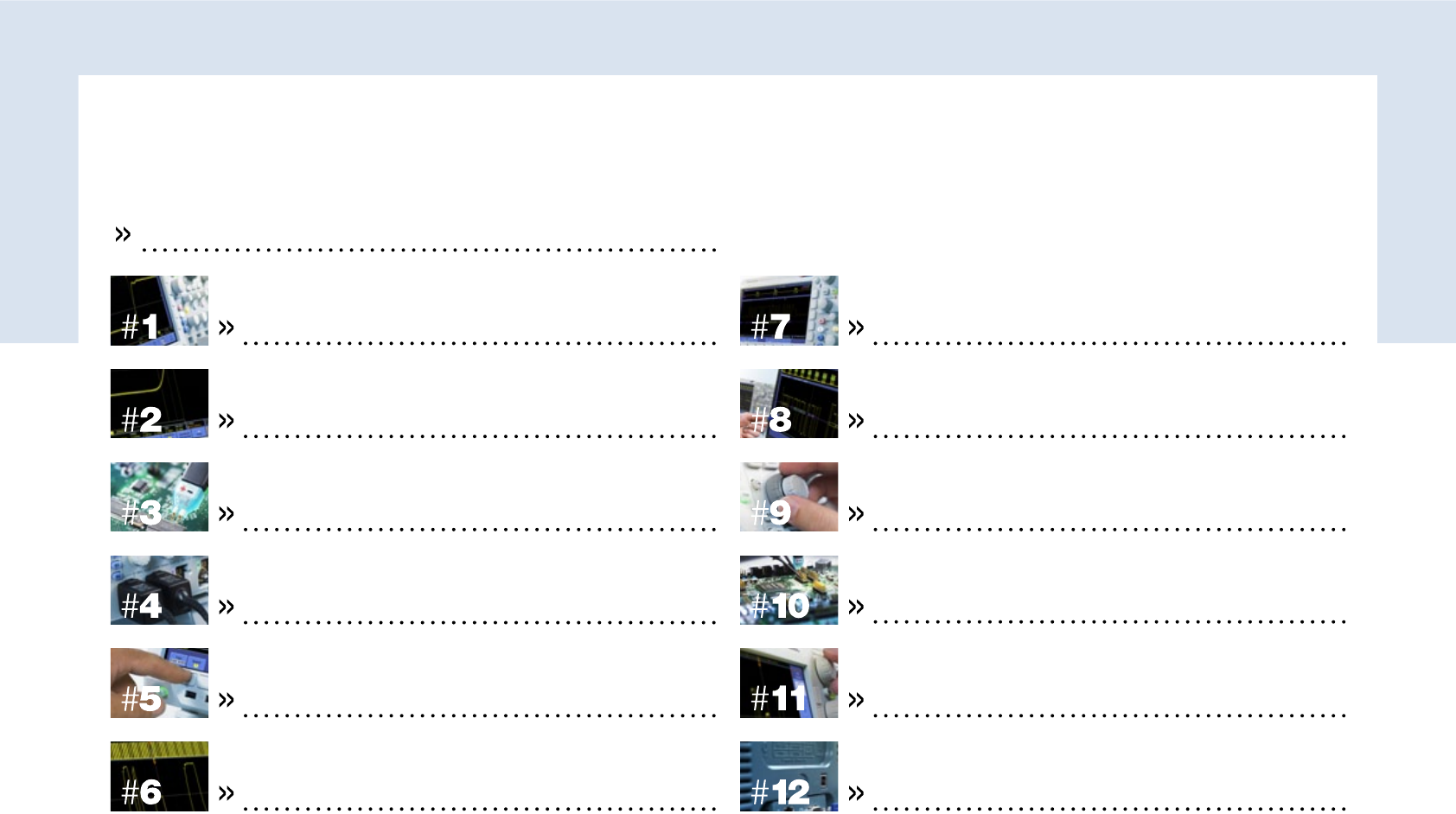
CONTENTS
1
2
3
4
5
6
7
8
9
10
11
12
CONTACT
INTRO
PAGE PAGE
CONTENTS
BANDWIDTH 5
THE DIGITAL STORAGE OSCILLOSCOPE: A BRIEF INTRODUCTION 4
LONG RECORD LENGTHS 17
RISE TIME 7 POWERFUL WAVEFORM NAVIGATION AND ANALYSIS 19
MATCHING PROBES 9 AUTOMATED WAVEFORM MEASUREMENTS 21
ACCURATE INPUT CHANNELS ... AND ENOUGH OF THEM 11 ADVANCED APPLICATION SUPPORT 23
FAST SAMPLE RATE 13 EASY, RESPONSIVE OPERATION 25
VERSATILE TRIGGERING 15 CONNECTIVITY AND EXPANSION 27
3
12 THINGS TO CONSIDER WHEN CHOOSING AN OSCILLOSCOPE
www.tek.co.uk
BANDWIDTH 5
RISE TIME 7
MATCHING PROBES 9
ACCURATE INPUT CHANNELS ... AND ENOUGH OF THEM 11
FAST SAMPLE RATE 13
VERSATILE TRIGGERING 15
LONG RECORD LENGTHS 17
POWERFUL WAVEFORM NAVIGATION AND ANALYSIS 19
AUTOMATED WAVEFORM MEASUREMENTS 21
ADVANCED APPLICATION SUPPORT 23
EASY, RESPONSIVE OPERATION 25
CONNECTIVITY AND EXPANSION 27
The digiTal sTorage oscilloscope: a brief inTroducTion 4
CONTENTS
1
2
3
4
5
6
7
8
9
10
11
12
CONTACT
INTRO
In short, whatever scope you choose it must not only match how and where you work but also:
Accurately capture your signals.
Have features that expand your capabilities and save you time.
Offer guaranteed not just typical specifications.
Accuracy. You will need a pretty good idea of what signals you’re going to need to look at: whether
(analog) audio and transducer signals or (digital) pulses and steps. If you’re looking at digital signals, will you
be measuring rise times, or just looking at approximate timing relationships? Will you use the scope to qualify
elements of your design, or mostly for debugging? Either way, accurate signal capture at the outset is more
important than any later signal processing – your decisions rely on accurate information, and you can always
process the information on a computer.
Capability. You need to consider not just your present generation of designs, but future generations too.
A high-quality scope will give you many years’ reliable service.
Guaranteed specs. Ensure that all the parameters you need to measure are detailed as “guaranteed
specifications” in the oscilloscope datasheet. Parameters listed as “Typical” are simply an indication of
oscilloscope performance, and cannot be used to make meaningful measurements that comply with
recognised quality standards.
The digital storage oscilloscope: a brief introduction
Oscilloscopes are the basic tool for anyone designing, manufacturing or repairing electronic
equipment. A digital storage oscilloscope (DSO, which this guide concentrates on) acquires
and stores waveforms. It can show high-speed repetitive and single-shot signals across
multiple channels to capture elusive glitches and transient events.
A scope shows the signal’s frequency, whether a malfunctioning component is distorting the signal,
how much of the signal is noise, whether the noise changes with time, and much, much more.
4
12 THINGS TO CONSIDER WHEN CHOOSING AN OSCILLOSCOPE
CONTENTS
1
2
3
4
5
6
7
8
9
10
11
12
CONTACT
INTRO
Download
For a fuller understanding
of scopes see the Tektronix
‘XYZs of Oscilloscopes’
XYZs of Oscilloscopes
Primer
ß
www.tek.co.uk

BANDWIDTH
System bandwidth determines an oscilloscope’s fundamental ability to
measure an analog signal - the maximum frequency range that it can
accurately measure.
What you need
Entry level scopes will often have a maximum bandwidth of 100 MHz. They can
accurately (within 2%) show the amplitudes of sine-wave signals up to 20 MHz.
For digital signals, oscilloscopes must capture the fundamental, third and fifth
harmonics or the display will lose key features. So, the bandwidth of the scope
together with the probe should similarly be at least 5x the maximum signal
bandwidth for better than ±2% measurement error – the ‘five times rule’.
This is also needed for accurate amplitude measurements.
High-speed digital, serial communications, video and other complex signals
can therefore require scope bandwidths of 500 MHz or more.
Bandwidth is defined as the frequency at which a sine-wave
input signal is attenuated to 70.7% of its true amplitude (the
-3 dB or ‘half-power’ point, shown here for a 1 GHz scope).
100
85
70.7
0.1 0.5
Frequency (GHz)
30% Amplitude degration!
Amplitude error (%)
1.0
-3 dB
~2% Amplitude degration
5
12 THINGS TO CONSIDER WHEN CHOOSING AN OSCILLOSCOPE
CONTENTS
1
2
3
4
5
6
7
8
9
10
11
12
CONTACT
INTRO
ß
www.tek.co.uk
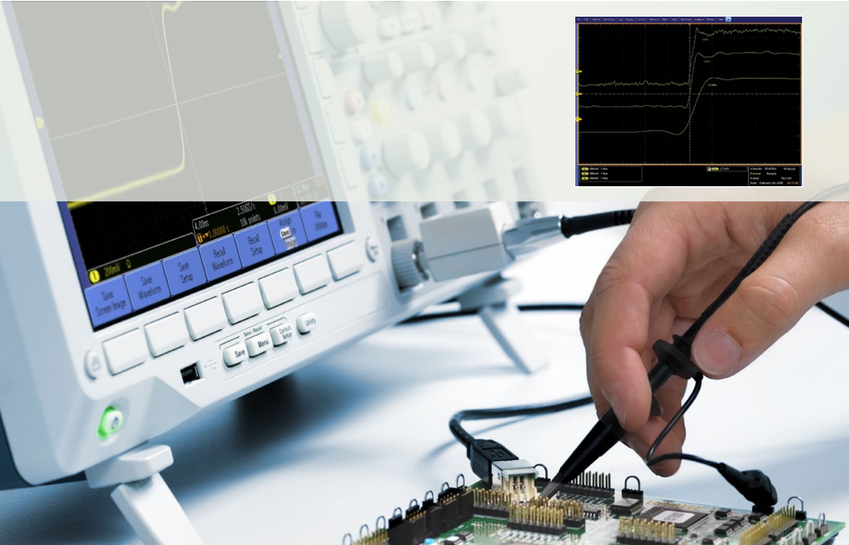
Remember the ‘five times rule’
When selecting bandwidth, use the ‘five times rule’. If bandwidth is too low,
your oscilloscope will not resolve high-frequency changes. Amplitude will
be distorted. Edges will vanish. Details will be lost.
Signals captured
at 250 MHz,
1 GHz and 4 GHz
bandwidth.
6
12 THINGS TO CONSIDER WHEN CHOOSING AN OSCILLOSCOPE
ß
CONTENTS
1
2
3
4
5
6
7
8
9
10
11
12
CONTACT
INTRO
www.tek.co.uk

RISE TIME
While analog engineers look at bandwidth, digital engineers are more
interested in the rise time of signals like pulses and steps.
What you need
The faster the rise time, the more accurate are the critical details of fast transitions.
Fast rise time is also needed for accurate time measurements.
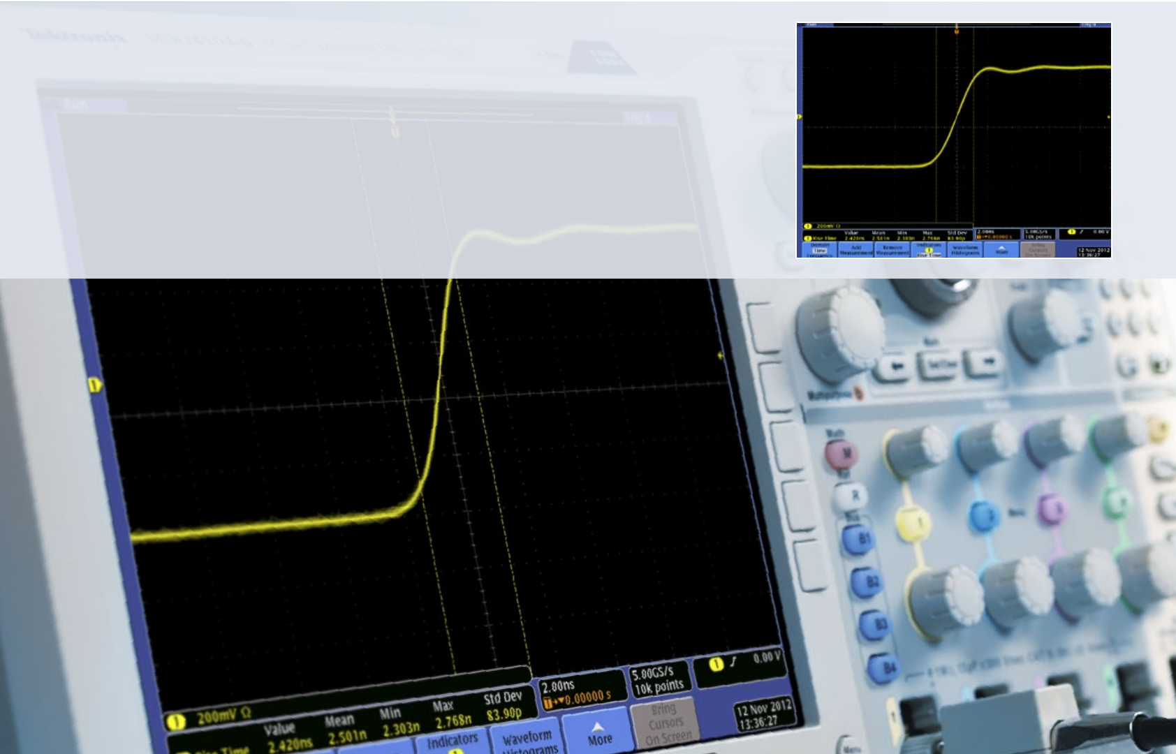
Rise time is defined as, where k is between 0.35 (typically for scopes
with bandwidth <1 GHz) and 0.40 to 0.45 (>1 GHz).
Similar to bandwidth, an oscilloscope’s rise time should be < 1/5 x fastest
rise time of signal.
E.g. a 4-ns rise time needs a scope with faster than 800 ps rise time. Note:
As with bandwidth, achieving this rule of thumb may not always be possible.
TTL and CMOS may need 400 to 300 ps rise times.
Your scope rise time must be fast enough to capture rapid
transitions accurately.
7
12 THINGS TO CONSIDER WHEN CHOOSING AN OSCILLOSCOPE
ß
CONTENTS
1
2
3
4
5
6
7
8
9
10
11
12
CONTACT
INTRO
www.tek.co.uk
Accurate rise time measurements are key
Many logic families have faster rise times (edge speeds) than their clock
rates suggest. A processor with a 20 MHz clock may well have signals with
rise times similar to those of an 800 MHz processor. Rise times are critical
for studying square waves and pulses. Square waves are standard for
testing amplifier distortion and timing signals for TVs and computers.
Pulses may represent glitches or information bits – too slow a rise time for
the circuit being tested could shift the pulse in time and give a wrong value.
8
12 THINGS TO CONSIDER WHEN CHOOSING AN OSCILLOSCOPE
ß
CONTENTS
1
2
3
4
5
6
7
8
9
10
11
12
CONTACT
INTRO
www.tek.co.uk

MATCHING PROBES
Precision measurements start at the probe tip. The probe’s bandwidth must
match that of the oscilloscope (the ‘five times rule’ again), and must not
overload the Device Under Test (DUT).
What you need
Probes actually become a critical part of the circuit, introducing resistive, capacitive
and inductive loading that alters the measurement. To minimize the effect it’s best to
use probes from the same manufacturer as the scope, forming an integrated solution.
Loading is critical. Resistive loading of standard passive probes is usually an
acceptable 10 M or better. Capacitive loading of 10, 12 or even 15 picoFarads (pF)
at high frequencies is a real problem though.
When selecting a mid-range scope choose probes with capacitive loadings of
< 10 pF. The best passive probes offer 1GHz bandwidth with a capacitive load <4 pF.
Probing for answers: Do you plan to measure voltage,
current or both? What frequency is your signal? How
large is the amplitude? Does the DUT have low or high
source impedance? Do you need to measure the signal
differentially? What you want to do determines the probes
you need.
9
12 THINGS TO CONSIDER WHEN CHOOSING AN OSCILLOSCOPE
www.tek.co.uk
CONTENTS
1
2
3
4
5
6
7
8
9
10
11
12
CONTACT
INTRO
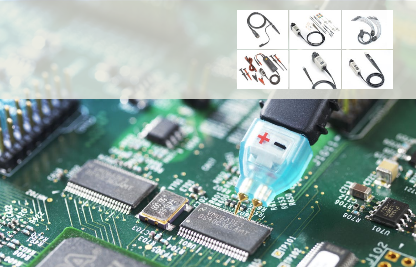
Use a range of probes
To start with, select passive probes that have high bandwidth and low
loading. Active ground-referenced probes offer 1 to 4 GHz bandwidth, and
differential active probes 20 GHz or more. Adding a current Probe enables
the scope to calculate and display instantaneous power, true power, apparent
power, and phase. High voltage probes measure to 40 kV peak. Specialty
probes include logic, optical and environmental types.
10
12 THINGS TO CONSIDER WHEN CHOOSING AN OSCILLOSCOPE
ß
CONTENTS
1
2
3
4
5
6
7
8
9
10
11
12
CONTACT
INTRO
Download
See the Tektronix primer
“ABC’s Of Probes”
for more details.
ABCs of Probes
Primer
ß
www.tek.co.uk
ACCURATE INPUT CHANNELS
... AND ENOUGH OF THEM
Digital scopes sample analog channels to store and display them. In general,
the more channels the better, although adding channels adds to the price.
What you need
Whether to select 2, 4, 8 or 16 channels depends on your application. Two or four analog channels
will allow you to view and compare signal timings of your waveforms, while debugging a digital
system with parallel data needs an additional 8 or 16 digital channels or more.
A Mixed Signal Oscilloscope adds digital timing channels, which indicate high or low states
and can be displayed together as a bus waveform. The latest Mixed Domain Oscilloscopes
add a dedicated RF input for making high frequency measurements in the frequency domain.
Whatever you choose, all channels should have good range, linearity, gain accuracy,
flatness and resistance to static discharge.
Some instruments share the sampling system between channels to save money.
But beware: the number of channels you turn on can reduce the sample rate.
Isolated channels simplify floating measurements. Unlike ground-referenced oscilloscopes,
the input connector shells can be isolated from each other and from earth ground.
A mixed domain oscilloscope not only offers analog and
digital channels, like an MSO, but also includes a dedicated
RF input channel that behaves like a spectrum analyzer.
11
12 THINGS TO CONSIDER WHEN CHOOSING AN OSCILLOSCOPE
www.tek.co.uk
CONTENTS
1
2
3
4
5
6
7
8
9
10
11
12
CONTACT
INTRO
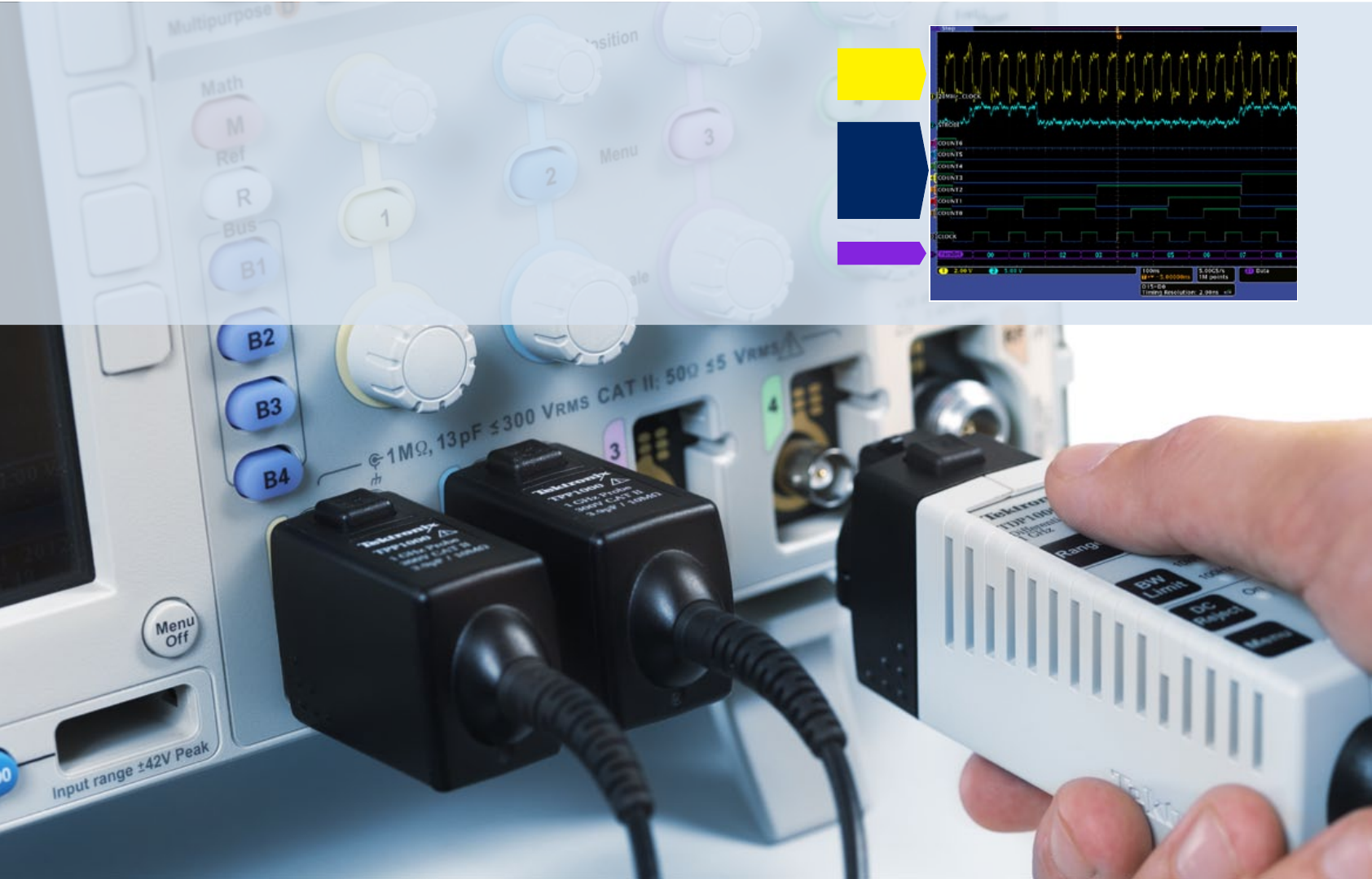
Analog
Digital
Bus
Choose enough channels
The more time-correlated analog and digital channels your scope has,
the more points in a circuit you can measure at the same time and the
easier it is to decode a wide parallel bus, for instance. The example
shows 2 analog, 8 digital and 1 decoded bus waveforms.
12
12 THINGS TO CONSIDER WHEN CHOOSING AN OSCILLOSCOPE
ß
CONTENTS
1
2
3
4
5
6
7
8
9
10
11
12
CONTACT
INTRO
www.tek.co.uk

FAST SAMPLE RATE
The sample rate of an oscilloscope is similar to the frame rate of a movie
camera. It determines how much waveform detail the scope can capture.
What you need
Sample rate (samples per second, S/s) is how often an oscilloscope samples the
signal. Again, we recommend a ‘five times rule’: use a sample rate of at least
5x your circuit’s highest frequency component.
The minimum sample rate may also be important if you need to look at slowly
changing signals over longer periods of time.
Most entry-level scopes have a (maximum) sample rate of 1 to 2 GS/s,
while mid-range ones can have 5 to 10 GS/s.
The faster you sample, the less information you’ll lose and the better the scope
will represent the signal under test. But the faster you will fill up your memory,
too, which limits the time you can capture.
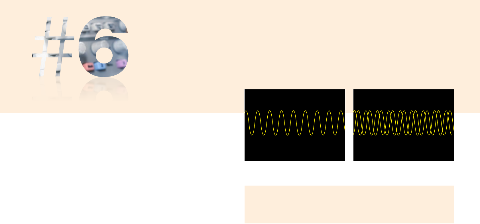
Accurate reconstruction of a signal depends on both the
sample rate and the interpolation method used. Linear
interpolation connects sample points with straight lines, but
this approach is limited to reconstructing straight edged
signals. Sin x/x interpolation is a mathematical process in
which points are calculated to fill in the time between the
real samples. This form of interpolation lends itself to curved
and irregular signal shapes, which are far more common
in the real world than pure square waves and pulses.
Consequently, sin x/x interpolation is the preferred method
for applications where the sample rate is 3 to 5 times the
system bandwidth.
100
90
10
0
Sine Wave Reproduced
using Sine x/x Interpolation
Sine Wave Reproduced
using Linear Interpolation
13
12 THINGS TO CONSIDER WHEN CHOOSING AN OSCILLOSCOPE
ß
CONTENTS
1
2
3
4
5
6
7
8
9
10
11
12
CONTACT
INTRO
www.tek.co.uk
To capture glitches you need speed!
Nyquist said that a signal must be sampled at least twice as fast as its highest
frequency component to accurately reconstruct it and avoid aliasing (showing
artefacts that are not actually there). Nyquist however is an absolute minimum
– it applies only to sine waves, and assumes a continuous signal. Glitches are
by definition not continuous, and sampling at only twice the rate of the highest
frequency component is usually not enough. Conclusion: A high sample rate
increases resolution, ensuring that you’ll see intermittent events.
14
12 THINGS TO CONSIDER WHEN CHOOSING AN OSCILLOSCOPE
ß
CONTENTS
1
2
3
4
5
6
7
8
9
10
11
12
CONTACT
INTRO
www.tek.co.uk
VERSATILE TRIGGERING
Triggering gives a stable display and lets you zero in on specific parts
of complex waveforms.
What you need
All oscilloscopes provide edge triggering, and most offer pulse width triggering.
To acquire anomalies and make best use of the scope’s record length, look
for a scope that offers advanced triggering on more challenging signals.
The wider the range of trigger options available the more versatile the scope
(and the faster you get to the root cause of a problem!):
- A & B sequence triggering; delay by time or delay by events
- Video triggering on line/frame/HD signals, etc.
- Logic triggering: slew rate, glitch, pulse width, time-out, runt, setup-and-hold
- Communications triggers: embedded system designs use both serial
(I2C, SPI,CAN/LIN, USB …) and parallel buses.
Untriggered display
Triggered display
Triggering synchronizes the horizontal sweep at the correct point in the signal, rather than
just starting the next trace at the point where the present trace happens to finish. A single
trigger acquires all input channels simultaneously.
See how it works
15
12 THINGS TO CONSIDER WHEN CHOOSING AN OSCILLOSCOPE
www.tek.co.uk
CONTENTS
1
2
3
4
5
6
7
8
9
10
11
12
CONTACT
INTRO
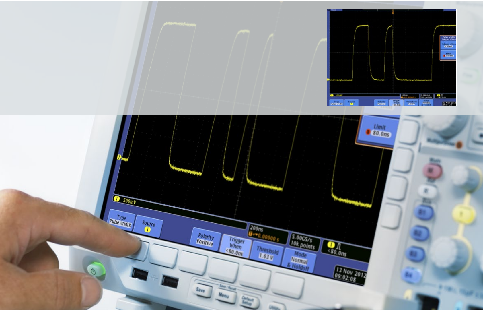
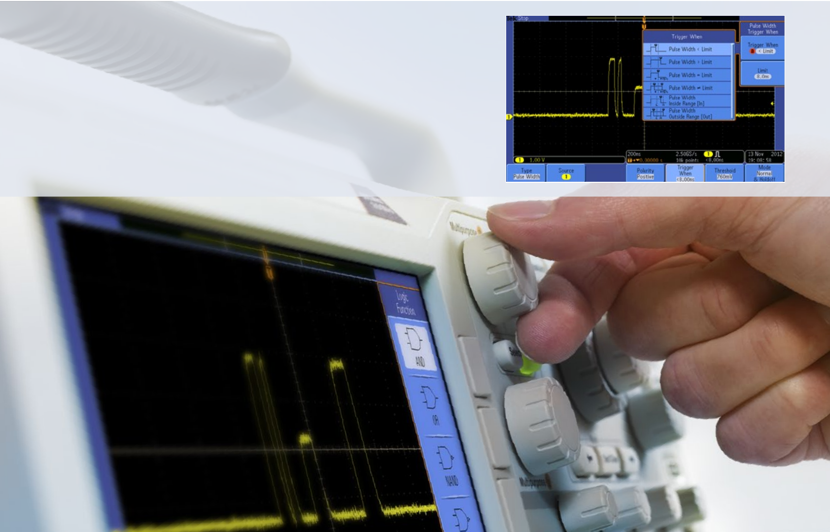
Advanced triggers find the right information
Triggering lets you isolate a group of waveforms to see what is going wrong.
Specialized triggers can respond to specific conditions in the incoming signal –
making it easy to detect, for example, a pulse that is narrower than it should be.
16
12 THINGS TO CONSIDER WHEN CHOOSING AN OSCILLOSCOPE
ß
CONTENTS
1
2
3
4
5
6
7
8
9
10
11
12
CONTACT
INTRO
www.tek.co.uk
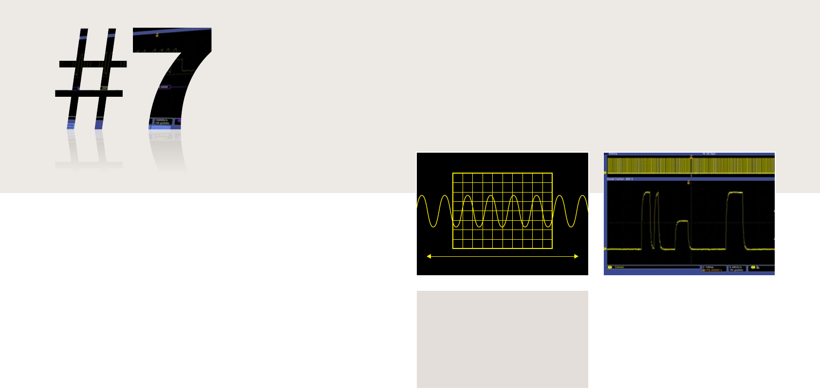
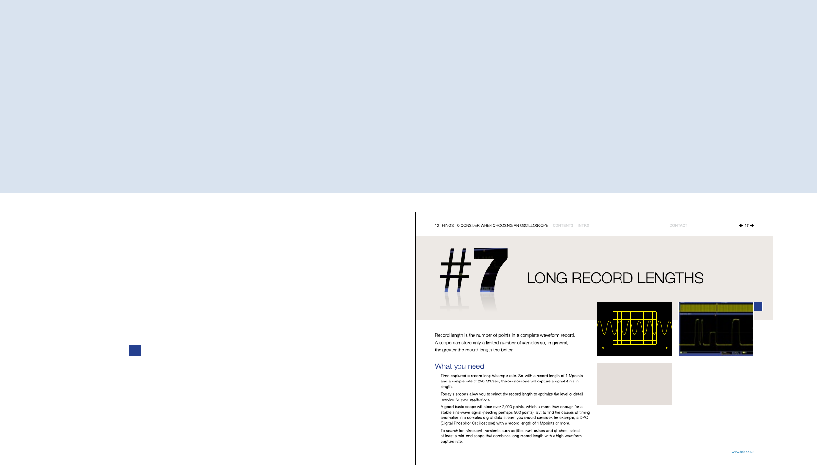
LONG RECORD LENGTHS
Record length is the number of points in a complete waveform record.
A scope can store only a limited number of samples so, in general,
the greater the record length the better.
What you need
Time captured = record length/sample rate. So, with a record length of 1 Mpoints
and a sample rate of 250 MS/sec, the oscilloscope will capture a signal 4 ms in
length.
Today’s scopes allow you to select the record length to optimize the level of detail
needed for your application.
A good basic scope will store over 2,000 points, which is more than enough for a
stable sine-wave signal (needing perhaps 500 points). But to find the causes of timing
anomalies in a complex digital data stream you should consider, for example, a DPO
(Digital Phosphor Oscilloscope) with a record length of 1 Mpoints or more.
To search for infrequent transients such as jitter, runt pulses and glitches, select
at least a mid-end scope that combines long record length with a high waveform
capture rate.
Since an oscilloscope can store only
a limited number of samples, the
waveform duration (time) will be inversely
proportional to the oscilloscope’s
sample rate. Time Interval =
Record Length / Sample Rate
17
12 THINGS TO CONSIDER WHEN CHOOSING AN OSCILLOSCOPE
ß
CONTENTS
1
2
3
4
5
6
7
8
9
10
11
12
CONTACT
INTRO
www.tek.co.uk
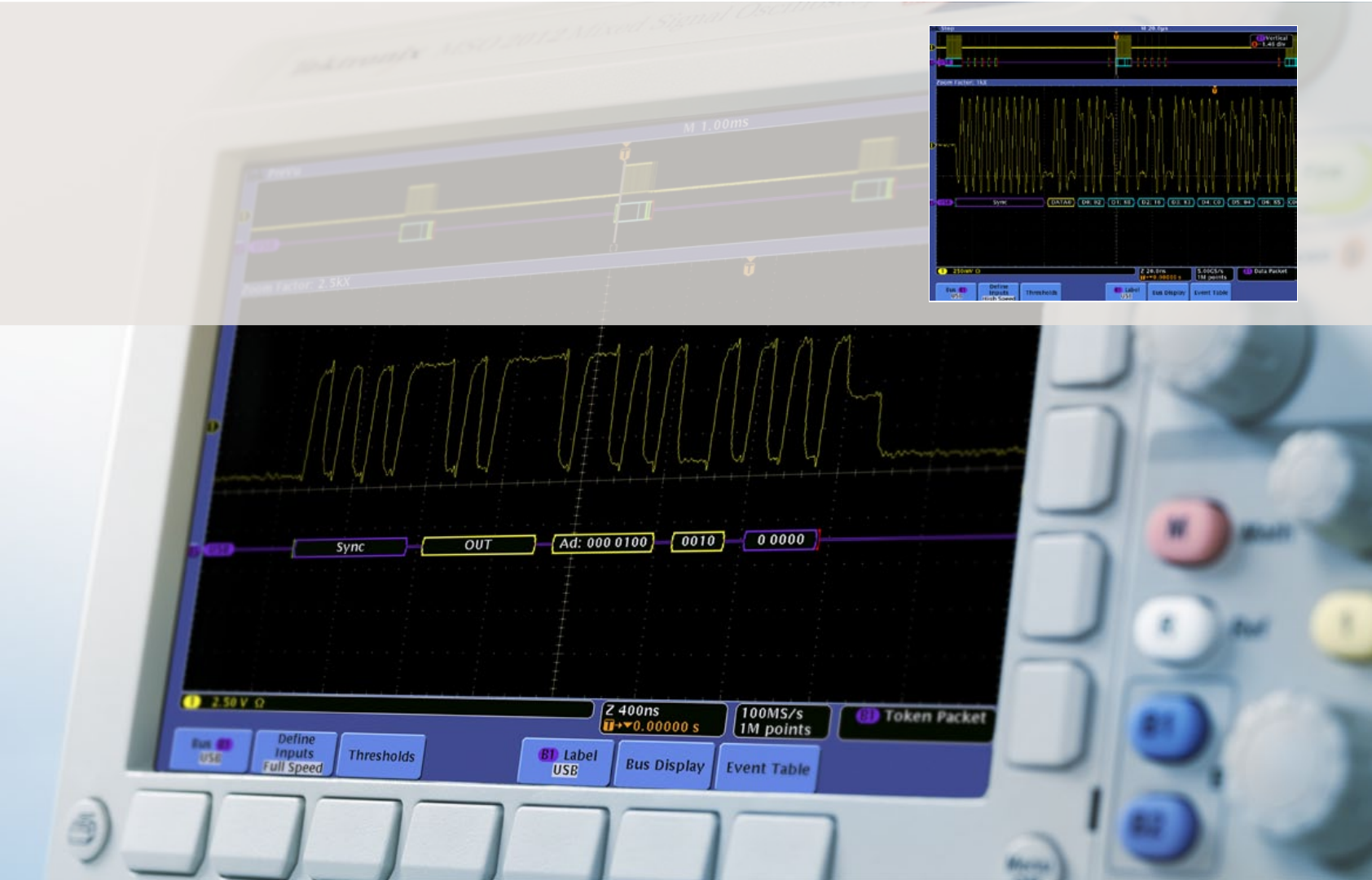
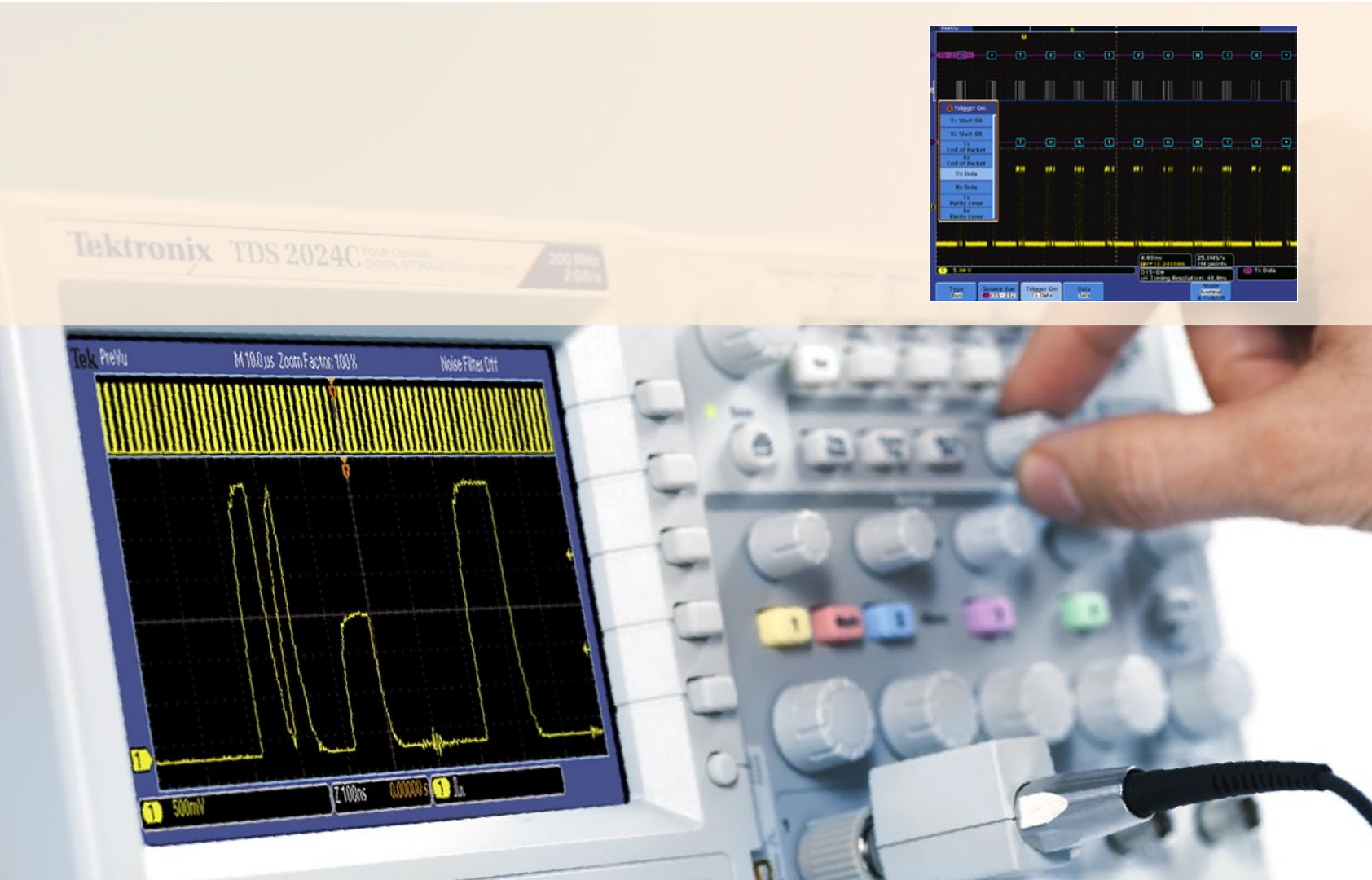
See the bigger picture
Capturing enough detail to decode this USB serial data stream requires high
resolution sampling (200ps). Capturing multiple packet contents needs a long
time (200µs). An oscilloscope with long record length (1 Mpoints) is needed to
display both.
18
12 THINGS TO CONSIDER WHEN CHOOSING AN OSCILLOSCOPE
ß
CONTENTS
1
2
3
4
5
6
7
8
9
10
11
12
CONTACT
INTRO
www.tek.co.uk
POWERFUL WAVEFORM
NAVIGATION AND ANALYSIS
Searching for specific waveform errors can be like searching for a needle
in a haystack. You need tools that automate the process and accelerate
the “time to answer”.
What you need
Zoom & Pan allows you to zoom in on an event of interest, and pan the area
backwards and forwards in time.
Play & Pause automatically pans the zoom window across the waveform. That allows
hands-free playback so you can concentrate on what’s important – the waveform itself.
Marks lets you mark events of interest while you’re looking for a problem. You can
use front-panel controls to rapidly jump between each mark for quick and easy timing
measurements (see panel).
Search & Mark lets you search through the entire acquisition and automatically mark
every occurrence of a user-specified event.
Advanced search lets you define various different criteria, similar to trigger conditions,
which will be automatically detected and marked in the captured waveform.
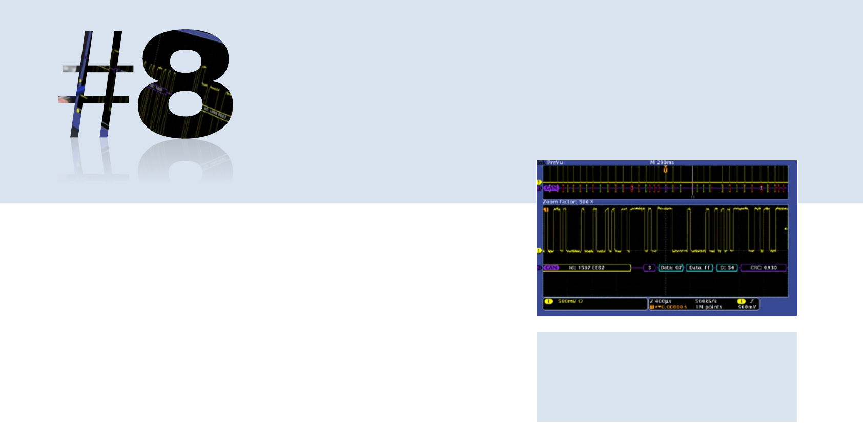
Oscilloscopes with record lengths in the millions of points
can show thousands of screens worth of signal activity,
essential for examining complex waveforms. Placing marks
on the waveform assists in latency measurements on a CAN
bus, for example.
19
12 THINGS TO CONSIDER WHEN CHOOSING AN OSCILLOSCOPE
ß
CONTENTS
1
2
3
4
5
6
7
8
9
10
11
12
CONTACT
INTRO
www.tek.co.uk
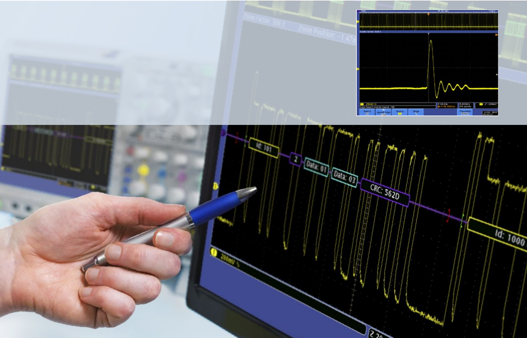
Wave Inspector®
marking every
pulse that crosses
300mV in a long
acquisition.
Consider advanced search tools
The industry’s fastest tool for automated navigation, search and analysis is Wave
Inspector®, a proprietary technology. It allows you to specify search criteria to
automatically find every occurrence in an acquisition that violates some specified
criteria such as setup and hold time.
20
12 THINGS TO CONSIDER WHEN CHOOSING AN OSCILLOSCOPE
ß
CONTENTS
1
2
3
4
5
6
7
8
9
10
11
12
CONTACT
INTRO
www.tek.co.uk

AUTOMATED WAVEFORM
MEASUREMENTS
Automated waveform measurements make it easier to obtain accurate
numerical readings.
What you need
Most scopes offer front-panel buttons and/or screen-based menus to take accurate
automated measurements.
Basic choices on most scopes include amplitude, period and rise/fall time.
Many digital scopes also provide mean and RMS calculations, duty cycle, and other
maths operations.
Advanced mathematics functions are found on some scopes, improving the ‘time to
answer’ even further. Some examples:
- FFT, Integrate, Differentiate, Logarithm, Exponent, Square root, Absolute
- Sine, Cosine, Tangent, Radians, Degrees
- Scalars, with user-adjustable variables and results of parametric measurements.
Automated measurements appear as on-screen
alphanumeric readouts, and are more accurate than direct
graticule interpretation.
Examples of fully automated waveform measurements:
Period Duty Cycle + High
Frequency Duty Cycle - Low
Width + Delay Minimum
Width - Phase Maximum
Rise time Burst width Overshoot +
Fall time Peak-to-peak Overshoot -
Amplitude Mean RMS
Extinction ratio Cycle mean Cycle RMS
Mean optical power Cycle area Jitter
21
12 THINGS TO CONSIDER WHEN CHOOSING AN OSCILLOSCOPE
www.tek.co.uk
CONTENTS
1
2
3
4
5
6
7
8
9
10
11
12
CONTACT
INTRO
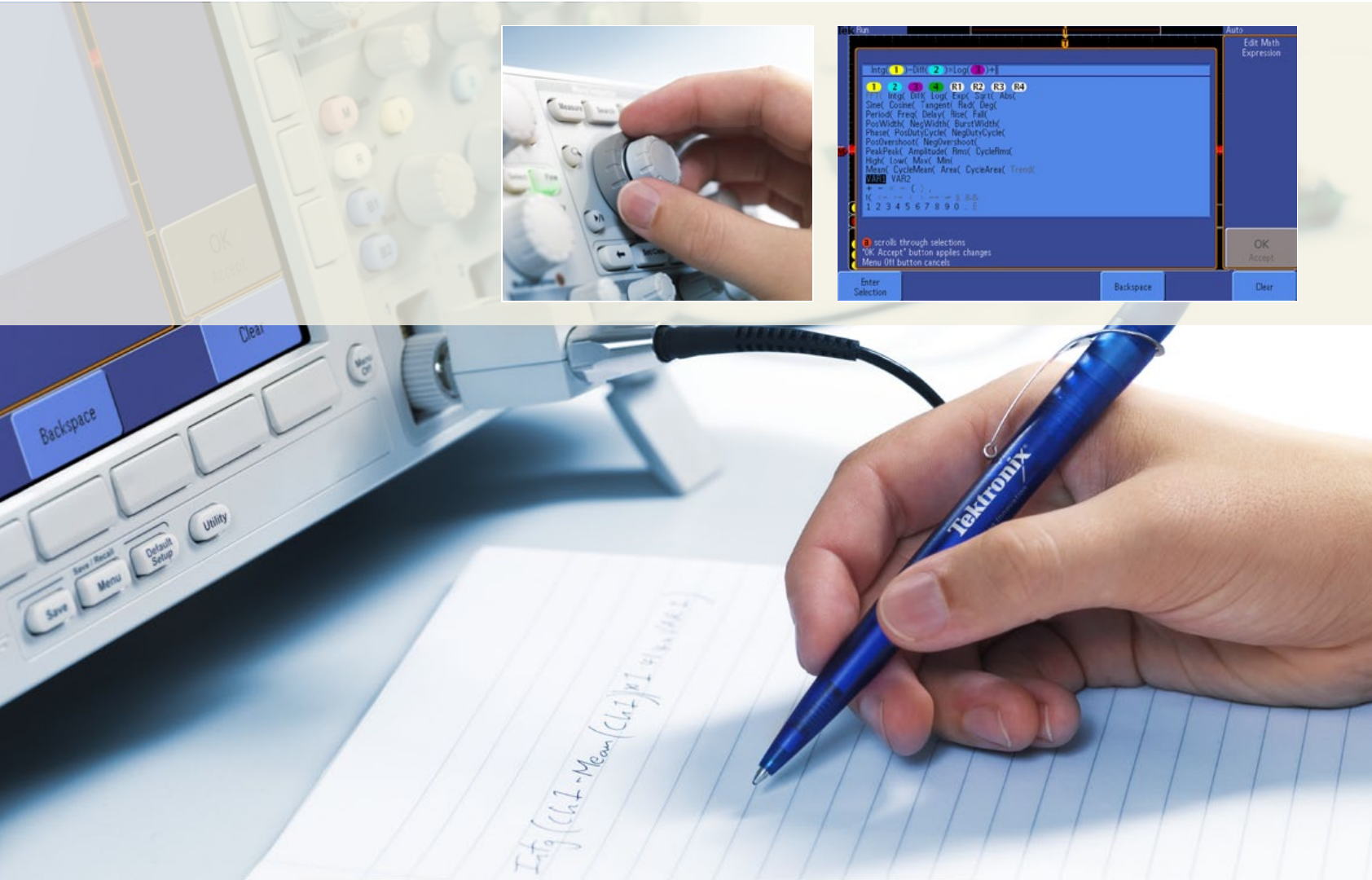
Look for fast answers
Once again, extra functions shorten the time to
answer. Digital Signal Processing techniques
can automate measurements – making them
faster, more accurate and more repeatable than
is possible with cursors. You can even write your
own formulae for specific maths functions.
22
12 THINGS TO CONSIDER WHEN CHOOSING AN OSCILLOSCOPE
ß
CONTENTS
1
2
3
4
5
6
7
8
9
10
11
12
CONTACT
INTRO
www.tek.co.uk
ADVANCED APPLICATION
SUPPORT
Advanced scopes have application software for optical and electrical design
troubleshooting and standards compliance.
What you need
Signal integrity and jitter measurement packages: provide insight into signal
integrity-related problems in digital systems, their causes, characteristics and effects.
RF applications: view signals in the frequency domain and analyze using spectrograms,
amplitude, frequency and phase versus time traces.
Support for debug of embedded systems with mixed analog & digital, parallel & serial
technologies such as CAN/LIN, I2C, SPI, FlexRay, MOST and others.
Education: electrical engineering students need to understand complex circuits and
electronic designs to develop next generation technologies.
Power measurement (SMPS, for example): automated measurements for power quality,
switching loss, harmonics, safe operating area, modulation, ripple, slew rate and more.
Others include optical communications, memory system verification, communications
standards testing, disk drive measurements, video measurements, and more.
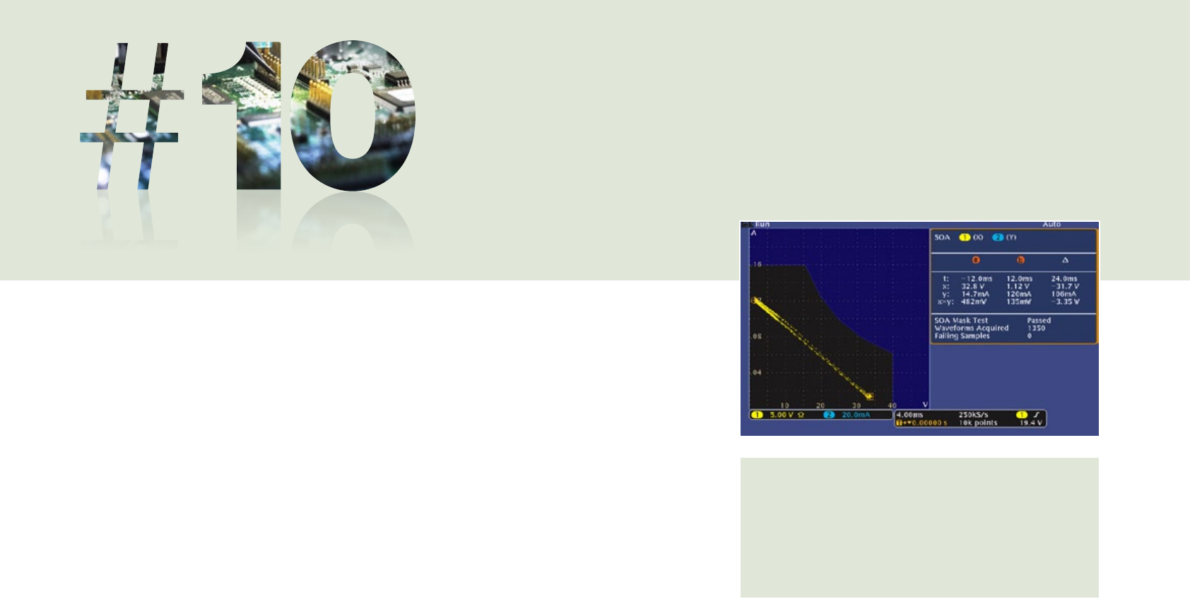
Is your SMPS switching device operating within safe limits?
Automated analysis tools provide power measurements at
the touch of a button, enabling quick and accurate analysis
of safe operating area (SOA), power quality, switching loss,
harmonics, modulation, ripple, and slew rate (di/dt, dv/dt).
23
12 THINGS TO CONSIDER WHEN CHOOSING AN OSCILLOSCOPE
ß
CONTENTS
1
2
3
4
5
6
7
8
9
10
11
12
CONTACT
INTRO
www.tek.co.uk
EASY, RESPONSIVE
OPERATION
Oscilloscopes should be easy to operate, even for occasional users.
The user interface is a large part of the ‘time to answer’ calculations.
What you need
Frequently used adjustments should have dedicated knobs.
AUTOSET and/or DEFAULT buttons will make for instant setup.
The scope should be responsive, reacting quickly to changing events.
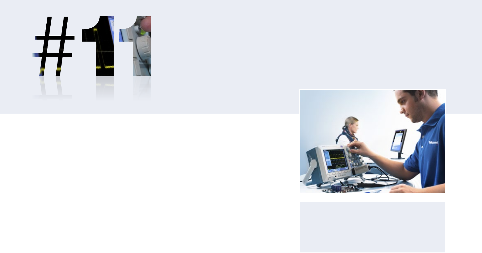
There should be support for your own language, with templates for the dials. Many people don’t use a scope every day. Intuitive controls
allow even occasional users to feel comfortable with the
scope while giving full-time users easy access to the most
advanced features. Many oscilloscopes are portable – for
use in the lab or in the field.
25
12 THINGS TO CONSIDER WHEN CHOOSING AN OSCILLOSCOPE
www.tek.co.uk
CONTENTS
1
2
3
4
5
6
7
8
9
10
11
12
CONTACT
INTRO
Controls that match your way of working
Oscilloscopes should give you different ways to operate the instrument.
Built-in help can provide a convenient, built-in reference manual, while smart
menus give easy access to multifunction, context-sensitive commands.
An icon-rich
graphical user
interface helps
you understand
and intuitively
use advanced
capabilities.
26
12 THINGS TO CONSIDER WHEN CHOOSING AN OSCILLOSCOPE
ß
CONTENTS
1
2
3
4
5
6
7
8
9
10
11
12
CONTACT
INTRO
www.tek.co.uk

CONNECTIVITY AND
EXPANSION
Connecting a scope to a computer directly or transferring data via portable media
allows advanced analysis, and simplifies documenting and sharing results.
What you need
Consider a scope that allows you to access a Windows desktop and provide network
printing and file sharing resources.
Check if it can run third-party analysis, documentation and productivity software.
Is it helpful to provide internet access, and share measurements with colleagues
real-time?
Can it meet your needs as they change? For example, can you add:
- Memory to channels to analyze longer record lengths
- Application-specific measurements and application modules
- A full range of probes and modules
- Accessories like battery packs and rack mounts
- Software to control the scope from your PC, take automated measurements,
waveform data logging and export waveforms live.
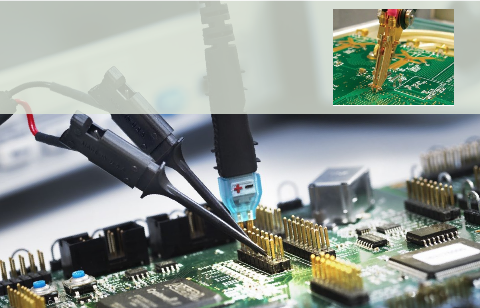
Standard interfaces can include GPIB, RS-232, USB,
Ethernet and LXI, and links to network communication
modules. USB is useful for USB flash drives to store
waveforms, captures and settings. PictBridge lets the
scope act like a digital camera. VGA connects to an
external monitor.
27
12 THINGS TO CONSIDER WHEN CHOOSING AN OSCILLOSCOPE
www.tek.co.uk
CONTENTS
1
2
3
4
5
6
7
8
9
10
11
12
CONTACT
INTRO

Ask about interfaces
LAN, Display, and Printer interfaces enable you to integrate your oscilloscope
with the rest of your working environment:
Ethernet port for network connectivity, plus compatible software to capture screen-shots,
waveform data and measurement results
USB Host port: quick & easy data storage, printing, and connecting a USB keyboard
USB device port for easy connection to a PC or direct printing to a printer
Video port to export the oscilloscope display to a monitor or projector
28
12 THINGS TO CONSIDER WHEN CHOOSING AN OSCILLOSCOPE
www.tek.co.uk
CONTENTS
1
2
3
4
5
6
7
8
9
10
11
12
CONTACT
INTRO

In the end, the scope you choose will have a price tag – but what is the real cost of ownership? Check out the
manufacturer’s support options to see how far they add value to your purchase and contribute to extending your
scope’s useful life. For example, on-site education and training, as well as design, system integration, project
management, and other professional services can help you maximize your productivity and ensure accurate and
reliable measurements. High-value support packages such as these, along with options like extended warranty
can save money in the long term, and bring peace of mind.
... AND FINALLY, CONSIDER
LOW COST OF OWNERSHIP
AND PEACE OF MIND!
29
12 THINGS TO CONSIDER WHEN CHOOSING AN OSCILLOSCOPE
www.tek.co.uk
CONTENTS
1
2
3
4
5
6
7
8
9
10
11
12
CONTACT
INTRO

For Further Information
To access product information and related literature please visit www.tek.co.uk
Freephone Number: 00800 2255 4835*
(available in Austria, Belgium, France, Germany, Ireland, Italy, Netherlands, Spain,
Sweden, Switzerland, UK)
* If Freephone numbers are not accessible from your phone, or for any other
countries, dial: +41 52 675 3777
Literature reference number:
“12 Things to Consider When Choosing an Oscilloscope”.
48X-28633-0
Copyright © 2012, Tektronix. All rights reserved. Tektronix products are covered by U.S. and foreign
patents, issued and pending. Information in this publication supersedes that in all previously published
material. Specification and price change privileges reserved. TEKTRONIX and TEK are registered
trademarks of Tektronix, Inc. All other trade names referenced are the service marks, trademarks
or registered trademarks of their respective companies.
12 THINGS TO CONSIDER WHEN CHOOSING AN OSCILLOSCOPE 30
www.tek.co.uk
CONTENTS
1
2
3
4
5
6
7
8
9
10
11
12
INTRO
CONTACT
