5163_ V14_i 42_Catalog Circular Polarized Patch Antenna AD5900 15 R Thales ANPRC 148 Product Catalog
User Manual: Circular Polarized Patch Antenna AD5900-15-R
Open the PDF directly: View PDF ![]() .
.
Page Count: 48

www.thalescomminc.com
Product Catalog
AN/PRC-148 Family of Radios

i
Introduction
About Thales
Communications, Inc.
Thales Communications, Inc., a
pioneer of software-defined radio
(SDR) technology, is a global leader
in the development, manufacture,
and support of innovative communi-
cations systems for warfighters and
first responders. The company
serves the ground, naval, airborne,
and homeland security domains with
tactical electronic equipment and
information systems that address
the technological and environmental
challenges presented in real-world
situations, especially those with size,
weight, and power constraints.
Thales Communications is part of
Thales, a global technology leader
for the defense and security,
aerospace, and transportation
markets. Thales Communications is
a U.S. proxy company, considered
100% American by the U.S.
Government. As a gateway for
international technologies, Thales
Communications facilitates the
introduction of broader Thales
technologies into the U.S. market.
Thales Communications is
headquartered in Clarksburg,
Maryland, where its products are
developed and manufactured.
Additionally, the company has set up
maintenance and repair depots
supporting troops in Kuwait, Iraq,
and Afghanistan. Establishing in-
theater facilities as close as possible
to warfighters is critical for those
who use and depend on the
equipment.
The AN/PRC-148.
The AN/PRC-148 legacy began
with the Multiband Inter/Intra Team
Radio (MBITR), which replaced
more than 60 pounds of
communications equipment with a
single radio weighing less than two
pounds. The AN/PRC-148 MBITR
was designed and developed under
a U.S. Government program of
record, as was the next-generation
MBITR—the AN/PRC-148 Joint
Tactical Radio System (JTRS)
Enhanced MBITR, or JEM.
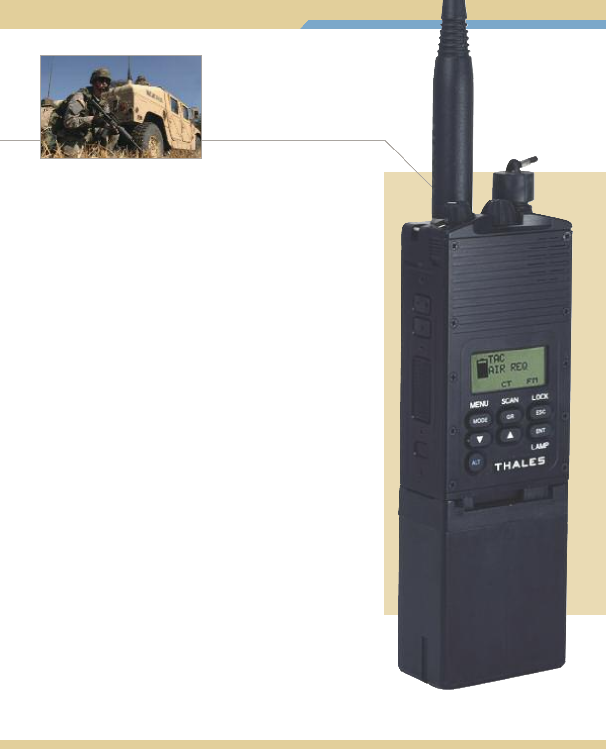
The AN/PRC-148, the smallest,
lightest, and most widely fielded
multiband, portable radio in the
world, is the cornerstone of a
complete communications system
for mounted and dismounted
operations.
Ready for the Net-Centric
Future.
The AN/PRC-148 JEM is not
only the first fielded production
radio developed under the U.S.
Department of Defense JTRS
program of record, but is also the
first fully functional radio designed
for net-centric warfare. In keeping
with JTRS program goals, the
AN/PRC-148 JEM can be
enhanced with legacy waveforms
and software—such as increased
data throughput, networking,
over-the-air cloning and improved
satellite communications—ensuring
interoperability with presently
fielded radios as well as with newly
developed and future capabilities.
All features are available via
simple software upgrades.
Software-Defined
Multiband Interoperability.
Gone are the days when a unit
leader had to rely on trained radio
operators burdened with
cumbersome manpacks and
entering frequencies from
notebooks. With 16 sets of
16 programmed channels in the
30-512 MHz range—downloaded
from a computer or keyed from the
front panel—the AN/PRC-148 JEM
gives the warfighter push-button
access to units in his area of
operation. From an infantry unit on
VHF SINCGARS, to an aircraft on
UHF HAVEQUICK, to operations
over a UHF long-range satellite link,
a unit leader can see all available
links by name or frequency right on
the display screen and
communicate with them seamlessly
with the push of a button.
Flexible Mobility.
The AN/PRC-148 JEM is a highly
adaptable radio, not just in software
configuration but also in mode and
range of operation. The small,
lightweight 5 Watt radio can be
worn anywhere on the body—
hip, chest, or back. By using the
handheld Remote Control Unit,
which features an embedded GPS
capability, the warfighter can send
and receive situational awareness
data. The AN/PRC-148 JEM’s
range of communication can be
quickly extended from 3.72 miles
(6 kilometers) to more than 18.64
miles (30 kilometers), simply by
inserting it into one of the Thales
Vehicle Adapter (VA) configurations,
which recharges the radio’s
batteries.
Trusted by warfighters for years, AN/PRC-148 radios are serving the military,
civilian agencies, and allied and coalition forces globally.
Rapid Dismount.
The JEM can be dismounted
from the VA configuration in less
than two seconds with a single
push-button action, with no cables
to disconnect and no loss in
communication. The AN/PRC-148
JEM’s versatility is further extended
by its ability to serve as a secure
means of sending data. With
the addition of the 56 kbps high-
throughput waveform, it adds a
new dimension to point-to-point
communications. It can also
enhance the battlespace
capabilities of weapon systems
that rely on dependable high-
speed data communications.
Delivering Full Connectivity.
With its broad capabilities,
flexibility, reliability, and proven
performance, the AN/PRC-148
radio gives battlefield leaders
confidence that they will be able
to establish and maintain
communications with all units at
the forward edge of the battlefield.
Catalog Overview.
This catalog is designed to provide
information of immediate interest
to customers. The first section
contains the system descriptions.
The radios are described first,
followed by the systems that
enhance their capabilities. Opposite
each product description page is
the listing of equipment that is
provided with that system. For
example, the page opposite the
AN/PRC-148 JEM contains all the
elements that are provided when
ordering the AN/PRC-148 JEM
system. The system descriptions
shown are typical configurations
that can be changed by customer
request. Prime mission equipment
comes with a standard one-year
warranty. Extended warranties are
available upon request.
The Software and Accessories
section contains a listing and
description of ancillaries that
customers can purchase to
support and supplement the
radio’s capabilities.
Both sections provide part
numbers and, where available,
National Stock Numbers (NSNs),
to assist in ordering the
equipment.
Thales Communications provides
Customer Support 24/7/365,
as shown in the final section of
this catalog.
For our U.S. Government
customers, our products are
listed on our GSA Schedule
(GS-35F-0001L).
All non-U.S. Government sales are
subject to U.S. Government export
approval. Specifications are subject
to change without notice.
Thales Communications is
committed to helping
warfighters and first
responders execute their
missions successfully and
return home safely.
ii

Introduction
i-iv
5 Watt Multiband Inter/Intra Team Radio
AN/PRC-148 (V)3(C)/(V)4(C) JEM 1-2
PRC6809 MBITR 3-4
Dismounted Systems/Fixed Site
20 Watt Man Portable System 5-6
20 Watt and 50 Watt Base Station 7-8
20 Watt Tactical Repeater 9-10
Vehicular Systems
20 Watt Vehicle Adapter 11-12
20 Watt AN/VRC-111 Vehicle Adapter Amplifier 13-14
50 Watt AN/VRC-111 Vehicle Adapter Amplifier – Dual Channel 15-16
50 Watt Vehicle Adapter Amplifier – Single Channel 17-18
50 Watt Low Profile Vehicle Adapter 19-20
50 Watt AN/VRC-113 Cradle Vehicle Adapter 21-22
Airborne Systems
Multichannel Multiband Airborne Radio (MMAR) 23
Lightweight Multiband Airborne Radio (LMAR) 23
Software and Accessories
Radio and Programming Software 25-26
Batteries, Chargers, and Power Adapters 27-28
Antennas 29-31
Cases and Holsters 32
Audio Accessories for the 2 Meter Submersible Urban Configuration Radios 33-34
Audio Accessories for the 20 Meter Submersible Maritime Configuration Radios 35
Cables, Adapters, Spares Kits, and Vehicle Adapter Accessories 36-38
Remote Control Unit with GPS 39
Customer Support
By Phone 41
Online 42
In-Theater 42
iii
Table of Contents
NOTE: – All non-U.S. Government sales are subject to U.S. Government export approval. Specifications are subject to change without notice.
– Photographs in this catalog are not to scale.
iv
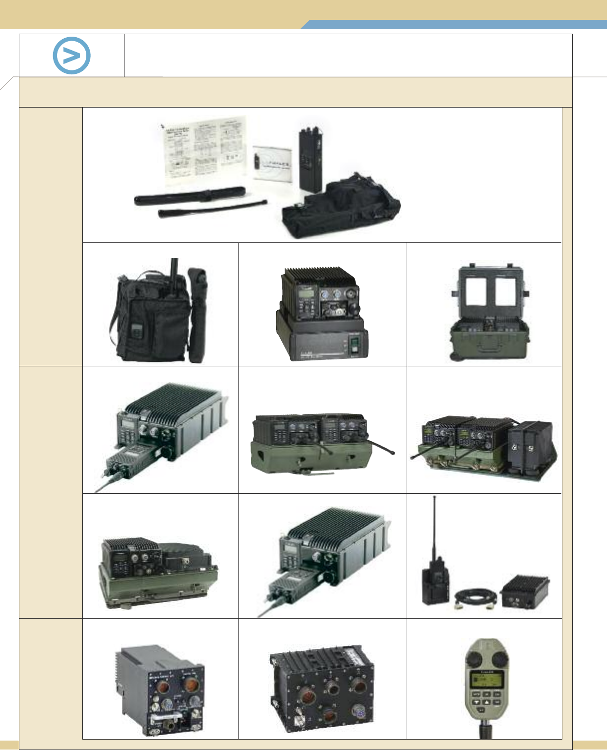
AN/PRC-148 Product Family
Thales offers an integrated systems approach based on the combat-proven multiband AN/PRC-148 radio to ensure low programmatic and
performance risk. All systems are built around the handheld radio and are designed to enhance its capabilities.
20 Watt Vehicle Adapter
Dismounted Systems/Fixed Site
20 Watt Man Portable System
20 Watt AN/VRC-111
Vehicle Adapter Amplifier
20 Watt Tactical Repeater
50 Watt AN/VRC-111
Vehicle Adapter Amplifier
Dual Channel
50 Watt Vehicle Adapter
Amplifier-Single Channel
Software and Accessories
Pictured:
Remote Control
Unit with GPS
Vehicular Systems
50 Watt Low Profile Vehicle Adapter
Airborne Systems,
Software and
Accessories
20 Watt Base Station
(50 Watt Version Available)
5 Watt Multiband Inter/Intra Team Radio System
50 Watt AN/VRC-113
Cradle Vehicle Adapter
Multiband Multichannel
Airborne Radio (MMAR)
Lightweight Multiband
Airborne Radio (LMAR)
1
5 Watt Multiband Inter/Intra Team Radio
■Fully interchangeable with AN/PRC-148
MBITR
■Fully compatible with existing VA and
VAA systems
■JTRS/SCA compliant supporting
technology insertion
Commonality Reliability Size, Weight, and Power
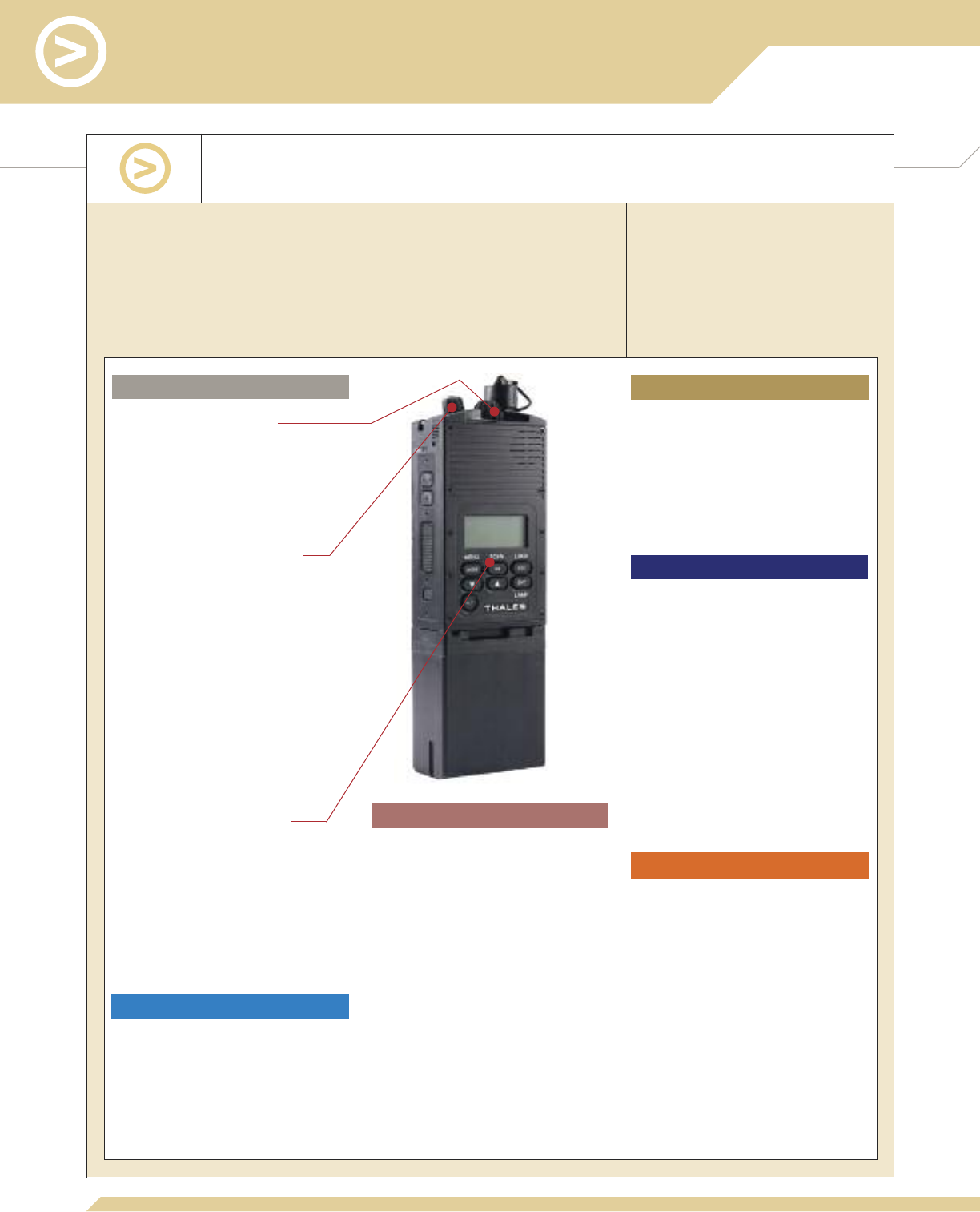
Key Design Features of the AN/PRC-148 (V)3(C)/(V)4(C) JEM
JTRS Enhanced Multiband Inter/Intra Team Radio
■>11,400 hours calculated MTBF
■Based on the battle-proven AN/PRC-
148 MBITR
■Government tested and certified as
part of DoD program of record
■<34 cubic inches (560 cubic centimeters)
including connectors per TIA-603-2001
■30.6 ounces (867.5 grams) including
battery and broadband antenna
■10 hours battery life measured per
TIA-603b
Dedicated 16-Channel Switch
■
<1-second waveform/channel switch time
■
Separate Channel and On/Off switches to
prevent unintentional radio shut-down
■
Group mapping to 256 channel presets
■
Low profile reduces damage
Dedicated Top Volume/On/Off Knob
■
Emergency zeroize switch
■
Top position for easy access with radio in
holster
■
Detent at Off position to prevent
unintentional radio shut-down
■
Low profile reduces damage
PTT, Squelch Disable and Programmable
Buttons
■
Recessed to prevent inadvertent action
■
Two user-programmable buttons provide
immediate access to mission-specific
functions
Intuitive, Function-Specific HMI
■
Function-based keypad provides quick,
direct access to common operations,
leading to fewer battle-stress errors
■
Recessed keys prevent accidental key
presses
■
Highly optimized Human Machine
Interface (HMI) incorporates customer
feedback based on battlefield experience
■
Machined aircraft aluminum chassis
delivers precise tolerances required for
immersibility (2 meter and 20 meter
versions available)
■
22 screws and robust O-ring apply even
pressure and lifetime sealing
Ease of Use
Immersibility
Implemented and Planned
■
AM/FM
■
HAVEQUICK I/II
■
SINCGARS to MIL-STD-188-241
■
SINCGARS FH2 to MIL-STD-188-241
■
High Throughput Waveform to MIL-STD-
188-181B (56 kbps)
■
Integrated Waveform to MIL-STD-188-
181C, -182B, and -183B (SATCOM IW)
■
Retransmission
■
Project 25
■
ANDVT (LPC-10 or MELP vocoders)
■
OTAC
■
Future Waveforms
■
Contiguous 30–512 MHz coverage
■
Type 1 encrypted
■
SECAN approved
■
-119 dBm typical FM receive sensitivity
providing greater communication range
■
RF output power from 0.1 to 5 Watts
Side RF and Digital Connector
■
Cable-free interface with VA/ VAA
■
No RF switch required; top antenna
connector disabled while in VA/ VAA
■
Supports 2-second rapid
dismount/insertion from/to VA/ VAA
■
Includes USB interface
Radio Profile
■
Clean, protrusion-free profile for
embedded integration with VA/ VAA
■
Allows one-button mechanical
engagement with VA/ VAA
■
Operating temperature: -31° to +60° C
■
Storage temperature: -33° to +71° C
■
Humidity: 95% Non-condensing
■
Altitude: 30,000 feet
■
Shock: EIA-603-2002
■
Vibration: EIA-603-2002
■
TEMPEST Compliance:
•NSTISSAM TEMPEST/1-92, Level III
•NACSEM 5112
Waveforms/Modes of Operation
Performance
Expandability
Ruggedization

2
A typical AN/PRC-148 (V)4(C) JEM System (Urban)* is
comprised of all of the following components:
Description Part Number NSN
Receiver-transmitter
Rechargeable lithium-ion battery
30-90 MHz antenna
90-512 MHz broadband antenna
Battery holder assembly
Carrying case
Operator manual
Quick reference guide, laminated
Holster, ACU digital camo
Keyfill adapter on 10-pin Maritime version only
*Versions:
■
AN/PRC-148(V)3(C), Maritime, immersible in salt water to 20 meters for 2 hours, Part Number PRC6999-ABS-XXX
6-pin (Part Number PRC6999-ABS-CIS) and 10-pin audio connector configurations available
■
AN/PRC-148(V)4(C), Urban, immersible in salt water to 2 meters for 30 minutes, Part Number PRC6999-BBS-XXX
4101660-XXX
1600515-7
1600629-1
1600500-3
4101240-501
1600495-1
84357
3400905-1
1600494-1
3600190-1
6140-01-487-1153
5985-01-487-1135
5985-01-584-7883
6160-01-487-1151
5895-01-487-1158
5895-01-487-1157
5995-01-487-1149
Optional Accessories
JTRS Upgrade Program: Subject to U.S. export approval, AN/PRC-148 MBITR versions (V)1(C) and
(V)2(C) may be upgradeable to AN/PRC-148 JEMs. Thales will provide a turn-in credit for an MBITR towards the
purchase of a JEM; either a replacement R/T or a complete radio system. Each JEM will have a 5-year warranty and
the following software features included: SINCGARS, HAVEQUICK II, and ANDVT. Thales will properly dispose of the
CCI equipment in accordance with regulations.
5 Watt Multiband Inter/Intra Team Radio
Commonality Reliability Size, Weight, and Power
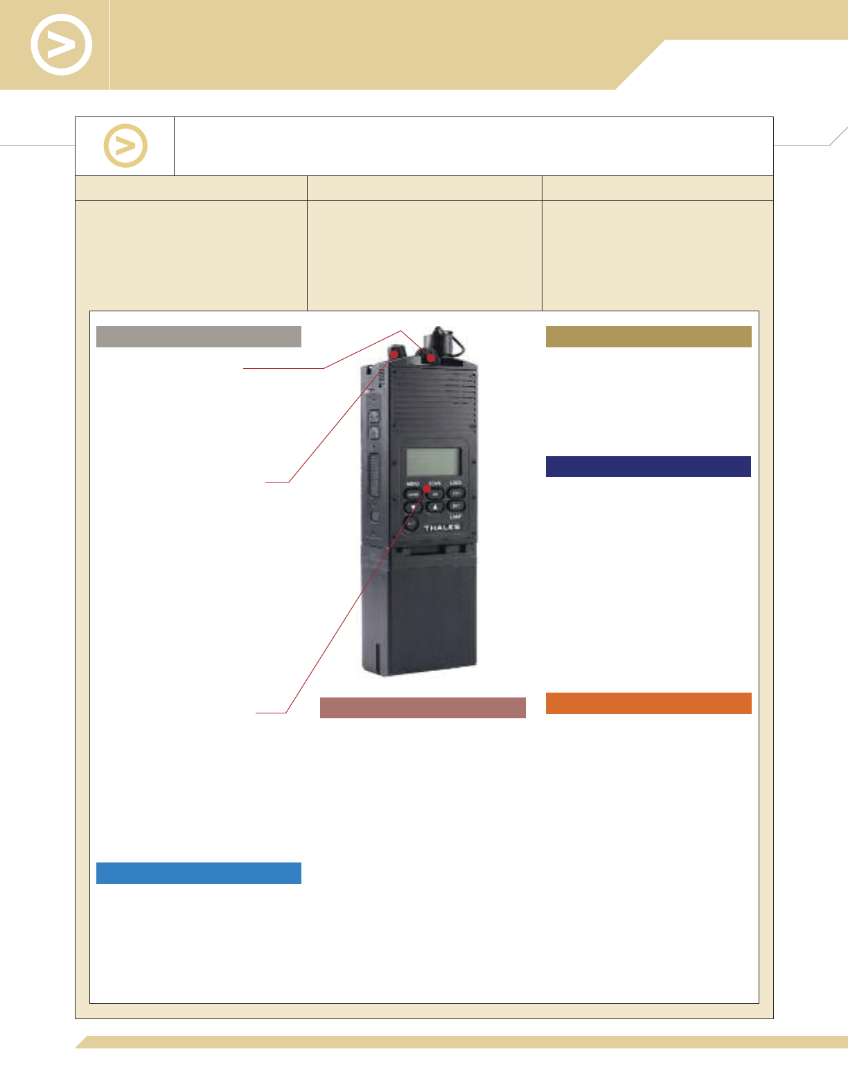
Key Design Features of the PRC6809 MBITR
Multiband Inter/Intra Team Radio
■
Contiguous 30–512 MHz coverage,
non-Type 1
■
-118 dBm typical FM receive sensitivity
providing greater communication range
■
RF output power from 0.1 to 5 Watts
Side RF and Digital Connector
■
Cable-free interface with VA/ VAA
■
No RF switch required; top antenna
connector disabled while in VA/VAA
■
Supports 2-second rapid
dismount/insertion from/to VA/ VAA
Radio Profile
■
Clean, protrusion-free profile for
embedded integration with VA/VAA
■
Allows one-button mechanical
engagement with VA/VAA
■
Operating temperature: -31° to +60° C
■
Storage temperature: -33° to +71° C
■
Humidity: 95% Non-condensing
■
Altitude: 30,000 feet
■
Shock: EIA-603-1992
■
Vibration: EIA-603-1992
Expandability
■<34 cubic inches (560 cubic centimeters)
including connectors per TIA-603-2001
■30.6 ounces (867.5 grams) including
battery and broadband antenna
■12 hours battery life measured per
TIA-603b
3
Ease of Use
Dedicated 16-Channel Switch
■
<1-second waveform/channel switch time
■
Separate Channel and On/Off switches to
prevent unintentional radio shut-down
■
Group mapping to 100 channel presets
■
Low profile reduces damage
Dedicated Top Volume/On/Off Knob
■
Emergency zeroize switch
■
Top position for easy access with radio in
holster
■
Detent at Off position to prevent
unintentional radio shut-down
■
Low profile reduces damage
PTT, Squelch Disable and Programmable
Buttons
■
Recessed to prevent inadvertent action
■
Two user-programmable buttons provide
immediate access to mission-specific
functions
Intuitive, Function-Specific HMI
■
Function-based keypad provides quick,
direct access to common operations,
leading to fewer battle-stress errors
■
Recessed keys prevent accidental key
presses
■
Highly optimized Human Machine
Interface (HMI) incorporates user
feedback based on battlefield experience
■
Machined aircraft aluminum chassis
delivers precise tolerances required for
immersibility (2 meter and 20 meter
versions available)
■
22 screws and robust O-ring apply even
pressure and lifetime sealing
Performance
Ruggedization
■>30,000 hours field-measured MTBF
■Based on the battle-proven AN/PRC-
148 MBITR
■Fully compatible with existing VA, VAA,
and AN/PRC-148 MBITR systems
Immersibility
■
AM/FM
■
Voice/Data
■
Encryption
•DES 12 kb/s option
•AES 12 kb/s option
■
Retransmission
Waveforms/Modes of Operation
4
A typical PRC6809 MBITR System (Urban)* is comprised
of all of the following components:
Description Part Number NSN
Receiver-transmitter
Rechargeable lithium-ion battery
30-90 MHz antenna
90-512 MHz broadband antenna
Holster, ACU digital camo
Carrying case
Operator manual
Quick reference guide, laminated
Operator manual supplement – DES
Operator manual supplement – AES
Keyfill Adapter – Maritime only
*Versions:
■
PRC6809-ABR-BAS, Maritime, immersible in salt water to 20 meters for 2 hours
■
PRC6809-BBR-BAS, Urban, immersible in salt water to 2 meters for 30 minutes
4101349-502
1600515-7
1600629-1
1600500-3
1600494-1
1600495-1
84345
3400738-1
84370
84374
3600190-1
5820-01-523-5722
6140-01-487-1153
5985-01-487-1135
5985-01-584-7883
5895-01-487-1157
5895-01-487-1158
5995-01-487-1149
Optional Accessory
5
Dismounted Systems/Fixed Site
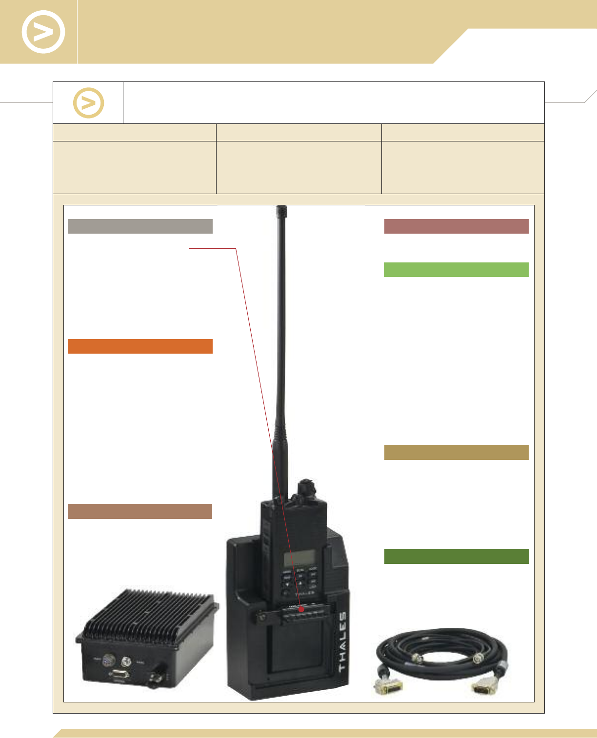
■Based on core transceiver, can use the
AN/PRC-148 JEM, AN/PRC-148
MBITR, PRC6809 MBITR
■≥8,000 hours MTBF
■≤15 minutes MTTR
■20 watts RF output across entire
30
–
512 MHz frequency range
Commonality Reliability Performance
Key Design Features of the
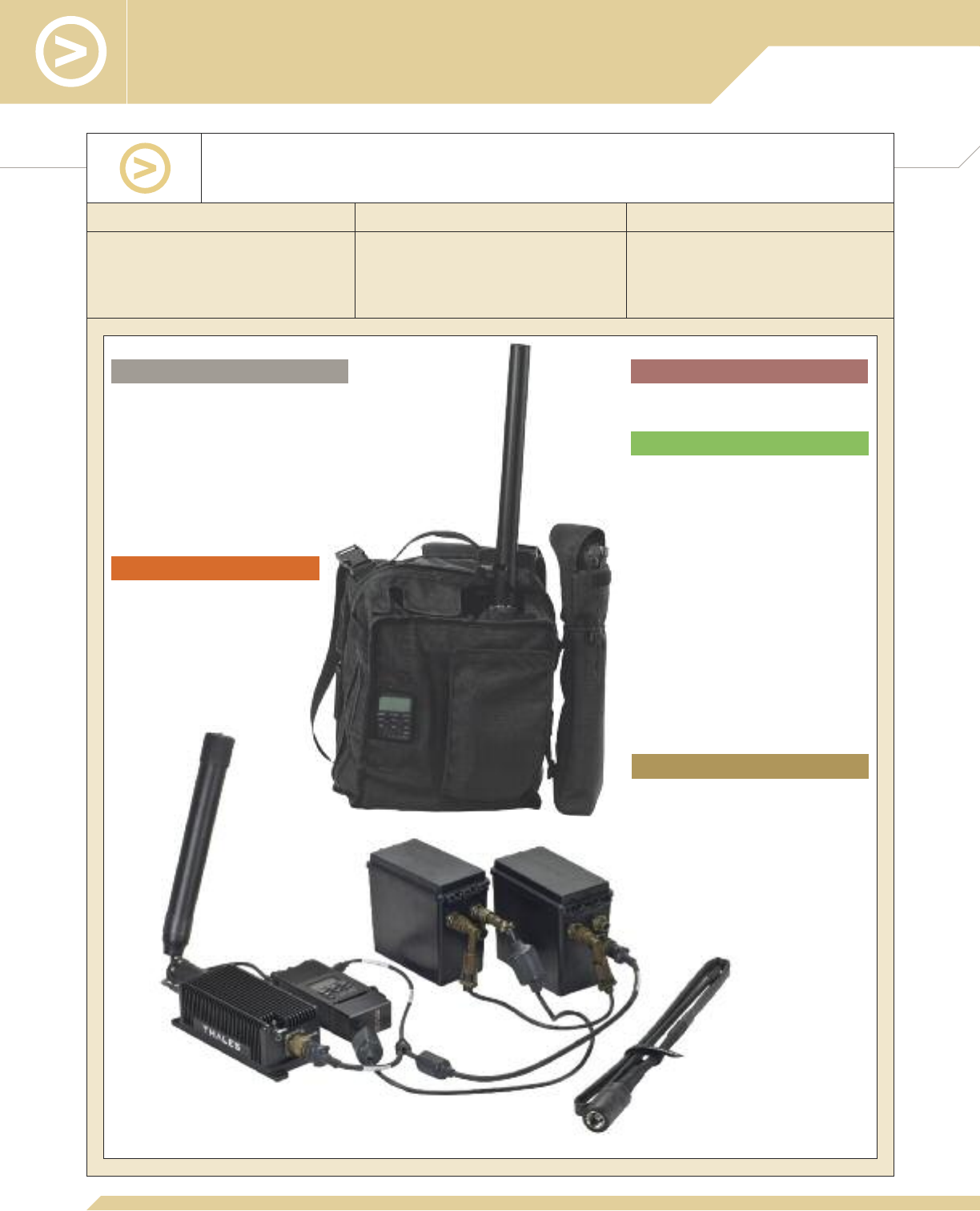
20 Watt Man Portable System (MPS)
■
Modular design for simplified field-level
maintenance
■
Heavy-duty ballistic nylon carrying bag
■
Configurations:
•Backpack
•Shoulder strap
•Handle strap
■
Operating temperature:
-31° to +60° C
■
Storage temperature:
-33° to +71° C
■
Humidity: 95% non-condensing
■
Altitude: 30,000 feet
Ruggedization
Ease of Use
■
Per radio installed
■
Fully configured weight: 15.98 pounds
(7.25 kg) (including batteries and
antenna)
■
Physical parameters of carrying bag:
approximately 13 x 10 x 7 inches
(33.0 x 25.4 x 17.8 cm)
■
Battery life (with 80:10:10 duty cycle):
•8 hours with two BA-5590
(non-rechargeable) or
BA-5390 (non-rechargeable)
batteries
•5 hours with one BB-2590
(rechargeable) battery
•10 hours with two BB-2590
(rechargeable) batteries
■
20 Watt transmission power in
30–512 MHz
■
Supports 20 Watt transmission with
50% duty cycle @ 60°C ambient
temperature
■
Typical -117 dBm FM receive sensitivity
Performance
Size, Weight, and Power
Waveforms/Modes of Operation
6
A typical 20 Watt Man Portable System (MA7035) is
comprised of all of the following components:
Description Part Number NSN
The MA7035 can be used with any radio in the AN/PRC-148 family. The available
receiver-transmitters are listed below.
Not required for MPS operation.
* Note that Maritime version may also be used.
1600610-1
1600604-3
85334
1600623-2
3100771-501
4101441-504
85343
85349
85350
1600609-1
84361
4101660–XXX
4101195-501
4101349-502
1600515-7
1600629-1
1600500-3
85336
5895-01-571-1634
6140-01-490-4316
6150-01-523-4570
5985-01-499-4494
5985-01-550-3291
5820-01-487-0973
5820-01-523-5722
6140-01-487-1153
5985-01-487-1135
5985-01-584-7883
6130-01-511-0352
20W amplifier
Battery boxes (2)
Rechargeable lithium-ion batteries (BB-2590) (2)
Parallel cable
Power/control cable
Battery adapter
RF Cable assembly, TNC-to-TNC
30-90 MHz antenna (for 20W operation)
90-512 MHz broadband antenna (for 20W operation)
Carrying bag
Operator manual
Receiver-transmitter: AN/PRC-148 JEM (Urban)*
or AN/PRC-148 MBITR (Urban)*
or PRC6809 MBITR (Urban)*
Rechargeable lithium-ion battery for radio
30-90 MHz antenna (for 5W operation)
90-512 MHz broadband antenna (for 5W operation)
Battery charger for two lithium-ion rechargeable batteries
7
Dismounted Systems/Fixed Site
■≥4,000 hours MTBF
■≤30 minutes MTTR
■20 watts RF output across entire
30–512 MHz frequency range
Commonality Reliability Performance
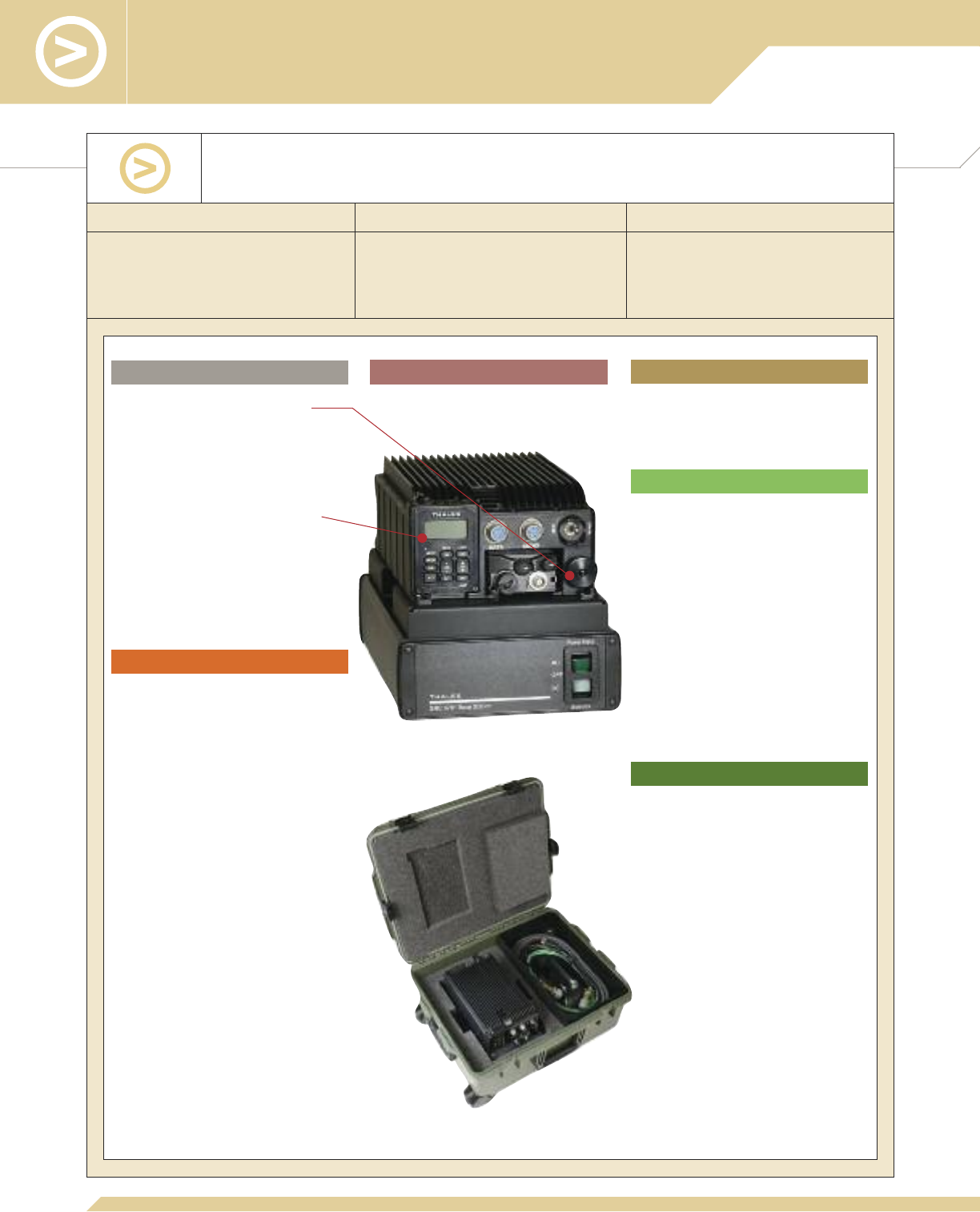
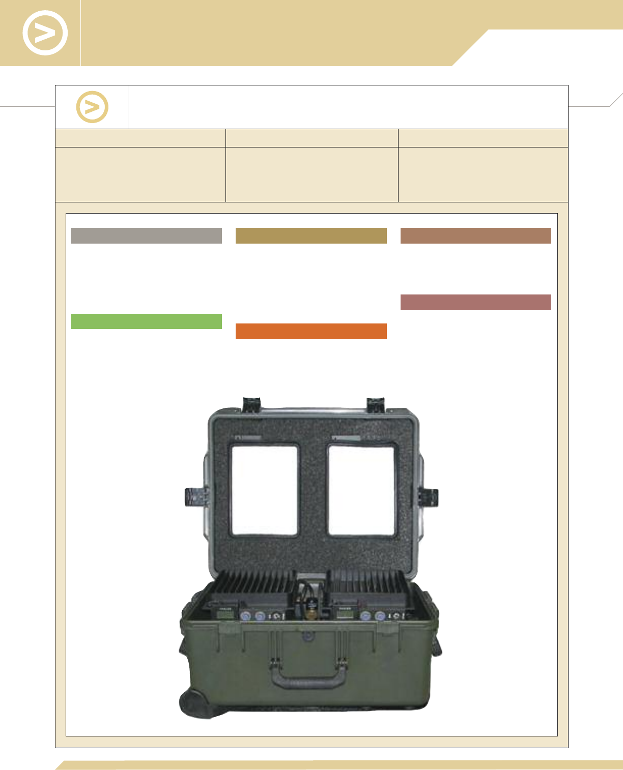
Key Design Features of the 20 Watt Base Station
50 Watt Base Station (GRC6781A) Also Available
■Based on core transceiver, can use
AN/PRC-148 JEM, AN/PRC-148
MBITR, and PRC6809 MBITR
■Built on the field-proven Vehicle Adapter
Waveforms/Modes of Operation
■
Per radio installed
Performance
■
Typical -115 dBm FM receive sensitivity
■
20 watt transmission power in
30–512 MHz
■
Wide range of power inputs:
•12.5-32 VDC (with Thales cabling);
•90–132 VAC @ 47-440 Hz or
•180–264 VAC @ 47-440 Hz
■
Smart charging of inserted radio
■
Physical Parameters (with control head
and radio with battery):
•Height: 8.3 inches (21 cm)
•Width: 8.4 inches (21.3 cm)
•Depth: 14.8 inches (37.6 cm)
•Weight: 28.0 pounds (12.7 kg) (radio,
amplifier, power supply),
57.5 pounds (26.1 kg) (equipment in
transit case)
■
EMI Compliance: EMI/EMC per MIL-STD-
461C
■
TEMPEST Compliance:
•NSTISSAM TEMPEST/1-92, level II
•NACSEM 5112
Size, Weight, and Power
2-Second Rapid Dismount/Insertion
■
Cable-free radio/VA interface
■
Single push/pull button to dismount/insert
■
Radio operation maintained during
insertion and dismount
Remote Operation with Common User
Interface
■
Removable Control Head Assembly with
audio interface
■
Remote control shares the same
user interface with AN/PRC-148 and
PRC6809, eliminates additional training
■
Operating temperature: 0° to +55° C
■
Storage temperature: -31° to +60° C
■
Humidity: 95% non-condensing
■
Altitude: 33,000 feet, per MIL-STD-810E
■
Shock per MIL-STD-810E
■
Vibration per MIL-STD-810E
■
Salt fog per MIL-STD-810E
■
Rugged transit case provides
environmental protection against driven
rain and sand and dust
Ruggedization
Product Specifications
Ease of Use

8
A typical 20 Watt Base Station (GRC6781, NSN 5820-01-
565-8321) is comprised of all of the following components:
Description NSN
Additionally, the Base Station requires a radio (receiver-transmitter and battery) and an
antenna mast kit for operation. The mast kits include antenna mast, 50 ft. antenna
cable, broadband antenna, and grounding rod.
Base Station, Main Assembly
Cable Assembly, DC power, 12 ft
Cable Assembly, AC power, 12 ft
Speaker microphone
Tactical speaker
Speaker cable, 10 ft
Ground wire
Transit case assembly
VA/Power Supply Assembly
Cable tray
Operator manual
Receiver-transmitter: AN/PRC-148 JEM (Urban)*
or AN/PRC-148 MBITR (Urban)*
or PRC6809 MBITR (Urban)*
Rechargeable lithium-ion battery for radio
Single antenna mast kit, 13.5 ft
Single antenna mast kit, 31.5 ft
Removable control head cable, optional 10 ft, 35 ft, 50 ft, 100 ft,
and 150 ft
30-90 MHz antenna (for dismounted radio operation)
90-512 MHz broadband antenna (for dismounted radio operation)
* Note that Maritime version may also be used.
Part Number
4101802-501
3500632-501
3500633-501
1600469-4
1600599-1
1600623-4
3500692-507
4101800-501
4101999-501
4400658-1
84368
4101660–XXX
4101195-501
4101349-502
1600515-7
1100634-502
1100634-501
3600215-X
1600629-1
1600500-3
5965-01-507-3576
5965-01-523-4572
5995-01-530-7173
5820-01-487-0973
5820-01-523-5722
6140-01-487-1153
5985-01-565-8768
5985-01-565-8769
5985-01-487-1135
5985-01-584-7883
Not required for Base Station operation; only used with receiver-transmitter when
removed from the Base Station.
9
Dismounted Systems/Fixed Site
■Based on core transceiver, can use
AN/PRC-148 JEM, AN/PRC-148
MBITR, and PRC6809 MBITR
■Built on the field-proven Vehicle Adapter
■≥2,500 hours MTBF
■≤45 minutes MTTR
■20 watts RF output across entire
30–512 MHz frequency range
(dual antenna model)
Commonality Reliability Performance
Key Design Features of the 20 Watt Tactical Repeater
Ease of Use
■
Local mode simplifies setup
■
Removable Control Head allows field
programming of each radio
■
Bi-directional repeater for net linking
■
External power:
•13–32 VDC;
•90–132 VAC; or
•180–264 VAC
■
Internal power: Two BB-2590
rechargeable batteries
■
Typical -115 dBm FM receive sensitivity
■
Retransmits voice and data, clear and
secure traffic
■
20 watt transmission power in
30-512 MHz with dual antennas
■
Rugged case for environmental protection
and ease of transport
■
Available 13.5 ft and 31.5 ft mast kits
with broadband center fed dipole
antennas
■
Per radios installed
Performance
Ruggedization
Modularity
Waveforms/Modes of Operation
Size, Weight, and Power

10
A typical 20 Watt Tactical Repeater (TRC6730) is
comprised of all of the following components:
Description Part Number NSN
5820-01-487-0973
5820-01-523-5722
6140-01-487-1153
5985-01-487-1135
5985-01-584-7883
The Tactical Repeater can be used with any radio in the AN/PRC-148 family (receiver-
transmitter with battery). Two radios and an antenna mast kit are required for operation.
The mast kits include antenna masts and 6 ft crosspiece, two 50 ft antenna cables, two
broadband antennas, and grounding rod.
†Only the PRC6809 MBITR can be used for unattended Tactical Repeater operation.
Repeater Main Assembly
Rechargeable lithium-ion batteries for internal power (BB-2590) (2)
Cable Assembly, DC power, 12 ft
Cable Assembly, AC power, 12 ft
Operator manual
Receiver-transmitter: AN/PRC-148 JEM (Urban)*†
or AN/PRC-148 MBITR (Urban)*†
or PRC6809 MBITR (Urban)*†
Rechargeable lithium-ion batteries for radio
Dual antenna mast kit, 13.5 ft
Dual antenna mast kit, 31.5 ft
30-90 MHz antenna (for dismounted radio operation)
90-512 MHz broadband antenna (for dismounted radio operation)
4101754-501
85357
3500632-501
3500633-501
84367
4101660-XXX
4101195-501
4101349-502
1600515-7
1100634-503
1100634-504
1600629-1
1600500-3
Not required for repeater operation; only used with receiver-transmitter when removed
from the repeater.
* Note that Maritime version may also be used.
11
Vehicular Systems
■Accepts all AN/PRC-148 and
PRC6809 models
■2-second radio dismount/insertion
■Cable-free radio/VA interface
■Non-obstructive low profile
■Typical -115 dBm FM receive sensitivity
■Excellent co-site performance
Commonality Ease of Use Performance
Key Design Features of the 20 Watt Vehicle Adapter (VA)
Waveforms/Modes of Operation
■
Per radio installed
■
Physical Parameters (with control head
and radio with battery):
•Height: 4.1 inches (10.4 cm)
•Width: 7.0 inches (17.8 cm)
•Depth: 13.4 inches (34.0 cm)
•Weight: 13.0 pounds (5.9 kg)
■
DC input power 12 to 32V, 240 Watts
■
20 Watt transmission power in
30–512 MHz
■
RF output power either 5 Watts or
20 Watts
■
Typical -115 dBm FM receive sensitivity
■
Smart charging of inserted radio battery
■
EMI Compliance: EMI/EMC per MIL-STD-
461C
■
TEMPEST Compliance:
•NSTISSAM TEMPEST/1-92, level II
•NACSEM 5112
Ease of Use
2-Second Rapid Dismount/Insertion
■
Cable-free radio/VA interface
■
Single push/pull button to dismount/insert
■
Radio operation maintained during
insertion and dismount
Remote Operation with Common User
Interface
■
Removable Control Head Assembly with
audio interface
■
Full communication and control capability
from inside (front and back) or outside of
the vehicle
■
Remote control shares the same
user interface with AN/PRC-148 and
PRC6809, eliminates additional training
■
Operating temperature: -31° to +60° C
■
Storage temperature: -33° to +71° C
■
Humidity: 95% non-condensing
■
Altitude: 30,000 feet, per MIL-STD-
810E
■
Shock per MIL-STD-810E
■
Blowing rain per MIL-STD-810E
■
Vibration per MIL-STD-810E
■
Sand and dust per MIL-STD-810E
■
Salt fog per MIL-STD-810E
■
Stand-alone installations
■
Mechanical interfaces: MT-6352,
MT-6352A – optional
Ruggedization
Performance
Product Specifications
Size, Weight, and Power
Modular Installation
12
* Note that Maritime version may also be used.
Vehicle Adapter, Including Removable Control Head (RCH)
Installation kit
RCH cable, 10 ft
DC input cable, 12 ft
Vehicle Adapter, Including RCH
Shock mount tray
Installation kit
Tactical speaker
Speaker cable, 10 ft
RCH cable, 10 ft
DC input cable, 12 ft
30-512 MHz Broadband Vehicle Antenna
Antenna cable, 26 ft, with N to BNC adapter
Receiver-transmitter: AN/PRC-148 JEM (Urban)*
or AN/PRC-148 MBITR (Urban)*
or PRC6809 MBITR (Urban)*
Rechargeable lithium-ion battery for radio
30-90 MHz antenna (for 5W operation)
90-512 MHz broadband antenna (for 5W operation)
136-174 MHz antenna (for 5W operation)
Description Part Number NSN
The MA6943 can be used with any radio in the AN/PRC-148 family. The available
receiver-transmitters and associated battery are listed below.
The VA system (MA6943-SYS, NSN 5895-01-573-2006) is comprised of all of the
following components:
A typical 20 Watt Vehicle Adapter is available in two
configurations: MA6943 and MA6943-SYS.
4101524-501
1100608-501
3600215-1
3500566-501
4101524-501
4600109-1
1100608-501
1600599-1
1600623-4
3600215-1
3500566-501
85184
85401-001
4101660–XXX
4101195-501
4101349-502
1600515-7
1600629-1
1600500-3
SS-1600293-1
5975-01-506-7585
5340-01-530-7169
5995-01-530-7166
6150-01-530-7296
5975-01-506-7585
5975-01-524-0033
5340-01-530-7169
5965-01-523-4572
5995-01-530-7173
5995-01-530-7166
6150-01-530-7296
5985-01-514-2271
5820-01-487-0973
5820-01-523-5722
6140-01-487-1153
5985-01-487-1135
5985-01-584-7883
5985-01-368-8971
Not required for VA operation; only used with receiver-transmitter when removed from
the VA.
The basic VA (MA6943, NSN 5895-01-507-3991) is comprised of all of the
following components:
13
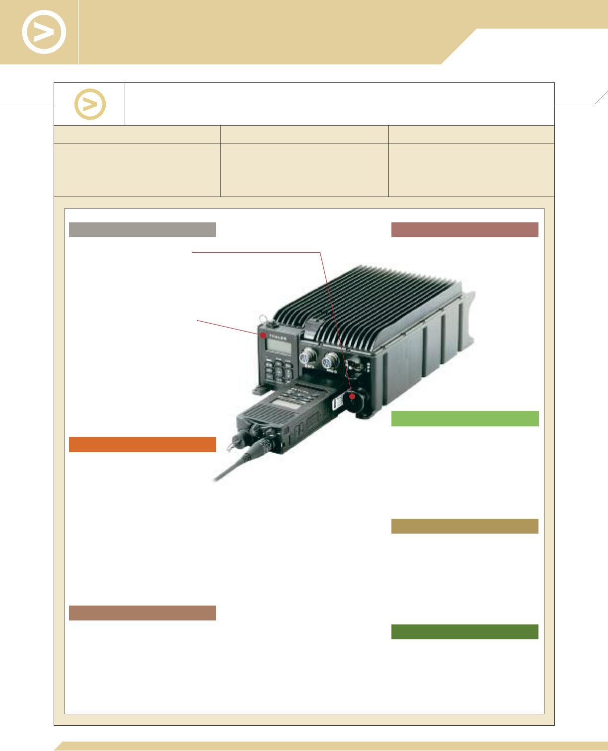
Vehicular Systems
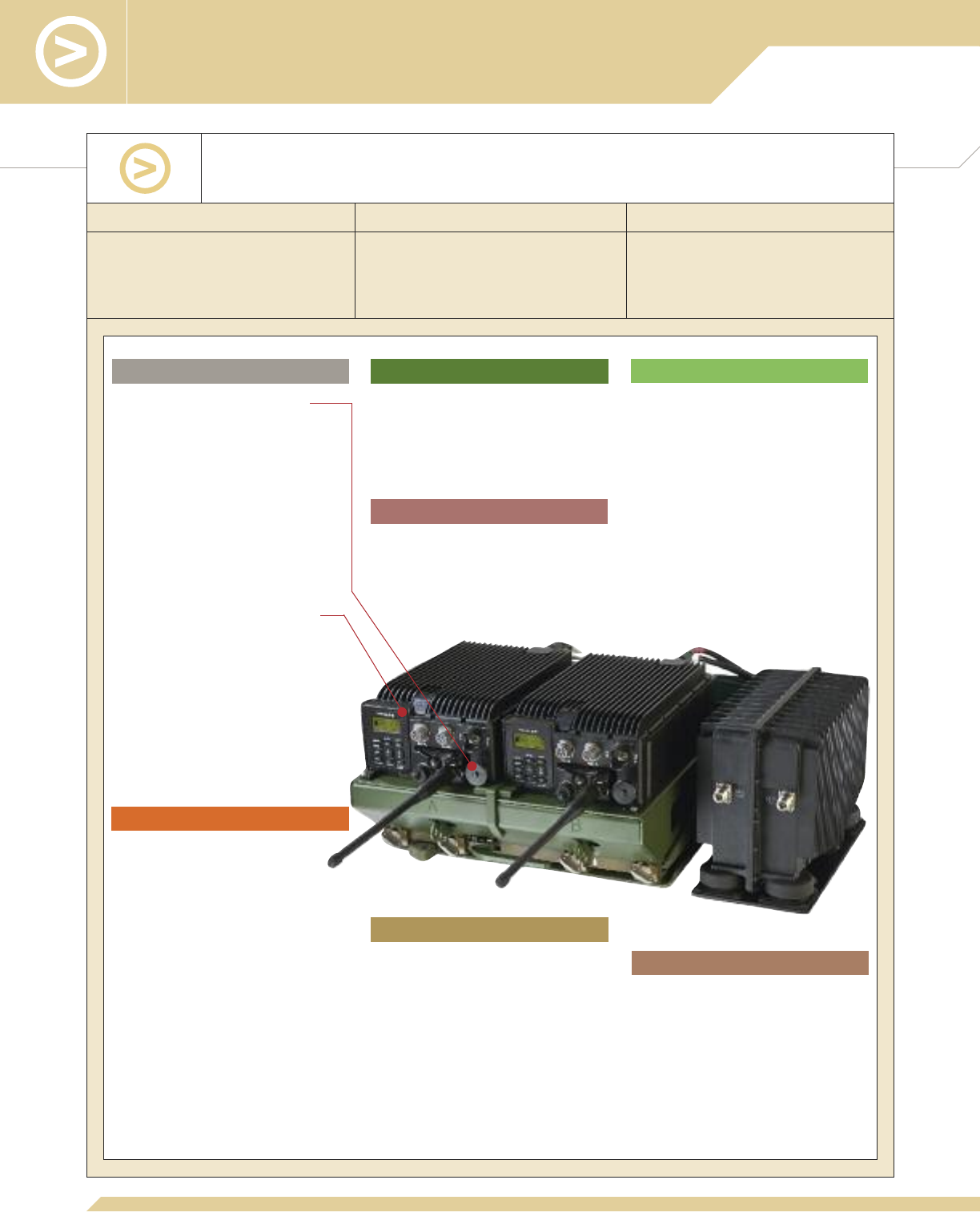
■Accepts all AN/PRC-148 and
PRC6809 models
■2-second radio dismount/insertion
■Cable-free radio/VAA interface
■Non-obstructive low profile
■Typical -115 dBm FM receive sensitivity
■Excellent co-site performance
Commonality Ease of Use Performance
Key Design Features of the 20 Watt AN/VRC-111
Vehicle Adapter Amplifier (VAA)
■
Fits within the dimension of SINCGARS
AN/VRC-92 mounting tray
■
Installs into SINCGARS MT-6352
■
Per radios installed
2-Second Rapid Dismount/Insertion
■
Cable-free radio/VAA interface
■
Single push/pull button to dismount/insert
■
Radio operation maintained during
insertion and dismount
Non-obstructive Low Profile
■
Radios embedded inside VA for lowest
height profile and cable-free interface
■
No obstruction of warfighter’s view of
battlefield
Remote Operation with Common User
Interface
■
Removable Control Head Assembly with
audio interface
■
Full communication and control capability
from inside (front and back) or outside of
the vehicle
■
Remote control shares the same user
interface with AN/PRC-148 and
PRC6809, eliminates additional training
■
Operating temperature: -31° to +60° C
■
Shock/Vibration per MIL-STD-810F
■
Ballistic shock per MIL-S-901 (Exceeds
MIL-STD-810F)
■
Blowing rain per MIL-STD-810F
Flexible Security Mechanism
■
Single lock supports independently
selectable multiple locking options
■
Locking of VAA to MT-6352 mounting base
■
Locking of radio to VA
Ruggedization and Security
■
Physical Parameters (with control head
and radio with battery):
•Height: 8.1 inches (20.6 cm)
•Width: 15.3 inches (38.86 cm)
•Depth: 14.9 inches (37.9 cm)
•Weight: 38 pounds with radios
(17.2 kg)
■
DC input power 12 to 32V, 240 Watts
per channel
■
20 Watt transmission power in
30–512 MHz
■
RF output power either 5 Watts or
20 Watts per channel
■
Typical -115 dBm FM receive sensitivity
■
50% duty cycle @ 60º C ambient
temperature
Performance
Modular Installation
■
EMI Compliance: EMI/EMC per MIL-STD-
461C
■
TEMPEST Compliance:
•NSTISSAM TEMPEST/1-92, level II
•NACSEM 5112
Product Specifications
Ease of Use Size, Weight, and Power
Waveforms/Modes of Operation

14
A typical 20 Watt AN/VRC-111 VAA (MA7036, NSN 5820-
01-536-0983) is comprised of all of the following components:
Description Part Number NSN
5975-01-506-7585
5820-01-544-5996
5820-01-487-0973
5820-01-523-5722
6140-01-487-1153
5985-01-514-2271
5985-01-487-1135
5985-01-584-7883
VA Unit Assembly (2 required)
VAA Tray Assembly
Operator manual, VA/VAA
Operator manual, radio: AN/PRC-148 JEM
*
or AN/PRC-148 MBITR
*
or PRC6809 MBITR
*
Quick reference guide, VA
Quick reference guide, VAA
Quick reference guide, radio: AN/PRC-148 JEM
or AN/PRC-148 MBITR
Receiver-transmitter (2 required): AN/PRC-148 JEM (Urban)*
or AN/PRC-148 MBITR (Urban)*
or PRC6809 MBITR (Urban)*
Rechargeable lithium-ion batteries for radio (2 required)
30-512 MHz Broadband Vehicle Antenna (2 required)
Antenna cable, 26 ft, with N to BNC adapter (2 required)
30-90 MHz antenna (for dismounted radio operation)
90-512 MHz broadband antenna (for dismounted radio operation)
4101524-501
4101858-503
84359
84357
84329
84345
3400685-1
3401095-1
3400905-1
3400577-1
4101660-XXX
4101195-501
4101349-502
1600515-7
85184
85401-001
1600629-1
1600500-3
* Note that Maritime version may also be used.
Not required for VAA operation; only used with receiver-transmitter when removed from
the VAA.
The MA7036 can be used with any radio in the AN/PRC-148 family (receiver-transmitter
with battery). Two radios, two antennas, and two antenna cables are required for
operation. The available receiver-transmitters and associated components are listed below.
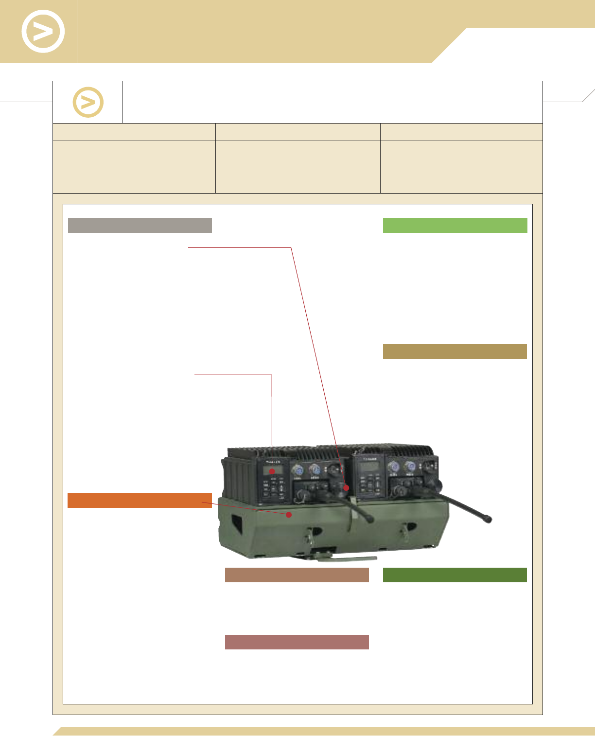
15
Vehicular Systems
■Accepts all AN/PRC-148 and
PRC6809 models
■2-second radio dismount/insertion
■Cable-free radio/VAA interface
■Non-obstructive low profile
■Typical -118 dBm FM receive sensitivity
■Superior co-site performance
Ease of Use
Commonality Ease of Use Performance
Key Design Features of the 50 Watt AN/VRC-111 VAA—
Dual Channel
■
EMI Compliance: EMI/EMC per MIL-STD-
461C
■
TEMPEST Compliance:
•NSTISSAM TEMPEST/1-92, level II
•NACSEM 5112
■
Per radios installed
Product Specifications
Modular Installation
■
Physical Parameters of radio unit:
•Height: 8.1 inches (20.6 cm)
•Width: 15.3 inches (38.9 cm)
•Depth: 14.9 inches (37.9 cm)
•Weight: 38 pounds with radios (17.2 kg)
■
Physical Parameters of amplifier:
•Height: 8.5 inches (21.6 cm)
•Width: 5.8 inches (14.5 cm)
•Depth: 12.0 inches (30.5 cm)
•Weight: 22 pounds, including shock
mount (10 kg)
■
DC input power 20 to 32V, 280 Watts
per channel
Size, Weight, and Power
Waveforms/Modes of Operation
■
20 Watt or 50 Watt transmission power
in 30-90 MHz
■
5 Watt or 20 Watt transmission power
in 90-512 MHz
■
Typical FM receive sensitivity:
•-118 dBm (30–88 MHz)
•-121 dBm (88–512 MHz)
•-115 dBm (minimum)
■
Continuous 50 Watt transmission for
indefinite time @ 60º C ambient
temperature
Performance
■
External dual-power amplifier can be
mounted remotely, supporting a variety of
installation configurations
■
Dual amplifier can be split into two single-
channel modules and mounted next to VA
for single-channel configuration (see
MA7134-SCA for more information)
■
Installs into SINCGARS MT-6352 and
MT-6353
2-Second Rapid Dismount/Insertion
■
Cable-free radio/VAA interface
■
Single push/pull button to dismount/insert
■
Radio operation maintained during
insertion and dismount
Non-obstructive Low Profile
■
Radios embedded inside VA for lowest
height profile and cable-free interface
■
No obstruction of warfighter’s view of
battlefield
Remote Operation with Common User
Interface
■
Removable Control Head Assembly with
audio interface
■
Full communication and control capability
from inside (front and back) or outside of
the vehicle
■
Remote control shares the same
user interface with AN/PRC-148 and
PRC6809, eliminates additional training
■
Operating temperature: -31° to
+60° C
■
Shock/Vibration per MIL-STD-810F
■
Ballistic shock per MIL-S-901
(Exceeds MIL-STD-810F)
■
Blowing rain per MIL-STD-810F
Flexible Security Mechanism
■
Single lock supports independently
selectable multiple locking options
■
Locking of VAA to MT-6352 mounting
base
■
Locking of radio to VA
Ruggedization and Security

16
A typical 50 Watt AN/VRC-111 VAA Dual Channel Version
(MA7134-NR) is comprised of all of the following components:
Description NSN
VA Exciter Unit Assembly (2 required)
VAA Tray
Modular RF Power Amp, Dual
Power Cable, Mounting Tray to Power Amplifier, 13 in
(40 ft and 44 ft also available)
RF Cable “A”, 18 in (36 in and 44 in also available)
RF Cable “B”, 13 in (36 in and 44 in also available)
Control Cable “A”, 24 in (42 in and 44 in also available)
Control Cable “B”, 18 in (42 in and 44 in also available)
Operator manual, 50W VAA
Quick reference guide
Receiver-transmitter (2 required): AN/PRC-148 JEM (Urban)*
or AN/PRC-148 MBITR (Urban)*
or PRC6809 MBITR (Urban)*
Rechargeable lithium-ion batteries for radio (2 required)
Cable, removable control head interface (2 required)
30-512 MHz Broadband Vehicle Antenna (2 required)
Antenna cable, 26 ft, with N to BNC adapter (2 required)
30-90 MHz antenna (for dismounted radio operation)
90-512 MHz broadband antenna (for dismounted radio operation)
Not required for VAA operation; only used with receiver-transmitter when removed from
the VAA.
* Note that Maritime version may also be used.
4101849-501
4101858-504
1600674-4
1600675-1
1600659-1
1600659-2
1600660-1
1600660-2
84381
3401378-1
4101660–XXX
4101195-501
4101349-502
1600515-7
3600215-1
85184
85401-001
1600629-1
1600500-3
5820-01-487-0973
5820-01-523-5722
6140-01-487-1153
5995-01-530-7166
5985-01-514-2271
5985-01-487-1135
5985-01-584-7883
Part Number
The MA7134 can be used with any radio in the AN/PRC-148 family (receiver-transmitter
with battery). Two radios, two antennas, two antenna cables, and two RCH cables are
required for operation. The available receiver-transmitters and associated components
are listed below.
17
Vehicular Systems
Key Design Features of the 50 Watt VAA—
Single Channel
■Accepts all AN/PRC-148 and
PRC6809 models
■2-second radio dismount/insertion
■Cable-free radio/VAA interface
■Non-obstructive low profile
■Typical -118 dBm FM receive sensitivity
■Superior co-site performance
Commonality Ease of Use Performance
Ease of Use
Modular Installation
2-Second Rapid Dismount/Insertion
■
Cable-free radio/VAA interface
■
Single push/pull button to dismount/insert
■
Radio operation maintained during
insertion and dismount
Non-obstructive Low Profile
■
Radio embedded inside VA for lowest
height profile and cable-free interface
■
No obstruction of warfighter’s view of
battlefield
Remote Operation with Common User
Interface
■
Removable Control Head Assembly with
audio interface
■
Full communication and control capability
from inside (front and back) or outside of
the vehicle
■
Remote control shares the same
user interface with AN/PRC-148 and
PRC6809, eliminates additional training
■
Operating temperature: -31° to
+60° C
■
Shock/Vibration per MIL-STD-810F
■
Ballistic shock per MIL-S-901
(Exceeds MIL-STD-810F)
■
Blowing rain per MIL-STD-810F
Flexible Security Mechanism
■
Single lock supports independently
selectable multiple locking options
■
Locking of VAA to MT-6352 mounting
base
■
Locking of radio to VA
■
20 Watt or 50 Watt transmission power
in 30-90 MHz
■
5 Watt or 20 Watt transmission power
in 90-512 MHz
■
Typical FM receive sensitivity:
•-118 dBm (30–88 MHz)
•-121 dBm (88–512 MHz)
•-115 dBm (minimum)
■
Continuous 50 Watt transmission for
indefinite time @ 60º C ambient
temperature
■
Physical Parameters of radio unit:
•Height: 8.1 inches (20.6 cm)
•Width: 15.3 inches (38.86 cm)
•Depth: 14.9 inches (37.9 cm)
•Weight: 33 pounds with radios (15 kg)
■
DC input power 20 to 32V, 280 Watts
■
EMI Compliance: EMI/EMC per MIL-STD-
461C
■
TEMPEST Compliance:
•NSTISSAM TEMPEST/1-92, level II
•NACSEM 5112
■
Per radio installed
Ruggedization and Security
■
External power amplifier can be mounted
remotely, supporting a variety of
installation configurations
■
Installs into SINCGARS MT-6352
Product Specifications Size, Weight, and Power
Performance
Waveforms/Modes of Operation

18
A typical 50 Watt AN/VRC-111 VAA Single Channel Version
(MA7134-SCA) is comprised of all of the following components:
Description Part Number NSN
5820-01-487-0973
5820-01-523-5722
6140-01-487-1153
5995-01-530-7166
5985-01-514-2271
5985-01-487-1135
5985-01-584-7883
* Note that Maritime version may also be used.
Receiver-transmitter: AN/PRC-148 JEM (Urban)*
or AN/PRC-148 MBITR (Urban)*
or PRC6809 MBITR (Urban)*
Rechargeable lithium-ion batteries for radio
Cable, removable control head interface
30-512 MHz Broadband Vehicle Antenna
Antenna cable, 26 ft, with N to BNC adapter
30-90 MHz antenna (for dismounted radio operation)
90-512 MHz broadband antenna (for dismounted radio operation)
4101849-501
4101858-504
1600674-1
1600661-1
1600659-1
1600660-1
84381
3401378-1
VA Exciter Unit Assembly
VAA Tray
Modular RF Power Amp, Single
Power Cable, Mounting Tray to Power Amplifier, 7.5 in
(40 in also available)
RF Cable “A”, 18 in (36 in and 44 in also available)
Control Cable “A”, 24 in (42 in and 44 in also available)
Operator manual, 50W VAA
Quick reference guide
The MA7134 can be used with any radio in the AN/PRC-148 family (receiver-transmitter
with battery). An antenna, antenna cable, and RCH cable are required for operation. The
available receiver-transmitters and associated components are listed below.
Not required for VAA operation; only used with receiver-transmitter when removed from
the VAA.
4101660-XXX
4101195-501
4101349-502
1600515-7
3600215-1
85184
85401-001
1600629-1
1600500-3
19
Vehicular Systems
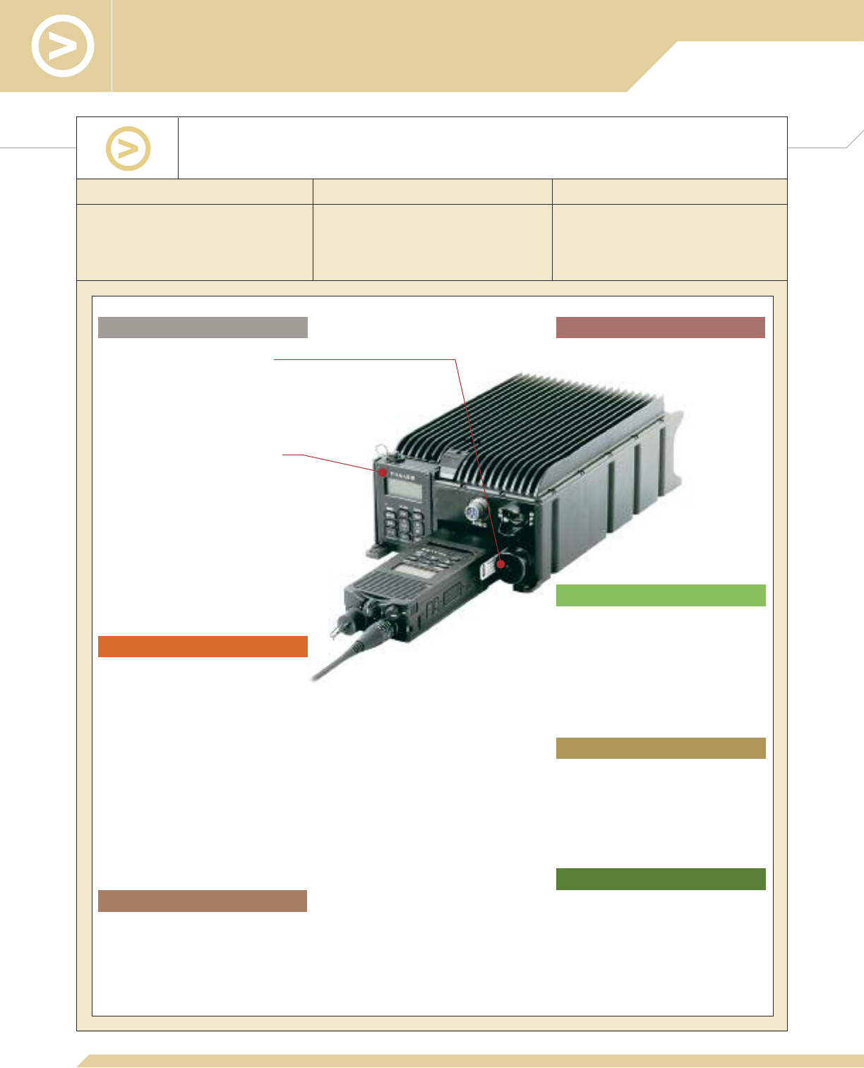
■2-second radio dismount/insertion
■Cable-free radio/LPVA interface
■Lowest profile 50 Watt vehicle adapter
for space constrained installation
■Typical -116 dBm FM receive sensitivity
■Programmable co-site filtering
Commonality Ease of Use Performance
Key Design Features of the
50 Watt Low Profile Vehicle Adapter (LPVA)
Waveforms/Modes of Operation
■
Per radio installed
Ease of Use
■
Physical Parameters (without radio):
•Height: 4.1 inches (10.4 cm)
•Width: 7.5 inches (19.1 cm)
•Depth: 13.4 inches (34.0 cm)
•Weight: 10 pounds (4.5 kg)
■
DC input power 20 to 32V, 240 Watts
maximum
■
Typical -116 dBm FM receive sensitivity
■
Smart charging of inserted radio battery
■
RF output power:
•50 Watts from 30-90 MHz
•20 Watts from 90-512 MHz
■
EMI Compliance: EMI/EMC per
MIL-STD-461E
■
TEMPEST Compliance:
•NSTISSAM TEMPEST/1-92, level II
•NACSEM 5112
Size, Weight, and Power
Performance
Product Specifications
■Accepts all AN/PRC-148 and
PRC6809 models
2-Second Rapid Dismount/Insertion
■
Cable-free radio/LPVA interface
■
Single push/pull button to
dismount/insert
■
Radio operation maintained during
insertion and dismount
Remote Operation with Common User
Interface
■
Removable Control Head Assembly with
audio interface
■
Full communication and control capability
from inside (front and back) or outside of
the vehicle
■
Remote control shares the same user
interface with AN/PRC-148 and
PRC6809, eliminates additional training
■
Operating temperature: -30° to +60° C
■
Storage temperature: -33° to +71° C
■
Humidity: 95% non-condensing, per
MIL-STD-810F
■
Altitude: 30,000 feet, per
MIL-STD-810F
■
Shock per MIL-STD-810F
■
Blowing rain per MIL-STD-810F
■
Vibration per MIL-STD-810F
■
Sand and dust per MIL-STD-810F
■
Salt fog per MIL-STD-810F
■Stand-alone installations
■
Mechanical interfaces: MT-6352,
MT-6352A – optional
Modular Installation
Ruggedization

20
A typical 50 Watt Low Profile Vehicle Adapter (MA7135A)
is comprised of all of the following components:
Description Part Number NSN
LPVA Unit Assembly
Installation kit
Power cable, 12 ft
Operator manual
Quick reference guide
4102214-502
1100679-XXX
1600750 -2
84407
3401498
Receiver-transmitter: AN/PRC-148 JEM (Urban)*
or AN/PRC-148 MBITR (Urban)*
or PRC6809 MBITR (Urban)*
Rechargeable lithium-ion battery for radio
30-512 MHz Broadband Vehicle Antenna
Antenna cable, 26 ft
Coaxial adapter, Type N Male to BNC Female
30-90 MHz antenna (for 5W operation)
90-512 MHz broadband antenna (for 5W operation)
136-174 MHz antenna (for 5W operation)
The LPVA can be used with any radio in the AN/PRC-148 family (receiver-transmitter
with battery). A radio battery, vehicle mount antenna, antenna cable, and adapter are
required for operation.
Not required for LPVA operation; only used with receiver-transmitter when
removed from the LPVA.
4101660–XXX
4101195-501
4101349-502
1600515-7
85184
85401- 001
82167
1600629-1
1600500-3
SS-1600293-1
5820-01-487-0973
5820-01-523-5722
6140-01-487-1153
5985-01-514-2271
5935-01-074-6496
5985-01-487-1135
5985-01-584-7883
5985-01-368-8971
Alternative mounting arrangement: LPVA part number MA7135 is supplied with a
Tray Assembly, part number 4600160-501, that allows the LPVA to be fitted onto a
standard MT-6352 SINCGARS Mounting Base as well as the applicable power cable,
coaxial adapter, and antenna.
* Note that Maritime version may also be used.
To use the LPVA on vehicles that only have a 12V power system, Thales offers a dc-to-dc converter, Part Number 1600765-1.
21
Vehicular Systems
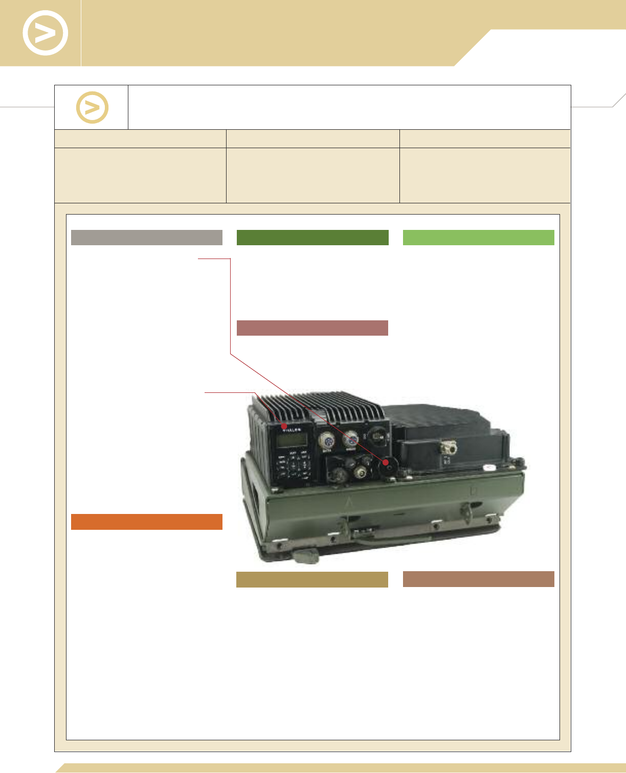
■Accepts all AN/PRC-148 and
PRC6809 models
■2-second radio dismount/insertion
■Cable-free radio/CVA interface
■Low profile 50 Watt vehicle adapter for
space constrained installation
■Typical -116 dBm FM receive sensitivity
■Programmable cosite filtering
Commonality Ease of Use Performance
Key Design Features of the 50 Watt AN/VRC-113
Cradle Vehicle Adapter (CVA)
Waveforms/Modes of Operation
■
Per radio installed
■
Physical Parameters
•Power Amplifier:
◆Height: 3.9 inches (9.9 cm)
◆Width: 7.5 inches (19.1 cm)
◆Depth: 12.8 inches (32.5 cm)
◆Weight: 8 pounds (3.6 kg)
•Cradle (no radio):
◆Height: 7.5 inches (19.1 cm)
◆Width: 5.2 inches (13.2 cm)
◆Depth: 2.6 inches (6.6 cm)
◆Weight (with cables): 3 pounds
(1.4 kg)
■
DC input power 20 to 32V, 240 Watts
maximum
■
Typical -116 dBm FM receive sensitivity
■
Smart charging of inserted radio battery
■
50 Watt transmission power in
30-90 MHz
■
20 Watt transmission power in
90-512 MHz
■
EMI Compliance: EMI/EMC per
MIL-STD-461E
■
TEMPEST Compliance:
•NSTISSAM TEMPEST/1-92, level II
•NACSEM 5112
Size, Weight, and Power
Performance
Product Specifications
Ease of Use
2-Second Rapid Dismount/Insertion
■
Cable-free interface to radio
■
Single mechanism to dismount/insert
■
Radio operation maintained during
insertion and dismount
Full function radio operations from front
panel
■
Operating temperature: -30° to +60° C
■
Storage temperature: -33° to +70° C
■
Humidity: MIL-STD-810F
■
Altitude: 30,000 feet, per
MIL-STD-810F
■
Shock per MIL-STD-810F
■
Blowing rain per MIL-STD-810F
■
Vibration per MIL-STD-810F
■
Sand and dust per MIL-STD-810F
■
Salt fog per MIL-STD-810F
■
Stand-alone vehicle installations
■
Separate cradle allows for separation
from Power Amplifier
Ruggedization
Modular Installation
22
A typical 50 Watt AN/VRC-113 Cradle Vehicle Adapter
(MA7138-BAS) is comprised of all of the following components:
Description Part Number NSN
5996-01-584-8748
CVA Unit Assembly
Cradle assembly
Installation kit, includes cables between
CVA and cradle
Power Cable, 12 ft
30-512 MHz broadband vehicle antenna
Operator manual
Quick reference guide
4102340-501
4102350-501
1100678-501
1600750-2
85184
84410
3401492
The CVA, available in several configurations, can be used with any radio in the AN/PRC-
148 family (receiver-transmitter with battery). An antenna and antenna
cable are required for operation.
* Note that Maritime version may also be used.
To use the CVA on vehicles that only have a 12V power system, Thales offers a dc-to-dc converter, Part Number 1600765-1.
Receiver-transmitter: AN/PRC-148 JEM (Urban)*
or AN/PRC-148 MBITR (Urban)*
or PRC6809 MBITR (Urban)*
Rechargeable lithium-ion battery for radio
Antenna (see Vehicular/Base Station antennas in Software
and Accessories section)
Antenna cable, 26 ft
30-90 MHz antenna (for 5W operation)
90-512 MHz broadband antenna (for 5W operation)
4101660–XXX
4101195-501
4101349-502
1600515-7
85401- 001
1600629-1
1600500-3
5820-01-487-0973
5820-01-523-5722
6140-01-487-1153
5985-01-487-1135
5985-01-584-7883
Not required for CVA operation; only used with receiver-transmitter when removed
from the CVA.
23
Airborne Systems
■
MIL-STD-810F environments
■
Input power conditioning 28 VDC per
MIL-STD-704
■
Supports external amplifiers
■
Compatible with tactical ground radios
■
VHF/UHF frequency coverage of
30-512 MHz continuous
■
Transmit output power selectable to
5 Watts
■
Receive sensitivity: -119 dBm typical
Based upon the AN/PRC-148 JEM
■
Supports tactical secure voice and data
waveforms
■
Dual radios operate independently or in
retransmit modes
■
Ethernet/IP interfaces with supported
VOIP/ROIP
■
Internal auto tuning co-site filters
■
Embedded reprogrammable INFOSEC
■
Remote command and control over IP
interfaces
■
Physical Parameters
•Height: 5.59 inches (14.2 cm)
•Width: 5 inches (12.7 cm)
•Depth: 9.4 inches (23.9 cm)
Based upon the PRC6809
■AM / FM / ATC / HAVEQUICK
■Remote command and control over
serial interface
■Physical Parameters
•
Height: 5.2 inches (13.1 cm)
•
Width: 6.2 inches (15.8 cm)
•
Depth: 4.1 inches (10.4 cm)
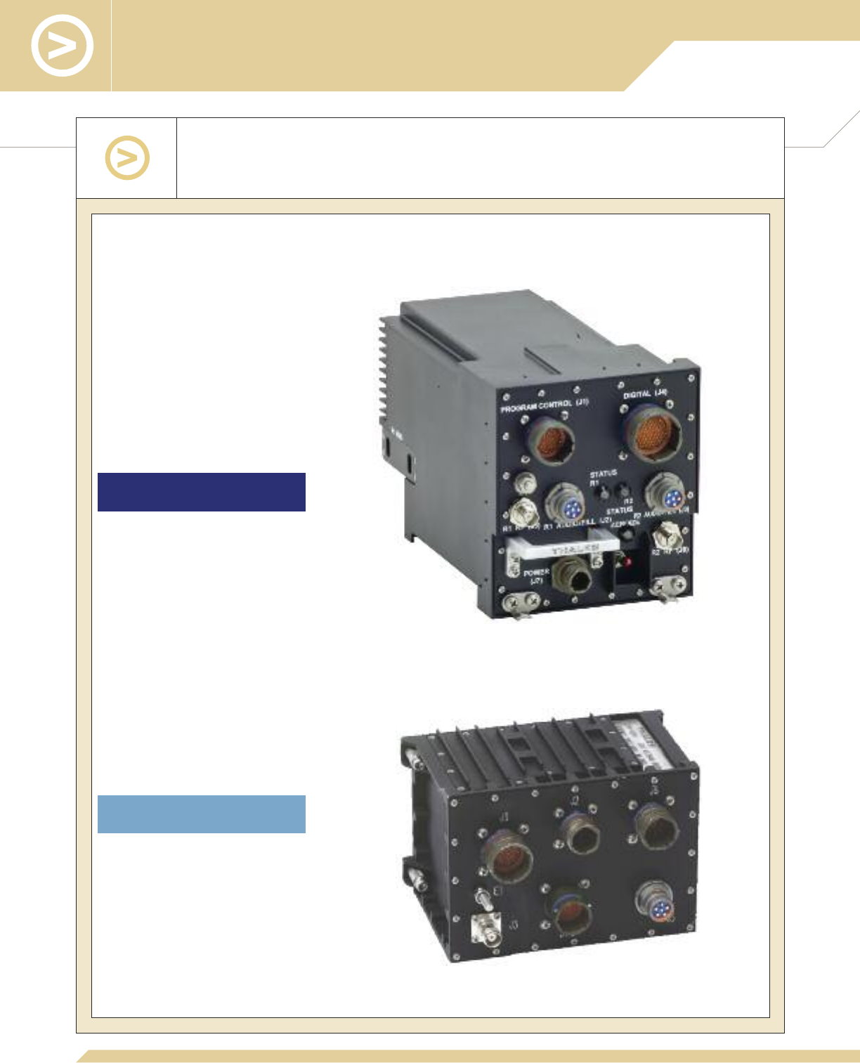
Repackaged AN/PRC-148 JEM and PRC6809 MBITR radios for airborne applications, e.g.,
unattended aircraft systems, aerostats, and small aircraft payloads
Key Design Features of the Multiband Airborne Radios
LMAR–Lightweight Multiband
Airborne Radio (ARC6809)
MMAR–Multichannel Multiband
Airborne Radio (ARC6999)
LMAR
MMAR

SOFTWARE AND
ACCESSORIES

25
MA6941N, PC Configuration Tool Kit for Type 1, AN/PRC-148 JEM, for
programming operating parameters into a [V]3[C] and [V]4[C] JEM; special radio side connector with USB connector,
supplied with a USB cable (Part Number 1100592-501) to connect the radio to a personal computer (PC) running
Windows 2000, Windows XP, or Vista. Program supplied on CD-ROM.
MA6941F, PC Programmer for Type 1, AN/PRC-148 MBITR, for programming
operating parameters into the [V]1[C] and [V]2[C] radio; RS-232 serial cable (Part Number 3500393-501) provided
to connect the encrypted version of the radio to a personal computer [PC] running Windows 98, Windows NT,
Windows 2000, or Windows XP. Program supplied on CD-ROM.
MA6941L, PC Programmer for PRC6809 MBITR, for programming operating parameters
into a PRC6809 radio with DES encryption; RS-232 serial cable (Part Number 3500393-501) provided to connect
the radio to a personal computer [PC] running Windows 98, Windows NT, Windows 2000, or Windows XP. Program
supplied on CD-ROM.
MA6941Q, PC Programmer Advanced Encryption, for programming operating parameters
into the (V)3(C) and (V)4(C) JEM with AES encryption; cable provided to connect the radio to a personal computer
(PC) running Windows 2000 or Windows XP. Program supplied on CD-ROM.
In addition to AM/FM capabilities, the following features are standard on the
AN/PRC-148 JEM (V)3(C) and (V)4(C) radios:
1700858-2, SINCGARS Frequency Hopping Electronic Counter-Counter
Measures [ECCM] Waveform, Single Channel Ground and Airborne Radio System (SINCGARS),
in accordance with MIL-STD-188-241-1/-2; frequency range of 30 to 90 MHz.
1700858-3, HAVEQUICK I/II Frequency Hopping ECCM Waveform, in accordance
with MIL-STD-188-220; frequency range of 225 to 400 MHz.
1700858-4, ANDVT Waveform, encrypted Advanced Narrowband Digital Voice Terminal, 5 kHz
bandwidth, maximum 2400 baud rate, LPC-10 vocoder is default, Mixed Excitation Linear Predictive (MELP) vocoder
available as an option.
The following features are available as options for the AN/PRC-148 JEM (V)3(C)
and (V)4(C) radios:
1700858-1, Retransmission, allows two AN/PRC-148 radios to be configured to provide a
bi-directional retransmission capability, thus providing range extension in difficult urban or terrestrial situations.
Operation requires two radios to be connected together using the Expedient Retransmission Kit (Part Number
1100540-501), or the separate Retransmission Cable. In all instances where Retransmission is desired
(e.g., handheld-to-handheld, through Vehicle Adapters or the Tactical Repeater), the handheld radios will require
this software. Retransmission is not compatible with the HAVEQUICK frequency hopping mode.
1700858-5, High Throughput Waveform (HTW), provides increased data throughput
capabilities of up to 56 kbps through a 25 kHz channel in accordance with the non-proprietary MIL-STD-188-181B.
This allows an increase of up to 3.5 times the over-the-air data speed relative to the standard AN/PRC-148 data
rate of 16 kbps. This option provides significantly improved performance for the digitized battlefield.
1700858-7, Project 25, AES, provides Project 25 Common Air Interface functionality in the JEM that
allows interoperability with public safety sectors, e.g., police, firefighters, etc.
Radio and Programming Software

1700858-8, SINCGARS Frequency Hopping 2, provides enhanced SINCGARS mode for
continued fielded interoperability with fielded SINCGARS systems.
1700858-9, Mixed Excitation Linear Predictive (MELP), provides an enhanced vocoder
at 2400 bps for improved voice quality with ANDVT.
1700858-10/11, Integrated Waveform [IW], the DAMA successor waveform for multi-channel
satellite communication. Waveform in accordance with MIL-STD-188-181C (5 kHz and 25 kHz UHF SATCOM),
MIL-STD-188-182B (5 kHz and 25 kHz demand assigned UHF SATCOM), and MIL-STD-188-183B (5 kHz and 25 kHz
multiple access UHF SATCOM).
1700858-12, Over-the-Air-Cloning (OTAC), provides a wireless capability for programming/
configuring multiple radios at once without the need for a cabled connection, reducing mission planning time.
The following features are available as options for the AN/PRC-148 MBITR
(V)1(C) and (V)2(C) Type 1 radios:
1700339-1, Retransmission, requires two radios to be connected together, used with the Expedient
Retransmission Kit (Part Number 1100540-501), or the separate Retransmission Cable, Tactical Repeater, or the
VAAs. Retransmission is not available in the HAVEQUICK frequency hopping mode. Retransmission is standard with
the PRC6809 radio.
1700339-2, SINCGARS Frequency Hopping Electronic Counter-Counter
Measures [ECCM], Single Channel Ground and Airborne Radio System, frequency range of 30 to 88 MHz.
1700339-3, HAVEQUICK II Frequency Hopping Electronic Counter-Counter
Measures [ECCM], frequency range of 225 to 400 MHz.
1700339-4, ANDVT, encrypted Advanced Narrow-band Digital Voice Terminal, 5 kHz bandwidth,
maximum 2400 baud rate.
1700339-5, Type 3 Analog Data Encryption Standard (DES), option available on
AN/PRC-148 MBITR and PRC6809 radios; provides encrypted interoperability with other handheld radios that have
analog DES, such as Motorola Saber and XTS.
1700339-8, SINCGARS Frequency Hopping 2, new SINCGARS frequency hopping
methodology in accordance with MIL-STD-188-241.
1700339-10, MELP (Mixed Excitation Linear Predictive), 2400 bps vocoder, in
accordance with STANAG 4591/MIL-STD-13005. Used in ANDVT radio operating mode, better audio quality than
LPC-10 vocoder.
The following features are available as options for the PRC6809 radios:
1700339-5, Type 3 Analog Data Encryption Standard (DES), option available on
AN/PRC-148 MBITR and PRC6809 radios; provides encrypted interoperability with other handheld radios that have
analog DES, such as Motorola Saber and XTS.
1700339-7, 256-bit Advanced Encryption Standard (AES), option available on
PRC6809 radios; provides higher level of software-based encryption for interoperability with other PRC6809 radios.
26
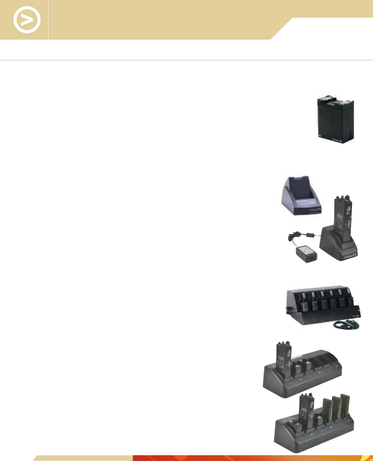
Batteries, Chargers, and Power Adapters
1600515-7, Lithium-Ion Rechargeable Battery, 4.8Ahr capacity provides the JEM with a
minimum of 10-hour duration with radio duty cycle of 10% transmit at 5W, 10% receive, and 80% stand-by per
TIA-603. With the same duty cycle, provides the MBITR with a minimum of 12-hour duration.
1600686-2, Lithium-ion Rechargeable Battery, 5.8Ahr capacity provides the JEM
with a minimum of 12-hour duration with radio duty cycle of 10% transmit at 5W, 10% receive, and 80%
stand-by per TIA-603. With the same duty cycle, provides the MBITR with a minimum of 15-hour duration.
There is an intelligent, “smart” micro-controller interface between battery
and charger. Charge time takes into account battery cell and ambient
temperatures. Each of the chargers listed below can charge both the 4.8Ah
and 5.8Ah batteries.
1600654-1, Single-Bay, AC Only, Battery Charger, five green LEDs
indicate battery state-of-charge with each LED representing 20% of full charge. A single multi-
colored LED indicates overall charger status. With a depleted battery, the typical charge time
is less than 3 hours. [This charger replaces Part Number 1600581-1]
1600701-2, Basic Single-Bay, AC Battery Charger, a single
multi-colored LED indicates battery state of charge. With a depleted battery, the typical charge
time is less than 5 hours.
1600701-5, Basic Single-Bay, AC / DC Battery Charger, a single
multi-colored LED indicates battery state of charge. With a depleted battery, the typical charge
time is less than 5 hours.
1600652-1, 6-Bay, AC or DC, Battery Charger, five green LEDs on
each bay indicate battery state of charge with each LED representing 20% of full charge. A
single multi-color LED indicates overall charger status. With 6 depleted batteries, the typical
charge time is less than 3 hours. [This charger replaces Part Number 1600580-1]
1600653-1, 6-Bay, AC Only, Battery Charger, five green LEDs
on each bay indicate battery state of charge with each LED representing 20% of full
charge. A single multi-color LED indicates overall charger status. With 6 depleted
batteries, the typical charge time is less than 3 hours. [This charger replaces Part
Number 1600580-2]
1600700-2, Basic 6-bay, AC or DC, Battery Charger,
each charger bay has a multi-colored LED indicating battery state-of-charge. With a
depleted battery, the typical charge time is less than 5 hours.
1600700-3, Basic 6-bay Combo, AC Battery Charger, each
charger bay has a multi-colored LED indicating battery state-of-charge. Capable of
simultaneously charging 3 AN/PRC-148 batteries and 3 AN/PRC-154 batteries in less
than 5 hours.
27

MA6751, 2-Bay, DC Only, Rugged Charger, supports two rechargeable
batteries, with or without radios. Integral power cable, 6 ft long with 15A inline fuse with bare wires
for connection to 10 to 32 VDC power, 100W maximum. A spare 15A fuse is provided in a
separate fuse holder. Each charger slot has a multi-colored LED to provide charge status. Retention
mechanism is designed to allow for easy installation/removal (jerk-and-run) of the radio or battery.
Mounting brackets provided for flush mounting to vertical bulkhead or any flat surface.
4101240-501, Battery Cell Holder, for 12x non-rechargeable DL2/3A cells,
NSN 6135-01-351-1131. The unit provides the JEM with a minimum of 8-hour duration with duty
cycle of 10% transmit at 5W, 10% receive, and 80% stand-by. With the same duty cycle, provides
the MBITR with a minimum of 10-hour duration.
4101310-501, SPAI (Special Power Adapter Interface), used to
interface to an external 12 to 32 VDC power source. The adapter attaches to the AN/PRC-148 and
the lithium-ion rechargeable battery. The regular battery is disconnected from the radio and connected
to the bottom of the SPAI; the top of the SPAI is connected to the radio. The SPAI provides power to
the radio and simultaneously recharges the lithium-ion rechargeable battery.
3500460-501, SPAI DC Input Cable, 6 ft long cable with
connector for the SPAI and bare wires with 15A in-line fuse, accepts 12 to 32 VDC
input voltage.
3500470-504, SPAI DC Input Cable, 6 ft long cable with connector
for the SPAI on one end and a vehicle cigarette lighter plug on the other end. 10A fuse
inside the cigarette lighter plug.
1100533-501, SPAI Cable Kit, 1ft long cable to connect to SPAI with
an in-line connector for 3 ft long interchangeable cables for BA-XX90 battery; cigar
lighter or red and black alligator clips to connect 12 to 32V DC input voltage to the
SPAI.
4101441-501, Battery Adapter, powers the radio from an external
DC power source, provides reverse polarity protection, as well as over-voltage and
over-current protection for the radio; includes a 4 ft long cable with bare wires.
8.5-16.5 VDC input. 30W maximum power with the radio transmitting at 5W.
4101441-502, Battery Adapter, powers the radio from an external
DC power source, provides reverse polarity protection, as well as over-voltage and
over-current protection for the radio; includes a 3 ft long cable with interfaces to
BA/BB90 batteries. 8.5-16.5 VDC input. 30W maximum power with the radio
transmitting at 5W.
4101441-504, Battery Adapter, powers the radio from an external DC power source, provides
reverse polarity protection, as well as over-voltage and over-current protection for the radio; 3 ft long cable with
interfaces to the battery box (Part Number 1600604). 8.5-16.5 VDC input. 30W maximum power with the radio
transmitting at 5W.
28
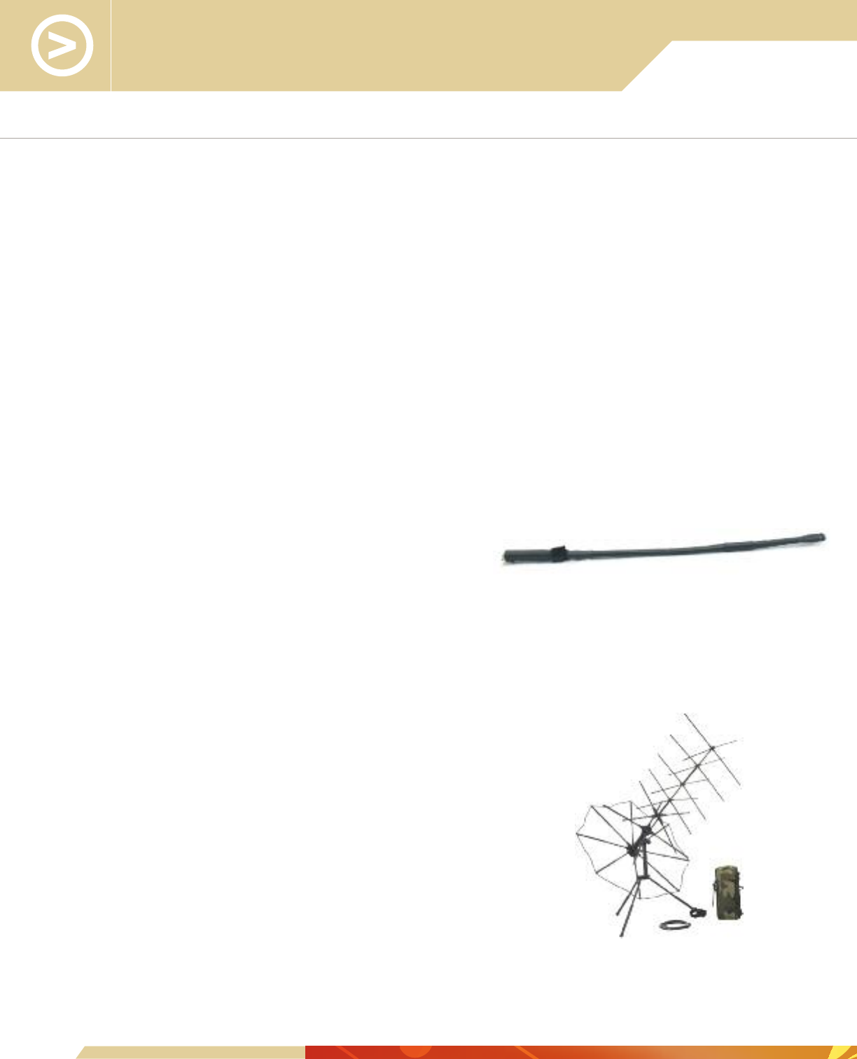
Antennas
29
Handheld Radio:
1600500-1, Handheld, 13-inch Broadband Whip Antenna; TNC connector; 8W
maximum; 20 m immersible general purpose handheld antenna providing solid performance for all waveforms from
90-512 MHz.
1600500-3, Handheld, 13-inch Broadband Whip Antenna; TNC connector; 8W
maximum; 2 m immersible general purpose handheld antenna providing solid performance for all waveforms from
90-512 MHz.
1600629-1, Handheld, 48-inch Blade Antenna; TNC connector, 8W maximum; 20 m
immersible SINCGARS handheld antenna providing optimal performance from 30-90 MHz.
1600638-1, Handheld, 10-inch Whip Antenna; TNC connector; 8W maximum; 20 m
immersible UHF handheld antenna providing optimal performance from 225-450 MHz.
1600638-2, Handheld, 10-inch Whip Antenna; TNC connector; 8W maximum; 2 m
immersible UHF handheld antenna providing optimal performance from 225-450 MHz.
1600707-1, Handheld, 20-inch Dual-band
Blade Antenna; TNC connector, 8W maximum, 20 m
immersible handheld antenna providing optimal performance from
30-90 MHz and 225-512 MHz.
SS-1600293-1, Handheld, 13.25-inch Whip Antenna; TNC connector; 8W maximum,
2 m immersible VHF handheld antenna providing optimal performance from 136-174 MHz.
SS-1600294-1, Handheld, 6.5-inch Whip Antenna; TNC connector; 8W maximum;
2 m immersible UHF handheld antenna providing optimal performance from 400-512 MHz.
Handheld SATCOM:
85288, Handheld/Manpack, Directional Coat Pocket
SATCOM Antenna, Trivec Avant AV2055-3; 3.1 lbs;
BNC female connector; 200W maximum; 240-318 MHz frequency band;
Compact directional SATCOM handheld/manpack antenna providing ultra high
gain (+10.5 dBi). (NSN 5985-01-463-6558).
85419-001, Directional Coat Pocket SATCOM
Antenna, Trivec Avant AV2125-2; 1.5 lbs; BNC female
connector; 100W maximum; 240-318 MHz frequency band; ultra-compact
directional SATCOM handheld/manpack antenna with magnetic mount and
director; +7 dBi.

Man-Portable:
85350, Man-Portable, 14.5-inch Nightstick Antenna; BNC male connector; 35W
maximum; general purpose manpack antenna providing solid performance for waveforms from 90-512 MHz; short
range performance 30-88 MHz.
85349, Man-Portable, 48-inch Blade Antenna; BNC Male connector; 24W maximum;
SINCGARS manpack antenna providing optimal performance from 30-88 MHz.
Vehicular/Base Station/Tactical Repeater:
85184*, Vehicular, 100-inch Whip Antenna, Shakespeare SFB3512/VRC;
N female connector; 100W maximum; general purpose vehicular antenna providing solid performance for waveforms
from 30-512 MHz.
85320*, Vehicular, 40-inch Broadband Whip Antenna, Chelton GD1813P4,
Black; BNC female connector; 50W maximum; general purpose vehicular antenna providing solid performance for
waveforms from 30-512 MHz.
85347, Vehicular, 40-inch Broadband Whip Antenna, Chelton GD1813,
Green; BNC female connector; 50W maximum; general purpose vehicular antenna providing solid performance for
waveforms from 30-512 MHz.
85348, Vehicular, 40-inch Broadband Whip Antenna, Chelton GD1813P66,
Tan; BNC female connector; 50W maximum; general purpose vehicular antenna providing solid performance for
waveforms from 30-512 MHz.
85468-001, Vehicular, RAMI-7909G, 82-inch Whip Antenna; BNC or N female
connector; 100W maximum; general purpose vehicular antenna providing solid performance for waveforms from 30-
512 MHz.
85464-001, Vehicular, Radiall R380.990.010, 58-inch Whip Antenna; BNC or N
female connector; 50W maximum, general purpose vehicular antenna providing solid performance for waveforms
from 30-512 MHz, especially strong UHF gain; 4 inch diameter cylinder.
85373, Vehicular/Base Station, 11-foot Whip Antenna, Valcom VMB-3512;
N connector (optional BNC); 100W maximum; general purpose vehicular antenna providing solid performance for
waveforms from 30-512 MHz.
1600658, Base Station, Mast:
1600658-1: 33-foot Mast, for Single Antenna
1600658-2: 13-foot Mast, for Single Antenna
1600658-3: 13-foot Mast, for Dual Antenna
1600658-4: 33-foot Mast, for Dual Antenna
*A broadband vehicle mount antenna must be installed and bonded to a metal surface to provide a ground plane for the antenna.
30

Antennas
31
1100634-501, Base Station, 33-foot Single Antenna Kit; includes 85373* antenna,
1600658-1 mast, SS-1600366-1 ground spike, and 3500711-501 50 ft. antenna cable.
1100634-502, Base Station, 13-foot. Single Antenna Kit; includes
85373* antenna, 1600658-2 mast, SS-1600366-1 ground spike, and 3500711-501 50 ft.
antenna cable.
1100634-503, Tactical Repeater, 13-foot Dual Antenna Kit; includes
two 85373* antennas, 1600658-3 mast with 6 ft. crosspiece, SS-1600366-1 ground spike,
and two 3500711-501 50 ft. antenna cables.
1100634-504, Tactical Repeater, 33-foot Dual Antenna Kit; includes
two 85373* antennas, 1600658-4 mast with 6 ft. crosspiece, SS-1600366-1 ground spike,
and two 3500711-501 50 ft. antenna cables.
Vehicular SATCOM:
85315, Vehicular SATCOM and Line-of-Sight (LOS), X-Wing Dual
Simultaneous Channels Antenna, Trivec Avant AV2090-4, Black;
N female/TNC female connector; 200W maximum; 225-400 MHz (LOS) and 240-400 MHz
(SATCOM) frequency bands; vehicular antenna supports two simultaneous radios, one SATCOM and
the other LOS, or one radio with a switch, gain +8 dBic.
85339, Vehicular Line-of-Sight (LOS)/SATCOM OTM Antenna,
Trivec Avant AV2086-1, Black; N female connector; 200W maximum; 225-400 MHz (LOS) and
240-320 MHz (SATCOM) frequency bands.
85374, Vehicular Line-of-Sight (LOS)/SATCOM OTM Antenna, Trivec Avant
AV2086-2 Magnetic Mount, Black; N female connector; 200W maximum; 225-400 MHz (LOS)
and 240-320 MHz (SATCOM) frequency bands.
85422-001, Vehicular SATCOM Batwing Antenna, Trivec
Avant AV2075-9, Black; 200W maximum; 225-400 MHz, gain +11 dBic.
*The Base Station and Tactical Repeater antennas, mounted on a mast, are center-fed and do not need a ground plane.
Tactical Repeater
Antenna Configuration
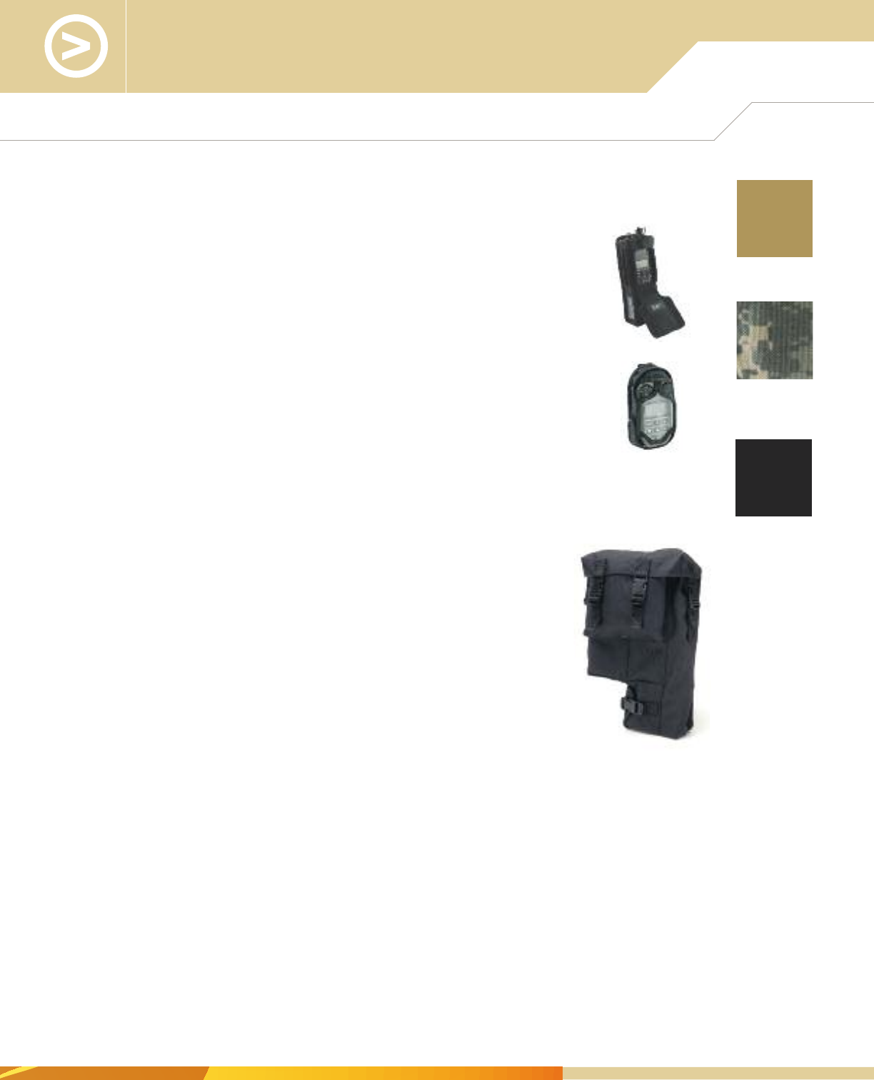
32
1600494-1, Holster, provides protection for the radio, with an adjustable flap
that provides flexibility to operate the radio while in transit. Nylon. ACU digital camouflage.
1600494-3, Holster, provides protection for the radio, with an adjustable
flap that provides flexibility to operate the radio while in transit. Nylon. Tan.
1600494-4, Holster, provides protection for the radio, with an adjustable
flap that provides flexibility to operate the radio while in transit. Nylon. Black.
1600699-1, Holster, provides protection for the Remote Control Unit with
GPS, with an adjustable flap that provides flexibility to operate the unit while in transit.
Nylon. ACU digital camouflage.
1600699-2, Holster, provides protection for the Remote Control Unit with
GPS, with an adjustable flap that provides flexibility to operate the unit while in transit.
Nylon. Black.
1600699-3, Holster, provides protection for the Remote Control Unit with GPS, with an
adjustable flap that provides flexibility to operate the unit while in transit. Nylon. Tan.
1600495-1, Accessory Bag/Carrying Case, tough nylon
black material bag with positive closures to prevent loss of components. Includes
two belt loop type straps and military clips and has compartments for two spare
batteries, audio accessory, and unused antenna, as well as a compartment for
the radio with its battery.
Cases and Holsters
ACU digital
camouflage
Tan
Black
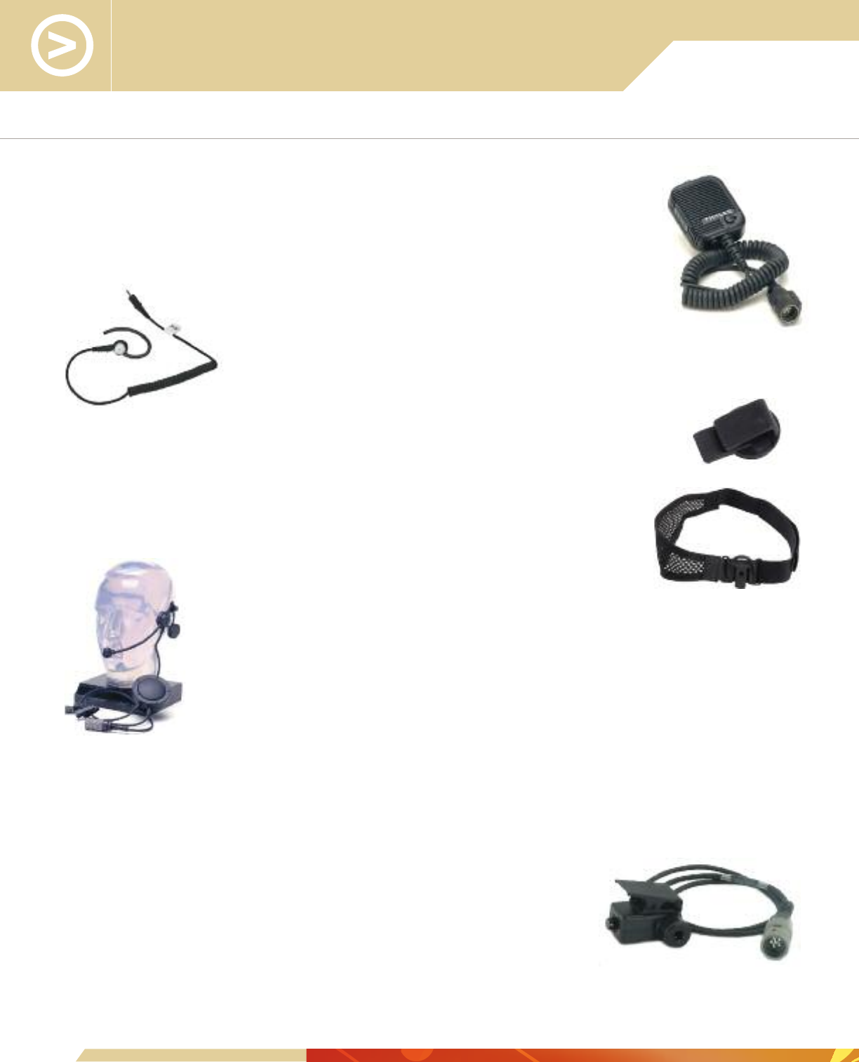
Audio Accessories for the 2 Meter
Submersible Urban Configuration Radios
1600469-4, Urban Speaker Microphone, fits in the palm of the hand or
attaches to web gear with spring clip on its back, has its own Press-To-Talk [PTT] switch and
volume control. At the bottom of the case there is a plastic cover that pulls back to reveal a
2.5 mm diameter socket for the Earphone.
1100542-501, Earphone Kit for Speaker
Microphone, plugs into the ear, 2.5 mm diameter plug
connects to the Speaker Microphone and “mutes” its speaker.
11000641-501, Commercial Lightweight Urban Headset Kit,
lightweight headset with a rigid headband, adjustable boom microphone, and speaker. A large,
in-line Press-To-Talk (PTT) switch with clothing clip is provided. The Helmet Clip, Part Number
85267, and the Head Strap, Part Number 85268, with Velcro fastening, are provided as
alternates to the removable rigid headband.
1600551-2, Commercial Lightweight Urban Headset, lightweight
headset with a rigid headband, adjustable boom microphone, and speaker. A large, in-line
Press-To-Talk (PTT) switch with clothing clip is provided.
1600567-1, Tactical Urban Headset, single-muff earpiece headset with adjustable boom
microphone, head strap, and in-line Press-To-Talk (PTT) switch. The cable has a U-94A/U jack disconnect at the
PTT switch.
85317, Headset Down-Lead Assembly, replacement lower
cable assembly of the Tactical Urban Headset, PN 1600567-1. Cable is 3 ft. long
with 6-pin connector to the radio and U-94A/U jack with ring Press-To-Talk (PTT)
switch. Used to connect compatible third-party audio accessories to the radio.
33
Helmet Clip
Head Strap

1600584-1, Urban Covert Headset, two-wire configuration; one
cable has the combined microphone and ring Press-To-Talk [PTT] switch, the other
cable is connected to a transducer which attaches to a transparent coiled plastic
tube with soft earpiece. The transducer also provides an inductive coupling to the
Wireless Earpiece. Includes a clip for attachment to clothing.
1600584-2, Wireless Earpiece, “in-the-ear” option for inductive
coupling to the Covert Headset, Part Number 1600584-1, used as an alternate
to the soft earpiece with its coiled plastic tube.
1600585-1, Urban Ear/Microphone Headset, two-wire configuration;
one cable with a ring Press-To-Talk [PTT] switch; the other cable connects to a flexible ear
hanger; a bone-conduction microphone is included in the earpiece.
1100597-501, Urban Combat Headset, two-wire configuration; one
cable has a speaker on a flexible arm with a boom microphone on another flexible arm;
the other cable has a ring Press-To-Talk (PTT) switch. Headset comes complete with
helmet clip, head strap, and rubber noise protector that shrouds the ear.
1600771-1, Peltor Comtac™ ACH, is a compact
Advanced Communications Headset (ACH) offering hearing protection and
designed for comfort under a helmet. “Talk-Through” mics powered by AAA
batteries maintain situational awareness by amplifying weak sounds (with
volume control) while offering hearing protection by limiting/suppressing
loud impulse noises. The headset down-lead terminates with a U/174 Plug
for quick-disconnect from the Push-To-Talk (PTT) Adapter. The boom mic can
be mounted on either side of the headset by the user to accommodate left
and right handed operators. Comes in a preassembled kit with camo bag,
gel ear cushions, batteries, and PTT.
1600771-1, Peltor Comtac™ ACH Single Comm Kit, Coyote Tan
1600771-2. Peltor Comtac™ ACH Dual Comm Kit, Coyote Tan
1600771-3, Peltor Comtac™ ACH Single Comm Kit, Olive Drab Green
1600771-4, Peltor Comtac™ ACH Dual Comm Kit, Olive Drab Green
34

Audio Accessories for the 20 Meter
Submersible Maritime Configuration Radios
All maritime audio accessories have the sealed 10-pin connector to
connect to the radio.
1600503-5, Tactical Maritime Headset, water-resistant,
single-muff earpiece headset, with boom microphone, head strap, and in-line
Press-To-Talk [PTT] switch.
1600584-3, Maritime Covert Headset, two-wire configuration; one cable has the ring
Press-To-Talk [PTT] switch; the other cable is connected to a transducer which includes the microphone and which
attaches to a transparent coiled plastic tube with soft earpiece. The transducer also provides an inductive coupling to
the Wireless Earpiece. Includes a clip for attachment to clothing. To be placed in a suitable waterproof bag when
diving to 20 m.
1600584-4, Maritime Covert Headset, two-wire configuration; one cable has the ring
Press-To-Talk [PTT] switch; the other cable is connected to a transducer which includes the microphone and which
attaches to a transparent coiled plastic tube with soft earpiece. The transducer includes a clip for attachment to
clothing. To be placed in a suitable waterproof bag when diving to 20 m.
1600584-2, Wireless Earpiece, “in-the-ear” option for
inductive coupling to the Covert Headset, Part Number 1600584-3
and - 4, used as an alternate to the soft earpiece with its coiled plastic
tube. To be placed in a suitable waterproof bag when diving to 20 m.
1600585-2, Maritime Ear/Microphone Headset, two-wire configuration; one cable with a
ring Press-To-Talk [PTT] switch; the other cable connects to a flexible ear hanger; a bone-conduction microphone
is included in the earpiece. To be placed in a suitable waterproof bag when diving to 20 m.
1100598-501, Maritime Combat Headset, two-wire configuration; one cable has a
speaker on a flexible arm with a boom microphone on another flexible arm; the other cable has a ring
Press-To-Talk (PTT) switch. Headset comes complete with helmet clip, head strap, and rubber noise protector
that shrouds the ear.
4600049-501, Maritime Speaker Microphone, fits in palm of the hand or attaches to
web gear, has its own Press-To-Talk (PTT) switch, with earphone jack and seal. To be placed in a
suitable waterproof bag when diving to 20 m.
1100542-501, Earphone Kit for Speaker Microphone, plugs into the
ear, 2.5 mm diameter plug connects to the Speaker Microphone and “mutes” its speaker. Place in
a suitable waterproof bag when diving to 20 m.
35
Wireless
Earpiece “in-the-
ear” Option

1100592-501, PC Configuration Tool Kit Cable, a 6 ft long USB
cable that attaches to a special side connector connecting the JEM to a USB PC port. This
arrangement can only be used for the PC Configuration Tool Kit.
1600713-11, USB High Speed Serial Data Cable, a 3 1/2 ft cable
with high RFI and EMI suppression on the JEM sidemate adapter terminating in a standard
type A USB connector. This cable also offers ruggedized mechanical and environmental
performance, which makes it suitable for in-theatre use. Used on JEM only. Can be used in
substitution of 1100592-501.
3500610-501, Cloning Cable, a 4 ft long cable connecting two radios
together via their side connectors to transfer mode and frequency settings from one radio
to another. Used for both MBITR and JEM. Replaces Part Number 3500395-501.
3500647-501, Data Mode Cable, a 4 ft long cable connecting the radio
side connector to a 25-pin D-connector for an RS-232 serial data interface. Includes a small
rotary switch to select between voice operation or a serial data interface. Used for both
MBITR and JEM. Replaces Part Number 3500396-501.
3500623-501, GPS Cable, a 3 ft long cable connecting the radio side
connector to a 15-pin D-connector to a PLGR or DAGR to transmit user-entered, five-digit
combat identification number and GPS-based grid coordinates of position. Used with both
MBITR and JEM. Replaces Part Number 3500465-501.
3500622-501, PDC Cable for ViaSat VDC400/VDC600,
a 6 ft long cable connecting the radio side connector to a multi-way PC Card connector for
the ViaSat PC Card. Used for both MBITR and JEM. Replaces Part Number 3500466-501.
36
Cables, Adapters, Spares Kits, and
Vehicle Adapter Accessories

Cables, Adapters, Spares Kits, and
Vehicle Adapter Accessories
1100540-501, Expedient Retransmit Kit,
for retransmission with two radios. The kit comprises a 10 ft
cable to connect the two radios together via their side
connectors and four co-axial low-pass and high-pass VHF and UHF
filters at different frequencies. These connect to the antenna
connectors of the receive and transmit radios with two coaxial cables
supplied in the kit.
3500611-501, Retransmission Cable, a 10 ft long cable to
connect two radios together via their side connectors. Used for both MBITR and JEM.
Replaces Part Number 3500485-501.
3500611-504, Retransmission Cable, a 50 ft long cable to
connect two radios via their side connectors in a communications repeater configuration.
Used for both MBITR and JEM.
3500562-501, Adapter Cable, Data, a 3 ft long cable connecting the radio side connector to a
GC328 6-pin plug for SINCGARS clock synchronization for packet data transmissions. Includes a small slide switch to
select between voice operation or the serial data interface. Used for both MBITR and JEM.
3500648-501, PC Programmer Cable, a 3 ft long cable connecting the radio side connector to a
9-pin D-connector for an RS-232 serial connection to a PC running the PC Programmer; this cable is supplied as part
of MA6941F, MA6941L, and MA6941Q. Used for MBITR only. Replaces Part Number 3500393-501
3500756-502, Remote Control Unit (RCU) with GPS Cable with Data
Access, RCU cable with a mid-cable DB-25 connector for RS-232 serial data access; the 3500758-501 cable
provides the mating DB-25 connector with the other end terminating in a ViaSat VDC400/600 PC Card connector.
3500758-501, PDC Remote Control Unit (RCU) with GPS Cable, a 6 ft cable
providing DB-25 to ViaSat VDC400/600 PC Card connector; for use with 3500756-502 RCU Cable with Data
Access.
3600190-1, Keyfill Adapter, 10-pin to 6-pin adapter for the 20 m Maritime radio. This allows the radio
to be keyfilled with a standard 6-pin connector keyfill device, such as the CYZ-10, KYK-13, and SKL. We do not
recommend the operational use of the adapter for regular 6-pin connector audio accessories; the radio is vulnerable
to damage if the 10-pin connector on the radio is snapped off.
3500458-501, KVL Keyfill Cable, a 2 ft long cable connecting the radio side connector
to the KVL 3000 Crypto Key Loader. Used with PRC6809 MBITR and Type 1 MBITR if analog Type 3 DES
is enabled.
3500755-501, KVL Keyfill Cable, 3 ft long cable connecting the radio’s 6-pin top connector to the
Motorola Keyfill Adapter Part Number TKN8531B of the KVL 3000 + Crypto Key Loader.
37

3500460-501, SPAI DC Input Cable, a 6 ft long cable with connector for
the SPAI and bare wires with 15A in-line fuse, accepts 12 to 32 VDC input voltage.
3500470-504, SPAI DC Input Cable, a 6 ft long cable with connector for
the SPAI on one end and a vehicle cigarette lighter plug on the other end, 10A fuse inside the
cigarette lighter plug.
3600215, Vehicle Adapter Removable Control Head (RCH) Cable, the RCH cable is
available in five lengths and provides a remote control interface for controlling a vehicle adapter system.
3600215-1: 10 ft
3600215-2: 35 ft
3600215-3: 50 ft
3600215-4: 100 ft
3600215-5: 150 ft
1600599-1, Tactical Speaker, ruggedized speaker, 4.7 in x 4.7 in x 3.5 in, used to
hear communications when using the Vehicle Adapter (VA). The microphone is included in the RCH.
The speaker is driven from the 5 Watt audio amplifier in the VA; however, the speaker has its own
audio level control and an on/off switch. The speaker is supplied with an adjustable mounting
bracket.
1600623, Tactical Speaker Cable, cable to connect from Vehicle Adapter
rear connector to the Tactical Speaker.
1600623-3: 6 ft
1600623-4: 10 ft
82165, TNC Male to BNC Female Adapter, used to connect the radio to a directional
satellite communication antenna that is supplied with a BNC coaxial cable, for example, Part Number 85288, the
Trivec Avant AV2055-3.
82167, Type N Male to BNC Female Adapter, allows use of BNC coaxial cables to connect to
RF output connector on the rear of the Vehicle Adapter.
1100590-501, Ready Spares Kit, designed to support five radios, either the Urban or Maritime
configuration. All parts can be replaced without opening the radio. An instruction sheet is included with the Kit.
1100588-501, Low Profile Volume Knob Kit, comprises 50x Low Profile volume knobs with
set screws, thread locking compound, and hex wrench. This is a replacement knob option for the original, longer
radio volume knobs.
1100606-501, Intermediate Spares Kit, designed to support 50 radios for one year, either the
Urban or Maritime configuration. All of these parts can be replaced without opening the radio. An instruction sheet is
included with the Kit.
38
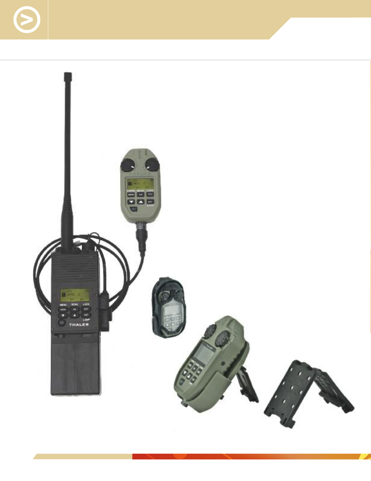
39
Remote Control Unit with GPS
MA6795, Remote Control Unit (RCU) with
GPS, includes the RCU (Part Number 4101890-501) and
associated accessories, as indicated. The RCU is an active
extension of the front panel controls of the radio. It is powered by
the radio and connects to the radio side connector via a 4 ft cable
with a breakaway connector (Part Number 3500733-501,
provided). With a radio worn on the back, the RCU is used in
conjunction with an audio accessory, such as a Speaker
Microphone or a headset, for the audio and PTT functions. The
RCU is suitable for mounting high on the body for optimum GPS
reception. The volume and channel rotary controls, as well as the
menu structure on the RCU display, replicate the front panel of
the radio. The antenna for the GPS sensor is built-in; the GPS
uses the Coarse Acquisition (CA) mode, not the Precision Y-code
(P/Y) mode. Once the radio’s Situational Awareness (SA) mode
has been selected, the unit displays the GPS position in standard
UTM/Military Grid Reference System (MGRS) coordinates, as well
as the Combat Identification Designator/Number (CID). Up to ten
of the latest CIDs with position can be stored and displayed. The
System is supplied with a plastic cradle with large and small utility
clips for various retention arrangements, including MOLLE. A
tough nylon pouch/holster in universal camouflage is also
supplied. Black and tan holsters are available as options.
AN/PRC-148
with RCU
RCU with Cradle and Belt Clips
Holster

CUSTOMER
SUPPORT

41
Customer Support
Our Customer Support Department assists our customers through four
key service areas:
■Technical Support: Help Desk services, technical website content
■Product Support: Product repairs, upgrades, and Return Material Authorization (RMA)
monitoring
■After Market Support: Critical inventory provisioning and web sales assistance
■Field Support: Maintenance and technical services at forward depots and customer
sites
Reach our Customer Support Department 24/7 by phone at our Call Support Center
and online at our website.
By Phone:
Within the U.S.: 1-800-914-0303
International Dialing: +1-240-864-7643
Using the options below, incoming calls are routed to the appropriate Customer Service
Specialist to ensure all inquiries are addressed as quickly as possible:
Option 1: Technical assistance and general inquiries
Option 2: Repairs, RMAs, and other product support matters
Option 3: Sales for spares and ancillary items, request quotes, make purchases,
and website Shopping Cart assistance

42
Thales Communications, Inc.
22605 Gateway Center Drive, Clarksburg, MD 20871
Voice: 1-240-864-7000 Toll Free: 1-800-258-4420
Email: solutions@thalescomminc.com
www.thalescomminc.com
Online:
Website: www.thalescomminc.com
Select “Customer Sign-in” under the “Customer Support” banner to access our Technical
Resources and to:
■Request and check status of RMAs
■Look up warranty status
■Look up shipping status
■Access online purchasing and quotes
A link is available for first-time visitors to create a user account.
In-Theater:
Thales Communications also has in-theater maintenance and repair depots supporting
troops in Kuwait, Iraq, and Afghanistan. For more information, check online for latest
points of contact.
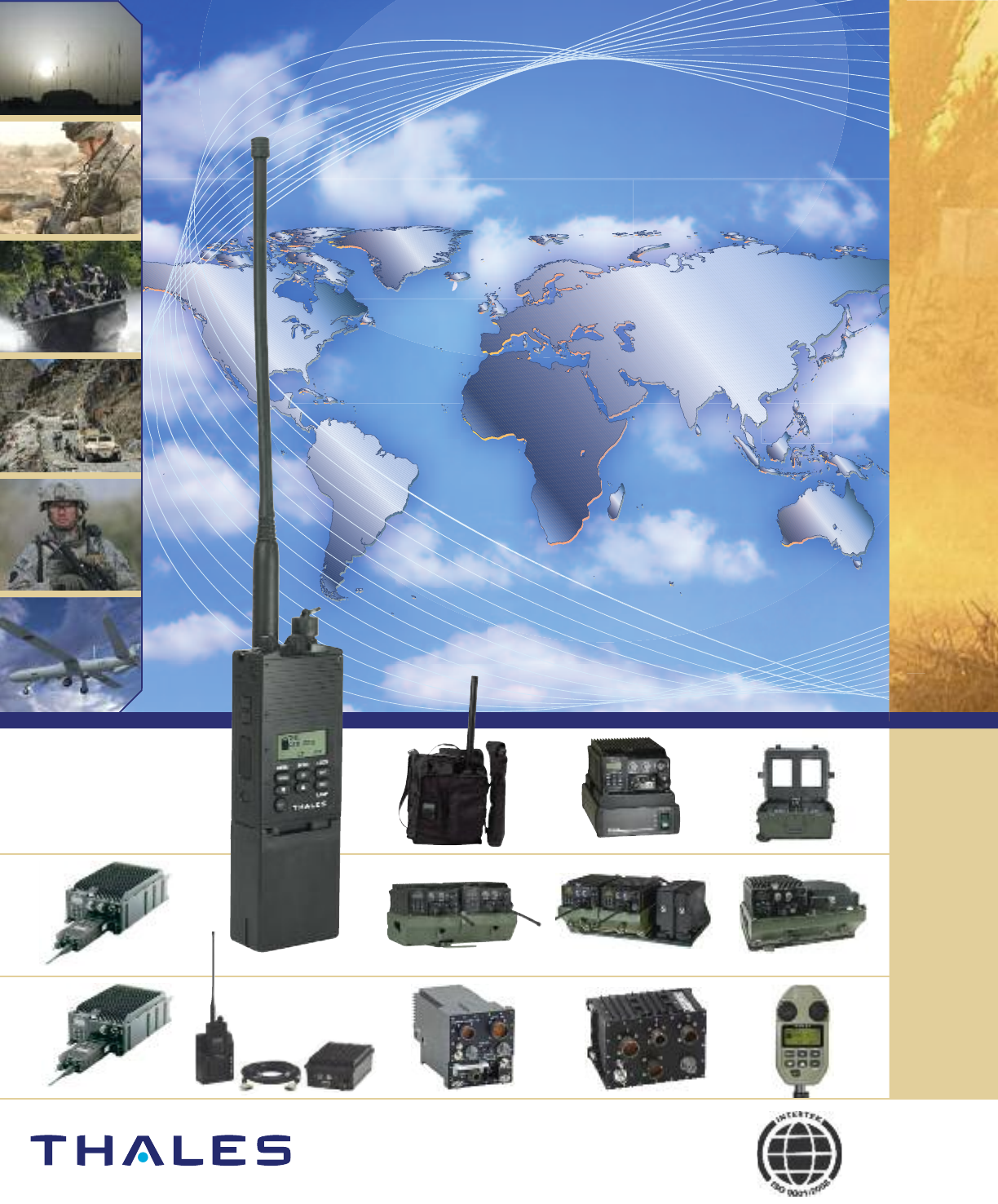
Thales Communications, Inc.,
22605 Gateway Center Drive, Clarksburg, MD 20871
Voice: 1-240-864-7000 Toll Free: 1-800-258-4420
Email: solutions@thalescomminc.com
www.thalescomminc.com 7001:112410:V2
